Dell Powerconnect J Ex4200 Software Manual Guide For JUNOS Version 11.1 Volume 1
Dell-Powerconnect-J-Ex4500-Quick-Reference-Guide-114549 dell-powerconnect-j-ex4500-quick-reference-guide-114549
2015-01-05
: Dell Dell-Powerconnect-J-Ex4200-Software-Manual-136613 dell-powerconnect-j-ex4200-software-manual-136613 dell pdf
Open the PDF directly: View PDF ![]() .
.
Page Count: 1308 [warning: Documents this large are best viewed by clicking the View PDF Link!]
- Table of Contents
- About This Guide
- Part 1: Junos OS for J-EX Series Switches Product Overview
- Chapter 1: Software Overview
- J-EX Series Switch Software Features Overview
- Layer 3 Protocols Supported on J-EX Series Switches
- Layer 3 Protocols Not Supported on J-EX Series Switches
- Security Features for J-EX Series Switches Overview
- High Availability Features for J-EX Series Switches Overview
- Understanding Software Infrastructure and Processes
- Chapter 2: Supported Hardware
- Chapter 1: Software Overview
- Part 2: Complete Software Configuration Statement Hierarchy
- Chapter 3: Complete Software Configuration Statement Hierarchy
- [edit access] Configuration Statement Hierarchy
- [edit chassis] Configuration Statement Hierarchy
- [edit class-of-service] Configuration Statement Hierarchy
- [edit ethernet-switching-options] Configuration Statement Hierarchy
- [edit firewall] Configuration Statement Hierarchy
- [edit forwarding-options] Configuration Statement Hierarchy
- [edit interfaces] Configuration Statement Hierarchy
- [edit poe] Configuration Statement Hierarchy
- [edit protocols] Configuration Statement Hierarchy
- [edit routing-instances] Configuration Hierarchy
- [edit snmp] Configuration Statement Hierarchy
- [edit virtual-chassis] Configuration Statement Hierarchy
- [edit vlans] Configuration Statement Hierarchy
- Chapter 3: Complete Software Configuration Statement Hierarchy
- Part 3: Software Installation
- Chapter 4: Software Installation Overview
- Chapter 5: Installing Junos OS
- Downloading Software Packages
- Installing Software on a J-EX Series Switch with a Single Routing Engine (CLI Procedure)
- Installing Software on a J-EX8200 Switch with Redundant Routing Engines (CLI Procedure)
- Installing Software on J-EX Series Switches (J-Web Procedure)
- Rebooting or Halting the J-EX Series Switch (J-Web Procedure)
- Chapter 6: Booting the Switch, Upgrading Software, and Managing Licenses
- Chapter 7: Verifying Software Installation
- Chapter 8: Troubleshooting Software Installation
- Troubleshooting Software Installation
- Troubleshooting a Switch That Has Booted from the Backup Junos OS Image
- Resilient Dual-Root Partitions Frequently Asked Questions
- How Does Upgrading to Junos OS Release 10.4R3 and Later Differ from Normal Upgrades?
- What Happens If I Do Not Upgrade Both the Loader Software and Junos OS at the Same Time?
- Can I Downgrade Junos OS Without Downgrading the Loader Software?
- Can I Upgrade to a Resilient Dual-Root Partition Release by Using the CLI?
- Will I Lose My Configuration During an Upgrade?
- How Long Will the Upgrade Process Take?
- What Happens to My Files If the System Detects a File System Corruption?
- How Will I Be Informed If My Switch Boots from the Alternate Slice Due to Corruption in the Root File System?
- Can I Use Automatic Software Update and Download to Upgrade to a Resilient Dual-Root Partition Release?
- Why Is the Message "At least one package installed on this device has limited support" Displayed When Users Log In to the Switch?
- Chapter 9: Configuration Statements for Software Installation
- Chapter 10: Operational Commands for Software Installation
- request system license add
- request system license delete
- request system license save
- request system reboot
- request system snapshot
- request system software add
- request system software delete
- request system software rollback
- request system software validate
- show system autoinstallation status
- show system boot-messages
- show system license
- show system snapshot
- show system storage partitions (J-EX Series Switches Only)
- Part 4: User Interfaces
- Part 5: Junos OS for J-EX Series Switches System Setup
- Chapter 14: System Setup Overview
- Chapter 15: Initial Configuration
- Connecting and Configuring a J-EX Series Switch (CLI Procedure)
- Connecting and Configuring a J-EX Series Switch (J-Web Procedure)
- Configuring the LCD Panel on J-EX Series Switches (CLI Procedure)
- Configuring Date and Time for the J-EX Series Switch (J-Web Procedure)
- Configuring System Identity for a J-EX Series Switch (J-Web Procedure)
- Chapter 16: Configuration Statements for System Setup
- arp
- authentication-key
- auxiliary
- boot-server (NTP)
- broadcast
- broadcast-client
- console (Physical Port)
- default-address-selection
- domain-name
- gre-path-mtu-discovery
- host-name
- icmpv4-rate-limit
- icmpv6-rate-limit
- inet6-backup-router
- internet-options
- ipip-path-mtu-discovery
- ipv6-duplicate-addr-detection-transmits
- ipv6-path-mtu-discovery
- ipv6-path-mtu-discovery-timeout
- ipv6-reject-zero-hop-limit
- lcd-menu
- location
- menu-item
- multicast-client
- no-multicast-echo
- no-ping-record-route
- no-ping-time-stamp
- no-redirects
- no-tcp-rfc1323
- no-tcp-rfc1323-paws
- ntp
- path-mtu-discovery
- peer
- ports
- processes
- server (NTP)
- tcp-drop-synfin-set
- traceoptions (SBC Configuration Process)
- trusted-key
- Chapter 17: Operational Commands for System Setup
- clear chassis display message
- clear system reboot
- configure
- op
- request chassis pic
- request chassis routing-engine master
- request system halt
- request system logout
- request system power-off
- request system reboot
- request system scripts convert
- request system scripts refresh-from commit
- request system scripts refresh-from event
- request system scripts refresh-from op
- request system storage cleanup
- restart
- set chassis display message
- set date
- show chassis firmware
- show chassis lcd
- show configuration
- show host
- show ntp associations
- show ntp status
- show system firmware
- show system reboot
- show system snapshot
- show system software
- show system storage
- show system switchover
- show system uptime
- show system users
- show system virtual-memory
- show task replication
- show version
- Part 6: Junos OS for J-EX Series Switches Configuration Management
- Chapter 18: Configuration Management Overview
- Chapter 19: Managing Junos OS Configuration
- Using the Configuration Tools in J-Web
- Managing Junos OS Configuration
- Uploading a Configuration File (CLI Procedure)
- Uploading a Configuration File (J-Web Procedure)
- Managing Configuration Files Through the Configuration History (J-Web Procedure)
- Loading a Previous Configuration File (CLI Procedure)
- Reverting to the Default Factory Configuration for the J-EX Series Switch
- Reverting to the Rescue Configuration for the J-EX Series Switch
- Setting or Deleting the Rescue Configuration (CLI Procedure)
- Setting or Deleting the Rescue Configuration (J-Web Procedure)
- Configuring Autoinstallation of Configuration Files (CLI Procedure)
- Chapter 20: Verifying Configuration
- Chapter 21: Configuration Statements for Configuration File Management
- Chapter 22: Operational Commands for Configuration File Management
- clear log
- clear system commit
- file archive
- file checksum md5
- file checksum sha1
- file checksum sha-256
- file compare
- file copy
- file delete
- file list
- file rename
- file show
- request system configuration rescue delete
- request system configuration rescue save
- request system scripts refresh-from commit
- request system scripts refresh-from event
- request system scripts refresh-from op
- show system commit
- show system configuration archival
- show system configuration rescue
- show system rollback
- test configuration
- Part 7: User and Access Management on J-EX Series Switches
- Chapter 23: User and Access Management on J-EX Series Switches Overview
- Chapter 24: User and Access Management Configuration
- Chapter 25: Troubleshooting User and Access Management
- Chapter 26: Configuration Statements for User and Access Management
- allow-commands
- allow-configuration
- announcement
- authentication (Login)
- authentication-order
- change-type
- class (Assigning a Class to an Individual User)
- class (Defining Login Classes)
- deny-commands
- deny-configuration
- format
- full-name
- idle-timeout
- login
- login-alarms
- login-tip
- maximum-length
- message
- minimum-changes
- minimum-length
- password (Login)
- permissions
- radius-options
- retry-options
- root-authentication
- root-login
- tacplus-options
- tacplus-server
- traceoptions (Address-Assignment Pool)
- uid
- user (Access)
- Chapter 27: Operational Commands for User and Access Management
- Part 8: Junos OS for J-EX Series Switches System Services
- Chapter 28: System Services Overview
- Chapter 29: System Services Configuration
- Configuring DHCP Services (J-Web Procedure)
- Configuring a DHCP SIP Server (CLI Procedure)
- Manually Generating Self-Signed Certificates on Switches (CLI Procedure)
- Enabling HTTPS and XNM-SSL Services on Switches Using Self-Signed Certificates (CLI Procedure)
- Deleting Self-Signed Certificates (CLI Procedure)
- Chapter 30: Monitoring System Services
- Chapter 31: Configuration Statements for System Services
- boot-file
- boot-server (DHCP)
- bootp
- ca-name
- cache-size
- cache-timeout-negative
- certificates
- certification-authority
- client-identifier
- connection-limit
- crl (Encryption Interface)
- default-lease-time
- description
- dhcp
- domain
- domain-name (DHCP)
- domain-search
- encoding
- enrollment-retry
- enrollment-url
- file
- ftp
- helpers
- http
- https
- interface (BOOTP)
- interface (DNS and TFTP Packet Forwarding or Relay Agent)
- ldap-url
- load-key-file
- local
- local-certificate
- maximum-certificates
- maximum-hop-count
- maximum-lease-time
- minimum-wait-time
- name-server
- no-listen
- outbound-ssh
- path-length
- pool
- port (HTTP/HTTPS)
- port (SRC Server)
- protocol-version
- rate-limit
- server (DHCP and BOOTP Relay Agent)
- server (DNS and TFTP Service)
- server-identifier
- servers
- service-deployment
- services
- session
- sip-server
- source-address (SRC Software)
- source-address-giaddr
- ssh
- static-binding
- system-generated-certificate
- telnet
- tftp
- traceoptions
- traceoptions (DHCP Server)
- traceoptions (DNS and TFTP Packet Forwarding)
- web-management
- wins-server
- Chapter 32: Operational Commands for System Services
- clear security pki local-certificate
- clear system services dhcp binding
- clear system services dhcp conflict
- clear system services dhcp statistics
- request ipsec switch
- request security certificate (signed)
- request security certificate (unsigned)
- request security key-pair
- request security pki generate-key-pair
- request security pki local-certificate generate-self-signed
- show security pki local-certificate
- show system services dhcp binding
- show system services dhcp conflict
- show system services dhcp global
- show system services dhcp pool
- show system services dhcp statistics
- show system services service-deployment
- ssh
- telnet
- Part 9: Junos OS for J-EX Series Switches System Monitoring
- Chapter 33: System Monitoring Overview
- Chapter 34: Administering and Monitoring System Functions
- Monitoring System Log Messages
- Checking Active Alarms with the J-Web Interface
- Monitoring Chassis Alarms for a J-EX8200 Switch
- Monitoring Switch Control Traffic
- Monitoring System Properties
- Monitoring Chassis Information
- Monitoring System Process Information
- Managing Log, Temporary, and Crash Files on the Switch (J-Web Procedure)
- Chapter 35: Configuration Statements for System Monitoring
- Chapter 36: Operational Commands for System Monitoring
- clear log
- file archive
- file checksum md5
- file checksum sha1
- file checksum sha-256
- file compare
- file copy
- file delete
- file list
- file rename
- file show
- monitor list
- monitor start
- monitor stop
- request chassis cb
- request chassis fabric plane
- request chassis fpc
- request system configuration rescue delete
- request system configuration rescue save
- request system scripts refresh-from commit
- request system scripts refresh-from event
- request system scripts refresh-from op
- show chassis alarms
- show chassis environment
- show chassis environment cb
- show chassis environment fpc
- show chassis environment routing-engine
- show chassis ethernet-switch
- show chassis fabric fpcs
- show chassis fabric map
- show chassis fabric plane
- show chassis fabric plane-location
- show chassis fpc
- show chassis hardware
- show chassis led
- show chassis location
- show chassis pic
- show chassis routing-engine
- show chassis temperature-thresholds
- show log
- show pfe next-hop
- show pfe route
- show pfe statistics ip
- show pfe statistics ip6
- show pfe terse
- show system alarms
- show system audit
- show system buffers
- show system connections
- show system core-dumps
- show system directory-usage
- show system processes
- Part 10: J-EX4200 and J-EX4500 Virtual Chassis
- Chapter 37: J-EX4200 and J-EX4500 Virtual Chassis—Overview, Components, and Configurations
- J-EX4200 and J-EX4500 Virtual Chassis Overview
- Basic Configuration of a Virtual Chassis with Master and Backup Switches
- Expanding Configurations—Within a Single Wiring Closet and Across Wiring Closets
- Global Management of Member Switches in a Virtual Chassis
- High Availability Through Redundant Routing Engines
- Adaptability as an Access Switch or Distribution Switch
- Understanding J-EX4200 and J-EX4500 Virtual Chassis Components
- Understanding How the Master in a J-EX4200 or J-EX4500 Virtual Chassis Is Elected
- Understanding Software Upgrade in a J-EX4200 or J-EX4500 Virtual Chassis
- Understanding Global Management of a J-EX4200 or J-EX4500 Virtual Chassis
- Understanding Nonvolatile Storage in a J-EX4200 or J-EX4500 Virtual Chassis
- Understanding the High-Speed Interconnection of the J-EX4200 and J-EX4500 Virtual Chassis Members
- Understanding J-EX4200 and J-EX4500 Virtual Chassis Link Aggregation
- Understanding J-EX4200 and J-EX4500 Virtual Chassis Configuration
- Understanding J-EX4200 and J-EX4500 Virtual Chassis Switch Version Compatibility
- Understanding Fast Failover in a J-EX4200 Virtual Chassis
- Understanding Split and Merge in a J-EX4200 or J-EX4500 Virtual Chassis
- Understanding Automatic Software Update on J-EX4200 and J-EX4500 Virtual Chassis Member Switches
- J-EX4200 and J-EX4500 Virtual Chassis Overview
- Chapter 38: J-EX4200 and J-EX4500 Virtual Chassis—Configuration Examples
- Example: Configuring a J-EX4200 Virtual Chassis with a Master and Backup in a Single Wiring Closet
- Example: Configuring a J-EX4500 Virtual Chassis with a Master and Backup in a Single Wiring Closet
- Example: Expanding a J-EX4200 Virtual Chassis in a Single Wiring Closet
- Example: Adding a J-EX4500 Switch to a Nonprovisioned Virtual Chassis
- Example: Adding J-EX4500 Switches to a Preprovisioned Virtual Chassis
- Example: Setting Up a Multimember J-EX4200 Virtual Chassis Access Switch with a Default Configuration
- Example: Configuring a J-EX4200 Virtual Chassis Interconnected Across Multiple Wiring Closets
- Example: Connecting J-EX4500 Member Switches in a Virtual Chassis Across Wiring Closets
- Example: Configuring Aggregated Ethernet High-Speed Uplinks Between a J-EX4200 Virtual Chassis Access Switch and a J-EX4200 Virtual Chassis Distribution Switch
- Example: Configuring Aggregated Ethernet High-Speed Uplinks with LACP Between a J-EX4200 Virtual Chassis Access Switch and a J-EX4200 Virtual Chassis Distribution Switch
- Example: Configuring a J-EX4200 Virtual Chassis Using a Preprovisioned Configuration File
- Example: Configuring a Preprovisioned Mixed J-EX4200 and J-EX4500 Virtual Chassis
- Example: Configuring Fast Failover on Uplink Module VCPs to Reroute Traffic When a J-EX4200 Virtual Chassis Switch or Intermember Link Fails
- Example: Assigning the Virtual Chassis ID to Determine Precedence During a J-EX4200 Virtual Chassis Merge
- Example: Configuring Link Aggregation Groups Using J-EX4200 Uplink Virtual Chassis Ports
- Example: Configuring Automatic Software Update on J-EX4200 Virtual Chassis Member Switches
- Chapter 39: Configuring J-EX4200 and J-EX4500 Virtual Chassis
- Configuring a J-EX4200 or J-EX4500 Virtual Chassis (CLI Procedure)
- Configuring a J-EX4200 Virtual Chassis (J-Web Procedure)
- Configuring a Mixed J-EX4200 and J-EX4500 Virtual Chassis (CLI Procedure)
- Installing Software on a Mixed J-EX4200 and J-EX4500 Virtual Chassis (CLI Procedure)
- Adding a New Switch to an Existing J-EX4200 Virtual Chassis (CLI Procedure)
- Adding a J-EX4200 Switch to a Preprovisioned J-EX4500 Virtual Chassis or a Preprovisioned Mixed J-EX4200 and J-EX4500 Virtual Chassis (CLI Procedure)
- Adding a J-EX4500 Switch to a Preprovisioned J-EX4200 Virtual Chassis (CLI Procedure)
- Adding a J-EX4500 Switch to a Nonprovisioned J-EX4200 Virtual Chassis (CLI Procedure)
- Replacing a Member Switch of a J-EX4200 or J-EX4500 Virtual Chassis Configuration (CLI Procedure)
- Removing a J-EX4200 or J-EX4500 Switch From a Mixed J-EX4200 and J-EX4500 Virtual Chassis (CLI Procedure)
- Configuring Mastership of the J-EX4200 or J-EX4500 Virtual Chassis (CLI Procedure)
- Setting an Uplink Module Port on a J-EX4200 Switch as a Virtual Chassis Port (CLI Procedure)
- Setting an SFP+ Port as a Virtual Chassis Port on a J-EX4500 Switch (CLI Procedure)
- Setting a J-EX4200 Uplink Module Port as a Virtual Chassis Port Using the LCD Panel
- Configuring the Virtual Management Ethernet Interface for Global Management of a J-EX4200 or J-EX4500 Virtual Chassis (CLI Procedure)
- Configuring the Timer for the Backup Member to Start Using Its Own MAC Address, as Master of the J-EX4200 or J-EX4500 Virtual Chassis (CLI Procedure)
- Configuring Fast Failover in a J-EX4200 Virtual Chassis
- Disabling Fast Failover in a J-EX4200 Virtual Chassis
- Disabling Split and Merge in a J-EX4200 or J-EX4500 Virtual Chassis (CLI Procedure)
- Assigning the Virtual Chassis ID to Determine Precedence During a J-EX4200 or J-EX4500 Virtual Chassis Merge (CLI Procedure)
- Configuring Automatic Software Update on J-EX4200 or J-EX4500 Virtual Chassis Member Switches (CLI Procedure)
- Configuring Graceful Routing Engine Switchover in a J-EX4200 or J-EX4500 Virtual Chassis (CLI Procedure)
- Chapter 40: Verifying J-EX4200 and J-EX4500 Virtual Chassis Configuration
- Command Forwarding Usage with a J-EX4200 or J-EX4500 Virtual Chassis
- Verifying the Member ID, Role, and Neighbor Member Connections of a J-EX4200 or J-EX4500 Virtual Chassis Member
- Verifying That Virtual Chassis Ports on a J-EX4200 or J-EX4500 Switch Are Operational
- Monitoring J-EX4200 and J-EX4500 Virtual Chassis Status and Statistics
- Verifying the Setting for the Virtual Chassis Mode on J-EX4200 and J-EX4500 Switches
- Verifying the Setting for the PIC Mode on a J-EX4500 Switch in a Virtual Chassis
- Verifying That Graceful Routing Engine Switchover Is Working in the J-EX4200 or J-EX4500 Virtual Chassis
- Chapter 41: Troubleshooting J-EX4200 and J-EX4500 Virtual Chassis
- Chapter 42: Configuration Statements for J-EX4200 and J-EX4500 Virtual Chassis
- Chapter 43: Operational Commands for J-EX4200 and J-EX4500 Virtual Chassis
- clear virtual-chassis vc-port statistics
- request chassis pic-mode
- request session member
- request virtual-chassis mode mixed
- request virtual-chassis recycle
- request virtual-chassis renumber
- request virtual-chassis vc-port
- request virtual-chassis vc-port
- show chassis pic-mode
- show system uptime
- show virtual-chassis active-topology
- show virtual-chassis fast-failover
- show virtual-chassis mode
- show virtual-chassis status
- show virtual-chassis vc-path
- show virtual-chassis vc-port
- show virtual-chassis vc-port statistics
- Chapter 37: J-EX4200 and J-EX4500 Virtual Chassis—Overview, Components, and Configurations
- Part 11: High Availability
- Chapter 44: High Availability—Overview
- Chapter 45: Examples of High Availability Configuration
- Chapter 46: Configuring High Availability
- Configuring VRRP for IPv6 (CLI Procedure)
- Configuring Nonstop Active Routing on J-EX Series Switches (CLI Procedure)
- Tracing Nonstop Active Routing Synchronization Events
- Configuring Line-Card Upgrade Groups for Nonstop Software Upgrade (CLI Procedure)
- Configuring Power Supply Redundancy (CLI Procedure)
- Configuring the Power Priority of Line Cards (CLI Procedure)
- Chapter 47: Administering High Availability
- Chapter 48: Configuration Statements for High Availability
- Chapter 49: Operational Commands for High Availability
- Part 12: Interfaces on J-EX Series Switches
- Chapter 50: Interfaces—Overview
- J-EX Series Switches Interfaces Overview
- Understanding Interface Naming Conventions on J-EX Series Switches
- Understanding Aggregated Ethernet Interfaces and LACP
- Understanding Interface Ranges on J-EX Series Switches
- Understanding Layer 3 Subinterfaces
- Understanding Unicast RPF for J-EX Series Switches
- Understanding IP Directed Broadcast for J-EX Series Switches
- 802.1Q VLANs Overview
- Chapter 51: Examples of Interfaces Configuration
- Example: Configuring Aggregated Ethernet High-Speed Uplinks Between a J-EX4200 Virtual Chassis Access Switch and a J-EX4200 Virtual Chassis Distribution Switch
- Example: Configuring Aggregated Ethernet High-Speed Uplinks with LACP Between a J-EX4200 Virtual Chassis Access Switch and a J-EX4200 Virtual Chassis Distribution Switch
- Example: Configuring Layer 3 Subinterfaces for a Distribution Switch and an Access Switch
- Example: Configuring Unicast RPF on a J-EX Series Switch
- Example: Configuring IP Directed Broadcast on a J-EX Series Switch
- Chapter 52: Configuring Interfaces
- Configuring Gigabit Ethernet Interfaces (CLI Procedure)
- Configuring Gigabit Ethernet Interfaces (J-Web Procedure)
- Port Role Configuration with the J-Web Interface (with CLI References)
- Adding an Interface Description to the Configuration
- Adding a Logical Unit Description to the Configuration
- Disabling a Physical Interface
- Disabling a Logical Interface
- Configuring Flow Control
- Configuring the Interface Address
- Configuring the Interface Bandwidth
- Configuring the Media MTU
- Setting the Protocol MTU
- Interface Ranges
- Configuring Interface Ranges
- Expanding Interface Range Member and Member Range Statements
- Configuration Inheritance for Member Interfaces
- Member Interfaces Inheriting Configuration from Configuration Groups
- Interfaces Inheriting Common Configuration
- Configuring Inheritance Range Priorities
- Configuration Expansion Where Interface Range Is Used
- Configuring Accounting for the Physical Interface
- Configuring Accounting for the Logical Interface
- Configuring Ethernet Loopback Capability
- Configuring Gratuitous ARP
- Configuring Static ARP Table Entries
- Disabling the Transmission of Redirect Messages on an Interface
- Configuring Unrestricted Proxy ARP
- Enabling or Disabling SNMP Notifications on Logical Interfaces
- Enabling or Disabling SNMP Notifications on Physical Interfaces
- Configuring Aggregated Ethernet Interfaces (CLI Procedure)
- Configuring Aggregated Ethernet Interfaces (J-Web Procedure)
- Configuring Aggregated Ethernet LACP (CLI Procedure)
- Configuring Aggregated Ethernet Link Protection
- Configuring Aggregated Ethernet Link Speed
- Configuring Aggregated Ethernet Minimum Links
- Configuring Tagged Aggregated Ethernet Interfaces
- Configuring a Layer 3 Subinterface (CLI Procedure)
- Configuring Unicast RPF (CLI Procedure)
- Disabling Unicast RPF (CLI Procedure)
- Configuring IP Directed Broadcast (CLI Procedure)
- Tracing Operations of an Individual Router or Switch Interface
- Tracing Operations of the Interface Process
- Setting the Mode on an SFP+ Uplink Module (CLI Procedure)
- Chapter 53: Verifying Interfaces
- Chapter 54: Troubleshooting Interfaces
- Troubleshooting Network Interfaces on J-EX4200 Switches
- Troubleshooting an Aggregated Ethernet Interface
- Troubleshooting Interface Configuration and Cable Faults
- Troubleshooting Unicast RPF
- Troubleshooting Virtual Chassis Port Connectivity on a J-EX4200 Switch
- Diagnosing a Faulty Twisted-Pair Cable (CLI Procedure)
- Chapter 55: Configuration Statements for Interfaces
- [edit chassis] Configuration Statement Hierarchy
- [edit interfaces] Configuration Statement Hierarchy
- 802.3ad
- accounting-profile
- address
- aggregated-devices
- aggregated-ether-options
- arp
- auto-negotiation
- bandwidth
- broadcast
- chassis
- description
- device-count
- disable (Interface)
- ether-options
- ethernet
- eui-64
- family (for J-EX Series switches)
- filter
- flow-control
- force-up
- gratuitous-arp-reply
- interface-range
- interfaces (for J-EX Series switches)
- lacp (802.3ad)
- lacp (Aggregated Ethernet)
- link-mode
- link-protection
- link-speed (Aggregated Ethernet)
- loopback (Aggregated Ethernet, Fast Ethernet, and Gigabit Ethernet)
- member
- members
- member-range
- minimum-links
- mtu
- native-vlan-id
- no-redirects
- periodic
- pic
- pic-mode
- port-mode
- preferred
- primary (Address on Interface)
- proxy-arp
- rpf-check
- sfpplus
- speed
- targeted-broadcast
- traceoptions (Individual Interfaces)
- traceoptions (Interface Process)
- traps
- unit
- vlan
- vlan-id
- vlan-tagging
- Chapter 56: Operational Commands for Interfaces
- clear ipv6 neighbors
- monitor interface
- request diagnostics tdr
- show diagnostics tdr
- show ethernet-switching interfaces
- show interfaces diagnostics optics
- show interfaces ge-
- show interfaces me0
- show interfaces queue
- show interfaces xe-
- show ipv6 neighbors
- show lacp interfaces
- test interface restart-auto-negotiation
- Chapter 50: Interfaces—Overview
- Part 13: Index

Dell PowerConnect J-Series
Ethernet Switch
Complete Software Guide for Junos OS, Release
11.1: Volume 1
Published: 2011-05-25
Revision 3

Dell
501 Dell Way
Round Rock , Texas 78682
United States
www.dell.com
This product includes the Envoy SNMP Engine, developed by Epilogue Technology, an Integrated Systems Company. Copyright © 1986-1997,
Epilogue Technology Corporation. All rights reserved. This program and its documentation were developed at private expense, and no part
of them is in the public domain.
This product includes memory allocation software developed by Mark Moraes, copyright © 1988, 1989, 1993, University of Toronto.
This product includes FreeBSD software developed by the University of California, Berkeley, and its contributors. All of the documentation
and software included in the 4.4BSD and 4.4BSD-Lite Releases is copyrighted by the Regents of the University of California. Copyright ©
1979, 1980, 1983, 1986, 1988, 1989, 1991, 1992, 1993, 1994. The Regents of the University of California. All rights reserved.
GateD software copyright © 1995, the Regents of the University. All rights reserved. Gate Daemon was originated and developed through
release 3.0 by Cornell University and its collaborators. GateD is based on Kirton’s EGP, UC Berkeley’s routing daemon (routed), and DCN’s
HELLO routing protocol. Development of GateD has been supported in part by the National Science Foundation. Portions of the GateD
software copyright © 1988, Regents of the University of California. All rights reserved. Portions of the GateD software copyright © 1991, D.
L. S. Associates.
This product includes software developed by Maker Communications, Inc., copyright © 1996, 1997, Maker Communications, Inc.
Information in this document is subject to change without notice. All rights reserved. Reproduction of these materials in any manner
whatsoever without the written permission of Dell, Inc. is strictly forbidden. Trademarks used in this text: Dell, the DELL logo, and PowerConnect
are trademarks of Dell Inc.
Juniper Networks, the Juniper Networks logo, JUNOS, NetScreen, ScreenOS, and Steel-Belted Radius are registered trademarks of Juniper
Networks, Inc. in the United States and other countries. JUNOSe is a trademark of Juniper Networks, Inc.
All other trademarks, service marks, registered trademarks, or registered service marks are the property of their respective owners.
Juniper Networks assumes no responsibility for any inaccuracies in this document. Juniper Networks reserves the right to change, modify,
transfer, or otherwise revise this publication without notice.
Products made or sold by Juniper Networks or components thereof might be covered by one or more of the following patents that are
owned by or licensed to Juniper Networks: U.S. Patent Nos. 5,473,599, 5,905,725, 5,909,440, 6,192,051, 6,333,650, 6,359,479, 6,406,312,
6,429,706, 6,459,579, 6,493,347, 6,538,518, 6,538,899, 6,552,918, 6,567,902, 6,578,186, and 6,590,785.
Dell PowerConnect J-Series Ethernet Switch Complete Software Guide for Junos OS, Release 11.1: Volume 1
© Copyright Dell, Inc. , 2011. All rights reserved.
Revision History
30 April 2011—Revision 3
15 November 2010—Revision 2
4 June 2010—Revision 1
The information in this document is current as of the date listed in the revision history.
ii

END USER LICENSE AGREEMENT
READ THIS END USER LICENSE AGREEMENT (“AGREEMENT”) BEFORE DOWNLOADING, INSTALLING, OR USING THE SOFTWARE.
BY DOWNLOADING, INSTALLING, OR USING THE SOFTWARE OR OTHERWISE EXPRESSING YOUR AGREEMENT TO THE TERMS
CONTAINED HEREIN, YOU (AS CUSTOMER OR IF YOU ARE NOT THE CUSTOMER, AS A REPRESENTATIVE/AGENT AUTHORIZED TO
BIND THE CUSTOMER) CONSENT TO BE BOUND BY THIS AGREEMENT. IF YOU DO NOT OR CANNOT AGREE TO THE TERMS CONTAINED
HEREIN, THEN (A) DO NOT DOWNLOAD, INSTALL, OR USE THE SOFTWARE, AND (B) YOU MAY CONTACT JUNIPER NETWORKS
REGARDING LICENSE TERMS.
1. The Parties. The parties to this Agreement are (i) Juniper Networks, Inc. (if the Customer’s principal office is located in the Americas) or
Juniper Networks (Cayman) Limited (if the Customer’s principal office is located outside the Americas) (such applicable entity being referred
to herein as “Juniper”), and (ii) the person or organization that originally purchased from Juniper or an authorized Juniper reseller the applicable
license(s) for use of the Software (“Customer”) (collectively, the “Parties”).
2. The Software. In this Agreement, “Software” means the program modules and features of the Juniper or Juniper-supplied software, for
which Customer has paid the applicable license or support fees to Juniper or an authorized Juniper reseller, or which was embedded by
Juniper in equipment which Customer purchased from Juniper or an authorized Juniper reseller. “Software” also includes updates, upgrades
and new releases of such software. “Embedded Software” means Software which Juniper has embedded in or loaded onto the Juniper
equipment and any updates, upgrades, additions or replacements which are subsequently embedded in or loaded onto the equipment.
3. License Grant. Subject to payment of the applicable fees and the limitations and restrictions set forth herein, Juniper grants to Customer
a non-exclusive and non-transferable license, without right to sublicense, to use the Software, in executable form only, subject to the
following use restrictions:
a. Customer shall use Embedded Software solely as embedded in, and for execution on, Juniper equipment originally purchased by
Customer from Juniper or an authorized Juniper reseller.
b. Customer shall use the Software on a single hardware chassis having a single processing unit, or as many chassis or processing units
for which Customer has paid the applicable license fees; provided, however, with respect to the Steel-Belted Radius or Odyssey Access
Client software only, Customer shall use such Software on a single computer containing a single physical random access memory space
and containing any number of processors. Use of the Steel-Belted Radius or IMS AAA software on multiple computers or virtual machines
(e.g., Solaris zones) requires multiple licenses, regardless of whether such computers or virtualizations are physically contained on a single
chassis.
c. Product purchase documents, paper or electronic user documentation, and/or the particular licenses purchased by Customer may
specify limits to Customer’s use of the Software. Such limits may restrict use to a maximum number of seats, registered endpoints, concurrent
users, sessions, calls, connections, subscribers, clusters, nodes, realms, devices, links, ports or transactions, or require the purchase of
separate licenses to use particular features, functionalities, services, applications, operations, or capabilities, or provide throughput,
performance, configuration, bandwidth, interface, processing, temporal, or geographical limits. In addition, such limits may restrict the use
of the Software to managing certain kinds of networks or require the Software to be used only in conjunction with other specific Software.
Customer’s use of the Software shall be subject to all such limitations and purchase of all applicable licenses.
d. For any trial copy of the Software, Customer’s right to use the Software expires 30 days after download, installation or use of the
Software. Customer may operate the Software after the 30-day trial period only if Customer pays for a license to do so. Customer may not
extend or create an additional trial period by re-installing the Software after the 30-day trial period.
e. The Global Enterprise Edition of the Steel-Belted Radius software may be used by Customer only to manage access to Customer’s
enterprise network. Specifically, service provider customers are expressly prohibited from using the Global Enterprise Edition of the
Steel-Belted Radius software to support any commercial network access services.
The foregoing license is not transferable or assignable by Customer. No license is granted herein to any user who did not originally purchase
the applicable license(s) for the Software from Juniper or an authorized Juniper reseller.
4. Use Prohibitions. Notwithstanding the foregoing, the license provided herein does not permit the Customer to, and Customer agrees
not to and shall not: (a) modify, unbundle, reverse engineer, or create derivative works based on the Software; (b) make unauthorized
copies of the Software (except as necessary for backup purposes); (c) rent, sell, transfer, or grant any rights in and to any copy of the
Software, in any form, to any third party; (d) remove any proprietary notices, labels, or marks on or in any copy of the Software or any product
in which the Software is embedded; (e) distribute any copy of the Software to any third party, including as may be embedded in Juniper
equipment sold in the secondhand market; (f) use any ‘locked’ or key-restricted feature, function, service, application, operation, or capability
without first purchasing the applicable license(s) and obtaining a valid key from Juniper, even if such feature, function, service, application,
operation, or capability is enabled without a key; (g) distribute any key for the Software provided by Juniper to any third party; (h) use the
iii

Software in any manner that extends or is broader than the uses purchased by Customer from Juniper or an authorized Juniper reseller; (i)
use Embedded Software on non-Juniper equipment; (j) use Embedded Software (or make it available for use) on Juniper equipment that
the Customer did not originally purchase from Juniper or an authorized Juniper reseller; (k) disclose the results of testing or benchmarking
of the Software to any third party without the prior written consent of Juniper; or (l) use the Software in any manner other than as expressly
provided herein.
5. Audit. Customer shall maintain accurate records as necessary to verify compliance with this Agreement. Upon request by Juniper,
Customer shall furnish such records to Juniper and certify its compliance with this Agreement.
6. Confidentiality. The Parties agree that aspects of the Software and associated documentation are the confidential property of Juniper.
As such, Customer shall exercise all reasonable commercial efforts to maintain the Software and associated documentation in confidence,
which at a minimum includes restricting access to the Software to Customer employees and contractors having a need to use the Software
for Customer’s internal business purposes.
7. Ownership. Juniper and Juniper’s licensors, respectively, retain ownership of all right, title, and interest (including copyright) in and to
the Software, associated documentation, and all copies of the Software. Nothing in this Agreement constitutes a transfer or conveyance
of any right, title, or interest in the Software or associated documentation, or a sale of the Software, associated documentation, or copies
of the Software.
8. Warranty, Limitation of Liability, Disclaimer of Warranty. The warranty applicable to the Software shall be as set forth in the warranty
statement that accompanies the Software (the “Warranty Statement”). Nothing in this Agreement shall give rise to any obligation to support
the Software. Support services may be purchased separately. Any such support shall be governed by a separate, written support services
agreement. TO THE MAXIMUM EXTENT PERMITTED BY LAW, JUNIPER SHALL NOT BE LIABLE FOR ANY LOST PROFITS, LOSS OF DATA,
OR COSTS OR PROCUREMENT OF SUBSTITUTE GOODS OR SERVICES, OR FOR ANY SPECIAL, INDIRECT, OR CONSEQUENTIAL DAMAGES
ARISING OUT OF THIS AGREEMENT, THE SOFTWARE, OR ANY JUNIPER OR JUNIPER-SUPPLIED SOFTWARE. IN NO EVENT SHALL JUNIPER
BE LIABLE FOR DAMAGES ARISING FROM UNAUTHORIZED OR IMPROPER USE OF ANY JUNIPER OR JUNIPER-SUPPLIED SOFTWARE.
EXCEPT AS EXPRESSLY PROVIDED IN THE WARRANTY STATEMENT TO THE EXTENT PERMITTED BY LAW, JUNIPER DISCLAIMS ANY
AND ALL WARRANTIES IN AND TO THE SOFTWARE (WHETHER EXPRESS, IMPLIED, STATUTORY, OR OTHERWISE), INCLUDING ANY
IMPLIED WARRANTY OF MERCHANTABILITY, FITNESS FOR A PARTICULAR PURPOSE, OR NONINFRINGEMENT. IN NO EVENT DOES
JUNIPER WARRANT THAT THE SOFTWARE, OR ANY EQUIPMENT OR NETWORK RUNNING THE SOFTWARE, WILL OPERATE WITHOUT
ERROR OR INTERRUPTION, OR WILL BE FREE OF VULNERABILITY TO INTRUSION OR ATTACK. In no event shall Juniper’s or its suppliers’
or licensors’ liability to Customer, whether in contract, tort (including negligence), breach of warranty, or otherwise, exceed the price paid
by Customer for the Software that gave rise to the claim, or if the Software is embedded in another Juniper product, the price paid by
Customer for such other product. Customer acknowledges and agrees that Juniper has set its prices and entered into this Agreement in
reliance upon the disclaimers of warranty and the limitations of liability set forth herein, that the same reflect an allocation of risk between
the Parties (including the risk that a contract remedy may fail of its essential purpose and cause consequential loss), and that the same
form an essential basis of the bargain between the Parties.
9. Termination. Any breach of this Agreement or failure by Customer to pay any applicable fees due shall result in automatic termination
of the license granted herein. Upon such termination, Customer shall destroy or return to Juniper all copies of the Software and related
documentation in Customer’s possession or control.
10. Taxes. All license fees payable under this agreement are exclusive of tax. Customer shall be responsible for paying Taxes arising from
the purchase of the license, or importation or use of the Software. If applicable, valid exemption documentation for each taxing jurisdiction
shall be provided to Juniper prior to invoicing, and Customer shall promptly notify Juniper if their exemption is revoked or modified. All
payments made by Customer shall be net of any applicable withholding tax. Customer will provide reasonable assistance to Juniper in
connection with such withholding taxes by promptly: providing Juniper with valid tax receipts and other required documentation showing
Customer’s payment of any withholding taxes; completing appropriate applications that would reduce the amount of withholding tax to
be paid; and notifying and assisting Juniper in any audit or tax proceeding related to transactions hereunder. Customer shall comply with
all applicable tax laws and regulations, and Customer will promptly pay or reimburse Juniper for all costs and damages related to any
liability incurred by Juniper as a result of Customer’s non-compliance or delay with its responsibilities herein. Customer’s obligations under
this Section shall survive termination or expiration of this Agreement.
11. Export. Customer agrees to comply with all applicable export laws and restrictions and regulations of any United States and any
applicable foreign agency or authority, and not to export or re-export the Software or any direct product thereof in violation of any such
restrictions, laws or regulations, or without all necessary approvals. Customer shall be liable for any such violations. The version of the
Software supplied to Customer may contain encryption or other capabilities restricting Customer’s ability to export the Software without
an export license.
iv

12. Commercial Computer Software. The Software is “commercial computer software” and is provided with restricted rights. Use,
duplication, or disclosure by the United States government is subject to restrictions set forth in this Agreement and as provided in DFARS
227.7201 through 227.7202-4, FAR 12.212, FAR 27.405(b)(2), FAR 52.227-19, or FAR 52.227-14(ALT III) as applicable.
13. Interface Information. To the extent required by applicable law, and at Customer's written request, Juniper shall provide Customer
with the interface information needed to achieve interoperability between the Software and another independently created program, on
payment of applicable fee, if any. Customer shall observe strict obligations of confidentiality with respect to such information and shall use
such information in compliance with any applicable terms and conditions upon which Juniper makes such information available.
14. Third Party Software. Any licensor of Juniper whose software is embedded in the Software and any supplier of Juniper whose products
or technology are embedded in (or services are accessed by) the Software shall be a third party beneficiary with respect to this Agreement,
and such licensor or vendor shall have the right to enforce this Agreement in its own name as if it were Juniper. In addition, certain third party
software may be provided with the Software and is subject to the accompanying license(s), if any, of its respective owner(s). To the extent
portions of the Software are distributed under and subject to open source licenses obligating Juniper to make the source code for such
portions publicly available (such as the GNU General Public License (“GPL”) or the GNU Library General Public License (“LGPL”)), Juniper
will make such source code portions (including Juniper modifications, as appropriate) available upon request for a period of up to three
years from the date of distribution. Such request can be made in writing to Juniper Networks, Inc., 1194 N. Mathilda Ave., Sunnyvale, CA
94089, ATTN: General Counsel. You may obtain a copy of the GPL at http://www.gnu.org/licenses/gpl.html, and a copy of the LGPL
at http://www.gnu.org/licenses/lgpl.html .
15. Miscellaneous. This Agreement shall be governed by the laws of the State of California without reference to its conflicts of laws
principles. The provisions of the U.N. Convention for the International Sale of Goods shall not apply to this Agreement. For any disputes
arising under this Agreement, the Parties hereby consent to the personal and exclusive jurisdiction of, and venue in, the state and federal
courts within Santa Clara County, California. This Agreement constitutes the entire and sole agreement between Juniper and the Customer
with respect to the Software, and supersedes all prior and contemporaneous agreements relating to the Software, whether oral or written
(including any inconsistent terms contained in a purchase order), except that the terms of a separate written agreement executed by an
authorized Juniper representative and Customer shall govern to the extent such terms are inconsistent or conflict with terms contained
herein. No modification to this Agreement nor any waiver of any rights hereunder shall be effective unless expressly assented to in writing
by the party to be charged. If any portion of this Agreement is held invalid, the Parties agree that such invalidity shall not affect the validity
of the remainder of this Agreement. This Agreement and associated documentation has been written in the English language, and the
Parties agree that the English version will govern. (For Canada: Les parties aux présentés confirment leur volonté que cette convention de
même que tous les documents y compris tout avis qui s'y rattaché, soient redigés en langue anglaise. (Translation: The parties confirm that
this Agreement and all related documentation is and will be in the English language)).
v

vi

Table of Contents
AboutThisGuide...............................................xxxiii
HowtoUseThisGuide.............................................xxxiii
Downloading Software ............................................xxxiv
DocumentationSymbolsKey........................................xxxv
RepairandWarranty..............................................xxxvi
RequestingTechnicalSupport.......................................xxxvi
Part 1 Junos OS for J-EX Series Switches Product Overview
Chapter1 SoftwareOverview.................................................3
J-EX Series Switch Software Features Overview . . . . . . . . . . . . . . . . . . . . . . . . . . . 3
Layer 3 Protocols Supported on J-EX Series Switches . . . . . . . . . . . . . . . . . . . . . . 17
Layer 3 Protocols Not Supported on J-EX Series Switches . . . . . . . . . . . . . . . . . . . 18
Security Features for J-EX Series Switches Overview . . . . . . . . . . . . . . . . . . . . . . 20
High Availability Features for J-EX Series Switches Overview . . . . . . . . . . . . . . . . 22
VRRP .........................................................22
GracefulProtocolRestart.........................................22
RedundantRoutingEngines.......................................23
VirtualChassis..................................................23
Graceful Routing Engine Switchover . . . . . . . . . . . . . . . . . . . . . . . . . . . . . . . . 24
LinkAggregation................................................24
NonstopActiveRouting..........................................24
NonstopSoftwareUpgrade.......................................24
Understanding Software Infrastructure and Processes . . . . . . . . . . . . . . . . . . . . . 25
Routing Engine and Packet Forwarding Engine . . . . . . . . . . . . . . . . . . . . . . . . 25
JunosOSProcesses.............................................26
Chapter2 SupportedHardware..............................................29
J-EX4200 Switches Hardware Overview . . . . . . . . . . . . . . . . . . . . . . . . . . . . . . . . 29
J-EX4200 Switches .............................................29
UplinkModules.................................................30
PoweroverEthernet(PoE)Ports...................................30
J-EX4200SwitchModels.............................................31
J-EX4500 Switches Hardware Overview . . . . . . . . . . . . . . . . . . . . . . . . . . . . . . . . . 31
J-EX4500Switches..............................................31
VirtualChassisModule...........................................33
UplinkModules.................................................33
PowerSupplies.................................................33
J-EX4500SwitchModels............................................34
vii

J-EX8208SwitchHardwareOverview..................................35
Software ......................................................35
ChassisPhysicalSpecifications....................................35
RoutingEnginesandSwitchFabric.................................36
LineCards .....................................................37
CoolingSystem.................................................37
PowerSupplies.................................................37
J-EX8216SwitchHardwareOverview...................................38
Software ......................................................38
Chassis Physical Specifications, LCD Panel, and Midplane . . . . . . . . . . . . . . 38
RoutingEnginesandSwitchFabric.................................40
Line Cards .....................................................41
CoolingSystem.................................................41
PowerSupplies.................................................42
Part 2 Complete Software Configuration Statement Hierarchy
Chapter 3 Complete Software Configuration Statement Hierarchy . . . . . . . . . . . . . . . 45
[edit access] Configuration Statement Hierarchy . . . . . . . . . . . . . . . . . . . . . . . . . 45
[edit chassis] Configuration Statement Hierarchy . . . . . . . . . . . . . . . . . . . . . . . . . 46
[edit class-of-service] Configuration Statement Hierarchy . . . . . . . . . . . . . . . . . . 47
[edit ethernet-switching-options] Configuration Statement Hierarchy . . . . . . . . 48
[edit firewall] Configuration Statement Hierarchy . . . . . . . . . . . . . . . . . . . . . . . . . 51
[edit forwarding-options] Configuration Statement Hierarchy . . . . . . . . . . . . . . . 51
[edit interfaces] Configuration Statement Hierarchy . . . . . . . . . . . . . . . . . . . . . . . 52
[edit poe] Configuration Statement Hierarchy . . . . . . . . . . . . . . . . . . . . . . . . . . . . 57
[edit protocols] Configuration Statement Hierarchy . . . . . . . . . . . . . . . . . . . . . . . 57
[edit routing-instances] Configuration Hierarchy . . . . . . . . . . . . . . . . . . . . . . . . . . 63
[edit snmp] Configuration Statement Hierarchy . . . . . . . . . . . . . . . . . . . . . . . . . . 64
[edit virtual-chassis] Configuration Statement Hierarchy . . . . . . . . . . . . . . . . . . . 64
[edit vlans] Configuration Statement Hierarchy . . . . . . . . . . . . . . . . . . . . . . . . . . . 65
Part 3 Software Installation
Chapter 4 Software Installation Overview . . . . . . . . . . . . . . . . . . . . . . . . . . . . . . . . . . . . . 69
InstallationOverview................................................69
Understanding Software Installation on J-EX Series Switches . . . . . . . . . . . 69
Overview of the Software Installation Process . . . . . . . . . . . . . . . . . . . . 69
SoftwarePackageSecurity....................................70
Installing Software on a Virtual Chassis . . . . . . . . . . . . . . . . . . . . . . . . . . 70
Installing Software on J-EX8200 Switches with Redundant Routing
Engines.................................................71
Installing Software Using Automatic Software Download . . . . . . . . . . . . 71
Troubleshooting Software Installation . . . . . . . . . . . . . . . . . . . . . . . . . . . 71
JunosOSPackageNames........................................72
Understanding System Snapshot on J-EX Series Switches . . . . . . . . . . . . . . 72
viii
Dell PowerConnect J-Series Ethernet Switch Complete Software Guide for Junos OS, Release 11.1: Volume 1

Understanding Resilient Dual-Root Partitions on Switches . . . . . . . . . . . . . . 74
Resilient Dual-Root Partition Scheme (Junos OS Release 10.4R3 and
Later)..................................................74
Earlier Partition Scheme (Junos OS Release 10.4R2 and Earlier) . . . . . . 74
Understanding Upgrading or Downgrading Between Resilient Dual-Root
Partition Releases and Earlier Releases . . . . . . . . . . . . . . . . . . . . . . . 75
LicensesOverview..................................................75
Understanding Software Licenses for J-EX Series Switches . . . . . . . . . . . . . . 76
FeaturesRequiringaLicense...................................76
LicenseWarningMessages....................................76
License Key Components for the J-EX Series Switch . . . . . . . . . . . . . . . . . . . . 77
Chapter5 InstallingJunosOS................................................79
DownloadingSoftwarePackages......................................79
Installing Software on a J-EX Series Switch with a Single Routing Engine (CLI
Procedure) ....................................................80
Installing Software on a J-EX8200 Switch with Redundant Routing Engines (CLI
Procedure).....................................................81
Preparing the Switch for the Software Installation . . . . . . . . . . . . . . . . . . . . . 82
Installing Software on the Backup Routing Engine . . . . . . . . . . . . . . . . . . . . . 83
Installing Software on the Default Master Routing Engine . . . . . . . . . . . . . . . 84
Returning Routing Control to the Default Master Routing Engine
(Optional) .................................................85
Installing Software on J-EX Series Switches (J-Web Procedure) . . . . . . . . . . . . . 86
Installing Software Upgrades from a Server . . . . . . . . . . . . . . . . . . . . . . . . . . 87
Installing Software Upgrades by Uploading Files . . . . . . . . . . . . . . . . . . . . . . 88
Rebooting or Halting the J-EX Series Switch (J-Web Procedure) . . . . . . . . . . . . . 88
Chapter 6 Booting the Switch, Upgrading Software, and Managing Licenses . . . . . . . 91
RegisteringtheSwitch...............................................91
BootingtheSwitch..................................................91
Booting a J-EX Series Switch Using a Software Package Stored on a USB
Flash Drive .................................................91
Creating a Snapshot and Using It to Boot a J-EX Series Switch . . . . . . . . . . . 92
Creating a Snapshot on a USB Flash Drive and Using It to Boot the
Switch.................................................93
Creating a Snapshot on an Internal Flash Drive and Using it to Boot the
Switch.................................................93
UpgradingSoftware.................................................94
Upgrading Software Using Automatic Software Download on J-EX Series
Switches ..................................................94
ManagingLicenses..................................................95
Managing Licenses for the J-EX Series Switch (CLI Procedure) . . . . . . . . . . . 95
AddingNewLicenses........................................95
DeletingLicenses............................................96
SavingLicenseKeys.........................................96
Managing Licenses for the J-EX Series Switch (J-Web Procedure) . . . . . . . . 96
AddingNewLicenses.........................................97
DeletingLicenses............................................97
DisplayingLicenseKeys......................................98
ix
Table of Contents

Downloading Licenses .......................................98
Chapter 7 Verifying Software Installation . . . . . . . . . . . . . . . . . . . . . . . . . . . . . . . . . . . . . 99
Routine Monitoring .................................................99
Verifying That Automatic Software Download Is Working Correctly . . . . . . . 99
Verifying That a System Snapshot Was Created on a J-EX Series Switch . . 100
Verifying Junos OS and Boot Loader Software Versions on an EX Series
Switch ...................................................100
Verifying the Number of Partitions and File System Mountings . . . . . . . 101
Verifying the Loader Software Version . . . . . . . . . . . . . . . . . . . . . . . . . . 102
Verifying Which Root Partition Is Active . . . . . . . . . . . . . . . . . . . . . . . . . 102
Verifying the Junos OS Version in Each Root Partition . . . . . . . . . . . . . . 103
MonitoringLicenses................................................104
Monitoring Licenses for the J-EX Series Switch . . . . . . . . . . . . . . . . . . . . . . . 104
Displaying Installed Licenses and License Usage Details . . . . . . . . . . . . 104
Displaying Installed License Keys . . . . . . . . . . . . . . . . . . . . . . . . . . . . . . 105
Chapter 8 Troubleshooting Software Installation . . . . . . . . . . . . . . . . . . . . . . . . . . . . . . 107
Troubleshooting Software Installation . . . . . . . . . . . . . . . . . . . . . . . . . . . . . . . . . 107
Recovering from a Failed Software Upgrade on a J-EX Series Switch . . . . . 107
Rebooting from the Inactive Partition . . . . . . . . . . . . . . . . . . . . . . . . . . . . . . 108
Freeing Disk Space for Software Installation . . . . . . . . . . . . . . . . . . . . . . . . . 109
Installation from the Boot Loader Generates ’cannot open package’
Error .....................................................109
Troubleshooting a Switch That Has Booted from the Backup Junos OS
Image ........................................................110
Resilient Dual-Root Partitions Frequently Asked Questions . . . . . . . . . . . . . . . . . 111
How Does Upgrading to Junos OS Release 10.4R3 and Later Differ from
NormalUpgrades?...........................................111
What Happens If I Do Not Upgrade Both the Loader Software and Junos OS
attheSameTime?..........................................111
Can I Downgrade Junos OS Without Downgrading the Loader
Software? .................................................112
Can I Upgrade to a Resilient Dual-Root Partition Release by Using the
CLI? ......................................................113
Will I Lose My Configuration During an Upgrade? . . . . . . . . . . . . . . . . . . . . . . 113
How Long Will the Upgrade Process Take? . . . . . . . . . . . . . . . . . . . . . . . . . . . 113
What Happens to My Files If the System Detects a File System
Corruption? ................................................113
How Will I Be Informed If My Switch Boots from the Alternate Slice Due to
Corruption in the Root File System? . . . . . . . . . . . . . . . . . . . . . . . . . . . . . 114
Can I Use Automatic Software Update and Download to Upgrade to a
Resilient Dual-Root Partition Release? . . . . . . . . . . . . . . . . . . . . . . . . . . 114
Why Is the Message "At least one package installed on this device has
limited support" Displayed When Users Log In to the Switch? . . . . . . . . 114
Chapter 9 Configuration Statements for Software Installation . . . . . . . . . . . . . . . . . . . 117
[edit chassis] Configuration Statement Hierarchy . . . . . . . . . . . . . . . . . . . . . . . . . 117
auto-image-upgrade................................................118
x
Dell PowerConnect J-Series Ethernet Switch Complete Software Guide for Junos OS, Release 11.1: Volume 1

Chapter 10 Operational Commands for Software Installation . . . . . . . . . . . . . . . . . . . . 119
requestsystemlicenseadd..........................................120
requestsystemlicensedelete.........................................121
requestsystemlicensesave..........................................122
requestsystemreboot..............................................123
requestsystemsnapshot............................................125
requestsystemsoftwareadd.........................................127
requestsystemsoftwaredelete.......................................131
requestsystemsoftwarerollback.....................................133
requestsystemsoftwarevalidate.....................................135
show system autoinstallation status . . . . . . . . . . . . . . . . . . . . . . . . . . . . . . . . . . . 137
showsystemboot-messages........................................138
showsystemlicense................................................141
showsystemsnapshot..............................................144
show system storage partitions (J-EX Series Switches Only) . . . . . . . . . . . . . . . 146
Part 4 User Interfaces
Chapter11 UserInterfacesOverview..........................................151
User Interfaces—Overview ...........................................151
CLIUserInterfaceOverview.......................................151
CLIOverview...............................................151
CLI Help and Command Completion . . . . . . . . . . . . . . . . . . . . . . . . . . . . 151
CLICommandModes........................................152
J-Web User Interface for J-EX Series Switches Overview . . . . . . . . . . . . . . . 153
Understanding J-Web Configuration Tools . . . . . . . . . . . . . . . . . . . . . . . . . . . 155
Understanding J-Web User Interface Sessions . . . . . . . . . . . . . . . . . . . . . . . . 157
Chapter 12 Using the Configuration Tools . . . . . . . . . . . . . . . . . . . . . . . . . . . . . . . . . . . . . . 159
UsingtheCLITerminal..............................................159
StartingtheJ-WebInterface.........................................160
Chapter 13 Operational Commands for User Interfaces . . . . . . . . . . . . . . . . . . . . . . . . . . 161
setclicomplete-on-space...........................................162
setclidirectory....................................................163
setcliidle-timeout.................................................164
setcliprompt.....................................................165
setclirestart-on-upgrade...........................................166
setcliscreen-length................................................167
setcliscreen-width................................................168
setcliterminal....................................................169
setclitimestamp..................................................170
showcli...........................................................171
showcliauthorization...............................................173
showclidirectory..................................................176
showclihistory....................................................177
startshell.........................................................178
xi
Table of Contents

Part 5 Junos OS for J-EX Series Switches System Setup
Chapter14 SystemSetupOverview...........................................181
JunosOS—Overview................................................181
J-EX Series Switch Software Features Overview . . . . . . . . . . . . . . . . . . . . . . 181
Understanding Software Infrastructure and Processes . . . . . . . . . . . . . . . . . 182
Routing Engine and Packet Forwarding Engine . . . . . . . . . . . . . . . . . . . . 182
JunosOSProcesses.........................................183
Chapter15 Initial Configuration ..............................................185
Connecting and Configuring a J-EX Series Switch (CLI Procedure) . . . . . . . . . . . 185
Connecting and Configuring a J-EX Series Switch (J-Web Procedure) . . . . . . . . 187
Configuring the LCD Panel on J-EX Series Switches (CLI Procedure) . . . . . . . . . 190
Disabling or Enabling Menus and Menu Options on the LCD Panel . . . . . . . 190
Configuring a Custom Display Message . . . . . . . . . . . . . . . . . . . . . . . . . . . . . 191
Configuring Date and Time for the J-EX Series Switch (J-Web Procedure) . . . . . 192
Configuring System Identity for a J-EX Series Switch (J-Web Procedure) . . . . . . 193
Chapter 16 Configuration Statements for System Setup . . . . . . . . . . . . . . . . . . . . . . . . . 195
arp..............................................................196
authentication-key .................................................197
auxiliary..........................................................198
boot-server(NTP).................................................199
broadcast........................................................200
broadcast-client...................................................201
console(PhysicalPort).............................................202
default-address-selection...........................................203
domain-name ....................................................204
gre-path-mtu-discovery ............................................204
host-name .......................................................205
icmpv4-rate-limit..................................................205
icmpv6-rate-limit .................................................206
inet6-backup-router ...............................................207
internet-options...................................................208
ipip-path-mtu-discovery............................................209
ipv6-duplicate-addr-detection-transmits . . . . . . . . . . . . . . . . . . . . . . . . . . . . . . 209
ipv6-path-mtu-discovery............................................210
ipv6-path-mtu-discovery-timeout ....................................210
ipv6-reject-zero-hop-limit............................................211
lcd-menu.........................................................212
location ..........................................................213
menu-item .......................................................214
multicast-client....................................................215
no-multicast-echo .................................................216
no-ping-record-route ...............................................216
no-ping-time-stamp................................................217
no-redirects .......................................................217
no-tcp-rfc1323 ....................................................218
no-tcp-rfc1323-paws ...............................................218
ntp..............................................................219
xii
Dell PowerConnect J-Series Ethernet Switch Complete Software Guide for Junos OS, Release 11.1: Volume 1

path-mtu-discovery ................................................219
peer.............................................................220
ports.............................................................221
processes ........................................................222
server(NTP)......................................................223
tcp-drop-synfin-set ................................................223
traceoptions (SBC Configuration Process) . . . . . . . . . . . . . . . . . . . . . . . . . . . . . . 224
trusted-key.......................................................226
Chapter 17 Operational Commands for System Setup . . . . . . . . . . . . . . . . . . . . . . . . . . 227
clearchassisdisplaymessage........................................228
clearsystemreboot................................................230
configure.........................................................232
op ..............................................................234
requestchassispic.................................................236
request chassis routing-engine master . . . . . . . . . . . . . . . . . . . . . . . . . . . . . . . . . 237
requestsystemhalt................................................239
requestsystemlogout..............................................242
requestsystempower-off...........................................243
requestsystemreboot..............................................245
requestsystemscriptsconvert.......................................247
request system scripts refresh-from commit . . . . . . . . . . . . . . . . . . . . . . . . . . . . 248
request system scripts refresh-from event . . . . . . . . . . . . . . . . . . . . . . . . . . . . . . 249
request system scripts refresh-from op . . . . . . . . . . . . . . . . . . . . . . . . . . . . . . . . 250
requestsystemstoragecleanup......................................251
restart...........................................................253
setchassisdisplaymessage.........................................257
setdate..........................................................259
showchassisfirmware.............................................260
showchassislcd..................................................262
show configuration ................................................269
showhost........................................................272
showntpassociations..............................................273
showntpstatus...................................................275
showsystemfirmware..............................................276
showsystemreboot................................................278
showsystemsnapshot.............................................279
showsystemsoftware..............................................281
showsystemstorage...............................................283
showsystemswitchover............................................285
showsystemuptime...............................................287
showsystemusers................................................289
showsystemvirtual-memory.........................................291
showtaskreplication...............................................320
showversion......................................................322
xiii
Table of Contents

Part 6 Junos OS for J-EX Series Switches Configuration Management
Chapter 18 Configuration Management Overview . . . . . . . . . . . . . . . . . . . . . . . . . . . . . . 327
ConfigurationFiles—Overview........................................327
Understanding Configuration Files for J-EX Series Switches . . . . . . . . . . . . . 327
ConfigurationFilesTerms........................................328
Understanding Automatic Refreshing of Scripts on J-EX Series Switches . . 329
Understanding Autoinstallation of Configuration Files on J-EX Series
Switches..................................................329
Typical Uses for Autoinstallation . . . . . . . . . . . . . . . . . . . . . . . . . . . . . . 329
Autoinstallation Configuration Files and IP Addresses . . . . . . . . . . . . . 330
Typical Autoinstallation Process on a New Switch . . . . . . . . . . . . . . . . 330
J-EX Series Switches Default Configuration . . . . . . . . . . . . . . . . . . . . . . . . . . . . . 331
J-EX4200DefaultConfiguration...................................331
J-EX4500DefaultConfiguration..................................336
J-EX8200 Switch Default Configuration . . . . . . . . . . . . . . . . . . . . . . . . . . . . 341
Chapter 19 Managing Junos OS Configuration . . . . . . . . . . . . . . . . . . . . . . . . . . . . . . . . . 343
Using the Configuration Tools in J-Web . . . . . . . . . . . . . . . . . . . . . . . . . . . . . . . . 343
Using the CLI Viewer in the J-Web Interface to View Configuration Text . . . 343
Using the CLI Editor in the J-Web Interface to Edit Configuration Text . . . . . 343
Using the Point and Click CLI Tool in the J-Web Interface to Edit Configuration
Text .....................................................344
Using the Commit Options to Commit Configuration Changes (J-Web
Procedure)................................................346
ManagingJunosOSConfiguration....................................347
Uploading a Configuration File (CLI Procedure) . . . . . . . . . . . . . . . . . . . . . . 348
Uploading a Configuration File (J-Web Procedure) . . . . . . . . . . . . . . . . . . . 349
Managing Configuration Files Through the Configuration History (J-Web
Procedure)................................................350
Displaying Configuration History . . . . . . . . . . . . . . . . . . . . . . . . . . . . . . . 350
Displaying Users Editing the Configuration . . . . . . . . . . . . . . . . . . . . . . . 351
Comparing Configuration Files with the J-Web Interface . . . . . . . . . . . . 351
Downloading a Configuration File with the J-Web Interface . . . . . . . . . 352
Loading a Previous Configuration File with the J-Web Interface . . . . . . 352
Loading a Previous Configuration File (CLI Procedure) . . . . . . . . . . . . . . . . . 352
Reverting to the Default Factory Configuration for the J-EX Series
Switch ...................................................353
Reverting to the Default Factory Configuration by Using the LCD
Panel.................................................354
Reverting to the Default Factory Configuration by Using the load
factory-defaultCommand................................354
Reverting to the Rescue Configuration for the J-EX Series Switch . . . . . . . . 355
Setting or Deleting the Rescue Configuration (CLI Procedure) . . . . . . . . . . 356
Setting or Deleting the Rescue Configuration (J-Web Procedure) . . . . . . . . 357
Configuring Autoinstallation of Configuration Files (CLI Procedure) . . . . . . 357
Chapter20 VerifyingConfiguration............................................361
Verifying Autoinstallation Status on a J-EX Series Switch . . . . . . . . . . . . . . . . . . 361
xiv
Dell PowerConnect J-Series Ethernet Switch Complete Software Guide for Junos OS, Release 11.1: Volume 1

Chapter 21 Configuration Statements for Configuration File Management . . . . . . . . 363
archival..........................................................363
archive-sites(ConfigurationFile).....................................364
autoinstallation ...................................................365
commit synchronize ...............................................366
configuration .....................................................367
configuration-servers...............................................368
interfaces ........................................................369
transfer-interval(Configuration)......................................370
transfer-on-commit ................................................371
Chapter 22 Operational Commands for Configuration File Management . . . . . . . . . . 373
clear log .........................................................374
clearsystemcommit...............................................375
filearchive........................................................376
filechecksummd5.................................................378
filechecksumsha1.................................................379
filechecksumsha-256.............................................380
file compare ......................................................381
file copy .........................................................383
filedelete........................................................384
filelist...........................................................385
filerename.......................................................386
fileshow.........................................................387
request system configuration rescue delete . . . . . . . . . . . . . . . . . . . . . . . . . . . . . 388
request system configuration rescue save . . . . . . . . . . . . . . . . . . . . . . . . . . . . . . 389
request system scripts refresh-from commit . . . . . . . . . . . . . . . . . . . . . . . . . . . . 390
request system scripts refresh-from event . . . . . . . . . . . . . . . . . . . . . . . . . . . . . . 391
request system scripts refresh-from op . . . . . . . . . . . . . . . . . . . . . . . . . . . . . . . . 392
showsystemcommit...............................................393
showsystemconfigurationarchival...................................395
showsystemconfigurationrescue....................................396
showsystemrollback..............................................397
testconfiguration..................................................399
Part 7 User and Access Management on J-EX Series Switches
Chapter 23 User and Access Management on J-EX Series Switches Overview . . . . . . 403
J-EX Series Switch Software Features Overview . . . . . . . . . . . . . . . . . . . . . . . . . 403
Understanding Software Infrastructure and Processes . . . . . . . . . . . . . . . . . . . . 404
Routing Engine and Packet Forwarding Engine . . . . . . . . . . . . . . . . . . . . . . 404
JunosOSProcesses............................................405
Chapter 24 User and Access Management Configuration . . . . . . . . . . . . . . . . . . . . . . . . 407
Configuring Management Access for the J-EX Series Switch (J-Web
Procedure) ...................................................407
Generating SSL Certificates to Be Used for Secure Web Access . . . . . . . . . . . . . 410
Configuring MS-CHAPv2 to Provide Password-Change Support (CLI
Procedure) ....................................................411
ManagingUsers(J-WebProcedure)....................................411
xv
Table of Contents

Chapter 25 Troubleshooting User and Access Management . . . . . . . . . . . . . . . . . . . . . . 415
Troubleshooting Loss of the Root Password . . . . . . . . . . . . . . . . . . . . . . . . . . . . . 415
Chapter 26 Configuration Statements for User and Access Management . . . . . . . . . . 419
allow-commands..................................................419
allow-configuration................................................420
announcement ...................................................420
authentication(Login)..............................................421
authentication-order ...............................................422
change-type......................................................423
class (Assigning a Class to an Individual User) . . . . . . . . . . . . . . . . . . . . . . . . . . . 423
class(DefiningLoginClasses)........................................424
deny-commands ..................................................425
deny-configuration ................................................426
format...........................................................427
full-name ........................................................427
idle-timeout......................................................428
login ............................................................429
login-alarms......................................................430
login-tip .........................................................430
maximum-length ..................................................431
message.........................................................432
minimum-changes.................................................433
minimum-length ..................................................434
password(Login)..................................................434
permissions ......................................................435
radius-options ....................................................435
retry-options .....................................................436
root-authentication ................................................437
root-login ........................................................438
tacplus-options ...................................................439
tacplus-server ....................................................440
traceoptions (Address-Assignment Pool) . . . . . . . . . . . . . . . . . . . . . . . . . . . . . . . 441
uid..............................................................442
user(Access).....................................................443
Chapter 27 Operational Commands for User and Access Management . . . . . . . . . . . 445
requestmessage..................................................446
showsubscribers..................................................447
Part 8 Junos OS for J-EX Series Switches System Services
Chapter28 SystemServicesOverview........................................457
DHCPOverview...................................................457
DHCP Services for J-EX Series Switches Overview . . . . . . . . . . . . . . . . . . . . 457
DHCP/BOOTP Relay for J-EX Series Switches Overview . . . . . . . . . . . . . . . 458
Understanding Public Key Cryptography on Switches . . . . . . . . . . . . . . . . . . . . . 459
Public Key Infrastructure (PKI) and Digital Certificates . . . . . . . . . . . . . . . . 459
Understanding Self-Signed Certificates on J-EX Series Switches . . . . . . . . . . . 460
xvi
Dell PowerConnect J-Series Ethernet Switch Complete Software Guide for Junos OS, Release 11.1: Volume 1

Chapter 29 System Services Configuration . . . . . . . . . . . . . . . . . . . . . . . . . . . . . . . . . . . . 463
Configuring DHCP Services (J-Web Procedure) . . . . . . . . . . . . . . . . . . . . . . . . . . 463
Configuring a DHCP SIP Server (CLI Procedure) . . . . . . . . . . . . . . . . . . . . . . . . . 466
Manually Generating Self-Signed Certificates on Switches (CLI Procedure) . . . 466
Generating a Public-Private Key Pair on Switches . . . . . . . . . . . . . . . . . . . . 467
Generating Self-Signed Certificates on Switches . . . . . . . . . . . . . . . . . . . . . 467
Enabling HTTPS and XNM-SSL Services on Switches Using Self-Signed
Certificates(CLIProcedure)......................................467
Deleting Self-Signed Certificates (CLI Procedure) . . . . . . . . . . . . . . . . . . . . . . . . 468
Chapter30 MonitoringSystemServices.......................................469
MonitoringDHCPServices..........................................469
Chapter 31 Configuration Statements for System Services . . . . . . . . . . . . . . . . . . . . . . 473
boot-file .........................................................473
boot-server(DHCP)................................................474
bootp ...........................................................475
ca-name.........................................................476
cache-size .......................................................476
cache-timeout-negative ............................................477
certificates .......................................................478
certification-authority ..............................................479
client-identifier....................................................479
connection-limit ..................................................480
crl(EncryptionInterface)............................................481
default-lease-time .................................................481
description .......................................................482
dhcp ............................................................483
domain..........................................................484
domain-name(DHCP).............................................485
domain-search ...................................................485
encoding ........................................................486
enrollment-retry ..................................................486
enrollment-url ....................................................487
file..............................................................487
ftp..............................................................488
helpers ..........................................................489
http .............................................................491
https............................................................492
interface(BOOTP).................................................493
interface (DNS and TFTP Packet Forwarding or Relay Agent) . . . . . . . . . . . . . . 494
ldap-url .........................................................494
load-key-file......................................................495
local ............................................................496
local-certificate ...................................................497
maximum-certificates..............................................497
maximum-hop-count ..............................................498
maximum-lease-time ..............................................498
minimum-wait-time ...............................................499
xvii
Table of Contents

name-server .....................................................499
no-listen.........................................................500
outbound-ssh.....................................................501
path-length ......................................................503
pool ............................................................504
port(HTTP/HTTPS)...............................................505
port(SRCServer).................................................505
protocol-version ..................................................506
rate-limit ........................................................506
server (DHCP and BOOTP Relay Agent) . . . . . . . . . . . . . . . . . . . . . . . . . . . . . . . . 507
server(DNSandTFTPService)......................................508
server-identifier ...................................................509
servers...........................................................510
service-deployment ................................................510
services...........................................................511
session...........................................................513
sip-server ........................................................514
source-address(SRCSoftware)......................................514
source-address-giaddr..............................................515
ssh..............................................................515
static-binding .....................................................516
system-generated-certificate.........................................517
telnet ............................................................517
tftp..............................................................518
traceoptions ......................................................519
traceoptions(DHCPServer)..........................................521
traceoptions (DNS and TFTP Packet Forwarding) . . . . . . . . . . . . . . . . . . . . . . . . 524
web-management.................................................526
wins-server .......................................................527
Chapter 32 Operational Commands for System Services . . . . . . . . . . . . . . . . . . . . . . . . 529
clearsecuritypkilocal-certificate.....................................530
clearsystemservicesdhcpbinding....................................531
clearsystemservicesdhcpconflict....................................532
clear system services dhcp statistics . . . . . . . . . . . . . . . . . . . . . . . . . . . . . . . . . . 533
requestipsecswitch...............................................534
request security certificate (signed) . . . . . . . . . . . . . . . . . . . . . . . . . . . . . . . . . . . 535
request security certificate (unsigned) . . . . . . . . . . . . . . . . . . . . . . . . . . . . . . . . . 536
requestsecuritykey-pair............................................537
request security pki generate-key-pair . . . . . . . . . . . . . . . . . . . . . . . . . . . . . . . . . 538
request security pki local-certificate generate-self-signed . . . . . . . . . . . . . . . . . 539
showsecuritypkilocal-certificate....................................540
showsystemservicesdhcpbinding...................................543
showsystemservicesdhcpconflict...................................545
showsystemservicesdhcpglobal....................................546
showsystemservicesdhcppool.....................................548
show system services dhcp statistics . . . . . . . . . . . . . . . . . . . . . . . . . . . . . . . . . . 550
show system services service-deployment . . . . . . . . . . . . . . . . . . . . . . . . . . . . . 552
ssh .............................................................553
xviii
Dell PowerConnect J-Series Ethernet Switch Complete Software Guide for Junos OS, Release 11.1: Volume 1

telnet ...........................................................555
Part 9 Junos OS for J-EX Series Switches System Monitoring
Chapter33 SystemMonitoringOverview......................................559
Understanding Alarm Types and Severity Levels on J-EX Series Switches . . . . . 559
DashboardforJ-EXSeriesSwitches...................................560
SystemInformationPanel........................................561
HealthStatusPanel............................................561
CapacityUtilizationPanel.......................................562
AlarmsPanel..................................................563
ChassisViewer................................................563
Chapter 34 Administering and Monitoring System Functions . . . . . . . . . . . . . . . . . . . . 569
MonitoringSystemLogMessages....................................569
Checking Active Alarms with the J-Web Interface . . . . . . . . . . . . . . . . . . . . . . . . 572
Monitoring Chassis Alarms for a J-EX8200 Switch . . . . . . . . . . . . . . . . . . . . . . . 573
MonitoringSwitchControlTraffic.....................................576
MonitoringSystemProperties........................................578
MonitoringChassisInformation......................................580
Monitoring System Process Information . . . . . . . . . . . . . . . . . . . . . . . . . . . . . . . . 582
Managing Log, Temporary, and Crash Files on the Switch (J-Web Procedure) . . 583
CleaningUpFiles..............................................584
Downloading Files .............................................584
DeletingFiles..................................................585
Chapter 35 Configuration Statements for System Monitoring . . . . . . . . . . . . . . . . . . . . 587
facility-override ...................................................587
file(SystemLogging)..............................................588
files.............................................................589
host ............................................................590
interface(AccountingorSampling)...................................591
log-prefix.........................................................591
match ...........................................................592
size .............................................................592
structured-data ...................................................593
syslog ...........................................................594
time-format ......................................................595
time-zone........................................................596
user(SystemLogging).............................................598
world-readable ...................................................599
Chapter 36 Operational Commands for System Monitoring . . . . . . . . . . . . . . . . . . . . . . 601
clearlog.........................................................602
filearchive.......................................................603
filechecksummd5................................................605
filechecksumsha1.................................................606
filechecksumsha-256.............................................607
filecompare......................................................608
filecopy..........................................................611
xix
Table of Contents

filedelete.........................................................612
filelist ...........................................................613
filerename.......................................................614
fileshow .........................................................615
monitorlist.......................................................616
monitorstart......................................................617
monitorstop......................................................618
requestchassiscb.................................................619
requestchassisfabricplane.........................................620
requestchassisfpc.................................................621
request system configuration rescue delete . . . . . . . . . . . . . . . . . . . . . . . . . . . . . 622
request system configuration rescue save . . . . . . . . . . . . . . . . . . . . . . . . . . . . . . 623
request system scripts refresh-from commit . . . . . . . . . . . . . . . . . . . . . . . . . . . . 624
request system scripts refresh-from event . . . . . . . . . . . . . . . . . . . . . . . . . . . . . . 625
request system scripts refresh-from op . . . . . . . . . . . . . . . . . . . . . . . . . . . . . . . . 626
showchassisalarms...............................................627
showchassisenvironment..........................................629
showchassisenvironmentcb........................................631
showchassisenvironmentfpc.......................................635
show chassis environment routing-engine . . . . . . . . . . . . . . . . . . . . . . . . . . . . . . 637
showchassisethernet-switch.......................................639
showchassisfabricfpcs............................................644
showchassisfabricmap............................................646
showchassisfabricplane...........................................649
showchassisfabricplane-location....................................651
showchassisfpc..................................................652
showchassishardware.............................................656
showchassisled..................................................660
showchassislocation..............................................664
showchassispic..................................................665
showchassisrouting-engine........................................668
show chassis temperature-thresholds . . . . . . . . . . . . . . . . . . . . . . . . . . . . . . . . . . 671
showlog.........................................................673
showpfenext-hop.................................................675
showpferoute....................................................677
showpfestatisticsip...............................................679
showpfestatisticsip6..............................................682
showpfeterse....................................................685
showsystemalarms...............................................686
showsystemaudit.................................................687
showsystembuffers...............................................689
showsystemconnections...........................................692
showsystemcore-dumps...........................................696
showsystemdirectory-usage........................................698
showsystemprocesses.............................................700
xx
Dell PowerConnect J-Series Ethernet Switch Complete Software Guide for Junos OS, Release 11.1: Volume 1

Part 10 J-EX4200 and J-EX4500 Virtual Chassis
Chapter 37 J-EX4200 and J-EX4500 Virtual Chassis—Overview, Components, and
Configurations ..................................................709
J-EX4200 and J-EX4500 Virtual Chassis Overview . . . . . . . . . . . . . . . . . . . . . . . 709
Basic Configuration of a Virtual Chassis with Master and Backup
Switches ..................................................710
Expanding Configurations—Within a Single Wiring Closet and Across Wiring
Closets ...................................................710
Global Management of Member Switches in a Virtual Chassis . . . . . . . . . . . 711
High Availability Through Redundant Routing Engines . . . . . . . . . . . . . . . . . . 711
Adaptability as an Access Switch or Distribution Switch . . . . . . . . . . . . . . . . 712
Understanding J-EX4200 and J-EX4500 Virtual Chassis Components . . . . . . . . 712
VirtualChassisPorts(VCPs)......................................712
MasterRole....................................................713
BackupRole...................................................713
LinecardRole..................................................714
MemberSwitchandMemberID...................................714
MastershipPriority..............................................715
VirtualChassisIdentifier(VCID)...................................716
Understanding How the Master in a J-EX4200 or J-EX4500 Virtual Chassis Is
Elected .......................................................717
Understanding Software Upgrade in a J-EX4200 or J-EX4500 Virtual
Chassis.......................................................718
Understanding Global Management of a J-EX4200 or J-EX4500 Virtual
Chassis.......................................................718
Understanding Nonvolatile Storage in a J-EX4200 or J-EX4500 Virtual
Chassis .......................................................721
NonvolatileMemoryFeatures.....................................721
Understanding the High-Speed Interconnection of the J-EX4200 and J-EX4500
VirtualChassisMembers.........................................721
Understanding J-EX4200 and J-EX4500 Virtual Chassis Link Aggregation . . . . . 721
Understanding J-EX4200 and J-EX4500 Virtual Chassis Configuration . . . . . . . 723
Understanding J-EX4200 and J-EX4500 Virtual Chassis Switch Version
Compatibility..................................................724
Understanding Fast Failover in a J-EX4200 Virtual Chassis . . . . . . . . . . . . . . . . . 725
Supported Topologies for Fast Failover . . . . . . . . . . . . . . . . . . . . . . . . . . . . . 725
HowFastFailoverWorks.........................................725
Fast Failover in a Ring Topology Using Dedicated VCPs . . . . . . . . . . . . . 725
Fast Failover in a Ring Topology Using Uplink Module VCPs . . . . . . . . . 727
Fast Failover in a Virtual Chassis Configuration Using Multiple Ring
Topologies.............................................729
Effects of Topology Changes on a Fast Failover Configuration . . . . . . . . . . . 730
Understanding Split and Merge in a J-EX4200 or J-EX4500 Virtual Chassis . . . . 731
What Happens When a Virtual Chassis Configuration Splits . . . . . . . . . . . . . 731
Merging Virtual Chassis Configurations . . . . . . . . . . . . . . . . . . . . . . . . . . . . . 732
Understanding Automatic Software Update on J-EX4200 and J-EX4500 Virtual
ChassisMemberSwitches.......................................734
xxi
Table of Contents

Chapter 38 J-EX4200 and J-EX4500 Virtual Chassis—Configuration Examples . . . . 735
Example: Configuring a J-EX4200 Virtual Chassis with a Master and Backup in
aSingleWiringCloset...........................................736
Example: Configuring a J-EX4500 Virtual Chassis with a Master and Backup in
aSingleWiringCloset...........................................740
Example: Expanding a J-EX4200 Virtual Chassis in a Single Wiring Closet . . . . 745
Example: Adding a J-EX4500 Switch to a Nonprovisioned Virtual Chassis . . . . 750
Example: Adding J-EX4500 Switches to a Preprovisioned Virtual Chassis . . . . . 754
Example: Setting Up a Multimember J-EX4200 Virtual Chassis Access Switch
withaDefaultConfiguration......................................757
Example: Configuring a J-EX4200 Virtual Chassis Interconnected Across Multiple
WiringClosets.................................................762
Example: Connecting J-EX4500 Member Switches in a Virtual Chassis Across
WiringClosets.................................................770
Example: Configuring Aggregated Ethernet High-Speed Uplinks Between a
J-EX4200 Virtual Chassis Access Switch and a J-EX4200 Virtual Chassis
Distribution Switch .............................................777
Example: Configuring Aggregated Ethernet High-Speed Uplinks with LACP
Between a J-EX4200 Virtual Chassis Access Switch and a J-EX4200 Virtual
ChassisDistributionSwitch......................................783
Example: Configuring a J-EX4200 Virtual Chassis Using a Preprovisioned
ConfigurationFile..............................................788
Example: Configuring a Preprovisioned Mixed J-EX4200 and J-EX4500 Virtual
Chassis ......................................................799
Example: Configuring Fast Failover on Uplink Module VCPs to Reroute Traffic
When a J-EX4200 Virtual Chassis Switch or Intermember Link Fails . . . . . 804
Example: Assigning the Virtual Chassis ID to Determine Precedence During a
J-EX4200VirtualChassisMerge..................................807
Example: Configuring Link Aggregation Groups Using J-EX4200 Uplink Virtual
ChassisPorts.................................................809
Example: Configuring Automatic Software Update on J-EX4200 Virtual Chassis
MemberSwitches..............................................818
Chapter 39 Configuring J-EX4200 and J-EX4500 Virtual Chassis . . . . . . . . . . . . . . . . . 821
Configuring a J-EX4200 or J-EX4500 Virtual Chassis (CLI Procedure) . . . . . . . . 822
Configuring a J-EX4200 or J-EX4500 Virtual Chassis with a Preprovisioned
ConfigurationFile...........................................823
Configuring a J-EX4200 or J-EX4500 Virtual Chassis with a Nonprovisioned
Configuration File ..........................................824
Configuring a J-EX4200 Virtual Chassis (J-Web Procedure) . . . . . . . . . . . . . . . . 826
Configuring a Mixed J-EX4200 and J-EX4500 Virtual Chassis (CLI
Procedure) ...................................................828
xxii
Dell PowerConnect J-Series Ethernet Switch Complete Software Guide for Junos OS, Release 11.1: Volume 1

Installing Software on a Mixed J-EX4200 and J-EX4500 Virtual Chassis (CLI
Procedure)....................................................831
Adding a New Switch to an Existing J-EX4200 Virtual Chassis (CLI
Procedure) ...................................................832
Adding a New Switch to an Existing Virtual Chassis Within the Same Wiring
Closet....................................................832
Adding a New Switch from a Different Wiring Closet to an Existing Virtual
Chassis...................................................833
Adding a New Switch to an Existing Preprovisioned Virtual Chassis Using
Autoprovisioning ...........................................835
Adding a J-EX4200 Switch to a Preprovisioned J-EX4500 Virtual Chassis or a
Preprovisioned Mixed J-EX4200 and J-EX4500 Virtual Chassis (CLI
Procedure) ...................................................837
Adding a J-EX4500 Switch to a Preprovisioned J-EX4200 Virtual Chassis (CLI
Procedure) ...................................................838
Adding a J-EX4500 Switch to a Nonprovisioned J-EX4200 Virtual Chassis (CLI
Procedure) ...................................................840
Replacing a Member Switch of a J-EX4200 or J-EX4500 Virtual Chassis
Configuration(CLIProcedure)....................................841
Remove, Repair, and Reinstall the Same Switch . . . . . . . . . . . . . . . . . . . . . . 841
Remove a Member Switch, Replace It with a Different Switch, and Reapply
theOldConfiguration.......................................842
Remove a Member Switch and Make Its Member ID Available for
Reassignment to a Different Switch . . . . . . . . . . . . . . . . . . . . . . . . . . . . 842
Removing a J-EX4200 or J-EX4500 Switch From a Mixed J-EX4200 and
J-EX4500 Virtual Chassis (CLI Procedure) . . . . . . . . . . . . . . . . . . . . . . . . . . 843
Configuring Mastership of the J-EX4200 or J-EX4500 Virtual Chassis (CLI
Procedure) ...................................................844
Configuring Mastership Using a Preprovisioned Configuration File . . . . . . . 844
Configuring Mastership Using a Configuration File That Is Not
Preprovisioned.............................................845
Setting an Uplink Module Port on a J-EX4200 Switch as a Virtual Chassis Port
(CLI Procedure) ...............................................846
Setting an Uplink VCP Between Two J-EX4200 Member Switches . . . . . . 848
Setting an Uplink VCP on a Standalone Switch . . . . . . . . . . . . . . . . . . . . . . 848
Setting an SFP+ Port as a Virtual Chassis Port on a J-EX4500 Switch (CLI
Procedure) ...................................................850
Setting a J-EX4200 Uplink Module Port as a Virtual Chassis Port Using the LCD
Panel........................................................850
Configuring the Virtual Management Ethernet Interface for Global Management
of a J-EX4200 or J-EX4500 Virtual Chassis (CLI Procedure) . . . . . . . . . . . . 852
Configuring the Timer for the Backup Member to Start Using Its Own MAC
Address, as Master of the J-EX4200 or J-EX4500 Virtual Chassis (CLI
Procedure) ...................................................852
Configuring Fast Failover in a J-EX4200 Virtual Chassis . . . . . . . . . . . . . . . . . . . 853
Disabling Fast Failover in a J-EX4200 Virtual Chassis . . . . . . . . . . . . . . . . . . . . . 854
Disabling Split and Merge in a J-EX4200 or J-EX4500 Virtual Chassis (CLI
Procedure) ...................................................854
xxiii
Table of Contents

Assigning the Virtual Chassis ID to Determine Precedence During a J-EX4200
or J-EX4500 Virtual Chassis Merge (CLI Procedure) . . . . . . . . . . . . . . . . . . 855
Configuring Automatic Software Update on J-EX4200 or J-EX4500 Virtual
Chassis Member Switches (CLI Procedure) . . . . . . . . . . . . . . . . . . . . . . . . . 855
Configuring Graceful Routing Engine Switchover in a J-EX4200 or J-EX4500
VirtualChassis(CLIProcedure)...................................856
Chapter 40 Verifying J-EX4200 and J-EX4500 Virtual Chassis Configuration . . . . . . 857
Command Forwarding Usage with a J-EX4200 or J-EX4500 Virtual Chassis . . 857
Verifying the Member ID, Role, and Neighbor Member Connections of a J-EX4200
or J-EX4500 Virtual Chassis Member . . . . . . . . . . . . . . . . . . . . . . . . . . . . . . 860
Verifying That Virtual Chassis Ports on a J-EX4200 or J-EX4500 Switch Are
Operational...................................................862
Monitoring J-EX4200 and J-EX4500 Virtual Chassis Status and Statistics . . . . 863
Verifying the Setting for the Virtual Chassis Mode on J-EX4200 and J-EX4500
Switches.....................................................865
Verifying the Setting for the PIC Mode on a J-EX4500 Switch in a Virtual
Chassis ......................................................865
Verifying That Graceful Routing Engine Switchover Is Working in the J-EX4200
orJ-EX4500VirtualChassis.....................................865
Chapter 41 Troubleshooting J-EX4200 and J-EX4500 Virtual Chassis . . . . . . . . . . . . 869
Troubleshooting a J-EX4200 or J-EX4500 Virtual Chassis . . . . . . . . . . . . . . . . . 869
A Disconnected Member Switch's ID Is Not Available for Reassignment . . 869
Load Factory Default Does Not Commit on a Multimember Virtual
Chassis ..................................................869
The Member ID Persists When a Member Switch Is Disconnected From a
VirtualChassis.............................................870
Chapter 42 Configuration Statements for J-EX4200 and J-EX4500 Virtual
Chassis .........................................................871
[edit virtual-chassis] Configuration Statement Hierarchy . . . . . . . . . . . . . . . . . . 871
auto-sw-update...................................................872
fast-failover ......................................................873
graceful-switchover................................................874
id...............................................................874
location..........................................................875
mac-persistence-timer .............................................876
mastership-priority.................................................877
member .........................................................878
no-management-vlan..............................................879
no-split-detection.................................................880
package-name ....................................................881
preprovisioned....................................................882
redundancy(GracefulSwitchover)....................................883
role .............................................................884
serial-number ....................................................886
traceoptions......................................................887
virtual-chassis ....................................................889
xxiv
Dell PowerConnect J-Series Ethernet Switch Complete Software Guide for Junos OS, Release 11.1: Volume 1

Chapter 43 Operational Commands for J-EX4200 and J-EX4500 Virtual Chassis . . 891
clear virtual-chassis vc-port statistics . . . . . . . . . . . . . . . . . . . . . . . . . . . . . . . . . 892
requestchassispic-mode...........................................893
requestsessionmember............................................895
request virtual-chassis mode mixed . . . . . . . . . . . . . . . . . . . . . . . . . . . . . . . . . . 896
requestvirtual-chassisrecycle.......................................898
requestvirtual-chassisrenumber.....................................899
requestvirtual-chassisvc-port.......................................900
requestvirtual-chassisvc-port.......................................901
showchassispic-mode.............................................902
showsystemuptime...............................................903
show virtual-chassis active-topology . . . . . . . . . . . . . . . . . . . . . . . . . . . . . . . . . . 905
showvirtual-chassisfast-failover.....................................907
showvirtual-chassismode..........................................908
showvirtual-chassisstatus..........................................910
showvirtual-chassisvc-path.........................................912
showvirtual-chassisvc-port.........................................914
show virtual-chassis vc-port statistics . . . . . . . . . . . . . . . . . . . . . . . . . . . . . . . . . 917
Part 11 High Availability
Chapter44 HighAvailability—Overview.......................................925
High Availability Features for J-EX Series Switches Overview . . . . . . . . . . . . . . . 925
VRRP........................................................925
GracefulProtocolRestart........................................926
RedundantRoutingEngines......................................926
Virtual Chassis ................................................926
Graceful Routing Engine Switchover . . . . . . . . . . . . . . . . . . . . . . . . . . . . . . . 927
LinkAggregation...............................................927
NonstopActiveRouting.........................................927
NonstopSoftwareUpgrade......................................928
Understanding VRRP on J-EX Series Switches . . . . . . . . . . . . . . . . . . . . . . . . . . 928
Overview of VRRP on J-EX Series Switches . . . . . . . . . . . . . . . . . . . . . . . . . 928
ExamplesofVRRPTopologies....................................929
Understanding Nonstop Active Routing on J-EX Series Switches . . . . . . . . . . . . 931
Understanding Nonstop Software Upgrade on J-EX Series Switches . . . . . . . . . 932
HowanNSSUWorks...........................................932
Standalone Switch.........................................933
VirtualChassis.............................................934
NSSU and Junos OS Release Support . . . . . . . . . . . . . . . . . . . . . . . . . . . . . . 935
Overview of NSSU Configuration and Operation . . . . . . . . . . . . . . . . . . . . . 935
Understanding Power Management on J-EX Series Switches . . . . . . . . . . . . . . . 935
PowerPriorityofLineCards......................................936
PowerSupplyRedundancy......................................938
Chapter 45 Examples of High Availability Configuration . . . . . . . . . . . . . . . . . . . . . . . . . 941
Example: Configuring Nonstop Active Routing on J-EX Series Switches . . . . . . . 941
Example: Configuring Line-Card Upgrade Groups for Nonstop Software Upgrade
onJ-EXSeriesSwitches.........................................944
xxv
Table of Contents

Chapter 46 Configuring High Availability . . . . . . . . . . . . . . . . . . . . . . . . . . . . . . . . . . . . . . 947
Configuring VRRP for IPv6 (CLI Procedure) . . . . . . . . . . . . . . . . . . . . . . . . . . . . . 947
Configuring Nonstop Active Routing on J-EX Series Switches (CLI
Procedure) ...................................................948
Tracing Nonstop Active Routing Synchronization Events . . . . . . . . . . . . . . . . . . 949
Configuring Line-Card Upgrade Groups for Nonstop Software Upgrade (CLI
Procedure)....................................................951
Configuring Power Supply Redundancy (CLI Procedure) . . . . . . . . . . . . . . . . . . . 952
Configuring the Power Priority of Line Cards (CLI Procedure) . . . . . . . . . . . . . . . 953
Chapter 47 Administering High Availability . . . . . . . . . . . . . . . . . . . . . . . . . . . . . . . . . . . . 955
Upgrading Software on a J-EX8200 Standalone Switch Using Nonstop Software
Upgrade(CLIProcedure)........................................955
Preparing the Switch for Software Installation . . . . . . . . . . . . . . . . . . . . . . . 955
Upgrading Both Routing Engines Using NSSU . . . . . . . . . . . . . . . . . . . . . . . 957
Upgrading One Routing Engine Using NSSU . . . . . . . . . . . . . . . . . . . . . . . . . 959
Upgrading the Original Master Routing Engine . . . . . . . . . . . . . . . . . . . . . . . 961
Verifying Power Configuration and Use . . . . . . . . . . . . . . . . . . . . . . . . . . . . . . . . 962
Chapter 48 Configuration Statements for High Availability . . . . . . . . . . . . . . . . . . . . . . 965
commit synchronize ...............................................965
fpc .............................................................966
fpcs.............................................................967
graceful-switchover................................................968
inet6-advertise-interval ............................................968
n-plus-n.........................................................969
nonstop-routing ..................................................969
nssu ............................................................970
power-budget-priority ..............................................971
preempt..........................................................971
priority...........................................................972
psu .............................................................972
redundancy(GracefulSwitchover)....................................973
redundancy(PowerManagement)....................................973
traceoptions......................................................974
upgrade-group....................................................976
virtual-inet6-address...............................................977
virtual-link-local-address............................................977
vrrp-inet6-group ..................................................978
Chapter 49 Operational Commands for High Availability . . . . . . . . . . . . . . . . . . . . . . . . 979
request system software nonstop-upgrade . . . . . . . . . . . . . . . . . . . . . . . . . . . . . 980
showchassisnonstop-upgrade......................................985
show chassis power-budget-statistics . . . . . . . . . . . . . . . . . . . . . . . . . . . . . . . . 986
showvrrp........................................................988
xxvi
Dell PowerConnect J-Series Ethernet Switch Complete Software Guide for Junos OS, Release 11.1: Volume 1

Part 12 Interfaces on J-EX Series Switches
Chapter50 Interfaces—Overview ............................................999
J-EX Series Switches Interfaces Overview . . . . . . . . . . . . . . . . . . . . . . . . . . . . . . 999
NetworkInterfaces.............................................999
SpecialInterfaces.............................................1000
Understanding Interface Naming Conventions on J-EX Series Switches . . . . . . 1001
Physical Part of an Interface Name . . . . . . . . . . . . . . . . . . . . . . . . . . . . . . . 1002
Logical Part of an Interface Name . . . . . . . . . . . . . . . . . . . . . . . . . . . . . . . . 1003
Wildcard Characters in Interface Names . . . . . . . . . . . . . . . . . . . . . . . . . . . 1003
Understanding Aggregated Ethernet Interfaces and LACP . . . . . . . . . . . . . . . . 1003
LinkAggregationGroup(LAG)...................................1004
Link Aggregation Control Protocol (LACP) . . . . . . . . . . . . . . . . . . . . . . . . . 1005
Understanding Interface Ranges on J-EX Series Switches . . . . . . . . . . . . . . . . . 1005
Understanding Layer 3 Subinterfaces . . . . . . . . . . . . . . . . . . . . . . . . . . . . . . . . . 1007
Understanding Unicast RPF for J-EX Series Switches . . . . . . . . . . . . . . . . . . . . 1008
Unicast RPF for J-EX Series Switches Overview . . . . . . . . . . . . . . . . . . . . . 1008
Unicast RPF Implementation for J-EX Series Switches . . . . . . . . . . . . . . . 1009
UnicastRPFPacketFiltering.................................1009
Bootstrap Protocol (BOOTP) and DHCP Requests . . . . . . . . . . . . . . . 1009
DefaultRouteHandling.....................................1009
WhentoEnableUnicastRPF....................................1009
WhenNottoEnableUnicastRPF.................................1010
Limitations of the Unicast RPF Implementation on J-EX4200 Switches . . . 1011
Understanding IP Directed Broadcast for J-EX Series Switches . . . . . . . . . . . . . 1012
IP Directed Broadcast for J-EX Series Switches Overview . . . . . . . . . . . . . . 1012
IP Directed Broadcast Implementation for J-EX Series Switches . . . . . . . . 1013
When to Enable IP Directed Broadcast . . . . . . . . . . . . . . . . . . . . . . . . . . . . . 1013
When Not to Enable IP Directed Broadcast . . . . . . . . . . . . . . . . . . . . . . . . . 1013
802.1QVLANsOverview............................................1013
Chapter 51 Examples of Interfaces Configuration . . . . . . . . . . . . . . . . . . . . . . . . . . . . . . 1015
Example: Configuring Aggregated Ethernet High-Speed Uplinks Between a
J-EX4200 Virtual Chassis Access Switch and a J-EX4200 Virtual Chassis
DistributionSwitch.............................................1015
Example: Configuring Aggregated Ethernet High-Speed Uplinks with LACP
Between a J-EX4200 Virtual Chassis Access Switch and a J-EX4200 Virtual
ChassisDistributionSwitch......................................1021
Example: Configuring Layer 3 Subinterfaces for a Distribution Switch and an
AccessSwitch................................................1026
Example: Configuring Unicast RPF on a J-EX Series Switch . . . . . . . . . . . . . . . . 1033
Example: Configuring IP Directed Broadcast on a J-EX Series Switch . . . . . . . . 1037
Chapter52 Configuring Interfaces ...........................................1041
Configuring Gigabit Ethernet Interfaces (CLI Procedure) . . . . . . . . . . . . . . . . . . 1042
Configuring VLAN Options and Port Mode . . . . . . . . . . . . . . . . . . . . . . . . . . 1042
ConfiguringtheLinkSettings....................................1043
xxvii
Table of Contents

ConfiguringtheIPOptions......................................1044
Configuring Gigabit Ethernet Interfaces (J-Web Procedure) . . . . . . . . . . . . . . . 1045
Port Role Configuration with the J-Web Interface (with CLI References) . . . . . . 1051
Adding an Interface Description to the Configuration . . . . . . . . . . . . . . . . . . . . . 1055
Example: Adding an Interface Description to the Configuration . . . . . . . . . 1055
Adding a Logical Unit Description to the Configuration . . . . . . . . . . . . . . . . . . . 1056
DisablingaPhysicalInterface.......................................1057
Example: Disabling a Physical Interface . . . . . . . . . . . . . . . . . . . . . . . . . . . . 1057
DisablingaLogicalInterface........................................1058
ConfiguringFlowControl...........................................1058
ConfiguringtheInterfaceAddress....................................1059
Configuring Interface IPv4 Addresses . . . . . . . . . . . . . . . . . . . . . . . . . . . . . 1060
Configuring Interface IPv6 Addresses . . . . . . . . . . . . . . . . . . . . . . . . . . . . . . 1061
Configuring the Interface Bandwidth . . . . . . . . . . . . . . . . . . . . . . . . . . . . . . . . . . 1061
ConfiguringtheMediaMTU.........................................1062
SettingtheProtocolMTU..........................................1065
Interface Ranges .................................................1066
ConfiguringInterfaceRanges....................................1066
Expanding Interface Range Member and Member Range Statements . . . 1069
Configuration Inheritance for Member Interfaces . . . . . . . . . . . . . . . . . . . . 1070
Member Interfaces Inheriting Configuration from Configuration Groups . . . 1071
Interfaces Inheriting Common Configuration . . . . . . . . . . . . . . . . . . . . . . . . 1073
Configuring Inheritance Range Priorities . . . . . . . . . . . . . . . . . . . . . . . . . . . . 1073
Configuration Expansion Where Interface Range Is Used . . . . . . . . . . . . . . 1073
Configuring Accounting for the Physical Interface . . . . . . . . . . . . . . . . . . . . . . . 1074
Applying an Accounting Profile to the Physical Interface . . . . . . . . . . . . . . 1075
Example: Applying an Accounting Profile to the Physical Interface . . . 1075
Configuring Accounting for the Logical Interface . . . . . . . . . . . . . . . . . . . . . . . . 1076
Applying an Accounting Profile to the Logical Interface . . . . . . . . . . . . . . . 1076
Example: Applying an Accounting Profile to the Logical Interface . . . . 1076
Configuring Ethernet Loopback Capability . . . . . . . . . . . . . . . . . . . . . . . . . . . . . 1077
ConfiguringGratuitousARP.........................................1078
Configuring Static ARP Table Entries . . . . . . . . . . . . . . . . . . . . . . . . . . . . . . . . . . 1078
Example: Configuring Static ARP Table Entries . . . . . . . . . . . . . . . . . . . . . . 1079
Disabling the Transmission of Redirect Messages on an Interface . . . . . . . . . . . 1079
Configuring Unrestricted Proxy ARP . . . . . . . . . . . . . . . . . . . . . . . . . . . . . . . . . . 1080
Enabling or Disabling SNMP Notifications on Logical Interfaces . . . . . . . . . . . . 1080
Enabling or Disabling SNMP Notifications on Physical Interfaces . . . . . . . . . . . 1080
Configuring Aggregated Ethernet Interfaces (CLI Procedure) . . . . . . . . . . . . . . . 1081
Configuring Aggregated Ethernet Interfaces (J-Web Procedure) . . . . . . . . . . . . 1082
Configuring Aggregated Ethernet LACP (CLI Procedure) . . . . . . . . . . . . . . . . . . 1085
Configuring Aggregated Ethernet Link Protection . . . . . . . . . . . . . . . . . . . . . . . 1086
Configuring Link Protection for Aggregated Ethernet Interfaces . . . . . . . . 1086
Configuring Primary and Backup Links for Link Aggregated Ethernet
Interfaces................................................1086
Reverting Traffic to a Primary Link When Traffic is Passing Through a Backup
Link .....................................................1087
Disabling Link Protection for Aggregated Ethernet Interfaces . . . . . . . . . . . 1087
Configuring Aggregated Ethernet Link Speed . . . . . . . . . . . . . . . . . . . . . . . . . . . 1087
xxviii
Dell PowerConnect J-Series Ethernet Switch Complete Software Guide for Junos OS, Release 11.1: Volume 1

Configuring Aggregated Ethernet Minimum Links . . . . . . . . . . . . . . . . . . . . . . . 1088
Configuring Tagged Aggregated Ethernet Interfaces . . . . . . . . . . . . . . . . . . . . . 1088
Configuring a Layer 3 Subinterface (CLI Procedure) . . . . . . . . . . . . . . . . . . . . . 1089
Configuring Unicast RPF (CLI Procedure) . . . . . . . . . . . . . . . . . . . . . . . . . . . . . . 1089
Disabling Unicast RPF (CLI Procedure) . . . . . . . . . . . . . . . . . . . . . . . . . . . . . . . . 1091
Configuring IP Directed Broadcast (CLI Procedure) . . . . . . . . . . . . . . . . . . . . . . 1091
Tracing Operations of an Individual Router or Switch Interface . . . . . . . . . . . . . 1092
Tracing Operations of the Interface Process . . . . . . . . . . . . . . . . . . . . . . . . . . . . 1093
Setting the Mode on an SFP+ Uplink Module (CLI Procedure) . . . . . . . . . . . . . 1093
Chapter53 Verifying Interfaces .............................................1095
Monitoring Interface Status and Traffic . . . . . . . . . . . . . . . . . . . . . . . . . . . . . . . . 1095
Verifying the Status of a LAG Interface . . . . . . . . . . . . . . . . . . . . . . . . . . . . . . . . 1096
Verifying That LACP Is Configured Correctly and Bundle Members Are Exchanging
LACPProtocolPackets.........................................1097
VerifyingtheLACPSetup.......................................1097
Verifying That LACP Packets Are Being Exchanged . . . . . . . . . . . . . . . . . . . 1097
Verifying That Layer 3 Subinterfaces Are Working . . . . . . . . . . . . . . . . . . . . . . . 1098
VerifyingUnicastRPFStatus........................................1099
Verifying IP Directed Broadcast Status . . . . . . . . . . . . . . . . . . . . . . . . . . . . . . . . . 1101
Chapter54 Troubleshooting Interfaces .......................................1103
Troubleshooting Network Interfaces on J-EX4200 Switches . . . . . . . . . . . . . . . 1103
The interface on the port in which an SFP or SFP+ transceiver is installed
in an SFP+ uplink module is down . . . . . . . . . . . . . . . . . . . . . . . . . . . . . 1103
Troubleshooting an Aggregated Ethernet Interface . . . . . . . . . . . . . . . . . . . . . . . 1104
Troubleshooting Interface Configuration and Cable Faults . . . . . . . . . . . . . . . . . 1104
Interface Configuration or Connectivity Is Not Working . . . . . . . . . . . . . . . . 1104
TroubleshootingUnicastRPF........................................1105
Legitimate Packets Are Discarded . . . . . . . . . . . . . . . . . . . . . . . . . . . . . . . . . 1105
Troubleshooting Virtual Chassis Port Connectivity on a J-EX4200 Switch . . . . 1106
Virtual Chassis port (VCP) connection does not work . . . . . . . . . . . . . . . . . 1106
Diagnosing a Faulty Twisted-Pair Cable (CLI Procedure) . . . . . . . . . . . . . . . . . . 1106
Chapter 55 Configuration Statements for Interfaces . . . . . . . . . . . . . . . . . . . . . . . . . . . . . 1111
[edit chassis] Configuration Statement Hierarchy . . . . . . . . . . . . . . . . . . . . . . . . . 1111
[edit interfaces] Configuration Statement Hierarchy . . . . . . . . . . . . . . . . . . . . . . 1112
802.3ad..........................................................1117
accounting-profile .................................................1118
address..........................................................1119
aggregated-devices................................................1120
aggregated-ether-options ...........................................1121
arp .............................................................1122
auto-negotiation ..................................................1123
bandwidth .......................................................1124
broadcast........................................................1125
chassis ..........................................................1126
description .......................................................1127
device-count .....................................................1128
disable(Interface).................................................1129
xxix
Table of Contents

ether-options.....................................................1130
ethernet .........................................................1131
eui-64 ...........................................................1131
family(forJ-EXSeriesswitches).....................................1132
filter ............................................................1136
flow-control ......................................................1137
force-up .........................................................1137
gratuitous-arp-reply ...............................................1138
interface-range ...................................................1139
interfaces (for J-EX Series switches) . . . . . . . . . . . . . . . . . . . . . . . . . . . . . . . . . . . 1141
lacp (802.3ad) ...................................................1148
lacp(AggregatedEthernet).........................................1149
link-mode .......................................................1150
link-protection ....................................................1151
link-speed(AggregatedEthernet)....................................1152
loopback (Aggregated Ethernet, Fast Ethernet, and Gigabit Ethernet) . . . . . . . 1153
member .........................................................1153
members ........................................................1154
member-range....................................................1155
minimum-links....................................................1156
mtu.............................................................1157
native-vlan-id ....................................................1158
no-redirects ......................................................1159
periodic .........................................................1160
pic ..............................................................1161
pic-mode ........................................................1161
port-mode .......................................................1162
preferred ........................................................1163
primary(AddressonInterface).......................................1164
proxy-arp ........................................................1165
rpf-check ........................................................1166
sfpplus ..........................................................1167
speed...........................................................1168
targeted-broadcast................................................1169
traceoptions (Individual Interfaces) . . . . . . . . . . . . . . . . . . . . . . . . . . . . . . . . . . . 1170
traceoptions(InterfaceProcess)......................................1172
traps ............................................................1173
unit .............................................................1174
vlan.............................................................1175
vlan-id ..........................................................1176
vlan-tagging ......................................................1177
Chapter 56 Operational Commands for Interfaces . . . . . . . . . . . . . . . . . . . . . . . . . . . . . . 1179
clearipv6neighbors...............................................1180
monitorinterface..................................................1181
requestdiagnosticstdr.............................................1188
showdiagnosticstdr...............................................1190
show ethernet-switching interfaces . . . . . . . . . . . . . . . . . . . . . . . . . . . . . . . . . . . 1195
show interfaces diagnostics optics . . . . . . . . . . . . . . . . . . . . . . . . . . . . . . . . . . . 1199
xxx
Dell PowerConnect J-Series Ethernet Switch Complete Software Guide for Junos OS, Release 11.1: Volume 1

showinterfacesge-...............................................1204
showinterfacesme0...............................................1215
showinterfacesqueue.............................................1222
showinterfacesxe-................................................1228
showipv6neighbors...............................................1241
showlacpinterfaces...............................................1243
test interface restart-auto-negotiation . . . . . . . . . . . . . . . . . . . . . . . . . . . . . . . . 1247
Part 13 Index
Index............................................................1251
xxxi
Table of Contents

xxxii
Dell PowerConnect J-Series Ethernet Switch Complete Software Guide for Junos OS, Release 11.1: Volume 1
About This Guide
•How to Use This Guide on page xxxiii
•Downloading Software on page xxxiv
•Documentation Symbols Key on page xxxv
•Repair and Warranty on page xxxvi
•Requesting Technical Support on page xxxvi
How to Use This Guide
This guide, the Dell PowerConnect J-Series Ethernet Switch Complete Software Guide for
Junos OS: Volume 1, provides the following information about the Junos Operating System
(Junos OS) for J-EX Series switches: product overview, complete software configuration
statement hierarchy, software installation, user interfaces, system setup, configuration
file management, user access management, system services, system monitoring, Virtual
Chassis, high availability, and interfaces.
For additional J-EX Series software information, see Volume 2.
To download the Dell PowerConnect J-EX Series documentation listed in Table 1 on
page xxxiii, see the following Dell support website:
http://www.support.dell.com/manuals
Table 1: List of J-EX Series Guides
DescriptionTitle
Component descriptions, site preparation, installation, replacement, and safety
and compliance information for J-EX4500 switches
Dell PowerConnect J-Series J-EX4500 Ethernet
Switch Hardware Guide
Component descriptions, site preparation, installation, replacement, and safety
and compliance information for J-EX4200 switches
Dell PowerConnect J-Series J-EX4200 Ethernet
Switch Hardware Guide
Component descriptions, site preparation, installation, replacement, and safety
and compliance information for J-EX8208 switches
Dell PowerConnect J-Series J-EX8208 Ethernet
Switch Hardware Guide
Component descriptions, site preparation, installation, replacement, and safety
and compliance information for J-EX8216 switches
Dell PowerConnect J-Series J-EX8216 Ethernet
Switch Hardware Guide
xxxiii

Table 1: List of J-EX Series Guides (continued)
DescriptionTitle
Junos OS for J-EX Series switches product overviews and complete software
configuration statement hierarchy—plus feature descriptions, configuration
examples, instructions, and reference pages for software installation, user
interfaces, system setup, configuration file management, user access
management, system services, system monitoring, Virtual Chassis, high
availability, and interfaces
Dell PowerConnect J-Series Ethernet Switch
Complete Software Guide for Junos OS:
Volume 1
Junos OS for J-EX Series switches feature descriptions, configuration examples,
instructions, and reference pages for Layer 2 bridging and Virtual LANs (VLANs),
spanning-tree protocols, Layer 3 protocols, IGMP snooping and multicast, access
control, rate limiting, port security, routing policy and packet filtering (firewall
filters), class of service (CoS), fibre channel over Ethernet (FCoE), MPLS, and
network management and monitoring
Dell PowerConnect J-Series Ethernet Switch
Complete Software Guide for Junos OS:
Volume 2
To download additional Junos OS documentation for J-EX Series and all other
PowerConnect J-Series products, see the following Juniper Networks support website:
http://www.juniper.net/support/partners/dell.
If the information in the latest release notes differs from the information in the
documentation, follow the release notes.
Downloading Software
You can download Junos OS for J-EX Series switches from the Download Software area
at juniper.net/support/csc/swdist-domestic/. To download the software, you must have
a Juniper Networks user account. For information about obtaining an account, see
http://www.support.dell.com.
xxxiv
Dell PowerConnect J-Series Ethernet Switch Complete Software Guide for Junos OS, Release 11.1: Volume 1
Documentation Symbols Key
Notice Icons
DescriptionMeaningIcon
Indicates important features or instructions.Informational note
Indicates a situation that might result in loss of data or hardware
damage.
Caution
Alerts you to the risk of personal injury or death.Warning
Alerts you to the risk of personal injury from a laser.Laser warning
Text and Syntax Conventions
ExamplesDescriptionConvention
To enter configuration mode, type the
configure command:
user@host> configure
Represents text that you type.Bold text like this
user@host> show chassis alarms
No alarms currently active
Represents output that appears on the
terminal screen.
Fixed-width text like this
•A policy term is a named structure that
defines match conditions and actions.
•Junos System Basics Configuration
Guide
•RFC 1997, BGP Communities Attribute
•Introduces important new terms.
•Identifies book names.
•Identifies RFC and Internet draft titles.
Italic text like this
Configure the machine’s domain name:
[edit]
root@# set system domain-name
domain-name
Represents variables (options for which
you substitute a value) in commands or
configuration statements.
Italic text like this
•To configure a stub area, include the
stub statement at the [edit protocols
ospf area area-id] hierarchy level.
•The console port is labeled CONSOLE.
Represents names of configuration
statements, commands, files, and
directories; IP addresses; configuration
hierarchy levels; or labels on routing
platform components.
Plain text like this
stub <default-metric metric>;Enclose optional keywords or variables.< > (angle brackets)
broadcast | multicast
(string1 |string2 |string3)
Indicates a choice between the mutually
exclusive keywords or variables on either
side of the symbol. The set of choices is
often enclosed in parentheses for clarity.
| (pipe symbol)
xxxv
About This Guide
Text and Syntax Conventions
ExamplesDescriptionConvention
rsvp { # Required for dynamic MPLS onlyIndicates a comment specified on the
same line as the configuration statement
to which it applies.
# (pound sign)
community name members [
community-ids ]
Enclose a variable for which you can
substitute one or more values.
[ ] (square brackets)
[edit]
routing-options {
static {
route default {
nexthop address;
retain;
}
}
}
Identify a level in the configuration
hierarchy.
Indention and braces ( { } )
Identifies a leaf statement at a
configuration hierarchy level.
; (semicolon)
J-Web GUI Conventions
•In the Logical Interfaces box, select All
Interfaces.
•To cancel the configuration, click
Cancel.
Represents J-Web graphical user
interface (GUI) items you click or select.
Bold text like this
In the configuration editor hierarchy,
select Protocols>Ospf.
Separates levels in a hierarchy of J-Web
selections.
>(bold right angle bracket)
Repair and Warranty
CAUTION: Many repairs may only be done by a certified service technician.
You should only perform troubleshooting and simple repairs as authorized
in your product documentation, or as directed by the online or telephone
service and support team. Damage due to servicing that is not authorized by
Dell is not covered by your warranty. Read and follow the safety instructions
that came with the product.
For more information, see “Getting Help” in the hardware guide for your Dell PowerConnect
J-EX Series Ethernet Switch.
Requesting Technical Support
For technical support, see http://www.support.dell.com. For more information, see “Getting
Help” in the hardware guide for your Dell PowerConnect J-EX Series Ethernet Switch.
xxxvi
Dell PowerConnect J-Series Ethernet Switch Complete Software Guide for Junos OS, Release 11.1: Volume 1


2
Dell PowerConnect J-Series Ethernet Switch Complete Software Guide for Junos OS, Release 11.1: Volume 1

CHAPTER 1
Software Overview
•J-EX Series Switch Software Features Overview on page 3
•Layer 3 Protocols Supported on J-EX Series Switches on page 17
•Layer 3 Protocols Not Supported on J-EX Series Switches on page 18
•Security Features for J-EX Series Switches Overview on page 20
•High Availability Features for J-EX Series Switches Overview on page 22
•Understanding Software Infrastructure and Processes on page 25
J-EX Series Switch Software Features Overview
The following tables list the J-EX Series Switches software features, the Junos operating
system (Junos OS) release in which they were introduced, and the first Junos OS release
for each switch:
•Table 2 on page 4—First Junos OS Release for Each J-EX Series Switch
•Table 3 on page 4—Access Control Features
•Table 4 on page 5—Administration Features
•Table 5 on page 5—Class-of-Service (CoS) Features
•Table 6 on page 6—Device Security Features
•Table 7 on page 6—Fibre Channel over Ethernet Features
•Table 8 on page 7—High Availability and Resiliency Features
•Table 9 on page 8—Interfaces Features
•Table 10 on page 9—IP Address Management Features
•Table 11 on page 9—IPv6 Features
•Table 12 on page 10—Layer 2 Network Protocols Features
•Table 13 on page 10—Layer 3 Protocols Features
•Table 14 on page 12—MPLS Features
•Table 15 on page 12—Multicast Features
•Table 16 on page 13—Network Management and Monitoring Features
3
•Table 17 on page 14—Port Security Features
•Table 18 on page 15—Routing Policy and Packet Filtering Features
•Table 19 on page 15—Spanning-Tree Protocols Features
•Table 20 on page 16—System Management Features
The Junos OS release for software features on a switch cannot be earlier than the first
Junos OS release for that switch.
Table 2: First Junos OS Release for Each J-EX Series Switch
Junos OS ReleaseSwitch
Junos OS Release 10.2R1J-EX4200 switches
Junos OS Release 10.2R1J-EX4200 Virtual Chassis
Junos OS Release 11.1R2J-EX4500 switches
Junos OS Release 11.1R2
NOTE: A mixed J-EX4200 and J-EX4500 Virtual
Chassis supports the same features as a J-EX4500
Virtual Chassis.
J-EX4500 Virtual Chassis and mixed
J-EX4200 and J-EX4500 Virtual Chassis
Junos OS Release 10.2R1J-EX8208 switches
Junos OS Release 10.2R1J-EX8216 switches
NOTE: In the features tables, software features that run on J-EX4200 Virtual
Chassis are indicated in the column headed "J-EX4200 Switches.” If the
feature is only for a J-EX4200 Virtual Chassis and not for a standalone switch,
the column entry includes "(J-EX4200 Virtual Chassis only)".
Table 3: Access Control Features by Junos OS Release
J-EX8200
Switches
J-EX4500
Virtual Chassis
J-EX4500
Switches
J-EX4200
SwitchesFeature
10.2R1Not supportedNot supported10.2R1802.1X authentication (port-based,
multiple supplicant)
10.3R1Not supportedNot supported10.2R1802.1X authentication with VLAN
assignment, VoIP VLAN support
10.3R1Not supportedNot supported10.2R1802.1X user-based dynamic firewall filters
10.3R1Not supportedNot supported10.2R1802.1X user-based dynamic firewall filters
on multiple-supplicant ports
4
Dell PowerConnect J-Series Ethernet Switch Complete Software Guide for Junos OS, Release 11.1: Volume 1
Table 3: Access Control Features by Junos OS Release (continued)
J-EX8200
Switches
J-EX4500
Virtual Chassis
J-EX4500
Switches
J-EX4200
SwitchesFeature
Not supportedNot supportedNot supported10.3R1Authentication fallback
Not supportedNot supportedNot supported10.2R1Captive portal authentication for Layer 3
interfaces
Not supportedNot supportedNot supported10.3R1Captive portal authentication for Layer 2
interfaces
10.3R111.1R210.2R110.2R1MAC RADIUS authentication
11.1R2Not supportedNot supported11.1R2NetBIOS snooping
10.2R111.1R211.1R210.2R1Server fail fallback
10.2R111.1R211.1R210.2R1TACACS+
Table 4: Administration Features by Junos OS Release
J-EX8200
Switches
J-EX4500 Virtual
Chassis
J-EX4500
Switches
J-EX4200
SwitchesFeature
10.2R111.1R211.1R210.2R1System logging (syslog) over IPv4
10.2R1Not supported11.1R210.2R1System logging (syslog) over IPv6
10.2R1Not supported11.1R210.2R1System snapshot
Table 5: Class-of-Service (CoS) Features by Junos OS Release
J-EX8200
Switches
J-EX4500 Virtual
Chassis
J-EX4500
Switches
J-EX4200
SwitchesFeature
10.2R111.1R211.1R210.2R1Class of service (CoS)—Class-based
queuing with prioritization, Layer 2 and
Layer 3 classification, rewrite, and
queueing; strict priority queuing on
egress
10.2R111.1R211.1R210.2R1CoS—DSCP, IEEE 802.1p, and IP
precedence packet rewrites on routed
VLAN interfaces (RVIs)
10.2R1Not supportedNot supported10.2R1CoS—Interface-specific classifiers on
routed VLAN interfaces (RVIs)
10.2R1Not applicableNot applicableNot applicableCoS—multidestination
10.2R111.1R211.1R210.2R1CoS—per-interface classification
5
Chapter 1: Software Overview
Table 5: Class-of-Service (CoS) Features by Junos OS Release (continued)
J-EX8200
Switches
J-EX4500 Virtual
Chassis
J-EX4500
Switches
J-EX4200
SwitchesFeature
10.2R1Not supported11.1R210.2R1CoS support on LAGs
10.2R1Not supported11.1R210.2R1CoS support on routed VLAN
interfaces (RVIs)
10.2R1Not supportedNot supported10.2R1Interface-specific CoS rewrite rules
10.2R111.1R211.1R210.2R1Junos EZQoS for CoS
10.1R111.1R211.1R210.2R1Port shaping and queue shaping
10.2R111.1R211.1R210.2R1Remarking of bridged packets
10.2R111.1R211.1R210.2R1Scheduled deficit weighted round
robin (SDWRR)
10.2R111.1R211.1R210.2R1Single-rate two-color marking
Table 6: Device Security Features by Junos OS Release
J-EX8200
Switches
J-EX4500 Virtual
Chassis
J-EX4500
Switches
J-EX4200
SwitchesFeature
10.0R111.1R211.1R210.2R1Automatic recovery for port error
disable conditions
10.2R111.1R211.1R210.2R1Storm control (broadcast and
unicast)
10.3R2Not supported11.1R210.3R2Storm control (multicast)
10.2R1Not supported11.1R210.2R1Unknown Layer 2 unicast forwarding
Table 7: Fibre Channel over Ethernet Features by Junos OS Release
J-EX8200
Switches
J-EX4500 Virtual
Chassis
J-EX4500
Switches
J-EX4200
SwitchesFeature
Not supportedNot supported11.1R2Not supportedFIP snooping
Not supportedNot supported11.1R2Not supportedPriority-based flow control (PFC)
6
Dell PowerConnect J-Series Ethernet Switch Complete Software Guide for Junos OS, Release 11.1: Volume 1
Table 8: High Availability and Resiliency Features by Junos OS Release
J-EX8200
Switches
J-EX4500 Virtual
Chassis
J-EX4500
Switches
J-EX4200
SwitchesFeature
9.4R111.1R2Not applicable10.2R1Graceful protocol restart for BGP
9.4R111.1R2Not applicable10.2R1Graceful protocol restart for IS-IS
9.4R111.1R2Not applicable10.2R1Graceful protocol restart for OSPF
Not applicableNot supportedNot applicable10.2R1
(J-EX4200 Virtual
Chassis only)
Graceful Routing Engine switchover
(GRES) for Virtual Chassis
10.2R111.1R2Not applicable10.2R1
(J-EX4200 Virtual
Chassis only)
GRES for ARP entries, forwarding
database, and Layer 3 Protocols
10.2R1Not supportedNot applicable10.2R1
(J-EX4200 Virtual
Chassis only)
GRES for port security (DHCP
snooping, DAI, and IP source guard)
10.2R111.1R211.1R210.2R1LACP support for dual-homing
applications in data centers
10.2R111.1R211.1R210.2R1Link Aggregation Control Protocol
(LACP)
10.2R111.1R211.1R210.2R1Link aggregation groups (LAGs)
Not applicableNot supportedNot applicable10.2R1
(J-EX4200 Virtual
Chassis only)
Link aggregation groups (LAGs) over
Virtual Chassis ports (VCPs)
10.4R1Not applicableNot applicable11.1R2Nonstop active routing (NSR) for
OSPFv2
11.1R211.1R2Not applicable11.1R2 (J-EX4200
Virtual Chassis)
Nonstop active routing (NSR) for BGP,
IS-IS, IGMP with BFD, and RIP
Not supportedNot supportedNot supportedNot supportedNonstop active routing (NSR) for IPv4
and IPv6
10.4R1Not supportedNot applicableNot applicableNonstop software upgrade (NSSU)
10.2R1Not supportedNot applicableNot applicablePower budget management
10.2R1Not supportedNot supported10.2R1Redundant trunk groups
Not applicableNot supportedNot applicable10.2R1
(J-EX4200 Virtual
Chassis only)
Virtual Chassis fast failover
7
Chapter 1: Software Overview

Table 8: High Availability and Resiliency Features by Junos OS Release (continued)
J-EX8200
Switches
J-EX4500 Virtual
Chassis
J-EX4500
Switches
J-EX4200
SwitchesFeature
Not applicable11.1R2Not applicable10.2R1
(J-EX4200 Virtual
Chassis only)
Virtual Chassis split and merge
Not applicable11.1R2Not applicable10.2R1
(J-EX4200 Virtual
Chassis only)
Virtual Chassis
•Automatic software update on
prospective member switches
•Front-panel configuration of uplink
module ports as Virtual Chassis
ports (VCPs)
Not applicable11.1R2Not applicable10.2R1
(J-EX4200 Virtual
Chassis only)
Virtual Chassis—Autoprovisioning of
Virtual Chassis ports (VCPs)
Not applicable11.1R2Not applicable10.2R1
(J-EX4200 Virtual
Chassis only)
Virtual Chassis—SFP uplink module
port interconnection of member
switches
10.2R111.1R211.1R210.2R1Virtual Router Redundancy Protocol
(VRRP)
10.2R1Not supportedNot supported10.2R1Virtual Router Redundancy Protocol
(VRRP) for IPv6 (except
authentication type and
authentication key)
Table 9: Interfaces Features by Junos OS Release
J-EX8200
Switches
J-EX4500 Virtual
Chassis
J-EX4500
Switches
J-EX4200
SwitchesFeature
10.2R1Not supportedNot supported10.2R1Digital optical monitoring (DOM)
10.2R1Not supported11.1R210.2R1Interface ranges
Not applicableNot applicableNot applicable10.2R1Power over Ethernet (PoE)
Not applicableNot applicableNot applicableNot supportedPower over Ethernet Plus (PoE+)
Not applicableNot applicableNot applicable10.2R1Power over Ethernet (PoE) power
management mode
Not supportedNot supported11.1R2Not supportedReflective relay
10.2R111.1R211.1R210.2R1Time domain reflectometry (TDR)
8
Dell PowerConnect J-Series Ethernet Switch Complete Software Guide for Junos OS, Release 11.1: Volume 1
Table 9: Interfaces Features by Junos OS Release (continued)
J-EX8200
Switches
J-EX4500 Virtual
Chassis
J-EX4500
Switches
J-EX4200
SwitchesFeature
10.2R1Not supportedNot supported10.2R1Unicast reverse-path forwarding
(RPF)
10.2R1Not supportedNot supported10.2R1VLAN-tagged Layer 3 subinterfaces
Table 10: IP Address Management Features by Junos OS Release
J-EX8200
Switches
J-EX4500 Virtual
Chassis
J-EX4500
Switches
J-EX4200
SwitchesFeature
10.2R111.1R211.1R210.2R1DHCP server and relay with option 82
for Layer 2 VLANs
10.2R111.1R211.1R210.2R1DHCP server and relay with option 82
for Layer 3 interfaces
Not supportedNot supportedNot supported10.2R1DNS for IPv6
10.2R1Not supportedNot supported9.3R2Local DHCP server
10.2R1Not supported11.1R210.2R1Static addresses
Table 11: IPv6 Features by Junos OS Release
J-EX8200
Switches
J-EX4500 Virtual
Chassis
J-EX4500
Switches
J-EX4200
SwitchesFeature
NOTE: A separate software license is required for IPv6. See “Understanding Software Licenses for J-EX Series Switches” on
page 76.
10.4R1Not supported11.1R210.2R1IPv6 CoS (multifield classification and
rewrite)
10.2R1Not supported11.1R210.2R1IPv6 management and services
10.2R1Not supported11.1R210.2R1IPv6 multicast protocols (PIM,
MLDv1/v2)
10.2R1Not supported11.1R210.2R1IPv6 path MTU discovery
10.2R1Not supportedNot supported10.2R1IS-IS for IPv6
10.2R1Not supported11.1R210.2R1RIPng
10.2R1Not supported11.1R210.2R1OSPFv3
9
Chapter 1: Software Overview
Table 12: Layer 2 Network Protocols Features by Junos OS Release
J-EX8200
Switches
J-EX4500 Virtual
Chassis
J-EX4500
Switches
J-EX4200
SwitchesFeature
10.2R111.1R211.1R210.2R1802.1Q VLAN tagging
Not supportedNot supportedNot supported10.2R1Layer 2 protocol tunneling (L2PT)
10.2R111.1R211.1R210.2R1Link Layer Discovery Protocol (LLDP)
Not supportedNot supportedNot supported10.2R1Link Layer Discovery Protocol–Media
Endpoint Discovery (LLDP-MED) with
voice over IP (VoIP) integration
9.4R111.1R211.1R210.2R1MAC-based VLANs
10.2R1Not supportedNot supported10.2R1Multiple VLAN Registration Protocol
(MVRP)
10.2R111.1R2Not supported10.2R1Private VLANs (PVLANs)
Not supported11.1R2Not supported10.4R1Private VLANs (PVLANs) support
across switches
10.2R1Not supported11.1R210.2R1Proxy ARP—restricted
10.2R111.1R211.1R210.2R1Proxy ARP—unrestricted
10.2R1Not supported11.1R210.2R1Proxy ARP per VLAN
11.1R2Not supportedNot supported10.2R1Q-in-Q tunneling
11.1R2Not supportedNot supported10.2R1Q-in-Q VLAN extended support for
multiple S-VLANs per access
interface, firewall-filter-based VLAN
assignment, and routed VLAN
interfaces (RVIs)
Not supportedNot supportedNot supported10.2R1VLAN ID translation
10.2R1Not supported11.1R210.2R1VLAN ranges
Table 13: Layer 3 Protocols Features by Junos OS Release
J-EX8200
Switches
J-EX4500 Virtual
Chassis
J-EX4500
Switches
J-EX4200
SwitchesFeature
10.2R111.1R211.1R210.2R1Bidirectional Forwarding Detection
(BFD)
10.2R111.1R211.1R210.2R1Border Gateway Protocol (BGP)
10
Dell PowerConnect J-Series Ethernet Switch Complete Software Guide for Junos OS, Release 11.1: Volume 1
Table 13: Layer 3 Protocols Features by Junos OS Release (continued)
J-EX8200
Switches
J-EX4500 Virtual
Chassis
J-EX4500
Switches
J-EX4200
SwitchesFeature
A separate software license is required for BGP and MBGP. See “Understanding Software Licenses for J-EX Series Switches”
on page 76.
10.4R1Not supportedNot supported10.4R1Distributed periodic packet
management (PPM) with BFD
10.2R111.1R211.1R210.2R1Distributed periodic packet
management (PPM) with LACP
10.2R1Not supportedNot supported10.2R1Filter-based forwarding
10.3R1Not supportedNot supported10.2R1Filter-based forwarding over IPv6
10.2R1Not supported11.1R210.2R1Intermediate System-to-Intermediate
System (IS-IS)
A separate software license is required for IS-IS. See “Understanding Software Licenses for J-EX Series Switches” on page 76.
10.2R1Not supportedNot supported10.2R1IPv6 Layer 3 multicast protocols
10.2R1Not supported11.1R210.2R1Jumbo frames on routed VLAN
interfaces (RVIs)
10.2R1Not supportedNot supported10.2R1OSPF Multitopology Routing
(MT-OSPF)
See the Junos OS Routing Protocols Configuration Guide.
10.2R111.1R211.1R210.2R1OSPFv2
Not supportedNot supportedNot supported10.3R1OSPFv3 IPSec support
10.2R111.1R211.1R210.2R1Routed VLAN interfaces (RVIs)
10.2R111.1R211.1R210.2R1Routing Information Protocol version
1 (RIPv1) and RIPv2
10.2R111.1R211.1R210.2R1Static routes
10.2R111.1R211.1R210.2R1Virtual routing and forwarding (VRF)
with IPv4—virtual routing instances
10.2R111.1R211.1R210.2R1VRF with IPv4—virtual routing
instances for multicast traffic
10.2R1Not supportedNot supported10.2R1VRF with IPv6—virtual routing
instances for multicast traffic
11
Chapter 1: Software Overview
Table 13: Layer 3 Protocols Features by Junos OS Release (continued)
J-EX8200
Switches
J-EX4500 Virtual
Chassis
J-EX4500
Switches
J-EX4200
SwitchesFeature
10.2R1Not supportedNot supported10.2R1VRF with IPv6—virtual routing
instances for unicast traffic
Table 14: MPLS Features by Junos OS Release
J-EX8200
Switches
J-EX4500 Virtual
Chassis
J-EX4500
Switches
J-EX4200
SwitchesFeature
A separate software license is required for MPLS. See “Understanding Software Licenses for J-EX Series Switches” on page 76.
11.1R2Not supportedNot supportedNot supportedAggregated Ethernet interfaces
(LAGs) on circuit cross-connects
(CCCs)
11.1R2Not supportedNot supportedNot supportedCCC with a beginning and ending on
the same switch
11.1R2Not supportedNot supported10.2R1IP over MPLS
11.1R2Not supportedNot supportedNot supportedLDP-based MPLS
11.1R2Not supportedNot supported10.2R1MPLS-based circuit cross-connects
(CCC)
Not supportedNot supportedNot supported10.2R1MPLS with class of service (CoS)
11.1R2Not supportedNot supportedNot supportedMPLS with Layer 2 VPNs on
Ethernet-encapsulated interfaces
(VLAN encapsulated interfaces are
not supported)
11.1R2Not supportedNot supportedNot supportedMPLS with Layer 3 VPNs—including
support for RVIs on customer edge
(CE) interfaces
11.1R2Not supportedNot supported10.2R1MPLS with RSVP-based
label-switched paths (LSPs)
Table 15: Multicast Features by Junos OS Release
J-EX8200
Switches
J-EX4500 Virtual
Chassis
J-EX4500
Switches
J-EX4200
SwitchesFeature
10.2R111.1R211.1R210.2R1IGMP (Internet Group Management
Protocol) version 1 (IGMPv1) and
IGMPv2
10.2R1Not supported11.1R210.2R1IGMP snooping with routed VLAN
interfaces (RVIs)
12
Dell PowerConnect J-Series Ethernet Switch Complete Software Guide for Junos OS, Release 11.1: Volume 1
Table 15: Multicast Features by Junos OS Release (continued)
J-EX8200
Switches
J-EX4500 Virtual
Chassis
J-EX4500
Switches
J-EX4200
SwitchesFeature
10.2R111.1R211.1R210.2R1IGMPv3
10.2R111.1R211.1R210.2R1IGMPv1/v2 snooping
10.2R111.1R211.1R210.2R1IGMPv3 snooping
10.2R111.1R211.1R210.2R1Multicast Source Discovery Protocol
(MSDP)
See the Junos OS Multicast Protocols Configuration Guide.
Not supportedNot supportedNot supported10.2R1Multicast VLAN registration (MVR)
10.2R1Not supportedNot supported10.2R1Protocol Independent Multicast dense
mode (PIM DM)
See the Junos OS Multicast Protocols Configuration Guide.
10.2R111.1R211.1R210.2R1Protocol Independent Multicast sparse
mode (PIM SM)
See the Junos OS Multicast Protocols Configuration Guide.
10.2R111.1R211.1R210.2R1Protocol Independent Multicast
source-specific multicast (PIM SSM)
See the Junos OS Multicast Protocols Configuration Guide.
10.2R1Not supportedNot supported10.2R1Single-source multicast
Table 16: Network Management and Monitoring Features by Junos OS Release
J-EX8200
Switches
J-EX4500 Virtual
Chassis
J-EX4500
Switches
J-EX4200
SwitchesFeature
Not supportedNot supportedNot supported10.2R1802.1ag Ethernet OAM connectivity
fault management (CFM)
10.2R1Not supportedNot supported10.2R1Ethernet OAM link fault management
(LFM)
10.2R111.1R211.1R210.2R1Port mirroring
10.2R1Not supportedNot supported10.2R1Port mirroring enhancements
•Layer 3 interface support
•Multiple VLAN support
13
Chapter 1: Software Overview
Table 16: Network Management and Monitoring Features by Junos OS Release (continued)
J-EX8200
Switches
J-EX4500 Virtual
Chassis
J-EX4500
Switches
J-EX4200
SwitchesFeature
Not supportedNot supportedNot supported10.2R1Port mirroring enhancements
•Ingress-only and egress-only
attributes on VLAN members to
avoid flooding mirrored traffic to
VLAN member interfaces VLAN on
the intermediate switch
10.2R111.1R211.1R210.2R1Real-time performance monitoring
(RPM)
10.3R111.1R211.1R210.3R1Real-time performance monitoring
(RPM)—hardware timestamps with
routed VLAN interfaces (RVIs)
10.2R111.1R211.1R210.2R1RMON
10.2R1Not supportedNot supported10.2R1sFlow monitoring technology
10.4R1Not supportedNot supported10.4R1sFlow technology—egress sampling
10.2R1Not supportedNot supported10.2R1sFlow technology— persistent IP
addresses for agent IDs and use in
datagrams
10.2R111.1R211.1R210.2R1Simple Network Management
Protocol version 1 (SNMPv1), SNMPv2,
and SNMPv3
Not supportedNot supported11.1R211.1R2Uplink failure detection
Table 17: Port Security Features by Junos OS Release
J-EX8200
Switches
J-EX4500 Virtual
Chassis
J-EX4500
Switches
J-EX4200
SwitchesFeature
10.2R111.1R211.1R210.2R1Automatic recovery for port error
disable conditions
10.2R1Not supported11.1R210.2R1DHCP option 82
10.3R1Not supportedNot supported10.2R1DHCP snooping
10.3R1Not supportedNot supported10.2R1Dynamic ARP inspection (DAI)
10.3R1Not supportedNot supported10.2R1IP source guard
10.2R111.1R211.1R210.2R1MAC limiting
14
Dell PowerConnect J-Series Ethernet Switch Complete Software Guide for Junos OS, Release 11.1: Volume 1
Table 17: Port Security Features by Junos OS Release (continued)
J-EX8200
Switches
J-EX4500 Virtual
Chassis
J-EX4500
Switches
J-EX4200
SwitchesFeature
10.3R111.1R211.1R210.2R1MAC address limit per port
Not supportedNot supportedNot supported10.2R1MAC move limiting
10.3R1Not supportedNot supported10.2R1Persistent storage for DHCP snooping
11.1R211.1R211.1R211.1R2Self-signed digital certificates for
enabling SSL services
10.2R111.1R211.1R210.2R1Static ARP support
Table 18: Routing Policy and Packet Filtering Features by Junos OS Release
J-EX8200
Switches
J-EX4500 Virtual
Chassis
J-EX4500
Switches
J-EX4200
SwitchesFeature
10.3R111.1R211.1R210.0R1Dynamic allocation of TCAM memory
to firewall filters
9.4R111.1R211.1R29.0R2Firewall filters and rate limiting
For a list of supported firewall filter match conditions and actions, see Firewall Filter Match Conditions and Actions for J-EX
Series Switches in the Dell PowerConnect J-Series Ethernet Switch Complete Software Guide for Junos OS: Volume 2 at
http://www.support.dell.com/manuals.
10.0R111.1R211.1R210.2R1Firewall filters on LAGs
10.2R111.1R211.1R210.2R1Firewall filters on loopback interface
10.4R1Not supported11.1R210.4R1Firewall filters on management
interface
Not applicable11.1R2Not applicable10.4R1 (J-EX4200
Virtual Chassis
only)
Firewall filters on virtual management
interface
10.3R1Not supportedNot supported10.2R1Firewall filters with IPv6
10.2R111.1R211.1R210.2R1Policing
Table 19: Spanning-Tree Protocols Features by Junos OS Release
J-EX8200
Switches
J-EX4500 Virtual
Chassis
J-EX4500
Switches
J-EX4200
SwitchesFeature
10.2R111.1R211.1R210.2R1BPDU protection for spanning-tree
protocols
15
Chapter 1: Software Overview
Table 19: Spanning-Tree Protocols Features by Junos OS Release (continued)
J-EX8200
Switches
J-EX4500 Virtual
Chassis
J-EX4500
Switches
J-EX4200
SwitchesFeature
10.2R111.1R211.1R210.2R1Loop protection for spanning-tree
protocols
10.2R111.1R211.1R210.2R1Root protection for spanning-tree
protocols
10.2R111.1R211.1R210.2R1Spanning tree:
•RSTP and VSTP concurrent
configuration
10.2R111.1R211.1R210.2R1Spanning tree:
•Spanning Tree Protocol (STP)
•Rapid Spanning Tree Protocol
(RSTP)
•Multiple Spanning Tree Protocol
(MSTP)
10.2R111.1R211.1R210.2R1Spanning tree:
•VLAN Spanning Tree Protocol
(VSTP)
Table 20: System Management Features by Junos OS Release
J-EX8200
Switches
J-EX4500 Virtual
Chassis
J-EX4500
Switches
J-EX4200
SwitchesFeature
Not supportedNot supported11.1R210.2R1Autoinstallation of configuration files
10.2R1Not supported11.1R210.2R1Automatic software download
10.2R111.1R211.1R210.2R1Configuration rollback
10.2R111.1R211.1R210.2R1IP directed broadcast
10.2R1Not supported11.1R210.2R1J-Web interface, for switch
configuration and management
Not applicable11.1R211.1R210.2R1Online insertion and removal (OIR) of
uplink modules
Related
Documentation
J-EX4200 Switches Hardware Overview on page 29•
•J-EX4500 Switches Hardware Overview on page 31
•J-EX8208 Switch Hardware Overview on page 35
•J-EX8216 Switch Hardware Overview on page 38
16
Dell PowerConnect J-Series Ethernet Switch Complete Software Guide for Junos OS, Release 11.1: Volume 1
•Layer 3 Protocols Supported on J-EX Series Switches on page 17
•Layer 3 Protocols Not Supported on J-EX Series Switches on page 18
Layer 3 Protocols Supported on J-EX Series Switches
J-EX Series switches support the Junos OS Layer 3 features and configuration statements
listed in Table 21 on page 17:
Table 21: Supported Junos OS Layer 3 Protocol Statements and Features
For More InformationNotesProtocol
Junos OS Routing Protocols Configuration GuideFully supported.BGP
Junos OS Routing Protocols Configuration GuideFully supported.BFD
Junos OS Routing Protocols Configuration GuideFully supported.ICMP
Junos OS Multicast Protocols Configuration GuideFully supported.IGMPv1, v2 and v3
Junos OS Routing Protocols Configuration GuideSupported, with the exceptions noted in “Layer 3
Protocols Not Supported on J-EX Series Switches”
on page 18.
IS-IS
Junos OS Multicast Protocols Configuration GuideSupported on J-EX4200 and J-EX8200 switches
(MLD versions 1 and 2).
MLD
Junos OS MPLS Applications Configuration GuideSupported, with the exceptions noted in “Layer 3
Protocols Not Supported on J-EX Series Switches”
on page 18.
MPLS
Junos OS Routing Protocols Configuration GuideSupported, with the exceptions noted in “Layer 3
Protocols Not Supported on J-EX Series Switches”
on page 18.
OSPFv1, v2 and
v3
Junos OS Multicast Protocols Configuration GuideFully supported on J-EX4200 and J-EX8200
switches.
PIM
Junos OS Routing Protocols Configuration GuideFully supported.RIP
Junos OS Routing Protocols Configuration GuideFully supported.RIPng
Junos OS Network Management Configuration GuideFully supported.SNMP
See “Understanding VRRP on J-EX Series Switches”
on page 928 in the Dell PowerConnect J-Series
Ethernet Switch Complete Software Guide for Junos
OS: Volume 2 at
http://www.support.dell.com/manuals. See also
Junos OS High Availability Guide.
Fully supported.VRRP
17
Chapter 1: Software Overview
Related
Documentation
Layer 3 Protocols Not Supported on J-EX Series Switches on page 18•
•J-EX Series Switch Software Features Overview on page 3
Layer 3 Protocols Not Supported on J-EX Series Switches
J-EX Series switches do not support the Junos OS Layer 3 protocols and features listed
in Table 22 on page 18:
Table 22: Junos OS Layer 3 Protocol Statements and Features That Are Not Supported
Configuration Statements Not Supported on J-EX Series SwitchesFeature
•dvmrp and subordinate statementsDVMRP
•cflow and subordinate statementsFlow aggregation (cflowd)
•Not supportedGRE
•[edit services] statements related to IPSecIPSec
•clns-routing statement
•ipv6-multicast statement
•lsp-interval statement
•label-switched-path statement
•lsp-lifetime statement
•te-metric statement
IS-IS:
•ES-IS
•IPv6 in multicast routing
protocols
•logical-routers and subordinate statementsLogical routers
•mld and all subordinate statements (J-EX4500 switches)MLD
•ldp and all subordinate statements (except on J-EX8200 switches)MPLS:
•Fast Reroute (FRR)
•Label Distribution Protocol
(LDP) (except on J-EX8200
switches)
•Layer 3 VPNs (except on
J-EX8200 switches)
•Multiprotocol BGP
(MP-BGP) for VPN-IPv4
family
•Pseudowire emulation
(PWE3)
•Routing policy statements
related to Layer 3 VPNs and
MPLS (except on J-EX8200
switches)
•Virtual Private LAN Service
(VPLS)
18
Dell PowerConnect J-Series Ethernet Switch Complete Software Guide for Junos OS, Release 11.1: Volume 1
Table 22: Junos OS Layer 3 Protocol Statements and Features That Are Not
Supported (continued)
Configuration Statements Not Supported on J-EX Series SwitchesFeature
•nat and subordinate statements
•Policy statements related to NAT
Network Address Translation
(NAT)
•demand-circuit statement
•label-switched-path and subordinate statements
•neighbor statement within an OSPF area
•peer-interface and subordinate statements within an OSPF area
•sham-link statement
•te-metric statement
OSPF
•Not supported on J-EX4500 switchesPIM DM
•inet6 family (J-EX4500 switches)PIM:
•IPv6
family mpls statementRouted VLAN interfaces
(RVIs)
•l2vpn and subordinate statements (except on J-EX8200 switches)
•ldp and subordinate statements (except on J-EX8200 switches)
•vpls and subordinate statements
Routing instances:
•Routing instance forwarding
•sap and all subordinate statementsSAP and SDP
•auto-export and subordinate statements
•dynamic-tunnels and subordinate statements
•lsp-next-hop and subordinate statements
•multicast and subordinate statements
•p2mp-lsp-next-hop and subordinate statements
•route-distinguisher-id statement (except on J-EX8200 switches)
General routing options in the
routing-options hierarchy:
•MPLS and
label-switched-paths
•accounting and subordinate statements
•family mpls and family multiservice under hash-key hierarchy
•Under monitoring group-name family inet output hierarchy:
•cflowd statement
•export-format-cflowd-version-5 statement
•flow-active-timeout statement
•flow-export-destination statement
•flow-inactive-timeout statement
•interface statement
•port-mirroring statement (On J-EX Series switches, port mirroring is implemented using the
analyzer statement.)
•sampling and subordinate statements
Traffic sampling and
fowarding in the
forwarding-options hierarchy
19
Chapter 1: Software Overview

Related
Documentation
Layer 3 Protocols Supported on J-EX Series Switches on page 17•
•J-EX Series Switch Software Features Overview on page 3
Security Features for J-EX Series Switches Overview
The Junos operating system (Junos OS) is a network operating system that has been
hardened through the separation of control forwarding and services planes, with each
function running in protected memory. The control-plane CPU is protected by rate limiting,
routing policy, and firewall filters to ensure switch uptime even under severe attack. In
addition, the switches fully integrate with the Juniper Networks Unified Access Control
(UAC) product to provide both standards-based 802.1X port-level access and Layer 2
through Layer 4 policy enforcement based on user identity. Access port security features
such as dynamic Address Resolution Protocol (ARP) inspection, DHCP snooping, and
MAC limiting are controlled through a single Junos OS CLI command.
J-EX Series Switches provide the following hardware and software security features:
Console Port—Allows use of the console port to connect to the Routing Engine through
an RJ-45 cable. You then use the command-line interface (CLI) to configure the switch.
Out-of-Band Management—A dedicated management Ethernet port on the rear panel
allows out-of-band management.
Software Images—All Junos OS images are signed by Juniper Networks certificate
authority (CA) with public key infrastructure (PKI).
User Authentication, Authorization, and Accounting (AAA)—Features include:
•User and group accounts with password encryption and authentication.
•Access privilege levels configurable for login classes and user templates.
•RADIUS authentication, TACACS+ authentication, or both, for authenticating users
who attempt to access the switch.
•Auditing of configuration changes through system logging or RADIUS/TACACS+.
802.1X Authentication—Provides network access control. Supplicants (hosts) are
authenticated when they initially connect to a LAN. Authenticating supplicants before
they receive an IP address from a DHCP server prevents unauthorized supplicants from
gaining access to the LAN. J-EX Series switches support Extensible Authentication
Protocol (EAP) methods, including EAP-MD5, EAP-TLS, EAP-TTLS, and EAP-PEAP.
Port Security—Access port security features include:
•DHCP snooping—Filters and blocks ingress DHCP server messages on untrusted ports;
builds and maintains an IP-address/MAC-address binding database (called the DHCP
snooping database).
•Dynamic ARP inspection (DAI)—Prevents ARP spoofing attacks. ARP requests and
replies are compared against entries in the DHCP snooping database, and filtering
decisions are made based on the results of those comparisons.
20
Dell PowerConnect J-Series Ethernet Switch Complete Software Guide for Junos OS, Release 11.1: Volume 1

•MAC limiting—Protects against flooding of the Ethernet switching table.
•MAC move limiting—Detects MAC movement and MAC spoofing on access ports.
•Trusted DHCP server—With a DHCP server on a trusted port, protects against rogue
DHCP servers sending leases.
•IP source guard—Mitigates the effects of IP address spoofing attacks on the Ethernet
LAN. The source IP address in the packet sent from an untrusted access interface is
validated against the source MAC address in the DHCP snooping database. The packet
is allowed for further processing if the source IP address to source MAC address binding
is valid; if the binding is not valid, the packet is discarded.
•DHCP option 82—Also known as the DHCP relay agent information option. Helps
protect the J-EX Series switch against attacks such as spoofing (forging) of IP addresses
and MAC addresses and DHCP IP address starvation. Option 82 provides information
about the network location of a DHCP client, and the DHCP server uses this information
to implement IP addresses or other parameters for the client.
•Unrestricted proxy ARP—The switch responds to all ARP messages with its own MAC
address. Hosts that are connected to the switch’s interfaces cannot communicate
directly with other hosts. Instead, all communications between hosts go through the
switch.
•Restricted proxy ARP—The switch does not respond to an ARP request if the physical
networks of the source and target of the ARP request are the same. It does not matter
whether the destination host has the same IP address as the incoming interface or a
different (remote) IP address. An ARP request for a broadcast address elicits no reply.
Device Security—Storm control permits the switch to monitor unknown unicast and
broadcast traffic and drop packets, or shut down, or temporarily disable the interface
when a specified traffic level is exceeded, thus preventing packets from proliferating and
degrading the LAN. You can enable storm control on access interfaces or trunk interfaces.
Firewall Filters—Allow auditing of various types of security violations, including attempts
to access the switch from unauthorized locations. Firewall filters can detect such attempts
and create audit log entries when they occur. The filters can also restrict access by limiting
traffic to source and destination MAC addresses, specific protocols, or, in combination
with policers, to specified data rates to prevent denial of service (DoS) attacks.
Policers—Provide rate-limiting capability to control the amount of traffic that enters an
interface, which acts to counter DoS attacks.
Encryption Standards—Supported standards include:
•128-, 192-, and 256-bit Advanced Encryption Standard (AES)
•56-bit Data Encryption Standard (DES) and 168-bit 3DES
Related
Documentation
See the following information in the Dell PowerConnect J-Series Ethernet Switch Complete
Software Guide for Junos OS: Volume 2 at http://www.support.dell.com/manuals:
•802.1X for J-EX Series Switches Overview
21
Chapter 1: Software Overview

•Firewall Filters for J-EX Series Switches Overview
•Port Security for J-EX Series Switches Overview
•Understanding Proxy ARP on J-EX Series Switches
•Understanding Storm Control on J-EX Series Switches
•Understanding the Use of Policers in Firewall Filters
High Availability Features for J-EX Series Switches Overview
High availability refers to the hardware and software components that provide redundancy
and reliability for packet-based communications. This topic covers the following high
availability features of J-EX Series Switches:
•VRRP on page 22
•Graceful Protocol Restart on page 22
•Redundant Routing Engines on page 23
•Virtual Chassis on page 23
•Graceful Routing Engine Switchover on page 24
•Link Aggregation on page 24
•Nonstop Active Routing on page 24
•Nonstop Software Upgrade on page 24
VRRP
You can configure the Virtual Router Redundancy Protocol (VRRP) or VRRP for IPv6 on
Gigabit Ethernet interfaces, 10-Gigabit Ethernet interfaces, and logical interfaces on the
switches. When VRRP is configured, the switches act as virtual routing platforms. VRRP
enables hosts on a LAN to make use of redundant routing platforms on that LAN without
requiring more than the static configuration of a single default route on the hosts. The
VRRP routing platforms share the IP address corresponding to the default route configured
on the hosts. At any time, one of the VRRP routing platforms is the master (active) and
the others are backups. If the master routing platform fails, one of the backup routing
platforms becomes the new master, providing a virtual default routing platform and
enabling traffic on the LAN to be routed without relying on a single routing platform.
Using VRRP, a backup switch can take over a failed default switch within a few seconds.
This is done with minimum loss of VRRP traffic and without any interaction with the
hosts.
Graceful Protocol Restart
With standard implementations of routing protocols, any service interruption requires
an affected switch to recalculate adjacencies with neighboring switches, restore routing
table entries, and update other protocol-specific information. An unprotected restart of
a switch can result in forwarding delays, route flapping, wait times stemming from protocol
reconvergence, and even dropped packets. Graceful protocol restart allows a restarting
switch and its neighbors to continue forwarding packets without disrupting network
22
Dell PowerConnect J-Series Ethernet Switch Complete Software Guide for Junos OS, Release 11.1: Volume 1

performance. Because neighboring switches assist in the restart (these neighbors are
called helper switches), the restarting switch can quickly resume full operation without
recalculating algorithms from scratch.
On the switches, graceful protocol restart can be applied to aggregate and static routes
and for routing protocols (BGP, IS-IS, OSPF, and RIP).
Graceful protocol restart works similarly for the different routing protocols. The main
benefits of graceful protocol restart are uninterrupted packet forwarding and temporary
suppression of all routing protocol updates. Graceful protocol restart thus allows a switch
to pass through intermediate convergence states that are hidden from the rest of the
network. Most graceful restart implementations define two types of switches—the
restarting switch and the helper switch. The restarting switch requires rapid restoration
of forwarding state information so that it can resume the forwarding of network traffic.
The helper switch assists the restarting switch in this process. Individual graceful restart
configuration statements typically apply to either the restarting switch or the helper
switch.
Redundant Routing Engines
Redundant Routing Engines are two Routing Engines that are installed in a switch. When
a switch has two Routing Engines, one functions as the master, while the other stands
by as a backup should the master Routing Engine fail. Redundant Routing Engines are
supported on Dell PowerConnect J-EX Series J-EX8200 Ethernet Switches.
The master Routing Engine receives and transmits routing information, builds and
maintains routing tables, communicates with interfaces and Packet Forwarding Engine
components of the switch, and has full control over the control plane of the switch.
The backup Routing Engine stays in sync with the master Routing Engine in terms of
protocol states, forwarding tables, and so forth. If the master becomes unavailable, the
backup Routing Engine takes over the functions that the master Routing Engine performs.
Network reconvergence takes place more quickly on switches with redundant Routing
Engines than on switches with a single Routing Engine.
Virtual Chassis
A Virtual Chassis is multiple switches connected together that operate as a single network
entity. The advantages of connecting multiple switches into a Virtual Chassis include
better-managed bandwidth at a network layer, simplified configuration and maintenance
because multiple devices can be managed as a single device, and a simplified Layer 2
network topology that minimizes or eliminates the need for loop prevention protocols
such as Spanning Tree Protocol (STP). A Virtual Chassis improves high availability by
introducing a variety of failover mechanisms; if a member switch, a line card, or an interface
fails on a switch that is a member of a Virtual Chassis, for instance, traffic to that switch,
line card, or interface can be rerouted within the Virtual Chassis.
Dell PowerConnect J-EX Series J-EX4200 Ethernet Switches and Dell PowerConnect
J-EX Series J-EX4500 Ethernet Switches can form a Virtual Chassis.
23
Chapter 1: Software Overview

Graceful Routing Engine Switchover
You can configure graceful Routing Engine switchover (GRES) on a switch with redundant
Routing Engines or on a Virtual Chassis, allowing control to switch from the master
Routing Engine to the backup Routing Engine with minimal interruption to network
communications. When you configure graceful Routing Engine switchover, the backup
Routing Engine automatically synchronizes with the master Routing Engine to preserve
kernel state information and forwarding state. Any updates to the master Routing Engine
are replicated to the backup Routing Engine as soon as they occur. If the kernel on the
master Routing Engine stops operating, the master Routing Engine experiences a hardware
failure, or the administrator initiates a manual switchover, mastership switches to the
backup Routing Engine.
When the backup Routing Engine assumes mastership in a redundant failover
configuration (that is, when graceful Routing Engine switchover is not enabled), the
Packet Forwarding Engines initialize their state to the boot state before they connect to
the new master Routing Engine. In contrast, in a graceful switchover configuration, the
Packet Forwarding Engines do not reinitialize their state, but resynchronize their state to
that of the new master Routing Engine. The interruption to traffic is minimal.
Link Aggregation
You can combine multiple physical Ethernet ports to form a logical point-to-point link,
known as a link aggregation group (LAG) or bundle. A LAG provides more bandwidth
than a single Ethernet link can provide. Additionally, link aggregation provides network
redundancy by load-balancing traffic across all available links. If one of the links should
fail, the system automatically load-balances traffic across all remaining links. In a Virtual
Chassis, LAGs can be used to load-balance network traffic between member switches.
The number of Ethernet interfaces you can include in a LAG and the number of LAGs you
can configure on a switch depend on the switch model.
Nonstop Active Routing
Nonstop active routing (NSR) provides high availability in a switch with redundant Routing
Engines by enabling transparent switchover of the Routing Engines without requiring
restart of supported routing protocols. Both Routing Engines are fully active in processing
protocol sessions, and so each can take over for the other. The switchover is transparent
to neighbor routing devices, which do not detect that a change has occurred.
To use nonstop active routing, you must also configure graceful Routing Engine switchover.
Nonstop Software Upgrade
Nonstop software upgrade (NSSU) is available on J-EX8200 switches with redundant
Routing Engines. NSSU takes advantage of graceful Routing Engine switchover and
nonstop active routing to enable upgrading the Junos OS version running on a switch or
Virtual Chassis with no disruption to the control plane. In addition, NSSU upgrades line
cards one at a time, permitting traffic to continue to flow through the line cards that are
not being upgraded. By configuring LAGs such that the member links reside on different
line cards, you can achieve minimal traffic disruption when performing an NSSU.
24
Dell PowerConnect J-Series Ethernet Switch Complete Software Guide for Junos OS, Release 11.1: Volume 1

Related
Documentation
For details on high availability features, see the following information in the Dell
PowerConnect J-Series Ethernet Switch Complete Software Guide for Junos OS: Volume
2at http://www.support.dell.com/manuals For more information, see the Junos OS High
Availability Configuration Guide.
•J-EX4200 Virtual Chassis Overview on page 709
•Understanding VRRP on J-EX Series Switches on page 928
•Understanding Aggregated Ethernet Interfaces and LACP on page 1003
•Understanding Nonstop Active Routing on J-EX Series Switches on page 931
•Understanding Nonstop Software Upgrade on J-EX Series Switches on page 932
•For more information, see the Junos OS High Availability Configuration Guide.
Understanding Software Infrastructure and Processes
Each switch runs the Junos operating system (Junos OS) for J-EX Series Switches on its
general-purpose processors. Junos OS includes processes for Internet Protocol (IP)
routing and for managing interfaces, networks, and the chassis.
The Junos OS runs on the Routing Engine. The Routing Engine kernel coordinates
communication among the Junos OS processes and provides a link to the Packet
Forwarding Engine.
With the J-Web interface and the command-line interface (CLI) to the Junos OS, you
configure switching features and routing protocols and set the properties of network
interfaces on your switch. After activating a software configuration, use either the J-Web
or CLI user interface to monitor the switch, manage operations, and diagnose protocol
and network connectivity problems.
•Routing Engine and Packet Forwarding Engine on page 25
•Junos OS Processes on page 26
Routing Engine and Packet Forwarding Engine
A switch has two primary software processing components:
•Packet Forwarding Engine—Processes packets; applies filters, routing policies, and
other features; and forwards packets to the next hop along the route to their final
destination.
•Routing Engine—Provides three main functions:
•Creates the packet forwarding switch fabric for the switch, providing route lookup,
filtering, and switching on incoming data packets, then directing outbound packets
to the appropriate interface for transmission to the network
•Maintains the routing tables used by the switch and controls the routing protocols
that run on the switch.
25
Chapter 1: Software Overview
•Provides control and monitoring functions for the switch, including controlling power
and monitoring system status.
Junos OS Processes
The Junos OS running on the Routing Engine and Packet Forwarding Engine consists of
multiple processes that are responsible for individual functions.
The separation of functions provides operational stability, because each process accesses
its own protected memory space. In addition, because each process is a separate software
package, you can selectively upgrade all or part of the Junos OS, for added flexibility.
Table 23 on page 26 describes the primary Junos OS processes.
Table 23: Junos OS Processes
DescriptionNameProcess
Detects hardware on the system that is used to configure network interfaces.
Monitors the physical status of hardware components and field-replaceable units
(FRUs), detecting when environment sensors such as temperature sensors are triggered.
Relays signals and interrupts—for example, when devices are taken offline, so that the
system can close sessions and shut down gracefully.
chassisdChassis process
Handles Layer 2 switching functionality such as MAC address learning, Spanning Tree
protocol and access port security. The process is also responsible for managing Ethernet
switching interfaces, VLANs, and VLAN interfaces.
Manages Ethernet switching interfaces, VLANs, and VLAN interfaces.
eswdEthernet
switching
process
Defines how routing protocols operate on the switch. The overall performance of the
switch is largely determined by the effectiveness of the forwarding process.
pfemForwarding
process
Configures and monitors network interfaces by defining physical characteristics such
as link encapsulation, hold times, and keepalive timers.
dcdInterface
process
Provides communication between the other processes and an interface to the
configuration database.
Populates the configuration database with configuration information and retrieves the
information when queried by other processes to ensure that the system operates as
configured.
Interacts with the other processes when commands are issued through one of the user
interfaces on the switch.
If a process terminates or fails to start when called, the management process attempts
to restart it a limited number of times to prevent thrashing and logs any failure
information for further investigation.
mgdManagement
process
Defines how routing protocols such as RIP, OSPF, and BGP operate on the device,
including selecting routes and maintaining forwarding tables.
rpdRouting protocol
process
26
Dell PowerConnect J-Series Ethernet Switch Complete Software Guide for Junos OS, Release 11.1: Volume 1

Related
Documentation
•For more information about processes, see the Junos OS Network Operations Guide
•For more information about basic system parameters, supported protocols, and
software processes, see the Junos OS System Basics Configuration Guide
27
Chapter 1: Software Overview

28
Dell PowerConnect J-Series Ethernet Switch Complete Software Guide for Junos OS, Release 11.1: Volume 1

CHAPTER 2
Supported Hardware
•J-EX4200 Switches Hardware Overview on page 29
•J-EX4200 Switch Models on page 31
•J-EX4500 Switches Hardware Overview on page 31
•J-EX4500 Switch Models on page 34
•J-EX8208 Switch Hardware Overview on page 35
•J-EX8216 Switch Hardware Overview on page 38
J-EX4200 Switches Hardware Overview
J-EX Series Switches provide scalable connectivity for the enterprise market, including
branch offices, campus locations, and data centers. The switches run the Junos operating
system (Junos OS), which provides Layer 2 and Layer 3 switching, routing, and security
services. The same Junos OS code base that runs on J-EX Series switches also runs on
all Dell PowerConnect J-SRX-Series Services Gateways.
•J-EX4200 Switches on page 29
•Uplink Modules on page 30
•Power over Ethernet (PoE) Ports on page 30
J-EX4200 Switches
Dell PowerConnect J-EX Series J-EX4200 Ethernet Switches provide connectivity for
medium- and high-density environments and scalability for growing networks. These
switches can be deployed wherever you need high density of Gigabit Ethernet ports (24
to 480 ports) or redundancy. Typically, J-EX4200 switches are used in large branch
offices, campus wiring closets, and data centers where they can be positioned as the top
device in a rack to provide connectivity for all the devices in the rack.
You can connect individual J-EX4200 switches together to form one unit and manage
the unit as a single chassis, called a Virtual Chassis. You can add more member switches
to the Virtual Chassis as needed, up to a total of 10 members.
J-EX4200 switches are available in models with 24 or 48 ports and with 8 ports equipped
for Power over Ethernet (PoE). All models provide ports that have 10/100/1000Base-T
Gigabit Ethernet connectors and optional 1-gigabit small form-factor pluggable (SFP)
29

transceivers, 10-gigabit small form-factor pluggable (SFP+) transceivers for use with
fiber connections.
Additionally, a 24-port model provides 100Base-FX/1000Base-X SFP ports. This model
is typically used as a small distribution switch.
All J-EX4200 switches have dedicated 64-Gbps Virtual Chassis ports that allow you to
connect the switches to each other. You can also use optional uplink module ports to
connect members of a Virtual Chassis across multiple wiring closets.
To provide carrier-class reliability, J-EX4200 switches include:
•Dual redundant power supplies that are field-replaceable and hot-swappable. An
optional additional connection to an external power source is also available.
•A field-replaceable fan tray with three fans. The switch remains operational if a single
fan fails.
•Redundant Routing Engines in a Virtual Chassis configuration. This redundancy enables
graceful Routing Engine switchover (GRES) and nonstop active routing (NSR).
•Junos OS with its modular design that enables failed system processes to gracefully
restart.
J-EX4200 switches have these features:
•Run under Junos OS for J-EX Series switches
•Have options of 24-port and 48-port models
•Have options of partial (8 ports) Power over Ethernet (PoE) capability
•Have optional uplink modules that provide connection to distribution switches
Uplink Modules
Optional uplink modules are available for all J-EX4200 switches. Uplink modules provide
four 1-gigabit small form-factor pluggable (SFP) transceivers or two 10-gigabit small
form-factor pluggable (SFP+) transceivers. You can use SFP or SFP+ ports to connect
an access switch to a distribution switch or to interconnect member switches of a Virtual
Chassis across multiple wiring closets.
Power over Ethernet (PoE) Ports
PoE ports provide electrical current to devices through the network cables so that separate
power cords for devices such as IP phones, wireless access points, and security cameras
are unnecessary. Two J-EX4200 switch models provide partial (8 ports) PoE capability.
Partial PoE models are used in environments where, for example, only a few ports for
wireless access points or security cameras are required.
Related
Documentation
J-EX4200 Switch Models on page 31•
•For information about switch FRUs and site preparation, see the Dell PowerConnect
J-Series J-EX4200 Ethernet Switch Hardware Guide at
http://www.support.dell.com/manuals.
30
Dell PowerConnect J-Series Ethernet Switch Complete Software Guide for Junos OS, Release 11.1: Volume 1

J-EX4200 Switch Models
The J-EX4200 switch is available with 24 or 48 ports and with partial Power over Ethernet
(PoE) capability. Table 24 on page 31 lists the J-EX4200 switch models.
Table 24: J-EX4200 Switch Models
Power Supply
(Minimum)Number of PoE-enabled PortsPortsModel
320 WFirst 8 ports24 Gigabit EthernetJ-EX4200-24T
320 WFirst 8 ports48 Gigabit EthernetJ-EX4200-48T
320 W–24 small form-factor pluggable
(SFP) transceivers
J-EX4200-24F
Related
Documentation
For front and rear panel illustrations and details, see the Dell PowerConnect J-Series
J-EX8208 Ethernet Switch Hardware Guide at http://www.support.dell.com/manuals.
•
•J-EX4200 Switches Hardware Overview on page 29
J-EX4500 Switches Hardware Overview
Dell PowerConnect J-EX Series J-EX4500 Ethernet Switches provide high performance,
scalable connectivity, and carrier-class reliability for high-density environments such as
campus-aggregation and data-center networks.
You can manage J-EX4500 switches using the same interfaces that you use for managing
other devices running the Junos operating system (Junos OS)—the command-line interface
(CLI) and the J-Web graphical interface.
The J-EX Series Switches run Junos OS, which provides Layer 2 and Layer 3 switching,
routing, and security services. The same Junos OS code base that runs on J-EX Series
switches also runs on all Dell PowerConnect J-SRX Series Services Gateways.
•J-EX4500 Switches on page 31
•Virtual Chassis Module on page 33
•Uplink Modules on page 33
•Power Supplies on page 33
J-EX4500 Switches
J-EX4500 switches provide connectivity for high-density 10-Gigabit Ethernet data center
top-of-rack and aggregation deployments. Typically, J-EX4500 switches are used in
data centers where they can be positioned as the top device in a rack to provide
connectivity for all devices in the rack.
31
Chapter 2: Supported Hardware
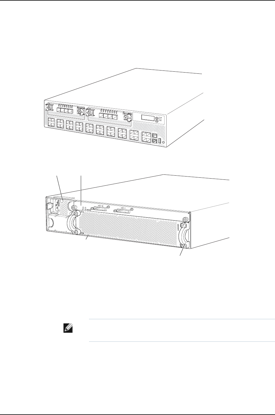
The J-EX4500 switch is 2 rack units (2 U) in size. Each J-EX4500 switch is designed to
optimize rack space utilization and cabling. See Figure 1 on page 32 and Figure 2 on
page 32.
Figure 1: J-EX4500 Switch Front
g020845
0123ST
0123ST
Figure 2: J-EX4500 Switch Rear with Virtual Chassis Module Installed
g021062
Fan tray
AC power
supply
Virtual
Chassis module
Fan tray handle
J-EX4500 switches are available in models with either front-to back airflow or
back-to-front airflow and hardware that is Converged Enhanced Ethernet (CEE) capable
or not. All models provide 40 wire-speed 10-gigabit small form-factor pluggable (SFP+)
network ports that can house either 1-Gigabit Ethernet connectors or 10-Gigabit Ethernet
connectors. All models support two optional high-speed uplink modules. See “J-EX4500
Switch Models” on page 34.
NOTE: The network ports are located on the front of the switch.
To provide carrier-class reliability, J-EX4500 switches include:
•Dual redundant, load-sharing power supplies that are field-replaceable, hot-removable,
and hot-insertable.
•A field-replaceable fan tray with five fans. The switch remains operational if a single
fan fails.
32
Dell PowerConnect J-Series Ethernet Switch Complete Software Guide for Junos OS, Release 11.1: Volume 1

•Redundant Routing Engines in a Virtual Chassis configuration. This redundancy enables
graceful Routing Engine switchover (GRES).
•Junos OS with its modular design that enables failed system processes to gracefully
restart.
Virtual Chassis Module
J-EX4500 switches ship with the Virtual Chassis module preinstalled horizontally on the
rear of the switch chassis. The Virtual Chassis module is an offline field-replaceable unit
(FRU).
The Virtual Chassis module has two dedicated Virtual Chassis ports (VCPs) that can be
used to interconnect the J-EX4500 switch with J-EX4200 switches or another J-EX4500
switch to form a Virtual Chassis. The Virtual Chassis module must be installed in a
J-EX4500 switch to form a Virtual Chassis.
Only two J-EX4500 switches can be interconnected into a Virtual Chassis composed
exclusively of J-EX4500 switches.
J-EX4200 and J-EX4500 switches can be connected together into the same Virtual
Chassis to form a mixed J-EX4200 and J-EX4500 Virtual Chassis. A mixed J-EX4200
and J-EX4500 Virtual Chassis supports up to two J-EX4500 switches and up to eight
J-EX4200 switches. You can interconnect J-EX4200 and J-EX4500 switches through
the dedicated Virtual Chassis ports (VCPs) to form a mixed Virtual Chassis.
You can also interconnect J-EX4500 switches through SFP+ uplink module ports or SFP+
network ports configured as VCPs to form a Virtual Chassis.
NOTE: Operating a J-EX4500 switch without the Virtual Chassis module is
not supported. J-EX4500 switches will not boot if the Virtual Chassis module
is not installed in the switch chassis.
Uplink Modules
Optional uplink modules are available for J-EX4500 switches. Two uplink modules can
be installed in a J-EX4500 switch. Each uplink module provides four SFP+ ports for
connecting to core devices in a data center. You can install SFP or SFP+ transceivers in
these ports. You can also configure the uplink module ports as VCPs to form a Virtual
Chassis.
Power Supplies
J-EX4500 switches support AC power supplies. J-EX4500 switches ship with one AC
power supply installed. You can install a second AC power supply in your J-EX4500
switch. For slot numbering and line-card details, see the Dell PowerConnect J-Series
J-EX4500 Ethernet Switch Hardware Guide at http://www.support.dell.com/manuals.
33
Chapter 2: Supported Hardware
CAUTION: Mixing power supplies with front-to-back and back-to-front airflow
in the same chassis is not supported.
Related
Documentation
J-EX4500 Switch Models on page 34•
•J-EX4200 and J-EX4500 Virtual Chassis Overview on page 709
J-EX4500 Switch Models
The J-EX4500 switch is available in two models. Table 25 on page 34 lists the models
for a J-EX4500 switch and the components included in each model.
NOTE: The network ports are located on the front of the switch.
Table 25: J-EX4500 Switch Models and Their Components
Switch Components
Direction of
Airflow
Access Port
ConfigurationModel
•Chassis
•One fan tray—displaying an EXHAUST label and
arrow icons pointing towards you
•One AC power supply—displaying an EXHAUST
label and an arrow icon pointing towards you
•One jumper cable
•One power supply cover panel
•Two uplink module cover panels
•One Virtual Chassis module
Front-to-back40-port GbE/10GbE
SFP/SFP+
GYTPN
•Chassis
•One fan tray—displaying an INTAKE label and
arrow icons pointing away from you
•One AC power supply—displaying an INTAKE label
and an arrow icon pointing away from you)
•One jumper cable
•One power supply cover panel
•Two uplink module cover panels
•One Virtual Chassis module
Back-to-front40-port GbE/10GbE
SFP/SFP+
TX9CD
NOTE: Uplink modules, transceivers, Virtual Chassis cables, and Virtual
Chassis cable connector retainers are not part of the J-EX4500 switch’s
shipping configuration. If you want to purchase any of these, or additional
power supplies for your switch, you must order them separately.
34
Dell PowerConnect J-Series Ethernet Switch Complete Software Guide for Junos OS, Release 11.1: Volume 1

CAUTION: Mixing power supplies with front-to-back and back-to-front airflow
in the same chassis is not supported.
Related
Documentation
For chassis specifications and front and rear panel details, see the Dell PowerConnect
J-Series J-EX4500 Ethernet Switch Hardware Guide at
http://www.support.dell.com/manuals.
•
•J-EX4500 Switches Hardware Overview on page 31
J-EX8208 Switch Hardware Overview
Dell PowerConnect J-EX Series J-EX8208 Ethernet Switches provide high performance,
scalable connectivity, and carrier-class reliability for high-density environments such as
campus-aggregation and data-center networks. The J-EX8208 switch is a modular
system that provides high availability and redundancy for all major hardware components,
including Routing Engines, switch fabric, fan tray, and power supplies.
You can manage J-EX8208 switches using the same interfaces that you use for managing
other devices running the Junos operating system (Junos OS)—the command-line interface
(CLI) and , the J-Web graphical interface.
•Software on page 35
•Chassis Physical Specifications on page 35
•Routing Engines and Switch Fabric on page 36
•Line Cards on page 37
•Cooling System on page 37
•Power Supplies on page 37
Software
The J-EX Series Switches run the Juniper Networks Junos OS, which provides Layer 2 and
Layer 3 switching, routing, and security services. The same Junos OS code base that runs
on J-EX Series switches also runs on all Dell PowerConnect J-SRX Series Services
Gateways.
Chassis Physical Specifications
The J-EX8208 switch is 14 rack units (14 U) in size (1/3 rack); three J-EX8208 switches
can fit in a standard 42 U rack. Each J-EX8208 switch is designed to optimize rack space
and cabling. See Figure 3 on page 36.
35
Chapter 2: Supported Hardware
Figure 3: J-EX8208 Switch
The J-EX8208 switch has a chassis-level LCD panel that displays Routing Engine and
switch fabric status as well as chassis components’ alarm information for rapid problem
identification. The LCD panel provides a user-friendly interface for performing initial
switch configuration, rolling back a configuration, or restoring the switch to its default
settings.
The J-EX8208 chassis backplane distributes the data, control, and management signals
to various system components along with distributing power throughout the system.
For LCD panel and chassis backplane details, see the Dell PowerConnect J-Series J-EX8208
Ethernet Switch Hardware Guide at http://www.support.dell.com/manuals.
Routing Engines and Switch Fabric
Switching functionality, system management, and system control functions of a J-EX8208
switch are performed by a Switch Fabric and Routing Engine (SRE) module. An SRE
module contains a Routing Engine and switch fabric. The SRE modules are installed in
the front of the chassis in the slots labeled SRE0 and SRE1. A redundant configuration
J-EX8208 switch has a second SRE module.
36
Dell PowerConnect J-Series Ethernet Switch Complete Software Guide for Junos OS, Release 11.1: Volume 1

The Switch Fabric (SF) module, working with the SRE module, provides the necessary
switching functionality to a J-EX8208 switch. The SF module is installed in the front of
the chassis in the slot labeled SF. In a redundant configuration the SF module provides
a redundant switch fabric. The additional switch fabric provides full 2+1 switch fabric
redundancy to the switch.
For details about the SRE module, SF module, and slot numbering, see the Dell
PowerConnect J-Series J-EX8208 Ethernet Switch Hardware Guide at
http://www.support.dell.com/manuals.
Line Cards
The J-EX8208 switch features eight horizontal line card slots and supports the line rate
for each line card. The line cards in J-EX8200 switches combine a Packet Forwarding
Engine and Ethernet interfaces on a single assembly. Line cards are field-replaceable
units (FRUs) that can be installed in the line card slots labeled 0 through 7 on the front
of the switch chassis. For slot numbering and line-card details, see the Dell PowerConnect
J-Series J-EX8208 Ethernet Switch Hardware Guide at
http://www.support.dell.com/manuals.
The following line cards are available for J-EX8208 switches:
•8-port 10-Gigabit Ethernet SFP+ line card: This line card has eight 10-gigabit SFP+
ports on its faceplate in which you can install SFP+ transceivers.
•40-port 10-Gigabit Ethernet SFP+ line card: This line card has 40 10-gigabit SFP+ ports
on its faceplate in which you can install either SFP+ or SFP transceivers.
•48-port 100/1000 SFP line card: This line card has 48 1-gigabit SFP ports on its
faceplate in which you can install SFP transceivers.
•48-port 10/100/1000 RJ-45 line card: This line card has 48 10/100/1000 Gigabit
Ethernet ports with RJ-45 connectors on its faceplate.
Cooling System
The cooling system in a J-EX8208 switch consists of a hot-removable and hot-insertable
fan tray. The fan tray contains 12 fans. The fan tray installs vertically on the left front of
the chassis and provides side-to-side chassis cooling. For details, see the Dell
PowerConnect J-Series J-EX8208 Ethernet Switch Hardware Guide at
http://www.support.dell.com/manuals.
Power Supplies
Power supplies for the J-EX8208 switch are fully redundant, load-sharing, and
hot-removable and hot-insertable field-replaceable units (FRUs). Each J-EX8208 switch
chassis can hold up to six 2000 W AC power supplies.
The 2000 W AC power supplies support both low-voltage line (100–120 VAC) and
high-voltage line (200–240 VAC) AC power configurations on a J-EX8208 switch. Each
2000 W AC power supply delivers 2000 W of power at high-voltage line (200–240 VAC)
or 1200 W at low-voltage line (100–120 VAC) to the J-EX8208 chassis.
37
Chapter 2: Supported Hardware

Only two AC power supplies are required for the base AC configuration and switch
powerup. The redundant AC configuration ships with six AC power supplies to provide
the capacity to power the system using N+1 or N+N power redundancy.
CAUTION: Mixing different types of power supplies in the same chassis is
not supported.
Related
Documentation
Connecting and Configuring a J-EX Series Switch (CLI Procedure) on page 185•
•Connecting and Configuring a J-EX Series Switch (J-Web Procedure) on page 187
•For details about switch FRUs and line cards, see the Dell PowerConnect J-Series
J-EX8208 Ethernet Switch Hardware Guide at http://www.support.dell.com/manuals.
J-EX8216 Switch Hardware Overview
The Dell PowerConnect J-EX Series J-EX8216 Ethernet Switch is a half-rack, midplane
architecture, modular Ethernet switch that is designed for ultra high-density environments
such as campus aggregation, data center, or high performance core switching
environments. J-EX8216 switches provide high-availability and redundancy for all major
hardware components, including Routing Engine (RE) modules, Switch Fabric (SF)
modules, fan trays (with redundant fans), and load-sharing 2000 W AC and 3000 W
AC power supplies. Like other Dell PowerConnect J-EX Series J-EX8200 Ethernet Switches,
J-EX8216 switches provide high performance, scalable connectivity, and carrier-class
reliability.
You can manage J-EX8216 switches using the same interfaces that you use for managing
other devices running the Junos operating system (Junos OS)—the command-line interface
(CLI) and the J-Web graphical interface.
•Software on page 38
•Chassis Physical Specifications, LCD Panel, and Midplane on page 38
•Routing Engines and Switch Fabric on page 40
•Line Cards on page 41
•Cooling System on page 41
•Power Supplies on page 42
Software
The J-EX Series Switches run Junos OS, which provides Layer 2 and Layer 3 switching,
routing, and security services. The same Junos OS code base that runs on J-EX Series
switches also runs on all Dell PowerConnect J-SRX Series Services Gateways.
Chassis Physical Specifications, LCD Panel, and Midplane
J-EX8216 switches are designed to optimize rack space and cabling. The J-EX8216 switch
is 21 rack units (21 U) in size (1/2 rack); two J-EX8216 switches can fit in a standard 42 U
rack. See Figure 4 on page 39 and Figure 5 on page 40. For chassis physical specification
38
Dell PowerConnect J-Series Ethernet Switch Complete Software Guide for Junos OS, Release 11.1: Volume 1
Figure 5: J-EX8216 Switch Rear
The J-EX8216 switch has a chassis-level LCD panel that displays Routing Engine and
switch fabric status as well as chassis components’ alarm information for rapid problem
identification. The LCD panel provides a user-friendly interface for performing initial
switch configuration, rolling back a configuration, or restoring the switch to the factory
default configuration.
The J-EX8216 chassis midplane distributes the data, control, and management signals
to system components and distributes power throughout the system.
For details about the LCD panel and midplane, see the Dell PowerConnect J-Series
J-EX8216 Ethernet Switch Hardware Guide at http://www.support.dell.com/manuals.
Routing Engines and Switch Fabric
System management and system control functions of a J-EX8216 switch are performed
by the Routing Engine (RE) module. An RE module contains a Routing Engine. The RE
40
Dell PowerConnect J-Series Ethernet Switch Complete Software Guide for Junos OS, Release 11.1: Volume 1

modules are hot-insertable and hot-removable field-replaceable units (FRUs) that are
installed in the front of the chassis in the slots labeled RE0 and RE1. A redundant
configuration J-EX8216 switch has a second RE module for redundancy.
The Switch Fabric (SF) modules provide the switching functionality to a J-EX8216 switch.
The SF modules are hot-insertable and hot-removable field-replaceable units (FRUs).
All eight SF modules are installed in the rear of the chassis in the slots labeled SF7 through
SF0. In a J-EX8216 switch, all eight SF modules are active and must be installed in the
switch for normal operation. If a single SF module fails, the input/output traffic for that
module is load-balanced among the remaining SF modules, providing graceful degradation
in midplane performance. The impact of an SF module failure on the performance of a
J-EX8216 switch varies based on the type of line cards installed in the switch and the
traffic mix flowing through them. In a J-EX8216 switch configuration that is fully loaded
with 8-port 10-Gigabit Ethernet SFP+ line cards, if one SF module fails, the remaining
seven SF modules still have sufficient switching capacity to maintain continuous switch
operation at full wire-rate performance.
For details about the RE and SF modules, see the Dell PowerConnect J-Series J-EX8216
Ethernet Switch Hardware Guide at http://www.support.dell.com/manuals.
Line Cards
The J-EX8216 switch features 16 horizontal line card slots and supports wire-rate
performance for all packet sizes for the installed line cards. The line cards in J-EX8200
switches combine a Packet Forwarding Engine and Ethernet interfaces on a single
assembly. They are field-replaceable units (FRUs), and you can install them in the slots
labeled 0 through 15 on the front of the switch chassis. All line cards are hot-insertable
and hot-removable. For line-card details, see the Dell PowerConnect J-Series J-EX8216
Ethernet Switch Hardware Guide at http://www.support.dell.com/manuals.
The following line cards are available for J-EX8216 switches:
•8-port 10-Gigabit Ethernet SFP+ line card: This line card has eight 10-gigabit SFP+
ports on its faceplate in which you can install SFP+ transceivers.
•40-port 10-Gigabit Ethernet SFP+ line card: This line card has 40 10-gigabit SFP+ ports
on its faceplate in which you can install either SFP+ or SFP transceivers.
•48-port 100/1000 SFP line card: This line card has 48 1-gigabit SFP ports on its
faceplate in which you can install SFP transceivers.
•48-port 10/100/1000 RJ-45 line card: This line card has 48 10/100/1000 Gigabit
Ethernet ports with RJ-45 connectors on its faceplate.
Cooling System
The cooling system in a J-EX8216 switch consists of two hot-insertable and
hot-removable, field-replaceable unit (FRU) fan trays. Each fan tray contains nine fans.
Both fan trays install vertically on the left front of the chassis and provide side-to-side
chassis cooling and front-to-side cooling. The top and bottom fan trays are identical and
interchangeable. However, only the top fan tray cools the SF modules installed in the
41
Chapter 2: Supported Hardware

rear of the chassis. For details, see the Dell PowerConnect J-Series J-EX8216 Ethernet
Switch Hardware Guide at http://www.support.dell.com/manuals.
Power Supplies
Power supplies for the J-EX8216 switch are fully redundant, load-sharing, and
hot-insertable and hot-removable field-replaceable units (FRUs). Each J-EX8216 switch
chassis can hold up to six 2000 W AC or six 3000 W AC power supplies.
The 2000 W AC power supplies support both low-voltage line (100–120 VAC) and
high-voltage line (200–240 VAC) AC power configurations on a J-EX8216 switch.
Each 3000 W AC power supply delivers 3000 W of power at high-voltage line (200–240
VAC) to the J-EX8216 chassis. Low-voltage line input is not supported for the 3000 W
AC power supplies on the J-EX8216 switch.
The redundant AC configuration ships with six AC power supplies to provide the capacity
to power the system using N+1 or N+N power redundancy.
For details about the power supplies, see the Dell PowerConnect J-Series J-EX8216 Ethernet
Switch Hardware Guide at http://www.support.dell.com/manuals.
CAUTION: Mixing different types of power supplies in the same chassis is
not a supported configuration.
Related
Documentation
•Connecting and Configuring a J-EX Series Switch (CLI Procedure) on page 185
•Connecting and Configuring a J-EX Series Switch (J-Web Procedure) on page 187
•For details about switch FRUs, slot numbering, and line cards, see the Dell PowerConnect
J-Series J-EX8216 Ethernet Switch Hardware Guide at
http://www.support.dell.com/manuals.
42
Dell PowerConnect J-Series Ethernet Switch Complete Software Guide for Junos OS, Release 11.1: Volume 1


44
Dell PowerConnect J-Series Ethernet Switch Complete Software Guide for Junos OS, Release 11.1: Volume 1

CHAPTER 3
Complete Software Configuration
Statement Hierarchy
•[edit access] Configuration Statement Hierarchy on page 45
•[edit chassis] Configuration Statement Hierarchy on page 46
•[edit class-of-service] Configuration Statement Hierarchy on page 47
•[edit ethernet-switching-options] Configuration Statement Hierarchy on page 48
•[edit firewall] Configuration Statement Hierarchy on page 51
•[edit forwarding-options] Configuration Statement Hierarchy on page 51
•[edit interfaces] Configuration Statement Hierarchy on page 52
•[edit poe] Configuration Statement Hierarchy on page 57
•[edit protocols] Configuration Statement Hierarchy on page 57
•[edit routing-instances] Configuration Hierarchy on page 63
•[edit snmp] Configuration Statement Hierarchy on page 64
•[edit virtual-chassis] Configuration Statement Hierarchy on page 64
•[edit vlans] Configuration Statement Hierarchy on page 65
[edit access] Configuration Statement Hierarchy
access {
profile profile-name {
accounting {
order [ radius |none ];
accounting-stop-on-access-deny;
accounting-stop-on-failure;
}
authentication-order [ authentication-method ];
radius {
accounting-server [ server-address ];
authentication-server [ server-address ];
}
}
}
45

Related
Documentation
For information about connecting a RADIUS servier to a switch and configuring 802.1
RADIUS accounting, see the Dell PowerConnect J-Series Ethernet Switch Complete
Software Guide for Junos OS: Volume 2 at http://www.support.dell.com/manuals.
•
[edit chassis] Configuration Statement Hierarchy
chassis {
aggregated-devices {
ethernet {
device-count number;
}
}
auto-image-upgrade;
fpc slot {
pic pic-number {
sfpplus {
pic-modemode;
}
}
power-budget-priority priority;
}
lcd-menu fpc slot-number {
menu-item (menu-name |menu-option);
}
nssu {
upgrade-group group-name {
fpcs (slot-number | [list-of-slot-numbers]);
member member-id {
fpcs (slot-number | [list-of-slot-numbers]);
}
}
}
psu {
redundancy {
n-plus-n;
}
}
redundancy {
graceful-switchover;
}
}
Related
Documentation
Configuring Aggregated Ethernet Interfaces (CLI Procedure) on page 1081•
•Upgrading Software Using Automatic Software Download on J-EX Series Switches on
page 94
•Configuring the LCD Panel on J-EX Series Switches (CLI Procedure) on page 190
•Configuring Graceful Routing Engine Switchover in a J-EX4200 or J-EX4500 Virtual
Chassis (CLI Procedure) on page 856
•Configuring Power Supply Redundancy (CLI Procedure) on page 952
•Configuring the Power Priority of Line Cards (CLI Procedure) on page 953
46
Dell PowerConnect J-Series Ethernet Switch Complete Software Guide for Junos OS, Release 11.1: Volume 1

•Configuring Line-card Upgrade Groups for Nonstop Software Upgrade (CLI Procedure)
on page 951
[edit class-of-service] Configuration Statement Hierarchy
class-of-service {
classifiers {
(dscp | ieee-802.1 | inet-precedence) classifier-name {
import (classifier-name | default);
forwarding-class class-name {
loss-priority loss-priority {
code-points [ aliases ][6 bit-patterns ];
}
}
}
}
code-point-aliases {
(dscp | ieee-802.1 | inet-precedence) {
alias-name bits;
}
}
congestion-notification-profile profile-name {
input{
ieee-802.1 {
code-point up-bits pfc;
}
}
forwarding-classes {
class class-name queue-num queue-number priority ( high | low );
}
interfaces {
interface-name {
congestion-notification-profile profile-name {
input {
ieee-802.1 {
code-point up-bits pfc;
}
}
}
}
scheduler-map map-name;
unit logical-unit-number {
forwarding-class class-name;
classifiers {
(dscp | ieee-802.1 | inet-precedence) (classifier-name | default);
}
}
}
}
multi-destination {
family {
ethernet {
broadcast forwarding-class-name;
}
47
Chapter 3: Complete Software Configuration Statement Hierarchy

inet {
classifiers {
(dscp | inet-precedence) classifier-name;
}
}
}
scheduler-map map-name;
}
rewrite-rules {
(dscp | ieee-802.1 | inet-precedence) rewrite-name {
import (rewrite-name | default);
forwarding-class class-name {
loss-priority loss-priority code-point (alias |bits);
}
}
}
scheduler-maps {
map-name {
forwarding-class class-name scheduler scheduler-name;
}
}
schedulers {
scheduler-name {
buffer-size (percent percentage | remainder);
drop-profile-map loss-priority loss-priority protocol protocol drop-profile profile-name;
priority priority;
shaping-rate (rate | percent percentage);
transmit-rate (rate | percent percentage | remainder);
}
}
}
Related
Documentation
For CoS configuration examples, instructions, and concepts, see the Dell PowerConnect
J-Series Ethernet Switch Complete Software Guide for Junos OS: Volume 2 at
http://www.support.dell.com/manuals.
•
[edit ethernet-switching-options] Configuration Statement Hierarchy
ethernet-switching-options {
analyzer {
name {
loss-priority priority;
ratio number;
input {
ingress {
interface (all | interface-name);
vlan (vlan-id |vlan-name);
}
egress {
interface (all | interface-name);
}
}
output {
interface interface-name;
48
Dell PowerConnect J-Series Ethernet Switch Complete Software Guide for Junos OS, Release 11.1: Volume 1

vlan (vlan-id |vlan-name);
}
}
}
bpdu-block {
disable-timeout timeout;
interface (all | [interface-name]);
}
dot1q-tunneling {
ether-type (0x8100 | 0x88a8 | 0x9100);
}
interfaces interface-name {
no-mac-learning;
}
mac-notification {
notification-interval seconds;
}
mac-table-aging-time seconds;
port-error-disable {
disable-timeout timeout;
}
redundant-trunk-group {
group name {
preempt-cutover-timer seconds;
interface
primary;
}
interface
}
}
secure-access-port {
static{
vlanvlan-id {
macmac-address next-hopinterface-name;
}
}
dhcp-snooping-file {
location local_pathname |remote_URL;
timeout seconds;
write-interval seconds;
}
interface (all | interface-name) {
allowed-mac {
mac-address-list;
}
(dhcp-trusted | no-dhcp-trusted );
fcoe-trusted;
mac-limit limit action action;
no-allowed-mac-log;
static-ip ip-address {
vlan vlan-name;
mac mac-address;
}
}
vlan (all | vlan-name) {
(arp-inspection | no-arp-inspection );
49
Chapter 3: Complete Software Configuration Statement Hierarchy

dhcp-option82 {
circuit-id {
prefix hostname;
use-interface-description;
use-vlan-id;
}
remote-id {
prefix hostname | mac | none;
use-interface-description;
use-string string;
}
vendor-id [string];
}
(examine-dhcp | no-examine-dhcp );
examine-fip {
fc-map fc-map-value;
}
(ip-source-guard | no-ip-source-guard);
mac-move-limit limit action action;
}
}
storm-control {
action-shutdown;
interface (all | interface-name) {
bandwidth bandwidth;
no-broadcast;
no-multicast;
no-registered-multicast;
no-unknown-unicast;
no-unregistered-multicast;
}
}
traceoptions {
file filename <files number> <no-stamp> <replace> <size size> <world-readable |
no-world-readable>;
flag flag <disable>;
}
unknown-unicast-forwarding {
vlan (all | vlan-name) {
interface interface-name;
}
}
voip {
interface (all | [interface-name | access-ports]) {
vlan vlan-name ;
forwarding-class (assured-forwarding | best-effort | expedited-forwarding |
network-control);
}
}
}
Related
Documentation
For configuration examples, instructions, and concepts for port mirroring, port security,
BPDU protection for spanning-tree protocols, redundant trunk links, storm control,
•
802.1X and VoIP, Q-in-Q tunneling, unicast forwarding, MAC notification, and FIP
50
Dell PowerConnect J-Series Ethernet Switch Complete Software Guide for Junos OS, Release 11.1: Volume 1

snooping, see the Dell PowerConnect J-Series Ethernet Switch Complete Software Guide
for Junos OS: Volume 2 at http://www.support.dell.com/manuals.
•DHCP Services for J-EX Series Switches Overview on page 457
[edit firewall] Configuration Statement Hierarchy
firewall {
family family-name {
filter filter-name {
interface-specific;
term term-name {
from {
match-conditions;
}
then {
action;
action-modifiers;
}
}
}
}
policer policer-name {
filter-specific;
if-exceeding {
bandwidth-limit bps;
burst-size-limit bytes;
}
then {
policer-action;
}
}
}
Related
Documentation
For firewall filters (packet filtering) configuration examples, instructions, and concepts,
see the Dell PowerConnect J-Series Ethernet Switch Complete Software Guide for Junos
OS: Volume 2 at http://www.support.dell.com/manuals.
•
[edit forwarding-options] Configuration Statement Hierarchy
helpers {
bootp {
dhcp-option82 {
circuit-id {
prefix hostname;
use-interface-description;
use-vlan-id;
}
remote-id {
prefix hostname | mac | none;
use-interface-description;
use-string string;
51
Chapter 3: Complete Software Configuration Statement Hierarchy

}
vendor-id <string>;
}
interface interface-name {
dhcp-option82 {
circuit-id {
prefix hostname;
use-interface-description;
use-vlan-id;
}
remote-id {
prefix hostname | mac | none;
use-interface-description;
use-string string;
}
vendor-id <string>;
}
source-address-giaddr;
}
source-address-giaddr;
}
}
Related
Documentation
DHCP Services for J-EX Series Switches Overview on page 457•
•For DHCP and port security configuration examples, instructions, and concepts, see
the Dell PowerConnect J-Series Ethernet Switch Complete Software Guide for Junos OS:
Volume 2 at http://www.support.dell.com/manuals.
•For more information about the [edit forwarding-options] hierarchy and its options,
see the Junos OS Policy Framework Configuration Guide.
[edit interfaces] Configuration Statement Hierarchy
interfaces {
aex{
accounting-profile name;
aggregated-ether-options {
(flow-control | no-flow-control);
lacp {
(active | passive);
admin-key key;
periodic interval;
system-id mac-address;
}
(link-protection | no-link-protection);
link-speed speed;
(loopback | no-loopback);
minimum-links number;
}
description text;
disable;
(gratuitous-arp-reply | no-gratuitous-arp-reply);
mtu bytes;
no-gratuitous-arp-request;
52
Dell PowerConnect J-Series Ethernet Switch Complete Software Guide for Junos OS, Release 11.1: Volume 1

traceoptions {
flag flag;
}
(traps | no-traps);
unit logical-unit-number {
accounting-profile name;
bandwidth rate;
description text;
disable;
family family-name {...}
proxy-arp (restricted | unrestricted);
(traps | no-traps);
vlan-id vlan-id-number;
}
vlan-tagging;
}
ge-fpc/pic/port {
accounting-profile name;
description text;
disable;
ether-options {
802.3ad {
aex;
(backup | primary);
lacp {
force-up;
}
}
(auto-negotiation | no-auto-negotiation);
(flow-control | no-flow-control);
link-mode mode;
(loopback | no-loopback);
speed (auto-negotiation | speed);
}
(gratuitous-arp-reply | no-gratuitous-arp-reply);
mtu bytes;
no-gratuitous-arp-request;
traceoptions {
flag flag;
}
(traps | no-traps);
unit logical-unit-number {
accounting-profile name;
bandwidth rate;
description text;
disable;
family family-name {...}
proxy-arp (restricted | unrestricted);
(traps | no-traps);
vlan-id vlan-id-number;
}
vlan-tagging;
}
interface-range name {
accounting-profile name;
description text;
53
Chapter 3: Complete Software Configuration Statement Hierarchy

disable;
ether-options {
802.3ad {
aex;
(backup | primary);
lacp {
force-up;
}
}
(auto-negotiation | no-auto-negotiation);
(flow-control | no-flow-control);
link-mode mode;
(loopback | no-loopback);
speed (auto-negotiation | speed);
}
(gratuitous-arp-reply | no-gratuitous-arp-reply);
member interface-name;
member-range starting-interface name to ending-interface name;
mtu bytes;
no-gratuitous-arp-request;
traceoptions {
flag flag;
}
(traps | no-traps);
unit logical-unit-number {
accounting-profile name;
bandwidth rate;
description text;
disable;
family family-name {...}
proxy-arp (restricted | unrestricted);
(traps | no-traps);
vlan-id vlan-id-number;
}
vlan-tagging;
}
lo0 {
accounting-profile name;
description text;
disable;
traceoptions {
flag flag;
}
(traps | no-traps);
unit logical-unit-number {
accounting-profile name;
bandwidth rate;
description text;
disable;
family family-name {...}
(traps | no-traps);
}
}
me0 {
accounting-profile name;
description text;
54
Dell PowerConnect J-Series Ethernet Switch Complete Software Guide for Junos OS, Release 11.1: Volume 1

disable;
(gratuitous-arp-reply | no-gratuitous-arp-reply);
no-gratuitous-arp-request;
traceoptions {
flag flag;
}
(traps | no-traps);
unit logical-unit-number {
accounting-profile name;
bandwidth rate;
description text;
disable;
family family-name {...}
(traps | no-traps);
vlan-id vlan-id-number;
}
vlan-tagging;
}
vlan {
accounting-profile name;
description text;
disable;
(gratuitous-arp-reply | no-gratuitous-arp-reply);
mtu bytes;
no-gratuitous-arp-request;
traceoptions {
flag flag;
}
(traps | no-traps);
unit logical-unit-number {
accounting-profile name;
bandwidth rate;
description text;
disable;
family family-name {...}
proxy-arp (restricted | unrestricted);
(traps | no-traps);
}
}
traceoptions {
file <filename> <files number> <match regular-expression> <size size>
<world-readable | no-world-readable>;
flag flag <disable>;
no-remote-trace;
}
vme {
accounting-profile name;
description text;
disable;
(gratuitous-arp-reply | no-gratuitous-arp-reply);
mtu bytes;
no-gratuitous-arp-request;
traceoptions {
flag flag;
}
(traps | no-traps);
55
Chapter 3: Complete Software Configuration Statement Hierarchy

unit logical-unit-number {
accounting-profile name;
bandwidth rate;
description text;
disable;
family family-name {...}
(traps | no-traps);
vlan-id vlan-id-number;
}
vlan-tagging;
}
xe-fpc/pic/port {
accounting-profile name;
description text;
disable;
ether-options {
802.3ad {
aex;
(backup | primary);
lacp {
force-up;
}
}
(flow-control | no-flow-control);
link-mode mode;
(loopback | no-loopback);
}
(gratuitous-arp-reply | no-gratuitous-arp-reply);
mtu bytes;
no-gratuitous-arp-request;
traceoptions {
flag flag;
}
(traps | no-traps);
unit logical-unit-number {
accounting-profile name;
bandwidth rate;
description text;
disable;
family family-name {...}
proxy-arp (restricted | unrestricted);
(traps | no-traps);
vlan-id vlan-id-number;
}
vlan-tagging;
}
}
Related
Documentation
Configuring Gigabit Ethernet Interfaces (CLI Procedure) on page 1042•
•Configuring Aggregated Ethernet Interfaces (CLI Procedure) on page 1081
•Configuring a Layer 3 Subinterface (CLI Procedure) on page 1089
•Configuring Routed VLAN Interfaces (CLI Procedure)
56
Dell PowerConnect J-Series Ethernet Switch Complete Software Guide for Junos OS, Release 11.1: Volume 1

•Configuring the Virtual Management Ethernet Interface for Global Management of a
J-EX4200 or J-EX4500 Virtual Chassis (CLI Procedure) on page 852
•J-EX Series Switches Interfaces Overview on page 999
•Junos OS Network Interfaces Configuration Guide
[edit poe] Configuration Statement Hierarchy
poe {
guard-band watts;
interface (all | interface-name) {
disable;
maximum-power watts;
priority (high | low);
telemetries {
disable;
duration hours;
interval minutes;
}
}
management (class | static);
notification-control {
fpc slot-number {
disable;
}
}
}
Related
Documentation
For Power over Ethernet (PoE) configuration examples, instructions, and concepts,
see the Dell PowerConnect J-Series Ethernet Switch Complete Software Guide for Junos
OS: Volume 2 at http://www.support.dell.com/manuals.
•
[edit protocols] Configuration Statement Hierarchy
protocols {
connections {
remote-interface-switch connection-name {
interface interface-name.unit-number;
transmit-lsp label-switched-path;
receive-lsp label-switched-path;
}
}
dot1x {
authenticator {
authentication-profile-name profile-name;
interface (all | [ interface-names ]) {
disable;
guest-vlan ( vlan-id | vlan-name);
mac-radius <restrict>;
maximum-requests number;
no-reauthentication;
quiet-period seconds;
57
Chapter 3: Complete Software Configuration Statement Hierarchy

reauthentication {
interval seconds;
}
retries number;
server-fail (deny | permit | use-cache | vlan-id |vlan-name);
server-reject-vlan (vlan-id |vlan-name);
server-timeout seconds;
supplicant (multiple | single | single-secure);
supplicant-timeout seconds;
transmit-period seconds;
}
static mac-address {
interface interface-name;
vlan-assignment (vlan-id |vlan-name);
}
}
igmp-snooping {
traceoptions {
file filename <files number> <size size> <world-readable | no-world-readable>
<match regex>;
flag flag (detail | disable | receive | send);
}
vlan (vlan-id |vlan-number) {
data-forwarding {
source {
groups group-prefix;
}
receiver {
source-vlans vlan-list;
install ;
}
}
disable {
interface interface-name
}
immediate-leave;
interface interface-name {
group-limit limit;
multicast-router-interface;
static (IGMP Snooping) {
group ip-address;
}
}
proxy ;
query-interval seconds;
query-last-member-interval seconds;
query-response-interval seconds;
robust-count number;
}
}
lldp {
disable;
advertisement-interval seconds;
hold-multiplier number;
interface (all | interface-name) {
disable;
58
Dell PowerConnect J-Series Ethernet Switch Complete Software Guide for Junos OS, Release 11.1: Volume 1

}
lldp-configuration-notification-interval seconds;
management-address ip-management-address;
netbios-snooping;
ptopo-configuration-maximum-hold-time seconds;
ptopo-configuration-trap-interval seconds;
traceoptions {
file filename <files number> <size size> <world-readable | no-world-readable>
<no-stamp> <replace>;
flag flag <disable>;
}
transmit-delay seconds;
}
lldp-med {
disable;
fast-start number;
interface (all | interface-name) {
disable;
location {
elin number;
civic-based {
what number;
country-code code;
ca-type {
number {
ca-value value;
}
}
}
}
}
}
mpls {
interface ( all | interface-name );
label-switched-path lsp-name to remote-provider-edge-switch;
path destination {
<address |hostname> <strict | loose>
}
mstp {
disable;
bpdu-block-on-edge;
bridge-priority priority;
configuration-name name;
forward-delay seconds;
hello-time seconds;
interface (all | interface-name) {
disable;
bpdu-timeout-action {
block;
log;
}
cost cost;
edge;
mode mode;
no-root-port;
priority priority;
59
Chapter 3: Complete Software Configuration Statement Hierarchy

}
max-age seconds;
max-hops hops;
msti msti-id {
vlan (vlan-id |vlan-name);
interface interface-name {
disable;
cost cost;
edge;
mode mode;
priority priority;
}
}
revision-level revision-level;
traceoptions {
file filename <files number > <size size> <no-stamp | world-readable |
no-world-readable>;
flag flag;
}
}
mvrp {
disable
interface (all |interface-name) {
disable;
join-timer milliseconds;
leave-timer milliseconds;
leaveall-timer milliseconds;
registration (forbidden | normal);
}
no-dynamic-vlan;
traceoptions {
file filename <files number > <size size> <no-stamp | world-readable |
no-world-readable>;
flag flag;
}
}
oam {
ethernet{
connectivity-fault-management {
action-profile profile-name {
default-actions {
interface-down;
}
}
linktrace {
age (30m | 10m | 1m | 30s | 10s);
path-database-size path-database-size;
}
maintenance-domain domain-name {
level number;
mip-half-function (none | default |explicit);
name-format (character-string | none | dns | mac+2oct);
maintenance-association ma-name {
continuity-check {
hold-interval minutes;
interval (10m | 10s | 1m | 1s| 100ms);
60
Dell PowerConnect J-Series Ethernet Switch Complete Software Guide for Junos OS, Release 11.1: Volume 1

loss-threshold number;
}
mep mep-id {
auto-discovery;
direction down;
interface interface-name;
remote-mep mep-id {
action-profile profile-name;
}
}
}
}
}
link-fault-management {
action-profile profile-name;
action {
syslog;
link-down;
}
event {
link-adjacency-loss;
link-event-rate;
frame-error count;
frame-period count;
frame-period-summary count;
symbol-period count;
}
interface interface-name {
link-discovery (active | passive);
pdu-interval interval;
event-thresholds threshold-value;
remote-loopback;
event-thresholds {
frame-errorcount;
frame-period count;
frame-period-summary count;
symbol-period count;
}
}
negotiation-options {
allow-remote-loopback;
no-allow-link-events;
}
}
}
}
rstp {
disable;
bpdu-block-on-edge;
bridge-priority priority;
forward-delay seconds;
hello-time seconds;
interface (all | interface-name) {
disable;
bpdu-timeout-action {
block;
61
Chapter 3: Complete Software Configuration Statement Hierarchy

log;
}
cost cost;
edge;
mode mode;
no-root-port;
priority priority;
}
max-age seconds;
}
traceoptions {
file filename <files number > <size size> <no-stamp | world-readable |
no-world-readable>;
flag flag;
}
}
sflow {
agent-id;
collector {
ip-address;
udp-port port-number;
}
disable;
interfaces interface-name {
disable;
polling-interval seconds;
sample-rate {
egress number;
ingress number;
}
}
polling-interval seconds;
sample-rate {
egress number;
ingress number;
}
source-ip;
}
stp {
disable;
bridge-priority priority;
forward-delay seconds;
hello-time seconds;
interface (all | interface-name) {
disable;
bpdu-timeout-action {
block;
log;
}
cost cost;
edge;
mode mode;
no-root-port;
priority priority;
}
max-age seconds;
62
Dell PowerConnect J-Series Ethernet Switch Complete Software Guide for Junos OS, Release 11.1: Volume 1

}
traceoptions {
file filename <files number > <size size> <no-stamp | world-readable |
no-world-readable>;
flag flag;
}
uplink-failure-detection {
group group-name {
link-to-monitor interface-name;
link-to-disable interface-name;
}
}
vstp {
bpdu-block-on-edge;
disable;
force-version stp;
vlan (all | vlan-id |vlan-name) {
bridge-priority priority;
forward-delay seconds;
hello-time seconds;
interface (all | interface-name) {
bpdu-timeout-action {
log;
block;
}
cost cost;
disable;
edge;
mode mode;
no-root-port;
priority priority;
}
max-age seconds;
traceoptions {
file filename <files number > <size size> <no-stamp | world-readable |
no-world-readable>;
flag flag;
}
}
}
}
Related
Documentation
For protocol configuration examples, instructions, and concepts, see the Dell
PowerConnect J-Series Ethernet Switch Complete Software Guide for Junos OS: Volume
2at http://www.support.dell.com/manuals.
•
[edit routing-instances] Configuration Hierarchy
routing-instances routing-instance-name {
instance-type virtual-router
interface interface-name
}
63
Chapter 3: Complete Software Configuration Statement Hierarchy

Related
Documentation
For routing configuration examples, instructions, and concepts, see the Dell
PowerConnect J-Series Ethernet Switch Complete Software Guide for Junos OS: Volume
2at http://www.support.dell.com/manuals.
•
[edit snmp] Configuration Statement Hierarchy
snmp {
rmon {
history index {
bucket-size number;
interface interface-name;
interval seconds;
owner owner-name;
}
}
}
Related
Documentation
For SNMP configuration examples, instructions, and concepts, see the Dell
PowerConnect J-Series Ethernet Switch Complete Software Guide for Junos OS: Volume
2at http://www.support.dell.com/manuals.
•
•Junos OS Network Management Configuration Guide
[edit virtual-chassis] Configuration Statement Hierarchy
virtual-chassis {
auto-sw-update {
package-name package-name;
}
fast-failover (ge | vcp disable | xe);
id id;
mac-persistence-timer seconds;
member member-id {
location location
mastership-priority number;
no-management-vlan;
serial-number;
role;
}
no-split-detection;
preprovisioned;
traceoptions {
file filename <files number> <size size> <world-readable | no-world-readable> <match
regex>;
flag flag ;
}
}
Related
Documentation
Example: Configuring a J-EX4200 Virtual Chassis with a Master and Backup in a Single
Wiring Closet on page 736
•
64
Dell PowerConnect J-Series Ethernet Switch Complete Software Guide for Junos OS, Release 11.1: Volume 1

•Example: Configuring a J-EX4200 Virtual Chassis Interconnected Across Multiple Wiring
Closets on page 762
•Example: Configuring a J-EX4200 Virtual Chassis Using a Preprovisioned Configuration
File on page 788
•Configuring a J-EX4200 or J-EX4500 Virtual Chassis (CLI Procedure) on page 822
•J-EX4200 and J-EX4500 Virtual Chassis Overview on page 709
[edit vlans] Configuration Statement Hierarchy
vlans {
vlan-name {
description text-description;
dot1q-tunneling {
customer-vlans (id | native | range);
layer2-protocol-tunneling all | protocol-name {
drop-threshold number;
shutdown-threshold number;
}
}
filter input filter-name;
filter output filter-name;
interface interface-name {
mapping (native (push | swap) | policy | tag (push | swap));
pvlan-trunk;
}
isolation-id id-number;
l3-interface vlan.logical-interface-number;
mac-limit number;
mac-table-aging-time seconds;
no-local-switching;
no-mac-learning;
primary-vlan vlan-name;
vlan-id number;
vlan-range vlan-id-low-vlan-id-high;
}
}
Related
Documentation
•For VLAN configuration examples, instructions, and concepts, see the Dell PowerConnect
J-Series Ethernet Switch Complete Software Guide for Junos OS: Volume 2 at
http://www.support.dell.com/manuals.
65
Chapter 3: Complete Software Configuration Statement Hierarchy

66
Dell PowerConnect J-Series Ethernet Switch Complete Software Guide for Junos OS, Release 11.1: Volume 1

PART 3
Software Installation
•Software Installation Overview on page 69
•Installing Junos OS on page 79
•Booting the Switch, Upgrading Software, and Managing Licenses on page 91
•Verifying Software Installation on page 99
•Troubleshooting Software Installation on page 107
•Configuration Statements for Software Installation on page 117
•Operational Commands for Software Installation on page 119
67

68
Dell PowerConnect J-Series Ethernet Switch Complete Software Guide for Junos OS, Release 11.1: Volume 1

CHAPTER 4
Software Installation Overview
•Installation Overview on page 69
•Licenses Overview on page 75
Installation Overview
•Understanding Software Installation on J-EX Series Switches on page 69
•Junos OS Package Names on page 72
•Understanding System Snapshot on J-EX Series Switches on page 72
•Understanding Resilient Dual-Root Partitions on Switches on page 74
Understanding Software Installation on J-EX Series Switches
A J-EX Series Switch is delivered with the Junos operating system (Junos OS) preinstalled.
As new features and software fixes become available, you must upgrade your software
to use them. You can also downgrade Junos OS to a previous release.
This topic covers:
•Overview of the Software Installation Process on page 69
•Software Package Security on page 70
•Installing Software on a Virtual Chassis on page 70
•Installing Software on J-EX8200 Switches with Redundant Routing Engines on page 71
•Installing Software Using Automatic Software Download on page 71
•Troubleshooting Software Installation on page 71
Overview of the Software Installation Process
A J-EX Series switch is delivered with Junos OS preinstalled. When you connect power
to the switch, it starts (boots) up from the installed software.
You upgrade Junos OS on a J-EX Series switch by copying a software package to your
switch or another system on your local network, then use either the J-Web interface or
the CLI to install the new software package on the switch. Finally, you reboot the switch;
it boots from the upgraded software. After a successful upgrade, you should back up the
new current configuration to a secondary device.
69

NOTE:
To access the J-Web interface, your management device must have the
following software installed:
•Operating system: Microsoft Windows XP Service Pack 3
•Browser version: One of the following. Other browsers might work but are
not supported by J-Series platforms.
•Microsoft Internet Explorer version 7.0
•Mozilla Firefox version 3.0
•Additional requirements:
•Only English-language browsers are supported.
•The browser and the network must be able to receive and process
HTTP/1.1 gzip compressed data.
During a successful upgrade, the upgrade package removes all files from /var/tmp and
completely reinstalls the existing software. It retains configuration files, and similar
information, such as secure shell and host keys, from the previous version. If the software
installation fails for any reason, such as loss of power during the installation process, the
system returns to the originally active installation when you reboot. At the completion
of a successful software upgrade, we recommend that you use the request system
snapshot command to copy the contents of the primary root partition to the alternate
root partition.
Software Package Security
All Junos OS releases are delivered in signed packages that contain digital signatures to
ensure official Juniper Networks software. For more information about signed software
packages, see the Junos OS Installation and Upgrade Guide.
Installing Software on a Virtual Chassis
You can connect individual J-EX Series switches together to form one unit and manage
the unit as a single device, called a Virtual Chassis. The Virtual Chassis operates as a
single network entity composed of members. Each member of a Virtual Chassis runs a
Junos OS package. Supported Virtual Chassis include J-EX4200 Virtual Chassis, J-EX4500
Virtual Chassis, and mixed J-EX4200 and J-EX4500 Virtual Chassis.
For ease of management, a Virtual Chassis provides flexible methods to upgrade software
releases. You can deploy a new software release to all members of a Virtual Chassis or
to only a particular member.
70
Dell PowerConnect J-Series Ethernet Switch Complete Software Guide for Junos OS, Release 11.1: Volume 1

Installing Software on J-EX8200 Switches with Redundant Routing Engines
You can install software on a J-EX8200 switch with redundant Routing Engines in one
of two ways:
•Perform a nonstop software upgrade (NSSU)—An NSSU upgrades both Routing
Engines with a single command and with a minimum of network disruption. An NSSU
takes advantage of graceful Routing Engine switchover (GRES) and nonstop active
routing (NSR) to ensure no disruption to the control plane. You can minimize disruption
to network traffic by defining link aggregation groups (LAGs) such that the member
links of each LAG reside on different line cards. The line cards are upgraded one at a
time, so that traffic continues to flow through the other line cards while a line card is
being upgraded.
You cannot use NSSU to downgrade the software running on a switch.
For more information about NSSU, see “Understanding Nonstop Software Upgrade
on J-EX Series Switches” on page 932.
•Upgrade each Routing Engine manually—You can perform a Junos OS installation on
each Routing Engine separately, starting with the backup Routing Engine. You can use
this procedure to downgrade the software running on a switch. See “Installing Software
on a J-EX8200 Switch with Redundant Routing Engines (CLI Procedure)” on page 81.
Installing Software Using Automatic Software Download
The automatic software download feature uses the DHCP message exchange process
to download and install software packages. Users can define a path to a software package
on the DHCP server, and then the DHCP server communicates this path to J-EX Series
switches acting as DHCP clients as part of the DHCP message exchange process. The
DHCP clients that have been configured for automatic software download receive these
messages and, when the software package name in the DHCP server message is different
from that of the software package that booted the DHCP client switch, download and
install the software package. See “Upgrading Software Using Automatic Software
Download on J-EX Series Switches” on page 94.
Troubleshooting Software Installation
If the Junos OS loads but the CLI is not working for any reason, or if the switch has no
software installed, you can use the recovery installation procedure to install the software
on the switch. See “Troubleshooting Software Installation” on page 107.
NOTE: You can also use this procedure to load two versions of Junos OS in
separate partitions on the switch.
Related
Documentation
Downloading Software Packages from Juniper Networks on page 79•
•Installing Software on J-EX Series Switches (J-Web Procedure) on page 86
•Installing Software on a J-EX Series Switch with a Single Routing Engine (CLI Procedure)
on page 80
71
Chapter 4: Software Installation Overview

•Installing Software on a J-EX8200 Switch with Redundant Routing Engines (CLI
Procedure) on page 81
•Understanding Nonstop Software Upgrade on J-EX Series Switches on page 932
•Understanding Resilient Dual-Root Partitions on Switches on page 74
Junos OS Package Names
You upgrade Junos OS on a J-EX Series Switch by copying a software package to your
switch or another system on your local network, then install the new software package
on the switch.
A software package name is in the following format:
package-name-m.nZx.y-domestic-signed.tgz
where:
•package-name is the name of the package—for example, jinstall-ex-4200.
•m.n is the software release, with mrepresenting the major release number and n
representing the minor release number—for example, 10.2.
•Zindicates the type of software release, where Rindicates released software and B
indicates beta-level software.
•x.y represents the version of the major software release (x) and an internal tracking
number (y)—for example, 1.6.
•domestic-signed is appended to all J-EX Series package names. For most Junos OS
packages, domestic is used for the United States and Canada and export for worldwide
distribution. However, for J-EX Series software, domestic is used for worldwide
distribution as well.
A sample J-EX Series software package name is:
jinstall-ex-4200-10.2R1.6-domestic-signed.tgz
Related
Documentation
Installing Software on J-EX Series Switches (J-Web Procedure) on page 86•
•Installing Software on a J-EX Series Switch with a Single Routing Engine (CLI Procedure)
on page 80
•Installing Software on a J-EX8200 Switch with Redundant Routing Engines (CLI
Procedure) on page 81
•Downloading Software Packages from Juniper Networks on page 79
•Understanding Software Installation on J-EX Series Switches on page 69
Understanding System Snapshot on J-EX Series Switches
You can create copies of the software running a J-EX Series Switch using the system
snapshot feature. The system snapshot feature takes a “snapshot” of the files currently
used to run the switch—the complete contents of the /config and /var directories, which
72
Dell PowerConnect J-Series Ethernet Switch Complete Software Guide for Junos OS, Release 11.1: Volume 1

include the running Junos OS, the active configuration, and the rescue configuration—and
copies all these files into an alternate (internal, meaning internal flash, or an external,
meaning USB flash) memory source. You can then use this snapshot to boot the switch
at the next bootup or as a backup boot option.
You can only use snapshots to move files to external memory if the switch was booted
from internal memory, or to move files to internal memory if the switch was booted from
external memory. You cannot create a snapshot in the memory source that booted the
switch even if the snapshot is being created on a different partition in the same memory
source.
Snapshots are particularly useful for moving files onto USB flash drives. You cannot use
the copy command or any other file-moving technique to move files from an internal
memory source to USB memory on the switch.
System snapshots on J-EX Series switches have the following limitations:
•You cannot use snapshots to move files to any destination outside of the switch other
than an installed external USB flash drive or to move files between switches that are
members of the same Virtual Chassis.
•Snapshot commands, like other Virtual Chassis commands, are always executed on
a local switch. In cases where a different member switches of the same Virtual Chassis
requests the snapshot, the snapshot command is pushed to the Virtual Chassis member
creating the snapshot and then executed. The output is then returned to the switch
that initiated the process. For instance, if the command to create an external snapshot
on Virtual Chassis member 3 is entered from Virtual Chassis member 1, the snapshot
of internal memory on Virtual Chassis member 3 is taken on external memory on Virtual
Chassis member 3. The output of the process is seen from Virtual Chassis member 1.
No files move between the switches.
Related
Documentation
Understanding Software Installation on J-EX Series Switches on page 69•
•Creating a Snapshot and Using It to Boot a J-EX Series Switch on page 92
73
Chapter 4: Software Installation Overview

Understanding Resilient Dual-Root Partitions on Switches
Resilient dual-root partitioning, introduced on J-EX Series Ethernet Switches in Junos
operating system (Junos OS) Release 10.4R3, provides additional resiliency to switches
in the following ways:
•Allows the switch to boot transparently from the second root partition if the system
fails to boot from the primary root partition.
•Provides separation of the root Junos OS file system from the /var file system. If
corruption occurs in the /var file system (a higher probability than in the root file system
due to the greater frequency in /var of reads and writes), the root file system is insulated
from the corruption.
This topic covers:
•Resilient Dual-Root Partition Scheme (Junos OS Release 10.4R3 and Later) on page 74
•Earlier Partition Scheme (Junos OS Release 10.4R2 and Earlier) on page 74
•Understanding Upgrading or Downgrading Between Resilient Dual-Root Partition
Releases and Earlier Releases on page 75
Resilient Dual-Root Partition Scheme (Junos OS Release 10.4R3 and Later)
J-EX Series switches that ship with Junos OS Release 10.4R3 or later are configured with
a root partition scheme that is optimized for resiliency, as shown in Table 26 on page 74.
Table 26: Resilient Dual-Root Partition Scheme
Slice 4
Slice 3
Slice 2Slice 1
s4ds3ds3es2as1a
/config/var/tmp/var/
(root Junos OS )
/
(root Junos OS )
In the resilient dual-root partition scheme, the /var file system is contained in a separate
slice from the root file systems, the /config directory is contained in its own slice, and
switches ship from the factory with identical Junos OS images in slice 1 and slice 2. The
/var file system, which has a greater frequency of reads and writes than the root file
systems and is therefore more likely to have corruption issues, is isolated from the root
directories and the /config directory. If the switch fails to boot, the system automatically
boots from the alternate root partition. (If the switch fails to boot from the active root
partition and instead boots from the alternate root partition, an alarm is triggered.)
Earlier Partition Scheme (Junos OS Release 10.4R2 and Earlier)
The earlier partition scheme is shown in Table 27 on page 75.
74
Dell PowerConnect J-Series Ethernet Switch Complete Software Guide for Junos OS, Release 11.1: Volume 1

Table 27: Earlier Partition Scheme
Slice 3Slice 2
Slice 1
s3es3ds2fs2as1fs1a
/config/var/tmp(empty until
initial
software
upgrade)
(empty until
initial
software
upgrade)
/var/
(root Junos
OS)
This is the partitioning scheme for a switch shipped with Release 10.4R2 or earlier (or
after you reformat the disk during a downgrade from Release 10.4R3 or later to Release
10.4R2 or earlier). In this partitioning scheme, the switch comes from the factory with
only one Junos OS image installed in the root Junos OS partition of slice 1. The first time
that you perform a software upgrade, the new Junos OS image is installed in slice 2. If
the switch fails to boot, you must manually trigger it to boot from the alternate partition
(rebooting from the alternate partition does not occur automatically).
Understanding Upgrading or Downgrading Between Resilient Dual-Root Partition
Releases and Earlier Releases
Upgrading from Release 10.4R2 or earlier to Release 10.4R3 or later differs from other
upgrades in two important ways:
•You must install a new loader software package in addition to installing the new Junos
OS image.
•Rebooting after the upgrade reformats the disk from three partitions to four partitions.
You can perform all operations for this special software upgrade from the CLI.
CAUTION: Back up any important log files because the /var/log files are not
saved or restored during an upgrade from a nonresilient dual-root partitions
release to a release that supports resilient dual-root partitions.
We recommend that you also save your /config files and any important log
files to an external medium because if there is a power interruption during
the upgrade process, they could be lost.
Related
Documentation
Resilient Dual-Root Partitions Frequently Asked Questions on page 111•
•Upgrading EX Series Switches to Support Resilient Dual-Root Partitions
Licenses Overview
•Understanding Software Licenses for J-EX Series Switches on page 76
•License Key Components for the J-EX Series Switch on page 77
75
Chapter 4: Software Installation Overview

Understanding Software Licenses for J-EX Series Switches
To enable and use some Junos OS features, you must purchase, install, and manage
separate software licenses. If the switch has the appropriate software license, you can
configure and use these features.
NOTE: The advanced feature license (AFL) software license is not currently
available for J-EX4500 switches.
The Junos OS feature license (the purchased authorization code) is universal. However,
to conform to Junos OS feature licensing requirements, you must install a unique license
key (a combination of the authorization code and the switch’s serial number) on each
switch.
For a Virtual Chassis deployment, two license keys are recommended for redundancy:
one for the master switch and the other for the backup switch. You do not need additional
license keys for the other member switches that you include within a Virtual Chassis.
This topic describes:
•Features Requiring a License on page 76
•License Warning Messages on page 76
Features Requiring a License
The following Junos OS features require an Advanced Feature License (AFL):
•Border Gateway Protocol (BGP) and multiprotocol BGP (MBGP)
•Intermediate System-to-Intermediate System (IS-IS)
•IPv6 protocols: OSPFv3, RIPng, IS-IS for IPv6, IPv6 BGP
•MPLS with RSVP-based label-switched paths (LSPs) and MPLS-based circuit
cross-connects (CCCs)
You can purchase a license for your J-EX Series switch model. The license allows you to
run all the advanced software features on your switch.
For information about how to purchase a software license, contact Dell.
NOTE: The AFL software license is not currently available for J-EX4500
switches.
License Warning Messages
For using features that require a license, you must install and configure a license key. To
obtain a license key, use the contact information provided in your certificate.
If you have not purchased the AFL and installed the license key, you receive warnings
when you try to commit the configuration:
76
Dell PowerConnect J-Series Ethernet Switch Complete Software Guide for Junos OS, Release 11.1: Volume 1

[edit protocols]
user@switch# bgp
warning: requires ’bgp’ license
error: commit failed: (statements constraint check failed)
The system generates system log (syslog) alarm messages notifying you that the feature
requires a license—for example:
Sep 3 05:59:11 craftd[806]: Minor alarm set, BGP Routing Protocol usage
requires a license
Sep 3 05:59:11 alarmd[805]: Alarm set: License color=YELLOW, class=CHASSIS,
reason=BGP Routing Protocol usage requires a license
Sep 3 05:59:11 alarmd[805]: LICENSE_EXPIRED: License for feature bgp(47) expired
Output of the show system alarms command displays the active alarms:
user@switch> show system alarms
1 alarm currently active
Alarm time Class Description
2009-09-03 06:00:11 UTC Minor BGP Routing Protocol usage requires a license
Related
Documentation
Managing Licenses for the J-EX Series Switch (CLI Procedure) on page 95•
•Managing Licenses for the J-EX Series Switch (J-Web Procedure) on page 96
•Monitoring Licenses for the J-EX Series Switch on page 104
•License Key Components for the J-EX Series Switch on page 77
•J-EX Series Switch Software Features Overview on page 3
License Key Components for the J-EX Series Switch
When you purchase a license for a Junos OS feature that requires a separate license, you
receive a license key.
A license key consists of two parts:
•License ID—Alphanumeric string that uniquely identifies the license key. When a license
is generated, it is given a license ID.
•License data—Block of binary data that defines and stores all license key objects.
For example, in the following typical license key, the string Junos204558 is the license
ID, and the trailing block of data is the license data:
Junos204558 aeaqea qmijhd amrqha ztfmbu gqzama uqceds
ra32zr lsevik ftvjed o4jy5u fynzzj mgviyl
kgioyf ardb5g sj7wnt rsfked wbjf5a sg
The license data defines the device ID for which the license is valid and the version of the
license.
Related
Documentation
•Managing Licenses for the J-EX Series Switch (CLI Procedure) on page 95
•Managing Licenses for the J-EX Series Switch (J-Web Procedure) on page 96
•Software Licenses for the J-EX Series Switch Overview on page 76
77
Chapter 4: Software Installation Overview

78
Dell PowerConnect J-Series Ethernet Switch Complete Software Guide for Junos OS, Release 11.1: Volume 1

CHAPTER 5
Installing Junos OS
•Downloading Software Packages on page 79
•Installing Software on a J-EX Series Switch with a Single Routing Engine (CLI
Procedure) on page 80
•Installing Software on a J-EX8200 Switch with Redundant Routing Engines (CLI
Procedure) on page 81
•Installing Software on J-EX Series Switches (J-Web Procedure) on page 86
•Rebooting or Halting the J-EX Series Switch (J-Web Procedure) on page 88
Downloading Software Packages
To upgrade Junos OS on your Dell PowerConnect J-EX Series switch, you can download
software packages from the Dell PowerConnect J-Series—Juniper Networks partner
website.
Before you can begin to download software upgrades, ensure that you have registered
your J-EX Series switch and obtained an account. To register for an account:
1. Locate the chassis serial number (not the Dell Service Tag) on your J-EX Series switch.
2. Go to http://www.juniper.net/partners/dell/ and click Register for an Account.
3. Fill out the registration information required.
When your user registration is approved, you receive login information and credentials
at the e-mail address you used for registration. If your registration is delayed or
additional information is required, you receive a message with further instructions.
4. Save the login information and credentials you receive to use for software download.
To download software upgrades from the Dell PowerConnect J-Series—Juniper Networks
partner website:
1. Go to http://www.juniper.net/partners/dell/.
2. Select J-EX.
3. Select the appropriate software package for your application. See “Junos OS Package
Names” on page 72.
4. Download the software to a local host or to an internal software distribution site.
79

If you have questions, contact Dell Customer Support at http://www.support.dell.com.
Related
Documentation
Installing Software on J-EX Series Switches (J-Web Procedure) on page 86•
•Installing Software on a J-EX Series Switch with a Single Routing Engine (CLI Procedure)
on page 80
•Understanding Software Installation on J-EX Series Switches on page 69
Installing Software on a J-EX Series Switch with a Single Routing Engine (CLI Procedure)
You can use this procedure to upgrade Junos OS on a J-EX Series switch with a single
Routing Engine, including an individual member of a J-EX4200 Virtual Chassis or all
members of a J-EX4200 Virtual Chassis, or a J-EX8200 switch using a single Routing
Engine. To upgrade software on a J-EX8200 switch running two Routing Engines, see
“Installing Software on a J-EX8200 Switch with Redundant Routing Engines (CLI
Procedure)” on page 81.
NOTE: Upgrading from Junos OS Release 10.4R2 or earlier to Release 10.4R3
or later requires that you also upgrade the loader software. See the release
notes for instructions on how to upgrade from Release 10.4R2 or earlier to
Release 10.4R3 or later.
To install software upgrades on a switch with a single Routing Engine:
1. Download the software package as described in “Downloading Software Packages”
on page 79.
2. (Optional) Back up the current software configuration to a second storage option.
See the Junos OS Installation and Upgrade Guide for instructions on performing this
task.
3. (Optional) Copy the software package to the switch. We recommend that you use
FTP to copy the file to the /var/tmp directory.
This step is optional because Junos OS can also be upgraded when the software
image is stored at a remote location. These instructions describe the software upgrade
process for both scenarios.
4. Install the new package on the switch:
user@switch> request system software addpackage
Replace package with one of the following paths:
•For a software package in a local directory on the switch—/var/tmp/package.tgz.
•For a software package on a remote server:
•ftp://hostname/pathname/package.tgz
•http://hostname/pathname/package.tgz
where package.tgz is, for example, jinstall-ex-4200-10.2R1.8-domestic-signed.tgz.
80
Dell PowerConnect J-Series Ethernet Switch Complete Software Guide for Junos OS, Release 11.1: Volume 1

Include the optional member option to install the software package on only one
member of a Virtual Chassis:
user@switch> request system software add source member member-id reboot
Other members of the Virtual Chassis are not affected. To install the software on all
members of the Virtual Chassis, do not include the member option.
NOTE: To abort the installation, do not reboot your device; instead, finish
the installation and then issue the request system software delete
package.tgz command, where package.tgz is, for example,
jinstall-ex-4200-10.2R1.8-domestic-signed.tgz. This is your last chance to
stop the installation.
5. Reboot to start the new software:
user@switch> request system reboot
6. After the reboot has completed, log in and verify that the new version of the software
is properly installed:
user@switch> show version
Related
Documentation
Installing Software on J-EX Series Switches (J-Web Procedure) on page 86•
•Troubleshooting Software Installation on page 107
•Junos OS Package Names on page 72
•Understanding Software Installation on J-EX Series Switches on page 69
Installing Software on a J-EX8200 Switch with Redundant Routing Engines (CLI
Procedure)
For a J-EX8200 switch with redundant Routing Engines, you can minimize disruption to
network operation during a Junos OS upgrade by upgrading the Routing Engines
separately, starting with the backup Routing Engine.
NOTE: Upgrading from Junos OS Release 10.4R2 or earlier to Release 10.4R3
or later requires that you also upgrade the loader software. See the release
notes for instructions on how to upgrade from Release 10.4R2 or earlier to
Release 10.4R3 or later.
NOTE: If your switch is running Junos OS Release 10.4 or later, you can
upgrade the software packages on both Routing Engines with a single
command and with minimal network disruption by using nonstop software
upgrade (NSSU) instead of this procedure. See “Upgrading Software on a
J-EX8200 Standalone Switch Using Nonstop Software Upgrade (CLI
Procedure)” on page 955.
81
Chapter 5: Installing Junos OS

WARNING: If graceful routing engine switchover (GRES) or nonstop active
routing (NSR) is enabled when you initiate a software installation, the
software does not install properly. Make sure you issue the CLI command
delete chassis redundancy when prompted. If GRES is enabled, it will be
removed with the redundancy command. By default, NSR is disabled. If NSR
is enabled, remove the nonstop-routing statement from the [edit
routing-options] hierarchy level to disable it.
To upgrade the software package on a J-EX8200 switch with one installed Routing
Engine, see “Installing Software on a J-EX Series Switch with a Single Routing Engine
(CLI Procedure)” on page 80.
To upgrade redundant Routing Engines, you first install the new Junos OS release on the
backup Routing Engine while keeping the currently running software version on the master
Routing Engine. After making sure that the new software version is running correctly on
the backup Routing Engine, you switch device control to the backup Routing Engine.
Finally, you install the new software on the new backup Routing Engine.
To upgrade Junos OS on the switch, perform the following tasks:
1. Preparing the Switch for the Software Installation on page 82
2. Installing Software on the Backup Routing Engine on page 83
3. Installing Software on the Default Master Routing Engine on page 84
4. Returning Routing Control to the Default Master Routing Engine (Optional) on page 85
Preparing the Switch for the Software Installation
Perform the following steps before installing the software:
1. Log in to the master Routing Engine’s console.
For information on logging in to the Routing Engine through the console port, see
“Connecting and Configuring a J-EX Series Switch (CLI Procedure)” on page 185.
2. Enter the Junos OS CLI configuration mode:
a. Start the CLI from the shell prompt:
user@switch:RE% cli
You will see:
{master}
user@switch>
b. Enter configuration mode:
user@switch> configure
You will see:
{master}[edit]
82
Dell PowerConnect J-Series Ethernet Switch Complete Software Guide for Junos OS, Release 11.1: Volume 1

user@switch#
3. Disable nonstop active routing (NSR) (supported on switches running Junos OS
Release 10.4 or later):
{master}[edit]
user@switch# delete routing-options nonstop-routing
4. Disable graceful Routing Engine switchover (GRES):
{master}[edit]
user@switch# deactivate chassis redundancy graceful-switchover
5. Save the configuration change on both Routing Engines:
{master}[edit]
user@switch# commit synchronize
NOTE: To ensure the most recent configuration changes are committed
before the software upgrade, perform this step even if nonstop active
routing and graceful Routing Engine switchover (GRES) were previously
disabled.
6. Exit the CLI configuration mode:
[edit]
user@switch# exit
7. (Optional) Back up the current software configuration to a second storage option.
See the Junos OS Installation and Upgrade Guide for instructions on performing this
task.
Installing Software on the Backup Routing Engine
After you have prepared the switch for software installation, install the software on the
backup Routing Engine. During the installation, the master Routing Engine continues
operations, minimizing the disruption to network traffic.
1. Download the software by following the procedures in “Downloading Software
Packages from Juniper Networks” on page 79.
2. Copy the software package to the switch. We recommend that you use FTP to copy
the file to the /var/tmp directory.
3. Log in to the console of the backup Routing Engine.
4. Install the new software package:
user@switch> request system software add /var/tmp/package.tgz
where package.tgz is, for example, jinstall-ex-8200–10.2R1.5–domestic-signed.tgz.
83
Chapter 5: Installing Junos OS

NOTE: To abort the installation, do not reboot your device; instead, finish
the installation and then issue the request system software delete
package.tgz command, where package.tgz is, for example,
jinstall-ex-8200–10.2R1.8–domestic-signed.tgz. This is your last chance to
stop the installation.
5. Reboot to start the new software:
user@switch> request system reboot
Reboot the system? [yes, no] (no) yes
NOTE: You must reboot the switch to load the new installation of the
Junos OS.
6. After the reboot has completed, log in and verify the new version of the software is
properly installed:
user@switch> show version
Installing Software on the Default Master Routing Engine
To transfer control to the backup Routing Engine and then upgrade or downgrade the
master Routing Engine software:
1. Log in to the master Routing Engine console port.
2. Transfer control to the backup Routing Engine:
CAUTION: Because graceful Routing Engine switchover is disabled, this
switchover causes all line cards in the switch to reload. All network traffic
passing through these line cards is lost during the line card reloads.
user@switch> request chassis routing-engine master switch
3. Verify that the default backup Routing Engine (shown as slot 1 in the command output)
is now the master Routing Engine:
user@switch> show chassis routing-engine
You will see:
Routing Engine status:
Slot 0:
Current state Backup
Election priority Master (default)
Routing Engine status:
Slot 1:
Current state Master
Election priority Backup (default)
4. Install the new software package:
84
Dell PowerConnect J-Series Ethernet Switch Complete Software Guide for Junos OS, Release 11.1: Volume 1

user@switch> request system software add package.tgz
5. Reboot the Routing Engine:
user@switch> request system reboot
Reboot the system? [yes, no] (no) yes
When the reboot completes, the prompt will reappear. Wait for this prompt to reappear
before proceeding to the next step.
6. Log in to the default backup Routing Engine (slot 1) through the console port.
7. Re-enable graceful Routing Engine switchover:
[edit]
user@switch# activate chassis redundancy graceful-switchover
Re-enabling graceful Routing Engine switchover allows any future Routing Engine
switchovers to occur without loss of any network traffic.
8. Re-enable nonstop active routing:
[edit]
user@switch# set routing-options nonstop-routing
NOTE: Automatic commit synchronization is a requirement for nonstop
active routing. If you have not yet enabled it, do so with the set system
commit synchronize command.
9. Save the configuration change:
[edit]
user@switch# commit synchronize
10. Log in and verify the version of the software installed.
If you want to return routing control to the Routing Engine that was the master Routing
Engine at the beginning of the procedure (the default master Routing Engine), perform
the next task.
Returning Routing Control to the Default Master Routing Engine (Optional)
The switch can maintain normal operations with the Routing Engine in slot 1 acting as
the master Routing Engine after the software upgrade, so only perform this task if you
want to return routing control to the default master Routing Engine in slot 0.
1. Transfer routing control back to the default master Routing Engine:
user@switch> request chassis routing-engine master switch
2. Verify that the default master Routing Engine (slot 0) is indeed the master Routing
Engine:
user@switch> show chassis routing-engine
You will see:
Routing Engine status:
Slot 0:
85
Chapter 5: Installing Junos OS

Current state Master
Election priority Master (default)
Routing Engine status:
Slot 1:
Current state Backup
Election priority Backup (default)
Related
Documentation
Installing Software on J-EX Series Switches (J-Web Procedure) on page 86•
•Upgrading Software on a J-EX8200 Standalone Switch Using Nonstop Software
Upgrade (CLI Procedure) on page 955
•Troubleshooting Software Installation on page 107
•Junos OS Package Names on page 72
•Understanding Software Installation on J-EX Series Switches on page 69
•For more information about J-EX8208 switch component and functionality redundancy,
see the Dell PowerConnect J-Series J-EX8208 Ethernet Switch Hardware Guide at
http://www.support.dell.com/manuals.
Installing Software on J-EX Series Switches (J-Web Procedure)
You can upgrade software packages on a single fixed-configuration switch, on an
individual member of a Virtual Chassis, or for all members of a Virtual Chassis.
You can use the J-Web interface to install software upgrades from a server using FTP or
HTTP, or by copying the file to the J-EX Series switch.
86
Dell PowerConnect J-Series Ethernet Switch Complete Software Guide for Junos OS, Release 11.1: Volume 1

NOTE:
To access the J-Web interface, your management device must have the
following software installed:
•Operating system: Microsoft Windows XP Service Pack 3
•Browser version: One of the following. Other browsers might work but are
not supported by J-Series platforms.
•Microsoft Internet Explorer version 7.0
•Mozilla Firefox version 3.0
•Additional requirements:
•Only English-language browsers are supported.
•The browser and the network must be able to receive and process
HTTP/1.1 gzip compressed data.
This topic describes:
1. Installing Software Upgrades from a Server on page 87
2. Installing Software Upgrades by Uploading Files on page 88
Installing Software Upgrades from a Server
To install software upgrades from a remote server by using FTP or HTTP:
1. Download the software package as described in “Downloading Software Packages
from Juniper Networks” on page 79.
2. Log in to the Juniper Networks authentication system using the username (generally
your e-mail address) and password supplied by Juniper Networks representatives.
3. In the J-Web interface, select Maintain >Software >Install Package.
4. On the Install Remote page, enter information into the fields described in Table 28
on page 87.
5. Click Fetch and Install Package. The software is activated after the switch has
rebooted.
Table 28: Install Remote Summary
Your ActionFunctionField
Type the full address of the software package
location on the FTP or HTTP server—one of the
following:
ftp://hostname/pathname/package-name
http://hostname/pathname/package-name
Specifies the FTP or HTTP server, file path, and
software package name.
Package Location
(required)
87
Chapter 5: Installing Junos OS
Table 28: Install Remote Summary (continued)
Your ActionFunctionField
Type the username.Specifies the username, if the server requires
one.
User
Type the password.Specifies the password, if the server requires
one.
Password
Check the box if you want the switching platform to
reboot automatically when the upgrade is complete.
If this box is checked, the switching platform is
automatically rebooted when the upgrade is
complete.
Reboot If Required
Installing Software Upgrades by Uploading Files
To install software upgrades by uploading files:
1. Download the software package.
2. In the J-Web interface, select Maintain>Software>Upload Package.
3. On the Upload Package page, enter information into the fields described in Table 29
on page 88.
4. Click Upload and Install Package. The software is activated after the switching
platform has rebooted.
Table 29: Upload Package Summary
Your ActionFunctionField
Type the location of the software package, or click
Browse to navigate to the location.
Specifies the location of the software
package.
File to Upload
(required)
Select the check box if you want the switching
platform to reboot automatically when the upgrade
is complete.
Specifies that the switching platform is
automatically rebooted when the upgrade
is complete.
Reboot If Required
Related
Documentation
Installing Software on a J-EX Series Switch with a Single Routing Engine (CLI Procedure)
on page 80
•
•Understanding Software Installation on J-EX Series Switches on page 69
•Troubleshooting Software Installation on page 107
Rebooting or Halting the J-EX Series Switch (J-Web Procedure)
You can use the J-Web interface to schedule a reboot or to halt the switching platform.
To reboot or halt the switching platform by using the J-Web interface:
88
Dell PowerConnect J-Series Ethernet Switch Complete Software Guide for Junos OS, Release 11.1: Volume 1

1. In the J-Web interface, select Maintain >Reboot.
2. Select one:
•Reboot Immediately—Reboots the switching platform immediately.
•Reboot in number of minutes—Reboots the switch in the number of minutes from
now that you specify.
•Reboot when the system time is hour:minute —Reboots the switch at the absolute
time that you specify, on the current day. You must select a 2-digit hour in 24-hour
format and a 2-digit minute.
•Halt Immediately— Stops the switching platform software immediately. After the
switching platform software has stopped, you can access the switching platform
through the console port only.
3. (Optional) In the Message box, type a message to be displayed to any users on the
switching platform before the reboot occurs.
4. Click Schedule. The J-Web interface requests confirmation to perform the reboot or
halt.
5. Click OK to confirm the operation.
•If the reboot is scheduled to occur immediately, the switch reboots. You cannot
access the J-Web interface until the switch has restarted and the boot sequence
is complete. After the reboot is complete, refresh the browser window to display
the J-Web interface login page.
•If the reboot is scheduled to occur in the future, the Reboot page displays the time
until reboot. You have the option to cancel the request by clicking Cancel Reboot
on the J-Web interface Reboot page.
•If the switch is halted, all software processes stop and you can access the switching
platform through the console port only. Reboot the switch by pressing any key on
the keyboard.
Related
Documentation
•Starting the J-Web Interface on page 160
89
Chapter 5: Installing Junos OS

90
Dell PowerConnect J-Series Ethernet Switch Complete Software Guide for Junos OS, Release 11.1: Volume 1

CHAPTER 6
Booting the Switch, Upgrading Software,
and Managing Licenses
•Registering the Switch on page 91
•Booting the Switch on page 91
•Upgrading Software on page 94
•Managing Licenses on page 95
Registering the Switch
Booting the Switch
•Booting a J-EX Series Switch Using a Software Package Stored on a USB Flash
Drive on page 91
•Creating a Snapshot and Using It to Boot a J-EX Series Switch on page 92
Booting a J-EX Series Switch Using a Software Package Stored on a USB Flash Drive
There are two methods of getting Junos OS onto a USB flash drive before using the
software to boot the switch. You can pre-install the software onto the USB flash drive
before inserting the USB flash drive into the USB port, or you can use the system snapshot
feature to copy files from internal switch memory to the USB flash drive.
To move files into USB flash memory using a system snapshot and use those files to
boot the switch, see “Creating a Snapshot and Using It to Boot a J-EX Series Switch” on
page 92. We recommend that you use this method to boot the switch from a USB flash
drive if your switch is running properly.
If you need to pre-install the software onto the USB flash drive, you can use the method
described in this topic. Pre-installing the Junos OS onto a USB flash drive to boot the
switch can be done at any time and is particularly useful when the switch boots to the
loader prompt because the switch cannot locate the Junos OS in internal flash memory.
Ensure that you have the following tools and parts available to boot the switch from a
USB flash drive:
91

•A USB flash drive that meets the J-EX Series switch USB port specifications. For
information, see the Dell PowerConnect J-Series Ethernet Switch hardware guides at
http://www.support.dell.com/manuals.
•A computer or other device that you can use to download the software package from
the Internet and copy it to the USB flash drive.
To download a Junos OS package onto a USB flash drive before inserting the USB flash
drive:
1. Download the Junos OS package that you would like to place onto the J-EX Series
switch from the Internet onto the USB flash drive using your computer or other device.
See “Downloading Software Packages from Juniper Networks” on page 79.
2. Remove the USB flash drive from the computer or other device.
3. Insert the USB flash drive into the USB port on the switch.
4. This step can only be performed when the prompt for the loader script (loader>) is
displayed. The loader script starts when the Junos OS loads but the CLI is not working
for any reason or if the switch has no software installed.
Install the software package onto the switch:
loader> install source
where source represents the name and location of the Junos OS package on the USB
flash drive. The Junos OS package on a flash drive is commonly stored in the root drive
as the only file—for example, file:///jinstall-ex-4200-10.2R1.5-domestic-signed.tgz.
Related
Documentation
Installing Software on a J-EX Series Switch with a Single Routing Engine (CLI Procedure)
on page 80
•
•Installing Software on J-EX Series Switches (J-Web Procedure) on page 86
•For the location of the USB port on your switch, see the Dell PowerConnect J-Series
Ethernet Switch hardware guides at http://www.support.dell.com/manuals.
•Understanding Software Installation on J-EX Series Switches on page 69
Creating a Snapshot and Using It to Boot a J-EX Series Switch
The system snapshot feature takes a “snapshot” of the files currently used to run the
J-EX Series switch—the complete contents of the /config and /var directories, which
include the running Junos OS, the active configuration, and the rescue configuration—and
copies all of these files into an alternate (internal, meaning internal flash, or an external,
meaning USB flash) memory source. You can then use these snapshots to boot the
switch at the next bootup or as a backup boot option.
This topic includes the following tasks:
1. Creating a Snapshot on a USB Flash Drive and Using It to Boot the Switch on page 93
2. Creating a Snapshot on an Internal Flash Drive and Using it to Boot the
Switch on page 93
92
Dell PowerConnect J-Series Ethernet Switch Complete Software Guide for Junos OS, Release 11.1: Volume 1

Creating a Snapshot on a USB Flash Drive and Using It to Boot the Switch
A snapshot can be created on USB flash memory after a switch is booted using files
stored in internal memory.
Ensure that you have the following tools and parts available before creating a snapshot
on a USB flash drive:
•A USB flash drive that meets the J-EX Series switch USB port specifications. For
information, see the Dell PowerConnect J-Series Ethernet Switch hardware guides at
http://www.support.dell.com/manuals.
To create a snapshot on USB flash memory and use it to boot the switch:
1. Place the snapshot into USB flash memory:
user@switch> request system snapshot partition media external slice 1
NOTE: This example uses the partition option. If you have already created
a partition for the snapshot, you don’t need to use the partition option.
2. (Optional) Perform this step if you want to boot the switch now using the snapshot
stored on the USB flash drive. If you created the snapshot as a backup, do not perform
this step.
•To reboot the switch using the most recently created snapshot:
user@switch> request system reboot media external
•To reboot the switch using a snapshot in a specific partition on the USB flash drive:
user@switch> request system reboot media external slice 1
Creating a Snapshot on an Internal Flash Drive and Using it to Boot the Switch
A snapshot can be created on internal memory after a switch is booted using files stored
in external memory.
To create a snapshot in internal memory and use it to boot the switch:
1. Place the snapshot files in internal memory:
user@switch> request system snapshot parition media internal slice 1
NOTE: This example uses the partition option. If you have already created
a partition for the snapshot, you don’t need to use the partition option.
2. (Optional) Perform this step if you want to boot the switch now using the newly
created snapshot. If you created the snapshot as a backup, do not perform this step.
•To reboot the switch using the most recently created snapshot:
user@switch> request system reboot media internal
93
Chapter 6: Booting the Switch, Upgrading Software, and Managing Licenses

•To reboot the switch using a snapshot in a specific partition in internal memory:
user@switch> request system reboot media internal slice 1
Related
Documentation
Verifying That a System Snapshot Was Created on a J-EX Series Switch on page 100•
•Understanding System Snapshot on J-EX Series Switches on page 72
Upgrading Software
•Upgrading Software Using Automatic Software Download on J-EX Series
Switches on page 94
Upgrading Software Using Automatic Software Download on J-EX Series Switches
The automatic software download feature uses the DHCP message exchange process
to download and install software packages. You configure the automatic software
download feature on J-EX Series switches acting as DHCP clients. You must enable
automatic software download on the J-EX Series switch before the software upgrade
can occur.
NOTE: Upgrading from Junos OS Release 10.4R2 or earlier to Release 10.4R3
or later is a special upgrade. Automatic software update and automatic
software download are supported for this special upgrade. However, after
an automatic installation you must take the extra step of upgrading the loader
software. See the release notes for instructions on how to upgrade the loader
software.
You configure a path to a software package file on the DHCP server. The server
communicates the path to the software package file through DHCP server messages.
If you enable automatic software download, the DHCP client J-EX Series switch compares
the software package name in the DHCP server message to the name of the software
package that booted the switch. If the software packages are different, the DHCP client
J-EX Series switch downloads and installs the software package specified in the DHCP
server message.
Before you upgrade software using automatic software download, ensure that you have
configured DHCP services for the switch, including configuring a path to a boot server
and a boot file. See the Junos OS System Basics Configuration Guide for information about
using the CLI to configure DHCP services and settings. See “Configuring DHCP Services
(J-Web Procedure)” on page 463 for information about using the J-Web interface to
configure DHCP services and settings.
To enable automatic software download on a J-EX Series switch acting as a DHCP client:
[edit chassis]
user@switch# set auto-image-upgrade
94
Dell PowerConnect J-Series Ethernet Switch Complete Software Guide for Junos OS, Release 11.1: Volume 1

Once automatic software download is enabled on your DHCP client J-EX Series switch
and once DHCP services are enabled on your network, an automatic software download
can occur at any time as part of the DHCP message exchange process.
If an automatic software download occurs, you see the following message on the switch:
Auto-image upgrade started
On successful installation system will reboot automatically
The switch reboots automatically to complete the upgrade.
Related
Documentation
Verifying That Automatic Software Download Is Working Correctly on page 99•
•Understanding Software Installation on J-EX Series Switches on page 69
•DHCP Services for J-EX Series Switches Overview on page 457
Managing Licenses
•Managing Licenses for the J-EX Series Switch (CLI Procedure) on page 95
•Managing Licenses for the J-EX Series Switch (J-Web Procedure) on page 96
Managing Licenses for the J-EX Series Switch (CLI Procedure)
To enable and use some Junos OS features on a J-EX Series switch, you must purchase,
install, and manage separate software licenses. Each switch requires one license. For a
Virtual Chassis deployment, two licenses are recommended for redundancy. After you
have configured the features, you see a warning message if the switch does not have a
license for the feature.
The AFL software license is not currently available for J-EX4500 switches.
Before you begin managing licenses, be sure that you have:
•Obtained the needed licenses. For information about how to purchase software licenses,
contact Dell.
•Understand what makes up a license key. For more information, see “License Key
Components for the J-EX Series Switch” on page 77.
This topic includes the following tasks:
•Adding New Licenses on page 95
•Deleting Licenses on page 96
•Saving License Keys on page 96
Adding New Licenses
To add one or more new license keys on the switch, with the CLI:
1. Add the license key or keys:
•To add one or more license keys from a file or URL, specify the filename of the file
or the URL where the key is located:
95
Chapter 6: Booting the Switch, Upgrading Software, and Managing Licenses

user@switch> request system license add filename | url
•To add a license key from the terminal:
user@switch> request system license add terminal
2. When prompted, enter the license key, separating multiple license keys with a blank
line.
If the license key you enter is invalid, an error appears in the CLI output when you press
Ctrl+d to exit the license entry mode.
Deleting Licenses
To delete one or more license keys from the switch with the CLI, specify the license ID:
user@switch> request system license delete license-id
You can delete only one license at a time.
Saving License Keys
To save the installed license keys to a file (which can be a URL) or to the terminal:
user@switch> request system license save filename | url
For example, the following command saves the installed license keys to a file named
license.conf:
user@switch> request system license save ftp://user@switch/license.conf
Related
Documentation
Managing Licenses for the J-EX Series Switch (J-Web Procedure) on page 96•
•Monitoring Licenses for the J-EX Series Switch on page 104
•Understanding Software Licenses J-EX Series Switches on page 76
Managing Licenses for the J-EX Series Switch (J-Web Procedure)
To enable and use some Junos OS features on a J-EX Series switch, you must purchase,
install, and manage separate software licenses. Each switch requires one license. For a
Virtual Chassis deployment, two licenses are recommended for redundancy. After you
have configured the features, you see a warning message if the switch does not have a
license for the feature.
The AFL software license is not currently available for J-EX4500 switches.
Before you begin managing licenses, be sure that you have:
•Obtained the needed licenses. For information about how to purchase software licenses,
contact Dell.
•Understand what makes up a license key. For more information, see “License Key
Components for the J-EX Series Switch” on page 77.
96
Dell PowerConnect J-Series Ethernet Switch Complete Software Guide for Junos OS, Release 11.1: Volume 1

NOTE:
To access the J-Web interface, your management device must have the
following software installed:
•Operating system: Microsoft Windows XP Service Pack 3
•Browser version: One of the following. Other browsers might work but are
not supported by J-Series platforms.
•Microsoft Internet Explorer version 7.0
•Mozilla Firefox version 3.0
•Additional requirements:
•Only English-language browsers are supported.
•The browser and the network must be able to receive and process
HTTP/1.1 gzip compressed data.
This topic includes the following tasks:
•Adding New Licenses on page 97
•Deleting Licenses on page 97
•Displaying License Keys on page 98
•Downloading Licenses on page 98
Adding New Licenses
To add one or more new license keys on the switch, with the J-Web license manager:
1. In the J-Web interface, select Maintain >Licenses.
2. Under Installed Licenses, click Add to add a new license key or keys.
3. Do one of the following, using a blank line to separate multiple license keys:
•In the License File URL box, type the full URL to the destination file containing the
license key or keys to be added.
•In the License Key Text box, paste the license key text, in plain-text format, for the
license to be added.
4. Click OK to add the license key or keys.
A list of features that use the license key is displayed. The table also lists the ID, state,
and version of the license key.
Deleting Licenses
To delete one or more license keys from a switch with the J-Web license manager:
1. In the J-Web interface, select Maintain >Licenses.
2. Select the check box of the license or licenses you want to delete.
97
Chapter 6: Booting the Switch, Upgrading Software, and Managing Licenses

3. Click Delete.
Displaying License Keys
To display the license keys installed on a switch with the J-Web license manager:
1. In the J-Web interface, select Maintain >Licenses.
2. Under Installed Licenses, click Display Keys to display all the license keys installed
on the switch.
A screen displaying the license keys in text format appears. Multiple licenses are separated
by a blank line.
Downloading Licenses
To download the license keys installed on the switch with the J-Web license manager:
1. In the J-Web interface, select Maintain >Licenses.
2. Under Installed Licenses, click Download Keys to download all the license keys
installed on the switch to a single file.
3. Select Save it to disk and specify the file to which the license keys are to be written.
You can also download the license file to your system.
Related
Documentation
•Managing Licenses for the J-EX Series Switch (CLI Procedure) on page 95
•Monitoring Licenses for the J-EX Series Switch on page 104
•Understanding Software Licenses for J-EX Series Switches on page 76
98
Dell PowerConnect J-Series Ethernet Switch Complete Software Guide for Junos OS, Release 11.1: Volume 1

CHAPTER 7
Verifying Software Installation
•Routine Monitoring on page 99
•Monitoring Licenses on page 104
Routine Monitoring
•Verifying That Automatic Software Download Is Working Correctly on page 99
•Verifying That a System Snapshot Was Created on a J-EX Series Switch on page 100
•Verifying Junos OS and Boot Loader Software Versions on an EX Series
Switch on page 100
Verifying That Automatic Software Download Is Working Correctly
Purpose Verify that the automatic software download feature is working correctly.
Action Use the show system services dhcp client interface-name command to verify that the
automatic software download feature has been used to install a software package.
user@switch> show system services dhcp client ge-0/0/1.0
Logical Interface Name ge-0/0/1.0
Hardware address 00:0a:12:00:12:12
Client Status bound
Vendor Identifier ether
Server Address 10.1.1.1
Address obtained 10.1.1.89
Lease Obtained at 2009-08-20 18:13:04 PST
Lease Expires at 2009-08-22 18:13:04 PST
DHCP Options :
Name: name-server, Value: [ 10.209.194.131, 2.2.2.2, 3.3.3.3 ]
Name: server-identifier, Value: 10.1.1.1
Name: router, Value: [ 10.1.1.80 ]
Name: boot-image,
Value: jinstall-ex-4200-10.2R1.5-domestic-signed.tgz
Name: boot-image-location,
Value: 10.1.1.25:/bootfiles/
Meaning The output from this command shows the name and location of the software package
under DHCP options when automatic software download was last used to install a
software package. The sample output in DHCP options shows that the last DHCP server
message to arrive on the DHCP client had a boot server address of 192.168.1.165 and a
99

boot file named jinstall-ex-4200-10.2R1.5-domestic-signed.tgz. If automatic software
download was enabled on this client switch during the last DHCP message exchange,
these values were used by the switch to upgrade the software.
Related
Documentation
Upgrading Software Using Automatic Software Download on J-EX Series Switches on
page 94
•
•DHCP Services for J-EX Series Switches Overview on page 457
Verifying That a System Snapshot Was Created on a J-EX Series Switch
Purpose Verify that a system snapshot was created with the proper files on a J-EX Series switch.
Action View the snapshot:
user@switch> show system snapshot media external
Information for snapshot on external (da1s1)
Creation date: Oct 1320:23:23 2009
Junos version on snapshot:
jbase : 10.0I20090726_0011_user
jcrypto-ex: 10.0I20090726_0011_user
jdocs-ex: 10.0I20090726_0011_user
jkernel-ex: 10.0I20090726_0011_user
jroute-ex: 10.0I20090726_0011_user
jswitch-ex: 10.0I20090726_0011_user
jweb-ex: 10.0I20090726_0011_user
jpfe-ex42x: 10.0I20090726_0011_user
Meaning The output shows the date and time when the snapshot was created and the packages
that are part of the snapshot. The date and time match the time when you created the
snapshot.
You can compare the output of this command to the output of the show system software
command to ensure that the snapshot contains the same packages as the software
currently running the switch.
Related
Documentation
Creating a Snapshot and Using It to Boot a J-EX Series Switch on page 92•
Verifying Junos OS and Boot Loader Software Versions on an EX Series Switch
Before or after upgrading or downgrading Junos OS, you might need to verify the Junos
OS version. You might also need to verify the boot loader software version if you are
upgrading to or downgrading from a release that supports resilient dual-root partitions
(Junos OS Release 10.4R3 and later).
This topic includes:
•Verifying the Number of Partitions and File System Mountings on page 101
•Verifying the Loader Software Version on page 102
100
Dell PowerConnect J-Series Ethernet Switch Complete Software Guide for Junos OS, Release 11.1: Volume 1

•Verifying Which Root Partition Is Active on page 102
•Verifying the Junos OS Version in Each Root Partition on page 103
Verifying the Number of Partitions and File System Mountings
Purpose Between Junos OS Release 10.4R2 and Release 10.4R3, upgrades were made to further
increase resiliency of root partitions, which required reformatting the disk from three
partitions to four partitions. Generally, if your switch is running Release 10.4R2 or earlier,
it has three partitions, and if it is running Release 10.4R3 or later, it has four partitions.
Action Verify how many partitions the disk has, as well as where each file system is mounted,
by using the following command:
user@switch> show system storage
fpc0:
-----------------------------------------------------------------------
Filesystem Size Used Avail Capacity Mounted on
/dev/da0s1a 184M 124M 45M 73% /
devfs 1.0K 1.0K 0B 100% /dev
/dev/md0 37M 37M 0B 100% /packages/mnt/jbase
/dev/md1 18M 18M 0B 100%
/packages/mnt/jcrypto-ex-10.4I20110121_0509_hbRPSRLI15184421081
/dev/md2 6.1M 6.1M 0B 100%
/packages/mnt/jdocs-ex-10.4I20110121_0509_hbRPSRLI15184421081
/dev/md3 154M 154M 0B 100%
/packages/mnt/jkernel-ex-10.4I20110121_0509_hbRPSRLI15184421081
/dev/md4 23M 23M 0B 100%
/packages/mnt/jpfe-ex42x-10.4I20110121_0509_hbRPSRLI15184421081
/dev/md5 46M 46M 0B 100%
/packages/mnt/jroute-ex-10.4I20110121_0509_hbRPSRLI15184421081
/dev/md6 28M 28M 0B 100%
/packages/mnt/jswitch-ex-10.4I20110121_0509_hbRPSRLI15184421081
/dev/md7 22M 22M 0B 100%
/packages/mnt/jweb-ex-10.4I20110121_0509_hbRPSRLI15184421081
/dev/md8 126M 10.0K 116M 0% /tmp
/dev/da0s3e 123M 632K 112M 1% /var
/dev/da0s3d 369M 20K 339M 0% /var/tmp
/dev/da0s4d 62M 62K 57M 0% /config
/dev/md9 118M 12M 96M 11% /var/rundb
procfs 4.0K 4.0K 0B 100% /proc
/var/jail/etc 123M 632K 112M 1%
/packages/mnt/jweb-ex-10.4I20110121_0509_hbRPSRLI15184421081/jail/var/etc
/var/jail/run 123M 632K 112M 1%
/packages/mnt/jweb-ex-10.4I20110121_0509_hbRPSRLI15184421081/jail/var/run
/var/jail/tmp 123M 632K 112M 1%
/packages/mnt/jweb-ex-10.4I20110121_0509_hbRPSRLI15184421081/jail/var/tmp
/var/tmp 369M 20K 339M 0%
/packages/mnt/jweb-ex-10.4I20110121_0509_hbRPSRLI15184421081/jail/var/tmp/uploads
devfs 1.0K 1.0K 0B 100%
/packages/mnt/jweb-ex-10.4I20110121_0509_hbRPSRLI15184421081/jail/dev
Meaning The presence of the partition name containing s4d indicates the fourth slice. If this were
a three-slice partition scheme, in place of s1a,s3e,s3d, and s4d, you would see s1a,s1f,
s2a,s2f,s3d, and s3e and you would not see s4d.
101
Chapter 7: Verifying Software Installation

Verifying the Loader Software Version
Purpose For the special case of upgrading from Junos OS Release 10.4R2 or earlier to Release
10.4R3 or later, you must upgrade the loader software.
Action For J-EX switches, except J-EX8200 switches:
user@switch> show chassis firmware
Part Type Version
FPC 0 uboot U-Boot 1.1.6 (Jan 3 2011 - 16:14:58) 1.0.0
loader FreeBSD/PowerPC U-Boot bootstrap loader 2.4
For J-EX8200 switches:
user@switch> show chassis firmware
Part Type Version
FPC 0 uboot U-Boot 1.1.6 (Jan 3 2011 - 16:14:58) 3.5.0
loader FreeBSD/PowerPC U-Boot bootstrap loader 2.4
Meaning For J-EX switches other than J-EX8200 switches, if there is version information following
the timestamp for U-Boot (1.0.0 in the example above), then the loader software does
not require upgrading. If there is no version information following the timestamp for
U-boot, then the loader software requires upgrading.
For J-EX8200 switches, the version number following the timestamp for U-Boot that is
lower than 3.5.0.
Verifying Which Root Partition Is Active
Purpose Switches running Release 10.4R3 or later have resilient dual-root partition functionality,
which includes the ability to boot transparently from the inactive partition if the system
fails to boot from the primary root partition.
You can verify which root partition is active using the following command:
Action user@switch> show system storage partitions
fpc0:
--------------------------------------------------------------------------
Boot Media: internal (da0)
Active Partition: da0s1a
Backup Partition: da0s2a
Currently booted from: active (da0s1a)
Partitions information:
Partition Size Mountpoint
s1a 184M /
s2a 184M altroot
s3d 369M /var/tmp
s3e 123M /var
s4d 62M /config
s4e unused (backup config)
102
Dell PowerConnect J-Series Ethernet Switch Complete Software Guide for Junos OS, Release 11.1: Volume 1

Verifying the Junos OS Version in Each Root Partition
Purpose Each switch contains two root partitions. We recommend that you copy the same Junos
OS version in each partition when you upgrade. In Junos OS Release 10.4R2 and earlier,
you might choose to have different Junos OS release versions in each partition. You might
have different versions during a software upgrade and before you have finished verifying
the new software installation. To enable a smooth reboot if corruption is found in the
primary root file system, ensure that the identical Junos OS images are in each root
partition. For Release 10.4R2 and earlier, you must manually reboot the switch from the
backup root partition. However, for Release 10.4R3 and later, the switch reboots
automatically from the backup root partition if it fails to reboot from the active partition.
Action Verify whether both root partitions contain the same image by using the following
commands:
user@switch> show system snapshot media internal slice 1
Information for snapshot on internal (da0s1)
Creation date: Jan 21 05:48:34 2011
JUNOS version on snapshot:
jbase : 10.4I20110121_0509_hbRPSRLI15184421081
jcrypto-ex: 10.4I20110121_0509_hbRPSRLI15184421081
jdocs-ex: 10.4I20110121_0509_hbRPSRLI15184421081
jkernel-ex: 10.4I20110121_0509_hbRPSRLI15184421081
jroute-ex: 10.4I20110121_0509_hbRPSRLI15184421081
jswitch-ex: 10.4I20110121_0509_hbRPSRLI15184421081
jweb-ex: 10.4I20110121_0509_hbRPSRLI15184421081
jpfe-ex42x: 10.4I20110121_0509_hbRPSRLI15184421081
user@switch# run show system snapshot media internal slice 2
Information for snapshot on internal (da0s2)
Creation date: Jan 21 05:47:54 2011
JUNOS version on snapshot:
jbase : 10.4I20110121_0509_hbRPSRLI15184421081
jcrypto-ex: 10.4I20110121_0509_hbRPSRLI15184421081
jdocs-ex: 10.4I20110121_0509_hbRPSRLI15184421081
jkernel-ex: 10.4I20110121_0509_hbRPSRLI15184421081
jroute-ex: 10.4I20110121_0509_hbRPSRLI15184421081
jswitch-ex: 10.4I20110121_0509_hbRPSRLI15184421081
jweb-ex: 10.4I20110121_0509_hbRPSRLI15184421081
jpfe-ex42x: 10.4I20110121_0509_hbRPSRLI15184421081
Related
Documentation
Upgrading J-EX Series Switches to Support Resilient Dual-Root Partitions•
•Verifying Junos OS and Boot Loader Software Versions on a J-EX Series Switch on
page 100
•Troubleshooting Software Installation on page 107
•Troubleshooting a Switch That Has Booted from the Backup Junos OS Image on
page 110
•Understanding Resilient Dual-Root Partitions on Switches on page 74
•Resilient Dual-Root Partitions Frequently Asked Questions on page 111
•show system storage partitions (J-EX Series Switches Only) on page 146
103
Chapter 7: Verifying Software Installation

Monitoring Licenses
•Monitoring Licenses for the J-EX Series Switch on page 104
Monitoring Licenses for the J-EX Series Switch
To enable and use some Junos OS features on the J-EX Series switch, you must purchase,
install, and manage the appropriate software licenses. Each switch requires one license.
For a Virtual Chassis deployment, two licenses are recommended for redundancy.
To monitor your installed licenses, perform the following tasks:
•Displaying Installed Licenses and License Usage Details on page 104
•Displaying Installed License Keys on page 105
Displaying Installed Licenses and License Usage Details
Purpose Verify that the expected license is installed and active on the switch and fully covers the
switch configuration.
Action From the CLI, enter the show system license command. (To display only the License usage
list, enter the show system license usage command. To display only the Licenses installed
output, enter show system license installed.)
user@switch> show system license
License usage:
Licenses Licenses Licenses Expiry
Feature name used installed needed
bgp 1 1 0 permanent
isis 0 1 0 permanent
ospf3 0 1 0 permanent
ripng 0 1 0 permanent
mpls 0 1 0 permanent
Licenses installed:
License identifier: JUNOS204558
License version: 2
Valid for device: BN0208380000
Features:
104
Dell PowerConnect J-Series Ethernet Switch Complete Software Guide for Junos OS, Release 11.1: Volume 1

ex—series - Licensed routing protocols in ex-series
permanent
Meaning The output shows the license or licenses (for Virtual Chassis deployments) installed on
the switch and license usage. Verify the following information:
•If a feature that requires a license is configured (used), a license is installed on the
switch. The Licenses needed column must show that no licenses are required.
•The appropriate number of licenses is installed. Each switch requires one license. For
a Virtual Chassis deployment, two licenses are recommended for redundancy.
•The expected license is installed.
Displaying Installed License Keys
Purpose Verify that the expected license keys are installed on the switch.
Action From the CLI, enter the show system license keys command.
user@switch> show system license keys
JUNOS204558 aeaqea qmijhd amrqha ztfmbu gqzama uqceds
ra32zr lsevik ftvjed o4jy5u fynzzj mgviyl
kgioyf ardb5g sj7wnf rsdked wbjf5a sg
Meaning The output shows the license key or keys (for Virtual Chassis deployments) installed on
the switch. Verify that each expected license key is present.
Related
Documentation
•Managing Licenses for the J-EX Series Switch (CLI Procedure) on page 95
•Managing Licenses for the J-EX Series Switch (J-Web Procedure) on page 96
•Understanding Software Licenses for J-EX Series Switches on page 76
105
Chapter 7: Verifying Software Installation

106
Dell PowerConnect J-Series Ethernet Switch Complete Software Guide for Junos OS, Release 11.1: Volume 1

CHAPTER 8
Troubleshooting Software Installation
•Troubleshooting Software Installation on page 107
•Troubleshooting a Switch That Has Booted from the Backup Junos OS Image on page 110
•Resilient Dual-Root Partitions Frequently Asked Questions on page 111
Troubleshooting Software Installation
•Recovering from a Failed Software Upgrade on a J-EX Series Switch on page 107
•Rebooting from the Inactive Partition on page 108
•Freeing Disk Space for Software Installation on page 109
•Installation from the Boot Loader Generates ’cannot open package’ Error on page 109
Recovering from a Failed Software Upgrade on a J-EX Series Switch
Problem If Junos OS loads but the CLI is not working for any reason, or if the switch has no software
installed, you can use this recovery installation procedure to install Junos OS.
Solution If there is already a Junos OS image on the system, you can either install the new Junos
OS package in a separate partition and have both Junos OS images remain on the system,
or you can wipe the disk clean before the new installation proceeds.
If there is no Junos OS image on the system, follow the instructions in “Booting a J-EX
Series Switch Using a Software Package Stored on a USB Flash Drive” on page 91 to get
an image on the system and boot the switch.
To perform a recovery installation:
1. Power on the switch. The loader script starts.
After the message Loading /boot/defaults/loader.conf appears, you are prompted
with:
Hit [Enter] to boot immediately, or space bar for command prompt.
2. Press the space bar to enter the manual loader. The loader> prompt appears.
3. Enter the following command:
loader> install [– –format] [– –external] source
107

where:
•format—Use this option to wipe the installation media before installing the software
package. If you do not include this option, the system installs the new Junos OS
package in a different partition from the partition used by the most recently installed
Junos OS package.
•external—Use this option to install the software package on an external medium.
•source—Represents the name and location of the Junos OS package either on a
server on the network or as a file on the USB flash drive:
•Network address of the server and the path on the server; for example,
tftp://192.17.1.28/junos/jinstall-ex-4200-10.2R1.5-domestic-signed.tgz
•The Junos OS package on a USB device is commonly stored in the root drive as
the only file; for example, file:///jinstall-ex-4200-10.2R1.5-domestic-signed.tgz
The boot process proceeds normally and ends with a login prompt.
Rebooting from the Inactive Partition
Problem J-EX Series switches shipped with Junos OS Release 10.4R2 or earlier have Junos OS
loaded on the system disk in partition 1. The first time you upgrade, the new software
package is installed in partition 2. When you finish the installation and reboot, partition
2 becomes the active partition. Similarly, subsequent software packages are installed in
the inactive partition, which becomes the active partition when you reboot at the end of
the installation process.
On switches shipped with Release 10.4R3 and later, the same Junos OS image is loaded
in each of the two root partitions, and you should copy the new software image to the
alternate partition each time you upgrade.
If you performed an upgrade and rebooted, the system resets the active partition. You
can use this procedure to manually boot from the inactive partition.
NOTE: If you have completed the installation of the software image but have
not yet rebooted, you can issue the request system software rollback command
to return to the original software installation package.
Solution Reboot from the inactive partition:
user@switch> request system reboot partition alternate
108
Dell PowerConnect J-Series Ethernet Switch Complete Software Guide for Junos OS, Release 11.1: Volume 1

NOTE: If you cannot access the CLI, you can reboot from the inactive partition
using the following procedure from the loader script prompt:
1. Unload and clear the interrupted boot from the active partition:
loader> unload
loader> unset vfs.root.mountfrom
2. Select the new (inactive) partition to boot from:
loader> set currdev=disk[0|1]s[1|2]:
where the first value is either 0 (internal) or 1 (external) and the second
value indicates the number of the inactive partition, either 1 or 2.
You must include the colon (:) at the end of this command.
3. Boot Junos OS from the inactive partition:
loader> boot
Freeing Disk Space for Software Installation
Problem The software installation process requires a certain amount of unused disk space. If there
is not enough space, you might receive an error message such as:
fetch: /var/tmp/incoming-package.tgz: No space left on device
Solution Identify and delete unnecessary files by using the request system storage cleanup
command.
Installation from the Boot Loader Generates ’cannot open package’ Error
Problem When you are installing a Junos OS software image from the loader prompt, a “cannot
open package error” is generated:
loader> install - -format
tftp://10.204.33.248/images/Flash_corr/official/jinstall-ex-4200-10.4I2011012-domestic-signed.tgz
Speed: 1000, full duplex
bootp: no reply
No response for RARP request
net_open: RARP failed
cannot open package (error 5)
Solution This problem might result from the IP address, gateway IP address, netmask address, or
server IP address not being properly set. You can set these values either from the shell
or from the u-boot prompt.
To set these values from the shell:
% nvram setenv ipaddr 10.204.35.235
% nvram setenv netmask 255.255.240.0
% nvram setenv gatewayip 10.204.47.254
% nvram setenv serverip 10.204.33.248
To set these values from the u-boot prompt, log in to a console connection, reboot, and
stop at the u-boot prompt (Cntrl-C):
109
Chapter 8: Troubleshooting Software Installation

=> setenv ipaddr 10.204.35.235
=> setenv gatewayip 10.204.47.254
=> setenv serverip 10.204.33.248
=> setenv netmask 255.255.240.0
=> saveenv
=> printenv Verify whether variables are set properly or not
=> boot
Related
Documentation
Upgrading EX Series Switches to Support Resilient Dual-Root Partitions•
•Installing Software on a J-EX Series Switch with a Single Routing Engine (CLI Procedure)
on page 80
•Upgrading Software Using Nonstop Software Upgrade (CLI Procedure) on page 955
•Installing Software on J-EX Series Switches (J-Web Procedure) on page 86
•Understanding Software Installation on J-EX Series Switches on page 69
•show system storage partitions (J-EX Series Switches Only) on page 146
Troubleshooting a Switch That Has Booted from the Backup Junos OS Image
Problem The switch boots from the backup root file partition. This event is flagged in two ways:
•Upon login through the console or management port, the following warning message
is displayed:
WARNING: THIS DEVICE HAS BOOTED FROM THE BACKUP JUNOS IMAGE
It is possible that the primary copy of JUNOS failed to boot up properly,
and so this device has booted from the backup copy.
Please re-install JUNOS to recover the primary copy in case it has been
corrupted.
•The following alarm message is generated:
user@switch> show chassis alarms
1 alarms currently active
Alarm time Class Description
2011-02-17 05:48:49 PST Minor Host 0 Boot from backup root
Solution Install a new Junos OS image on the partition that had the corruption, or take a snapshot
of the currently active partition and use it to replace the image in the backup partition:
user@switch# request system snapshot media internal slice alternate
Copying '/dev/da0s2a' to '/dev/da0s1a' .. (this may take a few minutes)
The following filesystems were archived: /
Related
Documentation
Verifying Junos OS and Boot Loader Software Versions on a J-EX Series Switch on
page 100
•
•Troubleshooting Software Installation on page 107
•show system storage partitions (J-EX Series Switches Only) on page 146
110
Dell PowerConnect J-Series Ethernet Switch Complete Software Guide for Junos OS, Release 11.1: Volume 1

Resilient Dual-Root Partitions Frequently Asked Questions
This FAQ addresses questions regarding resilient dual-root partitions on J-EX Series
switches and upgrading to resilient dual-root partition releases. This feature was
introduced on J-EX Series switches at Junos OS Release 10.4R3. It provides additional
resiliency for J-EX Series switches.
This FAQ covers the following questions:
•How Does Upgrading to Junos OS Release 10.4R3 and Later Differ from Normal
Upgrades? on page 111
•What Happens If I Do Not Upgrade Both the Loader Software and Junos OS at the
Same Time? on page 111
•Can I Downgrade Junos OS Without Downgrading the Loader Software? on page 112
•Can I Upgrade to a Resilient Dual-Root Partition Release by Using the CLI? on page 113
•Will I Lose My Configuration During an Upgrade? on page 113
•How Long Will the Upgrade Process Take? on page 113
•What Happens to My Files If the System Detects a File System Corruption? on page 113
•How Will I Be Informed If My Switch Boots from the Alternate Slice Due to Corruption
in the Root File System? on page 114
•Can I Use Automatic Software Update and Download to Upgrade to a Resilient
Dual-Root Partition Release? on page 114
•Why Is the Message "At least one package installed on this device has limited support"
Displayed When Users Log In to the Switch? on page 114
How Does Upgrading to Junos OS Release 10.4R3 and Later Differ from Normal Upgrades?
Upgrading from Junos OS Release 10.4R2 or earlier to Release 10.4R3 or later differs from
other upgrades in these ways:
•You must upgrade the loader software in addition to installing the new Junos OS image.
•Rebooting after the upgrade reformats the disk from three partitions to four partitions.
•The upgrade process and the reboot take longer due to the additional time required
to upgrade the loader software and additional time for the first reboot after the Junos
OS installation (longer than normal because it reformats the disk from three partitions
to four). Also, J-EX8200 switches require an additional reboot per Routing Engine as
part of the loader software upgrade.
What Happens If I Do Not Upgrade Both the Loader Software and Junos OS at the Same Time?
You must install a new loader software package if you are upgrading to a release that
supports resilient dual-root partitions (Release 10.4R3 and later) from an earlier release
(Release 10.4R2 and earlier). Table 30 on page 112 describes the combinations of Junos
OS and loader software versions.
111
Chapter 8: Troubleshooting Software Installation

Table 30: Combinations of Junos OS Versions and Loader Software Versions
NotesLoader SoftwareJunos OS Release
RecommendedNew loader software
For all J-EX Series switches except EX8200
switches:
U-Boot 1.1.6 (Mar 11 2011 - 04:39:06) 1.0.0
(Contains version 1.0.0 after the timestamp.)
For J-EX8200 switches:
U-Boot 1.1.6 (Jan 11 2008 - 05:24:35) 3.5.0
(Contains version 3.5.0.)
Release 10.4R3 and
later
RecommendedOld loader software
For all J-EX Series switches except EX8200
switches:
U-Boot 1.1.6 (Jan 11 2008 - 05:24:35)
(Does not contain a version number after the
timestamp.)
For J-EX8200 switches:
U-Boot 1.1.6 (Jan 11 2008 - 05:24:35) 2.3.0
(Contains a version earlier than 3.5.0.)
Release 10.4R2 and
earlier
The switch will come up and function
normally. However, if the switch cannot boot
from the active root partition, it cannot
transparently boot up from the alternate root
partition.
Old loader software
For all J-EX Series switches except EX8200
switches:
U-Boot 1.1.6 (Jan 11 2008 - 05:24:35)
(Does not contain a version number after the
timestamp.)
For J-EX8200 switches:
U-Boot 1.1.6 (Jan 11 2008 - 05:24:35) 2.3.0
(Contains a version earlier than 3.5.0.)
Release 10.4R3 and
later
The switch will come up and function
normally. However, on each reboot the switch
boots from the alternate root partition. This
might cause your switch to unexpectedly boot
with a previous Junos OS version (if a different
version is installed in the alternate partition).
See “Can I Downgrade Junos OS Without
Downgrading the Loader Software?” on
page 112.
New loader software
For all J-EX Series switches except EX8200
switches:
U-Boot 1.1.6 (Mar 11 2011 - 04:39:06) 1.0.0
(Contains version 1.0.0 after the timestamp.)
For J-EX8200 switches:
U-Boot 1.1.6 (Jan 11 2008 - 05:24:35) 3.5.0
(Contains version 3.5.0.)
Release 10.4R2 and
earlier
Can I Downgrade Junos OS Without Downgrading the Loader Software?
To downgrade to Release 10.4R2 or earlier without downgrading the loader software,
you must disable the boot-sequencing function. Because earlier Junos OS releases do
not contain the newer settings, the switch will boot on each subsequent reboot from the
alternate root partition rather than from the active partition. If you disable the
boot-sequencing function, you can run Release 10.4R2 or earlier with the new loader
software and have no adverse effects.
112
Dell PowerConnect J-Series Ethernet Switch Complete Software Guide for Junos OS, Release 11.1: Volume 1

Disable the boot-sequencing function in one of two ways:
•From the shell as user root:
% nvram setenv boot.btsq.disable 1
•From a console connection, reboot and stop at the u-boot prompt (Ctrl-C):
=> setenv boot.btsq.disable 1
=> savenv
Can I Upgrade to a Resilient Dual-Root Partition Release by Using the CLI?
Yes, you can perform the entire upgrade to resilient dual-root partitions from the CLI.
You download both the new loader software and Junos OS packages and install them
from the CLI. During the final reboot, the disk is automatically reformatted from three
partitions to four partitions.
Will I Lose My Configuration During an Upgrade?
Configuration files are preserved and restored during the reformatting of the disk. We
recommend that you save your configuration before upgrading because if there is a power
interruption during the installation process, files might be lost.
How Long Will the Upgrade Process Take?
The process of upgrading to a resilient dual-root partitions release takes longer than
other upgrades due to the additional step of upgrading the loader software and a longer
reboot time while the disk is reformatted to four partitions during the reboot of the switch
that completes the Junos OS upgrade. The reformat increases the reboot time for
J-EX4200, and J-EX4500 switches by 5 to 10 minutes. For J-EX8200 switches, the reboot
time increases by 10 to 25 minutes per Routing Engine, and additional reboots are required.
What Happens to My Files If the System Detects a File System Corruption?
During a reboot, the system checks each file system partition for corruption. Table 31 on
page 113 shows the action the system takes if corruption is detected and the corrective
action that you can take.
Table 31: Actions If Corrupt Files Are Found
Slice 4
Slice 3
Slice 2Slice 1
s4ds3ds3es2as1a
/config/var/tmp/var/
(root Junos OS)
/
(root Junos OS)
During early boot, the integrity of /var,/var/tmp, and
/config files are verified. If they are corrupted, the
corrupted slice is reformatted and the file directory in that
slice is lost.
If a root directory (/) is corrupted, the
corrupted file system is not mounted
and the switch boots from the
alternate slice.
113
Chapter 8: Troubleshooting Software Installation

Table 31: Actions If Corrupt Files Are Found (continued)
Slice 4
Slice 3
Slice 2Slice 1
s4ds3ds3es2as1a
Corrective action: Restore the /var or /config files from
the external backup.
Corrective action: Issue a request
system snapshot command from the
good root directory to the corrupted
slice.
How Will I Be Informed If My Switch Boots from the Alternate Slice Due to Corruption in the
Root File System?
If the switch detects corruption in the primary root file system, it boots from the alternate
root partition. When this occurs, you are notified in two ways:
•If you are logged in through the console port or the management port:
WARNING: THIS DEVICE HAS BOOTED FROM THE BACKUP JUNOS IMAGE
It is possible that the primary copy of JUNOS failed to boot up
properly, and so this device has booted from the backup copy.
Please re-install JUNOS to recover the primary copy in case
it has been corrupted.
•The following alarm message is generated:
user@switch> show chassis alarms
1 alarms currently active
Alarm time Class Description
2011-02-17 05:48:49 PST Minor Host 0 Boot from backup root
Can I Use Automatic Software Update and Download to Upgrade to a Resilient Dual-Root
Partition Release?
Automatic software update and automatic software download are both supported with
upgrading to resilient dual-root partition releases. However, after an automatic installation,
you must take the extra step of upgrading the loader software.
Automatic software update is for new members added to a Virtual Chassis that do not
have the same software as the master. Once this feature is configured on the Virtual
Chassis, any new member added with a different software version will be upgraded
automatically.
Automatic software download uses the DHCP message exchange process to download
and install software packages.
Why Is the Message "At least one package installed on this device has limited support" Displayed
When Users Log In to the Switch?
The following message might be displayed when you log in to a J-EX8200 switch:
114
Dell PowerConnect J-Series Ethernet Switch Complete Software Guide for Junos OS, Release 11.1: Volume 1

Logging to master
..Password:
--- JUNOS 10.4R3.4 built 2011-03-19 22:06:32 UTC
At least one package installed on this device has limited support.
Run 'file show /etc/notices/unsupported.txt' for details.
This message can be safely ignored or you can permanently remove it. It appears because
of the jloader package file detected on system, and only appears when the Junos OS
software is installed before upgrading the loader software.
You can permanently remove this message by removing the jloader package and rebooting
the system:
request system software delete jloader-ex-8200
request system reboot
Related
Documentation
•Upgrading J-EX Series Switches to Support Resilient Dual-Root Partitions
•Verifying Junos OS and Boot Loader Software Versions on a J-EX Series Switch on
page 100
•Troubleshooting Software Installation on page 107
•Troubleshooting a Switch That Has Booted from the Backup Junos OS Image on
page 110
•Verifying Junos OS and Boot Loader Software Versions on a J-EX Series Switch on
page 100
115
Chapter 8: Troubleshooting Software Installation

116
Dell PowerConnect J-Series Ethernet Switch Complete Software Guide for Junos OS, Release 11.1: Volume 1

CHAPTER 9
Configuration Statements for Software
Installation
•[edit chassis] Configuration Statement Hierarchy on page 117
[edit chassis] Configuration Statement Hierarchy
chassis {
aggregated-devices {
ethernet {
device-count number;
}
}
auto-image-upgrade;
fpc slot {
pic pic-number {
sfpplus {
pic-modemode;
}
}
power-budget-priority priority;
}
lcd-menu fpc slot-number {
menu-item (menu-name |menu-option);
}
nssu {
upgrade-group group-name {
fpcs (slot-number | [list-of-slot-numbers]);
member member-id {
fpcs (slot-number | [list-of-slot-numbers]);
}
}
}
psu {
redundancy {
n-plus-n;
}
}
redundancy {
graceful-switchover;
}
}
117

Related
Documentation
Configuring Aggregated Ethernet Interfaces (CLI Procedure) on page 1081•
•Upgrading Software Using Automatic Software Download on J-EX Series Switches on
page 94
•Configuring the LCD Panel on J-EX Series Switches (CLI Procedure) on page 190
•Configuring Graceful Routing Engine Switchover in a J-EX4200 or J-EX4500 Virtual
Chassis (CLI Procedure) on page 856
•Configuring Power Supply Redundancy (CLI Procedure) on page 952
•Configuring the Power Priority of Line Cards (CLI Procedure) on page 953
•Configuring Line-card Upgrade Groups for Nonstop Software Upgrade (CLI Procedure)
on page 951
auto-image-upgrade
Syntax auto-image-upgrade;
Hierarchy Level [edit chassis]
Release Information Statement introduced before Junos OS Release 10.2 for J-EX Series switches.
Description Enable automatic software download on a J-EX Series switch acting as a DHCP client.
The DHCP client J-EX Series switch compares the software package name in the DHCP
server message to the name of the software package that booted the switch. If the
software packages are different, the DHCP client J-EX Series switch downloads and
installs the software package specified in the DHCP server message.
Before you upgrade software using automatic software download, ensure that you have
configured DHCP services for the switch, including configuring a path to a boot server
and a boot file. See the Junos OS System Basics Configuration Guide for information about
using the CLI to configure DHCP services and settings. See “Configuring DHCP Services
(J-Web Procedure)” on page 463 for information about using the J-Web interface to
configure DHCP services and settings.
Default Automatic software download is disabled.
Required Privilege
Level
interface—To view this statement in the configuration.
interface-control—To add this statement to the configuration.
Related
Documentation
•Upgrading Software Using Automatic Software Download on J-EX Series Switches on
page 94
•Understanding Software Installation on J-EX Series Switches on page 69
•DHCP Services for J-EX Series Switches Overview on page 457
118
Dell PowerConnect J-Series Ethernet Switch Complete Software Guide for Junos OS, Release 11.1: Volume 1

CHAPTER 10
Operational Commands for Software
Installation
119

request system license add
Syntax request system license add (filename | terminal)
Release Information Command introduced before Junos OS Release 10.2 for J-EX Series switches.
Description Add a license key.
Options filename—License key from a file or URL. Specify the filename or the URL where the key
is located.
terminal—License key from the terminal.
Required Privilege
Level
maintenance
Related
Documentation
Adding New Licenses•
List of Sample Output request system license add on page 120
Output Fields When you enter this command, you are provided feedback on the status of your request.
Sample Output
request system license
add
user@host> request system license add terminal
120
Dell PowerConnect J-Series Ethernet Switch Complete Software Guide for Junos OS, Release 11.1: Volume 1

request system license delete
Syntax request system license delete license-id
Release Information Command introduced before Junos OS Release 10.2 for J-EX Series switches.
Description Delete a license key. You can delete only one license at a time.
Options license-id—License ID that uniquely identifies a license key.
Required Privilege
Level
maintenance
Related
Documentation
Deleting a License•
List of Sample Output request system license delete on page 121
Output Fields When you enter this command, you are provided feedback on the status of your request.
Sample Output
request system license
delete
user@host> request system license delete G03000002223
121
Chapter 10: Operational Commands for Software Installation

request system license save
Syntax request system license save (filename | terminal)
Release Information Command introduced before Junos OS Release 10.2 for J-EX Series switches.
Description Save installed license keys to a file or URL.
Options filename—License key from a file or URL. Specify the filename or the URL where the key
is located.
terminal—License key from the terminal.
Required Privilege
Level
maintenance
Related
Documentation
Saving License Keys•
List of Sample Output request system license save on page 122
Output Fields When you enter this command, you are provided feedback on the status of your request.
Sample Output
request system license
save
user@host> request system license save ftp://user@host/license.conf
122
Dell PowerConnect J-Series Ethernet Switch Complete Software Guide for Junos OS, Release 11.1: Volume 1

request system reboot
Syntax request system reboot
<all-members | local | member member-id>
<at time>
<in minutes>
<media (external | internal)>
<message “text”>
<other-routing-engine>
<slice (1 | 2 | alternate)>
Release Information Command introduced before Junos OS Release 10.2 for J-EX Series switches.
Description Reboot the Junos OS.
Reboot requests are recorded in the system log files, which you can view with the show
log command. You can view the process names with the show system processes
command.
Options none—Reboots the software immediately.
all-members |local |member member-id—(J-EX4200 switch only) (Optional) Specify
which member of the Virtual Chassis to reboot:
•all-members—Reboots each switch that is a member of the Virtual Chassis.
•local—Reboots the local switch, meaning the switch you are logged into, only.
•member member-id—Reboots the specified member switch of the Virtual Chassis.
at time—(Optional) Time at which to reboot the software, specified in one of the following
ways:
•+minutes—Number of minutes from now to reboot the software.
•hh:mm—Absolute time on the current day at which to reboot the software, specified
in 24-hour time.
•now—Stop or reboot the software immediately. This is the default.
•yymmddhhmm—Absolute time at which to reboot the software, specified as year,
month, day, hour, and minute.
in minutes—(Optional) Number of minutes from now to reboot the software. This option
is an alias for the at +minutes option.
media (external | internal)—(Optional) Boot medium for the next boot. The external option
reboots the switch using a software package stored on an external boot source, such
as a USB flash drive. The internal option reboots the switch using a software package
stored in an internal memory source.
message “text”—(Optional) Message to display to all system users before rebooting the
software.
123
Chapter 10: Operational Commands for Software Installation

other-routing-engine—(Optional) Reboot the other Routing Engine from which the
command is issued. For example, if you issue the command from the master Routing
Engine, the backup Routing Engine is rebooted. Similarly, if you issue the command
from the backup Routing Engine, the master Routing Engine is rebooted.
slice (1 | 2 | alternate)—(Optional) Reboot using the specified partition on the boot media.
This option has the following suboptions:
•1—Reboot from partition 1.
•2—Reboot from partition 2.
•alternate—Reboot from the alternate partition, which is the partition that did not
boot the switch at the last bootup.
Required Privilege
Level
maintenance
Related
Documentation
clear system reboot on page 230•
•request system halt on page 239
Output Fields When you enter this command, you are provided feedback on the status of your request.
Sample Output
request system reboot user@host> request system reboot
Reboot the system ? [yes,no] (no)
request system reboot
(at 2300)
user@host> request system reboot at 2300 message ?Maintenance time!?
Reboot the system ? [yes,no] (no) yes
shutdown: [pid 186]
*** System shutdown message from root@berry.network.net ***
System going down at 23:00
request system reboot
(in 2 Hours)
The following example, which assumes that the time is 5 PM (17:00), illustrates three
different ways to request the system to reboot in two hours:
user@host> request system reboot at +120
user@host> request system reboot in 120
user@host> request system reboot at 19:00
request system reboot
(Immediately)
user@host> request system reboot at now
request system reboot
(at 1:20 AM)
To reboot the system at 1:20 AM, enter the following command. Because 1:20 AM is the
next day, you must specify the absolute time.
user@host> request system reboot at 06060120
request system reboot at 120
Reboot the system at 120? [yes,no] (no) yes
124
Dell PowerConnect J-Series Ethernet Switch Complete Software Guide for Junos OS, Release 11.1: Volume 1

request system snapshot
Syntax request system snapshot
<as-primary>
<all-members | local | member member-id>
<media (external | internal)>
<partition>
<re0 | re1 | routing-engine routing-engine-id>
<slice (1 | 2 | alternate)>
Release Information Command introduced before Junos OS Release 10.2 for J-EX Series switches.
Description Take a snapshot of the files currently used to run the switch—the complete contents of
the /config and /var directories, which include the running Juniper Networks Junos OS,
the active configuration, and the rescue configuration—and copy all of these files into an
alternate (internal, meaning internal flash, or an external, meaning USB flash) memory
source.
Options none—Create a snapshot on the alternate media, meaning the external media if you
booted the switch using software stored on internal media or internal media if you
booted the switch using software stored on external media.
all-members |local |member member-id—(J-EX4200 switch only) (Optional) Specify
where to place the snapshot in Virtual Chassis configurations:
•all-members—Create a snapshot for each switch that is a member of the Virtual
Chassis.
•local—Create a snapshot on the local switch only.
•member member-id—Create a snapshot for the specified member or member
switches of the Virtual Chassis.
as-primary—(Optional) Create a bootable snapshot.
NOTE: The snapshot is always bootable on J-EX Series switches. The
as-primary option has no effect on snapshots on J-EX Series switches.
media (external |internal)—(Optional) Specify the destination media location for the
snapshot. The external option copies the snapshot to an external mass storage
device, such as a USB flash drive. The internal option copies the snapshot to an
internal memory source, such as internal flash memory.
partition—(Optional) Partition the destination media before copying over the snapshot.
re0 |re1 | routing-engine routing-engine-id—(J-EX8200 switch only) Specify where to
place the snapshot in dual Routing Engine configurations.
•re0—Create a snapshot on Routing Engine 0.
•re1—Create a snapshot on Routing Engine 1.
125
Chapter 10: Operational Commands for Software Installation

•routing-enginerouting-engine-id—Create a snapshot on the specified Routing
Engine.
slice (1|2|alternate)—(Optional) Specify the destination partition for the snapshot:
•1—Copy the snapshot to partition 1.
•2—Copy the snapshot to partition 2.
•alternate—Copy the snapshot to the alternate partition, which is the partition that
did not boot the switch at the last bootup.
Required Privilege
Level
view
Related
Documentation
show system snapshot on page 144•
•Creating a Snapshot and Using It to Boot a J-EX Series Switch on page 92
Output Fields When you enter this command, you are provided feedback on the status of your request.
Sample Output
request system
snapshot media
external slice 1
user@switch> request system snapshot media external slice 1
126
Dell PowerConnect J-Series Ethernet Switch Complete Software Guide for Junos OS, Release 11.1: Volume 1

request system software add
Syntax request system software add package-name
<best-effort-load>
<delay-restart>
<force>
<no-copy>
<no-validate>
<re0 | re1>
<reboot>
<unlink>
<validate>
Syntax (J-EX Series
Switches)
request system software add package-name
<best-effort-load>
<delay-restart>
<force>
<no-copy>
<no-validate>
<re0 | re1>
<reboot>
<set [package-name package-name]>
<unlink>
<validate>
Release Information Command introduced before Junos OS Release 10.2 for J-EX Series switches.
The set [package-name package-name]option added in Junos OS Release 11.1 for J-EX
Series switches.
Description Install a software package or bundle on the router or switch.
Options package-name—Location from which the software package or bundle is to be installed.
For example:
•/var/tmp/package-name—For a software package or bundle that is being installed
from a local directory on the router or switch.
•protocol://hostname/pathname/package-name—For a software package or bundle
that is to be downloaded and installed from a remote location. Replace protocol
with one of the following:
•ftp—File Transfer Protocol.
Use ftp://hostname/pathname/package-name. To specify authentication
credentials, use
ftp://<username>:<password>@hostname/pathname/package-name. To have
the system prompt you for the password, specify prompt in place of the
password. If a password is required, and you do not specify the password or
prompt, an error message is displayed.
•http—Hypertext Transfer Protocol.
Use http://hostname/pathname/package-name. To specify authentication
credentials, use
127
Chapter 10: Operational Commands for Software Installation

http://<username>:<password>@hostname/pathname/package-name. If a
password is required and you omit it, you are prompted for it.
•scp—Secure copy (available only for Canada and U.S. version).
Use scp://hostname/pathname/package-name. To specify authentication
credentials, use
scp://<username>:<password>@hostname/pathname/package-name.
NOTE:
•The pathname in the protocol is the relative path to the user’s home
directory on the remote system and not the root directory.
•Do not use the scp protocol in the request system software add
command to download and install a software package or bundle from
a remote location. The software upgrade is handled by the MGD
process which does not support scp.
Use the file copy command to copy the software package or bundle
from the remote location to the /var/tmp directory on the hard disk:
file copy scp://source/package-name /var/tmp
Then install the software package or bundle using the request system
software add command:
request system software add /var/tmp/package-name
best-effort-load—(Optional) Activate a partial load and treat parsing errors as warnings
instead of errors.
delay-restart—(Optional) Install software package or bundle, but do not restart software
processes.
force—(Optional) Force the addition of the software package or bundle (ignore warnings).
no-copy—(Optional) Install a software package or bundle, but do not save copies of
package or bundle files.
no-validate—(Optional) When loading a software package or bundle with a different
release, suppress the default behavior of the validate option.
re0 | re1—(Optional) On routers that support dual or redundant Routing Engines, load a
software package or bundle on the Routing Engine in slot 0 (re0) or Routing Engine
in slot 1 (re1).
reboot—(Optional) After adding the software package or bundle, reboot the system.
set [package-name package-name]—(Mixed J-EX4200 and J-EX4500 Virtual Chassis only)
(Optional) Install two software packages-a package for a J-EX4200 switch and the
same release of the package for a J-EX4500 switch-to upgrade all member switches
in a mixed J-EX4200 and J-EX4500 Virtual Chassis.
128
Dell PowerConnect J-Series Ethernet Switch Complete Software Guide for Junos OS, Release 11.1: Volume 1

validate—(Optional) Validate the software package or bundle against the current
configuration as a prerequisite to adding the software package or bundle. This is the
default behavior when the software package or bundle being added is a different
release.
Additional Information Before upgrading the software on the router or switch, when you have a known stable
system, issue the request system snapshot command to back up the software, including
the configuration, to the /altroot and /altconfig file systems. After you have upgraded
the software on the router or switch and are satisfied that the new package or bundle is
successfully installed and running, issue the request system snapshot command again
to back up the new software to the /altroot and /altconfig file systems.
After you run the request system snapshot command, you cannot return to the previous
version of the software, because the running and backup copies of the software are
identical.
If you are upgrading more than one package at the same time, delete the operating
system package, jkernel, last. Add the operating system package, jkernel, first and the
routing software package, jroute, last. If you are upgrading all packages at once, delete
and add them in the following order:
user@host> request system software add /var/tmp/jbase
user@host> request system software add /var/tmp/jkernel
user@host> request system software add /var/tmp/jpfe
user@host> request system software add /var/tmp/jdocs
user@host> request system software add /var/tmp/jroute
user@host> request system software add /var/tmp/jcrypto
Required Privilege
Level
maintenance
Related
Documentation
request system software delete on page 131•
•request system software rollback on page 133
•request system storage cleanup on page 251
•Upgrading Software
List of Sample Output request system software add validate on page 129
request system software add (Mixed J-EX4200 and J-EX4500 Virtual
Chassis) on page 130
Output Fields When you enter this command, you are provided feedback on the status of your request.
Sample Output
request system
software add validate
user@host> request system software add validate /var/tmp/ jinstall-7.2R1.7-domestic-signed.tgz
Checking compatibility with configuration
Initializing...
Using jbase-7.1R2.2
Using /var/tmp/jinstall-7.2R1.7-domestic-signed.tgz
Verified jinstall-7.2R1.7-domestic.tgz signed by PackageProduction_7_2_0
Using /var/validate/tmp/jinstall-signed/jinstall-7.2R1.7-domestic.tgz
129
Chapter 10: Operational Commands for Software Installation

Using /var/validate/tmp/jinstall/jbundle-7.2R1.7-domestic.tgz
Checking jbundle requirements on /
Using /var/validate/tmp/jbundle/jbase-7.2R1.7.tgz
Using /var/validate/tmp/jbundle/jkernel-7.2R1.7.tgz
Using /var/validate/tmp/jbundle/jcrypto-7.2R1.7.tgz
Using /var/validate/tmp/jbundle/jpfe-7.2R1.7.tgz
Using /var/validate/tmp/jbundle/jdocs-7.2R1.7.tgz
Using /var/validate/tmp/jbundle/jroute-7.2R1.7.tgz
Validating against /config/juniper.conf.gz
mgd: commit complete
Validation succeeded
Validating against /config/rescue.conf.gz
mgd: commit complete
Validation succeeded
Installing package '/var/tmp/jinstall-7.2R1.7-domestic-signed.tgz' ...
Verified jinstall-7.2R1.7-domestic.tgz signed by PackageProduction_7_2_0
Adding jinstall...
WARNING: This package will load JUNOS 7.2R1.7 software.
WARNING: It will save JUNOS configuration files, and SSH keys
WARNING: (if configured), but erase all other files and information
WARNING: stored on this machine. It will attempt to preserve dumps
WARNING: and log files, but this can not be guaranteed. This is the
WARNING: pre-installation stage and all the software is loaded when
WARNING: you reboot the system.
Saving the config files ...
Installing the bootstrap installer ...
WARNING: A REBOOT IS REQUIRED TO LOAD THIS SOFTWARE CORRECTLY. Use the
WARNING: 'request system reboot' command when software installation is
WARNING: complete. To abort the installation, do not reboot your system,
WARNING: instead use the 'request system software delete jinstall'
WARNING: command as soon as this operation completes.
Saving package file in /var/sw/pkg/jinstall-7.2R1.7-domestic-signed.tgz ...
Saving state for rollback ...
Sample Output
request system
software add (Mixed
user@switch> request system software add set
[/var/tmp/jinstall-ex4200-11.1R2.1-domestic-signed.tgz
/var/tmp/jinstall-ex-4500-11.1R2.1-domestic-signed.tgz]
J-EX4200 and ...
J-EX4500 Virtual
Chassis)
130
Dell PowerConnect J-Series Ethernet Switch Complete Software Guide for Junos OS, Release 11.1: Volume 1

request system software delete
Syntax request system software delete software-package
<force>
Release Information Command introduced before Junos OS Release 10.2 for J-EX Series switches.
Description Remove a software package or bundle from the router or switch.
CAUTION: Before removing a software package or bundle, make sure that
you have already placed the new software package or bundle that you intend
to load onto the router or switch.
Options software-package—Software package or bundle name. You can delete any or all of the
following software bundles or packages:
•jbase—(Optional) Junos base software suite
•jcrypto—(Optional, in domestic version only) Junos security software
•jdocs—(Optional) Junos online documentation file
•jkernel—(Optional) Junos kernel software suite
•jpfe—(Optional) Junos Packet Forwarding Engine support
•jroute—(Optional) Junos routing software suite
•junos—(Optional) Junos base software
force—(Optional) Ignore warnings and force removal of the software.
Additional Information Before upgrading the software on the router or switch, when you have a known stable
system, issue the request system snapshot command to back up the software, including
the configuration, to the /altroot and /altconfig file systems. After you have upgraded
the software on the router or switch and are satisfied that the new packages are
successfully installed and running, issue the request system snapshot command again
to back up the new software to the /altroot and /altconfig file systems. After you run the
request system snapshot command, you cannot return to the previous version of the
software, because the running and backup copies of the software are identical.
Required Privilege
Level
maintenance
Related
Documentation
request system software add on page 127•
•request system software rollback on page 133
•request system software validate on page 135
List of Sample Output request system software delete jdocs on page 132
131
Chapter 10: Operational Commands for Software Installation

Output Fields When you enter this command, you are provided feedback on the status of your request.
Sample Output
request system
software delete jdocs
The following example displays the system software packages before and after the jdocs
package is deleted through the request system software delete command:
user@host> show system software
Information for jbase:
Comment:
JUNOS Base OS Software Suite [7.2R1.7]
Information for jcrypto:
Comment:
JUNOS Crypto Software Suite [7.2R1.7]
Information for jdocs:
Comment:
JUNOS Online Documentation [7.2R1.7]
Information for jkernel:
Comment:
JUNOS Kernel Software Suite [7.2R1.7]
...
user@host> request system software delete jdocs
Removing package 'jdocs' ...
user@host> show system software
Information for jbase:
Comment:
JUNOS Base OS Software Suite [7.2R1.7]
Information for jcrypto:
Comment:
JUNOS Crypto Software Suite [7.2R1.7]
Information for jkernel:
Comment:
JUNOS Kernel Software Suite [7.2R1.7]
...
132
Dell PowerConnect J-Series Ethernet Switch Complete Software Guide for Junos OS, Release 11.1: Volume 1

request system software rollback
Syntax request system software rollback
Syntax (J-EX Series
Switch)
request system software rollback
<all-members>
<local>
<member member-id>
Release Information Command introduced before Junos OS Release 10.2 for J-EX Series switches.
Description Revert to the software that was loaded at the last successful request system software
add command.
Options none—Revert to the set of software as of the last successful request system software
add.
all-members—(J-EX4200 switches only) (Optional) Attempt to roll back to the previous
set of packages on all members of the Virtual Chassis configuration.
local—(J-EX4200 switches only) (Optional) Attempt to roll back to the previous set of
packages on the local Virtual Chassis member.
member member-id—(J-EX4200 switches only) (Optional) Attempt to roll back to the
previous set of packages on the specified member of the Virtual Chassis configuration.
Replace member-id with a value from 0 through 9.
Additional Information A software rollback fails if any required package (or a jbundle package containing the
required package) cannot be found in /var/sw/pkg.
Required Privilege
Level
maintenance
Related
Documentation
request system software abort•
•request system software add on page 127
•request system software delete on page 131
•request system software validate on page 135
•request system configuration rescue delete on page 388
•request system configuration rescue save on page 389
List of Sample Output request system software rollback on page 134
Output Fields When you enter this command, you are provided feedback on the status of your request.
133
Chapter 10: Operational Commands for Software Installation

Sample Output
request system
software rollback
user@host> request system software rollback
Verified SHA1 checksum of ./jbase-7.2R1.7.tgz
Verified SHA1 checksum of ./jdocs-7.2R1.7.tgz
Verified SHA1 checksum of ./jroute-7.2R1.7.tgz
Installing package './jbase-7.2R1.7.tgz' ...
Available space: 35495 require: 7335
Installing package './jdocs-7.2R1.7.tgz' ...
Available space: 35339 require: 3497
Installing package './jroute-7.2R1.7.tgz' ...
Available space: 35238 require: 6976
NOTICE: uncommitted changes have been saved in
/var/db/config/juniper.conf.pre-install
Reloading /config/juniper.conf.gz ...
Activating /config/juniper.conf.gz ...
mgd: commit complete
Restarting mgd ...
Restarting aprobed ...
Restarting apsd ...
Restarting cosd ...
Restarting fsad ...
Restarting fud ...
Restarting gcdrd ...
Restarting ilmid ...
Restarting irsd ...
Restarting l2tpd ...
Restarting mib2d ...
Restarting nasd ...
Restarting pppoed ...
Restarting rdd ...
Restarting rmopd ...
Restarting rtspd ...
Restarting sampled ...
Restarting serviced ...
Restarting snmpd ...
Restarting spd ...
Restarting vrrpd ...
WARNING: cli has been replaced by an updated version:
CLI release 7.2R1.7 built by builder on 2005-04-22 02:03:44 UTC
Restart cli using the new version ? [yes,no] (yes) yes
Restarting cli ...
user@host
134
Dell PowerConnect J-Series Ethernet Switch Complete Software Guide for Junos OS, Release 11.1: Volume 1

request system software validate
Syntax request system software validate package-name
Syntax (J-EX Series
Switch)
request system software validate
<member member-id>
Release Information Command introduced before Junos OS Release 10.2 for J-EX Series switches.
Description Validate candidate software against the current configuration of the router or switch.
Options member member-id—(J-EX4200 switches only) (Optional) Validate the software bundle
or package on the specified member of the Virtual Chassis configuration. Replace
member-id with a value from 0 through 9.
package-name—Name of the software bundle or package to test.
Required Privilege
Level
maintenance
Related
Documentation
request system software abort•
•request system software add on page 127
•request system software delete on page 131
•request system software rollback on page 133
List of Sample Output request system software validate (Successful Case) on page 136
request system software validate (Failure Case) on page 136
Output Fields When you enter this command, you are provided feedback on the status of your request.
135
Chapter 10: Operational Commands for Software Installation

Sample Output
request system
software validate
(Successful Case)
user@host> request system software validate /var/sw/pkg/jbundle-5.3I20020124_0520_sjg.tgz
Checking compatibility with configuration
Initializing...
Using /packages/jbase-5.3I20020122_1901_sjg
Using /var/sw/pkg/jbundle-5.3I20020124_0520_sjg.tgz
Using /var/chroot/var/tmp/jbundle/jbase-5.3I20020124_0520_sjg.tgz
Using /var/chroot/var/tmp/jbundle/jkernel-5.3I20020124_0520_sjg.tgz
Using /var/chroot/var/tmp/jbundle/jcrypto-5.3I20020124_0520_sjg.tgz
Using /var/chroot/var/tmp/jbundle/jpfe-5.3I20020124_0520_sjg.tgz
Using /var/chroot/var/tmp/jbundle/jdocs-5.3I20020124_0520_sjg.tgz
Using /var/chroot/var/tmp/jbundle/jroute-5.3I20020124_0520_sjg.tgz
Validating against /config/juniper.conf.gz
mgd: commit complete
WARNING: cli has been replaced by an updated version:
CLI release 5.3I0 built by sjg on 2002-01-24 05:23:53 UTC
Restart cli using the new version ? [yes,no] (yes)
request system
software validate
(Failure Case)
user@host> request system software validate 6.3/
Pushing bundle to lcc0-re0
error: Failed to transfer package to lcc0-re0
user@host> request system software validate test
Pushing bundle to lcc0-re0
Pushing bundle to lcc2-re0
lcc0-re0:
gzip: stdin: not in gzip format
tar: child returned status 1
ERROR: Not a valid package: /var/tmp/test
136
Dell PowerConnect J-Series Ethernet Switch Complete Software Guide for Junos OS, Release 11.1: Volume 1

show system autoinstallation status
Syntax show system autoinstallation status
Release Information Command introduced before Junos OS Release 10.2 for J-EX Series switches.
Description (J-EX Series switches) Display autoinstallation status information.
Options This command has no options.
Required Privilege
Level
view
List of Sample Output show system autoinstallation status on page 137
Output Fields Table 32 on page 137 describes the output fields for the show system autoinstallation
status command. Output fields are listed in the approximate order in which they appear.
Table 32: show system autoinstallation status Output Fields
Field DescriptionField Name
Display autoinstallation status information:
•Last committed file—File last committed for autoinstallation configuration.
•Configuration server of last committed file—IP address or URL of server configured to retrieve
configuration information for the last committed configuration file.
•Interface—Interface configured for autoinstallation.
•Name—Name of interface.
•State—Interface state.
•Address acquisition—Display IP address acquired and protocol used for acquisition upon bootup.
•Protocol—Protocol used for acquisition: BOOTP/DHCP or RARP.
•Acquired address—IP address acquired from the DHCPserver.
Autoinstallation status
Sample Output
show system
autoinstallation status
user@host> show system autoinstallation status
Autoinstallation status:
Master state: Active
Last committed file: None
Configuration server of last committed file: 0.0.0.0
Interface:
Name: fe-0/0/1
State: None
Address acquisition:
Protocol: DHCP Client
Acquired address: None
Protocol: RARP Client
Acquired address: None
137
Chapter 10: Operational Commands for Software Installation

show system boot-messages
Syntax show system boot-messages
Syntax (J-EX Series
Switch)
show system boot-messages
<all-members>
<local>
<member member-id>
Release Information Command introduced before Junos OS Release 10.2 for J-EX Series switches.
Description Display initial messages generated by the system kernel upon startup. These messages
are the contents of /var/run/dmesg.boot.
Options none—Display all boot time messages.
all-members—(J-EX4200 switches only) (Optional) Display boot time messages on all
members of the Virtual Chassis configuration.
local—(J-EX4200 switches only) (Optional) Display boot time messages on the local
Virtual Chassis member.
member member-id—(J-EX4200 switches only) (Optional) Display boot time messages
on the specified member of the Virtual Chassis configuration. Replace member-id
with a value from 0 through 9.
Required Privilege
Level
view
List of Sample Output show system boot-messages (QFX Series) on page 138
Sample Output
show system
boot-messages (QFX
Series)
user@switch> show sytem boot-messages
getmemsize: msgbufp[size=32768] = 0x81d07fe4
System physical memory distribution:
-------------------------------------------------------------------------------
Total physical memory: 4160749568 (3968 MB)
Physical memory used: 3472883712 (3312 MB)
Physical memory allocated to kernel: 2130706432 (2032 MB)
Physical memory allocated to user BTLB: 1342177280 (1280 MB)
-------------------------------------------------------------------------------
Copyright (c) 1996-2010, Juniper Networks, Inc.
All rights reserved.
Copyright (c) 1992-2006 The FreeBSD Project.
Copyright (c) 1979, 1980, 1983, 1986, 1988, 1989, 1991, 1992, 1993, 1994
The Regents of the University of California. All rights reserved.
JUNOS 11.1I #0: 2010-09-17 19:18:07 UTC
ssiano@svl-junos-pool125.juniper.net:/c/ssiano/DEV_QFX_SI_BRANCH/03/20100917.399988/
obj-xlr/bsd/sys/compile/JUNIPER-DCTOR
WARNING: debug.mpsafenet forced to 0 as ipsec requires Giant
JUNOS 11.1I #0: 2010-09-17 19:18:07 UTC
138
Dell PowerConnect J-Series Ethernet Switch Complete Software Guide for Junos OS, Release 11.1: Volume 1

ssiano@svl-junos-pool125.juniper.net:/c/ssiano/DEV_QFX_SI_BRANCH/03/20100917.399988/
obj-xlr/bsd/sys/compile/JUNIPER-DCTOR
real memory = 3472883712 (3312MB)
avail memory = 1708171264 (1629MB)
cpuid: 0, btlb_cpumap:0xfffffff8
FreeBSD/SMP: Multiprocessor System Detected: 12 CPUs
ETHERNET SOCKET BRIDGE initialising
Initializing QFX platform properties ..
cpu0 on motherboard
: RMI's XLR CPU Rev. 0.3 with no FPU implemented
L1 Cache: I size 32kb(32 line), D size 32kb(32 line), eight way.
L2 Cache: Size 1024kb, eight way
pic_lbus0: <XLR Local Bus>
pic_lbus0: <XLR Local Bus> on motherboard
Enter qfx control ethernet probe addr:0xc5eeec00
gmac4: <XLR GMAC GE Ethernet> on pic_lbus0
me0: Ethernet address 00:1d:b5:f7:68:40
Enter qfx control ethernet probe addr:0xc5eeeb40
gmac5: <XLR GMAC GE Ethernet> on pic_lbus0
me1: Ethernet address 00:1d:b5:f7:68:41
Enter qfx control ethernet probe addr:0xc5eeea80
gmac6: <XLR GMAC GE Ethernet> on pic_lbus0
me1: Ethernet address 00:1d:b5:f7:68:42
sio0 on pic_lbus0
Entering sioattach
sio0: type 16550A, console
xls_setup_intr: skip irq 3, xlr regs are set up somewhere else.
gblmem0 on pic_lbus0
ehci0: <RMI XLS USB 2.0 controller> on pic_lbus0
ehci_bus_attach: allocated resource. tag=1, base=bef24000
xls_ehci_init: endian hardware swapping NOT enabled.
usb0: EHCI version 1.0
usb0 on ehci0
usb0: USB revision 2.0
uhub0: vendor 0x0000 EHCI root hub, class 9/0, rev 2.00/1.00, addr 1
uhub0: 2 ports with 2 removable, self powered
umass0: USB USBFlashDrive, rev 2.00/11.00, addr 2
pcib0: PCIe link 0 up
pcib0: PCIe link 2 up
pcib0: PCIe link 3 up
pcib0: <XLS PCI Host Controller> on pic_lbus0
pci0: <PCI bus> on pcib0
pcib1: <PCI-PCI bridge> at device 0.0 on pci0
pci1: <PCI bus> on pcib1
pci1: <network, ethernet> at device 0.0 (no driver attached)
pcib2: <PCI-PCI bridge> at device 1.0 on pci0
pcib3: <PCI-PCI bridge> at device 2.0 on pci0
pci2: <PCI bus> on pcib3
pci2: <network, ethernet> at device 0.0 (no driver attached)
pcib4: <PCI-PCI bridge> at device 3.0 on pci0
pci3: <PCI bus> on pcib4
pci3: <network, ethernet> at device 0.0 (no driver attached)
cfi device address space at 0xbc000000
cfi0: <AMD/Fujitsu - 8MB> on pic_lbus0
cfi device address space at 0xbc000000
i2c0: <I2C bus controller> on pic_lbus0
i2c1: <I2C bus controller> on pic_lbus0
qfx_fmn0 on pic_lbus0
pool offset 1503776768
xlr_lbus0: <XLR Local Bus Controller> on motherboard
139
Chapter 10: Operational Commands for Software Installation

qfx_bcpld_probe[124]
qfx_bcpld_probe[138]: dev_type=0x0
qfx_bcpld_probe[124]
qfx_bcpld0: QFX BCPLD probe success
qfx_bcpld0qfx_bcpld_attach[174]
qfx_bcpld_attach[207] : bus_space_tag=0x0, bus_space_handle=0xbd900000
qfx_bcpld_probe[124]
qfx_bcpld1: QFX BCPLD probe success
qfx_bcpld1qfx_bcpld_attach[174]
tor_bcpld_slave_attach[1245] : bus_space_tag=0x0, bus_space_handle=0xbda00000
Initializing product: 96 ..
bmeb: bmeb_lib_init done 0xc60a5000, addr 0x809c99a0
bme0:Virtual BME driver initializing
Timecounter "mips" frequency 1200000000 Hz quality 0
Timecounter "xlr_pic_timer" frequency 66666666 Hz quality 1
Timecounters tick every 1.000 msec
Loading the NETPFE fc module
IPsec: Initialized Security Association Processing.
SMP: AP CPU #3 Launched!
SMP: AP CPU #1 Launched!
SMP: AP CPU #2 Launched!
SMP: AP CPU #4 Launched!
SMP: AP CPU #5 Launched!
SMP: AP CPU #7 Launched!
SMP: AP CPU #6 Launched!
SMP: AP CPU #11 Launched!
SMP: AP CPU #10 Launched!
SMP: AP CPU #9 Launched!
SMP: AP CPU #8 Launched!
da0 at umass-sim0 bus 0 target 0 lun 0
da0: <USB USBFlashDrive 1100> Removable Direct Access SCSI-0 device
da0: 40.000MB/s transfers
da0: 3920MB (8028160 512 byte sectors: 255H 63S/T 499C)
Trying to mount root from ufs:/dev/da0s1a
140
Dell PowerConnect J-Series Ethernet Switch Complete Software Guide for Junos OS, Release 11.1: Volume 1

show system license
Syntax show system license
<installed | keys | usage>
Release Information Command introduced before Junos OS Release 10.2 for J-EX Series switches.
Description Display licenses and information about how they are used.
Options none—Display all license information.
installed—(Optional) Display installed licenses only.
keys—(Optional) Display a list of license keys. Use this information to verify that each
expected license key is present.
usage—(Optional) Display the state of licensed features.
Required Privilege
Level
maintenance
List of Sample Output show system license on page 142
show system license installed on page 142
show system license keys on page 143
show system license usage on page 143
Output Fields Table 33 on page 141 lists the output fields for the show system license command. Output
fields are listed in the approximate order in which they appear.
Table 33: show system license Output Fields
Field DescriptionField Name
Name assigned to the configured feature. You use this information to verify that all the features for
which you installed licenses are present.
Feature name
Number of licenses used by a router or switch. You use this information to verify that the number of
licenses used matches the number configured. If a licensed feature is configured, the feature is
considered used.
NOTE: In Junos OS Release 10.1 and later, the Licenses used column displays the actual usage count
based on the number of active sessions or connections as reported by the corresponding feature
daemons. This is applicable for scalable license-based features such as Subscriber Access
(scale-subscriber), L2TP (scale-l2tp), Mobile IP (scale-mobile-ip), and so on.
Licenses used
141
Chapter 10: Operational Commands for Software Installation

Table 33: show system license Output Fields (continued)
Field DescriptionField Name
Information about the installed license key:
•License identifier—Identifier associated with a license key.
•State—State of the license key:valid or invalid.Aninvalid state indicates that the key was entered
incorrectly or is not valid for the specific device.
•License version—Version of a license. The version indicates how the license is validated, the type
of signature, and the signer of the license key.
•Valid for device—Device that can use a license key.
•Group defined—Group membership of a device.
•Features—Feature associated with a license, such as data link switching (DLSw).
Licenses installed
Number of licenses required for features being used but not yet properly licensed.Licenses needed
Amount of time left within the grace period before a license is required for a feature being used.Expiry
Sample Output
show system license user@host> show system license
License usage:
Licenses Licenses Licenses Expiry
Feature name used installed needed
subscriber-accounting 2 2 0 permanent
subscriber-authentication 1 2 0 permanent
subscriber-address-assignment 2 2 0 permanent
subscriber-vlan 2 2 0 permanent
subscriber-ip 0 2 0 permanent
scale-subscriber 2 3 0 permanent
scale-l2tp 4 5 0 permanent
scale-mobile-ip 1 2 0 permanent
Licenses installed:
License identifier: XXXXXXXXXX
License version: 2
Features:
subscriber-accounting - Per Subscriber Radius Accounting
permanent
subscriber-authentication - Per Subscriber Radius Authentication
permanent
subscriber-address-assignment - Radius/SRC Address Pool Assignment
permanent
subscriber-vlan - Dynamic Auto-sensed Vlan
permanent
subscriber-ip - Dynamic and Static IP
permanent
show system license
installed
user@host> show system license installed
License identifier: XXXXXXXXXX
License version: 2
Features:
subscriber-accounting - Per Subscriber Radius Accounting
permanent
subscriber-authentication - Per Subscriber Radius Authentication
142
Dell PowerConnect J-Series Ethernet Switch Complete Software Guide for Junos OS, Release 11.1: Volume 1

permanent
subscriber-address-assignment - Radius/SRC Address Pool Assignment
permanent
subscriber-vlan - Dynamic Auto-sensed Vlan
permanent
subscriber-ip - Dynamic and Static IP
permanent
show system license
keys
user@host> show system license keys
XXXXXXXXXX xxxxxx xxxxxx xxxxxx xxxxxx xxxxxx xxxxxx
xxxxxx xxxxxx xxxxxx xxxxxx xxxxxx xxxxxx
xxxxxx xxxxxx xxx
show system license
usage
user@host> show system license usage
License usage:
Licenses Licenses Licenses Expiry
Feature name used installed needed
subscriber-accounting 2 2 0 permanent
subscriber-authentication 1 2 0 permanent
subscriber-address-assignment 2 2 0 permanent
subscriber-vlan 2 2 0 permanent
subscriber-ip 0 2 0 permanent
scale-subscriber 2 3 0 permanent
scale-l2tp 4 5 0 permanent
scale-mobile-ip 1 2 0 permanent
143
Chapter 10: Operational Commands for Software Installation

show system snapshot
Syntax show system snapshot
<all-members | local | member member-id>
<media (external | internal)>
<slice (1 | 2 | alternate)>
Release Information Command introduced before Junos OS Release 10.2 for J-EX Series switches.
Description Display the complete collection of files in a snapshot.
Options none—Display the system snapshot on the alternate media, which is the media that does
not have the software packages that last booted the switch.
all-members | local | member member-id—(J-EX4200 switch only) Display the snapshot
in a Virtual Chassis configuration:
•all-members—Display the snapshot for each switch that is a member of the Virtual
Chassis.
•local—Display the snapshot on the switch that you are currently logged into.
•member member-id—Display the snapshot for the specified member switch of the
Virtual Chassis.
media (external | internal)—(Optional) Display the destination media location for the
snapshot. The external option specifies the snapshot on an external mass storage
device, such as a USB flash drive. The internal option specifies the snapshot on an
internal memory source, such as internal flash memory.
slice (1 | 2 | alternate)—Display the snapshot in a partition:
•1—Display the snapshot in partition 1.
•2—Display the snapshot in partition 2.
•alternate—Display the snapshot in the alternate partition, which is the partition
that did not boot the switch at the last bootup.
Required Privilege
Level
view
Related
Documentation
request system snapshot on page 125•
•Creating a Snapshot and Using It to Boot a J-EX Series Switch on page 92
•Verifying That a System Snapshot Was Created on a J-EX Series Switch on page 100
show system snapshot media external
user@switch> show system snapshot media external
Information for snapshot on external (da1s1)
Creation date: Oct 13 20:23:23 2009
JUNOS version on snapshot:
144
Dell PowerConnect J-Series Ethernet Switch Complete Software Guide for Junos OS, Release 11.1: Volume 1

jbase : 10.0I20090726_0011_user
jcrypto-ex: 10.0I20090726_0011_user
jdocs-ex: 10.0I20090726_0011_user
jkernel-ex: 10.0I20090726_0011_user
jroute-ex: 10.0I20090726_0011_user
jswitch-ex: 10.0I20090726_0011_user
jweb-ex: 10.0I20090726_0011_user
jpfe-ex42x: 10.0I20090726_0011_user
145
Chapter 10: Operational Commands for Software Installation
show system storage partitions (J-EX Series Switches Only)
Syntax show system storage partitions
<all-members>
<local>
<member member-id>
Release Information Command introduced in Junos OS Release 11.1 for J-EX Series switches.
Description Display information about the disk partitions on J-EX Series switches.
Options none—Display partition information.
all-members—(Optional) Display partition information for all members of the Virtual
Chassis.
local—(Optional) Display partition information for the local Virtual Chassis member.
member member-id—(Optional) Display partition information for the specified member
of the Virtual Chassis configuration.
Required Privilege
Level
view
Related
Documentation
Verifying Junos OS and Boot Loader Software Versions on a J-EX Series Switch on
page 100
•
List of Sample Output show system storage partitions on page 147
Output Fields Table 34 on page 146 describes the output fields for the show system storage partitions
command. Output fields are listed in the approximate order in which they appear.
Table 34: show system storage partitions Output Fields
Field DescriptionField Name
Media (internal or external) from which the switch was booted.Boot Media
Name of the active root partition.Active Partition
Name of the backup (alternative) root partition.Backup Partition
Partition from which the switch was last booted.Currently booted from
Information about partitions on the boot media:
•Partition—Partition identifier.
•Size—Size of partition.
•Mountpoint—Directory on which the partition is mounted.
Partitions information
146
Dell PowerConnect J-Series Ethernet Switch Complete Software Guide for Junos OS, Release 11.1: Volume 1

Sample Output
show system storage
partitions
user@switch> show system storage partitions
fpc0:
--------------------------------------------------------------------------
Boot Media: internal (da0)
Active Partition: da0s1a
Backup Partition: da0s2a
Currently booted from: active (da0s1a)
Partitions information:
Partition Size Mountpoint
s1a 184M /
s2a 184M altroot
s3d 369M /var/tmp
s3e 123M /var
s4d 62M /config
s4e unused (backup config)
147
Chapter 10: Operational Commands for Software Installation

148
Dell PowerConnect J-Series Ethernet Switch Complete Software Guide for Junos OS, Release 11.1: Volume 1


150
Dell PowerConnect J-Series Ethernet Switch Complete Software Guide for Junos OS, Release 11.1: Volume 1

CHAPTER 11
User Interfaces Overview
•User Interfaces—Overview on page 151
User Interfaces—Overview
•CLI User Interface Overview on page 151
•J-Web User Interface for J-EX Series Switches Overview on page 153
•Understanding J-Web Configuration Tools on page 155
•Understanding J-Web User Interface Sessions on page 157
CLI User Interface Overview
You can use two interfaces to monitor, configure, troubleshoot, and manage a J-EX Series
Switch: the J-Web graphical user interface and the Junos operating system (Junos OS)
command-line interface (CLI). Both of these user interfaces are shipped with the switch.
This topic describes the CLI. For information about the J-Web user interface, see “J-Web
User Interface for J-EX Series Switches Overview” on page 153.
•CLI Overview on page 151
•CLI Help and Command Completion on page 151
•CLI Command Modes on page 152
CLI Overview
The Junos OS CLI is a command shell that runs on top of a UNIX-based operating system
kernel. The CLI provides command help and command completion.
The CLI also provides a variety of UNIX utilities, such as Emacs-style keyboard sequences
that allow you to move around on a command line and scroll through recently executed
commands, regular expression matching to locate and replace values and identifiers in
a configuration, filter command output, or log file entries, store and archive router files
on a UNIX-based file system, and exit from the CLI environment and create a UNIX C
shell or Bourne shell to navigate the file system, manage switch processes, and so on.
CLI Help and Command Completion
To access CLI Help, type a question mark (?) at any level of the hierarchy. The system
displays a list of the available commands or statements and a short description of each.
151

To complete a command, statement, or option that you have partially typed, press the
Tab key or the Spacebar. If the partially typed letters uniquely identify a command, the
complete command name appears. Otherwise, a beep indicates that you have entered
an ambiguous command and the possible completions are displayed. This completion
feature also applies to other strings, such as filenames, interface names, usernames, and
configuration statements.
CLI Command Modes
The CLI has two modes, operational mode and configuration mode.
In operational mode, you enter commands to monitor and troubleshoot switch hardware
and software and network connectivity. Operational mode is indicated by the >
prompt—for example, user@switch>.
In configuration mode, you can define all properties of the Junos operating system (Junos
OS), including interfaces, VLANs, Virtual Chassis information, routing protocols, user
access, and several system hardware properties.
To enter configuration mode, enter the configure command:
user@switch> configure
Configuration mode is indicated by the #prompt, and includes the current location in
the configuration hierarchy—for example:
[edit interfaces ge-0/0/12]
user@switch#
In configuration mode, you are actually viewing and changing the candidate configuration
file. The candidate configuration allows you to make configuration changes without
causing operational changes to the current operating configuration, called the active
configuration. When you commit the changes you added to the candidate configuration,
the system updates the active configuration. Candidate configurations enable you to
alter your configuration without causing potential damage to your current network
operations.
To activate your configuration changes, enter the commit command.
To return to operational mode, go to the top of the configuration hierarchy and then
quit—for example:
[edit interfaces ge-0/0/12]
user@switch# top
[edit]
user@switch# exit
You can also activate your configuration changes and exit configuration mode with a
single command, commit and-quit. This command succeeds only if there are no mistakes
or syntax errors in the configuration.
TIP: When you commit the candidate configuration, you can require an explicit
confirmation for the commit to become permanent by using the commit
152
Dell PowerConnect J-Series Ethernet Switch Complete Software Guide for Junos OS, Release 11.1: Volume 1

confirmed command. This is useful for verifying that a configuration change
works correctly and does not prevent management access to the switch.
After you issue the commit confirmed command, you must issue another
commit command within the defined period of time (10 minutes by default)
or the system reverts to the previous configuration.
Related
Documentation
J-EX Series Switch Software Features Overview on page 3•
•Junos OS CLI User Guide
J-Web User Interface for J-EX Series Switches Overview
You can use two interfaces to monitor, configure, troubleshoot, and manage a J-EX Series
Switch: the J-Web graphical user interface and the Junos OS command-line interface
(CLI). Both user interfaces are shipped with the switch. This topic describes the J-Web
interface. You can navigate the J-Web interface, scroll pages, and expand and collapse
elements as you do in a typical Web browser interface. For information about the CLI
user interface, see “CLI User Interface Overview” on page 151.
NOTE:
To access the J-Web interface, your management device must have the
following software installed:
•Operating system: Microsoft Windows XP Service Pack 3
•Browser version: One of the following. Other browsers might work but are
not supported by J-Series platforms.
•Microsoft Internet Explorer version 7.0
•Mozilla Firefox version 3.0
•Additional requirements:
•Only English-language browsers are supported.
•The browser and the network must be able to receive and process
HTTP/1.1 gzip compressed data.
Each page of the J-Web interface is divided into panes.
•Top pane—Displays system identity information and links.
•Main pane—Location where you monitor, configure, diagnose (troubleshoot), and
manage (maintain) the switch by entering information in text boxes, making selections,
and clicking buttons.
•Side pane—Displays suboptions of the Monitor, Configure, Troubleshoot, or Maintain
task currently displayed in the main pane. Click a suboption to access it in the main
pane.
153
Chapter 11: User Interfaces Overview

The layout of the panes allows you to quickly navigate through the interface. Table 35
on page 154 summarizes the elements of the J-Web interface.
The J-Web interface provides CLI tools that allow you to perform all of the tasks that
you can perform from the Junos OS command-line interface (CLI), including a CLI Viewer
to view the current configuration, a CLI Editor for viewing and modifying the configuration,
and a Point & Click CLI editor that allows you to click through all of the available CLI
statements.
Table 35: J-Web Interface
DescriptionJ-Web Interface Element
Top Pane
The hostname of the switch.Host
The username you used to log in to the switch.Logged in as: username
A set of options using which you can configure committing multiple changes with a
single commit.
•Commit—Commits the candidate configuration of the current user session, along
with changes from other user sessions.
•Compare—Displays the XML log of pending configurations on the device.
•Discard—Discards the candidate configuration of the current user session, along
with changes from other user sessions.
•Preference—Indicates your choice of committing all configurations changes together
or committing each configuration change immediately. The two commit options
are:
•Commit changes immediately—Sets the system to force an immediate commit
on every page after every configuration change.
•Validate changes until explicit commit—Loads all configuration changes for an
accumulated single commit. If there are errors in loading the configuration, the
errors are logged. This is the default mode.
NOTE: There are some pages on which configuration changes must be committed
immediately. For such pages, if you configure the commit options for a single commit,
the system displays warning notifications that remind you to commit your changes
immediately. An example for such a page is Switching.
Commit Options
Displays links to information on help and the J-Web interface.
•Help Contents—View context-sensitive help topics.
•About—Displays information about the J-Web interface, such as the version number.
Help
Ends your current login session with the switch and returns you to the login page.Logout
154
Dell PowerConnect J-Series Ethernet Switch Complete Software Guide for Junos OS, Release 11.1: Volume 1

Table 35: J-Web Interface (continued)
DescriptionJ-Web Interface Element
Menu of J-Web main options. Click the tab to access an option.
•Dashboard—Displays a high-level, graphical view of the chassis and status of the
switch. It displays system health information, alarms, and system status.
•Configure—Configure the switch, and view configuration history.
•Monitor—View information about configuration and hardware on the switch.
•Maintain—Manage files and licenses, upgrade software, and reboot the switch.
•Troubleshoot—Run diagnostic tools to troubleshoot network issues.
Taskbar
Main Pane
Displays useful information—such as the definition, format, and valid range of an
option—when you move the cursor over the question mark.
Help (?) icon
Indicates a required field.Red asterisk (*)
(Applies to the Point & Click CLI editor only) Explains icons that appear in the user
interface to provide information about configuration statements:
•C—Comment. Move your cursor over the icon to view a comment about the
configuration statement.
•I—Inactive. The configuration statement does not apply for the switch.
•M—Modified. The configuration statement has been added or modified.
•*—Mandatory. The configuration statement must have a value.
Icon legend
Task Pane
(Applies to the Junos OS CLI configuration editor only) Displays the hierarchy of
committed statements in the switch configuration.
•Click Expand all to display the entire hierarchy.
•Click Hide all to display only the statements at the top level.
•Click plus signs (+) to expand individual items.
•Click minus signs (-) to hide individual items.
Configuration hierarchy
Related
Documentation
Using the Commit Options to Commit Configuration Changes (J-Web Procedure) on
page 346
•
•J-EX Series Switch Software Features Overview on page 3
•J-EX4200 Switches Hardware Overview on page 29
•J-EX Series Switch Software Features Overview on page 3
•Connecting and Configuring a J-EX Series Switch (J-Web Procedure) on page 187
•CLI User Interface Overview on page 151
Understanding J-Web Configuration Tools
The J-Web graphical user interface (GUI) allows you to monitor, configure, troubleshoot,
and manage the switching platform by means of a Web browser with Hypertext Transfer
155
Chapter 11: User Interfaces Overview

Protocol (HTTP) or HTTP over Secure Sockets Layer (HTTPS) enabled. The J-Web
interface provides access to all the configuration statements supported by the switch.
The J-Web interface provides three methods of configuring the switch:
•Configure menu
•Point & Click CLI Editor
•CLI Editor
Table 36 on page 156 gives a comparison of the three methods of configuration.
Table 36: Switching Platform Configuration Interfaces
UseFunctionDescriptionTool
Use for basic
configuration.
Configure basic switch platform
services:
•Interfaces
•Switching
•Virtual Chassis
•Security
•Services
•System Properties
•Routing
Web browser pages for setting up the switch quickly
and easily without configuring each statement
individually.
For example, use the Virtual Chassis Configuration
page to configure the Virtual Chassis parameters on
a J-EX4200 switch.
NOTE: You can configure and manage a standalone
J-EX4500 switch with the J-Web interface, but the
J-Web interface does not support configuration and
management of a J-EX4500 Virtual Chassis.
Configure
menu
Use for complete
configuration if you
are not familiar with
the Junos OS CLI or
prefer a graphical
interface.
Configure all switching platform
services:
•System parameters
•User Accounting and Access
•Interfaces
•VLAN properties
•Virtual Chassis properties
•Secure Access
•Services
•Routing protocols
Web browser pages divided into panes in which you
can do any of the following:
•Expand the entire configuration hierarchy and click
a configuration statement to view or edit. The main
pane displays all the options for the statement, with
a text box for each option.
•Paste a complete configuration hierarchy into a
scrollable text box, or edit individual lines.
•Upload or download a complete configuration.
•Roll back to a previous configuration.
•Create or delete a rescue configuration.
Point &
Click CLI
editor
Use for complete
configuration if you
know the Junos OS
CLI or prefer a
command interface.
Configure all switching platform
services:
•System parameters
•User Accounting and Access
•Interfaces
•VLAN properties
•Virtual Chassis properties
•Secure Access
•Services
•Routing protocols
Interface in which you do any of the following:
•Type commands on a line and press Enter to create
a hierarchy of configuration statements.
•Create an ASCII text file that contains the statement
hierarchy.
•Upload a complete configuration, or roll back to a
previous configuration.
•Create or delete a rescue configuration.
CLI editor
156
Dell PowerConnect J-Series Ethernet Switch Complete Software Guide for Junos OS, Release 11.1: Volume 1

Related
Documentation
Understanding J-Web User Interface Sessions on page 157•
•J-Web User Interface for J-EX Series Switches Overview on page 153
•Connecting and Configuring a J-EX Series Switch (J-Web Procedure) on page 187
•Configuration Files Terms on page 328
Understanding J-Web User Interface Sessions
You establish a J-Web session with the switch through an HTTP-enabled or
HTTPS-enabled Web browser. The HTTPS protocol, which uses 128-bit encryption, is
available only in domestic versions of the Junos operating system (Junos OS). To use
HTTPS, you must have installed a certificate on the switch and enabled HTTPS. See
“Generating SSL Certificates to Be Used for Secure Web Access” on page 410.
When you attempt to log in through the J-Web interface, the switch authenticates your
username with the same methods used for Telnet and SSH.
If the switch does not detect any activity through the J-Web interface for 15 minutes, the
session times out and is terminated. You must log in again to begin a new session.
To explicitly terminate a J-Web session at any time, click Logout in the top pane.
Related
Documentation
•J-Web User Interface for J-EX Series Switches Overview on page 153
•Configuring Management Access for the J-EX Series Switch (J-Web Procedure) on
page 407
157
Chapter 11: User Interfaces Overview

158
Dell PowerConnect J-Series Ethernet Switch Complete Software Guide for Junos OS, Release 11.1: Volume 1

CHAPTER 12
Using the Configuration Tools
•Using the CLI Terminal on page 159
•Starting the J-Web Interface on page 160
Using the CLI Terminal
The J-Web CLI terminal provides access to the Junos OS command-line interface (CLI)
through the J-Web interface. The functionality and behavior of the CLI available through
the CLI terminal page is the same as that of the Junos OS CLI available through the switch
console. The CLI terminal supports all CLI commands and other features such as CLI
help and autocompletion. Using the CLI terminal page you can fully configure, monitor,
and manage the switch.
•Before you can use the CLI terminal, you must configure the domain name and
hostname of the switch. See “Configuring System Identity for the J-EX Series Switch
(J-Web Procedure)” on page 193 for more information.
•To access the CLI through the J-Web interface, your management device requires the
following features:
•SSH access—Enable Secure shell (SSH) on your system. SSH provides a secured
method of logging in to the switch, to encrypt traffic so that it is not intercepted. If
SSH is not enabled on the system, the CLI terminal page displays an error.
•Java applet support—Make sure that your Web browser supports Java applets.
•JRE installed on the client—Install Java Runtime Environment (JRE) version 1.4 or
later on your system. JRE is a software package that must be installed on a system
to run Java applications. Download the latest JRE version from the Java Software
website http://www.java.com/. Installing JRE installs Java plug-ins, which once
installed, load automatically and transparently to render Java applets.
NOTE: The CLI terminal is supported on JRE version 1.4 and later only.
To access the CLI terminal, select Troubleshoot >CLI Terminal.
Related
Documentation
CLI User Interface Overview on page 151•
159

•Understanding J-Web Configuration Tools on page 155
Starting the J-Web Interface
You can use the J-Web graphical interface to configure and manage the J-EX Series
switch.
To start the J-Web interface:
1. Launch your HTTP-enabled or HTTPS-enabled Web browser.
To use HTTPS, you must have installed a certificate on the switch and enabled HTTPS.
2. After http:// or https:// in your Web browser, type the hostname or IP address of the
switch and press Enter.
The J-Web login page appears.
3. On the login page, type your username and password, and click Log In.
To correct or change the username or password you typed, click Reset, type the new
entry or entries, and click Log In.
NOTE: The default username is root with no password. You must change
this during initial configuration or the system does not accept the
configuration.
The Chassis Dashboard information page appears.
To explicitly terminate a J-Web session at any time, click Logout in the top pane.
Related
Documentation
•J-Web User Interface for J-EX Series Switches Overview on page 153
•Understanding How to Use the J-Web Interface to View System Information
160
Dell PowerConnect J-Series Ethernet Switch Complete Software Guide for Junos OS, Release 11.1: Volume 1

CHAPTER 13
Operational Commands for User
Interfaces
161

set cli complete-on-space
Syntax set cli complete-on-space (off | on)
Release Information Command introduced before Junos OS Release 10.2 for J-EX Series switches.
Description Set the command-line interface (CLI) to complete a partial command entry when you
type a space or a tab. This is the default behavior of the CLI.
Options off—Turn off command completion.
on—Allow either a space or a tab to be used for command completion.
Required Privilege
Level
view
Related
Documentation
CLI User Interface Overview•
•show cli on page 171
List of Sample Output set cli complete-on-space on page 162
Output Fields When you enter this command, you are provided feedback on the status of your request.
Sample Output
set cli
complete-on-space
In the following example, pressing the Spacebar changes the partial command entry
from com to complete-on-space. The example shows how adding the keyword off at the
end of the command disables command completion.
user@host> set cli com<Space>
user@host>set cli complete-on-space off
Disabling complete-on-space
162
Dell PowerConnect J-Series Ethernet Switch Complete Software Guide for Junos OS, Release 11.1: Volume 1

set cli directory
Syntax set cli directory directory
Release Information Command introduced before Junos OS Release 10.2 for J-EX Series switches.
Description Set the current working directory.
Options directory—Pathname of the working directory.
Required Privilege
Level
view
Related
Documentation
CLI User Interface Overview•
•show cli directory on page 176
List of Sample Output set cli directory on page 163
Output Fields When you enter this command, you are provided feedback on the status of your request.
Sample Output
set cli directory user@host> set cli directory /var/home/regress
Current directory: /var/home/regress
163
Chapter 13: Operational Commands for User Interfaces

set cli idle-timeout
Syntax set cli idle-timeout
<minutes>
Release Information Command introduced before Junos OS Release 10.2 for J-EX Series switches.
Description Set the maximum time that an individual session can be idle before the user is logged
off the router or switch.
Options minutes—(Optional) Maximum idle time. The range of values, in minutes, is 0 through
100,000. If you do not issue this command, and the user’s login class does not specify
this value, the user is never forced off the system after extended idle times. Setting
the value to 0 disables the timeout.
Required Privilege
Level
view
Related
Documentation
CLI User Interface Overview•
•show cli on page 171
List of Sample Output set cli idle-timeout on page 164
Output Fields When you enter this command, you are provided feedback on the status of your request.
Sample Output
set cli idle-timeout user@host> set cli idle-timeout 60
Idle timeout set to 60 minutes
164
Dell PowerConnect J-Series Ethernet Switch Complete Software Guide for Junos OS, Release 11.1: Volume 1

set cli prompt
Syntax set cli prompt string
Release Information Command introduced before Junos OS Release 10.2 for J-EX Series switches.
Description Set the prompt so that it is displayed within the CLI.
Options string—CLI prompt string. To include spaces in the prompt, enclose the string in quotation
marks. By default, the string is username@hostname.
Required Privilege
Level
view
Related
Documentation
CLI User Interface Overview•
•show cli on page 171
List of Sample Output set cli prompt on page 165
Output Fields When you enter this command, the new CLI prompt is displayed.
Sample Output
set cli prompt user@host> set cli prompt lab1-router>
lab1-router>
165
Chapter 13: Operational Commands for User Interfaces

set cli restart-on-upgrade
Syntax set cli restart-on-upgrade string (off | on)
Release Information Command introduced before Junos OS Release 10.2 for J-EX Series switches.
Description For an individual session, set the CLI to prompt you to restart the router or switch after
upgrading the software.
Options off—Disables the prompt.
on—Enables the prompt.
Required Privilege
Level
view
Related
Documentation
CLI User Interface Overview•
•show cli on page 171
List of Sample Output set cli restart-on-upgrade on page 166
Output Fields When you enter this command, you are provided feedback on the status of your request.
Sample Output
set cli
restart-on-upgrade
user@host> set cli restart-on-upgrade on
Enabling restart-on-upgrade
166
Dell PowerConnect J-Series Ethernet Switch Complete Software Guide for Junos OS, Release 11.1: Volume 1

set cli screen-length
Syntax set cli screen-length length
Release Information Command introduced before Junos OS Release 10.2 for J-EX Series switches.
Description Set terminal screen length.
Options length—Number of lines of text that the terminal screen displays (0through 10,000). The
default is 24.
Additional Information The point at which the ---(more)--- prompt appears on the screen is a function of this
setting and the settings for the set cli screen-width and set cli terminal commands.
Required Privilege
Level
view
Related
Documentation
CLI User Interface Overview•
•set cli screen-width on page 168
•set cli terminal on page 169
•show cli on page 171
List of Sample Output set cli screen-length on page 167
Output Fields When you enter this command, you are provided feedback on the status of your request.
Sample Output
set cli screen-length user@host> set cli screen-length 75
Screen length set to 75
167
Chapter 13: Operational Commands for User Interfaces

set cli screen-width
Syntax set cli screen-width width
Release Information Command introduced before Junos OS Release 10.2 for J-EX Series switches.
Description Set the terminal screen width.
Options width—Number of characters (0through 1024) in a line. The default is 80.
Additional Information The point at which the ---(more)--- prompt appears on the screen is a function of this
setting and the settings for the set cli screen-length and set cli terminal commands.
Required Privilege
Level
view
Related
Documentation
CLI User Interface Overview•
•set cli screen-length on page 167
•set cli terminal on page 169
•show cli on page 171
List of Sample Output set cli screen-width on page 168
Output Fields When you enter this command, you are provided feedback on the status of your request.
Sample Output
set cli screen-width user@host> set cli screen-width
Screen width set to 132
168
Dell PowerConnect J-Series Ethernet Switch Complete Software Guide for Junos OS, Release 11.1: Volume 1

set cli terminal
Syntax set cli terminal terminal-type
Release Information Command introduced before Junos OS Release 10.2 for J-EX Series switches.
Description Set the terminal type.
Options terminal-type—Type of terminal that is connected to the Ethernet management port:
•ansi—ANSI-compatible terminal (80 characters by 24 lines)
•small-xterm—Small xterm window (80 characters by 24 lines)
•vt100—VT100-compatible terminal (80 characters by 24 lines)
•xterm—Large xterm window (80 characters by 65 lines)
Required Privilege
Level
view
Related
Documentation
CLI User Interface Overview•
•set cli screen-length on page 167
•set cli screen-width on page 168
•show cli on page 171
List of Sample Output set cli terminal on page 169
Output Fields This command provides no output.
Sample Output
set cli terminal user@host> set cli terminal xterm
169
Chapter 13: Operational Commands for User Interfaces

set cli timestamp
Syntax set cli timestamp (format timestamp-format | disable)
Release Information Command introduced before Junos OS Release 10.2 for J-EX Series switches.
Description Set a timestamp for CLI output.
Options format timestamp-format—Set the date and time format for the timestamp. The timestamp
format you specify can include the following placeholders in any order:
•%m—Two-digit month
•%d—Two-digit date
•%T—Six-digit hour, minute, and seconds
disable—Remove the timestamp from the CLI.
Required Privilege
Level
view
Related
Documentation
CLI User Interface Overview•
•show cli on page 171
List of Sample Output set cli timestamp on page 170
Output Fields When you enter this command, you are provided feedback on the status of your request.
Sample Output
set cli timestamp user@host> set cli timestamp format '%m-%d-%T'
'04-21-17:39:13'
CLI timestamp set to: '%m-%d-%T'
170
Dell PowerConnect J-Series Ethernet Switch Complete Software Guide for Junos OS, Release 11.1: Volume 1
show cli
Syntax show cli
Release Information Command introduced before Junos OS Release 10.2 for J-EX Series switches.
Description Display configured CLI settings.
Options This command has no options.
Required Privilege
Level
view
List of Sample Output show cli on page 171
Output Fields Table 37 on page 171 lists the output fields for the show cli command. Output fields are
listed in the approximate order in which they appear.
Table 37: show cli Output Fields
Field DescriptionField Name
Capability to complete a partial command entry when you type a space or a tab: on or off.CLI complete-on-space
Maximum time that an individual session can be idle before the user is logged off the router or switch.
When this feature is enabled, the number of minutes is displayed. Otherwise, the state is disabled.
CLI idle-timeout
CLI is set to prompt you to restart the router or switch after upgrading the software: on or off.CLI restart-on-upgrade
Number of lines of text that the terminal screen displays.CLI screen-length
Number of characters in a line on the terminal screen.CLI screen-width
Terminal type.CLI terminal
Mode: enhanced.CLI is operating in
Date and time format for the timestamp. If the timestamp is not set, the state is disabled.CLI timestamp
Pathname of the working directory.CLI working directory
Sample Output
show cli user@host> show cli
CLI complete-on-space set to on
CLI idle-timeout disabled
CLI restart-on-upgrade set to on
CLI screen-length set to 47
CLI screen-width set to 132
CLI terminal is 'vt100'
CLI is operating in enhanced mode
171
Chapter 13: Operational Commands for User Interfaces

CLI timestamp disabled
CLI working directory is '/var/home/regress'
172
Dell PowerConnect J-Series Ethernet Switch Complete Software Guide for Junos OS, Release 11.1: Volume 1
show cli authorization
Syntax show cli authorization
Release Information Command introduced before Junos OS Release 10.2 for J-EX Series switches.
Description Display the permissions for the current user.
Options This command has no options.
Required Privilege
Level
view
List of Sample Output show cli authorization on page 175
Output Fields Table 38 on page 173 lists the output fields for the show cli authorization command. In
the table, all possible permissions are displayed and output fields are listed in alphabetical
order.
Table 38: show cli authorization Output Fields
Field DescriptionField Name
Can view access configuration information.access
Can modify access configuration.access-control
Can view user account information.admin
Can modify user account information.admin-control
Can clear learned network information.clear
Can enter configuration mode.configure
Can modify any configuration.control
Can edit configuration files.edit
Reserved for field (debugging) support.field
Can view firewall configuration information.firewall
Can modify firewall configuration information.firewall-control
Can read from and write to removable media.floppy
Can view flow-tap configuration information.flow-tap
Can configure flow-tap configuration information.flow-tap-control
173
Chapter 13: Operational Commands for User Interfaces

Table 38: show cli authorization Output Fields (continued)
Field DescriptionField Name
Can configure Profiler data.idp-profiler-operation
Can view interface configuration information.interface
Can modify interface configuration information.interface-control
Can perform system maintenance.maintenance
Can access the network by entering the ping,ssh,telnet, and
traceroute commands.
network
Can view Packet Gateway Control Protocol (PGCP) session mirroring
configuration.
pgcp-session-mirroring
Can modify PGCP session mirroring configuration all-control.pgcp-session-mirroring-control
Can reset or restart interfaces and system processes.reset
Can roll back to previous configurations.rollback
Can view routing configuration information.routing
Can modify routing configuration information.routing-control
Can view passwords and authentication keys in the configuration.secret
Can modify passwords and authentication keys in the configuration.secret-control
Can view security configuration information.security
Can modify security configuration information.security-control
Can start a local shell.shell
Can view SNMP configuration information.snmp
Can modify SNMP configuration information.snmp-control
Can view system configuration information.system
Can modify system configuration information.system-control
Can view trace file settings information.trace
Can modify trace file settings information.trace-control
Can view current values and statistics.view
174
Dell PowerConnect J-Series Ethernet Switch Complete Software Guide for Junos OS, Release 11.1: Volume 1

Table 38: show cli authorization Output Fields (continued)
Field DescriptionField Name
Can view all configuration information (not including secrets).view-configuration
Sample Output
show cli authorization user@host> show cli authorization
Current user: 'remote' login: 'user' class ''
Permissions:
admin -- Can view user accounts
admin-control-- Can modify user accounts
clear -- Can clear learned network information
configure -- Can enter configuration mode
control -- Can modify any configuration
edit -- Can edit full files
field -- Special for field (debug) support
floppy -- Can read and write from the floppy
interface -- Can view interface configuration
interface-control-- Can modify interface configuration
network -- Can access the network
reset -- Can reset/restart interfaces and daemons
routing -- Can view routing configuration
routing-control-- Can modify routing configuration
shell -- Can start a local shell
snmp -- Can view SNMP configuration
snmp-control-- Can modify SNMP configuration
system -- Can view system configuration
system-control-- Can modify system configuration
trace -- Can view trace file settings
trace-control-- Can modify trace file settings
view -- Can view current values and statistics
maintenance -- Can become the super-user
firewall -- Can view firewall configuration
firewall-control-- Can modify firewall configuration
secret -- Can view secret configuration
secret-control-- Can modify secret configuration
rollback -- Can rollback to previous configurations
security -- Can view security configuration
security-control-- Can modify security configuration
access -- Can view access configuration
access-control-- Can modify access configuration
view-configuration-- Can view all configuration (not including secrets)
flow-tap -- Can view flow-tap configuration
flow-tap-control-- Can configure flow-tap service
Individual command authorization:
Allow regular expression: none
Deny regular expression: none
Allow configuration regular expression: none
Deny configuration regular expression: none
175
Chapter 13: Operational Commands for User Interfaces

show cli directory
Syntax show cli directory
Release Information Command introduced before Junos OS Release 10.2 for J-EX Series switches.
Description Display the current working directory.
Options This command has no options.
Required Privilege
Level
view
List of Sample Output show cli directory on page 176
Output Fields Table 39 on page 176 lists the output fields for the show cli directory command. Output
fields are listed in the approximate order in which they appear.
Table 39: show cli directory Output Fields
Field DescriptionField Name
Pathname of the current working directory.Current directory
Sample Output
show cli directory user@host> show cli directory
Current directory: /var/home/regress
176
Dell PowerConnect J-Series Ethernet Switch Complete Software Guide for Junos OS, Release 11.1: Volume 1

show cli history
Syntax show cli history
<count>
Release Information Command introduced before Junos OS Release 10.2 for J-EX Series switches.
Description Display a list of previous CLI commands.
Options none—Display all previous CLI commands.
count—(Optional) Maximum number of commands to display.
Required Privilege
Level
view
List of Sample Output show cli history on page 177
Output Fields Table 40 on page 177 lists the output fields for the show cli history command. Output
fields are listed in the approximate order in which they appear.
Table 40: show cli history Output Fields
Field DescriptionField Name
Time at which the command was entered.timestamp
Command that was entered.command-syntax
Sample Output
show cli history user@host> show cli history
11:14:14 -- show arp
11:22:10 -- show cli authorization
11:27:12 -- show cli history
177
Chapter 13: Operational Commands for User Interfaces

start shell
Syntax start shell (csh | sh)
<user username>
Release Information Command introduced before Junos OS Release 10.2 for J-EX Series switches.
Description Exit from the CLI environment and create a UNIX-level shell. To return to the CLI, type
exit from the shell.
NOTE: To issue this command, the user must have the required login access
privileges configured by including the permissions statement at the [edit
system login class class-name]hierarchy level.
UNIX wheel group membership or permissions are no longer required to issue
this command.
Options csh—Create a UNIX C shell.
sh—Create a UNIX Bourne shell.
user username—(Optional) Start the shell as another user.
Additional Information When you are in the shell, the shell prompt has the following format:
username@hostname%
An example of the prompt is:
root@host%
Required Privilege
Level
shell and maintenance
List of Sample Output start shell csh on page 178
Output Fields When you enter this command, you are provided feedback on the status of your request.
Sample Output
start shell csh user@host> start shell csh
%
exit
%
username@hostname% start shell sh
%
exit
user@host>
178
Dell PowerConnect J-Series Ethernet Switch Complete Software Guide for Junos OS, Release 11.1: Volume 1


180
Dell PowerConnect J-Series Ethernet Switch Complete Software Guide for Junos OS, Release 11.1: Volume 1

CHAPTER 14
System Setup Overview
•Junos OS—Overview on page 181
Junos OS—Overview
•J-EX Series Switch Software Features Overview on page 181
•Understanding Software Infrastructure and Processes on page 182
J-EX Series Switch Software Features Overview
The following tables list the J-EX Series Switches software features, the Junos OS release
in which they were introduced, and the first Junos OS release for each switch:
•Table 2 on page 4—First Junos OS Release for Each J-EX Series Switch
•Table 3 on page 4—Access Control Features
•Table 4 on page 5—Administration Features
•Table 5 on page 5—Class-of-Service (CoS) Features
•Table 6 on page 6—Device Security Features
•Table 7 on page 6—Fibre Channel over Ethernet Features
•Table 8 on page 7—High Availability and Resiliency Features
•Table 9 on page 8—Interfaces Features
•Table 10 on page 9—IP Address Management Features
•Table 11 on page 9—IPv6 Features
•Table 12 on page 10—Layer 2 Network Protocols Features
•Table 13 on page 10—Layer 3 Protocols Features
•Table 14 on page 12—MPLS Features
•Table 15 on page 12—Multicast Features
•Table 16 on page 13—Network Management and Monitoring Features
•Table 17 on page 14—Port Security Features
•Table 18 on page 15—Routing Policy and Packet Filtering Features
181

•Table 19 on page 15—Spanning-Tree Protocols Features
•Table 20 on page 16—System Management Features
The Junos OS release for software features on a switch cannot be earlier than the first
Junos OS release for that switch.
Related
Documentation
J-EX4200 Switches Hardware Overview on page 29•
•J-EX4500 Switches Hardware Overview on page 31
•J-EX8208 Switch Hardware Overview on page 35
•J-EX8216 Switch Hardware Overview on page 38
•Layer 3 Protocols Supported on J-EX Series Switches on page 17
•Layer 3 Protocols Not Supported on J-EX Series Switches on page 18
Understanding Software Infrastructure and Processes
Each switch runs the Junos operating system (Junos OS) for J-EX Series Switches on its
general-purpose processors. Junos OS includes processes for Internet Protocol (IP)
routing and for managing interfaces, networks, and the chassis.
The Junos OS runs on the Routing Engine. The Routing Engine kernel coordinates
communication among the Junos OS processes and provides a link to the Packet
Forwarding Engine.
With the J-Web interface and the command-line interface (CLI) to the Junos OS, you
configure switching features and routing protocols and set the properties of network
interfaces on your switch. After activating a software configuration, use either the J-Web
or CLI user interface to monitor the switch, manage operations, and diagnose protocol
and network connectivity problems.
•Routing Engine and Packet Forwarding Engine on page 182
•Junos OS Processes on page 183
Routing Engine and Packet Forwarding Engine
A switch has two primary software processing components:
•Packet Forwarding Engine—Processes packets; applies filters, routing policies, and
other features; and forwards packets to the next hop along the route to their final
destination.
•Routing Engine—Provides three main functions:
•Creates the packet forwarding switch fabric for the switch, providing route lookup,
filtering, and switching on incoming data packets, then directing outbound packets
to the appropriate interface for transmission to the network
•Maintains the routing tables used by the switch and controls the routing protocols
that run on the switch.
182
Dell PowerConnect J-Series Ethernet Switch Complete Software Guide for Junos OS, Release 11.1: Volume 1
•Provides control and monitoring functions for the switch, including controlling power
and monitoring system status.
Junos OS Processes
The Junos OS running on the Routing Engine and Packet Forwarding Engine consists of
multiple processes that are responsible for individual functions.
The separation of functions provides operational stability, because each process accesses
its own protected memory space. In addition, because each process is a separate software
package, you can selectively upgrade all or part of the Junos OS, for added flexibility.
Table 23 on page 26 describes the primary Junos OS processes.
Table 41: Junos OS Processes
DescriptionNameProcess
Detects hardware on the system that is used to configure network interfaces.
Monitors the physical status of hardware components and field-replaceable units
(FRUs), detecting when environment sensors such as temperature sensors are triggered.
Relays signals and interrupts—for example, when devices are taken offline, so that the
system can close sessions and shut down gracefully.
chassisdChassis process
Handles Layer 2 switching functionality such as MAC address learning, Spanning Tree
protocol and access port security. The process is also responsible for managing Ethernet
switching interfaces, VLANs, and VLAN interfaces.
Manages Ethernet switching interfaces, VLANs, and VLAN interfaces.
eswdEthernet
switching
process
Defines how routing protocols operate on the switch. The overall performance of the
switch is largely determined by the effectiveness of the forwarding process.
pfemForwarding
process
Configures and monitors network interfaces by defining physical characteristics such
as link encapsulation, hold times, and keepalive timers.
dcdInterface
process
Provides communication between the other processes and an interface to the
configuration database.
Populates the configuration database with configuration information and retrieves the
information when queried by other processes to ensure that the system operates as
configured.
Interacts with the other processes when commands are issued through one of the user
interfaces on the switch.
If a process terminates or fails to start when called, the management process attempts
to restart it a limited number of times to prevent thrashing and logs any failure
information for further investigation.
mgdManagement
process
Defines how routing protocols such as RIP, OSPF, and BGP operate on the device,
including selecting routes and maintaining forwarding tables.
rpdRouting protocol
process
183
Chapter 14: System Setup Overview

Related
Documentation
•For more information about processes, see the Junos OS Network Operations Guide
•For more information about basic system parameters, supported protocols, and
software processes, see the Junos OS System Basics Configuration Guide
184
Dell PowerConnect J-Series Ethernet Switch Complete Software Guide for Junos OS, Release 11.1: Volume 1

CHAPTER 15
Initial Configuration
•Connecting and Configuring a J-EX Series Switch (CLI Procedure) on page 185
•Connecting and Configuring a J-EX Series Switch (J-Web Procedure) on page 187
•Configuring the LCD Panel on J-EX Series Switches (CLI Procedure) on page 190
•Configuring Date and Time for the J-EX Series Switch (J-Web Procedure) on page 192
•Configuring System Identity for a J-EX Series Switch (J-Web Procedure) on page 193
Connecting and Configuring a J-EX Series Switch (CLI Procedure)
There are two ways to connect and configure a J-EX Series switch: one method is through
the console using the command-line interface (CLI) and the other is using the J-Web
interface. This topic describes the CLI procedure.
NOTE: To run the ezsetup script, the switch must have the factory default
configuration as the active configuration. If you have configured anything on
the switch and want to run ezsetup, revert to the factory default configuration.
See “Reverting to the Default Factory Configuration for the J-EX Series Switch”
on page 353.
Before you begin connecting and configuring a J-EX Series switch through the console
using the CLI:
•Set the following parameter values in the console server or PC:
•Baud Rate—9600
•Flow Control—None
•Data—8
•Parity—None
185

•Stop Bits—1
•DCD State—Disregard
To connect and configure the switch from the console using the CLI:
1. Connect the console port to a laptop or PC using the RJ-45 to DB-9 serial port adapter.
The RJ-45 cable and RJ-45 to DB-9 serial port adapter are supplied with the switch.
•J-EX4500 switch—The console port is located on the front panel of the switch.
•J-EX8200 switch—The console port is located on the Switch Fabric and Routing
Engine (SRE) module in slot SRE0 in a J-EX8208 switch or on the Routing Engine
(RE) module in slot RE0 in a J-EX8216 switch.
2. At the Junos OS shell prompt root%, type ezsetup.
3. Enter the hostname. This is optional.
4. Enter the root password you plan to use for this device. You are prompted to re-enter
the root password.
5. Enter yes to enable services like Telnet and SSH. By default, Telnet is not enabled and
SSH is enabled.
NOTE: When Telnet is enabled, you will not be able to log in to a J-EX
Series switch through Telnet using root credentials. Root login is allowed
only for SSH access.
6. Use the Management Options page to select the management scenario:
NOTE: On J-EX4500 and J-EX8200 switches, only the out-of-band
management option is available.
•Configure in-band management. In this scenario you have the following two options:
•Use the default VLAN.
•Create a new VLAN—If you select this option, you are prompted to specify the
VLAN name, VLAN ID, management IP address, and default gateway. Select the
ports that must be part of this VLAN.
•Configure out-of-band management. Specify the IP address and gateway of the
management interface. Use this IP address to connect to the switch.
7. Specify the SNMP Read Community, Location, and Contact to configure SNMP
parameters. These parameters are optional.
8. Specify the system date and time. Select the time zone from the list. These options
are optional.
186
Dell PowerConnect J-Series Ethernet Switch Complete Software Guide for Junos OS, Release 11.1: Volume 1

9. The configured parameters are displayed. Enter yes to commit the configuration. The
configuration is committed as the active configuration for the switch.
10. (For J-EX4500 switches only) Enter the request chassis pic-mode intraconnect
operational mode command to set the PIC mode to intraconnect.
You can now log in with the CLI or the J-Web interface to continue configuring the switch.
If you use the J-Web interface to continue configuring the switch, the Web session is
redirected to the new management IP address. If the connection cannot be made, the
J-Web interface displays instructions for starting a J-Web session.
Related
Documentation
Connecting and Configuring a J-EX Series Switch (J-Web Procedure) on page 187•
•Installing and Connecting a J-EX4200 Switch
•Installing and Connecting a J-EX4500 Switch
•Installing and Connecting a J-EX8208 Switch
•Installing and Connecting a J-EX8216 Switch
Connecting and Configuring a J-EX Series Switch (J-Web Procedure)
There are two ways to connect and configure a J-EX Series switch: one method is through
the console using the command-line interface (CLI) and the other is using the J-Web
interface. This topic describes the J-Web procedure.
NOTE: Before you begin the configuration, enable a DHCP client on the
management PC you will connect to the switch so that the PC can obtain an
IP address dynamically.
187
Chapter 15: Initial Configuration
NOTE: Read the following steps before you begin the configuration. You
must complete the initial configuration using EZSetup within 10 minutes. The
switch exits EZSetup after 10 minutes and reverts to the factory default
configuration, and the PC loses connectivity to the switch.
•J-EX4200, J-EX4500, or J-EX8200 switch—The LCD panel displays a
count-down timer when the switch is in initial setup mode.
To connect and configure the switch using the J-Web interface:
1. Transition the switch into initial setup mode:
•J-EX4200, J-EX4500, or J-EX8200 switch—Use the Menu and Enter buttons located
to the right of the LCD panel (see Figure 6 on page 188):
Figure 6: LCD Panel in a J-EX4200, J-EX4500, or J-EX8200 Switch
1. Press the Menu button until you see MAINTENANCE MENU. Then press the
Enter button.
2. Press Menu until you see ENTER EZSetup. Then press Enter.
If EZSetup does not appear as an option in the menu, select Factory Default to
return the switch to the factory default configuration. EZSetup is displayed in
the menu of standalone switches only when a switch is set to the factory default
configuration.
3. Press Enter to confirm setup and continue with EZSetup.
2. Connect the Ethernet cable from the Ethernet port on the PC to the switch.
•J-EX4200 switch—Connect the cable to port 0 (ge-0/0/0) on the front panel of
the switch.
•J-EX4500 switch—Connect the cable to the port labeled MGMT on the front panel
of the switch.
•J-EX8200 switch—Connect the cable to the port labeled MGMT on the Switch Fabric
and Routing Engine (SRE) module in slot SRE0 in a J-EX8208 switch or on the
Routing Engine (RE) module in slot RE0 in a J-EX8216 switch.
These ports are configured as the DHCP server with the default IP address, 192.168.1.1.
The switch can assign an IP address to the management PC in the IP address range
192.168.1.2 through 192.168.1.253.
3. From the PC, open a Web browser, type http://192.168.1.1 in the address field, and
press Enter.
188
Dell PowerConnect J-Series Ethernet Switch Complete Software Guide for Junos OS, Release 11.1: Volume 1

4. On the J-Web login page, type root as the username, leave the password field blank,
and click Login.
5. On the Introduction page, click Next.
6. On the Basic Settings page, modify the hostname, the root password, and date and
time settings:
•Enter the hostname. This is optional.
•Enter a password and reenter the password.
•Specify the time zone.
•Synchronize the date and time settings of the switch with the management PC or
set them manually by selecting the appropriate option button. This is optional.
Click Next.
7. Use the Management Options page to select the management scenario:
NOTE: On J-EX4500 and J-EX8200 switches, only the out-of-band
management option is available.
•In-band Management—Use VLAN 'default' for management.
Select this option to configure all data interfaces as members of the default VLAN.
Click Next. Specify the management IP address and the default gateway for the
default VLAN.
•In-band Management—Create new VLAN for management.
Select this option to create a management VLAN. Click Next. Specify the VLAN
name, VLAN ID, member interfaces, management IP address, and default gateway
for the new VLAN.
•Out-of-band Management—Configure management port.
Select this option to configure only the management interface. Click Next. Specify
the IP address and default gateway for the management interface.
8. Click Next.
9. On the Manage Access page, you may select options to enable Telnet, SSH, and SNMP
services. For SNMP, you can configure the read community, location, and contact.
10. Click Next. The Summary screen displays the configured settings.
11. Click Finish. The configuration is committed as the active switch configuration.
189
Chapter 15: Initial Configuration

NOTE: After the configuration is committed, the connectivity between
the PC and the switch might be lost. To renew the connection, release and
renew the IP address by executing the appropriate commands on the
management PC or by removing and reinserting the Ethernet cable.
12. (For J-EX4500 switches only) In the CLI, enter the request chassis pic-mode
intraconnect operational mode command to set the PIC mode to intraconnect.
You can now log in using the CLI or the J-Web interface to continue configuring the switch.
If you use the J-Web interface to continue configuring the switch, the Web session is
redirected to the new management IP address. If the connection cannot be made, the
J-Web interface displays instructions for starting a J-Web session.
Related
Documentation
Connecting and Configuring a J-EX Series Switch (CLI Procedure) on page 185•
•Installing and Connecting a J-EX4200 Switch
•Installing and Connecting a J-EX4500 Switch
•Installing and Connecting a J-EX8208 Switch
•Installing and Connecting a J-EX8216 Switch
Configuring the LCD Panel on J-EX Series Switches (CLI Procedure)
The LCD panel on the front panel of J-EX Series switches displays a variety of information
about the switch in the Status menu and provides the Maintenance menu to allow you
to perform basic operations such as initial setup and reboot. You can disable these menus
or individual menu options if you do not want switch users to use them. You can also set
a custom message that will be displayed on the panel.
This topic describes:
•Disabling or Enabling Menus and Menu Options on the LCD Panel on page 190
•Configuring a Custom Display Message on page 191
Disabling or Enabling Menus and Menu Options on the LCD Panel
By default, the Maintenance menu, the Status menu, and the options in those menus in
the LCD panel are enabled. Users can configure and troubleshoot the switch using the
Maintenance menu and view certain details about the switch using the Status menu.
If you do not want users to be able to use those menus or use some of the menu options,
you can disable the menus or individual menu options. You can re-enable the menus or
menu options.
Issue the show chassis lcd operational mode command to see which menus and menu
options are currently enabled.
190
Dell PowerConnect J-Series Ethernet Switch Complete Software Guide for Junos OS, Release 11.1: Volume 1

NOTE: On some platforms you must specify an FPC slot number in these
commands. See the lcd-menu statement for details.
To disable a menu:
[edit]
user@switch# set chassis lcd-menu menu-item menu-name disable
To enable a menu:
[edit]
user@switch# delete chassis lcd-menu menu-item menu-name disable
To disable a menu option:
[edit]
user@switch# set chassis lcd-menu menu-item menu-option disable
To enable a menu option:
[edit]
user@switch# delete chassis lcd-menu menu-item menu-option disable
Configuring a Custom Display Message
You can configure the second line of the LCD to display a custom message temporarily
for 5 minutes or permanently.
To display a custom message temporarily:
•On a standalone J-EX4200 switch or a J-EX8200 switch:
user@switch> set chassis display message message
•On a switch in a Virtual Chassis configuration:
user@switch> set chassis display message message fpc-slot slot-number
To display a custom message permanently:
•On a standalone J-EX4200 or J-EX4500 switch or a J-EX8200 switch:
user@switch> set chassis display message message permanent
•On a switch in a Virtual Chassis configuration:
user@switch> set chassis display message message fpc-slot slot-number permanent
NOTE: The Menu button and the Enter button are disabled if the LCD is
configured to display a custom message.
To disable the display of the custom message:
user@switch> clear chassis display message
You can view the custom message by issuing the command show chassis lcd.
191
Chapter 15: Initial Configuration

Related
Documentation
LCD Panel in J-EX4200 Switches•
•LCD Panel in J-EX4500 Switches
•LCD Panel in a J-EX8200 Switch
Configuring Date and Time for the J-EX Series Switch (J-Web Procedure)
To configure date and time on a J-EX Series switch:
1. Select Configure >System Properties >Date & Time.
2. To modify the information, click Edit. Enter information into the Edit Date & Time page
as described in Table 42 on page 192.
3. Click one:
•To apply the configuration, click OK.
•To cancel your entries and return to the System Properties page, click Cancel.
NOTE: After you make changes to the configuration in this page, you
must commit the changes for them to take effect. To commit all changes
to the active configuration, select Commit Options >Commit. See “Using
the Commit Options to Commit Configuration Changes (J-Web
Procedure)” on page 346 for details about all commit options.
Table 42: Date and Time Settings
Your ActionFunctionTime
Select the appropriate time zone from
the list.
Identifies the timezone that the switching
platform is located in.
Time Zone
To immediately set the time, click one:
•Synchronize with PC time—The
switch synchronizes the time with that
of the PC.
•NTP Servers—The switch sends a
request to the NTP server and
synchronizes the system time.
•Manual—A pop-up window allows you
to select the current date and time
from a list.
Synchronizes the system time with that
of the NTP server. You can also manually
set the system time and date.
Set Time
Related
Documentation
J-Web User Interface for J-EX Series Switches Overview on page 153•
192
Dell PowerConnect J-Series Ethernet Switch Complete Software Guide for Junos OS, Release 11.1: Volume 1
Configuring System Identity for a J-EX Series Switch (J-Web Procedure)
To configure identification details for a J-EX Series switch:
1. Select Configure >System Properties >System Identity. The System Identity page
displays configuration details.
2. To modify the configuration, click Edit. Enter information into the System Identity
page as described in Table 43 on page 193.
NOTE: After you make changes to the configuration in this page, you must
commit the changes for them to take effect. To commit all changes to
the active configuration, select Commit Options >Commit. See “Using
the Commit Options to Commit Configuration Changes (J-Web
Procedure)” on page 346 for details about all commit options.
Table 43: Set Up Configuration Summary
Your ActionFunctionField
Type the hostname.Defines the hostname of the switching platform.Host Name
Type the domain name.Defines the network or subnetwork that the
machine belongs to.
Domain Name
Type a plain-text password. The system encrypts
the password.
NOTE: After a root password has been defined, it
is required when you log in to the J-Web user
interface or the CLI.
Sets the root password that user root can use
to log in to the switching platform.
Root Password
Retype the password.Verifies that the root password has been typed
correctly.
Confirm Root Password
To add an IP address, click Add.
To edit an IP address, click Edit.
To delete an IP address, click Delete.
Specifies a DNS server for the switching
platform to use to resolve hostnames into
addresses.
DNS Name Servers
To add a domain, click Add.
To edit a domain click Edit.
To delete a domain, click Delete.
Specifies the domains to be searched.Domain Search
Related
Documentation
•Configuring Date and Time for the J-EX Series Switch (J-Web Procedure) on page 192
193
Chapter 15: Initial Configuration

194
Dell PowerConnect J-Series Ethernet Switch Complete Software Guide for Junos OS, Release 11.1: Volume 1

CHAPTER 16
Configuration Statements for System
Setup
195

arp
Syntax arp {
aging-timer minutes;
gratuitous-arp-delayseconds;
gratuitous-arp-on-ifup;
interfaces {
interface-name {
aging-timer minutes;
}
}
passive-learning;
purging;
}
Hierarchy Level [edit system]
Release Information Statement introduced before Junos OS Release 10.2 for J-EX Series switches.
Description Specify ARP options. You can enable backup VRRP routers to learn ARP requests for
VRRP-IP to VRRP-MAC address translation. You can also set the time interval between
ARP updates.
Options aging-timer—Time interval in minutes between ARP updates. In environments where the
number of ARP entries to update is high (for example, on routers only, metro Ethernet
environments), increasing the time between updates can improve system
performance.
Default: 20 minutes
Range: 5 to 240 minutes
The remaining statements are explained separately.
Required Privilege
Level
system—To view this statement in the configuration.
system-control—To add this statement to the configuration.
Related
Documentation
•Configuring the Junos OS ARP Learning and Aging Options for Mapping IPv4 Network
Addresses to MAC Addresses
•Junos OS Network Interfaces Configuration Guide
196
Dell PowerConnect J-Series Ethernet Switch Complete Software Guide for Junos OS, Release 11.1: Volume 1

authentication-key
Syntax authentication-key key-number type type value password;
Hierarchy Level [edit system ntp]
Release Information Statement introduced before Junos OS Release 10.2 for J-EX Series switches.
Description Configure Network Time Protocol (NTP) authentication keys so that the router or switch
can send authenticated packets. If you configure the router or switch to operate in
authenticated mode, you must configure a key.
Both the keys and the authentication scheme (MD5) must be identical between a set of
peers sharing the same key number.
Options key-number—Positive integer that identifies the key.
type type—Authentication type. It can only be md5.
value password—The key itself, which can be from 1 through 8 ASCII characters. If the key
contains spaces, enclose it in quotation marks.
Required Privilege
Level
system—To view this statement in the configuration.
system-control—To add this statement to the configuration.
Related
Documentation
•Configuring NTP Authentication Keys
•broadcast on page 200
•peer on page 220
•server on page 223
•trusted-key on page 226
197
Chapter 16: Configuration Statements for System Setup

auxiliary
Syntax auxiliary {
disable;
insecure;
type terminal-type;
}
Hierarchy Level [edit system ports]
Release Information Statement introduced before Junos OS Release 10.2 for J-EX Series switches.
Description Configure the characteristics of the auxiliary port.
Default The auxiliary port is disabled.
Options disable—Disable the port.
insecure—Disable super user access or root logins to establish terminal connection.
type terminal-type—Type of terminal that is connected to the port.
Range: ansi,vt100,small-xterm,xterm
Default: The terminal type is unknown, and the user is prompted for the terminal type.
Required Privilege
Level
system—To view this statement in the configuration.
system-control—To add this statement to the configuration.
Related
Documentation
•Configuring the Junos OS to Set Console and Auxiliary Port Properties
198
Dell PowerConnect J-Series Ethernet Switch Complete Software Guide for Junos OS, Release 11.1: Volume 1

boot-server (NTP)
Syntax boot-server (address |hostname);
Hierarchy Level [edit system ntp]
Release Information Statement introduced before Junos OS Release 10.2 for J-EX Series switches.
Description Configure the server that NTP queries when the router or switch boots to determine the
local date and time.
When you boot the router or switch, it issues an ntpdate request, which polls a network
server to determine the local date and time. You need to configure a server that the router
or switch uses to determine the time when the router or switch boots. Otherwise, NTP
will not be able to synchronize to a time server if the server’s time appears to be very far
off of the local router’s or switch’s time. You can either configure an IP address or a
hostname for the boot server. If you configure a hostname instead of an IP address, the
ntpdate request resolves the hostname to an IP address when the router or switch boots
up.
Options •address—The IP address of an NTP boot server.
•hostname—The hostname of an NTP boot server.
Required Privilege
Level
system—To view this statement in the configuration.
system-control—To add this statement to the configuration.
Related
Documentation
•Synchronizing and Coordinating Time Distribution Using NTP
199
Chapter 16: Configuration Statements for System Setup

broadcast
Syntax broadcast address <key key-number> <version value> <ttl value>;
Hierarchy Level [edit system ntp]
Release Information Statement introduced before Junos OS Release 10.2 for J-EX Series switches.
Description Configure the local router or switch to operate in broadcast mode with the remote system
at the specified address. In this mode, the local router or switch sends periodic broadcast
messages to a client population at the specified broadcast or multicast address. Normally,
you include this statement only when the local router or switch is operating as a
transmitter.
Options address—The broadcast address on one of the local networks or a multicast address
assigned to NTP. You must specify an address, not a hostname. If the multicast
address is used, it must be 224.0.1.1.
key key-number—(Optional) All packets sent to the address include authentication fields
that are encrypted using the specified key number.
Range: Any unsigned 32-bit integer
ttl value—(Optional) Time-to-live (TTL) value to use.
Range: 1 through 255
Default: 1
version value—(Optional) Specify the version number to be used in outgoing NTP packets.
Range: 1 through 4
Default: 4
Required Privilege
Level
system—To view this statement in the configuration.
system-control—To add this statement to the configuration.
Related
Documentation
•Configuring the NTP Time Server and Time Services
200
Dell PowerConnect J-Series Ethernet Switch Complete Software Guide for Junos OS, Release 11.1: Volume 1

broadcast-client
Syntax broadcast-client;
Hierarchy Level [edit system ntp]
Release Information Statement introduced before Junos OS Release 10.2 for J-EX Series switches.
Description Configure the local router or switch to listen for broadcast messages on the local network
to discover other servers on the same subnet.
Required Privilege
Level
system—To view this statement in the configuration.
system-control—To add this statement to the configuration.
Related
Documentation
•Configuring the Router or Switch to Listen for Broadcast Messages Using NTP
201
Chapter 16: Configuration Statements for System Setup

console (Physical Port)
Syntax console {
disable;
insecure;
log-out-on-disconnect;
type terminal-type;
}
Hierarchy Level [edit system ports]
Release Information Statement introduced before Junos OS Release 10.2 for J-EX Series switches.
Description Configure the characteristics of the console port.
Default The console port is enabled and its speed is 9600 baud.
Options disable—Disable console login connections.
insecure—Disable root login connections to the console and auxiliary ports. Configuring
the console port as insecure also prevents superusers and anyone with a user identifier
(UID) of 0 from establishing terminal connections in multiuser mode.
log-out-on-disconnect—Log out the session when the data carrier on the console port is
lost.
type terminal-type—Type of terminal that is connected to the port.
Range: ansi,vt100,small-xterm,xterm
Default: The terminal type is unknown, and the user is prompted for the terminal type.
Required Privilege
Level
system—To view this statement in the configuration.
system-control—To add this statement to the configuration.
Related
Documentation
•Configuring the Junos OS to Set Console and Auxiliary Port Properties
202
Dell PowerConnect J-Series Ethernet Switch Complete Software Guide for Junos OS, Release 11.1: Volume 1

default-address-selection
Syntax default-address-selection;
Hierarchy Level [edit system]
Release Information Statement introduced before Junos OS Release 10.2 for J-EX Series switches.
Description Use the loopback interface, lo0, as the source address for all locally generated IP packets
when the packet is sent through a routed interface, but not when the packet is sent
through a local interface such as fxp0. The lo0 interface is the interface to the router’s
or switch’s Routing Engine.
Default The default address is used as the source address for all locally generated IP packets on
outgoing interfaces that are unnumbered. If an outgoing interface is numbered, the default
address is chosen using the following sequence:
•The primary address on the loopback interface lo0 that is not 127.0.0.1 is used.
•The primary address for the primary interface or the preferred address (if configured)
for the primary interface is used.
By default, the primary address on an interface is selected as the numerically lowest
local address configured on the interface.
An interface’s primary address is used by default as the local address for broadcast
and multicast packets sourced locally and sent out through the interface. An interface’s
preferred address is the default local address used for packets sourced by the local
router or switch to destinations on the subnet. By default, the numerically lowest local
address configured for the interface is chosen as the preferred address on the subnet.
To configure a different primary address or preferred address, include the primary or
preferred statement at the [edit interfaces interface-name unit logical-unit-number family
family address address or [edit logical-systems logical-system-name interfaces
interface-name unit logical-unit-number family family address address hierarchy levels.
For more information about default, primary, and preferred addresses for an interface,
see “Configuring Default, Primary, and Preferred Addresses and Interfaces” in the Junos
OS Network Interfaces Configuration Guide.
Required Privilege
Level
system—To view this statement in the configuration.
system-control—To add this statement to the configuration.
Related
Documentation
•Configuring the Junos OS to Select a Fixed Source Address for Locally Generated
TCP/IP Packets
•Junos OS Network Interfaces Configuration Guide
203
Chapter 16: Configuration Statements for System Setup

domain-name
Syntax domain-name domain-name;
Hierarchy Level [edit system]
Release Information Statement introduced before Junos OS Release 10.2 for J-EX Series switches.
Description Configure the name of the domain in which the router or switch is located. This is the
default domain name that is appended to hostnames that are not fully qualified.
Options domain-name—Name of the domain.
Required Privilege
Level
system—To view this statement in the configuration.
system-control—To add this statement to the configuration.
Related
Documentation
•Configuring the Domain Name for the Router or Switch
gre-path-mtu-discovery
Syntax (gre-path-mtu-discovery | no-gre-path-mtu-discovery);
Hierarchy Level [edit system internet-options]
Release Information Statement introduced before Junos OS Release 10.2 for J-EX Series switches.
Description Configure path MTU discovery for outgoing GRE tunnel connections:
•gre-path-mtu-discovery—Path MTU discovery is enabled.
•no-gre-path-mtu-discovery—Path MTU discovery is disabled.
Default Path MTU discovery is enabled.
Required Privilege
Level
system—To view this statement in the configuration.
system-control—To add this statement to the configuration.
Related
Documentation
•Configuring the Junos OS for Path MTU Discovery on Outgoing GRE Tunnel Connections
204
Dell PowerConnect J-Series Ethernet Switch Complete Software Guide for Junos OS, Release 11.1: Volume 1

host-name
Syntax host-name hostname;
Hierarchy Level [edit system]
Release Information Statement introduced before Junos OS Release 10.2 for J-EX Series switches.
Description Set the hostname of the router or switch.
Options hostname—Name of the router or switch.
Required Privilege
Level
system—To view this statement in the configuration.
system-control—To add this statement to the configuration.
Related
Documentation
•Configuring the Hostname of the Router or Switch
icmpv4-rate-limit
Syntax icmpv4-rate-limit {
bucket-size seconds;
packet-rate pps;
}
Hierarchy Level [edit system internet-options]
Release Information Statement introduced before Junos OS Release 10.2 for J-EX Series switches.
Description Configure rate-limiting parameters for ICMPv4 messages sent.
Options bucket-size seconds—Number of seconds in the rate-limiting bucket.
Range: 0 through 4294967295 seconds
Default: 5
packet-rate pps—Rate-limiting packets earned per second.
Range: 0 through 4294967295 pps
Default: 1000
Required Privilege
Level
admin—To view this statement in the configuration.
admin-control—To add this statement to the configuration.
Related
Documentation
•Configuring the Junos OS ICMPv4 Rate Limit for ICMPv4 Routing Engine Messages
205
Chapter 16: Configuration Statements for System Setup

icmpv6-rate-limit
Syntax icmpv6-rate-limit {
bucket-size seconds;
packet-rate packet-rate;
}
Hierarchy Level [edit system internet-options]
Release Information Statement introduced before Junos OS Release 10.2 for J-EX Series switches.
Description Configure rate-limiting parameters for ICMPv6 messages sent.
Options bucket-size seconds—Number of seconds in the rate-limiting bucket.
Range: 0 through 4294967295 seconds
Default: 5
packet-rate pps—Rate-limiting packets earned per second.
Range: 0 through 4294967295 pps
Default: 1000
Required Privilege
Level
admin—To view this statement in the configuration.
admin-control—To add this statement to the configuration.
Related
Documentation
•Configuring the Junos OS ICMPv6 Rate Limit for ICMPv6 Routing Engine Messages
206
Dell PowerConnect J-Series Ethernet Switch Complete Software Guide for Junos OS, Release 11.1: Volume 1

inet6-backup-router
Syntax inet6-backup-router address <destination destination-address>;
Hierarchy Level [edit system]
Release Information Statement introduced before Junos OS Release 10.2 for J-EX Series switches.
Description Set a default router (running IP version 6 [IPv6]) to use while the local router or switch
(running IPv6) is booting and if the routing protocol processes fail to start. The Junos OS
removes the route to this router or switch as soon as the software starts.
Options address—Address of the default router.
destination destination-address—(Optional) Destination address that is reachable through
the backup router. Include this option to achieve network reachability while loading,
configuring, and recovering the router or switch, but without the risk of installing a
default route in the forwarding table.
Default: All hosts (default route) are reachable through the backup router.
Required Privilege
Level
system—To view this statement in the configuration.
system-control—To add this statement to the configuration.
Related
Documentation
•Configuring a Backup Router
207
Chapter 16: Configuration Statements for System Setup

internet-options
Syntax internet-options {
(gre-path-mtu-discovery | no-gre-path-mtu-discovery);
icmpv4-rate-limit bucket-size bucket-size packet-rate packet-rate;
icmpv6-rate-limit bucket-size bucket-size packet-rate packet-rate;
(ipip-path-mtu-discovery | no-ipip-path-mtu-discovery);
ipv6-duplicate-addr-detection-transmits;
(ipv6-reject-zero-hop-limit | no-ipv6-reject-zero-hop-limit);
(ipv6-path-mtu-discovery | no-ipv6-path-mtu-discovery);
ipv6-path-mtu-discovery-timeout;
no-tcp-rfc1323;
no-tcp-rfc1323-paws;
(path-mtu-discovery | no-path-mtu-discovery);
source-port upper-limit <upper-limit>;
(source-quench | no-source-quench);
tcp-drop-synfin-set;
tcp-mss mss-value;
}
Hierarchy Level [edit system]
Release Information Statement introduced before Junos OS Release 10.2 for J-EX Series switches.
Description Configure system IP options to protect against certain types of denial-of-service (DoS)
attacks.
The remaining statements are explained separately.
Required Privilege
Level
admin—To view this statement in the configuration.
admin-control—To add this statement to the configuration.
Related
Documentation
Configuring the Junos OS ICMPv4 Rate Limit for ICMPv4 Routing Engine Messages•
•Configuring the Junos OS ICMPv6 Rate Limit for ICMPv6 Routing Engine Messages
•Configuring the Junos OS for IP-IP Path MTU Discovery on IP-IP Tunnel Connections
•Configuring the Junos OS for Path MTU Discovery on Outgoing GRE Tunnel Connections
•Configuring the Junos OS for Path MTU Discovery on Outgoing TCP Connections
•Configuring the Junos OS for IPv6 Duplicate Address Detection Attempts
•Configuring the Junos OS for Acceptance of IPv6 Packets with a Zero Hop Limit
•Configuring the Junos OS to Ignore ICMP Source Quench Messages
•Configuring the Junos OS to Enable the Router or Switch to Drop Packets with the SYN
and FIN Bits Set
•Configuring the Junos OS to Disable TCP RFC 1323 Extensions
•Configuring the Junos OS to Disable the TCP RFC 1323 PAWS Extension
•Configuring the Junos OS to Extend the Default Port Address Range
208
Dell PowerConnect J-Series Ethernet Switch Complete Software Guide for Junos OS, Release 11.1: Volume 1

•Configuring TCP MSS for Session Negotiation
ipip-path-mtu-discovery
Syntax (ipip-path-mtu-discovery | no-ipip-path-mtu-discovery);
Hierarchy Level [edit system internet-options]
Release Information Statement introduced before Junos OS Release 10.2 for J-EX Series switches.
Description Configure path MTU discovery for outgoing IP-IP tunnel connections:
•ipip-path-mtu-discovery—Path MTU discovery is enabled.
•no-ipip-path-mtu-discovery—Path MTU discovery is disabled.
Default Path MTU discovery is enabled.
Required Privilege
Level
system—To view this statement in the configuration.
system-control—To add this statement to the configuration.
Related
Documentation
•Configuring the Junos OS for IP-IP Path MTU Discovery on IP-IP Tunnel Connections
•internet-options on page 208
ipv6-duplicate-addr-detection-transmits
Syntax ipv6-duplicate-addr-detection-transmits;
Hierarchy Level [edit system internet-options]
Release Information Statement introduced before Junos OS Release 10.2 for J-EX Series switches.
Description Control the number of attempts for IPv6 duplicate address detection.
Default The default value is 3.
Required Privilege
Level
system—To view this statement in the configuration.
system-control—To add this statement to the configuration.
Related
Documentation
•Configuring the Junos OS for IPv6 Duplicate Address Detection Attempts
209
Chapter 16: Configuration Statements for System Setup

ipv6-path-mtu-discovery
Syntax (ipv6-path-mtu-discovery | no-ipv6-path-mtu-discovery);
Hierarchy Level [edit system internet-options]
Release Information Statement introduced before Junos OS Release 10.2 for J-EX Series switches.
Description Configure path MTU discovery for IPv6 packets:
•ipv6-path-mtu-discovery—IPv6 path MTU discovery is enabled.
•no-ipv6-path-mtu-discovery—IPv6 path MTU discovery is disabled.
Default IPv6 path MTU discovery is enabled.
Required Privilege
Level
system—To view this statement in the configuration.
system-control—To add this statement to the configuration.
Related
Documentation
•Configuring the Junos OS for IPv6 Path MTU Discovery
ipv6-path-mtu-discovery-timeout
Syntax ipv6-path-mtu-discovery-timeout minutes;
Hierarchy Level [edit system internet-options]
Release Information Statement introduced before Junos OS Release 10.2 for J-EX Series switches.
Description Set the IPv6 path MTU discovery timeout interval.
Options minutes—IPv6 path MTU discovery timeout.
Default: 10 minutes
Required Privilege
Level
system—To view this statement in the configuration.
system-control—To add this statement to the configuration.
Related
Documentation
•Configuring the Junos OS for IPv6 Path MTU Discovery
210
Dell PowerConnect J-Series Ethernet Switch Complete Software Guide for Junos OS, Release 11.1: Volume 1

ipv6-reject-zero-hop-limit
Syntax (ipv6-reject-zero-hop-limit | no-ipv6-reject-zero-hop-limit);
Hierarchy Level [edit system internet-options]
Release Information Statement introduced before Junos OS Release 10.2 for J-EX Series switches.
Description Enable and disable rejecting incoming IPv6 packets with a zero hop limit value in their
header.
Required Privilege
Level
system—To view this statement in the configuration.
system-control—To add this statement to the configuration.
Related
Documentation
•Configuring the Junos OS for Acceptance of IPv6 Packets with a Zero Hop Limit
211
Chapter 16: Configuration Statements for System Setup

lcd-menu
Syntax J-EX4200, or J-EX4500 switch:
lcd-menu fpc slot-number {
menu-item (menu-name |menu-option);
}
J-EX8200 switch:
lcd-menu {
menu-item (menu-name |menu-option);
}
Hierarchy Level [edit chassis]
Release Information Statement introduced in Junos OS Release 10.2 for J-EX Series switches.
Description Disable or enable the Maintenance menu or the Status menu in the LCD panel.
Options none—(J-EX8200 switches only) Disable or enable the specified menu or menu options.
fpc slot-number—(J-EX4200 and J-EX4500 switches only) Disable or enable the specified
menu or menu options, where slot-number is:
•0—On a standalone J-EX4200 switch or a J-EX4500 switch
•0–9—On a J-EX4200 switch in a Virtual Chassis. The value is the member ID of the
switch.
The remaining statement is explained separately.
Required Privilege
Level
interface—To view this statement in the configuration.
interface-level—To add this statement to the configuration.
Related
Documentation
•Configuring the LCD Panel on J-EX Series Switches (CLI Procedure) on page 190
•LCD Panel in J-EX4200 Switches
•LCD Panel in J-EX4500 Switches
•LCD Panel in a J-EX8200 Switch
212
Dell PowerConnect J-Series Ethernet Switch Complete Software Guide for Junos OS, Release 11.1: Volume 1

location
Syntax location {
altitude feet;
building name;
country-code code;
floor number;
hcoord horizontal-coordinate;
lata service-area;
latitude degrees;
longitude degrees;
npa-nxx number;
postal-code postal-code;
rack number;
vcoord vertical-coordinate;
}
Hierarchy Level [edit system]
Release Information Statement introduced before Junos OS Release 10.2 for J-EX Series switches.
Description Configure the system location in various formats.
Options altitude feet—Number of feet above sea level.
building name—Name of building. The name of the building can be 1 to 28 characters in
length. If the string contains spaces, enclose it in quotation marks (" ").
country-code code—Two-letter country code.
floor number—Floor in the building.
hcoord horizontal-coordinate—Bellcore Horizontal Coordinate.
lata service-area—Long-distance service area.
latitude degrees—Latitude in degree format.
longitude degrees—Longitude in degree format.
npa-nxx number—First six digits of the phone number (area code and exchange).
postal-code postal-code—Postal code.
rack number—Rack number.
vcoord vertical-coordinate—Bellcore Vertical Coordinate.
Required Privilege
Level
system—To view this statement in the configuration.
system-control—To add this statement to the configuration.
Related
Documentation
•Configuring the Physical Location of the Router or Switch
213
Chapter 16: Configuration Statements for System Setup

menu-item
Syntax menu-item (menu-name |menu-option);
Hierarchy Level [edit chassis lcd-menu fpc slot-number]
Release Information Statement introduced in Junos OS Release 10.2 for J-EX Series switches.
Description Disable or enable the Maintenance menu, the Status menu, or an individual option in one
of those menus in the LCD panel.
Options menu-name—Name of the LCD menu:
•maintenance-menu
•status-menu
menu-option—Specific option on one of the LCD menus. You must include the quotation
marks when you type the option.
•''maintenance-menu halt-menu''—System halt option
•''maintenance-menu system-reboot''—System reboot option
•''maintenance-menu rescue-config''—Load rescue option
•''maintenance-menu vc-uplink-config''—(J-EX4200 switches only) Request VC port
option for a J-EX4200 switch in a Virtual Chassis configuration
•''maintenance-menu factory-default''—Factory default option
•''status-menu vcp-status''—(J-EX4200 switches only) Virtual Chassis port (VCP) status
for a J-EX4200 switch in a Virtual Chassis configuration
•''status-menu sf-status1-menu''—(J-EX8200 switches only) Status of the switch fabric
on the Switch Fabric and Routing Engine (SRE) module in slot SRE0 on J-EX8208
switches. Status of the switch fabric on the Switch Fabric (SF) modules in slots SF0
and SF1 on J-EX8216 switches.
•''status-menu sf-status2-menu''—(J-EX8200 switches only) Status of the switch fabric
on the SRE module in slot SRE1 on J-EX8208 switches. Status of the switch fabric on
the SF modules in slots SF2–SF5 on J-EX8216 switches.
•''status-menu sf-status3-menu''—(J-EX8216 switches only) Status of the switch fabric
on the SF modules in slots SF6 and SF7
•''status-menu power-status''—(J-EX4200 and J-EX4500 switches only) Status of the
power supply
•''status-menu psu-status1-menu''—(J-EX8200 switches only) Status of the power
supplies in slots P0 and P1
•''status-menu psu-status2-menu''—(J-EX8200 switches only) Status of the power
supplies in slots P2–P5
•''status-menu environ-status''—Status of the fan and the temperature
214
Dell PowerConnect J-Series Ethernet Switch Complete Software Guide for Junos OS, Release 11.1: Volume 1

•''status-menu show-version''—The version of Junos OS for J-EX Series switches loaded
on the switch
Required Privilege
Level
view-level—To view this statement in the configuration.
control-level—To add this statement to the configuration.
Related
Documentation
•Configuring the LCD Panel on J-EX Series Switches (CLI Procedure) on page 190
•LCD Panel in J-EX4200 Switches
•LCD Panel in J-EX4500 Switches
•LCD Panel in a J-EX8200 Switch
multicast-client
Syntax multicast-client <address>;
Hierarchy Level [edit system ntp]
Release Information Statement introduced before Junos OS Release 10.2 for J-EX Series switches.
Description For NTP, configure the local router or switch to listen for multicast messages on the local
network to discover other servers on the same subnet.
Options address—(Optional) One or more IP addresses. If you specify addresses, the router or
switch joins those multicast groups.
Default: 224.0.1.1.
Required Privilege
Level
system—To view this statement in the configuration.
system-control—To add this statement to the configuration.
Related
Documentation
•Configuring the Router or Switch to Listen for Multicast Messages Using NTP
215
Chapter 16: Configuration Statements for System Setup

no-multicast-echo
Syntax no-multicast-echo;
Hierarchy Level [edit system]
Release Information Statement introduced before Junos OS Release 10.2 for J-EX Series switches.
Description Disable the Routing Engine from responding to ICMP echo requests sent to multicast
group addresses.
Default The Routing Engine responds to ICMP echo requests sent to multicast group addresses.
Required Privilege
Level
system—To view this statement in the configuration.
system-control—To add this statement to the configuration.
Related
Documentation
•Configuring the Junos OS to Disable the Routing Engine Response to Multicast Ping
Packets
no-ping-record-route
Syntax no-ping-record-route;
Hierarchy Level [edit system]
Release Information Statement introduced before Junos OS Release 10.2 for J-EX Series switches.
Description Configure the Junos OS to disable the reporting of the IP address in ping responses.
Required Privilege
Level
system—To view this statement in the configuration.
system-control—To add this statement to the configuration.
Related
Documentation
•Configuring the Junos OS to Disable the Reporting of IP Address and Timestamps in
Ping Responses
216
Dell PowerConnect J-Series Ethernet Switch Complete Software Guide for Junos OS, Release 11.1: Volume 1

no-ping-time-stamp
Syntax no-ping-time-stamp;
Hierarchy Level [edit system]
Release Information Statement introduced before Junos OS Release 10.2 for J-EX Series switches.
Description Configure the Junos OS to disable the recording of timestamps in ping responses.
Required Privilege
Level
system—To view this statement in the configuration.
system-control—To add this statement to the configuration.
Related
Documentation
•Configuring the Junos OS to Disable the Reporting of IP Address and Timestamps in
Ping Responses
no-redirects
Syntax no-redirects;
Hierarchy Level [edit system]
Release Information Statement introduced before Junos OS Release 10.2 for J-EX Series switches.
Description Disable the sending of protocol redirect messages by the router or switch.
To disable the sending of redirect messages on a per-interface basis, include the
no-redirects statement at the [edit interfaces interface-name unit logical-unit-number
family family]hierarchy level.
Default The router or switch sends redirect messages.
Required Privilege
Level
system—To view this statement in the configuration.
system-control—To add this statement to the configuration.
Related
Documentation
•Configuring the Junos OS to Disable Protocol Redirect Messages on the Router or
Switch
•Junos OS Network Interfaces Configuration Guide
217
Chapter 16: Configuration Statements for System Setup

no-tcp-rfc1323
Syntax no-tcp-rfc1323;
Hierarchy Level [edit system internet-options]
Release Information Statement introduced before Junos OS Release 10.2 for J-EX Series switches.
Description Configure the Junos OS to disable RFC 1323 TCP extensions.
Required Privilege
Level
system—To view this statement in the configuration.
system-control—To add this statement to the configuration.
Related
Documentation
•Configuring the Junos OS to Disable TCP RFC 1323 Extensions
no-tcp-rfc1323-paws
Syntax no-tcp-rfc1323-paws;
Hierarchy Level [edit system internet-options]
Release Information Statement introduced before Junos OS Release 10.2 for J-EX Series switches.
Description Configure the Junos OS to disable the RFC 1323 Protection Against Wrapped Sequence
(PAWS) number extension.
Required Privilege
Level
system—To view this statement in the configuration.
system-control—To add this statement to the configuration.
Related
Documentation
•Configuring the Junos OS to Disable the TCP RFC 1323 PAWS Extension
218
Dell PowerConnect J-Series Ethernet Switch Complete Software Guide for Junos OS, Release 11.1: Volume 1

ntp
Syntax ntp {
authentication-key number type type value password;
boot-server address;
broadcast <address> <key key-number> <version value> <ttl value>;
broadcast-client;
multicast-client <address>;
peer address <key key-number> <version value> <prefer>;
server address <key key-number> <version value> <prefer>;
source-address source-address;
trusted-key [key-numbers ];
}
Hierarchy Level [edit system]
Release Information Statement introduced before Junos OS Release 10.2 for J-EX Series switches.
Description Configure NTP on the router or switch.
The remaining statements are explained separately.
Required Privilege
Level
system—To view this statement in the configuration.
system-control—To add this statement to the configuration.
Related
Documentation
•Synchronizing and Coordinating Time Distribution Using NTP
path-mtu-discovery
Syntax (path-mtu-discovery | no-path-mtu-discovery);
Hierarchy Level [edit system internet-options]
Release Information Statement introduced before Junos OS Release 10.2 for J-EX Series switches.
Description Configure path MTU discovery for outgoing Transmission Control Protocol
(TCP) connections:
•path-mtu-discovery—Path MTU discovery is enabled.
•no-path-mtu-discovery—Path MTU discovery is disabled.
Default Path MTU discovery is enabled.
Required Privilege
Level
system—To view this statement in the configuration.
system-control—To add this statement to the configuration.
Related
Documentation
•Configuring the Junos OS for Path MTU Discovery on Outgoing TCP Connections
219
Chapter 16: Configuration Statements for System Setup

peer
Syntax peer address <key key-number> <version value> <prefer>;
Hierarchy Level [edit system ntp]
Release Information Statement introduced before Junos OS Release 10.2 for J-EX Series switches.
Description For NTP, configure the local router or switch to operate in symmetric active mode with
the remote system at the specified address. In this mode, the local router or switch and
the remote system can synchronize with each other. This configuration is useful in a
network in which either the local router or switch or the remote system might be a better
source of time.
Options address—Address of the remote system. You must specify an address, not a hostname.
key key-number—(Optional) All packets sent to the address include authentication fields
that are encrypted using the specified key number.
Range: Any unsigned 32-bit integer
prefer—(Optional) Mark the remote system as the preferred host, which means that if
all other factors are equal, this remote system is chosen for synchronization among
a set of correctly operating systems.
version value—(Optional) Specify the NTP version number to be used in outgoing NTP
packets.
Range: 1through 4
Default: 4
Required Privilege
Level
system—To view this statement in the configuration.
system-control—To add this statement to the configuration.
Related
Documentation
•Configuring the NTP Time Server and Time Services
220
Dell PowerConnect J-Series Ethernet Switch Complete Software Guide for Junos OS, Release 11.1: Volume 1

ports
Syntax ports {
auxiliary {
disable;
insecure;
type terminal-type;
}
console {
disable;
insecure;
log-out-on-disconnect;
type terminal-type;
}
}
Hierarchy Level [edit system]
Release Information Statement introduced before Junos OS Release 10.2 for J-EX Series switches.
Description Configure the properties of the console and auxiliary ports. The ports are located on the
router’s craft interface.
See the switch’s hardware documentation for port locations.
The remaining statements are explained separately.
Required Privilege
Level
system—To view this statement in the configuration.
system-control—To add this statement to the configuration.
Related
Documentation
•Configuring the Junos OS to Set Console and Auxiliary Port Properties
221
Chapter 16: Configuration Statements for System Setup

processes
Syntax processes {
process-name (enable | disable) failover (alternate-media | other-routing-engine);
timeout seconds;
}
Hierarchy Level [edit system]
Release Information Statement introduced before Junos OS Release 10.2 for J-EX Series switches.
Description Configure which Junos OS processes are running on the router or switch.
CAUTION: Never disable any of the software processes unless instructed to
do so by a customer support engineer.
Default All processes are enabled by default.
Options (enable | disable)—(Optional) Enable or disable a specified process.
failover (alternate-media | other-routing-engine)—(Optional) For routers or switches with
redundant Routing Engines only, switch to backup media if a process fails repeatedly.
If a process fails four times within 30 seconds, the router or switch reboots from the
alternate media or the other Routing Engine.
process-name—One of the valid process names. You can obtain a complete list of process
names by using the CLI command completion feature. After specifying a process
name, command completion also indicates any additional options for that process.
timeout seconds—(Optional) How often the system checks the watchdog timer, in seconds.
If the watchdog timer has not been checked in the specified number of seconds, the
system reloads. If you set the time value too low, it is possible for the system to
reboot immediately after it loads.
Values: 15,60, or 180
Default: 180 seconds (rounded up to 291 seconds by the Junos kernel)
Required Privilege
Level
system—To view this statement in the configuration.
system-control—To add this statement to the configuration.
Related
Documentation
•Disabling Junos OS Processes
222
Dell PowerConnect J-Series Ethernet Switch Complete Software Guide for Junos OS, Release 11.1: Volume 1

server (NTP)
Syntax server address <key key-number> <version value> <prefer>;
Hierarchy Level [edit system ntp]
Release Information Statement introduced before Junos OS Release 10.2 for J-EX Series switches.
Description For NTP, configure the local router or switch to operate in client mode with the remote
system at the specified address. In this mode, the local router or switch can be
synchronized with the remote system, but the remote system can never be synchronized
with the local router or switch.
Options address—Address of the remote system. You must specify an address, not a hostname.
key key-number—(Optional) Use the specified key number to encrypt authentication
fields in all packets sent to the specified address.
Range: Any unsigned 32-bit integer
prefer—(Optional) Mark the remote system as preferred host, which means that if all
other things are equal, this remote system is chosen for synchronization among a
set of correctly operating systems.
version value—(Optional) Specify the version number to be used in outgoing NTP packets.
Range: 1through 4
Default: 4
Required Privilege
Level
system—To view this statement in the configuration.
system-control—To add this statement to the configuration.
Related
Documentation
•Configuring the NTP Time Server and Time Services
tcp-drop-synfin-set
Syntax tcp-drop-synfin-set;
Hierarchy Level [edit system internet-options]
Release Information Statement introduced before Junos OS Release 10.2 for J-EX Series switches.
Description Configure the router or switch to drop packets that have both the SYN and FIN bits set.
Required Privilege
Level
admin—To view this statement in the configuration.
admin-control—To add this statement to the configuration.
Related
Documentation
•Configuring the Junos OS to Enable the Router or Switch to Drop Packets with the SYN
and FIN Bits Set
223
Chapter 16: Configuration Statements for System Setup

traceoptions (SBC Configuration Process)
Syntax traceoptions {
file filename <files number> <match regex> <size size>
<world-readable | no-world-readable>;
flag flag;
}
Hierarchy Level [edit system processes sbc-configuration-process]
Release Information Statement introduced before Junos OS Release 10.2 for J-EX Series switches.
Description Configure trace options for the session border controller (SBC) process of the border
signaling gateway (BSG).
Options file filename—Name of the file that receives the output of the tracing operation. Enclose
the name in quotation marks. All files are placed in the directory /var/log. You can
include the following file options:
•files number—(Optional) Maximum number of trace files. When a trace file named
trace-file reaches its maximum size, it is renamed trace-file.0, then trace-file.1, and so
on, until the maximum number of trace files is reached. Then the oldest trace file is
overwritten.
If you specify a maximum number of files, you must also specify a maximum file size
with the size option and a filename.
Range: 2 through 1000
Default: 3 files
•match regex—(Optional) Refine the output to include lines that contain the regular
expression.
•no-world-readable—(Optional) Disable unrestricted file access.
•size size—(Optional) Maximum size of each trace file, in kilobytes (KB), megabytes
(MB), or gigabytes (GB). When a trace file named trace-file reaches this size, it is
renamed trace-file.0. When the trace-file again reaches its maximum size, trace-file.0
is renamed trace-file.1 and trace-file is renamed trace-file.0. This renaming scheme
continues until the maximum number of trace files is reached. Then the oldest trace
file is overwritten. If you specify a maximum file size, you also must specify a maximum
number of trace files with the files option and filename.
Syntax: xkto specify KB, xmto specify MB, or xgto specify GB.
Range: 10 KB through 1 GB
Default: 128 KB
•world-readable—(Optional) Enable unrestricted file access.
flag flag—Tracing operation to perform. To specify more than one tracing operation,
include multiple flag statements. You can include the following flags:
224
Dell PowerConnect J-Series Ethernet Switch Complete Software Guide for Junos OS, Release 11.1: Volume 1

•all trace-level—Trace all SBC process operations.
•common trace-level—Trace common events.
•configuration trace-level—Trace configuration events.
•device-monitor trace-level—Trace device monitor events.
•ipc trace-level—Trace IPC events.
•memory—pool trace-level—Trace memory pool events.
•trace-level—Trace level options are related to the severity of the event being traced.
When you choose a trace level, messages at that level and higher levels are captured.
Enter one of the following trace levels as the trace-level:
•debug—Log all code flow of control.
•error—Log failures with a short-term effect.
•info—Log summary for normal operations, such as the policy decisions made for a
call.
•trace—Log program trace START and EXIT macros.
•warning—Log failure recovery events or failure of an external entity.
•ui trace-level—Trace user interface operations.
Required Privilege
Level
system—To view this statement in the configuration.
system-control—To add this statement to the configuration.
Related
Documentation
•See “Troubleshooting the IMSG” in the Junos OS Multiplay Solutions Guide
•System Management Configuration Statements
225
Chapter 16: Configuration Statements for System Setup

trusted-key
Syntax trusted-key [ key-numbers ];
Hierarchy Level [edit system ntp]
Release Information Statement introduced before Junos OS Release 10.2 for J-EX Series switches.
Description For NTP, configure the keys you are allowed to use when you configure the local router
or switch to synchronize its time with other systems on the network.
Options key-numbers—One or more key numbers. Each key can be any 32-bit unsigned integer
except 0.
Required Privilege
Level
system—To view this statement in the configuration.
system-control—To add this statement to the configuration.
Related
Documentation
•Configuring NTP Authentication Keys
•authentication-key on page 197
•broadcast on page 200
•peer on page 220
•server on page 223
226
Dell PowerConnect J-Series Ethernet Switch Complete Software Guide for Junos OS, Release 11.1: Volume 1

CHAPTER 17
Operational Commands for System Setup
227

clear chassis display message
Syntax clear chassis display message
Release Information Command introduced before Junos OS Release 10.2 for J-EX Series switches.
Description Clear or stop a text message on the craft interface display, which is on the front of the
router or switch or on the LCD panel display on the router or switch. The craft interface
alternates the display of text messages with standard craft interface messages, switching
between messages every 2 seconds. By default, on both the router and the switch, the
text message is displayed for 5 minutes. The craft interface display has four 20-character
lines. The LCD panel display has two 16-character lines, and text messages appear only
on the second line.
Options none—Clear or stop a text message on the craft interface display.
Required Privilege
Level
clear
Related
Documentation
Configuring the LCD Panel on J-EX Series Switches (CLI Procedure) on page 190•
•set chassis display message on page 257
•show chassis craft-interface
List of Sample Output clear chassis display message on page 228
Output Fields See show chassis craft-interface for an explanation of output fields.
Sample Output
clear chassis display
message
The following example displays and then clears the text message on the craft interface
display:
user@host> show chassis craft-interface
Red alarm: LED off, relay off
Yellow alarm: LED off, relay off
Host OK LED: On
Host fail LED: Off
FPCs 0 1 2 3 4 5 6 7
-------------------------------
Green .. *.. * *.
Red ........
LCD screen:
+--------------------+
|NOC contact Dusty |
|(888) 526-1234 |
+--------------------+
user@host> clear chassis display message
user@host> show chassis craft-interface
Red alarm: LED off, relay off
Yellow alarm: LED off, relay off
Host OK LED: On
228
Dell PowerConnect J-Series Ethernet Switch Complete Software Guide for Junos OS, Release 11.1: Volume 1

Host fail LED: Off
FPCs 0 1 2 3 4 5 6 7
-------------------------------
Green .. *.. * *.
Red ........
LCD screen:
+--------------------+
|host |
|Up: 0+17:05:47 |
| |
|Temperature OK |
+--------------------+
229
Chapter 17: Operational Commands for System Setup

clear system reboot
Syntax clear system reboot
<both-routing-engines>
Syntax (J-EX Series
Switch)
clear system reboot
<all-members>
<both-routing-engines>
<local>
<member member-id>
Release Information Command introduced before Junos OS Release 10.2 for J-EX Series switches.
Description Clear any pending system software reboots or halts.
Options none—Clear all pending system software reboots or halts.
all-members—(J-EX4200 switches only) (Optional) Clear all halt or reboot requests on
all members of the Virtual Chassis configuration.
both-routing-engines—(Systems with multiple Routing Engines) (Optional) Clear all halt
or reboot requests on both Routing Engines.
local—(J-EX4200 switches only) (Optional) Clear all halt or reboot requests on the local
Virtual Chassis member.
member member-id—(J-EX4200 switches only) (Optional) Clear all halt or reboot requests
on the specified member of the Virtual Chassis configuration. Replace member-id
with a value from 0 through 9.
Required Privilege
Level
maintenance
Related
Documentation
request system reboot•
•request system reboot
List of Sample Output clear system reboot on page 231
Output Fields When you enter this command, you are provided feedback on the status of your request.
230
Dell PowerConnect J-Series Ethernet Switch Complete Software Guide for Junos OS, Release 11.1: Volume 1

Sample Output
clear system reboot user@host> clear system reboot
reboot requested by root at Sat Dec 12 19:37:34 1998
[process id 17855]
Terminating...
231
Chapter 17: Operational Commands for System Setup

configure
Syntax configure
<dynamic>
<exclusive>
<private>
Release Information Command introduced before Junos OS Release 10.2 for J-EX Series switches.
Description Enter configuration mode. When this command is entered without any optional keywords,
everyone can make configuration changes and commit all changes made to the
configuration.
Options none—Enter configuration mode.
dynamic—(Optional) Configure routing policies and certain routing policy objects in a
dynamic database that is not subject to the same verification required in the standard
configuration database. As a result, the time it takes to commit changes to the
dynamic database is much shorter than for the standard configuration database.
You can then reference these policies and policy objects in routing policies you
configure in the standard database.
exclusive—(Optional) Lock the candidate configuration for as long as you remain in
configuration mode, allowing you to make changes without interference from other
users. Other users can enter and exit configuration mode, but they cannot change
the configuration.
private—(Optional) Allow multiple users to edit different parts of the configuration at
the same time and to commit only their own changes, or to roll back without
interfering with one another's changes. You cannot commit changes in configure
private mode when another user is in configure exclusive mode.
Additional Information For more information about the different methods of entering configuration mode and
the restrictions that apply, see the Junos OS System Basics Configuration Guide.
Required Privilege
Level
configure
Related
Documentation
show configuration on page 269•
List of Sample Output configure on page 232
Output Fields When you enter this command, you are placed in configuration mode and the system
prompt changes from hostname> to hostname#.
Sample Output
configure user@host> configure
232
Dell PowerConnect J-Series Ethernet Switch Complete Software Guide for Junos OS, Release 11.1: Volume 1

Entering configuration mode
[edit]
user@host#
233
Chapter 17: Operational Commands for System Setup

op
Syntax op filename
<detail>
<argument-name argument-value>
<key (md5 | sha-256 | sha1) key-value
<url url>
Release Information Command introduced before Junos OS Release 10.2 for J-EX Series switches.
Description Execute an op script stored in one of the following locations:
•On the router or switch in the /var/db/scripts/op directory
•At a remote URL
Options detail—(Optional) Display detailed output.
argument-name argument-value—(Optional) Specify one or more arguments to the script.
For each argument you include on the command line, you must specify a
corresponding value for the argument.
key (md5 | sha-256 | sha1) key-value—(Optional) With the <url> option, specify a checksum
hash to verify the integrity of the script. You can include the <key> option if the
checksum statement is included at the [edit system scripts op file filename]hierarchy
level.
url url—(Optional) Specify a URL where the script is located.
Additional Information For more information about Junos op scripts, see the Junos OS Configuration and
Operations Automation Guide.
Required Privilege
Level
maintenance
Related
Documentation
Executing an Op Script in the Junos OS Configuration and Operations Automation Guide•
•Executing an Op Script from a Remote Site in the Junos OS Configuration and Operations
Automation Guide
•checksum
•file checksum md5 on page 378
•file checksum sha-256 on page 380
•file checksum sha1 on page 379
List of Sample Output op on page 235
op url on page 235
Output Fields When you enter this command, you are provided feedback on the status of your request.
234
Dell PowerConnect J-Series Ethernet Switch Complete Software Guide for Junos OS, Release 11.1: Volume 1

Sample Output
op user@host> op script1 interface ge-0/2/0.0 protocol inet
op url user@host> op url https://www.juniper.net/fa/2009-04-01.01.slax key md5
8de24d09e1d90b2581bb937d2a5ad590 interface ge-0/2/0.0 protocol inet
235
Chapter 17: Operational Commands for System Setup

request chassis pic
Syntax request chassis pic (offline | online) fpc-slot slot-number pic-slot slot-number
Release Information Command introduced before Junos OS Release 10.2 for J-EX Series switches.
Description Control the operation of the PIC.
NOTE: To view a list of built-in PICs on the router or switch chassis, use the
show chassis hardware command.
Options offline—Take the PIC offline.
online—Bring the PIC online.
fpc-slot slot-number—Flexible PIC Concentrator (FPC) slot number. Replace slot-number
with a value appropriate for your router or switch:
•J-EX Series switches:
•J-EX4200 standalone switches—0.
•J-EX4200 switches in a Virtual Chassis configuration—0 through 9 (switch’s
member ID).
•J-EX8208 switches—0 through 7 (line card).
•J-EX8216 switches—0 through 15 (line card).
pic-slot slot-number—PIC slot number. For J-EX4200 switches, it is 0 for built-in network
interfaces and 1 for interfaces on uplink modules. For J-EX8208 and J-EX8216
switches, it is 0.
Required Privilege
Level
maintenance
Related
Documentation
show chassis hardware on page 656•
•show chassis pic on page 665
List of Sample Output request chassis pic on page 236
Output Fields When you enter this command, you are provided feedback on the status of your request.
Sample Output
request chassis pic user@host> request chassis pic pic-slot 0 online fpc-slot 0
FPC 0, PIC 0 is already online
236
Dell PowerConnect J-Series Ethernet Switch Complete Software Guide for Junos OS, Release 11.1: Volume 1

request chassis routing-engine master
Syntax request chassis routing-engine master (acquire | release | switch)
<force>
<no-confirm>
Release Information Command introduced before Junos OS Release 10.2 for J-EX Series switches.
Description For routers or switches with multiple Routing Engines, control which Routing Engine is
the master.
NOTE: Successive graceful Routing Engine switchover events must be a
minimum of 240 seconds (4 minutes) apart after both Routing Engines have
come up.
If the router or switch displays a warning message similar to “Standby Routing
Engine is not ready for graceful switchover. Packet Forwarding Engines that
are not ready for graceful switchover might be reset,” do not attempt
switchover. If you choose to proceed with switchover, only the Packet
Forwarding Engines that were not ready for graceful switchover are reset.
None of the Flexible PIC concentrators (FPCs) should spontaneously restart.
We recommend that you wait until the warning no longer appears and then
proceed with the switchover.
Options acquire—Attempt to become the master Routing Engine.
release—Request that the other Routing Engine become the master.
switch—Toggle mastership between Routing Engines.
The acquire,release, and switch options have the following suboptions:
no-confirm—(Optional) Do not request confirmation for the switch.
force—(Optional) Available only with the acquire option. Force the change to a new
master Routing Engine.
Additional Information Because both Routing Engines are always running, the transition from one to the other
as the master Routing Engine is immediate. However, the changeover interrupts
communication to the System and Switch Board (SSB). The SSB takes several seconds
to reinitialize the Flexible PIC Concentrators (FPCs) and restart the PICs. Interior gateway
protocol (IGP) and BGP convergence times depend on the specific network environment.
By default, the Routing Engine in slot 0 (RE0) is the master and the Routing Engine in
slot 1 (RE1) is the backup. To change the default master Routing Engine, include the
routing-engine statement at the [edit chassis redundancy] hierarchy level in the
configuration. For more information, see the Junos OS System Basics Configuration Guide
237
Chapter 17: Operational Commands for System Setup

To have the backup Routing Engine become the master Routing Engine, use the request
chassis routing-engine master switch command. If you use this command to change the
master and then restart the chassis software for any reason, the master reverts to the
default setting.
NOTE: Although the configurations on the two Routing Engines do not have
to be the same and are not automatically synchronized, we recommend
making both configurations the same.
Required Privilege
Level
maintenance
Related
Documentation
show chassis routing-engine on page 668•
List of Sample Output request chassis routing-engine master acquire on page 238
request chassis routing-engine master switch on page 238
Output Fields When you enter this command, you are provided feedback on the status of your request.
Sample Output
request chassis
routing-engine master
acquire
user@host> request chassis routing-engine master acquire
warning: Traffic will be interrupted while the PFE is re-initialized
warning: The other routing engine's file system could be corrupted
Reset other routing engine and become master ? [yes,no] (no)
request chassis
routing-engine master
switch
user@host> request chassis routing-engine master switch
warning: Traffic will be interrupted while the PFE is re-initialized
Toggle mastership between Routing Engines ? [yes,no] (no) yes
Resolving mastership...
Complete. The other Routing Engine becomes the master.
Switch mastership back to the local Routing Engine:
user@host> request chassis routing-engine master switch
warning: Traffic will be interrupted while the PFE is re-initialized
Toggle mastership between routing engines ? [yes,no] (no) yes
Resolving mastership...
Complete. The local routing engine becomes the master.
238
Dell PowerConnect J-Series Ethernet Switch Complete Software Guide for Junos OS, Release 11.1: Volume 1

request system halt
Syntax request system halt
<at time>
<both-routing-engines>
<other-routing-engine>
<in minutes>
<media (compact-flash | disk | removable-compact-flash | usb)>
<message "text">
Syntax (J-EX Series
Switch)
request system halt
<all-members>
<at time>
<both-routing-engines>
<in minutes>
<local>
<media (external | internal)>
<member member-id>
<message "text">
<other-routing-engine>
<slice slice>
Release Information Command introduced before Junos OS Release 10.2 for J-EX Series switches.
Description Stop the router or switch software.
Options none—Stop the router or switch software immediately.
all-members—(J-EX4200 switches only) (Optional) Halt all members of the Virtual
Chassis configuration.
at time —(Optional) Time at which to stop the software, specified in one of the following
ways:
•now—Stop the software immediately. This is the default.
•+minutes—Number of minutes from now to stop the software.
•yymmddhhmm—Absolute time at which to stop the software, specified as year,
month, day, hour, and minute.
•hh:mm—Absolute time on the current day at which to stop the software.
both-routing-engines—(Optional) Halt both Routing Engines at the same time.
local—(J-EX4200 switches only) (Optional) Halt the local Virtual Chassis member.
in minutes—(Optional) Number of minutes from now to stop the software. This option is
an alias for the at +minutes option.
media (compact-flash |disk | removable-compact-flash | usb)—(Optional) Boot medium
for next boot.
media (external | internal)—(J-EX Series switches) (Optional) Halt the boot media:
239
Chapter 17: Operational Commands for System Setup

•external—Halt the external mass storage device.
•internal—Halt the internal flash device.
member member-id—(J-EX4200 switches only) (Optional) Halt the specified member
of the Virtual Chassis configuration. Replace member-id with a value from 0 through
9.
message "text"—(Optional) Message to display to all system users before stopping the
software.
other-routing-engine—(Optional) Halt the other Routing Engine from which the command
is issued. For example, if you issue the command from the master Routing Engine,
the backup Routing Engine is halted. Similarly, if you issue the command from the
backup Routing Engine, the master Routing Engine is halted.
slice slice—(J-EX Series switches) (Optional) Halt a partition on the boot media. This
option has the following suboptions:
•1—Halt partition 1.
•2—Halt partition 2.
•alternate—Reboot from the alternate partition.
Additional Information NOTE: If you have a router or switch with two Routing Engines and you want
to shut the power off to the router or switch or remove a Routing Engine, you
must first halt the backup Routing Engine (if it has been upgraded), then halt
the master Routing Engine. To halt a Routing Engine, issue the request system
halt command. You can also halt both Routing Engines at the same time by
issuing the request system halt both-routing-engines command.
Required Privilege
Level
maintenance
Related
Documentation
clear system reboot on page 230•
List of Sample Output request system halt on page 241
request system halt (in 2 Hours) on page 241
request system halt (Immediately) on page 241
request system halt (at 1:20 AM) on page 241
request system halt (in 2 Hours) on page 241
request system halt (Immediately) on page 241
request system halt (at 1:20 AM) on page 241
Output Fields When you enter this command, you are provided feedback on the status of your request.
240
Dell PowerConnect J-Series Ethernet Switch Complete Software Guide for Junos OS, Release 11.1: Volume 1

Sample Output
request system halt user@host> request system halt
Halt the system ? [yes,no] (no) yes
*** FINAL System shutdown message from root@section2 ***
System going down IMMEDIATELY
Terminated
...
syncing disks... 11 8 done
The operating system has halted.
Please press any key to reboot.
request system halt
(in 2 Hours)
The following example, which assumes that the time is 5 PM (1700), illustrates three
different ways to request that the system stop 2 hours from now:
user@host> request system halt at +120
user@host> request system halt in 120
user@host> request system halt at 19:00
request system halt
(Immediately)
user@host> request system halt at now
request system halt
(at 1:20 AM)
To stop the system at 1:20 AM, enter the following command. Because 1:20 AM is the
next day, you must specify the absolute time.
user@host> request system halt at yymmdd120
request system halt at 120
Halt the system at 120? [yes,no] (no) yes
Sample Output
request system halt
(in 2 Hours)
The following example, which assumes that the time is 5 PM (1700), illustrates three
different ways to request that the system stop 2 hours from now:
user@switch> request system halt at +120
user@switch> request system halt in 120
user@switch> request system halt at 19:00
request system halt
(Immediately)
user@switch> request system halt at now
request system halt
(at 1:20 AM)
To stop the system at 1:20 AM, enter the following command. Because 1:20 AM is the
next day, you must specify the absolute time.
user@switch> request system halt at yymmdd120
request system halt at 120
Halt the system at 120? [yes,no] (no) yes
241
Chapter 17: Operational Commands for System Setup

request system logout
Syntax request system logout (pid pid | terminal terminal | user username)
<all>
Release Information Command introduced before Junos OS Release 10.2 for J-EX Series switches.
Description Log out users from the router or switch and the configuration database. If a user held the
configure exclusive lock, this command clears the exclusive lock.
Options all—(Optional) Log out all sessions owned by a particular PID, terminal session, or user.
pid pid—Log out the user session using the specified management process identifier (PID).
The PID type must be management process.
terminal terminal—Log out the user for the specified terminal session.
user username—Log out the specified user.
Required Privilege
Level
configure
Related
Documentation
Junos OS System Basics Configuration Guide•
List of Sample Output request system logout on page 242
Output Fields When you enter this command, you are provided feedback on the status of your request.
Sample Output
request system logout user@host> request system logout user tammy all
Connection closed by foreign host.
242
Dell PowerConnect J-Series Ethernet Switch Complete Software Guide for Junos OS, Release 11.1: Volume 1

request system power-off
Syntax request system power-off
<both-routing-engines>
<other-routing-engine>
<at time>
<in minutes>
<media (compact-flash | disk | removable-compact-flash | usb)>
<message "text">
Syntax (J-EX Series
Switch)
request system power-off
<all-members>
<at time>
<both-routing-engines>
<in minutes>
<local>
<media (external | internal)>
<member member-id>
<message "text">
<other-routing-engine>
<slice slice>
Release Information Command introduced before Junos OS Release 10.2 for J-EX Series switches.
Description Power off the software.
Options none—Power off the router or switch software immediately.
all-members—(J-EX4200 switches only) (Optional) Power off all members of the Virtual
Chassis configuration.
at time—(Optional) Time at which to power off the software, specified in one of the
following ways:
•now—Power off the software immediately. This is the default.
•+minutes—Number of minutes from now to power off the software.
•yymmddhhmm—Absolute time at which to power off the software, specified as
year, month, day, hour, and minute.
•hh:mm—Absolute time on the current day at which to power off the software.
both-routing-engines—(Optional) Power off both Routing Engines at the same time.
in minutes—(Optional) Number of minutes from now to power off the software. This
option is an alias for the at +minutes option.
local—(J-EX4200 switches only) (Optional) Power off the local Virtual Chassis member.
media (compact-flash | disk | removable-compact-flash | usb)—(Optional) Boot medium
for next boot. (The options removable-compact-flash and usb pertain to the J Series
routers only.)
243
Chapter 17: Operational Commands for System Setup

media (external | internal)—(J-EX Series switches) (Optional) Power off the boot media:
•external—Power off the external mass storage device.
•internal—Power off the internal flash device.
member member-id—(J-EX4200 switches only) (Optional) Power off the specified member
of the Virtual Chassis configuration. Replace member-id with a value from 0 through
9.
message "text"—(Optional) Message to display to all system users before powering off
the software.
other-routing-engine—(Optional) Power off the other Routing Engine from which the
command is issued. For example, if you issue the command from the master Routing
Engine, the backup Routing Engine is halted. Similarly, if you issue the command
from the backup Routing Engine, the master Routing Engine is halted.
slice slice—(J-EX Series switches) (Optional) Power off a partition on the boot media.
This option has the following suboptions:
•1—Power off partition 1.
•2—Power off partition 2.
•alternate—Reboot from the alternate partition.
Required Privilege
Level
maintenance
List of Sample Output request system power-off on page 244
Output Fields When you enter this command, you are provided feedback on the status of your request.
Sample Output
request system
power-off
user@host> request system power-off message “This router will be powered off in 30 minutes.
Please save your data and log out immediately.”
warning: This command will not halt the other routing-engine.
If planning to switch off power, use the both-routing-engines option.
Power Off the system ? [yes,no] (no) yes
*** FINAL System shutdown message from remote@nutmeg ***
System going down IMMEDIATELY
This router will be powered off in 30 minutes. Please save your data and log out
immediately.
Shutdown NOW!
[pid 5177]
244
Dell PowerConnect J-Series Ethernet Switch Complete Software Guide for Junos OS, Release 11.1: Volume 1

request system reboot
Syntax request system reboot
<all-members | local | member member-id>
<at time>
<in minutes>
<media (external | internal)>
<message “text”>
<other-routing-engine>
<slice (1 | 2 | alternate)>
Release Information Command introduced before Junos OS Release 10.2 for J-EX Series switches.
Description Reboot the Junos OS.
Reboot requests are recorded in the system log files, which you can view with the show
log command. You can view the process names with the show system processes
command.
Options none—Reboots the software immediately.
all-members |local |member member-id—(J-EX4200 switch only) (Optional) Specify
which member of the Virtual Chassis to reboot:
•all-members—Reboots each switch that is a member of the Virtual Chassis.
•local—Reboots the local switch, meaning the switch you are logged into, only.
•member member-id—Reboots the specified member switch of the Virtual Chassis.
at time—(Optional) Time at which to reboot the software, specified in one of the following
ways:
•+minutes—Number of minutes from now to reboot the software.
•hh:mm—Absolute time on the current day at which to reboot the software, specified
in 24-hour time.
•now—Stop or reboot the software immediately. This is the default.
•yymmddhhmm—Absolute time at which to reboot the software, specified as year,
month, day, hour, and minute.
in minutes—(Optional) Number of minutes from now to reboot the software. This option
is an alias for the at +minutes option.
media (external | internal)—(Optional) Boot medium for the next boot. The external option
reboots the switch using a software package stored on an external boot source, such
as a USB flash drive. The internal option reboots the switch using a software package
stored in an internal memory source.
message “text”—(Optional) Message to display to all system users before rebooting the
software.
245
Chapter 17: Operational Commands for System Setup

other-routing-engine—(Optional) Reboot the other Routing Engine from which the
command is issued. For example, if you issue the command from the master Routing
Engine, the backup Routing Engine is rebooted. Similarly, if you issue the command
from the backup Routing Engine, the master Routing Engine is rebooted.
slice (1 | 2 | alternate)—(Optional) Reboot using the specified partition on the boot media.
This option has the following suboptions:
•1—Reboot from partition 1.
•2—Reboot from partition 2.
•alternate—Reboot from the alternate partition, which is the partition that did not
boot the switch at the last bootup.
Required Privilege
Level
maintenance
Related
Documentation
clear system reboot on page 230•
•request system halt on page 239
Output Fields When you enter this command, you are provided feedback on the status of your request.
Sample Output
request system reboot user@host> request system reboot
Reboot the system ? [yes,no] (no)
request system reboot
(at 2300)
user@host> request system reboot at 2300 message ?Maintenance time!?
Reboot the system ? [yes,no] (no) yes
shutdown: [pid 186]
*** System shutdown message from root@berry.network.net ***
System going down at 23:00
request system reboot
(in 2 Hours)
The following example, which assumes that the time is 5 PM (17:00), illustrates three
different ways to request the system to reboot in two hours:
user@host> request system reboot at +120
user@host> request system reboot in 120
user@host> request system reboot at 19:00
request system reboot
(Immediately)
user@host> request system reboot at now
request system reboot
(at 1:20 AM)
To reboot the system at 1:20 AM, enter the following command. Because 1:20 AM is the
next day, you must specify the absolute time.
user@host> request system reboot at 06060120
request system reboot at 120
Reboot the system at 120? [yes,no] (no) yes
246
Dell PowerConnect J-Series Ethernet Switch Complete Software Guide for Junos OS, Release 11.1: Volume 1

request system scripts convert
Syntax request system scripts convert (slax-to-xslt | xslt-to-slax) source source/filename
destination destination/<filename>
Release Information Command introduced before Junos OS Release 10.2 for J-EX Series switches.
Description Convert an Extensible Stylesheet Language Transformations (XSLT) script to Stylesheet
Language, Alternative syntaX (SLAX), or convert a SLAX script to XSLT.
Options destination destination/<filename>—Specify a destination for the converted file.
Optionally, you can specify a filename for the converted file. If you do not specify a
filename, the software assigns one automatically. The default destination filename
is the same as the source filename, except the file extension is altered. For example,
the software converts a source file called test.xsl to test.slax. The software converts
a source file called test1.slax to test1.xsl.
slax-to-xslt—Convert a SLAX script to XSLT.
source source/filename—Specify a source file that you want to convert.
xslt-to-slax—Convert an XSLT script to SLAX.
Required Privilege
Level
maintenance
List of Sample Output request system scripts convert slax-to-xslt on page 247
request system scripts convert xslt-to-slax on page 247
Output Fields When you enter this command, you are provided feedback on the status of your request.
Sample Output
request system scripts
convert slax-to-xslt
user@host> request system scripts convert slax-to-xslt source /var/db/scripts/op/script1.slax
destination /var/db/scripts/op
conversion complete
request system scripts
convert xslt-to-slax
user@host> request system scripts convert xslt-to-slax source /var/db/scripts/commit/script1.xsl
destination /var/db/scripts/commit
conversion complete
247
Chapter 17: Operational Commands for System Setup

request system scripts refresh-from commit
Syntax request system scripts refresh-from commit file file-name url url-path
Release Information Command introduced before Junos OS Release 10.2 for J-EX Series switches.
Description Automatically download the initial Junos OS configuration and a set of standard commit
scripts during a Junos XML management protocol/NETCONF session when a switch is
brought up for the first time.
The Junos XML management protocol equivalent for this operational mode command
is:
<request-script-refresh-from>
<type>commit</type>
<file>file-name></file>
<URL>URL</URL>
</request-script-refresh-from>
Options file file-name—Name of the file to be downloaded.
url url-path—URL of the file to be downloaded.
Required Privilege
Level
maintenance
Related
Documentation
Understanding Automatic Refreshing of Scripts on J-EX Series Switches on page 329•
•Junos OS Junos XML Management Protocol Guide
•Junos OS NETCONF XML Management Protocol Guide
List of Sample Output request system scripts refresh-from commit file config.txt url
http://host1.juniper.net on page 248
Sample Output
request system scripts
refresh-from commit
user@switch> request system scripts refresh-from commit file config.txt url
http://host1.juniper.net
user@switch>
file config.txt url
http://host1.juniper.net
248
Dell PowerConnect J-Series Ethernet Switch Complete Software Guide for Junos OS, Release 11.1: Volume 1

request system scripts refresh-from event
Syntax request system scripts refresh-from event file file-name url url-path
Release Information Command introduced before Junos OS Release 10.2 for J-EX Series switches.
Description Automatically download the initial Junos OS configuration and a set of standard event
scripts during a Junos XML management protocol/NETCONF session when a switch is
brought up for the first time.
The Junos XML management protocol equivalent for this operational mode command
is:
<request-script-refresh-from>
<type>event</type>
<file>file-name></file>
<URL>URL</URL>
</request-script-refresh-from>
Options file file-name—Name of the file to be downloaded.
url url-path—URL of the file to be downloaded.
Required Privilege
Level
maintenance
Related
Documentation
Understanding Automatic Refreshing of Scripts on J-EX Series Switches on page 329•
•Junos OS Junos XML Management Protocol Guide
•Junos OS NETCONF XML Management Protocol Guide
List of Sample Output request system scripts refresh-from event file config.txt url
http://host1.juniper.net on page 249
Sample Output
request system scripts
refresh-from event file
user@switch> request system scripts refresh-from event file config.txt url http://host1.juniper.net
user@switch>
config.txt url
http://host1.juniper.net
249
Chapter 17: Operational Commands for System Setup

request system scripts refresh-from op
Syntax request system scripts refresh-from op file file-name url url-path
Release Information Command introduced before Junos OS Release 10.2 for J-EX Series switches.
Description Automatically download the initial Junos OS configuration and a set of standard op
scripts during a Junos XML management protocol/NETCONF session when a switch is
brought up for the first time.
The Junos XML management protocol equivalent for this operational mode command
is:
<request-script-refresh-from>
<type>op</type>
<file>file-name></file>
<URL>URL</URL>
</request-script-refresh-from>
Options file file-name—Name of the file to be downloaded.
url url-path—URL of the file to be downloaded.
Required Privilege
Level
maintenance
Related
Documentation
Understanding Automatic Refreshing of Scripts on J-EX Series Switches on page 329•
•Junos OS Junos XML Management Protocol Guide
•Junos OS NETCONF XML Management Protocol Guide
List of Sample Output request system scripts refresh-from op file config.txt url
http://host1.juniper.net on page 250
Sample Output
request system scripts
refresh-from op file
user@switch> request system scripts refresh-from op file config.txt url http://host1.juniper.net
user@switch>
config.txt url
http://host1.juniper.net
250
Dell PowerConnect J-Series Ethernet Switch Complete Software Guide for Junos OS, Release 11.1: Volume 1

request system storage cleanup
Syntax request system storage cleanup <dry-run>
Syntax (J-EX Series
Switch)
request system storage cleanup
<all-members>
<dry-run>
<local>
<member member-id>
Release Information Command introduced before Junos OS Release 10.2 for J-EX Series switches.
Description Free storage space on the router or switch by rotating log files and proposing a list of files
for deletion. User input is required for file deletion.
Options all-members—(J-EX4200 switches only) (Optional) Delete files on all members of the
Virtual Chassis configuration.
dry-run—(Optional) List files proposed for deletion (without deleting them).
local—(J-EX4200 switches only) (Optional) Delete files on the local Virtual Chassis
member.
member member-id—(J-EX4200 switches only) (Optional) Delete files on the specified
member of the Virtual Chassis configuration. Replace member-id with a value from
0 through 9.
Additional Information If logging is configured and being used, the dry-run option will rotate the log files. In that
case, the output displays the message “Currently rotating log files, please wait.” If no
logging is currently underway, the output displays only a list of files to delete.
Required Privilege
Level
maintenance
List of Sample Output request system storage cleanup dry-run on page 251
request system storage cleanup on page 252
Output Fields When you enter this command, you are provided feedback on the status of your request.
Sample Output
request system
storage cleanup
dry-run
user@host> request system storage cleanup dry-run
Currently rotating log files, please wait.
This operation can take up to a minute.
List of files to delete:
Size Date Name
11.4K Mar 8 15:00 /var/log/messages.1.gz
7245B Feb 5 15:00 /var/log/messages.3.gz
11.8K Feb 22 13:00 /var/log/messages.2.gz
3926B Mar 16 13:57 /var/log/messages.0.gz
3962B Feb 22 12:47 /var/log/sampled.1.gz
251
Chapter 17: Operational Commands for System Setup

4146B Mar 8 12:20 /var/log/sampled.0.gz
4708B Dec 21 11:39 /var/log/sampled.2.gz
7068B Jan 16 18:00 /var/log/messages.4.gz
13.7K Dec 27 22:00 /var/log/messages.5.gz
890B Feb 22 17:22 /var/tmp/sampled.pkts
65.8M Oct 26 09:10 /var/sw/pkg/jinstall-7.4R1.7-export-signed.tgz
63.1M Oct 26 09:13 /var/sw/pkg/jbundle-7.4R1.7.tgz
request system
storage cleanup
user@host> request system storage cleanup
Currently rotating log files, please wait.
This operation can take up to a minute.
List of files to delete:
Size Date Name
11.4K Mar 8 15:00 /var/log/messages.1.gz
7245B Feb 5 15:00 /var/log/messages.3.gz
11.8K Feb 22 13:00 /var/log/messages.2.gz
3926B Mar 16 13:57 /var/log/messages.0.gz
11.6K Mar 8 15:00 /var/log/messages.5.gz
7254B Feb 5 15:00 /var/log/messages.6.gz
12.9K Feb 22 13:00 /var/log/messages.8.gz
3726B Mar 16 13:57 /var/log/messages.7.gz
3962B Feb 22 12:47 /var/log/sampled.1.gz
4146B Mar 8 12:20 /var/log/sampled.0.gz
4708B Dec 21 11:39 /var/log/sampled.2.gz
7068B Jan 16 18:00 /var/log/messages.4.gz
13.7K Dec 27 22:00 /var/log/messages.5.gz
890B Feb 22 17:22 /var/tmp/sampled.pkts
65.8M Oct 26 09:10 /var/sw/pkg/jinstall-7.4R1.7-export-signed.tgz
63.1M Oct 26 09:13 /var/sw/pkg/jbundle-7.4R1.7.tgz
Delete these files ? [yes,no] (yes)
252
Dell PowerConnect J-Series Ethernet Switch Complete Software Guide for Junos OS, Release 11.1: Volume 1

restart
Syntax restart
<adaptive-services | audit-process | chassis-control | class-of-service | dhcp-service |
diameter-service | disk-monitoring | dynamic-flow-capture | ecc-error-logging |
event-processing | firewall | interface-control | ipsec-key-management | kernel-replication
| l2-learning | l2tp-service | lacp | mib-process | pgcp-service | pgm | pic-services-logging
| ppp | pppoe | protected-system-domain-service | redundancy-interface-process |
remote-operations | root-system-domain-service | routing <logical-system
logical-system-name> | sampling | service-deployment | services pgcp gateway
gateway-name |sbc-configuration-process | snmp | usb-control| web-management>
<gracefully | immediately | soft>
Syntax (J-EX Series
Switch)
restart
<autoinstallation | chassis-control | class-of-service | database-replication | dhcp |
dhcp-service | diameter-service | dot1x-protocol | ethernet-link-fault-management |
ethernet-switching | event-processing | firewall | general-authentication-service |
interface-control | kernel-replication | l2-learning | lacp | license-service | link-management
| lldpd-service | mib-process | mountd-service | multicast-snooping | pgm |
redundancy-interface-process | remote-operations | routing | secure-neighbor-discovery
| service-deployment | sflow-service | snmp | vrrp | web-management>
<gracefully | immediately | soft>
Release Information Command introduced before Junos OS Release 10.2 for J-EX Series switches.
Description Restart a Junos OS process.
CAUTION: Never restart a software process unless instructed to do so by a
customer support engineer. A restart might cause the router or switch to drop
calls and interrupt transmission, resulting in possible loss of data.
Options none—Same as gracefully.
adaptive-services—(Optional) Restart the configuration management process that
manages the configuration for stateful firewall, Network Address Translation (NAT),
intrusion detection services (IDS), and IP Security (IPsec) services on the Adaptive
Services PIC.
audit-process—(Optional) Restart the RADIUS accounting process.
autoinstallation—(J-EX Series switch only) (Optional) Restart the autoinstallation process.
chassis-control—(Optional) Restart the chassis management process.
class-of-service—(Optional) Restart the class-of-service (CoS) process, which controls
the router's or switch’s CoS configuration.
database-replication—(J-EX Series switch only) (Optional) Restart the database replication
process.
253
Chapter 17: Operational Commands for System Setup

dhcp—(J-EX Series switch only) (Optional) Restart the software process for a Dynamic
Host Configuration Protocol (DHCP) server. A DHCP server allocates network IP
addresses and delivers configuration settings to client hosts without user intervention.
dhcp-service—(J-EX Series switch only) (Optional) Restart the Dynamic Host Configuration
Protocol process.
diameter-service—(Optional) Restart the diameter process.
disk-monitoring—(Optional) Restart disk monitoring, which checks the health of the hard
disk drive on the Routing Engine.
dot1x-protocol—(J-EX Series switch only) (Optional) Restart the port-based network
access control process.
dynamic-flow-capture—(Optional) Restart the dynamic flow capture (DFC) process,
which controls DFC configurations on Monitoring Services III PICs.
ecc-error-logging—(Optional) Restart the error checking and correcting (ECC) process,
which logs ECC parity errors in memory on the Routing Engine.
ethernet-link-fault-management—(J-EX Series switch only) (Optional) Restart the Ethernet
OAM link fault management process.
ethernet-switching—(J-EX Series switch only) (Optional) Restart the Ethernet switching
process.
event-processing—(Optional) Restart the event process (eventd).
firewall—(Optional) Restart the firewall management process, which manages firewall
configuration.
general-authentication-service—(J-EX Series switch only) (Optional) Restart the general
authentication process.
gracefully—(Optional) Restart the software process.
immediately—(Optional) Immediately restart the software process.
interface-control—(Optional) Restart the interface process, which controls the router's
or switch’s physical interface devices and logical interfaces.
ipsec-key-management—(Optional) Restart the IPsec key management process.
kernel-replication—(Optional) Restart the kernel replication process, which replicates
the state of the backup Routing Engine when graceful Routing Engine switchover is
configured.
l2-learning—(Optional) Restart the Layer 2 address flooding and learning process.
lacp—(Optional) Restart the Link Aggregation Control Protocol process.
license-service—(J-EX Series switch only) (Optional) Restart the feature license
management process.
254
Dell PowerConnect J-Series Ethernet Switch Complete Software Guide for Junos OS, Release 11.1: Volume 1

lldpd-service—(J-EX Series switch only) (Optional) Restart the Link Layer Discovery
Protocol process.
mib-process—(Optional) Restart the Management Information Base (MIB) II process,
which provides the router's MIB II agent.
mountd-service—(J-EX Series switch only) (Optional) Restart the service for NFS mounts
requests.
multicast-snooping—(J-EX Series switch only) (Optional) Restart the multicast snooping
process.
pgcp-service—(Optional) Restart the pgcpd service process running on the Routing Engine.
This option does not restart pgcpd processes running on mobile station PICs. To
restart pgcpd processes running on mobile station PICs, use the services pgcp gateway
option.
pgm—(Optional) Restart the process that implements the Pragmatic General Multicast
(PGM) protocol for assisting in the reliable delivery of multicast packets.
pic-services-logging—(Optional) Restart the logging process for some PICs. With this
process, also known as fsad (the file system access daemon), PICs send special
logging information to the Routing Engine for archiving on the hard disk.
ppp—(Optional) Restart the Point-to-Point Protocol (PPP) process.
pppoe—(Optional) Restart the Point-to-Point Protocol over Ethernet (PPPoE) process.
protected-system-domain-service—(Optional) Restart the Protected System Domain
(PSD) process.
redundancy-interface-process—(Optional) Restart the ASP redundancy process.
remote-operations—(Optional) Restart the remote operations process, which provides
the ping and traceroute MIBs.
root-system-domain-service—(Optional) Restart the Root System Domain (RSD) service.
routing—(J-EX Series switch only) (Optional) Restart the routing protocol process.
routing <logical-system logical-system-name>—(Optional) Restart the routing protocol
process, which controls the routing protocols that run on the router or switch and
maintains the routing tables. Optionally, restart the routing protocol process for the
specified logical system only.
sampling—(Optional) Restart the sampling process, which performs packet sampling
and cflowd export.
secure-neighbor-discovery—(J-EX Series switch only) (Optional) Restart the secure
Neighbor Discovery Protocol process.
service-deployment—(Optional) Restart the service deployment service process.
255
Chapter 17: Operational Commands for System Setup

services pgcp gateway gateway-name—(Optional) Restart the pgcpd process for a specific
BGF running on an MS-PIC. This option does not restart the pgcpd process running
on the Routing Engine. To restart the pgcpd process on the Routing Engine, use the
pgcp-service option.
sflow-service—(J-EX Series switch only) (Optional) Restart the flow sampling (sFlow
technology) process.
snmp—(Optional) Restart the SNMP process, which provides the router's or switch’s
SNMP master agent.
soft—(Optional) Reread and reactivate the configuration without completely restarting
the software processes. For example, BGP peers stay up and the routing table stays
constant. Omitting this option results in a graceful restart of the software process.
vrrp—(J-EX Series switch only) (Optional) Restart the Virtual Router Redundancy Protocol
process.
web-management—(J-EX Series switch only) (Optional) Restart the Web management
process.
Required Privilege
Level
reset
Related
Documentation
Overview of Junos OS CLI Operational Mode Commands•
List of Sample Output restart interfaces on page 256
Output Fields When you enter this command, you are provided feedback on the status of your request.
Sample Output
restart interfaces user@host> restart interfaces
interfaces process terminated
interfaces process restarted
256
Dell PowerConnect J-Series Ethernet Switch Complete Software Guide for Junos OS, Release 11.1: Volume 1

set chassis display message
Syntax set chassis display message "message"
<permanent>
Release Information Command introduced before Junos OS Release 10.2 for J-EX Series switches.
Description Display or stop a text message on the craft interface display, which is on the front of the
router, or on the LCD panel display on the switch. The craft interface alternates the display
of text messages with standard craft interface messages, switching between messages
every 2 seconds. By default, on both the router and the switch, the text message is
displayed for 5 minutes. The craft interface display has four 20-character lines. The LCD
panel display has two 16-character lines, and text messages appear only on the second
line.
Options "message"—Message to display. On the craft interface display, if the message is longer
than 20 characters, it wraps onto the next line. If a word does not fit on one line, the
entire word moves down to the next line. Any portion of the message that does not
fit on the display is truncated. An empty pair of quotation marks (“ ”) deletes the
text message from the craft interface display. On the LCD panel display, the message
is limited to 16 characters.
fpc-slot slot-number—(J-EX4200 only) On the router or switch, display the text message
on the craft interface for a specific Flexible PIC Concentrator (FPC). Replace
slot-number with a value from 0through 31. On the switch, display the text message
for a specific member of a Virtual Chassis, where fpc-slot slot-number corresponds
to the member ID. Replace slot-number with a value from 0through 9.
permanent—(Optional) Display a text message on the craft interface display or LCD panel
display permanently.
Required Privilege
Level
clear
Related
Documentation
Configuring the LCD Panel on J-EX Series Switches (CLI Procedure) on page 190•
•clear chassis display message on page 228
•show chassis craft-interface
List of Sample Output set chassis display message (Creating) on page 257
set chassis display message (Deleting) on page 258
Output Fields See show chassis craft-interface for an explanation of output fields.
Sample Output
set chassis display
message (Creating)
The following example shows how to set the display message and verify the result:
user@host> set chassis display message "NOC contact Dusty (888) 555-1234"
257
Chapter 17: Operational Commands for System Setup

message sent
user@host> show chassis craft-interface
Red alarm: LED off, relay off
Yellow alarm: LED off, relay off
Host OK LED: On
Host fail LED: Off
FPCs 0 1 2 3 4 5 6 7
-------------------------------
Green .. *.. * *.
Red ........
LCD screen:
+--------------------+
|NOC contact Dusty |
|(888) 555-1234 |
+--------------------+
set chassis display
message (Deleting)
The following example shows how to delete the display message and verify that the
message is removed:
user@host> set chassis display message ""
message sent
user@host> show chassis craft-interface
Red alarm: LED off, relay off
Yellow alarm: LED off, relay off
Host OK LED: On
Host fail LED: Off
FPCs 0 1 2 3 4 5 6 7
-------------------------------
Green .. *.. * *.
Red ........
LCD screen:
+--------------------+
|host |
|Up: 0+17:05:47 |
| |
|Temperature OK |
+--------------------+
258
Dell PowerConnect J-Series Ethernet Switch Complete Software Guide for Junos OS, Release 11.1: Volume 1

set date
Syntax set date (date-time ntp <servers> <source-address source-address>)
Release Information Command introduced before Junos OS Release 10.2 for J-EX Series switches.
Description Set the date and time.
Options date-time—Date and time. Enter this string inside quotation marks.
ntp—Use a Network Time Protocol (NTP) server to synchronize the current date and time
setting on the router or switch.
servers—(Optional) Specify the IP address of one or more NTP servers.
source-address source-address—Specify the source address that the router or switch uses
to contact the remote NTP server.
Required Privilege
Level
view
Related
Documentation
Setting the Date and Time•
List of Sample Output set date on page 259
Output Fields When you enter this command, you are provided feedback on the status of your request.
Sample Output
set date user@host> set date ntp
21 Apr 17:22:02 ntpdate[3867]: step time server 172.17.27.46 offset 8.759252 sec
259
Chapter 17: Operational Commands for System Setup

show chassis firmware
Syntax show chassis firmware
Release Information Command introduced before Junos OS Release 10.2 for J-EX Series switches.
Command introduced for J-EX8200 switches in Junos OS Release 10.2 for J-EX Series
switches.
Description On the routers and switches, display the version levels of the firmware running on the
System Control Board (SCB), Switching and Forwarding Module (SFM), System and
Switch Board (SSB), Forwarding Engine Board (FEB), Flexible PIC Concentrators (FPCs),
and Routing Engines.
On J-EX4200 switches, display the version levels of the firmware running on the switch.
On a J-EX8208 switch, display the version levels of the firmware running on the Switch
Fabric and Routing Engine (SRE) modules and on the line cards (shown as FPCs). On a
J-EX8216 switch, display the version levels of the firmware running on the Routing Engine
(RE) modules and on the line cards (shown as FPCs).
Options none—Display the version levels of the firmware running. For a J-EX4200 switch that is
a member of a Virtual Chassis, display version levels for all members.
Required Privilege
Level
view
List of Sample Output show chassis firmware (J-EX4200 Switch) on page 260
show chassis firmware (J-EX8200 Switch) on page 261
Output Fields Table 44 on page 260 lists the output fields for the show chassis firmware command.
Output fields are listed in the approximate order in which they appear.
Table 44: show chassis firmware Output Fields
Field DescriptionField Name
Chassis part name.Part
Type of firmware: On routers: ROM or O/S. On switches: uboot or
loader.
Type
Version of firmware running on the chassis part.Version
Sample Output
show chassis firmware
(J-EX4200 Switch)
user@host> show chassis firmware
Part Type Version
FPC 0 uboot U-Boot 1.1.6 (Feb 6 2008 - 11:27:42)
loader FreeBSD/PowerPC U-Boot bootstrap loader 2.1
FPC 1 uboot U-Boot 1.1.6 (Feb 6 2008 - 11:27:42)
loader FreeBSD/PowerPC U-Boot bootstrap loader 2.1
260
Dell PowerConnect J-Series Ethernet Switch Complete Software Guide for Junos OS, Release 11.1: Volume 1

FPC 2 uboot U-Boot 1.1.6 (Feb 6 2008 - 11:27:42)
loader FreeBSD/PowerPC U-Boot bootstrap loader 2.1
show chassis firmware
(J-EX8200 Switch)
user@host> show chassis firmware
Part Type Version
FPC 0 U-Boot U-Boot 1.1.6 (Mar 25 2009 - 06:13:12) 2.4.0
loader FreeBSD/PowerPC U-Boot bootstrap loader 2.2
FPC 3 U-Boot U-Boot 1.1.6 (Dec 4 2009 - 13:17:34) 3.1.0
loader FreeBSD/PowerPC U-Boot bootstrap loader 2.2
FPC 5 U-Boot U-Boot 1.1.6 (Mar 25 2009 - 06:13:12) 2.4.0
loader FreeBSD/PowerPC U-Boot bootstrap loader 2.2
FPC 7 U-Boot U-Boot 1.1.6 (Feb 6 2009 - 05:31:46) 2.4.0
loader FreeBSD/PowerPC U-Boot bootstrap loader 2.2
Routing Engine 0 U-Boot U-Boot 1.1.6 (Mar 25 2009 - 06:13:12) 2.4.0
FreeBSD/PowerPC U-Boot bootstrap loader 2.2
loader
Routing Engine 1 U-Boot U-Boot 1.1.6 (Mar 25 2009 - 06:13:12) 2.4.0
loader FreeBSD/PowerPC U-Boot bootstrap loader 2.2
261
Chapter 17: Operational Commands for System Setup

show chassis lcd
Syntax show chassis lcd
<fpc-slot <fpc-slot-number>>
<menu <(all-members | local | member member-id)>>
Release Information Command introduced before Junos OS Release 10.2 for J-EX Series switches.
menu option introduced in Junos OS Release 10.2 for J-EX Series switches.
Description Display the information that appears on the LCD panel of J-EX4200, J-EX4500, and
J-EX8200 switches. Display the status of the currently selected port parameter of the
Status LED for each network port on the switch or line card.
Options none—Display the information that appears on the LCD panel (for J-EX4200 switches
configured as a Virtual Chassis, display the information for all Virtual Chassis
members). Display the status of the currently selected port parameter of the Status
LED for each network port.
fpc-slot <fpc-slot-number>—(Optional) Display the information as follows:
•(Standalone J-EX4200 or J-EX4500 switches) Display the information that appears
on the LCD panel for either an FPC slot with no fpc-slot-number value specified or
for the FPC slot specified by fpc-slot 0.fpc-slot refers to the switch itself and 0is
the only valid value for fpc-slot-number. Output for these options is the same as
for the none option.
Also display the status of the currently selected port parameter of the Status LED
for each network port.
•(J-EX4200 switches in a Virtual Chassis with two or more members) If no
fpc-slot-number value is specified, display the information that appears on the
LCD panel for all members of the Virtual Chassis. Output for this option is the same
as for the none option. If the fpc-slot-number value is specified (it equals the
member-id value), display the information for the specified member.
Also display the status of the currently selected port parameter of the Status LED
for each network port.
•(J-EX8200 switches)—Display the information that appears on the LCD panel for
the line card in the line-card slot specified by the fpc-slot-number value.
Also display the status of the currently selected port parameter of the Status LED
for each network port.
menu—(Optional) Display the names of the menus and menu options that are currently
enabled on the LCD panel.
menu all-members—(J-EX4200 switches only) (Optional) Display the names of the
menus and menu options that are currently enabled on the LCD panel for all Virtual
Chassis members.
262
Dell PowerConnect J-Series Ethernet Switch Complete Software Guide for Junos OS, Release 11.1: Volume 1

menu local—(J-EX4200 switches only) (Optional) Display the names of the menus and
menu options that are currently enabled on the LCD panel for the Virtual Chassis
member from which you issued the command.
menu member member-id—(J-EX4200 switches only) (Optional) Display the names of
the menus and menu options that are currently enabled on the LCD panel for the
specified Virtual Chassis member.
Required Privilege
Level
view
Related
Documentation
LCD Panel in J-EX4500 Switches•
•LCD Panel in a J-EX8200 Switch
•Configuring the LCD Panel on J-EX Series Switches (CLI Procedure) on page 190
List of Sample Output show chassis lcd (Two-Member Virtual Chassis) on page 264
show chassis lcd fpc-slot 1 (Virtual Chassis) on page 265
show chassis lcd (J-EX8200 Switch) on page 266
show chassis lcd fpc-slot 2 (J-EX8200 Switch) on page 267
show chassis lcd menu (J-EX4200 Switch) on page 268
show chassis lcd menu (J-EX8200 Switch) on page 268
Output Fields Table 45 on page 263 lists the output fields for the show chassis lcd command. Output
fields are listed in the approximate order in which they appear.
Table 45: show chassis lcd Output Fields
Field DescriptionField Name
FPC slot number of the switch whose content is being displayed. The number
is always 0, except for J-EX4200 switches in a Virtual Chassis, where it is the
member ID value.
On J-EX8200 switches, no slot number is displayed.
Front panel
contents for slot
Front panel
contents
(J-EX8200 and
QFX Series)
The first line displays the hostname (for Virtual Chassis members, displays the
member ID, the current role, and hostname; for J-EX8200 switches, displays
RE and the hostname). The second line displays the currently selected port
parameter of the Status LED and the alarms counter. The Status LED port
parameters are:
•ADM—Administrative
•SPD—Speed
•DPX—Duplex
•POE—Power over Ethernet (J-EX4200 switches only)
LCD screen
Current state of the Alarms, System, and Master LEDs (chassis status LEDs).LEDs status
Names of the interfaces on the switch.Interface
263
Chapter 17: Operational Commands for System Setup

Table 45: show chassis lcd Output Fields (continued)
Field DescriptionField Name
State of the currently selected port parameter of the Status LED for the interface.
The Status LED port parameters are:
NOTE: J-EX4500 and J-EX8200 switches do not have the POE port parameter.
The QFX Series products do not have any of the port parameters listed below.
•ADM—Administrative
•SPD—Speed
•DPX—Duplex
•POE—Power over Ethernet
LED
(ADM/SPD/DPX/POE)
On J-EX4500 switches, always 0. On J-EX4200 switches, member ID of the
Virtual Chassis member whose LCD menu is displayed.
fpcx
Sample Output
show chassis lcd
(Two-Member Virtual
Chassis)
user@switch> show chassis lcd
Front panel contents for slot: 0
---------------------------------
LCD screen:
00:BK switch1
LED:SPD ALARM 00
LEDs status:
Alarms LED: Off
System LED: Green
Master LED: Off
Interface LED(ADM/SPD/DPX/POE)
-------------------------------------
ge-0/0/0 Off
ge-0/0/1 Off
ge-0/0/2 Off
ge-0/0/3 Off
ge-0/0/4 Off
ge-0/0/5 Off
ge-0/0/6 Off
ge-0/0/7 Off
ge-0/0/8 Off
ge-0/0/9 Off
ge-0/0/10 Off
ge-0/0/11 Off
ge-0/0/12 Off
ge-0/0/13 Off
ge-0/0/14 Off
ge-0/0/15 Off
ge-0/0/16 Off
ge-0/0/17 Off
ge-0/0/18 Off
ge-0/0/19 Off
ge-0/0/20 Off
ge-0/0/21 Off
ge-0/0/22 Off
ge-0/0/23 Off
Front panel contents for slot: 1
---------------------------------
264
Dell PowerConnect J-Series Ethernet Switch Complete Software Guide for Junos OS, Release 11.1: Volume 1

LCD screen:
01:RE switch2
LED:SPD ALARM 01
LEDs status:
Alarms LED: Yellow
System LED: Green
Master LED: Green
Interface LED(ADM/SPD/DPX/POE)
-------------------------------------
ge-1/0/0 Off
ge-1/0/1 Off
ge-1/0/2 Off
ge-1/0/3 Off
ge-1/0/4 Off
ge-1/0/5 Off
ge-1/0/6 Off
ge-1/0/7 Off
ge-1/0/8 Off
ge-1/0/9 Off
ge-1/0/10 Off
ge-1/0/11 Off
ge-1/0/12 Off
ge-1/0/13 Off
ge-1/0/14 Off
ge-1/0/15 Off
ge-1/0/16 Off
ge-1/0/17 Off
ge-1/0/18 Off
ge-1/0/19 Off
ge-1/0/20 Off
ge-1/0/21 Off
ge-1/0/22 Off
ge-1/0/23 Off
The output for the show chassis lcd fpc-slot command is the same as the output for the
show chassis lcd command.
Sample Output
show chassis lcd
fpc-slot 1 (Virtual
Chassis)
user@switch> show chassis lcd fpc-slot 1
Front panel contents for slot: 1
---------------------------------
LCD screen:
01:RE switch2
LED:SPD ALARM 01
LEDs status:
Alarms LED: Yellow
System LED: Green
Master LED: Green
Interface LED(ADM/SPD/DPX/POE)
-------------------------------------
ge-1/0/0 Off
ge-1/0/1 Off
ge-1/0/2 Off
ge-1/0/3 Off
ge-1/0/4 Off
ge-1/0/5 Off
ge-1/0/6 Off
ge-1/0/7 Off
ge-1/0/8 Off
265
Chapter 17: Operational Commands for System Setup

ge-1/0/9 Off
ge-1/0/10 Off
ge-1/0/11 Off
ge-1/0/12 Off
ge-1/0/13 Off
ge-1/0/14 Off
ge-1/0/15 Off
ge-1/0/16 Off
ge-1/0/17 Off
ge-1/0/18 Off
ge-1/0/19 Off
ge-1/0/20 Off
ge-1/0/21 Off
ge-1/0/22 Off
ge-1/0/23 Off
Sample Output
show chassis lcd
(J-EX8200 Switch)
show chassis lcd
Front panel contents:
---------------------
LCD screen:
RE st-8200-r
LED:ADM ALARM 01
LEDs status:
Alarms LED: Yellow
System LED: Yellow
Master LED: Green
Interface LED(ADM/SPD/DPX)
------------------------------------------
ge-0/0/0 Off
ge-0/0/1 Off
ge-0/0/2 Off
ge-0/0/3 Off
ge-0/0/4 Off
ge-0/0/5 Off
ge-0/0/6 Off
ge-0/0/7 Off
ge-0/0/8 Off
ge-0/0/9 Off
ge-0/0/10 Off
ge-0/0/11 Off
ge-0/0/12 Off
ge-0/0/13 Off
ge-0/0/14 Off
ge-0/0/15 Off
ge-0/0/16 Off
ge-0/0/17 Off
ge-0/0/18 Off
ge-0/0/19 Off
ge-0/0/20 Off
ge-0/0/21 Off
ge-0/0/22 Off
ge-0/0/23 Off
ge-0/0/24 Off
ge-0/0/25 Off
ge-0/0/26 Off
ge-0/0/27 Off
ge-0/0/28 Off
ge-0/0/29 Off
ge-0/0/30 Off
266
Dell PowerConnect J-Series Ethernet Switch Complete Software Guide for Junos OS, Release 11.1: Volume 1

ge-0/0/31 Off
ge-0/0/32 Off
ge-0/0/33 Off
ge-0/0/34 Off
ge-0/0/35 Off
ge-0/0/36 Off
ge-0/0/37 Off
ge-0/0/38 Off
ge-0/0/39 Off
ge-0/0/40 Off
ge-0/0/41 Off
ge-0/0/42 Off
ge-0/0/43 Off
ge-0/0/44 Off
ge-0/0/45 Off
ge-0/0/46 Off
ge-0/0/47 Off
xe-2/0/0 Off
xe-2/0/1 Off
xe-2/0/2 Off
xe-2/0/3 Off
xe-2/0/4 Off
xe-2/0/5 Off
xe-2/0/6 Off
xe-2/0/7 Off
xe-3/0/0 Off
xe-3/0/1 Off
xe-3/0/2 Off
xe-3/0/3 Off
xe-3/0/4 Off
xe-3/0/5 Off
xe-3/0/6 Off
xe-3/0/7 Off
xe-5/0/0 Off
xe-5/0/1 Off
xe-5/0/2 Off
xe-5/0/3 Off
xe-5/0/4 Off
xe-5/0/5 Off
xe-5/0/6 On
xe-5/0/7 On
xe-7/0/5 Off
Sample Output
show chassis lcd
fpc-slot 2 (J-EX8200
Switch)
show chassis lcd fpc-slot 2
Interface LED(ADM/SPD/DPX)
------------------------------------------
xe-2/0/0 Off
xe-2/0/1 Off
xe-2/0/2 Off
xe-2/0/3 Off
xe-2/0/4 Off
xe-2/0/5 Off
xe-2/0/6 Off
xe-2/0/7 Off
267
Chapter 17: Operational Commands for System Setup

Sample Output
show chassis lcd menu
(J-EX4200 Switch)
user@switch> show chassis lcd menu
fpc0:
--------------------------------------------------------------------------
status-menu
status-menu vcp-status
status-menu power-status
status-menu environ-menu
status-menu show-version
maintenance-menu
maintenance-menu halt-menu
maintenance-menu system-reboot
maintenance-menu rescue-config
maintenance-menu vc-uplink-config
maintenance-menu factory-default
On a J-EX4200 switch in a Virtual Chassis, the output for the show chassis lcd menu
all-members command is the same as the output for the show chassis lcd menu command.
Sample Output
show chassis lcd menu
(J-EX8200 Switch)
user@switch> show chassis lcd menu
status-menu
status-menu sf-status1-menu
status-menu sf-status2-menu
status-menu psu-status1-menu
status-menu psu-status2-menu
status-menu environ-menu
status-menu show-version
maintenance-menu
maintenance-menu halt-menu
maintenance-menu system-reboot
maintenance-menu rescue-config
maintenance-menu factory-default
268
Dell PowerConnect J-Series Ethernet Switch Complete Software Guide for Junos OS, Release 11.1: Volume 1

show configuration
Syntax show configuration
<statement-path>
Release Information Command introduced before Junos OS Release 10.2 for J-EX Series switches.
Description Display the configuration that currently is running on the router or switch, which is the
last committed configuration.
Options none—Display the entire configuration.
statement-path—(Optional) Display one of the following hierarchies in a configuration.
(Each statement-path option has additional suboptions not described here. See the
appropriate configuration guide or J-EX Series switch documentation for more
information.)
•access—Network access configuration.
•access-profile—Access profile configuration.
•accounting-options—Accounting data configuration.
•applications—Applications defined by protocol characteristics.
•apply-groups—Groups from which configuration data is inherited.
•chassis—Chassis configuration.
•chassis network-services—Current running mode.
•class-of-service—Class-of-service configuration.
•diameter—Diameter base protocol layer configuration.
•ethernet-switching-options—(J-EX Series switch only) Ethernet switching
configuration.
•event-options—Event processing configuration.
•firewall—Firewall configuration.
•forwarding-options—Options that control packet sampling.
•groups—Configuration groups.
•interfaces—Interface configuration.
•jsrc—JSRC partition configuration.
•jsrc-partition—JSRC partition configuration.
•logical-systems—Logical system configuration.
•poe—(J-EX Series switch only) Power over Ethernet configuration.
•policy-options—Routing policy option configuration.
•protocols—Routing protocol configuration.
269
Chapter 17: Operational Commands for System Setup

•routing-instances—Routing instance configuration.
•routing-options—Protocol-independent routing option configuration.
•security—Security configuration.
•services—Service PIC applications configuration.
•snmp—Simple Network Management Protocol configuration.
•system—System parameters configuration.
•virtual-chassis—(J-EX Series switch only) Virtual Chassis configuration.
•vlans—(J-EX Series switch only) VLAN configuration.
Additional Information The portions of the configuration that you can view depend on the user class that you
belong to and the corresponding permissions. If you do not have permission to view a
portion of the configuration, the text ACCESS-DENIED is substituted for that portion of
the configuration. If you do not have permission to view authentication keys and passwords
in the configuration, because the secret permission bit is not set for your user account,
the text SECRET-DATA is substituted for that portion of the configuration. If an identifier
in the configuration contains a space, the identifier is displayed in quotation marks.
Required Privilege
Level
view
Related
Documentation
Displaying the Current Junos OS Configuration•
•Overview of Junos OS CLI Operational Mode Commands
List of Sample Output show configuration on page 270
show configuration policy-options on page 271
Output Fields This command displays information about the current running configuration.
Sample Output
show configuration user@host> show configuration
## Last commit: 2006-10-31 14:13:00 PST by alant version "8.2I0 [builder]"; ##
last changed: 2006-10-31 14:05:53 PST
system {
host-name nestor;
domain-name east.net;
backup-router 192.1.1.254;
time-zone America/Los_Angeles;
default-address-selection;
name-server {
192.154.169.254;
192.154.169.249;
192.154.169.176;
}
services {
telnet;
}
tacplus-server {
270
Dell PowerConnect J-Series Ethernet Switch Complete Software Guide for Junos OS, Release 11.1: Volume 1

1.2.3.4 {
secret /* SECRET-DATA */;
...
}
}
}
interfaces {
...
}
protocols {
isis {
export "direct routes";
}
}
policy-options {
policy-statement "direct routes" {
from protocol direct;
then accept;
}
}
show configuration
policy-options
user@host> show configuration policy-options
policy-options {
policy-statement "direct routes" {
from protocol direct;
then accept;
}
}
271
Chapter 17: Operational Commands for System Setup

show host
Syntax show host hostname
Release Information Command introduced before Junos OS Release 10.2 for J-EX Series switches.
Description Display Domain Name System (DNS) hostname information.
Options hostname—Hostname or address.
Additional Information The show host command displays the raw data received from the DNS server.
Required Privilege
Level
view
List of Sample Output show host on page 272
Sample Output
show host user@host> show host snark
snark.boojum.net has address 192.168.1.254
user@host> show host 192.168.1.254
Name: snark.boojum.net
Address: 192.168.1.254
Aliases:
272
Dell PowerConnect J-Series Ethernet Switch Complete Software Guide for Junos OS, Release 11.1: Volume 1
show ntp associations
Syntax show ntp associations
<no-resolve>
Release Information Command introduced before Junos OS Release 10.2 for J-EX Series switches.
Description Display Network Time Protocol (NTP) peers and their state.
Options none—Display NTP peers and their state.
no-resolve—(Optional) Suppress symbolic addressing.
Required Privilege
Level
view
Related
Documentation
show ntp status on page 275•
List of Sample Output show ntp associations on page 274
Output Fields Table 46 on page 273 describes the output fields for the show ntp associations command.
Output fields are listed in the approximate order in which they appear.
Table 46: show ntp associations Output Fields
Field DescriptionField Name
Address or name of the remote NTP peer.remote
Reference identifier of the remote peer. If the reference identifier is not known, this field shows a value
of 0.0.0.0.
refid
Stratum of the remote peer.st
Type of peer: b(broadcast), l(local), m(multicast), or u(unicast).t
When the last packet from the peer was received.when
Polling interval, in seconds.poll
Reachability register, in octal.reach
Current estimated delay of the peer, in milliseconds.delay
Current estimated offset of the peer, in milliseconds.offset
Current estimated dispersion of the peer, in milliseconds.disp
273
Chapter 17: Operational Commands for System Setup

Table 46: show ntp associations Output Fields (continued)
Field DescriptionField Name
Peer name and status of the peer in the clock selection process:
•space—Discarded because of a high stratum value or failed sanity checks.
•x—Designated "falseticker" by the intersection algorithm.
•.—Culled from the end of the candidate list.
•–—Discarded by the clustering algorithm.
•+—Included in the final selection set.
•#—Selected for synchronization, but the distance exceeds the maximum.
•*—Selected for synchronization.
•o—Selected for synchronization, but the packets-per-second (pps) signal is in use.
peer-name
Sample Output
show ntp associations user@host> show ntp associations
remote refid st t when poll reach delay offset disp
==============================================================================
*wolfe-gw.junipe tick.ucla.edu 2 u 43 64 377 1.86 0.319 0.08
274
Dell PowerConnect J-Series Ethernet Switch Complete Software Guide for Junos OS, Release 11.1: Volume 1

show ntp status
Syntax show ntp status
<no-resolve>
Release Information Command introduced before Junos OS Release 10.2 for J-EX Series switches.
Description Display the values of internal variables returned by Network Time Protocol (NTP) peers.
Options none—Display the values of internal variables returned by NTP peers.
no-resolve—(Optional) Suppress symbolic addressing.
Required Privilege
Level
view
Related
Documentation
show ntp associations on page 273•
List of Sample Output show ntp status on page 275
Sample Output
show ntp status user@host> show ntp status
status=0644 leap_none, sync_ntp, 4 events, event_peer/strat_chg,
version="ntpd 4.1.0-a Fri Jun 24 06:40:56 GMT 2005 (1)",
processor="i386", system="JUNOS7.4-20050624.0", leap=00, stratum=2,
precision=-28, rootdelay=6.849, rootdispersion=10.615, peer=38788,
refid=ntp-server.company-a.net,
reftime=c66705d9.06ee0f3c Fri, Jun 24 2005 15:21:13.027, poll=6,
clock=c6670602.cf6db940 Fri, Jun 24 2005 15:21:54.810, state=4,
offset=0.205, frequency=75.911, jitter=0.396, stability=0.005
275
Chapter 17: Operational Commands for System Setup

show system firmware
Syntax show system firmware
<compatibility>
Release Information Command introduced before Junos OS Release 10.2 for J-EX Series switches.
Description (J-EX8200 switches only) Display firmware information.
Options compatibility—(Optional) Display firmware compatibility information.
Required Privilege
Level
view
List of Sample Output show system firmware on page 276
show system firmware compatibility on page 276
Output Fields Table 47 on page 276 lists the output fields for the show system firmware command.
Output fields are listed in the approximate order in which they appear.
Table 47: show system firmware Output Fields
Field DescriptionField Name
Physical part on the router or switch affected by the firmware.Part
Type of firmware on the router or switch.Type
Location of the firmware on the interface.Tag
Firmware version on the affected router or switch parts.Current version
New versions of firmware for upgrading or downgrading.Available version
Firmware condition on the router or switch.Status
Whether you can upgrade or downgrade, or if no action is available
(none).
Action
Sample Output
show system firmware user@host> show system firmware
Part Type Tag Current Available Status
version version
FPC 0 ROM Monitor 0 0 6.4.10 OK
Routing Engine 0 RE BIOS 0 0 OK
show system firmware
compatibility
user@host> show system firmware compatibility
Part Type Tag Current Available Action
version version
276
Dell PowerConnect J-Series Ethernet Switch Complete Software Guide for Junos OS, Release 11.1: Volume 1

FPC 0 ROM Monitor 0 0 6.4.10 None
Routing Engine 0 RE BIOS 0 0 None
277
Chapter 17: Operational Commands for System Setup

show system reboot
Syntax show system reboot
<both-routing-engines>
Syntax (J-EX Series
Switch)
show system reboot
<all-members>
<both-routing-engines>
<local>
<member member-id>
Release Information Command introduced before Junos OS Release 10.2 for J-EX Series switches.
Description Display pending system reboots or halts.
Options none—Display pending reboots or halts on the active Routing Engine.
all-members—(J-EX4200 switches only) (Optional) Display halt or reboot request
information for all members of the Virtual Chassis configuration.
both-routing-engines—(Systems with multiple Routing Engines) (Optional) Display halt
or reboot request information on both Routing Engines.
local—(J-EX4200 switches only) (Optional) Display halt or reboot request information
for the local Virtual Chassis member.
member member-id—(J-EX4200 switches only) (Optional) Display halt or reboot request
information for the specified member of the Virtual Chassis configuration. Replace
member-id with a value from 0 through 9.
Required Privilege
Level
maintenance
List of Sample Output show system reboot on page 278
Sample Output
show system reboot user@host> show system reboot
reboot requested by root at Wed Feb 10 17:40:46 1999
[process id 17885]
278
Dell PowerConnect J-Series Ethernet Switch Complete Software Guide for Junos OS, Release 11.1: Volume 1

show system snapshot
Syntax show system snapshot
<all-members | local | member member-id>
<media (external | internal)>
<slice (1 | 2 | alternate)>
Release Information Command introduced before Junos OS Release 10.2 for J-EX Series switches.
Description Display the complete collection of files in a snapshot.
Options none—Display the system snapshot on the alternate media, which is the media that does
not have the software packages that last booted the switch.
all-members | local | member member-id—(J-EX4200 switch only) Display the snapshot
in a Virtual Chassis configuration:
•all-members—Display the snapshot for each switch that is a member of the Virtual
Chassis.
•local—Display the snapshot on the switch that you are currently logged into.
•member member-id—Display the snapshot for the specified member switch of the
Virtual Chassis.
media (external | internal)—(Optional) Display the destination media location for the
snapshot. The external option specifies the snapshot on an external mass storage
device, such as a USB flash drive. The internal option specifies the snapshot on an
internal memory source, such as internal flash memory.
slice (1 | 2 | alternate)—Display the snapshot in a partition:
•1—Display the snapshot in partition 1.
•2—Display the snapshot in partition 2.
•alternate—Display the snapshot in the alternate partition, which is the partition
that did not boot the switch at the last bootup.
Required Privilege
Level
view
Related
Documentation
request system snapshot on page 125•
•Creating a Snapshot and Using It to Boot a J-EX Series Switch on page 92
•Verifying That a System Snapshot Was Created on a J-EX Series Switch on page 100
show system snapshot media external
user@switch> show system snapshot media external
Information for snapshot on external (da1s1)
Creation date: Oct 13 20:23:23 2009
JUNOS version on snapshot:
279
Chapter 17: Operational Commands for System Setup

jbase : 10.0I20090726_0011_user
jcrypto-ex: 10.0I20090726_0011_user
jdocs-ex: 10.0I20090726_0011_user
jkernel-ex: 10.0I20090726_0011_user
jroute-ex: 10.0I20090726_0011_user
jswitch-ex: 10.0I20090726_0011_user
jweb-ex: 10.0I20090726_0011_user
jpfe-ex42x: 10.0I20090726_0011_user
280
Dell PowerConnect J-Series Ethernet Switch Complete Software Guide for Junos OS, Release 11.1: Volume 1

show system software
Syntax show system software
<detail>
Syntax (J-EX Series
Switch)
show system software
<all-members>
<detail>
<local>
<member member-id>
Release Information Command introduced before Junos OS Release 10.2 for J-EX Series switches.
Description Display the Junos OS extensions loaded on your router or switch.
Options none—Display standard information about all loaded Junos OS extensions.
all-members—(J-EX4200 switches only) (Optional) Display the system software running
on all members of the Virtual Chassis configuration.
detail—(Optional) Display detailed information about available Junos OS extensions.
local—(J-EX4200 switches only) (Optional) Display the system software running on the
local Virtual Chassis member.
member member-id—(J-EX4200 switches only) (Optional) Display the system software
running on the specified member of the Virtual Chassis configuration. Replace
member-id with a value from 0 through 9.
Required Privilege
Level
maintenance
List of Sample Output show system software on page 281
Output Fields When you enter this command, you are provided a list of Junos OS packages installed
on the router and their corresponding Junos OS release number.
Sample Output
show system software user@host> show system software
Information for jbase:
Comment:
JUNOS Base OS Software Suite [7.2R1.7]
Information for jcrypto:
Comment:
JUNOS Crypto Software Suite [7.2R1.7]
Information for jdocs:
Comment:
JUNOS Online Documentation [7.2R1.7]
281
Chapter 17: Operational Commands for System Setup

Information for jkernel:
Comment:
JUNOS Kernel Software Suite [7.2R1.7]
Information for jpfe:
Comment:
JUNOS Packet Forwarding Engine Support (M20/M40) [7.2R1.7]
Information for jroute:
Comment:
JUNOS Routing Software Suite [7.2R1.7]
Information for junos:
Comment:
JUNOS Base OS boot [7.2R1.7]
282
Dell PowerConnect J-Series Ethernet Switch Complete Software Guide for Junos OS, Release 11.1: Volume 1

show system storage
Syntax show system storage
<detail>
Syntax (J-EX Series
Switch)
show system storage
<detail>
<all-members>
<local>
<member member-id>
Release Information Command introduced before Junos OS Release 10.2 for J-EX Series switches.
Description Display statistics about the amount of free disk space in the router's or switch’s file
systems.
Options none—Display standard information about the amount of free disk space in the router's
or switch’s file systems.
detail—(Optional) Display detailed output.
all-members—(J-EX4200 switches only) (Optional) Display system storage statistics
for all members of the Virtual Chassis configuration.
local—(J-EX4200 switches only) (Optional) Display system storage statistics for the
local Virtual Chassis member.
member member-id—(J-EX4200 switches only) (Optional) Display system storage
statistics for the specified member of the Virtual Chassis configuration. Replace
member-id with a value from 0 through 9.
Required Privilege
Level
view
List of Sample Output show system storage on page 284
Output Fields Table 48 on page 283 describes the output fields for the show system storage command.
Output fields are listed in the approximate order in which they appear.
Table 48: show system storage Output Fields
Field DescriptionField Name
Name of the file system.Filesystem
Size of the file system.Size
Amount of space used in the file system.Used
Amount of space available in the file system.Avail
Percentage of the file system's space that is being used.Capacity
283
Chapter 17: Operational Commands for System Setup

Table 48: show system storage Output Fields (continued)
Field DescriptionField Name
Directory in which the file system is mounted.Mounted on
Sample Output
show system storage user@host> show system storage
Filesystem Size Used Avail Capacity Mounted on
/dev/ad0s1a 77M 37M 34M 52% /
devfs 16K 16K 0B 100% /dev/
/dev/vn0 12M 12M 0B 100% /packages/mnt/jbase
/dev/vn1 39M 39M 0B 100%
/packages/mnt/jkernel-7.2R1.7
/dev/vn2 12M 12M 0B 100%
/packages/mnt/jpfe-M40-7.2R1.7
/dev/vn3 2.3M 2.3M 0B 100%
/packages/mnt/jdocs-7.2R1.7
/dev/vn4 14M 14M 0B 100%
/packages/mnt/jroute-7.2R1.7
/dev/vn5 4.5M 4.5M 0B 100%
/packages/mnt/jcrypto-7.2R1.7
mfs:172 1.5G 4.0K 1.3G 0% /tmp
/dev/ad0s1e 12M 20K 11M 0% /config
procfs 4.0K 4.0K 0B 100% /proc
/dev/ad1s1f 9.4G 4.9G 3.7G 57% /var
284
Dell PowerConnect J-Series Ethernet Switch Complete Software Guide for Junos OS, Release 11.1: Volume 1
show system switchover
Syntax show system switchover
Release Information Command introduced before Junos OS Release 10.2 for J-EX Series switches.
Description Display whether graceful Routing Engine switchover (GRES) is configured, the state of
the kernel replication (ready or synchronizing), any replication errors, and whether the
primary and standby Routing Engines are using compatible versions of the kernel database.
NOTE: Issue the show system switchover command only on the backup
Routing Engine. This command is not supported on the master Routing Engine.
because the kernel-replication process daemon does not run on the master
Routing Engine. This process runs only on the backup Routing Engine.
Required Privilege
Level
view
List of Sample Output show system switchover (Backup Routing Engine) on page 286
Output Fields Table 49 on page 285 describes the output fields for the show system switchover command.
Output fields are listed in the approximate order in which they appear.
Table 49: show system switchover Output Fields
Field DescriptionField Name
Display graceful Routing Engine switchover status:
•On—Indicates graceful-switchover is specified for the routing-options configuration command.
•Off—Indicates graceful-switchover is not specified for the routing-options configuration command.
Graceful switchover
State of the configuration database:
•Ready—Configuration database has synchronized.
•Synchronizing—Configuration database is synchronizing. Displayed when there are updates within
the last 5 seconds.
•Synchronize failed—Configuration database synchronize process failed.
Configuration database
State of the kernel database:
•Ready—Kernel database has synchronized.
•Synchronizing—Kernel database is synchronizing. Displayed when there are updates within the last
5 seconds.
•Version incompatible—The primary and standby Routing Engines are running incompatible kernel
database versions.
•Replication error—An error occurred when the state was replicated from the primary Routing Engine.
Inspect /var/log/ksyncd for possible causes, or notify Juniper Networks customer support.
Kernel database
285
Chapter 17: Operational Commands for System Setup

Table 49: show system switchover Output Fields (continued)
Field DescriptionField Name
Routing Engine peer state:
•Steady State—Peer completed switchover transition.
•Peer Connected—Peer in switchover transition.
Peer state
Sample Output
show system
switchover (Backup
Routing Engine)
user@host> show system switchover
Graceful switchover: On
Configuration database: Ready
Kernel database: Ready
Peer state: Steady State
286
Dell PowerConnect J-Series Ethernet Switch Complete Software Guide for Junos OS, Release 11.1: Volume 1

show system uptime
Syntax show system uptime
Syntax (J-EX Series
Switch)
show system uptime
<all-members>
<local>
<member member-id>
Release Information Command introduced before Junos OS Release 10.2 for J-EX Series switches.
Description Display the current time and information about how long the router or switch, router or
switch software, and routing protocols have been running.
Options none—Show time since the system rebooted and processes started.
all-members—(J-EX4200 switches only) (Optional) Show time since the system rebooted
and processes started on all members of the Virtual Chassis configuration.
local—(J-EX4200 switches only) (Optional) Show time since the system rebooted and
processes started on the local Virtual Chassis member.
member member-id—(J-EX4200 switches only) (Optional) Show time since the system
rebooted and processes started on the specified member of the Virtual Chassis
configuration. Replace member-id with a value from 0 through 9.
Required Privilege
Level
view
Related
Documentation
Monitoring System Process Information•
•Monitoring System Properties
List of Sample Output show system uptime on page 288
Output Fields Table 50 on page 287 describes the output fields for the show system uptime command.
Output fields are listed in the approximate order in which they appear.
Table 50: show system uptime Output Fields
Field DescriptionField Name
Current system time in UTC.Current time
Date and time when the Routing Engine on the router or switch was last booted
and how long it has been running.
System booted
Date and time when the routing protocols were last started and how long they
have been running.
Protocols started
Date and time when a configuration was last committed. Also shows name of
user who issued the last commit command.
Last configured
287
Chapter 17: Operational Commands for System Setup

Table 50: show system uptime Output Fields (continued)
Field DescriptionField Name
Current time, in the local time zone, and how long the router or switch has been
operational.
time and up
Number of users logged in to the router or router.users
Load averages for the last 1 minute, 5 minutes, and 15 minutes.load averages
Sample Output
show system uptime user@host> show system uptime
Current time: 1998-10-13 19:45:47 UTC
System booted: 1998-10-12 20:51:41 UTC (22:54:06 ago)
Protocols started: 1998-10-13 19:33:45 UTC (00:12:02 ago)
Last configured: 1998-10-13 19:33:45 UTC (00:12:02 ago) by abc
12:45PM up 22:54, 2 users, load averages: 0.07, 0.02, 0.01
288
Dell PowerConnect J-Series Ethernet Switch Complete Software Guide for Junos OS, Release 11.1: Volume 1
show system users
Syntax show system users
<no-resolve>
Release Information Command introduced before Junos OS Release 10.2 for J-EX Series switches.
Description List information about the users who are currently logged in to the router or switch.
NOTE: The show system users command does not list information about the
automated users that are currently logged in to the router or switch from a
remote client application using Junos XML APIs, such as NETCONF. It only
shows details of administrative users that are logged in to a router or switch
using the CLI, J-Web, or an SSH client.
Options none—List information about the users who are currently logged in to the router or switch.
no-resolve—(Optional) Do not attempt to resolve IP addresses to hostnames.
Required Privilege
Level
view
List of Sample Output show system users on page 290
Output Fields Table 51 on page 289 describes the output fields for the show system users command.
Output fields are listed in the approximate order in which they appear.
Table 51: show system users Output Fields
Field DescriptionField Name
Current time, in the local time zone, and how long the router or switch has been operational.time and up
Number of users logged in to the router or switch.users
Load averages for the last 1 minute, 5 minutes, and 15 minutes.load averages
Username.USER
Terminal through which the user is logged in.TTY
System from which the user has logged in. A hyphen indicates that the user is logged in through the
console.
FROM
Time when the user logged in.LOGIN@
How long the user has been idle.IDLE
Processes that the user is running.WHAT
289
Chapter 17: Operational Commands for System Setup

Sample Output
show system users user@host> show system users
7:30PM up 4 days, 2:26, 2 users, load averages: 0.07, 0.02, 0.01
USER TTY FROM LOGIN@ IDLE WHAT
root d0 - Fri05PM 4days -csh (csh)
blue p0 level5.company.net 7:30PM - cli
290
Dell PowerConnect J-Series Ethernet Switch Complete Software Guide for Junos OS, Release 11.1: Volume 1

show system virtual-memory
Syntax show system virtual-memory
Syntax (J-EX Series) show system virtual-memory
<all-members>
<local>
<member member-id>
Release Information Command introduced before Junos OS Release 10.2 for J-EX Series switches.
Description Display the usage of Junos OS kernel memory listed first by size of allocation and then
by type of usage. Use the show system virtual-memory command for troubleshooting
with Dell Support.
Options none—Display kernel dynamic memory usage information.
all-members—(J-EX4200 switches only) (Optional) Display kernel dynamic memory
usage information for all members of the Virtual Chassis configuration.
local—(J-EX4200 switches only) (Optional) Display kernel dynamic memory usage
information for the local Virtual Chassis member.
member member-id—(J-EX4200 switches only) (Optional) Display kernel dynamic memory
usage information for the specified member of the Virtual Chassis configuration.
Replace member-id with a value from 0 through 9.
Additional Information NOTE: The show system virtual-memory command with the | display XML pipe
option now displays XML output for the command in the parent tags:
<vmstat-memstat-malloc>,<vmstat-memstat-zone>,<vmstat-sumstat>,
<vmstat-intr>, and <vmstat-kernel-state> with each child element as a
separate XML tag.
Required Privilege
Level
view
List of Sample Output show system virtual-memory on page 293
show system virtual-memory | display xml on page 297
Output Fields Table 52 on page 292 lists the output fields for the show system virtual-memory command.
Output fields are listed in the approximate order in which they appear.
291
Chapter 17: Operational Commands for System Setup
Table 52: show system virtual-memory Output Fields
Field DescriptionField Name
Memory statistics by bucket size
Memory block size (bytes). The kernel memory allocator appropriates blocks of memory whose size
is exactly a power of 2.
Size
Number of memory blocks of this size that are in use (bytes).In Use
Number of memory blocks of this size that are free (bytes).Free
Number of memory allocation requests made.Requests
Maximum value the free list can have. Once the system starts reclaiming physical memory, it continues
until the free list is increased to this value.
HighWater
Total number of times that the free elements for a bucket size exceed the high-water mark for that
bucket size.
Couldfree
Memory usage type by bucket size
Memory block size (bytes).Size
Kernel modules that are using these memory blocks. For a definition of each type, refer to a FreeBSD
book.
Type(s)
Memory statistics by type
Kernel module that is using dynamic memory.Type
Number of memory blocks used by this type. The number is rounded up.InUse
Amount of memory in use, in kilobytes (KB).MemUse
Maximum memory ever used by this type.HighUse
Maximum memory that can be allocated to this type.Limit
Total number of dynamic memory allocation requests this type has made.Requests
Number of times requests were blocked for reaching the maximum limit.Type Limit
Number of times requests were blocked for the kernel map.Kern Limit
Memory block sizes this type is using.Size(s)
Memory Totals
Total kernel dynamic memory in use (bytes, rounded up).In Use
Total kernel dynamic memory free (bytes, rounded up).Free
292
Dell PowerConnect J-Series Ethernet Switch Complete Software Guide for Junos OS, Release 11.1: Volume 1
Table 52: show system virtual-memory Output Fields (continued)
Field DescriptionField Name
Total number of memory allocation requests.Requests
Kernel module that is using memory.ITEM
Memory block size (bytes).Size
Maximum memory that can be allocated to this type.LImit
Number of memory blocks used by this type. The number is rounded up.Used
Number of memory blocks available to this type.Free
Total number of memory allocation requests this type has made.Requests
Timer events and scheduling interruptions.interrupt
Total number of interruptions for each type.total
Interruption rate.rate
Total for all interruptions.Total
Sample Output
show system
virtual-memory
user@host> show system virtual-memory
Memory statistics by bucket size
Size In Use Free Requests HighWater Couldfree
16 906 118 154876 1280 0
32 455 313 209956 640 0
64 4412 260 75380 320 20
128 3200 32 19361 160 81
256 1510 10 8844 80 4
512 446 2 5085 40 0
1K 18 2 5901 20 0
2K 1128 2 4445 10 1368
4K 185 1 456 5 0
8K 5 1 2653 5 0
16K 181 0 233 5 0
32K 2 0 1848 5 0
64K 20 0 22 5 0
128K 5 0 5 5 0
256K 2 0 2 5 0
512K 1 0 1 5 0
Memory usage type by bucket size
Size Type(s)
16 uc_devlist, nexusdev, iftable, temp, devbuf, atexit, COS, BPF,
DEVFS mount, DEVFS node, vnodes, mount, pcb, soname, proc-args, kld,
MD disk, rman, ATA generic, bus, sysctl, ippool, pfestat, ifstate,
pfe_ipc, mkey, rtable, ifmaddr, ipfw, rnode
32 atkbddev, dirrem, mkdir, diradd, freefile, freefrag, indirdep,
293
Chapter 17: Operational Commands for System Setup

bmsafemap, newblk, temp, devbuf, COS, vnodes, cluster_save buffer,
pcb, soname, proc-args, sigio, kld, Gzip trees, taskqueue, SWAP,
eventhandler, bus, sysctl, uidinfo, subproc, pgrp, pfestat, itable32,
ifstate, pfe_ipc, mkey, rtable, ifmaddr, ipfw, rnode, rtnexthop
64 isadev, iftable, MFS node, allocindir, allocdirect, pagedep, temp,
devbuf, lockf, COS, NULLFS hash, DEVFS name, vnodes,
cluster_save buffer, vfscache, pcb, soname, proc-args, file,
AR driver, AD driver, Gzip trees, rman, eventhandler, bus, sysctl,
subproc, pfestat, pic, ifstate, pfe_ipc, mkey, ifaddr, rtable, ipfw
128 ZONE, freeblks, inodedep, temp, devbuf, zombie, COS, DEVFS node,
vnodes, mount, vfscache, pcb, soname, proc-args, ttys, dev_t,
timecounter, kld, Gzip trees, ISOFS node, bus, uidinfo, cred,
session, pic, itable16, ifstate, pfe_ipc, rtable, ifstat, metrics,
rtnexthop, iffamily
256 iflogical, iftable, MFS node, FFS node, newblk, temp, devbuf,
NFS daemon, vnodes, proc-args, kqueue, file desc, Gzip trees, bus,
subproc, itable16, ifstate, pfe_ipc, sysctl, rtnexthop
512 UFS mount, temp, devbuf, mount, BIO buffer, ptys, ttys, AR driver,
Gzip trees, ISOFS mount, msg, ioctlops, ATA generic, bus, proc,
pfestat, lr, ifstate, pfe_ipc, rtable, ipfw, ifstat, rtnexthop
1K iftable, temp, devbuf, NQNFS Lease, kqueue, kld, AD driver,
Gzip trees, sem, MD disk, bus, ifstate, pfe_ipc, ipfw
2K uc_devlist, UFS mount, temp, devbuf, BIO buffer, pcb, AR driver,
Gzip trees, ioctlops, bus, ipfw, ifstat, rcache
4K memdesc, iftable, UFS mount, temp, devbuf, kld, Gzip trees, sem, msg
8K temp, devbuf, syncache, Gzip trees
16K indirdep, temp, devbuf, shm, msg
32K pagedep, kld, Gzip trees
64K VM pgdata, devbuf, MSDOSFS mount
128K UFS ihash, inodedep, NFS hash, kld, ISOFS mount
256K mbuf, vfscache
512K SWAP
Memory statistics by type Type Kern
Type InUse MemUse HighUse Limit Requests Limit Limit Size(s)
isadev 13 1K 1K127753K 13 0 0 64
atkbddev 2 1K 1K127753K 2 0 0 32
uc_devlist 24 3K 3K127753K 24 0 0 16,2K
nexusdev 3 1K 1K127753K 3 0 0 16
memdesc 1 4K 4K127753K 1 0 0 4K
mbuf 1 152K 152K127753K 1 0 0 256K
iflogical 6 2K 2K127753K 6 0 0 256
iftable 17 9K 9K127753K 18 0 0 16,64,256,1K,4K
ZONE 15 2K 2K127753K 15 0 0 128
VM pgdata 1 64K 64K127753K 1 0 0 64K
UFS mount 12 26K 26K127753K 12 0 0 512,2K,4K
UFS ihash 1 128K 128K127753K 1 0 0 128K
MFS node 6 2K 3K127753K 35 0 0 64,256
FFS node 906 227K 227K127753K 1352 0 0 256
dirrem 0 0K 4K127753K 500 0 0 32
mkdir 0 0K 1K127753K 38 0 0 32
diradd 0 0K 6K127753K 521 0 0 32
freefile 0 0K 4K127753K 374 0 0 32
freeblks 0 0K 8K127753K 219 0 0 128
freefrag 0 0K 1K127753K 193 0 0 32
allocindir 0 0K 25K127753K 1518 0 0 64
indirdep 0 0K 17K127753K 76 0 0 32,16K
allocdirect 0 0K 10K127753K 760 0 0 64
bmsafemap 0 0K 1K127753K 72 0 0 32
newblk 1 1K 1K127753K 2279 0 0 32,256
inodedep 1 128K 175K127753K 2367 0 0 128,128K
294
Dell PowerConnect J-Series Ethernet Switch Complete Software Guide for Junos OS, Release 11.1: Volume 1

pagedep 1 32K 33K127753K 47 0 0 64,32K
temp 1239 92K 96K127753K 8364 0 0 16,32,64K
devbuf 1413 5527K 5527K127753K 1535 0 0 16,32,64,128,256
lockf 38 3K 3K127753K 2906 0 0 64
atexit 1 1K 1K127753K 1 0 0 16
zombie 0 0K 2K127753K 3850 0 0 128
NFS hash 1 128K 128K127753K 1 0 0 128K
NQNFS Lease 1 1K 1K127753K 1 0 0 1K
NFS daemon 1 1K 1K127753K 1 0 0 256
syncache 1 8K 8K127753K 1 0 0 8K
COS 353 44K 44K127753K 353 0 0 16,32,64,128
BPF 189 3K 3K127753K 189 0 0 16
MSDOSFS mount 1 64K 64K127753K 1 0 0 64K
NULLFS hash 1 1K 1K127753K 1 0 0 64
DEVFS mount 2 1K 1K127753K 2 0 0 16
DEVFS name 487 31K 31K127753K 487 0 0 64
DEVFS node 471 58K 58K127753K 479 0 0 16,128
vnodes 28 7K 7K127753K 429 0 0 16,32,64,128,256
mount 15 8K 8K127753K 18 0 0 16,128,512
cluster_save buffer 0 0K 1K127753K 55 0 0 32,64
vfscache 1898 376K 376K127753K 3228 0 0 64,128,256K
BIO buffer 49 98K 398K127753K 495 0 0 512,2K
pcb 159 16K 17K127753K 399 0 0 16,32,64,128,2K
soname 82 10K 10K127753K 42847 0 0 16,32,64,128
proc-args 57 2K 3K127753K 2105 0 0 16,32,64,128,256
ptys 32 16K 16K127753K 32 0 0 512
ttys 254 33K 33K127753K 522 0 0 128,512
kqueue 5 3K 4K127753K 23 0 0 256,1K
sigio 1 1K 1K127753K 27 0 0 32
file 383 24K 24K127753K 16060 0 0 64
file desc 76 19K 20K127753K 3968 0 0 256
shm 1 12K 12K127753K 1 0 0 16K
dev_t 286 36K 36K127753K 286 0 0 128
timecounter 10 2K 2K127753K 10 0 0 128
kld 11 117K 122K127753K 34 0 0 16,32,128,1K,4K
AR driver 1 1K 3K127753K 5 0 0 64,512,2K
AD driver 2 2K 3K127753K 2755 0 0 64,1K
Gzip trees 0 0K 46K127753K 133848 0 0 32,64,128,256
ISOFS node 1136 142K 142K127753K 1189 0 0 128
ISOFS mount 9 132K 132K127753K 10 0 0 512,128K
sem 3 6K 6K127753K 3 0 0 1K,4K
MD disk 2 2K 2K127753K 2 0 0 16,1K
msg 4 25K 25K127753K 4 0 0 512,4K,16K
rman 59 4K 4K127753K 461 0 0 16,64
ioctlops 0 0K 2K127753K 992 0 0 512,2K
taskqueue 2 1K 1K127753K 2 0 0 32
SWAP 2 413K 413K127753K 2 0 0 32,512K
ATA generic 6 3K 3K127753K 6 0 0 16,512
eventhandler 17 1K 1K127753K 17 0 0 32,64
bus 340 30K 31K127753K 794 0 0 16,32,64,128,256
sysctl 0 0K 1K127753K 130262 0 0 16,32,64
uidinfo 4 1K 1K127753K 10 0 0 32,128
cred 22 3K 3K127753K 3450 0 0 128
subproc 156 10K 10K127753K 7882 0 0 32,64,256
proc 2 1K 1K127753K 2 0 0 512
session 12 2K 2K127753K 34 0 0 128
pgrp 16 1K 1K127753K 45 0 0 32
ippool 1 1K 1K127753K 1 0 0 16
pfestat 0 0K 1K127753K 47349 0 0 16,32,64,512
pic 5 1K 1K127753K 5 0 0 64,128
lr 1 1K 1K127753K 1 0 0 512
295
Chapter 17: Operational Commands for System Setup

itable32 110 4K 4K127753K 110 0 0 32
itable16 161 26K 26K127753K 161 0 0 128,256
ifstate 694 159K 160K127753K 1735 0 0 16,32,64,128,1K
pfe_ipc 0 0K 1K127753K 56218 0 0 16,32,64,128,1K
mkey 250 4K 4K127753K 824 0 0 16,32,64
ifaddr 9 1K 1K127753K 9 0 0 64
sysctl 0 0K 1K127753K 30 0 0 256
rtable 49 6K 6K127753K 307 0 0 16,32,64,128,512
ifmaddr 22 1K 1K127753K 22 0 0 16,32
ipfw 23 10K 10K127753K 48 0 0 16,32,64,512,2K
ifstat 698 805K 805K127753K 698 0 0 128,512,2K
rcache 4 8K 8K127753K 4 0 0 2K
rnode 27 1K 1K127753K 285 0 0 16,32
metrics 1 1K 1K127753K 3 0 0 128
rtnexthop 57 9K 9K127753K 312 0 0 32,128,256,512
iffamily 12 2K 2K127753K 12 0 0 128
Memory Totals: In Use Free Requests
9311K 54K 489068
ITEM SIZE LIMIT USED FREE REQUESTS
PIPE: 192, 0, 4, 81, 4422
SWAPMETA: 160, 95814, 0, 0, 0
unpcb: 160, 0, 114, 36, 279
ripcb: 192, 25330, 5, 37, 5
syncache: 128, 15359, 0, 64, 5
tcpcb: 576, 25330, 23, 12, 32
udpcb: 192, 25330, 14, 28, 255
socket: 256, 25330, 246, 26, 819
KNOTE: 96, 0, 27, 57, 71
NFSNODE: 352, 0, 0, 0, 0
NFSMOUNT: 544, 0, 0, 0, 0
VNODE: 224, 0, 2778, 43, 2778
NAMEI: 1024, 0, 0, 8, 40725
VMSPACE: 192, 0, 57, 71, 3906
PROC: 448, 0, 73, 17, 3923
DP fakepg: 64, 0, 0, 0, 0
PV ENTRY: 28, 499566, 44530, 152053, 1525141
MAP ENTRY: 48, 0, 1439, 134, 351075
KMAP ENTRY: 48, 35645, 179, 119, 10904
MAP: 108, 0, 7, 3, 7
VM OBJECT: 92, 0, 2575, 109, 66912
792644 cpu context switches
9863474 device interrupts
286510 software interrupts
390851 traps
3596829 system calls
16 kernel threads created
3880 fork() calls
27 vfork() calls
0 rfork() calls
0 swap pager pageins
0 swap pager pages paged in
0 swap pager pageouts
0 swap pager pages paged out
380 vnode pager pageins
395 vnode pager pages paged in
122 vnode pager pageouts
1476 vnode pager pages paged out
0 page daemon wakeups
296
Dell PowerConnect J-Series Ethernet Switch Complete Software Guide for Junos OS, Release 11.1: Volume 1

0 pages examined by the page daemon
101 pages reactivated
161722 copy-on-write faults
0 copy-on-write optimized faults
84623 zero fill pages zeroed
83063 zero fill pages prezeroed
7 intransit blocking page faults
535606 total VM faults taken
0 pages affected by kernel thread creation
238254 pages affected by fork()
2535 pages affected by vfork()
0 pages affected by rfork()
283379 pages freed
0 pages freed by daemon
190091 pages freed by exiting processes
17458 pages active
29166 pages inactive
0 pages in VM cache
10395 pages wired down
134610 pages free
4096 bytes per page
183419 total name lookups
cache hits (90% pos + 7% neg) system 0% per-directory
deletions 0%, falsehits 0%, toolong 0%
interrupt total rate
ata0 irq14 113338 3
mux irq7 727643 21
fxp1 irq10 1178671 34
sio0 irq4 833 0
clk irq0 3439769 99
rtc irq8 4403221 127
Total 9863475 286
show system
virtual-memory |
display xml
user@host> show system virtual-memory | display xml
<rpc-reply xmlns:junos="http://xml.juniper.net/junos/10.2R1/junos">
<system-virtual-memory-information>
<vmstat-memstat-malloc>
<memstat-name>CAM dev queue</memstat-name>
<inuse>1</inuse>
<memuse>1</memuse>
<high-use>-</high-use>
<memstat-req>1</memstat-req>
<memstat-size>64</memstat-size>
<memstat-name>entropy</memstat-name>
<inuse>1024</inuse>
<memuse>64</memuse>
<high-use>-</high-use>
<memstat-req>1024</memstat-req>
<memstat-size>64</memstat-size>
<memstat-name>linker</memstat-name>
<inuse>481</inuse>
<memuse>1871</memuse>
<high-use>-</high-use>
<memstat-req>1145</memstat-req>
<memstat-size>16,32,64,4096,32768,131072</memstat-size>
<memstat-name>lockf</memstat-name>
<inuse>56</inuse>
<memuse>4</memuse>
<high-use>-</high-use>
<memstat-req>5998</memstat-req>
297
Chapter 17: Operational Commands for System Setup

<memstat-size>64</memstat-size>
<memstat-name>devbuf</memstat-name>
<inuse>2094</inuse>
<memuse>3877</memuse>
<high-use>-</high-use>
<memstat-req>2099</memstat-req>
<memstat-size>16,32,64,128,512,1024,4096,8192,16384,32768,65536,131072</memstat-size>
<memstat-name>temp</memstat-name>
<inuse>21</inuse>
<memuse>66</memuse>
<high-use>-</high-use>
<memstat-req>3127</memstat-req>
<memstat-size>16,32,64,128,256,512,2048,4096,8192,16384,32768,65536,131072</memstat-size>
<memstat-name>ip6ndp</memstat-name>
<inuse>0</inuse>
<memuse>0</memuse>
<high-use>-</high-use>
<memstat-req>4</memstat-req>
<memstat-size>64</memstat-size>
<memstat-name>in6ifmulti</memstat-name>
<inuse>1</inuse>
<memuse>1</memuse>
<high-use>-</high-use>
<memstat-req>1</memstat-req>
<memstat-size>64</memstat-size>
<memstat-name>in6grentry</memstat-name>
<inuse>1</inuse>
<memuse>1</memuse>
<high-use>-</high-use>
<memstat-req>1</memstat-req>
<memstat-size>64</memstat-size>
<memstat-name>iflogical</memstat-name>
<inuse>13</inuse>
<memuse>3</memuse>
<high-use>-</high-use>
<memstat-req>13</memstat-req>
<memstat-size>64,2048</memstat-size>
<memstat-name>iffamily</memstat-name>
<inuse>28</inuse>
<memuse>4</memuse>
<high-use>-</high-use>
<memstat-req>28</memstat-req>
<memstat-size>32,1024,2048</memstat-size>
<memstat-name>rtnexthop</memstat-name>
<inuse>127</inuse>
<memuse>18</memuse>
<high-use>-</high-use>
<memstat-req>129</memstat-req>
<memstat-size>32,256,512,1024,2048,4096</memstat-size>
<memstat-name>metrics</memstat-name>
<inuse>3</inuse>
<memuse>1</memuse>
<high-use>-</high-use>
<memstat-req>5</memstat-req>
<memstat-size>256</memstat-size>
<memstat-name>inifmulti</memstat-name>
<inuse>3</inuse>
298
Dell PowerConnect J-Series Ethernet Switch Complete Software Guide for Junos OS, Release 11.1: Volume 1

<memuse>1</memuse>
<high-use>-</high-use>
<memstat-req>3</memstat-req>
<memstat-size>64</memstat-size>
<memstat-name>ingrentry</memstat-name>
<inuse>6</inuse>
<memuse>1</memuse>
<high-use>-</high-use>
<memstat-req>6</memstat-req>
<memstat-size>64</memstat-size>
<memstat-name>rnode</memstat-name>
<inuse>68</inuse>
<memuse>2</memuse>
<high-use>-</high-use>
<memstat-req>76</memstat-req>
<memstat-size>16,32</memstat-size>
<memstat-name>rcache</memstat-name>
<inuse>4</inuse>
<memuse>8</memuse>
<high-use>-</high-use>
<memstat-req>4</memstat-req>
<memstat-size>65536</memstat-size>
<memstat-name>ifdevice</memstat-name>
<inuse>4</inuse>
<memuse>1</memuse>
<high-use>-</high-use>
<memstat-req>4</memstat-req>
<memstat-size>16</memstat-size>
<memstat-name>ifstat</memstat-name>
<inuse>40</inuse>
<memuse>22</memuse>
<high-use>-</high-use>
<memstat-req>40</memstat-req>
<memstat-size>512,16384,32768</memstat-size>
<memstat-name>ipfw</memstat-name>
<inuse>42</inuse>
<memuse>23</memuse>
<high-use>-</high-use>
<memstat-req>91</memstat-req>
<memstat-size>16,32,64,128,256,512,1024,16384,32768,65536,131072</memstat-size>
<memstat-name>ifmaddr</memstat-name>
<inuse>103</inuse>
<memuse>3</memuse>
<high-use>-</high-use>
<memstat-req>103</memstat-req>
<memstat-size>16,32</memstat-size>
<memstat-name>rtable</memstat-name>
<inuse>129</inuse>
<memuse>14</memuse>
<high-use>-</high-use>
<memstat-req>139</memstat-req>
<memstat-size>16,32,64,128,1024,16384</memstat-size>
<memstat-name>sysctl</memstat-name>
<inuse>0</inuse>
<memuse>0</memuse>
<high-use>-</high-use>
<memstat-req>14847</memstat-req>
<memstat-size>16,32,64,4096,16384,32768</memstat-size>
<memstat-name>ifaddr</memstat-name>
<inuse>29</inuse>
299
Chapter 17: Operational Commands for System Setup

<memuse>3</memuse>
<high-use>-</high-use>
<memstat-req>29</memstat-req>
<memstat-size>64,128</memstat-size>
<memstat-name>mkey</memstat-name>
<inuse>345</inuse>
<memuse>6</memuse>
<high-use>-</high-use>
<memstat-req>2527</memstat-req>
<memstat-size>16,128</memstat-size>
<memstat-name>pfe_ipc</memstat-name>
<inuse>0</inuse>
<memuse>0</memuse>
<high-use>-</high-use>
<memstat-req>1422</memstat-req>
<memstat-size>16,32,64,128,512,1024,2048,8192,16384,32768,65536,131072</memstat-size>
<memstat-name>ifstate</memstat-name>
<inuse>594</inuse>
<memuse>51</memuse>
<high-use>-</high-use>
<memstat-req>655</memstat-req>
<memstat-size>16,32,64,128,256,1024,2048,4096,16384,32768</memstat-size>
<memstat-name>itable16</memstat-name>
<inuse>276</inuse>
<memuse>52</memuse>
<high-use>-</high-use>
<memstat-req>294</memstat-req>
<memstat-size>1024,4096</memstat-size>
<memstat-name>itable32</memstat-name>
<inuse>160</inuse>
<memuse>10</memuse>
<high-use>-</high-use>
<memstat-req>160</memstat-req>
<memstat-size>64</memstat-size>
<memstat-name>itable64</memstat-name>
<inuse>2</inuse>
<memuse>1</memuse>
<high-use>-</high-use>
<memstat-req>2</memstat-req>
<memstat-size>128</memstat-size>
<memstat-name>lr</memstat-name>
<inuse>1</inuse>
<memuse>1</memuse>
<high-use>-</high-use>
<memstat-req>1</memstat-req>
<memstat-size>16384</memstat-size>
<memstat-name>pic</memstat-name>
<inuse>5</inuse>
<memuse>1</memuse>
<high-use>-</high-use>
<memstat-req>5</memstat-req>
<memstat-size>64,512</memstat-size>
<memstat-name>pfestat</memstat-name>
<inuse>0</inuse>
<memuse>0</memuse>
<high-use>-</high-use>
<memstat-req>162</memstat-req>
<memstat-size>16,32,128,256,16384</memstat-size>
300
Dell PowerConnect J-Series Ethernet Switch Complete Software Guide for Junos OS, Release 11.1: Volume 1

<memstat-name>gencfg</memstat-name>
<inuse>224</inuse>
<memuse>56</memuse>
<high-use>-</high-use>
<memstat-req>540</memstat-req>
<memstat-size>16,32,64,256,512,32768,65536</memstat-size>
<memstat-name>jsr</memstat-name>
<inuse>2</inuse>
<memuse>1</memuse>
<high-use>-</high-use>
<memstat-req>4</memstat-req>
<memstat-size>16</memstat-size>
<memstat-name>idl</memstat-name>
<inuse>0</inuse>
<memuse>0</memuse>
<high-use>-</high-use>
<memstat-req>13</memstat-req>
<memstat-size>16,32,64,128,256,4096,16384,32768,131072</memstat-size>
<memstat-name>rtsmsg</memstat-name>
<inuse>0</inuse>
<memuse>0</memuse>
<high-use>-</high-use>
<memstat-req>2</memstat-req>
<memstat-size>131072</memstat-size>
<memstat-name>module</memstat-name>
<inuse>249</inuse>
<memuse>16</memuse>
<high-use>-</high-use>
<memstat-req>249</memstat-req>
<memstat-size>64,128</memstat-size>
<memstat-name>mtx_pool</memstat-name>
<inuse>1</inuse>
<memuse>8</memuse>
<high-use>-</high-use>
<memstat-req>1</memstat-req>
<memstat-size>64,128</memstat-size>
<memstat-name>DEVFS3</memstat-name>
<inuse>109</inuse>
<memuse>12</memuse>
<high-use>-</high-use>
<memstat-req>117</memstat-req>
<memstat-size>256</memstat-size>
<memstat-name>DEVFS1</memstat-name>
<inuse>102</inuse>
<memuse>23</memuse>
<high-use>-</high-use>
<memstat-req>109</memstat-req>
<memstat-size>2048</memstat-size>
<memstat-name>pgrp</memstat-name>
<inuse>12</inuse>
<memuse>1</memuse>
<high-use>-</high-use>
<memstat-req>21</memstat-req>
<memstat-size>64</memstat-size>
<memstat-name>session</memstat-name>
<inuse>8</inuse>
<memuse>1</memuse>
<high-use>-</high-use>
<memstat-req>15</memstat-req>
<memstat-size>512</memstat-size>
301
Chapter 17: Operational Commands for System Setup

<memstat-name>proc</memstat-name>
<inuse>2</inuse>
<memuse>1</memuse>
<high-use>-</high-use>
<memstat-req>2</memstat-req>
<memstat-size>16384</memstat-size>
<memstat-name>subproc</memstat-name>
<inuse>244</inuse>
<memuse>496</memuse>
<high-use>-</high-use>
<memstat-req>1522</memstat-req>
<memstat-size>2048,131072</memstat-size>
<memstat-name>cred</memstat-name>
<inuse>30</inuse>
<memuse>4</memuse>
<high-use>-</high-use>
<memstat-req>11409</memstat-req>
<memstat-size>256</memstat-size>
<memstat-name>plimit</memstat-name>
<inuse>17</inuse>
<memuse>4</memuse>
<high-use>-</high-use>
<memstat-req>133</memstat-req>
<memstat-size>2048</memstat-size>
<memstat-name>uidinfo</memstat-name>
<inuse>3</inuse>
<memuse>1</memuse>
<high-use>-</high-use>
<memstat-req>6</memstat-req>
<memstat-size>32,512</memstat-size>
<memstat-name>sysctloid</memstat-name>
<inuse>1117</inuse>
<memuse>34</memuse>
<high-use>-</high-use>
<memstat-req>1117</memstat-req>
<memstat-size>16,32,64</memstat-size>
<memstat-name>sysctltmp</memstat-name>
<inuse>0</inuse>
<memuse>0</memuse>
<high-use>-</high-use>
<memstat-req>743</memstat-req>
<memstat-size>16,32,64,1024</memstat-size>
<memstat-name>umtx</memstat-name>
<inuse>144</inuse>
<memuse>9</memuse>
<high-use>-</high-use>
<memstat-req>144</memstat-req>
<memstat-size>64</memstat-size>
<memstat-name>SWAP</memstat-name>
<inuse>2</inuse>
<memuse>209</memuse>
<high-use>-</high-use>
<memstat-req>2</memstat-req>
<memstat-size>64</memstat-size>
<memstat-name>bus</memstat-name>
<inuse>496</inuse>
<memuse>55</memuse>
<high-use>-</high-use>
<memstat-req>1196</memstat-req>
<memstat-size>16,32,64,128,32768</memstat-size>
<memstat-name>bus-sc</memstat-name>
302
Dell PowerConnect J-Series Ethernet Switch Complete Software Guide for Junos OS, Release 11.1: Volume 1

<inuse>23</inuse>
<memuse>33</memuse>
<high-use>-</high-use>
<memstat-req>335</memstat-req>
<memstat-size>16,32,64,512,1024,2048,8192,16384,65536,131072</memstat-size>
<memstat-name>devstat</memstat-name>
<inuse>10</inuse>
<memuse>21</memuse>
<high-use>-</high-use>
<memstat-req>10</memstat-req>
<memstat-size>16,131072</memstat-size>
<memstat-name>eventhandler</memstat-name>
<inuse>35</inuse>
<memuse>2</memuse>
<high-use>-</high-use>
<memstat-req>36</memstat-req>
<memstat-size>32,128</memstat-size>
<memstat-name>kobj</memstat-name>
<inuse>93</inuse>
<memuse>186</memuse>
<high-use>-</high-use>
<memstat-req>111</memstat-req>
<memstat-size>65536</memstat-size>
<memstat-name>DEVFS</memstat-name>
<inuse>8</inuse>
<memuse>1</memuse>
<high-use>-</high-use>
<memstat-req>9</memstat-req>
<memstat-size>16,64</memstat-size>
<memstat-name>rman</memstat-name>
<inuse>71</inuse>
<memuse>5</memuse>
<high-use>-</high-use>
<memstat-req>433</memstat-req>
<memstat-size>16,32,64</memstat-size>
<memstat-name>sbuf</memstat-name>
<inuse>0</inuse>
<memuse>0</memuse>
<high-use>-</high-use>
<memstat-req>522</memstat-req>
<memstat-size>16,32,32768,131072</memstat-size>
<memstat-name>NULLFS hash</memstat-name>
<inuse>1</inuse>
<memuse>1</memuse>
<high-use>-</high-use>
<memstat-req>1</memstat-req>
<memstat-size>64</memstat-size>
<memstat-name>taskqueue</memstat-name>
<inuse>5</inuse>
<memuse>1</memuse>
<high-use>-</high-use>
<memstat-req>5</memstat-req>
<memstat-size>64</memstat-size>
<memstat-name>turnstiles</memstat-name>
<inuse>145</inuse>
<memuse>10</memuse>
<high-use>-</high-use>
<memstat-req>145</memstat-req>
<memstat-size>64</memstat-size>
<memstat-name>Unitno</memstat-name>
303
Chapter 17: Operational Commands for System Setup

<inuse>8</inuse>
<memuse>1</memuse>
<high-use>-</high-use>
<memstat-req>44</memstat-req>
<memstat-size>16,64</memstat-size>
<memstat-name>ioctlops</memstat-name>
<inuse>0</inuse>
<memuse>0</memuse>
<high-use>-</high-use>
<memstat-req>27622</memstat-req>
<memstat-size>16,64,8192,16384,131072</memstat-size>
<memstat-name>iov</memstat-name>
<inuse>0</inuse>
<memuse>0</memuse>
<high-use>-</high-use>
<memstat-req>18578</memstat-req>
<memstat-size>16,64,128,256,512,1024,2048,131072</memstat-size>
<memstat-name>msg</memstat-name>
<inuse>4</inuse>
<memuse>25</memuse>
<high-use>-</high-use>
<memstat-req>4</memstat-req>
<memstat-size>32768,131072</memstat-size>
<memstat-name>sem</memstat-name>
<inuse>4</inuse>
<memuse>7</memuse>
<high-use>-</high-use>
<memstat-req>4</memstat-req>
<memstat-size>16384,32768,131072</memstat-size>
<memstat-name>shm</memstat-name>
<inuse>9</inuse>
<memuse>20</memuse>
<high-use>-</high-use>
<memstat-req>14</memstat-req>
<memstat-size>32768</memstat-size>
<memstat-name>ttys</memstat-name>
<inuse>321</inuse>
<memuse>61</memuse>
<high-use>-</high-use>
<memstat-req>528</memstat-req>
<memstat-size>512,32768</memstat-size>
<memstat-name>ptys</memstat-name>
<inuse>1</inuse>
<memuse>1</memuse>
<high-use>-</high-use>
<memstat-req>1</memstat-req>
<memstat-size>128</memstat-size>
<memstat-name>mbuf_tag</memstat-name>
<inuse>0</inuse>
<memuse>0</memuse>
<high-use>-</high-use>
<memstat-req>23383</memstat-req>
<memstat-size>16</memstat-size>
<memstat-name>soname</memstat-name>
<inuse>115</inuse>
<memuse>12</memuse>
<high-use>-</high-use>
<memstat-req>24712</memstat-req>
<memstat-size>16,32,64,256</memstat-size>
<memstat-name>pcb</memstat-name>
<inuse>216</inuse>
304
Dell PowerConnect J-Series Ethernet Switch Complete Software Guide for Junos OS, Release 11.1: Volume 1

<memuse>33</memuse>
<high-use>-</high-use>
<memstat-req>484</memstat-req>
<memstat-size>16,32,64,128,1024,2048,4096,16384,32768,65536</memstat-size>
<memstat-name>BIO buffer</memstat-name>
<inuse>43</inuse>
<memuse>86</memuse>
<high-use>-</high-use>
<memstat-req>405</memstat-req>
<memstat-size>65536</memstat-size>
<memstat-name>vfscache</memstat-name>
<inuse>1</inuse>
<memuse>256</memuse>
<high-use>-</high-use>
<memstat-req>1</memstat-req>
<memstat-size>65536</memstat-size>
<memstat-name>cluster_save buffer</memstat-name>
<inuse>0</inuse>
<memuse>0</memuse>
<high-use>-</high-use>
<memstat-req>2</memstat-req>
<memstat-size>32,64</memstat-size>
<memstat-name>VFS hash</memstat-name>
<inuse>1</inuse>
<memuse>128</memuse>
<high-use>-</high-use>
<memstat-req>1</memstat-req>
<memstat-size>32,64</memstat-size>
<memstat-name>vnodes</memstat-name>
<inuse>1</inuse>
<memuse>1</memuse>
<high-use>-</high-use>
<memstat-req>1</memstat-req>
<memstat-size>512</memstat-size>
<memstat-name>mount</memstat-name>
<inuse>290</inuse>
<memuse>23</memuse>
<high-use>-</high-use>
<memstat-req>535</memstat-req>
<memstat-size>16,32,64,128,256,4096,32768</memstat-size>
<memstat-name>vnodemarker</memstat-name>
<inuse>0</inuse>
<memuse>0</memuse>
<high-use>-</high-use>
<memstat-req>498</memstat-req>
<memstat-size>16384</memstat-size>
<memstat-name>pfs_nodes</memstat-name>
<inuse>25</inuse>
<memuse>3</memuse>
<high-use>-</high-use>
<memstat-req>25</memstat-req>
<memstat-size>128</memstat-size>
<memstat-name>pfs_vncache</memstat-name>
<inuse>27</inuse>
<memuse>1</memuse>
<high-use>-</high-use>
<memstat-req>53</memstat-req>
<memstat-size>32</memstat-size>
<memstat-name>STP</memstat-name>
<inuse>1</inuse>
305
Chapter 17: Operational Commands for System Setup

<memuse>1</memuse>
<high-use>-</high-use>
<memstat-req>1</memstat-req>
<memstat-size>64</memstat-size>
<memstat-name>GEOM</memstat-name>
<inuse>146</inuse>
<memuse>11</memuse>
<high-use>-</high-use>
<memstat-req>1042</memstat-req>
<memstat-size>16,32,64,128,256,512,2048,16384,32768,131072</memstat-size>
<memstat-name>syncache</memstat-name>
<inuse>1</inuse>
<memuse>8</memuse>
<high-use>-</high-use>
<memstat-req>1</memstat-req>
<memstat-size>16,32,64,128,256,512,2048,16384,32768,131072</memstat-size>
<memstat-name>tlv_stat</memstat-name>
<inuse>0</inuse>
<memuse>0</memuse>
<high-use>-</high-use>
<memstat-req>8</memstat-req>
<memstat-size>16,32,64,128,256,512,2048,16384,32768,131072</memstat-size>
<memstat-name>NFS daemon</memstat-name>
<inuse>1</inuse>
<memuse>8</memuse>
<high-use>-</high-use>
<memstat-req>1</memstat-req>
<memstat-size>16,32,64,128,256,512,2048,16384,32768,131072</memstat-size>
<memstat-name>p1003.1b</memstat-name>
<inuse>1</inuse>
<memuse>1</memuse>
<high-use>-</high-use>
<memstat-req>1</memstat-req>
<memstat-size>16</memstat-size>
<memstat-name>MD disk</memstat-name>
<inuse>10</inuse>
<memuse>20</memuse>
<high-use>-</high-use>
<memstat-req>10</memstat-req>
<memstat-size>65536</memstat-size>
<memstat-name>ata_generic</memstat-name>
<inuse>1</inuse>
<memuse>1</memuse>
<high-use>-</high-use>
<memstat-req>6</memstat-req>
<memstat-size>16,16384,32768</memstat-size>
<memstat-name>ISOFS mount</memstat-name>
<inuse>8</inuse>
<memuse>1</memuse>
<high-use>-</high-use>
<memstat-req>15</memstat-req>
<memstat-size>512</memstat-size>
<memstat-name>ISOFS node</memstat-name>
<inuse>1440</inuse>
<memuse>135</memuse>
<high-use>-</high-use>
<memstat-req>1457</memstat-req>
306
Dell PowerConnect J-Series Ethernet Switch Complete Software Guide for Junos OS, Release 11.1: Volume 1

<memstat-size>128</memstat-size>
<memstat-name>CAM SIM</memstat-name>
<inuse>1</inuse>
<memuse>1</memuse>
<high-use>-</high-use>
<memstat-req>1</memstat-req>
<memstat-size>64</memstat-size>
<memstat-name>CAM XPT</memstat-name>
<inuse>6</inuse>
<memuse>1</memuse>
<high-use>-</high-use>
<memstat-req>9</memstat-req>
<memstat-size>16,64,16384</memstat-size>
<memstat-name>CAM periph</memstat-name>
<inuse>1</inuse>
<memuse>1</memuse>
<high-use>-</high-use>
<memstat-req>1</memstat-req>
<memstat-size>128</memstat-size>
<memstat-name>ad_driver</memstat-name>
<inuse>1</inuse>
<memuse>1</memuse>
<high-use>-</high-use>
<memstat-req>1</memstat-req>
<memstat-size>256</memstat-size>
<memstat-name>pagedep</memstat-name>
<inuse>1</inuse>
<memuse>32</memuse>
<high-use>-</high-use>
<memstat-req>106</memstat-req>
<memstat-size>64</memstat-size>
<memstat-name>inodedep</memstat-name>
<inuse>1</inuse>
<memuse>128</memuse>
<high-use>-</high-use>
<memstat-req>464</memstat-req>
<memstat-size>256</memstat-size>
<memstat-name>newblk</memstat-name>
<inuse>1</inuse>
<memuse>1</memuse>
<high-use>-</high-use>
<memstat-req>336</memstat-req>
<memstat-size>64,4096</memstat-size>
<memstat-name>bmsafemap</memstat-name>
<inuse>0</inuse>
<memuse>0</memuse>
<high-use>-</high-use>
<memstat-req>63</memstat-req>
<memstat-size>64</memstat-size>
<memstat-name>allocdirect</memstat-name>
<inuse>0</inuse>
<memuse>0</memuse>
<high-use>-</high-use>
<memstat-req>320</memstat-req>
<memstat-size>128</memstat-size>
<memstat-name>indirdep</memstat-name>
<inuse>0</inuse>
<memuse>0</memuse>
<high-use>-</high-use>
<memstat-req>17</memstat-req>
<memstat-size>32</memstat-size>
307
Chapter 17: Operational Commands for System Setup

<memstat-name>allocindir</memstat-name>
<inuse>0</inuse>
<memuse>0</memuse>
<high-use>-</high-use>
<memstat-req>15</memstat-req>
<memstat-size>64</memstat-size>
<memstat-name>freefrag</memstat-name>
<inuse>0</inuse>
<memuse>0</memuse>
<high-use>-</high-use>
<memstat-req>12</memstat-req>
<memstat-size>32</memstat-size>
<memstat-name>freeblks</memstat-name>
<inuse>0</inuse>
<memuse>0</memuse>
<high-use>-</high-use>
<memstat-req>40</memstat-req>
<memstat-size>2048</memstat-size>
<memstat-name>freefile</memstat-name>
<inuse>0</inuse>
<memuse>0</memuse>
<high-use>-</high-use>
<memstat-req>101</memstat-req>
<memstat-size>32</memstat-size>
<memstat-name>diradd</memstat-name>
<inuse>0</inuse>
<memuse>0</memuse>
<high-use>-</high-use>
<memstat-req>465</memstat-req>
<memstat-size>64</memstat-size>
<memstat-name>mkdir</memstat-name>
<inuse>0</inuse>
<memuse>0</memuse>
<high-use>-</high-use>
<memstat-req>136</memstat-req>
<memstat-size>32</memstat-size>
<memstat-name>dirrem</memstat-name>
<inuse>0</inuse>
<memuse>0</memuse>
<high-use>-</high-use>
<memstat-req>168</memstat-req>
<memstat-size>32</memstat-size>
<memstat-name>newdirblk</memstat-name>
<inuse>0</inuse>
<memuse>0</memuse>
<high-use>-</high-use>
<memstat-req>1</memstat-req>
<memstat-size>32</memstat-size>
<memstat-name>savedino</memstat-name>
<inuse>0</inuse>
<memuse>0</memuse>
<high-use>-</high-use>
<memstat-req>157</memstat-req>
<memstat-size>512</memstat-size>
<memstat-name>UFS mount</memstat-name>
<inuse>15</inuse>
<memuse>36</memuse>
<high-use>-</high-use>
<memstat-req>15</memstat-req>
<memstat-size>2048,65536,131072</memstat-size>
<memstat-name>ata_dma</memstat-name>
308
Dell PowerConnect J-Series Ethernet Switch Complete Software Guide for Junos OS, Release 11.1: Volume 1

<inuse>2</inuse>
<memuse>1</memuse>
<high-use>-</high-use>
<memstat-req>2</memstat-req>
<memstat-size>256</memstat-size>
<memstat-name>UMAHash</memstat-name>
<inuse>1</inuse>
<memuse>2</memuse>
<high-use>-</high-use>
<memstat-req>4</memstat-req>
<memstat-size>4096,16384,32768,65536</memstat-size>
<memstat-name>cdev</memstat-name>
<inuse>22</inuse>
<memuse>3</memuse>
<high-use>-</high-use>
<memstat-req>22</memstat-req>
<memstat-size>256</memstat-size>
<memstat-name>file desc</memstat-name>
<inuse>141</inuse>
<memuse>32</memuse>
<high-use>-</high-use>
<memstat-req>1583</memstat-req>
<memstat-size>16,1024,2048,16384</memstat-size>
<memstat-name>VM pgdata</memstat-name>
<inuse>2</inuse>
<memuse>65</memuse>
<high-use>-</high-use>
<memstat-req>2</memstat-req>
<memstat-size>64</memstat-size>
<memstat-name>sigio</memstat-name>
<inuse>1</inuse>
<memuse>1</memuse>
<high-use>-</high-use>
<memstat-req>20</memstat-req>
<memstat-size>32</memstat-size>
<memstat-name>kenv</memstat-name>
<inuse>24</inuse>
<memuse>5</memuse>
<high-use>-</high-use>
<memstat-req>27</memstat-req>
<memstat-size>16,32,64,131072</memstat-size>
<memstat-name>atkbddev</memstat-name>
<inuse>2</inuse>
<memuse>1</memuse>
<high-use>-</high-use>
<memstat-req>2</memstat-req>
<memstat-size>32</memstat-size>
<memstat-name>kqueue</memstat-name>
<inuse>15</inuse>
<memuse>9</memuse>
<high-use>-</high-use>
<memstat-req>19</memstat-req>
<memstat-size>1024,4096,32768</memstat-size>
<memstat-name>proc-args</memstat-name>
<inuse>57</inuse>
<memuse>3</memuse>
<high-use>-</high-use>
<memstat-req>1001</memstat-req>
<memstat-size>16,32,64,128,256,512,1024</memstat-size>
<memstat-name>isadev</memstat-name>
<inuse>21</inuse>
309
Chapter 17: Operational Commands for System Setup

<memuse>2</memuse>
<high-use>-</high-use>
<memstat-req>21</memstat-req>
<memstat-size>64</memstat-size>
<memstat-name>zombie</memstat-name>
<inuse>0</inuse>
<memuse>0</memuse>
<high-use>-</high-use>
<memstat-req>1278</memstat-req>
<memstat-size>128</memstat-size>
<memstat-name>ithread</memstat-name>
<inuse>69</inuse>
<memuse>5</memuse>
<high-use>-</high-use>
<memstat-req>69</memstat-req>
<memstat-size>16,64,256</memstat-size>
<memstat-name>legacydrv</memstat-name>
<inuse>4</inuse>
<memuse>1</memuse>
<high-use>-</high-use>
<memstat-req>4</memstat-req>
<memstat-size>16</memstat-size>
<memstat-name>memdesc</memstat-name>
<inuse>1</inuse>
<memuse>4</memuse>
<high-use>-</high-use>
<memstat-req>1</memstat-req>
<memstat-size>131072</memstat-size>
<memstat-name>nexusdev</memstat-name>
<inuse>2</inuse>
<memuse>1</memuse>
<high-use>-</high-use>
<memstat-req>2</memstat-req>
<memstat-size>16</memstat-size>
<memstat-name>CAM queue</memstat-name>
<inuse>3</inuse>
<memuse>1</memuse>
<high-use>-</high-use>
<memstat-req>3</memstat-req>
<memstat-size>16</memstat-size>
<memstat-name>$PIR</memstat-name>
<inuse>4</inuse>
<memuse>1</memuse>
<high-use>-</high-use>
<memstat-req>4</memstat-req>
<memstat-size>32</memstat-size>
<memstat-name>KTRACE</memstat-name>
<inuse>100</inuse>
<memuse>10</memuse>
<high-use>-</high-use>
<memstat-req>100</memstat-req>
<memstat-size>128</memstat-size>
<memstat-name>kbdmux</memstat-name>
<inuse>5</inuse>
<memuse>9</memuse>
<high-use>-</high-use>
<memstat-req>5</memstat-req>
<memstat-size>128,2048,65536,131072</memstat-size>
</vmstat-memstat-malloc>
<vmstat-memstat-zone>
<zone-name>UMA Kegs:</zone-name>
310
Dell PowerConnect J-Series Ethernet Switch Complete Software Guide for Junos OS, Release 11.1: Volume 1

<zone-size>136</zone-size>
<count-limit>0</count-limit>
<used>71</used>
<free>1</free>
<zone-req>71</zone-req>
<zone-name>UMA Zones:</zone-name>
<zone-size>120</zone-size>
<count-limit>0</count-limit>
<used>71</used>
<free>19</free>
<zone-req>71</zone-req>
<zone-name>UMA Slabs:</zone-name>
<zone-size>64</zone-size>
<count-limit>0</count-limit>
<used>490</used>
<free>41</free>
<zone-req>579</zone-req>
<zone-name>UMA RCntSlabs:</zone-name>
<zone-size>104</zone-size>
<count-limit>0</count-limit>
<used>276</used>
<free>20</free>
<zone-req>276</zone-req>
<zone-name>UMA Hash:</zone-name>
<zone-size>128</zone-size>
<count-limit>0</count-limit>
<used>4</used>
<free>26</free>
<zone-req>5</zone-req>
<zone-name>16 Bucket:</zone-name>
<zone-size>76</zone-size>
<count-limit>0</count-limit>
<used>30</used>
<free>20</free>
<zone-req>30</zone-req>
<zone-name>32 Bucket:</zone-name>
<zone-size>140</zone-size>
<count-limit>0</count-limit>
<used>33</used>
<free>23</free>
<zone-req>33</zone-req>
<zone-name>64 Bucket:</zone-name>
<zone-size>268</zone-size>
<count-limit>0</count-limit>
<used>33</used>
<free>9</free>
<zone-req>33</zone-req>
<zone-name>128 Bucket:</zone-name>
<zone-size>524</zone-size>
<count-limit>0</count-limit>
<used>49</used>
<free>0</free>
<zone-req>49</zone-req>
<zone-name>VM OBJECT:</zone-name>
<zone-size>128</zone-size>
<count-limit>0</count-limit>
<used>2111</used>
<free>79</free>
<zone-req>25214</zone-req>
<zone-name>MAP:</zone-name>
<zone-size>160</zone-size>
311
Chapter 17: Operational Commands for System Setup

<count-limit>0</count-limit>
<used>7</used>
<free>41</free>
<zone-req>7</zone-req>
<zone-name>KMAP ENTRY:</zone-name>
<zone-size>68</zone-size>
<count-limit>35336</count-limit>
<used>19</used>
<free>149</free>
<zone-req>2397</zone-req>
<zone-name>MAP ENTRY:</zone-name>
<zone-size>68</zone-size>
<count-limit>0</count-limit>
<used>2031</used>
<free>153</free>
<zone-req>62417</zone-req>
<zone-name>PV ENTRY:</zone-name>
<zone-size>24</zone-size>
<count-limit>509095</count-limit>
<used>57177</used>
<free>6333</free>
<zone-req>1033683</zone-req>
<zone-name>DP fakepg:</zone-name>
<zone-size>72</zone-size>
<count-limit>0</count-limit>
<used>0</used>
<free>0</free>
<zone-req>0</zone-req>
<zone-name>mt_zone:</zone-name>
<zone-size>64</zone-size>
<count-limit>0</count-limit>
<used>238</used>
<free>57</free>
<zone-req>238</zone-req>
<zone-name>16:</zone-name>
<zone-size>16</zone-size>
<count-limit>0</count-limit>
<used>2114</used>
<free>119</free>
<zone-req>80515</zone-req>
<zone-name>32:</zone-name>
<zone-size>32</zone-size>
<count-limit>0</count-limit>
<used>1335</used>
<free>134</free>
<zone-req>10259</zone-req>
<zone-name>64:</zone-name>
<zone-size>64</zone-size>
<count-limit>0</count-limit>
<used>3529</used>
<free>129</free>
<zone-req>29110</zone-req>
<zone-name>96:</zone-name>
<zone-size>96</zone-size>
<count-limit>0</count-limit>
<used>2062</used>
<free>58</free>
<zone-req>4365</zone-req>
<zone-name>112:</zone-name>
<zone-size>112</zone-size>
<count-limit>0</count-limit>
312
Dell PowerConnect J-Series Ethernet Switch Complete Software Guide for Junos OS, Release 11.1: Volume 1

<used>361</used>
<free>164</free>
<zone-req>24613</zone-req>
<zone-name>128:</zone-name>
<zone-size>128</zone-size>
<count-limit>0</count-limit>
<used>359</used>
<free>61</free>
<zone-req>942</zone-req>
<zone-name>160:</zone-name>
<zone-size>160</zone-size>
<count-limit>0</count-limit>
<used>364</used>
<free>44</free>
<zone-req>577</zone-req>
<zone-name>224:</zone-name>
<zone-size>224</zone-size>
<count-limit>0</count-limit>
<used>422</used>
<free>20</free>
<zone-req>1950</zone-req>
<zone-name>256:</zone-name>
<zone-size>256</zone-size>
<count-limit>0</count-limit>
<used>204</used>
<free>36</free>
<zone-req>1225</zone-req>
<zone-name>288:</zone-name>
<zone-size>288</zone-size>
<count-limit>0</count-limit>
<used>2</used>
<free>24</free>
<zone-req>10</zone-req>
<zone-name>512:</zone-name>
<zone-size>512</zone-size>
<count-limit>0</count-limit>
<used>49</used>
<free>7</free>
<zone-req>911</zone-req>
<zone-name>1024:</zone-name>
<zone-size>1024</zone-size>
<count-limit>0</count-limit>
<used>213</used>
<free>11</free>
<zone-req>1076</zone-req>
<zone-name>2048:</zone-name>
<zone-size>2048</zone-size>
<count-limit>0</count-limit>
<used>199</used>
<free>113</free>
<zone-req>640</zone-req>
<zone-name>4096:</zone-name>
<zone-size>4096</zone-size>
<count-limit>0</count-limit>
<used>144</used>
<free>7</free>
<zone-req>2249</zone-req>
<zone-name>Files:</zone-name>
<zone-size>72</zone-size>
<count-limit>0</count-limit>
<used>665</used>
313
Chapter 17: Operational Commands for System Setup

<free>77</free>
<zone-req>16457</zone-req>
<zone-name>MAC labels:</zone-name>
<zone-size>20</zone-size>
<count-limit>0</count-limit>
<used>3998</used>
<free>227</free>
<zone-req>21947</zone-req>
<zone-name>PROC:</zone-name>
<zone-size>544</zone-size>
<count-limit>0</count-limit>
<used>116</used>
<free>10</free>
<zone-req>1394</zone-req>
<zone-name>THREAD:</zone-name>
<zone-size>416</zone-size>
<count-limit>0</count-limit>
<used>127</used>
<free>17</free>
<zone-req>131</zone-req>
<zone-name>KSEGRP:</zone-name>
<zone-size>88</zone-size>
<count-limit>0</count-limit>
<used>127</used>
<free>73</free>
<zone-req>131</zone-req>
<zone-name>UPCALL:</zone-name>
<zone-size>44</zone-size>
<count-limit>0</count-limit>
<used>0</used>
<free>0</free>
<zone-req>0</zone-req>
<zone-name>SLEEPQUEUE:</zone-name>
<zone-size>32</zone-size>
<count-limit>0</count-limit>
<used>145</used>
<free>194</free>
<zone-req>145</zone-req>
<zone-name>VMSPACE:</zone-name>
<zone-size>268</zone-size>
<count-limit>0</count-limit>
<used>57</used>
<free>13</free>
<zone-req>1335</zone-req>
<zone-name>mbuf_packet:</zone-name>
<zone-size>256</zone-size>
<count-limit>180000</count-limit>
<used>256</used>
<free>128</free>
<zone-req>49791</zone-req>
<zone-name>mbuf:</zone-name>
<zone-size>256</zone-size>
<count-limit>180000</count-limit>
<used>50</used>
<free>466</free>
<zone-req>105183</zone-req>
<zone-name>mbuf_cluster:</zone-name>
<zone-size>2048</zone-size>
<count-limit>25190</count-limit>
<used>387</used>
<free>165</free>
314
Dell PowerConnect J-Series Ethernet Switch Complete Software Guide for Junos OS, Release 11.1: Volume 1

<zone-req>5976</zone-req>
<zone-name>mbuf_jumbo_pagesize:</zone-name>
<zone-size>4096</zone-size>
<count-limit>0</count-limit>
<used>0</used>
<free>0</free>
<zone-req>0</zone-req>
<zone-name>mbuf_jumbo_9k:</zone-name>
<zone-size>9216</zone-size>
<count-limit>0</count-limit>
<used>0</used>
<free>0</free>
<zone-req>0</zone-req>
<zone-name>mbuf_jumbo_16k:</zone-name>
<zone-size>16384</zone-size>
<count-limit>0</count-limit>
<used>0</used>
<free>0</free>
<zone-req>0</zone-req>
<zone-name>ACL UMA zone:</zone-name>
<zone-size>388</zone-size>
<count-limit>0</count-limit>
<used>0</used>
<free>0</free>
<zone-req>0</zone-req>
<zone-name>g_bio:</zone-name>
<zone-size>132</zone-size>
<count-limit>0</count-limit>
<used>0</used>
<free>174</free>
<zone-req>69750</zone-req>
<zone-name>ata_request:</zone-name>
<zone-size>200</zone-size>
<count-limit>0</count-limit>
<used>0</used>
<free>57</free>
<zone-req>5030</zone-req>
<zone-name>ata_composite:</zone-name>
<zone-size>192</zone-size>
<count-limit>0</count-limit>
<used>0</used>
<free>0</free>
<zone-req>0</zone-req>
<zone-name>GENCFG:</zone-name>
<zone-size>72</zone-size>
<count-limit>1000004</count-limit>
<used>57</used>
<free>102</free>
<zone-req>57</zone-req>
<zone-name>VNODE:</zone-name>
<zone-size>292</zone-size>
<count-limit>0</count-limit>
<used>2718</used>
<free>25</free>
<zone-req>2922</zone-req>
<zone-name>VNODEPOLL:</zone-name>
<zone-size>72</zone-size>
<count-limit>0</count-limit>
<used>0</used>
<free>0</free>
<zone-req>0</zone-req>
315
Chapter 17: Operational Commands for System Setup

<zone-name>S VFS Cache:</zone-name>
<zone-size>68</zone-size>
<count-limit>0</count-limit>
<used>2500</used>
<free>76</free>
<zone-req>3824</zone-req>
<zone-name>L VFS Cache:</zone-name>
<zone-size>291</zone-size>
<count-limit>0</count-limit>
<used>51</used>
<free>14</free>
<zone-req>63</zone-req>
<zone-name>NAMEI:</zone-name>
<zone-size>1024</zone-size>
<count-limit>0</count-limit>
<used>0</used>
<free>8</free>
<zone-req>53330</zone-req>
<zone-name>NFSMOUNT:</zone-name>
<zone-size>480</zone-size>
<count-limit>0</count-limit>
<used>0</used>
<free>0</free>
<zone-req>0</zone-req>
<zone-name>NFSNODE:</zone-name>
<zone-size>460</zone-size>
<count-limit>0</count-limit>
<used>0</used>
<free>0</free>
<zone-req>0</zone-req>
<zone-name>PIPE:</zone-name>
<zone-size>404</zone-size>
<count-limit>0</count-limit>
<used>27</used>
<free>9</free>
<zone-req>717</zone-req>
<zone-name>KNOTE:</zone-name>
<zone-size>72</zone-size>
<count-limit>0</count-limit>
<used>42</used>
<free>64</free>
<zone-req>3311</zone-req>
<zone-name>socket:</zone-name>
<zone-size>412</zone-size>
<count-limit>25191</count-limit>
<used>343</used>
<free>8</free>
<zone-req>2524</zone-req>
<zone-name>unpcb:</zone-name>
<zone-size>140</zone-size>
<count-limit>25200</count-limit>
<used>170</used>
<free>26</free>
<zone-req>2157</zone-req>
<zone-name>ipq:</zone-name>
<zone-size>52</zone-size>
<count-limit>216</count-limit>
<used>0</used>
<free>0</free>
<zone-req>0</zone-req>
<zone-name>udpcb:</zone-name>
316
Dell PowerConnect J-Series Ethernet Switch Complete Software Guide for Junos OS, Release 11.1: Volume 1

<zone-size>232</zone-size>
<count-limit>25194</count-limit>
<used>19</used>
<free>32</free>
<zone-req>31</zone-req>
<zone-name>inpcb:</zone-name>
<zone-size>232</zone-size>
<count-limit>25194</count-limit>
<used>40</used>
<free>28</free>
<zone-req>105</zone-req>
<zone-name>tcpcb:</zone-name>
<zone-size>520</zone-size>
<count-limit>25193</count-limit>
<used>40</used>
<free>16</free>
<zone-req>105</zone-req>
<zone-name>tcptw:</zone-name>
<zone-size>56</zone-size>
<count-limit>5092</count-limit>
<used>0</used>
<free>0</free>
<zone-req>0</zone-req>
<zone-name>syncache:</zone-name>
<zone-size>128</zone-size>
<count-limit>15360</count-limit>
<used>0</used>
<free>60</free>
<zone-req>55</zone-req>
<zone-name>tcpreass:</zone-name>
<zone-size>20</zone-size>
<count-limit>1690</count-limit>
<used>0</used>
<free>0</free>
<zone-req>0</zone-req>
<zone-name>sackhole:</zone-name>
<zone-size>20</zone-size>
<count-limit>0</count-limit>
<used>0</used>
<free>0</free>
<zone-req>0</zone-req>
<zone-name>ripcb:</zone-name>
<zone-size>232</zone-size>
<count-limit>25194</count-limit>
<used>5</used>
<free>29</free>
<zone-req>5</zone-req>
<zone-name>SWAPMETA:</zone-name>
<zone-size>276</zone-size>
<count-limit>94948</count-limit>
<used>0</used>
<free>0</free>
<zone-req>0</zone-req>
<zone-name>FFS inode:</zone-name>
<zone-size>132</zone-size>
<count-limit>0</count-limit>
<used>1146</used>
<free>72</free>
<zone-req>1306</zone-req>
<zone-name>FFS1 dinode:</zone-name>
<zone-size>128</zone-size>
317
Chapter 17: Operational Commands for System Setup

<count-limit>0</count-limit>
<used>1146</used>
<free>24</free>
<zone-req>1306</zone-req>
<zone-name>FFS2 dinode:</zone-name>
<zone-size>256</zone-size>
<count-limit>0</count-limit>
<used>0</used>
<free>0</free>
<zone-req>0</zone-req>
</vmstat-memstat-zone>
<vmstat-sumstat>
<cpu-context-switch>934906</cpu-context-switch>
<dev-intr>1707986</dev-intr>
<soft-intr>33819</soft-intr>
<traps>203604</traps>
<sys-calls>1200636</sys-calls>
<kernel-thrds>60</kernel-thrds>
<fork-calls>1313</fork-calls>
<vfork-calls>21</vfork-calls>
<rfork-calls>0</rfork-calls>
<swap-pageins>0</swap-pageins>
<swap-pagedin>0</swap-pagedin>
<swap-pageouts>0</swap-pageouts>
<swap-pagedout>0</swap-pagedout>
<vnode-pageins>23094</vnode-pageins>
<vnode-pagedin>23119</vnode-pagedin>
<vnode-pageouts>226</vnode-pageouts>
<vnode-pagedout>3143</vnode-pagedout>
<page-daemon-wakeup>0</page-daemon-wakeup>
<page-daemon-examined-pages>0</page-daemon-examined-pages>
<pages-reactivated>8821</pages-reactivated>
<copy-on-write-faults>48364</copy-on-write-faults>
<copy-on-write-optimized-faults>31</copy-on-write-optimized-faults>
<zero-fill-pages-zeroed>74665</zero-fill-pages-zeroed>
<zero-fill-pages-prezeroed>70061</zero-fill-pages-prezeroed>
<transit-blocking-page-faults>85</transit-blocking-page-faults>
<total-vm-faults>191824</total-vm-faults>
<pages-affected-by-kernel-thrd-creat>0</pages-affected-by-kernel-thrd-creat>
<pages-affected-by-fork>95343</pages-affected-by-fork>
<pages-affected-by-vfork>3526</pages-affected-by-vfork>
<pages-affected-by-rfork>0</pages-affected-by-rfork>
<pages-freed>221502</pages-freed>
<pages-freed-by-deamon>0</pages-freed-by-deamon>
<pages-freed-by-exiting-proc>75630</pages-freed-by-exiting-proc>
<pages-active>45826</pages-active>
<pages-inactive>13227</pages-inactive>
<pages-in-vm-cache>49278</pages-in-vm-cache>
<pages-wired-down>10640</pages-wired-down>
<pages-free>70706</pages-free>
<bytes-per-page>4096</bytes-per-page>
<swap-pages-used>0</swap-pages-used>
<peak-swap-pages-used>0</peak-swap-pages-used>
<total-name-lookups>214496</total-name-lookups>
<positive-cache-hits>92</positive-cache-hits>
<negative-cache-hits>5</negative-cache-hits>
<pass2>0</pass2>
<cache-deletions>0</cache-deletions>
<cache-falsehits>0</cache-falsehits>
<toolong>0</toolong>
318
Dell PowerConnect J-Series Ethernet Switch Complete Software Guide for Junos OS, Release 11.1: Volume 1

</vmstat-sumstat>
<vmstat-intr>
<intr-name>irq0: clk </intr-name>
<intr-cnt>1243455</intr-cnt>
<intr-rate>999</intr-rate>
<intr-name>irq4: sio0 </intr-name>
<intr-cnt>1140</intr-cnt>
<intr-rate>0</intr-rate>
<intr-name>irq8: rtc </intr-name>
<intr-cnt>159164</intr-cnt>
<intr-rate>127</intr-rate>
<intr-name>irq9: cbb1 fxp0 </intr-name>
<intr-cnt>28490</intr-cnt>
<intr-rate>22</intr-rate>
<intr-name>irq10: fxp1 </intr-name>
<intr-cnt>20593</intr-cnt>
<intr-rate>16</intr-rate>
<intr-name>irq14: ata0 </intr-name>
<intr-cnt>5031</intr-cnt>
<intr-rate>4</intr-rate>
<intr-name>Total</intr-name>
<intr-cnt>1457873</intr-cnt>
<intr-rate>1171</intr-rate>
</vmstat-intr>
<vm-kernel-state>
<vm-kmem-map-free>248524800</vm-kmem-map-free>
</vm-kernel-state>
</system-virtual-memory-information>
<cli>
<banner></banner>
</cli>
</rpc-reply>
319
Chapter 17: Operational Commands for System Setup

show task replication
Syntax show task replication
Release Information Command introduced before Junos OS Release 10.2 for J-EX Series switches.
Description Displays graceful Routing Engine switchover (GRES) and nonstop active routing (NSR)
status. When you issue this command on the master Routing Engine, the status of nonstop
active routing synchronization is also displayed.
Options This command has no options.
Required Privilege
Level
view
List of Sample Output show task replication (Issued on the Master Routing Engine) on page 320
show task replication (Issued on the Backup Routing Engine) on page 320
Output Fields Table 53 on page 320 lists the output fields for the show task replication command. Output
fields are listed in the approximate order in which they appear.
Table 53: show task replication Output Fields
Field DescriptionField Name
Displays whether or not graceful Routing Engine switchover is
configured. The status can be Enabled or Disabled.
Stateful replication
Displays the Routing Engine on which the command is issued:
Master,Backup, or Not applicable (when the router has only one
Routing Engine).
RE mode
Protocol that are supported by nonstop active routing.Protocol
Nonstop active routing synchronization status for the supported
protocols. States are NotStarted,InProgress, and Complete.
Synchronization Status
Sample Output
show task replication
(Issued on the Master
Routing Engine)
user@host> show task replication
Stateful Replication: Enabled
RE mode: Master
Protocol Synchronization Status
OSPF NotStarted
BGP Complete
IS-IS NotStarted
LDP Complete
show task replication
(Issued on the Backup
Routing Engine)
user@host> show task replication
320
Dell PowerConnect J-Series Ethernet Switch Complete Software Guide for Junos OS, Release 11.1: Volume 1

Stateful Replication: Enabled
RE mode: Master
321
Chapter 17: Operational Commands for System Setup

show version
Syntax show version
<brief | detail>
Syntax (J-EX Series
Switch)
show version
<all-members>
<brief | detail>
<local>
<member member-id>
Release Information Command introduced before Junos OS Release 10.2 for J-EX Series switches.
Description Display the hostname and version information about the software running on the router
or switch.
Options none—Display standard information about the hostname and version of the software
running on the router or switch.
brief | detail—(Optional) Display the specified level of output.
all-members—(J-EX4200 switches only) (Optional) Display standard information about
the hostname and version of the software running on all members of the Virtual
Chassis configuration.
local—(J-EX4200 switches only) (Optional) Display standard information about the
hostname and version of the software running on the local Virtual Chassis member.
member member-id—(J-EX4200 switches only) (Optional) Display standard information
about the hostname and version of the software running on the specified member
of the Virtual Chassis configuration. Replace member-id with a value from 0 through
9.
Required Privilege
Level
view
List of Sample Output show version on page 323
322
Dell PowerConnect J-Series Ethernet Switch Complete Software Guide for Junos OS, Release 11.1: Volume 1

Sample Output
show version user@host> show version
Hostname: router1
Model: m20
JUNOS Base OS boot [7.2-20050312.0]
JUNOS Base OS Software Suite [7.2-20050312.0]
JUNOS Kernel Software Suite [7.2R1.7]
JUNOS Packet Forwarding Engine Support (M20/M40) [7.2R1.7]
JUNOS Routing Software Suite [7.2R1.7]
JUNOS Online Documentation [7.2R1.7]
JUNOS Crypto Software Suite [7.2R1.7]
{master}
user@host> show version psd 1
psd1-re0:
--------------------------------------------------------------------------
Hostname: china
Model: t640
JUNOS Base OS boot [9.1I20080311_1959_adthakur]
JUNOS Base OS Software Suite [9.1-20080321.0]
JUNOS Kernel Software Suite [9.1-20080321.0]
JUNOS Crypto Software Suite [9.1-20080321.0]
JUNOS Packet Forwarding Engine Support (M/T Common) [9.1-20080321.0]
JUNOS Packet Forwarding Engine Support (T-series) [9.1-20080321.0]
JUNOS Online Documentation [9.1-20080321.0]
JUNOS Routing Software Suite [9.1-20080321.0]
labpkg [7.0]
323
Chapter 17: Operational Commands for System Setup

324
Dell PowerConnect J-Series Ethernet Switch Complete Software Guide for Junos OS, Release 11.1: Volume 1

PART 6
Junos OS for J-EX Series Switches
Configuration Management
•Configuration Management Overview on page 327
•Managing Junos OS Configuration on page 343
•Verifying Configuration on page 361
•Configuration Statements for Configuration File Management on page 363
•Operational Commands for Configuration File Management on page 373
325

326
Dell PowerConnect J-Series Ethernet Switch Complete Software Guide for Junos OS, Release 11.1: Volume 1

CHAPTER 18
Configuration Management Overview
•Configuration Files—Overview on page 327
•J-EX Series Switches Default Configuration on page 331
Configuration Files—Overview
•Understanding Configuration Files for J-EX Series Switches on page 327
•Configuration Files Terms on page 328
•Understanding Automatic Refreshing of Scripts on J-EX Series Switches on page 329
•Understanding Autoinstallation of Configuration Files on J-EX Series
Switches on page 329
Understanding Configuration Files for J-EX Series Switches
A configuration file stores the complete configuration of a switch. The current
configuration of a switch is called the active configuration. You can alter this current
configuration and you can also return to a previous configuration or to a rescue
configuration. For more information, see “Configuration Files Terms” on page 328.
The Junos operating system (Junos OS) saves the 50 most recently committed
configuration files on the switch so that you can return to a previous configuration. The
configuration files are named:
•juniper.conf.gz—The current active configuration.
•juniper.conf.1.gz to juniper.conf.49.gz—Rollback configurations.
To make changes to the configuration file, you have to work in the configuration mode
in the CLI or use the configuration tools in the J-Web interface. When making changes
to a configuration file, you are viewing and changing the candidate configuration file. The
candidate configuration allows you to make configuration changes without causing
operational changes to the active configuration or causing potential damage to your
current network operations. Once you commit the changes made to the candidate
configuration, the system updates the active configuration.
Related
Documentation
Managing Configuration Files Through the Configuration History (J-Web Procedure)
on page 350
•
•Uploading a Configuration File (CLI Procedure) on page 348
327
•Uploading a Configuration File (J-Web Procedure) on page 349
•Loading a Previous Configuration File (CLI Procedure) on page 352
•Reverting to the Rescue Configuration for the J-EX Series Switch on page 355
•Configuration Files Terms on page 328
Configuration Files Terms
Table 54 on page 328 lists the various configuration file terms used for J-EX Series switches
and their definitions.
Table 54: Configuration File Terms
DefinitionTerm
The current committed configuration of a switch.active configuration
A working copy of the configuration that allows users to make configurational changes
without causing any operational changes until this copy is committed.
candidate configuration
Group of configuration statements that can be inherited by the rest of the configuration.configuration group
Have the candidate configuration checked for proper syntax, activated, and marked as
the current configuration file running on the switching platform.
commit a configuration
The Junos OS configuration consists of a hierarchy of statements. There are two types of
statements: container statements, which contain other statements, and leaf statements,
which do not contain other statements. All the container and leaf statements together
form the configuration hierarchy.
configuration hierarchy
The default configuration contains the initial values set for each configuration parameter
when a switch is shipped.
default configuration
Well-known configuration that recovers a switch from a configuration that denies
management access. You set a current committed configuration to be the rescue
configuration through the J-Web interface or CLI.
rescue configuration
Return to a previously committed configuration.roll back a configuration
Related
Documentation
J-EX4200 Default Configuration on page 331•
•J-EX4500 Default Configuration on page 336
•J-EX8200 Switch Default Configuration on page 341
•Loading a Previous Configuration File (CLI Procedure) on page 352
•Managing Configuration Files Through the Configuration History (J-Web Procedure)
on page 350
•Reverting to the Rescue Configuration for the J-EX Series Switch on page 355
•Understanding Configuration Files for J-EX Series Switches on page 327
328
Dell PowerConnect J-Series Ethernet Switch Complete Software Guide for Junos OS, Release 11.1: Volume 1

Understanding Automatic Refreshing of Scripts on J-EX Series Switches
You can automatically refresh commit,event, and op scripts using operational mode
commands on J-EX Series switches. The commands are:
•request system scripts refresh-from commit
•request system scripts refresh-from event
•request system scripts refresh-from op
The existing Junos operating system (Junos OS) command-line interface (CLI) refresh
and refresh-from configuration mode statements have been extended to work with Junos
XML management protocol and NETCONF XML management protocol sessions.
Related
Documentation
Understanding Autoinstallation of Configuration Files on J-EX Series Switches on
page 329
•
•CLI User Interface Overview on page 151
•Junos OS Junos XML Management Protocol Guide
•Junos OS NETCONF XML Management Protocol Guide
Understanding Autoinstallation of Configuration Files on J-EX Series Switches
Autoinstallation is the automatic configuration of a device over the network from a
pre-existing configuration file that you create and store on a configuration server—typically
a Trivial File Transfer Protocol (TFTP) server. You can use autoinstallation to automatically
configure new devices and to deploy multiple devices from a central location in the
network.
Autoinstallation takes place automatically when you connect an Ethernet port on a new
switch to the network and power on the switch. You can also explicitly enable
autoinstallation on J-EX Series Switches in your network to implement autoinstallation
when they are powered on. To configure autointallation, you specify a configuration
server, an autoinstallation interface, and a protocol for IP address acquisition.
This topic describes:
•Typical Uses for Autoinstallation on page 329
•Autoinstallation Configuration Files and IP Addresses on page 330
•Typical Autoinstallation Process on a New Switch on page 330
Typical Uses for Autoinstallation
•To deploy and update multiple devices from a central location in the network.
•To configure a new device—Autoinstallation takes place when you power on a device
that has only the factory default configuration (boot) file.
•To update a device—Autoinstallation takes place when a device that has been manually
configured for autoinstallation is powered on.
329
Chapter 18: Configuration Management Overview

Autoinstallation Configuration Files and IP Addresses
For the autoinstallation process to work, you must store one or more host-specific or
default configuration files on a configuration server in the network and have a service
available—typically Dynamic Host Configuration Protocol (DHCP)—to assign an IP address
to the switch.
You can set up the following configuration files for autoinstallation on the switch:
•network.conf—Default configuration file for autoinstallation, in which you specify IP
addresses and associated hostnames for devices on the network.
•switch.conf—Default configuration file for autoinstallation with a minimum configuration
sufficient for you to telnet to the device and configure it manually.
•hostname.conf—Host-specific configuration file for autoinstallation on a device that
contains all the configuration information necessary for the switch. In the filename,
hostname is replaced with the hostname assigned to the switch.
If the server with the autoinstallation configuration file is not on the same LAN segment
as the new device, or if a specific device is required by the network, you must configure
an intermediate device directly attached to the new switch, through which the new switch
can send TFTP, boot protocol (BOOTP), and Domain Name System (DNS) requests. In
this case, you specify the IP address of the intermediate device as the location to receive
TFTP requests for autoinstallation.
Typical Autoinstallation Process on a New Switch
When a J-EX Series switch is powered on for the first time, it performs the following
autoinstallation tasks:
1. The new switch sends out DHCP or BOOTP requests on each connected interface
simultaneously to obtain an IP address.
If a DHCP server responds to these requests, it provides the switch with some or all
of the following information:
•An IP address and subnet mask for the autoinstallation interface.
•The location of the (typically) TFTP server, Hypertext Transfer Protocol (HTTP)
server, or FTP server on which the configuration file is stored.
•The name of the configuration file to be requested from the TFTP server.
•The IP address or hostname of the TFTP server.
If the DHCP server provides the server’s hostname, a DNS server must be available
on the network to resolve the name to an IP address.
•The IP address of an intermediate device if the configuration server is on a different
LAN segment from the new switch.
330
Dell PowerConnect J-Series Ethernet Switch Complete Software Guide for Junos OS, Release 11.1: Volume 1

2. After the new switch acquires an IP address, the autoinstallation process on the switch
attempts to download a configuration file in the following ways:
a. If the DHCP server specifies the host-specific configuration file hostname.conf, the
switch uses that filename in the TFTP server request. The autoinstallation process
on the new switch makes three unicast TFTP requests for hostname.conf. If these
attempts fail, the switch broadcasts three requests to any available TFTP server
for the file.
b. If the new switch does not locate a hostname.conf file, the autoinstallation process
sends three unicast TFTP requests for a network.conf file that contains the switch’s
hostname-to-IP-address mapping information. If these attempts fail, the switch
broadcasts three requests to any available TFTP server for the file.
c. If the switch fails to find a network.conf file that contains a hostname entry for the
switch, the autoinstallation process sends out a DNS request and attempts to
resolve the new switch's IP address to a hostname.
d. If the new switch determines its hostname, it sends a TFTP request for the
hostname.conf file.
e. If the new switch is unable to map its IP address to a hostname, it sends TFTP
requests for the default configuration file switch.conf. The TFTP request procedure
is the same as for the network.conf file.
3. After the new switch locates a configuration file on a TFTP server, the autoinstallation
process downloads the file, installs the file on the switch, and commits the
configuration.
Related
Documentation
Configuring Autoinstallation of Configuration Files (CLI Procedure) on page 357•
•Connecting and Configuring a J-EX Series Switch (CLI Procedure) on page 185
•Connecting and Configuring a J-EX Series Switch (J-Web Procedure) on page 187
•Configuration Files Terms on page 328
J-EX Series Switches Default Configuration
•J-EX4200 Default Configuration on page 331
•J-EX4500 Default Configuration on page 336
•J-EX8200 Switch Default Configuration on page 341
J-EX4200 Default Configuration
Each J-EX Series switch is programmed with a factory default configuration that contains
the values set for each configuration parameter when a switch is shipped. The default
configuration file sets values for system parameters such as syslog and commit; configures
Power over Ethernet (PoE), storm control, and Ethernet switching on all interfaces; and
enables the LLDP and RSTP protocols.
331
Chapter 18: Configuration Management Overview

When you commit changes to the configuration, a new configuration file is created that
becomes the active configuration. You can always revert to the factory default
configuration. See “Reverting to the Default Factory Configuration for the J-EX Series
Switch” on page 353.
The following factory default configuration file is for a J-EX4200 switch with 24 ports
(for models that have more ports, this default configuration file has more interfaces):
NOTE: In this example, ge-0/0/0 through ge-0/0/23 are the network interface
ports. Optional uplink modules provide either two 10-gigabit small form-factor
pluggable transceivers (xe-0/1/0 and xe-0/1/1) or four 1-gigabit SFP
transceivers (ge-0/1/0 through ge-0/1/3). Although you can install only one
uplink module, the interfaces for both are shown below.
system {
syslog {
user * {
any emergency;
}
file messages {
any notice;
authorization info;
}
file interactive-commands {
interactive-commands any;
}
}
commit {
factory-settings {
reset-chassis-lcd-menu;
reset-virtual-chassis-configuration;
}
}
}
interfaces {
ge-0/0/0 {
unit 0 {
family ethernet-switching;
}
}
ge-0/0/1 {
unit 0 {
family ethernet-switching;
}
}
ge-0/0/2 {
unit 0 {
family ethernet-switching;
}
}
ge-0/0/3 {
unit 0 {
332
Dell PowerConnect J-Series Ethernet Switch Complete Software Guide for Junos OS, Release 11.1: Volume 1

family ethernet-switching;
}
}
ge-0/0/4 {
unit 0 {
family ethernet-switching;
}
}
ge-0/0/5 {
unit 0 {
family ethernet-switching;
}
}
ge-0/0/6 {
unit 0 {
family ethernet-switching;
}
}
ge-0/0/7 {
unit 0 {
family ethernet-switching;
}
}
ge-0/0/8 {
unit 0 {
family ethernet-switching;
}
}
ge-0/0/9 {
unit 0 {
family ethernet-switching;
}
}
ge-0/0/10 {
unit 0 {
family ethernet-switching;
}
}
ge-0/0/11 {
unit 0 {
family ethernet-switching;
}
}
ge-0/0/12 {
unit 0 {
family ethernet-switching;
}
}
ge-0/0/13 {
unit 0 {
family ethernet-switching;
}
}
ge-0/0/14 {
unit 0 {
family ethernet-switching;
333
Chapter 18: Configuration Management Overview

}
}
ge-0/0/15 {
unit 0 {
family ethernet-switching;
}
}
ge-0/0/16 {
unit 0 {
family ethernet-switching;
}
}
ge-0/0/17 {
unit 0 {
family ethernet-switching;
}
}
ge-0/0/18 {
unit 0 {
family ethernet-switching;
}
}
ge-0/0/19 {
unit 0 {
family ethernet-switching;
}
}
ge-0/0/20 {
unit 0 {
family ethernet-switching;
}
}
ge-0/0/21 {
unit 0 {
family ethernet-switching;
}
}
ge-0/0/22 {
unit 0 {
family ethernet-switching;
}
}
ge-0/0/23 {
unit 0 {
family ethernet-switching;
}
}
xe-0/1/0 {
unit 0 {
family ethernet-switching;
}
}
xe-0/1/1 {
unit 0 {
family ethernet-switching;
}
334
Dell PowerConnect J-Series Ethernet Switch Complete Software Guide for Junos OS, Release 11.1: Volume 1

}
ge-0/1/0 {
unit 0 {
family ethernet-switching;
}
}
ge-0/1/1 {
unit 0 {
family ethernet-switching;
}
}
ge-0/1/2 {
unit 0 {
family ethernet-switching;
}
}
ge-0/1/3 {
unit 0 {
family ethernet-switching;
}
}
}
protocols {
igmp-snooping{
vlan all;
}
lldp {
interface all;
}
lldp-med {
interface all;
}
rstp;
}
ethernet-switching-options {
storm-control {
interface all;
}
}
poe {
interface all;
}
Related
Documentation
Reverting to the Default Factory Configuration for the J-EX Series Switch on page 353•
•Connecting and Configuring a J-EX Series Switch (CLI Procedure) on page 185
•Connecting and Configuring a J-EX Series Switch (J-Web Procedure) on page 187
•Understanding Configuration Files for J-EX Series Switches on page 327
•J-EX Series Switches Interfaces Overview on page 999
335
Chapter 18: Configuration Management Overview

J-EX4500 Default Configuration
Each J-EX Series switch is programmed with a factory default configuration that contains
the values set for each configuration parameter when a switch is shipped. The default
configuration file sets values for system parameters such as syslog and commit, configures
Ethernet switching on all interfaces, enables IGMP snooping, and enables the LLDP and
RSTP protocols.
NOTE: Interfaces xe-0/0/0 through xe-0/0/39 are the network interface
ports. Optional uplink modules provide four 10-gigabit small form-factor
pluggable (SFP+) transceivers (xe-0/1/0 through xe-0/1/3) or four 1-gigabit
small form-factor pluggable (SFP) transceivers (xe-0/2/0 through xe-0/2/3).
Although you can install only one uplink module, the interfaces for both are
shown below.
When you commit changes to the configuration, a new configuration file is created, which
becomes the active configuration. You can always revert to the factory default
configuration. See “Reverting to the Default Factory Configuration for the J-EX Series
Switch” on page 353.
This topic shows the factory default configuration file of a J-EX4500 switch:
system {
syslog {
user * {
any emergency;
}
file messages {
any notice;
authorization info;
}
file interactive-commands {
interactive-commands any;
}
}
commit {
factory-settings {
reset-chassis-lcd-menu;
reset-virtual-chassis-configuration;
}
}
}
interfaces {
xe-0/0/0 {
unit 0 {
family ethernet-switching;
}
}
xe-0/0/1 {
unit 0 {
family ethernet-switching;
336
Dell PowerConnect J-Series Ethernet Switch Complete Software Guide for Junos OS, Release 11.1: Volume 1

}
}
xe-0/0/2 {
unit 0 {
family ethernet-switching;
}
}
xe-0/0/3 {
unit 0 {
family ethernet-switching;
}
}
xe-0/0/4 {
unit 0 {
family ethernet-switching;
}
}
xe-0/0/5 {
unit 0 {
family ethernet-switching;
}
}
xe-0/0/6 {
unit 0 {
family ethernet-switching;
}
}
xe-0/0/7 {
unit 0 {
family ethernet-switching;
}
}
xe-0/0/8 {
unit 0 {
family ethernet-switching;
}
}
xe-0/0/9 {
unit 0 {
family ethernet-switching;
}
}
xe-0/0/10 {
unit 0 {
family ethernet-switching;
}
}
xe-0/0/11 {
unit 0 {
family ethernet-switching;
}
}
xe-0/0/12 {
unit 0 {
family ethernet-switching;
}
337
Chapter 18: Configuration Management Overview

}
xe-0/0/13 {
unit 0 {
family ethernet-switching;
}
}
xe-0/0/14 {
unit 0 {
family ethernet-switching;
}
}
xe-0/0/15 {
unit 0 {
family ethernet-switching;
}
}
xe-0/0/16 {
unit 0 {
family ethernet-switching;
}
}
xe-0/0/17 {
unit 0 {
family ethernet-switching;
}
}
xe-0/0/18 {
unit 0 {
family ethernet-switching;
}
}
xe-0/0/19 {
unit 0 {
family ethernet-switching;
}
}
xe-0/0/20 {
unit 0 {
family ethernet-switching;
}
}
xe-0/0/21 {
unit 0 {
family ethernet-switching;
}
}
xe-0/0/22 {
unit 0 {
family ethernet-switching;
}
}
xe-0/0/23 {
unit 0 {
family ethernet-switching;
}
}
338
Dell PowerConnect J-Series Ethernet Switch Complete Software Guide for Junos OS, Release 11.1: Volume 1

xe-0/0/24 {
unit 0 {
family ethernet-switching;
}
}
xe-0/0/25 {
unit 0 {
family ethernet-switching;
}
}
xe-0/0/26 {
unit 0 {
family ethernet-switching;
}
}
xe-0/0/27 {
unit 0 {
family ethernet-switching;
}
}
xe-0/0/28 {
unit 0 {
family ethernet-switching;
}
}
xe-0/0/29 {
unit 0 {
family ethernet-switching;
}
}
xe-0/0/30 {
unit 0 {
family ethernet-switching;
}
}
xe-0/0/31 {
unit 0 {
family ethernet-switching;
}
}
xe-0/0/32 {
unit 0 {
family ethernet-switching;
}
}
xe-0/0/33 {
unit 0 {
family ethernet-switching;
}
}
xe-0/0/34 {
unit 0 {
family ethernet-switching;
}
}
xe-0/0/35 {
339
Chapter 18: Configuration Management Overview

unit 0 {
family ethernet-switching;
}
}
xe-0/0/36 {
unit 0 {
family ethernet-switching;
}
}
xe-0/0/37 {
unit 0 {
family ethernet-switching;
}
}
xe-0/0/38 {
unit 0 {
family ethernet-switching;
}
}
xe-0/0/39 {
unit 0 {
family ethernet-switching;
}
}
xe-0/1/0 {
unit 0 {
family ethernet-switching;
}
}
xe-0/1/1 {
unit 0 {
family ethernet-switching;
}
}
xe-0/1/2 {
unit 0 {
family ethernet-switching;
}
}
xe-0/1/3 {
unit 0 {
family ethernet-switching;
}
}
xe-0/2/0 {
unit 0 {
family ethernet-switching;
}
}
xe-0/2/1 {
unit 0 {
family ethernet-switching;
}
}
xe-0/2/2 {
unit 0 {
340
Dell PowerConnect J-Series Ethernet Switch Complete Software Guide for Junos OS, Release 11.1: Volume 1

family ethernet-switching;
}
}
xe-0/2/3 {
unit 0 {
family ethernet-switching;
}
}
}
protocols {
igmp-snooping {
vlan all;
}
rstp;
lldp {
interface all;
}
lldp-med {
interface all;
}
}
ethernet-switching-options {
storm-control {
interface all;
}
}
Related
Documentation
Reverting to the Default Factory Configuration for the J-EX Series Switch on page 353•
•Connecting and Configuring a J-EX Series Switch (CLI Procedure) on page 185
•Connecting and Configuring a J-EX Series Switch (J-Web Procedure) on page 187
•Understanding Configuration Files for J-EX Series Switches on page 327
•J-EX Series Switches Interfaces Overview on page 999
J-EX8200 Switch Default Configuration
Each J-EX8200 switch is programmed with a factory default configuration that contains
the values set for each configuration parameter when a switch is shipped. The default
configuration file sets values for system parameters such as the ARP aging timer, the
system log, and file messages, while also enabling the LLDP protocol, the RSTP protocol,
IGMP snooping, and storm control.
When you commit changes to the configuration, a new configuration file is created that
becomes the active configuration. You can always revert to the factory default
configuration. See “Reverting to the Default Factory Configuration for the J-EX Series
Switch” on page 353.
This topic shows the factory default configuration file of a J-EX8200 switch:
system {
arp {
aging-timer 5
}
341
Chapter 18: Configuration Management Overview

}
syslog {
user * {
any emergency;
}
file messages {
any notice;
authorization info;
}
file interactive-commands {
interactive-commands any;
}
}
commit {
factory-settings {
reset-chassis-lcd-menu;
}
}
}
protocols {
igmp-snooping {
vlan all;
}
lldp {
interface all;
}
rstp;
}
ethernet-switching-options {
storm-control {
interface all;
}
}
Related
Documentation
•Configuration Files Terms on page 328
•Connecting and Configuring a J-EX Series Switch (CLI Procedure) on page 185
•Connecting and Configuring a J-EX Series Switch (J-Web Procedure) on page 187
•Understanding Configuration Files for J-EX Series Switches on page 327
•J-EX8208 Switch Hardware Overview on page 35
•J-EX8216 Switch Hardware Overview on page 38
342
Dell PowerConnect J-Series Ethernet Switch Complete Software Guide for Junos OS, Release 11.1: Volume 1

CHAPTER 19
Managing Junos OS Configuration
•Using the Configuration Tools in J-Web on page 343
•Managing Junos OS Configuration on page 347
Using the Configuration Tools in J-Web
•Using the CLI Viewer in the J-Web Interface to View Configuration Text on page 343
•Using the CLI Editor in the J-Web Interface to Edit Configuration Text on page 343
•Using the Point and Click CLI Tool in the J-Web Interface to Edit Configuration
Text on page 344
•Using the Commit Options to Commit Configuration Changes (J-Web
Procedure) on page 346
Using the CLI Viewer in the J-Web Interface to View Configuration Text
To view the entire configuration file contents in text format, select Configure >CLI Tools
>CLI Viewer. The main pane displays the configuration in text format.
Each level in the hierarchy is indented to indicate each statement's relative position in
the hierarchy. Each level is generally set off with braces, with an open brace ({) at the
beginning of each hierarchy level and a closing brace (}) at the end. If the statement at
a hierarchy level is empty, the braces are not displayed. Each leaf statement ends with
a semicolon (;), as does the last statement in the hierarchy.
This indented representation is used when the configuration is displayed or saved as an
ASCII file. However, when you load an ASCII configuration file, the format of the file is
not so strict. The braces and semicolons are required, but the indention and use of new
lines are not required in ASCII configuration files.
Related
Documentation
Understanding J-Web Configuration Tools on page 155•
Using the CLI Editor in the J-Web Interface to Edit Configuration Text
Use the CLI Editor to edit configuration if you know the Junos OS CLI or prefer a command
interface.
To edit the entire configuration in text format:
343
CAUTION: We recommend that you use this method to edit and commit the
configuration only if you have experience editing configurations through the
CLI.
1. Select Configure >CLI Tools >CLI Editor. The main pane displays the configuration
in a text editor.
2. Navigate to the hierarchy level you want to edit.
You can edit the candidate configuration using standard text editor operations—insert
lines (by using the Enter key), delete lines, and modify, copy, and paste text.
3. Click Commit to load and commit the configuration.
The switching platform checks the configuration for the correct syntax before
committing it.
Related
Documentation
CLI User Interface Overview on page 151•
•Understanding J-Web Configuration Tools on page 155
Using the Point and Click CLI Tool in the J-Web Interface to Edit Configuration Text
To edit the configuration on a series of pages of clickable options that steps you through
the hierarchy, select Configure >CLI Tools >Point&Click CLI. The side pane displays
the top level of the configured hierarchy, and the main pane displays configured hierarchy
options and the Icon Legend.
To expand or hide the hierarchy of all the statements in the side pane, click Expand all
or Hide all. To expand or hide an individual statement in the hierarchy, click the expand
(+) or collapse (–) icon to the left of the statement.
TIP: Only those statements included in the committed configuration are
displayed in the hierarchy.
The configuration information in the main pane consists of configuration options that
correspond to configuration statements. Configuration options that contain subordinate
statements are identified by the term Nested.
To include, edit, or delete statements in the candidate configuration, click one of the links
described in Table 55 on page 344. Then specify configuration information by typing in a
field, selecting a value from a list, or clicking a check box (toggle).
Table 55: J-Web Edit Point & Click Configuration Links
FunctionLink
Displays fields and lists for a statement identifier, allowing you to add a new identifier to a statement.Add new entry
344
Dell PowerConnect J-Series Ethernet Switch Complete Software Guide for Junos OS, Release 11.1: Volume 1
Table 55: J-Web Edit Point & Click Configuration Links (continued)
FunctionLink
Displays information for a configuration option that has not been configured, allowing you to include
a statement.
Configure
Deletes the corresponding statement or identifier from the configuration. All subordinate statements
and identifiers contained within a deleted statement are also discarded.
Delete
Displays information for a configuration option that has already been configured, allowing you to
edit a statement.
Edit
Displays fields and lists for an existing statement identifier, allowing you to edit the identifier.Identifier
As you navigate through the configuration, the hierarchy level is displayed at the top of
the main pane. You can click a statement or identifier in the hierarchy to display the
corresponding configuration options in the main pane.
The main pane includes icons that display information about statements and identifiers
when you place your cursor over them. Table 56 on page 345 describes these icons.
Table 56: J-Web Edit Point & Click Configuration Icons
FunctionIcon
Displays a comment about a statement.C
Indicates that a statement is inactive.I
Indicates that a statement has been added or modified but has not been committed.M
Indicates that the statement or identifier is required in the configuration.*
Provides online help information.?
After typing or selecting your configuration edits, click a button in the main pane (described
in Table 57 on page 345) to apply your changes or cancel them, refresh the display, or
discard parts of the candidate configuration. An updated configuration does not take
effect until you commit it.
Table 57: J-Web Edit Point & Click Configuration Buttons
FunctionButton
Updates the display with any changes to the configuration made by other users.Refresh
Verifies edits and applies them to the current configuration file running on the switch.Commit
Removes edits applied to or deletes existing statements or identifiers from the candidate
configuration.
Discard
345
Chapter 19: Managing Junos OS Configuration

Related
Documentation
CLI User Interface Overview on page 151•
•Understanding J-Web Configuration Tools on page 155
Using the Commit Options to Commit Configuration Changes (J-Web Procedure)
You can use the single-commit feature to commit all outstanding configuration changes
in the J-Web interface on J-EX Series switches simultaneously. This helps in reducing the
time J-Web takes for committing configurations because when changes are committed
at every step, rollback configurations pile up.
For example, suppose you want to delete a firewall filter and add a new one. With
immediate commits, you would need to commit your changes twice for this action. Using
single commit, you can decrease the number of commits to one, thus saving time for
working on other configurations.
When you edit a configuration, you work on a copy of the current configuration, which is
your candidate configuration. The changes you make to the candidate configuration are
visible through the user interface immediately, allowing other users to edit those
configurations, but they do not take effect on the switch until you commit the changes.
When you commit the configuration, the candidate file is checked for proper syntax,
activated, and marked as the current, operational software configuration file. If multiple
users are editing the configuration when you commit the candidate configuration, changes
made by all users take effect.
You can configure the commit options to either commit all configuration changes together
or commit each configuration change immediately using the J-Web Commit Preference
page.
NOTE: There are some pages on which configuration changes must be
committed immediately. For such pages, if you configure the commit options
for a single commit, the system displays warning notifications that remind
you to commit your changes immediately. An example of such a page is the
Interface Page (Configure >Interface).
To configure the commit options on a J-EX Series switch using the J-Web interface:
1. Select Commit Options.
NOTE: All action links except Preference are disabled unless you edit,
add, or delete a configuration.
2. Choose an action. See Table 58 on page 347 for details on the actions.
3. Configure the commit options by selecting Preference. See Table 59 on page 347 for
details on preference options.
346
Dell PowerConnect J-Series Ethernet Switch Complete Software Guide for Junos OS, Release 11.1: Volume 1
Table 58: Commit Options
Your ActionFunctionMenu Item
1. Select Commit Options >Commit.
Changes are committed after the system validates your
configuration. A window displays that the configuration was
successfully committed or that the commit failed.
2. Click OK.
Click Details to view the commit log.
Commits the candidate
configuration of the current user
session, along with changes
from other user sessions.
Commit
1. Select Commit Options >Compare.
The XML log of pending configurations on the devices are
displayed similar to the CLI interface, in a “human-readable”
form.
2. Click Close.
Displays the XML log of pending
uncommitted configurations on
the device.
Compare
1. Select Commit Options >Discard.
2. Click OK to confirm the discard action.
Your changes are discarded after the system validates your
configuration.
Discards the candidate
configuration of your current
session, along with changes
from other user sessions.
Discard
1. Select Commit Options >Preference. The Commit Preference
page is displayed.
2. Configure the commit options by selecting your preference.
See Table 59 on page 347 for details on preference options.
Indicates your choice of
committing all global
configurations together or
committing each configuration
change immediately.
Preference
Table 59: Commit Preference Options
FunctionOption
Sets the system to validate and force an immediate commit on every screen after every configuration
change.
Validate and commit
configuration changes
Loads all the configuration changes for an accumulated single commit. If there are errors in loading
the configuration, the errors are logged. This is the default mode.
Once you select this option, you need to select Commit Options >Commit to commit your changes.
Validate configuration
changes
Related
Documentation
J-Web User Interface for J-EX Series Switches Overview on page 153•
•J-EX Series Switch Software Features Overview on page 3
Managing Junos OS Configuration
•Uploading a Configuration File (CLI Procedure) on page 348
•Uploading a Configuration File (J-Web Procedure) on page 349
347
Chapter 19: Managing Junos OS Configuration

•Managing Configuration Files Through the Configuration History (J-Web
Procedure) on page 350
•Loading a Previous Configuration File (CLI Procedure) on page 352
•Reverting to the Default Factory Configuration for the J-EX Series Switch on page 353
•Reverting to the Rescue Configuration for the J-EX Series Switch on page 355
•Setting or Deleting the Rescue Configuration (CLI Procedure) on page 356
•Setting or Deleting the Rescue Configuration (J-Web Procedure) on page 357
•Configuring Autoinstallation of Configuration Files (CLI Procedure) on page 357
Uploading a Configuration File (CLI Procedure)
You can create a configuration file on your local system, copy the file to the J-EX Series
switch and then load the file into the CLI. After you have loaded the configuration file,
you can commit it to activate the configuration on the switch. You can also edit the
configuration interactively using the CLI and commit it at a later time.
To upload a configuration file from your local system:
1. Create the configuration file using a text editor such as Notepad, making sure that the
syntax of the configuration file is correct. For more information about testing the
syntax of a configuration file see the Junos OS System Basics and Services Command
Reference.
2. In the configuration text file, use an option to perform the required action when the
file is loaded. Table 60 on page 348 lists and describes some options for the load
command.
Table 60: Options for the load command
DescriptionOptions
Combines the current active configuration and the configuration in filename or the one that you
type at the terminal. A merge operation is useful when you are adding a new section to an existing
configuration. If the active configuration and the incoming configuration contain conflicting
statements, the statements in the incoming configuration override those in the active
configuration.
merge
Discards the current candidate configuration and loads the configuration in filename or the one
that you type at the terminal. When you use the override option and commit the configuration,
all system processes reparse the configuration. You can use the override option at any level of
the hierarchy.
override
Searches for the replace tags, deletes the existing statements of the same name, if any, and
replaces them with the incoming configuration. If there is no existing statement of the same
name, the replace operation adds the statements marked with the replace tag to the active
configuration.
NOTE: For this operation to work, you must include replace tags in the text file or in the
configuration you type at the terminal.
replace
3. Press Ctrl+A to select all the text in the configuration file.
4. Press Ctrl+C to copy the contents of the configuration text file to the Clipboard.
348
Dell PowerConnect J-Series Ethernet Switch Complete Software Guide for Junos OS, Release 11.1: Volume 1

5. Log in to the switch using your username and password.
6. To enter configuration mode:
user@switch> configure
You will see this output, with the hash or pound mark indicating configuration mode.
Entering configuration mode
[edit]
user@switch#
7. Load the configuration file:
[edit]
user@switch# load merge terminal
8. At the cursor, paste the contents of the Clipboard using the mouse and the Paste icon:
[edit]
user@switch# load merge terminal
[Type ^D at a new line to end input]
>Cursor is here. Paste the contents of the clipboard here<
9. Press Enter.
10. Press Ctrl+D to set the end-of-file marker.
To view results of the configuration steps before committing the configuration, type the
show command at the user prompt.
To commit these changes to the active configuration, type the commit command at the
user prompt.You can also edit the configuration interactively using the CLI and commit
it at a later time.
Related
Documentation
Uploading a Configuration File (J-Web Procedure) on page 349•
•Understanding Configuration Files for J-EX Series Switches on page 327
Uploading a Configuration File (J-Web Procedure)
You can create a configuration file on your local system, copy the file to the J-EX Series
switch and then load the file into the CLI. After you have loaded the configuration file,
you can commit it to activate the configuration on the switch. You can also edit the
configuration interactively using the CLI and commit it at a later time.
To upload a configuration file from your local system:
1. Select Maintain >Config Management >Upload.
The main pane displays the File to Upload box.
2. Specify the name of the file to upload using one of the following methods:
•Type the absolute path and filename in the File to Upload box.
•Click Browse to navigate to the file.
3. Click Upload and Commit to upload and commit the configuration.
349
Chapter 19: Managing Junos OS Configuration

The switch checks the configuration for the correct syntax before committing it.
Related
Documentation
Uploading a Configuration File (CLI Procedure) on page 348•
•Understanding J-Web Configuration Tools on page 155
•Understanding Configuration Files for J-EX Series Switches on page 327
Managing Configuration Files Through the Configuration History (J-Web Procedure)
Use the Configuration History function to manage configuration files.
1. Displaying Configuration History on page 350
2. Displaying Users Editing the Configuration on page 351
3. Comparing Configuration Files with the J-Web Interface on page 351
4. Downloading a Configuration File with the J-Web Interface on page 352
5. Loading a Previous Configuration File with the J-Web Interface on page 352
Displaying Configuration History
To manage configuration files with the J-Web interface, select Maintain >Config
Management >History. The main pane displays History — Database Information page.
Table 61 on page 350 summarizes the contents of the display.
The configuration history display allows you to:
•View a configuration.
•Compare two configurations.
•Download a configuration file to your local system.
•Roll back the configuration to any of the previous versions stored on the switch.
Table 61: J-Web Configuration History Summary
DescriptionField
Version of the configuration file.Number
Date and time the configuration was committed.Date/Time
Name of the user who committed the configuration.User
Method by which the configuration was committed:
•cli—A user entered a Junos OS CLI command.
•junoscript—A Junos XML protocol client performed the operation. Commit operations performed by users
through the J-Web interface are identified in this way.
•snmp—An SNMP set request started the operation.
•other—Another method was used to commit the configuration.
Client
Comment.Comment
350
Dell PowerConnect J-Series Ethernet Switch Complete Software Guide for Junos OS, Release 11.1: Volume 1
Table 61: J-Web Configuration History Summary (continued)
DescriptionField
Method used to edit the configuration:
•Imported via paste— Configuration was edited and loaded with the Configure >CLI Tools >Edit
Configuration Text option.
•Imported upload [filename]—Configuration was uploaded with the Configure >CLI Tools >Point Click
Editor option.
•Modified via J–Web Configure — Configuration was modified with the J-Web Configure menu.
•Rolled back via user-interface— Configuration was rolled back to a previous version through the user
interface specified by user-interface, which can be Web Interface or CLI.
Log Message
Action to perform with the configuration file. The action can be Download or Rollback.Action
Displaying Users Editing the Configuration
To display a list of users editing the switching platform configuration, select Config
Management >History. The list is displayed as Database Information in the main pane.
Table 62 on page 351 summarizes the Database Information display.
Table 62: J-Web Configuration Database Information Summary
DescriptionField
Name of user editing the configuration.User Name
Time of day the user logged in to the switch.Start Time
Elapsed time since the user issued a configuration command from the CLI.Idle Time
Terminal on which the user is logged in.Terminal
Process identifier assigned to the user by the switching platform.PID
Designates a private or exclusive edit.Edit Flags
Level of the configuration hierarchy that the user is editing.Edit Path
Comparing Configuration Files with the J-Web Interface
To compare any two of the past 50 committed configuration files:
1. Select Config Management >History. A list of the current and the previous 49
configurations is displayed as Configuration History in the main pane.
2. Select the check boxes to the left of the two configuration versions you want to
compare.
3. Click Compare.
The main pane displays the differences between the two configuration files at each
hierarchy level as follows:
351
Chapter 19: Managing Junos OS Configuration

•Lines that have changed are highlighted side by side in green.
•Lines that exist only in the more recent configuration file are displayed in red on the
left.
•Lines that exist only in the older configuration file are displayed in blue on the right.
Downloading a Configuration File with the J-Web Interface
To download a configuration file from the switch to your local system:
1. Select Config Management >History. A list of current and previous 49 configurations
is displayed as Configuration History in the main pane.
2. In the Action column, click Download for the version of the configuration you want to
download.
3. Select the options your Web browser provides that allow you to save the configuration
file to a target directory on your local system.
The file is saved as an ASCII file.
Loading a Previous Configuration File with the J-Web Interface
To load (roll back) and commit a previous configuration file stored on the switching
platform:
1. Select Config Management >History. A list of current and previous 49 configurations
is displayed as Configuration History in the main pane.
2. In the Action column, click Rollback for the version of the configuration you want to
load.
The main pane displays the results of the rollback operation.
NOTE: When you click Rollback, the switch loads and commits the
selected configuration. This behavior is different from the switch's behavior
that occurs after you enter the rollback configuration mode command
from the CLI. In the latter case, the configuration is loaded but not
committed.
Related
Documentation
Loading a Previous Configuration File (CLI Procedure) on page 352•
•Understanding Configuration Files for J-EX Series Switches on page 327
•Understanding J-Web Configuration Tools on page 155
Loading a Previous Configuration File (CLI Procedure)
You can return to a previously committed configuration file if you need to revert to a
previous configuration. The J-EX Series switch saves the last 50 committed configurations,
including the rollback number, date, time, and name of the user who issued the commit
configuration command.
352
Dell PowerConnect J-Series Ethernet Switch Complete Software Guide for Junos OS, Release 11.1: Volume 1

Syntax
rollback <number>
Options
•none— Return to the most recently saved configuration.
•number—Configuration to return to.
•Range: 0 through 49. The most recently saved configuration is number 0, and the
oldest saved configuration is number 49.
•Default: 0
To return to a configuration prior to the most recently committed one:
1. Specify the rollback number (here, 1 is entered and the configuration returns to the
previously committed configuation):
[edit]
user@switch# rollback 1
load complete
2. Activate the configuration you have loaded:
[edit]
user@switch# commit
Related
Documentation
Managing Configuration Files Through the Configuration History (J-Web Procedure)
on page 350
•
•Configuration Files Terms on page 328
•For more information on rollback, see Junos OS CLI User Guide .
Reverting to the Default Factory Configuration for the J-EX Series Switch
If for any reason the current active configuration fails, you can revert to the default factory
configuration. You can also roll back to a previous configuration, as described in “Loading
a Previous Configuration File (CLI Procedure)” on page 352, or revert to the rescue
configuration, as described in “Reverting to the Rescue Configuration for the J-EX Series
Switch” on page 355.
The default factory configuration contains the basic configuration settings. This is the
first configuration of the switch and it is loaded when the switch is first installed and
powered on.
You can revert to the default factory configuration by using the Menu button to the right
of the LCD on the front panel of the switch or by using the load factory-default
configuration command.
•Reverting to the Default Factory Configuration by Using the LCD Panel on page 354
•Reverting to the Default Factory Configuration by Using the load factory-default
Command on page 354
353
Chapter 19: Managing Junos OS Configuration
Reverting to the Default Factory Configuration by Using the LCD Panel
To set the switch to the default factory configuration, use the LCD panel and buttons on
the front panel of the switch as shown in Figure 7 on page 354. If the switch model does
not have an LCD panel, use the CLI command described in the following section.
Use the LCD panel to revert to the default factory configuration if you want to run EZsetup.
When you use the CLI to revert to the default factory configuration, the configuration for
the root password is retained and you cannot run EZSetup.
Figure 7: J-EX Series Switch LCD Panel
NOTE: If you want to convert a J-EX4200 or J-EX4500 switch from a member
of a multimember Virtual Chassis configuration to a standalone switch, first
disconnect the cables connected to the Virtual Chassis ports (VCPs). See
Disconnecting a Virtual Chassis Cable from a J-EX4200 Switch or
Disconnecting a Virtual Chassis Cable from a J-EX4500 Switch in the
hardware guide for your switch. The Menu button procedure deletes all
modified configuration parameters, including Virtual Chassis parameters
such as member ID, mastership priority, and setting of VCP uplinks.
To revert to the default factory configuration by using the LCD panel:
1. Press the Menu button until you see MAINTENANCE MENU on the panel.
2. Press the Enter button.
3. Press Menu until you see FACTORY DEFAULT.
4. Press Enter. The display says RESTORE DEFAULT?
5. Press Enter. The screen flashes FACTORY DEFAULT IN PROGRESS and returns to the
idle menu.
Reverting to the Default Factory Configuration by Using the load factory-default
Command
The load factory-default command is a standard Junos OS configuration command.
Issuing this configuration command replaces the current active configuration with the
default factory configuration.
Use the LCD panel to revert to the default factory configuration if you want to run EZSetup.
When you use the CLI to revert to the default factory configuration, the configuration for
the root password is retained and you cannot run EZSetup.
354
Dell PowerConnect J-Series Ethernet Switch Complete Software Guide for Junos OS, Release 11.1: Volume 1

NOTE: The load factory-default command by itself is not supported on
J-EX4200 and J-EX4500 switches configured in a Virtual Chassis with multiple
members. In a multimember Virtual Chassis configuration, you can revert to
the default factory configuration while retaining the Virtual Chassis
parameters (member ID, mastership priority, or settings of VCP uplinks) using
the load factory-default CLI command.
To revert to the default factory configuration by using the load factory-default command:
1. [edit]
user@switch# load factory-default
2. [edit]
user@switch# delete system commit factory-settings
3. [edit]
user@switch# set system root-authentication plain-text-password
4. [edit]
user@switch# commit
5. Check the member ID and mastership priority with the show virtual-chassis status
command and check to see whether there are remaining settings for uplink VCPs by
using the show virtual-chassis vc-port command.
Related
Documentation
Configuring a J-EX4200 or J-EX4500 Virtual Chassis (CLI Procedure) on page 822•
•J-EX4200 Default Configuration on page 331
•J-EX4500 Default Configuration on page 336
•J-EX8200 Switch Default Configuration on page 341
•Understanding Configuration Files for J-EX Series Switches on page 327
•For more information about the load factory-default command, see the Junos OS CLI
User Guide.
Reverting to the Rescue Configuration for the J-EX Series Switch
If someone inadvertently commits a configuration that denies management access to
a J-EX Series switch and the console port is not accessible, you can overwrite the invalid
configuration and replace it with the rescue configuration by using the LCD panel on the
switch. The rescue configuration is a previously committed, valid configuration.
You can also revert to the default factory configuration, as described in “Reverting to the
Default Factory Configuration for the J-EX Series Switch” on page 353.
Before you begin to revert to the rescue configuration:
•Ensure that you have physical access to the switch.
•A rescue configuration for the switch must have been previously set.
355
Chapter 19: Managing Junos OS Configuration

To revert the switch to the rescue configuration:
1. At the LCD panel on the switch, press Menu until you see MAINTENANCE MENU.
2. Press Enter.
3. Press Menu until you see Load Rescue.
4. Press Enter.
5. When Commit Rescue is displayed, press Enter.
The LCD panel displays the message Commit Rescue in Progress. When the reversion
is complete, it displays the idle menu.
NOTE: If there is no rescue configuration saved on the switch, the message
Commit rescue failed is displayed.
Related
Documentation
Setting or Deleting the Rescue Configuration (CLI Procedure) on page 356•
•Setting or Deleting the Rescue Configuration (J-Web Procedure) on page 357
•LCD Panel in J-EX4200 Switches
•LCD Panel in J-EX4500 Switches
•LCD Panel in a J-EX8200 Switch
•Configuration Files Terms on page 328
Setting or Deleting the Rescue Configuration (CLI Procedure)
A rescue configuration is a well-known configuration that recovers a switch from a
configuration that denies management access. You set a current committed configuration
to be the rescue configuration through the J-Web interface or CLI.
If someone inadvertently commits a configuration that denies management access to
a J-EX Series switch and the console port is not accessible, you can overwrite the invalid
configuration and replace it with the rescue configuration by using the LCD panel on the
switch. The rescue configuration is a previously committed, valid configuration. We
recommend that the rescue configuration include the IP address (accessible from the
network) for the management port.
To set the current active configuration as the rescue configuration:
user@switch> request system configuration rescue save
To delete an existing rescue configuration:
user@switch> request system configuration rescue delete
Related
Documentation
Setting or Deleting the Rescue Configuration (J-Web Procedure) on page 357•
•Reverting to the Rescue Configuration for the J-EX Series Switch on page 355
356
Dell PowerConnect J-Series Ethernet Switch Complete Software Guide for Junos OS, Release 11.1: Volume 1

•Loading a Previous Configuration File (CLI Procedure) on page 352
•Configuration Files Terms on page 328
•show system configuration rescue on page 396
Setting or Deleting the Rescue Configuration (J-Web Procedure)
A rescue configuration is a well-known configuration that recovers a switch from a
configuration that denies management access. You set a current committed configuration
to be the rescue configuration through the J-Web interface or CLI.
If someone inadvertently commits a configuration that denies management access to
a J-EX Series switch and the console port is not accessible, you can overwrite the invalid
configuration and replace it with the rescue configuration by using the LCD panel on the
switch. The rescue configuration is a previously committed, valid configuration. We
recommend that the rescue configuration include the IP address (accessible from the
network) for the management port.
To view, set, or delete the rescue configuration using the J-Web interface, select Maintain
>Config Management >Rescue. On the Rescue page, you can perform the following
tasks:
•View the current rescue configuration—Click View rescue configuration.
•Set the current running configuration as the rescue configuration—Click Set rescue
configuration.
•Delete the current rescue configuration—Click Delete rescue configuration.
Related
Documentation
Setting or Deleting the Rescue Configuration (CLI Procedure) on page 356•
•Reverting to the Rescue Configuration for the J-EX Series Switch on page 355
•Configuration Files Terms on page 328
Configuring Autoinstallation of Configuration Files (CLI Procedure)
Autoinstallation is the automatic configuration of a device over the network from a
pre-existing configuration file that you create and store on a configuration server—typically
a Trivial File Transfer Protocol (TFTP) server. You can use autoinstallation to automatically
configure new devices and to deploy multiple devices from a central location in the
network.
No configuration is required on a new switch (a switch that has the factory default
configuration file), because it is an automated process. However, to specify
autoinstallation to run when you power on a switch already installed in your network,
you can enable it by specifying one or more interfaces, protocols, and configuration
servers to be used for autoinstallation.
Before you explicitly enable and configure autoinstallation on the switch, perform these
tasks as needed for your network’s configuration:
357
Chapter 19: Managing Junos OS Configuration

•Have a service available—typically Dynamic Host Configuration Protocol (DHCP)—to
assign an IP address to the switch
•Configure a DHCP server on your network to meet your network requirements. You can
configure a J-EX Series switch to operate as a DHCP server. For more information, see
“Configuring DHCP Services (J-Web Procedure)” on page 463.
•Create one of the following configuration files, and store it on a TFTP server (or HTTP
server or FTP server) in the network:
•A host-specific file with the name hostname.conf for each switch undergoing
autoinstallation. Replace hostname with the name of a switch. The hostname.conf
file typically contains all the configuration information necessary for the switch with
this hostname.
•A default configuration file named switch.conf with the minimum configuration
necessary to enable you to telnet into the new switch for further configuration.
•Physically attach the switch to the network using a Gigabit Ethernet port.
•If you configure the DHCP server to provide only the TFTP server hostname, add an IP
address-to-hostname mapping entry for the TFTP server to the DNS database file on
the Domain Name System (DNS) server in the network.
•If the new switch is not on the same network segment as the DHCP server (or other
device providing IP address resolution), configure an existing device as an intermediate
device to receive TFTP and DNS requests and forward them to the TFTP server and
the DNS server. You must configure the LAN or serial interface on the intermediate
device with the IP addresses of the hosts providing TFTP and DNS services. Connect
this interface to the new switch.
•If you are using hostname.conf files for autoinstallation, you must also complete the
following tasks:
•Configure the DHCP server to provide a hostname.conf filename to each new switch.
Each switch uses its hostname.conf filename to request a configuration file from the
TFTP server. Copy the necessary hostname.conf configuration files to the TFTP server.
•Create a default configuration file named network.conf, and copy it to the TFTP
server. This file contains IP-address-to-hostname mapping entries. If the DHCP
server does not send a hostname.conf filename to a new switch, the switch uses
network.conf to resolve its hostname based on its IP address.
Alternatively, you can add the IP-address-to-hostname mapping entry for the new
switch to a DNS database file.
The switch uses the hostname to request a hostname.conf file from the TFTP server.
To configure autoinstallation:
1. Specify the URL address of one or more servers from which to obtain configuration
files.
[edit system]
user@switch# set autoinstallation configuration-servers tftp://tftpconfig.sp.com
358
Dell PowerConnect J-Series Ethernet Switch Complete Software Guide for Junos OS, Release 11.1: Volume 1

NOTE: You can also use an FTP address, for example,
ftp://user:password@sftpconfig.sp.com.
2. Configure one or more Ethernet interfaces to perform autoinstallation and one or two
procurement protocols for each interface. The switch uses the protocols to send a
request for an IP address for the interface:
[edit system]
user@switch# set autoinstallation interfaces ge-0/0/0 bootp
Related
Documentation
•Verifying Autoinstallation Status on a J-EX Series Switch on page 361
•Understanding Autoinstallation of Configuration Files on J-EX Series Switches on
page 329
•DHCP Services for J-EX Series Switches Overview on page 457
359
Chapter 19: Managing Junos OS Configuration

360
Dell PowerConnect J-Series Ethernet Switch Complete Software Guide for Junos OS, Release 11.1: Volume 1

CHAPTER 20
Verifying Configuration
•Verifying Autoinstallation Status on a J-EX Series Switch on page 361
Verifying Autoinstallation Status on a J-EX Series Switch
Purpose Display the status of the autoinstallation feature on a J-EX Series switch.
Action From the CLI, enter the show system autoinstallation status command.
Sample Output
user@switch> show system autoinstallation status
Autoinstallation status:
Master state: Active
Last committed file: None
Configuration server of last committed file: 10.25.100.1
Interface:
Name: ge-0/0/0
State: Configuration Acquisition
Acquired:
Address: 192.168.124.75
Hostname: host-ge-000
Hostname source: DNS
Configuration filename: switch-ge-000.conf
Configuration filename server: 10.25.100.3
Address acquisition:
Protocol: DHCP Client
Acquired address: None
Protocol: RARP Client
Acquired address: None
Interface:
Name: ge-0/0/1
State: None
Address acquisition:
Protocol: DHCP Client
Acquired address: None
Protocol: RARP Client
Acquired address: None
Meaning The output shows the settings configured for autoinstallation. Verify that the values
displayed are correct for the switch when it is deployed on the network.
Related
Documentation
•Configuring Autoinstallation of Configuration Files (CLI Procedure) on page 357
361

362
Dell PowerConnect J-Series Ethernet Switch Complete Software Guide for Junos OS, Release 11.1: Volume 1

CHAPTER 21
Configuration Statements for
Configuration File Management
archival
Syntax archival {
configuration {
archive-sites {
ftp://username:<password>@<host>:<port>/<url-path>;
scp://<username>:<password>@<host>:<port>/<url-path>;
}
transfer-interval interval;
transfer-on-commit;
}
}
Hierarchy Level [edit system]
Release Information Statement introduced before Junos OS Release 10.2 for J-EX Series switches.
Description Configure copying of the currently active configuration to an archive site.
Options The remaining statements are explained separately.
Required Privilege
Level
admin—To view this statement in the configuration.
admin-control—To add this statement to the configuration.
Related
Documentation
•Using Junos OS to Configure a Router or Switch to Transfer Its Configuration to an
Archive Site
363

archive-sites (Configuration File)
Syntax archive-sites {
file://<path>/<filename>;
ftp://username@host:<port>url-path password password;
scp://username@host:<port>url-path password password;
}
Hierarchy Level [edit system archival configuration]
Release Information Command introduced before Junos OS Release 10.2 for J-EX Series switches.
Description Specify where to transfer the current configuration files. When specifying a URL in a Junos
OS statement using an IPv6 host address, you must enclose the entire URL in quotation
marks (" ") and enclose the IPv6 host address in brackets ([ ]). For example,
"scp://username<:password>@[ipv6-host-address]<:port>/url-path"
If you specify more than one archive site, the router or switch attempts to transfer the
configuration files to the first archive site in the list, moving to the next only if the transfer
fails. The format for the destination filename is
router-name_juniper.conf[.gz]_YYYYMMDD_HHMMSS.
NOTE: The time included in the destination filename is always in Coordinated
Universal Time (UTC) regardless of whether the time on the router or switch
is configured as UTC or the local time zone. The default time zone on the
router or switch is UTC.
Required Privilege
Level
system—To view this statement in the configuration.
system-control—To add this statement to the configuration.
Related
Documentation
•Using Junos OS to Configure a Router or Switch to Transfer Its Configuration to an
Archive Site
•configuration on page 367
•transfer-on-commit on page 371
364
Dell PowerConnect J-Series Ethernet Switch Complete Software Guide for Junos OS, Release 11.1: Volume 1

autoinstallation
Syntax autoinstallation {
configuration-servers {
url;
}
interfaces {
interface-name {
bootp;
rarp;
}
}
}
Hierarchy Level [edit system]
Release Information Statement introduced before Junos OS Release 10.2 for J-EX Series switches.
Description For J-EX Series switches. Download a configuration file automatically from an FTP,
Hypertext Transfer Protocol (HTTP), or Trivial FTP (TFTP) server. When you power on
a router or switch configured for autoinstallation, it requests an IP address from a Dynamic
Host Configuration Protocol (DHCP) server. Once the router or switch has an address, it
sends a request to a configuration server and downloads and installs a configuration.
Options The remaining statements are explained separately.
Required Privilege
Level
system—To view this statement in the configuration.
system-control—To add this statement to the configuration.
Related
Documentation
•Upgrading Software Using Automatic Software Download on J-EX Series Switches on
page 94
•configuration-servers on page 368
•idle-timeout on page 428
365
Chapter 21: Configuration Statements for Configuration File Management

commit synchronize
Syntax commit synchronize;
Hierarchy Level [edit system]
Release Information Statement introduced before Junos OS Release 10.2 for J-EX Series switches.
Description For devices with multiple Routing Engines only. Configure a commit command to
automatically result in a commit synchronize command. The Routing Engine on which
you execute the commit command (the requesting Routing Engine) copies and loads its
candidate configuration to the other (the responding) Routing Engines. All Routing Engines
then perform a syntax check on the candidate configuration file being committed. If no
errors are found, the configuration is activated and becomes the current operational
configuration on all Routing Engines.
Accounting of events and operations on a backup Routing Engine is not supported on
accounting servers such as TACACS+ or RADIUS. Logging of accounting events is
supported only for events and operations on a master Routing Engine.
Required Privilege
Level
system—To view this statement in the configuration.
system-control—To add this statement to the configuration.
Related
Documentation
•Configuring Multiple Routing Engines to Synchronize Committed Configurations
Automatically
366
Dell PowerConnect J-Series Ethernet Switch Complete Software Guide for Junos OS, Release 11.1: Volume 1

configuration
Syntax configuration {
transfer-interval interval;
transfer-on-commit;
archive-sites {
file://<path>/<filename>;
ftp://<username>:<password>@<host>:<port>/<url-path> password password;
http://username@host:<port>url-path password password;
scp://username@host:<port>url-path password password;
}
}
Hierarchy Level [edit system archival]
Release Information Statement introduced before Junos OS Release 10.2 for J-EX Series switches.
Description Configure the router or switch to transfer its currently active configuration by means of
FTP periodically or after each commit.
Options The remaining statements are explained separately.
Required Privilege
Level
system—To view this statement in the configuration.
system-control—To add this statement to the configuration.
Related
Documentation
•Using Junos OS to Configure a Router or Switch to Transfer Its Configuration to an
Archive Site
•archive
•transfer-interval on page 370
•transfer-on-commit on page 371
367
Chapter 21: Configuration Statements for Configuration File Management

configuration-servers
Syntax configuration-servers {
url;
}
Hierarchy Level [edit system autoinstallation]
Release Information Statement introduced before Junos OS Release 10.2 for J-EX Series switches.
Description For J-EX Series switches, configure the URL address of a server from which to obtain
configuration files. Examples of URLs:
tftp://hostname/path/filename
ftp://username:prompt@ftp.hostname.net/filename /
Required Privilege
Level
system—To view this statement in the configuration.
system-control—To add this statement to the configuration.
Related
Documentation
•Upgrading Software Using Automatic Software Download on J-EX Series Switches on
page 94
•autoinstallation on page 365
•idle-timeout on page 428
368
Dell PowerConnect J-Series Ethernet Switch Complete Software Guide for Junos OS, Release 11.1: Volume 1

interfaces
Syntax interfaces {
interface-name {
bootp;
rarp;
slarp;
}
}
Hierarchy Level [edit system autoinstallation]
Release Information Statement introduced before Junos OS Release 10.2 for J-EX Series switches.
Description For J-EX Series switches. Configure the interface on which to perform autoinstallation.
A request for an IP address is sent from the interface. Specify the IP address procurement
protocol.
Options bootp—Send requests over serial interfaces with Frame Relay.
rarp—Send requests over Ethernet interfaces.
Required Privilege
Level
system—To view this statement in the configuration.
system-control—To add this statement to the configuration.
Related
Documentation
•Upgrading Software Using Automatic Software Download on J-EX Series Switches on
page 94
•autoinstallation on page 365
369
Chapter 21: Configuration Statements for Configuration File Management

transfer-interval (Configuration)
Syntax transfer-interval interval;
Hierarchy Level [edit system archival configuration]
Release Information Statement introduced before Junos OS Release 10.2 for J-EX Series switches.
Description Configure the router or switch to periodically transfer its currently active configuration
to an archive site.
Options interval—Interval at which to transfer the current configuration to an archive site.
Range: 15 through 2880 minutes
Required Privilege
Level
system—To view this statement in the configuration.
system-control—To add this statement to the configuration.
Related
Documentation
•Using Junos OS to Configure a Router or Switch to Transfer Its Configuration to an
Archive Site
•archive
•configuration on page 367
•transfer-on-commit on page 371
370
Dell PowerConnect J-Series Ethernet Switch Complete Software Guide for Junos OS, Release 11.1: Volume 1

transfer-on-commit
Syntax transfer-on-commit;
Hierarchy Level [edit system archival configuration]
Release Information Statement introduced before Junos OS Release 10.2 for J-EX Series switches.
Description Configure the router or switch to transfer its currently active configuration to an archive
site each time you commit a candidate configuration.
NOTE: When specifying a URL in a Junos OS statement using an IPv6 host
address, you must enclose the entire URL in quotation marks (“ ”) and enclose
the IPv6 host address in brackets ([ ]). For example,
“ftp://username<:password>@[ipv6-host-address]<:port>/url-path”.
Required Privilege
Level
system—To view this statement in the configuration.
system-control—To add this statement to the configuration.
Related
Documentation
•Using Junos OS to Configure a Router or Switch to Transfer Its Configuration to an
Archive Site
•archive
•configuration on page 367
•transfer-interval on page 370
371
Chapter 21: Configuration Statements for Configuration File Management

372
Dell PowerConnect J-Series Ethernet Switch Complete Software Guide for Junos OS, Release 11.1: Volume 1

CHAPTER 22
Operational Commands for Configuration
File Management
373

clear log
Syntax clear log filename
<all>
Release Information Command introduced before Junos OS Release 10.2 for J-EX Series switches.
Description Remove contents of a log file.
Options filename—Name of the specific log file.
all—(Optional) Delete the specified log file and all archived versions of it.
Required Privilege
Level
clear
Related
Documentation
show log on page 673•
List of Sample Output clear log on page 374
Output Fields See file list for an explanation of output fields.
Sample Output
clear log The following sample commands list log file information, clear the contents of a log file,
and then display the updated log file information:
user@host> file list lcc0-re0:/var/log/sampled detail
lcc0-re0:
--------------------------------------------------------------------------
-rw-r----- 1 root wheel 26450 Jun 23 18:47 /var/log/sampled
total 1
user@host> clear log lcc0-re0:sampled
lcc0-re0:
--------------------------------------------------------------------------
user@host> file list lcc0-re0:/var/log/sampled detail
lcc0-re0:
--------------------------------------------------------------------------
-rw-r----- 1 root wheel 57 Sep 15 03:44 /var/log/sampled
total 1
374
Dell PowerConnect J-Series Ethernet Switch Complete Software Guide for Junos OS, Release 11.1: Volume 1

clear system commit
Syntax clear system commit
Release Information Command introduced before Junos OS Release 10.2 for J-EX Series switches.
Description Clear any pending commit operation.
Options This command has no options.
Required Privilege
Level
maintenance (or the actual user who scheduled the commit)
Related
Documentation
show system commit on page 393•
List of Sample Output clear system commit on page 375
clear system commit (None Pending) on page 375
clear system commit (User Does Not Have Required Privilege Level) on page 375
clear system commit (None Pending) on page 375
clear system commit (User Does Not Have Required Privilege Level) on page 375
Output Fields When you enter this command, you are provided feedback on the status of your request.
Sample Output
clear system commit user@host> clear system commit
Pending commit cleared.
clear system commit
(None Pending)
user@host> clear system commit
No commit scheduled.
clear system commit
(User Does Not Have
user@host> clear system commit
error: Permission denied
Required Privilege
Level)
Sample Output
clear system commit
(None Pending)
user@switch> clear system commit
No commit scheduled.
clear system commit
(User Does Not Have
user@switch> clear system commit
error: Permission denied
Required Privilege
Level)
375
Chapter 22: Operational Commands for Configuration File Management

file archive
Syntax file archive destination destination source source
<compress>
Release Information Command introduced before Junos OS Release 10.2 for J-EX Series switches.
Description Archive, and optionally compress, one or multiple local system files as a single file, locally
or at a remote location.
Options destination destination—Destination of the archived file or files. Specify the destination
as a URL or filename. The Junos OS adds one of the following suffixes if the
destination filename does not already have it:
•For archived files—The suffix .tar
•For archived and compressed files—The suffix .tgz
source source—Source of the original file or files. Specify the source as a URL or filename.
compress—(Optional) Compress the archived file with the GNU zip (gzip) compression
utility. The compressed files have the suffix .tgz.
Required Privilege
Level
maintenance
List of Sample Output file archive (Multiple Files) on page 376
file archive (Single File) on page 376
file archive (with Compression) on page 376
Output Fields When you enter this command, you are provided feedback on the status of your request.
Sample Output
file archive
(Multiple Files)
The following sample command archives all message files in the local directory
/var/log/messages as the single file messages-archive.tar.
user@host> file archive source /var/log/messages* destination /var/log/messages-archive.tar
/usr/bin/tar: Removing leading / from absolute path names in the archive.
user@host>
file archive (Single
File)
The following sample command archives one message file in the local directory
/var/log/messages as the single file messages-archive.tar.
user@host> file archive source /var/log/messages destination /var/log/messages-archive.tar
/usr/bin/tar: Removing leading / from absolute path names in the archive.
user@host
file archive
(with Compression)
The following sample command archives and compresses all message files in the local
directory /var/log/messages as the single file messages-archive.tgz.
user@host> file archive compress source /var/log/messages* destination
/var/log/messages-archive.tgz
376
Dell PowerConnect J-Series Ethernet Switch Complete Software Guide for Junos OS, Release 11.1: Volume 1

/usr/bin/tar: Removing leading / from absolute path names in the archive.
377
Chapter 22: Operational Commands for Configuration File Management

file checksum md5
Syntax file checksum md5 <pathname>filename
Release Information Command introduced before Junos OS Release 10.2 for J-EX Series switches.
Description Calculate the Message Digest 5 (MD5) checksum of a file.
Options pathname—(Optional) Path to a filename.
filename—Name of a local file for which to calculate the MD5 checksum.
Required Privilege
Level
maintenance
Related
Documentation
Configuring Checksum Hashes for a Commit Script in the Junos OS Configuration and
Operations Automation Guide
•
•Configuring Checksum Hashes for an Event Script in the Junos OS Configuration and
Operations Automation Guide
•Configuring Checksum Hashes for an Op Script in the Junos OS Configuration and
Operations Automation Guide
•Executing an Op Script from a Remote Site in the Junos OS Configuration and Operations
Automation Guide
•file checksum sha-256 on page 380
•file checksum sha1 on page 379
•op on page 234
List of Sample Output file checksum md5 on page 378
Output Fields When you enter this command, you are provided feedback on the status of your request.
Sample Output
file checksum md5 user@host> file checksum md5 jbundle-5.3R2.4-export-signed.tgz
MD5 (jbundle-5.3R2.4-export-signed.tgz) = 2a3b69e43f9bd4893729cc16f505a0f5
378
Dell PowerConnect J-Series Ethernet Switch Complete Software Guide for Junos OS, Release 11.1: Volume 1

file checksum sha1
Syntax file checksum sha1 <pathname>filename
Release Information Command introduced before Junos OS Release 10.2 for J-EX Series switches.
Description Calculate the Secure Hash Algorithm (SHA-1) checksum of a file.
Options pathname—(Optional) Path to a filename.
filename—Name of a local file for which to calculate the SHA-1 checksum.
Required Privilege
Level
maintenance
Related
Documentation
Configuring Checksum Hashes for a Commit Script in the Junos OS Configuration and
Operations Automation Guide
•
•Configuring Checksum Hashes for an Event Script in the Junos OS Configuration and
Operations Automation Guide
•Configuring Checksum Hashes for an Op Script in the Junos OS Configuration and
Operations Automation Guide
•Executing an Op Script from a Remote Site in the Junos OS Configuration and Operations
Automation Guide
•file checksum md5 on page 378
•file checksum sha-256 on page 380
•op on page 234
List of Sample Output file checksum sha1 on page 379
Output Fields When you enter this command, you are provided feedback on the status of your request.
Sample Output
file checksum sha1 user@host> file checksum sha1 /var/db/scripts/opscript.slax
SHA1 (/var/db/scripts/commitscript.slax) = ba9e47120c7ce55cff29afd73eacd370e162c676
379
Chapter 22: Operational Commands for Configuration File Management

file checksum sha-256
Syntax file checksum sha-256 <pathname>filename
Release Information Command introduced before Junos OS Release 10.2 for J-EX Series switches.
Description Calculate the Secure Hash Algorithm 2 family (SHA-256) checksum of a file.
Options pathname—(Optional) Path to a filename.
filename—Name of a local file for which to calculate the SHA-256 checksum.
Required Privilege
Level
maintenance
Related
Documentation
Configuring Checksum Hashes for a Commit Script in the Junos OS Configuration and
Operations Automation Guide
•
•Configuring Checksum Hashes for an Event Script in the Junos OS Configuration and
Operations Automation Guide
•Configuring Checksum Hashes for an Op Script in the Junos OS Configuration and
Operations Automation Guide
•Executing an Op Script from a Remote Site in the Junos OS Configuration and Operations
Automation Guide
•file checksum md5 on page 378
•file checksum sha1 on page 379
•op on page 234
List of Sample Output file checksum sha-256 on page 380
Output Fields When you enter this command, you are provided feedback on the status of your request.
Sample Output
file checksum sha-256 user@host> file checksum sha-256 /var/db/scripts/commitscript.slax
SHA256 (/var/db/scripts/commitscript.slax) =
94c2b061fb55399e15babd2529453815601a602b5c98e5c12ed929c9d343dd71
380
Dell PowerConnect J-Series Ethernet Switch Complete Software Guide for Junos OS, Release 11.1: Volume 1

file compare
Syntax file compare (files filename filename)
<context | unified>
<ignore-white-space >
Release Information Command introduced before Junos OS Release 10.2 for J-EX Series switches.
Description Compare two local files and describe the differences between them in default, context,
or unified output styles:
•Default—In the first line of output, cmeans lines were changed between the two files,
dmeans lines were deleted between the two files, and ameans lines were added
between the two files. The numbers preceding this alphabetical marker represent the
first file, and the lines after the alphabetical marker represent the second file. A left
angle bracket (<) in front of output lines refers to the first file. A right angle bracket (>)
in front of output lines refers to the second file.
•Context—The display is divided into two parts. The first part is the first file; the second
part is the second file. Output lines preceded by an exclamation point (!) have changed.
Additions are marked with a plus sign (+), and deletions are marked with a
minus sign (-).
•Unified—The display is preceded by the line number from the first and the second file
(xx,xxx,x). Before the line number, additions to the file are marked with a plus sign (+),
and deletions to the file are marked with a minus sign (-). The body of the output
contains the affected lines. Changes are viewed as additions plus deletions.
Options files filename—Names of two local files to compare.
context—(Optional) Display output in context format.
ignore-white-space—(Optional) Ignore changes in the amount of white space.
unified—(Optional) Display output in unified format.
Required Privilege
Level
none
List of Sample Output file compare files on page 381
file compare files context on page 382
file compare files unified on page 382
file compare files unified ignore-white-space on page 382
Output Fields When you enter this command, you are provided feedback on the status of your request.
Sample Output
file compare files user@host> file compare files /tmp/one /tmp/two
100c100
< full-name "File 1";
---
> full-name "File 2";
381
Chapter 22: Operational Commands for Configuration File Management

102c102
< class foo; # 'foo' is not defined
---
> class super-user;
file compare files
context
user@host> file compare files /tmp/one /tmp/two context
*** /tmp/one Wed Dec 3 17:12:50 2003
--- /tmp/two Wed Dec 3 09:13:14 2003
***************
*** 97,104 ****
}
}
user bill {
! full-name "Bill Smith";
! class foo; # 'foo' is not defined
authentication {
encrypted-password SECRET;
}
--- 97,105 ----
}
}
user bill {
! full-name "Bill Smith";
! uid 1089;
! class super-user;
authentication {
encrypted-password SECRET;
}
file compare files
unified
user@host> file compare files /tmp/one /tmp/two unified
--- /tmp/one Wed Dec 3 17:12:50 2003
+++ /tmp/two Wed Dec 3 09:13:14 2003
@@ -97,8 +97,9 @@
}
}
user bill {
- full-name "Bill Smith";
- class foo; # 'foo' is not defined
+ full-name "Bill Smith";
+ uid 1089;
+ class super-user;
authentication {
encrypted-passwordSECRET;
}
file compare files
unified
ignore-white-space
user@host> file compare files /tmp/one /tmp/two unified ignore-white-space
--- /tmp/one Wed Dec 3 09:13:10 2003
+++ /tmp/two Wed Dec 3 09:13:14 2003
@@ -99,7 +99,7 @@
user bill {
full-name "Bill Smith";
uid 1089;
- class foo; # 'foo' is not defined
+ class super-user;
authentication {
encrypted-password <SECRET>; # SECRET-DATA
}
382
Dell PowerConnect J-Series Ethernet Switch Complete Software Guide for Junos OS, Release 11.1: Volume 1

file copy
Syntax file copy source destination
<source-address address>
Release Information Command introduced before Junos OS Release 10.2 for J-EX Series switches.
Description Copy files from one place to another on the local router or switch or between the local
router or switch and a remote system.
Options source—Source of the original file. Specify this as a URL or filename.
destination—Destination of the copied file. Specify this as a URL or filename. If you are
copying a file to the current directory (your home directory on the local router or
switch) and are not renaming the file, specify the destination with a period (.).
source-address address—(Optional) Source IP host address. This option is useful for
specifying the source address of a secure copy (scp) file transfer.
Required Privilege
Level
maintenance
List of Sample Output file copy (A File from the Router or Switch to a PC) on page 383
file copy (A Configuration File Between Routing Engines) on page 383
file copy (A Log File Between Routing Engines) on page 383
Output Fields When you enter this command, you are provided feedback on the status of your request.
Sample Output
file copy (A File from
the Router or Switch to
a PC)
user@host> file copy /var/tmp/rpd.core.4 berry:/c/junipero/tmp
...transferring.file...... | 0 KB | 0.3 kB/s | ETA: 00:00:00 | 100%
file copy
(A Configuration File
The following sample command copies a configuration file from Routing Engine 0 to
Routing Engine 1:
Between Routing
Engines) user@host> file copy /config/juniper.conf re1:/var/tmp/copied-juniper.conf
file copy (A Log File
Between Routing
Engines)
The following sample command copies a log file from Routing Engine 0 to Routing Engine
1:
user@host> file copy lcc0-re0:/var/log/chassisd lcc0-re1:/var/tmp
383
Chapter 22: Operational Commands for Configuration File Management

file delete
Syntax file delete filename
<purge>
Release Information Command introduced before Junos OS Release 10.2 for J-EX Series switches.
Description Delete a file on the local router or switch.
Options filename—Name of the file to delete.
purge—(Optional) Overwrite regular files before deleting them.
Required Privilege
Level
maintenance
List of Sample Output file delete on page 384
Output Fields When you enter this command, you are provided feedback on the status of your request.
Sample Output
file delete user@host> file list /var/tmp
dcd.core
rpd.core
snmpd.core
user@host> file delete /var/tmp/snmpd.core
user@host> file list /var/tmp
dcd.core
rpd.core
384
Dell PowerConnect J-Series Ethernet Switch Complete Software Guide for Junos OS, Release 11.1: Volume 1

file list
Syntax file list
<detail | recursive>
<filename>
Release Information Command introduced before Junos OS Release 10.2 for J-EX Series switches.
Description Display a list of files on the local router or switch.
Options none—Display a list of all files for the current directory.
detail | recursive—(Optional) Display detailed output or descend recursively through the
directory hierarchy, respectively.
filename—(Optional) Display a list of files. For a routing matrix, the filename must include
the chassis information.
Additional Information The default directory is the home directory of the user logged in to the router or switch.
To view available directories, enter a space and then a backslash (/) after the file list
command. To view files within a specific directory, include a backslash followed by the
directory and, optionally, subdirectory name after the file list command.
Required Privilege
Level
maintenance
List of Sample Output file list on page 385
Output Fields When you enter this command, you are provided feedback on the status of your request.
Sample Output
file list user@host> file list /var/tmp
dcd.core
rpd.core
snmpd.core
385
Chapter 22: Operational Commands for Configuration File Management

file rename
Syntax file rename source destination
Release Information Command introduced before Junos OS Release 10.2 for J-EX Series switches.
Description Rename a file on the local router or switch.
Options destination—New name for the file.
source—Original name of the file. For a routing matrix, the filename must include the
chassis information.
Required Privilege
Level
maintenance
List of Sample Output file rename on page 386
Output Fields When you enter this command, you are provided feedback on the status of your request.
Sample Output
file rename The following example lists the files in /var/tmp, renames one of the files, and then
displays the list of files again to reveal the newly named file.
user@host> file list /var/tmp
dcd.core
rpd.core
snmpd.core
user@host> file rename /var/tmp/dcd.core /var/tmp/dcd.core.990413
user@host> file list /var/tmp
dcd.core.990413
rpd.core
snmpd.core
386
Dell PowerConnect J-Series Ethernet Switch Complete Software Guide for Junos OS, Release 11.1: Volume 1

file show
Syntax file show filename
<encoding (base64 | raw)>
Release Information Command introduced before Junos OS Release 10.2 for J-EX Series switches.
Description Display the contents of a file.
Options filename—Name of a file. For a routing matrix, the filename must include the chassis
information.
encoding (base64 | raw)—(Optional) Encode file contents with base64 encoding or show
raw text.
Required Privilege
Level
maintenance
List of Sample Output file show on page 387
Output Fields When you enter this command, you are provided feedback on the status of your request.
Sample Output
file show user@host> file show /var/log/messages
Apr 13 21:00:08 romney /kernel: so-1/1/2: loopback suspected; going to standby.
Apr 13 21:00:40 romney /kernel: so-1/1/2: loopback suspected; going to standby.
Apr 13 21:02:48 romney last message repeated 4 times
Apr 13 21:07:04 romney last message repeated 8 times
Apr 13 21:07:13 romney /kernel: so-1/1/0: Clearing SONET alarm(s) RDI-P
Apr 13 21:07:29 romney /kernel: so-1/1/0: Asserting SONET alarm(s) RDI-P
...
387
Chapter 22: Operational Commands for Configuration File Management

request system configuration rescue delete
Syntax request system configuration rescue delete
Release Information Command introduced before Junos OS Release 10.2 for J-EX Series switches.
Description Delete an existing rescue configuration.
Options This command has no options.
Required Privilege
Level
maintenance
Related
Documentation
request system configuration rescue save on page 389•
•request system software rollback on page 133
•show system commit on page 393
List of Sample Output request system configuration rescue delete on page 388
Output Fields This command produces no output.
Sample Output
request system
configuration rescue
delete
user@switch> request system configuration rescue delete
388
Dell PowerConnect J-Series Ethernet Switch Complete Software Guide for Junos OS, Release 11.1: Volume 1

request system configuration rescue save
Syntax request system configuration rescue save
Release Information Command introduced before Junos OS Release 10.2 for J-EX Series switches.
Description Save the most recently committed configuration as the rescue configuration so that you
can return to it at any time by using the rollback command.
Options This command has no options.
Required Privilege
Level
maintenance
Related
Documentation
request system software delete on page 131•
•request system software rollback on page 133
•show system commit on page 393
List of Sample Output request system configuration rescue save on page 389
request system configuration rescue save on page 389
Output Fields This command produces no output.
Sample Output
request system
configuration rescue
save
user@host> request system configuration rescue save
Sample Output
request system
configuration rescue
save
user@switch> request system configuration rescue save
389
Chapter 22: Operational Commands for Configuration File Management

request system scripts refresh-from commit
Syntax request system scripts refresh-from commit file file-name url url-path
Release Information Command introduced before Junos OS Release 10.2 for J-EX Series switches.
Description Automatically download the initial Junos OS configuration and a set of standard commit
scripts during a Junos XML management protocol/NETCONF session when a switch is
brought up for the first time.
The Junos XML management protocol equivalent for this operational mode command
is:
<request-script-refresh-from>
<type>commit</type>
<file>file-name></file>
<URL>URL</URL>
</request-script-refresh-from>
Options file file-name—Name of the file to be downloaded.
url url-path—URL of the file to be downloaded.
Required Privilege
Level
maintenance
Related
Documentation
Understanding Automatic Refreshing of Scripts on J-EX Series Switches on page 329•
•Junos OS Junos XML Management Protocol Guide
•Junos OS NETCONF XML Management Protocol Guide
List of Sample Output request system scripts refresh-from commit file config.txt url
http://host1.juniper.net on page 390
Sample Output
request system scripts
refresh-from commit
user@switch> request system scripts refresh-from commit file config.txt url
http://host1.juniper.net
user@switch>
file config.txt url
http://host1.juniper.net
390
Dell PowerConnect J-Series Ethernet Switch Complete Software Guide for Junos OS, Release 11.1: Volume 1

request system scripts refresh-from event
Syntax request system scripts refresh-from event file file-name url url-path
Release Information Command introduced before Junos OS Release 10.2 for J-EX Series switches.
Description Automatically download the initial Junos OS configuration and a set of standard event
scripts during a Junos XML management protocol/NETCONF session when a switch is
brought up for the first time.
The Junos XML management protocol equivalent for this operational mode command
is:
<request-script-refresh-from>
<type>event</type>
<file>file-name></file>
<URL>URL</URL>
</request-script-refresh-from>
Options file file-name—Name of the file to be downloaded.
url url-path—URL of the file to be downloaded.
Required Privilege
Level
maintenance
Related
Documentation
Understanding Automatic Refreshing of Scripts on J-EX Series Switches on page 329•
•Junos OS Junos XML Management Protocol Guide
•Junos OS NETCONF XML Management Protocol Guide
List of Sample Output request system scripts refresh-from event file config.txt url
http://host1.juniper.net on page 391
Sample Output
request system scripts
refresh-from event file
user@switch> request system scripts refresh-from event file config.txt url http://host1.juniper.net
user@switch>
config.txt url
http://host1.juniper.net
391
Chapter 22: Operational Commands for Configuration File Management

request system scripts refresh-from op
Syntax request system scripts refresh-from op file file-name url url-path
Release Information Command introduced before Junos OS Release 10.2 for J-EX Series switches.
Description Automatically download the initial Junos OS configuration and a set of standard op
scripts during a Junos XML management protocol/NETCONF session when a switch is
brought up for the first time.
The Junos XML management protocol equivalent for this operational mode command
is:
<request-script-refresh-from>
<type>op</type>
<file>file-name></file>
<URL>URL</URL>
</request-script-refresh-from>
Options file file-name—Name of the file to be downloaded.
url url-path—URL of the file to be downloaded.
Required Privilege
Level
maintenance
Related
Documentation
Understanding Automatic Refreshing of Scripts on J-EX Series Switches on page 329•
•Junos OS Junos XML Management Protocol Guide
•Junos OS NETCONF XML Management Protocol Guide
List of Sample Output request system scripts refresh-from op file config.txt url
http://host1.juniper.net on page 392
Sample Output
request system scripts
refresh-from op file
user@switch> request system scripts refresh-from op file config.txt url http://host1.juniper.net
user@switch>
config.txt url
http://host1.juniper.net
392
Dell PowerConnect J-Series Ethernet Switch Complete Software Guide for Junos OS, Release 11.1: Volume 1

show system commit
Syntax show system commit
Release Information Command introduced before Junos OS Release 10.2 for J-EX Series switches.
Description Display the pending commit operation (if any) and the commit history.
Options This command has no options.
Required Privilege
Level
view
Related
Documentation
clear system commit on page 375•
List of Sample Output show system commit on page 393
show system commit (At a Particular Time) on page 394
show system commit (At the Next Reboot) on page 394
show system commit (Rollback Pending) on page 394
Output Fields Table 63 on page 393 describes the output fields for the show system commit command.
Output fields are listed in the approximate order in which they appear.
Table 63: show system commit Output Fields
Field DescriptionField Name
Displays the last 50 commit operations listed, most recent to first. The identifier rescue designates a
configuration created for recovery using the request system configuration rescue save command.
Commit history
Date and time of the commit operation.Timestamp
User who executed the commit operation.Username
Method used to execute the commit operation:
•cli—CLI interactive user performed the commit operation.
•Junos XML protocol—Junos XML protocol client performed the commit operation.
•synchronize—The commit synchronize command was performed on the other Routing Engine.
•snmp—An SNMP SET request caused the commit operation.
•button—A button on the router or switch was pressed to commit a rescue configuration for recovery.
•autoinstall—A configuration obtained through autoinstallation was committed.
•other—A method other than those identified was used to perform the commit operation.
Commit method
Sample Output
show system commit user@host> show system commit
0 2003-07-28 19:14:04 PDT by root via other
1 2003-07-25 22:01:36 PDT by regress via cli
2 2003-07-25 22:01:32 PDT by regress via cli
393
Chapter 22: Operational Commands for Configuration File Management

3 2003-07-25 21:30:13 PDT by root via button
4 2003-07-25 13:46:48 PDT by regress via cli
5 2003-07-25 05:33:21 PDT by root via autoinstall
...
rescue 2002-05-10 15:32:03 PDT by root via other
show system commit
(At a Particular Time)
user@host> show system commit
commit requested by root via cli at Tue May 7 15:59:00 2002
show system commit
(At the Next Reboot)
user@host> show system commit
commit requested by root via cli at reboot
show system commit
(Rollback Pending)
user@host> show system commit
0 2005-01-05 15:00:37 PST by root via cli commit confirmed, rollback in 3mins
394
Dell PowerConnect J-Series Ethernet Switch Complete Software Guide for Junos OS, Release 11.1: Volume 1

show system configuration archival
Syntax show system configuration archival
Release Information Command introduced before Junos OS Release 10.2 for J-EX Series switches.
Description Display directory and number of files queued for archival transfer.
Options This command has no options.
Required Privilege
Level
maintenance
List of Sample Output show system configuration archival on page 395
Sample Output
show system
configuration archival
user@host> show system configuration archival
/var/transfer/config/:
total 8
395
Chapter 22: Operational Commands for Configuration File Management

show system configuration rescue
Syntax show system configuration rescue
Release Information Command introduced before Junos OS Release 10.2 for J-EX Series switches.
Description Display a rescue configuration, if one exists.
Options This command has no options.
Required Privilege
Level
maintenance
Related
Documentation
show system configuration archival on page 395•
List of Sample Output show system configuration rescue on page 396
Sample Output
show system
configuration rescue
user@host> show system configuration rescue
version "7.3"; groups {
global {
system {
host-name router1;
domain-name customer.net;
domain-search [ customer.net ];
backup-router 192.168.124.254;
name-server {
172.17.28.11;
172.17.28.101;
172.17.28.100;
172.17.28.10;
}
login {
user regress {
uid 928;
class ;
shell csh;
authentication {
encrypted-password "$1$kPU..$w.4FGRAGanJ8U4Yq6sbj7."; ##
SECRET-DATA
}
}
}
services {
ftp;
rlogin;
rsh;
telnet;
}
}
}
....
396
Dell PowerConnect J-Series Ethernet Switch Complete Software Guide for Junos OS, Release 11.1: Volume 1

show system rollback
Syntax show system rollback number
<compare number>
Release Information Command introduced before Junos OS Release 10.2 for J-EX Series switches.
Description Display the contents of a previously committed configuration, or the differences between
two previously committed configurations.
Options number—Number of a configuration to view. The output displays the configuration. The
range of values is 0through 49.
compare number —(Optional) Number of another previously committed (rollback)
configuration to compare to rollback number. The output displays the differences
between the two configurations. The range of values is 0through 49.
Required Privilege
Level
view
List of Sample Output show system rollback compare on page 397
Sample Output
show system rollback
compare
user@host> show system rollback 3 compare 1
[edit]
+ interfaces {
+ ge-1/1/1 {
+ unit 0 {
+ family inet {
+ filter {
+ input mf_plp;
+ }
+ address 14.1.1.1/30;
+ }
+ }
+ }
+ ge-1/2/1 {
+ unit 0 {
+ family inet {
+ filter {
+ input mf_plp;
+ }
+ address 13.1.1.1/30;
+ }
+ }
+ }
+ ge-1/3/0 {
+ unit 0 {
+ family inet {
+ filter {
+ input mf_plp;
+ }
+ address 12.1.1.1/30;
+ }
+ }
397
Chapter 22: Operational Commands for Configuration File Management

+ }
+}
398
Dell PowerConnect J-Series Ethernet Switch Complete Software Guide for Junos OS, Release 11.1: Volume 1

test configuration
Syntax test configuration filename
Release Information Command introduced before Junos OS Release 10.2 for J-EX Series switches.
Description Verify that the syntax of a configuration file is correct. If the configuration contains any
errors, a message is displayed to indicate the line number and column number in which
the error was found.
Options filename—Name of the configuration file.
Required Privilege
Level
view
List of Sample Output test configuration on page 399
Output Fields When you enter this command, you are provided feedback on the status of your request.
Sample Output
test configuration user@host> test configuration terminal
[Type ^D to end input]
system {
host-name bluesky;
paris-23;
login;
}
terminal:3:(8) syntax error: paris
[edit system]
'paris-23;'
syntax error
terminal:4:(11) statement must contain additional statements: ;
[edit system login]
'login ;'
statement must contain additional statements
configuration syntax failed
399
Chapter 22: Operational Commands for Configuration File Management

400
Dell PowerConnect J-Series Ethernet Switch Complete Software Guide for Junos OS, Release 11.1: Volume 1

PART 7
User and Access Management on J-EX
Series Switches
•User and Access Management on J-EX Series Switches Overview on page 403
•User and Access Management Configuration on page 407
•Troubleshooting User and Access Management on page 415
•Configuration Statements for User and Access Management on page 419
•Operational Commands for User and Access Management on page 445
401

402
Dell PowerConnect J-Series Ethernet Switch Complete Software Guide for Junos OS, Release 11.1: Volume 1

CHAPTER 23
User and Access Management on J-EX
Series Switches Overview
•J-EX Series Switch Software Features Overview on page 403
•Understanding Software Infrastructure and Processes on page 404
J-EX Series Switch Software Features Overview
This following tables list the J-EX Series Switches software features, the Junos operating
system (Junos OS) release in which they were introduced, and the first Junos OS release
for each switch:
•Table 2 on page 4—First Junos OS Release for Each J-EX Series Switch
•Table 3 on page 4—Access Control Features
•Table 4 on page 5—Administration Features
•Table 5 on page 5—Class-of-Service (CoS) Features
•Table 6 on page 6—Device Security Features
•Table 7 on page 6—Fibre Channel over Ethernet Features
•Table 8 on page 7—High Availability and Resiliency Features
•Table 9 on page 8—Interfaces Features
•Table 10 on page 9—IP Address Management Features
•Table 11 on page 9—IPv6 Features
•Table 12 on page 10—Layer 2 Network Protocols Features
•Table 13 on page 10—Layer 3 Protocols Features
•Table 14 on page 12—MPLS Features
•Table 15 on page 12—Multicast Features
•Table 16 on page 13—Network Management and Monitoring Features
•Table 17 on page 14—Port Security Features
•Table 18 on page 15—Routing Policy and Packet Filtering Features
403

•Table 19 on page 15—Spanning-Tree Protocols Features
•Table 20 on page 16—System Management Features
The Junos OS release for software features on a switch cannot be earlier than the first
Junos OS release for that switch.
Related
Documentation
J-EX4200 Switches Hardware Overview on page 29•
•J-EX4500 Switches Hardware Overview on page 31
•J-EX8208 Switch Hardware Overview on page 35
•J-EX8216 Switch Hardware Overview on page 38
•Layer 3 Protocols Supported on J-EX Series Switches on page 17
•Layer 3 Protocols Not Supported on J-EX Series Switches on page 18
Understanding Software Infrastructure and Processes
Each switch runs the Junos operating system (Junos OS) for J-EX Series Switches on its
general-purpose processors. Junos OS includes processes for Internet Protocol (IP)
routing and for managing interfaces, networks, and the chassis.
The Junos OS runs on the Routing Engine. The Routing Engine kernel coordinates
communication among the Junos OS processes and provides a link to the Packet
Forwarding Engine.
With the J-Web interface and the command-line interface (CLI) to the Junos OS, you
configure switching features and routing protocols and set the properties of network
interfaces on your switch. After activating a software configuration, use either the J-Web
or CLI user interface to monitor the switch, manage operations, and diagnose protocol
and network connectivity problems.
•Routing Engine and Packet Forwarding Engine on page 404
•Junos OS Processes on page 405
Routing Engine and Packet Forwarding Engine
A switch has two primary software processing components:
•Packet Forwarding Engine—Processes packets; applies filters, routing policies, and
other features; and forwards packets to the next hop along the route to their final
destination.
•Routing Engine—Provides three main functions:
•Creates the packet forwarding switch fabric for the switch, providing route lookup,
filtering, and switching on incoming data packets, then directing outbound packets
to the appropriate interface for transmission to the network
•Maintains the routing tables used by the switch and controls the routing protocols
that run on the switch.
404
Dell PowerConnect J-Series Ethernet Switch Complete Software Guide for Junos OS, Release 11.1: Volume 1

•Provides control and monitoring functions for the switch, including controlling power
and monitoring system status.
Junos OS Processes
The Junos OS running on the Routing Engine and Packet Forwarding Engine consists of
multiple processes that are responsible for individual functions.
The separation of functions provides operational stability, because each process accesses
its own protected memory space. In addition, because each process is a separate software
package, you can selectively upgrade all or part of the Junos OS, for added flexibility.
Table 23 on page 26 describes the primary Junos OS processes.
Table 64: Junos OS Processes
DescriptionNameProcess
Detects hardware on the system that is used to configure network interfaces.
Monitors the physical status of hardware components and field-replaceable units
(FRUs), detecting when environment sensors such as temperature sensors are triggered.
Relays signals and interrupts—for example, when devices are taken offline, so that the
system can close sessions and shut down gracefully.
chassisdChassis process
Handles Layer 2 switching functionality such as MAC address learning, Spanning Tree
protocol and access port security. The process is also responsible for managing Ethernet
switching interfaces, VLANs, and VLAN interfaces.
Manages Ethernet switching interfaces, VLANs, and VLAN interfaces.
eswdEthernet
switching
process
Defines how routing protocols operate on the switch. The overall performance of the
switch is largely determined by the effectiveness of the forwarding process.
pfemForwarding
process
Configures and monitors network interfaces by defining physical characteristics such
as link encapsulation, hold times, and keepalive timers.
dcdInterface
process
Provides communication between the other processes and an interface to the
configuration database.
Populates the configuration database with configuration information and retrieves the
information when queried by other processes to ensure that the system operates as
configured.
Interacts with the other processes when commands are issued through one of the user
interfaces on the switch.
If a process terminates or fails to start when called, the management process attempts
to restart it a limited number of times to prevent thrashing and logs any failure
information for further investigation.
mgdManagement
process
Defines how routing protocols such as RIP, OSPF, and BGP operate on the device,
including selecting routes and maintaining forwarding tables.
rpdRouting protocol
process
405
Chapter 23: User and Access Management on J-EX Series Switches Overview

Related
Documentation
•For more information about processes, see the Junos OS Network Operations Guide.
•For more information about basic system parameters, supported protocols, and
software processes, see the Junos OS System Basics Configuration Guide.
406
Dell PowerConnect J-Series Ethernet Switch Complete Software Guide for Junos OS, Release 11.1: Volume 1

CHAPTER 24
User and Access Management
Configuration
•Configuring Management Access for the J-EX Series Switch (J-Web
Procedure) on page 407
•Generating SSL Certificates to Be Used for Secure Web Access on page 410
•Configuring MS-CHAPv2 to Provide Password-Change Support (CLI
Procedure) on page 411
•Managing Users (J-Web Procedure) on page 411
Configuring Management Access for the J-EX Series Switch (J-Web Procedure)
You can manage a J-EX Series switch remotely through the J-Web interface. To
communicate with the switch, the J-Web interface uses Hypertext Transfer Protocol
(HTTP). HTTP allows easy Web access but no encryption. The data that is transmitted
between the Web browser and the switch by means of HTTP is vulnerable to interception
and attack. To enable secure Web access the switch supports HTTP over Secure Sockets
Layer (HTTPS). You can enable HTTP or HTTPS access on specific interfaces and ports
as needed.
Navigate to the Secure Access Configuration page by selecting Configure >System
Properties >Management Access. On this page, you can enable HTTP and HTTPS
access on interfaces for managing the J-EX Series switch through the J-Web interface.
You can also install SSL certificates and enable Junos XML management protocol over
SSL with the Secure Access page.
1. Click Edit to modify the configuration. Enter information into the Management Access
Configuration page as described in Table 65 on page 408.
2. To verify that Web access is enabled correctly, connect to the switch using the
appropriate method:
•For HTTP access—In your Web browser, type http://URL or http://IP address.
•For HTTPS access—In your Web browser, type https://URL or https://IP address.
•For SSL Junos XML management protocol access—To use this option, you must
have a Junos XML management protocol client such as Junos Scope.
407

NOTE: After you make changes to the configuration in this page, you
must commit the changes for them to take effect. To commit all changes
to the active configuration, select Commit Options >Commit. See “Using
the Commit Options to Commit Configuration Changes (J-Web
Procedure)” on page 346 for details about all commit options.
Table 65: Secure Management Access Configuration Summary
Your ActionFunctionField
Management Access tab
To specify an IPv4 address:
1. Select the check box IPv4 address.
2. Type an IP address—for example: 10.10.10.10.
3. Enter the subnet mask or address prefix. For example,
24 bits represents 255.255.255.0.
4. Click OK.
To specify an IPv6 address:
1. Select the check box IPv6 address.
2. Type an IP address—for
example:2001:ab8:85a3::8a2e:370:7334.
3. Enter the subnet mask or address prefix.
4. Click OK.
Specifies the management port IP
address. The software supports both IPv4
( displayed as IP) and IPv6 address.
NOTE: IPv6 is not supported on
J-EX4500 switches.
Management Port
IP/Management Port
IPv6
For IPv4 address type a 32-bit IP address, in dotted
decimal notation. Type a 128-bit IP address for IPv6
address type.
Defines a default gateway through which
to direct packets addressed to networks
that are not explicitly listed in the bridge
table constructed by the switch.
Default Gateway
Type an IP address.Specifies the IP address of the loopback
interface.
Loopback address
Enter the subnet mask or address prefix.Specifies the subnet mask for the
loopback interface.
Subnet Mask
Services tab
Select to enable the required services.Specifies services to be enabled: telnet
and SSH.
Services
To enable clear text access, select the Enable Junos XML
management protocol over Clear Text check box.
Enables clear text access to the Junos
XML management protocol XML scripting
API.
Enable Junos XML
management protocol
over Clear Text
To enable SSL access, select the Enable Junos XML
management protocol over SSL check box.
Enables secure SSL access to the Junos
XML management protocol XML scripting
API.
Enable Junos XML
protocol over SSL
408
Dell PowerConnect J-Series Ethernet Switch Complete Software Guide for Junos OS, Release 11.1: Volume 1

Table 65: Secure Management Access Configuration Summary (continued)
Your ActionFunctionField
To enable an SSL certificate, select a certificate from the
Junos XML management protocol SSL Certificate list—for
example, new.
Specifies SSL certificates to be used for
encryption.
This field is available only after you create
at least one SSL certificate.
Junos XML
management protocol
Certificate
To enable HTTP access, select the Enable HTTP access
check box.
Select and clear interfaces by clicking the direction
arrows:
•To enable HTTP access on an interface, add the
interface to the HTTP Interfaces list. You can either
select all interfaces or specific interfaces.
Enables HTTP access on interfaces.Enable HTTP
To enable HTTPS access, select the Enable HTTPS
access check box.
Select and deselect interfaces by clicking the direction
arrows:
•To enable HTTPS access on an interface, add the
interface to the HTTPS Interfaces list. You can either
select all interfaces or specific interfaces.
NOTE: Specify the certificate to be used for HTTPS
access.
Enables HTTPS access on interfaces.Enable HTTPS
Certificates tab
To add a certificate:
1. Have a general SSL certificate
available. For more information, see
“Generating SSL Certificates to Be
Used for Secure Web Access” on
page 410.
2. Click Add. The Add a Local Certificate
page opens.
3. Type a name in the Certificate Name
box—for example, new.
4. Open the certificate file and copy its
contents.
5. Paste the generated certificate and
RSA private key in the Certificate box.
To edit a certificate, select it and click
Edit.
To delete a certificate, select it and click
Delete.
Displays digital certificates required for
SSL access to the switch.
Allows you to add and delete SSL
certificates.
Certificates
409
Chapter 24: User and Access Management Configuration

Related
Documentation
Security Features for J-EX Series Switches Overview on page 20•
•Understanding J-Web User Interface Sessions on page 157
Generating SSL Certificates to Be Used for Secure Web Access
You can set up secure Web access for a J-EX Series switch. To enable secure Web access,
you must generate a digital Secure Sockets Layer (SSL) certificate and then enable
HTTPS access on the switch.
To generate an SSL certificate:
1. Enter the following openssl command in your SSH command-line interface on a BSD
or Linux system on which openssl is installed. The openssl command generates a
self-signed SSL certificate in the privacy-enhanced mail (PEM) format. It writes the
certificate and an unencrypted 1024-bit RSA private key to the specified file.
% openssl req –x509 –nodes –newkey rsa:1024 –keyout filename.pem -out filename.pem
where filename is the name of a file in which you want the SSL certificate to be
written—for example, my-certificate.
2. When prompted, type the appropriate information in the identification form. For
example, type US for the country name.
3. Display the contents of the file that you created.
cat my-certificate.pem
You can use the J-Web Configuration page to install the SSL certificate on the switch.
To do this, copy the file containing the certificate from the BSD or Linux system to the
switch. Then open the file, copy its contents, and paste them into the Certificate box on
the J-Web Secure Access Configuration page.
You can also use the following CLI statement to install the SSL certificate on the switch:
[edit]
user@switch# set security certificates local my-signed-cert load-key-file my-certificate.pem
Related
Documentation
Configuring Management Access for the J-EX Series Switch (J-Web Procedure) on
page 407
•
•Security Features for J-EX Series Switches Overview on page 20
410
Dell PowerConnect J-Series Ethernet Switch Complete Software Guide for Junos OS, Release 11.1: Volume 1

Configuring MS-CHAPv2 to Provide Password-Change Support (CLI Procedure)
Junos OS for J-EX Series switches enables you to configure the Microsoft Corporation
implementation of the Challenge Handshake Authentication Protocol version 2
(MS-CHAPv2) on the switch to provide password-change support. Configuring
MS-CHAPv2 on the switch provides users accessing a switch the option of changing the
password when the password expires, is reset, or is configured to be changed at next
login.
See RFC 2433 at Microsoft PPP CHAP Extensions for information about MS-CHAP.
Before you configure MS-CHAPv2 to provide password-change support, ensure that you
have:
•Configured RADIUS server authentication. Configure users on the authentication server
and set the first-tried option in the authentication order to radius. See Example:
Connecting a RADIUS Server for 802.1X to a J-EX Series Switch.
To configure MS-CHAPv2, specify the following:
[edit system radius-options]
user@switch# set password-protocol mschap-v2
You must have the required access permission on the switch in order to change your
password.
Related
Documentation
Managing Users (J-Web Procedure) on page 411•
•For more about configuring user access, see the Junos OS Access Privilege Configuration
Guide.
Managing Users (J-Web Procedure)
You can use the Users Configuration page for user information to add new users to a
J-EX Series switch. For each account, you define a login name and password for the user
and specify a login class for access privileges.
To configure users:
1. Select Configure >System Properties >User Management.
The User Management page displays details of users, the authentication order, the
RADIUS servers and TACACS servers present.
2. Click Edit.
3. Click any of the following options on the Users tab:
•Add—Select this option to add a user. Enter details as described in Table 66 on
page 412.
•Edit—Select this option to edit an existing user's details. Enter details as described
in Table 66 on page 412.
411
Chapter 24: User and Access Management Configuration

•Delete—Select this option to delete a user.
4. Click an option on the Authentication Methods and Order tab:
•Authentication Order—Drag and drop the authentication type from the Available
Methods section to the Selected Methods. Click the up or down buttons to modify
the authentication order.
•RADIUS server—Click one:
•Add—Select this option to add an authentication server. Enter details as described
in Table 67 on page 413.
•Edit—Select this option to modify the authentication server details. Enter details
as described in Table 67 on page 413.
•Delete—Select this option to delete an authentication server from the list.
•TACACS server—Click one:
•Add—Select this option to add an authentication server. Enter details as described
in Table 67 on page 413.
•Edit—Select this option to modify the authentication server details. Enter details
as described in Table 67 on page 413.
•Delete—Select this option to delete an authentication server from the list.
NOTE: After you make changes to the configuration in this page, you
must commit the changes for them to take effect. To commit all changes
to the active configuration, select Commit Options >Commit. See “Using
the Commit Options to Commit Configuration Changes (J-Web
Procedure)” on page 346 for details about all commit options.
Table 66: User Management Configuration Page Summary
Your ActionFunctionField
User Information
Type the username. It must be unique within the switching
platform. Do not include spaces, colons, or commas in the
username.
Specifies the name that identifies
the user.
Username (required)
Type the user’s ID.Specifies the user identification.User Id
Type the user's full name. If the full name contains spaces,
enclose it in quotation marks. Do not include colons or commas.
Specifies the user's full name.Full Name
412
Dell PowerConnect J-Series Ethernet Switch Complete Software Guide for Junos OS, Release 11.1: Volume 1
Table 66: User Management Configuration Page Summary (continued)
Your ActionFunctionField
Select the user's login class from the list:
•operator
•read-only
•super-user/superuser
•unauthorized
This list also includes any user-defined login classes.
Defines the user's access privilege.Login Class (required)
Type the login password for this user. The login password must
meet these criteria:
•The password must be at least 6 characters long.
•It can include alphabetic, numeric, and special characters, but
not control characters.
•It must contain at least one change of case or character class.
Specifies the login password for
this user.
Password
Retype the login password for this user.Verifies the login password for this
user.
Confirm Password
Table 67: Add an Authentication Server
Your ActionFunctionField
Type the server’s 32-bit IP address, in
dotted decimal notation.
Specifies the IP address of the server.IP Address
Type the password of the server.Specifies the password of the server.Password
Retype the password of the server.Verifies that the password of the server
is entered correctly.
Confirm Password
Type the port number.Specifies the port with which the server
is associated.
Server Port
Type the server’s 32-bit IP address, in
dotted decimal notation.
Specifies the source address of the
server.
Source Address
Type the number.
NOTE: Only 1 retry is permitted for a
TACACS server.
Specifies the number of login retries
allowed after a login failure.
Retry Attempts
Type the interval in seconds.Specifies the time interval to wait before
the connection to the server is closed.
Time out
Related
Documentation
•Configuring Management Access for the J-EX Series Switch (J-Web Procedure) on
page 407
413
Chapter 24: User and Access Management Configuration

414
Dell PowerConnect J-Series Ethernet Switch Complete Software Guide for Junos OS, Release 11.1: Volume 1
CHAPTER 25
Troubleshooting User and Access
Management
•Troubleshooting Loss of the Root Password on page 415
Troubleshooting Loss of the Root Password
Problem If you forget the root password for the switch, you can use the password recovery
procedure to reset the root password.
NOTE: You need physical access to the switch to recover the root password.
Solution To recover the root password:
1. Power off your switch by unplugging the power cord or turning off the power at the
wall switch.
2. Insert one end of the Ethernet cable into the serial port on the management device
and connect the other end to the console port on the back of the switch. See Figure
8 on page 415
Figure 8: Connecting to the Console Port on the J-EX Series Switch
3. On the management device, start your asynchronous terminal emulation application
(such as Microsoft Windows Hyperterminal) and select the appropriate COM port to
use (for example, COM1).
415

4. Configure the port settings as follows:
•Bits per second: 9600
•Data bits: 8
•Parity: None
•Stop bits: 1
•Flow control: None
5. Power on your switch by plugging in the power cord or turning on the power at the
wall switch.
6. When the following prompt appears, press the Spacebar to access the switch's
bootstrap loader command prompt:
Hit [Enter] to boot immediately, or space bar for command prompt.
Booting [kernel] in 1 second...
7. At the following prompt, type boot -s to start up the system in single-user mode:
loader> boot -s
8. At the following prompt, type recovery to start the root password recovery procedure:
Enter full path name of shell or 'recovery' for root password recovery or RETURN for
/bin/sh: recovery
A series of messages describe consistency checks, mounting of filesystems, and
initialization and checkout of management services. Then the CLI prompt appears.
9. Enter configuration mode in the CLI:
user@switch> configure
10. Set the root password. For example:
user@switch# set system root-authentication plain-text-password
11. At the following prompt, enter the new root password. For example:
New password: juniper1
Retype new password:
12. At the second prompt, reenter the new root password.
13. If you are finished configuring the network, commit the configuration.
root@switch# commit
commit complete
14. Exit configuration mode in the CLI.
root@switch# exit
15. Exit operational mode in the CLI.
root@switch> exit
16. At the prompt, enter yto reboot the switch.
Reboot the system? [y/n] y
416
Dell PowerConnect J-Series Ethernet Switch Complete Software Guide for Junos OS, Release 11.1: Volume 1

Related
Documentation
•Connecting and Configuring a J-EX Series Switch (CLI Procedure) on page 185
•Connecting and Configuring a J-EX Series Switch (J-Web Procedure) on page 187
•For information about configuring an encrypted root password, configuring SSH keys
to authenticate root logins, and configuring special requirements for plain-text
passwords, see the Junos OS System Basics Configuration Guide.
417
Chapter 25: Troubleshooting User and Access Management

418
Dell PowerConnect J-Series Ethernet Switch Complete Software Guide for Junos OS, Release 11.1: Volume 1

CHAPTER 26
Configuration Statements for User and
Access Management
allow-commands
Syntax allow-commands "regular-expression";
Hierarchy Level [edit system login class class-name]
Release Information Statement introduced before Junos OS Release 10.2 for J-EX Series switches.
Description Specify the operational mode commands that members of a login class can use.
Default If you omit this statement and the deny-commands statement, users can issue only those
commands for which they have access privileges through the permissions statement.
Options regular-expression—Extended (modern) regular expression as defined in POSIX 1003.2.
If the regular expression contains any spaces, operators, or wildcard characters,
enclose it in quotation marks.
Required Privilege
Level
admin—To view this statement in the configuration.
admin-control—To add this statement to the configuration.
Related
Documentation
•Specifying Access Privileges for Junos OS Operational Mode Commands
•deny-commands on page 425
•user on page 443
419

allow-configuration
Syntax allow-configuration "regular-expression";
Hierarchy Level [edit system login class class-name]
Release Information Statement introduced before Junos OS Release 10.2 for J-EX Series switches.
Description Explicitly allow configuration access to the specified levels in the hierarchy even if the
permissions set with the permissions statement do not grant such access by default.
Default If you omit this statement and the deny-configuration statement, users can edit only
those commands for which they have access privileges through the permissions statement.
Options regular-expression—Extended (modern) regular expression as defined in POSIX 1003.2.
If the regular expression contains any spaces, operators, or wildcard characters,
enclose it in quotation marks.
Required Privilege
Level
admin—To view this statement in the configuration.
admin-control—To add this statement to the configuration.
Related
Documentation
•Specifying Access Privileges for Junos OS Configuration Mode Hierarchies
•Regular Expressions for Allowing and Denying Junos OS Configuration Mode Hierarchies
•deny-configuration on page 426
•user on page 443
announcement
Syntax announcement text;
Hierarchy Level [edit system login]
Release Information Statement introduced before Junos OS Release 10.2 for J-EX Series switches.
Description Configure a system login announcement. This announcement appears after a user logs
in.
Options text—Text of the announcement. If the text contains any spaces, enclose it in quotation
marks.
Required Privilege
Level
system—To view this statement in the configuration.
system-control—To add this statement to the configuration
Related
Documentation
•Configuring the Junos OS to Display a System Login Announcement
•message on page 432
420
Dell PowerConnect J-Series Ethernet Switch Complete Software Guide for Junos OS, Release 11.1: Volume 1

authentication (Login)
Syntax authentication {
(encrypted-password "password" | plain-text-password);
load-key-file file-name;
ssh-dsa "public-key";
ssh-rsa "public-key";
}
Hierarchy Level [edit system login user username]
Release Information Statement introduced before Junos OS Release 10.2 for J-EX Series switches.
Description Authentication methods that a user can use to log in to the router or switch. You can
assign multiple authentication methods to a single user.
Options encrypted-password "password"—Message Digest 5 (MD5) or other encrypted
authentication. Specify the MD5 or other password. You can specify only one
encrypted password for each user.
You cannot configure a blank password for encrypted-password using blank quotation
marks (" "). You must configure a password whose number of characters range from
1 through 128 characters and enclose the password in quotation marks.
load-key-file—Load RSA (SSH version 1 and SSH version 2) and DSA (SSH version 2)
public keys from a file. The file is a URL containing one or more SSH keys.
plain-text-password—Plain-text password. The command-line interface (CLI) prompts
you for the password and then encrypts it.
ssh-dsa "public-key"—SSH version 2 authentication. Specify the SSH public key. You can
specify one or more public keys for each user.
ssh-rsa "public-key"—SSH version 1 and SSH version 2 authentication. Specify the SSH
public key. You can specify one or more public keys for each user.
Required Privilege
Level
admin—To view this statement in the configuration.
admin-control—To add this statement to the configuration.
Related
Documentation
•Configuring Junos OS User Accounts
•root-authentication on page 437
421
Chapter 26: Configuration Statements for User and Access Management

authentication-order
Syntax authentication-order [ authentication-methods ];
Hierarchy Level [edit system]
Release Information Statement introduced before Junos OS Release 10.2 for J-EX Series switches.
Description Configure the order in which the software tries different user authentication methods
when attempting to authenticate a user. For each login attempt, the software tries the
authentication methods in order, starting with the first one, until the password matches.
Default If you do not include the authentication-order statement, users are verified based on their
configured passwords.
Options authentication-methods—One or more authentication methods, listed in the order in which
they should be tried. The method can be one or more of the following:
•password—Use the password configured for the user with the authentication statement
at the [edit system login user] hierarchy level.
•radius—Use RADIUS authentication services.
•tacplus—Use TACACS+ authentication services.
Required Privilege
Level
system—To view this statement in the configuration.
system-control—To add this statement to the configuration.
Related
Documentation
•Configuring the Junos OS Authentication Order for RADIUS, TACACS+, and Local
Password Authentication
•authentication on page 421
422
Dell PowerConnect J-Series Ethernet Switch Complete Software Guide for Junos OS, Release 11.1: Volume 1

change-type
Syntax change-type (character-sets | set-transitions);
Hierarchy Level [edit system login password]
Release Information Statement introduced before Junos OS Release 10.2 for J-EX Series switches.
Description Set requirements for using character sets in plain-text passwords. When you combine
this statement with the minimum-changes statement, you can check for the total number
of character sets included in the password or for the total number of character-set
changes in the password. Newly created passwords must meet these requirements.
Options Specify one of the following:
•character-sets—The number of character sets in the password. Valid character sets
include uppercase letters, lowercase letters, numbers, punctuation, and other special
characters.
•set-transitions—The number of transitions between character sets.
Required Privilege
Level
system—To view this statement in the configuration.
system-control—To add this statement to the configuration.
Related
Documentation
•Special Requirements for Junos OS Plain-Text Passwords
•minimum-changes on page 433
class (Assigning a Class to an Individual User)
Syntax class class-name;
Hierarchy Level [edit system login user username]
Release Information Statement introduced before Junos OS Release 10.2 for J-EX Series switches.
Description Configure a user’s login class. You must configure one class for each user.
Options class-name—One of the classes defined at the [edit system login class] hierarchy level.
Required Privilege
Level
admin—To view this statement in the configuration.
admin-control—To add this statement to the configuration.
Related
Documentation
•Configuring Junos OS User Accounts
423
Chapter 26: Configuration Statements for User and Access Management

class (Defining Login Classes)
Syntax class class-name {
allow-commands "regular-expression";
allow-configuration "regular-expression";
deny-commands "regular-expression";
deny-configuration "regular-expression";
idle-timeout minutes;
permissions [permissions ];
}
Hierarchy Level [edit system login]
Release Information Statement introduced before Junos OS Release 10.2 for J-EX Series switches.
Description Define a login class.
Options class-name—A name you choose for the login class.
The remaining statements are explained separately.
Required Privilege
Level
admin—To view this statement in the configuration.
admin-control—To add this statement to the configuration.
Related
Documentation
•Defining Junos OS Login Classes
•user on page 443
424
Dell PowerConnect J-Series Ethernet Switch Complete Software Guide for Junos OS, Release 11.1: Volume 1

deny-commands
Syntax deny-commands "regular-expression";
Hierarchy Level [edit system login class]
Release Information Statement introduced before Junos OS Release 10.2 for J-EX Series switches.
Description Specify the operational mode commands that the user is denied permission to issue
even though the permissions set with the permissions statement would allow it.
Default If you omit this statement and the allow-commands statement, users can issue only
those commands for which they have access privileges through the permissions statement.
Options regular-expression—Extended (modern) regular expression as defined in POSIX 1003.2.
If the regular expression contains any spaces, operators, or wildcard characters,
enclose it in quotation marks.
Required Privilege
Level
admin—To view this statement in the configuration.
admin-control—To add this statement to the configuration.
Related
Documentation
•Specifying Access Privileges for Junos OS Operational Mode Commands
•allow-commands on page 419
•user on page 443
425
Chapter 26: Configuration Statements for User and Access Management

deny-configuration
Syntax deny-configuration "regular-expression";
Hierarchy Level [edit system login class]
Release Information Statement introduced before Junos OS Release 10.2 for J-EX Series switches.
Description Explicitly deny configuration access to the specified levels in the hierarchy even if the
permissions set with the permissions statement grant such access by default.
Default If you omit this statement and the allow-configuration statement, users can edit those
levels in the configuration hierarchy for which they have access privileges through the
permissions statement.
Options regular-expression—Extended (modern) regular expression as defined in POSIX 1003.2.
If the regular expression contains any spaces, operators, or wildcard characters,
enclose it in quotation marks.
Required Privilege
Level
admin—To view this statement in the configuration.
admin-control—To add this statement to the configuration.
Related
Documentation
•Specifying Access Privileges for Junos OS Configuration Mode Hierarchies
•allow-configuration on page 420
•user on page 443
426
Dell PowerConnect J-Series Ethernet Switch Complete Software Guide for Junos OS, Release 11.1: Volume 1

format
Syntax format (des | md5 | sha1);
Hierarchy Level [edit system login password]
Release Information Statement introduced before Junos OS Release 10.2 for J-EX Series switches.
Description Configure the authentication algorithm for plain-text passwords.
Default For Junos OS, the default encryption format is md5. For Junos-FIPS software, the default
encryption format is sha1.
Options The hash algorithm that authenticates the password can be one of three algorithms:
•des—Has a block size of 8 bytes; its key size is 48 bits long.
•md5—Produces a 128-bit digest.
•sha1—Produces a 160-bit digest.
Required Privilege
Level
system—To view this statement in the configuration.
system-control—To add this statement to the configuration.
Related
Documentation
•Special Requirements for Junos OS Plain-Text Passwords
full-name
Syntax full-name complete-name;
Hierarchy Level [edit system login user]
Release Information Statement introduced before Junos OS Release 10.2 for J-EX Series switches.
Description Configure the complete name of a user.
Options complete-name—Full name of the user. If the name contains spaces, enclose it in quotation
marks.
Required Privilege
Level
admin—To view this statement in the configuration.
admin-control—To add this statement to the configuration.
Related
Documentation
•Configuring Junos OS User Accounts
•user on page 443
•user
427
Chapter 26: Configuration Statements for User and Access Management

idle-timeout
Syntax idle-timeout minutes;
Hierarchy Level [edit system login class class-name]
Release Information Statement introduced before Junos OS Release 10.2 for J-EX Series switches.
Description For a login class, configure the maximum time that a session can be idle before the user
is logged off the router or switch. The session times out after remaining at the CLI
operational mode prompt for the specified time.
Default If you omit this statement, a user is never forced off the system after extended idle times.
Options minutes—Maximum idle time.
Range: 0 through 4294967295 minutes
Required Privilege
Level
admin—To view this statement in the configuration.
admin-control—To add this statement to the configuration.
Related
Documentation
•Configuring the Timeout Value for Idle Login Sessions
•user on page 443
428
Dell PowerConnect J-Series Ethernet Switch Complete Software Guide for Junos OS, Release 11.1: Volume 1

login
Syntax login {
announcement text;
class class-name {
allow-commands "regular-expression";
allow-configuration "regular-expression";
deny-commands "regular-expression";
deny-configuration "regular-expression";
idle-timeout minutes;
login-tip;
permissions [permissions ];
}
message text;
password {
change-type (set-transitions | character-set);
format (md5 | sha1 | des);
maximum-length length;
minimum-changes number;
minimum-length length;
}
retry-options {
backoff-threshold number;
backoff-factor seconds;
minimum-time seconds;
tries-before-disconnect number;
}
user username {
full-name complete-name;
uid uid-value;
class class-name;
authentication authentication;
(encrypted-password "password" | plain-text-password);
ssh-rsa "public-key";
ssh-dsa "public-key";
}
}
Hierarchy Level [edit system]
Release Information Statement introduced before Junos OS Release 10.2 for J-EX Series switches.
Description Configure user access to the router or switch.
Options The remaining statements are explained separately.
Required Privilege
Level
admin—To view this statement in the configuration.
admin-control—To add this statement to the configuration.
Related
Documentation
•Defining Junos OS Login Classes
429
Chapter 26: Configuration Statements for User and Access Management

login-alarms
Syntax login-alarms;
Hierarchy Level [edit system login class admin]
Release Information Statement introduced before Junos OS Release 10.2 for J-EX Series switches.
Description For J-EX Series switches. Show system alarms automatically when an admin user logs
in to the router or switch.
Required Privilege
Level
admin—To view this statement in the configuration.
admin-control—To add this statement to the configuration.
login-tip
Syntax login-tip;
Hierarchy Level [edit system login class class-name]
Release Information Statement introduced before Junos OS Release 10.2 for J-EX Series switches.
Description Enable CLI tips at login.
Default Disabled.
Required Privilege
Level
system—To view this statement in the configuration.
system-control—To add this statement to the configuration.
Related
Documentation
•Configuring CLI Tips
430
Dell PowerConnect J-Series Ethernet Switch Complete Software Guide for Junos OS, Release 11.1: Volume 1

maximum-length
Syntax maximum-length length;
Hierarchy Level [edit system login passwords]
Release Information Statement introduced before Junos OS Release 10.2 for J-EX Series switches.
Description Specify the maximum number of characters allowed in plain-text passwords. Newly
created passwords must meet this requirement.
Default For Junos-FIPS software, the maximum number of characters for plain-text passwords
is 20. For Junos OS, no maximum is set.
Options length—The maximum number of characters the password can include.
Range: 1 to 64 characters
Required Privilege
Level
system—To view this statement in the configuration.
system-control—To add this statement to the configuration.
Related
Documentation
•Special Requirements for Junos OS Plain-Text Passwords
431
Chapter 26: Configuration Statements for User and Access Management

message
Syntax message text;
Hierarchy Level [edit system login]
Release Information Statement introduced before Junos OS Release 10.2 for J-EX Series switches.
Description Configure a system login message. This message appears before a user logs in.
You can format the message using the following special characters:
•\n—New line
•\t—Horizontal tab
•\'—Single quotation mark
•\"—Double quotation mark
•\\—Backslash
Options text—Text of the message.
Required Privilege
Level
system—To view this statement in the configuration.
system-control—To add this statement to the configuration
Related
Documentation
•Configuring the Junos OS to Display a System Login Message
•announcement on page 420
432
Dell PowerConnect J-Series Ethernet Switch Complete Software Guide for Junos OS, Release 11.1: Volume 1

minimum-changes
Syntax minimum-changes number;
Hierarchy Level [edit system login passwords]
Release Information Statement introduced before Junos OS Release 10.2 for J-EX Series switches.
Description Specify the minimum number of character sets (or character set changes) required in
plain-text passwords. Newly created passwords must meet this requirement.
This statement is used in combination with the change-type statement. If the change-type
is character-sets, then the number of character sets included in the password is checked
against the specified minimum. If change-type is set-transitions, then the number of
character set changes in the password is checked against the specified minimum.
Default For Junos OS, the minimum number of changes is 1. For Junos-FIPS Software, the minimum
number of changes is 3.
Options number—The minimum number of character sets (or character set changes) required for
the password.
Required Privilege
Level
system—To view this statement in the configuration.
system-control—To add this statement to the configuration.
Related
Documentation
•Special Requirements for Junos OS Plain-Text Passwords
•change-type on page 423
433
Chapter 26: Configuration Statements for User and Access Management

minimum-length
Syntax minimum-length length;
Hierarchy Level [edit system login passwords]
Release Information Statement introduced before Junos OS Release 10.2 for J-EX Series switches.
Description Specify the minimum number of characters required in plain-text passwords. Newly
created passwords must meet this requirement.
Default For Junos OS, the minimum number of characters for plain-text passwords is six. For
Junos-FIPS software, the minimum number of characters for plain-text passwords is 10.
Options length—The minimum number of characters the password must include.
Range: 6 to 20 characters
Required Privilege
Level
system—To view this statement in the configuration.
system-control—To add this statement to the configuration.
Related
Documentation
•Special Requirements for Junos OS Plain-Text Passwords
•maximum-length on page 431
password (Login)
Syntax password {
change-type (set-transitions | character-set);
format (md5 | sha1 | des);
maximum-length length;
minimum-changes number;
minimum-length length;
}
Hierarchy Level [edit system login]
Release Information Statement introduced before Junos OS Release 10.2 for J-EX Series switches.
Description Configure special requirements such as character length and encryption format for
plain-text passwords. Newly created passwords must meet these requirements.
The remaining statements are explained separately.
Required Privilege
Level
system—To view this statement in the configuration.
system-control—To add this statement to the configuration.
Related
Documentation
•Special Requirements for Junos OS Plain-Text Passwords
•maximum-length on page 431
434
Dell PowerConnect J-Series Ethernet Switch Complete Software Guide for Junos OS, Release 11.1: Volume 1

permissions
Syntax permissions [ permissions ];
Hierarchy Level [edit system login class]
Release Information Statement introduced before Junos OS Release 10.2 for J-EX Series switches.
Description Configure the login access privileges to be provided on the router or switch.
Options permissions—Privilege type. For a list of permission flag types, see Junos OS Access
Privilege Levels Overview.
Required Privilege
Level
admin—To view this statement in the configuration.
admin-control—To add this statement to the configuration.
Related
Documentation
•Configuring Access Privilege Levels
•user on page 443
radius-options
Syntax radius-options {
attributes {
nas-ip-address ip-address;
}
password-protocol mschap-v2;
}
Hierarchy Level [edit system]
Release Information Statement introduced before Junos OS Release 10.2 for J-EX Series switches.
Description Configure RADIUS options for the NAS-IP address for outgoing RADIUS packets and
password protocol used in RADIUS packets.
Options ip-address—IP address of the network access server (NAS) that requests user
authentication.
mschap-v2—Protocol MS-CHAPv2, used for password authentication and password
changing.
Required Privilege
Level
system—To view this statement in the configuration.
system-control—To add this statement to the configuration.
Related
Documentation
•Configuring RADIUS Authentication
•Configuring RADIUS Authentication
435
Chapter 26: Configuration Statements for User and Access Management

retry-options
Syntax retry-options {
backoff-threshold number;
backoff-factor seconds;
maximum-time seconds;
minimum-time seconds;
tries-before-disconnect number;
}
Hierarchy Level [edit system login]
Release Information Statement introduced before Junos OS Release 10.2 for J-EX Series switches.
Description Maximum number of times a user can attempt to enter a password while logging in
through SSH or Telnet before being disconnected.
Options backoff-threshold number—Threshold for the number of failed login attempts before the
user experiences a delay when attempting to reenter a password. Use the
backoff-factor option to specify the length of delay, in seconds.
Range: 1 through 3
Default: 2
backoff-factor seconds—Length of delay after each failed login attempt. The length of
delay increases by this value for each subsequent login attempt after the value
specified in the backoff-threshold option.
Range: 5 through 10
Default: 5
maximum-time seconds—Maximum length of time that the connection remains open for
the user to enter a username and password to log in. If the user remains idle and
does not enter a username and password within the configured maximum-time, the
connection is closed.
Range: 20 through 300
Default: 120
minimum-time seconds—Minimum length of time that the connection remains open while
the user is attempting to enter a password to log in.
Range: 20 through 60
Default: 20
tries-before-disconnect number—Maximum number of times a user is allowed to attempt
to enter a password to log in through SSH or Telnet.
Range: 1 through 10
Default: 10
Required Privilege
Level
admin—To view this statement in the configuration.
admin-control—To add this statement to the configuration.
436
Dell PowerConnect J-Series Ethernet Switch Complete Software Guide for Junos OS, Release 11.1: Volume 1

Related
Documentation
•Limiting the Number of User Login Attempts for SSH and Telnet Sessions
•rate-limit on page 506
root-authentication
Syntax root-authentication {
(encrypted-password "password" | plain-text-password);
ssh-dsa "public-key";
ssh-rsa "public-key";
}
Hierarchy Level [edit system]
Release Information Statement introduced before Junos OS Release 10.2 for J-EX Series switches.
Description Configure the authentication methods for the root-level user, whose username is root.
Options encrypted-password "password"— MD5 or other encrypted authentication. Specify the
MD5 or other password. You can specify only one encrypted password.
You cannot configure a blank password for encrypted-password using blank quotation
marks (" "). You must configure a password whose number of characters range from
1 through 128 characters and enclose the password in quotation marks.
plain-text-password—Plain-text password. The CLI prompts you for the password and
then encrypts it. The CLI displays the encrypted version, and the software places the
encrypted version in its user database. You can specify only one plain-text password.
ssh-dsa "public-key"—SSH version 2 authentication. Specify the DSA (SSH version 2)
public key. You can specify one or more public keys.
ssh-rsa "public-key"—SSH version 1 authentication. Specify the RSA (SSH version 1 and
SSH version 2) public key. You can specify one or more public keys.
Required Privilege
Level
admin—To view this statement in the configuration.
admin-control—To add this statement to the configuration.
Related
Documentation
•Configuring the Root Password
•authentication on page 421
437
Chapter 26: Configuration Statements for User and Access Management

root-login
Syntax root-login (allow | deny | deny-password);
Hierarchy Level [edit system services ssh]
Release Information Statement introduced before Junos OS Release 10.2 for J-EX Series switches.
Description Control user access through SSH.
Default Allow user access through SSH.
Options allow—Allow users to log in to the router or switch as root through SSH.
deny—Disable users from logging in to the router or switch as root through SSH.
deny-password—Allow users to log in to the router or switch as root through SSH when
the authentication method (for example, RSA authentication) does not require a
password.
Required Privilege
Level
admin—To view this statement in the configuration.
admin-control—To add this statement to the configuration.
Related
Documentation
•Configuring SSH Service for Remote Access to the Router or Switch
438
Dell PowerConnect J-Series Ethernet Switch Complete Software Guide for Junos OS, Release 11.1: Volume 1

tacplus-options
Syntax tacplus-options {
(exclude-cmd-attribute | no-cmd-attribute-value);
service-name service-name;
}
Hierarchy Level [edit system]
Release Information Statement introduced before Junos OS Release 10.2 for J-EX Series switches.
Description Configure TACACS+ options for authentication and accounting.
Options exclude-cmd-attribute—Exclude the cmd attribute value completely from start and stop
accounting records to enable logging of accounting records in the correct log file on
a TACACS+ server.
no-cmd-attribute-value—Set the cmd attribute value to an empty string in the TACACS+
accounting start and stop requests to enable logging of accounting records in the
correct log file on a TACACS+ server.
service-name service-name—Name of the authentication service used when you configure
multiple TACACS+ servers to use the same authentication service.
Default: junos-exec
Required Privilege
Level
system—To view this statement in the configuration.
system-control—To add this statement to the configuration.
Related
Documentation
•Configuring TACACS+ Authentication
•Configuring TACACS+ System Accounting
•Junos OS Authentication Order for RADIUS, TACACS+, and Password Authentication
439
Chapter 26: Configuration Statements for User and Access Management

tacplus-server
Syntax tacplus-server server-address {
secret password;
single-connection;
source-address source-address;
timeout seconds;
}
Hierarchy Level [edit system]
Release Information Statement introduced before Junos OS Release 10.2 for J-EX Series switches.
Description Configure the TACACS+ server.
Options server-address—Address of the TACACS+ authentication server.
The remaining statements are explained separately.
Required Privilege
Level
system—To view this statement in the configuration.
system-control—To add this statement to the configuration.
Related
Documentation
•Configuring TACACS+ Authentication
440
Dell PowerConnect J-Series Ethernet Switch Complete Software Guide for Junos OS, Release 11.1: Volume 1

traceoptions (Address-Assignment Pool)
Syntax traceoptions {
file filename {
files number;
size maximum-file-size;
match regex;
(world-readable | no-world-readable);
}
flag address-assignment;
flag all;
flag configuration;
flag framework;
flag ldap;
flag local-authentication;
flag radius;
}
Hierarchy Level [edit system processes general-authentication-service]
Release Information Statement introduced before Junos OS Release 10.2 for J-EX Series switches.
Description Configure tracing options.
Options file filename—Name of the file that receives the output of the tracing operation. Enclose
the name in quotation marks. All files are placed in the directory /var/log.
files number—(Optional) Maximum number of trace files. When a trace file named
trace-file reaches its maximum size, it is renamed trace-file.0, then trace-file.1, and
so on, until the maximum number of trace files is reached. Then the oldest trace file
is overwritten.
If you specify a maximum number of files, you also must specify a maximum file size with
the size option and a filename.
Range: 2 through 1000
Default: 3 files
flag flag—Tracing operation to perform. To specify more than one tracing operation,
include multiple flag statements. You can include the following flags:
•address-assignment—All address-assignment events
•all—All tracing operations
•configuration—Configuration events
•framework—Authentication framework events
•ldap—LDAP authentication events
•local-authentication—Local authentication events
•radius—RADIUS authentication events
441
Chapter 26: Configuration Statements for User and Access Management

match regex—(Optional) Refine the output to include lines that contain the regular
expression.
no-world-readable—(Optional) Restrict access to the originator of the trace operation
only.
size size—(Optional) Maximum size of each trace file, in kilobytes (KB), megabytes (MB),
or gigabytes (GB). If you specify a maximum file size, you also must specify a
maximum number of trace files with the files option and filename.
Syntax: xk to specify KB, xm to specify MB, or xg to specify GB
Range: 10 KB through 1GB
Default: 128 KB
world-readable—(Optional) Enable unrestricted file access.
Required Privilege
Level
admin—To view this statement in the configuration.
admin-control—To add this statement to the configuration.
Related
Documentation
•Configuring Address-Assignment Pools
uid
Syntax uid uid-value;
Hierarchy Level [edit system login user]
Release Information Statement introduced before Junos OS Release 10.2 for J-EX Series switches.
Description Configure a user identifier for a login account.
Options uid-value—Number associated with the login account. This value must be unique on the
router or switch.
Range: 100 through 64000
Required Privilege
Level
admin—To view this statement in the configuration.
admin-control—To add this statement to the configuration.
Related
Documentation
•Configuring Junos OS User Accounts
442
Dell PowerConnect J-Series Ethernet Switch Complete Software Guide for Junos OS, Release 11.1: Volume 1

user (Access)
Syntax user username {
authentication {
class class-name;
(encrypted-password "password" | plain-text-password);
full-name complete-name;
ssh-dsa "public-key";
ssh-rsa "public-key";
uid uid-value;
}
}
Hierarchy Level [edit system login]
Release Information Statement introduced before Junos OS Release 10.2 for J-EX Series switches.
Description Configure access permission for individual users.
Options The remaining statements are explained separately.
Required Privilege
Level
admin—To view this statement in the configuration.
admin-control—To add this statement to the configuration.
Related
Documentation
•Configuring Junos OS User Accounts
•class on page 423
443
Chapter 26: Configuration Statements for User and Access Management

444
Dell PowerConnect J-Series Ethernet Switch Complete Software Guide for Junos OS, Release 11.1: Volume 1

CHAPTER 27
Operational Commands for User and
Access Management
445

request message
Syntax request message all message "text"
request message message "text" (terminal terminal-name | user user-name)
Release Information Command introduced before Junos OS Release 10.2 for J-EX Series switches.
Description Display a message on the screens of all users who are logged in to the router or switch
or on specific screens.
Options all—Display a message on the terminal of all users who are currently logged in.
message "text"—Message to display.
terminal terminal-name—Name of the terminal on which to display the message.
user user-name—Name of the user to whom to direct the message.
Required Privilege
Level
maintenance
List of Sample Output request message message on page 446
Output Fields When you enter this command, you are provided feedback on the status of your request.
Sample Output
request message
message
user@host> request message message "Maintenance window in 10 minutes" user maria
Message from user@host on ttyp0 at 20:27 ...
Maintenance window in 10 minutes
EOF
446
Dell PowerConnect J-Series Ethernet Switch Complete Software Guide for Junos OS, Release 11.1: Volume 1

show subscribers
Syntax show subscribers
<address address>
<client-type client-type>
<interface interface>
<logical-system logical-system>
<mac-address mac-address>
<profile-name profile-name>
<routing-instance routing-instance>
<stacked-vlan-id stacked-vlan-id>
<subscriber-state subscriber-state>
<vlan-id vlan-id>
<count | detail | extensive |summary (all | logical-system logical-system | routing-instance
routing-instance) | terse>
Release Information Command introduced before Junos OS Release 10.2 for J-EX Series switches.
client-type,mac-address,subscriber-state,extensive, and summary options introduced
in Junos OS Release 10.2.
count option usage with other options introduced in Junos OS Release 10.2.
Description Display information for active subscribers.
Options address—(Optional) Display subscribers whose IP address matches the specified address.
client-type—(Optional) Display subscribers whose client type matches the specified client
type (DHCP, L2TP, PPP, PPPOE, or VLAN).
count—(Optional) Display the count of total subscribers and active subscribers for any
specified option. You can use the count option alone or with the address,client-type,
interface,logical-system,mac-address,profile-name,routing-instance,stacked-vlan-id,
subscriber-state, and vlan-id options.
interface—(Optional) Display subscribers whose interface matches the specified interface.
logical system—(Optional) Display subscribers whose logical system matches the specified
logical system.
mac-address—(Optional) Display subscribers whose MAC address matches the specified
MAC address.
profile name—(Optional) Display subscribers whose dynamic profile matches the specified
profile name.
routing instance—(Optional) Display subscribers whose routing instance matches the
specified routing instance.
subscriber-state—(Optional) Display subscribers whose subscriber state matches the
specified subscriber state (ACTIVE, CONFIGURED, INIT, TERMINATED, or
TERMINATING).
vlan-id—(Optional) Display subscribers whose VLAN ID matches the specified VLAN ID.
447
Chapter 27: Operational Commands for User and Access Management

stacked-vlan-id—(Optional) Display subscribers whose stacked VLAN ID matches the
specified stacked VLAN ID.
detail | extensive | terse—(Optional) Display the specified level of output.
summary—(Optional) Display summary output.
NOTE: Due to display limitations, logical system and routing instance output
values are truncated when necessary.
Required Privilege
Level
view
List of Sample Output show subscribers on page 450
show subscribers detail (IPv4) on page 450
show subscribers detail (IPv6) on page 451
show subscribers detail (Tunneled Subscriber) on page 451
show subscribers logical-system on page 451
show subscribers count on page 451
show subscribers routing-instance inst1 count on page 451
show subscribers vlan-id on page 451
show subscribers vlan-id detail on page 451
show subscribers stacked-vlan-id detail on page 452
show subscribers stacked-vlan-id vlan-id detail (Combined Output) on page 452
show subscribers stacked-vlan-id vlan-id interface detail (Combined Output for a
Specific Interface) on page 452
show subscribers client-type dhcp detail on page 452
show subscribers extensive on page 452
show subscribers summary on page 453
show subscribers summary all on page 453
show subscribers summary terse on page 454
Output Fields Table 68 on page 448 lists the output fields for the show subscribers command. Output
fields are listed in the approximate order in which they appear.
Table 68: show subscribers Output Fields
Field DescriptionField Name
Name of subscriber.User Name
Subscriber client type (DHCP, VLAN, PPP, PPPOE, or L2TP).Type
Subscriber IPv4 address.IP Address
Subscriber IP netmask.IP Netmask
Subscriber IPv6 address.IPv6 Address
Subscriber IPv6 prefix.IPv6 Prefix
448
Dell PowerConnect J-Series Ethernet Switch Complete Software Guide for Junos OS, Release 11.1: Volume 1
Table 68: show subscribers Output Fields (continued)
Field DescriptionField Name
Length of the subscriber IPv6 prefix.IPv6 Prefix Length
Logical system associated with the subscriber.Logical System
Routing instance associated with the subscriber.Routing Instance
Interface associated with the subscriber. The router displays subscribers whose interface matches
or begins with the specified interface.
Interface
Whether the subscriber interface is static or dynamic.Interface Type
Dynamic profile used for the subscriber.Dynamic Profile Name
MAC address associated with the subscriber.MAC Address
Current state of the subscriber session (Init, Configured, Active, Terminating, Terminated, Tunneled).State
VLAN ID associated with the subscriber in the form tpid.vlan-id.VLAN Id
Stacked VLAN ID associated with the subscriber in the form tpid.vlan-id.Stacked VLAN Id
RADIUS accounting ID associated with the subscriber.RADIUS Accounting ID
Option 82 agent circuit ID associated with the subscriber.Agent Circuit ID
Option 82 agent remote ID associated with the subscriber.Agent Remote ID
IP address used by the DHCP relay agent.DHCP Relay IP Address
Date and time at which the subscriber logged in.Login Time
ID number for a subscriber service session.Session ID
Number of service sessions (that is, a service activated using RADIUS CoA) associated with the
subscribers.
Service Sessions
Service session profile name.Service Session Name
Number of seconds of access provided to the subscriber before the session is automatically terminated.Session Timeout
(seconds)
Number of seconds subscriber can be idle before the session is automatically terminated.Idle Timeout (seconds)
Name assigned to the IPv4 input filter (client or service session).IPv4 Input Filter Name
Name assigned to the IPv4 output filter (client or service session).IPv4 Output Filter Name
449
Chapter 27: Operational Commands for User and Access Management

Table 68: show subscribers Output Fields (continued)
Field DescriptionField Name
Name assigned to the IPv6 input filter (client or service session).IPv6 Input Filter Name
Name assigned to the IPv6 output filter (client or service session).IPv6 Output Filter Name
Name assigned to the logical interface input filter (client or service session).IFL Input Filter Name
Name assigned to the logical interface output filter (client or service session).IFL Output Filter Name
Number of subscribers summarized by state. The summary information includes the following:
•Init—Number of subscriber currently in the initialization state.
•Configured—Number of configured subscribers.
•Active—Number of active subscribers.
•Terminating—Number of subscribers currently terminating.
•Terminated—Number of terminated subscribers.
Summary information includes subscriber counts per state and the total number of subscribers.
Subscribers by State
Number of subscribers summarized by client type. Client types can include DHCP, VLAN, PPP, PPPOE,
and L2TP. Summary information includes subscriber counts per client type and the total number of
subscribers.
Subscribers by Client
Type
Number of subscribers summarized by logical system:routing instance (LS:RI) combination. Summary
information includes subscriber counts per LS:RI and the total number of subscribers.
Subscribers by LS:RI
Sample Output
show subscribers user@host> show subscribers
Interface IP Address/VLAN ID User Name LS:RI
ge-1/3/0.1073741824 100 default:default
demux0.1073741824 100.0.0.10 WHOLESALER-CLIENT default:default
demux0.1073741825 101.0.0.3 RETAILER1-CLIENT test1:retailer1
demux0.1073741826 102.0.0.3 RETAILER2-CLIENT test1:retailer2
show subscribers
detail (IPv4)
user@host> show subscribers detail
Type: DHCP
IP Address: 100.20.9.7
IP Netmask: 255.255.0.0
Logical System: default
Routing Instance: default
Interface: demux0.1073744127
Interface type: Dynamic
Dynamic Profile Name: dhcp-demux-prof
MAC Address: 00:10:95:00:00:98
State: Active
Radius Accounting ID: jnpr :2304
Session Timeout (seconds): 3600
Idle Timeout (seconds): 600
Login Time: 2009-08-25 14:43:52 PDT
Service Sessions: 2
450
Dell PowerConnect J-Series Ethernet Switch Complete Software Guide for Junos OS, Release 11.1: Volume 1

show subscribers
detail (IPv6)
user@host> show subscribers detail
Type: DHCP
IPv6 Address: 1080:0:0:0:8:800:200C:417A
Ipv6 Prefix: fec0:1:1:1::/128
Logical System: default1
Routing Instance: default
Interface: demux0.1073744127
Interface type: Dynamic
Dynamic Profile Name: dhcp-demux-prof
MAC Address: 00:10:95:00:00:98
State: Active
Radius Accounting ID: jnpr :2304
Login Time: 2009-08-25 14:43:52 PDT
Service Sessions: 2
show subscribers
detail (Tunneled
Subscriber)
user@host> show subscribers detail
Type: PPPoE
User Name: user1@example.com
Logical System: default
Routing Instance: default
Interface: pp0.1
State: Active, Tunneled
Radius Accounting ID: 512
show subscribers
logical-system
user@host> show subscribers logical-system test1 terse
Interface IP Address/VLAN ID User Name LS:RI
demux0.1073741825 101.0.0.3 RETAILER1-CLIENT test1:retailer1
demux0.1073741826 102.0.0.3 RETAILER2-CLIENT test1:retailer2
show subscribers
count
user@host> show subscribers count
Total Subscribers: 188, Active Subscribers: 188
show subscribers
routing-instance inst1
count
user@host> show subscribers routing-instance inst1 count
Total Subscribers: 188, Active Subscribers: 183
show subscribers
vlan-id
user@host> show subscribers vlan-id 100
Interface IP Address User Name
ge-1/0/0.1073741824
ge-1/2/0.1073741825
show subscribers
vlan-id detail
user@host> show subscribers vlan-id 100 detail
Type: VLAN
Interface: ge-1/0/0.1073741824
Interface type: Dynamic
Dynamic Profile Name: vlan-prof-tpid
State: Active
VLAN Id: 100
Login Time: 2009-03-11 06:48:54 PDT
Type: VLAN
Interface: ge-1/2/0.1073741825
Interface type: Dynamic
Dynamic Profile Name: vlan-prof-tpid
State: Active
VLAN Id: 100
Login Time: 2009-03-11 06:48:54 PDT
451
Chapter 27: Operational Commands for User and Access Management

show subscribers
stacked-vlan-id detail
user@host> show subscribers stacked-vlan-id 101 detail
Type: VLAN
Interface: ge-1/2/0.1073741824
Interface type: Dynamic
Dynamic Profile Name: svlan-prof
State: Active
Stacked VLAN Id: 0x8100.101
VLAN Id: 0x8100.100
Login Time: 2009-03-27 11:57:19 PDT
show subscribers
stacked-vlan-id vlan-id
user@host> show subscribers stacked-vlan-id 101 vlan-id 100 detail
Type: VLAN
Interface: ge-1/2/0.1073741824
detail (Combined
Output) Interface type: Dynamic
Dynamic Profile Name: svlan-prof
State: Active
Stacked VLAN Id: 0x8100.101
VLAN Id: 0x8100.100
Login Time: 2009-03-27 11:57:19 PDT
show subscribers
stacked-vlan-id vlan-id
user@host> show subscribers stacked-vlan-id 101 vlan-id 100 interface ge-1/2/0.* detail
Type: VLAN
Interface: ge-1/2/0.1073741824
interface detail Interface type: Dynamic
(Combined Output for
a Specific Interface)
Dynamic Profile Name: svlan-prof
State: Active
Stacked VLAN Id: 0x8100.101
VLAN Id: 0x8100.100
Login Time: 2009-03-27 11:57:19 PDT
show subscribers
client-type dhcp detail
user@host> show subscribers client-type dhcp detail
Type: DHCP
IP Address: 100.20.9.7
IP Netmask: 255.255.0.0
Logical System: default
Routing Instance: default
Interface: demux0.1073744127
Interface type: Dynamic
Dynamic Profile Name: dhcp-demux-prof
MAC Address: 00:10:95:00:00:98
State: Active
Radius Accounting ID: jnpr :2304
Login Time: 2009-08-25 14:43:52 PDT
Type: DHCP
IP Address: 100.20.10.7
IP Netmask: 255.255.0.0
Logical System: default
Routing Instance: default
Interface: demux0.1073744383
Interface type: Dynamic
Dynamic Profile Name: dhcp-demux-prof
MAC Address: 00:10:94:00:01:f3
State: Active
Radius Accounting ID: jnpr :2560
Login Time: 2009-08-25 14:43:56 PDT
show subscribers
extensive
user@host> show subscribers extensive
Type: DHCP
IPv6 Prefix: 2001::40:0:0:0/74
452
Dell PowerConnect J-Series Ethernet Switch Complete Software Guide for Junos OS, Release 11.1: Volume 1

IPv6 Prefix Length: 64
Logical System: default
Routing Instance: default
Interface: demux0.1073741825
Interface type: Dynamic
Dynamic Profile Name: dhcp-demux-prof
State: Active
Radius Accounting ID: jnpr :2
Agent Circuit ID: abc
Remote Circuit ID: xyz
Login Time: 2010-03-31 14:27:19 PDT
Service Sessions: 1
IPv6 Input Filter Name: demux0-inet6-in
Session ID: 213
Service Session Name: service-profile
IPv6 Input Filter Name: dfwd1-demux.1073741825-in
show subscribers
summary
user@host> show subscribers summary
Subscribers by State
Init 3
Configured 2
Active 183
Terminating 2
Terminated 1
TOTAL 191
Subscribers by Client Type
DHCP 107
PPP 76
VLAN 8
TOTAL 191
show subscribers
summary all
user@host> show subscribers summary all
Subscribers by State
Init 3
Configured 2
Active 183
Terminating 2
Terminated 1
TOTAL 191
Subscribers by Client Type
DHCP 107
PPP 76
VLAN 8
TOTAL 191
Subscribers by LS:RI
default:default 1
default:ri1 28
default:ri2 16
ls1:default 22
ls1:riA 38
ls1:riB 44
logsysX:routinstY 42
453
Chapter 27: Operational Commands for User and Access Management

TOTAL 191
show subscribers
summary terse
user@host> show subscribers summary terse
Interface IP Address/VLAN ID User Name LS:RI
ge-1/3/0.1073741824 100 default:default
demux0.1073741824 100.0.0.10 WHOLESALER-CLIENT default:default
demux0.1073741825 101.0.0.3 RETAILER1-CLIENT test1:retailer1
demux0.1073741826 102.0.0.3 RETAILER2-CLIENT test1:retailer2
454
Dell PowerConnect J-Series Ethernet Switch Complete Software Guide for Junos OS, Release 11.1: Volume 1


456
Dell PowerConnect J-Series Ethernet Switch Complete Software Guide for Junos OS, Release 11.1: Volume 1

CHAPTER 28
System Services Overview
•DHCP Overview on page 457
•Understanding Public Key Cryptography on Switches on page 459
•Understanding Self-Signed Certificates on J-EX Series Switches on page 460
DHCP Overview
•DHCP Services for J-EX Series Switches Overview on page 457
•DHCP/BOOTP Relay for J-EX Series Switches Overview on page 458
DHCP Services for J-EX Series Switches Overview
A Dynamic Host Configuration Protocol (DHCP) server can automatically allocate IP
addresses and also deliver configuration settings to client hosts on a subnet.
DHCP is particularly useful for managing a pool of IP addresses among hosts. An IP
address can be leased to a host for a limited period of time, allowing the DHCP server to
share a limited number of IP addresses among a group of hosts that do not need
permanent IP addresses.
DHCP, through the use of the automatic software download feature, can also be used
to install software packages on J-EX Series Switches. Users can define a path to a
software package on the DHCP server, and then the DHCP server communicates this
path to J-EX Series switches acting as DHCP clients as part of the DHCP message
exchange process. The DHCP clients that have been configured for automatic software
download receive these messages and, when the software package name in the DHCP
server message is different from that of the software package that booted the DHCP
client switch, download and install the software package. See “Upgrading Software
Using Automatic Software Download on J-EX Series Switches” on page 94.
To configure DHCP access service for a J-EX Series switch, you can use either the Junos
operating system (Junos OS) command-line interface (CLI) or the J-Web user interface.
For detailed information about configuring DHCP services, see the Junos OS System
Basics Configuration Guide. The configuration for DHCP service on the J-EX Series switch
includes the dhcp statement at the [edit system services] hierarchy level.
You can monitor DHCP services for the switch by using either operational-mode CLI
commands or the J-Web interface.
457

Related
Documentation
For information about configuring DHCP services with the CLI, see the Junos OS System
Basics Configuration Guide.
•
•Configuring DHCP Services (J-Web Procedure) on page 463
•Upgrading Software Using Automatic Software Download on J-EX Series Switches on
page 94
•Monitoring DHCP Services on page 469
DHCP/BOOTP Relay for J-EX Series Switches Overview
You can configure the J-EX Series Switch to act as a Dynamic Host Configuration Protocol
(DHCP) or Bootstrap Protocol (BOOTP) relay agent. This means that a locally attached
host can issue a DHCP or BOOTP request as a broadcast message. If the switch sees
this broadcast message, it relays the message to a specified DHCP or BOOTP server.
You should configure the switch to be a DHCP/BOOTP relay agent if you have locally
attached hosts and a distant DHCP or BOOTP server.
For detailed information about configuring a DHCP/BOOTP relay agent, see the Junos
OS Policy Framework Configuration Guide.
You can configure a J-EX Series Switch to use the gateway IP address (giaddr) as the
source IP address of the switch for relayed DHCP packets when the switch is used as the
DHCP relay agent. For information on configuring this option, see the
source-address-giaddr configuration statement.
NOTE: Because DHCP/BOOTP messages are broadcast and are not directed
to a specific server, switch, or router, J-EX Series switches cannot function
as both a DHCP server and a DHCP/BOOTP relay agent at the same time.
The Junos operating system (Junos OS) generates a commit error if both
options are configured at the same time, and the commit will not succeed
until one of the options is removed.
Related
Documentation
For information about configuring the switch as a DHCP/BOOTP relay agent, see the
Junos OS Policy Framework Configuration Guide.
•
•DHCP Services for J-EX Series Switches Overview on page 457
458
Dell PowerConnect J-Series Ethernet Switch Complete Software Guide for Junos OS, Release 11.1: Volume 1

Understanding Public Key Cryptography on Switches
Cryptography describes the techniques related to the following aspects of information
security:
•Privacy or confidentiality
•Integrity of data
•Authentication
•Nonrepudiation or nonrepudiation of origin—Nonrepudiation of origin means that
signers cannot claim that they did not sign a message while claiming that their private
key remains secret. In some nonrepudiation schemes used in digital signatures, a
timestamp is attached to the digital signature, so that even if the private key is exposed,
the signature remains valid. Public and private keys are described in the following text.
In practice, cryptographic methods protect the data transferred from one system to
another over public networks by encrypting the data using an encryption key. Public key
cryptography (PKC), which is used on J-EX Series Switches, uses a pair of encryption
keys: a public key and a private key. The public and private keys are created simultaneously
using the same encryption algorithm. The private key is held by a user secretly and the
public key is published. Data encrypted with a public key can be decrypted only with the
corresponding private key and vice versa. When you generate a public/private key pair,
the switch automatically saves the key pair in a file in the certificate store, from which it
is subsequently used in certificate request commands. The generated key pair is saved
as certificate-id.priv.
NOTE: The default RSA and DSA key size is 1024 bits. If you are using the
Simple Certificate Enrollment Protocol (SCEP), the Junos operating system
(Junos OS) supports RSA only.
This topic describes:
•Public Key Infrastructure (PKI) and Digital Certificates on page 459
Public Key Infrastructure (PKI) and Digital Certificates
Public key infrastructure (PKI) allows the distribution and use of the public keys in public
key cryptography with security and integrity. PKI manages the public keys by using digital
certificates. A digital certificate provides an electronic means of verifying the identity of
an individual, an organization, or a directory service that can store digital certificates.
A PKI typically consists of a Registration Authority (RA) that verifies the identities of
entities, authorizes their certificate requests, and generates unique asymmetric key pairs
(unless the users’ certificate requests already contain public keys); and a Certificate
Authority (CA) that issues corresponding digital certificates for the requesting entities.
Optionally, you can use a Certificate Repository that stores and distributes certificates
and a certificate revocation list (CRL) identifying the certificates that are no longer valid.
459
Chapter 28: System Services Overview

Each entity possessing the authentic public key of a CA can verify the certificates issued
by that CA.
Digital signatures exploit the public key cryptographic system as follows:
1. A sender digitally signs data by applying a cryptographic operation, involving its private
key, on a digest of the data.
2. The resulting signature is attached to the data and sent to the receiver.
3. The receiver obtains the digital certificate of the sender, which provides the sender’s
public key and confirmation of the link between its identity and the public key. The
sender’s certificate is often attached to the signed data.
4. The receiver either trusts this certificate or attempts to verify it. The receiver verifies
the signature on the data by using the public key contained in the certificate. This
verification ensures the authenticity and integrity of the received data.
As an alternative to using a PKI, an entity can distribute its public key directly to all
potential signature verifiers, so long as the key’s integrity is protected. The switch does
it by using a self-signed certificate as a container for the public key and the corresponding
entity’s identity.
Related
Documentation
Understanding Self-Signed Certificates on J-EX Series Switches on page 460•
Understanding Self-Signed Certificates on J-EX Series Switches
When you initialize a J-EX Series Switch with the factory default configuration, the switch
generates a self-signed certificate, allowing secure access to the switch through the
Secure Sockets Layer (SSL) protocol. Hypertext Transfer Protocol over Secure Sockets
Layer (HTTPS) and XML Network Management over Secure Sockets Layer (XNM-SSL)
are the two services that can make use of the self-signed certificates.
NOTE: Self-signed certificates do not provide additional security as do those
generated by Certificate Authorities (CAs). This is because a client cannot
verify that the server he or she has connected to is the one advertised in the
certificate.
The switches provide two methods for generating a self-signed certificate:
•Automatic generation
In this case, the creator of the certificate is the switch. An automatically generated
(also called “system-generated”) self-signed certificate is configured on the switch
by default.
After the switch is initialized, it checks for the presence of an automatically generated
self-signed certificate. If it does not find one, the switch generates one and saves it in
the file system.
460
Dell PowerConnect J-Series Ethernet Switch Complete Software Guide for Junos OS, Release 11.1: Volume 1

A self-signed certificate that is automatically generated by the switch is similar to an
SSH host key. It is stored in the file system, not as part of the configuration. It persists
when the switch is rebooted, and it is preserved when a request system snapshot
command is issued.
The switch uses the following distinguished name for the automatically generated
certificate:
“ CN=<device serial number>, CN=system generated, CN=self-signed”
If you delete the system-generated self-signed certificate on the switch, the switch
generates a self-signed certificate automatically.
•Manual generation
In this case, you create the self-signed certificate for the switch. At any time, you can
use the CLI to generate a self-signed certificate. Manually generated self-signed
certificates are stored in the file system, not as part of the configuration.
Self-signed certificates are valid for five years from the time they are generated. When
the validity of an automatically generated self-signed certificate expires, you can delete
it from the switch so that the switch generates a new self-signed certificate.
System-generated self-signed certificates and manually generated self-signed certificates
can coexist on the switch.
Related
Documentation
•Understanding Public Key Cryptography on Switches on page 459
•Manually Generating Self-Signed Certificates on Switches (CLI Procedure) on page 466
461
Chapter 28: System Services Overview

462
Dell PowerConnect J-Series Ethernet Switch Complete Software Guide for Junos OS, Release 11.1: Volume 1

CHAPTER 29
System Services Configuration
•Configuring DHCP Services (J-Web Procedure) on page 463
•Configuring a DHCP SIP Server (CLI Procedure) on page 466
•Manually Generating Self-Signed Certificates on Switches (CLI Procedure) on page 466
•Enabling HTTPS and XNM-SSL Services on Switches Using Self-Signed Certificates
(CLI Procedure) on page 467
•Deleting Self-Signed Certificates (CLI Procedure) on page 468
Configuring DHCP Services (J-Web Procedure)
Use the J-Web DHCP Configuration pages to configure DHCP pools for subnets and static
bindings for DHCP clients on a J-EX Series switch. If DHCP pools or static bindings are
already configured, use the Configure Global DHCP Parameters Configuration page to
add settings for these pools and static bindings. Settings that have been previously
configured for DHCP pools or static bindings are not overridden when you use the
Configure Global DHCP Parameters Configuration page.
To configure the DHCP server:
1. Select Configure >Services >DHCP.
2. Access a DHCP Configuration page:
•To configure a DHCP pool for a subnet, click Add in the DHCP Pools box.
•To configure a static binding for a DHCP client, click Add in the DHCP Static Binding
box.
•To globally configure settings for existing DHCP pools and static bindings, click
Configure Global DHCP Parameters.
3. Enter information into the DHCP Configuration pages as described in Table 69 on
page 464.
4. To apply the configuration, click Apply.
463

NOTE: After you make changes to the configuration in this page, you must
commit the changes for them to take effect. To commit all changes to
the active configuration, select Commit Options >Commit. See “Using the
Commit Options to Commit Configuration Changes (J-Web Procedure)”
on page 346 for details about all commit options.
Table 69: DHCP Server Configuration Pages Summary
Your ActionFunctionField
DHCP Pool Information
Type an IP address prefix.Specifies the subnet on which DHCP is
configured.
DHCP Subnet (required)
Type an IP address that is part of the subnet
specified in DHCP Subnet.
Specifies the lowest address in the IP address
pool range.
Address Range (Low)
(required)
Type an IP address that is part of the subnet
specified in DHCP Subnet. This address must
be greater than the address specified in Address
Range (Low).
Specifies the highest address in the IP address
pool range.
Address Range (High)
(required)
•To add an excluded address, type the
address next to the Add button, and click
Add.
•To delete an excluded address, select the
address in the Exclude Addresses box, and
click Delete.
Specifies addresses to exclude from the IP
address pool.
Exclude Addresses
Lease Time
Type a number from 60 through 4,294,967,295
(seconds). You can also type infinite to specify
a lease that never expires.
Specifies the maximum length of time a client
can hold a lease. (Dynamic BOOTP lease
lengths can exceed this maximum time.)
Maximum Lease Time
(Seconds)
Type a number from 60 through 2,147,483,647
(seconds). You can also type infinite to specify
a lease that never expires.
Specifies the length of time a client can hold a
lease for clients that do not request a specific
lease length.
Default Lease Time
(Seconds)
Server Information
Type the IP address of the server. If you do not
specify a server identifier, the primary address
of the interface on which the DHCP exchange
occurs is used.
Specifies the IP address of the DHCP server
reported to a client.
Server Identifier
Type the name of the domain.Specifies the domain name that clients must
use to resolve hostnames.
Domain Name
•To add a domain name, type the name next
to the Add button, and click Add.
•To delete a domain name, select the name
in the Domain Search box, and click Delete.
Specifies the order—from top to bottom—in
which clients must append domain names
when resolving hostnames using DNS.
Domain Search
464
Dell PowerConnect J-Series Ethernet Switch Complete Software Guide for Junos OS, Release 11.1: Volume 1

Table 69: DHCP Server Configuration Pages Summary (continued)
Your ActionFunctionField
•To add a DNS server, type an IP address next
to the Add button, and click Add.
•To remove a DNS server, select the IP
address in the DNS Name Servers box, and
click Delete.
Defines a list of DNS servers the client can use,
in the specified order—from top to bottom.
DNS Name Servers
•To add a relay agent, type an IP address next
to the Add button, and click Add.
•To remove a relay agent, select the IP
address in the Gateway Routers box, and
click Delete.
Defines a list of relay agents on the subnet, in
the specified order—from top to bottom.
Gateway Routers
•To add a NetBIOS name server, type an IP
address next to the Add button, and click
Add.
•To remove a NetBIOS name server, select
the IP address in the WINS Servers box, and
click Delete.
Defines a list of NetBIOS name servers, in the
specified order—from top to bottom.
WINS Servers
Boot Options
Type a path and filename.Specifies the path and filename of the initial
boot file to be used by the client.
Boot File
Type the IP address or hostname of the TFTP
server.
Specifies the TFTP server that provides the
initial boot file to the client.
Boot Server
DHCP Static Binding Information
Type the hexadecimal MAC address of the
client.
Specifies the MAC address of the client to be
permanently assigned a static IP address.
DHCP MAC Address
(required)
•To add an IP address, type it next to the Add
button, and click Add.
•To remove an IP address, select it in the Fixed
IP Addresses box, and click Delete.
Defines a list of IP addresses permanently
assigned to the client. A static binding must
have at least one fixed address assigned to it,
but multiple addresses are also allowed.
Fixed IP Addresses
(required)
Type a client hostname.Specifies the name of the client used in DHCP
messages exchanged between the server and
the client. The name must be unique to the
client within the subnet on which the client
resides.
Host Name
Type a client identifier in string form.Specifies the name of the client used by the
DHCP server to index its database of address
bindings. The name must be unique to the client
within the subnet on which the client resides.
Client Identifier
Type a client identifier in hexadecimal form.Specifies the name of the client, in hexadecimal
form, used by the DHCP server to index its
database of address bindings. The name must
be unique to the client within the subnet on
which the client resides.
Hexadecimal Client
Identifier
465
Chapter 29: System Services Configuration

Related
Documentation
DHCP Services for J-EX Series Switches Overview on page 457•
•Monitoring DHCP Services on page 469
Configuring a DHCP SIP Server (CLI Procedure)
You can use the sip-server statement on the J-EX Series switch to configure option 120
on a DHCP server. The DHCP server sends configured option values—Session Initiation
Protocol (SIP) server addresses or names—to DHCP clients when they request them.
Previously, you were only allowed to specify a SIP server by address using [edit system
services dhcp option 120]. You specify either an IPv4 address or a fully qualified domain
name to be used by SIP clients to locate a SIP server. You cannot specify both an address
and name in the same statement.
To configure a SIP server using the address option:
[edit system services dhcp]
user@switch# set sip-server address
For example, to configure one address:
[edit system services dhcp]
user@switch set sip-server 172.168.0.11
To configure a SIP server using the name option:
[edit system services dhcp]
user@switch# set sip-server name
For example, to configure a name:
[edit system services dhcp]
user@switch set sip-server abc.example.com
Related
Documentation
DHCP Services for J-EX Series Switches Overview on page 457•
•Junos OS System Basics Configuration Guide
Manually Generating Self-Signed Certificates on Switches (CLI Procedure)
J-EX Series switches allow you to generate custom self-signed certificates and store
them in the file system. The certificate you generate manually can coexist with the
automatically generated self-signed certificate on the switch. To enable secure access
to the switch over SSL, you can use either the system-generated self-signed certificate
or a certificate you have generated manually.
To generate self-signed certificates manually, you must complete the following tasks:
•Generating a Public-Private Key Pair on Switches on page 467
•Generating Self-Signed Certificates on Switches on page 467
466
Dell PowerConnect J-Series Ethernet Switch Complete Software Guide for Junos OS, Release 11.1: Volume 1

Generating a Public-Private Key Pair on Switches
A digital certificate has an associated cryptographic key pair that is used to sign the
certificate digitally. The cryptographic key pair comprises a public key and a private key.
When you generate a self-signed certificate, you must provide a public-private key pair
that can be used to sign the self-signed certificate. Therefore, you must generate a
public-private key pair before you can generate a self-signed certificate.
To generate a public-private key pair:
user@switch> request security pki generate-key-pair certificate-id certificate-id-name
NOTE: Optionally, you can specify the encryption algorithm and the size of
the encryption key. If you do not specify the encryption algorithm and
encryption key size, default values are used. The default encryption algorithm
is RSA, and the default encryption key size is 1024 bits.
After the public-private key pair is generated, the switch displays the following:
generated key pair certificate-id-name, key size 1024 bits
Generating Self-Signed Certificates on Switches
To generate the self-signed certificate manually, include the certificate ID name, the
subject of the distinguished name (DN), the domain name, the IP address of the switch,
and the e-mail address of the certificate holder:
user@switch> request security pki local-certificate generate-self-signed certificate-id
certificate-id-name domain-name domain-name email email-address ip-address switch-ip-address
subject subject-of-distinguished-name
The certificate you have generated is stored in the switch’s file system. The certificate
ID you have specified while generating the certificate is a unique identifier that you can
use to enable the HTTPS or XNM-SSL services.
To verify that the certificate was generated and loaded properly, enter the show security
pki local-certificate operational command.
Related
Documentation
Enabling HTTPS and XNM-SSL Services on Switches Using Self-Signed Certificates
(CLI Procedure) on page 467
•
•Understanding Self-Signed Certificates on J-EX Series Switches on page 460
Enabling HTTPS and XNM-SSL Services on Switches Using Self-Signed Certificates
(CLI Procedure)
You can use the system-generated self-signed certificate or a manually generated
self-signed certificate to enable Web management HTTPS and XNM-SSL services.
•To enable HTTPS services using the automatically generated self-signed certificate:
[edit]
467
Chapter 29: System Services Configuration

user@switch# set system services web-management https system-generated-certificate
•To enable HTTPS services using a manually generated self-signed certificate:
[edit]
user@switch# set system services web-management https pki-local-certificate
certificate-id-name
NOTE: The value of the certificate-id-name must match the name you
specified when you generated the self-signed certificate manually.
•To enable XNM-SSL services using a manually generated self-signed certificate:
[edit]
user@switch# set system services xnm-ssl local-certificate certificate-id-name
NOTE: The value of the certificate-id-name must match the name you
specified when you generated the self-signed certificate manually.
Related
Documentation
Manually Generating Self-Signed Certificates on Switches (CLI Procedure) on page 466•
•Understanding Self-Signed Certificates on J-EX Series Switches on page 460
Deleting Self-Signed Certificates (CLI Procedure)
You can delete a self-signed certificate that is automatically or manually generated from
the J-EX Series switch. When you delete the automatically generated self-signed
certificate, the switch generates a new self-signed certificate and stores it in the file
system.
•To delete the automatically generated certificate and its associated key pair from the
switch:
user@switch> clear security pki local-certificate system-generated
•To delete a manually generated certificate and its associated key pair from the switch:
user@switch> clear security pki local-certificate certificate-id certificate-id-name
•To delete all manually generated certificates and their associated key pairs from the
switch:
user@switch> clear security pki local-certificate all
Related
Documentation
•Manually Generating Self-Signed Certificates on Switches (CLI Procedure) on page 466
•Understanding Self-Signed Certificates on J-EX Series Switches on page 460
468
Dell PowerConnect J-Series Ethernet Switch Complete Software Guide for Junos OS, Release 11.1: Volume 1

CHAPTER 30
Monitoring System Services
•Monitoring DHCP Services on page 469
Monitoring DHCP Services
Purpose A switch or router can operate as a DHCP server. Use the monitoring functionality to view
information about dynamic and static DHCP leases, conflicts, pools, and statistics.
Action To monitor the DHCP server in the J-Web interface, select Monitor >Services >DHCP.
To monitor the DHCP server in the CLI, enter the following CLI commands:
•show system services dhcp binding
•show system services dhcp conflict
•show system services dhcp pool
•show system services dhcp statistics
•show system services dhcp relay-statistics
•show system services dhcp global
•show system services dhcp client
Meaning Table 70 on page 469 summarizes the output fields in DHCP displays in the J-Web interface.
Table 70: Summary of DHCP Output Fields
Additional InformationValuesField
Global tab
469
Table 70: Summary of DHCP Output Fields (continued)
Additional InformationValuesField
This column displays the following information:
•Boot lease length
•Domain Name
•Name servers
•Server identifier
•Domain search
•Gateway routers
•WINS server
•Boot file
•Boot server
•Default lease time
•Minimum lease time
•Maximum lease time
Name
Displays the value for each of the parameters in the
Name column.
Value
Bindings tab
List of IP addresses the DHCP server has assigned to
clients.
Allocated
Address
Corresponding media access control (MAC) address
of the client.
MAC
Address
DHCP servers can assign a dynamic binding from a pool
of IP addresses or a static binding to one or more specific
IP addresses.
Type of binding assigned to the client: dynamic or
static.
Binding
Type
Date and time the lease expires, or never for leases
that do not expire.
Lease
Expires
Pools tab
Subnet on which the IP address pool is defined.Pool Name
Lowest address in the IP address pool.Low
Address
Highest address in the IP address pool.High
Address
Addresses excluded from the address pool.Excluded
Addresses
Clients tab
Name of the logical interface.Interface
Name
470
Dell PowerConnect J-Series Ethernet Switch Complete Software Guide for Junos OS, Release 11.1: Volume 1
Table 70: Summary of DHCP Output Fields (continued)
Additional InformationValuesField
Vendor identification.Hardware
Address
State of the client binding.Status
IP address obtained from the DHCP server.Address
Obtained
Indicates whether server update is enabled.Update
Server
Date and time the lease was obtained.Lease
Obtained
Date and time the lease expires.Lease
Expires
Reacquires an IP address from the server for the
interface. When you click this option, the command
sends a discover message if the client state is INIT
and a renew request message if the client state is
BOUND. For all other states it performs no action.
Renew
Clears other resources received earlier from the server,
and reinitializes the client state to INIT for the
particular interface.
Release
Conflicts tab
Date and time the client detected the conflict.Detection
Time
Only client-detected conflicts are displayed.How the conflict was detected.Detection
Method
The addresses in the conflicts list remain excluded until
you use the clear system services dhcp conflict command
to manually clear the list.
IP address where the conflict occurs.Address
DHCP Statistics
Relay Statistics tab
Displays the number of packet counters.Packet
Counters
Graphically displays the number of dropped packet
counters.
Dropped
Packet
Counters
Statistics tab
471
Chapter 30: Monitoring System Services

Table 70: Summary of DHCP Output Fields (continued)
Additional InformationValuesField
Total number of packets dropped and the number of
packets dropped due to a particular condition.
Packets
dropped
Number of BOOTREQUEST, DHCPDECLINE,
DHCPDISCOVER, DHCPINFORM, DHCPRELEASE, and
DHCPREQUEST messages sent from DHCP clients
and received by the DHCP server.
Messages
received
Number of BOOTREPLY, DHCPACK, DHCPOFFER,
and DHCPNAK messages sent from the DHCP server
to DHCP clients.
Messages
sent
Related
Documentation
•Configuring DHCP Services (J-Web Procedure) on page 463
•DHCP Services for J-EX Series Switches Overview on page 457
472
Dell PowerConnect J-Series Ethernet Switch Complete Software Guide for Junos OS, Release 11.1: Volume 1

CHAPTER 31
Configuration Statements for System
Services
boot-file
Syntax boot-file filename;
Hierarchy Level [edit system services dhcp],
[edit system services dhcp pool],
[edit system services dhcp static-binding]
Release Information Statement introduced before Junos OS Release 10.2 for J-EX Series switches.
Description For J-EX Series switches. Set the boot file advertised to DHCP clients. After the client
receives an IP address and the boot file location from the DHCP server, the client uses
the boot image stored in the boot file to complete DHCP setup.
Options filename—The location of the boot file on the boot server. The filename can include a
pathname.
Required Privilege
Level
system—To view this statement in the configuration.
system-control—To add this statement to the configuration.
Related
Documentation
•Configuring the Router, Switch, or Interface to Act as a DHCP Server on J Series Services
Routers and J-EX Series Switches
•boot-server on page 474
473

boot-server (DHCP)
Syntax boot-server (address |hostname);
Hierarchy Level [edit system services dhcp],
[edit system services dhcp pool],
[edit system services dhcp static-binding]
Release Information Statement introduced before Junos OS Release 10.2 for J-EX Series switches.
Description For J-EX Series switches. Configure the name of the boot server advertised to DHCP
clients. The client uses a boot file located on the boot server to complete DHCP setup.
Options •address—IP address of a DHCP boot server.
•hostname—Hostname of a DHCP boot server.
Required Privilege
Level
system—To view this statement in the configuration.
system-control—To add this statement to the configuration.
Related
Documentation
•Configuring the Router, Switch, or Interface to Act as a DHCP Server on J Series Services
Routers and J-EX Series Switches
•boot-file on page 473
474
Dell PowerConnect J-Series Ethernet Switch Complete Software Guide for Junos OS, Release 11.1: Volume 1

bootp
Syntax bootp {
client-response-ttl number;
description text-description;
interface (interface-name |interface-group) {
client-response-ttl number;
description text-description;
maximum-hop-count number;
minimum-wait-time seconds;
no-listen;
server address {
logical-system logical-system-name <routing-instance [ <default>
routing-instance-names ]>;
routing-instance [ <default> routing-instance-names ];
}
}
maximum-hop-count number;
minimum-wait-time seconds;
relay-agent-option;
server address {
<logical-system logical-system-name> <routing-instance
[routing-instance-names ]>;
}
}
Hierarchy Level [edit forwarding-options helpers]
Release Information Statement introduced before Junos OS Release 10.2 for J-EX Series switches.
Description Configures a router, switch, or interface to act as a Dynamic Host Configuration Protocol
(DHCP) or bootstrap protocol (BOOTP) relay agent.
DHCP relaying is disabled.
Options The remaining statements are explained separately.
Required Privilege
Level
interface—To view this statement in the configuration.
interface-control—To add this statement to the configuration.
Related
Documentation
•Configuring Routers, Switches, and Interfaces as DHCP and BOOTP Relay Agents
•Setting Up DHCP Option 82 with the Switch as a Relay Agent Between Clients and
DHCP Server (CLI Procedure)
475
Chapter 31: Configuration Statements for System Services

ca-name
Syntax ca-name ca-identity;
Hierarchy Level [edit security certificates certification-authority]
Release Information Statement introduced before Junos OS Release 10.2 for J-EX Series switches.
Description (Encryption interface on J-EX Series switches) Specify the certificate authority (CA)
identity to use in the certificate request.
Options ca-identity—CA identity to use in the certificate request.
Required Privilege
Level
admin—To view this statement in the configuration.
admin-control—To add this statement to the configuration.
Related
Documentation
•Configuring Digital Certificates for an ES PIC
cache-size
Syntax cache-size bytes;
Hierarchy Level [edit security certificates]
Release Information Statement introduced before Junos OS Release 10.2 for J-EX Series switches.
Description (Encryption interface on J-EX Series switches) Configure the cache size for digital
certificates.
Options bytes—Cache size for digital certificates.
Range: 64 through 4,294,967,295
Default: 2 megabytes (MB)
NOTE: We recommend that you limit your cache size to 4 MB.
Required Privilege
Level
admin—To view this statement in the configuration.
admin-control—To add this statement to the configuration
Related
Documentation
•Configuring Digital Certificates for an ES PIC
476
Dell PowerConnect J-Series Ethernet Switch Complete Software Guide for Junos OS, Release 11.1: Volume 1

cache-timeout-negative
Syntax cache-timeout-negative seconds;
Hierarchy Level [edit security certificates]
Release Information Statement introduced before Junos OS Release 10.2 for J-EX Series switches.
Description (Encryption interface on J-EX Series switches) Configure a negative cache for digital
certificates.
Options seconds—Negative time to cache digital certificates, in seconds.
Range: 10 through 4,294,967,295
Default: 20
CAUTION: Configuring a large negative cache value can lead to a
denial-of-service attack.
Required Privilege
Level
admin—To view this statement in the configuration.
admin-control—To add this statement to the configuration
477
Chapter 31: Configuration Statements for System Services

certificates
Syntax certificates {
cache-size bytes;
cache-timeout-negative seconds;
certification-authority ca-profile-name {
ca-name ca-identity;
crl file-name;
encoding (binary | pem);
enrollment-url url-name;
file certificate-filename;
ldap-url url-name;
}
enrollment-retry attempts;
local certificate-name {
certificate-key-string;
load-key-file URL-or-path;
}
maximum-certificates number;
path-length certificate-path-length;
}
Hierarchy Level [edit security]
Release Information Statement introduced before Junos OS Release 10.2 for J-EX Series switches.
Description (Encryption interface on J-EX Series switches) Configure the digital certificates for IPsec.
The remaining statements are explained separately.
Required Privilege
Level
admin—To view this statement in the configuration.
admin-control—To add this statement to the configuration.
478
Dell PowerConnect J-Series Ethernet Switch Complete Software Guide for Junos OS, Release 11.1: Volume 1

certification-authority
Syntax certification-authority ca-profile-name {
ca-name ca-identity;
crl file-name;
encoding (binary | pem);
enrollment-url url-name;
file certificate-filename;
ldap-url url-name;
}
Hierarchy Level [edit security certificates]
Release Information Statement introduced before Junos OS Release 10.2 for J-EX Series switches.
Description (Encryption interface J-EX Series switches) Configure a certificate authority profile name.
The remaining statements are explained separately.
Required Privilege
Level
admin—To view this statement in the configuration.
admin-control—To add this statement to the configuration
client-identifier
Syntax client-identifier (ascii client-id | hexadecimal client-id);
Hierarchy Level [edit system services dhcp static-binding]
Release Information Statement introduced before Junos OS Release 10.2 for J-EX Series switches.
Description For J-EX Series switches. Configure the client’s unique identifier. This identifier is used by
the DHCP server to index its database of address bindings. Either a client identifier or the
client’s MAC address is required to uniquely identify the client on the network.
Options client-id—A name or number that uniquely identifies the client on the network. The client
identifier can be an ASCII string or hexadecimal digits.
Required Privilege
Level
system—To view this statement in the configuration.
system-control—To add this statement to the configuration.
Related
Documentation
•Configuring the Router, Switch, or Interface to Act as a DHCP Server on J Series Services
Routers and J-EX Series Switches
479
Chapter 31: Configuration Statements for System Services

connection-limit
Syntax connection-limit limit;
Hierarchy Level [edit system services finger],
[edit system services ftp],
[edit system services ssh],
[edit system services telnet],
[edit system services xnm-clear-text],
[edit system services xnm-ssl]
Release Information Statement introduced before Junos OS Release 10.2 for J-EX Series switches.
Description Configure the maximum number of connections sessions for each type of system services
(finger, ftp, ssh, telnet, xnm-clear-text, or xnm-ssl) per protocol (either IPv6 or IPv4).
Options limit—(Optional) Maximum number of established connections per protocol (either IPv6
or IPv4).
Range: 1through 250
Default: 75
Required Privilege
Level
system—To view this statement in the configuration.
system-control—To add this statement to the configuration.
Related
Documentation
•Configuring clear-text or SSL Service for Junos XML Protocol Client Applications
•Configuring DTCP-over-SSH Service for the Flow-Tap Application
•Configuring Finger Service for Remote Access to the Router
•Configuring FTP Service for Remote Access to the Router or Switch
•Configuring SSH Service for Remote Access to the Router or Switch
•Configuring Telnet Service for Remote Access to a Router or Switch
480
Dell PowerConnect J-Series Ethernet Switch Complete Software Guide for Junos OS, Release 11.1: Volume 1

crl (Encryption Interface)
Syntax crl file-name;
Hierarchy Level [edit security certificates]
Release Information Statement introduced before Junos OS Release 10.2 for J-EX Series switches.
Description (Encryption interface on J-EX Series switches) Configure the certificate revocation list
(CRL). A CRL is a time-stamped list identifying revoked certificates, which is signed by a
CA and made available to the participating IPsec peers on a regular periodic basis.
Options file-name—Specify the file from which to read the CRL.
Required Privilege
Level
admin—To view this statement in the configuration.
admin-control—To add this statement to the configuration
default-lease-time
Syntax default-lease-time seconds;
Hierarchy Level [edit system services dhcp],
[edit system services dhcp pool],
[edit system services dhcp static-binding]
Release Information Statement introduced before Junos OS Release 10.2 for J-EX Series switches.
Description For J-EX Series switches. Specify the length of time in seconds that a client holds the
lease for an IP address assigned by a DHCP server. This setting is used if a lease time is
not requested by the client.
Options seconds—Number of seconds the lease can be held.
Default: 86400 (1 day)
Required Privilege
Level
system—To view this statement in the configuration.
system-control—To add this statement to the configuration.
Related
Documentation
•Configuring the Router, Switch, or Interface to Act as a DHCP Server on J Series Services
Routers and J-EX Series Switches
•maximum-lease-time on page 498
481
Chapter 31: Configuration Statements for System Services

description
Syntax description text-description;
Hierarchy Level [edit forwarding-options helpers bootp],
[edit forwarding-options helpers bootpinterface (interface-name |interface-group)],
[edit forwarding-options helpers domain],
[edit forwarding-options helpers domain interface interface-name],
[edit forwarding-options helpers tftp],
[edit forwarding-options helpers tftpinterface interface-name]
Release Information Statement introduced before Junos OS Release 10.2 for J-EX Series switches.
Description Describe a BOOTP, DHCP, Domain Name System (DNS), or Trivial File Transfer Protocol
(TFTP) service, or an interface that is configured for the service.
Required Privilege
Level
interface—To view this statement in the configuration.
interface-control—To add this statement to the configuration.
Related
Documentation
•Configuring DNS and TFTP Packet Forwarding
•Configuring Routers, Switches, and Interfaces as DHCP and BOOTP Relay Agents
482
Dell PowerConnect J-Series Ethernet Switch Complete Software Guide for Junos OS, Release 11.1: Volume 1

dhcp
Syntax dhcp {
boot-file filename;
boot-server (address |hostname);
default-lease-time seconds;
domain-name domain-name;
domain-search [domain-list];
maximum-lease-time seconds;
name-server {
address;
}
option {
[ (id-number option-type option-value) | (id-number array option-type option-value) ];
}
pool address/prefix-length {
address-range {
low address;
high address;
}
exclude-address {
address;
}
}
router {
address;
}
static-binding mac-address {
fixed-address {
address;
}
host-name hostname;
client-identifier (ascii client-id | hexadecimal client-id);
}
server-identifier address;
wins-server {
address;
}
}
Hierarchy Level [edit system services]
Release Information Statement introduced before Junos OS Release 10.2 for J-EX Series switches.
Description For J-EX Series switches. Configure a router, switch, or interface as a DHCP server. A
DHCP server can allocate network addresses and deliver configuration information to
client hosts on a TCP/IP network.
The remaining statements are explained separately.
Required Privilege
Level
system—To view this statement in the configuration.
system-control—To add this statement to the configuration.
483
Chapter 31: Configuration Statements for System Services

Related
Documentation
•Configuring the Router, Switch, or Interface to Act as a DHCP Server on J Series Services
Routers and J-EX Series Switches
•System Management Configuration Statements
domain
Syntax domain {
description text-description;
interface interface-name {
broadcast;
description text-description;
no-listen;
server address <logical-system logical-system-name> <routing-instance
routing-instance-name>;
}
server address <logical-system logical-system-name> <routing-instance
routing-instance-name>;
}
Hierarchy Level [edit forwarding-options helpers]
Release Information Statement introduced before Junos OS Release 10.2 for J-EX Series switches.
Description Enable DNS request packet forwarding.
The remaining statements are explained separately.
Required Privilege
Level
interface—To view this statement in the configuration.
interface-control—To add this statement to the configuration.
Related
Documentation
•Configuring DNS and TFTP Packet Forwarding
484
Dell PowerConnect J-Series Ethernet Switch Complete Software Guide for Junos OS, Release 11.1: Volume 1

domain-name (DHCP)
Syntax domain-name domain-name;
Hierarchy Level [edit system services dhcp],
[edit system services dhcp pool],
[edit system services dhcp static-binding]
Release Information Statement introduced before Junos OS Release 10.2 for J-EX Series switches.
Description For J-EX Series switches. Configure the name of the domain in which clients search for
a DHCP server host. This is the default domain name that is appended to hostnames
that are not fully qualified.
Options domain-name—Name of the domain.
Required Privilege
Level
system—To view this statement in the configuration.
system-control—To add this statement to the configuration.
Related
Documentation
•Configuring the Router, Switch, or Interface to Act as a DHCP Server on J Series Services
Routers and J-EX Series Switches
domain-search
Syntax domain-search [ domain-list ];
Hierarchy Level [edit system],
[edit system services dhcp],
[edit system services dhcp pool],
[edit system services dhcp static-binding]
Release Information Statement introduced before Junos OS Release 10.2 for J-EX Series switches.
Description Configure a list of domains to be searched.
Options domain-list—A list of domain names to search. The list can contain up to six domain
names, with a total of up to 256 characters.
Required Privilege
Level
system—To view this statement in the configuration.
system-control—To add this statement to the configuration.
Related
Documentation
•Configuring the Domains to Search When a Router or Switch Is Included in Multiple
Domains
•Configuring the Router, Switch, or Interface to Act as a DHCP Server on J Series Services
Routers and J-EX Series Switches
485
Chapter 31: Configuration Statements for System Services

encoding
Syntax encoding (binary | pem);
Hierarchy Level [edit security ike policy ike-peer-address],
[edit security certificates certification-authority ca-profile-name]
Release Information Statement introduced before Junos OS Release 10.2 for J-EX Series switches.
Description (Encryption interface on J-EX Series switches) Specify the file format used for the
local-certificate and local-key-pair statements.
Options binary—Binary file format.
pem—Privacy-enhanced mail (PEM), an ASCII base 64 encoded format.
Default: binary
Required Privilege
Level
admin—To view this statement in the configuration.
admin-control—To add this statement to the configuration.
Related
Documentation
•Configuring Digital Certificates for an ES PIC
•Configuring an IKE Policy for Digital Certificates for an ES PIC
enrollment-retry
Syntax enrollment-retry attempts;
Hierarchy Level [edit security certificates]
Release Information Statement introduced before Junos OS Release 10.2 for J-EX Series switches.
Description (Encryption interface on J-EX Series switches) Specify how many times a router or switch
can resend a digital certificate request.
Options attempts—Number of enrollment retries.
Range: 0through 100
Default: 0
Required Privilege
Level
admin—To view this statement in the configuration.
admin-control—To add this statement to the configuration.
486
Dell PowerConnect J-Series Ethernet Switch Complete Software Guide for Junos OS, Release 11.1: Volume 1

enrollment-url
Syntax enrollment-url url-name;
Hierarchy Level [edit security certificates certification-authority ca-profile-name]
Release Information Statement introduced before Junos OS Release 10.2 for J-EX Series switches.
Description (Encryption interface on J-EX Series switches) Specify where your router or switch sends
Simple Certificate Enrollment Protocol-based (SCEP-based) certificate enrollment
requests (certificate authority URL).
Options url-name—Certificate authority URL.
Required Privilege
Level
admin—To view this statement in the configuration.
admin-control—To add this statement to the configuration.
file
Syntax file certificate-filename;
Hierarchy Level [edit security certificates certification-authority ca-profile-name]
Release Information Statement introduced before Junos OS Release 10.2 for J-EX Series switches.
Description (Encryption interface on J-EX Series switches) Specify the file from which to read the
digital certificate.
Options certificate-filename—File from which to read the digital certificate.
Required Privilege
Level
admin—To view this statement in the configuration.
admin-control—To add this statement to the configuration.
487
Chapter 31: Configuration Statements for System Services

ftp
Syntax ftp {
connection-limit limit;
rate-limit limit;
}
Hierarchy Level [edit system services]
Release Information Statement introduced before Junos OS Release 10.2 for J-EX Series switches.
Description Allow FTP requests from remote systems to the local router or switch.
Options The remaining statements are explained separately.
Required Privilege
Level
system—To view this statement in the configuration.
system-control—To add this statement to the configuration.
Related
Documentation
•Configuring FTP Service for Remote Access to the Router or Switch
488
Dell PowerConnect J-Series Ethernet Switch Complete Software Guide for Junos OS, Release 11.1: Volume 1

helpers
Syntax helpers {
bootp {
client-response-ttl number;
description text-description;
interface interface-group {
client-response-ttl number;
description text-description;
maximum-hop-count number;
minimum-wait-time seconds;
no-listen;
server address {
logical-system logical-system-name <routing-instance [ <default>
routing-instance-names ]>;
routing-instance [ <default> routing-instance-names ];
}
}
maximum-hop-count number;
minimum-wait-time seconds;
relay-agent-option;
server address {
logical-system logical-system-name <routing-instance [ <default>
routing-instance-names ]>;
routing-instance [ <default> routing-instance-names ];
}
}
domain {
description text-description;
interface interface-name {
broadcast;
description text-description;
no-listen;
server address <logical-system logical-system-name> <routing-instance
routing-instance-name>;
}
server address <logical-system logical-system-name> <routing-instance
routing-instance-name>;
}
port port-number {
description text-description;
interface interface-name {
broadcast;
description text-description;
no-listen;
server address <logical-system logical-system-name> <routing-instance
routing-instance-name>;
}
server address <logical-system logical-system-name> <routing-instance
routing-instance-name>;
}
tftp {
description text-description;
interface interface-name {
489
Chapter 31: Configuration Statements for System Services

broadcast;
description text-description;
no-listen;
server address <logical-system logical-system-name> <routing-instance
routing-instance-name>;
}
server address <logical-system logical-system-name> <routing-instance
routing-instance-name>;
}
traceoptions {
file filename <files number> <match regular-expression> <size bytes> <world-readable |
no-world-readable>;
flag flag;
level level;
no-remote-trace level;
}
}
Hierarchy Level [edit forwarding-options]
Release Information Statement introduced before Junos OS Release 10.2 for J-EX Series switches.
Description Enable TFTP or DNS request packet forwarding, or configure the router, switch, or interface
to act as a DHCP/BOOTP relay agent. Use only one server address per interface or global
configuration.
The remaining statements are explained separately.
Required Privilege
Level
interface—To view this statement in the configuration.
interface-control—To add this statement to the configuration.
Related
Documentation
•Configuring DNS and TFTP Packet Forwarding
•Configuring Routers, Switches, and Interfaces as DHCP and BOOTP Relay Agents
490
Dell PowerConnect J-Series Ethernet Switch Complete Software Guide for Junos OS, Release 11.1: Volume 1

http
Syntax http {
interfaces [ interface-names ];
port port;
}
Hierarchy Level [edit system services web-management]
Release Information Statement introduced before Junos OS Release 10.2 for J-EX Series switches.
Description Configure the port and interfaces for HTTP service, which is unencrypted.
Options interfaces [ interface-names ]—Name of one or more interfaces on which to allow the
HTTP service. By default, HTTP access is allowed through built-in Fast Ethernet or
Gigabit Ethernet interfaces only.
The remaining statement is explained separately.
Required Privilege
Level
system—To view this statement in the configuration.
system-control—To add this statement to the configuration.
Related
Documentation
•Configuring Management Access for the J-EX Series Switch (J-Web Procedure) on
page 407
•Junos OS J-Web Interface User Guide
•https on page 492
•port on page 505
•web-management on page 526
491
Chapter 31: Configuration Statements for System Services

https
Syntax https {
interfaces [ interface-names ];
local-certificate name;
port port;
}
Hierarchy Level [edit system services web-management]
Release Information Statement introduced before Junos OS Release 10.2 for J-EX Series switches.
Description Configure the secure version of HTTP (HTTPS) service, which is encrypted.
Options interfaces [ interface-names]—Name of one or more interfaces on which to allow the
HTTPS service. By default, HTTPS access is allowed through any ingress interface,
but HTTP access is allowed through built-in Fast Ethernet or Gigabit Ethernet
interfaces only.
local-certificate name—Name of the X.509 certificate for a Secure Sockets Layer (SSL)
connection. An SSL connection is configured at the [edit security certificates local]
hierarchy.
The remaining statements are explained separately.
Required Privilege
Level
system—To view this statement in the configuration.
system-control—To add this statement to the configuration.
Related
Documentation
•Configuring Management Access for the J-EX Series Switch (J-Web Procedure) on
page 407
•Junos OS J-Web Interface User Guide
•http on page 491
•port on page 505
•web-management on page 526
492
Dell PowerConnect J-Series Ethernet Switch Complete Software Guide for Junos OS, Release 11.1: Volume 1

interface (BOOTP)
Syntax interface (interface-name |interface-group) {
client-response-ttl number;
description text-description;
maximum-hop-count number;
minimum-wait-time seconds;
no-listen;
server address {
logical-system logical-system-name <routing-instance [ <default>
routing-instance-names ]>;
routing-instance [ <default> routing-instance-names ];
}
}
Hierarchy Level [edit forwarding-options helpers bootp]
Release Information Statement introduced before Junos OS Release 10.2 for J-EX Series switches.
Description Specify the interface for a DHCP and BOOTP relay agent.
Options interface-group—Sets a logical interface or group of logical interfaces with a specific
DHCP relay configuration.
The remaining statements are explained separately.
Required Privilege
Level
interface—To view this statement in the configuration.
interface-control—To add this statement to the configuration.
Related
Documentation
•Configuring Routers, Switches, and Interfaces as DHCP and BOOTP Relay Agents
•Setting Up DHCP Option 82 with the Switch as a Relay Agent Between Clients and
DHCP Server (CLI Procedure)
493
Chapter 31: Configuration Statements for System Services

interface (DNS and TFTP Packet Forwarding or Relay Agent)
Syntax interface interface-name {
broadcast;
description text-description;
no-listen;
server address <logical-system logical-system-name> <routing-instance
routing-instance-name>;
}
Hierarchy Level [edit forwarding-options helpers domain],
[edit forwarding-options helpers tftp]
Release Information Statement introduced before Junos OS Release 10.2 for J-EX Series switches.
Description Specify the interface for monitoring and forwarding DNS or TFTP requests.
Options interface-name—Name of the interface.
The remaining statements are explained separately.
Required Privilege
Level
interface—To view this statement in the configuration.
interface-control—To add this statement to the configuration.
Related
Documentation
•Configuring DNS and TFTP Packet Forwarding
ldap-url
Syntax <ldap-url url-name>;
Hierarchy Level [edit security certificates certification-authority ca-profile-name]
Release Information Statement introduced before Junos OS Release 10.2 for J-EX Series switches.
Description (Encryption interface on J-EX Series switches) (Optional) Specify the Lightweight Directory
Access Protocol (LDAP) URL for digital certificates.
Options url-name—Name of the LDAP URL.
Required Privilege
Level
system—To view this statement in the configuration.
system-control—To add this statement to the configuration.
Related
Documentation
•Configuring Digital Certificates for an ES PIC
494
Dell PowerConnect J-Series Ethernet Switch Complete Software Guide for Junos OS, Release 11.1: Volume 1

load-key-file
Syntax load-key-file;
Hierarchy Level [edit system root-authentication],
[edit system login user username authentication]
Release Information Statement introduced before Junos OS Release 10.2 for J-EX Series switches.
Description Load RSA (SSH version 1 and SSH version 2) and DSA (SSH version 2) public keys from
a file. The file is a URL containing one or more SSH keys.
Required Privilege
Level
admin—To view this statement in the configuration.
admin-control—To add this statement to the configuration.
Related
Documentation
•Configuring the Root Password
•Configuring Junos OS User Accounts
495
Chapter 31: Configuration Statements for System Services

local
Syntax local certificate-name {
certificate-key-string;
load-key-file URL-or-path;
}
Hierarchy Level [edit security certificates]
Release Information Statement introduced before Junos OS Release 10.2 for J-EX Series switches.
Description Import a paired X.509 private key and authentication certificate, to enable Junos XML
protocol client applications to establish Secure Sockets Layer (SSL) connections to the
router or switch.
Options certificate-key-string—String of alphanumeric characters that constitute the private key
and certificate.
certificate-name—Name that uniquely identifies the certificate.
load-key-file URL-or-path—File that contains the private key and certificate. It can be one
of two types of values:
•Pathname of a file on the local disk (assuming you have already used another method
to copy the certificate file to the router’s or switch’s local disk)
•URL to the certificate file location (for instance, on the computer where the Junos XML
protocol client application runs)
Required Privilege
Level
system—To view this statement in the configuration.
system-control—To add this statement to the configuration.
Related
Documentation
•Importing SSL Certificates for Junos XML Protocol Support
496
Dell PowerConnect J-Series Ethernet Switch Complete Software Guide for Junos OS, Release 11.1: Volume 1

local-certificate
Syntax local-certificate;
Hierarchy Level [edit system services service-deployment],
[edit system services web-management https],
[edit system services xnm-ssl]
Release Information Statement introduced before Junos OS Release 10.2 for J-EX Series switches.
Description Import or reference an SSL certificate.
Required Privilege
Level
admin—To view this statement in the configuration.
admin-control—To add this statement to the configuration.
Related
Documentation
•Configuring clear-text or SSL Service for Junos XML Protocol Client Applications
•Generating SSL Certificates to Be Used for Secure Web Access on page 410
•Importing SSL Certificates for Junos XML Protocol Support
maximum-certificates
Syntax maximum-certificates number;
Hierarchy Level [edit security certificates]
Release Information Statement introduced before Junos OS Release 10.2 for J-EX Series switches.
Description (Encryption interface on J-EX Series switches) Configure the maximum number of peer
digital certificates to be cached.
Options number—Maximum number of peer digital certificates to be cached.
Range: 64 through 4,294,967,295 peer certificates
Default: 1024 peer certificates
Required Privilege
Level
system—To view this statement in the configuration.
system-control—To add this statement to the configuration.
497
Chapter 31: Configuration Statements for System Services

maximum-hop-count
Syntax maximum-hop-count number;
Hierarchy Level [edit forwarding-options helpers bootp],
[edit forwarding-options helpers bootpinterface (interface-name |interface-group)]
Release Information Statement introduced before Junos OS Release 10.2 for J-EX Series switches.
Description Specify the maximum number of hops allowed.
Options number—Maximum number of hops.
Default: 4 hops
Required Privilege
Level
interface—To view this statement in the configuration.
interface-control—To add this statement to the configuration.
Related
Documentation
•Configuring Routers, Switches, and Interfaces as DHCP and BOOTP Relay Agents
maximum-lease-time
Syntax maximum-lease-time seconds;
Hierarchy Level [edit system services dhcp]
Release Information Statement introduced before Junos OS Release 10.2 for J-EX Series switches.
Description For J-EX Series switches. Specify the maximum length of time in seconds for which a
client can request and hold a lease on a DHCP server.
An exception is that the dynamic BOOTP lease length can exceed the maximum lease
length specified.
Options seconds—The maximum number of seconds the lease can be held.
Required Privilege
Level
system—To view this statement in the configuration.
system-control—To add this statement to the configuration
Related
Documentation
•Configuring the Router, Switch, or Interface to Act as a DHCP Server on J Series Services
Routers and J-EX Series Switches
•default-lease-time on page 481
498
Dell PowerConnect J-Series Ethernet Switch Complete Software Guide for Junos OS, Release 11.1: Volume 1

minimum-wait-time
Syntax minimum-wait-time seconds;
Hierarchy Level [edit forwarding-options helpers bootp],
[edit forwarding-options helpers bootpinterface (interface-name |interface-group)]
Release Information Statement introduced before Junos OS Release 10.2 for J-EX Series switches.
Description Specify the minimum time allowed.
Options seconds—Minimum time.
Default: 0 seconds
Required Privilege
Level
interface—To view this statement in the configuration.
interface-control—To add this statement to the configuration.
Related
Documentation
•Configuring Routers, Switches, and Interfaces as DHCP and BOOTP Relay Agents
name-server
Syntax name-server {
address;
}
Hierarchy Level [edit system],
[edit system services dhcp],
[edit system services dhcp pool],
[edit system services dhcp static-binding]
Release Information Statement introduced before Junos OS Release 10.2 for J-EX Series switches.
Description Configure one or more Domain Name System (DNS) name servers.
Options address—Address of the name server. To configure multiple name servers, include multiple
address options.
Required Privilege
Level
system—To view this statement in the configuration.
system-control—To add this statement to the configuration.
Related
Documentation
•Configuring a DNS Name Server for Resolving a Hostname into Addresses
•Configuring the Router, Switch, or Interface to Act as a DHCP Server on J Series Services
Routers and J-EX Series Switches
499
Chapter 31: Configuration Statements for System Services

no-listen
Syntax no-listen;
Hierarchy Level [edit forwarding-options helpers bootp interface (interface-name |interface-group)],
[edit forwarding-options helpers domain interface interface-name],
[edit forwarding-options helpers tftp interface interface-name]
Release Information Statement introduced before Junos OS Release 10.2 for J-EX Series switches.
Description Disable recognition of DNS requests or stop packets from being forwarded on a logical
interface, a group of logical interfaces, a router, or a switch.
Required Privilege
Level
interface—To view this statement in the configuration.
interface-control—To add this statement to the configuration.
Related
Documentation
•Configuring DNS and TFTP Packet Forwarding
•Configuring Routers, Switches, and Interfaces as DHCP and BOOTP Relay Agents
500
Dell PowerConnect J-Series Ethernet Switch Complete Software Guide for Junos OS, Release 11.1: Volume 1

outbound-ssh
Syntax [edit system services]
outbound-ssh {
client client-id {
address {
port port-number;
retry number;
timeout seconds;
}
device-id device-id;
keep-alive {
retry number;
timeout seconds;
}
reconnect-strategy (in-order | sticky);
secret password;
services netconf;
}
traceoptions {
file filename <files number> <match regex> <size size> <world-readable |
no-world-readable>;
flag flag;
no-remote-trace;
}
}
Hierarchy Level [edit system services]
Release Information Statement introduced before Junos OS Release 10.2 for J-EX Series switches.
Description Configure a router or switch running the Junos OS behind a firewall to communicate with
client management applications on the other side of the firewall.
Default To configure transmission of the router’s or switch’s device ID to the application, include
the device-id statement at the [edit system services] hierarchy level.
Options client-id—Identifies the outbound-ssh configuration stanza on the router or switch. Each
outbound-ssh stanza represents a single outbound SSH connection. This attribute
is not sent to the client.
device-id—Identifies the router or switch to the client during the initiation sequence.
keep-alive—(Optional) When configured, specifies that the router or switch send keepalive
messages to the management server. To configure the keepalive message, you must
set both the timeout and retry attributes.
reconnect-strategy—(Optional) Specify the method the router or switch uses to reestablish
a disconnected outbound SSH connection. Two methods are available:
•in-order—Specify that the router or switch first attempt to establish an outbound SSH
session based on the management server address list. The router or switch attempts
501
Chapter 31: Configuration Statements for System Services

to establish a session with the first server on the list. If this connection is not available,
the router or switch attempts to establish a session with the next server, and so on
down the list until a connection is established.
•sticky—Specify that the router or switch first attempt to reconnect to the management
server that it was last connected to. If the connection is unavailable, it attempts to
establish a connection with the next client on the list and so forth until a connection
is made.
retry—Number of keepalive messages the router or switch sends without receiving a
response from the client before the current SSH connection is disconnected. The
default is three messages.
secret—(Optional) Router’s or switch’s public SSH host key. If added to the outbound-ssh
statement, during the initialization of the outbound SSH service, the router or switch
passes its public key to the management server. This is the recommended method
of maintaining a current copy of the router’s or switch’s public key.
timeout—Length of time that the Junos server waits for data before sending a keep alive
signal. The default is 15 seconds.
When reconnecting to a client, the router or switch attempts to reconnect to the client
based on the retry and timeout values for each client listed.
address—Hostname or the IPv4 address of the NSM application server. You can list
multiple clients by adding each client’s IP address or hostname along with the
following connection parameters:
•port—Outbound SSH port for the client. The default is port 22.
•retry—Number of times the router or switch attempts to establish an outbound SSH
connection before giving up. The default is three tries.
•timeout—Length of time that the router or switch attempts to establish an outbound
SSH connection before giving up. The default is fifteen seconds.
filename—(Optional) By default, the filename of the log file used to record the trace
options is the name of the traced process (for example, mib2d or snmpd). Use this
option to override the default value.
files—(Optional) Maximum number of trace files generated. By default, the maximum
number of trace files is 10. Use this option to override the default value.
When a trace file reaches its maximum size, the system archives the file and starts a new
file. The system archives trace files by appending a number to the filename in
sequential order from 1 to the maximum value (specified by the default value or the
options value set here). Once the maximum value is reached, the numbering sequence
is restarted at 1, overwriting the older file.
size—(Optional) Maximum size of the trace file in kilobytes (KB). Once the maximum file
size is reached, the system archives the file. The default value is 1000 KB. Use this
option to override the default value.
502
Dell PowerConnect J-Series Ethernet Switch Complete Software Guide for Junos OS, Release 11.1: Volume 1

match—(Optional) When used, the system only adds lines to the trace file that match
the regular expression specified. For example, if the match value is set to =error, the
system only records lines to the trace file that include the string error.
services—Services available for the session. Currently, NETCONF is the only service
available.
world-readable | no-world-readable—(Optional) Whether the files are accessible by the
originator of the trace operation only or by any user. By default, log files are only
accessible by the user that started the trace operation (no-world-readable).
all | configuration | connectivity—(Optional) Type of tracing operation to perform.
all—Log all events.
configuration—Log all events pertaining to the configuration of the router or switch.
connectivity—Log all events pertaining to the establishment of a connection between
the client server and the router or switch.
no-remote-trace—(Optional) Disable remote tracing.
Required Privilege
Level
interface—To view this statement in the configuration.
interface-control—To add this statement to the configuration.
Related
Documentation
•Configuring Outbound SSH Service
•System Management Configuration Statements
path-length
Syntax path-length certificate-path-length;
Hierarchy Level [edit security certificates]
Release Information Statement introduced before Junos OS Release 10.2 for J-EX Series switches.
Description (Encryption interface on J-EX Series switches) Configure the digital certificate path length.
Options certificate-path-length—Digital certificate path length.
Range: 2 through 15 certificates
Default: 15 certificates
Required Privilege
Level
admin—To view this statement in the configuration.
admin-control—To add this statement to the configuration.
Related
Documentation
•Configuring Digital Certificates for an ES PIC
503
Chapter 31: Configuration Statements for System Services

pool
Syntax pool address/prefix-length {
address-range {
low address;
high address;
}
exclude-address {
address;
}
}
Hierarchy Level [edit system services dhcp]
Release Information Statement introduced before Junos OS Release 10.2 for J-EX Series switches.
Description For J-EX Series switches. Configure a pool of IP addresses for DHCP clients on a subnet.
When a client joins the network, the DHCP server dynamically allocates an IP address
from this pool.
Options address-range—Lowest and highest IP addresses in the pool that are available for dynamic
address assignment. If no range is specified, the pool will use all available addresses
within the subnet specified. (Broadcast addresses, interface addresses, and excluded
addresses are not available.)
exclude-address—Addresses within the range that are not used for dynamic address
assignment. You can exclude one or more addresses within the range.
The remaining statements are explained separately.
Required Privilege
Level
system—To view this statement in the configuration.
system-control—To add this statement to the configuration.
Related
Documentation
•Configuring the Router, Switch, or Interface to Act as a DHCP Server on J Series Services
Routers and J-EX Series Switches
504
Dell PowerConnect J-Series Ethernet Switch Complete Software Guide for Junos OS, Release 11.1: Volume 1

port (HTTP/HTTPS)
Syntax port port-number;
Hierarchy Level [edit system services web-management]
Release Information Statement introduced before Junos OS Release 10.2 for J-EX Series switches.
Description Configure the port on which the HTTP or HTTPS service is connected.
Options port-number—The TCP port number on which the specified service listens.
Required Privilege
Level
system—To view this statement in the configuration.
system-control—To add this statement to the configuration.
Related
Documentation
•Table 65 on page 408
•Junos OS J-Web Interface User Guide
•http on page 491
•https on page 492
•web-management on page 526
port (SRC Server)
Syntax port port-number;
Hierarchy Level [edit system services service-deployment servers server-address]
Release Information Statement introduced before Junos OS Release 10.2 for J-EX Series switches.
Description Configure the port number on which to contact the SRC server.
Options port-number—(Optional) The TCP port number for the SRC server.
Default: 3333
Required Privilege
Level
system—To view this statement in the configuration.
system-control—To add this statement to the configuration.
Related
Documentation
•Configuring the Junos OS to Work with SRC Software
505
Chapter 31: Configuration Statements for System Services

protocol-version
Syntax protocol-version version;
Hierarchy Level [edit system services ssh]
Release Information Statement introduced before Junos OS Release 10.2 for J-EX Series switches.
Description Specify the secure shell (SSH) protocol version.
Options version—SSH protocol version
Values: v1,u2, or [ v1 v2 ]
Default: [v1 v2]
Required Privilege
Level
admin—To view this statement in the configuration.
admin-control—To add this statement to the configuration.
Related
Documentation
•Configuring SSH Service for Remote Access to the Router or Switch
rate-limit
Syntax rate-limit limit;
Hierarchy Level [edit system services finger],
[edit system services ftp],
[edit system services ssh],
[edit system services telnet],
[edit system services xnm-clear-text],
[edit system services xnm-ssl]
Release Information Statement introduced before Junos OS Release 10.2 for J-EX Series switches.
Description Configure the maximum number of connections attempts per protocol (either IPv6 or
IPv4) on an access service.
Options rate-limit limit—(Optional) Maximum number of connection attempts allowed per minute,
per IP protocol (either IPv4 or IPv6).
Range: 1through 250
Default: 150
Required Privilege
Level
system—To view this statement in the configuration.
system-control—To add this statement to the configuration.
Related
Documentation
•Configuring clear-text or SSL Service for Junos XML Protocol Client Applications
506
Dell PowerConnect J-Series Ethernet Switch Complete Software Guide for Junos OS, Release 11.1: Volume 1

server (DHCP and BOOTP Relay Agent)
Syntax server address {
logical-system logical-system-name <routing-instance [ <default>
routing-instance-names ]>;
routing-instance [ <default> routing-instance-names ];
}
Hierarchy Level [edit forwarding-options helpers bootp],
[edit forwarding-options helpers bootp interface (interface-name |interface-group)]
Release Information Statement introduced before Junos OS Release 10.2 for J-EX Series switches.
Description Configure the router or switch to act as a DHCP and BOOTP relay agent.
Options •address—One or more addresses of the server.
•logical-system logical-system-name—(Optional) Logical system of the server.
•routing-instance routing-instance-names—(Optional) Routing instance name that belong
to the DHCP or BOOTP relay agent.
Required Privilege
Level
interface—To view this statement in the configuration.
interface-control—To add this statement to the configuration.
Related
Documentation
•Configuring Routers, Switches, and Interfaces as DHCP and BOOTP Relay Agents
507
Chapter 31: Configuration Statements for System Services

server (DNS and TFTP Service)
Syntax server address <logical-system logical-system-name> <routing-instance
routing-instance-name>;
Hierarchy Level [edit forwarding-options helpers domain],
[edit forwarding-options helpers domain interface interface-name],
[edit forwarding-options helpers tftp],
[edit forwarding-options helpers tftp interface interface-name]
Release Information Statement introduced before Junos OS Release 10.2 for J-EX Series switches.
Description Specify the DNS or TFTP server for forwarding DNS or TFTP requests. Only one server
can be specified for each interface.
Options address—Address of the server.
logical-system logical-system-name—(Optional) Logical system of the server.
routing-instance [ routing-instance-names ]—(Optional) Set the routing instance name
or names that belong to the DNS server or TFTP server.
Required Privilege
Level
interface—To view this statement in the configuration.
interface-control—To add this statement to the configuration.
Related
Documentation
•Configuring DNS and TFTP Packet Forwarding
508
Dell PowerConnect J-Series Ethernet Switch Complete Software Guide for Junos OS, Release 11.1: Volume 1

server-identifier
Syntax server-identifier address;
Hierarchy Level [edit system services dhcp],
[edit system services dhcp pool],
[edit system services dhcp static-binding]
Release Information Statement introduced before Junos OS Release 10.2 for J-EX Series switches.
Description For J-EX Series switches. Configure a server identifier. The identifier can be used to identify
a DHCP server in a DHCP message. It can also be used as a destination address from
clients to servers (for example, when the boot file is set, but not the boot server).
Servers include the server identifier in DHCPOFFER messages so that clients can distinguish
between multiple lease offers. Clients include the server identifier in DHCPREQUEST
messages to select a lease and indicate which offer is accepted from multiple lease
offers. Also, clients can use the server identifier to send unicast request messages to
specific DHCP servers to renew a current lease.
This address must be a manually assigned, static IP address. The server cannot send a
request and receive an IP address from itself or another DHCP server.
Default If no server identifier is set, the DHCP server sets the server identifier based on the primary
interface address used by the server to receive a client request. For example, if the client
sends a DHCP request and the server receives it on fe-0/0/0 and the primary interface
address is 1.1.1.1, then the server identifier is set to 1.1.1.1.
Options address—IPv4 address of the server. This address must be accessible by all clients served
within a specified range of addresses (based on an address pool or static binding).
Required Privilege
Level
system—To view this statement in the configuration.
system-control—To add this statement to the configuration.
Related
Documentation
•Configuring the Router, Switch, or Interface to Act as a DHCP Server on J Series Services
Routers and J-EX Series Switches
509
Chapter 31: Configuration Statements for System Services

servers
Syntax servers server-address {
port port-number;
}
Hierarchy Level [edit system services service-deployment]
Release Information Statement introduced before Junos OS Release 10.2 for J-EX Series switches.
Description Configure an IPv4 address for the Session and Resource Control (SRC) server.
Options server-address—The TCP port number.
Default: 3333
The remaining statements are explained separately.
Required Privilege
Level
system—To view this statement in the configuration.
system-control—To add this statement to the configuration.
Related
Documentation
•Configuring the Junos OS to Work with SRC Software
service-deployment
Syntax service-deployment {
servers server-address {
port port-number;
}
source-address source-address;
}
Hierarchy Level [edit system services]
Release Information Statement introduced before Junos OS Release 10.2 for J-EX Series switches.
Description Enable Junos OS to work with the Session and Resource Control (SRC) software.
The remaining statements are explained separately.
Required Privilege
Level
system—To view this statement in the configuration.
system-control—To add this statement to the configuration.
Related
Documentation
•Configuring the Junos OS to Work with SRC Software
510
Dell PowerConnect J-Series Ethernet Switch Complete Software Guide for Junos OS, Release 11.1: Volume 1

services
Syntax servicesw {
dhcp { \* DHCP not supported on a DCF
dhcp_services;
}
finger {
connection-limit limit;
rate-limit limit;
}
ftp {
connection-limit limit;
rate-limit limit;
}
ssh {
protocol-version [v1 v2];
connection-limit limit;
rate-limit limit;
root-login (allow | deny | deny-password);
}
service-deployment {
servers server-address {
port-number port-number;
}
source-address source-address;
}
telnet {
connection-limit limit;
rate-limit limit;
}
web-management {
http {
interfaces [ interface-names ];
port port;
}
https {
interfaces [ interface-names ];
local-certificate name;
port port;
}
session {
idle-timeout [ minutes ];
session-limit [ session-limit ];
}
}
xnm-clear-text {
connection-limit limit;
rate-limit limit;
}
xnm-ssl {
connection-limit limit;
local-certificate name;
rate-limit limit;
}
511
Chapter 31: Configuration Statements for System Services

}
Hierarchy Level [edit system]
Release Information Statement introduced before Junos OS Release 10.2 for J-EX Series switches.
Description Configure the router or switch so that users on remote systems can access the local
router or switch through the DHCP server, finger, rlogin, SSH, telnet, Web management,
Junos XML protocol clear-text, Junos XML protocol SSL, and network utilities or enable
Junos OS to work with the Session and Resource Control (SRC) software.
The remaining statements are explained separately.
Required Privilege
Level
system—To view this statement in the configuration.
system-control—To add this statement to the configuration.
Related
Documentation
•Configuring clear-text or SSL Service for Junos XML Protocol Client Applications
•Configuring the Router, Switch, or Interface to Act as a DHCP Server on J Series Services
Routers and J-EX Series Switches
•Configuring the Junos OS to Work with SRC Software
512
Dell PowerConnect J-Series Ethernet Switch Complete Software Guide for Junos OS, Release 11.1: Volume 1

session
Syntax session {
idle-timeout minutes;
session-limit session-limit;
}
Hierarchy Level [edit system services web-management]
Release Information Statement introduced before Junos OS Release 10.2 for J-EX Series switches.
Description Configure limits for the number of minutes a session can be idle before it times out, and
configure the number of simultaneous J-Web user login sessions.
Options idle-timeout minutes—Configure the number of minutes a session can be idle before it
times out.
Range: 1through 1440
Default: 1440
session-limit session-limit—Configure the maximum number of simultaneous J-Web user
login sessions.
Range: 1through 1024
Default: Unlimited
Required Privilege
Level
system—To view this statement in the configuration.
system-control—To add this statement to the configuration.
Related
Documentation
•Junos OS J-Web Interface User Guide
513
Chapter 31: Configuration Statements for System Services

sip-server
Syntax sip-server [address |name];
Hierarchy Level [edit system services dhcp],
[edit system services dhcp pool],
[edit system services dhcp static-binding]
Release Information Statement introduced before Junos OS Release 10.2 for J-EX Series switches.
Description Configure Session Initiation Protocol (SIP) server addresses or names for DHCP servers.
Options address—IPv4 address of the SIP server. To configure multiple SIP servers, include multiple
address options. This address must be accessible by all clients served within a
specified range of addresses (based on an address pool or static binding).
name—Fully qualified domain name of the SIP server. To configure multiple SIP servers,
include multiple name options. This domain name must be accessible by all clients
served within a specified range of addresses (based on an address pool or static
binding).
Required Privilege
Level
system—To view this statement in the configuration.
system-control—To add this statement to the configuration.
Related
Documentation
•Configuring a DHCP SIP Server on page 466
source-address (SRC Software)
Syntax source-address source-address;
Hierarchy Level [edit system services service-deployment]
Release Information Statement introduced before Junos OS Release 10.2 for J-EX Series switches.
Description Enable Junos OS to work with the Session and Resource Control (SRC) software.
Options source-address—Local IPv4 address to be used as source address for traffic to the SRC
server. The source address restricts traffic within the out-of-band network.
Required Privilege
Level
system—To view this statement in the configuration.
system-control—To add this statement to the configuration.
Related
Documentation
•Configuring the Junos OS to Work with SRC Software
514
Dell PowerConnect J-Series Ethernet Switch Complete Software Guide for Junos OS, Release 11.1: Volume 1

source-address-giaddr
Syntax source-address-giaddr;
Hierarchy Level [edit forwarding-options helpers bootp],
[edit forwarding-options helpers bootp interface interface-name]
Release Information Statement introduced before Junos OS Release 10.2 for J-EX Series switches.
Description Configure the gateway IP address (giaddr) as the source IP address of the switch for
relayed DHCP packets when the switch is used as the DHCP relay agent.
When this statement is entered in the [edit forwarding-options helpers bootp] hierarchy,
the gateway IP address is configured as the source IP address of the switch for relayed
DHCP packets exiting all interfaces on the switch.
When this statement is entered in the [edit forwarding-options helpers bootp interface
interface-name] hierarchy, the gateway IP address is configured as the source IP address
of the switch for relayed DHCP packets exiting the specified interface of the switch.
The IP address of the interface that the DHCP packet exits on the switch acting as a
DHCP relay agent is used as the source IP address for relayed DHCP packets by default.
Required Privilege
Level
interface—To view this statement in the configuration.
interface-control—To add this statement to the configuration.
Related
Documentation
•DHCP/BOOTP Relay for J-EX Series Switches Overview on page 458
ssh
Syntax ssh {
protocol-version [v1 v2];
connection-limit limit;
rate-limit limit;
root-login (allow | deny | deny-password);
}
Hierarchy Level [edit system services]
Release Information Statement introduced before Junos OS Release 10.2 for J-EX Series switches.
Description Allow SSH requests from remote systems to the local router or switch.
The remaining statements are explained separately.
Required Privilege
Level
system—To view this statement in the configuration.
system-control—To add this statement to the configuration.
Related
Documentation
•Configuring SSH Service for Remote Access to the Router or Switch
515
Chapter 31: Configuration Statements for System Services

static-binding
Syntax static-binding mac-address {
client-identifier (ascii client-id | hexadecimal client-id);
fixed-address {
address;
}
host-name client-hostname;
}
Hierarchy Level [edit system services dhcp]
Release Information Statement introduced before Junos OS Release 10.2 for J-EX Series switches.
Description For J-EX Series switches. Set static bindings for DHCP clients. A static binding is a mapping
between a fixed IP address and the client’s MAC address or client identifier.
Options mac-address—The MAC address of the client. This is a hardware address that uniquely
identifies a client on the network.
fixed-address address—Fixed IP address assigned to the client. Typically a client has one
address assigned, but you can assign more.
host-name client-hostname—Hostname of the client requesting the DHCP server. The
name can include the local domain name. Otherwise, the name is resolved based
on the domain-name statement.
client-identifier (ascii client-id | hexadecimal client-id)—Used by the DHCP server to index
the database of address bindings. The client identifier is an ASCII string or
hexadecimal number and can include a type-value pair as specified in RFC 1700,
Assigned Numbers. Either a client identifier or the client’s MAC address must be
configured to uniquely identify the client on the network.
Required Privilege
Level
system—To view this statement in the configuration.
system-control—To add this statement to the configuration.
Related
Documentation
•Configuring the Router, Switch, or Interface to Act as a DHCP Server on J Series Services
Routers and J-EX Series Switches
516
Dell PowerConnect J-Series Ethernet Switch Complete Software Guide for Junos OS, Release 11.1: Volume 1

system-generated-certificate
Syntax system-generated-certificate;
Hierarchy Level [edit system services web-management https]
Release Information Command introduced in Junos OS Release 11.1 for J-EX Series switches.
Description Configure the automatically generated self-signed certificate for enabling HTTPS services..
Required Privilege
Level
system—To view this statement in the configuration.
system-control—To add this statement to the configuration.
Related
Documentation
•Enabling HTTPS and XNM-SSL Services on Switches Using Self-Signed Certificates
(CLI Procedure) on page 467
telnet
Syntax telnet {
connection-limit limit;
rate-limit limit;
}
Hierarchy Level [edit system services]
Release Information Statement introduced before Junos OS Release 10.2 for J-EX Series switches.
Description Allow Telnet connections from remote systems to the local router or switch.
The remaining statements are explained separately.
Required Privilege
Level
system—To view this statement in the configuration.
system-control—To add this statement to the configuration.
Related
Documentation
•Configuring Telnet Service for Remote Access to a Router or Switch
517
Chapter 31: Configuration Statements for System Services

tftp
Syntax tftp {
description text-description;
interface interface-name {
broadcast;
description text-description;
no-listen;
server address <logical-system logical-system-name> <routing-instance
routing-instance-name>;
}
server address <logical-system logical-system-name> <routing-instance
routing-instance-name>;
}
Hierarchy Level [edit forwarding-options helpers]
Release Information Statement introduced before Junos OS Release 10.2 for J-EX Series switches.
Description Enable TFTP request packet forwarding.
The remaining statements are explained separately.
Required Privilege
Level
interface—To view this statement in the configuration.
interface-control—To add this statement to the configuration.
Related
Documentation
•Configuring DNS and TFTP Packet Forwarding
518
Dell PowerConnect J-Series Ethernet Switch Complete Software Guide for Junos OS, Release 11.1: Volume 1

traceoptions
Syntax traceoptions {
file filename <files number> <size size>;
flag all;
flag certificates;
flag database;
flag general;
flag ike;
flag parse;
flag policy-manager;
flag routing-socket;
flag timer;
level
no-remote-trace
}
Hierarchy Level [edit security],
[edit services ipsec-vpn]
Trace options can be configured at either the [edit security] or the [edit services ipsec-vpn]
hierarchy level, but not at both levels.
Release Information Statement introduced before Junos OS Release 10.2 for J-EX Series switches.
Description Configure security trace options.
To specify more than one trace option, include multiple flag statements. Trace option
output is recorded in the /var/log/kmd file.
Options files number—(Optional) Maximum number of trace files. When a trace file (for example,
kmd) reaches its maximum size, it is renamed kmd.0, then kmd.1, and so on, until the
maximum number of trace files is reached. Then the oldest trace file is overwritten.
If you specify a maximum number of files, you must also specify a maximum file size with
the size option.
Range: 2 through 1000 files
Default: 0 files
size size—(Optional) Maximum size of each trace file, in kilobytes (KB). When a trace file
(for example, kmd) reaches this size, it is renamed, kmd.0, then kmd.1 and so on, until
the maximum number of trace files is reached. Then the oldest trace file is overwritten.
Default: 1024 KB
flag flag—Trace operation to perform. To specify more than one trace operation, include
multiple flag statements.
•all—Trace all security events.
•certificates—Trace certificate events.
•database—Trace database events.
519
Chapter 31: Configuration Statements for System Services

•general—Trace general events.
•ike—Trace IKE module processing.
•parse—Trace configuration processing.
•policy-manager—Trace policy manager processing.
•routing-socket—Trace routing socket messages.
•timer—Trace internal timer events.
level level—(Optional) Set traceoptions level.
•all—match all levels.
•error—Match error conditions.
•info—Match informational messages.
•notice—Match conditions that should be handled specially.
•verbose—Match verbose messages.
•warning—Match warning messages.
no-remote-trace—(Optional) Disable remote tracing
Required Privilege
Level
admin—To view the configuration.
admin-control—To add this statement to the configuration.
Related
Documentation
•Configuring Tracing Operations for Security Services
520
Dell PowerConnect J-Series Ethernet Switch Complete Software Guide for Junos OS, Release 11.1: Volume 1

traceoptions (DHCP Server)
Syntax traceoptions {
file filename <files number> <match regex> <size size> <world-readable |
no-world-readable>;
flag flag;
}
Hierarchy Level [edit system services dhcp]
Release Information Statement introduced before Junos OS Release 10.2 for J-EX Series switches.
Description Define tracing operations for DHCP processes for J-EX Series switches.
Options file filename—Name of the file that receives the output of the tracing operation. Enclose
the name in quotation marks. All files are placed in the directory /var/log.
files number—(Optional) Maximum number of trace files. When a trace file named
trace-file reaches its maximum size, it is renamed trace-file.0, then trace-file.1, and
so on, until the maximum number of trace files is reached. Then the oldest trace file
is overwritten.
If you specify a maximum number of files, you also must specify a maximum file size with
the size option and a filename.
Range: 2through 1000
Default: 3files
flag flag—Tracing operation to perform. To specify more than one tracing operation,
include multiple flag statements. You can include the following flags:
•all—All tracing operations
•binding—Trace binding operations
•config—Log reading of configuration
•conflict—Trace user-detected conflicts for IP addresses
•event—Trace important events
•ifdb—Trace interface database operations
•io— Trace I/O operations
•lease—Trace lease operations
•main—Trace main loop operations
•misc— Trace miscellaneous operations
•packet—Trace DHCP packets
•options—Trace DHCP options
•pool—Trace address pool operations
521
Chapter 31: Configuration Statements for System Services

•protocol—Trace protocol operations
•rtsock—Trace routing socket operations
•scope—Trace scope operations
•signal—Trace DHCP signal operations
•trace—All tracing operations
•ui—Trace user interface operations
match regex—(Optional) Refine the output to include lines that contain the regular
expression.
•all—All tracing operations
•binding—Trace binding operations
•config— Log reading of configuration
•conflict—Trace user-detected conflicts for IP addresses
•event—Trace important events
•ifdb— Trace interface database operations
•io—Trace I/O operations
•lease—Trace lease operations
•main—Trace main loop operations
•match regex— Refine the output to include lines that contain the regular expression.
•misc—Trace miscellaneous operations
•packet—Trace DHCP packets
•options—Trace DHCP options
•pool—Trace address pool operations
•protocol—Trace protocol operations
•rtsock—Trace routing socket operations
•scope—Trace scope operations
•signal—Trace DHCP signal operations
•trace—All tracing operations
•ui—Trace user interface operations
no-world-readable—(Optional) Disable unrestricted file access.
522
Dell PowerConnect J-Series Ethernet Switch Complete Software Guide for Junos OS, Release 11.1: Volume 1

size size—(Optional) Maximum size of each trace file, in kilobytes (KB), megabytes (MB),
or gigabytes (GB). When a trace file named trace-file reaches this size, it is renamed
trace-file.0. When the trace-file again reaches its maximum size, trace-file.0 is renamed
trace-file.1 and trace-file is renamed trace-file.0. This renaming scheme continues
until the maximum number of trace files is reached. Then the oldest trace file is
overwritten.
If you specify a maximum file size, you also must specify a maximum number of trace
files with the files option and filename.
Syntax: xkto specify KB, xmto specify MB, or xgto specify GB
Range: 10 KB through 1 GB
Default: 128 KB
world-readable—(Optional) Enable unrestricted file access.
Required Privilege
Level
system—To view this statement in the configuration.
system-control—To add this statement to the configuration.
Related
Documentation
•Configuring Tracing Operations for DHCP Processes
•System Management Configuration Statements
523
Chapter 31: Configuration Statements for System Services

traceoptions (DNS and TFTP Packet Forwarding)
Syntax traceoptions {
file filename <files number> <match regular-expression> <size bytes> <world-readable |
no-world-readable>;
flag flag;
level level;
<no-remote-trace>;
}
Hierarchy Level [edit forwarding-options helpers]
Release Information Statement introduced before Junos OS Release 10.2 for J-EX Series switches.
Description Configure tracing operations for BOOTP, DNS and TFTP packet forwarding.
Default If you do not include this statement, no tracing operations are performed.
Options file filename—Name of the file to receive the output of the tracing operation. Enclose the
name in quotation marks (" "). All files are placed in a file named fud in the directory
/var/log. If you include the file statement, you must specify a filename.
files number—(Optional) Maximum number of trace files. When a trace file named
trace-file reaches its maximum size, it is renamed trace-file.0, then trace-file.1, and
so on, until the maximum number of trace files is reached. Then the oldest trace file
is overwritten.
If you specify a maximum number of files, you also must specify a maximum file size with
the size option and a filename.
Range: 2 through 1000
Default: 3 files
flag flag—Tracing operation to perform. To specify more than one tracing operation,
include multiple flag statements. You can include the following flags:
•address—Trace address management events
•all—Trace all events
•bootp—Trace BOOTP or DHCP services events
•config—Trace configuration events
•domain—Trace DNS service events
•ifdb—Trace interface database operations
•io—Trace I/O operations
•main—Trace main loop events
•port—Trace arbitrary protocol events
•rtsock—Trace routing socket operations
524
Dell PowerConnect J-Series Ethernet Switch Complete Software Guide for Junos OS, Release 11.1: Volume 1

•tftp—Trace TFTP service events
•trace—Trace tracing operations
•ui—Trace user interface operations
•util—Trace miscellaneous utility operations
match regular-expression—(Optional) Refine the output to include lines that contain the
regular expression.
no-remote-trace—(Optional) Disable remote tracing globally or for a specific tracing
operation.
no-world-readable—(Optional) Restrict file access to the owner.
size size—(Optional) Maximum size of each trace file, in kilobytes (KB), megabytes (MB),
or gigabytes (GB). When a trace file named trace-file reaches this size, it is renamed
trace-file.0. When the trace-file file again reaches its maximum size, trace-file.0 is
renamed trace-file.1 and trace-file is renamed trace-file.0. This renaming scheme
continues until the maximum number of trace files is reached. Then the oldest trace
file is overwritten.
If you specify a maximum file size, you also must specify a maximum number of trace
files with the files option and filename.
Syntax: xkto specify KB, xmto specify MB, or xgto specify GB
Range: 0 bytes through 4,294,967,295 KB
Default: 128 KB
world-readable—(Optional) Enable unrestricted file access.
Required Privilege
Level
interface—To view this statement in the configuration.
interface-control—To add this statement to the configuration.
Related
Documentation
•Tracing BOOTP, DNS, and TFTP Forwarding Operations
525
Chapter 31: Configuration Statements for System Services

web-management
Syntax web-management {
http {
interfaces [ interface-names ];
port port;
}
https {
interfaces [ interface-names ];
local-certificate name;
port port;
}
}
Hierarchy Level [edit system services]
Release Information Statement introduced before Junos OS Release 10.2 for J-EX Series switches.
Description Configure settings for HTTP or HTTPS access. HTTP access allows management of the
router or switch using the browser-based J-Web graphical user interface. HTTPS access
allows secure management of the router or switch using the J-Web interface. With HTTPS
access, communication between the router or switch Web server and your browser is
encrypted.
The remaining statements are explained separately.
Required Privilege
Level
system—To view this statement in the configuration.
system-control—To add this statement to the configuration.
Related
Documentation
•Table 65 on page 408
•Junos OS J-Web Interface User Guide
•http on page 491
•https on page 492
•port on page 505
526
Dell PowerConnect J-Series Ethernet Switch Complete Software Guide for Junos OS, Release 11.1: Volume 1

wins-server
Syntax wins-server {
address;
}
Hierarchy Level [edit system services dhcp],
[edit system services dhcp pool],
[edit system services dhcp static-binding]
Release Information Statement introduced before Junos OS Release 10.2 for J-EX Series switches.
Description For J-EX Series switches. Specify one or more NetBIOS Name Servers. When a DHCP
client is added to the network and assigned an IP address, the NetBIOS Name Server
manages the Windows Internet Name Service (WINS) database that matches IP
addresses (such as 192.168.1.3) to Windows NetBIOS names (such as \\Marketing ). List
servers in order of preference.
Options address—IPv4 address of the NetBIOS Name Server running WINS. To configure multiple
servers, include multiple address options.
Required Privilege
Level
system—To view this statement in the configuration.
system-control—To add this statement to the configuration.
Related
Documentation
•Configuring the Router, Switch, or Interface to Act as a DHCP Server on J Series Services
Routers and J-EX Series Switches
527
Chapter 31: Configuration Statements for System Services

528
Dell PowerConnect J-Series Ethernet Switch Complete Software Guide for Junos OS, Release 11.1: Volume 1

CHAPTER 32
Operational Commands for System
Services
529

clear security pki local-certificate
Syntax clear security pki local-certificate
<all | certificate-id certificate-id-name | system-generated>
Release Information Command introduced in Junos OS Release 11.1 for J-EX Series switches.
Description Delete local digital certificates, certificate requests, and the corresponding public/private
key pairs from the switch.
Options all—(Optional) Delete all local digital certificates, certificate requests, and the
corresponding public and private key pairs from the router.
NOTE: This option does not delete the automatically generated
self-signed certificate or its public/private key pair.
certificate-id certificate-id-name—(Optional) Delete the specified local digital certificate
and corresponding public and private key pair.
system-generated—(Optional) Delete the automatically generated self-signed certificate.
Required Privilege
Level
clear
Related
Documentation
Deleting Self-Signed Certificates (CLI Procedure) on page 468•
List of Sample Output clear security pki local-certificate all on page 530
Output Fields This command produces no output.
Sample Output
clear security pki
local-certificate all
user@switch> clear security pki local-certificate all
530
Dell PowerConnect J-Series Ethernet Switch Complete Software Guide for Junos OS, Release 11.1: Volume 1

clear system services dhcp binding
Syntax clear system services dhcp binding
<address>
Release Information Command introduced before Junos OS Release 10.2 for J-EX Series switches.
Description (J-EX Series switches) Remove obsolete IP address bindings on a Dynamic Host
Configuration Protocol (DHCP) server and return them to the IP address pool.
Options address—(Optional) Remove a specific IP address binding and return it to the address
pool.
Required Privilege
Level
view and system
Related
Documentation
show system services dhcp binding on page 543•
List of Sample Output clear system services dhcp binding on page 531
Output Fields When you enter this command, you are provided feedback on the status of your request.
Sample Output
clear system services
dhcp binding
user@host> clear system services dhcp binding
531
Chapter 32: Operational Commands for System Services

clear system services dhcp conflict
Syntax clear system services dhcp conflict
<address>
Release Information Command introduced before Junos OS Release 10.2 for J-EX Series switches.
Description (J-EX Series switches) Remove IP addresses from the Dynamic Host Configuration
Protocol (DHCP) server conflict list and return them to the IP address pool.
Options address—(Optional) Remove a specific IP address from the conflict list and return it to
the address pool.
Required Privilege
Level
view and system
Related
Documentation
show system services dhcp conflict on page 545•
List of Sample Output clear system services dhcp conflict on page 532
Output Fields When you enter this command, you are provided feedback on the status of your request.
Sample Output
clear system services
dhcp conflict
user@host> clear system services dhcp conflict
532
Dell PowerConnect J-Series Ethernet Switch Complete Software Guide for Junos OS, Release 11.1: Volume 1

clear system services dhcp statistics
Syntax clear system services dhcp statistics
Release Information Command introduced before Junos OS Release 10.2 for J-EX Series switches.
Description (J-EX Series switches) Clear Dynamic Host Configuration Protocol (DHCP) server
statistics.
Options This command has no options.
Required Privilege
Level
view and system
Related
Documentation
show system services dhcp statistics on page 550•
List of Sample Output clear system services dhcp statistics on page 533
Output Fields When you enter this command, you are provided feedback on the status of your request.
Sample Output
clear system services
dhcp statistics
user@host> clear system services dhcp statistics
533
Chapter 32: Operational Commands for System Services

request ipsec switch
Syntax request ipsec switch (interface <es-fpc/pic/port> | security-associations <sa-name>)
Release Information Command introduced before Junos OS Release 10.2 for J-EX Series switches.
Description (Encryption interface on J-EX Series switches) Manually switch from the primary to the
backup encryption services interface, or switch from the primary to the backup IP Security
(IPsec) tunnel.
Options interface <es-fpc/pic/port>—Switch to the backup encryption interface.
security-associations <sa-name>—Switch to the backup tunnel.
Required Privilege
Level
view
Related
Documentation
show ipsec redundancy•
List of Sample Output request ipsec switch on page 534
Output Fields When you enter this command, you are provided feedback on the status of your request.
Sample Output
request ipsec switch user@host> request ipsec switch security-associations sa-private
534
Dell PowerConnect J-Series Ethernet Switch Complete Software Guide for Junos OS, Release 11.1: Volume 1

request security certificate (signed)
Syntax request security certificate enroll filename filename subject subject
alternative-subject alternative-subject certification-authority certification-authority encoding
(binary | pem) key-file key-file domain-name domain-name
Release Information Command introduced before Junos OS Release 10.2 for J-EX Series switches.
Description (Encryption interface on J-EX Series switches) Obtain a signed certificate from a certificate
authority (CA). The signed certificate validates the CA and the owner of the certificate.
The results are saved in a specified file to the /var/etc/ikecert directory.
Options filename filename—File that stores the certificate.
subject subject—Distinguished name (dn), which consists of a set of components—for
example, an organization (o), an organization unit (ou), a country (c), and a locality
(l).
alternative-subject alternative-subject—Tunnel source address.
certification-authority certification-authority—Name of the certificate authority profile in
the configuration.
encoding (binary | pem)—File format used for the certificate. The format can be a binary
file or privacy-enhanced mail (PEM), an ASCII base64-encoded format. The default
format is binary.
key-file key-file—File containing a local private key.
domain-name domain-name—Fully qualified domain name.
Required Privilege
Level
maintenance
List of Sample Output request security certificate (signed) on page 535
Output Fields When you enter this command, you are provided feedback on the status of your request.
Sample Output
request security
certificate (signed)
user@host> request security certificate enroll filename host.crt subject c=uk,o=london
alternative-subject 10.50.1.4 certification-authority verisign key-file host-1.prv domain-name
host.juniper.net
CA name: juniper.net CA file: ca_verisign
local pub/private key pair: host.prv
subject: c=uk,o=london domain name: host.juniper.net
alternative subject: 10.50.1.4
Encoding: binary
Certificate enrollment has started. To view the status of your enrollment, check
the key management process (kmd) log file at /var/log/kmd. <--------------
535
Chapter 32: Operational Commands for System Services

request security certificate (unsigned)
Syntax request security certificate enroll filename filename ca-file ca-file ca-name ca-name
encoding (binary | perm) url url
Release Information Command introduced before Junos OS Release 10.2 for J-EX Series switches.
Description (Encryption interface on J-EX Series switches) Obtain a certificate from a certificate
authority (CA). The results are saved in a specified file to the /var/etc/ikecert directory.
Options filename filename—File that stores the public key certificate.
ca-file ca-file—Name of the certificate authority profile in the configuration.
ca-name ca-name—Name of the certificate authority.
encoding (binary | pem)—File format used for the certificate. The format can be a binary
file or privacy-enhanced mail (PEM), an ASCII base64-encoded format. The default
value is binary.
url url—Certificate authority URL.
Required Privilege
Level
maintenance
List of Sample Output request security certificate (unsigned) on page 536
Output Fields When you enter this command, you are provided feedback on the status of your request.
Sample Output
request security
certificate (unsigned)
user@host> request security certificate enroll filename ca_verisign ca-file verisign ca-name
juniper.net urlxyzcompany URL
http://<verisign ca-name xyzcompany url>/cgi-bin/pkiclient.exe CA name: juniper.net
CA file: verisign Encoding: binary
Certificate enrollment has started. To view the status of your enrollment, check
the key management process (kmd) log file at /var/log/kmd. <--------------
536
Dell PowerConnect J-Series Ethernet Switch Complete Software Guide for Junos OS, Release 11.1: Volume 1

request security key-pair
Syntax request security key-pair filename
<size key-size>
<type (rsa | dsa)>
Release Information Command introduced before Junos OS Release 10.2 for J-EX Series switches.
Description (Encryption interface on J-EX Series switches) Generate a public and private key pair
for a digital certificate.
Options filename—Name of a file in which to store the key pair.
size key-size—(Optional) Key size, in bits. The key size can be 512,1024, or 2048. The
default value is 1024.
type—(Optional) Algorithm used to encrypt the key:
•rsa—RSA algorithm. This is the default.
•dsa—Digital signature algorithm with Secure Hash Algorithm (SHA).
Required Privilege
Level
maintenance
List of Sample Output request security key-pair on page 537
Output Fields When you enter this command, you are provided feedback on the status of your request.
Sample Output
request security
key-pair
user@host> request security key-pair security-key-file
537
Chapter 32: Operational Commands for System Services

request security pki generate-key-pair
Syntax request security pki generate-key-pair certificate-id certificate-id-name
<size (512 | 1024 | 2048)>
<type (dsa | rsa)>
Release Information Command introduced in Junos OS Release 11.1 for J-EX Series switches.
Description Generate a public key infrastructure (PKI) public/private key pair for a local digital
certificate.
Options certificate-id certificate-id-name—Name of the local digital certificate and the public/private
key pair.
size—(Optional) Key pair size. The key pair size can be 512,1024, or 2048 bits. If a key pair
size is not specified, the default value, 1024 bits, is applied.
type—(Optional) The algorithm to be used for encrypting the public/private key pair. The
encryption algorithm can be dsa or rsa . If an encryption algorithm is not specified,
the default value, rsa, is applied.
Required Privilege
Level
maintenance
Related
Documentation
Manually Generating Self-Signed Certificates on Switches (CLI Procedure) on page 466•
List of Sample Output request security pki generate-key-pair on page 538
Output Fields When you enter this command, you are provided feedback on the status of your request.
Sample Output
request security pki
generate-key-pair
user@switch> request security pki generate-key-pair certificate-id billy size 2048
Generated key pair billy, key size 2048 bits
538
Dell PowerConnect J-Series Ethernet Switch Complete Software Guide for Junos OS, Release 11.1: Volume 1

request security pki local-certificate generate-self-signed
Syntax request security pki local-certificate generate-self-signed certificate-id certificate-id-name
domain-name domain-name ip-address ip-address email email-address
subject subject-distinguished-name
Release Information Command introduced in Junos OS Release 11.1 for J-EX Series switches.
Description Manually generate a self-signed certificate for the given distinguished name.
Options certificate-id certificate-id-name—Name of the local digital certificate and the public/private
key pair.
domain-name domain-name—Fully qualified domain name (FQDN). The FQDN provides
the identity of the certificate owner for Internet Key Exchange (IKE) negotiations
and provides an alternative to the subject name.
email email-address—E-mail address of the certificate holder.
ip-address ip-address—IP address of the switch.
subject subject-distinguished-name—Distinguished name format that contains the common
name, department, company name, state, and country:
•CN—Common name
•OU—Organizational unit name
•O—Organization name
•ST—State
•C—Country
Required Privilege
Level
maintenance
security
Related
Documentation
Manually Generating Self-Signed Certificates on Switches (CLI Procedure) on page 466•
Output Fields When you enter this command, you are provided feedback on the status of your request.
request security pki local-certificate generate-self-signed
user@switch> request security pki local-certificate generate-self-signed certificate-id self-cert
subject cn=abc domain-name abc.net email jdoe@abc.net
Self-signed certificate generated and loaded successfully
539
Chapter 32: Operational Commands for System Services

show security pki local-certificate
Syntax show security pki local-certificate
<brief | detail>
<certificate-id certificate-id-name>
<system-generated>
Release Information Command introduced in Junos OS Release 11.1 for J-EX Series switches.
Description Display information about the local digital certificates and the corresponding public keys
installed in the switch.
Options none—(Same as brief) Display information about all local digital certificates and
corresponding public keys.
brief | detail—(Optional) Display information about local digital certificates and
corresponding public keys for the specified level of output.
certificate-id certificate-id-name—(Optional) Display information about only the specified
the local digital certificate and corresponding public keys.
system-generated—(Optional) Display information about the automatically generated
self-signed certificate.
Required Privilege
Level
view
Related
Documentation
Manually Generating Self-Signed Certificates on Switches (CLI Procedure) on page 466•
List of Sample Output show security pki local-certificate on page 541
show security pki local-certificate detail on page 542
Output Fields Table 71 on page 540 lists the output fields for the show security pki local-certificate
command. Output fields are listed in the approximate order in which they appear.
Table 71: show security pki local-certificate Output Fields
Level of OutputField DescriptionField Name
All levelsName of the digital certificate.Certificate identifier
detailRevision number of the digital certificate.Certificate version
detailUnique serial number of the digital certificate.Serial number
none briefAuthority that issued the digital certificate.Issued by
none briefDevice that was issued the digital certificate.Issued to
540
Dell PowerConnect J-Series Ethernet Switch Complete Software Guide for Junos OS, Release 11.1: Volume 1

Table 71: show security pki local-certificate Output Fields (continued)
Level of OutputField DescriptionField Name
detailAuthority that issued the digital certificate, including details of the authority
organized using the distinguished name format. Possible subfields are:
•Common name—Name of the authority.
•Organization—Organization of origin.
•Organizational unit—Department within an organization.
•State—State of origin.
•Country—Country of origin.
Issuer
detailDetails of the digital certificate holder organized using the distinguished name
format. Possible subfields are:
•Common name—Name of the authority.
•Organization—Organization of origin.
•Organizational unit—Department within an organization.
•State—State of origin.
•Country—Country of origin.
Subject
detailDomain name or IP address of the device related to the digital certificate.Alternate subject
All levelsTime period when the digital certificate is valid. Values are:
•Not before—Start time when the digital certificate becomes valid.
•Not after—End time when the digital certificate becomes invalid.
Validity
All levelsEncryption algorithm used with the private key, such as rsaEncryption (1024
bits).
Public key
algorithm
All levelsPublic key verification status: Failed or Passed. The detail output also provides
the verification hash.
Public key
verification status
detailEncryption algorithm that the CA used to sign the digital certificate, such as
sha1WithRSAEncryption.
Signature algorithm
detailSecure Hash Algorithm (SHA1) and Message Digest 5 (MD5) hashes used to
identify the digital certificate.
Fingerprint
detailDistinguished name information and URL for the certificate revocation list (CRL)
server.
Distribution CRL
detailUse of the public key, such as Certificate signing,CRL signing,Digital signature,
or Key encipherment.
Use for key
Sample Output
show security pki
local-certificate
user@switch> show security pki local-certificate
Certificate identifier: local-entrust2
Issued to: router2.juniper.net, Issued by: juniper
Validity:
541
Chapter 32: Operational Commands for System Services

Not before: 2005 Nov 21st, 23:28:22 GMT
Not after: 2008 Nov 21st, 23:58:22 GMT
Public key algorithm: rsaEncryption(1024 bits)
Public key verification status: Passed
show security pki
local-certificate detail
user@switch> show security pki local-certificate detail
Certificate identifier: local-entrust3
Certificate version: 3
Serial number: 4355 94f9
Issuer:
Organization: juniper, Country: us
Subject:
Organization: juniper, Country: us, Common name: switch1.juniper.net
Alternate subject: switch1.juniper.net
Validity:
Not before: 2005 Nov 21st, 23:33:58 GMT
Not after: 2008 Nov 22nd, 00:03:58 GMT
Public key algorithm: rsaEncryption(1024 bits)
Public key verification status: Passed
fb:79:df:d4:a9:03:0f:d3:69:7e:c1:e4:27:35:9c:d9:b1:a2:47:78
d2:6d:f3:e5:f4:68:4f:b3:04:45:88:57:99:82:39:a6:51:9e:5f:42
23:3f:d7:6e:3d:a5:54:a9:b1:2d:6e:90:dd:12:8a:bf:ef:2b:20:50
ba:f0:da:d9:0c:ad:5e:d6:c6:98:3a:ae:3f:90:dd:94:78:c1:ea:2e
7c:f0:2d:d4:79:d4:cd:f0:52:df:5e:72:f2:e7:ae:66:f7:61:f4:bc
72:57:3e:6c:6d:d3:24:58:8b:f4:ef:da:2a:6a:fa:eb:98:f8:34:84
79:54:da:4f:d3:6f:52:1f
Signature algorithm: sha1WithRSAEncryption
Fingerprint:
61:3a:d0:b4:7a:16:9b:39:ba:81:3f:9d:ab:34:e5:c8:be:3b:a1:6d (sha1)
60:a0:ff:58:05:4a:65:73:9d:74:3a:e1:83:6f:1b:c8 (md5)
Distribution CRL:
C=us, O=juniper, CN=CRL1
http://CA-1/CRL/juniper_us_crlfile.crl
Use for key: Digital signature
542
Dell PowerConnect J-Series Ethernet Switch Complete Software Guide for Junos OS, Release 11.1: Volume 1
show system services dhcp binding
Syntax show system services dhcp binding
<detail>
<address>
Release Information Command introduced before Junos OS Release 10.2 for J-EX Series switches.
Description Display Dynamic Host Configuration Protocol (DHCP) server client binding information.
Options none—Display brief information about all active client bindings.
detail—(Optional) Display detailed information about all active client bindings.
address—(Optional) Display detailed client binding information for the specified IP address
only.
Required Privilege
Level
view and system
Related
Documentation
clear system services dhcp binding on page 531•
List of Sample Output show system services dhcp binding on page 544
show system services dhcp binding address on page 544
show system services dhcp binding address detail on page 544
Output Fields Table 72 on page 543 describes the output fields for the show system services dhcp binding
command. Output fields are listed in the approximate order in which they appear.
Table 72: show system services dhcp binding Output Fields
Level of OutputField DescriptionField Name
All levelsList of IP addresses the DHCP server has assigned to clients.Allocated address
All levelsCorresponding media access control (MAC) hardware address of the client.MAC address
All levels(address option only) Client's unique identifier (represented by an ASCII string
or hexadecimal digits). This identifier is used by the DHCP server to index its
database of address bindings.
Client identifier
All levelsType of binding assigned to the client. DHCP servers can assign a dynamic
binding from a pool of IP addresses or a static binding to one or more specific
IP addresses.
Binding Type
All levelsTime the lease expires or never for leases that do not expire.Lease Expires at
detail(address option only) Time the client obtained the lease from the DHCP server.Lease Obtained at
detailStatus of the binding. Bindings can be active or expired.State
543
Chapter 32: Operational Commands for System Services

Table 72: show system services dhcp binding Output Fields (continued)
Level of OutputField DescriptionField Name
detailAddress pool that contains the IP address assigned to the client.Pool
detailInterface on which the DHCP message exchange occurs. The IP address pool
is configured based on the interface's IP address. If a relay agent is used, its IP
address is also displayed.
Request received
on
detailUser-defined options created for the DHCP server. If no options have been
defined, this field is blank.
DHCP options
Sample Output
show system services
dhcp binding
user@host> show system services dhcp binding
Allocated address MAC address Binding Type Lease expires at
192.168.1.2 00:a0:12:00:12:ab static never
192.168.1.3 00:a0:12:00:13:02 dynamic 2004-05-03 13:01:42 PDT
show system services
dhcp binding address
user@host> show system services dhcp binding 192.168.1.3
DHCP binding information:
Allocated address: 192.168.1.3
Mac address: 00:a0:12:00:12:ab
Client identifier
61 63 65 64 2d 30 30 3a 61 30 3a 31 32 3a 30 30aced-00:a0:12:00
3a 31 33 3a 30 32:13:02
Lease information:
Binding Type dynamic
Obtained at 2004-05-02 13:01:42 PDT
Expires at 2004-05-03 13:01:42 PDT
show system services
dhcp binding address
detail
user@host> show system services dhcp binding 192.168.1.3 detail
DHCP binding information:
Allocated address 192.168.1.3
MAC address 00:a0:12:00:12:ab
Pool 192.168.1.0/24
Request received on fe-0/0/0, relayed by 192.168.4.254
Lease information:
Type DHCP
Obtained at 2004-05-02 13:01:42 PDT
Expires at 2004-05-03 13:01:42 PDT
State active
DHCP options:
Name: name-server, Value: { 6.6.6.6, 6.6.6.7 }
Name: domain-name, Value: mydomain.tld
Code: 19, Type: flag, Value: off
Code: 40, Type: string, Value: domain.tld
Code: 32, Type: ip-address, Value: 3.3.3.33
544
Dell PowerConnect J-Series Ethernet Switch Complete Software Guide for Junos OS, Release 11.1: Volume 1

show system services dhcp conflict
Syntax show system services dhcp conflict
Release Information Command introduced before Junos OS Release 10.2 for J-EX Series switches.
Description (J-EX Series switches) Display Dynamic Host Configuration Protocol (DHCP)
client-detected conflicts for IP addresses. When a conflict is detected, the DHCP server
removes the address from the address pool.
Options This command has no options.
Required Privilege
Level
view and system
Related
Documentation
clear system services dhcp conflict on page 532•
List of Sample Output show system services dhcp conflict on page 545
Output Fields Table 73 on page 545 describes the output fields for the show system services dhcp conflict
command. Output fields are listed in the approximate order in which they appear.
Table 73: show system services dhcp conflict Output Fields
Field DescriptionField Name
Date and time the client detected the conflict.Detection time
How the conflict was detected.Detection method
IP address where the conflict occurs. The addresses in the conflicts
list remain excluded from the pool until you use a clear system
services dhcp conflict command to manually clear the list.
Address
Sample Output
show system services
dhcp conflict
user@host> show system services dhcp conflict
Detection time Detection method Address
2004-08-03 19:04:00 PDT ARP 3.3.3.5
2004-08-04 04:23:12 PDT Ping 4.4.4.8
2004-08-05 21:06:44 PDT Client 3.3.3.10
545
Chapter 32: Operational Commands for System Services
show system services dhcp global
Syntax show system services dhcp global
Release Information Command introduced before Junos OS Release 10.2 for J-EX Series switches.
Description (J-EX Series switches) Display Dynamic Host Configuration Protocol (DHCP) global
configuration options. Global options apply to all scopes and clients served by the DHCP
server. Global options are overridden if specified otherwise in scope or client options.
Scope options apply to specific subnets or ranges of addresses. Client options apply to
specific clients.
Options This command has no options.
Required Privilege
Level
view and system
List of Sample Output show system services dhcp global on page 546
Output Fields Table 74 on page 546 describes the output fields for the show system services dhcp global
command. Output fields are listed in the approximate order in which they appear.
Table 74: show system services dhcp global Output Fields
Field DescriptionField Name
Length of lease time assigned to BOOTP clients.BOOTP lease length
Lease time assigned to clients that do not request a specific lease
time.
Default lease time
Minimum time a client retains an IP address lease on the server.Minimum lease time
Maximum time a client can retain an IP address lease on the server.Maximum lease time
User-defined options created for the DHCP server. If no options
have been defined, this field is blank.
DHCP options
Sample Output
show system services
dhcp global
user@host> show system services dhcp global
Global settings:
BOOTP lease length infinite
DHCP lease times:
Default lease time 1 hour
Minimum lease time 2 hours
Maximum lease time infinite
DHCP options:
Name: name-server, Value: { 6.6.6.6, 6.6.6.7 }
Name: domain-name, Value: mydomain.tld
546
Dell PowerConnect J-Series Ethernet Switch Complete Software Guide for Junos OS, Release 11.1: Volume 1

Code: 19, Type: flag, Value: off
Code: 40, Type: string, Value: domain.tld
Code: 32, Type: ip-address, Value: 3.3.3.33
547
Chapter 32: Operational Commands for System Services
show system services dhcp pool
Syntax show system services dhcp pool
<detail>
<subnet-address>
Release Information Command introduced before Junos OS Release 10.2 for J-EX Series switches.
Description (J-EX Series switches) Display Dynamic Host Configuration Protocol (DHCP) server IP
address pools.
Options none—Display brief information about all IP address pools.
detail—(Optional) Display detailed information.
subnet-address—(Optional) Display information for the specified subnet address.
Required Privilege
Level
view and system
List of Sample Output show system services dhcp pool on page 549
show system services dhcp pool subnet-address on page 549
show system services dhcp pool subnet-address detail on page 549
Output Fields Table 75 on page 548 describes the output fields for the show system services dhcp pool
command. Output fields are listed in the approximate order in which they appear.
Table 75: show system services dhcp pool Output Fields
Level of OutputField DescriptionField Name
None specifiedSubnet on which the IP address pool is defined.Pool name
None specifiedLowest address in the IP address pool.Low address
None specifiedHighest address in the IP address pool.High address
None specifiedAddresses excluded from the address pool.Excluded addresses
None specified(subnet-address option only) Subnet to which the specified address pool belongs.Subnet
None specified(subnet-address option only) Range of IP addresses in the address pool.Address range
detailNumber of IP addresses in the pool that are assigned to DHCP clients and the
total number of IP addresses in the pool.
Addresses assigned
detailNumber of assigned IP addresses in the pool that are active.Active
detailNumber of assigned IP addresses in the pool that are excluded.Excluded
detailLease time assigned to clients that do not request a specific lease time.Default lease time
548
Dell PowerConnect J-Series Ethernet Switch Complete Software Guide for Junos OS, Release 11.1: Volume 1

Table 75: show system services dhcp pool Output Fields (continued)
Level of OutputField DescriptionField Name
detailMinimum time a client can retain an IP address lease on the server.Minimum lease
time
detailMaximum time a client can retain an IP address lease on the server.Maximum lease
time
detailUser-defined options created for the DHCP server. If no options have been
defined, this field is blank.
DHCP options
Sample Output
show system services
dhcp pool
user@host> show system services dhcp pool
Pool name Low address High address Excluded addresses
3.3.3.0/24 3.3.3.2 3.3.3.254 3.3.3.1
show system services
dhcp pool
subnet-address
user@host> show system services dhcp pool 3.3.3.0/24
Pool information:
Subnet 3.3.3.0/24
Address range 3.3.3.2 - 3.3.3.254
Addresses assigned 2/253
show system services
dhcp pool
subnet-address detail
user@host> show system services dhcp pool 3.3.3.0/24 detail
Pool information:
Subnet 3.3.3.0/24
Address range 3.3.3.2 - 3.3.3.254
Addresses assigned 2/253
Active: 1, Excluded: 1
DHCP lease times:
Default lease time 1 hour
Minimum lease time 2 hours
Maximum lease time infinite
DHCP options:
Name: name-server, Value: { 6.6.6.6, 6.6.6.7 }
Name: domain-name, Value: mydomain.tld
Name: router, Value: { 3.3.3.1 }
Name: server-identifier, Value: 3.3.3.1
Code: 19, Type: flag, Value: off
Code: 40, Type: string, Value: domain.tld
Code: 32, Type: ip-address, Value: 3.3.3.333.3.3.254 3.3.3.1
549
Chapter 32: Operational Commands for System Services
show system services dhcp statistics
Syntax show system services dhcp statistics
Release Information Command introduced before Junos OS Release 10.2 for J-EX Series switches.
Description (J-EX Series switches) Display Dynamic Host Configuration Protocol (DHCP) server
statistics.
Options This command has no options.
Required Privilege
Level
view and system
Related
Documentation
clear system services dhcp statistics on page 533•
List of Sample Output show system services dhcp statistics on page 551
Output Fields Table 76 on page 550 describes the output fields for the show system services dhcp statistics
command. Output fields are listed in the approximate order in which they appear.
Table 76: show system services dhcp statistics Output Fields
Field DescriptionField Name
Lease time assigned to clients that do not request a specific lease time.Default lease time
Minimum time a client can retain an IP address lease on the server.Minimum lease time
Maximum time a client can retain an IP address lease on the server.Maximum lease time
Total number of packets dropped and number of packets dropped because of:
•Invalid hardware address
•Invalid opcode
•Invalid server address
•No available address
•No interface match
•No routing instance match
•No valid local addresses
•Packet too short
•Read error
•Send error
Packets dropped
550
Dell PowerConnect J-Series Ethernet Switch Complete Software Guide for Junos OS, Release 11.1: Volume 1

Table 76: show system services dhcp statistics Output Fields (continued)
Field DescriptionField Name
Number of the following message types sent from DHCP clients and received by the DHCP server:
•BOOTREQUEST
•DHCPDECLINE
•DHCPDISCOVER
•DHCPINFORM
•DHCPRELEASE
•DHCPREQUEST
Messages received
Number of the following message types sent from the DHCP server to DHCP clients:
•BOOTREPLY
•DHCPACK
•DHCPOFFER
•DHCPNAK
Messages sent
Sample Output
show system services
dhcp statistics
user@host> show system services dhcp statistics
DHCP lease times:
Default lease time 1 hour
Minimum lease time 2 hours
Maximum lease time infinite
Packets dropped:
Total 0
Bad hardware address 0
Bad opcode 0
Invalid server address 0
No available addresses 0
No interface match 0
No routing instance match 0
No valid local address 0
Packet too short 0
Read error 0
Send error 0
Messages received:
BOOTREQUEST 0
DHCPDECLINE 0
DHCPDISCOVER 0
DHCPINFORM 0
DHCPRELEASE 0
DHCPREQUEST 0
Messages sent:
BOOTREPLY 0
DHCPACK 0
DHCPOFFER 0
DHCPNAK 0
551
Chapter 32: Operational Commands for System Services

show system services service-deployment
Syntax show system services service-deployment
Release Information Command introduced before Junos OS Release 10.2 for J-EX Series switches.
Description Display information about a Session and Resource Control (SRC) client.
Options This command has no options.
Required Privilege
Level
view system
List of Sample Output show system services service-deployment on page 552
Output Fields Table 77 on page 552 lists the output fields for the show system services service-deployment
command. Output fields are listed in the approximate order in which they appear.
Table 77: show system services service-deployment Output Fields
Field DescriptionField Name
Configured PDT Keepalive interval, in seconds.PDT Keepalive settings
Number of Keepalives sent.Keepalives sent
Number of notifications sent.Notifications sent
Time at which the last update from peer was
received.
Last update from peer
Sample Output
show system services
service-deployment
user@host> show system services service-deployment
Connected to 192.4.4.4 port 10288 since 2004-05-03 11:04:34 PDT Keepalive settings:
Interval 15 seconds Keepalives sent: 750 Notifications sent: 0 Last update from
peer: 00:00:06 ago
552
Dell PowerConnect J-Series Ethernet Switch Complete Software Guide for Junos OS, Release 11.1: Volume 1

ssh
Syntax ssh host
<bypass-routing>
<inet | inet6>
<interface interface-name>
<logical-system logical-system-name>
<routing-instance routing-instance-name>
<source address>
<v1 | v2>
Syntax (J-EX Series) ssh host
<bypass-routing>
<inet | inet6>
<interface interface-name>
<routing-instance routing-instance-name>
<source address>
<v1 | v2>
Release Information Command introduced in Junos OS Release 9.0 for J-EX Series switches.
Description Use the SSH program to open a connection between a local router or switch and a remote
system and execute commands on the remote system. You can issue the ssh command
from the Junos OS CLI to log in to a remote system or from a remote system to log in to
the local router or switch. When executing this command, you include one or more CLI
commands by enclosing them in quotation marks and separating the commands with
semicolons:
ssh address 'cli-command1 ;cli-command2 '
Options host—Name or address of the remote system.
bypass-routing—(Optional) Bypass the normal routing tables and send ping requests
directly to a system on an attached network. If the system is not on a directly attached
network, an error is returned. Use this option to ping a local system through an
interface that has no route through it.
inet | inet6—(Optional) Create an IPv4 or IPv6 connection, respectively.
interface interface-name—(Optional) Interface name for the SSH session. (This option
does not work when default-address-selection is configured at the [edit system]
hierarchy level, because this configuration uses the loopback interface as the source
address for all locally generated IP packets.)
logical-system logical-system-name—(Optional) Name of a particular logical system for
the SSH attempt.
routing-instance routing-instance-name—(Optional) Name of the routing instance for the
SSH attempt.
source address—(Optional) Source address of the SSH connection.
553
Chapter 32: Operational Commands for System Services

v1 | v2—(Optional) Use SSH version 1 or 2, respectively, when connecting to a remote
host.
Additional Information To configure an SSH (version 1) key for your user account, include the authentication
ssh-rsa statement at the [edit system login user user-name]hierarchy level. To configure
an SSH (version 2) key for your user account, include the authentication dsa-rsa statement
at the [edit system login user user-name]hierarchy level. For details, see the Junos OS
System Basics Configuration Guide.
You can limit the number of times a user can attempt to enter a password while logging
in through SSH. To specify the number of times a user can attempt to enter a password
to log in through SSH, include the retry-options statement at the [edit system login]
hierarchy level. For details, see the Junos OS System Basics Configuration Guide.
Required Privilege
Level
network
Related
Documentation
Configuring SSH Host Keys for Secure Copying of Data•
List of Sample Output ssh on page 554
Output Fields When you enter this command, you are provided feedback on the status of your request.
Sample Output
ssh user@switch> ssh cree
Host key not found from the list of known hosts.
Are you sure you want to continue connecting (yes/no)? yes
Host ?cree' added to the list of known hosts.
boojun@cree's password:
Last login: Sun Jun 21 10:43:42 1998 from junos-router
% ...
554
Dell PowerConnect J-Series Ethernet Switch Complete Software Guide for Junos OS, Release 11.1: Volume 1

telnet
Syntax telnet host
<8bit>
<bypass-routing>
<inet | inet6>
<interface interface-name>
<logical-system logical-system-name>
<no-resolve>
<port port-number>
<routing-instance routing-instance-name>
<source source-address>
Syntax (J-EX Series
Switch)
telnet host
<8bit>
<bypass-routing>
<inet | inet6>
<interface interface-name>
<no-resolve>
<port port-number>
<routing-instance routing-instance-name>
<source source-address>
Release Information Command introduced before Junos OS Release 10.2 for J-EX Series switches.
Description Open a telnet session to a remote system. Type Ctrl+] to escape from the telnet session
to the telnet command level, and then type quit to exit from telnet.
Options host—Name or address of the remote system.
8bit—(Optional) Use an 8-bit data path.
bypass-routing—(Optional) Bypass the normal routing tables and send ping requests
directly to a system on an attached network. If the system is not on a directly attached
network, an error is returned. Use this option to ping a local system through an
interface that has no route through it.
inet | inet6—(Optional) Open an IPv4 or IPv6 session, respectively.
interface interface-name—(Optional) Interface name for the telnet session. (This option
does not work when default-address-selection is configured at the [edit system]
hierarchy level, because this configuration uses the loopback interface as the source
address for all locally generated IP packets.)
logical-system logical-system-name—(Optional) Name of a particular logical system for
the telnet attempt.
no-resolve—(Optional) Do not attempt to determine the hostname that corresponds to
the IP address.
port port-number—(Optional) Port number or service name on the remote system.
555
Chapter 32: Operational Commands for System Services

routing-instance routing-instance-name—(Optional) Name of the routing instance for the
telnet attempt.
source source-address—(Optional) Source address of the telnet connection.
Additional Information You can limit the number of times a user can attempt to enter a password while logging
in through telnet. To specify the number of times a user can attempt to enter a password
to log in through telnet, include the retry-options statement at the [edit system login]
hierarchy level. For details, see the Junos OS System Basics Configuration Guide.
Required Privilege
Level
network
List of Sample Output telnet on page 556
Output Fields When you enter this command, you are provided feedback on the status of your request.
Sample Output
telnet user@host> telnet 192.154.1.254
Trying 192.154.169.254...
Connected to level5.company.net.
Escape character is '^]'.
ttypa
login:
556
Dell PowerConnect J-Series Ethernet Switch Complete Software Guide for Junos OS, Release 11.1: Volume 1


558
Dell PowerConnect J-Series Ethernet Switch Complete Software Guide for Junos OS, Release 11.1: Volume 1
CHAPTER 33
System Monitoring Overview
•Understanding Alarm Types and Severity Levels on J-EX Series Switches on page 559
•Dashboard for J-EX Series Switches on page 560
Understanding Alarm Types and Severity Levels on J-EX Series Switches
Before monitoring alarms on the switch, become familiar with the terms defined in Table
78 on page 559.
Table 78: Alarm Terms
DefinitionTerm
Signal alerting you to conditions that might prevent normal operation. On a switch, the alarm
signal is the yellow ALARM LED lit on the front of the chassis.
alarm
Failure event that triggers an alarm.alarm condition
Seriousness of the alarm. The level of severity can be either major (red) or minor (yellow).alarm severity
Predefined alarm triggered by a physical condition on the switch such as a power supply failure,
excessive component temperature, or media failure.
chassis alarm
Predefined alarm triggered by a missing rescue configuration or failure to install a license for a
licensed software feature.
system alarm
Alarm Types
The switch supports these alarms:
•Chassis alarms indicate a failure on the switch or one of its components. Chassis alarms
are preset and cannot be modified.
•System alarms indicate a missing rescue configuration. System alarms are preset and
cannot be modified, although you can configure them to appear automatically in the
J-Web interface display or CLI display.
Alarm Severity Levels
559

Alarms on J-EX Series Switches have two severity levels:
•Major (red)—Indicates a critical situation on the switch that has resulted from one of
the following conditions. A red alarm condition requires immediate action.
•One or more hardware components have failed.
•One or more hardware components have exceeded temperature thresholds.
•An alarm condition configured on an interface has triggered a critical warning.
•Minor (yellow or amber)—Indicates a noncritical condition on the switch that, if left
unchecked, might cause an interruption in service or degradation in performance. A
yellow alarm condition requires monitoring or maintenance.
A missing rescue configuration generates a yellow system alarm.
Related
Documentation
Checking Active Alarms with the J-Web Interface on page 572•
•Dashboard for J-EX Series Switches on page 560
Dashboard for J-EX Series Switches
When you log in to the J-Web user interface, the dashboard for the J-EX Series switch
appears. Use the dashboard to view system information.
NOTE: You can configure and manage a standalone J-EX4500 switch with
the J-Web interface, but the J-Web interface does not support configuration
or management of a J-EX4500 Virtual Chassis.
The dashboard comprises four panels and a graphical chassis viewer. You can click
Preferences to choose which panels are to be displayed and set the refresh interval for
chassis viewer information. Click OK to save your preference changes and return to the
dashboard or click Cancel to return to the dashboard without saving changes.
NOTE: You can drag and drop the various panels to different locations in the
J-Web window.
This topic describes:
•System Information Panel on page 561
•Health Status Panel on page 561
•Capacity Utilization Panel on page 562
•Alarms Panel on page 563
•Chassis Viewer on page 563
560
Dell PowerConnect J-Series Ethernet Switch Complete Software Guide for Junos OS, Release 11.1: Volume 1
System Information Panel
Table 79: System Information
DescriptionField
Indicates the local name of the J-EX Series switch.System name
Indicates the model of the J-EX Series switch.
NOTE: For a J-EX8208 switch or a J-EX8216 switch, the Device model information changes with
respect to the selected line card, the Switch Fabric and Routing Engine (SRE) module in a
J-EX8208 switch, or the Routing Engine (RE) module in a J-EX8216 switch.
Device model
Indicates the following:
•For J-EX4200 switches not configured as Virtual Chassis and for J-EX4500 switches, the value
in Inventory is always 1 FPC. FPC is a legacy term for a slot in a large chassis; here, it simply
refers to the single switch.
•For a J-EX4200 switch configured as a Virtual Chassis, the value in Inventory is displayed as
1–10 FPC, with the number corresponding to the number of member switches.
•For a J-EX8208 switch, the values in Inventory are displayed as 1–3 CB and 0–8 FPC. Control
board (CB) refers to SRE and SF modules. FPC refers to line cards.
•For a J-EX8216 switch, the values in Inventory are displayed as 1-2 CB and 0-16 FPC. Control
board (CB) refers to RE modules and FPC refers to line cards.
Inventory details
Indicates the version of the Junos OS image.Junos image
Indicates the version of the boot image that is used.Boot image
Indicates the time since the last reboot.Device uptime
Indicates the time when the switch was last configured.Last configured time
Health Status Panel
Table 80: Health Status
DescriptionField
J-EX4200 Switches
Indicates the memory used in the Routing Engine. In a Virtual Chassis configuration, the
memory utilization value of the master Routing Engine is displayed.
Memory util.
Indicates the usage and capacity of internal flash memory and any external USB flash
drive.
Flash
Indicates the chassis temperature status. Temperatures in the dashboard are listed in
Celsius and the corresponding Fahrenheit values.
Temp.
Indicates the average CPU usage over 15 minutes.CPU load
561
Chapter 33: System Monitoring Overview
Table 80: Health Status (continued)
DescriptionField
Indicates the status of the fans in the fan tray. The possible values are OK,Failed, and
Absent.
Fan status
J-EX4500 Switches
NOTE: You can configure and manage a standalone J-EX4500 switch with the J-Web interface, but the J-Web interface does
not support configuration or management of a J-EX4500 Virtual Chassis.
Indicates the memory used in the Routing Engine.Memory util.
Indicates the usage and capacity of internal flash memory and any external USB flash
drive.
Flash
Indicates the average CPU usage over 15 minutes.CPU load
Indicates the status of the fans in the fan tray. The possible values are OK,Failed, and
Absent. Also indicates the direction of airflow of the fan tray. The possible values are
Front to back and Back to front.
Fan status
J-EX8208 Switches
Indicates the memory used in the Routing Engine. In a Virtual Chassis configuration, the
memory utilization value of the master Routing Engine is displayed.
Memory util.
Indicates the average CPU usage over 15 minutes.CPU load
Indicates the usage and capacity of internal flash memory and any external USB flash
drive.
Flash
J-EX8216 Switches
Indicates the memory used in the Routing Engine. In a Virtual Chassis configuration, the
memory utilization value of the master Routing Engine is displayed.
Memory util.
Indicates the average CPU usage over 15 minutes.CPU load
Indicates the usage and capacity of internal flash memory and any external USB flash
drive.
Flash
Capacity Utilization Panel
Table 81: Capacity Utilization
DescriptionField
Indicates the number of active ports in the switch.Number of active ports
Indicates the number of ports in the switch.Total number of ports
Indicates the number of MAC-Table entries.Used-up MAC-Table entries
562
Dell PowerConnect J-Series Ethernet Switch Complete Software Guide for Junos OS, Release 11.1: Volume 1
Table 81: Capacity Utilization (continued)
DescriptionField
Indicates the maximum number of MAC-Table entries permitted.Supported MAC-Table entries
Indicates the number of VLANs configured.Number of VLANs configured
Indicates the maximum number of VLANs supported.Number of VLANs supported
Alarms Panel
Displays information about the last five alarms raised in the system. For example, if there
are 5 major alarms, then details for all 5 major alarms are displayed. If there are 4 major
alarms and 3 minor alarms, then details of the 4 major alarms and 1 minor alarm are
displayed. Major alarms are displayed in red and minor alarms are displayed in yellow.
Chassis Viewer
You can click the Rear View button to see the back of the chassis image. Click Front View
to see the front of the image. In a Virtual Chassis configuration, the Rear View button is
disabled if the switch is not selected.
NOTE: You can configure and manage a standalone J-EX4500 switch with
the J-Web interface, but the J-Web interface does not support configuration
or management of a J-EX4500 Virtual Chassis.
•Table 82 on page 563—Describes the chassis viewer for J-EX4200 switches.
•Table 83 on page 564—Describes the chassis viewer for J-EX4500 switches.
NOTE: In the J-EX4500 switch, the rear chassis view incorrectly shows the
Virtual Chassis module as an “Interconnect module.”
•Table 84 on page 565—Describes the chassis viewer for J-EX8208 switches.
•Table 85 on page 566—Describes the chassis viewer for J-EX8216 switches.
Table 82: Chassis Viewer for J-EX4200 Switches
DescriptionField
Front View
563
Chapter 33: System Monitoring Overview
Table 82: Chassis Viewer for J-EX4200 Switches (continued)
DescriptionField
In the image, the colors listed below denote the interface status:
•Green—Interface is up and operational.
•Yellow—Interface is up but is nonoperational.
•Gray—Interface is down and nonoperational.
Hover the mouse pointer over the interface (port) to view more information.
For a Virtual Chassis configuration, select the switch to view the interface status.
If an SFP+ uplink module is installed in the switch, hover the mouse pointer over the port icon to
display whether the module is configured to operate in 1-gigabit mode or 10G-gigabit mode. If the
module is configured to operate in 1-gigabit mode, the tool tip information is displayed for all 4 ports.
If the module is configured to operate in 10-gigabit mode, the tool tip information is displayed only
for 2 ports.
For SFP and SFP+ ports, the interfaces appear dimmed if no transceiver is inserted. The chassis
viewer displays “Transceiver not plugged-in” when you hover the mouse pointer over the port icon.
Interface status
LCD panel configured for the LEDs on the ports. Hover the mouse pointer over the icon to view the
current character display.
LCD panel
Rear View of the J-EX4200 Switch
Hover the mouse pointer over the fan tray icon to display Name, Status, and Description information.
For a Virtual Chassis, the status of the fans of the selected member switch is displayed.
Fan tray
Displayed only when switches are configured as a Virtual Chassis. The colors listed below denote
the Virtual Chassis port (VCP) status:
•Green—VCP is up and operational.
•Yellow—VCP is up but is nonoperational.
•Gray—VCP is down and nonoperational.
Virtual Chassis port
Indicates the USB port for the switch.
NOTE: We recommend you use USB flash drives purchased from Juniper Networks for your J-EX
Series switch.
USB port
The management port is used to connect the switch to a management device for out-of-band
management.
Management (me0)
port
The console port is used to connect the switch to a management console or to a console server.
(You might do this for initial switch configuration.)
Console port
Hover the mouse pointer over the power supply icons to display Name, Status, and Description
information.
Power supplies
Table 83: Chassis Viewer for J-EX4500 Switches
DescriptionField
Front View
564
Dell PowerConnect J-Series Ethernet Switch Complete Software Guide for Junos OS, Release 11.1: Volume 1
Table 83: Chassis Viewer for J-EX4500 Switches (continued)
DescriptionField
In the image, the colors listed below denote the interface status:
•Green—Interface is up and operational.
•Yellow—Interface is up but is nonoperational.
•Gray—Interface is down and nonoperational.
Hover the mouse pointer over the interface (port) to view more information.
If an SFP+ uplink module is installed in the switch, hover the mouser pointer over the interface
(ports) on the module for more information.
For SFP and SFP+ ports, the interfaces appear dimmed if no transceiver is inserted. The chassis
viewer displays “Transceiver not plugged-in” when you hover the mouse pointer over the port
icon.
Interface status
LCD panel configured for the LEDs on the ports. Hover the mouse pointer over the icon to view
the current character display.
LCD panel
The console port is used to connect the switch to a management console or to a console server.Console port
The management port is used to connect the switch to a management device for out-of-band
management. Use this port for initial switch configuration.
Management (me0) port
Indicates the USB port for the switch.
NOTE: We recommend you use USB flash drives purchased from Dell for your J-EX Series
switch.
USB port
Rear View of the J-EX4500 Switch
Hover the mouse pointer over the fan tray icon to display status of the fans and airflow direction
information.
Fan tray
Hover the mouse pointer over the power supply icons to display Name, Status, and Description
information.
Power supplies
In the J-EX4500 switch, the rear chassis view incorrectly shows the Virtual Chassis module as
an “Interconnect module.”
Virtual Chassis module
Table 84: Chassis Viewer for J-EX8208 Switches
DescriptionField
Front View
565
Chapter 33: System Monitoring Overview
Table 84: Chassis Viewer for J-EX8208 Switches (continued)
DescriptionField
In the image, click any line card, SRE module, or SF module to view the front view of the selected
component. The colors listed below denote the interface status:
•Green—Interface is up and operational.
•Yellow—Interface is up but is nonoperational.
•Gray—Interface is down and nonoperational.
Hover the mouse pointer over the interface (port) to view more information.
You can view status for the following ports on the SRE module:
•USB port—Indicates the USB port for the switch.
NOTE: We recommend you use USB flash drives purchased from Juniper Networks for your J-EX
Series switch.
•Auxiliary port—This port is not enabled on the switch. It is reserved for future use.
•Management (me0) port—The management port is used to connect the switch to a management
device for out-of-band management.
•Console port—The console port is used to connect the switch to a management console or to a
console server. (You might do this for initial switch configuration.)
Because the SF module has no ports, no status information is displayed.
Interface status
Slots on the switch are labeled, from the top of the switch down:
•0–3 (line cards)
•SRE0, SF, SRE1 (SRE and SF modules)
•4–7 (line cards)
Slot numbers
The active slots contain a gray temperature icon. Hover the mouse pointer over the icon to display
temperature information for the slot.
Temperature
Hover the mouse pointer over the fan tray icon to display Name, Status, and Description information.Fan status
Hover the mouse pointer over the power supply icons to display Name, Status, and Description
information.
Power supplies
LCD panel configured for the LEDs on the ports. Hover the mouse pointer over the icon to view the
current character display.
LCD panel
The J-EX8208 switch does not have any components on the rear of the chassis.
Rear View
Table 85: Chassis Viewer for J-EX8216 Switches
DescriptionField
Front View
566
Dell PowerConnect J-Series Ethernet Switch Complete Software Guide for Junos OS, Release 11.1: Volume 1
Table 85: Chassis Viewer for J-EX8216 Switches (continued)
DescriptionField
In the image, click any line card or RE module to view the front view of the selected component. The
colors listed below denote the interface status:
•Green—Interface is up and operational.
•Yellow—Interface is up but is nonoperational.
•Gray—Interface is down and nonoperational.
Hover the mouse pointer over the interface (port) to view more information.
You can view status for the following ports on the RE module:
•USB port—Indicates the USB port for the switch.
NOTE: We recommend you use USB flash drives purchased from Dell for your J-EX Series switch.
•Auxiliary port—This port is not enabled on the switch. It is reserved for future use.
•Management (me0) port—The management port is used to connect the switch to a management
device for out-of-band management.
•Console port—The console port is used to connect the switch to a management console or to a
console server. (You might do this for initial switch configuration.)
Interface status
Slots on the switch are labeled, from the top of the switch down:
•RE0 (RE module)
•RE1 (RE module)
•0–15 (line cards)
Slot numbers
The active slots contain a gray temperature icon. Hover the mouse pointer over the icon to display
temperature information for the slot.
Temperature
Hover the mouse pointer over the fan tray icon to display consolidated fan information.Fan status
Hover the mouse pointer over the power supply icons to display Name, Status, and Description
information.
Power supplies
LCD panel configured for the LEDs on the ports. Hover the mouse pointer over the icon to view the
current character display.
LCD panel
Rear View
Hover the mouse pointer over the SF module icons in their respective slots to display information.
Slots are numbered SF7–SF0, from left to right.
SF modules
Related
Documentation
•J-Web User Interface for J-EX Series Switches Overview on page 153
•Checking Active Alarms with the J-Web Interface on page 572
•J-EX4200 Switches Hardware Overview on page 29
•J-EX4500 Switches Hardware Overview on page 31
•J-EX8208 Switch Hardware Overview on page 35
•J-EX8216 Switch Hardware Overview on page 38
567
Chapter 33: System Monitoring Overview

568
Dell PowerConnect J-Series Ethernet Switch Complete Software Guide for Junos OS, Release 11.1: Volume 1

CHAPTER 34
Administering and Monitoring System
Functions
•Monitoring System Log Messages on page 569
•Checking Active Alarms with the J-Web Interface on page 572
•Monitoring Chassis Alarms for a J-EX8200 Switch on page 573
•Monitoring Switch Control Traffic on page 576
•Monitoring System Properties on page 578
•Monitoring Chassis Information on page 580
•Monitoring System Process Information on page 582
•Managing Log, Temporary, and Crash Files on the Switch (J-Web Procedure) on page 583
Monitoring System Log Messages
Purpose Use the monitoring functionality to filter and view system log messages for J-EX Series
switches.
Action To view events in the J-Web interface, select Monitor >Events and Alarms >View Events.
Apply a filter or a combination of filters to view messages. You can use filters to display
relevant events. Table 86 on page 570 describes the different filters, their functions, and
the associated actions.
NOTE: You can configure and manage a standalone J-EX4500 switch with
the J-Web interface, but the J-Web interface does not support configuration
or management of a J-EX4500 Virtual Chassis.
To view events in the CLI, enter the following command:
show log
569

Table 86: Filtering System Log Messages
Your ActionFunctionField
To specify events recorded in a particular file,
select the system log filename from the list—for
example, messages.
Select Include archived files to include archived
files in the search.
Specifies the name of a system log file for which you want
to display the recorded events.
Lists the names of all the system log files that you configure.
By default, a log file, messages, is included in the /var/log/
directory.
System Log
File
To specify events generated by a process, type
the name of the process.
For example, type mgd to list all messages
generated by the management process.
Specifies the name of the process generating the events you
want to display.
To view all the processes running on your system, enter the
CLI command show system processes.
For more information about processes, see the Junos OS
Installation and Upgrade Guide.
Process
To specify the time period:
•Click the Calendar icon and select the year,
month, and date—for example, 02/10/2007.
•Click the Calendar icon and select the year,
month, and date—for example, 02/10/2007.
•Click to select the time in hours, minutes, and
seconds.
Specifies the time period in which the events you want
displayed are generated.
Displays a calendar that allows you to select the year, month,
day, and time. It also allows you to select the local time.
By default, the messages generated in the last hour are
displayed. End Time shows the current time and Start Time
shows the time one hour before End Time.
Date From
To
To specify events with a specific ID, type the
partial or complete ID—for example,
TFTPD_AF_ERR.
Specifies the event ID for which you want to display the
messages.
Allows you to type part of the ID and completes the remainder
automatically.
An event ID, also known as a system log message code,
uniquely identifies a system log message. It begins with a
prefix that indicates the generating software process or
library.
Event ID
To specify events with a specific description, type
a text string from the description with regular
expression.
For example, type ^Initial* to display all messages
with lines beginning with the term Initial.
Specifies text from the description of events that you want
to display.
Allows you to use regular expressions to match text from the
event description.
NOTE: Regular expression matching is case-sensitive.
Description
To apply the filter and display messages, click
Search.
Applies the specified filter and displays the matching
messages.
Search
Meaning Table 87 on page 571 describes the Event Summary fields.
570
Dell PowerConnect J-Series Ethernet Switch Complete Software Guide for Junos OS, Release 11.1: Volume 1

NOTE: By default, the View Events page in the J-Web interface displays the
most recent 25 events, with severity levels highlighted in different colors.
After you specify the filters, Event Summary displays the events matching
the specified filters. Click the First,Next,Prev, and Last links to navigate
through messages.
Table 87: Viewing System Log Messages
Additional InformationFunctionField
The information displayed in this field is different for
messages generated on the local Routing Engine than
for messages generated on another Routing Engine
(on a system with two Routing Engines installed and
operational). Messages from the other Routing Engine
also include the identifiers re0 and re1 to identify the
Routing Engine.
Displays the name and ID of the process that generated
the system log message.
Process
A severity level indicates how seriously the triggering
event affects switch functions. When you configure a
location for logging a facility, you also specify a severity
level for the facility. Only messages from the facility
that are rated at that level or higher are logged to the
specified file.
Severity level of a message is indicated by different
colors.
•Unknown—Gray—Indicates no severity level is
specified.
•Debug/Info/Notice—Green—Indicates conditions
that are not errors but are of interest or might warrant
special handling.
•Warning—Yellow—Indicates conditions that warrant
monitoring.
•Error—Blue—Indicates standard error conditions that
generally have less serious consequences than errors
in the emergency, alert, and critical levels.
•Critical—Pink—Indicates critical conditions, such as
hard-drive errors.
•Alert—Orange—Indicates conditions that require
immediate correction, such as a corrupted system
database.
•Emergency—Red—Indicates system panic or other
conditions that cause the switch to stop functioning.
Severity
The event ID begins with a prefix that indicates the
generating software process.
Some processes on a switch do not use codes. This
field might be blank in a message generated from such
a process.
An event can belong to one of the following type
categories:
•Error—Indicates an error or failure condition that
might require corrective action.
•Event—Indicates a condition or occurrence that does
not generally require corrective action.
Displays a code that uniquely identifies the message.
The prefix on each code identifies the message source,
and the rest of the code indicates the specific event or
error.
Event ID
571
Chapter 34: Administering and Monitoring System Functions
Table 87: Viewing System Log Messages (continued)
Additional InformationFunctionField
Displays a more detailed explanation of the message.Event
Description
Displays the time at which the message was logged.Time
Related
Documentation
Checking Active Alarms with the J-Web Interface on page 572•
•Understanding Alarm Types and Severity Levels on J-EX Series Switches on page 559
Checking Active Alarms with the J-Web Interface
Purpose Use the monitoring functionality to view alarm information for the J-EX Series switches
including alarm type, alarm severity, and a brief description for each active alarm on the
switching platform.
NOTE: You can configure and manage a standalone J-EX4500 switch with
the J-Web interface, but the J-Web interface does not support configuration
or management of a J-EX4500 Virtual Chassis.
Action To view the active alarms:
1. Select Monitor >Events and Alarms >View Alarms in the J-Web interface.
2. Select an alarm filter based on alarm type, severity, description, and date range.
3. Click Go.
All the alarms matching the filter are displayed.
NOTE: When the switch is reset, the active alarms are displayed.
Meaning Table 88 on page 572 lists the alarm output fields.
Table 88: Summary of Key Alarm Output Fields
ValuesField
Category of the alarm:
•Chassis—Indicates an alarm condition on the chassis (typically an environmental alarm such as
one related to temperature).
•System—Indicates an alarm condition in the system.
Type
Alarm severity—either major (red) or minor (yellow).Severity
572
Dell PowerConnect J-Series Ethernet Switch Complete Software Guide for Junos OS, Release 11.1: Volume 1
Table 88: Summary of Key Alarm Output Fields (continued)
ValuesField
Brief synopsis of the alarm.Description
Date and time when the failure was detected.Time
Related
Documentation
Monitoring System Log Messages on page 569•
•Dashboard for J-EX Series Switches on page 560
•Understanding Alarm Types and Severity Levels on J-EX Series Switches on page 559
Monitoring Chassis Alarms for a J-EX8200 Switch
Purpose This document provides information on chassis alarm conditions, and how you should
respond when a certain chassis alarm is seen on your switch.
Various conditions related to the chassis components trigger yellow and red alarms. You
cannot configure these conditions. See “Understanding Alarm Types and Severity Levels
on J-EX Series Switches” on page 559.
Action You can monitor chassis alarms by watching the ALM chassis status LED and using the
LCD panel to gather information about the alarm. See Chassis Status LEDs in a J-EX8200
Switch and LCD Panel in a J-EX8200 Switch.
To display switch chassis alarms in the CLI, use the following command
user@host> show chassis alarms
The command output displays the number of alarms currently active, the time when the
alarm began, the severity level, and an alarm description. Note the date and time of an
alarm so that you can correlate it with error messages in the messages system log file.
You can also monitor chassis alarms using the J-Web interface. See “Checking Active
Alarms with the J-Web Interface” on page 572.
Table 89 on page 573 lists some of the chassis alarms that a J-EX8200 switch can
generate.
Table 89: Chassis Alarms for J-EX8200 Switches
Additional InformationSeverityRemedyAlarm ConditionComponent
The switch will eventually get too
hot to operate if a fan tray is
removed. Temperature alarms will
follow.
This alarm is expected during fan
tray removal and installation.
Yellow/RedInstall the fan tray.The fan tray has been
removed from the
chassis.
Fan tray
573
Chapter 34: Administering and Monitoring System Functions

Table 89: Chassis Alarms for J-EX8200 Switches (continued)
Additional InformationSeverityRemedyAlarm ConditionComponent
Individual fans cannot be
replaced; you must replace the
fan tray.
RedReplace the fan tray.One or more fans in a
fan tray is spinning
below the required
speed.
Fan tray
The switch will eventually get too
hot to operate if a fan tray is not
operating. Temperature alarms
will follow.
RedRemove and reinsert
the fan tray.
If removing and
reinserting the fan tray
does not resolve the
problem, reboot the
switch.
The fan tray’s internal
connection to the
switch is not
functioning properly.
Fan tray
You can ignore this alarm in cases
in which a power supply slot can
remain empty.
You will not see this alarm if the
switch is booted with an empty
power supply slot.
This alarm is expected during
power supply removal and
installation.
This alarm can be triggered by a
line card insertion. The alarm
condition corrects itself when
seen for this reason.
YellowInstall a power supply
in the empty power
supply slot.
A power supply slot
that contained a power
supply at bootup is
now empty.
Power supply
RedReplace the failed
power supply.
A power supply has
failed due to an input
or output failure, or due
to temperature issues.
Power supply
RedRemove and reinsert
the power supply.
If removing and
reinserting the power
supply does not resolve
the problem, reboot
the switch.
A power supply’s
internal connection to
the switch is not
operating properly.
Power supply
574
Dell PowerConnect J-Series Ethernet Switch Complete Software Guide for Junos OS, Release 11.1: Volume 1

Table 89: Chassis Alarms for J-EX8200 Switches (continued)
Additional InformationSeverityRemedyAlarm ConditionComponent
The chassis is warm and should
be cooled down. The switch is still
functioning normally.
To monitor temperature:
user@switch>show chassis
environment
To monitor temperature
thresholds:
user@switch>show chassis
temperature-thresholds
YellowAdjust room
temperature
downward, if possible.
Ensure airflow through
the switch is
unobstructed.
The chassis warm
temperature threshold
has been exceeded
and fan speeds have
increased.
Temperature
The chassis is hot and should be
cooled down. The switch might
still function normally but is close
to shutting down if it hasn’t
already.
To monitor temperature:
user@switch>show chassis
environment
To monitor temperature
thresholds:
user@switch>show chassis
temperature-thresholds
RedAdjust room
temperature
downward, if possible.
Ensure airflow through
the switch is
unobstructed.
The chassis high
temperature threshold
has been exceeded
and the fans are
operating at full speed.
Temperature
The chassis is warm and should
be cooled down. The switch is still
functioning normally.
To monitor temperature:
user@switch>show chassis
environment
To monitor temperature
thresholds: user@switch>show chassis
temperature-thresholds
YellowReplace the fan tray
that has the faulty fan
or fans.
Adjust room
temperature
downward, if possible.
Ensure airflow through
the switch is
unobstructed.
The chassis warm
temperature threshold
has been exceeded,
and one or more fans
are not operating
properly. The operating
fans are running at full
speed.
Temperature
575
Chapter 34: Administering and Monitoring System Functions
Table 89: Chassis Alarms for J-EX8200 Switches (continued)
Additional InformationSeverityRemedyAlarm ConditionComponent
The chassis is hot and should be
cooled down. The switch might
still function normally but is close
to shutting down if it hasn’t
already.
To monitor temperature:
user@switch>show chassis
environment
To monitor temperature
thresholds:
user@switch>show chassis
temperature-thresholds
RedReplace the fan tray
that has the faulty fan
or fans.
Adjust room
temperature
downward, if possible.
Ensure airflow through
the switch is
unobstructed.
The chassis high
temperature threshold
has been exceeded,
and one or more fans is
not operating properly.
The operating fans are
running at full speed.
Temperature
YellowReplace the hardware
component.
The temperature
sensor on a hardware
component has failed.
Temperature
RedThe RE, SRE, or SF
module must be
replaced.
The RE, SRE, or SF
module has failed.
Routing Engine (RE),
Switch Fabric and
Routing Engine (SRE),
or Switch Fabric (SF)
module
The network link is disabled by
default, so you might see this
alarm before you connect the
switch to the network.
Red or
Yellow
Check network
connectivity.
The link to the network
is down.
Link Status
Related
Documentation
Checking Active Alarms with the J-Web Interface on page 572•
•Chassis Status LEDs in a J-EX8200 Switch
Monitoring Switch Control Traffic
Purpose Use the packet capture feature when you need to quickly capture and analyze switch
control traffic on a switch. The packet capture feature allows you to capture traffic
destined for or originating from the Routing Engine.
Action To use the packet capture feature in the J-Web interface, select Troubleshoot >Packet
Capture.
NOTE: You can configure and manage a standalone J-EX4500 switch with
the J-Web interface, but the J-Web interface does not support configuration
or management of a J-EX4500 Virtual Chassis.
576
Dell PowerConnect J-Series Ethernet Switch Complete Software Guide for Junos OS, Release 11.1: Volume 1

To use the packet capture feature in the CLI, enter the following CLI command:
monitor traffic
Meaning You can use the packet capture feature to compose expressions with various matching
criteria to specify the packets that you want to capture. You can decode and view the
captured packets in the J-Web interface as they are captured. The packet capture feature
does not capture transient traffic.
Table 90: Packet Capture Field Summary
Your ActionFunctionField
From the list, select an interface—for
example, ge-0/0/0.
Specifies the interface on which the packets are captured.
If you select default, packets on the Ethernet management
port 0, are captured.
Interface
From the list, select Detail.Specifies the extent of details to be displayed for the
packet headers.
•Brief—Displays the minimum packet header information.
This is the default.
•Detail—Displays packet header information in moderate
detail.
•Extensive—Displays the maximum packet header
information.
Detail level
From the list, select the number of packets
to be captured—for example, 10.
Specifies the number of packets to be captured. Values
range from 1to 1000. Default is 10. Packet capture stops
capturing packets after this number is reached.
Packets
Select address-matching criteria. For
example:
1. From the Direction list, select source.
2. From the Type list, select host.
3. In the Address box, type 10.1.40.48.
4. Click Add.
Specifies the addresses to be matched for capturing the
packets using a combination of the following parameters:
•Direction—Matches the packet headers for IP address,
hostname, or network address of the source, destination
or both.
•Type—Specifies if packet headers are matched for host
address or network address.
You can add multiple entries to refine the match criteria
for addresses.
Addresses
From the list, select a protocol—for example,
tcp.
Matches the protocol for which packets are captured. You
can choose to capture TCP, UDP, or ICMP packets or a
combination of TCP, UDP, and ICMP packets.
Protocols
Select a direction and a port. For example:
•From the Type list, select src.
•In the Port box, type 23.
Matches packet headers containing the specified source
or destination TCP or UDP port number or port name.
Ports
Advanced Options
To display absolute TCP sequence numbers
in the packet headers, select this check box.
Specifies that absolute TCP sequence numbers are to be
displayed for the packet headers.
Absolute TCP
Sequence
577
Chapter 34: Administering and Monitoring System Functions
Table 90: Packet Capture Field Summary (continued)
Your ActionFunctionField
To include link-layer packet headers while
capturing packets, select this check box.
Specifies that link-layer packet headers are to be
displayed.
Layer 2 Headers
To read all packets that reach the interface,
select this check box.
Specifies not to place the interface in promiscuous mode,
so that the interface reads only packets addressed to it.
In promiscuous mode, the interface reads every packet
that reaches it.
Non-Promiscuous
To display the packet headers in hexadecimal
format, select this check box.
Specifies that packet headers, except link-layer headers,
are to be displayed in hexadecimal format.
Display Hex
To display the packet headers in ASCII and
hexadecimal formats, select this check box.
Specifies that packet headers are to be displayed in
hexadecimal and ASCII format.
Display ASCII and
Hex
You can enter match conditions directly in
this field in expression format or modify the
expression composed from the match
conditions you specified for Addresses,
Protocols, and Ports. If you change the match
conditions specified for Addresses, Protocols,
and Ports again, packet capture overwrites
your changes with the new match conditions.
Specifies the match condition for the packets to be
captured. The match conditions you specify for Addresses,
Protocols, and Ports are displayed in expression format
in this field.
Header Expression
Type the number of bytes you want to capture
for each packet header—for example, 256.
Specifies the number of bytes to be displayed for each
packet. If a packet header exceeds this size, the display is
truncated for the packet header. The default value is 96
bytes.
Packet Size
To prevent packet capture from resolving IP
addresses to hostnames, select this check
box.
Specifies that IP addresses are not to be resolved into
hostnames in the packet headers displayed.
Don't Resolve
Addresses
To stop displaying timestamps in the
captured packet headers, select this check
box.
Suppresses the display of packet header timestamps.No Timestamp
To decode and display the packet headers on
the J-Web page, clear this check box.
Writes the captured packets to a file in PCAP format in
/var/tmp. The files are named with the prefix jweb-pcap
and the extension .pcap. If you select this option, the
decoded packet headers are not displayed on the packet
capture page.
Write Packet
Capture File
Related
Documentation
Using the CLI Terminal on page 159•
Monitoring System Properties
Purpose Use the monitoring functionality to view system properties such as the name and IP
address of the switch and resource usage.
578
Dell PowerConnect J-Series Ethernet Switch Complete Software Guide for Junos OS, Release 11.1: Volume 1
Action To monitor system properties in the J-Web interface, select Monitor >System View >
System Information.
NOTE: You can configure and manage a standalone J-EX4500 switch with
the J-Web interface, but the J-Web interface does not support configuration
or management of a J-EX4500 Virtual Chassis.
To monitor system properties in the CLI, enter the following commands:
•show system uptime
•show system users
•show system storage
Meaning Table 91 on page 579 summarizes key output fields in the system properties display.
Table 91: Summary of Key System Properties Output Fields
Additional InformationValuesField
General Information
Serial number for the switch.Serial
Number
Export software is for use outside of the U.S. and
Canada.
Version of Junos OS active on the switch, including
whether the software is for domestic or export use.
Junos OS
Version
The name of switch.Hostname
The IP address of the switch.IP Address
The loopback address.Loopback
Address
The address of the domain name server.Domain
Name
Server
The time zone on the switch.Time Zone
Time
Current system time, in Coordinated Universal Time
(UTC).
Current
Time
Date and time when the switch was last booted and
how long it has been running.
System
Booted
Time
579
Chapter 34: Administering and Monitoring System Functions
Table 91: Summary of Key System Properties Output Fields (continued)
Additional InformationValuesField
Date and time when the switching protocols were last
started and how long they have been running.
Protocol
Started
Time
Date and time when a configuration was last
committed. This field also shows the name of the user
who issued the last commit command, through either
the J-Web interface or the CLI.
Last
Configured
Time
The CPU load average for 1, 5, and 15 minutes.Load
Average
Storage Media
Memory usage details of internal flash.Internal
Flash
Memory
Usage details of external flash memory.External
Flash
Memory
Logged in Users Details
Username of any user logged in to the switching
platform.
User
Terminal through which the user is logged in.Terminal
System from which the user has logged in. A hyphen
indicates that the user is logged in through the console.
From
This is the LOGIN@ field in show system users command
output.
Time when the user logged in.Login Time
How long the user has been idle.Idle Time
Related
Documentation
Monitoring System Process Information on page 582•
•Understanding J-Web User Interface Sessions on page 157
Monitoring Chassis Information
Purpose Use the monitoring functionality to view chassis properties such as general switch
information, temperature and fan status, and resource information for the J-EX Series
switch.
Action To view chassis properties in the J-Web interface, select Monitor >System View >
Chassis Information.
580
Dell PowerConnect J-Series Ethernet Switch Complete Software Guide for Junos OS, Release 11.1: Volume 1
NOTE: You can configure and manage a standalone J-EX4500 switch with
the J-Web interface, but the J-Web interface does not support configuration
or management of a J-EX4500 Virtual Chassis.
To view chassis properties in the CLI, enter the following commands:
•show chassis environment
•show chassis fpc
•show chassis hardware
Meaning Table 92 on page 581 gives information about the key output fields for chassis information.
NOTE: For a J-EX4500 switch or a J-EX4200 standalone switch, the FPC
slot number refers to the switch itself and is always 0. In a Virtual Chassis
configuration, the FPC slot number refers to the member ID. In a J-EX8200
switch, the FPC slot number refers to the line card slot number.
Table 92: Summary of the Key Output Fields for Chassis Information
ValuesField
Select the Master tab to view details about the master Routing Engine or select Backup
to view details about the backup Routing Engine.
Routing Engine Details
This table displays the following details of the master Routing Engine:
•Routing engine module
•Model
•Version
•Part number
•Serial number
•Memory utilization
•Temperature
•Start time
•CPU load average for 1, 5, and 15 minutes
Name/Value
Power and Fan Tray Details
Select the Power tab to view details of the power supplies.Power
Displays the status and model number of each power supply.Name/Value
Select the Fan tab to view details about the fans.Fan
Displays the status of each fan in the corresponding FPC.Name/Value
581
Chapter 34: Administering and Monitoring System Functions
Table 92: Summary of the Key Output Fields for Chassis Information (continued)
ValuesField
Chassis Component Details
Select an FPC to view General,Temperature,Resource, and Sub-component details.Select component
Select the General tab to view the general information about the chassis components.General
Displays general information:
•Version—Revision level. Supply the version number when reporting hardware problems
to customer support.
•Part Number
•Serial Number—Supply the serial number when contacting customer support about
the switch chassis.
•Description—Brief text description.
Name/Value
Select the Temperature tab to view the temperature details of the components in the
selected FPC.
Temperature
Displays the temperature details of the sensors present in the selected FPC.Name/Value
Select the Resource tab to view the resource details of the selected FPC.Resource
Displays resource details:
•State:
•Dead—Held in reset because of errors.
•Diag—The FPC is running diagnostics.
•Dormant—Held in reset.
•Empty—No FPC is present.
•Online—The FPC is online and running.
•Probed—Probe is complete. The FPC is awaiting restart of the Packet Forwarding
Engine (PFE).
•Probe-wait—The FPC is waiting for the probe operation to start.
•Total CPU DRAM—Total DRAM, in megabytes, available to the FPC.
•Start time—Date and time the switch was last rebooted.
Name/Value
Related
Documentation
Monitoring System Process Information on page 582•
•Monitoring System Properties on page 578
•Dashboard for J-EX Series Switches on page 560
Monitoring System Process Information
Purpose Use the monitoring functionality to view the processes running on the switch.
582
Dell PowerConnect J-Series Ethernet Switch Complete Software Guide for Junos OS, Release 11.1: Volume 1
Action To view the software processes running on the switch in the J-Web interface, select
Monitor >System View >Process Details.
NOTE: You can configure and manage a standalone J-EX4500 switch with
the J-Web interface, but the J-Web interface does not support configuration
or management of a J-EX4500 Virtual Chassis.
To view the software processes running on the switch in the CLI, enter the following
command.
show system processes
Meaning Table 93 on page 583 summarizes the output fields in the system process information
display.
The display includes the total CPU load and total memory utilization.
Table 93: Summary of System Process Information Output Fields
Additional InformationValuesField
Identifier of the process.PID
Owner of the process.Name
Current state of the process.State
Percentage of the CPU that is being used by the
process.
CPU Load
Amount of memory that is being used by the
process.
Memory Utilization
Time of day when the process started.Start Time
Related
Documentation
Monitoring System Properties on page 578•
•For more information about show system properties command, see show system
uptime on page 903
Managing Log, Temporary, and Crash Files on the Switch (J-Web Procedure)
You can use the J-Web interface to rotate log files and delete unnecessary log, temporary,
and crash files on the switch.
583
Chapter 34: Administering and Monitoring System Functions

NOTE: You can configure and manage a standalone J-EX4500 switch with
the J-Web interface, but the J-Web interface does not support configuration
or management of a J-EX4500 Virtual Chassis.
1. Cleaning Up Files on page 584
2. Downloading Files on page 584
3. Deleting Files on page 585
Cleaning Up Files
If you are running low on storage space, use the file cleanup procedure to quickly identify
files to delete.
The file cleanup procedure performs the following tasks:
•Rotates log files—Archives the current log files, and creates fresh log files.
•Deletes log files in /var/log—Deletes files that are not currently being written to.
•Deletes temporary files in /var/tmp—Deletes files that have not been accessed within
two days.
•Deletes all crash files in /var/crash—Deletes core files that the switch has written during
an error.
To rotate log files and delete unnecessary files with the J-Web interface:
1. Select Maintain >Files.
2. In the Clean Up Files section, click Clean Up Files. The switching platform rotates log
files and identifies files that can be safely deleted.
The J-Web interface displays the files that you can delete and the amount of space
that will be freed on the file system.
3. Click one:
•To delete the files and return to the Files page, click OK.
•To cancel your entries and return to the list of files in the directory, click Cancel.
Downloading Files
You can use the J-Web interface to download a copy of an individual log, temporary, or
crash file from the switching platform. When you download a file, it is not deleted from
the file system.
NOTE: You can configure and manage a standalone J-EX4500 switch with
the J-Web interface, but the J-Web interface does not support configuration
or management of a J-EX4500 Virtual Chassis.
584
Dell PowerConnect J-Series Ethernet Switch Complete Software Guide for Junos OS, Release 11.1: Volume 1

To download files with the J-Web interface:
1. In the J-Web interface, select Maintain >Files.
2. In the Download and Delete Files section, click one:
•Log Files—Log files in the /var/log directory on the switch.
•Temporary Files—Lists the temporary files in the /var/tmp directory on the switching
platform.
•Jailed Temporary Files (Install, Session, etc)—Lists the files in the /var/jail/tmp
directory on the switching platform.
•Crash (Core) Files—Lists the core files in the /var/crash directory on the switching
platform.
The J-Web interface displays the files located in the directory.
3. Select the files that you want to download and click Download.
4. Choose a location for the saved file.
The file is saved as a text file, with a .txt file extension.
Deleting Files
You can use the J-Web interface to delete an individual log, temporary, and crash file
from the switching platform. When you delete the file, it is permanently removed from
the file system.
NOTE: You can configure and manage a standalone J-EX4500 switch with
the J-Web interface, but the J-Web interface does not support configuration
or management of a J-EX4500 Virtual Chassis.
CAUTION: If you are unsure whether to delete a file from the switching
platform, we recommend using the Clean Up Files tool described in “Cleaning
Up Files” on page 584. This tool determines which files can be safely deleted
from the file system.
To delete files with the J-Web interface:
1. Select Maintain >Files.
2. In the Download and Delete Files section, click one:
•Log Files—Lists the log files in the /var/log directory on the switching platform.
•Temporary Files—Lists the temporary files in the /var/tmp directory on the switching
platform.
585
Chapter 34: Administering and Monitoring System Functions

•Jailed Temporary Files (Install, Session, etc)—Lists the files in the /var/jail/tmp
directory on the switching platform.
•Crash (Core) Files—Lists the core files in the /var/crash directory on the switching
platform.
The J-Web interface displays the files in the directory.
3. Select the box next to each file you plan to delete.
4. Click Delete.
The J-Web interface displays the files you can delete and the amount of space that
will be freed on the file system.
5. Click one of the following buttons on the confirmation page:
•To delete the files and return to the Files page, click OK.
•To cancel your entries and return to the list of files in the directory, click Cancel.
Related
Documentation
•J-Web User Interface for J-EX Series Switches Overview on page 153
586
Dell PowerConnect J-Series Ethernet Switch Complete Software Guide for Junos OS, Release 11.1: Volume 1

CHAPTER 35
Configuration Statements for System
Monitoring
facility-override
Syntax facility-override facility;
Hierarchy Level [edit system syslog host]
Release Information Statement introduced before Junos OS Release 10.2 for J-EX Series switches.
Description Substitute an alternate facility for the default facilities used when messages are directed
to a remote destination.
Options facility—Alternate facility to substitute for the default facilities. For a list of the possible
facilities, see Junos OS System Log Alternate Facilities for Remote Logging.
Required Privilege
Level
system—To view this statement in the configuration.
system-control—To add this statement to the configuration.
Related
Documentation
•Changing the Alternative Facility Name for Remote System Log Messages
•Junos OS System Log Messages Reference
587

file (System Logging)
Syntax file filename {
facility severity;
archive {
files number;
size size;
(no-world-readable |world-readable);
}
explicit-priority;
match "regular-expression";
structured-data {
brief;
}
}
Hierarchy Level [edit system syslog]
Release Information Statement introduced before Junos OS Release 10.2 for J-EX Series switches.
Description Configure the logging of system messages to a file.
Options facility—Class of messages to log. To specify multiple classes, include multiple
facility severity statements. For a list of the facilities, see Junos OS System Logging
Facilities and Message Severity Levels.
file filename—File in the /var/log directory in which to log messages from the specified
facility. To log messages to more than one file, include more than one file statement.
severity—Severity of the messages that belong to the facility specified by the paired
facility name. Messages with severities of the specified level and higher are logged.
For a list of the severities, see Junos OS System Logging Facilities and Message
Severity Levels.
The remaining statements are explained separately.
Required Privilege
Level
system—To view this statement in the configuration.
system-control—To add this statement to the configuration.
Related
Documentation
•Directing System Log Messages to a Log File
•Junos OS System Log Messages Reference
588
Dell PowerConnect J-Series Ethernet Switch Complete Software Guide for Junos OS, Release 11.1: Volume 1

files
Syntax files number;
Hierarchy Level [edit system syslog archive],
[edit system syslog file filename archive]
Release Information Statement introduced before Junos OS Release 10.2 for J-EX Series switches.
Description Configure the maximum number of archived log files to retain. When the Junos OS logging
utility has written a defined maximum amount of data to a log file logfile, it closes the
file, compresses it, and renames it to logfile.0.gz (for information about the maximum
file size, see size). The utility then opens and writes to a new file called logfile. When the
new file reaches the maximum size, the logfile.0.gz file is renamed to logfile.1.gz, and the
new file is closed, compressed, and renamed logfile.0.gz. By default, the logging facility
creates up to ten archive files in this manner. Once the maximum number of archive files
exists, each time the active log file reaches the maximum size, the contents of the oldest
archive file are lost (overwritten by the next oldest file).
Options number—Maximum number of archived files.
Range: 1 through 1000
Default: 10 files
Required Privilege
Level
system—To view this statement in the configuration.
system-control—To add this statement to the configuration.
Related
Documentation
•Specifying Log File Size, Number, and Archiving Properties
•Junos OS System Log Messages Reference
•size on page 592
589
Chapter 35: Configuration Statements for System Monitoring

host
Syntax host (hostname | other-routing-engine) {
facility severity;
explicit-priority;
facility-override facility;
log-prefix string;
match "regular-expression";
}
J-EX Series Switches host (hostname | other-routing-engine | scc-master) {
facility severity;
explicit-priority;
facility-override facility;
log-prefix string;
match "regular-expression";
}
Hierarchy Level [edit system syslog]
Release Information Statement introduced before Junos OS Release 10.2 for J-EX Series switches.
Description Configure the logging of system messages to a remote destination.
Options facility—Class of messages to log. To specify multiple classes, include multiple facility
severity statements. For a list of the facilities, see Junos OS System Logging Facilities
and Message Severity Levels.
hostname—IPv4 address, IPv6 address, or fully qualified hostname of the remote machine
to which to direct messages. To direct messages to multiple remote machines,
include a host statement for each one.
other-routing-engine—Direct messages to the other Routing Engine on a router or switch
with two Routing Engines installed and operational.
severity—Severity of the messages that belong to the facility specified by the paired
facility name. Messages with severities of the specified level and higher are logged.
For a list of the severities, see Junos OS System Logging Facilities and Message
Severity Levels.
The remaining statements are explained separately.
Required Privilege
Level
system—To view this statement in the configuration.
system-control—To add this statement to the configuration.
Related
Documentation
•Directing System Log Messages to a Remote Machine or the Other Routing Engine
•Junos OS System Log Messages Reference
590
Dell PowerConnect J-Series Ethernet Switch Complete Software Guide for Junos OS, Release 11.1: Volume 1

interface (Accounting or Sampling)
Syntax interface interface-name {
engine-id number;
engine-type number;
source-address address;
}
Hierarchy Level [edit forwarding-options accounting name output],
[edit forwarding-options sampling output]
Release Information Statement introduced before Junos OS Release 10.2 for J-EX Series switches.
Description Specify the output interface for monitored traffic.
Options interface-name—Name of the interface.
The remaining statements are explained separately.
Usage Guidelines See Configuring Discard Accounting or Configuring Traffic Sampling.
Required Privilege
Level
interface—To view this statement in the configuration.
interface-control—To add this statement to the configuration.
log-prefix
Syntax log-prefix string;
Hierarchy Level [edit system syslog host]
Release Information Statement introduced before Junos OS Release 10.2 for J-EX Series switches.
Description Include a text string in each message directed to a remote destination.
Options string—Text string to include in each message.
Required Privilege
Level
system—To view this statement in the configuration.
system-control—To add this statement to the configuration.
Related
Documentation
•Adding a Text String to System Log Messages
•Junos OS System Log Messages Reference
591
Chapter 35: Configuration Statements for System Monitoring

match
Syntax match "regular-expression";
Hierarchy Level [edit system syslog file filename],
[edit system syslog host hostname | other-routing-engine| scc-master)],
[edit system syslog user (username | *)]
Release Information Statement introduced before Junos OS Release 10.2 for J-EX Series switches.
Description Specify a text string that must (or must not) appear in a message for the message to be
logged to a destination.
Required Privilege
Level
system—To view this statement in the configuration.
system-control—To add this statement to the configuration.
Related
Documentation
•Using Regular Expressions to Refine the Set of Logged Messages
size
Syntax size size;
Hierarchy Level [edit system syslog archive],
[edit system syslog file filename archive]
Release Information Statement introduced before Junos OS Release 10.2 for J-EX Series switches.
Description Configure the maximum amount of data that the Junos OS logging utility writes to a log
file logfile before archiving it (closing it, compressing it, and changing its name to
logfile.0.gz). The utility then opens and writes to a new file called logfile. For information
about the number of archive files that the utility creates in this way, see files.
Options size—Maximum size of each system log file, in kilobytes (KB), megabytes (MB), or
gigabytes (GB).
Syntax: xkto specify the number of kilobytes, xmfor the number of megabytes, or xg
for the number of gigabytes
Range: 64 KB through 1 GB
Default: 1 MB for MX Series routers and the QFX Series
Required Privilege
Level
system—To view this statement in the configuration.
system-control—To add this statement to the configuration.
Related
Documentation
•Specifying Log File Size, Number, and Archiving Properties
•Junos OS System Log Messages Reference
•files on page 589
592
Dell PowerConnect J-Series Ethernet Switch Complete Software Guide for Junos OS, Release 11.1: Volume 1

structured-data
Syntax structured-data {
brief;
}
Hierarchy Level [edit system syslog file filename]
Release Information Statement introduced before Junos OS Release 10.2 for J-EX Series switches.
Description Write system log messages to the log file in structured-data format, which complies with
Internet draft draft-ietf-syslog-protocol-23, The syslog Protocol
(http://tools.ietf.org/html/draft-ietf-syslog-protocol-23).
NOTE: When this statement is included, other statements that specify the
format for messages written to the file are ignored (the explicit-priority
statement at the [edit system syslog file filename]hierarchy level and the
time-format statement at the [edit system syslog] hierarchy level).
Required Privilege
Level
system—To view this statement in the configuration.
system-control—To add this statement to the configuration.
Related
Documentation
•Logging Messages in Structured-Data Format
•Junos OS System Log Messages Reference
•explicit-priority
•time-format on page 595
593
Chapter 35: Configuration Statements for System Monitoring

syslog
Syntax syslog {
archive {
files number;
size maximum-file-size;
start-time "YYYY-MM-DD.hh:mm";
transfer-interval minutes;
(world-readable | no-world-readable);
}
console {
facility severity;
}
file filename {
facility severity;
explicit-priority;
match "regular-expression";
archive {
files number;
size maximum-file-size;
start-time "YYYY-MM-DD.hh:mm";
transfer-interval minutes;
(world-readable | no-world-readable);
}
structured-data {
brief;
}
}
host (hostname | other-routing-engine | scc-master) {
facility severity;
explicit-priority;
facility-override facility;
log-prefix string;
match "regular-expression";
source-address source-address;
}
source-address source-address;
time-format (millisecond | year | year millisecond);
user (username | *) {
facility severity;
match "regular-expression";
}
}
Hierarchy Level [edit system]
Release Information Statement introduced before Junos OS Release 10.2 for J-EX Series switches.
Description Configure the types of system log messages to log to files, a remote destination, user
terminals, or the system console.
The remaining statements are explained separately.
594
Dell PowerConnect J-Series Ethernet Switch Complete Software Guide for Junos OS, Release 11.1: Volume 1

Required Privilege
Level
system—To view this statement in the configuration.
system-control—To add this statement to the configuration.
Related
Documentation
•Junos OS System Log Configuration Overview
•Junos OS System Log Messages Reference
time-format
Syntax time-format (year | millisecond | year millisecond);
Hierarchy Level [edit system syslog]
Release Information Statement introduced before Junos OS Release 10.2 for J-EX Series switches.
Description Include the year, the millisecond, or both, in the timestamp on every standard-format
system log message. The additional information is included for messages directed to
each destination configured by a file,console, or user statement at the [edit system syslog]
hierarchy level, but not to destinations configured by a host statement.
By default, the timestamp specifies the month, date, hour, minute, and second when the
message was logged—for example, Aug 21 12:36:30.
NOTE: When the structured-data statement is included at the [edit system
syslog file filename]hierarchy level, this statement is ignored for the file.
Options millisecond—Include the millisecond in the timestamp.
year—Include the year in the timestamp.
Required Privilege
Level
system—To view this statement in the configuration.
system-control—To add this statement to the configuration.
Related
Documentation
•Including the Year or Millisecond in Timestamps
•Junos OS System Log Messages Reference
•structured-data on page 593
595
Chapter 35: Configuration Statements for System Monitoring

time-zone
Syntax time-zone (GMT hour-offset |time-zone);
Hierarchy Level [edit system]
Release Information Statement introduced before Junos OS Release 10.2 for J-EX Series switches.
Description Set the local time zone. To have the time zone change take effect for all processes running
on the router or switch, you must reboot the router or switch.
Default UTC
Options GMT hour-offset—Set the time zone relative to UTC time.
Range: –14 through +12
Default: 0
time-zone—Specify the time zone as UTC, which is the default time zone, or as a string
such as PDT (Pacific Daylight Time), or use one of the following continents and
major cities:
Africa/Abidjan, Africa/Accra, Africa/Addis_Ababa, Africa/Algiers, Africa/Asmera,
Africa/Bamako, Africa/Bangui, Africa/Banjul, Africa/Bissau, Africa/Blantyre,
Africa/Brazzaville, Africa/Bujumbura, Africa/Cairo, Africa/Casablanca, Africa/Ceuta,
Africa/Conakry, Africa/Dakar, Africa/Dar_es_Salaam, Africa/Djibouti, Africa/Douala,
Africa/El_Aaiun, Africa/Freetown, Africa/Gaborone, Africa/Harare, Africa/Johannesburg,
Africa/Kampala, Africa/Khartoum, Africa/Kigali, Africa/Kinshasa, Africa/Lagos,
Africa/Libreville, Africa/Lome, Africa/Luanda, Africa/Lubumbashi, Africa/Lusaka,
Africa/Malabo, Africa/Maputo, Africa/Maseru, Africa/Mbabane, Africa/Mogadishu,
Africa/Monrovia, Africa/Nairobi, Africa/Ndjamena, Africa/Niamey, Africa/Nouakchott,
Africa/Ouagadougou, Africa/Porto-Novo, Africa/Sao_Tome, Africa/Timbuktu,
Africa/Tripoli, Africa/Tunis, Africa/Windhoek
America/Adak, America/Anchorage, America/Anguilla, America/Antigua, America/Aruba,
America/Asuncion, America/Barbados, America/Belize, America/Bogota, America/Boise,
America/Buenos_Aires, America/Caracas, America/Catamarca, America/Cayenne,
America/Cayman, America/Chicago, America/Cordoba, America/Costa_Rica,
America/Cuiaba, America/Curacao, America/Dawson, America/Dawson_Creek,
America/Denver, America/Detroit, America/Dominica, America/Edmonton,
America/El_Salvador, America/Ensenada, America/Fortaleza, America/Glace_Bay,
America/Godthab, America/Goose_Bay, America/Grand_Turk, America/Grenada,
America/Guadeloupe, America/Guatemala, America/Guayaquil, America/Guyana,
America/Halifax, America/Havana, America/Indiana/Knox, America/Indiana/Marengo,
America/Indiana/Vevay, America/Indianapolis, America/Inuvik, America/Iqaluit,
America/Jamaica, America/Jujuy, America/Juneau, America/La_Paz, America/Lima,
America/Los_Angeles, America/Louisville, America/Maceio, America/Managua,
America/Manaus, America/Martinique, America/Mazatlan, America/Mendoza,
America/Menominee, America/Mexico_City, America/Miquelon, America/Montevideo,
America/Montreal, America/Montserrat, America/Nassau, America/New_York,
America/Nipigon, America/Nome, America/Noronha, America/Panama,
America/Pangnirtung, America/Paramaribo, America/Phoenix, America/Port-au-Prince,
America/Port_of_Spain, America/Porto_Acre, America/Puerto_Rico, America/Rainy_River,
America/Rankin_Inlet, America/Regina, America/Rosario, America/Santiago,
596
Dell PowerConnect J-Series Ethernet Switch Complete Software Guide for Junos OS, Release 11.1: Volume 1

America/Santo_Domingo, America/Sao_Paulo, America/Scoresbysund,
America/Shiprock, America/St_Johns, America/St_Kitts, America/St_Lucia,
America/St_Thomas, America/St_Vincent, America/Swift_Current, America/Tegucigalpa,
America/Thule, America/Thunder_Bay, America/Tijuana, America/Tortola,
America/Vancouver, America/Whitehorse, America/Winnipeg, America/Yakutat,
America/Yellowknife
Antarctica/Casey, Antarctica/DumontDUrville, Antarctica/Mawson, Antarctica/McMurdo,
Antarctica/Palmer, Antarctica/South_Pole
Arctic/Longyearbyen
Asia/Aden, Asia/Alma-Ata, Asia/Amman, Asia/Anadyr, Asia/Aqtau, Asia/Aqtobe,
Asia/Ashkhabad, Asia/Baghdad, Asia/Bahrain, Asia/Baku, Asia/Bangkok, Asia/Beirut,
Asia/Bishkek, Asia/Brunei, Asia/Calcutta, Asia/Chungking, Asia/Colombo, Asia/Dacca,
Asia/Damascus, Asia/Dubai, Asia/Dushanbe, Asia/Gaza, Asia/Harbin, Asia/Hong_Kong,
Asia/Irkutsk, Asia/Ishigaki, Asia/Jakarta, Asia/Jayapura, Asia/Jerusalem, Asia/Kabul,
Asia/Kamchatka, Asia/Karachi, Asia/Kashgar, Asia/Katmandu, Asia/Krasnoyarsk,
Asia/Kuala_Lumpur, Asia/Kuching, Asia/Kuwait, Asia/Macao, Asia/Magadan, Asia/Manila,
Asia/Muscat, Asia/Nicosia, Asia/Novosibirsk, Asia/Omsk, Asia/Phnom_Penh,
Asia/Pyongyang, Asia/Qatar, Asia/Rangoon, Asia/Riyadh, Asia/Saigon, Asia/Seoul,
Asia/Shanghai, Asia/Singapore, Asia/Taipei, Asia/Tashkent, Asia/Tbilisi, Asia/Tehran,
Asia/Thimbu, Asia/Tokyo, Asia/Ujung_Pandang, Asia/Ulan_Bator, Asia/Urumqi,
Asia/Vientiane, Asia/Vladivostok, Asia/Yakutsk, Asia/Yekaterinburg, Asia/Yerevan
Atlantic/Azores, Atlantic/Bermuda, Atlantic/Canary, Atlantic/Cape_Verde, Atlantic/Faeroe,
Atlantic/Jan_Mayen, Atlantic/Madeira, Atlantic/Reykjavik, Atlantic/South_Georgia,
Atlantic/St_Helena, Atlantic/Stanley
Australia/Adelaide, Australia/Brisbane, Australia/Broken_Hill, Australia/Darwin,
Australia/Hobart, Australia/Lindeman, Australia/Lord_Howe, Australia/Melbourne,
Australia/Perth, Australia/Sydney
Europe/Amsterdam, Europe/Andorra, Europe/Athens, Europe/Belfast, Europe/Belgrade,
Europe/Berlin, Europe/Bratislava, Europe/Brussels, Europe/Bucharest, Europe/Budapest,
Europe/Chisinau, Europe/Copenhagen, Europe/Dublin, Europe/Gibraltar, Europe/Helsinki,
Europe/Istanbul, Europe/Kaliningrad, Europe/Kiev, Europe/Lisbon, Europe/Ljubljana,
Europe/London, Europe/Luxembourg, Europe/Madrid, Europe/Malta, Europe/Minsk,
Europe/Monaco, Europe/Moscow, Europe/Oslo, Europe/Paris, Europe/Prague,
Europe/Riga, Europe/Rome, Europe/Samara, Europe/San_Marino, Europe/Sarajevo,
Europe/Simferopol, Europe/Skopje, Europe/Sofia, Europe/Stockholm, Europe/Tallinn,
Europe/Tirane, Europe/Vaduz, Europe/Vatican, Europe/Vienna, Europe/Vilnius,
Europe/Warsaw, Europe/Zagreb, Europe/Zurich
Indian/Antananarivo, Indian/Chagos, Indian/Christmas, Indian/Cocos, Indian/Comoro,
Indian/Kerguelen, Indian/Mahe, Indian/Maldives, Indian/Mauritius, Indian/Mayotte,
Indian/Reunion
Pacific/Apia, Pacific/Auckland, Pacific/Chatham, Pacific/Easter, Pacific/Efate,
Pacific/Enderbury, Pacific/Fakaofo, Pacific/Fiji, Pacific/Funafuti, Pacific/Galapagos,
Pacific/Gambier, Pacific/Guadalcanal, Pacific/Guam, Pacific/Honolulu, Pacific/Johnston,
Pacific/Kiritimati, Pacific/Kosrae, Pacific/Kwajalein, Pacific/Majuro, Pacific/Marquesas,
Pacific/Midway, Pacific/Nauru, Pacific/Niue, Pacific/Norfolk, Pacific/Noumea,
Pacific/Pago_Pago, Pacific/Palau, Pacific/Pitcairn, Pacific/Ponape, Pacific/Port_Moresby,
Pacific/Rarotonga, Pacific/Saipan, Pacific/Tahiti, Pacific/Tarawa, Pacific/Tongatapu,
Pacific/Truk, Pacific/Wake, Pacific/Wallis, Pacific/Yap
Required Privilege
Level
system—To view this statement in the configuration.
system-control—To add this statement to the configuration.
Related
Documentation
•Modifying the Default Time Zone for a Router or Switch Running Junos OS
•System Management Configuration Statements
597
Chapter 35: Configuration Statements for System Monitoring

user (System Logging)
Syntax user (username | *) {
facility severity;
match "regular-expression";
}
Hierarchy Level [edit system syslog]
Release Information Statement introduced before Junos OS Release 10.2 for J-EX Series switches.
Description Configure the logging of system messages to user terminals.
Options *(the asterisk)—Log messages to the terminal sessions of all users who are currently
logged in.
facility—Class of messages to log. To specify multiple classes, include multiple facility
severity statements. For a list of the facilities, see Junos OS System Logging Facilities
and Message Severity Levels.
severity—Severity of the messages that belong to the facility specified by the paired
facility name. Messages with severities the specified level and higher are logged. For
a list of the severities, see Junos OS System Logging Facilities and Message Severity
Levels.
username—Junos OS login name of the user whose terminal session is to receive system
log messages. To log messages to more than one user’s terminal session, include
more than one user statement.
The remaining statement is explained separately.
Required Privilege
Level
system—To view this statement in the configuration.
system-control—To add this statement to the configuration.
Related
Documentation
•Directing System Log Messages to a User Terminal
•Junos OS System Logging Facilities and Message Severity Levels
•Junos OS System Log Messages Reference
598
Dell PowerConnect J-Series Ethernet Switch Complete Software Guide for Junos OS, Release 11.1: Volume 1

world-readable
Syntax world-readable | no-world-readable;
Hierarchy Level [edit system syslog archive],
[edit system syslog file filename archive]
Release Information Statement introduced before Junos OS Release 10.2 for J-EX Series switches.
Description Grant all users permission to read log files, or restrict the permission only to the root user
and users who have the Junos maintenance permission.
Default no-world-readable
Required Privilege
Level
system—To view this statement in the configuration.
system-control—To add this statement to the configuration.
Related
Documentation
•Specifying Log File Size, Number, and Archiving Properties
•Junos System Log Messages Reference
599
Chapter 35: Configuration Statements for System Monitoring

600
Dell PowerConnect J-Series Ethernet Switch Complete Software Guide for Junos OS, Release 11.1: Volume 1

CHAPTER 36
Operational Commands for System
Monitoring
601

clear log
Syntax clear log filename
<all>
Release Information Command introduced before Junos OS Release 10.2 for J-EX Series switches.
Description Remove contents of a log file.
Options filename—Name of the specific log file.
all—(Optional) Delete the specified log file and all archived versions of it.
Required Privilege
Level
clear
Related
Documentation
show log on page 673•
List of Sample Output clear log on page 602
Output Fields See file list for an explanation of output fields.
Sample Output
clear log The following sample commands list log file information, clear the contents of a log file,
and then display the updated log file information:
user@host> file list lcc0-re0:/var/log/sampled detail
lcc0-re0:
--------------------------------------------------------------------------
-rw-r----- 1 root wheel 26450 Jun 23 18:47 /var/log/sampled
total 1
user@host> clear log lcc0-re0:sampled
lcc0-re0:
--------------------------------------------------------------------------
user@host> file list lcc0-re0:/var/log/sampled detail
lcc0-re0:
--------------------------------------------------------------------------
-rw-r----- 1 root wheel 57 Sep 15 03:44 /var/log/sampled
total 1
602
Dell PowerConnect J-Series Ethernet Switch Complete Software Guide for Junos OS, Release 11.1: Volume 1

file archive
Syntax file archive destination destination source source
<compress>
Release Information Command introduced before Junos OS Release 10.2 for J-EX Series switches.
Description Archive, and optionally compress, one or multiple local system files as a single file, locally
or at a remote location.
Options destination destination—Destination of the archived file or files. Specify the destination
as a URL or filename. The Junos OS adds one of the following suffixes if the
destination filename does not already have it:
•For archived files—The suffix .tar
•For archived and compressed files—The suffix .tgz
source source—Source of the original file or files. Specify the source as a URL or filename.
compress—(Optional) Compress the archived file with the GNU zip (gzip) compression
utility. The compressed files have the suffix .tgz.
Required Privilege
Level
maintenance
List of Sample Output file archive (Multiple Files) on page 603
file archive (Single File) on page 603
file archive (with Compression) on page 603
Output Fields When you enter this command, you are provided feedback on the status of your request.
Sample Output
file archive
(Multiple Files)
The following sample command archives all message files in the local directory
/var/log/messages as the single file messages-archive.tar.
user@host> file archive source /var/log/messages* destination /var/log/messages-archive.tar
/usr/bin/tar: Removing leading / from absolute path names in the archive.
user@host>
file archive (Single
File)
The following sample command archives one message file in the local directory
/var/log/messages as the single file messages-archive.tar.
user@host> file archive source /var/log/messages destination /var/log/messages-archive.tar
/usr/bin/tar: Removing leading / from absolute path names in the archive.
user@host
file archive
(with Compression)
The following sample command archives and compresses all message files in the local
directory /var/log/messages as the single file messages-archive.tgz.
user@host> file archive compress source /var/log/messages* destination
/var/log/messages-archive.tgz
603
Chapter 36: Operational Commands for System Monitoring

/usr/bin/tar: Removing leading / from absolute path names in the archive.
604
Dell PowerConnect J-Series Ethernet Switch Complete Software Guide for Junos OS, Release 11.1: Volume 1

file checksum md5
Syntax file checksum md5 <pathname>filename
Release Information Command introduced before Junos OS Release 10.2 for J-EX Series switches.
Description Calculate the Message Digest 5 (MD5) checksum of a file.
Options pathname—(Optional) Path to a filename.
filename—Name of a local file for which to calculate the MD5 checksum.
Required Privilege
Level
maintenance
Related
Documentation
Configuring Checksum Hashes for a Commit Script in the Junos OS Configuration and
Operations Automation Guide
•
•Configuring Checksum Hashes for an Event Script in the Junos OS Configuration and
Operations Automation Guide
•Configuring Checksum Hashes for an Op Script in the Junos OS Configuration and
Operations Automation Guide
•Executing an Op Script from a Remote Site in the Junos OS Configuration and Operations
Automation Guide
•file checksum sha-256 on page 380
•file checksum sha1 on page 379
•op on page 234
List of Sample Output file checksum md5 on page 605
Output Fields When you enter this command, you are provided feedback on the status of your request.
Sample Output
file checksum md5 user@host> file checksum md5 jbundle-5.3R2.4-export-signed.tgz
MD5 (jbundle-5.3R2.4-export-signed.tgz) = 2a3b69e43f9bd4893729cc16f505a0f5
605
Chapter 36: Operational Commands for System Monitoring

file checksum sha1
Syntax file checksum sha1 <pathname>filename
Release Information Command introduced before Junos OS Release 10.2 for J-EX Series switches.
Description Calculate the Secure Hash Algorithm (SHA-1) checksum of a file.
Options pathname—(Optional) Path to a filename.
filename—Name of a local file for which to calculate the SHA-1 checksum.
Required Privilege
Level
maintenance
Related
Documentation
Configuring Checksum Hashes for a Commit Script in the Junos OS Configuration and
Operations Automation Guide
•
•Configuring Checksum Hashes for an Event Script in the Junos OS Configuration and
Operations Automation Guide
•Configuring Checksum Hashes for an Op Script in the Junos OS Configuration and
Operations Automation Guide
•Executing an Op Script from a Remote Site in the Junos OS Configuration and Operations
Automation Guide
•file checksum md5 on page 378
•file checksum sha-256 on page 380
•op on page 234
List of Sample Output file checksum sha1 on page 606
Output Fields When you enter this command, you are provided feedback on the status of your request.
Sample Output
file checksum sha1 user@host> file checksum sha1 /var/db/scripts/opscript.slax
SHA1 (/var/db/scripts/commitscript.slax) = ba9e47120c7ce55cff29afd73eacd370e162c676
606
Dell PowerConnect J-Series Ethernet Switch Complete Software Guide for Junos OS, Release 11.1: Volume 1

file checksum sha-256
Syntax file checksum sha-256 <pathname>filename
Release Information Command introduced before Junos OS Release 10.2 for J-EX Series switches.
Description Calculate the Secure Hash Algorithm 2 family (SHA-256) checksum of a file.
Options pathname—(Optional) Path to a filename.
filename—Name of a local file for which to calculate the SHA-256 checksum.
Required Privilege
Level
maintenance
Related
Documentation
Configuring Checksum Hashes for a Commit Script in the Junos OS Configuration and
Operations Automation Guide
•
•Configuring Checksum Hashes for an Event Script in the Junos OS Configuration and
Operations Automation Guide
•Configuring Checksum Hashes for an Op Script in the Junos OS Configuration and
Operations Automation Guide
•Executing an Op Script from a Remote Site in the Junos OS Configuration and Operations
Automation Guide
•file checksum md5 on page 378
•file checksum sha1 on page 379
•op on page 234
List of Sample Output file checksum sha-256 on page 607
Output Fields When you enter this command, you are provided feedback on the status of your request.
Sample Output
file checksum sha-256 user@host> file checksum sha-256 /var/db/scripts/commitscript.slax
SHA256 (/var/db/scripts/commitscript.slax) =
94c2b061fb55399e15babd2529453815601a602b5c98e5c12ed929c9d343dd71
607
Chapter 36: Operational Commands for System Monitoring

file compare
Syntax file compare (files filename filename)
<context | unified>
<ignore-white-space >
Release Information Command introduced before Junos OS Release 10.2 for J-EX Series switches.
Description Compare two local files and describe the differences between them in default, context,
or unified output styles:
•Default—In the first line of output, cmeans lines were changed between the two files,
dmeans lines were deleted between the two files, and ameans lines were added
between the two files. The numbers preceding this alphabetical marker represent the
first file, and the lines after the alphabetical marker represent the second file. A left
angle bracket (<) in front of output lines refers to the first file. A right angle bracket (>)
in front of output lines refers to the second file.
•Context—The display is divided into two parts. The first part is the first file; the second
part is the second file. Output lines preceded by an exclamation point (!) have changed.
Additions are marked with a plus sign (+), and deletions are marked with a
minus sign (-).
•Unified—The display is preceded by the line number from the first and the second file
(xx,xxx,x). Before the line number, additions to the file are marked with a plus sign (+),
and deletions to the file are marked with a minus sign (-). The body of the output
contains the affected lines. Changes are viewed as additions plus deletions.
Options files filename—Names of two local files to compare.
context—(Optional) Display output in context format.
ignore-white-space—(Optional) Ignore changes in the amount of white space.
unified—(Optional) Display output in unified format.
Required Privilege
Level
none
List of Sample Output file compare files on page 609
file compare files context on page 609
file compare files unified on page 609
file compare files unified ignore-white-space on page 609
Output Fields When you enter this command, you are provided feedback on the status of your request.
608
Dell PowerConnect J-Series Ethernet Switch Complete Software Guide for Junos OS, Release 11.1: Volume 1

Sample Output
file compare files user@host> file compare files /tmp/one /tmp/two
100c100
< full-name "File 1";
---
> full-name "File 2";
102c102
< class foo; # 'foo' is not defined
---
> class super-user;
file compare files
context
user@host> file compare files /tmp/one /tmp/two context
*** /tmp/one Wed Dec 3 17:12:50 2003
--- /tmp/two Wed Dec 3 09:13:14 2003
***************
*** 97,104 ****
}
}
user bill {
! full-name "Bill Smith";
! class foo; # 'foo' is not defined
authentication {
encrypted-password SECRET;
}
--- 97,105 ----
}
}
user bill {
! full-name "Bill Smith";
! uid 1089;
! class super-user;
authentication {
encrypted-password SECRET;
}
file compare files
unified
user@host> file compare files /tmp/one /tmp/two unified
--- /tmp/one Wed Dec 3 17:12:50 2003
+++ /tmp/two Wed Dec 3 09:13:14 2003
@@ -97,8 +97,9 @@
}
}
user bill {
- full-name "Bill Smith";
- class foo; # 'foo' is not defined
+ full-name "Bill Smith";
+ uid 1089;
+ class super-user;
authentication {
encrypted-passwordSECRET;
}
file compare files
unified
ignore-white-space
user@host> file compare files /tmp/one /tmp/two unified ignore-white-space
--- /tmp/one Wed Dec 3 09:13:10 2003
+++ /tmp/two Wed Dec 3 09:13:14 2003
@@ -99,7 +99,7 @@
user bill {
full-name "Bill Smith";
uid 1089;
609
Chapter 36: Operational Commands for System Monitoring

- class foo; # 'foo' is not defined
+ class super-user;
authentication {
encrypted-password <SECRET>; # SECRET-DATA
}
610
Dell PowerConnect J-Series Ethernet Switch Complete Software Guide for Junos OS, Release 11.1: Volume 1

file copy
Syntax file copy source destination
<source-address address>
Release Information Command introduced before Junos OS Release 10.2 for J-EX Series switches.
Description Copy files from one place to another on the local router or switch or between the local
router or switch and a remote system.
Options source—Source of the original file. Specify this as a URL or filename.
destination—Destination of the copied file. Specify this as a URL or filename. If you are
copying a file to the current directory (your home directory on the local router or
switch) and are not renaming the file, specify the destination with a period (.).
source-address address—(Optional) Source IP host address. This option is useful for
specifying the source address of a secure copy (scp) file transfer.
Required Privilege
Level
maintenance
List of Sample Output file copy (A File from the Router or Switch to a PC) on page 611
file copy (A Configuration File Between Routing Engines) on page 611
file copy (A Log File Between Routing Engines) on page 611
Output Fields When you enter this command, you are provided feedback on the status of your request.
Sample Output
file copy (A File from
the Router or Switch to
a PC)
user@host> file copy /var/tmp/rpd.core.4 berry:/c/junipero/tmp
...transferring.file...... | 0 KB | 0.3 kB/s | ETA: 00:00:00 | 100%
file copy
(A Configuration File
The following sample command copies a configuration file from Routing Engine 0 to
Routing Engine 1:
Between Routing
Engines) user@host> file copy /config/juniper.conf re1:/var/tmp/copied-juniper.conf
file copy (A Log File
Between Routing
Engines)
The following sample command copies a log file from Routing Engine 0 to Routing Engine
1:
user@host> file copy lcc0-re0:/var/log/chassisd lcc0-re1:/var/tmp
611
Chapter 36: Operational Commands for System Monitoring

file delete
Syntax file delete filename
<purge>
Release Information Command introduced before Junos OS Release 10.2 for J-EX Series switches.
Description Delete a file on the local router or switch.
Options filename—Name of the file to delete. For a routing matrix, include chassis information in
the filename if the file to be deleted is not local to the Routing Engine from which
the command is issued.
purge—(Optional) Overwrite regular files before deleting them.
Required Privilege
Level
maintenance
List of Sample Output file delete on page 612
Output Fields When you enter this command, you are provided feedback on the status of your request.
Sample Output
file delete user@host> file list /var/tmp
dcd.core
rpd.core
snmpd.core
user@host> file delete /var/tmp/snmpd.core
user@host> file list /var/tmp
dcd.core
rpd.core
612
Dell PowerConnect J-Series Ethernet Switch Complete Software Guide for Junos OS, Release 11.1: Volume 1

file list
Syntax file list
<detail | recursive>
<filename>
Release Information Command introduced before Junos OS Release 10.2 for J-EX Series switches.
Description Display a list of files on the local router or switch.
Options none—Display a list of all files for the current directory.
detail | recursive—(Optional) Display detailed output or descend recursively through the
directory hierarchy, respectively.
filename—(Optional) Display a list of files. For a routing matrix, the filename must include
the chassis information.
Additional Information The default directory is the home directory of the user logged in to the router or switch.
To view available directories, enter a space and then a backslash (/) after the file list
command. To view files within a specific directory, include a backslash followed by the
directory and, optionally, subdirectory name after the file list command.
Required Privilege
Level
maintenance
List of Sample Output file list on page 613
Output Fields When you enter this command, you are provided feedback on the status of your request.
Sample Output
file list user@host> file list /var/tmp
dcd.core
rpd.core
snmpd.core
613
Chapter 36: Operational Commands for System Monitoring

file rename
Syntax file rename source destination
Release Information Command introduced before Junos OS Release 10.2 for J-EX Series switches.
Description Rename a file on the local router or switch.
Options destination—New name for the file.
source—Original name of the file. For a routing matrix, the filename must include the
chassis information.
Required Privilege
Level
maintenance
List of Sample Output file rename on page 614
Output Fields When you enter this command, you are provided feedback on the status of your request.
Sample Output
file rename The following example lists the files in /var/tmp, renames one of the files, and then
displays the list of files again to reveal the newly named file.
user@host> file list /var/tmp
dcd.core
rpd.core
snmpd.core
user@host> file rename /var/tmp/dcd.core /var/tmp/dcd.core.990413
user@host> file list /var/tmp
dcd.core.990413
rpd.core
snmpd.core
614
Dell PowerConnect J-Series Ethernet Switch Complete Software Guide for Junos OS, Release 11.1: Volume 1

file show
Syntax file show filename
<encoding (base64 | raw)>
Release Information Command introduced before Junos OS Release 10.2 for J-EX Series switches.
Description Display the contents of a file.
Options filename—Name of a file. For a routing matrix, the filename must include the chassis
information.
encoding (base64 | raw)—(Optional) Encode file contents with base64 encoding or show
raw text.
Required Privilege
Level
maintenance
List of Sample Output file show on page 615
Output Fields When you enter this command, you are provided feedback on the status of your request.
Sample Output
file show user@host> file show /var/log/messages
Apr 13 21:00:08 romney /kernel: so-1/1/2: loopback suspected; going to standby.
Apr 13 21:00:40 romney /kernel: so-1/1/2: loopback suspected; going to standby.
Apr 13 21:02:48 romney last message repeated 4 times
Apr 13 21:07:04 romney last message repeated 8 times
Apr 13 21:07:13 romney /kernel: so-1/1/0: Clearing SONET alarm(s) RDI-P
Apr 13 21:07:29 romney /kernel: so-1/1/0: Asserting SONET alarm(s) RDI-P
...
615
Chapter 36: Operational Commands for System Monitoring

monitor list
Syntax monitor list
Release Information Command introduced before Junos OS Release 10.2 for J-EX Series switches.
Description Display the status of monitored log and trace files.
Options This command has no options.
Additional Information Log files are generated by the routing protocol process or by system logging. The log files
generated by system logging are configured with the syslog statement at the [edit system]
hierarchy level and the options statement at the [edit routing-options] hierarchy level.
The trace files generated by the routing protocol process are those configured with
traceoptions statements at the [edit routing-options],[edit interfaces], and [edit protocols
protocol]hierarchy levels.
Required Privilege
Level
trace
Related
Documentation
monitor start on page 617•
•monitor stop on page 618
List of Sample Output monitor list on page 616
Output Fields Table 94 on page 616 describes the output fields for the monitor list command. Output
fields are listed in the approximate order in which they appear.
Table 94: monitor list Output Fields
Field DescriptionField Name
Indicates the file is being monitored.monitor start
Name of the file that is being monitored."filename"
Date and time at which the file was last modified.Last changed
Sample Output
monitor list user@host> monitor list
monitor start "vrrpd" (Last changed Dec 03:11:06 20)
monitor start "cli-commands" (Last changed Nov 07:3)
616
Dell PowerConnect J-Series Ethernet Switch Complete Software Guide for Junos OS, Release 11.1: Volume 1

monitor start
Syntax monitor start filename
Release Information Command introduced before Junos OS Release 10.2 for J-EX Series switches.
Description Start displaying the system log or trace file and additional entries being added to those
files.
Options filename—Specific log or trace file.
Additional Information Log files are generated by the routing protocol process or by system logging. The log files
generated by system logging are configured with the syslog statement at the [edit system]
hierarchy level and the options statement at the [edit routing-options] hierarchy level.
The trace files generated by the routing protocol process are configured with traceoptions
statements at the [edit routing-options],[edit interfaces], and [edit protocols protocol]
hierarchy levels.
Required Privilege
Level
trace
Related
Documentation
monitor list on page 616•
•monitor stop on page 618
List of Sample Output monitor start on page 617
Output Fields Table 95 on page 617 describes the output fields for the monitor start command. Output
fields are listed in the approximate order in which they appear.
Table 95: monitor start Output Fields
Field DescriptionField Name
Name of the file from which entries are being displayed. This line is
displayed initially and when the command switches between log
files.
***filename ***
Timestamp for the log entry.Date and time
Sample Output
monitor start user@host> monitor start system-log
*** system-log***
Jul 20 15:07:34 hang sshd[5845]: log: Generating 768 bit RSA key.
Jul 20 15:07:35 hang sshd[5845]: log: RSA key generation complete.
Jul 20 15:07:35 hang sshd[5845]: log: Connection from 204.69.248.180 port 912
Jul 20 15:07:37 hang sshd[5845]: log: RSA authentication for root accepted.
Jul 20 15:07:37 hang sshd[5845]: log: ROOT LOGIN as 'root' from trip.jcmax.com
Jul 20 15:07:37 hang sshd[5845]: log: Closing connection to 204.69.248.180
617
Chapter 36: Operational Commands for System Monitoring

monitor stop
Syntax monitor stop filename
Release Information Command introduced before Junos OS Release 10.2 for J-EX Series switches.
Description Stop displaying the system log or trace file.
Options filename—Specific log or trace file.
Additional Information Log files are generated by the routing protocol process or by system logging. The log files
generated by system logging are those configured with the syslog statement at the
[edit system] hierarchy level and the options statement at the [edit routing-options]
hierarchy level. The trace files generated by the routing protocol process are those
configured with traceoptions statements at the [edit routing-options],[edit interfaces],
and [edit protocols protocol]hierarchy levels.
Required Privilege
Level
trace
Related
Documentation
monitor list on page 616•
•monitor start on page 617
List of Sample Output monitor stop on page 618
Output Fields This command produces no output.
Sample Output
monitor stop user@host> monitor stop
618
Dell PowerConnect J-Series Ethernet Switch Complete Software Guide for Junos OS, Release 11.1: Volume 1

request chassis cb
Syntax request chassis cb (offline | online) slot slot-number
Release Information Command introduced before Junos OS Release 10.2 for J-EX Series switches.
Description (J-EX8200 switches only) Control the operation of the Control Board (CB). For information
about the meaning of “CBs” on the switches, see J-EX Series Switches Hardware and CLI
Terminology Mapping.
Options offline—Take the CB offline.
online—Bring the CB online.
slot slot-number—CB slot number:
•J-EX8208 switch—Replace slot-number with a value from 0 through 2.
•J-EX8216 switch—Replace slot-number with a value from 0 through 1.
Required Privilege
Level
maintenance
List of Sample Output request chassis cb on page 619
Output Fields When you enter this command, you are provided feedback on the status of your request.
Sample Output
request chassis cb user@host> request chassis cb offline slot 1
Backup CB 1 cannot be set offline, backup RE is online
619
Chapter 36: Operational Commands for System Monitoring

request chassis fabric plane
Syntax request chassis fabric plane plane-number (offline | online)
Release Information Command introduced before Junos OS Release 10.2 for J-EX Series switches.
Description (J-EX8200 switches only) Control the operation of the specified fabric plane.
Options offline—Take the fabric plane offline. Use the request chassis fabric plane plane-number
offline command to clear a FAULT state on a fabric plane. To bring the fabric plane
back online, use the request chassis fabric plane plane-number online command.
online—Bring the fabric plane online.
plane plane-number—Fabric plane number.
•For the J-EX8208 switch, replace plane-number with a value from 0 through 11.
•For the J-EX8216 switch, replace plane-number with a value from 0 through 7.
Required Privilege
Level
maintenance
List of Sample Output request chassis fabric plane 0 online on page 620
request chassis fabric plane 0 offline on page 620
request chassis fabric plane 0 online (J-EX8200 switch) on page 620
Output Fields When you enter this command, you are provided feedback on the status of your request.
Sample Output
request chassis fabric
plane 0 online
user@host> request chassis fabric plane 0 online
Online initiated, use “show chassis fabric plane” to verify
request chassis fabric
plane 0 offline
user@host> request chassis fabric plane 0 offline
Offline initiated, use “show chassis fabric plane” to verify
request chassis fabric
plane 0 online
(J-EX8200 switch)
user@host> request chassis fabric plane 0 online
Plane 0 is already active
620
Dell PowerConnect J-Series Ethernet Switch Complete Software Guide for Junos OS, Release 11.1: Volume 1

request chassis fpc
Syntax request chassis fpc (offline | online | restart) slot slot-number
Release Information Command introduced before Junos OS Release 10.2 for J-EX Series switches.
Description (J-EX Series switches) Control the operation of the Flexible PIC Concentrator (PIC). For
information about the meaning of “FPC” on the switches, see the hardware and CLI
terminology equivalents tables in the J-EX Series hardware guides at
http://www.support.dell.com/manuals.
Options offline—Take the FPC offline.
online—Bring the FPC online.
restart—Restart the FPC.
slot slot-number—FPC slot number:
•J-EX Series switches:
•J-EX4200 switches in a Virtual Chassis configuration—Replace slot-number with
a value from 0 through 9 (switch’s member ID).
•J-EX8208 switches—Replace slot-number with a value from 0 through 7 (line
card).
•J-EX8216 switches—Replace slot-number with a value from 0 through 15 (line
card).
Required Privilege
Level
maintenance
Related
Documentation
show chassis fpc on page 652•
List of Sample Output request chassis fpc on page 621
Output Fields When you enter this command, you are provided feedback on the status of your request.
Sample Output
request chassis fpc user@host> request chassis fpc online slot 0
FPC 0 already online
621
Chapter 36: Operational Commands for System Monitoring

request system configuration rescue delete
Syntax request system configuration rescue delete
Release Information Command introduced before Junos OS Release 10.2 for J-EX Series switches.
Description Delete an existing rescue configuration.
Options This command has no options.
Required Privilege
Level
maintenance
Related
Documentation
request system configuration rescue save on page 389•
•request system software rollback on page 133
•show system commit on page 393
List of Sample Output request system configuration rescue delete on page 622
request system configuration rescue delete on page 622
Output Fields This command produces no output.
Sample Output
request system
configuration rescue
delete
user@host> request system configuration rescue delete
Sample Output
request system
configuration rescue
delete
user@switch> request system configuration rescue delete
622
Dell PowerConnect J-Series Ethernet Switch Complete Software Guide for Junos OS, Release 11.1: Volume 1

request system configuration rescue save
Syntax request system configuration rescue save
Release Information Command introduced before Junos OS Release 10.2 for J-EX Series switches.
Description Save the most recently committed configuration as the rescue configuration so that you
can return to it at any time by using the rollback command.
Options This command has no options.
Required Privilege
Level
maintenance
Related
Documentation
request system software delete on page 131•
•request system software rollback on page 133
•show system commit on page 393
List of Sample Output request system configuration rescue save on page 623
Output Fields This command produces no output.
Sample Output
request system
configuration rescue
save
user@switch> request system configuration rescue save
623
Chapter 36: Operational Commands for System Monitoring

request system scripts refresh-from commit
Syntax request system scripts refresh-from commit file file-name url url-path
Release Information Command introduced before Junos OS Release 10.2 for J-EX Series switches.
Description Automatically download the initial Junos OS configuration and a set of standard commit
scripts during a Junos XML management protocol/NETCONF session when a switch is
brought up for the first time.
The Junos XML management protocol equivalent for this operational mode command
is:
<request-script-refresh-from>
<type>commit</type>
<file>file-name></file>
<URL>URL</URL>
</request-script-refresh-from>
Options file file-name—Name of the file to be downloaded.
url url-path—URL of the file to be downloaded.
Required Privilege
Level
maintenance
Related
Documentation
Understanding Automatic Refreshing of Scripts on J-EX Series Switches on page 329•
•Junos OS Junos XML Management Protocol Guide
•Junos OS NETCONF XML Management Protocol Guide
List of Sample Output request system scripts refresh-from commit file config.txt url
http://host1.juniper.net on page 624
Sample Output
request system scripts
refresh-from commit
user@switch> request system scripts refresh-from commit file config.txt url
http://host1.juniper.net
user@switch>
file config.txt url
http://host1.juniper.net
624
Dell PowerConnect J-Series Ethernet Switch Complete Software Guide for Junos OS, Release 11.1: Volume 1

request system scripts refresh-from event
Syntax request system scripts refresh-from event file file-name url url-path
Release Information Command introduced before Junos OS Release 10.2 for J-EX Series switches.
Description Automatically download the initial Junos OS configuration and a set of standard event
scripts during a Junos XML management protocol/NETCONF session when a switch is
brought up for the first time.
The Junos XML management protocol equivalent for this operational mode command
is:
<request-script-refresh-from>
<type>event</type>
<file>file-name></file>
<URL>URL</URL>
</request-script-refresh-from>
Options file file-name—Name of the file to be downloaded.
url url-path—URL of the file to be downloaded.
Required Privilege
Level
maintenance
Related
Documentation
Understanding Automatic Refreshing of Scripts on J-EX Series Switches on page 329•
•Junos OS Junos XML Management Protocol Guide
•Junos OS NETCONF XML Management Protocol Guide
List of Sample Output request system scripts refresh-from event file config.txt url
http://host1.juniper.net on page 625
Sample Output
request system scripts
refresh-from event file
user@switch> request system scripts refresh-from event file config.txt url http://host1.juniper.net
user@switch>
config.txt url
http://host1.juniper.net
625
Chapter 36: Operational Commands for System Monitoring

request system scripts refresh-from op
Syntax request system scripts refresh-from op file file-name url url-path
Release Information Command introduced before Junos OS Release 10.2 for J-EX Series switches.
Description Automatically download the initial Junos OS configuration and a set of standard op
scripts during a Junos XML management protocol/NETCONF session when a switch is
brought up for the first time.
The Junos XML management protocol equivalent for this operational mode command
is:
<request-script-refresh-from>
<type>op</type>
<file>file-name></file>
<URL>URL</URL>
</request-script-refresh-from>
Options file file-name—Name of the file to be downloaded.
url url-path—URL of the file to be downloaded.
Required Privilege
Level
maintenance
Related
Documentation
Understanding Automatic Refreshing of Scripts on J-EX Series Switches on page 329•
•Junos OS Junos XML Management Protocol Guide
•Junos OS NETCONF XML Management Protocol Guide
List of Sample Output request system scripts refresh-from op file config.txt url
http://host1.juniper.net on page 626
Sample Output
request system scripts
refresh-from op file
user@switch> request system scripts refresh-from op file config.txt url http://host1.juniper.net
user@switch>
config.txt url
http://host1.juniper.net
626
Dell PowerConnect J-Series Ethernet Switch Complete Software Guide for Junos OS, Release 11.1: Volume 1

show chassis alarms
Syntax show chassis alarms
Release Information Command introduced before Junos OS Release 10.2 for J-EX Series switches.
Description Display information about the conditions that have been configured to trigger alarms.
Options none—Display information about the conditions that have been configured to trigger
alarms.
Additional Information You cannot clear the alarms for chassis components. Instead, you must remedy the
cause of the alarm. When a chassis alarm is lit, it indicates that you are running the router
or switch in a manner that we do not recommend.
In Junos OS Release 11.1 and later, alarms for fans also show the slot number of the fans
in the CLI output.
Required Privilege
Level
view
List of Sample Output show chassis alarms (Alarms Active) on page 627
show chassis alarms (No Alarms Active) on page 627
show chassis alarms (Fan Tray) on page 628
show chassis alarms (Backup Routing Engine) on page 628
Output Fields Table 96 on page 627 lists the output fields for the show chassis alarms command. Output
fields are listed in the approximate order in which they appear.
Table 96: show chassis alarms Output Fields
Field DescriptionField Name
Date and time the alarm was first recorded.Alarm time
Severity class for this alarm: Minor or Major.Class
Information about the alarm.Description
Sample Output
show chassis alarms
(Alarms Active)
user@host> show chassis alarms
3 alarms are currently active
Alarm time Class Description
2000-02-07 10:12:22 UTC Major fxp0: ethernet link down
2000-02-07 10:11:54 UTC Minor YELLOW ALARM - PEM 1 Removed
2000-02-07 10:11:03 UTC Minor YELLOW ALARM - Lower Fan Tray Removed
show chassis alarms
(No Alarms Active)
user@host> show chassis alarms
No alarms are currently active
627
Chapter 36: Operational Commands for System Monitoring

show chassis alarms
(Fan Tray)
user@host> show chassis alarms
4 alarms currently active
Alarm time Class Description
2010-11-11 20:27:38 UTC Major Side Fan Tray 7 Failure
2010-11-11 20:27:13 UTC Minor Side Fan Tray 7 Overspeed
2010-11-11 20:27:13 UTC Major Side Fan Tray 5 Failure
2010-11-11 20:27:13 UTC Major Side Fan Tray 0 Failure
show chassis alarms
(Backup Routing
Engine)
user@host> show chassis alarms
2 alarms are currently active
Alarm time Class Description
2005-04-07 10:12:22 PDT Minor Host 1 Boot from alternate media
2005-04-07 10:11:54 PDT Major Host 1 compact-flash missing in Boot List
628
Dell PowerConnect J-Series Ethernet Switch Complete Software Guide for Junos OS, Release 11.1: Volume 1

show chassis environment
Syntax show chassis environment
Release Information Command introduced before Junos OS Release 10.2 for J-EX Series switches.
Description Display environmental information about the router or switch chassis, including the
temperature and information about the fans, power supplies, and Routing Engine.
Options none—Display environmental information about the router or switch chassis.
For information about the remaining options, see the Related Documentation.
Required Privilege
Level
view
Related
Documentation
show chassis environment cb on page 631•
•show chassis environment cip
•show chassis environment fpc on page 635
•show chassis environment fpm
•show chassis environment mcs
•show chassis environment pcg
•show chassis environment pem
•show chassis environment routing-engine on page 637
List of Sample Output show chassis environment (J-EX4200 Standalone Switch) on page 630
Output Fields Table 97 on page 629 lists the output fields for the show chassis environment command.
Output fields are listed in the approximate order in which they appear.
Table 97: show chassis environment Output Fields
Field DescriptionField Name
Item, Status, MeasurementClass
Power information:
Power information:
•Power supply status: OK,Testing (during initial power-on), Failed, or Absent.
•Information about the Power Entry Module status: OK,Testing (during initial power-on), Check,
Failed, or Absent.
Power
Temperature of air flowing through the chassis in degrees Celsius (C) and Fahrenheit (F).Temp
Fan status: OK,Testing (during initial power-on), Failed, or Absent.Measurement indicates if fans are
spinning at normal or high speed.
Fan
629
Chapter 36: Operational Commands for System Monitoring

Table 97: show chassis environment Output Fields (continued)
Field DescriptionField Name
Information about other components of the chassis:Misc
Sample Output
show chassis
environment
user@host> show chassis environment
Class Item Status Measurement
Power FPC 0 Power Supply 0 OK
(J-EX4200 Standalone
Switch) FPC 0 Power Supply 1 Absent
Temp FPC 0 CPU OK 41 degrees C / 105 degrees F
FPC 0 EX-PFE1 OK 42 degrees C / 107 degrees F
FPC 0 EX-PFE2 OK 46 degrees C / 114 degrees F
FPC 0 GEPHY Front Left OK 25 degrees C / 77 degrees F
FPC 0 GEPHY Front Right OK 27 degrees C / 80 degrees F
FPC 0 Uplink Conn OK 29 degrees C / 84 degrees F
Fans FPC 0 Fan 1 OK Spinning at normal speed
FPC 0 Fan 2 OK Spinning at normal speed
FPC 0 Fan 3 OK Spinning at normal speed
630
Dell PowerConnect J-Series Ethernet Switch Complete Software Guide for Junos OS, Release 11.1: Volume 1
show chassis environment cb
Syntax show chassis environment cb
<slot>
Release Information Command introduced before Junos OS Release 10.2 for J-EX Series switches.
Description (J-EX8200 switches only) Display environmental information about the Control Boards
(CBs). For information about the meaning of “CBs” on the switches, see the hardware
and CLI terminology equivalents table in the Dell PowerConnect J-Series J-EX8208 Ethernet
Switch Hardware Guide or the Dell PowerConnect J-Series J-EX8216 Ethernet Switch
Hardware Guide at http://www.support.dell.com/manuals.
Options none—Display environmental information about all CBs.
slot—(Optional) Display environmental information about the specified CB. On the routers,
replace slot with 0or 1. On the switches, replace slot with 0,1, or 2.
slot—(Optional) Display environmental information about the specified CB. On J-EX8200
switches, replace slot with 0or 1or 2.
Required Privilege
Level
view
List of Sample Output show chassis environment cb (J-EX8200 Switch) on page 632
show chassis environment cb (J-EX8208 Switch) on page 633
Output Fields Table 98 on page 631 lists the output fields for the show chassis environment cb command.
Output fields are listed in the approximate order in which they appear.
Table 98: show chassis environment cb Output Fields
Field DescriptionField Name
Status of the CB. If two CBs are installed and online, one is functioning as the master, and the other
is the standby.
•Online—CB is online and running.
•Offline— CB is powered down.
NOTE: On the J-EX8208 switch, the installation can include three CBs. See the hardware and CLI
terminology equivalents table in the Dell PowerConnect J-Series J-EX8208 Ethernet Switch Hardware
Guide or the Dell PowerConnect J-Series J-EX8216 Ethernet Switch Hardware Guide at
http://www.support.dell.com/manuals.
State
Temperature in Celsius (C) and Fahrenheit (F) of the air flowing past the CB.
•Temperature Intake—Measures the temperature of the air intake to cool the power supplies.
•Temperature Exhaust—Measures the temperature of the hot air exhaust.
Temperature
Power required and measured on the CB. The left column displays the required power, in volts. The
right column displays the measured power, in millivolts.
Power
631
Chapter 36: Operational Commands for System Monitoring

Table 98: show chassis environment cb Output Fields (continued)
Field DescriptionField Name
Revision level of the generic bus device. (Not on switches.)BUS Revision
Revision level of the field-programmable gate array (FPGA). (Not on switches.)FPGA Revision
Sample Output
show chassis
environment cb
(J-EX8200 Switch)
user@host> show chassis environment cb
CB 0 status:
State Online Master
Temperature Intake 20 degrees C / 68 degrees F
Temperature Exhaust 24 degrees C / 75 degrees F
Power 1
1.1 V 1086 mV
1.2 V 1179 mV
1.2 V * 1182 mV
1.2 V * 1182 mV
1.25 V 1211 mV
1.5 V 1472 mV
1.8 V 1756 mV
2.5 V 2449 mV
3.3 V 3254 mV
3.3 V bias 3300 mV
5.0 V 4911 mV
12.0 V 11891 mV
Power 2
3.3 V bias * 3615 mV
3.3 V bias * 3615 mV
3.3 V bias * 3567 mV
3.3 V bias * 3664 mV
4.3 V bias * 4224 mV
4.3 V bias * 4215 mV
4.3 V bias * 4224 mV
4.3 V bias * 4205 mV
4.3 V bias * 4195 mV
4.3 V bias * 4215 mV
5.0 V bias 4920 mV
CB 1 status:
State Online Standby
Temperature Intake 19 degrees C / 66 degrees F
Temperature Exhaust 23 degrees C / 73 degrees F
Power 1
1.1 V 1082 mV
1.2 V 1169 mV
1.2 V * 1179 mV
1.2 V * 1179 mV
1.25 V 1214 mV
1.5 V 1482 mV
1.8 V 1759 mV
2.5 V 2481 mV
3.3 V 3248 mV
3.3 V bias 3306 mV
5.0 V 4911 mV
12.0 V 11910 mV
Power 2
632
Dell PowerConnect J-Series Ethernet Switch Complete Software Guide for Junos OS, Release 11.1: Volume 1

3.3 V bias * 3644 mV
3.3 V bias * 3664 mV
3.3 V bias * 3586 mV
3.3 V bias * 3654 mV
4.3 V bias * 4224 mV
4.3 V bias * 4215 mV
4.3 V bias * 4224 mV
4.3 V bias * 4205 mV
4.3 V bias * 4244 mV
4.3 V bias * 4215 mV
5.0 V bias 4930 mV
CB 2 status:
State Online
Temperature Intake 19 degrees C / 66 degrees F
Temperature Exhaust 23 degrees C / 73 degrees F
Power 1
1.2 V 1195 mV
1.5 V 1511 mV
1.8 V 1804 mV
2.5 V 2526 mV
3.3 V 3300 mV
3.3 V bias 3306 mV
12.0 V 12220 mV
show chassis
environment cb
(J-EX8208 Switch)
user@host> show chassis environment cb
CB 0 status:
State Online Master
Temperature Intake 20 degrees C / 68 degrees F
Temperature Exhaust 24 degrees C / 75 degrees F
Power 1
1.1 V 1086 mV
1.2 V 1179 mV
1.2 V * 1182 mV
1.2 V * 1182 mV
1.25 V 1211 mV
1.5 V 1466 mV
1.8 V 1759 mV
2.5 V 2455 mV
3.3 V 3261 mV
3.3 V bias 3300 mV
5.0 V 4930 mV
12.0 V 11891 mV
Power 2
3.3 V bias * 3606 mV
3.3 V bias * 3615 mV
3.3 V bias * 3567 mV
3.3 V bias * 3673 mV
4.3 V bias * 4224 mV
4.3 V bias * 4215 mV
4.3 V bias * 4234 mV
4.3 V bias * 4205 mV
4.3 V bias * 4186 mV
4.3 V bias * 4215 mV
5.0 V bias 4940 mV
CB 1 status:
State Online Standby
Temperature Intake 19 degrees C / 66 degrees F
Temperature Exhaust 23 degrees C / 73 degrees F
Power 1
1.1 V 1086 mV
1.2 V 1169 mV
633
Chapter 36: Operational Commands for System Monitoring

1.2 V * 1179 mV
1.2 V * 1179 mV
1.25 V 1211 mV
1.5 V 1479 mV
1.8 V 1759 mV
2.5 V 2475 mV
3.3 V 3235 mV
3.3 V bias 3306 mV
5.0 V 4930 mV
12.0 V 11891 mV
Power 2
3.3 V bias * 3644 mV
3.3 V bias * 3664 mV
3.3 V bias * 3586 mV
3.3 V bias * 3654 mV
4.3 V bias * 4215 mV
4.3 V bias * 4224 mV
4.3 V bias * 4215 mV
4.3 V bias * 4215 mV
4.3 V bias * 4234 mV
4.3 V bias * 4224 mV
5.0 V bias 4920 mV
CB 2 status:
State Online
Temperature Intake 20 degrees C / 68 degrees F
Temperature Exhaust 24 degrees C / 75 degrees F
Power 1
1.2 V 1202 mV
1.5 V 1508 mV
1.8 V 1804 mV
2.5 V 2520 mV
3.3 V 3300 mV
3.3 V bias 3300 mV
12.0 V 12200 mV
634
Dell PowerConnect J-Series Ethernet Switch Complete Software Guide for Junos OS, Release 11.1: Volume 1

show chassis environment fpc
Syntax show chassis environment fpc
<slot>
Release Information Command introduced before Junos OS Release 10.2 for J-EX Series switches.
Description J-EX Series switches. Display environmental information about Flexible PIC Concentrators
(FPCs).
Options none—Display environmental information about all FPCs.
slot or fpc-slot—(Optional) Display environmental information about an individual FPC:
•J-EX Series switches:
•J-EX4200 standalone switches—Replace slot with 0.
•J-EX4200 switches in a Virtual Chassis configuration—Replace slot with a value
from 0 through 9 (switch’s member ID).
•J-EX8208 switches—Replace slot with a value from 0 through 7 (line card).
•J-EX8216 switches—Replace slot with a value from 0 through 15 (line card).
Required Privilege
Level
view
List of Sample Output show chassis environment fpc on page 636
Output Fields Table 99 on page 635 lists the output fields for the show chassis environment fpc command.
Output fields are listed in the approximate order in which they appear.
Table 99: show chassis environment fpc Output Fields
Field DescriptionField Name
Status of the FPC:
•Unknown—FPC is not detected by the router.
•Empty—No FPC is present.
•Present—FPC is detected by the chassis daemon but is either not supported by the current version
of the Junos OS, or the FPC is coming up but not yet online.
•Ready—FPC is in intermediate or transition state.
•Announce online—Intermediate state during which the FPC is coming up but not yet online, and the
chassis manager acknowledges the chassisd FPC online initiative.
•Online—FPC is online and running.
•Offline—FPC is powered down.
•Diagnostics—FPC is set to operate in diagnostics mode.
State
Information about the voltage supplied to the FPC. The left column displays the required power, in
volts. The right column displays the measured power, in millivolts.
Power
635
Chapter 36: Operational Commands for System Monitoring

Sample Output
show chassis
environment fpc
user@switch> show chassis environment fpc 0
FPC 0 status:
State Online
Temperature 42 degrees C / 107 degrees F
636
Dell PowerConnect J-Series Ethernet Switch Complete Software Guide for Junos OS, Release 11.1: Volume 1

show chassis environment routing-engine
Syntax show chassis environment routing-engine
<slot>
Release Information Command introduced before Junos OS Release 10.2 for J-EX Series switches.
Description Display Routing Engine environmental status information.
Options none—Display environmental information about all Routing Engines.
slot—(Optional) Display environmental information about an individual Routing Engine.
On J-EX4200 standalone switches, replace slot with 0. On J-EX4200 switches in a
Virtual Chassis configuration and on J-EX8208 and J-EX8216 switches, replace slot
with 0or 1.
Required Privilege
Level
view
List of Sample Output show chassis environment routing-engine (Nonredundant) on page 637
show chassis environment routing-engine (Redundant) on page 637
Output Fields Table 100 on page 637 lists the output fields for the show chassis environment
routing-engine command. Output fields are listed in the approximate order in which they
appear.
Table 100: show chassis environment routing-engine Output Fields
Field DescriptionField Name
Number of the Routing Engine slot: 0or 1.Routing engine slot status
Status of the Routing Engine:
•Online Master—MCS is online, operating as Master.
•Online Standby—MCS is online, operating as Standby.
State
Temperature of the air flowing past the Routing Engine.Temperature
Sample Output
show chassis
environment
user@host> show chassis environment routing-engine
Routing Engine 0 status:
State Online Master
Temperature 27 degrees C / 80 degrees
routing-engine
(Nonredundant)
show chassis
environment
user@host> show chassis environment routing-engine
Route Engine 0 status:
State: Online Master
routing-engine
(Redundant) Temperature: 26 degrees C / 78 degrees F
Route Engine 1 status:
637
Chapter 36: Operational Commands for System Monitoring

State: Online Standby
Temperature: 26 degrees C / 78 degrees F
638
Dell PowerConnect J-Series Ethernet Switch Complete Software Guide for Junos OS, Release 11.1: Volume 1

show chassis ethernet-switch
Syntax show chassis ethernet-switch
<errors <port>>
Syntax (J-EX8200
Switch)
show chassis ethernet-switch
<statistics <port> | switch <number>
Release Information Command introduced before Junos OS Release 10.2 for J-EX Series switches.
Description (J-EX8200 switches only) Display information about the ports on the Control Board
(CB) Ethernet switch.
Options none—Display information about each connected port on the Ethernet switch.
errors—(Optional) Display the numbers and types of errors accumulated on all ports of
the Ethernet switch.
errors port—(Optional) Display the numbers and types of errors accumulated on the
specified port (0 through 15) of the Ethernet switch. On the J-EX8200 switch, replace
port with a value from 0through 27.
statistics—(Optional) Display traffic statistics for each connected port on the Ethernet
switch.
statistics port—(Optional) Display traffic statistics for the specified port on the Ethernet
switch. On the J-EX8200 switch, replace port with a value from 0through 27.
statistics switch number—(Optional) Display traffic statistics for the specified Ethernet
switch number. On the J-EX8216 switch, replace number with a value from 0through
2. On the J-EX8208 switch, replace number with a value from 0through 1.
Required Privilege
Level
view
List of Sample Output show chassis ethernet-switch on page 641
show chassis ethernet-switch errors on page 641
show chassis ethernet-switch statistics on page 642
Output Fields Table 101 on page 640 lists the output fields for the show chassis ethernet-switch command.
Output fields are listed in the approximate order in which they appear.
639
Chapter 36: Operational Commands for System Monitoring
Table 101: show chassis ethernet-switch Output Fields
Field DescriptionField Name
Information about the link between each port on the CB's Ethernet switch and one of the following
devices:
•FPC0 (Flexible PIC Concentrator 0) through FPC7
•Local controller
•Other RE (on a system with two Routing Engines)
•SPMB (Switch Processor Mezzanine Board)
Link is good on port n
connected to device
or
Link is good on FE port
n connected to device
Speed at which the Ethernet link is running: 10 Mb or 100 Mb. 16E.Speed is
Duplex type of the Ethernet link: full or half.Duplex is
By default, interfaces automatically choose the correct speed based on the PIC type and whether
the PIC is configured to operate in multiplexed mode (using the no-concatenate statement at the
[edit chassis] hierarchy level, as described in the Junos OS System Basics Configuration Guide).
Auto-negotiate is
enabled
Number of multilevel threshold-3 (MLT-3) Fast Ethernet errors detected.MLT3
Accumulated error counts for port n connected to device FPCn: (error output only)
Number of lock errors detected.Lock
Number of transmission errors detected.Xmit
Number of electrostatic discharge (ESD) errors detected.ESD
Number of false carrier errors detected.False Carrier
Number of disconnect errors detected.Disconnects
Number of errors detected on an Ethernet link over optical fiber.FX mode
Statistics for port n connected to device FPCn (statistics output only)
Number of unicast packets sent.TX Unicast packets
Number of multicast packets sent.TX Multicast packets
Number of broadcast packets sent.TX Broadcast packets
Number of packets aborted during sending because of collisions after 64 bytes.TX Late collisions
Number of packets not sent because of too many collisions.TX Excessive collisions
Number of transmitted packets that were dropped.TX Dropped packets
Number of unicast packets received.RX Unicast packets
Number of multicast packets received.RX Multicast packets
640
Dell PowerConnect J-Series Ethernet Switch Complete Software Guide for Junos OS, Release 11.1: Volume 1

Table 101: show chassis ethernet-switch Output Fields (continued)
Field DescriptionField Name
Number of broadcast packets received.RX Broadcast packets
Number of packets discarded because of frame check sequence errors.RX FCS Errors
Number of incomplete octets received.RX Alignment Errors
Number of incoming packets that were dropped.RX Dropped Packets
Number of fragmented packets received.RX Fragments
Number of symbols received that the router did not correctly decode.RX Symbol Errors
Sample Output
show chassis
ethernet-switch
user@host> show chassis ethernet-switch
Link is good on port 0 connected to device: FPC0
Speed is 100Mb
Duplex is full
Link is good on port 1 connected to device: FPC1
Speed is 100Mb
Duplex is full
Link is good on port 2 connected to device: FPC2
Speed is 100Mb
Duplex is full
Link is good on port 3 connected to device: FPC3
Speed is 100Mb
Duplex is full
Link is good on port 7 connected to device: Local controller
Speed is 100Mb
Duplex is full
Link is good on port 9 connected to device: SPMB
Speed is 100Mb
Duplex is full
Link is good on port 13 connected to device: FPC5
Speed is 100Mb
Duplex is full
show chassis
ethernet-switch errors
user@host> show chassis ethernet-switch errors
Accumulated error counts for port 0 connected to device FPC0:
MLT3 2
Lock 0
Xmit 0
ESD 0
False carrier 2
Disconnects 0
FX mode 0
641
Chapter 36: Operational Commands for System Monitoring

Accumulated error counts for port 1 connected to device FPC1:
MLT3 2
Lock 0
Xmit 0
ESD 0
False carrier 2
Disconnects 0
FX mode 0
Accumulated error counts for port 2 connected to device FPC2:
MLT3 2
Lock 0
Xmit 0
ESD 0
False carrier 3
Disconnects 0
FX mode 0
Accumulated error counts for port 3 connected to device FPC3:
MLT3 0
Lock 0
Xmit 0
ESD 0
False carrier 0
Disconnects 0
Accumulated error counts for port 4 connected to device Nothing:
MLT3 0
Lock 0
Xmit 0
ESD 0
False carrier 0
Disconnects 0
FX mode 0
...
show chassis
ethernet-switch
statistics
user@host> show chassis ethernet-switch statistics
Statistics for port 0 connected to device FPC0:
TX Unicast packets 68113
TX Multicast packets 0
TX Broadcast packets 20851
TX Late collisions 0
TX Excessive collisions 0
TX Dropped packets 0
RX Unicast packets 67410
RX Multicast packets 0
RX Broadcast packets 20852
RX FCS Errors 0
RX Alignment Errors 0
RX Dropped Packets 0
RX Fragments 0
RX Symbol Errors 0
Statistics for port 1 connected to device FPC1:
TX Unicast packets 66496
TX Multicast packets 0
TX Broadcast packets 20080
TX Late collisions 0
TX Excessive collisions 0
TX Dropped packets 0
RX Unicast packets 66037
RX Multicast packets 0
642
Dell PowerConnect J-Series Ethernet Switch Complete Software Guide for Junos OS, Release 11.1: Volume 1

RX Broadcast packets 20080
RX FCS Errors 0
RX Alignment Errors 0
RX Dropped Packets 0
RX Fragments 0
RX Symbol Errors 0
Statistics for port 2 connected to device FPC2:
TX Unicast packets 64206
TX Multicast packets 0
TX Broadcast packets 21183
TX Late collisions 0
TX Excessive collisions 0
TX Dropped packets 0
RX Unicast packets 63671
RX Multicast packets 0
RX Broadcast packets 21183
RX FCS Errors 0
RX Alignment Errors 0
RX Dropped Packets 0
RX Fragments 0
RX Symbol Errors 0
Statistics for port 3 connected to device FPC3:
...
643
Chapter 36: Operational Commands for System Monitoring

show chassis fabric fpcs
Syntax show chassis fabric fpcs
<lcc number>
Release Information Command introduced before Junos OS Release 10.2 for J-EX Series switches.
Description ( J-EX8200 switches only) Display the state of the electrical and optical switch fabric
links between the Flexible PIC Concentrators (FPCs) and the Switch Interface Boards
(SIBs).
Options none—Display the switch fabric link state.
Required Privilege
Level
view
List of Sample Output show chassis fabric fpcs (J-EX8200 Switch) on page 644
Output Fields Table 102 on page 644 lists the output fields for the show chassis fabric fpcs command.
Output fields are listed in the approximate order in which they appear.
Table 102: show chassis fabric fpcs Output Fields
Field DescriptionField Name
Switching fabric link (link from SIB to FPC) state for each FPC:
•Unused—FPC is not present.
•Destination error on PFEs list of PFE numbers—Destination errors
to the listed Packet Forwarding Engines. Indicates that the link
is not carrying traffic to the listed Packet Forwarding Engines.
The list of Packet Forwarding Engines with destination errors is
displayed in the output.
•Links ok—Link between the spare SIB and FPC is eligible to carry
traffic.
•Link error—Link between the SIB and FPC has CRC errors.
However, the link is still eligible to carry traffic.
•Plane disabled—Fabric plane has been disabled for the following
reasons:
•Destination errors have exceeded the thresholds.
•Run-time link errors have exceeded the thresholds.
•Initialization time link errors detected, and link training was
unsuccessful.
•Plane enabled—Link between the active SIB and FPC is eligible
to carry traffic.
Fabric management FPC
state
Sample Output
show chassis fabric
fpcs (J-EX8200
Switch)
user@host> show chassis fabric fpcs
Fabric management FPC state
FPC 6
PFE #0
Plane 0: Plane enabled
644
Dell PowerConnect J-Series Ethernet Switch Complete Software Guide for Junos OS, Release 11.1: Volume 1

Plane 1: Plane enabled
Plane 2: Plane enabled
Plane 3: Plane enabled
Plane 4: Links ok
Plane 5: Links ok
Plane 6: Links ok
Plane 7: Links ok
Plane 8: Plane enabled
Plane 9: Plane enabled
Plane 10: Plane enabled
Plane 11: Plane enabled
PFE #1
Plane 0: Plane enabled
Plane 1: Plane enabled
Plane 2: Plane enabled
Plane 3: Plane enabled
Plane 4: Links ok
Plane 5: Links ok
Plane 6: Links ok
Plane 7: Links ok
Plane 8: Plane enabled
Plane 9: Plane enabled
Plane 10: Plane enabled
Plane 11: Plane enabled
FPC 7
PFE #0
Plane 0: Plane enabled
Plane 1: Plane enabled
Plane 2: Plane enabled
Plane 3: Plane enabled
Plane 4: Links ok
Plane 5: Links ok
Plane 6: Links ok
Plane 7: Links ok
Plane 8: Plane enabled
Plane 9: Plane enabled
Plane 10: Plane enabled
Plane 11: Plane enabled
PFE #1
Plane 0: Plane enabled
Plane 1: Plane enabled
Plane 2: Plane enabled
Plane 3: Plane enabled
Plane 4: Links ok
Plane 5: Links ok
Plane 6: Links ok
Plane 7: Links ok
Plane 8: Plane enabled
Plane 9: Plane enabled
Plane 10: Plane enabled
Plane 11: Plane enabled
645
Chapter 36: Operational Commands for System Monitoring

show chassis fabric map
Syntax show chassis fabric map
plane <plane-number>
Release Information Command introduced before Junos OS Release 10.2 for J-EX Series switches.
Description (J-EX8200 switches only) On the J-EX8200 switch, display the state of the switching
fabric map for connections from each Packet Forwarding Engine on the Dense Port
Concentrators (DPCs) to the ports on the fabric planes, as interpreted by the fabric plane.
For information about the meaning of “fabric plane”, “DPCs”, and “SIBs” on the switches,
see the hardware and CLI terminology equivalents table in the Dell PowerConnect J-Series
J-EX8208 Ethernet Switch Hardware Guide or the Dell PowerConnect J-Series J-EX8216
Ethernet Switch Hardware Guide at http://www.support.dell.com/manuals.
Options none—Display the switching fabric map state for the J-EX8200 switch.
planeplane-number—(Optional) Display the state of the fabric link for the specified plane
number.
•For the J-EX8208 switch, replace plane-number with a value from 0 through 11.
•For the J-EX8216 switch, replace plane-number with a value from 0 through 7.
Required Privilege
Level
view
List of Sample Output show chassis fabric map plane 1 (J-EX8200 Switch) on page 647
Output Fields Table 103 on page 646 lists the output fields for the show chassis fabric map command.
Output fields are listed in the approximate order in which they appear.
Table 103: show chassis fabric map Output Fields
Field DescriptionField Name
Fabric map for receive side links.in-links
Fabric map for transmit side links.out-links
State of the fabric link:
•RESET—Link between SIB and FPC/DPC is powered down on
purpose. This is done in all non-dual PFE based boards.
•UP—Link between SIB and FPC/DPC is up and running.
•DOWN—Link between SIB and FPC/DPC is powered down.
•FAULT—SIB is in alarmed state where the SIB’s plane is not
operational for the following reasons:
•On-board F-chip is not operational.
•Fiber optic connector faults.
•FPC connector faults.
•SIB midplane connector faults.
state
646
Dell PowerConnect J-Series Ethernet Switch Complete Software Guide for Junos OS, Release 11.1: Volume 1

Sample Output
show chassis fabric
map plane 1 (J-EX8200
Switch)
user@host> show chassis fabric map plane 1
regress@tp-grande01> show chassis fabric map plane 1
DPC6PFE0->CB0F0_00_0 Down CB0F0_00_0->DPC6PFE0 Down
DPC6PFE1->CB0F0_00_1 Down CB0F0_00_1->DPC6PFE1 Down
DPC6PFE2->CB0F0_00_2 Down CB0F0_00_2->DPC6PFE2 Down
DPC6PFE3->CB0F0_00_3 Down CB0F0_00_3->DPC6PFE3 Down
DPC0PFE0->CB0F0_01_0 Down CB0F0_01_0->DPC0PFE0 Down
DPC0PFE1->CB0F0_01_1 Down CB0F0_01_1->DPC0PFE1 Down
DPC0PFE2->CB0F0_01_2 Down CB0F0_01_2->DPC0PFE2 Down
DPC0PFE3->CB0F0_01_3 Down CB0F0_01_3->DPC0PFE3 Down
DPC5PFE0->CB0F0_02_0 Down CB0F0_02_0->DPC5PFE0 Down
DPC5PFE1->CB0F0_02_1 Down CB0F0_02_1->DPC5PFE1 Down
DPC5PFE2->CB0F0_02_2 Down CB0F0_02_2->DPC5PFE2 Down
DPC5PFE3->CB0F0_02_3 Down CB0F0_02_3->DPC5PFE3 Down
DPC3PFE0->CB0F0_03_0 Down CB0F0_03_0->DPC3PFE0 Down
DPC3PFE1->CB0F0_03_1 Down CB0F0_03_1->DPC3PFE1 Down
DPC3PFE2->CB0F0_03_2 Down CB0F0_03_2->DPC3PFE2 Down
DPC3PFE3->CB0F0_03_3 Down CB0F0_03_3->DPC3PFE3 Down
DPC4PFE0->CB0F0_04_0 Down CB0F0_04_0->DPC4PFE0 Down
DPC4PFE1->CB0F0_04_1 Down CB0F0_04_1->DPC4PFE1 Down
DPC4PFE2->CB0F0_04_2 Down CB0F0_04_2->DPC4PFE2 Down
DPC4PFE3->CB0F0_04_3 Down CB0F0_04_3->DPC4PFE3 Down
DPC2PFE0->CB0F0_05_0 Down CB0F0_05_0->DPC2PFE0 Down
DPC2PFE1->CB0F0_05_1 Down CB0F0_05_1->DPC2PFE1 Down
DPC2PFE2->CB0F0_05_2 Down CB0F0_05_2->DPC2PFE2 Down
DPC2PFE3->CB0F0_05_3 Down CB0F0_05_3->DPC2PFE3 Down
DPC7PFE0->CB0F0_06_0 Down CB0F0_06_0->DPC7PFE0 Down
DPC7PFE1->CB0F0_06_1 Down CB0F0_06_1->DPC7PFE1 Down
DPC7PFE2->CB0F0_06_2 Down CB0F0_06_2->DPC7PFE2 Down
DPC7PFE3->CB0F0_06_3 Down CB0F0_06_3->DPC7PFE3 Down
DPC1PFE0->CB0F0_07_0 Down CB0F0_07_0->DPC1PFE0 Down
DPC1PFE1->CB0F0_07_1 Down CB0F0_07_1->DPC1PFE1 Down
DPC1PFE2->CB0F0_07_2 Down CB0F0_07_2->DPC1PFE2 Down
DPC1PFE3->CB0F0_07_3 Down CB0F0_07_3->DPC1PFE3 Down
DPC0PFE0->CB0F0_08_0 Down CB0F0_08_0->DPC0PFE0 Down
DPC0PFE1->CB0F0_08_1 Down CB0F0_08_1->DPC0PFE1 Down
DPC0PFE2->CB0F0_08_2 Down CB0F0_08_2->DPC0PFE2 Down
DPC0PFE3->CB0F0_08_3 Down CB0F0_08_3->DPC0PFE3 Down
DPC7PFE0->CB0F0_09_0 Down CB0F0_09_0->DPC7PFE0 Down
DPC7PFE1->CB0F0_09_1 Down CB0F0_09_1->DPC7PFE1 Down
DPC7PFE2->CB0F0_09_2 Down CB0F0_09_2->DPC7PFE2 Down
DPC7PFE3->CB0F0_09_3 Down CB0F0_09_3->DPC7PFE3 Down
DPC1PFE0->CB0F0_10_0 Down CB0F0_10_0->DPC1PFE0 Down
DPC1PFE1->CB0F0_10_1 Down CB0F0_10_1->DPC1PFE1 Down
DPC1PFE2->CB0F0_10_2 Down CB0F0_10_2->DPC1PFE2 Down
DPC1PFE3->CB0F0_10_3 Down CB0F0_10_3->DPC1PFE3 Down
DPC4PFE0->CB0F0_11_0 Down CB0F0_11_0->DPC4PFE0 Down
DPC4PFE1->CB0F0_11_1 Down CB0F0_11_1->DPC4PFE1 Down
DPC4PFE2->CB0F0_11_2 Down CB0F0_11_2->DPC4PFE2 Down
DPC4PFE3->CB0F0_11_3 Down CB0F0_11_3->DPC4PFE3 Down
DPC2PFE0->CB0F0_12_0 Down CB0F0_12_0->DPC2PFE0 Down
DPC2PFE1->CB0F0_12_1 Down CB0F0_12_1->DPC2PFE1 Down
DPC2PFE2->CB0F0_12_2 Down CB0F0_12_2->DPC2PFE2 Down
DPC2PFE3->CB0F0_12_3 Down CB0F0_12_3->DPC2PFE3 Down
DPC5PFE0->CB0F0_13_0 Down CB0F0_13_0->DPC5PFE0 Down
DPC5PFE1->CB0F0_13_1 Down CB0F0_13_1->DPC5PFE1 Down
DPC5PFE2->CB0F0_13_2 Down CB0F0_13_2->DPC5PFE2 Down
DPC5PFE3->CB0F0_13_3 Down CB0F0_13_3->DPC5PFE3 Down
DPC3PFE0->CB0F0_14_0 Down CB0F0_14_0->DPC3PFE0 Down
647
Chapter 36: Operational Commands for System Monitoring

DPC3PFE1->CB0F0_14_1 Down CB0F0_14_1->DPC3PFE1 Down
DPC3PFE2->CB0F0_14_2 Down CB0F0_14_2->DPC3PFE2 Down
DPC3PFE3->CB0F0_14_3 Down CB0F0_14_3->DPC3PFE3 Down
DPC6PFE0->CB0F0_15_0 Down CB0F0_15_0->DPC6PFE0 Down
DPC6PFE1->CB0F0_15_1 Down CB0F0_15_1->DPC6PFE1 Down
DPC6PFE2->CB0F0_15_2 Down CB0F0_15_2->DPC6PFE2 Down
DPC6PFE3->CB0F0_15_3 Down CB0F0_15_3->DPC6PFE3 Down
648
Dell PowerConnect J-Series Ethernet Switch Complete Software Guide for Junos OS, Release 11.1: Volume 1

show chassis fabric plane
Syntax show chassis fabric plane
Release Information Command introduced before Junos OS Release 10.2 for J-EX Series switches.
Description (J-EX8200 switches only) Display the state of all fabric planes. This command can be
used on the master Routing Engine only.
Required Privilege
Level
view
List of Sample Output show chassis fabric plane (J-EX8200 Switch) on page 649
Output Fields Table 104 on page 649 lists the output fields for the show chassis fabric plane command.
Output fields are listed in the approximate order in which they appear.
Table 104: show chassis fabric plane Output Fields
Level of outputField DescriptionField Name
noneNumber of the plane.Plane
noneState of each plane:
•ACTIVE—SIB is operational and running.
•OFFLINE—SIB is powered down.
•FAULTY— SIB is in alarmed state where the SIB’s plane is not
operational for the following reasons:
•On-board fabric ASIC is not operational.
•Fiber optic connector faults.
•FPC connector faults.
•SIB midplane connector faults.
Plane state
Sample Output
show chassis fabric
plane (J-EX8200
Switch)
user@host> show chassis fabric plane
Fabric management PLANE state
Plane 0
Plane state: ACTIVE
Plane 1
Plane state: ACTIVE
Plane 2
Plane state: ACTIVE
Plane 3
Plane state: ACTIVE
Plane 4
Plane state: SPARE
Plane 5
Plane state: SPARE
Plane 6
Plane state: SPARE
Plane 7
Plane state: SPARE
649
Chapter 36: Operational Commands for System Monitoring

Plane 8
Plane state: ACTIVE
Plane 9
Plane state: ACTIVE
Plane 10
Plane state: ACTIVE
Plane 11
Plane state: ACTIVE
650
Dell PowerConnect J-Series Ethernet Switch Complete Software Guide for Junos OS, Release 11.1: Volume 1

show chassis fabric plane-location
Syntax show chassis fabric plane-location
Release Information Command introduced before Junos OS Release 10.2 for J-EX Series switches.
Description (J-EX8200 switches only) Display the Control Board (CB) location of each plane. This
command can be used on the master Routing Engine or the backup Routing Engine. For
information about the meaning of “CBs” and “fabric plane” on the switches, see the
hardware and CLI terminology equivalents table in the Dell PowerConnect J-Series
J-EX8208 Ethernet Switch Hardware Guide or the Dell PowerConnect J-Series J-EX8216
Ethernet Switch Hardware Guide at http://www.support.dell.com/manuals.
Options This command has no options.
Required Privilege
Level
view
List of Sample Output show chassis fabric plane-location (J-EX8200 Switch) on page 651
Output Fields Table 105 on page 651 lists the output fields for the show chassis fabric plane location
command. Output fields are listed in the approximate order in which they appear.
Table 105: show chassis fabric plane location Output Fields
Field DescriptionField Name
Plane number.Plane n
Control board number.Control Board n
Sample Output
show chassis fabric
plane-location
(J-EX8200 Switch)
user@host> show chassis fabric plane-location
------------Fabric Plane Locations-------------
Plane 0 Control Board 0
Plane 1 Control Board 0
Plane 2 Control Board 0
Plane 3 Control Board 0
Plane 4 Control Board 1
Plane 5 Control Board 1
Plane 6 Control Board 1
Plane 7 Control Board 1
Plane 8 Control Board 2
Plane 9 Control Board 2
Plane 10 Control Board 2
Plane 11 Control Board 2
651
Chapter 36: Operational Commands for System Monitoring

show chassis fpc
Syntax show chassis fpc
<detail <slot>> | <pic-status <slot>>
Release Information Command introduced before Junos OS Release 10.2 for J-EX Series switches.
Description Display status information about the installed Flexible PIC Concentrators (FPCs) and
PICs.
Options none—Display status information for all FPCs.
detail—(Optional) Display detailed status information for all FPCs or for the FPC in the
specified slot (see fpc-slot or slot).
fpc-slot—(Optional) FPC slot number:
•J-EX Series switches:
•J-EX4200 standalone switches—Replace fpc-slot with 0.
•J-EX4200 switches in a Virtual Chassis configuration—Replace fpc-slot with a
value from 0through 9(switch’s member ID).
•J-EX8208 switches—Replace fpc-slot with a value from 0through 7(line card).
•J-EX8216 switches—Replace fpc-slot with a value from 0through 15 (line card).
pic-status—(Optional) Display status information for all PICs or for the PIC in the specified
slot (see fpc-slot).
Required Privilege
Level
view
Related
Documentation
request chassis fpc on page 621•
List of Sample Output show chassis fpc (Hardware Not Supported) on page 654
show chassis fpc detail (Hardware Not Supported) on page 654
show chassis fpc pic-status on page 654
Output Fields Table 106 on page 653 lists the output fields for the show chassis fpc command. Output
fields are listed in the approximate order in which they appear.
652
Dell PowerConnect J-Series Ethernet Switch Complete Software Guide for Junos OS, Release 11.1: Volume 1
Table 106: show chassis fpc Output Fields
Level of OutputField DescriptionField Name
all levelsSlot number and state. The state can be one of the following conditions:
•Dead—Held in reset because of errors.
•Diag—Slot is being ignored while the FPC is running diagnostics.
•Dormant—Held in reset.
•Empty—No FPC is present.
•Online—FPC is online and running.
•Present—FPC is detected by the chassis daemon but either is not supported
by the current version of Junos OS or is inserted in the wrong slot. The output
also states either Hardware Not Supported or Hardware Not In Right Slot. The
FPC is coming up but not yet online.
•Probed—Probe is complete; awaiting restart of the Packet Forwarding Engine
(PFE).
•Probe-wait—Waiting to be probed.
Slot or Slot State
all levelsSlot number.Logical slot
all levelsTemperature of the air passing by the FPC, in degrees Celsius or in both Celsius
and Fahrenheit.
Temp (C) or
Temperature
all levelsTotal percentage of CPU being used by the FPC's processor.Total CPU
Utilization (%)
none specifiedOf the total CPU being used by the FPC's processor, the percentage being used
for interrupts.
Interrupt CPU
Utilization (%)
none specifiedTotal DRAM, in megabytes, available to the FPC's processor.Memory DRAM
(MB)
none specifiedPercentage of heap space (dynamic memory) being used by the FPC's processor.
If this number exceeds 80 percent, there may be a software problem (memory
leak).
Heap Utilization
(%)
none specifiedPercentage of buffer space being used by the FPC's processor for buffering
internal messages.
Buffer Utilization
(%)
detailAmount of DRAM available to the FPC's CPU.Total CPU DRAM
detailAmount of reduced latency dynamic random access memory (RLDRAM)
available to the FPC CPU.
Total RLDRAM
detailAmount of double data rate dynamic random access memory (DDR DRAM)
available to the FPC CPU.
Total DDR DRAM
detailAmount of static RAM (SRAM) used by the FPC's CPU.Total SRAM
detailTotal amount of memory used for storing packets and notifications.Total SDRAM
653
Chapter 36: Operational Commands for System Monitoring

Table 106: show chassis fpc Output Fields (continued)
Level of OutputField DescriptionField Name
detailI/O Manager version number, manufacturer, and part number.I/O Manager ASICs
information
detailTime when the Routing Engine detected that the FPC was running.Start time
detailHow long the Routing Engine has been connected to the FPC and, therefore,
how long the FPC has been up and running.
Uptime
none specified(pic-status output only) Type of PIC.PIC type
Sample Output
show chassis fpc
(Hardware Not
Supported)
user@host> show chassis fpc
show chassis fpc
Temp CPU Utilization (%) Memory Utilization (%)
Slot State (C) Total Interrupt DRAM (MB) Heap Buffer
0 Online -------------------- CPU less FPC --------------------
1 Present ------ Hardware Not In Right Slot ------
2 Online 0 0 0 0 0
3 Present ------ Hardware Not Supported ------
4 Empty
5 Empty
6 Online 0 0 0 0 0
show chassis fpc detail
(Hardware Not
Supported)
user@host> show chassis fpc detail
Slot 0 information:
State Online
Total CPU DRAM ---- CPU less FPC ----
Start time 2006-07-07 03:21:00 UTC
Uptime 27 minutes, 51 seconds
Slot 1 information:
State Present
Reason --- Hardware Not In Right Slot ---
Slot 2 information:
State Online
Total CPU DRAM 32 MB
Start time 2006-07-07 03:20:59 UTC
Uptime 27 minutes, 52 seconds
Slot 3 information:
State Present
Reason --- Hardware Not Supported ---
Total CPU DRAM 0 MB
Slot 6 information:
State Online
Total CPU DRAM 32 MB
Start time 2006-07-07 03:21:01 UTC
Uptime 27 minutes, 50 seconds
show chassis fpc
pic-status
user@host> show chassis fpc pic-status
Slot 0 Online
PIC 1 1x OC-12 ATM, MM
PIC 2 1x OC-12 ATM, MM
654
Dell PowerConnect J-Series Ethernet Switch Complete Software Guide for Junos OS, Release 11.1: Volume 1

PIC 3 1x OC-12 ATM, MM
Slot 1 Online
PIC 0 1x OC-48 SONET, SMIR
Slot 2 Online
PIC 0 1x OC-192 SONET, SMSR
655
Chapter 36: Operational Commands for System Monitoring

show chassis hardware
Syntax show chassis hardware
<clei-models | detail | extensive | models>
Syntax (EX Series) show chassis hardware
<clei-models>
<detail | extensive>
<models>
Release Information Command introduced before Junos OS Release 10.2 for J-EX Series switches.
Description Display a list of all Flexible PIC Concentrators (FPCs) and PICs installed in the router or
switch chassis, including the hardware version level and serial number.
In J-EX Series switch command output, FPC refers to the following:
•On J-EX4200 standalone switches and J-EX4500 switches—Refers to the switch; FPC
number is always 0.
•On J-EX4200 switches in a Virtual Chassis configuration—Refers to the member of a
Virtual Chassis; FPC number equals the member ID, from 0 through 9.
•On J-EX8208 and J-EX8216 switches—Refers to a line card; FPC number equals the
slot number for the line card.
Options none—Display information about hardware.
clei-models—(Optional) Display Common Language Equipment Identifier (CLEI) bar
code and model number for orderable field-replaceable units (FRUs).
detail—(Optional) Include RAM and disk information in output.
extensive—(Optional) Display ID EEPROM information.
models—(Optional) Display model numbers and part numbers for orderable FRUs and,
for components that use ID EEPROM format v2, the CLEI code.
Required Privilege
Level
view
List of Sample Output show chassis hardware (J-EX8216 Switch) on page 658
show chassis hardware clei-models (J-EX8216 Switch) on page 658
show chassis hardware detail (J-EX4200 Switch) on page 659
show chassis hardware models (J-EX4500 Switch) on page 659
Output Fields Table 107 on page 657 lists the output fields for the show chassis hardware command.
Output fields are listed in the approximate order in which they appear.
656
Dell PowerConnect J-Series Ethernet Switch Complete Software Guide for Junos OS, Release 11.1: Volume 1
Table 107: show chassis hardware Output Fields
Level of OutputField DescriptionField Name
All levelsChassis component:
•(J-EX Series switches)—Information about the chassis, Routing Engine (SRE
and RE modules in J-EX8200 switches), power supplies, fan trays, and LCD
panel. Also displays information about Flexible PIC Concentrators (FPCs)
and associated Physical Interface Cards (PICs). Information about the
backplane, midplane, and SIBs (SF modules) is displayed for J-EX8200
switches. See the hardware and CLI terminology equivalents table in the Dell
PowerConnect J-Series J-EX8208 Ethernet Switch Hardware Guide or the Dell
PowerConnect J-Series J-EX8216 Ethernet Switch Hardware Guide at
http://www.support.dell.com/manuals.
Item
All levelsRevision level of the chassis component.Version
All levelsPart number of the chassis component.Part number
All levelsSerial number of the chassis component. The serial number of the backplane
is also the serial number of the router or switch chassis. Use this serial number
when you need to contact Juniper Networks Customer Support about the router
or switch chassis.
Serial number
extensive(extensive keyword only) Identification number that describes the FRU hardware.Assb ID or
Assembly ID
extensive(extensive keyword only) Version number of the FRU hardware.Assembly Version
extensive(extensive keyword only) Flags.Assembly Flags
none specified(clei-models,extensive, and models keyword only) Model number of FRU
hardware component.
FRU model number
none specified(clei-models and extensive keyword only) Common Language Equipment
Identifier code. This value is displayed only for hardware components that use
ID EEPROM format v2. This value is not displayed for components that use ID
EEPROM format v1.
CLEI code
extensiveID EEPROM version used by hardware component: 0x00 (version 0), 0x01
(version 1), or 0x02 (version 2).
EEPROM Version
All levelsBrief description of the hardware item:Description
•Type of power supply.
•Type of PIC. If the PIC type is not supported on the current software release,
the output states Hardware Not Supported.
•Type of FPC: FPC Type 1,FPC Type 2,FPC Type 3,FPC Type 4 , or FPC Type
OC192.
On J-EX Series switches, a brief description of the FPC.
•MPC M 16x 10GE—16-port 10-Gigabit Module Port Concentrator that supports
SFP+ optical transceivers. (Not on J-EX Series switches.)
•For hosts, the Routing Engine type.
657
Chapter 36: Operational Commands for System Monitoring

Table 107: show chassis hardware Output Fields (continued)
Level of OutputField DescriptionField Name
•For small form-factor pluggable transceiver (SFP) modules, the type of fiber:
LX,SX,LH, or T.
•LCD description for J-EX Series switches.
Sample Output
show chassis hardware
(J-EX8216 Switch)
user@host> show chassis hardware
Hardware inventory:
Item Version Part number Serial number Description
Chassis REV 06 CY0109260072 DELL J-EX8216
Midplane REV 06 710-016845 BA0909160167 EX8216-MP
CB 0 REV 22 710-020771 AX0109197708 EX8216-RE320
Routing Engine 0 BUILTIN BUILTIN RE-EX8216
CB 1 REV 22 710-020771 AX0109197755 EX8216-RE320
Routing Engine 1 BUILTIN BUILTIN RE-EX8216
FPC 5 REV 20 710-020683 BC0109228159 EX8200-48F
CPU REV 13 710-020598 BF0109197545 EX8200-CPU
PIC 0 BUILTIN BUILTIN 48x 100 Base-FX/1000
Base-X
SIB 0 REV 10 710-021613 AY0109207864 EX8216-SF320
SIB 1 REV 10 710-021613 AY0109207808 EX8216-SF320
SIB 2 REV 10 710-021613 AY0109207917 EX8216-SF320
SIB 3 REV 10 710-021613 AY0109207831 EX8216-SF320
SIB 4 REV 10 710-021613 AY0109207811 EX8216-SF320
SIB 5 REV 10 710-021613 AY0109207881 EX8216-SF320
SIB 6 REV 10 710-021613 AY0109207837 EX8216-SF320
SIB 7 REV 10 710-021613 AY0109207819 EX8216-SF320
PSU 0 REV 01 740-030762 BG0709251730 EX8200-AC2K
PSU 1 REV 01 740-030762 BG0709251728 EX8200-AC2K
PSU 2 REV 01 740-030762 BG0709251743 EX8200-AC2K
PSU 3 REV 01 740-030762 BG0709251741 EX8200-AC2K
PSU 4 REV 01 740-030762 BG0709251729 EX8200-AC2K
PSU 5 REV 01 740-030762 BG0709251737 EX8200-AC2K
Top Fan Tray
FTC 0 REV 1 760-030533 CX1209110149 EX8216-FT
FTC 1 REV 1 760-030533 CX1209110149 EX8216-FT
Bottom Fan Tray
FTC 0 REV 1 760-030533 CX1209110121 EX8216-FT
FTC 1 REV 1 760-030533 CX1209110121 EX8216-FT
LCD 0 REV 04 710-025742 CE0109020194 EX8200 LCD
Sample Output
show chassis hardware
clei-models (J-EX8216
Switch)
user@host> show chassis hardware clei-models
Hardware inventory:
Item Version Part number CLEI code FRU model number
Midplane REV 08 710-016845
PSU 0 REV 05 740-023002 COUPAEAEAA EX8200-PWR-AC3KR
PSU 1 REV 05 740-023002 COUPAEAEAA EX8200-PWR-AC3KR
PSU 2 REV 05 740-023002 COUPAEAEAA EX8200-PWR-AC3KR
PSU 3 REV 05 740-023002 COUPAEAEAA EX8200-PWR-AC3KR
PSU 4 REV 05 740-023002 COUPAEAEAA EX8200-PWR-AC3KR
PSU 5 REV 05 740-023002 COUPAEAEAA EX8200-PWR-AC3KR
658
Dell PowerConnect J-Series Ethernet Switch Complete Software Guide for Junos OS, Release 11.1: Volume 1

Top Fan Tray
Bottom Fan Tray
Sample Output
show chassis hardware
detail (J-EX4200
Switch)
user@host> show chassis hardware detail
Hardware inventory:
Item Version Part number Serial number Description
Chassis BM0208327733 DELL J-EX4200-24T
Routing Engine 0 REV 11 750-021256 BM0208327733 EX4200-24T, 8 POE
Routing Engine 0 BM0208327733 EX4200-24T, 8 POE
FPC 0 REV 11 750-021256 BM0208327733 EX4200-24T, 8 POE
CPU BUILTIN BUILTIN FPC CPU
PIC 0 BUILTIN BUILTIN 24x 10/100/1000 Base-T
PIC 1 REV 03B 711-021270 AR0208162285 4x GE SFP
BRD REV 08 711-021264 AK0208328289 EX4200-24T, 8 POE
Power Supply 0 REV 03 740-020957 AT0508346354 PS 320W AC
Fan Tray Fan Tray
Sample Output
show chassis hardware
models (J-EX4500
Switch)
user@host> show chassis hardware models
Hardware inventory:
Item Version Part number Serial number FRU model number
Routing Engine 0 REV 01 750-035700 GG0210271867 EX4500-40F-FB-C
FPC 0 REV 01 750-035700 GG0210271867 EX4500-40F-FB-C
PIC 0 BUILTIN BUILTIN EX4500-40F-FB-C
Power Supply 1 REV 01 740-029654 H884FS00JC09 EX4500-PWR1-AC-FB
659
Chapter 36: Operational Commands for System Monitoring

show chassis led
Syntax show chassis led
<fpc-slot <fpc-slot-number>>
Release Information Command introduced before Junos OS Release 10.2 for J-EX Series switches.
Description Display the status and colors of the chassis LEDs on the front panel of the switch. A major
alarm (red) indicates a critical error condition that requires immediate action. A minor
alarm (yellow) indicates a noncritical condition that requires monitoring or maintenance.
A minor alarm that is left unchecked might cause interruption in service or performance
degradation.
Options none—Display the status of the chassis status LEDs (for J-EX4200 switches configured
as a Virtual Chassis, display the information for all Virtual Chassis members).
fpc-slot <fpc-slot-number>—(Optional) Display the information as follows:
•(Standalone J-EX4200 or J-EX4500 switches) Display the status of the chassis
status LEDs for either an FPC slot with no fpc-slot-number value specified or for
the FPC slot specified by fpc-slot 0.fpc-slot refers to the switch itself and 0is the
only valid value for fpc-slot-number. Output for these options is the same as for
the none option.
•(J-EX4200 switches in a Virtual Chassis with two or more members) If no
fpc-slot-number value is specified, display the status of the chassis status LEDs
for all members of the Virtual Chassis. Output for this option is the same as for
the none option. If the fpc-slot-number value is specified (it equals the member-id
value), display the status of the chassis status LEDs for the specified member.
•(J-EX8200 switches)—Display the status of the chassis status LEDs for the line
card in the line-card slot specified by the fpc-slot-number value.
Required Privilege
Level
view
Related
Documentation
Chassis Status LEDs in J-EX4200 Switches•
•Chassis Status LEDs in J-EX4500 Switches
•Chassis Status LEDs in a J-EX8200 Switch
Output Fields Table 108 on page 661 lists the output fields for the show chassis led command. Output
fields are listed in the approximate order in which they appear.
660
Dell PowerConnect J-Series Ethernet Switch Complete Software Guide for Junos OS, Release 11.1: Volume 1

Table 108: show chassis led Output Fields
Field DescriptionField Name
FPC slot number of the switch whose content is being displayed. The number
is always 0, except for J-EX4200 switches in a Virtual Chassis, where it is the
member ID value.
On J-EX8200 switches, no slot number is displayed.
Front panel
contents for slot
Front panel
contents
(J-EX8200
switches)
Displays status of the ALM LED:
•Off—No alarm has been configured.
•Green—No alarm has been triggered.
•Red—Major alarm.
•Yellow—Minor alarm
Alarms LED
Displays status of the SYS LED:
•Off—Switch is powered off.
•Green—Switch is operating normally.
•Yellow—Switch is booting.
System LED
Displays status of the MST LED (on J-EX4200 and J-EX8200 switches):
•Green—On a J-EX4200 Virtual Chassis switch, indicates the switch is the
master in the Virtual Chassis configuration. On other switches, indicates that
the Routing Engine is operational.
•Off
•On a J-EX4200 Virtual Chassis switch, indicates that this switch is not the
master in the Virtual Chassis configuration.
•On standalone J-EX4200 and J-EX8200 switches, indicates that the
Routing Engine is not operational.
Master LED:
Names of the interfaces on the switch.Interface
State of the currently selected port parameter of the Status LED for the interface.
The Status LED port parameters are:
NOTE: J-EX4500 and J-EX8200 switches do not have the POE port parameter.
•ADM—Administrative
•SPD—Speed
•DPX—Duplex
•POE—Power over Ethernet
LED
(ADM/SPD/DPX/POE)
show chassis led
user@switch> show chassis led
Front panel contents for slot: 0
---------------------------------
LEDs status:
661
Chapter 36: Operational Commands for System Monitoring

Alarms LED: Off
System LED: Green
Master LED: Green
Interface LED(ADM/SPD/DPX/POE)
-------------------------------------
ge-0/0/0 Off
ge-0/0/1 Full Duplex
ge-0/0/2 Full Duplex
ge-0/0/3 Off
ge-0/0/4 Off
ge-0/0/5 Full Duplex
ge-0/0/6 Full Duplex
ge-0/0/7 Full Duplex
ge-0/0/8 Full Duplex
ge-0/0/9 Full Duplex
ge-0/0/10 Full Duplex
ge-0/0/11 Full Duplex
ge-0/0/12 Full Duplex
ge-0/0/13 Full Duplex
ge-0/0/14 Full Duplex
ge-0/0/15 Full Duplex
ge-0/0/16 Full Duplex
ge-0/0/17 Full Duplex
ge-0/0/18 Full Duplex
ge-0/0/19 Full Duplex
ge-0/0/20 Full Duplex
ge-0/0/21 Full Duplex
ge-0/0/22 Off
ge-0/0/23 Off
ge-0/0/24 Full Duplex
ge-0/0/25 Full Duplex
ge-0/0/26 Off
ge-0/0/27 Off
ge-0/0/28 Full Duplex
ge-0/0/29 Full Duplex
show chassis led fpc-slot 0
user@switch> show chassis led fpc-slot 0
Front panel contents for slot: 0
---------------------------------
LEDs status:
Alarms LED: Red
System LED: Green
Master LED: Green
Interface LED(ADM/SPD/DPX/POE)
-------------------------------------
ge-0/0/0 Off
ge-0/0/1 Off
ge-0/0/2 Off
ge-0/0/3 Off
ge-0/0/4 Off
ge-0/0/5 Off
ge-0/0/6 Off
ge-0/0/7 Off
ge-0/0/8 Off
ge-0/0/9 Off
ge-0/0/10 Off
ge-0/0/11 Off
ge-0/0/12 Off
ge-0/0/13 Off
662
Dell PowerConnect J-Series Ethernet Switch Complete Software Guide for Junos OS, Release 11.1: Volume 1

ge-0/0/14 Off
ge-0/0/15 Off
ge-0/0/16 Off
ge-0/0/17 Off
ge-0/0/18 Off
ge-0/0/19 Off
ge-0/0/20 Off
ge-0/0/21 Off
ge-0/0/22 Off
ge-0/0/23 Off
663
Chapter 36: Operational Commands for System Monitoring

show chassis location
Syntax show chassis location
Release Information Command introduced before Junos OS Release 10.2 for J-EX Series switches.
Description Display the physical location of the chassis. This command can only be used on the
master Routing Engine.
Options none—Display all information about the physical location of the chassis.
Required Privilege
Level
view
List of Sample Output show chassis location on page 664
show chassis location on page 664
Output Fields Table 109 on page 664 lists the output fields for the show chassis location command.
Output fields are listed in the approximate order in which they appear.
Table 109: show chassis location Output Fields
Field DescriptionField Name
Country code information.country-code
Postal code information.postal-code
Building information.Building
Floor information.Floor
Global FPC number. The FPC slot number, when all FPC slots in the
Routing Matrix are considered. The range of values is 0through 31.
Global FPC
Sample Output
show chassis location user@host> show chassis location
country-code: US
postal-code: 94404
Building: Building 2, Floor: 2
Sample Output
show chassis location user@host> show chassis location
country-code: US
postal-code: 94404
Building: Building 2, Floor: 2
664
Dell PowerConnect J-Series Ethernet Switch Complete Software Guide for Junos OS, Release 11.1: Volume 1

show chassis pic
Syntax show chassis pic fpc-slot slot-number pic-slot slot-number
Release Information Command introduced before Junos OS Release 10.2 for J-EX Series switches.
Description Display status information about the PIC installed in the specified Flexible PIC
Concentrator (FPC) and PIC slot.
Options fpc-slot slot-number—Display information about the PIC in this particular FPC slot:
•J-EX Series switches:
•J-EX4200 standalone switches—Replace slot-number with 0.
•J-EX4200 switches in a Virtual Chassis configuration—Replace slot-number with
a value from 0 through 9 (switch’s member ID).
•J-EX8208 switches—Replace slot-number with a value from 0 through 7 (line
card).
•J-EX8216 switches—Replace slot-number with a value from 0 through 15 (line
card).
pic-slot slot-number—Display information about the PIC in this particular PIC slot. For
J-EX4200 switches, replace slot-number with 0 for built-in network interfaces and
1 for interfaces on uplink modules. For J-EX8208 and J-EX8216 switches, replace
slot-number with 0.
Required Privilege
Level
view
Related
Documentation
request chassis pic on page 236•
List of Sample Output show chassis pic fpc-slot pic-slot on page 667
show chassis pic fpc-slot pic-slot (PIC Offline) on page 667
show chassis pic fpc-slot pic-slot (FPC Offline) on page 667
show chassis pic fpc-slot pic-slot (FPC Not Present) on page 667
show chassis pic fpc-slot pic-slot (PIC Not Present) on page 667
show chassis pic fpc-slot pic-slot (OTN) on page 667
Output Fields Table 110 on page 665 lists the output fields for the show chassis pic command. Output
fields are listed in the approximate order in which they appear.
Table 110: show chassis pic Output Fields
Field DescriptionField Name
PIC type.Type
Type of ASIC on the PIC.ASIC type
665
Chapter 36: Operational Commands for System Monitoring

Table 110: show chassis pic Output Fields (continued)
Field DescriptionField Name
Status of the PIC. State is displayed only when a PIC is in the slot.
•Online—PIC is online and running.
•Offline—PIC is powered down.
State
PIC hardware version.PIC version
How long the PIC has been online.Uptime
(MultiServices PICs only) Services package supported: Layer-2 or
Layer-3.
Package
Port-level information for the PIC.PIC Port Information
Port number for the PIC.Port Number
Type of cable connected to the port: LH,LX, or SXCable Type
Port-level information for the PIC.
•Port—Port number
•Cable type—Type of small form-factor pluggable (SFP) optical
transceiver installed. Uplink interfaces display -U. Down link
interfaces display -D.
•Fiber type—Type of fiber. SM is single-mode.
•Xcvr vendor—Transceiver vendor name.
•Xcvr vendor part number—Transceiver vendor part number.
•BX10-10-km bidirectional optics.
•BX40-40-km bidirectional optics.
•SFP-LX-40-km SFP optics.
•Wavelength—Wavelength of the transmitted signal. Uplinks are
always 1310 nm. Downlinks are either 1490 nm or 1550 nm.
PIC Port Information
(MX960 Router
Bidirectional Optics)
Port-level information for the next-generation SONET/SDH SFP
PIC.
•Port—Port number
•Cable type—Type of small form-factor pluggable (SFP) optical
transceiver installed.
•Fiber type—Type of fiber: SM (single-mode) or MM (multimode).
•Xcvr vendor—Transceiver vendor name.
•Xcvr vendor part number—Transceiver vendor part number.
•Wavelength—Wavelength of the transmitted signal.
Next-generation SONET/SDH SFPs use 1310 nm.
PIC Port Information
(next-generation
SONET/SDH SFP)
666
Dell PowerConnect J-Series Ethernet Switch Complete Software Guide for Junos OS, Release 11.1: Volume 1

Sample Output
show chassis pic
fpc-slot pic-slot
user@host> show chassis pic fpc-slot 2 pic-slot 0
PIC fpc slot 2 pic slot 0 information:
Type 10x 1GE(LAN), 1000 BASE
ASIC type H chip
State Online
PIC version 1.1
Uptime 1 day, 50 minutes, 58 seconds
PIC Port Information:
Port Cable
Number Type
0 GIGE 1000LX
6 GIGE 1000LX
show chassis pic
fpc-slot pic-slot
(PIC Offline)
user@host> show chassis pic fpc-slot 1 pic-slot 0
PIC fpc slot 1 pic slot 0 information:
State Offline
show chassis pic
fpc-slot pic-slot
(FPC Offline)
user@host> show chassis pic fpc-slot 1 pic-slot 0
FPC 1 is not online
show chassis pic
fpc-slot pic-slot
(FPC Not Present)
user@host> show chassis pic fpc-slot 4 pic-slot 0
FPC slot 4 is empty
show chassis pic
fpc-slot pic-slot
(PIC Not Present)
user@host> show chassis pic fpc-slot 5 pic-slot 2
FPC 5, PIC 2 is empty
show chassis pic
fpc-slot pic-slot (OTN)
user@host> show chassis pic fpc-slot 5 pic-slot 0
PIC fpc slot 5 pic slot 0 information:
Type 1x10GE(LAN),OTN
ASIC type H chip
State Online
PIC version 1.0
Uptime 5 minutes, 50 seconds
667
Chapter 36: Operational Commands for System Monitoring
show chassis routing-engine
Syntax show chassis routing-engine
<bios | slot>
Syntax (J-EX Series
Switch)
show chassis routing-engine
<slot>
Release Information Command introduced before Junos OS Release 10.2 for J-EX Series switches.
Description Display the status of the Routing Engine.
Options none—Display information about one or more Routing Engines.
bios—(Optional) Display the basic input/output system (BIOS) firmware version.
slot—(Systems with multiple Routing Engines) (Optional) Display information for an
individual Routing Engine. Replace slot with 0 or 1.
Required Privilege
Level
view
Related
Documentation
request chassis routing-engine master on page 237•
List of Sample Output show chassis routing-engine (QFX Series) on page 669
Output Fields Table 111 on page 668 lists the output fields for theshow chassis routing-engine command.
Output fields are listed in the approximate order in which they appear.
Table 111: show chassis routing-engine Output Fields
Field DescriptionField Name
(Systems with single and multiple Routing Engines) Slot number.Slot
(Systems with multiple Routing Engines) Current state of the Routing Engine: Master,Backup, or
Disabled.
Current state
(Systems with multiple Routing Engines) Election priority for the Routing Engine: Master or Backup.Election priority
Temperature of the air flowing past the Routing Engine.Temperature
Total DRAM available to the Routing Engine's processor.DRAM
Percentage of Routing Engine memory being used.Memory utilization
668
Dell PowerConnect J-Series Ethernet Switch Complete Software Guide for Junos OS, Release 11.1: Volume 1
Table 111: show chassis routing-engine Output Fields (continued)
Field DescriptionField Name
Information about the Routing Engine's CPU utilization:
•User—Percentage of CPU time being used by user processes.
•Background—Percentage of CPU time being used by background processes.
•Kernel—Percentage of CPU time being used by kernel processes.
•Interrupt—Percentage of CPU time being used by interrupts.
•Idle—Percentage of CPU time that is idle.
CPU utilization
Routing Engine model number.Model
(Systems with multiple Routing Engines) Identification number of the Routing Engine in this slot.Serial ID
Time at which the Routing Engine started running.Start time
How long the Routing Engine has been running.Uptime
Reason for last reboot, including:
•power cycle/failure—Reboot due to the switching off of the power button behind the Routing Engine,
not the power button on the chassis.
•watchdog—Reboot due to a hardware watchdog.
•power-button hard power off—Reboot due to pressing of the power button.
•misc hardware reason—Reboot due to miscellaneous hardware reasons.
•thermal shutdown—Reboot due to the router reaching a critical temperature point at which it is
unsafe to continue operations.
•hard disk failure—Reboot due to a hard disk failure.
•reset from debugger—Reboot due to reset from the debugger.
•chassis control reset—Reboot due to a chassis control reset.
•bios auto recovery reset—Reboot due to a BIOS auto-recovery reset.
•could not be determined—Reboot due to an undetermined reason.
•Router rebooted after a normal shutdown—Reboot due to a normal shutdown.
Last reboot reason
Routing Engine load averages for the last 1, 5, and 15 minutes.Load averages
Sample Output
show chassis
routing-engine (QFX
Series)
user@switch> show chassis routing-engine
Routing Engine status:
Slot 0:
Current state Master
Election priority Master (default)
DRAM 2820 MB
Memory utilization 49 percent
CPU utilization:
User 1 percent
Background 0 percent
Kernel 1 percent
Interrupt 0 percent
Idle 97 percent
669
Chapter 36: Operational Commands for System Monitoring

Model QFX3500-48S4Q
Serial ID S/N ED3709
Uptime 3 days, 4 hours, 29 minutes, 42 seconds
Last reboot reason 0x200:chassis control reset
Load averages: 1 minute 5 minute 15 minute
0.37 0.26 0.19
670
Dell PowerConnect J-Series Ethernet Switch Complete Software Guide for Junos OS, Release 11.1: Volume 1

show chassis temperature-thresholds
Syntax show chassis temperature-thresholds
Release Information Command introduced before Junos OS Release 10.2 for J-EX Series switches.
Description Display chassis temperature threshold settings, in degrees Celsius.
Required Privilege
Level
view
List of Sample Output show chassis temperature-thresholds on page 671
show chassis temperature-thresholds (QFX Series) on page 672
Output Fields Table 112 on page 671 lists the output fields for the show chassis temperature-thresholds
command. Output fields are listed in the approximate order in which they appear.
Table 112: show chassis temperature-thresholds Output Fields
Field DescriptionField name
Chassis component. If per FRU per slot thresholds are configured, the components about which
information is displayed include the chassis, the Routing Engines, FPCs, and FEBs. If per FRU per slot
thresholds are not configured, the components about which information is displayed include the
chassis and the Routing Engines.
Item
Temperature threshold settings, in degrees Celsius, for the fans to operate at normal and high speeds.
•Normal—The fans operate at normal speed if the component is at or below this temperature and
all the fans are present and functioning normally.
•High—The fans operate at high speed if the component has exceeded this temperature or a fan
has failed or is missing.
An alarm is not triggered until the temperature exceeds the threshold settings for a yellow alarm or
a red alarm.
Fan speed
Temperature threshold settings, in degrees Celsius, that trigger a yellow alarm.
•Normal—The temperature that must be exceeded on the component to trigger a yellow alarm
when the fans are running at full speed.
•Bad fan—The temperature that must be exceeded on the component to trigger a yellow alarm
when one or more fans have failed or are missing.
Yellow alarm
Temperature threshold settings, in degrees Celsius, that trigger a red alarm.
•Normal—The temperature that must be exceeded on the component to trigger a red alarm when
the fans are running at full speed.
•Bad fan—The temperature that must be exceeded on the component to trigger a red alarm when
one or more fans have failed or are missing.
Red alarm
Sample Output
show chassis
temperature-thresholds
user@host> show chassis temperature-thresholds
Fan speed Yellow alarm Red alarm
(degrees C) (degrees C) (degrees C)
671
Chapter 36: Operational Commands for System Monitoring

Item Normal High Normal Bad fan Normal Bad fan
Chassis default 48 54 65 55 75 65
Routing Engine 0 70 80 95 95 110 110
Routing Engine 1 70 80 95 95 110 110
FPC 0 55 60 75 65 90 80
FPC 1 55 60 75 65 90 80
FPC 2 55 60 75 65 90 80
FPC 3 55 60 75 65 90 80
FPC 4 55 60 75 65 90 80
FPC 5 55 60 75 65 90 80
FPC 6 55 60 75 65 90 80
FPC 7 55 60 75 65 90 80
FPC 8 55 60 75 65 90 80
FPC 9 55 60 75 65 90 80
FPC 10 55 60 75 65 90 80
FPC 11 55 60 75 65 90 80
show chassis
temperature-thresholds
(QFX Series)
user@switch> show chassis temperature-thresholds
Fan speed Yellow alarm Red alarm
(degrees C) (degrees C) (degrees C)
Item Normal High Normal Bad fan Normal Bad fan
FPC Sensor TopLeft I 30 65 55 45 60 50
FPC Sensor TopRight I 30 65 55 45 60 50
FPC Sensor TopLeft E 30 65 55 45 60 50
FPC Sensor TopRight E 30 65 55 45 60 50
FPC Sensor TopMiddle I 30 65 55 45 60 50
FPC Sensor TopMiddle E 30 65 55 45 60 50
FPC Sensor Bottom I 30 65 55 45 60 50
FPC Sensor Bottom E 30 65 55 45 60 50
FPC Sensor Die Temp 30 65 55 45 60 50
FPC Sensor Mgmnt Brd I 30 65 55 45 60 50
672
Dell PowerConnect J-Series Ethernet Switch Complete Software Guide for Junos OS, Release 11.1: Volume 1

show log
Syntax show log
<filename | user <username>>
Release Information Command introduced before Junos OS Release 10.2 for J-EX Series switches.
Description List log files, display log file contents, or display information about users who have logged
in to the router or switch.
Options none—List all log files.
filename—(Optional) Display the log messages in the specified log file.
user <username>—(Optional) Display logging information about users who have recently
logged in to the router or switch. If you include username, display logging information
about the specified user.
Required Privilege
Level
trace
List of Sample Output show log on page 673
show log filename on page 673
show log user on page 674
Sample Output
show log user@host> show log
total 57518
-rw-r--r-- 1 root bin 211663 Oct 1 19:44 dcd
-rw-r--r-- 1 root bin 999947 Oct 1 19:41 dcd.0
-rw-r--r-- 1 root bin 999994 Oct 1 17:48 dcd.1
-rw-r--r-- 1 root bin 238815 Oct 1 19:44 rpd
-rw-r--r-- 1 root bin 1049098 Oct 1 18:00 rpd.0
-rw-r--r-- 1 root bin 1061095 Oct 1 12:13 rpd.1
-rw-r--r-- 1 root bin 1052026 Oct 1 06:08 rpd.2
-rw-r--r-- 1 root bin 1056309 Sep 30 18:21 rpd.3
-rw-r--r-- 1 root bin 1056371 Sep 30 14:36 rpd.4
-rw-r--r-- 1 root bin 1056301 Sep 30 10:50 rpd.5
-rw-r--r-- 1 root bin 1056350 Sep 30 07:04 rpd.6
-rw-r--r-- 1 root bin 1048876 Sep 30 03:21 rpd.7
-rw-rw-r-- 1 root bin 19656 Oct 1 19:37 wtmp
show log filename user@host> show log rpd
Oct 1 18:00:18 trace_on: Tracing to ?/var/log/rpd? started
Oct 1 18:00:18 EVENT <MTU> ds-5/2/0.0 index 24 <Broadcast PointToPoint Multicast
Oct 1 18:00:18
Oct 1 18:00:19 KRT recv len 56 V9 seq 148 op add Type route/if af 2 addr
13.13.13.21 nhop type local nhop 13.13.13.21
Oct 1 18:00:19 KRT recv len 56 V9 seq 149 op add Type route/if af 2 addr
13.13.13.22 nhop type unicast nhop 13.13.13.22
Oct 1 18:00:19 KRT recv len 48 V9 seq 150 op add Type ifaddr index 24 devindex
43
Oct 1 18:00:19 KRT recv len 144 V9 seq 151 op chnge Type ifdev devindex 44
Oct 1 18:00:19 KRT recv len 144 V9 seq 152 op chnge Type ifdev devindex 45
Oct 1 18:00:19 KRT recv len 144 V9 seq 153 op chnge Type ifdev devindex 46
673
Chapter 36: Operational Commands for System Monitoring

Oct 1 18:00:19 KRT recv len 1272 V9 seq 154 op chnge Type ifdev devindex 47
...
show log user user@host> show log user
darius mg2546 Thu Oct 1 19:37 still logged in
darius mg2529 Thu Oct 1 19:08 - 19:36 (00:28)
darius mg2518 Thu Oct 1 18:53 - 18:58 (00:04)
root mg1575 Wed Sep 30 18:39 - 18:41 (00:02)
root ttyp2 jun.site.per Wed Sep 30 18:39 - 18:41 (00:02)
alex ttyp1 192.168.1.2 Wed Sep 30 01:03 - 01:22 (00:19)
674
Dell PowerConnect J-Series Ethernet Switch Complete Software Guide for Junos OS, Release 11.1: Volume 1

show pfe next-hop
Syntax show pfe next-hop
<interface interface-name>
Release Information Command introduced before Junos OS Release 10.2 for J-EX Series switches.
Description Display Packet Forwarding Engine next-hop information.
Options none—Display all Packet Forwarding Engine next-hop information.
interface interface-name—(Optional) Display the Packet Forwarding Engine next-hop
interface.
Required Privilege
Level
admin
List of Sample Output show pfe next-hop on page 676
675
Chapter 36: Operational Commands for System Monitoring

Sample Output
show pfe next-hop user@host> show pfe next-hop
Nexthop Info:
ID Type Interface Protocol Encap Next Hop Addr MTU
----- -------- ------------- --------- ------------ --------------- -----
4 Mcast - IPv4 - 0.0.0.0 0
5 Bcast - IPv4 - - 0
7 Discard - IPv4 - - 0
8 MDiscard - IPv4 - - 0
9 Reject - IPv4 - - 0
13 Local - IPv4 - 192.168.4.60 0
14 Resolve fxp0.0 IPv4 Unspecified - 0
17 Local - IPv4 - 127.0.0.1 0
18 Unicast fxp0.0 IPv4 Unspecified 192.168.4.254 0
21 Local - IPv4 - 11.1.0.1 0
22 Unicast at-0/1/0.0 IPv4 ATM SNAP 11.1.0.2 4482
...
676
Dell PowerConnect J-Series Ethernet Switch Complete Software Guide for Junos OS, Release 11.1: Volume 1

show pfe route
Syntax show pfe route
<<inet6 | ip | iso> <prefix prefix> | <table <table-name> <index index> <prefix prefix>>>
<mpls>
<summary>
Syntax (J-EX Series
Switch)
show pfe route
<<inet6 | ip> <prefix prefix> | <table <table-name> <index index> <prefix prefix>>>
<mpls>
<summary>
Release Information Command introduced before Junos OS Release 10.2 for J-EX Series switches.
Description Display the routes in the Packet Forwarding Engine forwarding table. The Packet
Forwarding Engine forwards packets between input and output interfaces.
NOTE: The Routing Engine maintains a master copy of the forwarding table.
It copies the forwarding table to the Packet Forwarding Engine, which is the
part of the router or switch responsible for forwarding packets. To display
the routes in the Routing Engine forwarding table, use the show route
forwarding table command. For more information, see the Junos OS Routing
Protocols and Policies Command Reference.
Options none—Display all Packet Forwarding Engine forwarding table information.
inet6—(Optional) Display Packet Forwarding Engine IPv6 routes.
ip—(Optional) Display Packet Forwarding Engine IPv4 routes.
iso —(Optional) Display ISO version routing tables.
mpls—(Optional) Display Packet Forwarding Engine Multiprotocol Label Switching
(MPLS) information.
prefix prefix—(Optional) IPv4 or IPv6 prefix for which to show table entries.
summary—(Optional) Display summary of Packet Forwarding Engine information.
table <table-name> <index index> <prefix prefix>—(Optional) Display table information.
Optionally, specify the table name, index, or prefix.
Required Privilege
Level
admin
List of Sample Output show pfe route ip on page 677
show pfe route iso on page 678
Sample Output
show pfe route ip user@host> show pfe route ip
677
Chapter 36: Operational Commands for System Monitoring

IPv4 Route Table 0, default.0, 0x0:
Destination NH IP Addr Type NH ID Interface
--------------------------------- --------------- -------- ----- ---------
default Discard 8
127.0.0.1 127.0.0.1 Local 256
172.16/12 192.168.71.254 Unicast 68 fxp0.0
192.168.0/18 192.168.71.254 Unicast 68 fxp0.0
192.168.40/22 192.168.71.254 Unicast 68 fxp0.0
192.168.64/18 192.168.71.254 Unicast 68 fxp0.0
192.168.64/21 Resolve 67 fxp0.0
192.168.71.249 192.168.71.249 Local 66
192.168.220.0/30 Resolve 303 fe-0/0/0.0
192.168.220.0 192.168.220.0 Receive 301 fe-0/0/0.0
224.0.0.1 Mcast 5
255.255.255.255 Bcast 6
...
show pfe route iso user@host# show pfe route iso
CLNS Route Table 0, CLNP.0, 0x0:
Destination Type NH ID Interface
---------------------------------------- -------- ----- ---------
default Reject 60
47.0005.80ff.f800.0000.0108.0001.0102.5508.2159/152 Local 514
49.0001.00a0.c96b.c491/72 Local 536
678
Dell PowerConnect J-Series Ethernet Switch Complete Software Guide for Junos OS, Release 11.1: Volume 1

show pfe statistics ip
Syntax show pfe statistics ip
<icmp | options>
Release Information Command introduced before Junos OS Release 10.2 for J-EX Series switches.
Description Display IPv4 Packet Forwarding Engine statistics.
Options none—Display all IPv4 Packet Forward Engine statistics.
icmp—(Optional) Display Packet Forwarding Engine IP ICMP statistics.
options—(Optional) Display Packet Forwarding Engine IP options statistics.
Required Privilege
Level
admin
List of Sample Output show pfe statistics ip icmp on page 680
show pfe statistics ip options on page 681
Output Fields Table 113 on page 679 lists the output fields for the show pfe statistics ip command. Output
fields are listed in the approximate order in which they appear.
Table 113: show pfe statistics ip Output Fields
Field DescriptionField Name
ICMP statistics, including the following:
•requests—Number of ICMP notifications sent to the PFE. If a throttler is configured, the number of
notifications might not reflect all requests made. (See the throttled icmps field description.)
•network unreachables—When route lookups fail, ICMP packets are sent to the source. These packets
are ICMP TypeDestination Unreachable (3) and ICMP Code=Network Unreachable (0).
•ttl expired—Number of notifications processed as a result of time-to-live (TTL) expiration packets.
•ttl captured—Number of TTL expired packets sent by PFE interfaces to the Routing Engine.
•redirects—Number of ICMP errors sent with Type=Redirect (5).
•mtu exceeded—Number of ICMP errors sent with Type=Source Quench (4).
•icmp/option handoffs—Number of packets that the PFE hardware requests the PFE software to
process.
ICMP Statistics
679
Chapter 36: Operational Commands for System Monitoring

Table 113: show pfe statistics ip Output Fields (continued)
Field DescriptionField Name
ICMP errors, including the following:
•unknown unreachables—Unknown code (greater than 16) found for an unknown unreachable type
ICMP error.
•unsupported ICMP type—Any ICMP type other than UNREACH, REDIRECT, TIME_EXCEED, and
PARAM_PROB.
•unprocessed redirects—When trying to find the neighbor to send redirects to, the PFE could not find
the next-hop information.
•invalid ICMP type—Any ICMP type other than UNREACH, REDIRECT, TIME_EXCEED, and
PARAM_PROB.
•invalid protocol—An incorrect protocol was detected by the ICMP processor.
•bad input interface if1—The PFE software cannot map the interface index supplied by the chips to
a proper data structure in the microkernel.
•throttled icmps—Number of requests dropped because of rate limiting by the PFE.
•runts—Number of packets for which the IP header length is less than the minimum length that is
supported.
ICMP errors
ICMP discard statistics, including the following:
•multicasts—ICMP packets are not sent for link-layer multicast packets. These are counted as invalid
source addresses (not a unicast address or all zeros).
•bad source addresses—ICMP packets were received from an invalid source address (not a unicast
address or all zeros).
•bad dest addresses—ICMP packets were sent to an invalid destination address (not a unicast address
or all zeros).
•IP fragments—ICMP responses are sent only for the first fragments. The rest do not receive a
response. This is the count for ICMP requests that receive no response.
•ICMP errors—Number of ICMP error packets.
ICMP Discards
Sample Output
show pfe statistics ip
icmp
user@host> show pfe statistics ip icmp
ICMP Statistics:
0 requests
0 network unreachables
0 ttl expired
0 ttl captured
0 redirects
0 mtu exceeded
0 icmp/option handoffs
ICMP Errors:
0 unknown unreachables
0 unsupported ICMP type
0 unprocessed redirects
0 invalid ICMP type
0 invalid protocol
0 bad input interface
0 throttled icmps
0 runts
ICMP Discards:
0 multicasts
0 bad source addresses
680
Dell PowerConnect J-Series Ethernet Switch Complete Software Guide for Junos OS, Release 11.1: Volume 1

0 bad dest addresses
0 IP fragments
0 ICMP errors
show pfe statistics ip
options
user@host> show pfe statistics ip options
IP Option Values:
LSRR/SSRR forwarding enabled
IP Option Statistics:
0 loose source routes
0 strict source routes
0 record routes
889382 router alerts
0 other options
IP Option Errors:
0 runts
2 bad versions
0 runt header lengths
0 giant header lengths
0 null frames
0 bad option lengths
0 duplicate options
0 bad option pointers
0 source route frames dropped
188 frames queued
1126 frames dropped
681
Chapter 36: Operational Commands for System Monitoring

show pfe statistics ip6
Syntax show pfe statistics ip6
<icmp>
Release Information Command introduced before Junos OS Release 10.2 for J-EX Series switches.
Description Display Packet Forwarding Engine IPv6 statistics.
Options none—Display all Packet Forwarding Engine IPv6 statistics.
icmp—(Optional) Display Packet Forwarding Engine IP ICMP statistics.
Required Privilege
Level
admin
List of Sample Output show pfe statistics ip6 icmp on page 683
Output Fields Table 114 on page 682 lists the output fields for the show pfe statistics ip6 command.
Output fields are listed in the approximate order in which they appear.
Table 114: show pfe statistics ip6 Output Fields
Field DescriptionField Name
ICMP6 statistics, including the following:
•requests—Number of ICMP notifications sent to the PFE. If a throttler is configured, the number of
notifications might not reflect all requests made. (See the throttled icmps field description.)
•network unreachables—When route lookups fail, ICMP packets are sent to the source. These packets
are ICMP Type= Destination Unreachable (3) and ICMP Code= Network Unreachable (0).
•ttl expired—Number of notifications processed as a result of time-to-live (TTL) expiration packets.
•ttl captured—Number of TTL expired packets sent by PFE interfaces to the Routing Engine.
•redirects—Number of ICMP errors sent with Type=Redirect (5).
•mtu exceeded—Number of ICMP errors sent with Type=Source Quench (4).
•icmp/option handoffs—Number of packets that the PFE hardware requests the PFE software to
process.
ICMP6 Statistics
682
Dell PowerConnect J-Series Ethernet Switch Complete Software Guide for Junos OS, Release 11.1: Volume 1

Table 114: show pfe statistics ip6 Output Fields (continued)
Field DescriptionField Name
ICMP6 errors, including the following:
•unknown unreachables—Unknown code (greater than 16) found for an unknown unreachable type
ICMP error.
•unsupported ICMP type—Any ICMP type other than UNREACH, REDIRECT, TIME_EXCEED, and
PARAM_PROB.
•unprocessed redirects—When trying to find the neighbor to send redirects to, the PFE could not find
the next-hop information.
•invalid ICMP type—Any ICMP type other than UNREACH, REDIRECT, TIME_EXCEED, and
PARAM_PROB.
•invalid protocol—An incorrect protocol was detected by the ICMP processor.
•bad input interface if1—The PFE software cannot map the interface index supplied by the chips to
a proper data structure in the microkernel.
•throttled icmps—Number of requests dropped because of rate limiting by the PFE.
•runts—Number of packets for which the IP header length is less than the minimum length that is
supported.
ICMP6 errors
ICMP6 discard statistics, including the following:
•multicasts—ICMP packets are not sent for link-layer multicast packets. These are counted as invalid
source addresses (not a unicast address or all zeros).
•bad source addresses—ICMP packets were received from an invalid source address (not a unicast
address or all zeros).
•bad dest addresses—ICMP packets were sent to an invalid destination address (not a unicast address
or all zeros).
•IP fragments—ICMP responses are sent only for the first fragments. The rest do not receive a
response. This is the count for ICMP requests that receive no response.
•ICMP errors—Number of ICMP error packets.
ICMP6 Discards
Sample Output
show pfe statistics ip6
icmp
user@host> show pfe statistics ip6 icmp
ICMP6 Statistics:
0 requests
0 network unreachables
0 ttl expired
0 ttl captured
0 redirects
0 mtu exceeded
0 icmp/option handoffs
ICMP6 Errors:
0 unknown unreachables
0 unsupported ICMP type
0 unprocessed redirects
0 invalid ICMP type
0 invalid protocol
0 bad input interface
0 throttled icmps
0 runts
ICMP6 Discards:
0 multicasts
0 bad source addresses
683
Chapter 36: Operational Commands for System Monitoring

0 bad dest addresses
0 IP fragments
0 ICMP errors
684
Dell PowerConnect J-Series Ethernet Switch Complete Software Guide for Junos OS, Release 11.1: Volume 1

show pfe terse
Syntax show pfe terse
Release Information Command introduced before Junos OS Release 10.2 for J-EX Series switches.
Description Display Packet Forwarding Engine status information.
Options none—Display brief information about the Packet Forwarding Engine.
Required Privilege
Level
admin
List of Sample Output show pfe terse (J-EX4200) on page 685
Sample Output
show pfe terse
(J-EX4200)
user@switch> show pfe terse
fpc0:
--------------------------------------------------------------------------
Slot Type Slot State Uptime
0 HCM Present Online 1w3d 23:57
0 SFI Present Online 1w3d 23:56
0 PFEM Present Online 1w3d 23:55
{master:0}
685
Chapter 36: Operational Commands for System Monitoring

show system alarms
Syntax show system alarms
Release Information Command introduced before Junos OS Release 10.2 for J-EX Series switches..
Description Display active system alarms.
Options This command has no options.
Additional Information System alarms are preset. They include a configuration alarm that appears when no
rescue configuration alarm is set and a license alarm that appears when a software
feature is configured and no valid license is configured for the feature. For more
information about system alarms, see the Junos OS System Basics Configuration Guide.
In Junos OS release 11.1 and later, alarms for fans also show the slot number of the fans
in the CLI output.
Required Privilege
Level
admin
List of Sample Output show system alarms on page 686
show system alarms (Fan Tray) on page 686
show system alarms (QFX Series) on page 686
Sample Output
show system alarms user@host> show system alarms
2 alarms currently active
Alarm time Class Description
2005-02-24 17:29:34 UTC Minor IPsec VPN tunneling usage requires a
license
2005-02-24 17:29:34 UTC Minor Rescue configuration is not sent
show system alarms
(Fan Tray)
user@host> show system alarms
4 alarms currently active
Alarm time Class Description
2010-11-11 20:27:38 UTC Major Side Fan Tray 7 Failure
2010-11-11 20:27:13 UTC Minor Side Fan Tray 7 Overspeed
2010-11-11 20:27:13 UTC Major Side Fan Tray 5 Failure
2010-11-11 20:27:13 UTC Major Side Fan Tray 0 Failure
show system alarms
(QFX Series)
user@switches> show system alarms
2 alarms currently active
Alarm time Class Description
2005-02-24 17:29:34 UTC Minor Rescue configuration is not sent
686
Dell PowerConnect J-Series Ethernet Switch Complete Software Guide for Junos OS, Release 11.1: Volume 1

show system audit
Syntax show system audit
<root-only>
Syntax (J-EX Series) show system audit
<all-members>
<local>
<member member-id>
<root-only>
Release Information Command introduced before Junos OS Release 10.2 for J-EX Series switches.
Description Display the state and checksum values for file systems.
Options none—Display the state and checksum values for all file systems.
all-members—(J-EX4200 only) (Optional) Display file system MD5 hash and permissions
information on all members of the Virtual Chassis configuration.
local—(J-EX4200 only) (Optional) Display file system MD5 hash and permissions
information on the local Virtual Chassis member.
member member-id—(J-EX4200 and only) (Optional) Display file system MD5 hash and
permissions information on the specified member of the Virtual Chassis configuration.
Replace member-id with a value from 0 through 9.
root-only—(Optional) Check only the root (/) file system.
Additional Information To redirect the output to a file, issue the following command:
ssh device-name 'show system audit root-only' > output-file
If you save the output of the show system audit root-only command to a file, you can
compare it to subsequent output from the command to determine whether anything has
changed.
Required Privilege
Level
admin
List of Sample Output show system audit root-only on page 687
show system audit root-only (QFX Series) on page 688
Sample Output
show system audit
root-only
user@host> show system audit root-only
# user: root
# machine: my-host
# tree: /
date: Fri Feb 11 21:21:46 2000
# .
/set type=file uid=0 gid=0 mode=0755 nlink=1
. type=dir nlink=23 size=1024 time=950252640.0
687
Chapter 36: Operational Commands for System Monitoring

.cshrc uid=3 gid=7 mode=0644 size=177 time=939182975.0 \
md5digest=f414e06fea6bd646244b98e13d6e6226
.kernel.jkernel.backup \
mode=0744 size=1934552 time=944688902.0 \
md5digest=2c343cf0bd9fea8f04f78604feed7aa4
.profile uid=3 gid=7 mode=0644 nlink=2 size=173 time=939182975.0 \
md5digest=55a1e3c6c67789c9d3a1cce1ea39f670
COPYRIGHT uid=3 gid=7 mode=0444 size=3425 time=939182975.0 \
md5digest=7df8bc77dcee71382ea73eb0ec6a9243
boot.config mode=0644 size=3 time=945902618.0 \
md5digest=93d722493ed38477338a1405d7dcbb40
boot.help uid=3 gid=7 mode=0444 size=411 time=939182876.0 \
md5digest=9b7126385734bcae753f4179ab59d8e5
compat type=link mode=0777 size=11 time=915149058.0 \
link=/usr/compat
kernel mode=0444 size=1947607 time=950230892.0 \
md5digest=1a2a8aff2fec678a918ba0d6bf063980
kernel.avr uid=1112 size=1947642 time=950252597.0 \
md5digest=82e1637682d58ec28964dfee7fccb62e
kernel.config \
mode=0644 size=0 time=915149058.0 \
md5digest=d41d8cd98f00b204e9800998ecf8427e
sys type=link mode=0777 size=11 time=915149029.0 \
link=usr/src/sys
show system audit
root-only (QFX Series)
user@switch> show system audit root-only
# user: root
# machine: my-host
# tree: /
date: Fri Feb 11 21:21:46 2000
# .
/set type=file uid=0 gid=0 mode=0755 nlink=1
. type=dir nlink=23 size=1024 time=950252640.0
.cshrc uid=3 gid=7 mode=0644 size=177 time=939182975.0 \
md5digest=f414e06fea6bd646244b98e13d6e6226
.kernel.jkernel.backup \
mode=0744 size=1934552 time=944688902.0 \
md5digest=2c343cf0bd9fea8f04f78604feed7aa4
.profile uid=3 gid=7 mode=0644 nlink=2 size=173 time=939182975.0 \
md5digest=55a1e3c6c67789c9d3a1cce1ea39f670
COPYRIGHT uid=3 gid=7 mode=0444 size=3425 time=939182975.0 \
md5digest=7df8bc77dcee71382ea73eb0ec6a9243
boot.config mode=0644 size=3 time=945902618.0 \
md5digest=93d722493ed38477338a1405d7dcbb40
boot.help uid=3 gid=7 mode=0444 size=411 time=939182876.0 \
md5digest=9b7126385734bcae753f4179ab59d8e5
compat type=link mode=0777 size=11 time=915149058.0 \
link=/usr/compat
kernel mode=0444 size=1947607 time=950230892.0 \
md5digest=1a2a8aff2fec678a918ba0d6bf063980
kernel.avr uid=1112 size=1947642 time=950252597.0 \
md5digest=82e1637682d58ec28964dfee7fccb62e
kernel.config \
mode=0644 size=0 time=915149058.0 \
md5digest=d41d8cd98f00b204e9800998ecf8427e
sys type=link mode=0777 size=11 time=915149029.0 \
link=usr/src/sys
688
Dell PowerConnect J-Series Ethernet Switch Complete Software Guide for Junos OS, Release 11.1: Volume 1

show system buffers
Syntax show system buffers
Syntax (J-EX Series) show system buffers
<all-members>
<local>
<member member-id>
Release Information Command introduced before Junos OS Release 10.2 for J-EX Series switches..
Description Display information about the buffer pool that the Routing Engine uses for local traffic.
Local traffic is the routing and management traffic that is exchanged between the Routing
Engine and the Packet Forwarding Engine within the router or switch, as well as the routing
and management traffic from IP (that is, from OSPF, BGP, SNMP, ping operations, and
so on).
Options none—Show all buffer statistics.
all-members—(J-EX4200 switches only) (Optional) Show buffer statistics for on all
members of the Virtual Chassis configuration.
local—(J-EX4200 switches only) (Optional) Show buffer statistics for the local Virtual
Chassis member.
member member-id—(J-EX4200 switches only) (Optional) Show buffer statistics for the
specified member of the Virtual Chassis configuration. Replace member-id with a
value from 0 through 9.
Additional Information A special type of memory buffer called a cluster is 2 KB in size. For more information, see
The Design and Implementation of the 4.4BSD Operation System by McKusic, Bostic,
Karels, and Quarterman.
Required Privilege
Level
view
List of Sample Output show system buffers on page 690
show system buffers (QFX Series) on page 691
Output Fields Table 115 on page 690 describes the output fields for the show system buffers command.
Output fields are listed in the approximate order in which they appear.
689
Chapter 36: Operational Commands for System Monitoring
Table 115: show system buffers Output Fields
Field DescriptionField Name
Memory buffers (mbufs) are 128-byte buffers that are used for various purposes inside the kernel.
Each memory buffer has a type, and the output itemizes the amount allocated for each type. Types
with no memory buffers allocated are not displayed.
mbufs in use
Number of memory buffers currently holding packet headersmbufs allocated to
packet headers
Number of memory buffers currently holding the state for sockets.mbufs allocated to
control blocks
Number of memory buffers currently holding socket send data.mbufs allocated to send
data
Number of memory buffers currently holding Packet Forwarding Engine refill data.mbufs allocated to pfe
refill data
Number of memory buffers currently holding fxp data.mbufs allocated to fxp
data
Number of memory buffers currently holding addresses for sockets.mbufs allocated to
socket names and
addresses
Allocation statistics for mbuf clusters.mbuf clusters in use
Total amount of memory in use by the networking and interprocess communication (IPC) code.allocated to network
Number of times a memory allocation request within the IPC and networking code failed.requests for memory
denied
Number of times a memory allocation request within the IPC and networking code was postponed.requests for memory
delayed
Number of times a memory allocation request within the IPC and networking code triggered a memory
reclamation attempt.
calls to protoocl drain
routines
Sample Output
show system buffers user@host> show system buffers
853 mbufs in use:
2 mbufs allocated to packet headers
37 mbufs allocated to protocol control blocks
28 mbufs allocated to socket names and addresses
2 mbufs allocated to socket send data
400 mbufs allocated to pfe refill data
384 mbufs allocated to fxp data
784/944 mbuf clusters in use
1994 Kbytes allocated to network (83% in use)
0 requests for memory denied
690
Dell PowerConnect J-Series Ethernet Switch Complete Software Guide for Junos OS, Release 11.1: Volume 1

0 requests for memory delayed
0 calls to protocol drain routines
show system buffers
(QFX Series)
user@switch> show system buffers
6/1794/1800 mbufs in use (current/cache/total)
5/917/922/30000 mbuf clusters in use (current/cache/total/max)
0/640 mbuf+clusters out of packet secondary zone in use (current/cache)
0/0/0/0 4k (page size) jumbo clusters in use (current/cache/total/max)
0/0/0/0 9k jumbo clusters in use (current/cache/total/max)
0/0/0/0 16k jumbo clusters in use (current/cache/total/max)
11K/2282K/2294K bytes allocated to network (current/cache/total)
0/0/0 requests for mbufs denied (mbufs/clusters/mbuf+clusters)
0/0/0 requests for jumbo clusters denied (4k/9k/16k)
0/17/6656 sfbufs in use (current/peak/max)
0 requests for sfbufs denied
0 requests for sfbufs delayed
0 requests for I/O initiated by sendfile
0 calls to protocol drain routines
691
Chapter 36: Operational Commands for System Monitoring

show system connections
Syntax show system connections
<extensive>
<all-chassis | all-lcc | lcc number | scc>
<inet | inet6>
<show-routing-instances>
Syntax (J-EX Series) show system connections
<extensive>
<all-members>
<inet | inet6>
<local>
<member member-id>
<show-routing-instances>
Release Information Command introduced before Junos OS Release 10.2 for J-EX Series switches.
Description Display information about the active IP sockets on the Routing Engine. Use this command
to verify which servers are active on a system and what connections are currently in
progress.
Options none—Display information about all active IP sockets on the Routing Engine.
extensive—(Optional) Display exhaustive system process information, which, for TCP
connections, includes the TCP control block. This option is useful for debugging TCP
connections.
all-members—(J-EX4200 switches only) (Optional) Display system connection activity
for all members of the Virtual Chassis configuration.
inet | inet6—(Optional) Display IPv4 connections or IPv6 connections, respectively.
local—(J-EX4200 switches only) (Optional) Display system connection activity for the
local Virtual Chassis member.
member member-id—(J-EX4200 switches only) (Optional) Display system connection
activity for the specified member of the Virtual Chassis configuration. Replace
member-id with a value from 0 through 9.
show-routing-instances—(Optional) Display routing instances.
Required Privilege
Level
view
List of Sample Output show system connections on page 693
show system connections extensive on page 694
show system connections show-routing-instances on page 694
Output Fields Table 116 on page 693 describes the output fields for the show system connections
command. Output fields are listed in the approximate order in which they appear.
692
Dell PowerConnect J-Series Ethernet Switch Complete Software Guide for Junos OS, Release 11.1: Volume 1

Table 116: show system connections Output Fields
Field DescriptionField Name
Protocol of the socket: IP,TCP, or UDP for IPv4 or IPv6.Proto
Number of input packets received by the protocol and waiting to
be processed by the application.
Recv-Q
Number of output packets sent by the application and waiting to
be processed by the protocol.
Send-Q
Local address and port of the socket, separated by a period. An
asterisk (*) indicates that the bound address is the wildcard address.
Server sockets typically have the wildcard address and a well-known
port bound to them.
Local Address
Foreign address and port of the socket, separated by a period. An
asterisk (*) indicates that the address or port is a wildcard.
Foreign Address
Routing instances associated with active IP sockets on the Routing
Engine.
Routing Instance (Displayed
only when the
show-routing-instance
option is used.
For TCP, the protocol state of the socket.(state)
Sample Output
show system
connections
user@host> show system connections
Active Internet connections (including servers)
Proto Recv-Q Send-Q Local Address Foreign Address (state)
tcp 0 2 192.168.4.16.513 208.197.169.254.894 ESTABLISHED
tcp 0 0 192.168.4.16.513 208.197.169.195.945 ESTABLISHED
tcp 0 0 *.23 *.* LISTEN
tcp 0 0 *.22 *.* LISTEN
tcp 0 0 *.513 *.* LISTEN
tcp00 *.514 *.* LISTEN
tcp 0 0*.21 *.* LISTEN
tcp00 *.79 *.* LISTEN
tcp 00 *.1023 *.* LISTEN
tcp 00 *.111 *.* LISTEN
udp00192.168.4.16.1634 208.197.169.249.2049
udp00192.168.4.16.1627 208.197.169.254.2049
udp00192.168.4.16.1371 208.197.169.195.2049
udp00*.* *.*
udp00*.9999 *.*
udp00 *.161 *.*
udp00192.168.4.16.1039 192.168.4.16.1023
udp00192.168.4.16.1038 192.168.4.16.1023
udp 00 192.168.4.16.1037 192.168.4.16.1023
udp00192.168.4.16.1036 192.168.4.16.1023
udp00*.1022 *.*
udp00*.1023 *.*
693
Chapter 36: Operational Commands for System Monitoring

udp00*.111 *.*
udp00*.* *.*
show system
connections extensive
user@host> show system connections extensive
Active Internet connections (including servers)
Proto Recv-Q Send-Q Local Address Foreign Address (state)
tcp 0 2 192.168.4.16.513 208.197.169.254.894 ESTABLISHED
iss: 3972677059 sndup: 3972693435 sndcc: 10
snduna: 3972693435 sndnxt: 3972693437 sndwnd: 17376
sndmax: 3972693437 sndcwnd: 65535 sndssthresh: 1073725440
irs: 484187869 rcvup: 484188060 rcvcc: 98357
rcvnxt: 484188070 rcvadv: 484205446 rcvwnd: 17376
rtt: 1 srtt: 7 rttv: 5
rxtcur: 120 rxtshift: 0 rtseq: 1103707591
rttmin: 2 duration: 5011 mss: 1448
flags: REQ_SCALE RCVD_SCALE REQ_TSTMP RCVD_TSTMP RCVD_CC [0x41e0]
tcp 0 0 192.168.4.16.513 208.197.169.195.945 ESTABLISHED
iss: 1057609890 sndup: 1057790796 sndcc: 2
snduna: 1057790810 sndnxt: 1057790810 sndwnd: 17376
sndmax: 1057790810 sndcwnd: 39096 sndssthresh: 1073725440
irs: 3551947312 rcvup: 3551947422 rcvcc: 0
rcvnxt: 3551947422 rcvadv: 3551964798 rcvwnd: 17376
rtt: 0 srtt: 17 rttv: 11
rxtcur: 300 rxtshift: 0 rtseq: 0
rttmin: 2 duration: 125814 mss: 1448
flags: REQ_SCALE RCVD_SCALE REQ_TSTMP RCVD_TSTMP [0x1e0]
udp0 0192.168.4.16.1634208.197.169.249.2049
udp0 0192.168.4.16.1627208.197.169.254.2049
udp0 0192.168.4.16.1371208.197.169.195.2049
udp 0 0*.* *.*
udp0 0*.9999*.*
udp 0 0*.161*.*
udp0 0192.168.4.16.1039192.168.4.16.1023
udp0 0192.168.4.16.1038192.168.4.16.1023
udp0 0192.168.4.16.1037192.168.4.16.1023
udp0 0192.168.4.16.1036192.168.4.16.1023
udp0 0*.1022*.*
udp 0 0*.1023 *.*
udp0 0 *.111*.*
udp0 0*.**.*
show system
connections
show-routing-instances
user@host> show system connections show-routing-instances
Active Internet connections (including servers) (including routing-instances)
Proto Recv-Q Send-Q Local Address Foreign Address Routing Instance
(state)
tcp4 0 0 192.168.69.204.23 172.17.28.19.4267 default
ESTABLISHED
tcp4 0 0 192.168.69.204.58540 10.209.7.138.23 default
ESTABLISHED
tcp4 0 0 192.168.69.204.23 172.17.28.19.1098 default
ESTABLISHED
tcp4 0 0 192.168.7.1.57668 192.168.9.1.179 default
ESTABLISHED
tcp4 0 0 192.168.7.1.179 192.168.8.1.49209 default
ESTABLISHED
tcp4 0 0 128.0.0.1.6234 128.0.3.17.1024
__juniper_private1__ ESTABLISHED
tcp4 0 0 128.0.0.4.9000 128.0.0.4.59103
__juniper_private1__ ESTABLISHED
tcp4 0 0 128.0.0.4.59103 128.0.0.4.9000
__juniper_private1__ ESTABLISHED
694
Dell PowerConnect J-Series Ethernet Switch Complete Software Guide for Junos OS, Release 11.1: Volume 1

tcp4 0 0 *.32012 *.*
__juniper_private1__ LISTEN
tcp4 0 0 *.9000 *.*
__juniper_private1__ LISTEN
tcp4 0 0 *.33007 *.*
__juniper_private2__ LISTEN
tcp46 0 0 *.179 *.* default
LISTEN
tcp4 0 0 *.179 *.* default
LISTEN
tcp4 0 0 *.6154 *.*
__juniper_private1__ LISTEN
tcp4 0 0 *.6153 *.*
__juniper_private1__ LISTEN
tcp4 0 0 *.7000 *.*
__juniper_private1__ LISTEN
tcp4 0 0 *.6152 *.*
__juniper_private1__ LISTEN
tcp4 0 0 *.6156 *.*
__juniper_private1__ LISTEN
tcp4 0 0 *.33005 *.*
__juniper_private2__ LISTEN
tcp4 0 0 *.31343 *.*
__juniper_private1__ LISTEN
tcp4 0 0 *.31341 *.*
__juniper_private1__ LISTEN
tcp4 0 0 *.32003 *.*
__juniper_private2__ LISTEN
tcp4 0 0 *.666 *.*
__juniper_private1__ LISTEN
tcp4 0 0 *.38 *.*
__juniper_private1__ LISTEN
tcp4 0 0 *.3221 *.* default
LISTEN
695
Chapter 36: Operational Commands for System Monitoring

show system core-dumps
Syntax show system core-dumps
<brief | detail>
<core-filename>
<core-file-info>
Syntax (J-EX Series
Switches)
show system core-dumps
<all-members>
<brief | detail>
<core-filename>
<core-file-info>
<local>
<member member-id>
Release Information Command introduced before Junos OS Release 10.2 for J-EX Series switches.
Description Show core files on all routers or switches running Junos OS. You can use the show system
core-dumps command to show a list of system core files created when the router or
switch has failed. This command can be useful for diagnostic purposes. Each list item
includes the file permissions, number of links, owner, group, size, modification date, and
path and filename.
You can use the option core-filename and its options core-file-info,brief, and detail to
display more information about the specified core-dump files.
Options none—Display a list of all existing core-dump files.
all-members—(J-EX4200 switches only) (Optional) Display system core files on all
members of the Virtual Chassis configuration.
brief—(Optional) View details of binary.
core-file-info—(Optional) Display the stack trace of a core file.
core-filename—(Optional) Name of a specific core file to display.
detail—(Optional) View stack trace with details of the binary file.
local—(J-EX4200 switches only) (Optional) Display system core files on the local Virtual
Chassis member.
member member-id—(J-EX4200 switches only) (Optional) Display system core files on
the specified member of the Virtual Chassis configuration. Replace member-id with
a value from 0 through 9.
Required Privilege
Level
view
List of Sample Output show system core-dumps on page 697
show system core-dumps on page 697
696
Dell PowerConnect J-Series Ethernet Switch Complete Software Guide for Junos OS, Release 11.1: Volume 1

Output Fields Table 117 on page 697 describes the output fields for the show system core-dumps
command. Output fields are listed in the approximate order in which they appear.
Table 117: show system core-dumps Output Fields
Field DescriptionField Name
Read/write permissions for the file named.Permissions
Number of links to the file.Links
Name of the file owner.Owner
Name of the group with file access.Group
File size in bytes.File size
Last file modification date and time.Modified
File path where the file resides and the filename.Path/filename
Sample Output
show system
core-dumps
This example shows the command output if core files exist.
user@switcht> show system core-dumps
-rw------- 1 root wheel 268369920 Jun 18 17:59 /var/crash/vmcore.0
-rw-rw---- 1 root field 3371008 Jun 18 17:53 /var/tmp/rpd.core.0
-rw-r--r-- 1 root wheel 27775914 Jun 18 17:59 /var/crash/kernel.0
show system
core-dumps
This example shows the command output if core files do not exist.
user@host> show system core-dumps
/var/crash/*core*: No such file or directory
/var/tmp/*core*: No such file or directory
/var/crash/kernel.*: No such file or directory
697
Chapter 36: Operational Commands for System Monitoring

show system directory-usage
Syntax show system directory-usage
<depth number>
<path>
Syntax (J-EX Series) show system directory-usage
<all-members>
<depth number>
<local>
<member member-id>
<path>
Release Information Command introduced before Junos OS Release 10.2 for J-EX Series switches.
Description Display directory usage information.
Options none—Display all directory usage information.
all-members—(J-EX4200 switches only) (Optional) Display directory information for all
members of the Virtual Chassis configuration.
depth number—(Optional) Depth of the directory to traverse. This option is useful when
you want to limit the output shown for a large file system.
local—(J-EX4200 switches only) (Optional) Display directory information for the local
Virtual Chassis member.
member member-id—(J-EX4200 switches only) (Optional) Display directory information
for the specified member of the Virtual Chassis configuration. Replace member-id
with a value from 0 through 9.
path—(Optional) Path or root directory to traverse.
Required Privilege
Level
view
List of Sample Output show system directory-usage (J-EX4200) on page 699
Output Fields Table 118 on page 698 describes the output fields for the show system directory-usage
command. Output fields are listed in the approximate order in which they appear.
Table 118: show system directory-usage Output Fields
Field DescriptionField Name
Number of bytes used by files in a directory.bytes
Name of the directory.directory-name
698
Dell PowerConnect J-Series Ethernet Switch Complete Software Guide for Junos OS, Release 11.1: Volume 1

Sample Output
show system
directory-usage
(J-EX4200)
user@switch> show system directory-usage
fpc0:
--------------------------------------------------------------------------
/var/tmp
2.0K /var/tmp/.snap
14K /var/tmp/gres-tp
2.0K /var/tmp/rtsdb
78K /var/tmp/if-rtsdb
{master:0}
699
Chapter 36: Operational Commands for System Monitoring

show system processes
Syntax show system processes
<brief | detail | extensive | summary>
<health (pid process-identifer | process-name process-name)>
<providers>
<resource-limits (brief | detail) process-name>
<wide>
Syntax (J-EX Series
Switch)
show system processes
<all-members>
<brief | detail | extensive | summary>
<health (pid process-identifer | process-name process-name)>
<local>
<member member-id>
<providers>
<resource-limits (brief | detail) process-name>
<wide>
Release Information Command introduced before Junos OS Release 10.2 for J-EX Series switches.
Description Display information about software processes that are running on the router or switch
and that have controlling terminals.
Options none—Display standard information about system processes.
all-members—(J-EX4200 switches only) (Optional) Display standard system process
information for all members of the Virtual Chassis configuration.
brief | detail | extensive | summary—(Optional) Display the specified level of detail.
health (pid process-identifer | process-name process-name)—(Optional) Display process
health information.
local—(J-EX4200 switches only) (Optional) Display standard system process information
for the local Virtual Chassis member.
member member-id—(J-EX4200 switches only) (Optional) Display standard system
process information for the specified member of the Virtual Chassis configuration.
Replace member-id with a value from 0 through 9.
providers—(Optional) Display provider processes.
resource-limits (brief | detail) process-name—(Optional) Display process resource limits.
wide—(Optional) Display process information that might be wider than 80 columns.
Required Privilege
Level
view
List of Sample Output show system processes on page 703
show system processes brief on page 703
show system processes detail on page 703
700
Dell PowerConnect J-Series Ethernet Switch Complete Software Guide for Junos OS, Release 11.1: Volume 1
show system processes extensive on page 704
show system processes summary on page 705
Output Fields Table 119 on page 701 describes the output fields for the show system processes command.
Output fields are listed in the approximate order in which they appear.
Table 119: show system processes Output Fields
Level of OutputField DescriptionField Name
brief extensive
summary
Last process identifier assigned to the process.last PID
brief extensive
summary
Three load averages followed by the current time.load averages
brief extensive
summary
Number of existing processes and the number of processes in each state
(sleeping, running, starting, zombies, and stopped).
processes
brief extensive
summary
Information about physical and virtual memory allocation.Mem
brief extensive
summary
Information about physical and virtual memory allocation.Swap
detail extensive
summary
Process identifier.PID
none detailControl terminal name.TT
701
Chapter 36: Operational Commands for System Monitoring

Table 119: show system processes Output Fields (continued)
Level of OutputField DescriptionField Name
none detailSymbolic process state. The state is given by a sequence of letters. The first
letter indicates the run state of the process:
•D—In disk or other short-term, uninterruptible wait
•I—Idle (sleeping longer than about 20 seconds)
•R—Runnable
•S—Sleeping for less than 20 seconds
•T—Stopped
•Z—Dead (zombie)
•+—The process is in the foreground process group of its control terminal.
•<—The process has raised CPU scheduling priority.
•>—The process has specified a soft limit on memory requirements and is
currently exceeding that limit; such a process is not swapped.
•A—The process requested random page replacement.
•E—The process is trying to exit.
•L—The process has pages locked in core.
•N—The process has reduced CPU scheduling priority.
•S—The process requested first-in, first-out (FIFO) page replacement.
•s—The process is a session leader.
•V—The process is temporarily suspended.
•W—The process is swapped out.
•X—The process is being traced or debugged.
STAT
detailUser identifier.UID
extensive summaryProcess owner.USERNAME
detailParent process identifier.PPID
detail extensive
summary
(D)—Short-term CPU usage.
(E and S)—Raw (unweighted) CPU usage. The value of this field is used to sort
the processes in the output.
CPU
detailResident set size.RSS
detailSymbolic name of the wait channel.WCHAN
detailLocal time when the process started running.STARTED
detail extensive
summary
Current priority of the process. A lower number indicates a higher priority.PRI
detail extensive
summary
UNIX "niceness" value. A lower number indicates a higher priority.NI or NICE
extensive summaryTotal size of the process (text, data, and stack), in kilobytes.SIZE
702
Dell PowerConnect J-Series Ethernet Switch Complete Software Guide for Junos OS, Release 11.1: Volume 1

Table 119: show system processes Output Fields (continued)
Level of OutputField DescriptionField Name
extensive summaryCurrent amount of resident memory, in kilobytes.RES
extensive summaryCurrent state of the process (for example, sleep,wait,run,idle,zombie, or stop).STATE
detail extensive
summary
(S)—Number of system and user CPU seconds that the process has used.
(None, D, and E)—Total amount of time that the command has been running.
TIME
extensive summaryWeighted CPU usage.WCPU
detail extensive
summary
Command that is currently running.COMMAND
Sample Output
show system
processes
user@host> show system processes
PID TT STAT TIME COMMAND
0 ?? DLs 0:00.70 (swapper)
1 ?? Is 0:00.35 /sbin/init --
2 ?? DL 0:00.00 (pagedaemon)
3 ?? DL 0:00.00 (vmdaemon)
4 ?? DL 0:42.37 (update)
5 ?? DL 0:00.00 (if_jnx)
80 ?? Ss 0:14.66 syslogd -s
96 ?? Is 0:00.01 portmap
128 ?? Is 0:02.70 cron
173 ?? Is 0:02.24 /usr/local/sbin/sshd (sshd1)
189 ?? S 0:03.80 /sbin/watchdog -t180
190 ?? I 0:00.03 /usr/sbin/tnetd -N
191 ?? S 2:24.76 /sbin/ifd -N
192 ?? S< 0:55.44 /usr/sbin/xntpd -N
195 ?? S 0:53.11 /usr/sbin/snmpd -N
196 ?? S 1:15.73 /usr/sbin/mib2d -N
198 ?? I 0:00.75 /usr/sbin/inetd -N
2677 ?? I 0:00.01 /usr/sbin/mgd -N
2712 ?? Ss 0:00.24 rlogind
2735 ?? R 0:00.00 /bin/ps -ax
1985 p0- S 0:07.41 ./rpd -N
2713 p0 Is 0:00.24 -tcsh (tcsh)
2726 p0 S+ 0:00.07 cli
show system
processes brief
user@host> show system processes brief
last pid: 543; load averages: 0.00, 0.00, 0.00 18:29:47
37 processes: 1 running, 36 sleeping
Mem: 25M Active, 3976K Inact, 19M Wired, 8346K Buf, 202M Free
Swap: 528M Total, 64K Used, 528M Free
show system
processes detail
user@host> show system processes detail
PID UID PPID CPU PRI NI RSS WCHAN STARTED TT STAT TIME COMMAND
3151 1049 3129 2 28 0 672 - 1:13PM p0 R+ 0:00.00 ps -ax -r
1 0 0 0 10 0 376 wait 1:51PM ?? Is 0:00.29 /sbin/ini
2 0 0 0 -18 0 12 psleep 1:51PM ?? DL 0:00.00 (pagedae
703
Chapter 36: Operational Commands for System Monitoring

3 0 0 0 28 0 12 psleep 1:51PM ?? DL 0:00.00 (vmdaemo
4 0 0 0 28 0 12 update 1:51PM ?? DL 0:07.15 (update)
5 0 0 0 2 0 12 pfesel 1:51PM ?? IL 0:02.90 (if_pfe)
27 0 1 0 10 0 17936 mfsidl 1:51PM ?? Is 0:00.46 mfs /dev/
81 0 1 0 2 0 496 select 1:52PM ?? Ss 0:31.21 syslogd -
119 1 1 0 2 0 492 select 1:52PM ?? Is 0:00.00 portmap
134 0 1 0 2 0 580 select 1:52PM ?? S 0:02.95 amd -p -a
151 0 1 0 18 0 532 pause 1:52PM ?? Is 0:00.34 cron
183 0 1 0 2 0 420 select 1:52PM ?? Ss 0:00.07 /usr/loca
206 0 1 0 18 0 72 pause 1:52PM ?? S 0:00.51 /sbin/wat
207 0 1 0 2 0 520 select 1:52PM ?? I 0:00.16 /usr/sbin
208 0 1 0 2 0 536 select 1:52PM ?? S 0:08.21 /sbin/dcd
210 0 1 255 2 -12 740 select 1:52PM ?? S< 0:05.83 /usr/sbin
211 0 1 0 2 0 376 select 1:52PM ?? S 0:00.03 /usr/sbin
215 0 1 0 2 0 548 select 1:52PM ?? I 0:00.50 /usr/sbin
219 0 1 0 3 0 540 ttyin 1:52PM v0 Is+ 0:00.02 /usr/libe
220 0 1 0 3 0 540 ttyin 1:52PM v1 Is+ 0:00.01 /usr/libe
221 0 1 0 3 0 540 ttyin 1:52PM v2 Is+ 0:00.01 /usr/libe
222 0 1 0 3 0 540 ttyin 1:52PM v3 Is+ 0:00.01 /usr/libe
735 0 1 0 2 0 468 select 2:47PM ?? S 0:19.14 /usr/sbin
736 0 1 0 2 0 212 select 2:47PM ?? S 0:14.13 /usr/sbin
1380 0 1 0 3 0 888 ttyin 7:32PM d0 Is+ 0:00.46 bash
3019 0 207 0 2 0 636 select 10:49AM ?? Ss 0:02.93 tnp.chass
3122 0 1380 0 2 0 1764 select 12:33PM d0 S 0:00.77 ./rpd -N
3128 0 215 0 2 0 580 select 12:45PM ?? Ss 0:00.12 rlogind
3129 1049 3128 0 18 0 944 pause 12:45PM p0 Ss 0:00.14 -tcsh (tc
0 0 0 0 -18 0 0 sched 1:51PM ?? DLs 0:00.10 (swapper
show system
processes extensive
user@host> show system processes extensive
last pid: 544; load averages: 0.00, 0.00, 0.00 18:30:33
37 processes: 1 running, 36 sleeping
Mem: 25M Active, 3968K Inact, 19M Wired, 8346K Buf, 202M Free
Swap: 528M Total, 64K Used, 528M Free
PID USERNAME PRI NICE SIZE RES STATE TIME WCPU CPU COMMAND
544 root 30 0 604K 768K RUN 0:00 0.00% 0.00% top
3 root 28 0 0K 12K psleep 0:00 0.00% 0.00% vmdaemon
4 root 28 0 0K 12K update 0:03 0.00% 0.00% update
528 aviva 18 0 660K 948K pause 0:00 0.00% 0.00% tcsh
204 root 18 0 300K 544K pause 0:00 0.00% 0.00% csh
131 root 18 0 332K 532K pause 0:00 0.00% 0.00% cron
186 root 18 0 196K 68K pause 0:00 0.00% 0.00% watchdog
27 root 10 0 512M 16288K mfsidl 0:00 0.00% 0.00% mount_mfs
1 root 10 0 620K 344K wait 0:00 0.00% 0.00% init
304 root 3 0 884K 900K ttyin 0:00 0.00% 0.00% bash
200 root 3 0 180K 540K ttyin 0:00 0.00% 0.00% getty
203 root 3 0 180K 540K ttyin 0:00 0.00% 0.00% getty
202 root 3 0 180K 540K ttyin 0:00 0.00% 0.00% getty
201 root 3 0 180K 540K ttyin 0:00 0.00% 0.00% getty
194 root 2 0 2248K 1640K select 0:11 0.00% 0.00% rpd
205 root 2 0 964K 800K select 0:12 0.00% 0.00% tnp.chassisd
189 root 2 -12 352K 740K select 0:03 0.00% 0.00% xntpd
114 root 2 0 296K 612K select 0:00 0.00% 0.00% amd
188 root 2 0 780K 600K select 0:00 0.00% 0.00% dcd
527 root 2 0 176K 580K select 0:00 0.00% 0.00% rlogind
195 root 2 0 212K 552K select 0:00 0.00% 0.00% inetd
187 root 2 0 192K 532K select 0:00 0.00% 0.00% tnetd
83 root 2 0 188K 520K select 0:00 0.00% 0.00% syslogd
538 root 2 0 1324K 516K select 0:00 0.00% 0.00% mgd
99 daemon 2 0 176K 492K select 0:00 0.00% 0.00% portmap
163 root 2 0 572K 420K select 0:00 0.00% 0.00% nsrexecd
704
Dell PowerConnect J-Series Ethernet Switch Complete Software Guide for Junos OS, Release 11.1: Volume 1

192 root 2 0 560K 400K select 0:10 0.00% 0.00% snmpd
191 root 2 0 1284K 376K select 0:00 0.00% 0.00% mgd
537 aviva 2 0 636K 364K select 0:00 0.00% 0.00% cli
193 root 2 0 312K 204K select 0:07 0.00% 0.00% mib2d
5 root 2 0 0K 12K pfesel 0:00 0.00% 0.00% if_pfe
2 root -18 0 0K 12K psleep 0:00 0.00% 0.00% pagedaemon
0 root -18 0 0K 0K sched 0:00 0.00% 0.00% swapper
show system
processes summary
user@host> show system processes summary
last pid: 543; load averages: 0.00, 0.00, 0.00 18:29:47
37 processes: 1 running, 36 sleeping
Mem: 25M Active, 3976K Inact, 19M Wired, 8346K Buf, 202M Free
Swap: 528M Total, 64K Used, 528M Free
PID USERNAME PRI NICE SIZE RES STATE TIME WCPU CPU COMMAND
527 root 2 0 176K 580K select 0:00 0.04% 0.04% rlogind
543 root 30 0 604K 768K RUN 0:00 0.00% 0.00% top
705
Chapter 36: Operational Commands for System Monitoring

706
Dell PowerConnect J-Series Ethernet Switch Complete Software Guide for Junos OS, Release 11.1: Volume 1

PART 10
J-EX4200 and J-EX4500 Virtual Chassis
•J-EX4200 and J-EX4500 Virtual Chassis—Overview, Components, and
Configurations on page 709
•J-EX4200 and J-EX4500 Virtual Chassis—Configuration Examples on page 735
•Configuring J-EX4200 and J-EX4500 Virtual Chassis on page 821
•Verifying J-EX4200 and J-EX4500 Virtual Chassis Configuration on page 857
•Troubleshooting J-EX4200 and J-EX4500 Virtual Chassis on page 869
•Configuration Statements for J-EX4200 and J-EX4500 Virtual Chassis on page 871
•Operational Commands for J-EX4200 and J-EX4500 Virtual Chassis on page 891
707

708
Dell PowerConnect J-Series Ethernet Switch Complete Software Guide for Junos OS, Release 11.1: Volume 1

CHAPTER 37
J-EX4200 and J-EX4500 Virtual
Chassis—Overview, Components, and
Configurations
•J-EX4200 and J-EX4500 Virtual Chassis Overview on page 709
•Understanding J-EX4200 and J-EX4500 Virtual Chassis Components on page 712
•Understanding How the Master in a J-EX4200 or J-EX4500 Virtual Chassis Is
Elected on page 717
•Understanding Software Upgrade in a J-EX4200 or J-EX4500 Virtual Chassis on page 718
•Understanding Global Management of a J-EX4200 or J-EX4500 Virtual
Chassis on page 718
•Understanding Nonvolatile Storage in a J-EX4200 or J-EX4500 Virtual
Chassis on page 721
•Understanding the High-Speed Interconnection of the J-EX4200 and J-EX4500 Virtual
Chassis Members on page 721
•Understanding J-EX4200 and J-EX4500 Virtual Chassis Link Aggregation on page 721
•Understanding J-EX4200 and J-EX4500 Virtual Chassis Configuration on page 723
•Understanding J-EX4200 and J-EX4500 Virtual Chassis Switch Version
Compatibility on page 724
•Understanding Fast Failover in a J-EX4200 Virtual Chassis on page 725
•Understanding Split and Merge in a J-EX4200 or J-EX4500 Virtual Chassis on page 731
•Understanding Automatic Software Update on J-EX4200 and J-EX4500 Virtual Chassis
Member Switches on page 734
J-EX4200 and J-EX4500 Virtual Chassis Overview
The Dell PowerConnect J-EX Series J-EX4200 Ethernet Switch and the Dell PowerConnect
J-EX Series J-EX4500 Ethernet Switch support the Virtual Chassis flexible, scaling switch
solution. You can connect individual J-EX4200 switches and J-EX4500 switches together
to form one unit and manage the unit as a single chassis.
Up to ten J-EX4200 switches can be interconnected into a single J-EX4200 Virtual
Chassis, a Virtual Chassis composed exclusively of J-EX4200 switches.
709

Up to two J-EX4500 switches can be interconnected into a single J-EX4500 Virtual
Chassis, a Virtual Chassis composed exclusively of J-EX4500 switches.
J-EX4200 and J-EX4500 switches can be interconnected into the same Virtual Chassis
to form a mixed J-EX4200 and J-EX4500 Virtual Chassis. A mixed J-EX4200 and
J-EX4500 Virtual Chassis supports up to two J-EX4500 switches and up to eight J-EX4200
switches.
The available bandwidth increases as you include more members within any Virtual
Chassis configuration. See “Understanding the High-Speed Interconnection of the
J-EX4200 and J-EX4500 Virtual Chassis Members” on page 721.
This topic describes:
•Basic Configuration of a Virtual Chassis with Master and Backup Switches on page 710
•Expanding Configurations—Within a Single Wiring Closet and Across Wiring
Closets on page 710
•Global Management of Member Switches in a Virtual Chassis on page 711
•High Availability Through Redundant Routing Engines on page 711
•Adaptability as an Access Switch or Distribution Switch on page 712
Basic Configuration of a Virtual Chassis with Master and Backup Switches
You need to interconnect at least two J-EX4200 or J-EX4500 switches in a Virtual Chassis
configuration. A dedicated VCP is included on all J-EX4200 switches and is on the Virtual
Chassis module on J-EX4500 switches. See “Configuring a J-EX4200 or J-EX4500 Virtual
Chassis (CLI Procedure)” on page 822.
Expanding Configurations—Within a Single Wiring Closet and Across Wiring Closets
As your needs grow, you can easily expand the Virtual Chassis configuration to include
more member switches. Within a single wiring closet, simply add member switches by
cabling together the dedicated VCPs. For more information about expanding Virtual
Chassis configurations within a single wiring closet, see:
•Adding a New Switch to an Existing J-EX4200 Virtual Chassis (CLI Procedure) on
page 832
•Adding a J-EX4200 Switch to a Preprovisioned J-EX4500 Virtual Chassis or a
Preprovisioned Mixed J-EX4200 and J-EX4500 Virtual Chassis (CLI Procedure) on
page 837
•Adding a J-EX4500 Switch to a Preprovisioned J-EX4200 Virtual Chassis (CLI
Procedure) on page 838
•Adding a J-EX4500 Switch to a Nonprovisioned J-EX4200 Virtual Chassis (CLI
Procedure) on page 840
You can also expand a Virtual Chassis configuration beyond a single wiring closet.
Interconnect switches located in multiple wiring closets or in multiple data center racks
by installing SFP or SFP+ uplink modules and connecting the uplink module ports on
J-EX4200 member switches or by connecting the 10-Gigabit Ethernet SFP+ network
710
Dell PowerConnect J-Series Ethernet Switch Complete Software Guide for Junos OS, Release 11.1: Volume 1

interfaces on the J-EX4500 member switches. To use SFP and SFP+ uplink module ports
or network interfaces for interconnecting member switches, you must first explicitly
configure them as VCPs. See:
•Setting an Uplink Module Port on a J-EX4200 Switch as a Virtual Chassis Port (CLI
Procedure) on page 846
•Setting an SFP+ Port as a Virtual Chassis Port on a J-EX4500 Switch (CLI Procedure)
on page 850
When you are creating a Virtual Chassis configuration with multiple members, you might
want to deterministically control the role and member ID assigned to each member
switch. You can do this by creating a preprovisioned configuration. We recommend using
a preprovisioned configuration in a mixed J-EX4200 and J-EX4500 Virtual Chassis to
ensure the switch roles are properly configured. See “Configuring a J-EX4200 or J-EX4500
Virtual Chassis (CLI Procedure)” on page 822 or “Configuring a Mixed J-EX4200 and
J-EX4500 Virtual Chassis (CLI Procedure)” on page 828.
You can add switches to a preprovisioned configuration by using the autoprovisioning
feature to automatically configure the uplink module ports as VCPs on the switches
being added. See “Adding a New Switch to an Existing J-EX4200 Virtual Chassis (CLI
Procedure)” on page 832 for detailed information.
Global Management of Member Switches in a Virtual Chassis
The interconnected member switches in a Virtual Chassis configuration operate as a
single network entity. You run EZSetup only once to specify the identification parameters
for the master, and these parameters implicitly apply to all members of the Virtual Chassis
configuration. You can view the Virtual Chassis configuration as a single device in the
J-Web user interface (J-EX4200 Virtual Chassis only) and apply various device
management functions to all members of the Virtual Chassis configuration.
The serial console port and dedicated out-of-band management port that are on the
individual switches have global virtual counterparts when the switches are interconnected
in a Virtual Chassis configuration. A virtual console allows you to connect to the master
by connecting a terminal directly to the console port of any member switch. A virtual
management Ethernet (VME) interface allows you to remotely manage the Virtual Chassis
configuration by connecting to the out-of-band management port of any member switch
through a single IP address. See “Understanding Global Management of a J-EX4200 or
J-EX4500 Virtual Chassis” on page 718.
High Availability Through Redundant Routing Engines
A Virtual Chassis configuration has a master and a backup, each of which has a Routing
Engine. These redundant Routing Engines handle all routing protocol processes and
control the Virtual Chassis configuration. See “High Availability Features for J-EX Series
Switches Overview” on page 22 for further information on redundant Routing Engines
and additional high availability features.
711
Chapter 37: J-EX4200 and J-EX4500 Virtual Chassis—Overview, Components, and Configurations

Adaptability as an Access Switch or Distribution Switch
A Virtual Chassis configuration supports a variety of user environments, because it can
be composed on different models of J-EX4200 and J-EX4500 switches. You can select
different switch models to support various functions. For example, you could set up a
Virtual Chassis configuration with partial PoE models to support the company's internal
servers and configure one more Virtual Chassis configuration with partial PoE models to
support the company's external servers. Alternatively, the Virtual Chassis configuration
can be used as a distribution switch.
Related
Documentation
Understanding J-EX4200 and J-EX4500 Virtual Chassis Components on page 712•
•Understanding How the Master in a J-EX4200 or J-EX4500 Virtual Chassis Is Elected
on page 717
•Understanding J-EX4200 and J-EX4500 Virtual Chassis Switch Version Compatibility
on page 724
•Understanding J-EX4200 and J-EX4500 Virtual Chassis Link Aggregation on page 721
•Understanding J-EX4200 and J-EX4500 Virtual Chassis Configuration on page 723
•J-EX4200 Switch Models on page 31
•J-EX4500 Switch Models on page 34
Understanding J-EX4200 and J-EX4500 Virtual Chassis Components
You can interconnect up to ten Dell PowerConnect J-EX Series J-EX4200 Ethernet
Switches in a J-EX4200 Virtual Chassis, up to two Dell PowerConnect J-EX Series
J-EX4500 Ethernet Switches in a J-EX4500 Virtual Chassis, and up to two J-EX4500
Ethernet Switches and up to eight J-EX4200 switches in a mixed J-EX4200 and J-EX4500
Virtual Chassis.
This topic covers:
•Virtual Chassis Ports (VCPs) on page 712
•Master Role on page 713
•Backup Role on page 713
•Linecard Role on page 714
•Member Switch and Member ID on page 714
•Mastership Priority on page 715
•Virtual Chassis Identifier (VCID) on page 716
Virtual Chassis Ports (VCPs)
There are two dedicated Virtual Chassis ports (VCPs) on the rear panel of the J-EX4200
switch that are used exclusively to interconnect a J-EX4200 switch to another J-EX4200
switch or a J-EX4500 switch in a Virtual Chassis configuration. The interfaces for these
dedicated ports are operational by default when the ports are properly cabled. In addition,
you can interconnect the switch with another J-EX4200 switch across a wider distance
712
Dell PowerConnect J-Series Ethernet Switch Complete Software Guide for Junos OS, Release 11.1: Volume 1

by installing an optional SFP or SFP+ uplink module in a J-EX4200 switch or by using the
network interfaces in a J-EX4200-24F switch. To do this using uplink module ports, you
need to install one uplink module in at least one J-EX4200 switch at each end of the link.
You must set the uplink module ports or the J-EX4200-24F network interfaces to function
as VCPs in order for the interconnected switches to be recognized as members of the
same Virtual Chassis configuration.
There are two dedicated Virtual Chassis ports (VCPs) on the Virtual Chassis module on
a J-EX4500 switch. These dedicated VCPs can be used to interconnect the J-EX4500
switch with a J-EX4200 switch or a J-EX4500 switch to form a Virtual Chassis.
Additionally, you can interconnect two J-EX4500 switches across a wider distance within
a Virtual Chassis by configuring any 10-Gigabit Ethernet SFP+ port as a VCP.
Master Role
The member that functions in the master role in the Virtual Chassis:
•Manages the member switches.
•Runs the Junos operating system (Junos OS) for J-EX Series Switches in a master role.
•Runs the chassis management processes and control protocols.
•Represents all the member switches interconnected within the Virtual Chassis
configuration. (The hostname and other properties that you assign to this switch during
setup apply to all members of the Virtual Chassis configuration.)
When a J-EX4200 or J-EX4500 switch is powered on as a standalone switch, it is
considered the master member. In a multimember Virtual Chassis configuration, one
member functions as the master and a second member functions as the backup:
•In a preprovisioned configuration, one of the two members assigned as routing-engine
functions as the master member. The selection of which member assigned as
routing-engine functions as master and which as backup is determined by the software
based on the master election algorithm. See “Understanding How the Master in a
J-EX4200 or J-EX4500 Virtual Chassis Is Elected” on page 717.
•In a configuration that is not preprovisioned, the selection of the master and backup
is determined by the mastership priority value and secondary factors in the master
election algorithm.
In a mixed J-EX4200 and J-EX4500 Virtual Chassis, the J-EX4500 switches must always
be in the master and backup roles and, therefore, be assigned the routing-engine role in
a preprovisioned configuration.
Backup Role
The member that functions in the backup role in the Virtual Chassis:
•Maintains a state of readiness to take over the master role if the master fails.
•Runs Junos OS for J-EX Series switches in a backup role.
713
Chapter 37: J-EX4200 and J-EX4500 Virtual Chassis—Overview, Components, and Configurations

•Synchronizes with the master in terms of protocol states, forwarding tables, and so
forth, so that it is prepared to preserve routing information and maintain network
connectivity without disruption in case the master is unavailable.
You must have at least two member switches in the Virtual Chassis configuration to have
a backup member.
•In a preprovisioned configuration, one of the two members assigned as routing-engine
functions in the backup role. The selection of which member assigned as routing-engine
functions as master and which as backup is determined by the software based on the
master election algorithm. See “Understanding How the Master in a J-EX4200 or
J-EX4500 Virtual Chassis Is Elected” on page 717.
•In a configuration that is not preprovisioned, the selection of the master and backup
is determined by the mastership priority value and secondary factors in the master
election algorithm.
In a mixed J-EX4200 and J-EX4500 Virtual Chassis, the J-EX4500 switches must always
be assigned the routing-engine roles and must always be acting in the master or backup
roles.
Linecard Role
A member that functions in the linecard role in the Virtual Chassis:
•Runs only a subset of Junos OS for J-EX Series switches.
•Does not run the chassis control protocols.
•Can detect certain error conditions (such as an unplugged cable) on any interfaces
that have been configured on it through the master.
The Virtual Chassis configuration must have at least three members to include a linecard
member.
•In a preprovisioned configuration, you can explicitly configure a member with the role
of linecard, which makes it ineligible for functioning as a master or backup.
•In a configuration that is not preprovisioned, the members that are not selected as
master or backup function as linecard members of the Virtual Chassis configuration.
The selection of the master and backup is determined by the mastership priority value
and secondary factors in the master election algorithm. A switch with a mastership
priority of 0 will always be in the linecard role.
In a mixed J-EX4200 and J-EX4500 Virtual Chassis, the J-EX4200 switches must always
be assigned the linecard role.
Member Switch and Member ID
Each physically discrete J-EX4200 or J-EX4500 switch is a potential member of a Virtual
Chassis configuration. When a J-EX4200 or J-EX4500 switch is powered on, it receives
a member ID that is displayed on the front-panel LCD. If the switch is powered on as a
standalone switch, its member ID is always 0. When the switch is interconnected with
other switches in a Virtual Chassis configuration, its member ID (0through 9) is assigned
714
Dell PowerConnect J-Series Ethernet Switch Complete Software Guide for Junos OS, Release 11.1: Volume 1

by the master based on various factors, such as the order in which the switch was added
to the Virtual Chassis configuration or the member ID assigned by a preprovisioned
configuration.
If the Virtual Chassis configuration previously included a member switch and that member
was physically disconnected or removed from the Virtual Chassis configuration, its
member ID is not available for assignment as part of the standard sequential assignment
by the master. For example, you might have a Virtual Chassis configuration composed
of member 0, member 2, and member 3, because member 1 was removed. When you
add another member switch and power it on, the master assigns it as member 4.
The member ID distinguishes the member switches from one another. You use the member
ID:
•To assign a mastership priority value to a member switch
•To configure interfaces for a member switch
•To apply some operational commands to a member switch
•To display status or characteristics of a member switch
Mastership Priority
In a configuration that is not preprovisioned, you can designate the role (master, backup,
or linecard) that a member switch performs within the Virtual Chassis configuration by
configuring its mastership priority (from 0to 255). The mastership priority value is the
factor with the highest precedence for selecting the master of the Virtual Chassis
configuration. A switch with a mastership priority of 0will never assume the backup or
master role.
The default value for mastership priority is 128 for both J-EX4200 and J-EX4500 switches.
When a switch is powered on, it receives the default mastership priority value. Because
it is the only member of the Virtual Chassis configuration, it is also the master. When you
interconnect a standalone switch to an existing Virtual Chassis configuration (which
implicitly includes its own master), we recommend that you explicitly configure the
mastership priority of the members that you want to function as the master and backup.
In a mixed J-EX4200 and J-EX4500 Virtual Chassis that is not configuring using a
preprovisioned configuration, we recommend setting the mastership priority to 255 for
the J-EX4500 switches and to 0for the J-EX4200 switches. This configuration ensures
the J-EX4500 switches maintain the master and backup roles, even in the event of a
J-EX4500 switch failure. A mixed J-EX4200 and J-EX4500 Virtual Chassis does not
function properly when a J-EX4200 switch is working in the master or backup role.
NOTE: Configuring the same mastership priority value for both the master
and backup helps to ensure a smooth transition from master to backup in
case the master becomes unavailable. It prevents the old master from
preempting control from the backup in situations where the backup has taken
control of the Virtual Chassis configuration due to the original master being
unavailable.
715
Chapter 37: J-EX4200 and J-EX4500 Virtual Chassis—Overview, Components, and Configurations

We also recommend that you configure the highest possible mastership priority value
(255) for those two members, because that guarantees that these two members continue
to function as the master and backup when other members are added to the Virtual
Chassis configuration. Any other members of the Virtual Chassis configuration (members
with lower mastership priority) are considered linecard members.
In a preprovisioned configuration, the mastership priority value is assigned by the software,
based on the specified role.
Virtual Chassis Identifier (VCID)
All members of a Virtual Chassis configuration share one Virtual Chassis identifier (VCID).
This identifier is derived from internal parameters. When you are monitoring a Virtual
Chassis configuration, the VCID is displayed in the user interface.
Related
Documentation
J-EX4200 and J-EX4500 Virtual Chassis Overview on page 709•
•Example: Configuring a J-EX4200 Virtual Chassis with a Master and Backup in a Single
Wiring Closet on page 736
•Example: Configuring a J-EX4500 Virtual Chassis with a Master and Backup in a Single
Wiring Closet on page 740
•Example: Configuring a J-EX4200 Virtual Chassis Using a Preprovisioned Configuration
File on page 788
•Setting an Uplink Module Port on a J-EX4200 Switch as a Virtual Chassis Port (CLI
Procedure) on page 846
•Setting an SFP+ Port as a Virtual Chassis Port on a J-EX4500 Switch (CLI Procedure)
on page 850
716
Dell PowerConnect J-Series Ethernet Switch Complete Software Guide for Junos OS, Release 11.1: Volume 1

Understanding How the Master in a J-EX4200 or J-EX4500 Virtual Chassis Is Elected
All switches that are interconnected in a J-EX4200 or J-EX4500 Virtual Chassis
configuration are member switches of that Virtual Chassis. Each Virtual Chassis
configuration has one member that functions as the master and controls the Virtual
Chassis configuration. In a mixed J-EX4200 and J-EX4500 Virtual Chassis, a J-EX4500
switch must be in the master role.
When a Virtual Chassis configuration boots, the Junos operating system (Junos OS) for
the switches automatically runs a master election algorithm to determine which member
switch takes the role of master.
The algorithm that the software uses to determine the master is as follows:
1. Choose the member with the highest user-configured mastership priority (255 is the
highest possible value). A switch with a configured mastership priority of 0 will always
stay in the linecard role.
2. Choose the member that was master the last time the Virtual Chassis configuration
booted.
3. Choose the member that has been included in the Virtual Chassis configuration for
the longest period of time. (For this to be a deciding factor, there has to be a minimum
time lapse of 1 minute between the power-ons of the individual interconnected member
switches.)
4. Choose the member with the lowest MAC address.
The variations among switches and switch models do not impact the master election
algorithm. To ensure that a specific member is elected as the master:
1. Power on only the switch that you want to configure as master of the Virtual Chassis
configuration.
2. Configure the mastership priority of that member to have the highest possible value
(255).
NOTE: In a mixed J-EX4200 and J-EX4500 Virtual Chassis that is not
preprovisioned, you must assign the highest possible value to the J-EX4500
switches to ensure they are acting in the master and backup roles. You
should also assign a mastership priority value of 0to the J-EX4200
switches to ensure they stay in the linecard role.
3. Continue to configure other members through the master member, as desired.
4. Power on the other members.
Related
Documentation
J-EX4200 and J-EX4500 Virtual Chassis Overview on page 709•
•Understanding J-EX4200 and J-EX4500 Virtual Chassis Components on page 712
•Understanding J-EX4200 and J-EX4500 Virtual Chassis Configuration on page 723
717
Chapter 37: J-EX4200 and J-EX4500 Virtual Chassis—Overview, Components, and Configurations

Understanding Software Upgrade in a J-EX4200 or J-EX4500 Virtual Chassis
A Virtual Chassis can be composed of multiple J-EX4200 and J-EX4500 switches, and
each member switch is running a Junos operating system (Junos OS) package. For ease
of management, the Virtual Chassis configuration provides flexible methods to upgrade
software releases.
A new software release can be upgraded for the entire Virtual Chassis configuration or
for a particular member in the Virtual Chassis configuration through a CLI command. You
can add software packages to either a single member of the Virtual Chassis configuration
or to all members of the Virtual Chassis configuration at the same time.
In a mixed J-EX4200 and J-EX4500 Virtual Chassis, the member switches must be running
the same version of the Junos OS. You can upgrade all member switches simultaneously
by specifying a path to both a J-EX4200 Junos OS image and a J-EX4500 Junos OS image
in the same request system software add command-line statement.
Related
Documentation
J-EX4200 and J-EX4500 Virtual Chassis Overview on page 709•
•Understanding J-EX4200 and J-EX4500 Virtual Chassis Components on page 712
•Understanding Automatic Software Update on J-EX4200 and J-EX4500 Virtual Chassis
Member Switches on page 734
•Installing Software on a J-EX Series Switch with a Single Routing Engine (CLI Procedure)
on page 80
Understanding Global Management of a J-EX4200 or J-EX4500 Virtual Chassis
A J-EX4200 or J-EX4500 Virtual Chassis is composed of multiple J-EX4200 or J-EX4500
switches, so it has multiple console ports and multiple out-of-band management Ethernet
ports located on the switches.
You can connect a PC or laptop directly to a console port of any member switch to set
up and configure the Virtual Chassis. When you connect to the console port of any member
switch, the console session is redirected to the master switch, as shown in Figure 9 on
page 719.
718
Dell PowerConnect J-Series Ethernet Switch Complete Software Guide for Junos OS, Release 11.1: Volume 1
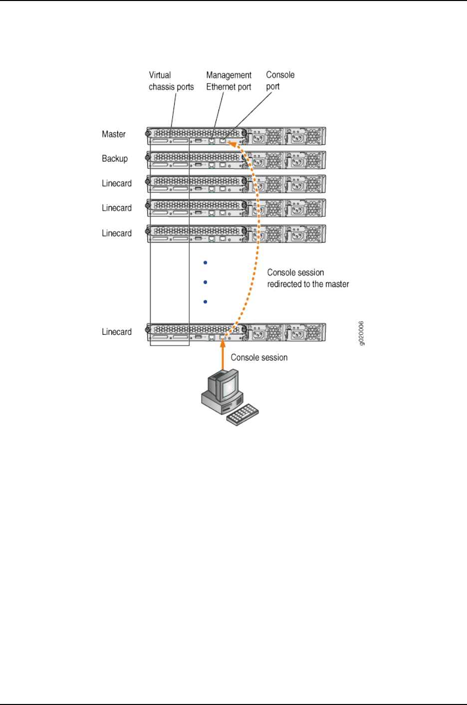
Figure 9: Console Session Redirection (J-EX4200 Virtual Chassis Pictured)
If the master becomes unavailable, the console session is disconnected from the old
master and a new session is established with the newly elected master.
An out-of-band management Ethernet port is often referred to simply as a management
Ethernet port. It uses a dedicated management channel for device maintenance and
allows a system administrator to monitor and manage the switch by remote control.
The Virtual Chassis configuration can be managed remotely through SSH or Telnet using
a global management interface called the virtual management Ethernet (VME) interface.
The VME interface is a logical interface representing any and all of the out-of-band
management ports on the member switches. When you connect to the Virtual Chassis
configuration using the VME interface’s IP address, the connection is redirected to the
master member as shown in Figure 10 on page 720.
719
Chapter 37: J-EX4200 and J-EX4500 Virtual Chassis—Overview, Components, and Configurations
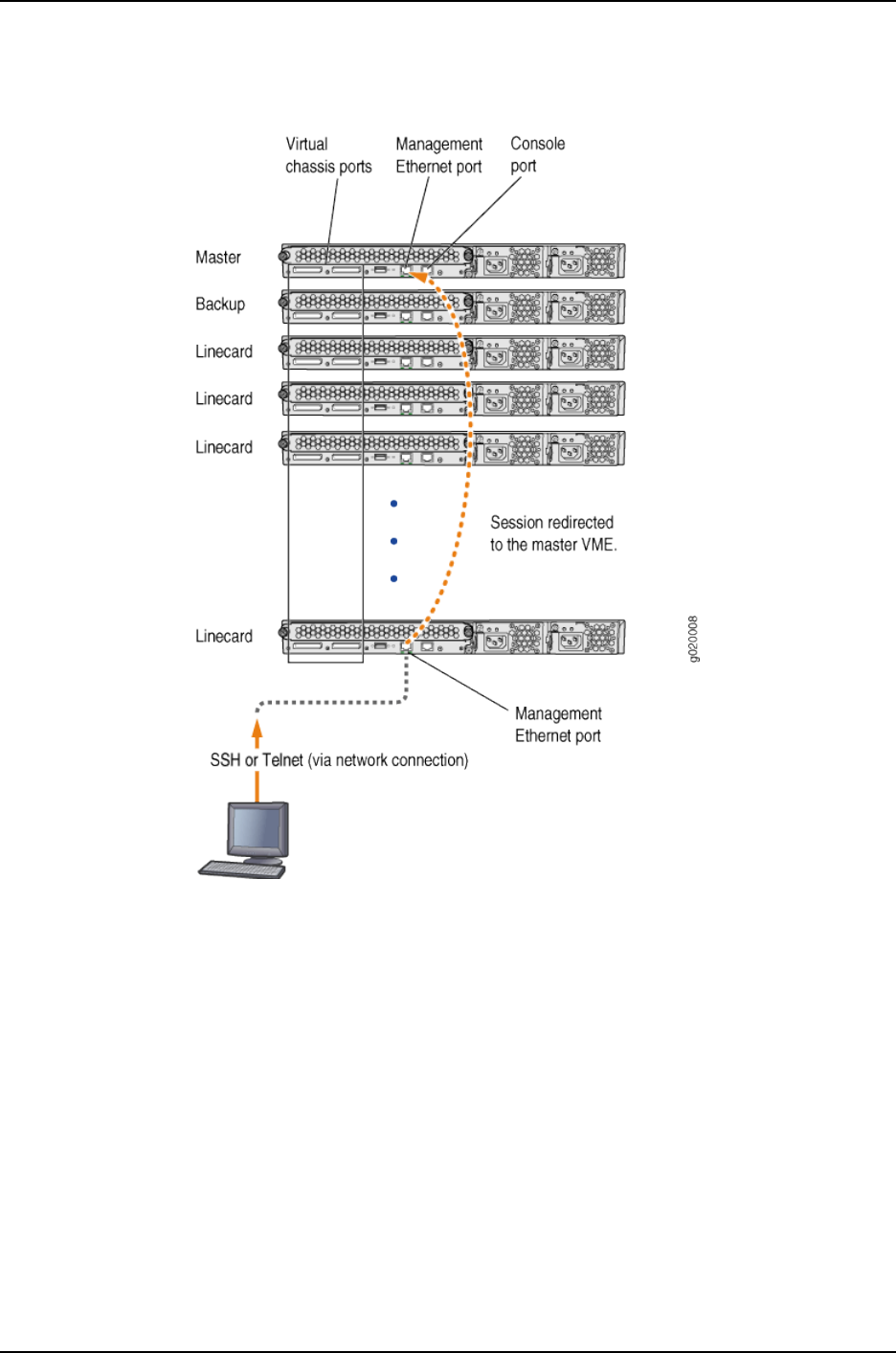
Figure 10: Management Ethernet Port Redirection to the VME Interface
If the master management Ethernet link is unavailable, the session is redirected through
the backup management Ethernet link. If there is no active management Ethernet link
on the backup, the VME interface chooses a management Ethernet link on one of the
linecard members, selecting the linecard member with the lowest member ID as its first
choice.
You can configure an IP address for the VME global management interface at any time.
You can perform remote configuration and administration of all members of the Virtual
Chassis configuration through the VME interface.
Related
Documentation
Understanding J-EX4200 and J-EX4500 Virtual Chassis Components on page 712•
•Example: Configuring a J-EX4200 Virtual Chassis with a Master and Backup in a Single
Wiring Closet on page 736
720
Dell PowerConnect J-Series Ethernet Switch Complete Software Guide for Junos OS, Release 11.1: Volume 1

•Configuring the Virtual Management Ethernet Interface for Global Management of a
J-EX4200 or J-EX4500 Virtual Chassis (CLI Procedure) on page 852
Understanding Nonvolatile Storage in a J-EX4200 or J-EX4500 Virtual Chassis
The J-EX4200 and J-EX4500 switches store the Junos operating system (Junos OS)
system files in internal flash memory. In the Virtual Chassis configurations, both the
master switch and the backup switch store the configuration information for all the
member switches.
•Nonvolatile Memory Features on page 721
Nonvolatile Memory Features
Junos OS optimizes the way the Virtual Chassis stores its configuration if a member
switch or the Virtual Chassis configuration is shut down improperly:
•If the master is not available, the backup switch takes on the role of the master and
its internal flash memory takes over as the alternate location for maintaining nonvolatile
configuration memory.
•If a member switch is taken offline for repair, the master stores the configuration of
the member switch.
Related
Documentation
Command Forwarding Usage with a J-EX4200 or J-EX4500 Virtual Chassis on page 857•
•Monitoring System Properties on page 578
Understanding the High-Speed Interconnection of the J-EX4200 and J-EX4500 Virtual
Chassis Members
Two high-speed Virtual Chassis ports (VCPs) on the J-EX4200 and J-EX4500 switches
enable the member switches to be interconnected and operate as a single, powerful
device. Each VCP interface is 32 Gbps bidirectional. When VCP interfaces are used to
form a ring topology, each segment provides 64 Gbps bidirectional bandwidth. Because
the VCP links act as point-to-point links, multiple segments of the ring can be used
simultaneously. This allows the Virtual Chassis configuration bandwidth to scale as you
interconnect more members within the ring topology.
Related
Documentation
Understanding J-EX4200 and J-EX4500 Virtual Chassis Components on page 712•
•Virtual Chassis Cabling Configuration Examples for J-EX4200 Switches
Understanding J-EX4200 and J-EX4500 Virtual Chassis Link Aggregation
You can combine physical Ethernet ports belonging to different member switches of a
J-EX4200 or J-EX4500 Virtual Chassis configuration to form a logical point-to-point link,
known as a link aggregation group (LAG) or bundle. A LAG provides more bandwidth than
a single Ethernet link can provide. Additionally, link aggregation provides network
721
Chapter 37: J-EX4200 and J-EX4500 Virtual Chassis—Overview, Components, and Configurations

redundancy by load-balancing traffic across all available links. If one of the links fails,
the system automatically load-balances traffic across all remaining links.
You can select up to four uplink module ports or SFP network ports on a J-EX4200 switch
that have been configured as Virtual Chassis ports (VCPs) to form a LAG. When you set
uplink module ports or SFP network ports on Virtual Chassis member switches as uplink
VCPs, connect two or more of those uplink VCPs on one member to at least two uplink
VCPs on another member, and configure those uplink VCPs to operate at the same link
speed, the uplink VCPs automatically form a LAG. Each LAG is assigned a positive-integer
identifier called a trunk ID.
You can also convert the SFP+ 10-Gigabit Ethernet ports on a J-EX4500 switch to VCP
ports. These VCP ports can only be used to connect J-EX4500 switches. Up to 8 VCPs
can be a part of the same LAG between two J-EX4500 switches.
A LAG over uplink VCPs provides higher overall bandwidth for forwarding traffic between
the member switches connected by the uplink VCPs, faster management communications,
and greater redundancy of operations among the members than would be available
without the LAG. All J-EX4200 switches as well as J-EX4500 switches using a VCP
module have two dedicated VCPs. A LAG over uplink VCPs provides an additional Virtual
Chassis link throughput of 20 Gbps for the switches. Up to eight Virtual Chassis LAGs
can be created per member.
See “Setting an Uplink Module Port on a J-EX4200 Switch as a Virtual Chassis Port (CLI
Procedure)” on page 846 for information about configuring uplink module ports and SFP
network ports as uplink VCPs.
NOTE: The interfaces that are included within a bundle or LAG are sometimes
referred to as member interfaces. Do not confuse this term with member
switches, which refers to J-EX4200 or J-EX4500 switches that are
interconnected as a Virtual Chassis. It is possible to create a LAG that is
composed of member interfaces that are located in different member
switches of a Virtual Chassis.
Related
Documentation
J-EX4200 and J-EX4500 Virtual Chassis Overview on page 709•
•Understanding Aggregated Ethernet Interfaces and LACP on page 1003
•Example: Configuring Aggregated Ethernet High-Speed Uplinks Between a J-EX4200
Virtual Chassis Access Switch and a J-EX4200 Virtual Chassis Distribution Switch on
page 777
•Example: Configuring Aggregated Ethernet High-Speed Uplinks with LACP Between
a J-EX4200 Virtual Chassis Access Switch and a J-EX4200 Virtual Chassis Distribution
Switch on page 783
•Example: Configuring a J-EX4200 Virtual Chassis Interconnected Across Multiple Wiring
Closets on page 762
•Example: Connecting J-EX4500 Member Switches in a Virtual Chassis Across Wiring
Closets on page 770
722
Dell PowerConnect J-Series Ethernet Switch Complete Software Guide for Junos OS, Release 11.1: Volume 1

•Example: Configuring Link Aggregation Groups Using J-EX4200 Uplink Virtual Chassis
Ports on page 809
Understanding J-EX4200 and J-EX4500 Virtual Chassis Configuration
You configure and manage almost all aspects of a J-EX4200 or J-EX4500 Virtual Chassis
configuration through the master of the Virtual Chassis. However, you can also configure
Virtual Chassis parameters when a switch is a standalone switch not interconnected
with other members.
J-EX4200 and J-EX4500 switches have some innate characteristics of a Virtual Chassis
by default. A standalone switch is assigned member ID 0and is the master of itself.
Therefore, you can edit its Virtual Chassis configuration. When the standalone switch is
interconnected with an existing Virtual Chassis configuration, the Virtual Chassis
configuration statements and any uplink Virtual Chassis port (VCP) settings that you
previously specified on the standalone switch remain part of its configuration.
A switch is not recognized as a member of a Virtual Chassis until it is interconnected with
the master or interconnected with an existing member of the Virtual Chassis. When a
switch is located too far away to be interconnected through dedicated VCPs, you can
specify an uplink module port or a network interface as a VCP by using the request
virtual-chassis vc-port command. You must issue the request virtual-chassis vc-port
command on the switch you are adding to the Virtual Chassis as well as on the existing
member switch that you will connect to the new member. Because the to-be-added
switch is not yet a member, the master switch will not recognize that added switch unless
the latter has an uplink VCP. A link aggregation group (LAG) will be formed automatically
when the new switch is added to the configuration if more than one such link with the
same speed is detected between uplink VCPs on the new member and an existing
member. See “Understanding J-EX4200 and J-EX4500 Virtual Chassis Link Aggregation”
on page 721.
When an uplink module port or a network interface is set as a VCP, it cannot be used for
any additional purpose. If you want to use the uplink module port or network interface
for another purpose, you can delete the VCP setting by using the request virtual-chassis
vc-port command. You can execute this command directly on the member whose uplink
VCP setting you want to delete or through the master of the Virtual Chassis configuration.
CAUTION: Deleting a VCP in a Virtual Chassis chain configuration can cause
the Virtual Chassis configuration to split. For more information, see
“Understanding Split and Merge in a J-EX4200 or J-EX4500 Virtual Chassis”
on page 731.
You can create a preprovisioned configuration. This type of configuration allows you to
deterministically control the member ID and role assigned to a member switch by
associating the switch with its serial number. Preprovisioned configuration is highly
recommended for a mixed J-EX4200 and J-EX4500 Virtual Chassis. For an example of
723
Chapter 37: J-EX4200 and J-EX4500 Virtual Chassis—Overview, Components, and Configurations

a preprovisioned configuration, see “Example: Configuring a J-EX4200 Virtual Chassis
Using a Preprovisioned Configuration File” on page 788.
NOTE: If a switch is interconnected with other switches in a Virtual Chassis
configuration, each individual switch that is included as a member of the
configuration is identified with a member ID. The member ID functions as an
FPC slot number. When you are configuring interfaces for a Virtual Chassis
configuration, you specify the appropriate member ID (0 through 9) as the
slot element of the interface name.
The default factory settings for a Virtual Chassis configuration include FPC
0 as a member of the default VLAN because FPC 0 is configured as part of
the ethernet-switching family. In order to include FPC 1 through FPC 9 in the
default VLAN, add the ethernet-switching family to the configurations for
those interfaces.
Related
Documentation
Understanding J-EX4200 and J-EX4500 Virtual Chassis Components on page 712•
•Understanding How the Master in a J-EX4200 or J-EX4500 Virtual Chassis Is Elected
on page 717
•Example: Configuring a J-EX4200 Virtual Chassis Interconnected Across Multiple Wiring
Closets on page 762
•Example: Configuring a J-EX4200 Virtual Chassis with a Master and Backup in a Single
Wiring Closet on page 736
•request virtual-chassis vc-port on page 900
Understanding J-EX4200 and J-EX4500 Virtual Chassis Switch Version Compatibility
J-EX4200 or J-EX4500 switches must be running the same software versions to be
interconnected into a Virtual Chassis. The master checks the hardware version, the Junos
operating system (Junos OS) version, and other component versions running in a switch
that is physically interconnected to its Virtual Chassis port (VCP). Different hardware
models can be members of the same Virtual Chassis configuration. However, the master
will not assign a member ID to a switch that is running a different software version. A
switch that is running a different version of software will not be allowed to join the Virtual
Chassis configuration.
Related
Documentation
Understanding J-EX4200 and J-EX4500 Virtual Chassis Components on page 712•
•Understanding Software Upgrade in a J-EX4200 or J-EX4500 Virtual Chassis on page 718
•Understanding Software Installation on J-EX Series Switches on page 69
•Installing Software on a J-EX Series Switch with a Single Routing Engine (CLI Procedure)
on page 80
•Installing Software on J-EX Series Switches (J-Web Procedure) on page 86
724
Dell PowerConnect J-Series Ethernet Switch Complete Software Guide for Junos OS, Release 11.1: Volume 1

Understanding Fast Failover in a J-EX4200 Virtual Chassis
The Virtual Chassis fast failover feature is a hardware-assisted failover mechanism that
automatically reroutes traffic and reduces traffic loss in the event of a link failure or switch
failure in a Virtual Chassis. If a link between two members fails, traffic flow between
those members must be rerouted quickly so that there is minimal traffic loss.
Fast failover is effective only for Virtual Chassis members configured in ring topologies
using identical port types.
NOTE: Fast failover is not supported in a mixed J-EX4200 and J-EX4500
Virtual Chassis or in a J-EX4500 Virtual Chassis.
This topic describes the following:
•Supported Topologies for Fast Failover on page 725
•How Fast Failover Works on page 725
•Effects of Topology Changes on a Fast Failover Configuration on page 730
Supported Topologies for Fast Failover
For fast failover to be effective, the Virtual Chassis members must be configured in a ring
topology. The ring topology can be formed by using either dedicated Virtual Chassis ports
(VCPs) or user-configured uplink module VCPs. Fast failover is supported only in a ring
topology that uses identical port types—for example, either a topology that uses all
dedicated VCPs or one that uses all uplink module VCPs. Fast failover is not supported
in a ring topology that includes both dedicated VCPs and uplink module VCPs. Fast
failover is supported, however, in a Virtual Chassis configuration that consists of multiple
rings.
How Fast Failover Works
When fast failover is activated, each VCP is automatically configured with a backup port
of the same type (dedicated VCP, SFP uplink VCP, or SFP+ uplink VCP). If a VCP fails,
its backup port is used to send traffic. These backup ports act as standby ports and are
not meant for load-balancing traffic or any other purposes.
Fast Failover in a Ring Topology Using Dedicated VCPs
When fast failover is activated in a ring topology that uses dedicated VCPs, each VCP is
automatically configured with a backup port of the same type. If a VCP fails, its backup
port is used to send traffic. Figure 11 on page 726 shows normal traffic flow in a ring topology
using dedicated VCPs.
725
Chapter 37: J-EX4200 and J-EX4500 Virtual Chassis—Overview, Components, and Configurations
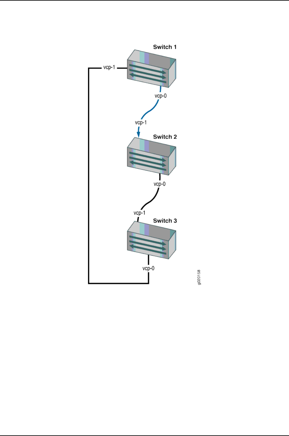
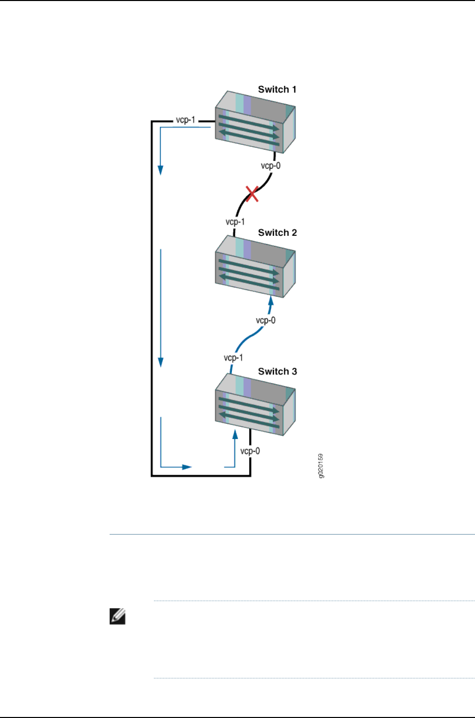
Figure 12: Traffic Redirected by Fast Failover After a Dedicated VCP Link
Failure
When the failed link is restored, the Virtual Chassis reconfigures the topology to the
topology's original state.
Fast Failover in a Ring Topology Using Uplink Module VCPs
In a ring topology that uses uplink module VCPs, each uplink module VCP is automatically
configured with a backup uplink module VCP. If an uplink module VCP fails, its backup
port is used to send traffic. Figure 13 on page 728 shows normal traffic flow in a ring topology
using SFP uplink module VCPs.
NOTE: To use SFP uplink module ports as VCPs, you must configure them
to be VCPs using the request virtual-chassis vc-port command. Once
configured, they are converted into VCPs. For example, xe-0/1/0 becomes
vcp-255/1/0 after you configure it to be a VCP.
727
Chapter 37: J-EX4200 and J-EX4500 Virtual Chassis—Overview, Components, and Configurations
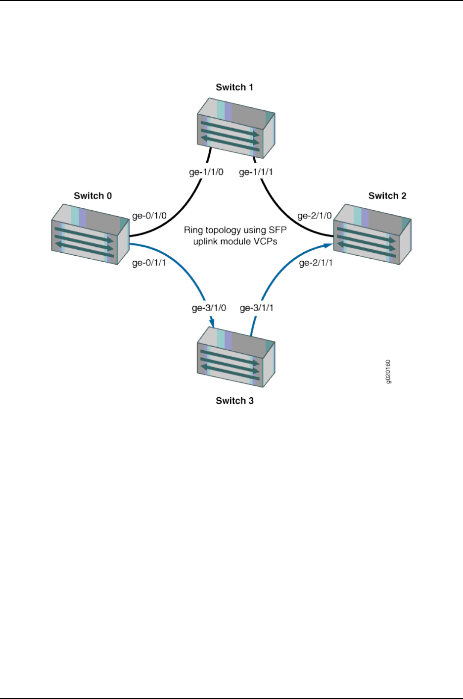
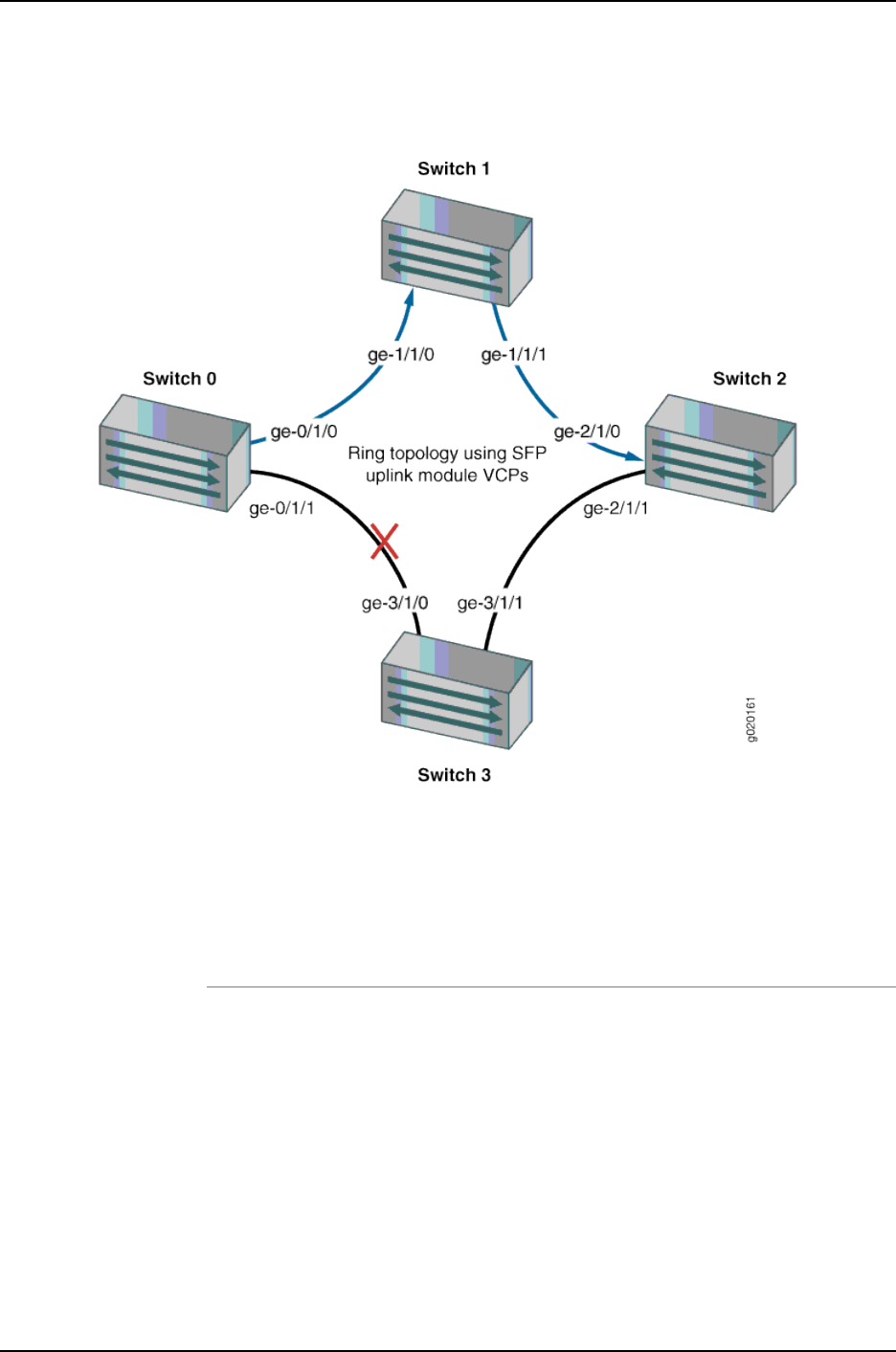
Figure 14: Traffic Redirected by Fast Failover After SFP Uplink Module
VCP Link Failure
In a ring topology that uses SFP uplink module VCPs, there are four ports per module.
Consecutive pairs of ports are automatically configured as backup ports for each other.
For example, if a Virtual Chassis member has an SFP uplink module installed, uplink
module VCPs ge-0/1/0 and ge-0/1/1 are automatically configured as backup ports for
each other. Similarly, ports ge-0/1/2 and ge-0/1/3 are automatically configured as backup
ports for each other.
Fast Failover in a Virtual Chassis Configuration Using Multiple Ring Topologies
Fast failover is supported in a Virtual Chassis configuration with a multiple-ring topology,
as shown in Figure 15 on page 730.
729
Chapter 37: J-EX4200 and J-EX4500 Virtual Chassis—Overview, Components, and Configurations
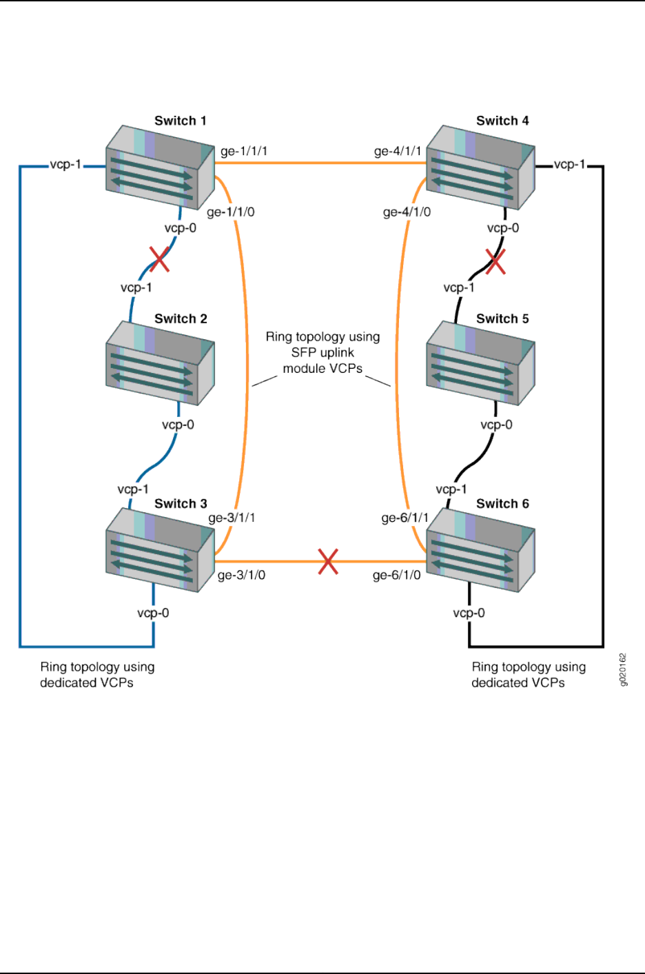
Figure 15: Traffic Redirected by Fast Failover After VCP Link Failures in a
Topology with Multiple Rings
In this scenario, the Virtual Chassis configuration has three rings: two rings that use
dedicated VCPs and one ring that uses SFP uplink module VCPs. Fast failover works
independently on each ring. Each dedicated VCP in a ring is backed up by another
dedicated VCP. Similarly, each SFP uplink module VCP is backed up by another SFP
uplink module VCP. Fast failover does not support a ring topology consisting of a mix of
dedicated VCPs and uplink module VCPs.
Effects of Topology Changes on a Fast Failover Configuration
Once the fast failover feature has been activated, topology changes to the Virtual Chassis
configuration do not affect the fast failover configuration. In the event of a link or switch
failure, fast failover functions normally.
730
Dell PowerConnect J-Series Ethernet Switch Complete Software Guide for Junos OS, Release 11.1: Volume 1

Related
Documentation
Understanding J-EX4200 and J-EX4500 Virtual Chassis Configuration on page 723•
•Example: Configuring Fast Failover on Uplink Module VCPs to Reroute Traffic When a
J-EX4200 Virtual Chassis Switch or Intermember Link Fails on page 804
•Setting an Uplink Module Port on a J-EX4200 Switch as a Virtual Chassis Port (CLI
Procedure) on page 846
Understanding Split and Merge in a J-EX4200 or J-EX4500 Virtual Chassis
In a J-EX4200 Virtual Chassis, J-EX4500 Virtual Chassis, or mixed J-EX4200 and
J-EX4500 Virtual Chassis, two or more switches are connected together to form a unit
that is managed as a single chassis. If there is a disruption to the Virtual Chassis
configuration due to member switches failing or being removed from the configuration,
the Virtual Chassis configuration splits into two separate Virtual Chassis. This situation
could cause disruptions in the network if the two separate configurations share common
resources, such as global IP addresses. The split and merge feature provides a method
to prevent the separate Virtual Chassis configurations from adversely affecting the
network and also allows the two parts to merge back into a single Virtual Chassis
configuration.
NOTE: If a Virtual Chassis configuration splits into separate parts, we
recommend that you resolve the problem that caused the Virtual Chassis
configuration to split as soon as possible.
You can also use this feature to merge two active but separate Virtual Chassis that have
not previously been part of the same configuration into one Virtual Chassis configuration.
NOTE: The split and merge feature is enabled by default on J-EX4200 and
J-EX4500 switches. You can disable the split and merge feature by using the
set virtual-chassis no-split-detection command.
This topic describes:
•What Happens When a Virtual Chassis Configuration Splits on page 731
•Merging Virtual Chassis Configurations on page 732
What Happens When a Virtual Chassis Configuration Splits
When a Virtual Chassis configuration splits into two separate Virtual Chassis
configurations, the individual member switches detect this topology change and run the
master election algorithm to select a new master for each of the two Virtual Chassis
configurations. The new masters then determine whether their Virtual Chassis
configuration remains active. One of the configurations remains active based on the
following:
731
Chapter 37: J-EX4200 and J-EX4500 Virtual Chassis—Overview, Components, and Configurations

•It contains both the stable master and the stable backup (that is, the master and
backup from the original Virtual Chassis configuration before the split).
•It contains the stable master and the configuration is greater than half the Virtual
Chassis size.
•It contains the stable backup and is at least half the Virtual Chassis size.
In accordance with the rules given in the second and third list items, if the Virtual Chassis
configuration splits into two equal parts and the stable master and stable backup are in
different parts, then the part that contains the stable backup becomes active.
NOTE: The number of members in the Virtual Chassis configuration includes
all member switches connected to date minus the number whose Virtual
Chassis member IDs have been recycled (that is, made available for
reassignment). Therefore, the size of the Virtual Chassis configuration
increases when a new member switch is detected and decreases when a
member switch's ID is recycled.
These rules ensure that only one of the two separate Virtual Chassis configurations
created by the split remains active. The member switches in the inactive Virtual Chassis
configuration remain in a linecard role. For the inactive members to become active again,
one of the following things must happen:
•The problem that caused the original Virtual Chassis configuration to split is resolved,
allowing the two Virtual Chassis configurations to merge.
•You load the factory default configuration on the inactive members, which causes the
inactive members to function as standalone switches or become part of a different
Virtual Chassis configuration.
NOTE: When you remove a member switch from a Virtual Chassis
configuration, we recommend that you recycle the member ID using the
request virtual-chassis recycle command.
Merging Virtual Chassis Configurations
There are two scenarios in which separate Virtual Chassis merge:
•A Virtual Chassis configuration that had split into two is now merging back into a single
configuration because the problem that had caused it to split has been resolved.
•You want to merge two Virtual Chassis that had not previously been configured together.
Every Virtual Chassis configuration has a unique ID (VCID) that is automatically assigned
when the Virtual Chassis configuration is formed. You can also explicitly assign a VCID
using the set virtual-chassis id command. A VCID that you assign takes precedence over
automatically assigned VCIDs.
732
Dell PowerConnect J-Series Ethernet Switch Complete Software Guide for Junos OS, Release 11.1: Volume 1

When you reconnect the separate Virtual Chassis configurations or connect them for the
first time, the members determine whether or not the separate Virtual Chassis
configurations can merge. The members use the following rules to determine whether
a merge is possible:
•If the Virtual Chassis configurations have the same VCID, then the configurations can
merge. If the two Virtual Chassis were formed as the result of a split, they have the
same VCID.
•If the VCIDs are different, then the two configurations can merge only if both are active
(inactive configurations cannot merge, ensuring that members removed from one
Virtual Chassis configuration do not become members of another Virtual Chassis
configuration). If the configurations to merge are both active and one of them has a
user-configured VCID, this ID becomes the ID of the merged Virtual Chassis. If neither
Virtual Chassis has a user-configured VCID, then the VCID of the configuration with
the highest mastership priority becomes the ID of the merged Virtual Chassis. The
resulting merged Virtual Chassis configuration is active.
When you connect two Virtual Chassis configurations, the following events occur:
1. Connecting the two split Virtual Chassis configurations triggers the shortest-path-first
(SPF) algorithm. The SPF algorithm computes the network topology and then triggers
the master election algorithm. The master election algorithm waits for the members
to synchronize the topology information before running.
2. The master election algorithm merges the VCIDs of all the members.
3. Each member runs the master election algorithm to select a master and a backup
from among all members with the same VCIDs. For more information, see
“Understanding How the Master in a J-EX4200 or J-EX4500 Virtual Chassis Is Elected”
on page 717.
4. The master determines whether the Virtual Chassis configuration is active or inactive.
(See “What Happens When a Virtual Chassis Configuration Splits” on page 731.)
5. If the Virtual Chassis configuration is active, the master assigns roles to all members.
If the Virtual Chassis configuration is inactive, the master assigns all members the
role of linecard.
6. When the other members receive their role from the master, they change their role to
backup or linecard. They also use the active or inactive state information sent by the
master to set their own state to active or inactive and to construct the Virtual Chassis
member list from the information sent by the master.
7. If the Virtual Chassis state is active, the master waits for messages from the members
indicating that they have changed their roles to the assigned roles, and then the master
changes its own role to master.
733
Chapter 37: J-EX4200 and J-EX4500 Virtual Chassis—Overview, Components, and Configurations

NOTE: When you merge two Virtual Chassis that had not previously been
part of the same Virtual Chassis configuration, any configuration settings
(such as the settings for Telnet and FTP services, GRES, fast failover, VLANs,
and so on) that exist on the new master become the configuration settings
for all members of the new Virtual Chassis, overwriting any other configuration
settings.
Related
Documentation
Understanding J-EX4200 and J-EX4500 Virtual Chassis Configuration on page 723•
•Example: Assigning the Virtual Chassis ID to Determine Precedence During a J-EX4200
Virtual Chassis Merge on page 807
•Assigning the Virtual Chassis ID to Determine Precedence During a J-EX4200 or
J-EX4500 Virtual Chassis Merge (CLI Procedure) on page 855
•Disabling Split and Merge in a J-EX4200 or J-EX4500 Virtual Chassis (CLI Procedure)
on page 854
Understanding Automatic Software Update on J-EX4200 and J-EX4500 Virtual Chassis
Member Switches
The automatic software update feature automatically updates the Junos operating
system (Junos OS) version on prospective member switches as they are added to the
Virtual Chassis. The new member switch immediately joins the Virtual Chassis
configuration and is put in the active state.
For a standalone J-EX4200 or J-EX4500 switch to join an existing Virtual Chassis
configuration, it must be running the same version of Junos OS that is running on the
Virtual Chassis master. When the master in a Virtual Chassis configuration detects that
a new switch has been added to the configuration, it checks the software version on the
new switch. If the software version on the new switch is not the same as the version
running on the master, the master keeps the new switch in the inactive state. If you have
not enabled the automatic software update feature, you have to manually install the
correct software version on each prospective member switch as it is added to the Virtual
Chassis configuration.
Related
Documentation
•Understanding Software Upgrade in a J-EX4200 or J-EX4500 Virtual Chassis on page 718
•Example: Configuring Automatic Software Update on J-EX4200 Virtual Chassis Member
Switches on page 818
•Configuring Automatic Software Update on J-EX4200 or J-EX4500 Virtual Chassis
Member Switches (CLI Procedure) on page 855
734
Dell PowerConnect J-Series Ethernet Switch Complete Software Guide for Junos OS, Release 11.1: Volume 1

CHAPTER 38
J-EX4200 and J-EX4500 Virtual
Chassis—Configuration Examples
•Example: Configuring a J-EX4200 Virtual Chassis with a Master and Backup in a Single
Wiring Closet on page 736
•Example: Configuring a J-EX4500 Virtual Chassis with a Master and Backup in a Single
Wiring Closet on page 740
•Example: Expanding a J-EX4200 Virtual Chassis in a Single Wiring Closet on page 745
•Example: Adding a J-EX4500 Switch to a Nonprovisioned Virtual Chassis on page 750
•Example: Adding J-EX4500 Switches to a Preprovisioned Virtual Chassis on page 754
•Example: Setting Up a Multimember J-EX4200 Virtual Chassis Access Switch with a
Default Configuration on page 757
•Example: Configuring a J-EX4200 Virtual Chassis Interconnected Across Multiple Wiring
Closets on page 762
•Example: Connecting J-EX4500 Member Switches in a Virtual Chassis Across Wiring
Closets on page 770
•Example: Configuring Aggregated Ethernet High-Speed Uplinks Between a J-EX4200
Virtual Chassis Access Switch and a J-EX4200 Virtual Chassis Distribution
Switch on page 777
•Example: Configuring Aggregated Ethernet High-Speed Uplinks with LACP Between
a J-EX4200 Virtual Chassis Access Switch and a J-EX4200 Virtual Chassis Distribution
Switch on page 783
•Example: Configuring a J-EX4200 Virtual Chassis Using a Preprovisioned Configuration
File on page 788
•Example: Configuring a Preprovisioned Mixed J-EX4200 and J-EX4500 Virtual
Chassis on page 799
•Example: Configuring Fast Failover on Uplink Module VCPs to Reroute Traffic When a
J-EX4200 Virtual Chassis Switch or Intermember Link Fails on page 804
•Example: Assigning the Virtual Chassis ID to Determine Precedence During a J-EX4200
Virtual Chassis Merge on page 807
735

•Example: Configuring Link Aggregation Groups Using J-EX4200 Uplink Virtual Chassis
Ports on page 809
•Example: Configuring Automatic Software Update on J-EX4200 Virtual Chassis Member
Switches on page 818
Example: Configuring a J-EX4200 Virtual Chassis with a Master and Backup in a Single
Wiring Closet
A Virtual Chassis configuration is a scalable switch. You can provide secure, redundant
network accessibility with a basic two-member J-EX4200 Virtual Chassis and later
expand the Virtual Chassis configuration to provide additional access ports as your office
grows.
This example describes how to configure a J-EX4200 Virtual Chassis with a master and
backup in a single wiring closet:
•Requirements on page 736
•Overview and Topology on page 736
•Configuration on page 738
•Verification on page 738
•Troubleshooting the Virtual Chassis on page 740
Requirements
This example uses the following hardware and software components:
•Junos OS Release 10.2 or later for J-EX Series switches
•One J-EX4200-48T switch
•One J-EX4200-24T switch
•One uplink module
Before you begin, be sure you have:
1. Rack-mounted the switches.
2. Installed the uplink module. .
3. Cabled the switches..
For instructions, see the Dell PowerConnect J-Series J-EX4200 Ethernet Switch Hardware
Guide at http://www.support.dell.com/manuals.
Overview and Topology
A Virtual Chassis configuration allows you to accommodate the networking needs of a
growing office. The default configuration of a two-member Virtual Chassis includes a
master and a backup switch. In addition to providing more access ports than a single
switch can provide, a Virtual Chassis configuration provides high availability through
redundancy.
736
Dell PowerConnect J-Series Ethernet Switch Complete Software Guide for Junos OS, Release 11.1: Volume 1

This example shows a Virtual Chassis configuration composed of two J-EX4200 switches.
One of the switches has an uplink module with ports that can be configured to connect
to a distribution switch or customer edge (CE) router or that can be configured as Virtual
Chassis ports (VCPs) to interconnect with a member switch that is located too far for
the dedicated VCP cabling. (The network interfaces on J-EX4200-24F switches can also
be configured as VCPs.) For information on configuring the uplink ports as trunk ports to
a distribution switch, see “Configuring Gigabit Ethernet Interfaces (CLI Procedure)” on
page 1042. For an example of configuring uplink ports as VCPs, see “Setting an Uplink
Module Port on a J-EX4200 Switch as a Virtual Chassis Port (CLI Procedure)” on page 846.
By default, after you interconnect the switches with the dedicated VCPs and power on
the switches, the VCPs are operational. The mastership priorities and member IDs are
assigned by the software. The software elects a master based on several criteria, including
how long a member switch has belonged to the Virtual Chassis configuration. For
additional details, see “Understanding How the Master in a J-EX4200 or J-EX4500 Virtual
Chassis Is Elected” on page 717. Therefore, we recommend that you start by powering on
only one member switch, the one that you want to function as the master.
NOTE: We recommend that you use the commit synchronize command to
save any configuration changes that you make to a multimember Virtual
Chassis.
The Virtual Chassis configuration provides networking access for 50 onsite workers, who
are sitting within range of a single wiring closet. The workers all use personal computers
and VoIP phones. As the office grows, you can add more J-EX4200 switches to meet
increased needs for access ports.
The topology for this example consists of two switches, one of which contains an uplink
module:
•One J-EX4200-48T switch (SWA-0) with 48 access ports, all of which support PoE
•One J-EX4200-24T switch (SWA-1) with 24 access ports, including eight ports that
support PoE
•One uplink module, with two 10-Gigabit Ethernet ports, is installed in SWA-1.
Table 120 on page 737 shows the default configuration settings for the two-member
Virtual Chassis.
Table 120: Components of the Basic Virtual Chassis Access Switch Topology
Role and PriorityMember IDHardwareMember Switch
Master: mastership priority
128
0J-EX4200-48T switchSWA-0
Backup: mastership priority
128
1J-EX4200-48T switchSWA-1
737
Chapter 38: J-EX4200 and J-EX4500 Virtual Chassis—Configuration Examples

Figure 16 on page 738 shows that SWA-0 and SWA-1 are interconnected with their
dedicated VCPs on the rear panel. The LCD on the front displays the member ID and role.
SWA-0 also includes an uplink module. Its uplink ports can be used to connect to a
distribution switch.
Figure 16: Basic J-EX4200 Virtual Chassis with Master and Backup
Configuration
Configure a Virtual Chassis with a default master and backup in a single wiring closet:
Step-by-Step
Procedure
To configure a Virtual Chassis with master and backup:
1. Make sure the VCPs on the rear panel of the member switches are properly cabled.
For Virtual Chassis cabling examples, see the Dell PowerConnect J-Series J-EX4200
Ethernet Switch Hardware Guide at http://www.support.dell.com/manuals.
2. Power on SWA-0 (the member switch that you want to function as the master).
3. Check the front-panel LCD to confirm that the switch has powered on correctly.
4. Run the EZSetup program on SWA-0, specifying the identification parameters. See
“Connecting and Configuring a J-EX Series Switch (CLI Procedure)” on page 185 or
“Connecting and Configuring a J-EX Series Switch (J-Web Procedure)” on page 187
for details.
5. Configure SWA-0 with the virtual management Ethernet (VME) interface for
out-of-band management of the Virtual Chassis configuration, if desired.
[edit]
user@SWA-0# set interfaces vme unit 0 family inet address /ip-address/mask/
6. Power on SWA-1.
Verification
To confirm that the Virtual Chassis configuration is operational, perform these tasks:
•Verifying That the Mastership Priority Is Assigned Appropriately on page 738
•Verifying That the VCPs Are Operational on page 739
Verifying That the Mastership Priority Is Assigned Appropriately
Purpose Verify that the master, which has been selected by default, is the member switch that
you want to function in that role.
738
Dell PowerConnect J-Series Ethernet Switch Complete Software Guide for Junos OS, Release 11.1: Volume 1

Action Check the front-panel LCD to confirm that the switch has powered on correctly and
that a member ID has been assigned.
1.
2. List the member switches of the Virtual Chassis configuration.
user@SWA-0> show virtual-chassis status
Virtual Chassis ID: 0019.e250.47a0
Mastership Neighbor List
Member ID Status Serial No Model priority Role ID Interface
0 (FPC 0) Prsnt AK0207360276 ex4200-48t 128 Master* 1 vcp-0
1 vcp-1
1 (FPC 1) Prsnt AK0207360281 ex4200-24t 128 Backup 0 vcp-0
0 vcp-1
Member ID for next new member: 2 (FPC 2)
Meaning The show virtual-chassis status command lists the member switches interconnected
in a Virtual Chassis configuration with the member IDs that have been assigned by the
master, the mastership priority values, and the roles. It also displays the neighbor members
with which each member is interconnected. The output shows that SWA-0, member 0,
has been assigned default mastership priority 128. Because SWA-0 is the first member
to be powered on, it has the most seniority and is therefore assigned the role of master.
SWA-1 is powered on after member 0, so it is assigned the role of backup. The member
IDs are displayed on the front panel of the switches. Check and confirm whether the
default assignment is satisfactory.
Verifying That the VCPs Are Operational
Purpose Verify that the dedicated VCPs interconnecting the switches are operational.
Action Display the VCPs of all the members:
user@SWA-0> show virtual-chassis vc-port all-members
fpc0:
--------------------------------------------------------------------------
Interface Type Status Speed Neighbor
or (mbps) ID Interface
PIC / Port
vcp-0 Dedicated Up 32000 1 vcp-1
vcp-1 Dedicated Up 32000 1 vcp-0
fpc1:
--------------------------------------------------------------------------
Interface Type Status Speed Neighbor
or (mbps) ID Interface
PIC / Port
vcp-0 Dedicated Up 32000 1 vcp-0
vcp-1 Dedicated Up 32000 1 vcp-1
Meaning The show virtual-chassis vc-port command lists the interfaces that are enabled for the
member switches of the Virtual Chassis configuration and shows the status of the
interfaces. The output in this example shows that two of the VCPs are operational and
two VCPs are not. A single cable has been used to interconnect vcp-0 of member ID 0
739
Chapter 38: J-EX4200 and J-EX4500 Virtual Chassis—Configuration Examples

and vcp-0 of member ID 1. That interconnection is sufficient for the switch to be
operational. However, we recommend that you connect the second set of VCPs for
redundancy.
Troubleshooting the Virtual Chassis
To troubleshoot the configuration of a Virtual Chassis, perform these tasks:
Troubleshooting the Assignment of Roles
Problem The master and backup roles are not assigned to the member switches that you want
to function in these roles.
Solution Modify the mastership priority values.
To quickly modify the mastership priority of SWA-1 (member ID 1), copy the following
command and paste it into the switch terminal window:
[edit virtual-chassis]
user@SWA-1# set member 1 mastership-priority 255
Troubleshooting the VCPs
Problem The VCPs are down.
Solution Check to make sure that you have cabled the appropriate ports.1.
2. Check to make sure that the cables are seated properly.
You should generally cable and interconnect both of the VCPs on the member switches,
for redundancy and high availability.
Related
Documentation
Example: Expanding a J-EX4200 Virtual Chassis in a Single Wiring Closet on page 745•
•Example: Setting Up a Multimember J-EX4200 Virtual Chassis Access Switch with a
Default Configuration on page 757
•Example: Configuring a J-EX4200 Virtual Chassis Using a Preprovisioned Configuration
File on page 788
•Configuring a J-EX4200 or J-EX4500 Virtual Chassis (CLI Procedure) on page 822
•Configuring a J-EX4200 Virtual Chassis (J-Web Procedure) on page 826
Example: Configuring a J-EX4500 Virtual Chassis with a Master and Backup in a Single
Wiring Closet
A Virtual Chassis configuration is a scalable switch. You can provide secure, redundant
network accessibility with a basic two-member J-EX4500 Virtual Chassis configuration
and later expand the Virtual Chassis configuration to provide additional access ports as
your office grows.
740
Dell PowerConnect J-Series Ethernet Switch Complete Software Guide for Junos OS, Release 11.1: Volume 1

This example describes how to configure a J-EX4500 Virtual Chassis with a master and
backup in a single wiring closet:
•Requirements on page 741
•Overview and Topology on page 741
•Configuration on page 742
•Verification on page 743
•Troubleshooting the Virtual Chassis on page 744
Requirements
This example uses the following hardware and software components:
•Junos OS Release 11.1 or later for J-EX Series switches
•Two J-EX4500 switches with Virtual Chassis modules
Before you begin, be sure you have:
1. Rack-mounted the switches. For instructions, see the Dell PowerConnect J-Series
J-EX4500 Ethernet Switch Hardware Guide at http://www.support.dell.com/manuals.
2. Cabled the switches but not the VCPs.
Overview and Topology
A Virtual Chassis configuration allows you to accommodate the networking needs of a
growing office. The default configuration of a two-member Virtual Chassis includes a
master and a backup switch. In addition to providing more access ports than a single
switch can provide, a Virtual Chassis configuration provides high availability through
redundancy.
After you interconnect the switches with the dedicated VCPs and power on the switches,
the VCPs are operational. The mastership priorities and member IDs are assigned by the
software. The software elects a master based on several criteria, including how long a
member switch has belonged to the Virtual Chassis configuration. For additional details,
see “Understanding How the Master in a J-EX4200 or J-EX4500 Virtual Chassis Is Elected”
on page 717. Therefore, we recommend that you start by powering on only one member
switch, the one that you want to function as the master.
NOTE: We recommend that you use the commit synchronize command to
save any configuration changes that you make to a multimember Virtual
Chassis.
The Virtual Chassis configuration provides networking access for onsite workers who are
sitting within range of a single wiring closet. The workers all use personal computers and
VoIP phones. As the office grows, you can add J-EX4200 switches to meet increased
needs for access ports.
The topology for this example consists of two J-EX4500 switches.
741
Chapter 38: J-EX4200 and J-EX4500 Virtual Chassis—Configuration Examples
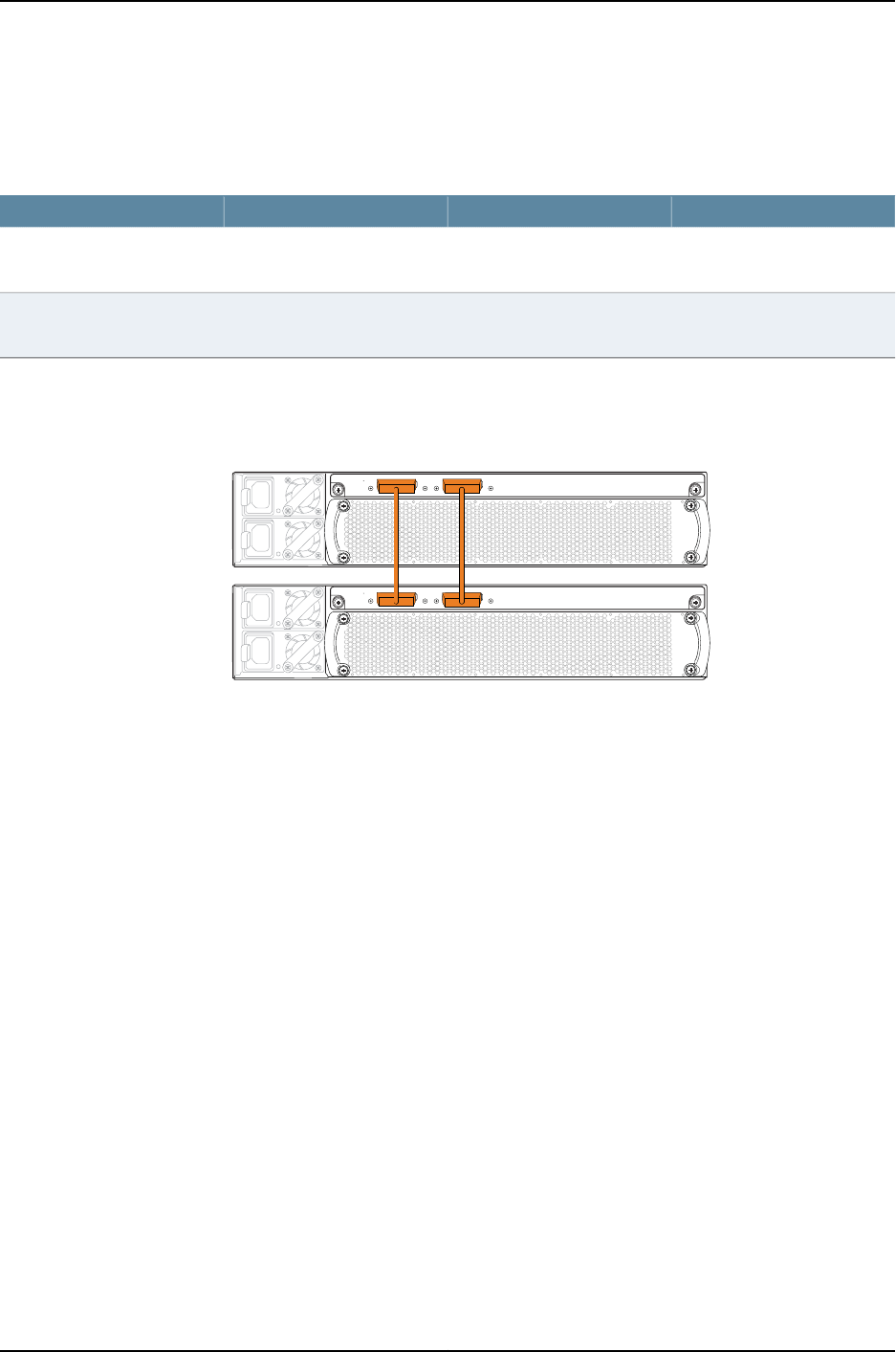
Table 121 on page 742 shows the default configuration settings for the two-member Virtual
Chassis.
Table 121: Components of the Basic Virtual Chassis Access Switch Topology
Role and PriorityMember IDHardwareMember Switch
Master: mastership priority
128
0J-EX4500 switchSWA-0
Backup: mastership priority
128
1J-EX4500 switchSWA-1
Figure 17 on page 742 shows that SWA-0 and SWA-1 are interconnected with their
dedicated VCPs on the rear panel. The LCD on the front displays the member ID and role.
Figure 17: Basic J-EX4500 Virtual Chassis with Master and Backup
1
0
1
0
g021056
J-EX4500
J-EX4500
Configuration
Configure a Virtual Chassis with a default master and backup in a single wiring closet:
Step-by-Step
Procedure
To configure a Virtual Chassis with master and backup:
1. Power on SWA-0 (the member switch that you want to function as the master).
2. Power on SWA-1 (the member switch that you want to function as the backup).
3. Set the PIC mode to Virtual Chassis mode on both switches:
user@switch> request chassis pic-mode virtual-chassis
4. Run the EZSetup program on SWA-0, specifying the identification parameters. See
“Connecting and Configuring a J-EX Series Switch (CLI Procedure)” on page 185 for
details.
5. Cable the Virtual Chassis member switches together.
6. Configure SWA-0 with the virtual management Ethernet (VME) interface for
out-of-band management of the Virtual Chassis configuration, if desired:
[edit]
user@SWA-0# set interfaces vme unit 0 family inet address /ip-address/mask/
742
Dell PowerConnect J-Series Ethernet Switch Complete Software Guide for Junos OS, Release 11.1: Volume 1

Verification
To confirm that the Virtual Chassis configuration is operational, perform these tasks:
•Verifying That the Mastership Priority Is Assigned Appropriately on page 743
•Verifying That the VCPs Are Operational on page 743
Verifying That the Mastership Priority Is Assigned Appropriately
Purpose Verify that the master, which has been selected by default, is the member switch that
you want to function in that role.
Action Check the front-panel LCD to confirm that the switch has powered on correctly and
that a member ID has been assigned.
1.
2. List the member switches of the Virtual Chassis configuration.
user@SWA-0> show virtual-chassis status
Virtual Chassis ID: 0019.e250.47a0
Mastership Neighbor List
Member ID Status Serial No Model priority Role ID Interface
0 (FPC 0) Prsnt AK0207360276 ex4500-40f 128 Master* 1 vcp-0
1 vcp-1
1 (FPC 1) Prsnt AK0207360281 ex4500-40f 128 Backup 0 vcp-0
0 vcp-1
Member ID for next new member: 2 (FPC 2)
Meaning The show virtual-chassis status command lists the member switches interconnected
in a Virtual Chassis configuration with the member IDs that have been assigned by the
master, the mastership priority values, and the roles. It also displays the neighbor members
with which each member is interconnected. The output shows that SWA-0, member 0,
has been assigned default mastership priority 128. Because SWA-0 is the first member
to be powered on, it has the most seniority and is therefore assigned the role of master.
SWA-1 is powered on after member 0, so it is assigned the role of backup. The member
IDs are displayed on the front panel of the switches. Check and confirm whether the
default assignment is satisfactory.
Verifying That the VCPs Are Operational
Purpose Verify that the dedicated VCPs interconnecting the switches are operational.
Action Display the VCPs of all the members:
user@SWA-0> show virtual-chassis vc-port all-members
fpc0:
--------------------------------------------------------------------------
Interface Type Status Speed Neighbor
or (mbps) ID Interface
PIC / Port
vcp-0 Dedicated Up 32000 1 vcp-1
vcp-1 Dedicated Up 32000 1 vcp-0
743
Chapter 38: J-EX4200 and J-EX4500 Virtual Chassis—Configuration Examples

fpc1:
--------------------------------------------------------------------------
Interface Type Status Speed Neighbor
or (mbps) ID Interface
PIC / Port
vcp-0 Dedicated Up 32000 1 vcp-0
vcp-1 Dedicated Up 32000 1 vcp-1
Meaning The show virtual-chassis vc-port command lists the interfaces that are enabled for the
member switches of the Virtual Chassis configuration and shows the status of the
interfaces. The output in this example shows that two of the VCPs are operational. A
single cable has been used to interconnect vcp-0 of member ID 0 and vcp-0 of member
ID 1. That interconnection is sufficient for the switch to be operational. However, we
recommend that you connect the second set of VCPs for redundancy.
Troubleshooting the Virtual Chassis
To troubleshoot the configuration of a Virtual Chassis, perform these tasks:
Troubleshooting the Assignment of Roles
Problem The master and backup roles are not assigned to the member switches that you want
to function in these roles.
Solution Modify the mastership priority values.
To quickly modify the mastership priority of SWA-1 (member ID 1), copy the following
command and paste it into the switch terminal window:
[edit virtual-chassis]
user@SWA-1# set member 1 mastership-priority 255
Troubleshooting the VCPs
Problem The VCPs are down.
Solution Check to make sure that you have cabled the appropriate ports.1.
2. Check to make sure that the cables are seated properly.
You should generally cable and interconnect both of the VCPs on the member switches,
for redundancy and high availability.
Related
Documentation
Example: Connecting J-EX4500 Member Switches in a Virtual Chassis Across Wiring
Closets on page 770
•
•Example: Configuring a Preprovisioned Mixed J-EX4200 and J-EX4500 Virtual Chassis
on page 799
•Configuring a J-EX4200 or J-EX4500 Virtual Chassis (CLI Procedure) on page 822
744
Dell PowerConnect J-Series Ethernet Switch Complete Software Guide for Junos OS, Release 11.1: Volume 1

Example: Expanding a J-EX4200 Virtual Chassis in a Single Wiring Closet
A Virtual Chassis is a scalable switch composed of multiple interconnected J-EX4200
and/or J-EX4500 switches.
This example describes how to configure an expanding J-EX4200 Virtual Chassis within
a single wiring closet:
•Requirements on page 745
•Overview and Topology on page 745
•Configuration on page 747
•Verification on page 748
•Troubleshooting on page 749
Requirements
This example uses the following hardware and software components:
•Junos OS Release 10.2 or later for J-EX Series switches
•One J-EX4200-48T switch
•Two J-EX4200-24T switches
•One uplink module
Before you begin, be sure you have confirmed that the existing J-EX4200 Virtual Chassis
configuration is operating correctly. See “Verifying That Virtual Chassis Ports on a
J-EX4200 or J-EX4500 Switch Are Operational” on page 862.
Overview and Topology
A Virtual Chassis configuration can be expanded without disrupting the site's network
connectivity. This example describes adding a member switch to an existing Virtual
Chassis configuration to provide additional access ports for connecting more PCs and
Voice over IP (VoIP) phones at this location. You can continue to expand the Virtual
Chassis configuration with additional members in the same wiring closet, using the same
procedure. If you want to expand the Virtual Chassis configuration to include member
switches in another wiring closet, see “Example: Configuring a J-EX4200 Virtual Chassis
Interconnected Across Multiple Wiring Closets” on page 762.
If you want to retain the roles of the existing master and backup switches, explicitly
configure the mastership priority of these switches, specifying the highest possible value
(255) for both the master and the backup.
During expansion, the existing Virtual Chassis configuration can remain powered on and
connected to the network. Before powering up the new switch, interconnect it to the
other switches using the dedicated VCPs on the rear panel. Do not run the EZSetup
program on the added member switch.
745
Chapter 38: J-EX4200 and J-EX4500 Virtual Chassis—Configuration Examples

This example shows an existing Virtual Chassis configuration composed of two J-EX4200
switches. The Virtual Chassis configuration is being expanded to include J-EX4200-24T
switch.
The topology for this example consists of:
•One J-EX4200-48T switch (SWA-0) with 48 access ports, 8 of which support Power
over Ethernet (PoE)
•Two J-EX4200-24T switch (SWA-1 and SWA-2) each with 24 access ports, including
8 ports that support PoE
•One uplink module with two 10-gigabit Ethernet ports is installed in the J-EX4200-48T
switch. These ports can be configured as trunk ports to connect to a distribution switch
or customer edge (CE) router or as Virtual Chassis ports (VCPs) to interconnect with
a member switch that is located too far for dedicated VCP cabling. (The uplink module
ports on the SFP and SFP+ uplink modules and the SFP network interfaces on the
J-EX4200-24F switches can also be used for these purposes.) For information on
configuring the uplink ports as trunk ports to a distribution switch, see “Configuring
Gigabit Ethernet Interfaces (CLI Procedure)” on page 1042 or “Configuring Gigabit Ethernet
Interfaces (J-Web Procedure)” on page 1045. For information on configuring uplink ports
as Virtual Chassis ports, see “Setting an Uplink Module Port on a J-EX4200 Switch as
a Virtual Chassis Port (CLI Procedure)” on page 846.
Table 122 on page 746 shows the configuration settings for the expanded Virtual Chassis.
Table 122: Components of the Expanded Virtual Chassis Access Switch
Role in Virtual ChassisMember IDHardwareMember Switch
master; mastership priority
255
0J-EX4200-48T switchSWA-0
backup; mastership priority
255
1J-EX4200-24T switchSWA-1
linecard; mastership priority
128
2J-EX4200-24T switchSWA-2
Figure 18 on page 747 shows that the three member switches ( SWA-0, SWA-1 and SWA-2)
are interconnected with their dedicated VCPs on the rear panel. The LCD on the front
displays the member ID and role. SWA-0 also includes an uplink module. Its uplink ports
can be used to connect to a distribution switch.
746
Dell PowerConnect J-Series Ethernet Switch Complete Software Guide for Junos OS, Release 11.1: Volume 1

Figure 18: Expanded J-EX4200 Virtual Chassis in a Single Wiring Closet
Configuration
To expand a Virtual Chassis configuration to include additional member switches within
a single wiring closet, perform these tasks:
NOTE: We recommend that you use the commit synchronize command to
save any configuration changes that you make to a multimember Virtual
Chassis configuration.
CLI Quick
Configuration
To maintain the master and backup roles of the existing members and ensure that the
new member switch functions in a linecard role, copy the following commands and paste
them into the terminal window:
[edit]
user@SWA-0# set virtual-chassis member 0 mastership-priority 255
user@SWA-1# set virtual-chassis member 1 mastership-priority 255
Step-by-Step
Procedure
To ensure that the existing member switches retain their current roles and to add another
member switch in a linecard role:
1. Configure the mastership priority of SWA-0 (member 0) to be the highest possible
value, thereby ensuring that it functions as the master of the expanded Virtual
Chassis configuration.
[edit virtual-chassis]
user@SWA-0# set member 0 mastership-priority 255
2. Configure the mastership priority of SWA-1 (member 1) to be the highest possible
value. This setting is recommended for high availability and smooth transition of
mastership in case the original master becomes unavailable.
[edit virtual-chassis]
user@SWA-1# set member 1 mastership-priority 255
3. Interconnect the unpowered SWA-2 with SWA-0 and SWA-1 using the dedicated
VCPs on the rear panel. For Virtual Chassis cabling examples, see see the Dell
PowerConnect J-Series J-EX4200 Ethernet Switch Hardware Guide at
http://www.support.dell.com/manuals.
4. Power on SWA-2.
747
Chapter 38: J-EX4200 and J-EX4500 Virtual Chassis—Configuration Examples

You do not need to run EZSetup on SWA-2. The identification parameters that were
set up for the master apply implicitly to all members of the Virtual Chassis
configuration. SWA-2 functions in a linecard role, because SWA-0 and SWA-1 have
been configured to the highest mastership priority values.
Verification
To verify that the new switch has been added in the linecard role and that its VCPs are
operational, perform these tasks:
•Verifying That the New Switch Has Been Added in a Linecard Role on page 748
•Verifying That the VCPs Are Operational on page 748
Verifying That the New Switch Has Been Added in a Linecard Role
Purpose Verify that SWA-2 has been added in a linecard role to the Virtual Chassis configuration.
Action Use the show virtual-chassis status command to list the member switches with their
member IDs, mastership priority values, and assigned roles.
user@SWA-0> show virtual-chassis status
Virtual Chassis ID: 0000.e255.00e0
Mastership Neighbor List
Member ID Status Serial No Model Priority Role ID Interface
0 (FPC 0) Prsnt abc123 ex4200-48t 255 Master* 1 vcp-0
2 vcp-1
1 (FPC 1) Prsnt def456 ex4200-24t 255 Backup 2 vcp-0
0 vcp-1
2 (FPC 2) Prsnt abd231 ex4200-24t 128 Linecard 0 vcp-0
1 vcp-1
Meaning The show virtual-chassis status command lists the member switches of the Virtual Chassis
configuration with the member IDs and mastership priority values. It also displays the
neighbor members with which each member is interconnected. This output shows that
SWA-2 has been assigned member ID 2 and has the default mastership priority value
128. Because the mastership priority is lower than the mastership priority of the other
members, SWA-2 functions in the linecard role. You can continue to add more member
switches, following the same procedure. It is possible to have multiple members in linecard
roles with the same mastership priority value.
Verifying That the VCPs Are Operational
Purpose Verify that the dedicated VCPs interconnecting the member switches are operational.
Action List the VCP interfaces on the Virtual Chassis configuration.
user@SWA-0>show virtual-chassis vc-port all-members
fpc0:
--------------------------------------------------------------------------
Interface Type Status
748
Dell PowerConnect J-Series Ethernet Switch Complete Software Guide for Junos OS, Release 11.1: Volume 1

or
PIC / Port
vcp-0 Dedicated Up
vcp-1 Dedicated Up
fpc1:
--------------------------------------------------------------------------
Interface Type Status
or
PIC / Port
vcp-0 Dedicated Up
vcp-1 Dedicated Up
fpc2:
--------------------------------------------------------------------------
Interface Type Status
or
PIC / Port
vcp-0 Dedicated Up
vcp-1 Dedicated Up
Meaning The show virtual-chassis vc-port all-members command lists all the interfaces for the
Virtual Chassis configuration. In this case, no VCP uplinks have been configured. However,
the VCP interfaces are automatically configured and enabled when you interconnect
member switches using the dedicated VCPs. We recommend that you interconnect the
member switches using both VCPs for redundancy. The VCP interfaces are identified
simply as vcp-0 and vcp-1. The fpc number is the same as the member ID.
Troubleshooting
To troubleshoot the configuration of an expanded Virtual Chassis, perform these tasks:
Troubleshooting Mastership Priority
Problem You want to designate a different member as the master.
Solution Change the mastership priority value or values of the switches, designating the highest
mastership priority value for the switch that you want to be master.
1. Lower the mastership priority of the existing master (member 0).
[edit virtual-chassis]
user@SWA-0# set member 0 mastership-priority 1
2. Set the mastership priority of the member that you want to be the master to the
highest possible value (255):
[edit virtual-chassis]
user@SWA-2# set member 2 mastership-priority 255
Troubleshooting Nonoperational VCPs
Problem The VCP interface shows a status of down.
Solution Check the cable to make sure that it is properly and securely connected to the VCPs.
749
Chapter 38: J-EX4200 and J-EX4500 Virtual Chassis—Configuration Examples

Related
Documentation
Example: Setting Up a Multimember J-EX4200 Virtual Chassis Access Switch with a
Default Configuration on page 757
•
•Configuring a J-EX4200 or J-EX4500 Virtual Chassis (CLI Procedure) on page 822
•Configuring a J-EX4200 Virtual Chassis (J-Web Procedure) on page 826
Example: Adding a J-EX4500 Switch to a Nonprovisioned Virtual Chassis
A Virtual Chassis is multiple switches operating as a single network entity. You might
want to expand an existing Virtual Chassis by adding one or two J-EX4500 switches to
your Virtual Chassis configuration. Up to two J-EX4500 switches can be part of a mixed
J-EX4200 and J-EX4500 Virtual Chassis.
This example describes how to add two J-EX4500 switches to an existing J-EX4200
Virtual Chassis that was nonprovisioned. A nonprovisioned configuration is a Virtual
Chassis whose roles were assigned automatically rather than configured statically
(preprovisioned).
•Requirements on page 750
•Overview and Topology on page 750
•Configuration on page 752
•Verification on page 753
Requirements
This example uses the following hardware and software components:
•Junos OS Release 11.1 or later for J-EX Series switches
•Two J-EX4200 switches interconnected into a Virtual Chassis
•Two standalone J-EX4500 switches with Virtual Chassis modules
Before you begin, be sure you have:
1. An operational J-EX4200 Virtual Chassis with two member J-EX4200 switches that
was configured using a nonprovisioned configuration.
2. Installed the same version of Junos OS Release 11.1 or later for all members of the
Virtual Chassis and on the J-EX4500 switches.
3. Rack-mounted the switches. For rack-mounting instructions, see the Dell PowerConnect
J-Series J-EX4500 Ethernet Switch Hardware Guide at
http://www.support.dell.com/manuals.
Overview and Topology
You can create a J-EX4200 Virtual Chassis by cabling two operational J-EX4200 switches
together using the dedicated Virtual Chassis port (VCP) on each J-EX4200 switch. When
you create a Virtual Chassis using this method, the switches run a master election
algorithm that decides the Virtual Chassis roles for each member switch. The master
750
Dell PowerConnect J-Series Ethernet Switch Complete Software Guide for Junos OS, Release 11.1: Volume 1

election algorithm first checks the mastership priority ID. The mastership priority ID is
any number between 0 and 255. The switch with the highest mastership priority ID is
elected into the master role and the switch with the second highest mastership priority
ID is elected into the backup role.
The default mastership priority ID for a J-EX4200 or J-EX4500 switch is 128. Both
J-EX4200 switches are using this default mastership priority ID in the operational
J-EX4200 Virtual Chassis in this example.
In a mixed J-EX4200 and J-EX4500 Virtual Chassis, the J-EX4500 switches must assume
and remain in the master and backup roles. The mastership priorities are set as part of
this procedure.
NOTE: We recommend that you use the commit synchronize command to
save any configuration changes that you make to a multimember Virtual
Chassis.
Table 123 on page 751 shows the default configuration settings for the two-member Virtual
Chassis before the J-EX4500 member switches are added to the Virtual Chassis.
Table 123: Components of the J-EX4200 Virtual Chassis Before the J-EX4500 Member Switches
Are Added
Role and PriorityMember IDHardwareMember Switch
Master: mastership priority
128
0J-EX4200 switchSWA-0
Backup: mastership priority
128
1J-EX4200 switchSWA-1
Table 124 on page 751 shows the configuration of the mixed J-EX4200 and J-EX4500
Virtual Chassis after the J-EX4500 member switches are added to the Virtual Chassis.
Table 124: Final Mixed J-EX4200 and J-EX4500 Virtual Chassis Components
Role and PriorityMember IDHardwareMember Switch
Linecard: mastership priority
0
0J-EX4200 switchSWA-0
Linecard: mastership priority
0
1J-EX4200 switchSWA-1
Master: mastership priority
255
2J-EX4500 switchSWA-2
Backup: mastership priority
255
3J-EX4500 switchSWA-3
Figure 19 on page 752 shows the hardware topology of the mixed J-EX4200 and J-EX4500
Virtual Chassis.
751
Chapter 38: J-EX4200 and J-EX4500 Virtual Chassis—Configuration Examples
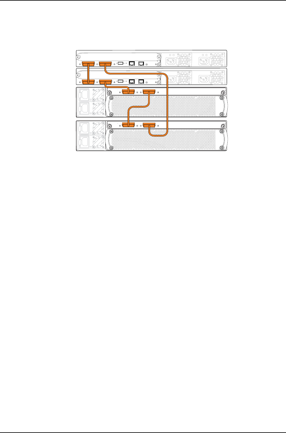
Figure 19: Mixed J-EX4200 and J-EX4500 Virtual Chassis Topology
(Nonprovisioned Configuration)
1
0
1
0
g021057
J-EX4200
J-EX4200
J-EX4500
J-EX4500
Configuration
To add two J-EX4500 switches to an existing J-EX4200 Virtual Chassis:
Step-by-Step
Procedure
1. Log in to the J-EX4200 Virtual Chassis
Set all member switches into mixed mode:2.
user@switch> request virtual-chassis mode mixed all-members
3. Reboot all member switches in the Virtual Chassis:
user@switch> request system reboot
4. Power on SWA-2, the J-EX4500 switch that you want to function in the master role.
5. Power on SWA-3, the J-EX4500 switch that you want to function in the backup
role.
6. Set the PIC mode to the Virtual Chassis mode on both SWA-0 and SWA-3:
user@switch> request chassis pic-mode virtual-chassis
7. On each of the switches SWA-2 and SWA-3, configure the switch as a member of
the mixed J-EX4200 and J-EX4500 Virtual Chassis:
user@switch> request virtual-chassis mode mixed
8. Reboot the J-EX4500 switches.
9. Cable SWA-2 into the Virtual Chassis using the dedicated VCPs on the back of the
J-EX4200 and J-EX4500 member switches.
10. Cable SWA-3 into the Virtual Chassis using the dedicated VCPs on the back of the
J-EX4200 and J-EX4500 member switches.
11. Log onto the Virtual Chassis and set the mastership priority for the J-EX4200
switches to 0and the J-EX4500 switches to 255:
[edit virtual-chassis]
user@SWA–0# set member 0 mastership-priority 0
user@SWA–0# set member 1 mastership-priority 0
752
Dell PowerConnect J-Series Ethernet Switch Complete Software Guide for Junos OS, Release 11.1: Volume 1

user@SWA–0# set member 2 mastership-priority 255
user@SWA–0# set member 3 mastership-priority 255
NOTE: A switch with a mastership priority ID of 0 never assumes the
master or backup role within a Virtual Chassis. This configuration ensures
that the J-EX4200 member switches remain in the linecard roles even
during Virtual Chassis topology changes.
Verification
To confirm that the Virtual Chassis configuration is operational, perform these tasks:
•Verifying Virtual Chassis Availability and Roles on page 753
Verifying Virtual Chassis Availability and Roles
Purpose Verify that the Virtual Chassis is up and that the member switches are in the correct roles.
Action List the member switches and roles.
user@SWA-2> show virtual-chassis status
Virtual Chassis ID: 0019.e250.47a0
Mastership Neighbor List
Member ID Status Serial No Model priority Role ID Interface
0 (FPC 0) Prsnt AK02073602764 ex4200-48t 0 Linecard 1 vcp-0
3 vcp-1
1 (FPC 1) Prsnt AK02073602814 ex4200-48t 0 Linecard 0 vcp-0
2 vcp-1
2 (FPC 2) Prsnt AK02073602844 ex4500-40f 255 Master* 1 vcp-0
3 vcp-1
3 (FPC 3) Prsnt AK02073602088 ex4500-40f 255 Backup 2 vcp-0
0 vcp-1
Member ID for next new member: 4 (FPC 4)
Meaning The show virtual-chassis status command lists the member switches interconnected
in a Virtual Chassis configuration with the member IDs that have been assigned by the
master, the mastership priority values, and the roles. It also displays the neighbor members
with which each member is interconnected. The output shows that the switches have
the correct mastership priorities and roles.
Related
Documentation
Example: Adding a J-EX4500 Switch to a Nonprovisioned Virtual Chassis on page 750•
753
Chapter 38: J-EX4200 and J-EX4500 Virtual Chassis—Configuration Examples

•Example: Connecting J-EX4500 Member Switches in a Virtual Chassis Across Wiring
Closets on page 770
•Adding a J-EX4500 Switch to a Nonprovisioned J-EX4200 Virtual Chassis (CLI
Procedure) on page 840
•Configuring a J-EX4200 or J-EX4500 Virtual Chassis (CLI Procedure) on page 822
Example: Adding J-EX4500 Switches to a Preprovisioned Virtual Chassis
A Virtual Chassis is multiple switches operating as a single network entity. You might
want to expand your existing Virtual Chassis by adding one or two J-EX4500 switches
to your Virtual Chassis configuration. Up to two J-EX4500 switches can be part of a
mixed J-EX4200 and J-EX4500 Virtual Chassis.
This example describes how to add two J-EX4500 switches to an existing J-EX4200
Virtual Chassis that was preprovisioned. A preprovisioned configuration is a Virtual Chassis
configuration in which the roles were statically assigned to each member switch:
•Requirements on page 754
•Overview and Topology on page 754
•Configuration on page 756
•Verification on page 756
Requirements
This example uses the following hardware and software components:
•Junos OS Release 11.1 or later for J-EX Series switches
•Two J-EX4200 switches interconnected into a Virtual Chassis
•Two standalone J-EX4500 switches with Virtual Chassis modules
Before you begin, be sure you have:
1. An operational J-EX4200 Virtual Chassis with two member J-EX4200 switches that
was configured using a preprovisioned configuration.
2. Installed the same version of Junos OS Release 11.1 or later on all members of the
Virtual Chassis and on the J-EX4500 switches.
3. Rack-mounted the switches. For rack-mounting instructions, see the Dell PowerConnect
J-Series J-EX4500 Ethernet Switch Hardware Guide at
http://www.support.dell.com/manuals.
Overview and Topology
You can create a J-EX4200 Virtual Chassis by cabling two operational J-EX4200 switches
together using the dedicated Virtual Chassis port (VCP) on each J-EX4200 switch. When
you preprovision a Virtual Chassis, you configure the roles for each member switch.
754
Dell PowerConnect J-Series Ethernet Switch Complete Software Guide for Junos OS, Release 11.1: Volume 1
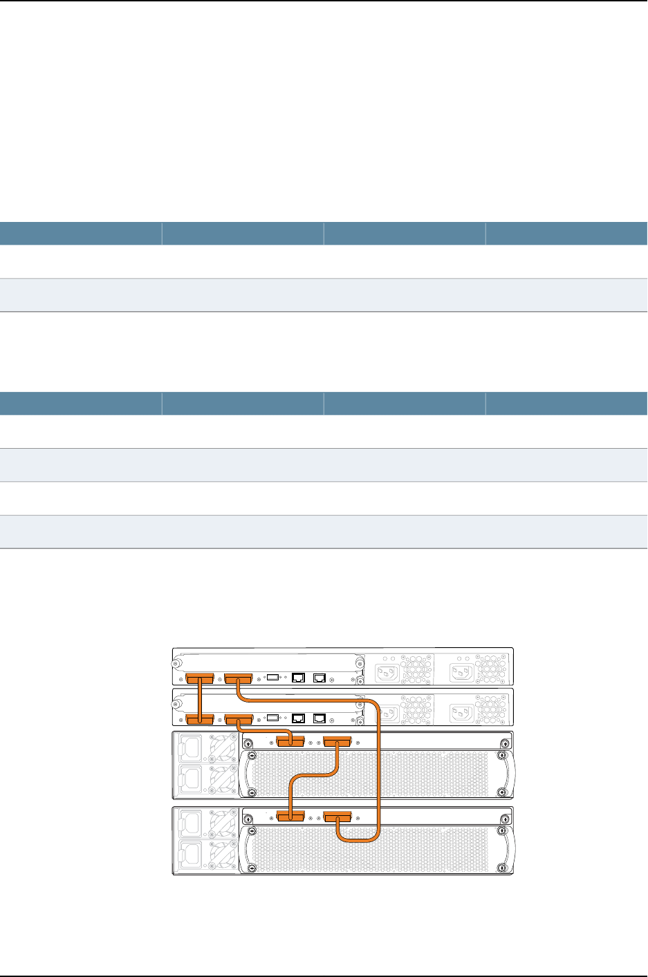
In a mixed J-EX4200 and J-EX4500 Virtual Chassis, the J-EX4500 switches must assume
and remain in the master and backup roles. The steps in this procedure ensure that the
J-EX4500 switches are set and remain in the master or backup roles.
Table 125 on page 755 shows the configuration of the two-member J-EX4200 Virtual
Chassis before the J-EX4500 member switches are added.
Table 125: Components of the J-EX4200 Virtual Chassis Before the J-EX4500 Member Switches
Are Added
Role and PriorityMember IDHardwareMember Switch
Master0J-EX4200 switchSWA-0
Backup1J-EX4200 switchSWA-1
Table 126 on page 755 shows the configuration of the mixed J-EX4200 and J-EX4500
Virtual Chassis after the J-EX4500 member switches are added to the Virtual Chassis.
Table 126: Final Mixed J-EX4200 and J-EX4500 Virtual Chassis Components
Role and PriorityMember IDHardwareMember Switch
Linecard0J-EX4200 switchSWA-0
Linecard1J-EX4200 switchSWA-1
Master2J-EX4500 switchSWA-2
Backup3J-EX4500 switchSWA-3
Figure 20 on page 755 shows the hardware topology of the mixed J-EX4200 and J-EX4500
Virtual Chassis.
Figure 20: Mixed J-EX4200 and J-EX4500 Virtual Chassis Topology
(Preprovisioned Configuration)
1
0
1
0
g021057
J-EX4200
J-EX4200
J-EX4500
J-EX4500
755
Chapter 38: J-EX4200 and J-EX4500 Virtual Chassis—Configuration Examples

Configuration
To add two J-EX4500 switches to an existing J-EX4200 Virtual Chassis that was
preprovisioned:
Step-by-Step
Procedure
1. Log into the J-EX4200 Virtual Chassis
Set all member switches into mixed mode:2.
user@switch> request virtual-chassis mode mixed all-members
3. Reboot all member switches in the Virtual Chassis:
user@switch> request system reboot
4. Power on SWA-2 and SWA-3, the J-EX4500 switches.
5. Set the PIC mode to the Virtual Chassis mode on both SWA-2 and SWA-3:
user@switch> request chassis pic-mode virtual-chassis
6. On each of the switches SWA-2 and SWA-3, configure the switch as a member of
the mixed J-EX4200 and J-EX4500 Virtual Chassis:
user@switch> request virtual-chassis mode mixed
7. Reboot the J-EX4500 switches.
8. Log onto the J-EX4200 Virtual Chassis and change the roles of the J-EX4200
member switches to line-card:
[edit virtual-chassis]
user@SWA–0# set member 0 role line-card
user@SWA–0# set member 1 role line-card
9. Add the J-EX4500 switches to the Virtual Chassis configuration:
[edit virtual-chassis]
user@SWA–0# set member 2 serial-number ghi789 role master
user@SWA–0# set member 3 serial-number jkl012 role backup
10. Cable SWA-2 and SWA-3 into the Virtual Chassis using the dedicated VCPs on the
back of the J-EX4200 and J-EX4500 member switches.
Verification
To confirm that the Virtual Chassis configuration is operational, perform these tasks:
•Verifying Virtual Chassis Availability and Roles on page 756
Verifying Virtual Chassis Availability and Roles
Purpose Verify that the Virtual Chassis is up and that the member switches are in the correct roles.
Action List the member switches and roles.
user@SWA-2> show virtual-chassis status
Virtual Chassis ID: 0019.e250.47a0
Mastership Neighbor List
756
Dell PowerConnect J-Series Ethernet Switch Complete Software Guide for Junos OS, Release 11.1: Volume 1

Member ID Status Serial No Model priority Role ID Interface
0 (FPC 0) Prsnt AK02073602764 ex4200-48t 0 Linecard 1 vcp-0
3 vcp-1
1 (FPC 1) Prsnt AK02073602814 ex4200-48t 0 Linecard 0 vcp-0
2 vcp-1
2 (FPC 2) Prsnt AK02073602844 ex4500-40f 129 Master* 1 vcp-0
3 vcp-1
3 (FPC 3) Prsnt AK02073602088 ex4500-40f 129 Backup 2 vcp-0
0 vcp-1
Meaning The show virtual-chassis status command lists the member switches interconnected
in a Virtual Chassis configuration with the member IDs that have been assigned by the
master, the mastership priority values, and the roles. It also displays the neighbor members
with which each member is interconnected. The output shows that the switches have
the correct mastership priorities and roles.
Related
Documentation
Example: Adding J-EX4500 Switches to a Preprovisioned Virtual Chassis on page 754•
•Example: Connecting J-EX4500 Member Switches in a Virtual Chassis Across Wiring
Closets on page 770
•Adding a J-EX4500 Switch to a Preprovisioned J-EX4200 Virtual Chassis (CLI
Procedure) on page 838
•Configuring a J-EX4200 or J-EX4500 Virtual Chassis (CLI Procedure) on page 822
Example: Setting Up a Multimember J-EX4200 Virtual Chassis Access Switch with a
Default Configuration
You can configure a multimember J-EX4200 Virtual Chassis access switch in a single
wiring closet without setting any parameters—by simply cabling the switches together,
using the dedicated Virtual Chassis ports (VCPs). You do not need to modify the default
configuration to enable these ports. They are operational by default. The Virtual Chassis
configuration automatically assigns the master, backup, and linecard roles, based on the
sequence in which the switches are powered on and other factors in the master election
algorithm.
TIP: We recommend that you explicitly configure the mastership priority of
the switches to ensure that the switches continue to perform the desired
roles when additional switches are added or other changes occur. However,
it is possible to use the default configuration described in this example.
757
Chapter 38: J-EX4200 and J-EX4500 Virtual Chassis—Configuration Examples

This example describes how to configure a multimember Virtual Chassis in a single wiring
closet, using the default role assignments:
•Requirements on page 758
•Overview and Topology on page 758
•Configuration on page 759
•Verification on page 760
•Troubleshooting on page 762
Requirements
This example uses the following hardware and software components:
•Junos OS Release 10.2 or later for J-EX Series switches
•Two J-EX4200-48T switches
•Four J-EX4200-24T switches
Overview and Topology
A Virtual Chassis configuration is easily expandable. This example shows a Virtual Chassis
configuration composed of six J-EX4200 switches. It provides networking access for 180
onsite workers, who are sitting within range of a single wiring closet. The six combined
switches are identified by a single host name and managed through a global management
IP address.
To set up a multimember Virtual Chassis configuration within a single wiring closet, you
need to run the EZSetup program only once. Connect to the master and run EZSetup to
specify its identification, time zone, and network properties. When additional switches
are connected through the Virtual Chassis ports (VCPs), they automatically receive the
same properties that were specified for the master.
The topology for this example (see Figure 21 on page 759) consists of six switches:
•Two J-EX4200-48T switches (SWA-0 and SWA-1) with 48 access ports, 8 of which
support Power over Ethernet (PoE)
•Four J-EX4200-24T switches (SWA-2, SWA-3, SWA-4, and SWA-5) with 24 access
ports, 8 of which support PoE
Figure 21 on page 759 shows that all the member switches are interconnected with the
dedicated VCPs on the rear panel. The LCD on the front displays the member ID and role.
758
Dell PowerConnect J-Series Ethernet Switch Complete Software Guide for Junos OS, Release 11.1: Volume 1
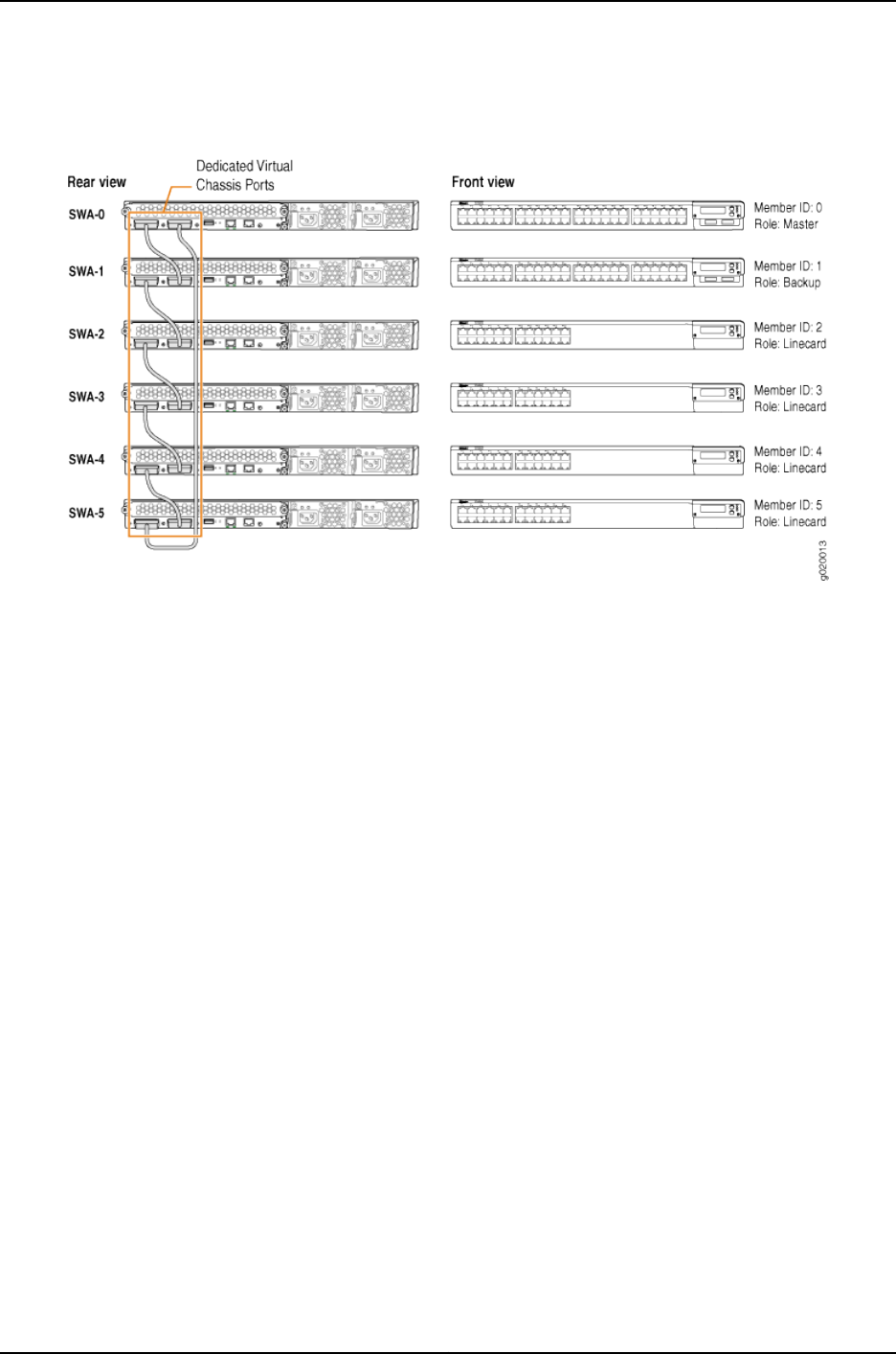
Figure 21: Default Configuration of a Multimember J-EX4200 Virtual
Chassis in a Single Wiring Closet
Configuration
To configure a multimember Virtual Chassis access switch in a single wiring closet using
the factory defaults, perform this task:
Step-by-Step
Procedure
To configure a multimember Virtual Chassis with default role assignments:
1. Make sure the dedicated VCPs on the rear panel are properly cabled. For cabling
instructions and examples, see the Dell PowerConnect J-Series J-EX4200 Ethernet
Switch Hardware Guide at http://www.support.dell.com/manuals.
2. Power on the switch that you want to function as the master (SWA-0). This
examples uses one of the larger switches (J-EX4200-48T) as the master.
3. Check the front panel LCD to confirm that the switch has powered on correctly and
that a member ID has been assigned.
4. Run the EZSetup program on SWA-0, the master, specifying the identification
parameters. See “Connecting and Configuring a J-EX Series Switch (CLI Procedure)”
on page 185 for details.
5. Configure SWA-0 with the virtual management Ethernet (VME) interface for
out-of-band management of the Virtual Chassis configuration, if desired.
[edit]
user@SWA-0# set interfaces vme unit 0 family inet address /ip-address/mask/
6. After a lapse of at least 1 minute, power on SWA-1. This example uses the second
J-EX4200-48T switch as the backup.
7. Check the front panel LCD to confirm that the switch has powered on correctly and
that a member ID has been assigned.
759
Chapter 38: J-EX4200 and J-EX4500 Virtual Chassis—Configuration Examples

8. Power on SWA-2, and check the front panels to make sure that the switch is
operating correctly.
9. Continue to power on the member switches one by one, checking the front panels
as you proceed.
Verification
To confirm that the configuration is working properly, perform these tasks:
•Verifying the Member IDs and Roles of the Member Switches on page 760
•Verifying That the VCPs Are Operational on page 760
Verifying the Member IDs and Roles of the Member Switches
Purpose Verify that all the interconnected member switches are included within the Virtual Chassis
configuration and that their roles are assigned appropriately.
Action Display the members of the Virtual Chassis configuration:
user@SWA-0> show virtual-chassis status
Virtual Chassis ID: 0000.e255.00e0
Mastership Neighbor List
Member ID Status Serial No Model Priority Role ID Interface
0 (FPC 0) Prsnt abc123 ex4200-48t 128 Master* 1 vcp-0
5 vcp-1
1 (FPC 1) Prsnt def123 ex4200-48p 128 Backup 2 vcp-0
0 vcp-1
2 (FPC 2) Prsnt abd231 ex4200-24t 128 Linecard 3 vcp-0
1 vcp-1
3 (FPC 3) Prsnt cab123 ex4200-24t 128 Linecard 4 vcp-0
2 vcp-1
4 (FPC 4) Prsnt fed456 ex4200-24t 128 Linecard 5 vcp-0
3 vcp-1
5 (FPC 5) Prsnt jkl231 ex4200-24t 128 Linecard 0 vcp-0
4 vcp-1
Meaning The show virtual-chassis status command lists the member switches of the Virtual Chassis
configuration with the member IDs and mastership priority values. It also displays the
neighbor members with which each member is interconnected. The fpc number is the
same as the member ID.
Verifying That the VCPs Are Operational
Purpose Verify that the dedicated VCPs interconnecting the member switches are operational.
Action Display the VCP interfaces.
760
Dell PowerConnect J-Series Ethernet Switch Complete Software Guide for Junos OS, Release 11.1: Volume 1

user@SWA-0> show virtual-chassis vc-port all-members
fpc0:
--------------------------------------------------------------------------
Interface Type Status
or
PIC / Port
vcp-0 Dedicated Up
vcp-1 Dedicated Up
fpc1:
--------------------------------------------------------------------------
Interface Type Status
or
PIC / Port
vcp-0 Dedicated Up
vcp-1 Dedicated Up
fpc2:
--------------------------------------------------------------------------
Interface Type Status
or
PIC / Port
vcp-0 Dedicated Up
vcp-1 Dedicated Up
fpc3:
--------------------------------------------------------------------------
Interface Type Status
or
PIC / Port
vcp-0 Dedicated Up
vcp-1 Dedicated Up
fpc4:
--------------------------------------------------------------------------
Interface Type Status
or
PIC / Port
vcp-0 Dedicated Up
vcp-1 Dedicated Up
fpc5:
Interface Type Status
or
PIC / Port
vcp-0 Dedicated Up
vcp-1 Dedicated Up
Meaning The show virtual-chassis vc-port all-members command lists the VCP interfaces that are
enabled for the member switches of the Virtual Chassis configuration and shows the
status of the interfaces. In this case, no VCP uplinks have been configured. However, the
VCP interfaces are automatically configured and enabled when you interconnect member
switches using the dedicated VCPs. The dedicated VCP interfaces are identified simply
as vcp-0 and vcp-1. They do not use the standard interface address (in which the member
ID is represented by the first digit). The output in this example shows that all interfaces
are operational. The fpc number is the same as the member ID.
761
Chapter 38: J-EX4200 and J-EX4500 Virtual Chassis—Configuration Examples

Troubleshooting
To troubleshoot the configuration of a multimember Virtual Chassis in a single wiring
closet, perform these tasks:
Troubleshooting Mastership Priority
Problem You want to explicitly designate one member as the master and another as backup.
Solution Change the mastership priority value of the member that you want to function as master,
assigning the highest mastership priority value to that member.
NOTE: These configuration changes are made through the current master,
SWA-0.
1. Configure mastership priority of member 0 to be the highest possible value.
[edit virtual-chassis]
user@SWA-0# set member 0 mastership-priority 255
2. Set the mastership priority of another member that you want to function as the backup
member as the same value:
[edit virtual-chassis]
user@SWA-0# set member 2 mastership-priority 255
Troubleshooting Nonoperational VCPs
Problem The VCP interface shows a status of down.
Solution Check the cable to make sure that it is properly and securely connected to the VCPs.
Related
Documentation
Understanding How the Master in a J-EX4200 or J-EX4500 Virtual Chassis Is Elected
on page 717
•
•Example: Configuring a J-EX4200 Virtual Chassis with a Master and Backup in a Single
Wiring Closet on page 736
•Example: Configuring a J-EX4200 Virtual Chassis Interconnected Across Multiple Wiring
Closets on page 762
•Configuring a J-EX4200 or J-EX4500 Virtual Chassis (CLI Procedure) on page 822
•Configuring a J-EX4200 Virtual Chassis (J-Web Procedure) on page 826
Example: Configuring a J-EX4200 Virtual Chassis Interconnected Across Multiple
Wiring Closets
A J-EX4200 Virtual Chassis can be composed of multiple J-EX4200 switches in different
locations. You can install member switches in different wiring closets, interconnecting
762
Dell PowerConnect J-Series Ethernet Switch Complete Software Guide for Junos OS, Release 11.1: Volume 1

the member switches by cabling and configuring uplink module ports or SFP network
ports on J-EX4200-24F switches as Virtual Chassis ports (VCPs).
This example shows how to use uplink VCPs to connect Virtual Chassis members that
are located too far apart to be connected using the dedicated VCPs. Uplink VCPs can
also be used to connect Virtual Chassis members to form link aggregation groups (LAGs).
For the latter usage, see “Example: Configuring Link Aggregation Groups Using J-EX4200
Uplink Virtual Chassis Ports” on page 809.
NOTE: You can also configure the SFP networks ports on J-EX4200-24F
switches as VCPs to connect Virtual Chassis member switches across wiring
closets and to form LAGs.
This example describes how to configure a Virtual Chassis access switch interconnected
across wiring closets:
•Requirements on page 763
•Overview and Topology on page 764
•Configuration on page 766
•Verification on page 768
•Troubleshooting on page 770
Requirements
This example uses the following hardware and software components:
•Junos OS Release 10.2 or later for J-EX Series switches
•Four J-EX4200 switches
•Four uplink modules
763
Chapter 38: J-EX4200 and J-EX4500 Virtual Chassis—Configuration Examples

Before you interconnect the members of the Virtual Chassis configuration across wiring
closets, be sure you have:
1. Installed an uplink module in each member switch. For instructions, see the Dell
PowerConnect J-Series J-EX4200 Ethernet Switch Hardware Guide at
http://www.support.dell.com/manuals.
2. Powered on and connected the switch in the master role, SWA-0, and run the EZSetup
program (see Table 128 on page 772 for switch names used in this example). See
“Connecting and Configuring a J-EX Series Switch (CLI Procedure)” on page 185 for
details.
3. Configured SWA-0 with the virtual management Ethernet (VME) interface for remote,
out-of-band management of the Virtual Chassis configuration, if desired. See
“Configuring the Virtual Management Ethernet Interface for Global Management of
a J-EX4200 or J-EX4500 Virtual Chassis (CLI Procedure)” on page 852.
4. Interconnected SWA-0 and SWA-1 using the dedicated VCPs on the rear panel. SWA-1
must not be powered on at this time.
5. Interconnected SWA-2 and SWA-3 using the dedicated VCPs on the rear panel. SWA-2
and SWA-3 must not be powered on at this time.
Overview and Topology
In this example, four J-EX4200 switches will be interconnected in a Virtual Chassis
configuration. Two of these switches (SWA-0 and SWA-1) are located in wiring closet
A, and the two other switches (SWA-2 and SWA-3) are located in wiring closet B.
For ease of monitoring and manageability, we want to interconnect all four switches as
members of a Virtual Chassis configuration. Prior to configuring the Virtual Chassis, we
installed uplink modules in each of the member switches. In this example, uplink modules
are installed in all four members so that there are redundant VCP connections across
the wiring closets. If you want to expand this configuration to include more members
within these wiring closets, you do not need to add any more uplink modules. Simply use
the dedicated VCPs on the rear panel. The redundancy of uplink VCPs provided in this
example is sufficient.
We have interconnected the switches in wiring closet A and also interconnected the ones
in wiring closet B using the dedicated VCPs. The interfaces for the dedicated VCPs are
operational by default. They do not need to be configured.
However, the Virtual Chassis cables that interconnect the dedicated VCPs of member
switches within a single wiring closet are not long enough to connect member switches
across wiring closets. Instead, we will use the fiber-optic cable connections in the uplink
modules to interconnect the member switches in wiring closet A to the member switches
in wiring closet B. You only need to interconnect one member switch in wiring closet A
to one in wiring closet B to form the Virtual Chassis configuration. However, for
redundancy, this example connects uplink module ports from the two member switches
in wiring closet A to the two member switches in wiring closet B.
We will specify the highest mastership priority value (255) for SWA-0 to make it the
master before we power on SWA-1. Because SWA-0 and SWA-1 are interconnected with
764
Dell PowerConnect J-Series Ethernet Switch Complete Software Guide for Junos OS, Release 11.1: Volume 1

the dedicated VCPs, the master detects that SWA-1 is a member of its Virtual Chassis
configuration and assigns it a member ID.
We configure SWA-2 in wiring closet B without running EZSetup by directly connecting
to the console port. If you wish, you can run EZSetup and specify identification parameters.
Later, when you interconnect SWA-2 with SWA-0, the master of the Virtual Chassis
configuration, the master overwrites any conflicting parameters.
We will use SWA-2 as the backup of the Virtual Chassis configuration. If a problem occurs
in wiring closet A, SWA-2 would take control of the Virtual Chassis configuration and
maintain the network connections. We will configure the same mastership priority value
for SWA-2 (255) that we configured for the master. Because we power on SWA-0 before
we power on SWA-2, SWA-0 has additional prioritization properties that allow it to retain
mastership of the Virtual Chassis configuration. We recommend setting identical
mastership priority values for the master and backup members for high availability and
smooth transition of mastership in case the original master becomes unavailable. (Setting
identical mastership priority values for the master and backup members prevents the
previous master from pre-empting the master role from the new master when the previous
master comes back online.)
After we have configured SWA-2 and set one of its uplink module ports as an uplink VCP,
we will interconnect its uplink VCP with an uplink VCP on SWA-0.
Finally, we will power on SWA-3. Because SWA-3 is interconnected with SWA-2 using
the dedicated VCPs on the rear panel, the master will detect that SWA-3 is part of the
expanded Virtual Chassis configuration and assign it member ID 3. For redundancy, we
will configure an uplink VCP on SWA-3 through the master and interconnect that uplink
VCP with an uplink VCP on SWA-1.
Table 127 on page 765 shows the Virtual Chassis configuration settings for a Virtual Chassis
composed of member switches in different wiring closets.
Table 127: Components of a Virtual Chassis Interconnected Across Multiple Wiring Closets
LocationRole and PriorityMember IDSwitch
Wiring closet Amaster; mastership priority
255
0SWA-0
Wiring closet Alinecard; mastership priority
128
1SWA-1
Wiring closet Bbackup; mastership priority
255
2SWA-2
Wiring closet Blinecard; mastership priority
128
3SWA-3
Figure 22 on page 766 shows the different types of interconnections used for this Virtual
Chassis configuration. The rear view shows the member switches within each wiring
closet interconnected to each other using the dedicated VCPs. The front view shows the
uplink VCPs interconnected across the wiring closets.
765
Chapter 38: J-EX4200 and J-EX4500 Virtual Chassis—Configuration Examples
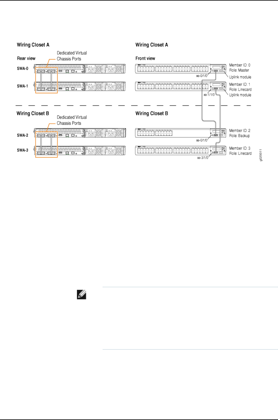
Figure 22: J-EX4200 Virtual Chassis Interconnected Across Wiring Closets
Configuration
To configure the Virtual Chassis across multiple wiring closets, perform this task:
Step-by-Step
Procedure
To configure a Virtual Chassis across multiple wiring closets:
1. Configure the mastership priority of SWA-0 (member 0) to be the highest possible
value (255), thereby ensuring that it functions as the master of the expanded Virtual
Chassis configuration:
[edit virtual-chassis]
user@SWA-0# set member 0 mastership-priority 255
2. Prepare the members in wiring closet A for interconnecting with the member
switches in wiring closet B by setting uplink VCPs for member 0 and member 1:
user@SWA-0> request virtual-chassis vc-port set pic-slot 1 port 0
user@SWA-0> request virtual-chassis vc-port set pic-slot 1 port 0 member 1
NOTE:
•For redundancy, this example configures an uplink VCP in both SWA-0
and SWA-1.
•This example omits the specification of the member member-id option
in configuring an uplink VCP for SWA-0 (and, later, for SWA-2). The
command applies by default to the switch where it is executed.
3. Prepare SWA-2 in wiring closet B for interconnecting with the Virtual Chassis
configuration by configuring its mastership priority to be the highest possible value
(255). Its member ID is currently 0, because it is not yet interconnected with the
other members of the Virtual Chassis configuration. It is operating as a standalone
switch. Its member ID will change when it is interconnected.
766
Dell PowerConnect J-Series Ethernet Switch Complete Software Guide for Junos OS, Release 11.1: Volume 1

[edit virtual-chassis]
user@SWA-2# set member 0 mastership-priority 255
NOTE: SWA-2 is configured with the same mastership priority value
that we configured for SWA-0. However, the longer uptime of SWA-0
ensures that, once the interconnection is made, SWA-0 functions as
the master and SWA-2 functions as the backup.
4. Specify one uplink module port in SWA-2 as an uplink VCP. Its member ID is 0,
because it is not yet interconnected with the other members of the Virtual Chassis
configuration.
NOTE: The setting of the uplink VCP remains intact when SWA-2 reboots
and joins the Virtual Chassis configuration as member 2.
user@SWA-2> request virtual-chassis vc-port set pic-slot 1 port 0
5. Physically interconnect SWA-0 and SWA-2 across wiring closets using their uplink
VCPs. Although SWA-0 and SWA-2 have the same mastership priority value (255),
SWA-0 was powered on first and thus has longer uptime. This results in SWA-0
retaining mastership while SWA-2 reboots and joins the now expanded Virtual
Chassis configuration as the backup, with member ID 2.
6. Power on SWA-3. It joins the expanded Virtual Chassis configuration as member 3.
NOTE: Member ID 3is assigned to SWA-3 because SWA-3 was powered
on after members 0, 1, and 2.
7. Because SWA-3 is now interconnected as a member of the Virtual Chassis
configuration, you can specify a redundant uplink VCP on SWA-3 through the master
of the Virtual Chassis configuration:
user@SWA-0> request virtual-chassis vc-port set pic-slot 1 port 0 member 3
8. Physically interconnect SWA-3 and SWA-1 across wiring closets using their uplink
VCPs. Both SWA-1 and SWA-3 have the default mastership priority value (128) and
function in a linecard role.
NOTE: We recommend that you use the commit synchronize command
to save any configuration changes that you make to a multimember
Virtual Chassis.
Results Display the results of the configuration on SWA-0:
[edit]
user@SWA-0# show virtual-chassis
767
Chapter 38: J-EX4200 and J-EX4500 Virtual Chassis—Configuration Examples

member 0 {
mastership-priority 255;
}
member 1 {
mastership-priority 128;
}
member 2 {
mastership-priority 255;
}
member 3 {
mastership-priority 128;
}
}
Verification
To confirm that the configuration is working properly, perform these tasks:
•Verifying the Member IDs and Roles of the Member Switches on page 768
•Verifying that the Dedicated VCPs and Uplink VCPs Are Operational on page 769
Verifying the Member IDs and Roles of the Member Switches
Purpose Verify that all the interconnected member switches are included within the Virtual Chassis
configuration and that their roles are assigned appropriately.
Action Display the members of the Virtual Chassis configuration:
user@SWA-0> show virtual-chassis status
Virtual Chassis ID: 0000.e255.00e0
Mastership Neighbor List
Member ID Status Serial No Model Priority Role ID Interface
0 (FPC 0) Prsnt abc123 ex4200-48t 255 Master* 1 vcp-0
2 vcp-1
2 vcp-255/1/0
1 (FPC 1) Prsnt def456 ex4200-24t 128 Linecard 0 vcp-0
0 vcp-1
3 vcp–255/1/0
2 (FPC 2) Prsnt ghi789 ex4200-48t 255 Backup 3 vcp-0
3 vcp-1
0 vcp-255/1/0
3 (FPC 3) Prsnt jkl012 ex4200-24t 128 Linecard 2 vcp-0
2 vcp-1
3 vcp–255/1/0
Meaning The show virtual-chassis status command lists the member switches interconnected as
a Virtual Chassis configuration with the member IDs that have been assigned by the
master, the mastership priority values, and the roles. It also displays the neighbor members
with which each member is interconnected.
768
Dell PowerConnect J-Series Ethernet Switch Complete Software Guide for Junos OS, Release 11.1: Volume 1

Verifying that the Dedicated VCPs and Uplink VCPs Are Operational
Purpose Verify that the dedicated VCPs interconnecting member switches in wiring closet A and
the uplink VCPs interconnecting the member switches between wiring closets are
operational.
Action Display the VCP interfaces:
user@SWA-0> show virtual-chassis status all-members
fpc0:
--------------------------------------------------------------------------
Interface Type Trunk Status Speed Neighbor
or ID (mbps) ID Interface
PIC / Port
vcp-0 Dedicated 1 Up 32000
vcp-1 Dedicated 2 Up 32000 1 vcp-0
1/0 Auto-Configured —1 Up 1000 2 vcp-255/1/0
fpc1:
--------------------------------------------------------------------------
Interface Type Trunk Status Speed Neighbor
or ID (mbps) ID Interface
PIC / Port
vcp-0 Dedicated 1 Up 32000 0 vcp-0
vcp-1 Dedicated 2 Up 32000 0 vcp-1
1/0 Auto-Configured —1 Up 1000 3 vcp-255/1/0
fpc2:
--------------------------------------------------------------------------
Interface Type Trunk Status Speed Neighbor
or ID (mbps) ID Interface
PIC / Port
vcp-0 Dedicated 1 Up 32000 3 vcp-0
vcp-1 Dedicated 2 Up 32000
1/0 Auto-Configured —1 Up 1000 0 vcp-255/1/0
fpc3:
--------------------------------------------------------------------------
Interface Type Trunk Status Speed Neighbor
or ID (mbps) ID Interface
PIC / Port
vcp-0 Dedicated 1 Up 32000 2 vcp-0
vcp-1 Dedicated 2 Up 32000 2 vcp-1
1/0 Auto-Configured —1 Up 1000 1 vcp-255/1/0
Meaning The dedicated VCPs are displayed as vcp-0 and vcp-1. The interface on the switch that
has been set as an uplink VCP is displayed as 1/0. The member interface names of uplink
VCPs are of the form vcp-255/pic/port—for example, vcp-255/1/0. In that name, vcp-255
indicates that the interface is an uplink VCP, 1is the uplink PIC number, and 0is the uplink
port number. The fpc number is the same as the member ID. The Trunk ID is a positive
number ID assigned to the LAG formed by the Virtual Chassis. If no LAG is formed, the
value is –1.
769
Chapter 38: J-EX4200 and J-EX4500 Virtual Chassis—Configuration Examples

Troubleshooting
To troubleshoot a Virtual Chassis configuration that is interconnected across wiring
closets, perform these tasks:
Troubleshooting Nonoperational VCPs
Problem An uplink VCP shows a status of down.
Solution Check the cable to make sure that it is properly and securely connected to the ports.•
•If the VCP is an uplink module port, make sure that it has been explicitly set as an uplink
VCP.
•If the VCP is an uplink module port, make sure that you have specified the options
(pic-slot,port, and member) correctly.
Related
Documentation
Example: Configuring a J-EX4200 Virtual Chassis with a Master and Backup in a Single
Wiring Closet on page 736
•
•Example: Expanding a J-EX4200 Virtual Chassis in a Single Wiring Closet on page 745
•Example: Setting Up a Multimember J-EX4200 Virtual Chassis Access Switch with a
Default Configuration on page 757
•Setting an Uplink Module Port on a J-EX4200 Switch as a Virtual Chassis Port (CLI
Procedure) on page 846
Example: Connecting J-EX4500 Member Switches in a Virtual Chassis Across Wiring
Closets
A J-EX4500 switch can be a member of a J-EX4500 Virtual Chassis or a mixed J-EX4200
and J-EX4500 Virtual Chassis. A J-EX4500 Virtual Chassis can be composed of two
J-EX4500 switches in different wiring closets or locations; a mixed J-EX4200 and
J-EX4500 Virtual Chassis can be composed of J-EX4200 and J-EX4500 switches in
different locations or wiring closets provided that at least one J-EX4200 switch is
connected to one J-EX4500 switch using the dedicated Virtual Chassis port (VCP)
connections available on both switches.
You connect J-EX4500 member switches in a Virtual Chassis together by installing them
in different wiring closets and configuring a 10-Gigabit Ethernet SFP+ connection
connecting the switches as a Virtual Chassis port (VCP).
NOTE: You can only use the procedure provided in this example to connect
J-EX4500 switches together in a J-EX4500 Virtual Chassis or a mixed
J-EX4200 and J-EX4500 Virtual Chassis. User-configured VCPs between
J-EX4200 switches and J-EX4500 switches are not supported.
770
Dell PowerConnect J-Series Ethernet Switch Complete Software Guide for Junos OS, Release 11.1: Volume 1

This example shows how to use the 10-Gigabit Ethernet SFP+ ports on J-EX4500 switches
to connect two J-EX4500 member switches that are located too far apart to be connected
using the dedicated VCPs in a mixed J-EX4200 and J-EX4500 Virtual Chassis. The
procedure to connect two J-EX4500 switches in a J-EX4500 Virtual Chassis is identical
to the procedure shown in this example.
NOTE: Any 10-Gigabit Ethernet SFP+ connection on a J-EX4500 switch can
be configured as a VCP. A J-EX4500 switch has network and uplink ports
that support 10-Gigabit Ethernet SFP+ transceivers.
This example describes how to connect two J-EX4500 member switches across wiring
closets:
•Requirements on page 771
•Overview and Topology on page 771
•Configuration on page 773
•Verification on page 775
•Troubleshooting on page 776
Requirements
This example uses the following hardware and software components:
•Junos OS Release 11.1 or later for J-EX Series switches
•Two J-EX4500 member switches
•Four J-EX4200 member switches
Before you interconnect the members of the Virtual Chassis configuration across wiring
closets, be sure you have:
1. Preprovisioned the Virtual Chassis so that the J-EX4500 switches are in the master
role, SWA-0, and backup role, SWA-3. See “Configuring a Mixed J-EX4200 and
J-EX4500 Virtual Chassis (CLI Procedure)” on page 828 for details.
2. Configured SWA-0 with the virtual management Ethernet (VME) interface for remote,
out-of-band management of the Virtual Chassis configuration, if desired. See
“Configuring the Virtual Management Ethernet Interface for Global Management of
a J-EX4200 or J-EX4500 Virtual Chassis (CLI Procedure)” on page 852.
3. Interconnected SWA-0, SWA-1, and SWA-2 using the dedicated VCPs on the rear
panel.
4. Interconnected SWA-3, SWA-4, and SWA-5 using the dedicated VCPs on the rear
panel.
Overview and Topology
In this example, two J-EX4500 switches and four J-EX4200 switches are interconnected
in a mixed J-EX4200 and J-EX4500 Virtual Chassis configuration. One J-EX4500 switch
771
Chapter 38: J-EX4200 and J-EX4500 Virtual Chassis—Configuration Examples
(SWA-0) and two J-EX4200 switches (SWA-1 and SWA-2) are located in wiring closet
A, and the other J-EX4500 switch (SWA-3) and the other two J-EX4200 switches (SWA-4
and SWA-5) are located in wiring closet B.
For ease of monitoring and manageability, we want to interconnect all six switches as
members of a Virtual Chassis configuration.
We have interconnected the switches in wiring closet A and also interconnected the ones
in wiring closet B using the dedicated VCPs. The interfaces for the dedicated VCPs are
operational by default. They do not need to be configured.
However, the Virtual Chassis cables that interconnect the dedicated VCPs of member
switches within a single wiring closet are not long enough to connect member switches
across wiring closets. Instead, we will use a 10-Gigabit Ethernet SFP+ connection to
interconnect the member switches in wiring closet A to the member switches in wiring
closet B. You only need to interconnect one member switch in wiring closet A to one in
wiring closet B to form the Virtual Chassis configuration. In this example, this connection
will be made by connecting the J-EX4500 switches in each wiring closet together by
configuring a 10-Gigabit Ethernet SFP+ connection as a VCP.
We will preprovision the entire Virtual Chassis to set the roles for all member switches.
Because we are configuring a mixed J-EX4200 and J-EX4500 Virtual Chassis, we must
set the J-EX4500 switches in the master and backup roles. We will first power on SWA-0
and preprovision the Virtual Chassis. We will then cable the Virtual Chassis before
powering on the other member switches.
Table 128 on page 772 shows the Virtual Chassis configuration settings for a Virtual Chassis
composed of member switches in different wiring closets.
Table 128: Components of a Virtual Chassis Interconnected Across Multiple Wiring Closets
LocationRole and PriorityMember ID
Model
Switch
Wiring closet AMaster0J-EX4500 switchSWA-0
Wiring closet ALinecard1J-EX4200 switchSWA-1
Wiring closet ALinecard2J-EX4200 switchSWA-2
Wiring closet BBackup3J-EX4500 switchSWA-3
Wiring closet BLinecard4J-EX4200 switchSWA-4
Wiring closet BLinecard5J-EX4200 switchSWA-5
Figure 23 on page 773 shows the different types of interconnections used for this Virtual
Chassis configuration. The rear view shows the member switches within each wiring
closet interconnected to each other using the dedicated VCPs. The front view shows the
uplink VCPs interconnected across the wiring closets.
772
Dell PowerConnect J-Series Ethernet Switch Complete Software Guide for Junos OS, Release 11.1: Volume 1
Figure 23: Mixed J-EX4200 and J-EX4500 Virtual Chassis Interconnected
Across Multiple Wiring Closets
g021058
J-EX4500 - Rear J-EX4500 - Rear
J-EX4500
Front
J-EX4500
Front
Wiring closet A Wiring closet B
J-EX4200 - Rear J-EX4200 - Rear
1
0
1
0
ST
0123 ST
0 1 2 3
Configuration
To configure the Virtual Chassis across multiple wiring closets, perform this task:
Step-by-Step
Procedure
To configure a Virtual Chassis across multiple wiring closets:
1. Power on SWA-0 (the J-EX4500 switch acting as member 0).
2. Power on SWA-3 (the J-EX4500 switch acting as member 3).
3. Set the PIC mode to the Virtual Chassis mode on both SWA-0 and SWA-3:
user@switch> request chassis pic-mode virtual-chassis
4. Power on the remaining switches.
5. Configure all switches individually as members of the mixed J-EX4200 and J-EX4500
Virtual Chassis:
user@switch> request virtual-chassis mode mixed
6. Reboot all switches:
user@switch> request system reboot
7. Log back onto SWA-0 after the reboot has completed.
8. Run EZSetup on SWA-0 to set the parameters for the entire Virtual Chassis. See
“Connecting and Configuring a J-EX Series Switch (CLI Procedure)” on page 185.
9. Preprovision the Virtual Chassis from SWA-0. Specify all members for the Virtual
Chassis configuration, listing each switch’s serial number with the desired member
773
Chapter 38: J-EX4200 and J-EX4500 Virtual Chassis—Configuration Examples

ID and the desired role. You must assign the routing-engine role to the J-EX4500
member switches and the line-card role to the J-EX4200 member switches.
[edit virtual-chassis]
user@SWA–0# set preprovisioned
user@SWA–0# set member 0 serial-number abc123 role routing-engine
user@SWA–0# set member 1 serial-number def456 role line-card
user@SWA–0# set member 2 serial-number ghi789 role line-card
user@SWA–0# set member 3 serial-number jkl012 role routing-engine
user@SWA–0# set member 4 serial-number mno345 role line-card
user@SWA–0# set member 5 serial-number pqr678 role line-card
10. Commit the configuration:
user@SWA–0> commit synchronize
11. Prepare the members in wiring closet A for interconnecting with the member
switches in wiring closet B by setting the 10-Gigabit Ethernet SFP+ interfaces on
SWA-0 as VCPs:
user@SWA-0> request virtual-chassis vc-port set pic-slot 1 port 0
user@SWA-0> request virtual-chassis vc-port set pic-slot 1 port 1
user@SWA-0> request virtual-chassis vc-port set pic-slot 1 port 2
user@SWA-0> request virtual-chassis vc-port set pic-slot 1 port 3
user@SWA-0> request virtual-chassis vc-port set pic-slot 1 port 4
user@SWA-0> request virtual-chassis vc-port set pic-slot 1 port 5
user@SWA-0> request virtual-chassis vc-port set pic-slot 1 port 6
user@SWA-0> request virtual-chassis vc-port set pic-slot 1 port 7
12. Prepare the members in wiring closet B for interconnecting with the member
switches in wiring closet A by setting the 10-Gigabit Ethernet SFP+ interfaces on
SWA-3 as VCPs:
user@SWA-3> request virtual-chassis vc-port set pic-slot 1 port 0
user@SWA-3> request virtual-chassis vc-port set pic-slot 1 port 1
user@SWA-3> request virtual-chassis vc-port set pic-slot 1 port 2
user@SWA-3> request virtual-chassis vc-port set pic-slot 1 port 3
user@SWA-3> request virtual-chassis vc-port set pic-slot 1 port 4
user@SWA-3> request virtual-chassis vc-port set pic-slot 1 port 5
user@SWA-3> request virtual-chassis vc-port set pic-slot 1 port 6
user@SWA-3> request virtual-chassis vc-port set pic-slot 1 port 7
13. Physically interconnect SWA-0 with SWA-1, then interconnect all switches in wiring
closet A.
14. Physically interconnect SWA-0 with SWA-3 across wiring closets using the
10-Gigabit Ethernet SFP+ connections.
15. Physically interconnect all switches in wiring closet B.
774
Dell PowerConnect J-Series Ethernet Switch Complete Software Guide for Junos OS, Release 11.1: Volume 1

NOTE: We recommend that you use the commit synchronize command
to save any configuration changes that you make to a multimember
Virtual Chassis.
Results Display the results of the configuration on SWA-0:
[edit virtual-chassis]
user@SWA-0# show
member 0 {
role routing-engine;
serial-number abc123;
}
member 1 {
role line-card;
serial-number def456;
}
member 2 {
role line-card;
serial-number ghi789;
}
member 3 {
role routing-engine;
serial-number jkl012;
}
member 4 {
role line-card;
serial-number mno345;
}
member 5{
role line-card;
serial-number pqr678;
}
}
Verification
To confirm that the configuration is working properly, perform these tasks:
•Verifying the Member IDs and Roles of the Member Switches on page 775
Verifying the Member IDs and Roles of the Member Switches
Purpose Verify that all the interconnected member switches are included within the Virtual Chassis
configuration and that their roles are assigned appropriately.
Action Display the members of the Virtual Chassis configuration:
user@SWA-0> show virtual-chassis status
Virtual Chassis ID: 000.e255.00e0
Virtual Chassis Mode: Mixed
Mastership Neighbor List
775
Chapter 38: J-EX4200 and J-EX4500 Virtual Chassis—Configuration Examples

Member ID Status Serial No Model Priority Role ID Interface
0 (FPC 0) Prsnt abc123 ex4500-40f 255 Master* 1 vcp-0
2 vcp-1
3 vcp-255/1/1
3 vcp-255/1/2
3 vcp-255/1/3
3 vcp-255/1/4
3 vcp-255/1/5
3 vcp-255/1/6
3 vcp-255/1/7
3 vcp-255/1/8
1 (FPC 1) Prsnt def456 ex4200-48t 128 Linecard 0 vcp-0
2 vcp-1
2 (FPC 2) Prsnt ghi789 ex4200-48t 128 Linecard 0 vcp-0
1 vcp-1
0 vcp-255/1/0
3 (FPC 3) Prsnt jkl012 ex4500-40f 255 Backup 4 vcp-0
5 vcp-1
0 vcp-255/1/1
0 vcp-255/1/2
0 vcp-255/1/3
0 vcp-255/1/4
0 vcp-255/1/5
0 vcp-255/1/6
0 vcp-255/1/7
0 vcp-255/1/8
4 (FPC 4) Prsnt mno345 ex4200-48t 128 Linecard 3 vcp-0
5 vcp-1
5 (FPC 5) Prsnt pqr678 ex4200-48t 128 Linecard 3 vcp-0
4 vcp-1
Meaning The show virtual-chassis status command lists the member switches interconnected as
a Virtual Chassis configuration with the member IDs that have been assigned by the
master and the roles. It also displays the neighbor members with which each member is
interconnected.
Troubleshooting
To troubleshoot a Virtual Chassis configuration that is interconnected across wiring
closets, perform these tasks:
Troubleshooting Nonoperational VCPs
Problem A user-configured VCP shows a status of down.
Solution Check the cable to make sure that it is properly and securely connected to the ports.•
•Make sure the VCP that it has been explicitly set as an uplink VCP.
•Make sure that you have specified the options (pic-slot,port, and member) correctly.
776
Dell PowerConnect J-Series Ethernet Switch Complete Software Guide for Junos OS, Release 11.1: Volume 1

Related
Documentation
Setting an SFP+ Port as a Virtual Chassis Port on a J-EX4500 Switch (CLI Procedure)
on page 850
•
Example: Configuring Aggregated Ethernet High-Speed Uplinks Between a J-EX4200
Virtual Chassis Access Switch and a J-EX4200 Virtual Chassis Distribution Switch
J-EX Series switches allow you to combine multiple Ethernet links into one logical interface
for higher bandwidth and redundancy. The ports that are combined in this manner are
referred to as a link aggregation group (LAG) or bundle. The number of Ethernet links
you can combine into a LAG depends on your J-EX Series switch model. See
“Understanding Aggregated Ethernet Interfaces and LACP” on page 1003 for more
information.
This example describes how to configure uplink LAGs to connect a Virtual Chassis access
switch to a Virtual Chassis distribution switch:
•Requirements on page 777
•Overview and Topology on page 777
•Configuration on page 779
•Verification on page 782
•Troubleshooting on page 782
Requirements
This example uses the following software and hardware components:
•Junos OS Release 10.2 or later for J-EX Series switches
•Two J-EX4200-48T switches
•Two J-EX4200-24F switches
•Four uplink modules
Before you configure the LAGs, be sure you have:
•Configured the Virtual Chassis switches. See “Configuring a J-EX4200 or J-EX4500
Virtual Chassis (CLI Procedure)” on page 822.
•Configured the uplink ports on the switches as trunk ports. See “Configuring Gigabit
Ethernet Interfaces (CLI Procedure)” on page 1042.
Overview and Topology
For maximum speed and resiliency, you can combine uplinks between an access switch
and a distribution switch into LAGs. Using LAGs can be particularly effective when
connecting a multimember Virtual Chassis access switch to a multimember Virtual
Chassis distribution switch.
The Virtual Chassis access switch in this example is composed of two member switches.
Each member switch has an uplink module with two 10-Gigabit Ethernet ports. These
777
Chapter 38: J-EX4200 and J-EX4500 Virtual Chassis—Configuration Examples

ports are configured as trunk ports, connecting the access switch with the distribution
switch.
Configuring the uplinks as LAGs has the following advantages:
•Link Aggregation Control Protocol (LACP) can optionally be configured for link
negotiation.
•It doubles the speed of each uplink from 10 Gbps to 20 Gbps.
•If one physical port is lost for any reason (a cable is unplugged or a switch port fails,
or one member switch is unavailable), the logical port transparently continues to
function over the remaining physical port.
The topology used in this example consists of one Virtual Chassis access switch and one
Virtual Chassis distribution switch. The access switch is composed of two J-EX4200-48T
switches (SWA-0 and SWA-1), interconnected to each other with their Virtual Chassis
ports (VCPs) as member switches of Host-A. The distribution switch is composed of two
J-EX4200-24F switches (SWD-0 and SWD-1), interconnected with their VCPs as member
switches of Host-D.
Each member of the access switch has an uplink module installed. Each uplink module
has two ports. The uplinks are configured to act as trunk ports, connecting the access
switch with the distribution switch. One uplink port from SWA-0 and one uplink port from
SWA-1 are combined as LAG ae0 to SWD-0. This link is used for one VLAN. The remaining
uplink ports from SWA-0 and from SWA-1 are combined as a second LAG connection
(ae1) to SWD-1. LAG ae1 is used for another VLAN.
NOTE: If the remote end of the LAG link is a security device, LACP might not
be supported because security devices require a deterministic configuration.
In this case, do not configure LACP. All links in the LAG are permanently
operational unless the switch detects a link failure within the Ethernet physical
layer or data link layers.
778
Dell PowerConnect J-Series Ethernet Switch Complete Software Guide for Junos OS, Release 11.1: Volume 1
Figure 24: Topology for LAGs Connecting a J-EX4200 Virtual Chassis
Access Switch to a J-EX4200 Virtual Chassis Distribution Switch
Table 151 on page 1017 details the topology used in this configuration example.
Table 129: Components of the Topology for Connecting Virtual Chassis Access Switches to a
Virtual Chassis Distribution Switch
Trunk PortMember IDUplink ModuleBase Hardware
Hostname and
VCIDSwitch
xe-0/1/0 to SWD-0
xe-0/1/1 to SWD-1
0One uplink moduleJ-EX4200-48T
switch
Host-A Access
switch
VCID 1
SWA-0
xe-1/1/0 to SWD-0
xe-1/1/1 to SWD-1
1One uplink moduleJ-EX4200-48T
switch
Host-A Access
switch
VCID 1
SWA-1
xe-0/1/0 to SWA-0
xe-0/1/1 to SWA-1
0One uplink moduleJ-EX4200 L-24F
switch
Host-D Distribution
switch
VCID 4
SWD-0
xe-1/1/0 to SWA-0
xe-1/1/1 to SWA-1
1One uplink moduleJ-EX4200 L-24F
switch
Host-D Distribution
switch
VCID 4
SWD-1
Configuration
To configure two uplink LAGs from the Virtual Chassis access switch to the Virtual Chassis
distribution switch:
779
Chapter 38: J-EX4200 and J-EX4500 Virtual Chassis—Configuration Examples

CLI Quick
Configuration
To quickly configure aggregated Ethernet high-speed uplinks between a Virtual Chassis
access switch and a Virtual Chassis distribution switch, copy the following commands
and paste them into the switch terminal window:
[edit]
set chassis aggregated-devices ethernet device-count 2
set interfaces ae0 aggregated-ether-options minimum-links 1
set interfaces ae0 aggregated-ether-options link-speed 10g
set interfaces ae1 aggregated-ether-options minimum-links 1
set interfaces ae1 aggregated-ether-options link-speed 10g
set interfaces ae0 unit 0 family inet address 192.0.2.0/25
set interfaces ae1 unit 0 family inet address 192.0.2.128/25
set interfaces xe-0/1/0 ether-options 802.ad ae0
set interfaces xe-1/1/0 ether-options 802.ad ae0
set interfaces xe-0/1/1 ether-options 802.ad ae1
set interfaces xe-1/1/1 ether-options 802.ad ae1
Step-by-Step
Procedure
To configure aggregated Ethernet high-speed uplinks between a Virtual Chassis access
switch and a Virtual Chassis distribution switch:
1. Specify the number of LAGs to be created on the chassis:
[edit chassis]
user@Host-A# set aggregated-devices ethernet device-count 2
2. Specify the number of links that need to be present for the ae0 LAG interface to be
up:
[edit interfaces]
user@Host-A# set ae0 aggregated-ether-options minimum-links 1
3. Specify the number of links that need to be present for the ae1 LAG interface to be
up:
[edit interfaces]
user@Host-A# set ae1 aggregated-ether-options minimum-links 1
4. Specify the media speed of the ae0 link:
[edit interfaces]
user@Host-A# set ae0 aggregated-ether-options link-speed 10g
5. Specify the media speed of the ae1 link:
[edit interfaces]
user@Host-A# set ae1 aggregated-ether-options link-speed 10g
6. Specify the interface ID of the uplinks to be included in LAG ae0:
[edit interfaces]
user@Host-A# set xe-0/1/0 ether-options 802.ad ae0
user@Host-A# set xe-1/1/0 ether-options 802.ad ae0
7. Specify the interface ID of the uplinks to be included in LAG ae1:
[edit interfaces]
user@Host-A# set xe-0/1/1 ether-options 802.ad ae1
user@Host-A# set xe1/1/1 ether-options 802.ad ae1
8. Specify that LAG ae0 belongs to the subnet for the employee broadcast domain:
[edit interfaces]
780
Dell PowerConnect J-Series Ethernet Switch Complete Software Guide for Junos OS, Release 11.1: Volume 1

user@Host-A# set ae0 unit 0 family inet address 192.0.2.0/25
9. Specify that LAG ae1 belongs to the subnet for the guest broadcast domain:
[edit interfaces]
user@Host-A# set ae1 unit 0 family inet address 192.0.2.128/25
Results Display the results of the configuration:
[edit]
chassis {
aggregated-devices {
ethernet {
device-count 2;
}
}
}
interfaces {
ae0 {
aggregated-ether-options {
link-speed 10g;
minimum-links 2;
}
unit 0 {
family inet {
address 192.0.2.0/25;
}
}
}
ae1 {
aggregated-ether-options {
link-speed 10g;
minimum-links 2;
}
unit 0 {
family inet {
address 192.0.2.128/25;
}
}
xe–0/1/0 {
ether-options {
802.ad ae0;
}
}
xe–1/1/0 {
ether-options {
802.ad ae0;
}
}
xe–0/1/1 {
ether-options {
802.ad ae1;
}
}
xe–1/1/1 {
ether-options {
781
Chapter 38: J-EX4200 and J-EX4500 Virtual Chassis—Configuration Examples

802.ad ae1;
}
}
}
Verification
To verify that switching is operational and two LAGs have been created, perform these
tasks:
•Verifying That LAG ae0 Has Been Created on page 782
•Verifying That LAG ae1 Has Been Created on page 782
Verifying That LAG ae0 Has Been Created
Purpose Verify that LAG ae0 has been created on the switch.
Action show interfaces ae0 terse
Interface Admin Link Proto Local Remote
ae0 up up
ae0.0 up up inet 192.0.2.0/25
Meaning The output confirms that the ae0 link is up and shows the family and IP address assigned
to this link.
Verifying That LAG ae1 Has Been Created
Purpose Verify that LAG ae1 has been created on the switch
Action show interfaces ae1 terse
Interface Admin Link Proto Local Remote
ae1 up down
ae1.0 up down inet 192.0.2.128/25
Meaning The output shows that the ae1 link is down.
Troubleshooting
Troubleshooting a LAG That Is Down
Problem The show interfaces terse command shows that the LAG is down.
Solution Check the following:
•Verify that there is no configuration mismatch.
•Verify that all member ports are up.
•Verify that a LAG is part of family ethernet switching (Layer 2 LAG) or family inet (Layer
3 LAG).
•Verify that the LAG member is connected to the correct LAG at the other end.
•Verify that the LAG members belong to the same switch (or the same Virtual Chassis).
782
Dell PowerConnect J-Series Ethernet Switch Complete Software Guide for Junos OS, Release 11.1: Volume 1

Related
Documentation
Example: Configuring a J-EX4200 Virtual Chassis with a Master and Backup in a Single
Wiring Closet on page 736
•
•Example: Configuring Aggregated Ethernet High-Speed Uplinks with LACP Between
a J-EX4200 Virtual Chassis Access Switch and a J-EX4200 Virtual Chassis Distribution
Switch on page 783
•Example: Connecting an Access Switch to a Distribution Switch.
•Virtual Chassis Cabling Configuration Examples for J-EX4200 Switches
•For information about and instructions for installing an uplink module, see the Dell
PowerConnect J-Series J-EX4200 Ethernet Switch Hardware Guide at
http://www.support.dell.com/manuals.
Example: Configuring Aggregated Ethernet High-Speed Uplinks with LACP Between
a J-EX4200 Virtual Chassis Access Switch and a J-EX4200 Virtual Chassis Distribution
Switch
J-EX Series switches allow you to combine multiple Ethernet links into one logical interface
for higher bandwidth and redundancy. The ports that are combined in this manner are
referred to as a link aggregation group (LAG) or bundle. J-EX Series switches allow you
to further enhance these links by configuring Link Aggregation Control Protocol (LACP).
This example describes how to overlay LACP on the LAG configurations that were created
in “Example: Configuring Aggregated Ethernet High-Speed Uplinks Between a J-EX4200
Virtual Chassis Access Switch and a J-EX4200 Virtual Chassis Distribution Switch” on
page 777:
•Requirements on page 783
•Overview and Topology on page 784
•Configuring LACP for the LAGs on the Virtual Chassis Access Switch on page 784
•Configuring LACP for the LAGs on the Virtual Chassis Distribution Switch on page 785
•Verification on page 786
•Troubleshooting on page 787
Requirements
This example uses the following software and hardware components:
•Junos OS Release 10.2 or later for J-EX Series switches
•Two J-EX4200-48T switches
•Two J-EX4200-24F switches
•Four J-EX Series uplink modules
Before you configure LACP, be sure you have:
783
Chapter 38: J-EX4200 and J-EX4500 Virtual Chassis—Configuration Examples

•Set up the Virtual Chassis switches. See “Configuring a J-EX4200 or J-EX4500 Virtual
Chassis (CLI Procedure)” on page 822.
•Configured the uplink ports on the switches as trunk ports. See “Configuring Gigabit
Ethernet Interfaces (CLI Procedure)” on page 1042.
•Configured the LAGs. See “Example: Configuring Aggregated Ethernet High-Speed
Uplinks Between a J-EX4200 Virtual Chassis Access Switch and a J-EX4200 Virtual
Chassis Distribution Switch” on page 777.
Overview and Topology
This example assumes that you are familiar with “Example: Configuring Aggregated
Ethernet High-Speed Uplinks Between a J-EX4200 Virtual Chassis Access Switch and a
J-EX4200 Virtual Chassis Distribution Switch” on page 777. The topology in this example
is exactly the same as the topology in that other example. This example shows how to
use LACP to enhance the LAG functionality.
LACP exchanges are made between actors (the transmitting link) and partners (the
receiving link). The LACP mode can be either active or passive.
NOTE: If the actor and partner are both in passive mode, they do not exchange
LACP packets, which results in the aggregated Ethernet links not coming up.
By default, LACP is in passive mode. To initiate transmission of LACP packets
and responses to LACP packets, you must enable LACP in active mode.
By default, the actor and partner send LACP packets every second.
The interval can be fast (every second) or slow (every 30 seconds).
Configuring LACP for the LAGs on the Virtual Chassis Access Switch
To configure LACP for the access switch LAGs, perform these tasks:
CLI Quick
Configuration
To quickly configure LACP for the access switch LAGs, copy the following commands
and paste them into the switch terminal window:
[edit]
set interfaces ae0 aggregated-ether-options lacp active periodic fast
set interfaces ae1 aggregated-ether-options lacp active periodic fast
Step-by-Step
Procedure
To configure LACP for Host-A LAGs ae0 and ae1:
1. Specify the aggregated Ethernet options for both bundles:
[edit interfaces]
user@Host-A#set ae0 aggregated-ether-options lacp active periodic fast
user@Host-A#set ae1 aggregated-ether-options lacp active periodic fast
Results Display the results of the configuration:
[edit interfaces]
user@Host-A# show
ae0 {
784
Dell PowerConnect J-Series Ethernet Switch Complete Software Guide for Junos OS, Release 11.1: Volume 1

aggregated-ether-options {
lacp {
active;
periodic fast;
}
}
}
ae1 {
aggregated-ether-options {
lacp {
active;
periodic fast;
}
}
}
Configuring LACP for the LAGs on the Virtual Chassis Distribution Switch
To configure LACP for the two uplink LAGs from the Virtual Chassis access switch to the
Virtual Chassis distribution switch, perform these tasks:
CLI Quick
Configuration
To quickly configure LACP for the distribution switch LAGs, copy the following commands
and paste them into the switch terminal window:
[edit interfaces]
set ae0 aggregated-ether-options lacp passive periodic fast
set ae1 aggregated-ether-options lacp passive periodic fast
Step-by-Step
Procedure
To configure LACP for Host D LAGs ae0 and ae1:
1. Specify the aggregated Ethernet options for both bundles:
[edit interfaces]
user@Host-D#set ae0 aggregated-ether-options lacp passive periodic fast
user@Host-D#set ae1 aggregated-ether-options lacp passive periodic fast
Results Display the results of the configuration:
[edit interfaces]
user@Host-D# show
ae0 {
aggregated-ether-options {
lacp {
passive;
periodic fast;
}
}
}
ae1 {
aggregated-ether-options {
lacp {
passive
periodic fast;
}
}
}
785
Chapter 38: J-EX4200 and J-EX4500 Virtual Chassis—Configuration Examples

Verification
To verify that LACP packets are being exchanged, perform these tasks:
•Verifying the LACP Settings on page 786
•Verifying That the LACP Packets Are Being Exchanged on page 786
Verifying the LACP Settings
Purpose Verify that LACP has been set up correctly.
Action Use the show lacp interfaces interface-name command to check that LACP has been
enabled as active on one end.
user@Host-A> show lacp interfaces xe-0/1/0
Aggregated interface: ae0
LACP state: Role Exp Def Dist Col Syn Aggr Timeout Activity
xe-0/1/0 Actor No Yes No No No Yes Fast Active
xe-0/1/0 Partner No Yes No No No Yes Fast Passive
LACP protocol: Receive State Transmit State Mux State
xe-0/1/0 Defaulted Fast periodic Detached
Meaning The output indicates that LACP has been set up correctly and is active at one end.
Verifying That the LACP Packets Are Being Exchanged
Purpose Verify that LACP packets are being exchanged.
Action Use the show interfaces aexstatistics command to display LACP information.
user@Host-A> show interfaces ae0 statistics
Physical interface: ae0, Enabled, Physical link is Down
Interface index: 153, SNMP ifIndex: 30
Link-level type: Ethernet, MTU: 1514, Speed: Unspecified, Loopback: Disabled,
Source filtering: Disabled, Flow control: Disabled, Minimum links needed: 1,
Minimum bandwidth needed: 0
Device flags : Present Running
Interface flags: Hardware-Down SNMP-Traps Internal: 0x0
Current address: 02:19:e2:50:45:e0, Hardware address: 02:19:e2:50:45:e0
Last flapped : Never
Statistics last cleared: Never
Input packets : 0
Output packets: 0
Input errors: 0, Output errors: 0
Logical interface ae0.0 (Index 71) (SNMP ifIndex 34)
Flags: Hardware-Down Device-Down SNMP-Traps Encapsulation: ENET2
Statistics Packets pps Bytes bps
Bundle:
786
Dell PowerConnect J-Series Ethernet Switch Complete Software Guide for Junos OS, Release 11.1: Volume 1

Input : 0 0 0 0
Output: 0 0 0 0
Protocol inet
Flags: None
Addresses, Flags: Dest-route-down Is-Preferred Is-Primary
Destination: 10.10.10/24, Local: 10.10.10.1, Broadcast: 10.10.10.255
Meaning The output here shows that the link is down and that no protocol data units (PDUs) are
being exchanged.
Troubleshooting
To troubleshoot a nonworking LACP link, perform these tasks:
Troubleshooting a Nonworking LACP Link
Problem The LACP link is not working.
Solution Check the following:
•Remove the LACP configuration and verify whether the static LAG is up.
•Verify that LACP is configured at both ends.
•Verify that LACP is not passive at both ends.
•Verify whether LACP protocol data units (PDUs) are being exchanged by running the
monitor traffic-interface lag-member detail command.
Related
Documentation
Example: Connecting an Access Switch to a Distribution Switch•
•Understanding Aggregated Ethernet Interfaces and LACP on page 1003
•For Virtual Chassis cabling examples and instructions for installing an uplink module,
see the Dell PowerConnect J-Series J-EX4200 Ethernet Switch Hardware Guide at
http://www.support.dell.com/manuals.
787
Chapter 38: J-EX4200 and J-EX4500 Virtual Chassis—Configuration Examples

Example: Configuring a J-EX4200 Virtual Chassis Using a Preprovisioned Configuration
File
You can deterministically control both the role and the member ID assigned to each
member switch in a J-EX4200 Virtual Chassis configuration by creating a preprovisioned
configuration file.
A preprovisioned configuration file links the serial number of each J-EX4200 switch in
the configuration to a specified member ID and role. The serial number must be specified
in the configuration file for the member to be recognized as part of the Virtual Chassis
configuration.
NOTE: When you use a preprovisioned configuration, you cannot modify the
mastership priority or member ID of member switches through the user
interfaces.
NOTE: After you have created a preprovisioned Virtual Chassis configuration,
you can use the autoprovisioning feature to add member switches to that
configuration. See “Adding a New Switch to an Existing J-EX4200 Virtual
Chassis (CLI Procedure)” on page 832.
This example describes how to configure a Virtual Chassis across multiple wiring closets
using a preprovisioned configuration file:
•Requirements on page 788
•Overview and Topology on page 789
•Configuration on page 793
•Verification on page 796
•Troubleshooting on page 799
Requirements
This example uses the following hardware and software components:
•Junos OS Release 10.2 or later for J-EX Series switches
•Five J-EX4200-48T switches
•Five J-EX4200-24T switches
•Four uplink modules
788
Dell PowerConnect J-Series Ethernet Switch Complete Software Guide for Junos OS, Release 11.1: Volume 1

Before you create the preprovisioned configuration of the Virtual Chassis and interconnect
the members across the wiring closets, be sure you have:
1. Made a list of the serial numbers of all the switches to be connected as a Virtual
Chassis configuration.
2. Noted the desired role (routing-engine or line-card) of each switch. If you configure
the member with a routing-engine role, it is eligible to function as a master or backup.
If you configure the member with a line-card role , it is not eligible to become a master
or backup.
3. Installed an uplink module in each of the member switches that will be interconnected
across wiring closets. See Installing an Uplink Module in a J-EX4200 Switch.
4. Interconnected the member switches within each wiring closet using the dedicated
VCPs on the rear panel of switches. See Connecting a Virtual Chassis Cable to a
J-EX4200 Switch.
5. Powered on the switch that you plan to use as the master switch (SWA-0).
6. Run the EZSetup program on SWA-0, specifying the identification parameters. See
“Connecting and Configuring a J-EX Series Switch (CLI Procedure)” on page 185 for
details.
SWA-0 is going to be configured in the example to function as the master of the Virtual
Chassis configuration. Thus, the properties that you specify for SWA-0 will apply to
the entire Virtual Chassis configuration, including all the member switches that you
specify in the preprovisioned configuration file.
7. Configured SWA-0 with the virtual management Ethernet (VME) interface for
out-of-band management of the Virtual Chassis configuration, if desired.
[edit]
user@SWA-0# set interfaces vme unit 0 family inet address /ip-address/mask/
Overview and Topology
You must select two members that you want to make eligible for election as master of
the Virtual Chassis configuration. When you list these two members in the preprovisioned
configuration file, you designate both members as routing-engine. One will function as
the master of the Virtual Chassis configuration and the other will function as the backup.
You designate additional members, which are not eligible for election as master, as having
the line-card role in the preprovisioned configuration file.
In this example, five J-EX4200 switches (SWA-0 through SWA-4) are interconnected
with their dedicated VCPs in wiring closet A and five J-EX4200 switches (SWA-5 through
SWA-9) are interconnected with their dedicated VCPs in wiring closet B.
SWA-0 (in wiring closet A) is going to be the master of the Virtual Chassis configuration.
This example shows how to create a preprovisioned configuration file on SWA-0 for all
member switches that will be interconnected in the Virtual Chassis configuration. The
preprovisioned configuration file includes member IDs for the members in wiring closet
A and for the members in wiring closet B.
789
Chapter 38: J-EX4200 and J-EX4500 Virtual Chassis—Configuration Examples

SWA-5 (in wiring closet B) is going to be the backup of the Virtual Chassis configuration.
Both SWA-0 and SWA-5 are specified in the preprovisioned configuration file with the
role of routing-engine. All other members are specified with the role of line-card.
If all member switches could be interconnected with their dedicated VCPs, you could
simply power on the switches after saving and committing the preprovisioned
configuration file. The master detects the connection of the members through the
dedicated VCPs and applies the parameters specified in the preprovisioned configuration
file.
However, the Virtual Chassis cables that interconnect the VCPs of member switches
within a single wiring closet are not long enough to connect member switches across
wiring closets. Instead, you can configure the uplink module ports or the SFP networks
ports on J-EX4200-24F switches as VCPs to interconnect the member switches in wiring
closet A to the member switch in wiring closet B. For redundancy, this example connects
uplink VCPs from two member switches in wiring closet A (SWA–0 and SWA–2) to two
member switches (SWA-5 and SWA-7) in wiring closet B.
NOTE: You can use interfaces on SFP and SFP+ uplink modules and the SFP
network ports on J-EX4200-24F switches as VCPs. When an uplink module
port or SFP network port is set as a VCP, it cannot be used for any other
purpose. The SFP uplink module has four 1-Gbps ports; the SFP+ uplink
module has four 1-Gbps or two 10-Gbps ports. The uplink module ports that
are not set as VCPs can be configured as trunk ports to connect to a
distribution switch.
Because this particular preprovisioned configuration is for a Virtual Chassis that is
interconnected across wiring closets, we will bring up the Virtual Chassis configuration
in stages. First, we power on SWA-0 (without powering on any other switches) and create
the preprovisioned configuration file. Then we power on the remaining switches in wiring
closet A. If we check the status of the Virtual Chassis configuration at this point by using
the show virtual-chassis status command, it will display only member 0 through member
4. The members that have not yet been interconnected will not be listed.
Next power on SWA-5 without powering on the remaining switches (SWA-6 through
SWA-9) in wiring closet B. Bring up SWA-5 as a standalone switch and set one of its
uplinks as a VCP prior to interconnecting it with the Virtual Chassis configuration in wiring
closet A. Without this setting, SWA-5 cannot be detected as a member switch by the
master of the Virtual Chassis configuration.
You can set the uplink VCP of SWA-5 without running the EZSetup program by directly
connecting to the console port. If you wish, you can run the EZSetup program and specify
identification parameters. When you interconnect SWA-5 with the master of the Virtual
Chassis configuration, the master overwrites any conflicting parameters.
After setting the VCP in SWA-5, connect this VCP with the VCP of SWA-0 in wiring closet
A. SWA-5 (serial number pqr678) is specified as a routing-engine in the preprovisioned
configuration file.
790
Dell PowerConnect J-Series Ethernet Switch Complete Software Guide for Junos OS, Release 11.1: Volume 1

This example uses SWA-5 as the backup of the Virtual Chassis configuration. If a problem
occurred in wiring closet A, SWA-5 would take control of the Virtual Chassis configuration
and maintain the network connections. Specify both SWA-0 and SWA-5 as routing-engine.
Because SWA-0 is powered on prior to SWA-5, it has additional prioritization properties
that cause it to be elected as master of the Virtual Chassis configuration.
After being physically interconnected with SWA-0, SWA-5 reboots and comes up as
member 5 and as the backup of the Virtual Chassis configuration.
Power on the remaining switches (SWA-6 through SWA-9) in wiring closet B. The master
can now detect that all members are present. Finally, for redundancy, configure an
additional VCP on SWA-7 through the master.
The topology for this example consists of:
•Three J-EX4200-48T switches (SWA-0 , SWA-2, and SWA-4) in wiring closet A.
•Two J-EX4200-48T switches (SWA-5 and SWA-9) in wiring closet B.
•Two J-EX4200-24T switches (SWA-1 and SWA-3) in wiring closet A.
•Three J-EX4200-24T switches (SWA-6, SWA-7, and SWA-8) in wiring closet B.
•Four uplink modules. Two are installed in wiring closet A and two are installed in wiring
closet B.
Table 130 on page 791 shows the Virtual Chassis configuration settings for a preprovisioned
Virtual Chassis composed of member switches in different wiring closets.
Table 130: Components of a Preprovisioned J-EX4200 Virtual Chassis Interconnected Across
Multiple Wiring Closets
LocationHardware
Uplink Module
PortsRoleMember IDSerial numberSwitch
Wiring closet AJ-EX4200-48T
and uplink
module
xe-0/1/0routing-engine0abc123SWA-0
Wiring closet AJ-EX4200-24Tlinecard1def456SWA-1
Wiring closet AJ-EX4200-48T
and uplink
module
xe-2/1/0linecard2ghi789SWA-2
Wiring closet AJ-EX4200-24Tlinecard3jkl012SWA-3
Wiring closet AJ-EX4200-48Tlinecard4mno345SWA-4
791
Chapter 38: J-EX4200 and J-EX4500 Virtual Chassis—Configuration Examples
Table 130: Components of a Preprovisioned J-EX4200 Virtual Chassis Interconnected Across
Multiple Wiring Closets (continued)
LocationHardware
Uplink Module
PortsRoleMember IDSerial numberSwitch
Wiring closet BJ-EX4200-48T
and uplink
module
xe-0/1/0
NOTE: The
member ID of
SWA-5 is 0at
the time that its
uplink module
port is
configured as a
VCP.
routing-engine5pqr678SWA-5
Wiring closet BJ-EX4200-24Tlinecard6stu901SWA-6
Wiring closet BJ-EX4200-24T
and uplink
module
xe-7/1/0linecard7vwx234SWA-7
Wiring closet BJ-EX4200-24Tlinecard8yza567SWA-8
Wiring closet BJ-EX4200-48Tlinecard9bcd890SWA-9
Figure 25 on page 793 shows the different types of interconnections used for this Virtual
Chassis configuration. The rear view shows that the member switches within each wiring
closet are interconnected to each other using the dedicated VCPs. The front view shows
that the uplink module ports that have been set as VCPs and interconnected across the
wiring closets. The uplink module ports that are not set as VCPs can be configured as
trunk ports to connect to a distribution switch.
NOTE: The interconnections shown in Figure 25 on page 793 are the same as
they would be for a configuration that was not preprovisioned across wiring
closets.
792
Dell PowerConnect J-Series Ethernet Switch Complete Software Guide for Junos OS, Release 11.1: Volume 1
Figure 25: Maximum Size J-EX4200 Virtual Chassis Interconnected Across
Wiring Closets
Configuration
To configure the Virtual Chassis across multiple wiring closets using a preprovisioned
configuration, perform this task:
NOTE: We recommend that you use the commit synchronize command to
save any configuration changes that you make to a multimember Virtual
Chassis configuration.
793
Chapter 38: J-EX4200 and J-EX4500 Virtual Chassis—Configuration Examples

Step-by-Step
Procedure
To create a preprovisioned configuration for the Virtual Chassis:
1. Specify the preprovisioned configuration mode:
[edit virtual-chassis]
user@SWA–0# set preprovisioned
2. Specify all the members that will be included in the Virtual Chassis configuration,
listing each switch's serial number with the desired member ID and the desired role:
[edit virtual-chassis]
user@SWA–0# set member 0 serial-number abc123 role routing-engine
user@SWA–0# set member 1 serial-number def456 role line-card
user@SWA–0# set member 2 serial-number ghi789 role line-card
user@SWA–0# set member 3 serial-number jkl012 role line-card
user@SWA–0# set member 4 serial-number mno345 role line-card
user@SWA–0# set member 5 serial-number pqr678 role routing-engine
user@SWA–0# set member 6 serial-number stu901 role line-card
user@SWA–0# set member 7 serial-number vwx234 role line-card
user@SWA-0# set member 8 serial-number yza567 role line-card
user@SWA–0# set member 9 serial-number bcd890 role line-card
3. Power on the member switches in wiring closet A.
4. Prepare the members in wiring closet A for interconnecting with the member
switches in wiring closet B by setting uplink VCPs for member 0 and member 2:
user@SWA-0> request virtual-chassis vc-port set pic-slot 1 port 0
user@SWA-2> request virtual-chassis vc-port set pic-slot 1 port 0 member 2
NOTE:
•For redundancy, this example sets an uplink VCP in both SWA-0 and
SWA-2.
•This example omits the specification of the member 0in setting the
uplink for SWA-0. The command applies by default to the switch
where it is executed.
5. Power on SWA-5 and connect to it. This switch comes up as member ID 0and
functions as master of itself. Although SWA-5 is listed in the preprovisioned
configuration file, it is not a present member of the Virtual Chassis configuration
that has been powered on thus far. In order for the master to detect SWA-5 as a
connected member, you must first set an uplink VCP on SWA-5 and interconnect
that VCP with the uplink VCP of SWA-0.
6. Set the first uplink of SWA-5 to function as a VCP. Because SWA-5 has been
powered on as a separate switch and is still operating independently at this point,
its member ID is 0.
user@SWA-5> request virtual-chassis vc-port set pic-slot 1 port 0
794
Dell PowerConnect J-Series Ethernet Switch Complete Software Guide for Junos OS, Release 11.1: Volume 1

NOTE: This example omits the specification of the member 0in
configuring the uplink for SWA-5 (at this point the member ID of SWA-5
is still 0). The command applies by default to the switch where it is
executed.
7. Power off SWA-5 and connect the fiber cable from SWA-5 uplink VCP xe-0/1/0 to
the uplink VCP xe-0/1/0 on SWA-0.
8. Power on SWA-5.
9. Now that SWA-5 has been brought up as member 5 of the Virtual Chassis
configuration, power on the remaining switches (SWA-6 through SWA-9) in wiring
closet B. They are interconnected with SWA-5 using the dedicated VCPs on the
rear panel and are therefore detected by the master as interconnected members.
If you check the status of the Virtual Chassis configuration at this point, all the
members that were specified in the preprovisioned configuration file should be
displayed as present. Additional configuration for member switches can now be
done through the master switch.
10. Set one uplink module port of SWA-7 to function as a VCP:
user@SWA-0> request virtual-chassis vc-port set pic-slot 1 port 0
member 7
Results Display the results of the configuration on SWA-0:
[edit]
user@SWA-0# show
virtual-chassis {
member 0 {
role routing-engine;
serial-number abc123;
}
member 1 {
role line-card;
serial-number def456;
}
member 2 {
role line-card;
serial-number ghi789;
}
member 3 {
role line-card;
serial-number jkl012;
}
member 4 {
role line-card;
serial-number mno345;
}
member 5 {
role routing-engine;
serial-number pqr678;
}
795
Chapter 38: J-EX4200 and J-EX4500 Virtual Chassis—Configuration Examples

member 6 {
role line-card;
serial-number stu901;
}
member 7 {
role line-card;
serial-number vwx234;
}
member 8 {
role line-card;
serial-number yza567;
}
member 9 {
role line-card;
serial-number bcd890;
}
preprovisioned;
}
Verification
To confirm that the configuration is working properly, perform these tasks:
•Verifying the Member IDs and Roles of the Member Switches on page 796
•Verifying That the Dedicated VCPs and Uplink VCPs Are Operational on page 797
Verifying the Member IDs and Roles of the Member Switches
Purpose Verify that the member IDs and roles are all set as expected.
Action Display the members of the Virtual Chassis configuration:
user@SWA-0> show virtual-chassis status
Preprovisioned Virtual Chassis
Virtual Chassis ID: 0000.e255.0000
Mastership Neighbor List
Member ID Status Serial No Model Priority Role ID Interface
0 (FPC 0) Prsnt abc123 ex4200-48t 129 Master* 1 vcp-0
4 vcp-1
5 1/0
1 (FPC 1) Prsnt def456 ex4200-24t 0 Linecard 2 vcp-0
0 vcp—1
2 (FPC 2) Prsnt ghi789 ex4200-48t 0 Linecard 3 vcp-0
1 vcp-1
7 1/0
3 (FPC 3) Prsnt jkl012 ex4200-24t 0 Linecard 4 vcp-0
2 vcp-1
4 (FPC 4) Prsnt mno345 ex4200-48t 0 Linecard 0 vcp-0
3 vcp-1
5 FPC 5) Prsnt pqr678 ex4200-48t 129 Backup 6 vcp-0
9 vcp-1
796
Dell PowerConnect J-Series Ethernet Switch Complete Software Guide for Junos OS, Release 11.1: Volume 1

0 1/0
6 (FPC 6) Prsnt stu901 ex4200-24t 0 Linecard 7 vcp-0
5 vcp-1
7 (FPC 7) Prsnt vwx234 ex4200-24t 0 Linecard 8 vcp-0
6 vcp-1
2 1/0
8 (FPC 8) Prsnt yza567 ex4200-24t 0 Linecard 9 vcp-0
7 vcp-1
9 (FPC 9) Prsnt bc7890 ex4200-48t 0 Linecard 5 vcp-0
8 vcp-1
Meaning The output shows that all members listed in the preprovisioned configuration file are
connected to the Virtual Chassis configuration. It confirms that SWA-0 (member 0) is
functioning as the master of the Virtual Chassis configuration. The other switch configured
with the routing-engine role (SWA-5) is functioning as the backup. The Neighbor List
displays the interconnections of the member VCPs.
Verifying That the Dedicated VCPs and Uplink VCPs Are Operational
Purpose Verify that the dedicated VCPs interconnecting the member switches within each wiring
closet and the uplink module VCPs interconnecting the member switches across wiring
closets are operational.
Action Display the VCP interfaces:
user@SWA-0> show virtual-chassis vc-port all-members
fpc0:
--------------------------------------------------------------------------
Interface Type Status Speed Neighbor
or (mbps) ID Interface
PIC / Port
vcp-0 Dedicated Up
vcp-1 Dedicated Up
1/0 Configured Up
fpc1:
--------------------------------------------------------------------------
Interface Type Status Speed Neighbor
or (mbps) ID Interface
PIC / Port
vcp-0 Dedicated Up
vcp-1 Dedicated Up
fpc2:
--------------------------------------------------------------------------
Interface Type Status Speed Neighbor
or (mbps) ID Interface
PIC / Port
vcp-0 Dedicated Up
vcp-1 Dedicated Up
1/0 Configured Up
797
Chapter 38: J-EX4200 and J-EX4500 Virtual Chassis—Configuration Examples

fpc3:
--------------------------------------------------------------------------
Interface Type Status Speed Neighbor
or (mbps) ID Interface
PIC / Port
vcp-0 Dedicated Up
vcp-1 Dedicated Up
fpc4:
--------------------------------------------------------------------------
Interface Type Status Speed Neighbor
or (mbps) ID Interface
PIC / Port
vcp-0 Dedicated Up
vcp-1 Dedicated Up
fpc5:
--------------------------------------------------------------------------
Interface Type Status Speed Neighbor
or (mbps) ID Interface
PIC / Port
vcp-0 Dedicated Up
vcp-1 Dedicated Up
1/0 Configured Up
fpc6:
--------------------------------------------------------------------------
Interface Type Status Speed Neighbor
or (mbps) ID Interface
PIC / Port
vcp-0 Dedicated Up
vcp-1 Dedicated Up
fpc7:
--------------------------------------------------------------------------
Interface Type Status Speed Neighbor
or (mbps) ID Interface
PIC / Port
vcp-0 Dedicated Up
vcp-1 Dedicated Up
1/0 Configured Up
fpc8:
--------------------------------------------------------------------------
Interface Type Status Speed Neighbor
or (mbps) ID Interface
PIC / Port
vcp-0 Dedicated Up
vcp-1 Dedicated Up
fpc9:
--------------------------------------------------------------------------
Interface Type Status Speed Neighbor
or (mbps) ID Interface
PIC / Port
vcp-0 Dedicated Up
vcp-1 Dedicated Up
798
Dell PowerConnect J-Series Ethernet Switch Complete Software Guide for Junos OS, Release 11.1: Volume 1

Meaning The dedicated VCPs interconnecting the member switches within wiring closets are
displayed as vcp-0 and vcp-1. The uplink module VCPs interconnecting member switches
(members 0, 2, 5, and 7) across wiring closets are displayed as 1/0 and 1/1 and identified
as Configured.
Troubleshooting
To troubleshoot a preprovisioned Virtual Chassis configuration that is interconnected
across wiring closets, perform these tasks:
Troubleshooting Nonoperational VCPs
Problem A VCP shows a status of down.
Solution Check the cable to make sure that it is properly and securely connected to the ports.
Related
Documentation
Example: Configuring a J-EX4200 Virtual Chassis with a Master and Backup in a Single
Wiring Closet on page 736
•
•Example: Configuring a J-EX4200 Virtual Chassis Interconnected Across Multiple Wiring
Closets on page 762
•Configuring a J-EX4200 or J-EX4500 Virtual Chassis (CLI Procedure) on page 822
•Configuring a J-EX4200 Virtual Chassis (J-Web Procedure) on page 826
Example: Configuring a Preprovisioned Mixed J-EX4200 and J-EX4500 Virtual Chassis
We recommend using a preprovisioned configuration file to configure a mixed J-EX4200
and J-EX4500 Virtual Chassis. Preprovisioning the mixed J-EX4200 and J-EX4500 Virtual
Chassis helps ensure the J-EX4500 member switches remain in the master and backup
roles and the J-EX4200 member switches remain in the linecard role.
You can deterministically control both the role and the member ID assigned to each
member switch in a mixed J-EX4200 and J-EX4500 Virtual Chassis configuration by
creating a preprovisioned configuration file.
NOTE: When you use a preprovisioned configuration, you cannot modify the
mastership priority or member ID of member switches through the user
interfaces.
This example describes how to configure a Virtual Chassis using a preprovisioned
configuration file:
•Requirements on page 800
•Overview and Topology on page 800
•Configuration on page 801
799
Chapter 38: J-EX4200 and J-EX4500 Virtual Chassis—Configuration Examples

•Verification on page 803
•Troubleshooting on page 803
Requirements
This example uses the following hardware and software components:
•Junos OS Release 11.1 or later for J-EX Series switches
•Two J-EX4500 switches, each with a Virtual Chassis module
•Two J-EX4200 switches
Before you create the preprovisioned configuration of the Virtual Chassis and interconnect
the members across the wiring closets, be sure you have:
1. Made a list of the serial numbers of all the switches to be connected as a Virtual
Chassis configuration.
2. Noted the desired role (routing-engine or line-card) of each switch. Always configure
the J-EX4500 switches in the routing-engine role. Always configure the J-EX4200
switches in the line-card role.
3. Ensured that the same version of Junos OS is running on all member switches.
Overview and Topology
A preprovisioned configuration file links the serial number of each switch in the Virtual
Chassis configuration to a specified member ID and role. The serial number must be
specified in the configuration file for the member to be recognized as part of the Virtual
Chassis configuration.
In a J-EX4500 Virtual Chassis or in a mixed J-EX4200 and J-EX4500 Virtual Chassis, you
should always configure the J-EX4500 switches in the master and backup roles.
You designate additional members, which are not eligible for election as master, as having
the line-card role in the preprovisioned configuration file. In a mixed J-EX4200 and
J-EX4500 Virtual Chassis with two J-EX4500 switches, always configure the J-EX4200
switches in the line-card role.
In this example, two J-EX4500 switches (SWA-0 and SWA-1) and two J-EX4200 switches
(SWA-2 and SWA-3) are interconnected with their dedicated VCPs.
SWA-0 is going to be the master of the Virtual Chassis configuration. This example shows
how to create a preprovisioned configuration file on SWA-0 for all member switches that
will be interconnected in the Virtual Chassis configuration. The preprovisioned
configuration file includes member IDs for all member switches.
SWA-1 is going to be the backup of the Virtual Chassis configuration. Both SWA-0 and
SWA-1 are specified in the preprovisioned configuration file with the role of routing-engine.
All other members are specified with the role of line-card.
After all member switches are interconnected with their dedicated VCPs, you can simply
power on the switches after saving and committing the preprovisioned configuration file.
800
Dell PowerConnect J-Series Ethernet Switch Complete Software Guide for Junos OS, Release 11.1: Volume 1
The master detects the connection of the members through the dedicated VCPs and
applies the parameters specified in the preprovisioned configuration file.
NOTE: You can use interfaces on SFP and SFP+ uplink modules as VCPs.
When an uplink module port or SFP network port is set as a VCP, it cannot
be used for any other purpose.
We will bring up the Virtual Chassis configuration in stages. First, we power on SWA-0
(without powering on any other switches) and create the preprovisioned configuration
file. Then we power on the remaining switches.
The topology for this example consists of:
•Two J-EX4500 switches (SWA-0 and SWA-1)
•Two J-EX4200 switches (SWA-2 and SWA-3)
Table 131 on page 801 shows the Virtual Chassis configuration settings for a preprovisioned
Virtual Chassis.
Table 131: Components of a Preprovisioned Mixed J-EX4200 and J-EX4500 Virtual Chassis
HardwareRoleMember IDSerial numberSwitch
J-EX4500 switch with
a Virtual Chassis
module
routing-engine0abc123SWA-0
J-EX4500 switch with
a Virtual Chassis
module
routing-engine1def456SWA-1
J-EX4200 switchlinecard2ghi789SWA-2
J-EX4200 switchlinecard3jkl012SWA-3
Configuration
To configure the Virtual Chassis across multiple wiring closets using a preprovisioned
configuration, perform this task:
NOTE: We recommend that you use the commit synchronize command to
save any configuration changes that you make to a multimember Virtual
Chassis configuration.
Step-by-Step
Procedure
To create a preprovisioned configuration for the Virtual Chassis:
1. Power on the J-EX4500 switch in the master role (SWA-0).
2. Set the PIC mode to Virtual Chassis mode on SWA-0:
user@switch> request chassis pic-mode virtual-chassis
801
Chapter 38: J-EX4200 and J-EX4500 Virtual Chassis—Configuration Examples

3. Set the Virtual Chassis mode to mixed:
user@switch> request virtual-chassis mode mixed
4. Reboot the switch.
5. After the switch reboots, specify the preprovisioned configuration mode:
[edit virtual-chassis]
user@SWA–0# set preprovisioned
6. Specify all members to be included in the Virtual Chassis configuration, listing each
switch's serial number with the desired member ID and the desired role:
[edit virtual-chassis]
user@SWA–0# set member 0 serial-number abc123 role routing-engine
user@SWA–0# set member 1 serial-number def456 role line-card
user@SWA–0# set member 2 serial-number ghi789 role line-card
user@SWA–0# set member 3 serial-number jkl012 role line-card
7. Power on the remaining switches.
8. Set the Virtual Chassis mode to mixed on the remaining switches:
user@switch> request virtual-chassis mode mixed
9. Reboot the switches.
10. When the reboot completes, physically cable the switches together using the
dedicated Virtual Chassis ports (VCPs).
Results Display the results of the configuration on SWA-0:
[edit]
user@SWA-0# show
virtual-chassis {
member 0 {
role routing-engine;
serial-number abc123;
}
member 1 {
role line-card;
serial-number def456;
}
member 2 {
role line-card;
serial-number ghi789;
}
member 3 {
role line-card;
serial-number jkl012;
}
preprovisioned;
}
802
Dell PowerConnect J-Series Ethernet Switch Complete Software Guide for Junos OS, Release 11.1: Volume 1

Verification
To confirm that the configuration is working properly, perform these tasks:
•Verifying the Member IDs and Roles of the Member Switches on page 803
Verifying the Member IDs and Roles of the Member Switches
Purpose Verify that the member IDs and roles are all set as expected.
Action Display the members of the Virtual Chassis configuration:
user@SWA-0> show virtual-chassis status
Preprovisioned Virtual Chassis
Virtual Chassis ID: 0000.e255.0000
Mastership Neighbor List
Member ID Status Serial No Model Priority Role ID Interface
0 (FPC 0) Prsnt abc123 ex4500-40f 129 Master* 1 vcp-1
3 vcp-0
1 (FPC 1) Prsnt def456 ex4500-40f 0 Backup 0 vcp-0
2 vcp-1
2 (FPC 2) Prsnt ghi789 ex4200-48t 0 Linecard 1 vcp-0
3 vcp-1
3 (FPC 3) Prsnt jkl012 ex4200-24t 0 Linecard 2 vcp-0
0 vcp-1
Meaning The output shows that all members listed in the preprovisioned configuration file are
connected to the Virtual Chassis configuration. It confirms that SWA-0 (member 0) is
functioning as the master of the Virtual Chassis configuration. The other switch configured
with the routing-engine role (SWA-1) is functioning as the backup. The Neighbor List
displays the interconnections of the member VCPs.
Troubleshooting
To troubleshoot a preprovisioned Virtual Chassis configuration that is interconnected
across wiring closets, perform these tasks:
Troubleshooting Nonoperational VCPs
Problem A VCP shows a status of down.
Solution Check the cable to make sure that it is properly and securely connected to the ports.
Related
Documentation
Adding a J-EX4200 Switch to a Preprovisioned J-EX4500 Virtual Chassis or a
Preprovisioned Mixed J-EX4200 and J-EX4500 Virtual Chassis (CLI Procedure) on
page 837
•
•Configuring a Mixed J-EX4200 and J-EX4500 Virtual Chassis (CLI Procedure) on
page 828
803
Chapter 38: J-EX4200 and J-EX4500 Virtual Chassis—Configuration Examples

•Configuring a J-EX4200 or J-EX4500 Virtual Chassis (CLI Procedure) on page 822
Example: Configuring Fast Failover on Uplink Module VCPs to Reroute Traffic When a
J-EX4200 Virtual Chassis Switch or Intermember Link Fails
The Virtual Chassis fast failover feature is a hardware-assisted failover mechanism that
automatically reroutes traffic and reduces traffic loss in the event of a link or switch
failure. If a link between two members fails, traffic flow between those members must
be rerouted quickly so that there is minimal traffic loss.
Fast failover is enabled by default on all dedicated J-EX4200 Virtual Chassis ports (VCPs).
Fast failover is not supported in a J-EX4500 Virtual Chassis or in a mixed J-EX4200 and
J-EX4500 Virtual Chassis.
This example describes how to configure fast failover on uplink module VCPs in a
J-EX4200 Virtual Chassis configuration:
•Requirements on page 804
•Overview and Topology on page 804
•Configuration on page 806
•Verification on page 806
Requirements
This example uses the following hardware and software components:
•Junos OS Release 10.2 or later for J-EX Series switches
•Six J-EX4200-24T switches
•Four SFP uplink modules
Before you begin configuring fast failover, be sure you have:
1. Mounted the switches.
2. Cabled the switches in a multiple-ring topology to create the Virtual Chassis
configuration.
For instructions, see the Dell PowerConnect J-Series J-EX4200 Ethernet Switch Hardware
Guide at http://www.support.dell.com/manuals.
Overview and Topology
In a Virtual Chassis configuration, fast failover automatically reroutes traffic and reduces
traffic loss in the event of a link failure or a member switch failure. By default, fast failover
is enabled on all dedicated VCPs. If you configure uplink module ports as VCPs, you must
manually configure fast failover on these ports.
For fast failover to be effective, the Virtual Chassis members must be configured in a ring
topology. The ring topology can be formed by using either dedicated VCPs or
user-configured uplink module VCPs. Fast failover is supported only in a ring topology
804
Dell PowerConnect J-Series Ethernet Switch Complete Software Guide for Junos OS, Release 11.1: Volume 1
that uses identical port types, for example, either a topology that uses all dedicated VCPs
or one that uses all uplink module VCPs. Fast failover is not supported in a ring topology
that includes both dedicated VCPs and uplink module VCPs. Fast failover is supported,
however, in a Virtual Chassis configuration that consists of multiple rings.
This example shows how to enable fast failover on uplink module VCPs.
Figure 26 on page 805 shows an example of a multiple-ring topology.
Figure 26: Traffic Redirected by Fast Failover After VCP Link Failures in
a Topology with Multiple Rings
The topology for this example consists of six switches:
805
Chapter 38: J-EX4200 and J-EX4500 Virtual Chassis—Configuration Examples

•Six J-EX4200-24T switches, four of which have an SFP uplink module installed
(switches 1, 3, 4, and 6)
Configuration
To configure the fast failover feature on uplink module VCPs:
CLI Quick
Configuration
To configure fast failover on all SFP uplink module VCPs, copy the following command
and paste it into the terminal window on switch 1:
[edit]
set virtual-chassis fast-failover ge
Step-by-Step
Procedure
To configure fast failover on SFP uplink module VCPs:
1. Enable fast failover on all SFP uplink module VCPs in the Virtual Chassis
configuration:
[edit]
user@switch1# set virtual-chassis fast-failover ge
NOTE: We recommend that you use the commit synchronize command
to save any configuration changes that you make to a multimember
Virtual Chassis.
Results Check the results of the configuration:
[edit virtual-chassis]
user@switch1# show
fast-failover {
ge;
}
Verification
To confirm that fast failover is enabled on SFP uplink module VCPs in the Virtual Chassis
configuration, perform this task:
•Verifying That Fast Failover Is Enabled on page 806
Verifying That Fast Failover Is Enabled
Purpose Verify that fast failover has been enabled in a Virtual Chassis configuration.
Action Issue the show virtual-chassis fast-failover command.
user@switch1> show virtual-chassis fast-failover
Fast failover on dedicated VCP ports: Enabled
Fast failover on XE uplink VCP ports: Disabled
Fast failover on GE uplink VCP ports: Enabled
806
Dell PowerConnect J-Series Ethernet Switch Complete Software Guide for Junos OS, Release 11.1: Volume 1

Meaning Fast failover is enabled on all dedicated VCPs and SFP uplink module VCPs in the Virtual
Chassis configuration.
Related
Documentation
Configuring Fast Failover in a J-EX4200 Virtual Chassis on page 853•
•Disabling Fast Failover in a J-EX4200 Virtual Chassis on page 854
•Configuring a J-EX4200 or J-EX4500 Virtual Chassis (CLI Procedure) on page 822
•Configuring a J-EX4200 Virtual Chassis (J-Web Procedure) on page 826
Example: Assigning the Virtual Chassis ID to Determine Precedence During a J-EX4200
Virtual Chassis Merge
There are two scenarios in which separate Virtual Chassis merge:
•A Virtual Chassis configuration that had split into two is now merging back into a single
configuration because the problem that had caused it to split has been resolved.
•You merge two Virtual Chassis that had not previously been configured together.
You can explicitly assign a Virtual Chassis ID (VCID) so that, when two J-EX4200 Virtual
Chassis configurations merge, the ID that you assigned takes precedence over the
automatically assigned VCIDs and becomes the ID of the newly merged Virtual Chassis
configuration.
NOTE: This example shows how to assign the VCID on a J-EX4200 Virtual
Chassis. This process is identical on a J-EX4500 Virtual Chassis and on a
mixed J-EX4200 and J-EX4500 Virtual Chassis.
This example describes how to assign the VCID in a J-EX4200 Virtual Chassis
configuration:
•Requirements on page 807
•Overview and Topology on page 808
•Configuration on page 808
•Verification on page 809
Requirements
This example uses the following hardware and software components:
•Junos OS Release 10.2 or later for J-EX Series switches
NOTE: For a J-EX4500 Virtual Chassis or a mixed Virtual Chassis, Junos
OS Release 11.1 or later is required.
•Two J-EX4200-48T switches
807
Chapter 38: J-EX4200 and J-EX4500 Virtual Chassis—Configuration Examples

•Two J-EX4200-24T switches
Before you begin, be sure you have:
1. Installed the switches. .
2. Cabled the switches to create the Virtual Chassis configuration.
For instructions, see the Dell PowerConnect J-Series J-EX4200 Ethernet Switch Hardware
Guide at http://www.support.dell.com/manuals.
Overview and Topology
Every Virtual Chassis configuration has a unique ID that is automatically assigned when
the Virtual Chassis configuration is formed. You can also configure a Virtual Chassis ID
using the set virtual-chassis id command. When two Virtual Chassis merge, the Virtual
Chassis ID that you assigned takes precedence over the automatically assigned Virtual
Chassis IDs and becomes the ID for the newly merged Virtual Chassis configuration.
The topology for this example consists of four switches:
•Two J-EX4200-24T switches
•Two J-EX4200-48T switches
The switches are connected as a four-member Virtual Chassis configuration and are
identified as switch-A, switch-B, switch-C, and switch-D. The master is switch-A.
Configuration
To assign the Virtual Chassis ID in a Virtual Chassis configuration:
CLI Quick
Configuration
To assign a Virtual Chassis ID so that when two Virtual Chassis configurations merge,
the ID that you assigned takes precedence over the automatically assigned Virtual Chassis
IDs and becomes the ID of the newly merged Virtual Chassis configuration, copy the
following command and paste it into the terminal window:
[edit]
set virtual-chassis id 9622.6ac8.5345
808
Dell PowerConnect J-Series Ethernet Switch Complete Software Guide for Junos OS, Release 11.1: Volume 1

Step-by-Step
Procedure
To assign the Virtual Chassis ID in a Virtual Chassis configuration:
1. Assign the Virtual Chassis ID:
[edit]
user@switch-A# set virtual-chassis id 9622.6ac8.5345
NOTE: We recommend that you use the commit synchronize command
to save any configuration changes that you make to a multimember
Virtual Chassis configuration.
Verification
To verify that the Virtual Chassis ID has been assigned as you intended, perform these
tasks:
•Verifying That the Virtual Chassis ID Is Assigned on page 809
Verifying That the Virtual Chassis ID Is Assigned
Purpose Verify that the Virtual Chassis ID has been assigned in a Virtual Chassis configuration.
Action Issue the show configuration virtual-chassis id command.1.
2. Check to see that the Virtual Chassis ID number is listed.
user@switch-A> show configuration virtual-chassis id
id 9622.6ac8.5345;
Meaning The Virtual Chassis ID has been assigned as 9622.6ac8.5345.
Related
Documentation
Assigning the Virtual Chassis ID to Determine Precedence During a J-EX4200 or
J-EX4500 Virtual Chassis Merge (CLI Procedure) on page 855
•
•Configuring a J-EX4200 or J-EX4500 Virtual Chassis (CLI Procedure) on page 822
•Configuring a J-EX4200 Virtual Chassis (J-Web Procedure) on page 826
Example: Configuring Link Aggregation Groups Using J-EX4200 Uplink Virtual Chassis
Ports
You can form link aggregation groups (LAGs) between J-EX4200 Virtual Chassis member
switches in different wiring closets using uplink Virtual Chassis ports (VCPs) and, on
J-EX4200-24F switches, network VCPs. LAGs balance traffic across the member links,
increase the uplink bandwidth, and provide increased availability. To form LAGs using
uplink or network VCPs, you configure the uplink module interfaces or network interfaces
on the member switches as VCPs and connect the VCPs using fiber-optic cables. For the
LAGs to form, the uplink or network VCPs on each member switch that will form a LAG
must operate at the same link speed and you must interconnect at least two uplink or
809
Chapter 38: J-EX4200 and J-EX4500 Virtual Chassis—Configuration Examples

network VCPs on each of those members. You can connect uplink or network VCPs
operating at different link speeds, but they will not form a LAG.
NOTE: The LAGs formed by VCPs are different from LAGs formed by Virtual
Chassis network interfaces. For more information on LAGs formed by network
interfaces, see “Understanding J-EX4200 and J-EX4500 Virtual Chassis Link
Aggregation” on page 721.
This example shows how to configure uplink module interfaces and network interfaces
as VCPs on multiple member switches of a Virtual Chassis configuration and then connect
them to form LAGs:
•Requirements on page 810
•Overview and Topology on page 811
•Configuration on page 812
•Verification on page 815
•Troubleshooting on page 818
Requirements
This example uses the following hardware and software components:
•Junos OS Release 10.2 or later for J-EX Series switches
•Five J-EX4200 switches, one of which is a J-EX4200-24F model
•Four uplink modules
810
Dell PowerConnect J-Series Ethernet Switch Complete Software Guide for Junos OS, Release 11.1: Volume 1

Before you configure the uplink module interfaces and network interfaces on Virtual
Chassis member switches as VCPs and interconnect the members to form a LAG, be
sure you have:
1. Installed the uplink modules in the SWA-0, SWA-1, SWA-2, and SWA-3 switches. For
instructions, see the Dell PowerConnect J-Series J-EX4200 Ethernet Switch Hardware
Guide at http://www.support.dell.com/manuals.
2. Powered on SWA-0, connected it to the network, and run the EZSetup program. See
“Connecting and Configuring a J-EX Series Switch (CLI Procedure)” on page 185 for
details.
3. Configured SWA-0 with the virtual management Ethernet (VME) interface for remote,
out-of-band management of the Virtual Chassis configuration, if desired. See
“Configuring the Virtual Management Ethernet Interface for Global Management of
a J-EX4200 or J-EX4500 Virtual Chassis (CLI Procedure)” on page 852.
4. Ensured that SWA-1 is not powered on and then interconnected SWA-0 and SWA-1
using the dedicated VCPs on the rear panel.
NOTE: The interfaces for the dedicated VCPs are operational by default.
They do not need to be configured.
5. Ensured that SWA-2, SWA-3, and SWA-4 are not powered on. They are not connected
in any way, so when they are initially powered on they will be standalone switches.
Overview and Topology
In this example, five J-EX4200 switches will be interconnected to form LAGs for ease of
monitoring and manageability. Two of these switches (SWA-0 and SWA-1) are located
in wiring closet A and the three others (SWA-2, SWA-3, and SWA-4) are located in wiring
closet B. SWA-0 will form one LAG with SWA-2 and another LAG with SWA-4, and SWA-1
will form a LAG with SWA-3.
We will use fiber-optic cables connected to the uplink and network VCPs to interconnect
the member switches in wiring closet A to the member switches in wiring closet B.
We will specify the highest mastership priority value (255) for SWA-0 to make it the
master before we power on SWA-1. Because SWA-0 and SWA-1 are interconnected with
the dedicated VCPs, the master detects that SWA-1 is a member of its Virtual Chassis
configuration and assigns it a member ID.
We will use SWA-2 as the backup of the Virtual Chassis configuration. We will configure
the same mastership priority value for SWA-2 (255) that we configured for the master.
Because we power on SWA-0 before we power on SWA-2, SWA-0 retains mastership
of the Virtual Chassis configuration.
NOTE: We recommend setting identical mastership priority values for the
master and backup members for high availability and smooth transition of
mastership in case the original master becomes unavailable.
811
Chapter 38: J-EX4200 and J-EX4500 Virtual Chassis—Configuration Examples
We will configure the uplink module interfaces on three of the switches as uplink VCPs.
On the J-EX4200-24F switch we will configure two of the network interfaces as VCPs.
We will interconnect two of the uplink VCPs on SWA-0 with two of the uplink VCPs on
SWA-2. Similarly, we will interconnect the two uplink VCPs on SWA-1 with the two uplink
VCPs on SWA-3. Finally, we will connect the two remaining uplink VCPs on SWA-0 with
two network VCPs on SWA-4. As a result, three LAGs will be automatically formed.
Figure 27 on page 812 shows the interconnections used to form LAGs using uplink VCPs
and the network VCPs after the procedure below has been completed.
Figure 27: J-EX4200 Virtual Chassis Interconnected Across Wiring Closets
to Form LAGs
Configuration
To configure the Virtual Chassis uplink module interfaces and network interfaces as
uplink VCPs and interconnect them between two wiring closets to form LAGs, perform
this task:
812
Dell PowerConnect J-Series Ethernet Switch Complete Software Guide for Junos OS, Release 11.1: Volume 1

Step-by-Step
Procedure
To configure a Virtual Chassis across multiple wiring closets and interconnect them to
form LAGs:
1. Configure the mastership priority of SWA-0 (member 0) to be the highest possible
value (255), thereby ensuring that it functions as the master of the expanded Virtual
Chassis configuration:
[edit virtual-chassis]
user@SWA-0# set member 0 mastership-priority 255
2. Power on SWA-1.
3. Prepare the members in wiring closet A for interconnecting with the member
switches in wiring closet B by setting all of the SFP uplink module interfaces on
SWA-0 and two of the uplink module interfaces on SWA-1 as uplink VCPs:
user@SWA-0> request virtual-chassis vc-port set pic-slot 1 port 0
user@SWA-0> request virtual-chassis vc-port set pic-slot 1 port 1
user@SWA-0> request virtual-chassis vc-port set pic-slot 1 port 2
user@SWA-0> request virtual-chassis vc-port set pic-slot 1 port 3
user@SWA-0> request virtual-chassis vc-port set pic-slot 1 port 0 member 1
user@SWA-0> request virtual-chassis vc-port set pic-slot 1 port 1 member 1
NOTE: This example omits the specification of the member member-id
option in configuring the uplink VCPs for SWA-0 (and, later, for SWA-2).
The command applies by default to the switch where it is executed.
4. Power on SWA-2.
5. If SWA-2 was previously configured, revert it to the factory default configuration.
See “Reverting to the Default Factory Configuration for the J-EX Series Switch” on
page 353.
6. Prepare SWA-2 in wiring closet B by configuring its mastership priority to be the
highest possible value (255). Its member ID is currently 0, because it is not yet
interconnected with the other members of the Virtual Chassis configuration. It is
operating as a standalone switch. Its member ID will change when it is
interconnected.
[edit virtual-chassis]
user@SWA-2# set member 0 mastership-priority 255
NOTE: SWA-2 is configured with the same mastership priority value
that we configured for SWA-0. However, the longer uptime of SWA-0
ensures that, once the interconnection is made, SWA-0 functions as
the master and SWA-2 functions as the backup.
7. Specify two of the SFP uplink module interfaces in SWA-2 as uplink VCPs. The
member IDs are 0, because they are not yet interconnected with the other members
of the Virtual Chassis configuration:
813
Chapter 38: J-EX4200 and J-EX4500 Virtual Chassis—Configuration Examples

NOTE: The settings of the uplink VCPs remain intact when SWA-2
reboots and joins the Virtual Chassis configuration as member 2.
user@SWA-2> request virtual-chassis vc-port set pic-slot 1 port 0
user@SWA-2> request virtual-chassis vc-port set pic-slot 1 port 1
8. Power off SWA-2.
9. Physically interconnect SWA-0 and SWA-2 across wiring closets using two of the
uplink VCPs on each switch.
10. Power on SWA-2. SWA-2 joins the Virtual Chassis configuration and a LAG is
automatically formed between SWA-0 and SWA-2. In addition, although SWA-0
and SWA-2 have the same mastership priority value (255), SWA-0 was powered
on first and thus has longer uptime. This results in SWA-0 retaining mastership
while SWA-2 reboots and joins the now expanded Virtual Chassis configuration as
the backup, with member ID 2.
11. Power on SWA-3.
12. If SWA-3 was previously configured, revert it to the factory default configuration.
13. Specify both SFP+ uplink module interfaces in SWA-3 as uplink VCPs:
user@SWA-3> request virtual-chassis vc-port set pic-slot 1 port 0
user@SWA-3> request virtual-chassis vc-port set pic-slot 1 port 1
14. Power off SWA-3.
15. Physically interconnect SWA-3 with SWA-2 using their dedicated VCPs.
16. Physically interconnect SWA-1 and SWA-3 across wiring closets using their uplink
VCPs.
17. Power on SWA-3. It joins the Virtual Chassis configuration as member 3.
NOTE: Member ID 3is assigned to SWA-3 because SWA-3 was powered
on after members 0, 1, and 2.
A LAG is automatically formed between SWA-1 and SWA-3. In addition, both SWA-1
and SWA-3 have the default mastership priority value (128) and function in a linecard
role.
18. Power on SWA-4.
19. If SWA-4 was previously configured, revert it to the factory default configuration.
20. Configure two of the network interfaces on SWA-4 as uplink VCPs:
user@SWA-4> request virtual-chassis vc-port set pic-slot 0 port 20
user@SWA-4> request virtual-chassis vc-port set pic-slot 0 port 21
21. Power off SWA-4.
814
Dell PowerConnect J-Series Ethernet Switch Complete Software Guide for Junos OS, Release 11.1: Volume 1

22. Physically interconnect SWA-4 and SWA-0 across wiring closets using the network
VCPs on SWA-4 and the two remaining SFP uplink VCPs on SWA-0.
23. Power on SWA-4. A LAG is automatically formed between SWA-4 and SWA-0. In
addition, SWA-4 joins the Virtual Chassis configuration in the linecard role.
Results Display the results of the configuration on SWA-0:
user@SWA-0> show configuration virtual-chassis
member 0 {
mastership-priority 255;
}
member 1 {
mastership-priority 128;
}
member 2 {
mastership-priority 255;
}
member 3 {
mastership-priority 128;
}
member 4 {
mastership-priority 128;
}
}
Verification
To confirm that the configuration is working properly, perform these tasks:
•Verifying the Member IDs and Roles of the Member Switches on page 815
•Verifying That the VCPs Are Operational on page 816
Verifying the Member IDs and Roles of the Member Switches
Purpose Verify that all the interconnected member switches are included within the Virtual Chassis
configuration and that their roles are assigned appropriately.
Action Display the members of the Virtual Chassis configuration:
user@SWA-0> show virtual-chassis status
Virtual Chassis ID: 0000.e255.00e0
Mastership Neighbor List
Member ID Status Serial No Model Priority Role ID Interface
0 (FPC 0) Prsnt abc123 ex4200-48t 255 Master* 1 vcp-0
1 vcp-1
2 vcp-255/1/0
2 vcp-255/1/1
4 vcp-255/0/20
4 vcp-255/0/21
1 (FPC 1) Prsnt def456 ex4200-24t 128 Linecard 0 vcp-0
0 vcp-1
815
Chapter 38: J-EX4200 and J-EX4500 Virtual Chassis—Configuration Examples

3 vcp–255/1/0
3 vcp–255/1/1
2 (FPC 2) Prsnt ghi789 ex4200-48t 255 Backup 3 vcp-0
3 vcp-1
0 vcp-255/1/0
0 vcp-255/1/1
3 (FPC 3) Prsnt jkl012 ex4200-24t 128 Linecard 2 vcp-0
2 vcp-1
1 vcp–255/1/0
1 vcp–255/1/1
4 (FPC 4) Prsnt mno345 ex4200-24f 128 Linecard 0 vcp-255/1/2
0 vcp-255/1/3
Meaning The show virtual-chassis status command lists the member switches interconnected in
a Virtual Chassis configuration with the member IDs that have been assigned by the
master, the mastership priority values, and the roles. It also displays the neighbor members
with which each member is interconnected by the dedicated VCPs, by uplink VCPs, and
by network VCPs.
Verifying That the VCPs Are Operational
Purpose Verify that the dedicated VCPs interconnecting member switches in wiring closets A and
B and the uplink and network VCPs interconnecting the member switches between wiring
closets are operational.
Action Display the Virtual Chassis interfaces:
user@SWA-0> show virtual-chassis vc-port all-members
fpc0:
--------------------------------------------------------------------------
Interface Type Trunk Status Speed Neighbor
or ID (mbps) ID Interface
PIC / Port
vcp-0 Dedicated 1 Up 32000 1 vcp-0
vcp-1 Dedicated 2 Up 32000 1 vcp-1
1/0 Configured 3 Up 1000 2 vcp-255/1/0
1/1 Configured 3 Up 1000 2 vcp-255/1/1
1/2 Configured 4 Up 1000 4 vcp-255/0/20
1/3 Configured 4 Up 1000 4 vcp-255/0/21
fpc1:
--------------------------------------------------------------------------
Interface Type Trunk Status Speed Neighbor
or ID (mbps) ID Interface
PIC / Port
vcp-0 Dedicated 1 Up 32000 0 vcp-0
vcp-1 Dedicated 2 Up 32000 0 vcp-1
1/0 Configured 3 Up 10000 3 vcp-255/1/0
1/1 Configured 3 Up 10000 3 vcp-255/1/1
fpc2:
--------------------------------------------------------------------------
816
Dell PowerConnect J-Series Ethernet Switch Complete Software Guide for Junos OS, Release 11.1: Volume 1

Interface Type Trunk Status Speed Neighbor
or ID (mbps) ID Interface
PIC / Port
vcp-0 Dedicated 1 Up 32000 3 vcp-0
vcp-1 Dedicated 2 Up 32000 3 vcp-1
1/0 Configured 3 Up 1000 0 vcp-255/1/0
1/1 Configured 3 Up 1000 0 vcp-255/1/1
1/2 —1 Down 1000
1/3 —1 Down 1000
fpc3:
--------------------------------------------------------------------------
Interface Type Trunk Status Speed Neighbor
or ID (mbps) ID Interface
PIC / Port
vcp-0 Dedicated 1 Up 32000 2 vcp-0
vcp-1 Dedicated 2 Up 32000 2 vcp-1
1/0 Configured 3 Up 10000 1 vcp-255/1/0
1/1 Configured 3 Up 10000 1 vcp-255/1/1
fpc4:
--------------------------------------------------------------------------
Interface Type Trunk Status Speed Neighbor
or ID (mbps) ID Interface
PIC / Port
vcp-0 Dedicated 1 Down 32000
vcp-1 Dedicated 2 Down 32000
0/20 Configured 3 Up 1000 0 vcp-255/1/2
0/21 Configured 3 Up 1000 0 vcp-255/1/3
Meaning The dedicated VCPs are displayed as vcp-0 and vcp-1. The uplink module interfaces that
have been set as uplink VCPs are displayed as 1/0,1/1,1/2, and 1/3. The network interfaces
that have been set as VCPs are displayed as 0/20 and 0/21. The neighbor interface names
of uplink and network VCPs are of the form vcp-255/pic/port—for example, vcp-255/1/0.
In that name, vcp-255 indicates that the interface is a VCP, 1is the uplink PIC number,
and 0is the port number. The fpc number is the same as the member ID. The trunk ID is
a positive number ID assigned to the LAG formed by the Virtual Chassis. If no LAG is
formed, the value is –1.
NOTE: Each switch assigns the trunk IDs to its local interfaces. As a result,
the pair of interfaces that form one end of a LAG on one switch will have the
same trunk ID, and the pair of interfaces that form the other end of the LAG
will have the same trunk ID, but the trunk IDs on either end of the LAG might
be different. For example, in Figure 27 on page 812, the uplink VCPs 1/2 and
1/3 on SWA-0 form a LAG with the network VCPs 0/20 and 0/21 on SWA-4.
Uplink VCPs 1/2 and 1/3 on SWA-0 both have trunk ID 4, while network VCPs
0/20 and 0/21 on SWA-4 both have trunk ID 3. The trunk IDs are different
between the switches because SWA-0 assigns the trunk IDs for its local
uplink VCPs and SWA-4 assigns the trunk IDs for its local VCPs.
817
Chapter 38: J-EX4200 and J-EX4500 Virtual Chassis—Configuration Examples

Troubleshooting
To troubleshoot a Virtual Chassis configuration that is interconnected across wiring
closets, perform this task:
Troubleshooting Nonoperational VCPs
Problem An uplink VCP shows a status of down.
Solution Check the cable to make sure that it is properly and securely connected to the interfaces.•
•If the VCP is an uplink module interface, make sure that it has been explicitly set as an
uplink VCP.
•If the VCP is an uplink module interface, make sure that you have specified the options
(pic-slot,port, and member) correctly.
Related
Documentation
Example: Configuring a J-EX4200 Virtual Chassis with a Master and Backup in a Single
Wiring Closet on page 736
•
•Example: Expanding a J-EX4200 Virtual Chassis in a Single Wiring Closet on page 745
•Example: Setting Up a Multimember J-EX4200 Virtual Chassis Access Switch with a
Default Configuration on page 757
•Setting an Uplink Module Port on a J-EX4200 Switch as a Virtual Chassis Port (CLI
Procedure) on page 846
Example: Configuring Automatic Software Update on J-EX4200 Virtual Chassis Member
Switches
The automatic software update feature automatically updates the Junos OS version on
prospective member switches as they are added to a Virtual Chassis configuration of
J-EX4200 switches so the new member switch immediately joins the J-EX4200 Virtual
Chassis configuration and is put in the active state. If the software version on the new
switch is not the same as the version running on the master, the master keeps the new
switch in the inactive state. If you have not enabled the automatic software update
feature, you will have to manually install the correct software version on each prospective
member switch as it is added to the Virtual Chassis configuration.
This example describes how to configure the Virtual Chassis automatic software update
feature:
•Requirements on page 819
•Overview and Topology on page 819
•Configuration on page 819
•Verification on page 820
818
Dell PowerConnect J-Series Ethernet Switch Complete Software Guide for Junos OS, Release 11.1: Volume 1

Requirements
This example uses the following hardware and software components:
•Three J-EX4200 switches
•Junos OS Release 10.2 or later for J-EX Series switches
Before you begin, be sure you have:
1. Ensured that two member switches are running the same version of Junos OS for J-EX
Series switches so that they can form the initial Virtual Chassis configuration.
2. Cabled and powered on those two switches to create the Virtual Chassis configuration.
For instructions, see the Dell PowerConnect J-Series J-EX4200 Ethernet Switch Hardware
Guide at http://www.support.dell.com/manuals.
3. Ensured that you know the name or the URL of the software package to be used by
the automatic software update feature.
Overview and Topology
For a standalone J-EX4200 switch to join an existing Virtual Chassis configuration, it
must be running the same version of Junos OS that is running on the Virtual Chassis
master. If the software version on the new switch is not the same as the version running
on the master, the master keeps the new switch in the inactive state.
The topology for this example consists of three J-EX Series switches. Two of the switches
are connected in a Virtual Chassis configuration and are therefore running the same
version of Junos OS for J-EX Series switches. The third switch is a standalone switch that
is running a different software version than the Virtual Chassis member switches. In this
example, we will enable the automatic software update feature on the Virtual Chassis
configuration and then add the third switch to the configuration. The master will detect
the presence of the new switch, check the software version running on the new switch,
and, because it is not the same version currently running on the master, will update the
software version on the new switch and reboot the switch so that it can join the Virtual
Chassis configuration and immediately be put in the active state.
Configuration
To configure automatic software update, perform this task:
Step-by-Step
Procedure
To configure automatic software update:
Enable automatic software update and configure the path to the software package:1.
[edit]
user@switch# set virtual-chassis auto-sw-update package-name
/var/tmp/jinstall-ex-4200-10.2R1.1-domestic-signed.tgz
2. Connect the new switch to the existing Virtual Chassis configuration, and power on
the switch.
819
Chapter 38: J-EX4200 and J-EX4500 Virtual Chassis—Configuration Examples

Results Check the results of the configuration:
[edit virtual-chassis]
user@switch# show
auto-sw-update {
package-name /var/tmp/jinstall-ex4200-10.2R1.1-domestic-signed.tgz;
}
Verification
To verify that the software version on the new switch has been updated and that the
switch has joined the Virtual Chassis configuration, perform this task:
•Verifying That the Software Version Is Updated on page 820
Verifying That the Software Version Is Updated
Purpose Verify that the new switch has joined the Virtual Chassis configuration.
NOTE: If the software version on the new switch had not been updated
successfully, the master would not allow the switch to join the Virtual Chassis
configuration.
Action Issue the show virtual-chassis status command.
user@switch> show virtual-chassis status
Virtual Chassis ID: 0019.e250.47a0
Mastership Neighbor List
Member ID Status Serial No Model priority Role ID Interface
0 (FPC 0) Prsnt AK0207360276 ex4200-24t 255 Master* 1 vcp-1
2 vcp-0
1 (FPC 1) Prsnt AK0207360281 ex4200-24t 255 Backup 2 vcp-1
0 vcp-0
2 (FPC 2) Prsnt AJ0207391130 ex4200-48t 128 Linecard 0 vcp-1
1 vcp-0
Meaning Because in the initial two-member Virtual Chassis configuration member 0 was the
master and member 1 was the backup, the output shows that the new switch has been
assigned member ID 2and has been given the Linecard role. The Status field shows that
member 2 is Prsnt, which means that it is in the active state.
Related
Documentation
•Configuring Automatic Software Update on J-EX4200 or J-EX4500 Virtual Chassis
Member Switches (CLI Procedure) on page 855
•Adding a New Switch to an Existing J-EX4200 Virtual Chassis (CLI Procedure) on
page 832
820
Dell PowerConnect J-Series Ethernet Switch Complete Software Guide for Junos OS, Release 11.1: Volume 1

CHAPTER 39
Configuring J-EX4200 and J-EX4500
Virtual Chassis
•Configuring a J-EX4200 or J-EX4500 Virtual Chassis (CLI Procedure) on page 822
•Configuring a J-EX4200 Virtual Chassis (J-Web Procedure) on page 826
•Configuring a Mixed J-EX4200 and J-EX4500 Virtual Chassis (CLI Procedure) on page 828
•Installing Software on a Mixed J-EX4200 and J-EX4500 Virtual Chassis (CLI
Procedure) on page 831
•Adding a New Switch to an Existing J-EX4200 Virtual Chassis (CLI
Procedure) on page 832
•Adding a J-EX4200 Switch to a Preprovisioned J-EX4500 Virtual Chassis or a
Preprovisioned Mixed J-EX4200 and J-EX4500 Virtual Chassis (CLI
Procedure) on page 837
•Adding a J-EX4500 Switch to a Preprovisioned J-EX4200 Virtual Chassis (CLI
Procedure) on page 838
•Adding a J-EX4500 Switch to a Nonprovisioned J-EX4200 Virtual Chassis (CLI
Procedure) on page 840
•Replacing a Member Switch of a J-EX4200 or J-EX4500 Virtual Chassis Configuration
(CLI Procedure) on page 841
•Removing a J-EX4200 or J-EX4500 Switch From a Mixed J-EX4200 and J-EX4500
Virtual Chassis (CLI Procedure) on page 843
•Configuring Mastership of the J-EX4200 or J-EX4500 Virtual Chassis (CLI
Procedure) on page 844
•Setting an Uplink Module Port on a J-EX4200 Switch as a Virtual Chassis Port (CLI
Procedure) on page 846
•Setting an SFP+ Port as a Virtual Chassis Port on a J-EX4500 Switch (CLI
Procedure) on page 850
•Setting a J-EX4200 Uplink Module Port as a Virtual Chassis Port Using the LCD
Panel on page 850
•Configuring the Virtual Management Ethernet Interface for Global Management of a
J-EX4200 or J-EX4500 Virtual Chassis (CLI Procedure) on page 852
•Configuring the Timer for the Backup Member to Start Using Its Own MAC Address, as
Master of the J-EX4200 or J-EX4500 Virtual Chassis (CLI Procedure) on page 852
821

•Configuring Fast Failover in a J-EX4200 Virtual Chassis on page 853
•Disabling Fast Failover in a J-EX4200 Virtual Chassis on page 854
•Disabling Split and Merge in a J-EX4200 or J-EX4500 Virtual Chassis (CLI
Procedure) on page 854
•Assigning the Virtual Chassis ID to Determine Precedence During a J-EX4200 or
J-EX4500 Virtual Chassis Merge (CLI Procedure) on page 855
•Configuring Automatic Software Update on J-EX4200 or J-EX4500 Virtual Chassis
Member Switches (CLI Procedure) on page 855
•Configuring Graceful Routing Engine Switchover in a J-EX4200 or J-EX4500 Virtual
Chassis (CLI Procedure) on page 856
Configuring a J-EX4200 or J-EX4500 Virtual Chassis (CLI Procedure)
This topic only applies to a J-EX4200 Virtual Chassis or a J-EX4500 Virtual Chassis. For
information on configuring a mixed J-EX4200 and J-EX4500 Virtual Chassis, see
“Configuring a Mixed J-EX4200 and J-EX4500 Virtual Chassis (CLI Procedure)” on page 828.
You can interconnect J-EX4200 switches or J-EX4500 switches using the dedicated
Virtual Chassis ports (VCPs) on the switch. You do not have to configure the interfaces
for the dedicated VCPs. If you want to interconnect J-EX4200 member switches that
are located in different racks or wiring closets, interconnect them using uplinks configured
as VCPs. See “Setting an Uplink Module Port on a J-EX4200 Switch as a Virtual Chassis
Port (CLI Procedure)” on page 846.
If you want to interconnect J-EX4500 switches that are located in different racks or wiring
closets, interconnect them using 10-Gigabit Ethernet SFP+ ports configured as VCPs.
See “Setting an SFP+ Port as a Virtual Chassis Port on a J-EX4500 Switch (CLI
Procedure)” on page 850.
NOTE: A multimember Virtual Chassis configuration has two Routing Engines,
one in the master and the other in the backup. Therefore, we recommend
that you always use commit synchronize rather than simply commit to save
configuration changes made for a Virtual Chassis. This ensures that the
configuration changes are saved in both Routing Engines.
A J-EX4200 or J-EX4500 Virtual Chassis can be configured with either:
•A preprovisioned configuration—Allows you to deterministically control the member
ID and role assigned to a member switch by tying it to its serial number.
822
Dell PowerConnect J-Series Ethernet Switch Complete Software Guide for Junos OS, Release 11.1: Volume 1

•A nonprovisioned configuration—The master sequentially assigns a member ID to other
member switches. The role is determined by the mastership priority value and other
factors in the master election algorithm.
This topic includes:
•Configuring a J-EX4200 or J-EX4500 Virtual Chassis with a Preprovisioned
Configuration File on page 823
•Configuring a J-EX4200 or J-EX4500 Virtual Chassis with a Nonprovisioned
Configuration File on page 824
Configuring a J-EX4200 or J-EX4500 Virtual Chassis with a Preprovisioned Configuration File
Preprovisioning a Virtual Chassis configuration allows you to assign the member ID and
role for each switch in the Virtual Chassis. Preprovisioning is supported for a J-EX4200
Virtual Chassis and a J-EX4500 Virtual Chassis.
To configure a Virtual Chassis using a preprovisioned configuration:
1. Make a list of the serial numbers of all the switches to be connected in a Virtual Chassis
configuration.
2. Note the desired role (routing-engine or line-card) of each switch. If you configure the
member with a routing-engine role, it is eligible to function as a master or backup. If
you configure the member with a line-card role, it is not eligible to become a master
or backup.
3. Interconnect the member switches using the dedicated VCPs on the rear panel of
switches. For instructions, see the Dell PowerConnect J-Series J-EX4200 Ethernet
Switch Hardware Guide or the Dell PowerConnect J-Series J-EX4500 Ethernet Switch
Hardware Guide at http://www.support.dell.com/manuals.
NOTE: For management purposes, we recommend arranging the switches
in member ID sequence, either from top to bottom or from bottom to top
(0–9).
4. Power on only the switch that you plan to use as the master switch. Do not power on
the other switches at this time.
5. Run the EZSetup program on the master switch, specifying the identification
parameters. See “Connecting and Configuring a J-EX Series Switch (CLI Procedure)”
on page 185 for details.
NOTE: The properties that you specify for the master switch apply to the
entire Virtual Chassis configuration, including all the members listed in
the preprovisioned configuration file.
6. Configure the master switch with the virtual management Ethernet (VME) interface
for out-of-band management of the Virtual Chassis configuration, if desired.
823
Chapter 39: Configuring J-EX4200 and J-EX4500 Virtual Chassis

[edit]
user@switch# set interfaces vme unit 0 family inet address /ip-address/mask/
7. Specify the preprovisioned configuration mode:
[edit virtual-chassis]
user@switch# set preprovisioned
8. Specify all the members that you want to included in the Virtual Chassis configuration,
listing each switch’s serial number with the desired member ID and the desired role:
[edit virtual-chassis]
user@switch# set member 0 serial-number abc123 role routing-engine
user@switch# set member 1 serial-number def456 role line-card
user@switch# set member 2 serial-number ghi789 role line-card
user@switch# set member 3 serial-number jkl012 role line-card
user@switch# set member 4 serial-number mno345 role line-card
user@switch# set member 5 serial-number pqr678 role routing-engine
user@switch# set member 6 serial-number stu901 role line-card
user@switch# set member 7 serial-number vwx234 role line-card
user@switch# set member 8 serial-number yza567 role line-card
user@switch# set member 9 serial-number bcd890 role line-card
9. Power on the member switches.
10. (J-EX4500 switches only) Verify the PIC mode setting:
user@switch> show chassis pic-mode
If the PIC mode setting is not set to virtual-chassis, set the PIC mode to virtual-chassis:
user@switch> request chassis pic-mode virtual-chassis
NOTE: You cannot modify the mastership priority when you are using a
preprovisioned configuration. The mastership priority values are generated
automatically and controlled by the role that is assigned to the member
switch in the configuration file. The two Routing Engines are assigned the
same mastership priority value. However, the member that was powered on
first has higher prioritization according to the master election algorithm. See
“Understanding How the Master in a J-EX4200 or J-EX4500 Virtual Chassis
Is Elected” on page 717.
Configuring a J-EX4200 or J-EX4500 Virtual Chassis with a Nonprovisioned Configuration File
Nonprovisioned configuration can be used to configure a J-EX4200 Virtual Chassis or a
J-EX4500 Virtual Chassis.
824
Dell PowerConnect J-Series Ethernet Switch Complete Software Guide for Junos OS, Release 11.1: Volume 1

To configure the Virtual Chassis using a nonprovisioned configuration:
1. Interconnect the member switches using the dedicated VCPs on the switches. For
instructions, see the Dell PowerConnect J-Series J-EX4200 Ethernet Switch Hardware
Guide or the Dell PowerConnect J-Series J-EX4500 Ethernet Switch Hardware Guide
at http://www.support.dell.com/manuals.
NOTE: For management purposes, we recommend arranging the switches
in member ID sequence, either from top to bottom or from bottom to top
(0–9).
2. Power on only the switch that you plan to use as the master switch (SWA-0). Do not
power on the other switches at this time.
3. Run the EZSetup program on SWA-0, specifying the identification parameters. See
“Connecting and Configuring a J-EX Series Switch (CLI Procedure)” on page 185 for
details.
NOTE: The properties that you specify for SWA-0 apply to the entire
Virtual Chassis configuration, including all the members interconnected
through VCPs..
4. Configure SWA-0 with the virtual management Ethernet (VME) interface for
out-of-band management of the Virtual Chassis configuration, if desired.
[edit]
user@SWA-0# set interfaces vme unit 0 family inet address /ip-address/mask/
5. Configure mastership priority for the master, backup, and other members, if desired:
NOTE: If you are configuring a mixed J-EX4200 and J-EX4500 Virtual
Chassis, you must configuring the J-EX4500 switches with the highest
priority. The highest values ensure the J-EX4500 switches are configured
in the master and backup roles.
[edit virtual-chassis]
user@SWA–0# set member 0 mastership-priority 255
user@SWA–0# set member 5 mastership-priority 255
6. Power on the member switches in sequential order, one by one.
7. (J-EX4500 switches only) Enter the show chassis pic-mode operational mode
command to verify the current PIC mode setting. If the PIC mode is currently set to
intraconnect, enter the request chassis pic-mode virtual-chassis operational mode
command to set the PIC mode to virtual-chassis. Reboot the switch to complete the
procedure.
825
Chapter 39: Configuring J-EX4200 and J-EX4500 Virtual Chassis

NOTE: If you do not edit the Virtual Chassis configuration file, a
nonprovisioned configuration is generated by default. The mastership priority
value for each member switch is 128. The master role is selected by default.
You can change the role that is performed by the members by modifying the
mastership priority. See “Configuring Mastership of the J-EX4200 or J-EX4500
Virtual Chassis (CLI Procedure)” on page 844. We recommend that you specify
the same mastership priority value for the desired master and backup
members. In this example, the highest possible mastership priority has been
assigned to two members. However, the member that was powered on first
has higher prioritization according to the master election algorithm. See
“Understanding How the Master in a J-EX4200 or J-EX4500 Virtual Chassis
Is Elected” on page 717. The other members use the default mastership priority
in this example, which qualifies them to function in the role of linecard.
NOTE: If you want to change the member ID that the master has assigned
to a member switch, use the request virtual-chassis renumber command.
Related
Documentation
Example: Configuring a Preprovisioned Mixed J-EX4200 and J-EX4500 Virtual Chassis
on page 799
•
•Configuring Mastership of the J-EX4200 or J-EX4500 Virtual Chassis (CLI Procedure)
on page 844
•Monitoring J-EX4200 and J-EX4500 Virtual Chassis Status and Statistics on page 863
Configuring a J-EX4200 Virtual Chassis (J-Web Procedure)
To take advantage of the scalability features of J-EX4200 switches, you can configure
a Virtual Chassis that includes up to ten member switches. You can interconnect the
member switches using the dedicated Virtual Chassis ports (VCPs) on the back of the
switches. You do not have to configure the interface for the dedicated VCPs. If you want
to interconnect member switches that are located in different racks or wiring closets,
interconnect them using uplinks configured as VCP interfaces. See “Setting an Uplink
Module Port on a J-EX4200 Switch as a Virtual Chassis Port (CLI Procedure)” on page 846.
NOTE: The J-Web interface is currently not supported for a J-EX4500 Virtual
Chassis or a mixed J-EX4200 and J-EX4500 Virtual Chassis.
To configure a J-EX4200 Virtual Chassis using the J-Web interface:
826
Dell PowerConnect J-Series Ethernet Switch Complete Software Guide for Junos OS, Release 11.1: Volume 1
1. Select Configure >Virtual Chassis.
NOTE: After you make changes to the configuration in this page, you must
commit the changes for them to take effect. To commit all changes to
the active configuration, select Commit Options >Commit. See “Using
the Commit Options to Commit Configuration Changes (J-Web
Procedure)” on page 346 for details about all commit options.
2. The properties you can configure are displayed.
The first section of the Virtual Chassis Configuration page displays the Virtual Chassis
member configuration. The display includes a list of member switches, their member
IDs, and the mastership priority.
The second section displays the operational status of the Virtual Chassis configuration,
member details, and the dedicated and configured Virtual Chassis ports (VCPs).
3. Enter information into the page as described in Table 132 on page 827.
4. Click one:
•Add—To add a member's configuration to the Virtual Chassis configuration, click
Add.
•Edit—To modify an existing member's configuration, click Edit.
•Delete—To delete the configuration of a member, click Delete.
5. To configure an uplink as a VCP, select the member in the Virtual Chassis members
list and select Action >Select Uplink Port as VCP. Select the port from the list.
6. To delete an uplink VCP from a member, select the member in the Virtual Chassis
members list and select Action >Delete Uplink Port as VCP.
Table 132: Virtual Chassis Configuration Fields
Your ActionFunctionField
Member Details
Select an identifier from the list. Select an ID
from 0through 9.
Specifies the identifier for the member switch. The
master switch assigns member IDs.
Member ID
Select a number from 1through 255, with 255
being the highest priority (128 is the default).
Specifies the mastership priority to be assigned to the
member.
Priority
Click to disable the management VLAN on
the port.
If you want to reserve an individual member's
management Ethernet port, you can remove that port
from being part of the virtual management ethernet
(VME) interface.
Disable
Management VLAN
Click to refresh the operational status.Refreshes the operational status of Virtual Chassis
members.
Refresh
827
Chapter 39: Configuring J-EX4200 and J-EX4500 Virtual Chassis

Related
Documentation
Configuring a J-EX4200 or J-EX4500 Virtual Chassis (CLI Procedure) on page 822•
•Example: Configuring a J-EX4200 Virtual Chassis with a Master and Backup in a Single
Wiring Closet on page 736
•Example: Configuring a J-EX4200 Virtual Chassis Interconnected Across Multiple Wiring
Closets on page 762
•Monitoring J-EX4200 and J-EX4500 Virtual Chassis Status and Statistics on page 863
•Virtual Chassis Cabling Configuration Examples for J-EX4200 Switches
•J-EX4200 and J-EX4500 Virtual Chassis Overview on page 709
Configuring a Mixed J-EX4200 and J-EX4500 Virtual Chassis (CLI Procedure)
This topic explains how to configure a mixed J-EX4200 and J-EX4500 Virtual Chassis
when none of the switches are part of a Virtual Chassis only. It does not explain how to
configure a J-EX4200 Virtual Chassis or a J-EX4500 Virtual Chassis or how to add a
switch to an existing Virtual Chassis. For information on configuring a J-EX4200 Virtual
Chassis or a J-EX4500 Virtual Chassis, see “Configuring a J-EX4200 or J-EX4500 Virtual
Chassis (CLI Procedure)” on page 822.
You can configure a mixed J-EX4200 and J-EX4500 Virtual Chassis that includes up to
two J-EX4500 switches and up to eight J-EX4200 member switches. You can interconnect
the member switches using the dedicated Virtual Chassis ports (VCPs) on the back of
the switch.
For information on adding a switch to an existing Virtual Chassis, see:
•Adding a New Switch to an Existing J-EX4200 Virtual Chassis (CLI Procedure) on
page 832
•Adding a J-EX4200 Switch to a Preprovisioned J-EX4500 Virtual Chassis or a
Preprovisioned Mixed J-EX4200 and J-EX4500 Virtual Chassis (CLI Procedure) on
page 837
•Adding a J-EX4500 Switch to a Preprovisioned EX4200 Virtual Chassis (CLI Procedure)
on page 838
•Adding a J-EX4500 Switch to a Nonprovisioned J-EX4200 Virtual Chassis (CLI
Procedure) on page 840
You do not have to configure the interfaces for the dedicated VCPs. If you want to
interconnect member switches that are located in different racks or wiring closets,
interconnect them using network ports or uplinks configured as VCP interfaces. See:
•Setting an Uplink Module Port on a J-EX4200 Switch as a Virtual Chassis Port (CLI
Procedure) on page 846
•Setting an SFP+ Port as a Virtual Chassis Port on a J-EX4500 Switch (CLI Procedure)
on page 850
828
Dell PowerConnect J-Series Ethernet Switch Complete Software Guide for Junos OS, Release 11.1: Volume 1

We recommend using a preprovisioned configuration when configuring a mixed J-EX4200
and J-EX4500 Virtual Chassis when none of the member switches are currently members
of a Virtual Chassis. A preprovisioned configuration allows you to deterministically control
the member ID and role assigned to a member switch by tying it to its serial number. This
procedure only shows how to configure a preprovisioned mixed J-EX4200 and EX4500
Virtual Chassis for this reason.
Nonprovisioned configuration is supported for a mixed J-EX4200 and J-EX4500 Virtual
Chassis configuration. In a nonprovisioned configuration, the master sequentially assigns
a member ID to other member switches, and the other member switches' roles are
determined by the mastership priority value and other factors in the master election
algorithm. We recommend nonprovisioned configuration of a mixed J-EX4200 and
J-EX4500 Virtual Chassis is only if you are adding a J-EX4200 or J-EX4500 switch to an
existing nonprovisioned Virtual Chassis. See “Adding a J-EX4500 Switch to a
Nonprovisioned J-EX4200 Virtual Chassis (CLI Procedure)” on page 840.
To configure a mixed J-EX4200 and J-EX4500 Virtual Chassis:
1. Make a list of the serial numbers of all the switches to be connected in the Virtual
Chassis.
2. Power and log onto the J-EX4500 switches only. If a switch has not previously been
configured, see “Connecting and Configuring an EX Series Switch (CLI Procedure)”
on page 185.
3. Verify the PIC mode setting:
user@switch> show chassis pic-mode
4. If the PIC mode was not set to Virtual Chassis mode, set the PIC mode to Virtual
Chassis mode:
user@switch> request chassis pic-mode virtual-chassis
5. Set the Virtual Chassis mode to mixed:
user@switch> request virtual-chassis mode mixed
6. Reboot the J-EX4500 switches:
user@switch> request system reboot
7. Power and log onto the J-EX4200 switches. If a switch has not previously been
configured, see “Connecting and Configuring an EX Series Switch (CLI Procedure)”
on page 185.
8. Set the Virtual Chassis mode on the J-EX4200 switches to mixed:
user@switch> request virtual-chassis mode mixed
9. Reboot the J-EX4200 switches:
user@switch> request system reboot
10. After you have rebooted the switches, log into the J-EX4500 switch that you powered
on first. This switch is the master switch.
829
Chapter 39: Configuring J-EX4200 and J-EX4500 Virtual Chassis

11. Run the EZSetup program on the master switch, specifying the identification
parameters. See “Connecting and Configuring an EX Series Switch (CLI Procedure)”
on page 185 for details.
NOTE: The properties that you specify for the master switch apply to the
entire mixed J-EX4200 and J-EX4500 Virtual Chassis.
12. On the master switch, configure the virtual management Ethernet (VME) interface
for out-of-band management of the Virtual Chassis, if desired.
[edit]
user@switch# set interfaces vme unit 0 family inet address /ip-address/mask/
13. On the master switch, specify the preprovisioned configuration mode:
[edit virtual-chassis]
user@switch# set preprovisioned
14. On the master switch, specify all members for the Virtual Chassis configuration, listing
each switch’s serial number with the desired member ID and the desired role. Assign
the routing-engine role to the J-EX4500 member switches and the line-card role to
the J-EX4200 member switches.
[edit virtual-chassis]
user@switch# set member 0 serial-number abc123 role routing-engine
user@switch# set member 1 serial-number def456 role routing-engine
user@switch# set member 2 serial-number ghi789 role line-card
user@switch# set member 3 serial-number jkl012 role line-card
user@switch# set member 4 serial-number mno345 role line-card
user@switch# set member 5 serial-number pqr678 role line-card
user@switch# set member 6 serial-number stu901 role line-card
user@switch# set member 7 serial-number vwx234 role line-card
user@switch# set member 8 serial-umber yza567 role line-card
user@switch# set member 9 serial-number bcd890 role line-card
15. Interconnect the member switches by using either the dedicated VCPs on the member
switches (see Connecting a Virtual Chassis Cable to a J-EX4200 Switch) or by
connecting them through the uplink ports (J-EX4200 member switches) or SFP+
ports (J-EX4500 member switches) that you have configured as VCPs (see “Setting
an Uplink Module Port on a J-EX4200 Switch as a Virtual Chassis Port (CLI Procedure)”
on page 846 or “Setting an SFP+ Port as a Virtual Chassis Port on a J-EX4500 Switch
(CLI Procedure)” on page 850).
NOTE: You cannot modify the mastership priority when you are using a
preprovisioned configuration. The mastership priority values are generated
automatically and controlled by the role that is assigned to the member
switch in the configuration file.
Related
Documentation
Configuring Mastership of the J-EX4200 or J-EX4500 Virtual Chassis (CLI Procedure)
on page 844
•
•Monitoring J-EX4200 and J-EX4500 Virtual Chassis Status and Statistics on page 863
830
Dell PowerConnect J-Series Ethernet Switch Complete Software Guide for Junos OS, Release 11.1: Volume 1

Installing Software on a Mixed J-EX4200 and J-EX4500 Virtual Chassis (CLI Procedure)
You can use this procedure to upgrade or downgrade Junos OS for all member switches
in an operational mixed J-EX4200 and J-EX4500 Virtual Chassis.
To upgrade Junos OS for an operational mixed J-EX4200 and J-EX4500 Virtual Chassis:
1. Download the same version of Junos OS Release 11.1 or later software for a J-EX4200
switch and a J-EX4500 switch. See “Downloading Software Packages from Juniper
Networks” on page 79.
2. (Optional) Back up the current software configuration to a second storage option.
See the Junos OS Installation and Upgrade Guide for instructions on performing this
task.
3. (Optional) Copy both software packages to the member switch acting in the master
role. We recommend that you use FTP to copy the file to the /var/tmp directory.
This step is optional because Junos OS can also be upgraded when the software
image is stored at a remote location. These instructions describe the software upgrade
process for both scenarios.
4. Install both new packages on the Virtual Chassis:
user@switch> request system software add set [package package]
NOTE: You enter the request system software add set [package package]
command once on the Virtual Chassis to download the software package
onto all member switches in the mixed J-EX4200 and J-EX4500 Virtual
Chassis.
Replace package with one of the following paths:
•For a software package in a local directory on the switch—/var/tmp/package.tgz.
•For a software package on a remote server:
•ftp://hostname/pathname/package.tgz
•http://hostname/pathname/package.tgz
where package.tgz is, for example, jinstall-ex-4200-11.1R2.8-domestic-signed.tgz.
NOTE: To abort the installation, do not reboot your Virtual Chassis; instead,
finish the installation and then issue the request system software delete
package.tgz command, where package.tgz is, for example,
jinstall-ex-4500-11.1R2.8-domestic-signed.tgz. This is your last chance to
stop the installation.
5. Reboot the Virtual Chassis to start the new software:
user@switch> request system reboot
831
Chapter 39: Configuring J-EX4200 and J-EX4500 Virtual Chassis

6. After the reboot has completed, log in and verify that the new version of the software
is properly installed for all member switches in the Virtual Chassis:
user@switch> show version
Related
Documentation
Understanding J-EX4200 and J-EX4500 Virtual Chassis Components on page 712•
Adding a New Switch to an Existing J-EX4200 Virtual Chassis (CLI Procedure)
This topic explains how to add switches to an existing J-EX4200 Virtual Chassis. For
information on adding a switch to another type of Virtual Chassis, see “Adding a J-EX4200
Switch to a Preprovisioned J-EX4500 Virtual Chassis or a Preprovisioned Mixed J-EX4200
and J-EX4500 Virtual Chassis (CLI Procedure)” on page 837, “Adding a J-EX4500 Switch
to a Preprovisioned J-EX4200 Virtual Chassis (CLI Procedure)” on page 838, or “Adding a
J-EX4500 Switch to a Nonprovisioned J-EX4200 Virtual Chassis (CLI Procedure)” on
page 840.
To add a J-EX4200 or J-EX4500 switch to an existing Virtual Chassis configuration, use
the procedure that matches what you need to accomplish:
•Adding a New Switch to an Existing Virtual Chassis Within the Same Wiring
Closet on page 832
•Adding a New Switch from a Different Wiring Closet to an Existing Virtual
Chassis on page 833
•Adding a New Switch to an Existing Preprovisioned Virtual Chassis Using
Autoprovisioning on page 835
Adding a New Switch to an Existing Virtual Chassis Within the Same Wiring Closet
This procedure can be used to add a J-EX4200 switch to a J-EX4200 Virtual Chassis.
Before you begin, be sure you have:
•Mounted the new switch in a rack.
•Confirmed that the new switch is powered off.
•If you are expanding a preprovisioned configuration, made a note of the serial number
(the number is on the back of the switch). You will need to edit the Virtual Chassis
configuration to include the serial number of the new member switch.
•If you are expanding a preprovisioned configuration, edited the existing Virtual Chassis
configuration to include the serial number of the new member switch. You can specify
the role of the new member switch when you add its serial number in the Virtual Chassis
configuration file. The parameters specified in the master Virtual Chassis configuration
file are applied to the new switch after it has been interconnected to an existing member
switch.
832
Dell PowerConnect J-Series Ethernet Switch Complete Software Guide for Junos OS, Release 11.1: Volume 1

NOTE: After you have created a preprovisioned Virtual Chassis
configuration, you can use the autoprovisioning feature to add member
switches to that configuration.
To add a new member switch to an existing Virtual Chassis configuration within the same
wiring closet:
1. If the new member switch has been previously configured, revert that switch’s
configuration to the factory defaults. See “Reverting to the Default Factory
Configuration for the J-EX Series Switch” on page 353.
2. Interconnect the unpowered new switch to at least one member of the existing Virtual
Chassis configuration using the dedicated Virtual Chassis ports (VCPs).
3. Power on the new switch.
4. Confirm that the new member switch is now included within the Virtual Chassis
configuration by checking the front-panel LCD for the member ID. It should display a
member ID that is higher than 0 (1 through 9), because there is already at least one
member of the Virtual Chassis configuration.
NOTE: If you are using a preprovisioned configuration, the member ID is
automatically assigned to the member’s serial number in the configuration
file.
Adding a New Switch from a Different Wiring Closet to an Existing Virtual Chassis
This procedure can be used to add a J-EX4200 switch to a J-EX4200 Virtual Chassis.
To add a new switch from a different wiring closet to an existing Virtual Chassis
configuration, you must use a long cable to connect the members switches across wiring
closets. You can use a port on an SFP or SFP+ uplink module, or an SFP network port on
a J-EX4200 switch, and a fiber-optic cable for this purpose.
Before you begin, be sure you have:
•Installed the uplink modules needed for the Virtual Chassis configuration.
•Mounted the new switch in a rack.
•If the new member switch has been previously configured, reverted its configuration
to the factory defaults. See “Reverting to the Default Factory Configuration for the
J-EX Series Switch” on page 353.
•Powered on the new member switch as a standalone switch and configured its uplink
module ports as VCPs. Otherwise, it cannot be recognized as a member switch by the
master.
833
Chapter 39: Configuring J-EX4200 and J-EX4500 Virtual Chassis

•If you are expanding a preprovisioned configuration, made a note of the serial number
(the number is on the back of the switch). You will need to edit the Virtual Chassis
configuration to include the serial number of the new member switch.
•If you are expanding a preprovisioned configuration, edited the existing Virtual Chassis
configuration to include the serial number of the new member switch. You can specify
the role of the new member switch when you add its serial number in the Virtual Chassis
configuration file. The parameters specified in the master Virtual Chassis configuration
file are applied to the new switch after it has been interconnected with its uplink VCP
to an existing member switch.
•Confirmed that the new, currently standalone switch is powered off.
•Prepared an existing member switch for interconnecting with the new switch through
an uplink module port by configuring an uplink module port as a VCP on the existing
member switch.
NOTE: After you have created a preprovisioned Virtual Chassis
configuration, you can use the autoprovisioning feature to add member
switches to that configuration.
To add a new member switch that is going to be interconnected with the existing Virtual
Chassis configuration across wiring closets:
1. Power on the new switch.
2. Connect a laptop or terminal to the console port of the switch, or use EZSetup on the
LCD Panel of the standalone switch to specify temporary identification parameters.
(When you interconnect the new member switch with the existing Virtual Chassis
configuration, the master will overwrite and disable any specified parameters that
conflict with the Virtual Chassis parameters or assigned member configuration.)
3. Use the CLI or the J-Web interface to set the uplink module ports as VCPs.
NOTE: If you are using a nonprovisioned configuration, you might configure
the new member switch with a mastership priority value that is less than
that of the existing member switches. Doing so ensures that the new
member switch will function in a linecard role when it is included within
the Virtual Chassis configuration.
4. Power off the new switch.
5. Interconnect the new member switch to at least one member of the existing Virtual
Chassis configuration using the uplink module ports that have been configured as
VCPs on each of the switches.
6. Power on the new member switch.
7. Confirm that the new member switch is now included within the Virtual Chassis
configuration by checking the front-panel LCD for the member ID. It should display a
834
Dell PowerConnect J-Series Ethernet Switch Complete Software Guide for Junos OS, Release 11.1: Volume 1

member ID that is higher than 0 (1 through 9), because there is already at least one
member of the Virtual Chassis configuration.
NOTE: If you are using a preprovisioned configuration, the member ID is
automatically assigned to the member's serial number in the configuration
file.
Adding a New Switch to an Existing Preprovisioned Virtual Chassis Using Autoprovisioning
This procedure can be used to add a J-EX4200 switch to an existing J-EX4200 Virtual
Chassis.
Before you begin, be sure you have:
•Installed the uplink modules needed for the Virtual Chassis configuration.
•Mounted the new switch in a rack.
•Ensured that the preprovisioned Virtual Chassis configuration has an active master.
For more information, see “Example: Configuring a J-EX4200 Virtual Chassis Using a
Preprovisioned Configuration File” on page 788.
•On the master, configured the Link Level Discovery Protocol (LLDP) on the uplink
module ports that will be used as VCPs. LLDP is configured by default but might have
been disabled. To configure LLDP, see Configuring LLDP (CLI Procedure).
•Ensured that the new member switch has the factory-default configuration. If the new
member switch has been previously configured, revert its configuration to the factory
defaults. See “Reverting to the Default Factory Configuration for the J-EX Series Switch”
on page 353.
•Made a note of the serial number (the number is on the back of the switch). You will
need to edit the Virtual Chassis configuration to include the serial number of the new
member switch.
•Edited the existing Virtual Chassis preprovisioned configuration to include the serial
number of the new member switch. You can specify the role of the new member switch
when you add its serial number to the Virtual Chassis configuration file. The parameters
specified in the master Virtual Chassis configuration file are applied to the new member
switch after it has been interconnected through its uplink VCP to an existing member
switch.
•Prepared an existing member switch to interconnect with the new switch through an
uplink module port by configuring an uplink module port as a VCP on the existing
member switch.
•Ensured that the operational modes of the uplink modules on the existing member
switch and the new member switch match.
•Confirmed that the new member switch is powered off.
•Interconnected the existing switch with the new switch using the appropriate cable.
835
Chapter 39: Configuring J-EX4200 and J-EX4500 Virtual Chassis

If the preceding conditions are not met, autoprovisioning will not work and you will need
to manually configure uplink module ports on the switch to be added to the configuration
to be VCPs. For more information, see “Setting an Uplink Module Port on a J-EX4200
Switch as a Virtual Chassis Port (CLI Procedure)” on page 846.
To add a switch to an existing preprovisioned Virtual Chassis configuration using the
autoprovisioning feature:
1. Power on the new member switch.
2. Confirm that the new member switch is now included in the Virtual Chassis
configuration by checking the front-panel LCD for the member ID. It should display a
member ID in the range from 0 through 9. The member ID is automatically assigned
to the new member switch's serial number in the configuration file.
Related
Documentation
Example: Expanding a J-EX4200 Virtual Chassis in a Single Wiring Closet on page 745•
•Example: Setting Up a Multimember J-EX4200 Virtual Chassis Access Switch with a
Default Configuration on page 757
•Example: Configuring a J-EX4200 Virtual Chassis Interconnected Across Multiple Wiring
Closets on page 762
•Example: Configuring a J-EX4200 Virtual Chassis Using a Preprovisioned Configuration
File on page 788
•Example: Configuring Automatic Software Update on J-EX4200 Virtual Chassis Member
Switches on page 818
•Monitoring J-EX4200 and J-EX4500 Virtual Chassis Status and Statistics on page 863
•Replacing a Member Switch of a J-EX4200 or J-EX4500 Virtual Chassis Configuration
(CLI Procedure) on page 841
836
Dell PowerConnect J-Series Ethernet Switch Complete Software Guide for Junos OS, Release 11.1: Volume 1

Adding a J-EX4200 Switch to a Preprovisioned J-EX4500 Virtual Chassis or a
Preprovisioned Mixed J-EX4200 and J-EX4500 Virtual Chassis (CLI Procedure)
This topic explains how to add a J-EX4200 switch to an already configured and
operational J-EX4500 Virtual Chassis (a Virtual Chassis composed entirely of J-EX4500
switches) or a mixed J-EX4200 and J-EX4500 Virtual Chassis (a Virtual Chassis composed
of J-EX4200 and J-EX4500 switches) that was configured using a preprovisioned
configuration.
If you want to configure a mixed J-EX4200 and J-EX4500 Virtual Chassis and none of
the switches are members of a Virtual Chassis, see “Configuring a Mixed J-EX4200 and
J-EX4500 Virtual Chassis (CLI Procedure)” on page 828.
If you want to add a J-EX4200 switch to an nonprovisioned J-EX4500 Virtual Chassis or
a nonprovisioned mixed J-EX4200 and J-EX4500 Virtual Chassis, see “Adding a J-EX4500
Switch to a Nonprovisioned J-EX4200 Virtual Chassis (CLI Procedure)” on page 840.
To add a J-EX4200 switch to a J-EX4500 Virtual Chassis or a mixed J-EX4200 and
J-EX4500 Virtual Chassis that was configured using a preprovisioned configuration:
1. Power on the J-EX4200 switch that will be added to the Virtual Chassis.
2. Set the Virtual Chassis mode to mixed:
user@switch> request virtual-chassis mode mixed
3. Reboot the J-EX4200 switch.
user@switch> request system reboot
4. Log on to the J-EX4500 Virtual Chassis or the mixed J-EX4200 and J-EX4500 Virtual
Chassis.
5. (J-EX4500 Virtual Chassis only) Set the Virtual Chassis mode to mixed for all Virtual
Chassis member switches:
user@switch> request virtual-chassis mode mixed all-members
NOTE: Each member switch will already have been configured in mixed
mode in a mixed J-EX4200 and J-EX4500 Virtual Chassis.
6. (J-EX4500 Virtual Chassis only) Reboot all member switches in the J-EX4500 Virtual
Chassis.
user@switch> request system reboot all-members
7. Add the J-EX4200 switch to the preprovisioned configuration:
[edit virtual-chassis]
user@SWA–0# set member 5 serial-number mno123 role line-card
837
Chapter 39: Configuring J-EX4200 and J-EX4500 Virtual Chassis

NOTE: In a mixed J-EX4200 and J-EX4500 Virtual Chassis, the J-EX4200
member switches must be in the line-card role.
8. Interconnect the J-EX4200 switch into the Virtual Chassis by using the dedicated
VCPs on the rear panel of the switches to connect to a dedicated VCP of a switch
that is already part of the Virtual Chassis. See Connecting a Virtual Chassis Cable to
a J-EX4200 Switch.
Related
Documentation
Configuring Mastership of the J-EX4200 or J-EX4500 Virtual Chassis (CLI Procedure)
on page 844
•
•Setting an Uplink Module Port on a J-EX4200 Switch as a Virtual Chassis Port (CLI
Procedure) on page 846
•Setting an SFP+ Port as a Virtual Chassis Port on a J-EX4500 Switch (CLI Procedure)
on page 850
Adding a J-EX4500 Switch to a Preprovisioned J-EX4200 Virtual Chassis (CLI
Procedure)
This topic explains how to add a J-EX4500 switch to an already configured and
operational J-EX4200 Virtual Chassis, a Virtual Chassis composed entirely of J-EX4200
switches.
If you want to configure a mixed J-EX4200 and J-EX4500 Virtual Chassis and none of
the switches are members of a Virtual Chassis, see “Configuring a Mixed J-EX4200 and
J-EX4500 Virtual Chassis (CLI Procedure)” on page 828.
If you want to add a J-EX4500 switch to a nonprovisioned J-EX4200 Virtual Chassis, see
“Adding a J-EX4500 Switch to a Nonprovisioned J-EX4200 Virtual Chassis (CLI
Procedure)” on page 840.
A J-EX4500 switch can be added to a J-EX4200 Virtual Chassis to create a mixed
J-EX4200 and J-EX4500 Virtual Chassis.
To add a J-EX4500 switch to a J-EX4200 Virtual Chassis that was configured using a
preprovisioned configuration:
1. Power on the J-EX4500 switch with the installed Virtual Chassis module.
2. Verify the PIC mode setting:
user@switch> show chassis pic-mode
3. If the PIC mode was not set to Virtual Chassis mode, set the PIC mode to Virtual
Chassis mode:
user@switch> request chassis pic-mode virtual-chassis
4. Set the Virtual Chassis mode to mixed:
user@switch> request virtual-chassis mode mixed
838
Dell PowerConnect J-Series Ethernet Switch Complete Software Guide for Junos OS, Release 11.1: Volume 1

5. Reboot the J-EX4500 switch.
user@switch> request system reboot
6. Log on to the J-EX4200 Virtual Chassis.
7. Set the Virtual Chassis mode to mixed for all member switches:
user@switch> request virtual-chassis mode mixed all-members
8. Reboot the Virtual Chassis.
user@switch> request system reboot all-members
9. Log in to the J-EX4200 Virtual Chassis after the reboot is complete.
10. On the master switch, add the J-EX4500 switch to the preprovisioned configuration:
[edit virtual-chassis]
user@switch# set member 5 serial-number mno123 role routing-engine
NOTE: In a mixed J-EX4200 and J-EX4500 Virtual Chassis, the J-EX4500
member switches must be in the routing-engine role.
11. On the master switch, change each J-EX4200 switch in the routing-engine role to the
line-card role:
[edit virtual-chassis]
user@switch# replace member 0 serial-number abc123 role routing-engine with member
0 serial-number abc123 role line-card
user@switch# replace member 1 serial-number def456 role routing-engine with member
1 serial-number def456 role line-card
NOTE: The J-EX4200 switches must be in the line-card role in a mixed
J-EX4200 and J-EX4500 Virtual Chassis.
12. Interconnect the J-EX4500 switch with a switch already in the Virtual Chassis using
the dedicated VCPs on the rear panel of the switches. For instructions, see the Dell
PowerConnect J-Series J-EX4500 Ethernet Switch Hardware Guide at
http://www.support.dell.com/manuals.
Related
Documentation
Configuring Mastership of the J-EX4200 or J-EX4500 Virtual Chassis (CLI Procedure)
on page 844
•
•Setting an Uplink Module Port on a J-EX4200 Switch as a Virtual Chassis Port (CLI
Procedure) on page 846
•Setting an SFP+ Port as a Virtual Chassis Port on a J-EX4500 Switch (CLI Procedure)
on page 850
839
Chapter 39: Configuring J-EX4200 and J-EX4500 Virtual Chassis

Adding a J-EX4500 Switch to a Nonprovisioned J-EX4200 Virtual Chassis (CLI
Procedure)
This topic explains how to add a J-EX4500 switch to an already configured and
operational J-EX4200 Virtual Chassis, a Virtual Chassis composed entirely of J-EX4200
switches, that was configured using a nonprovisioned configuration.
If you want to configure a mixed J-EX4200 and J-EX4500 Virtual Chassis and none of
the switches are members of a Virtual Chassis, see “Configuring a Mixed J-EX4200 and
J-EX4500 Virtual Chassis (CLI Procedure)” on page 828.
If you want to add a J-EX4500 switch to a preprovisioned J-EX4200 Virtual Chassis, see
“Adding a J-EX4200 Switch to a Preprovisioned J-EX4500 Virtual Chassis or a
Preprovisioned Mixed J-EX4200 and J-EX4500 Virtual Chassis (CLI Procedure)” on
page 837.
A J-EX4500 switch can be added to a J-EX4200 Virtual Chassis to create a mixed
J-EX4200 and J-EX4500 Virtual Chassis.
To add a J-EX4500 switch to a J-EX4200 Virtual Chassis that was configured using a
nonprovisioned configuration:
1. Power on the J-EX4500 switch with the installed Virtual Chassis module.
2. Verify the PIC mode setting:
user@switch> show chassis pic-mode
3. If the PIC mode was not set to Virtual Chassis mode, set the PIC mode to Virtual
Chassis mode:
user@switch> request chassis pic-mode virtual-chassis
4. Set the Virtual Chassis mode to mixed:
user@switch> request virtual-chassis mode mixed
5. Reboot the J-EX4500 switch.
user@switch> request system reboot
6. Log into the J-EX4200 Virtual Chassis.
7. Set the Virtual Chassis mode to mixed for all member switches:
user@switch> request virtual-chassis mode mixed all-members
8. Reboot all member switches in the Virtual Chassis.
user@switch> request system reboot all-members
9. After the reboots are complete, interconnect the J-EX4500 switch with another
member of the Virtual Chassis by using the dedicated VCPs on the rear panel of the
switches. For instructions, see the Dell PowerConnect J-Series J-EX4500 Ethernet
Switch Hardware Guide at http://www.support.dell.com/manuals.
10. Log into the Virtual Chassis.
840
Dell PowerConnect J-Series Ethernet Switch Complete Software Guide for Junos OS, Release 11.1: Volume 1

11. Set the mastership priority of the J-EX4500 switch to 255:
[edit virtual-chassis]
user@switch# set member 5 mastership-priority 255
NOTE: This step ensures the J-EX4500 switch is placed in the master role.
In a mixed J-EX4200 and J-EX4500 Virtual Chassis, the J-EX4500 member
switches must be in the master or backup role.
12. On the master switch, set the mastership priority of each J-EX4200 switch to 0:
[edit virtual-chassis]
user@switch# replace member member-id mastership-priority mastership-priority with
member member-id mastership-priority 0
Setting the J-EX4200 switches to mastership priority 0 ensures that they stay in the
linecard role.
Related
Documentation
Example: Adding a J-EX4500 Switch to a Nonprovisioned Virtual Chassis on page 750•
•Configuring a Mixed J-EX4200 and J-EX4500 Virtual Chassis (CLI Procedure) on
page 828
Replacing a Member Switch of a J-EX4200 or J-EX4500 Virtual Chassis Configuration
(CLI Procedure)
You can replace a member switch of a J-EX4200 Virtual Chassis, a J-EX4500 Virtual
Chassis, or a mixed J-EX4200 and J-EX4500 Virtual Chassis without disrupting network
service for the other members. You can retain the existing configuration of the member
switch and apply it to a new member switch, or you can free up the member ID and make
it available for assignment to a new member switch.
To replace a member switch, use the procedure that matches what you need to
accomplish:
•Remove, Repair, and Reinstall the Same Switch on page 841
•Remove a Member Switch, Replace It with a Different Switch, and Reapply the Old
Configuration on page 842
•Remove a Member Switch and Make Its Member ID Available for Reassignment to a
Different Switch on page 842
Remove, Repair, and Reinstall the Same Switch
If you need to repair a member switch, you can remove it from the Virtual Chassis
configuration without disrupting network service for the other members. The master
stores the configuration of the member ID so that it can be reapplied when the member
switch (with the same base MAC address) is reconnected.
1. Power off and disconnect the member switch to be repaired.
841
Chapter 39: Configuring J-EX4200 and J-EX4500 Virtual Chassis

2. Repair, as necessary.
3. Reconnect the switch and power it on.
Remove a Member Switch, Replace It with a Different Switch, and Reapply the Old Configuration
If you are unable to repair a member switch, you can replace it with a different member
switch and retain the old configuration. The master stores the configuration of the member
that was removed. When you connect a different member switch, the master assigns a
new member ID. But the old configuration is still stored under the previous member ID
of the previous member switch.
NOTE: If you have used a preprovisioned configuration, you can use the
replace command to change the serial number in the Virtual Chassis
configuration file. Substitute the serial number of the replacement member
switch (on the back of the switch) for the serial number of the member switch
that was removed.
1. Power off and disconnect the member switch to be replaced.
2. If the replacement member switch has been previously configured, revert that switch’s
configuration to the factory defaults. See “Reverting to the Default Factory
Configuration for the J-EX Series Switch” on page 353.
3. Connect the replacement member switch and power it on.
4. Note the member ID displayed on the front panel.
5. Issue the request virtual-chassis renumber command from the Virtual Chassis master
to change the member switch’s current member ID to the member ID that belonged
to the member switch that was removed from the Virtual Chassis configuration.
Remove a Member Switch and Make Its Member ID Available for Reassignment to a Different
Switch
When you remove a member switch from the Virtual Chassis configuration, the master
keeps that member switch’s member ID on reserve. To make that member switch’s
member ID available for reassignment, issue the request virtual-chassis recycle command
from the Virtual Chassis master.
NOTE: When you add or delete members in a Virtual Chassis configuration,
internal routing changes might cause temporary traffic loss for a few seconds.
Related
Documentation
Monitoring J-EX4200 and J-EX4500 Virtual Chassis Status and Statistics on page 863•
•Adding a New Switch to an Existing J-EX4200 Virtual Chassis (CLI Procedure) on
page 832
842
Dell PowerConnect J-Series Ethernet Switch Complete Software Guide for Junos OS, Release 11.1: Volume 1

•Adding a J-EX4200 Switch to a Preprovisioned J-EX4500 Virtual Chassis or a
Preprovisioned Mixed J-EX4200 and J-EX4500 Virtual Chassis (CLI Procedure) on
page 837
•Adding a J-EX4500 Switch to a Preprovisioned J-EX4200 Virtual Chassis (CLI
Procedure) on page 838
•Adding a J-EX4500 Switch to a Nonprovisioned J-EX4200 Virtual Chassis (CLI
Procedure) on page 840
Removing a J-EX4200 or J-EX4500 Switch From a Mixed J-EX4200 and J-EX4500
Virtual Chassis (CLI Procedure)
This topic explains how to remove a J-EX4200 or J-EX4500 switch from a mixed J-EX4200
and J-EX4500 Virtual Chassis. It also explains how to reconfigure the Virtual Chassis in
cases in which you are removing the switches to convert a mixed J-EX4200 and J-EX4500
Virtual Chassis into a J-EX4200 Virtual Chassis or a J-EX4500 Virtual Chassis.
To remove a J-EX4200 or J-EX4500 switch from a mixed J-EX4200 and J-EX4500 Virtual
Chassis:
1. Power off and disconnect the member switch that is being removed from the Virtual
Chassis.
2. If the Virtual Chassis configuration was preprovisioned, remove the switch from the
preprovisioned configuration. See “Replacing a Member Switch of a J-EX4200 or
J-EX4500 Virtual Chassis Configuration (CLI Procedure)” on page 841. If the Virtual
Chassis was nonprovisioned, change the mastership-priority values of each member
switch as needed to reconfigure the Virtual Chassis roles. See “Configuring Mastership
of the J-EX4200 or J-EX4500 Virtual Chassis (CLI Procedure)” on page 844.
3. If the removal of the switch changes the Virtual Chassis from a mixed J-EX4200 and
J-EX4500 Virtual Chassis to a J-EX4200 or J-EX4500 Virtual Chassis, disable mixed
Virtual Chassis mode for all of the switches in the Virtual Chassis:
user@switch> request virtual-chassis mode mixed disable all-members
Reboot all member switching the Virtual Chassis to complete this step:
user@switch> request system reboot all-members
4. If you want to place the removed switch back onto the network as a standalone switch,
disable mixed Virtual Chassis mode on the switch:
user@switch> request virtual-chassis mode mixed disable
5. (J-EX4500 switch only) Set the PIC mode on the removed switch to intraconnect:
user@switch> request chassis pic-mode intraconnect
You only need to perform this step if you want to put the J-EX4500 switch back onto
the network as a standalone switch.
6. Reboot the standalone switch so the new settings can take effect.
843
Chapter 39: Configuring J-EX4200 and J-EX4500 Virtual Chassis

Configuring Mastership of the J-EX4200 or J-EX4500 Virtual Chassis (CLI Procedure)
You can designate the role (master, backup, or linecard) that a member switch performs
within a J-EX4200 Virtual Chassis, J-EX4500 Virtual Chassis, or a mixed J-EX4200 and
J-EX4500 Virtual Chassis whether or not you are using a preprovisioned configuration.
NOTE: A multimember Virtual Chassis configuration has two Routing Engines,
one in the master and the other in the backup. Therefore, we recommend
that you always use commit synchronize rather than simply commit to save
configuration changes made for a Virtual Chassis. This ensures that the
configuration changes are saved in both Routing Engines.
This topic describes:
•Configuring Mastership Using a Preprovisioned Configuration File on page 844
•Configuring Mastership Using a Configuration File That Is Not Preprovisioned on page 845
Configuring Mastership Using a Preprovisioned Configuration File
To configure mastership using a preprovisioned configuration for a J-EX4200 Virtual
Chassis, J-EX4500 Virtual Chassis, or mixed J-EX4200 and J-EX4500 Virtual Chassis:
1. Note the serial numbers of the switches that you want to function in the master role
and backup role.
2. Power on only the switch (SWA-0) that you want to function in the master role.
3. Edit the configuration to specify the preprovisioned configuration mode:
[edit virtual-chassis]
user@SWA-0# set preprovisioned
4. List the serial numbers of the member switches that you want to function as master
and backup, specifying their role as routing-engine:
[edit]
user@SWA-0# set virtual-chassis member 0 serial-number abc123 role routing-engine
user@SWA-0# set virtual-chassis member 2 serial-number def456 role routing-engine
NOTE: In a mixed J-EX4200 and J-EX4500 Virtual Chassis, you must
configure the J-EX4500 switch or switches in the routing-engine role to
ensure the J-EX4500 switches function in the master or backup roles. The
J-EX4200 switches must be configured in the line-card role.
844
Dell PowerConnect J-Series Ethernet Switch Complete Software Guide for Junos OS, Release 11.1: Volume 1

NOTE: You cannot directly modify the mastership priority value when you
are using a preprovisioned configuration. The mastership priority values
are generated automatically and controlled by the role that is assigned
to the member switch in the configuration file. The two members assigned
the routing-engine role are assigned the same mastership priority value
(128). However, the member that was powered on first has higher
prioritization according to the master election algorithm. See
“Understanding How the Master in a J-EX4200 or J-EX4500 Virtual Chassis
Is Elected” on page 717. Only two members can be specified with the
routing-engine role.
5. List the serial numbers of any other member switches that you want to include in the
Virtual Chassis configuration. You may also specify their role as line-card, if desired.
Configuring Mastership Using a Configuration File That Is Not Preprovisioned
To configure mastership of the Virtual Chassis through a configuration that is not
preprovisioned for a J-EX4200 Virtual Chassis or a J-EX4500 Virtual Chassis:
NOTE: The following procedure can be used to configure a mixed J-EX4200
and J-EX4500 Virtual Chassis, but is not the recommended procedure. We
recommend preprovisioning a mixed J-EX4200 and J-EX4500 Virtual Chassis
to ensure the J-EX4500 switches are in the master and backup roles.
1. Power on only the switch that you want to function in the master role (SWA-0).
2. Configure the highest possible mastership priority value (255) for the member that
you want to function in the master role:
[edit virtual-chassis]
user@SWA-0# set member 0 mastership-priority 255
NOTE: In a mixed J-EX4200 and J-EX4500 Virtual Chassis, we recommend
configuring the J-EX4500 switches with the highest mastership priorities
to ensure the J-EX4500 switches function in the master and backup roles.
3. Configure the same mastership priority value (continue to edit the Virtual Chassis
configuration on the master) for the member that you want to be the backup (SWA-1):
[edit virtual-chassis]
user@SWA-0# set member 1 mastership-priority 255
845
Chapter 39: Configuring J-EX4200 and J-EX4500 Virtual Chassis

NOTE: We recommend that the master and backup have the same
mastership priority value to prevent the master and backup status from
switching back and forth between master and backup members in failover
conditions.
4. If you are configuring a J-EX4200 or J-EX4500 Virtual Chassis, use the default
mastership priority value (128) for the remaining member switches or configure the
mastership priority to a value that is lower than the value specified for members
functioning in the master and backup roles.
If you are configuring a mixed J-EX4200 and J-EX4500 Virtual Chassis, use the
mastership priority value of 0for each J-EX4200 switch. A switch with a mastership
priority value of 0never becomes the master switch.
Related
Documentation
Monitoring J-EX4200 and J-EX4500 Virtual Chassis Status and Statistics on page 863•
•Adding a New Switch to an Existing J-EX4200 Virtual Chassis (CLI Procedure) on
page 832
•Adding a J-EX4200 Switch to a Preprovisioned J-EX4500 Virtual Chassis or a
Preprovisioned Mixed J-EX4200 and J-EX4500 Virtual Chassis (CLI Procedure) on
page 837
•Adding a J-EX4500 Switch to a Preprovisioned J-EX4200 Virtual Chassis (CLI
Procedure) on page 838
•Adding a J-EX4500 Switch to a Nonprovisioned J-EX4200 Virtual Chassis (CLI
Procedure) on page 840
Setting an Uplink Module Port on a J-EX4200 Switch as a Virtual Chassis Port (CLI
Procedure)
The procedure described in this topic can only be used to connect two J-EX4200 switches
together within the same Virtual Chassis. To set an SFP+ port on a J-EX4500 switch as
a Virtual Chassis port (VCP), see “Setting an SFP+ Port as a Virtual Chassis Port on a
J-EX4500 Switch (CLI Procedure)” on page 850.
You can interconnect J-EX4200 switches that are beyond the reach of the Virtual Chassis
cables as members of a Virtual Chassis configuration by using the SFP network
ports—including the SFP uplink module or SFP+ uplink module—and connecting the
uplink ports . You can also use the SFP network ports for this purpose. To use the uplink
ports or SFP network ports for interconnecting member switches, you must explicitly set
the uplink ports as VCPs.
NOTE: When an uplink port is set as a VCP interface, it cannot be used for
any other purpose. You can set one port as a VCP interface and configure the
other port in trunk mode as an uplink to a distribution switch.
846
Dell PowerConnect J-Series Ethernet Switch Complete Software Guide for Junos OS, Release 11.1: Volume 1

Before you set an uplink port as a VCP:
1. Install the uplink module in the member switches that you want to interconnect.
2. Power on and connect to the switch that you plan to designate as the master of the
Virtual Chassis configuration.
NOTE: Do not power on the other switches at this point.
3. Run EZSetup on the switch that you are configuring to be the master. Follow the
prompts to specify the hostname and other identification, time zone, and network
properties. See “Connecting and Configuring a J-EX Series Switch (CLI Procedure)”
on page 185 for details. The properties that you specify for the master apply to the
entire Virtual Chassis configuration, including all the member switches that you later
interconnect with the master.
4. If you want to configure and manage the Virtual Chassis configuration remotely, specify
the VME global management interface. You can configure the VME global management
interface when you are setting up the master or you can do it after completing the
other configuration steps for the Virtual Chassis. See “Configuring the Virtual
Management Ethernet Interface for Global Management of a J-EX4200 or J-EX4500
Virtual Chassis (CLI Procedure)” on page 852.
5. Configure mastership of the Virtual Chassis using either the nonprovisioned or
preprovisioned configuration. See “Configuring Mastership of the J-EX4200 or
J-EX4500 Virtual Chassis (CLI Procedure)” on page 844 for details.
NOTE: A multimember Virtual Chassis configuration has two Routing Engines,
one in the master and the other in the backup. Therefore, we recommend
that you always use commit synchronize rather than simply commit to save
configuration changes made for a Virtual Chassis configuration. This ensures
that the configuration changes are saved in both Routing Engines.
To interconnect a Virtual Chassis configuration across long distances, such as between
wiring closets, you need to:
•Prepare the existing Virtual Chassis configuration for interconnecting with a potential
member switch that is beyond the reach of a Virtual Chassis cable by setting at least
one uplink VCP on an existing member of the Virtual Chassis configuration.
•Prepare the potential member switch for interconnecting with the existing Virtual
Chassis configuration by setting at least one uplink VCP on the standalone switch.
NOTE: We recommend that you set two uplink VCPs within each wiring closet
for redundancy.
847
Chapter 39: Configuring J-EX4200 and J-EX4500 Virtual Chassis

This topic describes:
1. Setting an Uplink VCP Between Two J-EX4200 Member Switches on page 848
2. Setting an Uplink VCP on a Standalone Switch on page 848
Setting an Uplink VCP Between Two J-EX4200 Member Switches
You can set an uplink port of a J-EX4200 Virtual Chassis member as a VCP.
NOTE: If you use the SFP+ uplink module, you must configure all member
switches to support either 1-gigabit SFP transceivers or 10-gigabit SFP+
transceivers on J-EX4200 switches. See “Setting the Mode on an SFP+ Uplink
Module (CLI Procedure)” on page 1093.
To set the uplink ports for the local member switch (for example, member 0) and for a
different member switch (for example, member 1) to function as VCPs:
1. Set one uplink port of member 0 as a VCP interface. You do not need to specify the
member member-id option, because the command applies by default on the member
where it is executed.
user@switch> request virtual-chassis vc-port set pic-slot 1 port 0
2. Set one uplink port of member 1 as a VCP interface.
user@switch>request virtual-chassis vc-port set pic-slot 1 port 0 member 1
This step includes the member member-id option, because it is executed on a different
member switch than the local member switch.
Setting an Uplink VCP on a Standalone Switch
You can set an uplink VCP on a standalone switch. You must set an uplink port on the
standalone switch as a VCP prior to physically interconnecting the switch with the existing
Virtual Chassis configuration. Otherwise, the master cannot detect that the switch is a
member of the Virtual Chassis configuration.
To set one uplink VCP on the potential member (SWA-2), which is currently operating
as a standalone switch:
1. Power on the standalone switch.
2. Set one uplink port as a VCP interface. You do not need to specify the member
member-id option, because the command applies by default on the member where
it is executed.
user@switch> request virtual-chassis vc-port set pic-slot 1 port 0
848
Dell PowerConnect J-Series Ethernet Switch Complete Software Guide for Junos OS, Release 11.1: Volume 1

NOTE: If you do specify the member member-id option, use member ID 0.
Because the switch is not yet interconnected with the other members of
the Virtual Chassis configuration, its current member ID is 0. Its member
ID will change when it is interconnected with the Virtual Chassis
configuration. It does not impact the functioning of the uplink VCP that
its VCP interface is set with 0as the member ID. The VCP interface has
significance only on the local switch.
3. After you have set the uplink VCP on the standalone switch, physically interconnect
its uplink port with the VCP uplink ports of the members in the existing Virtual Chassis
configuration.
4. The new member switch reboots and joins the now expanded Virtual Chassis
configuration with a different member ID.
NOTE: The setting for the new member switch's uplink VCP remains intact
and is not affected by the change of member ID.
5. If you have additional members in the second wiring closet, set a redundant VCP
uplink on another member switch by issuing the request virtual-chassis vc-port
command.
Related
Documentation
Configuring a J-EX4200 or J-EX4500 Virtual Chassis (CLI Procedure) on page 822•
•Configuring a J-EX4200 Virtual Chassis (J-Web Procedure) on page 826
•Example: Configuring a J-EX4200 Virtual Chassis Interconnected Across Multiple Wiring
Closets on page 762
•Example: Configuring a J-EX4200 Virtual Chassis Using a Preprovisioned Configuration
File on page 788
•Monitoring J-EX4200 and J-EX4500 Virtual Chassis Status and Statistics on page 863
849
Chapter 39: Configuring J-EX4200 and J-EX4500 Virtual Chassis

Setting an SFP+ Port as a Virtual Chassis Port on a J-EX4500 Switch (CLI Procedure)
You can set any 10-Gigabit Ethernet SFP+ port on a J-EX4500 switch as a Virtual Chassis
port (VCP). Setting a 10-Gigabit Ethernet SFP+ transceiver as a VCP is useful in cases in
which you have to connect Virtual Chassis members together across a distance that is
greater than the longest VCP cable can breach.
You can only use the 10-Gigabit Ethernet SFP+ ports to connect J-EX4500 switches
together. You must use the native VCPs to connect J-EX4200 switches and J-EX4500
switches together to form a Virtual Chassis. You cannot connect a J-EX4500 switch to
a J-EX4200 switch to form a mixed J-EX4200 and J-EX4500 Virtual Chassis using this
procedure.
Before you set an uplink port as a VCP on a J-EX4500 switch:
•Cable the J-EX4500 switches together using an 10-Gigabit Ethernet SFP+ connection.
To set an SFP+ connection as a VCP:
1. Set the 10–Gigabit Ethernet SFP+ port as a VCP interface:
user@switch> request virtual-chassis vc-port set pic-slot 1 port 0
2. Log onto the other J-EX4500 switch, and set the other end of the SFP+ connection
as a VCP interface:
user@switch> request virtual-chassis vc-port set pic-slot 1 port 0
Related
Documentation
Example: Connecting J-EX4500 Member Switches in a Virtual Chassis Across Wiring
Closets on page 770
•
Setting a J-EX4200 Uplink Module Port as a Virtual Chassis Port Using the LCD Panel
You can interconnect J-EX4200 switches that are beyond the reach of the Virtual Chassis
cables as members of a Virtual Chassis by using SFP and SFP+ uplink module ports.
You can also use the network ports to interconnect Virtual Chassis member switches.
To use the uplink module ports for interconnecting member switches, you must explicitly
set the ports as Virtual Chassis Ports (VCPs).
This topic describes how to set or delete the uplink module ports and the network ports
as VCPs using the LCD panel.
The following procedure shows how to configure uplink module port ge-0/1/2 as a VCP.
To set an uplink module port as a VCP using the LCD panel:
1. Press Menu until you see MAINTENANCE MENU.
2. Press Menu until you see REQUEST VC PORT.
3. Press Enter. You will see SET VC PORT?.
850
Dell PowerConnect J-Series Ethernet Switch Complete Software Guide for Junos OS, Release 11.1: Volume 1

4. Press Enter. You will see SET FPC 0?.
5. Press Enter. You will see SET PIC 0?.
6. Press Menu until you see SET PIC 1?.
7. Press Enter. You will see SET PORT 0?.
8. Press Menu until you see SET PORT 2?.
9. Press Enter. You will see CONFIGURING ....
10. Once the configuration has been accepted, press Enter to return to the MAINTENANCE
menu.
You can also use the LCD panel to delete a VCP, thus resetting the port to an uplink
module port or a network port.
To reset vcp-0/1/2 to an uplink module port using the LCD panel:
1. Press Menu until you see MAINTENANCE MENU.
2. Press Menu until you see REQUEST VC PORT.
3. Press Enter. You will see SET VC PORT?.
4. Press Menu. You will see DELETE VC PORT?.
5. Press Enter. You will see DELETE FPC 0?.
6. Press Enter. You will see DELETE PIC 0?.
7. Press Menu until you see DELETE PIC 1?.
8. Press Enter. You will see DELETE PORT 0?.
9. Press Menu until you see DELETE PORT 2?.
10. Press Enter. You will see CONFIGURING ....
11. Once the configuration has been accepted, press Enter to return to the MAINTENANCE
menu.
Related
Documentation
LCD Panel in J-EX4200 Switches•
•Configuring a J-EX4200 or J-EX4500 Virtual Chassis (CLI Procedure) on page 822
•Setting an Uplink Module Port on a J-EX4200 Switch as a Virtual Chassis Port (CLI
Procedure) on page 846
•Understanding Interface Naming Conventions on J-EX Series Switches on page 1001
851
Chapter 39: Configuring J-EX4200 and J-EX4500 Virtual Chassis

Configuring the Virtual Management Ethernet Interface for Global Management of a
J-EX4200 or J-EX4500 Virtual Chassis (CLI Procedure)
If you want to configure and manage the Virtual Chassis remotely through SSH or Telnet,
configure the virtual management Ethernet (VME) interface on the master of the Virtual
Chassis. You can configure and manage all members of the Virtual Chassis through this
single global interface.
1. Power on the switch that you want to function as the master.
2. Check the front-panel LCD to confirm that the switch has powered on correctly.
3. Run the EZSetup program on the switch, specifying the identification parameters. See
“Connecting and Configuring a J-EX Series Switch (CLI Procedure)” on page 185.
To configure the VME interface:
[edit]
user@SWA-0# set interfaces vme unit 0 family inet address /ip-address/mask/
Related
Documentation
Example: Configuring a J-EX4200 Virtual Chassis with a Master and Backup in a Single
Wiring Closet on page 736
•
•Understanding Global Management of a J-EX4200 or J-EX4500 Virtual Chassis on
page 718
Configuring the Timer for the Backup Member to Start Using Its Own MAC Address, as
Master of the J-EX4200 or J-EX4500 Virtual Chassis (CLI Procedure)
When a backup member takes control of the Virtual Chassis configuration because of a
reset or other temporary failure, the backup uses the MAC address of the old master.
This helps to ensure a smooth transition of mastership with no disruption to network
connectivity.
The MAC persistence timer is used in situations in which the master is no longer a member
of the Virtual Chassis configuration because it has been physically disconnected or
removed. If the old master does not rejoin the Virtual Chassis configuration before the
timer elapses, the new master starts using its own MAC address.
The default timer value is 10 minutes. There are no minimum or maximum limits.
Before you begin configuring the timer, ensure that you have at least two member switches
in the Virtual Chassis.
To configure or modify the MAC persistence timer:
[edit virtual-chassis]
user@switch# set mac-persistence-timer minutes
Related
Documentation
Configuring a J-EX4200 or J-EX4500 Virtual Chassis (CLI Procedure) on page 822•
•Understanding J-EX4200 and J-EX4500 Virtual Chassis Components on page 712
852
Dell PowerConnect J-Series Ethernet Switch Complete Software Guide for Junos OS, Release 11.1: Volume 1

Configuring Fast Failover in a J-EX4200 Virtual Chassis
The Virtual Chassis fast failover feature is a hardware-assisted failover mechanism that
automatically reroutes traffic and reduces traffic loss in the event of a link or switch
failure. If a link between two members fails, traffic flow between those members must
be rerouted quickly so that there is minimal traffic loss.
While fast failover is enabled by default on dedicated Virtual Chassis ports (VCPs) for a
J-EX4200 Virtual Chassis, you must manually enable fast failover on uplink module ports
that have been configured as VCPs.
NOTE: Fast failover is not supported in a mixed J-EX4200 and J-EX4500
Virtual Chassis or in a J-EX4500 Virtual Chassis.
Before you begin configuring fast failover, ensure that the dedicated VCPs or uplink
module VCPs are connected in a ring topology.
•To reenable the fast failover feature on all dedicated VCPs in a ring:
[edit]
user@switch# delete virtual-chassis fast-failover vcp disable
•To configure the fast failover feature on all SFP+ uplink module VCPs in a ring:
[edit]
user@switch# set virtual-chassis fast-failover xe
•To configure the fast failover feature on all SFP uplink module VCPs in a ring:
[edit]
user@switch# set virtual-chassis fast-failover ge
Related
Documentation
Example: Configuring Fast Failover on Uplink Module VCPs to Reroute Traffic When a
J-EX4200 Virtual Chassis Switch or Intermember Link Fails on page 804
•
•Disabling Fast Failover in a J-EX4200 Virtual Chassis on page 854
•Understanding Fast Failover in a J-EX4200 Virtual Chassis on page 725
853
Chapter 39: Configuring J-EX4200 and J-EX4500 Virtual Chassis

Disabling Fast Failover in a J-EX4200 Virtual Chassis
While fast failover is enabled by default on dedicated Virtual Chassis ports (VCPs) on
J-EX4200, you can manually disable fast failover on dedicated VCPs.
NOTE: Fast failover is not supported in a mixed J-EX4200 and J-EX4500
Virtual Chassis or in a J-EX4500 Virtual Chassis.
•To disable the fast failover feature on all dedicated VCPs in a ring:
[edit]
user@switch# set virtual-chassis fast-failover vcp disable
•To disable the fast failover feature on all SFP uplink module VCPs in a ring:
[edit]
user@switch# delete virtual-chassis fast-failover ge
Related
Documentation
Example: Configuring Fast Failover on Uplink Module VCPs to Reroute Traffic When a
J-EX4200 Virtual Chassis Switch or Intermember Link Fails on page 804
•
•Configuring Fast Failover in a J-EX4200 Virtual Chassis on page 853
•Understanding Fast Failover in a J-EX4200 Virtual Chassis on page 725
Disabling Split and Merge in a J-EX4200 or J-EX4500 Virtual Chassis (CLI Procedure)
The split and merge feature is enabled by default on J-EX4200 and J-EX4500 switches
in a Virtual Chassis. You can disable the split and merge feature. If you disable the split
and merge feature and the Virtual Chassis splits, both parts of the split Virtual Chassis
configuration remain active.
In a preprovisioned J-EX4200 Virtual Chassis, J-EX4500 Virtual Chassis, or mixed
J-EX4200 and J-EX4500 Virtual Chassis, if both Routing Engines end up in the same
Virtual Chassis configuration after a split, the other part of the split Virtual Chassis
configuration remains inactive. If the Routing Engines end up in different parts of the split
Virtual Chassis configuration and the rest of the member switches are configured as
having linecard roles, then a backup Routing Engine might not be selected for either part.
To disable the split and merge feature in a J-EX4200 Virtual Chassis, J-EX4500 Virtual
Chassis, or mixed J-EX4200 and J-EX4500 Virtual Chassis:
[edit]
user@switch# set virtual-chassis no-split-detection
Related
Documentation
Example: Assigning the Virtual Chassis ID to Determine Precedence During a J-EX4200
Virtual Chassis Merge on page 807
•
•Understanding Split and Merge in a J-EX4200 or J-EX4500 Virtual Chassis on page 731
854
Dell PowerConnect J-Series Ethernet Switch Complete Software Guide for Junos OS, Release 11.1: Volume 1

Assigning the Virtual Chassis ID to Determine Precedence During a J-EX4200 or
J-EX4500 Virtual Chassis Merge (CLI Procedure)
Every J-EX4200 Virtual Chassis, J-EX4500 Virtual Chassis, or mixed J-EX4200 and
J-EX4500 Virtual Chassis has a unique ID that is automatically assigned when the Virtual
Chassis configuration is formed. You can also explicitly assign a Virtual Chassis ID using
the set virtual-chassis id command. When two Virtual Chassis configurations attempt to
merge, the Virtual Chassis ID that you assigned takes precedence over the automatically
assigned Virtual Chassis IDs and becomes the ID for the newly merged Virtual Chassis
configuration.
To configure the Virtual Chassis ID:
[edit]
user@switch# set virtual-chassis id id
Related
Documentation
Example: Assigning the Virtual Chassis ID to Determine Precedence During a J-EX4200
Virtual Chassis Merge on page 807
•
•Understanding Split and Merge in a J-EX4200 or J-EX4500 Virtual Chassis on page 731
Configuring Automatic Software Update on J-EX4200 or J-EX4500 Virtual Chassis
Member Switches (CLI Procedure)
The automatic software update feature allows you to automatically update the software
version on prospective member switches as they are added so that they can join a
J-EX4200 Virtual Chassis, J-EX4500 Virtual Chassis, or mixed J-EX4200 and J-EX4500
Virtual Chassis.
NOTE: Upgrading from Junos OS Release 10.4R2 or earlier to Release 10.4R3
or later is a special upgrade. Automatic software update and automatic
software download are supported for this special upgrade, however, after
an automatic installation you must take the extra step of upgrading the loader
software. See the release notes for instructions on how to upgrade the loader
software.
Before you begin, ensure that you know the name or the URL of the software package
to be used by the automatic software update feature.
To configure the automatic software update feature:
[edit]
user@switch# set virtual-chassis auto-sw-update package-name package-name
If the software package is located on a local directory on the switch, use the following
format for package-name:
/pathname/package-name
855
Chapter 39: Configuring J-EX4200 and J-EX4500 Virtual Chassis

If the software package is to be downloaded and installed from a remote location, use
one of the following formats:
ftp://hostname/pathname/package-name
ftp://username:prompt@ftp.hostname.net/package-name
http://hostname/pathname/package-name
Related
Documentation
Example: Configuring Automatic Software Update on J-EX4200 Virtual Chassis Member
Switches on page 818
•
•Understanding Automatic Software Update on J-EX4200 and J-EX4500 Virtual Chassis
Member Switches on page 734
Configuring Graceful Routing Engine Switchover in a J-EX4200 or J-EX4500 Virtual
Chassis (CLI Procedure)
In a J-EX4200 Virtual Chassis, J-EX4500 Virtual Chassis, or mixed J-EX4200 and
J-EX4500 Virtual Chassis, one member switch is assigned the master role and has the
master Rouing Engine. Another member switch is assigned the backup role and has the
backup Routing Engine. Graceful Routing Engine switchover (GRES) enables the master
and backup Routing Engines in a Virtual Chassis configuration to switch from the master
to backup without interruption to packet forwarding. When you configure graceful Routing
Engine switchover, the backup Routing Engine automatically synchronizes with the master
Routing Engine to preserve kernel state information and the forwarding state.
To set up the Virtual Chassis configuration to use graceful Routing Engine switchover
(GRES):
1. Set up a minimum of two switches in a Virtual Chassis configuration with mastership
priority of 255:
[edit]
user@switch# set virtual-chassis member 0 mastership-priority 255
[edit]
user@switch# set virtual-chassis member 1 mastership-priority 255
2. Set up graceful Routing Engine switchover:
[edit]
user@switch# set chassis redundancy graceful-switchover
Commit the configuration.
Related
Documentation
•Example: Configuring a J-EX4200 Virtual Chassis with a Master and Backup in a Single
Wiring Closet on page 736
•High Availability Features for J-EX Series Switches Overview on page 22
•Understanding J-EX4200 and J-EX4500 Virtual Chassis Configuration on page 723
856
Dell PowerConnect J-Series Ethernet Switch Complete Software Guide for Junos OS, Release 11.1: Volume 1

CHAPTER 40
Verifying J-EX4200 and J-EX4500 Virtual
Chassis Configuration
•Command Forwarding Usage with a J-EX4200 or J-EX4500 Virtual Chassis on page 857
•Verifying the Member ID, Role, and Neighbor Member Connections of a J-EX4200 or
J-EX4500 Virtual Chassis Member on page 860
•Verifying That Virtual Chassis Ports on a J-EX4200 or J-EX4500 Switch Are
Operational on page 862
•Monitoring J-EX4200 and J-EX4500 Virtual Chassis Status and Statistics on page 863
•Verifying the Setting for the Virtual Chassis Mode on J-EX4200 and J-EX4500
Switches on page 865
•Verifying the Setting for the PIC Mode on a J-EX4500 Switch in a Virtual
Chassis on page 865
•Verifying That Graceful Routing Engine Switchover Is Working in the J-EX4200 or
J-EX4500 Virtual Chassis on page 865
Command Forwarding Usage with a J-EX4200 or J-EX4500 Virtual Chassis
Some CLI commands can be run either on all members or on a specific member of a
Virtual Chassis configuration. This functionality is referred to as command forwarding.
For example, to collect information about your system prior to contacting Dell at
http://www.support.dell.com, use the command request support information all-members
to gather data for all the member switches. If you want to gather this data only for a
particular member switch, use the command request support information member
member-id .
Table 133 on page 858 provides a list of commands that can be run either on all members
of the Virtual Chassis configuration or on a specific member switch.
857

Table 133: Commands That Can be Run on All or Specific Members of the Virtual Chassis
Configuration
member-member-idall-members
Purpose
Commands Available for
Command Forwarding
Displays information for the
specified member switch.
Displays information for all
members of the Virtual
Chassis configuration.
Use this command when you
contact Dell about your
component problem. This
command is the equivalent of
using the following CLI
commands:
•show version
•show chassis firmware
•show chassis hardware
•show chassis environment
•show interfaces extensive
(for each configured
interface)
•show configuration
(excluding any
SECRET-DATA)
•show system
virtual-memory
request support information
Partitions the hard disk on the
specified member switch.
Partitions the hard disk on all
members of the Virtual
Chassis configuration.
Set up the hard disk for
partitioning. After this
command is issued, the hard
disk is partitioned the next
time the system is rebooted.
When the hard disk is
partitioned, the contents of
/altroot and /altconfig are
saved and restored. All other
data on the hard disk is at risk
of being lost.
request system partition
hard-disk
Reboots the specified
member switch.
Reboots all members of the
Virtual Chassis configuration.
Reboot Junos OS for J-EX
Series switches after a
software upgrade and
occasionally to recover from
an error condition.
request system reboot
Backs up the file system on
the specified member switch.
Backs up the file systems on
all members of the Virtual
Chassis configuration.
Back up the currently running
and active file system.
request system snapshot
Runs cleanup on the specified
member switch.
Runs cleanup on all members
of the Virtual Chassis
configuration.
Free storage space on the
switch by rotating log files
and proposing a list of files for
deletion. User input is required
for file deletion.
request system storage
cleanup
Displays information for the
specified member switch.
Displays information for all
members of the Virtual
Chassis configuration.
Display users who are viewing
the system log.
show log user
858
Dell PowerConnect J-Series Ethernet Switch Complete Software Guide for Junos OS, Release 11.1: Volume 1
Table 133: Commands That Can be Run on All or Specific Members of the Virtual Chassis
Configuration (continued)
member-member-idall-members
Purpose
Commands Available for
Command Forwarding
Displays information for the
specified member switch.
Displays information for all
members of the Virtual
Chassis configuration.
Display active system alarms.show system alarms
Displays information for the
specified member switch.
Displays information for all
members of the Virtual
Chassis configuration.
Display the state and
checksum values for file
systems.
show system audit
Displays information for the
specified member switch.
Displays information for all
members of the Virtual
Chassis configuration.
Display initial messages
generated by the system
kernel upon startup. These
messages are the contents of
/var/run/dmesg.boot.
show system boot-messages
Displays information for the
specified member switch.
Displays information for all
members of the Virtual
Chassis configuration.
Display a core file generated
by an internal Junos OS
process.
show system core-dumps
Displays information for the
specified member switch.
Displays information for all
members of the Virtual
Chassis configuration.
Display directory usage
information.
show system directory-usage
Displays information for the
specified member switch.
Displays information for all
members of the Virtual
Chassis configuration.
Display pending system
reboots or halts.
show system reboot
Displays information for the
specified member switch.
Displays information for all
members of the Virtual
Chassis configuration.
Display information about the
backup software that is
located in the /altroot and
/altconfig file systems. To
back up software, use the
request system snapshot
command.
show system snapshot
Displays information for the
specified member switch.
Displays information for all
members of the Virtual
Chassis configuration.
Display the Junos OS
extensions loaded on your
switch.
show system software
Displays information for the
specified member switch.
Displays information for all
members of the Virtual
Chassis configuration.
Display systemwide
protocol-related statistics.
show system statistics
Displays information for the
specified member switch.
Displays information for all
members of the Virtual
Chassis configuration.
Display statistics about the
amount of free disk space in
the switch's file systems.
show system storage
Displays information for the
specified member switch.
Displays information for all
members of the Virtual
Chassis configuration.
Display the current time and
information about how long
the switch, the switch
software, and any existing
protocols have been running
show system uptime
859
Chapter 40: Verifying J-EX4200 and J-EX4500 Virtual Chassis Configuration
Table 133: Commands That Can be Run on All or Specific Members of the Virtual Chassis
Configuration (continued)
member-member-idall-members
Purpose
Commands Available for
Command Forwarding
Shows all users who are
currently logged in to the
specified member switch.
Shows all users who are
currently logged in to any
members of the Virtual
Chassis configuration.
Show all users who are
currently logged in.
show system users
Displays information for the
specified member switch.
Displays information for all
members of the Virtual
Chassis configuration.
Display the usage of Junos OS
kernel memory, listed first by
size of allocation and then by
type of usage. Use show
system virtual-memory for
troubleshooting with JTAC.
show system virtual-memory
Table 134 on page 860 shows a list of commands that are relevant only to the master
switch in a Virtual Chassis configuration. Do not use the options all-members or
member-member-id with these commands.
Table 134: Commands Relevant Only to the Master
Purpose
Commands Relevant Only to the
Master
Set the data and time.set date
Display information about the buffer pool that the Routing Engine uses for local traffic.
Local traffic is the routing and management traffic that is exchanged between the Routing
Engine and the Packet Forwarding Engine within the switch, as well as the routing and
management traffic from IP (that is, from OSPF, BGP, SNMP, ping operations, and so
on).
show system buffers
Display information about the active IP sockets on the Routing Engine. Use this command
to verify which servers are active on a system and which connections are currently in
progress.
show system connections
Display information about software processes that are running on the switch and that
have controlling terminals.
show system processes
Related
Documentation
Monitoring J-EX4200 and J-EX4500 Virtual Chassis Status and Statistics on page 863•
•Understanding J-EX4200 and J-EX4500 Virtual Chassis Components on page 712
•Junos OS System Basics and Services Command Reference
Verifying the Member ID, Role, and Neighbor Member Connections of a J-EX4200 or
J-EX4500 Virtual Chassis Member
Purpose You can designate the role that a member performs within a J-EX4200 Virtual Chassis,
a J-EX4500 Virtual Chassis, or a mixed J-EX4200 and J-EX4500 Virtual Chassis
configuration, or you can allow the role to be assigned by default. You can designate the
member ID that is assigned to a specific switch by creating a permanent association
860
Dell PowerConnect J-Series Ethernet Switch Complete Software Guide for Junos OS, Release 11.1: Volume 1

between the switch’s serial number and a member ID, using a preprovisioned configuration.
Or you can let the member ID be assigned by the master, based on the sequence in which
the member switch is powered on and on which member IDs are currently available.
The role and member ID of the member switch are displayed on the front-panel LCD.
Each member switch can be cabled to one or two other member switches, using either
the dedicated Virtual Chassis ports (VCPs) on the rear panel, an uplink module port that
has been configured as a VCP, or an SFP network port that has been configured as a
VCP. The members that are cabled together are considered neighbor members.
Action To display the role and member ID assignments using the CLI:
user@switch> show virtual-chassis status
Virtual Chassis ID: 0000.e255.00e0
Mastership Neighbor List
Member ID Status Serial No Model Priority Role ID, Interface
0 (FPC 0) Prsnt abc123 ex4200-48t 255 Master* 1 vcp-0
2 vcp-1
1 (FPC 1) Prsnt def456 ex4200-24t 255 Backup 2 vcp-0
0 vcp-1
2 (FPC 2) Prsnt abd231 ex4200-24t 128 Linecard 0 vcp-0
1 vcp-1
Meaning This output verifies that three J-EX4200 switches have been interconnected as a Virtual
Chassis configuration through their dedicated VCPs to create a J-EX4200 Virtual Chassis.
The display shows which of the VCPs is connected to which neighbor. The first port
(vcp-0) of member 0is connected to member 1and the second port of member 0(vcp-1)
is connected to member 2. The FPC slots for the switches are the same as the member
IDs.
The Mastership Priority values indicate that the master and backup members have been
explicitly configured, because they are not using the default value (128).
NOTE: This example uses output from a J-EX4200 Virtual Chassis. The
output, with the exception of the Model column, would be identical on a
J-EX4500 Virtual Chassis or a mixed J-EX4200 and J-EX4500 Virtual Chassis.
Related
Documentation
Configuring Mastership of the J-EX4200 or J-EX4500 Virtual Chassis (CLI Procedure)
on page 844
•
•Configuring a J-EX4200 or J-EX4500 Virtual Chassis (CLI Procedure) on page 822
•Configuring a J-EX4200 Virtual Chassis (J-Web Procedure) on page 826
•Configuring a Mixed J-EX4200 and J-EX4500 Virtual Chassis (CLI Procedure) on
page 828
861
Chapter 40: Verifying J-EX4200 and J-EX4500 Virtual Chassis Configuration

•Monitoring J-EX4200 and J-EX4500 Virtual Chassis Status and Statistics on page 863
Verifying That Virtual Chassis Ports on a J-EX4200 or J-EX4500 Switch Are Operational
Purpose Display the status of Virtual Chassis ports (VCPs) in a J-EX4200 Virtual Chassis, J-EX4500
Virtual Chassis, or mixed J-EX4200 and J-EX4500 Virtual Chassis.
NOTE: The interfaces for VCPs are not displayed when you issue the show
interfaces ge- command.
Action Display the VCPs:
user@switch> show virtual-chassis vc-port all-members
fpc0:
--------------------------------------------------------------------------
Interface Type Trunk Status Speed Neighbor
or ID (mbps) ID Interface
PIC / Port
vcp-0 Dedicated 1 Up 32000 1 vcp-0
vcp-1 Dedicated 2 Up 32000 1 vcp-1
1/0 Configured 3 Up 1000 2 vcp-255/1/0
1/1 Configured 3 Up 1000 2 vcp-255/1/1
1/2 Configured 4 Up 1000 4 vcp-255/0/20
1/3 Configured 4 Up 1000 4 vcp-255/0/21
fpc1:
--------------------------------------------------------------------------
Interface Type Trunk Status Speed Neighbor
or ID (mbps) ID Interface
PIC / Port
vcp-0 Dedicated 1 Up 32000 0 vcp-0
vcp-1 Dedicated 2 Up 32000 0 vcp-1
1/0 Configured 3 Up 10000 3 vcp-255/1/0
1/1 Configured 3 Up 10000 3 vcp-255/1/1
fpc2:
--------------------------------------------------------------------------
Interface Type Trunk Status Speed Neighbor
or ID (mbps) ID Interface
PIC / Port
vcp-0 Dedicated 1 Up 32000 3 vcp-0
vcp-1 Dedicated 2 Up 32000 3 vcp-1
1/0 Configured 3 Up 1000 0 vcp-255/1/0
1/1 Configured 3 Up 1000 0 vcp-255/1/1
1/2 —1 Down 1000
1/3 —1 Down 1000
fpc3:
--------------------------------------------------------------------------
Interface Type Trunk Status Speed Neighbor
or ID (mbps) ID Interface
PIC / Port
vcp-0 Dedicated 1 Up 32000 2 vcp-0
vcp-1 Dedicated 2 Up 32000 2 vcp-1
862
Dell PowerConnect J-Series Ethernet Switch Complete Software Guide for Junos OS, Release 11.1: Volume 1

1/0 Configured 3 Up 10000 1 vcp-255/1/0
1/1 Configured 3 Up 10000 1 vcp-255/1/1
fpc4:
--------------------------------------------------------------------------
Interface Type Trunk Status Speed Neighbor
or ID (mbps) ID Interface
PIC / Port
vcp-0 Dedicated 1 Down 32000
vcp-1 Dedicated 2 Down 32000
0/20 Configured 3 Up 1000 0 vcp-255/1/2
0/21 Configured 3 Up 1000 0 vcp-255/1/3
Meaning The dedicated VCPs are displayed as vcp-0 and vcp-1. The uplink module interfaces that
have been set as uplink VCPs are displayed as 1/0,1/1,1/2, and 1/3. The network interfaces
that have been set as VCPs are displayed as 0/20 and 0/21. The neighbor interface names
of uplink and network VCPs are of the form vcp-255/pic/port—for example, vcp-255/1/0.
In that name, vcp-255 indicates that the interface is a VCP, 1is the uplink PIC number,
and 0is the port number. The fpc number is the same as the member ID. The trunk ID is
a positive number ID assigned to the link aggregation group (LAG) formed by the Virtual
Chassis. If no LAG is formed, the value is –1.
NOTE: This example uses output from a J-EX4200 Virtual Chassis. The output
would be identical on a J-EX4500 Virtual Chassis or a mixed J-EX4200 and
J-EX4500 Virtual Chassis.
Related
Documentation
Monitoring J-EX4200 and J-EX4500 Virtual Chassis Status and Statistics on page 863•
•Configuring a J-EX4200 or J-EX4500 Virtual Chassis (CLI Procedure) on page 822
•Configuring a J-EX4200 Virtual Chassis (J-Web Procedure) on page 826
•Configuring a Mixed J-EX4200 and J-EX4500 Virtual Chassis (CLI Procedure) on
page 828
Monitoring J-EX4200 and J-EX4500 Virtual Chassis Status and Statistics
Purpose Use the monitoring functionality to view the following information about J-EX4200 or
J-EX4500 member switches and ports in a Virtual Chassis:
•Member details and how members are connected with each other
•Traffic statistics for Virtual Chassis ports of the selected members
•Details of the VCP packet counters
Action To view Virtual Chassis monitoring details in the J-Web interface for a J-EX4200 Virtual
Chassis, select Monitor > Virtual Chassis.
863
Chapter 40: Verifying J-EX4200 and J-EX4500 Virtual Chassis Configuration

NOTE: The J-Web interface is currently not supported for the J-EX4500
Virtual Chassis or for the mixed J-EX4200 and J-EX4500 Virtual Chassis.
To view member details for all members in the CLI, enter the following command:
user@switch> show virtual-chassis status
To view VCP traffic statistics for a specific member in the CLI, enter the following
command:
user@switch>show virtual-chassis vc-port statistics member member-id
To view the path a packet takes when going from a source interface to a destination
interface in a Virtual Chassis configuration using the CLI, enter the following command:
user@switch> show virtual-chassis vc-path
Meaning In the J-Web interface the top half of the screen displays details of the Virtual Chassis
configuration, such as:
•Member
•Role
•Interface
•Type
•Speed
•Neighboring Member ID
•Link Status
•Error count
Click the Stop button to stop fetching values from the switch, and click the Start button
to start plotting data again from the point where it was stopped.
To view a graph of the statistics for the selected VCP of the member, click Show Graph.
Refresh Interval (sec)—Displays the time interval you have set for page refresh.
Click Clear Statistics to clear the monitoring statistics for the selected member switch.
You can specify the interval at which the member details and statistics must be refreshed.
The bottom half of the screen displays a chart of the Virtual Chassis statistics and the
port packet counters.
For details about the output from CLI commands, see the show virtual-chassis status
and show virtual-chassis vc-port statistics command summaries.
Related
Documentation
Configuring a J-EX4200 or J-EX4500 Virtual Chassis (CLI Procedure) on page 822•
•Configuring a J-EX4200 Virtual Chassis (J-Web Procedure) on page 826
•Configuring a Mixed J-EX4200 and J-EX4500 Virtual Chassis (CLI Procedure) on
page 828
864
Dell PowerConnect J-Series Ethernet Switch Complete Software Guide for Junos OS, Release 11.1: Volume 1

•Verifying the Member ID, Role, and Neighbor Member Connections of a J-EX4200 or
J-EX4500 Virtual Chassis Member on page 860
Verifying the Setting for the Virtual Chassis Mode on J-EX4200 and J-EX4500 Switches
Purpose You must configure J-EX4200 and J-EX4500 switches into mixed Virtual Chassis mode
if you want those switches to act as member switches in a mixed J-EX4200 and J-EX4500
Virtual Chassis. You must also configure a J-EX4200 or J-EX4500 switch out of mixed
Virtual Chassis mode if you remove the switch from a mixed Virtual Chassis. You must
change the Virtual Chassis mode for all member switches in a Virtual Chassis if all
J-EX4200 or J-EX4500 switches are removed from a mixed J-EX4200 and J-EX4500
Virtual Chassis and the Virtual Chassis is no longer mixed.
Action To display the Virtual Chassis mode of any J-EX4200 or J-EX4500 switch:
user@switch> show virtual-chassis mode
fpc0:
--------------------------------------------------------------------------
Mixed Mode: Disabled
Meaning The output indicates that the switch is currently not in mixed Virtual Chassis mode.
Related
Documentation
Configuring a Mixed J-EX4200 and J-EX4500 Virtual Chassis (CLI Procedure) on
page 828
•
Verifying the Setting for the PIC Mode on a J-EX4500 Switch in a Virtual Chassis
Purpose Verify the PIC mode setting for a J-EX4500 switch in a Virtual Chassis.
Action To verify the current PIC mode setting:
user@switch> show chassis pic-mode
fpc0:
--------------------------------------------------------------------------
Pic Mode: Intraconnect
Meaning The output shows that the PIC mode is currently set to Intraconnect. You must set the
PIC mode to virtual-chassis if you want the switch to be part of a Virtual Chassis.
Related
Documentation
Configuring a Mixed J-EX4200 and J-EX4500 Virtual Chassis (CLI Procedure) on
page 828
•
Verifying That Graceful Routing Engine Switchover Is Working in the J-EX4200 or
J-EX4500 Virtual Chassis
Purpose Verify that graceful Routing Engine switchover (GRES) is working in a J-EX4200 Virtual
Chassis, a J-EX4500 Virtual Chassis, or a mixed J-EX4200 and J-EX4500 Virtual Chassis.
Action On the master switch, verify the member ID of the backup Routing Engine:
865
Chapter 40: Verifying J-EX4200 and J-EX4500 Virtual Chassis Configuration

{master:0}
user@switch> show virtual-chassis status
Virtual Chassis ID: 5efa.4b7a.aae6
Mastership Neighbor List
Member ID Status Serial No Model priority Role ID Interface
0 (FPC 0) Prsnt BM0208105281 ex4200-24t 255 Master* 1 vcp-0
1 (FPC 1) Prsnt BP0208192350 ex4200-48t 255 Backup 0 vcp-0
Member ID for next new member: 2 (FPC 2)
1. Connect to the backup Routing Engine:
{master:0}
user@switch> request session member 1
{backup:1}
user@switch>
2. Verify that the backup Routing Engine is ready for switchover on member ID 1:
{backup:1}
user@switch> show system switchover
Graceful switchover: On
Configuration database: Ready
Kernel database: Ready
Peer state: Steady State
3. Switch the current backup Routing Engine to master Routing Engine:
NOTE: You must wait a minimum of 2 minutes between Routing Engine
failovers for the Routing Engines to synchronize.
{backup:1}
user@switch> request chassis routing-engine master acquire
4. Verify that the master and backup Routing Engines have switched roles:
NOTE: Member ID 1is now the master and member ID 0is now the backup.
{master:1}
user@switch> show virtual-chassis status
Virtual Chassis ID: 5efa.4b7a.aae6
Mastership Neighbor
List
Member ID Status Serial No Model priority Role ID
Interface
0 (FPC 0) Prsnt BM0208105281 ex4200-24t 255 Backup 1 vcp-0
1 (FPC 1) Prsnt BP0208192350 ex4200-48t 255 Master* 0 vcp-0
866
Dell PowerConnect J-Series Ethernet Switch Complete Software Guide for Junos OS, Release 11.1: Volume 1

Member ID for next new member: 2 (FPC 2)
Meaning With graceful Routing Engine switchover enabled, when you initiated a switchover from
the backup Routing Engine, the backup Routing Engine became the master and the
master Routing Engine became the backup.
Related
Documentation
•Configuring Graceful Routing Engine Switchover in a J-EX4200 or J-EX4500 Virtual
Chassis (CLI Procedure) on page 856
867
Chapter 40: Verifying J-EX4200 and J-EX4500 Virtual Chassis Configuration

868
Dell PowerConnect J-Series Ethernet Switch Complete Software Guide for Junos OS, Release 11.1: Volume 1

CHAPTER 41
Troubleshooting J-EX4200 and J-EX4500
Virtual Chassis
•Troubleshooting a J-EX4200 or J-EX4500 Virtual Chassis on page 869
Troubleshooting a J-EX4200 or J-EX4500 Virtual Chassis
This topic describes the following troubleshooting issues for a J-EX4200 Virtual Chassis,
a J-EX4500 Virtual Chassis, or a mixed J-EX4200 and J-EX4500 Virtual Chassis:
•A Disconnected Member Switch's ID Is Not Available for Reassignment on page 869
•Load Factory Default Does Not Commit on a Multimember Virtual Chassis on page 869
•The Member ID Persists When a Member Switch Is Disconnected From a Virtual
Chassis on page 870
A Disconnected Member Switch's ID Is Not Available for Reassignment
Problem You disconnected a switch from the Virtual Chassis, but the disconnected switch’s
member ID is still displayed in the status output. You cannot reassign that member ID to
another switch.
Solution When you disconnect a member of a Virtual Chassis configuration, the master retains
the member ID and member configuration in its configuration database. Output from
the show virtual-chassis status command continues to display the member ID of the
disconnected member with a status of NotPrsnt.
If want to permanently disconnect the member switch, you can free up the member ID
by using the request virtual-chassis recycle command. This will also clear the status of
that member.
Load Factory Default Does Not Commit on a Multimember Virtual Chassis
Problem The load factory default command fails on a multimember Virtual Chassis.
Solution The load factory default command is not supported on a multimember Virtual Chassis
configuration. For information on how to revert the switches in the Virtual Chassis to
factory default settings, see “Reverting to the Default Factory Configuration for the J-EX
Series Switch” on page 353.
869

The Member ID Persists When a Member Switch Is Disconnected From a Virtual Chassis
Problem Gigabit Ethernet interfaces retain their previous slot numbers when a member switch is
disconnected from the Virtual Chassis.
Solution If a switch had been previously connected as a member of a Virtual Chassis configuration,
it retains the member ID that it was assigned as a member of that configuration even
after it is disconnected and operating as a standalone switch. The interfaces that were
configured while the switch was a member of the Virtual Chassis configuration retain
the old member ID as the first digit of the interface name.
For example, if the switch was previously member 1, its interfaces are named ge-1/0/0
and so on.
To change the switch’s member ID, so that its member ID is 0, and to rename the switch’s
interfaces accordingly:
1. To change the member ID to 0:
user@switch> request virtual-chassis renumber member-id 1 new-member-id 0
2. To rename the interfaces to match the new member ID:
[edit virtual-chassis]
user@switch# replace pattern ge-1/ with ge-0/
Related
Documentation
•Monitoring J-EX4200 and J-EX4500 Virtual Chassis Status and Statistics on page 863
•Configuring a J-EX4200 or J-EX4500 Virtual Chassis (CLI Procedure) on page 822
•Configuring a J-EX4200 Virtual Chassis (J-Web Procedure) on page 826
•For more information about the replace command, see the Junos OS CLI User Guide at
http://www.juniper.net/techpubs/software/junos/index.html .
870
Dell PowerConnect J-Series Ethernet Switch Complete Software Guide for Junos OS, Release 11.1: Volume 1

CHAPTER 42
Configuration Statements for J-EX4200
and J-EX4500 Virtual Chassis
•[edit virtual-chassis] Configuration Statement Hierarchy on page 871
[edit virtual-chassis] Configuration Statement Hierarchy
virtual-chassis {
auto-sw-update {
package-name package-name;
}
fast-failover (ge | vcp disable | xe);
id id;
mac-persistence-timer seconds;
member member-id {
location location
mastership-priority number;
no-management-vlan;
serial-number;
role;
}
no-split-detection;
preprovisioned;
traceoptions {
file filename <files number> <size size> <world-readable | no-world-readable> <match
regex>;
flag flag ;
}
}
Related
Documentation
Example: Configuring a J-EX4200 Virtual Chassis with a Master and Backup in a Single
Wiring Closet on page 736
•
•Example: Configuring a J-EX4200 Virtual Chassis Interconnected Across Multiple Wiring
Closets on page 762
•Example: Configuring a J-EX4200 Virtual Chassis Using a Preprovisioned Configuration
File on page 788
•Configuring a J-EX4200 or J-EX4500 Virtual Chassis (CLI Procedure) on page 822
•J-EX4200 and J-EX4500 Virtual Chassis Overview on page 709
871

auto-sw-update
Syntax auto-sw-update {
package-name package-name;
}
Hierarchy Level [edit virtual-chassis]
Release Information Statement introduced before Junos OS Release 10.2 for J-EX Series switches.
Description Enable the automatic software update feature for Virtual Chassis configurations.
The remaining statement is explained separately.
Default The automatic software update feature is disabled.
Required Privilege
Level
system—To view this statement in the configuration.
system-control—To add this statement to the configuration.
Related
Documentation
•Example: Configuring Automatic Software Update on J-EX4200 Virtual Chassis Member
Switches on page 818
•Configuring Automatic Software Update on J-EX4200 or J-EX4500 Virtual Chassis
Member Switches (CLI Procedure) on page 855
872
Dell PowerConnect J-Series Ethernet Switch Complete Software Guide for Junos OS, Release 11.1: Volume 1

fast-failover
Syntax fast-failover (ge | vcp disable | xe);
Hierarchy Level [edit virtual-chassis]
Release Information Statement introduced before Junos OS Release 10.2 for J-EX Series switches.
Description (J-EX4200 Virtual Chassis) Enable the fast failover feature on all SFP uplink module
Virtual Chassis ports (VCPs), or disable the fast failover feature on all dedicated VCPs
in a ring topology.
Fast failover is not supported on a mixed J-EX4200 and J-EX4500 Virtual Chassis or a
J-EX4500 Virtual Chassis.
Default Fast failover is enabled on dedicated VCPs; it is not enabled on uplink module VCPs.
Options •ge—Enable fast failover on all Gigabit Ethernet uplink module VCPs in the ring.
•vcp disable—Disable fast failover on all dedicated VCPs in the ring.
•xe—Enable fast failover on all 10-Gigabit Ethernet uplink module VCPs in the ring.
Required Privilege
Level
system—To view this statement in the configuration.
system-control—To add this statement to the configuration.
Related
Documentation
•Example: Configuring Fast Failover on Uplink Module VCPs to Reroute Traffic When a
J-EX4200 Virtual Chassis Switch or Intermember Link Fails on page 804
•Configuring Fast Failover in a J-EX4200 Virtual Chassis on page 853
•Disabling Fast Failover in a J-EX4200 Virtual Chassis on page 854
873
Chapter 42: Configuration Statements for J-EX4200 and J-EX4500 Virtual Chassis

graceful-switchover
Syntax graceful-switchover;
Hierarchy Level [edit chassis redundancy]
Release Information Statement introduced before Junos OS Release 10.2 for J-EX Series switches.
Description For switches with more than one Routing Engine, including those in a Virtual Chassis,
configure the master Routing Engine to switch over gracefully to a backup Routing Engine
without interruption to packet forwarding.
Default Graceful Routing Engine switchover (GRES) is disabled.
Required Privilege
Level
interface—To view this statement in the configuration.
interface-control—To add this statement to the configuration.
Related
Documentation
•Example: Configuring Nonstop Active Routing on J-EX Series Switches on page 941
•Configuring Graceful Routing Engine Switchover in a J-EX4200 or J-EX4500 Virtual
Chassis (CLI Procedure) on page 856
•Configuring Nonstop Active Routing on J-EX Series Switches (CLI Procedure) on page 948
id
Syntax id id;
Hierarchy Level [edit virtual-chassis]
Release Information Statement introduced before Junos OS Release 10.2 for J-EX Series switches.
Description Configure the alphanumeric string that identifies a Virtual Chassis configuration.
Options id—Virtual Chassis ID (VCID), which uses the ISO family address format—for example,
9622.6ac8.5345.
Required Privilege
Level
system—To view this statement in the configuration.
system-control—To add this statement to the configuration.
Related
Documentation
•Example: Assigning the Virtual Chassis ID to Determine Precedence During a J-EX4200
Virtual Chassis Merge on page 807
•Assigning the Virtual Chassis ID to Determine Precedence During a J-EX4200 or
J-EX4500 Virtual Chassis Merge (CLI Procedure) on page 855
874
Dell PowerConnect J-Series Ethernet Switch Complete Software Guide for Junos OS, Release 11.1: Volume 1

location
Syntax location location;
Hierarchy Level [edit virtual-chassis member member-id]
Release Information Statement introduced in Junos OS Release 11.1 for J-EX Series switches.
Description Set a description of the location of the Virtual Chassis member switch or external Routing
Engine.
The Location field is visible to users who enter the show virtual-chassis status detail
command.
Setting this description has no effect on the operation of the Virtual Chassis member.
Options location—Location of the current member switch or external Routing Engine. The location
can be any single word.
Required Privilege
Level
system—To view this statement in the configuration.
system-control—To add this statement to the configuration.
Related
Documentation
•Example: Configuring a J-EX4200 Virtual Chassis Using a Preprovisioned Configuration
File on page 788
•Example: Configuring a Mixed J-EX4200 and J-EX4500 Virtual Chassis in a Single
Wiring Closet
•Configuring a J-EX4200 or J-EX4500 Virtual Chassis (CLI Procedure) on page 822
•Configuring a Mixed J-EX4200 and J-EX4500 Virtual Chassis (CLI Procedure) on
page 828
875
Chapter 42: Configuration Statements for J-EX4200 and J-EX4500 Virtual Chassis

mac-persistence-timer
Syntax mac-persistence-timer minutes;
Hierarchy Level [edit virtual-chassis]
Release Information Statement introduced before Junos OS Release 10.2 for J-EX Series switches.
Description If the master is physically disconnected or removed from the Virtual Chassis configuration,
the MAC persistence timer determines how long the backup (new master) continues to
use the address of the old master. When the MAC persistence timer expires, the backup
(new master) begins to use its own MAC address.
There are no minimum or maximum timer limits.
Default 10 minutes
Options minutes—Time in minutes that the member switch in the backup role continues to use
the address of the old master before using its own MAC address after the switch in
the master role is physically disconnected or removed from the Virtual Chassis.
Required Privilege
Level
system—To view this statement in the configuration.
system-control—To add this statement to the configuration.
Related
Documentation
•Configuring the Timer for the Backup Member to Start Using Its Own MAC Address, as
Master of the J-EX4200 or J-EX4500 Virtual Chassis (CLI Procedure) on page 852
•Understanding J-EX4200 and J-EX4500 Virtual Chassis Components on page 712
876
Dell PowerConnect J-Series Ethernet Switch Complete Software Guide for Junos OS, Release 11.1: Volume 1

mastership-priority
Syntax mastership-priority number;
Hierarchy Level [edit virtual-chassis member member-id]
Release Information Statement introduced before Junos OS Release 10.2 for J-EX Series switches.
Mastership priority option 0introduced in Junos OS Release 11.1 for J-EX Series switches.
Description (On J-EX4200 and J-EX4500 Virtual Chassis only) The mastership priority value is the
most important factor in determining the role of the member switch within the Virtual
Chassis configuration. Other factors (see “Understanding How the Master in a J-EX4200
or J-EX4500 Virtual Chassis Is Elected” on page 717) also affect the election of the master.
The mastership priority value takes the highest precedence in the master election
algorithm. The member switch with highest mastership priority becomes the master of
the Virtual Chassis configuration. Toggling back and forth between master and backup
status in failover conditions is undesirable, so we recommend that you assign the same
mastership priority value to both the master and the backup. Secondary factors in the
master election algorithm determine which of these two members (that is, the two
members that are assigned the highest mastership priority value) functions as the master
of the Virtual Chassis configuration.
A switch with a mastership priority of 0never takes the master or backup role.
Default 128
Options number—Mastership priority value.
Range: 0 through 255
Required Privilege
Level
system—To view this statement in the configuration.
system-control—To add this statement to the configuration.
Related
Documentation
•Example: Configuring a J-EX4200 Virtual Chassis with a Master and Backup in a Single
Wiring Closet on page 736
•Example: Configuring a J-EX4200 Virtual Chassis Interconnected Across Multiple Wiring
Closets on page 762
•Configuring a J-EX4200 or J-EX4500 Virtual Chassis (CLI Procedure) on page 822
877
Chapter 42: Configuration Statements for J-EX4200 and J-EX4500 Virtual Chassis

member
Syntax member member-id {
location location
mastership-priority number;
no-management-vlan;
serial-number;
role;
}
Hierarchy Level [edit virtual-chassis]
Release Information Statement introduced before Junos OS Release 10.2 for J-EX Series switches.
Description Configure a J-EX4200 or J-EX4500 switch as a member of a Virtual Chassis configuration.
Default When a J-EX4200 or J-EX4500 is powered on as a standalone switch (not interconnected
through its Virtual Chassis ports (VCPs) with other switches), its default member ID is
0.
Options member-id—Identifies a specific member switch of a Virtual Chassis configuration.
Range: 0 through 9
In a J-EX4200 or J-EX4500 Virtual Chassis, each switch has a member ID between 0
and 9.
The remaining statements are explained separately.
Required Privilege
Level
system—To view this statement in the configuration.
system-control—To add this statement to the configuration.
Related
Documentation
•Example: Configuring a J-EX4200 Virtual Chassis Using a Preprovisioned Configuration
File on page 788
•Configuring a J-EX4200 or J-EX4500 Virtual Chassis (CLI Procedure) on page 822
878
Dell PowerConnect J-Series Ethernet Switch Complete Software Guide for Junos OS, Release 11.1: Volume 1

no-management-vlan
Syntax no-management-vlan;
Hierarchy Level [edit virtual-chassis member member-id]
Release Information Statement introduced before Junos OS Release 10.2 for J-EX Series switches.
Description Remove the specified member’s out-of-band management port from the Virtual
Management Ethernet (VME) global management VLAN of the Virtual Chassis
configuration.
For a member that is functioning in a linecard role, you can use this configuration to
reserve the member's management Ethernet port for local troubleshooting:
virtual-chassis {
member 2 {
no-management-vlan;
}
}
You cannot configure the IP address for a local management Ethernet port using the CLI
or the J-Web interface. To do this, you need to use the shell ifconfig command.
Required Privilege
Level
system—To view this statement in the configuration.
system-control—To add this statement to the configuration.
Related
Documentation
•Example: Setting Up a Multimember J-EX4200 Virtual Chassis Access Switch with a
Default Configuration on page 757
•Configuring the Virtual Management Ethernet Interface for Global Management of a
J-EX4200 or J-EX4500 Virtual Chassis (CLI Procedure) on page 852
•Understanding Global Management of a J-EX4200 or J-EX4500 Virtual Chassis on
page 718
879
Chapter 42: Configuration Statements for J-EX4200 and J-EX4500 Virtual Chassis

no-split-detection
Syntax no-split-detection;
Hierarchy Level [edit virtual-chassis]
Release Information Statement introduced before Junos OS Release 10.2 for J-EX Series switches.
Description Disable the split and merge feature in a Virtual Chassis configuration.
Default The split and merge feature is enabled.
Required Privilege
Level
system—To view this statement in the configuration.
system-control—To add this statement to the configuration.
Related
Documentation
•Example: Assigning the Virtual Chassis ID to Determine Precedence During a J-EX4200
Virtual Chassis Merge on page 807
•Disabling Split and Merge in a J-EX4200 or J-EX4500 Virtual Chassis (CLI Procedure)
on page 854
•Assigning the Virtual Chassis ID to Determine Precedence During a J-EX4200 or
J-EX4500 Virtual Chassis Merge (CLI Procedure) on page 855
•Understanding Split and Merge in a J-EX4200 or J-EX4500 Virtual Chassis on page 731
880
Dell PowerConnect J-Series Ethernet Switch Complete Software Guide for Junos OS, Release 11.1: Volume 1

package-name
Syntax package-name package-name;
Hierarchy Level [edit virtual-chassis auto-sw-update]
Release Information Statement introduced before Junos OS Release 10.2 for J-EX Series switches.
Description Specify the software package name or location of the software package to be used by
the automatic software update feature for Virtual Chassis configurations.
Default No package name is specified.
Options package-name—Name of the software package or the URL to the software package to
be used.
•If the software package is located on a local directory on the switch, use the following
format for package-name:
/pathname/package-name
•If the software package is to be downloaded and installed from a remote location, use
one of the following formats:
ftp://hostname/pathname/package-name
ftp://username:prompt@ftp.hostname.net/package-name
http://hostname/pathname/package-name
Required Privilege
Level
system—To view this statement in the configuration.
system-control—To add this statement to the configuration.
Related
Documentation
•Example: Configuring Automatic Software Update on J-EX4200 Virtual Chassis Member
Switches on page 818
•Configuring Automatic Software Update on J-EX4200 or J-EX4500 Virtual Chassis
Member Switches (CLI Procedure) on page 855
881
Chapter 42: Configuration Statements for J-EX4200 and J-EX4500 Virtual Chassis

preprovisioned
Syntax preprovisioned;
Hierarchy Level [edit virtual-chassis]
Release Information Statement introduced before Junos OS Release 10.2 for J-EX Series switches.
Description Enable the preprovisioned configuration mode for a Virtual Chassis configuration.
When the preprovisioned configuration mode is enabled for a J-EX4200 or J-EX4500
Virtual Chassis, you cannot use the CLI or the J-Web interface to change the mastership
priority or member ID of member switches.
A preprovisioned configuration is highly recommended for a mixed J-EX4200 and
J-EX4500 Virtual Chassis.
Required Privilege
Level
system—To view this statement in the configuration.
system-control—To add this statement to the configuration.
Related
Documentation
•Example: Configuring a J-EX4200 Virtual Chassis Using a Preprovisioned Configuration
File on page 788
•Configuring a J-EX4200 or J-EX4500 Virtual Chassis (CLI Procedure) on page 822
•Adding a New Switch to an Existing J-EX4200 Virtual Chassis (CLI Procedure) on
page 832
•Replacing a Member Switch of a J-EX4200 or J-EX4500 Virtual Chassis Configuration
(CLI Procedure) on page 841
882
Dell PowerConnect J-Series Ethernet Switch Complete Software Guide for Junos OS, Release 11.1: Volume 1

redundancy (Graceful Switchover)
Syntax redundancy {
graceful-switchover;
}
Hierarchy Level [edit chassis]
Release Information Statement introduced before Junos OS Release 10.2 for J-EX Series switches.
Description For J-EX4200 and J-EX4500 switches configured as a Virtual Chassis and for J-EX8200
switches with more than one Routing Engine, enable redundant Routing Engines.
The remaining statement is explained separately.
Default Redundancy is enabled for the Routing Engines.
Required Privilege
Level
interface—To view this statement in the configuration.
interface-control—To add this statement to the configuration.
Related
Documentation
•Configuring Graceful Routing Engine Switchover in a J-EX4200 or J-EX4500 Virtual
Chassis (CLI Procedure) on page 856
883
Chapter 42: Configuration Statements for J-EX4200 and J-EX4500 Virtual Chassis

role
Syntax role (line-card | routing-engine);
Hierarchy Level [edit virtual-chassis preprovisioned member member-id]
Release Information Statement introduced before Junos OS Release 10.2 for J-EX Series switches.
Description (J-EX4200 Virtual Chassis, J-EX4500 Virtual Chassis, and mixed J-EX4200 and J-EX4500
Virtual Chassis) Specify the role to be performed by each member switch. Associate the
role permanently with the member’s serial number.
When you use a preprovisioned configuration, you cannot modify the mastership priority
or member ID of member switches through the user interfaces. The mastership priority
value is generated by the software, based on the assigned role:
•A member configured as routing-engine is assigned the mastership priority 129.
•A member configured as line-card is assigned the mastership priority 0.
•A member listed in the preprovisioned configuration without an explicitly specified role
is assigned the mastership priority 128.
The configured role specifications are permanent. If both routing-engine members fail,
aline-card member cannot take over as master of the Virtual Chassis configuration. You
must delete the preprovisioned configuration to change the specified roles in a J-EX4200
Virtual Chassis, J-EX4500 Virtual Chassis, or mixed J-EX4200 and J-EX4500 Virtual
Chassis.
Explicitly configure two members as routing-engine and configure additional switches
as members of the preprovisioned Virtual Chassis by specifying only their serial numbers
in a J-EX4200 Virtual Chassis. If you do not explicitly configure the role of the additional
members, they function in a linecard role by default. In that case, a member that is
functioning in a linecard role can take over mastership if the members functioning as
master and backup (routing-engine role) both fail.
In a mixed J-EX4200 and J-EX4500 Virtual Chassis, the J-EX4500 switches must be
assigned the routing-engine role and the J-EX4200 switches must be assigned the line-card
role.
Options line-card—Enables the member to be eligible to function only in the linecard role. Any
member of the Virtual Chassis configuration other than the master or backup functions
•
in the linecard role and runs only a subset of Junos OS for J-EX Series switches. A
member functioning in the linecard role does not run the control protocols or the chassis
management processes.
A J-EX4200 or J-EX4500 Virtual Chassis configuration must have at least three
members in order to include a member that functions in the linecard role.
•routing-engine—Enables the member to function as a master or backup of the Virtual
Chassis configuration. The master manages all members of the Virtual Chassis
configuration and runs the chassis management processes and control protocols. The
884
Dell PowerConnect J-Series Ethernet Switch Complete Software Guide for Junos OS, Release 11.1: Volume 1

backup synchronizes with the master in terms of protocol states, forwarding tables,
and so forth, so that it is prepared to preserve routing information and maintain network
connectivity without disruption in case the master is unavailable.
(J-EX4200 Virtual Chassis, J-EX4500 Virtual Chassis, and mixed J-EX4200 and
J-EX4500 Virtual Chassis) Specify two and only two members as routing-engine. The
software determines which of the two members assigned the routing-engine role
functions as master, based on the master election algorithm. See “Understanding How
the Master in a J-EX4200 or J-EX4500 Virtual Chassis Is Elected” on page 717. In a
J-EX4200 Virtual Chassis, J-EX4500 Virtual Chassis, or mixed J-EX4200 and J-EX4500
Virtual Chassis, the routing-engine role is associated with a switch.
Required Privilege
Level
system—To view this statement in the configuration.
system-control—To add this statement to the configuration.
Related
Documentation
•Example: Configuring a J-EX4200 Virtual Chassis Using a Preprovisioned Configuration
File on page 788
•Configuring a J-EX4200 or J-EX4500 Virtual Chassis (CLI Procedure) on page 822
•Configuring a J-EX4200 Virtual Chassis (J-Web Procedure) on page 826
•Adding a New Switch to an Existing J-EX4200 Virtual Chassis (CLI Procedure) on
page 832
•Replacing a Member Switch of a J-EX4200 or J-EX4500 Virtual Chassis Configuration
(CLI Procedure) on page 841
885
Chapter 42: Configuration Statements for J-EX4200 and J-EX4500 Virtual Chassis

serial-number
Syntax serial-number serial-number;
Hierarchy Level [edit virtual-chassis preprovisioned member member-id]
Release Information Statement introduced before Junos OS Release 10.2 for J-EX Series switches.
Description In a preprovisioned J-EX4200 or J-EX4500 Virtual Chassis, specify the serial number of
each member switch to be included in the Virtual Chassis configuration. If you do not
include the serial number within the Virtual Chassis configuration, the switch cannot be
recognized as a member of a preprovisioned configuration.
Options serial-number—Permanent serial number for the external Routing Engine or for the member
switch.
Required Privilege
Level
system—To view this statement in the configuration.
system-control—To add this statement to the configuration.
Related
Documentation
•Example: Configuring a J-EX4200 Virtual Chassis Using a Preprovisioned Configuration
File on page 788
•Configuring a J-EX4200 or J-EX4500 Virtual Chassis (CLI Procedure) on page 822
•Configuring a J-EX4200 Virtual Chassis (J-Web Procedure) on page 826
•Adding a New Switch to an Existing J-EX4200 Virtual Chassis (CLI Procedure) on
page 832
•Replacing a Member Switch of a J-EX4200 or J-EX4500 Virtual Chassis Configuration
(CLI Procedure) on page 841
886
Dell PowerConnect J-Series Ethernet Switch Complete Software Guide for Junos OS, Release 11.1: Volume 1

traceoptions
Syntax traceoptions {
file filename <files number> <no-stamp> <replace> <size size> <world-readable |
no-world-readable>;
flag flag <detail> <disable> <receive> <send>;
}
Hierarchy Level [edit virtual-chassis]
Release Information Statement introduced before Junos OS Release 10.2 for J-EX Series switches.
Description Define tracing operations for the Virtual Chassis configuration.
Default Tracing operations are disabled.
Options detail—(Optional) Generate detailed trace information for a flag.
disable—(Optional) Disable a flag.
file filename—Name of the file to receive the output of the tracing operation. Enclose the
name within quotation marks. All files are placed in the directory /var/log.
files number—(Optional) Maximum number of trace files. When a trace file named
trace-file reaches its maximum size, it is renamed trace-file.0, then trace-file.1, and
so on, until the maximum number of trace files is reached. Then the oldest trace file
is overwritten. If you specify a maximum number of files, you also must specify a
maximum file size with the size option.
Range: 2 through 1000
Default: 3 files
flag flag—Tracing operation to perform. To specify more than one tracing operation,
include multiple flag statements. You can include the following flags:
•all—All tracing operations.
TIP: The all flag displays a subset of logs that are useful in debugging most
issues. For more detailed information, use all detail.
•auto-configuration—Trace Virtual Chassis ports (VCPs) that have been automatically
configured.
•csn—Trace Virtual Chassis complete sequence number (CSN) packets.
•error—Trace Virtual Chassis errored packets.
•hello—Trace Virtual Chassis hello packets.
•krt—Trace Virtual Chassis KRT events.
•lsp—Trace Virtual Chassis link-state packets.
887
Chapter 42: Configuration Statements for J-EX4200 and J-EX4500 Virtual Chassis

•lsp-generation—Trace Virtual Chassis link-state packet generation.
•me—Trace Virtual Chassis ME events.
•normal—Trace normal events.
•packets—Trace Virtual Chassis packets.
•parse—Trace reading of the configuration.
•psn—Trace partial sequence number (PSN) packets.
•route—Trace Virtual Chassis routing information.
•spf—Trace Virtual Chassis SPF events.
•state—Trace Virtual Chassis state transitions.
•task—Trace Virtual Chassis task operations.
no-stamp—(Optional) Do not place a timestamp on any trace file.
no-world-readable—(Optional) Restrict file access to the user who created the file.
receive—(Optional) Trace received packets.
replace—(Optional) Replace a trace file rather than appending information to it.
send—(Optional) Trace transmitted packets.
size size—(Optional) Maximum size of each trace file, in kilobytes (KB), megabytes (MB),
or gigabytes (GB). When a trace file named trace-file reaches its maximum size, it is
renamed trace-file.0, then trace-file.1, and so on, until the maximum number of trace
files is reached. Then the oldest trace file is overwritten. If you specify a maximum
number of files, you also must specify a maximum file size with the files option.
Syntax: xkto specify KB, xmto specify MB, or xgto specify GB
Range: 10 KB through 1 GB
Default: 128 KB
world-readable—(Optional) Enable unrestricted file access.
Required Privilege
Level
system—To view this statement in the configuration.
system-control—To add this statement to the configuration.
Related
Documentation
•Monitoring J-EX4200 and J-EX4500 Virtual Chassis Status and Statistics on page 863
•Verifying the Member ID, Role, and Neighbor Member Connections of a J-EX4200 or
J-EX4500 Virtual Chassis Member on page 860
•Verifying That Virtual Chassis Ports on a J-EX4200 or J-EX4500 Switch Are Operational
on page 862
•Troubleshooting a J-EX4200 or J-EX4500 Virtual Chassis on page 869
888
Dell PowerConnect J-Series Ethernet Switch Complete Software Guide for Junos OS, Release 11.1: Volume 1

virtual-chassis
Syntax virtual-chassis {
auto-sw-update {
package-name package-name;
}
fast-failover (ge | vcp disable | xe);
id id;
mac-persistence-timer seconds;
member member-id {
mastership-priority number;
no-management-vlan;
serial-number;
role;
}
no-split-detection;
preprovisioned;
traceoptions {
file filename <files number> <size size> <world-readable | no-world-readable> <match
regex>;
flag flag ;
}
}
Hierarchy Level [edit]
Release Information Statement introduced before Junos OS Release 10.2 for J-EX Series switches.
Description Configure Virtual Chassis information.
The remaining statements are explained separately.
Default A standalone J-EX4200 or J-EX4500 switch is a Virtual Chassis by default. It has a default
member ID of 0, a default mastership priority of 128, and a default role as master.
Required Privilege
Level
system—To view this statement in the configuration.
system-control—To add this statement to the configuration.
Related
Documentation
•Example: Configuring a J-EX4200 Virtual Chassis with a Master and Backup in a Single
Wiring Closet on page 736
•Configuring a J-EX4200 or J-EX4500 Virtual Chassis (CLI Procedure) on page 822
889
Chapter 42: Configuration Statements for J-EX4200 and J-EX4500 Virtual Chassis

890
Dell PowerConnect J-Series Ethernet Switch Complete Software Guide for Junos OS, Release 11.1: Volume 1

CHAPTER 43
Operational Commands for J-EX4200 and
J-EX4500 Virtual Chassis
891

clear virtual-chassis vc-port statistics
Syntax clear virtual-chassis vc-port statistics
<all-members>
<interface-name>
<local>
<member member-id>
Release Information Command introduced before Junos OS Release 10.2 for J-EX Series switches.
Description Clear—reset to zero (0)—the traffic statistics counters on Virtual Chassis ports (VCPs).
Options none—Clear traffic statistics for VCPs of all members of a Virtual Chassis configuration.
all-members—(Optional) Clear traffic statistics for VCPs of all members of a Virtual
Chassis configuration.
interface-name—(Optional) Clear traffic statistics for the specified VCP.
local—(Optional) Clear traffic statistics for VCPs from the switch or external Routing
Engine on which this command is entered.
member member-id—(Optional) Clear traffic statistics for VCPs from the specified member
of a Virtual Chassis configuration.
Required Privilege
Level
clear
Related
Documentation
show virtual-chassis vc-port statistics on page 917•
•show virtual-chassis vc-port on page 914
•Monitoring J-EX4200 and J-EX4500 Virtual Chassis Status and Statistics on page 863
List of Sample Output clear virtual-chassis vc-port statistics (J-EX4200 Virtual Chassis) on page 892
clear virtual-chassis vc-port statistics member 3 on page 892
Sample Output
clear virtual-chassis
vc-port statistics
user@switch> clear virtual-chassis vc-port statistics
fpc0:
--------------------------------------------------------------------------
(J-EX4200 Virtual
Chassis) Statistics cleared
clear virtual-chassis
vc-port statistics
member 3
user@switch> clear virtual-chassis vc-port statistics member 3
Cleared statistics on member 3
892
Dell PowerConnect J-Series Ethernet Switch Complete Software Guide for Junos OS, Release 11.1: Volume 1

request chassis pic-mode
Syntax request chassis pic-mode (intraconnect | virtual-chassis)
<all-members>
<local>
<member member-id>
Release Information Command introduced in Junos OS Release 11.1 for J-EX Series switches.
Description Set the PIC mode on a J-EX4500 switch.
The PiC mode must be set to virtual-chassis if the J-EX4500 switch is part of a Virtual
Chassis. The PIC mode must be set to intraconnect if the J-EX4500 switch is not part of
a Virtual Chassis.
The default PIC mode setting is virtual-chassis if the J-EX4500 switch was shipped with
a Virtual Chassis module.
The PIC mode is not set if the J-EX4500 switch was sent without the Virtual Chassis
module. The J-EX4500 switch functions in intraconnect mode when the PIC mode is not
set.
Use the show chassis pic-mode command to verify the current PIC mode setting.
The PIC mode setting is maintained through reboots even though it is set in operational
mode.
Options intraconnect—Set the PIC mode to intraconnect.
virtual-chassis—Set the PIC mode to Virtual Chassis.
none—Set the PIC mode on the member switch where the command is issued.
all-members—(Optional) Set the PIC mode for all members of the Virtual Chassis
configuration.
local—(Optional) Set the PIC mode on the member switch where the command is issued.
member member-id—(Optional) Set the PIC mode of the specified member of the Virtual
Chassis configuration.
Required Privilege
Level
view
Related
Documentation
Verifying the Setting for the PIC Mode on a J-EX4500 Switch in a Virtual Chassis on
page 865
•
•Configuring a Mixed J-EX4200 and J-EX4500 Virtual Chassis (CLI Procedure) on
page 828
•Adding a J-EX4500 Switch to a Preprovisioned J-EX4200 Virtual Chassis (CLI
Procedure) on page 838
893
Chapter 43: Operational Commands for J-EX4200 and J-EX4500 Virtual Chassis

•Adding a J-EX4500 Switch to a Nonprovisioned J-EX4200 Virtual Chassis (CLI
Procedure) on page 840
List of Sample Output request chassis pic-mode virtual-chassis on page 894
request chassis pic-mode intraconnect on page 894
Sample Output
request chassis
pic-mode
virtual-chassis
user@switch> request chassis pic-mode virtual-chassis
request chassis
pic-mode intraconnect
user@switch> request chassis pic-mode intraconnect
894
Dell PowerConnect J-Series Ethernet Switch Complete Software Guide for Junos OS, Release 11.1: Volume 1

request session member
Syntax request session member member-id
Release Information Command introduced before Junos OS Release 10.2 for J-EX Series switches.
Description Start a session with the specified member of a Virtual Chassis configuration.
Options member-id—Member ID for the specific member of the Virtual Chassis configuration.
Required Privilege
Level
maintenance
Related
Documentation
member on page 878•
•Understanding J-EX4200 and J-EX4500 Virtual Chassis Components on page 712
895
Chapter 43: Operational Commands for J-EX4200 and J-EX4500 Virtual Chassis

request virtual-chassis mode mixed
Syntax request virtual-chassis mode mixed
<all-members>
<disable>
<local>
<member member-id>
Release Information Command introduced in Junos OS Release 11.1 for J-EX Series switches.
Description Configure a J-EX4200 or J-EX4500 switch as a member of a mixed J-EX4200 and
J-EX4500 Virtual Chassis.
Entering this command on each member switch in a mixed J-EX4200 and J-EX4500
Virtual Chassis is a requirement. A switch that is cabled into a mixed J-EX4200 and
J-EX4500 Virtual Chassis is not recognized by the Virtual Chassis until this command is
entered.
To avoid potential traffic disruptions and configuration issues, we recommend entering
this command and rebooting the member switch before cabling it into the mixed J-EX4200
and J-EX4500 Virtual Chassis if you are cabling a mixed J-EX4200 and J-EX4500 for the
first time. The command can be entered after cabling the switch into the mixed J-EX4200
and J-EX4500 Virtual Chassis, however.
The switch or switches must be rebooted for this command to take effect.
The Virtual Chassis mode setting is maintained through reboots even though it is set in
operational mode.
Options none—Set the Virtual Chassis mode to mixed on the member switch where the command
is issued.
all-members—(Optional) Set the Virtual Chassis mode to mixed for all members of the
Virtual Chassis configuration.
disable—Disable the Virtual Chassis mixed mode setting if it was previously enabled.
local—(Optional) Set the Virtual Chassis mode to mixed on the member switch where
the command is issued.
member member-id—(Optional) Set the Virtual Chassis mode to mixed on the specified
member of the Virtual Chassis configuration.
Required Privilege
Level
system-control
Related
Documentation
Configuring a Mixed J-EX4200 and J-EX4500 Virtual Chassis (CLI Procedure) on
page 828
•
•Verifying the Member ID, Role, and Neighbor Member Connections of a J-EX4200 or
J-EX4500 Virtual Chassis Member on page 860
896
Dell PowerConnect J-Series Ethernet Switch Complete Software Guide for Junos OS, Release 11.1: Volume 1


request virtual-chassis recycle
Syntax request virtual-chassis recycle member-id member-id
Release Information Command introduced before Junos OS Release 10.2 for J-EX Series switches.
Description Make a previously used member ID available for reassignment.
When you remove a member switch from the Virtual Chassis configuration, the master
reserves that member ID. To make the member ID available for reassignment, you must
use this command.
NOTE: You must run this command from the Virtual Chassis member in the
master role.
Options member-id member-id—Specify the member ID that you want to make available for
reassignment to a different member.
Required Privilege
Level
system-control
Related
Documentation
request virtual-chassis renumber on page 899•
•Replacing a Member Switch of a J-EX4200 or J-EX4500 Virtual Chassis Configuration
(CLI Procedure) on page 841
List of Sample Output request virtual-chassis recycle member-id 3 on page 898
Sample Output
request virtual-chassis
recycle member-id 3
user@switch> request virtual-chassis recycle member-id 3
898
Dell PowerConnect J-Series Ethernet Switch Complete Software Guide for Junos OS, Release 11.1: Volume 1

request virtual-chassis renumber
Syntax request virtual-chassis renumber member-id old-member-id new-member-id new-member-id
Release Information Command introduced before Junos OS Release 10.2 for J-EX Series switches.
Description Renumber a member of a Virtual Chassis configuration.
NOTE: You must run this command from the Virtual Chassis member in the
master role.
Options member-id old-member-id—Specify the ID of the member that you wish to renumber.
new-member-id new-member-id—Specify an unassigned member ID (from 0 through 9).
Required Privilege
Level
system-control
Related
Documentation
request virtual-chassis recycle on page 898•
•Replacing a Member Switch of a J-EX4200 or J-EX4500 Virtual Chassis Configuration
(CLI Procedure) on page 841
List of Sample Output request virtual-chassis renumber member-id 5 new-member-id 4 on page 899
Sample Output
request virtual-chassis
renumber member-id
5 new-member-id 4
user@switch> request virtual-chassis renumber member-id 5 new-member-id 4
899
Chapter 43: Operational Commands for J-EX4200 and J-EX4500 Virtual Chassis

request virtual-chassis vc-port
Syntax request virtual-chassis vc-port set | delete pic-slot pic-slot port port-number
<member member-id>
Release Information Command introduced before Junos OS Release 10.2 for J-EX Series switches.
Description Enable or disable an uplink module port (on an SFP or SFP+ uplink module) or an SFP
network port as a Virtual Chassis port (VCP).
If you omit member member-id, this command defaults to enabling or disabling the uplink
VCP or SFP network port configured as a VCP on the switch where the command is
issued.
Options pic-slot pic-slot—Number of the PIC slot for the uplink module port or SFP network port
on the switch.
port port-number—Number of the uplink module port or SFP network port that is to be
enabled or disabled as a VCP.
member member-id—(Optional) Enable or disable the specified VCP on the specified
member of the Virtual Chassis configuration.
Required Privilege
Level
system-control
Related
Documentation
request virtual-chassis vc-port on page 901 (dedicated port)•
•show virtual-chassis vc-port on page 914
•show virtual-chassis vc-port statistics on page 917
•clear virtual-chassis vc-port statistics on page 892
•Understanding J-EX4200 and J-EX4500 Virtual Chassis Components on page 712
List of Sample Output request virtual-chassis vc-port set pic-slot 1 port 0 on page 900
request virtual-chassis vc-port set pic-slot 1 port 1 member 3 on page 900
request virtual-chassis vc-port delete pic-slot 1 port 1 member 3 on page 900
Sample Output
request virtual-chassis
vc-port set pic-slot 1
port 0
user@switch> request virtual-chassis vc-port set pic-slot 1 port 0
To check the results of this command, use the show virtual-chassis vc-port command.
request virtual-chassis
vc-port set pic-slot 1
port 1 member 3
user@switch> request virtual-chassis vc-port set pic-slot 1 port 1 member 3
To check the results of this command, use the show virtual-chassis vc-port command.
request virtual-chassis
vc-port delete pic-slot
1 port 1 member 3
user@switch> request virtual-chassis vc-port delete pic-slot 1 port 1 member 3
To check the results of this command, use the show virtual-chassis vc-port command.
900
Dell PowerConnect J-Series Ethernet Switch Complete Software Guide for Junos OS, Release 11.1: Volume 1

request virtual-chassis vc-port
Syntax request virtual-chassis vc-port set interface vcp-interface-name
<member member-id> <disable>
Release Information Command introduced before Junos OS Release 10.2 for J-EX Series switches.
Description Disable or enable a Virtual Chassis port (VCP) on a dedicated VCP on a J-EX4200 or
J-EX4500 switch.
Options interface vcp-interface-name—Name of the interface to enable or disable.
If you omit member member-id in a J-EX4200 Virtual Chassis, J-EX4500 Virtual
Chassis, or mixed J-EX4200 and J-EX4500 Virtual Chassis, this command defaults
to disabling or enabling the dedicated VCP on the switch where the command is
issued. The dedicated VCPs are enabled in the factory default configuration.
member member-id—(Optional on J-EX4200 and J-EX4500 switches) Enable or disable
the specified VCP on the specified member of the Virtual Chassis configuration.
disable—(Optional) Disable the specified VCP. If you omit this keyword, the command
enables the dedicated VCP.
Required Privilege
Level
system-control
Related
Documentation
request virtual-chassis vc-port on page 900•
•show virtual-chassis vc-port on page 914
•show virtual-chassis vc-port statistics on page 917
•clear virtual-chassis vc-port statistics on page 892
•Understanding J-EX4200 and J-EX4500 Virtual Chassis Components on page 712
List of Sample Output request virtual-chassis vc-port set interface vcp-0 disable (J-EX4200 Virtual
Chassis) on page 901
Sample Output
request virtual-chassis
vc-port set interface
user@switch> request virtual-chassis vc-port set interface vcp-0 disable
To check the results of this command, use the show virtual-chassis vc-port command.
vcp-0 disable
(J-EX4200 Virtual
Chassis)
901
Chapter 43: Operational Commands for J-EX4200 and J-EX4500 Virtual Chassis

show chassis pic-mode
Syntax show chassis pic-mode
<all-members>
<local>
<member member-id>
Release Information Command introduced in Junos OS Release 11.1 for J-EX Series switches.
Description Display the PIC mode on a J-EX4500 switch.
The PiC mode must be set to virtual-chassis if the J-EX4500 switch is part of a Virtual
Chassis. The PIC mode must be set to intraconnect if the J-EX4500 switch is not part of
a Virtual Chassis.
The default PIC mode setting is virtual-chassis if the J-EX4500 switch was shipped with
a Virtual Chassis module.
The PIC mode is not set if the J-EX4500 switch was ordered without the Virtual Chassis
module. The J-EX4500 switch functions in intraconnect mode when the PIC mode is not
set.
Use the request chassis pic-mode command to configure the PIC mode setting.
Options none—Display the PIC mode on the member switch where the command is issued.
all-members—(Optional) Display the PIC mode for all members of the Virtual Chassis
configuration.
local—(Optional) Display the PIC mode on the member switch where the command is
issued.
member member-id—(Optional) Display the PIC mode of the specified member of the
Virtual Chassis configuration.
Required Privilege
Level
view
Related
Documentation
request chassis pic-mode on page 893•
•Configuring a Mixed J-EX4200 and J-EX4500 Virtual Chassis (CLI Procedure) on
page 828
List of Sample Output show chassis pic-mode on page 902
Sample Output
show chassis pic-mode user@switch> show chassis pic-mode
fpc0:
--------------------------------------------------------------------------
Pic Mode: Intraconnect
902
Dell PowerConnect J-Series Ethernet Switch Complete Software Guide for Junos OS, Release 11.1: Volume 1

show system uptime
Syntax show system uptime (all-members | member member-id)
Release Information Command introduced before Junos OS Release 10.2 for J-EX Series switches.
Description Display the current time and information about how long the Virtual Chassis, the Junos
OS software, and routing protocols have been running.
Options all-members—Display the current time and information about how long the Virtual Chassis,
the Junos OS software, and routing protocols have been running for all the member
switches of the Virtual Chassis configuration.
member member-id—Display the current time and information about how long the Virtual
Chassis, the Junos OS software, and routing protocols have been running for the
specific member of the Virtual Chassis configuration.
Required Privilege
Level
view
Related
Documentation
virtual-chassis on page 889•
•Monitoring System Properties on page 578
List of Sample Output show system uptime member 0 on page 904
Output Fields Table 135 on page 903 lists the output fields for the show system uptime command. Output
fields are listed in the approximate order in which they appear.
Table 135: show system uptime Output Fields
Field DescriptionField Name
Current system time in UTC.Current time
Date and time when the switch was last booted and how long it has been
running.
System booted
Date and time when the routing protocols were last started and how long they
have been running.
Protocols started
Date and time when a configuration was last committed. Also shows the name
of the user who issued the last commit command.
Last configured
Current time, in the local time zone, and how long the switch has been
operational.
Time and up
Number of users logged into the switch.Users
Load averages for the last 1 minute, 5 minutes, and 15 minutes.Load averages
903
Chapter 43: Operational Commands for J-EX4200 and J-EX4500 Virtual Chassis

Sample Output
show system uptime
member 0
user@switch>show system uptime member 0
fpc0:
------------------------------------------------------------------------
Current time: 2008-02-06 05:24:20 UTC
System booted: 2008-01-31 08:26:54 UTC (5d 20:57 ago)
Protocols started: 2008-01-31 08:27:56 UTC (5d 20:56 ago)
Last configured: 2008-02-05 03:26:43 UTC (1d 01:57 ago) by root
5:24AM up 5 days, 20:57, 1 user, load averages: 0.14, 0.06, 0.01
904
Dell PowerConnect J-Series Ethernet Switch Complete Software Guide for Junos OS, Release 11.1: Volume 1

show virtual-chassis active-topology
Syntax show virtual-chassis active-topology
<all-members>
<local>
<member member-id>
Release Information Command introduced before Junos OS Release 10.2 for J-EX Series switches.
Description Display the active topology of the Virtual Chassis configuration with next-hop reachability
information.
Options none—Display the active topology of the member switch where the command is issued.
all-members—(Optional) Display the active topology of all members of the Virtual Chassis
configuration.
local—(Optional) Display the active topology of the switch or external Routing Engine
on which this command is entered.
member member-id—(Optional) Display the active topology of the specified member of
the Virtual Chassis configuration.
Required Privilege
Level
view
Related
Documentation
Monitoring J-EX4200 and J-EX4500 Virtual Chassis Status and Statistics on page 863•
•Understanding J-EX4200 and J-EX4500 Virtual Chassis Configuration on page 723
List of Sample Output show virtual-chassis active-topology (J-EX4200 Virtual Chassis) on page 905
Output Fields Table 136 on page 905 lists the output fields for the show virtual-chassis active-topology
command. Output fields are listed in the approximate order in which they appear.
Table 136: show virtual-chassis active-topology Output Fields
Field DescriptionField Name
Specifies the member ID of the destination.Destination ID
Specifies the member ID and Virtual Chassis port (VCP) of the next hop to which
packets for the destination ID are forwarded.
Next-hop
Sample Output
show virtual-chassis
active-topology
user@switch> show virtual-chassis active-topology
1 1(vcp-1)
(J-EX4200 Virtual
Chassis)
2 1(vcp-1)
905
Chapter 43: Operational Commands for J-EX4200 and J-EX4500 Virtual Chassis

3 1(vcp-1)
4 1(vcp-1)
5 8(vcp-0) 1(vcp-1)
6 8(vcp-0)
7 8(vcp-0)
8 8(vcp-0)
906
Dell PowerConnect J-Series Ethernet Switch Complete Software Guide for Junos OS, Release 11.1: Volume 1

show virtual-chassis fast-failover
Syntax show virtual-chassis fast-failover
Release Information Command introduced before Junos OS Release 10.2 for J-EX Series switches.
Description Display information about the fast failover feature in a Virtual Chassis configuration.
Required Privilege
Level
view
Related
Documentation
Example: Configuring Fast Failover on Uplink Module VCPs to Reroute Traffic When a
J-EX4200 Virtual Chassis Switch or Intermember Link Fails on page 804
•
•Configuring Fast Failover in a J-EX4200 Virtual Chassis on page 853
•Disabling Fast Failover in a J-EX4200 Virtual Chassis on page 854
List of Sample Output show virtual-chassis fast-failover on page 907
Output Fields Table 137 on page 907 lists the output fields for the show virtual-chassis fast-failover
command. Output fields are listed in the approximate order in which they appear.
Table 137: show virtual-chassis fast-failover Output Fields
Field DescriptionField Name
Indicates fast failover status on dedicated VCPs.Fast failover on
dedicated VCP
ports
Indicates fast failover status on SFP+ uplink module VCPs.Fast failover on XE
uplink VCP ports
Indicates fast failover status on SFP uplink module VCPs.Fast failover on GE
uplink VCP ports
Sample Output
show virtual-chassis
fast-failover
user@switch1> show virtual-chassis fast-failover
Fast failover on dedicated VCP ports: Enabled
Fast failover on XE uplink VCP ports: Disabled
Fast failover on GE uplink VCP ports: Enabled
907
Chapter 43: Operational Commands for J-EX4200 and J-EX4500 Virtual Chassis

show virtual-chassis mode
Syntax show virtual-chassis mode
<all-members>
<local>
<member member-id>
Release Information Command introduced in Junos OS Release 11.1 for J-EX Series switches.
Description Display the Virtual Chassis mixed mode status.
A J-EX4200 or J-EX4500 switch must have mixed mode enabled if it is part of a mixed
J-EX4200 and J-EX4500 Virtual Chassis. Mixed mode must be disabled for the switch
in all other contexts.
Options none—Display the Virtual Chassis mixed mode status on the switch where the command
is entered.
all-members—(Optional) Display the Virtual Chassis mixed mode status for all member
switches in the Virtual Chassis.
local—(Optional) Display the Virtual Chassis mixed mode status on the switch where
the command is entered.
member member-id—(Optional) Display the Virtual Chassis mixed mode status of the
specified member of the Virtual Chassis.
Required Privilege
Level
view
Related
Documentation
request virtual-chassis mode mixed on page 896•
•Configuring a Mixed J-EX4200 and J-EX4500 Virtual Chassis (CLI Procedure) on
page 828
List of Sample Output show virtual-chassis mode on page 908
Output Fields Table 138 on page 908 lists the output fields for the show virtual-chassis mode command.
Table 138: show virtual-chassis mode Output Fields
Field DescriptionField Name
Specifies the mixed mode status of the member switch. Mixed mode is either Enabled or Disabled
for the member switch.
Mixed Mode
Sample Output
show virtual-chassis
mode
user@switch>show virtual-chassis mode
fpc0:
--------------------------------------------------------------------------
Mixed Mode: Disabled
908
Dell PowerConnect J-Series Ethernet Switch Complete Software Guide for Junos OS, Release 11.1: Volume 1

909
Chapter 43: Operational Commands for J-EX4200 and J-EX4500 Virtual Chassis

show virtual-chassis status
Syntax show virtual-chassis status
Release Information Command introduced before Junos OS Release 10.2 for J-EX Series switches.
Location field introduced in Junos OS Release 11.1 for J-EX Series switches.
Description Display information about all members of the Virtual Chassis configuration.
Required Privilege
Level
view
Related
Documentation
Monitoring J-EX4200 and J-EX4500 Virtual Chassis Status and Statistics on page 863•
Output Fields Table 139 on page 910 lists the output fields for the show virtual-chassis status command.
Output fields are listed in the approximate order in which they appear.
Table 139: show virtual-chassis status Output Fields
Field DescriptionField Name
Assigned ID that applies to the entire Virtual Chassis configuration.Virtual Chassis ID
Assigned member ID and FPC slot (from 0 through 9).Member ID
For a nonprovisioned configuration:
•Prsnt for a member that is currently connected to the Virtual Chassis configuration
•NotPrsnt for a member ID that has been assigned but is not currently connected
For a preprovisioned configuration:
•Prsnt for a member that is specified in the preprovisioned configuration file and is
currently connected to the Virtual Chassis configuration
•Unprvsnd for a member that is interconnected with the Virtual Chassis configuration,
but is not specified in the preprovisioned configuration file
Status
Serial number of the member switch or external Routing EngineSerial No
Model number of the member switchModel
Mastership priority value of the member switchMastership Priority
Role of the member switchRole
Location of the member device
If this field is empty, the location field was not configured for the device.
Location
Member ID of the neighbor member to which this member’s VCP is connected.Neighbor List
910
Dell PowerConnect J-Series Ethernet Switch Complete Software Guide for Junos OS, Release 11.1: Volume 1

show virtual-chassis status (J-EX4200 Virtual Chassis)
user@switch> show virtual-chassis status
Virtual Chassis ID: 0019.e250.47a0
Mastership Neighbor List
Member ID Status Serial No Model priority Role ID Interface
0 (FPC 0) Prsnt AK0207360276 ex4200-24t 249 Master* 8 vcp-0
1 vcp-1
1 (FPC 1) Prsnt AK0207360281 ex4200-24t 248 Backup 0 vcp-0
2 vcp-1
2 (FPC 2) Prsnt AJ0207391130 ex4200-48p 247 Linecard 1 vcp-0
3 vcp-1
3 (FPC 3) Prsnt AK0207360280 ex4200-24t 246 Linecard 2 vcp-0
4 vcp-1
4 (FPC 4) Prsnt AJ0207391113 ex4200-48p 245 Linecard 3 vcp-0
5 vcp-1
5 (FPC 5) Prsnt BP0207452204 ex4200-48t 244 Linecard 4 vcp-0
6 vcp-1
6 (FPC 6) Prsnt BP0207452222 ex4200-48t 243 Linecard 5 vcp-0
7 vcp-1
7 (FPC 7) Prsnt BR0207432028 ex4200-24f 242 Linecard 6 vcp-0
8 vcp-1
8 (FPC 8) Prsnt BR0207431996 ex4200-24f 241 Linecard 7 vcp-0
0 vcp-1
Member ID for next new member: 9 (FPC 9)
911
Chapter 43: Operational Commands for J-EX4200 and J-EX4500 Virtual Chassis

show virtual-chassis vc-path
Syntax show virtual-chassis vc-path source-interface interface-name destination-interface
interface-name
Release Information Command introduced before Junos OS Release 10.2 for J-EX Series switches.
Description Show the path a packet takes when going from a source interface to a destination
interface in a Virtual Chassis configuration.
Options source-interface interface-name—Name of the interface from which the packet originates
destination-interface interface-name—Name of the interface to which the packet is delivered
Required Privilege
Level
view
Related
Documentation
Monitoring J-EX4200 and J-EX4500 Virtual Chassis Status and Statistics on page 863•
•Understanding J-EX4200 and J-EX4500 Virtual Chassis Configuration on page 723
List of Sample Output show virtual-chassis vc-path source-interface destination-interface on page 912
Output Fields Table 140 on page 912 lists the output fields for the show virtual-chassis vc-path command.
Output fields are listed in the approximate order in which they appear.
Table 140: show virtual-chassis vc-path Output Fields
Field DescriptionField Name
The number of hops between the source and destination interfaces.Hop
The Virtual Chassis ID of the member switch that contains the Packet Forwarding
Engine for each intermediate hop.
Member
The number of the Packet Forwarding Engine in each Virtual Chassis member
through which a packet passes. Each Packet Forwarding Engine is the next hop
of the preceding Packet Forwarding Engine.
PFE-Device
The name of the interface through which the Packet Forwarding Engines are
connected. The interface for the first hop is always the source interface and the
interface for the last hop is always the destination interface. For intermediate
hops, the Interface field denotes the Packet Forwarding Engines through which
the packet passes on its way to the next hop.
Interface
Sample Output
show virtual-chassis
vc-path
user@switch> show virtual-chassis vc-path source-interface ge-0/0/0 destination-interface
ge-1/0/1
vc-path from ge-0/0/0 to ge-1/0/1
Hop Member PFE-Device Interface
source-interface
destination-interface 0 0 1 ge-0/0/0
1 0 0 internal-1/24
912
Dell PowerConnect J-Series Ethernet Switch Complete Software Guide for Junos OS, Release 11.1: Volume 1

2 1 3 vcp-0
3 1 4 ge-1/0/1
913
Chapter 43: Operational Commands for J-EX4200 and J-EX4500 Virtual Chassis

show virtual-chassis vc-port
Syntax show virtual-chassis vc-port
<all-members>
<local>
<member member-id>
Release Information Command introduced before Junos OS Release 10.2 for J-EX Series switches.
Description Display the status of the Virtual Chassis ports (VCPs), including both the dedicated VCPs
and the uplink module ports configured as VCPs.
Options none—Display the operational status of all VCPs of the member switch where the
command is issued.
all-members—(Optional) Display the operational status of all VCPs on all members of
the Virtual Chassis configuration.
local—(Optional) Display the operational status of the switch or external Routing Engine
on which this command is entered.
member member-id—(Optional) Display the operational status of all VCPs for the specified
member of the Virtual Chassis configuration.
Required Privilege
Level
view
Related
Documentation
show virtual-chassis vc-port statistics on page 917•
•Monitoring J-EX4200 and J-EX4500 Virtual Chassis Status and Statistics on page 863
List of Sample Output show virtual-chassis vc-port (J-EX4200 Virtual Chassis) on page 915
show virtual-chassis vc-port all-members on page 915
Output Fields Table 141 on page 914 lists the output fields for the show virtual-chassis vc-port command.
Output fields are listed in the approximate order in which they appear.
Table 141: show virtual-chassis vc-port Output Fields
Field DescriptionField Name
The FPC number is the same as the member ID.fpcnumber
VCP name.
•The dedicated VCPs in a J-EX4200 or J-EX4500 Virtual Chassis are vcp-0 and vcp-1.
•The uplink module ports set as VCPs in a J-EX4200 Virtual Chassis are named 1/0 and 1/1,
representing the PIC number and the port number.
Interface or PIC/Port
914
Dell PowerConnect J-Series Ethernet Switch Complete Software Guide for Junos OS, Release 11.1: Volume 1
Table 141: show virtual-chassis vc-port Output Fields (continued)
Field DescriptionField Name
Type of VCP:
•Dedicated—The rear panel VCP on a J-EX4200 or J-EX4500 switch.
•Configured—Uplink module port configured as a VCP in a J-EX4200 or J-EX4500 Virtual Chassis.
•Auto-Configured—Uplink module port autoconfigured as a VCP in a J-EX4200 or J-EX4500 Virtual
Chassis.
See “Setting an Uplink Module Port on a J-EX4200 Switch as a Virtual Chassis Port (CLI Procedure)”
on page 846 for information about configuring VCPs.
Type
A positive-number ID assigned to a link aggregation group (LAG) formed by the Virtual Chassis. The
trunk ID value is –1 if no trunk is formed. A LAG between uplink VCPs requires that the link speed be
the same on connected interfaces and that at least two VCPs on one member be connected to at
least two VCPs on the other member in a J-EX4200 or J-EX4500 Virtual Chassis.
Dedicated VCP LAGs are assigned trunk IDs 1 and 2. Trunk IDs for LAGs formed with uplink VCPs
therefore have values of 3 or greater.
The trunk ID value changes if the link-adjacency state between LAG members changes; trunk
membership is then allocated or deallocated.
Trunk ID
Interface status:
•absent—Interface is not a VCP link.
•down—VCP link is down.
•up—VCP link is up.
Status
Speed of the interface in megabits per second.Speed (mbps)
The Virtual Chassis member ID and interface of a VCP on a member that is connected to the interface
or PIC/Port field in the same row as this interface.
Neighbor ID/Interface
Sample Output
show virtual-chassis
vc-port (J-EX4200
Virtual Chassis)
user@switch> show virtual-chassis vc-port
fpc0:
-------------------------------------------------------------------------–
Interface Type Trunk Status Speed Neighbor
or ID (mbps) ID Interface
PIC / Port
vcp-0 Dedicated 1 Up 32000 1 vcp-1
vcp-1 Dedicated 2 Up 32000 0 vcp-0
1/0 Auto-Configured 3 Up 1000 2 vcp-255/1/0
1/0 Auto-Configured 3 Up 1000 2 vcp-255/1/1
show virtual-chassis
vc-port all-members
user@switch> show virtual-chassis vc-port all-members
fpc0:
--------------------------------------------------------------------------
Interface Type Trunk Status Speed Neighbor
or ID (mbps) ID Interface
915
Chapter 43: Operational Commands for J-EX4200 and J-EX4500 Virtual Chassis

PIC / Port
vcp-0 Dedicated 1 Up 32000 1 vcp-1
vcp-1 Dedicated 2 Up 32000 0 vcp-0
1/0 Auto-Configured 3 Up 1000 2 vcp-255/1/0
1/1 Auto-Configured 3 Up 1000 2 vcp-255/1/1
fpc1:
--------------------------------------------------------------------------
Interface Type Trunk Status Speed Neighbor
or ID (mbps) ID Interface
PIC / Port
vcp-0 Dedicated 1 Up 32000 0 vcp-1
vcp-1 Dedicated 2 Up 32000 0 vcp-0
1/0 Auto-Configured —1 Up 1000 3 vcp-255/1/0
fpc2:
--------------------------------------------------------------------------
Interface Type Trunk Status Speed Neighbor
or ID (mbps) ID Interface
PIC / Port
vcp-0 Dedicated 1 Up 32000 3 vcp-1
vcp-1 Dedicated 2 Up 32000 3 vcp-0
1/0 Auto-Configured 3 Up 1000 0 vcp-255/1/0
1/1 Auto-Configured 3 Up 1000 0 vcp-255/1/1
fpc3:
--------------------------------------------------------------------------
Interface Type Trunk Status Speed Neighbor
or ID (mbps) ID Interface
PIC / Port
vcp-0 Dedicated 1 Up 32000 2 vcp-0
vcp-1 Dedicated 2 Up 32000 2 vcp-1
1/0 Auto-Configured —1 Up 1000 1 vcp-255/1/0
916
Dell PowerConnect J-Series Ethernet Switch Complete Software Guide for Junos OS, Release 11.1: Volume 1

show virtual-chassis vc-port statistics
Syntax show virtual-chassis vc-port statistics
<all-members>
<brief | detail | extensive >
<interface-name>
<local>
<member member-id>
Release Information Command introduced before Junos OS Release 10.2 for J-EX Series switches.
Description Display the traffic statistics collected on Virtual Chassis ports (VCPs).
Options none—Display traffic statistics for VCPs of all members of a Virtual Chassis configuration.
brief | detail | extensive—(Optional) Display the specified level of output. Using the brief
option is equivalent to entering the command with no options (the default). The
detail and extensive options provide identical displays.
all-members—(Optional) Display traffic statistics for VCPs of all members of a Virtual
Chassis configuration.
interface-name—(Optional) Display traffic statistics for the specified VCP.
local—(Optional) Display traffic statistics for VCPs on the switch or external Routing
Engine on which this command is entered.
member member-id—(Optional) Display traffic statistics for VCPs on the specified member
of a Virtual Chassis configuration.
Required Privilege
Level
view
Related
Documentation
clear virtual-chassis vc-port statistics on page 892•
•show virtual-chassis vc-port on page 914
•Monitoring J-EX4200 and J-EX4500 Virtual Chassis Status and Statistics on page 863
List of Sample Output show virtual-chassis vc-port statistics on page 920
show virtual-chassis vc-port statistics brief on page 920
show virtual-chassis vc-port statistics extensive on page 921
show virtual-chassis vc-port statistics member 0 on page 922
Output Fields Table 142 on page 918 lists the output fields for the show virtual-chassis vc-port statistics
command. Output fields are listed in the approximate order in which they appear.
917
Chapter 43: Operational Commands for J-EX4200 and J-EX4500 Virtual Chassis
Table 142: show virtual-chassis vc-port statistics Output Fields
Level of OutputField DescriptionField Name
All levels(J-EX4200, J-EX4500, and mixed J-EX4200 and
J-EX4500 Virtual Chassis only) ID of the Virtual
Chassis member. The FPC number is the same as the
member ID.
fpcnumber
briefVCP name.Interface
brief,member, noneNumber of octets and packets received on the VCP.Input Octets/Packets
brief,member, noneNumber of octets and packets transmitted on the
VCP.
Output
Octets/Packets
All levelsMember ID of the Virtual Chassis master.master: number
detail,extensiveVCP for which RX (Receive) statistics,TX (Transmit)
statistics, or both are reported by the VCP subsystem
during a sampling interval—since the statistics counter
was last cleared.
Port
detail,extensiveTotal number of octets received and transmitted on
the VCP.
Total octets
detail,extensiveTotal number of packets received and transmitted on
the VCP.
Total packets
detail,extensiveNumber of unicast packets received and transmitted
on the VCP.
Unicast packets
detail,extensiveNumber of broadcast packets received and
transmitted on the VCP.
Broadcast packets
detail,extensiveNumber of multicast packets received and transmitted
on the VCP.
Multicast packets
detail,extensiveNumber of media access control (MAC) control
frames received and transmitted on the VCP.
MAC control frames
detail,extensiveNumber of packets received on the VCP that had a
length—excluding framing bits, but including frame
check sequence (FCS) octets—of between 64 and
1518 octets, inclusive, and had one of the following
errors:
•Invalid FCS with an integral number of octets (FCS
error)
•Invalid FCS with a nonintegral number of octets
(alignment error)
CRC alignment errors
detail,extensiveNumber of packets received on the VCP that were
longer than 1518 octets (excluding framing bits, but
including FCS octets) but were otherwise well formed.
Oversize packets
918
Dell PowerConnect J-Series Ethernet Switch Complete Software Guide for Junos OS, Release 11.1: Volume 1
Table 142: show virtual-chassis vc-port statistics Output Fields (continued)
Level of OutputField DescriptionField Name
detail,extensiveNumber of packets received on the VCP that were
shorter than 64 octets (excluding framing bits but
including FCS octets) and were otherwise well
formed..
Undersize packets
detail,extensiveNumber of packets received on the VCP that were
longer than 1518 octets—excluding framing bits, but
including FCS octets—and that had either an FCS error
or an alignment error.
NOTE: This definition of jabber is different from the
definition in IEEE-802.3 section 8.2.1.5 (10Base5) and
section 10.3.1.4 (10Base2). These documents define
jabber as the condition in which any packet exceeds
20 ms. The allowed range to detect jabber is between
20 ms and 150 ms.
Jabber packets
detail,extensiveNumber of packets received on the VCP that were
shorter than 64 octets (excluding framing bits, but
including FCS octets), and had either an FCS error or
an alignment error.
Fragment frames normally increment because both
runts (which are normal occurrences caused by
collisions) and noise hits are counted.
Fragments received
detail,extensiveNumber of outbound packets received on the VCP
that could not be transmitted because of errors.
Ifout errors
detail,extensiveNumber of outbound packets received on the VCP
that were dropped, rather than being encapsulated
and sent out of the switch as fragments. The packet
drop counter is incremented if a temporary shortage
of packet memory causes packet fragmentation to
fail.
Packet drop events
detail,extensiveNumber of packets received on the VCP (including
invalid packets) that were 64 octets in length
(excluding framing bits, but including FCS octets).
64 octets frames
detail,extensiveNumber of packets received on the VCP (including
invalid packets) that were between 65 and 127 octets
in length, inclusive (excluding framing bits, but
including FCS octets).
65–127 octets frames
detail,extensiveNumber of packets received on the VCP (including
invalid packets) that were between 128 and 255 octets
in length, inclusive (excluding framing bits, but
including FCS octets).
128–255 octets
frames
919
Chapter 43: Operational Commands for J-EX4200 and J-EX4500 Virtual Chassis
Table 142: show virtual-chassis vc-port statistics Output Fields (continued)
Level of OutputField DescriptionField Name
detail,extensiveNumber of packets received on the VCP (including
invalid packets) that were between 256 and 511 octets
in length, inclusive (excluding framing bits, but
including FCS octets).
256–511 octets
frames
detail,extensiveNumber of packets received on the VCP (including
invalid packets) that were between 512 and
1023 octets in length, inclusive (excluding framing
bits, but including FCS octets).
512–1023 octets
frames
detail,extensiveNumber of packets received on the VCP (including
invalid packets) that were between 1024 and
1518 octets in length, inclusive (excluding framing bits,
but including FCS octets).
1024–1518 octets
frames
detail,extensiveNumber of packets per second received and
transmitted on the VCP.
Rate packets per
second
detail,extensiveNumber of bytes per second received and transmitted
on the VCP.
Rate bytes per
second
Sample Output
show virtual-chassis
vc-port statistics
user@switch> show virtual-chassis vc-port statistics
fpc0:
--------------------------------------------------------------------------
Interface Input Octets/Packets Output Octets/Packets
internal-0/24 0 / 0 0 / 0
internal-0/25 0 / 0 0 / 0
internal-1/26 0 / 0 0 / 0
internal-1/27 0 / 0 0 / 0
vcp-0 0 / 0 0 / 0
vcp-1 0 / 0 0 / 0
internal-0/26 0 / 0 0 / 0
internal-0/27 0 / 0 0 / 0
internal-1/24 0 / 0 0 / 0
internal-1/25 0 / 0 0 / 0
{master:0}
show virtual-chassis
vc-port statistics brief
user@switch> show virtual-chassis vc-port statistics brief
fpc0:
--------------------------------------------------------------------------
Interface Input Octets/Packets Output Octets/Packets
internal-0/24 0 / 0 0 / 0
internal-0/25 0 / 0 0 / 0
internal-1/26 0 / 0 0 / 0
internal-1/27 0 / 0 0 / 0
vcp-0 0 / 0 0 / 0
vcp-1 0 / 0 0 / 0
internal-0/26 0 / 0 0 / 0
internal-0/27 0 / 0 0 / 0
internal-1/24 0 / 0 0 / 0
920
Dell PowerConnect J-Series Ethernet Switch Complete Software Guide for Junos OS, Release 11.1: Volume 1

internal-1/25 0 / 0 0 / 0
{master:0}
show virtual-chassis
vc-port statistics
extensive
user@switch> show virtual-chassis vc-port statistics extensive
fpc0:
--------------------------------------------------------------------------
RX TX
Port: internal-0/24
Total octets: 0 0
Total packets: 0 0
Unicast packets: 0 0
Broadcast packets: 0 0
Multicast packets: 0 0
MAC control frames: 0 0
CRC alignment errors: 0
Oversize packets: 0
Undersize packets: 0
Jabber packets: 0
Fragments received: 0
Ifout errors: 0
Packet drop events: 0
64 octets frames: 0
65-127 octets frames: 0
128-255 octets frames: 0
256-511 octets frames: 0
512-1023 octets frames: 0
1024-1518 octets frames: 0
Rate packets per second: 0 0
Rate bytes per second: 0 0
...
Port: vcp-0
Total octets: 0 0
Total packets: 0 0
Unicast packets: 0 0
Broadcast packets: 0 0
Multicast packets: 0 0
MAC control frames: 0 0
CRC alignment errors: 0
Oversize packets: 0
Undersize packets: 0
Jabber packets: 0
Fragments received: 0
Ifout errors: 0
Packet drop events: 0
64 octets frames: 0
65-127 octets frames: 0
128-255 octets frames: 0
256-511 octets frames: 0
512-1023 octets frames: 0
1024-1518 octets frames: 0
Rate packets per second: 0 0
Rate bytes per second: 0 0
Port: vcp-1
Total octets: 0 0
Total packets: 0 0
921
Chapter 43: Operational Commands for J-EX4200 and J-EX4500 Virtual Chassis

Unicast packets: 0 0
Broadcast packets: 0 0
Multicast packets: 0 0
MAC control frames: 0 0
CRC alignment errors: 0
Oversize packets: 0
Undersize packets: 0
Jabber packets: 0
Fragments received: 0
Ifout errors: 0
Packet drop events: 0
64 octets frames: 0
65-127 octets frames: 0
128-255 octets frames: 0
256-511 octets frames: 0
512-1023 octets frames: 0
1024-1518 octets frames: 0
Rate packets per second: 0 0
Rate bytes per second: 0 0
...
{master:0}
show virtual-chassis
vc-port statistics
member 0
user@switch>show virtual-chassis vc-port statistics member 0
fpc0:
--------------------------------------------------------------------------
Interface Input Octets/Packets Output Octets/Packets
internal-0/24 0 / 0 0 / 0
internal-0/25 0 / 0 0 / 0
internal-1/26 0 / 0 0 / 0
internal-1/27 0 / 0 0 / 0
vcp-0 0 / 0 0 / 0
vcp-1 0 / 0 0 / 0
internal-0/26 0 / 0 0 / 0
internal-0/27 0 / 0 0 / 0
internal-1/24 0 / 0 0 / 0
internal-1/25 0 / 0 0 / 0
{master:0}
922
Dell PowerConnect J-Series Ethernet Switch Complete Software Guide for Junos OS, Release 11.1: Volume 1

PART 11
High Availability
•High Availability—Overview on page 925
•Examples of High Availability Configuration on page 941
•Configuring High Availability on page 947
•Administering High Availability on page 955
•Configuration Statements for High Availability on page 965
•Operational Commands for High Availability on page 979
923

924
Dell PowerConnect J-Series Ethernet Switch Complete Software Guide for Junos OS, Release 11.1: Volume 1

CHAPTER 44
High Availability—Overview
•High Availability Features for J-EX Series Switches Overview on page 925
•Understanding VRRP on J-EX Series Switches on page 928
•Understanding Nonstop Active Routing on J-EX Series Switches on page 931
•Understanding Nonstop Software Upgrade on J-EX Series Switches on page 932
•Understanding Power Management on J-EX Series Switches on page 935
High Availability Features for J-EX Series Switches Overview
High availability refers to the hardware and software components that provide redundancy
and reliability for packet-based communications. This topic covers the following high
availability features of J-EX Series Switches:
•VRRP on page 925
•Graceful Protocol Restart on page 926
•Redundant Routing Engines on page 926
•Virtual Chassis on page 926
•Graceful Routing Engine Switchover on page 927
•Link Aggregation on page 927
•Nonstop Active Routing on page 927
•Nonstop Software Upgrade on page 928
VRRP
You can configure the Virtual Router Redundancy Protocol (VRRP) or VRRP for IPv6 on
Gigabit Ethernet interfaces, 10-Gigabit Ethernet interfaces, and logical interfaces on the
switches. When VRRP is configured, the switches act as virtual routing platforms. VRRP
enables hosts on a LAN to make use of redundant routing platforms on that LAN without
requiring more than the static configuration of a single default route on the hosts. The
VRRP routing platforms share the IP address corresponding to the default route configured
on the hosts. At any time, one of the VRRP routing platforms is the master (active) and
the others are backups. If the master routing platform fails, one of the backup routing
platforms becomes the new master, providing a virtual default routing platform and
enabling traffic on the LAN to be routed without relying on a single routing platform.
Using VRRP, a backup switch can take over a failed default switch within a few seconds.
925

This is done with minimum loss of VRRP traffic and without any interaction with the
hosts.
Graceful Protocol Restart
With standard implementations of routing protocols, any service interruption requires
an affected switch to recalculate adjacencies with neighboring switches, restore routing
table entries, and update other protocol-specific information. An unprotected restart of
a switch can result in forwarding delays, route flapping, wait times stemming from protocol
reconvergence, and even dropped packets. Graceful protocol restart allows a restarting
switch and its neighbors to continue forwarding packets without disrupting network
performance. Because neighboring switches assist in the restart (these neighbors are
called helper switches), the restarting switch can quickly resume full operation without
recalculating algorithms from scratch.
On the switches, graceful protocol restart can be applied to aggregate and static routes
and for routing protocols (BGP, IS-IS, OSPF, and RIP).
Graceful protocol restart works similarly for the different routing protocols. The main
benefits of graceful protocol restart are uninterrupted packet forwarding and temporary
suppression of all routing protocol updates. Graceful protocol restart thus allows a switch
to pass through intermediate convergence states that are hidden from the rest of the
network. Most graceful restart implementations define two types of switches—the
restarting switch and the helper switch. The restarting switch requires rapid restoration
of forwarding state information so that it can resume the forwarding of network traffic.
The helper switch assists the restarting switch in this process. Individual graceful restart
configuration statements typically apply to either the restarting switch or the helper
switch.
Redundant Routing Engines
Redundant Routing Engines are two Routing Engines that are installed in a switch. When
a switch has two Routing Engines, one functions as the master, while the other stands
by as a backup should the master Routing Engine fail. Redundant Routing Engines are
supported on Dell PowerConnect J-EX Series J-EX8200 Ethernet Switches.
The master Routing Engine receives and transmits routing information, builds and
maintains routing tables, communicates with interfaces and Packet Forwarding Engine
components of the switch, and has full control over the control plane of the switch.
The backup Routing Engine stays in sync with the master Routing Engine in terms of
protocol states, forwarding tables, and so forth. If the master becomes unavailable, the
backup Routing Engine takes over the functions that the master Routing Engine performs.
Network reconvergence takes place more quickly on switches with redundant Routing
Engines than on switches with a single Routing Engine.
Virtual Chassis
A Virtual Chassis is multiple switches connected together that operate as a single network
entity. The advantages of connecting multiple switches into a Virtual Chassis include
better-managed bandwidth at a network layer, simplified configuration and maintenance
926
Dell PowerConnect J-Series Ethernet Switch Complete Software Guide for Junos OS, Release 11.1: Volume 1

because multiple devices can be managed as a single device, and a simplified Layer 2
network topology that minimizes or eliminates the need for loop prevention protocols
such as Spanning Tree Protocol (STP). A Virtual Chassis improves high availability by
introducing a variety of failover mechanisms; if a member switch, a line card, or an interface
fails on a switch that is a member of a Virtual Chassis, for instance, traffic to that switch,
line card, or interface can be rerouted within the Virtual Chassis.
Dell PowerConnect J-EX Series J-EX4200 Ethernet Switches and Dell PowerConnect
J-EX Series J-EX4500 Ethernet Switches can form a Virtual Chassis.
Graceful Routing Engine Switchover
You can configure graceful Routing Engine switchover (GRES) on a switch with redundant
Routing Engines or on a Virtual Chassis, allowing control to switch from the master
Routing Engine to the backup Routing Engine with minimal interruption to network
communications. When you configure graceful Routing Engine switchover, the backup
Routing Engine automatically synchronizes with the master Routing Engine to preserve
kernel state information and forwarding state. Any updates to the master Routing Engine
are replicated to the backup Routing Engine as soon as they occur. If the kernel on the
master Routing Engine stops operating, the master Routing Engine experiences a hardware
failure, or the administrator initiates a manual switchover, mastership switches to the
backup Routing Engine.
When the backup Routing Engine assumes mastership in a redundant failover
configuration (that is, when graceful Routing Engine switchover is not enabled), the
Packet Forwarding Engines initialize their state to the boot state before they connect to
the new master Routing Engine. In contrast, in a graceful switchover configuration, the
Packet Forwarding Engines do not reinitialize their state, but resynchronize their state to
that of the new master Routing Engine. The interruption to traffic is minimal.
Link Aggregation
You can combine multiple physical Ethernet ports to form a logical point-to-point link,
known as a link aggregation group (LAG) or bundle. A LAG provides more bandwidth
than a single Ethernet link can provide. Additionally, link aggregation provides network
redundancy by load-balancing traffic across all available links. If one of the links should
fail, the system automatically load-balances traffic across all remaining links. In a Virtual
Chassis, LAGs can be used to load-balance network traffic between member switches.
The number of Ethernet interfaces you can include in a LAG and the number of LAGs you
can configure on a switch depend on the switch model.
Nonstop Active Routing
Nonstop active routing (NSR) provides high availability in a switch with redundant Routing
Engines by enabling transparent switchover of the Routing Engines without requiring
restart of supported routing protocols. Both Routing Engines are fully active in processing
protocol sessions, and so each can take over for the other. The switchover is transparent
to neighbor routing devices, which do not detect that a change has occurred.
To use nonstop active routing, you must also configure graceful Routing Engine switchover.
927
Chapter 44: High Availability—Overview

Nonstop Software Upgrade
Nonstop software upgrade (NSSU) is available on J-EX8200 switches with redundant
Routing Engines. NSSU takes advantage of graceful Routing Engine switchover and
nonstop active routing to enable upgrading the Junos OS version running on a switch
with no disruption to the control plane. In addition, NSSU upgrades line cards one at a
time, permitting traffic to continue to flow through the line cards that are not being
upgraded. By configuring LAGs such that the member links reside on different line cards,
you can achieve minimal traffic disruption when performing an NSSU.
Related
Documentation
For more information on high availability features, see the Junos OS High Availability
Configuration Guide.
•
•J-EX4200 Virtual Chassis Overview on page 709
•Understanding VRRP on J-EX Series Switches on page 928
•Understanding Aggregated Ethernet Interfaces and LACP on page 1003
•Understanding Nonstop Active Routing on J-EX Series Switches on page 931
•Understanding Nonstop Software Upgrade on J-EX Series Switches on page 932
Understanding VRRP on J-EX Series Switches
J-EX Series Switches support the Virtual Router Redundancy Protocol (VRRP) and VRRP
for IPv6. This topic covers:
•Overview of VRRP on J-EX Series Switches on page 928
•Examples of VRRP Topologies on page 929
Overview of VRRP on J-EX Series Switches
You can configure the Virtual Router Redundancy Protocol (VRRP) or VRRP for IPv6 on
Gigabit Ethernet interfaces, 10-Gigabit Ethernet interfaces, and logical interfaces on J-EX
Series switches. When VRRP is configured, the switches act as virtual routing platforms.
VRRP enables hosts on a LAN to make use of redundant routing platforms on that LAN
without requiring more than the static configuration of a single default route on the hosts.
The VRRP routing platforms share the IP address corresponding to the default route
configured on the hosts. At any time, one of the VRRP routing platforms is the master
(active) and the others are backups. If the master routing platform fails, one of the backup
routing platforms becomes the new master, providing a virtual default routing platform
and enabling traffic on the LAN to be routed without relying on a single routing platform.
Using VRRP, a backup J-EX Series switch can take over a failed default switch within a
few seconds. This is done with minimum loss of VRRP traffic and without any interaction
with the hosts.
VRRP for IPv6 provides a much faster switchover to an alternate default routing platform
than IPv6 Neighbor Discovery (ND) procedures. VRRP for IPv6 does not support the
authentication-type or authentication-key statements.
928
Dell PowerConnect J-Series Ethernet Switch Complete Software Guide for Junos OS, Release 11.1: Volume 1
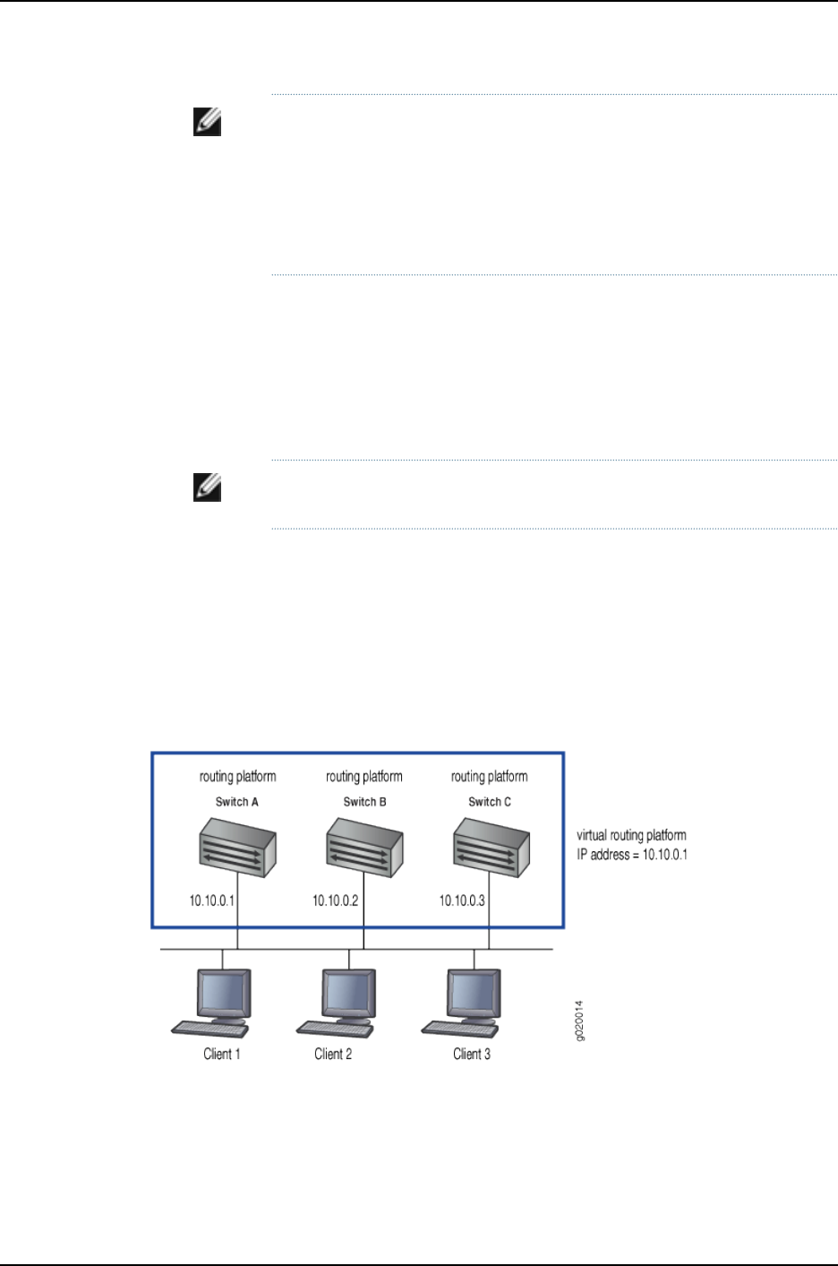
NOTE: Do not confuse the VRRP master and backup routing platforms with
the master and backup member switches of a Virtual Chassis configuration.
The master and backup members of a Virtual Chassis configuration compose
a single host. In a VRRP topology, one host operates as the master routing
platform and another operates as the backup routing platform, as shown in
Figure 29 on page 930.
Switches running VRRP dynamically elect master and backup routing platforms. You
can also force assignment of master and backup routing platforms using priorities from
1through 255, with 255 being the highest priority. In VRRP operation, the default master
routing platform sends advertisements to backup routing platforms at regular intervals.
The default interval is 1 second. If the backup routing platforms do not receive an
advertisement for a set period, the backup routing platform with the highest priority takes
over as master and begins forwarding packets.
NOTE: Priority 255 cannot be set for routed VLAN interfaces (RVIs).
VRRP is defined in RFC 3768, Virtual Router Redundancy Protocol.
Examples of VRRP Topologies
Figure 28 on page 929 illustrates a basic VRRP topology with J-EX Series switches. In this
example, Switches A, B, and C are running VRRP and together they make up a virtual
routing platform. The IP address of this virtual routing platform is 10.10.0.1 (the same
address as the physical interface of Switch A).
Figure 28: Basic VRRP on J-EX Series Switches
Figure 29 on page 930 illustrates a basic VRRP topology using Virtual Chassis configurations.
Switch A, Switch B, and Switch C are each composed of multiple interconnected Dell
PowerConnect J-EX Series J-EX4200 Ethernet Switches. Each Virtual Chassis
configuration operates as a single switch, which is running VRRP, and together they make
929
Chapter 44: High Availability—Overview
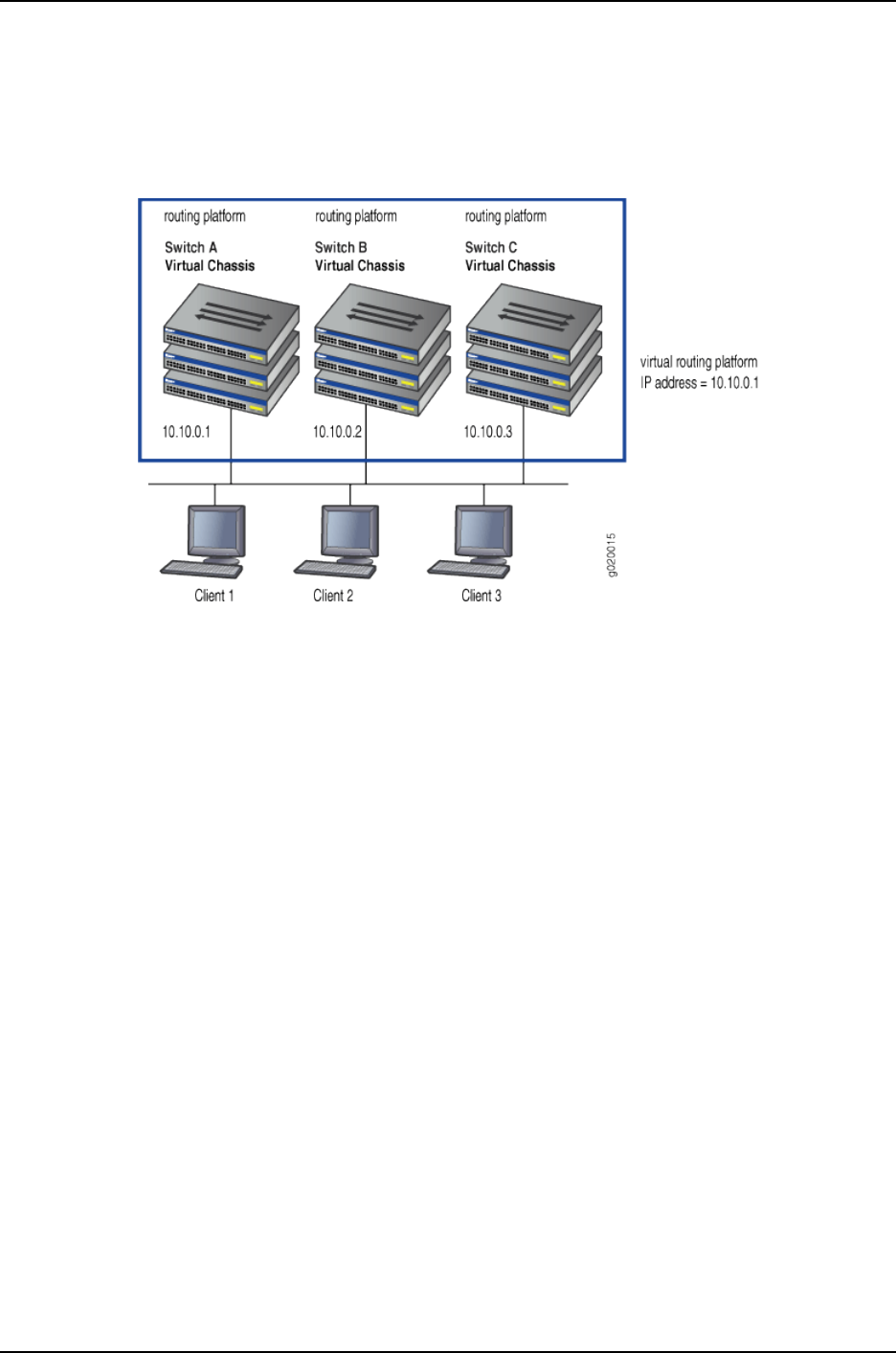
up a virtual routing platform. The IP address of this virtual routing platform is 10.10.0.1
(the same address as the physical interface of Switch A).
Figure 29: VRRP on Virtual Chassis Switches
Because the virtual routing platform uses the IP address of the physical interface of
Switch A, Switch A is the master VRRP routing platform, while Switch B and Switch C
function as backup VRRP routing platforms. Clients 1 through 3 are configured with the
default gateway IP address of 10.10.0.1 as the master router, Switch A, forwards packets
sent to its IP address. If the master routing platform fails, the switch configured with the
higher priority becomes the master virtual routing platform and provides uninterrupted
service for the LAN hosts. When Switch A recovers, it becomes the master virtual routing
platform again.
Related
Documentation
For more information on VRRP or VRRP for IPv6, see the Junos OS High Availability
Configuration Guide.
•
•High Availability Features for J-EX Series Switches Overview on page 22
•Configuring VRRP for IPv6 (CLI Procedure) on page 947
930
Dell PowerConnect J-Series Ethernet Switch Complete Software Guide for Junos OS, Release 11.1: Volume 1

Understanding Nonstop Active Routing on J-EX Series Switches
You can configure nonstop active routing (NSR) on a J-EX Series switch with redundant
Routing Engines to enable the transparent switchover of the Routing Engines in the event
that one of the Routing Engines goes down.
Nonstop active routing provides high availability for Routing Engines by enabling
transparent switchover of the Routing Engines without requiring restart of supported
routing protocols. Both Routing Engines are fully active in processing protocol sessions,
and so each can take over for the other. The switchover is transparent to neighbor routing
devices, which do not detect that a change has occurred.
Enable nonstop active routing when neighbor routing devices are not configured to support
graceful restart of protocols or when you want to ensure graceful restart of protocols for
which graceful restart is not supported (such as PIM).
You do not need to start the two Routing Engines simultaneously to synchronize them
for nonstop active routing. If both Routing Engines are not present or not up when you
issue a commit synchronize statement, the candidate configuration is committed in the
master Routing Engine and when the backup Routing Engine is inserted or comes online,
its configuration is automatically synchronized with that of the master.
Nonstop active routing uses the same infrastructure as graceful Routing Engine switchover
(GRES) to preserve interface and kernel information. However, nonstop active routing
also saves routing protocol information by running the routing protocol process (rpd) on
the backup Routing Engine. By saving this additional information, nonstop active routing
does not rely on other routing devices to assist in restoring routing protocol information.
NOTE: After a graceful Routing Engine switchover, we recommend that you
issue the clear interface statistics (interface-name | all) command to reset the
cumulative values for local statistics on the new master Routing Engine.
If you suspect a problem with the synchronization of Routing Engines when nonstop
active routing is enabled, you can gather troubleshooting information using trace options.
For example, if certain protocols lose connectivity with neighbors after a graceful Routing
Engine switchover with NSR enabled, you can use trace options to help isolate the
problem. See “Tracing Nonstop Active Routing Synchronization Events” on page 949.
NOTE: Graceful restart and nonstop active routing are mutually exclusive.
You will receive an error message upon commit if both are configured.
Related
Documentation
Configuring Nonstop Active Routing on J-EX Series Switches (CLI Procedure) on page 948•
•Example: Configuring Nonstop Active Routing on J-EX Series Switches on page 941
931
Chapter 44: High Availability—Overview

Understanding Nonstop Software Upgrade on J-EX Series Switches
Nonstop software upgrade (NSSU) enables you to upgrade the software running on a
Dell PowerConnect J-EX Series J-EX8200 Ethernet Switch with redundant Routing
Engines using a single command and with minimal disruption to network traffic.
Performing an NSSU provides these benefits:
•No disruption to the control plane—An NSSU takes advantage of graceful Routing
Engine switchover (GRES) and nonstop active routing (NSR) to ensure no disruption
to the control plane. During the upgrade process, interface, kernel, and routing protocol
information is preserved.
•Minimal disruption to traffic—By default, an NSSU upgrades each line card one at a
time. Traffic continues to flow through the other line cards while a line card is being
restarted as part of the upgrade. You can minimize disruption to traffic by configuring
link aggregation groups (LAGs) such that the member links of each LAG reside on
different line cards. When one member link of a LAG is down, the remaining links are
up, and traffic continues to flow through the LAG.
Because upgrading each line card one at a time can increase the amount of time it
takes to perform an upgrade, you can optionally configure line-card upgrade groups.
The line cards in an upgrade group are upgraded simultaneously, reducing the amount
of time it takes to complete an upgrade.
NOTE: Upgrading from Junos OS Release 10.4R2 or earlier to Release 10.4R3
or later requires that you also upgrade the loader software. See the release
notes for instructions on how to upgrade from Release 10.4R2 or earlier to
Release 10.4R3 or later.
This topic covers:
•How an NSSU Works on page 932
•NSSU and Junos OS Release Support on page 935
•Overview of NSSU Configuration and Operation on page 935
How an NSSU Works
This section describes what happens when you request an NSSU on a:
•Standalone Switch on page 933
•Virtual Chassis on page 934
932
Dell PowerConnect J-Series Ethernet Switch Complete Software Guide for Junos OS, Release 11.1: Volume 1

Standalone Switch
When you request an NSSU on a standalone switch:
1. The switch verifies that:
•Both Routing Engines are online and running the same software version.
•Both Routing Engines have sufficient storage space for the new software image.
•Graceful Routing Engine switchover and nonstop active routing are enabled.
2. The switch installs the new software image on the backup Routing Engine and reboots
it.
3. The switch resynchronizes the backup Routing Engine to the master Routing Engine.
4. The line cards in the first upgrade group (or the line card in slot 0, if no upgrade groups
are defined) download the new image and then restart. Traffic continues to flow
through the line cards in the other upgrade groups during this process.
5. When line cards restarted in Step 4 are online again, the line cards in the next upgrade
group download the new image and restart. This process continues until all online
line cards have restarted with the new software.
NOTE: If you have taken a line card offline with the CLI before you start
the NSSU, the line card is not restarted and remains offline.
6. The switch performs a graceful Routing Engine switchover, so that the upgraded
backup Routing Engine becomes the master.
7. The switch installs the new software on the original master Routing Engine.
To complete the upgrade process, the original master Routing Engine must be
rebooted. You can do so manually or have the switch perform an automatic reboot
by including the reboot option when you request the NSSU. After the original master
has been rebooted, you can optionally return control to it by requesting a graceful
Routing Engine switchover.
933
Chapter 44: High Availability—Overview

Virtual Chassis
When you request an NSSU on a Virtual Chassis:
1. The master external Routing Engine verifies that:
•It has a backup external Routing Engine that is online.
•All Virtual Chassis members have redundant Routing Engines and the Routing
Engines are online.
•All Routing Engines are running the same software version.
•All Routing Engines have sufficient storage space for the new software image.
•Graceful Routing Engine switchover and nonstop active routing are enabled.
2. The master external Routing Engine installs the new software image on the backup
external Routing Engine and reboots it.
3. The backup external Routing Engine resynchronizes with the master external Routing
Engine.
4. The master external Routing Engine installs the new software on the backup Routing
Engines in the member switches and reboots the backup Routing Engines.
5. When the reboot of the backup Routing Engines complete, the line cards in the first
upgrade group download the new image and then restart. (If no upgrade groups are
defined, the line card in slot 0 of member 0 downloads the new image and restarts.)
Traffic continues to flow through the line cards in the other upgrade groups during
this process.
6. When line cards restarted in Step 5 are online again, the line cards in the next upgrade
group (or the next sequential line card) download the new image and restart. This
process continues until all online line cards have restarted with the new software.
NOTE: If you have taken a line card offline with the CLI before you start
the NSSU, the line card is not restarted and remains offline.
7. The new software image is installed on the master Routing Engines, both external
and internal.
8. The member switches perform a graceful Routing Engine switchover, so that the
upgraded backup Routing Engines become masters.
9. The master external Routing Engine performs a graceful Routing Engine switchover
so that the backup external Routing Engine is now the master.
To complete the upgrade process, the original master Routing Engines, both external
and internal, must be rebooted. You can do so manually or have the reboot performed
automatically by including the reboot option when you request the NSSU. After the
original master external Routing Engine has been rebooted, you can optionally return
control to it by requesting a graceful Routing Engine switchover.
934
Dell PowerConnect J-Series Ethernet Switch Complete Software Guide for Junos OS, Release 11.1: Volume 1

NSSU and Junos OS Release Support
A J-EX8200 switch must be running a Junos OS release that supports NSSU before you
can perform an NSSU. If a switch is running a software version that does not support
NSSU, use the procedure described in “Installing Software on a J-EX8200 Switch with
Redundant Routing Engines (CLI Procedure)” on page 81 to upgrade the software.
You cannot use an NSSU to downgrade the software—that is, to install an earlier version
of the software than is currently running on the switch. To install an earlier software
version, use the software installation procedure described in “Installing Software on a
J-EX8200 Switch with Redundant Routing Engines (CLI Procedure)” on page 81.
Table 143 on page 935 lists the J-EX Series switches and Virtual Chassis that support NSSU
and the Junos OS release at which they began supporting it.
Table 143: Platform and Release Support for NSSU
Junos OS ReleasePlatform
10.4 or laterJ-EX8200 switch
Overview of NSSU Configuration and Operation
NSSU requires no configuration. You can optionally configure line-card upgrade groups
using the CLI. See “Example: Configuring Line-card Upgrade Groups for Nonstop Software
Upgrade on J-EX Series Switches” on page 944.
You perform an NSSU by executing the request system software nonstop-upgrade
command. Graceful Routing Engine switchover and nonstop active routing must be
enabled before you execute the command. For detailed instructions on how to perform
an NSSU, see “Upgrading Software on a J-EX8200 Standalone Switch Using Nonstop
Software Upgrade (CLI Procedure)” on page 955.
Related
Documentation
Upgrading Software on a J-EX8200 Standalone Switch Using Nonstop Software
Upgrade (CLI Procedure) on page 955
•
•Example: Configuring Line-card Upgrade Groups for Nonstop Software Upgrade on
J-EX Series Switches on page 944
Understanding Power Management on J-EX Series Switches
The power management feature for Dell PowerConnect J-EX Series J-EX8200 Ethernet
Switches helps ensure that normal operation of the system is not disrupted because of
insufficient power to the switch. It does so by employing a power budget policy.
Power management does the following in its power budget policy:
•Budgets power for each switch component that requires power. The amount that
power management budgets for each component is the maximum power that
component might consume. For example, for the fan tray, power management budgets
the amount of power required to run the fans at their maximum speed setting.
935
Chapter 44: High Availability—Overview

•Reserves a set amount of power for power supply redundancy. In its default
configuration, power management manages the switch for N+1 power redundancy,
which ensures uninterrupted system operation if one power supply fails. For example,
if a switch has four online 3000 W power supplies, power management reserves 3000
W in its power budget policy for redundancy. It allocates the remaining 9000 W to
normal operating power.
•Specifies the rules under which components receive power. These rules are designed
to ensure the least disruption to switch operation under conditions of insufficient power.
For example, power management provides power to core system components, such
as the Routing Engine, before it provides power to line cards.
You can configure certain aspects of power management’s budget policy, specifically:
•The power priority of individual line cards. By assigning different power priorities to the
line cards, you can determine which line cards are more likely to receive power in the
event of insufficient power.
•The power redundancy configuration. The default power redundancy configuration is
N+1; you can optionally configure N+N. For example, if you have deployed two
independent AC power feeds to the switch, configure N+N redundancy. When you
configure power management for N+N redundancy, it reserves the appropriate amount
of power in its power budget and reports insufficient power conditions accordingly.
These configurable items are discussed further in:
•Power Priority of Line Cards on page 936
•Power Supply Redundancy on page 938
Power Priority of Line Cards
Power management powers line cards on or off based on the power priority of the slots
they occupy:
•When a switch powers on, power management provides power to the line cards in the
order of their slot priority, with line cards in high priority slots receiving power first. Thus
if available power (including redundant power) is exhausted before all line cards receive
power, higher priority cards are powered on while lower priority cards remain powered
off.
•If the switch starts receiving insufficient power because of power supply failure or some
other problem, power management powers off the line cards in reverse-priority order
until power (including redundant power) is sufficient for the remaining cards. Thus
higher priority line cards are more likely to retain power in power shortage conditions
than are lower priority line cards.
•Power management responds to changes in power availability and line card operating
status by powering line cards on or off as appropriate. For example, if you add a power
supply, lower priority cards that were powered off due to insufficient power are powered
on in priority order.
If you take a line card offline, power management no longer allocates power to it. If
power to the switch is insufficient when you take a line card offline, power management
936
Dell PowerConnect J-Series Ethernet Switch Complete Software Guide for Junos OS, Release 11.1: Volume 1

allocates the freed power to a lower priority card that was offline due to lack of power
and brings it online. Restarting a line card, however, does not affect the power allocated
to it. Thus when power is insufficient, restarting a line card does not change its operating
status or the operating status of other line cards.
NOTE: Because power management does not allocate power to an offline
line card, a line card that has been taken offline in a J-EX8200 switch is
not automatically brought online when you commit a configuration. You
must explicitly bring the line card online with the request chassis fpc slot
slot-number online command. This behavior differs from other platforms
running Junos operating system (Junos OS), which automatically bring an
offline FPC online when you commit a configuration.
The actual power priority of a slot is determined first by the slot’s assigned priority and
second by the slot’s number. If more than one slot has the same assigned priority, power
priority is determined by slot number, with the lowest-numbered slots receiving power
first.
By default, all slots are assigned the lowest priority. You can assign a priority to a slot
using the CLI. If you do not explicitly assign priorities to slots, the slots receive power in
ascending order of slot numbers.
Because the purpose of power management is to ensure minimal system disruption
when power is insufficient, slot power priority does not always determine which line cards
receive power. In some cases, power management might provide power to a lower priority
line card rather than a higher priority line card. For example:
•If power is insufficient for a line card in a higher priority slot but is sufficient for a line
card in a lower priority slot, the lower priority slot receives the power. For example, if
an 8-port SFP+ line card requiring 450 W is in a higher priority slot than a 48-port SFP
line card requiring 330 W, the 48-port SFP line card receives the power if there is more
than 330 W but less than 450 W available.
•In an operating switch that has insufficient power, power management does not power
off operating line cards to provide power to a newly inserted line card or a line card
that is brought online after being offline, even if the line card has a higher priority than
the currently operating line cards.
However, if you restart the switch, power management reruns the current power budget
policy and powers line cards on or off based on their priority. As a result, line cards
receive power strictly by priority order and previously operating line cards might no
longer receive power.
•If you change the assigned power priority of line cards when there is insufficient power
for all the line cards, power management does not power down line cards that had
been receiving power because they are now a lower priority.
937
Chapter 44: High Availability—Overview

Power Supply Redundancy
By default, power management in J-EX8200 switches is configured to manage the power
supplies for N+1 redundancy, in which one power supply is held in reserve for backup if
one of the other power supplies is removed or fails.
You can configure power management to manage the power supplies for N+N
redundancy. In N+N redundancy, power management holds N power supplies in reserve
for backup. For example, if your switch has six power supplies and you configure N+N
redundancy, power management makes three power supplies available for normal
operating power and reserves three power supplies for redundancy (3+3). If you have an
odd number of power supplies, power management allocates one more power supply
to normal operating power than to redundant power. For example, if you have five power
supplies, the N+N configuration is 3+2.
Given the same number of power supplies, an N+N configuration usually provides less
normal operating power than an N+1 configuration because the N+N configuration holds
more power in reserve for backup. Table 144 on page 938 shows the effect on normal
operating power in N+1 and N+N configurations.
Table 144: Available Operating Power in N+1 and N+N Redundancy
Configurations
Normal Operating Power in
N+N Configuration
Normal Operating Power in N+1
Configuration
Number of Power
Supplies at nW Each
1x(nW)1 x (nW)2
2x(nW)2 x (nW)3
2x(nW)3 x (nW)4
3x(nW)4 x (nW)5
3x(nW)5 x (nW)6
To compensate for the reduced normal operating power, power management reserves
less power to the chassis in an N+N configuration than in an N+1 configuration. This
reduction in reserved chassis power allows a switch in an N+N configuration to power
more line cards than it could without the reduction. For the J-EX8208 switch, the power
reserved for the chassis is reduced to 1200 W from 1600 W; for the J-EX8216 switch, it
is reduced to 1800 W from 2400 W.
NOTE: To achieve the reduction in reserved chassis power, power
management reduces the maximum fan speed to 60 percent in an N+N
configuration from 80 percent in an N+1 configuration. Because the maximum
fan speed is reduced, it is possible that a line card that overheats would be
shut down sooner in an N+N configuration than in an N+1 configuration.
938
Dell PowerConnect J-Series Ethernet Switch Complete Software Guide for Junos OS, Release 11.1: Volume 1

Power management automatically recalculates the redundant power and normal
operating power as power supplies go online or offline. For example, if you have an N+N
configuration with three online 2000 W power supplies, power management allocates
2000 W to redundant power. If you bring a fourth 2000 W power supply online, power
management then allocates 4000 W to redundant power. If a power supply goes offline
again, power management once again allocates 2000 W to redundant power.
When power is insufficient to meet the budgeted power requirements, power management
raises alarms as follows:
•If all the line cards are receiving power but insufficient redundant power exists to
maintain the configured N+1 or N+N power configuration, power management raises
a minor (yellow) alarm. If this condition persists for 5 minutes, the alarm becomes a
major (red) alarm.
•If one or more line cards are down because of insufficient power (including redundant
power), power management raises a major (red) alarm.
Power management clears all alarms when sufficient power is available to meet normal
operating and redundant power requirements.
Related
Documentation
•Understanding Alarm Types and Severity Levels on J-EX Series Switches on page 559
•Configuring the Power Priority of Line Cards (CLI Procedure) on page 953
•Configuring Power Supply Redundancy (CLI Procedure) on page 952
•Verifying Power Configuration and Use on page 962
939
Chapter 44: High Availability—Overview

940
Dell PowerConnect J-Series Ethernet Switch Complete Software Guide for Junos OS, Release 11.1: Volume 1

CHAPTER 45
Examples of High Availability
Configuration
•Example: Configuring Nonstop Active Routing on J-EX Series Switches on page 941
•Example: Configuring Line-Card Upgrade Groups for Nonstop Software Upgrade on
J-EX Series Switches on page 944
Example: Configuring Nonstop Active Routing on J-EX Series Switches
Nonstop active routing (NSR) provides high availability for Routing Engines by enabling
transparent switchover of the Routing Engines without necessitating restart of supported
routing protocols. Both Routing Engines are fully active in processing protocol sessions,
and so each can take over for the other. The switchover is transparent to neighbors.
This example describes how to configure nonstop active routing on switches with multiple
Routing Engines:
•Requirements on page 941
•Overview and Topology on page 941
•Configuration on page 942
•Verification on page 943
•Troubleshooting on page 943
Requirements
This example uses the following hardware and software components:
•A J-EX Series switch with multiple Routing Engines
•Junos OS Release 10.4 or later for J-EX Series switches
Overview and Topology
Configure nonstop active routing on any J-EX Series switch with multiple Routing Engines
or J-EX Series switch in a Virtual Chassis configuration. Nonstop active routing is
advantageous in networks where neighbor routing devices do not support graceful restart
protocol extensions.
941

The topology used in this example consists of a J-EX8200 switch with redundant Routing
Engines connected to neighbor routing devices that are not configured to support graceful
restart of protocols.
Configuration
CLI Quick
Configuration
To quickly configure nonstop active routing, copy the following commands and paste
them into the switch terminal window:
[edit]
set chassis redundancy graceful-switchover
set routing-options nonstop-routing
set system commit synchronize
Step-by-Step
Procedure
To configure nonstop active routing on a switch:
Enable graceful Routing Engine switchover (GRES):1.
[edit chassis redundancy]
user@switch# set graceful-switchover
2. Enable nonstop active routing (by default, nonstop active routing is disabled):
[edit routing-options]
user@switch# set nonstop-routing
3. Synchronize configuration changes between the Routing Engines:
[edit system]
user@switch# set commit synchronize
If you try to commit the nonstop active routing configuration without including the
commit synchronize statement, the commit fails.
NOTE: If the backup Routing Engine is down when you issue the commit,
a warning is displayed and the candidate configuration is committed in
the master Routing Engine. When the backup Routing Engine comes
up, its configuration is automatically synchronized with that of the
master. If you subsequently insert or bring up a backup Routing Engine,
it automatically synchronizes its configuration with the master Routing
Engine configuration.
Results Check the results of the configuration:
[edit]
user@switch# show
chassis {
redundancy {
graceful-switchover;
}
routing-options {
nonstop-routing;
}
system {
commit synchronize;
942
Dell PowerConnect J-Series Ethernet Switch Complete Software Guide for Junos OS, Release 11.1: Volume 1

}
Verification
To confirm that the configuration is working properly, perform these tasks:
•Verifying That Nonstop Active Routing Is Working Correctly on the Switch on page 943
Verifying That Nonstop Active Routing Is Working Correctly on the Switch
Purpose Verify that nonstop active routing is enabled.
Action Issue the show task replication command:
user@switch# show task replication
Stateful Replication: Enabled
RE mode: Master
Protocol Synchronization Status
OSPF Complete
RIP Complete
PIM Complete
RSVP Complete
Meaning This output shows that nonstop active routing (Stateful Replication) is enabled on master
routing engine. If nonstop routing is not enabled, instead of the output shown above:
•On the backup routing engine the following error message is displayed: “error: the
routing subsystem is not running.”
•On the master routing engine, the following output is displayed if nonstop routing is
not enabled:
Stateful Replication: Disabled
RE mode: Master
Troubleshooting
To troubleshoot nonstop active routing, perform these tasks:
Investigating Problems with Synchronization of Routing Engines When NSR Is
Enabled
Problem A protocol loses connectivity with neighbors after a graceful Routing Engine switchover
(GRES) occurs with nonstop active routing (NSR) enabled.
Solution Use trace options to help isolate the problem and gather troubleshooting information.
Using the information gathered from trace options, you can confirm or eliminate the
synchronization of the Routing Engines as the cause of the loss of connectivity for the
protocol. See “Tracing Nonstop Active Routing Synchronization Events” on page 949.
Related
Documentation
Configuring Nonstop Active Routing on J-EX Series Switches (CLI Procedure) on page 948•
•Tracing Nonstop Active Routing Synchronization Events on page 949
943
Chapter 45: Examples of High Availability Configuration

•Understanding Nonstop Active Routing on J-EX Series Switches on page 931
Example: Configuring Line-Card Upgrade Groups for Nonstop Software Upgrade on
J-EX Series Switches
Nonstop software upgrade (NSSU) enables you to upgrade the software running on a
J-EX8200 switch with redundant Routing Engines using a single command and with
minimal disruption to network traffic. By default, NSSU upgrades the software running
on the line cards one line card at a time. To reduce the time an NSSU takes, you can
configure line-card upgrade groups.
This example shows how to configure NSSU to use line-card upgrade groups:
•Requirements on page 944
•Overview and Topology on page 944
•Configuration on page 945
Requirements
This example uses the following hardware and software components:
•A J-EX8200 switch with redundant Routing Engines
•Junos OS Release 10.4 or later for J-EX Series switches
Before you begin to configure line-card upgrade groups, ensure that you have configured
the link aggregation groups (LAGs) as described in “Configuring Aggregated Ethernet
Interfaces (CLI Procedure)” on page 1081. See “Overview and Topology” on page 944 for
details about the LAG configurations for this example.
Overview and Topology
In its default configuration, NSSU upgrades each line card in a switch or Virtual Chassis
one at a time. Traffic continues to flow through the other line cards while a line card is
being restarted as part of the upgrade. This behavior allows you minimize disruption to
traffic by configuring link aggregation groups (LAGs) such that the member links of each
LAG reside on different line cards. When one member link of a LAG is down, the remaining
links are up, and traffic continues to flow through the LAG.
Because the default configuration upgrades each line card one at a time, the upgrade
can take some time to complete. You can reduce the time it takes to perform an NSSU
by configuring line-card upgrade groups. Instead of being upgraded sequentially, the line
cards in an upgrade group are upgraded simultaneously. To achieve minimal traffic
disruption, you must define the line-card upgrade groups such that the member links of
the LAGs reside on line cards that are in different upgrade groups.
This example uses a J-EX8200 switch that has five line cards installed in slots 0 through
4. Two LAGs have been configured:
•ae0—Has two member links, one on the line card in slot 0 and one on the line card in
slot 1.
944
Dell PowerConnect J-Series Ethernet Switch Complete Software Guide for Junos OS, Release 11.1: Volume 1
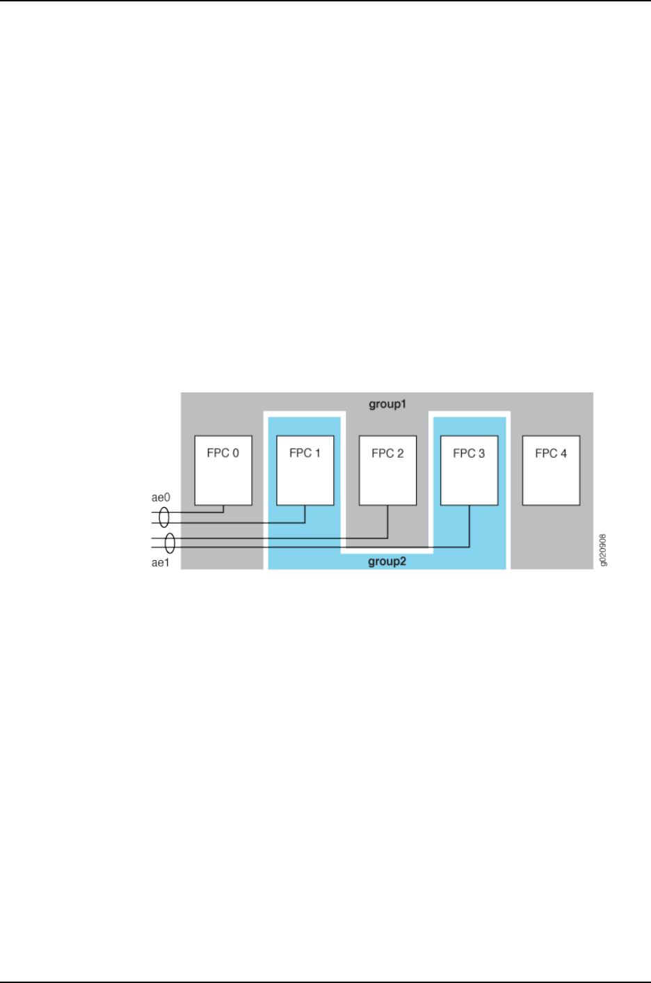
•ae1—Has two member links, one on the line card in slot 2 and one on the line card in
slot 3.
The interfaces on the line card in slot 4 are not part of either LAG.
To minimize the time an upgrade takes and to ensure that the member links of each LAG
are in different upgrade groups, this example configures the following two line-card
upgrade groups:
•group1—Contains the line cards in slots 0, 2, and 4.
•group2—Contains the line cards in slots 1 and 3.
The line card in slot 4 could be put in either group. It could also be left out of an upgrade
group entirely, and it would be upgraded separately after the line cards in the upgrade
groups have been upgraded. However, it is more efficient to include it in an upgrade group.
Figure 30 on page 945 illustrates the topology.
Figure 30: Example Line-Card Upgrade Group Topology
Configuration
To create line-card upgrade groups, perform these tasks:
CLI Quick
Configuration
To quickly create the line-card upgrade groups, copy the following commands and paste
them into the switch terminal window:
[edit]
set chassis nssu upgrade-group group1 fpcs [0 2 4]
set chassis nssu upgrade-group group2 fpcs [1 3]
Step-by-Step
Procedure
To create the line-card upgrade groups for an NSSU:
Create the first line-card upgrade group:1.
[edit chassis]
user@switch# set nssu upgrade-group group1 fpcs [0 2 4]
2. Create the second line-card upgrade group:
[edit chassis]
user@switch# set nssu upgrade-group group2 fpcs [1 3]
Results Display the results of the configuration:
945
Chapter 45: Examples of High Availability Configuration

[edit chassis]
user@switch# show
nssu {
upgrade-group group1 {
fpcs [ 0 2 4 ];
}
upgrade-group group2 {
fpcs [ 1 3 ];
}
}
Related
Documentation
•Configuring Line-card Upgrade Groups for Nonstop Software Upgrade (CLI Procedure)
on page 951
•Upgrading Software on a J-EX8200 Standalone Switch Using Nonstop Software
Upgrade (CLI Procedure) on page 955
946
Dell PowerConnect J-Series Ethernet Switch Complete Software Guide for Junos OS, Release 11.1: Volume 1

CHAPTER 46
Configuring High Availability
•Configuring VRRP for IPv6 (CLI Procedure) on page 947
•Configuring Nonstop Active Routing on J-EX Series Switches (CLI Procedure) on page 948
•Tracing Nonstop Active Routing Synchronization Events on page 949
•Configuring Line-Card Upgrade Groups for Nonstop Software Upgrade (CLI
Procedure) on page 951
•Configuring Power Supply Redundancy (CLI Procedure) on page 952
•Configuring the Power Priority of Line Cards (CLI Procedure) on page 953
Configuring VRRP for IPv6 (CLI Procedure)
By configuring the Virtual Router Redundancy Protocol (VRRP) on J-EX Series switches,
you can enable hosts on a LAN to make use of redundant routing platforms on that LAN
without requiring more than the static configuration of a single default route on the hosts.
You can configure VRRP for IPv6 on Gigabit Ethernet, 10-Gigabit Ethernet, and logical
interfaces.
To configure VRRP for IPv6:
1. Configure VRRP group support on interfaces:
[edit interfaces interface-name unit logical-unit-number family inet6
address address]
user@switch# set vrrp-inet6-group group-id priority number virtual-inet6-address
address virtual-link-local-address ipv6-address
You must explicitly define a virtual link local address for each VRRP for IPv6 group.
Otherwise, when you attempt to commit the configuration, the commit request fails.
The virtual link local address must be on the same subnet as the physical interface
address.
2. If you want to configure the priority order in which this switch functioning as a backup
router becomes the master router if the master router becomes nonoperational,
configure a priority for this switch:
[edit interfaces interface-name unit logical-unit-number family inet6
address address vrrp-inet6-group group-id]
user@switch# set priority number
947

3. Specify the interval in milliseconds in which the master router sends advertisement
packets to the members of the VRRP group:
[edit interfaces interface-name unit logical-unit-number family inet6
address address vrrp-inet6-group group-id]
user@switch# set inet6-advertise-interval milliseconds
4. By default, a higher-priority backup router preempts a lower-priority master router.
•To explicitly enable the master router to be preempted:
[edit interfaces interface-name unit logical-unit-number family inet6
address address vrrp-inet6-group group-id]
user@switch# set preempt
•To prohibit a higher-priority backup router from preempting a lower priority master
router:
[edit interfaces interface-name unit logical-unit-number family inet6
address address vrrp-inet6-group group-id]
user@switch# set no-preempt
Related
Documentation
•show vrrp on page 988
•Understanding VRRP on J-EX Series Switches on page 928
Configuring Nonstop Active Routing on J-EX Series Switches (CLI Procedure)
Nonstop active routing (NSR) provides a mechanism for transparent switchover of the
Routing Engines without necessitating restart of supported routing protocols. Both Routing
Engines are fully active in processing protocol sessions, and so each can take over for
the other. The switchover is transparent to neighbors.
You can configure nonstop active routing on a J-EX Series switch with redundant Routing
Engines to enable the transparent switchover of the Routing Engines in the event that
the Routing Engines switch over. You can also disable nonstop active routing after you
have enabled it.
To configure nonstop active routing:
1. Enable graceful Routing Engine switchover (GRES):
[edit chassis redundancy]
user@switch# set graceful-switchover
2. Enable nonstop active routing (by default, nonstop active routing is disabled):
[edit routing-options]
user@switch# set nonstop-routing
3. Synchronize configuration changes between the Routing Engines:
[edit system]
user@switch# set commit synchronize
948
Dell PowerConnect J-Series Ethernet Switch Complete Software Guide for Junos OS, Release 11.1: Volume 1

If you try to commit the nonstop active routing configuration without including the
commit synchronize statement, the commit fails.
NOTE: There is no requirement to start the two Routing Engines
simultaneously. If the backup Routing Engine is not up when you commit
synchronize, the candidate configuration is committed in the master Routing
Engine and when the backup Routing Engine is inserted or comes online, its
configuration is automatically synchronized with that of the master.
BEST PRACTICE: After a graceful Routing Engine switchover, we recommend
that you issue the clear interface statistics (interface-name | all) command to
reset the cumulative values for local statistics on the new master Routing
Engine.
To disable nonstop active routing:
[edit routing-options]
user@switch# delete nonstop-routing
Related
Documentation
Example: Configuring Nonstop Active Routing on J-EX Series Switches on page 941•
•Tracing Nonstop Active Routing Synchronization Events on page 949
•Understanding Nonstop Active Routing on J-EX Series Switches on page 931
Tracing Nonstop Active Routing Synchronization Events
To track the progress of nonstop active routing synchronization between Routing Engines,
you can configure nonstop active routing trace options flags for each supported protocol
and for BFD sessions and record these operations to a log file.
To configure nonstop active routing trace options for supported routing protocols, include
the nsr-synchronization statement at the [edit protocols protocol-name traceoptions flag]
hierarchy level and optionally specify one or more of the detail,disable,receive, and send
options:
[edit protocols]
bgp {
traceoptions {
flag nsr-synchronization <detail> <disable> <receive> <send>;
}
}
isis {
traceoptions {
flag nsr-synchronization <detail> <disable> <receive> <send>;
}
}
ldp {
traceoptions {
flag nsr-synchronization <detail> <disable> <receive> <send>;
949
Chapter 46: Configuring High Availability

}
}
mpls {
traceoptions {
flag nsr-synchronization;
flag nsr-synchronization-detail;
}
}
(ospf | ospf3) {
traceoptions {
flag nsr-synchronization <detail> <disable> <receive> <send>;
}
}
(rip | ripng) {
traceoptions {
flag nsr-synchronization <detail> <disable> <receive> <send>;
}
}
pim {
traceoptions {
flag nsr-synchronization <detail> <disable> <receive> <send>;
}
}
To configure nonstop active routing trace options for BFD sessions, include the
nsr-synchronization and nsr-packet statements at the [edit protocols bfd traceoptions
flag] hierarchy level.
[edit protocols]
bfd {
traceoptions {
flag nsr-synchronization;
flag nsr-packet;
}
}
To trace the Layer 2 VPN signaling state replicated from routes advertised by BGP, include
the nsr-synchronization statement at the [edit routing-options traceoptions flag] hierarchy
level. This flag also traces the label and logical interface association that VPLS receives
from the kernel replication state.
[edit routing-options]
traceoptions {
flag nsr-synchronization;
}
Related
Documentation
Configuring Nonstop Active Routing•
•Configuring Nonstop Active Routing on J-EX Series Switches (CLI Procedure) on page 948
•traceoptions on page 974
•Example: Configuring Nonstop Active Routing
•Example: Configuring Nonstop Active Routing on J-EX Series Switches on page 941
950
Dell PowerConnect J-Series Ethernet Switch Complete Software Guide for Junos OS, Release 11.1: Volume 1

Configuring Line-Card Upgrade Groups for Nonstop Software Upgrade (CLI Procedure)
Nonstop software upgrade (NSSU) enables you to upgrade the software running on a
J-EX8200 switch with redundant Routing Engines using a single command and with
minimal disruption to network traffic.
In its default configuration, NSSU upgrades each line card in a switch or Virtual Chassis
one at a time. Traffic continues to flow through the other line cards while a line card is
being restarted as part of the upgrade. This behavior allows you to minimize disruption
to traffic by configuring link aggregation groups (LAGs) such that the member links of
each LAG reside on different line cards. When one member link of a LAG is down, the
remaining links are up, and traffic continues to flow through the LAG.
You can reduce the time it takes to perform an NSSU by configuring NSSU to use line-card
upgrade groups. When you define an upgrade group, NSSU upgrades the line cards in
the upgrade group at the same time instead of sequentially. To achieve minimal traffic
disruption, you must define the line-card upgrade groups such that the member links of
the LAGs reside on line cards that are in different upgrade groups. For information on
how to configure LAGs, see “Configuring Aggregated Ethernet Interfaces (CLI Procedure)”
on page 1081.
To configure line-card upgrade groups on a standalone J-EX8200 switch:
•To create an upgrade group and add a line card to it:
[edit chassis]
user@switch# set nssu upgrade-group group-name fpcs slot-number
For example, to create an upgrade group called group3 and add the line card in slot 5
to it:
[edit chassis]
user@switch# set nssu upgrade-group group3 fpcs 5
If group3 already exists, this command adds line card 5 to group3.
•To create an upgrade group and add multiple line cards to it:
[edit chassis]
user@switch# set nssu upgrade-group group-name fpcs [list-of-slot-numbers]
For example, to create an upgrade group called primary and add line cards in slots 1,
4, and 7 to it:
[edit chassis]
user@switch# set nssu upgrade-group primary fpcs [1 4 7]
If primary already exists, this command adds line cards in slots 1, 4, and 7 to primary.
Related
Documentation
Example: Configuring Line-Card Upgrade Groups for Nonstop Software Upgrade on
J-EX Series Switches on page 944
•
•Upgrading Software on a J-EX8200 Standalone Switch Using Nonstop Software
Upgrade (CLI Procedure) on page 955
951
Chapter 46: Configuring High Availability

•Understanding Nonstop Software Upgrade on J-EX Series Switches on page 932
Configuring Power Supply Redundancy (CLI Procedure)
By default, the power management feature in J-EX8200 switches is configured to manage
the power supplies for N+1 redundancy, in which one power supply is held in reserve for
backup if any one of the other power supplies is removed or fails.
You can configure power management to manage the power supplies for N+N
redundancy. For example, to set up your AC power supplies for dual power feed, N+N
redundancy is required. In N+N redundancy, power management allocates half of the
online power supplies to normal operating power and half to redundant power. If you
have an odd number of online power supplies, power management allocates one more
power supply to normal operating power than to redundant power.
This topic describes how to configure power management for N+N redundancy and how
to revert back to N+1 redundancy if your deployment needs change.
Before you configure power management for N+N redundancy, ensure that you have
sufficient power supplies to meet the power requirements of this configuration. Use the
show chassis power-budget-statistics command to display your current power budget.
NOTE: To allow more power to be available to line cards, power management
compensates for the reduced normal operating power in an N+N configuration
by reserving less power to the chassis than it does in an N+1 configuration.
For the J-EX8208 switch, the power reserved for the chassis is reduced to
1200 W from 1600 W. For the J-EX8216 switch, it is reduced to 1800 W from
2400 W. In determining whether you have enough power for an N+N
configuration, take this reduction of reserved chassis power into account.
The reduction in reserved chassis power is achieved by reducing the maximum
fan speed to 60 percent in an N+N configuration from 80 percent in an N+1
configuration. Because the maximum fan speed is reduced, it is possible that
a line card that overheats would be shut down sooner in an N+N configuration
than in an N+1 configuration.
To configure N+N redundancy:
[edit chassis]
user@switch# set psu redundancy n-plus-n
To revert back to N+1 redundancy:
[edit chassis]
user@switch# delete chassis psu redundancy n-plus-n
Related
Documentation
Configuring the Power Priority of Line Cards (CLI Procedure) on page 953•
•Verifying Power Configuration and Use on page 962
952
Dell PowerConnect J-Series Ethernet Switch Complete Software Guide for Junos OS, Release 11.1: Volume 1

•Understanding Power Management on J-EX Series Switches on page 935
Configuring the Power Priority of Line Cards (CLI Procedure)
The power management facility on J-EX8200 switches allows you to assign power
priorities to the slots occupied by line cards. Power management provides power to the
slots in priority order, which means that line cards in higher priority slots are more likely
to receive power than line cards in lower priority slots if power to the switch is insufficient
to power all the line cards.
When assigning power priority to slots, keep these points in mind:
•0 is the highest priority. For a J-EX8208 switch, you can assign a priority of 0 through
7 to a slot. For a J-EX8216 switch, you can assign a priority of 0 through 15 to a slot.
•All slots are assigned the lowest priority by default.
•If a group of slots shares the same assigned priority, each slot’s power priority within
the group is based on its slot number, with the lowest-numbered slots receiving power
first.
To assign or change the power priority for a slot:
[edit chassis]
user@switch# set fpc slot power-budget-priority priority
For example, to set slot 6 to priority 0, enter:
[edit chassis]
user@switch# set fpc 6 power-budget-priority 0
Related
Documentation
•Configuring Power Supply Redundancy (CLI Procedure) on page 952
•Verifying Power Configuration and Use on page 962
•Understanding Power Management on J-EX Series Switches on page 935
953
Chapter 46: Configuring High Availability

954
Dell PowerConnect J-Series Ethernet Switch Complete Software Guide for Junos OS, Release 11.1: Volume 1

CHAPTER 47
Administering High Availability
•Upgrading Software on a J-EX8200 Standalone Switch Using Nonstop Software
Upgrade (CLI Procedure) on page 955
•Verifying Power Configuration and Use on page 962
Upgrading Software on a J-EX8200 Standalone Switch Using Nonstop Software
Upgrade (CLI Procedure)
You can use nonstop software upgrade (NSSU) to upgrade the software on standalone
J-EX8200 switches with redundant Routing Engines. NSSU upgrades the software running
on the Routing Engines and line cards with minimal traffic disruption during the upgrade.
NSSU is supported on switches running Junos OS Release 10.4 or later.
With NSSU, you can upgrade both Routing Engines at the same time with a single
command. You also have the option of upgrading just one Routing Engine, the backup
Routing Engine, which becomes the master Routing Engine after the upgrade is done.
You then use the standard software installation process to upgrade the original master
Routing Engine.
This topic covers:
•Preparing the Switch for Software Installation on page 955
•Upgrading Both Routing Engines Using NSSU on page 957
•Upgrading One Routing Engine Using NSSU on page 959
•Upgrading the Original Master Routing Engine on page 961
Preparing the Switch for Software Installation
Before you begin software installation using NSSU:
•(Optional) Configure line-card upgrade groups as described in “Configuring Line-card
Upgrade Groups for Nonstop Software Upgrade (CLI Procedure)” on page 951. By
default, an NSSU upgrades line cards one at a time to allow aggregated Ethernet links
that have members on different line cards to remain up through the upgrade process.
Configuring line-card upgrade groups reduces the time an upgrade takes because the
line cards in each upgrade group are upgraded at the same time rather than sequentially.
•Verify that the Routing Engines are running the same version of the software. Enter the
following command:
955

{master}
user@switch> show version invoke-on all-routing-engines
re0:
--------------------------------------------------------------------------
Hostname: switch
Model: ex8208
JUNOS Base OS boot [10.4-20100712.0]
JUNOS Base OS Software Suite [10.4-20100712.0]
JUNOS Kernel Software Suite [10.4-20100712.0]
JUNOS Crypto Software Suite [10.4-20100712.0]
JUNOS Online Documentation [10.4-20100712.0]
JUNOS Enterprise Software Suite [10.4-20100712.0]
LC JUNOS Installation Software [10.4-20100712.0]
JUNOS Routing Software Suite [10.4-20100712.0]
JUNOS Web Management [10.4-20100712.0]
re1:
--------------------------------------------------------------------------
Hostname: switch
Model: ex8208
JUNOS Base OS boot [10.4-20100712.0]
JUNOS Base OS Software Suite [10.4-20100712.0]
JUNOS Kernel Software Suite [10.4-20100712.0]
JUNOS Crypto Software Suite [10.4-20100712.0]
JUNOS Online Documentation [10.4-20100712.0]
JUNOS Enterprise Software Suite [10.4-20100712.0]
LC JUNOS Installation Software [10.4-20100712.0]
JUNOS Routing Software Suite [10.4-20100712.0]
JUNOS Web Management [10.4-20100712.0]
If the Routing Engines are not running the same version of the software, use the request
system software add command to upgrade the Routing Engine that is running the earlier
software version. For instructions on upgrading a single Routing Engine, see “Installing
Software on a J-EX8200 Switch with Redundant Routing Engines (CLI Procedure)” on
page 81.
•Ensure that nonstop active routing (NSR) and graceful Routing Engine switchover
(GRES) are enabled. To verify that they are enabled, you need to check only the state
of nonstop active routing—if nonstop active routing is enabled, then graceful Routing
Engine switchover is enabled.
To verify that nonstop active routing is enabled, execute the following command:
{master}
user@switch> show task replication
Stateful Replication: Enabled
RE mode: Master
Protocol Synchronization Status
OSPF Complete
RIP Complete
PIM Complete
RSVP Complete
956
Dell PowerConnect J-Series Ethernet Switch Complete Software Guide for Junos OS, Release 11.1: Volume 1

If nonstop active routing is not enabled (Stateful Replication is Disabled), see
“Configuring Nonstop Active Routing on J-EX Series Switches (CLI Procedure)” on
page 948 for information on how to enable it.
•(Optional) Back up the system software on each Routing Engine to a second storage
device with the request system snapshot command.
Upgrading Both Routing Engines Using NSSU
This procedure describes how to upgrade both Routing Engines using NSSU. When the
upgrade completes, both Routing Engines are running the new version of the software,
and the backup Routing Engine is the new master Routing Engine.
To upgrade both Routing Engines using NSSU:
1. Download the software package by following the procedure in “Downloading Software
Packages” on page 79.
2. Copy the software package to the switch. We recommend that you use FTP to copy
the file to the /var/tmp directory.
3. Log in to the master Routing Engine using the console connection. You can perform
an NSSU from the management interface, but a console connection allows you to
monitor the progress of the master Routing Engine reboot.
4. Install the new software package:
{master}
user@switch> request system software nonstop-upgrade reboot
/var/tmp/package-name-m.nZx-distribution.tgz
where package-name-m.nZx-distribution.tgz is, for example,
jinstall-ex-8200-10.4R1.5-domestic-signed.tgz.
The switch displays the following status messages as the upgrade executes:
Chassis ISSU Check Done
ISSU: Validating Image
ISSU: Preparing Backup RE
Pushing bundle to re1
WARNING: A reboot is required to install the software
WARNING: Use the 'request system reboot' command immediately
Backup upgrade done
Rebooting Backup RE
Rebooting re1
ISSU: Backup RE Prepare Done
Waiting for Backup RE reboot
GRES operational
Initiating Chassis In-Service-Upgrade
Chassis ISSU Started
ISSU: Preparing Daemons
ISSU: Daemons Ready for ISSU
ISSU: Starting Upgrade for FRUs
ISSU: Preparing for Switchover
ISSU: Ready for Switchover
Checking In-Service-Upgrade status
Item Status Reason
FPC 0 Online
957
Chapter 47: Administering High Availability

FPC 1 Online
FPC 2 Online
FPC 3 Offline Offlined by CLI command
FPC 4 Online
FPC 5 Online
FPC 6 Online
FPC 7 Online
Resolving mastership...
Complete. The other routing engine becomes the master.
ISSU: RE switchover Done
ISSU: Upgrading Old Master RE
WARNING: A reboot is required to install the software
WARNING: Use the 'request system reboot' command immediately
ISSU: Old Master Upgrade Done
ISSU: IDLE
Shutdown NOW!
[pid 2635]
*** FINAL System shutdown message from user@switch ***
System going down IMMEDIATELY
NOTE: If you omit the reboot option in this step, you must manually reboot
the original master Routing Engine with the request system reboot
command for the upgrade to complete.
5. Log in after the reboot completes. To verify that both Routing Engines have been
upgraded, enter the following command:
{backup}
user@switch> show version invoke-on all-routing-engines
re0:
------------------------------------------------------------------
Hostname: switch
Model: ex8208
JUNOS Base OS boot [10.4-20100826.0]
JUNOS Base OS Software Suite [10.4-20100826.0]
JUNOS Kernel Software Suite [10.4-20100826.0]
JUNOS Crypto Software Suite [10.4-20100826.0]
JUNOS Online Documentation [10.4-20100826.0]
JUNOS Enterprise Software Suite [10.4-20100826.0]
LC JUNOS Installation Software [10.4-20100826.0]
JUNOS Routing Software Suite [10.4-20100826.0]
JUNOS Web Management [10.4-20100826.0]
re1:
------------------------------------------------------------------
Hostname: switch
Model: ex8208 JUNOS Base OS boot [10.4-20100826.0]
JUNOS Base OS Software Suite [10.4-20100826.0]
JUNOS Kernel Software Suite [10.4-20100826.0]
JUNOS Crypto Software Suite [10.4-20100826.0]
JUNOS Online Documentation [10.4-20100826.0]
JUNOS Enterprise Software Suite [10.4-20100826.0]
LC JUNOS Installation Software [10.4-20100826.0]
JUNOS Routing Software Suite [10.4-20100826.0]
JUNOS Web Management [10.4-20100826.0]
958
Dell PowerConnect J-Series Ethernet Switch Complete Software Guide for Junos OS, Release 11.1: Volume 1

6. To verify that the line cards that were online before the upgrade are online after the
upgrade, log in to the master Routing Engine and enter the show chassis
nonstop-upgrade command:
{backup}
user@switch> request routing-engine login master
{master}
user@switch> show chassis nonstop-upgrade
Item Status Reason
FPC 0 Online
FPC 1 Online
FPC 2 Online
FPC 3 Offline Offlined by CLI command
FPC 4 Online
FPC 5 Online
FPC 6 Online
FPC 7 Online
7. If you want to make re0 the master Routing Engine again, enter the following
command:
{master}
user@switch> request chassis routing-engine master switch
Toggle mastership between routing engines ? [yes,no] (no) yes
You can verify that re0 is the master Routing Engine by executing the show chassis
routing-engine command.
8. Back up the system software on each Routing Engine to a second storage device with
the request system snapshot command.
Upgrading One Routing Engine Using NSSU
This procedure describes how to upgrade one of the Routing Engines using NSSU. When
the upgrade completes, the backup Routing Engine is running the new software version
and is the new master. The original master Routing Engine, now the backup Routing
Engine, continues to run the previous software version.
To upgrade one Routing Engine using NSSU:
1. Download the software package by following the procedure in “Downloading Software
Packages from Juniper Networks” on page 79.
2. Copy the software package to the switch. We recommend that you use FTP to copy
the file to the /var/tmp directory.
3. Log in to the master Routing Engine.
4. Request an NSSU and specify the no-old-master-upgrade option:
{master}
user@switch> request system software nonstop-upgrade
no-old-master-upgrade /var/tmp/package-name-m.nZx-distribution.tgz
959
Chapter 47: Administering High Availability

where package-name-m.nZx-distribution.tgz is, for example,
jinstall-ex-8200-10.4R2.5-domestic-signed.tgz.
The switch displays the following status messages as the upgrade executes:
Chassis ISSU Check Done
ISSU: Validating Image
ISSU: Preparing Backup RE
Pushing bundle to re1
WARNING: A reboot is required to install the software
WARNING: Use the 'request system reboot' command immediately
Backup upgrade done
Rebooting Backup RE
Rebooting re1
ISSU: Backup RE Prepare Done
Waiting for Backup RE reboot
GRES operational
Initiating Chassis In-Service-Upgrade
Chassis ISSU Started
ISSU: Preparing Daemons
ISSU: Daemons Ready for ISSU
ISSU: Starting Upgrade for FRUs
ISSU: Preparing for Switchover
ISSU: Ready for Switchover
Checking In-Service-Upgrade status
Item Status Reason
FPC 0 Online
FPC 1 Online
FPC 2 Online
FPC 3 Offline Offlined by CLI command
FPC 4 Online
FPC 5 Online
FPC 6 Online
FPC 7 Online
Resolving mastership...
Complete. The other routing engine becomes the master.
ISSU: RE switchover Done
Skipping Old Master Upgrade
ISSU: IDLE
When the upgrade is complete, the original master Routing Engine (re0) becomes
the backup Routing Engine.
5. To verify that the original backup Routing Engine (re1) has been upgraded, enter the
following command:
{backup}
user@switch> show version invoke-on all-routing-engines
re0:
----------------------------------------------------------------------
Hostname: switch
Model: ex8208
JUNOS Base OS boot [10.4-20100712.0]
JUNOS Base OS Software Suite [10.4-20100712.0]
JUNOS Kernel Software Suite [10.4-20100712.0]
JUNOS Crypto Software Suite [10.4-20100712.0]
JUNOS Online Documentation [10.4-20100712.0]
JUNOS Enterprise Software Suite [10.4-20100712.0]
LC JUNOS Installation Software [10.4-20100712.0]
JUNOS Routing Software Suite [10.4-20100712.0]
960
Dell PowerConnect J-Series Ethernet Switch Complete Software Guide for Junos OS, Release 11.1: Volume 1

JUNOS Web Management [10.4-20100712.0]
re1:
----------------------------------------------------------------------
Hostname: switch
Model: ex8208
JUNOS Base OS boot [10.4-20100828.0]
JUNOS Base OS Software Suite [10.4-20100828.0]
JUNOS Kernel Software Suite [10.4-20100828.0]
JUNOS Crypto Software Suite [10.4-20100828.0]
JUNOS Online Documentation [10.4-20100828.0]
JUNOS Enterprise Software Suite [10.4-20100828.0]
LC JUNOS Installation Software [10.4-20100828.0]
JUNOS Routing Software Suite [10.4-20100828.0]
JUNOS Web Management [10.4-20100828.0]
6. To verify that the line cards that were online before the upgrade are online after the
upgrade, log in to the new master Routing Engine and enter the show chassis
nonstop-upgrade command:
{backup}
user@switch> request routing-engine login master
--- JUNOS 10.4-20100828.0 built 2010-08-28 05:19:44 UTC
{master}
user@switch> show chassis nonstop-upgrade
Item Status Reason
FPC 0 Online
FPC 1 Online
FPC 2 Online
FPC 3 Offline Offlined by CLI command
FPC 4 Online
FPC 5 Online
FPC 6 Online
FPC 7 Online
Upgrading the Original Master Routing Engine
This procedure describes how to upgrade the original master Routing Engine after you
have upgraded the original backup Routing Engine as described in “Upgrading One Routing
Engine Using NSSU” on page 959.
1. Log in to the current master Routing Engine (re1):
2. Enter configuration mode and disable nonstop active routing:
{master}[edit]
user@switch# delete routing-options nonstop-routing
3. Deactivate graceful Routing Engine switchover and commit the configuration:
{master}[edit]
user@switch# deactivate chassis redundancy graceful-switchover
{master}[edit]
user@switch# commit
4. Log in to the current backup Routing Engine (re0) using a console connection.
5. Request a software installation:
961
Chapter 47: Administering High Availability

user@switch> request system software add reboot
/var/tmp/package-name-m.nZx-distribution.tgz
NOTE: When you use NSSU to upgrade only one Routing Engine, the
installation package is not automatically deleted from /var/tmp, leaving
the package available to be used to upgrade the original master Routing
Engine.
6. After the upgrade completes, log in to the current master Routing Engine (re1) and
enter CLI configuration mode.
7. Re-enable nonstop active routing and graceful Routing Engine switchover:
[edit]
user@switch# activate chassis redundancy graceful-switchover
[edit]
user@switch# set routing-options nonstop-routing
[edit]
user@switch# commit
8. (Optional) To return control to the original master Routing Engine (re0), exit CLI
configuration mode and enter the following command:
{master}
user@switch> request chassis routing-engine master switch
Toggle mastership between routing engines ? [yes,no] (no) yes
You can verify that re0 is the master Routing Engine by executing the show chassis
routing-engine command.
9. (Optional) Back up the system software on each Routing Engine to a second storage
device with the request system snapshot command.
Related
Documentation
Example: Configuring Line-card Upgrade Groups for Nonstop Software Upgrade on
J-EX Series Switches on page 944
•
•Troubleshooting Software Installation on page 107
•Junos OS Package Names on page 72
•Understanding Nonstop Software Upgrade on J-EX Series Switches on page 932
•Understanding Software Installation on J-EX Series Switches on page 69
Verifying Power Configuration and Use
Purpose Verify on a J-EX8200 switch:
•What the power redundancy and line card priority settings are
•Whether the N+1 or N+N power requirements are being met
962
Dell PowerConnect J-Series Ethernet Switch Complete Software Guide for Junos OS, Release 11.1: Volume 1

•Whether the switch has sufficient power for a new line card or an N+N configuration
Action Enter the following command:
user@switch> show chassis power-budget-statistics
PSU 1 (EX8200-AC2K) : 1200 W
PSU 2 (EX8200-AC2K) : 1200 W
PSU 3 (EX8200-AC2K) : 1200 W
PSU 4 (EX8200-AC2K) : 1200 W
Total Power supplied by all Online PSUs : 4800 W
Power Redundancy Configuration : N+N
Power Reserved for the Chassis : 1200 W
FPC 5 (EX8200-48F ) : 330 W Priority: 7
FPC 6 (EX8200-8XS ) : 450 W Priority: 0
Actual Power Used : 1980 W
Power Available (Redundant case) : 420 W
Total Power Available : 2820 W
Meaning The switch is configured for N+N redundancy. As shown by the Power Available
(Redundant case) field, the switch has sufficient power to meet the N+N power
requirements and has an additional 420 W available. The switch has insufficient power
for an additional 8-port SFP+ line card while maintaining N+N redundancy, because the
line card requires 450 W. However, it does have enough power for an additional 48-port
SFP line card, which requires only 330 W. The 8-port SFP+ line card in slot 6 has a higher
power priority than the 48-port SFP line card line card in slot 5.
NOTE: The amount of power shown in the Actual Power Used field reflects
the total power allocated in the power budget for the installed components
rather than the actual power being used by the components. Because the
power budget allocation is based on maximum power use, actual power
consumption is likely to be much less.
Related
Documentation
•Configuring Power Supply Redundancy (CLI Procedure) on page 952
•Configuring the Power Priority of Line Cards (CLI Procedure) on page 953
963
Chapter 47: Administering High Availability

964
Dell PowerConnect J-Series Ethernet Switch Complete Software Guide for Junos OS, Release 11.1: Volume 1

CHAPTER 48
Configuration Statements for High
Availability
commit synchronize
Syntax commit synchronize;
Hierarchy Level [edit system]
Release Information Statement introduced before Junos OS Release 10.2 for J-EX Series switches.
Description For devices with multiple Routing Engines only. Configure a commit command to
automatically result in a commit synchronize command. The Routing Engine on which
you execute the commit command (the requesting Routing Engine) copies and loads its
candidate configuration to the other (the responding) Routing Engines. All Routing Engines
then perform a syntax check on the candidate configuration file being committed. If no
errors are found, the configuration is activated and becomes the current operational
configuration on all Routing Engines.
Acounting of events and operations on a backup Routing Engine is not supported on
accounting servers such as TACACS+ or RADIUS. Logging of accounting events is
supported only for events and operations on a master Routing Engine.
Required Privilege
Level
system—To view this statement in the configuration.
system-control—To add this statement to the configuration.
Related
Documentation
•Configuring Multiple Routing Engines to Synchronize Committed Configurations
Automatically
965

fpc
Syntax fpc slot {
pic pic-number {
sfpplus {
pic-modemode;
}
}
power-budget-priority priority;
Hierarchy Level [edit chassis]
Release Information Statement introduced before Junos OS Release 10.2 for J-EX Series switches.
Description On a J-EX4200 switch, specify the port of the SFP+ uplink module for which you want
to configure the operating mode.
On a J-EX8200 switch, specify the line card slot for which you want to assign a power
priority.
Options slot—Number of the slot:
•0—Standalone J-EX4200 switches. The FPC refers to the switch itself.
•0–9—J-EX4200 switch in a Virtual Chassis configuration. The value corresponds to
the switch’s member ID.
•0–7—J-EX8200 switch. The slot is a line card slot.
•0–15—J-EX8216 switch. The slot is a line card slot.
The remaining statements are explained separately.
Required Privilege
Level
interface—To view this statement in the configuration.
interface-control—To add this statement to the configuration.
Related
Documentation
•Setting the Mode on an SFP+ Uplink Module (CLI Procedure) on page 1093
•Configuring the Power Priority of Line Cards (CLI Procedure) on page 953
966
Dell PowerConnect J-Series Ethernet Switch Complete Software Guide for Junos OS, Release 11.1: Volume 1

fpcs
Syntax fpcs (slot-number | [list-of-slot-numbers]);
Hierarchy Level [edit chassis nssu upgrade-group group-name],
[edit chassis nssu upgrade-group group-name member member-id]
Release Information Statement introduced in Junos OS Release 10.4 for J-EX Series switches.
Description (J-EX8200 switches only) Assign one or more line cards to a line-card upgrade group by
specifying their slot numbers.
Options list-of-slot-numbers—A list of slot numbers of multiple line cards to be included in the
upgrade group. Separate the slot numbers with spaces and enclose the list in square
brackets—for example: [3 4 7].
slot-number—The slot number of a single line card to be included in the upgrade group.
Required Privilege
Level
interface—To view this statement in the configuration.
interface-control—To add this statement to the configuration.
Related
Documentation
•Example: Configuring Line-card Upgrade Groups for Nonstop Software Upgrade on
J-EX Series Switches on page 944
•Configuring Line-card Upgrade Groups for Nonstop Software Upgrade (CLI Procedure)
on page 951
967
Chapter 48: Configuration Statements for High Availability

graceful-switchover
Syntax graceful-switchover;
Hierarchy Level [edit chassis redundancy]
Release Information Statement introduced before Junos OS Release 10.2 for J-EX Series switches.
Description For switches with more than one Routing Engine, configure the master Routing Engine
to switch over gracefully to a backup Routing Engine without interruption to packet
forwarding.
Default Graceful Routing Engine switchover (GRES) is disabled.
Required Privilege
Level
interface—To view this statement in the configuration.
interface-control—To add this statement to the configuration.
Related
Documentation
•Example: Configuring Nonstop Active Routing on J-EX Series Switches on page 941
•Configuring Graceful Routing Engine Switchover in a J-EX4200 or J-EX4500 Virtual
Chassis (CLI Procedure) on page 856
•Configuring Nonstop Active Routing on J-EX Series Switches (CLI Procedure) on page 948
•Installing Software on a J-EX8200 Switch with Redundant Routing Engines (CLI
Procedure) on page 81
inet6-advertise-interval
Syntax inet6-advertise-interval milliseconds;
Hierarchy Level [edit interfaces interface-name unit logical-unit-number family inet6 address address
vrrp-inet6-group group-id]
Release Information Statement introduced before Junos OS Release 10.2 for J-EX Series switches.
Description Configure the interval between Virtual Router Redundancy Protocol (VRRP) IPv6
advertisement packets.
Options milliseconds—Interval, in milliseconds, between advertisement packets.
Range: 100 to 40,000 ms
Default: 1 second
Required Privilege
Level
interface—To view this statement in the configuration.
interface-control—To add this statement to the configuration.
Related
Documentation
•Configuring VRRP for IPv6 (CLI Procedure) on page 947
968
Dell PowerConnect J-Series Ethernet Switch Complete Software Guide for Junos OS, Release 11.1: Volume 1

n-plus-n
Syntax n-plus-n;
Hierarchy Level [edit chassis psu redundancy]
Release Information Statement introduced in Junos OS Release 10.2 for J-EX Series switches.
Description Configure N+N power supply redundancy for power management on a J-EX8200 switch.
Required Privilege
Level
interface—To view this statement in the configuration.
interface-control—To add this statement to the configuration.
Related
Documentation
•Configuring Power Supply Redundancy (CLI Procedure) on page 952
nonstop-routing
Syntax nonstop-routing;
Hierarchy Level [edit routing-options]
Release Information Statement introduced in Junos OS Release 10.4 for J-EX Series switches.
Description For routing platforms with two Routing Engines, configure a master Routing Engine to
switch over gracefully to a backup Routing Engine and preserve routing protocol
information.
Required Privilege
Level
interface—To view this statement in the configuration.
interface-control—To add this statement to the configuration.
Related
Documentation
•Configuring Nonstop Active Routing
•Configuring Nonstop Active Routing on J-EX Series Switches (CLI Procedure) on page 948
969
Chapter 48: Configuration Statements for High Availability

nssu
Syntax nssu {
upgrade-group group-name {
fpcs (slot-number | [list-of-slot-numbers]);
member member-id {
fpcs (slot-number | [list-of-slot-numbers]);
}
}
}
Hierarchy Level [edit chassis]
Release Information Statement introduced in Junos OS Release 10.4 for J-EX Series switches.
Description (J-EX8200 switches only) Define a line-card upgrade group for nonstop software upgrade
(NSSU). All line cards in an upgrade group are upgraded to the new software version at
the same time.
The remaining statements are explained separately.
Default If no line-card upgrade groups are defined, NSSU upgrades line cards one at a time in
ascending order by slot number.
Required Privilege
Level
interface—To view this statement in the configuration.
interface-control—To add this statement to the configuration.
Related
Documentation
•Example: Configuring Line-card Upgrade Groups for Nonstop Software Upgrade on
J-EX Series Switches on page 944
•Configuring Line-card Upgrade Groups for Nonstop Software Upgrade (CLI Procedure)
on page 951
970
Dell PowerConnect J-Series Ethernet Switch Complete Software Guide for Junos OS, Release 11.1: Volume 1

power-budget-priority
Syntax power-budget-priority priority;
Hierarchy Level [edit chassis fpc slot]
Release Information Statement introduced in Junos OS Release 10.2 for EX Sries switches.
Description Assign a power priority to the specified line card slot on a J-EX8200 switch.
Default All line card slots are initially assigned the lowest priority.
Options priority—Assigned power priority for the slot, with 0 being the highest priority.
Range: 0 through 7 for a J-EX8208 switch; 0 through 15 for a J-EX8216 switch
Range: 0 through 15 for a J-EX8216 switch
Required Privilege
Level
interface—To view this statement in the configuration.
interface-control—To add this statement to the configuration.
Related
Documentation
•Configuring the Power Priority of Line Cards (CLI Procedure) on page 953
preempt
Syntax (preempt | no-preempt) {
hold-time seconds;
}
Hierarchy Level [edit interfaces interface-name unit logical-unit-number family inet6 address address
vrrp-inet6-group group-id]
Release Information Statement introduced before Junos OS Release 10.2 for J-EX Series switches.
Description Configure whether a backup router can preempt a master router:
•preempt—Allow the master router to be preempted.
•no-preempt—Prohibit the preemption of the master router.
The remaining statement is explained separately.
Required Privilege
Level
interface—To view this statement in the configuration.
interface-control—To add this statement to the configuration.
Related
Documentation
•Configuring VRRP for IPv6 (CLI Procedure) on page 947
971
Chapter 48: Configuration Statements for High Availability

priority
Syntax priority number;
Hierarchy Level [edit interfaces interface-name unit logical-unit-number family inet address address vrrp-group
group-id],
[edit interfaces interface-name unit logical-unit-number family inet6 address address
vrrp-inet6-group group-id]
Release Information Statement introduced before Junos OS Release 10.2 for J-EX Series switches.
Description Configure a switch’s priority for becoming the master default routing platform. The routing
platform with the highest priority within the group becomes the master.
Options number—Routing platform’s priority for being elected to be the master router in the VRRP
group. A larger value indicates a higher priority for being elected.
Range: 1 through 255
Default: 100 (for backup routers)
NOTE: Priority 255 cannot be assigned to routed VLAN interfaces (RVIs).
Required Privilege
Level
interface—To view this statement in the configuration.
interface-control—To add this statement to the configuration.
Related
Documentation
•Configuring VRRP for IPv6 (CLI Procedure) on page 947
psu
Syntax psu {
redundancy {
n-plus-n;
}
}
Hierarchy Level [edit chassis]
Release Information Statement introduced in Junos OS Release 10.2 for J-EX Series switches.
Description Configure N+N power supply redundancy for power management on a J-EX8200 switch.
The remaining statements are explained separately.
Required Privilege
Level
interface—To view this statement in the configuration.
interface-control—To add this statement to the configuration.
Related
Documentation
•Configuring Power Supply Redundancy (CLI Procedure) on page 952
972
Dell PowerConnect J-Series Ethernet Switch Complete Software Guide for Junos OS, Release 11.1: Volume 1

redundancy (Graceful Switchover)
Syntax redundancy {
graceful-switchover;
}
Hierarchy Level [edit chassis]
Release Information Statement introduced before Junos OS Release 10.2 for J-EX Series switches.
Description For J-EX4200 and J-EX4500 switches configured as a Virtual Chassis and for J-EX8200
switches with more than one Routing Engine, enable redundant Routing Engines.
The remaining statement is explained separately.
Default Redundancy is enabled for the Routing Engines.
Required Privilege
Level
interface—To view this statement in the configuration.
interface-control—To add this statement to the configuration.
Related
Documentation
•Configuring Graceful Routing Engine Switchover in a J-EX4200 or J-EX4500 Virtual
Chassis (CLI Procedure) on page 856
•Installing Software on a J-EX8200 Switch with Redundant Routing Engines (CLI
Procedure) on page 81
redundancy (Power Management)
Syntax redundancy {
n-plus-n;
}
Hierarchy Level [edit chassis psu]
Release Information Statement introduced in Junos OS Release 10.2 for J-EX Series switches.
Description Configure N+N power supply redundancy for power management on a J-EX8200 switch.
The remaining statement is explained separately.
Default N+1 power supply redundancy is configured by default.
Required Privilege
Level
interface—To view this statement in the configuration.
interface-control—To add this statement to the configuration.
Related
Documentation
•Configuring Power Supply Redundancy (CLI Procedure) on page 952
973
Chapter 48: Configuration Statements for High Availability

traceoptions
Syntax traceoptions {
file name <size size> <files number> > <world-readable | no-world-readable>;
flag flag <flag-modifier> <disable>;
}
Hierarchy Level [edit protocols bfd],
[edit protocols bgp],
[edit protocols isis],
[edit protocols ldp],
[edit protocols mpls],
[edit protocols ospf],
[edit protocols ospf3],
[edit protocols pim],
[edit protocols rip],
[edit protocols ripng],
[edit routing-options]
Release Information Statement introduced in Junos OS Release 10.4 for J-EX Series switches.
Description Define tracing operations that track nonstop active routing (NSR) functionality in the
router.
To specify more than one tracing operation, include multiple flag statements.
Default If you do not include this statement, no global tracing operations are performed.
Options disable—(Optional) Disable the tracing operation. You can use this option to disable a
single operation when you have defined a broad group of tracing operations, such
as all.
file name—Name of the file to receive the output of the tracing operation. Enclose the
name within quotation marks. All files are placed in the directory /var/log. We
recommend that you place global routing protocol tracing output in the file routing-log.
files number—(Optional) Maximum number of trace files. When a trace file named trace-file
reaches its maximum size, it is renamed trace-file.0, then trace-file.1, and so on, until
the maximum number of trace files is reached. Then the oldest trace file is overwritten.
Range: 2 through 1000 files
Default: 2 files
If you specify a maximum number of files, you also must specify a maximum file size with
the size option.
flag flag—Tracing operation to perform. To specify more than one tracing operation,
include multiple flag statements. The nonstop active routing tracing options are:
•nsr-packet—Detailed trace information for BFD nonstop active routing only
•nsr-synchronization—Tracing operations for nonstop active routing
974
Dell PowerConnect J-Series Ethernet Switch Complete Software Guide for Junos OS, Release 11.1: Volume 1

•nsr-synchronization-detail—(MPLS only) Tracing operations for nonstop active routing
in detail
flag-modifier—(Optional) Modifier for the tracing flag. Except for BFD sessions, you can
specify one or more of these modifiers:
•detail—Detailed trace information
•receive—Packets being received
•send—Packets being transmitted
no-world-readable—Restrict users from reading the log file.
size size—(Optional) Maximum size of each trace file, in kilobytes (KB), megabytes (MB),
or gigabytes (GB). When a trace file named trace-file reaches this size, it is renamed
trace-file.0. When the trace-file again reaches its maximum size, trace-file.0 is renamed
trace-file.1 and trace-file is renamed trace-file.0. This renaming scheme continues until
the maximum number of trace files is reached. Then the oldest trace file is overwritten.
Syntax: xkto specify KB, xmto specify MB, or xgto specify GB
Range: 10 KB through the maximum file size supported on your system
Default: 128 KB
If you specify a maximum file size, you also must specify a maximum number of trace
files with the files option.
world-readable—Allow users to read the log file.
Required Privilege
Level
routing and trace—To view this statement in the configuration.
routing-control and trace-control—To add this statement to the configuration.
Related
Documentation
•Tracing Nonstop Active Routing Synchronization Events on page 949
975
Chapter 48: Configuration Statements for High Availability

upgrade-group
Syntax upgrade-group group-name {
fpcs (slot-number | [list-of-slot-numbers]);
member member-id {
fpcs (slot-number | [list-of-slot-numbers]);
}
}
Hierarchy Level [edit chassis nssu]
Release Information Statement introduced in Junos OS Release 10.4 for J-EX Series switches.
Description (J-EX8200 switches only) Assign a name to the line-card upgrade group being created
for nonstop software upgrade (NSSU).
Options group-name—Name of the upgrade group.
The remaining statements are explained separately.
Required Privilege
Level
interface—To view this statement in the configuration.
interface-control—To add this statement to the configuration.
Related
Documentation
•Example: Configuring Line-card Upgrade Groups for Nonstop Software Upgrade on
J-EX Series Switches on page 944
•Configuring Line-card Upgrade Groups for Nonstop Software Upgrade (CLI Procedure)
on page 951
976
Dell PowerConnect J-Series Ethernet Switch Complete Software Guide for Junos OS, Release 11.1: Volume 1

virtual-inet6-address
Syntax virtual-inet6-address [addresses];
Hierarchy Level [edit interfaces interface-name unit logical-unit-number family inet6 address address
vrrp-inet6-group group-id]
Release Information Statement introduced before Junos OS Release 10.2 for J-EX Series switches.
Description Configure the addresses of the virtual routers in a Virtual Router Redundancy Protocol
(VRRP) IPv6 group. You can configure up to eight addresses.
NOTE: The address of an aggregated Ethernet interface (a LAG) or a routed
VLAN interface (RVI) cannot be assigned as the virtual router address in a
VRRP IPv6 group.
Options addresses—Addresses of one or more virtual routers. Do not include a prefix length. If the
address is the same as the interface’s physical address, the interface becomes the
master virtual router for the group.
Required Privilege
Level
interface—To view this statement in the configuration.
interface-control—To add this statement to the configuration.
Related
Documentation
•Configuring VRRP for IPv6 (CLI Procedure) on page 947
virtual-link-local-address
Syntax virtual-link-local-address ipv6-address;
Hierarchy Level [edit interfaces interface-name unit logical-unit-number family inet6 address address
vrrp-inet6-group group-id]
Release Information Statement introduced before Junos OS Release 10.2 for J-EX Series switches.
Description Configure a virtual link local address for a Virtual Router Redundancy Protocol (VRRP)
IPv6 group. You must explicitly define a virtual link local address for each VRRP IPv6
group. The virtual link local address must be in the same subnet as the physical interface
address.
Options ipv6-address—Virtual link local IPv6 address for VRRP for an IPv6 group.
Required Privilege
Level
interface—To view this statement in the configuration.
interface-control—To add this statement to the configuration.
Related
Documentation
•Configuring VRRP for IPv6 (CLI Procedure) on page 947
977
Chapter 48: Configuration Statements for High Availability

vrrp-inet6-group
Syntax vrrp-inet6-group group-id {
inet6-advertise-interval milliseconds;
preempt{
hold-time seconds;
}
priority number;
virtual-inet6-address;
virtual-link-local-address
}
Hierarchy Level [edit interfaces interface-name unit logical-unit-number family inet6 address address]
Release Information Statement introduced before Junos OS Release 10.2 for J-EX Series switches.
Description Configure a Virtual Router Redundancy Protocol (VRRP) IPv6 group.
Options group-id—VRRP group identifier. If you enable MAC source address filtering on the
interface, you must include the virtual MAC address in the list of source MAC
addresses that you specify in the source-address-filter statement. MAC addresses
ranging from 00:00:5e:00:01:00 through 00:00:5e:00:01:ff are reserved for VRRP,
as defined in RFC 3768. The VRRP group number must be the decimal equivalent
of the last hexadecimal byte of the virtual MAC address.
Range: 0 through 255
The remaining statements are explained separately.
Required Privilege
Level
interface—To view this statement in the configuration.
interface-control—To add this statement to the configuration.
Related
Documentation
•Configuring VRRP for IPv6 (CLI Procedure) on page 947
978
Dell PowerConnect J-Series Ethernet Switch Complete Software Guide for Junos OS, Release 11.1: Volume 1

CHAPTER 49
Operational Commands for High
Availability
979

request system software nonstop-upgrade
Syntax request system software nonstop-upgrade package-name
<no-copy>
<no-old-master-upgrade>
<reboot >
<unlink>
Release Information Command introduced in Junos OS Release 10.4 for J-EX Series switches.
Description (J-EX8200 switches only) Perform a nonstop software upgrade (NSSU) on a J-EX8200
switch with redundant Routing Engines. When you execute this command on a standalone
switch, both the backup and master Routing Engines are upgraded, with the previous
backup Routing Engine becoming the new master at the end of the upgrade. The previous
backup Routing Engines become the new master Routing Engines.
This command has the following requirements:
•The Routing Engines must be running the same Junos OS release.
•Graceful Routing Engine switchover (GRES) must be enabled.
•Nonstop active routing (NSR) must be enabled.
•The command must be executed from the master Routing Engine on a standalone
switch.
•For minimal traffic disruption, you must define link aggregation groups (LAGs) such
that the member links reside on different line cards.
Options package-name—Location from which the software package or bundle is to be installed.
For example:
•/var/tmp/package-name—For a software package or bundle that is being installed
from a local directory on the switch.
•protocol://hostname/pathname/package-name—For a software package or bundle
that is to be downloaded and installed from a remote location. Replace protocol
with one of the following:
•ftp—File Transfer Protocol.
Use ftp://hostname/pathname/package-name. To specify authentication
credentials, use
ftp://<username>:<password>@hostname/pathname/package-name. To have
the system prompt you for the password, specify prompt in place of the
password. If a password is required, and you do not specify the password or
prompt, an error message is displayed.
•http—Hypertext Transfer Protocol.
Use http://hostname/pathname/package-name. To specify authentication
credentials, use
http://<username>:<password>@hostname/pathname/package-name. If a
password is required and you omit it, you are prompted for it.
980
Dell PowerConnect J-Series Ethernet Switch Complete Software Guide for Junos OS, Release 11.1: Volume 1

•scp—Secure copy (available only for Canada and U.S. version).
Use scp://hostname/pathname/package-name. To specify authentication
credentials, use
scp://<username>:<password>@hostname/pathname/package-name.
NOTE: The pathname in the protocol is the relative path to the user home
directory on the remote system and not the root directory.
no-copy—(Optional) Install a software package or bundle, but do not save copies of
package or bundle files.
no-old-master-upgrade—(Optional) (Standalone J-EX8200 switches only) Upgrade the
backup Routing Engine only. After the upgrade completes, the original master Routing
Engine becomes the backup Routing Engine and continues running the previous
software version.
reboot—(Optional) When the reboot option is included, the original master (new backup)
Routing Engines are automatically rebooted after being upgraded to the new
software. When the reboot option is not included, you must manually reboot the
original master (new backup) Routing Engines using the request system reboot
command.
unlink—(Optional) Remove the software package after a successful upgrade is completed.
Required Privilege
Level
maintenance
Related
Documentation
show chassis nonstop-upgrade on page 985•
•Upgrading Software on a J-EX8200 Standalone Switch Using Nonstop Software
Upgrade (CLI Procedure) on page 955
List of Sample Output request system software nonstop-upgrade reboot (Standalone Switch) on page 981
request system software nonstop-upgrade no-old-master-upgrade (Standalone
Switch) on page 982
request system software nonstop-upgrade reboot (Virtual Chassis) on page 983
Output Fields When you enter this command, you are provided feedback on the status of your request.
Sample Output
request system
software
{master}
user@switch> request system software nonstop-upgrade reboot
/var/tmp/jinstall-ex-8200–10.4R1.5–domestic-signed.tgz
Chassis ISSU Check Done
nonstop-upgrade
reboot (Standalone
Switch)
ISSU: Validating Image
ISSU: Preparing Backup RE
Pushing bundle to re1
WARNING: A reboot is required to install the software
WARNING: Use the 'request system reboot' command immediately
981
Chapter 49: Operational Commands for High Availability

Backup upgrade done
Rebooting Backup RE
Rebooting re1
ISSU: Backup RE Prepare Done
Waiting for Backup RE reboot
GRES operational
Initiating Chassis In-Service-Upgrade
Chassis ISSU Started
ISSU: Preparing Daemons
ISSU: Daemons Ready for ISSU
ISSU: Starting Upgrade for FRUs
ISSU: Preparing for Switchover
ISSU: Ready for Switchover
Checking In-Service-Upgrade status
Item Status Reason
FPC 0 Online
FPC 2 Offline Offlined by CLI command
FPC 3 Online
Resolving mastership...
Complete. The other routing engine becomes the master.
ISSU: RE switchover Done
ISSU: Upgrading Old Master RE
WARNING: A reboot is required to install the software
WARNING: Use the 'request system reboot' command immediately
ISSU: Old Master Upgrade Done
ISSU: IDLE
Shutdown NOW!
[pid 2635]
*** FINAL System shutdown message from user@switch ***
System going down IMMEDIATELY
request system
software
{master}
user@switch> request system software nonstop-upgrade no-old-master-upgrade
/var/tmp/jinstall-ex-8200–10.4R1.5–domestic-signed.tgz
Chassis ISSU Check Done
nonstop-upgrade
no-old-master-upgrade
(Standalone Switch)
ISSU: Validating Image
ISSU: Preparing Backup RE
Pushing bundle to re1
WARNING: A reboot is required to install the software
WARNING: Use the 'request system reboot' command immediately
Backup upgrade done
Rebooting Backup RE
Rebooting re1
ISSU: Backup RE Prepare Done
Waiting for Backup RE reboot
GRES operational
Initiating Chassis In-Service-Upgrade
Chassis ISSU Started
ISSU: Preparing Daemons
ISSU: Daemons Ready for ISSU
ISSU: Starting Upgrade for FRUs
ISSU: Preparing for Switchover
ISSU: Ready for Switchover
Checking In-Service-Upgrade status
Item Status Reason
FPC 0 Online
FPC 1 Online
982
Dell PowerConnect J-Series Ethernet Switch Complete Software Guide for Junos OS, Release 11.1: Volume 1

FPC 2 Online
FPC 3 Offline Offlined by CLI command
FPC 4 Online
FPC 5 Online
FPC 6 Online
FPC 7 Online
Resolving mastership...
Complete. The other routing engine becomes the master.
ISSU: RE switchover Done
Skipping Old Master Upgrade
ISSU: IDLE
request system
software
{master:9}
user@external-routing-engine> request system software nonstop-upgrade reboot
/var/tmp/jinstall-ex-xre200-11.1-20101130.0-domestic-signed.tgz
Chassis ISSU Check Done
nonstop-upgrade
reboot (Virtual
Chassis)
ISSU: Validating Image
ISSU: Preparing LCC Backup REs
ISSU: Preparing Backup RE
Pushing bundle /var/tmp/jinstall-ex-xre200-11.1-20101130.0-domestic-signed.tgz
to member8
--------------------------------------------------------------------------
WARNING: A reboot is required to install the software
WARNING: Use the 'request system reboot' command immediately
VC Backup upgrade done
Rebooting VC Backup RE
Rebooting member8
ISSU: Backup RE Prepare Done
Waiting for VC Backup RE reboot
Pushing bundle to member0-backup
Pushing bundle to member1-backup
WARNING: A reboot is required to install the software
WARNING: Use the 'request system reboot' command immediately
WARNING: A reboot is required to install the software
WARNING: Use the 'request system reboot' command immediately
Rebooting member0-backup
Rebooting LCC [member0-backup]
Rebooting member1-backup
Rebooting LCC [member1-backup]
ISSU: LCC Backup REs Prepare Done
GRES operational
Initiating Chassis Nonstop-Software-Upgrade
Chassis ISSU Started
ISSU: Preparing Daemons
ISSU: Daemons Ready for ISSU
ISSU: Starting Upgrade for FRUs
ISSU: Preparing for Switchover
ISSU: Ready for Switchover
Checking Nonstop-Upgrade status
member0:
--------------------------------------------------------------------------
Item Status Reason
FPC 0 Online
FPC 1 Online
FPC 2 Online
FPC 5 Online
member1:
983
Chapter 49: Operational Commands for High Availability

--------------------------------------------------------------------------
Item Status Reason
FPC 0 Online
FPC 1 Offline Offlined due to config
FPC 2 Online
FPC 3 Online
FPC 4 Online
FPC 5 Online
FPC 7 Online
member0:
--------------------------------------------------------------------------
Item Status Reason
FPC 0 Online
FPC 1 Online
FPC 2 Online
FPC 5 Online
member1:
--------------------------------------------------------------------------
Item Status Reason
FPC 0 Online
FPC 1 Offline Offlined due to config
FPC 2 Online
FPC 3 Online
FPC 4 Online
FPC 5 Online
FPC 7 Online
ISSU: Upgrading Old Master RE
Pushing bundle /var/tmp/incoming-package-8200.tgz to member0-master
Pushing bundle /var/tmp/incoming-package-8200.tgz to member1-master
ISSU: RE switchover Done
WARNING: A reboot is required to install the software
WARNING: Use the 'request system reboot' command immediately
Rebooting ...
shutdown: [pid 2188]
Shutdown NOW!
ISSU: Old Master Upgrade Done
ISSU: IDLE
Shutdown NOW!
*** FINAL System shutdown message from root@ ***
System going down IMMEDIATELY
984
Dell PowerConnect J-Series Ethernet Switch Complete Software Guide for Junos OS, Release 11.1: Volume 1

show chassis nonstop-upgrade
Syntax show chassis nonstop-upgrade
Release Information Command introduced in Junos OS Release 10.4 for J-EX Series switches.
Description (J-EX8200 switches only) Display the status of the line cards after the most recent
nonstop software upgrade (NSSU). This command must be issued on the master Routing
Engine.
Required Privilege
Level
view
Related
Documentation
request system software nonstop-upgrade on page 980•
•Upgrading Software on a J-EX8200 Standalone Switch Using Nonstop Software
Upgrade (CLI Procedure) on page 955
List of Sample Output show chassis nonstop-upgrade (Standalone Switch) on page 985
Output Fields Table 145 on page 985 lists the output fields for the show chassis nonstop-upgrade
command. Output fields are listed in the approximate order in which they appear.
Table 145: show chassis nonstop-upgrade Output Fields
Field DescriptionField Name
Line card slot number.Item
State of line card:
•Error—Line card is in an error state.
•Online—Line card is online and running.
•Offline—Line card is powered down.
Status
Reason for the state (if the line card is offline).Reason
Sample Output
show chassis
nonstop-upgrade
(Standalone Switch)
user@switch> show chassis nonstop-upgrade
Item Status Reason
FPC 0 Online
FPC 1 Online
FPC 2 Online
FPC 3 Offline Offlined by CLI command
FPC 4 Online
FPC 5 Online
FPC 6 Online
FPC 7 Online
985
Chapter 49: Operational Commands for High Availability

show chassis power-budget-statistics
Syntax show chassis power-budget-statistics
Release Information Command introduced in Junos OS Release 10.2 for J-EX Series switches.
Description Display the power budget of a J-EX8200 switch.
Required Privilege
Level
view
Related
Documentation
Verifying Power Configuration and Use on page 962•
•Configuring the Power Priority of Line Cards (CLI Procedure) on page 953
•Configuring Power Supply Redundancy (CLI Procedure) on page 952
List of Sample Output show chassis power-budget-statistics on page 987
Output Fields Table 146 on page 986 lists the output fields for the show chassis power-budget-statistics
command. Output fields are listed in the approximate order in which they appear.
Table 146: show chassis power-budget-statistics Output Fields
Field DescriptionField Name
Number of watts supplied by the power supply. All installed
power supplies, whether currently operating or not, are listed.
PSU n(supply type)
Total number of watts supplied by all currently operating power
supplies.
Power supplied by all Online PSUs
Configured power redundancy setting, either N+1 or N+N.Power Redundancy Configuration
Power reserved for the chassis:
•For a J-EX8208 switch: 1600 W in an N+1 configuration;
1200 W in an N+N configuration
•For a J-EX8216 switch: 2400 W in an N+1 configuration;
1800 W in an N+N configuration
The power reserved for the chassis includes the maximum
power requirements for the fan tray and Switch Fabric and
Routing Engine (SRE), Routing Engine (RE), and Switch Fabric
(SF) modules in both base and redundant configurations.
Power Reserved for the Chassis
Number of watts required by the line card in slot nand the
power priority assigned to the slot.
FPC n(card type)
Power budgeted for all the components in the switch. This
equal to the power reserved for the chassis plus the power
requirements of all online line cards. Because the amount
budgeted is based on maximum power requirements, the real
power consumption of the switch is likely to be less than this
figure.
Actual Power Used
986
Dell PowerConnect J-Series Ethernet Switch Complete Software Guide for Junos OS, Release 11.1: Volume 1

Table 146: show chassis power-budget-statistics Output Fields (continued)
Field DescriptionField Name
Unused power available to the switch in the power budget,
excluding redundant power. If power is insufficient to meet the
N+1 or N+N redundancy requirements, this value is 0.
Power Available (Redundant case)
Unused power available to the switch in the power budget,
including redundant power.
Total Power Available
Sample Output
show chassis
power-budget-statistics
user@switch> show chassis power-budget-statistics
PSU 0 (EX8200-AC2K) : 2000 W
PSU 1 (EX8200-AC2K) : 2000 W
PSU 2 (EX8200-AC2K) : 2000 W
Total Power supplied by all Online PSUs : 6000 W
Power Redundancy Configuration : N+N
Power Reserved for the Chassis : 1600 W
FPC 6 (EX8200-8XS ) : 450 W Priority: 7
Actual Power Used : 2050 W
Power Available (Redundant case) : 1950 W
Total Power Available : 3950 W
987
Chapter 49: Operational Commands for High Availability

show vrrp
Syntax show vrrp
<brief | detail | extensive | summary>
<interface interface-name>
<track interfaces>
Release Information Command introduced before Junos OS Release 10.2 for J-EX Series switches.
Description Display information and status about VRRP groups.
Options none—(Same as brief) Display brief status information about all VRRP interfaces.
brief | detail | extensive | summary—(Optional) Display the specified level of output.
interface interface-name —(Optional) Display information and status about the specified
VRRP interface.
track interfaces—(Optional) Display information and status about VRRP track interfaces.
Required Privilege
Level
view
Related
Documentation
Configuring VRRP for IPv6 (CLI Procedure) on page 947•
List of Sample Output show vrrp on page 993
show vrrp brief on page 993
show vrrp detail (IPv6) on page 993
show vrrp detail (Route Track) on page 993
show vrrp extensive on page 994
show vrrp interface on page 995
show vrrp summary on page 996
show vrrp track detail on page 996
show vrrp track summary on page 996
Output Fields Table 147 on page 988 lists the output fields for the show vrrp command. Output fields
are listed in the approximate order in which they appear.
Table 147: show vrrp Output Fields
Level of OutputField DescriptionField Name
none, brief, extensive,
summary
Name of the logical interface.Interface
extensivePhysical interface index number, which reflects its initialization sequence.Interface index
extensiveTotal number of VRRP groups configured on the interface.Groups
extensiveTotal number of VRRP groups that are active (that is, whose interface state is
either up or down).
Active
988
Dell PowerConnect J-Series Ethernet Switch Complete Software Guide for Junos OS, Release 11.1: Volume 1
Table 147: show vrrp Output Fields (continued)
Level of OutputField DescriptionField Name
extensiveNonerrored statistics for the logical interface:
•Advertisement sent—Number of VRRP advertisement protocol data units
(PDUs) that the interface has transmitted.
•Advertisement received—Number of VRRP advertisement PDUs received by
the interface.
•Packets received—Number of VRRP packets received for VRRP groups on the
interface.
•No group match received—Number of VRRP packets received for VRRP groups
that do not exist on the interface.
Interface VRRP
PDU statistics
extensiveErrored statistics for the logical interface:
•Invalid IPAH next type received—Number of packets received that use the IP
Authentication Header protocol (IPAH) and that do not encapsulate VRRP
packets.
•Invalid VRRP ttl value received—Number of packets received whose IP time-
to-live (TTL) value is not 255.
•Invalid VRRP version received—Number of packets received whose VRRP
version is not 2.
•Invalid VRRP pdu type received—Number of packets received whose VRRP
PDU type is not 1.
•Invalid VRRP authentication type received—Number of packets received whose
VRRP authentication is not none, simple, or md5.
•Invalid VRRP IP count received—Number of packets received whose VRRP IP
count exceeds 8.
•Invalid VRRP checksum received—Number of packets received whose VRRP
checksum does not match the calculated value.
Interface VRRP
PDU error statistics
detail, extensiveName of the physical interface.Physical interface
All levelsLogical unit number.Unit
none, brief, detail,
extensive
Address of the physical interface.Address
detail, extensivePhysical interface index number, which reflects its initialization sequence.Index
detail, extensiveSNMP index number for the physical interface.SNMP ifIndex
detail, extensiveStatus of VRRP traps: Enabled or Disabled.VRRP-Traps
none, brief, summaryIdentifier for the address and the address itself:
•lcl—Configured local interface address.
•mas—Address of the master virtual router. This address is displayed only
when the local interface is acting as a backup router.
•vip—Configured virtual IP addresses.
Type and Address
989
Chapter 49: Operational Commands for High Availability
Table 147: show vrrp Output Fields (continued)
Level of OutputField DescriptionField Name
none, brief, extensive,
summary
State of the physical interface:
•down—The device is present and the link is unavailable.
•not present—The interface is configured, but no physical device is present.
•unknown—The VRRP process has not had time to query the kernel about the
state of the interface.
•up—The device is present and the link is established.
Interface state or
Int state
none, brief, extensive,
summary
VRRP group number.Group
extensiveVRRP state:
•backup—The interface is acting as the backup router interface.
•bringup—VRRP is just starting, and the physical device is not yet present.
•idle—VRRP is configured on the interface and is disabled. This can occur when
VRRP is first enabled on an interface whose link is established.
•initializing—VRRP is initializing.
•master—The interface is acting as the master router interface.
•transition—The interface is changing between being the backup and being
the master router.
State
detail, extensiveConfigured VRRP priority for the interface.Priority
detail, extensiveConfigured VRRP advertisement interval.Advertisement
interval
detail, extensiveConfigured VRRP authentication type: none,simple, or md5.Authentication type
detail, extensiveWhether preemption is allowed on the interface: yes or no.Preempt
detail, extensiveWhether the interface is configured to accept packets destined for the virtual
IP address: yes or no.
Accept-data mode
detail, extensiveNumber of virtual IP addresses that have been configured on the interface.VIP count
detail, extensiveList of virtual IP addresses configured on the interface.VIP
detail, extensiveTime until the advertisement timer expires.Advertisement
timer
detail, extensiveIP address of the interface that is acting as the master. If the VRRP interface is
down, the output is N/A.
Master router
detail, extensiveTime that the virtual router has been up.Virtual router
uptime
detail, extensiveTime that the master router has been up.Master router
uptime
990
Dell PowerConnect J-Series Ethernet Switch Complete Software Guide for Junos OS, Release 11.1: Volume 1
Table 147: show vrrp Output Fields (continued)
Level of OutputField DescriptionField Name
detail, extensiveMAC address associated with the virtual IP address.Virtual MAC
detail, extensiveWhether tracking is enabled or disabled.Tracking
detail, extensiveCurrent operational priority for being the VRRP master.Current priority
detail, extensiveConfigured base priority for being the VRRP master.Configured priority
detail, extensiveMinimum time interval, in seconds, between successive changes to the current
priority. Disabled indicates no minimum interval.
Priority hold-time
detail(track option only) Displays the time remaining in the priority hold-time interval.Remaining-time
detail extensiveWhether interface tracking is enabled or disabled. When enabled, the output
also displays the number of tracked interfaces.
Interface tracking
detail extensiveName of the tracked interface.Interface/Tracked
interface
detail, extensiveCurrent operational state of the tracked interface: up or down.Int state/Interface
state
detail, extensiveCurrent operational speed, in bits per second, of the tracked interface.Int speed/Speed
detail, extensiveOperational priority cost incurred due to the state and speed of this tracked
interface. This cost is applied to the configured priority to obtain the current
priority.
Incurred priority
cost
detail, extensiveSpeed below which the corresponding priority cost is incurred. In other words,
when the speed of the interface drops below the threshold speed, the
corresponding priority cost is incurred.
An entry of down means that the corresponding priority cost is incurred when
the interface is down.
Threshold
detail, extensiveWhether route tracking is enabled or disabled. When enabled, the output also
displays the number of tracked routes.
Route tracking
detail, extensiveThe number of routes being tracked.Route count
detail, extensiveThe IP address of the route being tracked.Route
detail, extensiveThe VPN routing and forwarding (VRF) routing instance that the tracked route
is in.
VRF name
detail, extensiveThe state of the route being tracked: up,down, or unknown.Route state
detail, extensiveConfigured priority cost. This value is incurred when the interface speed drops
below the corresponding threshold or when the tracked route goes down.
Priority cost
991
Chapter 49: Operational Commands for High Availability

Table 147: show vrrp Output Fields (continued)
Level of OutputField DescriptionField Name
detail, extensiveWhether the threshold is active (*). If the threshold is active, the corresponding
priority cost is incurred.
Active
extensiveNumber of VRRP advertisements sent and received by the group.Group VRRP PDU
statistics
extensiveErrored statistics for the VRRP group:
•Bad authentication type received—Number of VRRP PDUs received with an
invalid authentication type. The received authentication can be none,simple,
or md5 and must be the same for all routers in the VRRP group.
•Bad password received—Number of VRRP PDUs received with an invalid key
(password). The password for simple authentication must be the same for
all routers in the VRRP group
•Bad MD5 digest received—Number of VRRP PDUs received for which the MD5
digest computed from the VRRP PDU differs from the digest expected by the
VRRP instance configured on the router.
•Bad advertisement timer received—Number of VRRP PDUs received with an
advertisement time interval that is inconsistent with the one in use among
the routers in the VRRP group.
•Bad VIP count received—Number of VRRP PDUs whose virtual IP address
counts differ from the count that has been configured on the VRRP instance.
•Bad VIPADDR received—Number of VRRP PDUs whose virtual IP addresses
differ from the list of virtual IP addresses configured on the VRRP instance.
Group VRRP PDU
error statistics
extensiveState transition statistics for the VRRP group:
•Idle to master transitions—Number of times that the VRRP instance
transitioned from the idle state to the master state.
•Idle to backup transitions—Number of times that the VRRP instance
transitioned from the idle state to the backup state.
•Backup to master transitions—Number of times that the VRRP instance
transitioned from the backup state to the master state.
•Master to backup transitions—Number of times that the VRRP instance
transitioned from the master state to the backup state.
Group state
transition statistics
none, briefVRRP information:
•backup—The interface is acting as the backup router interface.
•bringup—VRRP is just starting, and the physical device is not yet present.
•idle—VRRP is configured on the interface and is disabled. This can occur when
VRRP is first enabled on an interface whose link is established.
•initializing—VRRP is initializing.
•master—The interface is acting as the master router interface.
•transition—The interface is changing between being the backup and being
the master router.
VR state
none, briefVRRP timer information:
•A—Time, in seconds, until the advertisement timer expires.
•D—Time, in seconds, until the Master is Dead timer expires.
Timer
992
Dell PowerConnect J-Series Ethernet Switch Complete Software Guide for Junos OS, Release 11.1: Volume 1

Sample Output
show vrrp user@host> show vrrp
Interface State Group VR state Timer Type Address
ge-0/0/0.121 up 1 master A 1.052 lcl gec0::12:1:1:1
vip ge80::12:1:1:99
vip gec0::12:1:1:99
ge-0/0/2.131 up 1 master A 0.364 lcl gec0::13:1:1:1
vip ge80::13:1:1:99
vip gec0::13:1:1:99
show vrrp brief The output for the show vrrp brief command is identical to that for the show vrrp command.
For sample output, see show vrrp on page 993.
show vrrp detail (IPv6) user@host> show vrrp detail
Physical interface: ge-0/0/0, Unit: 121, Vlan-id: 212, Address: gec0::12:1:1:1/120
Index: 67, SNMP ifIndex: 45, VRRP-Traps: enabled
Interface state: up, Group: 1, State: master
Priority: 200, Advertisement interval: 1, Authentication type: none
Preempt: yes, Accept-data mode: no, VIP count: 2, VIP: ge80::12:1:1:99,
gec0::12:1:1:99
Advertisement timer: 1.121s, Master router: ge80::12:1:1:1
Virtual router uptime: 00:03:47, Master router uptime: 00:03:41
Virtual MAC: 00:00:5e:00:02:01
Tracking: disabled
Physical interface: ge-0/0/2, Unit: 131, Vlan-id: 213, Address: gec0::13:1:1:1/120
Index: 69, SNMP ifIndex: 47, VRRP-Traps: enabled
Interface state: up, Group: 1, State: master
Priority: 200, Advertisement interval: 1, Authentication type: none
Preempt: yes, Accept-data mode: no, VIP count: 2, VIP: ge80::13:1:1:99,
gec0::13:1:1:99
Advertisement timer: 0.327s, Master router: ge80::13:1:1:1
Virtual router uptime: 00:03:47, Master router uptime: 00:03:41
Virtual MAC: 00:00:5e:00:02:01
Tracking: disabled
show vrrp detail
(Route Track)
user@host> show vrrp detail
Physical interface: ge-1/1/0, Unit: 0, Address: 30.30.30.30/24
Index: 67, SNMP ifIndex: 379, VRRP-Traps: enabled
Interface state: up, Group: 100, State: master
Priority: 150, Advertisement interval: 1, Authentication type: none
Preempt: yes, Accept-data mode: no, VIP count: 1, VIP: 30.30.30.100
Advertisement timer: 1.218s, Master router: 30.30.30.30
Virtual router uptime: 00:04:28, Master router uptime: 00:00:13
Virtual MAC: 00:00:5e:00:01:64
Tracking: enabled
Current priority: 150, Configured priority: 150
Priority hold-time: disabled
Interface tracking: disabled
Route tracking: enabled, Route count: 1
993
Chapter 49: Operational Commands for High Availability

Route VRF name Route state Priority cost
192.168.40.0/22 default up 30
show vrrp extensive user@host> show vrrp extensive
Interface: ge-0/0/0.121, Interface index: 67, Groups: 1, Active : 1
Interface VRRP PDU statistics
Advertisement sent : 188
Advertisement received : 0
Packets received : 0
No group match received : 0
Interface VRRP PDU error statistics
Invalid IPAH next type received : 0
Invalid VRRP TTL value received : 0
Invalid VRRP version received : 0
Invalid VRRP PDU type received : 0
Invalid VRRP authentication type received: 0
Invalid VRRP IP count received : 0
Invalid VRRP checksum received : 0
Physical interface: ge-0/0/0, Unit: 121, Vlan-id: 212, Address: gec0::12:1:1:1/120
Index: 67, SNMP ifIndex: 45, VRRP-Traps: enabled
Interface state: up, Group: 1, State: master
Priority: 200, Advertisement interval: 1, Authentication type: none
Preempt: yes, Accept-data mode: no, VIP count: 2, VIP: ge80::12:1:1:99,
gec0::12:1:1:99
Advertisement timer: 1.034s, Master router: ge80::12:1:1:1
Virtual router uptime: 00:04:04, Master router uptime: 00:03:58
Virtual MAC: 00:00:5e:00:02:01
Tracking: disabled
Group VRRP PDU statistics
Advertisement sent : 188
Advertisement received : 0
Group VRRP PDU error statistics
Bad authentication type received: 0
Bad password received : 0
Bad MD5 digest received : 0
Bad advertisement timer received: 0
Bad VIP count received : 0
Bad VIPADDR received : 0
Group state transition statistics
Idle to master transitions : 0
Idle to backup transitions : 1
Backup to master transitions : 1
Master to backup transitions : 0
Interface: ge-0/0/2.131, Interface index: 69, Groups: 1, Active : 1
Interface VRRP PDU statistics
Advertisement sent : 186
Advertisement received : 0
Packets received : 0
No group match received : 0
Interface VRRP PDU error statistics
Invalid IPAH next type received : 0
Invalid VRRP TTL value received : 0
Invalid VRRP version received : 0
Invalid VRRP PDU type received : 0
Invalid VRRP authentication type received: 0
Invalid VRRP IP count received : 0
Invalid VRRP checksum received : 0
994
Dell PowerConnect J-Series Ethernet Switch Complete Software Guide for Junos OS, Release 11.1: Volume 1

Physical interface: ge-0/0/2, Unit: 131, Vlan-id: 213, Address: gec0::13:1:1:1/120
Index: 69, SNMP ifIndex: 47, VRRP-Traps: enabled
Interface state: up, Group: 1, State: master
Priority: 200, Advertisement interval: 1, Authentication type: none
Preempt: yes, Accept-data mode: no, VIP count: 2, VIP: ge80::13:1:1:99,
gec0::13:1:1:99
Advertisement timer: 0.396s, Master router: ge80::13:1:1:1
Virtual router uptime: 00:04:04, Master router uptime: 00:03:58
Virtual MAC: 00:00:5e:00:02:01
Tracking: disabled
Group VRRP PDU statistics
Advertisement sent : 186
Advertisement received : 0
Group VRRP PDU error statistics
Bad authentication type received: 0
Bad password received : 0
Bad MD5 digest received : 0
Bad advertisement timer received: 0
Bad VIP count received : 0
Bad VIPADDR received : 0
Group state transition statistics
Idle to master transitions : 0
Idle to backup transitions : 1
Backup to master transitions : 1
Master to backup transitions : 0
show vrrp interface user@host> show vrrp interface
Interface: ge-0/0/0.121, Interface index: 67, Groups: 1, Active : 1
Interface VRRP PDU statistics
Advertisement sent : 205
Advertisement received : 0
Packets received : 0
No group match received : 0
Interface VRRP PDU error statistics
Invalid IPAH next type received : 0
Invalid VRRP TTL value received : 0
Invalid VRRP version received : 0
Invalid VRRP PDU type received : 0
Invalid VRRP authentication type received: 0
Invalid VRRP IP count received : 0
Invalid VRRP checksum received : 0
Physical interface: ge-0/0/0, Unit: 121, Vlan-id: 212, Address: gec0::12:1:1:1/120
Index: 67, SNMP ifIndex: 45, VRRP-Traps: enabled
Interface state: up, Group: 1, State: master
Priority: 200, Advertisement interval: 1, Authentication type: none
Preempt: yes, Accept-data mode: no, VIP count: 2, VIP: ge80::12:1:1:99,
gec0::12:1:1:99
Advertisement timer: 0.789s, Master router: ge80::12:1:1:1
Virtual router uptime: 00:04:26, Master router uptime: 00:04:20
Virtual MAC: 00:00:5e:00:02:01
Tracking: disabled
Group VRRP PDU statistics
Advertisement sent : 205
Advertisement received : 0
Group VRRP PDU error statistics
Bad authentication type received: 0
Bad password received : 0
Bad MD5 digest received : 0
995
Chapter 49: Operational Commands for High Availability

Bad advertisement timer received: 0
Bad VIP count received : 0
Bad VIPADDR received : 0
Group state transition statistics
Idle to master transitions : 0
Idle to backup transitions : 1
Backup to master transitions : 1
Master to backup transitions : 0
show vrrp summary user@host> show vrrp summary
Interface State Group VR state Type Address
ge-4/1/0.0 up 1 backup lcl 10.57.0.2
vip 10.57.0.100
show vrrp track detail user@host> show vrrp track detail
Tracked interface: ae1.211
State: up, Speed: 400m
Incurred priority cost: 0
Threshold Priority cost Active
400m 10
300m 60
200m 110
100m 160
down 190
Tracking VRRP interface: ae0.210, Group: 1
VR State: master
Current priority: 200, Configured priority: 200
Priority hold-time: disabled, Remaining-time: 50.351
show vrrp track
summary
user@host> show vrrp track summary
Track if State Speed VRRP if Group VR State Current priority
ae1.211 up 400m ae0.210 1 master 200
996
Dell PowerConnect J-Series Ethernet Switch Complete Software Guide for Junos OS, Release 11.1: Volume 1

PART 12
Interfaces on J-EX Series Switches
•Interfaces—Overview on page 999
•Examples of Interfaces Configuration on page 1015
•Configuring Interfaces on page 1041
•Verifying Interfaces on page 1095
•Troubleshooting Interfaces on page 1103
•Configuration Statements for Interfaces on page 1111
•Operational Commands for Interfaces on page 1179
997

998
Dell PowerConnect J-Series Ethernet Switch Complete Software Guide for Junos OS, Release 11.1: Volume 1

CHAPTER 50
Interfaces—Overview
•J-EX Series Switches Interfaces Overview on page 999
•Understanding Interface Naming Conventions on J-EX Series Switches on page 1001
•Understanding Aggregated Ethernet Interfaces and LACP on page 1003
•Understanding Interface Ranges on J-EX Series Switches on page 1005
•Understanding Layer 3 Subinterfaces on page 1007
•Understanding Unicast RPF for J-EX Series Switches on page 1008
•Understanding IP Directed Broadcast for J-EX Series Switches on page 1012
•802.1Q VLANs Overview on page 1013
J-EX Series Switches Interfaces Overview
J-EX Series Switches have two types of interfaces: network interfaces and special
interfaces. This topic provides brief information on these interfaces. For additional
information, see the Junos OS Network Interfaces Configuration Guide.
For information on interface-naming conventions on J-EX Series switches, see
“Understanding Interface Naming Conventions on J-EX Series Switches” on page 1001.
This topic describes:
•Network Interfaces on page 999
•Special Interfaces on page 1000
Network Interfaces
Network interfaces connect to the network and carry network traffic. Table 148 on page 999
lists the types of network interfaces supported on J-EX Series switches.
Table 148: Network Interface Types and Purposes
PurposeType
All J-EX Series switches allow you to group Ethernet interfaces at the physical layer to form a
single link layer interface, also known as a link aggregation group (LAG) or bundle. These
aggregated Ethernet interfaces help to balance traffic and increase the uplink bandwidth.
Aggregated Ethernet
interfaces
999

Table 148: Network Interface Types and Purposes (continued)
PurposeType
Use these J-EX Series switch interfaces to connect a personal computer, laptop, file server, or
printer to the network. When you power on a J-EX Series switch and use the factory-default
configuration, the software automatically configures interfaces in access mode for each of the
network ports. The default configuration also enables autonegotiation for both speed and link
mode.
LAN access interfaces
J-EX Series switches provide PoE network ports with various switch models. These ports can
be used to connect voice over IP (VoIP) telephones, wireless access points, video cameras,
and point-of-sale devices to safely receive power from the same access ports that are used
to connect personal computers to the network. PoE interfaces are enabled by default in the
factory configuration.
Power over Ethernet (PoE)
interfaces
J-EX Series access switches can be connected to a distribution switch or customer-edge (CE)
switches or routers. To use a port for this type of connection, you must explicitly configure the
port interface for trunk mode. The interfaces from the distribution switch or CE switch to the
access switches must also be configured for trunk mode.
Trunk interfaces
Special Interfaces
Table 149 on page 1000 lists the types of special interfaces supported on J-EX Series
switches.
Table 149: Special Interface Types and Purposes
PurposeType
Each J-EX Series switch has a serial port, labeled CON or CONSOLE, for connecting tty-type
terminals to the switch using standard PC-type tty cables. The console port does not have a
physical address or IP address associated with it. However, it is an interface in the sense that
it provides access to the switch. On a J-EX4200 Virtual Chassis or a J-EX4500 Virtual Chassis,
you can access the master and configure all members of the Virtual Chassis through any
member's console port. For more information on the console port in a Virtual Chassis, see
“Understanding Global Management of a J-EX4200 or J-EX4500 Virtual Chassis” on page 718.
Console port
All J-EX Series switches have this software-only virtual interface that is always up. The loopback
interface provides a stable and consistent interface and IP address on the switch.
Loopback
The Junos operating system (Junos OS) for J-EX Series switches automatically creates the
switch's management Ethernet interface, me0. The management Ethernet interface provides
an out-of-band method for connecting to the switch. To use me0 as a management port, you
must configure its logical port, me0.0, with a valid IP address. You can connect to the
management interface over the network using utilities such as SSH or Telnet. SNMP can use
the management interface to gather statistics from the switch. (The management interface
me0 is analogous to the fxp0 interfaces on routers running Junos OS.)
Management interface
J-EX Series switches use a Layer 3 routed VLAN interface (RVI) named vlan to route traffic
from one broadcast domain to another and to perform other Layer 3 functions such as traffic
engineering. These functions are typically performed by a router interface in a traditional network.
The RVI functions as a logical router, eliminating the need for having both a switch and a router.
The RVI (the vlan interface) must be configured as part of a broadcast domain or virtual private
LAN service (VPLS) routing instance for Layer 3 traffic to be routed out of it.
Routed VLAN Interface (RVI)
1000
Dell PowerConnect J-Series Ethernet Switch Complete Software Guide for Junos OS, Release 11.1: Volume 1

Table 149: Special Interface Types and Purposes (continued)
PurposeType
Virtual Chassis ports (VCPs) are used to interconnect switches in a Virtual Chassis:
•J-EX4200 and J-EX4500 switches—Each J-EX4200 switch or J-EX4500 switch with a Virtual
Chassis module installed has two dedicated VCPs on its rear panel. These ports can be used
to interconnect up to ten J-EX4200 switches in a J-EX4200 Virtual Chassis, two J-EX4500
switches in a J-EX4500 Virtual Chassis, and up to two J-EX4500 switches and up to eight
J-EX4200 switches in a mixed J-EX4200 and J-EX4500 Virtual Chassis. When you power
on J-EX Series switches that are interconnected in this manner, the software automatically
configures the VCP interfaces for the dedicated ports that have been interconnected. These
VCP interfaces are not configurable or modifiable. See “Understanding the High-Speed
Interconnection of the J-EX4200 and J-EX4500 Virtual Chassis Members” on page 721.
You can also interconnect J-EX4200 switches across distances of up to 25 miles (40 km)
by using the SFP or SFP+ uplink module ports. To do so, you must explicitly configure the
uplink module ports on the members you want to connect as VCPs. See “Setting an Uplink
Module Port on a J-EX4200 Switch as a Virtual Chassis Port (CLI Procedure)” on page 846.
Similarly, you can interconnect J-EX4500 switches across distances of up to 25 miles (40
km) by using the SFP+ ports. To do so, you must explicitly configure the SFP+ ports as VCPs.
See “Setting an SFP+ Port as a Virtual Chassis Port on a J-EX4500 Switch (CLI Procedure)”
on page 850.
Virtual Chassis port (VCP)
interfaces
J-EX4200 and J-EX4500 switches have a VME interface. This is a logical interface that is used
for Virtual Chassis configurations and allows you to manage all the members of the Virtual
Chassis through the master. For more information on the VME interface, see “Understanding
Global Management of a J-EX4200 or J-EX4500 Virtual Chassis” on page 718.
Virtual management Ethernet
(VME) interface
Related
Documentation
J-EX4200 Switches Hardware Overview on page 29•
•J-EX4500 Switches Hardware Overview on page 31
•J-EX8208 Switch Hardware Overview on page 35
•J-EX8216 Switch Hardware Overview on page 38
•PoE and J-EX Series Switches Overview
•Understanding Aggregated Ethernet Interfaces and LACP on page 1003
•Understanding Layer 3 Subinterfaces on page 1007
Understanding Interface Naming Conventions on J-EX Series Switches
J-EX Series Switches use a naming convention for defining the interfaces that is similar
to that of other platforms running under the Junos operating system (Junos OS). This
topic provides brief information on the naming conventions used for interfaces on J-EX
Series switches. For additional information, see the Junos OS Network Interfaces
Configuration Guide.
This topic describes:
•Physical Part of an Interface Name on page 1002
•Logical Part of an Interface Name on page 1003
•Wildcard Characters in Interface Names on page 1003
1001
Chapter 50: Interfaces—Overview

Physical Part of an Interface Name
Interfaces in Junos OS are specified as follows:
type-fpc /pic /port
J-EX Series switches apply this convention as follows:
•type—J-EX Series interfaces use the following media types:
•ge—Gigabit Ethernet interface
•xe—10 Gigabit Ethernet interface
•fpc—Flexible PIC Concentrator. J-EX Series interfaces use the following convention for
the FPC number in interface names:
•On a standalone J-EX4200 switch and a standalone J-EX4500 switch, FPC refers
to the switch itself. The FPC number is always 0on these switches.
•On a J-EX4200 Virtual Chassis, a J-EX4500 Virtual Chassis, or a mixed J-EX4200
and J-EX4500 Virtual Chassis, the FPC number indicates the member ID of the switch
in the Virtual Chassis.
•On a J-EX8200 standalone switch, the FPC number indicates the slot number of the
line card that contains the physical interface.
•pic—J-EX Series interfaces use the following convention for the PIC (Physical Interface
Card) number in interface names:
•On J-EX4200 and J-EX4500 switches, the PIC number is 0for all built-in interfaces
(interfaces that are not an uplink port).
•On J-EX4200 switches, the PIC number is 1for uplink ports.
•On J-EX4500 switches, the PIC number is 1for uplink ports on the left-hand uplink
module and 2for uplink ports on right-hand uplink module.
•On J-EX8200 switches, the PIC number is always 0.
•port—J-EX Series interfaces use the following convention for port numbers:
•On J-EX4200 and J-EX4500 switches, built-in network ports are numbered from
left to right. On models that have two rows of ports, the ports on the top row start
with 0followed by the remaining even-numbered ports, and the ports on the bottom
row start with 1followed by the remaining odd-numbered ports.
•Uplink ports in J-EX4200 and J-EX4500 switches are labeled from left to right,
starting with 0.
•On J-EX8200 switches, the network ports are numbered from left to right on each
line card. On line cards that have two rows of ports, the ports on the top row start
with 0followed by the remaining even-numbered ports, and the ports on the bottom
row start with 1followed by the remaining odd-numbered ports.
1002
Dell PowerConnect J-Series Ethernet Switch Complete Software Guide for Junos OS, Release 11.1: Volume 1

Logical Part of an Interface Name
The logical unit part of the interface name corresponds to the logical unit number, which
can be a number from 0 through 16384. In the virtual part of the name, a period (.)
separates the port and logical unit numbers: type-fpc/pic/port.logical-unit-number. For
example, if you issue the show ethernet-switching interfaces command on a system with
a default VLAN, the resulting display shows the logical interfaces associated with the
VLAN:
Interface State VLAN members Blocking
ge-0/0/0.0 down remote-analyzer unblocked
ge-0/0/1.0 down default unblocked
ge-0/0/10.0 down default unblocked
When you configure aggregated Ethernet interfaces, you configure a logical interface
that is called a bundle oraLAG. Each LAG can include up to 8 or 12 Ethernet interfaces,
depending on the switch model.
Wildcard Characters in Interface Names
In the show interfaces and clear interfaces commands, you can use wildcard characters
in the interface-name option to specify groups of interface names without having to type
each name individually. You must enclose all wildcard characters except the asterisk (*)
in quotation marks (" ").
Related
Documentation
J-EX Series Switches Interfaces Overview on page 999•
•For information about switch front panels and slot-numbering schemes, see the Dell
PowerConnect Ethernet switch hardware guides at http://www.support.dell.com.
Understanding Aggregated Ethernet Interfaces and LACP
IEEE 802.3ad link aggregation enables you to group Ethernet interfaces to form a single
link layer interface, also known as a link aggregation group (LAG) or bundle.
Aggregating multiple links between physical interfaces creates a single logical
point-to-point trunk link or a LAG. The LAG balances traffic across the member links
within an aggregated Ethernet bundle and effectively increases the uplink bandwidth.
Another advantage of link aggregation is increased availability, because the LAG is
composed of multiple member links. If one member link fails, the LAG continues to carry
traffic over the remaining links.
Link Aggregation Control Protocol (LACP), a component of IEEE 802.3ad, provides
additional functionality for LAGs.
This topic describes:
•Link Aggregation Group (LAG) on page 1004
•Link Aggregation Control Protocol (LACP) on page 1005
1003
Chapter 50: Interfaces—Overview
Link Aggregation Group (LAG)
You configure a LAG by specifying the link number as a physical device and then
associating a set of interfaces (ports) with the link. All the interfaces must have the same
speed and be in full-duplex mode. The Junos operating system (Junos OS) for J-EX Series
Switches assigns a unique ID and port priority to each interface. The ID and priority are
not configurable.
The number of interfaces that can be grouped into a LAG and the total number of LAGs
supported on a switch varies according to switch model. Table 150 on page 1004 lists the
J-EX Series switches and the maximum number of interfaces per LAG and maximum
number of LAGs they support.
Table 150: Maximum Interfaces per LAG and Maximum LAGs per Switch
Maximum LAGs
Maximum Interfaces
per LAGSwitch Model
648J-EX4200 and J-EX4200 Virtual Chassis
648J-EX4500 and J-EX4500 Virtual Chassis
25512J-EX8200
When configuring LAGs, consider the following guidelines:
•The LAG must be configured on both sides of the link.
•The interfaces on either side of the link must be set to the same speed.
•You can configure and apply firewall filters on a LAG.
•LACP can optionally be configured for link negotiation.
You can combine physical Ethernet ports belonging to different member switches of a
Virtual Chassis configuration to form a LAG. See “Understanding J-EX4200 and J-EX4500
Virtual Chassis Link Aggregation” on page 721.
NOTE: The interfaces that are included within a bundle or LAG are sometimes
referred to as member interfaces. Do not confuse this term with member
switches, which refers to switches that are interconnected as a Virtual Chassis.
It is possible to create a LAG that is composed of member interfaces that are
located in different member switches of a Virtual Chassis.
A LAG creates a single logical point-to-point connection. A typical deployment for a LAG
would be to aggregate trunk links between an access switch and a distribution switch or
customer edge (CE) router.
1004
Dell PowerConnect J-Series Ethernet Switch Complete Software Guide for Junos OS, Release 11.1: Volume 1

Link Aggregation Control Protocol (LACP)
When LACP is configured, it detects misconfigurations on the local end or the remote
end of the link.
About enabling LACP:
•When LACP is not enabled, a local LAG might attempt to transmit packets to a remote
single interface, which causes the communication to fail.
•When LACP is enabled, a local LAG cannot transmit packets unless a LAG with LACP
is also configured on the remote end of the link.
By default, Ethernet links do not exchange protocol data units (PDUs), which contain
information about the state of the link. You can configure Ethernet links to actively
transmit PDUs, or you can configure the links to passively transmit them, sending out
LACP PDUs only when they receive them from another link. The transmitting link is known
as the actor and the receiving link is known as the partner.
In a scenario where a dual-homed server is deployed with a switch, the network interface
cards form a LAG with the switch. During a server upgrade, the server may not be able
to exchange LACP PDUs. In such a situation you can configure an interface to be in the
UP state even if no PDUs are exchanged. Use the force-up statement to configure an
interface when the peer has limited LACP capability. The interface selects the associated
LAG by default, whether the switch and peer are both in active or passive mode. When
there are no received PDUs, the partner is considered to be working in the passive mode.
Therefore, LACP PDU transmissions are controlled by the transmitting link.
If the remote end of the LAG link is a security device, LACP might not be supported
because security devices require a deterministic configuration. In this case, do not configure
LACP. All links in the LAG are permanently operational unless the switch detects a link
failure within the Ethernet physical layer or data link layers.
Related
Documentation
Understanding J-EX4200 and J-EX4500 Virtual Chassis Link Aggregation on page 721•
•Understanding Redundant Trunk Links on J-EX Series Switches
•Example: Configuring Aggregated Ethernet High-Speed Uplinks Between a J-EX4200
Virtual Chassis Access Switch and a J-EX4200 Virtual Chassis Distribution Switch on
page 777
•Example: Configuring Aggregated Ethernet High-Speed Uplinks with LACP Between
a J-EX4200 Virtual Chassis Access Switch and a J-EX4200 Virtual Chassis Distribution
Switch on page 783
•Junos OS Network Interfaces Configuration Guide
Understanding Interface Ranges on J-EX Series Switches
You can use the interface ranges to group interfaces of the same type that share a
common configuration profile. This helps reduce the time and effort in configuring
1005
Chapter 50: Interfaces—Overview

interfaces on J-EX Series switches. The configurations common to all the interfaces can
be included in the interface range definition.
The interface range definition contains the name of the interface range defined, the
names of the individual member interfaces that do not fall in a series of interfaces, a
range of interfaces defined in the member range, and the configuration statements
common to all the interfaces. An interface range defined with member ranges and
individual members but without any common configurations, is also a valid definition.
NOTE: The interface range definition is supported only for Gigabit, 10-Gigabit,
and Fast Ethernet interfaces.
The common configurations defined in the interface range will be overridden by the local
configuration.
The defined interface ranges can be used at places where the interface node is used in
the following configuration hierarchies:
•ethernet-switching-options analyzer name input egress interface
•ethernet-switching-options analyzer name input ingress interface
•ethernet-switching-options analyzer output interface
•ethernet-switching-options bpdu-block interface
•ethernet-switching-options interfaces
•ethernet-switching-options redundant-trunk-group group-name interface
•ethernet-switching-options secure-access-port interface
•ethernet-switching-options voip interface
•poe interface
•protocols dot1x authentication interface
•protocols gvrp interface
•protocols igmp interface
•protocols igmp-snooping vlan vlan-name interface
•protocols isis interface
•protocols link-management peer lmp-control-channel interface
•protocols link-management te-link name interface
•protocols lldp interface
•protocols lldp-med interface
•protocols mpls interface
•protocols mstp interface
•protocols mstp msti-id interface
1006
Dell PowerConnect J-Series Ethernet Switch Complete Software Guide for Junos OS, Release 11.1: Volume 1

•protocols mstp msti-id vlan vlan-id interface
•protocols oam ethernet link-fault-management interface
•protocols ospf area
•protocols pim interface
•protocols rip group group-name neighbor
•protocols ripng group group-name neighbor
•protocols router-advertisement interface
•protocols router-discovery interface
•protocols rsvp interface
•protocols sflow interfaces
•protocols stp interface
•protocols vstp vlan vlan-id interface
•vlans vlan-name interface
Related
Documentation
J-EX Series Switches Interfaces Overview on page 999•
•Configuring Gigabit Ethernet Interfaces (CLI Procedure) on page 1042
•Configuring Aggregated Ethernet Interfaces (CLI Procedure) on page 1081
•Configuring a Layer 3 Subinterface (CLI Procedure) on page 1089
•Junos OS Network Interfaces Configuration Guide
•interface-range on page 1139
Understanding Layer 3 Subinterfaces
A Layer 3 subinterface is a logical division of a physical interface that operates at the
network level and therefore can receive and forward 802.1Q VLAN tags. You can use
Layer 3 subinterfaces to route traffic among multiple VLANs along a single trunk line that
connects a J-EX Series Switch to a Layer 2 switch. Only one physical connection is required
between the switches. This topology is often called a “router on a stick” or a “one-armed
router” when the Layer 3 device is a router.
To create Layer 3 subinterfaces on a J-EX Series switch, you enable VLAN tagging, partition
the physical interface into logical partitions, and bind the VLAN ID to the logical interface.
You can partition one physical interface into up to 4094 different subinterfaces, one for
each VLAN. We recommend that you use the VLAN ID as the subinterface number when
you configure the subinterface. The Junos operating system (Junos OS) reserves VLAN
IDs 0 and 4095.
VLAN tagging places the VLAN ID in the frame header, allowing each physical interface
to handle multiple VLANs. When you configure multiple VLANs on an interface, you must
1007
Chapter 50: Interfaces—Overview

also enable tagging on that interface. Junos OS on J-EX Series switches supports a subset
of the 802.1Q standard for receiving and forwarding routed or bridged Ethernet frames
with single VLAN tags and running Virtual Router Redundancy Protocol (VRRP) over
802.1Q-tagged interfaces. Double-tagging is not supported.
Related
Documentation
J-EX Series Switches Interfaces Overview on page 999•
•Example: Configuring Layer 3 Subinterfaces for a Distribution Switch and an Access
Switch on page 1026
•Junos OS Network Interfaces Configuration Guide
Understanding Unicast RPF for J-EX Series Switches
Unicast reverse-path forwarding (RPF) helps protect the switch against denial-of-service
(DoS) and distributed denial-of-service (DDoS) attacks by verifying the unicast source
address of each packet that arrives on an ingress interface where unicast RPF is enabled.
It also helps ensure that traffic arriving on ingress interfaces comes from a network source
that the receiving interface can reach.
When you enable unicast RPF, the switch forwards a packet only if the receiving interface
is the best return path to the packet's unicast source address. This is known as strict
mode unicast RPF.
NOTE: On Dell PowerConnect J-EX Series J-EX4200 Ethernet Switches, the
switch applies unicast RPF globally to all interfaces when unicast RPF is
configured on any interface. For additional information, see “Limitations of
the Unicast RPF Implementation on J-EX4200 Switches” on page 1011.
This topic covers:
•Unicast RPF for J-EX Series Switches Overview on page 1008
•Unicast RPF Implementation for J-EX Series Switches on page 1009
•When to Enable Unicast RPF on page 1009
•When Not to Enable Unicast RPF on page 1010
•Limitations of the Unicast RPF Implementation on J-EX4200 Switches on page 1011
Unicast RPF for J-EX Series Switches Overview
Unicast RPF functions as an ingress filter that reduces the forwarding of IP packets that
might be spoofing an address. By default, unicast RPF is disabled on the switch interfaces.
The type of unicast RPF provided on the switches—that is, strict mode unicast RPF is
especially useful on untrusted interfaces. An untrusted interface is an interface where
untrusted users or processes can place packets on the network segment.
The switch supports only the active paths method of determining the best return path
back to a unicast source address. The active paths method looks up the best reverse
1008
Dell PowerConnect J-Series Ethernet Switch Complete Software Guide for Junos OS, Release 11.1: Volume 1

path entry in the forwarding table. It does not consider alternate routes specified using
routing-protocol-specific methods when determining the best return path.
If the forwarding table lists the receiving interface as the interface to use to forward the
packet back to its unicast source, it is the best return path interface. Strict mode unicast
RPF recognizes only one best return path to a unicast source address.
Use strict mode unicast RPF only on symmetrically routed interfaces. (For information
about symmetrically routed interfaces, see “When to Enable Unicast RPF” on page 1009.)
For more information about strict unicast RPF, see RFC 3704, Ingress Filtering for
Multihomed Networks at http://www.ietf.org/rfc/rfc3704.txt.
Unicast RPF Implementation for J-EX Series Switches
This section includes:
•Unicast RPF Packet Filtering on page 1009
•Bootstrap Protocol (BOOTP) and DHCP Requests on page 1009
•Default Route Handling on page 1009
Unicast RPF Packet Filtering
When you enable unicast RPF on the switch, the switch handles traffic in the following
manner:
•If the switch receives a packet on the interface that is the best return path to the unicast
source address of that packet, the switch forwards the packet.
•If the best return path from the switch to the packet's unicast source address is not
the receiving interface, the switch discards the packet.
•If the switch receives a packet that has a source IP address that does not have a routing
entry in the forwarding table, the switch discards the packet.
Bootstrap Protocol (BOOTP) and DHCP Requests
Bootstrap protocol (BOOTP) and DHCP request packets are sent with a broadcast MAC
address and therefore the switch does not perform unicast RPF checks on them. The
switch forwards all BOOTP packets and DHCP request packets without performing
unicast RPF checks.
Default Route Handling
If the best return path to the source is the default route (0.0.0.0) and the default route
points to reject, the switch discards all unicast RPF packets. If the default route points
to a valid network interface, the switch performs a normal unicast RPF check on the
packets.
When to Enable Unicast RPF
Enable unicast RPF when you want to ensure that traffic arriving on a network interface
comes from a source that resides on a network that that interface can reach. You can
enable unicast RPF on untrusted interfaces to filter spoofed packets. For example, a
1009
Chapter 50: Interfaces—Overview
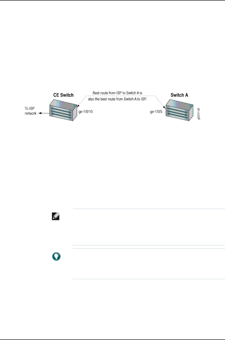
common application for unicast RPF is to help defend an enterprise network from
DoS/DDoS attacks coming from the Internet.
Enable unicast RPF only on symmetrically routed interfaces. A symmetrically routed
interface uses the same route in both directions between the source and the destination,
as shown in Figure 31 on page 1010. Symmetrical routing means that if an interface receives
a packet, the switch uses the same interface to send a reply to the packet source (the
receiving interface matches the forwarding-table entry for the best return path to the
source).
Figure 31: Symmetrically Routed Interfaces
Enabling unicast RPF on asymmetrically routed interfaces (where different interfaces
receive a packet and reply to its source) results in packets from legitimate sources being
filtered (discarded) because the best return path is not the same interface that received
the packet.
The following switch interfaces are most likely to be symmetrically routed and thus are
candidates for unicast RPF enabling:
•The service provider edge to a customer
•The customer edge to a service provider
•A single access point out of the network (usually on the network perimeter)
•A terminal network that has only one link
NOTE: Because unicast RPF is enabled globally on J-EX4200 switches, ensure
that all interfaces are symmetrically routed before you enable unicast RPF
on those switches. Enabling unicast RPF on asymmetrically routed interfaces
results in packets from legitimate sources being filtered.
TIP: Enabling unicast RPF as close as possible to the traffic source stops
spoofed traffic before it can proliferate or reach interfaces that do not have
unicast RPF enabled.
When Not to Enable Unicast RPF
Typically, you will not enable unicast RPF if:
•Switch interfaces are multihomed.
•Switch interfaces are trusted interfaces.
1010
Dell PowerConnect J-Series Ethernet Switch Complete Software Guide for Junos OS, Release 11.1: Volume 1
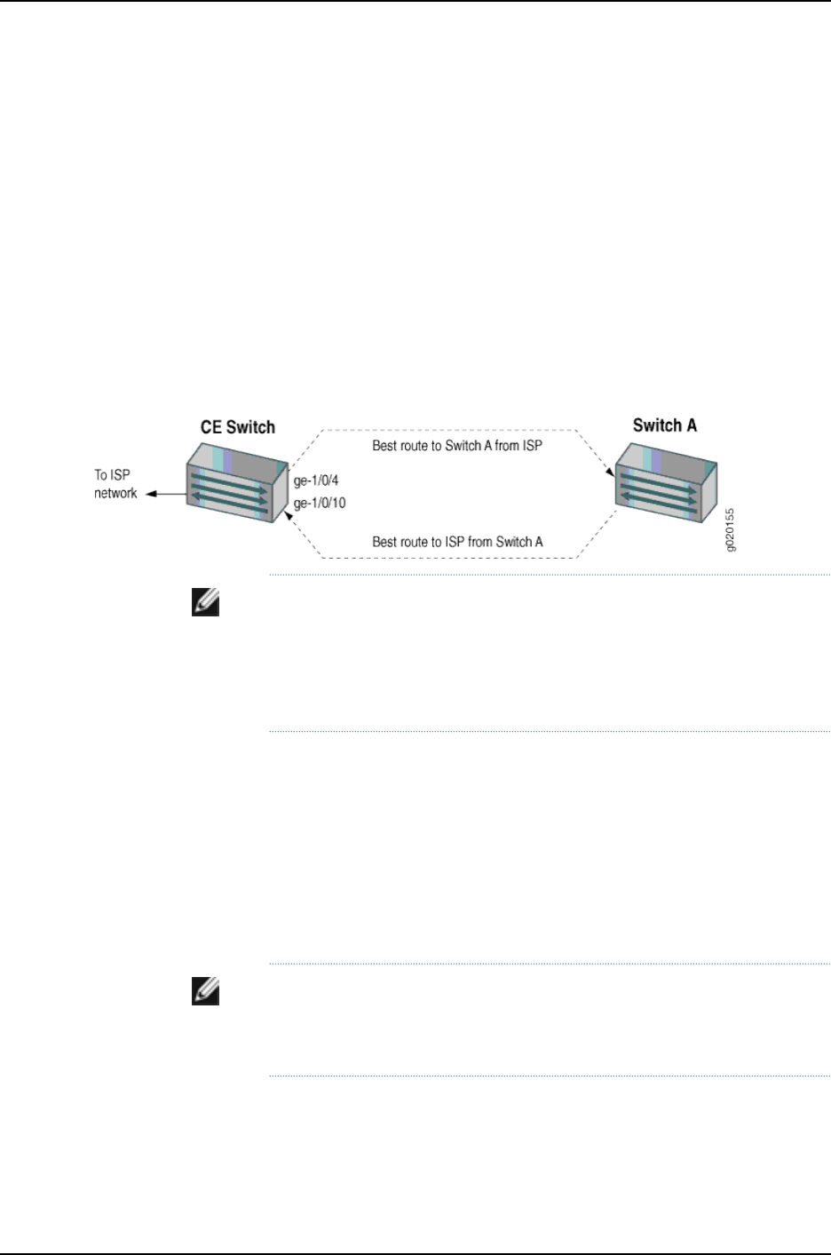
•BGP is carrying prefixes and some of those prefixes are not advertised or are not
accepted by the ISP under its policy. (The effect in this case is the same as filtering an
interface by using an incomplete access list.)
•Switch interfaces face the network core. Core-facing interfaces are usually
asymmetrically routed.
An asymmetrically routed interface uses different paths to send and receive packets
between the source and the destination, as shown in Figure 32 on page 1011. This means
that if an interface receives a packet, that interface does not match the forwarding table
entry as the best return path back to the source. If the receiving interface is not the best
return path to the source of a packet, unicast RPF causes the switch to discard the packet
even though it comes from a valid source.
Figure 32: Asymmetrically Routed Interfaces
NOTE: Do not enable unicast RPF on J-EX4200 switches if any switch
interfaces are asymmetrically routed, because unicast RPF is enabled globally
on all interfaces of those switches. All switch interfaces must be
symmetrically routed for you to enable unicast RPF without the risk of the
switch discarding traffic that you want to forward.
Limitations of the Unicast RPF Implementation on J-EX4200 Switches
On J-EX4200 switches, the switch implements unicast RPF on a global basis. You cannot
enable unicast RPF on a per-interface basis. Unicast RPF is globally disabled by default.
•When you enable unicast RPF on any interface, it is automatically enabled on all switch
interfaces, including link aggregation groups (LAGs) and routed VLAN interfaces (RVIs).
•When you disable unicast RPF on the interface (or interfaces) on which you enabled
unicast RPF, it is automatically disabled on all switch interfaces.
NOTE: You must explicitly disable unicast RPF on every interface on which
it was explicitly enabled. Otherwise, unicast RPF remains enabled on all
switch interfaces.
The J-EX4200 switches do not perform unicast RPF filtering on equal-cost multipath
(ECMP) traffic. The unicast RPF check examines only one best return path to the packet
source, but ECMP traffic employs an address block consisting of multiple paths.
1011
Chapter 50: Interfaces—Overview

Using unicast RPF to filter ECMP traffic on J-EX4200 switches can result in the switch
discarding packets that you want to forward because the unicast RPF filter does not
examine the entire ECMP address block.
Related
Documentation
Example: Configuring Unicast RPF on a J-EX Series Switch on page 1033•
•Configuring Unicast RPF (CLI Procedure) on page 1089
•Disabling Unicast RPF (CLI Procedure) on page 1091
Understanding IP Directed Broadcast for J-EX Series Switches
IP directed broadcast helps you implement remote administration tasks such as backups
and wake-on-LAN (WOL) application tasks by sending broadcast packets targeted at
the hosts in a specified destination subnet. IP directed broadcast packets traverse the
network in the same way as unicast IP packets until they reach the destination subnet.
When they reach the destination subnet and IP directed broadcast is enabled on the
receiving switch, the switch translates (“explodes”) the IP directed broadcast packet
into a broadcast that floods the packet on the target subnet. All hosts on the target
subnet receive the IP directed broadcast packet.
This topic covers:
•IP Directed Broadcast for J-EX Series Switches Overview on page 1012
•IP Directed Broadcast Implementation for J-EX Series Switches on page 1013
•When to Enable IP Directed Broadcast on page 1013
•When Not to Enable IP Directed Broadcast on page 1013
IP Directed Broadcast for J-EX Series Switches Overview
IP directed broadcast packets have a destination IP address that is a valid broadcast
address for the subnet that is the target of the directed broadcast (the target subnet).
The intent of an IP directed broadcast is to flood the target subnet with the broadcast
packets without broadcasting to the entire network. IP directed broadcast packets cannot
originate from the target subnet.
When you send an IP directed broadcast packet, as it travels to the target subnet, the
network forwards it in the same way as it forwards a unicast packet. When the packet
reaches a switch that is directly connected to the target subnet, the switch checks to see
whether IP directed broadcast is enabled on the interface that is directly connected to
the target subnet:
•If IP directed broadcast is enabled on that interface, the switch broadcasts the packet
on that subnet by rewriting the destination IP address as the configured broadcast IP
address for the subnet. The switch converts the packet to a link-layer broadcast packet
that every host on the network processes.
•If IP directed broadcast is disabled on the interface that is directly connected to the
target subnet, the switch drops the packet.
1012
Dell PowerConnect J-Series Ethernet Switch Complete Software Guide for Junos OS, Release 11.1: Volume 1

IP Directed Broadcast Implementation for J-EX Series Switches
You configure IP directed broadcast on a per-subnet basis by enabling IP directed
broadcast on the Layer 3 interface of the subnet’s VLAN. When the switch that is
connected to that subnet receives a packet that has the subnet’s broadcast IP address
as the destination address, the switch broadcasts the packet to all hosts on the subnet.
By default, IP directed broadcast is disabled.
When to Enable IP Directed Broadcast
IP directed broadcast is disabled by default. Enable IP directed broadcast when you want
to perform remote management or administration services such as backups or WOL
tasks on hosts in a subnet that does not have a direct connection to the Internet.
Enabling IP directed broadcast on a subnet affects only the hosts within that subnet.
Only packets received on the subnet’s Layer 3 interface that have the subnet’s broadcast
IP address as the destination address are flooded on the subnet.
When Not to Enable IP Directed Broadcast
Typically, you do not enable IP directed broadcast on subnets that have direct connections
to the Internet. Disabling IP directed broadcast on a subnet’s Layer 3 interface affects
only that subnet. If you disable IP directed broadcast on a subnet and a packet that has
the broadcast IP address of that subnet arrives at the switch, the switch drops the
broadcast packet.
If a subnet has a direct connection to the Internet, enabling IP directed broadcast on it
increases the network’s susceptibility to denial-of-service (DoS) attacks.
For example, a malicious attacker can spoof a source IP address (use a source IP address
that is not the actual source of the transmission to deceive a network into identifying the
attacker as a legitimate source) and send IP directed broadcasts containing Internet
Control Message Protocol (ICMP) echo (ping) packets. When the hosts on the network
with IP directed broadcast enabled receive the ICMP echo packets, they all send replies
to the victim that has the spoofed source IP address. This creates a flood of ping replies
in a DoS attack that can overwhelm the spoofed source address; this is known as a
“smurf” attack. Another common DoS attack on exposed networks with IP directed
broadcast enabled is a “fraggle” attack, which is similar to a smurf attack except that
the malicious packet is a User Datagram Protocol (UDP) echo packet instead of an ICMP
echo packet.
Related
Documentation
Example: Configuring IP Directed Broadcast on a J-EX Series Switch on page 1037•
•Configuring IP Directed Broadcast (CLI Procedure) on page 1091
802.1Q VLANs Overview
For Ethernet, Fast Ethernet, Tri-Rate Ethernet copper, Gigabit Ethernet, 10-Gigabit
Ethernet, and aggregated Ethernet interfaces supporting VPLS, the Junos OS supports
a subset of the IEEE 802.1Q standard for channelizing an Ethernet interface into multiple
1013
Chapter 50: Interfaces—Overview

logical interfaces, allowing many hosts to be connected to the same Gigabit Ethernet
switch, but preventing them from being in the same routing or bridging domain.
1014
Dell PowerConnect J-Series Ethernet Switch Complete Software Guide for Junos OS, Release 11.1: Volume 1

CHAPTER 51
Examples of Interfaces Configuration
•Example: Configuring Aggregated Ethernet High-Speed Uplinks Between a J-EX4200
Virtual Chassis Access Switch and a J-EX4200 Virtual Chassis Distribution
Switch on page 1015
•Example: Configuring Aggregated Ethernet High-Speed Uplinks with LACP Between
a J-EX4200 Virtual Chassis Access Switch and a J-EX4200 Virtual Chassis Distribution
Switch on page 1021
•Example: Configuring Layer 3 Subinterfaces for a Distribution Switch and an Access
Switch on page 1026
•Example: Configuring Unicast RPF on a J-EX Series Switch on page 1033
•Example: Configuring IP Directed Broadcast on a J-EX Series Switch on page 1037
Example: Configuring Aggregated Ethernet High-Speed Uplinks Between a J-EX4200
Virtual Chassis Access Switch and a J-EX4200 Virtual Chassis Distribution Switch
J-EX Series switches allow you to combine multiple Ethernet links into one logical interface
for higher bandwidth and redundancy. The ports that are combined in this manner are
referred to as a link aggregation group (LAG) or bundle. The number of Ethernet links
you can combine into a LAG depends on your J-EX Series switch model. See
“Understanding Aggregated Ethernet Interfaces and LACP” on page 1003 for more
information.
This example describes how to configure uplink LAGs to connect a Virtual Chassis access
switch to a Virtual Chassis distribution switch:
•Requirements on page 1015
•Overview and Topology on page 1016
•Configuration on page 1018
•Verification on page 1020
•Troubleshooting on page 1021
Requirements
This example uses the following software and hardware components:
1015

•Junos OS Release 10.2 or later for J-EX Series switches
•Two J-EX4200-48T switches
•Two J-EX4200-24F switches
•Four uplink modules
Before you configure the LAGs, be sure you have:
•Configured the Virtual Chassis switches. See “Configuring a J-EX4200 or J-EX4500
Virtual Chassis (CLI Procedure)” on page 822.
•Configured the uplink ports on the switches as trunk ports. See “Configuring Gigabit
Ethernet Interfaces (CLI Procedure)” on page 1042.
Overview and Topology
For maximum speed and resiliency, you can combine uplinks between an access switch
and a distribution switch into LAGs. Using LAGs can be particularly effective when
connecting a multimember Virtual Chassis access switch to a multimember Virtual
Chassis distribution switch.
The Virtual Chassis access switch in this example is composed of two member switches.
Each member switch has an uplink module with two 10-Gigabit Ethernet ports. These
ports are configured as trunk ports, connecting the access switch with the distribution
switch.
Configuring the uplinks as LAGs has the following advantages:
•Link Aggregation Control Protocol (LACP) can optionally be configured for link
negotiation.
•It doubles the speed of each uplink from 10 Gbps to 20 Gbps.
•If one physical port is lost for any reason (a cable is unplugged or a switch port fails,
or one member switch is unavailable), the logical port transparently continues to
function over the remaining physical port.
The topology used in this example consists of one Virtual Chassis access switch and one
Virtual Chassis distribution switch. The access switch is composed of two J-EX4200-48T
switches (SWA-0 and SWA-1), interconnected to each other with their Virtual Chassis
ports (VCPs) as member switches of Host-A. The distribution switch is composed of two
J-EX4200-24F switches (SWD-0 and SWD-1), interconnected with their VCPs as member
switches of Host-D.
Each member of the access switch has an uplink module installed. Each uplink module
has two ports. The uplinks are configured to act as trunk ports, connecting the access
switch with the distribution switch. One uplink port from SWA-0 and one uplink port from
SWA-1 are combined as LAG ae0 to SWD-0. This link is used for one VLAN. The remaining
uplink ports from SWA-0 and from SWA-1 are combined as a second LAG connection
(ae1) to SWD-1. LAG ae1 is used for another VLAN.
1016
Dell PowerConnect J-Series Ethernet Switch Complete Software Guide for Junos OS, Release 11.1: Volume 1
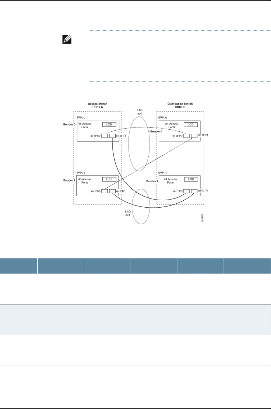
NOTE: If the remote end of the LAG link is a security device, LACP might not
be supported because security devices require a deterministic configuration.
In this case, do not configure LACP. All links in the LAG are permanently
operational unless the switch detects a link failure within the Ethernet physical
layer or data link layers.
Figure 33: Topology for LAGs Connecting a J-EX4200 Virtual Chassis
Access Switch to a J-EX4200 Virtual Chassis Distribution Switch
Table 151 on page 1017 details the topology used in this configuration example.
Table 151: Components of the Topology for Connecting a Virtual Chassis Access Switch to a
Virtual Chassis Distribution Switch
Trunk PortMember IDUplink ModuleBase Hardware
Hostname and
VCIDSwitch
xe-0/1/0 to SWD-0
xe-0/1/1 to SWD-1
0One uplink moduleJ-EX4200-48T
switch
Host-A Access
switch
VCID 1
SWA-0
xe-1/1/0 to SWD-0
xe-1/1/1 to SWD-1
1One plink moduleJ-EX4200-48T
switch
Host-A Access
switch
VCID 1
SWA-1
xe-0/1/0 to SWA-0
xe-0/1/1 to SWA-1
0One uplink moduleJ-EX4200-24F
switch
Host-D Distribution
switch
VCID 4
SWD-0
1017
Chapter 51: Examples of Interfaces Configuration

Table 151: Components of the Topology for Connecting a Virtual Chassis Access Switch to a
Virtual Chassis Distribution Switch (continued)
Trunk PortMember IDUplink ModuleBase Hardware
Hostname and
VCIDSwitch
xe-1/1/0 to SWA-0
xe-1/1/1 to SWA-1
1One uplink moduleJ-EX4200-24F
switch
Host-D Distribution
switch
VCID 4
SWD-1
Configuration
To configure two uplink LAGs from the Virtual Chassis access switch to the Virtual Chassis
distribution switch:
CLI Quick
Configuration
To quickly configure aggregated Ethernet high-speed uplinks between a Virtual Chassis
access switch and a Virtual Chassis distribution switch, copy the following commands
and paste them into the switch terminal window:
[edit]
set chassis aggregated-devices ethernet device-count 2
set interfaces ae0 aggregated-ether-options minimum-links 1
set interfaces ae0 aggregated-ether-options link-speed 10g
set interfaces ae1 aggregated-ether-options minimum-links 1
set interfaces ae1 aggregated-ether-options link-speed 10g
set interfaces ae0 unit 0 family inet address 192.0.2.0/25
set interfaces ae1 unit 0 family inet address 192.0.2.128/25
set interfaces ge-0/1/0 ether-options 802.3ad ae0
set interfaces ge-1/1/0 ether-options 802.3ad ae0
set interfaces ge-0/1/1 ether-options 802.3ad ae1
set interfaces ge-1/1/1 ether-options 802.3ad ae1
Step-by-Step
Procedure
To configure aggregated Ethernet high-speed uplinks between a Virtual Chassis access
switch and a Virtual Chassis distribution switch:
1. Specify the number of LAGs to be created on the chassis:
[edit chassis]
user@Host-A# set aggregated-devices ethernet device-count 2
2. Specify the number of links that need to be present for the ae0 LAG interface to be
up:
[edit interfaces]
user@Host-A# set ae0 aggregated-ether-options minimum-links 1
3. Specify the number of links that need to be present for the ae1 LAG interface to be
up:
[edit interfaces]
user@Host-A# set ae1 aggregated-ether-options minimum-links 1
4. Specify the media speed of the ae0 link:
[edit interfaces]
user@Host-A# set ae0 aggregated-ether-options link-speed 10g
5. Specify the media speed of the ae1 link:
[edit interfaces]
1018
Dell PowerConnect J-Series Ethernet Switch Complete Software Guide for Junos OS, Release 11.1: Volume 1

user@Host-A# set ae1 aggregated-ether-options link-speed 10g
6. Specify the interface ID of the uplinks to be included in LAG ae0:
[edit interfaces]
user@Host-A# set ge-0/1/0 ether-options 802.3ad ae0
user@Host-A# set ge-1/1/0 ether-options 802.3ad ae0
7. Specify the interface ID of the uplinks to be included in LAG ae1:
[edit interfaces]
user@Host-A# set ge-0/1/1 ether-options 802.3ad ae1
user@Host-A# set ge-1/1/1 ether-options 802.3ad ae1
8. Specify that LAG ae0 belongs to the subnet for the employee broadcast domain:
[edit interfaces]
user@Host-A# set ae0 unit 0 family inet address 192.0.2.0/25
9. Specify that LAG ae1 belongs to the subnet for the guest broadcast domain:
[edit interfaces]
user@Host-A# set ae1 unit 0 family inet address 192.0.2.128/25
Results Display the results of the configuration:
[edit]
chassis {
aggregated-devices {
ethernet {
device-count 2;
}
}
}
interfaces {
ae0 {
aggregated-ether-options {
link-speed 10g;
minimum-links 1;
}
unit 0 {
family inet {
address 192.0.2.0/25;
}
}
}
ae1 {
aggregated-ether-options {
link-speed 10g;
minimum-links 1;
}
unit 0 {
family inet {
address 192.0.2.128/25;
}
}
ge–0/1/0 {
ether-options {
1019
Chapter 51: Examples of Interfaces Configuration

802.3ad ae0;
}
}
ge–1/1/0 {
ether-options {
802.3ad ae0;
}
}
ge–0/1/1 {
ether-options {
802.3ad ae1;
}
}
ge–1/1/1 {
ether-options {
802.3ad ae1;
}
}
}
Verification
To verify that switching is operational and two LAGs have been created, perform these
tasks:
•Verifying That LAG ae0 Has Been Created on page 1020
•Verifying That LAG ae1 Has Been Created on page 1020
Verifying That LAG ae0 Has Been Created
Purpose Verify that LAG ae0 has been created on the switch.
Action show interfaces ae0 terse
Interface Admin Link Proto Local Remote
ae0 up up
ae0.0 up up inet 192.0.2.0/25
Meaning The output confirms that the ae0 link is up and shows the family and IP address assigned
to this link.
Verifying That LAG ae1 Has Been Created
Purpose Verify that LAG ae1 has been created on the switch
Action show interfaces ae1 terse
Interface Admin Link Proto Local Remote
ae1 up down
ae1.0 up down inet 192.0.2.128/25
Meaning The output shows that the ae1 link is down.
1020
Dell PowerConnect J-Series Ethernet Switch Complete Software Guide for Junos OS, Release 11.1: Volume 1

Troubleshooting
Troubleshooting a LAG That Is Down
Problem The show interfaces terse command shows that the LAG is down.
Solution Check the following:
•Verify that there is no configuration mismatch.
•Verify that all member ports are up.
•Verify that a LAG is part of family ethernet switching (Layer 2 LAG) or family inet (Layer
3 LAG).
•Verify that the LAG member is connected to the correct LAG at the other end.
•Verify that the LAG members belong to the same switch (or the same Virtual Chassis).
Related
Documentation
Example: Configuring a J-EX4200 Virtual Chassis with a Master and Backup in a Single
Wiring Closet on page 736
•
•Example: Configuring Aggregated Ethernet High-Speed Uplinks with LACP Between
a J-EX4200 Virtual Chassis Access Switch and a J-EX4200 Virtual Chassis Distribution
Switch on page 783
•Example: Connecting an Access Switch to a Distribution Switch.
•Virtual Chassis Cabling Configuration Examples for J-EX4200 Switches
•Installing an Uplink Module in a J-EX4200 Switch
•Uplink Modules in J-EX4200 Switches
Example: Configuring Aggregated Ethernet High-Speed Uplinks with LACP Between
a J-EX4200 Virtual Chassis Access Switch and a J-EX4200 Virtual Chassis Distribution
Switch
J-EX Series switches allow you to combine multiple Ethernet links into one logical interface
for higher bandwidth and redundancy. The ports that are combined in this manner are
referred to as a link aggregation group (LAG) or bundle. J-EX Series switches allow you
to further enhance these links by configuring Link Aggregation Control Protocol (LACP).
This example describes how to overlay LACP on the LAG configurations that were created
in “Example: Configuring Aggregated Ethernet High-Speed Uplinks Between a J-EX4200
Virtual Chassis Access Switch and a J-EX4200 Virtual Chassis Distribution Switch” on
page 777:
•Requirements on page 1022
•Overview and Topology on page 1022
•Configuring LACP for the LAGs on the Virtual Chassis Access Switch on page 1022
•Configuring LACP for the LAGs on the Virtual Chassis Distribution Switch on page 1023
1021
Chapter 51: Examples of Interfaces Configuration

•Verification on page 1024
•Troubleshooting on page 1025
Requirements
This example uses the following software and hardware components:
•Junos OS Release 10.2 or later for J-EX Series switches
•Two J-EX4200-48T switches
•Two J-EX4200-24F switches
•Four J-EX Series uplink modules
Before you configure LACP, be sure you have:
•Set up the Virtual Chassis switches. See “Configuring a J-EX4200 or J-EX4500 Virtual
Chassis (CLI Procedure)” on page 822.
•Configured the uplink ports on the switches as trunk ports. See “Configuring Gigabit
Ethernet Interfaces (CLI Procedure)” on page 1042.
•Configured the LAGs. See “Example: Configuring Aggregated Ethernet High-Speed
Uplinks Between a J-EX4200 Virtual Chassis Access Switch and a J-EX4200 Virtual
Chassis Distribution Switch” on page 777.
Overview and Topology
This example assumes that you are familiar with “Example: Configuring Aggregated
Ethernet High-Speed Uplinks Between a J-EX4200 Virtual Chassis Access Switch and a
J-EX4200 Virtual Chassis Distribution Switch” on page 777. The topology in this example
is exactly the same as the topology in that other example. This example shows how to
use LACP to enhance the LAG functionality.
LACP exchanges are made between actors (the transmitting link) and partners (the
receiving link). The LACP mode can be either active or passive.
NOTE: If the actor and partner are both in passive mode, they do not exchange
LACP packets, which results in the aggregated Ethernet links not coming up.
By default, LACP is in passive mode. To initiate transmission of LACP packets
and responses to LACP packets, you must enable LACP in active mode.
By default, the actor and partner send LACP packets every second.
The interval can be fast (every second) or slow (every 30 seconds).
Configuring LACP for the LAGs on the Virtual Chassis Access Switch
To configure LACP for the access switch LAGs, perform these tasks:
CLI Quick
Configuration
To quickly configure LACP for the access switch LAGs, copy the following commands
and paste them into the switch terminal window:
1022
Dell PowerConnect J-Series Ethernet Switch Complete Software Guide for Junos OS, Release 11.1: Volume 1

[edit]
set interfaces ae0 aggregated-ether-options lacp active periodic fast
set interfaces ae1 aggregated-ether-options lacp active periodic fast
Step-by-Step
Procedure
To configure LACP for Host-A LAGs ae0 and ae1:
1. Specify the aggregated Ethernet options for both bundles:
[edit interfaces]
user@Host-A#set ae0 aggregated-ether-options lacp active periodic fast
user@Host-A#set ae1 aggregated-ether-options lacp active periodic fast
Results Display the results of the configuration:
[edit interfaces]
user@Host-A# show
ae0 {
aggregated-ether-options {
lacp {
active;
periodic fast;
}
}
}
ae1 {
aggregated-ether-options {
lacp {
active;
periodic fast;
}
}
}
Configuring LACP for the LAGs on the Virtual Chassis Distribution Switch
To configure LACP for the two uplink LAGs from the Virtual Chassis access switch to the
Virtual Chassis distribution switch, perform these tasks:
CLI Quick
Configuration
To quickly configure LACP for the distribution switch LAGs, copy the following commands
and paste them into the switch terminal window:
[edit interfaces]
set ae0 aggregated-ether-options lacp passive periodic fast
set ae1 aggregated-ether-options lacp passive periodic fast
Step-by-Step
Procedure
To configure LACP for Host D LAGs ae0 and ae1:
1. Specify the aggregated Ethernet options for both bundles:
[edit interfaces]
user@Host-D#set ae0 aggregated-ether-options lacp passive periodic fast
user@Host-D#set ae1 aggregated-ether-options lacp passive periodic fast
Results Display the results of the configuration:
[edit interfaces]
user@Host-D# show
1023
Chapter 51: Examples of Interfaces Configuration

ae0 {
aggregated-ether-options {
lacp {
passive;
periodic fast;
}
}
}
ae1 {
aggregated-ether-options {
lacp {
passive
periodic fast;
}
}
}
Verification
To verify that LACP packets are being exchanged, perform these tasks:
•Verifying the LACP Settings on page 1024
•Verifying That the LACP Packets Are Being Exchanged on page 1024
Verifying the LACP Settings
Purpose Verify that LACP has been set up correctly.
Action Use the show lacp interfaces interface-name command to check that LACP has been
enabled as active on one end.
user@Host-A> show lacp interfaces ge-0/1/0
Aggregated interface: ae0
LACP state: Role Exp Def Dist Col Syn Aggr Timeout Activity
ge-0/1/0 Actor No Yes No No No Yes Fast Active
ge-0/1/0 Partner No Yes No No No Yes Fast Passive
LACP protocol: Receive State Transmit State Mux State
ge-0/1/0 Defaulted Fast periodic Detached
Meaning The output indicates that LACP has been set up correctly and is active at one end.
Verifying That the LACP Packets Are Being Exchanged
Purpose Verify that LACP packets are being exchanged.
Action Use the show interfaces aexstatistics command to display LACP information.
user@Host-A> show interfaces ae0 statistics
1024
Dell PowerConnect J-Series Ethernet Switch Complete Software Guide for Junos OS, Release 11.1: Volume 1

Physical interface: ae0, Enabled, Physical link is Down
Interface index: 153, SNMP ifIndex: 30
Link-level type: Ethernet, MTU: 1514, Speed: Unspecified, Loopback: Disabled,
Source filtering: Disabled, Flow control: Disabled, Minimum links needed: 1,
Minimum bandwidth needed: 0
Device flags : Present Running
Interface flags: Hardware-Down SNMP-Traps Internal: 0x0
Current address: 02:19:e2:50:45:e0, Hardware address: 02:19:e2:50:45:e0
Last flapped : Never
Statistics last cleared: Never
Input packets : 0
Output packets: 0
Input errors: 0, Output errors: 0
Logical interface ae0.0 (Index 71) (SNMP ifIndex 34)
Flags: Hardware-Down Device-Down SNMP-Traps Encapsulation: ENET2
Statistics Packets pps Bytes bps
Bundle:
Input : 0 0 0 0
Output: 0 0 0 0
Protocol inet
Flags: None
Addresses, Flags: Dest-route-down Is-Preferred Is-Primary
Destination: 10.10.10/24, Local: 10.10.10.1, Broadcast: 10.10.10.255
Meaning The output here shows that the link is down and that no protocol data units (PDUs) are
being exchanged.
Troubleshooting
To troubleshoot a nonworking LACP link, perform these tasks:
Troubleshooting a Nonworking LACP Link
Problem The LACP link is not working.
Solution Check the following:
•Remove the LACP configuration and verify whether the static LAG is up.
•Verify that LACP is configured at both ends.
•Verify that LACP is not passive at both ends.
•Verify whether LACP protocol data units (PDUs) are being exchanged by running the
monitor traffic-interface lag-member detail command.
Related
Documentation
Example: Connecting an Access Switch to a Distribution Switch•
•Virtual Chassis Cabling Configuration Examples for J-EX4200 Switches
•Installing an Uplink Module in a J-EX4200 Switch
•Understanding Aggregated Ethernet Interfaces and LACP on page 1003
1025
Chapter 51: Examples of Interfaces Configuration

Example: Configuring Layer 3 Subinterfaces for a Distribution Switch and an Access
Switch
In a large LAN, you commonly need to partition the network into multiple VLANs. You
can configure Layer 3 subinterfaces to route traffic between the VLANs. In one common
topology, known as a “router on a stick” or a “one-armed router,” you connect a router
to an access switch with connections to multiple VLANs.
This example describes how to create Layer 3 subinterfaces on trunk interfaces of a
distribution switch and access switch so that you can route traffic among multiple VLANs:
•Requirements on page 1026
•Overview and Topology on page 1026
•Configuring the Access Switch Subinterfaces on page 1027
•Configuring the Distribution Switch Subinterfaces on page 1029
•Verification on page 1031
Requirements
This example uses the following hardware and software components:
•For the distribution switch, one J-EX4200-24F switch. This model is designed to be
used as a distribution switch for aggregation or collapsed core network topologies and
in space-constrained data centers. It has twenty-four 1-Gigabit Ethernet fiber SFP ports
and an uplink module with two 10-Gigabit Ethernet SFP+ ports.
•For the access switch, any Layer 2 switch that supports 802.1Q VLAN tags.
•Junos OS Release 10.2 or later for J-EX Series switches.
Before you connect the switches, make sure you have:
•Connected the two switches.
•Configured the necessary VLANs. See the instructions for configuring VLANs in the Dell
PowerConnect J-Series Ethernet Switch Complete Software Guide for Junos OS: Volume
2at http://www.support.dell.com/manuals.
Overview and Topology
In a large office with multiple buildings and VLANs, you commonly aggregate traffic from
a number of access switches into a distribution switch. This configuration example shows
a simple topology to illustrate how to connect a single Layer 2 access switch connected
to multiple VLANs to a distribution switch, enabling traffic to pass between those VLANs.
In the example topology, the LAN is segmented into five VLANs, all associated with
interfaces on the access switch. One 1-Gigabit Ethernet port on the access switch's uplink
module connects to one 1-Gigabit Ethernet port on the distribution switch.
Table 152 on page 1027 lists the settings for the example topology.
1026
Dell PowerConnect J-Series Ethernet Switch Complete Software Guide for Junos OS, Release 11.1: Volume 1

Table 152: Components of the Topology for Creating Layer 3 Subinterfaces on an Access Switch
and a Distribution Switch
SettingsProperty
Any Layer 2 switch with multiple 1-Gigabit Ethernet ports and at least one 1-Gigabit
Ethernet uplink module
Access switch hardware
J-EX4200-24F, 24 1-Gigabit Ethernet fiber SPF ports (ge-0/0/0 through ge-0/0/23);
one 2-port 10-Gigabit Ethernet SFP+ uplink module
Distribution switch hardware
vlan1, tag 101
vlan2, tag 102
vlan3, tag 103
vlan4, tag 104
vlan5, tag 105
VLAN names and tag IDs
vlan1: 1.1.1.0/24 (addresses 1.1.1.1 through 1.1.1.254)
vlan2: 2.1.1.0/24 (addresses 2.1.1.1 through 2.1.1.254)
vlan3: 3.1.1.0/24 (addresses 3.1.1.1 through 3.1.1.254)
vlan4: 4.1.1.0/24 (addresses 4.1.1.1 through 4.1.1.254)
vlan5: 5.1.1.0/24 (addresses 5.1.1.1 through 5.1.1.254)
VLAN subnets
On the access switch: ge-0/1/0
On the distribution switch: ge-0/0/0
Port interfaces
Configuring the Access Switch Subinterfaces
CLI Quick
Configuration
To quickly create and configure subinterfaces on the access switch, copy the following
commands and paste them into the switch terminal window:
[edit]
set interfaces ge-0/1/0 vlan-tagging
set interfaces ge-0/1/0 unit 0 vlan-id 101 family inet address 1.1.1.1/24
set interfaces ge-0/1/0 unit 1 vlan-id 102 family inet address 2.1.1.1/24
set interfaces ge-0/1/0 unit 2 vlan-id 103 family inet address 3.1.1.1/24
set interfaces ge-0/1/0 unit 3 vlan-id 104 family inet address 4.1.1.1/24
set interfaces ge-0/1/0 unit 4 vlan-id 105 family inet address 5.1.1.1/24
Step-by-Step
Procedure
To configure the subinterfaces on the access switch:
1. On the trunk interface of the access switch, enable VLAN tagging:
[edit interfaces ge-0/1/0]
user@access-switch# set vlan-tagging
2. Bind vlan1's VLAN ID to the logical interface:
[edit interfaces ge-0/1/0]
user@access-switch# set unit 0 vlan-id 101
1027
Chapter 51: Examples of Interfaces Configuration

3. Set vlan1's subinterface IP address:
[edit interfaces ge-0/1/0]
user@access-switch# set unit 0 family inet address 1.1.1.1/24
4. Bind vlan2's VLAN ID to the logical interface:
[edit interfaces ge-0/1/0]
user@access-switch# set unit 1 vlan-id 102
5. Set vlan2's subinterface IP address:
[edit interfaces ge-0/1/0]
user@access-switch# set unit 1 family inet address 2.1.1.1/24
6. Bind vlan3's VLAN ID to the logical interface:
[edit interfaces ge-0/1/0]
user@access-switch# set unit 2 vlan–id 103
7. Set vlan3's subinterface IP address:
[edit interfaces ge-0/1/0]
user@access-switch# set unit 2 family inet address 3.1.1.1/24
8. Bind vlan4's VLAN ID to the logical interface:
[edit interfaces ge-0/1/0]
user@access-switch# set unit 3 vlan-id 104
9. Set vlan4's subinterface IP address:
[edit interfaces ge-0/1/0]
user@access-switch# set unit 3 family inet address 4.1.1.1/24
10. Bind vlan5's VLAN ID to the logical interface:
[edit interfaces ge-0/1/0]
user@access-switch# set unit 4 vlan-id 105
11. Set vlan5's subinterface IP address:
[edit interfaces ge-0/1/0]
user@access-switch# set unit 4 family inet address 5.1.1.1/24
Results Check the results of the configuration:
user@access-switch> show configuration
interfaces {
ge-0/1/0 {
vlan-tagging;
unit 0 {
vlan-id 101;
family inet {
address 1.1.1.1/24;
}
}
unit 1 {
vlan-id 102;
family inet {
address 2.1.1.1/24;
1028
Dell PowerConnect J-Series Ethernet Switch Complete Software Guide for Junos OS, Release 11.1: Volume 1

}
}
unit 2 {
vlan-id 103;
family inet {
address 3.1.1.1/24;
}
}
unit 3 {
vlan-id 104;
family inet {
address 4.1.1.1/24;
}
}
unit 4 {
vlan-id 105;
family inet {
address 5.1.1.1/24;
}
}
}
Configuring the Distribution Switch Subinterfaces
CLI Quick
Configuration
To quickly create and configure subinterfaces on the distribution switch, copy the following
commands and paste them into the switch terminal window:
[edit]
set interfaces ge-0/0/0 vlan-tagging
set interfaces ge-0/0/0 unit 0 vlan-id 101 family inet address 1.1.1.2/24
set interfaces ge-0/0/0 unit 1 vlan-id 102 family inet address 2.1.1.2/24
set interfaces ge-0/0/0 unit 2 vlan-id 103 family inet address 3.1.1.2/24
set interfaces ge-0/0/0 unit 3 vlan-id 104 family inet address 4.1.1.2/24
set interfaces ge-0/0/0 unit 4 vlan-id 105 family inet address 5.1.1.2/24
Step-by-Step
Procedure
To configure subinterfaces on the distribution switch:
1. On the trunk interface of the distribution switch, enable VLAN tagging:
[edit interfaces ge-0/0/0]
user@distribution-switch# set vlan-tagging
2. Bind vlan1's VLAN ID to the logical interface:
[edit interfaces ge-0/0/0]
user@distribution-switch# set unit 0 vlan-id 101
3. Set vlan1's subinterface IP address:
[edit interfaces ge-0/0/0]
user@distribution-switch# set unit 0 family inet address 1.1.1.2/24
4. Bind vlan2's VLAN ID to the logical interface:
[edit interfaces ge-0/0/0]
user@distribution-switch# set unit 1 vlan-id 102
5. Set vlan2's subinterface IP address:
[edit interfaces ge-0/0/0]
1029
Chapter 51: Examples of Interfaces Configuration

user@distribution-switch# set unit 1 family inet address 2.1.1.2/24
6. Bind vlan3's VLAN ID to the logical interface:
[edit interfaces ge-0/0/0]
user@distribution-switch# set unit 2 vlan-id 103
7. Set vlan3's subinterface IP address:
[edit interfaces ge-0/0/0]
user@distribution-switch# set unit 2 family inet address 3.1.1.2/24
8. Bind vlan4's VLAN ID to the logical interface:
[edit interfaces ge-0/0/0]
user@distribution-switch# set unit 3 vlan-id 104
9. Set vlan4's subinterface IP address:
[edit interfaces ge-0/0/0]
user@distribution-switch# set unit 3 family inet address 4.1.1.2/24
10. Bind vlan5's VLAN ID to the logical interface:
[edit interfaces ge-0/0/0]
user@distribution-switch# set unit 4 vlan-id 105
11. Set vlan5's subinterface IP address:
[edit interfaces ge-0/0/0]
user@distribution-switch# set unit 4 family inet address 5.1.1.2/24
Results user@distribution-switch> show configuration
interfaces {
ge-0/0/0 {
vlan-tagging;
unit 0 {
vlan-id 101;
family inet {
address 1.1.1.2/24;
}
}
unit 1 {
vlan-id 102;
family inet {
address 2.1.1.2/24;
}
}
unit 2 {
vlan-id 103;
family inet {
address 3.1.1.2/24;
}
}
unit 3 {
vlan-id 104;
family inet {
address 4.1.1.2/24;
}
}
1030
Dell PowerConnect J-Series Ethernet Switch Complete Software Guide for Junos OS, Release 11.1: Volume 1

unit 4 {
vlan-id 105;
family inet {
address 5.1.1.2/24;
}
}
}
Verification
To confirm that the configuration is working properly, perform these tasks:
•Verifying That Subinterfaces Were Created on page 1031
•Verifying That Traffic Passes Between VLANs on page 1031
Verifying That Subinterfaces Were Created
Purpose Verify that the subinterfaces were properly created on the access switch and distribution
switch.
Action Use the show interfaces command on the access switch:1.
user@access-switch> show interfaces ge-0/1/0 terse
Interface Admin Link Proto Local Remote
ge-0/1/0 up up
ge-0/1/0.0 up up inet 1.1.1.1/24
ge-0/1/0.1 up up inet 2.1.1.1/24
ge-0/1/0.2 up up inet 3.1.1.1/24
ge-0/1/0.3 up up inet 4.1.1.1/24
ge-0/1/0.4 up up inet 5.1.1.1/24
ge-0/1/0.32767 up up
2. Use the show interfaces command on the distribution switch:
user@distribution-switch> show interfaces ge-0/0/0 terse
Interface Admin Link Proto Local Remote
ge-0/0/0 up up
ge-0/0/0.0 up up inet 1.1.1.2/24
ge-0/0/0.1 up up inet 2.1.1.2/24
ge-0/0/0.2 up up inet 3.1.1.2/24
ge-0/0/0.3 up up inet 4.1.1.2/24
ge-0/0/0.4 up up inet 5.1.1.2/24
ge-0/0/0.32767 up up
Meaning Each subinterface created is displayed as a ge-fpc/pic/port.x logical interface, where x
is the unit number in the configuration. The status is listed as up, indicating the link is
working.
Verifying That Traffic Passes Between VLANs
Purpose Verify that the distribution switch is correctly routing traffic from one VLAN to another.
1031
Chapter 51: Examples of Interfaces Configuration

Action Ping from the access switch to the distribution switch on each subinterface.
1. From the access switch, ping the address of the vlan1 subinterface on the distribution
switch:
user@access-switch> ping 1.1.1.2 count 4
PING 1.1.1.2 (1.1.1.2): 56 data bytes
64 bytes from 1.1.1.2: icmp_seq=0 ttl=64 time=0.333 ms
64 bytes from 1.1.1.2: icmp_seq=1 ttl=64 time=0.113 ms
64 bytes from 1.1.1.2: icmp_seq=2 ttl=64 time=0.112 ms
64 bytes from 1.1.1.2: icmp_seq=3 ttl=64 time=0.158 ms
--- 1.1.1.2 ping statistics ---
4 packets transmitted, 4 packets received, 0% packet loss
round-trip min/avg/max/stddev = 0.112/0.179/0.333/0.091 ms
2. From the access switch, ping the address of the vlan2 subinterface on the distribution
switch:
user@access-switch> ping 2.1.1.2 count 4
PING 2.1.1.2 (2.1.1.2): 56 data bytes
64 bytes from 2.1.1.2: icmp_seq=0 ttl=64 time=0.241 ms
64 bytes from 2.1.1.2: icmp_seq=1 ttl=64 time=0.113 ms
64 bytes from 2.1.1.2: icmp_seq=2 ttl=64 time=0.162 ms
64 bytes from 2.1.1.2: icmp_seq=3 ttl=64 time=0.167 ms
--- 2.1.1.2 ping statistics ---
4 packets transmitted, 4 packets received, 0% packet loss
round-trip min/avg/max/stddev = 0.113/0.171/0.241/0.046 ms
3. From the access switch, ping the address of the vlan3 subinterface on the distribution
switch:
user@access-switch> ping 3.1.1.2 count 4
PING 3.1.1.2 (3.1.1.2): 56 data bytes
64 bytes from 3.1.1.2: icmp_seq=0 ttl=64 time=0.341 ms
64 bytes from 3.1.1.2: icmp_seq=1 ttl=64 time=0.162 ms
64 bytes from 3.1.1.2: icmp_seq=2 ttl=64 time=0.112 ms
64 bytes from 3.1.1.2: icmp_seq=3 ttl=64 time=0.208 ms
--- 3.1.1.2 ping statistics ---
4 packets transmitted, 4 packets received, 0% packet loss
round-trip min/avg/max/stddev = 0.112/0.206/0.341/0.085 ms
4. From the access switch, ping the address of the vlan4 subinterface on the distribution
switch:
user@access-switch> ping 4.1.1.2 count 4
PING 4.1.1.2 (4.1.1.2): 56 data bytes
64 bytes from 4.1.1.2: icmp_seq=0 ttl=64 time=0.226 ms
64 bytes from 4.1.1.2: icmp_seq=1 ttl=64 time=0.166 ms
64 bytes from 4.1.1.2: icmp_seq=2 ttl=64 time=0.107 ms
64 bytes from 4.1.1.2: icmp_seq=3 ttl=64 time=0.221 ms
--- 4.1.1.2 ping statistics ---
1032
Dell PowerConnect J-Series Ethernet Switch Complete Software Guide for Junos OS, Release 11.1: Volume 1

4 packets transmitted, 4 packets received, 0% packet loss
round-trip min/avg/max/stddev = 0.107/0.180/0.226/0.048 ms
5. From the access switch, ping the address of the vlan5 subinterface on the distribution
switch:
user@access-switch> ping 5.1.1.2 count 4
PING 5.1.1.2 (5.1.1.2): 56 data bytes
64 bytes from 5.1.1.2: icmp_seq=0 ttl=64 time=0.224 ms
64 bytes from 5.1.1.2: icmp_seq=1 ttl=64 time=0.104 ms
64 bytes from 5.1.1.2: icmp_seq=2 ttl=64 time=0.102 ms
64 bytes from 5.1.1.2: icmp_seq=3 ttl=64 time=0.170 ms
--- 5.1.1.2 ping statistics ---
4 packets transmitted, 4 packets received, 0% packet loss
round-trip min/avg/max/stddev = 0.102/0.150/0.224/0.051 ms
Meaning If all the ping packets are transmitted and are received by the destination address, the
subinterfaces are up and working.
Related
Documentation
Example: Connecting an Access Switch to a Distribution Switch•
•Configuring a Layer 3 Subinterface (CLI Procedure) on page 1089
Example: Configuring Unicast RPF on a J-EX Series Switch
Unicast reverse-path forwarding (RPF) helps protect the switch against denial-of-service
(DoS) and distributed denial-of-service (DDoS) attacks by verifying the unicast source
address of each packet that arrives on an ingress interface where unicast RPF is enabled.
This example shows how to help defend the switch ingress interfaces against
denial-of-service (DoS) and distributed denial-of-service (DDoS) attacks by configuring
unicast reverse-path forwarding (RPF) on a customer-edge interface to filter incoming
traffic:
•Requirements on page 1033
•Overview and Topology on page 1034
•Configuration on page 1034
•Verification on page 1035
Requirements
This example uses the following software and hardware components:
•Junos OS Release 10.2 or later for J-EX Series switches
•Two J-EX8200 switches
Before you begin, be sure you have:
•Connected the two switches by symmetrically routed interfaces.
1033
Chapter 51: Examples of Interfaces Configuration

•Ensured that the interface on which you will configure unicast RPF is symmetrically
routed.
Overview and Topology
Large amounts of unauthorized traffic such as attempts to flood a network with fake
(bogus) service requests in a denial-of-service (DoS) attack can consume network
resources and deny service to legitimate users. One way to help prevent DoS and
distributed denial-of-service (DDoS) attacks is to verify that incoming traffic originates
from legitimate network sources.
Unicast RPF helps ensure that a traffic source is legitimate (authorized) by comparing
the source address of each packet that arrives on an interface to the forwarding-table
entry for its source address. If the switch uses the same interface that the packet arrived
on to reply to the packet's source, this verifies that the packet originated from an
authorized source, and the switch forwards the packet. If the switch does not use the
same interface that the packet arrived on to reply to the packet's source, the packet
might have originated from an unauthorized source, and the switch discards the packet.
This example uses two J-EX8200 switches. On J-EX4200 switches, you cannot configure
individual interfaces for unicast RPF. On J-EX4200 switches, the switch applies unicast
RPF globally to all interfaces on the switch. See “Understanding Unicast RPF for J-EX
Series Switches” on page 1008 for more information on limitations regarding the
configuration of unicast RPF on J-EX4200 switches.
In this example, an enterprise network's system administrator wants to protect Switch
A against potential DoS and DDoS attacks from the Internet. The administrator configures
unicast RPF on interface ge-1/0/10 on Switch A. Packets arriving on interface ge-1/0/10
on Switch A from the Switch B source also use incoming interface ge-1/0/10 as the best
return path to send packets back to the source.
The topology of this configuration example uses two J-EX8200 switches, Switch A and
Switch B, connected by symmetrically routed interfaces:
•Switch A is on the edge of an enterprise network. The interface ge-1/0/10 on Switch A
connects to the interface ge-1/0/5 on Switch B.
•Switch B is on the edge of the service provider network that connects the enterprise
network to the Internet.
Configuration
To enable unicast RPF, perform these tasks:
CLI Quick
Configuration
To quickly configure unicast RPF on Switch A, copy the following command and paste
it into the switch terminal window:
[edit interfaces]
set ge-1/0/10 unit 0 family inet rpf-check
1034
Dell PowerConnect J-Series Ethernet Switch Complete Software Guide for Junos OS, Release 11.1: Volume 1

Step-by-Step
Procedure
To configure unicast RPF on Switch A:
1. Enable unicast RPF on interface ge-1/0/10:
[edit interfaces]
user@switch# set ge-1/0/10 unit 0 family inet rpf-check
Results Check the results:
[edit interfaces]
user@switch# show
ge-1/0/10 {
unit 0 {
family inet {
rpf-check;
}
}
}
Verification
To confirm that the configuration is correct, perform these tasks:
•Verifying That Unicast RPF Is Enabled on the Switch on page 1035
Verifying That Unicast RPF Is Enabled on the Switch
Purpose Verify that unicast RPF is enabled.
Action Verify that unicast RPF is enabled on interface ge-1/0/10 by using the show interfaces
ge-1/0/10 extensive or show interfaces ge-1/0/10 detail command.
user@switch> show interfaces ge-1/0/10 extensive
Physical interface: ge-1/0/10, Enabled, Physical link is Down
Interface index: 139, SNMP ifIndex: 58, Generation: 140
Link-level type: Ethernet, MTU: 1514, Speed: Auto, MAC-REWRITE Error: None,
Loopback: Disabled, Source filtering: Disabled, Flow control: Enabled,
Auto-negotiation: Enabled, Remote fault: Online
Device flags : Present Running
Interface flags: Hardware-Down SNMP-Traps Internal: 0x0
Link flags : None
CoS queues : 8 supported, 8 maximum usable queues
Hold-times : Up 0 ms, Down 0 ms
Current address: 00:19:e2:50:95:ab, Hardware address: 00:19:e2:50:95:ab
Last flapped : Never
Statistics last cleared: Never
Traffic statistics:
Input bytes : 0 0 bps
Output bytes : 0 0 bps
Input packets: 0 0 pps
Output packets: 0 0 pps
IPv6 transit statistics:
Input bytes : 0
Output bytes : 0
Input packets: 0
Output packets: 0
Input errors:
Errors: 0, Drops: 0, Framing errors: 0, Runts: 0, Policed discards: 0,
1035
Chapter 51: Examples of Interfaces Configuration

L3 incompletes: 0, L2 channel errors: 0, L2 mismatch timeouts: 0,
FIFO errors: 0, Resource errors: 0
Output errors:
Carrier transitions: 0, Errors: 0, Drops: 0, Collisions: 0, Aged packets: 0,
FIFO errors: 0, HS link CRC errors: 0, MTU errors: 0, Resource errors: 0
Egress queues: 8 supported, 4 in use
Queue counters: Queued packets Transmitted packets Dropped packets
0 best-effort 0 0 0
1 assured-forw 0 0 0
5 expedited-fo 0 0 0
7 network-cont 0 0 0
Active alarms : LINK
Active defects : LINK
MAC statistics: Receive Transmit
Total octets 0 0
Total packets 0 0
Unicast packets 0 0
Broadcast packets 0 0
Multicast packets 0 0
CRC/Align errors 0 0
FIFO errors 0 0
MAC control frames 0 0
MAC pause frames 0 0
Oversized frames 0
Jabber frames 0
Fragment frames 0
VLAN tagged frames 0
Code violations 0
Filter statistics:
Input packet count 0
Input packet rejects 0
Input DA rejects 0
Input SA rejects 0
Output packet count 0
Output packet pad count 0
Output packet error count 0
CAM destination filters: 0, CAM source filters: 0
Autonegotiation information:
Negotiation status: Incomplete
Packet Forwarding Engine configuration:
Destination slot: 1
Logical interface ge-1/0/10.0 (Index 69) (SNMP ifIndex 59) (Generation 135)
Flags: Device-Down SNMP-Traps 0x0 Encapsulation: ENET2
Traffic statistics:
Input bytes : 0
Output bytes : 0
Input packets: 0
Output packets: 0
IPv6 transit statistics:
Input bytes : 0
Output bytes : 0
Input packets: 0
Output packets: 0
Local statistics:
1036
Dell PowerConnect J-Series Ethernet Switch Complete Software Guide for Junos OS, Release 11.1: Volume 1

Input bytes : 0
Output bytes : 0
Input packets: 0
Output packets: 0
Transit statistics:
Input bytes : 0 0 bps
Output bytes : 0 0 bps
Input packets: 0 0 pps
Output packets: 0 0 pps
IPv6 transit statistics:
Input bytes : 0
Output bytes : 0
Input packets: 0
Output packets: 0
Protocol inet, Generation: 144, Route table: 0
Flags: uRPF
Addresses, Flags: Is-Preferred Is-Primary
Meaning The second-to-last line of the display shows the unicast RPF flag enabled, confirming
that unicast RPF is enabled on interface ge-1/0/10.
Related
Documentation
Configuring Unicast RPF (CLI Procedure) on page 1089•
•Disabling Unicast RPF (CLI Procedure) on page 1091
Example: Configuring IP Directed Broadcast on a J-EX Series Switch
IP directed broadcast provides a method of sending broadcast packets to hosts on a
specified subnet without broadcasting those packets to hosts on the entire network.
This example shows how to enable a subnet to receive IP directed broadcast packets
so you can perform backups and other network management tasks remotely:
•Requirements on page 1037
•Overview and Topology on page 1038
•Configuration on page 1038
Requirements
This example uses the following software and hardware components:
•Junos OS Release 10.2 or later for J-EX Series switches
•One PC
•One J-EX Series switch
Before you configure IP directed broadcast for a subnet:
•Ensure that the subnet does not have a direct connection to the Internet.
•Configure routed VLAN interfaces (RVIs) for the ingress and egress VLANs on the
switch. See Configuring Routed VLAN Interfaces (CLI Procedure) or Configuring VLANs
for J-EX Series Switches (J-Web Procedure).
1037
Chapter 51: Examples of Interfaces Configuration
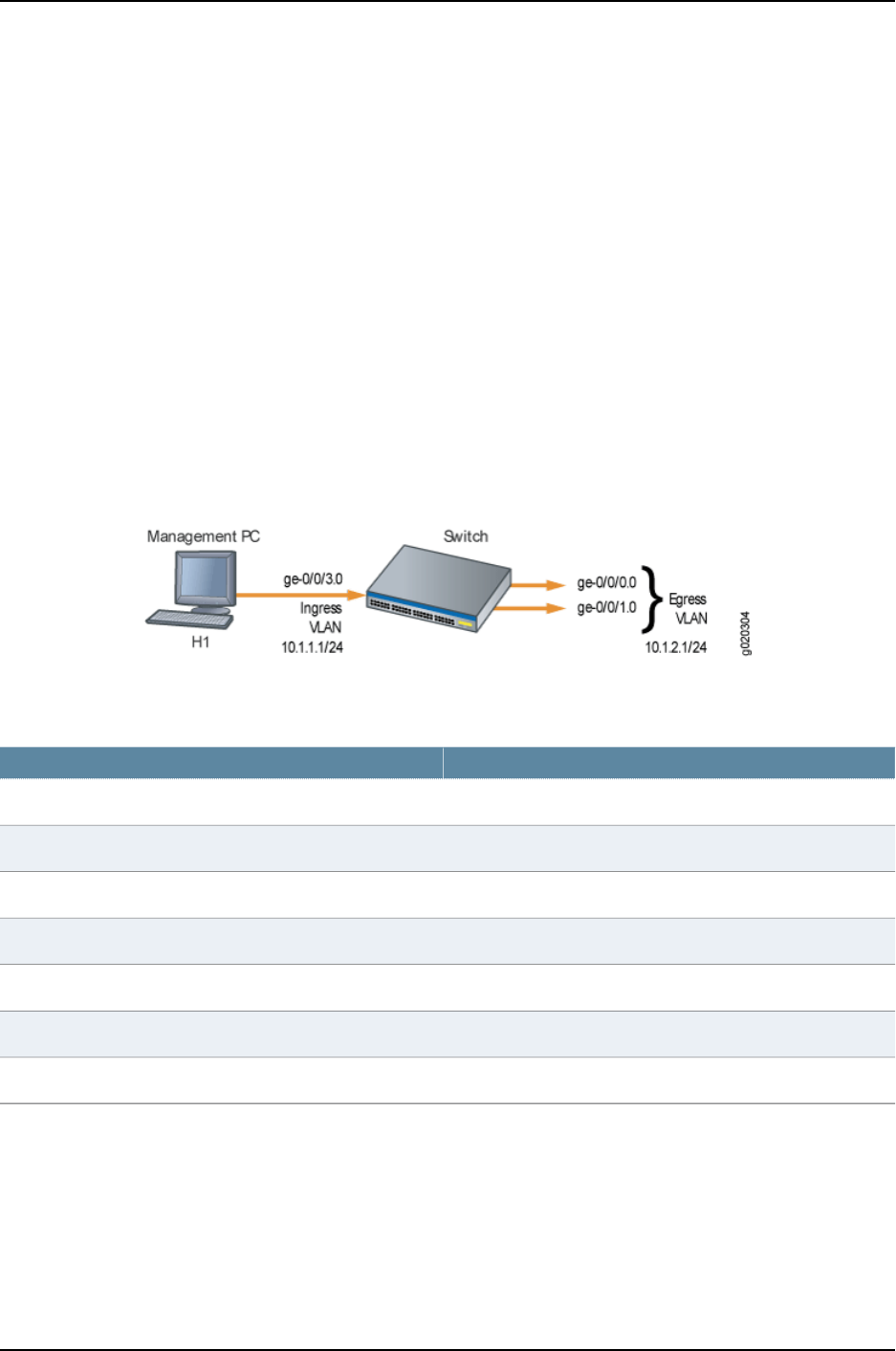
Overview and Topology
You might want to perform remote administration tasks such as backups and
wake-on-LAN (WOL) application tasks to manage groups of clients on a subnet. One
way to do this is to send IP directed broadcast packets targeted at the hosts in a particular
target subnet.
The network forwards IP directed broadcast packets as if they were unicast packets.
When the IP directed broadcast packet is received by a VLAN that is enabled for
targeted-broadcast, the switch broadcasts the packet to all the hosts in its subnet.
In this topology (see Figure 34 on page 1038), a host is connected to an interface on a J-EX
Series switch to manage the clients in subnet 10.1.2.1/24. When the switch receives a
packet with the broadcast IP address of the target subnet as its destination address, it
forwards the packet to the subnet’s Layer 3 interface and broadcasts it to all the hosts
within the subnet.
Figure 34: Topology for IP Directed Broadcast
Table 153 on page 1038 shows the settings of the components in this example.
Table 153: Components of the IP Directed Broadcast Topology
SettingsProperty
J-EX Series switchSwitch hardware
v0Ingress VLAN name
10.1.1.1/24Ingress VLAN IP address
v1Egress VLAN name
10.1.2.1/24Egress VLAN IP address
ge-0/0/3.0Interfaces in VLAN v0
ge-0/0/0.0 and ge-0/0/1.0Interfaces in VLAN v1
Configuration
To configure IP directed broadcast on a subnet to enable remote management of its
hosts:
1038
Dell PowerConnect J-Series Ethernet Switch Complete Software Guide for Junos OS, Release 11.1: Volume 1

CLI Quick
Configuration
To quickly configure the switch to accept IP directed broadcasts targeted at subnet
10.1.2.1/24, copy the following commands and paste them into the switch’s terminal
window:
[edit]
set interfaces ge-0/0/0.0 family ethernet-switching vlan members v1
set interfaces ge-0/0/1.0 family ethernet-switching vlan members v1
set interfaces vlan.1 family inet address 10.1.2.1/24
set interfaces ge-0/0/3.0 family ethernet-switching vlan members v0
set interfaces vlan.0 family inet address 10.1.1.1/24
set vlans v1 l3-interface vlan.1
set vlans v0 l3-interface vlan.0
set interfaces vlan.1 family inet targeted-broadcast
Step-by-Step
Procedure
To configure the switch to accept IP directed broadcasts targeted at subnet 10.1.2.1/24:
1. Add logical interface ge-0/0/0.0 to VLAN v1:
[edit interfaces]
user@switch# set ge-0/0/0.0 family ethernet-switching vlan members v1
2. Add logical interface ge-0/0/1.0 to VLAN v1:
[edit interfaces]
user@switch# set ge-0/0/1.0 family ethernet-switching vlan members v1
3. Configure the IP address for the egress VLAN, v1:
[edit interfaces]
user@switch# set vlan.1 family inet address 10.1.2.1/24
4. Add logical interface ge-0/0/3.0 to VLAN v0:
[edit interfaces]
user@switch# set ge-0/0/3.0 family ethernet-switching vlan members v0
5. Configure the IP address for the ingress VLAN:
[edit interfaces]
user@switch# set vlan.0 family inet address 10.1.1.1/24
6. To route traffic between the ingress and egress VLANs, associate a Layer 3 interface
with each VLAN:
[edit vlans]
user@switch# set v1 l3-interfacevlan.1
user@switch# set v0 l3–interface vlan.0
7. Enable the Layer 3 interface for the egress VLAN to receive IP directed broadcasts:
[edit interfaces]
user@switch# set vlan.1 family inet targeted-broadcast
Results Check the results:
user@switch# show
interfaces {
ge-0/0/0 {
unit 0 {
family ethernet-switching {
vlan {
1039
Chapter 51: Examples of Interfaces Configuration

members v1;
}
}
}
}
ge-0/0/1 {
unit 0 {
family ethernet-switching {
vlan {
members v1;
}
}
}
}
ge-0/0/3 {
unit 0 {
family ethernet-switching {
vlan {
members v0;
}
}
}
}
vlan {
unit 0 {
family inet {
targeted-broadcast;
address 10.1.1.1/24;
}
}
unit 1 {
family inet {
targeted-broadcast;
address 10.1.2.1/24;
}
}
}
vlans {
default;
v0 {
l3-interface vlan.0;
}
v1 {
l3-interface vlan.1;
}
}
Related
Documentation
•Configuring IP Directed Broadcast (CLI Procedure) on page 1091
1040
Dell PowerConnect J-Series Ethernet Switch Complete Software Guide for Junos OS, Release 11.1: Volume 1

CHAPTER 52
Configuring Interfaces
•Configuring Gigabit Ethernet Interfaces (CLI Procedure) on page 1042
•Configuring Gigabit Ethernet Interfaces (J-Web Procedure) on page 1045
•Port Role Configuration with the J-Web Interface (with CLI References) on page 1051
•Adding an Interface Description to the Configuration on page 1055
•Adding a Logical Unit Description to the Configuration on page 1056
•Disabling a Physical Interface on page 1057
•Disabling a Logical Interface on page 1058
•Configuring Flow Control on page 1058
•Configuring the Interface Address on page 1059
•Configuring the Interface Bandwidth on page 1061
•Configuring the Media MTU on page 1062
•Setting the Protocol MTU on page 1065
•Interface Ranges on page 1066
•Configuring Accounting for the Physical Interface on page 1074
•Configuring Accounting for the Logical Interface on page 1076
•Configuring Ethernet Loopback Capability on page 1077
•Configuring Gratuitous ARP on page 1078
•Configuring Static ARP Table Entries on page 1078
•Disabling the Transmission of Redirect Messages on an Interface on page 1079
•Configuring Unrestricted Proxy ARP on page 1080
•Enabling or Disabling SNMP Notifications on Logical Interfaces on page 1080
•Enabling or Disabling SNMP Notifications on Physical Interfaces on page 1080
•Configuring Aggregated Ethernet Interfaces (CLI Procedure) on page 1081
•Configuring Aggregated Ethernet Interfaces (J-Web Procedure) on page 1082
•Configuring Aggregated Ethernet LACP (CLI Procedure) on page 1085
•Configuring Aggregated Ethernet Link Protection on page 1086
•Configuring Aggregated Ethernet Link Speed on page 1087
•Configuring Aggregated Ethernet Minimum Links on page 1088
1041

•Configuring Tagged Aggregated Ethernet Interfaces on page 1088
•Configuring a Layer 3 Subinterface (CLI Procedure) on page 1089
•Configuring Unicast RPF (CLI Procedure) on page 1089
•Disabling Unicast RPF (CLI Procedure) on page 1091
•Configuring IP Directed Broadcast (CLI Procedure) on page 1091
•Tracing Operations of an Individual Router or Switch Interface on page 1092
•Tracing Operations of the Interface Process on page 1093
•Setting the Mode on an SFP+ Uplink Module (CLI Procedure) on page 1093
Configuring Gigabit Ethernet Interfaces (CLI Procedure)
An Ethernet interface must be configured for optimal performance in a high-traffic
network. J-EX Series switches include a factory default configuration that:
•Enables all the network interfaces on the switch
•Sets a default port mode (access)
•Sets default link settings
•Specifies a logical unit (unit 0) and assigns it to family ethernet-switching (except on
J-EX8200 switches and Virtual Chassis)
•Specifies Rapid Spanning Tree Protocol (RSTP) and Link Layer Discovery Protocol
(LLDP)
This topic describes:
•Configuring VLAN Options and Port Mode on page 1042
•Configuring the Link Settings on page 1043
•Configuring the IP Options on page 1044
Configuring VLAN Options and Port Mode
By default, when you boot a switch and use the factory default configuration, or when
you boot the switch and do not explicitly configure a port mode, all interfaces on the
switch are in access mode and accept only untagged packets from the VLAN named
default. You can optionally configure another VLAN and use that instead of default. You
can also configure a port to accept untagged packets from the user-configured VLAN.
For details on this concept (native VLAN), see “Understanding Bridging and VLANs on
J-EX Series Switches” in Dell PowerConnect J-Series Ethernet Switch Complete Software
Guide for Junos OS: Volume 2 at http://www.support.dell.com/manuals.
If you are connecting either a desktop phone, wireless access point or a security camera
to a Power over Ethernet (PoE) port, you can configure some parameters for the PoE
interface. PoE interfaces are enabled by default. For detailed information on PoE settings,
see Configuring PoE (CLI Procedure).
If you are connecting a device to other switches and to routers on the LAN, you need to
assign the interface to a logical port and configure the logical port as a trunk port. See
1042
Dell PowerConnect J-Series Ethernet Switch Complete Software Guide for Junos OS, Release 11.1: Volume 1

“Port Role Configuration with the J-Web Interface (with CLI References)” on page 1051 for
more information about port configuration.
If you are connecting to a server that contains virtual machines and a VEPA for packet
aggregation from those virtual machines, configure the port as a tagged-access port. For
more information about tagged access, see “Understanding Bridging and VLANs on J-EX
Series Switches” in Dell PowerConnect J-Series Ethernet Switch Complete Software Guide
for Junos OS: Volume 2 at http://www.support.dell.com/manuals.
To configure a Gigabit Ethernet interface or 10-Gigabit Ethernet interface for trunk port
mode:
[edit]
user@switch# set interfaces interface-name unit logical-unit-number family ethernet-switching
port-mode trunk
To configure a Gigabit Ethernet interface or 10-Gigabit Ethernet interface for
tagged-access port mode:
[edit]
user@switch# set interfaces interface-name unit logical-unit-number family ethernet-switching
port-mode tagged-access
Configuring the Link Settings
J-EX Series switches include a factory default configuration that enables interfaces with
the following link settings:
•All Gigabit Ethernet interfaces are set to auto-negotiation.
•The speed for Gigabit Ethernet interfaces is set to auto, allowing the interface to operate
at 10m, 100m, or 1g. The link operates at the highest possible speed, depending on the
capabilities of the remote end.
•The flow control for Gigabit Ethernet interfaces and 10-Gigabit Ethernet interfaces is
set to enabled.
•The link mode is set to auto, allowing the interface to operate as either full duplex or
half duplex. The link operates as full duplex unless this mode is not supported at the
remote end.
•The 10-Gigabit Ethernet interfaces default to no auto-negotiation. The default speed
is 10g and the default link mode is full duplex.
1043
Chapter 52: Configuring Interfaces

To configure the link settings:
•Set link settings for a Gigabit Ethernet interface:
[edit]
user@switch# set interfaces ge-fpc/pic/port ether-options
•Set link settings for a 10-Gigabit Ethernet interface:
[edit]
user@switch# set interfaces xe-fpc/pic/port ether-options
NOTE: On J-EX Series switches, fpc can have the following values:
•On a standalone J-EX4200 switch and standalone J-EX4500 switch, FPC
refers to the switch itself. The FPC number is always 0on these switches.
•On a J-EX4200 Virtual Chassis, a J-EX4500 Virtual Chassis, or a mixed
J-EX4200 and J-EX4500 Virtual Chassis, the FPC number indicates the
member ID of the switch within the Virtual Chassis.
•On a standalone J-EX8200 switch, the FPC number indicates the slot
number of the line card that contains the physical interface.
pic can have the following values:
•On J-EX4200 and J-EX4500 switches, the PIC number is 0for all built-in
interfaces (interfaces that are not an uplink port).
•On J-EX4200 switches, the PIC number is 1for uplink ports.
•On J-EX4500 switches, the PIC number is 1for uplink ports on the left-hand
uplink module and 2for uplink ports on the right-hand uplink module.
•On J-EX8200 switches, the PIC number is always 0.
The ether-options statement allows you to modify the configuration:
•802.3ad—Specify an aggregated Ethernet bundle. See “Configuring Aggregated Ethernet
Interfaces (CLI Procedure)” on page 1081.
•auto-negotiation—Enable or disable autonegotation of flow control, link mode, and
speed.
•flow-control—Enable or disable flow control.
•link-mode—Specify full-duplex,half-duplex, or automatic.
•loopback—Enable or disable loopback mode.
•speed—Specify 10m,100m,1g, or autonegotiation.
Configuring the IP Options
To specify an IP address for the logical unit using IPv4:
1044
Dell PowerConnect J-Series Ethernet Switch Complete Software Guide for Junos OS, Release 11.1: Volume 1

[edit]
user@switch# set interfaces interface-name unit logical-unit-number family inet address ip-address
To specify an IP address for the logical unit using IPv6:
[edit]
user@switch# set interfaces interface-name unit logical-unit-number family inet6 address
ip-address
NOTE: Access interfaces on J-EX4200 and J-EX4500 switches are set to
family ethernet-switching by default. You might have to delete this or another
user-configured family setting before changing the setting to family inet or
family inet6.
Related
Documentation
Configuring Gigabit Ethernet Interfaces (J-Web Procedure) on page 1045•
•Monitoring Interface Status and Traffic on page 1095
•show interfaces ge- on page 1204
•show interfaces xe- on page 1228
•Understanding Interface Naming Conventions on J-EX Series Switches on page 1001
Configuring Gigabit Ethernet Interfaces (J-Web Procedure)
An Ethernet interface must be configured for optimal performance in a high-traffic
network.
To configure properties on a Gigabit Ethernet interface or a 10-Gigabit Ethernet interface
on a J-EX Series switch:
1. Select Interfaces >Ports.
The page lists Gigabit Ethernet and 10-Gigabit Ethernet interfaces and their link status.
NOTE: After you make changes to the configuration in this page, you must
commit the changes immediately for them to take effect. To commit all
changes to the active configuration, select Commit Options >Commit.
See “Using the Commit Options to Commit Configuration Changes (J-Web
Procedure)” on page 346 for details about all commit options.
2. Select the interface you want to configure. If the interface you want to configure is
not listed under Ports in the top table on the page, select the FPC (the FPC is the line
card on a J-EX8200 switch or the member switch in a Virtual Chassis configuration)
that includes that interface from the List Ports for FPC list.
Details for the selected interface such as administrative status, link status, speed,
duplex, and flow control are displayed in the bottom table on the page.
1045
Chapter 52: Configuring Interfaces

NOTE: You can select multiple interfaces and modify their settings at the
same time. When you do this, you cannot modify the IP address or enable
or disable the administrative status of the selected interface.
3. Click Edit and select the set of options you want to configure first:
•Port Role—Enables you to assign a profile for the selected interface.
NOTE: When you select a particular port role, pre-configured port
security parameters are set for the VLAN that the interface belongs to.
For example, if you select the port role Desktop, the port security options
examine-dhcp and arp-inspection are enabled on the VLAN that the
interface belongs to. If there are interfaces in the VLAN that have static
IP addresses, those interfaces might lose connectivity because those
static IP addresses might not be present in the DHCP pool. Therefore,
when you are selecting a port role, ensure that the corresponding port
security settings for the VLAN are applicable to the interface.
For basic information on port security features such as DHCP snooping
(CLI option examine-dhcp) or dynamic ARP inspection (DAI) (CLI option
arp-inspection) and for port security configuration instructions, see Dell
PowerConnect J-Series Ethernet Switch Complete Software Guide for
Junos OS: Volume 2 at http://www.support.dell.com/manuals.
Click Details to view the configuration parameters for the selected port role.
•VLAN Options—Enables you to configure VLAN options for the selected interface.
•Link Options—Enables you to modify the following link options for the selected
interface:
•Speed
•MTU
•Autonegotiation
•Flow Control
•Duplex
•IP Options—Enables you to configure an IP address for the interface.
4. Configure the interface by configuring options in the selected option set. See Table
154 on page 1047 for details on options.
5. Repeat Steps 3 and 4 for the remaining option sets that you want to configure for the
interface.
1046
Dell PowerConnect J-Series Ethernet Switch Complete Software Guide for Junos OS, Release 11.1: Volume 1

NOTE: To enable or disable the administrative status for a selected
interface, click Enable Port or Disable Port.
Table 154: Port Edit Options
Your ActionFunctionField
Specifies a profile (role) to assign to the interface.
NOTE: Once a port role is configured on the
interface, you cannot specify VLAN options or IP
options.
NOTE: Only the following port roles can be
applied on J-EX8200 switch interfaces:
•Default
•Layer 2 uplink
•Routed uplink
Port Role
1. Click Details to view CLI commands for this role.
2. Click OK.
Applies the default role.
The interface family is set to ethernet-switching,
port mode is set to access, and RSTP is enabled.
Default
1. Select an existing VLAN configuration or type the
name of a new VLAN configuration to be associated
with the interface.
2. Click Details to view CLI commands for this role.
3. Click OK.
Applies the desktop role.
The interface family is set to ethernet-switching,
port mode is set to access, RSTP is enabled with
the edge and point-to-point options, and port
security parameters (MAC limit =1; dynamic ARP
inspection and DHCP snooping enabled) are set.
Desktop
1. Select an existing VLAN configuration or type the
name of a new VLAN configuration to be associated
with the interface.
You can also select an existing VoIP VLAN
configuration or a new VoIP VLAN configuration to
be associated with the interface.
NOTE: VoIP is not supported on J-EX8200 switches.
2. Click Details to view CLI commands for this role.
3. Click OK.
Applies the desktop and phone role.
The interface family is set to ethernet-switching,
port mode is set to access, port security
parameters (MAC limit =1; dynamic ARP
Inspection and DHCP snooping enabled) are set,
and recommended CoS parameters are specified
for forwarding classes, schedulers, and classifiers.
See Table 155 on page 1050 for more CoS
information.
Desktop and
Phone
1. Select an existing VLAN configuration or type the
name of a new VLAN configuration to be associated
with the interface. Type the VLAN ID for a new VLAN.
2. Click Details to view CLI commands for this role.
3. Click OK.
Applies the wireless access point role.
The interface family is set to ethernet-switching,
port mode is set to access, and RSTP is enabled
with the edge and point-to-point options.
Wireless Access
Point
1047
Chapter 52: Configuring Interfaces

Table 154: Port Edit Options (continued)
Your ActionFunctionField
To specify an IPv4 address:
1. Select the check box IPv4 address.
2. Type an IP address—for example: 10.10.10.10.
3. Enter the subnet mask or address prefix. For
example, 24 bits represents 255.255.255.0.
4. Click OK.
To specify an IPv6 address:
1. Select the check box IPv6 address.
2. Type an IP address—for example:
2001:ab8:85a3::8a2e:370:7334.
3. Enter the subnet mask or address prefix.
4. Click OK.
NOTE: IPv6 is not supported on J-EX4500 switches.
Applies the routed uplink role.
The interface family is set to inet, and
recommended CoS parameters are set for
schedulers and classifiers. See Table 155 on
page 1050 for more CoS information.
Routed Uplink
1. For this port role you can select a VLAN member and
associate a native VLAN with the interface.
2. Click Details to view CLI commands for this role.
3. Click OK.
Applies the Layer 2 uplink role.
The interface family is set to ethernet-switching,
port mode is set to trunk, RSTP is enabled with
the point-to-point option, and port security is set
to dhcp-trusted.
Layer 2 Uplink
Specifies that no port role is configured for the
selected interface.
None
NOTE: See “Port Role Configuration with the J-Web Interface (with CLI References)” on page 1051 for details on the CLI commands
that are associated with each port role.
NOTE: For a J-EX8200 switch, dynamic ARP inspection and DHCP snooping parameters are not configured.
VLAN Options
1048
Dell PowerConnect J-Series Ethernet Switch Complete Software Guide for Junos OS, Release 11.1: Volume 1
Table 154: Port Edit Options (continued)
Your ActionFunctionField
If you select Trunk, you can:
1. Click Add to add a VLAN member.
2. Select the VLAN and click OK.
3. (Optional) Associate a native VLAN with the
interface and click OK.
If you select Access, you can:
1. Select the VLAN member to be associated with the
interface.
2. (Optional) Associate a VoIP VLAN with the interface.
Only a VLAN with a VLAN ID can be associated as a
VoIP VLAN.
NOTE: VoIP is not supported on J-EX8200 switches.
3. Click OK.
Specifies the mode of operation for the interface:
trunk or access.
Port Mode
Link Options
Type a value from 256 through 9216. The default MTU
for Gigabit Ethernet interfaces is 1514.
Specifies the maximum transmission unit size for
the interface.
MTU (bytes)
Select one of the following values: 10 Mbps, 100 Mbps,
1000 Mbps, or Auto-Negotiation.
Specifies the speed for the mode.Speed
Select one: automatic,half, or full.Specifies the link mode.Duplex
Enter a brief description for the link.Describes the link.
NOTE: If the interface is part of a link aggregation
group (LAG), only the option Description is
enabled.
Description
Select the check box to enable autonegotiation, or clear
the check box to disable it. By default, autonegotiation
is enabled.
Enables or disables autonegotiation.Enable Auto
Negotiation
Select the check box to enable flow control to regulate
the amount of traffic sent out of the interface, or clear
the check box to disable flow control and permit
unrestricted traffic. Flow control is enabled by default.
Enables or disables flow control.Enable Flow
Control
IP Options
1049
Chapter 52: Configuring Interfaces
Table 154: Port Edit Options (continued)
Your ActionFunctionField
1. To specify an IPv4 address, select the check box IPv4
address.
2. Type an IP address—for example: 10.10.10.10.
3. Enter the subnet mask or address prefix. For
example, 24 bits represents 255.255.255.0.
4. Click OK.
Specifies an IPv4 address for the interface.
NOTE: If the IP address is cleared, the interface
still belongs to the inet family.
IPv4 Address
1. To specify an IPv6 address, select the check box
IPv6 address.
2. Type an IP address—for example:
2001:ab8:85a3::8a2e:370:7334.
3. Enter the subnet mask or address prefix.
4. Click OK.
NOTE: IPv6 is not supported on J-EX4500 switches.
Specifies an IPv6 address for the interface.
NOTE: If the IP address is cleared, the interface
still belongs to the inet family.
IPv6 Address
Table 155: Recommended CoS Settings for Port Roles
Recommended SettingsCoS Parameter
There are four forwarding classes:
•voice—Queue number is set to 7.
•expedited-forwarding—Queue number is set to 5.
•assured-forwarding—Queue number is set to 1.
•best-effort—Queue number is set to 0.
Forwarding Classes
The schedulers and their settings are:
•Strict-priority—Transmission rate is set to 10 percent and buffer size to 5 percent.
•Expedited-scheduler—Transmission rate is set to 30 percent, buffer size to 30 percent, and
priority to low.
•Assured-scheduler—Transmission rate is set to 25 percent, buffer size to 25 percent, and
priority to low.
•Best-effort scheduler—Transmission rate is set to 35 percent, buffer size to 40 percent, and
priority to low.
Schedulers
When a desktop and phone, routed uplink, or layer 2 uplink role is applied on an interface, the
forwarding classes and schedulers are mapped using the scheduler map.
Scheduler maps
Imports the default ieee-802.1 classifier configuration and sets the loss priority to low for the
code point 101 for the voice forwarding class.
ieee-802.1 classifier
Imports the default dscp classifier configuration and sets the loss priority to low for the code
point 101110 for the voice forwarding class.
dscp classifier
1050
Dell PowerConnect J-Series Ethernet Switch Complete Software Guide for Junos OS, Release 11.1: Volume 1

Related
Documentation
Configuring Gigabit Ethernet Interfaces (CLI Procedure) on page 1042•
•Monitoring Interface Status and Traffic on page 1095
•J-EX Series Switches Interfaces Overview on page 999
•For information about the class of service (CoS) implementation in the Junos OS, see
the Dell PowerConnect J-Series Ethernet Switch Complete Software Guide for Junos OS:
Volume 2 at http://www.support.dell.com/manuals,
•Understanding Interface Naming Conventions on J-EX Series Switches on page 1001
Port Role Configuration with the J-Web Interface (with CLI References)
When you configure Gigabit Ethernet interface properties with the J-Web interface
(Configure > Interfaces) you can optionally select pre-configured port roles for those
interfaces. When you select a role from the Port Role field and apply it to a port, the J-Web
interface modifies the switch configuration using CLI commands. Table 156 on page 1051
lists the CLI commands applied for each port role.
NOTE: If there is an existing port role configuration, it is cleared before the
new port role configuration is applied.
Table 156: Port Role Configuration Summary
CLI CommandsConfiguration Description
Default Port Role
set interfaces interfaceapply-macro juniper-port-profile
Default
Set the port role to Default.
set interfaces interface unit 0 family ethernet-switching
port-mode access
Set port family to ethernet-switching.
Set port mode to access.
delete protocols rstp interface interface disable
Enable RSTP if redundant trunk groups are not
configured.
set protocols rstp interface interface disable
Disable RSTP if redundant trunk groups are
configured.
Desktop Port Role
set interfaces interface apply-macro juniper-port-profile
Desktop
Set the port role to desktop.
set vlans <vlan name> vlan-id <vlan-id>Set VLAN if new VLAN is specified.
set interfaces interface unit 0 family ethernet-switching
port-mode access
Set port family to ethernet-switching.
Set Port Mode to Access.
1051
Chapter 52: Configuring Interfaces
Table 156: Port Role Configuration Summary (continued)
CLI CommandsConfiguration Description
set interfaces interface unit 0 family ethernet-switching
vlan members vlan-members
Set VLAN if new VLAN is specified.
set ethernet-switching-options secure-access-port vlan
MacTest arp-inspection
Set port security parameters.
set protocols rstp interface interface edge
Set RSTP protocol with edge option.
set protocols rstp interface interface disable
RSTP protocol is disabled if redundant trunk groups
are configured.
Desktop and Phone Port Role
set interfaces interfaceapply-macro juniper-port-profile
Desktop and Phone
Set the port role to desktop and phone.
set vlans vlan-namevlan-id vlan id
Set data VLAN if new VLAN is specified.
Set voice VLAN if new voice VLAN is specified.
set interfaces interfaceunit 0 family ethernet-switching
port-mode access
Set port family to ethernet-switching.
Set Port Mode to access.
set interfaces interface unit 0 family ethernet-switching
vlan members vlan-members
Set data VLAN on port stanza.
set ethernet-switching-options secure-access-port vlan
MacTest arp-inspection
Set port security parameters.
set ethernet-switching-options voip interface interface.0
vlan vlan vlan name
Set VOIP VLAN.
set class-of-service interfaces interfacescheduler-map
juniper-port-profile-map
set class-of-service interfaces interface unit 0
classifiers ieee-802.1 juniper_ieee_classifier
set class-of-service interfaces interfaceunit 0 classifiers
dscp juniper-dscp-classifier
Set class of service parameters
SCHEDULER_MAP=juniper-port-profile-map
IEEE_CLASSIFIER=juniper-ieee-classifier
DSCP_CLASSIFIER=juniper-dscp-classifier
Refer Table 157 on page 1054 for details.Set CoS Configuration
Wireless Access Point Port Role
set interfaces interface apply-macro juniper-port-profile
Wireless Access Point
Set the port role to wireless access point.
set vlans vlan namevlan-id vlan-id
Set VLAN on VLANs stanza.
set interfaces interface unit 0 family ethernet-switching
port-mode access
Set port family to ethernet-ewitching
Set port mode to Access.
set interfaces interface unit 0 family ethernet-switching
vlan members vlan-members
Set VLAN on port stanza.
1052
Dell PowerConnect J-Series Ethernet Switch Complete Software Guide for Junos OS, Release 11.1: Volume 1

Table 156: Port Role Configuration Summary (continued)
CLI CommandsConfiguration Description
set protocols rstp interface interface edge
Set RSTP protocol with edge option.
set protocols rstp interface interface disable
RSTP protocol is disabled if redundant trunk groups
are configured.
Routed Uplink Port Role
set interfaces interface apply-macro juniper-port-profile
Routed Uplink
Set the port role to Routed Uplink.
set interfaces interfaceunit 0 family inet address
ipaddress
Set port family to inet.
Set IP address on the port.
set class-of-service interfaces interfacescheduler-map
juniper-port-profile-map
set class-of-service interfaces interface unit 0
classifiers ieee-802.1 juniper_ieee_classifier
set class-of-service interfaces interfaceunit 0 classifiers
dscp juniper-dscp-classifier
Set class-of-service parameters
SCHEDULER_MAP=juniper-port-profile-map
IEEE_CLASSIFIER=juniper-ieee-classifier
DSCP_CLASSIFIER=juniper-dscp-classifier
Refer Table 157 on page 1054 for details.Set CoS configuration
Layer 2 Uplink Port Role
set interfaces interface apply-macro juniper-port-profile
Layer2 Uplink
Set the port role to Layer 2 Uplink.
set interfaces interface unit 0 family ethernet-switching
port-mode trunk
Set port family to ethernet-switching
Set port mode to trunk.
set interfaces interface unit 0 family ethernet-switching
native-vlan-id vlan-name
Set Native VLAN name.
set interfaces interface unit 0 family ethernet-switching
vlan members vlan-members
Set the port as part of all valid VLANs; ”valid" refers
to all VLANs except native VLAN and voice VLANs.
set ethernet-switching-options secure-access-port
dhcp-trusted
Set port security parameter.
set protocols rstp interface interface mode point-to-point
Set RSTP protocol with point-to-point option.
set protocols rstp interface interface disable
Disable RSTP if redundant trunk groups are
configured.
set class-of-service interfaces interfacescheduler-map
juniper-port-profile-map
set class-of-service interfaces interface unit 0
classifiers ieee-802.1 juniper_ieee_classifier
set class-of-service interfaces interfaceunit 0 classifiers
dscp juniper-dscp-classifier
Set class-of-service parameters.
SCHEDULER_MAP=juniper-port-profile-map
IEEE_CLASSIFIER=juniper_ieee_classifier
DSCP_CLASSIFIER=juniper_dscp_classifier
1053
Chapter 52: Configuring Interfaces
Table 156: Port Role Configuration Summary (continued)
CLI CommandsConfiguration Description
Refer to Table 157 on page 1054 for details.Set CoS configuration
Table 157 on page 1054 lists the CLI commands for the recommended CoS settings that
are committed when the CoS configuration is set.
Table 157: Recommended CoS Settings for Port Roles
CLI CommandCoS Parameter
Forwarding Classes
set class-of-service forwarding-classes class voice queue-num 7
voice
set class-of-service forwarding-classes class expedited-forwarding queue-num
5
expedited-forwarding
set class-of-service forwarding-classes class assured-forwarding queue-num
1
assured-forwarding
set class-of-service forwarding-classes class best-effort queue-num 0
best-effort
Schedulers
The CLI commands are:
•set class-of-service schedulers strict-priority-scheduler transmit-rate
percent 10
set class-of-service schedulers strict-priority-scheduler buffer-size
percent 5
set class-of-service schedulers strict-priority-scheduler priority
strict-high
strict-priority-scheduler
The CLI commands are:
•set class-of-service schedulers expedited-scheduler transmit-rate percent
30
set class-of-service schedulers expedited-scheduler buffer-size percent 30
set class-of-service schedulers expedited-scheduler priority low
expedited-scheduler
The CLI commands are:
set class-of-service schedulers assured-scheduler transmit-rate percent 25
set class-of-service schedulers strict-priority-scheduler buffer-size percent
25
set class-of-service schedulers strict-priority-scheduler priority low
assured-scheduler
The CLI commands are:
set class-of-service schedulers best-effort-scheduler transmit-rate percent
35
set class-of-service schedulers best-effort-scheduler buffer-size percent 40
set class-of-service schedulers best-effort-scheduler priority low
best-effort-scheduler
1054
Dell PowerConnect J-Series Ethernet Switch Complete Software Guide for Junos OS, Release 11.1: Volume 1

Table 157: Recommended CoS Settings for Port Roles (continued)
CLI CommandCoS Parameter
The classifiers are:
set class-of-service classifiers ieee-802.1 juniper_ieee_classifier import
default forwarding-class voice loss-priority low code-points 101
set class-of-service classifiers dscp juniper_dscp_classifier import default
forwarding-class voice loss-priority low code-points 101110
Classifiers
Related
Documentation
Configuring Gigabit Ethernet Interfaces (J-Web Procedure) on page 1045•
•Configuring Gigabit Ethernet Interfaces (CLI Procedure) on page 1042
Adding an Interface Description to the Configuration
You can include a text description of each physical interface in the configuration file. Any
descriptive text you include is displayed in the output of the show interfaces commands,
and is also exposed in the ifAlias Management Information Base (MIB) object. It has no
impact on the interface’s configuration. To add a text description, include the description
statement at the [edit interfaces interface-name]hierarchy level:
[edit interfaces interface-name]
description text;
The description can be a single line of text. If the text contains spaces, enclose it in
quotation marks.
NOTE: You can configure the extended DHCP relay to include the interface
description in the option 82 Agent Circuit ID suboption. See “Enabling and
Disabling Insertion of Option 82 Information” in the Junos OS Subscriber
Access Configuration Guide.
For information about describing logical units, see “Adding a Logical Unit Description to
the Configuration” on page 1056.
Example: Adding an Interface Description to the Configuration
Add a description to a Fast Ethernet interface:
[edit interfaces]
user@host#
set fe-0/0/1 description "Backbone connection to PHL01"
[edit interfaces]
user@host#
show
fe-0/0/1 {
description "Backbone connection to PHL01";
unit 0 {
family inet {
address 192.168.0.1/30;
}
1055
Chapter 52: Configuring Interfaces

}
}
To display the description from the router or switch CLI, use the show interfaces command:
user@host>
show interfaces fe-0/0/1
Physical interface: fe-0/0/1, Enabled, Physical link is Up
Interface index: 129, SNMP ifIndex: 23
Description: Backbone connection to PHL01
...
To display the interface description from the interfaces MIB, use the snmpwalk command
from a server. To isolate information for a specific interface, search for the interface index
shown in the SNMP ifIndex field of the show interfaces command output. The ifAlias
object is in ifXTable.
user-server>snmpwalk host-fxp0.mylab public ifXTable | grep -e '\.23'
snmpwalk host-fxp0.mylab public ifXTable | grep -e '\.23'
ifMIB.ifMIBObjects.ifXTable.ifXEntry.ifName.23 = fe-0/0/1
ifMIB.ifMIBObjects.ifXTable.ifXEntry.ifInMulticastPkts.23 = Counter32: 0
ifMIB.ifMIBObjects.ifXTable.ifXEntry.ifInBroadcastPkts.23 = Counter32: 0
ifMIB.ifMIBObjects.ifXTable.ifXEntry.ifOutMulticastPkts.23 = Counter32: 0
ifMIB.ifMIBObjects.ifXTable.ifXEntry.ifOutBroadcastPkts.23 = Counter32: 0
ifMIB.ifMIBObjects.ifXTable.ifXEntry.ifHCInOctets.23 = Counter64: 0
ifMIB.ifMIBObjects.ifXTable.ifXEntry.ifHCInUcastPkts.23 = Counter64: 0
ifMIB.ifMIBObjects.ifXTable.ifXEntry.ifHCInMulticastPkts.23 = Counter64: 0
ifMIB.ifMIBObjects.ifXTable.ifXEntry.ifHCInBroadcastPkts.23 = Counter64: 0
ifMIB.ifMIBObjects.ifXTable.ifXEntry.ifHCOutOctets.23 = Counter64: 42
ifMIB.ifMIBObjects.ifXTable.ifXEntry.ifHCOutUcastPkts.23 = Counter64: 0
ifMIB.ifMIBObjects.ifXTable.ifXEntry.ifHCOutMulticastPkts.23 = Counter64: 0
ifMIB.ifMIBObjects.ifXTable.ifXEntry.ifHCOutBroadcastPkts.23 = Counter64: 0
ifMIB.ifMIBObjects.ifXTable.ifXEntry.ifLinkUpDownTrapEnable.23 = enabled(1)
ifMIB.ifMIBObjects.ifXTable.ifXEntry.ifHighSpeed.23 = Gauge32: 100
ifMIB.ifMIBObjects.ifXTable.ifXEntry.ifPromiscuousMode.23 = false(2)
ifMIB.ifMIBObjects.ifXTable.ifXEntry.ifConnectorPresent.23 = true(1)
ifMIB.ifMIBObjects.ifXTable.ifXEntry.ifAlias.23 = Backbone connection to PHL01
ifMIB.ifMIBObjects.ifXTable.ifXEntry.ifCounterDiscontinuityTime.23 = Timeticks:
(0) 0:00:00.00
Adding a Logical Unit Description to the Configuration
You can include a text description of each logical unit in the configuration file. Any
descriptive text you include is displayed in the output of the show interfaces commands,
and is also exposed in the ifAlias Management Information Base (MIB) object. It has no
impact on the interface’s configuration. To add a text description, include the description
statement:
description text;
You can include this statement at the following hierarchy levels:
•[edit interfaces interface-name unit logical-unit-number]
•[edit logical-systems logical-system-name interfaces interface-name unit
logical-unit-number]
1056
Dell PowerConnect J-Series Ethernet Switch Complete Software Guide for Junos OS, Release 11.1: Volume 1
The description can be a single line of text. If the text contains spaces, enclose it in
quotation marks.
NOTE: You can configure the extended DHCP relay to include the interface
description in the option 82 Agent Circuit ID suboption. See “Enabling and
Disabling Insertion of Option 82 Information” in the Junos OS Subscriber
Access Configuration Guide.
For information about describing physical interfaces, see “Adding an Interface Description
to the Configuration” on page 1055.
Disabling a Physical Interface
You can disable a physical interface, marking it as being down, without removing the
interface configuration statements from the configuration. To do this, include the disable
statement at the [edit interfaces interface-name]hierarchy level:
[edit interfaces interface-name]
disable;
CAUTION: Dynamic subscribers and logical interfaces use physical interfaces
for connection to the network. The Junos OS allows you to set the interface
to disable and commit the change while dynamic subscribers and logical
interfaces are still active. This action results in the loss of all subscriber
connections on the interface. Use care when disabling interfaces.
NOTE: On the router, when you use the disable statement at the edit interfaces
hierarchy level, depending on the PIC type, the interface might or might not
turn off the laser. Older PIC transceivers do not support turning off the laser,
but newer Gigabit Ethernet PICs with SFP transceivers do support it and the
laser will be turned off when the interface is disabled.
WARNING: Do not stare into the laser beam or view it directly with optical
instruments even if the interface has been disabled.
Example: Disabling a Physical Interface
Disable a physical interface:
[edit interfaces]
so-1/1/0 {
mtu 8000;
clocking internal;
encapsulation ppp;
sonet-options {
1057
Chapter 52: Configuring Interfaces

fcs 16;
}
unit 0 {
family inet {
address 172.16.0.0/12 {
destination 172.16.0.4;
}
}
}
}
[edit interfaces]
user@host# set so-1/1/0 disable
[edit interfaces]
user@host# show so-1/1/0
so-1/1/0 {
disable;# Interface is marked as disabled
mtu 8000;
clocking internal;
encapsulation ppp;
sonet-options {
fcs 16;
}
unit 0 {
family inet {
address 172.16.0.0 {
destination 172.16.0.3;
}
}
}
}
Disabling a Logical Interface
You can unconfigure a logical interface, effectively disabling that interface, without
removing the logical interface configuration statements from the configuration. To do
this, include the disable statement:
disable;
You can include this statement at the following hierarchy levels:
•[edit interfaces interface-name unit logical-unit-number]
•[edit logical-systems logical-system-name interfaces interface-name unit
logical-unit-number]
When an interface is disabled, a route (pointing to the reserved target “REJECT”) with
the IP address of the interface and a 32–bit subnet mask is installed in the routing table.
See the Junos Software Routing Protocols Configuration Guide.
Configuring Flow Control
By default, the router or switch imposes flow control to regulate the amount of traffic
sent out on a Fast Ethernet, Tri-Rate Ethernet copper, Gigabit Ethernet, and 10-Gigabit
1058
Dell PowerConnect J-Series Ethernet Switch Complete Software Guide for Junos OS, Release 11.1: Volume 1

Ethernet interface. Flow control is not supported on the 4-port Fast Ethernet PIC. This is
useful if the remote side of the connection is a Fast Ethernet or Gigabit Ethernet switch.
You can disable flow control if you want the router or switch to permit unrestricted traffic.
To disable flow control, include the no-flow-control statement:
no-flow-control;
To explicitly reinstate flow control, include the flow-control statement:
flow-control;
You can include these statements at the following hierarchy levels:
•[edit interfaces interface-name aggregated-ether-options]
•[edit interfaces interface-name ether-options]
•[edit interfaces interface-name fastether-options]
•[edit interfaces interface-name gigether-options]
Configuring the Interface Address
You assign an address to an interface by specifying the address when configuring the
protocol family. For the inet or inet6 family, configure the interface IP address. For the
iso family, configure one or more addresses for the loopback interface. For the ccc,
ethernet-switching,tcc,mpls,tnp, and vpls families, you never configure an address.
NOTE: The point-to-point (PPP) address is taken from the loopback interface
address that has the primary attribute. When the loopback interface is
configured as an unnumbered interface, it takes the primary address from
the donor interface.
To assign an address to an interface, include the address statement:
address address {
broadcast address;
destination address;
destination-profile name;
eui-64;
preferred;
primary;
}
You can include these statements at the following hierarchy levels:
•[edit interfaces interface-name unit logical-unit-number family family]
•[edit logical-systems logical-system-name interfaces interface-name unit
logical-unit-number family family]
In the address statement, specify the network address of the interface.
1059
Chapter 52: Configuring Interfaces

For each address, you can optionally configure one or more of the following:
•Broadcast address for the interface subnet—Specify this in the broadcast statement;
this applies only to Ethernet interfaces, such as the management interface fxp0,em0,
or me0 the Fast Ethernet interface, and the Gigabit Ethernet interface.
•Address of the remote side of the connection (for point-to-point interfaces
only)—Specify this in the destination statement.
•PPP properties to the remote end—Specify this in the destination-profile statement.
You define the profile at the [edit access group-profile name ppp] hierarchy level (for
point-to-point interfaces only).
•Whether the router or switch automatically generates the host number portion of
interface addresses—The eui-64 statement applies only to interfaces that carry IPv6
traffic, in which the prefix length of the address is 64 bits or less, and the low-order 64
bits of the address are zero. This option does not apply to the loopback interface (lo0)
because IPv6 addresses configured on the loopback interface must have a 128-bit
prefix length.
•Whether this address is the preferred address—Each subnet on an interface has a
preferred local address. If you configure more than one address on the same subnet,
the preferred local address is chosen by default as the source address when you
originate packets to destinations on the subnet. For more information about preferred
addresses, see “Configuring Default, Primary, and Preferred Addresses and Interfaces”
in the Junos OS Network Interfaces Configuration Guide.
By default, the preferred address is the lowest-numbered address on the subnet. To
override the default and explicitly configure the preferred address, include the preferred
statement when configuring the address.
•Whether this address is the primary address—Each interface has a primary local address.
If an interface has more than one address, the primary local address is used by default
as the source address when you originate packets out the interface where the
destination gives no hint about the subnet (for example, some ping commands). For
more information about primary addresses, see “Configuring Default, Primary, and
Preferred Addresses and Interfaces” in the Junos OS Network Interfaces Configuration
Guide.
By default, the primary address on an interface is the lowest-numbered non-127 preferred
address on the interface. To override the default and explicitly configure the preferred
address, include the primary statement when configuring the address.
•Configuring Interface IPv4 Addresses on page 1060
•Configuring Interface IPv6 Addresses on page 1061
Configuring Interface IPv4 Addresses
You can configure router or switch interfaces with a 32-bit IP version 4 (IPv4) address
and optionally with a destination prefix, sometimes called a subnet mask. An IPv4 address
utilizes a 4-octet dotted decimal address syntax (for example, 192.16.1.1). An IPv4 address
with destination prefix utilizes a 4-octet dotted decimal address syntax appended with
a destination prefix (for example, 192.16.1.1/30).
1060
Dell PowerConnect J-Series Ethernet Switch Complete Software Guide for Junos OS, Release 11.1: Volume 1

To configure an IPv4 address on routers and switches running Junos OS, use the edit
interface interface-name unit number family inet address a.b.c.d/nn statement at the [edit
interfaces] hierarchy level.
NOTE: Routers and switches running the Junos OS support /31 destination
prefixes when used in point-to-point Ethernet configurations; however, they
are not supported by many other devices, such as hosts, hubs, routers, or
switches. You must determine if the peer system also supports /31 destination
prefixes before configuration.
Configuring Interface IPv6 Addresses
You represent IP version 6 (IPv6) addresses in hexadecimal notation using a
colon-separated list of 16-bit values.
You assign a 128-bit IPv6 address to an interface by including the address statement:
address aaaa:bbbb:...:zzzz/nn;
You can include this statement at the following hierarchy levels:
•[edit interfaces interface-name unit logical-unit-number family inet6]
•[edit logical-systems logical-system-name interfaces interface-name unit
logical-unit-number family inet6]
The double colon (::) represents all bits set to 0, as shown in the following example:
interfaces fe-0/0/1 {
unit 0 {
family inet6 {
address fec0:1:1:1::2/64;
}
}
}
NOTE: You must manually configure the switch advertisement and advertise
the default prefix for autoconfiguration to work on a specific interface.
Related
Documentation
Configuring IPCP Options•
•Configuring Default, Primary, and Preferred Addresses and Interfaces
Configuring the Interface Bandwidth
By default, the Junos OS uses the physical interface’s speed for the MIB-II object, ifSpeed.
You can configure the logical unit to populate the ifSpeed variable by configuring a
bandwidth value for the logical interface. The bandwidth statement sets an
1061
Chapter 52: Configuring Interfaces

informational-only parameter; you cannot adjust the actual bandwidth of an interface
with this statement.
NOTE: We recommend that you be careful when setting this value. Any
interface bandwidth value that you configure using the bandwidth statement
affects how the interface cost is calculated for a dynamic routing protocol,
such as OSPF. By default, the interface cost for a dynamic routing protocol
is calculated using the following formula:
cost = reference-bandwidth/bandwidth,
where bandwidth is the physical interface speed. However, if you specify a
value for bandwidth using the bandwidth statement, that value is used to
calculate the interface cost, rather than the actual physical interface
bandwidth.
To configure the bandwidth value for a logical interface, include the bandwidth statement:
bandwidth rate;
You can include this statement at the following hierarchy levels:
•[edit interfaces interface-name unit logical-unit-number]
•[edit logical-systems logical-system-name interfaces interface-name unit
logical-unit-number]
rate is the peak rate, in bps or cps. You can specify a value in bits per second either as a
complete decimal number or as a decimal number followed by the abbreviation k(1000),
m(1,000,000), or g(1,000,000,000). You can also specify a value in cells per second
by entering a decimal number followed by the abbreviation c; values expressed in cells
per second are converted to bits per second using the formula 1 cps = 384 bps. The value
can be any positive integer. The bandwidth statement is valid for all logical interfaces,
except multilink interfaces.
Configuring the Media MTU
The default media MTU size used on a physical interface depends on the encapsulation
used on that interface. In some cases, the default IP Protocol MTU depends on whether
the protocol used is IP version 4 (IPv4) or International Organization for Standardization
(ISO). Table 158 on page 1062 lists the media and protocol MTU sizes by interface type,
and Table 159 on page 1063 lists the encapsulation overhead by encapsulation type.
Table 158: Media MTU Sizes by Interface Type for J-EX Series Switches
Default IP Protocol
MTU (Bytes)
Maximum MTU
(Bytes)
Default Media
MTU (Bytes)Interface Type
1500 (IPv4), 1497
(ISO)
91921514Gigabit Ethernet
1062
Dell PowerConnect J-Series Ethernet Switch Complete Software Guide for Junos OS, Release 11.1: Volume 1

Table 158: Media MTU Sizes by Interface Type for J-EX Series
Switches (continued)
Default IP Protocol
MTU (Bytes)
Maximum MTU
(Bytes)
Default Media
MTU (Bytes)Interface Type
1500 (IPv4), 1497
(ISO)
9192151410-Gigabit Ethernet
Table 159: Encapsulation Overhead by Encapsulation Type
Encapsulation Overhead (Bytes)Interface Encapsulation
21802.1Q/Ethernet 802.3
26802.1Q/Ethernet Subnetwork Access Protocol (SNAP)
18802.1Q/Ethernet version 2
4ATM Cell Relay
12ATM permanent virtual connection (PVC)
4Cisco HDLC
17Ethernet 802.3
4Ethernet circuit cross-connect (CCC) and virtual private
LAN service (VPLS)
32Ethernet over ATM
22Ethernet SNAP
18Ethernet translational cross-connect (TCC)
14Ethernet version 2
4Extended virtual local area network (VLAN) CCC and
VPLS
22Extended VLAN TCC
4Frame Relay
4PPP
4VLAN CCC
4VLAN VPLS
22VLAN TCC
1063
Chapter 52: Configuring Interfaces

The default media MTU is calculated as follows:
Default media MTU = Default IP MTU + encapsulation overhead
When you are configuring point-to-point connections, the MTU sizes on both sides of the
connections must be the same. Also, when you are configuring point-to-multipoint
connections, all interfaces in the subnet must use the same MTU size.
NOTE: The actual frames transmitted also contain cyclic redundancy check
(CRC) bits, which are not part of the media MTU. For example, the media
MTU for a Gigabit Ethernet Version 2 interface is specified as 1514 bytes, but
the largest possible frame size is actually 1518 bytes; you need to consider
the extra bits in calculations of MTUs for interoperability.
The physical MTU for Ethernet interfaces does not include the 4-byte frame
check sequence (FCS) field of the Ethernet frame.
If you do not configure an MPLS MTU, the Junos OS derives the MPLS MTU
from the physical interface MTU. From this value, the software subtracts the
encapsulation-specific overhead and space for the maximum number of
labels that might be pushed in the Packet Forwarding Engine. Currently, the
software provides for three labels of four bytes each, for a total of 12 bytes.
In other words, the formula used to determine the MPLS MTU is the following:
MPLS MTU = physical interface MTU – encapsulation overhead – 12
If you configure an MTU value by including the mtu statement at the [edit
interfaces interface-name unit logical-unit-number family mpls] hierarchy level,
the configured value is used.
For information about configuring the encapsulation on an interface, see “Configuring
Interface Encapsulation on Physical Interfaces” in the Junos OS Network Interfaces
Configuration Guide.
To modify the default media MTU size for a physical interface, include the mtu statement
at the [edit interfaces interface-name]hierarchy level:
[edit interfaces interface-name]
mtu bytes;
If you change the size of the media MTU, you must ensure that the size is equal to or
greater than the sum of the protocol MTU and the encapsulation overhead.
NOTE: Changing the media MTU or protocol MTU causes an interface to be
deleted and added again.
1064
Dell PowerConnect J-Series Ethernet Switch Complete Software Guide for Junos OS, Release 11.1: Volume 1

You configure the protocol MTU by including the mtu statement at the following hierarchy
levels:
•[edit interfaces interface-name unit logical-unit-number family family]
•[edit logical-systems logical-system-name interfaces interface-name unit
logical-unit-number family family]
Because tunnel services interfaces are considered logical interfaces, you cannot configure
the MTU setting for the physical interface. This means you cannot include the mtu
statement at the [edit interfaces interface-name]hierarchy level for the following interface
types: generic routing encapsulation (gr-), IP-IP (ip-), loopback (lo-), link services (ls-),
multilink services (ml-), and multicast (pe-,pd-). You can, however, configure the protocol
MTU on tunnel interfaces, as described in “Setting the Protocol MTU” on page 1065.
Setting the Protocol MTU
When you initially configure an interface, the protocol maximum transmission unit (MTU)
is calculated automatically. If you subsequently change the media MTU, the protocol
MTU on existing address families automatically changes.
For a list of default protocol MTU values, see “Configuring the Media MTU” on page 1062.
To modify the MTU for a particular protocol family, include the mtu statement:
mtu bytes;
You can include this statement at the following hierarchy levels:
•[edit interfaces interface-name unit logical-unit-number family family]
•[edit logical-systems logical-system-name interfaces interface-name unit
logical-unit-number family family]
If you increase the size of the protocol MTU, you must ensure that the size of the media
MTU is equal to or greater than the sum of the protocol MTU and the encapsulation
overhead. For a list of encapsulation overhead values, see Table 159 on page 1063. If you
reduce the media MTU size, but there are already one or more address families configured
and active on the interface, you must also reduce the protocol MTU size. (You configure
the media MTU by including the mtu statement at the [edit interfaces interface-name]
hierarchy level, as discussed in “Configuring the Media MTU” on page 1062.)
NOTE: Changing the media MTU or protocol MTU causes an interface to be
deleted and added again.
The maximum number of data-link connection identifiers (DLCIs) is determined by the
MTU on the interface. If you have keepalives enabled, the maximum number of DLCIs is
1000, with the MTU set to 5012.
The actual frames transmitted also contain cyclic redundancy check (CRC) bits, which
are not part of the MTU. For example, the default protocol MTU for a Gigabit Ethernet
1065
Chapter 52: Configuring Interfaces

interface is 1500 bytes, but the largest possible frame size is actually 1504 bytes; you
need to consider the extra bits in calculations of MTUs for interoperability.
Interface Ranges
The Junos OS allows you to group a range of identical interfaces into an interface range.
You first specify the group of identical interfaces in the interface range. Then you can
apply a common configuration to the specified interface range, reducing the number of
configuration statements required and saving time while producing a compact
configuration.
•Configuring Interface Ranges on page 1066
•Expanding Interface Range Member and Member Range Statements on page 1069
•Configuration Inheritance for Member Interfaces on page 1070
•Member Interfaces Inheriting Configuration from Configuration Groups on page 1071
•Interfaces Inheriting Common Configuration on page 1073
•Configuring Inheritance Range Priorities on page 1073
•Configuration Expansion Where Interface Range Is Used on page 1073
Configuring Interface Ranges
To configure an interface range, include the interface-range statement at the [edit
interfaces] hierarchy level.
The interface-range statement accepts only physical networking interface names in its
definition. The following interface types are supported for J-EX Ethernet switches and
example CLI descriptors are shown:
•Ethernet—(xe | ge | fe)-fpc/pic/port
Interfaces can be grouped either as a range of interfaces or using a number range under
the interface-range statement definition.
Interfaces in an interface-range definition can be added as part of a member range or as
individual members or multiple members using a number range.
To specify a member range, use the member-range statement at the [edit interfaces
interface-range name]hierarchy level.
To specify interfaces in lexical order, use the member-range start-range to end-range
statement.
A range for a member statement should contain the following:
•*—All, specifies all available interfaces.
•num—Number, specifies one specific interface by its number.
•[low-high]—Numbers between low to high, specifies a range of sequential interfaces.
•[num1, num2, num3]—Numbers num1,num2, and num3 specify multiple specific
interfaces.
1066
Dell PowerConnect J-Series Ethernet Switch Complete Software Guide for Junos OS, Release 11.1: Volume 1

Example: Specifying an
Interface Range
Member Range
member-range ge-0/0/0 to ge-4/0/40;
To specify one or multiple members, use the member statement at the [edit interfaces
interface-range name]hierarchy level.
To specify the list of interface range members individually or for multiple interfaces using
regex, use the member list of interface names statement.
Example: Specifying an
Interface Range
Member
member ge-0/0/0;
member ge-0/*/*
member ge-0/[1-10]/0;
member ge-0/[1,2,3]/3;
Regex or wildcards are not supported for interface-type prefixes. For example, prefixes
ge,fe, and xe must be mentioned explicitly.
An interface-range definition can contain both member and member-range statements
within it. There is no maximum limit on the number of member or member-range
statements within an interface-range. However, at least one member or member-range
statement must exist within an interface-range definition.
Example: Interface
Range Common
Configuration
Configuration common to an interface range can be added as a part of the interface-range
definition, as follows:
[edit]
interfaces {
+ interface-range foo {
+ member-range ge-1/0/0 to ge-4/0/40;
+ member ge-0/1/1;
+ member ge-5/[1-10]/*;
/*Common configuration is added as part of interface-range definition*/
mtu 256;
hold-time up 10;
ether-options {
flow-control;
speed {
100m;
}
802.3ad primary;
}
}
}
An interface-range definition having just member or member-range statements and no
common configurations statements is valid.
These defined interface ranges can be used in other configuration hierarchies, in places
where an interface node exists.
Example:
Interface-Range foo
protocols {
dot1x {
authenticator {
Used Under the
Protocols Hierarchy interface foo{
retries 1;
1067
Chapter 52: Configuring Interfaces

}
}
}
}
foo should be an interface-range defined at the [interfaces] hierarchy level. In the above
example, the interface node can accept both individual interfaces and interface ranges.
TIP: To view an interface range in expanded configuration, use the (show |
display inheritance) command. For more information, see the Junos OS CLI
User Guide.
By default, interface-range is not available to configure in the CLI where the interface
statement is available. The following locations are supported; however, some of the
hierarchies shown in this list are product specific:
•protocols dot1x authentication interface
•protocols dvmrp interface
•protocols oam ethernet lmi interface
•protocols esis interface
•protocols igmp interface
•protocols igmp-host client num interface
•protocols mld-host client num interface
•protocols router-advertisement interface
•protocols isis interface
•protocols ldp interface
•protocols oam ethernet link-fault-management interface
•protocols lldp interface
•protocols link-management peer lmp-control-channel interface
•protocols link-management peer control-channel
•protocols link-management te-link name interface
•protocols mld interface
•protocols ospf area id interface
•protocols pim interface
•protocols router-discovery interface
•protocols rip group name neighbour
•protocols ripng group name neighbour
•protocols rsvp interface
1068
Dell PowerConnect J-Series Ethernet Switch Complete Software Guide for Junos OS, Release 11.1: Volume 1

•protocols snmp interface
•protocols layer2-control bpdu-block interface
•protocols layer2-control mac-rewrite interface
•protocols mpls interface
•protocols stp interface
•protocols rstp interface
•protocols mstp interface
•protocols vstp interface
•protocols mstp msti id interface
•protocols mstp msti vlan id interface
•protocols vstp vlan name interface
•protocols gvrp interface
•protocols igmp-snooping vlan name interface
•protocols lldp interface
•protocols lldp-med interface
•protocols sflow interfaces
•ethernet-switching-options analyzer name input [egress | ingress ] interface
•ethernet-switching-options analyzer name output interface
•ethernet-switching-options secure-access-port interface
•ethernet-switching-options interfaces ethernet-switching-options voip interface
•ethernet-switching-options redundant-trunk-group group g1 interface
•ethernet-switching-options redundant-trunk-group group g1 interface
•ethernet-switching-options bpdu-block interface
•poe interface vlans pro-bng-mc1-bsd1 interface
Expanding Interface Range Member and Member Range Statements
All member and member-range statements in an interface range definition are expanded
to generate the final list of interface names for the specified interface range.
Example: Expanding
Interface Range
[edit]
interfaces {
interface-range range-1 {
Member and Member
Range Statements member-range ge-0/0/0 to ge-4/0/20;
member ge-10/1/1;
member ge-5/[0-5]/*;
/*Common configuration is added part of the interface-range definition*/
mtu 256;
hold-time up 10;
ether-options {
1069
Chapter 52: Configuring Interfaces

flow-control;
speed {
100m;
}
802.3ad primary;
}
}
}
For the member-range statement, all possible interfaces between start-range and
end-range are considered in expanding the members. For example, the following
member-range statement:
member-range ge-0/0/0 to ge-4/0/20
expands to:
[ge-0/0/0, ge-0/0/1 ... ge-0/0/max_ports
ge-0/1/0 ge-0/1/1 ... ge-0/1/max_ports
ge-0/2/0 ge-0/2/1 ... ge-0/2/max_ports
.
.
ge-0/MAX_PICS/0 ... ge-0/max_pics/max_ports
ge-1/0/0 ge-1/0/1 ... ge-1/0/max_ports
.
ge-1/MAX_PICS/0 ... ge-1/max_pics/max_ports
.
.
ge-4/0/0 ge-4/0/1 ... ge-4/0/max_ports]
The following member statement:
ge-5/[0-5]/*
expands to:
ge-5/0/0 ... ge-5/0/max_ports
ge-5/1/0 ... ge-5/0/max_ports
.
.
ge-5/5/0 ... ge-5/5/max_ports
The following member statement:
ge-5/1/[2,3,6,10]
expands to:
ge-5/1/2
ge-5/1/3
ge-5/1/6
ge-5/1/10
Configuration Inheritance for Member Interfaces
When the Junos OS expands the member and member-range statements present in an
interface-range, it creates interface objects if they are not explicitly defined in the
configuration. The common configuration is copied to all its member interfaces in the
interface-range.
1070
Dell PowerConnect J-Series Ethernet Switch Complete Software Guide for Junos OS, Release 11.1: Volume 1

Example:
Configuration Priorities
Foreground interface configuration takes priority compared to configuration inherited by
the interface through the interface-range.
interfaces {
interface-range range-1 {
member-range ge-1/0/0/ to ge-10/0/47;
mtu 256;
}
ge-1/0/1 {
mtu 1024;
}
}
In the preceding example, interface ge-1/0/1 will have an MTU value of 1024.
This can be verified with output of the show interfaces | display inheritance command,
as follows:
user@host: # show interfaces | display inheritance
## 'ge-1/0/0' was expanded from interface-range 'range-1'
##
ge-1/0/0 {
##
## '256' was expanded from interface-range 'range-1'
##
mtu 256;
}
ge-1/0/1 {
mtu 1024;
}
##
## 'ge-1/0/2' was expanded from interface-range 'range-1'
##
ge-1/0/2 {
##
## '256' was expanded from interface-range 'range-1'
##
mtu 256;
}
.........
.........
##
## 'ge-10/0/47' was expanded from interface-range 'range-1'
##
ge-10/0/47 {
##
## '256' was expanded from interface-range 'range-1'
##
mtu 256;
}
Member Interfaces Inheriting Configuration from Configuration Groups
Interface range member interfaces inherit the config-groups configuration like any other
foreground configuration. interface-range is similar to any other foreground configuration
statement. The only difference is that the interface-range goes through a member
interfaces expansion before the Junos OS reads this configuration.
groups {
1071
Chapter 52: Configuring Interfaces

global {
interfaces {
<*> {
hold-time up 10;
}
}
}
apply-groups [global];
interfaces {
interface-range range-1 {
member-range ge-1/0/0 to ge-10/0/47;
mtu 256;
}
}
}
The hold-time configuration is applied to all members of interface-range range-1.
This can be verified with show interfaces | display inheritance as below:
user@host# show interfaces | display inheritance
ge-1/0/0 {
##
## '256' was expanded from interface-range 'range-1'
##
mtu 256;
##
## 'hold-time' was inherited from group 'global'
## '10' was inherited from group 'global'
##
hold-time up 10;
}
ge-1/0/1 {
##
## '256' was expanded from interface-range 'range-1'
##
mtu 256;
##
## 'hold-time' was inherited from group 'global'
## '10' was inherited from group 'global'
##
hold-time up 10;
}
ge-10/0/47 {
##
## '256' was expanded from interface-range 'range-1'
##
mtu 256;
##
## 'hold-time' was inherited from group 'global'
## '10' was inherited from group 'global'
##
hold-time up 10;
}
1072
Dell PowerConnect J-Series Ethernet Switch Complete Software Guide for Junos OS, Release 11.1: Volume 1

Interfaces Inheriting Common Configuration
If an interface is a member of several interface ranges, that interface will inherit the
common configuration from all of those interface ranges.
[edit]
interfaces {
interface-range range-1 {
member-range ge-1/0/0 to ge-10/0/47;
mtu 256;
}
}
interfaces {
interface-range range-1 {
member-range ge-10/0/0 to ge-10/0/47;
hold-time up 10;
}
}
In this example, interfaces ge-10/0/0 through ge-10/0/47 will have both hold-time and
mtu.
Configuring Inheritance Range Priorities
The interface ranges are defined in the order of inheritance priority, with the first interface
range configuration data taking priority over subsequent interface ranges.
[edit]
interfaces {
interface-range int-grp-one {
member-range ge-0/0/0 to ge-4/0/40;
member ge-1/1/1;
/*Common config is added part of the interface-range definition*/
mtu 256;
hold-time up 10;
}
}
interfaces {
interface-range int-grp-two {
member-range ge-5/0/0 to ge-10/0/40;
member ge-1/1/1;
mtu 1024;
}
}
Interface ge-1/1/1 exists in both interface-range int-grp-one and interface-range int-grp-two.
This interface inherits mtu 256 from interface-range int-grp-one because it was defined
first.
Configuration Expansion Where Interface Range Is Used
In this example, interface-range range-1 is used under the protocols hierarchy:
[edit]
interfaces {
interface-range range-1 {
1073
Chapter 52: Configuring Interfaces

member ge-10/1/1;
member ge-5/5/1;
mtu 256;
hold-time up 10;
ether-options {
flow-control;
speed {
100m;
}
802.3ad primary;
}
}
protocols {
dot1x {
authenticator {
interface range-1 {
retries 1;
}
}
}
}
}
The interface node present under authenticator is expanded into member interfaces of
the interface-range range-1 as follows:
protocols {
dot1x {
authenticator {
interface ge-10/1/1 {
retries 1;
}
interface ge-5/5/1 {
retries 1;
}
}
}
}
The interface range-1 statement is expanded into two interfaces, ge-10/1/1 and ge-5/5/1,
and configuration retries 1is copied under those two interfaces.
This configuration can be verified using the show protocols dot1x | display inheritance
command.
Configuring Accounting for the Physical Interface
Routers and switches running the Junos OS can collect various kinds of data about traffic
passing through the router and switch. You can set up one or more accounting profiles
that specify some common characteristics of this data, including the following:
•The fields used in the accounting records
•The number of files that the router or switch retains before discarding, and the number
of bytes per file
1074
Dell PowerConnect J-Series Ethernet Switch Complete Software Guide for Junos OS, Release 11.1: Volume 1

•The polling period that the system uses to record the data
You configure the profiles and define a unique name for each profile using statements
at the [edit accounting-options] hierarchy level. There are two types of accounting profiles:
interface profiles and filter profiles. You configure interface profiles by including the
interface-profile statement at the [edit accounting-options] hierarchy level. You configure
filter profiles by including the filter-profile statement at the [edit accounting-options]
hierarchy level. For more information, see the Junos OS Network Management Configuration
Guide.
You apply filter profiles by including the accounting-profile statement at the [edit firewall
filter filter-name]and [edit firewall family family filter filter-name]hierarchy levels. For
more information, see the Junos OS Policy Framework Configuration Guide.
Applying an Accounting Profile to the Physical Interface
To enable accounting on an interface, include the accounting-profile statement at the
[edit interfaces interface-name]hierarchy level:
[edit interfaces interface-name]
accounting-profile name;
You can also reference profiles by logical unit; for more information, see “Configuring
Accounting for the Logical Interface” on page 1076.
Example: Applying an Accounting Profile to the Physical Interface
Configure an accounting profile for an interface and apply it to a physical interface:
[edit]
accounting-options {
file if_stats {
size 4m files 10 transfer-interval 15;
archive-sites {
"ftp://login:password@host/path";
}
}
interface-profile if_profile {
interval 15;
file if_stats {
fields {
input-bytes;
output-bytes;
input-packets;
output-packets;
input-errors;
output-errors;
}
}
}
}
[edit interfaces ge-1/0/1]
accounting-profile if_profile;
1075
Chapter 52: Configuring Interfaces

Configuring Accounting for the Logical Interface
Routers or switches running the Junos OS can collect various kinds of data about traffic
passing through the router or switch . You can set up one or more accounting profiles that
specify some common characteristics of this data, including the following:
•The fields used in the accounting records
•The number of files that the router or switch retains before discarding, and the number
of bytes per file
•The period that the system uses to record the data
You configure the profiles and define a unique name for each profile using statements
at the [edit accounting-options] hierarchy level. There are two types of accounting profiles:
interface profiles and filter profiles. You configure interface profiles by including the
interface-profile statement at the [edit accounting-options] hierarchy level. You configure
filter profiles by including the filter-profile statement at the [edit accounting-options]
hierarchy level. For more information, see the Junos OS Network Management Configuration
Guide.
You apply filter profiles by including the accounting-profile statement at the [edit firewall
filter filter-name]and [edit firewall family family filter filter-name]hierarchy levels. For
more information, see the Junos OS Policy Framework Configuration Guide.
Applying an Accounting Profile to the Logical Interface
To enable accounting on a logical interface, include the accounting-profile statement:
accounting-profile name;
You can include this statement at the following hierarchy level:
•[edit interfaces interface-name unit logical-unit-number]
You can also reference profiles for the physical interface; for more information, see
“Configuring Accounting for the Physical Interface” on page 1074.
Example: Applying an Accounting Profile to the Logical Interface
Configure an accounting profile for an interface and apply it to a logical interface:
[edit]
accounting-options {
file if_stats {
size 4m files 10 transfer-interval 15;
archive-sites {
"ftp://login:password@host/path";
}
}
interface-profile if_profile {
interval 15;
file if_stats {
fields {
1076
Dell PowerConnect J-Series Ethernet Switch Complete Software Guide for Junos OS, Release 11.1: Volume 1

input-bytes;
output-bytes;
input-packets;
output-packets;
input-errors;
output-errors;
}
}
}
}
[edit interfaces ge-1/0/1 unit 1]
accounting-profile if_profile;
To reference profiles by physical interface, see “Applying an Accounting Profile to the
Physical Interface” on page 1075. For information about configuring a firewall filter
accounting profile, see the Junos OS Policy Framework Configuration Guide.
Configuring Ethernet Loopback Capability
By default, local aggregated Ethernet, Fast Ethernet, Tri-Rate Ethernet copper, Gigabit
Ethernet, and 10-Gigabit Ethernet interfaces connect to a remote system. To place an
interface in loopback mode, include the loopback statement:
loopback;
NOTE: If you configure a local loopback on a 1-port 10-Gigabit IQ2 and IQ2-E
PIC using the loopback statement at the [edit interfaces interface-name
gigether-options] hierarchy level, the transmit-path stops working, causing
the remote end to detect a link down.
To return to the default—that is, to disable loopback mode—delete the loopback
statement from the configuration:
[edit]
user@host# delete interfaces fe-fpc/pic/port fastether-options loopback
To explicitly disable loopback mode, include the no-loopback statement:
no-loopback;
You can include the loopback and no-loopback statements at the following hierarchy
levels:
•[edit interfaces interface-name aggregated-ether-options]
•[edit interfaces interface-name ether-options]
•[edit interfaces interface-name fastether-options]
•[edit interfaces interface-name gigether-options]
1077
Chapter 52: Configuring Interfaces

Configuring Gratuitous ARP
Gratuitous Address Resolution Protocol (ARP) requests provide duplicate IP address
detection. A gratuitous ARP request is a broadcast request for a router’s own IP address.
If a router or switch sends an ARP request for its own IP address and no ARP replies are
received, the router- or switch-assigned IP address is not being used by other nodes. If a
router or switch sends an ARP request for its own IP address and an ARP reply is received,
the router- or switch-assigned IP address is already being used by another node.
By default, the router or switch responds to gratuitous ARP requests. On Ethernet
interfaces, you can disable responses to gratuitous ARP requests. To disable responses
to gratuitous ARP requests, include the no-gratuitous-arp-request statement at the [edit
interfaces interface-name]hierarchy level:
[edit interfaces interface-name]
no-gratuitous-arp-request;
To return to the default—that is, to respond to gratuitous ARP requests—delete the
no-gratuitous-arp-request statement from the configuration:
[edit]
user@host# delete interfaces interface-name no-gratuitous-arp-request
Gratuitous ARP replies are reply packets sent to the broadcast MAC address with the
target IP address set to be the same as the sender’s IP address. When the router or switch
receives a gratuitous ARP reply, the router or switch can insert an entry for that reply in
the ARP cache.
By default, updating the ARP cache on gratuitous ARP replies is disabled on the router
or switch. On Ethernet interfaces, you can enable handling of gratuitous ARP replies on
a specific interface by including the gratuitous-arp-reply statement at the [edit interfaces
interface-name]hierarchy level:
[edit interfaces interface-name]
gratuitous-arp-reply;
To restore the default behavior, include the no-gratuitous-arp-reply statement at the
[edit interfaces interface-name]hierarchy level:
[edit interfaces interface-name]
no-gratuitous-arp-reply;
Configuring Static ARP Table Entries
To configure static ARP table entries, include the arp statement:
arp ip-address (mac | multicast-mac) mac-address <publish>;
You can include this statement at the following hierarchy levels:
•[edit interfaces interface-name unit logical-unit-number family inet address address]
•[edit logical-systems logical-system-name interfaces interface-name unit
logical-unit-number family inet address address]
1078
Dell PowerConnect J-Series Ethernet Switch Complete Software Guide for Junos OS, Release 11.1: Volume 1

The IP address that you specify must be part of the subnet defined in the enclosing
address statement.
To associate a multicast MAC address with a unicast IP address, include the multicast-mac
statement.
Specify the MAC address as six hexadecimal bytes in one of the following formats:
nnnn.nnnn.nnnn or nn:nn:nn:nn:nn:nn; for example, 0011.2233.4455 or 00:11:22:33:44:55.
For unicast MAC addresses only, if you include the publish option, the router or switch
replies to proxy ARP requests.
NOTE: When you need to conserve IP addresses, you can configure an
Ethernet interface to be unnumbered by including the unnumbered-address
statement at the [edit interfaces interface-name unit logical-unit-number family
inet] hierarchy level. For more information, see “Configuring an Unnumbered
Interface” in the Junos OS Network Interfaces Configuration Guide.
NOTE: The Junos OS supports the IPv6 static neighbor discovery cache
entries, similar to the static ARP entries in IPv4.
Example: Configuring Static ARP Table Entries
Configure two static ARP table entries on the router or switch’s management interface:
[edit interfaces]
fxp0 {
unit 0 {
family inet {
address 10.10.0.11/24 {
arp 10.10.0.99 mac 0001.0002.0003;
arp 10.10.0.101 mac 00:11:22:33:44:55 publish;
}
}
}
}
Related
Documentation
Applying Policers•
•Configuring an Unnumbered Interface
Disabling the Transmission of Redirect Messages on an Interface
By default, the interface sends protocol redirect messages. To disable the sending of
these messages on an interface, include the no-redirects statement:
no-redirects;
1079
Chapter 52: Configuring Interfaces

You can include this statement at the following hierarchy levels:
•[edit interfaces interface-name unit logical-unit-number family family]
•[edit logical-systems logical-system-name interfaces interface-name unit
logical-unit-number family family]
To disable the sending of protocol redirect messages for the entire router or switch,
include the no-redirects statement at the [edit system] hierarchy level.
Configuring Unrestricted Proxy ARP
To configure unrestricted proxy ARP, include the proxy-arp statement:
proxy-arp;
You can include this statement at the following hierarchy levels:
•[edit interfaces interface-name unit logical-unit-number ]
•[edit logical-systems logical-system-name interfaces interface-name unit
logical-unit-number]
To return to the default—that is, to disable unrestricted proxy ARP—delete the proxy-arp
statement from the configuration:
[edit]
user@host# delete interfaces interface-name unit logical-unit-number proxy-arp
You can track the number of unrestricted proxy ARP requests processed by the router or
switch by issuing the show system statistics arp operational mode command.
Enabling or Disabling SNMP Notifications on Logical Interfaces
By default, Simple Network Management Protocol (SNMP) notifications are sent when
the state of an interface or a connection changes. To explicitly enable these notifications
on the logical interface, include the traps statement; to disable these notifications on
the logical interface, include the no-traps statement:
(traps | no-traps);
You can include these statements at the following hierarchy levels:
•[edit interfaces interface-name unit logical-unit-number]
•[edit logical-systems logical-system-name interfaces interface-name unit
logical-unit-number]
Enabling or Disabling SNMP Notifications on Physical Interfaces
By default, Simple Network Management Protocol (SNMP) notifications are sent when
the state of an interface or a connection changes. To explicitly enable these notifications
on the physical interface, include the traps statement at the [edit interfaces
1080
Dell PowerConnect J-Series Ethernet Switch Complete Software Guide for Junos OS, Release 11.1: Volume 1

interface-name]hierarchy level. To disable these notifications on the physical interface,
include the no-traps statement at the [edit interfaces interface-name]hierarchy level:
[edit interfaces interface-name]
(traps | no-traps);
Configuring Aggregated Ethernet Interfaces (CLI Procedure)
Use the link aggregation feature to aggregate one or more links to form a virtual link or
link aggregation group (LAG). The MAC client can treat this virtual link as if it were a single
link. Link aggregation increases bandwidth, provides graceful degradation as failure
occurs, and increases availability.
NOTE: An interface with an already configured IP address cannot form part
of the aggregation group.
To configure aggregated Ethernet interfaces, using the CLI:
1. Specify the number of aggregated Ethernet interfaces to be created:
[edit chassis]
user@switch# set aggregated-devices ethernet device-count 2
2. Specify the minimum number of links for the aggregated Ethernet interface (aex),
that is, the defined bundle, to be labeled “up”:
NOTE: By default only one link must be up for the bundle to be labeled
“up”.
[edit interfaces]
user@switch# set ae0 aggregated-ether-options minimum-links 2
3. Specify the link speed for the aggregated Ethernet bundle:
[edit interfaces]
user@switch# set ae0 aggregated-ether-options link-speed 10g
4. Specify the members to be included within the aggregated Ethernet bundle:
[edit interfaces]
user@switch# set ge-0/1/0 ether-options 802.3ad ae0
user@switch# set ge-1/1/0 ether-options 802.3ad ae0
5. Specify an interface family for the aggregated Ethernet bundle:
[edit interfaces]
user@switch# set ae0 unit 0 family inet address 192.0.2.0/25
For information about adding LACP to a LAG, see “Configuring Aggregated Ethernet LACP
(CLI Procedure)” on page 1085.
Related
Documentation
Configuring Aggregated Ethernet Interfaces (J-Web Procedure) on page 1082•
1081
Chapter 52: Configuring Interfaces

•Example: Configuring Aggregated Ethernet High-Speed Uplinks Between a J-EX4200
Virtual Chassis Access Switch and a J-EX4200 Virtual Chassis Distribution Switch on
page 777
•Example: Configuring Aggregated Ethernet High-Speed Uplinks with LACP Between
a J-EX4200 Virtual Chassis Access Switch and a J-EX4200 Virtual Chassis Distribution
Switch on page 783
•Verifying the Status of a LAG Interface on page 1096
•Understanding Aggregated Ethernet Interfaces and LACP on page 1003
Configuring Aggregated Ethernet Interfaces (J-Web Procedure)
Use the link aggregation feature to aggregate one or more Ethernet interfaces to form a
virtual link or link aggregation group (LAG) on a J-EX Series switch. The MAC client can
treat this virtual link as if it were a single link. Link aggregation increases bandwidth,
provides graceful degradation as failure occurs, and increases availability. You can use
the J-Web interface to configure aggregated Ethernet interfaces, or a LAG, on the switch.
NOTE: Interfaces that are already configured with MTU, duplex, flow control,
or logical interfaces are listed but are not available for aggregation.
To configure an aggregated Ethernet interface (also referred to as a LAG):
1. Select Configure >Interfaces >Link Aggregation.
The list of aggregated interfaces is displayed.
NOTE: After you make changes to the configuration in this page, you must
commit the changes immediately for them to take effect. To commit all
changes to the active configuration, select Commit Options >Commit.
See “Using the Commit Options to Commit Configuration Changes (J-Web
Procedure)” on page 346 for details about all commit options.
2. Click one of the following:
•Add—Creates an aggregated Ethernet interface, or LAG. Enter information as
specified in Table 160 on page 1083.
•Edit—Modifies a selected LAG.
•Aggregation—Modifies settings for the selected LAG. Enter information as
specified in Table 160 on page 1083.
•VLAN—Specifies VLAN options for the selected LAG. Enter information as specified
in Table 161 on page 1084.
•IP Option—Specifies IP options for the selected LAG. Enter information as specified
in Table 162 on page 1084.
1082
Dell PowerConnect J-Series Ethernet Switch Complete Software Guide for Junos OS, Release 11.1: Volume 1

•Delete—Deletes the selected LAG.
•Disable Port or Enable Port—Disables or enables the administrative status on the
selected interface.
•Device Count—Configures the number of aggregated logical devices available to
the switch. Select the number and click OK.
Table 160: Aggregated Ethernet Interface Options
Your ActionFunctionField
None. The name is supplied by the
software.
Specifies the name of the aggregated
interface.
Aggregated Interface
Select from the list.Specifies the mode in which LACP
packets are exchanged between the
interfaces. The modes are:
•None—Indicates that no mode is
applicable.
•Active—Indicates that the interface
initiates transmission of LACP packets
•Passive—Indicates that the interface
responds only to LACP packets.
LACP Mode
Enter a description.Specifies a description for the LAG.Description
To add interfaces to the LAG, select the
interfaces and click Add. Click OK.
To remove an interface from the LAG,
select the interface and click Remove.
NOTE: Only interfaces that are
configured with the same speed can be
selected together for a LAG.
Specifies the interfaces in the LAG.Interface
Select the check box to enable log
generation, or clear the check box to
disable log generation.
Specifies whether to enable generation
of log entries for the LAG.
Enable Log
1083
Chapter 52: Configuring Interfaces
Table 161: VLAN Options
Your ActionFunctionField
If you select Trunk, you can:
1. Click Add to add a VLAN member.
2. Select the VLAN and click OK.
3. (Optional) Associate a native VLAN
ID with the port.
If you select Access, you can:
1. Select the VLAN member to be
associated with the port.
2. (Optional) Associate a VoIP VLAN
with the interface. Only a VLAN with
a VLAN ID can be associated as a
VoIP VLAN.
Click OK.
Specifies the mode of operation for the
port: trunk or access.
Port Mode
Table 162: IP Options
Your ActionFunctionField
1. Select the check box IPv4 address.
2. Type an IP address—for example,
10.10.10.10.
3. Enter the subnet mask or address
prefix. For example, 24 bits
represents 255.255.255.0.
4. Click OK.
Specifies an IPv4 address for the selected
LAG.
IPv4 Address
1. Select the check box IPv6 address.
2. Type an IP address—for example,
2001:ab8:85a3::8a2e:370:7334.
3. Enter the subnet mask or address
prefix.
4. Click OK.
Specifies an IPv6 address for the selected
LAG.
IPv6 Address
Related
Documentation
Configuring Aggregated Ethernet Interfaces (CLI Procedure) on page 1081•
•Example: Configuring Aggregated Ethernet High-Speed Uplinks Between a J-EX4200
Virtual Chassis Access Switch and a J-EX4200 Virtual Chassis Distribution Switch on
page 777
•Example: Configuring Aggregated Ethernet High-Speed Uplinks with LACP Between
a J-EX4200 Virtual Chassis Access Switch and a J-EX4200 Virtual Chassis Distribution
Switch on page 783
•Verifying the Status of a LAG Interface on page 1096
1084
Dell PowerConnect J-Series Ethernet Switch Complete Software Guide for Junos OS, Release 11.1: Volume 1

•Configuring Aggregated Ethernet LACP (CLI Procedure) on page 1085
•Understanding Aggregated Ethernet Interfaces and LACP on page 1003
Configuring Aggregated Ethernet LACP (CLI Procedure)
For aggregated Ethernet interfaces on J-EX Series switches, you can configure the Link
Aggregation Control Protocol (LACP). LACP is one method of bundling several physical
interfaces to form one logical interface. You can configure aggregated Ethernet with or
without LACP enabled.
Before you configure LACP, be sure you have:
•Configured the aggregated Ethernet bundles—also known as link aggregation groups
(LAGs). See “Configuring Aggregated Ethernet Interfaces (CLI Procedure)” on page 1081
When LACP is enabled, the local and remote sides of the aggregated Ethernet links
exchange protocol data units (PDUs), containing information about the state of the link.
You can configure Ethernet links to actively transmit PDUs, or you can configure the links
to passively transmit them, sending out LACP PDUs only when they receive them from
another link. One side of the link must be configured as active for the link to be up.
NOTE: Do not add LACP to a LAG if the remote end of the LAG link is a security
device, unless the security device supports LACP. Security devices often do
not support LACP because they require a deterministic configuration.
To configure LACP:
1. Enable one side of the aggregated Ethernet link as active:
[edit interfaces]
user@switch# set aexaggregated-ether-options lacp active
2. Specify the interval at which the interfaces send LACP packets:
[edit interfaces]
user@switch# set aexaggregated-ether-options lacp periodic fast
Related
Documentation
Configuring Aggregated Ethernet Interfaces (CLI Procedure) on page 1081•
•Configuring Aggregated Ethernet Interfaces (J-Web Procedure) on page 1082
•Example: Configuring Aggregated Ethernet High-Speed Uplinks with LACP Between
a J-EX4200 Virtual Chassis Access Switch and a J-EX4200 Virtual Chassis Distribution
Switch on page 783
•Example: Configuring Aggregated Ethernet High-Speed Uplinks Between a J-EX4200
Virtual Chassis Access Switch and a J-EX4200 Virtual Chassis Distribution Switch on
page 777
•Verifying the Status of a LAG Interface on page 1096
1085
Chapter 52: Configuring Interfaces

•Understanding Aggregated Ethernet Interfaces and LACP on page 1003
Configuring Aggregated Ethernet Link Protection
You can configure link protection for aggregated Ethernet interfaces to provide QoS on
the links during operation.
On aggregated Ethernet interfaces, you designate a primary and backup link to support
link protection. Egress traffic passes only through the designated primary link. This includes
transit traffic and locally generated traffic on the router or switch. When the primary link
fails, traffic is routed through the backup link. Because some traffic loss is unavoidable,
egress traffic is not automatically routed back to the primary link when the primary link
is reestablished. Instead, you manually control when traffic should be diverted back to
the primary link from the designated backup link.
•Configuring Link Protection for Aggregated Ethernet Interfaces on page 1086
•Configuring Primary and Backup Links for Link Aggregated Ethernet
Interfaces on page 1086
•Reverting Traffic to a Primary Link When Traffic is Passing Through a Backup
Link on page 1087
•Disabling Link Protection for Aggregated Ethernet Interfaces on page 1087
Configuring Link Protection for Aggregated Ethernet Interfaces
Aggregated Ethernet interfaces support link protection to ensure QoS on the interface.
To configure link protection:
1. Specify that you want to configure the options for an aggregated Ethernet interface.
user@host#edit interfaces aexaggregated-ether-options
2. Configure the link protection mode.
[edit interfaces aexaggregated-ether-options]
user@host#set link-protection mode
Configuring Primary and Backup Links for Link Aggregated Ethernet Interfaces
To configure link protection, you must specify a primary and a secondary, or backup, link.
To configure a primary link and a backup link:
1. Configure the primary logical interface.
[edit interfaces interface-name]
user@host# set (ether-options | fastether-options | gigether-options) 802.3ad aex
primary
2. Configure the backup logical interface.
[edit interfaces interface-name]
user@host# set (ether-options | fastether-options | gigether-options) 802.3ad aex
backup
1086
Dell PowerConnect J-Series Ethernet Switch Complete Software Guide for Junos OS, Release 11.1: Volume 1

Reverting Traffic to a Primary Link When Traffic is Passing Through a Backup Link
On aggregated Ethernet interfaces, you designate a primary and backup link to support
link protection. Egress traffic passes only through the designated primary link. This includes
transit traffic and locally generated traffic on the router or switch. When the primary link
fails, traffic is routed through the backup link. Because some traffic loss is unavoidable,
egress traffic is not automatically routed back to the primary link when the primary link
is reestablished. Instead, you manually control when traffic should be diverted back to
the primary link from the designated backup link.
To manually control when traffic should be diverted back to the primary link from the
designated backup link:
user@host# request interface revert aex
Disabling Link Protection for Aggregated Ethernet Interfaces
To disable link protection, issue the [request interface revert aexoperational command.]
user@host# request interface revert aexaggregated-ether-options link-protection
Configuring Aggregated Ethernet Link Speed
On aggregated Ethernet interfaces, you can set the required link speed for all interfaces
included in the bundle. All interfaces that make up a bundle must be the same speed. If
you include in the aggregated Ethernet interface an individual link that has a speed
different from the speed you specify in the link-speed parameter, an error message will
be logged.
To set the required link speed:
1. Specify that you want to configure the aggregated Ethernet options.
user@host# edit interfaces interface-name aggregated-ether-options
2. Configure the link speed.
[edit interfaces interface-name aggregated-ether-options ]
user@host# set link-speed speed
speed can be in bits per second either as a complete decimal number or as a decimal
number followed by the abbreviation k(1000), m(1,000,000), or g(1,000,000,000).
Aggregated Ethernet links on J-EX Series switches can be configured to operate at
one of the following speeds:
•10m
•100m
•1g
•10g
•50g
1087
Chapter 52: Configuring Interfaces

Configuring Aggregated Ethernet Minimum Links
On aggregated Ethernet interfaces, you can configure the minimum number of links that
must be up for the bundle as a whole to be labeled up. By default, only one link must be
up for the bundle to be labeled up.
To configure the minimum number of links:
1. Specify that you want to configure the aggregated Ethernet options.
user@host# edit interfaces interface-name aggregated-ether-options
2. Configure the minimum number of links.
[edit interfaces interface-name aggregated-ether-options]
user@host# set minimum-links number
On J-EX Series switches, other than J-EX8200 switches, the range of valid values for
minimum-links number is 1 through 8. When the maximum value (8) is specified, all
configured links of a bundle must be up for the bundle to be labeled up.
On J-EX8200 switches, the range of valid values for minimum-links number is 1 through
12. When the maximum value (12) is specified, all configured links of a bundle must be
up for the bundle to be labeled up.
If the number of links configured in an aggregated Ethernet interface is less than the
minimum link value configured under the aggregated-ether-options statement, the
configuration commit fails and an error message is displayed.
Configuring Tagged Aggregated Ethernet Interfaces
To specify aggregated Ethernet interfaces, include the vlan-tagging statement at the
[edit interfaces aex]hierarchy level:
[edit interfaces aex]
vlan-tagging;
You must also include the vlan-id statement:
vlan-id number;
You can include this statement at the following hierarchy levels:
•[edit interfaces interface-name unit logical-unit-number]
•[edit logical-systems logical-system-name interfaces interface-name unit
logical-unit-number]
For more information about the vlan-tagging and vlan-id statements, see “802.1Q VLANs
Overview” on page 1013.
Related
Documentation
vlan-id•
•vlan-tagging on page 1177
1088
Dell PowerConnect J-Series Ethernet Switch Complete Software Guide for Junos OS, Release 11.1: Volume 1

Configuring a Layer 3 Subinterface (CLI Procedure)
J-EX Series switches use Layer 3 subinterfaces to divide a physical interface into multiple
logical interfaces, each corresponding to a VLAN. The switch uses the Layer 3
subinterfaces to route traffic between subnets.
To configure Layer 3 subinterfaces, you enable VLAN tagging and partition one or more
physical ports into multiple logical interfaces, each corresponding to a VLAN ID.
Before you begin, make sure you set up your VLANs. See the instructions in the Dell
PowerConnect J-Series Ethernet Switch Complete Software Guide for Junos OS: Volume
2at http://www.support.dell.com/manuals.
To configure Layer 3 subinterfaces:
1. Enable VLAN tagging:
[edit interfaces interface-name]
user@switch# set vlan-tagging
2. Bind each VLAN ID to a logical interface:
[edit interfaces interface-name]
user@switch# set unit logical-unit-number vlan-id vlan-id-number
Related
Documentation
Example: Configuring Layer 3 Subinterfaces for a Distribution Switch and an Access
Switch on page 1026
•
•Verifying That Layer 3 Subinterfaces Are Working on page 1098
•Understanding Layer 3 Subinterfaces on page 1007
Configuring Unicast RPF (CLI Procedure)
Unicast reverse-path forwarding (RPF) can help protect your LAN from denial-of-service
(DoS) and distributed denial-of-service (DDoS) attacks on untrusted interfaces. Enabling
unicast RPF on the switch interfaces filters traffic with source addresses that do not use
the incoming interface as the best return path back to the source. When a packet comes
into an interface, if that interface is not the best return path to the source, the switch
discards the packet. If the incoming interface is the best return path to the source, the
switch forwards the packet.
NOTE: On J-EX4200 switches, you can only enable unicast RPF globally, on
all switch interfaces. You cannot enable unicast RPF on a per-interface basis.
Before you begin:
•On a J-EX8200 switch, ensure that the selected switch interface is symmetrically
routed before you enable unicast RPF. A symmetrically routed interface is an interface
that uses the same route in both directions between the source and the destination.
1089
Chapter 52: Configuring Interfaces

Do not enable unicast RPF on asymmetrically routed interfaces. An asymmetrically
routed interface uses different paths to send and receive packets between the source
and the destination.
•On a J-EX4200 switch, ensure that all switch interfaces are symmetrically routed before
you enable unicast RPF on an interface. When you enable unicast RPF on any interface,
it is enabled globally on all switch interfaces. Do not enable unicast RPF on
asymmetrically routed interfaces. An asymmetrically routed interface uses different
paths to send and receive packets between the source and the destination.
To enable unicast RPF, configure it explicitly on a selected customer-edge interface:
[edit interfaces]
user@switch# set ge-1/0/10 unit 0 family inet rpf-check
BEST PRACTICE: On J-EX4200 switches, unicast RPF is enabled globally on
all switch interfaces, regardless of whether you configure it explicitly on only
one interface or only on some interfaces.
On J-EX4200 switches, we recommend that you enable unicast RPF explicitly
on either all interfaces or only one interface. To avoid possible confusion, do
not enable it on only some interfaces:
•Enabling unicast RPF explicitly on only one interface makes it easier if you
choose to disable it in the future because you must explicitly disable unicast
RPF on every interface on which you explicitly enabled it. If you explicitly
enable unicast RPF on two interfaces and you disable it on only one
interface, unicast RPF is still implicitly enabled globally on the switch. The
drawback to this approach is that the switch displays the flag that indicates
that unicast RPF is enabled only on interfaces on which unicast RPF is
explicitly enabled, so even though unicast RPF is enabled on all interfaces,
this status is not displayed.
•Enabling unicast RPF explicitly on all interfaces makes it easier to know
whether unicast RPF is enabled on the switch because every interface
shows the correct status. (Only interfaces on which you explicitly enable
unicast RPF display the flag that indicates that unicast RPF is enabled.)
The drawback to this approach is that if you want to disable unicast RPF,
you must explicitly disable it on every interface. If unicast RPF is enabled
on any interface, it is implicitly enabled on all interfaces.
Related
Documentation
Example: Configuring Unicast RPF on a J-EX Series Switch on page 1033•
•Verifying Unicast RPF Status on page 1099
•Disabling Unicast RPF (CLI Procedure) on page 1091
•Troubleshooting Unicast RPF on page 1105
•Understanding Unicast RPF for J-EX Series Switches on page 1008
1090
Dell PowerConnect J-Series Ethernet Switch Complete Software Guide for Junos OS, Release 11.1: Volume 1

Disabling Unicast RPF (CLI Procedure)
Unicast reverse-path forwarding (RPF) can help protect your LAN from denial-of-service
(DoS) and distributed denial-of-service (DDoS) attacks on untrusted interfaces. Unicast
RPF filters traffic with source addresses that do not use the incoming interface as the
best return path back to the source. If the network configuration changes so that an
interface that has unicast RPF enabled becomes a trusted interface or becomes
asymmetrically routed (the interface that receives a packet is not the best return path
to the packet’s source), disable unicast RPF.
To disable unicast RPF on a J-EX4200 switch, you must delete it from every interface on
which you explicitly configured it. If you do not disable unicast RPF on every interface on
which you explicitly enabled it, it remains implicitly enabled on all interfaces. If you attempt
to delete unicast RPF from an interface on which it was not explicitly enabled, the message
warning: statement not found displays. If you do not disable unicast RPF on every interface
on which you explicitly enabled it, unicast RPF remains implicitly enabled on all interfaces
of the J-EX4200 switch.
On J-EX8200 switches, the switch does not apply unicast RPF to an interface unless you
explicitly enable that interface for unicast RPF.
To disable unicast RPF, delete its configuration from the interface:
[edit interfaces]
user@switch# delete ge-1/0/10 unit 0 family inet rpf-check
NOTE: On J-EX4200 switches, if you do not disable unicast RPF on every
interface on which you explicitly enabled it, unicast RPF remains implicitly
enabled on all interfaces.
Related
Documentation
Example: Configuring Unicast RPF on a J-EX Series Switch on page 1033•
•Verifying Unicast RPF Status on page 1099
•Configuring Unicast RPF (CLI Procedure) on page 1089
•Understanding Unicast RPF for J-EX Series Switches on page 1008
Configuring IP Directed Broadcast (CLI Procedure)
You can use IP directed broadcast on a J-EX Series switch to facilitate remote network
management by sending broadcast packets to hosts on a specified subnet without
broadcasting to the entire network. IP directed broadcast packets are broadcast on only
the target subnet. The rest of the network treats IP directed broadcast packets as unicast
packets and forwards them accordingly.
Before you begin to configure IP directed broadcast:
1091
Chapter 52: Configuring Interfaces

•Ensure that the subnet on which you want broadcast packets using IP direct broadcast
is not directly connected to the Internet.
•Configure a routed VLAN interface (RVI) for the subnet that will be enabled for IP direct
broadcast. See the instructions in the Dell PowerConnect J-Series Ethernet Switch
Complete Software Guide for Junos OS: Volume 2 at
http://www.support.dell.com/manuals.
NOTE: We recommend that you do not enable IP directed broadcast on
subnets that have a direct connection to the Internet because of increased
exposure to denial-of-service (DoS) attacks.
To enable IP directed broadcast for a specified subnet:
1. Add the target subnet’s logical interfaces to the VLAN:
[edit interfaces]
user@switch# set ge-0/0/0.0 family ethernet-switching vlan members v1
user@switch# set ge-0/0/1.0 family ethernet-switching vlan members v1
2. Configure the Layer 3 interface on the VLAN that is the target of the IP directed
broadcast packets:
[edit interfaces]
user@switch# set vlan.1 family inet address 10.1.2.1/24
3. Associate a Layer 3 interface with the VLAN:
[edit vlans]
user@switch# set v1 l3-interface vlan.1
4. Enable the Layer 3 interface for the VLAN to receive IP directed broadcasts:
[edit interfaces]
user@switch# set vlan.1 family inet targeted-broadcast
Related
Documentation
Example: Configuring IP Directed Broadcast on a J-EX Series Switch on page 1037•
•Understanding IP Directed Broadcast for J-EX Series Switches on page 1012
Tracing Operations of an Individual Router or Switch Interface
To trace the operations of individual router or switch interfaces, include the traceoptions
statement at the [edit interfaces interface-name]hierarchy level:
[edit interfaces interface-name]
traceoptions {
flag flag;
}
1092
Dell PowerConnect J-Series Ethernet Switch Complete Software Guide for Junos OS, Release 11.1: Volume 1

You can specify the following interface tracing flags:
•all—Trace all interface operations.
•event—Trace all interface events.
•ipc—Trace all interface interprocess communication (IPC) messages.
•media—Trace all interface media changes.
The interfaces traceoptions statement does not support a trace file. The logging is done
by the kernel, so the tracing information is placed in the system syslog files.
Tracing Operations of the Interface Process
To trace the operations of the router or switch interface process, dcd, include the
traceoptions statement at the [edit interfaces] hierarchy level:
[edit interfaces]
traceoptions {
file <filename> <files number> <match regular-expression> <size size> <world-readable |
no-world-readable>;
flag flag <disable>;
no-remote-trace;
}
By default, interface process operations are placed in the file named dcd and three 1-MB
files of tracing information are maintained.
You can specify the following flags in the interfaces traceoptions statement:
•change-events—Log changes that produce configuration events.
•config-states—Log the configuration state machine changes.
•kernel—Log configuration IPC messages to kernel.
•kernel-detail—Log details of configuration messages to kernel.
For general information about tracing, see the tracing and logging information in the
Junos OS System Basics Configuration Guide.
Setting the Mode on an SFP+ Uplink Module (CLI Procedure)
SFP+ uplink modules are supported on J-EX4200 switches. You can use these uplink
modules either for two SFP+ transceivers or four SFP transceivers. You configure the
operating mode on the module to match the type of transceiver you want to use—that
is, for SFP+ transceivers, you configure the 10-gigabit operating mode, and for SFP
transceivers, you configure the 1-gigabit operating mode.
By default, the SFP+ uplink module operates in the 10-gigabit mode and supports only
SFP+ transceivers. If you have not changed the module from the default setting and you
want to use SFP+ transceivers, you do not need to configure the operating mode.
1093
Chapter 52: Configuring Interfaces

To set the operating mode of an SFP+ uplink module:
1. Change the operating mode to the appropriate mode for the transceiver type you
want to use by using one of the following commands:
[edit]
user@switch# set chassis fpc 0 pic 1 sfpplus pic-mode 1g
[edit]
user@switch# set chassis fpc 0 pic 1 sfpplus pic-mode 10g
2. If the switch is running:
•The changed operating mode takes effect immediately unless a port on the SFP+
uplink module is a Virtual Chassis port (VCP). If any port on the SFP+ uplink module
is a VCP, the changed operating mode does not take effect until the next reboot of
the switch.
NOTE: During the operating mode change, the Packet Forwarding Engine
is restarted. In a Virtual Chassis configuration, this means that the
Flexible PIC Concentrator connection with the master is dropped and
then reconnected.
You can see whether the operating mode has been changed to the new mode you
configured by issuing the show chassis pic fpc-slot slot-number pic-slot 1 command.
Related
Documentation
•For details about the uplink modules and optical interface support for a J-EX4200
switch, see the Dell PowerConnect J-Series J-EX4200 Ethernet Switch Hardware Guide
at http://www.support.dell.com/manuals.
1094
Dell PowerConnect J-Series Ethernet Switch Complete Software Guide for Junos OS, Release 11.1: Volume 1

CHAPTER 53
Verifying Interfaces
•Monitoring Interface Status and Traffic on page 1095
•Verifying the Status of a LAG Interface on page 1096
•Verifying That LACP Is Configured Correctly and Bundle Members Are Exchanging LACP
Protocol Packets on page 1097
•Verifying That Layer 3 Subinterfaces Are Working on page 1098
•Verifying Unicast RPF Status on page 1099
•Verifying IP Directed Broadcast Status on page 1101
Monitoring Interface Status and Traffic
Purpose Use the monitoring functionality to view interface status or to monitor interface bandwidth
utilization and traffic statistics on the J-EX Series switches.
The J-Web interface monitors interface bandwidth utilization and plots real-time charts
to display input and output rates in bytes per second. In addition, the Interface monitoring
page displays input and output packet counters and error counters in the form of charts.
Alternatively, you can enter the show commands in the CLI to view interface status and
traffic statistics.
Action To view general interface information in the J-Web interface such as available interfaces,
select Monitor >Interfaces. Click any interface to view details about its status.
To set up interface monitoring for J-EX4200 Virtual Chassis and J-EX8200 switches,
select a member from the Port for FPC list. Details such as the admin status and link
status are displayed in the table.
NOTE: By default, the details of the first member in the Port for FPC
drop-down list is displayed.
You have the following options:
•Start/Stop—Starts or stops monitoring the selected interface.
•Show Graph—Displays input and output packet counters and error counters in the
form of charts. Also, click the pop-up icon to view the graph in a separate window.
1095

•Details—Displays interface information such as general details, traffic statistics, I/O
errors, CoS counters, and Ethernet statistics.
•Refresh Interval (sec)—Displays the time interval you have set for page refresh.
•Clear Statistics—Clears the statistics for the interface selected from the table.
Using the CLI:
•To view interface status for all the interfaces, enter show interfaces xe-.
•To view status and statistics for a specific interface, enter show interfaces
xe-interface-name.
•To view status and traffic statistics for all interfaces, enter either show interfaces xe-
detail or show interfaces xe- extensive.
Meaning In the J-Web interface the charts displayed are:
•Bar charts—Display the input and output error counters.
•Pie charts—Display the number of broadcast, unicast, and multicast packet counters.
For details about output from the CLI commands, see show interfaces ge- (Gigabit
Ethernet) or show interfaces xe- (10-Gigabit Ethernet).
Related
Documentation
Configuring Gigabit Ethernet Interfaces (J-Web Procedure) on page 1045•
•Configuring Gigabit Ethernet Interfaces (CLI Procedure) on page 1042
Verifying the Status of a LAG Interface
Purpose Verify that a LAG (ae0) has been created on the switch.
Action Enter the following command:
user@switch> show interfaces ae0 terse
Interface Admin Link Proto Local Remote
ae0 up up
ae0.0 up up inet 10.10.10.2/24
Meaning The output confirms that the ae0 link is up and shows the family and IP address assigned
to this link.
Related
Documentation
Configuring Aggregated Ethernet Interfaces (CLI Procedure) on page 1081•
•Configuring Aggregated Ethernet Interfaces (J-Web Procedure) on page 1082
•Example: Configuring Aggregated Ethernet High-Speed Uplinks Between a J-EX4200
Virtual Chassis Access Switch and a J-EX4200 Virtual Chassis Distribution Switch on
page 777
1096
Dell PowerConnect J-Series Ethernet Switch Complete Software Guide for Junos OS, Release 11.1: Volume 1

Verifying That LACP Is Configured Correctly and Bundle Members Are Exchanging
LACP Protocol Packets
Verify that LACP has been set up correctly and that the bundle members are transmitting
LACP protocol packets.
1. Verifying the LACP Setup on page 1097
2. Verifying That LACP Packets Are Being Exchanged on page 1097
Verifying the LACP Setup
Purpose Verify that the LACP has been set up correctly.
Action To verify that LACP has been enabled as active on one end:
user@switch>show lacp interfaces xe-0/1/0
Aggregated interface: ae0
LACP state: Role Exp Def Dist Col Syn Aggr Timeout Activity
xe-0/1/0 Actor No Yes No No No Yes Fast Active
xe-0/1/0 Partner No Yes No No No Yes Fast Passive
LACP protocol: Receive State Transmit State Mux State
xe-0/1/0 Defaulted Fast periodic Detached
Meaning This example shows that LACP has been configured with one side as active and the other
as passive. When LACP is enabled, one side must be set as active in order for the bundled
link to be up.
Verifying That LACP Packets Are Being Exchanged
Purpose Verify that LACP packets are being exchanged between interfaces.
Action Use the show interfaces aexstatistics command to display LACP BPDU exchange
information.
show interfaces ae0 statistics
Physical interface: ae0, Enabled, Physical link is Down
Interface index: 153, SNMP ifIndex: 30
Link-level type: Ethernet, MTU: 1514, Speed: Unspecified, Loopback: Disabled,
Source filtering: Disabled, Flow control: Disabled, Minimum links needed: 1,
Minimum bandwidth needed: 0
Device flags : Present Running
Interface flags: Hardware-Down SNMP-Traps Internal: 0x0
Current address: 02:19:e2:50:45:e0, Hardware address: 02:19:e2:50:45:e0
Last flapped : Never
Statistics last cleared: Never
Input packets : 0
1097
Chapter 53: Verifying Interfaces

Output packets: 0
Input errors: 0, Output errors: 0
Logical interface ae0.0 (Index 71) (SNMP ifIndex 34)
Flags: Hardware-Down Device-Down SNMP-Traps Encapsulation: ENET2
Statistics Packets pps Bytes bps
Bundle:
Input : 0 0 0 0
Output: 0 0 0 0
Protocol inet,
Flags: None
Addresses, Flags: Dest-route-down Is-Preferred Is-Primary
Destination: 10.10.10/24, Local: 10.10.10.1, Broadcast: 10.10.10.255
Meaning The output here shows that the link is down and that no PDUs are being exchanged
(when there is no other traffic flowing on the link).
Related
Documentation
Configuring Aggregated Ethernet LACP•
•Verifying the Status of a LAG Interface
Verifying That Layer 3 Subinterfaces Are Working
Purpose After configuring Layer 3 subinterfaces, verify they are set up properly and transmitting
data.
Action Use the show interfaces command to determine if you successfully created the
subinterfaces and the links are up:
1.
user@switch> show interfaces interface-name terse
Interface Admin Link Proto Local Remote
ge-0/0/0 up up
ge-0/0/0.0 up up inet 1.1.1.1/24
ge-0/0/0.1 up up inet 2.1.1.1/24
ge-0/0/0.2 up up inet 3.1.1.1/24
ge-0/0/0.3 up up inet 4.1.1.1/24
ge-0/0/0.4 up up inet 5.1.1.1/24
ge-0/0/0.32767 up up
2. Use the ping command from a device on one subnet to an address on another subnet
to determine if packets were transmitted correctly on the subinterface VLANs:
user@switch> ping ip-address
PING 1.1.1.1 (1.1.1.1): 56 data bytes
64 bytes from 1.1.1.1: icmp_seq=0 ttl=64 time=0.157 ms
64 bytes from 1.1.1.1: icmp_seq=1 ttl=64 time=0.238 ms
64 bytes from 1.1.1.1: icmp_seq=2 ttl=64 time=0.255 ms
64 bytes from 1.1.1.1: icmp_seq=3 ttl=64 time=0.128 ms
--- 1.1.1.1 ping statistics ---
4 packets transmitted, 4 packets received, 0% packet loss
Meaning The output confirms that the subinterfaces are created and the links are up.
1098
Dell PowerConnect J-Series Ethernet Switch Complete Software Guide for Junos OS, Release 11.1: Volume 1

Related
Documentation
Configuring a Layer 3 Subinterface (CLI Procedure) on page 1089•
•Example: Configuring Layer 3 Subinterfaces for a Distribution Switch and an Access
Switch on page 1026
Verifying Unicast RPF Status
Purpose Verify that unicast reverse-path forwarding (RPF) is enabled and is working on the
interface.
Action Use one of the show interfaces interface-name commands with either the extensive or
detail options to verify that unicast RPF is enabled and working on the switch. The example
below displays output from the show interfaces ge- extensive command.
user@switch> show interfaces ge-1/0/10 extensive
Physical interface: ge-1/0/10, Enabled, Physical link is Down
Interface index: 139, SNMP ifIndex: 58, Generation: 140
Link-level type: Ethernet, MTU: 1514, Speed: Auto, MAC-REWRITE Error: None,
Loopback: Disabled, Source filtering: Disabled, Flow control: Enabled,
Auto-negotiation: Enabled, Remote fault: Online
Device flags : Present Running
Interface flags: Hardware-Down SNMP-Traps Internal: 0x0
Link flags : None
CoS queues : 8 supported, 8 maximum usable queues
Hold-times : Up 0 ms, Down 0 ms
Current address: 00:19:e2:50:95:ab, Hardware address: 00:19:e2:50:95:ab
Last flapped : Never
Statistics last cleared: Never
Traffic statistics:
Input bytes : 0 0 bps
Output bytes : 0 0 bps
Input packets: 0 0 pps
Output packets: 0 0 pps
IPv6 transit statistics:
Input bytes : 0
Output bytes : 0
Input packets: 0
Output packets: 0
Input errors:
Errors: 0, Drops: 0, Framing errors: 0, Runts: 0, Policed discards: 0,
L3 incompletes: 0, L2 channel errors: 0, L2 mismatch timeouts: 0,
FIFO errors: 0, Resource errors: 0
Output errors:
Carrier transitions: 0, Errors: 0, Drops: 0, Collisions: 0, Aged packets: 0,
FIFO errors: 0, HS link CRC errors: 0, MTU errors: 0, Resource errors: 0
Egress queues: 8 supported, 4 in use
Queue counters: Queued packets Transmitted packets Dropped packets
0 best-effort 0 0 0
1 assured-forw 0 0 0
5 expedited-fo 0 0 0
7 network-cont 0 0 0
Active alarms : LINK
1099
Chapter 53: Verifying Interfaces

Active defects : LINK
MAC statistics: Receive Transmit
Total octets 0 0
Total packets 0 0
Unicast packets 0 0
Broadcast packets 0 0
Multicast packets 0 0
CRC/Align errors 0 0
FIFO errors 0 0
MAC control frames 0 0
MAC pause frames 0 0
Oversized frames 0
Jabber frames 0
Fragment frames 0
VLAN tagged frames 0
Code violations 0
Filter statistics:
Input packet count 0
Input packet rejects 0
Input DA rejects 0
Input SA rejects 0
Output packet count 0
Output packet pad count 0
Output packet error count 0
CAM destination filters: 0, CAM source filters: 0
Autonegotiation information:
Negotiation status: Incomplete
Packet Forwarding Engine configuration:
Destination slot: 1
Logical interface ge-1/0/10.0 (Index 69) (SNMP ifIndex 59) (Generation 135)
Flags: Device-Down SNMP-Traps 0x0 Encapsulation: ENET2
Traffic statistics:
Input bytes : 0
Output bytes : 0
Input packets: 0
Output packets: 0
IPv6 transit statistics:
Input bytes : 0
Output bytes : 0
Input packets: 0
Output packets: 0
Local statistics:
Input bytes : 0
Output bytes : 0
Input packets: 0
Output packets: 0
Transit statistics:
Input bytes : 0 0 bps
Output bytes : 0 0 bps
Input packets: 0 0 pps
Output packets: 0 0 pps
IPv6 transit statistics:
Input bytes : 0
Output bytes : 0
Input packets: 0
Output packets: 0
Protocol inet, Generation: 144, Route table: 0
1100
Dell PowerConnect J-Series Ethernet Switch Complete Software Guide for Junos OS, Release 11.1: Volume 1

Flags: uRPF
Addresses, Flags: Is-Preferred Is-Primary
Meaning The show interfaces ge-1/0/10 extensive command (and the show interfaces ge-1/0/10
detail command) displays in-depth information about the interface. The Flags: output
field near the bottom of the display reports the unicast RPF status. If unicast RPF has
not been enabled, the uRPF flag is not displayed.
On J-EX4200 switches, unicast RPF is implicitly enabled on all switch interfaces, including
aggregated Ethernet interfaces (also referred to as link aggregation groups or LAGs) and
routed VLAN interfaces (RVIs) when you enable unicast RPF on a single interface.
However, the unicast RPF status is shown as enabled only on interfaces for which you
have explicitly configured unicast RPF. Thus, the uRPF flag is not displayed on interfaces
for which you have not explicitly configured unicast RPF even though unicast RPF is
implicitly enabled on all interfaces on J-EX4200 switches.
Related
Documentation
show interfaces xe- on page 1228•
•Example: Configuring Unicast RPF on a J-EX Series Switch on page 1033
•Configuring Unicast RPF (CLI Procedure) on page 1089
•Disabling Unicast RPF (CLI Procedure) on page 1091
•Troubleshooting Unicast RPF on page 1105
Verifying IP Directed Broadcast Status
Purpose Verify that IP directed broadcast is enabled and is working on the subnet.
Action Use the show vlans extensive command to verify that IP directed broadcast is enabled
and working on the subnet as shown in the following example.
Related
Documentation
•Configuring IP Directed Broadcast (CLI Procedure) on page 1091
•Example: Configuring IP Directed Broadcast on a J-EX Series Switch on page 1037
1101
Chapter 53: Verifying Interfaces

1102
Dell PowerConnect J-Series Ethernet Switch Complete Software Guide for Junos OS, Release 11.1: Volume 1

CHAPTER 54
Troubleshooting Interfaces
•Troubleshooting Network Interfaces on J-EX4200 Switches on page 1103
•Troubleshooting an Aggregated Ethernet Interface on page 1104
•Troubleshooting Interface Configuration and Cable Faults on page 1104
•Troubleshooting Unicast RPF on page 1105
•Troubleshooting Virtual Chassis Port Connectivity on a J-EX4200 Switch on page 1106
•Diagnosing a Faulty Twisted-Pair Cable (CLI Procedure) on page 1106
Troubleshooting Network Interfaces on J-EX4200 Switches
This topic provides troubleshooting information for specific problems related to interfaces
on J-EX4200 switches.
•The interface on the port in which an SFP or SFP+ transceiver is installed in an SFP+
uplink module is down on page 1103
The interface on the port in which an SFP or SFP+ transceiver is installed in an SFP+ uplink
module is down
Problem The interface on the port in which an SFP or SFP+ transceiver is installed in an SFP+
uplink module installed in a J-EX4200 switch is down.
When you check the status with the CLI command show interfaces ge- or with the J-Web
user interface, the disabled port is not listed.
Cause By default, the SFP+ uplink module operates in the 10-gigabit mode and supports only
SFP+ transceivers. The operating mode for the module is incorrectly set.
Solution Either SFP+ or SFP transceivers can be installed in SFP+ uplink modules. You must
configure the operating mode of the SFP+ uplink module to match the type of transceiver
you want to use. For SFP+ transceivers, configure the 10-gigabit operating mode and for
SFP transceivers, configure the 1-gigabit operating mode. See “Setting the Mode on an
SFP+ Uplink Module (CLI Procedure)” on page 1093.
Related
Documentation
Troubleshooting Virtual Chassis Port Connectivity on a J-EX4200 Switch on page 1106•
•Monitoring Interface Status and Traffic on page 1095
1103

•Configuring Gigabit Ethernet Interfaces (CLI Procedure) on page 1042
•Configuring Gigabit Ethernet Interfaces (J-Web Procedure) on page 1045
•Removing a Transceiver from a J-EX Series Switch
•Uplink Modules in J-EX4200 Switches
•J-EX Series Switches Interfaces Overview on page 999
Troubleshooting an Aggregated Ethernet Interface
Problem The show interfaces terse command shows that the LAG is down.
Solution Check the following:
•Verify that there is no configuration mismatch.
•Verify that all member ports are up.
•Verify that a LAG is part of family ethernet—switching (Layer 2 LAG) or family inet
(Layer 3 LAG).
•Verify that the LAG member is connected to the correct LAG at the other end.
•Verify that the LAG members belong to the same switch (or the same Virtual Chassis).
Related
Documentation
Verifying the Status of a LAG Interface on page 1096•
•Example: Configuring Aggregated Ethernet High-Speed Uplinks Between a J-EX4200
Virtual Chassis Access Switch and a J-EX4200 Virtual Chassis Distribution Switch on
page 777
•Example: Configuring Aggregated Ethernet High-Speed Uplinks with LACP Between
a J-EX4200 Virtual Chassis Access Switch and a J-EX4200 Virtual Chassis Distribution
Switch on page 783
Troubleshooting Interface Configuration and Cable Faults
Troubleshooting interface configuration and connectivity on the J-EX Series switch:
1. Interface Configuration or Connectivity Is Not Working on page 1104
Interface Configuration or Connectivity Is Not Working
Problem You encounter errors when you attempt to configure an interface on the switch, or the
interface is exhibiting connectivity problems.
Solution Use the port troubleshooter feature in the J-Web interface to identify and rectify port
configuration and connectivity related problems.
To use the J-Web interface port troubleshooter:
1104
Dell PowerConnect J-Series Ethernet Switch Complete Software Guide for Junos OS, Release 11.1: Volume 1

1. Select the option Troubleshoot from the main menu.
2. Click Troubleshoot Port. The Port Troubleshooting wizard is displayed. Click Next.
3. Select the ports to troubleshoot.
4. Select the test cases to be executed on the selected port. Click Next.
When the selected test cases are executed, the final result and the recommended
action is displayed.
If there is a cable fault, the port troubleshooter displays details and the recommended
action. For example, the cable must be replaced.
If the port configuration needs to be modified, the port troubleshooter displays details
and the recommended action.
Related
Documentation
Monitoring Interface Status and Traffic on page 1095•
•Configuring Gigabit Ethernet Interfaces (J-Web Procedure) on page 1045
•Configuring Gigabit Ethernet Interfaces (CLI Procedure) on page 1042
•Connecting and Configuring a J-EX Series Switch (CLI Procedure) on page 185
•Connecting and Configuring a J-EX Series Switch (J-Web Procedure) on page 187
Troubleshooting Unicast RPF
Troubleshooting issues for unicast reverse-path forwarding (RPF) on J-EX Series switches
include:
1. Legitimate Packets Are Discarded on page 1105
Legitimate Packets Are Discarded
Problem The switch filters valid packets from legitimate sources, which results in the switch's
discarding packets that should be forwarded.
Solution The interface or interfaces on which legitimate packets are discarded are asymmetrically
routed interfaces. An asymmetrically routed interface uses different paths to send and
receive packets between the source and the destination, so the interface that receives
a packet is not the same interface the switch uses to reply to the packet's source.
Unicast RPF works properly only on symmetrically routed interfaces. A symmetrically
routed interface is an interface that uses the same route in both directions between the
source and the destination. Unicast RPF filters packets by checking the forwarding table
for the best return path to the source of an incoming packet. If the best return path uses
the same interface as the interface that received the packet, the switch forwards the
packet. If the best return path uses a different interface than the interface that received
the packet, the switch discards the packet.
1105
Chapter 54: Troubleshooting Interfaces

NOTE: On J-EX4200 switches, unicast RPF works properly only if all switch
interfaces—including aggregated Ethernet interfaces (also referred to as link
aggregation groups or LAGs) and routed VLAN interfaces (RVIs)—are
symmetrically routed, because unicast RPF is enabled globally on all switch
interfaces.
Related
Documentation
Verifying Unicast RPF Status on page 1099•
•Understanding Unicast RPF for J-EX Series Switches on page 1008
Troubleshooting Virtual Chassis Port Connectivity on a J-EX4200 Switch
This topic provides troubleshooting information for specific problems related to uplink
module ports on J-EX4200 switches.
1. Virtual Chassis port (VCP) connection does not work on page 1106
Virtual Chassis port (VCP) connection does not work
Problem The Virtual Chassis port (VCP) connection configured in a J-EX4200 switch does not
work.
A port of the uplink module is set as a VCP.
Cause The uplink module installed in the switch was replaced.
Solution Set a port in the uplink module as a VCP. See “Setting an Uplink Module Port on a
J-EX4200 Switch as a Virtual Chassis Port (CLI Procedure)” on page 846.
Related
Documentation
Monitoring Interface Status and Traffic on page 1095•
•Configuring Gigabit Ethernet Interfaces (CLI Procedure) on page 1042
•Configuring Gigabit Ethernet Interfaces (J-Web Procedure) on page 1045
•Installing an Uplink Module in a J-EX4200 Switch
•Removing a Transceiver from a J-EX Series Switch
•Uplink Modules in J-EX4200 Switches
•Understanding Virtual Chassis Hardware Configuration on a J-EX4200 Switch
Diagnosing a Faulty Twisted-Pair Cable (CLI Procedure)
Problem A 10/100/1000Base-T Ethernet interface has connectivity problems that you suspect
might be caused by a faulty cable.
Solution Use the time domain reflectometry (TDR) test to determine whether a twisted-pair
Ethernet cable is faulty.
1106
Dell PowerConnect J-Series Ethernet Switch Complete Software Guide for Junos OS, Release 11.1: Volume 1

The TDR test:
•Detects and reports faults for each twisted pair in an Ethernet cable. Faults detected
include open circuits, short circuits, and impedance mismatches.
•Reports the distance to fault to within 1 meter.
•Detects and reports pair swaps, pair polarity reversals, and excessive pair skew.
The TDR test is supported on the following switches and interfaces:
•J-EX4200 switches—RJ-45 network interfaces. The TDR test is not supported on
management interfaces and SFP interfaces.
•J-EX8200 switches—Interfaces on the 48-port RJ-45 line card.
NOTE: We recommend running the TDR test on an interface when there is
no traffic on the interface.
To diagnose a cable problem by running the TDR test:
1. Run the request diagnostics tdr command.
user@switch> request diagnostics tdr start interface ge-0/0/10
Interface TDR detail:
Test status : Test successfully executed ge-0/0/10
2. View the results of the TDR test with the show diagnostics tdr command.
user@switch> show diagnostics tdr interface ge-0/0/10
Interface TDR detail:
Interface name : ge-0/0/10
Test status : Passed
Link status : Down
MDI pair : 1-2
Cable status : Normal
Distance fault : 0 Meters
Polartiy swap : N/A
Skew time : N/A
MDI pair : 3-6
Cable status : Normal
Distance fault : 0 Meters
Polartiy swap : N/A
Skew time : N/A
MDI pair : 4-5
Cable status : Open
Distance fault : 1 Meters
Polartiy swap : N/A
Skew time : N/A
MDI pair : 7-8
Cable status : Normal
Distance fault : 0 Meters
Polartiy swap : N/A
Skew time : N/A
Channel pair : 1
Pair swap : N/A
1107
Chapter 54: Troubleshooting Interfaces

Channel pair : 2
Pair swap : N/A
Downshift : N/A
3. Examine the Cable status field for the four MDI pairs to determine if the cable has a
fault. In the preceding example, the twisted pair on pins 4 and 5 is broken or cut at
approximately one meter from the ge-0/0/10 port connection.
NOTE: The Test Status field indicates the status of the TDR test, not the
cable. The value Passed means the test completed—it does not mean that
the cable has no faults.
The following is additional information about the TDR test:
•The TDR test can take some seconds to complete. If the test is still running when you
execute the show diagnostics tdr command, the Test status field displays Started. For
example:
user@switch> show diagnostics tdr interface ge-0/0/22
Interface TDR detail:
Interface name : ge-0/0/22
Test status : Started
•You can terminate a running TDR test before it completes by using the request
diagnostics tdr abort interface interface-name command. The test terminates with no
results, and the results from any previous test are cleared.
•You can display summary information about the last TDR test results for all interfaces
on the switch that support the TDR test by not specifying an interface name with the
show diagnostics tdr command. For example:
user@switch> show diagnostics tdr
Interface Test status Link status Cable status Max distance fault
ge-0/0/0 Passed UP OK 0
ge-0/0/1 Not Started N/A N/A N/A
ge-0/0/2 Passed UP OK 0
ge-0/0/3 Not Started N/A N/A N/A
ge-0/0/4 Passed UP OK 0
ge-0/0/5 Passed UP OK 0
ge-0/0/6 Passed UP OK 0
ge-0/0/7 Not Started N/A N/A N/A
ge-0/0/8 Passed Down OK 0
ge-0/0/9 Not Started N/A N/A N/A
ge-0/0/10 Passed Down Fault 1
ge-0/0/11 Passed UP OK 0
ge-0/0/12 Not Started N/A N/A N/A
ge-0/0/13 Not Started N/A N/A N/A
ge-0/0/14 Not Started N/A N/A N/A
ge-0/0/15 Not Started N/A N/A N/A
ge-0/0/16 Not Started N/A N/A N/A
ge-0/0/17 Not Started N/A N/A N/A
ge-0/0/18 Not Started N/A N/A N/A
ge-0/0/19 Passed Down OK 0
ge-0/0/20 Not Started N/A N/A N/A
ge-0/0/21 Not Started N/A N/A N/A
1108
Dell PowerConnect J-Series Ethernet Switch Complete Software Guide for Junos OS, Release 11.1: Volume 1


1110
Dell PowerConnect J-Series Ethernet Switch Complete Software Guide for Junos OS, Release 11.1: Volume 1

CHAPTER 55
Configuration Statements for Interfaces
•[edit chassis] Configuration Statement Hierarchy on page 1111
•[edit interfaces] Configuration Statement Hierarchy on page 1112
[edit chassis] Configuration Statement Hierarchy
chassis {
aggregated-devices {
ethernet {
device-count number;
}
}
auto-image-upgrade;
fpc slot {
pic pic-number {
sfpplus {
pic-modemode;
}
}
power-budget-priority priority;
}
lcd-menu fpc slot-number {
menu-item (menu-name |menu-option);
}
nssu {
upgrade-group group-name {
fpcs (slot-number | [list-of-slot-numbers]);
member member-id {
fpcs (slot-number | [list-of-slot-numbers]);
}
}
}
psu {
redundancy {
n-plus-n;
}
}
redundancy {
graceful-switchover;
}
}
1111

Related
Documentation
Configuring Aggregated Ethernet Interfaces (CLI Procedure) on page 1081•
•Upgrading Software Using Automatic Software Download on J-EX Series Switches on
page 94
•Configuring the LCD Panel on J-EX Series Switches (CLI Procedure) on page 190
•Configuring Graceful Routing Engine Switchover in a J-EX4200 or J-EX4500 Virtual
Chassis (CLI Procedure) on page 856
•Configuring Power Supply Redundancy (CLI Procedure) on page 952
•Configuring the Power Priority of Line Cards (CLI Procedure) on page 953
•Configuring Line-card Upgrade Groups for Nonstop Software Upgrade (CLI Procedure)
on page 951
[edit interfaces] Configuration Statement Hierarchy
interfaces {
aex{
accounting-profile name;
aggregated-ether-options {
(flow-control | no-flow-control);
lacp {
(active | passive);
admin-key key;
periodic interval;
system-id mac-address;
}
(link-protection | no-link-protection);
link-speed speed;
(loopback | no-loopback);
minimum-links number;
}
description text;
disable;
(gratuitous-arp-reply | no-gratuitous-arp-reply);
mtu bytes;
no-gratuitous-arp-request;
traceoptions {
flag flag;
}
(traps | no-traps);
unit logical-unit-number {
accounting-profile name;
bandwidth rate;
description text;
disable;
family family-name {...}
proxy-arp (restricted | unrestricted);
(traps | no-traps);
vlan-id vlan-id-number;
}
vlan-tagging;
1112
Dell PowerConnect J-Series Ethernet Switch Complete Software Guide for Junos OS, Release 11.1: Volume 1

}
ge-fpc/pic/port {
accounting-profile name;
description text;
disable;
ether-options {
802.3ad {
aex;
(backup | primary);
lacp {
force-up;
}
}
(auto-negotiation | no-auto-negotiation);
(flow-control | no-flow-control);
link-mode mode;
(loopback | no-loopback);
speed (auto-negotiation | speed);
}
(gratuitous-arp-reply | no-gratuitous-arp-reply);
mtu bytes;
no-gratuitous-arp-request;
traceoptions {
flag flag;
}
(traps | no-traps);
unit logical-unit-number {
accounting-profile name;
bandwidth rate;
description text;
disable;
family family-name {...}
proxy-arp (restricted | unrestricted);
(traps | no-traps);
vlan-id vlan-id-number;
}
vlan-tagging;
}
interface-range name {
accounting-profile name;
description text;
disable;
ether-options {
802.3ad {
aex;
(backup | primary);
lacp {
force-up;
}
}
(auto-negotiation | no-auto-negotiation);
(flow-control | no-flow-control);
link-mode mode;
(loopback | no-loopback);
speed (auto-negotiation | speed);
}
1113
Chapter 55: Configuration Statements for Interfaces

(gratuitous-arp-reply | no-gratuitous-arp-reply);
member interface-name;
member-range starting-interface name to ending-interface name;
mtu bytes;
no-gratuitous-arp-request;
traceoptions {
flag flag;
}
(traps | no-traps);
unit logical-unit-number {
accounting-profile name;
bandwidth rate;
description text;
disable;
family family-name {...}
proxy-arp (restricted | unrestricted);
(traps | no-traps);
vlan-id vlan-id-number;
}
vlan-tagging;
}
lo0 {
accounting-profile name;
description text;
disable;
traceoptions {
flag flag;
}
(traps | no-traps);
unit logical-unit-number {
accounting-profile name;
bandwidth rate;
description text;
disable;
family family-name {...}
(traps | no-traps);
}
}
me0 {
accounting-profile name;
description text;
disable;
(gratuitous-arp-reply | no-gratuitous-arp-reply);
no-gratuitous-arp-request;
traceoptions {
flag flag;
}
(traps | no-traps);
unit logical-unit-number {
accounting-profile name;
bandwidth rate;
description text;
disable;
family family-name {...}
(traps | no-traps);
vlan-id vlan-id-number;
1114
Dell PowerConnect J-Series Ethernet Switch Complete Software Guide for Junos OS, Release 11.1: Volume 1

}
vlan-tagging;
}
vlan {
accounting-profile name;
description text;
disable;
(gratuitous-arp-reply | no-gratuitous-arp-reply);
mtu bytes;
no-gratuitous-arp-request;
traceoptions {
flag flag;
}
(traps | no-traps);
unit logical-unit-number {
accounting-profile name;
bandwidth rate;
description text;
disable;
family family-name {...}
proxy-arp (restricted | unrestricted);
(traps | no-traps);
}
}
traceoptions {
file <filename> <files number> <match regular-expression> <size size>
<world-readable | no-world-readable>;
flag flag <disable>;
no-remote-trace;
}
vme {
accounting-profile name;
description text;
disable;
(gratuitous-arp-reply | no-gratuitous-arp-reply);
mtu bytes;
no-gratuitous-arp-request;
traceoptions {
flag flag;
}
(traps | no-traps);
unit logical-unit-number {
accounting-profile name;
bandwidth rate;
description text;
disable;
family family-name {...}
(traps | no-traps);
vlan-id vlan-id-number;
}
vlan-tagging;
}
xe-fpc/pic/port {
accounting-profile name;
description text;
disable;
1115
Chapter 55: Configuration Statements for Interfaces

ether-options {
802.3ad {
aex;
(backup | primary);
lacp {
force-up;
}
}
(flow-control | no-flow-control);
link-mode mode;
(loopback | no-loopback);
}
(gratuitous-arp-reply | no-gratuitous-arp-reply);
mtu bytes;
no-gratuitous-arp-request;
traceoptions {
flag flag;
}
(traps | no-traps);
unit logical-unit-number {
accounting-profile name;
bandwidth rate;
description text;
disable;
family family-name {...}
proxy-arp (restricted | unrestricted);
(traps | no-traps);
vlan-id vlan-id-number;
}
vlan-tagging;
}
}
Related
Documentation
Configuring Gigabit Ethernet Interfaces (CLI Procedure) on page 1042•
•Configuring Aggregated Ethernet Interfaces (CLI Procedure) on page 1081
•Configuring a Layer 3 Subinterface (CLI Procedure) on page 1089
•Configuring Routed VLAN Interfaces (CLI Procedure)
•Configuring the Virtual Management Ethernet Interface for Global Management of a
J-EX4200 or J-EX4500 Virtual Chassis (CLI Procedure) on page 852
•J-EX Series Switches Interfaces Overview on page 999
•Junos OS Network Interfaces Configuration Guide
1116
Dell PowerConnect J-Series Ethernet Switch Complete Software Guide for Junos OS, Release 11.1: Volume 1

802.3ad
Syntax 802.3ad {
aex;
(backup | primary);
lacp {
force-up;
}
}
Hierarchy Level [edit interfaces interface-name ether-options],
[edit interfaces interface-range name ether-options]
Release Information Statement introduced before Junos OS Release 10.2 for J-EX Series switches.
Description Configure membership in a link aggregration group (LAG).
Options •aex—Name of the LAG.
•backup—Designate the interface as the backup interface for link-protection mode.
•primary—Designate the interface as the primary interface for link-protection mode.
The remaining statements are described separately.
Required Privilege
Level
interface—To view this statement in the configuration.
interface-control—To add this statement to the configuration.
Related
Documentation
•Example: Configuring Aggregated Ethernet High-Speed Uplinks Between a J-EX4200
Virtual Chassis Access Switch and a J-EX4200 Virtual Chassis Distribution Switch on
page 777
•Example: Configuring Aggregated Ethernet High-Speed Uplinks with LACP Between
a J-EX4200 Virtual Chassis Access Switch and a J-EX4200 Virtual Chassis Distribution
Switch on page 783
•Configuring Aggregated Ethernet Interfaces (CLI Procedure) on page 1081
•Configuring Aggregated Ethernet LACP (CLI Procedure) on page 1085
•Understanding Aggregated Ethernet Interfaces and LACP on page 1003
•Junos OS Network Interfaces Configuration Guide
1117
Chapter 55: Configuration Statements for Interfaces

accounting-profile
Syntax accounting-profile name;
Hierarchy Level [edit interfaces interface-name],
[edit interfaces interface-name unit logical-unit-number],
[edit interfaces interface-range name]
Release Information Statement introduced before Junos OS Release 10.2 for J-EX Series switches.
Description Enable collection of accounting data for the specified physical or logical interface or
interface range.
Options name—Name of the accounting profile.
Required Privilege
Level
interface—To view this statement in the configuration.
interface-control—To add this statement to the configuration.
Related
Documentation
•Applying an Accounting Profile to the Physical Interface on page 1075
•Applying an Accounting Profile to the Logical Interface on page 1076
1118
Dell PowerConnect J-Series Ethernet Switch Complete Software Guide for Junos OS, Release 11.1: Volume 1

address
Syntax address address {
arp ip-address (mac | multicast-mac) mac-address <publish>;
broadcast address;
destination address;
destination-profile name;
eui-64;
master-only;
multipoint-destination address dlci dlci-identifier;
multipoint-destination address {
epd-threshold cells;
inverse-arp;
oam-liveness {
up-count cells;
down-count cells;
}
oam-period (disable | seconds);
shaping {
(cbr rate | rtvbr peak rate sustained rate burst length | vbr peak rate sustained rate burst
length);
queue-length number;
}
vci vpi-identifier.vci-identifier;
}
primary;
preferred;
(vrrp-group | vrrp-inet6-group) group-number {
(accept-data | no-accept-data);
advertise–interval seconds;
authentication-type authentication;
authentication-key key;
fast-interval milliseconds;
(preempt | no-preempt) {
hold-time seconds;
}
priority-number number;
track {
priority-cost seconds;
priority-hold-time interface-name {
interface priority;
bandwidth-threshold bits-per-second {
priority;
}
}
route ip-address/mask routing-instance instance-name priority-cost cost;
}
virtual-address [ addresses ];
}
}
Hierarchy Level [edit interfaces interface-name unit logical-unit-number family family],
[edit logical-systems logical-system-name interfaces interface-name unit logical-unit-number
family family]
1119
Chapter 55: Configuration Statements for Interfaces

Release Information Statement introduced before Junos OS Release 10.2 for J-EX Series switches.
Description Configure the interface address.
Options address—Address of the interface.
The remaining statements are explained separately.
Required Privilege
Level
interface—To view this statement in the configuration.
interface-control—To add this statement to the configuration.
Related
Documentation
•Configuring the Protocol Family
•negotiate-address
•unnumbered-address (Ethernet)
•Junos OS System Basics Configuration Guide
aggregated-devices
Syntax aggregated-devices {
ethernet {
device-count number;
}
}
Hierarchy Level [edit chassis]
Release Information Statement introduced before Junos OS Release 10.2 for J-EX Series switches.
Description Configure properties for aggregated devices on the switch.
The remaining statements are explained separately.
Default Aggregated devices are disabled.
Required Privilege
Level
interface—To view this statement in the configuration.
interface-control—To add this statement to the configuration.
Related
Documentation
•Example: Configuring Aggregated Ethernet High-Speed Uplinks Between a J-EX4200
Virtual Chassis Access Switch and a J-EX4200 Virtual Chassis Distribution Switch on
page 777
•Configuring Aggregated Ethernet Interfaces (CLI Procedure) on page 1081
•Understanding Aggregated Ethernet Interfaces and LACP on page 1003
•Junos OS Network Interfaces Configuration Guide
1120
Dell PowerConnect J-Series Ethernet Switch Complete Software Guide for Junos OS, Release 11.1: Volume 1

aggregated-ether-options
Syntax aggregated-ether-options {
(flow-control | no-flow-control);
lacp {
(active | passive);
admin-key key;
periodic interval;
system-id mac-address;
}
(link-protection | no-link-protection);
link-speed speed;
(loopback | no-loopback);
minimum-links number;
}
Hierarchy Level [edit interfaces aex]
Release Information Statement introduced before Junos OS Release 10.2 for J-EX Series switches.
Description Configure the aggregated Ethernet properties of a specific aggregated Ethernet interface.
The remaining statements are explained separately.
Required Privilege
Level
interface—To view this statement in the configuration.
interface-control—To add this statement to the configuration.
Related
Documentation
•Example: Configuring Aggregated Ethernet High-Speed Uplinks Between a J-EX4200
Virtual Chassis Access Switch and a J-EX4200 Virtual Chassis Distribution Switch on
page 777
•Example: Configuring Aggregated Ethernet High-Speed Uplinks with LACP Between
a J-EX4200 Virtual Chassis Access Switch and a J-EX4200 Virtual Chassis Distribution
Switch on page 783
•Configuring Aggregated Ethernet Interfaces (CLI Procedure) on page 1081
•Configuring Aggregated Ethernet LACP (CLI Procedure) on page 1085
•Understanding Aggregated Ethernet Interfaces and LACP on page 1003
•Junos OS Network Interfaces Configuration Guide
1121
Chapter 55: Configuration Statements for Interfaces

arp
Syntax arp ip-address (mac | multicast-mac) mac-address <publish>;
Hierarchy Level [edit interfaces interface-name unit logical-unit-number family inet address address],
[edit logical-systems logical-system-name interfaces interface-name unit logical-unit-number
family inet address ˇaddress]
Release Information Statement introduced before Junos OS Release 10.2 for J-EX Series switches.
Description For Ethernet, Fast Ethernet, and Gigabit Ethernet interfaces only, configure Address
Resolution Protocol (ARP) table entries, mapping IP addresses to MAC addresses.
Options ip-address—IP address to map to the MAC address. The IP address specified must be
part of the subnet defined in the enclosing address statement.
mac mac-address—MAC address to map to the IP address. Specify the MAC address as
six hexadecimal bytes in one of the following formats: nnnn.nnnn.nnnn or
nn:nn:nn:nn:nn:nn. For example, 0011.2233.4455 or 00:11:22:33:44:55.
multicast-mac mac-address—Multicast MAC address to map to the IP address. Specify
the multicast MAC address as six hexadecimal bytes in one of the following formats:
nnnn.nnnn.nnnn or nn:nn:nn:nn:nn:nn. For example, 0011.2233.4455 or 00:11:22:33:44:55.
publish—(Optional) Have the router or switch reply to ARP requests for the specified IP
address. If you omit this option, the router or switch uses the entry to reach the
destination but does not reply to ARP requests.
Required Privilege
Level
interface—To view this statement in the configuration.
interface-control—To add this statement to the configuration.
Related
Documentation
•Configuring Static ARP Table Entries on page 1078
•Configuring Static ARP Entries
1122
Dell PowerConnect J-Series Ethernet Switch Complete Software Guide for Junos OS, Release 11.1: Volume 1

auto-negotiation
Syntax (auto-negotiation | no-auto-negotiation);
Hierarchy Level [edit interfaces interface-name ether-options],
[edit interfaces interface-name gigether-options],
[edit interfaces ge-pim/0/0 switch-options switch-port port-number]
Release Information Statement introduced before Junos OS Release 10.2 for J-EX Series switches.
Description Explicitly enable autonegotiation only.
•auto-negotiation—Enables autonegotiation. This is the default.
•no-auto-negotiation—Disable autonegotiation. When autonegotiation is disabled, you
must explicitly configure the link mode and speed.
Default Autonegotiation is automatically enabled. No explicit action is taken after the
autonegotiation is complete or if the negotiation fails.
Required Privilege
Level
interface—To view this statement in the configuration.
interface-control—To add this statement to the configuration.
Related
Documentation
•Gigabit Ethernet Autonegotiation Overview
•Configuring Gigabit Ethernet Interfaces (CLI Procedure) on page 1042
•Configuring Gigabit Ethernet Interfaces (CLI Procedure) on page 1042
1123
Chapter 55: Configuration Statements for Interfaces

bandwidth
Syntax bandwidth rate;
Hierarchy Level [edit interfaces interface-name unit logical-unit-number],
[edit logical-systems logical-system-name interfaces interface-name unit logical-unit-number]
Release Information Statement introduced before Junos OS Release 10.2 for J-EX Series switches.
Description Configure an informational-only bandwidth value for an interface. This statement is valid
for all logical interface types except multilink and aggregated interfaces.
NOTE: We recommend that you be careful when setting this value. Any
interface bandwidth value that you configure using the bandwidth statement
affects how the interface cost is calculated for a dynamic routing protocol,
such as OSPF. By default, the interface cost for a dynamic routing protocol
is calculated using the following formula:
cost = reference-bandwidth/bandwidth,
where bandwidth is the physical interface speed. However, if you specify a
value for bandwidth using the bandwidth statement, that value is used to
calculate the interface cost, rather than the actual physical interface
bandwidth.
Options rate—Peak rate, in bits per second (bps) or cells per second (cps). You can specify a
value in bits per second either as a complete decimal number or as a decimal number
followed by the abbreviation k(1000), m(1,000,000), or g(1,000,000,000). You
can also specify a value in cells per second by entering a decimal number followed
by the abbreviation c; values expressed in cells per second are converted to bits per
second by means of the formula 1 cps = 384 bps.
Range: Not limited.
Required Privilege
Level
interface—To view this statement in the configuration.
interface-control—To add this statement to the configuration.
Related
Documentation
•Configuring the Interface Bandwidth on page 1061
1124
Dell PowerConnect J-Series Ethernet Switch Complete Software Guide for Junos OS, Release 11.1: Volume 1

broadcast
Syntax broadcast address;
Hierarchy Level [edit interfaces interface-name unit logical-unit-number family family address address],
[edit logical-systems logical-system-name interfaces interface-name unit logical-unit-number
family family address address]
Release Information Statement introduced before Junos OS Release 10.2 for J-EX Series switches.
Description Set the broadcast address on the network or subnet. On a subnet you cannot specify a
host address of 0, nor can you specify a broadcast address.
Default The default broadcast address has a host portion of all ones.
Options address—Broadcast address. The address must have a host portion of either all ones or
all zeros. You cannot specify the addresses 0.0.0.0 or 255.255.255.255.
Required Privilege
Level
interface—To view this statement in the configuration.
interface-control—To add this statement to the configuration.
Related
Documentation
•Configuring the Interface Address on page 1059
1125
Chapter 55: Configuration Statements for Interfaces

chassis
Syntax chassis {
aggregated-devices {
ethernet {
device-count number;
}
}
auto-image-upgrade;
fpc slot {
pic pic-number {
sfpplus {
pic-modemode;
}
}
power-budget-priority priority;
}
lcd-menu fpc slot-number {
menu-item (menu-name |menu-option);
}
nssu {
upgrade-group group-name {
fpcs (slot-number | [list-of-slot-numbers]);
member member-id {
fpcs (slot-number | [list-of-slot-numbers]);
}
}
}
psu {
redundancy {
n-plus-n;
}
}
redundancy {
graceful-switchover;
}
}
Hierarchy Level [edit]
Release Information Statement introduced before Junos OS Release 10.2 for J-EX Series switches.
Description Configure chassis-specific properties for the switch.
The remaining statements are explained separately.
Required Privilege
Level
interface—To view this statement in the configuration.
interface-control—To add this statement to the configuration.
Related
Documentation
Configuring Aggregated Ethernet Interfaces (CLI Procedure) on page 1081•
•Upgrading Software Using Automatic Software Download on J-EX Series Switches on
page 94
1126
Dell PowerConnect J-Series Ethernet Switch Complete Software Guide for Junos OS, Release 11.1: Volume 1

•Configuring the LCD Panel on J-EX Series Switches (CLI Procedure) on page 190
•Configuring Graceful Routing Engine Switchover in a J-EX4200 or J-EX4500 Virtual
Chassis (CLI Procedure) on page 856
•Configuring Power Supply Redundancy (CLI Procedure) on page 952
•Configuring the Power Priority of Line Cards (CLI Procedure) on page 953
•Configuring Line-card Upgrade Groups for Nonstop Software Upgrade (CLI Procedure)
on page 951
description
Syntax description text;
Hierarchy Level [edit interfaces interface-name],
[edit interfaces interface-name unit logical-unit-number],
[edit logical-systems logical-system-name interfaces interface-name unit logical-unit-number]
Release Information Statement introduced before Junos OS Release 10.2 for J-EX Series switches.
Description Provide a textual description of the interface or the logical unit. Any descriptive text you
include is displayed in the output of the show interfaces commands, and is also exposed
in the ifAlias Management Information Base (MIB) object. It has no effect on the operation
of the interface on the router or switch.
The textual description can also be included in the extended DHCP relay option 82 Agent
Circuit ID suboption.
Options text—Text to describe the interface. If the text includes spaces, enclose the entire text
in quotation marks.
Required Privilege
Level
interface—To view this statement in the configuration.
interface-control—To add this statement to the configuration.
Related
Documentation
•Adding an Interface Description to the Configuration on page 1055
•Adding a Logical Unit Description to the Configuration on page 1056
•Configuring Gigabit Ethernet Interfaces (CLI Procedure) on page 1042
•Enabling and Disabling Insertion of Option 82 Information
1127
Chapter 55: Configuration Statements for Interfaces

device-count
Syntax device-count number;
Hierarchy Level [edit chassis aggregated-devices ethernet]
Release Information Statement introduced before Junos OS Release 10.2 for J-EX Series switches.
Description Configure the number of aggregated Ethernet logical devices available to the switch.
Options number—Maximum number of aggregated Ethernet logical interfaces on the switch.
Range: 1 through 64 for standalone J-EX4200 and J-EX4500 switches and for J-EX4200
and J-EX4500 Virtual Chassis
Range: 1 through 255 for standalone J-EX8200 switches
Required Privilege
Level
interface—To view this statement in the configuration.
interface-control—To add this statement to the configuration.
Related
Documentation
•Example: Configuring Aggregated Ethernet High-Speed Uplinks Between a J-EX4200
Virtual Chassis Access Switch and a J-EX4200 Virtual Chassis Distribution Switch on
page 777
•Configuring Aggregated Ethernet Interfaces (CLI Procedure) on page 1081
•Junos OS Network Interfaces Configuration Guide
1128
Dell PowerConnect J-Series Ethernet Switch Complete Software Guide for Junos OS, Release 11.1: Volume 1
disable (Interface)
Syntax disable;
Hierarchy Level [edit interfaces interface-name],
[edit interfaces interface-name unit logical-unit-number],
[edit logical-systems logical-system-name interfaces interface-name unit logical-unit-number]
Release Information Statement introduced before Junos OS Release 10.2 for J-EX Series switches.
Description Disable a physical or a logical interface, effectively unconfiguring it.
CAUTION: Dynamic subscribers and logical interfaces use physical interfaces
for connection to the network. The Junos OS allows you to set the interface
to disable and commit the change while dynamic subscribers and logical
interfaces are still active. This action results in the loss of all subscriber
connections on the interface. Use care when disabling interfaces.
NOTE: When you use the disable statement at the edit interfaces hierarchy
level, the laser will be turned off when the interface is disabled.
WARNING: Do not stare into the laser beam or view it directly with optical
instruments even if the interface has been disabled.
Required Privilege
Level
interface—To view this statement in the configuration.
interface-control—To add this statement to the configuration.
Related
Documentation
•Disabling a Physical Interface on page 1057
•Disabling a Logical Interface on page 1058
1129
Chapter 55: Configuration Statements for Interfaces

ether-options
Syntax Gigabit Ethernet interfaces:
ether-options {
802.3ad {
aex;
(backup | primary);
lacp {
force-up;
}
}
(auto-negotiation | no-auto-negotiation);
(flow-control | no-flow-control);
link-mode mode;
(loopback | no-loopback);
speed (speed | auto-negotiation);
}
10-Gigabit Ethernet interfaces:
ether-options {
802.3ad {
aex;
(backup | primary);
lacp {
force-up;
}
}
(flow-control | no-flow-control);
(loopback | no-loopback);
}
Hierarchy Level [edit interfaces interface-name],
[edit interfaces interface-range name]
Release Information Statement introduced before Junos OS Release 10.2 for J-EX Series switches.
Description Configure Ethernet properties for a Gigabit Ethernet interface or a 10-Gigabit Ethernet
interface on a J-EX Series switch.
The remaining statements are explained separately.
Required Privilege
Level
interface—To view this statement in the configuration.
interface-control—To add this statement to the configuration.
Related
Documentation
•Configuring Gigabit Ethernet Interfaces (CLI Procedure) on page 1042
•Configuring Gigabit Ethernet Interfaces (J-Web Procedure) on page 1045
•Understanding Aggregated Ethernet Interfaces and LACP on page 1003
•J-EX Series Switches Interfaces Overview on page 999
•Junos OS Network Interfaces Configuration Guide
1130
Dell PowerConnect J-Series Ethernet Switch Complete Software Guide for Junos OS, Release 11.1: Volume 1

ethernet
Syntax ethernet {
device-count number;
}
Hierarchy Level [edit chassis aggregated-devices]
Release Information Statement introduced before Junos OS Release 10.2 for J-EX Series switches.
Description Configure properties for Ethernet aggregated devices on the switch.
The remaining statement is explained separately.
Required Privilege
Level
interface—To view this statement in the configuration.
interface-control—To add this statement to the configuration.
Related
Documentation
•Configuring Aggregated Ethernet Interfaces (CLI Procedure) on page 1081
•Junos OS Network Interfaces Configuration Guide
eui-64
Syntax eui-64;
Hierarchy Level [edit interfaces interface-name unit number family inet6 address address]
Release Information Statement introduced before Junos OS Release 10.2 for J-EX Series switches.
Description For interfaces that carry IP version 6 (IPv6) traffic, automatically generate the host
number portion of interface addresses.
Required Privilege
Level
interface—To view this statement in the configuration.
interface-control—To add this statement to the configuration.
Related
Documentation
•Configuring the Interface Address on page 1059
1131
Chapter 55: Configuration Statements for Interfaces

family (for J-EX Series switches)
Syntax family ccc on page 1132
family ethernet-switching on page 1132
family inet on page 1132
family inet6 on page 1132
family iso on page 1133
family mpls on page 1133
family ccc family ccc;
family
ethernet-switching
family ethernet-switching {
filter {
input filter-name;
output filter-name;
}
native-vlan-id vlan-id;
port-mode mode;
reflective-relay;
vlan {
members [ (all | names |vlan-ids) ];
}
}
family inet family inet {
address address {
arp ip-address (mac | multicast-mac) mac-address <publish>;
broadcast;
preferred;
primary;
vrrp-group group-id {
advertise-interval milliseconds;
preempt | no-preempt {
hold-time seconds;
}
priority number;
virtual-address [addresses];
virtual-link-local-address ip-address;
}
}
filter {
input filter-name;
output filter-name;
}
mtu bytes;
no-redirects;
no-neighbor-learn;
primary;
rpf-check;
targeted-broadcast;
}
family inet6 family inet6 {
address address {
1132
Dell PowerConnect J-Series Ethernet Switch Complete Software Guide for Junos OS, Release 11.1: Volume 1

eui-64;
ndp ip-address (mac | multicast-mac) mac-address <publish>;
preferred;
primary;
vrrp-inet6-group group-id {
inet6-advertise-interval milliseconds;
preempt |preempt {
hold-time seconds;
}
priority number;
virtual-inet6-address [addresses];
virtual-link-local-address ipv6–address;
}
}
(dad-disable | no-dad-disable);
filter {
input filter-name;
output filter-name;
}
mtu bytes;
no-neighbor-learn;
rpf-check;
}
family iso family iso {
address interface-address;
mtu bytes;
}
family mpls family mpls {
mtu bytes;
}
Hierarchy Level [edit interfaces interface-name unit logical-unit-number],
[edit interfaces interface-range name unit logical-unit-number]
Release Information Statement introduced before Junos OS Release 10.2 for J-EX Series switches.
Description Configure protocol family information for the logical interface on the switch.
Default Access interfaces on J-EX4200 and J-EX4500 switches are set to family
ethernet-switching by default. If you are going to change the family setting for an interface,
you might have to delete this default setting or any user-configured family setting before
you change the setting to another family type.
J-EX8200 switch interfaces do not have a default family setting.
You must configure a logical interface to be able to use the physical device.
1133
Chapter 55: Configuration Statements for Interfaces
Options See Table 163 on page 1134 for protocol families available on the switch interfaces. Different
protocol families support different subsets of the interfaces types on the switch.
Interface types on the switch are:
•Aggregated Ethernet (ae)
•Gigabit Ethernet (ge)
•Interface-range configuration (interface-range)
•Loopback (lo0)
•Management Ethernet (me0)
•Routed VLAN interface (RVI) (vlan)
•Virtual management Ethernet (vme)
•10-Gigabit Ethernet (xe)
If you are using an interface range, the supported protocol families are the ones supported
by the interface types that compose the range.
Not all interface types support all family substatements. Check your switch CLI for
supported substatements for a particular protocol family configuration.
Table 163: Protocol Families and Supported Interface Types
Supported Interface Types
DescriptionFamily xevmevlanme0lo0geae
✓✓✓Circuit cross-connect protocol familyccc
✓✓✓✓Ethernet switching protocol familyethernet-
switching
✓✓✓✓✓✓✓IPv4 protocol familyinet
✓✓✓✓✓✓✓IPv6 protocol familyinet6
✓✓✓✓✓✓✓Junos OS protocol family for IS-IS
traffic
iso
✓✓✓✓✓✓MPLS protocol familympls
The remaining statements are explained separately.
Required Privilege
Level
interface—To view this statement in the configuration.
interface-control—To add this statement to the configuration.
1134
Dell PowerConnect J-Series Ethernet Switch Complete Software Guide for Junos OS, Release 11.1: Volume 1

Related
Documentation
•Example: Configuring MPLS on J-EX Series Switches
•Configuring Gigabit Ethernet Interfaces (CLI Procedure) on page 1042
•Configuring Aggregated Ethernet Interfaces (CLI Procedure) on page 1081
•Configuring Routed VLAN Interfaces (CLI Procedure)
•Junos OS Network Interfaces Configuration Guide
1135
Chapter 55: Configuration Statements for Interfaces

filter
Syntax filter {
group filter-group-number;
input filter-name;
input-list [ filter-names ];
output filter-name;
output-list [ filter-names ];
}
Hierarchy Level [edit interfaces interface-name unit logical-unit-number family family],
[edit logical-systems logical-system-name interfaces interface-name unit logical-unit-number
family family]
Release Information Statement introduced before Junos OS Release 10.2 for J-EX Series switches.
Description Apply a filter to an interface. You can also use filters for encrypted traffic. When you
configure filters, you can configure them under the family ethernet-switching,inet,inet6,
mpls, or vpls only.
Options group filter-group-number—Define an interface to be part of a filter group. The default
filter group number is 0.
Range: 0 through 255
input filter-name—Name of one filter to evaluate when packets are received on the
interface.
output filter-name—Name of one filter to evaluate when packets are transmitted on the
interface.
The remaining statements are explained separately.
Required Privilege
Level
interface—To view this statement in the configuration.
interface-control—To add this statement to the configuration.
Related
Documentation
•Applying a Filter to an Interface
•Configuring Firewall Filters (CLI Procedure)
•Configuring Gigabit Ethernet Interfaces (CLI Procedure) on page 1042
•Example: Configuring Firewall Filters for Port, VLAN, and Router Traffic on J-EX Series
Switches
•Junos OS Services Interfaces Configuration Guide
•Junos OS Policy Framework Configuration Guide
•Junos OS System Basics Configuration Guide
1136
Dell PowerConnect J-Series Ethernet Switch Complete Software Guide for Junos OS, Release 11.1: Volume 1

flow-control
Syntax (flow-control | no-flow-control);
Hierarchy Level [edit interfaces interface-name aggregated-ether-options],
[edit interfaces interface-name ether-options],
[edit interfaces interface-name fastether-options],
[edit interfaces interface-name gigether-options],
[edit interfaces interface-name multiservice-options],
[edit interfaces interface-range name aggregated-ether-options],
[edit interfaces interface-range name ether-options]
Release Information Statement introduced before Junos OS Release 10.2 for J-EX Series switches.
Description For aggregated Ethernet, Fast Ethernet, and Gigabit Ethernet interfaces only, explicitly
enable flow control, which regulates the flow of packets from the router or switch to the
remote side of the connection. Enabling flow control is useful when the remote device
is a Gigabit Ethernet switch. Flow control is not supported on the 4-port Fast Ethernet
PIC.
Default Flow control is enabled.
Required Privilege
Level
interface—To view this statement in the configuration.
interface-control—To add this statement to the configuration.
Related
Documentation
•Configuring Flow Control on page 1058
•Configuring Gigabit Ethernet Interfaces (CLI Procedure) on page 1042
force-up
Syntax force-up;
Hierarchy Level [edit interfaces interface-name ether-options 802.3ad lacp]
Release Information Statement introduced before Junos OS Release 10.2 for J-EX Series switches.
Description Set the state of the interface as UP when the peer has limited LACP capability.
Required Privilege
Level
interface—To view this statement in the configuration.
interface-control—To add this statement to the configuration.
Related
Documentation
•Configuring Gigabit Ethernet Interfaces (CLI Procedure) on page 1042
•Configuring Gigabit Ethernet Interfaces (J-Web Procedure) on page 1045
•Understanding Aggregated Ethernet Interfaces and LACP on page 1003
•Junos OS Network Interfaces Configuration Guide
1137
Chapter 55: Configuration Statements for Interfaces

gratuitous-arp-reply
Syntax (gratuitous-arp-reply | no-gratuitous-arp-reply);
Hierarchy Level [edit interfaces interface-name]
Release Information Statement introduced before Junos OS Release 10.2 for J-EX Series switches.
Description For Ethernet interfaces, enable updating of the ARP cache for replies received in response
to gratuitous ARP requests.
Default Updating of the ARP cache is disabled on all Ethernet interfaces.
Required Privilege
Level
interface—To view this statement in the configuration.
interface-control—To add this statement to the configuration.
Related
Documentation
•Configuring Gratuitous ARP on page 1078
•no-gratuitous-arp-request
1138
Dell PowerConnect J-Series Ethernet Switch Complete Software Guide for Junos OS, Release 11.1: Volume 1

interface-range
Syntax interface-range name {
accounting-profile name;
description text;
disable;
ether-options {
802.3ad {
aex;
(backup | primary);
lacp {
force-up;
}
}
(auto-negotiation | no-auto-negotiation);
(flow-control | no-flow-control);
link-mode mode;
(loopback | no-loopback);
speed (auto-negotiation | speed);
}
(gratuitous-arp-reply | no-gratuitous-arp-reply);
member interface-name;
member-range starting-interface name to ending-interface name;
mtu bytes;
no-gratuitous-arp-request;
traceoptions {
flag flag;
}
(traps | no-traps);
unit logical-unit-number {
accounting-profile name;
bandwidth rate;
description text;
disable;
family family-name {...}
proxy-arp (restricted | unrestricted);
(traps | no-traps);
vlan-id vlan-id-number;
}
vlan-tagging;
}
Hierarchy Level [edit interfaces]
Release Information Statement introduced before Junos OS Release 10.2 for J-EX Series switches.
Description Group interfaces that share a common configuration profile.
NOTE: You can use interface ranges only for Gigabit and 10-Gigabit Ethernet
interfaces.
1139
Chapter 55: Configuration Statements for Interfaces

Options name—Name of the interface range.
NOTE: You can use regular expressions and wildcards to specify the interfaces
in the member configuration. Do not use wildcards for interface types.
The remaining statements are explained separately.
Required Privilege
Level
interface—To view this statement in the configuration.
interface-control—To add this statement to the configuration.
Related
Documentation
•Configuring Gigabit Ethernet Interfaces (CLI Procedure) on page 1042
•Understanding Interface Ranges on J-EX Series Switches on page 1005
•J-EX Series Switches Interfaces Overview on page 999
•Junos OS Network Interfaces Configuration Guide
1140
Dell PowerConnect J-Series Ethernet Switch Complete Software Guide for Junos OS, Release 11.1: Volume 1

interfaces (for J-EX Series switches)
Syntax interfaces ae on page 1141
interfaces ge on page 1141
interfaces interface-range on page 1143
interfaces lo0 on page 1143
interfaces me0 on page 1144
interfaces traceoptions on page 1144
interfaces vlan on page 1144
interfaces vme on page 1145
interfaces xe on page 1146
interfaces ae aex{
accounting-profile name;
aggregated-ether-options {
(flow-control | no-flow-control);
lacp {
(active | passive);
admin-key key;
periodic interval;
system-id mac-address;
}
(link-protection | no-link-protection);
link-speed speed;
(loopback | no-loopback);
minimum-links number;
}
description text;
disable;
(gratuitous-arp-reply | no-gratuitous-arp-reply);
mtu bytes;
no-gratuitous-arp-request;
traceoptions {
flag flag;
}
(traps | no-traps);
unit logical-unit-number {
accounting-profile name;
bandwidth rate;
description text;
disable;
family family-name {...}
proxy-arp (restricted | unrestricted);
(traps | no-traps);
vlan-id vlan-id-number;
}
vlan-tagging;
}
interfaces ge ge-fpc/pic/port {
accounting-profile name;
description text;
disable;
ether-options {
802.3ad {
1141
Chapter 55: Configuration Statements for Interfaces

aex;
(backup | primary);
lacp {
force-up;
}
}
(auto-negotiation | no-auto-negotiation);
(flow-control | no-flow-control);
link-mode mode;
(loopback | no-loopback);
speed (auto-negotiation | speed);
}
(gratuitous-arp-reply | no-gratuitous-arp-reply);
mtu bytes;
no-gratuitous-arp-request;
traceoptions {
flag flag;
}
(traps | no-traps);
unit logical-unit-number {
accounting-profile name;
bandwidth rate;
description text;
disable;
family family-name {...}
proxy-arp (restricted | unrestricted);
(traps | no-traps);
vlan-id vlan-id-number;
}
vlan-tagging;
}
1142
Dell PowerConnect J-Series Ethernet Switch Complete Software Guide for Junos OS, Release 11.1: Volume 1

interfaces
interface-range
interface-range name {
accounting-profile name;
description text;
disable;
ether-options {
802.3ad {
aex;
(backup | primary);
lacp {
force-up;
}
}
(auto-negotiation | no-auto-negotiation);
(flow-control | no-flow-control);
link-mode mode;
(loopback | no-loopback);
speed (auto-negotiation | speed);
}
(gratuitous-arp-reply | no-gratuitous-arp-reply);
member interface-name;
member-range starting-interface name to ending-interface name;
mtu bytes;
unit logical-unit-number {
accounting-profile name;
bandwidth rate;
description text;
disable;
family family-name {...}
proxy-arp (restricted | unrestricted);
(traps | no-traps);
vlan-id vlan-id-number;
}
vlan-tagging;
}
interfaces lo0 lo0 {
accounting-profile name;
description text;
disable;
traceoptions {
flag flag;
}
(traps | no-traps);
unit logical-unit-number {
accounting-profile name;
bandwidth rate;
description text;
disable;
family family-name {...}
(traps | no-traps);
}
}
1143
Chapter 55: Configuration Statements for Interfaces

interfaces me0 me0 {
accounting-profile name;
description text;
disable;
(gratuitous-arp-reply | no-gratuitous-arp-reply);
no-gratuitous-arp-request;
traceoptions {
flag flag;
}
(traps | no-traps);
unit logical-unit-number {
accounting-profile name;
bandwidth rate;
description text;
disable;
family family-name {...}
(traps | no-traps);
vlan-id vlan-id-number;
}
vlan-tagging;
}
interfaces traceoptions traceoptions {
file <filename> <files number> <match regular-expression> <size size> <world-readable |
no-world-readable>;
flag flag <disable>;
no-remote-trace;
}
interfaces vlan vlan {
accounting-profile name;
description text;
disable;
(gratuitous-arp-reply | no-gratuitous-arp-reply);
mtu bytes;
no-gratuitous-arp-request;
traceoptions {
flag flag;
}
(traps | no-traps);
unit logical-unit-number {
accounting-profile name;
bandwidth rate;
description text;
disable;
family family-name {...}
proxy-arp (restricted | unrestricted);
(traps | no-traps);
}
}
1144
Dell PowerConnect J-Series Ethernet Switch Complete Software Guide for Junos OS, Release 11.1: Volume 1

interfaces vme vme {
accounting-profile name;
description text;
disable;
(gratuitous-arp-reply | no-gratuitous-arp-reply);
mtu bytes;
no-gratuitous-arp-request;
traceoptions {
flag flag;
}
(traps | no-traps);
unit logical-unit-number {
accounting-profile name;
bandwidth rate;
description text;
disable;
family family-name {...}
(traps | no-traps);
vlan-id vlan-id-number;
}
vlan-tagging;
}
1145
Chapter 55: Configuration Statements for Interfaces

interfaces xe xe-fpc/pic/port {
accounting-profile name;
description text;
disable;
ether-options {
802.3ad {
aex;
(backup | primary);
lacp {
force-up;
}
}
(flow-control | no-flow-control);
link-mode mode;
(loopback | no-loopback);
}
(gratuitous-arp-reply | no-gratuitous-arp-reply);
mtu bytes;
no-gratuitous-arp-request;
traceoptions {
flag flag;
}
(traps | no-traps);
unit logical-unit-number {
accounting-profile name;
bandwidth rate;
description text;
disable;
family family-name {...}
proxy-arp (restricted | unrestricted);
(traps | no-traps);
vlan-id vlan-id-number;
}
vlan-tagging;
}
Hierarchy Level [edit]
Release Information Statement introduced before Junos OS Release 10.2 for J-EX Series switches.
Description Configure interfaces on J-EX Series switches.
1146
Dell PowerConnect J-Series Ethernet Switch Complete Software Guide for Junos OS, Release 11.1: Volume 1
Options See Table 164 on page 1147 for the interface types and protocol-family options supported
on the switch. Different protocol families support different subsets of the interface
types on the switch. See the family statement for syntax of the protocol families
supported for switch interfaces.
Not all interface types support all family substatements. Check your switch CLI for
supported substatements for a particular protocol family configuration.
Table 164: Interface Types and Their Supported Protocol Families
Supported Protocol Families
DescriptionInterface Type mplsisoinet6inet
ethernet-
switchingccc
✓✓✓✓✓✓Aggregated Ethernet interface
(also referred to as a link
aggregation group [LAG])
ae
✓✓✓✓✓✓Gigabit Ethernet interfacege
✓✓✓✓Loopback interfacelo0
✓✓✓✓✓Management Ethernet interfaceme0
✓✓✓Routed VLAN interface (RVI)vlan
✓✓✓✓Virtual management Ethernet
interface
vme
✓✓✓✓✓✓10-Gigabit Ethernet interfacexe
Supported protocol families are the ones supported by the interface
types that compose the range.
Interface-range configurationinterface-range
The remaining statements are explained separately.
Required Privilege
Level
interface—To view this statement in the configuration.
interface-control—To add this statement to the configuration.
Related
Documentation
•Configuring Gigabit Ethernet Interfaces (CLI Procedure) on page 1042
•Configuring Aggregated Ethernet Interfaces (CLI Procedure) on page 1081
•Configuring a Layer 3 Subinterface (CLI Procedure) on page 1089
•Configuring Routed VLAN Interfaces (CLI Procedure)
•Configuring the Virtual Management Ethernet Interface for Global Management of a
J-EX4200 or J-EX4500 Virtual Chassis (CLI Procedure) on page 852
•J-EX Series Switches Interfaces Overview on page 999
•Junos OS Network Interfaces Configuration Guide
1147
Chapter 55: Configuration Statements for Interfaces

lacp (802.3ad)
Syntax lacp {
force-up;
}
Hierarchy Level [edit interfaces interface-name ether-options 802.3ad]
Release Information Statement introduced before Junos OS Release 10.2 for J-EX Series switches.
Description Configure the Link Aggregation Control Protocol (LACP) parameters for interfaces.
Required Privilege
Level
interface—To view this statement in the configuration.
interface-control—To add this statement to the configuration.
Related
Documentation
•Example: Configuring Aggregated Ethernet High-Speed Uplinks Between a J-EX4200
Virtual Chassis Access Switch and a J-EX4200 Virtual Chassis Distribution Switch on
page 777
•Example: Configuring Aggregated Ethernet High-Speed Uplinks with LACP Between
a J-EX4200 Virtual Chassis Access Switch and a J-EX4200 Virtual Chassis Distribution
Switch on page 783
•Configuring Aggregated Ethernet Interfaces (CLI Procedure) on page 1081
•Configuring Aggregated Ethernet LACP (CLI Procedure) on page 1085
•Understanding Aggregated Ethernet Interfaces and LACP on page 1003
•Junos OS Network Interfaces Configuration Guide
1148
Dell PowerConnect J-Series Ethernet Switch Complete Software Guide for Junos OS, Release 11.1: Volume 1

lacp (Aggregated Ethernet)
Syntax lacp {
(active | passive);
admin-key key;
link-protection {
disable;
(revertive |non-revertive);
}
periodic interval;
system-id mac-address;
system-priority priority;
}
Hierarchy Level [edit interfaces aexaggregated-ether-options]
Release Information Statement introduced before Junos OS Release 10.2 for J-EX Series switches.
Description For aggregated Ethernet interfaces only, configure Link Aggregation Control Protocol
(LACP).
Default If you do not specify LACP as either active or passive, LACP remains passive.
Options •active—Initiate transmission of LACP packets.
•passive—Respond to LACP packets.
The remaining statements are explained separately.
Required Privilege
Level
interface—To view this statement in the configuration.
interface-control—To add this statement to the configuration.
Related
Documentation
•Configuring Aggregated Ethernet LACP
•Configuring Aggregated Ethernet LACP (CLI Procedure) on page 1085
•Example: Configuring Aggregated Ethernet High-Speed Uplinks with LACP Between
a J-EX4200 Virtual Chassis Access Switch and a J-EX4200 Virtual Chassis Distribution
Switch on page 783
1149
Chapter 55: Configuration Statements for Interfaces

link-mode
Syntax link-mode mode (automatic | full-duplex | half-duplex);
Hierarchy Level [edit interfaces interface-name],
[edit interfaces interface-name ether-options],
[edit interfaces ge-pim/0/0 switch-options switch-port port-number]
Release Information Statement introduced before Junos OS Release 10.2 for J-EX Series switches.
Description Set the device’s link connection characteristic.
Options mode—Link characteristics:
•automatic—Link mode is negotiated. This is the default for J-EX Series switches.
•full-duplex—Connection is full duplex.
•half-duplex—Connection is half duplex.
Default: Fast Ethernet interfaces can operate in either full-duplex or half-duplex mode.
NOTE: On J-EX Series switches, if no-auto-negotiation is specified in [edit
interfaces interface-name ether-options], you can select only full-duplex
or half-duplex. If auto-negotiation is specified, you can select any mode.
Required Privilege
Level
interface—To view this statement in the configuration.
interface-control—To add this statement to the configuration.
Related
Documentation
•Configuring the Link Characteristics on Ethernet Interfaces
1150
Dell PowerConnect J-Series Ethernet Switch Complete Software Guide for Junos OS, Release 11.1: Volume 1

link-protection
Syntax link–protection {
disable;
(revertive |non-revertive);
}
Hierarchy Level [edit interfaces aexaggregated-ether-options]
[edit interfaces aexaggregated-ether-options lacp]
Release Information Statement introduced before Junos OS Release 10.2 for J-EX Series switches.
Description For aggregated Ethernet interfaces only, configure link protection. In addition to enabling
link protection, a primary and a secondary (backup) link must be configured to specify
what links egress traffic should traverse. To configure primary and secondary links on
the switch, include the primary and backup statements at the [edit interfaces
ge-fpc/pic/port ether-options 802.3ad aex]hierarchy level or at the [edit interfaces
xe-fpc/pic/port ether-options 802.3ad aex]hierarchy level.
Options The statements are explained separately.
Required Privilege
Level
interface—To view this statement in the configuration.
interface-control—To add this statement to the configuration.
Related
Documentation
•Configuring Aggregated Ethernet Link Protection on page 1086
1151
Chapter 55: Configuration Statements for Interfaces

link-speed (Aggregated Ethernet)
Syntax link-speed speed;
Hierarchy Level [edit interfaces aexaggregated-ether-options],
[edit interfaces interface-range name aggregated-ether-options],
[edit interfaces interface-range name aggregated-sonet-options]
Release Information Statement introduced before Junos OS Release 10.2 for J-EX Series switches.
Description For aggregated Ethernet interfaces only, set the required link speed.
Options speed—For aggregated Ethernet links, you can specify speed in bits per second either as
a complete decimal number or as a decimal number followed by the abbreviation
k(1000), m(1,000,000), or g(1,000,000,000).
Aggregated Ethernet links on J-EX Series switches can be configured to operate at one
of the following speed values:
•10m
•100m
•1g
•10g
Required Privilege
Level
interface—To view this statement in the configuration.
interface-control—To add this statement to the configuration.
Related
Documentation
•Configuring Aggregated Ethernet Link Speed on page 1087
•Configuring Aggregated Ethernet Interfaces (CLI Procedure) on page 1081
•Example: Configuring Aggregated Ethernet High-Speed Uplinks Between a J-EX4200
Virtual Chassis Access Switch and a J-EX4200 Virtual Chassis Distribution Switch on
page 777
1152
Dell PowerConnect J-Series Ethernet Switch Complete Software Guide for Junos OS, Release 11.1: Volume 1

loopback (Aggregated Ethernet, Fast Ethernet, and Gigabit Ethernet)
Syntax (loopback | no-loopback);
Hierarchy Level [edit interfaces interface-name aggregated-ether-options],
[edit interfaces interface-name ether-options],
[edit interfaces interface-name fastether-options],
[edit interfaces interface-name gigether-options],
[edit interfaces interface-range name ether-options]
Release Information Statement introduced before Junos OS Release 10.2 for J-EX Series switches.
Description For aggregated Ethernet, Fast Ethernet, Gigabit Ethernet, and 10-Gigabit Ethernet
interfaces, enable or disable loopback mode.
NOTE: By default, local aggregated Ethernet, Fast Ethernet, Tri-Rate Ethernet
copper, Gigabit Ethernet, and 10-Gigabit Ethernet interfaces connect to a
remote system.
Required Privilege
Level
interface—To view this statement in the configuration.
interface-control—To add this statement to the configuration.
Related
Documentation
•Configuring Ethernet Loopback Capability on page 1077
member
Syntax member interface-name;
Hierarchy Level [edit interfaces interface-range interface-range-name]
Release Information Statement introduced before Junos OS Release 10.2 for J-EX Series switches.
Description Specify the name of the member interface belonging to an interface range on the J-EX
Series switch.
Options interface-name—Name of the interface.
Required Privilege
Level
interface—To view this statement in the configuration.
interface-control—To add this statement to the configuration.
Related
Documentation
•Configuring Gigabit Ethernet Interfaces (CLI Procedure) on page 1042
•Understanding Interface Ranges on J-EX Series Switches on page 1005
•J-EX Series Switches Interfaces Overview on page 999
•Junos OS Network Interfaces Configuration Guide
1153
Chapter 55: Configuration Statements for Interfaces

members
Syntax members [ (all | names |vlan-ids) ];
Hierarchy Level [edit interfaces interface-name unit logical-unit-number family ethernet-switching vlan]
Release Information Statement introduced before Junos OS Release 10.2 for J-EX Series switches.
Description For trunk interfaces, configure the VLANs that can carry traffic.
TIP: To display a list of all configured VLANs on the system, including VLANs
that are configured but not committed, type ?after vlan or vlans in your
configuration mode command line. Note that only one VLAN is displayed for
a VLAN range.
NOTE: The number of VLANs supported per switch varies for each model.
Use the configuration-mode command set vlans id vlan-id ? to determine the
maximum number of VLANs allowed on a switch. You cannot exceed this
VLAN limit because each VLAN is assigned an ID number when it is created.
You can, however, exceed the recommended VLAN member maximum. To
determine the maximum number of VLAN members allowed on a switch,
multiply the VLAN maximum for the switch times 8 (vmember limit = vlan
max * 8).
If a switch configuration exceeds the recommended VLAN member maximum,
you see a warning message when you commit the configuration. If you ignore
the warning and commit such a configuration, the configuration succeeds
but you run the risk of crashing the Ethernet switching process (eswd) due
to memory allocation failure.
Options all—Specifies that this trunk interface is a member of all the VLANs that are configured
on this switch. When a new VLAN is configured on the switch, this trunk interface
automatically becomes a member of the VLAN.
NOTE: Since VLAN members are limited, specifying all could cause the
number of VLAN members to exceed the limit at some point.
names—Name of one or more VLANs. VLAN IDs are applied automatically in this case.
NOTE: all cannot be a VLAN name.
1154
Dell PowerConnect J-Series Ethernet Switch Complete Software Guide for Junos OS, Release 11.1: Volume 1

vlan-ids—Numeric identifier of one or more VLANs. For a series of tagged VLANs, specify
a range; for example, 10-20 or 10-20 23 27-30.
NOTE: Each configured VLAN must have a specified VLAN ID to successfully
commit the configuration; otherwise, the configuration commit fails.
Required Privilege
Level
interface—To view this statement in the configuration.
interface-control—To add this statement to the configuration.
Related
Documentation
•show ethernet-switching interfaces on page 1195
•show vlans
•Example: Setting Up Basic Bridging and a VLAN for a J-EX Series Switch
•Example: Connecting an Access Switch to a Distribution Switch
•Configuring Gigabit Ethernet Interfaces (CLI Procedure) on page 1042
•Configuring Gigabit Ethernet Interfaces (J-Web Procedure) on page 1045
•Configuring VLANs for J-EX Series Switches (CLI Procedure)
•Creating a Series of Tagged VLANs (CLI Procedure)
•Understanding Bridging and VLANs on J-EX Series Switches
•Junos OS Network Interfaces Configuration Guide
member-range
Syntax member-range starting-interface-name to ending-interface-name;
Hierarchy Level [edit interfaces interface-range interface-range-name]
Release Information Statement introduced before Junos OS Release 10.2 for J-EX Series switches.
Description Specify the names of the first and last members of a sequence of interfaces belonging
to an interface range.
Options Range: Starting interface-name to ending interface-name—The name of the first member
and the name of the last member in the interface sequence.
Required Privilege
Level
interface—To view this statement in the configuration.
interface-control—To add this statement to the configuration.
Related
Documentation
•Configuring Gigabit Ethernet Interfaces (CLI Procedure) on page 1042
•Understanding Interface Ranges on J-EX Series Switches on page 1005
•J-EX Series Switches Interfaces Overview on page 999
•Junos OS Network Interfaces Configuration Guide
1155
Chapter 55: Configuration Statements for Interfaces

minimum-links
Syntax minimum-links number;
Hierarchy Level [edit interfaces aexaggregated-ether-options],
[edit interfaces aexaggregated-sonet-options],
[edit interfaces interface-name mlfr-uni-nni-bundle-options],
[edit interfaces interface-name unit logical-unit-number],
[edit interfaces interface-range range aggregated-ether-options],
[edit interfaces interface-range range aggregated-sonet-options],
[edit logical-systems logical-system-name interfaces interface-name unit logical-unit-number]
Release Information Statement introduced before Junos OS Release 10.2 for J-EX Series switches.
Description For aggregated Ethernet, multilink, link services, and voice services interfaces only, set
the minimum number of links that must be up for the bundle to be labeled up.
Options number—Number of links.
Range: 1 through 8 (1 through 12 for J-EX8200 switches)
Default: 1
Required Privilege
Level
interface—To view this statement in the configuration.
interface-control—To add this statement to the configuration.
Related
Documentation
•Configuring Aggregated Ethernet Minimum Links on page 1088
•Configuring Aggregated Ethernet Interfaces (CLI Procedure) on page 1081
•Example: Configuring Aggregated Ethernet High-Speed Uplinks Between a J-EX4200
Virtual Chassis Access Switch and a J-EX4200 Virtual Chassis Distribution Switch on
page 777
•Junos OS Services Interfaces Configuration Guide
1156
Dell PowerConnect J-Series Ethernet Switch Complete Software Guide for Junos OS, Release 11.1: Volume 1

mtu
Syntax mtu bytes;
Hierarchy Level [edit interfaces interface-name],
[edit interfaces interface-name unit logical-unit-number family family],
[edit interfaces interface-range name],
[edit logical-systems logical-system-name interfaces interface-name unit logical-unit-number
family family]
Release Information Statement introduced before Junos OS Release 10.2 for J-EX Series switches.
Description Specify the maximum transmission unit (MTU) size for the media or protocol. The default
MTU size depends on the device type. Changing the media MTU or protocol MTU causes
an interface to be deleted and added again.
On J-EX Series switches, keep the following points in mind if you are configuring MTU
size for jumbo frames on these special types of interfaces:
•For LAG interfaces—Configuring the jumbo MTU size on a link aggregation group (LAG)
interface (aex) automatically configures the jumbo MTU size on the member links.
•For RVIs—Jumbo frames of up to 9216 bytes are supported on the routed VLAN interface
(RVI), which is named vlan. The RVI functions as a logical router. To route jumbo data
packets on the RVI, you must configure the jumbo MTU size on the member physical
interfaces of the RVI and not on the RVI itself (the vlan interface). However, for jumbo
control packets–for example, to ping the RVI with a packet size of 6000 bytes or
more–you must explicitly configure the jumbo MTU size on the interface named vlan
(the RVI).
CAUTION: For J-EX Series switches, setting or deleting the jumbo MTU size
on the RVI (the vlan interface) while the switch is transmitting packets might
result in dropped packets.
NOTE: Not all devices allow you to set an MTU value, and some devices have
restrictions on the range of allowable MTU values. You cannot configure an
MTU for management Ethernet (fxp0, or em0, or me0) interfaces or for
loopback, multilink, and multicast tunnel devices.
For more information on configuring MTU for specific interfaces and router or switch
combinations, see “Configuring the Media MTU” on page 1062.
Options bytes—MTU size.
Range: 256 through 9192 bytes
Default: 1500 bytes (INET, INET6, and ISO families), 1448 bytes (MPLS), 1514 bytes
(J-EX Series interfaces)
1157
Chapter 55: Configuration Statements for Interfaces

Required Privilege
Level
interface—To view this statement in the configuration.
interface-control—To add this statement to the configuration.
Related
Documentation
•Configuring the Media MTU on page 1062
•Configuring Gigabit Ethernet Interfaces (CLI Procedure) on page 1042
•“Configuring Routed VLAN Interfaces (CLI Procedure)” in the Dell PowerConnect J-Series
Ethernet Switch Complete Software Guide for Junos OS: Volume 2 at
http://www.support.dell.com/manuals
•Setting the Protocol MTU on page 1065
native-vlan-id
Syntax native-vlan-id vlan-id;
Hierarchy Level [edit interfaces interface-name unit 0 family ethernet-switching]
Release Information Statement introduced before Junos OS Release 10.2 for J-EX Series switches.
Description Configure the VLAN identifier to associate with untagged packets received on the interface.
Options vlan-id—Numeric identifier of the VLAN.
Range: 0 through 4095
Required Privilege
Level
routing—To view this statement in the configuration.
routing-control—To add this statement to the configuration.
Related
Documentation
•show vlans
•show ethernet-switching interfaces on page 1195
•Configuring Gigabit Ethernet Interfaces (CLI Procedure) on page 1042
•Configuring Gigabit Ethernet Interfaces (J-Web Procedure) on page 1045
•“Understanding Bridging and VLANs on J-EX Series Switches” in the Dell PowerConnect
J-Series Ethernet Switch Complete Software Guide for Junos OS: Volume 2 at
http://www.support.dell.com/manuals
•Junos OS Network Interfaces Configuration Guide
1158
Dell PowerConnect J-Series Ethernet Switch Complete Software Guide for Junos OS, Release 11.1: Volume 1

no-redirects
Syntax no-redirects;
Hierarchy Level [edit interfaces interface-name unit logical-unit-number family family]
Release Information Statement introduced before Junos OS Release 10.2 for J-EX Series switches.
Description Do not send protocol redirect messages on the interface.
To disable the sending of protocol redirect messages for the entire router or switch,
include the no-redirects statement at the [edit system] hierarchy level.
Default Interfaces send protocol redirect messages.
Required Privilege
Level
interface—To view this statement in the configuration.
interface-control—To add this statement to the configuration.
Related
Documentation
•Disabling the Transmission of Redirect Messages on an Interface on page 1079
•Junos OS System Basics Configuration Guide
1159
Chapter 55: Configuration Statements for Interfaces

periodic
Syntax periodic interval;
Hierarchy Level [edit interfaces aexaggregated-ether-options lacp],
[edit interfaces interface-range name aggregated-ether-options lacp]
Release Information Statement introduced before Junos OS Release 10.2 for J-EX Series switches.
Description For aggregated Ethernet interfaces only, configure the interval for periodic transmission
of LACP packets.
Options interval—Interval for periodic transmission of LACP packets.
•fast—Transmit packets every second.
•slow—Transmit packets every 30 seconds.
Default: fast
Required Privilege
Level
interface—To view this statement in the configuration.
interface-control—To add this statement to the configuration.
Related
Documentation
•Configuring Aggregated Ethernet LACP
•Configuring Aggregated Ethernet LACP (CLI Procedure) on page 1085
•Example: Configuring Aggregated Ethernet High-Speed Uplinks Between a J-EX4200
Virtual Chassis Access Switch and a J-EX4200 Virtual Chassis Distribution Switch on
page 777
1160
Dell PowerConnect J-Series Ethernet Switch Complete Software Guide for Junos OS, Release 11.1: Volume 1

pic
Syntax pic pic-number {
sfpplus {
pic-modemode;
}
}
Hierarchy Level [edit chassis fpc slot]
Release Information Statement introduced before Junos OS Release 10.2 for J-EX Series switches.
Description Enable the specified port of the SFP+ uplink module to perform in the operating mode
specified by pic-mode. The port is indicated by a Physical Interface Card (PIC) number.
Options pic-number—Number of the PIC. For uplink ports in J-EX4200 switches, the PIC number
is always 1.
The remaining statements are explained separately.
Required Privilege
Level
interface—To view this statement in the configuration.
interface-control—To add this statement to the configuration.
Related
Documentation
•Setting the Mode on an SFP+ Uplink Module (CLI Procedure) on page 1093
pic-mode
Syntax pic-mode mode;
Hierarchy Level [edit chassis fpc slot pic pic-number sfpplus ]
Release Information Statement introduced before Junos OS Release 10.2 for J-EX Series switches.
Description Configure the operating mode for the specified port on the SFP+ uplink module on a
J-EX4200 switch.
Options mode—Operating mode of the SFP+ uplink module:
•1G—1-gigabit operating mode
•10G—10-gigabit operating mode
Required Privilege
Level
interface—To view this statement in the configuration.
interface-control—To add this statement to the configuration.
Related
Documentation
•Setting the Mode on an SFP+ Uplink Module (CLI Procedure) on page 1093
1161
Chapter 55: Configuration Statements for Interfaces

port-mode
Syntax port-mode mode;
Hierarchy Level [edit interfaces interface-name unit logical-unit-number family ethernet-switching]
Release Information Statement introduced before Junos OS Release 10.2 for J-EX Series switches.
Description Configure whether an interface on the switch operates in access, tagged-access, or trunk
mode.
Default All switch interfaces are in access mode.
Options mode—Operating mode for an interface can be one of the following:
•access—In this mode, the interface can be in a single VLAN only. Access interfaces
typically connect to single network devices such as PCs, printers, IP telephones, and
IP cameras.
•tagged-access—In this mode, the interface can accept tagged packets from one access
device. Tagged-access interfaces typically connect to servers running Virtual machines
using VEPA technology.
•trunk—In this mode, the interface can be in multiple VLANs and accept tagged packets
from multiple devices. Trunk interfaces typically connect to other switches and to
routers on the LAN.
NOTE: The number of VLANs supported per switch varies for each model.
Use the configuration-mode command set vlans id vlan-id ? to determine
the maximum number of VLANs allowed on a switch. You cannot exceed
this VLAN limit because each VLAN is assigned an ID number when it is
created. You can, however, exceed the recommended VLAN member
maximum. To determine the maximum number of VLAN members allowed
on a switch, multiply the VLAN maximum for the switch times 8 (vmember
limit = vlan max * 8).
If a switch configuration exceeds the recommended VLAN member
maximum, you see a warning message when you commit the configuration.
If you ignore the warning and commit such a configuration, the configuration
succeeds but you run the risk of crashing the Ethernet switching process
(eswd) due to memory allocation failure.
Required Privilege
Level
interface—To view this statement in the configuration.
interface-control—To add this statement to the configuration.
Related
Documentation
“Example: Connecting an Access Switch to a Distribution Switch” in the Dell
PowerConnect J-Series Ethernet Switch Complete Software Guide for Junos OS: Volume
2at http://www.support.dell.com/manuals
•
1162
Dell PowerConnect J-Series Ethernet Switch Complete Software Guide for Junos OS, Release 11.1: Volume 1

•Example: Configuring Reflective Relay for Use with VEPA Technology
•Configuring Gigabit Ethernet Interfaces (CLI Procedure) on page 1042
•Configuring VLANs for J-EX Series Switches (CLI Procedure)
•Junos OS Network Interfaces Configuration Guide
preferred
Syntax preferred;
Hierarchy Level [edit interfaces interface-name unit logical-unit-number family family address address],
[edit logical-systems logical-system-name interfaces interface-name unit logical-unit-number
family family address address]
Release Information Statement introduced before Junos OS Release 10.2 for J-EX Series switches.
Description Configure this address to be the preferred address on the interface. If you configure more
than one address on the same subnet, the preferred source address is chosen by default
as the source address when you originate packets to destinations on the subnet.
Default The lowest-numbered address on the subnet is the preferred address.
Required Privilege
Level
interface—To view this statement in the configuration.
interface-control—To add this statement to the configuration.
Related
Documentation
•Configuring the Interface Address on page 1059
1163
Chapter 55: Configuration Statements for Interfaces

primary (Address on Interface)
Syntax primary;
Hierarchy Level [edit interfaces interface-name unit logical-unit-number family family address address],
[edit logical-systems logical-system-name interfaces interface-name unit logical-unit-number
family family address address]
Release Information Statement introduced before Junos OS Release 10.2 for J-EX Series switches.
Description Configure this address to be the primary address of the protocol on the interface. If the
logical unit has more than one address, the primary address is used by default as the
source address when packets originate from the interface and the destination address
does not indicate the subnet.
Default For unicast traffic, the primary address is the lowest non-127 preferred address on the
unit.
Required Privilege
Level
interface—To view this statement in the configuration.
interface-control—To add this statement to the configuration.
Related
Documentation
•Configuring the Interface Address on page 1059
1164
Dell PowerConnect J-Series Ethernet Switch Complete Software Guide for Junos OS, Release 11.1: Volume 1

proxy-arp
Syntax proxy-arp (restricted | unrestricted);
Hierarchy Level [edit interfaces interface-name unit logical-unit-number],
[edit logical-systems logical-system-name interfaces interface-name unit logical-unit-number]
Release Information Statement introduced before Junos OS Release 10.2 for J-EX Series switches.
Description For Ethernet interfaces only, configure the router or switch to respond to any ARP request,
as long as the router or switch has an active route to the ARP request’s target address.
Default Proxy ARP is not enabled. The router or switch responds to an ARP request only if the
destination IP address is its own.
Options •none—The switch responds to any ARP request for a local or remote address if the
switch has a route to the target IP address.
•restricted—(Optional) The switch responds to ARP requests in which the physical
networks of the source and target are different and does not respond if the source and
target IP addresses are in the same subnet. The switch must also have a route to the
target IP address.
•unrestricted—(Optional) The switch responds to any ARP request for a local or remote
address if the switch has a route to the target IP address.
Default: unrestricted
Required Privilege
Level
interface—To view this statement in the configuration.
interface-control—To add this statement to the configuration.
Related
Documentation
•Configuring Unrestricted Proxy ARP on page 1080
•“Configuring Proxy ARP (CLI Procedure)” in the Dell PowerConnect J-Series Ethernet
Switch Complete Software Guide for Junos OS: Volume 2 at
http://www.support.dell.com/manuals
•“Example: Configuring Proxy ARP on a J-EX Series Switch” in the Dell PowerConnect
J-Series Ethernet Switch Complete Software Guide for Junos OS: Volume 2 at
http://www.support.dell.com/manuals
1165
Chapter 55: Configuration Statements for Interfaces

rpf-check
Syntax rpf-check;
Hierarchy Level [edit interfaces interface-name unit logical-unit-number family inet],
[edit interfaces interface-name unit logical-unit-number family inet6]
Release Information Statement introduced before Junos OS Release 10.2 for J-EX Series switches.
Description On J-EX4200 switches, enable a reverse-path forwarding (RPF) check on unicast traffic
(except ECMP packets) on all ingress interfaces.
On J-EX8200 switches, enable an RPF check on unicast traffic, including ECMP packets,
on the selected ingress interface.
Default Unicast RPF is disabled on all interfaces.
Required Privilege
Level
interface—To view this statement in the configuration.
interface-control—To add this statement to the configuration.
Related
Documentation
•Example: Configuring Unicast RPF on a J-EX Series Switch on page 1033
•Configuring Unicast RPF (CLI Procedure) on page 1089
•Disabling Unicast RPF (CLI Procedure) on page 1091
•Understanding Unicast RPF for J-EX Series Switches on page 1008
1166
Dell PowerConnect J-Series Ethernet Switch Complete Software Guide for Junos OS, Release 11.1: Volume 1

sfpplus
Syntax sfpplus {
pic-modemode;
}
Hierarchy Level [edit chassis fpc slot pic pic-number]
Release Information Statement introduced before Junos OS Release 10.2 for J-EX Series switches.
Description Configure the operating mode for the specified port on the SFP+ uplink module on the
J-EX4200 switch.
The remaining statement is explained separately.
Default By default, the SFP+ uplink module operates in the 10-gigabit mode and supports SFP+
transceivers.
NOTE: The SFP+ uplink module provides two ports for 10-gigabit small
form-factor pluggable (SFP+) transceivers when configured to operate in
10-gigabit mode or four ports for 1-gigabit small form-factor pluggable (SFP)
transceivers when configured to operate in 1-gigabit mode.
Required Privilege
Level
interface—To view this statement in the configuration.
interface-control—To add this statement to the configuration.
Related
Documentation
•Setting the Mode on an SFP+ Uplink Module (CLI Procedure) on page 1093
1167
Chapter 55: Configuration Statements for Interfaces

speed
Syntax speed (auto-negotiation | speed) ;
Hierarchy Level [edit interfaces interface-name ether-options]
Release Information Statement introduced before Junos OS Release 10.2 for J-EX Series switches.
Description Configure the interface’s speed.
Default If the auto-negotiation statement at the [edit interfaces interface-name ether-options]
hierarchy level is enabled, the auto-negotiation option is enabled by default.
Options •auto-negotiation—Automatically negotiate the speed based on the speed of the other
end of the link. This option is available only when the auto-negotiation statement at
the [edit interfaces interface-name ether-options] hierarchy level is enabled.
•speed—Specify the interface speed. If the auto-negotiation statement at the [edit
interfaces interface-name ether-options] hierarchy level is disabled, you must specify
a specific value. This value sets the speed that is used on the link. If the auto-negotiation
statement is enabled, you might want to configure a specific speed value to advertise
the desired speed to the remote end.
•10m—10 Mbps
•100m—100 Mbps
•1g—1 Gbps
Required Privilege
Level
interface—To view this statement in the configuration.
interface-control—To add this statement to the configuration.
Related
Documentation
•Configuring Gigabit Ethernet Interfaces (CLI Procedure) on page 1042
•Configuring Gigabit Ethernet Interfaces (J-Web Procedure) on page 1045
•Junos OS Network Interfaces Configuration Guide
1168
Dell PowerConnect J-Series Ethernet Switch Complete Software Guide for Junos OS, Release 11.1: Volume 1

targeted-broadcast
Syntax targeted-broadcast;
Hierarchy Level [edit interfacesge-chassis/slot/port unit logical-unit-number family inet]
Release Information Statement introduced before Junos OS Release 10.2 for J-EX Series switches.
Description Enable IP directed broadcast on a specified subnet.
Default IP directed broadcast is disabled.
Required Privilege
Level
interface—To view this statement in the configuration.
interface-control—To add this statement to the configuration.
Related
Documentation
•Example: Configuring IP Directed Broadcast on a J-EX Series Switch on page 1037
•Configuring IP Directed Broadcast (CLI Procedure) on page 1091
•Understanding IP Directed Broadcast for J-EX Series Switches on page 1012
1169
Chapter 55: Configuration Statements for Interfaces

traceoptions (Individual Interfaces)
Syntax traceoptions {
file filename <files name> <size size> <world-readable | no-world-readable>;
flag flag;
match;
}
Hierarchy Level [edit interfaces interface-name]
Release Information Statement introduced before Junos OS Release 10.2 for J-EX Series switches.
Description Define tracing operations for individual interfaces.
To specify more than one tracing operation, include multiple flag statements.
The interfaces traceoptions statement does not support a trace file. The logging is done
by the kernel, so the tracing information is placed in the system syslog file in the directory
/var/log.
Default If you do not include this statement, no interface-specific tracing operations are performed.
Options file name—Name of the file to receive the output of the tracing operation. Enclose the
name within quotation marks. All files are placed in the directory /var/log. By default,
interface process tracing output is placed in the file files number—(Optional)
Maximum number of trace files. When a trace file named trace-file reaches its
maximum size, it is renamed trace-file.0, then trace-file.1, and so on, until the
maximum number of trace files is reached. Then the oldest trace file is
overwritten.dcd.
match—(Optional) Regular expression for lines to be traced.
no-world-readable—(Optional) Prevent any user from reading the log file.
world-readable—(Optional) Allow any user to read the log file.
size size—(Optional) Maximum size of each trace file, in kilobytes (KB), megabytes (MB),
or gigabytes (GB). When a trace file named trace-file reaches this size, it is renamed
trace-file.0. When the trace-file again reaches its maximum size, trace-file.0 is
renamed trace-file.1 and trace-file is renamed trace-file.0. This renaming scheme
continues until the maximum number of trace files is reached. Then, the oldest trace
file is overwritten.
flag—Tracing operation to perform. To specify more than one tracing operation, include
multiple flag statements. The following are the interface-specific tracing options.
•all—All interface tracing operations
•event—Interface events
•ipc—Interface interprocess communication (IPC) messages
1170
Dell PowerConnect J-Series Ethernet Switch Complete Software Guide for Junos OS, Release 11.1: Volume 1

•media—Interface media changes
•q921—Trace ISDN Q.921 frames
•q931—Trace ISDN Q.931 frames
Required Privilege
Level
interface—To view this statement in the configuration.
interface-control—To add this statement to the configuration.
Related
Documentation
•Tracing Operations of an Individual Router or Switch Interface on page 1092
1171
Chapter 55: Configuration Statements for Interfaces

traceoptions (Interface Process)
Syntax traceoptions {
file <filename> <files number> <match regular-expression> <size size> <world-readable |
no-world-readable>;
flag flag <disable>;
no-remote-trace;
}
Hierarchy Level [edit interfaces]
Release Information Statement introduced before Junos OS Release 10.2 for J-EX Series switches.
Description Define tracing operations for the interface process (dcd).
Default If you do not include this statement, no interface-specific tracing operations are performed.
Options disable—(Optional) Disable the tracing operation. You can use this option to disable a
single operation when you have defined a broad group of tracing operations, such
as all.
filename—Name of the file to receive the output of the tracing operation. Enclose the
name within quotation marks. All files are placed in the directory /var/log. By default,
interface process tracing output is placed in the file dcd.
files number—(Optional) Maximum number of trace files. When a trace file named
trace-file reaches its maximum size, it is renamed trace-file.0, then trace-file.1, and
so on, until the maximum number of trace files is reached. Then the oldest trace file
is overwritten.
If you specify a maximum number of files, you also must specify a maximum file size with
the size option.
Range: 2 through 1000
Default: 3 files
flag—Tracing operation to perform. To specify more than one tracing operation, include
multiple flag statements. You can include the following flags:
•all
•change-events—Log changes that produce configuration events
•config-states—Log the configuration state machine changes
•kernel—Log configuration IPC messages to kernel
•kernel-detail—Log details of configuration messages to kernel
no-world-readable—(Optional) Disallow any user to read the log file.
size size—(Optional) Maximum size of each trace file, in kilobytes (KB), megabytes (MB),
or gigabytes (GB). When a trace file named trace-file reaches this size, it is renamed
1172
Dell PowerConnect J-Series Ethernet Switch Complete Software Guide for Junos OS, Release 11.1: Volume 1

trace-file.0. When the trace-file again reaches its maximum size, trace-file.0 is renamed
trace-file.1 and trace-file is renamed trace-file.0. This renaming scheme continues
until the maximum number of trace files is reached. Then, the oldest trace file is
overwritten.
If you specify a maximum file size, you also must specify a maximum number of trace
files with the files option.
Syntax: xkto specify kilobytes, xmto specify megabytes, or xgto specify gigabytes
Range: 10 KB through the maximum file size supported on your router
Default: 1 MB
world-readable—(Optional) Allow any user to read the log file.
match regex—(Optional) Refine the output to include only those lines that match the
given regular expression.
Required Privilege
Level
interface—To view this statement in the configuration.
interface-control—To add this statement to the configuration.
Related
Documentation
•Tracing Operations of the Interface Process on page 1093
traps
Syntax (traps | no-traps);
Hierarchy Level [edit interfaces interface-name],
[edit interfaces interface-name unit logical-unit-number],
[edit interfaces interface-range name],
[edit logical-systems logical-system-name interfaces interface-name unit logical-unit-number]
Release Information Statement introduced before Junos OS Release 10.2 for J-EX Series switches.
Description Enable or disable the sending of Simple Network Management Protocol (SNMP)
notifications when the state of the connection changes.
Required Privilege
Level
interface—To view this statement in the configuration.
interface-control—To add this statement to the configuration.
Related
Documentation
•Enabling or Disabling SNMP Notifications on Physical Interfaces on page 1080
•Enabling or Disabling SNMP Notifications on Logical Interfaces on page 1080
1173
Chapter 55: Configuration Statements for Interfaces

unit
Syntax unit logical-unit-number {
accounting-profile name;
bandwidth rate;
description text;
disable;
family family-name {...}
proxy-arp (restricted | unrestricted);
(traps | no-traps);
vlan-id vlan-id-number;
}
Hierarchy Level [edit interfaces interface-name],
[edit interfaces interface-range name]
Release Information Statement introduced before Junos OS Release 10.2 for J-EX Series switches.
Description Configure a logical interface on the physical device. You must configure a logical interface
to be able to use the physical device.
Options logical-unit-number—Number of the logical unit.
Range: 0 through 16,384
The remaining statements are explained separately.
Required Privilege
Level
interface—To view this statement in the configuration.
interface-control—To add this statement to the configuration.
Related
Documentation
•Configuring Gigabit Ethernet Interfaces (CLI Procedure) on page 1042
•Configuring Aggregated Ethernet Interfaces (CLI Procedure) on page 1081
•J-EX Series Switches Interfaces Overview on page 999
•Junos OS Network Interfaces Configuration Guide
1174
Dell PowerConnect J-Series Ethernet Switch Complete Software Guide for Junos OS, Release 11.1: Volume 1

vlan
Syntax vlan {
members [ (all | names |vlan-ids) ];
}
Hierarchy Level [edit interfaces interface-name unit logical-unit-number family ethernet-switching]
Release Information Statement introduced before Junos OS Release 10.2 for J-EX Series switches.
Description Bind an 802.1Q VLAN tag ID to a logical interface.
The remaining statement is explained separately.
Required Privilege
Level
interface—To view this statement in the configuration.
interface-control—To add this statement to the configuration.
Related
Documentation
•show ethernet-switching interfaces on page 1195
•“Example: Setting Up Bridging with Multiple VLANs for J-EX Series Switches” in the
Dell PowerConnect J-Series Ethernet Switch Complete Software Guide for Junos OS:
Volume 2 at http://www.support.dell.com/manuals
•“Configuring Routed VLAN Interfaces (CLI Procedure)” in the Dell PowerConnect J-Series
Ethernet Switch Complete Software Guide for Junos OS: Volume 2 at
http://www.support.dell.com/manuals
•“Understanding Bridging and VLANs on J-EX Series Switches” in the Dell PowerConnect
J-Series Ethernet Switch Complete Software Guide for Junos OS: Volume 2 at
http://www.support.dell.com/manuals
•Junos OS Network Interfaces Configuration Guide
1175
Chapter 55: Configuration Statements for Interfaces

vlan-id
Syntax vlan-id vlan-id-number;
Hierarchy Level [edit interfaces interface-name unit logical-unit-number]
Release Information Statement introduced before Junos OS Release 10.2 for J-EX Series switches.
Description Bind an 802.1Q VLAN tag ID to a logical interface.
NOTE: The VLAN tag ID cannot be configured on logical interface unit 0. The
logical unit number must be 1or higher.
Options vlan-id-number—A valid VLAN identifier.
Range: 1 through 4094
Required Privilege
Level
interface—To view this statement in the configuration.
interface-control—To add this statement to the configuration.
Related
Documentation
•vlan-tagging on page 1177
•Example: Configuring Layer 3 Subinterfaces for a Distribution Switch and an Access
Switch on page 1026
•Configuring Gigabit Ethernet Interfaces (CLI Procedure) on page 1042
•Configuring Gigabit Ethernet Interfaces (J-Web Procedure) on page 1045
•Configuring a Layer 3 Subinterface (CLI Procedure) on page 1089
•Junos OS Network Interfaces Configuration Guide
1176
Dell PowerConnect J-Series Ethernet Switch Complete Software Guide for Junos OS, Release 11.1: Volume 1

vlan-tagging
Syntax vlan-tagging;
Hierarchy Level [edit interfaces interface-name]
Release Information Statement introduced before Junos OS Release 10.2 for J-EX Series switches.
Description For Fast Ethernet and Gigabit Ethernet interfaces and aggregated Ethernet interfaces
configured for VPLS, enable the reception and transmission of 802.1Q VLAN-tagged
frames on the interface.
Required Privilege
Level
interface—To view this statement in the configuration.
interface-control—To add this statement to the configuration.
Related
Documentation
•802.1Q VLANs Overview on page 1013
•vlan-id on page 1176
•Configuring a Layer 3 Subinterface (CLI Procedure) on page 1089
•Configuring Tagged Aggregated Ethernet Interfaces on page 1088
•Example: Configuring Layer 3 Subinterfaces for a Distribution Switch and an Access
Switch on page 1026
1177
Chapter 55: Configuration Statements for Interfaces

1178
Dell PowerConnect J-Series Ethernet Switch Complete Software Guide for Junos OS, Release 11.1: Volume 1

CHAPTER 56
Operational Commands for Interfaces
1179

clear ipv6 neighbors
Syntax clear ipv6 neighbors
<all | host hostname>
Release Information Command introduced before Junos OS Release 10.2 for J-EX Series switches.
Description Clear IPv6 neighbor cache information.
Options none—Clear all IPv6 neighbor cache information.
all—(Optional) Clear all IPv6 neighbor cache information.
host hostname—(Optional) Clear the information for the specified IPv6 neighbors.
Required Privilege
Level
view
Related
Documentation
show ipv6 neighbors on page 1241•
List of Sample Output clear ipv6 neighbors on page 1180
Output Fields When you enter this command, you are provided feedback on the status of your request.
Sample Output
clear ipv6 neighbors user@host> clear ipv6 neighbors
1180
Dell PowerConnect J-Series Ethernet Switch Complete Software Guide for Junos OS, Release 11.1: Volume 1

monitor interface
Syntax monitor interface
<interface-name | traffic <detail>>
Release Information Command introduced before Junos OS Release 10.2 for J-EX Series switches.
Description Display real-time statistics about interfaces, updating the statistics every second. Check
for and display common interface failures, such as loopbacks detected and increases in
framing errors.
Options none—Display real-time statistics for all interfaces.
interface-name—(Optional) Display real-time statistics for the specified interface.
traffic—(Optional) Display traffic data for all active interfaces.
detail—(Optional) With traffic option only, display detailed output.
Additional Information The output of this command shows how much each field has changed since you started
the command or since you cleared the counters by using the c key. For a description of
the statistical information provided in the output of this command, see the show interfaces
extensive command for a particular interface type in the Junos OS Interfaces Command
Reference. To control the output of the monitor interface interface-name command while
it is running, use the keys listed in Table 165 on page 1181. The keys are not case-sensitive.
Table 165: Output Control Keys for the monitor interface interface-name
Command
ActionKey
Clears (returns to zero) the delta counters since monitor interface was started. This
does not clear the accumulative counter. To clear the accumulative counter, use
the clear interfaces interval command.
c
Freezes the display, halting the display of updated statistics and delta counters.f
Displays information about a different interface. The command prompts you for the
name of a specific interface.
i
Displays information about the next interface. The monitor interface command
displays the physical or logical interfaces in the same order as the show interfaces
terse command.
n
Quits the command and returns to the command prompt.q or Esc
Thaws the display, resuming the update of the statistics and delta counters.t
To control the output of the monitor interface traffic command while it is running, use
the keys listed in Table 166 on page 1182. The keys are not case-sensitive.
1181
Chapter 56: Operational Commands for Interfaces
Table 166: Output Control Keys for the monitor interface traffic Command
ActionKey
Displays the statistics in units of bytes and bytes per second (bps).b
Clears (return to 0) the delta counters in the Current Delta column. The statistics
counters are not cleared.
c
Displays the Current Delta column (instead of the rate column) in bps or packets
per second (pps).
d
Displays the statistics in units of packets and packets per second (pps).p
Quits the command and returns to the command prompt.q or Esc
Displays the rate column (instead of the Current Delta column) in bps and pps.r
Required Privilege
Level
trace
List of Sample Output monitor interface (Physical) on page 1183
monitor interface (OTN Interface) on page 1185
monitor interface (Logical) on page 1186
monitor interface traffic on page 1186
monitor interface traffic detail on page 1187
Output Fields Table 167 on page 1182 describes the output fields for the monitor interface command.
Output fields are listed in the approximate order in which they appear.
Table 167: monitor interface Output Fields
Level of OutputField DescriptionField Name
All levelsHostname of the router.router1
All levelsHow long the monitor interface command has been running or how long since
you last cleared the counters.
Seconds
All levelsCurrent time (UTC).Time
All levelsTime difference between when the statistics were displayed and the actual
clock time.
•x—Time taken for the last polling (in milliseconds).
•y—Minimum time taken across all pollings (in milliseconds).
•z—Maximum time taken across all pollings (in milliseconds).
Delay x/y/z
All levelsShort description of the interface, including its name, status, and encapsulation.Interface
All levelsState of the link: Up,Down, or Test.Link
1182
Dell PowerConnect J-Series Ethernet Switch Complete Software Guide for Junos OS, Release 11.1: Volume 1
Table 167: monitor interface Output Fields (continued)
Level of OutputField DescriptionField Name
All levelsCumulative number for the counter in question since the time shown in the
Seconds field, which is the time since you started the command or last cleared
the counters.
Current delta
All levels(Logical interfaces only) Number and rate of bytes and packets destined to the
router or switch through the specified interface. When a burst of traffic is
received, the value in the output packet rate field might briefly exceed the peak
cell rate. It takes awhile (generally, less than 1 second) for this counter to
stabilize.:
•Input bytes—Number of bytes received on the interface.
•Output bytes—Number of bytes transmitted on the interface.
•Input packets—Number of packets received on the interface.
•Output packets—Number of packets transmitted on the interface.
Local Statistics
All levels(Logical interfaces only) Statistics for traffic transiting the router or switch.
When a burst of traffic is received, the value in the output packet rate field might
briefly exceed the peak cell rate. It takes awhile (generally, less than 1 second)
for this counter to stabilize.:
•Input bytes—Number of bytes received on the interface.
•Output bytes—Number of bytes transmitted on the interface.
•Input packets—Number of packets received on the interface.
•Output packets—Number of packets transmitted on the interface.
Remote Statistics
All levelsTotal number of bytes and packets received and transmitted on the interface.
These statistics are the sum of the local and remote statistics. When a burst of
traffic is received, the value in the output packet rate field might briefly exceed
the peak cell rate. It takes awhile (generally, less than 1 second) for this counter
to stabilize.
•Input bytes—Number of bytes received on the interface.
•Output bytes—Number of bytes transmitted on the interface.
•Input packets—Number of packets received on the interface.
•Output packets—Number of packets transmitted on the interface.
Traffic statistics
detailWith the traffic option, displays the interface description configured at the
[edit interfaces interface-name]hierarchy level.
Description
Sample Output
monitor interface
(Physical)
user@host> monitor interface so-0/0/0
router1 Seconds: 19 Time: 15:46:29
Interface: so-0/0/0, Enabled, Link is Up
Encapsulation: PPP, Keepalives, Speed: OC48
Traffic statistics: Current Delta
Input packets: 6045 (0 pps) [11]
Input bytes: 6290065 (0 bps) [13882]
Output packets: 10376 (0 pps) [10]
Output bytes: 10365540 (0 bps) [9418]
Encapsulation statistics:
1183
Chapter 56: Operational Commands for Interfaces

Input keepalives: 1901 [2]
Output keepalives: 1901 [2]
NCP state: Opened
LCP state: Opened
Error statistics:
Input errors: 0 [0]
Input drops: 0 [0]
Input framing errors: 0 [0]
Policed discards: 0 [0]
L3 incompletes: 0 [0]
L2 channel errors: 0 [0]
L2 mismatch timeouts: 0 [0]
Carrier transitions: 1 [0]
Output errors: 0 [0]
Output drops: 0 [0]
Aged packets: 0 [0]
Active alarms : None
Active defects: None
SONET error counts/seconds:
LOS count 1 [0]
LOF count 1 [0]
SEF count 1 [0]
ES-S 0 [0]
SES-S 0 [0]
SONET statistics:
BIP-B1 458871 [0]
BIP-B2 460072 [0]
REI-L 465610 [0]
BIP-B3 458978 [0]
REI-P 458773 [0]
1184
Dell PowerConnect J-Series Ethernet Switch Complete Software Guide for Junos OS, Release 11.1: Volume 1

Received SONET overhead:
F1 : 0x00 J0 : 0x00 K1 : 0x00
K2 : 0x00 S1 : 0x00 C2 : 0x00
C2(cmp) : 0x00 F2 : 0x00 Z3 : 0x00
Z4 : 0x00 S1(cmp) : 0x00
Transmitted SONET overhead:
F1 : 0x00 J0 : 0x01 K1 : 0x00
K2 : 0x00 S1 : 0x00 C2 : 0xcf
F2 : 0x00 Z3 : 0x00 Z4 : 0x00
Next='n', Quit='q' or ESC, Freeze='f', Thaw='t', Clear='c', Interface='i'
monitor interface
(OTN Interface)
user@host> monitor interface ge-7/0/0
Interface: ge-7/0/0, Enabled, Link is Up
Encapsulation: Ethernet, Speed: 10000mbps
Traffic statistics:
Input bytes: 0 (0 bps)
Output bytes: 0 (0 bps)
Input packets: 0 (0 pps)
Output packets: 0 (0 pps)
Error statistics:
Input errors: 0
Input drops: 0
Input framing errors: 0
Policed discards: 0
L3 incompletes: 0
L2 channel errors: 0
L2 mismatch timeouts: 0
Carrier transitions: 5
Output errors: 0
Output drops: 0
Aged packets: 0
Active alarms : None
Active defects: None
Input MAC/Filter statistics:
Unicast packets 0
Broadcast packets 0
Multicast packets 0
Oversized frames 0
Packet reject count 0
DA rejects 0
SA rejects 0
Output MAC/Filter Statistics:
Unicast packets 0
Broadcast packets 0
Multicast packets 0
Packet pad count 0
Packet error count 0
OTN Link 0
OTN Alarms: OTU_BDI, OTU_TTIM, ODU_BDI
OTN Defects: OTU_BDI, OTU_TTIM, ODU_BDI, ODU_TTIM
OTN OC - Seconds
LOS 2
LOF 9
OTN OTU - FEC Statistics
Corr err ratio N/A
Corr bytes 0
Uncorr words 0
OTN OTU - Counters
1185
Chapter 56: Operational Commands for Interfaces

BIP 0
BBE 0
ES 0
SES 0
UAS 422
OTN ODU - Counters
BIP 0
BBE 0
ES 0
SES 0
UAS 422
OTN ODU - Received Overhead APSPCC 0-3: 0
monitor interface
(Logical)
user@host> monitor interface so-1/0/0.0
host name Seconds: 16 Time: 15:33:39
Delay: 0/0/1
Interface: so-1/0/0.0, Enabled, Link is Down
Flags: Hardware-Down Point-To-Point SNMP-Traps
Encapsulation: PPP
Local statistics: Current delta
Input bytes: 0 [0]
Output bytes: 0 [0]
Input packets: 0 [0]
Output packets: 0 [0]
Remote statistics:
Input bytes: 0 (0 bps) [0]
Output bytes: 0 (0 bps) [0]
Input packets: 0 (0 pps) [0]
Output packets: 0 (0 pps) [0]
Traffic statistics:
Destination address: 192.168.8.193, Local: 192.168.8.21
Next='n', Quit='q' or ESC, Freeze='f', Thaw='t', Clear='c', Interface='i'
monitor interface
traffic
user@host> monitor interface traffic
host name Seconds: 15 Time: 12:31:09
Interface Link Input packets (pps) Output packets (pps)
so-1/0/0 Down 0 (0) 0 (0)
so-1/1/0 Down 0 (0) 0 (0)
so-1/1/1 Down 0 (0) 0 (0)
so-1/1/2 Down 0 (0) 0 (0)
so-1/1/3 Down 0 (0) 0 (0)
t3-1/2/0 Down 0 (0) 0 (0)
t3-1/2/1 Down 0 (0) 0 (0)
t3-1/2/2 Down 0 (0) 0 (0)
t3-1/2/3 Down 0 (0) 0 (0)
so-2/0/0 Up 211035 (1) 36778 (0)
so-2/0/1 Up 192753 (1) 36782 (0)
so-2/0/2 Up 211020 (1) 36779 (0)
so-2/0/3 Up 211029 (1) 36776 (0)
so-2/1/0 Up 189378 (1) 36349 (0)
so-2/1/1 Down 0 (0) 18747 (0)
so-2/1/2 Down 0 (0) 16078 (0)
so-2/1/3 Up 0 (0) 80338 (0)
at-2/3/0 Up 0 (0) 0 (0)
at-2/3/1 Down 0 (0) 0 (0)
Bytes=b, Clear=c, Delta=d, Packets=p, Quit=q or ESC, Rate=r, Up=^U, Down=^D
1186
Dell PowerConnect J-Series Ethernet Switch Complete Software Guide for Junos OS, Release 11.1: Volume 1

monitor interface
traffic detail
user@host> monitor interface traffic detail
host name Seconds: 15 Time: 12:31:09
Interface Link Input packets (pps) Output packets (pps) Description
t1-0/1/1:0 Up 19769 (0) 0 (0) To-OSAKA-1
...
Bytes=b, Clear=c, Delta=d, Packets=p, Quit=q or ESC, Rate=r, Up=^U, Down=^D
1187
Chapter 56: Operational Commands for Interfaces

request diagnostics tdr
Syntax request diagnostics tdr (abort | start) interface interface-name
Release Information Command introduced before Junos OS Release 10.2 for J-EX Series switches.
Description Start a time domain reflectometry (TDR) diagnostic test on the specified interface. This
test characterizes and locates faults on twisted-pair Ethernet cables. For example, it can
detect a broken twisted pair and provide the approximate distance to the break. It can
also detect polarity swaps, pair swaps, and excessive skew.
The TDR test is supported on the following switches and interfaces:
•J-EX4200 switches—RJ-45 network interfaces. The TDR test is not supported on
management interfaces and SFP interfaces.
•J-EX8200 switches—Interfaces on the 48-port RJ-45 line card.
NOTE: We recommend running the TDR test when there is no traffic on the
interface under test.
You view the results of the TDR test with the show diagnostics tdr command.
Options abort—Stop the TDR test currently in progress on the specified interface. No results are
reported, and previous results, if any, are cleared.
interface-name—The name of the interface.
start—Start a TDR test on the specified interface.
Required Privilege
Level
maintenance
Related
Documentation
show diagnostics tdr on page 1190•
•Diagnosing a Faulty Twisted-Pair Cable (CLI Procedure) on page 1106
List of Sample Output request diagnostics tdr start interface ge-0/0/19 on page 1189
Output Fields Table 168 on page 1189 lists the output fields for the request diagnostics tdr command.
Output fields are listed in the approximate order in which they appear.
1188
Dell PowerConnect J-Series Ethernet Switch Complete Software Guide for Junos OS, Release 11.1: Volume 1

Table 168: request diagnostics tdr Output Fields
Field DescriptionField Name
Information about the status of the TDR test request:
•Admin Down interface-name—The interface is administratively down.
The TDR test cannot run on interfaces that are administratively down.
•Interface interface-name not found—The interface does not exist.
•Test successfully executed interface-name—The test has successfully
started on the interface. You can view the test results with the show
diagnostics tdr command.
•VCT not supported on interface-name—The TDR test is not supported
on the interface.
Test Status
Sample Output
request diagnostics tdr
start interface
ge-0/0/19
user@switch> request diagnostics tdr start interface ge-0/0/19
Interface TDR detail:
Test status : Test successfully executed ge-0/0/19
1189
Chapter 56: Operational Commands for Interfaces

show diagnostics tdr
Syntax show diagnostics tdr
<interface interface-name>
Release Information Command introduced before Junos OS Release 10.2 for J-EX Series switches.
Description Display the results of a time domain reflectometry (TDR) diagnostic test run on an
interface. A TDR test characterizes and locates faults on twisted-pair Ethernet cables.
For example, it can detect a broken twisted pair and provide the approximate distance
to the break. It can also detect polarity swaps, pair swaps, and excessive skew.
The TDR test is supported on the following switches and interfaces:
•J-EX4200 switches—RJ-45 network interfaces. The TDR test is not supported on
management interfaces and SFP interfaces.
•J-EX8200 switches—Interfaces on the 48-port RJ-45 line card.
Use the request diagnostics tdr command to request a TDR test on a specified interface.
Use the show diagnostic tdr command to display the last TDR test results for a specified
interface or the last TDR test results for all network interfaces on the switch that support
the TDR test.
Options none—Show summarized last results for all interfaces on the switch that support the
TDR test.
interface interface-name—Show detailed last results for the specified interface or a range
of interfaces. Specify a range of interfaces by entering the beginning and ending
interface in the range, separated by a dash—for example, ge-0/0/15-ge-0/0/20.
Required Privilege
Level
view
Related
Documentation
request diagnostics tdr on page 1188•
•Diagnosing a Faulty Twisted-Pair Cable (CLI Procedure) on page 1106
List of Sample Output show diagnostics tdr interface ge-0/0/19 (Normal Cable) on page 1192
show diagnostics tdr interface ge-2/0/2 (Faulty Cable) on page 1193
show diagnostics tdr (All Supported Interfaces) on page 1193
Output Fields Table 169 on page 1190 lists the output fields for the show diagnostics tdr command. Output
fields are listed in the approximate order in which they appear.
Table 169: show diagnostics tdr Output Fields
Field DescriptionField Name
Name of interface for which TDR test results are being reported.Interface name or
Interface
1190
Dell PowerConnect J-Series Ethernet Switch Complete Software Guide for Junos OS, Release 11.1: Volume 1

Table 169: show diagnostics tdr Output Fields (continued)
Field DescriptionField Name
Status of TDR test:
•Aborted—Test was terminated by operator before it was complete.
•Failed—Test was not completed successfully.
•Interface interface-name not found—Specified interface does not
exist.
•Not Started—No TDR test results are available for the interface.
•Passed—Test completed successfully. The cable, however, might
still have a fault—see the Cable status field for information on the
cable.
•Started—Test is currently running and not yet complete.
•VCT not supported on interface-name—TDR test is not supported
on the interface.
Test status
Operating status of link: UP or Down.Link status
Twisted pair for which test results are being reported, identified by
pin numbers. (Displayed only when the interface option is used.)
MDI pair
When detailed information is displayed, status for a twisted pair:
•Failed—TDR test failed on the cable pair.
•Impedance Mismatch—Impedance on the twisted pair is not correct.
Possible reasons for an impedance mismatch include:
•The twisted pair is not connected properly.
•The twisted pair is damaged.
•The connector is faulty.
•Normal—No cable fault detected for the twisted pair.
•Open—Lack of continuity between the pins at each end of the
twisted-pair.
•Short on Pair-n—A short-circuit was detected on the twisted pair.
When summary information for all interfaces is displayed, status for
the cable as a whole:
•Fault—A fault was detected on one or more of the twisted-pairs.
•OK—No fault was detected on any of the twisted pairs.
Cable status
Distance to the fault in whole meters. If there is no fault, this value is
0.
When summary information for all interfaces is displayed, this value
is the distance to the most distant fault if there is more than one
twisted pair with a fault.
Distance fault or
Max distance fault
1191
Chapter 56: Operational Commands for Interfaces

Table 169: show diagnostics tdr Output Fields (continued)
Field DescriptionField Name
Indicates the polarity status of the twisted pair:
•Normal—Polarity is normal. Each conductor in the twisted pair has
been connected the same pins at the both ends of the connection.
For example, a conductor connected to pin 1 at the near end of the
connection is connected to pin 1 at the far end.
•Reversed—Polarity has been reversed. For the twisted pair, the
conductors have switched which pins they are connected to at the
near and far ends of the connection. For example, the conductor
connected to pin 1 at the near end is connected to pin 2 at the far
end.
(Not available on J-EX8200 switches.) (Displayed only when the
interface option is used)
Polarity swap
Difference in nanoseconds between the propagation delay on this
twisted pair and the twisted pair with the shortest propagation delay.
(Not available on J-EX8200 switches.) (Displayed only when the
interface option is used.)
Skew time
Number of the 10/100BASE-T transmit/receive pair being reported
on.
Channel Pair
Indicates whether or not the twisted pairs are swapped:
•MDI—The pairs are not swapped (straight-through cable).
•MDIX—The pairs are swapped (cross-over cable).
(Displayed only when the interface option is used.)
Pair Swap
Indicates whether the connection speed is being downshifted:
•No Downshift—No downshifting of connection speed.
•Downshift occurs—Connection speed is downshifted to 10 or 100
Mbs. This occurs if the cable is a two-pair cable rather than the
four-pair cable required by Gigabit Ethernet.
(Displayed only when the interface option is used.)
Downshift
Sample Output
show diagnostics tdr
interface ge-0/0/19
(Normal Cable)
user@switch> show diagnostics tdr interface ge-0/0/19
Interface TDR detail:
Interface name : ge-0/0/19
Test status : Passed
Link status : UP
MDI pair : 1-2
Cable status : Normal
Distance fault : 0 Meters
Polartiy swap : Normal
Skew time : 0 ns
MDI pair : 3-6
Cable status : Normal
Distance fault : 0 Meters
1192
Dell PowerConnect J-Series Ethernet Switch Complete Software Guide for Junos OS, Release 11.1: Volume 1

Polartiy swap : Normal
Skew time : 8 ns
MDI pair : 4-5
Cable status : Normal
Distance fault : 0 Meters
Polartiy swap : Normal
Skew time : 8 ns
MDI pair : 7-8
Cable status : Normal
Distance fault : 0 Meters
Polartiy swap : Normal
Skew time : 8 ns
Channel pair : 1
Pair swap : MDI
Channel pair : 2
Pair swap : MDI
Downshift : No Downshift
Sample Output
show diagnostics tdr
interface ge-2/0/2
(Faulty Cable)
user@switch> show diagnostics tdr interface ge-2/0/2
Interface TDR detail:
Interface name : ge-2/0/2
Test status : Passed
Link status : Down
MDI Pair : 1-2
Cable status : 1-2
Distance fault : 2 Meters
Polartiy swap : N/A
Skew time : N/A
MDI Pair : 3-6
Cable status : Impedance Mismatch
Distance fault : 3 Meters
Polartiy swap : N/A
Skew time : N/A
MDI Pair : 4-5
Cable status : Impedance Mismatch
Distance fault : 3 Meters
Polartiy swap : N/A
Skew time : N/A
MDI Pair : 7-8
Cable status : Short on Pair-2
Distance fault : 3 Meters
Polartiy swap : N/A
Skew time : N/A
Channel pair : 1
Pair swap : N/A
Channel pair : 2
Pair swap : N/A
Downshift : N/A
Sample Output
show diagnostics tdr
(All Supported
Interfaces)
user@switch> show diagnostics tdr
Interface Test status Link status Cable status Max distance fault
ge-0/0/0 Not Started N/A N/A N/A
ge-0/0/1 Not Started N/A N/A N/A
ge-0/0/2 Started N/A N/A N/A
ge-0/0/3 Started N/A N/A N/A
ge-0/0/4 Passed UP OK 0
ge-0/0/5 Passed UP Fault 173
1193
Chapter 56: Operational Commands for Interfaces

ge-0/0/6 Passed UP OK 0
ge-0/0/7 Passed UP OK 0
ge-0/0/8 Passed UP OK 0
ge-0/0/9 Passed UP OK 0
ge-0/0/10 Passed UP OK 0
ge-0/0/11 Passed UP OK 0
ge-0/0/12 Passed UP OK 0
ge-0/0/13 Passed UP OK 0
ge-0/0/14 Passed UP OK 0
ge-0/0/15 Passed UP OK 0
ge-0/0/16 Passed UP OK 0
ge-0/0/17 Passed UP OK 0
ge-0/0/18 Passed UP OK 0
ge-0/0/19 Passed UP OK 0
ge-0/0/20 Passed Down Fault 0
ge-0/0/21 Passed Down Fault 5
ge-0/0/22 Passed UP OK 0
ge-0/0/23 Passed UP OK 0
1194
Dell PowerConnect J-Series Ethernet Switch Complete Software Guide for Junos OS, Release 11.1: Volume 1

show ethernet-switching interfaces
Syntax show ethernet-switching interfaces
<brief | detail | summary>
<interface interface-name>
Release Information Command introduced before Junos OS Release 10.2 for J-EX Series switches.
In Junos OS Release 11.1 for J-EX Series switches, the detail view was updated to include
reflective relay information.
Description Display information about Ethernet switching interfaces.
Options none—Display brief information for Ethernet switching interfaces.
brief | detail | summary—(Optional) Display the specified level of output.
interface interface-name—(Optional) Display Ethernet switching information for a specific
interface.
Required Privilege
Level
view
Related
Documentation
show ethernet-switching mac-learning-log•
•show ethernet-switching table
•“Configuring Autorecovery From the Disabled State on Secure or Storm Control
Interfaces (CLI Procedure)” in the Dell PowerConnect J-Series Ethernet Switch Complete
Software Guide for Junos OS: Volume 2 at http://www.support.dell.com/manuals
List of Sample Output show ethernet-switching interfaces on page 1197
show ethernet-switching interfaces ge-0/0/15 brief on page 1197
show ethernet-switching interfaces ge-0/0/2 detail (Blocked by RTG
rtggroup) on page 1197
show ethernet-switching interfaces ge-0/0/15 detail (Blocked by STP) on page 1197
show ethernet-switching interfaces ge-0/0/17 detail (Disabled by
bpdu-control) on page 1198
show ethernet-switching interfaces detail (C-VLAN to S-VLAN Mapping) on page 1198
show ethernet-switching interfaces detail (reflective relay is configured) on page 1198
Output Fields Table 170 on page 1195 lists the output fields for the show ethernet-switching interfaces
command. Output fields are listed in the approximate order in which they appear.
Table 170: show ethernet-switching interfaces Output Fields
Level of OutputField DescriptionField Name
none, brief,detail,
summary
Name of a switching interface.Interface
detailVLAN index internal to Junos OS.Index
1195
Chapter 56: Operational Commands for Interfaces
Table 170: show ethernet-switching interfaces Output Fields (continued)
Level of OutputField DescriptionField Name
none, brief,detailInterface state. Values are up and down.State
detailAccess mode is the port mode default and works with a single VLAN. Port mode
can also be trunk, which accepts tagged packets from multiple VLANs on other
switches. The third port mode value is tagged-access which accepts tagged
packets from access devices.
Port mode
detailReflective relay allows packets to use the same interface for both upstream
and downstream traffic. When reflective relay has been configured, the status
displayed is always enabled . When reflective relay is not configured, this entry
does not appear in the command output.
Reflective Relay
Status
detailEtherType is a two-octet field in an Ethernet frame used to indicate which
protocol is encapsulated in the payload of an incoming Ethernet packet. Both
802.1Q packets and Q in Q packets use this field. The output displayed for this
particular field indicates the interface’s ethertype which is used to match the
ethertype of incoming 802.1Q packets and Q in Q packets. The indicated
ethertype field is also added to the interface’s outgoing 802.1Q and Q in Q
packets.
Ethertype for the
interface
none, brief,detail,Names of VLANs that belong to this interface.VLAN membership
none, brief,detail,Number of the 802.1Q-tag.Tag
none, brief,detail,Specifies whether the interface forwards 802.1Q tagged or untagged traffic.Tagging
none, brief,detail,The forwarding state of the interface:
•unblocked—Traffic is forwarded on the interface.
•blocked—Traffic is not being forwarded on the interface.
•Disabled by bpdu control—The interface is disabled due to receiving BPDUs
on a protected interface. If the disable-timeout statement has been included
in the BPDU configuration, the interface automatically returns to service after
the timer expires.
•blocked by RTG—The specified redundant trunk group is disabled.
•blocked by STP—The interface is disabled due to a spanning tree protocol
error.
•MAC limit exceeded—The interface is temporarily disabled due to a MAC
limiting error. The disabled interface is automatically restored to service when
the disable timeout expires.
•MAC move limit exceeded—The interface is temporarily disabled due to a MAC
move limiting error. The disabled interface is automatically restored to service
when the disable timeout expires.
•Storm control in effect—The interface is temporarily disabled due to a storm
control error. The disabled interface is automatically restored to service when
the disable timeout expires.
Blocking
detailNumber of MAC addresses learned by this interface.Number of MACs
learned on IFL
1196
Dell PowerConnect J-Series Ethernet Switch Complete Software Guide for Junos OS, Release 11.1: Volume 1

Table 170: show ethernet-switching interfaces Output Fields (continued)
Level of OutputField DescriptionField Name
detailWhen mapping is configured, the status is one of the following C-VLAN to
S-VLAN mapping types:
•dot1q-tunneled—The interface maps all traffic to the S-VLAN (all-in-one
bundling).
•native—The interface maps untagged and priority tagged packets to the
S-VLAN.
•push—The interface maps packets to a firewall filter to an S-VLAN.
•policy-mapped—The interface maps packets to a specifically defined S-VLAN.
•integer—The interface maps packets to the specified S-VLAN.
When mapping is not configured, this entry does not appear in the command
output.
mapping
Sample Output
show
ethernet-switching
interfaces
user@switch> show ethernet-switching interfaces
Interface State VLAN members Tag Tagging Blocking
ae0.0 up default untagged unblocked
ge-0/0/2.0 up vlan300 300 untagged blocked by RTG (rtggroup)
ge-0/0/3.0 up default blocked by STP
ge-0/0/4.0 down default MAC limit exceeded
ge-0/0/5.0 down default MAC move limit exceeded
ge-0/0/6.0 down default Storm control in effect
ge-0/0/7.0 down default unblocked
ge-0/0/13.0 up default untagged unblocked
ge-0/0/14.0 up vlan100 100 tagged unblocked
vlan200 200 tagged unblocked
ge-0/0/15.0 up vlan100 100 tagged blocked by STP
vlan200 200 tagged blocked by STP
ge-0/0/16.0 down default untagged unblocked
ge-0/0/17.0 down vlan100 100 tagged Disabled by bpdu-control
vlan200 200 tagged Disabled by bpdu-control
show
ethernet-switching
user@switch> show ethernet-switching interfaces ge-0/0/15 brief
Interface State VLAN members Tag Tagging Blocking
interfaces ge-0/0/15
brief ge-0/0/15.0 up vlan100 100 tagged blocked by STP
vlan200 200 tagged blocked by STP
show
ethernet-switching
user@switch> show ethernet-switching interfaces ge-0/0/2 detail
Interface: ge-0/0/2.0, Index: 65, State: up, Port mode: Access
interfaces ge-0/0/2 VLAN membership:
detail (Blocked by RTG
rtggroup)
vlan300, 802.1Q Tag: 300, untagged, msti-id: 0, blocked by RTG(rtggroup)
Number of MACs learned on IFL: 0
show
ethernet-switching
user@switch> show ethernet-switching interfaces ge-0/0/15 detail
1197
Chapter 56: Operational Commands for Interfaces

Interface: ge-0/0/15.0, Index: 70, State: up, Port mode: Trunk
interfaces ge-0/0/15
detail (Blocked by
STP) VLAN membership:
vlan100, 802.1Q Tag: 100, tagged, msti-id: 0, blocked by STP
vlan200, 802.1Q Tag: 200, tagged, msti-id: 0, blocked by STP
Number of MACs learned on IFL: 0
show
ethernet-switching
user@switch> show ethernet-switching interfaces ge-0/0/17 detail
Interface: ge-0/0/17.0, Index: 71, State: down, Port mode: Trunk
interfaces ge-0/0/17 VLAN membership:
detail (Disabled by
bpdu-control)
vlan100, 802.1Q Tag: 100, tagged, msti-id: 1, Disabled by bpdu-control
vlan200, 802.1Q Tag: 200, tagged, msti-id: 2, Disabled by bpdu-control
Number of MACs learned on IFL: 0
show
ethernet-switching
user@switch>show ethernet-switching interfaces ge-0/0/6.0 detail
Interface: ge-0/0/6.0, Index: 73, State: up, Port mode: Access
VLAN membership:
interfaces detail map, 802.1Q Tag: 134, Mapped Tag: native, push, dot1q-tunneled, unblocked
map, 802.1Q Tag: 134, Mapped Tag: 20, push, dot1q-tunneled, unblocked
(C-VLAN to S-VLAN
Mapping)
show
ethernet-switching
user@switch1> show ethernet-switching interfaces ge-7/0/2 detail
Interface: ge-7/0/2, Index: 66, State: down, Port mode: Tagged-access
Reflective Relay Status: Enabled
interfaces detail Ether type for the interface: 0x8100
(reflective relay is
configured)
VLAN membership:
VLAN_Purple VLAN_Orange VLAN_Blue, 802.1Q Tag: 450, tagged, unblocked
Number of MACs learned on IFL: 0
1198
Dell PowerConnect J-Series Ethernet Switch Complete Software Guide for Junos OS, Release 11.1: Volume 1

show interfaces diagnostics optics
Syntax show interfaces diagnostics optics interface-name
Release Information Command introduced before Junos OS Release 10.2 for J-EX Series switches.
Description Display diagnostics data and alarms for Gigabit Ethernet optical transceivers (SFP or
SFP+) installed in J-EX Series switches. The information provided by this command is
known as digital optical monitoring (DOM) information.
Thresholds that trigger a high alarm, low alarm, high warning, or low warning are set by
the transponder vendors. Generally, a high alarm or low alarm indicates that the optics
module is not operating properly. This information can be used to diagnose why a
transceiver is not working.
Options interface-name—Name of the interface associated with the port in which the transceiver
is installed: ge-fpc/pic/port or xe-fpc/pic/port.
Required Privilege
Level
view
Related
Documentation
Monitoring Interface Status and Traffic on page 1095•
•For instructions for installing and removing a transceiver, see the Dell PowerConnect
J-Series Ethernet Switch hardware guides at http://www.support.dell.com/manuals.
•Junos OS Network Interfaces Configuration Guide
List of Sample Output show interfaces diagnostics optics ge-0/1/0 (SFP Transceiver) on page 1202
show interfaces diagnostics optics xe-0/1/0 (SFP+ Transceiver) on page 1202
Output Fields Table 171 on page 1199 lists the output fields for the show interfaces diagnostics optics
command. Output fields are listed in the approximate order in which they appear.
Table 171: show interfaces diagnostics optics Output Fields
Field DescriptionField Name
Displays the name of the physical interface.Physical interface
Displays the magnitude of the laser bias power setting current, in
milliamperes. The laser bias provides direct modulation of laser diodes and
modulates currents.
Laser bias current
Displays the laser output power, in milliwatts (mW) and decibels referred
to 1.0 mW (dBm).
Laser output power
Displays the temperature, in Celsius and Fahrenheit.Module temperature
Displays the voltage, in Volts.Module voltage
1199
Chapter 56: Operational Commands for Interfaces
Table 171: show interfaces diagnostics optics Output Fields (continued)
Field DescriptionField Name
Displays the receiver signal average optical power, in milliwatts (mW) and
decibels referred to 1.0 mW (dBm).
Receiver signal average optical power
Displays whether the laser bias power setting high alarm is On or Off.Laser bias current high alarm
Displays whether the laser bias power setting low alarm is On or Off.Laser bias current low alarm
Displays whether the laser bias power setting high warning is On or Off.Laser bias current high warning
Displays whether the laser bias power setting low warning is On or Off.Laser bias current low warning
Displays whether the laser output power high alarm is On or Off.Laser output power high alarm
Displays whether the laser output power low alarm is On or Off.Laser output power low alarm
Displays whether the laser output power high warning is On or Off.Laser output power high warning
Displays whether the laser output power low warning is On or Off.Laser output power low warning
Displays whether the module temperature high alarm is On or Off.Module temperature high alarm
Displays whether the module temperature low alarm is On or Off.Module temperature low alarm
Displays whether the module temperature high warning is On or Off.Module temperature high warning
Displays whether the module temperature low warning is On or Off.Module temperature low warning
Displays whether the module voltage high alarm is On or Off.Module voltage high alarm
Displays whether the module voltage low alarm is On or Off.Module voltage low alarm
Displays whether the module voltage high warning is On or Off.Module voltage high warning
Displays whether the module voltage low warning is On or Off.Module voltage low warning
Displays whether the receive laser power high alarm is On or Off.Laser rx power high alarm
Displays whether the receive laser power low alarm is On or Off.Laser rx power low alarm
Displays whether the receive laser power high warning is On or Off.Laser rx power high warning
Displays whether the receive laser power low warning is On or Off.Laser rx power low warning
Displays the vendor-specified threshold for the laser bias current high alarm.Laser bias current high alarm threshold
1200
Dell PowerConnect J-Series Ethernet Switch Complete Software Guide for Junos OS, Release 11.1: Volume 1
Table 171: show interfaces diagnostics optics Output Fields (continued)
Field DescriptionField Name
Laser fault condition. Displays whether the Tx laser fault alarm is On or Off.Tx laser fault alarm
(Not available for SFP and SFP+ transceivers)
Displays the vendor-specified threshold for the laser bias current low alarm.Laser bias current low alarm threshold
Displays the vendor-specified threshold for the laser bias current high
warning.
Laser bias current high warning threshold
Displays the vendor-specified threshold for the laser bias current low warning.Laser bias current low warning threshold
Displays the vendor-specified threshold for the laser output power high
alarm.
Laser output power high alarm threshold
Displays the vendor-specified threshold for the laser output power low alarm.Laser output power low alarm threshold
Displays the vendor-specified threshold for the laser output power high
warning.
Laser output power high warning threshold
Displays the vendor-specified threshold for the laser output power low
warning.
Laser output power low warning threshold
Displays the vendor-specified threshold for the module temperature high
alarm.
Module temperature high alarm threshold
Displays the vendor-specified threshold for the module temperature low
alarm.
Module temperature low alarm threshold
Displays the vendor-specified threshold for the module temperature high
warning.
Module temperature high warning threshold
Displays the vendor-specified threshold for the module temperature low
warning.
Module temperature low warning threshold
Displays the vendor-specified threshold for the module voltage high alarm.Module voltage high alarm threshold
Displays the vendor-specified threshold for the module voltage low alarm.Module voltage low alarm threshold
Displays the vendor-specified threshold for the module voltage high warning.Module voltage high warning threshold
Displays the vendor-specified threshold for the module voltage low warning.Module voltage low warning threshold
Displays the vendor-specified threshold for the laser rx power high alarm.Laser rx power high alarm threshold
Displays the vendor-specified threshold for the laser rx power low alarm.Laser rx power low alarm threshold
Displays the vendor-specified threshold for the laser rx power high warning.Laser rx power high warning threshold
Displays the vendor-specified threshold for the laser rx power low warning.Laser rx power low warning threshold
1201
Chapter 56: Operational Commands for Interfaces

Sample Output
show interfaces
diagnostics optics
user@host> show interfaces diagnostics optics ge-0/1/0
Physical interface: ge-0/1/0
Laser bias current : 5.444 mA
ge-0/1/0
(SFP Transceiver) Laser output power : 0.3130 mW / -5.04 dBm
Module temperature : 36 degrees C / 97 degrees F
Module voltage : 3.2120 V
Receiver signal average optical power : 0.3840 mW / -4.16 dBm
Laser bias current high alarm : Off
Laser bias current low alarm : Off
Laser bias current high warning : Off
Laser bias current low warning : Off
Laser output power high alarm : Off
Laser output power low alarm : Off
Laser output power high warning : Off
Laser output power low warning : Off
Module temperature high alarm : Off
Module temperature low alarm : Off
Module temperature high warning : Off
Module temperature low warning : Off
Module voltage high alarm : Off
Module voltage low alarm : Off
Module voltage high warning : Off
Module voltage low warning : Off
Laser rx power high alarm : Off
Laser rx power low alarm : Off
Laser rx power high warning : Off
Laser rx power low warning : Off
Laser bias current high alarm threshold : 15.000 mA
Laser bias current low alarm threshold : 1.000 mA
Laser bias current high warning threshold : 12.000 mA
Laser bias current low warning threshold : 2.000 mA
Laser output power high alarm threshold : 0.6300 mW / -2.01 dBm
Laser output power low alarm threshold : 0.0660 mW / -11.80 dBm
Laser output power high warning threshold : 0.6300 mW / -2.01 dBm
Laser output power low warning threshold : 0.0780 mW / -11.08 dBm
Module temperature high alarm threshold : 109 degrees C / 228 degrees F
Module temperature low alarm threshold : -29 degrees C / -20 degrees F
Module temperature high warning threshold : 103 degrees C / 217 degrees F
Module temperature low warning threshold : -13 degrees C / 9 degrees F
Module voltage high alarm threshold : 3.900 V
Module voltage low alarm threshold : 2.700 V
Module voltage high warning threshold : 3.700 V
Module voltage low warning threshold : 2.900 V
Laser rx power high alarm threshold : 1.2589 mW / 1.00 dBm
Laser rx power low alarm threshold : 0.0100 mW / -20.00 dBm
Laser rx power high warning threshold : 0.7939 mW / -1.00 dBm
Laser rx power low warning threshold : 0.0157 mW / -18.04 dBm
Sample Output
show interfaces
diagnostics optics
user@host> show interfaces diagnostics optics xe-0/1/0
Physical interface: xe-0/1/0
Laser bias current : 4.968 mA
xe-0/1/0
(SFP+ Transceiver) Laser output power : 0.4940 mW / -3.06 dBm
Module temperature : 27 degrees C / 81 degrees F
Module voltage : 3.2310 V
Receiver signal average optical power : 0.0000
Laser bias current high alarm : Off
1202
Dell PowerConnect J-Series Ethernet Switch Complete Software Guide for Junos OS, Release 11.1: Volume 1

Laser bias current low alarm : Off
Laser bias current high warning : Off
Laser bias current low warning : Off
Laser output power high alarm : Off
Laser output power low alarm : Off
Laser output power high warning : Off
Laser output power low warning : Off
Module temperature high alarm : Off
Module temperature low alarm : Off
Module temperature high warning : Off
Module temperature low warning : Off
Module voltage high alarm : Off
Module voltage low alarm : Off
Module voltage high warning : Off
Module voltage low warning : Off
Laser rx power high alarm : Off
Laser rx power low alarm : On
Laser rx power high warning : Off
Laser rx power low warning : On
Laser bias current high alarm threshold : 10.500 mA
Laser bias current low alarm threshold : 2.000 mA
Laser bias current high warning threshold : 9.000 mA
Laser bias current low warning threshold : 2.500 mA
Laser output power high alarm threshold : 1.4120 mW / 1.50 dBm
Laser output power low alarm threshold : 0.0740 mW / -11.31 dBm
Laser output power high warning threshold : 0.7070 mW / -1.51 dBm
Laser output power low warning threshold : 0.1860 mW / -7.30 dBm
Module temperature high alarm threshold : 75 degrees C / 167 degrees F
Module temperature low alarm threshold : -5 degrees C / 23 degrees F
Module temperature high warning threshold : 70 degrees C / 158 degrees F
Module temperature low warning threshold : 0 degrees C / 32 degrees F
Module voltage high alarm threshold : 3.630 V
Module voltage low alarm threshold : 2.970 V
Module voltage high warning threshold : 3.465 V
Module voltage low warning threshold : 3.135 V
Laser rx power high alarm threshold : 1.5849 mW / 2.00 dBm
Laser rx power low alarm threshold : 0.0407 mW / -13.90 dBm
Laser rx power high warning threshold : 0.7943 mW / -1.00 dBm
Laser rx power low warning threshold : 0.1023 mW / -9.90 dBm
1203
Chapter 56: Operational Commands for Interfaces

show interfaces ge-
Syntax show interfaces ge-fpc/pic/port
<brief | detail | extensive | terse>
<descriptions>
<media>
<snmp-index snmp-index>
<statistics>
Release Information Command introduced before Junos OS Release 10.2 for J-EX Series switches.
Description Display status information about the specified Gigabit Ethernet interface.
Options ge-fpc/pic/port—Display standard information about the specified Gigabit Ethernet
interface.
brief | detail | extensive | terse—(Optional) Display the specified level of output.
descriptions—(Optional) Display interface description strings.
media—(Optional) Display media-specific information about network interfaces.
snmp-index snmp-index —(Optional) Display information for the specified SNMP index
of the interface.
statistics—(Optional) Display static interface statistics.
Required Privilege
Level
view
Related
Documentation
Monitoring Interface Status and Traffic on page 1095•
•Troubleshooting Network Interfaces on J-EX4200 Switches on page 1103
•Troubleshooting an Aggregated Ethernet Interface on page 1104
•Junos OS Network Interfaces Configuration Guide
List of Sample Output show interfaces ge-0/0/0 on page 1211
show interfaces ge-0/0/0 brief on page 1211
show interfaces ge-0/0/0 detail on page 1211
show interfaces ge-0/0/4 extensive on page 1212
Output Fields Table 172 on page 1204 lists the output fields for the show interfaces ge- command. Output
fields are listed in the approximate order in which they appear.
Table 172: show interfaces ge- Output Fields
Level of OutputField DescriptionField Name
Physical Interface
All levelsName of the physical interface.Physical interface
1204
Dell PowerConnect J-Series Ethernet Switch Complete Software Guide for Junos OS, Release 11.1: Volume 1
Table 172: show interfaces ge- Output Fields (continued)
Level of OutputField DescriptionField Name
All levelsState of the interface: Enabled or Disabled.Enabled
detail extensive noneIndex number of the physical interface, which reflects its initialization sequence.Interface index
detail extensive noneSNMP index number for the physical interface.SNMP ifIndex
detail extensiveUnique number for use by Dell technical support only.Generation
brief detail extensiveOptional user-specified description.Description
All levelsEncapsulation being used on the physical interface.Link-level type
All levelsMaximum transmission unit size on the physical interface. Default is 1514.MTU
All levelsSpeed of the interface: Auto if autonegotiation of speed is enabled; speed in
megabits per second if the interface speed is explicitly configured.
Speed
All levelsLink mode of interface: Auto if autonegotiation of link mode is enabled;
Full-Duplex or Half-Duplex if the link mode is explicitly configured.
Duplex
All levelsLoopback status: Enabled or Disabled. If loopback is enabled, type of loopback:
Local or Remote.
Loopback
All levelsSource filtering status: Enabled or Disabled.Source filtering
All levelsFlow control status: Enabled or Disabled.Flow control
All levelsAutonegotiation status: Enabled or Disabled.Auto-negotiation
All levelsRemote fault status:
•Online—Autonegotiation is manually configured as online.
•Offline—Autonegotiation is manually configured as offline.
Remote-fault
All levelsInformation about the physical device.Device flags
All levelsInformation about the interface.Interface flags
All levelsInformation about the link.Link flags
detail extensive noneNumber of CoS queues configured.CoS queues
detail extensiveCurrent interface hold-time up and hold-time down, in milliseconds.Hold-times
detail extensive noneConfigured MAC address.Current address
detail extensive noneMAC address of the hardware.Hardware address
1205
Chapter 56: Operational Commands for Interfaces

Table 172: show interfaces ge- Output Fields (continued)
Level of OutputField DescriptionField Name
detail extensive noneDate, time, and how long ago the interface went from down to up. The format
is Last flapped: year-month-day hour:minute:second timezone (hour:minute:second
ago). For example, Last flapped: 2008–01–16 10:52:40 UTC (3d 22:58 ago).
Last flapped
detail extensiveTime when the statistics for the interface were last set to zero.Statistics last
cleared
detail extensiveNumber and rate of bytes and packets received and transmitted on the physical
interface.
•Input bytes—Number of bytes received on the interface.
•Output bytes—Number of bytes transmitted on the interface.
•Input packets—Number of packets received on the interface
•Output packets—Number of packets transmitted on the interface.
NOTE: The bandwidth bps counter is not enabled on the switch.
Traffic statistics
extensiveInput errors on the interface. The following paragraphs explain the counters
whose meaning might not be obvious:
•Errors—Sum of the incoming frame aborts and FCS errors.
•Drops—Number of packets dropped by the input queue of the I/O Manager
ASIC. If the interface is saturated, this number increments once for every
packet that is dropped by the ASIC's RED mechanism.
•Framing errors—Number of packets received with an invalid frame checksum
(FCS).
•Runts—Number of frames received that are smaller than the runt threshold.
•Policed discards—Number of frames that the incoming packet match code
discarded because they were not recognized or not of interest. Usually, this
field reports protocols that the Junos OS does not handle.
•L3 incompletes—Number of incoming packets discarded because they failed
Layer 3 sanity checks of the headers. For example, a frame with less than 20
bytes of available IP header is discarded.
•L2 channel errors—Number of times the software did not find a valid logical
interface for an incoming frame.
•L2 mismatch timeouts—Number of malformed or short packets that caused
the incoming packet handler to discard the frame as unreadable.
•FIFO errors—Number of FIFO errors in the receive direction that are reported
by the ASIC on the PIC. If this value is ever nonzero, the PIC is probably
malfunctioning.
•Resource errors—Sum of transmit drops.
Input errors
1206
Dell PowerConnect J-Series Ethernet Switch Complete Software Guide for Junos OS, Release 11.1: Volume 1

Table 172: show interfaces ge- Output Fields (continued)
Level of OutputField DescriptionField Name
extensiveOutput errors on the interface. The following paragraphs explain the counters
whose meaning might not be obvious:
•Carrier transitions—Number of times the interface has gone from down to up.
This number does not normally increment quickly, increasing only when the
cable is unplugged, the far-end system is powered down and then up, or
another problem occurs. If the number of carrier transitions increments quickly
(perhaps once every 10 seconds), the cable, the far-end system, or the PIC
or PIM is malfunctioning.
•Errors—Sum of the outgoing frame aborts and FCS errors.
•Drops—Number of packets dropped by the output queue of the I/O Manager
ASIC. If the interface is saturated, this number increments once for every
packet that is dropped by the ASIC's RED mechanism.
•Collisions—Number of Ethernet collisions. The Gigabit Ethernet PIC supports
only full-duplex operation, so for Gigabit Ethernet PICs, this number should
always remain 0. If it is nonzero, there is a software bug.
•Aged packets—Number of packets that remained in shared packet SDRAM
so long that the system automatically purged them. The value in this field
should never increment. If it does, it is most likely a software bug or possibly
malfunctioning hardware.
•FIFO errors—Number of FIFO errors in the send direction as reported by the
ASIC on the PIC. If this value is ever nonzero, the PIC is probably
malfunctioning.
•HS link CRC errors—Number of errors on the high-speed links between the
ASICs responsible for handling the switch interfaces.
•MTU errors—Number of packets whose size exceeded the MTU of the interface.
•Resource errors—Sum of transmit drops.
Output errors
detail extensiveTotal number of egress queues supported on the specified interface.Egress queues
detail extensiveCoS queue number and its associated user-configured forwarding class name.
•Queued packets—Number of queued packets.
•Transmitted packets—Number of transmitted packets.
•Dropped packets—Number of packets dropped by the ASIC's RED mechanism.
Queue counters
(Egress )
detail extensive noneEthernet-specific defects that can prevent the interface from passing packets.
When a defect persists for a certain amount of time, it is promoted to an alarm.
Based on the switch configuration, an alarm can ring the red or yellow alarm
bell on the switch or turn on the red or yellow alarm LED on the front of the
switch. These fields can contain the value None or Link.
•None—There are no active defects or alarms.
•Link—Interface has lost its link state, which usually means that the cable is
unplugged, the far-end system has been turned off, or the PIC is
malfunctioning.
Active alarms and
Active defects
1207
Chapter 56: Operational Commands for Interfaces

Table 172: show interfaces ge- Output Fields (continued)
Level of OutputField DescriptionField Name
extensiveReceive and Transmit statistics reported by the PIC's MAC subsystem.
•Total octets and total packets—Total number of octets and packets. For
Gigabit Ethernet IQ PICs, the received octets count varies by interface type.
•Unicast packets, Broadcast packets, and Multicast packets—Number of unicast,
broadcast, and multicast packets.
•CRC/Align errors—Total number of packets received that had a length
(excluding framing bits, but including FCS octets) of between 64 and 1518
octets, inclusive, and had either a bad FCS with an integral number of octets
(FCS Error) or a bad FCS with a nonintegral number of octets (Alignment
Error).
•FIFO error—Number of FIFO errors that are reported by the ASIC on the PIC.
If this value is ever nonzero, the PIC is probably malfunctioning.
•MAC control frames—Number of MAC control frames.
•MAC pause frames—Number of MAC control frames with pause operational
code.
•Oversized frames—Number of frames that exceed 1518 octets.
•Jabber frames—Number of frames that were longer than 1518 octets (excluding
framing bits, but including FCS octets), and had either an FCS error or an
alignment error. This definition of jabber is different from the definition in
IEEE-802.3 section 8.2.1.5 (10BASE5) and section 10.3.1.4 (10BASE2). These
documents define jabber as the condition in which any packet exceeds 20
ms. The allowed range to detect jabber is from 20 ms to 150 ms.
•Fragment frames—Total number of packets that were less than 64 octets in
length (excluding framing bits, but including FCS octets), and had either an
FCS error or an alignment error. Fragment frames normally increment because
both runts (which are normal occurrences caused by collisions) and noise
hits are counted.
•Code violations—Number of times an event caused the PHY to indicate “Data
reception error” or “invalid data symbol error.”
MAC statistics
extensiveReceive and Transmit statistics reported by the PIC's MAC address filter
subsystem.
Filter Statistics
1208
Dell PowerConnect J-Series Ethernet Switch Complete Software Guide for Junos OS, Release 11.1: Volume 1

Table 172: show interfaces ge- Output Fields (continued)
Level of OutputField DescriptionField Name
extensiveInformation about link autonegotiation:
•Negotiation status:
•Complete—The autonegotiation process between the local and remote
Ethernet interfaces was successful.
•Incomplete—Remote Ethernet interface has the speed or link mode
configured or does not perform autonegotiation.
•No autonegotiation—Local Ethernet interface has autonegotiation disabled
and the link mode and speed are manually configured.
•Link partner—Information from the link partner:
•Link mode—Depending on the capability of the attached Ethernet device,
either Full-duplex or Half-duplex. If the link mode of the remote device
cannot be determined, value is Unknown.
•Flow control—Types of flow control supported by the remote Ethernet
device. For Gigabit Ethernet interfaces, types are Symmetric (link partner
supports PAUSE on receive and transmit), Asymmetric (link partner supports
PAUSE on transmit), and Symmetric/Asymmetric (link partner supports
PAUSE on both receive and transmit or PAUSE only on receive).
•Remote fault—Remote fault information from the link partner—Failure
indicates a receive link error. OK indicates that the link partner is receiving.
Negotiation error indicates a negotiation error. Offline indicates that the
link partner is going offline.
•Link partner speed—Speed of the link partner.
•Local resolution—Resolution of the autonegotiation process on the local
interface:
•Flow control—Type of flow control that is used by local interface. For Gigabit
Ethernet interfaces, types are Symmetric (link partner supports PAUSE on
receive and transmit), Asymmetric (link partner supports PAUSE on
transmit), and Symmetric/Asymmetric (link partner supports PAUSE on
both receive and transmit or PAUSE only on receive).
•Link mode—Link mode of local interface: either Full-duplex or Half-duplex.
Displayed when Negotiation status is Incomplete.
•Local link speed—Speed of the local interface. Displayed when Negotiation
status is Incomplete.
•Remote fault—Remote fault information. Link OK (no error detected on
receive), Offline (local interface is offline), and Link Failure (link error
detected on receive).
Autonegotiation
information
extensiveInformation about the configuration of the Packet Forwarding Engine:
•Destination slot—FPC slot number.
NOTE: On standalone J-EX4200 or standalone J-EX4500 switches, the FPC
slot number refers to the switch itself and is always 0. On a J-EX4200 Virtual
Chassis or J-EX4500 Virtual Chassis, the FPC slot number refers to the member
ID. On a standalone J-EX8200 switch, the FPC slot number refers to the line
card slot number on the switch.
Packet Forwarding
Engine
configuration
Logical Interface
All levelsName of the logical interface.Logical interface
1209
Chapter 56: Operational Commands for Interfaces
Table 172: show interfaces ge- Output Fields (continued)
Level of OutputField DescriptionField Name
detail extensive noneIndex number of the logical interface, which reflects its initialization sequence.Index
detail extensive noneSNMP interface index number for the logical interface.SNMP ifIndex
detail extensiveUnique number for use by Dell technical support only.Generation
All levelsInformation about the logical interface.Flags
All levelsEncapsulation on the logical interface.Encapsulation
detail extensive noneProtocol family.Protocol
detail extensiveNumber and rate of bytes and packets received (input) and transmitted (output)
on the specified interface.
Traffic statistics
extensiveIf IPv6 statistics tracking is enabled, number of IPv6 bytes and packets received
and transmitted on the logical interface.
IPv6 transit
statistics
extensiveNumber and rate of bytes and packets destined to and from the switch.Local statistics
extensiveNumber and rate of bytes and packets transiting the switch.Transit statistics
detail extensiveUnique number for use by Dell technical support only.Generation
detail extensive noneRoute table in which the logical interface address is located. For example, 0
refers to the routing table inet.0.
Route Table
detail extensiveNames of any input filters applied to this interface.Input Filters
detail extensiveNames of any output filters applied to this interface.Output Filters
detail extensiveInformation about protocol family flags.
If unicast reverse-path forwarding (RPF) is explicitly configured on the specified
interface, the uRPF flag is displayed. If unicast RPF was configured on a different
interface (and therefore is enabled on all switch interfaces) but was not explicitly
configured on the specified interface, the uRPF flag is not displayed even though
unicast RPF is enabled.
Flags
briefProtocol family configured on the logical interface. If the protocol is inet, the IP
address of the interface is also displayed.
protocol-family
detail extensive noneInformation about the address flags.Flags
detail extensive noneIP address of the remote side of the connection.Destination
detail extensive noneIP address of the logical interface.Local
detail extensive noneBroadcast address of the logical interlace.Broadcast
1210
Dell PowerConnect J-Series Ethernet Switch Complete Software Guide for Junos OS, Release 11.1: Volume 1

Table 172: show interfaces ge- Output Fields (continued)
Level of OutputField DescriptionField Name
detail extensiveUnique number for use by Dell technical support only.Generation
Sample Output
show interfaces
ge-0/0/0
user@switch> show interfaces ge-0/0/0
Physical interface: ge-0/0/0, Enabled, Physical link is Down
Interface index: 129, SNMP ifIndex: 21
Link-level type: Ethernet, MTU: 1514, Speed: Unspecified, Loopback: Disabled,
Source filtering: Disabled, Flow control: Enabled, Auto-negotiation: Enabled
Remote fault: Online
Device flags : Present Running Down
Interface flags: Hardware-Down SNMP-Traps Internal: 0x0
CoS queues : 8 supported, 8 maximum usable queues
Hold-times : Up 0 ms, Down 0 ms
Current address: 00:19:e2:50:3f:41, Hardware address: 00:19:e2:50:3f:41
Last flapped : 2008-01-16 11:40:53 UTC (4d 02:30 ago)
Input rate : 0 bps (0 pps)
Output rate : 0 bps (0 pps)
Ingress rate at Packet Forwarding Engine : 0 bps (0 pps)
Ingress drop rate at Packet Forwarding Engine : 0 bps (0 pps)
Active alarms : None
Active defects : None
Logical interface ge-0/0/0.0 (Index 65) (SNMP ifIndex 22)
Flags: SNMP-Traps
Encapsulation: ENET2
Input packets : 0
Output packets: 0
Protocol eth-switch
Flags: None
show interfaces
ge-0/0/0 brief
user@switch> show interfaces ge-0/0/0 brief
Physical interface: ge-0/0/0, Enabled, Physical link is Down
Description: voice priority and tcp and icmp traffic rate-limiting filter at i
ngress port
Link-level type: Ethernet, MTU: 1514, Speed: Unspecified, Loopback: Disabled,
Source filtering: Disabled, Flow control: Enabled, Auto-negotiation: Enabled,
Remote fault: Online
Device flags : Present Running Down
Interface flags: Hardware-Down SNMP-Traps Internal: 0x0
Link flags : None
Logical interface ge-0/0/0.0
Flags: Device-Down SNMP-Traps Encapsulation: ENET2
eth-switch
show interfaces
ge-0/0/0 detail
user@switch> show interfaces ge-0/0/0 detail
Physical interface: ge-0/0/0, Enabled, Physical link is Up
Interface index: 193, SNMP ifIndex: 206, Generation: 196
Link-level type: Ethernet, MTU: 1514, Speed: Auto, Duplex: Auto,
BPDU Error: None, MAC-REWRITE Error: None, Loopback: Disabled,
Source filtering: Disabled, Flow control: Enabled, Auto-negotiation: Enabled,
Remote fault: Online
Device flags : Present Running
Interface flags: SNMP-Traps Internal: 0x0
1211
Chapter 56: Operational Commands for Interfaces

Link flags : None
CoS queues : 8 supported, 8 maximum usable queues
Hold-times : Up 0 ms, Down 0 ms
Current address: 00:1f:12:30:ff:40, Hardware address: 00:1f:12:30:ff:40
Last flapped : 2009-05-05 06:03:05 UTC (00:22:13 ago)
Statistics last cleared: Never
Traffic statistics:
Input bytes : 0 0 bps
Output bytes : 0 0 bps
Input packets: 0 0 pps
Output packets: 0 0 pps
IPv6 transit statistics:
Input bytes : 0
Output bytes : 0
Input packets: 0
Output packets: 0
Egress queues: 8 supported, 4 in use
Queue counters: Queued packets Transmitted packets Dropped packets
0 best-effort 0 0 0
1 assured-forw 0 0 0
5 expedited-fo 0 0 0
7 network-cont 0 0 0
Active alarms : None
Active defects : None
Logical interface ge-0/0/0.0 (Index 65) (SNMP ifIndex 235) (Generation 130)
Flags: SNMP-Traps Encapsulation: ENET2
Bandwidth: 0
Traffic statistics:
Input bytes : 0
Output bytes : 0
Input packets: 0
Output packets: 0
Local statistics:
Input bytes : 0
Output bytes : 0
Input packets: 0
Output packets: 0
Transit statistics:
Input bytes : 0 0 bps
Output bytes : 0 0 bps
Input packets: 0 0 pps
Output packets: 0 0 pps
Protocol eth-switch, Generation: 146, Route table: 0
Flags: Is-Primary
Input Filters: f1,
Output Filters: f2,,,,
show interfaces
ge-0/0/4 extensive
user@switch> show interfaces ge-0/0/4 extensive
Physical interface: ge-0/0/4, Enabled, Physical link is Up
Interface index: 165, SNMP ifIndex: 152, Generation: 168
Link-level type: Ethernet, MTU: 1514, Speed: Auto, Duplex: Auto,
MAC-REWRITE Error: None, Loopback: Disabled, Source filtering: Disabled,
Flow control: Enabled, Auto-negotiation: Enabled, Remote fault: Online
Device flags : Present Running
Interface flags: SNMP-Traps Internal: 0x0
1212
Dell PowerConnect J-Series Ethernet Switch Complete Software Guide for Junos OS, Release 11.1: Volume 1

Link flags : None
CoS queues : 8 supported, 8 maximum usable queues
Hold-times : Up 0 ms, Down 0 ms
Current address: 00:1f:12:33:65:44, Hardware address: 00:1f:12:33:65:44
Last flapped : 2008-09-17 11:02:25 UTC (16:32:54 ago)
Statistics last cleared: Never
Traffic statistics:
Input bytes : 0 0 bps
Output bytes : 2989761 984 bps
Input packets: 0 0 pps
Output packets: 24307 1 pps
IPv6 transit statistics:
Input bytes : 0
Output bytes : 0
Input packets: 0
Output packets: 0
Input errors:
Errors: 0, Drops: 0, Framing errors: 0, Runts: 0, Policed discards: 0,
L3 incompletes: 0, L2 channel errors: 0, L2 mismatch timeouts: 0,
FIFO errors: 0, Resource errors: 0
Output errors:
Carrier transitions: 1, Errors: 0, Drops: 0, Collisions: 0, Aged packets: 0,
FIFO errors: 0, HS link CRC errors: 0, MTU errors: 0, Resource errors: 0
Egress queues: 8 supported, 4 in use
Queue counters: Queued packets Transmitted packets Dropped packets
0 best-effort 0 0 0
1 assured-forw 0 0 0
5 expedited-fo 0 0 0
7 network-cont 0 24307 0
Active alarms : None
Active defects : None
MAC statistics: Receive Transmit
Total octets 0 2989761
Total packets 0 24307
Unicast packets 0 0
Broadcast packets 0 0
Multicast packets 0 24307
CRC/Align errors 0 0
FIFO errors 0 0
MAC control frames 0 0
MAC pause frames 0 0
Oversized frames 0
Jabber frames 0
Fragment frames 0
Code violations 0
Autonegotiation information:
Negotiation status: Complete
Link partner:
Link mode: Full-duplex, Flow control: None, Remote fault: OK,
Link partner Speed: 1000 Mbps
Local resolution:
Flow control: None, Remote fault: Link OK
Packet Forwarding Engine configuration:
Destination slot: 0
Direction : Output
1213
Chapter 56: Operational Commands for Interfaces

CoS transmit queue Bandwidth Buffer Priority
Limit
% bps % usec
0 best-effort 95 950000000 95 NA low
none
7 network-control 5 50000000 5 NA low
none
Logical interface ge-0/0/4.0 (Index 82) (SNMP ifIndex 184) (Generation 147)
Flags: SNMP-Traps Encapsulation: ENET2
Traffic statistics:
Input bytes : 0
Output bytes : 4107883
Input packets: 0
Output packets: 24307
IPv6 transit statistics:
Input bytes : 0
Output bytes : 0
Input packets: 0
Output packets: 0
Local statistics:
Input bytes : 0
Output bytes : 4107883
Input packets: 0
Output packets: 24307
Transit statistics:
Input bytes : 0 0 bps
Output bytes : 0 0 bps
Input packets: 0 0 pps
Output packets: 0 0 pps
IPv6 transit statistics:
Input bytes : 0
Output bytes : 0
Input packets: 0
Output packets: 0
Protocol eth-switch, Generation: 159, Route table: 0
Flags: None
Input Filters: f2,
Output Filters: f1,,,,
1214
Dell PowerConnect J-Series Ethernet Switch Complete Software Guide for Junos OS, Release 11.1: Volume 1

show interfaces me0
Syntax show interfaces me0
<brief | detail | extensive | terse>
<descriptions>
<media>
<routing-instance>
<statistics>
Release Information Command introduced before Junos OS Release 10.2 for J-EX Series switches.
Description Display status information about the management Ethernet interface.
Options none—Display standard information about the management Ethernet interface.
brief | detail | extensive | terse—(Optional) Display the specified level of output.
descriptions—(Optional) Display interface description strings.
media—(Optional) Display media-specific information about network interfaces.
routing-instance—(Optional) Display the name of the routing instance.
statistics—(Optional) Display static interface statistics.
Required Privilege
Level
view
Related
Documentation
“Example: Configuring a Firewall Filter on a Management Interface on a J-EX Series
Switch” in the Dell PowerConnect J-Series Ethernet Switch Complete Software Guide
for Junos OS: Volume 2 at http://www.support.dell.com/manuals
•
•“Configuring Firewall Filters (CLI Procedure)” in the Dell PowerConnect J-Series Ethernet
Switch Complete Software Guide for Junos OS: Volume 2 at
http://www.support.dell.com/manuals
List of Sample Output show interfaces me0 on page 1219
show interfaces me0 brief on page 1219
show interfaces me0 detail on page 1220
show interfaces me0 extensive on page 1220
Output Fields Table 173 on page 1215 lists the output fields for the show interfaces me0 command. Output
fields are listed in the approximate order in which they appear.
Table 173: show interfaces me0 Output Fields
Level of OutputField DescriptionField Name
Physical Interface
All levelsName of the physical interface.Physical interface
1215
Chapter 56: Operational Commands for Interfaces
Table 173: show interfaces me0 Output Fields (continued)
Level of OutputField DescriptionField Name
All levelsState of the interface: Enabled or Disabled.Enabled
detail extensive noneIndex number of the physical interface, which reflects its initialization sequence.Interface index
detail extensive noneSNMP index number for the physical interface.SNMP ifIndex
detail extensiveUnique number for use by Dell technical support only.Generation
brief detail extensiveOptional user-specified description.Description
All levelsInformation about the type of functional interface.Type
All levelsEncapsulation being used on the physical interface.Link-level type
All levelsMaximum transmission unit size on the physical interface. The default is 1514.MTU
detail extensiveInterface that acts as a clock source. This field is not supported on J-EX Series
switches and the default value is always Unspecified.
Clocking
All levelsSpeed at which the interface is running.Speed
All levelsInformation about the physical device.Device flags
All levelsInformation about the interface.Interface flags
detail extensive noneInformation about whether the link is duplex and whether the negotiation is
manual or automatic.
Link type
detail extensiveInformation about the device dependent physical interface selector. This field
is applied only when a clocking option is specified. This field is not supported
on J-EX Series switches and the default value is always Unspecified.
Physical info
detail extensiveCurrent interface hold-time up and hold-time down, in milliseconds.Hold-times
detail extensive noneConfigured MAC address.Current address
detail extensive noneMAC address of the hardware.Hardware address
detail extensiveInformation about alternate hardware address.Alternate link
address
detail extensive noneDate, time, and how long ago the interface went from down to up. The format
is Last flapped: year-month-day hour:minute:second timezone
(weeksw:daysdhour:minute:second ago). For example, Last flapped: 2008–01–16
10:52:40 UTC (3w:3d 22:58 ago).
Last flapped
1216
Dell PowerConnect J-Series Ethernet Switch Complete Software Guide for Junos OS, Release 11.1: Volume 1

Table 173: show interfaces me0 Output Fields (continued)
Level of OutputField DescriptionField Name
detail extensiveTime when the statistics for the interface was last set to zero. The format is
Last flapped: year-month-day hour:minute:second timezone
(weeksw:daysdhour:minute:second ago). For example, Last flapped: 2008–01–16
10:52:40 UTC (3w:3d 22:58 ago).
Statistics last
cleared
detail extensiveNumber and rate of bytes and packets received and transmitted on the physical
interface.
Following are fields in Traffic statistics:
•Input bytes—Number of bytes received on the interface.
•Output bytes—Number of bytes transmitted on the interface.
•Input packets—Number of packets received on the interface.
•Output packets—Number of packets transmitted on the interface.
Traffic statistics
detail extensiveNumber and rate of bytes and IPv6 packets received and transmitted on the
physical interface.
Following are fields in IPv6 transit statistics:
•Input bytes—Number of bytes received on the interface.
•Output bytes—Number of bytes transmitted on the interface.
•Input packets—Number of packets received on the interface.
•Output packets—Number of packets transmitted on the interface.
IPv6 transit
statistics
extensiveInput errors on the interface. The following paragraphs explain the counters
whose meaning might not be obvious:
•Errors—Sum of the incoming frame aborts and frame checksum (FCS) errors.
•Drops—Number of packets dropped by the input queue of the I/O Manager
ASIC.
•Framing errors—Number of packets received with an invalid FCS.
•Runts—Number of frames received that are smaller than the runt threshold.
•Giants— Number of packets that exceed the size for the medium. For example,
if the medium is Ethernet, the Giant field shows the count of packets with
size greater than 1518 bytes.
•Policed discards—Number of frames that the incoming packet match code
discarded because they were not recognized or not of interest. Usually, this
field reports protocols that the Junos OS does not handle.
•Resource errors—Sum of transmit drops.
Input errors
1217
Chapter 56: Operational Commands for Interfaces
Table 173: show interfaces me0 Output Fields (continued)
Level of OutputField DescriptionField Name
extensiveOutput errors on the interface. The following paragraphs explain the counters
whose meaning might not be obvious:
•Carrier transitions—Number of times the interface has gone from down to up.
This number does not normally increment quickly. It increases only when the
cable is unplugged, the far-end system is powered down and then up, or
another problem occurs. If the number of carrier transitions increment quickly
(perhaps once every 10 seconds), the cable, the far-end system, or the PIC
or PIM is malfunctioning.
•Errors—Sum of the outgoing frame aborts and FCS errors.
•Drops—Number of packets dropped by the output queue of the I/O Manager
ASIC. If the interface is saturated, this number increments once for every
packet that is dropped by the ASIC's RED mechanism.
•MTU errors—Number of packets whose size exceeded the MTU of the interface.
•Resource errors—Sum of transmit drops.
Output errors
Logical Interface
All levelsName of the logical interface.Logical interface
detail extensive noneIndex number of the logical interface, which reflects its initialization sequence.Index
detail extensive noneSNMP interface index number for the logical interface.SNMP ifIndex
detail extensiveUnique number for use by Dell technical support only.Generation
All levelsInformation about the logical interface.Flags
All levelsEncapsulation on the logical interface.Encapsulation
detail extensiveNumber and rate of bytes and packets received (input) and transmitted (output)
on the specified interface.
Traffic statistics
detail extensiveIf IPv6 statistics tracking is enabled, number of IPv6 bytes and packets received
and transmitted on the logical interface.
IPv6 transit
statistics
extensiveNumber and rate of bytes and packets destined to and exiting from the switch.Local statistics
detail extensive noneProtocol family.Protocol
detail extensiveUnique number for use by Dell technical support only.Generation
detail extensiveRouting table in which the logical interface address is located. For example, 0
refers to the routing table inet.0.
Route Table
detail extensiveInformation about protocol family flags.Flags
extensiveIngress filter name.Input Filter
extensiveEgress filter name.Output Filter
1218
Dell PowerConnect J-Series Ethernet Switch Complete Software Guide for Junos OS, Release 11.1: Volume 1

Table 173: show interfaces me0 Output Fields (continued)
Level of OutputField DescriptionField Name
detail extensive noneInformation about the management interface addresses.Addresses
detail extensive noneInformation about the address flags.Flags
detail extensive noneIP address of the remote side of the connection.Destination
detail extensive noneIP address of the logical interface.Local
detail extensive noneBroadcast address of the logical interface.Broadcast
detail extensiveUnique number for use by Dell technical support only.Generation
Sample Output
show interfaces me0 user@switch> show interfaces me0
Physical interface: me0, Enabled, Physical link is Up
Interface index: 1, SNMP ifIndex: 33
Type: Ethernet, Link-level type: Ethernet, MTU: 1514, Speed: 1000mbps
Device flags : Present Running
Interface flags: SNMP-Traps
Link type : Full-Duplex
Current address: 00:1f:12:35:3c:bf, Hardware address: 00:1f:12:35:3c:bf
Last flapped : 2010-07-31 23:45:50 PDT (5d 00:32 ago)
Input packets : 1661830
Output packets: 3200
Logical interface me0.0 (Index 3) (SNMP ifIndex 34)
Flags: SNMP-Traps Encapsulation: ENET2
Input packets : 1661830
Output packets: 3200
Protocol inet
Flags: Is-Primary
Addresses, Flags: Is-Preferred Is-Primary
Destination: 10.204.32/20, Local: 10.204.33.103,
Broadcast: 10.204.47.255
Protocol inet6
Flags: Is-Primary
Addresses, Flags: Is-Preferred
Destination: fe80::/64, Local: fe80::21f:12ff:fe35:3cbf
show interfaces me0
brief
user@switch> show interfaces me0 brief
Physical interface: me0, Enabled, Physical link is Up
Type: Ethernet, Link-level type: Ethernet, MTU: 1514, Clocking: Unspecified,
Speed: 1000mbps
Device flags : Present Running
Interface flags: SNMP-Traps
Logical interface me0.0
Flags: SNMP-Traps Encapsulation: ENET2
inet 10.204.33.103/20
1219
Chapter 56: Operational Commands for Interfaces

inet6 fe80::21f:12ff:fe35:3cbf/64
show interfaces me0
detail
user@switch> show interfaces me0 detail
Physical interface: me0, Enabled, Physical link is Up
Interface index: 1, SNMP ifIndex: 33, Generation: 1
Type: Ethernet, Link-level type: Ethernet, MTU: 1514, Clocking: Unspecified,
Speed: 1000mbps
Device flags : Present Running
Interface flags: SNMP-Traps
Link type : Full-Duplex
Physical info : Unspecified
Hold-times : Up 0 ms, Down 0 ms
Current address: 00:1f:12:35:3c:bf, Hardware address: 00:1f:12:35:3c:bf
Alternate link address: Unspecified
Last flapped : 2010-07-31 23:45:50 PDT (5d 00:37 ago)
Statistics last cleared: Never
Traffic statistics:
Input bytes : 366663167
Output bytes : 498590
Input packets: 1664031
Output packets: 3259
IPv6 transit statistics:
Input bytes : 0
Output bytes : 0
Input packets: 0
Output packets: 0
Logical interface me0.0 (Index 3) (SNMP ifIndex 34) (Generation 1)
Flags: SNMP-Traps Encapsulation: ENET2
Traffic statistics:
Input bytes : 366665637
Output bytes : 500569
Input packets: 1664048
Output packets: 3275
IPv6 transit statistics:
Input bytes : 0
Output bytes : 0
Input packets: 0
Output packets: 0
Local statistics:
Input bytes : 366665637
Output bytes : 500569
Input packets: 1664048
Output packets: 3275
Protocol inet, Generation: 1, Route table: 0
Flags: Is-Primary
Addresses, Flags: Is-Preferred Is-Primary
Destination: 10.204.32/20, Local: 10.204.33.103, Broadcast: 10.204.47.255,
Generation: 1
Protocol inet6, Generation: 2, Route table: 0
Flags: Is-Primary
Addresses, Flags: Is-Preferred
Destination: fe80::/64, Local: fe80::21f:12ff:fe35:3cbf
Generation: 2
show interfaces me0
extensive
user@switch> show interfaces me0 extensive
Physical interface: me0, Enabled, Physical link is Up
Interface index: 1, SNMP ifIndex: 33, Generation: 1
Type: Ethernet, Link-level type: Ethernet, MTU: 1514, Clocking: Unspecified,
Speed: 100mbps
1220
Dell PowerConnect J-Series Ethernet Switch Complete Software Guide for Junos OS, Release 11.1: Volume 1

Device flags : Present Running
Interface flags: SNMP-Traps
Link type : Full-Duplex
Physical info : Unspecified
Hold-times : Up 0 ms, Down 0 ms
Current address: 00:1f:12:38:58:bf, Hardware address: 00:1f:12:38:58:bf
Alternate link address: Unspecified
Last flapped : 2010-08-15 06:27:33 UTC (03:06:22 ago)
Statistics last cleared: Never
Traffic statistics:
Input bytes : 82310392
Output bytes : 1966952
Input packets: 110453
Output packets: 17747
IPv6 transit statistics:
Input bytes : 0
Output bytes : 0
Input packets: 0
Output packets: 0
Input errors:
Errors: 0, Drops: 0, Framing errors: 0, Runts: 0, Giants: 0,
Policed discards: 0, Resource errors: 0
Output errors:
Carrier transitions: 1, Errors: 0, Drops: 0, MTU errors: 0,
Resource errors: 0
Logical interface me0.0 (Index 3) (SNMP ifIndex 34) (Generation 1)
Flags: SNMP-Traps Encapsulation: ENET2
Traffic statistics:
Input bytes : 82310392
Output bytes : 1966952
Input packets: 110453
Output packets: 17747
Local statistics:
Input bytes : 82310392
Output bytes : 1966952
Input packets: 110453
Output packets: 17747
Protocol inet, Generation: 1, Route table: 0
Flags: Is-Primary
Input Filters: mgmt_filter,
Addresses, Flags: Is-Default Is-Preferred Is-Primary
Destination: 10.204.96/20, Local: 10.204.96.234,
Broadcast: 10.204.111.255, Generation: 1
1221
Chapter 56: Operational Commands for Interfaces

show interfaces queue
Syntax show interfaces queue
<both-ingress-egress>
<egress>
<forwarding-class forwarding-class>
<ingress>
<interface-name interface-name>
Release Information Command introduced before Junos OS Release 10.2 for J-EX Series switches.
Description Display class-of-service (CoS) queue information for physical interfaces.
Options none—Show detailed CoS queue statistics for all physical interfaces.
both-ingress-egress—(Optional) Show both ingress and egress queue statistics. (Ingress
statistics are not available for all interfaces.)
egress—(Optional) Show eqress queue statistics only.
forwarding-class forwarding-class—(Optional) Show queue statistics only for the specified
forwarding class.
ingress—(Optional) Show ingress queue statistics only. (Ingress statistics are not available
for all interfaces.)
interface-name interface-name—(Optional) Show queue statistics for the specified
interface.
Required Privilege
Level
view
Related
Documentation
Monitoring Interface Status and Traffic on page 1095•
•“Monitoring Interfaces That Have CoS Components” in the Dell PowerConnect J-Series
Ethernet Switch Complete Software Guide for Junos OS: Volume 2 at
http://www.support.dell.com/manuals
•“Defining CoS Schedulers (CLI Procedure)” in the Dell PowerConnect J-Series Ethernet
Switch Complete Software Guide for Junos OS: Volume 2 at
http://www.support.dell.com/manuals
•“Configuring CoS Traffic Classification for Ingress Queuing on 40-port SFP+ Line Cards
(CLI Procedure)” in the Dell PowerConnect J-Series Ethernet Switch Complete Software
Guide for Junos OS: Volume 2 at http://www.support.dell.com/manuals
List of Sample Output show interfaces queue ge-0/0/0 on page 1224
show interfaces queue xe-6/0/39 (40-port SFP+ Line Card in a J-EX8200
Switch) on page 1225
Output Fields Table 174 on page 1223 lists the output fields for the show interfaces queue command.
Output fields are listed in the approximate order in which they appear.
1222
Dell PowerConnect J-Series Ethernet Switch Complete Software Guide for Junos OS, Release 11.1: Volume 1
Table 174: show interfaces queue Output Fields
Field DescriptionField Name
Physical Interface and Forwarding Class Information
Name of the physical interface.Physical interface
State of the interface. Possible values are:
•Administratively down, Physical link is Down—The interface is turned off, and
the physical link is inoperable.
•Administratively down, Physical link is Up—The interface is turned off, but the
physical link is operational and can pass packets when it is enabled.
•Enabled, Physical link is Down—The interface is turned on, but the physical
link is inoperable and cannot pass packets.
•Enabled, Physical link is Up—The interface is turned on, and the physical link
is operational and can pass packets.
Enabled
Index number of the physical interface, which reflects its initialization sequence.Interface index
SNMP index number for the physical interface.SNMP ifIndex
User-configured interface description.Description
Number of forwarding classes supported and in use for the interface.Forwarding classes
Ingress Queues Information (not shown for all interfaces)
Number of input queues supported and in use on the specified interface. For
an interface on an oversubscribed line card such as the 40-port SFP+ line card,
the ingress queue handles low priority traffic on the interface.
Ingress queues
Transmission statistics for the queue:
•Packets—Number of packets transmitted by this queue.
•Bytes—Number of bytes transmitted by this queue.
•Tail-dropped packets—Number of packets dropped because the queue
buffers were full.
Transmitted
For an interface on an oversubscribed line card such as the 40-port SFP+ line
card, the number of Packet Forwarding Engine chassis queues supported and
in use for the port group to which the interface belongs. The Packet Forwarding
Engine chassis queue for a port group handles high priority traffic from all the
interfaces in the port group.
PFE chassis queues
Egress Queues Information
Number of output queues supported and in use on the specified interface.Egress queues
CoS queue number.Queue
This counter is not supported on J-EX Series switches.Queued
1223
Chapter 56: Operational Commands for Interfaces

Table 174: show interfaces queue Output Fields (continued)
Field DescriptionField Name
Number of packets and bytes transmitted by this queue. Information on
transmitted packets and bytes can include:
•Packets—Number of packets transmitted.
•Bytes—Number of bytes transmitted.
•Tail-dropped packets—Number of arriving packets dropped because output
queue buffers were full.
•RED-dropped packets—Number of packets dropped because of random early
detection (RED).
•Low—Number of low loss priority packets dropped because of RED.
•High—Number of high loss priority packets dropped because of RED.
•RED-dropped bytes—Number of bytes dropped because of random early
detection (RED).
•Low—Number of low loss priority bytes dropped because of RED.
•High—Number of high loss priority bytes dropped because of RED.
Transmitted
For an interface on an oversubscribed line card such as the 40-port SFP+ line
card, the number of Packet Forwarding Engine chassis queues supported and
in use for the port group to which the interface belongs. The queue statistics
reflect the traffic flowing on all the interfaces in the port group.
Packet Forwarding Engine Chassis Queues
Sample Output
show interfaces queue
ge-0/0/0
user@switch> show interfaces queue ge–0/0/0
Physical interface: ge-0/0/0, Enabled, Physical link is Down
Interface index: 130, SNMP ifIndex: 501
Forwarding classes: 16 supported, 4 in use
Egress queues: 8 supported, 4 in use
Queue: 0, Forwarding classes: best-effort
Queued:
Transmitted:
Packets : 0
Bytes : 0
Tail-dropped packets : 0
Queue: 1, Forwarding classes: assured-forwarding
Queued:
Transmitted:
Packets : 0
Bytes : 0
Tail-dropped packets : 0
Queue: 5, Forwarding classes: expedited-forwarding
Queued:
Transmitted:
Packets : 0
Bytes : 0
Tail-dropped packets : 0
Queue: 7, Forwarding classes: network-control
Queued:
Transmitted:
Packets : 0
1224
Dell PowerConnect J-Series Ethernet Switch Complete Software Guide for Junos OS, Release 11.1: Volume 1

Bytes : 0
Tail-dropped packets : 0
show interfaces queue
xe-6/0/39 (40-port
user@switch> show interfaces queue xe-6/0/39
Physical interface: xe-6/0/39, Enabled, Physical link is Up
SFP+ Line Card in a
J-EX8200 Switch) Interface index: 291, SNMP ifIndex: 1641
Forwarding classes: 16 supported, 7 in use
Ingress queues: 1 supported, 1 in use
Transmitted:
Packets : 337069086018
Bytes : 43144843010304
Tail-dropped packets : 8003867575
PFE chassis queues: 1 supported, 1 in use
Transmitted:
Packets : 0
Bytes : 0
Tail-dropped packets : 0
Forwarding classes: 16 supported, 7 in use
Egress queues: 8 supported, 7 in use
Queue: 0, Forwarding classes: best-effort
Queued:
Transmitted:
Packets : 334481399932
Bytes : 44151544791024
Tail-dropped packets : 0
Queue: 1, Forwarding classes: assured-forwarding
Queued:
Transmitted:
Packets : 0
Bytes : 0
Tail-dropped packets : 0
Queue: 2, Forwarding classes: mcast-be
Queued:
Transmitted:
Packets : 274948977
Bytes : 36293264964
Tail-dropped packets : 0
Queue: 4, Forwarding classes: mcast-ef
Queued:
Transmitted:
Packets : 0
Bytes : 0
Tail-dropped packets : 0
Queue: 5, Forwarding classes: expedited-forwarding
Queued:
Transmitted:
Packets : 0
Bytes : 0
Tail-dropped packets : 0
Queue: 6, Forwarding classes: mcast-af
Queued:
Transmitted:
Packets : 0
Bytes : 0
Tail-dropped packets : 0
Queue: 7, Forwarding classes: network-control
Queued:
Transmitted:
Packets : 46714
Bytes : 6901326
1225
Chapter 56: Operational Commands for Interfaces

Tail-dropped packets : 0
Packet Forwarding Engine Chassis Queues:
Queues: 8 supported, 7 in use
Queue: 0, Forwarding classes: best-effort
Queued:
Transmitted:
Packets : 739338141426
Bytes : 94635282101928
Tail-dropped packets : 0
RED-dropped packets : 5606426444
Low : 5606426444
High : 0
RED-dropped bytes : 683262846464
Low : 683262846464
High : 0
Queue: 1, Forwarding classes: assured-forwarding
Queued:
Transmitted:
Packets : 0
Bytes : 0
Tail-dropped packets : 0
RED-dropped packets : 0
Low : 0
High : 0
RED-dropped bytes : 0
Low : 0
High : 0
Queue: 2, Forwarding classes: mcast-be
Queued:
Transmitted:
Packets : 0
Bytes : 0
Tail-dropped packets : 0
RED-dropped packets : 0
Low : 0
High : 0
RED-dropped bytes : 0
Low : 0
High : 0
Queue: 4, Forwarding classes: mcast-ef
Queued:
Transmitted:
Packets : 0
Bytes : 0
Tail-dropped packets : 0
RED-dropped packets : 0
Low : 0
High : 0
RED-dropped bytes : 0
Low : 0
High : 0
Queue: 5, Forwarding classes: expedited-forwarding
Queued:
Transmitted:
Packets : 0
Bytes : 0
Tail-dropped packets : 0
RED-dropped packets : 0
Low : 0
High : 0
1226
Dell PowerConnect J-Series Ethernet Switch Complete Software Guide for Junos OS, Release 11.1: Volume 1

RED-dropped bytes : 0
Low : 0
High : 0
Queue: 6, Forwarding classes: mcast-af
Queued:
Transmitted:
Packets : 0
Bytes : 0
Tail-dropped packets : 0
RED-dropped packets : 0
Low : 0
High : 0
RED-dropped bytes : 0
Low : 0
High : 0
Queue: 7, Forwarding classes: network-control
Queued:
Transmitted:
Packets : 97990
Bytes : 14987506
Tail-dropped packets : 0
RED-dropped packets : 0
Low : 0
High : 0
RED-dropped bytes : 0
Low : 0
High : 0
1227
Chapter 56: Operational Commands for Interfaces

show interfaces xe-
Syntax show interfaces xe-fpc/pic/port
<brief | detail | extensive | terse>
<descriptions>
<media>
<statistics>
Release Information Command introduced before Junos OS Release 10.2 for J-EX Series switches.
Description Display status information about the specified 10-Gigabit Ethernet interface.
Options xe-fpc/pic/port —Display standard information about the specified 10-Gigabit Ethernet
interface.
brief | detail | extensive | terse—(Optional) Display the specified level of output.
descriptions—(Optional) Display interface description strings.
media—(Optional) Display media-specific information about network interfaces. For
10-Gigabit Ethernet interfaces, using the media option does not provide you with
new or additional information. The output is the same as when the media option is
not used.
statistics—(Optional) Display static interface statistics. For 10-Gigabit Ethernet interfaces,
using the statistics option does not provide you with new or additional information.
The output is the same as when the statistics option is not used.
Required Privilege
Level
view
Related
Documentation
Monitoring Interface Status and Traffic on page 1095•
•Troubleshooting Network Interfaces on J-EX4200 Switches on page 1103
•Troubleshooting an Aggregated Ethernet Interface on page 1104
•Junos OS Network Interfaces Configuration Guide
List of Sample Output show interfaces xe-4/1/0 on page 1237
show interfaces xe-0/1/0 brief on page 1237
show interfaces xe-4/1/0 detail on page 1237
show interfaces xe-6/0/39 extensive on page 1238
Output Fields Table 175 on page 1228 lists the output fields for the show interfaces xe- command. Output
fields are listed in the approximate order in which they appear.
Table 175: show interfaces xe- Output Fields
Level of OutputField DescriptionField Name
Fields for the Terse Output Level Only
1228
Dell PowerConnect J-Series Ethernet Switch Complete Software Guide for Junos OS, Release 11.1: Volume 1
Table 175: show interfaces xe- Output Fields (continued)
Level of OutputField DescriptionField Name
terseName of the physical or logical interface.Interface
terseAdministrative state of the interface.Admin
terseState of the physical link.Link
terseProtocol family configured on the logical interface.Proto
terseLocal IP address of the logical interface.Local
terseRemote IP address of the logical interface.Remote
Fields for the Physical Interface
brief
detail
extensive
none
Name of the physical interface.Physical interface
brief
detail
extensive
none
State of the interface. Can be one of the following:
•Administratively down, Physical link is Down—The interface is turned off, and
the physical link is inoperable and cannot pass packets even when it is
enabled.
•Administratively down, Physical link is Up—The interface is turned off, but the
physical link is operational and can pass packets when it is enabled.
•Enabled, Physical link is Down—The interface is turned on, but the physical
link is inoperable and cannot pass packets.
•Enabled, Physical link is Up—The interface is turned on, and the physical link
is operational and can pass packets.
Enabled
detail
extensive
none
Index number of the physical interface, which reflects its initialization sequence.Interface index
detail
extensive
none
SNMP index number for the physical interface.SNMP ifIndex
detail
extensive
Unique number for use by Dell technical support only.Generation
brief
detail
extensive
none
User-configured interface description.Description
brief
detail
extensive
none
Encapsulation being used on the physical interface.Link-level type
1229
Chapter 56: Operational Commands for Interfaces

Table 175: show interfaces xe- Output Fields (continued)
Level of OutputField DescriptionField Name
brief
detail
extensive
none
Maximum transmission unit size on the physical interface.MTU
brief
detail
extensive
none
Speed at which the interface is running.Speed
brief
detail
extensive
none
Duplex mode of the interface.Duplex
detail
extensive
none
Not supported on J-EX Series switches.BPDU Error
detail
extensive
none
Not supported on J-EX Series switches.MAC-REWRITE
Error
brief
detail
extensive
none
Loopback status: Enabled or Disabled. If loopback is enabled, type of loopback:
Local or Remote.
Loopback
brief
detail
extensive
none
Source filtering status: Enabled or Disabled.Source filtering
brief
detail
extensive
none
Flow control status: Enabled or Disabled.Flow control
brief
detail
extensive
none
Information about the physical device.Device flags
brief
detail
extensive
none
Information about the interface.Interface flags
brief
detail
extensive
none
Information about the link.Link flags
1230
Dell PowerConnect J-Series Ethernet Switch Complete Software Guide for Junos OS, Release 11.1: Volume 1
Table 175: show interfaces xe- Output Fields (continued)
Level of OutputField DescriptionField Name
detail
extensive
none
Number of CoS queues configured.CoS queues
detail
extensive
Current interface hold-time up and hold-time down, in milliseconds.Hold-times
detail
extensive
none
Configured MAC address.Current address
detail
extensive
none
Hardware MAC address.Hardware address
detail
extensive
none
Date, time, and how long ago the interface went from down to up. The format
is year-month-day hour:minute:second timezone (weekswdaysd
hours:minutes:seconds ago). For example, 2008–01–16 10:52:40 UTC (3d 22:58
ago).
Last flapped
noneInput rate in bits per second (bps) and packets per second (pps).Input Rate
noneOutput rate in bps and pps.Output Rate
detail
extensive
Date, time, and how long ago the statistics for the interface were cleared. The
format is year-month-day hour:minute:second timezone (weekswdaysd
hours:minutes:seconds ago). For example, 2010-05-17 07:51:28 PDT (00:04:33
ago).
Statistics last
cleared
detail
extensive
Number and rate of bytes and packets received and transmitted on the physical
interface.
•Input bytes—Number of bytes received on the interface and rate in bits per
second.
•Output bytes—Number of bytes transmitted on the interface and rate in bits
per second.
•Input packets—Number of packets received on the interface and rate in
packets per second.
•Output packets—Number of packets transmitted on the interface and rate in
packets per second.
Traffic statistics
detail
extensive
If IPv6 statistics tracking is enabled, number of IPv6 bytes and packets received
and transmitted on the logical interface:
•Input bytes—Number of bytes received on the interface.
•Output bytes—Number of bytes transmitted on the interface.
•Input packets—Number of packets received on the interface.
•Output packets—Number of packets transmitted on the interface.
IPv6 transit
statistics
1231
Chapter 56: Operational Commands for Interfaces

Table 175: show interfaces xe- Output Fields (continued)
Level of OutputField DescriptionField Name
extensiveInput errors on the interface:
•Errors—Sum of the incoming frame aborts and FCS errors.
•Drops—Number of packets dropped by the input queue of the I/O Manager
ASIC. If the interface is saturated, this number increments once for every
packet that is dropped by the ASIC's RED mechanism.
•Framing errors—Number of packets received with an invalid frame checksum
(FCS).
•Runts—Number of frames received that are smaller than the runt threshold.
•Policed discards—Number of frames that the incoming packet match code
discarded because they were not recognized or not of interest. Usually, this
field reports protocols that the Junos OS does not handle.
•L3 incompletes—Number of incoming packets discarded because they failed
Layer 3 sanity checks of the header. For example, a frame with less than
20 bytes of available IP header is discarded. L3 incomplete errors can be
ignored if you configure the ignore-l3-incompletes statement.
•L2 channel errors—Number of times the software did not find a valid logical
interface for an incoming frame.
•L2 mismatch timeouts—Number of malformed or short packets that caused
the incoming packet handler to discard the frame as unreadable.
•FIFO errors—Number of FIFO errors in the receive direction that are reported
by the ASIC on the PIC. If this value is ever nonzero, the PIC is probably
malfunctioning.
•Resource errors—Sum of transmit drops.
Input errors
extensiveOutput errors on the interface:
•Carrier transitions—Number of times the interface has gone from down to up.
This number does not normally increment quickly, increasing only when the
cable is unplugged, the far-end system is powered down and then up, or
another problem occurs. If the number of carrier transitions increments quickly
(perhaps once every 10 seconds), the cable, the far-end system, or the PIC
or PIM is malfunctioning.
•Errors—Sum of the outgoing frame aborts and FCS errors.
•Drops—Number of packets dropped by the output queue of the I/O Manager
ASIC. If the interface is saturated, this number increments once for every
packet that is dropped by the ASIC's RED mechanism.
•Collisions—Number of Ethernet collisions. A 10-Gigabit Ethernet interface
supports only full-duplex operation, so for 10-Gigabit Ethernet interfaces,
this number should always remain 0. If it is nonzero, there is a software bug.
•Aged packets—Number of packets that remained in shared packet SDRAM
so long that the system automatically purged them. The value in this field
should never increment. If it does, it is most likely a software bug or possibly
malfunctioning hardware.
•FIFO errors—Number of FIFO errors in the send direction as reported by the
ASIC on the PIC. If this value is ever nonzero, the PIC is probably
malfunctioning.
•HS link CRC errors—Number of errors on the high-speed links between the
ASICs responsible for handling the switch interfaces.
•MTU errors—Number of packets whose size exceeded the MTU of the interface.
•Resource errors—Sum of transmit drops.
Output errors
1232
Dell PowerConnect J-Series Ethernet Switch Complete Software Guide for Junos OS, Release 11.1: Volume 1

Table 175: show interfaces xe- Output Fields (continued)
Level of OutputField DescriptionField Name
detail
extensive
Number of CoS ingress queues supported on the specified interface. Displayed
only for an interface on a 40-port SFP+ line card.
Ingress queues
detail
extensive
Number of CoS egress queues supported on the specified interface.Egress queues
detail
extensive
Number of Packet Forwarding Engine egress queues shared by the interfaces
in a port group. Displayed only for an interface on a 40-port SFP+ line card.
PFE Egress queues
detail
extensive
Statistics for queues:
•Queued packets—Number of queued packets. This counter is not supported
on EX switches and always contains 0.
•Transmitted packets—Number of transmitted packets.
•Dropped packets—Number of packets dropped by the ASIC's RED mechanism.
Queue counters
detail
extensive
none
Ethernet-specific defects that can prevent the interface from passing packets.
When a defect persists for a certain amount of time, it is promoted to an alarm.
Based on the switch configuration, an alarm can ring the red or yellow alarm
bell on the switch or turn on the red or yellow alarm LED on the front of the
switch. These fields can contain the value None or Link.
•None—There are no active defects or alarms.
•Link—Interface has lost its link state, which usually means that the cable is
unplugged, the far-end system has been turned off, or the PIC is
malfunctioning.
Active alarms and
Active defects
1233
Chapter 56: Operational Commands for Interfaces

Table 175: show interfaces xe- Output Fields (continued)
Level of OutputField DescriptionField Name
extensiveReceive and Transmit statistics reported by the PIC's MAC subsystem.
•Total octets and total packets—Total number of octets and packets.
•Unicast packets, Broadcast packets, and Multicast packets—Number of unicast,
broadcast, and multicast packets.
•CRC/Align errors—Total number of packets received that had a length
(excluding framing bits, but including FCS octets) of between 64 and 1518
octets, inclusive, and had either a bad FCS with an integral number of octets
(FCS Error) or a bad FCS with a nonintegral number of octets (Alignment
Error).
•FIFO error—Number of FIFO errors that are reported by the ASIC on the PIC.
If this value is ever nonzero, the PIC is probably malfunctioning.
•MAC control frames—Number of MAC control frames.
•MAC pause frames—Number of MAC control frames with pause operational
code.
•Oversized frames—Number of frames that exceed 1518 octets.
•Jabber frames—Number of frames that were longer than 1518 octets (excluding
framing bits, but including FCS octets), and had either an FCS error or an
alignment error. This definition of jabber is different from the definition in
IEEE-802.3 section 8.2.1.5 (10BASE5) and section 10.3.1.4 (10BASE2). These
documents define jabber as the condition in which any packet exceeds 20
ms. The allowed range to detect jabber is from 20 ms to 150 ms.
•Fragment frames—Total number of packets that were less than 64 octets in
length (excluding framing bits, but including FCS octets), and had either an
FCS error or an alignment error. Fragment frames normally increment because
both runts (which are normal occurrences caused by collisions) and noise
hits are counted.
•Code violations—Number of times an event caused the PHY to indicate “Data
reception error” or “invalid data symbol error.”
MAC statistics
extensiveInformation about the configuration of the Packet Forwarding Engine:
•Destination slot—FPC slot number.
NOTE: On standalone J-EX4200 or standalone J-EX4500 switches, the FPC
slot number refers to the switch itself and is always 0.On a J-EX4200 Virtual
Chassis or J-EX4500 Virtual Chassis, the FPC slot number refers to the member
ID. On a standalone J-EX8200 switch, the FPC slot number refers to the line
card slot number on the switch.
Packet Forwarding
Engine
configuration
1234
Dell PowerConnect J-Series Ethernet Switch Complete Software Guide for Junos OS, Release 11.1: Volume 1
Table 175: show interfaces xe- Output Fields (continued)
Level of OutputField DescriptionField Name
extensiveScheduler information for the CoS egress queues on the physical interface:
•Direction—Queue direction, always Output.
•CoS transmit queue—Queue number and its associated user-configured
forwarding class name.
•Bandwidth—Information about bandwidth allocated to the queue:
•%—Bandwidth allocated to the queue as a percentage
•bps—Bandwidth allocated to the queue in bps
•Buffer—Information about buffer space allocated to the queue:
•%—Buffer space allocated to the queue as a percentage.
•usec—Buffer space allocated to the queue in microseconds. This value is
nonzero only if the buffer size is configured in terms of time.
•Priority—Queue priority: low or high.
•Limit—Displayed if rate limiting is configured for the queue. Possible values
are none and exact.Ifexact is configured, the queue transmits only up to the
configured bandwidth, even if excess bandwidth is available. If none is
configured, the queue transmits beyond the configured bandwidth if
bandwidth is available.
CoS Information
Fields for Logical Interfaces
brief
detail
extensive
none
Name of the logical interface.Logical interface
detail
extensive
none
Index number of the logical interface, which reflects its initialization sequence.Index
detail
extensive
none
SNMP interface index number for the logical interface.SNMP ifIndex
detail
extensive
Unique number for use by Dell technical support only.Generation
brief
detail
extensive
none
User-configured description of the interface.Description
brief
detail
extensive
none
Information about the logical interface.Flags
brief
detail
extensive
none
Encapsulation on the logical interface.Encapsulation
1235
Chapter 56: Operational Commands for Interfaces
Table 175: show interfaces xe- Output Fields (continued)
Level of OutputField DescriptionField Name
detail
extensive
Number and rate of bytes and packets received (input) and transmitted (output)
on the specified interface.
Traffic statistics
extensiveNumber and rate of bytes and packets destined to and from the switch.Local statistics
extensiveNumber and rate of bytes and packets transiting the switch.Transit statistics
detail
extensive
none
Protocol family.Protocol
detail
extensive
Unique number for use by Dell technical support only.Generation
detail
extensive
none
Route table in which the logical interface address is located. For example, 0
refers to the routing table inet.0.
Route Table
detail
extensive
Names of any input filters applied to this interface.Input Filters
detail
extensive
Names of any output filters applied to this interface.Output Filters
detail
extensive
Information about protocol family flags.
If unicast reverse-path forwarding (RPF) is explicitly configured on the specified
interface, the uRPF flag is displayed. If unicast RPF was configured on a different
interface (and therefore is enabled on all switch interfaces) but was not explicitly
configured on the specified interface, the uRPF flag is not displayed even though
unicast RPF is enabled.
Flags
detail
extensive
none
Information about the address flags.Addresses, Flags
briefProtocol family configured on the logical interface. If the protocol is inet, the IP
address of the interface is also displayed.
protocol-family
detail
extensive
none
Information about the address flags.Flags
detail
extensive
none
IP address of the remote side of the connection.Destination
detail
extensive
none
IP address of the logical interface.Local
1236
Dell PowerConnect J-Series Ethernet Switch Complete Software Guide for Junos OS, Release 11.1: Volume 1

Table 175: show interfaces xe- Output Fields (continued)
Level of OutputField DescriptionField Name
detail
extensive
none
Broadcast address of the logical interlace.Broadcast
detail
extensive
Unique number for use by Dell technical support only.Generation
Sample Output
show interfaces
xe-4/1/0
user@switch show interfaces xe-4/1/0
Physical interface: xe-4/1/0, Enabled, Physical link is Up
Interface index: 387, SNMP ifIndex: 369
Link-level type: Ethernet, MTU: 1514, Speed: 10Gbps, Duplex: Full-Duplex,
BPDU Error: None, MAC-REWRITE Error: None, Loopback: Disabled,
Source filtering: Disabled, Flow control: Enabled
Device flags : Present Running
Interface flags: SNMP-Traps Internal: 0x0
Link flags : None
CoS queues : 8 supported, 8 maximum usable queues
Current address: 00:23:9c:03:8e:70, Hardware address: 00:23:9c:03:8e:70
Last flapped : 2009-05-12 08:01:04 UTC (00:13:44 ago)
Input rate : 36432 bps (3 pps)
Output rate : 0 bps (0 pps)
Active alarms : None
Active defects : None
Logical interface xe-4/1/0.0 (Index 66) (SNMP ifIndex 417)
Flags: SNMP-Traps Encapsulation: ENET2
Input packets : 0
Output packets: 0
Protocol eth-switch
Flags: None
show interfaces
xe-0/1/0 brief
user@switch> show interfaces xe-0/1/0 brief
Physical interface: xe-0/1/0, Enabled, Physical link is Up
Link-level type: Ethernet, MTU: 1514, Speed: 1000mbps, Loopback: Disabled,
Source filtering: Disabled, Flow control: Enabled
Device flags : Present Running
Interface flags: SNMP-Traps Internal: 0x0
Link flags : None
Logical interface xe-0/1/0.0
Flags: SNMP-Traps Encapsulation: ENET2
eth-switch
show interfaces
xe-4/1/0 detail
user@switch> show interfaces xe-4/1/0 detail
Physical interface: xe-4/1/0, Enabled, Physical link is Up
Interface index: 387, SNMP ifIndex: 369, Generation: 390
Link-level type: Ethernet, MTU: 1514, Speed: 10Gbps, Duplex: Full-Duplex,
BPDU Error: None, MAC-REWRITE Error: None, Loopback: Disabled,
Source filtering: Disabled, Flow control: Enabled
Device flags : Present Running
Interface flags: SNMP-Traps Internal: 0x0
Link flags : None
1237
Chapter 56: Operational Commands for Interfaces

CoS queues : 8 supported, 8 maximum usable queues
Hold-times : Up 0 ms, Down 0 ms
Current address: 00:23:9c:03:8e:70, Hardware address: 00:23:9c:03:8e:70
Last flapped : 2009-05-12 08:01:04 UTC (00:13:49 ago)
Statistics last cleared: Never
Traffic statistics:
Input bytes : 4945644 48576 bps
Output bytes : 0 0 bps
Input packets: 3258 4 pps
Output packets: 0 0 pps
IPv6 transit statistics:
Input bytes : 0
Output bytes : 0
Input packets: 0
Output packets: 0
Egress queues: 8 supported, 4 in use
Queue counters: Queued packets Transmitted packets Dropped packets
0 best-effort 0 0 0
1 assured-forw 0 0 0
5 expedited-fo 0 0 0
7 network-cont 0 0 0
Active alarms : None
Active defects : None
Logical interface xe-4/1/0.0 (Index 66) (SNMP ifIndex 417) (Generation 158)
Flags: SNMP-Traps Encapsulation: ENET2
Traffic statistics:
Input bytes : 0
Output bytes : 0
Input packets: 0
Output packets: 0
Local statistics:
Input bytes : 0
Output bytes : 0
Input packets: 0
Output packets: 0
Transit statistics:
Input bytes : 0 0 bps
Output bytes : 0 0 bps
Input packets: 0 0 pps
Output packets: 0 0 pps
Protocol eth-switch, Generation: 174, Route table: 0
Flags: None
Input Filters: f1,
Output Filters: f2,,,,
show interfaces
xe-6/0/39 extensive
user@switch> show interfaces xe-6/0/39 extensive
Physical interface: xe-6/0/39, Enabled, Physical link is Up
Interface index: 291, SNMP ifIndex: 1641, Generation: 316
Link-level type: Ethernet, MTU: 1514, Speed: 10Gbps, Duplex: Full-Duplex,
BPDU Error: None, MAC-REWRITE Error: None, Loopback: Disabled,
Source filtering: Disabled, Flow control: Enabled
Device flags : Present Running
Interface flags: SNMP-Traps Internal: 0x0
Link flags : None
CoS queues : 8 supported, 8 maximum usable queues
1238
Dell PowerConnect J-Series Ethernet Switch Complete Software Guide for Junos OS, Release 11.1: Volume 1

Hold-times : Up 0 ms, Down 0 ms
Current address: 00:19:e2:72:f2:88, Hardware address: 00:19:e2:72:f2:88
Last flapped : 2010-05-13 14:49:43 PDT (1d 00:14 ago)
Statistics last cleared: Never
Traffic statistics:
Input bytes : 49625962140160 4391057408 bps
Output bytes : 47686985710805 4258984960 bps
Input packets: 387702829264 4288139 pps
Output packets: 372554570944 4159166 pps
IPv6 transit statistics:
Input bytes : 0
Output bytes : 0
Input packets: 0
Output packets: 0
Input errors:
Errors: 0, Drops: 0, Framing errors: 0, Runts: 0, Policed discards: 0,
L3 incompletes: 0, L2 channel errors: 0, L2 mismatch timeouts: 0,
FIFO errors: 0, Resource errors: 0
Output errors:
Carrier transitions: 1, Errors: 0, Drops: 0, Collisions: 0, Aged packets: 0,
FIFO errors: 0, HS link CRC errors: 0, MTU errors: 0, Resource errors: 0
Ingress queues: 2 supported, 2 in use
Queue counters: Queued packets Transmitted packets Dropped packets
Low priority 0 336342805223 7986622358
High priorit 0 0 0
Egress queues: 8 supported, 8 in use
Queue counters: Queued packets Transmitted packets Dropped packets
0 best-effort 0 333760130103 0
1 assured-forw 0 0 0
2 mcast-be 0 274948977 0
3 queue3 0 0 0
4 mcast-ef 0 0 0
5 expedited-fo 0 0 0
6 mcast-af 0 0 0
7 network-cont 0 46613 0
PFE Egress queues: 8 supported, 8 in use
Queue counters: Queued packets Transmitted packets Dropped packets
0 best-effort 0 737867061290 5595302082
1 assured-forw 0 0 0
2 mcast-be 0 0 0
3 queue3 0 0 0
4 mcast-ef 0 0 0
5 expedited-fo 0 0 0
6 mcast-af 0 0 0
7 network-cont 0 97800 0
Active alarms : None
Active defects : None
MAC statistics: Receive Transmit
Total octets 49625962140160 47686985710805
Total packets 387702829264 372554570944
Unicast packets 387702829264 372554518472
Broadcast packets 0 2
Multicast packets 0 52470
CRC/Align errors 0 0
FIFO errors 0 0
MAC control frames 0 0
MAC pause frames 0 0
Oversized frames 0
Jabber frames 0
Fragment frames 0
1239
Chapter 56: Operational Commands for Interfaces

Code violations 0
Packet Forwarding Engine configuration:
Destination slot: 6
CoS information:
Direction : Output
CoS transmit queue Bandwidth Buffer Priority Limit
% bps % usec
0 best-effort 75 7500000000 75 0 low none
2 mcast-be 20 2000000000 20 0 low none
7 network-cont 5 500000000 5 0 low none
Logical interface xe-6/0/39.0 (Index 1810) (SNMP ifIndex 2238) (Generation 1923)
Flags: SNMP-Traps 0x0 Encapsulation: ENET2
Traffic statistics:
Input bytes : 0
Output bytes : 9375416
Input packets: 0
Output packets: 48901
Local statistics:
Input bytes : 0
Output bytes : 9375416
Input packets: 0
Output packets: 48901
Transit statistics:
Input bytes : 0 0 bps
Output bytes : 0 0 bps
Input packets: 0 0 pps
Output packets: 0 0 pps
Protocol eth-switch, Generation: 1937, Route table: 0
Flags: Trunk-Mode
1240
Dell PowerConnect J-Series Ethernet Switch Complete Software Guide for Junos OS, Release 11.1: Volume 1

show ipv6 neighbors
Syntax show ipv6 neighbors
Release Information Command introduced before Junos OS Release 10.2 for J-EX Series switches.
Description Display information about the IPv6 neighbor cache.
Options This command has no options.
Required Privilege
Level
view
Related
Documentation
clear ipv6 neighbors on page 1180•
List of Sample Output show ipv6 neighbors on page 1241
show ipv6 neighbors on page 1241
Output Fields Table 176 on page 1241 describes the output fields for the show ipv6 neighbors command.
Output fields are listed in the approximate order in which they appear.
Table 176: show ipv6 neighbors Output Fields
Field DescriptionField Name
Name of the IPv6 interface.IPv6 Address
Link-layer address.Linklayer Address
State of the link: up,down,incomplete,reachable,stale, or
unreachable.
State
Number of seconds until the entry expires.Exp
Whether the neighbor is a routing device: yes or no.Rtr
Whether this entry was created using the Secure Neighbor Discovery
(SEND) protocol: yes or no.
Secure
Name of the interface.Interface
Sample Output
show ipv6 neighbors user@host> show ipv6 neighbors
IPv6 Address Linklayer Address State Exp Rtr Interface
fe80::2a0:c9ff:fe5b:4c1e 00:a0:c9:5b:4c:1e reachable 15 yes fxp0.0
show ipv6 neighbors user@host > show ipv6 neighbors
IPv6 Address Linklayer Address State Exp Rtr Secure
Interface
1241
Chapter 56: Operational Commands for Interfaces

fe80::14fb:5dcf:54bd:ff76 00:90:69:a0:a8:bc stale 1113 yes yes
ge-3/2/0.0
1242
Dell PowerConnect J-Series Ethernet Switch Complete Software Guide for Junos OS, Release 11.1: Volume 1

show lacp interfaces
Syntax show lacp interfaces interface-name
Release Information Command introduced before Junos OS Release 10.2 for J-EX Series switches.
Description Display Link Aggregation Control Protocol (LACP) information about the specified
aggregated Ethernet or Gigabit Ethernet interface.
Options none—Display LACP information for all interfaces.
interface-name—(Optional) Display LACP information for the specified interface:
•Aggregated Ethernet—aex
•Gigabit Ethernet—ge-fpc/pic/port
•10-Gigabit Ethernet—xe-fpc/pic/port
Required Privilege
Level
view
Related
Documentation
Example: Configuring Aggregated Ethernet High-Speed Uplinks Between a J-EX4200
Virtual Chassis Access Switch and a J-EX4200 Virtual Chassis Distribution Switch on
page 777
•
•Example: Configuring Aggregated Ethernet High-Speed Uplinks with LACP Between
a J-EX4200 Virtual Chassis Access Switch and a J-EX4200 Virtual Chassis Distribution
Switch on page 783
•Configuring Aggregated Ethernet Interfaces (CLI Procedure) on page 1081
•Configuring Aggregated Ethernet LACP (CLI Procedure) on page 1085
•Understanding Aggregated Ethernet Interfaces and LACP on page 1003
•Junos OS Network Interfaces Configuration Guide
List of Sample Output show lacp interfaces (Aggregated Ethernet) on page 1246
Output Fields Table 177 on page 1243 lists the output fields for the show lacp interfaces command. Output
fields are listed in the approximate order in which they appear.
Table 177: show lacp interfaces Output Fields
Field DescriptionField Name
Aggregated Ethernet interface value.Aggregated interface
1243
Chapter 56: Operational Commands for Interfaces

Table 177: show lacp interfaces Output Fields (continued)
Field DescriptionField Name
LACP state information for each aggregated Ethernet interface:
•For a child interface configured with force-up, LACP state displays FUP along with the interface
name.
•Role—Role played by the interface. It can be one of the following:
•Actor—Local device participating in LACP negotiation.
•Partner—Remote device participating in LACP negotiation.
•Exp—Expired state. Yes indicates the actor or partner is in an expired state. No indicates the actor
or partner is not in an expired state.
•Def—Default. Yes indicates that the actor’s receive machine is using the default operational partner
information, administratively configured for the partner. No indicates the operational partner
information in use has been received in an LACP PDU.
•Dist—Distribution of outgoing frames. No indicates distribution of outgoing frames on the link is
currently disabled and is not expected to be enabled. Otherwise, the value is Yes.
•Col—Collection of incoming frames. Yes indicates collection of incoming frames on the link is
currently enabled and is not expected to be disabled. Otherwise, the value is No.
•Syn—Synchronization. If the value is Yes, the link is considered synchronized. It has been allocated
to the correct link aggregation group, the group has been associated with a compatible aggregator,
and the identity of the link aggregation group is consistent with the system ID and operational key
information transmitted. If the value is No, the link is not synchronized. It is currently not in the right
aggregation.
•Aggr—Ability of aggregation port to aggregate (Yes) or to operate only as an individual link (No).
•Timeout—LACP timeout preference. Periodic transmissions of LACP PDUs occur at either a slow
or fast transmission rate, depending upon the expressed LACP timeout preference (Long Timeout
or Short Timeout).
•Activity—Actor or partner’s port activity. Passive indicates the port’s preference for not transmitting
LAC PDUs unless its partner’s control value is Active.Active indicates the port’s preference to
participate in the protocol regardless of the partner’s control value.
LACP State
1244
Dell PowerConnect J-Series Ethernet Switch Complete Software Guide for Junos OS, Release 11.1: Volume 1

Table 177: show lacp interfaces Output Fields (continued)
Field DescriptionField Name
LACP protocol information for each aggregated interface:
•Link state (active or standby) indicated in parentheses next to the interface when link protection
is configured.
•Receive State—One of the following values:
•Current—The state machine receives an LACP PDU and enters the Current state.
•Defaulted—If no LACP PDU is received before the timer for the Current state expires a second
time, the state machine enters the Defaulted state.
•Expired—If no LACP PDU is received before the timer for the Current state expires once, the state
machine enters the Expired state.
•Initialize—When the physical connectivity of a link changes or a Begin event occurs, the state
machine enters the Initialize state.
•LACP Disabled—If the port is operating in half duplex, the operation of LACP is disabled on the
port, forcing the state to LACP Disabled. This state is similar to the Defaulted state, except that
the port is forced to operate as an individual port.
•Port Disabled—If the port becomes inoperable and a Begin event has not occurred, the state
machine enters the Port Disabled state.
•Transmit State—Transmit state of state machine. One of the following values:
•Fast Periodic—Periodic transmissions are enabled at a fast transmission rate.
•No Periodic—Periodic transmissions are disabled.
•Periodic Timer—Transitory state entered when the periodic timer expires.
•Slow Periodic—Periodic transmissions are enabled at a slow transmission rate.
•Mux State—State of the multiplexer state machine for the aggregation port. The state is one of the
following values:
•Attached—Multiplexer state machine initiates the process of attaching the port to the selected
aggregator.
•Collecting—Yes indicates that the receive function of this link is enabled with respect to its
participation in an aggregation. Received frames are passed to the aggregator for collection. No
indicates the receive function of this link is not enabled.
•Collecting Distributing—Collecting and distributing states are merged together to form a combined
state (coupled control). Because independent control is not possible, the coupled control state
machine does not wait for the partner to signal that collection has started before enabling both
collection and distribution.
•Detached—Process of detaching the port from the aggregator is in progress.
•Distributing—Yes indicates that the transmit function of this link is enabled with respect to its
participation in an aggregation. Frames may be passed down from the aggregator’s distribution
function for transmission. No indicates the transmit function of this link is not enabled.
•Waiting—Multiplexer state machine is in a holding process, awaiting an outcome.
LACP Protocol
LACP statistics are returned when the extensive option is used and provides the following information:
•LACP Rx—LACP received counter that increments for each normal hello.
•LACP Tx—Number of LACP transmit packet errors logged.
•Unknown Rx—Number of unrecognized packet errors logged.
•Illegal Rx—Number of invalid packets received.
LACP Statistics
1245
Chapter 56: Operational Commands for Interfaces

Sample Output
show lacp interfaces
(Aggregated Ethernet)
user@host> show lacp interfaces ae0 extensive
Aggregated interface: ae0
LACP state: Role Exp Def Dist Col Syn Aggr Timeout Activity
ge-1/0/1FUP Actor No Yes No No No Yes Fast Active
ge-1/0/1FUP Partner No Yes No No No Yes Fast Passive
ge-1/0/2 Actor No Yes No No No Yes Fast Active
ge-1/0/2 Partner No Yes No No No Yes Fast Passive
LACP protocol: Receive State Transmit State Mux State
ge-1/0/1FUP CURRENT Fast periodic Collecting
distributing
ge-1/0/2 CURRENT Fast periodic Collecting
distributing
ge-1/0/1 (active) CURRENT Fast periodic Collecting
distributing
ge-1/0/2 (standby) CURRENT Fast periodic WAITING
LACP Statistics: LACP Rx LACP Tx Unknown Rx Illegal Rx
ge-1/0/1 0 0 0 0
ge-1/0/2 0 0 0 0
1246
Dell PowerConnect J-Series Ethernet Switch Complete Software Guide for Junos OS, Release 11.1: Volume 1

test interface restart-auto-negotiation
Syntax test interface restart-auto-negotiation interface-name
Release Information Command introduced before Junos OS Release 10.2 for J-EX Series switches.
Description Restarts auto-negotiation on a Fast Ethernet or Gigabit Ethernet interface.
Options interface-name—Interface name: fe-fpc/pic/port or ge-fpc/pic/port.
Required Privilege
Level
view
List of Sample Output test interface restart-auto-negotiation on page 1247
Output Fields Use the show interfaces extensive command to see the state for auto-negotiation.
Sample Output
test interface
restart-auto-negotiation
user@host> test interface restart-auto-negotiation fe-1/0/0
1247
Chapter 56: Operational Commands for Interfaces

1248
Dell PowerConnect J-Series Ethernet Switch Complete Software Guide for Junos OS, Release 11.1: Volume 1


1250
Dell PowerConnect J-Series Ethernet Switch Complete Software Guide for Junos OS, Release 11.1: Volume 1

Index
Symbols
128-bit IPv6 address..........................................................1061
32-bit IPv4 address...........................................................1060
802.1Q VLANs
for interfaces, overview............................................1013
VLAN tagging................................................................1177
802.1Q/Ethernet 802.3 encapsulation
encapsulation overhead.........................................1063
802.1Q/Ethernet SNAP encapsulation
encapsulation overhead.........................................1063
802.3ad statement..............................................................1117
A
access control feature support, by Junos OS
release.......................................................................................4
access privileges
specifying ........................................................................411
accounting profiles
logical interfaces........................................................1076
logical interfaces, example
configuration...........................................................1076
physical interfaces.....................................................1075
physical interfaces, example
configuration...........................................................1075
accounting-profile statement.........................................1118
usage guidelines.............................................1075, 1076
active alarms, checking......................................................572
Add a RADIUS Server page
field summary................................................................413
Add a User Configuration page
field summary................................................................412
address statement...............................................................1119
usage guidelines........................................................1059
addresses
router source addresses...........................................203
administration feature support, by Junos OS
release.......................................................................................5
advanced feature licenses (AFLs) See licenses
AFLs See licenses
aggregated Ethernet interfaces
and LACP......................................................................1003
configuring (CLI).........................................................1081
configuring (J-Web).................................................1082
configuring a Layer 3 subinterface.....................1089
configuring IP directed broadcast........................1091
configuring LACP on.................................................1085
configuring unicast RPF on...................................1089
disabling unicast RPF on.........................................1091
link protection............................................................1086
link speed......................................................................1087
maximum interfaces per LAG..............................1004
minimum links............................................................1088
setting the mode on SFP+ uplink
modules....................................................................1093
tracing operations on individual
interfaces.................................................................1092
tracing operations on the interface
process......................................................................1093
troubleshooting...........................................................1104
VLAN tagging for.......................................................1088
aggregated Ethernet uplinks between access and
distribution switches
example configuration .............................................1015
aggregated Ethernet uplinks with LACP between
access and distribution switches
example configuration .............................................1021
aggregated-devices statement......................................1120
aggregated-ether-options statement..........................1121
alarm severity
major (red) ...................................................................560
minor (yellow).............................................................560
alarms
active, checking............................................................572
major...............................................................................560
minor...............................................................................560
overview..........................................................................559
red.....................................................................................560
yellow..............................................................................560
1251

alarms, displaying
chassis.............................................................................627
system.............................................................................686
allow-commands statement...........................................419
allow-configuration statement......................................420
announcement statement...............................................420
archival configuration
displaying.......................................................................395
archival statement...............................................................363
archive-sites statement
configuration files.......................................................364
archiving files...............................................................376, 603
ARP
static ARP table entries...........................................1078
unrestricted proxy ARP...........................................1080
arp statement..............................................................196, 1122
ATM cell-relay encapsulation overhead....................1063
ATM PVC encapsulation overhead..............................1063
authentication
specifying access privileges .....................................411
authentication statement
login...................................................................................421
authentication-key statement.........................................197
authentication-order statement....................................422
authorization See permissions
auto-image-upgrade statement......................................118
auto-negotiation statement
Gigabit Ethernet...........................................................1123
auto-sw-update statement.............................................872
autoinstallation statement..............................................365
autoinstallation, displaying the status of.....................137
automatic software download
for resilient dual-root partition upgrade...............114
upgrading software with.............................................94
verifying.............................................................................99
automatic software update
configuring on a Virtual Chassis............................855
for resilient dual-root partition upgrade...............114
Virtual Chassis members, overview......................734
auxiliary statement..............................................................198
B
backup image, booting from, troubleshooting...........110
bandwidth statement........................................................1124
usage guidelines.........................................................1061
boot loader software See loader software
boot messages, displaying................................................138
boot operations, DHCP......................................................465
boot-file statement.............................................................473
boot-server statement
DHCP................................................................................474
NTP....................................................................................199
booting
from a snapshot.............................................................92
from a USB flash drive..................................................91
from the backup image, troubleshooting............110
bootp statement...................................................................475
brief statement
system logging.............................................................593
broadcast messages, synchronizing NTP....................201
broadcast statement...............................................200, 1125
usage guidelines........................................................1059
broadcast-client statement..............................................201
bucket-size statement
ICMPv4............................................................................205
ICMPv6...........................................................................206
buffers, displaying system...............................................689
C
ca-name statement............................................................476
cables
diagnosing faulty twisted-pair cable..................1106
troubleshooting cable faults..................................1104
cache-size statement.........................................................476
cache-timeout-negative statement .............................477
cannot open package error, troubleshooting.............109
CB (Control Board)
environmental information, displaying................631
Ethernet switch, displaying port
information...............................................................639
operation of, controlling............................................619
certificates..............................................................................407
key pairs, generating...................................................537
signed certificate, obtaining....................................535
SSL certficates, adding............................................409
unsigned certificate, obtaining...............................536
certificates statement........................................................478
certification-authority statement..................................479
change-type statement.....................................................423
chassis
alarm condition indicator..........................................572
alarm conditions, displaying....................................627
craft interface display messages
clearing the display of.......................................228
displaying...............................................................257
stopping the display of.....................................257
environmental information, displaying...............629
Ethernet switch information, displaying............639
1252
Dell PowerConnect J-Series Ethernet Switch Complete Software Guide for Junos OS, Release 11.1: Volume 1

firmware version, displaying...................................260
installed hardware, displaying...............................656
location, displaying....................................................664
monitoring.....................................................................580
serial numbers, displaying.......................................656
switch fabric status
FPCs, displaying..................................................644
temperature threshold settings,
displaying....................................................................671
chassis dashboard..............................................................560
chassis software process.................................26, 183, 405
chassis statement...............................................................1126
chassisd process.................................................26, 183, 405
checksum
displaying values for all files...................................687
MD5, calculating for a file..............................378, 605
SHA-1, calculating for a file...........................379, 606
SHA-256, calculating for a file.....................380, 607
Cisco HDLC encapsulation overhead.........................1063
class statement
assigning to user..........................................................423
login..................................................................................424
cleaning up files....................................................................584
cleanup, storage space.......................................................251
clear chassis display message command..................228
clear ipv6 neighbors command.....................................1180
clear log command....................................................374, 602
clear security pki local-certificate command............530
clear system commit command.....................................375
clear system reboot command......................................230
clear system services dhcp binding command..........531
clear system services dhcp conflict command........532
clear system services dhcp statistics
command...........................................................................533
clear virtual-chassis vc-port statistics
command...........................................................................892
CLI
command completion................................................162
command history
displaying.................................................................177
current working directory
displaying................................................................176
setting......................................................................163
date, setting...................................................................259
exiting to create UNIX-level shell...........................178
idle timeout, setting....................................................164
permissions, displaying..............................................173
prompt, setting..............................................................165
restart, after software upgrade..............................166
screen length, setting..................................................167
screen width, setting..................................................168
settings, displaying........................................................171
terminal type, setting.................................................169
timestamp, setting.......................................................170
CLI command forwarding on a Virtual Chassis........857
CLI terminal in J-Web..........................................................159
client-identifier statement...............................................479
command-line interface See CLI; CLI terminal
commit operations, pending
clearing............................................................................375
displaying.......................................................................393
commit scripts, converting................................................247
commit synchronize statement...........................366, 965
committed configuration
methods.........................................................................350
summaries.....................................................................350
compact flash
displaying usage..........................................................580
comparing files............................................................381, 608
completing partial command entry...............................162
compressing files.......................................................376, 603
configuration
adding users....................................................................411
deleting rescue configuration.......................388, 622
displaying
archival configuration.......................................395
current configuration........................................269
previous configuration......................................397
rescue configuration.........................................396
saving rescue configuration..........................389, 623
secure Web access.....................................................407
syntax, verifying...........................................................399
upgrading (J-Web)........................................................87
uploading ......................................................................349
See also software installation; software
updates; software upgrades
configuration database, summary..................................351
configuration history
database summary......................................................351
summary........................................................................350
configuration mode, entering...........................................232
configuration statement....................................................367
configuration text
editing....................................................................343, 344
viewing in J-Web..........................................................343
configuration-servers statement...................................368
configure command............................................................232
1253
Index

configuring a J-EX Series switch
with J-Web......................................................................187
with the CLI.....................................................................185
conflicting IP addresses, displaying..............................545
connection-limit statement............................................480
connections
IP sockets, displaying active...................................692
SSH, opening................................................................553
console statement
physical port..................................................................202
Control Board See CB
conventions, documentation.........................................xxxv
converting a mixed Virtual Chassis to a J-EX4200
or J-EX4500 Virtual Chassis.......................................843
converting scripts..................................................................247
copying files....................................................................383, 611
core-dumps
usage information, displaying................................696
CoS (class of service)
feature support, by Junos OS release.......................5
port role settings........................................................1054
queue statistics, displaying....................................1222
CPU utilization, displaying................................................583
craft interface display messages
clearing............................................................................228
displaying........................................................................257
stopping...........................................................................257
crl statement..........................................................................481
current working directory
displaying.........................................................................176
setting...............................................................................163
customer support..............................................................xxxvi
D
daemons See processes, software
dashboard,
chassis view..................................................................560
date
setting from CLI............................................................259
default gateway
defining...........................................................................408
default-address-selection statement.........................203
default-lease-time statement.........................................481
deleting
current rescue configuration (CLI configuration
editor)..........................................................................356
files..........................................................................384, 612
licenses (J-Web).............................................................97
software packages........................................................131
deleting files...........................................................................585
deny-commands statement...........................................425
deny-configuration statement........................................426
description statement........................................................1127
example configuration............................................1055
helper service or interface........................................482
usage guidelines............................................1055, 1056
destination statement
usage guidelines........................................................1059
destination-profile statement
usage guidelines........................................................1059
device security feature support, by Junos OS
release.......................................................................................6
device-count statement...................................................1128
DHCP (Dynamic Host Configuration Protocol)
address bindings
clearing....................................................................531
displaying...............................................................543
address conflicts
clearing...................................................................532
displaying..............................................................545
address pools, displaying.........................................548
address statistics
clearing...................................................................533
displaying..............................................................550
configuration.................................................................463
conflicts............................................................................471
global settings, displaying.......................................546
monitoring.....................................................................469
DHCP leases
configuring ....................................................................464
monitoring......................................................................470
DHCP pages
field summary..............................................................464
DHCP pools
configuring (Quick Configuration)........................464
monitoring......................................................................470
DHCP server
boot operations ..........................................................465
configuration.................................................................463
information ...................................................................464
monitoring operations..............................................469
static bindings .............................................................465
subnet for configuration (Quick
Configuration).........................................................464
dhcp statement....................................................................483
diagnose
packet capture..............................................................576
1254
Dell PowerConnect J-Series Ethernet Switch Complete Software Guide for Junos OS, Release 11.1: Volume 1

diagnosis
DHCP conflicts...............................................................471
viewing active alarms.................................................572
digital certificates See certificates
directories
usage information, displaying................................698
working, displaying.......................................................176
disable statement
interfaces.......................................................................1129
logical interfaces
usage guidelines...............................................1058
physical interfaces
usage guidelines................................................1057
disabling
physical interfaces.....................................................1057
example configuration....................................1057
disk space available
displaying.......................................................................283
freeing..............................................................................109
DNS
hostnames, displaying...............................................272
DNS server
defining ............................................................................193
documentation conventions..........................................xxxv
domain name
defining ............................................................................193
Domain Name System See DNS
domain statement..............................................................484
domain-name statement
DHCP...............................................................................485
router...............................................................................204
domain-search statement...............................................485
domains to be searched...................................................485
DoS attacks
unicast RPF for...........................................................1008
downgrades, software See software downgrades
downloading
licenses (J-Web)............................................................98
software.................................................................xxxiv, 79
downloading files.................................................................584
Dynamic Host Configuration Protocol See DHCP
E
edit access configuration statement
(hierarchy)............................................................................45
edit chassis configuration statement
(hierarchy)....................................................................46, 1111
edit class-of-service configuration statement
(hierarchy).............................................................................47
edit ethernet-switching-options configuration
statement (hierarchy)......................................................48
edit firewall configuration statement
(hierarchy)..............................................................................51
edit forwarding-options configuration statement
(hierarchy)..............................................................................51
edit interfaces configuration statement
(hierarchy)....................................................................52, 1112
edit poe configuration statement (hierarchy)..............57
edit protocols configuration statement
(hierarchy).............................................................................57
edit routing-instances configuration statement
(hierarchy)............................................................................63
edit snmp configuration statement (hierarchy).........64
edit virtual-chassis configuration statement
(hierarchy)............................................................................64
edit vlans configuration statement (hierarchy)..........65
editing configuration text, in J-Web...............................343
encapsulation overhead values, in bytes..................1063
encoding statement...........................................................486
enrollment-retry statement............................................486
enrollment-url statement.................................................487
environmental information
CB, displaying.................................................................631
chassis, displaying......................................................629
FPC, displaying.............................................................635
Routing Engines, displaying.....................................637
ether-options statement..................................................1130
Ethernet 802.3 encapsulation overhead..................1063
Ethernet CCC encapsulation overhead.....................1063
Ethernet interfaces
10-Gigabit Ethernet status information,
displaying..................................................................1228
CoS queues status information,
displaying..................................................................1222
Gigabit Ethernet, status information,
displaying.................................................................1204
gratuitous ARP............................................................1078
VLAN tagging................................................................1177
Ethernet over ATM encapsulation overhead...........1063
Ethernet ports
alarm condition indicator..........................................572
Ethernet SNAP encapsulation overhead..................1063
ethernet statement..............................................................1131
Ethernet switch information, displaying.....................639
Ethernet TCC encapsulation overhead......................1063
eui-64 statement..................................................................1131
usage guidelines........................................................1059
1255
Index

event viewer, J-Web
overview.........................................................................569
See also system log messages
extended VLAN
CCC and VPLS encapsulation overhead..........1063
TCC encapsulation overhead...............................1063
F
facility-override statement...............................................587
failed software upgrade, recovering from....................107
family statement..................................................................1132
FAQ about resilient dual-root partitions........................111
See also resilient dual-root partition
Fast Ethernet interfaces
link protection............................................................1086
loopback mode...........................................................1077
VLAN tagging................................................................1177
fast failover
configuring for J-EX4200 Virtual Chassis..........853
disabling for J-EX4200 Virtual Chassis..............854
J-EX4200 Virtual Chassis example
configuration............................................................804
fast-failover statement
Virtual Chassis fast failover.....................................873
FCoE (Fibre Channel over Ethernet)
feature support, by Junos OS release.......................6
FEB firmware version, displaying...................................260
file archive command...............................................376, 603
file checksum md5 command..............................378, 605
file checksum sha-256 command......................380, 607
file checksum sha1 command..............................379, 606
file compare command...........................................381, 608
file copy command......................................................383, 611
file delete command..................................................384, 612
file list command........................................................385, 613
file rename command..............................................386, 614
file show command....................................................387, 615
file statement
security certificate.......................................................487
system logging.............................................................588
file systems
checksum values, displaying..................................687
free disk space, displaying.......................................283
files
archiving................................................................376, 603
calculating MD5 checksum...........................378, 605
calculating SHA-1 checksum........................379, 606
calculating SHA-256 checksum.................380, 607
cleaning up....................................................................584
comparing............................................................381, 608
compressing........................................................376, 603
contents, displaying...........................................387, 615
copying....................................................................383, 611
deleting........................................................384, 585, 612
downloading.................................................................584
list of, displaying.................................................385, 613
log file, clearing...................................................374, 602
managing.......................................................................583
renaming...............................................................386, 614
status of, displaying....................................................616
files statement......................................................................589
filter statement.....................................................................1136
firmware
chassis, displaying......................................................260
system, displaying.......................................................276
flow control..........................................................................1058
flow-control statement.....................................................1137
usage guidelines........................................................1058
force-up statement.............................................................1137
format statement.................................................................427
Forwarding Engine Board (FEB) firmware,
displaying...........................................................................260
forwarding software process..........................26, 183, 405
FPC
environmental information, displaying...............635
firmware version, displaying...................................260
installed, displaying list.............................................656
operation of, controlling............................................621
status, displaying.........................................................652
switch fabric status, displaying.............................644
fpc statement.......................................................................966
fpcs statement......................................................................967
Frame Relay encapsulation overhead........................1063
free disk space
creating for software installation..........................109
displaying.......................................................................283
freeing up storage space....................................................251
frequently asked questions (FAQ) about resilient
dual-root partitions............................................................111
See also resilient dual-root partition
ftp statement........................................................................488
full-name statement...........................................................427
fwdd process.........................................................26, 183, 405
G
Gigabit Ethernet interfaces
configuring (CLI)........................................................1042
configuring (J-Web).................................................1045
1256
Dell PowerConnect J-Series Ethernet Switch Complete Software Guide for Junos OS, Release 11.1: Volume 1

configuring port roles (J-Web)..............................1051
diagnostics information, displaying....................1199
flow control.................................................................1058
link protection............................................................1086
loopback mode...........................................................1077
status information, displaying...................1204, 1228
VLAN tagging................................................................1177
graceful Routing Engine switchover (GRES)
configuring on a Virtual Chassis............................856
displaying.......................................................................285
verifying in a Virtual Chassis...................................865
graceful-switchover statement............................874, 968
gratuitous ARP.....................................................................1078
gratuitous-arp-reply statement.....................................1138
usage guidelines.........................................................1078
gre-path-mtu-discovery statement.............................204
GRES See graceful Routing Engine switchover
H
halting a J-EX Series switch
Immediately, with J-Web ...........................................89
with J-Web.......................................................................88
halts
pending
clearing...................................................................230
displaying...............................................................278
requesting......................................................................239
hardware
installed, displaying....................................................656
major (red) alarm conditions on..........................560
helpers statement...............................................................489
high availability
feature overview.............................................................22
feature support, by Junos OS release........................7
overview..........................................................................925
history, CLI commands
displaying.........................................................................177
host statement.....................................................................590
host-name statement........................................................205
hostname
defining ............................................................................193
DNS, displaying.............................................................272
HTTP (Hypertext Transfer Protocol)
enabling Web access ................................................407
http statement.......................................................................491
HTTPS (Hypertext Transfer Protocol over SSL)
enabling secure access ............................................407
Quick Configuration....................................................407
https statement....................................................................492
Hypertext Transfer Protocol See HTTP
Hypertext Transfer Protocol over SSL See HTTPS
I
icmpv4-rate-limit statement..........................................205
icmpv6-rate-limit statement..........................................206
id statement
Virtual Chassis ID.........................................................874
idle time, displaying............................................................580
idle timeout
user, setting....................................................................164
idle-timeout statement.....................................................428
ifd process..............................................................26, 183, 405
inactive partition, rebooting from...................................108
inet protocol family
interface addresses..................................................1060
inet6 protocol family
interface addresses...................................................1061
inet6-advertise-interval statement.............................968
inet6-backup-router statement.....................................207
insecure statement..............................................................202
Install Remote page
field summary..................................................................87
installation................................................................................127
licenses (CLI)...................................................................95
licenses (J-Web).............................................................97
software upgrades, from a remote server............87
software upgrades, uploading..................................88
See also software installation
interface addresses
logical interfaces.......................................................1059
interface ranges
configuration...............................................................1066
expanding member and member range
statements..............................................................1069
expanding member interfaces...............................1071
inheritance for member interfaces.....................1070
inheritance range priorities.....................................1073
inheriting common configuration........................1073
overview.......................................................................1066
under other hierarchies............................................1073
interface software process..............................26, 183, 405
interface statement
accounting or sampling.............................................591
BOOTP............................................................................493
DNS or TFTP packet forwarding or relay
agent...........................................................................494
interface statistics, real-time, displaying.....................1181
1257
Index

interface-range statement...............................................1139
usage guidelines........................................................1066
interfaces..............................................................................1003
802.1Q VLANs, overview..........................................1013
accounting profiles for logical interfaces..........1076
accounting profiles for logical interfaces,
configuring...............................................................1076
accounting profiles for logical interfaces,
example configuration........................................1076
accounting profiles for physical
interfaces..................................................................1075
accounting profiles for physical interfaces,
configuring...............................................................1074
accounting profiles for physical interfaces,
example configuration.........................................1075
configuration examples...........................................1015
descriptive text.............................................................1127
descriptive text for logical interfaces.................1056
descriptive text for physical interfaces.............1055
disabling logical interfaces....................................1058
disabling physical interfaces.................................1057
feature support, by Junos OS release.......................8
flow control.................................................................1058
Gigabit Ethernet interface configuration
(CLI)...........................................................................1042
Gigabit Ethernet interface configuration
(J-Web).....................................................................1045
gratuitous ARP............................................................1078
interface addresses for logical
interfaces.................................................................1059
interface ranges.........................................................1005
IP directed broadcast for, overview.....................1012
IPv4 address configuration...................................1060
IPv6 address configuration.....................................1061
Layer 3 subinterfaces, overview...........................1007
logical interface bandwidth...................................1061
loopback mode for physical interfaces..............1077
maximum interfaces per LAG..............................1004
media MTU size for physical interfaces............1062
monitoring....................................................................1095
naming conventions.................................................1001
network interfaces......................................................999
overview.........................................................................999
port role configuration (J-Web)............................1051
protocol MTU on logical interfaces....................1065
protocol redirect messages for logical
interfaces..................................................................1079
SNMP notifications on logical
interfaces.................................................................1080
SNMP notifications on physical
interfaces.................................................................1080
special interfaces......................................................1000
static ARP table entries, configuring..................1078
troubleshooting...........................................................1104
troubleshooting on J-EX4200 switches............1103
unicast RPF for, limitations......................................1011
unicast RPF for, overview.......................................1008
unrestricted proxy ARP, configuring...................1080
verifying IP directed broadcast...............................1101
verifying LAG status.................................................1096
verifying Layer 3 subinterfaces............................1098
verifying unicast RPF...............................................1099
See also aggregated Ethernet interfaces
interfaces statement.................................................369, 1141
internet-options statement.............................................208
IP address management feature support, by Junos
OS release................................................................................9
IP addresses
128-bit.............................................................................1061
32-bit.............................................................................1060
conflicting, displaying................................................545
removing from DHCP server conflict list............532
IP directed broadcast
example configuration.............................................1037
on aggregated Ethernet interfaces......................1091
overview on interfaces..............................................1012
verifying...........................................................................1101
IP packets
router source addresses...........................................203
IP sockets, displaying active............................................692
ipip-path-mtu-discovery statement............................209
IPsec services
encryption services interfaces
backup and primary, switching
interfaces...........................................................534
backup and primary, switching
services..............................................................534
IPv4 Protocol family
interface addresses..................................................1059
IPv6
feature support, by Junos OS release.......................9
neighbor cache information, clearing.................1180
neighbor cache information, displaying.............1241
ipv6-duplicate-addr-detection-transmits
statement...........................................................................209
ipv6-path-mtu-discovery statement............................210
ipv6-path-mtu-discovery-timeout statement..........210
ipv6-reject-zero-hop-limit statement............................211
1258
Dell PowerConnect J-Series Ethernet Switch Complete Software Guide for Junos OS, Release 11.1: Volume 1

ISO Protocol family...........................................................1059
J
J-EX Series switches
halting (J-Web)..............................................................88
rebooting (J-Web).........................................................88
registering..........................................................................79
J-EX4200 switches
adding a J-EX4500 switch to a nonprovisioned
J-EX4200 Virtual Chassis...................................840
adding a J-EX4500 to a preprovisioned
J-EX4200 Virtual Chassis....................................838
adding switches to a Virtual Chassis...................832
adding to a preprovisioned Virtual
Chassis........................................................................837
configuring a Virtual Chassis.........................736, 822
configuring a Virtual Chassis (J-Web)................826
configuring a Virtual Chassis across multiple
wiring closets............................................................762
configuring automatic software update for
Virtual Chassis..........................................................818
configuring LAGs on..................................................809
configuring uplinks between access and
distribution switches...............................................777
configuring uplinks with LACP between access
and distribution switches.....................................783
expanding a Virtual Chassis....................................745
fast failover...................................................................804
hardware overview........................................................29
preprovisioning for Virtual Chassis.......................788
preprovisioning, example configuration.............799
removing from a mixed Virtual Chassis..............843
setting an uplink module port as a VCP.............846
troubleshooting interfaces......................................1103
J-EX4500 switches
adding a nonprovisioned J-EX4500 to a Virtual
Chassis........................................................................750
adding to a nonprovisioned J-EX4200 Virtual
Chassis.......................................................................840
adding to a preprovisioned J-EX4200 Virtual
Chassis........................................................................838
configuring a Virtual Chassis...................................822
front view...........................................................................32
hardware overview.........................................................31
preprovisioning, example configuration.............799
rear view.............................................................................32
removing from a mixed Virtual Chassis..............843
setting an SFP+ port as a VCP..............................850
J-EX8200 switches
chassis alarms..............................................................573
default configuration...................................................341
installing software on redundant Routing
Engines...........................................................................81
J-EX8208 hardware overview...................................35
J-EX8216 hardware overview....................................38
power management..................................................935
software installation on redundant Routing
Engines............................................................................71
J-EX8208 switch
front view..........................................................................36
hardware overview........................................................35
J-EX8216 switch
front view..........................................................................39
hardware overview........................................................38
rear view............................................................................40
J-Web interface
CLI terminal in................................................................159
event viewer..................................................................569
requirements for use...................................................153
Junos operating system See Junos OS
Junos OS
access control feature support, by release.............4
administration feature support, by release.............5
alarms, displaying.......................................................686
autoinstallation status, displaying.........................137
automatic software download.................................94
boot messages, displaying.......................................138
buffers, displaying......................................................689
bundles, deleting...........................................................131
checksum values, displaying..................................687
CLI terminal in J-Web..................................................159
compatible loader software versions for
resilient dual-root partition....................................111
core-dumps, displaying............................................696
CoS feature support, by release..................................5
device security feature support, by release............6
directory usage, displaying......................................698
disk space, displaying................................................283
downgrading without downgrading loader
software, for resilient dual-root
partition.........................................................................112
downloading software.................................................79
FCoE feature support, by release...............................6
feature overview................................................................3
first release for each switch..........................................4
halt, requesting a.........................................................239
high availability feature support, by release...........7
1259
Index

installation See software installation
interfaces feature support, by release......................8
IP address management feature support, by
release..............................................................................9
IPv6 feature support, by release.................................9
Layer 2 protocols feature support, by
release............................................................................10
Layer 3 protocols feature support, by
release............................................................................10
loaded extensions, displaying.................................281
MPLS feature support, by release.............................12
multicast feature support, by release......................12
network management feature support, by
release.............................................................................13
overview.........................................................25, 182, 404
package names...............................................................72
packages, deleting........................................................131
Packet Forwarding Engine......................25, 182, 404
pending reboots
clearing...................................................................230
displaying...............................................................278
port security feature support, by release...............14
powering off...................................................................243
processes.......................................................26, 183, 405
processes, displaying.................................................700
product registration.......................................................79
rebooting................................................................123, 245
Release 10.4R2 and earlier partition
scheme..........................................................................74
Release 10.4R3 or later partition scheme.............74
rolling back......................................................................133
Routing Engine.............................................25, 182, 404
routing policy and packet filtering (firewall)
feature support, by release.....................................15
software downloads.....................................................79
spanning-tree protocol feature support, by
release.............................................................................15
SRC client, displaying................................................552
system management feature support, by
release.............................................................................16
upgrades between resilient dual-root partition
and earlier releases...................................................75
upgrades, downloading...............................................79
upgrades, performing..................................................127
uptime, displaying.......................................................287
validating candidate....................................................135
verifying compatible loader software versions
for resilient dual-root partition..........................100
version, displaying.......................................................579
general....................................................................322
virtual memory, displaying........................................291
Junos XML management protocol
enabling secure access.............................................407
Junos XML management protocol over SSL.............407
K
kernel memory usage, displaying....................................291
kernel replication state, displaying................................285
key pair for digital certificate, generating.....................537
keyboard sequences
used with monitor interface command..............1181
used with monitor interface traffic
command...................................................................1181
L
LACP (Link Aggregation Control Protocol)
and aggregated Ethernet interfaces..................1003
configuring (CLI).........................................................1081
configuring (J-Web).................................................1082
configuring on aggregated Ethernet
interfaces.................................................................1085
maximum interfaces per LAG..............................1004
overview for interfaces............................................1005
verifying.........................................................................1097
lacp statement
Aggregated Ethernet.................................................1149
lacp statement (802.3ad)...............................................1148
LAGs (link aggregation groups)
configuring on J-EX4200 Virtual Chassis uplink
ports............................................................................809
maximum interfaces per........................................1004
maximum per interface..........................................1004
verifying status...........................................................1096
laptop See management device
Layer 2 protocols feature support, by Junos OS
release.....................................................................................10
Layer 3 protocols
feature support, by Junos OS release.....................10
statements and features not supported on J-EX
switches.........................................................................18
supported statements and features on J-EX
switches..........................................................................17
Layer 3 subinterfaces
for access and distribution switches, example
configuration ..........................................................1026
on aggregated Ethernet interfaces.....................1089
1260
Dell PowerConnect J-Series Ethernet Switch Complete Software Guide for Junos OS, Release 11.1: Volume 1

overview........................................................................1007
verifying........................................................................1098
LCD panel
configuring......................................................................190
setting an uplink module port as VCP with
(J-EX4200 only).....................................................850
lcd-menu statement............................................................212
ldap-url statement..............................................................494
license keys
displaying (J-Web)........................................................98
licenses
adding...............................................................................120
adding (CLI).....................................................................95
adding (J-Web)...............................................................97
deleting..............................................................................121
deleting (J-Web).............................................................97
displaying..........................................................................141
downloading (J-Web)..................................................98
license keys, displaying (J-Web)..............................98
managing..................................................................95, 96
monitoring......................................................................104
saving................................................................................122
line cards
power priority, configuring.......................................953
link aggregation
configuring (CLI)).......................................................1081
configuring (J-Web).................................................1082
link protection, aggregated Ethernet interfaces
configuring...................................................................1086
configuring primary and backup links...............1086
disabling........................................................................1087
reverting traffic to primary link.............................1087
link speed
Ethernet aggregation...............................................1087
link-mode statement.........................................................1150
link-protection statement.................................................1151
link-speed statement
aggregated Ethernet..................................................1152
usage guidelines........................................................1087
lo0 interface...........................................................................203
load-key-file statement....................................................495
loader software
compatible Junos OS versions..................................111
downgrading Junos OS without downgrading
loader software..........................................................112
troubleshooting error.................................................109
verifying compatible Junos OS versions.............100
loading a configuration file...............................................349
See also software installation; software
updates; software upgrades
local statement....................................................................496
local-certificate statement...............................................497
location statement......................................................213, 875
location, chassis...................................................................664
log files
clearing contents of..........................................374, 602
contents, displaying....................................................673
display of
starting.....................................................................617
stopping..................................................................618
status, displaying.........................................................616
log-out-on-disconnect statement................................202
log-prefix statement
system logging..............................................................591
logging out users...................................................................242
logical interfaces
disabling.......................................................................1058
login classes
specifying ........................................................................411
login statement.....................................................................429
login time, displaying..........................................................580
login-alarms statement....................................................430
login-tip statement.............................................................430
logout, users...........................................................................242
loopback mode....................................................................1077
loopback statement
aggregated Ethernet, Fast Ethernet, and Gigabit
Ethernet......................................................................1153
Fast Ethernet interfaces, usage
guidelines..................................................................1077
Gigabit Ethernet interfaces, usage
guidelines..................................................................1077
M
MAC persistence timer, configuring..............................852
mac-persistence-timer statement...............................876
major (red) alarms
description.....................................................................560
management access
configuring.....................................................................407
management device
connecting through the CLI......................................415
connecting to console port.......................................415
management software process....................26, 183, 405
1261
Index

managing
files...................................................................................583
licenses......................................................................95, 96
reboots..............................................................................88
mastership, Virtual Chassis
not preprovisioned......................................................845
preprovisioned.............................................................844
mastership-priority statement........................................877
match statement.................................................................592
maximum transmission unit See MTUs
maximum-certificates statement.................................497
maximum-hop-count statement..................................498
maximum-lease-time statement.................................498
maximum-length statement............................................431
MD5 checksum, calculating...................................378, 605
media MTUs.........................................................................1062
See also MTUs
member interfaces
expanding......................................................................1071
inheritance...................................................................1070
member statement...................................................878, 1153
usage guidelines........................................................1066
member-range statement...............................................1155
usage guidelines........................................................1066
members statement
interfaces.......................................................................1154
memory utilization, displaying........................................583
menu-item statement.........................................................214
merging
disabling on a Virtual Chassis................................854
Virtual Chassis, configuring ID for...............807, 855
message statement............................................................432
messages
boot, displaying.............................................................138
broadcast messages, NTP........................................201
user screens, displaying on.....................................446
mgd process..........................................................26, 183, 405
minimum links for aggregation
Ethernet links..............................................................1088
minimum-changes statement........................................433
minimum-length statement............................................434
minimum-links statement...............................................1156
usage guidelines........................................................1088
minimum-wait-time statement....................................499
minor (yellow) alarms
description.....................................................................560
mixed Virtual Chassis.........................................................828
configuring.....................................................................828
See also Virtual Chassis
monitor interface command............................................1181
monitor list command........................................................616
monitor start command.....................................................617
monitor stop command.....................................................618
monitoring
chassis............................................................................580
DHCP services..............................................................469
interfaces......................................................................1095
system process information....................................582
system properties........................................................578
Virtual Chassis..............................................................863
MPLS
feature support, by Junos OS release......................12
protocol family...........................................................1059
mtu statement......................................................................1157
logical interfaces, usage guidelines....................1065
usage guidelines........................................................1062
MTUs
logical interfaces.......................................................1065
physical interfaces....................................................1062
protocol MTUs............................................................1065
multicast feature support, by Junos OS release...........12
multicast-client statement...............................................215
N
n-plus-n statement............................................................969
name-server statement....................................................499
naming conventions for interfaces
overview.........................................................................1001
wildcard characters..................................................1003
native-vlan-id statement.................................................1158
network interfaces
types and purposes...................................................999
network management feature support, by Junos
OS release..............................................................................13
Network Time Protocol See NTP
next hops
Packet Forwarding Engine, displaying.................675
no-flow-control statement..............................................1137
usage guidelines........................................................1058
no-gratuitous-arp-reply statement..............................1138
usage guidelines.........................................................1078
no-gratuitous-arp-request statement
usage guidelines.........................................................1078
no-gre-path-mtu-discovery statement......................204
no-ipip-path-mtu-discovery statement.....................209
no-ipv6-path-mtu-discovery statement.....................210
no-ipv6-reject-zero-hop-limit statement.....................211
no-listen statement............................................................500
1262
Dell PowerConnect J-Series Ethernet Switch Complete Software Guide for Junos OS, Release 11.1: Volume 1

no-loopback statement....................................................1153
usage guidelines.........................................................1077
no-management-vlan statement.................................879
no-multicast-echo statement.........................................216
no-path-mtu-discovery statement................................219
no-ping-record-route statement....................................216
no-ping-time-stamp statement......................................217
no-redirects statement.............................................217, 1159
usage guidelines.........................................................1079
no-split-detection statement
Virtual Chassis ............................................................880
no-tcp-rfc1323 statement.................................................218
no-tcp-rfc1323-paws statement.....................................218
no-traps statement.............................................................1173
usage guidelines on logical interfaces..............1080
usage guidelines on physical interfaces...........1080
no-world-readable statement
system logging.............................................................599
nonstop active routing
configuring.....................................................................948
example configuration ..............................................941
overview...........................................................................931
trace options.................................................................949
nonstop software upgrade See NSSU
nonstop-routing statement.............................................969
NSR See nonstop active routing
NSSU (nonstop software upgrade)
configuring line-card upgrade
groups................................................................944, 951
Junos OS release support........................................935
on a Virtual Chassis, overview................................934
overview..........................................................................932
upgrading software with..........................................955
nssu statement.....................................................................970
NTP
listening for broadcast messages..........................201
peer status, displaying...............................................273
peer values, displaying...............................................275
ntp statement.........................................................................219
O
one-armed router...............................................................1007
op command..........................................................................234
op scripts
converting.......................................................................247
executing........................................................................234
operating system See Junos OS
operational mode scripts, executing............................234
other-routing-engine option to host
statement...........................................................................590
outbound SSH
router-initiated SSH....................................................501
outbound-ssh statement..................................................501
output control keys
for monitor interface command.............................1181
for monitor interface traffic command...............1182
P
package-name statement................................................881
packet capture.......................................................................576
Packet Forwarding Engine
IPv4 statistics, displaying.........................................679
IPv6 statistics, displaying.........................................682
next hops, displaying..................................................675
routing table, displaying............................................677
software component................................25, 182, 404
terse information, displaying..................................685
packet-rate statement
ICMPv4............................................................................205
ICMPv6...........................................................................206
packets
router source addresses...........................................203
partial command entry, completing..............................162
partition.......................................................................................74
scheme for Junos OS 10.4R2 and earlier...............74
scheme for Junos OS 10.4R3 or later......................74
See also resilient dual-root partition
password statement
login..................................................................................434
passwords
RADIUS secret...............................................................413
root password, recovering.........................................415
path-length statement......................................................503
path-mtu-discovery statement.......................................219
PC See management device
peer statement.....................................................................220
periodic statement.............................................................1160
permissions statement......................................................435
permissions, CLI, displaying...............................................173
PFE See Packet Forwarding Engine
physical interfaces
descriptive text.............................................................1127
disabling........................................................................1057
VLAN tagging................................................................1177
pic statement.........................................................................1161
pic-mode statement...........................................................1161
1263
Index

PICs
installed, displaying list.............................................656
operation of, controlling...........................................236
status
displaying for a specific PIC...........................665
displaying FPCs and PICs................................652
PoE (Power over Ethernet)
ports on a J-EX4200....................................................30
Point-to-Point Protocol encapsulation
overhead...........................................................................1063
pool statement
DHCP...............................................................................504
port roles
configuring....................................................................1051
CoS settings recommended.................................1054
port security feature support, by Junos OS
release.....................................................................................14
port statement
HTTP/HTTPS...............................................................505
SRC...................................................................................505
port-mode statement........................................................1162
ports statement.....................................................................221
power management
configuring power priority of line cards..............953
configuring power supply redundancy................952
overview..........................................................................935
verifying...........................................................................962
power priority of line cards, configuring......................953
power supply redundancy, configuring........................952
power-budget-priority statement...................................971
powering off routing software
requesting a system power off...............................243
preempt statement..............................................................971
preferred statement...........................................................1163
usage guidelines........................................................1060
preprovisioned statement................................................882
preprovisioning
J-EX4200.......................................................................788
J-EX4200 and J-EX4500.........................................799
primary statement
address on interface..................................................1164
priority statement.................................................................972
process ID, displaying.........................................................583
process information, system, monitoring...................582
process owner, displaying.................................................583
process start time, displaying.........................................583
process state, displaying...................................................583
processes
configuring failover......................................................222
displaying information..............................................700
restarting.........................................................................253
processes statement...........................................................222
processes, software
chassis process...........................................26, 183, 405
forwarding process....................................26, 183, 405
interface process........................................26, 183, 405
management process...............................26, 183, 405
routing protocol process..........................26, 183, 405
prompt
setting to display in CLI..............................................165
properties, system, monitoring.......................................578
protocol families, MTU modification for...................1065
protocol MTUs.....................................................................1062
logical interfaces.......................................................1065
See also MTUs
protocol redirect messages............................................1079
protocol-version statement............................................506
proxy-arp statement..........................................................1165
psu statement........................................................................972
Q
QoS
on aggregated Ethernet interfaces....................1086
R
RADIUS secret (password)...............................................413
radius-options statement ................................................435
rate-limit statement...........................................................506
real-time monitoring
files....................................................................................616
interfaces........................................................................1181
rebooting
displaying pending reboots......................................278
from the inactive partition........................................108
immediately with J-Web.............................................89
pending reboots
clearing...................................................................230
requesting a system reboot............................123, 245
with J-Web ......................................................................88
reconfiguring a Virtual Chassis.......................................843
redirect messages..............................................................1079
redundancy.............................................................................925
configuring failover......................................................222
See also high availability
1264
Dell PowerConnect J-Series Ethernet Switch Complete Software Guide for Junos OS, Release 11.1: Volume 1

redundancy statement
graceful Routing Engine switchover
(GRES)..............................................................883, 973
power management...................................................973
registering the switch............................................................79
remote server, upgrading from...........................................87
remote system access, operational mode
commands.........................................................................555
removing
files..........................................................................384, 612
software packages........................................................131
renaming files...............................................................386, 614
repair and warranty
limitations....................................................................xxxvi
replacing a Virtual Chassis member switch...............841
replication errors, displaying............................................285
request chassis cb command..........................................619
request chassis fabric plane command......................620
request chassis fpc command.........................................621
request chassis pic command........................................236
request chassis pic-mode command..........................893
request chassis routing-engine master
command............................................................................237
request diagnostic tdr command.................................1188
request ipsec switch command.....................................534
request message command...........................................446
request security certificate (signed)
command...........................................................................535
request security certificate (unsigned)
command...........................................................................536
request security key-pair command.............................537
request security pki generate-key-pair
command...........................................................................538
request security pki local-certificate generate
self-signed command...................................................539
request session member command............................895
request system configuration rescue delete
command.......................................................356, 388, 622
request system configuration rescue save
command.................................................................389, 623
request system halt command.......................................239
request system license add command........................120
request system license delete command.....................121
request system license save command........................122
request system logout command..................................242
request system power-off command..........................243
request system reboot command.........................123, 245
request system scripts convert command.................247
request system scripts refresh-from commit
command.......................................................248, 390, 624
request system scripts refresh-from event
command........................................................249, 391, 625
request system scripts refresh-from op
command.......................................................250, 392, 626
request system snapshot command.............................125
request system software add command.....................127
request system software delete command.................131
request system software nonstop-upgrade
command..........................................................................980
request system software rollback command............133
request system software validate command............135
request system storage cleanup command...............251
request virtual-chassis mode mixed
command...........................................................................896
request virtual-chassis recycle command.................898
request virtual-chassis vc-port (dedicated port)
command............................................................................901
request virtual-chassis vc-port (uplink port)
command..........................................................................900
request virtual–chassis renumber command..........899
rescue configuration
deleting.................................................................388, 622
displaying.......................................................................396
saving.....................................................................389, 623
setting...............................................................................357
resilient dual-root partition
automatic software update for................................114
differences from normal upgrades..........................111
downgrading Junos OS without downgrading
loader software..........................................................112
FAQ.......................................................................................111
handling corruption during.........................................113
jloader message at login.............................................114
Junos OS versions and compatible loader
software versions.......................................................111
message about corruption during...........................114
overview.............................................................................74
saving configuration during upgrade......................113
upgrade and downgrade overview..........................75
upgrade time required.................................................113
upgrading to with the CLI...........................................113
verifying Junos OS versions and compatible
loader software versions......................................100
restart command..................................................................253
restart-auto-negotiation, performing..........................1247
restarting software processes.........................................253
retry-options statement....................................................436
1265
Index

reverting to earlier software..............................................133
role statement......................................................................884
rollback
displaying........................................................................397
requesting........................................................................133
root password
defining ............................................................................193
recovering........................................................................415
root-authentication statement.......................................437
root-login statement..........................................................438
router on a stick...................................................................1007
routers
domains to be searched...........................................485
failover, configuring.....................................................222
source addresses........................................................203
Routing Engines
connections, displaying............................................692
environmental information, displaying...............637
operation of, controlling............................................237
redundant, installing software on............................81
single, installing software on....................................80
software component................................25, 182, 404
status, displaying........................................................668
switchover information, displaying.......................285
routing policy and packet filtering (firewall) feature
support, by Junos OS release..........................................15
routing protocol software process...............26, 183, 405
rpd process............................................................26, 183, 405
rpf-check statement..........................................................1166
S
SCB firmware version, displaying..................................260
scc-master option to host statement.........................590
scheduling a reboot
with J-Web.......................................................................89
screen length, setting...........................................................167
screen width, setting...........................................................168
scripts, converting.................................................................247
secret (password), RADIUS..............................................413
secure access
Junos XML management protocol SSL
access..........................................................................407
Secure Access page
field summary..............................................................408
security certificate See certificates
security features
overview............................................................................20
self diagnosis See op scripts
serial numbers
displaying (CLI)............................................................656
displaying (J-Web)......................................................579
serial-number statement.................................................886
server statement
DHCP and BOOTP service ......................................507
DNS and TFTP service .............................................508
NTP...................................................................................223
server-identifier statement..............................................509
servers statement.................................................................510
service-deployment statement......................................510
services statement
remote router access...................................................511
Session and Resource Control (SRC) client..............552
session statement.................................................................513
set chassis display message command......................257
set cli complete-on-space command..........................162
set cli directory command.................................................163
set cli idle-timeout command.........................................164
set cli prompt command...................................................165
set cli restart-on-upgrade command...........................166
set cli screen-length command.......................................167
set cli screen-width command.......................................168
set cli terminal command.................................................169
set cli timestamp command.............................................170
set date command..............................................................259
Set Up page
field summary................................................................193
SFP uplink modules
J-EX4200, overview......................................................30
SFP+ uplink modules
J-EX4200, overview......................................................30
J-EX4500, overview......................................................33
setting the mode.......................................................1093
sfpplus statement...............................................................1167
SHA-1 checksum, calculating................................379, 606
SHA-256 checksum, calculating.........................380, 607
show chassis alarms command.....................................627
show chassis environment cb command...................631
show chassis environment command.........................629
show chassis environment fpc command.................635
show chassis environment routing-engine
command............................................................................637
show chassis ethernet-switch command..................639
show chassis fabric fpcs command.............................644
show chassis fabric map command............................646
show chassis fabric plane command..........................649
show chassis fabric plane-location...............................651
show chassis firmware command................................260
1266
Dell PowerConnect J-Series Ethernet Switch Complete Software Guide for Junos OS, Release 11.1: Volume 1

show chassis fpc command............................................652
show chassis hardware command...............................656
show chassis lcd command.............................................262
show chassis led command............................................660
show chassis location command..................................664
show chassis nonstop-upgrade command...............985
show chassis pic command............................................665
show chassis pic-mode command..............................902
show chassis power-budget-statistics
command...........................................................................986
show chassis routing-engine command....................668
show chassis temperature-thresholds
command.............................................................................671
show cli authorization command....................................173
show cli command.................................................................171
show cli directory command.............................................176
show cli history command.................................................177
show configuration command........................................269
show diagnostics tdr command....................................1190
show ethernet-switching interfaces
command...........................................................................1195
show host command...........................................................272
show interfaces diagnostics optics
command..........................................................................1199
show interfaces ge- (Gigabit Ethernet)
command.........................................................................1204
show interfaces me0 command....................................1215
show interfaces queue command................................1222
show interfaces xe- (10-Gigabit Ethernet)
command..........................................................................1228
show ipv6 neighbors command.....................................1241
show lacp interfaces command....................................1243
show log command.............................................................673
show ntp associations command..................................273
show ntp status command...............................................275
show pfe next-hop command.........................................675
show pfe route command.................................................677
show pfe statistics ip command....................................679
show pfe statistics ip6 command.................................682
show pfe terse command................................................685
show security pki local-certificate command..........540
show subscribers command............................................447
show system alarms command....................................686
show system audit command.........................................687
show system autoinstallation status
command.............................................................................137
show system boot-messages command....................138
show system buffers command....................................689
show system commit command...................................393
show system configuration archival
command...........................................................................395
show system configuration rescue command.........396
show system connections command..........................692
show system core-dumps command.........................696
show system directory-usage command...................698
show system firmware command.................................276
show system license command.......................................141
show system processes command....................583, 700
show system reboot command......................................278
show system rollback command...................................397
show system services dhcp binding
command...........................................................................543
show system services dhcp conflict
command...........................................................................545
show system services dhcp global command.........546
show system services dhcp pool command.............548
show system services dhcp statistics
command...........................................................................550
show system services service-deployment
command...........................................................................552
show system snapshot command................................279
show system software command..................................281
show system statistics command..................................144
show system storage command....................................283
show system storage partitions command................146
show system switchover command.............................285
show system uptime command..........................287, 903
show system users command........................................289
show system virtual-memory command....................291
show task replication command....................................320
show version command.....................................................322
show virtual-chassis active-topology
command...........................................................................905
show virtual-chassis fast-failover command...........907
show virtual-chassis status command........................910
show virtual-chassis vc-path command.....................912
show virtual-chassis vc-port command......................914
show virtual-chassis vc-port statistics
command.............................................................................917
show virtual-chasssis mode command.....................908
show vrrp command..........................................................988
sip-server statement...........................................................514
size statement.......................................................................592
SLAX, converting to XSLT..................................................247
slice See resilient dual-root partition
snapshot See system snapshot
sockets, displaying active IP............................................692
1267
Index

software..................................................................25, 182, 404
downloading........................................................xxxiv, 79
halting immediately (J-Web) ...................................89
installing............................................................................79
version, displaying.......................................................579
See also Junos OS
software downgrades
between resilient dual-root partition and earlier
releases..........................................................................75
mixed Virtual Chassis.................................................831
without downgrading loader software, for
resilient dual-root partition...................................112
software installation
automatic software download.................................94
booting from a snapshot............................................92
booting from a USB flash drive.................................91
downloading software.................................................79
freeing disk space for.................................................109
Junos OS package names...........................................72
mixed Virtual Chassis.................................................831
overview............................................................................69
partition scheme for Junos OS 10.4R2 and
earlier..............................................................................74
partition scheme for Junos OS 10.4R3 or
later.................................................................................74
redundant Routing Engines........................................81
request system software add statement
for....................................................................................127
resilient dual-root partition, FAQ..............................111
See also resilient dual-root partition
resilient dual-root partition, overview....................74
single Routing Engine..................................................80
system snapshot, overview........................................72
troubleshooting.......................................................71, 107
troubleshooting boot loader error.........................109
troubleshooting booting from the backup
image.............................................................................110
verifying.............................................................................99
software licenses See licenses
software processes See processes
software updates, automatic on Virtual Chassis
members
configuring.....................................................................855
for resilient dual-root partition upgrade...............114
overview..........................................................................734
software upgrades...............................................................932
automatic software download.................................94
automatic software update for resilient
dual-root partition upgrade..................................114
between resilient dual-root partition and earlier
releases..........................................................................75
CLI, for resilient dual-root partition........................113
compatible loader software versions for
resilient dual-root partition....................................111
downloading....................................................................79
failed, troubleshooting................................................107
handling corruption during resilient dual-root
partition upgrade.......................................................113
installing by uploading................................................88
installing from remote server....................................87
jloader message at login, for resilient dual-root
partition upgrade......................................................114
message about corruption during resilient
dual-root partition upgrade..................................114
mixed Virtual Chassis.................................................831
on a Virtual Chassis, overview.................................718
rebooting from the inactive partition...................108
resilient dual-root partition upgrade, time
required.........................................................................113
saving configuration during resilient dual-root
partition upgrade.......................................................113
statement for..................................................................127
verifying compatible loader software versions
for resilient dual-root partition..........................100
with NSSU......................................................................955
See also NSSU
source-address statement
SRC....................................................................................514
source-address-giaddr statement
interfaces.........................................................................515
spanning-tree protocol feature support, by Junos
OS release..............................................................................15
special interfaces
types and purposes.................................................1000
speed statement.................................................................1168
splitting
disabling on a Virtual Chassis................................854
SRC client information, displaying.................................552
SRC software..........................................................................510
ssh command........................................................................553
ssh statement.........................................................................515
SSH, opening a connection..............................................553
SSL (Secure Sockets Layer)
certificates, adding.....................................................409
enabling secure access (Quick
Configuration)..........................................................407
start shell command............................................................178
1268
Dell PowerConnect J-Series Ethernet Switch Complete Software Guide for Junos OS, Release 11.1: Volume 1

starting the switch
from a snapshot.............................................................92
from a USB flash drive..................................................91
startup messages, displaying...........................................138
static ARP table entries
configuring....................................................................1078
example configuration.............................................1079
static-binding statement...................................................516
statistics
DHCP.................................................................................471
DHCP server, displaying............................................550
interfaces, real-time...................................................1181
storage space, freeing..........................................................251
structured-data statement..............................................593
subscriber access
subscriber information, displaying........................447
subscribers
displaying........................................................................447
support
technical, requesting................................................xxxvi
switch fabric status, displaying......................................644
switchover, displaying information about..................285
symbols key, documentation..........................................xxxv
syntax of configuration files, verifying..........................399
syslog statement
system processes........................................................594
System Control Board (SCB) firmware version,
displaying...........................................................................260
system identification, displaying....................................579
system identity, configuring..............................................193
system log messages
event viewer..................................................................569
monitoring (Quick Configuration)........................569
system management feature support, by Junos OS
release.....................................................................................16
system overview
software.........................................................25, 182, 404
system process information, displaying......................583
system snapshot
booting the switch from..............................................92
overview.............................................................................72
verifying...........................................................................100
system storage, displaying...............................................580
system time
defining ............................................................................192
displaying........................................................................579
system uptime
displaying........................................................................287
Virtual Chassis.............................................................903
system-generated-certificate statement.....................517
T
tacplus-options statement..............................................439
tacplus-server statement................................................440
target-broadcast statement...........................................1169
tcp-drop-synfin-set statement.......................................223
TDR test, diagnosing cable problems.........................1106
technical support...............................................................xxxvi
telnet command...................................................................555
telnet statement....................................................................517
terminal screen length, setting.........................................167
terminal screen width, setting.........................................168
terminal type, setting..........................................................169
test configuration command...........................................399
test interface restart-auto-negotiation
command..........................................................................1247
text message on craft interface
clearing............................................................................228
displaying........................................................................257
tftp statement........................................................................518
time See system time; system uptime; time zone
time zone
defining ............................................................................192
displaying........................................................................579
time-format statement.....................................................595
time-zone statement.........................................................596
timeout, user, setting...........................................................164
timer, MAC persistence, configuring.............................852
timestamp, CLI output, setting........................................170
trace files
display of
starting.....................................................................617
stopping..................................................................618
status, displaying.........................................................616
traceoptions
on individual aggregated Ethernet
interfaces.................................................................1092
on the interface process (dcd).............................1093
traceoptions statement
address-assignment pool.........................................441
DHCP.................................................................................521
DNS and TFTP packet forwarding........................524
interface processes.....................................................1172
interfaces.......................................................................1170
nonstop active routing...............................................974
nonstop active routing usage guidelines...........949
SBC configuration process
border signaling gateways..............................224
1269
Index

security.............................................................................519
Virtual Chassis..............................................................887
transfer-interval statement
archiving of configuration.........................................370
transfer-on-commit statement.......................................371
traps statement....................................................................1173
usage guidelines on logical interfaces..............1080
usage guidelines on physical interfaces...........1080
Trivial Network Protocol family
interface addresses..................................................1059
troubleshooting
aggregated Ethernet interfaces............................1104
booting from the backup image..............................110
cable connectivity......................................................1104
cannot open package error......................................109
failed software upgrade.............................................107
file system corruption during resilient dual-root
partition upgrade.......................................................113
J-EX4200 interfaces..................................................1103
jloader message at login, for resilient dual-root
partition upgrade......................................................114
lack of disk space.........................................................109
LACP nonworking link..............................................1025
LAGs.................................................................................1021
root password recovery..............................................415
software installation.............................................71, 107
unicast RPF...................................................................1105
VCP connectivity........................................................1106
Virtual Chassis.............................................................869
warranty limitations on switch
components............................................................xxxvi
warranty limitations on the switch.....................xxxvi
trusted-key statement.......................................................226
TTY, displaying.....................................................................580
twisted-pair cables, diagnosing problem in..............1106
type statement
console port...................................................................202
U
uid statement........................................................................442
unicast RPF (reverse-path forwarding)
disabling on aggregated Ethernet
interfaces..................................................................1091
example configuration.............................................1033
limitations on interfaces...........................................1011
on aggregated Ethernet interfaces.....................1089
overview on interfaces............................................1008
troubleshooting...........................................................1105
verifying.........................................................................1099
unit statement
interfaces........................................................................1174
UNIX-level shell, creating...................................................178
unrestricted proxy ARP
configuring...................................................................1080
upgrade-group statement................................................976
upgrades See software upgrades
uplink modules
in J-EX4500..............................................................30, 33
setting as a VCP..........................................................846
uplink module VCPs, for fast failover....................727
Upload package page
field summary.................................................................88
uploading a configuration file..........................................349
See also software installation; software
updates; software upgrades
uptime, displaying................................................................287
USB flash drive, booting the switch from.......................91
user statement
access..............................................................................443
system logging.............................................................598
user timeout, setting............................................................164
username
displaying.......................................................................580
specifying ........................................................................411
users
adding ...............................................................................411
CLI permissions, displaying.......................................173
displaying.......................................................................580
logged in, displaying...................................................289
logging users out..........................................................242
logs, displaying.............................................................673
messages, displaying for..........................................446
using outbound-ssh
connect routers behind firewalls............................501
V
validating software...............................................................135
VCPs (Virtual Chassis ports)
clear statistics..............................................................892
displaying........................................................................914
setting an SFP+ port as (J-EX4500 only).........850
setting an uplink module port as (J-EX4200
only)............................................................................846
setting an uplink module port as, with LCD
panel (J-EX4200 only)........................................850
statistics...........................................................................917
verifying...........................................................................862
verifying syntax of configuration file.............................399
1270
Dell PowerConnect J-Series Ethernet Switch Complete Software Guide for Junos OS, Release 11.1: Volume 1

version
firmware, displaying...................................................260
software, displaying....................................................579
general....................................................................322
View Events page
field summary (filtering log messages)..............570
field summary (viewing log messages)...............571
viewing configuration text in J-Web..............................343
Virtual Chassis
active topology............................................................905
adding a J-EX4200 switch to a preprovisioned
Virtual Chassis..........................................................837
adding a J-EX4500 switch to a nonprovisioned
J-EX4200 Virtual Chassis...................................840
adding a J-EX4500 to a preprovisioned
J-EX4200 Virtual Chassis....................................838
adding a nonprovisioned J-EX4500....................750
adding a preprovisioned J-EX4500......................754
adding switches to a J-EX4200 Virtual
Chassis........................................................................832
and link aggregation.....................................................721
command forwarding on..........................................857
commands on all members...................................858
commands on master only.....................................860
components....................................................................712
configuration statements (hierarchy)..................871
configuration, understanding..................................723
configuring a J-EX4200 across multiple wiring
closets.........................................................................762
configuring a mixed Virtual Chassis.....................828
configuring aggregated Ethernet uplinks
between access and distribution J-EX4200
switches.......................................................................777
configuring aggregated Ethernet uplinks with
LACP between access and distribution
J-EX4200 switches................................................783
configuring automatic software update............855
configuring EX4500 switches across multiple
wiring closets............................................................770
configuring graceful Routing Engine switchover
(GRES).......................................................................856
configuring J-EX4200 (CLI)....................................822
configuring J-EX4200 (J-Web)..............................826
configuring J-EX4200 automatic software
update..........................................................................818
configuring J-EX4200 fast failover............804, 853
configuring J-EX4200 LAGs...................................809
configuring J-EX4500................................................822
configuring master and backup...................736, 740
configuring mastership.............................................845
configuring mastership (preprovisioned)..........844
configuring the backup member MAC
persistence timer ...................................................852
configuring the Virtual Chassis ID...............807, 855
configuring the VME interface for global
management............................................................852
converting a mixed Virtual Chassis .....................843
dedicated VCP..............................................................901
disabling J-EX4200 fast failover ..........................854
disabling split and merge.........................................854
electing the master.......................................................717
expanding.......................................................................745
global management....................................................718
global management, configuring the VME
interface for...............................................................852
installing software on a mixed Virtual
Chassis.........................................................................831
member ID......................................................................910
member ID, reassigning............................................898
members of...................................................................878
merging.................................................................807, 855
merging, overview........................................................732
monitoring.....................................................................863
nonvolatile storage.......................................................721
NSSU on, understanding..........................................934
overview..........................................................................709
preprovisioning a J-EX4200....................................788
preprovisioning J-EX4200 and J-EX4500.........799
reconfiguring.................................................................843
renumbering a member...........................................899
replacing a member switch......................................841
session............................................................................895
setting an SFP+ port as a VCP (J-EX4500
only)............................................................................850
setting an uplink module port as VCP
(J-EX4200 only).....................................................846
setting an uplink module port as VCP with LCD
panel (J-EX4200 only)........................................850
software upgrade.........................................................718
system uptime.............................................................903
troubleshooting...........................................................869
troubleshooting port connectivity.......................1106
uplink VCP.....................................................................900
verifying chassis ports...............................................862
verifying graceful Routing Engine switchover
(GRES).......................................................................865
verifying member ID, role, neighbor
connections..............................................................860
1271
Index

verifying mode setting..............................................865
verifying the PIC mode..............................................865
verifying VCPs...............................................................862
version compatibility..................................................724
Virtual Chassis ports See VCPs
Virtual Chassis ID.......................................................807, 855
Virtual Chassis ports See VCPs
virtual memory, displaying.................................................291
virtual-chassis statement................................................889
virtual-inet6-address statement....................................977
virtual-link-local-address statement............................977
VLAN CCC encapsulation overhead...........................1063
vlan statement
interfaces........................................................................1175
VLAN tagging.........................................................................1177
on aggregated Ethernet interfaces....................1088
VLAN VPLS encapsulation overhead.........................1063
vlan-id statement................................................................1176
vlan-tagging statement.....................................................1177
VME (virtual management Ethernet) interface
configuring for global Virtual Chassis
management............................................................852
vpls protocol family
interface addresses..................................................1059
VRRP (Virtual Router Redundancy Protocol)
configuring for IPv6.....................................................947
overview..........................................................................928
vrrp-inet6-group statement............................................978
W
warranty and repair
limitations....................................................................xxxvi
web access, secure See secure access
web-management statement........................................526
wildcard characters in interface names....................1003
wins-server statement........................................................527
working directory
current, displaying........................................................176
current, setting..............................................................163
world-readable statement
system logging.............................................................599
X
XSLT, converting to SLAX..................................................247
Y
yellow alarms........................................................................560
1272
Dell PowerConnect J-Series Ethernet Switch Complete Software Guide for Junos OS, Release 11.1: Volume 1
