Dell Powerconnect W Airwave 7 5 Users Manual 7.5 User Guide
2015-01-05
: Dell Dell-Powerconnect-W-Airwave-7-5-Users-Manual-136692 dell-powerconnect-w-airwave-7-5-users-manual-136692 dell pdf
Open the PDF directly: View PDF ![]() .
.
Page Count: 338 [warning: Documents this large are best viewed by clicking the View PDF Link!]
- Dell PowerConnect W- AirWave 7.5 User Guide
- Contents
- Chapter 1 Introduction
- Chapter 2
Installing and Getting Started
- Hardware Requirements and Installation Media
- Supported Browsers
- Installing Linux CentOS 6.2 (Phase 1)
- Installing AirWave Software (Phase 2)
- Getting Started
- Step 1: Configuring Date and Time
- Step 2: Checking for Prior Installations
- Step 3: Installing AMP Software
- Step 4: Checking the AirWave Installation
- Step 5: Assigning an IP Address to the AirWave System
- Step 6: Naming the AirWave Network Administration System
- Step 7: Generating AMP’s SSL Certificate
- Step 8: Changing the Default Root Password
- Completing the Installation
- Getting Started
- Upgrading AirWave
- Configuring and Mapping Port Usage for AMP
- AirWave Navigation Basics
- Getting Started with AirWave
- Chapter 3
Configuring AirWave
- Before You Begin
- Formatting the Top Header
- Customizing Columns in Lists
- Resetting Pagination Records
- Using the Pagination Widget
- Using Export CSV for Lists and Reports
- Defining Graph Display Preferences
- Customizing the Dashboard
- Customized Search
- Setting Severe Alert Warning Behavior
- Defining General AirWave Server Settings
- Defining AirWave Network Settings
- AirWave User Roles
- Creating AirWave Users
- Configuring Login Message, TACACS+, RADIUS, and LDAP Authentication
- Enabling AirWave to Manage Your Devices
- Setting Up Device Types
- Configuring Cisco WLSE and WLSE Rogue Scanning
- Configuring ACS Servers
- Integrating AirWave with an Existing Network Management Solution (NMS)
- Auditing PCI Compliance on the Network
- Deploying WMS Offload
- Chapter 4
Configuring and Using Device Groups
- AirWave Groups Overview
- Configuring Basic Group Settings
- Adding and Configuring Group AAA Servers
- Configuring Group Security Settings
- Configuring Group SSIDs and VLANs
- Configuring Radio Settings for Device Groups
- Cisco WLC Group Configuration
- Accessing Cisco WLC Configuration
- Navigating Cisco WLC Configuration
- Configuring WLANs for Cisco WLC Devices
- Defining and Configuring LWAPP AP Groups for Cisco Devices
- Viewing and Creating Cisco AP Groups
- Configuring Cisco Controller Settings
- Configuring Wireless Parameters for Cisco Controllers
- Configuring Cisco WLC Security Parameters and Functions
- Configuring Management Settings for Cisco WLC
- Configuring Group PTMP Settings
- Configuring Proxim Mesh Radio Settings
- Configuring Group MAC Access Control Lists
- Specifying Minimum Firmware Versions for APs in a Group
- Comparing Device Groups
- Deleting a Group
- Changing Multiple Group Configurations
- Modifying Multiple Devices
- Using Global Groups for Group Configuration
- Chapter 5
Discovering, Adding, and Managing Devices
- Device Discovery Overview
- Discovering and Adding Devices
- Monitoring Devices
- Viewing Device Monitoring Statistics
- Understanding the APs/Devices > Monitor Pages for All Device Types
- Monitoring Data Specific to Wireless Devices
- Evaluating Radio Statistics for an AP
- Monitoring Data for Mesh Devices
- Monitoring Data for Wired Devices (Routers and Switches)
- Understanding the APs/Devices > Interfaces Page
- Auditing Device Configuration
- Using Device Folders (Optional)
- Configuring and Managing Devices
- Troubleshooting a Newly Discovered Down Device
- Setting up Spectrum Analysis in AirWave
- Chapter 6
Creating and Using Templates
- Group Templates
- Viewing and Adding Templates
- Configuring General Template Files and Variables
- Configuring Templates for Dell PowerConnect W-Instant
- Configuring Templates for AirMesh
- Configuring Cisco IOS Templates
- Configuring Cisco Catalyst Switch Templates
- Configuring Symbol Controller / HP WESM Templates
- Configuring a Global Template
- Chapter 7 Using RAPIDS and Rogue Classification
- Chapter 8
Performing Daily Administration in AirWave
- Monitoring and Supporting AirWave with the System Pages
- Monitoring and Supporting WLAN Clients
- Overview of the Clients Pages
- Monitoring WLAN Users in the Clients > Connected and Clients > All Pages
- Monitoring Rogue Clients With the Clients > Rogue Clients Page
- Supporting Guest WLAN Users With the Clients > Guest Users Page
- Supporting VPN Users with the Clients > VPN Sessions Page
- Supporting RFID Tags With the Clients > Tags Page
- Evaluating and Diagnosing User Status and Issues
- Managing Mobile Devices with SOTI MobiControl and AirWave
- Monitoring and Supporting AirWave with the Home Pages
- Monitoring AirWave with the Home > Overview Page
- Viewing and Updating License Information
- Searching AirWave with the Home > Search Page
- Accessing AirWave Documentation
- Configuring Your Own User Information with the Home > User Info Page
- Using the System > Configuration Change Jobs Page
- Using the System > Firmware Upgrade Jobs Page
- Using the System > Performance Page
- Supporting AirWave Servers with the Master Console
- Backing Up AirWave
- Using AirWave Failover for Backup
- Logging out of AirWave
- Chapter 9
Creating, Running, and Emailing Reports
- Overview of AirWave Reports
- Using Daily Reports
- Viewing Generated Reports
- Using Custom Reports
- Using the Dell License Report
- Using the Capacity Planning Report
- Using the Configuration Audit Report
- Using the Device Summary Report
- Using the Device Uptime Report
- Using the IDS Events Report
- Using the Inventory Report
- Using the Memory and CPU Utilization Report
- Using the Network Usage Report
- Using the New Rogue Devices Report
- Using the New Users Report
- Using the PCI Compliance Report
- Using the Port Usage Report
- Using the RADIUS Authentication Issues Report
- Using the RF Health Report
- Using the Rogue Clients Report
- Using the Rogue Containment Audit Report
- Using the Client Session Report
- Defining Reports
- Emailing and Exporting Reports
- Chapter 10
Using VisualRF
- Features
- Useful Terms
- Starting VisualRF
- Basic QuickView Navigation
- Using the Settings in the VisualRF > Setup Page
- Configuring QuickView Personal Preferences
- Increasing Location Accuracy
- Using QuickView to Assess RF Environments
- Planning and Provisioning
- Creating a New Campus
- Creating a New Building in a Campus
- Importing a Floor Plan
- Editing a Floor Plan Image
- Cropping the Floor Plan Image
- Sizing a Non-CAD Floor Plan
- Removing Color from a Floor Plan Image
- Assigning Campus, Building and Floor Numbers
- Assigning Optional Planner, Owner, or Installer Information for the Floor Plan
- Controlling the Layers in the Uploaded Floor Plan (CAD only)
- Error Checking of CAD Images
- Last Steps in Editing an Uploaded Image
- Provisioning Existing Access Points onto the Floor Plan
- Automatically Provisioning APs onto a Floor Plan
- Tweaking a Planning Region
- Auto-Matching Planned Devices
- Printing a Bill of Materials Report
- Importing and Exporting in VisualRF
- VisualRF Location APIs
- About VisualRF Plan
- Appendix A
Setting Up Dell PowerConnect-W Instant in AirWave
- Overview of Dell PowerConnect W-Instant
- Using Dell PowerConnect W-Instant with AirWave
- Setting up Dell PowerConnect-W Instant
- Remaining Manual Admin Tasks in AirWave
- Adding Additional Instant APs to AirWave
- Changing the Mode to Monitor Only for New Instant Devices
- AirWave Pages with Instant-Specific Features
- Other Available Features
- Known Issues of the Dell PowerConnect-W Instant Integration with AirWave
- Index

Dell PowerConnect W-
AirWave 7.5
User Guide

Dell PowerConnect W-AirWave 7.5 | User Guide 0510897-10 | Aug 2012
Copyright
© 2012 Aruba Networks, Inc. Aruba Networks trademarks include , Aruba Networks®, Aruba Wireless
Networks®, the registered Aruba the Mobile Edge Company logo, and Aruba Mobility Management System®. Dell™, the DELL™
logo, and PowerConnect™ are trademarks of Dell Inc.
All rights reserved. Specifications in this manual are subject to change without notice.
Originated in the USA. All other trademarks are the property of their respective owners.
Open Source Code
Certain Aruba products include Open Source software code developed by third parties, including software code subject to the GNU
General Public License (GPL), GNU Lesser General Public License (LGPL), or other Open Source Licenses. Includes software from
Litech Systems Design. The IF-MAP client library copyright 2011
Infoblox, Inc. All rights reserved. This product includes software developed by Lars Fenneberg, et al. The Open Source code used
can be found at this site:
http://www.arubanetworks.com/open_source
Legal Notice
The use of Aruba Networks, Inc. switching platforms and software, by all individuals or corporations, to terminate other vendors’
VPN client devices constitutes complete acceptance of liability by that individual or corporation for this action and indemnifies, in
full, Aruba Networks, Inc. from any and all legal actions that might be taken against it with respect to infringement of copyright on
behalf of those vendors.

Dell PowerConnect W-AirWave 7.5 | User Guide | iii
Contents
Chapter 1 Introduction.......................................................................................................................... 1
A Unified Wireless Network Command Center .............................................................................1
AirWave Management Platform ..............................................................................................1
Dell PowerConnect W Configuration...................................................................................... 2
VisualRF........................................................................................................................................ 2
RAPIDS.........................................................................................................................................2
Master Console and Failover....................................................................................................3
Integrating AirWave into the Network and Organizational Hierarchy ......................................3
Administrative Roles .................................................................................................................. 4
Chapter 2 Installing and Getting Started ........................................................................................... 5
Hardware Requirements and Installation Media..........................................................................5
Supported Browsers..........................................................................................................................5
Installing Linux CentOS 6.2 (Phase 1)..............................................................................................6
Installing AirWave Software (Phase 2)...........................................................................................6
Getting Started............................................................................................................................6
Step 1: Configuring Date and Time..................................................................................6
Step 2: Checking for Prior Installations .......................................................................... 7
Step 3: Installing AMP Software......................................................................................7
Step 4: Checking the AirWave Installation ....................................................................7
Step 5: Assigning an IP Address to the AirWave System ...........................................8
Step 6: Naming the AirWave Network Administration System ..................................8
Step 7: Generating AMP’s SSL Certificate.....................................................................8
Step 8: Changing the Default Root Password................................................................8
Completing the Installation .......................................................................................................9
Upgrading AirWave............................................................................................................................9
Configuring and Mapping Port Usage for AMP...........................................................................9
AirWave Navigation Basics............................................................................................................10
Status Section...........................................................................................................................11
Navigation Section...................................................................................................................12
Activity Section.........................................................................................................................14
Help Links in the UI...................................................................................................................15
Common List Settings ..............................................................................................................15
Buttons and Icons ....................................................................................................................16
Getting Started with AirWave ........................................................................................................17
Chapter 3 Configuring AirWave......................................................................................................... 19
Before You Begin..............................................................................................................................19
Formatting the Top Header ............................................................................................................. 19
Customizing Columns in Lists .........................................................................................................20
Resetting Pagination Records........................................................................................................ 21
Using the Pagination Widget.......................................................................................................... 22
Using Export CSV for Lists and Reports........................................................................................ 22
Defining Graph Display Preferences.............................................................................................22
Customizing the Dashboard............................................................................................................ 23
Adding Widgets ........................................................................................................................23

iv | Dell PowerConnect W-AirWave 7.5 | User Guide
Available Widgets ....................................................................................................................24
Customized Search .......................................................................................................................... 26
Setting Severe Alert Warning Behavior .......................................................................................27
Defining General AirWave Server Settings .................................................................................27
AMP Setup > General ..............................................................................................................27
General Settings...............................................................................................................28
Automatic Authorization Settings..................................................................................29
Top Header Settings ........................................................................................................29
Search Preferences.........................................................................................................29
Home Overview Settings.................................................................................................30
Display Settings................................................................................................................30
Device Configuration Settings .......................................................................................31
AMP Features ...................................................................................................................31
External Logging Settings ...............................................................................................32
Historical Data Retention Settings ................................................................................ 32
Firmware Upgrade Defaults ...........................................................................................33
Additional AMP Services................................................................................................34
Performance Settings......................................................................................................34
Defining AirWave Network Settings .............................................................................................35
Primary Network Interface Settings ..................................................................................... 36
Secondary Network Interface Settings................................................................................36
Network Time Protocol (NTP) Settings.................................................................................37
Static Routes ............................................................................................................................. 37
AirWave User Roles.........................................................................................................................37
User Roles and VisualRF .........................................................................................................38
Creating AirWave User Roles.................................................................................................38
Creating AirWave Users..................................................................................................................41
Configuring Login Message, TACACS+, RADIUS, and LDAP Authentication......................... 43
Setting Up Login Configuration Options................................................................................44
Setting up Single Sign-On .......................................................................................................44
Specifying the Authentication Priority..................................................................................44
Configuring RADIUS Authentication and Authorization ....................................................45
Integrating a RADIUS Accounting Server............................................................................46
Configuring TACACS+ Authentication ..................................................................................46
Configuring Cisco ACS to Work with AirWave............................................................47
Configuring LDAP Authentication and Authorization......................................................... 48
Enabling AirWave to Manage Your Devices................................................................................50
Configuring Communication Settings for Discovered Devices.........................................50
Loading Device Firmware Onto AirWave (optional)........................................................... 52
Overview of the Device Setup > Upload Firmware & Files Page .............................52
Loading Firmware Files onto AirWave..........................................................................53
Using Web Auth Bundles in AirWave...........................................................................55
Setting Up Device Types ................................................................................................................. 55
Configuring Cisco WLSE and WLSE Rogue Scanning................................................................ 56
Introduction to Cisco WLSE....................................................................................................56
Initial WLSE Configuration ......................................................................................................56
Adding an ACS Server for WLSE ................................................................................... 57
Enabling Rogue Alerts for Cisco WLSE ........................................................................57
Configuring WLSE to Communicate with APs ............................................................. 57
Discovering Devices........................................................................................................57
Managing Devices ...........................................................................................................58
Inventory Reporting .........................................................................................................58
Defining Access ...............................................................................................................58
Grouping ............................................................................................................................58
Configuring IOS APs for WDS Participation ........................................................................58
WDS Participation............................................................................................................58

Dell PowerConnect W-AirWave 7.5 | User Guide | v
Primary or Secondary WDS ...........................................................................................59
Configuring ACS for WDS Authentication............................................................................59
Configuring Cisco WLSE Rogue Scanning........................................................................... 59
Configuring ACS Servers.................................................................................................................61
Integrating AirWave with an Existing Network Management Solution (NMS) .....................62
Auditing PCI Compliance on the Network....................................................................................63
Introduction to PCI Requirements ......................................................................................... 63
PCI Auditing...............................................................................................................................63
Enabling or Disabling PCI Auditing........................................................................................64
Deploying WMS Offload.................................................................................................................. 65
Overview of WMS Offload in AirWave ................................................................................. 65
General Configuration Tasks Supporting WMS Offload in AirWave...............................66
Additional Information Supporting WMS Offload............................................................... 66
Chapter 4 Configuring and Using Device Groups........................................................................... 67
AirWave Groups Overview .............................................................................................................68
Viewing All Defined Device Groups ...................................................................................... 69
Configuring Basic Group Settings .................................................................................................70
Adding and Configuring Group AAA Servers...............................................................................77
Configuring Group Security Settings.............................................................................................79
Configuring Group SSIDs and VLANs ...........................................................................................82
Configuring Radio Settings for Device Groups............................................................................85
Cisco WLC Group Configuration ....................................................................................................88
Accessing Cisco WLC Configuration .................................................................................... 89
Navigating Cisco WLC Configuration....................................................................................89
Configuring WLANs for Cisco WLC Devices........................................................................89
Defining and Configuring LWAPP AP Groups for Cisco Devices.....................................92
Viewing and Creating Cisco AP Groups ............................................................................... 92
Configuring Cisco Controller Settings...................................................................................93
Configuring Wireless Parameters for Cisco Controllers....................................................93
Configuring Cisco WLC Security Parameters and Functions............................................94
Configuring Management Settings for Cisco WLC ............................................................94
Configuring Group PTMP Settings.................................................................................................95
Configuring Proxim Mesh Radio Settings.....................................................................................95
Configuring Group MAC Access Control Lists.............................................................................97
Specifying Minimum Firmware Versions for APs in a Group....................................................97
Comparing Device Groups .............................................................................................................. 98
Deleting a Group...............................................................................................................................99
Changing Multiple Group Configurations .....................................................................................99
Modifying Multiple Devices.......................................................................................................... 101
Using Global Groups for Group Configuration ...........................................................................104
Chapter 5 Discovering, Adding, and Managing Devices ............................................................ 107
Device Discovery Overview..........................................................................................................107
Discovering and Adding Devices.................................................................................................107
SNMP/HTTP Scanning ..........................................................................................................108
Adding Networks for SNMP/HTTP Scanning............................................................ 108
Adding Credentials for Scanning.................................................................................108
Defining a Scan Set .......................................................................................................109
Running a Scan Set........................................................................................................110
The Cisco Discovery Protocol (CDP)...................................................................................112
Authorizing Devices to AirWave from APs/Devices > New Page..................................112

vi | Dell PowerConnect W-AirWave 7.5 | User Guide
Manually Adding Individual Devices...................................................................................112
Adding Devices with the Device Setup > Add Page ................................................113
Adding Multiple Devices from a CSV File...................................................................115
Adding Universal Devices.............................................................................................117
Assigning Devices to the Ignored Page ............................................................................. 117
Unignoring a Device...............................................................................................................117
Monitoring Devices........................................................................................................................118
Viewing Device Monitoring Statistics.................................................................................118
Understanding the APs/Devices > Monitor Pages for All Device Types......................119
Monitoring Data Specific to Wireless Devices................................................................. 120
Evaluating Radio Statistics for an AP..................................................................................126
Overview of the Radio Statistics Page .......................................................................126
Viewing Real-Time ARM Statistics .............................................................................126
Issues Summary section...............................................................................................127
802.11 Radio Counters Summary .................................................................................127
Radio Statistics Interactive Graphs ............................................................................128
Recent ARM Events Log................................................................................................129
Detected Interfering Devices Table............................................................................130
Active BSSIDs Table......................................................................................................131
Monitoring Data for Mesh Devices .....................................................................................131
Monitoring Data for Wired Devices (Routers and Switches) .........................................132
Understanding the APs/Devices > Interfaces Page.........................................................134
Auditing Device Configuration ............................................................................................. 136
Using Device Folders (Optional)...........................................................................................136
Configuring and Managing Devices............................................................................................ 137
Moving a Device from Monitor Only to Manage Read/Write Mode.............................. 138
Configuring AP Settings ........................................................................................................ 139
Setting a Maintenance Window for a Device ...................................................................144
Configuring Device Interfaces for Switches......................................................................145
Individual Device Support and Firmware Upgrades.........................................................147
Troubleshooting a Newly Discovered Down Device................................................................149
Setting up Spectrum Analysis in AirWave .................................................................................151
Spectrum Configurations and Prerequisites......................................................................151
Setting up a Permanent Spectrum Dell AP Group............................................................ 151
Configuring an Individual AP to run in Spectrum Mode ..................................................152
Configuring a Controller to use the Spectrum Profile ......................................................153
Chapter 6 Creating and Using Templates...................................................................................... 155
Group Templates ............................................................................................................................155
Supported Device Templates ...............................................................................................155
Template Variables ................................................................................................................156
Viewing and Adding Templates ...................................................................................................156
Configuring General Template Files and Variables ..................................................................159
Configuring General Templates ........................................................................................... 159
IOS Configuration File Template .................................................................................. 160
Device Configuration File on APs/Devices > Audit Configuration Page ...............160
Using Template Syntax..........................................................................................................161
Using Directives to Eliminate Reporting of Configuration Mismatches........................161
Ignore_and_do_not_push Command ......................................................................... 161
Push_and_exclude Command .....................................................................................161
Using Conditional Variables in Templates..........................................................................162
Using Substitution Variables in Templates ........................................................................ 162
Using AP-Specific Variables ................................................................................................ 163
Configuring Templates for Dell PowerConnect W-Instant .....................................................164
Configuring Templates for AirMesh ............................................................................................165
Configuring Cisco IOS Templates ................................................................................................165

Dell PowerConnect W-AirWave 7.5 | User Guide | vii
Applying Startup-config Files ...............................................................................................166
WDS Settings in Templates ..................................................................................................166
SCP Required Settings in Templates...................................................................................167
Supporting Multiple Radio Types via a Single IOS Template..........................................167
Configuring Single and Dual-Radio APs via a Single IOS Template..............................167
Configuring Cisco Catalyst Switch Templates...........................................................................168
Configuring Symbol Controller / HP WESM Templates............................................................168
Configuring a Global Template..................................................................................................... 170
Chapter 7 Using RAPIDS and Rogue Classification..................................................................... 173
Introduction to RAPIDS .................................................................................................................173
Viewing Overall Network Health on RAPIDS > Overview........................................................174
Setting Up RAPIDS ......................................................................................................................... 175
Basic Configuration................................................................................................................175
Rogue Containment Options .................................................................................................177
Additional Settings ................................................................................................................. 178
Defining RAPIDS Rules.................................................................................................................. 178
Controller Classification with WMS Offload...................................................................... 179
Device OUI Score ...................................................................................................................179
Rogue Device Threat Level...................................................................................................180
Viewing and Configuring RAPIDS Rules.............................................................................180
Deleting or Editing a Rule..............................................................................................182
Recommended RAPIDS Rules..............................................................................................182
Using RAPIDS Rules with Additional AirWave Functions ...............................................182
Viewing Rogues on the RAPIDS > List Page..............................................................................183
Overview of the RAPIDS > Detail Page.......................................................................................185
Viewing Ignored Rogue Devices..........................................................................................186
Using RAPIDS Workflow to Process Rogue Devices.......................................................186
Score Override................................................................................................................................187
Using the Audit Log ........................................................................................................................ 188
Additional Resources.....................................................................................................................188
Chapter 8 Performing Daily Administration in AirWave.............................................................. 189
Monitoring and Supporting AirWave with the System Pages ................................................189
Using the System > Status Page..........................................................................................189
Viewing Device Events in System > Syslog & Traps........................................................ 191
Using the System > Event Log Page....................................................................................192
Viewing, Delivering and Responding to Triggers and Alerts ..........................................193
Viewing Triggers.....................................................................................................................193
Creating New Triggers ..........................................................................................................193
Setting Triggers for Devices.........................................................................................196
Setting Triggers for Interfaces and Radios................................................................197
Setting Triggers for Discovery .....................................................................................197
Setting Triggers for Clients...........................................................................................198
Setting Triggers for RADIUS Authentication Issues ................................................199
Setting Triggers for IDS Events....................................................................................199
Setting Triggers for AirWave Health...........................................................................200
Delivering Triggered Alerts...................................................................................................200
Viewing Alerts.........................................................................................................................200
Responding to Alerts..............................................................................................................201
Monitoring and Supporting WLAN Clients.................................................................................202
Overview of the Clients Pages ............................................................................................. 202
Monitoring WLAN Users in the Clients > Connected and Clients > All Pages............. 203
Monitoring Rogue Clients With the Clients > Rogue Clients Page................................. 206

viii | Dell PowerConnect W-AirWave 7.5 | User Guide
Supporting Guest WLAN Users With the Clients > Guest Users Page .........................207
Supporting VPN Users with the Clients > VPN Sessions Page ......................................209
Supporting RFID Tags With the Clients > Tags Page .......................................................209
Evaluating and Diagnosing User Status and Issues.................................................................210
Evaluating User Status with the Clients > Client Detail Page .........................................210
Mobile Device Access Control in Clients > Client Detail and Clients > Connected ..
211
Classifying Dell Devices in Client Detail.....................................................................212
Quick Links for Clients on Dell Devices ......................................................................213
Using the Deauthenticate Client Feature ................................................................... 213
Viewing a Client’s Association History.......................................................................213
Viewing the Rogue Association History for a Client.................................................213
Evaluating Client Status with the Clients > Diagnostics Page........................................214
Managing Mobile Devices with SOTI MobiControl and AirWave.......................................... 214
Overview of SOTI MobiControl.............................................................................................214
Prerequisites for Using MobiControl with AirWave......................................................... 215
Adding a Mobile Device Management Server for MobiControl..................................... 215
Accessing MobiControl from the Clients > Client Detail Page .......................................215
Monitoring and Supporting AirWave with the Home Pages...................................................216
Monitoring AirWave with the Home > Overview Page.................................................... 216
Viewing and Updating License Information.......................................................................218
Searching AirWave with the Home > Search Page .........................................................218
Accessing AirWave Documentation...................................................................................220
Configuring Your Own User Information with the Home > User Info Page ..................220
Using the System > Configuration Change Jobs Page.....................................................222
Using the System > Firmware Upgrade Jobs Page.......................................................... 222
Using the System > Performance Page..............................................................................223
Supporting AirWave Servers with the Master Console...........................................................226
Using the Public Portal on Master Console....................................................................... 227
Adding a Managed AMP with the Master Console..........................................................228
Using Global Groups with Master Console ........................................................................228
Backing Up AirWave......................................................................................................................229
Viewing and Downloading Backups ................................................................................... 229
Running Backup on Demand ................................................................................................230
Restoring from a Backup.......................................................................................................230
Using AirWave Failover for Backup ............................................................................................ 230
Navigation Section of AirWave Failover ............................................................................ 231
Adding Watched AirWave Stations .................................................................................... 231
Logging out of AirWave................................................................................................................. 232
Chapter 9 Creating, Running, and Emailing Reports.................................................................... 233
Overview of AirWave Reports...................................................................................................... 233
Reports > Definitions Page Overview ................................................................................. 233
Reports > Generated Page Overview..................................................................................235
Using Daily Reports........................................................................................................................236
Viewing Generated Reports..................................................................................................236
Using Custom Reports ...........................................................................................................237
Using the Dell License Report ..............................................................................................238
Using the Capacity Planning Report....................................................................................238
Using the Configuration Audit Report ................................................................................. 240
Using the Device Summary Report......................................................................................241
Using the Device Uptime Report..........................................................................................243
Using the IDS Events Report.................................................................................................244
Using the Inventory Report ...................................................................................................245
Using the Memory and CPU Utilization Report..................................................................247
Using the Network Usage Report ........................................................................................247

Dell PowerConnect W-AirWave 7.5 | User Guide | ix
Using the New Rogue Devices Report................................................................................248
Using the New Users Report ................................................................................................250
Using the PCI Compliance Report........................................................................................251
Using the Port Usage Report ................................................................................................251
Using the RADIUS Authentication Issues Report .............................................................252
Using the RF Health Report...................................................................................................253
Using the Rogue Clients Report ........................................................................................... 255
Using the Rogue Containment Audit Report ......................................................................256
Using the Client Session Report...........................................................................................256
Defining Reports .............................................................................................................................257
Emailing and Exporting Reports ................................................................................................... 261
Emailing Reports in General Email Applications............................................................... 261
Emailing Reports to Smarthost.............................................................................................261
Exporting Reports to XML or CSV ........................................................................................261
Transferring Reports Using FTP...........................................................................................262
Chapter 10 Using VisualRF ................................................................................................................. 263
Features ...........................................................................................................................................264
Useful Terms ...................................................................................................................................264
Starting VisualRF ............................................................................................................................ 265
Basic QuickView Navigation ........................................................................................................ 265
Network View Navigation .....................................................................................................266
Overlays ...........................................................................................................................266
Display Menu ..................................................................................................................267
Edit Menu......................................................................................................................... 268
Mesh View Navigation ..........................................................................................................269
Using the Settings in the VisualRF > Setup Page......................................................................270
Server Settings .......................................................................................................................271
Location Settings....................................................................................................................272
Location Calculation Timer Settings ................................................................................... 273
Attenuation Settings ..............................................................................................................274
Adding a New Attenuation ...........................................................................................275
VisualRF Resource Utilization...............................................................................................275
Configuring QuickView Personal Preferences..........................................................................275
Increasing Location Accuracy..................................................................................................... 279
Adding Exterior Walls ............................................................................................................280
Location Training for Stationary Devices...........................................................................281
Adding Client Surveys............................................................................................................281
Adding Regions.......................................................................................................................282
Adding Location Probability Regions..........................................................................283
Adding a Wiring Closet..................................................................................................283
Viewing Port Status on Deployed Switches ......................................................................285
Fine-Tuning Location Service in VisualRF > Setup........................................................... 285
Configuring Infrastructure ............................................................................................286
Deploying APs for Client Location Accuracy ............................................................287
Using QuickView to Assess RF Environments ...........................................................................288
Viewing a Wireless User’s RF Environment.......................................................................288
Tracking Location History.............................................................................................289
Checking Signal Strength to Client Location ............................................................. 289
Viewing an AP’s Wireless RF Environment........................................................................289
Viewing a Floor Plan’s RF Environment .............................................................................. 290
Viewing a Network, Campus, Building’s RF Environment................................................291
Viewing Campuses, Buildings, or Floors from a Tree View.............................................292
Planning and Provisioning ............................................................................................................292
Creating a New Campus........................................................................................................293

x | Dell PowerConnect W-AirWave 7.5 | User Guide
Creating a New Building in a Campus ................................................................................ 293
Importing a Floor Plan............................................................................................................295
Editing a Floor Plan Image .................................................................................................... 296
Cropping the Floor Plan Image.....................................................................................296
Sizing a Non-CAD Floor Plan........................................................................................296
Removing Color from a Floor Plan Image...................................................................297
Assigning Campus, Building and Floor Numbers......................................................297
Assigning Optional Planner, Owner, or Installer Information for the Floor Plan .298
Controlling the Layers in the Uploaded Floor Plan (CAD only) ...............................298
Error Checking of CAD Images ....................................................................................298
Last Steps in Editing an Uploaded Image...................................................................298
Provisioning Existing Access Points onto the Floor Plan ................................................298
Automatically Provisioning APs onto a Floor Plan............................................................299
Tweaking a Planning Region ................................................................................................301
Auto-Matching Planned Devices.........................................................................................302
Printing a Bill of Materials Report ....................................................................................... 302
Importing and Exporting in VisualRF ...........................................................................................303
Exporting a campus................................................................................................................303
Importing from CAD................................................................................................................303
Batch Importing CAD Files....................................................................................................304
Requirements..................................................................................................................304
Pre Processing Steps ....................................................................................................304
Upload Processing Steps..............................................................................................304
Post Processing Steps ..................................................................................................304
Sample Upload Instruction XML File...........................................................................305
Common Importation Problems ...................................................................................305
Importing from a Dell PowerConnect W-Series Controller............................................. 305
Pre-Conversion Checklist .............................................................................................305
Process on Controller....................................................................................................306
Process on AirWave......................................................................................................306
VisualRF Location APIs..................................................................................................................306
Sample Device Location Response.....................................................................................306
Sample Site Inventory Response.........................................................................................306
About VisualRF Plan....................................................................................................................... 307
Overview ..................................................................................................................................307
Minimum requirements .........................................................................................................307
Installation ...............................................................................................................................308
Differences between VisualRF and VisualRF Plan online................................................308
Appendix A Setting Up Dell PowerConnect-W Instant in AirWave ............................................. 309
Overview of Dell PowerConnect W-Instant...............................................................................309
Using Dell PowerConnect W-Instant with AirWave.................................................................309
Setting up Dell PowerConnect-W Instant ..................................................................................310
Setting up Dell PowerConnect W-Instant Manually ........................................................311
Creating your Organization String ............................................................................... 311
The Shared Secret Key .................................................................................................311
Entering the Organization String and AirWave Information into the IAP .............311
Setting up Dell PowerConnect W-Instant Automatically ................................................312
Remaining Manual Admin Tasks in AirWave ............................................................................313
Enabling the IAP Role ............................................................................................................ 313
Verifying the Shared Secret ................................................................................................. 313
Adding the Instant Device to AirWave ............................................................................... 314
Resolving Mismatches ..................................................................................................314
Adding Additional Instant APs to AirWave ................................................................................315
Changing the Mode to Monitor Only for New Instant Devices............................................... 316
AirWave Pages with Instant-Specific Features........................................................................317

Dell PowerConnect W-AirWave 7.5 | User Guide | xi
Other Available Features...............................................................................................................317
Firmware Image Management.............................................................................................317
Intrusion Detection System .................................................................................................. 317
Known Issues of the Dell PowerConnect-W Instant Integration with AirWave.................. 317
Index....................................................................................................................................................................... 319

xii | Dell PowerConnect W-AirWave 7.5 | User Guide

Dell PowerConnect W-AirWave 7.5 | User Guide Introduction | 1
Chapter 1
Introduction
Thank you for choosing Dell PowerConnect W-AirWave. AirWave makes it easy and efficient to manage your
wireless network by combining industry-leading functionality with an intuitive user interface, enabling network
administrators and helpdesk staff to support and control even the largest wireless networks in the world.
The User Guide provides instructions for the installation, configuration, and operation of AirWave. This chapter
includes the following topics:
-“A Unified Wireless Network Command Center” on page1
-“Integrating AirWave into the Network and Organizational Hierarchy” on page3
If you have any questions or comments, please contact Dell support at support.dell.com.
A Unified Wireless Network Command Center
AirWave is the only network management software that offers you a single intelligent console from which to
monitor, analyze, and configure wireless networks in automatic fashion. Whether your wireless network is simple
or a large, complex, multi-vendor installation, AirWave manages it all.
AirWave supports hardware from leading wireless vendors including the following:
-Dell PowerConnect W-Series
-Aruba Networks
-Avaya
-Cisco (Aironet and WLC)
-Enterasys
-Juniper Networks
-LANCOM Systems
-Meru
-Nortel
-ProCurve by HP
-Proxim
-Symbol
-Trapeze
-Tropos
and many others.
The components of the AirWave are detailed below:
AirWave Management Platform
The AirWave Management Platform (AMP) is the centerpiece of AirWave, offering the following functions and
benefits:
-Core network management functionality:
Network dscovery

2 | Introduction Dell PowerConnect W-AirWave 7.5 | User Guide
Configuration of APs & controllers
Automated compliance audits
Firmware distribution
Monitoring of every device and user connected to the network
Real-time and historical trend reports
-Granular administrative access
Role-based (for example, Administrator contrasted with Help Desk)
Network segment (for example, “Retail Store” network contrasted with “Corporate HQ” network)
-Flexible device support
Thin, thick, mesh network architecture
Multi-vendor support
Current and legacy hardware support
Dell PowerConnect W Configuration
AirWave supports global and group-level configuration of Dell PowerConnect W-Series ArubaOS (AOS), the
operating system, software suite, and application engine that operates mobility and centralizes control over the
entire mobile environment. For a complete description of ArubaOS, refer to the Dell PowerConnect W-Series
ArubaOS User Guide at support.dell.com/manuals.
AirWave consolidates and pushes global Dell PowerConnect W-Series configurations from within AirWave.
Two pages in AirWave support Dell PowerConnect W Configuration:
-Device Setup > Dell PowerConnect W Configuration for global Dell PowerConnect W Configuration
-Groups > Dell PowerConnect W Config for group-level Dell PowerConnect W Configuration
For additional information that includes a comprehensive inventory of all pages and settings that support Dell
PowerConnect W Configuration, refer to the Dell PowerConnect W-AirWave Configuration Guide at
support.dell.com/manuals.
VisualRF
VisualRF is a powerful tool for monitoring and managing radio frequency (RF) dynamics within your wireless
network, to include the following functions and benefits:
-Accurate location information for all wireless users and devices
-Up-to-date heat maps and channel maps for RF diagnostics
Adjusts for building materials
Supports multiple antenna types
-Floor plan, building, and campus views
-Visual display of errors and alerts
-Easy import of existing floor plans and building maps
-Planning of new floor plans and AP placement recommendations
RAPIDS
RAPIDS is a powerful and easy-to-use tool for monitoring and managing security on your wireless network, to
include the following features and benefits:
-Automatic detection of unauthorized wireless devices
-Rogue device classification that supports multiple methods of rogue detection

Dell PowerConnect W-AirWave 7.5 | User Guide Introduction | 3
-Wireless detection:
Uses authorized wireless APs to report other devices within range.
Calculates and displays rogue location on VisualRF map.
-Wired network detection:
Discovers rogue APs located beyond the range of authorized APs/sensors.
Queries routers and switches.
Ranks devices according to the likelihood they are rogues.
Multiple tests to eliminate false positive results.
Provides rogue discovery that identifies the switch and port to which a rogue device is connected.
Master Console and Failover
The Dell PowerConnect W-AirWave Master Console and Failover tools enable network-wide information in
easy-to-understand presentation, to entail operational information and high-availability for failover scenarios.
The benefits of these tools include the following:
-Provides network-wide visibility, even when the WLAN grows to 50,000+ devices
-Executive Portal allows executives to view high-level usage and performance data
-Aggregated alerts
-Failover
Many-to-one failover
One-to-one failover
The Master Console and Failover servers can be configured with a Device Down trigger that generates an alert if
communication is lost. In addition to generating an alert, the Master Console or Failover server can also send
email or NMS notifications about the event.
Integrating AirWave into the Network and Organizational Hierarchy
Dell PowerConnect W-AirWave generally resides in the NOC and communicates with various components of
your WLAN infrastructure. In basic deployments, AirWave communicates solely with indoor wireless access
points (and WLAN controllers over the wired network. In more complex deployments, AirWave seamlessly
integrates and communicates with authentication servers, accounting servers, TACACS+ servers, LDAP servers,
routers, switches, network management servers, wireless IDS solutions, helpdesk systems, indoor wireless access
points, mesh devices. AirWave has the flexibility to manage devices on local networks, remote networks, and
networks using Network Address Translation (NAT). AirWave communicates over-the-air or over-the-wire using
a variety of protocols.
The power, performance, and usability of AirWave become more apparent when considering the diverse
components within a WLAN. Table 1 itemizes some example network components.
Table 1 Components of a WLAN
Component Description
Autonomous AP Standalone device which performs radio and authentication functions
Thin AP Radio-only device coupled with WLAN controller to perform authentication
WLAN controller Used in conjunction with thin APs to coordinate authentication and roaming
NMS Network Management Systems and Event Correlation (OpenView, Tivoli, and so forth)
RADIUS Authentication RADIUS authentication servers (Funk, FreeRADIUS, ACS, or IAS)

4 | Introduction Dell PowerConnect W-AirWave 7.5 | User Guide
Administrative Roles
The flexibility of AirWave enables it to integrate seamlessly into your business hierarchy as well as your network
topology. AirWave facilitates various administrative roles to match each individual user's role and responsibility:
-A Help Desk user may be given read-only access to monitoring data without being permitted to make
configuration changes.
-A U.S.-based network engineer may be given read-write access to manage device configurations in North
America, but not to control devices in the rest of the world.
-A security auditor may be given read-write access to configure security policies across the entire WLAN.
-NOC personnel may be given read-only access to monitoring all devices from the Master Console.
RADIUS Accounting AirWave itself serves as a RADIUS accounting client
Wireless Gateways Provide HTML redirect and/or wireless VPNs
TACACS+ and LDAP Used to authenticate AirWave administrative users
Routers/Switches Provide AirWave with data for user information and AP and Rogue discovery
Help Desk Systems Remedy EPICOR
Rogue APs Unauthorized APs not registered in the AirWave database of managed APs
Table 1 Components of a WLAN
Component Description

Dell PowerConnect W-AirWave 7.5 | User Guide Installing and Getting Started | 5
Chapter 2
Installing and Getting Started
This chapter contains information and procedures for installing and launching AirWave and includes the
following topics:
-“Hardware Requirements and Installation Media” on page5
-“Supported Browsers” on page5
-“Installing Linux CentOS 6.2 (Phase 1)” on page6
-“Installing AirWave Software (Phase 2)” on page6
-“Configuring and Mapping Port Usage for AMP” on page9
-“AirWave Navigation Basics” on page10
-“Getting Started with AirWave” on page17
Hardware Requirements and Installation Media
The AirWave installation CD includes all software (including the Linux OS) required to complete the
installation of AirWave. AirWave supports any hardware that is Red Hat Enterprise Linux 6.2 certified. By
default, all installs are based on a 64-bit operating system.
AirWave hardware requirements vary by version. As additional features are added to AirWave, increased hardware
resources become necessary. For the most recent hardware requirements, refer to the Dell PowerConnect W-
AirWave 7.5 Server Sizing Guide at Home > Documentation.
AirWave is intended to operate as a soft appliance. Other applications should not run on the same installation.
Additionally, local shell users can access data on AirWave, so it is important to restrict access to the shell only to
authorized users.
You can create pseudo users in place of root for companies that don't allow root logins. Customers who disallow
root access can give sudo privileges to other user accounts.
Supported Browsers
Windows (XP, Vista, Windows 7)
-Internet Explorer 8/9
-Firefox 3.x
-Google Chrome 9.x (stable)
Mac OS X (10.5, 10.6, 10.7)
-Safari 4.x and higher
-Firefox 3.x
-Google Chrome 9.x
NOTE: AirWave does not support downgrading to older versions. Significant data could be lost or compromised in such a
downgrade. In unusual circumstances requiring that you return to an earlier version of AirWave, we recommend you perform a
fresh installation of the earlier AirWave version, and then restore data from a pre-upgrade backup.
6 | Installing and Getting Started Dell PowerConnect W-AirWave 7.5 | User Guide
Installing Linux CentOS 6.2 (Phase 1)
Perform the following steps to install the Linux CentOS 6.2 operating system. The Linux installation is a
prerequisite to installing AirWave on the network management system.
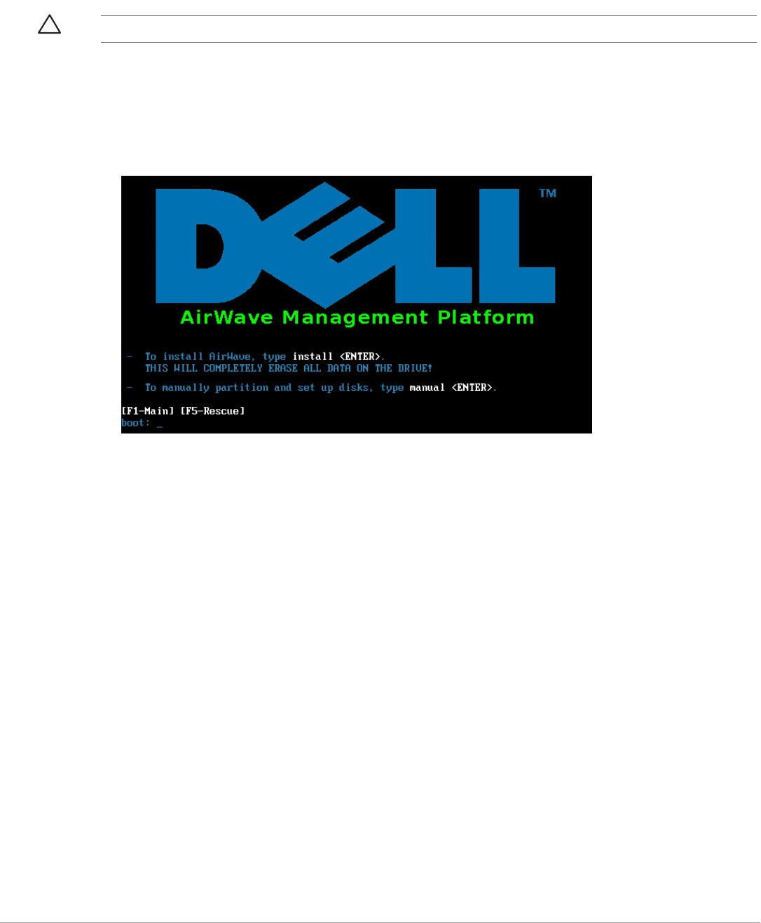
1. Insert the AirWave installation CD-ROM into the drive and boot the server.
2. Type install and press Enter
To configure the partitions manually, type manual and press Enter.
Figure 1 AirWave Installation
3. Allow the installation process to continue. Installing the CentOS software (Phase I) takes 10 to 20 minutes to
complete. This process formats the hard drive and launches Anaconda to install all necessary packages.
Anaconda gauges the progress of the installation.
Upon completion, the system will prompt you to eject the installation CD and reboot the system.
4. Remove the CD from the drive and store in a safe location.
Installing AirWave Software (Phase 2)
Getting Started
After the reboot, the GRUB screen appears.
1. Press Enter or wait six seconds, and the system automatically loads the kernel.
2. When the kernel is loaded, log into the server using the following credentials:
-login = root
-password = admin
3. Start the AirWave software installation script by executing the./amp-install command.
Type./amp-install at the command prompt and press Enter to execute the script.
Step 1: Configuring Date and Time
The following message appears, and this step ensures the proper date and time are set on the server.
------------------------ Date and Time Configuration ------------------
CAUTION: This procedure erases the hard drive(s) on the server.

Dell PowerConnect W-AirWave 7.5 | User Guide Installing and Getting Started | 7
Current Time: Fri Nov 21 09:18:12 PST 2008
1) Change Date and Time
2) Change Time Zone
0) Finish
Ensure that you enter the accurate date and time during this process. Errors will arise later in the installation if
the specified date varies significantly from the actual date, especially if the specified date is in the future and it is
fixed later. Best practices is to configure NTPD to gradually adjust your clock to the correct time.
1. Select 1 to set the date and select 2 to set the time zone. Press Enter after each configuration to return to the
message menu above.
2. Press 0 to complete the configuration of date and time information and to continue to the next step.
Step 2: Checking for Prior Installations
The following message appears after date and time are set:
Welcome to AMP Installer Phase 2
STEP 2: Checking for previous AMP installations
If a previous version of AirWave software is not discovered, the installation program automatically proceeds to
Step 3. If a previous version of the software is discovered, the following message appears on the screen.
The installation program discovered a previous version of the software. Would you
like to reinstall AMP? This will erase AMP's database. Reinstall (y/n)?
Type y and then press Enter to proceed.
Step 3: Installing AMP Software
The following message appears while AirWave software is transferred and compiled.
STEP 3: Installing AMP software
This will take a few minutes.
Press Alt-F9 to see detailed messages.
Press Alt-F1 return to this screen.
This step requires no user input, but you can follow the instructions to monitor its progress and switch back to
the installation screen.
Step 4: Checking the AirWave Installation
After the AirWave software installation is complete, the following message appears:
STEP 4: Checking AMP installation
Database is up.
AMP is running version: (version number)
This step requires no user input. Proceed to the next step when prompted to do so.
CAUTION: Changing these settings after the installation can cause data loss, especially for time-series data such as Client and
Usage graphs. Avoid delayed configuration.
CAUTION: This action erases the current database, including all historical information. To ensure that the AMP database is
backed up prior to reinstallation, answer `n` at the prompt above and contact your Value Added Reseller or directly contact Dell
support at support.dell.com.

8 | Installing and Getting Started Dell PowerConnect W-AirWave 7.5 | User Guide
Step 5: Assigning an IP Address to the AirWave System
While the AirWave primary network interface accepts a DHCP address initially during installation, AirWave does
not function when launched unless a static IP is assigned. Complete these tasks to assign the static IP address. The
following message appears:
STEP 5: Assigning AMP's address
AMP must be configured with a static IP.
--------------- Primary Network Interface Configuration -------------
1) IP Address : xxx.xxx.xxx.xxx
2) Netmask : xxx.xxx.xxx.xxx
3) Gateway : xxx.xxx.xxx.xxx
4) Primary DNS : xxx.xxx.xxx.xxx
5) Secondary DNS: xxx.xxx.xxx.xxx
9) Commit Changes
0) Exit (discard changes)
If you want to configure a second network interface, please
use AMP's web interface, AMP Setup --> Network Tab
1. Enter the network information.
2. To commit the changes, type 9 and then press Enter. To discard the changes, type 0 and then press Enter.
Step 6: Naming the AirWave Network Administration System
Upon completion of the previous step, the following message appears.
STEP 6: Naming AMP
AMP name is currently set to: New AMP
Please enter a name for your AMP:
At the prompt, enter a name for your AirWave server and press Enter.
Step 7: Generating AMP’s SSL Certificate
Upon completion of the previous step, the following message appears on the screen.
STEP 7: Generating AMP's SSL Certificate
Does AMP have a valid DNS name on your network (y/n)?
1. If AirWave does not have a valid host name on the network, type n at the prompt. The following appears:
Generating SSL certificate for < IP Address >
2. If AirWave has a valid host name on the network, type y at the prompt. The following appears:
Enter AMP's fully qualified domain name:
3. Type the AirWave DNS name and press Enter. The following message appears:
Generating SSL certificate for < IP Address >
Proceed to the next step when the system prompts you.
Step 8: Changing the Default Root Password
Upon completion of the prior step, the following message appears.
NOTE: The Secondary DNS setting is an optional field.

Dell PowerConnect W-AirWave 7.5 | User Guide Installing and Getting Started | 9
STEP 8: Changing default root password.
It is strongly recommended that you change the default 'root' password.
Please use a password that you consider to be safe, secore, and memorabl.
Changing password for user root.
New Password:
Enter the new root password and press Enter. The Linux root password is similar to a Windows administrator
password. The root user is a super user who has full access to all commands and directories on the computer.
This password should be kept as secure as possible because it allows full access to the machine. This password is
not often needed on a day-to-day basis but is required to perform AirWave upgrades and advanced
troubleshooting. If you lose this password, contact Dell support at support.dell.com for resetting instructions.
Completing the Installation
Upon completion of all previous steps, the following message appears.
CONGRATULATIONS! AMP is configured properly.
To access AMP web console, browse to https://<IP Address>
Login with the following credentials:
Username: admin
Password: admin
-To view the Phase 1 installation log file, type cat/root/install.log.
-To view the Phase 2 installation log file, type cat/tmp/amp-install.log.
-To access the AirWave GUI, enter the AirWave IP address in the address bar of any browser. The AirWave
GUI then prompts for your license key. If you are entering a dedicated Master Console or AirWave Failover
license, refer to “Supporting AirWave Servers with the Master Console” on page226 for additional
information.
Upgrading AirWave
To upgrade AirWave:
1. Download the latest version from download.dell-pcw.com.
2. Copy the file to the AirWave /root directory using WinSCP.
3. On the AirWave, run the following command, where x.x.x is the latest AirWave release number:
# start_dell_upgrade -v x.x.x
The version-specific script will deploy all needed files, update the database, perform any data migrations, and
restart the AirWave services.
Configuring and Mapping Port Usage for AMP
The following table itemizes the communication protocols and ports necessary for AirWave to communicate with
wireless LAN infrastructure devices, including access points (APs), controllers, routers, switches, and RADIUS
servers. Assign or adjust port usage on the network administration system as required to support these
components.
Table 2 AirWave Protocol and Port Chart
Port Type Protocol Description Direction Device Type
21 TCP FTP Firmware distribution > APs or controllers

10 | Installing and Getting Started Dell PowerConnect W-AirWave 7.5 | User Guide
AirWave Navigation Basics
Every AirWave page contains the following three basic sections:
-Status Section
-Navigation Section
22 TCP SSH Configure devices > APs or controllers
22 TCP SSH Configure AMP from CLI < Laptop or workstation
22 TCP VTUN Support connection (optional) > Dell support home office
22 TCP SCP Transfer configuration files or FW < APs or controllers
23 TCP Telnet Configure devices > APs or controllers
23 TCP VTUN Support connection (Optional) > Dell support home office
25 TCP SMTP Support email (optional) > Dell support email server
49 UDP TACACS AMP Administrative Authentication > Cisco TACACS+
53 UDP DNS DNS lookup from AMP > DNS Server
69 UDP TFTP Transfer configuration files or FW < APs or controllers
80 TCP HTTP Configure devices > Legacy APs
80 TCP VTUN Support connection (optional) > Dell support home office
161 UDP SNMP Get and Set operations > APs or controllers
162 UDP SNMP Traps from devices < APs or controllers
162 UDP SNMP Traps from AMP > NMS
443 TCP HTTPS Web management < Laptop or workstation
443 TCP HTTPS WLSE polling > WLSE
443 TCP VTUN Support connection (optional) > Dell support home office
1701 TCP HTTPS AP and rogue discovery > WLSE
1741 TCP HTTP WLSE polling > WLSE
1812 UDP RADIUS
Auth
Authenticate & authorize AMP
administrative users on a RADIUS
server.
> RADIUS auth server
1813 UDP RADIUS
accounting
Retrieve usernames for authenticated
WLAN clients from NAS (captive portal,
controller, autonomous AP). Only used
when usernames are not available in
the SNMP MIB of a controller or
autonomous AP.
< RADIUS accounting client
2002 TCP HTTPS Retrieve client authentication info > ACS
5050 UDP RTLS Real Time Location Feed < Dell thin APs
8211 UDP PAPI Real Time Feed (AMON) < > WLAN controllers
ICMP Ping Probe > APs or controllers
Table 2 AirWave Protocol and Port Chart (Continued)
Port Type Protocol Description Direction Device Type

Dell PowerConnect W-AirWave 7.5 | User Guide Installing and Getting Started | 11
-Activity Section
The AirWave pages also contain Help links that opens a PDF of the AirWave User Guide.
Status Section
The Status section is a snapshot view of overall WLAN performance and provides direct links for immediate
access to key system components. You can customize the contents of the Status section on the Home > User
Info page. Refer to “Configuring Your Own User Information with the Home > User Info Page” on page220.
The table below describes these elements in further detail.
Table 3 Status Section/Top Header Components of the AirWave GUI
Field Description
New Devices The number of wireless APs or wireless LAN controllers that have been discovered by AMP but not yet
managed by network administrators. When selected, AMP directs you to a page that displays a detailed list
of devices awaiting authorization.
Up (Wired &
Wireless)
The number of managed authorized devices that are currently responding to AMP requests. When selected,
AMP shows a detailed list of all Up devices.
Up (Wired) The number of managed authorized, wired devices that are currently responding to AMP requests. When
selected, AMP shows a detailed list of all Up devices.
Up (Wireless) The number of managed authorized, wireless devices that are currently responding to AMP requests. When
selected, AMP shows a detailed list of all Up devices.
Down (Wired &
Wireless)
The number of managed, authorized devices that are not currently responding to AMP SNMP requests.
When selected, AMP shows a detailed list of all Down devices.
Down (Wired) The number of managed authorized, wired devices that are not currently responding to AMP requests. When
selected, AMP shows a detailed list of all Up devices.
Down (Wireless) The number of managed authorized, wireless devices that are not currently responding to AMP requests.
When selected, AMP shows a detailed list of all Up devices.
Mismatched The total number of Mismatched devices. A device is considered mismatched when the desired
configuration in AMP does not match the actual device configuration read from the device.
Rogue The number of devices that have been classified by the RAPIDS rules engine above the threshold defined on
the Home > User Info page. If, for example, the threshold is defined as “Suspected Rogue,” then the Rogue
count will include Suspected Rogues as well as classifications above Suspected, which include Rogue and
Contained Rogue.
Clients The number of wireless users currently associated to the wireless network via all the APs managed by AMP.
When selected, AMP shows a list of users that are associated. Prior to version 7.4, this was called “Users.”
VPN Sessions Displays the number of active VPN sessions. When selected, AMP shows a list of active sessions on the
Clients > VPN Sessions page. Note that if this page is empty, then there are no active VPN sessions to view.
You can navigate to the APs/Devices > List page and verify in the table that there are no active VPN sessions.
Alerts Displays the number of non-acknowledged AMP alerts generated by user-configured triggers. When
selected, AMP shows a detailed list of active alerts.
Include Device
Types in Header
Stats
You can support statistics for any combination of the following device types:
-Fat APs
-Thin APs
-Controllers
-Routers/Switches
-Others
Refer to “Configuring Your Own User Information with the Home > User Info Page” on page 220.
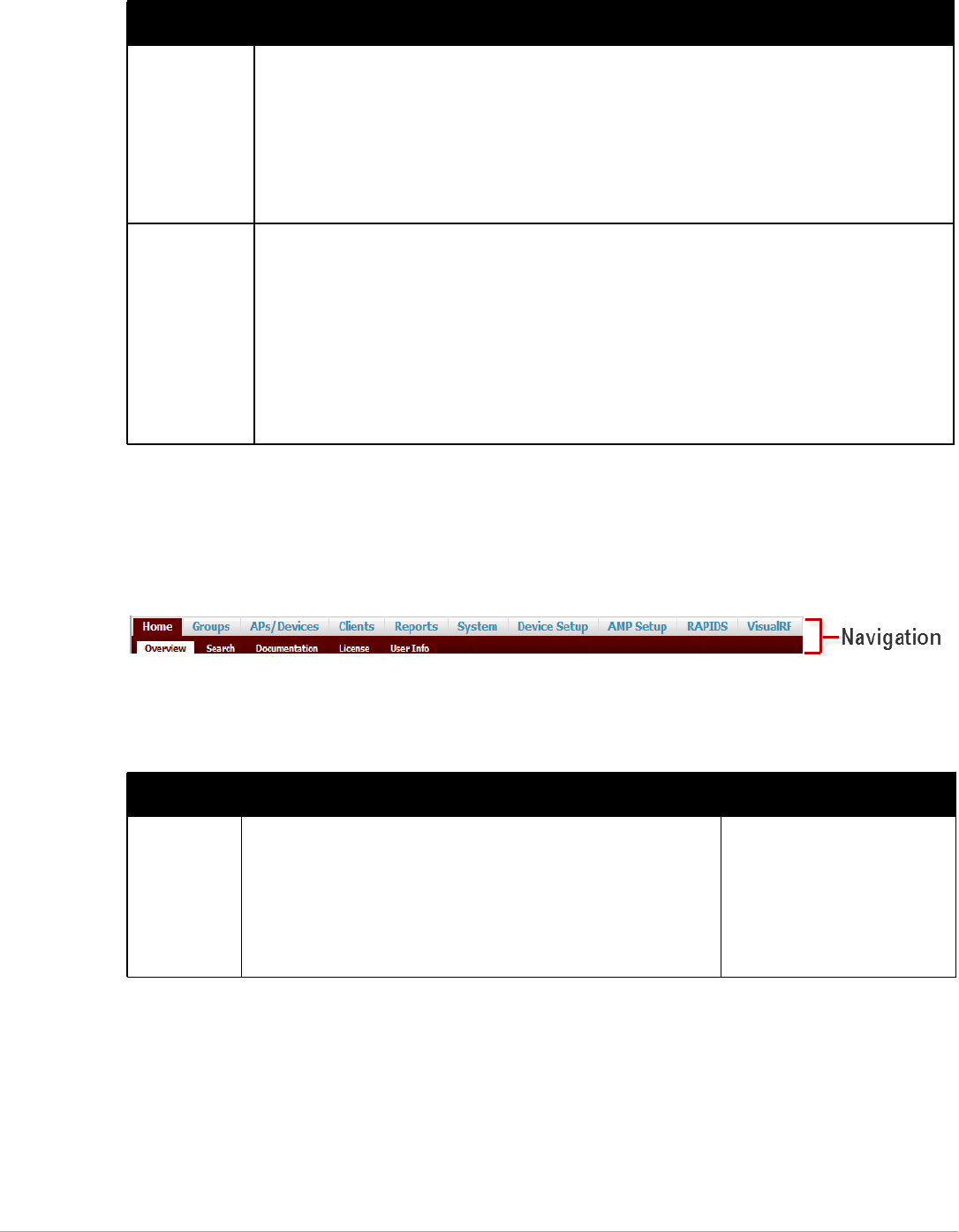
12 | Installing and Getting Started Dell PowerConnect W-AirWave 7.5 | User Guide
Navigation Section
The Navigation section displays tabs for all main GUI pages within AirWave. The top bar is a static navigation
bar containing tabs for the main components of AirWave, while the lower bar is context-sensitive and displays the
subtabs for the highlighted tab.
Figure 2 Navigation section of the Home > Overview Page
Some navigation items may be hidden for users depending on a user’s role. The table below describes the
navigation elements in further detail.
Severe Alert
Threshold
The Severe Alert Threshold determines the severity level that results in a Severe Alert. Specify either
Normal, Warning, Minor, Major, or Critical as the severity alert threshold value. These threshold values are
tied to triggers that are created on the System > Triggers page. For example, if a trigger is defined to result in
a “Critical” alert, and if the Severe Alert Threshold here is defined as “Major,” then the list of Severe Alerts
will include all “Major” and “Critical” alerts. Similarly, if this value is set to “Normal”, which is the lowest
threshold, then the list of Severe Alerts will include all alerts.
When a Severe Alert exists, a component named Severe Alerts will appear at the right of the Status field in
bold red font. This field will not display if a Severe Alert does not exist. In addition, only users who are
enabled for viewing Severe Alerts on the Home > User Info page can see severe alerts.
Search Use the Search field to perform partial string searches on a large number of fields including the notes,
version, secondary version, radio serial number, device serial number, LAN MAC, radio MAC and apparent IP
of all the APs as well as the client MAC, VPN user, LAN IP, VPN IP fields.
Entering a search string displays search results in two phases:
-“Fast” search results - display quickly and divide the results into Clients, APs, Controllers, and Switches,
and shows only basic columns relevant to each search category
-“Full” search results - accessed by selecting the “Click here to perform a Full Search to expand the
results” link at the top of the Fast search results form. This action sends the earlier search term to a
much deeper search of AMP. The Customize Search section allows you to expand the search to include
all types of devices, clients (connected, historical, and rogue), VPN sessions (connected and historical),
folders, groups, tags, and rogue devices.
Table 4 Components and Subtabs of AirWave Navigation
Main Tab Description Subtabs
Home The Home pages provide basic AirWave information including system
name, host name, IP address, current time, running time, and software
version.
The Home pages also provide a central point for network status
information and monitoring tools, giving graphical display of network
activity, and links to many of the most frequent tools in AirWave. For
additional information, refer to “Monitoring and Supporting AirWave with
the Home Pages” on page 216.
Overview
Search
Documentation
License
User Info
Table 3 Status Section/Top Header Components of the AirWave GUI (Continued)
Field Description

Dell PowerConnect W-AirWave 7.5 | User Guide Installing and Getting Started | 13
Groups The Groups pages provide information on the logical “groups” of devices
that have been established for efficient monitoring and configuration. For
additional information, see Chapter 4, “Configuring and Using Device
Groups” on page 67.
Some of the focused subtabs will not appear for all groups. Focused
subtabs are visible based on the device type field on the Groups > Basic
page. This subtab is the first page to appear when adding or editing
groups.
NOTE: When individual device configurations are specified, device-level
settings override the Group-level settings to which a device belongs.
List
Focused Subtabs:
-Monitor
-Basic
-Templates
-Security
-SSIDs
-AAA Servers
-Radio
-Dell Config
-Cisco WLC Config
-PTMP
-Proxim Mesh
-MAC ACL
-Firmware
-Compare
APs/Devices The APs/Devices pages provide detailed information about all authorized
APs and wireless LAN switches or controllers on the network, including
all configuration and current monitoring data.
These pages interact with several additional pages in AirWave. Refer to
Chapter 5, “Discovering, Adding, and Managing Devices” on page 107.
NOTE: When specified, device-level settings override the default Group-
level settings.
List
New
Up
Down
Mismatched
Ignored
Focused Subtabs:
-Monitor
-Interfaces
-Manage
-Audit
-Compliance
-Rogues Contained
Clients The Clients pages provide detailed information about all client devices
and users currently and historically associated to the WLAN, including
VPN users. Prior to 7.4, this tab was called “Users”. For additional
information, refer to “Monitoring and Supporting WLAN Clients” on
page 202
Connected
All
Rogue Clients
Guest Users
VPN Sessions
VPN Users
Tags
Guest Users Subtabs:
-Client Detail
-Diagnostics
VPN Users Subtab:
-VPN User Detail
Reports The Reports pages list all the standard and custom reports generated by
AirWave. For additional information, refer to Chapter 9, “Creating,
Running, and Emailing Reports” on page 233.
Generated
Definition
Definition Subtab:
-Detail
Table 4 Components and Subtabs of AirWave Navigation (Continued)
Main Tab Description Subtabs

14 | Installing and Getting Started Dell PowerConnect W-AirWave 7.5 | User Guide
Activity Section
The Activity section is the main section of the user interface. This section displays all detailed configuration and
monitoring information. It is where you view activity and implement configuration changes.
System The System page provides information about AirWave operation and
administration, including overall system status, the job scheduler, trigger/
alert administration, and so forth.
For additional information, refer to “Monitoring and Supporting AirWave
with the System Pages” on page 189.
Status
Syslog & Traps
Event Log
Triggers
Alerts
Backups
Configuration Change Jobs
Firmware Upgrade Jobs
Performance
Device Setup The Device Setup pages provide the ability to add, configure, and monitor
devices, to include setting AP discovery parameters, performing firmware
management, defining VLANs, and so forth. For additional information,
refer to “Enabling AirWave to Manage Your Devices” on page 50.
Discover
Add
Communication
Dell Configuration (if global Dell
Configuration is enabled)
Upload Firmware & Files
Certificate
AMP Setup The AMP Setup pages provide all information relating to the configuration
of AirWave itself and its connection to your network. This page entails
several processes, configurations, or tools in AirWave. For additional
information, start with Chapter 3, “Configuring AirWave” on page 19.
NOTE: Some AMP Setup pages may not be visible depending on the role
of the logged-in user set in AirWave.
General
Network
Users
Roles
Guest Users
Authentication
MDM Server
Device Type Setup
WLSE
ACS
NMS
RADIUS Accounting
PCI Compliance
RAPIDS The RAPIDS pages provide all information relating to rogue access
points, including methods of discovery and lists of discovered and
possible rogues. For additional information, refer to Chapter 7, “Using
RAPIDS and Rogue Classification” on page 173.
NOTE: The RAPIDS pages may not be visible to the logged-in user,
depending on their role set in AMP.
Overview
List
IDS Events
Setup
Rules
Score Override
Audit Log
VisualRF VisualRF pages provide graphical access to floor plans, client location,
and RF visualization for floors, buildings, and campuses that host your
network. Refer to Chapter 10, “Using VisualRF” on page 263.
Floor Plans
Setup
Import
Audit Log
Table 4 Components and Subtabs of AirWave Navigation (Continued)
Main Tab Description Subtabs
NOTE: The AMP Setup tab varies with user role. The RAPIDS and VisualRF tabs appear based on the license entered on the Home
> License page, and might not be visible on your AirWave view.
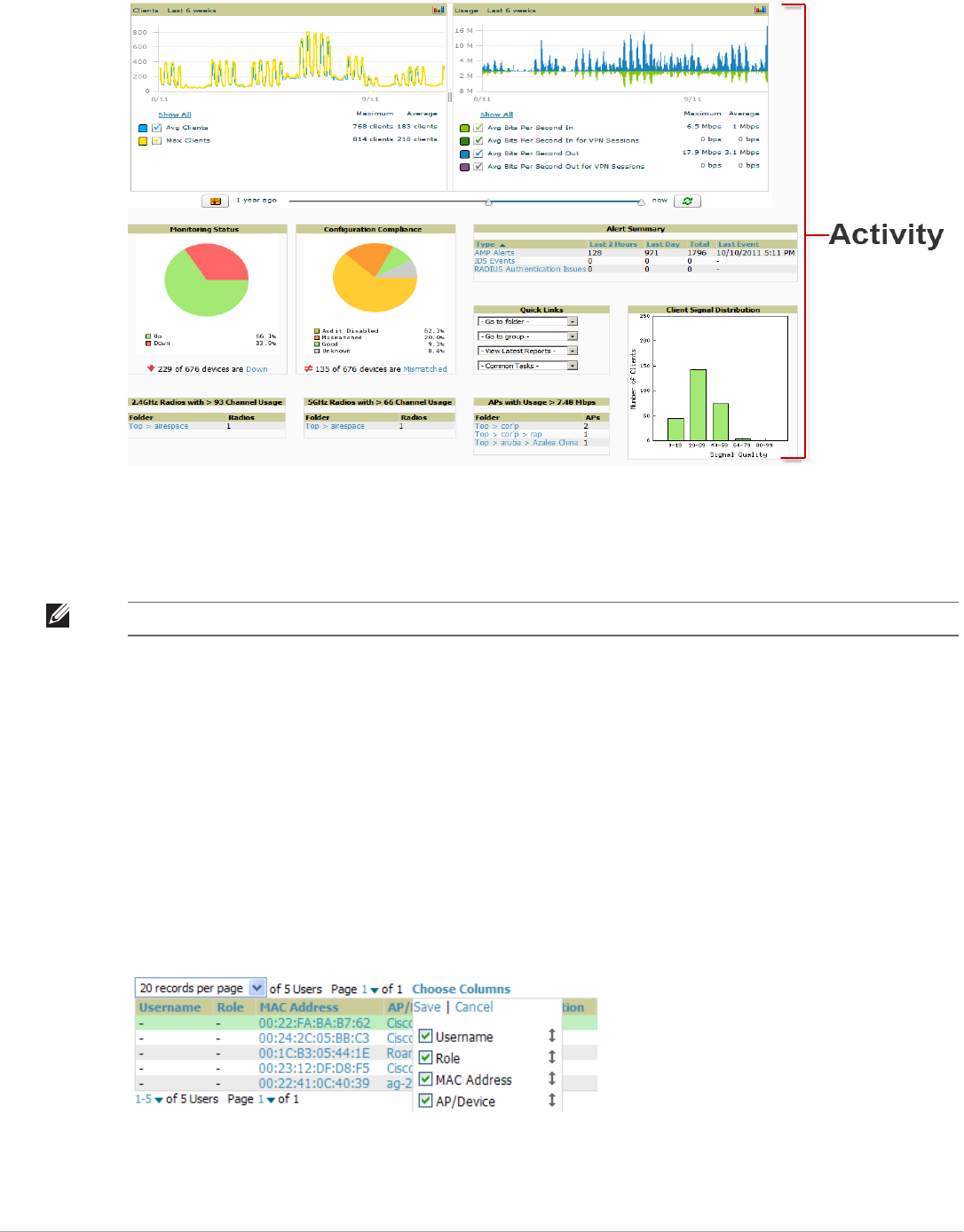
Dell PowerConnect W-AirWave 7.5 | User Guide Installing and Getting Started | 15
Figure 3 Activity section of the Home>Overview Page
Help Links in the UI
The Help link is available on every page within AirWave. When selected, this launches the AirWave User Guide
PDF file.
Common List Settings
All of the lists in AirWave have some common options. All lists are paginated with a configurable number of
items per page. Selecting the Records Per Page dropdown menu (which usually looks like a range such as 1-20 on
the upper left hand side of a list table) enables you select or enter the number of rows that appear at a time in the
list. The next down arrow displays a dropdown menu that allows you to select the exact page you would like to
view, as shown in Figure 4.
The Choose Columns option, illustrated on Figure 4, allows you to configure the columns that are presented in
the list and the order in which they are presented. To disable a column, clear its checkbox. To reorder the
columns, drag a row to the appropriate new position. When you are satisfied with the enabled columns and their
order, select Save at the top of the columns list.
Figure 4 Common List Settings Choose Columns Illustration
These settings are user specific. To reset them, select Reset List Preferences on Home > User Info.
NOTE: Adobe Reader must be installed in order to view the PDF help file.
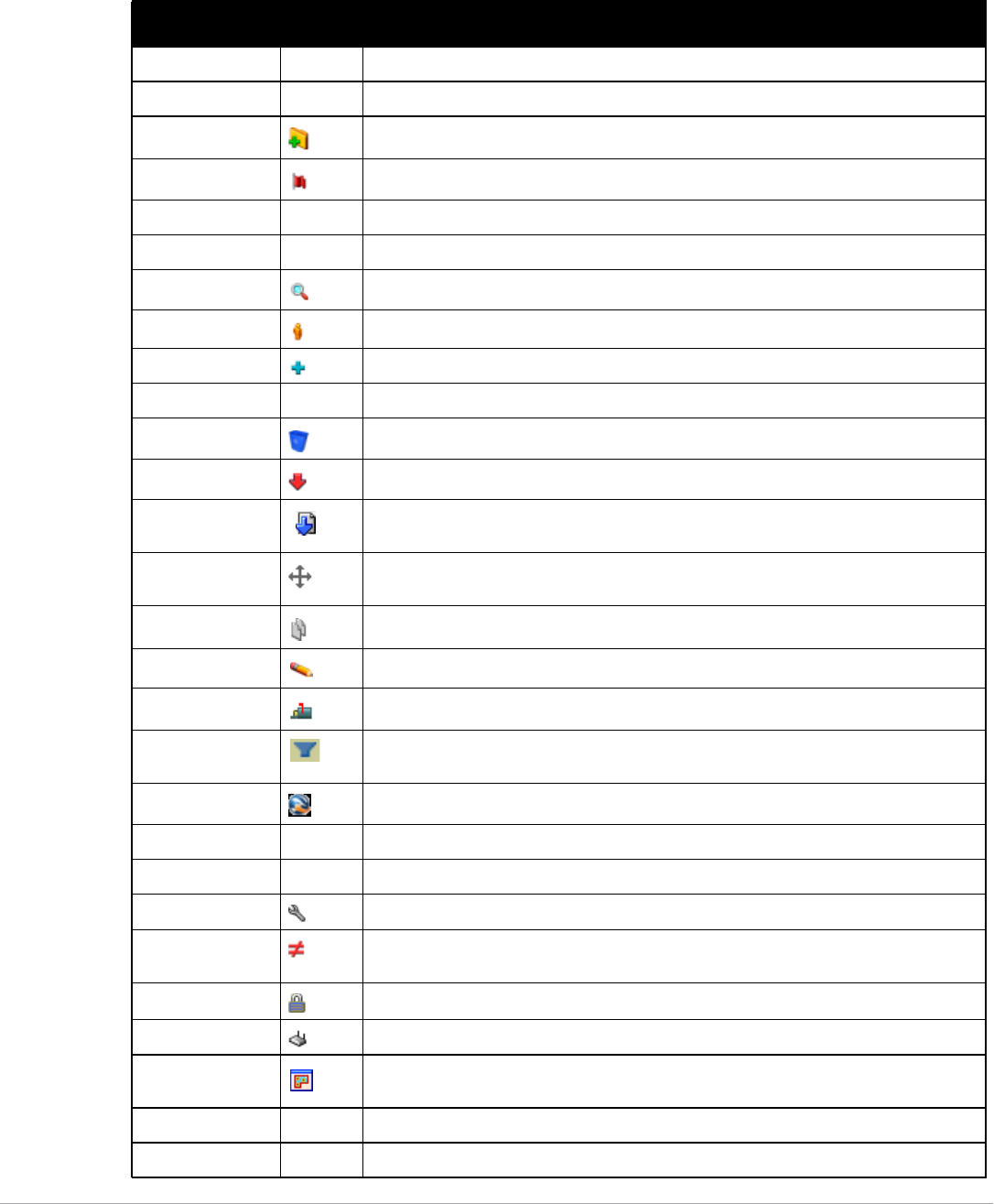
16 | Installing and Getting Started Dell PowerConnect W-AirWave 7.5 | User Guide
Buttons and Icons
Standard buttons and icons are used throughout AirWave as follows:
Table 5 Standard Buttons and Icons of the AirWave User Page
Function ImageaDescription
Acknowledge Acknowledges and clears an AMP alert.
Add Adds the object to both AMP’s database and the onscreen display list.
Add Folder Adds a new folder to hierarchically organize APs.
Alert Indicates an alert.
Apply Applies all “saved” configuration changes to devices on the WLAN.
Audit Reads device configuration, compare to desired, and update status.
Choose Chooses a new Helpdesk incident to be the Current Incident.
Clients Indicates WLAN users. Select this number to see a list of connected clients.
Create Creates a new Helpdesk incident.
Customize Ignores selected settings when calculating the configuration status.
Delete Deletes an object from AMP’s database.
Down Indicates Down devices and radios.
Download Original
Floor Plan
Downloads the original VisualRF floor plan drawing. When you click this button, you have the
option of opening the drawing or saving it to a file.
Drag and Drop Dragging and dropping objects with this icon changes the sequence of items in relation to
each other.
Duplicate Duplicates or makes a copy of the configuration of an AirWave object.
Edit Edits the object properties.
Email Links to email reports.
Filter (Funnel icon) Filters list by values of the selected column. To reset all filters in all columns, click Reset
filters link at the bottom of the table.
Google Earth Views device’s location in Google Earth (requires plug-in).
Ignore Ignores specific device(s) - devices selected with check boxes.
Import Updates a Group’s desired settings to match current settings.
Manage Manages the object properties.
Mismatched Indicates mismatched device configuration, in which the most recent configuration in AMP
and the current configuration on a device are mismatched.
Monitor Indicates an access point is in “monitor only” mode.
New Devices Indicates new access points and devices.
Open in New
Window
Opens a VisualRF floor plan in a new browser window.
Poll Now Polls device (or controller) immediately, override group polling settings.
Preview Displays a preview of changes applicable to multiple groups.
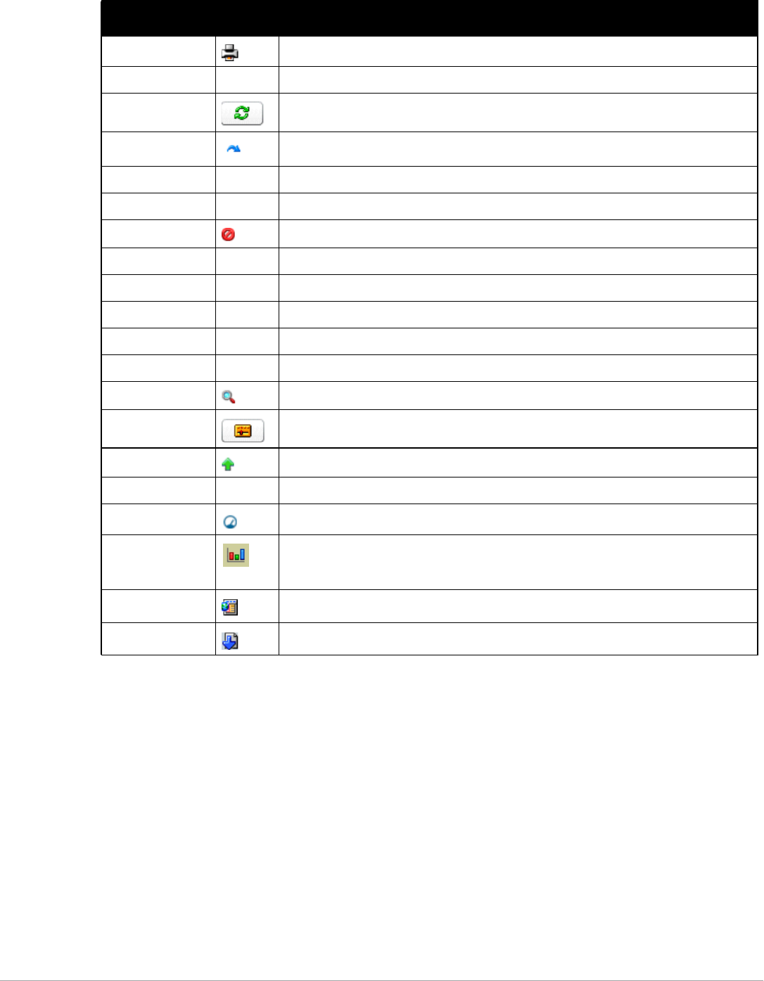
Dell PowerConnect W-AirWave 7.5 | User Guide Installing and Getting Started | 17
Getting Started with AirWave
This topic describes how to perform an initial launch of the AirWave network management solution on a session-
based authentication scheme.
When an AirWave URL is accessed either interactively using a browser or programmatically using an API, a sent
cookie may match a session stored in the database, granting authentication (but not necessarily access, depending
on how the user’s role matches the required role for the URL). If the cookie is not present or the session in the
database has expired, the request is denied.
For browser requests, this results in a login form being displayed. When you submit the login form, the supplied
credentials are checked against the AMP’s user database, an external RADIUS server, an external TACACS+
server, or an external LDAP server, per the AMP’s configuration. If the credentials are valid, the user’s browser is
sent a session cookie to use in subsequent requests.
Print Prints the report.
Reboot Reboots devices or AMP.
Refresh Refreshes the display of interactive graphs when settings have changed.
Relate Relates an AP, Group or Client to a Helpdesk incident.
Replace Hardware Confers configuration and history of one AP to a replacement device.
Revert Returns all configurable data on the screen to its original status.
Rogue Indicates a rogue AP, and links to RAPIDS.
Run Runs a new user-defined report.
Save Saves the information on the page in the AMP database.
Save & Apply Saves changes to AMP’s database and apply all changes to devices.
Scan Scans for devices and rogues using selected networks.
Schedule Schedules a window for reports, device changes, or maintenance.
Search Searches AMP for the specified client, device, rogue, group, folder, tag, or session.
Set Time Range Sets the time range for interactive graphs to the range specified.
Up Indicates devices which are in the Up status.
Update Firmware Applies a new firmware image to an AP/device.
Usage Displays current bandwidth.
View Historical
Graph in New
Window
Displays all data series for the selected graph over the last two hours, last day, last week,
last month, and last year in one new pop-up window.
VisualRF Links to VisualRF - real time visualization.
XML Links to export XHTML versions of reports.
a. Not all AMP GUI components are itemized in graphic format in this table.
Table 5 Standard Buttons and Icons of the AirWave User Page (Continued)
Function ImageaDescription
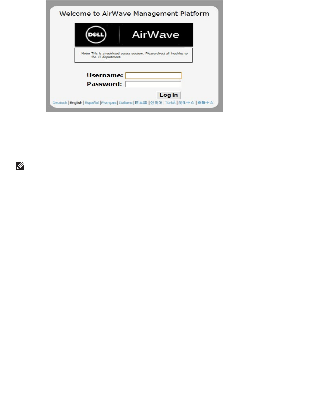
18 | Installing and Getting Started Dell PowerConnect W-AirWave 7.5 | User Guide
Use your browser to navigate to the static IP address assigned to the internal page of the AMP, as shown in Figure
5. Enter the User Name and Password as admin/admin for your initial login, and then select Log In.
Figure 5 AirWave Login Form
If desired, you can set one of the available languages for your login. AirWave will remember your selected
language until you log out and select another. You must log out in order to select a different language.
After successful authentication, your browser launches the AirWave Home > Overview page.
NOTE: AirWave pages are protected via SSL. Some browsers will display a confirmation dialog for your self-signed certificate.
Signing your certificate will prevent this dialog from displaying. Changing the default login and password on the AMP Setup >
Users page is recommended. Refer to the procedure “Creating AirWave User Roles” on page 38 for additional information.

Dell PowerConnect W-AirWave 7.5 | User Guide Configuring AirWave | 19
Chapter 3
Configuring AirWave
This chapter contains the following procedures to deploy initial AirWave configuration:
-“Formatting the Top Header” on page19
-“Customizing Columns in Lists” on page20
-“Resetting Pagination Records” on page21
-“Using the Pagination Widget” on page22
-“Using Export CSV for Lists and Reports” on page22
-“Defining Graph Display Preferences” on page22
-“Customizing the Dashboard” on page23
-“Setting Severe Alert Warning Behavior” on page27
-“Defining General AirWave Server Settings” on page27
-“Defining AirWave Network Settings” on page35
-“Creating AirWave User Roles” on page38
-“Creating AirWave Users” on page41
-“Configuring Login Message, TACACS+, RADIUS, and LDAP Authentication” on page43
-“Enabling AirWave to Manage Your Devices” on page50
-“Setting Up Device Types” on page55
-“Configuring Cisco WLSE and WLSE Rogue Scanning” on page56
-“Configuring ACS Servers” on page61
-“Integrating AirWave with an Existing Network Management Solution (NMS)” on page62
-“Auditing PCI Compliance on the Network” on page63
-“Deploying WMS Offload” on page65
Before You Begin
Remember to complete the required configurations in this chapter before proceeding. AirWave support remains
available to you for any phase of AirWave installation.
Formatting the Top Header
The Dell PowerConnect W-AirWave 7.5 interface centers around a horizontal row of tabs with nested subtabs.
A row of statistics hyperlinks called Top Header Stats above the tabs represents commonly used subtabs. These
hyperlinks provide the ability to view certain key statistics by mousing over, such as number and type of Down
devices, and serve as shortcuts to frequently viewed subtabs. Figure 6 illustrates the navigation bar. For more
details on hyperlinks, tabs and subtabs, see “AirWave Navigation Basics” on page10.
NOTE: Additional configurations are available after basic configuration is complete.
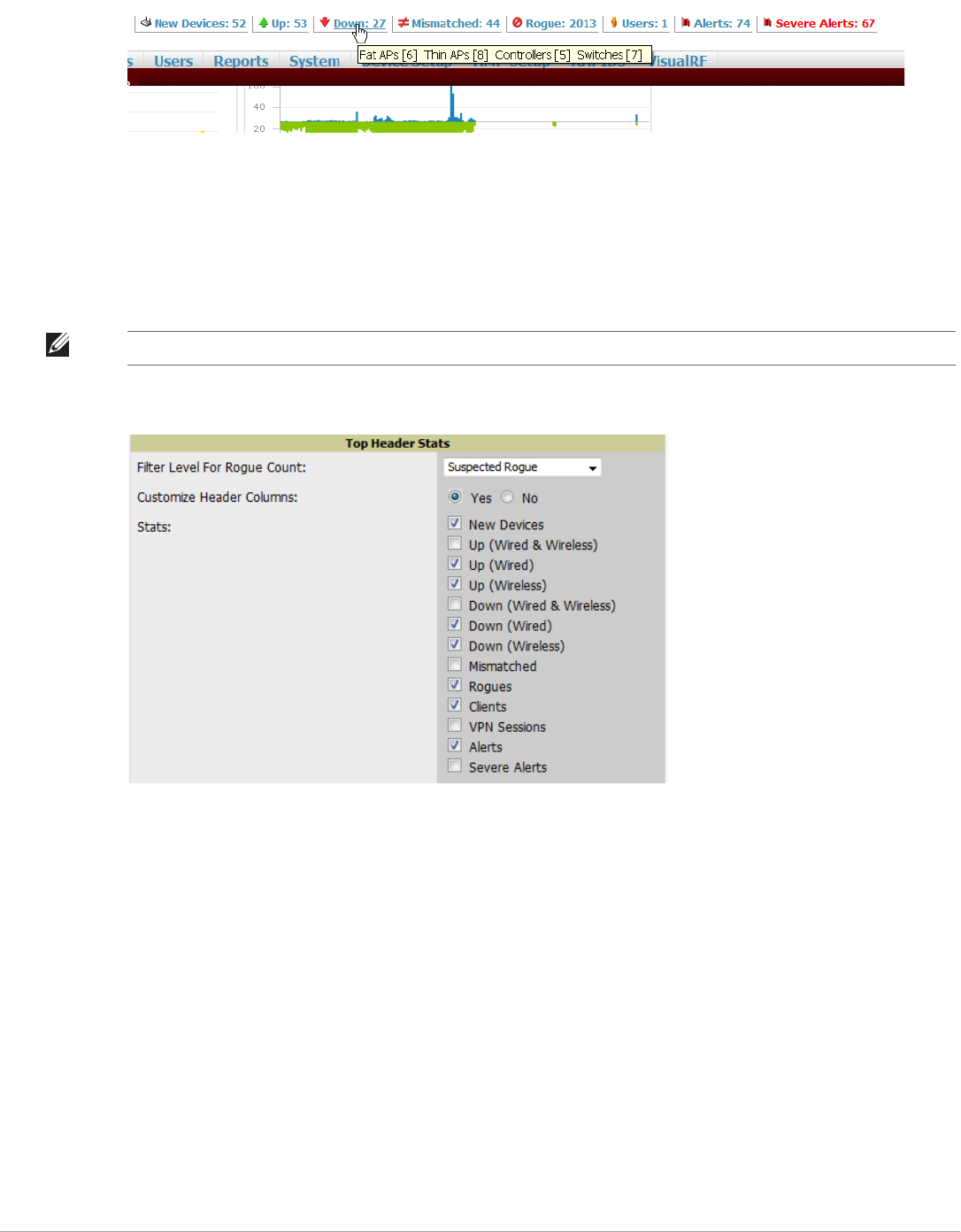
20 | Configuring AirWave Dell PowerConnect W-AirWave 7.5 | User Guide
Figure 6 Navigation Bar Displaying Down Device Statistics
You can control the Top Header Stats links that appear from the AMP Setup > General page, as described in
“Defining General AirWave Server Settings” on page27. Top Header Stats can also be customized for individual
users on the Home > User Info page. There you can select the statistics to display for certain device types and
override the AMP Setup page.
All possible display options for users are shown in Figure 7, and these fields are described in detail in “Configuring
Your Own User Information with the Home > User Info Page” on page220.
Figure 7 Home > User Info Top Header Stats Display Options
You can also set the severity level of critical alerts displayed for a user role. For details including a description of
what constitutes a severe alert, see “Setting Severe Alert Warning Behavior” on page27.
Customizing Columns in Lists
Customize the columns for any list table selecting Choose Columns, as shown in Figure 8. Use the up/down
arrows to change the order in which the column heads appear.
NOTE: A confirmation message does not appear when you make modifications to the Top Header Stats.
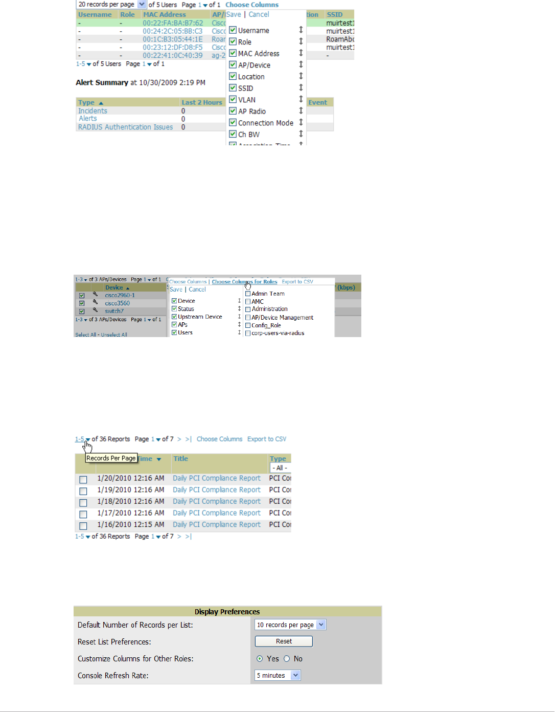
Dell PowerConnect W-AirWave 7.5 | User Guide Configuring AirWave | 21
Figure 8 Choose Columns Dropdown List
For more information on the universal list elements, see “Common List Settings” on page15.
You can also control which column heads appear for each user role by selecting Yes in the Customize Header
Columns field in Home > User Info, as also appears in Figure 7. This exposes the Choose Columns for Roles
dropdown menu in all tables shown in Figure 9.
The first column shows the user roles that were customized, if any. The second column allows you to establish left
to right columns and order them using the arrows.
Figure 9 Table With Choose Columns for Roles Menu Selected
Resetting Pagination Records
To control the number of records in any individual list, select the link with Records Per Page mouseover text at
the top left of the table, as shown in Figure 10. AirWave remembers each list table’s pagination preferences.
Figure 10 Records Per Page Drop Down Menu
To reset all Records Per Page preferences, select Reset in the Display Preferences section of the Home > User
Info page, as shown in Figure 11.
Figure 11 Home > User Info Display Preferences section
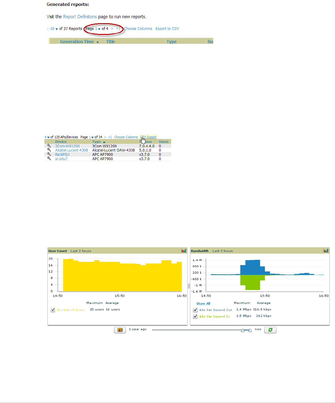
22 | Configuring AirWave Dell PowerConnect W-AirWave 7.5 | User Guide
Using the Pagination Widget
The pagination widget is located at the top and bottom of every list table, as shown in Figure 12.
Figure 12 Pagination Widget
Use the down arrow next to Page 1 to see all the page numbers for that table in a dropdown menu. From here,
you can jump to any portion of the table. Select the > symbol to jump to the next page, and >| to jump to the
last page.
Using Export CSV for Lists and Reports
Some tables have a Export CSV setting you can use export the data as a spreadsheet. See Figure 13 for an
example of a list with the Export CSV option selected.
Figure 13 List with CSV Export Selected
AirWave also enables CSV exporting of all report types. For more information, see “Exporting Reports to XML or
CSV” on page261.
Defining Graph Display Preferences
Many of the graphs in AirWave are Flash-based, which allows you to adjust the graph settings attributes as shown
in Figure 14.
Figure 14 Interactive Graphs on the Home > Overview Page
This Flash-enabled GUI allows for custom settings and adjustments as follows:
-Drag the slider at the bottom of the screen to move the scope of the graph between one year ago and the
current time.
-Drag the slider between graphs to change the relative sizes of each.
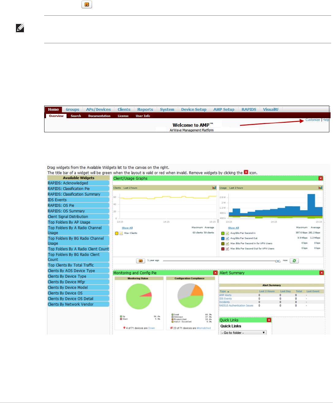
Dell PowerConnect W-AirWave 7.5 | User Guide Configuring AirWave | 23
-Deselect checkboxes to change the data displayed on each graph. The button with green arrows refreshes data
on the graph.
The Show All link displays all of the available checkboxes supporting the Flash graphs. Once a change to the
slider bars has been made, the same change can be applied to all other Flash graphs on that page with a Set time
range button ( ).
Customizing the Dashboard
You can rearrange or remove widgets appearing on the Home > Overview dashboard by selecting the Customize
link to the right of this window, as shown in Figure 15.
Figure 15 Customize Button on the Home > Overview Page
The Customize workspace that appears is shown in Figure 16.
Figure 16 Customize Overview Page
Adding Widgets
The Available Widgets section on the left holds all available graphical elements (widgets). Select any blue widget
tile with a verbal description enclosed, and it immediately turns into a graphical element with a description.
Drag the widgets you want to appear on the Home > Overview dashboard across to the gridlines and arrange
them in the right section, within the gridlines. A widget snaps back to the nearest available gridline if you drop it
NOTE: A non-Flash version of the AirWave user page is available if desired. Instead of Flash, it uses the RRD graphs that were
used in earlier versions of AirWave. For non-Flash graphs, select the graph to open a popup window that shows historical data.
Contact Dell support for more information on activating this feature in the AirWave database.

24 | Configuring AirWave Dell PowerConnect W-AirWave 7.5 | User Guide
across two or more lines and turns red if you attempt to place it over gridlines already occupied by widgets.
Widgets with a green top banner are properly placed and set to appear when you select Save. Widgets that remain
in the left section will not appear; although they can be reinstated by selecting Restore Defaults.
Available Widgets
Table 6 describes the list of available widgets along with a description for each. Note that when a widget is
enabled, the information that displays can vary based on the user’s permission level. Certain “roles,” for example,
limit the top folder that a user can view.
Table 6 Available Widgets
Widget Description
Client/Usage Graphs The Client graph is enabled by default and, by default, shows the maximum number of
attached clients over the last two hours. Select the Show All link to view more specific
client information on the graph, such as the total and average clients for a specific SSID,
the maximum VPN sessions, etc. The available check boxes within this graph are
determined by the SSIDs that AirWave is aware of from polling the device.
The Usage graph is enabled by default and, by default, shows the average bits-per-
second in/out information and average VPN in/out information. Select the Show All link
to view usage information for specific SSIDs. The available checkboxes within this
graph are determined by by the SSIDs that AirWave is aware of from polling the device.
The information in these graphs is color coded to match the selected check boxes.
Monitoring and Config Pie The Monitoring Status pie shows the percentage of total devices that are up and the
number and perctentage of devices that are currently down. Clicking within this pie
chart takes you to the APs/Devices > Down page.
The Configuration Compliance pie shows the percentage of devices that are
mismatched, good, unknown, and those with auditing disabled. It also provides a
summary of the total number of devices that are mismatched. Clicking within this pie
chart takes you to the APs/Devices > Mismatch page.
These pie charts are enabled by default.
Alert Summary The Alert Summary table is enabeld by default and provides the number of AirWave
alerts, IDS events, and RADIUS authentication issues over the last 2 hours, the last 24
hours, and the total since the last AirWave reboot.
-Click on AirWave Alerts to drill down to more detailed alert infromation. This
information displays in the current page. You can return to the Alert Summary graph
by selecting the Home Overview link.
-Click on IDS Events to drill to more detailed event information. This link takes you to
the RAPIDS > IDS Events page.
-Click on RADIUS Authentication Issues to drill to more detailed RADIUS
authentication information. This information displays in the current page. You can
return to the Alert Summary graph by selecting the Home Overview link.
Quick Links The Quick Links section is enabled by default. This section provides the user with easy
navigation to a specific folder, group, report, or common task.
RAPIDS: Acknowledged The Acknowledged RAPIDS Devices pie chart shows the percentage of acknowledged
and unacknowledged RAPIDS that the user has visibility into. The RAPIDS information
appears from the moment a rogue is discovered until it is deleted. Ignored rogues,
however, are not included in this chart.
This chart also displays on the RAPIDS > Overview page.
RAPIDS: Classification Pie The RAPIDS: Classification Pie shows the percentage of devices classified as Valid,
Suspected Neighbor, Suspected Valid, Suspected Rogue, Rogue, and Neighbor that are
attached to AirWave. The RAPIDS information appears from the moment a rogue is
discovered until it is deleted. Ignored rogues, however, are not included in this chart.
This pie chart can also be viewed on the RAPIDS > Overview page.

Dell PowerConnect W-AirWave 7.5 | User Guide Configuring AirWave | 25
RAPIDS: Classification Summary The RAPIDS: Classification Summary table shows the number of devices classified as
Valid, Suspected Valid, Neighbor, Suspected Neighbor, Suspected Rogue, Rogue, and
Unclassified that are attached to AirWave. In addition, contained rogue information will
appear if Manage rogue AP containment is set to Yes on the RAPIDS > Setup page.
The RAPIDS information appears from the moment a rogue is discovered until it is
deleted. Note that ignored rogues are not included in this chart.
This table can also be viewed on the RAPIDS > Overview page.
IDS Events The IDS Events table shows the number and type of attacks logged by the intrusion
detection system over the last 2 hours, the last 24 hours, and the total since the last
AirWave reboot. This is the same table that displays on the RAPIDS > Overview page.
RAPIDS: OS Pie The RAPIDS: OS Pie chart shows the top 9 rogue devices by OS, Others, Unknown, and
Not Scanned. The RAPIDS information appears from the moment a rogue is discovered
until it is deleted. Note that ignored rogues are not included in this chart.
This pie chart can also be viewed on the RAPIDS > Overview page.
RAPIDS: OS Summary The RAPIDS: OS Summary table shows the top 9 rogue devices by OS, Others, Unknown,
and Not Scanned. The RAPIDS information appears from the moment a rogue is
discovered until it is deleted. Note that ignored rogues are not included in this chart.
This table can also be viewed on the RAPIDS > Overview page.
Top Folders By AP Usage This chart lists the folders and the number of APs in each folder whose usage is greater
than the cutoff (or usage threshold). The cutoff represents 75% of the “maximum usage,”
where the maximum usage is the AP with the highest usage regardless of the folder in
which it resides. The cutoff value is displayed within the title, and this value can vary.
The chart takes into account approved APs with radios based on the last 24 hours. In
addition, this chart is updated every hour.
Top Folders By A Radio Channel
Usage
This chart shows the folders and the number of A radios (5GHz) in each folder whose
channel usage is greater than the cutoff (or usage threshold) as measured by Mbps. This
cutoff is on the on the AMP Setup > General page using the Configure Channel Busy
Threshold option. If this option is not configured, then the cutoff is 75% of the ‘maximum,’
where the ‘maximum’ refers to the AP that has the highest usage regardless of the folder
in which it resides. The cutoff value is displayed within the title, and this value can vary.
This chart takes into account approved APs with ‘A’ radios based on the last 24 hours. In
addition, this chart is updated every hour.
Top Folders By BG Radio Channel
Usage
This chart shows the folders and the number of BG radios (2.4GHz) in each folder whose
channel usage is greater than the cutoff (or usage threshold) as measured by Mbps. This
cutoff is on the on the AMP Setup > General page using the Configure Channel Busy
Threshold option. If this option is not configured, then the cutoff is 75% of the ‘maximum,’
where the ‘maximum’ refers to the AP that has the highest usage regardless of the folder
in which it resides. The cutoff value is displayed within the title, and this value can vary.
This chart takes into account approved APs with ‘BG’ radios based on the last 24 hours.
In addition, this chart is updated every hour.
Top Folders By A Radio Client Count This chart shows the folders and the number of A radios (5GHz) in each folder whose
client count is greater than the cutoff. The cutoff represents 75% of the ‘maximum,’
where the ‘maximum’ is the radio that has the highest client count regardless of the
folder. The cutoff value is displayed within the title and can vary. This chart takes into
account approved APs with A radios based on the last 24 hours. In addition, this chart is
updated every hour.
Top Folders By BG Radio Client
Count
This chart shows the folders and the number of BG radios (2.4GHz) in each folder whose
client count is greater than the cutoff. The cutoff represents 75% of the ‘maximum,’
where the ‘maximum’ is the radio that has the highest client count regardless of the
folder. The cutoff value is displayed within the title and can vary. This chart takes into
account approved APs with BG radios based on the last 24 hours. In addition, this chart
is updated every hour.
Top Clients By Total Traffic The widget looks at currently connected clients as well has client historical information
over the past 24 hours and then displays the top 10 clients with the must usage. You can
click on a MAC address to view more information about any of the clients that display on
this table. This table is updated every hour.
Table 6 Available Widgets
Widget Description
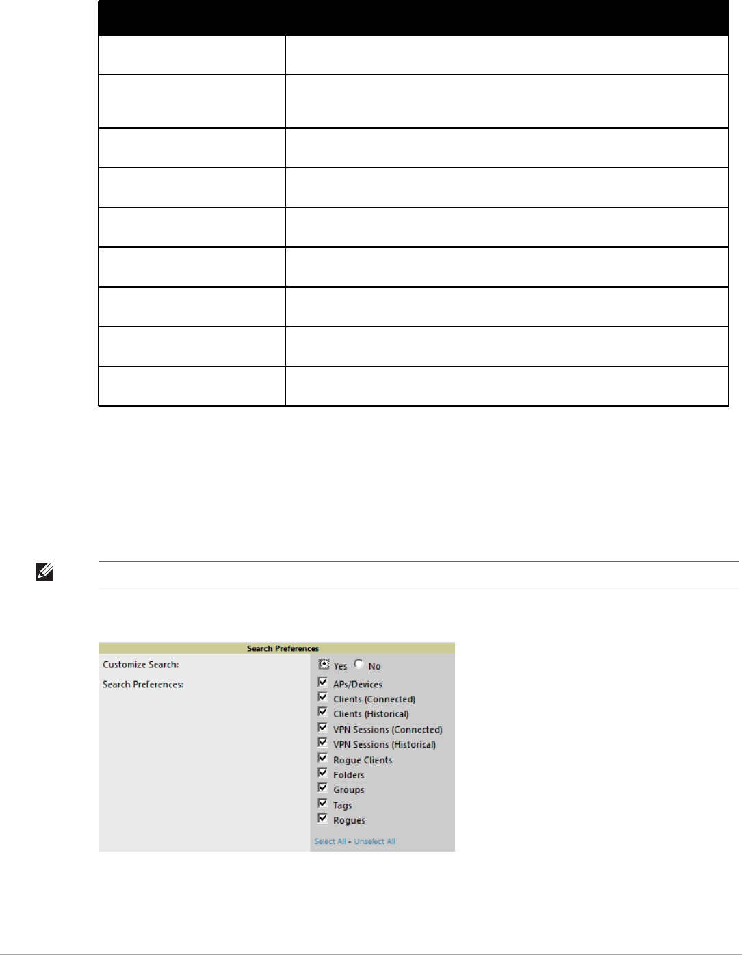
26 | Configuring AirWave Dell PowerConnect W-AirWave 7.5 | User Guide
Customized Search
You can customize the Full search results to display only desired categories of matches on the Home > User Info
page. Go to the Search Preferences section, select Yes in the Customize Search field, then select or deselect
categories of results and save your changes. The Customize Search feature is turned off by default, and all boxes
are selected. .
Figure 17 Home > User Info Customized Search Preferences
Clients By AOS Device Type This pie chart shows the percentage of clients that have attached to AirWave over the
last 24 hours based on the AOS device type.
Clients By Device Type This pie chart shows the percentage of clients that have attached to AirWave over the
last 24 hours based on the device type (such as a specific operating system or smart
phone type).
Clients By Device Mfgr This pie chart shows the percentage of clients that have attached to AirWave over the
last 24 hours based on the client manufacturer.
Clients By Device Model This pie chart shows the percentage of clients that have attached to AirWave over the
last 24 hours based on the device model (such as the smart phone type).
Clients By Mfgr & Model This pie chart shows the percentage of clients that have attached to AirWave over the
last 24 hours based on the client manufacturer and model.
Clients By Device OS This pie chart shows the percentage of clients that have attached to AirWave over the
last 24 hours based on the device operating system (such as Windows or Android).
Clients By Device OS Detail This pie chart shows the percentage of clients that have attached to AirWave over the
last 24 hours based on the device operating system version (such as Windows NT 6.1).
Clients By Network Vendor This pie chart shows the percentage of clients that have attached to AirWave over the
last 24 hours based on each device’s network interface vendor.
Client Signal Distribution The Client Signal Distribution chart shows the number of attached devices that have a
signal quality within a set of ranges.
Table 6 Available Widgets
Widget Description
NOTE: A confirmation message does not appear after you make modifications to Search Preferences.
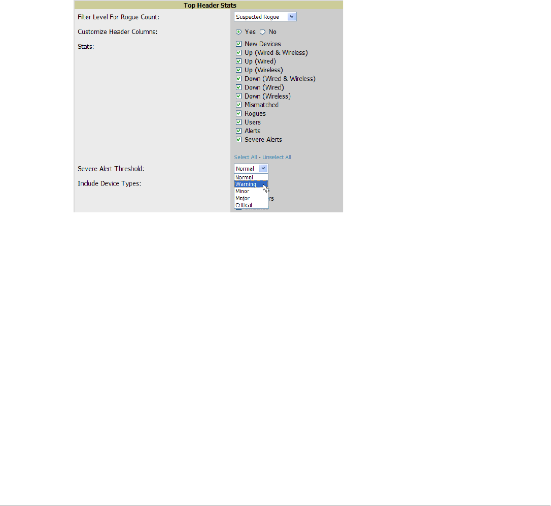
Dell PowerConnect W-AirWave 7.5 | User Guide Configuring AirWave | 27
Setting Severe Alert Warning Behavior
You can control the alert levels you can see on the the Alerts top header stats link from the Home > User Info
page. The Severe Alert Threshold determines the severity level that results in a Severe Alert. Specify either
Normal, Warning, Minor, Major, or Critical as the severity alert threshold value. These threshold values are tied
to triggers that are created on the System > Triggers page. For example, if a trigger is defined to result in a
“Critical” alert, and if the Severe Alert Threshold here is defined as “Major,” then the list of Severe Alerts will
include all “Major” and “Critical” alerts. Similarly, if this value is set to “Normal,” which is the lowest threshold,
then the list of Severe Alerts will include all alerts.
When a Severe Alert exists, a new component named Severe Alerts will appear at the right of the Status field in
bold red font. This field is hidden if there are no Severe Alerts. In addition, only users who are enabled for viewing
Severe Alerts on the Home > User Info page can see severe alerts.
The Severe Alert Threshold dropdown menu, located in the Top Header Stats section of the Home > User Info
page is shown in Figure 18.
Figure 18 Home > User Info > Severe Alert Threshold Dropdown Menu
Defining General AirWave Server Settings
This section describes all pages accessed from the AMP Setup tab. It also describes two pages in the Device Setup
tab—the Communication and Upload Files pages. Once required and optional configuration tasks in this
chapter are complete, continue to later chapters in this document to create and deploy device groups and device
configuration and discovery on the network.
AMP Setup > General
The first step in configuring AirWave is to specify the general settings for the AirWave server. Figure 19
illustrates the AMP Setup > General page. Select Save when the General Server settings are complete and
whenever making subsequent changes. These settings are applied globally across the product (for all users).
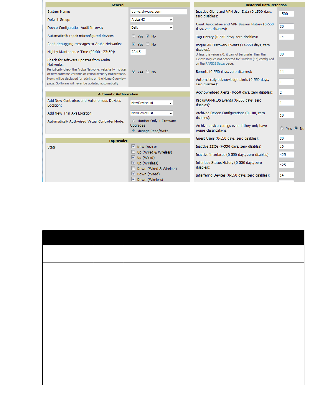
28 | Configuring AirWave Dell PowerConnect W-AirWave 7.5 | User Guide
Figure 19 AMP Setup > General Page Illustration (Partial View)
General Settings
Browse to the AMP Setup > General page, locate the General section, and enter the information described in
Table 7:
Table 7 AMP Setup > General > General Section Fields and Default Values
Setting Default Description
System Name Defines your name for your AirWave server, with a maximum limit of 20
alphanumeric characters.
Default Group Access
Points
Sets the device group that this AirWave server uses as the default for device-level
configuration. Select a device group from the drop-down menu. A group must first
be defined on the Groups > List page to appear in this drop-down menu. For
additional information, refer to Chapter 4, “Configuring and Using Device Groups”
on page 67.
Device Configuration
Audit Interval
Daily This setting defines the interval of queries which compares actual device settings
to the Group configuration policies stored in the AirWave database. If the settings
do not match, the AP is flagged as mismatched and AirWave sends an alert via
email, log, or SNMP.
NOTE: Enabling this feature with a frequency of Daily or more frequently is
recommended to ensure that your AP configurations comply with your established
policies. Specifying Never is not recommended.
Automatically repair
misconfigured
devices
Disabled If enabled, this setting automatically reconfigures the settings on the device when
the device is in Manage mode and AirWave detects a variance between actual
device settings and the Group configuration policy in the AirWave database.
Send debugging
messages
Enabled If enabled, AirWave automatically emails any system errors to Dell support at
support.dell.com to assist in debugging.

Dell PowerConnect W-AirWave 7.5 | User Guide Configuring AirWave | 29
Automatic Authorization Settings
On the AMP Setup > General page, locate the Automatic Authorization section. These settings allow you to
control the conditions by which devices are automatically authorized into AP groups and folders. AirWave
validates the Folder and Group to ensure that both settings have been set to valid dropdown options. Table 8
describes the settings and default values in this section.
Top Header Settings
On the AMP Setup > General page, locate the Top Header section to select the Top Header Stats to be
displayed at the top of the interface. For more detailed information about each option, refer to Table 3 Status
Section/Top Header Components of the AirWave GUI on page 11.
Search Preferences
On the AMP Setup > General page, locate the Search Preferences section. Select the search categories to include
in a “Full” search of AirWave such APs/devices, clients (connected and/or historical), VPN sessions (connected
and/or historical), rogues, rogue clients, tags, folders, and groups. All are selected by default. Per-user search
preferences can be set in the Home > User Info page; refer to “Customized Search” on page26.
Nightly Maintenance
Time (00:00 - 23:59)
04:15 Specifies the local time of day AirWave should perform daily maintenance. During
maintenance, AirWave cleans the database, performs backups, and completes a
few other housekeeping tasks. Such processes should not be performed during
peak hours of demand.
Check for software
updates
Yes Enables AirWave to check automatically for multiple update types. Check daily for
AirWave updates, to include enhancements, device template files, important
security updates, and other important news. This setting requires a direct internet
connection via AirWave.
Table 8 AMP Setup > General > Automatic Authorization Fields and Default Values
Setting Default Description
Add New Controllers
and Autonomous
Devices Location
New
Device
List
Globally add new controllers and autonomous devices to:
-The New Device List (located in APs/Devices > New).
-The same folder and group as the discovering device.
-The same group and folder of their closest IP neighbor on the same subnet.
-Choose a group and folder. If you select this option, enter the folder/group in the
Auto Authorization Group and Auto Authorization Folder fields that display.
NOTE: This setting can be overridden in Groups > Basic.
Add New Thin APs
Location
New
Device
List
Globally add new thin APs to:
-The New Devices list.
-The same folder and group as the discovering device.
-The same group and folder of their closest IP neighbor on the same subnet.
-Choose a group and folder. If you select this option, enter the folder/group in the
Auto Authorization Group and Auto Authorization Folder fields that display.
NOTE: This setting can be overridden in Groups > Basic.
Automatically
Authorized Virtual
Controller Mode
Manage
Read/
Write
Specify whether Virtual Controller mode for Instant APs will be in Manage Read/Write
mode or Monitor Only mode.
Table 7 AMP Setup > General > General Section Fields and Default Values (Continued)
Setting Default Description

30 | Configuring AirWave Dell PowerConnect W-AirWave 7.5 | User Guide
Home Overview Settings
On the AMP Setup > General page, locate the Home Overview Preferences section. Table 9 describes the
settings and default values in this section.
Display Settings
On the AMP Setup > General page, locate the Display section and select the options to appear by default in new
device groups.
Table 10 describes the settings and default values in this section.
Table 9 AMP Setup > General > Home Overview Preferences Fields and Default Values
Setting Default Description
Configure Channel
Busy Threshold
Yes Whether you want to configure the threshold at which a channel is considered to be
busy at the Top Folders By Radio Channel Usage Overview widget.
Channel Busy
Threshold (%)
10 The threshold percent at which the radio channel is considered busier than normal.
NOTE: Changes to this section apply across all of AirWave. These changes affect all users and all new device groups.
Table 10 AMP Setup > General > Display Fields and Default Values
Setting Default Description
Use fully qualified
domain names
No Sets AirWave to use fully qualified domain names for APs instead of the AP name. For
example, ‘testap.yourdomain.com; would be used instead of ‘testap.’
This option is supported only for Cisco IOS, Dell PowerConnect W-Series, Aruba
Networks, and Alcatel-Lucent devices.
Show vendor-specific
device settings for
All Devices Displays a drop-down menu that determines which Group tabs and options are
viewable by default in new groups, and selects the device types that use fully qualified
domain names. This field has three options, as follows:
-All devices—When selected, AirWave displays all Group tabs and setting options.
-Only devices on this AMP—When selected, AirWave hides all options and tabs
that do not apply to the APs and devices currently on AirWave.
-Selected device type—When selected, a new field appears listing many device
types. This option allows you to specify the device types for which AirWave
displays group settings. You can override this setting.
Look up device and
wireless user
hostnames
Yes Enables AirWave to look up the DNS for new user hostnames. This setting can be
turned off to troubleshoot performance issues.
DNS Hostname
Lifetime
24 hours Defines the length of time, in hours, for which a DNS server hostname remains valid on
AirWave, after which AirWave refreshes DNS lookup:
-1 hour
-2 hours
-4 hours
-12 hours
-24 hours
Device
Troubleshooting Hint
N/A The message included in this field is displayed along with the Down if a device’s
upstream device is up. This applies to all APs and controllers but not to routers and
switches.

Dell PowerConnect W-AirWave 7.5 | User Guide Configuring AirWave | 31
Device Configuration Settings
Locate the Device Configuration section and adjust the settings. Table 11 describes the settings and default
values of this section.
AMP Features
Locate the AMP Features section and adjust settings to enable or disable VisualRF and RAPIDS. Table 12
describes these settings and default values.
Table 11 AMP Setup > General > Device Configuration Section Fields and Default Values
Setting Default Description
Guest User
Configuration
Disabled Enables or prevents guest users to/from pushing configurations to devices. Options are
Disabled (default), Enabled for Devices in Manage (Read/Write),Enabled for all
Devices.
Allow WMS Offload
configuration in
monitor-only mode
No When Yes is selected, you can enable the ArubaOS WMS offload feature on the Groups
> Basic page for WLAN switches in Monitor Only mode. Enabling WMS offload does
not cause a controller to reboot. This option is supported only for Dell and Dell
PowerConnect W-Series devices.
Allow disconnecting
users while in monitor-
only mode
No Sets whether you can deauthenticate a user for a device in monitor-only mode. If set to
No, the Deauthenticate Client button for in a Clients > Client Detail page is enabled only
for Managed devices.
Allow non-UTF8
characters
No Whether AirWave can use character sets other than UTF-8 for configuration settings.
Use Global
PowerConnect W
Configuration
No Enables Dell configuration profile settings to be globally configured and then assigned
to device groups. If disabled, settings can be defined entirely within Groups > Dell
PowerConnect W Config instead of globally.
NOTE: Changing this setting may require importing configuration on your devices.
When an existing Dell PowerConnect W-Series configuration setup is to be converted
from global to group, follow these steps:
1. Set all the devices to Monitor Only mode before setting the flag.
2. Each device Group will need to have an import performed from the Audit page of a
controller in the AMP group.
3. All of the thin APs need to have their settings imported after the device group
settings have finished importing.
4. If the devices were set to Monitor Only mode, set them back to Managed mode.
Table 12 AMP Setup > General > AMP Features Fields and Default Values
Setting Default Description
Display VisualRF No Enable or disable the VisualRF navigation tab.
Display RAPIDS No Enable or disable the RAPIDS navigation tab.
Hide setup pages from
non-admin users
Yes Restrict access to following pages to users with the AMP Administration role only:
-VisualRF > Setup
-AMP Setup > NMS
-RAPIDS > Score Override
-RAPIDS > Rules
-RAPIDS > Setup
-System > Triggers
Allow role based report
visibility
Yes Enable or disable role-based reporting in AMP. When disabled, reports can only be
generated with by-subject visibility.
32 | Configuring AirWave Dell PowerConnect W-AirWave 7.5 | User Guide
External Logging Settings
Locate the External Logging section and adjust settings to send audit and system events to an external syslog
server. Table 13 describes these settings and default values. You can also send a test message using the Send Test
Message button after enabling any of the logging options.
Historical Data Retention Settings
Locate the Historical Data Retention section and specify the number of days you want to keep client session
records and rogue discovery events. Table 14 describes the settings and default values of this section. Many
settings can be set to have no expiration date.
Table 13 AMP Setup > General > External Logging Section Fields and Default Values
Setting Default Description
Syslog Server N/A Enter the IP address of the syslog server.
Syslog Port 514 Enter the port of the syslog server.
Include event log
messages
No Select Yes to send event log messages to an external syslog server.
Event log facility local1 Select the facility for the event log from the drop-down menu.
Include audit log
messages
No Select Yes to send audit log messages to an external syslog server.
Audit log facility local1 Select the facility for the audit log from the drop-down menu.
Table 14 AMP Setup > General > Historical Data Retention Fields and Default Values
Setting Default Description
Inactive Client and
VPN User Data
(0-1500 days, zero
disables)
60 Defines the number of days AirWave stores basic information about inactive clients and
VPN users. A shorter setting of 60 days is recommended for customers with high user
turnover such as hotels. The longer you store inactive user data, the more hard disk space
you require.
Client Association and
VPN Session History
(0-550 days, zero
disables)
14 Defines the number of days AirWave stores client and VPN session records. The longer
you store client session records, the more hard disk space you require.
Tag History
(0-550 days, zero
disables)
14 Sets the number of days AirWave retains location history for Wi-Fi tags.
Rogue AP Discovery
Events
(14-550 days, zero
disables)
14 Defines the number of days AirWave stores Rogue Discovery Events. The longer you store
discovery event records, the more hard disk space you require.
Reports
(0-550 days, zero
disables)
60 Defines the number of days AirWave stores Reports. Large numbers of reports, over 1000,
can cause the Reports > Generated page to be slow to respond.
Automatically
Acknowledge Alerts
(0-550 days, zero
disables)
14 Defines automatically acknowledged alerts as the number of days AirWave retains alerts
that have been automatically acknowledged. Setting this value to 0 disables this function,
and alerts will never expire or be deleted from the database.
Acknowledged Alerts
(0-550 days, zero
disables)
60 Defines the number of days AirWave retains information about acknowledged alerts.
Large numbers of Alerts, over 2000, can cause the System > Alerts page to be slow to
respond.

Dell PowerConnect W-AirWave 7.5 | User Guide Configuring AirWave | 33
Firmware Upgrade Defaults
Locate the Firmware Upgrade Defaults section and adjust settings as required. This section allows you to
configure the default firmware upgrade behavior for AirWave. Table 15 describes the settings and default values
of this section.
Radius/ARM/IDS
Events
(0-550 days, zero
disables)
14 Defines the number of days AirWave retains information about RADIUS, ARM, and IDS
events. Setting this value to 0disables this function, and the information will never expire
or be deleted from the database.
Archived Device
Configurations
(0-100, zero disables)
10 Defines the number of configurations that will be retained for archived devices.. Whether
rogue information is included depends on the setting of the Archive device configs even if
they only have rogue classifications setting.
Archive device configs
even if they only have
rogue classifications
No Sets whether to archive device configurations even if the device only has rogue
classifications.
Guest Users
(0-550 days, zero
disables)
30 Sets the number of days that AirWave is to support any guest user. A value of 0 disables
this function, and guest users will never expire or be deleted from the AirWave database.
Inactive SSIDs
(0-550 days, zero
disables)
425 Sets the number of days AirWave retains historical information after AirWave last saw a
client on a specific SSID. Setting this value to 0disables this function, and inactive SSIDs
will never expire or be deleted from the database.
Inactive Interfaces (0-
550 days, zero
disables)
425 Sets the number of days AirWave retains inactive interface information after the interface
has been removed or deleted from the device. Setting this value to 0disables this function,
and inactive interface information will never expire or be deleted from the database.
Interface Status
History
(0-550 days, zero
disables)
425 Sets the number of days AirWave retains historical information on interface status.
Setting this value to 0disables this function.
Interfering Devices (0-
550 days, zero
disables)
14 Sets the number of days AirWave retains historical information on interfering devices.
Setting this value to 0disables this function.
Device Events (Syslog,
Traps)
(1-31 days)
2 Sets the number of days AirWave retains historical information on device events such as
syslog entries and SNMP traps. Setting this value to 0disables this function. Refer to
“Viewing Device Events in System > Syslog & Traps” on page 191.
Mesh Link History
(0-550 days)
30 Sets the number of days AirWave retains historical information for mesh links.
Device Uptime (0-120
months, zero disables)
60 Sets the number of months AirWave retains historical information on device uptime.
Setting this value to 0disables this function.
Client Data Retention
Interval
(1-425 days)
425 Sets the number of days AirWave retains historical informatio for clients.
Table 15 AMP Setup > General > Firmware Upgrade Defaults Fields and Default Values
Setting Default Description
Allow firmware
upgrades in monitor-
only mode
No If Yes is selected, AirWave upgrades the firmware for APs in Monitor Only mode. When
AirWave upgrades the firmware in this mode, the desired configuration are not be pushed
to AirWave. Only the firmware is applied. The firmware upgrade may result in
configuration changes. AirWave does not correct those changes when the AP is in
Monitor Only mode.
Table 14 AMP Setup > General > Historical Data Retention Fields and Default Values (Continued)
Setting Default Description

34 | Configuring AirWave Dell PowerConnect W-AirWave 7.5 | User Guide
Additional AMP Services
Locate the Additional AMP Services section, and adjust settings as required. Table 16 describes the settings and
default values of this section.
Performance Settings
Locate the Performance section. Performance tuning is unlikely to be necessary for many AirWave
implementations, and likely provides the most improvements for customers with extremely large Pro or
Maximum Interleaved
Jobs
(1-20)
20 Defines the number of jobs AirWave runs at the same time. A job can include multiple
APs. When jobs are started by multiple users, AirWave will interleave upgrades so that
one user's job does not completely block another’s.
Maximum Interleaved
Devices Per Job
(1-1000)
20 Defines the number of devices that can be in the process of upgrading at the same time.
Within a single job, AirWave may start the upgrade process for up to this number of
devices at the same time. However, only one device will be actively downloading a
firmware file at any given time.
Failures before
stopping
(0-20, zero disables)
1 Sets the default number of upgrade failures before AirWave pauses the upgrade process.
User intervention is required to resume the upgrade process. Setting this value to 0
disables this function.
Table 16 AMP Setup > General > Additional AMP Services Fields and Default Values
Setting Default Description
Enable FTP Server No Enables or disables the FTP server on AMP. The FTP server is only used to manage Aruba
AirMesh and Cisco Aironet 4800 APs. Best practice is to disable the FTP server if you do
not have any supported devices in the network.
Enable RTLS Collector No Enables or disables the RTLS Collector, which is used to allow ArubaOS controllers to send
signed and encrypted RTLS (real time locating system) packets to VisualRF-- in other
words, AirWave becomes the acting RTLS server. The RTLS server IP address must be
configured on each controller. This function is used for VisualRF to improve location
accuracy and to locate chirping asset tags. This function is supported only for Dell
PowerConnect W-Series, Alcatel-Lucent, and Aruba Networks devices.
If Yes is specified, the following additional fields appear. These configuration settings
should match the settings configured on the controller:
-RTLS Port—Specify the port for the AirWave RTLS server.
-RTLS Username—Enter the user name used by the controller to decode RTLS
messages.
-RTLS Password—Enter the RTLS server password that matches the controllers’ value.
-Confirm RTLS Password—Re-enter the RTLS server password.
Use embedded mail
server
Yes Enables or disables the embedded mail server that is included with AirWave. If Yes is
specified, then enter information for an optional mail relay server.
This field supports a Send Test Email button for testing server functionality. Clicking this
button prompts you with To and From fields in which you must enter valid email addresses.
Process user roaming
traps from Cisco WLC
Yes Whether AirWave should parse client association and authentication traps from Cisco
WLC controllers to give real time information on users connected to the wireless network.
Enable AMON data
collection
Yes Allows AirWave to collect enhanced data from Dell PowerConnect W-Series devices on
certain firmware versions. See the Dell PowerConnect W-AirWave Best Practices Guide
in Home > Documentation for more details.
Table 15 AMP Setup > General > Firmware Upgrade Defaults Fields and Default Values (Continued)
Setting Default Description

Dell PowerConnect W-AirWave 7.5 | User Guide Configuring AirWave | 35
Enterprise installations. Please contact Dell support at support.dell.com if you think you might need to change
any of these settings. Table 17 describes the settings and default values of this section.
What Next?
-Go to additional tabs in the AMP Setup section to continue additional setup configurations. The next section
describes configuring AMP network Settings.
-Complete the required configurations in this chapter before proceeding. Dell support remains available to you for
any phase of AMP installation.
Defining AirWave Network Settings
The next step in configuring AirWave is to confirm the AirWave network settings. Define these settings by
navigating to the AMP Setup > Network page. Figure 20 illustrates the contents of this page.
Table 17 AMP Setup > General > Performance Fields and Default Values
Setting Default Description
Monitoring
Processes
(1-16)
Based on the
number of
cores for your
server
Optional setting configures the throughput of monitoring data. Increasing this
setting allows AirWave to process more data per second, but it can take
resources away from other AirWave processes. Contact Dell support at
support.dell.com if you think you might need to increase this setting for your
network.
Maximum number of
configuration
processes
(1-80)
5 Increases the number of processes that are pushing configurations to your
devices, as an option. The optimal setting for your network depends on the
resources available, especially RAM. Contact Dell support at support.dell.com if
you think you might need to increase this setting for your network.
Maximum number of
audit processes
(1-80)
3 Increases the number of processes that audit configurations for your devices,
as an option. The optimal setting for your network depends on the resources
available, especially RAM. Contact Dell support at support.dell.com if you are
considering increasing this setting for your network.
SNMP Fetcher Count
(2-6)
2
Verbose Logging of
SNMP Configuration
No Enables or disables logging detailed records of SNMP configuration
information.
SNMP Rate Limiting
for Monitored
Devices
No When enabled, AirWave fetches SNMP data more slowly, potentially reducing
device CPU load. This setting is used for networks containing legacy controllers
not available through Dell. Dell recommends not enabling this setting.
Collect Syslog and
SNMP trap Device
Events
Yes This option specifies whether traps used to detect roaming events, auth failures,
AP up/down status, and IDS events will still be collected if they are sent by
managed devices.
RAPIDS Processing
Priority
Low Defines the processing and system resource priority for RAPIDS in relation to
AirWave as a whole.
When AirWave is processing data at or near its maximum capacity, reducing
the priority of RAPIDS can ensure that processing of other data (such as client
connections and bandwidth usage) is not adversely impacted.
The default priority is Low. You can also tune your system performance by
changing group poll periods.
If you select Custom for the priority, then also specify the RAPIDS custom
process limit.
RAPIDS custom
process limit
(1-16)
1 when Custom
is specified for
the RAPIDS
Processing
Priority.
Sets the maximum number of monitoring process assigned to RAPIDS work.
Note that this option is only available if Custom is specified for the Rapics
Processing Priority.
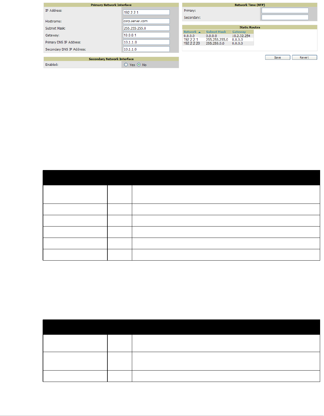
36 | Configuring AirWave Dell PowerConnect W-AirWave 7.5 | User Guide
Figure 20 AMP Setup > Network Page Illustration
Specify the network configuration options described in the sections that follow to define the AirWave network
settings. Select Save when you have completed all changes on the AMP Setup > Network page, or select Revert to
return to the last settings. Save restarts any affected services and may temporarily disrupt your network
connection.
Primary Network Interface Settings
Locate the Primary Network Interface section. The information in this sections should match what you defined
during initial network configuration and should not require changes. Table 18 describes the settings and default
values.
Secondary Network Interface Settings
Locate the Secondary Network Interface section. The information in this section should match what you defined
during initial network configuration and should not require changes. Table 19 describes the settings and default
values.
Table 18 Primary Network Interface Fields and Default Values
Setting Default Description
IP Address None Sets the IP address of the AirWave network interface.
NOTE: This address must be a static IP address.
Hostname None Sets the DNS name assigned to the AirWave server.
Subnet Mask None Sets the subnet mask for the primary network interface.
Gateway None Sets the default gateway for the network interface.
Primary DNS IP None Sets the primary DNS IP address for the network interface.
Secondary DNS IP None Sets the secondary DNS IP address for the network interface.
Table 19 Secondary Network Interface Fields and Default Values
Setting Default Description
Enabled No Select Yes to enable a secondary network interface. You will be promted to define the
IP address and subnet mask.
IP Address None Specify the IP address of the AirWave secondary network.
NOTE: This address must be a static IP address.
Subnet Mask None Specify the subnet mask for the secondary network interface.
Dell PowerConnect W-AirWave 7.5 | User Guide Configuring AirWave | 37
Network Time Protocol (NTP) Settings
On the AMP Setup > Network page, locate the Network Time Protocol (NTP) section. The Network Time
Protocol is used to synchronize the time between AirWave and your network’s NTP server. NTP servers
synchronize with external reference time sources, such as satellites, radios, or modems.
To disable NTP services, clear both the Primary and Secondary NTP server fields. Any problem related to
communication between AirWave and the NTP servers creates an entry in the event log. Table 20 describes the
settings and default values in more detail. For more information on ensuring that AirWave servers have the
correct time, please see http://support.ntp.org/bin/view/Servers/NTPPoolServers.
Static Routes
On the AMP Setup > Network page, locate the Static Routes area. This section displays network, subnet mask,
and gateway settings that you have defined elsewhere from a command-line interface.
What Next?
-Go to additional tabs in the AMP Setup section to continue additional setup configurations. The next section
describes AMP roles.
-Complete the required configurations in this chapter before proceeding. Dell support remains available to you for
any phase of AMP configuration.
AirWave User Roles
The AMP Setup > Roles page defines the viewable devices, the operations that can be performed on devices, and
general AirWave access. User roles can be created that provide users with access to folders within multiple
branches of the overall hierarchy. This feature assists non-administrative users, such as help desk or IT staff, who
support a subset of accounts or sites within a single AirWave deployment. You can restrict user roles to multiple
folders within the overall hierarchy even if they do not share the same top-level folder. Non-admin users are only
able to see data and users for devices within their assigned subset of folders.
NOTE: Specifying NTP servers is optional. NTP servers synchronize the time on the AirWave server, not on individual access
points.
Table 20 AMP Setup > Network > Secondary Network Fields and Default Values
Setting Default Description
Primary ntp1.yourdomain.com Sets the IP address or DNS name for the primary NTP server.
Secondary ntp2.yourdomain.com Sets the IP address or DNS name for the secondary NTP server.
NOTE: This section does not enable you to configure new routes or remove existing routes.
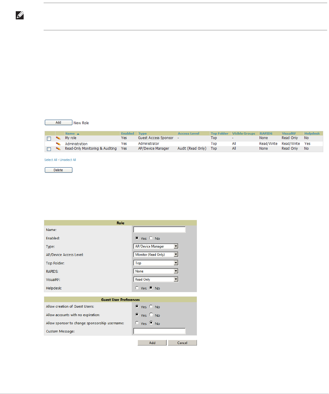
38 | Configuring AirWave Dell PowerConnect W-AirWave 7.5 | User Guide
User Roles and VisualRF
VisualRF ses the same user roles as defined for AirWave—users can see floor plans that contain an AP to which
they have access in AirWave, although only visible APs appear on the floor plan. VisualRF users can also see any
building that contains a visible floor plan and any campus that contains a visible building.
When a new role is added to AirWave, VisualRF must be restarted for the new user to be enabled. Refer to
Chapter 10, “Using VisualRF” on page263 for additional information.
Creating AirWave User Roles
Perform the following steps to view, add, edit, or delete user roles:
1. Go to the AMP Setup > Roles page. This page displays all roles currently configured in AirWave. Figure 21
illustrates the contents and layout of this page.
Figure 21 AMP Setup > Roles Page Illustration
2. Select Add to create a new role, select the pencil icon to edit an existing role, or select a checkbox and select
Delete to remove that role from AirWave. When you select Add or the edit icon, the Add/Edit Role page
appears, illustrated in Figure 22.
Figure 22 AMP Setup > Roles > Add/Edit Role Page Illustration
NOTE: In VisualRF > Setup > Server Settings, a new flag added in AirWave 7.2 allows you to restrict the visibility of empty floor
plans to the role of the user who created them. In previous versions, a floor plan without APs could be visible to all users. By
default, this setting is set to No.
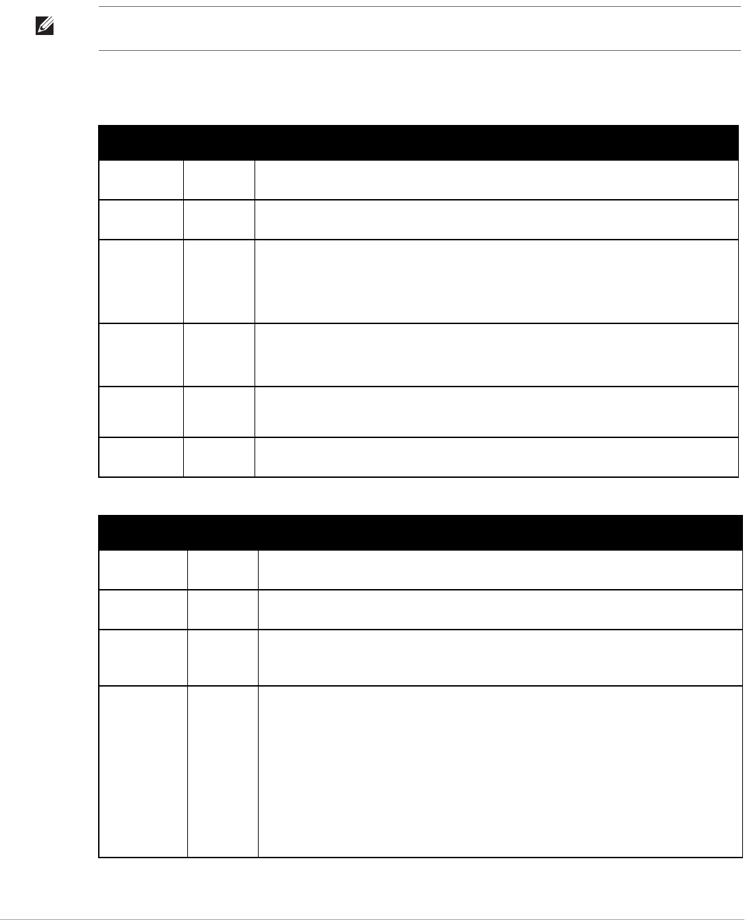
Dell PowerConnect W-AirWave 7.5 | User Guide Configuring AirWave | 39
3. Enter or edit the settings on this page. As explained earlier in this section, Roles define the type of user-level
access, the user-level privileges, and the view available to the user for device groups and devices in AirWave.
The available configuration options differ for each role type.
The following tables describe the available settings and default values for each role type.
NOTE: Most users will see two sections on this page: Role and Guest User Preferences. The Guest User Preferences section will
not appear, however, if Guest User Configuration is disabled in AMP Setup > General.
Table 21 AMP Setup > Roles > Add/Edit Roles Fields and Default Values for AMP Admninistrator Role
Setting Default Description
Name None Sets the administrator-definable string that names the role. The role name should indicate the
devices and groups that are viewable, as well as the privileges granted to that role.
Enabled Yes Disables or enables the role. Disabling a role prevents all users of that role from logging in to
AirWave.
Type AP/Device
Manager
Defines the type of role.
AMP Administrator—The AirWave Administrator has full access to AirWave and all of the
devices. Only the AirWave Administrator can create new users or access the AMP Setup page,
the VisualRF > Setup page, VisualRF > Audit Log page, System > AMP Events, and System >
Performance.
Dell Controller
Role
Disabled Enables or disables Single Sign-On for the role. If enabled, allows the role to
directly access Dell controller UIs from the Quick Links or IP Address hypertext
throughout AirWave without having to enter credentials for the controller.
Allow user to
disable
timeout
No
Custom
Message
none A custom message can also be included.
Table 22 AMP Setup > Roles > Add/Edit Roles Fields and Default Values for AP/Device Manager Role
Setting Default Description
Name None Sets the administrator-definable string that names the role. The role name should indicate the
devices and groups that are viewable, as well as the privileges granted to that role.
Enabled Yes Disables or enables the role. Disabling a role prevents all users of that role from logging in to
AirWave.
Type AP/Device
Manager
Defines the type of role.
AP/Device Manager—AP/Device Managers have access to a limited number of devices and
groups based on the Top folder and varying levels of control based on the Access Level.
AP/Device
Access Level
Monitor
(Read Only)
Defines the privileges the role has over the viewable APs. AirWave supports three privilege
levels, as follows:
-Manage (Read/Write)—Manage users can view and modify devices and Groups. Selecting
this option causes a new field, Allow authorization of APs/Devices, to appear on the page,
and is enabled by default.
-Audit (Read Only)—Audit users have read only access to the viewable devices and Groups.
Audit users have access to the APs/Devices > Audit page, which may contain sensitive
information including AP passwords.
-Monitor (Read Only)—Monitor users have read-only access to devices and groups and
VisualRF. Monitor users cannot view the APs/Devices > Audit page which may contain
sensitive information, including passwords.

40 | Configuring AirWave Dell PowerConnect W-AirWave 7.5 | User Guide
Top Folder None Defines the highest viewable folder for the role. The role is able to view all devices and groups
contained by the specified top folder. The top folder and its subfolders must contain all of the
devices in any of the groups it can view.
NOTE: AirWave enables user roles to be created with access to folders within multiple branches
of the overall hierarchy. This feature assists non-administrator users who support a subset of
accounts or sites within a single AirWave deployment, such as help desk or IT staff.
User roles can be restricted to multiple folders within the overall hierarchy, even if they do not
share the same top-level folder. Non-administrator users are only able to see data and users for
devices within their assigned subset of folders.
Allow
authorization of
APs/Devices
Yes NOTE: This option is only available when the AP/Device Access Level is specified as Manage
(Read/Write).
RAPIDS None Sets the RAPIDS privileges, which are set separately from the APs/Devices. This field specifies
the RAPIDS privileges for the role, and options are as follows:
-None— Cannot view the RAPIDS tab or any Rogue APs.
-Read Only—The user can view the RAPIDS pages but cannot make any changes to rogue
APs or perform OS scans.
-Read/Write—The user may edit individual rogues, classification, threat levels and notes,
and perform OS scans.
-Administrator—Has the same privileges as the Read/Write user, but can also set up RAPIDS
rules, override scores and is the only user who can access the RAPIDS > Setup page.
VisualRF Read Only Sets the VisualRF privileges, which are set separately from the APs/Devices. Options are as
follows:
-Read Only—The user can view the VisualRF pages but cannot make any changes to floor
plans.
-Read/Write—The user may edit individual floor plans, buildings, and campuses.
Dell Controller
Role
Disabled Enables or disables Single Sign-On for the role. If enabled, allows the role to
directly access Dell controller UIs from the Quick Links or IP Address hypertext
throughout AirWave without having to enter credentials for the controller.
Display client
diagnostics
screens by
default
No Sets the role to support helpdesk users with parameters that are specific to the needs of
helpdesk personnel supporting users on a wireless network.
Enable Adobe
Flash
Yes Enables the Adobe Flash application for all users who are assigned this role. Adobe Flash
supports interactive graphics on the Home > Overview page, VisualRF, QuickView functions, the
Radio Statistics page for thin AP radios, and additional AirWave pages.
NOTE: This field is only visible if a specific flag is set in the AirWave database. By default this
option is hidden and Flash is enabled for all users.
Allow user to
disable timeout
No
Allow creation
of Guest Users
Yes If this option is enabled, users with an assigned role of Monitoring or Audit can be given access
to guest user account creation along with the option to allow a sponsor to change its username.
NOTE: This option is not available if the AP/Device Access Level is specified as Manage (Read/
Write).
Allow accounts
with no
expiration
Yes
Allow sponsor
to change
sponsorship
username
No
Table 22 AMP Setup > Roles > Add/Edit Roles Fields and Default Values for AP/Device Manager Role (Continued)
Setting Default Description

Dell PowerConnect W-AirWave 7.5 | User Guide Configuring AirWave | 41
.
What Next?
-Go to additional tabs in the AMP Setup section to continue additional setup configurations. The next section
describes how to set up AMP users.
-Complete the required configurations in this chapter before proceeding. Dell support remains available to you for
any phase of AirWave configuration.
Creating AirWave Users
AirWave installs with only one AirWave user—the admin, who is authorized to perform the following functions:
-Define additional users with varying levels of privilege, be it manage read/write or monitoring.
-Limit the viewable devices as well as the level of access a user has to the devices.
Custom
Message
none A custom message can also be included.
Table 23 AMP Setup > Roles > Add/Edit Roles Fields and Default Values for Guest Access Sponsor Role
Setting Default Description
Name None Sets the administrator-definable string that names the role. The role name should indicate the
devices and groups that are viewable, as well as the privileges granted to that role.
Enabled Yes Disables or enables the role. Disabling a role prevents all users of that role from logging in to
AirWave.
Type AP/Device
Manager
Defines the type of role.
Guest Access Sponsor—Limited-functionality role to allow helpdesk or reception desk staff to
grant wireless access to temporary personnel. This role only has access to the defined top
folder of APs.
Top Folder None Defines the Top viewable folder for the role. The role is able to view all devices and groups
contained by the Top folder. The top folder and its subfolders must contain all of the devices in
any of the groups it can view.
NOTE: AirWave enables user roles to be created with access to folders within multiple branches
of the overall hierarchy. This feature assists non-administrator users who support a subset of
accounts or sites within a single AirWave deployment, such as help desk or IT staff.
User roles can be restricted to multiple folders within the overall hierarchy, even if they do not
share the same top-level folder. Non-administrator users are only able to see data and users for
devices within their assigned subset of folders.
Allow user to
disable
timeout
No Whether a user can disable AirWave’s timeout feature.
Allow
accounts with
no expiration
Yes Specifies whether to allow accounts that have no expiration set.
Allow sponsor
to change
sponsorship
username
No Specifies whether a sponsor can change the sponsorship user name.
Custom
Message
none A custom message can also be included.
Table 22 AMP Setup > Roles > Add/Edit Roles Fields and Default Values for AP/Device Manager Role (Continued)
Setting Default Description
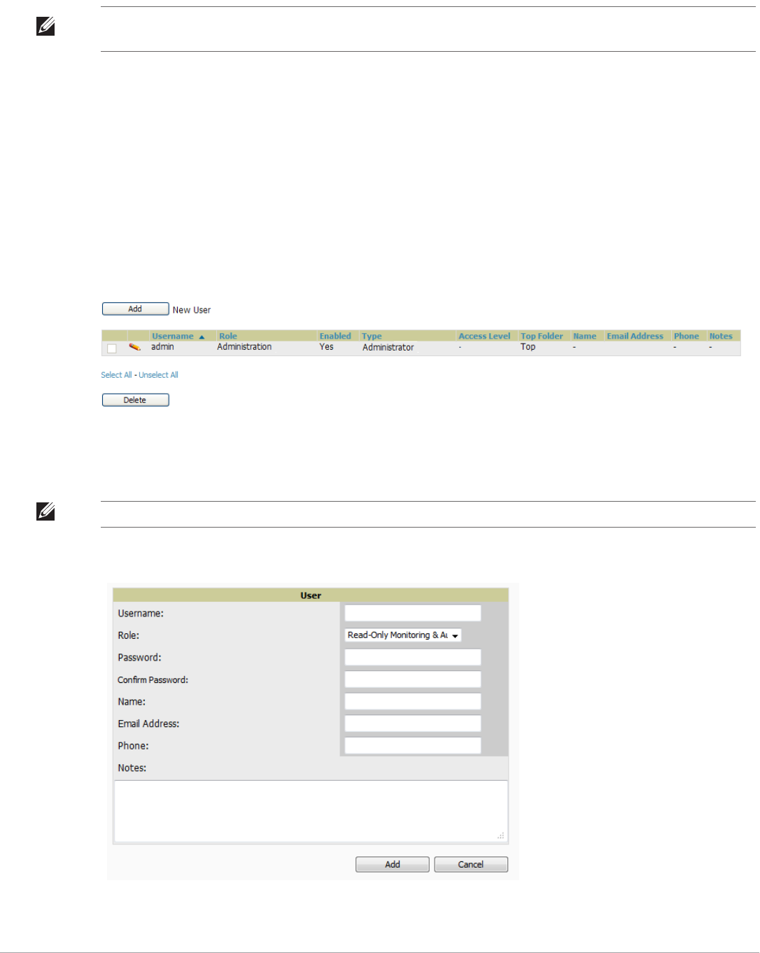
42 | Configuring AirWave Dell PowerConnect W-AirWave 7.5 | User Guide
Each general user that you add must have a user name, a password, and a role. Use unique and meaningful user
names as they are recorded in the log files when you or other users make changes in AirWave.
The user role defines the user type, access level, and the top folder for that user. User roles are defined on the
AMP Setup > Roles page. Refer to the previous procedure in this chapter for additional information, “Creating
AirWave User Roles” on page38.
The admin user can provide optional additional information about the user, including the user's real name, email
address, phone number, and so forth.
Perform the following steps to display, add, edit, or delete AirWave users of any privilege level. You must be an
admin user to complete these steps.
1. Go to the AMP Setup > Users page. This page displays all users currently configured in AirWave. Figure 23
illustrates the contents and layout of this page.
Figure 23 AMP Setup > Users Page Illustration
2. Select Add to create a new user, select the pencil icon to edit an existing user, or select a user and select Delete
to remove that user from AirWave. When you select Add or the edit icon, the Add User page appears,
illustrated in Figure 24.
Figure 24 AMP Setup > Users > Add/Edit User Page Illustration
NOTE: Username and password are not required if you configure AirWave to use RADIUS, TACACS, or LDAP authentication. You
do not need to add individual users to the AirWave server if you use RADIUS, TACACS, or LDAP authentication.
NOTE: A current user cannot change his/her own role. The Role drop-down field is disabled to prevent this.

Dell PowerConnect W-AirWave 7.5 | User Guide Configuring AirWave | 43
3. Enter or edit the settings on this page. Table 24 describes these settings in additional detail.
4. Select Add to create the new user, Save to retain changes to an existing user, or Cancel to cancel out of this
screen. The user information you have configured appears on the AMP Setup > Users page, and the user
propagates to all other AirWave pages and relevant functions.
What Next?
-Go to additional tabs in the AMP Setup section to continue additional setup configurations.
-Complete the required configurations in this chapter before proceeding. Dell support remains available to you for
any phase of AirWave installation.
Configuring Login Message, TACACS+, RADIUS, and LDAP
Authentication
AirWave uses session-based authentication with a configurable login message and idle timeout. As an option, you
can set AirWave to use an external user database to simplify password management for AirWave administrators
and users. This section contains the following procedures to be followed in AMP Setup > Authentication:
-Setting Up Login Configuration Options
-Setting up Single Sign-On
-Specifying the Authentication Priority
-Configuring TACACS+ Authentication
-Configuring RADIUS Authentication and Authorization
-Integrating a RADIUS Accounting Server
Table 24 AMP Setup > Users > Add/Edit User Fields and Default Values
Setting Default Description
Username None Sets the username as an alphanumeric string. The Username is used when logging in to AirWave
and appears in AirWave log files.
Role None Specifies the user’s Role, which defines the Top viewable folder as well as the type and access
level of the user specified in the previous field.
The admin user defines user roles on the AMP Setup > Roles page, and each user in the system is
assigned to a role.
Password None Sets the password for the user being created or edited. Enter an alphanumeric string without
spaces, and enter the password again in the Confirm Password field.
NOTE: Because the default user's password is identical to the name, it is strongly recommended
that you change this password.
Name None Allows you to define an optional and alphanumeric text field that takes note of the user's actual
name.
Email Address None Allows you to specify a specific email address that will propagate throughout many additional
pages in AirWave for that user, including reports, triggers, and alerts.
Phone None Allows you to enter an optional phone number for the user.
Notes None Enables you to cite any additional notes about the user, including the reason they were granted
access, the user's department, or job title.
NOTE: AirWave enables user roles to be created with access to folders within multiple branches of the overall hierarchy. This
feature assists non-administrator users who support a subset of accounts or sites within a single AirWave deployment, such as
help desk or IT staff.
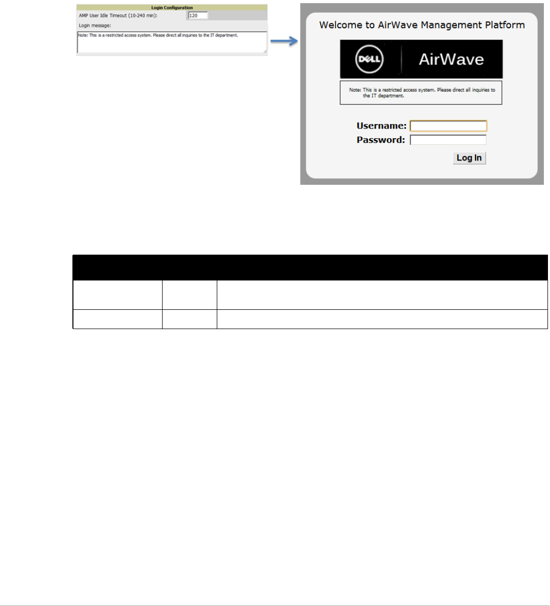
44 | Configuring AirWave Dell PowerConnect W-AirWave 7.5 | User Guide
-Configuring LDAP Authentication and Authorization
Setting Up Login Configuration Options
Administrators can optionally configure AirWave’s user idle timeout or a message-of-the-day that appears when a
user first logs in, as shown in Figure 25:
Figure 25 Login configuration field and results in AirWave Login page
1. Go to AMP Setup > Authentication.
2. Complete the fields described on Table 25:
3. Select Save when you are finished or follow the next procedure to configure Single Sign-On, TACACS+,
LDAP, and RADIUS Authentication options.
Setting up Single Sign-On
Administrators can set up single sign-on (SSO) for users that have access to AirWave controllers. This allows
users to log in to AirWave and use the IP Address or Quick Links hypertext links across AirWave to access the
controller’s UI without having to enter credentials again. The links the user can select to access a controller can be
found on the APs/Devices > Monitor page in the Device Info section, and on device list pages.
This feature must be enabled per role in AMP Setup > Roles.
To enable this feature for this AMP, locate the Single Sign-On section in AMP Setup > Authentication. In the
Enable Single Sign-On field, select Yes. Then select Save if you are finished or follow the next procedure to
specify the authentication priority.
Specifying the Authentication Priority
To specify the authentication priority for this AMP, locate the Authentication Priority section in AMP Setup >
Authentication, and select either Local or Remote as the priority.
Table 25 Login Configuration section of AMP Setup > Authentication
Field Default Description
Max AMP User Idle
Timeout
60 Number of minutes of idle time until AirWave automatically ends the user session.
Affects all users of this AirWave. The range is 5-240 minutes.
Login message none A persistent message that will appear for all of this AirWave’s users after they log in.
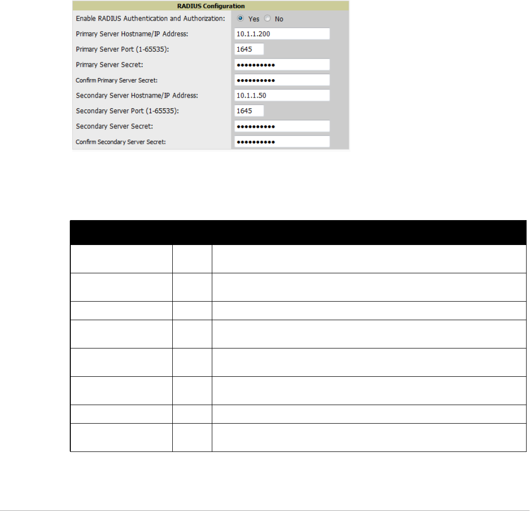
Dell PowerConnect W-AirWave 7.5 | User Guide Configuring AirWave | 45
If Local is selected, then remote will be attempted if a user is not available. If Remote is selected, then the local
database is searched if remote authentication fails. The order of remote authentication is RADIUS first, followed
by TACACS, and finally LDAP.
Select Save if you are finished or follow the next procedure to configure RADIUS, TACACS+, and LDAP
Authentication options.
Configuring RADIUS Authentication and Authorization
For RADIUS capability, you must configure the IP/Hostname of the RADIUS server, the TCP port, and the
server shared secret. Perform these steps to configuration RADIUS authentication:
1. Go to the AMP Setup > Authentication page. This page displays current status of RADIUS. Figure 26
illustrates this page.
Figure 26 AMP Setup > Authentication Page Illustration for RADIUS
2. Select No to disable or Yes to enable RADIUS authentication. If you select Yes, several new fields appear.
Complete the fields described in Table 26.
3. Select Save to retain these configurations, and continue with additional steps in the next procedure.
Table 26 AMP Setup > Authentication Fields and Default Values for RADIUS Authentication
Field Default Description
Primary Server Hostname/
IP Address
N/A Enter the IP address or the hostname of the primary RADIUS server.
Primary Server Port (1-
65535)
1812 Enter the TCP port for the primary RADIUS server.
Primary Server Secret N/A Specify and confirm the primary shared secret for the primary RADIUS server.
Confirm Primary Server
Secret
N/A Re-enter the primary server secret.
Secondary Server
Hostname/IP Address
N/A Enter the IP address or the hostname of the secondary RADIUS server.
Secondary Server Port (1-
65535)
1812 Enter the TCP port for the secondary RADIUS server.
Secondary Server Secret N/A Enter the shared secret for the secondary RADIUS server.
Confirm Secondary Server
Secret
N/A Re-enter the secondary server secret.
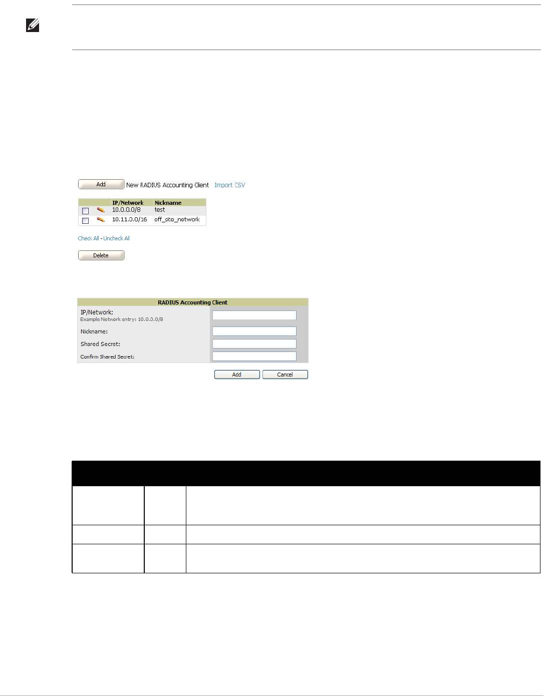
46 | Configuring AirWave Dell PowerConnect W-AirWave 7.5 | User Guide
Integrating a RADIUS Accounting Server
Optionally, you can configure RADIUS server accounting on AMP Setup > RADIUS Accounting. This capability
is not required for basic AirWave operation, but can increase the user-friendliness of AirWave administration in
large networks. Figure 27 illustrates the settings of this optional configuration interface.
Perform the following steps and configurations to enable AirWave to receive accounting records from a separate
RADIUS server. Figure 27 illustrates the display of RADIUS accounting clients already configured, and Figure 28
illustrates the Add RADIUS Accounting Client page.
Figure 27 AMP Setup > RADIUS Accounting Page Illustration
Figure 28 AMP Setup > RADIUS > Add RADIUS Accounting Client Page Illustration
1. To specify the RADIUS authentication server or network, browse to the AMP Setup > RADIUS Accounting
page, select Add, illustrated in Figure 28, and provide the information in Table 27.
2. Complete the following fields:
Configuring TACACS+ Authentication
For TACACS+ capability, you must configure the IP/Hostname of the TACACS+ server, the TCP port, and the
server shared secret. This TACACS+ configuration is for AirWave users and does not affect APs or users logging
into APs.
1. Go to the AMP Setup > Authentication page. This page displays current status of TACACS+. Figure 29
illustrates this page when neither TACACS+, LDAP, nor RADIUS authentication is enabled in AirWave.
NOTE: AirWave checks the local username and password before checking with the RADIUS server. If the user is found locally, the
local password and role apply. When using RADIUS, it’s not necessary or recommended to define users on the AirWave server.
The only recommended user is the backup admin, in case the RADIUS server goes down.
Table 27 AMP Setup > Radius Accounting Fields and Default Values for LDAP Authentication
Setting Default Description
IP/Network None Specify the IP address for the authentication server if you only want to accept packets from one
device. To accept packets from an entire network enter the IP/Netmask of the network (for
example, 10.51.0.0/24).
Nickname None Sets a user-defined name for the authentication server.
Shared Secret
(Confirm)
None Sets the Shared Secret that is used to establish communication between AirWave and the
RADIUS authentication server.
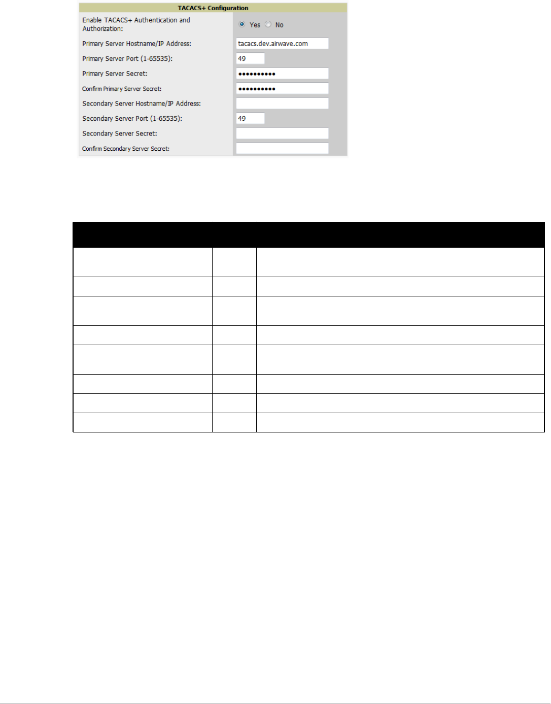
Dell PowerConnect W-AirWave 7.5 | User Guide Configuring AirWave | 47
Figure 29 AMP Setup > Authentication Page Illustration for TACACS+
2. Select No to disable or Yes to enable TACACS+ authentication. If you select Yes, several new fields appear.
Complete the fields described in Table 28.
3. Select Save and continue with additional steps.
Configuring Cisco ACS to Work with AirWave
To configure Cisco ACS to work with AirWave, you must define a new service named AMP that uses https on the
ACS server.
1. The AMP https service is added to the TACACS+ (Cisco) interface under the Interface Configuration tab.
2. Select a checkbox for a new service.
3. Enter AMP in the service column and https in the protocol column.
4. Select Save.
5. Edit the existing groups or users in TACACS to use the “AMP service” and define a role for the group or user.
The role defined on the Group Setup page in ACS must match the exact name of the role defined on the
AMP Setup > Roles page.
The defined role should use the following format: role=<name_of_AMP_role>. One example is as follows:
role=DormMonitoring
As with routers and switches, AMP does not need to know usernames.
Table 28 AMP Setup > Authentication Fields and Default Values for TACACS+ Authentication
Field Default Description
Primary Server Hostname/IP
Address
N/A Enter the IP address or the hostname of the primary TACACS+ server.
Primary Server Port (1-65535) 49 Enter the port for the primary TACACS+ server.
Primary Server Secret N/A Specify and confirm the primary shared secret for the primary TACACS+
server.
Confirm Primary Server Secret N/A Re-enter the primary server secret.
Secondary Server Hostname/IP
Address
N/A Enter the IP address or hostname of the secondary TACACS+ server.
Secondary Server Port (1-65535) 49 Enter the port for the secondary TACACS+ server.
Secondary Server Secret N/A Enter the shared secret for the secondary TACACS+ server.
Confirm Secondary Server Secret N/A Re-enter the secondary server secret.
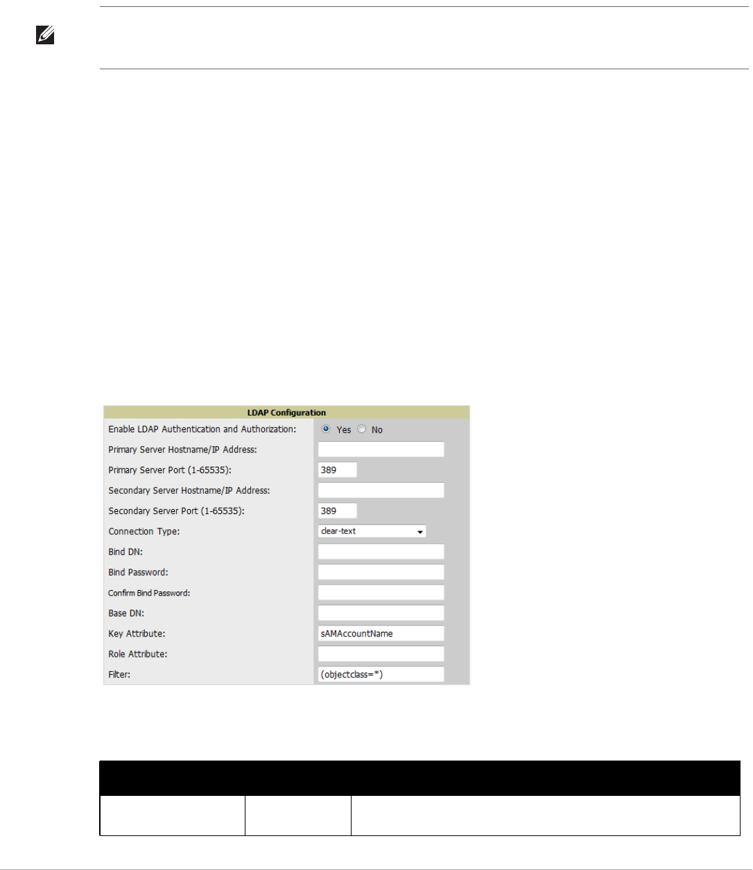
48 | Configuring AirWave Dell PowerConnect W-AirWave 7.5 | User Guide
6. AMP also needs to be configured as an AAA client.
On the Network Configuration page, select Add Entry.
Enter the IP address of AirWave as the AAA Client IP Address.
The secret should be the same value that was entered on the AMP Setup > TACACS+ page.
7. Select TACACS+ (Cisco IOS) in the Authenticate Using drop down menu and select submit + restart.
What Next?
-Go to additional tabs in the AMP Setup section to continue additional setup configurations.
-Complete the required configurations in this chapter before proceeding. Dell support remains available to you for
any phase of AirWave installation.
Configuring LDAP Authentication and Authorization
LDAP (Lightweight Directory Access Protocol) provides users with a way of accessing and maintaining
distributed directory information services over a network. When LDAP is enabled, a client can begin a session by
authenticating against an LDAP server which by default is on TCP port 389.
Perform these steps to configuration RADIUS authentication:
1. Go to the AMP Setup > Authentication page.
2. Select the Yes radio button to enable LDAP authentication and authorization. Once enabled, the available
LDAP configuration options will display. Figure 30 illustrates this page.
Figure 30 AMP Setup > Authentication Page Illustration for LDAP
3. Complete the fields described in Table 29.
NOTE: AirWave checks the local username and password store before checking with the TACACS+ server. If the user is found
locally, the local password and local role apply. When using TACAS+, it is not necessary or recommended to define users on the
AirWave server. The only recommended user is the backup administrator, in the event that the TACAS+ server goes down.
Table 29 AMP Setup > Authentication Fields and Default Values for LDAP Authentication
Field Default Description
Primary Server Hostname/
IP Address
none Enter the IP address or the hostname of the primary LDAP server.

Dell PowerConnect W-AirWave 7.5 | User Guide Configuring AirWave | 49
4. Select Save to retain these configurations, and continue with additional steps in the next procedure.
What Next?
-Go to additional subtabs in AMP Setup to continue additional setup configurations.
-Complete the required configurations in this chapter before proceeding. Dell support remains available to you for
any phase of AirWave installation.
Primary Server Port (1-
65535)
389 Enter the port where the LDAP server is listening. The default port is 389.
Secondary Server
Hostname/IP Address
none Optionally enter the IP address or hostname of the secondary LDAP server.
This server will be contacted in the event that the primary LDAP server is not
reachable.
Secondary Server Port (1-
65535)
389 Enter the port where the LDAP service is listening on the secondary LDAP
server. The default port is 389.
Connection Type clear-text Specify one of the following connection types between AirWave and the
LDAP server:
-clear-text results in unencrypted communication.
-ldap-s results in communication over SSL.
-start-tls uses certificates to initiate encrypted communication.
View Server Certificate none If Connection Type is configured as start-tls, then also specify whether the
start-tls connection type uses a certificate.
-none - The server may provide a certificate, but it will not be verified.
This may mean that you are connected to the wrong server.
-optional - Verifies only when the servers offers a valid certificate.
-require - The server must provide a valid certificate.
A valid LDAP Server CA Certificate must be provided in case of optional or
require. Certificates uploaded on the Device Setup > Certificates page with
a type of Intermediate CA or Trusted CA are listed in the drop down for LDAP
Server CA Certificate.
LDAP Server CA
Certificate
none Specify the LDAP server certificate to use to initiate encrypted
communication. Only certificates that have been uploaded with a type of
Intermediate CA or Trusted CA will appear in this drop down.
NOTE: This LDAP Server CA Certificate drop down menu oly appears if View
Server Certificate is specified as optional or require.
Bind DN none Specify the Distinguished Name (DN) of the administrator account, such as
‘cn=admin01,cn=admin,dn=domain,dn=com’. Note that for the Active
directory, the bind DN can also be in the administrator@domain format (for
example, adminstrator@acme.com).
Bind Password none Specify the bind DN account password.
Confirm Bind Password none Re-enter the bind password.
Base DN none The DN of the node in your directory tree from which to start searching for
records. Generally, this would be the node that contains all the users who
may access AirWave, for example cn=users,dc=domain,dc=com.
Key Attribute sAMAccountNam
e
The LDAP attribute that identifies the user, such as ‘sAMAccountName’ for
Active Directory
Role Attribute none The LDAP attribute that contains the AirWave role, for example
AirWaveRole.
Filter (objectclass=*) This option limits the object classes in which the key,role attributes would
be searched.
Table 29 AMP Setup > Authentication Fields and Default Values for LDAP Authentication (Continued)
Field Default Description
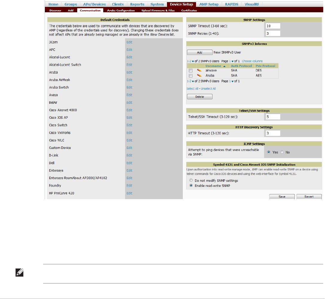
50 | Configuring AirWave Dell PowerConnect W-AirWave 7.5 | User Guide
Enabling AirWave to Manage Your Devices
Once AirWave is installed and active on the network, the next task is to define the basic settings that allow
AirWave to communicate with and manage your devices. Device-specific firmware files are often required or are
highly desirable. Furthermore, the use of Web Auth bundles is advantageous for deployment of Cisco WLC
wireless LAN controllers when they are present on the network.
This section contains the following procedures:
-Configuring Communication Settings for Discovered Devices
-Loading Device Firmware Onto AirWave (optional)
Configuring Communication Settings for Discovered Devices
To configure AirWave to communicate with your devices, to define the default shared secrets, and to set SNMP
polling information, navigate to the Device Setup > Communication page, illustrated in Figure 31.
Figure 31 Device Setup > Communication Page Illustration
Perform the following steps to define the default credentials and SNMP settings for the wireless network.
1. On the Device Setup > Communication page, locate the Default Credentials area. Enter the credentials for
each device model on your network. The default credentials are assigned to all newly discovered APs.
The Edit button edits the default credentials for newly discovered devices. To modify the credentials for
existing devices, use the APs/Devices > Manage page or the Modify Devices link on the APs/Devices > List
page.
NOTE: Community strings and shared secrets must have read-write access for AirWave to configure the devices. Without read-
write access, AirWave may be able to monitor the devices but cannot apply any configuration changes.
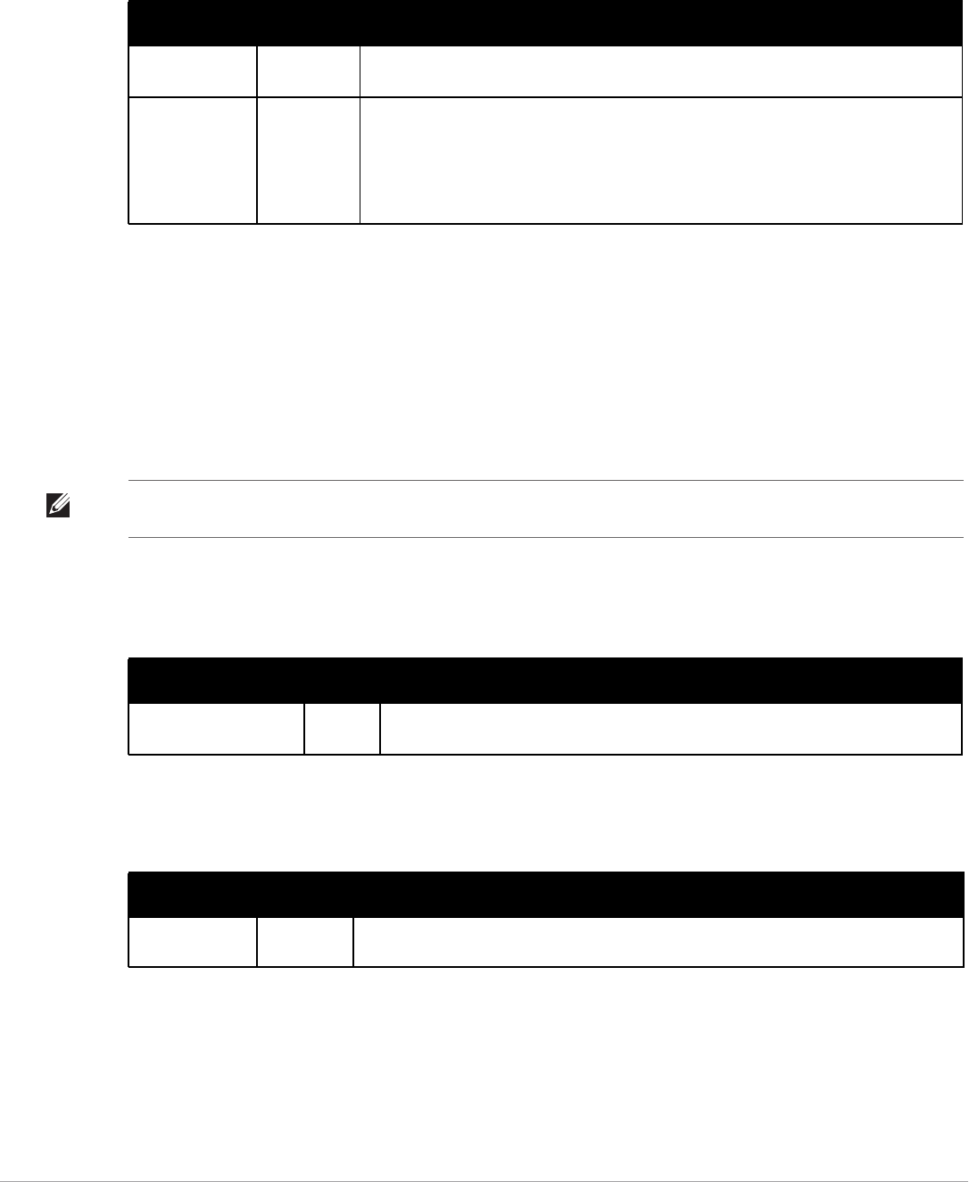
Dell PowerConnect W-AirWave 7.5 | User Guide Configuring AirWave | 51
2. Browse to the Device Setup > Communication page, locate the SNMP Settings section, and enter or revise the
following information. Table 30 lists the settings and default values.
3. Locate the SNMPv3 Informs section. Select the Add button to reveal configuration options. AirWave users
will need to configure all v3 users that are configured on the controller. The SNMP Inform receiver in the
AirWave will be restarted when users are changed or added to the controller.
-Username - Username of the SNMP v3 user as configured on the controller.
-Auth Protocol - Can be MD5 or SHA. The default setting is SHA.
-Auth and Priv Protocol Passphrases - Enter the authentication and privilege protocol passphrases for the
user as configured on the controller.
-Priv Protocol - Can be DES or AES. The default setting is DES..
4. Locate the Telnet/SSH Settings section, and complete or adjust the default value for the field. Table 31 shows
the setting and default value.
5. Locate the HTTP Discovery Settings section and adjust the default value. Table 32 shows the setting and
default value.
Table 30 Device Setup > Communication > SNMP Settings Fields and Default Values
Setting Default Description
SNMP Timeout
(3-60 sec)
3 Sets the time, in seconds, that AirWave waits for a response from a device after sending an
SNMP request.
SNMP Retries (1-
40)
3 Sets the number of times AirWave tries to poll a device when it does not receive a response
within the SNMP Timeout Period or the Group's Missed SNMP Poll Threshold setting (1-
100). If AirWave does not receive an SNMP response from the device after the specified
number of retries, AirWave classifies that device as Down.
NOTE: Although the upper limit for this value is 40, some SNMP libraries still have a hard
limit of 20 retries. In these cases, any retry value that is set above 20 will still stop at 20.
NOTE: This form allows you to edit existing SNMPv3 users by selecting the pencil icon next to the desired user. It also allows you
to remove existing users by selecting the user’s checkbox and then clicking Delete.
Table 31 Device Setup > Communication > Telnet/SSH Settings Fields and Default Values
Setting Default Description
Telnet/SSH Timeout
(3-120 sec)
10 Sets the timeout period in seconds used when performing Telnet and SSH commands.
Table 32 Device Setup > Communication > HTTP Discovery Settings Fields and Default Values
Setting Default Description
HTTP Timeout
(3-120 sec)
5 Sets the timeout period in seconds used when running an HTTP discovery scan.

52 | Configuring AirWave Dell PowerConnect W-AirWave 7.5 | User Guide
6. Locate the ICMP Settings section and adjust the default value as required. Table 33 shows the setting and
default value.
7. Locate the Symbol 4131 and Cisco Aironet IOS SNMP Initialization area. Select one of the options listed.
Table 34 describes the settings and default values:
Loading Device Firmware Onto AirWave (optional)
Overview of the Device Setup > Upload Firmware & Files Page
AirWave enables automated firmware distribution to the devices on your network. Once you have downloaded
the firmware files from the vendor, you can upload this firmware to AirWave for distribution to devices via the
Device Setup > Upload Firmware & Files page.
This page lists all firmware files on AirWave with file information. This page also enables you to add new
firmware files, to delete firmware files, and to add New Web Auth Bundle files.
The following additional pages support firmware file information:
-Firmware files uploaded to AirWave appear as an option in the drop-down menu on the Groups > Firmware
page and as a label on individual APs/Devices > Manage pages.
-Use the AMP Setup page to configure AirWave-wide default firmware options.
Table 35 below itemizes the contents, settings, and default values for the Upload Firmware & Files page.
Table 33 Device Setup > Communication > ICMP Settings Fields and Default Values
Setting Default Description
Attempt to ping
devices that
were
unreachable
via SNMP
Yes -When Yes is selected, AirWave attempts to ping the AP device.
-Select No if performance is affected in negative fashion by this function. If a large number
of APs are unreachable by ICMP, likely to occur where there is in excess of 100 APs, the
timeouts start to impede network performance.
NOTE: If ICMP is disabled on the network, select No to avoid the performance penalty caused
by numerous ping requests.
Table 34 Device Setup > Communication > Symbol 4131 and Cisco Aironet IOS SNMP Initialization Fields and Default
Values
Setting Default Description
Do Not Modify
SNMP Settings
Yes When selected, specifies that AirWave not modify any SNMP settings. If SNMP is not already
initialized on the Symbol, Nomadix, and Cisco IOS APs, AirWave is not able to manage them.
Enable read-write
SNMP
No When selected, and when on networks where the Symbol, Nomadix, and Cisco IOS APs do
not have SNMP initialized, this setting enables SNMP so the devices can be managed by
AirWave.
Table 35 Device Setup > Upload Firmware & Files Fields and Default Values
Setting Default Description
Type Dell PowerConnect W-
Series Controller (any
model)
Displays a drop-down list of the primary AP makes and models that
AirWave supports with automated firmware distribution.
Owner Role None Displays the user role that uploaded the firmware file. This is the role that
has access to the file when an upgrade is attempted.
Description None Displays a user-configurable text description of the firmware file.
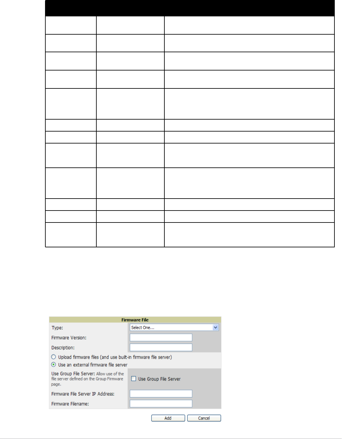
Dell PowerConnect W-AirWave 7.5 | User Guide Configuring AirWave | 53
Loading Firmware Files onto AirWave
Perform the following steps to load a device firmware file onto AirWave:
1. Go to the Device Setup > Upload Firmware & Files page.
2. Select Add. The Add Firmware File page appears. Figure 32 illustrates this page.
Figure 32 Device Setup > Upload Firmware and Files > Add Page Illustration
Server Protocol None Displays the file transfer protocol by which the firmware file was
obtained from the server. This can be either FTP or TFTP.
Use Group File
Server
None If enabled, displays the name of the file server supporting the group.
Firmware File
Server IP address
None Displays the IP address for a firmware file server.
Firmware Filename None Displays the name of the file that was uploaded to AirWave and to be
transferred to an AP when the file is used in an upgrade.
Firmware MD5
Checksum
None Displays the MD5 checksum of the file after it was uploaded to AirWave.
The MD5 checksum is used to verify that the file was uploaded to
AirWave without issue. The checksum should match the checksum of the
file before it was uploaded.
Firmware File Size None Displays the size of the firmware file in bytes.
Firmware Version None Displays the firmware version number. This is a user-configurable field.
HTML Filename None Supporting HTML, displays the name of the file that was uploaded to
AirWave and to be transferred to an AP when the file is used in an
upgrade.
HTML MD5
Checksum
None Supporting HTML, displays the MD5 checksum of the file after it was
uploaded to AirWave. The MD5 checksum is used to verify that the file
was uploaded to AirWave without issue. The checksum should match the
checksum of the file before it was uploaded.
HTML File Size None Supporting HTML, displays the size of the file in bytes.
HTML Version None Supporting HTML, displays the version of HTML used for file transfer.
Desired Firmware
File for Specified
Groups
None The firmware file is set as the desired firmware version on the Groups >
Firmware Files page of the specified groups. You cannot delete a
firmware file that is set as the desired firmware version for a group.
Table 35 Device Setup > Upload Firmware & Files Fields and Default Values (Continued)
Setting Default Description

54 | Configuring AirWave Dell PowerConnect W-AirWave 7.5 | User Guide
3. Select Supported Firmware Versions and Features to view supported firmware versions.
Enter the appropriate information and select Add. The file uploads to AirWave and once complete, this file
appears on the Device Setup > Upload Firmware & Files page. This file also appears on additional pages that
display firmware files (such as the Group > Firmware page and on individual APs/Devices > Manage pages).
4. You can also import a CSV list of groups and their external TFTP firmware servers. Table 36 itemizes the
settings of this page.
NOTE: Unsupported and untested firmware may cause device mismatches and other problems. Please contact AirWave support
at support.dell.com before installing non-certified firmware.
Table 36 Supported Firmware Versions and Features Fields and Default Values
Setting Default Description
Type Dell PowerConect W-
Series Controller
Indicates the firmware file is used with the specified type. If you
select an IOS device from the Type drop-down menu, you have the
option of choosing a server protocol of TFTP or FTP. If you choose
FTP, you may later notice that the firmware files are pushed to the
device more quickly.
With selection of some types, particularly Cisco controllers, you can
specify the boot software version.
Firmware Version None Provides a user-configurable field to specify the firmware version
number. Appears if you did not select the default Dell PowerConect
W-Series Controller type.
Description None Provides a user-configurable text description of the firmware file.
Upload firmware
files (and use built-in
firmware)
Built-in Selects the TFTP server that access points use to download their
firmware. The built-in TFTP server is recommended.
If you choose to use an external TFTP server, enter the File Server IP
Address and the Firmware Filename.
Use an external
firmware file server
N/A You can also choose to assign the external TFTP server on a per-
group basis. If you select this option, you must enter the IP address
on the Groups > Firmware page. Complete the Firmware File Server
IP Address field.
NOTE: With selection of some Types, you are prompted with the
Server Protocol field that lets you select which protocol to use, and
this varies from device to device. If you select FTP, AirWave uses an
anonymous user for file upload.
Use Group File
Server
Disabled If you opt to use an external firmware file server, this additional
option appears. This setting instructs AirWave to use the server that
is associated with the group instead of defining a server.
Firmware File Server
IP Address
None Provides the IP address of the External TFTP Server (like
SolarWinds) used for the firmware upgrade. This option displays
when the user selects the Use an external firmware file option.
Firmware Filename None Enter the name of the firmware file that needs to be uploaded.
Ensure that the firmware file is in the TFTP root directory. If you are
using a non-external server, you select Choose File to find your local
copy of the file.
NOTE: Additional fields may appear for multiple device types. AirWave prompts you for additional firmware information as
required. For example, Intel and Symbol distribute their firmware in two separate files: an image file and an HTML file. Both files
must be uploaded to AirWave for the firmware to be distributed successfully via AirWave.
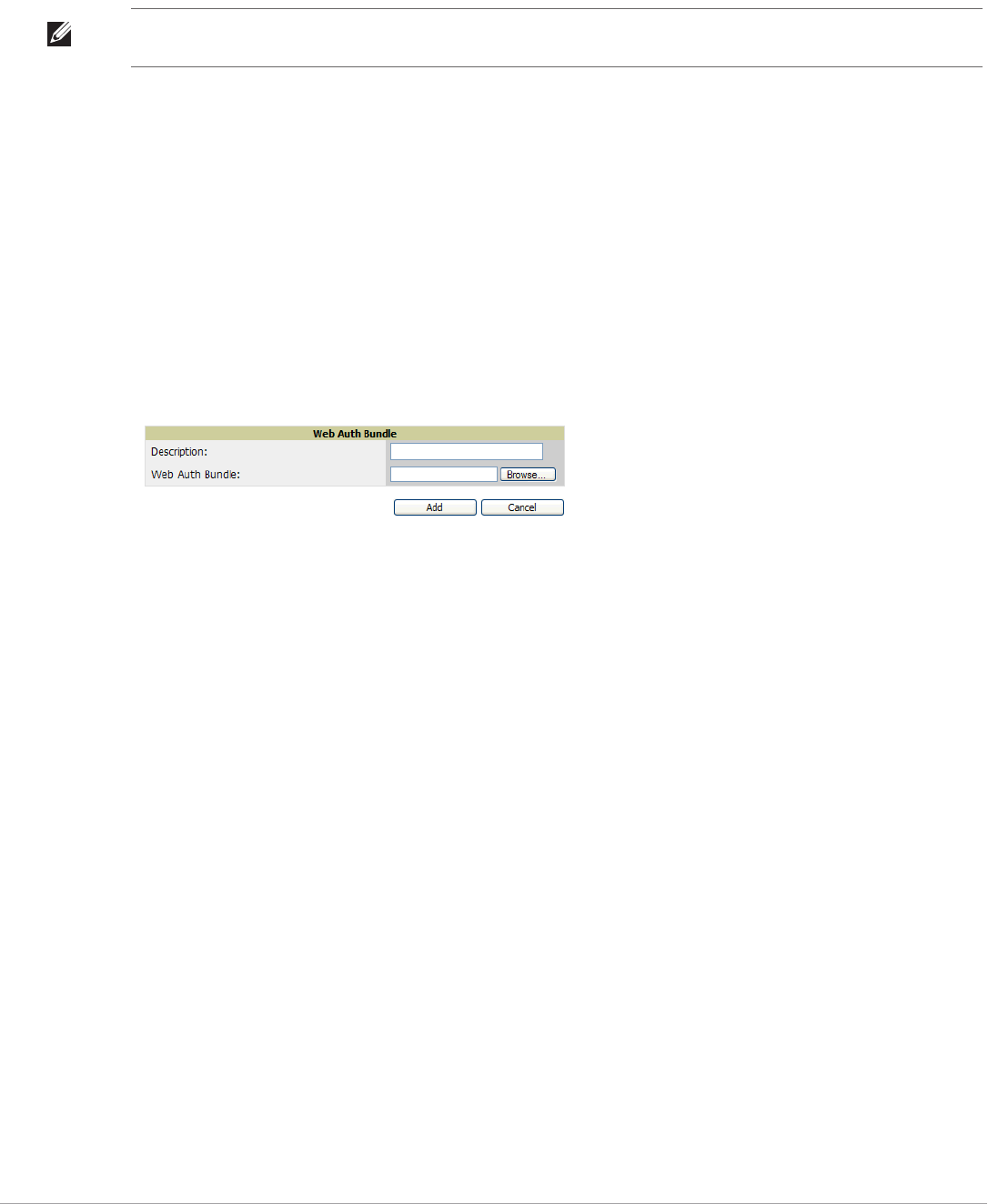
Dell PowerConnect W-AirWave 7.5 | User Guide Configuring AirWave | 55
5. Select Add to import the firmware file.
To delete a firmware file that has already been uploaded to AirWave, return to the Device Setup > Upload
Firmware & Files page, select the checkbox for the firmware file and select Delete.
Using Web Auth Bundles in AirWave
Web authentication bundles are configuration files that support Cisco WLC wireless LAN controllers. This
procedure requires that you have local or network access to a Web Auth configuration file for Cisco WLC
devices.
Perform these steps to add or edit Web Auth bundles in AirWave.
1. Go to the Device Setup > Upload Firmware & Files page. This page displays any existing Web Auth bundles
that are currently configured in AirWave, and allows you to add or delete Web Auth bundles.
2. Scroll to the bottom of the page. Select Add New Web Auth Bundle to create a new Web Auth bundle (see
Figure 33), or select the pencil icon next to an existing bundle to edit. You may also delete Web Auth bundles
by selecting that bundle with the checkbox, and selecting Delete.
Figure 33 Add Web Auth Bundle Page Illustration
3. Enter a descriptive label in the description field. This is the label used to identify and track Web Auth bundles
on the page.
4. Enter the path and filename of the Web Auth configuration file in the Web Auth Bundle field or select
Choose File to locate the file.
5. Select Add to complete the Web Auth bundle creation, or Save if replacing a previous Web Auth
configuration file, or Cancel to abort the Web Auth integration.
For additional information and a case study that illustrates the use of Web Auth bundles with Cisco WLC
controllers, refer to the following document on Cisco’s Web site:
-Wireless LAN controller Web Authentication Configuration Example, Document ID: 69340
http://www.cisco.com/en/US/tech/tk722/tk809/technologies_configuration_example09186a008067489f.shtml
Setting Up Device Types
On AMP Setup > Device Type Setup, you can define how the Device Type displayed for users on your network is
calculated from available data. The first matching property is used. These rules cannot be edited or deleted, but
only reordered or enabled.
You can change the priority order of rules by dragging and dropping rows, as shown in Figure 34.
Check or uncheck the checkbox under the Enabled column to turn device setup rules on or off.
Refer to “Monitoring and Supporting WLAN Clients” on page202 for more information on the Device Type
column that appears in Clients list tables.
NOTE: A firmware file may not be deleted if it is the desired version for a group. Use the Group > Firmware page to investigate this
potential setting and status.
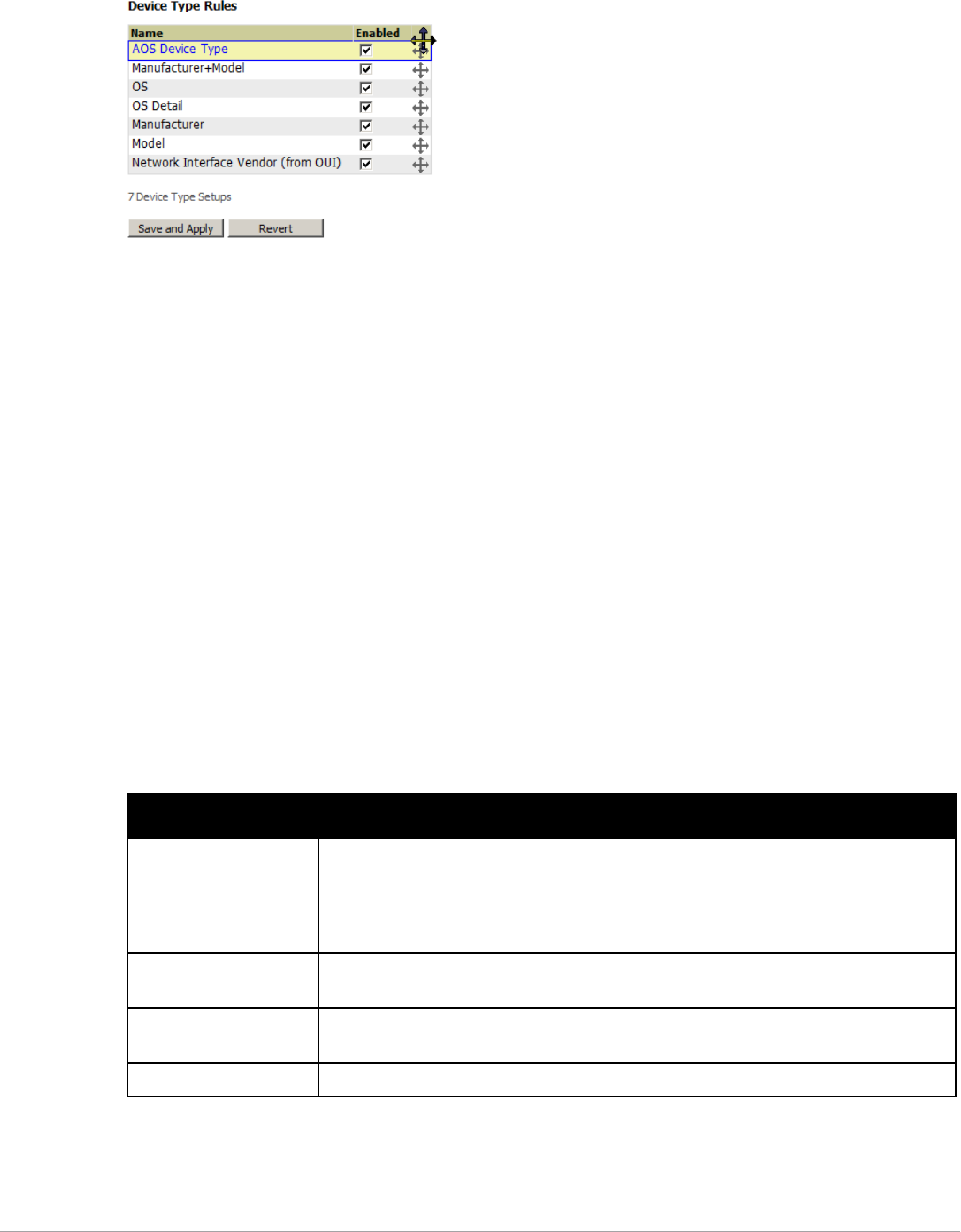
56 | Configuring AirWave Dell PowerConnect W-AirWave 7.5 | User Guide
Figure 34 AMP Setup > Device Type Setup Page Illustration
Configuring Cisco WLSE and WLSE Rogue Scanning
The Cisco Wireless LAN Solution Engine (WLSE) includes rogue scanning functions that AirWave supports.
This section contains the following topics and procedures, and several of these sections have additional sub-
procedures:
-Introduction to Cisco WLSE
-Initial WLSE Configuration
-Configuring IOS APs for WDS Participation
-Configuring ACS for WDS Authentication
-Configuring Cisco WLSE Rogue Scanning
You must enter one or more CiscoWorks WLSE hosts to be polled for discovery of Cisco devices and rogue AP
information.
Introduction to Cisco WLSE
Cisco WLSE functions as an integral part of the Cisco Structured Wireless-Aware Network (SWAN)
architecture, which includes IOS Access Points, a Wireless Domain Service, an Access Control Server, and a
WLSE. In order for AirWave to obtain Rogue AP information from the WLSE, all SWAN components must be
properly configured. Table 37 describes these components.
Initial WLSE Configuration
Use the following general procedures to configure and deploy a WLSE device in AirWave:
-Adding an ACS Server for WLSE
Table 37 Cisco SWAN Architecture Components
SWAN Component Requirements
WDS (Wireless Domain
Services)
-WDS Name
-Primary and backup IP address for WDS devices (IOS AP or WLSM)
-WDS Credentials APs within WDS Group
NOTE: WDS can be either a WLSM or an IOS AP. WLSM (WDS) can control up to 250 access
points. AP (WDS) can control up to 30 access points.
WLSE (Wireless LAN
Solution Engine)
-IP Address
-Login
ACS (Access Control
Server)
-IP Address
-Login
APs -APs within WDS Group

Dell PowerConnect W-AirWave 7.5 | User Guide Configuring AirWave | 57
-Enabling Rogue Alerts for Cisco WLSE
-Configuring WLSE to Communicate with APs
-Discovering Devices
-Managing Devices
-Inventory Reporting
-Defining Access
-Grouping
-WDS Participation
-Primary or Secondary WDS
Adding an ACS Server for WLSE
1. Go to the Devices > Discover > AAA Server page.
2. Select New from the drop-down list.
3. Enter the Server Name, Server Port (default 2002), Username, Password, and Secret.
4. Select Save.
Enabling Rogue Alerts for Cisco WLSE
1. Go to the Faults > Network Wide Settings > Rogue AP Detection page.
2. Select the Enable.
3. Select Apply.
Additional information about rogue device detection is available in “Configuring Cisco WLSE Rogue Scanning”
on page 59.
Configuring WLSE to Communicate with APs
1. Go to the Device Setup > Discover page.
2. Configure SNMP Information.
3. Configure HTTP Information.
4. Configure Telnet/SSH Credentials.
5. Configure HTTP ports for IOS access points.
6. Configure WLCCP credentials.
7. Configure AAA information.
Discovering Devices
The following three methods can be used to discover access points within WLSE:
-Using Cisco Discovery Protocol (CDP)
-Importing from a file
-Importing from CiscoWorks
Perform these steps to discover access points.
1. Go to the Device > Managed Devices > Discovery Wizard page.
2. Import devices from a file.
3. Import devices from Cisco Works.
4. Import using CDP.

58 | Configuring AirWave Dell PowerConnect W-AirWave 7.5 | User Guide
Managing Devices
Prior to enabling radio resource management on IOS access points, the access points must be under WLSE
management.
Use these pages to make such configurations:
1. Go to Device > Discover > Advanced Options.
2. Select the method to bring APs into management Auto, or specify via filter.
Inventory Reporting
When new devices are managed, the WLSE generates an inventory report detailing the new APs. AirWave
accesses the inventory report via the SOAP API to auto-discover access points. This is an optional step to enable
another form of AP discovery in addition to AirWave, CDP, SNMP scanning, and HTTP scanning discovery for
Cisco IOS access points. Perform these steps for inventory reporting.
1. Go to Devices > Inventory > Run Inventory.
2. Run Inventory executes immediately between WLSE polling cycles.
Defining Access
AirWave requires System Admin access to WLSE. Use these pages to make these configurations.
1. Go to Administration > User Admin.
2. Configure Role and User.
Grouping
It’s much easier to generate reports or faults if APs are grouped in WLSE. Use these pages to make such
configurations.
1. Go to Devices > Group Management.
2. Configure Role and User.
Configuring IOS APs for WDS Participation
IOS APs (1100, 1200) can function in three roles within SWAN:
-Primary WDS
-Backup WDS
-WDS Member
AirWave monitors AP WDS role and displays this information on AP Monitoring page.
WDS Participation
Perform these steps to configure WDS participation.
1. Log in to the AP.
2. Go to the Wireless Services > AP page.
3. Select Enable participation in SWAN Infrastructure.
NOTE: AirWave becomes the primary management/monitoring vehicle for IOS access points, but for AirWave to gather Rogue
information, the WLSE must be an NMS manager to the APs.
NOTE: APs functioning as WDS Master or Primary WDS will no longer show up as Down is the radios are enabled.

Dell PowerConnect W-AirWave 7.5 | User Guide Configuring AirWave | 59
4. Select Specified Discovery and enter the IP address of the Primary WDS device (AP or WLSM).
5. Enter the Username and Password for the WLSE server.
Primary or Secondary WDS
Perform these steps to configure primary or secondary functions for WDS.
1. Go to the Wireless Services > WDS > General Setup page.
2. If the AP is the Primary or Backup WDS, select Use the AP as Wireless Domain Services.
Select Priority (set 200 for Primary, 100 for Secondary).
Configure the Wireless Network Manager (configure the IP address of WLSE).
3. If the AP is Member Only, leave all options unchecked.
4. Go to the Security > Server Manager page.
5. Enter the IP address and Shared Secret for the ACS server and select Apply.
6. Go to the Wireless Services > WDS > Server Group page.
7. Enter the WDS Group of AP.
8. Select the ACS server in the Priority 1 drop-down menu and select Apply.
Configuring ACS for WDS Authentication
ACS authenticates all components of the WDS and must be configured first. Perform these steps to make this
configuration.
1. Login to the ACS.
2. Go to the System Configuration > ACS Certificate Setup page.
3. Install a New Certificate by selecting the Install New Certificate button, or skip to the next step if the
certificate was previously installed.
4. Select User Setup in the left frame.
5. Enter the Username that will be used to authenticate into the WDS and select Add/Edit.
6. Enter the Password that will be used to authenticate into the WDS and select Submit.
7. Go to the Network Configuration > Add AAA Client page.
8. Add AP Hostname, AP IP Address, and Community String (for the key).
9. Enter the Password that will be used to authenticate into the WDS and select Submit.
For additional and more general information about ACS, refer to “Configuring ACS Servers” on page61.
Configuring Cisco WLSE Rogue Scanning
The AMP Setup > WLSE page allows AirWave to integrate with the Cisco Wireless LAN Solution Engine
(WLSE). AirWave can discover APs and gather rogue scanning data from the Cisco WLSE.
Figure 35 illustrates and itemizes the AirWave settings for communication that is enabled between AirWave and
WLSE.
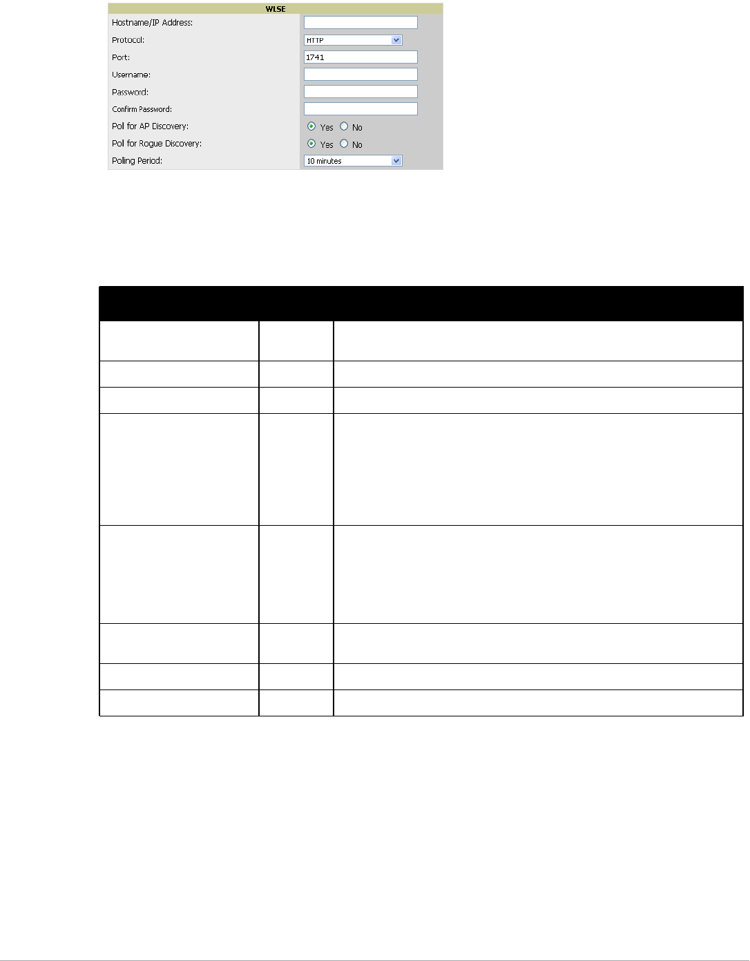
60 | Configuring AirWave Dell PowerConnect W-AirWave 7.5 | User Guide
Figure 35 AMP Setup > WLSE > Add WLSE Page Illustration
Perform the following steps for optional configuration of AirWave for support of Cisco WLSE rogue scanning.
1. To add a Cisco WLSE server to AirWave , navigate to the AMP Setup > WLSE page and select Add.
Complete the fields in this page. Table 38 describes the settings and default values.
2. After you have completed all fields, select Save. AirWave is now configured to gather rogue information from
WLSE rogue scans. As a result of this configuration, any rogues found by WLSE appear on the RAPIDS > List
page.
What Next?
-Go to additional tabs in the AMP Setup section to continue additional setup configurations.
-Complete the required configurations in this chapter before proceeding. Dell support remains available to you for
any phase of AirWave installation.
Table 38 AMP Setup > WLSE Fields and Default Values
Setting Default Description
Hostname/IP Address None Designates the IP address or DNS Hostname for the WLSE server, which must
already be configured on the Cisco WLSE server.
Protocol HTTP Specifies the protocol to be used when polling the WLSE.
Port 1741 Defines the port AirWave uses to communicate with the WLSE server.
Username None Defines the username AirWave uses to communicate with the WLSE server. The
username and password must be configured the same way on the WLSE server
and on AirWave.
The user needs permission to display faults to discover rogues and inventory API
(XML API) to discover manageable APs. As derived from a Cisco limitation, only
credentials with alphanumeric characters (that have only letters and numbers,
not other symbols) allow AirWave to pull the necessary XML APIs.
Password None Defines the password AirWave uses to communicate with the WLSE server. The
username and password must be configured the same way on the WLSE server
and on AirWave.
As derived from a Cisco limitation, only credentials with alphanumeric
characters (that have only letters and numbers, not other symbols) allow
AirWave to pull the necessary XML APIs.
Poll for AP Discovery; Poll for
Rogue Discovery
Yes Sets the method by which AirWave uses WLSE to poll for discovery of new APs
and/or new rogue devices on the network.
Last Contacted None Displays the last time AirWave was able to contact the WLSE server.
Polling Period 10 minutes Determines how frequently AirWave polls WLSE to gather rogue scanning data.
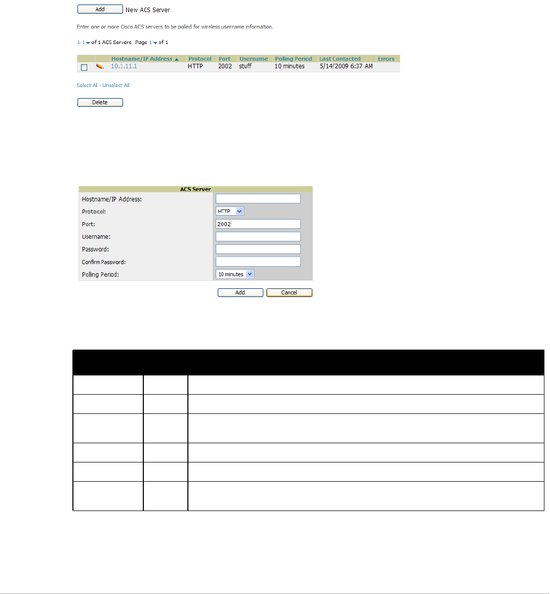
Dell PowerConnect W-AirWave 7.5 | User Guide Configuring AirWave | 61
Configuring ACS Servers
This is an optional configuration. The AMP Setup > ACS page allows AirWave to poll one or more Cisco ACS
servers for wireless username information. When you specify an ACS server, AirWave gathers information about
your wireless users. Refer to “” on page56 if you want to use your ACS server to manage your AirWave users.
Perform these steps to configure ACS servers:
1. Go to the AMP Setup > ACS page. This page displays current ACS setup, as illustrated in Figure 36.
Figure 36 AMP Setup > ACS Page Illustration
2. Select Add to create a new ACS server, or select a pencil icon to edit an existing server. To delete an ACS
server, select that server and select Delete. When selecting Add or edit, the Details page appears, as illustrated
in Figure 37.
Figure 37 AMP Setup > ACS > Add/Edit Details Page Illustration
3. Complete the settings on AMP Setup > ACS > Add/Edit Details. Table 39 describes these fields:
4. Select Add to finish creating the new ACS server, or Save to finish editing an existing ACS server.
5. The ACS server must have logging enabled for passed authentications. Enable the Log to CSV Passed
Authentications report option, as follows:
Table 39 AMP Setup > ACS > Add/Edit Details Fields and Default Values
Field Default Description
IP/Hostname None Sets the DNS name or the IP address of the ACS Server.
Protocol HTTP Launches a drop-down menu specifying the protocol AirWave uses when it polls the ACS server.
Port 2002 Sets the port through which AirWave communicates with the ACS. AirWave generally
communicates via SNMP traps on port 162.
Username None Sets the Username of the account AirWave uses to poll the ACS server.
Password None Sets the password of the account AirWave uses to poll the ACS server.
Polling Period 10 min Launches a drop-down menu that specifies how frequently AirWave polls the ACS server for
username information.

62 | Configuring AirWave Dell PowerConnect W-AirWave 7.5 | User Guide
Log in to the ACS server, select System Configuration, then in the Select frame, select Logging.
Under Enable Logging, select CSV Passed Authentications. The default logging options function and
support AirWave. These include the two columns AirWave requires: User-Name and Caller-ID.
What Next?
-Go to additional tabs in the AMP Setup section to continue additional setup configurations.
-Complete the required configurations in this chapter before proceeding. Dell support remains available to you for
any phase of AirWave installation.
Integrating AirWave with an Existing Network Management Solution
(NMS)
This is an optional configuration. The AMP Setup > NMS configuration page allows AirWave to integrate with
other Network Management Solution (NMS) consoles. This configuration enables advanced and interoperable
functionality as follows:
-AirWave can forward WLAN-related SNMP traps to the NMS, or AirWave can send SNMPv1 or SNMPv2
traps to the NMS.
-AirWave can be used in conjunction with Hewlett-Packard’s ProCurve Manager.
-The necessary files for either type of NMS interoperability are downloaded from the AMP Setup > NMS page
as follows. For additional information, contact support.
Perform these steps to configure NMS support in AirWave:
1. Go to AMP Setup > NMS, illustrated in Figure 38.
Figure 38 AMP Setup > NMS Page Illustration
2. Select Add to integrate a new NMS server, or select the pencil icon to edit an existing server. Provide the
information described in Table 40:
3. The NMS Integration Add/Edit page includes the Netcool/OMNIbus Integration link to information and
instructions. The IBM Tivoli Netcool/OMNIbus operations management software enables automated event
correlation and additional features resulting in optimized network uptime.
4. The NMS Integration Add/Edit page includes the HP ProCurve Manager Integration link. Select this link for
additional information, zip file download, and brief instructions for installation with AirWave. Select Add to
finish creating the NMS server, or Save to configure an existing NMS server.
What Next?
-Go to additional tabs in the AMP Setup section to continue additional setup configurations.
Table 40 AMP Setup > NMS Integration Add/Edit Fields and Default Values
Setting Default Description
Hostname None Cites the DNS name or the IP address of the NMS.
Port 162 Sets the port AirWave uses to communicate with the NMS.
NOTE: AirWave generally communicates via SNMP traps on port 162.
Community String None Sets the community string used to communicate with the NMS.
SNMP Version v2C Sets the SNMP version of the traps sent to the Host.
Enabled Yes Enables or disables trap logging to the specified NMS.
Send Configuration Traps Yes Enables NMS servers to transmit SNMP configuration traps.

Dell PowerConnect W-AirWave 7.5 | User Guide Configuring AirWave | 63
-Complete the required configurations in this chapter before proceeding. Dell support remains available to you for
any phase of AirWave installation.
Auditing PCI Compliance on the Network
This section describes PCI requirements and auditing functions in AirWave, with the following topics:
-Introduction to PCI Requirements
-PCI Auditing
-Enabling or Disabling PCI Auditing
Introduction to PCI Requirements
AirWave supports wide security standards and functions in the wireless network. One component of network
security is the optional deployment of Payment Card Industry (PCI) Auditing.
The Payment Card Industry (PCI) Data Security Standard (DSS) establishes multiple levels in which payment
cardholder data is protected in a wireless network. AirWave supports PCI requirements according to the
standards and specifications set forth by the following authority:
-Payment Card Industry (PCI) Data Security Standard (DSS)
PCI Security Standards Council Website
https://www.pcisecuritystandards.org
PCI Quick Reference Guide, Version 1.2 (October 2008)
https://www.pcisecuritystandards.org/pdfs/pci_ssc_quick_guide.pdf
PCI Auditing
PCI Auditing in AirWave allows you to monitor, audit, and demonstrate PCI compliance on the network. There
are five primary pages in which you establish, monitor, and access PCI auditing, as follows:
-The AMP Setup > PCI Compliance page enables or disables PCI Compliance monitoring on the network, and
displays the current compliance status on the network. See “Enabling or Disabling PCI Auditing” on page64.
-The Reports > Definitions page allows you to create custom-configured and custom-scheduled PCI
Compliance reports. See “Reports > Definitions Page Overview” on page233.
-The Reports > Generated page lists PCI Compliance reports currently available, and allows you to generate
the latest daily version of the PCI Compliance Report with a single select. Refer to “Reports > Generated
Page Overview” on page235.
-The APs/Devices > PCI Compliance page enables you to analyze PCI Compliance for any specific device on
the network. This page is accessible when you select a specific device from the APs/Devices > Monitor page.
First, you must enable this function through AMP Setup. See “Enabling or Disabling PCI Auditing” on
page64.
-The PCI Compliance Report offers additional information. Refer to “Using the PCI Compliance Report” on
page251. This report not only contains Pass or Fail status for each PCI requirement, but cites the action
required to resolve a Fail status when sufficient information is available.
NOTE: When any PCI requirement is enabled on AirWave, then AirWave grades the network as pass or fail for the respective PCI
requirement. Whenever a PCI requirement is not enabled in AirWave, then AirWave does not monitor the network’s status in
relation to that requirement, and cannot designate Pass or Fail network status. AirWave users without RAPIDS visibility enabled
will not see the 11.1 PCI requirements in the PCI Compliance Report.

64 | Configuring AirWave Dell PowerConnect W-AirWave 7.5 | User Guide
Enabling or Disabling PCI Auditing
Perform these steps to verify status and to enable or disable AirWave support for PCI 1.2 requirements. enabling
one or all PCI standards on AirWave enables real-time information and generated reports that advise on Pass or
Fail status. The PCI auditing supported in AirWave is reported in Table 41.
1. To determine what PCI Compliance standards are enabled or disabled on AirWave, navigate to the AMP
Setup > PCI Compliance page, illustrated in Figure 39.
Table 41 PCI Requirements and Support in AirWave
Requirement Description
1.1 Monitoring configuration standards for network firewall devices
When Enabled: PCI Requirement 1.1 establishes firewall and router configuration standards.
A device fails Requirement 1.1 if there are mismatches between the desired configuration and the
configuration on the device.
When Disabled: firewall router and device configurations are not checked for PCI compliance, and
Pass or Fail status is not reported or monitored.
1.2.3 Monitoring firewall installation between any wireless networks and the cardholder data environment
When Enabled: A device passes requirement 1.2.3 if it can function as a stateful firewall.
When Disabled: firewall router and device installation are not checked for PCI compliance.
2.1 Monitoring the presence of vendor-supplied default security settings
When Enabled: PCI Requirement 2 establishes the standard in which all vendor-supplied default
passwords are changed prior to a device’s presence and operation in the network.
A device fails requirement 2.1 if the username, passwords or SNMP credentials being used by AirWave
to communicate with the device are on a list of forbidden default credentials. The list includes common
vendor default passwords, for example.
When Disabled: device passwords and other vendor default settings are not checked for PCI
compliance.
2.1.1 Changing vendor-supplied defaults for wireless environments
When Enabled: A device fails requirement 2.1.1 if the passphrases, SSIDs, or other security-related
settings are on a list of forbidden values that AirWave establishes and tracks. The list includes common
vendor default passwords. The user can input new values to achieve compliance.
When Disabled: network devices are not checked for forbidden information and PCI Compliance is not
established.
4.1.1 Using strong encryption in wireless networks
When Enabled: PCI Requirement 4 establishes the standard by which payment cardholder data is
encrypted prior to transmission across open public networks. PCI disallows WEP encryption as an
approved encryption method after June 20, 2010. A device fails requirement 4.1.1 if the desired or actual
configuration reflect that WEP is enabled on the network, or if associated users can connect with WEP.
When Disabled: AirWave cannot establish a pass or fail status with regard to PCI encryption
requirements on the network.
11.4 Using intrusion-detection or intrusion-prevention systems to monitor all traffic
When Enabled: AirWave reports pass or fail status when monitoring devices capable of reporting IDS
events. Recent IDS events are summarized in the PCI Compliance report or the IDS Report.
When Disabled: AirWave does not monitor the presence of PCI-compliant intrusion detection or
prevention systems, nor can it report Pass or Fail status with regard to IDS events.
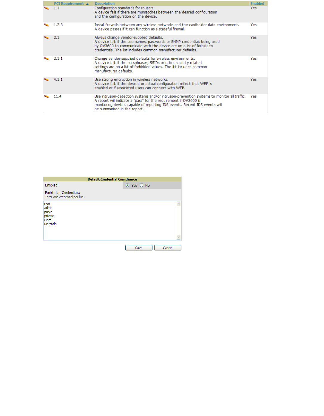
Dell PowerConnect W-AirWave 7.5 | User Guide Configuring AirWave | 65
Figure 39 AMP Setup > PCI Compliance Page Illustration
2. To enable, disable, or edit any category of PCI Compliance monitoring in AirWave, select the pencil icon next
to the category. The Default Credential Compliance page displays for the respective PCI standard.
3. Create changes as required. Specific credentials can be cited in the Forbidden Credentials section of any Edit
page to enforce PCI requirements in AirWave . Figure 40 shows an example of how to edit the PCI 2.1
requirement.
Figure 40 Default Credential Compliance for PCI Requirements
4. Select Save.
5. To view and monitor PCI auditing on the network, use generated or daily reports. See Chapter 9, “Creating,
Running, and Emailing Reports” . In addition, you can view the real-time PCI auditing of any given device
online. Perform these steps:
a. Go to the APs/Devices > List page.
b. Select a specific device. The Monitor page for that device displays. The APs/Devices page also displays a
Compliance subtab in the menu bar.
c. Select Compliance to view complete PCI compliance auditing for that specific device.
Deploying WMS Offload
Overview of WMS Offload in AirWave
This section describes the Dell PowerConnect W-Series Wireless LAN Management Server (WMS) offload
infrastructure. WMS Offload is supported with the following two requirements:
-ArubaOS Version 2.5.4 or later
-AirWave Version 6.0 or later

66 | Configuring AirWave Dell PowerConnect W-AirWave 7.5 | User Guide
The Dell PowerConnect W WMS feature is an enterprise-level hardware device and server architecture with
managing software for security and network policy. There are three primary components of the WMS
deployment:
-Air Monitor AP devices establish and monitor RF activity on the network.
-The WMS server manages devices and network activity to include rogue AP detection and enforcement of
network policy.
-The AirWave graphical user interface (GUI) allows users to access and use the WMS functionality.
WMS Offload is the ability to place the burden of the WMS server data and GUI functions on AirWave. WMS
master controllers provide this data so that AirWave can support rigorous network monitoring capabilities.
General Configuration Tasks Supporting WMS Offload in AirWave
WMS Offload must be enabled with a six-fold process and related configuration tasks as follows:
1. Configure WLAN switches for optimal AirWave monitoring.
a. Disable debugging.
b. Ensure AirWave server is a trap receiver host.
c. Ensure proper traps are enabled.
2. Configure AirWave to optimally monitor the AirWave infrastructure.
a. Enable WMS offload on the AMP Setup > General page.
b. Configure SNMP communication.
c. Create a proper policy for monitoring the AirWave infrastructure.
d. Discover the infrastructure.
3. Configure device classification.
a. Set up rogue classification.
b. Set up rogue classification override.
c. Establish user classification override devices.
4. Deploy ArubaOS-specific monitoring features.
a. Enable remote AP and wired network monitoring.
b. View controller license information.
5. Convert existing floor plans to VisualRF to include the following elements:
Dell PowerConnect W-Series ArubaOS
RF Plan
6. Use RTLS for increasing location accuracy (optional).
a. Enable RTLS service on the AirWave server.
b. Enable RTLS on ArubaOS infrastructure.
Additional Information Supporting WMS Offload
Refer to the Dell PowerConnect W-AirWave 7.5 Best Practices Guide at support.dell.com/manuals for additional
information, including detailed concepts, configuration procedures, restrictions, ArubaOS infrastructure, and
AirWave version differences in support of WMS Offload.

Dell PowerConnect W-AirWave 7.5 | User Guide Configuring and Using Device Groups | 67
Chapter 4
Configuring and Using Device Groups
This chapter describes the deployment of device groups within AirWave. The section below describes the pages
or focused subtabs available on the Groups tab. Note that the available subtabs can vary significantly from one
device group to another—one or more subtabs may not appear, depending on the Default Group display option
selected on the AMP Setup > General page and the types of devices you add to AirWave.
Figure 41 Subtabs under the Group tab
-List—This page is the default page in the Groups section of AirWave. It lists all groups currently configured
in AirWave and provides the foundation for all group-level configurations. See “Viewing All Defined Device
Groups” on page69.
-Monitor—This page displays client and bandwidth usage information, lists devices in a given group, provides
an Alert Summary table for monitoring alerts for the group, and provides a detailed Audit Log for group-level
activity.
-Basic—This page appears when you create a new group on the Groups > List page. Once you define a group
name, AirWave displays the Basic page from which you configure many group-level settings. This page
remains available for any device group configured in AirWave. Refer to “Configuring Basic Group Settings”
on page70.
-Templates—This page manages templates for any device group. Templates allow you to manage the
configuration of Dell PowerConnect W-Series, 3Com, Alcatel-Lucent, Aruba Networks, Cisco Aironet IOS,
Cisco Catalyst switches, Enterasys, HP, Nortel, Symbol and Trapeze devices in a given group using a
configuration file. Variables in such templates configure device-specific properties, such as name, IP address
and channel. Variables also define group-level properties. For additional information about using the
Templates page, refer to Chapter 6, “Creating and Using Templates” on page155.
-Security—This page defines general security settings for device groups, to include RADIUS, encryption, and
additional security settings on devices. Refer to “Configuring Group Security Settings” on page79.
-SSIDs—This page sets SSIDs, VLANs, and related parameters in device groups. Refer to “Configuring Group
SSIDs and VLANs” on page82.
-AAA Servers—This page configures authentication, authorization, and accounting settings in support of
RADIUS servers for device groups. Refer to “Adding and Configuring Group AAA Servers” on page77.
-Radio—This page defines general 802.11 radio settings for device groups. Refer to “Configuring Radio
Settings for Device Groups” on page85.
-Dell PowerConnect W Config—This page manages ArubaOS Device Groups, AP Overrides, and other profiles
specific to Dell PowerConnect W-Series devices on the network. Use this page as an alternative to the Device
Setup > Dell PowerConnect W Configuration page. The appearance of this page varies depending on
whether AMP is configured for global configuration or group configuration. For additional information, refer
to the Dell PowerConnect W-Series ArubaOS Configuration Guide at support.dell.com/manuals.
-Cisco WLC Config—This page consolidates controller-level settings from the Group Radio, Security, SSIDs,
Cisco WLC Radio and AAA Server pages into one navigation tree that is easier to navigate, and has familiar
layout and terminology. Bulk configuration for per-thin AP settings, previously configured on the Group
LWAPP APs tab, can now be performed from Modify Devices on the APs/Devices > List page. Refer to
“Cisco WLC Group Configuration” on page88.

68 | Configuring and Using Device Groups Dell PowerConnect W-AirWave 7.5 | User Guide
-PTMP—This page defines settings specific to Proxim MP devices when present. As such, this page is only
available when a Proxim MP device is added to this group. Refer to “Configuring Group PTMP Settings” on
page95.
-Proxim Mesh—This page defines mesh AP settings specific to Proxim devices when present. Refer to
“Configuring Proxim Mesh Radio Settings” on page95.
-MAC ACL—This page defines MAC-specific settings that apply to Proxim, Symbol, and ProCurve 520 devices
when present. Refer to “Configuring Group MAC Access Control Lists” on page97.
-Firmware—This page manages firmware files for many devices. “Specifying Minimum Firmware Versions for
APs in a Group” on page97.
-Compare—This page allows you to compare line item-settings between two device groups. On the Groups >
List page, select the Compare two groups link, select the two groups from the drop-down menus, then select
Compare. “Comparing Device Groups” on page98.
This chapter also provides the following additional procedures for group-level configurations:
-“Deleting a Group” on page99
-“Changing Multiple Group Configurations” on page99
-“Modifying Multiple Devices” on page101
-“Using Global Groups for Group Configuration” on page104
AirWave Groups Overview
Enterprise APs, controllers, routers, and switches have hundreds of variable settings that must be configured
precisely to achieve optimal performance and network security. Configuring all settings on each device
individually is time consuming and error prone. AirWave addresses this challenge by automating the processes of
device configuration and compliance auditing. At the core of this approach is the concept of Device Groups, with
the following functions and benefits:
-AirWave allows certain settings to be managed efficiently at the Group level, while others are managed at an
individual device level.
-AirWave defines a Group as a subset of the devices on the wireless LAN, ranging in size from one device to
hundreds of devices that share certain common configuration settings.
-Groups may be defined based on geography (such as “5th Floor APs”), usage or security policies (such as
“Guest Access APs”), function (such as “Manufacturing APs”), or any other appropriate variable.
-Devices within a group may originate from different vendors or hardware models, but all devices within a
Group share certain basic configuration settings.
Typical group configuration variables include the following settings:
-Basic settings - SSID, SNMP polling interval, and so forth
-Security settings - VLANs, WEP, 802.1x, ACLs, and so forth
-Radio settings - data rates, fragmentation threshold, RTS threshold, DTIM, preamble, and so forth.
When configuration changes are applied at a group level, they are assigned automatically to every device within
that group. Such changes must be applied with every device in Managed mode. Monitor mode is the more
common mode.
CAUTION: Always review the Audit page before pushing configuration to a device or group.
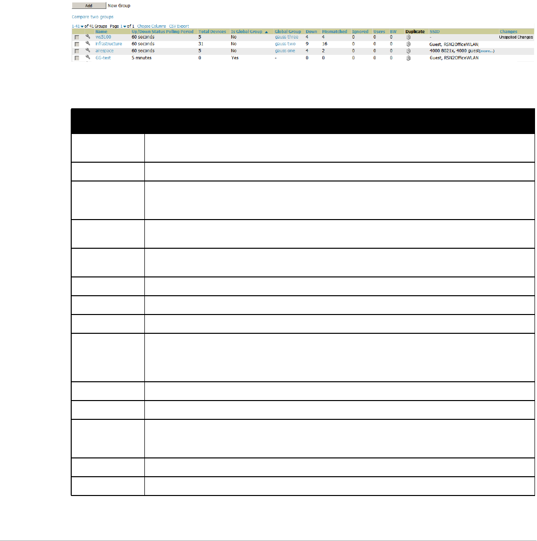
Dell PowerConnect W-AirWave 7.5 | User Guide Configuring and Using Device Groups | 69
Individual device settings—such as device name, RF channel selection, RF transmission power, antenna settings,
and so forth—typically should not be managed at a group level and must be individually configured for optimal
performance. Individual AP settings are configured on the APs/Devices > Manage page.
You can create as many different groups as required. Administrators usually establish groups that range in size
from five to 100 wireless devices.
Group configuration can be enhanced with the AirWave Global Groups feature, which lets you create Global
Groups with configurations that are pushed to individual Subscriber Groups.
Viewing All Defined Device Groups
To display a list of all defined groups, browse to the Groups > List page, illustrated in Figure 42.
Figure 42 Groups > List Page Illustration
Table 42 describes the columns in the Groups > List page.
Table 42 Groups > List Columns
Column Description
Add New Group Launches a page that enables you to add a new group by name and to define group parameters for devices
in that group. For additional information, refer to “Configuring Basic Group Settings” on page 70.
Changes Displays when a group has unapplied changes.
Manage
(wrench icon)
Goes to the Groups > Basic configuration page for that group. Hover your mouse over the icon to see a list of
shortcuts to group-specific subtabs that would appear across the navigation section if this group is
selected. (See Figure 43.)
Name Uniquely identifies the group by location, vendor, department or any other identifier (such as ‘Accounting
APs,’ ‘Floor 1 APs,’ ‘Cisco devices,’ ‘802.1x APs,’ and so forth).
Is Global Group If a group is designated as global, it may not contain APs but it may be used as a template for other groups.
This column may also indicate Yes if this group has been pushed to the AirWave from a Master Console.
Global Group Specifies which group this Subscriber Group is using as its template.
SSID The SSID assigned to supported device types within the group.
Total Devices Total number of devices contained in the group including APs, controllers, routers, or switches.
Down The number of access points within the group that are not reachable via SNMP or are no longer associated
to a controller. Note that thin APs are not directly polled with SNMP, but are polled through the controller.
That controller may report that the thin AP is down or is no longer on the controller. At this point, AirWave
classifies the device as down.
Mismatched The number of devices within the group that are in a mismatched state.
Ignored The number of ignored devices in that group.
Clients The number of mobile users associated with all access points within the group. To avoid double counting of
clients, clients are only listed in the group of the AP with which they are associated. Note that device groups
with only controllers in them report no clients.
Usage A running average of the sum of bytes in and bytes out for the managed radio page.
VPN Sessions Number of active (connected) VPN sessions under this group.
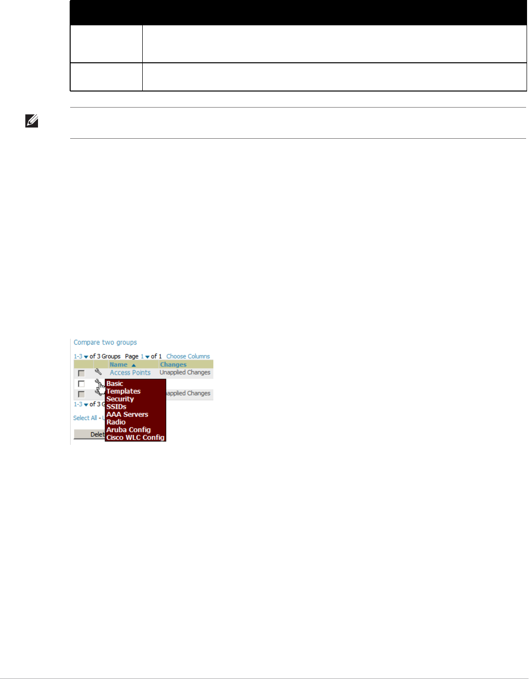
70 | Configuring and Using Device Groups Dell PowerConnect W-AirWave 7.5 | User Guide
Configuring Basic Group Settings
The first default device group that AirWave sets up is the Access Points group, but you can use this procedure to
add and configure any device group. Perform these steps to configure basic group settings, then continue to
additional procedures to define additional settings as required.
1. Go to the Groups > List page. Existing device groups appear on this page.
2. To create a new group, select Add. Enter a group name and select Add. The Groups > Basic page appears.
To edit an existing device group, select the manage (wrench) icon next to the group. The Groups > Basic
page appears. If you mouse over an existing group’s wrench, a popup menu allows you to select Basic,
Templates, Security, SSIDs, AAA Servers, Radio, Dell PowerConnect W Config or Cisco WLC Config to
edit those pages as desired, as illustrated in Figure 43.
Figure 43 Pop-up When Hovering over Wrench Icon in Groups > List
Figure 44 illustrates an example Groups > Basic page.
Up/Down Status
Polling Period
The time between Up/Down SNMP polling periods for each device in the group. Detailed SNMP polling
period information is available on the Groups > Basic configuration page. Note that by default, most polling
intervals do not match the up/down period.
Duplicate Creates a new group with the name Copy of <Group Name> with identical configuration settings. (Dell
configuration settings will have to be manually added back.)
Table 42 Groups > List Columns (Continued)
Column Description
NOTE: When you first configure AirWave, there is only one default group labeled Access Points. If you have no other groups
configured, refer to “Configuring Basic Group Settings” on page 70.
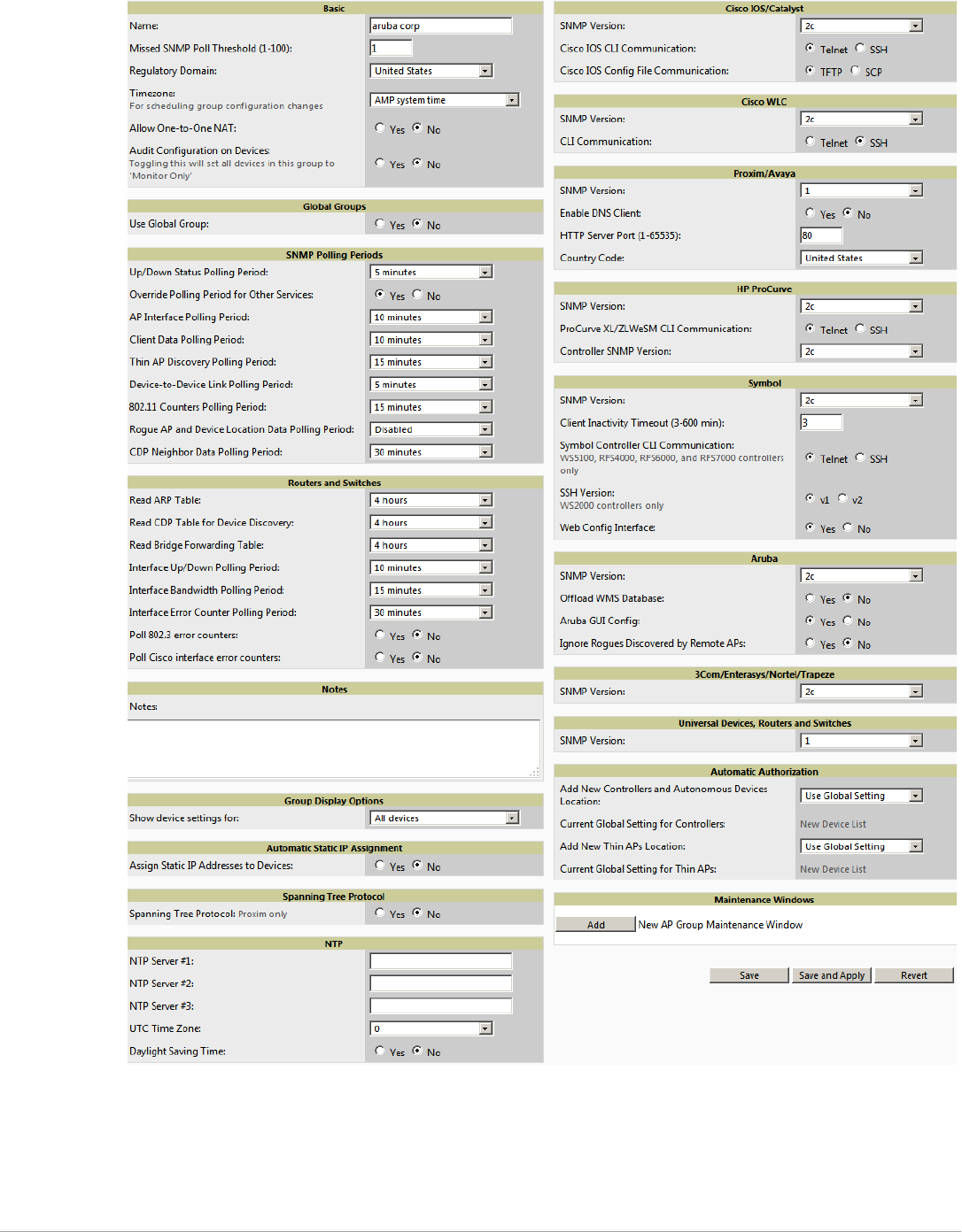

72 | Configuring and Using Device Groups Dell PowerConnect W-AirWave 7.5 | User Guide
4. Complete the SNMP Polling Periods section. The information in this section overrides default settings. Table
44 describes the SNMP polling settings.
Table 43 Basic and Global Groups Fields and Default Values
Setting Default Description
Name Defined when
first adding the
group
Displays or changes the group name. As desired, use this field to set the name to uniquely
identify the group by location, vendor, department, or any other identifier (such as
“Accounting APs,” “Cisco devices,” “802.1x APs,” and so forth).
Missed SNMP
Poll Threshold
(1-100)
1 Sets the number of Up/Down SNMP polls that must be missed before AirWave considers a
device to be down. The number of SNMP retries and the SNMP timeout of a poll can be set
on the Device Setup > Communication page.
Regulatory
Domain
United States Sets the regulatory domain in AirWave, limiting the selectable channels for APs in the
group.
Timezone AMP System
Time
Allows group configuration changes to be scheduled relative to the time zone in which the
devices are located. This setting is used for scheduling group-level configuration changes.
Allow One-to-
One NAT
No Allows AirWave to talk to the devices on a different IP address than the one configured on
the device.
NOTE: If enabled, the LAN IP Address listed on the AP/Devices > Manage configuration
page under the Settings area is different than the IP Address under the Device
Communication area.
Audit
Configuration on
Devices
Yes Auditing and pushing of configuration to devices can be disabled on all the devices in the
group. Once disabled, all the devices in the groups will not be counted towards
mismatched devices.
Is Global Group No If specified as Yes, then this group can be selected in the Use Global Group drop down
menu for future group configurations.
Use Global
Group
No When enabled, this field allows you to define the device group to be a Global Group. Refer
to “Using Global Groups for Group Configuration” on page 104.
Table 44 SNMP Polling Periods Fields and Default Values
Setting Default Description
Up/Down Status Polling
Period
5 minutes Sets time between Up/Down SNMP polling for each device in the group.
The Group SNMP Polling Interval overrides the global parameter configured on
the Device Setup > Communication page. An initial polling interval of 5minutes is
best for most networks.
Override Polling Period for
Other Services
No Enables or disables overriding the base SNMP Polling Period. If you select Yes,
the other settings in the SNMP Polling Periods section are activated, and you
can override default values.
AP Interface Polling Period 10 minutes Sets the interval at which AirWave polls for radio monitoring and bandwidth
being used by a device.
Client Data Polling Period 10 minutes Sets time between SNMP polls for client data for devices in the group.
Thin AP Discovery Polling
Period
15 minutes Sets time between SNMP polls for Thin AP Device Discovery. Controllers are the
only devices affected by this polling interval.
Device-to-Device link Polling
Period
5 minutes Sets time between SNMP polls for Device-to-Device link polling. Mesh APs are
the only devices affected by this polling interval.
802.11 Counters Polling Period 15 minutes Sets time between SNMP polls for 802.11 Counter information.
Rogue AP and Device
Location Data Polling Period
30 minutes Sets time between SNMP polls for Rogue AP and Device Location Data polling.

Dell PowerConnect W-AirWave 7.5 | User Guide Configuring and Using Device Groups | 73
5. To configure support for routers and switches in the group, locate the Routers and Switches section and
adjust these settings as required. This section defines the frequency in which all devices in the group polled.
These settings can be disabled entirely as desired. Table 45 describes the SNMP polling settings.
6. Record additional information and comments about the group in the Notes section.
CDP Neighbor Data Polling
Period
30 minutes Sets the frequency in which this group polls the network for Cisco Discovery
Protocol (CDP) neighbors.
Mesh Discovery Polling
Period
15 minutes Sets time between SNMP polls for Mesh Device Discovery.
Table 45 Routers and Switches Fields and Default Values
Setting Default Description
Read ARP Table 4 hours Sets the frequency in which devices poll routers and switches for Address
Resolution Protocol (ARP) table information. This setting can be disabled, or set
to poll for ARP information in a range from every 15 seconds to 12 hours.
Read CDP Table for Device
Discovery
4 hours For Cisco devices, sets the frequency in which devices poll routers and switches
for Cisco Discovery Protocol (CDP) information. This setting can be disabled, or
set to poll for CDP neighbor information in a range from every 15 seconds to 12
hours.
Read Bridge Forwarding Table 4 hours Sets the frequency in which devices poll the network for bridge forwarding
information. This setting can be disabled, or set to poll bridge forwarding tables
from switches in a range from every 15 seconds to 12 hours.
Interface Up/Down Polling
Period
5 minutes Sets the frequency in which network interfaces are polled for up/down status.
This setting can be disabled, or set to poll from switches in a range from every 15
seconds to 30 minutes.
Interface Bandwidth Polling
Period
15 minutes Sets the frequency in which network interfaces are polled for bandwidth usage.
This setting can be disabled, or set to poll from switches in a range from every 5
minutes to 30 minutes.
Interface Error Counter
Polling Period
30 minutes Sets the frequency in which network interfaces are polled for up/down status.
This setting can be disabled, or set to poll bridge forwarding tables from
switches in a range from every 5 minutes to 30 minutes.
Poll 802.3 error counters No Sets whether 802.3 error counters should be polled.
Poll Cisco interface error
counters
No Sets whether the interface error counters for Cisco devices should be polled.
Table 44 SNMP Polling Periods Fields and Default Values (Continued)
Setting Default Description

74 | Configuring and Using Device Groups Dell PowerConnect W-AirWave 7.5 | User Guide
7. To configure which options and tabs are visible for the group, complete the settings in the Group Display
Options section. Table 46 describes the settings and default values.
8. To assign dynamically a range of static IP addresses to new devices as they are added into the group, locate the
Automatic Static IP Assignment section on the Groups > Basic configuration page. If you select Yes in this
section, additional fields appear. Complete these fields as required. Table 47 describes the settings and
default values This section is only relevant for a small number of device types, and will appear when they are
present.
9. To configure Spanning Tree Protocol on WLC devices and Proxim APs, locate the Spanning Tree Protocol
section on the Groups > Basic configuration page. Adjust these settings as required. Table 48 describes the
settings and default values.
Table 46 Group Display Options Fields and Default Values
Setting Default Description
Show device
settings for:
Only
devices on
this AMP
Drop-down menu determines which Group tabs and options are to be viewable by default in
new groups. Settings include the following:
-All Devices—AirWave displays all Group tabs and setting options.
-Only devices in this group—AirWave hides all options and tabs that do not apply to
the devices in the group. If you use this setting, then to get the group list to display the
correct SSIDs for the group, you must Save and Apply on the group.
-Only devices on this AMP— hides all options and tabs that do not apply to the APs and
devices currently on AirWave.
-Use system defaults—Use the default settings on AMP Setup > General
-Selected device types—Allows you to specify the device types for which AirWave
displays Group settings.
Selected Device
Types
N/A This option appears if you chose to display selected device types, allowing you to select the
device types to display group settings. Use Select devices in this group to display only devices
in the group being configured.
Table 47 Automatic Static IP Assignment Fields and Default Values
Setting Default Description
Assign Static IP
Addresses to
Devices
No Specify whether to enable AirWave to statically assign IP addresses from a specified range to
all devices in the Group. If this value is set to Yes, then the additional configuration fields
described in this table will become available.
Start IP Address none Sets the first address AirWave assigns to the devices in the Group.
Number of
Addresses
none Sets the number of addresses in the pool from which AirWave can assign IP addresses.
Subnet Mask none Sets the subnet mask to be assigned to the devices in the Group.
Subnet Gateway none Sets the gateway to be assigned to the devices in the Group.
Next IP Address none Defines the next IP address queued for assignment. This field is disabled for the initial Access
Points group.
Table 48 Spanning Tree Protocol Fields and Default Values
Setting Default Description
Spanning Tree
Protocol
No Specify wehther to enable or disables Spanning Tree Protocol on Proxim APs.If this value is
set to Yes, then the additional configuration fields described in this table will become
available.

Dell PowerConnect W-AirWave 7.5 | User Guide Configuring and Using Device Groups | 75
10. To configure Network Time Protocol (NTP) settings locate the NTP section and adjust these settings as
required. Table 49 describes the settings and default values.
11. To configure settings specific to Cisco IOS/Catalyst, locate the Cisco IOS/Catalyst section and adjust these
settings as required. Table 50 describes the settings and default values.
Bridge Priority 32768 Sets the priority for the AP. Values range from 0 to 65535. Lower values have higher priority.
The lowest value is the root of the spanning tree. If all devices are at default the device with
the lowest MAC address will become the root.
Bridge Maximum
Age
20 Sets the maximum time, in seconds, that the device stores protocol information. The
supported range is from 6 to 40.
Bridge Hello Time 2 Sets the time, in seconds, between Hello message broadcasts.
Bridge Forward
Delay
15 Sets the time, in seconds, that the port spends in listening and learning mode if the spanning
tree has changed.
Table 49 NTP Fields and Default Values
Setting Default Description
NTP Server #1,2,3 None Sets the IP address of the NTP servers to be configured on the AP.
UTC Time Zone 0 Sets the hour offset from UTC time to local time for the AP. Times displayed in AirWave graphs
and logs use the time set on the AirWave server.
Daylight Saving
Time
No Enables or disables the advanced daylight saving time settings in the Proxim section of the
Groups > Basic configuration page.
Table 50 Cisco IOS/Catalyst Fields and Default Values
Setting Default Description
SNMP Version 2c The version of SNMP used by AirWave to communicate to the AP.
Cisco IOS CLI
Communication
Telnet The protocol AirWave uses to communicate with Cisco IOS devices. Selecting SSH
uses the secure shell for command line page (CLI) communication and displays an
SSH Version option. Selecting Telnet sends the data in clear text via Telnet.
Cisco IOS Config File
Communication
TFTP The protocol AirWave uses to communicate with Cisco IOS devices. Selecting SCP
uses the secure copy protocol for file transfers and displays an SCP Version option.
Selecting TFTP will use the insecure trivial file transfer protocol. The SCP login and
password should be entered in the Telnet username and password fields.
Table 48 Spanning Tree Protocol Fields and Default Values (Continued)
Setting Default Description

76 | Configuring and Using Device Groups Dell PowerConnect W-AirWave 7.5 | User Guide
12. To configure settings specific to Cisco WLC, locate the Cisco WLC section and adjust these settings as
required. Table 51 describes the settings and default values.
13. To configure settings specific to Aruba locate the Aruba section and adjust these settings as required. Table
52 describes the settings and default values of this section.
14. To configure settings for 3Com, Enterasys, Nortel, or Trapeze devices, locate the 3Com/Enterasys/Nortel/
Trapeze section and define the version of SNMP to be supported.
15. To configure settings for universal devices on the network, including routers and switches that support both
wired and wireless networks, locate the Universal Devices, Routers and Switches section of the Groups >
Basic page and define the version of SNMP to be supported.
Table 51 Cisco WLC Fields and Default Values
Setting Default Description
SNMP Version 2c Sets the version of SNMP used by AirWave to communicate to WLC controllers.
CLI Communication SSH Sets the protocol AirWave uses to communicate with Cisco IOS devices. Selecting
SSH uses the secure shell for command line page (CLI) communication. Selecting
Telnet sends the data in clear text via Telnet.
NOTE: When configuring Cisco WLC controllers, refer to “Configuring Wireless Parameters for Cisco Controllers” on page 93.
Table 52 Dell Fields and Default Values
Setting Default Description
SNMP Version 2c The version of SNMP used by AirWave to communicate to the AP.
Offload WMS
Database
No Configures commands previously documented in the Dell PowerConnect W-AirWave Best
Practices Guide. When enabled, this feature allows AirWave to display historical information
for WLAN switches.
Changing the setting to Yes pushes commands via SSH to all WLAN switches in Monitor Only
mode without rebooting the controller. The command can be pushed to controllers in manage
mode (also without rebooting the controller) if the Allow WMS Offload setting on AMP Setup >
General is changed to Yes.
Dell PowerConnect
W GUI Config
Yes This setting selects whether you'd like to configure your Aruba devices using the Groups >
Dell PowerConnect W Config method (either global or group) or using Templates.
Ignore Rogues
Discovered by
Remote APs
No Configures whether to turn off RAPIDS rogue classification and rogue reporting for RAPs in
this group.
Delete Certificates
On Controller
No Specifies whether to delete the current certificates on an ArubaOS controller.

Dell PowerConnect W-AirWave 7.5 | User Guide Configuring and Using Device Groups | 77
16. To control the conditions by which devices are automatically authorized into this group, locate the Automatic
Authorization settings section and adjust these settings as required. Table 53 describes the settings and
default values.
17. The specify the Virtual Controller Certificates to be applied to this group, locate the Virtual Controller
Certificates settings section and adjust these settings as desired. Table 54 describes the settings and default
values.
18. To automate putting multiple devices in this group into Manage mode at once so that changes can be applied
and have the devices revert to Monitor-Only mode after the maintenance period is over, locate the
Maintenance Windows option and define a new AP Group Maintenance Window.
19. Select Save when the configurations of the Groups > Basic configuration page are complete to retain these
settings without pushing these settings to all devices in the group. Save is a good option if you intend to make
additional device changes in the group, and you want to wait until all configurations are complete before you
push all configurations at one time.
Select Save and Apply to make the changes permanent, or select Revert to discard all unapplied changes.
What Next?
-Continue to additional sections in this chapter to create new groups or to edit existing groups.
-Once general group-level configurations are complete, continue to later chapters in this document to add or
edit additional device-level configurations and to use several additional AirWave functions.
Adding and Configuring Group AAA Servers
Configure RADIUS servers on the Groups > AAA Servers page.
Table 53 Automatic Authorization Fields and Default Values
Setting Default Description
Add New Controllers and
Autonomous Devices
Location
Use
Global
Setting
Whether to auto authorize new controllers to the New Devices List, the same Group/
Folder as the discovering devices, the same Group/Folder as the closest IP neighbor,
and/or a specified auto-authorization group and folder. The Current Global Setting set in
AMP Setup > General is shown below this field. Selecting a different option overrides
the global setting.
Add New Thin APs
Location
Use
Global
Setting
Whether to auto authorize new thin APs to the New Devices List, the same Group/Folder
as the discovering devices, the same Group/Folder as the closest IP neighbor, and/or a
specified auto-authorization group and folder. The Current Global Setting set in AMP
Setup > General is shown below. Selecting a different option overrides the global setting
for this group.
Table 54 Virtual Controller Certificate Fields and Default Values
Setting Default Description
CA Cert None Specify a CA certificate for the virutal controller. The fields in this drop down will
populate when a certificate of type Intermediate CA or Trusted CA is added in the Device
Setup > Certificates page.
Servert Cert None Specify a CA certificate for the virutal controller. The fields in this drop down will
populate when a certificate of type Server Cert is added in the Device Setup >
Certificates page.
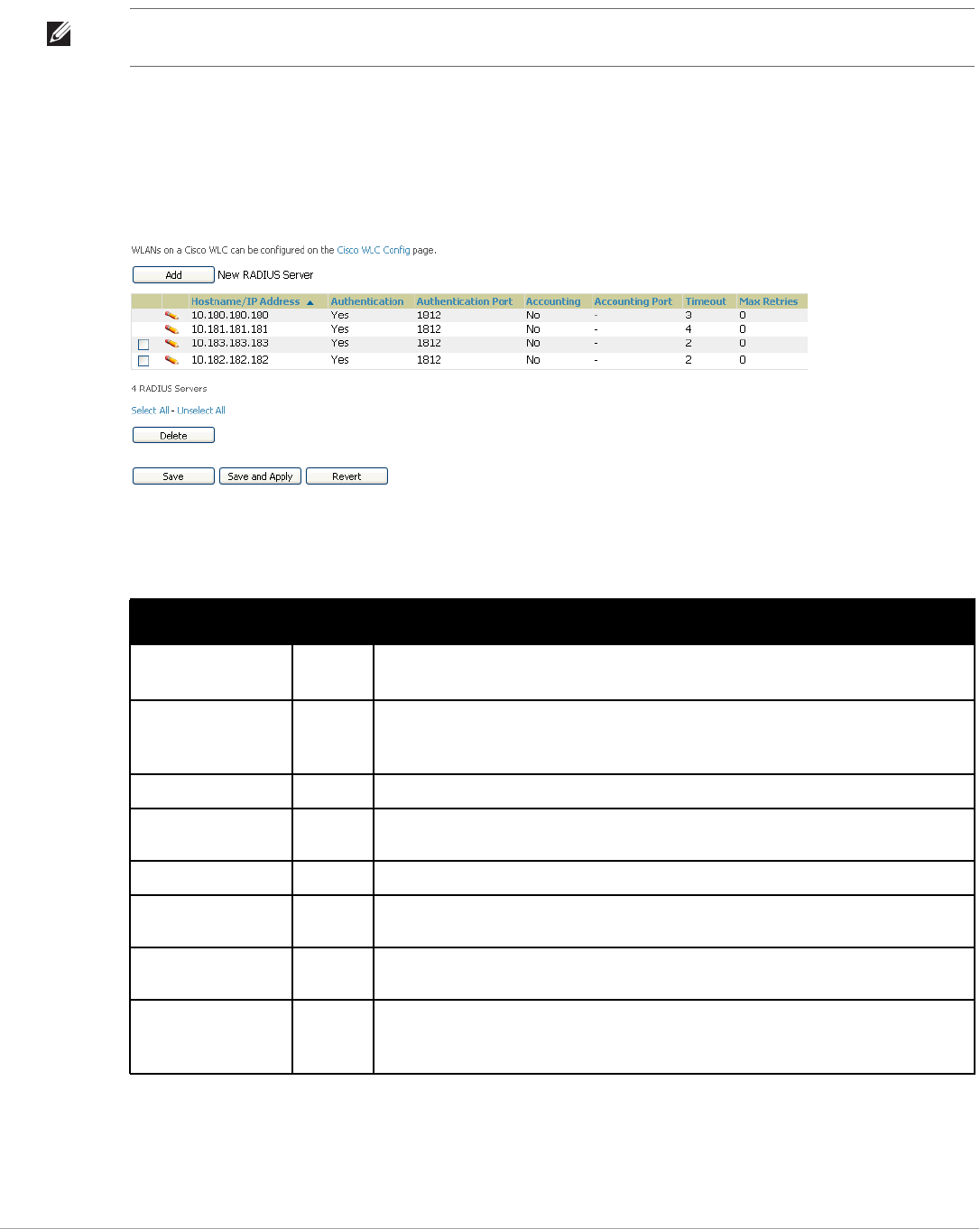
78 | Configuring and Using Device Groups Dell PowerConnect W-AirWave 7.5 | User Guide
Once defined on this page, RADIUS servers are selectable in the drop-down menus on the Groups > Security and
Groups > SSIDs configuration pages. Perform these steps to create RADIUS servers.
1. Go to the Groups > List page and select the group for which to define AAA servers by selecting the group
name. The Monitor page appears.
2. Select the AAA Servers page. The AAA Servers page appears, enabling you to add a RADIUS server. Figure
45 illustrate this page for AAA RADIUS Servers:
Figure 45 Groups > AAA Servers Page Illustration
3. To add a RADIUS server or edit an existing server, select Add New RADIUS Server or the corresponding
pencil icon to edit an existing server. Table 55 describes the settings and default values of the Add/Edit page.
4. Select Add to complete the creation of the RADIUS server, or select Save if editing an existing RADIUS
server. The Groups > AAA Servers page displays this new or edited server. You can now reference this server
on the Groups > Security page.
NOTE: TACACS+ servers are configurable only for Cisco WLC devices. Refer to “Configuring Cisco WLC Security Parameters and
Functions” on page 94.
Table 55 Adding a RADIUS Server Fields and Default Values
Setting Default Description
Hostname/IP Address None Sets the IP Address or DNS name for RADIUS Server.
NOTE: IP Address is required for Proxim/ORiNOCO and Cisco Aironet IOS APs.
Secret and Confirm
Secret
None Sets the shared secret that is used to establish communication between AirWaveand the
RADIUS server.
NOTE: The shared secret entered in AirWave must match the shared secret on the server.
Authentication No Sets the RADIUS server to perform authentication when this setting is enabled with Yes.
Authentication Port (1-
65535)
1812 Appears when Authentication is enabled. Sets the port used for communication between
the AP and the RADIUS server.
Accounting No Sets the RADIUS server to perform accounting functions when enabled with Yes.
Accounting Port (1-
65535)
1813 Appears when Accounting is enabled.Sets the port used for communication between the
AP and the RADIUS server.
Timeout (0-86400) None Sets the time (in seconds) that the access point waits for a response from the RADIUS
server.
Max Retries
(0-20)
None Sets the number of times a RADIUS request is resent to a RADIUS server before failing.
NOTE: If a RADIUS server is not responding or appears to be responding slowly, consider
increasing the number of retries.
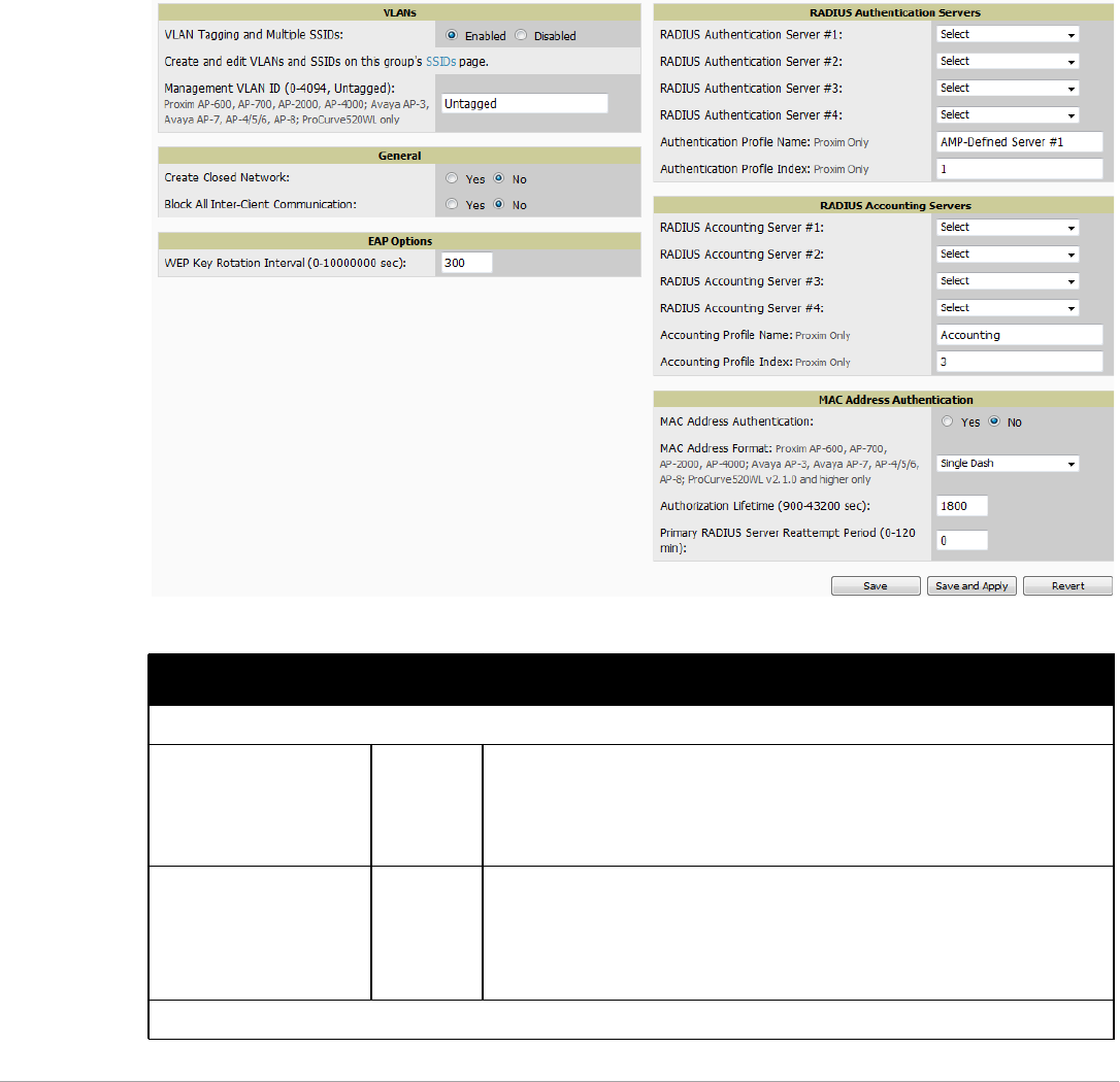
Dell PowerConnect W-AirWave 7.5 | User Guide Configuring and Using Device Groups | 79
AirWave supports reports for subsequent RADIUS Authentication. These are viewable by selecting Reports >
Generated, scrolling to the bottom of the page, and selecting Latest RADIUS Authentication Issues Report.
5. To make additional RADIUS configurations for device groups, use the Groups > Security page and continue
to the next topic.
Configuring Group Security Settings
The Groups > Security page allows you to set security policies for APs in a device group:
1. Select the device group for which to define security settings from the Groups > List page.
2. Go to Groups > Security. Some controls on this page interact with additional AirWave pages. Figure 46
illustrates this page and Table 56 explains the fields and default values.
Figure 46 Groups > Security Page Illustration
Table 56 Groups > Security Page Fields and Default Values
Setting Default Description
VLANs Section
VLAN Tagging and Multiple
SSIDs
Enabled This field enables support for VLANs and multiple SSIDs on the wireless network. If
this setting is enabled, define additional VLANs and SSIDs on the Groups > SSIDs
page. Refer to “Configuring Group SSIDs and VLANs” on page 82. If this setting is
disabled, then you can specify the Encryption Mode in the Encryption section that
displays. Refer to Table 57 for information on configuring Encryption.
Management VLAN ID Untagged This setting sets the ID for the management VLAN when VLANs are enabled in
AirWave. This setting is supported only for the following devices:
-Proxim AP-600, AP-700, AP-2000, AP-4000
-Avaya AP-3, Avaya AP-7, AP-4/5/6, AP-8
-ProCurve520WL
General Section

80 | Configuring and Using Device Groups Dell PowerConnect W-AirWave 7.5 | User Guide
Create Closed Network No If enabled, the APs in the Group do not broadcast their SSIDs.
NOTE: Creating a closed network will make it more difficult for intruders to detect
your wireless network.
Block All Inter-client
Communication
No If enabled, this setting blocks client devices associated with an AP from
communicating with other client devices on the wireless network.
NOTE: This option may also be identified as PSPF (Publicly Secure Packet
Forwarding), which can be useful for enhanced security on public wireless
networks.
EAP Options Section
WEP Key Rotation Interval 300 Sets the frequency at which the Wired Equivalent Privacy (WEP) keys are rotated in
the device group being configured. The supported range is from 0 to 10,000,000
seconds.
RADIUS Authentication Servers Section
RADIUS Authentication
Server #1 - #4
Not selected Defines one or more RADIUS Authentication servers to be supported in this device
group. Select up to four RADIUS authentication servers from the four drop-down
menus.
Authentication Profile
Name
AMP-
Defined
Server #1
For Proxim devices only, this field sets the name of the authentication profile to be
supported in this device group.
Authentication Profile Index 1 For Proxim devices only, this field sets the name of the authentication profile index
to be supported in this device group.
RADIUS Accounting Servers Section
RADIUS Accounting Server
#1-#4
Not selected Defines one or more RADIUS Accounting servers to be supported in this device
group. Select up to four RADIUS accounting servers from the four drop-down
menus.
Authentication Profile
Name
For Proxim devices only, this field sets the name of the accounting profile to be
supported in this device group.
Authentication Profile Index 3 For Proxim devices only, this field sets the name of the accounting profile index to
be supported in this device group.
MAC Address Authentication Section
MAC Address
Authentication
No If enabled, only MAC addresses known to the RADIUS server are permitted to
associate to APs in the Group.
MAC Address Format Single Dash Allows selection of the format for MAC addresses used in RADIUS authentication
and accounting requests:
-Dash Delimited: xx-xx-xx-xx-xx-xx (default)
-Colon Delimited: xx:xx:xx:xx:xx:xx
-Single-Dash: xxxxxx-xxxxxx
-No Delimiter: xxxxxxxxxxxx
This option is supported only for Proxim AP-600, AP-700, AP-2000, AP-4000, Avaya
AP3/4/5/6/7/8, HP ProCurve 520WL
Authorization Lifetime 1800 Sets the amount of time a user can be connected before reauthorization is required.
The supported range is from 900 to 43,200 seconds.
Primary RADIUS Server
Reattempt Period
0 Specifies the time (in minutes) that the AP awaits responses from the primary
RADIUS server before communicating with the secondary RADIUS server, and so
forth
Table 56 Groups > Security Page Fields and Default Values (Continued)
Setting Default Description

Dell PowerConnect W-AirWave 7.5 | User Guide Configuring and Using Device Groups | 81
The Encryption options display on the Groups > Security page when the VLan Tagging and Multiple SSIDs
option is set to Disabled. This setting defaults to No Encryption. Refer to Table 57 for information regarding
configuring encryption.
Table 57 Groups > Security Encryption Mode settings
Setting Default Description
Encryption Mode Optional WEP, Require WEP, Require 802.1X, Require LEAP, Require 802.1X + WEP, Require 802.1X + LEAP, LEAP
+ WEP
Transmit Key 1
Key #1 None
Key #2 None
Key #3 None
Key #4 None
Encryption Mode Static CKIP
CKIP Static Key (hex)
and Confirm
None
CKIP Key Index 1
CKIP Key Permutation No
CKIP MMH Mode No
Encryption Mode WPA
Unicast Cipher (Cisco
only)
AES
Encryption Mode WPA/PSK
Unicast Cipher (Cisco
only)
AES/TKIP
WPA Preshared Key
(Alphanumeric)
None
Encryption Mode WPA2
WPA2 WPA
Compatibility Mode
Yes
WPA1 Cipher (Cisco
WLC Only)
TKIP NOTE: This drop down is only available if WPA2 WPA Compatibility Mode is Yes.
Unicast Cipher (Cisco
Only)
AES/TKIP
Encryption Mode WPA2/PSK
WPA2 WPA
Compatibility Mode
Yes
WPA1 Cipher (Cisco
WLC Only)
TKIP NOTE: This drop down is only available if WPA2 WPA Compatibility Mode is Yes.
Unicast Cipher (Cisco
Only)
AES/TKIP
WPA Preshared Key
(Alphanumeric)
None
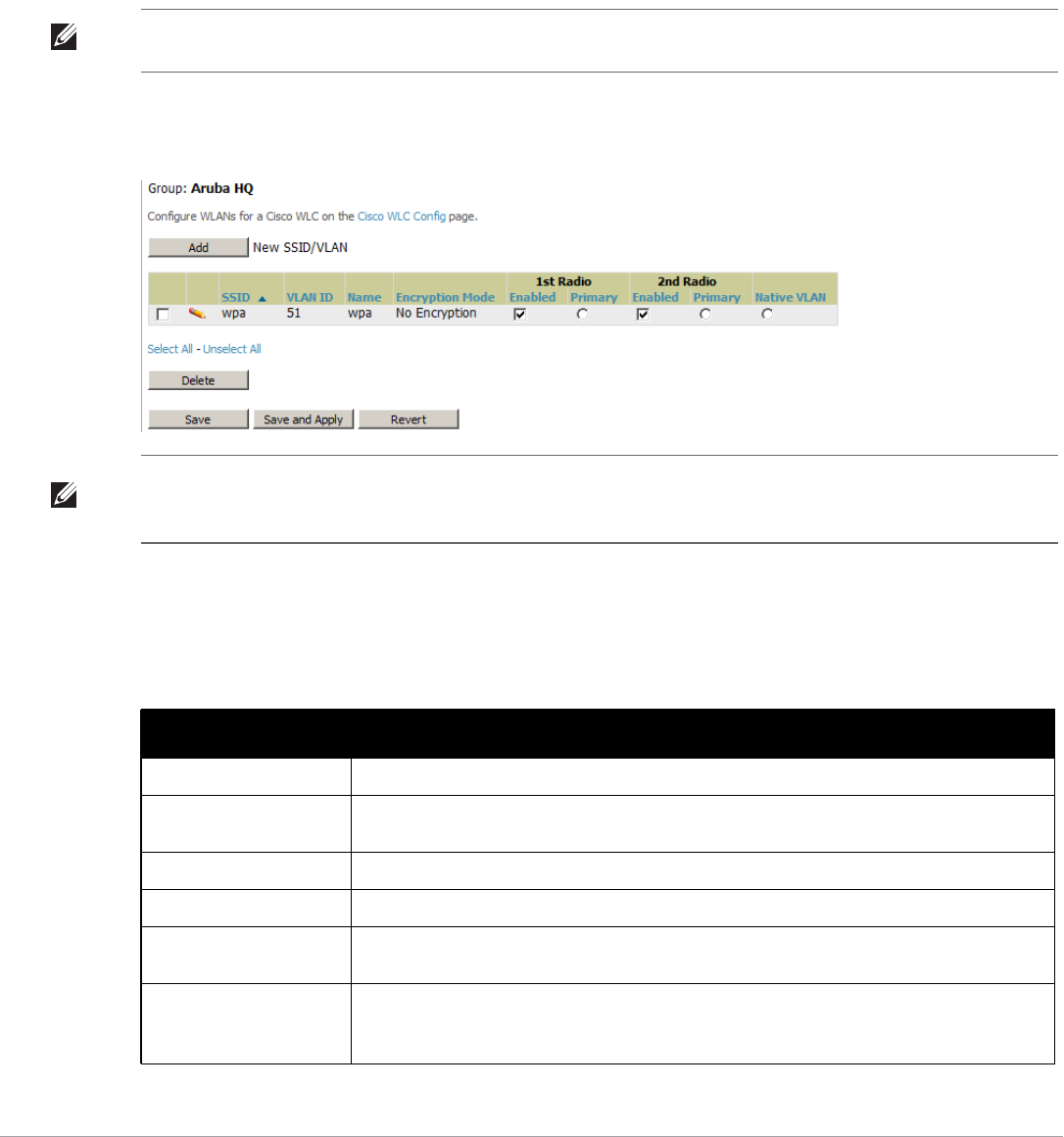
82 | Configuring and Using Device Groups Dell PowerConnect W-AirWave 7.5 | User Guide
3. Select Save to retain these security configurations for the group, select Save and Apply to make the changes
permanent, or select Revert to discard all unapplied changes.
4. Continue with additional security-related procedures in this document for additional RADIUS and SSID
settings for device groups, as required.
Configuring Group SSIDs and VLANs
The Groups > SSIDs configuration page allows you to create and edit SSIDs and VLANs that apply to a device
group. Perform these steps to create or edit VLANs and to set SSIDs.
Figure 47 illustrates an example of the Groups > SSIDs page.
Figure 47 Groups > SSIDs Page Illustration
1. Go to Groups > List and select the group name for which to define SSIDs/VLANs.
2. Select the Groups > SSIDs configuration page. Table 58 describes the information that appears for SSIDs and
VLANs that are currently configured for the device group.
NOTE: WLANs that are supported from one or more Cisco WLC controllers can be configured on the Groups > Cisco WLC Config
page.
NOTE: AirWave reports users by radio and by SSID. Graphs on the AP and controller monitoring pages display bandwidth in and
out based on SSID. AirWave reports can also be run and filtered by SSID. An option on the AMP Setup > General page can age out
inactive SSIDs and their associated graphical data.
Table 58 Groups > SSIDs Fields and Descriptions
Field Description
SSID Displays the SSID associated with the VLAN.
VLAN ID Identifies the number of the primary VLAN SSID on which encrypted or unencrypted packets can
pass between the AP and the switch.
Name Displays the name of the VLAN.
Encryption Mode Displays the encryption on the VLAN.
First or Second Radio
Enabled
Enables the VLAN, SSID and Encryption Mode on the radio control.
First or Second Radio
Primary
Specifies which VLAN to be used as the primary VLAN. A primary VLAN is required.
NOTE: If you create an open network (see the Create Closed Network setting below) in which the
APs broadcast an SSID, the primary SSID is broadcast.
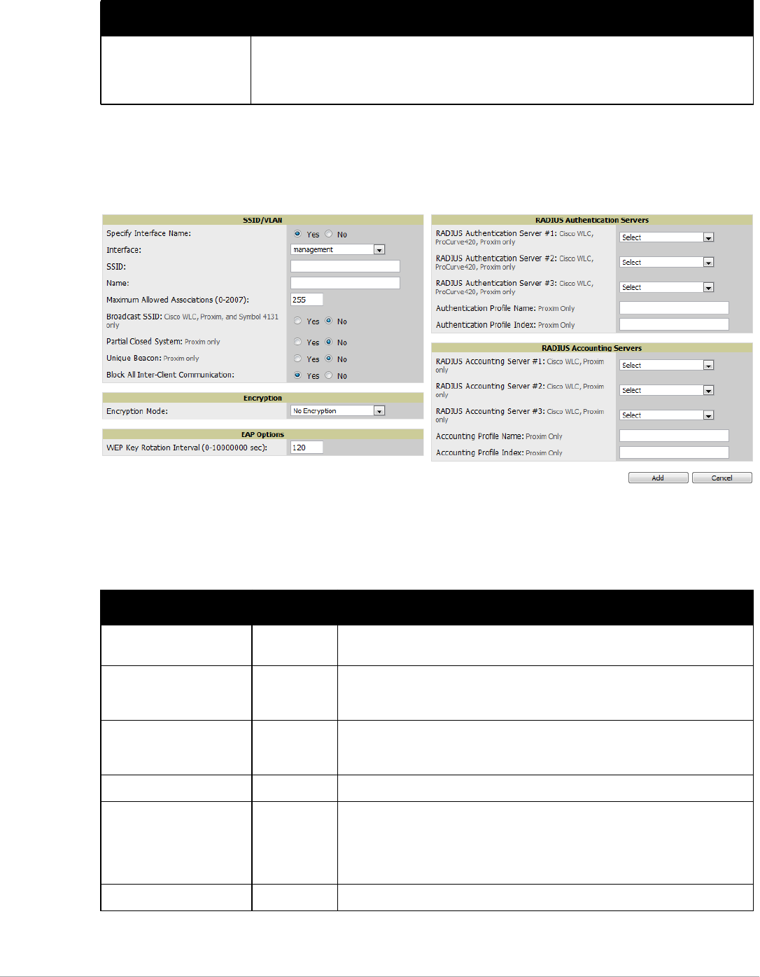
Dell PowerConnect W-AirWave 7.5 | User Guide Configuring and Using Device Groups | 83
3. Select Add to create a new SSID or VLAN, or select the pencil icon next to an existing SSID/VLAN to edit
that existing SSID or VLAN. The Add SSID/VLAN configuration page appears as illustrated in Figure 48 and
explained in Table 59.
Figure 48 Groups > SSIDs > Add SSID/VLAN Page Illustration
4. Locate the SSID/VLAN section on the Groups > SSIDs configuration page and adjust these settings as
required. This section encompasses the basic VLAN configuration. Table 59 describes the settings and default
values. Note that the displayed settings can vary.
Native VLAN Sets this VLAN to be the native VLAN. Native VLANs are untagged and typically used for
management traffic only. AirWave requires a Native VLAN to be set. For AP types do not require a
native VLAN, create a dummy VLAN, disable it on both radio controls, and ensure that it has the
highest VLAN ID.
Table 59 Groups > SSIDs > SSID/VLAN Section Fields and Default Values
Setting Default Description
Specify Interface Name Yes Enables or disables an interface name for the VLAN interface. Selecting No for
this option displays the Enable VLAN Tagging and VLAN ID options.
Enable VLAN Tagging
(Cisco WLC, Proxim,
Symbol only)
Enables or disables VLAN tagging. Displays if Specify Interface Name is set to
No.
VLAN ID (1-4094) None Indicates the number of the VLAN designated as the Native VLAN, typically for
management purposes. Displays if Specify Interface Name is set to No and
Enable VLAN Tagging is set to Yes.
Interface management Sets the interface to support the SSID/VLAN combination.
SSID None Sets the Service Set Identifier (SSID), which is a 32-character user-defined
identifier attached to the header of packets sent over a WLAN. It acts as a
password when a mobile device tries to connect to the network through the AP,
and a device is not permitted to join the network unless it can provide the unique
SSID.
Name None Sets a user-definable name associated with SSID/VLAN combination.
Table 58 Groups > SSIDs Fields and Descriptions (Continued)
Field Description

84 | Configuring and Using Device Groups Dell PowerConnect W-AirWave 7.5 | User Guide
5. Locate the Encryption area on the Groups > SSIDs page and adjust these settings as required. Table 60
describes the available encryption modes. Table 57 describes configuration settings for each mode.
6. Locate the EAP Options area on the Groups > SSIDs page, and complete the settings. Table 61 describes the
settings and default values.
Maximum Allowed
Associations (0-2007)
255 Indicates the maximum number of mobile users which can associate with the
specified VLAN/SSID.
NOTE: 0 means unlimited for Cisco.
Broadcast SSID (Cisco
WLC, Proxim and Symbol
4131 only)
No For specific devices as cited, this setting enables the AP to broadcast the SSID
for the specified VLAN/SSID. This setting works in conjunction with the Create
Closed Network setting on the Groups > Security configuration page. Proxim
devices support a maximum of four SSIDs.
NOTE: This option should be enabled to ensure support of legacy users.
Partial Closed System
(Proxim only)
No For Proxim only, this setting enables to AP to send its SSID in every beacon, but it
does not respond to any probe requests.
Unique Beacon
(Proxim only)
No For Proxim only, if more than one SSID is enabled, this option enables them to be
sent in separate beacons.
Block All Inter-Client
Communication
Yes This setting blocks communication between client devices based on SSID.
Table 60 Groups > SSIDs > Encryption Section Field and Default Values
Setting Default Description
Encryption Mode No Encryption Drop-down menu determines the level of encryption required for devices to associate
to the APs. The drop-down menu options are as follows. Each option displays
additional encryption settings that must be defined. Complete the associated settings
for any encryption type chosen:
-No Encryption
-Optional WEP—Wired Equivalent Privacy, not PCI compliant as of 2010
-Require WEP—Wired Equivalent Privacy, not PCI compliant as of 2010
-Require 802.1x—Based on the WEP algorithm
-Require Leap—Lightweight Extensible Authentication Protocol
-802.1x+WEP—Combines the two encryption types shown
-802.1x+LEAP—Combines the two encryption types shown
-LEAP+WEP—Combines the two encryption types shown
-Static CKIP—Cisco Key Integrity Protocol
-WPA—Wi-Fi Protected Access protocol
-WPA/PSK—Combines WPA with Pre-Shared Key encryption
-WPA2—Wi-Fi Protected Access 2 encryption
-WPA2/PSK—Combines the two encryption methods shown
-xSec—FIPS-compliant encryption including Layer 2 header info
Table 61 Groups > SSIDs > EAP Options Section Field and Default Value
Setting Default Description
WEP Key Rotation
Interval (0-10000000 sec)
120 Time (in seconds) between WEP key rotation on the AP.
Table 59 Groups > SSIDs > SSID/VLAN Section Fields and Default Values (Continued)
Setting Default Description
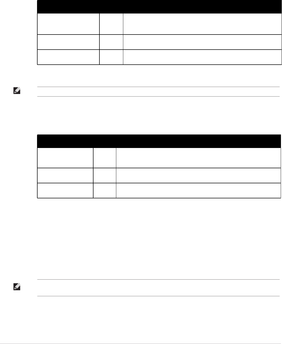
Dell PowerConnect W-AirWave 7.5 | User Guide Configuring and Using Device Groups | 85
7. Locate the RADIUS Authentication Servers area on the Groups > SSIDs configuration page and define the
settings. Table 62 describes the settings and default values.
8. Select Save when the security settings and configurations in this procedure are complete.
9. Locate the RADIUS Accounting Servers area on the Groups > SSIDs configuration page and define the
settings. Table 63 describes the settings and default values.
10. Select Add when you have completed all sections. This returns you to the Groups > SSIDs page.
11. Select Save to retain these SSID configurations for the group, select Save and Apply to make the changes
permanent, or select Revert to discard all unapplied changes.
12. Continue with additional Group procedures in this document as required.
Configuring Radio Settings for Device Groups
The Groups > Radio configuration page allows you to specify detailed RF-related settings for devices in a
particular group.
Perform the following steps to define RF-related radio settings for groups.
1. Go to the Groups > List page and select the group for which to define radio settings by selecting the group
name. Alternatively, select Add from the Groups > List page to create a new group, define a group name. In
either case, the Monitor page appears.
Table 62 Groups > SSIDs > RADIUS Authentication Servers Fields and Default Values
Setting Default Description
RADIUS Authentication Server
1-3
(Cisco WLC, Proxim only)
None Drop-down menu to select RADIUS Authentication servers previously entered on
the Groups > RADIUS configuration page. These RADIUS servers dictate how
wireless clients authenticate onto the network.
Authentication Profile Name
(Proxim Only)
None Sets the Authentication Profile Name for Proxim AP-600, AP-700, AP-2000, AP-4000.
Authentication Profile Index
(Proxim Only)
None Sets the Authentication Profile Index for Proxim AP-600, AP-700, AP-2000, AP-4000.
NOTE: You may need to return to the Groups > Security configuration page to configure or reconfigure RADIUS servers.
Table 63 Groups > SSIDs > Radius Accounting Servers Fields and Default Values
Setting Default Description
RADIUS Accounting Server
1-3 (Cisco WLC, Proxim
Only)
None Pull-down menu selects RADIUS Accounting servers previously entered on the Groups
> RADIUS configuration page. These RADIUS servers dictate where the AP sends
RADIUS Accounting packets for this SSID/VLAN.
Accounting Profile Name
(Proxim Only)
None Sets the Accounting Profile Name for Proxim AP-600, AP-700, AP-2000, AP-4000.
Accounting Profile Index
(Proxim Only)
None Sets the Accounting Profile Index for Proxim AP-600, AP-700, AP-2000, AP-4000.
NOTE: If you have existing deployed devices, you may want to use the current RF settings on those devices as a guide for
configuring the settings in your default Group.
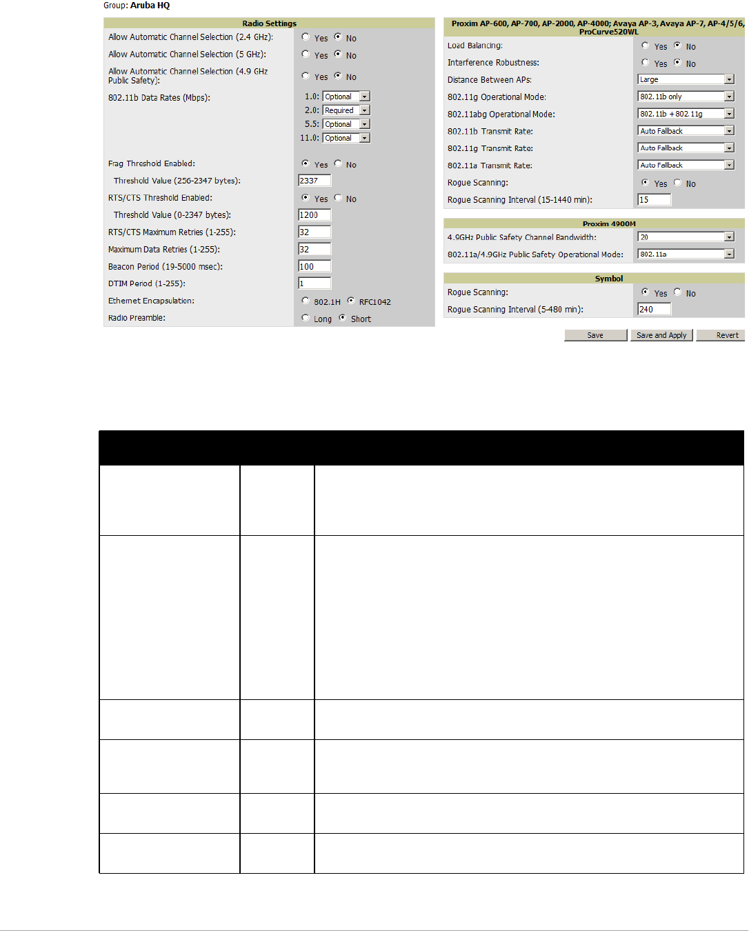
86 | Configuring and Using Device Groups Dell PowerConnect W-AirWave 7.5 | User Guide
2. Go to the Groups > Radio page. Figure 49 illustrates this page.
Figure 49 Groups > Radio Page Illustration
3. Locate the Radio Settings area and adjust these settings as required. Table 64 describes the settings and
default values.
Table 64 Groups > Radio > Radio Settings Fields and Default Values
Setting Default Description
Allow Automatic Channel
Selection (2.4, 5, and
4.9GHz Public Safety)
No If enabled, whenever the AP is rebooted it uses its radio to scan the airspace and
select its optimal RF channel based on observed signal strength from other radios.
NOTE: If you enable this feature, AirWave automatically reboots the APs in the group
when the change is implemented.
802.11b Data Rates
(Mbps)
Required:
-1.0
-2.0
Optional:
-5.5
-11.0
Displays pull-down menus for various data rates for transmitting data.
NOTE: This setting does not apply to Cisco LWAPP devices.
The three values in each of the pull-down menus are as follows:
-Required—The AP transmits only unicast packets at the specified data rate;
multicast packets are sent at a higher data rate set to optional. (Corresponds to a
setting of yes on Cisco devices.)
-Optional—The AP transmits both unicast and multicast at the specified data
rate. (Corresponds to a setting of basic on Cisco devices.)
-Not Used—The AP does not transmit data at the specified data rate.
(Corresponds to a setting of no on Cisco devices.)
Frag Threshold Enabled No If enabled, this setting enables packets to be sent as several pieces instead of as one
block. In most cases, leave this option disabled.
Threshold Value (256-2347
bytes)
2337 If Fragmentation Threshold is enabled, this specifies the size (in bytes) at which
packets are fragmented. A lower Fragmentation Threshold setting might be required
if there is a great deal of radio interference.
RTS/CTS Threshold
Enabled
No If enabled, this setting configures the AP to issue a RTS (Request to Send) before
sending a packet. In most cases, leave this option disabled.
RTS/CTS Threshold Value
(0-2347 bytes)
2338 If RTS/CTS is enabled, this specifies the size of the packet (in bytes) at which the AP
sends the RTS before sending the packet.
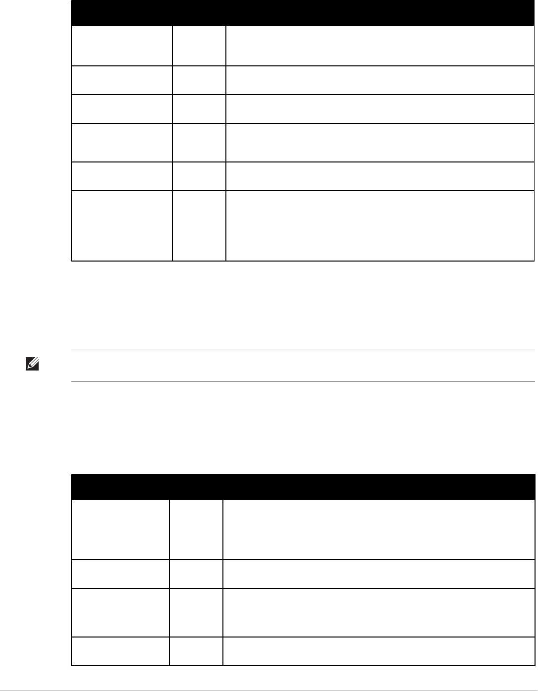
Dell PowerConnect W-AirWave 7.5 | User Guide Configuring and Using Device Groups | 87
4. Certain wireless access points offer proprietary settings or advanced functionality that differ from prevailing
industry standards. If you use these APs in the device group, you may wish to take advantage of this
proprietary functionality.
To configure these settings, locate the proprietary settings areas on the Groups > Radio page and continue
with the additional steps in this procedure.
5. To configure settings specific to the Proxim AP-600, AP-700, AP-2000, AP-4000; Avaya AP-3/4/5/6//7/8, and
ProCurve 520WL, locate the appropriate section of Groups > Radio page and define the required fields.
Table 65 describes the settings and default values.
RTS/CTS Maximum
Retries (1-255)
32 If RTS/CTS is enabled, this specifies the maximum number of times the AP issues an
RTS before stopping the attempt to send the packet through the radio.
Acceptable values range from 1 to 128.
Maximum Data Retries (1-
255)
32 The maximum number of attempts the AP makes to send a packet before giving up
and dropping the packet. Acceptable values range from 1 to 255.
Beacon Period (19-5000
msec)
100 Time between beacons (in microseconds).
DTIM Period (1-255) 2 DTIM alerts power-save devices that a packet is waiting for them. This setting
configures DTIM packet frequency as a multiple of the number of beacon packets.
The DTIM Interval indicates how many beacons equal one cycle.
Ethernet Encapsulation RFC1042 This setting selects either the RFC1042 or 802.1h Ethernet encapsulation standard for
use by the group.
Radio Preamble Long This setting determines whether the APs uses a short or long preamble. The
preamble is generated by the AP and attached to the packet prior to transmission.
The short preamble is 50 percent shorter than the long preamble and thus may
improve wireless network performance.
NOTE: Because older WLAN hardware may not support the “short” preamble, the
“long” preamble is recommended as a default setting in most environments.
Table 64 Groups > Radio > Radio Settings Fields and Default Values (Continued)
Setting Default Description
NOTE: Proprietary settings are only applied to devices in the group from the specific vendor and are not configured on devices
from vendors that do not support the functionality.
Table 65 Groups > Radio > Proxim AP-600, AP-700, AP-2000, AP-4000; Avaya AP-3, Avaya AP-7, AP-4/5/6, AP-8;
ProCurve520WL Fields and Default Values
Setting Default Description
Load Balancing No If enabled, this setting allows client devices associating to an AP with two radio cards
to determine which card to associate with, based on the load (# of clients) on each
card.
NOTE: This feature is only available when two 802.11b wireless cards are used in an
AP-2000.
Interference Robustness No If enabled, this option will fragment packets greater than 500 bytes in size to reduce
the impact of radio frequency interference on wireless data throughput.
Distance Between APs Large This setting adjusts the receiver sensitivity. Reducing receiver sensitivity from its
maximum may help reduce the amount of crosstalk between wireless stations to
better support roaming users. Reducing the receiver sensitivity, user stations will be
more likely to connect with the nearest access point.
802.11g Operational
Mode
802.11b
+802.11g
This setting sets the operational mode of all g radios in the group to either b only, g
only orb+g.

88 | Configuring and Using Device Groups Dell PowerConnect W-AirWave 7.5 | User Guide
6. To configure settings specific to Proxim 4900M, locate the Proxim 4900M section and define the required
fields. Table 66 describes the settings and default values.
7. To configure Symbol-only settings, locate the Symbol section and define the required fields. Table 67
describes the settings and default values.
8. Select Save when radio configurations as described above are complete, select Save and Apply to make the
changes permanent, or select Revert to discard all unapplied changes.
Cisco WLC Group Configuration
The Groups > Cisco WLC Config page consolidates the settings for Cisco WLC devices from all group pages.
The Groups > SSIDs subtab applies to all device types except for Cisco WLC, which have WLANs configured on
802.11abg Operational
Mode
802.11b
+802.11g
This setting sets the operational mode of all a/b/g radios in the group to either a only, b
only, g only orb+g.
802.11b Transmit Rate Auto
Fallback
This setting specifies the minimum transmit rate required for the AP to permit a user
device to associate.
802.11g Transmit Rate Auto
Fallback
This setting specifies the minimum transmit rate required for the AP to permit a user
device to associate.
802.11a Transmit Rate Auto
Fallback
This setting specifies the minimum transmit rate required for the AP to permit a user
device to associate.
Rogue Scanning Yes If enabled, any ORiNOCO or Avaya APs in the group (with the appropriate firmware)
will passively scan for rogue access points at the specified interval. This rogue scan
will not break users' association to the network.
NOTE: This feature can affect the data performance of the access point.
Rogue Scanning Interval
(15-1440 min)
15 minutes If Rogue Scanning is enabled, this setting controls the frequency with which scans
are conducted (in minutes). Frequent scans provide the greatest security, but AP
performance and throughput available to user devices may be impacted modestly
during a rogue scan.
Table 66 Groups > Radio > Proxim 4900M Fields and Default Values
Setting Default Description
4.9GHz Public Safety
Channel Bandwidth
20 This setting specifies the channel bandwidth for the 4.9 GHz radio. It is only applicable
if you are running the 802.11a/4.9GHz radio in 4.9GHz mode.
802.11a/4.9GHz Public
Safety Operational Mode
802.11a This setting specifies if the AP will run the 802.11a/4.9GHz radio in 802.11a mode or in
4.9 GHz mode. Please note that 4.9 GHz is a licensed frequency used for public safety.
Table 67 Groups > Radio > Symbol Fields and Default Values
Setting Default Description
Rogue Scanning Yes If enabled, Symbol access points with 3.9.2 or later firmware in the group will passively scan
for rogue access points at the specified interval. This rogue scan will not break a user’s
association to the network.
Rogue Scanning
Interval (5-480 min)
240 If Rogue Scanning is enabled, this setting controls the frequency with which scans are
conducted (in minutes). Frequent scans provide the greatest security, but AP performance
and throughput available to user devices may be impacted modestly during a rogue scan.
Table 65 Groups > Radio > Proxim AP-600, AP-700, AP-2000, AP-4000; Avaya AP-3, Avaya AP-7, AP-4/5/6, AP-8;
ProCurve520WL Fields and Default Values (Continued)
Setting Default Description
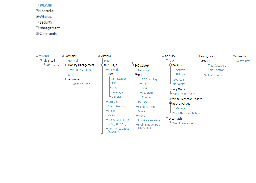
Dell PowerConnect W-AirWave 7.5 | User Guide Configuring and Using Device Groups | 89
the Cisco WLC Config page. It is not recommended to have Symbol 4131 and Proxim APs in the same group as
Cisco devices. Also, it is recommended that users set device preferences to Only devices in this group. This topic
describes how to access and navigate the Groups > Cisco WLC Config page.
Accessing Cisco WLC Configuration
Go to the Cisco WLC Config page in one of these two ways:
1. In Groups > List, select a group that has been defined to support Cisco devices. The Cisco WLC Config option
appears in the subtabs.
2. In Groups > List, create a new group to support Cisco devices with these steps:
Select Add from the Groups > List page to create a new group, enter a group name, and select Add.
Once AirWave prompts you with the Groups > Basic page, ensure that you enable device-specific settings
for Cisco WLC.
Once you select Save or Save and Apply, then the Groups > Cisco WLC Config subtab appears in the
navigation pane at the top in association with that group.
Navigating Cisco WLC Configuration
The navigation pane on the left side of the Groups > Cisco WLC Config page is expandable, and displays the
Cisco configurations supported and deployed. Figure 50 and Figure 51 illustrate this navigation pane.
You can pre-populate the group WLC settings from a controller in the same group by performing an import on
the controller’s Audit page.
Figure 50 Groups > Cisco WLC Config Page Illustration, collapsed view
Figure 51 Groups > Cisco WLC Config Page Illustration, expanded view
Configuring WLANs for Cisco WLC Devices
In Cisco WLC Config, WLANs are based on SSIDs or VLANs that are dedicated to Cisco WLC controllers.
Perform the following steps to define and configure WLANs for Cisco WLC controllers.
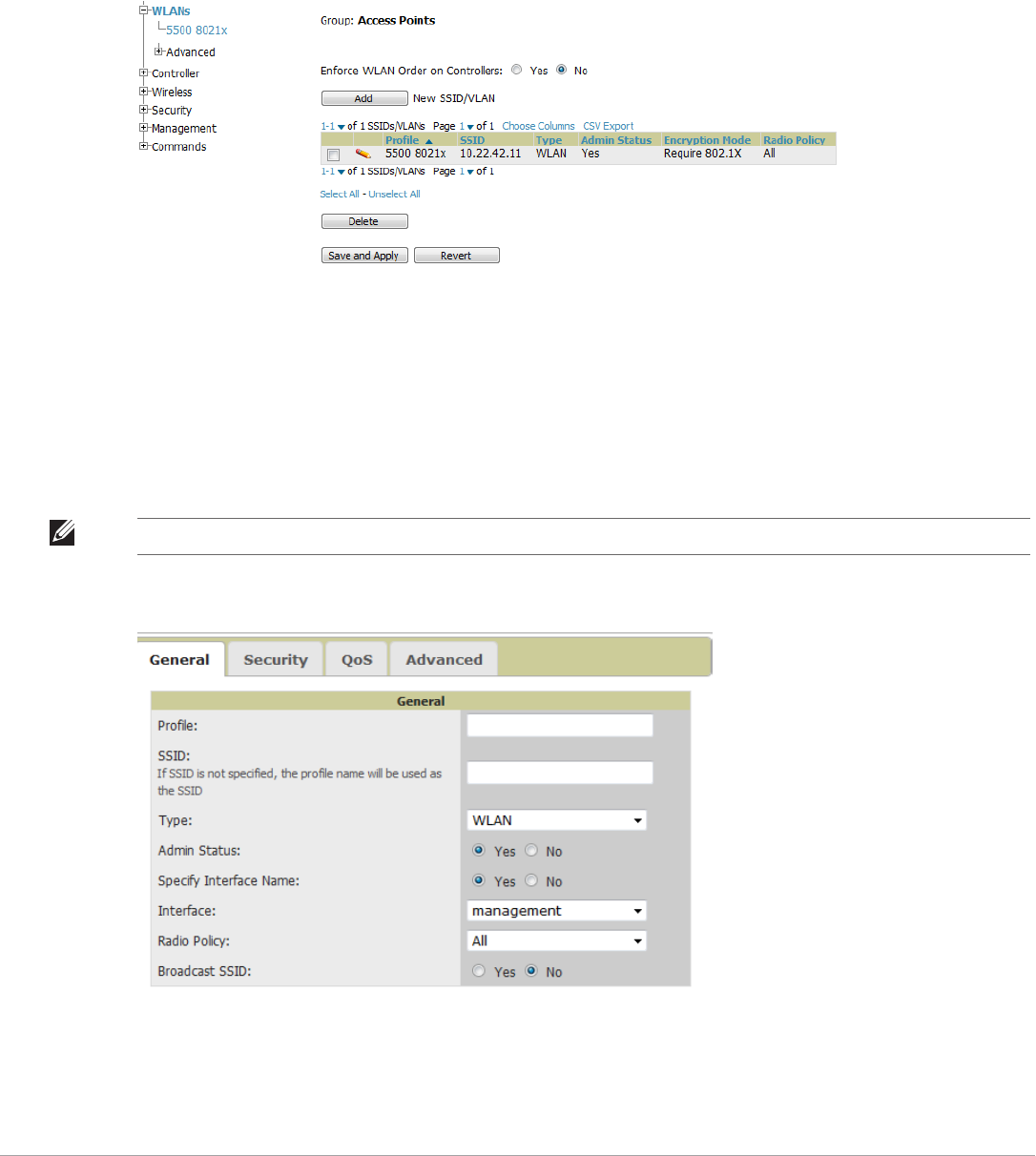
90 | Configuring and Using Device Groups Dell PowerConnect W-AirWave 7.5 | User Guide
1. Go to the Groups > Cisco WLC Config page, and select WLANs in the navigation pane at left. This page
displays the SSIDs or VLANs that are available for use with Cisco WLC devices and enables you to define new
SSIDs or VLANs. Figure 52 illustrates this page.
2. To change the ID/position of a WLAN on the controller by dragging and dropping, set the toggle to Yes. Note
that the by setting this flag to Yes, AirWave will display a mismatch if the WLANs in the desired config and
device config differ only on the order.
Figure 52 Groups > Cisco WLC Config > WLANS page illustration
3. To add or edit SSIDs or VLANs that are dedicated to Cisco WLC devices, either select the Add button, or
select the pencil icon for an existing SSID/VLAN. A new page appears comprised of four tabs, as follows:
General—Defines general administrative parameters for the Cisco WLC WLAN.
Security—Defines encryption and RADIUS servers.
QoS—Defines quality of service (QoS) parameters for the Cisco WLC WLAN.
Advanced—Defines advanced settings that are available only with Cisco WLC devices, for example, AAA
override, coverage, DHCP and DTIM period.
Figure 53 Groups > Cisco WLC Config > WLANs > Add New SSID/VLAN > General Tab Illustration
NOTE: Refer to Cisco documentation for additional information about Cisco WLC devices and related features.
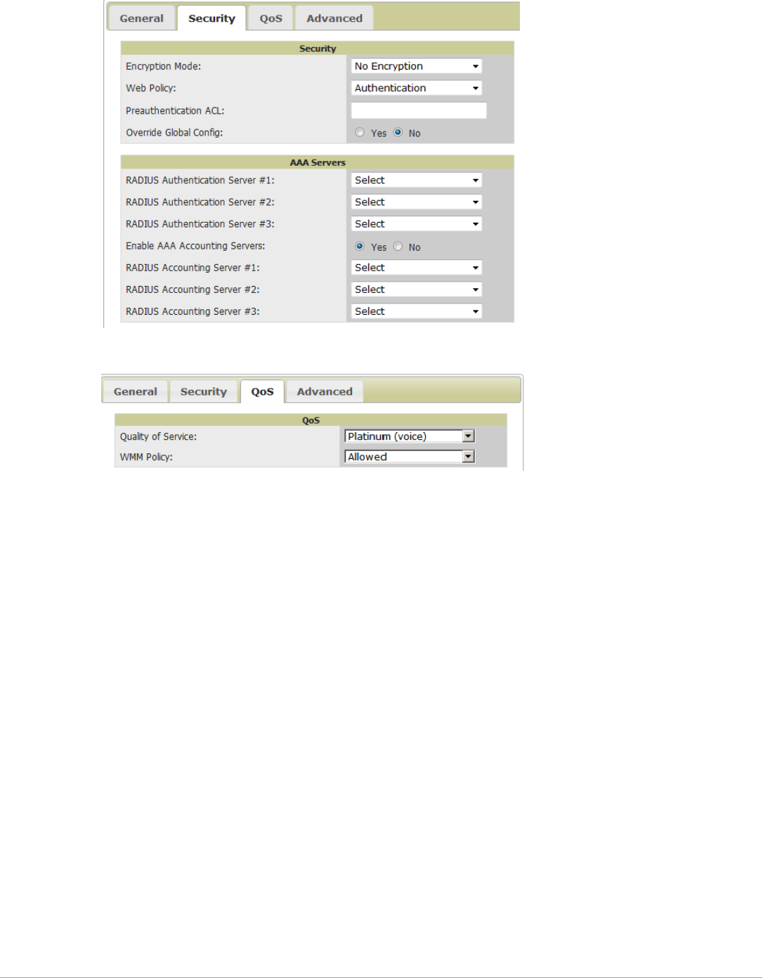
Dell PowerConnect W-AirWave 7.5 | User Guide Configuring and Using Device Groups | 91
Figure 54 Groups > Cisco WLC Config > WLANs > Add New SSID/VLAN > Security Tab Illustration
Figure 55 Groups > Cisco WLC Config > WLANs > Add New SSID/VLAN > QoS Tab Illustration
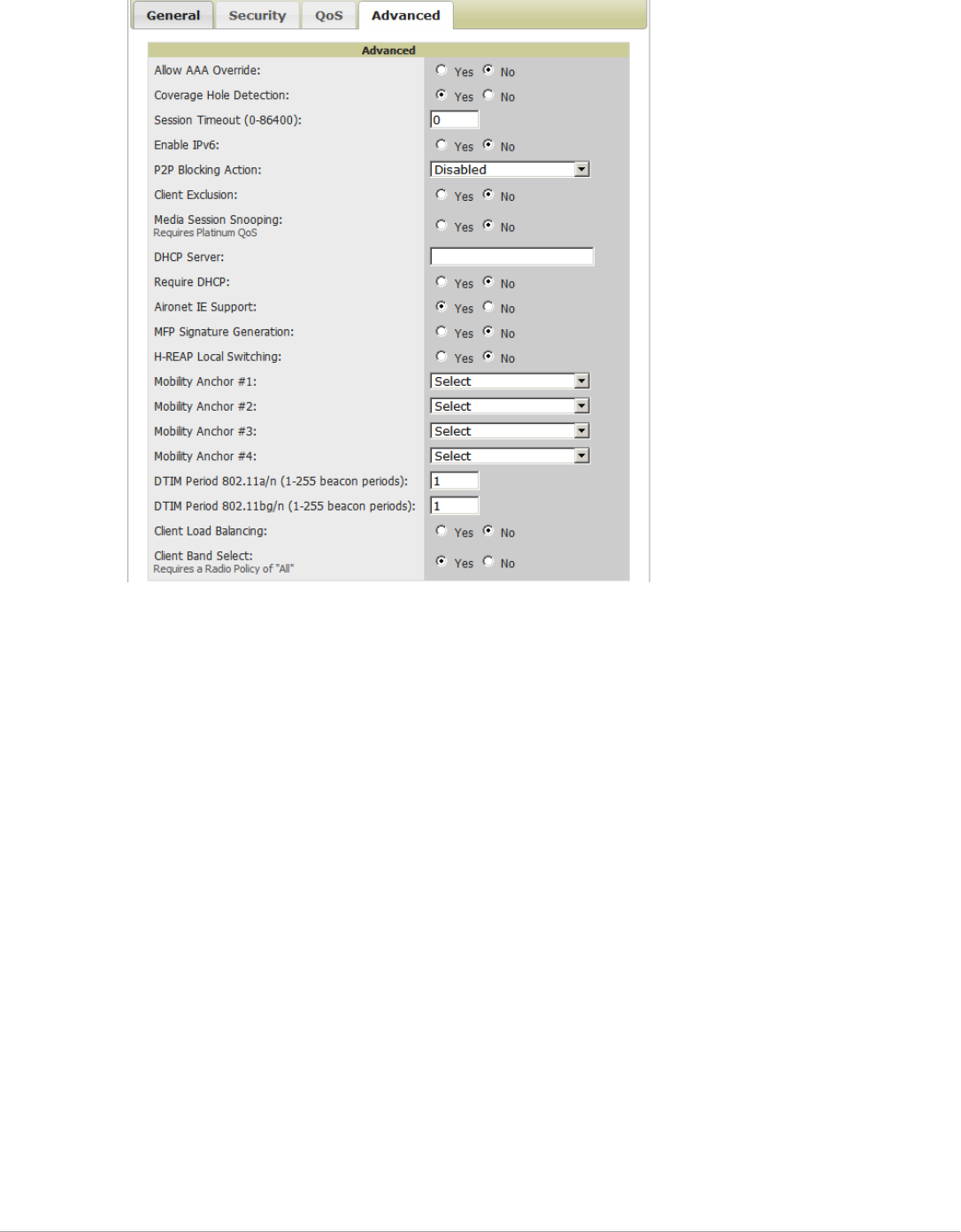
92 | Configuring and Using Device Groups Dell PowerConnect W-AirWave 7.5 | User Guide
Figure 56 Groups > Cisco WLC Config > WLANs > Add New SSID/VLAN > Advanced Tab Illustration
Defining and Configuring LWAPP AP Groups for Cisco Devices
The Groups > Cisco WLC Config > WLANs > Advanced > AP Groups page allows you to add/edit/delete AP
Groups on the Cisco WLC. LWAPP AP Groups are used to limit the WLANs available on each AP. Cisco thin
APs are assigned to LWAPP AP Groups.
Viewing and Creating Cisco AP Groups
1. Go to the Groups > Cisco WLC Config page, and select WLANs > Advanced > AP Groups in the navigation
pane at left. This page displays the configured LWAPP APs. Figure 57 illustrates this page.
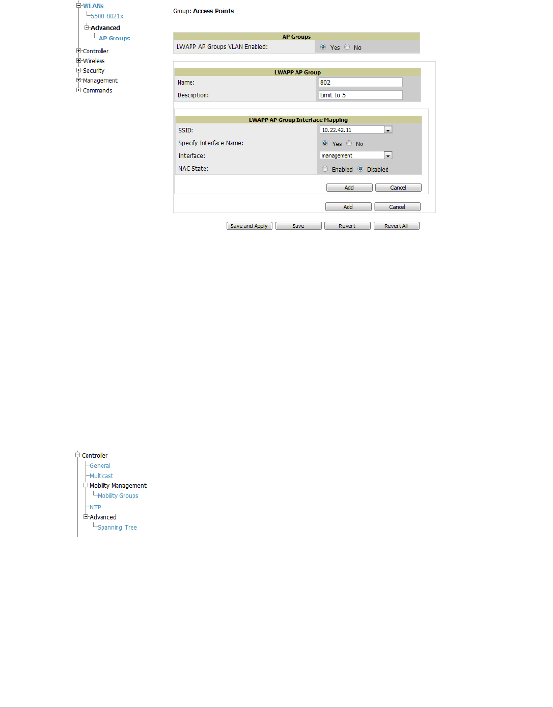
Dell PowerConnect W-AirWave 7.5 | User Guide Configuring and Using Device Groups | 93
Figure 57 Groups > Cisco WLC Config > WLANS > Advanced > AP Groups Page Illustration
2. To add a new LWAPP AP group, select Yes in the AP Groups section. Additional controls appear.
3. Select Add to create a new LWAPP AP group. To edit an existing LWAPP AP group, select the pencil icon
next to that group. Add one or more SSIDs and the interface/VLAN ID mapping on the Add/Edit page of the
LWAPP AP Group.
4. Select Save and Apply to make these changes permanent, or select Save to retain these changes to be pushed
to controllers at a later time.
Configuring Cisco Controller Settings
The Groups > Cisco WLC Config > Controller page defines general Cisco WLC settings, Multicast settings,
Cisco mobility groups to be supported on Cisco controllers, Network Time Protocol (NTP), and Spanning Tree
Protocol settings.
Go to the Groups > Cisco WLC Config > Controller page. This navigation is illustrated in Figure 58.
Figure 58 Groups > Cisco WLC Config > Controller Navigation
Configuring Wireless Parameters for Cisco Controllers
This section illustrates the configuration of Wireless settings in support of Cisco WLC controllers. The navigation
for Wireless settings is illustrated in Figure 59.
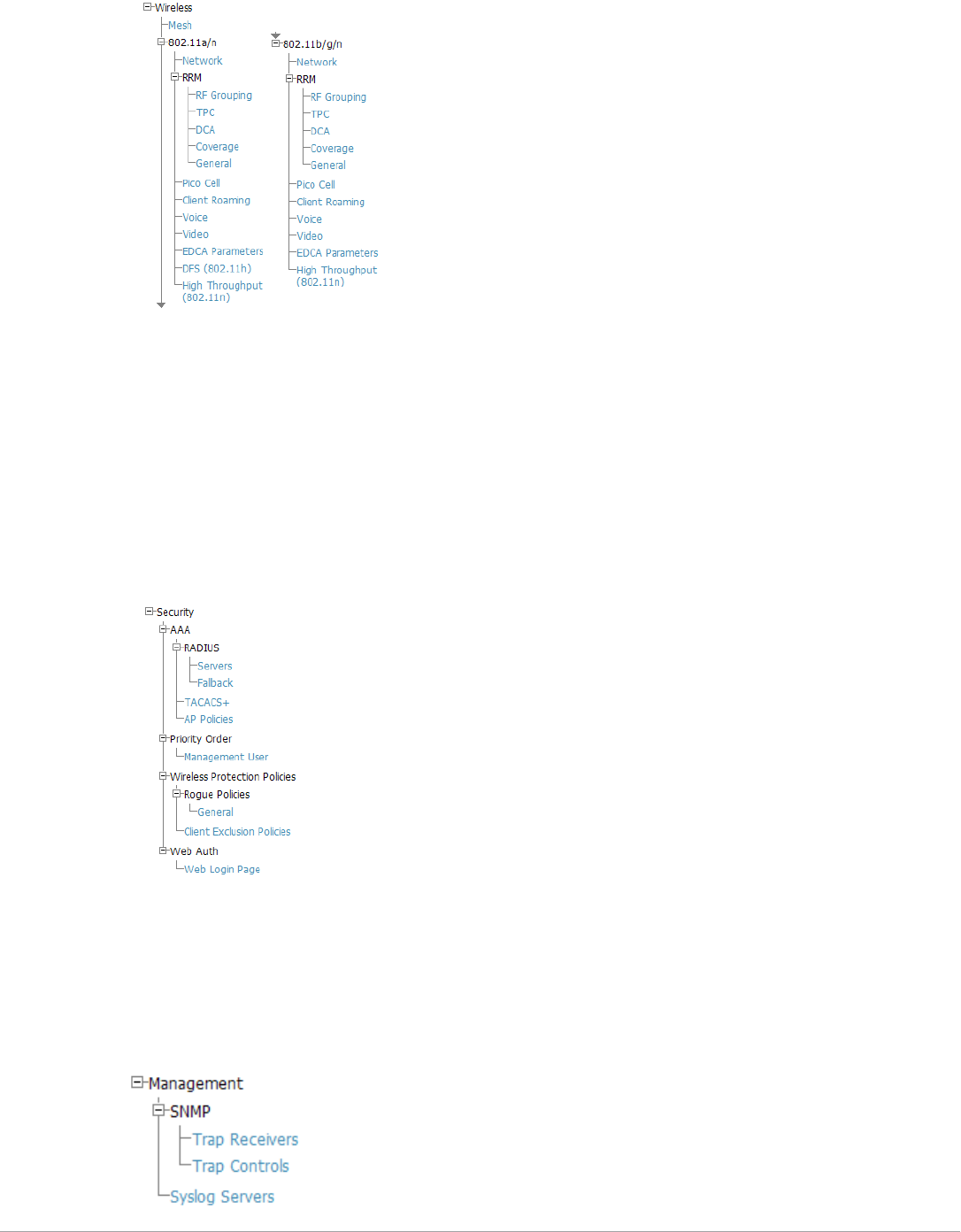
94 | Configuring and Using Device Groups Dell PowerConnect W-AirWave 7.5 | User Guide
Figure 59 Groups > Cisco WLC Config > Wireless Navigation Illustration
Configuring Cisco WLC Security Parameters and Functions
AirWave enables you to configure many security settings that are specific to Cisco WLC controllers. This section
supports four overriding types of configuration, as follows:
-AAA, to cover both RADIUS and TACACS+ server configuration
-Priority Order
-Wireless Protection Policies
-Web Auth
Figure 60 illustrates these components and this navigation:
Figure 60 Groups > Cisco WLC Config > Security Navigation Illustration
Configuring Management Settings for Cisco WLC
AirWave allows you to configure of SNMP and Syslog Server settings for Cisco WLC controllers. You can
configure up to four trap receivers on the Cisco WLC including the AMP IP that can be used in Global Groups.
To define SNMP and server settings, go to the Groups > Cisco WLC Config > Management page, illustrated in
Figure 61.
Figure 61 Groups > Cisco WLC Config > Management Navigation Illustration
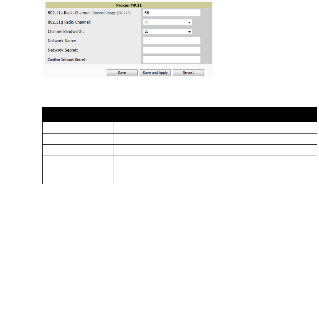
Dell PowerConnect W-AirWave 7.5 | User Guide Configuring and Using Device Groups | 95
Configuring Group PTMP Settings
The Groups > PTMP configuration page configures Point-to-Multipoint (PTMP) for all subscriber and base
stations in the device group. Subscriber stations must be in the same group as all base stations with which they
might connect.
Perform the following steps to configure these functions.
1. Go to the Groups > List page and select the group for which to define PTMP settings by selecting the group
name. Alternatively, select Add from the Groups > List page to create a new group, define a group name. In
either case, the Monitor page appears.
2. Select the PTMP tab in the AirWave navigation menu. Figure 62 illustrates this page.
Figure 62 Groups > PTMP Page Illustration
3. Define the settings on this page. Table 68 describes the settings and default values.
4. Select Save and Apply when configurations are complete to make them permanent, or select Save to retain
these settings prior to pushing to controllers at a later time.
Configuring Proxim Mesh Radio Settings
1. Go to the Groups > Proxim Mesh configuration page to configure Mesh-specific radio settings.
2. Define the settings as required for your network. Figure 63 illustrates this page. Table 69 and Table 70
describe the settings and default values.
Table 68 Groups > PTMP Fields and Default Values
Setting Default Description
802.11a Radio Channel 58 Selects the channel used for 802.11a radios by the devices in this group.
802.11g Radio Channel 10 Selects the channel used for 802.11g radios by the devices in this group.
Channel Bandwidth 20 Defines the channel bandwidth used by the devices in this group.
Network Name Wireless Network Sets the Network name, with a range of length supported from two to 32
alphanumeric characters.
Network Secret None Sets a shared password to authenticate clients to the network.
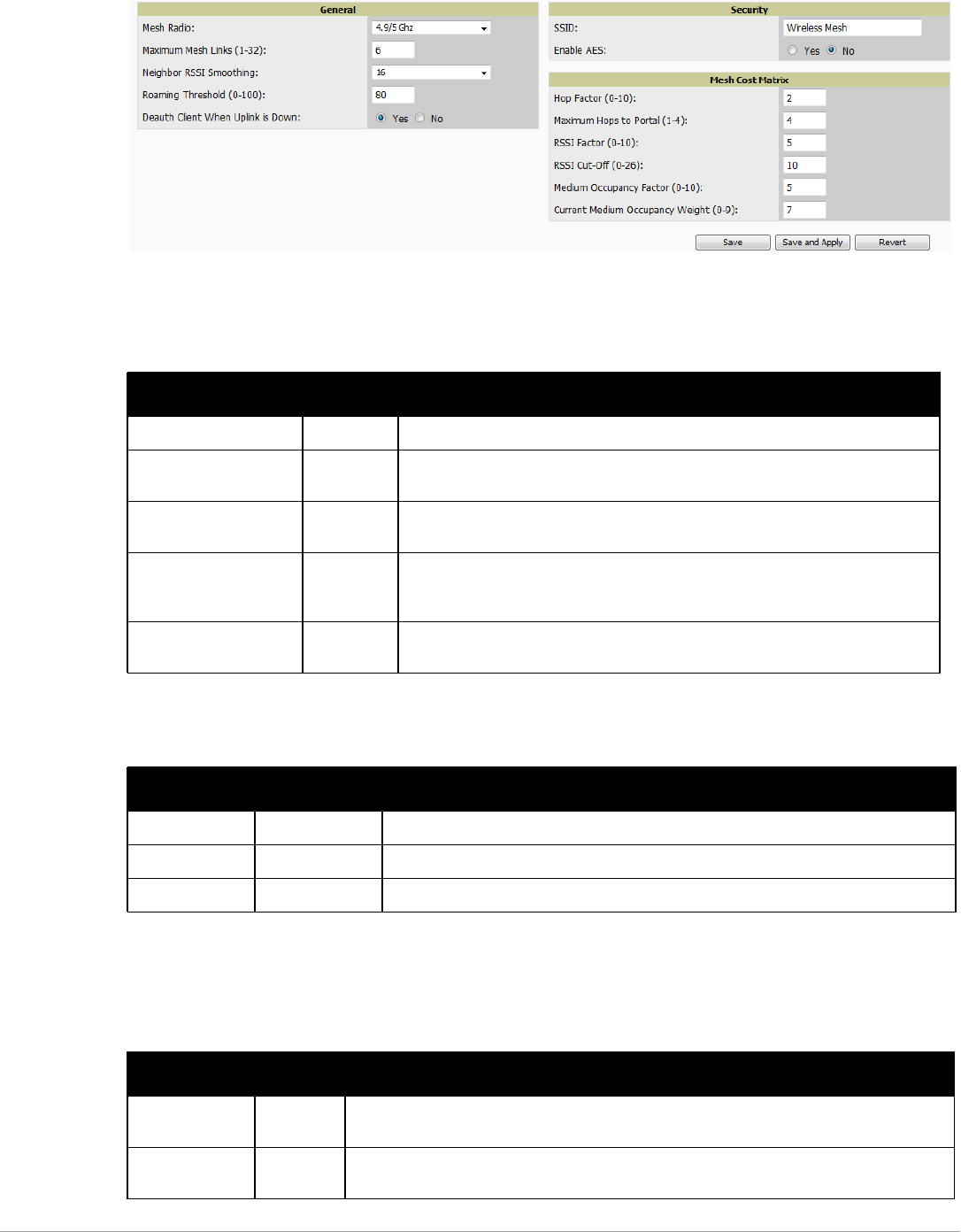
96 | Configuring and Using Device Groups Dell PowerConnect W-AirWave 7.5 | User Guide
Figure 63 Groups > Proxim Mesh Page Illustration
The General section contains settings for mesh radio, number of mesh links, RSSI smoothing, roaming
threshold and de-auth client.
The Security section contains settings for SSID and enabling AES encryption.
3. The Mesh Cost Matrix configuration section contains settings for hop factor and maximum hops to portal,
RSSI factor and cut-off, medium occupancy factor and current medium occupancy weight. Adjust these
settings as required for your network. Table 71 describes these settings and default values.
Table 69 Groups > Proxim Mesh > General Fields and Default Values
Setting Default Description
Mesh Radio 4.9/5Ghz Drop-down selects the radio that acts as the backhaul to the network.
Maximum Mesh Links (1-
32)
6 Sets the maximum number of mesh links allowed on an AP. This number includes
the uplink to the portal as well as downlinks to other mesh APs.
Neighbor RSSI
Smoothing
16 Specifies the number of beacons to wait before switching to a new link.
Roaming Threshold (0-
100)
80 Specifies the difference in cost between two paths that must be exceeded before
the AP roams. To switch to a new path it must have a cost that is less by at least the
roaming threshold. A high threshold results in fewer mesh roams.
Deauth Client when
Uplink is Down
Yes With Yes selected, clients have authentication removed (are deauthenticated) if the
uplink is lost.
Table 70 Groups > Proxim Mesh > Security Fields and Default Values
Setting Default Description
SSID None Sets the SSID used by the Mesh Radio to connect to the mesh network.
Enable AES No Enable or disable AES encryption.
Shared Secret None Specify a shared secret if Enable AES is Yes.
Table 71 Groups > Proxim Mesh > Mesh Cost Matrix Fields and Default Values
Setting Default Description
Hop Factor (1-10) 5 Sets the factor associated with each hop when calculating the best path to the portal AP.
Higher factors will have more impact when deciding the best uplink.
Maximum Hops
to Portal (1-4)
4 Set the maximum number of hops for the AP to reach the Portal AP.
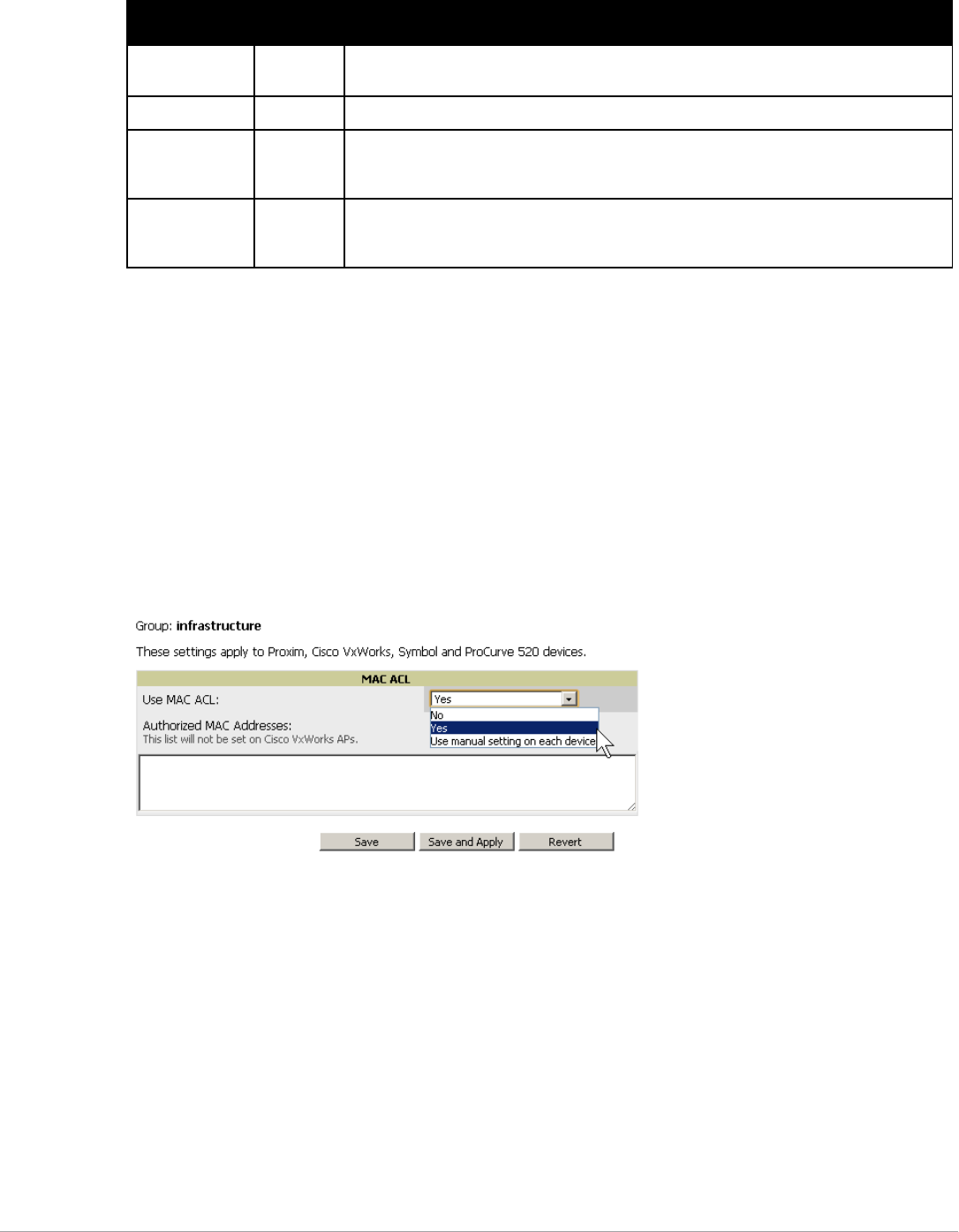
Dell PowerConnect W-AirWave 7.5 | User Guide Configuring and Using Device Groups | 97
4. Select Save when configurations are complete to retain these settings. Select Save and Apply to make the
changes permanent, or select Revert to discard all unapplied changes.
Configuring Group MAC Access Control Lists
This configuration is optional. If you use Symbol, Proxim, or ProCurve 520WL wireless access points, AirWave
enables you to specify the MAC addresses of devices that are permitted to associate with APs in the Group. Other
devices are not able to associate to APs in the Group, even if the users of those devices are authorized users on the
network.
Perform the following steps to use the MAC ACL function.
1. Browse to the Groups > MAC ACL configuration page. Figure 64 illustrates this page.
Figure 64 Groups > MAC ACL Page Illustration
2. Select Yes on the Use MAC ACL drop-down menu. Enter all authorized MAC addresses, separated by white
spaces.
3. Select Save when configurations are complete to retain these settings. Select Save and Apply to make the
changes permanent, or select Revert to discard all unapplied changes.
Specifying Minimum Firmware Versions for APs in a Group
This configuration is optional. AirWave allows you the option of defining the minimum firmware version for each
AP type in a group on the Groups > Firmware configuration page. At the time that you define the minimum
version, AirWave automatically upgrades all eligible APs.
When you add APs into the group in the future, you will be able to upgrade APs manually. The firmware for an
AP is not upgraded automatically when it is added to a group. Perform the following steps to make this firmware
configuration.
RSSI Factor (0-
10)
5 Sets the factor associated with the RSSI values used when calculating the best path to the
portal AP. Higher factors will have more impact when deciding the best uplink.
RSSI Cutoff (0-26) 10 Specifies the minimum RSSI needed to become a mesh neighbor.
Medium
Occupancy
Factor (0-10)
5 Sets the factor associated with Medium Occupancy when calculating the best path to the
portal AP. Higher factors will have more impact when deciding the best uplink.
Current Medium
Occupancy
Weight (0-9)
7 Specifies the importance given to the most recently observed Medium Occupancy against all
of the previously viewed medium occupancies. Lower values place more importance on
previously observed Medium Occupancies.
Table 71 Groups > Proxim Mesh > Mesh Cost Matrix Fields and Default Values (Continued)
Setting Default Description
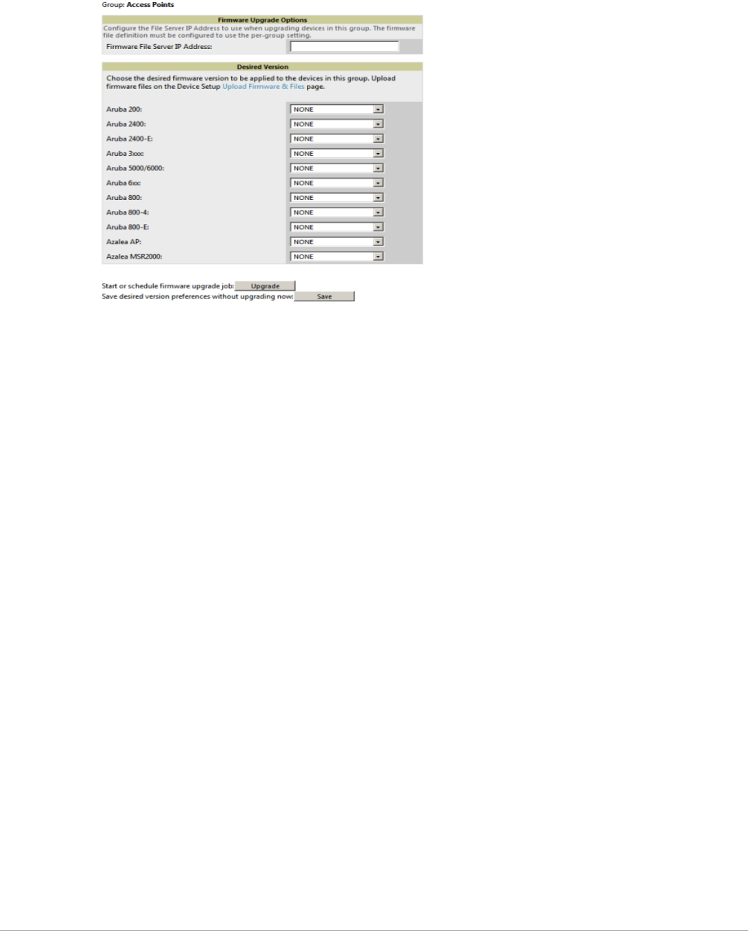
98 | Configuring and Using Device Groups Dell PowerConnect W-AirWave 7.5 | User Guide
1. Browse to the Groups > Firmware configuration page. Figure 65 illustrates this page.
Figure 65 Groups > Firmware Page Illustration
2. For each device type in the group, specify the minimum acceptable firmware version. If no firmware versions
are listed, go to the Device Setup > Upload Firmware & Files configuration page to upload the firmware files
to AirWave.
3. Select Upgrade to apply firmware preferences to devices in the group.
4. Select Save to save the firmware file as the desired version for the group.
5. If you have opted to assign an external TFTP server on a per-group basis on the Device Setup > Upload
Firmware & Files configuration page, you can enter the IP address in the Firmware Upgrade Options field on
the top of this configuration page.
6. Once you have defined your first group, you can configure that group to be the default group on your network.
When AirWave discovers new devices that need to be assigned to a management group, the default group
appears at the top of all drop-down menus and lists. Newly discovered devices are place automatically in the
default group if AirWave is set to Automatically Monitor/Manage New Devices on the AirWave configuration
page.
7. Browse to the AMP Setup > General configuration page.
8. From Default Group drop down menu, select the desired group to make it the default.
Comparing Device Groups
You can compare two existing device groups with a detailed line-item comparison. Group comparison allows
several levels of analysis including the following:
-Compare performance, bandwidth consumption, or troubleshooting metrics between two groups.
-Debug one device group against the settings of a similar and better performing device group.
-Use one group as a model by which to fine-tune configurations for additional device groups.
This topic presumes that at least two device groups are at least partly configured in AirWave, each with saved
configurations. Perform the following steps to compare two existing device groups:
1. From the Groups > List page, select the Compare two groups link. Two drop-down menus appear.
2. Select the two groups to compare in the drop-down menus, and select Compare. The Compare page appears,
displaying some or many configuration categories. Figure 66 illustrates this page.
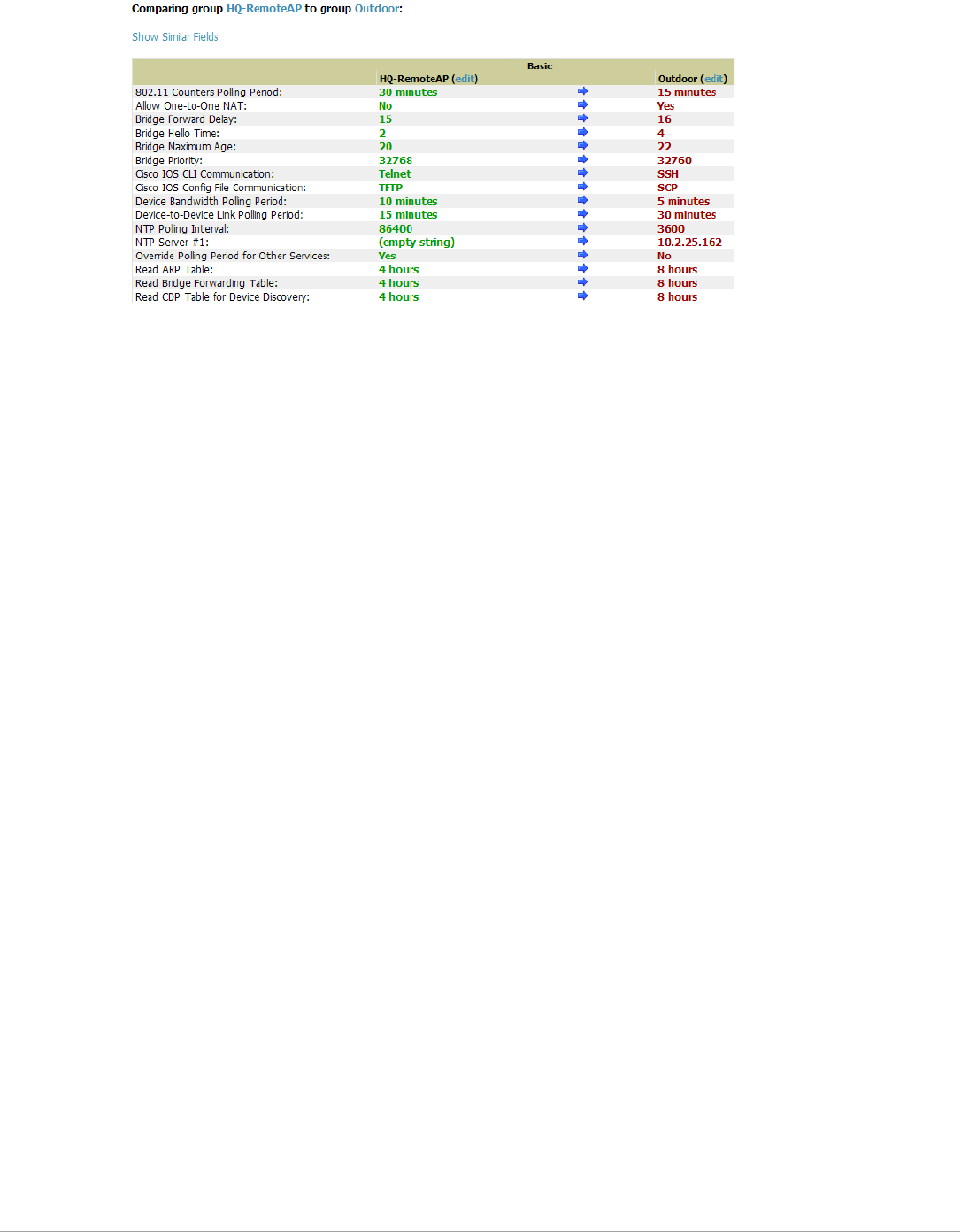
Dell PowerConnect W-AirWave 7.5 | User Guide Configuring and Using Device Groups | 99
Figure 66 Comparing Two Devices Groups on the Groups > List > Compare Page (Partial View)
3. Note the following factors when using the Compare page:
The Compare page can be very long or very abbreviated, depending on how many configurations the
device groups share or do not share.
When a configuration differs between two groups, the setting is flagged in red text for the group on the
right.
The default setting of the Compare page is to highlight settings that differ between two groups.
To display settings that are similar or identical between two device groups, select Show Similar Fields
at the top left of the page. The result may be a high volume of information.
Select Hide Similar Fields to return to the default display, emphasizing configuration settings that
differ between two groups.
You can change the configuration for either or both groups by selecting Edit in the corresponding column
heading. The appropriate configuration page appears.
If you make and save changes to either or both groups, go back to the Groups > List page and select
Compare two groups. Select the same two groups again for updated information.
Additional topics in this document describe the many fields that can appear on the Groups > List >
Compare page.
Deleting a Group
Perform the following steps to delete an existing Group from the AirWave database:
1. Browse to the Groups > List configuration page.
2. Ensure that the group you wish to delete is not marked as the default group. (See the AMP Setup > General
page.) AirWave does not permit you to delete the current default group.
3. Ensure that there are no devices in the group that you want to delete. AirWave does not permit you to delete
a group that still contains managed devices. You must move all devices to other groups before deleting a
group.
4. Ensure that the group is not a global group that has subscriber groups, and is not a group that was pushed
from a Master Console. AirWave will not delete a group in which either of those cases is true.
5. Select the checkbox and select Delete.
Changing Multiple Group Configurations
Perform the following steps to make any changes to an existing group's configuration:
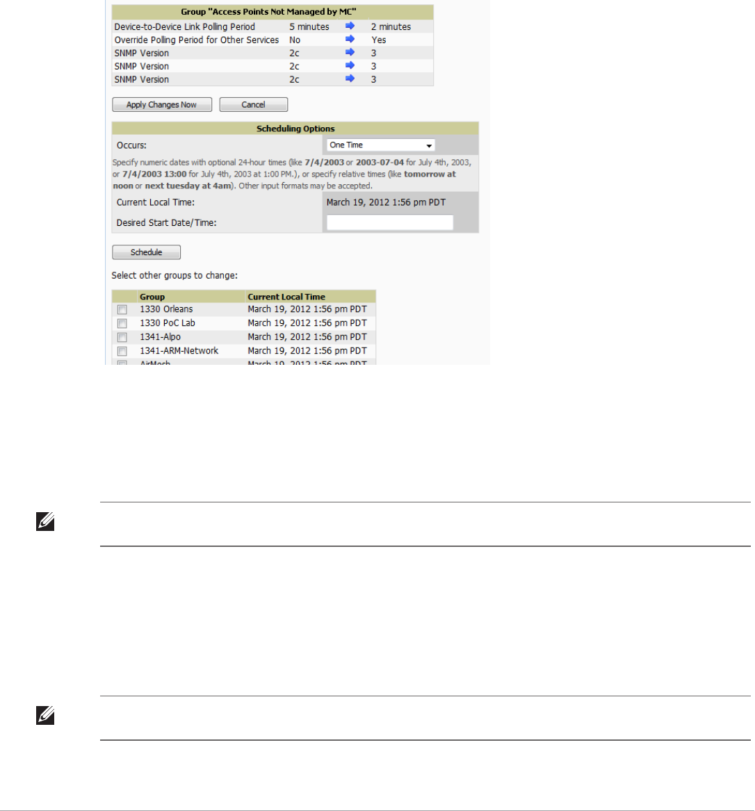
100 | Configuring and Using Device Groups Dell PowerConnect W-AirWave 7.5 | User Guide
1. Browse to the Groups > List configuration page.
2. Select the Modify button (the wrench icon) for the group you wish to edit. The Groups > Basic configuration
page appears.
3. Select the fields to be edited on the Basic configuration page or go to Radio, Security, VLANs, or MAC ACL
configuration page and edit the fields. Use the Save button to store the changes prior to applying them.
4. When all changes for the group are complete select the Save and Apply button to make the changes
permanent. Figure 67 illustrates the confirmation message that appears.
Figure 67 Groups > Basic Configuration Change Confirmation Page Illustration
5. AirWave displays a Configuration Change screen confirming the changes that will be applied to the group's
settings.
6. There are several action possibilities from within this confirmation configuration page.
Apply Changes Now — Applies the changes immediately to access points within the group. If you wish to
edit multiple groups, you must use the Preview button.
Scheduling Options — Schedules the changes to be applied to this group in the future. Enter the desired
change date in the Start Date/Time field. You can also specify if this is a one-time schedule or a recurring
schedule. Recurring options are Daily, Weekly, Monthly, and Annually. AirWave takes the time zone into
account for the group if a time zone other than AirWave System Time has been configured on the Groups
> Basic configuration page.
Cancel — Cancels the application of changes (immediately or scheduled).
7. Apply changes to multiple groups by selecting the appropriate group or groups and selecting Preview.
NOTE: You cannot apply Dell PowerConnect W Config changes to other groups. If the only changes on the configuration page are
to PowerConnect W-Seriesdevices, the list of groups and the preview button will not appear.
NOTE: To completely nullify the change request, select Revert on one of the group configuration pages after you have selected
Cancel.

Dell PowerConnect W-AirWave 7.5 | User Guide Configuring and Using Device Groups | 101
Modifying Multiple Devices
AirWave provides a very powerful utility that modifies all APs or a subset of access points unrelated to the typical
AirWave group construct. This utility provides the ability to delete simultaneously multiple devices, migrate
multiple devices to another group and/or folder, update credentials and optimize channels. Perform these steps to
modify multiple devices.
1. To modify multiple devices, go to one of the following pages with a device list:
-APs/Devices > List
-APs/Devices > Up
-APs/Devices > Down
-APs/Devices > Mismatched
-Groups > Monitor
Each of these pages displays a list of devices. Controller monitoring pages also have lists of their thin APs
which can be modified using Modify Devices.
2. Select Modify Devices to make the checkboxes at the left of all devices appear. In addition, a new section
appears in this page location to display various settings that can be configured for multiple devices at one time
(some operations cannot be performed on the selected devices). Figure 68 illustrates this page.
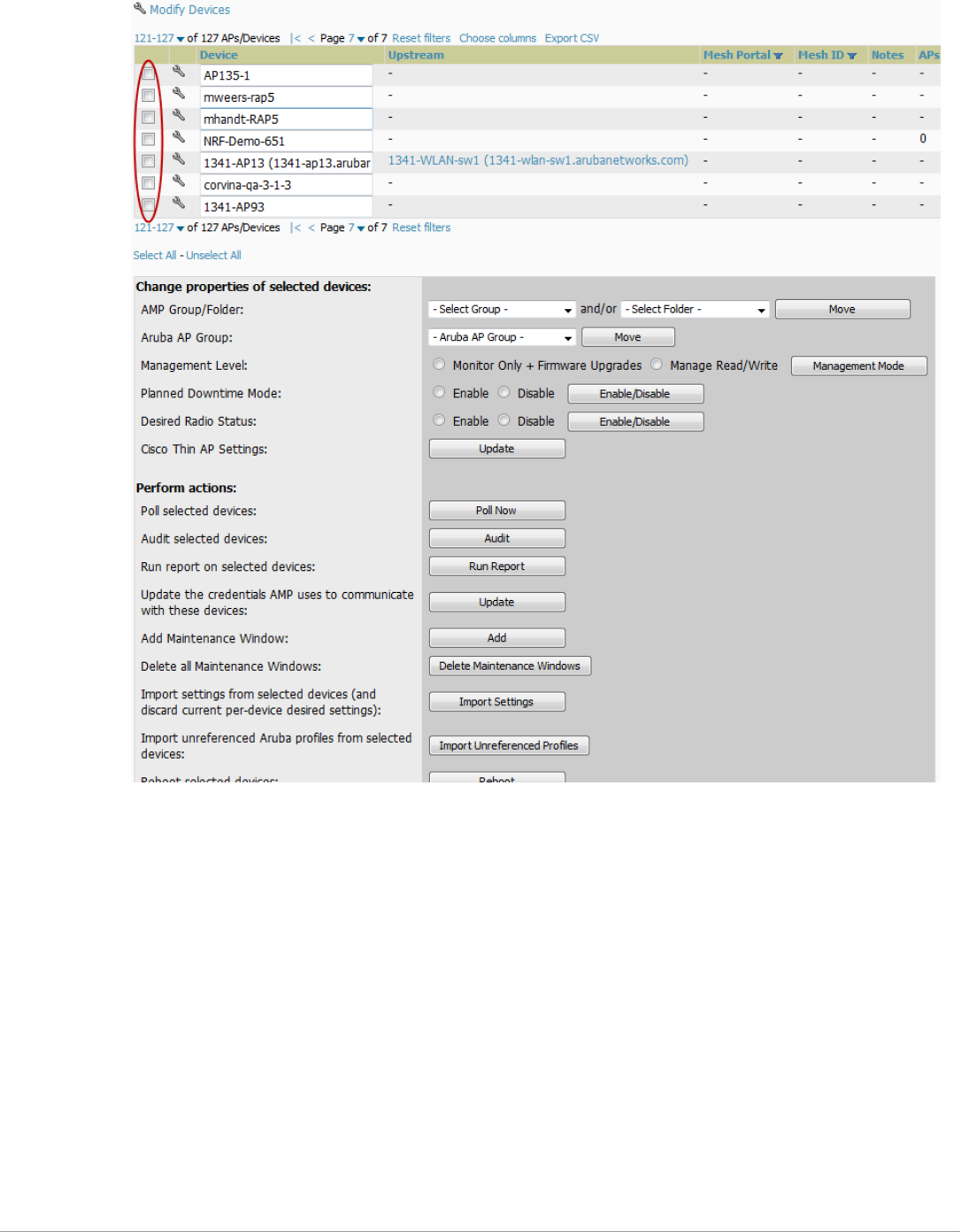
102 | Configuring and Using Device Groups Dell PowerConnect W-AirWave 7.5 | User Guide
Figure 68 Modify Multiple Devices Section Illustration
3. Select one or more devices that are to share the configurations. Select the checkbox for each device to modify.
4. In the Modify Multiple Devices section, select any button or use any drop-down menu for the supported
changes. Any action you take applies to all selected devices. Each action you take will direct you to a new
configuration page, or prompt you with a confirmation page to confirm your changes.
5. You are taken to a confirmation configuration page that allows you to schedule the change for a time in the
future. Enter a start date and time in the scheduling field and select when the change should occur from the
drop-down menu (one time is the default, but you may select recurring options for many of the actions).
Scheduled jobs can be viewed and edited in the System > Configuration Change Jobs tab.
6. Using the neighbor lists, AirWave is able to optimize channel selection for APs. Select the APs to optimize
and AirWave minimizes the channel interference while giving channel priority to the most heavily used APs.
Table 72 describes these actions and controls.

Dell PowerConnect W-AirWave 7.5 | User Guide Configuring and Using Device Groups | 103
Table 72 Modify Multiple Devices Section Fields and Default Values
Action Description
AMP Group/Folder Move the selected devices to a new group or folder. If the AP is in managed mode when it is
moved to a new group, it will be reconfigured.
Dell PowerConnect W Moves the selected APs to a new group or folder. If the AP is in managed mode when it is moved
to a new group it will be reconfigured.
Management Level Move the selected devices into Monitor Only or Manage Read/Write Mode.
Planned Maintenance Mode Puts the selected devices into Planned Maintenance. During the maintenance mode, no AP
Down triggers will be deployed on these devices. Users will not be able to delete folders that
contain devices in Planned Maintenance. The devices in Planned Maintenance will show the Up
status, but will not be tracked in historical graphs and logs as Up.
Desired Radio Status Enables or disables the radios on the selected device. Does not apply Cisco IOS APs.
Cisco Thin AP Settings Bulk configuration for per-thin AP settings, previously configured on the Group LWAPP AP
tab, can be performed from Modify Devices on the APs/Devices List page. Make changes
to LWAPP AP groups, including the option that was under Modify Devices.
Poll selected devices Polls selected devices for current user count and bandwidth data; overrides default poll settings
for the group. Polling numerous devices may create a temporary performance load on your
AirWave server.
Audit selected devices Fetches the current configuration from the device and compares it to the desired AirWave
configuration. The audit action updates the Configuration Status.
NOTE: In versions of AirWave prior to 7.3, the Audit button appeared on Groups > List for groups
with audit disabled. Now, if a group has audit disabled for its devices, AirWave does not show
the Audit button in the Modify devices list.
Run report on selected
devices
Takes you to the Reports > Definitions page where you can define or run a custom report for
selected devices. For more details and a procedure, see “Using Custom Reports” on page 237.
Update the credentials AMP
uses to communicate with
these devices
Update changes the credentials AirWave uses to communicate with the device. It does not
change the credentials on the AP.
Add Maintenance Window Automate the manual action of putting the selected devices into Manage mode at once so that
changes can be applied, and after the maintenance period is over, the devices automatically
revert to Monitor-Only mode.
Maintenance windows can be set as a one-time or recurring event.
Delete all Maintenance
Windows
Deletes all maintenance windows set for these devices.
Import settings from selected
devices (and discard current
pre-device desired settings)
Audit updates a number of the AP specific settings AirWave initially read off of the AP including
channel, power, antenna settings and SSL certifications. AirWave recommends using this setting
if APs have been updated outside of AirWave. Most settings on the APs/Devices Manage
configuration page are set to the values currently read off of the devices.
Reboot selected devices Reboots the selected devices. Use caution when rebooting devices because this can disrupt
wireless users.
Reprovision selected Dell
devices
Configures the controller to send provisioning parameters such as radio, antenna, and IP
address settings to the selected APs. Please note that APs will be rebooted as part of
reprovisioning.
Replace Hardware Select the down device that will be replaced and view the list of AirWave devices that match the
name or IP address of the selected device. The down devices can be replaced with any device in
the New Devices list or in the current folder or group.
Upgrade firmware for
selected devices
Upgrades firmware for the selected devices. Refer to the firmware upgrade help under APs/
Devices > Manage configuration page for detailed help on Firmware job options.
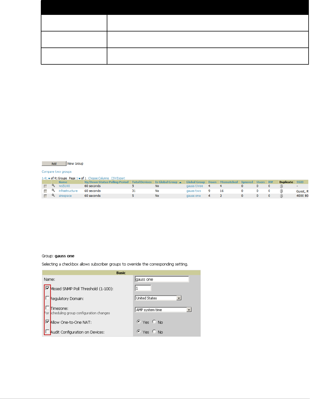
104 | Configuring and Using Device Groups Dell PowerConnect W-AirWave 7.5 | User Guide
Using Global Groups for Group Configuration
To apply group configurations using the AirWave Global Groups feature, first go to the Groups > List
configuration page. Select Add to add a new group, or select the name of the group to edit settings for an existing
group. Select the Duplicate icon (usually near the last column of the list) to create a new group with identical
configuration to an existing group.
-To have Global Group status, a group must contain no devices; accordingly, access points can never be added
to a Global Group. Global groups are visible to users of all roles, so they may not contain devices, which can be
made visible only to certain roles. Figure 69 illustrates the Groups > List page.
Figure 69 Groups > List Page Illustration
-To set a group as a Global Group, go to the Groups > Basic configuration page for an existing or a newly
created group. Select Yes for the Is Global Group field under the Global Group section.
-When the change is saved and applied, the group will have a checkbox next to fields. Figure 70 illustrates this
configuration page.
Figure 70 Groups > Basic Page for a Global Group (partial view)
-When a Global Group configuration is pushed to Subscriber Groups, all settings are static except for settings
with the checkbox selected; for fields with checkboxes selected, the value or setting can be changed on the
corresponding tab for each managed group. In the case of the Groups > SSIDs configuration page, override
options are available only on the Add configuration page (go to the Groups > SSIDs configuration page and
select Add). Global templates are also configurable as part of Global Groups; for more information, see
“Creating and Using Templates” on page 155.
Cancel firmware upgrade for
selected devices
Cancels any firmware upgrades that are scheduled or in progress for the selected APs.
Rename devices Rename all the selected devices in bulk. Note that you can also rename the devices one at a time
using the editable Name fields in each row.
Delete selected devices from
AMP
Removes the selected APs from AirWave. The deletes will be performed in the background and
may take a minute to be removed from the list.
Table 72 Modify Multiple Devices Section Fields and Default Values (Continued)
Action Description
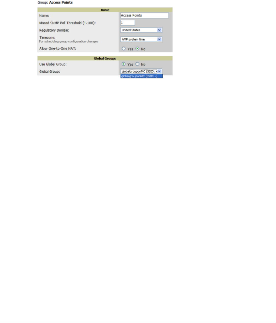
Dell PowerConnect W-AirWave 7.5 | User Guide Configuring and Using Device Groups | 105
-Once Global Groups have been configured, groups may be created or configured to subscribe to a particular
Global Group. Go to the Groups > Basic configuration page of a group and locate the Use Global Groups
section. Select the Yes radio button and select the name of the Global Group from the drop-down menu.
Then select Save and Apply to make the changes permanent. Figure 71 illustrates this page.
Figure 71 Groups > Basic > Managed Page Illustration
-Once the configuration is pushed, the unchecked fields from the Global Group appears on the Subscriber
Group as static values and settings. Only fields that had the override checkbox selected in the Global Group
appear as fields that can be set at the level of the Subscriber Group. Any changes to a static field must be
made on the Global Group.
-If a Global Group has Subscriber Groups, it cannot be changed to a non-Global Group. A Global Group
without Subscriber Groups can be changed to a regular Group by updating the setting on the Groups > Basic
configuration interface. The Global Groups feature can also be used with the Master Console. For more
information about this feature, refer to “Supporting AirWave Servers with the Master Console” on page 226.

106 | Configuring and Using Device Groups Dell PowerConnect W-AirWave 7.5 | User Guide

Dell PowerConnect W-AirWave 7.5 | User Guide Discovering, Adding, and Managing Devices | 107
Chapter 5
Discovering, Adding, and Managing
Devices
This chapter describes how to add, configure, and monitor wired and wireless devices, and contains the following
sections corresponding to features of the Device Setup and APs/Devices tabs:
-“Device Discovery Overview” on page107
-“Discovering and Adding Devices” on page107
-“Monitoring Devices” on page118
-“Configuring and Managing Devices” on page137
-“Troubleshooting a Newly Discovered Down Device” on page149
-“Setting up Spectrum Analysis in AirWave” on page151
Device Discovery Overview
Once you have deployed AirWave on the network, the next step is to discover all existing devices connected to
your network.
AirWave allows device discovery in the following ways, all of which are described in this chapter:
-SNMP/HTTP discovery scanning—This is the primary method to discover devices on your network,
configured in the Device Setup > Discover page. See “SNMP/HTTP Scanning” on page108.
-Cisco Discovery Protocol (CDP)—AirWave enhances support for CDP by discovering a Cisco device’s CDP
neighbors. See “The Cisco Discovery Protocol (CDP)” on page112.
-Manual device entry—This admin-supported method of discovery applies when you know of devices that are
already on your network. See the following sections for information and procedures:
“Manually Adding Individual Devices” on page112
“Adding Multiple Devices from a CSV File” on page115
“Adding Universal Devices” on page117
-Controller-driven device discovery—Thin APs will automatically be discovered in the network and added to
the New Devices list when you add their controller to AirWave. To add the thin APs, refer to “Authorizing
Devices to AirWave from APs/Devices > New Page” on page112.
Discovering and Adding Devices
This section describes the following topics:
-SNMP/HTTP Scanning
-The Cisco Discovery Protocol (CDP)
-Authorizing Devices to AirWave from APs/Devices > New Page
-Manually Adding Individual Devices
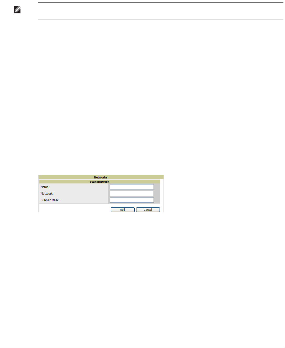
108 | Discovering, Adding, and Managing Devices Dell PowerConnect W-AirWave 7.5 | User Guide
SNMP/HTTP Scanning
SNMP/HTTP discovery scanning is the primary method for discovering devices on your network, including rogue
devices. Enable this scanning method from the Device Setup > Discover page.
SNMP/HTTP scanning information is provided in these sections:
-Adding Networks for SNMP/HTTP Scanning—explains how to enable networks that have been defined for
scanning.
-Adding Credentials for Scanning—explains how to define network credentials for scanning. Credentials must
be defined before using them in scan sets.
-Defining a Scan Set—explains how to create a scan set by combining networks and credentials when scanning
for devices.
-Running a Scan Set—provides a procedure for running a scan set.
Adding Networks for SNMP/HTTP Scanning
The first step when enabling SNMP/HTTP scanning for devices is to define the network segments to be scanned.
Perform these steps.
1. Go to the Device Setup > Discover page, and scroll down to the Networks section.
2. In the Networks section, select the Add button to add a new scan network. The Scan Network page appears,
as shown in Figure 72. (Note that you may have to scroll down the page again to view this section.)
Alternatively, you can edit an existing scan network by selecting the corresponding pencil icon. The New/Edit
Networks page also appears in this instance.
Figure 72 Device Setup > Discover > New Network Section Illustration
3. In the Name field, provide a name for the network to be scanned (for example, Accounting Network).
4. In the Network field, define the IP network range, or the first IP address on the network, to be scanned. One
example would be 10.52.0.0.
5. Enter the Subnet Mask for the network to be scanned (for example, 255.255.252.0). The largest subnet
AirWave supports is 255.255.0.0.
6. Select Add.
7. Repeat these steps to add as many networks for which to enable device scanning. All network segments
configured in this way appear in the Network section of the Device Setup > Discover page.
8. Complete the configuration of scan credentials, then combine scan networks and scan credentials to create
scan sets. The next two procedures in this section describe these tasks.
Adding Credentials for Scanning
The next step in SNMP/HTTP device discovery is to define the scan credentials that govern scanning of a given
network. New APs inherit scan credentials from the System Credentials that you configure on the Device Setup
> Communications page.
Perform these steps to define scan credentials for SNMP/HTTP scanning:
NOTE: This page is only visible to users with the AirWave Administrator role or roles that have “Allow authorization of APs/
Devices” enabled in AMP Setup > Roles.
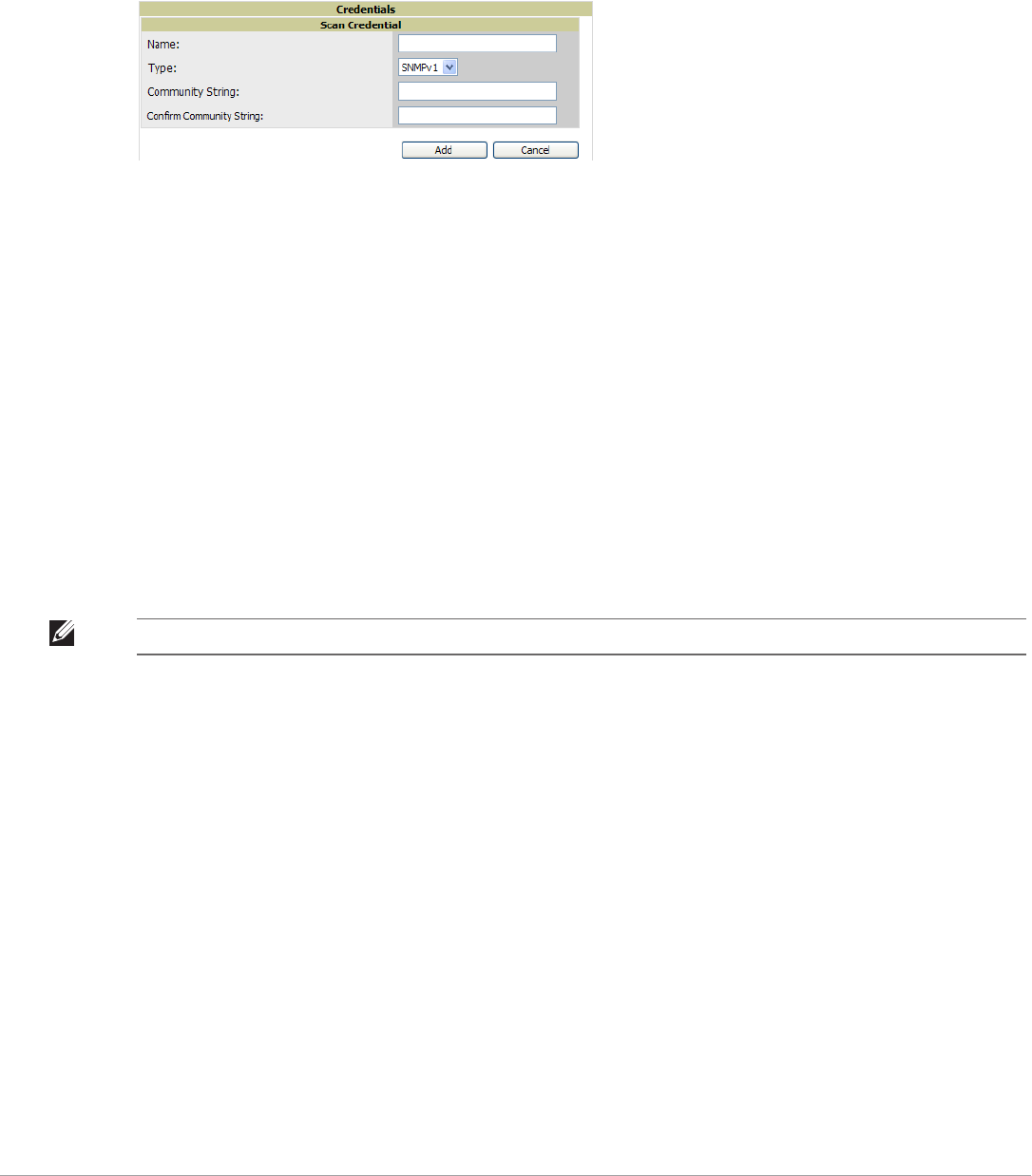
Dell PowerConnect W-AirWave 7.5 | User Guide Discovering, Adding, and Managing Devices | 109
1. Locate the Credentials section on the Device Setup > Discover page. (Scroll down if necessary.) This page
displays scan sets, networks, and credentials that have been configured so far, and allows you to define new
elements for device scanning.
2. To create a new scan credential, select the Add button to add a new scan credential. Figure 73 illustrates this
page. (Note that you may have to scroll down the page again to view this section.)
Figure 73 Device Setup > Discover > Add/Edit New Scan Credential Section Illustration
3. Enter a name for the credential in the Name field (for example, Default). This field supports alphanumeric
characters (both upper and lower case), blank spaces, hyphens, and underscore characters.
4. Choose the type of scan to be completed (SNMPv1, SNMPv2, or HTTP). In most cases, perform scans using
SNMP for device discovery, but consider the following factors in your decision:
-SNMPv1 and SNMP v2 differ between in their supported traps, supported MIBs, and network query
elements used in device scanning.
-HTTP discovers devices using the HyperText Transfer Protocol in communications between servers and
additional network components. HTTP is not as robust in processing network events as is SNMP, but
HTTP may be sufficient, simpler, or preferable in certain scenarios.
a. If you selected SNMPv1 or SNMPv2, then define and confirm the Community String to be used during
scanning. In this section, the community string used can be either read-only or read/write, as AirWave
only uses it for discovering APs. To bring APs under management, AirWave uses the credentials supplied
in the Device Setup > Communication SNMP section. Once the device is authorized, it will use the non-
scanning credentials.
b. If you selected HTTP for the type, then enter a Username and Password for the scan credentials.
5. Select Add after you have completed the previous steps. The Device Setup > Discover page displays the new
scan credential or credentials just created or edited.
6. Repeat these steps to add as many credentials as you require.
7. Once scan networks and scan credentials are defined, combine them by creating scan sets using the next
procedure: “Defining a Scan Set” on page109.
Defining a Scan Set
Once you have defined at least one network and one scan credential, you can create a scan set that combines the
two for device discovery. Perform these steps to create a scan set.
1. Locate the Scan Set area at the top of the Device Setup > Discover page.
2. Select Add New Scan Set to see all scan components configured so far. If you wish to create a new network, or
new scanning credentials, you can select Add in either of these fields to create new components prior to
creating a scan set.
3. Select the Network(s) to be scanned and the Credential(s) to be used. AirWave defines a unique scan for
each Network-Credential combination.
NOTE: AirWave automatically appends the type of scan (SNMP or HTTP) to the Label.
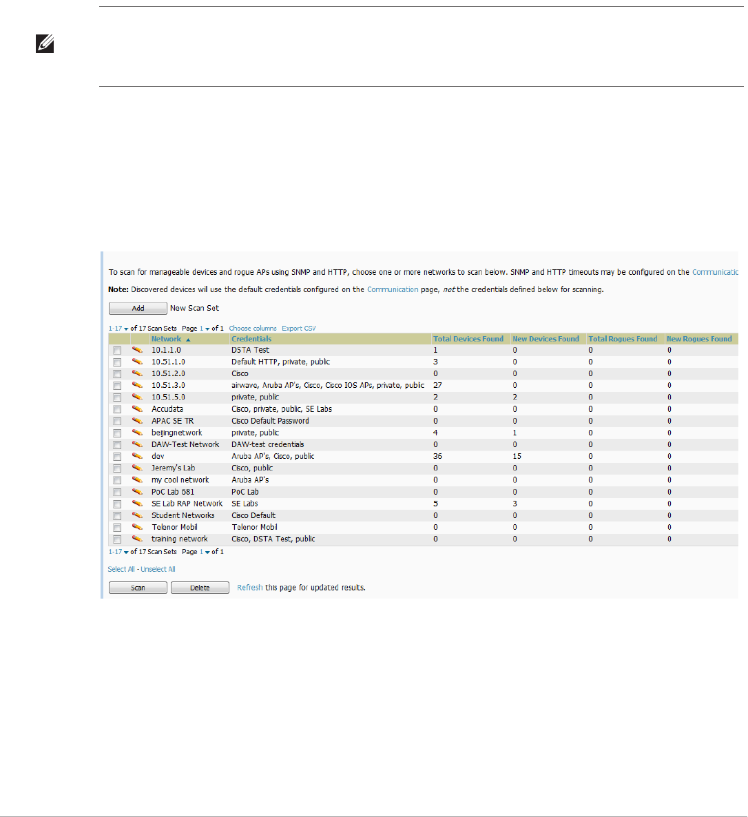
110 | Discovering, Adding, and Managing Devices Dell PowerConnect W-AirWave 7.5 | User Guide
4. In the Automatic Authorization section, select whether to override the global setting in AMP Setup >
General and have New Devices be automatically authorized into the New Device List, the same Group/Folder
as the discovering devices, the same Group/Folder as the closest IP neighbor, and/or a specified auto-
authorization group and folder.
5. Select Add to create the selected scans, which then appear in a list at the top of the Device Setup > Discover
page.
6. To edit an existing scan, select the pencil icon next to the scan on the Device Setup > Discover page.
7. When ready, proceed to the next task, “Running a Scan Set” on page110.
Running a Scan Set
Once a scan has been defined on the Device Setup > Discover page, AirWave can now scan for devices. Perform
these steps.
1. Browse to the Device Setup > Discover page and locate the list of all scan sets that have been defined so far.
Figure 74 illustrates this page.
Figure 74 Device Setup > Discover Executing a Scan Illustration
2. Check the box next to the scan(s) that you would like to execute.
3. Select Scan to execute the selected scans, and the scan immediately begins. The Stop column indicates the
scan is In Progress. Clicking this column heading will stop the scan(s).
4. For future scans, select the Show Scheduling Options link and enter the desired date and time to schedule a
future scan.
5. After several minutes have passed, refresh the browser page and view the results of the scan. When the Start
and Stop columns display date and time information, the scan is available to display the results.
NOTE: Scheduling an HTTP scan to run daily on your network can help you to discover rogues. Some consumer APs, like most D-
Link, Linksys, and NetGear models, do not support SNMP and are found only on the wired side with an HTTP scan. These devices
are discovered only if they have a valid IP address. Proper credentials are not required to discover these APs. Wireless scans and
the AMC discover these rogues without any special changes.
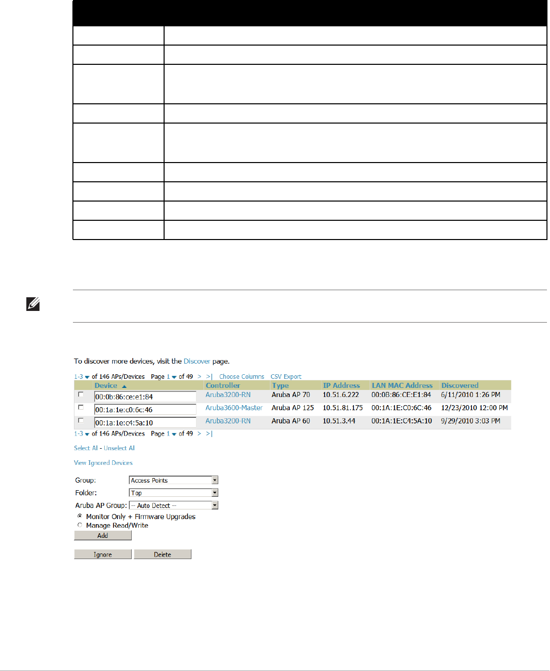
Dell PowerConnect W-AirWave 7.5 | User Guide Discovering, Adding, and Managing Devices | 111
6. Select the pencil icon for the scan to display the results. Table 73 describes the scan results and related
information.
7. Go to the APs/Devices > New page to see a full list of the newly discovered devices that the scan detected.
Figure 75 illustrates this page.
Figure 75 APs/Devices > New Page Illustration
What Next?
-To authorize one or more devices to a group, see “Authorizing Devices to AirWave from APs/Devices > New
Page” on page112.
-To delete a device altogether from AirWave, select the corresponding check box for each device, and select
Delete.
Table 73 Device Setup > Discover > Discovery Execution Fields
Column Description
Network Displays the network to be scanned.
Credentials Displays the credentials used in the scan.
Total Devices Found Displays the total number of APs detected during the scan that AirWave can configure and monitor.
Total includes both APs that are currently being managed by AirWave as well as newly discovered
APs that are not yet being managed.
New Devices Found Displays the number of discovered APs that are not yet managed, but are available.
Total Rogues Found Displays the total number of APs detected during the scan that AirWave could not configure or monitor.
Total includes both APs that have been discovered in earlier scans as well as newly discovered APs
from the most recent scan.
New Rogues Found Displays the number of rogue APs discovered on the most recent scan.
Start Displays the date and time the most recent scan was started.
Stop Displays the date and time the scan most recently completed.
Scheduled Displays the scheduled date and time for scans that are scheduled to be run.
NOTE: This page is only visible to users with the AirWave Administrator role or roles that have “Allow authorization of APs/
Devices” enabled in AMP Setup > Roles.

112 | Discovering, Adding, and Managing Devices Dell PowerConnect W-AirWave 7.5 | User Guide
-Dell PowerConnect W-Series thin APs can have Dell PowerConnect W AP Group specified, and Cisco thin
APs can have LWAPP AP Group specified when they are authorized.
The Cisco Discovery Protocol (CDP)
CDP uses the polling interval configured for each individual Cisco switch or router on the Groups > List page.
AirWave requires read-only access to a router or switch for all subnets that contain wired or wireless devices. The
polling interval is specified on the Groups > Basic page.
Authorizing Devices to AirWave from APs/Devices > New Page
Once you have discovered devices on your network, add these devices to a group and specify whether the device is
to be placed in Manage Read/Write or Monitor Only mode. To configure a new group, refer to “Configuring and
Using Device Groups” on page67.
In Manage Read/Write mode, AirWave compares the device’s current configuration settings with the Group
configuration settings and automatically updates the device’s configuration to match the Group policy.
In Monitor Only mode, AirWave updates the firmware, compares the current configuration with the policy, and
displays any discrepancies on the APs/Devices > Audit page, but does not change the configuration of the device.
Once you have added several devices to the Group, and verified that no unexpected or undesired configuration
changes will be made to the devices, you can begin to put the devices in Manage Read/Write mode using the
APs/Devices > Manage or the Modify these devices link on any list page.
Perform the following steps to add a newly discovered device to a group:
1. Browse to the APs/Devices > New page. The APs/Devices > New page displays all newly discovered devices,
the related controller (when known/applicable) and the device vendor, model, LAN MAC Address, IP Address,
and the date/time of discovery.
2. Select the group and folder to which the device will be added from the drop-down menu (the default group
appears at the top of the Group listing). Devices cannot be added to a Global Group; groups designated as
Global Groups cannot contain access points.
3. Select either the Monitor Only or the Manage Read/Write radio button and select Add.
At this point, you can go to the APs/Devices > List page and select the folder(s) to which you have assigned
one or more devices to verify that your device has been properly assigned. If you wish to assign a device to the
Ignored page, or delete it entirely from AirWave, go to step4.
4. If you do not want to manage or monitor a discovered device, you may select the device(s) from the list and
select either Ignore or Delete. If you choose to Ignore the devices, they will not be displayed in the APs/
Devices > New list, even if they are discovered in subsequent scans. You can view a list of all Ignored devices
on the APs/Devices > Ignored page. If you choose to Delete the device, it will be listed on the APs/Devices >
New list if discovered by AirWave in a subsequent scan. Refer to “Assigning Devices to the Ignored Page” on
page117.
Manually Adding Individual Devices
Some deployment situations may require that you manually add devices to AirWave. You can add devices
manually by uploading a CSV file, or from the Device Setup > Add page.
CAUTION: Put devices in Monitor Only mode when they are added to a newly established device group. This avoids overwriting
any important existing configuration settings.
NOTE: If you select Manage Select Devices, AirWave automatically overwrites existing evice settings with the specified group
settings. Placing newly discovered devices in Monitor mode is strongly recommended until you can confirm that all group
configuration settings are appropriate for that device.
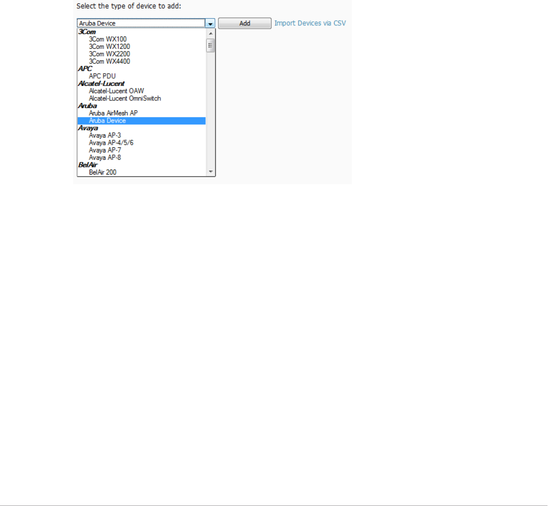
Dell PowerConnect W-AirWave 7.5 | User Guide Discovering, Adding, and Managing Devices | 113
This section describes the following procedures:
Adding Devices with the Device Setup > Add Page
Adding Multiple Devices from a CSV File
Adding Universal Devices
Adding Devices with the Device Setup > Add Page
Manually adding devices from the Device Setup > Add page to AirWave is an option for adding all device types.
You only need to select device vendor information from a drop down menu for Cisco and Dell PowerConnect W-
Series devices, and AirWave automatically finds and adds specific make and model information into its database.
Perform these steps to manually add devices to AirWave:
1. The first step to add a device manually is to select the vendor and model. Browse to the Device Setup > Add
page and select the vendor and model of the device to add. Figure 76 illustrates this page.
Figure 76 Device Setup > Add Page Illustration
2. Select Add. The Device Communications and Location sections appear, illustrated in Figure 77.
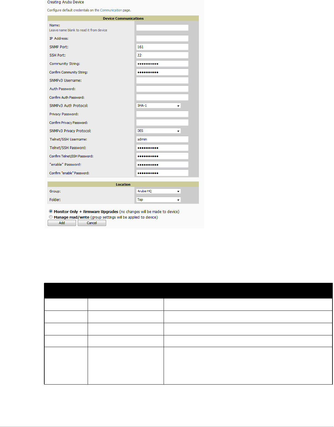
114 | Discovering, Adding, and Managing Devices Dell PowerConnect W-AirWave 7.5 | User Guide
Figure 77 Device Setup > Add > Device Communications and Location Sections
3. Complete these Device Communications and Location settings for the new device. Table 74 further
describes the contents of this page. Settings may differ from device to device based on the type of device and
the features that the device supports. In several cases, the default values from any given device derive from the
Device Setup > Communication page.
Table 74 Device Communication and Location Fields and Default Values
Setting Default Description
Name None User-configurable name for the AP (maximum of 20 characters).
IP Address None IP address of the device. This field is required.
SNMP Port 161 Port AirWave uses to communicate with the AP using SNMP.
SSH Port 22 For devices that support SSH, specify the SSH port number.
Community
String
(Confirm)
Taken from Device Setup >
Communication
Community string used to communicate with the AP.
NOTE: The Community String should have RW (Read-Write) capability.
New, out-of-the-box Cisco devices typically have SNMP disabled and a
blank username and password combination for HTTP and Telnet. Cisco
supports multiple community strings per AP.

Dell PowerConnect W-AirWave 7.5 | User Guide Discovering, Adding, and Managing Devices | 115
4. In the Location field, select the appropriate group and folder for the device.
5. At the bottom of the page, select either the Monitor Only or Management read/write radio button. The
choice depends on whether or not you wish to overwrite the Group settings for the device being added. For
more information and a detailed procedure, see “Authorizing Devices to AirWave from APs/Devices > New
Page” on page112.
6. Select Add to finish adding the devices to the network.
Adding Multiple Devices from a CSV File
You can add devices in bulk from a CSV file to AirWave. Here you also have the option of specifying vendor name
only, and AirWave will automatically determine the correct type while bringing up the device. If your CSV file
SNMPv3
Username
Taken from Device Setup >
Communication
If you are going to manage configuration for the device, this field provides
a read-write user account (SNMP, HTTP, and Telnet) within the Cisco
Security System for access to existing APs. AirWave initially uses this
username and password combination to control the Cisco AP. AirWave
creates a user-specified account with which to manage the AP if the User
Creation Options are set to Create and user Specified as User
Auth Password Taken from Device Setup >
Communication
SNMPv3 authentication password.
NOTE: SNMPv3 supports three security levels: (1) no authentication and
no encryption, (2) authentication and no encryption, and (3) authentication
and encryption. AirWave currently only supports authentication and
encryption.
Privacy
Password
(Confirm)
Taken from Device Setup >
Communication
SNMPv3 privacy password.
NOTE: SNMPv3 supports three security levels: (1) no authentication and
no encryption, (2) authentication and no encryption, and (3) authentication
and encryption. AirWave currently only supports authentication and
encryption.
SNMPv3 Auth
Protocol
Taken from Device Setup >
Communication
Drop-down menu that allows you to enable the SNMPv3 authentication
protocol to the device being added.
SNMPv3 Privacy
Protocol
Taken from Device Setup >
Communication
Drop-down menu that allows you to enable SNMPv3 privacy protocol to
the device being added.
Telnet/SSH
Username
Taken from Device Setup >
Communication
Telnet username for existing Cisco IOS APs. AirWave uses the Telnet
username/password combination to manage the AP and to enable SNMP
if desired.
NOTE: New, out-of-the-box Cisco IOS-based APs typically have SNMP
disabled with a default telnet username of Cisco and default password of
Cisco. This value is required for management of any existing Cisco IOS-
based APs.
Telnet/SSH
Password
(Confirm)
Taken from Device Setup >
Communication
Telnet password for existing Cisco IOS APs. AirWave uses the Telnet
username/password combination to manage the AP and to enable SNMP
if desired.
NOTE: New, out-of-the-box Cisco IOS-based APs typically have SNMP
disabled with a default telnet username of Cisco and default password of
Cisco. This value is required for management of any existing Cisco IOS-
based APs.
“enable”
Password
(Confirm)
Taken from Device Setup >
Communication
Password that allows AirWave to enter enable mode on the device.
Table 74 Device Communication and Location Fields and Default Values (Continued)
Setting Default Description
NOTE: If you select Manage read/write, AirWave overwrites existing device settings with the Groups settings. Place newly
discovered devices in Monitor read/only mode to enable auditing of actual settings instead of Group Policy settings.
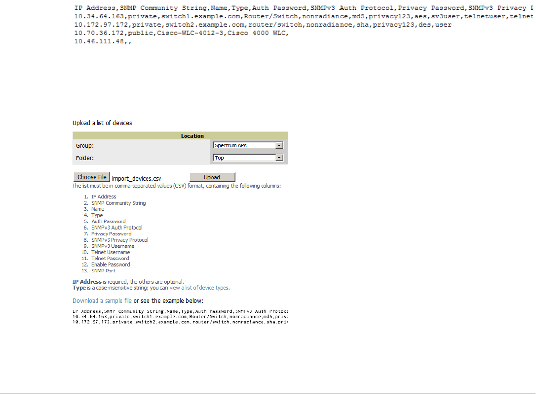
116 | Discovering, Adding, and Managing Devices Dell PowerConnect W-AirWave 7.5 | User Guide
includes make and model information, AirWave will add the information provided in the CSV file as it did
before. It will not override what you have specified in this file in any way.
The CSV list must contain the following columns:
-IP Address
-SNMP Community String
-Name
-Type
-Auth Password
-SNMPv3 Auth Protocol
-Privacy Password
-SNMPv3 Privacy Protocol
-SNMPv3 Username
-Telnet Username
-Telnet Password
-Enable Password
-SNMP Port
You can download a CSV file and customize it as you like. A sample CSV file is illustrated in Figure 78.
Figure 78 Sample CSV File
1. To import a CSV file, go to the Device Setup > Add page.
2. Select the Import Devices via CSV link. The Upload a list of devices page displays; see Figure 79.
Figure 79 Device Setup > Add > Import Devices via CSV Page Illustration
3. Select a group and folder into which to import the list of devices.
4. Select Choose File and select the CSV list file on your computer.
5. Select Upload to add the list of devices into AirWave.
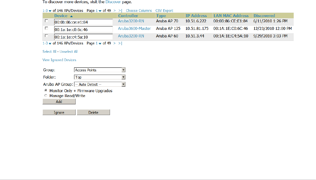
Dell PowerConnect W-AirWave 7.5 | User Guide Discovering, Adding, and Managing Devices | 117
Adding Universal Devices
AirWave gets basic monitoring information from any device including switches, routers and APs whether or not
they are supported devices. Entering SNMP credentials is optional. If no SNMP credentials are entered, AirWave
will provide ICMP monitoring of universal devices. This allows you to monitor key elements of the wired network
infrastructure, including upstream switches, RADIUS servers and other devices. While AirWave can manage
most leading brands and models of wireless infrastructure, universal device support also enables basic monitoring
of many of the less commonly used devices.
Perform the same steps to add universal devices to AirWave that were detailed in “Adding Devices with the
Device Setup > Add Page” on page113.
AirWave collects basic information about universal devices including name, contact, uptime and location. Once
you have added a universal device, you can view a list of its interfaces on APs/Devices > Manage.
By selecting the pencil icon next to an interface, you can assign it to be non-monitored or monitored as Interface
1 or 2. AirWave collects this information and displays it on the APs/Devices > Monitor page in the Interface
section. AirWave supports MIB-II interfaces and polls in/out byte counts for up to two interfaces. AirWave also
monitors sysUptime.
Assigning Devices to the Ignored Page
A device can be assigned to the Ignored page from the APs/Devices > New page. The advantage of having the
device be designated in this way, as in the case of a device that is temporarily down for a known reason, is that
when you take it off the ignored list, it returns immediately to the location in AirWave where it had resided
before it was marked Ignored.
-Ignored devices are not displayed in APs/Devices > New if discovered in subsequent scans.
-Deleted devices will be listed on the APs/Devices > New if discovered in subsequent scans.
Perform these steps to further process or return an ignored device to a managed status.
1. Go to the APs/Devices > New page to view all newly discovered devices. See Figure 80.
Figure 80 APs/Devices > New Page Illustration
2. Select the checkbox beside the device or devices that you want to ignore, and then select the Ignore button.
Unignoring a Device
Perform these steps to further process a device or to return an ignored device to a managed status.
1. To view all devices that are ignored, go to the APs/Devices > Ignored page, illustrated in Figure 81.

118 | Discovering, Adding, and Managing Devices Dell PowerConnect W-AirWave 7.5 | User Guide
Figure 81 APs/Devices > Ignored Page Illustration
This page provides the following information for any ignored device:
-device name or MAC address, when known
-controller associated with that device
-device type
-device IP address
-LAN MAC address for the LAN on which the device is located
-date and time of device discovery
2. To change the device parameters for a given device, select its checkbox and adjust group, folder, monitor, and
manage settings as desired.
3. Select Add to add the device to AirWave so that it appears on the APs/Devices > New list.
4. The Unignore button will either return the device to its regular folder or group or send it to the APs/
Devices > New page.
Monitoring Devices
This section discusses various device monitoring options and includes the following sections:
-Viewing Device Monitoring Statistics
-Understanding the APs/Devices > Monitor Pages for All Device Types
-Evaluating Radio Statistics for an AP
-Monitoring Data for Mesh Devices
-Monitoring Data for Wired Devices (Routers and Switches)
-Understanding the APs/Devices > Interfaces Page
-Auditing Device Configuration
-Using Device Folders (Optional)
Viewing Device Monitoring Statistics
You can view many useful device monitoring statistics in the APs/Devices > List page. The APs/Devices > List
page displays Clients and Usage interactive graphs (formerly Users and Bandwidth prior to 7.4) and lists all
devices that are managed or monitored by AirWave.
To see only the Up devices, you can click the Up link in the Top Header Stats bar (next to the green arrow). This
displays the APs/Devices > Up page with the same information, but only containing active devices. You can do
the same with the Down and Mismatched top header stats links.
Use the Go to folder field to filter the list by folder, or click Expand folders to show all APs/Devices if you are
looking at a filtered device list. A lock icon in the Configuration column indicates that the device in that row is in
Monitor only mode. Figure 82 illustrates this page.
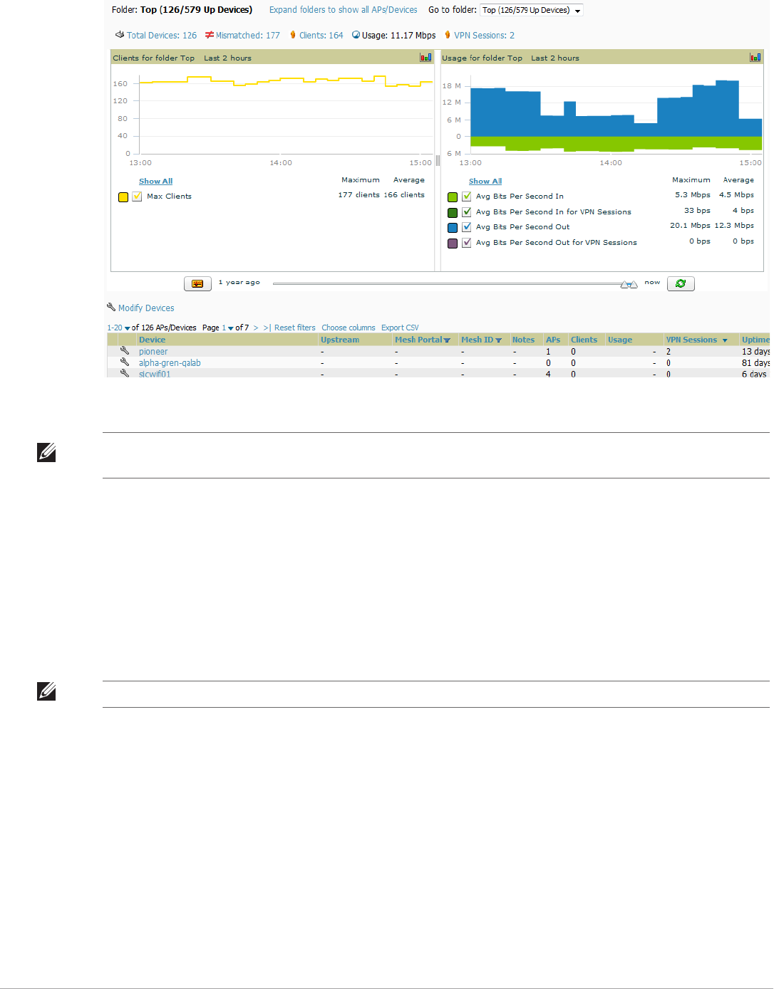
Dell PowerConnect W-AirWave 7.5 | User Guide Discovering, Adding, and Managing Devices | 119
Figure 82 APs/Devices > List (partial view)
Verify that the devices you added are now appearing in the APs/Devices > Up page.
The same section also appears on the Groups > Monitor page and is hyperlinked from a controller's monitoring
interface.
The Alert Summary section of APs/Devices > List cites the number of events that have occurred in the last two
hours, the last 24 hours, and total. There are three categories of alerts as listed below:
AMP Alerts
IDS Events
RADIUS Authentication Issues
For more information on the Alert Summary table, refer to “Viewing Alerts” on page200.
Understanding the APs/Devices > Monitor Pages for All Device Types
You can quickly go to any device’s monitoring page once you go to its specific folder or group on the APs/Devices
> List page by selecting its hyperlinked name in the Device column.
All Monitor pages include a section at the top displaying information such as monitoring/configuration status,
serial number, total users, firmware version, and so on, as shown in Figure 83.
NOTE: Newly added devices will have a status of Down until they have been polled the first time. Their configuration status will
remain Unknown until they have finished verification. The Up status is not contingent on verification.
NOTE: The Alert Summary table is also a feature of the Home > Overview page and has the same links in that location.
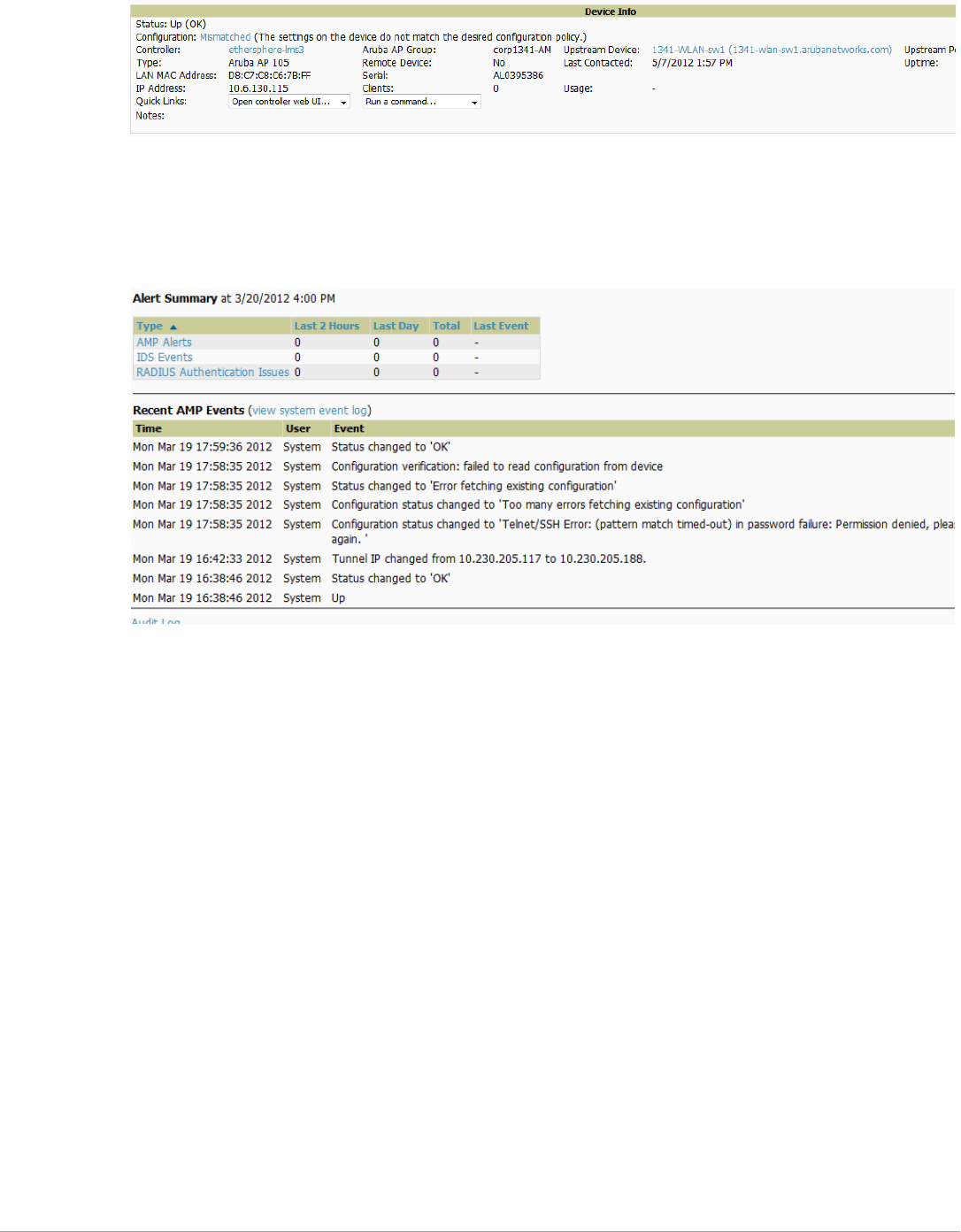
120 | Discovering, Adding, and Managing Devices Dell PowerConnect W-AirWave 7.5 | User Guide
Figure 83 Monitoring Page Top Level Data Common to All Device Types
The alert summary and recent events sections are also the same regardless of the device type, and these sections
appear toward the bottom of these pages. In addition, a link to the Audit Log is available on the bottom of this
page. A portion of this page is shown in Figure 84.
Figure 84 Monitoring Page Bottom Level Data Common to All Device Types (partial view)
Monitoring pages vary according to whether they are wired routers/switches, controllers/WLAN switches, or thin
or fat APs; whether the device is a Mesh device; and whether Spectrum is enabled. These differences are
discussed in the sections that follow.
Monitoring Data Specific to Wireless Devices
The APs/Devices > Monitor page for controllers and APs include a graph for users and bandwidth. The
controller graph lists the APs connected to it, while the APs include a list of users it has connected.
When available, lists of CDP and RF neighbors are also listed.
A sample monitoring page for wireless devices is shown in Figure 85.
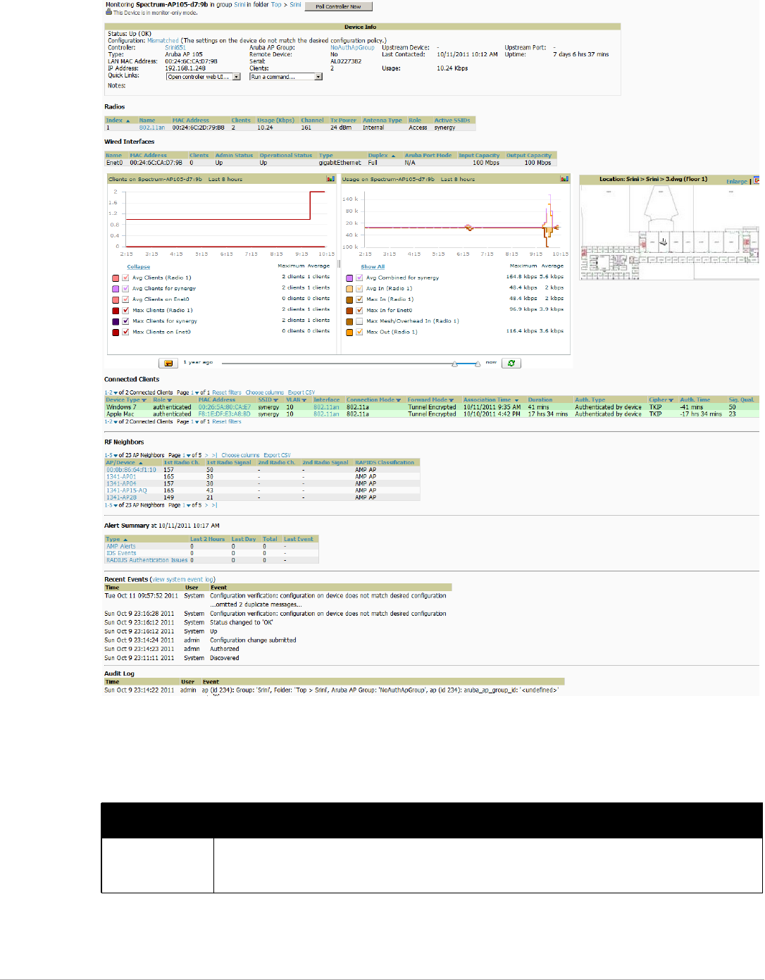
Dell PowerConnect W-AirWave 7.5 | User Guide Discovering, Adding, and Managing Devices | 121
Figure 85 APs/Devices > Monitor Page for Wireless Devices (partial view of an AP
)
Table 75 describes the fields and information displayed in the Device Info section. The displayed fields vary from
device to device.
Table 75 APs/Devices > Monitor > Device Info Fields and Default Values
Field Description
Poll Now Button above the Device Info section that, when pressed, immediately polls the individual AP or the
controller for a thin AP; this overrides the group's preset polling intervals to force an immediate update of
all data except for rogue information. Shows “attempt” status and last polling times.

122 | Discovering, Adding, and Managing Devices Dell PowerConnect W-AirWave 7.5 | User Guide
Status Displays ability of AirWave to connect to the AP. Up (no issue) means everything is working as it should.
Down (SNMP “get” failed) means AirWave can get to the device but not speak with it using SNMP. Check
the SNMP credentials AirWave is using the view secrets link on the APs/Devices > Manage page and
verify SNMP is enabled on the AP. Many APs ship with SNMP disabled. Down (ICMP ping failed after
SNMP get failed) means AirWave is unable to connect to the AP using SNMP and is unable to ping the AP.
This usually means AirWave is blocked from connecting to the AP or the AP needs to be rebooted or reset.
Configuration Good means all the settings on the AP agree with the settings AirWave wants them to have. Mismatched
means there is a configuration mismatch between what is on the AP and what AirWave wants to push to
the AP. The Mismatched link directs you to this specific APs/Devices > Audit page where each mismatch is
highlighted. Unknown means the device configuration has not yet been fetched (possible issue with
credentials). Verifying means that the device is fetching a configuration that will be compared to the
desired settings. Error indicates a problem with the device. This configuration is accompanied with a
description of the error.
Firmware Displays the firmware version running on the AP.
NOTE: Newer AirMesh APs include the new bootloader APBoot. AirWave helps to identify the new
AirMesh APs from the old SKUs by displaying the bootloader information here.
Licenses (Appears
for Dell controllers)
Selecting this link opens a pop-up window that lists the licenses installed for this controller, and whether
they have expired.
Controller (Appears
for APs)
Displays the controller for the associated AP device as a link. Select the link to display the APs/Devices >
Monitor page for that controller.
Mesh Gateway * Specifies the mesh AP acting as the wired connection to the network.
Mesh Mode* Specifies whether the AP is a portal device or a mesh node. The portal device is connected to the network
over a wired connection. A node is a device downstream of the portal that uses wireless connections to
reach the portal device.
Mesh ID * The name of the mesh device.
View in Google
Earth*
Selecting the Google Earth icon opens the mesh network view in Google Earth.
Type Displays the make and model of the device.
Last Contacted Displays the most recent time AirWave has polled the AP for information. The polling interval can be set on
the Groups > Basic page.
Uptime Displays the amount of time since the AP has been rebooted. This is the amount of time the AP reports and
is not based on any connectivity with AirWave.
LAN MAC Address Displays the MAC address of the Ethernet interface on the device.
Serial Displays the serial number of the device.
Radio Serial Displays the serial number of the radios in the device. This field is not available for all APs.
Location Displays the SNMP location of the device.
Contact Displays the SNMP contact of the device.
IP Address Displays the IP address that AirWave uses to communicate to the device. This number is also a link to the
AP web interface. When the link is moused over a pop-up menu will appear allowing you to http, https,
telnet or SSH to the device.
NOTE: For Dell controllers, if Single Sign-On is enabled for your role in this AirWave and you have access to
this controller, you will not have to enter the credentials for this controller again after selecting this link.
Outer IP Public IP address for a RAP device.
Remote LAN IP LAN IP address for a RAP. This address is useful for troubleshooting from the local network.
Table 75 APs/Devices > Monitor > Device Info Fields and Default Values (Continued)
Field Description

Dell PowerConnect W-AirWave 7.5 | User Guide Discovering, Adding, and Managing Devices | 123
*This field is only available for mesh APs. To see an example of mesh monitoring, see “Monitoring Data for Mesh
Devices” on page131.
Table 76 describes the information in the Radio table for APs:
Devices with wired interfaces will display the Wired Interfaces table, which is described in Table 77:
Quick Links -Open controller web UI: A drop-down menu that allows you to jump to the controller’s UI in a new
window.
NOTE: For Dell controllers, if Single Sign-On is enabled for your role in this AirWave and you have access to
this controller, you will not have to enter the credentials for this controller again after selecting this link.
-Run a command: A drop-down menu with a list of CLI commands you can run directly from the APs/
Devices > Monitor page.
APs For controllers, displays the number of APs managed by this device at the time of the last polling.
Clients Displays the total number of users associated to the device or its APs regardless of which radio they are
associated to, at the time of the last polling.
Usage Combined bandwidth through the device at time of polling.
Table 76 APs/Devices > Monitor > Radio Fields and Descriptions
Field Description
Index The number of the radio, used to distinguish radios that may be of the same type on a device.
Name The Radio type (802.11a/b/g/n) as a link to the Radio Statistics page for that radio.
MAC Address The MAC address of the corresponding radio in the AP.
Clients The number of users associated to the corresponding radio at the time of the last polling.
Usage (Kbps) The amount of bandwidth being pushed through the corresponding radio interface or device at the time of
the last polling.
Channel The channel of the corresponding radio.
Tx Power Some devices report transmit power reduction rather than transmit power; no value is reported for those
devices.
Antenna Type Indicates Internal or External radio. For devices where antenna type is defined per AP, the same antenna
type will be listed for each radio.
Channel Width* The bandwidth of the channel used by 802.11 stations. Legacy devices use 20 MHz channels, and newer
devices that support the 802.11n standard can use 40 MHz channels to increase throughput.
Mesh Links * The total number of mesh links to the device including uplinks and downlinks.
Role Whether the radio acts as a Mesh Node or Access
Active SSIDs The SSID(s) of the radio.
Table 77 APs/Devices > Monitor > Wired Interfaces Fields and Descriptions
Field Description
Name Displays the name of the interface.
MAC Address Displays the MAC address of the corresponding interface in the device.
Clients Displays the number of users associated to the corresponding interface at the time of the last polling.
Table 75 APs/Devices > Monitor > Device Info Fields and Default Values (Continued)
Field Description
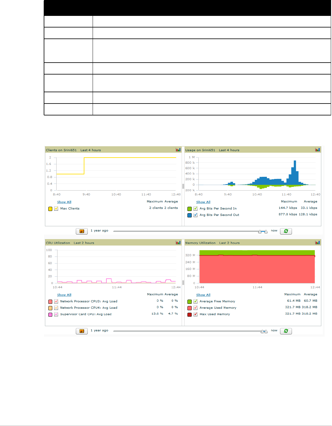
124 | Discovering, Adding, and Managing Devices Dell PowerConnect W-AirWave 7.5 | User Guide
Figure 86 illustrates the interactive graphs.
Figure 86 Interactive Graphs for an Dell PowerConnect W-Series Controller
Type Indicates the type of interface - gigabit Ethernet or fast Ethernet for wired interfaces.
Admin Status The administrator setting that determined whether the port is on or off.
Operational Status Displays the current status of the interface. If an interface is Up, then AirWave is able to ping it and fetch
SNMP information. If the AP is listed as Down, then AirWave is either unable to ping the interface or unable
to read the necessary SNMP information from the device.
Duplex Duplex mode of the link, full or half.
Dell Port Mode Either Active Standby (which provides redundancy so that when an active interface fails, the user traffic
can failover to the standby interface) or one of the forwarding modes (Split, Bridge).
Input Capacity The input capacity of the interface.
Output Capacity The output capacity of the interface.
Table 77 APs/Devices > Monitor > Wired Interfaces Fields and Descriptions (Continued)
Field Description
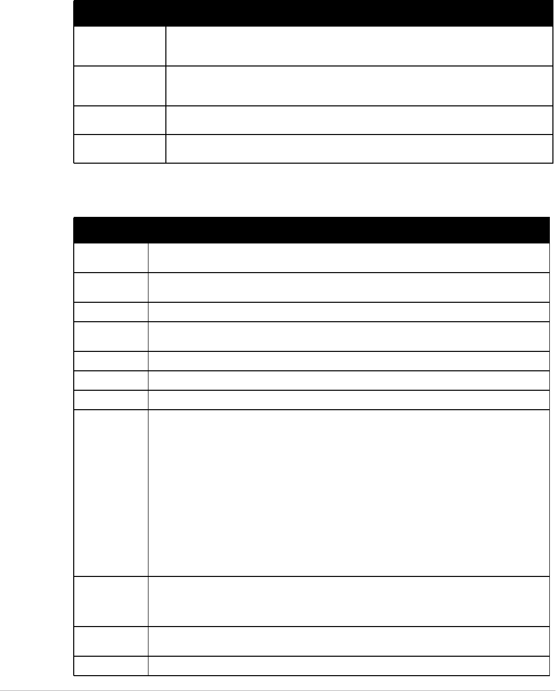
Dell PowerConnect W-AirWave 7.5 | User Guide Discovering, Adding, and Managing Devices | 125
Table 78 describes the graphs on this page.
Table 79 describes the fields and information displayed for the Connected Clients display.
Table 78 APs/Devices > Monitor Graphical Data
Graph Description
Clients Formerly “Users”. Shows the max and average client count reported by the device radios for a
configurable period of time. User count for controllers are the sum of the user count on the associated
APs. Checkboxes below the graph can be used to limit the data displayed.
Usage Formerly “Bandwidth”. Shows the bandwidth in and out reported by the device for a configurable
period of time. Bandwidth for controllers is the sum of the associated APs. Checkboxes below the graph
can be used to limit the data displayed.
CPU Utilization
(controllers only)
Reports overall CPU utilization (not on a per-CPU basis) of the device.
Memory Utilization
(controllers only)
Reports average used and free memory and average max memory for the device.
Table 79 APs/Devices > Monitor > Connected Clients Fields and Default Values
Field Description
Username Provides the name of the User associated to the AP. AirWave gathers this data in a variety of ways. It can be
taken from RADIUS accounting data or traps.
Device Type The type of device the user is using as determined by the Device Type Rules set up by an administrator in
AMP Setup > Device Type Setup. For more information, refer to “Setting Up Device Types” on page 55.
Role The role of the connected client such as employee, perforce, or logon (captive portal).
MAC Address Displays the Radio MAC address of the user associated to the AP. Also provides a link that redirects to the
Users > Detail page.
Radio Displays the radio to which the user is associated.
Association Time Displays the first time AirWave recorded the MAC address as being associated.
Duration Displays the length of time the MAC address has been associated.
Auth Type Displays the type of authentication employed by the user. Supported auth types include:
-EAP—Extensible Authentication Protocol.
-RADIUS accounting—RADIUS accounting servers integrated with AirWave provide the RADIUS
Accounting Auth type
-WPA2—Wi-Fi Protected Access 2 encryption
-No Encryption
AirWave considers all other types as not authenticated.
The information AirWave displays in Auth Type and Cipher columns depends on what information the server
receives from the devices it is monitoring. The client devices may all be similar, but if the APs to which they
are associated are of different models, or if security is set up differently between them, then different Auth
Type or Cipher values may be reported to AirWave.
If all APs are the same model and all are set up the same way, then another reason for differing Auth Types
might be the use of multiple VLANs or SSIDs. One client device might authenticate on one SSID using one
Auth Type and another client device might authenticate on a second SSID using a different Auth Type.
Cipher Displays the encryption or decryption cipher supporting the user, when this information is available. The
client devices may all be similar, but if the APs to which they are associated are of different models, or if
security is set up differently between them, then different Auth Type or Cipher values may be reported to
AirWave.
Auth Time Shows how long the user has been authenticated, in minutes. A negative number (such as -17 min)
indicates that the user has not authenticated for the duration displayed.
Signal Quality Displays the average signal quality the user experienced.
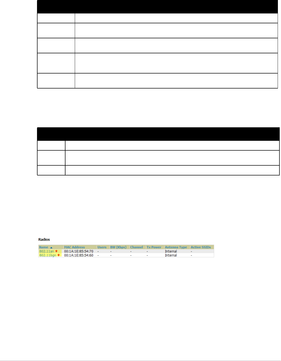
126 | Discovering, Adding, and Managing Devices Dell PowerConnect W-AirWave 7.5 | User Guide
The Recent Events area lists the most recent events specific to the device. This information also appears on the
System > Events Log page (refer to “Using the System > Event Log Page” on page192). Table 80 describes the
fields in this page that display in the Recent Events table.
Evaluating Radio Statistics for an AP
The APs/Devices > Monitor > Radio Statistics page contains useful data for pinpointing network issues at the
AP radio level for Dell APs and Cisco WLC thin APs (firmware 4.2 or greater).
To see radio statistics details, navigate to the APs/Devices > Monitoring page for a supported AP and select the
linked radio under the Name column in the Radios list table, as illustrated in Figure 87.
Figure 87 Links to the Radio Statistics page on APs/Devices > Monitoring for an AP
Overview of the Radio Statistics Page
The Radio Statistics page displays transmit and receive statistics about the communication quality of individual
radios. Depending on the AP, assigned group profiles, and recent activity on this radio, this data gives visibility
into recent and historical changes in the network, fetches real-time statistics from the AP’s controller, indicates
actively interfering devices (requires Dell PowerConnect W-Series AP set to Spectrum mode), and summarizes
major issues.
Viewing Real-Time ARM Statistics
Dell AP Groups that have the Adaptive Radio Management (ARM) feature enabled continuously optimize each
AP to use the best channel and transmission power settings available. An AP configured with ARM will
automatically adjust to a better channel if it reaches a configured threshold for noise, MAC errors, or PHY errors;
additionally, it can attenuate transmit power and switch between radio modes as needed. For more information,
refer to the ARM chapter in the Dell PowerConnect W-SeriesArubaOS User Guide at support.dell.com/manuals.
Usage Displays the average bandwidth consumed by the MAC address.
Goodput The ratio of the total bytes transmitted or received in the network to the total air time required for
transmitting or receiving the bytes.
Location Displays the QuickView box allows users to view features including heatmap for a device and location
history for a user.
LAN IP
Addresses
Displays the IP assigned to the user MAC. This information is not always available. AirWave can gather it
from the ARP cache of switches discovered by AirWave. This column can accommodate multiple IP
addresses for a client if it has both IPv4 and IPv6.
LAN Hostnames The DNS hostname(s) broadcast by the client. This column can accommodate multiple hostnames for a
client if it has both IPv4 and IPv6.
Table 80 APs/Devices > Monitor > Recent Events Fields and Default Values
Field Description
Time Displays the day and time the event was recorded.
User Displays the user that triggered the event. Configuration changes are logged as the AirWave user that submitted
them. Automated AirWave events are logged as the System user.
Event Displays a short text description of the event.
Table 79 APs/Devices > Monitor > Connected Clients Fields and Default Values (Continued)
Field Description
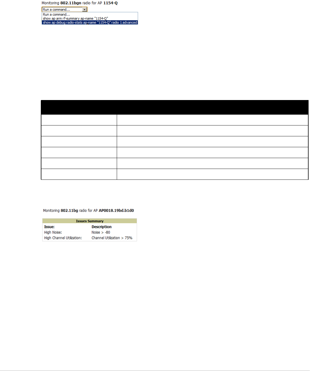
Dell PowerConnect W-AirWave 7.5 | User Guide Discovering, Adding, and Managing Devices | 127
Complete ARM statistics from Dell PowerConnect W-Series controllers can be retrieved from the Radio
Statistics page by selecting the Run a command drop-down menu and choosing button, as illustrated in Figure
88.
Figure 88 Fetch additional radio stats by running a show command
When this button is selected, a new browser window launches with the statistics in plain text. Other ARM-
tracked metrics are visible in the Radio Statistics page for Dell PowerConnect W-Series APs.
Issues Summary section
The Issues Summary section only displays when noise, client count, non-802.11 interfering devices, channel
utilization, usage, and MAC and PHY errors reach a certain threshold of concern, as described in Table 81 and
illustrated in Figure 89:
Figure 89 Issues Summary Section Illustration
These issues highlighted in this section can be examined in detail using the corresponding interactive graphs on
the same page. See the Radio Statistics Interactive Graphs section of this chapter for details.
802.11 Radio Counters Summary
This table appears for radios with 802.11 counters and summarizes the number of times an expected
acknowledgement frame was not received, the number of duplicate frames, the number of frames containing
Frame Check Sequence (FCS) errors, and the number of frame/packet transmission retries and failures. These
aggregate error counts are broken down by Current, Last Hour, Last Day, and Last Week time frames, as
illustrated in Figure 90.
Table 81 Issues Summary labels and thresholds
Issue Triggering Threshold
High Noise > -80
High Number of Clients > 15
High Channel Utilization > 75%
High Usage > 75% of max
Interfering Devices Detected Detected within the last 5 minutes
High MAC/Phy Errors > 1000 frames/sec
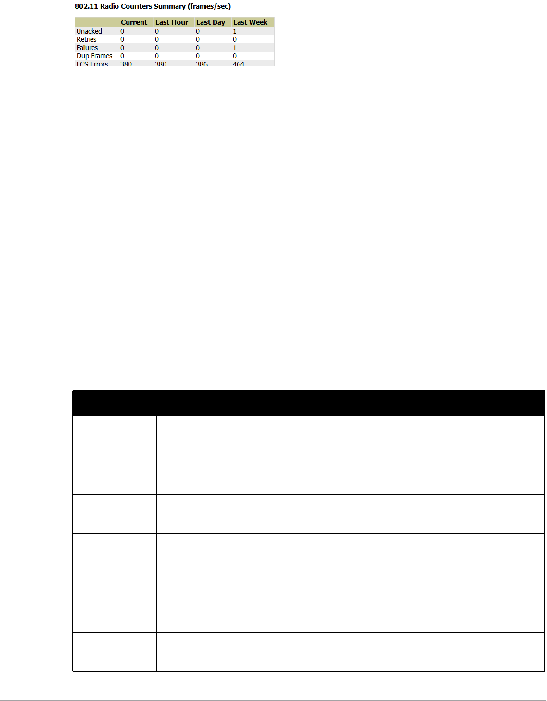
128 | Discovering, Adding, and Managing Devices Dell PowerConnect W-AirWave 7.5 | User Guide
Figure 90 802.11 Radio Counters Summary table
The frame- per-second rate of these and other 802.11 errors over time are tracked and compared in the 802.11
Counters graph on the same page.
Radio Statistics Interactive Graphs
Time-series graphs for the radio are displayed across a tabbed, dual-pane interface to show changes recorded at
every polling interval over time. Clients and Usage data are polled based on the AP's group's User Data Polling
Period. Channel, Noise, and Power are based on AP Interface Polling Period. 802.11 Counters data are based on
the APs group’s 802.11 Counters Polling Period.
You can adjust the attributes of these graphs as follows:
-Drag the horizontal slider under the graphs to move the scope of all graphs between one year ago and the
current time.
-Drag the vertical slider between graphs to change the relative width of each.
-The Show All link displays all of the available data series.
-The bar-graph icon on the upper right-hand corner of each graph opens a new window and displays all data
series for the selected graph over the last two hours, last day, last week, last month, and last year in one page.
The graphs that display depend on the AP and/or its controller.
-Select the checkbox next to any metric to remove its data from the graph. Select Collapse to remove
unchecked metrics from the legend, and Show All to restore them.
The two graph panes enable simultaneous display of two different information sets, as detailed in:
Table 82 Radio Statistics Interactive Graphs Descriptions
Graph Title Description
Clients A line graph that displays the maximum users associated to the corresponding radio at polling intervals
over the time range set in the slider. Select Show All for other metrics such as average users and max
users for various individual devices.
Usage An area graph displaying the average bandwidth in each direction for the radio. Select Show All for other
metrics such as max bandwidth in and out, average and max mesh/overhead or overhead bandwidth, and
average/max Enet0.
Channel An area graph that displays the channel changes (if any) of the radio over time. Frequent, regular channel
changes on an Dell or Cisco WLC AP radio usually indicate that the Adaptive Radio Management feature
(ARM) in ArubaOS is compensating for high noise levels from interfering devices.
Noise An area graph that displays signal interference (noise floor) levels in units of dBm. Noise from interfering
devices above your AP’s noise threshold can result in dropped packets. For ARM-enabled Dell APs,
crossing the noise threshold triggers an automatic channel change.
Power A line graph that displays the average and maximum radio transmit power, between 0 and 30 dBm, over
the time range set in the slider. You can adjust the transmit power manually in the APs/Devices > Manage
page for this radio’s AP, or enable ARM on Dell APs to dynamically adjust the power toward your
acceptable Coverage Index as needed. For more information, see the “Adaptive Radio Management”
chapter of the Dell PowerConnect W-Series ArubaOS User Guide.
MAC/Phy Errors A line graph displaying the frame reception rate, physical layer error rate (resulting from poor signal
reception or broken antennas), and the data link (MAC) layer (corrupt frames, driver decoding issues) for
the radio.
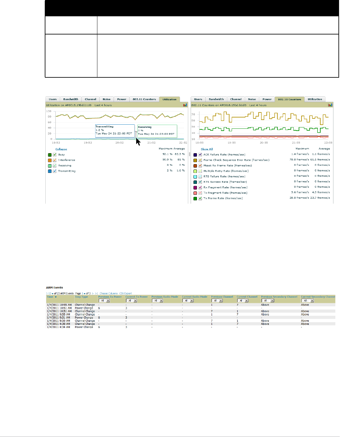
Dell PowerConnect W-AirWave 7.5 | User Guide Discovering, Adding, and Managing Devices | 129
Figure 91 Radio Statistics Interactive Graphs Illustration – Bandwidth and 802.11 Counters displayed
Recent ARM Events Log
If this radio references an active and enabled ARM profile, and if your AirWave is enabled as a trap host (see the
Dell PowerConnect W-AirWave 7.5 Best Practices Guide for instructions), ARM-initiated events such as automatic
channel changes, power changes, and mode changes are displayed in the ARM Events table with the original and
modified values; these values can be selected for filtering the results. You can export the table in CSV format.
The columns and values are illustrated in Figure 92.
Figure 92 ARM Events Table Illustration
802.11 Counters A line graph that displays statistics such as frame rate, fragment rate, retry rate, duplicate frame rate, and
other metrics tracked by 802.11 counters.
Utilization (Dell, Dell
PowerConnect W,
and Cisco WLC
thin APs on
supported firmware
versions only)
Displays max and average percentages on this radio for busy, interfering receiving and transmitting
signals. Special configuration on the controller is required to enable this data. Consult the Dell
PowerConnect W-AirWave 7.5 Best Practices Guide in Home > Documentation for details.
Table 82 Radio Statistics Interactive Graphs Descriptions (Continued)
Graph Title Description
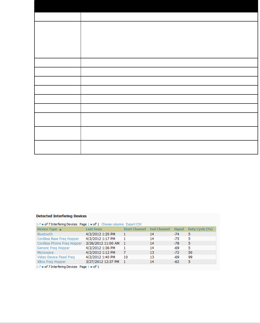
130 | Discovering, Adding, and Managing Devices Dell PowerConnect W-AirWave 7.5 | User Guide
The columns and values are described in Table 83.
Detected Interfering Devices Table
For Dell PowerConnect W-Series APs running in Spectrum mode, the same non-802.11 interfering devices
identified in the Issues Summary section are classified in the Detected Interfering Devices table along with the
timestamp of its last detection, the start and end channels of the interference, the signal to noise ratio, and the
percentage of time the interference takes place (duty cycle), as illustrated in Figure 93. This table can be exported
to CSV format, and the displayed columns can be moved or hidden as needed.
Figure 93 Detected Interfering Devices Table Illustration
Possible device types for the Detected Interfering Devices table are:
-Audio Device Fixed Freq
-Bluetooth
-Cordless Base Freq Hopper
-Cordless Phone Fixed Freq
Table 83 ARM Events table Columns and Values
Column Description
Time The time of the ARM event.
Trap Type The type of trap that delivered the change information. Current ARM trap types that display in
AirWave are:
-Power Change
-Mode Change
-Channel Change
Values that display in the following columns depend on the Trap Type.
Previous Tx Power Old value for transmit power before the Power Change event took place.
Current Tx Power New transmit power value after the change.
Previous Radio Mode Old value for radio mode before the Mode Change event took place.
Current Radio Mode New radio mode value after the change.
Previous Channel Old primary channel value before the Channel Change event took place.
Current Channel New primary channel value after the change.
Previous Secondary
Channel
Old secondary channel value (for 40Mhz channels on 802.11n devices) before the Channel Change
event took place.
Current Secondary
Channel
New secondary channel value after the change.
Change Reason If the noise and interference cause for the change can be determined, they will be displayed here.
Mode change reasons are not yet tracked.
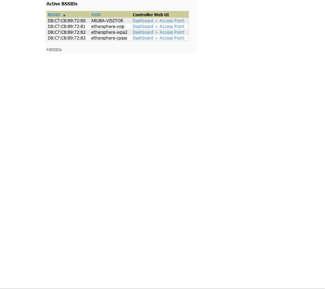
Dell PowerConnect W-AirWave 7.5 | User Guide Discovering, Adding, and Managing Devices | 131
-Cordless Phone Freq Hopper
-Generic Fixed Freq
-Generic Freq Hopper
-Microwave
-Microwave Inverter
-Unknown
-Video Device Fixed Freq
-Wi-Fi
-XBox Freq Hopper
Active BSSIDs Table
The Active BSSIDs table maps the BSSIDs on a radio with the SSID it broadcasts to the network, as illustrated in
Figure 94. This table appears only for Dell PowerConnect W-Series AP radios.
Figure 94 Active BSSIDs Table Illustration
Monitoring Data for Mesh Devices
The monitoring page for mesh devices includes basic device information at the top, two tables for Radios and
Wired Interfaces, and Clients, Usage, CPU Utilization, and Memory Utilization graphs. Under these graphs are a
list of associated Clients, Mesh Links, RF Neighbors, and other common event logs and information.
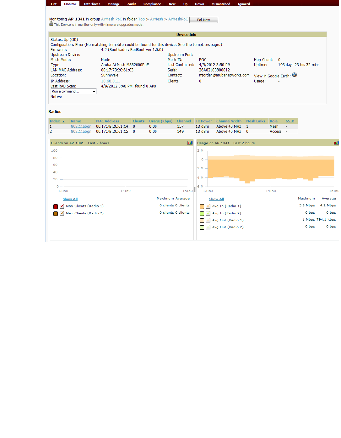
132 | Discovering, Adding, and Managing Devices Dell PowerConnect W-AirWave 7.5 | User Guide
Figure 95 APs/Devices > Monitor page for a Mesh Device
These fields are described in detail in “Viewing Device Monitoring Statistics” on page118.
Monitoring Data for Wired Devices (Routers and Switches)
The monitoring page for routers and switches includes basic device information at the top, a bandwidth graph
depicting the sum of all the physical interfaces, and beneath that, CPU/Memory utilization graphs as shown in
Figure 96.
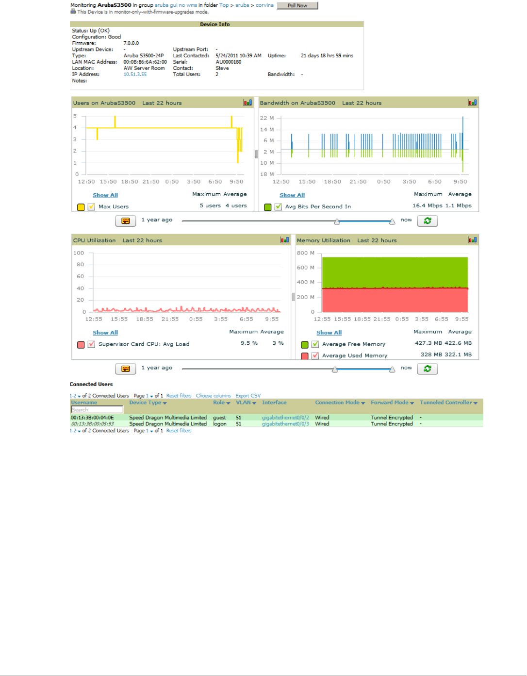
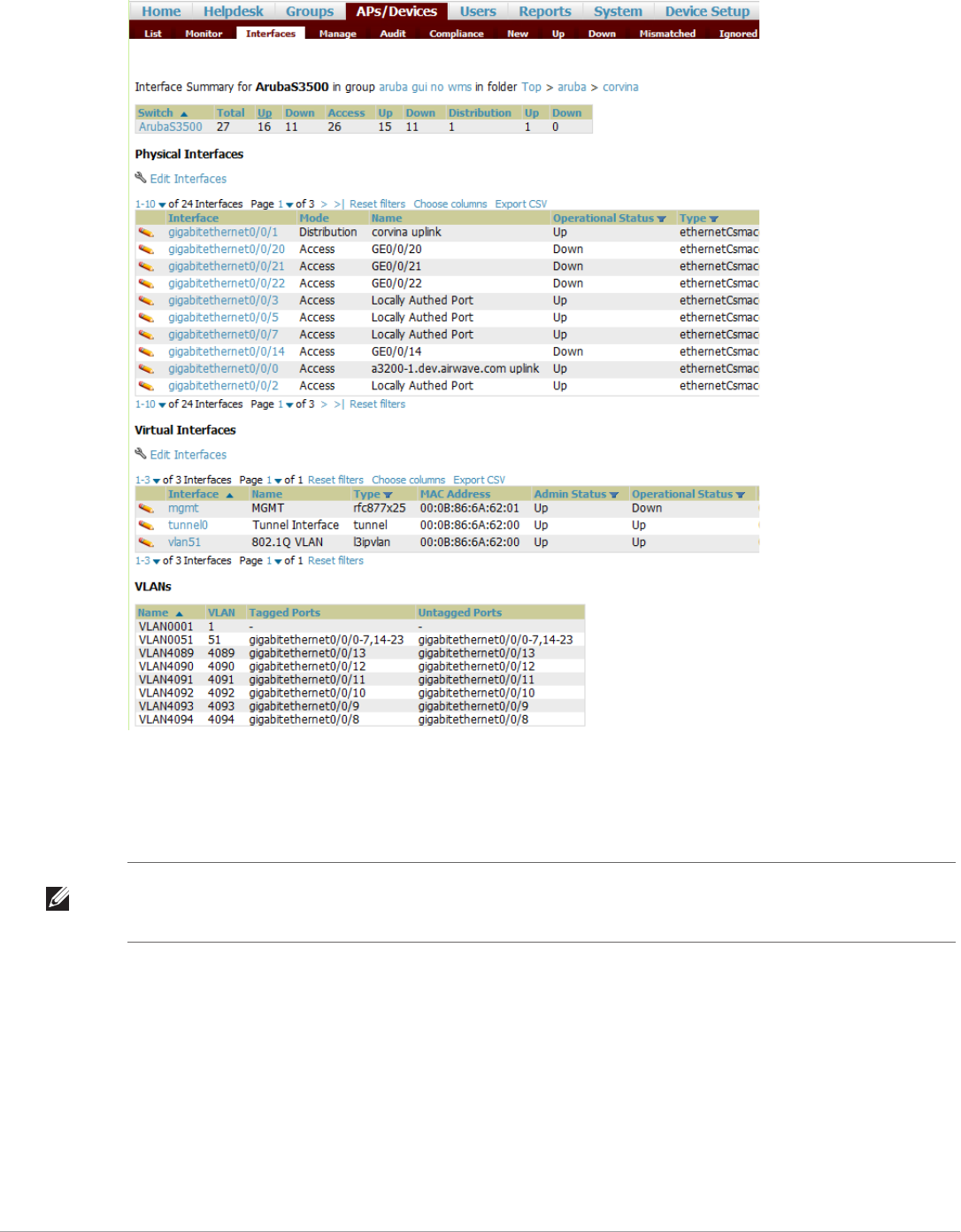
134 | Discovering, Adding, and Managing Devices Dell PowerConnect W-AirWave 7.5 | User Guide
Figure 97 APs/Devices > Interfaces Page for Wired Devices (partial view)
.
The Interfaces page includes a summary of all the interfaces at the top. In case of the stacked switches, the
master includes the interfaces of all the members including its own. The physical and the virtual interfaces are
displayed in separate tables, labeled Physical Interfaces and Virtual Interfaces. VLANs are listed below the
interface.
AirWave monitors Up/Down status and bandwidth information on all interfaces. You can edit multiple interfaces
concurrently by selecting one of the two Edit Interfaces hyperlinks. Interface labels are used to group one or more
interfaces for the purpose of defining interface bandwidth triggers.
Understanding the APs/Devices > Interfaces Page
“Monitoring Data for Wired Devices (Routers and Switches)” on page132 showed you how to view high- level
interface information for all physical and virtual interfaces on an entire router or switch. Select any interface
hotlink in the Interface column of the Physical or Virtual Interfaces tables on the stacked switches to go to an
Interface Monitoring page displaying data relevant to that specific interface, as shown Figure 98.
NOTE: The Interfaces page for AirMesh APs includes VLANs as part of the Virtual Interfaces. When no management interface is
specified, VLAN1 will be treated as management interface. If VLAN1 does not exist, then ethernet 0 will be treated as the
management interface
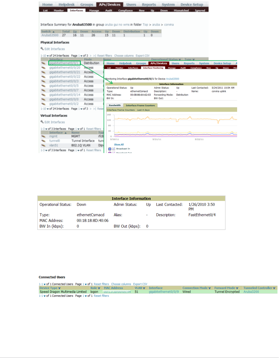
Dell PowerConnect W-AirWave 7.5 | User Guide Discovering, Adding, and Managing Devices | 135
Figure 98 Interface Monitoring Page for a Wired Device
An Interface Monitoring page is comprised of three sections: Interface Information, Usage and Interface Frame
Counters graphs, and Connected Clients.
Specifics of the interface are in the Interface Information section, as depicted in Figure 99.
Figure 99 Individual Interface Information Section
Bandwidth, and various standard and enterprise specific error counting information is displayed in the lower
section in a tabbed graph, which are shown in Figure 98 above.
Connected Clients, if any, are listed in a table below the interactive graphs as shown in Figure 100.
Figure 100 Connected Clients list in APs/Devices > Interface Monitoring for a selected interface
What Next?
All device lists in AirWaveact as portals to management pages if you have the proper read/write privileges.
Selecting the wrench or pencil icon next to a device table entry, or selecting Modify Devices where appropriate
above a device table, will take you to the appropriate Management page (APs/Devices > Manage). For more
information, see “Configuring and Managing Devices” on page137.
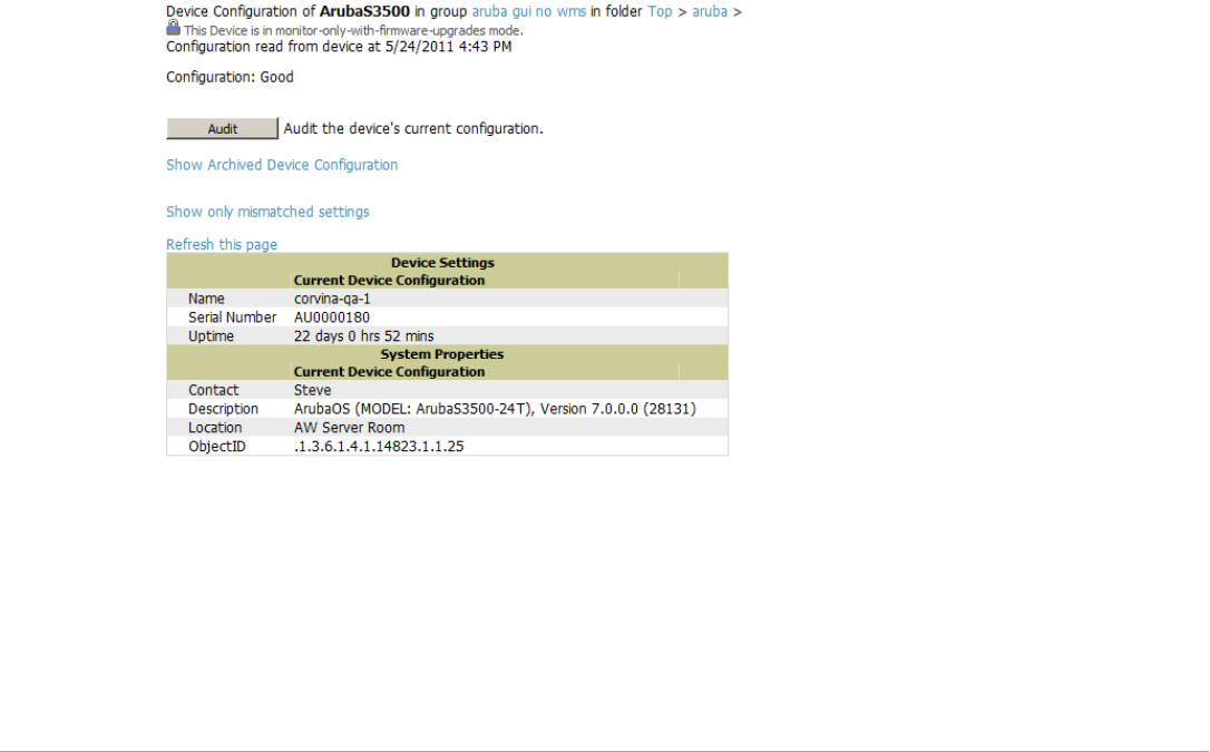
136 | Discovering, Adding, and Managing Devices Dell PowerConnect W-AirWave 7.5 | User Guide
Auditing Device Configuration
When you have added a newly discovered device successfully to a Group in Monitor mode, the next step is to
verify device configuration status. Determine whether any changes will be applied to that device when you
convert it to Managed read/write mode.
AirWave uses SNMP or Telnet to read a device’s configuration. SNMP is used for Cisco controllers. Dell
PowerConnect W-Series devices and wired routers and switches use Telnet/SSH to read device configuration. See
“Individual Device Support and Firmware Upgrades” on page147 for more details.
Perform these steps to verify the device configuration status:
1. Browse to the APs/Devices > List page.
2. Locate the device in the list and check the information in the Configuration column.
3. If the device is in Monitor mode, the lock symbol appears in the Configuration column, indicating that the
device is locked and will not be configured by AirWave.
4. Verify the additional information in the Configuration column for that device.
-A status of Good indicates that all of the device's current settings match the group policy settings and that
no changes will be applied when the device is shifted to Manage mode.
-A status of Mismatched indicates that at least one of the device's current configuration settings does not
match the group policy and will be changed when the device is shifted to Manage mode.
5. If the device configuration is Mismatched, select the Mismatched link to go to the APs/Devices > Audit
page. This page lists detailed information for all existing configuration parameters and settings for an
individual device.
The group configuration settings are displayed on the right side of the page. If the device is moved from
Monitor to Manage mode, the settings on the right side of the page overwrite the settings on the left. Figure
101 illustrates this page.
Figure 101 APs/Devices > Audit Page Illustration
6. Review the list of changes to be applied to the device to determine whether the changes are appropriate. If
not, you need to change the Group settings or reassign the device to another Group.
Using Device Folders (Optional)
The devices on the APs/Devices > List page include List, Up, Down, and Mismatched fields. These devices are
arranged in groups called folders. Folders provide a logical organization of devices unrelated to the configuration
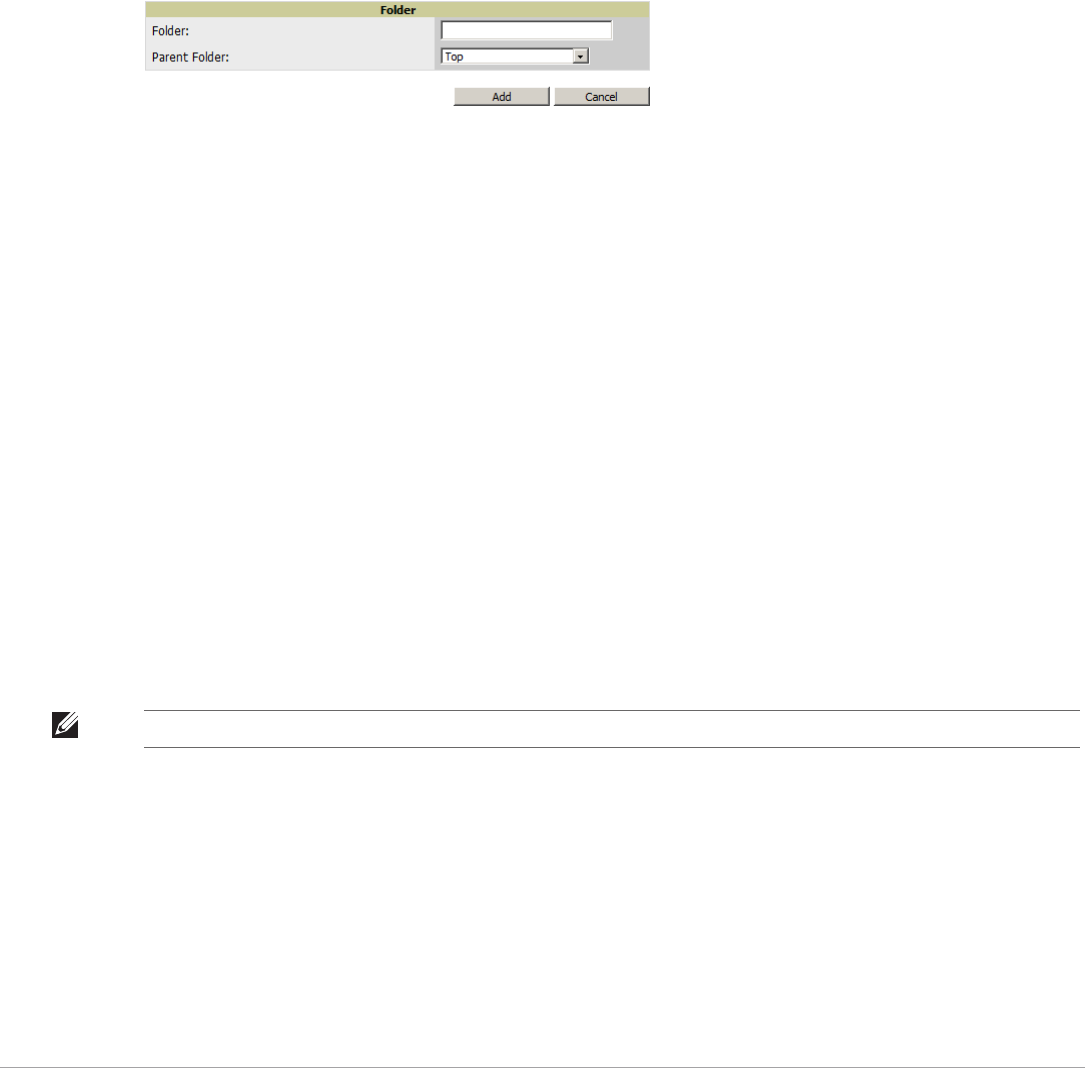
Dell PowerConnect W-AirWave 7.5 | User Guide Discovering, Adding, and Managing Devices | 137
groups of the devices. Using folders, you can quickly view basic statistics about devices. You must use folders if
you want to limit the APs and devices AirWave users can see.
Folder views are persistent in AirWave. If you select the Top folder and then select the Down link at the top of
the page, you are taken to all of the down devices in the folder.
If you want to see every down device, select the Expand folders to show all devices link. When the folders are
expanded, you see all of the devices on AirWave that satisfy the criteria of the page. You also see an additional
column that lists the folder containing the AP.
Perform the following steps to add a device folder to AirWave.
1. To add a folder, select the Add New Folder link at the bottom of APs/Devices > List, > Up, > Down, or >
Mismatched pages. Figure 102 illustrates the page.
Figure 102 Folder Creation Page Illustration
2. Enter the name of the new folder.
3. Select the Parent folder.
4. Select Add.
Once a new folder has been created, devices can be moved into it using the Modify Devices link or when New
Devices are added into AirWave.
Configuring and Managing Devices
This section contains the following topics describing individual device configuration within device groups:
-Moving a Device from Monitor Only to Manage Read/Write Mode
-Configuring AP Settings
-Configuring Device Interfaces for Switches
-Individual Device Support and Firmware Upgrades
While most device configuration settings can be efficiently managed by AirWave at a Group level, certain
settings must be managed at the individual device level. For example, because devices within a Group are often
contiguous with one another, and have overlapping coverage areas, it makes sense to manage these devices
individually to avoid RF interference.
AirWave automatically saves the last 10 device configurations for reference and compliance purposes. Archived
device configurations are linked on the APs/Devices > Audit page and identified by name. By default,
configuration is tracked by the date and time it was created; device configurations are also archived by date.
It is not possible to push archived configurations to devices, but archived configurations can be compared to the
current configuration, the desired configuration, or to other archived configurations using the drop-down menus
on the APs/Devices > Audit page. This applies to startup or to running configuration files.
NOTE: Any changes made at an individual device level will automatically override Group level settings.
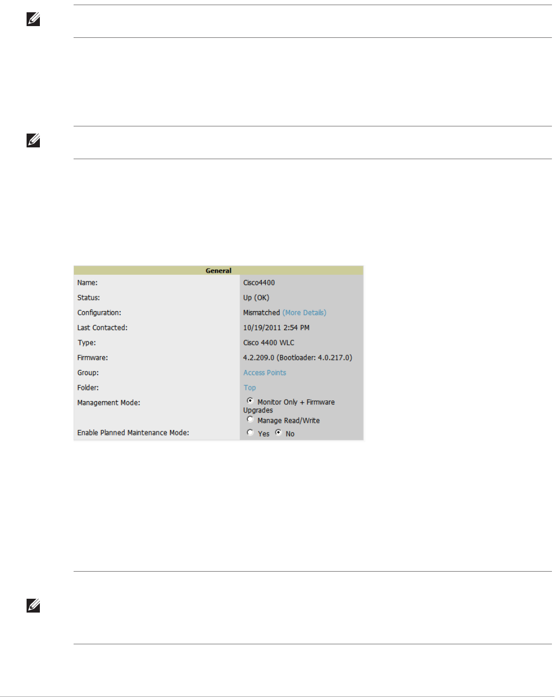
138 | Discovering, Adding, and Managing Devices Dell PowerConnect W-AirWave 7.5 | User Guide
Compare two configurations to highlight the specific lines that are mismatched. The Audit page provides links to
the AirWave pages where any mismatched settings can be configured.
Moving a Device from Monitor Only to Manage Read/Write Mode
Once the device configuration status is Good on the APs/Devices > List page, or once you have verified all
changes that will be applied to the device on the APs/Devices > Audit page, you can safely shift the device from
Monitor Only mode to Manage Read/Write mode.
To move a device from Monitor Only to Manage Read/Write mode, perform the following steps.
1. Go to the APs/Devices > List page and select the wrench icon next to the name of the AP to be shifted from
Monitor Only mode to Manage Read/Write mode. This directs you to the APs/Devices > Manage page.
2. Locate the General area as shown in Figure 103.
Figure 103 APs/Devices > Manage > General Section Illustration
3. Select Manage Read/Write on the Management Mode field.
4. Select Save and Apply, then Confirm Edit on the confirmation page to retain these settings and to push
configuration to the device.
5. For device configuration changes that require the device to reboot, use the Schedule function to push the
changes at a time when WLAN users will not be affected.
6. To move multiple devices into managed mode at once, use the Modify Devices link on an AP list page. For
more information, refer to “Modifying Multiple Devices” on page101.
NOTE: These procedures assume you are familiar with the function buttons available to save, apply, revert, and so on. For details
on button functions, see “Buttons and Icons” on page 16.
NOTE: Once a device is in Manage mode, AirWave will push a new configuration to the device in the event that the actual device
configuration does not match the AirWave configuration for that device.
NOTE: Use the Enable Planned Maintenance Mode field in APs/Devices > Manage > General to put this device into planned
maintenance. During the maintenance mode, no AP Down triggers will be deployed on these devices. Users will not be able to
delete folders that contain devices in Planned Maintenance. The devices in Planned Maintenance will show the Up status, but will
not be tracked in historical graphs and logs as Up. You can set multiple devices into Planned Maintenance Mode in the Modify
Devices link on an AP list page.
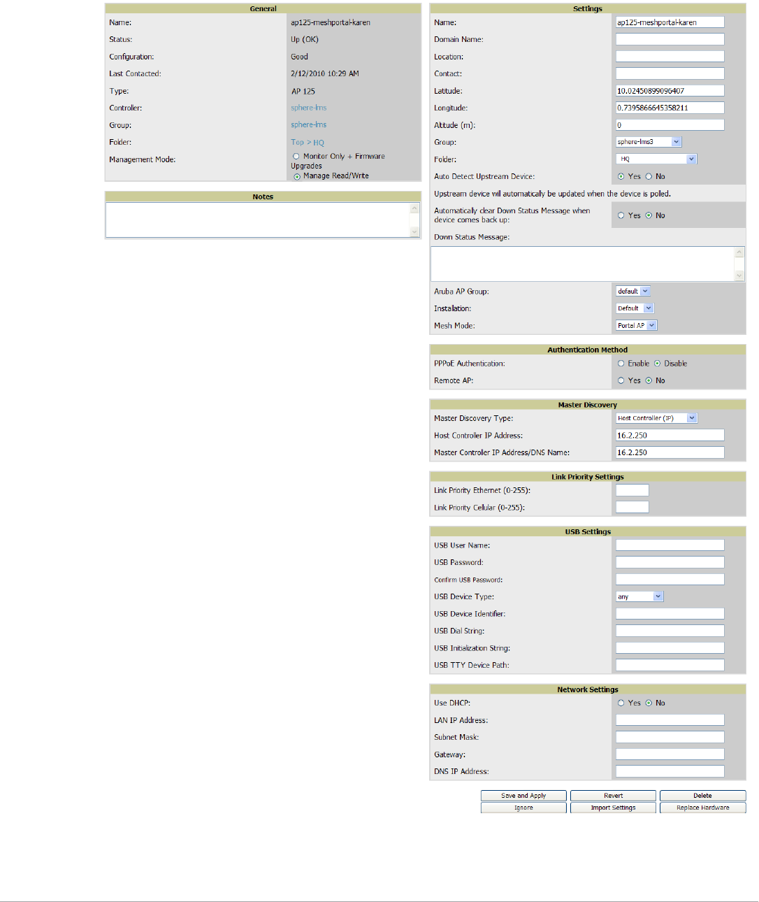
Dell PowerConnect W-AirWave 7.5 | User Guide Discovering, Adding, and Managing Devices | 139
Configuring AP Settings
1. Browse to the APs/Devices > List page and select the wrench icon next to the device whose AP settings you
want to edit. This directs you to the Manage page for that device. Figure 104 illustrates this page.
Figure 104 APs/Devices > Manage Page Illustration
If any changes are scheduled for this AP, they appear in a Scheduled Changes section at the top of the page
above the other fields. The linked name of the job takes you to its System > Configuration Change Job
Detail page.

140 | Discovering, Adding, and Managing Devices Dell PowerConnect W-AirWave 7.5 | User Guide
2. Locate the General section for information about the AP’s current status. Table 84 describes the fields,
information, and settings.
3. Review and provide the following information in the Settings area. Devices with dual radios display radio-
specific settings in the Slot A and Slot B area. If a device is dual-radio capable but only has one device
installed, AirWave manages that device as if it were a single slot device.
Table 85 describes field settings, default values, and information for the Settings section of this page.
Table 84 APs/Devices > Manage > General Fields and Descriptions
Field Description
Name Displays the name currently set on the device.
Status Displays the current status of an AP. If an AP is Up, then AirWave is able to ping it and fetch SNMP
information from the AP. If the AP is listed Down then AirWave is either unable to ping the AP or
unable to read the necessary SNMP information from the device.
Configuration Displays the current configuration status of the AP. To update the status, select Audit on the APs/
Devices > Audit page.
Last Contacted Displays the last time AirWave successfully contacted the AP.
Type Displays the type of AP.
Firmware Displays the version of firmware running on the AP.
Group Links to the Group > Monitoring page for the AP.
Template Displays the name of the group template currently configuring the AP. Also displays a link to the
Groups > Template page. This is only visible for APs that are managed by templates.
Folder Displays the name of the folder containing the AP. Also displays a link to the APs/Devices > List page
for the folder.
Management Mode Displays the current management mode of the AP. No changes are made to the AP when it is in
Monitor Only mode. AirWave pushes configurations and makes changes to an AP when it is in
Manage Read/Write mode.
Enable Planned
Maintenance Mode
Put this device into planned maintenance. During the maintenance mode, no AP Down triggers will
be deployed on these devices. Users will not be able to delete folders that contain devices in Planned
Maintenance. The devices in Planned Maintenance will show the Up status, but will not be tracked in
historical graphs and logs as Up. You can set multiple devices into Planned Maintenance Mode in the
Modify Devices link on an AP list page.
Notes Provides a free-form text field to describe device information.
NOTE: Devices from different vendors have different RF settings and capabilities. The fields in the Settings section of the APs/
Devices > Manage page are context-sensitive and only present the information relevant for the particular device vendor and
model.
Table 85 APs/Devices > Manage > Settings Fields and Default Values
Setting Default Device Type Description
Name None All User-configurable name for the device (max. 20 characters)
Domain Name None IOS Field populated upon initial device discovery or upon refreshing
settings. Enable this option from AMP Setup > Network page to
display this field on the APs/Devices > Manage page, with fully-
qualified domain names for IOS APs. This field is used in conjunction
with Domain variable in IOS templates.

Dell PowerConnect W-AirWave 7.5 | User Guide Discovering, Adding, and Managing Devices | 141
4. Complete additional settings on the APs/Devices > Manage page, to include H-REAP, certificates, radio
settings, and network settings. Table 86 describes many of the possible fields.
Location Read from the
device
All The SNMP location set on the device.
Latitude None All Text field for entering the latitude of the device. The latitude is used
with the Google Earth integration.
Longitude None All Text field for entering the longitude of the device. The longitude is
used with the Google Earth integration.
Altitude (meters) None All Text field for entering the altitude of the device when known. This
setting is used with the Google Earth integration. Specify altitude in
meters.
Group Default Group All Drop-down menu that can be used to assign the device to another
Group.
Folder Top All Drop-down menu that can be used to assign the device to another
Group.
Auto Detect
Upstream Device
Yes All Selecting Yes enables automatic detection of upstream device, which
is automatically updated when the device is polled.
Selecting No displays a drop-down menu of upstream devices.
Automatically
clear Down
Status Message
when device
comes back up
None All Whether the message entered in the Down Status Message field
should be removed after the device returns to the Up status.
Down Status
Message
None All Enter a text message that provides information to be conveyed if the
device goes down.
AP Group
Installation
Mesh Mode
Administrative
Status
Enable All Enables or disables administrative mode for the device.
Mode Local All Designates the mode in which the device should operate. Options
include the following:
-Local
-H-REAP
-Monitor
-Rogue Detector
-Sniffer
Table 85 APs/Devices > Manage > Settings Fields and Default Values (Continued)
Setting Default Device Type Description
NOTE: For complete listing and discussion of settings applicable only to Dell PowerConnect W-Series devices, see the Dell
PowerConnect W Configuration Guide.

142 | Discovering, Adding, and Managing Devices Dell PowerConnect W-AirWave 7.5 | User Guide
Table 86 APs/Devices > Manage, Additional Settings
Setting Default Device Type Description
Mesh Role Mesh AP Mesh Devices Drop-down menu specifies the mesh role for the AP as shown:
-Mesh AP —The AP will act like a mesh client. It will use other
APs as its uplink to the network.
-Portal AP —The AP will become a portal AP. It will use a wired
connection as its uplink to the network and serve it over the radio
to other APs.
-None —The AP will act like a standard AP. It will not perform
meshing functions.
Mesh Mobility Static Mesh Devices Select Static if the AP is static, as in the case of a device mounted on
a light pole or in the ceiling. Select Roaming if the AP is mobile. Two
examples would be an AP mounted in a police car or utility truck.
Receive Antenna Diversity Cisco Drop-down menu for the receive antenna provides three options:
Diversity —Device will use the antenna that receives the best signal.
If the device has two fixed (non-removable) antennas, the Diversity
setting should be used for both receive and transmit antennas.
Right —If your device has removable antennas and you install a high-
gain antenna on the device's right connector (the connector on the
right side when viewing the back panel of the device), use this setting
for receive and transmit.
Left —If your device has removable antennas and you install a high-
gain antenna on the device's left connector, use this setting for both
receive and transmit.
Transmit Antenna Diversity Cisco See description in Receive Antenna above.
Antenna Diversity Primary Only Symbol 4131 Drop-down menu provides the following options:
Full Diversity—The AP receives information on the antenna with the
best signal strength and quality. The AP transmits on the antenna
from which it last received information.
Primary Only—The AP transmits and receives on the primary
antenna only. Secondary Only: The AP transmits and receives on the
secondary antenna only.
Rx Diversity—The AP receives information on the antenna with the
best signal strength and quality. The AP transmits information on the
primary antenna only.
Transmit Power
Reduction
0 Proxim Transmit Power Reduction determines the APs transmit power. The
max transmit power is reduced by the number of decibels specified.
Channel 6 All Represents the AP’s current RF channel setting. The number relates
to the center frequency output by the AP’s RF synthesizer.
Contiguous APs should be set to different channels to minimize
‘crosstalk,’ which occurs when the signals from APs overlap and
interfere with each other. This RF interference negatively influences
WLAN performance.
802.11b’s 2.4-GHz range has a total bandwidth of 80-MHz, separated
into 11 center channels. Of these channels, only 3 are non-
overlapping (1, 6, and 11). In the United States, most organizations
use only these non-overlapping channels.
Transmit Power
Level
Highest power
level
supported by
the radio in the
regulatory
domain
(country)
Cisco, Symbol,
Proxim AP-600,
AP-700, AP-2000
(802.11g)
Determines the power level of radio transmission. Government
regulations define the highest allowable power level for radio
devices. This setting must conform to established standards for the
country in which you use the device. You can increase the coverage
radius of the access point by increasing the Transmit Power Level.
However, while this increases the zone of coverage, it also makes it
more likely that the AP will interfere with neighboring APs.
Supported values are: Cisco (100mW, 50mW, 30mW, 20mW, 5mW,
1mW) Symbol (Full or 50mW, 30mW, 15mW, 5mW, 1mW)

Dell PowerConnect W-AirWave 7.5 | User Guide Discovering, Adding, and Managing Devices | 143
5. Locate the Template Options area on the APs/Devices > Manage page.
Table 87 describes field settings, default values, and additional information for this page.
6. For Cisco WLC devices, go to the interfaces section of the APs/Devices > Manage page. Select Add new
Interface to add another controller interface, or select the pencil icon to edit an existing controller interface.
Radio Enabled Yes All The Radio Enabled option allows you to disable the radio's ability to
transmit or receive data while still maintaining Ethernet connectivity
to the network. AirWave will still monitor the Ethernet page and
ensure the AP stays online. Customers typically use this option to
temporarily disable wireless access in particular locations.
This setting can be scheduled at an AP level or Group level.
NOTE: You cannot disable radios unless rogue scanning is disabled in
Groups > Radio.
Use DHCP Yes All If enabled, the AP will be assigned a new IP address using DHCP. If
disabled, the AP will use a static IP address. For improved security
and manageability, disable DHCP and using static IP addresses.
LAN IP None All The IP Address of the AP Ethernet interface. If One-to-One NAT is
enabled, AirWave will communicate with the AP on a different
address (the IP Address defined in the Device Communication
section).
If DHCP is enabled, the current assigned address will appear grayed
out and the field cannot be updated in this area.
Subnet Mask None All Provides the IP subnet mask to identify the sub-network so the IP
address can be recognized on the LAN. If DHCP is enabled, the
current assigned address will appear grayed out and the field cannot
be updated in this area.
Gateway None All The IP address of the default internet gateway. If DHCP is enabled,
the current assigned address will appear grayed out and the field
cannot be updated in this area.
Table 86 APs/Devices > Manage, Additional Settings (Continued)
Setting Default Device Type Description
NOTE: This section only appears for IOS APs, Symbol devices, and Dell PowerConnect W-Series controllers in groups with Dell
PowerConnect W GUI Config disabled.
Table 87 APs/Devices > Manage > Template Options Fields and Default Values
Setting Default Device Type Description
WDS Role Client Cisco IOS
Wireless LAN
Controllers only
Set the WDS role for this AP. Select Master for the WDS master APs and
Client for the WDS Client. Once this is done you can use the %if
wds_role= % to push the client, master, or backup lines to appropriate
WDS APs.
SSL Certificate None Cisco IOS AirWave will read the SSL Certificate off of the AP when it comes UP in
AirWave. The information in this field will defines what will be used in
place of %certificate%.
Extra Device
Commands
None Cisco IOS Defines the lines that will replace the %ap_include_1% variable in the
IOS template. This field allows for unique commands to be run on
individual APs. If you have any settings that are unique per AP like a
MOTD you can set them here.
switch_command None Cisco Catalyst
switches
Defines lines included for each of the members in the stack. This field
appears only on the master's Manage page. The information in this field
will determine what is used in place of the %switch_command%
variable.
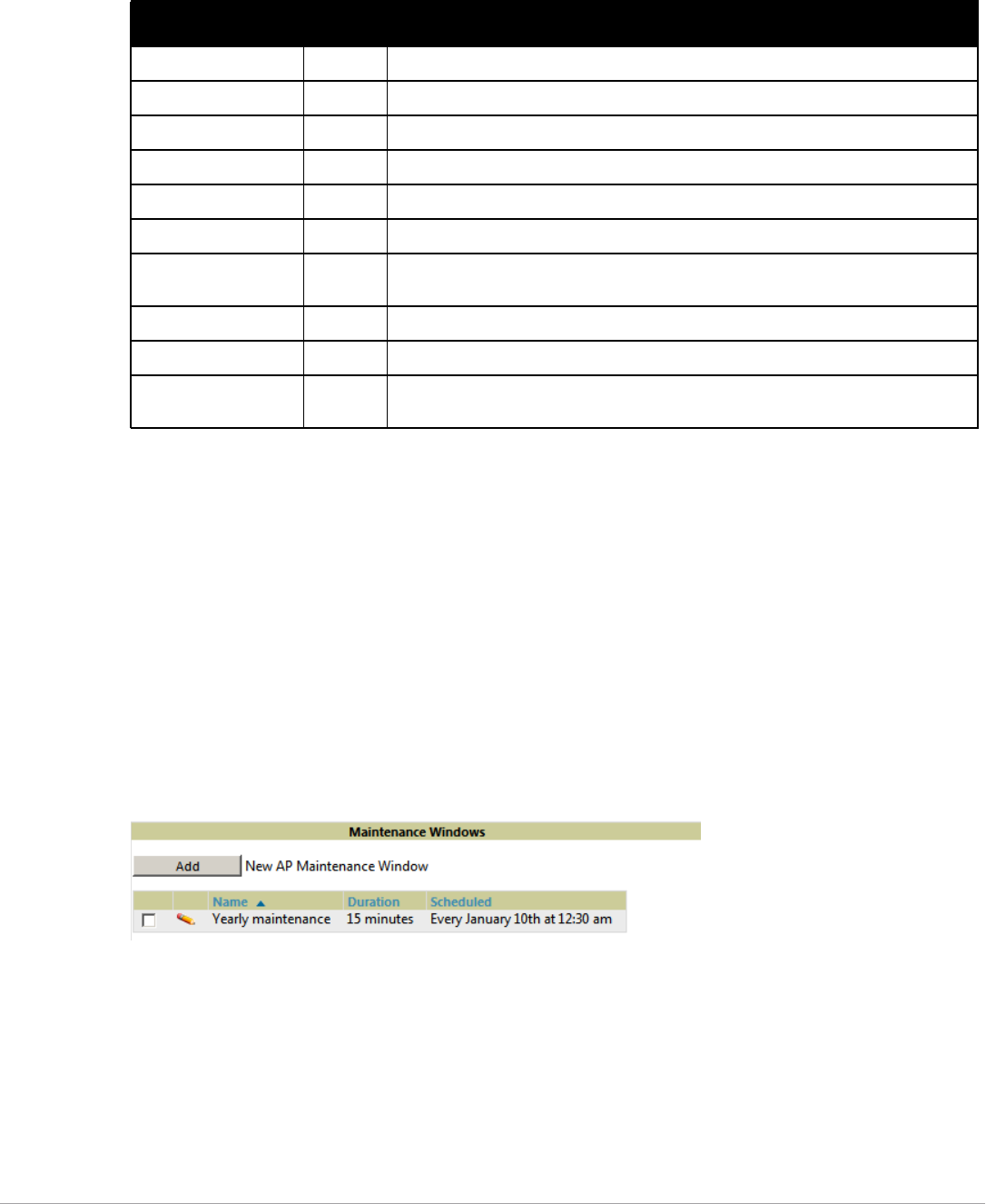
144 | Discovering, Adding, and Managing Devices Dell PowerConnect W-AirWave 7.5 | User Guide
Table 88 describes the settings and default values. For detailed descriptions of Cisco WLC devices supported
by AirWave, refer to the Cisco WLC product documentation.
Setting a Maintenance Window for a Device
AirWave can automate the manual action of putting multiple devices into Manage mode at once so that changes
can be applied, and after the maintenance period is over, the devices automatically revert to Monitor-Only mode.
Maintenance windows can be set as a one-time or recurring event on the APs/Devices > Manage and Groups >
Basic page.s You can also use the Modify Devices link to add or delete maintenance windows to or from multiple
selected devices at once. Additionally, this feature can be used on the Master Console to set maintenance
windows for multiple AirWaves.
To set a maintenance window for a single device, follow these steps:
1. Select a device and navigate to the APs/Devices > Manage page for a device.
2. At the bottom of the page, locate the Maintenance Windows section.
3. Select Add New AP Maintenance Window.
Figure 105 Add New Maintenance Window in APs/Devices > Manage page
4. Enter a name for the maintenance window.
5. In the Occurs field, specify whether the maintenance window should occur one time, or daily, weekly,
monthly, or annually. Additional options may display based on the selected value. For example, if you select
monthly, the you will be prompted to specify the day of the month for the recurrance.
6. Set the desired start time and the duration (in minutes) of the maintenance window.
7. Select Add.
Table 88 APs/Devices > Manage > Interface Fields and Descriptions for Cisco WLC Devices
Field Default Description
Name None The name of the interface on the controller.
VLAN ID None The VLAN ID for the interface on the controller.
Port None The port on the controller to access the interface.
IP Address None The IP address of the controller.
Subnet Mask None The subnet mask for the controller.
Gateway None The controller's gateway.
Primary and Secondary
DHCP Servers
None The DHCP servers for the controller.
Guest LAN Disabled Indicates a guest LAN.
Quarantine VLAN ID Disabled Enabled indicates it is a quarantine VLAN; used only for H-REAP-associated clients.
Dynamic Device
Management
Enabled When enabled, makes the interface an AP-manager interface. Cisco calls this feature
Dynamic AP Management.
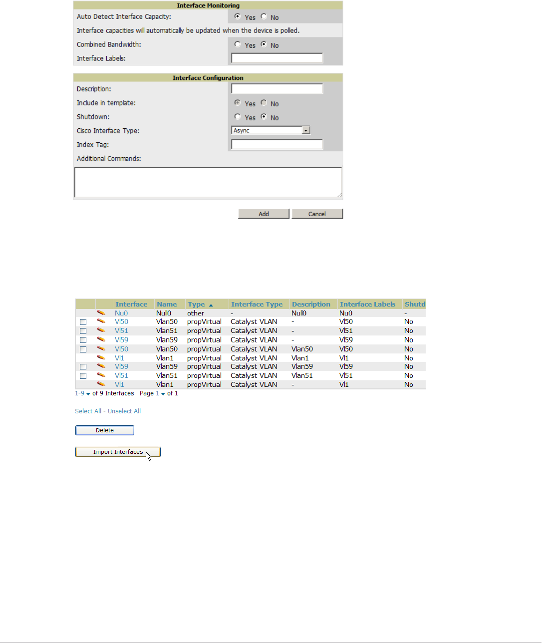
Dell PowerConnect W-AirWave 7.5 | User Guide Discovering, Adding, and Managing Devices | 145
Configuring Device Interfaces for Switches
When you go to the APs/Devices > Interfaces page for a switch, you can add a Virtual interface by selecting Add
and entering the appropriate information in the page that then appears, as shown in Figure 106.
Figure 106 Add Virtual Interfaces Page for Wired Devices
.
New physical and virtual interfaces are discovered using SNMP polling as described in “SNMP/HTTP Scanning”
on page108. To refresh and reload all current interface information from a device, select Import Interfaces on
the bottom of the page as shown in Figure 107.
Figure 107 Import Interfaces for Refresh and Reload (lower portion of page)
You can view details for each interface on a wired device from its individual interface page as well. For details, see
“Understanding the APs/Devices > Interfaces Page” on page134.
You can configure interface settings individually or in groups. For individual settings, select the pencil icon next
the interface name in AP/Devices > Interfaces.
This takes you to the Interfaces Monitoring and Configuration window which has a slightly different appearance
depending on whether you are configuring a physical or virtual interface, as shown in Figure 108 and Figure 109.
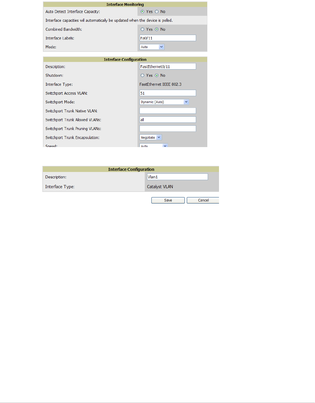
146 | Discovering, Adding, and Managing Devices Dell PowerConnect W-AirWave 7.5 | User Guide
Figure 108 Physical Interfaces Monitoring and Configuration Sections
Figure 109 Virtual Individual Interfaces Configuration Section
To configure interfaces as a group, select Edit Interfaces above the Physical or Virtual Interfaces table as shown in
Figure 110.
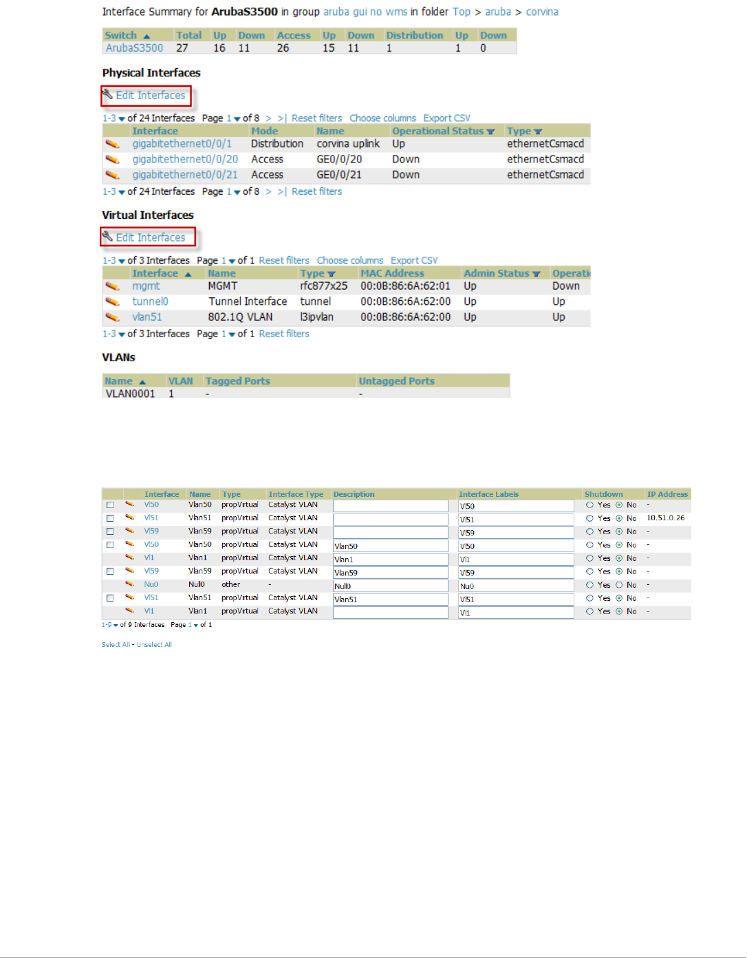
Dell PowerConnect W-AirWave 7.5 | User Guide Discovering, Adding, and Managing Devices | 147
Figure 110 Edit Multiple Interfaces
You will remain on the same page, but will have the option to make changes to the most commonly edited
settings in batch mode, as shown in Figure 111.
Figure 111 Multiple Interface Editing Page Illustration
AirWave assembles the entire running configuration using templates and your modifications to these pages. For a
more detailed discussion on templates, see Chapter 6, “Creating and Using Templates” on page155.
Individual Device Support and Firmware Upgrades
Perform the following steps to configure AP communication settings for individual Dell PowerConnect W-Series
device types.
1. Locate the Device Communication area on the APs/Devices > Manage page.
2. Specify the credentials to be used to manage the AP. Figure 112 illustrates this page.
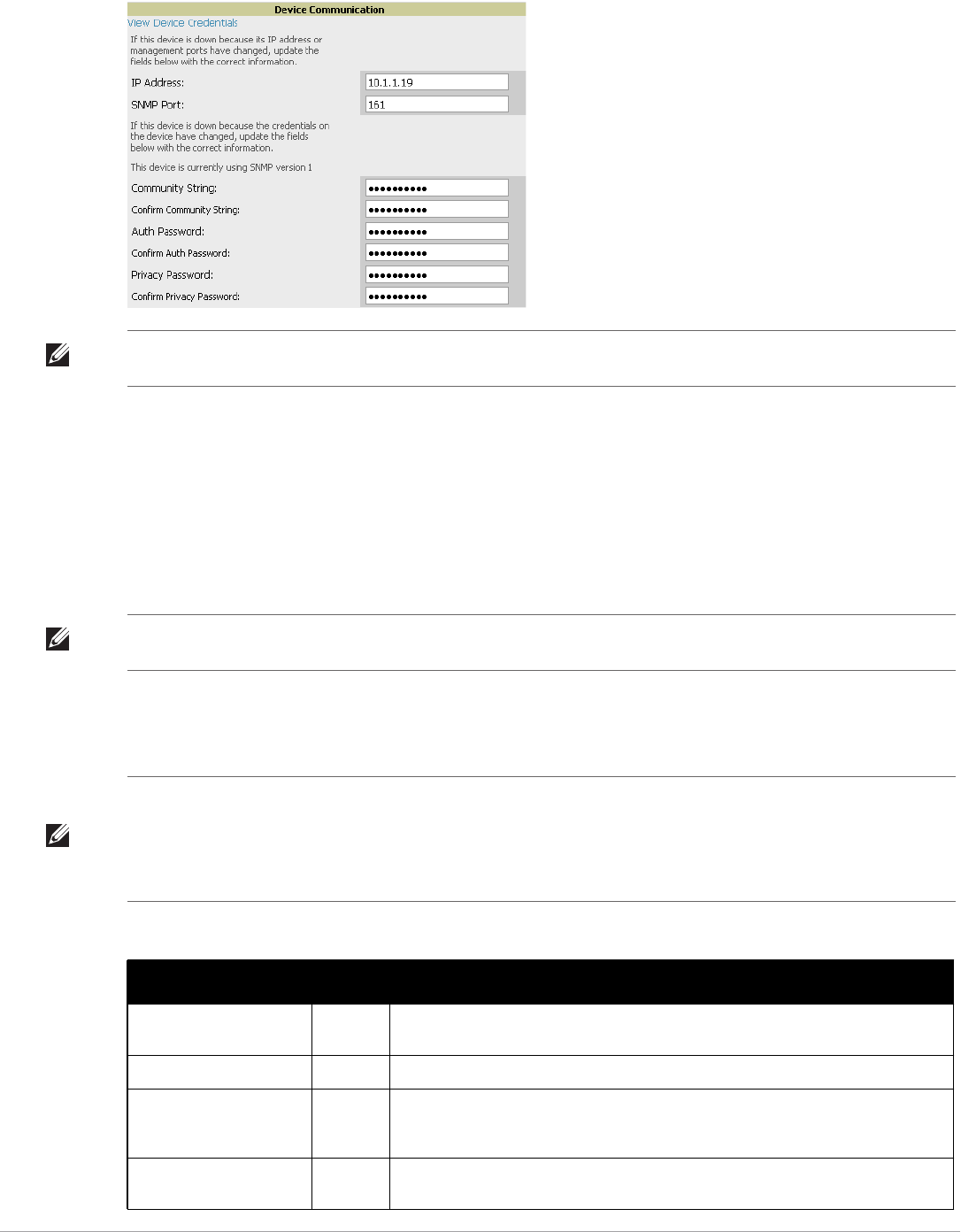
148 | Discovering, Adding, and Managing Devices Dell PowerConnect W-AirWave 7.5 | User Guide
Figure 112 APs/Devices > Manage > Device Communication
3. Enter and confirm the appropriate Auth Password and Privacy Password.
4. You can disable the View AP Credentials link in AirWave by the root user. Contact Dell support at
support.dell.com for detailed instructions to disable the link.
5. (Optional.) Enter the appropriate SSH and Telnet credentials if you are configuring Dell, Aruba Networks,
Alcatel-Lucent or any Cisco device except Cisco WLAN controllers.
6. Select Apply, then Confirm Edit to apply the changes to the AP immediately, Schedule to schedule the
changes during a specific time, or Cancel to return to APs/Devices > Manage.
Select the Update Firmware button at the bottom right of the page to upgrade the device's firmware.
Figure 113 illustrates the page that opens and Table 89 describes the settings and default values.
NOTE: The Device Communication area may appear slightly different depending on the particular vendor and model of the APs
being used.
NOTE: Some AP configuration changes may require the AP to be rebooted. Use the Schedule function to schedule these changes
to occur at a time when WLAN users will not be affected.
NOTE: The Update Firmware button only appears if 1) the AirWave Administrator has enabled Allow firmware upgrades in
monitor-only mode in AMP Setup > General or 2) if you are looking at an APs/Devices > Manage page for a controller or
autonomous AP that supports firmware upgrades in AirWave. See the “Supported Wireless Firmware Versions” document (the
AirWave Firmware Matrix) in Home > Documentation to see all of the AirWave-supported devices that can perform firmware
upgrades. In most cases, you cannot upgrade firmware directly on thin APs.
Table 89 APs/Devices > Manage > Update Firmware Fields and Default Values
Setting Default Description
Desired Version None Specifies the firmware to be used in the upgrade. Firmware can be added to this drop-
down menu on the Device Setup > Upload Firmware & Files page.
Job Name None Sets a user-defined name for the upgrade job. Use a meaningful and descriptive name.
Use “/safe” flag for Cisco
IOS firmware upgrade
command
No Enables or disables the /safe flag when upgrading IOS APs. The /safe flag must be
disabled on older APs for the firmware file to fit in flash memory.
Email Recipients None Displays a list of email addresses that should receive alert emails if a firmware upgrade
fails.
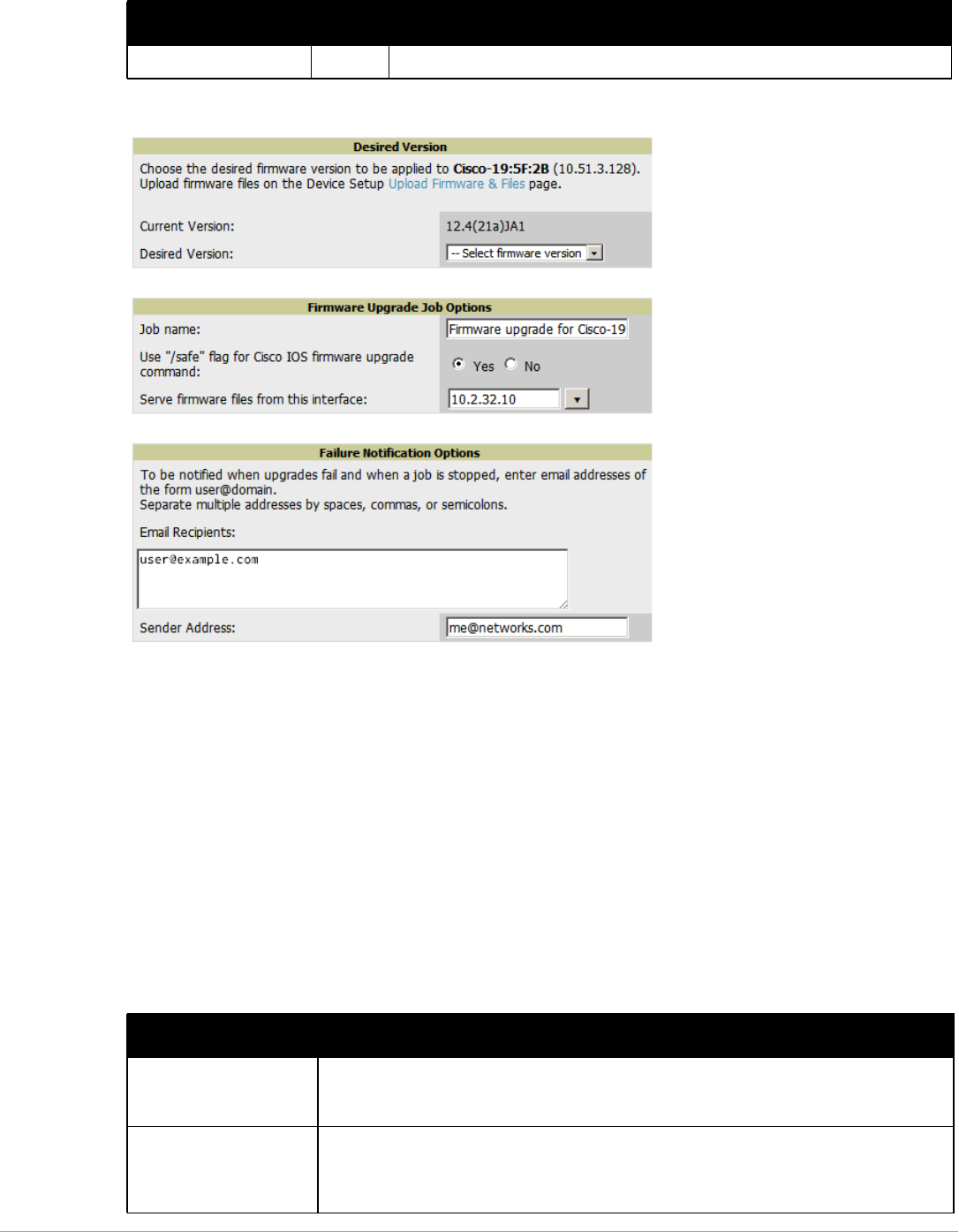
Dell PowerConnect W-AirWave 7.5 | User Guide Discovering, Adding, and Managing Devices | 149
Figure 113 APs/Devices > Manage Firmware Upgrades
Initiating a firmware upgrade will change the Firmware Status column for the device to Pending in APs/Devices
> List. You can review the status of all recent firmware upgrade jobs in System > Firmware Upgrade Jobs.
Troubleshooting a Newly Discovered Down Device
If the device status on the APs/Devices > List page remains Down after it has been added to a group, the most
likely source of the problem is an error in the SNMP community string being used to manage the device. Perform
the following steps to troubleshoot this scenario.
1. Select the Name of the down device in the list of devices on the APs/Devices > List or APs/Devices > Down
page. This automatically directs you to the APs/Device > Monitor page for that device.
2. Locate the Status field in the Device Info section. If the Status is Down, it includes a description of the cause
of the problem. Some of the common system messages are as follows in Table 90:
Sender Address None Displays the From address in the alert email.
Table 90 Common System Messages for Down Status
Message Meaning
AP is no longer associated
with controller
This means the AP no longer shows up in any controller's AP list (on the AirWave server). Either
the AP was removed from the controller, or it has roamed to another controller that AirWave does
not have visibility to, or it is offline.
Controller is Down When a controller goes down, AirWave automatically marks all associated thin APs down This is
because communication to thin APs are via the controller, and AirWave assumes that if the
Controller has gone offline, then all associated APs are down as well until they are reassociated
with another Controller).
Table 89 APs/Devices > Manage > Update Firmware Fields and Default Values (Continued)
Setting Default Description
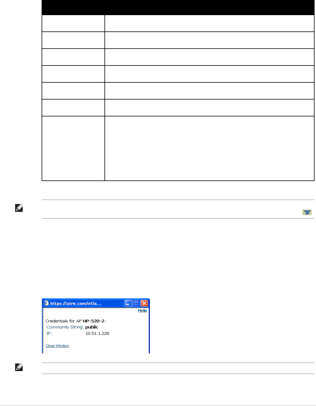
150 | Discovering, Adding, and Managing Devices Dell PowerConnect W-AirWave 7.5 | User Guide
3. If the SNMP Get Failed message appears, select the APs/Devices > Manage tab to go to the management
page for that device.
4. If visible, select the View Device Credentials link in the Device Communications section of APs/Devices >
Manage. This displays the credentials AirWave is using unsuccessfully to communicate with the device. This
link can be removed from AirWave for security reasons by setting a flag in AirWave. Only users with root
access to the AirWave command line can show or hide this link. To disable this feature, please contact Dell
support at support.dell.com. Figure 114 illustrates this page.
Figure 114 View Device Credentials Window
Downloading The AP is in the process of downloading firmware or configuration. (This only applies to Cisco WLC
thin APs and some Symbol APs.)
Error fetching existing
configuration
AirWave could not fetch a config for the AP. Usually this is because AirWave has incorrect
credentials and was not able to log in.
ICMP Ping Failed (after
SNMP Get Failed)
The device is not responding and is likely offline.
SNMP Get Failed SNMP credentials and/or configuration may be incorrect. Verify that SNMP is enabled and that
credentials and access ports are configured correctly on both the target device and in AirWave.
SNMP Trap AirWave received an SNMP trap from the controller indicating that the AP is no longer associated
to the controller.
Telnet Error: command
timed out
Telnet/SSH username and password specified for that device is incorrect.
Unexpected LAN MAC
Address found at this
device’s IP address
If AirWave detects that the LAN MAC address of a device has changed this error message will
appear. This usually indicates that a physical hardware change has occurred (while reusing the
same IP Address) without using the Replace Hardware feature in AirWave. This error may also
indicate an IP address conflict between two or more devices.
When an unexpected LAN MAC address is seen in a device's IP address, its APs/Devices >
Manage page displays the message “Click Replace Hardware (preferred) or Reset MAC Address
to reset the LAN MAC address if this device has been replaced with new hardware” at the top of
the page. Use the Replace Hardware button at the bottom of that page in order to avoid this
message.
Table 90 Common System Messages for Down Status (Continued)
Message Meaning
NOTE: To view the detailed status of all your down devices at once, navigate to APs/Devices > Down (try the Down top header
stats link) and look at the Detailed Status column for the list of down devices. This column can be sorted using the Filter icon ().
NOTE: The View Device Credentials message may appear slightly different depending on the vendor and model.

Dell PowerConnect W-AirWave 7.5 | User Guide Discovering, Adding, and Managing Devices | 151
5. If the credentials are incorrect, return to the Device Communications area on the APs/Devices > Manage
page. Enter the appropriate credentials, and select Apply.
6. Return to the APs/Devices > List page to see if the device appears with a Status of Up.
Setting up Spectrum Analysis in AirWave
The spectrum analysis software modules on Dell PowerConnect W-Series AP models AP-105, RAP-5WN, the
AP-12x series, the AP-13x series and the AP-9x series can examine the radio frequency (RF) environment in
which the Wi-Fi network is operating, identify interference and classify its sources.
The spectrum analyzer is used in conjunction with Adaptive Radio Management (ARM) technology. While the
spectrum analyzer identifies and classifies Wi-Fi and non-Wi-Fi sources of interference, ARM automatically
ensures that APs serving clients will stay clear of interference.
Individual APs or groups of APs can be converted to dedicated spectrum monitors through the dot11a and dot11g
radio profiles of that AP or AP group, or through a special spectrum override profile.
Each 802.11a and 802.11g radio profile references a spectrum profile, which identifies the spectrum band the
radio will monitor and analyze, and defines the default ageout times for each monitored device type. By default,
an 802.11a radio profile references a spectrum profile named default-a (which configures the radio to monitor the
upper channels of the 5 GHz radio band), and an 802.11g radio profile references a spectrum profile named
default-g (which configures the radio to monitor all channels the 2.4 GHz radio band).
Most interference will occur in the 2.4 GHz radio band.
For more information about Spectrum analysis and ARM technology, refer to the Dell PowerConnect W-ArubaOS
User Guide at support.dell.com/manuals.
Spectrum Configurations and Prerequisites
The following prerequisites must be in place to configure an AP to run in Spectrum mode in AirWave:
-The AP must be in Manage Read/Write mode.
-The AP’s associated controller must have an RFprotect license and must run ArubaOS 6.0 or later.
-Dell PowerConnect W GUI Config must be enabled for that AP’s group in the Groups > Basic page.
There are three main situations in which you would set one or more devices to Spectrum mode in AirWave:
-Dell PowerConnect W AP Groups running permanently with the default Spectrum profile
-Individual APs running temporarily in Spectrum mode while part of a Dell PowerConnect W AP Group set to
ap-mode
-Controller-level Spectrum Overrides (an alternative to creating new Dell PowerConnect W AP groups or new
radio profiles for temporary changes)
Setting up a Permanent Spectrum Dell AP Group
If you have multiple supported Dell PowerConnect W-Series APs in multiple controllers that you want to run in
Spectrum mode over the long run, you create a special Dell PowerConnect W AP group and set up a profile that
is set to spectrum-mode and references the default Spectrum profile. Set up more than one profile if you want to
utilize both radio bands in Spectrum mode.
If you use an 802.11a or 802.11g radio profile to create a group of spectrum monitors, all APs in any AP group
referencing that radio profile will be set to spectrum mode. Therefore, best practices are to create a new 802.11a
or 802.11g radio profile just for spectrum monitors.
If Use Global Dell PowerConnect W Configuration is enabled in AMP Setup > General, create the
configuration below, then go to the controller group's Dell PowerConnect W Config page and select the newly
created Dell PowerConnect W AP Group.
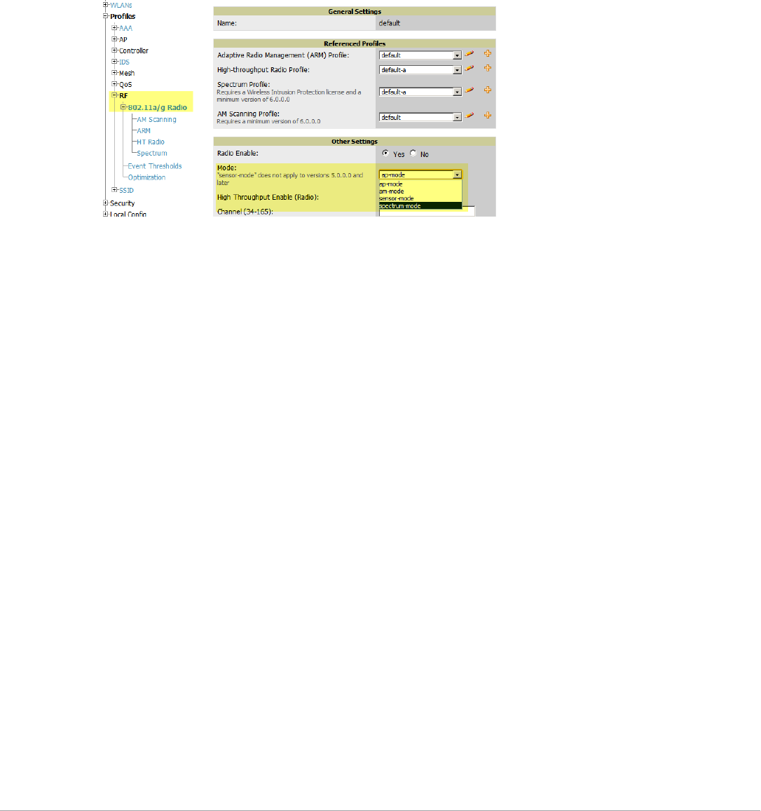
152 | Discovering, Adding, and Managing Devices Dell PowerConnect W-AirWave 7.5 | User Guide
Perform these steps to set the AP group to use the default Spectrum profile settings:
1. In Groups > Dell PowerConnect W Config, select Add New Dell PowerConnect W AP Group.
2. Give the new Group a name (like “Spectrum APs”) and select the plus sign next to the 802.11a Radio Profile
to create a new radio profile.
3. Enter a name under the General Settings section of Profiles > RF > 802.11a/g Radio.
4. In the Other Settings section, change the Mode field from ap-mode to spectrum-mode, as illustrated in
Figure 115. Then select Save.
Figure 115 Spectrum mode in Dell PowerConnect W Configuration
The above steps will use the defaults in the referenced Spectrum Profile. In most cases, you should not change
the settings in the default profile. If you must change the defaults, however, navigate to Groups > Dell
PowerConnect W Config > Profiles > RF > 802.11a/g Radio > Spectrum page and create a new Spectrum
profile with non-default settings.
If all of the devices in this Dell PowerConnect W AP Group are managed by the same controller and you want to
temporarily override one or more profile settings in your spectrum-mode APs, you can set up a controller override.
To disable spectrum mode in this group, change the referenced radio profile back to default.
Configuring an Individual AP to run in Spectrum Mode
If you want to temporarily set an individual radio in an AP to run in Spectrum mode without creating or changing
Dell PowerConnect W AP Groups or radio profiles, perform these steps to set up a Spectrum Override on a
supported Dell PowerConnect W-Series AP:
1. Go to the APs/Devices > Manage page for a Spectrum-supported AP (W-AP105, W-AP120 Series, W-AP90
Series and W-AP130 Series).
2. After checking the Audit page, set the AP to Manage Read/Write mode.
3. Select Yes on the Spectrum Override field for one or both radios, depending on the band and channels you
want it to analyze.
4. Select the band that should run in spectrum. If you selected the 5GHz band in the 802.11an Radio section,
choose the lower, middle, or upper range of channels that you want to be analyzed by this radio.
5. Select Save and Apply and confirm your edit.
This overrides the current Mode setting for that AP (ap-mode or am-mode).
After making this change, you can view the Radio Role field that will appear in the Radios section of the APs/
Devices > Monitor page.
The new role, Spectrum Sensor, is a link to the Spectrum Analysis page for the controller that manages this AP, as
illustrated in Figure 116.
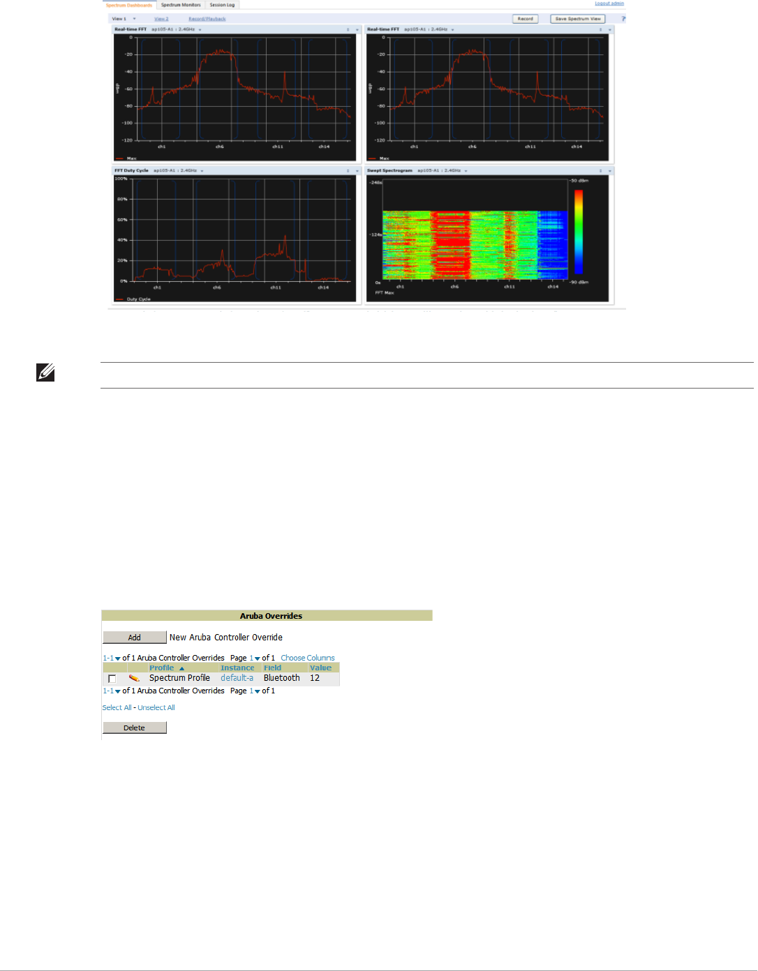
Dell PowerConnect W-AirWave 7.5 | User Guide Discovering, Adding, and Managing Devices | 153
Figure 116 Spectrum Analysis on Controller Dashboard
To disable Spectrum mode on this individual AP after it has collected data, return to the APs/Devices > Manage
page for this AP and set the Spectrum Override field back to No.
Configuring a Controller to use the Spectrum Profile
You can use AirWave to customize individual fields in the profile instance used by a particular controller without
having to create new Dell PowerConnect W AP groups and new radio profiles. To do this, you can set a
controller-level override for its referenced Spectrum profile, as illustrated in Figure 117. This will affect all
Spectrum-supported APs managed by this controller.
Figure 117 Override Section of a Supported Controller’s Manage Page
Perform these steps to override individual profile settings for an Dell PowerConnect W-Series controller that is
part of a spectrum-mode Dell PowerConnect W AP group:
1. Select a Spectrum-supported Dell PowerConnect W-Series controller that is referencing a Spectrum profile,
and go to its APs/Devices > Manage page. Set it to Manage Read/Write mode.
2. Under the Dell PowerConnect WOverrides section, select Add New Dell PowerConnect W Controller
Override.
3. In the Profile drop-down menu, select the Spectrum Profile type.
4. In the Profile Instance drop-down menu, select the instance of the Spectrum profile used by the controller.
NOTE: This chart is only available for Dell PowerConnect W-AP92, 93, 104, 105, 134,and 135 APs.

154 | Discovering, Adding, and Managing Devices Dell PowerConnect W-AirWave 7.5 | User Guide
5. In the Field drop-down menu, select the setting you would like to change (such as an Age-Out setting or a
Spectrum Band), and enter the overriding value below it.
6. Select Add to save your changes.
7. To create additional overrides for this controller, select Add New Dell PowerConnect W Controller Override
again.
8. When you have finished, select Save and Apply.
You can also use the above procedure to turn on Spectrum mode for radio profiles on one particular controller, or
use the overrides to point your radio profile to a non-default Spectrum profile for just this controller.

Dell PowerConnect W-AirWave 7.5 | User Guide Creating and Using Templates | 155
Chapter 6
Creating and Using Templates
This chapter provides an overview and several tasks supporting the use of device configuration templates in
AirWave, and contains the following topics:
-“Group Templates” on page155
-“Viewing and Adding Templates” on page156
-“Configuring General Template Files and Variables” on page159
-“Configuring Templates for Dell PowerConnect W-Instant” on page164
-“Configuring Templates for AirMesh” on page165
-“Configuring Cisco IOS Templates” on page165
-“Configuring Cisco Catalyst Switch Templates” on page168
-“Configuring Symbol Controller / HP WESM Templates” on page168
-“Configuring a Global Template” on page170
Group Templates
Supported Device Templates
Templates are helpful configuration tools that allow AirWaveto manage virtually all device settings. A template
uses variables to adjust for minor configuration differences between devices.
The Groups > Templates configuration page allows you to create configuration templates for the following types
of devices:
-Dell PowerConnect W
-Aruba
-Alcatel-Lucent
-Cisco Aironet IOS autonomous APs
-Cisco Catalyst switches
-HP ProCurve 530 and WeSM controllers
-Nomadix
-Symbol
-Trapeze
3Com
Nortel
Enterasys
It is also possible to create local templates in a subscriber group—using global groups does not mean that global
templates are mandatory
NOTE: Use the graphical Dell config feature in support of Dell devices, particularly for AOS 3.3.2.x and later. Refer to the Dell
PowerConnect W-AirWave Configuration Guide for additional information.
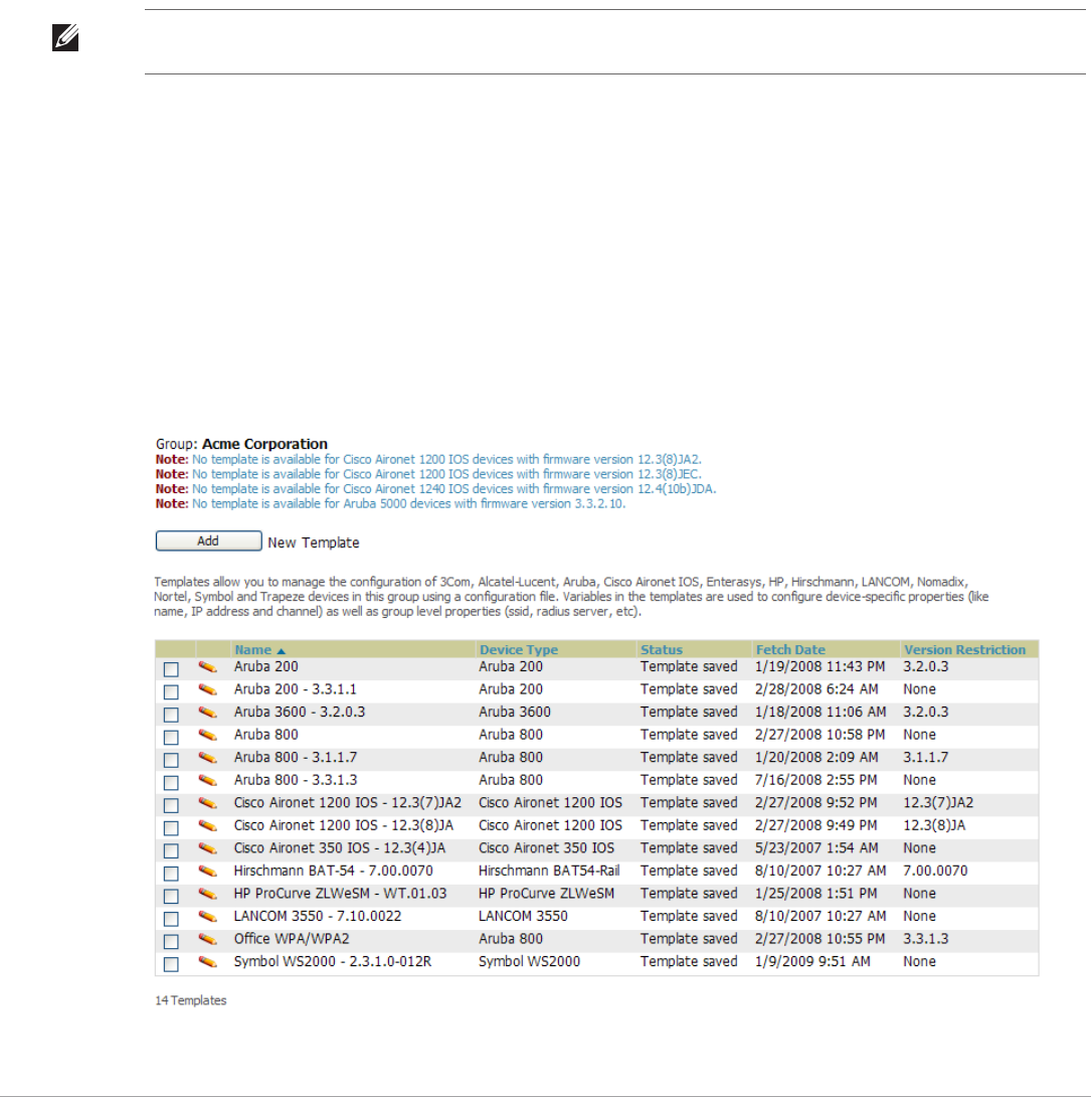
156 | Creating and Using Templates Dell PowerConnect W-AirWave 7.5 | User Guide
Template Variables
Variables in templates configure device-specific properties, such as name, IP address and channel. Variables can
also be used to configure group-level properties, such as SSID and RADIUS server, which may differ from one
group to the next. The AirWave template understands many variables including the following:
-%ap_include_1% through %ap_include_10%
-%channel%
-%hostname%
-%ip_address%
-%ofdmpower%
The variable settings correspond to device-specific values on the APs/Devices > Manage configuration page for
the specific AP that is getting configured.
Viewing and Adding Templates
Perform these steps to display, add, or edit templates.
1. Go to the Groups > List page, and select a group for which to add or edit templates. This can be a new group,
created with the Add button, or you can edit an existing group by selecting the corresponding pencil icon. The
Groups > Basic page for that group appears.Additional information about adding and editing groups is
described in “Configuring and Using Device Groups” on page67.
2. From the AirWave navigation pane, select Templates. The Templates page appears. Figure 118 illustrates the
Groups > Templates configuration page.
Figure 118 Groups > Templates Page Illustration for a Sample Device Group
NOTE: Changes made on the other Group pages (Radio, Security, VLANs, SSIDs, and so forth) are not applied to any APs that are
configured by templates.
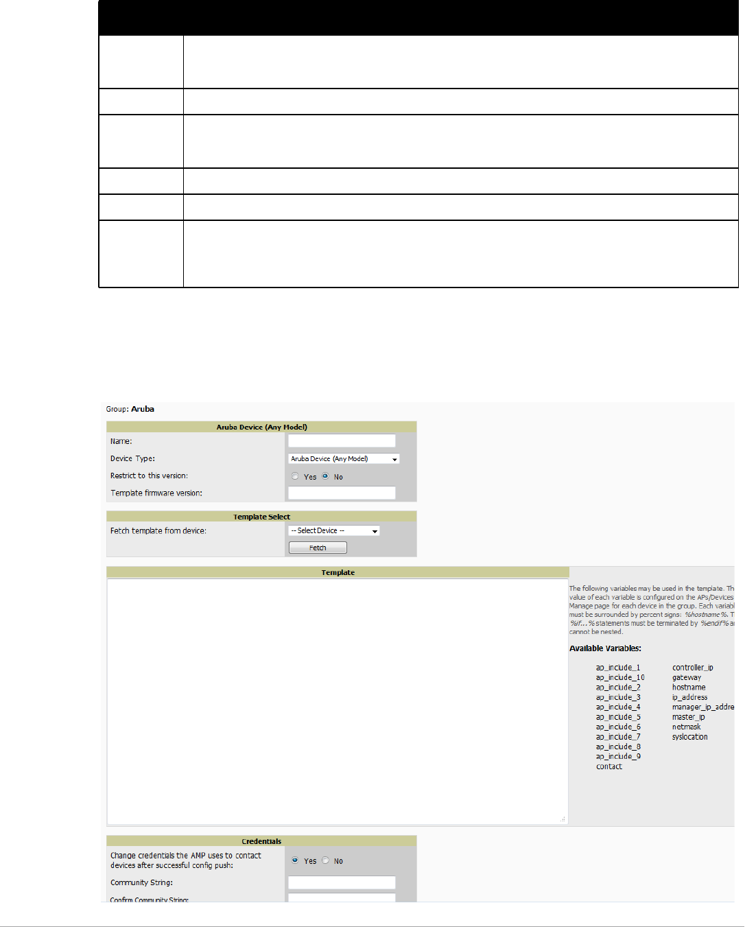
Dell PowerConnect W-AirWave 7.5 | User Guide Creating and Using Templates | 157
Table 91 describes the columns in this image.
3. To create a new template and add it to the AirWave template inventory, go to the Groups > List page, and
select the group name, and the Details page appears. Select Templates, then Add.
4. Complete the configurations illustrated in Figure 119.
Figure 119 Groups > Templates > Add Template Page Illustration
Table 91 Groups > Templates Fields and Default Values
Setting Description
Notes When applicable, this section lists devices that are active on the network with no template available for the
respective firmware. Select the link from such a note to launch the Add Template configuration page for that
device.
Name Displays the template name.
Device Type Displays the template that applies to APs or devices of the specified type. If vendor (Any Model) is selected, the
template applies to all models from that vendor that do not have a version specific template defined. If there are
two templates that might apply to a device, the template with the most restrictions takes precedence.
Status Displays the status of the template.
Fetch Date Sets the date that the template was originally fetched from a device.
Version
Restriction
Designates that the template only applies to APs running the version of firmware specified. If the restriction is
None, then the template applies to all the devices of the specified type in the group. If there are two templates
that might apply to a device the template with the most restrictions takes precedence. If there is a template that
matches a devices firmware it will be used instead of a template that does not have a version restriction.

158 | Creating and Using Templates Dell PowerConnect W-AirWave 7.5 | User Guide
The settings for the Add a Template page are described in Table 92. Note that the fields can vary based on the
Group.
Table 92 Groups > Templates > Add Template Fields and Default Values
Setting Default Description
Use Global Template No Uses a global template that has been previously configured on the Groups >
Templates configuration page. Available templates will appear in the drop-down
menu. If Yes is selected you can also configure global template variables. For
Symbol devices you can select the groups of thin APs to which the template
should be applied. For more information about global templates, see “Configuring
a Global Template” on page 170.
Name None Defines the template display name.
AP Type Cisco IOS (Any
Model)
Determines that the template applies to APs or devices of the specified type. If
Cisco IOS (Any Model) is selected, the template applies to all IOS APs that do not
have a version specific template specified.
Reboot APs After
Configuration Changes
No Determines reboot when AirWave applies the template, copied from the new
configuration file to the startup configuration file on the AP. If No is selected,
AirWave uses the AP to merge the startup and running configurations. If Yes is
selected, the configuration is copied to the startup configuration file and the AP is
rebooted.
This field is only visible for some devices.
Restrict to this version No Restricts the template to APs of the specified firmware version. If Yes is selected,
the template only applies to APs on the version of firmware specified in the
Template Firmware Version field.
Template firmware
version
None Designates that the template only applies to APs running the version of firmware
specified.
Fetch Template from
Device
None Selects an AP from which to fetch a configuration. The configuration will be
turned into a template with basic AP specific settings like channel and power
turned into variables. The variables are filled with the data on the APs/Devices >
Manage page for each AP.
Template Variables None Add variables to be used in the template for the group. Refer to “Configuring
General Template Files and Variables” on page 159 for more information.
Group Template
Variables
Add variables to be used for a Group Template.
Thin AP Groups Configure a template for selected Thin AP groups.
AP Template Specify tempalte variables specifically for APs.
Change credentials the
AMP uses to contact
devices after successful
config push:
No Specify whether to change the credentials that AirWave uses to contact devices
after the configuration has been pushed. If this option is enabled, then new
credential information fields display.
Community String None If the template is updating the community strings on the AP, enter the new
community string AirWave should use here. AirWave updates the credentials it is
using to communicate to the device after the device has been managed.
Telnet/SSH Username None If the template is updating the Telnet/SSH Username on the AP, enter the new
username AirWave should use here. AirWave updates the credentials it is using
to communicate to the device after the device has been managed.
Telnet/SSH Password None If the template is updating the Telnet/SSH password on the AP, enter the new
Telnet/SSH password AirWave should use here. AirWave updates the credentials
it is using to communicate to the device after the device has been managed.
“enable” Password None If the template is updating the enable password on the AP, enter the new enable
password AirWave should use here. AirWave updates the credentials it is using
to communicate to the device after the device has been managed.
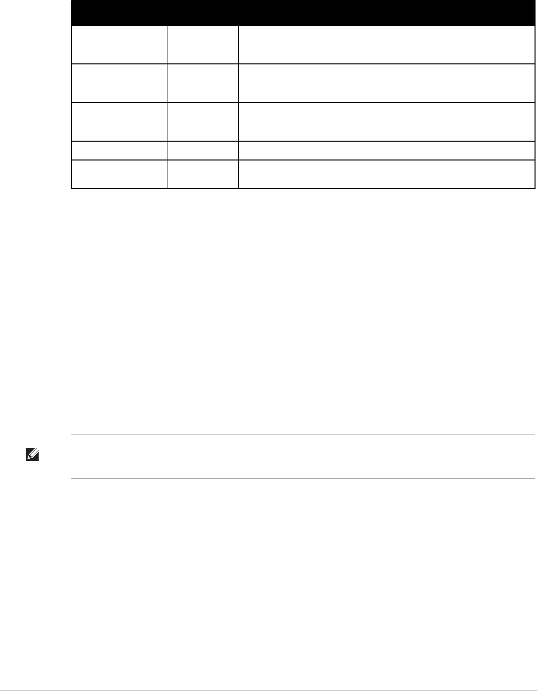
Dell PowerConnect W-AirWave 7.5 | User Guide Creating and Using Templates | 159
Configuring General Template Files and Variables
This section describes the most general aspects of configuring AP device templates and the most common
variables:
-Configuring General Templates
-Using Template Syntax
-Using Directives to Eliminate Reporting of Configuration Mismatches
-Using Conditional Variables in Templates
-Using Substitution Variables in Templates
-Using AP-Specific Variables
Configuring General Templates
Perform the following steps to configure Templates within a Group.
1. Select a Group to configure.
2. Select an AP from the Group to serve as a model AP for the others in the Group. You should select a device
that is configured currently with all the desired settings. If any APs in the group have two radios, make sure to
select a model AP that has two radios and that both are configured in proper and operational fashion.
3. Go to the Groups > Templates configuration page. Select Add to add a new template.
4. Select the type of device that will be configured by this template.
5. Select the model AP from the drop-down list, and select Fetch.
6. AirWave automatically attempts to replace some values from the configuration of that AP with variables to
enable AP-specific options to be set on an AP-by-AP basis. Refer to “Using Template Syntax” on page161
These variables are always encapsulated between % signs. On the right side of the configuration page is the
Additional Variables section. This section lists all available variables for your template. Variables that are in
use in a template are green, while variables that are not yet in use are black. Verify these substitutions to
ensure that all of the settings that you believe should be managed on an AP-by-AP basis are labeled as
SNMPv3 Username None If the template is updating the SNMP v3 Username password on the AP, enter the
new SNMP Username password here. AirWave updates the credentials it is
using to communicate to the device after the device has been managed.
Auth Password None If the template is updating the SNMP v3 Auth password on the AP, enter the new
SNMP Username password here. AirWave updates the credentials it is using to
communicate to the device after the device has been managed.
Privacy Password None If the template is updating the SNMP v3 Privacy password on the AP, enter the
new SNMP Username password here. AirWave updates the credentials it is
using to communicate to the device after the device has been managed.
SNMPv3 Auth Protocol MD5 Specifies the SNMPv3 Auth protocol, either MD5 or SHA-1.
SNMPv3 Privacy
Protocol
DES Specifies the SNMPv3 Privacy protocol, either DES or AES. This option is not
available for all Device Types.
Table 92 Groups > Templates > Add Template Fields and Default Values (Continued)
Setting Default Description
NOTE: Start with a small group of access points and placing these APs in Monitor Only mode, which is read-only. Do this using the
Modify Devices link until you are fully familiar with the template configuration process. This prevents configuration changes from
being applied to the APs until you are sure you have the correct configuration specified.

160 | Creating and Using Templates Dell PowerConnect W-AirWave 7.5 | User Guide
variables in this fashion. If you believe that any AP-level settings are not marked correctly, please contact Dell
customer support at support.dell.com before proceeding.
7. Specify the device types for the template. The templates only apply to devices of the specified type.
Specify whether AirWave should reboot the devices after a configuration push. If the Reboot Devices after
Configuration Changes option is selected, then AirWave instructs the AP to copy the configuration from
AirWave to the startup configuration file of the AP and reboot the AP.
If the Reboot Devices after Configuration Changes option is not selected, then AirWave instructs the AP
to copy the configuration to the startup configuration file and then tell the AP to copy the startup
configuration file to the running configuration file.
Use the reboot option when there are changes requiring reboot to take effect, for example, removing a new
SSID from a Cisco IOS device. Copying the configuration from startup configuration file to running
configuration file merges the two configurations and can cause undesired configuration lines to remain
active on the AP.
8. Restrict the template to apply only to the specified version of firmware. If the template should only apply to a
specific version of firmware, select Yes and enter the firmware version in the Template Firmware Version text
field.
9. Select Save and Apply to push the configuration to all of the devices in the group. If the devices are in
monitor-only mode (which is recommended while you are crafting changes to a template or creating a new
one), then AirWave will audit the devices and compare their current configuration to the one defined in the
template.
For example, changing the SSID on Cisco IOS APs requires the AP to be rebooted. Two other settings that
require the AP to be rebooted for configuration change are Logging and NTP. A configuration mismatch
results if the AP is not rebooted.
If logging and NTP service are not required according to the Group configuration, but are enabled on the AP,
you would see a configuration file mismatch as follows if the AP is not rebooted:
IOS Configuration File Template
…
(no logging queue-limit)
…
Device Configuration File on APs/Devices > Audit Configuration Page
…
line con 0
line vty 5 15
actual logging 10.51.2.1
actual logging 10.51.2.5
actual logging facility local6
actual logging queue-limit 100
actual logging trap debugging
no service pad
actual ntp clock-period 2861929
actual ntp server 209.172.117.194
radius-server attribute 32 include-in-access-req format %h
…
10. Once the template is correct and all mismatches are verified on the APs/Devices > Audit configuration page,
use the Modify Devices link on the Groups > Monitor configuration page to place the desired devices into
NOTE: If you set the reboot flag to No, then some changes could result in configuration mismatches until the AP is rebooted.

Dell PowerConnect W-AirWave 7.5 | User Guide Creating and Using Templates | 161
Management mode. This removes the APs from Monitor mode (read-only) and instructs the AP to pull down
its new startup configuration file from AirWave.
Using Template Syntax
Template syntax is comprised of the following components, described in this section:
-Using AP-Specific Variables
-Using Directives to Eliminate Reporting of Configuration Mismatches
-Using Conditional Variables in Templates
-Using Substitution Variables in Templates
Using Directives to Eliminate Reporting of Configuration Mismatches
AirWave is designed to audit AP configurations to ensure that the actual configuration of the access point exactly
matches the Group template. When a configuration mismatch is detected, AirWave generates an automatic alert
and flags the AP as having a Mismatched configuration status on the user page.
However, when using the templates configuration function, there will be times when the running-config file and
the startup-config file do not match under normal circumstances. For example, the ntp clock-period setting
is almost never identical in the running-config file and the startup-config file. You can use directives such as
<ignore_and_do_not_push> to customize the template to keep AirWave from reporting mismatches for this
type of variance.
AirWave provides two types of directives that can be used within a template to control how AirWave constructs
the startup-config file to send to each AP and whether it reports variances between the running-config file and
the startup-config file as "configuration mismatches.” Lines enclosed in <push_and_exclude> are included in
the AP startup-config file but AirWave ignores them when verifying configurations. Lines enclosed in
<ignore_and_do_not_push> cause AirWave to ignore those lines during configuration verification.
Ignore_and_do_not_push Command
The ignore and do not push directive should typically be used when a value cannot be configured on the
device, but always appears in the running-config file. Lines enclosed in the ignore and do not push directive will
not be included in the startup-config file that is copied to each AP.
When AirWave is comparing the running-config file to the startup-config file for configuration verification, it will
ignore any lines in the running-config file that start with the text within the directive. Lines belonging to an
ignored and unpushed line, the lines immediately below the line and indented, are ignored as well. In the
example below, if you were to bracket the NTP server, the NTP clock period would behave as if it were bracketed
because it belongs with or is associated with the NTP server line.
Push_and_exclude Command
Instead of using the full tags you may use the parenthesis shorthand, (substring). The push and exclude directive
is used to push commands to the AP that will not appear in the running-config file. For example, some no
commands that are used to remove SSIDs or remove configuration parameters do not appear in the running-
NOTE: Devices can be placed into Management mode individually from the APs/Devices > Manage configuration page.
NOTE: The line <ignore_and_do_not_push>ntp clock-period</ignore_and_do_not_push> will cause lines starting with "ntp clock-
period" to be ignored. However, the line <ignore_and_do_not_push>ntp </ignore_and_do_not_push> causes all lines starting with
"ntp" to be ignored, so it is important to be as specific as possible.
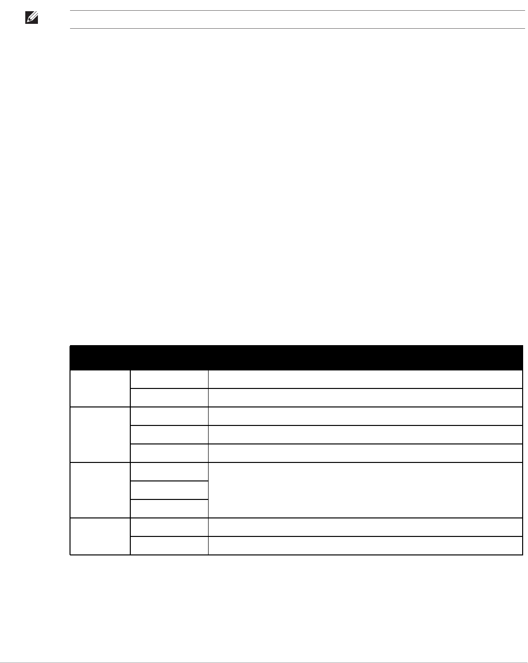
162 | Creating and Using Templates Dell PowerConnect W-AirWave 7.5 | User Guide
config file of a device. A command inside the push and exclude directive are included in the startup-config file
pushed to a device, but AirWave excludes them when calculating and reporting configuration mismatches.
Below are some examples of using directives:
…
line con 0
</push_and_exclude>no stopbits</push_and_exclude>
line vty 5 15
!
ntp server 209.172.117.194
<ignore_and_do_not_push>ntp clock-period</ignore_and_do_not_push>
end
Using Conditional Variables in Templates
Conditional variables allow lines in the template to be applied only to access points where the enclosed
commands will be applicable and not to any other access points within the Group. For example, if a group of APs
consists of dual-radio Cisco 1200 devices (802.11a/b) and single-radio Cisco 1100 (802.11b) devices, it is
necessary to make commands related to the 802.11a device in the 1200 APs conditional. Conditional variables are
listed in the table below.
The syntax for conditional variables is as follows, and syntax components are described in Table 93:
%if variable=value%
…
%endif%
Using Substitution Variables in Templates
Substitution variables are used to set AP-specific values on each AP in the group. It is obviously not desirable to
set the IP address, hostname, and channel to the same values on every AP within a Group. The variables in Table
94 are substituted with values specified on each access point’s APs/Devices > Manage configuration page within
the AirWave User page.
NOTE: The opening tag may have leading spaces.
Table 93 Conditional Variable Syntax Components
Variable Values Meaning
interface Dot11Radio0 2.4GHz radio module is installed
Dot11Radio1 5GHz external radio module is installed
radio_type a Installed 5GHz radio module is 802.11a
b Installed 2.4GHz radio module is 802.11b only
g Installed 2.4GHz radio module is 802.11g capable
wds_role backup The WDS role of the AP is the value selected in the dropdown menu on the APs/Devices
> Manage configuration page for the device.
client
master
IP Static IP address of the device is set statically on the AP Manage configuration page.
DHCP IP address of the device is set dynamically using DHCP

Dell PowerConnect W-AirWave 7.5 | User Guide Creating and Using Templates | 163
Sometimes, the running-config file on the AP does not include the command for one of these variables because
the value is set to the default. For example, when the “transmission power” is set to maximum (the default), the
line “power local maximum” will not appear in the AP running-config file, although it will appear in the startup-
config file. AirWave would typically detect and flag this variance between the running-config file and startup-
config file as a configuration mismatch. To prevent AirWave from reporting a configuration mismatch between
the desired startup-config file and the running-config file on the AP, AirWave suppresses the lines in the desired
configuration when auditing the AP configuration (similar to the way AirWave suppresses lines enclosed in
parentheses, which is explained below). A list of the default values that causes lines to be suppressed when
reporting configuration mismatches is shown in Table 94.
Using AP-Specific Variables
When a template is applied to an AP all variables are replaced with the corresponding settings from the APs/
Devices > Manage configuration page. This enables AP-specific settings (such as Channel) to be managed
effectively on an AP-by-AP basis. The list of used and available variables appears on the template detail
configuration page. Variables are always encapsulated between % signs. The following example illustrates this
usage:
hostname %hostname%
Table 94 Substitution Variables in Templates
Variable Meaning Command Suppressed Default
hostname Name hostname %hostname% -
channel Channel channel %channel% -
ip_address netmask IP address
Subnet mask
ip address %ip_address%
%netmask% or ip address dhcp …
-
gateway Gateway ip default-gateway %gateway% -
antenna_ receive Receive antenna antenna receive
%antenna_receive%
diversity
antenna_transmit Transmit antenna antenna transmit
%antenna_transmit%
diversity
cck_power 802.11g radio module CCK power
level
power local cck %cck_power% maximum
ofdm_power 802.11g radio module OFDM power
level
power local ofdm %ofdm_power% maximum
power 802.11a and 802.11b radio module
power level
power local %power% maximum
location The location of the SNMP server. snmp-server location %location% -
contact The SNMP server contact. snmp-server contact %contact% -
certificate The SSL Certificate used by the AP %certificate% -
ap include The AP include fields allow for
configurable variables. Any lines
placed in the AP Include field on
the APs/Devices > Manage
configuration page replace this
variable.
%ap_include_1% through
%ap_include_10%
-
chassis id Serial Number of the device %chassis_id% -
domain dns-domain of the device %domain% -
interfaces Interfaces of the device %interfaces% -

164 | Creating and Using Templates Dell PowerConnect W-AirWave 7.5 | User Guide
…
interface Dot11Radio0
…
power local cck %CCK_POWER%
power local ofdm %OFDM_POWER%
channel %CHANNEL%
…
The hostname line sets the AP hostname to the hostname stored in AirWave.
The power lines set the power local cck and ofdm values to the numerical values that are stored in AirWave.
Configuring Templates for Dell PowerConnect W-Instant
The first Instant network that is added to AirWave automatically includes the default configuration that is used
as a template to provision other Instant networks. See the Dell PowerConnect W-Instant Quick Start Guide, the
Dell PowerConnect W-Instant Professional Installation Guide, and the Dell PowerConnect W-Instant Access
Point Installation Guides for 90, 100, and 130 Series IAPs for information on setting up the hardware and
configuring the network.
AirWave enables you to control Instant configuration settings via the Groups > Templates configuration page. A
sample configuration is provided below.
virtual-controller-country US
virtual-controller-key %guid%
virtual-controller-ip %ip_address_a_b_c%.3
name %hostname%
%if organization%
organization %organization%
%endif%
syslog-server 216.31.249.235
syslog-level debug
terminal-access
clock timezone Pacific-Time -08 00
rf-band 5.0
ams-ip %manager_ip_address%
ams-key %password%
allow-new-aps
%allowed_aps%
snmp-server engine-id undefined
arm
wide-bands 5ghz
min-tx-power 18
max-tx-power 127
band-steering-mode prefer-5ghz
air-time-fairness-mode fair-access
syslog-level warn ap-debug
syslog-level warn network
syslog-level warn security
syslog-level warn system
syslog-level warn user
syslog-level warn user-debug
syslog-level warn wireless
NOTE: Be sure that the default configuration is validated and has been pre-tested in a non-production environment prior to
applying it to a production network. Any changes that are made to this configuration will follow the same process each time and
will be applied to other Instant networks as described in this document.

Dell PowerConnect W-AirWave 7.5 | User Guide Creating and Using Templates | 165
mgmt-user admin 446f8a8ddacdb735dd42a9873a2e80e2
wlan ssid-profile remote-node-guest
index 0
type employee
essid %ssid%
wpa-passphrase a804e1744c137371943bdeed410e720a58eca75717ff714b
opmode wpa2-psk-aes
rf-band all
captive-portal disable
dtim-period 1
inactivity-timeout 1000
broadcast-filter none
enet-vlan guest
wlan external-captive-portal
server localhost
port 80
url "/"
auth-text "%venue%"
ids classification
ids
wireless-containment none
Refer to Appendix A “Setting Up Dell PowerConnect-W Instant in AirWave” on page309 more information
about using Instant in AirWave.
Configuring Templates for AirMesh
Introduced in 7.5, AirMesh devices can be configured using templates. AirWave automatically adds a template
for the first AirMesh AP in a group. The configurations are pushed using CLI commands. The sample code below
includes Mesh configuration options.
mesh
mesh-id %mesh_id%
%preferred_link%
neighbor-list-type %neighbor_list_type%
authentication open key-management wpa2
psk ascii 5d4f50485e4f5048ed1da60b85f2784d6bbf16442fdcbfc06aeb4460d98263f5
neighbor-list
%neighbor_list%
service avt
%avt_ingress_interface%
%avt_ingress_ip%
buffer_time 200
mode %avt_mode%
Configuring Cisco IOS Templates
Cisco IOS access points have hundreds of configurable settings. AirWave enables you to control them via the
Groups > Templates configuration page. This page defines the startup-config file of the devices rather than
using the AirWave normal Group configuration pages. AirWave no longer supports making changes for these
devices via the browser-based page, but rather uses templates to configure all settings, including settings that
were controlled formerly on the AirWave Group configuration pages. Perform these steps to configure a Cisco
IOS Template for use with one or more groups, and the associated devices.
NOTE: AirWave displays a warning if AirMesh APs attempting to either upgrade or push configurations lack the necessary write
permissions.

166 | Creating and Using Templates Dell PowerConnect W-AirWave 7.5 | User Guide
This section includes the following topics:
-Applying Startup-config Files
-WDS Settings in Templates
-SCP Required Settings in Templates
-Supporting Multiple Radio Types via a Single IOS Template
-Configuring Single and Dual-Radio APs via a Single IOS Template
Applying Startup-config Files
Each of the APs in the Group copies its unique startup-config file from AirWave via TFTP or SCP.
-If the Reboot Devices after Configuration Changes option is selected, then AirWave instructs the AP to copy
the configuration from AirWave to the startup-config file of the AP and reboot the AP.
-If the Reboot Devices after Configuration Changes option is not selected, then AirWave instructs the AP to
copy the configuration to the startup-config file and then tell the AP to copy the startup config file to the
running-config file. Use the reboot option when possible. Copying the configuration from startup to running
merges the two configurations and can cause undesired configuration lines to remain active on the AP.
WDS Settings in Templates
A group template supports Cisco WDS settings. APs functioning in a WDS environment communicate with the
Cisco WLSE via a WDS master. IOS APs can function in Master or Slave mode. Slave APs report their rogue
findings to the WDS Master (AP or WLSM which reports the data back to the WLSE. On the APs/Devices >
Manage configuration page, select the proper role for the AP in the WDS Role drop down menu.
The following example sets an AP as a WDS Slave with the following lines:
%if wds_role=client%
wlccp ap username wlse password 7 XXXXXXXXXX
%endif%
The following example sets an AP as a WDS Master with the following lines:
%if wds_role=master%
aaa authentication login method_wds group wds
aaa group server radius wds server
10.2.25.162 auth-port 1645 acct-port 1646
wlccp authentication-server infrastructure method_wds
wlccp wds priority 200 interface BVI1
wlccp ap username wlse password 7 095B421A1C
%endif%
The following example sets an AP as a WDS Master Backup with the following lines:
%if wds_role=backup%
aaa authentication login method_wds group wds
aaa group server radius wds server
10.2.25.162 auth-port 1645 acct-port 1646
wlccp authentication-server infrastructure method_wds
wlccp wds priority 250 interface BVI1
wlccp ap username wlse password 7 095B421A1C
%endif%
NOTE: Changes made on the standard AirWave Group configuration pages, to include Basic, Radio, Security, VLANs, and so forth,
are not applied to any template-based APs.

Dell PowerConnect W-AirWave 7.5 | User Guide Creating and Using Templates | 167
SCP Required Settings in Templates
A few things must be set up before enabling SCP on the Groups > Basic configuration page. The credentials
used by AirWave to login to the AP must have level 15 privileges. Without them AirWave is not able to
communicate with the AP via SCP. The line "aaa authorization exec default local" must be in the APs
configuration file and the AP must have the SCP server enabled. These three settings correspond to the following
lines in the AP’s configuration file:
-username Cisco privilege 15 password 7 0802455D0A16
-aaa authorization exec default local
-ip scp server enable
The username line is a guideline and will vary based on the username being set, in this case Cisco, and the
password and encoding type, in this case 0802455D0A16 and 7 respectively.
These values can be set on a group wide level using Templates and TFTP. Once these lines are set, SCP can be
enabled on the Groups > Basic configuration page without problems.
Supporting Multiple Radio Types via a Single IOS Template
Some lines in an IOS configuration file should only apply to 802.11g vs. 802.11b. For instance, lines related to
speed rates that mention rates above 11.0Mb/s do not work for 802.11b radios that cannot support these
speeds.Use the "%IF variable=value% … %ENDIF%" construct to allow a single IOS configuration template to
configure APs with different radio types within the same Group as illustrated below:
interface Dot11Radio0
…
%IF radio_type=g%
speed basic-1.0 basic-2.0 basic-5.5 6.0 9.0 11.0 12.0 18.0 24.0 36.0 48.0 54.0
%ENDIF%
%IF radio_type=b%
speed basic-1.0 2.0 5.5 11.0
%ENDIF%
%IF radio_type=g%
power local cck %CCK_POWER%
power local ofdm %OFDM_POWER%
%ENDIF%
…
Configuring Single and Dual-Radio APs via a Single IOS Template
To configure single and dual-radio APs using the same IOS config template, you can use the interface variable
within the %IF…% construct. The below example illustrates this usage:
%IF interface=Dot11Radio1%
interface Dot11Radio1
bridge-group 1
bridge-group 1 block-unknown-source
bridge-group 1 spanning-disabled
bridge-group 1 subscriber-loop-control
no bridge-group 1 source-learning
no bridge-group 1 unicast-flooding
no ip address
no ip route-cache
rts threshold 2312
speed basic-6.0 basic-9.0 basic-12.0 basic-18.0 basic-24.0 36.0 48.0 54.0
ssid decibel-ios-a
authentication open
guest-mode
station-role root
%ENDIF%

168 | Creating and Using Templates Dell PowerConnect W-AirWave 7.5 | User Guide
Configuring Cisco Catalyst Switch Templates
Cisco Catalyst Switch templates are configured much like Cisco IOS templates with the addition of the
interfaces and switch_command (for stacked switches) variables. Interfaces can be configured on the Device
Interface pages, as shown in “Configuring Device Interfaces for Switches” on page145. You can import interface
information as described in this section or by fetching a template from that device, as described in “Configuring
General Templates” on page159.
Configuring Symbol Controller / HP WESM Templates
This section describes the configuration of templates for Symbol controllers and HP WESM devices.
Symbol controllers (RFS x000, 5100 and 2000) can be configured in AirWave using templates. AirWave supports
Symbol thin AP firmware upgrades from the controller’s manage page.
A sample running-configuration file template is provided in this topic for reference. A template can be fetched
from a model device using the Cisco IOS device procedure described in “Configuring Cisco IOS Templates” on
page165. Cisco IOS template directives such as ignore_and_do_not_push can also be applied to Symbol
templates.
Certain parameters such as hostname and location are turned into variables with the % tags so that device-
specific values can be read from the individual manage pages and inserted into the template. They are listed in
Available Variable boxes on the right-hand side of the template fields.
Certain settings have integrated variables, including ap-license and adoption-preference-id. The radio
preamble has been template-integrated as well. An option on the Group > Templates page reboots the device
after pushing a configuration to it.
A sample Symbol controller partial template is included below for reference.
!
! configuration of RFS4000 version 4.2.1.0-005R
!
version 1.4
!
!
aaa authentication login default local none
service prompt crash-info
!
network-element-id RFS4000
!
username admin password 1 5baa61e4c9b93f3f0682250b6cf8331b7ee68fd8
username admin privilege superuser
username operator password 1 fe96dd39756ac41b74283a9292652d366d73931f
!
!
access-list 100 permit ip 192.168.0.0/24 any rule-precedence 10
!
spanning-tree mst cisco-interoperability enable
spanning-tree mst configuration
name My Name
!
ip dns-server-forward
wwan auth-type chap
no bridge multiple-spanning-tree enable bridge-forward
NOTE: Just one template is used for any type of Cisco IOS device, and another is used for any type of Catalyst Switch regardless of
individual model.

Dell PowerConnect W-AirWave 7.5 | User Guide Creating and Using Templates | 169
country-code us
aap-ipfilter-list no port 3333 plz
aap-ipfilter-list no port 3333 tcp plz
deny tcp src-start-ip 0.0.0.0 src-end-ip 255.255.255.255 dst-start-ip 0.0.0.0 dst-end-
ip 255.255.255.255 dst-start-port 3333 dst-end-port 3334 rule 1
%redundancy_config%
logging buffered 4
logging console 4
snmp-server engineid netsnmp 6b8b45674b30f176
snmp-server location %location%
snmp-server contact %contact%
snmp-server sysname %hostname%
snmp-server manager v2
snmp-server manager v3
snmp-server user snmptrap v3 encrypted auth md5 0x1aa491f4ca7c55df0f57801bece9044c
snmp-server user snmpmanager v3 encrypted auth md5 0x1aa491f4ca7c55df0f57801bece9044c
snmp-server user snmpoperator v3 encrypted auth md5 0xb03b1ebfa0e3d02f50e2b1c092ab7c9f
A sample Symbol Smart RF template is provided below for reference:
radio %radio_index% radio-mac %radio_mac%
%if radio_type=11a%
radio %radio_index% coverage-rate 18
%endif%
%if radio_type=11an%
radio %radio_index% coverage-rate 18
%endif%
%if radio_type=11b%
radio %radio_index% coverage-rate 5p5
%endif%
%if radio_type=11bg%
radio %radio_index% coverage-rate 6
%endif%
%if radio_type=11bgn%
radio %radio_index% coverage-rate 18
%endif%
A sample Symbol thin AP template is provided below for reference and for the formatting of if statements.
radio add %radio_index% %lan_mac% %radio_type% %ap_type%
radio %radio_index% radio-number %radio_number%
radio %radio_index% description %description%
%if radio_type=11a%
radio %radio_index% speed basic6 9 basic12 18 basic24 36 48 54
radio %radio_index% antenna-mode primary
radio %radio_index% self-heal-offset 1
radio %radio_index% beacon-interval 99
radio %radio_index% rts-threshold 2345
radio %radio_index% max-mobile-units 25
radio %radio_index% admission-control voice max-perc 76
radio %radio_index% admission-control voice res-roam-perc 11
radio %radio_index% admission-control voice max-mus 101
radio %radio_index% admission-control voice max-roamed-mus 11
%endif%
%if radio_type=11an%
radio %radio_index% speed basic11a 9 18 36 48 54 mcs
0,1,2,3,4,5,6,7,8,9,10,11,12,13,14,15
%endif%
%if radio_type=11b%
radio %radio_index% speed basic1 basic2 basic5p5 basic11

170 | Creating and Using Templates Dell PowerConnect W-AirWave 7.5 | User Guide
%endif%
%if radio_type=11bg%
radio %radio_index% speed basic1 basic2 basic5p5 6 9 basic11 12 18 24 36 48 54
radio %radio_index% on-channel-scan
radio %radio_index% adoption-pref-id 7
radio %radio_index% enhanced-beacon-table
radio %radio_index% enhanced-probe-table
%endif%
%if radio_type=11bgn%
radio %radio_index% speed basic11b2 6 9 12 18 24 36 48 54 mcs
0,1,2,3,4,5,6,7,8,9,10,11,12,13,14,15
%endif%
radio %radio_index% channel-power indoor %channel% %transmit_power%
%channel_attribute%
%detector%
%adoption_pref_id%
radio %radio_index% enhanced-beacon-table
radio %radio_index% on-channel-scan
%ap_include_4%
Configuring a Global Template
Global templates allow AirWave users to define a single template in a global group that can be used to manage
APs in subscriber groups. They turn settings like group RADIUS servers and encryption keys into variables that
can be configured on a per-group basis.
Perform the following steps to create a global template, or to view or edit an existing global template:
1. Go to the Group > Templates configuration page for the global group that owns it.
2. Select Add to add a new template, or select the pencil icon next to an existing template to edit it.
3. Examine the configurations illustrated in Figure 120.
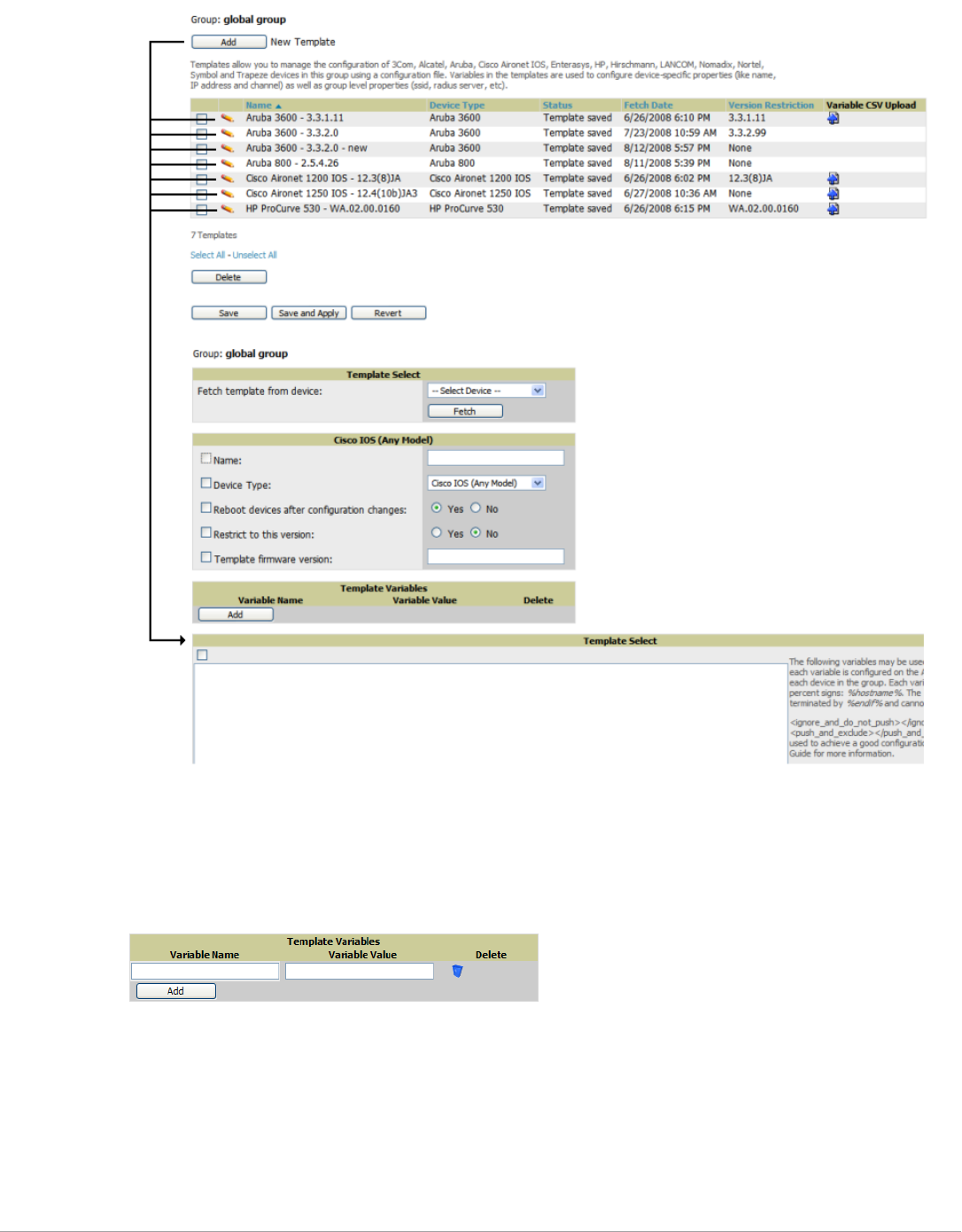
Dell PowerConnect W-AirWave 7.5 | User Guide Creating and Using Templates | 171
Figure 120 Group > Templates > Add Page Illustration
4. Use the drop-down menu to select a device from which to build the global template and select Fetch. The
menus are populated with all devices that are contained in any group that subscribes to the global group. The
fetched configuration populates the template field. Global template variables can be configured with the Add
button in the Template Variables box, illustrated in Figure 121.
Figure 121 Template Variables Illustration
The variable name cannot have any spaces or non-alphanumeric characters. The initial variable value entered
is the default value, but can be changed on a per-group basis later. You can also populate global template
variables by uploading a CSV file (see below).
5. Once you have configured your global template, select Add. You are taken to a confirmation configuration
page where you can review your changes.
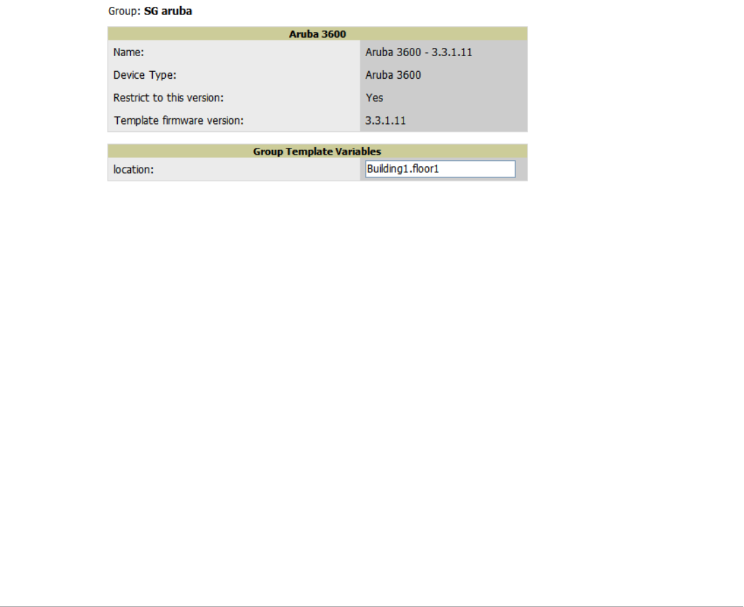
172 | Creating and Using Templates Dell PowerConnect W-AirWave 7.5 | User Guide
6. If you want to add the global template, select Apply Changes Now. If you do not want to add the template,
select Cancel and Discard Changes. Canceling from the confirmation configuration page causes the template
and all of the template variables to be lost.
7. Once you have added a new global template, you can use a CSV upload option to configure global template
variables. Go to the Groups > Templates configuration page and select the CSV upload icon for the
template. The CSV file must contain columns for Group Name and Variable Name. All fields must be
completed.
Group Name—the name of the subscriber group that you wish to update.
Variable Name—the name of the group template variable you wish to update.
Variable Value—the value to set.
For example, for a global template with a variable called "ssid_1", the CSV file might resemble what follows:
Group Name, ssid_1
Subscriber 1, Value 0
8. Once you have defined and saved a global template, it is available for use by any local group that subscribes to
the global group. Go to the Groups > Template configuration page for the local group and select the pencil
icon next to the global template in the list. Figure 122 illustrates this page.
Figure 122 Groups > Templates Edit, Upper Portion
9. To make template changes, go to the Groups > Template configuration page for the global group and select
the pencil icon next to the template you wish to edit. Note that you cannot edit the template itself from the
subscriber group's Groups > Templates tab.
10. If group template variables have been defined, you are able to edit the value for the group on the Groups >
Templates, Add configuration page in the Group Template Variables box. For Symbol devices, you are also
able to define the template per group of APs.

Dell PowerConnect W-AirWave 7.5 | User Guide Using RAPIDS and Rogue Classification | 173
Chapter 7
Using RAPIDS and Rogue Classification
This chapter provides an overview to rogue device and IDS event detection, alerting, and analysis using RAPIDS,
and contains the following sections:
-“Introduction to RAPIDS” on page173
-“Viewing Rogues on the RAPIDS > List Page” on page183
-“Setting Up RAPIDS” on page175
-“Defining RAPIDS Rules” on page178
-“Score Override” on page187
-“Using the Audit Log” on page188
-“Additional Resources” on page188
Introduction to RAPIDS
Rogue device detection is a core component of wireless security. With RAPIDS rules engine and containment
options, you can create a detailed definition of what constitutes a rogue device, and quickly act on a rogue AP for
investigation, restrictive action, or both. Once rogue devices are discovered, RAPIDS alerts your security team of
the possible threat and provides essential information needed to locate and manage the threat.
RAPIDS discovers unauthorized devices in your WLAN network in the following ways:
-Over the Air, using your existing enterprise APs or the optional AMP Management Client (AMC).
-On the Wire
Polling routers and switches to identify, classify, and locate unknown APs
Using the controller’s wired discovery information
Using HTTP and SNMP scanning
Furthermore, RAPIDS integrates with external intrusion detection systems (IDS), as follows:
-Dell WIP—Dell PowerConnect W Series’ Wireless Intrusion Protection (WIP) module integrates wireless
intrusion protection into the mobile edge infrastructure. The WIP module provides wired and wireless AP
detection, classification and containment; detects DoS and impersonation attacks; and prevents client and
network intrusions.
-Cisco WLSE (1100 and 1200 IOS)—AirWave fetches rogue information from the HTTP interface and gets
new AP information from SOAP API. This system provides wireless discovery information rather than rogue
detection information.
-AirMagnet Enterprise—Retrieves a list of managed APs from AirWave.
-AirDefense—Uses the AirWave XML API to keep its list of managed devices up to date.
-WildPackets OmniPeek—Retrieves a list of managed APs from AirWave.
NOTE: To set up a scan, refer to “Discovering and Adding Devices” on page 107.
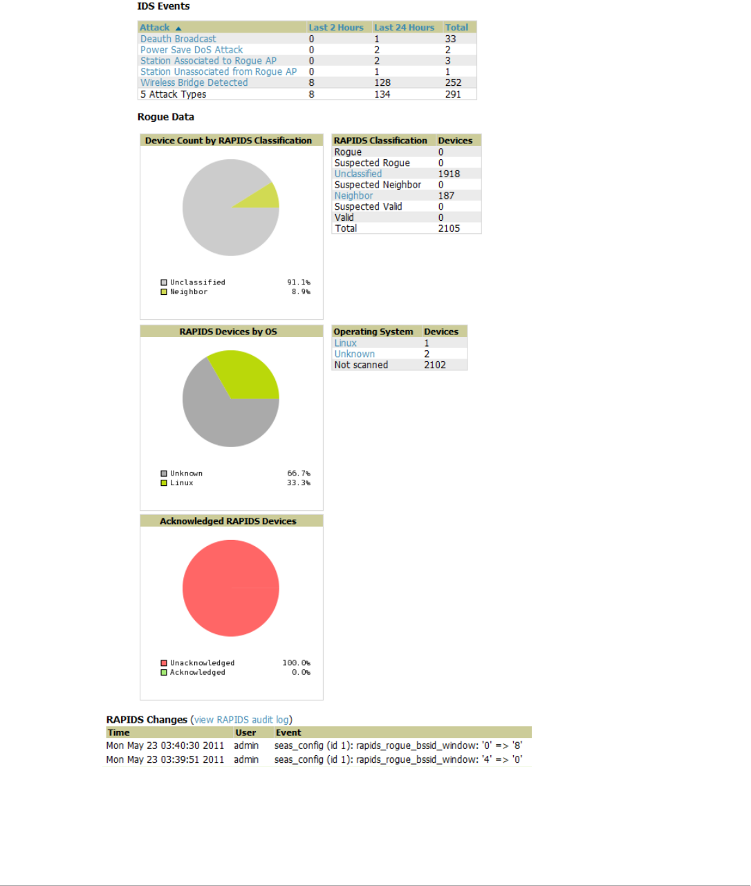
174 | Using RAPIDS and Rogue Classification Dell PowerConnect W-AirWave 7.5 | User Guide
Viewing Overall Network Health on RAPIDS > Overview
The RAPIDS > Overview page displays a page of RAPIDS summary information (see Figure 123). Table 95
defines the summary information that appears on the page.
Figure 123 RAPIDS > Overview Page Illustration

Dell PowerConnect W-AirWave 7.5 | User Guide Using RAPIDS and Rogue Classification | 175
Setting Up RAPIDS
The RAPIDS > Setup page allows you to configure your AirWave server for RAPIDS. Complete the settings on
this page as desired, and select Save. Most of the settings are internal to how AirWave will process rogues.
Basic Configuration
On the RAPIDS > Setup page, the Basic Configuration section allows you to define RAPIDS behavior settings.
illustrates this page and describes the fields:
Table 95 RAPIDS > Overview Fields and Descriptions
Summary Description
IDS Events Displays a list of attack types for the designated folder and subfolders. Field displays events from the past
two hours, the past 24 hours, and total IDS events. Names of attacks link to summary pages with more
details.
NOTE: AirWave should be configured as the SNMP trap receiver on the controllers to receive IDS traps.
See the Dell PowerConnect W-AirWave 7.5 Best Practices Guide for details.
Device Count by
RAPIDS
Classification
A pie chart of rogue device percentages by RAPIDS classification.
RAPIDS
Classification
A summary list with details of the statistics depicted in the Device Count by RAPIDS Classification pie
chart. Click the linked classification name to be taken to a filtered rogue list.
RAPIDS Devices by
OS
A pie chart of RAPIDS percentages by the detected operating system.
Operating System Detected operating systems represented in this summary listing. Click on the linked Operating System
name to see the rogues list filtered by that classification.
OS scans can be run manually or enabled to run automatically on the RAPIDS > Setup page.
Acknowledged
RAPIDS Devices
A color coded pie chart comparing the number of acknowledged devices to the unacknowledged
devices.
RAPIDS Changes Tracks every change made to RAPIDS including changes to rules, manual classification, and components
on the RAPIDS > Setup page. A link at the top of the list directs you to the RAPIDS > Audit Log page.
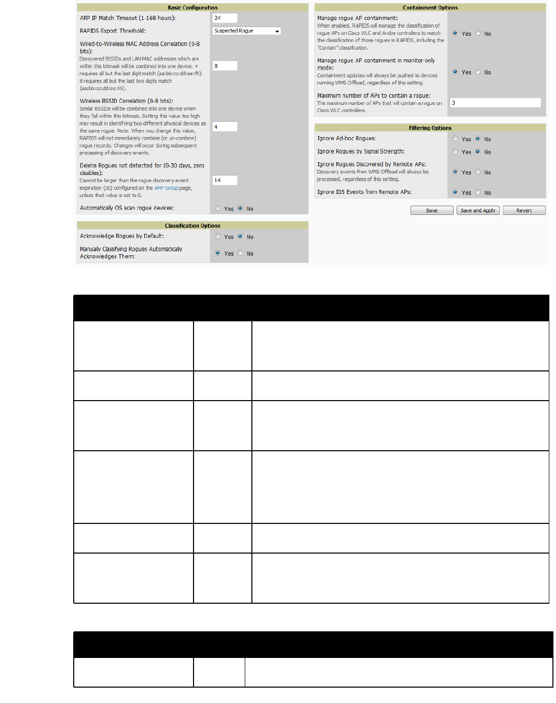
176 | Using RAPIDS and Rogue Classification Dell PowerConnect W-AirWave 7.5 | User Guide
Figure 124 RAPIDS > Setup Page Illustration
Table 96 RAPIDS > Setup > Basic Configuration Fields
Field Default Description
ARP IP Match Timeout (1-168
hours)
24 If you have routers and switches on the AirWave, and it's scanning them for
ARP tables, this can assign a rogue IP address information. This timeout
specifies how recent that information needs to be for the IP address to be
considered valid. Note that the default ARP poll period is long (several hours).
RAPIDS Export Threshold Suspected
Rogue
Exported rogues will be sent to VisualRF for location calculation.
Wired-to-Wireless MAC
Address Correlation (0-8 bits)
4 Discovered BSSIDs and LAN MAC addresses which are within this bitmask will
be combined into one device. 4 requires all but the last digit match
(aa:bb:cc:dd:ee:fX). 8 requires all but the last two digits match
(aa:bb:cc:dd:ee:XX).
Wireless BSSID Correlation
(0-8 bits)
4 Similar BSSIDs will be combined into one device when they fall within this
bitmask. Setting this value too high may result in identifying two different
physical devices as the same rogue.
NOTE: When you change this value, RAPIDS will not immediately combine (or
un-combine) rogue records. Changes will occur during subsequent processing
of discovery events.
Delete Rogues not detected
for (0-30 days, zero disables):
0 This value cannot be larger than the rogue discovery event expiration (30)
configured on the AMP Setup page, unless that value is set to 0.
Automatically OS scan rogue
devices
No Whether to scan the operating system of rogues. Enabling this feature will
cause RAPIDS to perform an OS scan when it gets in IP address for a rogue
device. The OS scan will be run when a rogue gets an IP address for the first
time or if the IP address changes.
Table 97 RAPIDS > Setup > Classification Options Fields
Field Default Description
Acknowledge Rogues by
Default
No Sets RAPIDS to acknowledge rogue devices upon initial detection, prior to their
classification.
Dell PowerConnect W-AirWave 7.5 | User Guide Using RAPIDS and Rogue Classification | 177
Filtered rogues are dropped from the system before they are processed through the rules engine. This can speed
up overall performance but will eliminate all visibility into these types of devices.
Rogue Containment Options
Using RAPIDS, AirWave can shield rogue devices from associating to Cisco WLC controllers (versions 4.2.114
and later), and PowerConnect W-Series controllers (running AOS versions 3.x and later). AirWave will alert you
to the appearance of the rogue device and identify any mismatch between controller configuration and the
desired configuration.
Table 99 shows the Containment Options section of the RAPIDS > Setup page.
1. Navigate to the RAPIDS > Setup page.
Manually Classifying Rogues
Automatically Acknowledges
them
Yes Defines whether acknowledgement happens automatically whenever a rogue
device receives a manual classification.
Table 98 RAPIDS > Setup > Filtering Options
Field Default Description
Ignore Ad-hoc rogues No Filters rogues according to ad-hoc status.
Ignore Rogues by Signal
Strength
No Filters rogues according to signal strength. Since anything below the established
threshold will be ignored and possibly dangerous, best practices is to keep this
setting disabled. Instead, incorporate signal strength into the classification rules
on the RAPIDS > Rules page.
Ignore Rogues Discovered by
Remote APs
No Filters rogues according to the remote AP that discovers them. Enabling this
option causes AirWave to drop all rogue discovery information coming from
remote APs.
Ignore IDS Events from
Remote APs
No Filters IDS Events discovered by remote APs.
Table 97 RAPIDS > Setup > Classification Options Fields (Continued)
Field Default Description
NOTE: WMS Offload is not required to manage containment in AirWave.
Table 99 RAPIDS > Setup > Containment Options Fields and Default Values
Field Default Description
Manage rogue AP
Containment
Yes Rogue APs on Cisco WLC and Dell PowerConnect W-Series controllers as
defined by the Rules engine will be classified as a Contained Rogue. AirWave
pushes the containment status of a rogue device to the controller and the
controller takes the appropriate action. For the rogue device to be contained, you
may need to configure containment on the controller.
Manage rogue AP
containment in monitor-only
mode
No If disabled, AirWave will display the desired containment settings but will not
push them to devices. This may result in mismatches in device classifications.
This can be useful for administrators that want to see what RAPIDS would push
to the controller without making any changes to their network.
If enabled, AirWave will push the desired containment settings to the controllers
in Monitor-Only mode, as well as the devices in Managed mode.
Maximum number of APs to
contain a rogue
3 Sets the maximum number of APs that will contain a rogue on Cisco WLC
controllers.
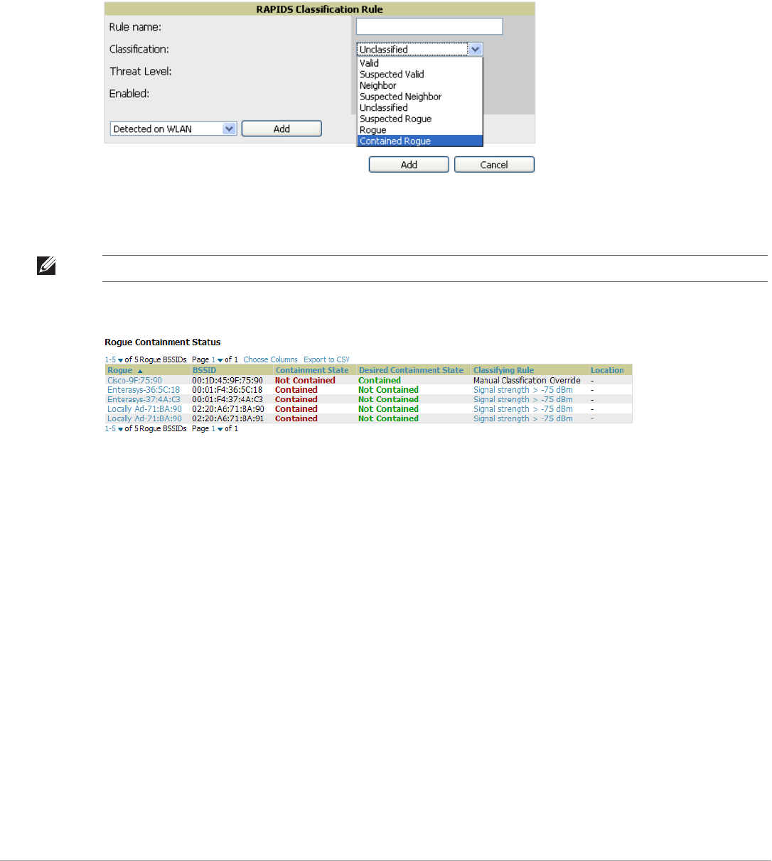
178 | Using RAPIDS and Rogue Classification Dell PowerConnect W-AirWave 7.5 | User Guide
2. From the Containment Options section, select Yes in the Manage rogue AP containment field. Once this is
done, the Contained Rogue classification will appear as an option in the classification drop down menu as
shown in Figure 125.
Additionally, once this option been enabled, the option to manage contained APs in Monitor-Only mode
becomes available. Containment in Monitor-Only mode means configuration changes will still be pushed to
the controller, even though it is in monitor-only mode.
Figure 125 RAPIDS > Rules > Add Classification Rule Menu with Containment
From the APs/Devices > Rogues Contained page, you can see the containment status information, as shown in
Figure 126.
Figure 126 Rogue Containment Status Page
Additional Settings
Additional RAPIDS settings such as role filtering and performance tuning are available in the following locations:
-Use the AirWave Setup > Roles > Add/Edit Role Page to define the ability to use RAPIDS by user role.
Refer to “Creating AirWave User Roles” on page38.
-Use the AirWave Setup > General > Performance Tuning page to define the processing priority of RAPIDS
in relation to AirWave as a whole (see Table 17 on page 35).
Defining RAPIDS Rules
The RAPIDS > Rules page is one of the core components of RAPIDS. This feature allows you to define rules by
which any detected device on the network is classified.
This section describes how to define, use, and monitor RAPIDS rules, provides examples of such rules, and
demonstrates how they are helpful.
This section contains the following topics:
-“Controller Classification with WMS Offload” on page179
-“Device OUI Score” on page179
-“Rogue Device Threat Level” on page180
NOTE: The Rogue Containment device tab is only present for devices that support containment.
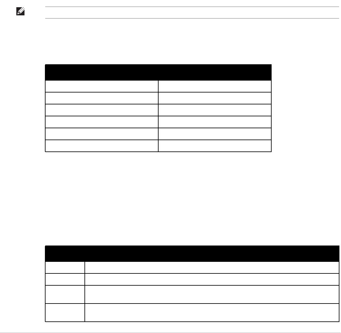
Dell PowerConnect W-AirWave 7.5 | User Guide Using RAPIDS and Rogue Classification | 179
-“Viewing and Configuring RAPIDS Rules” on page180
-“Recommended RAPIDS Rules” on page182
-“Using RAPIDS Rules with Additional AirWave Functions” on page182
Controller Classification with WMS Offload
This classification method is supported only when WMS offload is enabled on Dell PowerConnect W-Series
WLAN switches. Controller classification of this type remains distinct from RAPIDS classification. WLAN
switches feed wireless device information to AirWave, which AirWave then processes. AirWave then pushes the
WMS classification to all of the Dell PowerConnect W-Series controllers that are WMS offload enabled.
WMS Offload ensures that a particular BSSID has the same classification on all of the controllers. WMS Offload
removes some load from master controllers and feeds 'connected-to-lan' information to the RAPIDS classification
engine. RAPIDS classifications and controller classifications are separate and often are not synchronized.
The following table compares how default classification may differ between AirWave and ArubaOS for scenarios
involving WMS Offload.
For additional information about WMS Offload, refer to the Dell PowerConnect W-AirWave Best Practices Guide
in Home > Documentation.
Device OUI Score
The Organizationally Unique Identifier (OUI) score is based on the LAN MAC address of a device. RAPIDS can
be configured to poll your routers and switches for the bridge forwarding tables. RAPIDS then takes the MAC
addresses from those tables and runs them through a proprietary database to derive the OUI score. The OUI score
of each device is viewable from each rogue’s detail page. Table 101 provides list the OUI scores definitions.
NOTE: RAPIDS classification is not pushed to the devices.
Table 100 Rogue Device Classification Matrix
AMP ArubaOS (ARM)
Unclassified (default state) Unknown
Rogue Rogue
Suspected Neighbor Interfering
Neighbor Known Interfering
Valid Valid
Contained Rogue DOS
Table 101 Device OUI Scores
Score Description
Score of 1 Indicates any device on the network; this is the lowest threat level on the network.
Score of 2 Indicates any device in which the OUI belongs to a manufacturer that produces wireless (802.11) equipment.
Score of 3 Indicates that the OUI matches a block that contains APs from vendors in the Enterprise and small office/ small
home market.
Score of 4 Indicates that the OUI matches a block that belonged to a manufacturer that produces small office/ small home
access points.
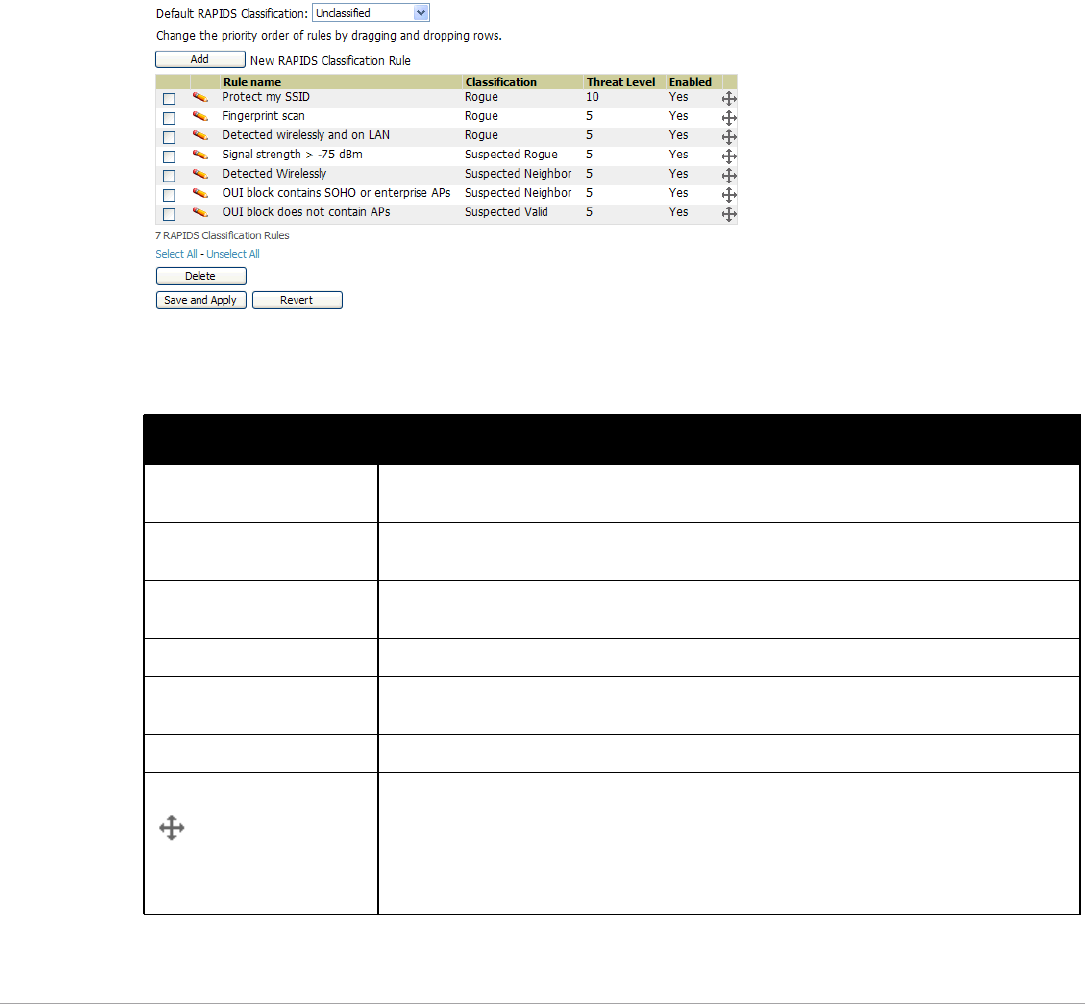
180 | Using RAPIDS and Rogue Classification Dell PowerConnect W-AirWave 7.5 | User Guide
Rogue Device Threat Level
The threat level classification adds granularity for each general RAPIDS classification. Devices of the same
classification can have differing threat scores based on the classifying rule, ranging from 1 to 10 with a default
value of 5. This classification process can help identify the greater threat. Alerts can be defined and sorted by
threat level.
Threat level and classification are both assigned to a device when a device matches a rule. Once classified, a
device’s classification and threat level change only if it is classified by a new rule or is manually changed. Threats
levels can be manually defined on the RAPIDS > Detail page when the RAPIDS classification is manually
overridden or you can edit the rule to have a higher threat level.
Viewing and Configuring RAPIDS Rules
To view the RAPIDS rules that are currently configured on AirWave, navigate to the RAPIDS > Rules page
(Figure 127).
Figure 127 RAPIDS > Rules Page Illustration
Table 102 defines the fields in the RAPIDS > Rules page.
Table 102 RAPIDS > Rules Page
Field Description
Default Classification This drop down specifies the classification that a rogue device receives when it does not match
any rules.
Add New RAPIDS
Classification Rule
Select this button to create a RAPIDS classification rule.
Rule Name Displays the name of any rule that has been configured. Rule names should be descriptive and
should convey the core purpose for which it was created.
Classification Displays the classification that devices receive if they meeting the rule criteria.
Threat Level Displays the numeric threat level for the rogue device that pertains to the rule. Refer to “Rogue
Device Threat Level” on page 180 for additional information.
Enabled Displays the status of the rule, whether enabled or disabled.
Reorder Drag and Drop Icon Changes the sequence of rules in relation to each other. Select, then drag and drop, the icon for
any rule to move it up or down in relation to other rules. A revised sequence of rules must be
saved before rogues are classified in the revised sequence.
NOTE: The sequence of rules is very important for proper rogue classification. A device gets
classified by the first rule to which it complies, even if it conforms to additional rules later in the
sequence.
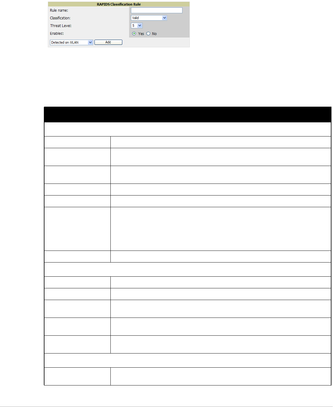
Dell PowerConnect W-AirWave 7.5 | User Guide Using RAPIDS and Rogue Classification | 181
To create a new rule, select the Add button next to New RAPIDS Classification Rule to launch the RAPIDS
Classification Rule page (see Figure 128).
Figure 128 Classification Rule Page
Fill in the settings described in Table 102 then select an option from the drop down menu.
Table 103 defines the drop down menu options that are at the bottom left of the RAPIDS Classification Rule
dialog box (see Figure 128). Once all rule settings are defined, select Add. The new rule automatically appears in
the RAPIDS > Rules page.
Table 103 Properties Drop Down Menu
Option Description
Wireless Properties
Detected on WLAN Classifies based on how the rogue is detected on the wireless LAN.
Detecting AP Count Classifies based on the number of managed devices that can hear the rogue. Enter a numeric
value and select At Least or At Most.
Encryption Classifies based on the rogue matching a specified encryption method. Note that you can select
for 'no encryption' with a rule that says “Encryption does not match WEP or better”.
Network type Rogue is running on the selected network type, either Ad-hoc or Infrastructure.
Signal Strength Rogue matches signal strength parameters. Specify a minimum and maximum value in dBm.
SSID Classifies the rogue when it matches or does not match the specified string for the SSID or a
specified regular expression.
NOTE: For SSID matching functions, AirWave processes only alpha-numeric characters and the
asterisk wildcard character (*). AirWave ignores all other non-alpha-numeric characters. For
example, the string of ethersphere-* matches the SSID of ethersphere-wpa2 but also
the SSID of ethersphere_this_is_an_example (without any dashes).
Detected Client Count Classifies based on the number of valid clients.
Wireline Properties
Detected on LAN Rogue is detected on the wired network. Select Yes or No.
Fingerprint Scan Rogue matches fingerprint parameters.
IP Address Rogue matches a specified IP address or subnet. Enter IP address or subnet information as
explained by the fields.
OUI Score Rogue matches manufacturer OUI criteria. You can specify minimum and maximum OUI score
settings from two drop-down lists. Select remove to remove one or both criteria, as desired.
Operating System Rogue matches OS criteria. Specify matching or non-matching OS criteria as prompted by the
fields.
Wireless/Wireline Properties
Manufacturer Rogue matches the manufacturer information of the rogue device. Specify matching or non-
matching manufacturer criteria.

182 | Using RAPIDS and Rogue Classification Dell PowerConnect W-AirWave 7.5 | User Guide
After creating a new rule, select Add to return to the RAPIDS > Rules page. Select Save and Apply to have the
new rule take effect.
Deleting or Editing a Rule
To delete a rule from the RAPIDS rules list, go to the RAPIDS > Rules page. Select the check box next to the
rule you want to delete, and select Delete. The rule is automatically deleted from RAPIDS > Rules.
To edit any existing rule, select its pencil icon to launch the RAPIDS Classification Rule page (see Figure 128).
Edit or revise the fields as necessary, then select Save.
To change the sequence in which rules apply to any rogue device, drag and drop the rule to a new position in the
rules sequence.
Recommended RAPIDS Rules
-If Any Device Has Your SSID, then Classify as Rogue
The only devices broadcasting your corporate SSID should be devices that you are aware of and are managed
by AirWave. Rogue devices often broadcast your official SSID in an attempt to get access to your users, or to
trick your users into providing their authentication credentials. Devices with your SSID generally pose a severe
threat. This rule helps to discover, flag, and emphasize such a device for prompt response on your part.
-If Any Device Has Your SSID and is Not an Ad-Hoc Network Type, then Classify as Rogue
This rule classifies a device as a rogue when the SSID for a given device is your SSID and is not an Ad-Hoc
device. Windows XP automatically tries to create an Ad-hoc network if it can not find the SSID for which it is
searching. This means that user’s laptops on your network may appear as Ad-Hoc devices that are
broadcasting your SSID. If this happens too frequently, you can restrict the rule to apply to non-ad-hoc
devices.
-If More Than Four APs Have Discovered a Device, then Classify as Rogue
By default, AirWave tries to use Signal Strength to determine if a device is on your premises. Hearing device
count is another metric that can be used.
The important concept in this scenario is that legitimate neighboring devices are only heard by a few APs on
the edge of your network. Devices that are heard by a large number of your APs are likely to be in the heart of
your campus. This rule works best for scenarios in large campuses or that occupy an entire building. For
additional rules that may help you in your specific network scenario, contact Dell support at support.dell.com.
Using RAPIDS Rules with Additional AirWave Functions
Rules that you configure on the RAPIDS > Rules page establish an important way of processing rogue devices on
your network, and flagging them for attention as required. Such devices appear on the following pages in
AirWave, with additional information:
-RAPIDS > List—Lists rogue devices as classified by rules.
-RAPIDS > Rules—Displays the rules that classify rogue devices.
-RAPIDS > Overview—Displays general rogue device count and statistical information.
MAC Address Rogue matches the MAC address. Specify matching or non-matching address criteria, or use a
wildcard (*) for partial matches.
Dell Controller Properties
Controller Classification Rogue matches the specified controller classification.
Confidence Rogue falls within a specified minimum and maximum confidence level, ranging from 1 to 100.
Table 103 Properties Drop Down Menu (Continued)
Option Description
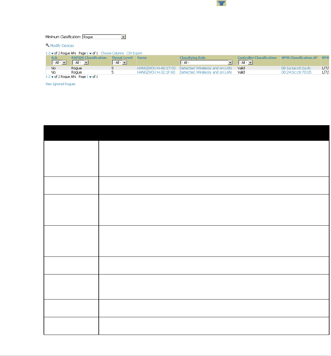
Dell PowerConnect W-AirWave 7.5 | User Guide Using RAPIDS and Rogue Classification | 183
-System > Triggers—Displays triggers that are currently configured, including any triggers that have been
defined for rogue events.
-Reports > Definitions—Allows you to run New Rogue Devices Report with custom settings.
-VisualRF—Displays physical location information for rogue devices.
Viewing Rogues on the RAPIDS > List Page
To view a rogue AP, select the RAPIDS > List tab and select a rogue device type from the Minimum
Classification drop-down menu (see Figure 129). You can sort the table columns (up/down) by selecting the
column head. Most columns can be filtered using the funnel icon ( ). The active links on this page launch
additional pages for RAPIDS configuration or device processing.
Figure 129 RAPIDS > List Page Illustration (partial view)
Table 104 details the column information displayed in Figure 129. For additional information about RAPIDS
rules, refer to “Defining RAPIDS Rules” on page178.
Table 104 RAPIDS > List Column Definitions
Column Description
Ack Displays whether or not the rogue device has been acknowledged. Devices can be acknowledged
manually or you can configure RAPIDS so that manually classifying rogues will automatically
acknowledges them. Additionally, devices can be acknowledged by using Modify Devices link at the top
of the RAPIDS > List page. Rogues should be acknowledged when the AirWave user has investigated
them and determined that they are not a threat (see “Basic Configuration” on page 175).
RAPIDS Classification Displays the current RAPIDS classification. This classification is determined by the rules defined on the
RAPIDS > Rules page.
Threat Level This field displays the numeric threat level of the device, in a range from 1 to 10. The definition of threat
level is configurable, as described in “Rogue Device Threat Level” on page 180.
The threat level is also supported with Triggers (see “Monitoring and Supporting AirWave with the
System Pages” on page 189).
Name Displays the alpha-numeric name of the rogue device, as known. By default, AirWave assigns each
rogue device a name derived from the OUI vendor and the final six digits of the MAC address.
Clicking the linked name will redirect you to the RAPIDS > Detail page for that rogue device. Refer to
“Overview of the RAPIDS > Detail Page” on page 185.
Classifying Rule Displays the RAPIDS Rule that classified the rogue device (see“Viewing and Configuring RAPIDS
Rules” on page 180).
Controller
Classification
Displays the classification of the device based on the controller’s hard-coded rules.
NOTE: This column is hidden unless Offload WMS Database is enabled by at least one group on the
Groups > Basic page.
WMS Classification
AP
The AP that provided the information used to classify the device. Click the linked device name to be
redirected to the APs/Devices > Monitor page for that AP.
WMS Classification
Date
The date that WMS set the classification.

184 | Using RAPIDS and Rogue Classification Dell PowerConnect W-AirWave 7.5 | User Guide
Confidence The confidence level of the suspected rogue. How confidence is calculated varies based on the version
of ArubaOS. When an ArubaOS controller sees evidence that a device might be on the wire it will up the
confidence level. If ArubaOS is completely sure that it is on the wire, it gets classified as a rogue.
Wired Displays whether the rogue device has been discovered on one of your wired networks by polling
routers/switches, your SNMP/HTTP scans, or Dell WIP information. This column displays Yes or is blank
if wired information was not detected.
Detecting APs Displays the number of AP devices that have wirelessly detected the rogue device. A designation of
heard implies the device was heard over the air.
Location If the rogue has been placed in VisualRF, this column will display the name of the floor plan the rogue is
on as a link to the VisualRF Floor Plan View page.
SSID Displays the most recent SSID that was heard from the rogue device.
Signal Displays the strongest signal strength detected for the rogue device.
RSSI Displays Received Signal Strength Indication (RSSI) designation, a measure of the power present in a
received radio signal.
Network Type Displays the type of network in which the rogue is present, for example:
-Ad-hoc—This type of network usually indicates that the rogue is a laptop that attempts to create a
network with neighboring laptops, and is less likely to be a threat.
-AP—This type of network usually indicates an infrastructure network, for example. This may be
more of a threat.
-Unknown—The network type is not known.
Encryption Type Displays the encryption that is used by the device. Possible contents of this field include the following
encryption types:
-Open—No encryption
-WEP—Wired Equivalent Privacy
-WPA—Wi-Fi Protected Access
Generally, this field alone does not provide enough information to determine if a device is a rogue, but it
is a useful attribute. If a rogue is not running any encryption method, you have a wider security hole
than with an AP that is using encryption.
Ch Indicates the most recent RF channel on which the rogue was detected. Note: It can be detected on
more than one channel if it contains more than one radio.
LAN MAC Address The LAN MAC address of the rogue device.
LAN Vendor Indicates the LAN vendor of the rogue device, when known.
Radio MAC Address Displays the MAC address for the radio device, when known.
Radio Vendor Indicates the radio vendor of the rogue device, when known.
OS This field displays the OS of the device, as known. OS is the result of a running an OS port scan on a
device. An IP addresses is required to run an OS scan. The OS reported here is based on the results of
the scan.
Model Displays the model of rogue device, if known. This is determined with a fingerprint scan, and this
information may not always be available.
IP Address Displays the IP address of the rogue device. The IP address data comes from fingerprint scans or ARP
polling of routers and switches.
Last Discovering AP Displays the most recent AP to discover the rogue device. The device name in this column is taken from
the device name in AirWave. Click the linked device name to be redirected to the APs/Devices >
Monitor page for that AP.
Switch/Router Displays the switch or router where the device’s LAN MAC address was last seen.
Port Indicates the physical port of the switch or router where the rogue was last seen.
Table 104 RAPIDS > List Column Definitions (Continued)
Column Description
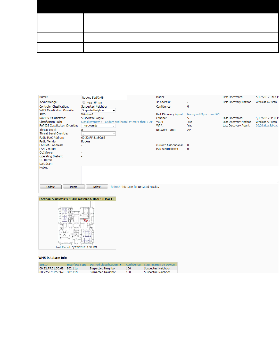
Dell PowerConnect W-AirWave 7.5 | User Guide Using RAPIDS and Rogue Classification | 185
Overview of the RAPIDS > Detail Page
Select a device Name in the RAPIDS > List page to view the Detail page (Figure 130).
Figure 130 RAPIDS > Detail Page Illustration
Important things to remember regarding the information in the device detail page are:
-Users with the role of Admin can see all rogue AP devices.
-Active rogue clients associated with this AP are listed in the Current Rogue Client Associations table.
Selecting a linked MAC address will take you to the Clients > Client Detail page, where you can view
fingerprinting and device details.
-Users with roles limited by folder can see a rogue AP if there is at least one discovering device that they can
see.
-The discovery events displayed are from APs that you can see on the network. There may be additional
discovery events that remain hidden to certain user roles.
Notes Indicates any notes about the rogue device that may have been added.
Last Seen Indicates the date and time the rogue device was last seen.
Current Associations The number of current rogue client associations to this device.
Max associations The highest number of rogue client associations ever detected at one time.
Table 104 RAPIDS > List Column Definitions (Continued)
Column Description

186 | Using RAPIDS and Rogue Classification Dell PowerConnect W-AirWave 7.5 | User Guide
-Each rogue device frequently has multiple discovery methods, all of which are listed.
-As you work through the rogue devices, use the Name and Notes fields to identify the AP and document its
location.
-You can use the global filtering options on the RAPIDS > Setup page to filter rogue devices according to
signal strength, ad-hoc status, and discovered by remote APs.
-VisualRF uses the heard signal information to calculate the physical location of the device.
-If the device is seen on the wire, RAPIDS reports the switch and port for easy isolation.
-If you find that the rogue belongs to a neighboring business, for example, you can override the classification to
a neighbor and acknowledge the device. Otherwise, it is strongly recommended that you extract the device
from your building and delete the rogue device from your system. If you delete a rogue, you will be notified
the next time it is discovered.
-Most columns in the Discovery Events list table on this page can be filtered using the funnel icon ( ).
To update a rogue device:
1. Select the Identify OS for Suspected Rogues option if an IP address is available to obtain operating system
information using an nmap scan. Note that if you are running wireline security software on your network, it
may identify your AirWave as a threat, which you can ignore.
2. Select the Ignore button if the rogue device is to be ignored. Ignored devices will not trigger alerts if they are
rediscovered or reclassified.
3. Select the Delete button if the rogue device is to be removed from AirWave processing.
Viewing Ignored Rogue Devices
The RAPIDS > List page allows you to view ignored rogues—devices that have been removed from the rogue
count displayed by AirWave. Such devices do not trigger alerts and do not display on lists of rogue devices. To
display ignored rogue devices, select View Ignored Rogues at the bottom left of the page.
Once a classification that has rogue devices is chosen from the drop-down menu, a detailed table displays all
known information.
Using RAPIDS Workflow to Process Rogue Devices
One suggested workflow for using RAPIDS is as follows:
-Start from the RAPIDS > List page. Sort the devices on this page based on classification type. Begin with
Rogue APs, working your way through the devices listed.
-Select Modify Devices, then select all devices that have an IP address and select Identify OS. AirWave
performs a port scan on the device and attempts to determine the operating system (see “Setting Up
RAPIDS” on page175)
You should investigate devices running an embedded Linux OS installation. The OS scan can help identify
false positives and isolate some devices that should receive the most attention.
-Find the port and switch at which the device is located and shut down the port or follow wiring to the device.
-To manage the rogue, remove it from the network and acknowledge the rogue record. If you want to allow it
on the network, classify the device as valid and update with notes that describe it.
NOTE: Not all rogue discovery methods will have all information required for resolution. For example, the switch/router
information, port, or IP address are found only through switch or router polling. Furthermore, RSSI, signal, channel, SSID, WEP, or
network type information only appear through wireless scanning. Such information can vary according to the device type that
performs the scan.
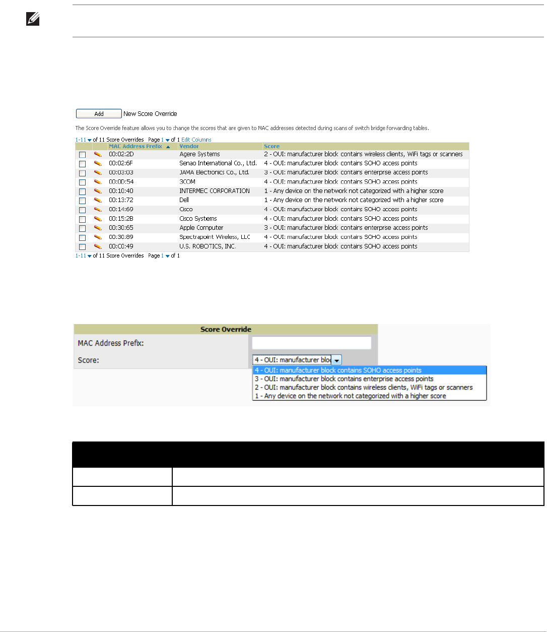
Dell PowerConnect W-AirWave 7.5 | User Guide Using RAPIDS and Rogue Classification | 187
Score Override
On RAPIDS > Score Override page you can change the OUI scores that are given to MAC addresses detected
during scans of bridge forwarding tables on routers or switches. Figure 131, Figure 132, and Table 105 illustrate
and describe RAPIDS Score Override. Perform these steps to create a score override.
Once a new score is assigned, all devices with the specified MAC address prefix receive the new score.
1. Navigate to the RAPIDS > Score Override page. This page lists all existing overrides if they have been
created.
Figure 131 RAPIDS > Score Override Page
2. Select Add to create a new override or select the pencil icon next to an existing override to edit that override.
The Score Override add or edit page appears (Figure 132).
Figure 132 Add/Edit Score Override Page
3. Enter in the six-digit MAC prefix for which to define a score, and select the desired score. Once the new score
has been saved, all detected devices with that prefix receive the new score.
4. Select Add to create the new override, or select Save to retain changes to an existing override. The new or
revised override appears on the RAPIDS > Score Override page.
5. To remove any override, select that override in the checkbox and select Delete.
NOTE: Note that rescoring a MAC Address Prefix poses a security risk. The block has received its score for a reason. Any devices
that fall within this block receive the new score.
Table 105 RAPIDS > Add/Edit Score Override Page Fields
Field Description
MAC Address Prefix Use this field to define the OUI prefix to be re-scored.
Score Use this field to set the score that a device, with the specified MAC address prefix, will receive.
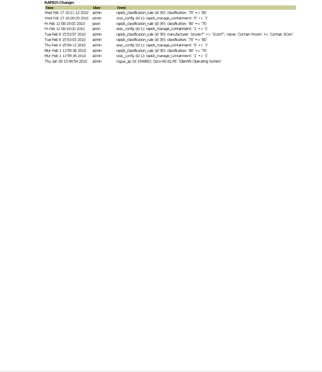
188 | Using RAPIDS and Rogue Classification Dell PowerConnect W-AirWave 7.5 | User Guide
Using the Audit Log
The Audit Log is a record of any changes made to the RAPIDS rules, setup page, and manual changes to specific
rogues. This allows you to see how something is changes, when it changed, and who made the alteration. The
Audit Log can be found at RAPIDS > Audit Log. For more information, see Figure 133.
Figure 133 Audit Log Page Illustration
Additional Resources
The following AirWave tools support RAPIDS:
-System Triggers and Alerts—Triggers and Alerts that are associated with rogue devices follow the
classification-based system described in this chapter. For additional information about triggers that support
rogue device detection, see to “Viewing, Delivering and Responding to Triggers and Alerts” on page193.
-Reports—The New Rogue Devices Report displays summary and detail information about all rogues first
discovered in a given time period. For more information, see “Using the New Rogue Devices Report” on
page248.
For additional security-related features and functions, see the following topics in this guide.
-“Configuring Group Security Settings” on page79
-“Configuring Cisco WLC Security Parameters and Functions” on page94
-“Configuring Group SSIDs and VLANs” on page82
-“Monitoring and Supporting AirWave with the System Pages” on page189

Dell PowerConnect W-AirWave 7.5 | User Guide Performing Daily Administration in AirWave | 189
Chapter 8
Performing Daily Administration in
AirWave
Daily WLAN administration often entails network monitoring, supporting WLAN and AirWave users, and
monitoring AirWave system operations.
This chapter contains the following administration procedures:
-“Monitoring and Supporting AirWave with the System Pages” on page189
-“Monitoring and Supporting WLAN Clients” on page202
-“Evaluating and Diagnosing User Status and Issues” on page210
-“Managing Mobile Devices with SOTI MobiControl and AirWave” on page214
-“Monitoring and Supporting AirWave with the Home Pages” on page216
-“Supporting AirWave Servers with the Master Console” on page226
-“Backing Up AirWave” on page229
-“Using AirWave Failover for Backup” on page230
-“Logging out of AirWave” on page232
Monitoring and Supporting AirWave with the System Pages
The System pages provide a centralized location for system-wide AirWave data and settings. Apart from Triggers,
Alerts, and Backups pages that are described elsewhere in this chapter, the remaining pages of the System section
are as follows:
-System > Status—Displays status of all AirWave services and links to their log pages. Refer to “Using the
System > Status Page” on page189.
-System > Syslog & Traps—Displays all syslog messages and SNMP traps that AirWave receives. Refer to
“Viewing Device Events in System > Syslog & Traps” on page191.
-System > Event Log—This useful debugging tool keeps a list of recent AirWave events, including APs
coming up and down, services restarting, and most AirWave-related errors as well as the user that initiated the
action. Refer to “Using the System > Event Log Page” on page192.
-System > Triggers—View and edit triggering conditions that cause AirWave to send out alert notifications.
Refer to “Viewing, Delivering and Responding to Triggers and Alerts” on page193.
-System > Alerts—View or acknowledge alerts sent out by the system and use the Triggering Agent links to
drill down to the device that triggered the alert. Refer to “Viewing Alerts” on page200.
-System > Backups— View the backup files that are run nightly. Refer to “Backing Up AirWave” on page229.
-System > Configuration Change Jobs—Manages configuration changes in AirWave. Refer to “Using the
System > Configuration Change Jobs Page” on page222.
-System > Firmware Upgrade Jobs—Displays information about current and scheduled firmware upgrades.
Refer to “Using the System > Firmware Upgrade Jobs Page” on page222.
-System > Performance—Displays basic AirWave hardware information as well as resource usage over time.
Refer to “Using the System > Performance Page” on page223.
Using the System > Status Page
The System > Status page displays the status of all of AirWave services. Services will either be OK, Disabled, or
Down. If any service is Down (displayed in red) please contact Dell support at support.dell.com. The Reboot
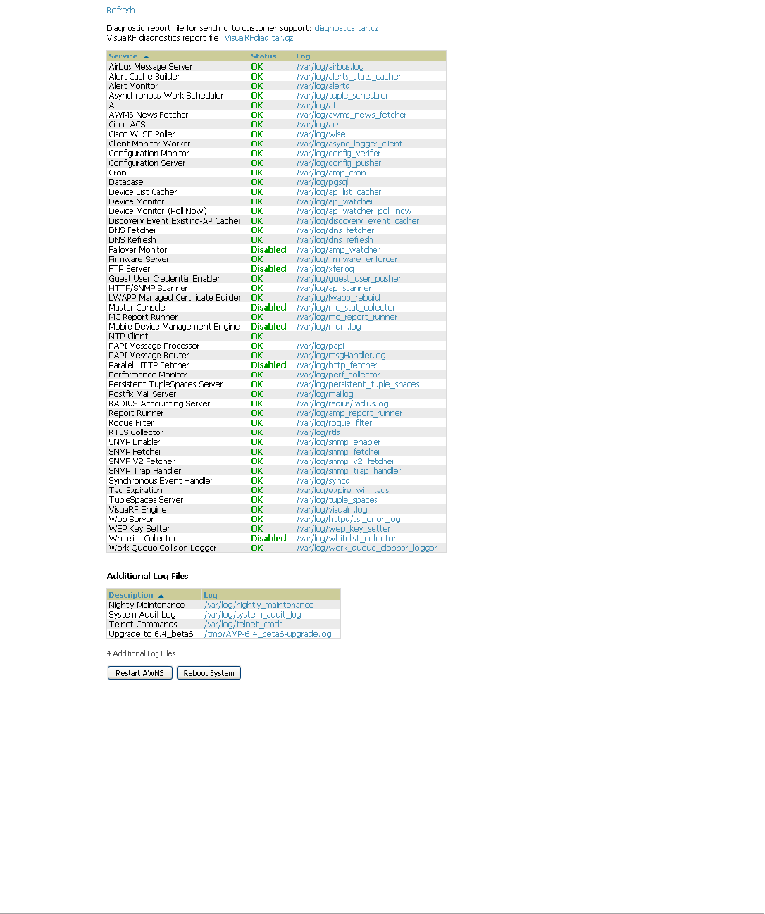
190 | Performing Daily Administration in AirWave Dell PowerConnect W-AirWave 7.5 | User Guide
System button provides a graceful way to power cycle your AirWave remotely when it is needed. The Restart
AirWave button will restart the AirWave services without power cycling the server or reloading the OS. Figure
134 illustrates this page.
Figure 134 System > Status Page Illustration
-The link diagnostics.tar.gz contains reports and logs that are helpful to Dell support in troubleshooting and
solving problems. Your Dell support representative may ask for this file along with other logs that are linked on
this page.
-Similarly, the VisualRFdiag.zip link contains VisualRF diagnostic information that might be requested by
Dell support.
-A summary table lists logs that appear on the System > Status page. These are used to diagnose AirWave
problems. Additional logs are available via SSH access in the /var/log and /tmp directories; Dell support
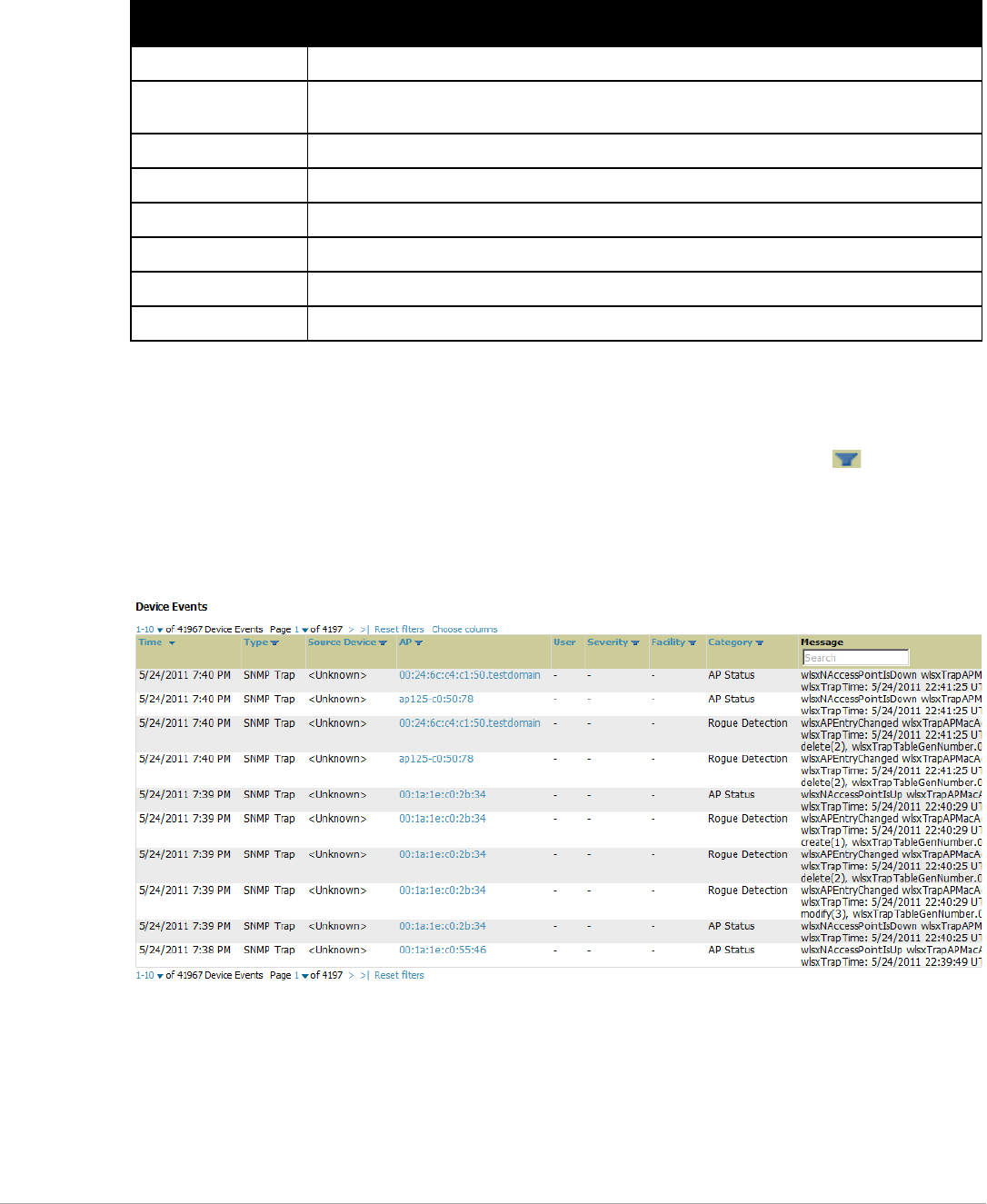
Dell PowerConnect W-AirWave 7.5 | User Guide Performing Daily Administration in AirWave | 191
engineers may request these logs for help in troubleshooting problems and will provide detailed instructions
on how to retrieve them. Table 106 describes some of the most important logs:
Viewing Device Events in System > Syslog & Traps
Admins can use the System > Syslog & Traps page to review all syslog messages and SNMP traps that AirWave
receives from the trigger type Device Event. These device events are listed by time, type, source device, AP,
severity, facility, category, and message. Most columns can be filtered using the funnel icon ( ), and messages
can be filtered by substring using the Search field, as seen in Figure 135.
You can change the historical data retention from the Device Events (Syslog, Traps) field in AMP Setup >
General.
Figure 135 System > Syslog & Traps Page Illustration
Table 106 A Sample of Important Status Logs
Log Description
pgsql Logs database activity.
error_log Reports problems with the web server. Also linked from the internal server error page that displays on
the web page; please send this log to Dell support whenever reporting an internal server error.
maillog Applies in cases where emailed reports or alerts do not arrive at the intended recipient's address.
radius Displays error messages associated with RADIUS accounting.
async_logger Tracks many device monitoring processes, including user-AP association.
async_logger_client Logs device configuration checks.
config_pusher Logs errors in pushing configuration to devices.
visualrf.log Details errors and messages associated with the VisualRF application.
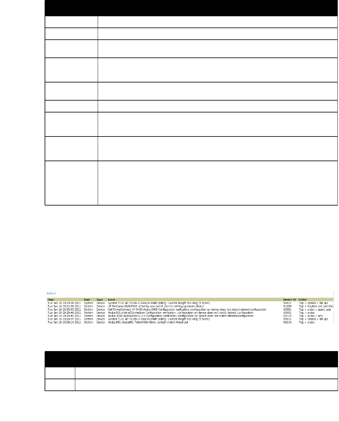
192 | Performing Daily Administration in AirWave Dell PowerConnect W-AirWave 7.5 | User Guide
Table 107 describes the columns and the information provided in each:
Syslog messages also appear in the APs/Devices > Monitor page for controllers and in Clients > Client Detail
pages under the Association History section.
Using the System > Event Log Page
The System > Event Log page is a very useful debugging tool containing a list of recent AirWave events
including APs coming up and down, services restarting, and most AirWave-related errors as well as the user that
initiated the action. Figure 136 illustrates this page, and Table 108 describes the page components.
Figure 136 System > Event Log Page Illustration
Table 107 System > Syslog & Traps Columns and Descriptions
Column Description
Time The timestamp of the device event.
Type Either Syslog or SNMP Trap.
Source Device The name of the device that sent the message. Will be a link if you have visibility to the device. Can be
empty if AirWave could not correlate the source IP.
AP Contains a link to the APs/Devices > Monitor page for a device other than the source device that was
correlated from some data contained in the message (by LAN MAC, BSSID, or IP Address). Can be blank,
and will only be a link if you have visibility to the device.
Client Displays a user’s MAC address if one was found in the message. Can be blank, and will be a link if you
have visibility to the user’s AP.
Severity The severity level of the event: Emergency, Alert, Critical, Bug, Error, Warning, Notice, or Info
Facility Part of the syslog spec - sort of the logical source of the message. From controllers, will always be one of
local0-local7 (you can configure on the controller when sending syslog messages to a particular receiver
which facility you want to use in the messages).
Category If SNMP Trap: Hardware, IDS, Client Security, AP Security, AP Status, Software, or Rogue Detection. For
Syslog messages, a category is based on the process name on the controller that sent the syslog
message. The categorization for traps and syslog messages only works for events from a Dell controller.
Message The raw trap message including the AP MAC Address, time sent, and other information. For syslogs,
AirWave does not display the numbers at the beginning of the message that indicate the severity and
facility. For traps, AirWave will attempt to translate them to human-readable format when possible.
AirWave will not receive processed SNMP traps into the Device Event framework if the AirWave doesn't
have MIB file to translate the trap.
Use the Search field at the top of the column to filter the messages by a substring.
Table 108 Event Log Fields
Column Description
Time Date and time of the event.
User The AirWave user that triggered the event. When AirWave itself is responsible, System is displayed.
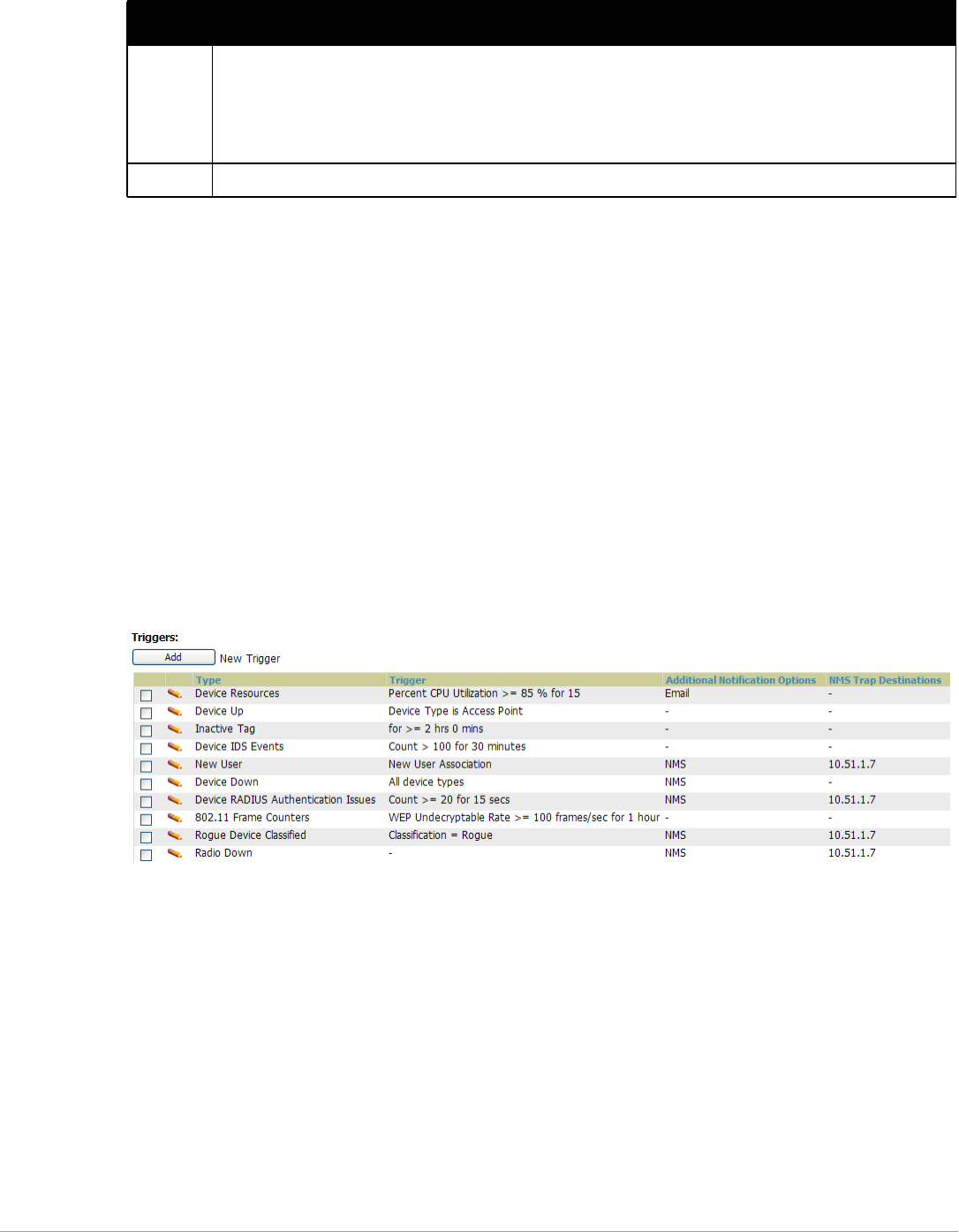
Dell PowerConnect W-AirWave 7.5 | User Guide Performing Daily Administration in AirWave | 193
Viewing, Delivering and Responding to Triggers and Alerts
This section describes triggers and alerts and contain the following topics:
-Viewing Triggers
-Creating New Triggers
-Delivering Triggered Alerts
-Viewing Alerts
-Responding to Alerts
AirWave monitors key aspects of wireless LAN performance. When certain parameters or conditions arise that
are outside normal bounds, AirWave generates (or triggers) alerts that enable you to address problems, frequently
before users have a chance to report them.
Viewing Triggers
To view defined system triggers, navigate to the System > Triggers page. Figure 137 illustrates this page.
Figure 137 System > Triggers Page Illustration (partial view)
Creating New Triggers
Perform the following steps to create and configure one or more new triggers. These steps define settings that are
required for any type of trigger.
1. To create a new trigger, select the Add New Trigger button from the System > Triggers page. The page that
appears is illustrated in Figure 138.
Type Displays the Type of event recorded, which is one of four types, as follows:
-Device—An event localized to one specific device.
-Group—A group-wide event.
-System—A system-wide event.
-Alert—If a trigger is configured to report to the log, an Alert type event will be logged here.
Event The event AirWave observed; useful for debugging, user tracking, and change tracking.
Table 108 Event Log Fields
Column Description
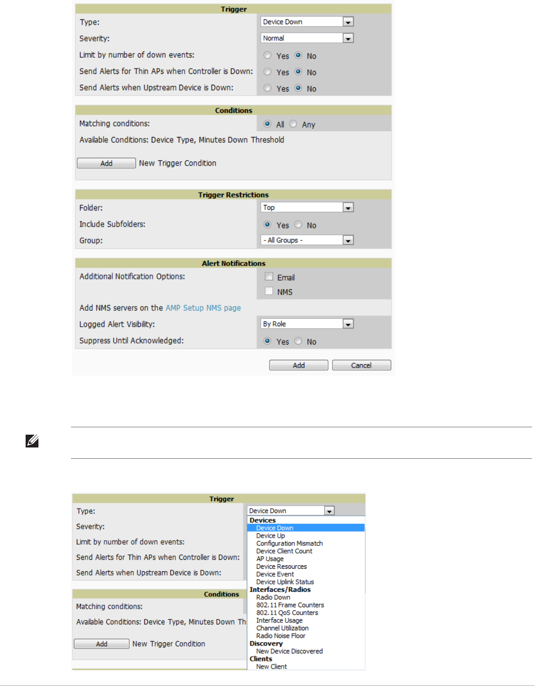
194 | Performing Daily Administration in AirWave Dell PowerConnect W-AirWave 7.5 | User Guide
Figure 138 Add New Trigger Page Illustration
2. In the Trigger section, choose the desired trigger Type and Severity. Figure 139 illustrates some of the
supported trigger types.
Figure 139 System > Triggers > Add Trigger Type Drop-down Menu
NOTE: The alert summary information at the top of the AirWave screen can be configured to separately display severe alerts.
Refer to “Configuring Your Own User Information with the Home > User Info Page” on page 220 for more details.

Dell PowerConnect W-AirWave 7.5 | User Guide Performing Daily Administration in AirWave | 195
Once you have selected a trigger type, the Add Trigger page changes, depending on the trigger type that you
select. In many cases, you must configure at least one Condition setting. Conditions, settings and default values
vary according to trigger type. Triggers with conditions can be configured to fire if any criteria match as well as if
all criteria match.
-Some trigger types share common settings, such as Duration (which can be expressed in hours, minutes,
seconds, or a combination of these) and Severity (from Normal to Critical).
-After you select Save, the trigger appears on your next viewing of the System > Triggers page with all other
active triggers.
-You can edit or delete any trigger as desired from the System > Triggers page.
To edit an existing trigger, select the pencil icon next to the respective trigger and edit settings in the
Trigger Detail page described in Table 110.
To delete a trigger, check the box next to the trigger to remove, and select Delete.
3. Configure the Trigger Restrictions and Alert Notifications. This configuration is consistent regardless of the
trigger type to be defined.
a. The Trigger Restrictions settings establishes how widely or how narrowly the trigger applies. Define the
folder, subfolder, and Group covered by this trigger. Table 109 describes the options for trigger
restrictions.
b. In addition to appearing on the System > Alerts page, the Alert Notifications settings can be configured
to distribute to email or to a network management system (NMS), or to both.
-If you select Email, you are prompted to set the sender and recipient email addresses.
-If you select NMS, you are prompted to choose one or more of the pre-defined trap destinations, which
are configured on the AMP Setup >NMS page. Note that this option is only available if an NMS server
has been added to AirWave.
-Define the Logged Alert Visibility, in which you can choose how this trigger is distributed. The trigger
can distribute according to how is it generated (triggering agent), or by the role with which it is
associated.
-The Suppress Until Acknowledged setting defines whether the trigger requires manual and
administrative acknowledgement to gain visibility. If No, a new alert will be created every time the
trigger criteria are met. If Yes, an alert will only be received the first time the criteria is met. A new alert
for the device is not created until the initial one is acknowledged.
Repeat this procedure for as many triggers and conditions as desired.
Complete the creation of your trigger type using one of the following procedures for each trigger:
-“Setting Triggers for Devices” on page 196
-“Setting Triggers for Interfaces and Radios” on page 197
Table 109 System > Trigger Restrictions Fields and Default Values
Notification Option Description
Folder Sets the trigger to apply only to APs/Devices in the specified folder or subfolders depending on the
Include Subfolders option.
NOTE: If the trigger is restricted by folder and group, it only applies to the intersection of the two—it
only applies to APs in the group and in the folder.
Include Subfolders Sets the trigger to apply to all devices in the specified folder and all of the devices in folders under
the specified folder.
Group Sets the trigger to apply only to APs/Devices in the specified group.
NOTE: If the trigger is restricted by folder and group, it only applies to the intersection of the two—it
only applies to APs in the group and in the folder.

196 | Performing Daily Administration in AirWave Dell PowerConnect W-AirWave 7.5 | User Guide
-“Setting Triggers for Discovery” on page 197
-“Setting Triggers for Clients” on page 198
-“Setting Triggers for RADIUS Authentication Issues” on page 199
-“Setting Triggers for IDS Events” on page 199
-“Setting Triggers for AirWave Health” on page 200
Setting Triggers for Devices
Perform the following steps to configure device-related triggers.
a. Choose a device type from the Devices listed in the Type drop-down menu. See Figure 139. Table 110
itemizes and describes device trigger options and condition settings.
Table 110 Device Trigger Types
Option Description
Device Down This is the default type whenever configuring a new trigger. This type of trigger activates when an
authorized, monitored AP has failed to respond to SNMP queries from AirWave.
To set the conditions for this trigger type, select Add in the Conditions section. Complete the conditions with
the Option,Condition, and Value drop-down menus. The conditions establish the device type. Multiple
conditions can apply to this type of trigger. The Device Down trigger can be configured to send alerts for
thin APs when the controller is down; this behavior is turned off by default.
Triggers with the Minutes Down condition enabled will compare the amount of time an AP has been down to
the value (in minutes) set for the condition.
When the Limit by number of down events is enabled, you can set the number of down events that activate
the trigger, as well as the duration of the time window to be measured. AirWave will then count the number
of times that the device has gone from Up to Down in the specified span of time and display this in the
Device Down alert.
Device Up This trigger type activates when an authorized, previously down AP is now responding to SNMP queries. To
set the conditions for this trigger type, select Add in the Conditions section.
Configuration
Mismatch
This trigger type activates when the actual configuration on the AP does not match the defined Group
configuration policy.
To set the conditions for this trigger type, select Add in the Conditions section.
Device Client
Count
Activates when a device reaches a user-count threshold for more than a specified period (such as more
than 10 users associated for more than 60 seconds).
AP Usage Activates when the total bandwidth through the device has exceeded a predefined threshold for more than
a specified period (such as more than 1500kbps for more than 120 seconds). You can also select bandwidth
direction and page/radio. Selecting this type displays the following new fields in the Type section. Define
these settings.
-Alert if Device Bandwidth >= (kbps)—This threshold establishes a device-specific bandwidth policy, not
a bandwidth policy on the network as a whole.
-Bandwidth Direction—Choose In,Out,orCombined. This bandwidth is monitored on the device itself,
not on the network as a whole.
Device Resources This type of trigger indicates that the CPU or memory utilization for a device (including router or switch) has
exceeded a defined percentage for a specified period of time.

Dell PowerConnect W-AirWave 7.5 | User Guide Performing Daily Administration in AirWave | 197
b. Repeat this procedure for as many triggers and conditions as desired. Refer to the start of “Creating New
Triggers” on page193 to create a new trigger.
Setting Triggers for Interfaces and Radios
To configure radio- and interface-related triggers, choose a trigger type from the Interfaces/Radios category,
listed in the Type drop-down menu. Table 111 itemizes and describes the radio trigger types and condition
settings.
Setting Triggers for Discovery
Perform the following steps to configure triggers related to device discovery.
Device Event This trigger is used for alerting based on SNMP traps and syslog messages, which are displayed in System
> Syslogs & Traps,APs/Devices > Monitor for affected devices, and in Clients > Client Detail. The conditions
supported are:
-Event Contents (case insensitive substring matches on message content)
-Event Type (syslog or trap)
-Syslog Severity: Emergency, Alert, Critical, Bug, Error, Warning, Notice, or Info
-Syslog Category
-SNMP Trap Category: Hardware, IDS, Client Security, AP Security, AP Status, Software, or Rogue
Detection
NOTE: During the process of upgrading or installation for non-Master Console/Failover AirWaves, AirWave
creates two default trigger definitions for Device Events:
-SNMP Trap Category of Hardware or Software
-Event Type is Syslog and Syslog Severity >= Critical
Device Uplink
Status
This trigger deploys whenever a RAP’s active uplink changes from Ethernet to USB or vice versa. The
corresponding events are captured in a RAP’s APs/Devices > Monitor page.
Table 111 Interfaces/Radio-Related Trigger Types
Radio Trigger Options Description
Radio Down Indicates that a device’s radio is down on the network. Once you choose this trigger type, select
Add New Trigger Condition to create at least one condition. This type requires that a
radio capability be set as a condition. The Value drop-down menu supports several condition
options.
802.11 Frame Counters Enables monitoring of traffic levels. There are multiple rate-related parameters for which you
define conditions including ACK Failures, Retry Rate, and Rx Fragment Rate. See the Option
drop-down menu in the Conditions section of the trigger page for a complete list of parameters.
Select Add New Trigger Condition to access these settings. Define at least one condition
for this trigger type.
802.11 QoS Counters Enables monitoring of Quality of Service (QoS) parameters on the network, according to traffic
type. The rate of different parameters includes ACK Failures, Duplicated Frames and
Transmitted Fragments. See the drop-down field menu in the conditions section of the trigger
page for a complete list of parameters. Select Add New Trigger Condition to access these
settings. Define at least one condition for this trigger type.
Interface Usage Interface labels defined on the trigger page will be used to set up triggers on one or more
interfaces and/or radios. Available conditions are Device Type,Interface Description,
Interface Label,Interface Mode, Interface Speed In (Mbps),Interface Speed Out
(Mbps),Interface Type, and Radio Type.
Channel Utilization Indicates that channel utilization has crossed particular thresholds. Available conditions are
Interference (%),Radio Type,Time Busy (%),Time Receiving (%), and Time Transmitting (%).
Radio Noise Floor Indicates that the Noise Floor dBM has exceeded a certain value for aspecified period of time.
Table 110 Device Trigger Types (Continued)
Option Description

198 | Performing Daily Administration in AirWave Dell PowerConnect W-AirWave 7.5 | User Guide
a. Choose a trigger type from the Discovery category, listed in the Type drop-down menu. See Figure 139.
b. Repeat this procedure for as many triggers and conditions as desired. Refer to the start of “Creating New
Triggers” on page193 to create a new trigger.
Setting Triggers for Clients
Perform the following steps to configure user-related triggers.
a. Choose a trigger type from the Clients category, listed in the Type drop-down menu. See Figure 139.
Table 113 itemizes and describes the Client-related trigger types, and condition settings for each discovery
trigger type.
Table 112 Discovery Trigger Types and Condition Settings
Discovery Trigger Options Description
New Device Discovered This trigger type flags the discovery of a new AP, router, or switch connected to the
network (an device that AirWave can monitor and configure). Once you choose this trigger
type, select Add New Trigger Condition to specify a Device Type (Access Point,
Controller, Remote AP, or Router/Switch)
Table 113 Client Trigger Types and Condition Settings
Client Trigger
Option Description
New Client This trigger type indicates a new user has associated to a device within a defined set of groups or folders. A
Filter on connection mode field appears to allow you to filter by Wired or Wireless clients. Note that the
New Client trigger type does not require the configuration of any condition settings, so the Condition
section disappears.
Connected Clients This trigger type indicates a device (based on an input list of MAC addresses) has associated to the
wireless network. It is required to define one or more MAC addresses with the field that appears.
Client Usage This trigger type indicates that the sustained rate of bandwidth used by an individual user has exceeded a
predefined threshold for more than a specified period, in seconds (such as more than 1500kbps for more
than 120 seconds).
Once you choose this trigger type, select Add New Trigger Condition to specify the bandwidth
characteristics that triggers an alert. You can apply multiple conditions to this type of trigger.
The Value field requires that you input a numerical figure for kilobits per second (kbps).
New VPN User This trigger type indicates a new VPN user has associated to a device within a defined set of groups or
folders. Note that the New VPN User trigger type does not require the configuration of any condition
settings, so the Condition section disappears.
Connected VPN
Users
This trigger type indicates a VPN device (based on an input list of MAC addresses) has associated to the
VPN network. It is required to define one or more VPN usernames with the field that appears.
VPN Session
Usage
This trigger type indicates that the sustained rate of bandwidth used in an individual VPN session has
exceeded a predefined threshold for more than a specified period, in seconds (such as more than 1500kbps
for more than 120 seconds).
Once you choose this trigger type, select Add New Trigger Condition to specify the bandwidth
characteristics that triggers an alert. You can apply multiple conditions to this type of trigger.
The Value field requires that you input a numerical figure for kilobits per second (kbps).
Inactive Tag This trigger type flags events in which an RFID tag has not been reported back to AirWave by a controller
for more than a certain number of hours. This trigger can be used to help identify inventory that might be
lost or stolen. Set the time duration for this trigger type if not already completed.
IPv4 Link-Local
Addresses
When enabled, this trigger checks whether the total count of self-assigned IP addresses has crossed a set
threshold for clients within a selected folder or group. The alert deployed by this trigger includes a link to
search for IP addresses containing 169.254.x.x.

Dell PowerConnect W-AirWave 7.5 | User Guide Performing Daily Administration in AirWave | 199
b. Repeat this procedure for as many triggers and conditions as desired. Refer to the start of “Creating New
Triggers” on page193 to create a new trigger.
Setting Triggers for RADIUS Authentication Issues
Perform the following steps to configure RADIUS-related triggers.
a. Choose a trigger type from the RADIUS Authentication Issues list in the drop-down Type menu. Table
114 itemizes and describes the condition settings for each RADIUS Authentication trigger type.
b. Repeat this procedure for as many triggers and conditions as desired. Refer to the start of “Creating New
Triggers” on page193 to create a new trigger.
Setting Triggers for IDS Events
Perform the following steps to configure Intrusion Detection System (IDS)-related triggers.
a. Choose the Device IDS Events trigger type from the drop-down Type menu. See Figure 139. Table 115
describes condition settings for this trigger type.
Client Goodput This trigger type indicates that the goodput for an individual client has exceeded a predefined threshold.
Available conditions are Usage Kbps (combined), Usage Kbps (in), and Usage Kbps (out).
Client Speed This trigger type indicates that the speed for an individual client has exceeded a predefined threshold. The
available condition for this trigger is Speed Mbps.
Table 114 RADIUS Authentication Trigger Types and Condition Settings
Option Description
Client RADIUS
Authentication Issues
This trigger type sets the threshold for the maximum number of failures before an alert is issued for a
user. Select Add New Trigger Condition to specify the count characteristics that trigger an alert. The
Option,Condition, and Value fields allow you to define the numeric value of user issues.
Device RADIUS
Authentication Issues
This trigger type sets the threshold for the maximum number of failures before an alert is issued for a
device. The Option,Condition, and Value fields allow you to define the numeric value of user issues.
Total RADIUS
Authentication Issues
This trigger sets the threshold for the maximum number of failures before an alert is issued for both
users and devices.
Table 115 Device IDS Events Authentication Trigger Types and Condition Settings
IDS Trigger
Options Description
Device IDS Events This trigger type is based on the number of IDS events has exceeded the threshold specified as Count in
the Condition within the period of time specified in seconds in Duration. Alerts can also be generated for
traps based on name, category or severity. Select Add New Trigger Condition to specify the count
characteristics that trigger an IDS alert.
Rogue Device
Classified
This trigger type indicates that a device has been discovered with the specified Rogue Score. Ad-hoc
devices can be excluded automatically from this trigger by selecting Yes. See “Using RAPIDS and Rogue
Classification” on page 173 for more information on score definitions and discovery methods.
Once you choose this trigger type, select Add New Trigger Condition to create one or more conditions. A
condition for this trigger enables you to specify the nature of the rogue device in multiple ways.
Client on Rogue AP This trigger type indicates that a client has associated to a rogue AP. Available conditions include rogue
classification, and whether the client is valid.
Table 113 Client Trigger Types and Condition Settings (Continued)
Client Trigger
Option Description

200 | Performing Daily Administration in AirWave Dell PowerConnect W-AirWave 7.5 | User Guide
b. Repeat this procedure for as many triggers and conditions as desired. Refer to the start of “Creating New
Triggers” on page193 to create a new trigger.
Setting Triggers for AirWave Health
After completing steps 1-3 in “Creating New Triggers” on page193, perform the following steps to configure
IDS-related triggers.
a. Choose the Disk Usage trigger type from the drop-down Type menu. See Figure 139 for trigger types.
Table 116 describes the condition settings for this trigger type.
b. Repeat this procedure for as many triggers and conditions as desired. Refer to the start of “Creating New
Triggers” on page193 to create a new trigger.
Delivering Triggered Alerts
AirWave uses Postfix to deliver alerts and reports via email because it provides a high level of security and queues
email locally until delivery. If AirWave is located behind a firewall, preventing it from sending email directly to a
specified recipient, use the following procedures to forward email to a smarthost.
1. Add the following line to /etc/postfix/main.cf:
relayhost = [mail.example.com]
where mail.example.com is the IP address or hostname of your smarthost
2. Run service postfix restart.
3. Send a test message to an email address:
Mail -v user@example.com
Subject: test mail
.
CC:
4. Press Enter.
5. Check the mail log to ensure mail was sent:
tail -f /var/log/maillog
Viewing Alerts
Apart from visiting System > Alerts, AirWave displays alerts and provides alert details in two additional ways:
1. The Alert Summary table is available on the following AirWave pages, and is illustrated in Figure 140:
-APs/Devices > List
-Groups > Monitor
-Home > Overview
-Clients > Connected or Client Detail
Table 116 Disk Usage Trigger and Condition Settings
AMP Health
Trigger Description
Disk Usage This trigger type is based on the disk usage of AirWave. This type of trigger indicates that disk usage for the
AirWave server has met or surpassed a defined threshold. Select Add New Trigger Condition to specify the
disk usage characteristics that trigger an alert.
Set one of these triggers at 90% so you receive a warning before AirWave suffers performance degradation
due to lack of disk space.
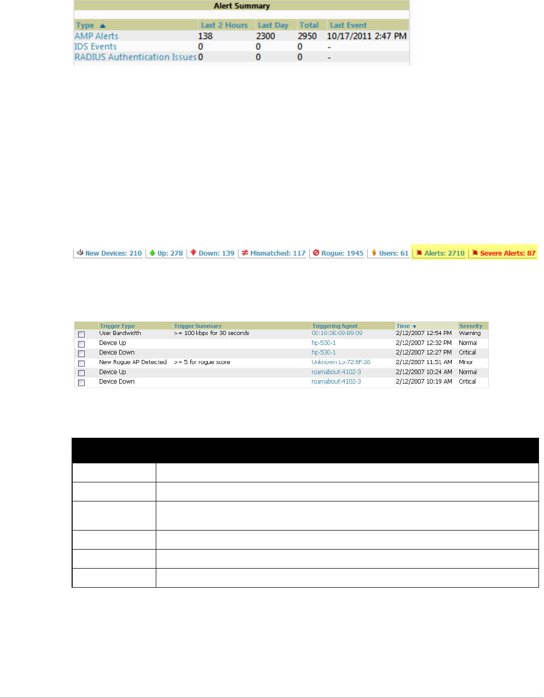
Dell PowerConnect W-AirWave 7.5 | User Guide Performing Daily Administration in AirWave | 201
Figure 140 Alert Summary Table Illustration
This table displays alerts as follows; select the alert Type to display alert details:
-AirWave Alerts—Displays details for all device alerts.
-IDS Events—Displays details of all Intrusion Detection System (IDS) events and attacks under the
RAPIDS tab. You must be enabled as a RAPIDS user to see this page.
-RADIUS Authentication Issues—Displays RADIUS-related alerts for devices in the top viewable folder
available to the AirWave user. The detailed list displays the MAC address, username, AP, radio, controller,
RADIUS server, and time of each event. Alerts can be sorted by any column.
2. The Alerts and Severe Alerts top header stats in the Status bar at the top of all AirWave pages, illustrated in
Figure 141. The Severe Alert Threshold can be configured on the Home > User Info page.Refer to “Setting
Severe Alert Warning Behavior” on page27.
Figure 141 Alerts in the AirWave Status Bar (highlighted)
Select the Alerts or the Severe Alerts counter or navigate to the System > Alerts page. Figure 142 illustrates
this page.
Figure 142 System > Alerts Page Illustration
For each new alert, the System > Alerts page displays the items listed in Table 117.
Responding to Alerts
Once you have viewed an alert, you may take one of the following courses of action:
-Leave it in active status if it is unresolved. The alert remains on the new alerts list until you acknowledge or
delete it. If an alert already exists, the trigger for that AP or user does not create another alert until the existing
alert has been acknowledged or deleted.
Table 117 System > Alerts Fields and Default Settings
Field Description
Trigger Type Displays and sorts triggers by the type of trigger.
Trigger Summary Provides an additional summary information related to the trigger.
Triggering Agent Lists the name of the AP that generated the trigger. Select the name to display its APs/Devices > Manage
page.
Time Displays the date and time the trigger was generated.
Severity Displays the severity code associated with that trigger.
Details Displays additional details for alerts.

202 | Performing Daily Administration in AirWave Dell PowerConnect W-AirWave 7.5 | User Guide
-Move the alert to the Alert Log by selecting it and selecting Acknowledge. You can see all logged alerts by
selecting the View logged alerts link at the top of the System > Alerts page. Select the Alerts link to return to
the list of new alerts.
-Delete the alert by selecting it from the list and clicking the Delete button.
Monitoring and Supporting WLAN Clients
This section describes the Clients pages as follows:
-Overview of the Clients Pages
-Monitoring WLAN Users in the Clients > Connected and Clients > All Pages
-Monitoring Rogue Clients With the Clients > Rogue Clients Page
-Supporting Guest WLAN Users With the Clients > Guest Users Page
-Supporting VPN Users with the Clients > VPN Sessions Page
-Supporting RFID Tags With the Clients > Tags Page
-See also Evaluating and Diagnosing User Status and Issues.
For information about creating AirWave users and AirWave user roles, refer to:
-Creating AirWave Users
-Creating AirWave User Roles
If you need to create an AirWave user account for frontline personnel who are to support Guest WLAN users,
refer to “Supporting Guest WLAN Users With the Clients > Guest Users Page” on page207.
Overview of the Clients Pages
The Clients pages display multiple types of user data for existing WLAN clients and VPN users. The data comes
from a number of locations, including data tables on the access points, information from RADIUS accounting
servers, and AirWave-generated data. AirWave supports the following Clients pages:
-Clients > Connected—Displays active users that are currently connected to the WLAN. Refer to
“Monitoring WLAN Users in the Clients > Connected and Clients > All Pages” on page203.
-Clients > All—Displays all users of which AirWave is aware, with related information. Non-active users are
listed in gray text. For a description of the information supported on this page, refer to “Monitoring WLAN
Users in the Clients > Connected and Clients > All Pages” on page203.
-Clients > Rogue Clients —Displays connected rogue clients.
-Clients > Guest Users —Displays all guest users in AirWave and allows you to create, edit, or delete guest
users. See “Supporting Guest WLAN Users With the Clients > Guest Users Page” on page207.
-Clients > Client Detail—Displays client device information, alerts, signal quality, bandwidth, and
association history. This page appears when you select a user’s MAC address link from these list tables:
Clients > Connected
Clients > All
Home > Search page results that display the user MAC address
See “Evaluating User Status with the Clients > Client Detail Page” on page210.
-Clients > Diagnostics—Displays possible client device issues, diagnostic summary data, user counts, AP
information, 802.11 counters summary, and additional information. This page appears when you select a
user’s MAC address from one of the following pages:
Clients > Connected
Clients > All
Home > Search page results or Search field results that display the user MAC address

Dell PowerConnect W-AirWave 7.5 | User Guide Performing Daily Administration in AirWave | 203
See “Evaluating Client Status with the Clients > Diagnostics Page” on page214.
-Clients > Tags—Displays a list of wireless tags, such as Aeroscout, PanGo and Newbury, that are heard by
thin APs, and reported back to a controller that is monitored by AirWave. “Supporting RFID Tags With the
Clients > Tags Page” on page209.
Monitoring WLAN Users in the Clients > Connected and Clients > All Pages
The Clients > Connected page displays all users currently connected in AirWave, and is illustrated in Figure 143
and described in Table 118. This page contains the following information at a glance:
-The Folder field shows the current folder of Connected Clients you are viewing. You can view users under a
particular folder from the Go to folder dropdown menu.
-Links under the Folder fields showing the Total Devices, Mismatched, Clients, and Bandwidth (a static,
unlinked statistic) summarize the device information for this folder. Select these links to be taken to detail
pages for each: Total Devices redirects to the APs/Devices > List for that folder, Mismatched redirects to the
list in APs/Devices > Mismatched for that folder, and selecting Clients refreshes the page but expands to
include users in the subfolders.
-Interactive graphs display average and max Clients over time, and Usage in and out for the selected folder
over time.
-Below the Clients and Usage graphs is the list of connected users
The information on this page can be adjusted in the following ways:
-Drag the slider to pick the time range on the interactive graphs, and select Show All to select other options to
display.
-The Alert Summary section displays custom configured alerts that were defined in the System > Alerts page.
-Use the Filter icon ( ) next to certain columns (AP/Device, Role, VLAN, Connection Mode, and others)
to filter the results by one of the values under that column.You can filter the list by substring match under the
Username column.
The Clients > Connected page includes SSID information for users, and can display wired users using remote
Access Point (RAP) devices in tunnel and split-tunnel mode.
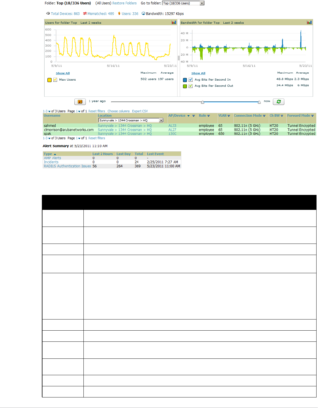
204 | Performing Daily Administration in AirWave Dell PowerConnect W-AirWave 7.5 | User Guide
Figure 143 Clients > Connected Page Illustration (Partial View)
Table 118 Clients > Connected Table Columns and Links (Alphabetical)
Field Description
AOS Device Type The type of client device determined by the Dell controller -- a fallback in case the rules set in AMP Setup >
Device Type Setup were unable to determine the device type.
AP/Device Displays the name of the AP to which the MAC address is associated as a link to this AP's APs/Devices >
Monitor page.
Association Time The first time AirWave recorded the user for this association.
Auth. Time The how long ago the user authenticated.
NOTE: This value displays as a negative number for unauthenticated users.
Auth. Type The type of authentication employed by the user:
-WPA2 (EAP-PEAP) is the standard setting.
-EAP is reported by Dell PowerConnect W-Series devices via SNMP traps.
-RADIUS accounting servers integrated with AirWave will provide the RADIUS Accounting Auth type.
-Web (PAP) - Captive Portal.
-All others are considered to be not authenticated.
Usage The average bandwidth consumed by the MAC address.
Ch BW The channel bandwidth that currently supports 802.11n users.
Cipher Displays WEP with keys. This data is also displayed in the Client Session report in the Session Data By
Client section.
Connection
Mode
The Radio mode used by the user to associate to the AP for 802.11n clients.
Device Type The type of device determined by AMP Setup > Device Type Setup rules.
Duration The length of time the MAC address has been associated.

Dell PowerConnect W-AirWave 7.5 | User Guide Performing Daily Administration in AirWave | 205
EAP Supplicant The party being authenticated in the Extensible Authentication Protocol.
Forward Mode Forwarding mode for the port: Bridge, Tunnel, or Split Tunnel.
Goodput The ratio of the total bytes transmitted or received in the network to the total air time required for transmitting
or receiving the bytes.
Group The group containing the AP that the user is associated with.
Guest User Specifies whether the user is a guest.
Interface The interface on the device to which the user is connected.
LAN Hostname The LAN hostname of the user MAC.
LAN IP Address The IP assigned to the user MAC. AirWave gathers it from the association table of APs.
Location If a value appears here, the location of this user’s client has been mapped on VisualRF. Select the location to
open a new VisualRF Floor Plan Location window.
MAC Address The radio MAC address of the user associated to APs as a link to the Users > Detail page for this user.
Manufacturer The manufacturer of the user’s device.
Model The model of the user’s device.
Name The product of the user’s device.
Network Chipset The chipset indicates the functions the device was designed to perform.
Network Driver Driver name or other information.
Notes Free notes about the user.
OS The device’s operating system type.
OS Detail Additional information on the operating system such as version numbers.
Phone Number Contact number for the user.
Role Specifies the role that a Dell controller assigned to the connected user, such as “employee.”
Serial Number Serial number of the device.
Service End Ending timestamp of the device usage.
Service Start Beginning timestamp of the device usage.
Sig. Qual. The average signal quality the user experienced.
SSID The SSID with which the user is associated.
Speed The packet and byte counts of data frames successfully transmitted to and received from associated
stations.
Tunneled
Controller
If a user is connected to a switch, indicates which controller the user is authenticated to.
Username Displays the name of the user associated to the AP. AirWave gathers this data from device traps, SNMP
polling, or RADIUS accounting. Usernames appear in italics when a username for that MAC address has
been stored in the database from a previous association, but AirWave is not getting a username for the
current association. This may indicate that the user has not yet been authenticated for this session or
AirWave may not be getting a username from an external source.
VLAN Displays the VLAN assigned to the user, if available.
Table 118 Clients > Connected Table Columns and Links (Continued)(Alphabetical)
Field Description
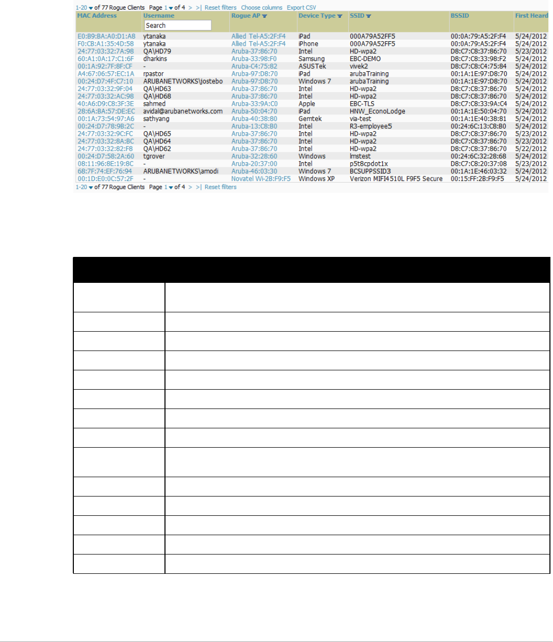
206 | Performing Daily Administration in AirWave Dell PowerConnect W-AirWave 7.5 | User Guide
Monitoring Rogue Clients With the Clients > Rogue Clients Page
You can view connected rogue clients in AirWave by selecting the Clients > Rogue Clients page. In this page,
you can click on the MAC address of a rogue to view the Client Details page or on a Rogue AP link to view the
RAPIDS > Details page for the AP. Figure 144 illustrates the Clients > Rogue Clients page.
Figure 144 Clients > Rogue Clients Page Illustration
Table 119 describes the fields on this page.
Table 119 Clients > Rogue Clients Fields
Field Description
MAC Address Displays the MAC address of the rogue client. Click on this to jump to the Clients > Client Detail page for
this rogue.
Username The username associated with this client.
Rogue AP The name of the Rogue AP. Click on this to jump to the RAPIDS > Detail page for this AP.
Device Type The type of device, such as iPhone, Windows 7, etc.
SSID The SSID of this client.
BSSID The BSSID of this client.
First Heard The date and time when this rogue client was first noticed.
Last Heard The date and time when this rogue client was last noticed.
Location If a location is available, you can click on this link to open the VisualRF floor plan and location on which
this client resides.
Connection Mode Shows the type of connection, such as 802.11n, 802.11b, etc.
Ch BW Shows the channel bandwidth for this rogue client.
Signal Shows the signal value for this rogue client.
SNR Shows the signal-to-noise ratio.
Channel Shows the channel on which this rogue client is broadcasting.
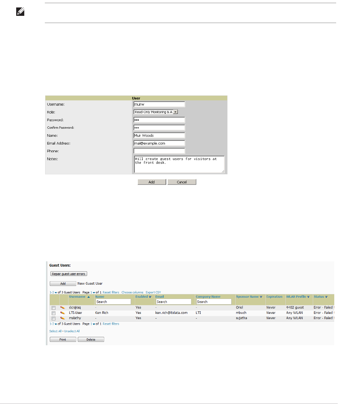
Dell PowerConnect W-AirWave 7.5 | User Guide Performing Daily Administration in AirWave | 207
Supporting Guest WLAN Users With the Clients > Guest Users Page
AirWave supports guest user provisioning for Dell PowerConnect W-Series, Alcatel-Lucent, and Cisco WLC
devices. This allows frontline staff such as receptionists or help desk technicians to grant wireless access to WLAN
visitors or other temporary personnel.
Perform the following steps in the pages described to configure these settings.
1. Navigate to the AMP Setup > Roles page and select the Read-Only Monitoring & Auditing role type. Under
Guest User Preferences, enable Allow creation of Guest Users.
2. Next, navigate to the AMP Setup > Users page and create a new user with the role that was just created.
Figure 145 illustrates this page.
Figure 145 AMP Setup > Users Page Illustration
3. The newly created login information should be provided to the person or people who will be responsible for
creating guest access users.
4. The next step in creating a guest access user is to navigate to the Users > Guest Clients tab. From this tab,
you can add new guest users, you can edit existing users, and you can repair guest user errors.
This page displays a list of guest users and data, to include the expiration date, the SSID (for Cisco WLC) and
other information. Figure 146 illustrates this page and Table 120 describes the information.
Figure 146 Clients > Guest Users Page Illustration
NOTE: The Guest User Preferences section on AMP Setup > Roles, as well as the Clients > Guest Users subtab, will not appear if
Guest User Configuration is globally disabled in AMP Setup > General.
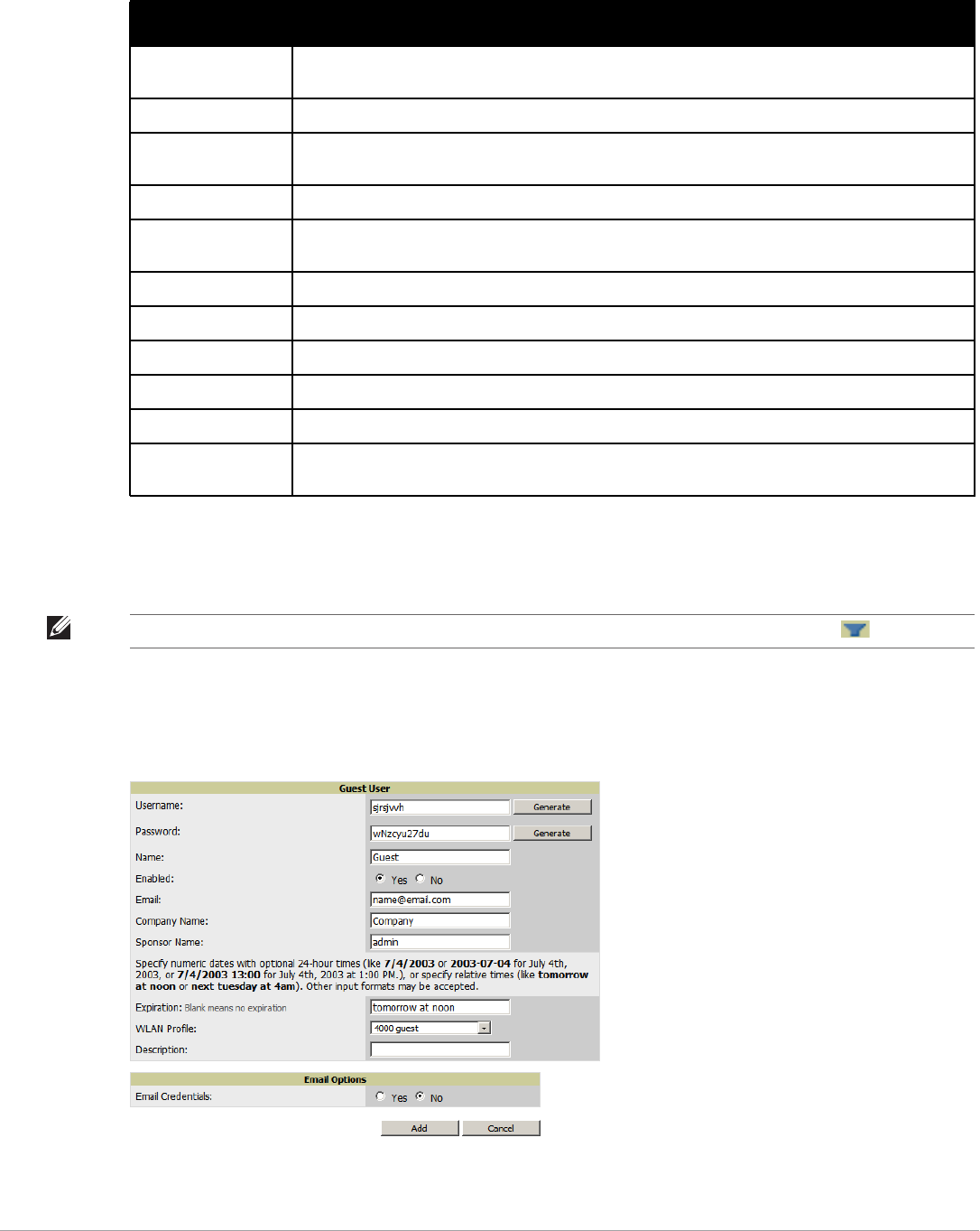
208 | Performing Daily Administration in AirWave Dell PowerConnect W-AirWave 7.5 | User Guide
Guest users associated to the wireless network appear on the same list as other wireless users, but are
identified as guest users in the Guest User column. The Client Detail page for a guest user also contains a box
with the same guest information that appears for each user on the Clients > Guest Users list.
5. To add a new guest user, select Add, and complete the fields illustrated in Figure 147. Table 120 above
describes most fields. The first three fields are required, and the remaining fields are optional.
Figure 147 Clients > Guest Users > Add New Guest User Page Illustration
To make the Username or Password anonymous and to increase security, complete these fields then select
Generate. The anonymous and secure Username and Password appear in the respective fields.
Table 120 Clients > Guest Users Fields
Field Description
Repair Guest User
Errors
Sets AirWave to attempt to push the guest user again in an attempt to repair any errors in the Status
column.
Add New Guest User Adds a new guest user to a controller via AirWave.
Username Randomly generates a user name for privacy protection. This name appears on the Guest User detail
page.
Name Displays the specified guest user name.
Enabled Enables or disables the user status. Set the status of the guest user as active (enabled) or expired
(disabled).
Email Displays the optional email address of the user.
Company Name Displays the optional company name for the user.
Sponsor Name Displays the name of the sponsor for the guest user. This setting is optional.
Expiration Displays the date the guest user's access is to expire.
WLAN Profile Sets the SSID that the guest user can access. This setting applies to Cisco WLC only.
Status Reports current status by the controller. If error messages appear in this column, select the user with
the checkbox at left, and select the Repair guest user errors button.
NOTE: The Enabled, Sponsor Name, WLAN Profile, and Status columns can be filtered using the funnel icon ().
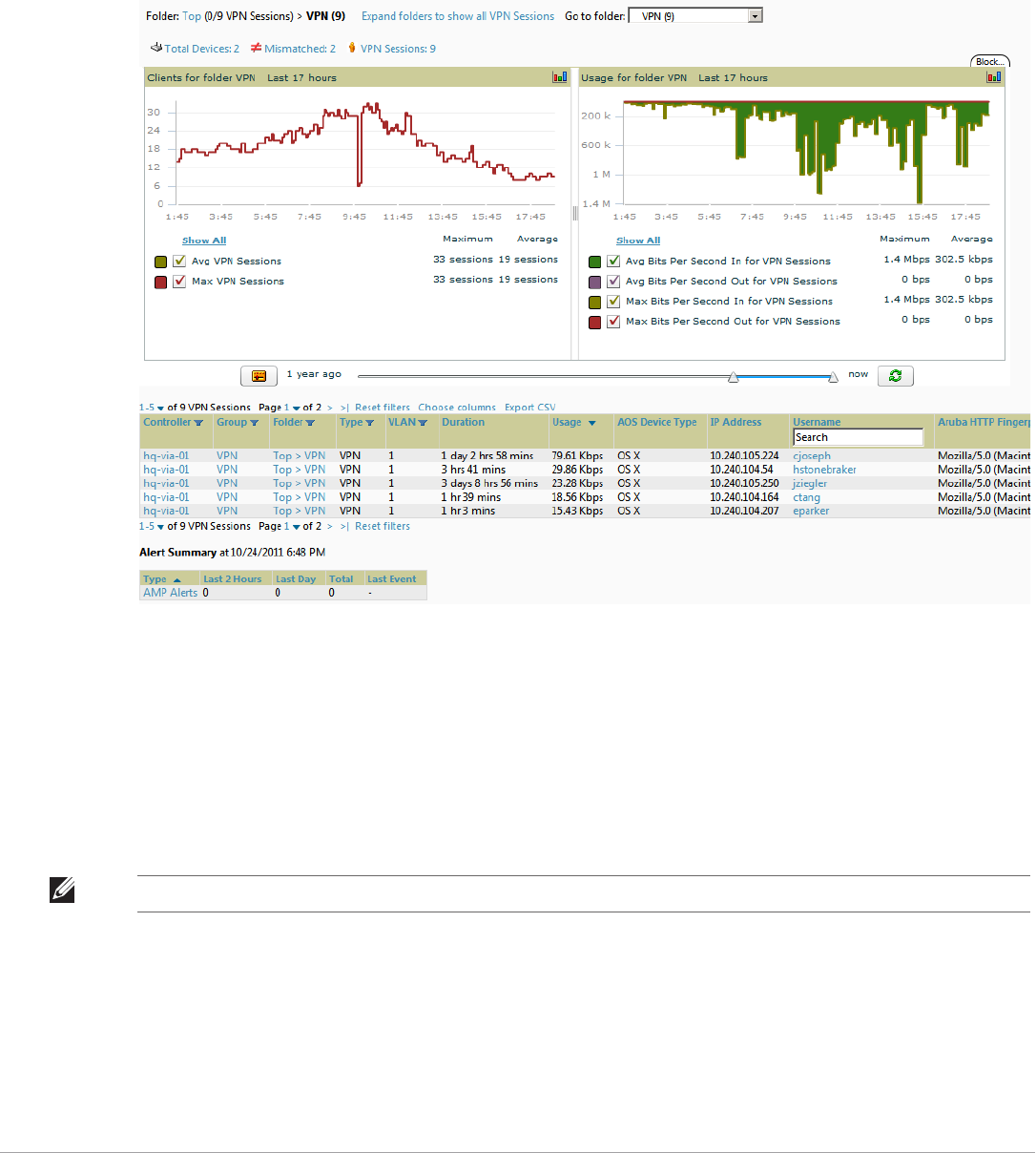
Dell PowerConnect W-AirWave 7.5 | User Guide Performing Daily Administration in AirWave | 209
6. Select Add to complete the new guest user, or select Cancel to back out of new user creation. The Clients >
Guest Users page appears and displays results, as applicable.
Supporting VPN Users with the Clients > VPN Sessions Page
The Clients > VPN Sessions page shows active VPN Sessions along with device type and HTTP fingerprinting
information.
Figure 148 Clients > VPN Sessions Page Illustration
When a VPN username is selected, a Clients > VPN User Detail page displays with current VPN sessions, a user
and bandwidth interactive graph, and a historical VPN sessions list table.
Supporting RFID Tags With the Clients > Tags Page
Radio Frequency Identification (RFID) supports identifying and tracking wireless devices with radio waves. RFID
uses radio wave tags for these and additional functions. Active tags have a battery and transmit signals
autonomously, and passive tags have no battery. RFID tags often support additional and proprietary
improvements to network integration, battery life, and other functions.
The Clients > Tags page displays a list of wireless tags, such as Aeroscout, PanGo and Newbury, that are heard by
thin APs, and reported back to a controller that AirWave monitors. AirWave displays the information it receives
NOTE: Guest users being pushed to large numbers of controllers may take a very long time to push.
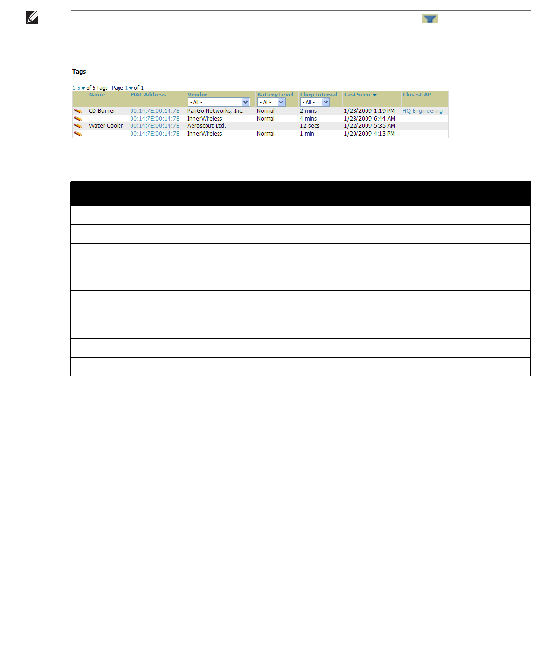
210 | Performing Daily Administration in AirWave Dell PowerConnect W-AirWave 7.5 | User Guide
from the controller in a table on this page. Figure 149 illustrates this page, and Table 121 describes fields and
information displayed.
Figure 149 Clients > Tags Page Illustration
-To edit the name of the tag, or to add notes to the tag's record, select the pencil icon next to the entry in the
list. You can then add or change the name and add notes like “maternity ward inventory” or “Chicago
warehouse,” as two examples.
-The Inactive Tag trigger can be used to generate an alert if a tag is not reported to AirWave after a certain
interval. This can help to identify lost or stolen inventory. For more information about enabling this trigger,
refer to the section “Monitoring and Supporting AirWave with the System Pages” on page189.
Evaluating and Diagnosing User Status and Issues
If a WLAN user reports difficulty with the wireless network, the administration or Helpdesk personnel can view
and process related user information from the Client Detail and Diagnostic pages. This section describes these
two pages as follows:
-Evaluating User Status with the Clients > Client Detail Page
-Evaluating Client Status with the Clients > Diagnostics Page
Evaluating User Status with the Clients > Client Detail Page
The Clients > Client Detail page is a focused subtab that becomes visible when you select a specific WLAN
user. Access the Clients > Client Detail page by selecting the MAC Address link for a specific user from one of
the following pages:
NOTE: The Vendor,Battery Level, and Chirp Interval columns can be filtered using the funnel icon ( ).
Table 121 Clients > Tags Fields
Field Description
Name Displays the user-editable name associated with the tag.
MAC Address Displays the MAC address of the AP that reported the tag.
Vendor Displays the vendor of the tag (Aeroscout, PanGo and Newbury)—display all or filter by type.
Battery Level Displays battery information—filterable in drop-down menu at the top of the column; is not displayed for
Aeroscout tags.
Chirp Interval Displays the tag chirp frequency or interval, filterable from the drop-down menu at the top of the column.
Note that the chirp interval from the RFID tag influences the battery life of active tags as well as search
times. If a tag chirps with very long chirp interval, it may take longer time for the location engine to
accurately measure x and y coordinates.
Last Seen Date and time the tag was last reported to AirWave.
Closest AP The AP that last reported the tag to the controller (linked to the AP monitoring page in AirWave).
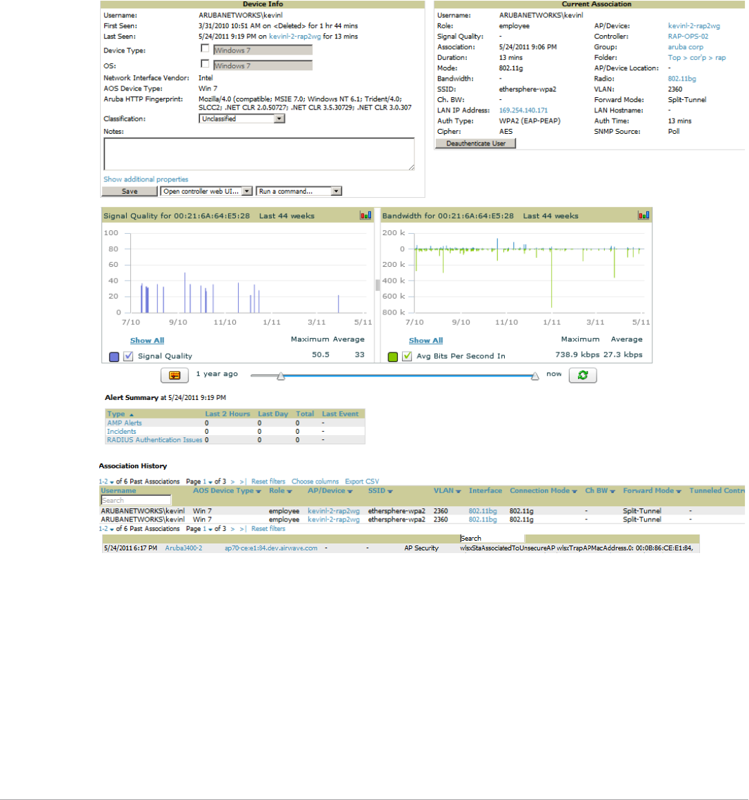
Dell PowerConnect W-AirWave 7.5 | User Guide Performing Daily Administration in AirWave | 211
-Clients > Connected
-Clients > All
-Home > Search page results or Search field Client results that display the user MAC address
This page provides information for the wireless device, signal quality, and bandwidth consumption. This page
also provides an AP association history and current association status. Finally, if VisualRF is enabled in AMP
Setup > General, this page provides a graphical map of the user location and facility information.
Figure 150 illustrates the contents of Clients > Client Details page.
Figure 150 Clients > Client Detail Page Illustration (partial view)
Mobile Device Access Control in Clients > Client Detail and Clients > Connected
Mobile Device Access Control (MDAC) secures, provisions and manages network access for Apple® iOS and
other employee-owned mobile devices by enabling device fingerprinting, device registration, and increased device
visibility.
Use the checkbox next to these fields to enable them in Clients > Client Detail:
-Device Type
-OS
-OS Detail
-Manufacturer
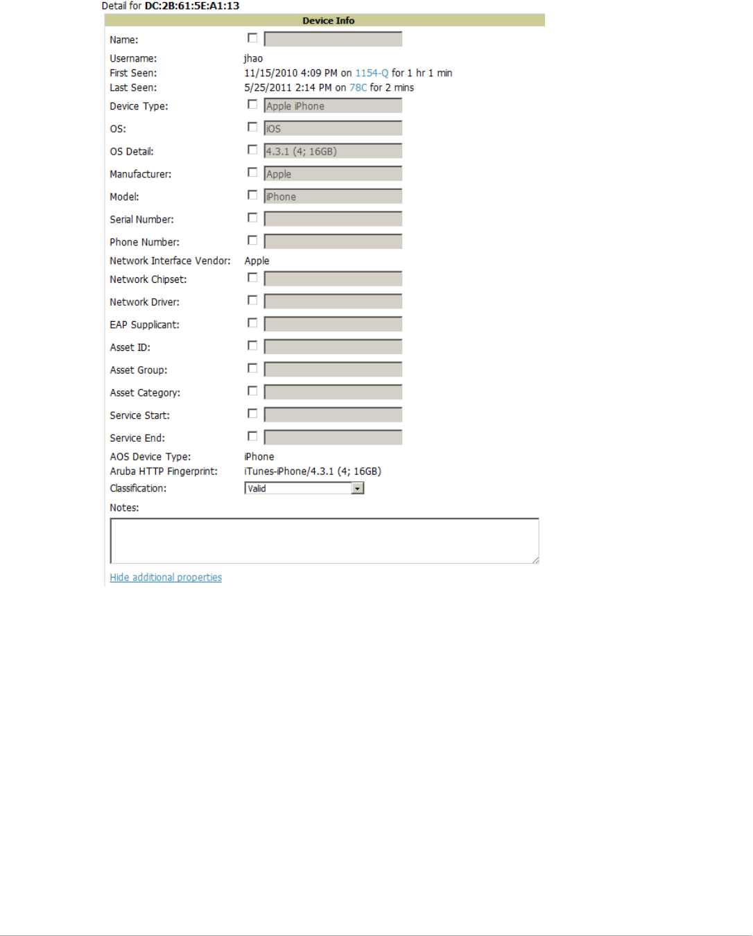
212 | Performing Daily Administration in AirWave Dell PowerConnect W-AirWave 7.5 | User Guide
To see more options, select the Show additional properties link. The results are illustrated in Figure 151:
Figure 151 Device Info section in Clients > Client Detail after Show additional properties is selected
Classifying Dell Devices in Client Detail
If you have deployed Dell PowerConnect W-Series controllers and have WMS Offload enabled on the network,
the Clients > Client Detail page allows you to classify the device in the Device Information section, and to push
this configuration to the Dell PowerConnect W-Series controllers that govern the devices. The classifications are
as follows:
-Unclassified—Devices are unclassified by default.
-Valid—If the Protect Valid Stations option is enabled, this setting designates the device as a legitimate
network device. Once this Valid setting is pushed, this setting prevents valid stations from connecting to a
non-valid AP.
-Contained—When this status is pushed to the device, Dell PowerConnect W-Series controllers will attempt
to keep it contained from the network.
You can classify the user regardless of whether WMS Offload is enabled. If WMS Offload is enabled, the
classification will get pushed up to the controller.
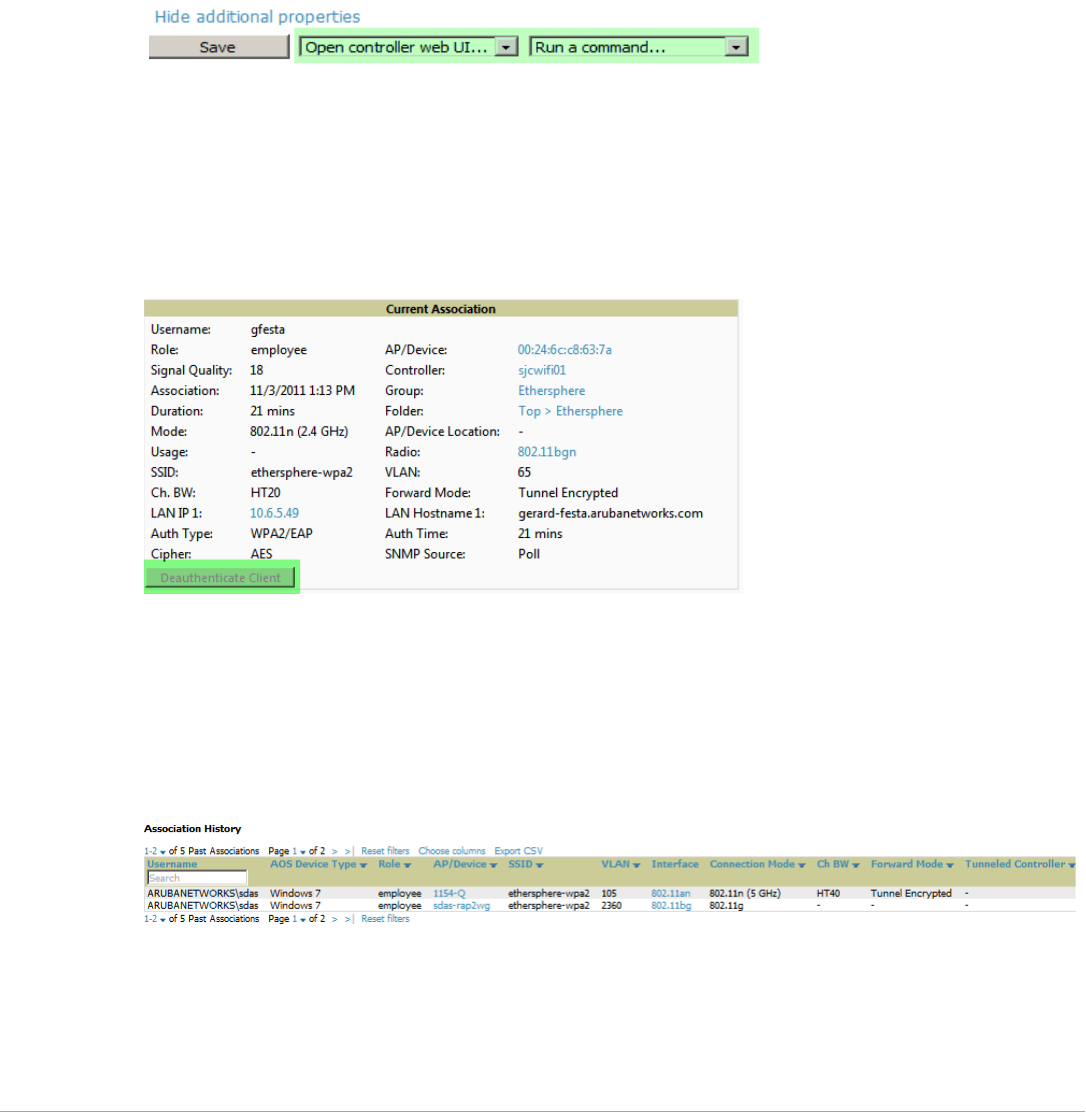
Dell PowerConnect W-AirWave 7.5 | User Guide Performing Daily Administration in AirWave | 213
Quick Links for Clients on Dell Devices
In Clients > Client Detail, the following two drop-down menus appear next to the Save button in the Device
Info section:
-Open controller web UI: A drop-down menu that allows you to jump to the controller’s UI in a new window.
Thin APs link to Controller > Access Points when not operating in mesh mode, or Controller > Mesh Nodes
otherwise. Controllers show several more pages in this menu (Security Dashboard, for instance) if the
controller is running ArubaOS version 6.1 or greater.
-Run a command: A drop-down menu with a list of CLI commands you can run directly from the APs/Devices
> Monitor page.
Figure 152 Open controller web UI and Run a command Menus
Using the Deauthenticate Client Feature
Some displays of the Clients > Client Detail page include the Deauthenticate Client feature in the Current
Association section. Specifically, those displays are for devices which support this operation, namely Dell
PowerConnect W-Series and Cisco WLC with firmware version v4.0.0.0 or later.
Select Deauthenticate Client to use this feature, as shown in Figure 153:
Figure 153 Deauthenticate Client button in Current Association section of Clients > Client Detail
Viewing a Client’s Association History
Past association details of a client are tracked in the Association History table, which is located under the VRF
QuickView illustration (if available) and the Alert Summary in Clients > Client Detail.
The columns in this table, shown in Figure 154, are the same as the fields in the Current Association section for
this user.
Figure 154 Association History in Clients > Client Detail
Viewing the Rogue Association History for a Client
Past association details of a rogue client are tracked in the Rogue Association History table, which is located
under the Association History table in Clients > Client Detail.
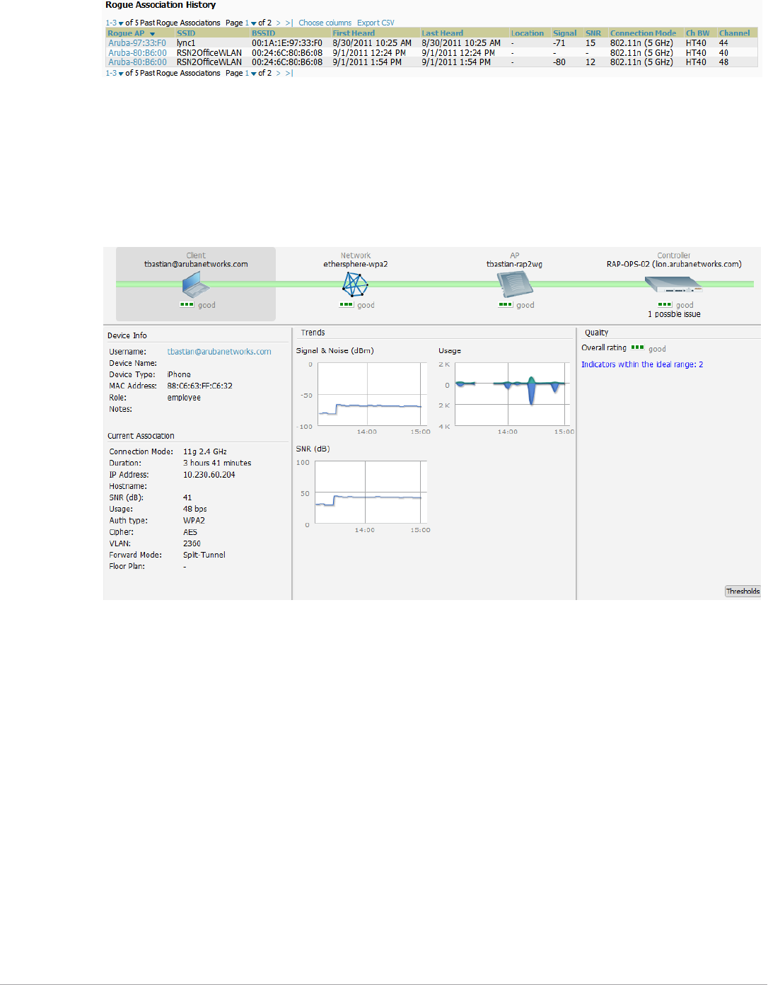
214 | Performing Daily Administration in AirWave Dell PowerConnect W-AirWave 7.5 | User Guide
Figure 155 Rogue Association History table in Clients > Client Detail
Evaluating Client Status with the Clients > Diagnostics Page
The Clients > Diagnostics page is accessible from the Clients > Client Detail page. You can also search for a
user and select the associated MAC address from the search results.
This page provides an overview of a WLAN user’s general status and connectivity on the network, as illustrated in
Figure 156.
Figure 156 Clients > Diagnostics Page Illustration
Each section of the Clients > Diagnostics page displays information by which to evaluate possible user issues.
You can also click on the Thresholds button in the lower-right corner to configure Good and Fair threshold values
for APs, Clients, Controllers, Networks, and Switches. Note that values that fall below Fair are automatically
considered as Poor.
Managing Mobile Devices with SOTI MobiControl and AirWave
Overview of SOTI MobiControl
SOTI MobiControl, the mobile device management platform for Windows Mobile, Apple, and Android devices,
has been integrated into AirWave to provide direct access to the MobiControl Web Console.
MobiControl runs on your Mobile Device Manager (MDM) server. This server provisions mobile devices to
configure connectivity settings, enforce security policies, restore lost data, and other administrative services.
Information gathered from mobile devices can include policy breaches, data consumption, and existing
configuration settings.

Dell PowerConnect W-AirWave 7.5 | User Guide Performing Daily Administration in AirWave | 215
Prerequisites for Using MobiControl with AirWave
In order to use the MobiControl integration in AirWave, the following is required:
-An AirWave running version 7.2.3 or later
-An MDM server with SOTI MobiControl Console 8.0x
-A client device that is:
associated with WLAN infrastructure managed by the AirWave server running 7.2.3 or later
being actively managed by the SOTI MobiControl server
For more information about setting up MobiControl, please see http://www.soti.net/mc/help/.
In order to use SOTI MobiControl from within AirWave, you must first add your MDM server and designate it as
a MobiControl.
Adding a Mobile Device Management Server for MobiControl
1. To add an MDM server to AirWave, navigate to AMP Setup > MDM Server and select Add. Complete the
fields on this page. Table 122 describes the settings and default values:
2. When finished, select Add.
The list page for the MDM server also displays:
-Last Contacted – The last time AirWave was able to contact the MDM server.
-Errors – Issues, if any, encountered during the last contact.
During each polling period, AirWave will obtain a list of all device IDs and their WLAN MAC addresses. The
information about device OS, device OS Detail, Manufacturer, Model, Name are retrieved from MobiControl
and populated to the Clients > Client Detail page for supported mobile devices. A View device in SOTI
MobiControl link provides direct access to the MobiControl Web Console for additional details about the
device. MobiControl information overrides data obtained from ArubaOS 6.0 controllers.
Accessing MobiControl from the Clients > Client Detail Page
In order to access the MobiControl web console for a SOTI-managed mobile device from within AirWave, follow
these steps:
1. Navigate to a page that lists clients. This can include:
-Clients > Connected or Clients > All
Table 122 AMP Setup > MDM Server > Add Fields and Descriptions
Field Description
Hostname/IP
Address
The address or DNS hostname configured for your MobiControl Web Console.
Protocol Whether HTTP or HTTPS is to be used when polling the MDM server. The port on which to connect to the
MDM server is inferred from the protocol: with HTTP, AirWave will connect to port 80 of the SOTI server; with
HTTPS, AirWave will connect to port 443.
URL Context The URL context appended to the server URL to build the URL when connecting with the SOTI server. For
MobiControl v8.0x the default URL Context is "MobiControlWeb". For MobiControl v8.5x the default URL Context
is “MobiControl”.
Enabled Whether this server can be polled by AirWave. Make sure it is set to Yes.
Username/
Password
The login credentials for accessing the web console of the MobiControl system.
Polling Period The frequency in which AirWave polls the MDM server. The default is 5 minutes.
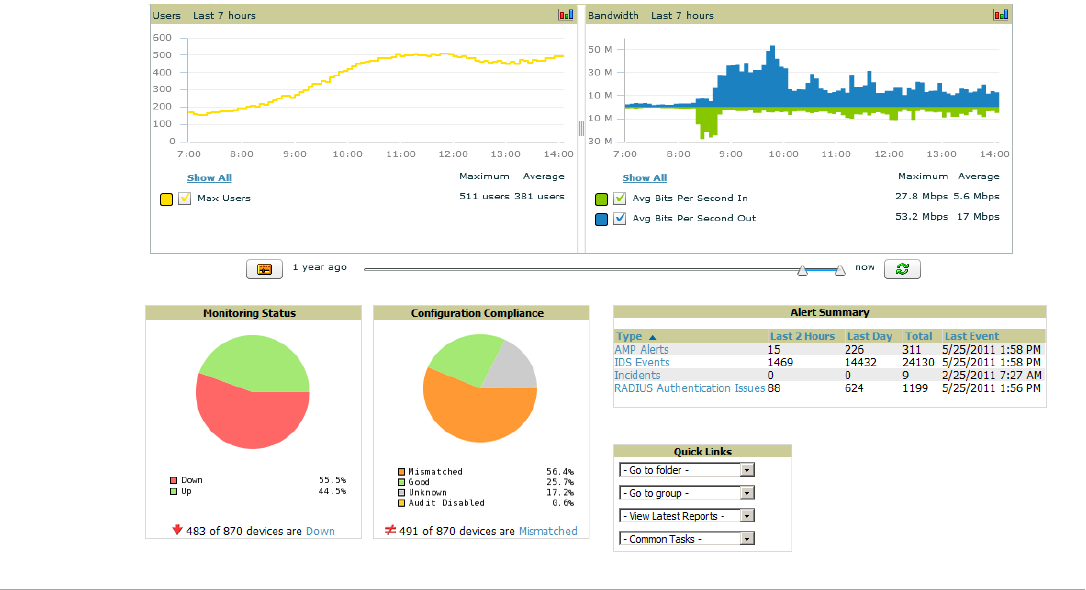
216 | Performing Daily Administration in AirWave Dell PowerConnect W-AirWave 7.5 | User Guide
-Search results that display user MAC address
2. Select the MAC address in the Clients list table. The Clients > Client Detail page displays.
3. Under the Classification field, select the View device in SOTI MobiControl link. A new window will display
the MobiControl Web Console for this device.
Monitoring and Supporting AirWave with the Home Pages
The Home tab of AirWave provides the most frequent starting point for monitoring network status and
establishing primary AirWave functions once AirWave configuration is complete. From the Home tab, you can
access the following pages:
-The Home > Overview page condenses a large amount of information about your AirWave. You can view the
health and usage of your network and use shortcuts to view system information. Refer to “Monitoring AirWave
with the Home > Overview Page” on page 216 below.
-The Home > Search page provides a simple way to find users. managed devices, groups, and rogues. Refer to
“Searching AirWave with the Home > Search Page” on page 218.
-The Home > Documentation page contains all relevant AirWave documentation. See “Accessing AirWave
Documentation” on page220.
-The Home > License page provides product licensing information. See “Viewing and Updating License
Information” on page218.
-The Home > User Info page is where logged-in users can configure their name, contact information, rogue
count filter level, customized header columns, severe alert threshold, personalized search preferences, record
display preferences, and the refresh rate of the console. See “Configuring Your Own User Information with the
Home > User Info Page” on page 220.
Monitoring AirWave with the Home > Overview Page
To view your overall network health, navigate to Home > Overview page. Figure 157 illustrates this page, and
Table 123 describes the contents. The information that displays varies depending on your role.
Figure 157 Home > Overview Page Illustration

Dell PowerConnect W-AirWave 7.5 | User Guide Performing Daily Administration in AirWave | 217
The Customize link on the upper-right side of the page allows you to customize the widgets on the Home >
Overview page. See “Customizing the Dashboard” on page23.
Table 123 Home > Overview Sections and Charts
Section Description
Clients This chart is a graphical summary of the number of users on the network during a period of time. The time
can be adjusted. Select Show All to display a list of data series that this graph can display, such as the user
count by SSID.
Clear the Max Clients or Avg Clients checkbox to change the display of the graph. The graph displays the
maximum number of users by default. To view historical graphs in a new window, select the three-bar icon
on the upper right of the chart.
Usage This adjustable chart displays bandwidth data over time. To remove bandwidth in or out from the graphical
display, clear the check box for Avg Bits Per Second In or Out.
To display details for specific devices, select Show All and select the devices to be included in the graphical
bandwidth summary chart. To view historical graphs in a new window, select the three-bar icon on the upper
right of the chart.
Monitoring
Status
This pie chart shows the percentage of all devices that are up and down on the network. To review devices
that are down, select Down in the legend or the chart, and the APs/Devices > Down page displays.
Configuration
Compliance
The pie chart displays all known device configuration status on the network. Devices are classified as Good,
Unknown,Mismatched, or Audit Disabled. Select the Mismatched link to see the APs/Devices > Mismatched
page.
Alert Summary This section displays all known and current alerts configured and enabled in the System > Alerts page (refer
to “Viewing, Delivering and Responding to Triggers and Alerts” on page 193). Alerts can be sorted using the
column headers (Type, Last 2 Hours,Last Day,Total,or Last Event). The Alert Summary field displays three
types of alerts:
-AMP Alerts
-IDS Events
-RADIUS Authentication Issues
Select any alert type for more information.
Quick Links The Quick Links section provides drop-down menus that enable you to move to the most common and
frequently used pages in AirWave, as follows:
-Go to folder—This menu lists all folders defined in AirWave from the APs/Devices List page. See “Using
Device Folders (Optional)” on page 136.
-Go to group—This menu lists all groups defined in AirWave, and enables you to display information for
any or all of them. Use the Groups pages to edit, add, or delete groups that appear in this section. See
“Configuring and Using Device Groups” on page 67.
-View Latest Reports—AirWave supports creating custom reports or viewing the latest daily version of
any report. Select any report type to display the daily version. See “Creating, Running, and Emailing
Reports” on page 233.
-Common Tasks—This menu lists quick links to the most heavily used task-oriented pages in AirWave, to
include the following:
Configure Alert Thresholds—This link takes you to the System > Triggers page. See “Viewing
Triggers” on page 193.
Configure Default Credentials—This link takes you to the Device Setup > Communication page. See
“Configuring Communication Settings for Discovered Devices” on page 50.
Discover New Devices on Your Network—This link takes you to the Device Setup > Discover page.
See “Discovering, Adding, and Managing Devices” on page 107.
Supported Devices and Features—This link displays a PDF that summarizes all supported devices
and features in chart format for AirWave.
Upload Device Firmware—This link displays the Device Setup > Upload Firmware & Files & Files
Upload page. See “Overview of the Device Setup > Upload Firmware & Files Page” on page 52.
View Event Log—This link displays the System > Event Log page. See “Using the System > Event Log
Page” on page 192.
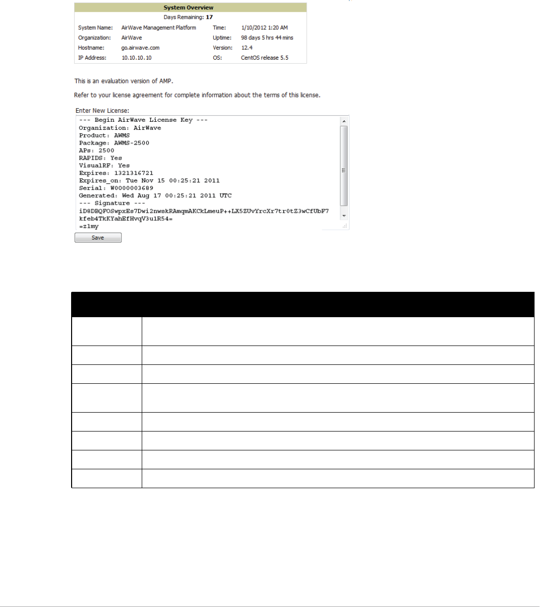
218 | Performing Daily Administration in AirWave Dell PowerConnect W-AirWave 7.5 | User Guide
Viewing and Updating License Information
Navigate to the Home > License page using the standard AirWave menu. Figure 158 illustrates this page, and
Table 124 describes the contents.
Please be aware that you cannot enter multiple licenses. To combine multiple license entitlements into one new
license, contact Dell support at support.dell.com.
Figure 158 Home > License Page Illustration
Searching AirWave with the Home > Search Page
While the Search field at the top of every AirWave page allows you to perform a quick search across a small
number of common categories, the Home > Search page conducts a deep system-wide search to find connected
and historical clients, VPN users, managed devices, rogue devices, rogue clients, groups, folders, and tags.
Table 124 Home > License Static Fields and Descriptions
Field Description
System Name Displays a user-definable name for AirWave. The System Name can be configured from the AMP Setup >
General page.
Organization Displays the organization listed on your license key.
Hostname Displays the DNS name assigned to AirWave.
IP Address Displays the static IP address assigned to AirWave. The IP Address can be configured from the AMP Setup
> Network page.
Time Displays the current date and time set on AirWave.
Uptime Displays the amount of time since the operating system was last booted.
Version Displays the version number of AirWave code currently running.
OS Displays the version of Linux installed on the server.
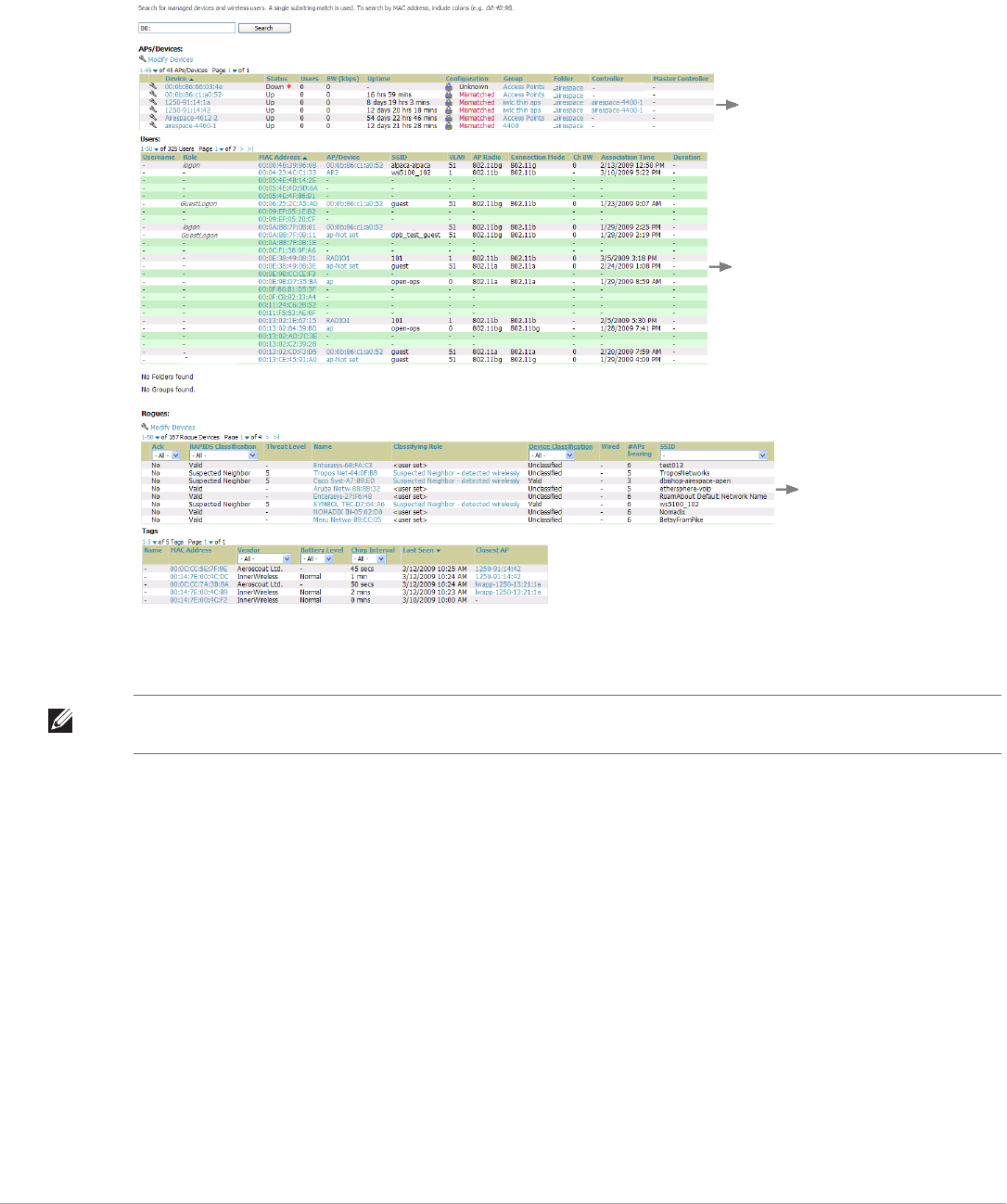
Dell PowerConnect W-AirWave 7.5 | User Guide Performing Daily Administration in AirWave | 219
Search performs partial string searches on a large number of fields including the notes, version, secondary version,
radio serial number, device serial number, LAN MAC, radio MAC and apparent IP address of all the APs, as well
as the client MAC, VPN user, Client, LAN IP and VPN IP fields. Figure 159 illustrates this page.
Figure 159 Home > Search Page Illustration with Sample Hits on “00:”
1. Enter the keyword or text with which to search. If searching for a MAC address, enter it in colon-delimited
format.
2. Select Search, and the results display after a short moment. Results support several hypertext links to
additional pages, and the Filter icon over some columns allow for additional filtering of search returns.
Search results are categorized in the following sequence. Categories of search results can be customized on
the Home > User Info page to limit the scope of information returned. Not all categories below may offer
returns for a given search:
-Devices
-Clients
-VPN Users
-Rogues and Rogue Clients
-Tags
-Folders and Groups
NOTE: The AirWave Search utility is case-insensitive when single or double quotes are not used. For exact case-sensitive
matches, use quotes around the search phrase.
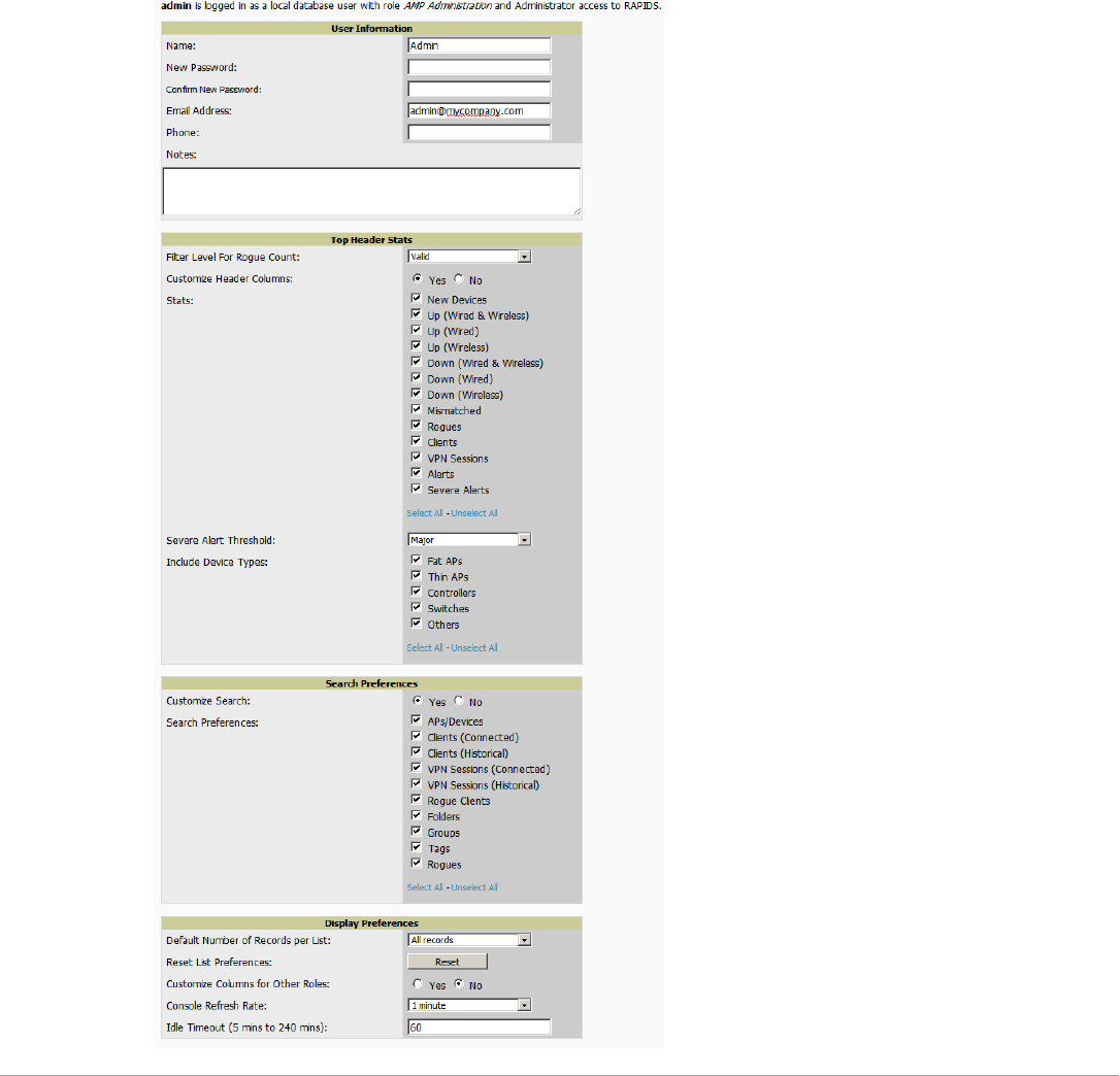
220 | Performing Daily Administration in AirWave Dell PowerConnect W-AirWave 7.5 | User Guide
Accessing AirWave Documentation
The Home > Documentation page provides easy access to all relevant AirWave documentation. All of the
documents on this page are hosted locally by your AirWave server and can be viewed by any PDF viewer.
If you have any questions that are not answered by the documentation, please contact Dell support.
Configuring Your Own User Information with the Home > User Info Page
The Home > User Info page displays information about the user that is logged into AirWave. This page includes
the authentication type (local user, RADIUS, or TACACS+) and access level. This page enables customization
some of the information displayed in AirWave, and is the place to change your password.
The logged-in users can customize the information displayed in the AirWave header. Figure 160 illustrates the
Home > User Info page, and Table 125 lists the fields.
Figure 160 Home > User Info Page Illustration

Dell PowerConnect W-AirWave 7.5 | User Guide Performing Daily Administration in AirWave | 221
Perform the following steps to configure your own user account with the Home > User Info page:
1. In the User Information section, enter the following information:
-Name—Enter the ID by which you log into and operate in AirWave.
-Email Address—Enter the email address to be used for alerts, triggers, and additional AirWave functions
that support an email address.
-Phone—Enter the area code and phone number, if desired.
-Notes—Enter any additional text-based information that helps other AirWave users or administrators to
understand the functions, roles, or other rights of the user being created.
Table 125 Home > User Info Fields and Descriptions
Field Description
Top Header Stats
Filter Level For Rogue Count Specifies the minimum classification that will cause a device to be included in the rogue
count header information. More about the classifications can be found in “Controller
Classification with WMS Offload” on page 179.
Customize Header Columns Enables/disables the ability to control which statistics hyperlinks (also known as Top
Header Stats) are displayed at the top of every AirWave screen.
Stats Select the specific data you would like to see in the Top Header Stats. Refer to “Status
Section” on page 11.
Note: This field only appears if you selected Yes in the previous field.
Severe Alert Threshold Configures the minimum severity of an alert to be included in the Severe Alerts count. See
“Setting Severe Alert Warning Behavior” on page 27 for details.
Note: The severe alerts count header info will only be displayed if ‘Severe Alerts’ is
selected in the Stats section above and if a severe alert exists.
Note: This field only appears if you selected Yes in the Customize Header Columns field.
Include Device Types Configures the types of devices that should be included in the header stats. If a device
type is not selected then it will not be included in the header stats.
Note: This field only appears if you selected Yes in Customize Header Columns.
Search Preferences
Customize Search Set to No by default; when set to Yes, you can select which search categories to display
when “Full” search results are returned.
Display Preferences
Default Number of Records per
List
Defines the number of rows to appear in any list by default. If a row count is manually set,
it will override the default setting.
Reset List Preferences Reset all list preferences including number of records per list, column order and hidden
column information.
Customize Columns for Other
Roles
Allows admin users to determine the columns that should be displayed and the order they
should be displayed for specific user roles. To customize lists for other users, navigate to
that list and select Choose Columns for roles above the list. Make the desired column
changes; select the roles to update and Save.
Console Refresh Rate The frequency in which lists and charts automatically refresh on a page.
Idle Timeout
(5 mins to 240 mins)
Number of minutes of idle time until AirWave automatically ends the user session. This
setting only the logged-in user of this AirWave. The default is 60 minutes. To set the max
idle timeout for all users of this AirWave, see “Setting Up Login Configuration Options” on
page 44.
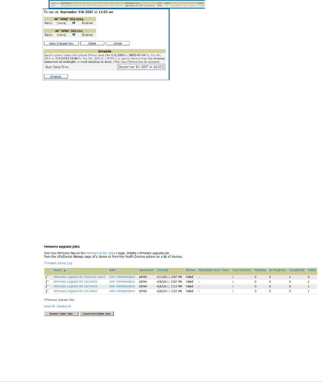
222 | Performing Daily Administration in AirWave Dell PowerConnect W-AirWave 7.5 | User Guide
Using the System > Configuration Change Jobs Page
Schedule configuration change jobs are summarized on the System > Configuration Change Jobs page. Perform
the following steps to use this page, illustrated in Figure 161.
Figure 161 System > Configuration Change Jobs Page Illustration
1. To edit an existing configuration change job select on the linked description name. On the subsequent edit
page you can choose to run the job immediately by selecting Apply Changes Now, reschedule the job by
selecting Schedule, Delete the job, or Cancel the job edit.
2. Select the linked AP or group name under the Subject column to go to its monitoring page.
3. Select the linked group and folder names under Folder or Group to go to the AP's folder or group page.
4. Scheduled configuration change jobs will also appear on the Manage page for an AP or the Monitoring page
for a group.
Using the System > Firmware Upgrade Jobs Page
The System > Firmware Upgrade Jobs page displays a list of recent firmware upgrade jobs that have been
initiated in the APs/Devices > Manage page or Modify Devices page for a controller or autonomous AP that
supports firmware upgrades in AirWave.
Successful upgrade jobs are not archived on this page -- generally you visit this page to review failed or pending
firmware upgrade jobs.
Users with the AP/Device Manager role and higher can view this page. Audit-only users cannot view this page or
tab.
Figure 162 System > Firmware Upgrade Jobs Page Illustration
You can perform the following operations on this page:
-To restart failed firmware upgrade jobs, select the checkboxes next to the rows you want to restart and select
the Restart Failed Jobs button.
-To stop a pending upgrade job and remove it from the list, select the Cancel and Delete Jobs button.
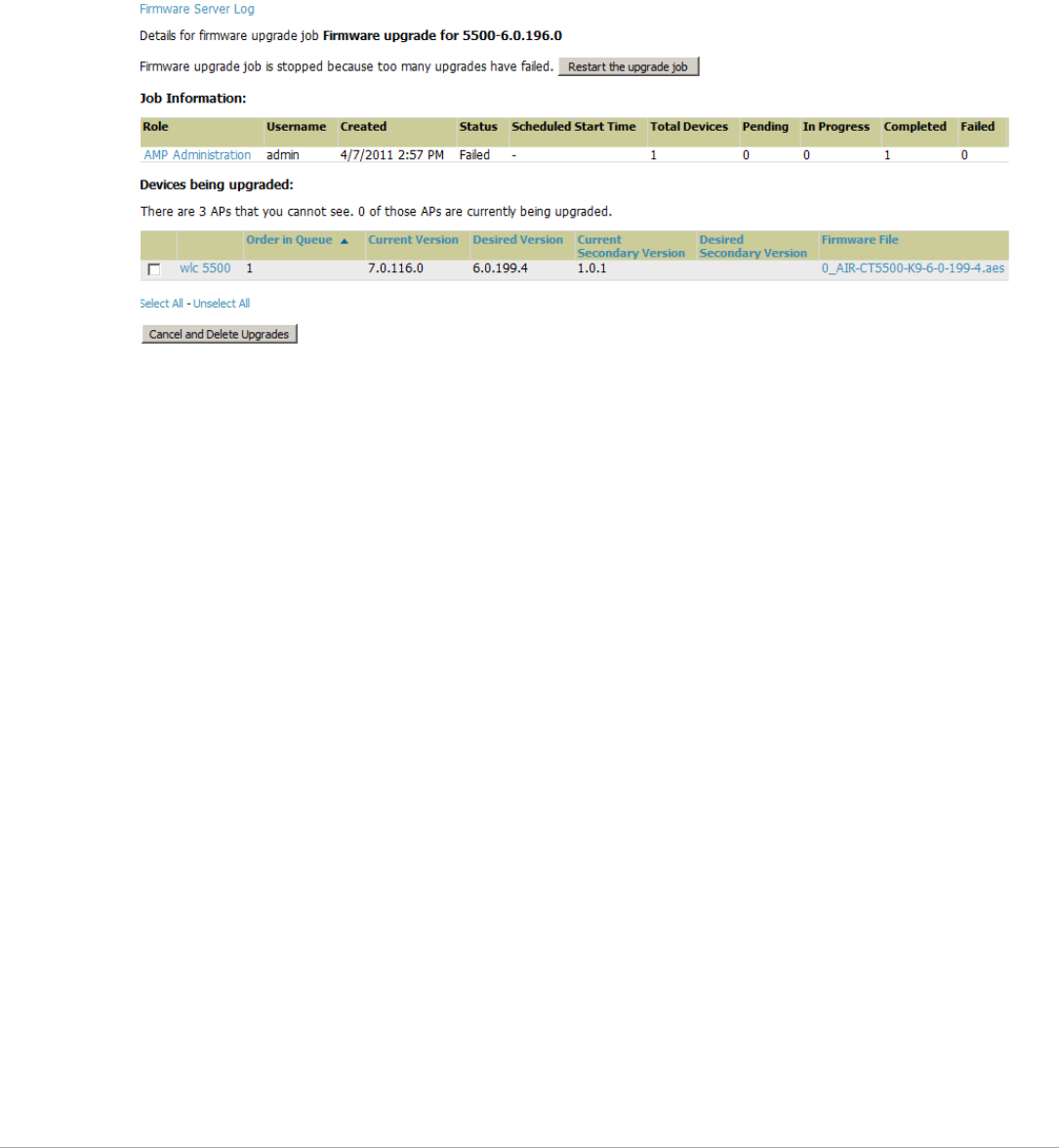
Dell PowerConnect W-AirWave 7.5 | User Guide Performing Daily Administration in AirWave | 223
-Use additional links on the page as shortcuts to the Device Setup > Upload Firmware & Files page, or the
complete raw text of the Firmware Server Log
-To view additional details about an individual upgrade job including the devices being upgraded, select the
name of an upgrade job from the Name column to go to the System > Firmware Upgrade Job Detail page,
illustrated in Figure 163.
From here you can click the device name to go to its APs/Devices > Monitor page, or the link under
Firmware File column to go to the Device Setup > Upload Firmware & Files page.
Figure 163 System > Firmware Upgrade Job Detail Page Illustration
Using the System > Performance Page
The System > Performance page displays basic AirWave hardware information as well as resource usage over
time. AirWave logs performance statistics such as load average, memory and swap data every minute.
The historical logging is useful to determine the best usable polling period and track the health of AirWave over
time.
The page is divided into four sections:
-System Information
-Performance Graphs
-Database Statistics
-Disk Usage
Figure 164 illustrates this page and Table 126 describes fields and information displayed.
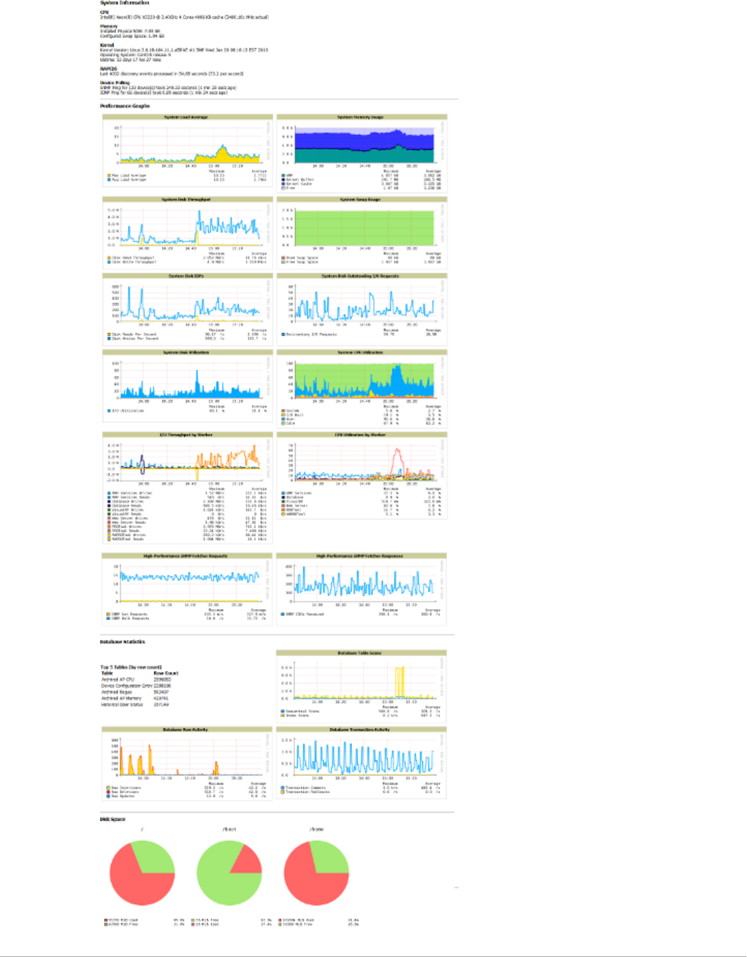
224 | Performing Daily Administration in AirWave Dell PowerConnect W-AirWave 7.5 | User Guide
Figure 164 System > Performance Page Illustration (Partial Screen)

Dell PowerConnect W-AirWave 7.5 | User Guide Performing Daily Administration in AirWave | 225
Table 126 System > Performance Page Fields and Graphs
Field Description
System Information
CPU(s) Basic CPU information as reported by the operating system.
Memory The amount of physical RAM and Swap space seen by the operating system. Refer to the Dell
PowerConnect W-AirWave Server Hardware Guide at support.dell.com/manuals for hardware
requirements.
Kernel The version of the Linux kernel running on the box.
Architecture The AirWave’s architecture information.
Device Polling Displays some AP/Device polling statistics.
Performance Graphs
System Load Average The number of jobs currently waiting to be processed. Load is a rough metric that will tell you
how busy a server is. A typical AirWave load is around 2-3 times the number of CPU cores you
have in your system. A constant load of 4x to 5x is cause for concern. A load above 6x is a
serious issue and will probably result in AirWave becoming unusable. To lower the load average,
try increasing a few polling periods in the Groups > Basic page.
System Memory Usage The amount of RAM that is currently used broken down by usage. It is normal for AirWave to
have very little free RAM. Linux automatically allocates all free RAM as cache and buffer. If the
kernel needs additional RAM for process it will dynamically take it from the cache and buffer.
System Disk Utilization The amount of data read from the disk and written to the disk.
System Disk IOPs The number of disk reads and writes per second.
System Disk Throughput The rate of reading and writing from and to the disk in bytes per second.
System Disk Outstanding I/O
Requests
The average number of outstanding I/O requests (queue depth). If it's high, it means that I/O
requests (disk reads/writes) aren't being serviced as fast as they're being asked for.
System Swap Usage The amount of Swap memory used by AirWave. Swap is used when the there is no more free
physical RAM. A large performance penalty is paid when swap is used. If an AirWave
consistently uses swap, you should consider installing additional RAM.
System CPU Utilization The percentage of CPU that has been used by the user and the system as well as the amount
that was idle.
I/O Throughput by Worker/by
Service
Displays reads and writes for workers (AirWave services, database, VisualRF, web server, RRD
tool and AWRRD tool) and for services (AirWave, VisualRF and web server).
CPU Utilization by Worker/by
Service
Displays reads and writes for workers (AirWave services, database, VisualRF, web server, RRD
tool and AWRRD tool) and for services (AirWave, VisualRF and web server).
System Network Bandwidth All traffic in and out measured in bits per second of your primary network interface (Eth0 being
the most common).
Bandwidth by Protocol Displays the amount of traffic used by Telnet, HTTPS and SNMP used by your primary network
interface (Eth0 being the most common).
Legacy SNMP Fetcher
Requests
The number of SNMP get and walk requests per second performed by the legacy (v1 and v3)
SNMP fetcher.
Legacy SNMP Fetcher
Responses
The number of SNMP OIDs received per second performed by the legacy (v1 and v3) SNMP
fetcher.
High Performance SNMP
Fetcher Requests
The number of SNMP get and walk requests per second performed by the high performance
SNMP (v2c) fetcher.
High Performance SNMP
Fetcher Responses
The number of SNMP OIDs received per second performed by the high performance SNMP
(v2c) fetcher.

226 | Performing Daily Administration in AirWave Dell PowerConnect W-AirWave 7.5 | User Guide
There are several initial steps that you can take to troubleshoot AirWave performance problems, including slow
page loads and timeout errors. Initial troubleshooting steps would include the following:
-Increasing the polling period settings on the Groups > Basic page.
-Increasing the polling period time for groups with routers and switches.
-Adding additional memory to the server. Please consult the sizing information in the latest edition of the Dell
PowerConnect W-AirWave Server Sizing Guide or contact Dell support at support.dell.com for the latest
recommendations.
Supporting AirWave Servers with the Master Console
The Master Console (MC) is used to monitor multiple AirWave stations from one central location. The Master
Console is designed for customers running multiple AirWave servers. Once an AirWave station has been added
to the MC, it will be polled for basic AirWave information.
Much like the normal Home > Overview page, the Master Console Home > Overview page provides summary
statistics for the entire network at a glance. Figure 165 illustrates the Overview page:
Database Statistics
Top 5 Tables (by row count) The five largest tables in AirWave. Degraded performance has been noticed for in some cases
for tables over 200,000 rows. Decreasing the length of time client data is stored on the AirWave
page is recommended if a user/client table exceeds 250,000 rows.
Database Table Scans The number of database table scans performed by the database.
Database Row Activity The number of insertions, deletions and updates performed to the database.
Database Transaction
Activity
The number of commits and rollbacks performed by the database.
Disk Space
Disk Space Pie charts that display the amount of used and free hard drive space for each partition. If a drive
reaches over 80% full, you may want to lower the Historical Data Retention settings on the AMP
Setup > General page or consider additional drive space.
Table 126 System > Performance Page Fields and Graphs (Continued)
Field Description
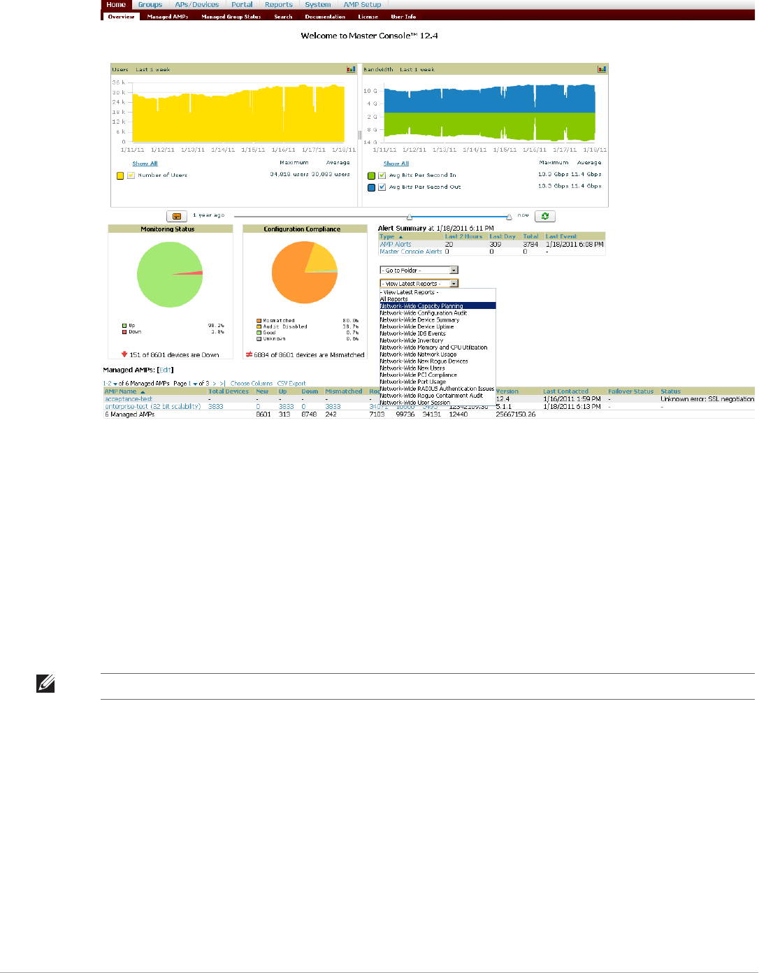
Dell PowerConnect W-AirWave 7.5 | User Guide Performing Daily Administration in AirWave | 227
Figure 165 Master Console Home > Overview Page Illustration
-Reports can be run from the Master Console to display information from multiple AirWave stations; because
such reports can be extremely large, reports can also be run as summary only so that they generate more
quickly and finish as a manageable file size.
-The Master Console can also be used to populate group-level configuration on managed AirWave
installations using the Global Groups feature.
-The Master Console offers a display of devices that are in a Down or Error state anywhere on the network.
This information is supported on Master Console pages that display device lists such as Home > Overview
and APs Devices > List.
-The Master Console and Failover servers can be configured with a Managed AMP Down trigger that
generates an alert if communication is lost to a managed or watched AirWave station. The Master Console or
Failover server can also send email or NMS notifications about the event. .
Using the Public Portal on Master Console
The Master Console also contains an optional Public Portal which allows any user to view basic group-level data
for each managed AirWave. This feature is disabled by default for security reasons; no AirWave or Master
Console login is required to view the public portal. The Public Portal can be enabled in AMP Setup > General in
the Master Console section. Once enabled, a new Portal tab will appear to the right of the Groups tab (refer to
the navigation section in Figure 165 in the previous page). The URL of the public portal will be https://
your.AMP.name/public. When you upgrade to the latest version of AirWave, the public portal is disabled by
default, regardless of the type of license.
NOTE: The license key determines if the server will behave as a Master Console or as a standard AirWave server.
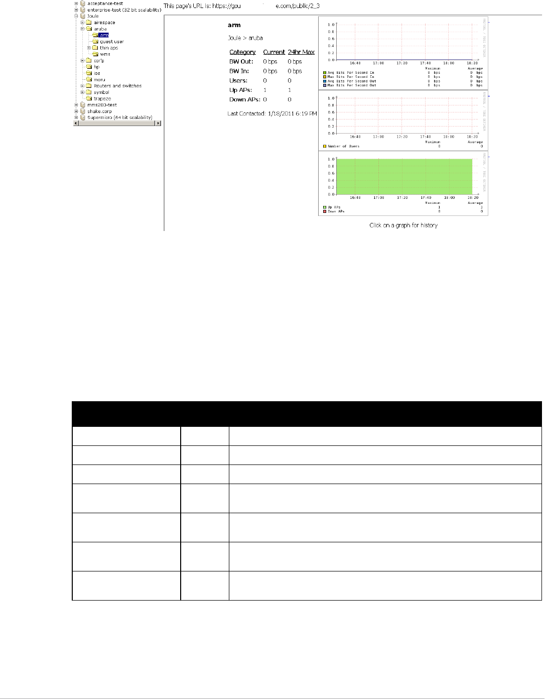
228 | Performing Daily Administration in AirWave Dell PowerConnect W-AirWave 7.5 | User Guide
Figure 166 Public Portal Page Illustration
The Public Portal supports configuration of the iPhone interface. This can be configured using the Master
Console AirWave page. See “Defining General AirWave Server Settings” on page27.
Adding a Managed AMP with the Master Console
Perform the following steps to add a managed AirWave console.
1. Navigate to the Home > Managed AMPs page.
2. Select the pencil icon to edit or reconfigure an existing AirWave console, or select Add New Managed AMP
to create a new AirWave console. The Managed AMP page appears. Complete the settings on this page as
described in Table 127.
3. When finished, select Add to return to the Managed AMPs list page.
Using Global Groups with Master Console
To push configurations to managed groups using the AirWave Global Groups feature, follow these steps:
Table 127 Managed AMP Fields and Default Values
Field Default Description
Hostname / IP Address N/A Enter the IP address or Hostname of the AirWave server to be managed.
Polling Enabled Yes Enables or disables the Master Console polling of managed AirWave server.
Polling Period 5 minutes Determines how frequently the Master Console polls the managed AirWave server.
Username N/A The username used by the Master Console to login to the managed AirWave server.
The user needs to be an AP/Device Manager or AirWave Administrator.
Password
(Confirm Password)
N/A The password used by the Master Console to login to the managed AirWave server.
HTTP Timeout
(5-1000 sec)
60 Defines the timeout period used when polling the managed AirWave server.
Manage Group
Configuration
No Defines whether the Master Console can manage device groups on the managed
AirWave server.

Dell PowerConnect W-AirWave 7.5 | User Guide Performing Daily Administration in AirWave | 229
1. Navigate to the Master Console's Groups > List page.
2. Select Add to add a new group, or select the name of the group to edit settings for an existing group.
3. Select the Duplicate icon to create a new group with identical configuration to an existing group. Groups
created on the Master Console will act as Global Groups, or groups with master configurations that can be
pushed out to subscriber groups on managed AMPs. Global groups are visible to all users, so they cannot
contain APs (which can be restricted based on user role).
4. Selecting the name of an existing group on the Master Console loads the subtabs for Basic, Security, SSIDs,
AAA Servers, Templates, Radio, Cisco WLC Config, Proxim Mesh, and MAC ACL pages, if such pages and
configurations are active for the devices in that group.
These subtabs contain the same fields as the group subtabs on a monitored AMP, but each field also has a
checkbox. The Master Console can also configure global templates that can be used in subscriber groups. The
process is the same as described in the Chapter 6, “Creating and Using Templates” , except that there is no
process by which templates can be fetched from devices in the subscriber group on managed AirWaves.
Instead, the template must be copied and pasted into the Master Console Global Group.
When a Global Group is pushed from the Master Console to subscriber groups on managed AirWaves, all
settings will be static except for settings with the checkbox selected; for fields with checkboxes selected, the value
or setting can be changed on the corresponding tab for each managed group. For list pages, override options are
available only on the Add page for each list. It will take several minutes for changes to Global Groups on the
Master Console to be pushed to the managed AirWaves; make sure that the Manage Group Configuration
option is enabled for each managed AirWave.
Once Global Groups have been configured on the Master Console, groups must be created or configured on the
managed AirWaves to subscribe to a particular Global Group. To configure subscriber groups, enable Use Global
Groups on the Group > Basic page of a group on a managed AirWave. Select the name of the Global Group
from the drop-down menu, and then select Save and Apply. Note that the MC doesn’t push anything when you
create new subscriber groups; the copy of the Global Group already on the managed AirWave provides the
information.
Once the configuration is pushed, the non-overridden fields from the Global Group will appear on the subscriber
group as static values and settings. Only fields that had the override checkbox selected in the Global Group will
appear as fields that can be set at the level of the subscriber group. Any changes to a static field must be made on
the Global Group.
The Global Groups feature can also be used without the Master Console. For more information about how this
feature works, refer to “Configuring and Using Device Groups” on page 67.
Backing Up AirWave
AirWave creates nightly archives of all relational data, statistical data, and log files. This occurs by default at 4:15
AM, but is configurable on the AMP Setup > General page under Nightly Maintenance Time.
Although AirWave only keeps the last four sets of archives, the archives can be downloaded manually or
automatically off-site for more extensive backup strategies. AirWave creates one data backup file each night. The
data backup file contains all of the device and group information as well as historical data and system files,
including IP address, NTP information, mail relay hosts, and other AirWave settings.
Viewing and Downloading Backups
To view current AirWave backup files, go to the System > Backups page. Figure 167 illustrates this page.
Figure 167 System > Backups Page Illustration

230 | Performing Daily Administration in AirWave Dell PowerConnect W-AirWave 7.5 | User Guide
To download a backup file, select the filename URL and the File Download popup page appears.
Regularly save the data backup file to another machine or media. This process can be automated easily with a
nightly script.
Running Backup on Demand
To create an immediate backup:
1. Log into the AirWave system as root.
2. Run the backup script by typing amp_backup.
This creates a backup of the system located in /alternative/databackup.tar.gz.
Restoring from a Backup
To restore a backup file on a new machine:
1. Use your AirWave Installation CD to build a new machine. The new machine must be running the same
version as the AirWave that created the backup file.
2. Copy the nightly_data00[1-4].tar.gz file to the /tmp directory in the new AirWave.
A file transfer client that supports SFTP/SCP for Windows is WinSCP: http://winscp.sourceforge.net/eng/
WinSCP allows you to transfer the nightly00[1-4].tar.gz file from your local PC to the new AirWave using the
secure copy protocol (SCP).
3. Log onto the new server as root.
4. Change to the scripts directory by typing scripts.
5. Run the restore script by typing ./amp_restore -d /tmp/nightly_data00[1-4].tar.gz.
Using AirWave Failover for Backup
The failover version of AirWave provides a “many to one” hot backup server. The Failover AirWave polls the
watched AMPs to verify that each is up and running. If the watched AirWave is unreachable for the specified
number of polls, the Failover AirWave automatically restores the most recent saved backup from the watched
AirWave and begins polling its APs.
NOTE: Nightly maintenance and amp_backup scripts back up the full AirWave data and save the file as nightly_data00[1-4].tar.gz.
In previous AirWave versions, the scripts created both config backup and data backup files. In order to restore the AirWave data,
it is only necessary to have most recent data backup file, and AirWave no longer uses or supports the config backup file, effective
as of AirWave 6.3.2 and later AirWave versions.
NOTE: Network administrators can now use the nightly backup from a 32-bit AMP to restore AMP on a 64-bit installation, rather
than having to create a special backup file or use the special restore script.

Dell PowerConnect W-AirWave 7.5 | User Guide Performing Daily Administration in AirWave | 231
Navigation Section of AirWave Failover
The Navigation section displays tabs to all main GUI pages within AirWave Failover. The top bar is a static
navigation bar containing tabs for the main components of AirWave, while the lower bar is context-sensitive and
displays the subtabs for the highlighted tab. Table 128 describes the contents of this page.
Adding Watched AirWave Stations
Navigate to the Home > Watched AMPs page to begin backing up and monitoring AirWave stations. Once an
AirWave installation has been added to the Watched AMP list, the Failover AMP will download the most recent
backup and begin polling. The Failover AMP and the Watched AMP must be on the same version or else the
watched AirWave will be unable to restore properly. If any of the watched AMPs are not on the same version of
AirWave, you will need to upgrade. The Failover AMP will need HTTPS access (port 443) to the watched AMP to
verify that the web page is active and to fetch downloads.
Once the Failover AMP determines that the Watched AMP is not up (based on the user-defined missed poll
threshold) it will restore the data backup of the Watched AMP and begin monitoring the watched AMP APs and
devices. There are many variables that affect how long this will take including how long client historical data is
being retained, but for an AMP with 1,000 APs it might take up to 10 minutes. For an AMP with 2,500 APs, it
might take as long as 20 minutes. The Failover AMP will retain its original IP address.
In summary, the Failover AMP could take over for the Watched AMP in as little as five minutes; it might take up
to an additional 10-20 minutes to unpack the watched AMP data and begin monitoring APs. The most important
factors are the missed poll threshold, which is defined by the user, and the size of the watched AMP backup,
which is affected by the total number of APs and by the amount of data being saved, especially client historical
data.
To restore the Watched AMP, run the backup script from the command line and copy the current data file and
the old Watched AMP configuration file to the Watched AMP. Then run the restore script. More information
about backups and restores can be found in “Backing Up AirWave” on page 229.
Table 128 Contents of the Navigation Section of Failover
Main Tab Description Subtabs
Home The Home page provides basic AirWave Failover information including system
name, hostname, IP address, current time, running time, software version, and
watched AirWave information.
-Overview
-User Info
-Watched AMPs
-License
System The System page provides information related to AirWave operation and
administration including overall system status, performance monitoring, and
backups.
-Status
-Triggers
-Alerts
-Event Log
-Backups
-Performance
AMP Setup The Setup page provides all information relating to the configuration of AirWave
itself and its connection to your network.
-General
-Network
-Users
-TACACS+
Table 129 Home > Watched Page Fields and Default Values
Setting Default Description
IP/Hostname None The IP address or Hostname of the watched AMP.
The Failover AMP needs HTTPS access to the watched AMPs.
Username None A username with management rights on the watched AMP.
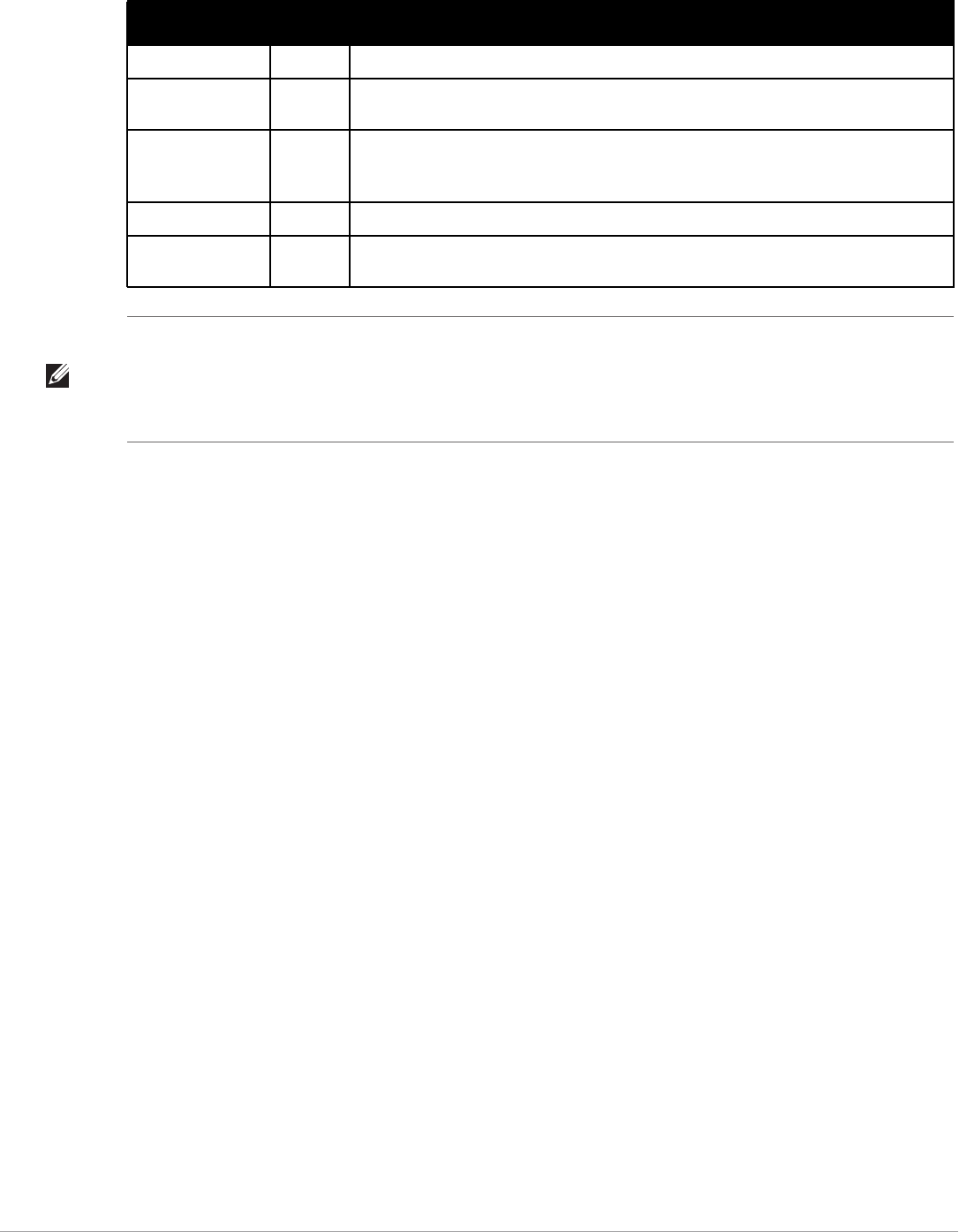
232 | Performing Daily Administration in AirWave Dell PowerConnect W-AirWave 7.5 | User Guide
Logging out of AirWave
To log out of AirWave, select the Logout link on the upper right hand corner of every AirWave page.
You will be logged off automatically based on the number of minutes set in the Idle Timeout setting of Home >
User Info. Refer to “Configuring Login Message, TACACS+, RADIUS, and LDAP Authentication” on page43.
Password None The password for the username with management rights specified above.
HTTP Timeout
(5-1000 Sec)
60 The amount of time before AirWave considers a polling attempt failed.
Polling Enabled Yes Enables or disables polling of the Watched AMP.
NOTE: You do not need to disable polling of the watched AMP system if it is set to be down
during nightly maintenance or is being upgraded.
Polling Period 5 minutes The amount of time between polls of the Watched AMP.
Missed Poll
Threshold
None The number of polls that can be missed before the failover AMP will begin actively monitoring
the Watched AMP APs.
Table 129 Home > Watched Page Fields and Default Values (Continued)
Setting Default Description
NOTE: When selecting a backup file, be sure to select the one that is most relevant, whether that is failover-as-AMP or failover-
as-failover. An AirWave acting as a failover keeps its nightly backups in /var/airwave-backup, and the backups of watched AMPs
are stored in /var/airwave-backup/watched_amps. In the event of a failover, a new backup-as-failover is made and placed in /var/
airwave-backup/watcher. However, the existing backups-as-failover in /var/airwave-backup remains there until they are aged out
by standard rotation.

Dell PowerConnect W-AirWave 7.5 | User Guide Creating, Running, and Emailing Reports | 233
Chapter 9
Creating, Running, and Emailing
Reports
This chapter describes AirWave reports, including access, creation, scheduling, and distribution.
This chapter includes the following sections:
-“Overview of AirWave Reports” on page233
-“Using Daily Reports” on page236
-“Defining Reports” on page257
-“Emailing and Exporting Reports” on page261
AirWave ships with several reports enabled by default. Default reports may run nightly or weekly, depending on
the AirWave release. Review the list of defined and scheduled reports with the Reports > Generated and Reports
> Definition pages to determine if default reports are desired. If not, you can delete, disable, or reschedule any of
them.
AirWave supports additional specialized reports as follows:
-System > Status page supports the diagnostic report file for sending to customer support: diagnostics.tar.gz.
-System > Status page supports the VisualRF diagnostics report file: VisualRFdiag.tar.gz.
-VisualRF > Network View supports the Bill of Materials (BOM) report. Refer to Chapter 10, “Using
VisualRF” on page263.
Overview of AirWave Reports
Reports are powerful tools in network analysis, user configuration, device optimization, and network monitoring
on multiple levels. Among their benefits, reports provide an interface for multiple configurations.
AirWave reports have the following general parameters:
-AirWave runs daily versions of all reports during predefined windows of time. All reports can be scheduled to
run in the background.
-The daily version of any report is available instantly in the Reports > Generated page.
-The Inventory and the Configuration Audit reports are the only reports that don’t span a period of time.
Instead, these two reports provide a snapshot of the current state of the network.
-Users can create all other reports over a custom time period on the Reports > Definitions page. All reports
can be emailed or exported to XML format for easy data manipulation using a spreadsheet.
Reports > Definitions Page Overview
The Reports > Definitions page allows you to define new reports and see the reports already defined.
The Definitions page includes these sections:
-Report Definitions section—The Add button allows you to define a custom report using the Custom
Options drag and drop interface, or from any of the report types in the dropdown menu. The Report
Definitions table has a complete list of all saved report definitions with an option to return to each
definition’s table to further customize your report. When you create a report, the following additional buttons
are available:
Add and Run allows you to create a report definition and run that report immediately.

234 | Creating, Running, and Emailing Reports Dell PowerConnect W-AirWave 7.5 | User Guide
Run Now (visible from the expanded Report Definitions menu) allows immediate running of a custom
report as soon as you set the parameters. You must save its definition separately, if you want to remember
the parameters.
-Report definitions for other roles section—This section, supported for admin users, displays additional
reports that have been scheduled for other roles. This section of the page adds the Role column, and other
columns are the same.
Each pane includes a Latest Report column with the most recently run reports for each definition and role
created. Run and Delete buttons allow you to select a report from the definitions table to run or delete. Once you
define a report from the Definition page, it appears on the Generated page. The Reports > Definition page is
shown in Figure 168, and Table 130 describes the fields available when you select a specific report definition.
Table 130 Reports > Definition Page Fields and Descriptions
Field Description
Report Definition Displays a field for entering report title and dropdown menu, shown in Figure 169, displaying all
possible report types.
Report Restrictions Displays dynamic fields that include spaces for selecting attributes and entering data relevant to your
selected report type scope such as groups, folders, SSID, Device Search filter, report start and end
times.
Scheduling Options Reveals options for one time or regularly scheduled reporting by selecting Yes. Options include report
frequency, start time, and current system time.
Report Visibility Allows you to determine a report’s visibility according to user role.
Email Options Reveals email address preferences for sending reports by selecting Yes. Be sure to always enter a
valid e-mail address.
Add and Run Available when adding a new Report Definition. Allows you to create a report definition and run that
report right then.
Run Now Available when adding a new Report Definition. Allows you to run any report that has been defined on
the spot without saving settings or creating a new report definition.
Add Saves report definition you just created.
Save and Run Available when viewing an existing Report Definition. Allows you to edit a report definition and run that
report right then.
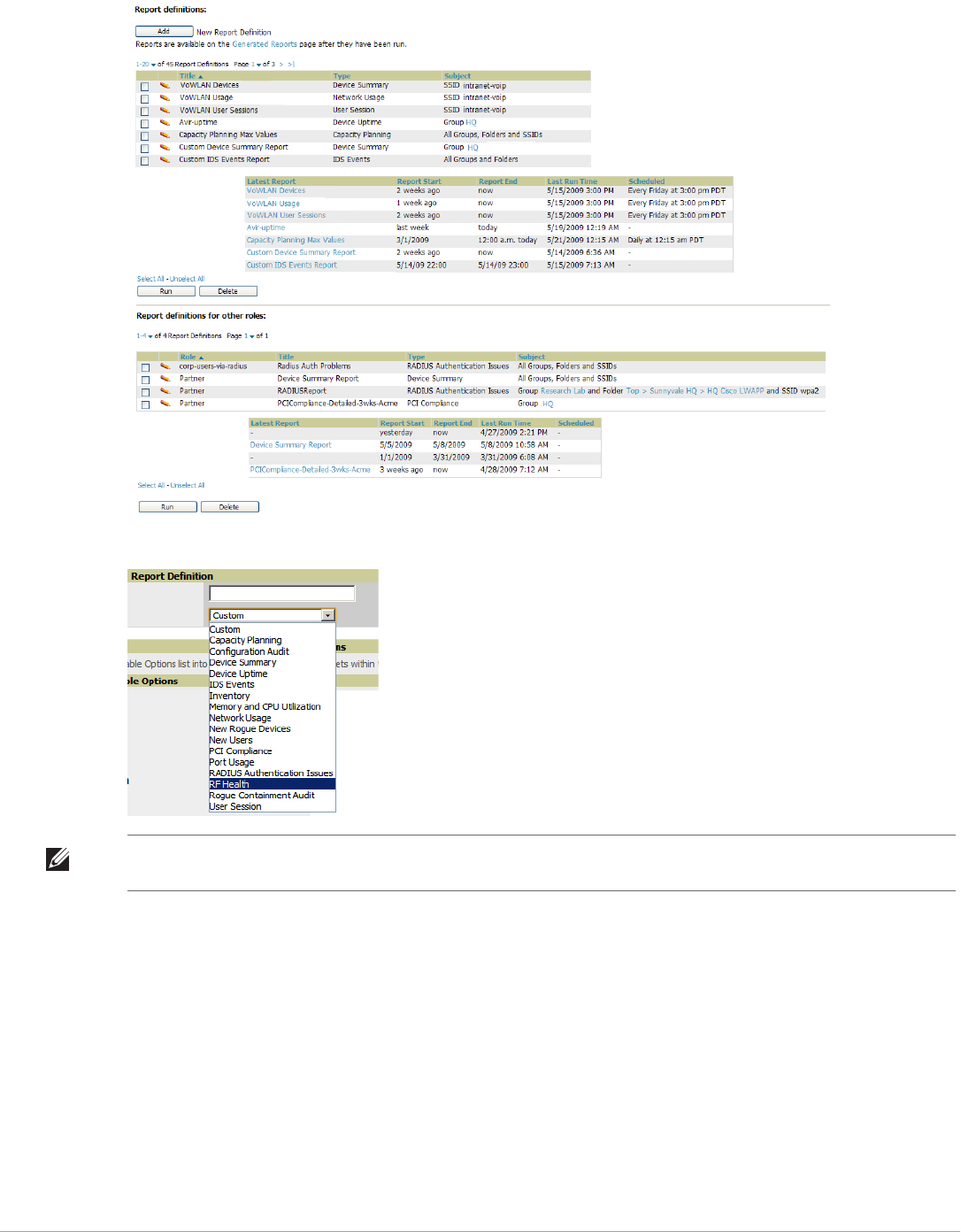
Dell PowerConnect W-AirWave 7.5 | User Guide Creating, Running, and Emailing Reports | 235
Figure 168 Reports > Definitions Page Illustration (Split View)
Figure 169 Report Type Drop-down Menu in Reports > Definitions Illustration
Reports > Generated Page Overview
The Reports > Generated page displays reports that have been run, as well as the most recent daily version of any
report. An Admin user can see and edit all report definitions in AirWave. Users with Monitor Only roles can see
reports and definitions only if they have access to all devices in the reports.
The Reports > Generated page contains three primary sections, as follows:
-Generated reports configured for the current role and for additional roles
-Generated reports for other roles
-The latest daily reports for immediate online viewing
NOTE: Only admin users have complete access to all report information. The AirWave reports and online displays of information
can vary with configuration, User Roles, and Folders.
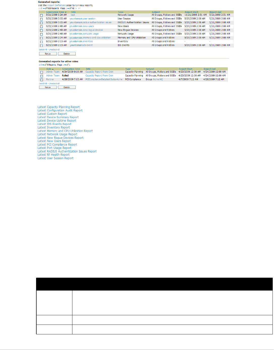
236 | Creating, Running, and Emailing Reports Dell PowerConnect W-AirWave 7.5 | User Guide
Figure 170 Reports > Generated Page Example
Figure 171 Reports > Generated Page with Single-click Report Viewing Options
Using Daily Reports
This section describes the default and custom-scheduled reports supported in AirWave. These reports can be
accessed from the Reports > Generated page.
Viewing Generated Reports
The Reports > Generated page supports the following general viewing options:
-By default, the reports on the Reports > Generated page are sorted by Generation Time. You can sort reports
by any other column header in sequential or reverse sequential order. You can also choose columns, export the
Generated Reports list in CSV, and modify the pagination of this list.
-The Reports > Detail page launches when you select any report title from this page.
The Generated Reports page contains fewer columns and information than the Definitions page. Table 131
describes each column for the Reports > Generated page.
Table 131 Reports > Generated Page Fields and Descriptions
Field Description
Generated Time Displays the date and time of the last time the report was run, or when the latest report is available. Selecting
the link in this field displays the latest version of a given report. When the latest version of a given report is
not available, this field is blank. In this case, a report can be run by selecting the report title and selecting
Run.
Title Displays title of the report. This is a user-configured field when creating the report.
Type Displays the type of the report.
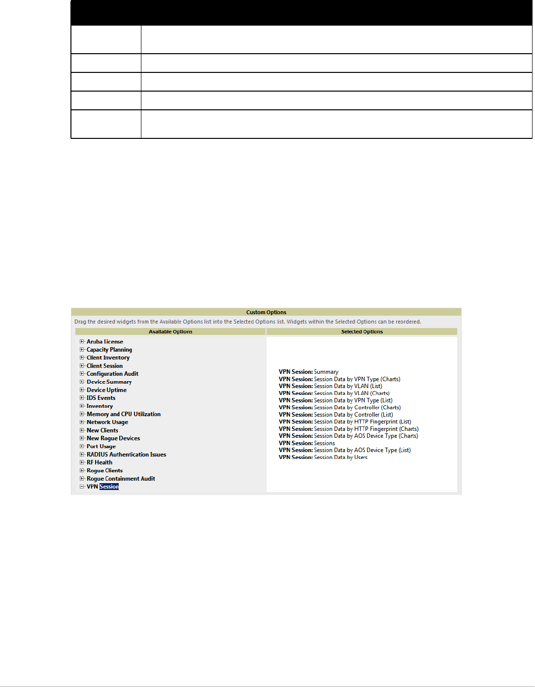
Dell PowerConnect W-AirWave 7.5 | User Guide Creating, Running, and Emailing Reports | 237
Using Custom Reports
Custom reports allow users to specify the data that should be included in a report.
Perform these steps to create a Custom Report.
1. Navigate to the Reports > Definitions page.
2. Select Add.
3. Enter a Title for the new report.
4. By default, the Custom option will be selected in the Type drop-down menu, and the Custom Options
section appears below as shown in Figure 172.
Figure 172 Custom Options Page Illustration
The left pane of the Custom Options section lists all available data that can be included in the report. For
example, if the data you want to include is in the RF Health report, select RF Health to view a list of all
available radio frequency information. Then, simply drag the desired data from the Available Options list on
the left to the Selected Options pane on the right.
The order of the data in the Selected Options section is the order that it will appear in the report. The data
can be reordered by dragging an item up or down the list.
5. Below the Custom Options panes is a Report Restrictions section. All reports allow you to restrict based a
specified Group, Folder, and Device Type. When you select Custom Options to include in a report,
additional restrictions will be available. For example, if you select Device Summary: Most Utilized by Usage,
then you can restrict the report to include and/or exclude specific devices. Some detailed reporting options,
such as New Rogue Devices: Discovery Events, allow you to specify the columns to include in the report.
Subject Displays the scope of the report, to include groups, folders, SSIDs, or any combination of these that are
included in the report.
User This displays the user who created the customized report.
Report Start Displays the beginning of the time period covered in the report.
Report End Displays the end of the time period covered in the report.
Role In the Reports definitions for other roles section, this column indicates the roles for which additional reports
are defined.
Table 131 Reports > Generated Page Fields and Descriptions
Field Description
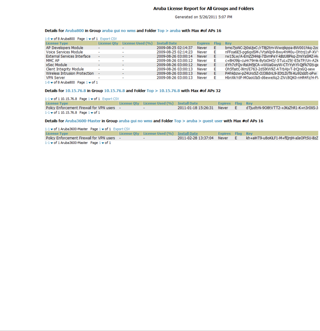
238 | Creating, Running, and Emailing Reports Dell PowerConnect W-AirWave 7.5 | User Guide
6. Below the Report Restrictions section are Scheduling Options, Report Visibility, and Email Options
sections. Choose the parameters as needed for your report, especially a Report Start and Report End.
7. When finished, select Add and Run to add the report to your list and run it immediately, Run Now to run
without being added to the list, Add to add but not run the report, or Cancel to exit this page.
Using the Dell License Report
A new Dell License Report has been added in the Reports tab to track licenses on Dell devices in your network.
This report includes information on the type, quantity, percent used, installation date, expiration date, and the
license keys.
Figure 173 Dell License Report Detail Page
Using the Capacity Planning Report
The Capacity Planning Report tracks device bandwidth capacity and throughput in device groups, folders, and
SSIDs. This report assists in analyzing device capacity and performance on the network, and such analysis can
help to achieve network efficiency and improved experience for users.
This report is based on interface-level activity. The information in this report can be sorted by any column header
in sequential or reverse-sequential order by selecting the column heading.
Refer also to the “Using the Network Usage Report” on page247 for additional bandwidth information.
The following figures and Table 132 illustrate and describe the contents of the Capacity Planning Report.
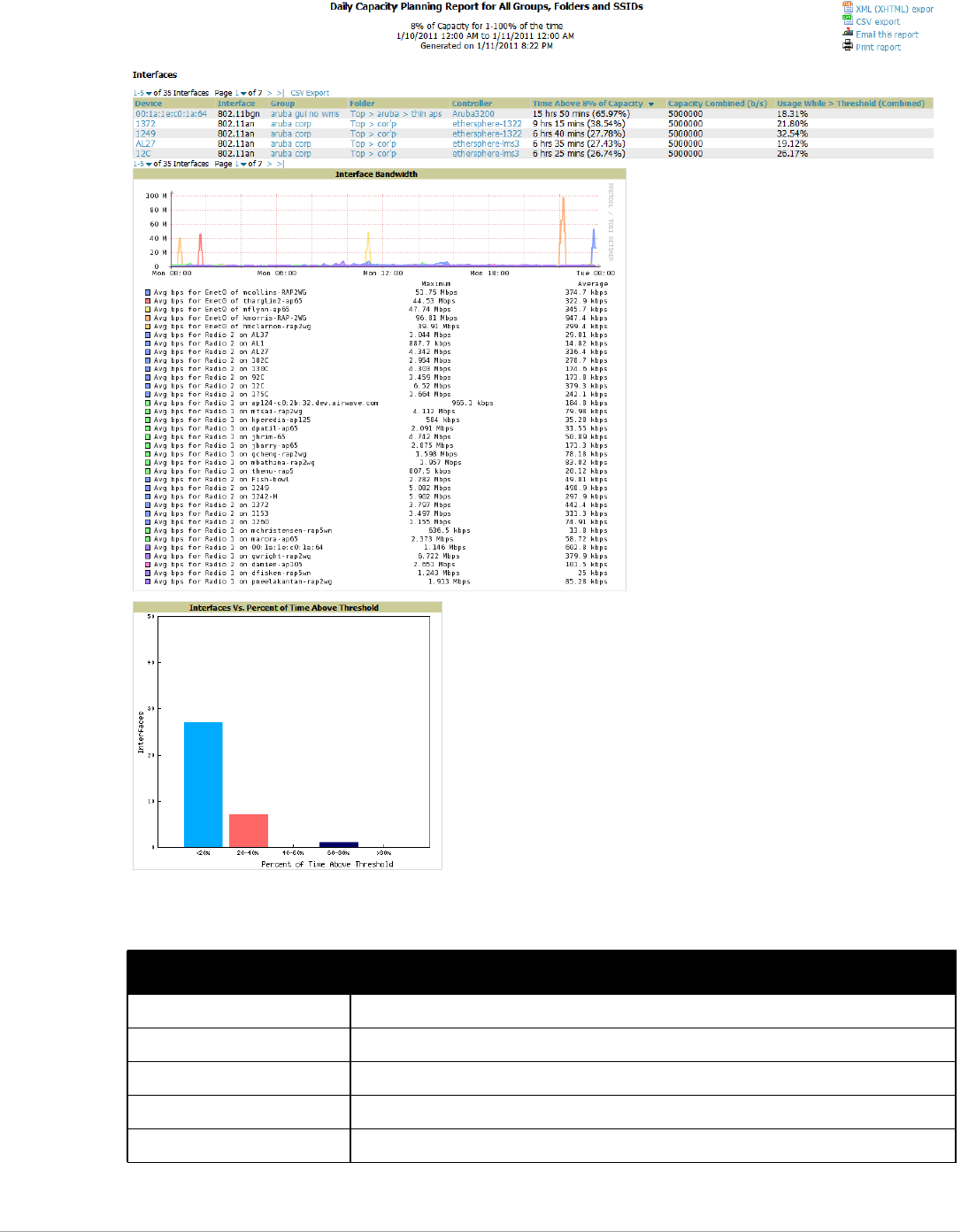
Dell PowerConnect W-AirWave 7.5 | User Guide Creating, Running, and Emailing Reports | 239
Figure 174 Capacity Planning Report Detail Page
Table 132 Capacity Planning Report Fields and Contents, Top Portion
Field Description
Device Displays the device type or name.
Interface Displays the type of 802.11 wireless service supported by the device.
Group Displays the device group with which the device is associated.
Folder Displays the folder with which the device is associated.
Controller Displays the controller with which a device operates.

240 | Creating, Running, and Emailing Reports Dell PowerConnect W-AirWave 7.5 | User Guide
Using the Configuration Audit Report
The Configuration Audit Report provides an inventory of device configurations on the network, enabling you to
display information one device at a time, one folder at a time, or one device group at a time. This report links to
additional configuration pages.
Perform these steps to view the most recent version of the report, then to configure a given device using this
report.
1. Navigate to the Reports > Generated page.
2. Scroll to the bottom, and select Latest Configuration Audit Report to display Detail device configuration
information for all devices. The ensuing Detail report can be very large in size, and provides multiple links to
additional device configuration or information display pages.
3. You can display device-specific configuration to reduce report size and to focus on a specific device. When
viewing configured devices on the Detail page, select a device in the Name column. The device-specific
configuration appears.
4. You can create or assign a template for a given device from the Detail page. Select Add a Template when
viewing device-specific configuration information.
5. You can audit the current device configuration from the Detail page. Select Audit when viewing device-
specific information.
6. You can display archived configuration about a given device from the Detail page. Select Show Archived
Device Configuration.
Figure 175 and Table 133 illustrate and describe the general Configuration Audit report and related contents.
Time Above 1% of Capacity Displays the time duration in which the device has functioned above 0% of capacity. A low
percentage of use in this field may indicate that a device is under-used or poorly configured in
relation to its capacity, or in relation to user needs.
Capacity Combined (b/s) Displays the combined capacity in and out of the device, in bits-per-second.
Usage While > Threshold
(Combined)
Displays the time in which a device has functioned above defined threshold capacity, both in
and out.
Overall Usage (Combined) Displays the overall usage of the device, both combined in and out traffic.
Usage While > Threshold (in) Displays device usage that exceeds the defined and incoming threshold capacity.
Overall Usage (In) Displays overall device usage for incoming data.
Usage While > Threshold (Out) Displays device usage for outgoing data that exceeds defined thresholds.
Overall Usage (Out) Displays device usage for outgoing data.
Table 132 Capacity Planning Report Fields and Contents, Top Portion (Continued)
Field Description
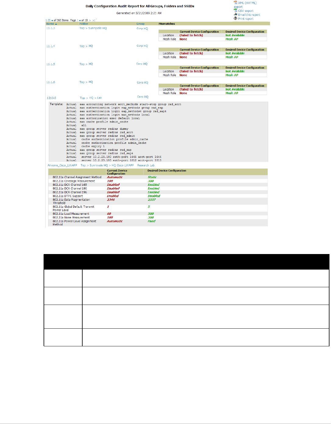
Dell PowerConnect W-AirWave 7.5 | User Guide Creating, Running, and Emailing Reports | 241
Figure 175 Reports > Generated > Daily Configuration Audit Report Page, abbreviated example
Using the Device Summary Report
The Device Summary Report identifies devices that are the most or least used devices, and a comprehensive list
of all devices. One potential use of this report is to establish more equal bandwidth distribution across multiple
devices. This report contains the following five lists of devices.
-Most Utilized by Maximum Number of Simultaneous Users—By default, this list displays the 10 devices that
support the highest numbers of users. This list provides links to additional information or configuration pages
for each device to make adjustments, as desired.
Table 133 Daily Configuration Audit Report
Field Description
Name Displays the device name for every device on the network. Selecting a given device name in this column allows
you to display device-specific configuration.
Folder Displays the folder in which the device is configured in AirWave. Selecting the folder name in this report
displays the APs/Devices > List page for additional device, folder and configuration options.
Group Displays the group with which any given device associates. Selecting the group for a given device takes you to
the Groups > Monitor page for that specific group, to display graphical group information, modification options,
alerts, and an audit log for the related group.
Mismatches This field displays configuration mismatch information. When a device configuration does not match ideal
configuration, this field displays the ideal device settings compared to current settings.
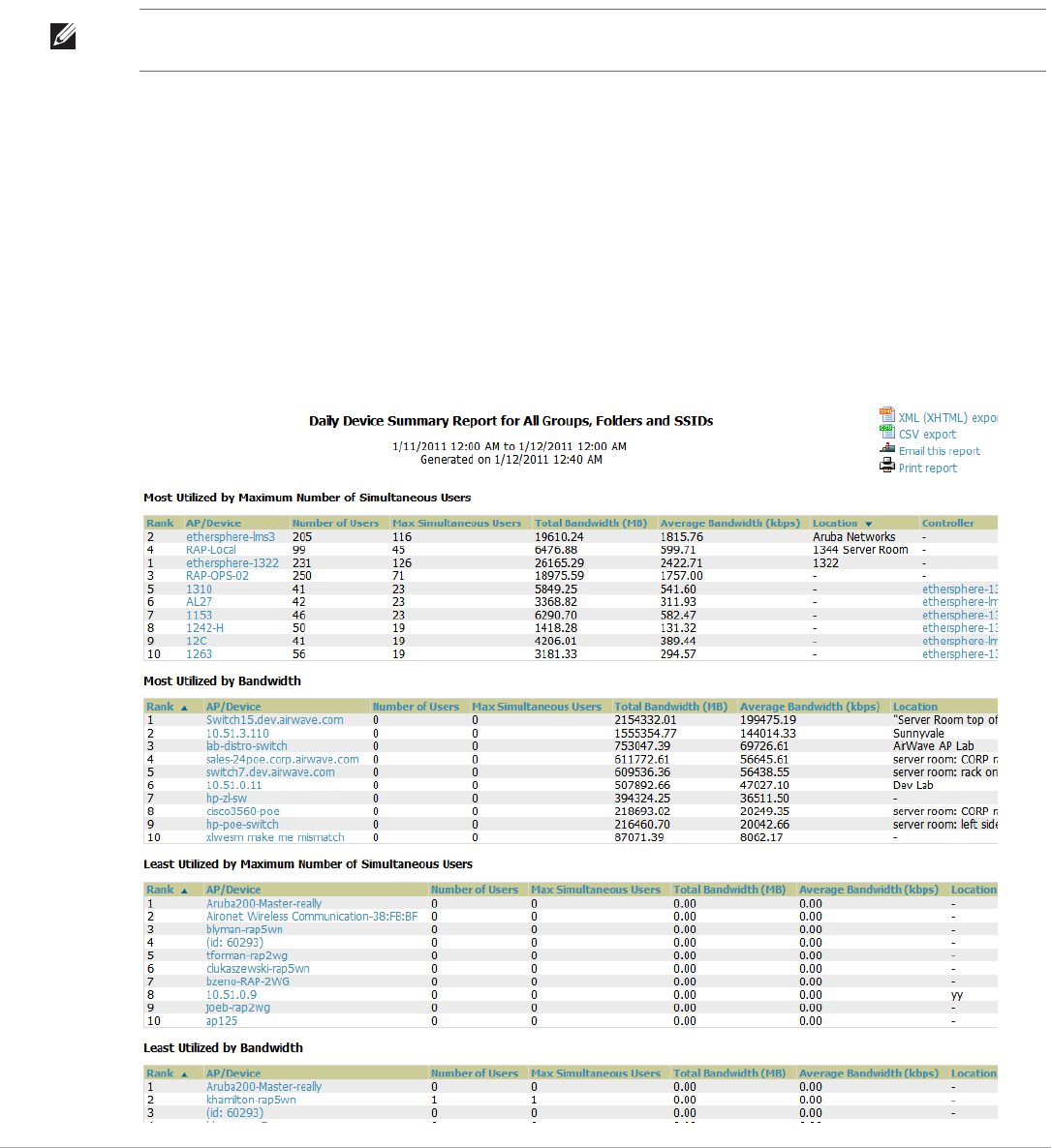
242 | Creating, Running, and Emailing Reports Dell PowerConnect W-AirWave 7.5 | User Guide
-Most Utilized by Bandwidth—By default, this list displays the 10 devices that consistently have the highest
bandwidth consumption during the time period defined for the report. This list provides links to additional
information or configuration pages for each device.
-Least Utilized by Maximum Number of Simultaneous Users—By default, this list displays the 10 devices that
are the least used, according to the number of users.
-Least Utilized by Bandwidth—By default, this list displays the 10 devices that are the least used, according to
the bandwidth throughput.
-Devices—This list displays all devices in AirWave. By default it is sorted alphabetically by device name.
Any section of this report can be sorted by any of the columns. For example, you can specify a location and then
sort the Devices list by the Location column to see details by location, or you can see all of the APs associated
with a particular controller by sorting on the Controller column. If the AP name contains information about the
location of the AP, you can sort by AP name.
If sorting the Devices list does not provide you with sufficient detail, you can specify a Group or Folder in the
report Definition of a custom report. If you create a separate Group or Folder for each set of master and local
controllers, you can generate a separate report for each Group or Folder. With this method, the summary sections
of each report contain only devices from that Group or Folder.
Figure 176 and Table 134 illustrate and describe the Reports > Generated > Device Summary Detail page.
Figure 176 Reports > Generated > Daily Device Summary Report Illustration (partial view)
NOTE: You can specify the number of devices that appear in each of the first four categories in the Reports > Definitions > Add
page.

Dell PowerConnect W-AirWave 7.5 | User Guide Creating, Running, and Emailing Reports | 243
Using the Device Uptime Report
The Device Uptime Report monitors device performance and availability on the network, tracking uptime by
multiple criteria to include the following:
-Total average uptime by SNMP and ICMP
-Average uptime by device group
-Average uptime by device folder
You can use this report as the central starting point to improve uptime by multiple criteria. This report covers
protocol-oriented, device-oriented, or SSID-oriented information. This report can help to monitor and optimize
the network in multiple ways. It can demonstrate service parameters, can establish locations that have superior or
problematic uptime availability, and can help with additional analysis in multiple ways. Locations, device groups,
or other groupings within a network can be identified as needing attention or can be proven to have superior
performance when using this report.
The Device Uptime Report contains columns that track bootstrap count (number of times the device has gone
down for a firmware change), reboot count, downtime duration, and downtime duration percent. As mentioned
above, you can optionally ignore device downtime during planned maintenance periods in this report, and you
can restrict the report to business days only.
Figure 177 and Table 134 illustrate and describe the Device Uptime report.
Table 134 Reports > Generated > Daily Device Summary Report Unique Fields and Descriptions
Field Description
Max Simultaneous Users Displays the maximum number of users that were active on the associated device during the
period of time that the report covers.
Total Bandwidth (MB) Displays the bandwidth in megabytes that the device supported during the period of time covered
by the report.
Average Bandwidth (kbps) Displays the average bandwidth throughput for the device during the period of time covered by the
report.
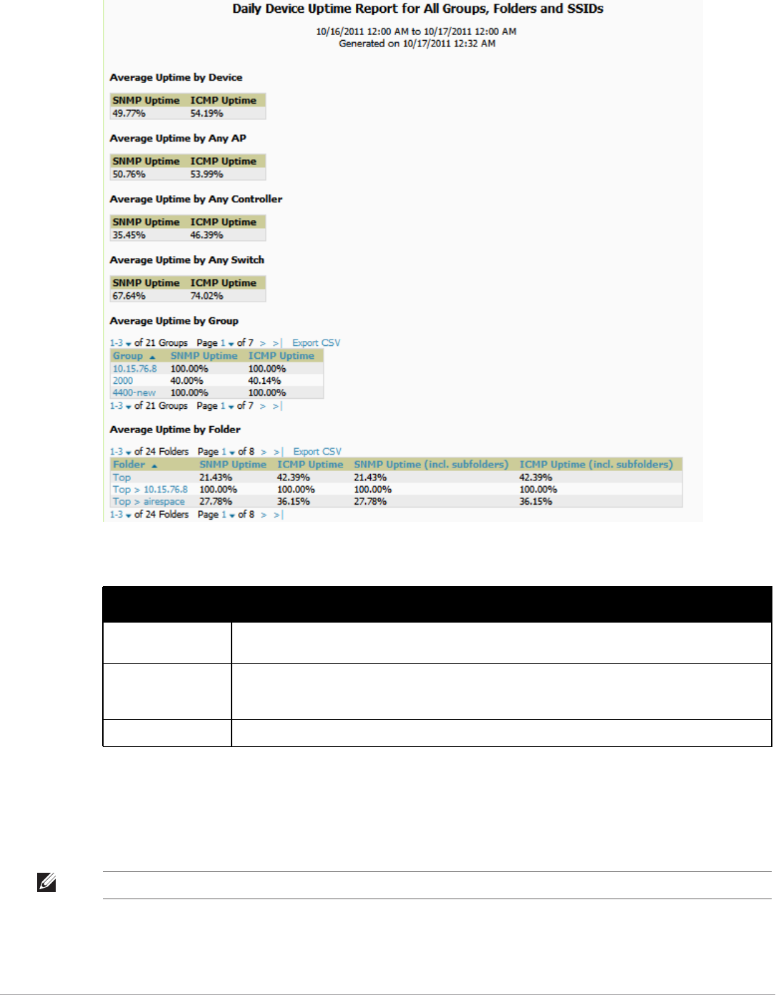
244 | Creating, Running, and Emailing Reports Dell PowerConnect W-AirWave 7.5 | User Guide
Figure 177 Device Uptime Report Illustration
Using the IDS Events Report
The IDS Events Report lists and tracks IDS events on the network involving APs or controller devices. This
report cites the number of IDS events for devices that have experienced the most instances in the prior 24 hours,
and provides links to support additional analysis or configuration in response.
The Home > Overview page also cites IDS events, and triggers can be configured for IDS events. Refer to
“Setting Triggers for IDS Events” on page199 for additional information.
Table 135 Reports > Generated > Device Uptime Report Unique Fields and Descriptions
Field Description
SNMP Uptime Displays the percentage of time the device was reachable via ICMP. AirWave polls the device via
SNMP at the rate specified on the Groups > Basic page.
ICMP Uptime Displays the percentage of time the device was reachable via ICMP. If the device is reachable via
SNMP it is assumed to be reachable via ICMP. AirWave only pings the device if SNMP fails and then it
pings at the SNMP polling interval rate.
Time Since Last Boot The uptime as reported by the device at the end of the time period covered by the report.
NOTE: Your role must be enabled to view RAPIDS to see this report.
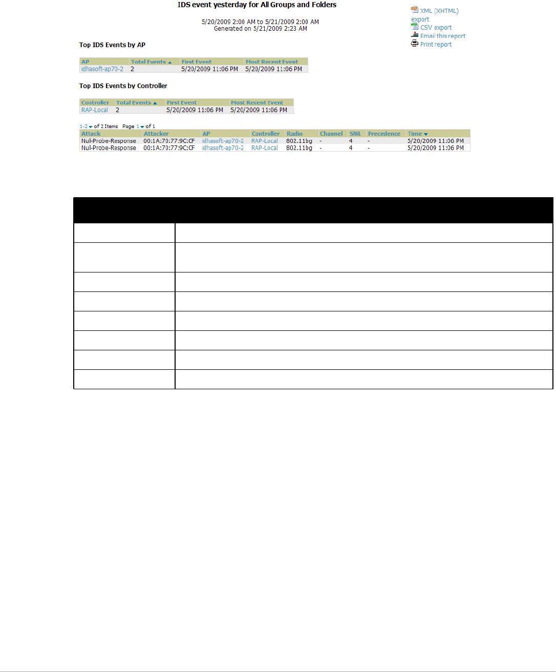
Dell PowerConnect W-AirWave 7.5 | User Guide Creating, Running, and Emailing Reports | 245
Selecting the AP device or controller name takes you to the APs/Devices > List page.
Figure 178 and Table 136 illustrate and describe the Reports > Generated > IDS Events Detail page.
Figure 178 Reports > Generated > IDS Events Report Illustration
Using the Inventory Report
The Inventory Report itemizes all devices and firmware versions on the network, to include vendor information
and graphical pie-chart summaries. The primary sections of this report are as follows:
-Vendor Summary—Lists the vendors for all devices or firmware on the network.
-Firmware Version Summary—Lists the firmware version for all firmware used on the network.
-Model Summary—Lists the model numbers for all devices or firmware on the network.
See Figure 179 for an illustration of a sample report.
Table 136 Reports > Generated > IDS Events Detail Unique Fields and Descriptions
Field Description
Attack Displays the name or label for the IDS event.
Controllers This column lists the controllers for which IDS events have occurred in the prior 24 hours, and
provides a link to the APs/Devices > Monitor page for each.
Attacker Displays the MAC address of the device that generated the IDS event.
Radio Displays the 802.11 radio type associated with the IDS event.
Channel Displays the 802.11 radio channel associated with the IDS event, when known.
SNR Displays the signal-to-noise (SNR) radio associated with the IDS event.
Precedence Displays precedence information associated with the IDS event, when known.
Time Displays the time of the IDS event.
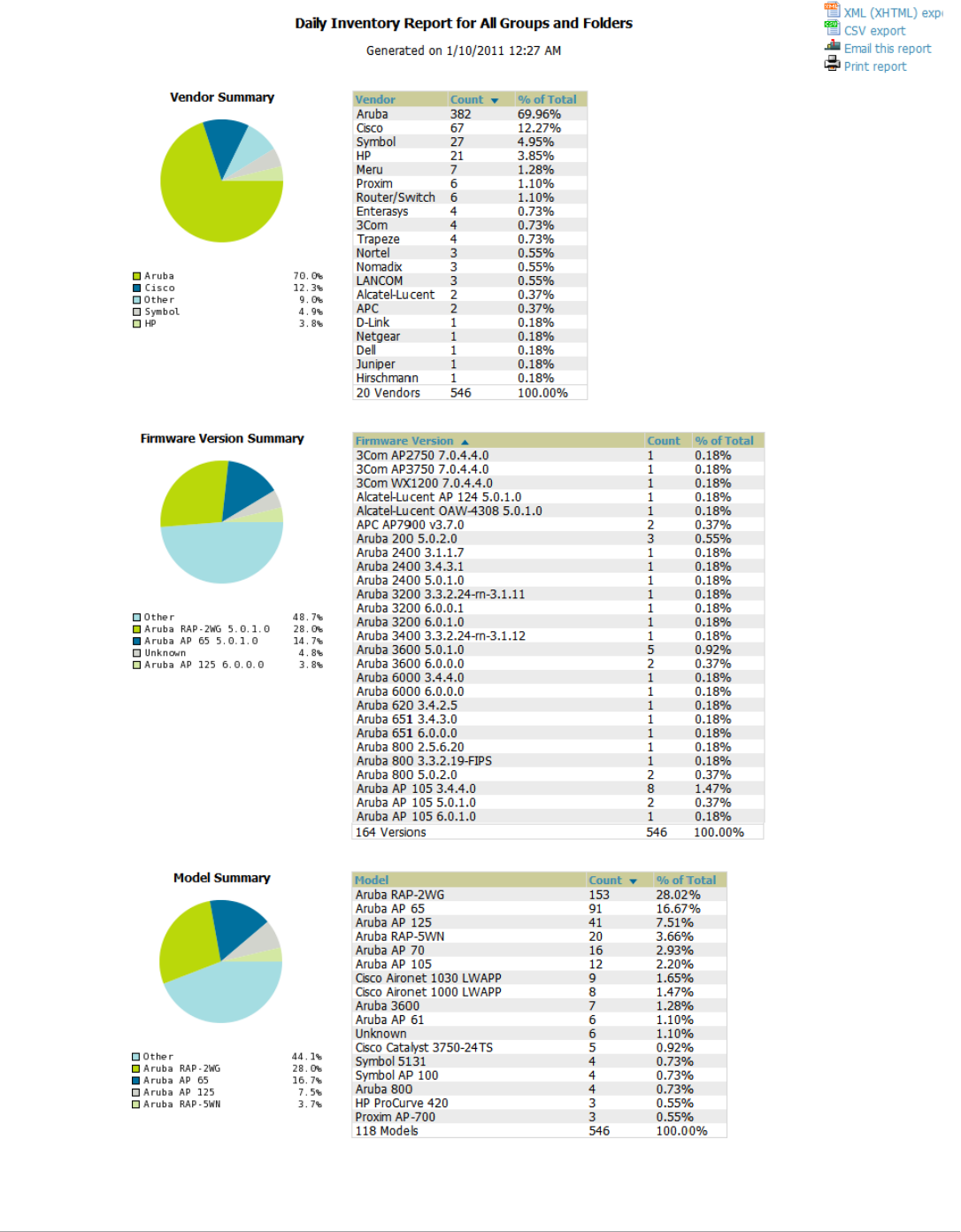
246 | Creating, Running, and Emailing Reports Dell PowerConnect W-AirWave 7.5 | User Guide
Figure 179 Reports > Generated > Inventory Report Illustration (Edited View)
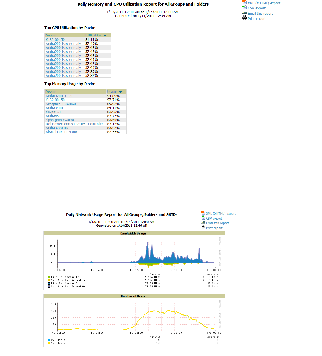
Dell PowerConnect W-AirWave 7.5 | User Guide Creating, Running, and Emailing Reports | 247
Using the Memory and CPU Utilization Report
The Memory and CPU Utilization Report displays the top memory usage by device, and CPU usage on the
network by device. Both are by percentage.
To create a scheduled and generated report of this type, refer to “Using Daily Reports” on page236.
Figure 180 illustrates the Reports > Detail page for this report.
Figure 180 Reports > Generated > Daily Memory and CPU Usage Report Illustration (Contents Rearranged for
Space)
Using the Network Usage Report
The Network Usage Report contains network-wide information in two categories:
-Bandwidth usage by device—maximum and average bandwidth in kbps
-Number of users by time period—average bandwidth in and out
Figure 181 illustrates the Reports > Detail page for the Daily Network Usage.
Figure 181 Reports > Generated > Network Usage Report Illustration

248 | Creating, Running, and Emailing Reports Dell PowerConnect W-AirWave 7.5 | User Guide
Using the New Rogue Devices Report
The New Rogue Devices Report summarizes rogue device information including the following categories of
information:
-Rogue devices by RAPIDS classification—described in “Using RAPIDS and Rogue Classification” on
page173
-Top rogue devices by number of discovering APs
-Top rogue devices by signal strength
-Graphical summary of rogue devices by LAN MAC address vendor
-Graphical summary of rogue devices by radio MAC address vendor
-Text-based table summary of rogue device counts
-Detailed and text-based table of rogue devices discovered only wirelessly with extensive device parameters and
hyperlink interoperability to additional AirWave pages
-Detailed and text-based table of all rogue devices supporting all discovery methods with extensive device
parameters and hyperlink interoperability to additional AirWave pages
-Detailed and text-based table of discovery events pertaining to the discovery of rogue devices with extensive
parameters and hyperlink interoperability to additional AirWave pages
This report is not run by default, but is available after you define it.
Refer to Figure 182 for a sample illustration of this report.
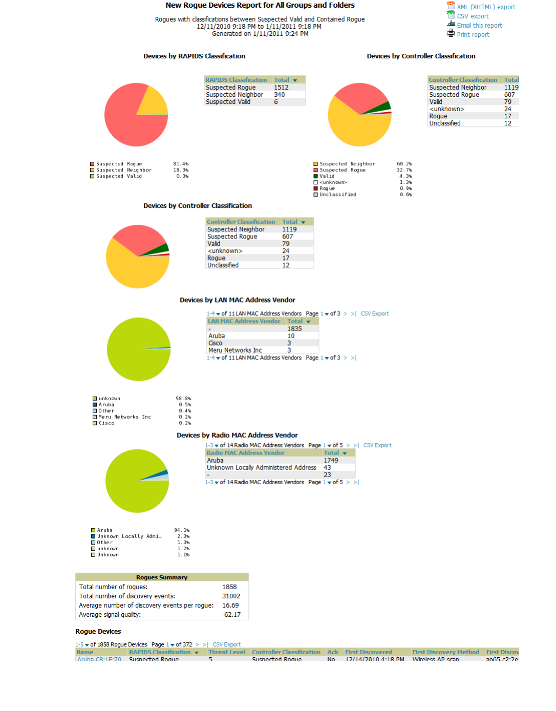

250 | Creating, Running, and Emailing Reports Dell PowerConnect W-AirWave 7.5 | User Guide
Using the New Users Report
The New Users Report lists all new users that have appeared on the network during the time duration defined for
the report. This report covers the user identifier, the associated role when known, device information and more.
The report definition can filter on connection mode (wired, wireless or both).
Figure 183 illustrates the fields and information in the New Users Report.
Table 137 New Rogue Devices Report Fields
Field Description
Name Displays the device name, as able to be determined.
RAPIDS Classification Displays the RAPIDS classification for the rogue device, as classified by rules defined on the
RAPIDS > Rules page. Refer to “Using RAPIDS and Rogue Classification” on page 173 for
additional information.
Threat Level Displays the numeric threat level by which the device has been classified, according to rules
defined on the RAPIDS > Rules page. Refer to “Using RAPIDS and Rogue Classification” on
page 173 for additional information.
Ack Displays whether the device has been acknowledged with the network.
First Discovered Displays the date and time that the rogue device was first discovered on the network.
First Discovery Method Displays the method by which the rogue device was discovered.
First Discovery Agent Displays the network device that first discovered the rogue device.
Last Discovering AP Displays the network device that most recently discovered the rogue device.
Model Displays the rogue device type when known.
Operating System Displays the operating system for the device type, when known.
IP Address Displays the IP address of the rogue device when known.
SSID Displays the SSID for the rogue device when known.
Network Type Displays the network type on which the rogue was detected, when known.
Channel Displays the wireless RF channel on which the rogue device was detected.
WEP Displays WEP encryption usage when known.
RSSI Displays Received Signal Strength (RSSI) information for radio signal strength when known.
Signal Displays signal strength when known.
LAN MAC Address Displays the MAC address for the associated LAN when known.
LAN Vendor Displays LAN vendor information associated with the rogue device, when known.
Radio MAC Address Displays the MAC address for the radio device, when known.
Radio Vendor Displays the vendor information for the radio device when known.
Port Displays the router or switch port associated with the rogue device when known.
Last Seen Displays the last time in which the rogue device was seen on the network.
Total Discovering APs Displays the total number of APs that detected the rogue device.
Total Discovery Events Displays the total number of instances in which the rogue device was discovered.
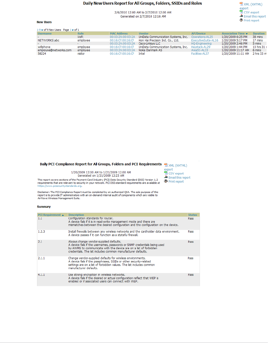
Dell PowerConnect W-AirWave 7.5 | User Guide Creating, Running, and Emailing Reports | 251
Figure 183 Reports > Generated > New Users Report Illustration
Using the PCI Compliance Report
AirWave supports PCI requirements in accordance with the Payment Card Industry (PCI) Data Security
Standard (DSS). The PCI Compliance Report displays current PCI configurations and status as enabled on the
network. Verify that AirWave is enabled to monitor compliance with PCI requirements, as described in the
“Enabling or Disabling PCI Auditing” on page64.
In addition to citing simple pass or fail status with regard to each PCI requirement, AirWave introduces very
detailed diagnostic information to recommend the specific action or actions required to achieve Pass status, when
sufficient information is available. Refer to the “Auditing PCI Compliance on the Network” on page63 for
information about enabling PCI on the network. The configurations in that section enable or disable the contents
of the PCI Compliance Report that is viewable on the Reports > Generated page.
Figure 184 illustrates the fields and information in a PCI Compliance Report.
Figure 184 Reports > Generated > PCI Compliance Report Illustration Example
Using the Port Usage Report
You can generate a wide array of port usage statistics from the Port Usage Report including each of the following:
-List of all the switches and ports in your network by folder
-List of unused ports
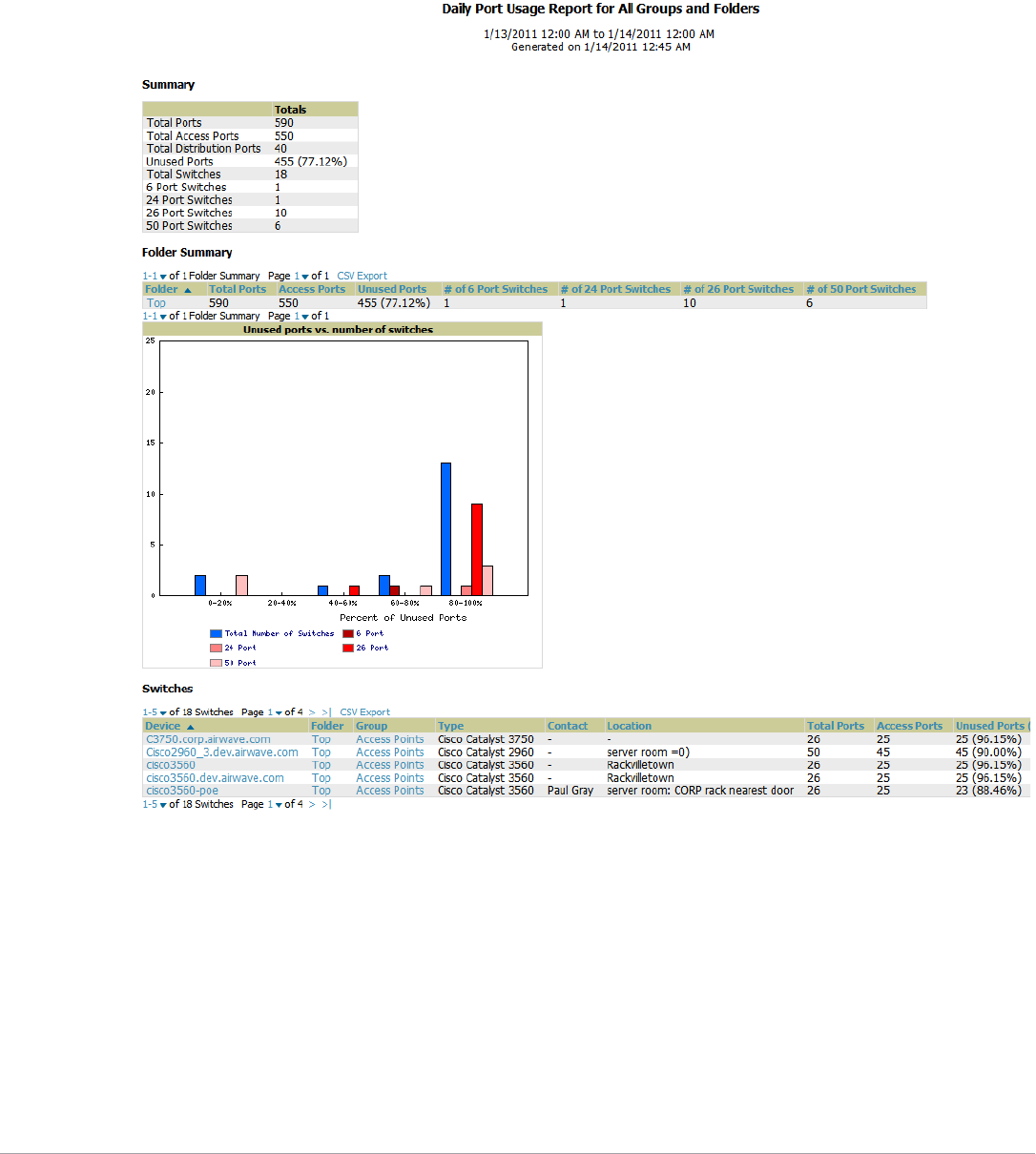
252 | Creating, Running, and Emailing Reports Dell PowerConnect W-AirWave 7.5 | User Guide
-List of access and distribution ports
-Histogram displaying unused ports vs. unused switches by type (access or distribution)
-List of most used switches
-List of most used ports
A sample of the types of information used to generate in a Port Usage Report appears in Figure 185.
Figure 185 Reports > Generated > Port Usage Report Detail Page (partial view)
Using the RADIUS Authentication Issues Report
The RADIUS Authentication Issues Report contains issues that may appear with controllers, RADIUS servers,
and users. Figure 186 illustrates the fields and information in the RADIUS Authentication Issues Report.
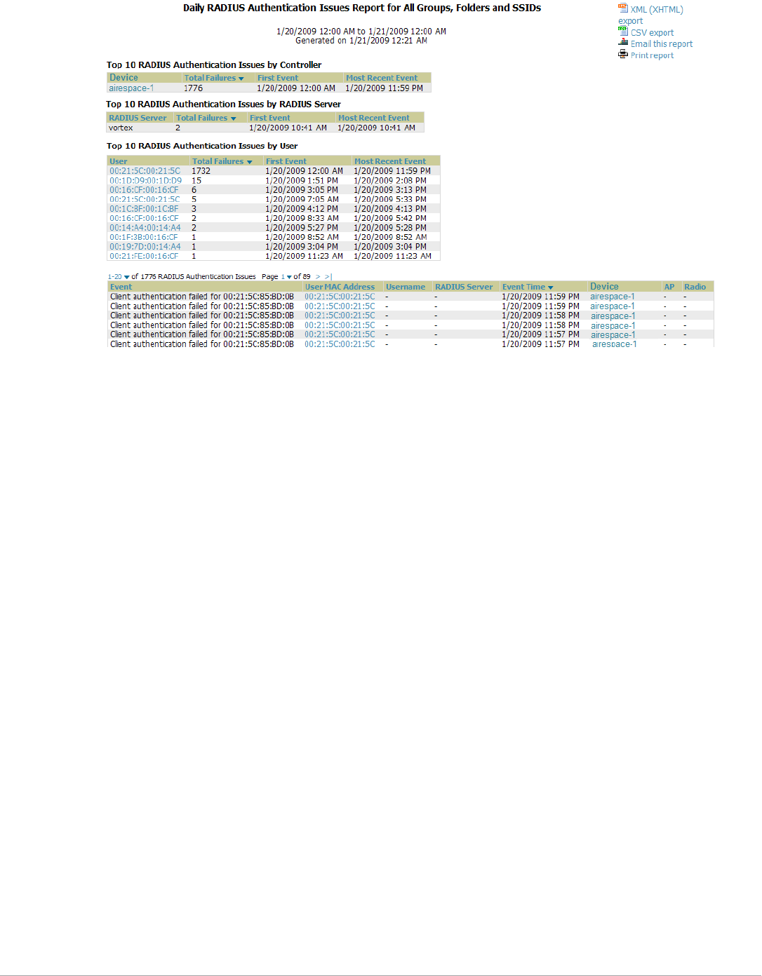
Dell PowerConnect W-AirWave 7.5 | User Guide Creating, Running, and Emailing Reports | 253
Figure 186 Reports > Generated > RADIUS Authentication Issues Detail Page Illustration
Using the RF Health Report
The RF Health Report tracks the top AP radio issues by noise, MAC/Phy errors, channel changes, transmit power
changes, mode changes, and interfering devices (the last two apply only if there are ARM events). This report
assists in pinpointing the most problematic devices on your network, and lists the top 10 devices by problem type.
Problematic APs are displayed in two separate lists Problem Radios lists, grouped by radio frequency. A device will
make it into the list if it violates two or more thresholds. (For more on the thresholds that indicate problems,
refer to “Evaluating Radio Statistics for an AP” on page126.)
Other lists grouped by radio frequency include Most Noise, Most/Least Utilized by Channel Usage, Most MAC/
Phy Errors, Most Channel Changes, Most Transmit Power Changes.
If an RF Health Report has not been generated before, you can create it by following the instructions on the
Defining Reports section of this chapter.
Figure 187 illustrates a sample RF Health Report.
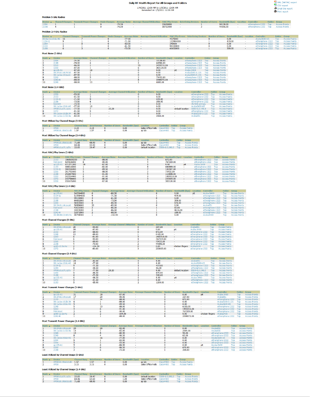
254 | Creating, Running, and Emailing Reports Dell PowerConnect W-AirWave 7.5 | User Guide
Figure 187 Reports > Detail > Daily RF Health Report Page Illustration
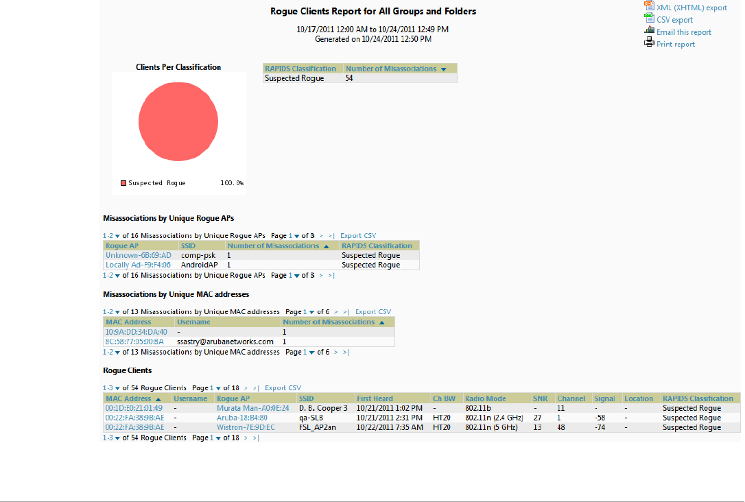
Dell PowerConnect W-AirWave 7.5 | User Guide Creating, Running, and Emailing Reports | 255
All tables in RF Health indicate the rank, device type, number of users, bandwidth, location, controller, folder,
and group, and all are sorted according to rank. Selecting a value under the Device column in any table will take
you to the APs/Devices > Monitor > Radio Statistics page for the band indicated in the table title (5 GHz or 2.4
GHz).
-Every list contains Rank, Device (name, not type), Channel Changes, Average Noise, Average Channel
Utilization, Clients, Usage, Location, Controller name, Speed, Goodput, Folder, and Group.
-The third column in the list (after Device) will be the column the list is sorted by.
-If that column would otherwise be in the list (Channel Changes), it does not show up in the list where it
would otherwise.
-Note that sometimes the sorted column is not one of those common ones, such as the Interfering Devices
section.
AirWave limits data storage to 183 days (approximately six months) per radio. If you create an RF Health Report
with a date range longer than 183 days, it will only include Channel Changes, Transmit Power Changes, Average
Utilization, Mac/Phy Errors and Average Noise based on whatever part of the report intersects the last 183 days.
This differs from most reports because other data (like bandwidth and users) maxes out at 425 days, and AirWave
validates reports so you can only run them over a 366-day duration.
Using the Rogue Clients Report
The Rogue Clients report tracks the number of valid users that connected to rogues in the specified time frame,
and can be filtered by rogue classification. Ad-hoc devices can be included, and specific details that should be
included about the clients can be selected.
By default, the minimum RAPIDS classification is Suspected Rogue, and the maximum is Contained Rogue.
Figure 188 Reports > Detail > Rogue Clients Report Page Illustration
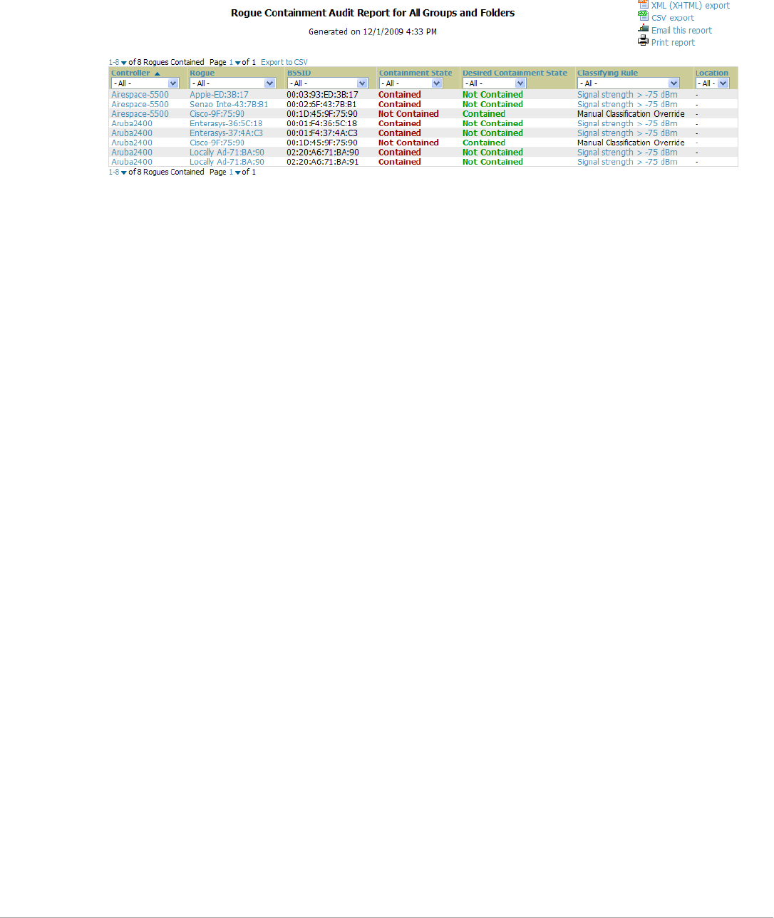
256 | Creating, Running, and Emailing Reports Dell PowerConnect W-AirWave 7.5 | User Guide
Using the Rogue Containment Audit Report
The rogue containment audit report that lets you know if any containment is failing. Figure 189 illustrates the
fields and information in this report type.
Figure 189 Reports > Detail > Rogue Containment Audit Report Page Illustration
Using the Client Session Report
The Client Session Report extensively itemizes user-level activity by session- any instance in which a user
connects to the network. In list and chart form, this report tracks and display session information that can include
any or all of the following:
-Session Data by OS (List or Chart)
-Session Data by OS Detail (List or Chart)
-Session Data by Model (List or Chart)
-Session Data by Manufacturer (List or Chart)
-Session Data by Device Type (List or Chart)
-Session Data by AOS Device Type (List or Chart)
-Session Data by Network Interface Vendor (List or Chart)
-Session Data by Network Chipset (List or Chart)
-Session Data by Network Driver (List or Chart)
-Session Data by EAP Supplicant (List or Chart)
-Session Data by Asset Group (List or Chart)
-Session Data by Asset Category (List or Chart)
-Session Data by Connection Mode (List or Chart)
-Session Data by SSID (List or Chart)
-Session Data by Role (List or Chart)
-Session Data by VLAN (List or Chart)
-Session Data by Cipher (List or Chart)
-Summary
-Sessions
-Session Data By Client
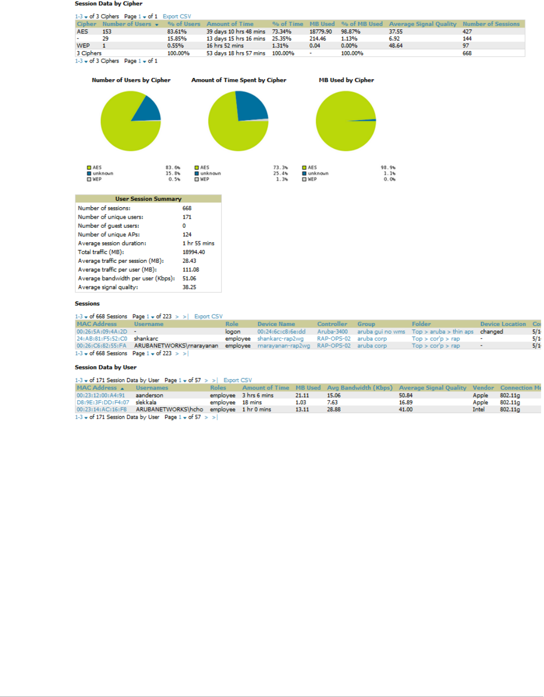
Dell PowerConnect W-AirWave 7.5 | User Guide Creating, Running, and Emailing Reports | 257
Figure 190 Client Session Detail, Partial View
Defining Reports
You can create reports in AirWave for any time period you wish, to be run when you wish, and distributed to
recipients that you define. Perform these steps to create and run custom reports. Reports created with the
Reports > Definition page appear on this and on the Reports > Generated page once defined.
1. To create or edit a report, browse to the Reports > Definition page and select the Add button, or select the
pencil icon to edit an existing report definition. Figure 191 illustrates one view of the Reports > Definition
page.
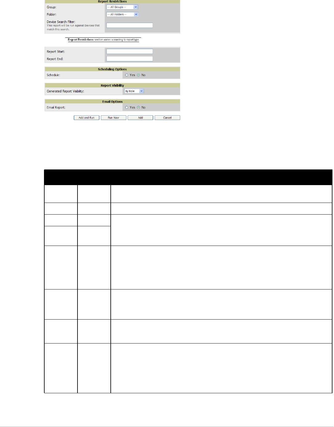
258 | Creating, Running, and Emailing Reports Dell PowerConnect W-AirWave 7.5 | User Guide
Figure 191 Defining a Report with Reports > Definitions > Add Button
2. Complete the fields described in Table 138 and any additional Report Restrictions. The Report Restrictions
section changes according to the report type you choose. Additional information about each report type is
described in “Using Daily Reports” on page236.
Table 138 Reports > Definitions > Add Page Fields
Field Default Description
Title Empty Enter a Report Title. Use a title that is a meaningful and descriptive, so it may be found easily on the
lists of reports that appear on either Generated or Definitions pages.
Type Capacity Choose the type of report you wish to create in the Report Type drop-down menu.
Group All Groups Specify the groups and folders to be covered in the report by choosing All Groups (or All Folders)
or specifying Use selected groups (or Use selected folders) in the drop-down menu.
If Use selected groups is chosen, a menu with checkboxes appears, allowing you to choose the
groups to include in the report.
Folder All Folders
Device
Search Filter
Blank Add a specific alpha numeric string for finding devices that match that which you entered. Note
that once you enter a search string, new or deleted devices that match the search string will
automatically be included or excluded in all future reports generated until you delete or change the
search string.
For certain reports, such as New User and Client Session, will allow you to search devices
associated with a specific user or device.
Filter by
device type
All Device
Types
Filter this report by device type. By selecting the second option - Use selected device types - you
can select the checkboxes next to the specific device types you want to filter on: Access Points
(such as campus APs remote APs, and different types of Mesh APs), Controllers (Master, Local,
Standby, and Virtual), Switches & Routers, and Universal & Custom Devices.
SSID All SSIDs This field displays for most report types. When this field appears, and when you select Use
Selected IDs, a new list of SSIDs displays. Check (select) the specific SSIDs to be included in the
report.
Report Start
Report End
Blank These fields establish the time period to be covered by the report. These fields are supported for
most report types. When these fields do not appear, the report provides a snapshot of current
status rather than information covering a period of time
Times can be entered in relative or absolute form. A start date of 6 months 3 weeks 5 days 9 hours
ago and an end time of 4 months 2 weeks 1 day ago is valid, as is a start date of 5/5/2008 13:00 and
an end date of 6/6/2008 9:00. Absolute times must be entered in a 24-hour format. Other reports, like
the Inventory Report, give a snapshot picture of the AirWave at the present time.
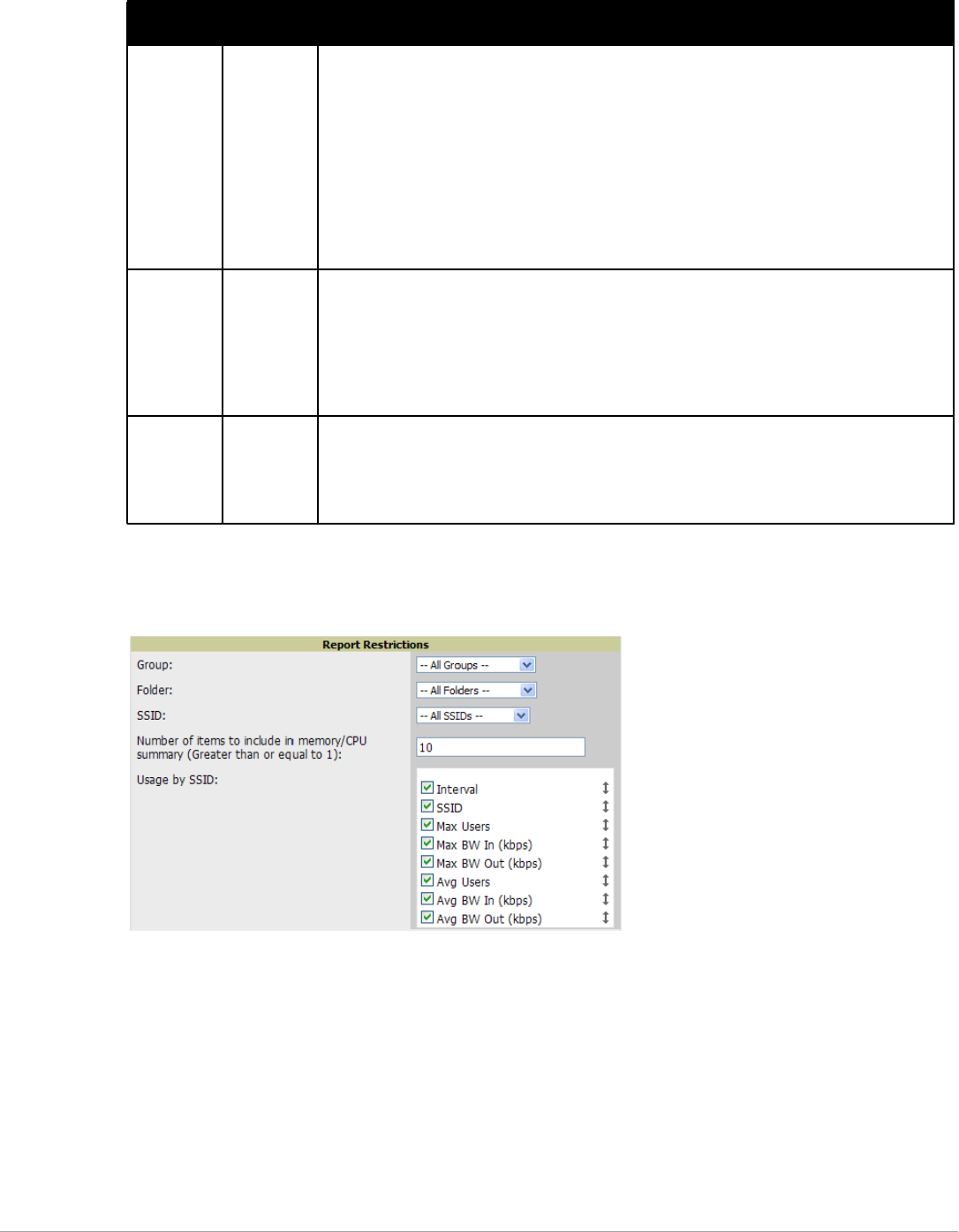
Dell PowerConnect W-AirWave 7.5 | User Guide Creating, Running, and Emailing Reports | 259
In the report restrictions section you can customize any detailed information contained in a chosen report. Figure
192 shows a sample Report Restrictions page.
Figure 192 Report Restrictions Illustration
By default all data will be included. Deselect the checkbox to hide specific information. The list can also be
reordered by dragging and dropping the separate lines. The order displayed here will match the column order in
the report.
3. Do one of the following:
-Select Add and Run to generate the report immediately, in addition to saving report settings.
-Select Run Now to generate the report immediately without creating a new report definition or saving the
report settings.
-Select Add (only) to complete the report creation, to be run at the time scheduled.
-Select Cancel to exit from the Add page.
Schedule No When you select Yes, new fields display that allow you to define a specific time for report creation.
The report schedule setting is distinct from the Report Start and Report End fields, as these define
the period of time to be covered by the report.
These Schedule fields establish the time that a report runs, independent of report scope:
-Current Local Time—Displays for reference the time of the AirWave system.
-Desired Start Date/Time—Sets the time the report runs, which may often be separate from the
time period covered by the report. This allows you to run a report during less busy hours.
-Occurs—Select whether the report is to be run one time, daily, weekly, monthly, or annually.
Depending on the recurrence pattern selected, you get an additional drop-down menu. For
example, if you select a recurrence of monthly, you get an additional drop-down menu that
allows you to pick which day of the month (day 1, day 2, and so forth) the report should run.
Generated
Report
Visibility
By Role This field allows you to display the report either by user role (with the report appearing in User Role
lists on the Reports > Generated page) or by Subject (displaying reports by Subject on the Reports
> Generated page).
-By Role: When you create a report definition, the reports are visible to everybody who has the
same role as you (ie AirWave Administrator), and to nobody else.
-By Subject: When the report is run, AirWave users have access to the report if they are
allowed to view all the devices in the report.
Email Report No Select Yes to display sender and recipient fields. Enter a valid Sender Address where marked to
indicate the address that appears in the From field of the emailed report. Enter a valid recipient
email addresses, separated by commas when using multiple email addresses.
NOTE: AirWave will not attempt to email a report with an excessively large number of rows in the
detail section.
Table 138 Reports > Definitions > Add Page Fields (Continued)
Field Default Description

260 | Creating, Running, and Emailing Reports Dell PowerConnect W-AirWave 7.5 | User Guide
Table 139 describes the configurable settings for the custom report to be created. Select any of the report names
to view additional information on that report type.
Table 139 Report Types and Scheduling Options Supported for Custom Reports
Report Type Can by Run by
Time Period
Can be Run by
Group/Folder Description
Using Custom
Reports
Yes Yes Summarizes devices based on which have exceeded a
defined percentage of their maximum bandwidth capacity.
Pulls data for AP radios or interfaces of universal devices
(ifSpeed value).
Using the Capacity
Planning Report
Yes Yes Tracks bandwidth capacity and consumption according to
thresholds for data throughput. This is a device-oriented
report.
Using the
Configuration Audit
Report
No Yes Provides a snapshot of the configuration of all specified
access points in AirWave, at report run time.
Using the Device
Summary Report
Yes Yes Summarizes user and bandwidth statistics and lists devices in
AirWave.
Using the Device
Uptime Report
Yes Yes Summarizes device uptime within defined groups or folders.
Using the IDS Events
Report
Yes Yes Summarizes IDS events; can be limited to a summary of a
certain number of events.
Using the Inventory
Report
No Yes Provides an audit of vendors, models and firmware versions
of devices in AirWave.
Using the Memory
and CPU Utilization
Report
Yes Yes Summarizes usage for controllers for defined top number of
devices; can be run with or without per-CPU details and
details about device memory usage.
Using the Network
Usage Report
Yes Yes Summarizes bandwidth data and number of users.
Using the New
Rogue Devices
Report
Yes No Shows new rogue devices by score, discovering AP, and MAC
address vendor.
Using the New
Users Report
Yes No Provides a summary list of new users, including username,
role, MAC address, discovering AP, and association time.
Using the PCI
Compliance Report
Yes Yes Provides a summary of network compliance with PCI
requirements, according to the PCI requirements enabled in
AirWave using the AMP Setup > PCI Compliance page.
Using the Port
Usage Report
Yes Yes Summarizes switch and port information across the network.
Generates information on the unused ports. Provides a
detailed list of all available switches and ports in the network.
Using the RADIUS
Authentication
Issues Report
Yes Yes Summarizes RADIUS authentication issues by controller and
by user, as well as a list of all issues.
Using the RF Health
Report
Yes Yes Tracks problematic radios, changes, errors, and interfering
devices.
Using the RF Health
Report
No Yes Identifies discrepancies between access point containment
status specified in AirWave compared to containment status
identified by the controller at report run time.

Dell PowerConnect W-AirWave 7.5 | User Guide Creating, Running, and Emailing Reports | 261
Emailing and Exporting Reports
This section describes three ways in which distribute reports from AirWave:
-Emailing Reports in General Email Applications
-Emailing Reports to Smarthost
-Exporting Reports to XML or CSV
Emailing Reports in General Email Applications
Perform these steps to set up email distribution of reports in AirWave:
-All reports contain a link to export the report to an XML file and a text box where you may specify email
addresses, separated by commas, to which reports are sent.
-Select Email This Report to email the report to the address specified in the text box above the button.
Additional information about email-based report generation is described in “Defining Reports” on page257, and
in “Emailing Reports to Smarthost” on page261.
Emailing Reports to Smarthost
AirWave uses Postfix to deliver alerts and reports via email, because it provides a high level of security and locally
queues email until delivery. If AirWave sits behind a firewall, which prevents it from sending email directly to the
specified recipient, use the following procedure to forward email to a smarthost.
1. Add the following line to /etc/postfix/main.cf:
relayhost = [mail.example.com]
Where: mail.example.com is the IP address or hostname of your smarthost.
2. Run service postfix restart
3. Send a test message to an email address.
Mail -v xxx@xxx.com
Subject: test mail
.
CC:
4. Press Enter.
5. Check the mail log to ensure mail was sent by running this command:
tail -f /var/log/maillog
Exporting Reports to XML or CSV
AirWave allows you to export individual reports in XML (xhtml) or CSV. You can also export all reports at once
and a zip file will be generated with all of the files in CSV format included. These files may be read by an HTML
browser or opened in Excel. The CSV files can be opened in any text editor.
Using the Client
Session Report
Yes Yes Summarizes user data by radio mode, SSID and VLAN, as well
as lists all sessions.
Table 139 Report Types and Scheduling Options Supported for Custom Reports (Continued)
Report Type Can by Run by
Time Period
Can be Run by
Group/Folder Description
NOTE: This method of exporting files supports graphics and links, and prevents Missing File C:\filename.css error messages.

262 | Creating, Running, and Emailing Reports Dell PowerConnect W-AirWave 7.5 | User Guide
Transferring Reports Using FTP
Once reports are generated, you can also copy them to any ftp accessible destination using a sample script. For
more information, contact Dell support at support.dell.com.
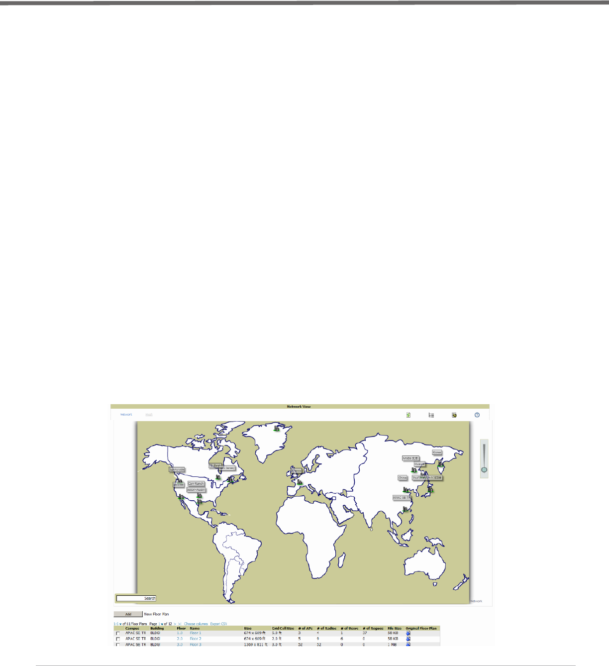
Dell PowerConnect W-AirWave 7.5 | User Guide Using VisualRF | 263
Chapter 10
Using VisualRF
This chapter contains information about VisualRF, and includes the following topics:
-“Features” on page264
-“Useful Terms” on page264
-“Starting VisualRF” on page265
-“Basic QuickView Navigation” on page265
-“Using the Settings in the VisualRF > Setup Page” on page270
-“Configuring QuickView Personal Preferences” on page275
-“Increasing Location Accuracy” on page279
-“Using QuickView to Assess RF Environments” on page288
-“Planning and Provisioning” on page292
-“Importing and Exporting in VisualRF” on page303
-“VisualRF Location APIs” on page306
-“About VisualRF Plan” on page307
The VisualRF module provides a real-time picture of the actual radio environment of your wireless network and
the ability to plan the wireless coverage of new sites. To understand what is happening on your wireless network,
you need to know where your users and devices are located, and you need to monitor the RF environment in
those areas. VisualRF puts this information at your fingertips through integrated mapping and location data.
VisualRF uses sophisticated RF fingerprinting to accurately display coverage patterns and calculate the location
of every wireless device in range. Moreover, VisualRF does not require dedicated RF sensors or a costly additional
location appliance - all the necessary information is gathered from your existing wireless access points and
controllers.
Figure 193 Example VisualRF Page Showing all networks

264 | Using VisualRF Dell PowerConnect W-AirWave 7.5 | User Guide
Features
-Mesh monitoring page specially for viewing Dell AirMesh devices. VisualRF automatically renders Mesh APs
based on GPS coordinates.
-Floor plan upload wizard enables direct importation of JPEG, GIF, PNG, PDF (single page only) and CAD
files for floor plans. NOTE: PDF floor plans must be generated from a source file. Other PDFs, such as those
scanned from a printer, will not import properly. Similarly, CAD files must be generated by AutoCAD.
-Batch upload wizard enables batch uploads of multiple CAD files with corresponding walls, and access points.
-Accurate calculation of the location of all client devices (laptops, RFID Tags, PDAs, Phones) using RF data
from your existing APs and controllers. Increased accuracy of device placement can be achieved with periodic
site surveys.
-Graphical navigation allows your Help Desk to view floor plans simply by clicking on the appropriate campus,
building, or floor.
-Tree view allows you to navigate to a specific campus, building, or floor via a tree navigation.
-Heatmaps depict the strength of RF coverage in each location.
-Speed (data rate) view which depicts the highest possible speed at every location on a floor plan.
-Built into AirWave for onscreen display of alerts and error conditions. For instance, an AP icon will display in
red when a critical alert is active or when usage conditions exceed pre-defined thresholds.
-Location playback viewer which allows visual tracking of up to 24 hours of location history.
-Dynamically recalculates path loss and device locations based on real-time data from your wireless LAN, for
increased location accuracy.
-Calibrates RF data from multiple vendors’ APs (and across different product lines from the same vendor) for
accurate display even in multi-vendor and multi-architecture environments. Refer to the Supported
Infrastructure Devices document for a list of vendors and supported devices.
-Full planning capabilities based on speed or signal requirements.
Useful Terms
-AP-to-AP Signal (Neighbor) - Some APs/Controllers have the ability to report the signal strength of APs that
they hear. AirWave uses these signal strength readings to dynamically attenuate floor plans to increase the
accuracy of client locations and heat maps.
-Client Surveys - Client surveys within VisualRF use access points to understand which clients they hear and
at what signal strength.
-dB (Decibels) - difference/ratio between two signal levels.
-dBm - dB as compared to 1 mW. It is a logarithmic measurement (integer) which is typically used in place of
mW to represent receive-power level. AirWave normalizes all signals to dBm, so it is easy to evaluate
performance between various vendors.
-mW - 1/1000 of a Watt. It is a linear measurement (always positive) generally used to represent transmission.
-QuickView - Flash front end for VisualRF, which displays information generated by the back-end service.
-Rogue Surveys - Rogue surveys are facilitated by AMC, VisualRF and the client's radio to understand which
access points they hear and what signal strength.
-RSSI (Received Signal Strength Indicator) - IEEE defines RSSI is a mechanism by which RF energy is to be
measured by the circuitry on a wireless NIC (0-255). RSSI is not standard across vendors. Each vendor
determines their own RSSI scale/values.
-Unassociated Client Information - Some APs/Controllers have the ability to report the signal strength of
visible clients that are associated to a radio on a neighboring AP. AirWave also uses these signal strength
readings to more accurately place these unassociated clients.
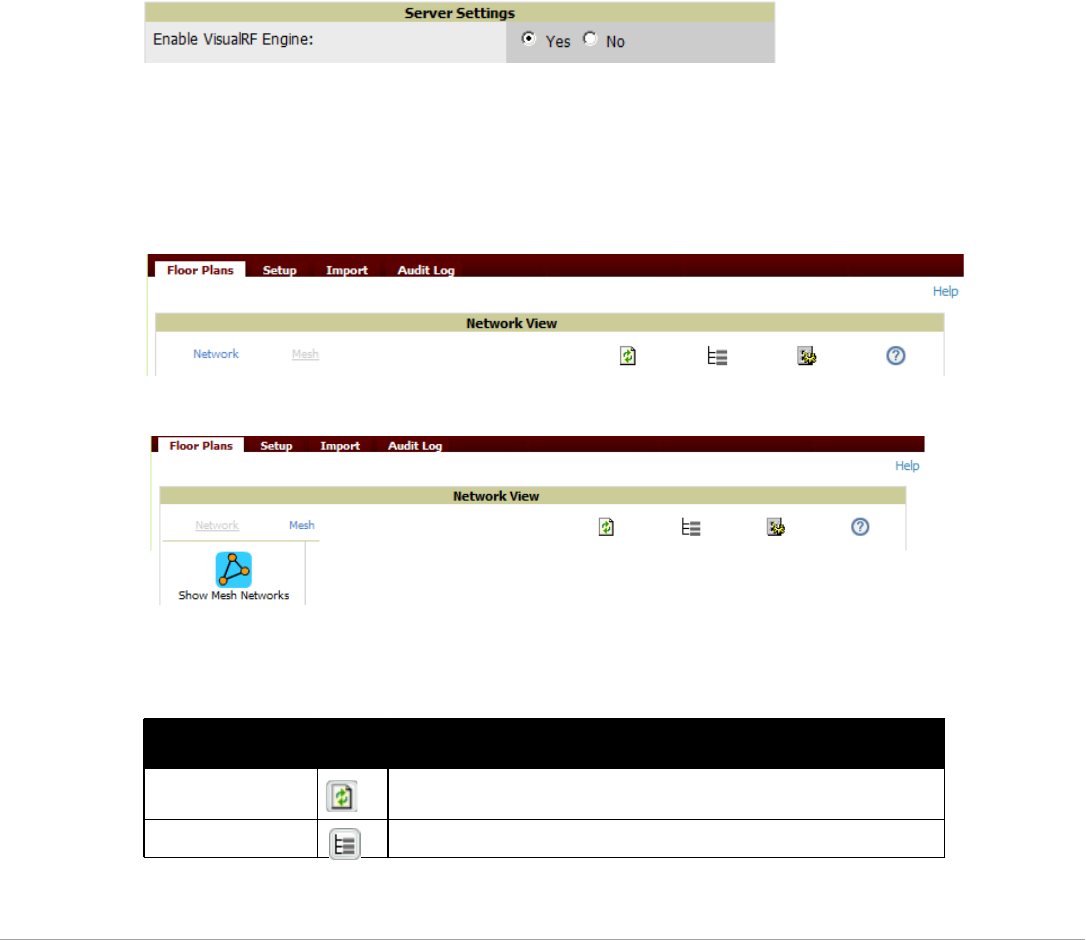
Dell PowerConnect W-AirWave 7.5 | User Guide Using VisualRF | 265
-VisualRF - The AirWave service that calculates location, calculates path loss, and provides floor plan editing
capabilities.
-VisualRF Plan - Makes the planning portions of VisualRF available in an offline software package that does
not require a server. For more information about VisualRF Plan, see “About VisualRF Plan” on page307.
Starting VisualRF
In order to launch VisualRF, AMP Setup must specify to display the VisualRF tab, and the VisualRF engine must
be switched on in VisualRF > Setup. Both of these pages are visible to logged-in administrators only. By default:
-Display VisualRF is enabled in AMP Setup > General.
-Enable VisualRF Engine is disabled in VisualRF > Setup.
To enable VisualRF, follow these instructions while logged in as an administrator:
1. Navigate to VisualRF > Setup.
2. In the Server Settings section, select Yes in the Enable VisualRF Engine field. Then select Save.
Figure 194 VisualRF > Setup > Server Settings Section
Basic QuickView Navigation
The top-level menus of VisualRF are split into two major categories: Network and Mesh, as shown in Figure 195
and Figure 196. Selecting these menus will cause relevant submenus and sections to display below:
Figure 195 Default VisualRF Top Level Menu - Network View
Figure 196 Default VisualRF Top Level Menu - Mesh View
Table 140 describes the top level icons and their functions on VisualRF.
Table 140 Top Level Icons and Descriptions
Operation Icon Description
Refresh Refresh the floor plan to see changes.
Open Site Tree Display the Network Tree View Window on top of the floor plan.
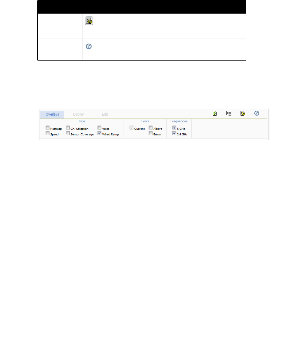
266 | Using VisualRF Dell PowerConnect W-AirWave 7.5 | User Guide
Network View Navigation
When viewing a floor plan in Network View, the top-level menu changes to Overlays, Display, and Edit toggles.
Overlays
Figure 197 Overlays Menu
The Overlays menu contains three common sections: Type, Floors, and Frequencies. Selecting options in the
Type section will display additional menu sections that affect the data overlays on the floor plan you are viewing.
These additional options appear between the Type and Floors sections.
Type section
Select one of the following types:
-Heatmap - Evaluate coverage based on signal levels by providing the highest dBm (energy level) for all areas of
a floor plan. When this option is selected, the Signal Cutoff drop-down menu displays. From this drop-down,
you can select a common cutoff value or you can specify a custom value.
-Speed - Evaluate coverage based on transmit power of client by providing the highest data rate a user will
receive for all areas of a floor plan. When this option is selected, the Client Transmit Power drop-down menu
displays. Use this drop-down to select a transmit power value for the overlay. Additionally, a Rates section
appears enabling you to select either 54Mbps, 300Mbps, and 450Mbps.
-Ch. Utilization - View how much airtime is used in the environment. Airtime usage is a good measure of how
busy an area is. When you select this option, a new Data Set menu appears where you can select the Current
or Maximum Total, Receive, Transmit, or Interference information to display on the floor plan.
-Sensor Coverage - Provides the farthest area which a sensor can hear. When this option is selected, the Client
Transmit Power drop-down menu displays. Use this drop-down to select a transmit power value for the
overlay.
-Voice - Provides color-coded overlay based on number of radios covering each grid cell based on the selected
signal cutoff. When this option is selected, the Signal Cutoff drop-down menu displays. From this drop-
down, you can select a common cutoff value or you can specify a custom value.
-Wired Range - Displays the distance an Ethernet cable can be pulled from an IDF. The max range is equal to
300 feet minus 5 percent minus 1.1x the floor height.
Floors section
The Floors section shows the overlay information for adjacent floors to determine how the bleed through from
adjacent floors affects the viewed floor. Select all options to see all floors, or one or more of the following options:
Preferences Configure personal viewing preferences. The Preferences menu allows you
to configure user preferences (overlay types, grid lines, alerts, icon sizes).
See “Configuring QuickView Personal Preferences” on page 275 for more
details.
Help Launch the online help.
NOTE: This User Guide currently contains the most up-to-date help
information for the VisualRF interface.
Table 140 Top Level Icons and Descriptions (Continued)
Operation Icon Description
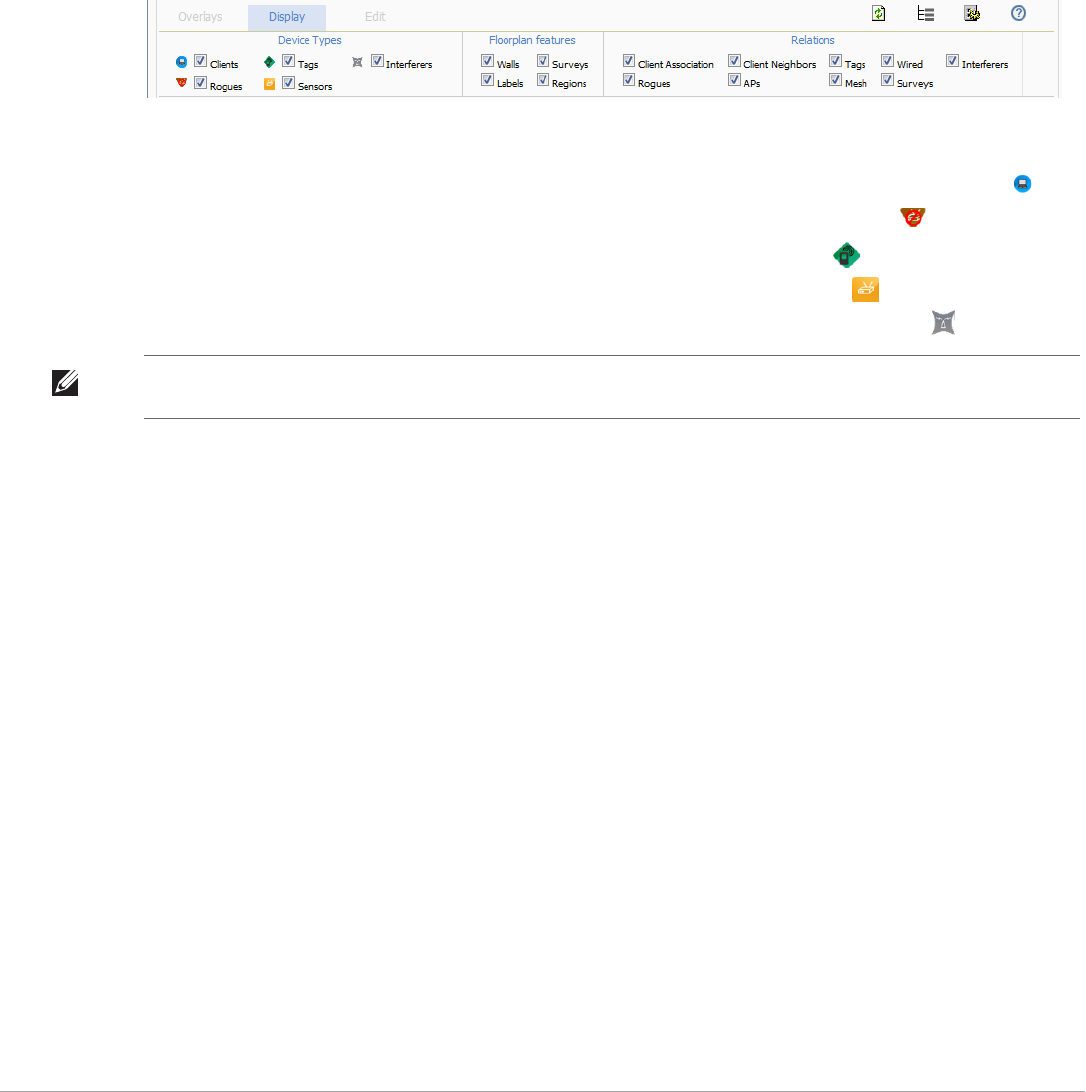
Dell PowerConnect W-AirWave 7.5 | User Guide Using VisualRF | 267
-Above - show the data from APs located on the floor above
-Current (default)
-Below - show the data from APs located on the floor below
Frequencies section
Select the desired frequency from the following options:
-5 GHz (lines are always green)
-2.4 GHz (lines are always blue)
Display Menu
Figure 198 Display Menu
Device Types section
-Clients - Turns the display of wireless users on or off. Clients on the floor plan are indicated by the icon.
-Rogues - Toggle rogue devices on or off. Rogues on the floor plan are indicated by the icon.
-Tags - Toggle WiFi Tags on or off. Tags on the floor plan are indicated by the icon.
-Sensors - Toggle sensors on or off. Sensors on the floor plan are indicated by the icon.
-Interferers - Toggle interferers on or off. Interferers on the floor plan are indicated by the icon.
Floorplan Features section
-Walls - Toggle walls on or off.
-Labels - Toggle labels on or off.
-Regions - Toggle regions on or off.
-Surveys - Toggle surveys on or off.
Relations section
-Client Association - Toggle line between the wireless client and AP of association.
-Rogues - Toggle lines between rogue APs and radios which hear the AP.
-Client Neighbors - Toggle lines between client and radios that hear the client excluding the radio of
association.
-APs - Toggle lines between APs which heard each other.
-Tags - Toggle lines between WiFi Tags and radios which hear the Tags. For Tags there is no radio of
association.
-Wired - Toggle lines between APs/sensors and their IDF.
-Mesh - Toggle lines between Mesh portals and nodes.
-Surveys - Toggle lines between client (x,y) to APs by client during survey.
-Interferers - Toggle lines between interferers and the radios that have discovered them. For interferers, there
is no radio of association.
NOTE: Interferer indicators works for AOS customers running 6.1 or newer that have run the mgmt-server type AirWave
command, and have APs performing Spectrum analysis through hybrid scanning or dedicated spectrum monitors.

268 | Using VisualRF Dell PowerConnect W-AirWave 7.5 | User Guide
Edit Menu
Figure 199 Edit Menu Options
Options in the Edit menu allow you to add information to the floor plan. Table 141 explains the options in the
Edit menu:
Figure 200 shows additional navigation controls when viewing floor plans. In the bottom left corner of the
window is the Search box. In the top right corner is the zoom control. You can also zoom by using Ctrl + your
mouse wheel as well as the + and - keys. In the bottom right corner are navigation tools related to network,
campus, and building.
Table 141 Edit Icons and Descriptions
Operation Description
Edit Locked/Unlocked Specifies whether to lock or unlock a floor plan for editing.
Draw Walls Add walls onto a floor plan. Refer to “Adding Exterior Walls” on page 280.
Draw Region Add a region onto a floor plan. Click once to begin drawing a region, and double click (or Ctrl+click)
when you are finished drawing. Specify a Region Type for the new region. Region types include
Location Testing, Planning, Wiring Closet, and Location Probability. Refer to “Adding Regions” on
page 282 for more information on adding regions.
Resize Update the scale of the floor plan to properly reflect the accurate dimensions of the floor plan.
Building Orientation For customers who leverage external APIs, this option enables you to retrieve device location using
longitude and latitude coordinates for two GPS points rather than (x,y) coordinates relative to the floor
plan image.
NOTE: This option can be ignored for customers who do not leverage the external APIs.
Set Origin Set a single origination point per floor. The origination point is used for multi-floor buildings so that
VisualRF knows how to vertically align multiple floor plans. This is especially useful in multi-floor
buildings for ensuring that multi-floor heatmaps display properly.
A best practice is to select a common location that is identifiable on all floors, such as the corner of the
building, a stairwell, elevator shaft, etc., and then place the orientation icon in the same location on all
floor plans in the building. Then, for example, if you crop out more white space on the first floor (for a
lobby, for example), VisualRF will have enough information to adjust and ensure that the floors are not
misaligned.
Add Deployed Device Provision APs onto a floor plan (APs monitored by AirWave).
Add Planned Device Manually plan APs onto a floor plan (APs not monitored by AirWave).
Delete Planned
Devices/Delete
Deployed Device
Remove all specified devices on a floor plan.
Delete Surveys Remove all surveys (rogue and client) on floor plan.
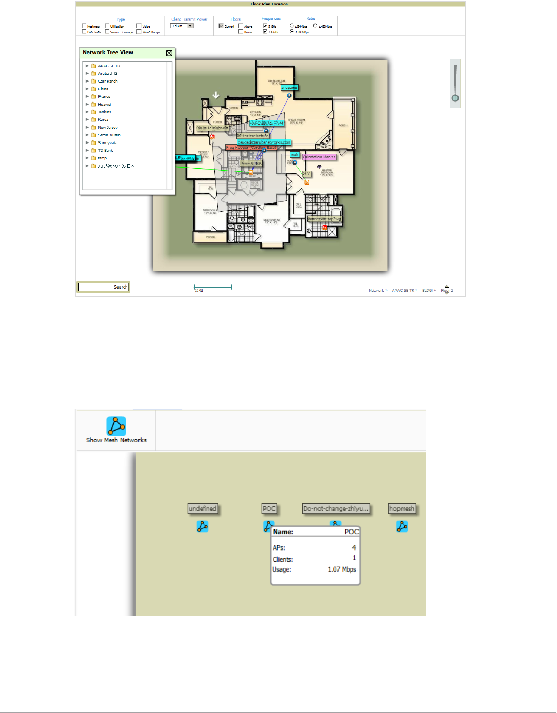
Dell PowerConnect W-AirWave 7.5 | User Guide Using VisualRF | 269
Figure 200 On-Screen Navigation Options
Mesh View Navigation
Mesh view provides a visual Mesh monitoring page specially for viewing DellAirMesh devices. It automatically
renders Mesh APs based on GPS coordinates.
Figure 201 displays an example of a Mesh Network view with a mouseover above a network icon:
Figure 201 Viewing Mesh Networks in VisualRF
You can mouse over each mesh network icon to view the number of APs, Clients, and the Usage.
Clicking on an AirMesh network will display the APs with labels:
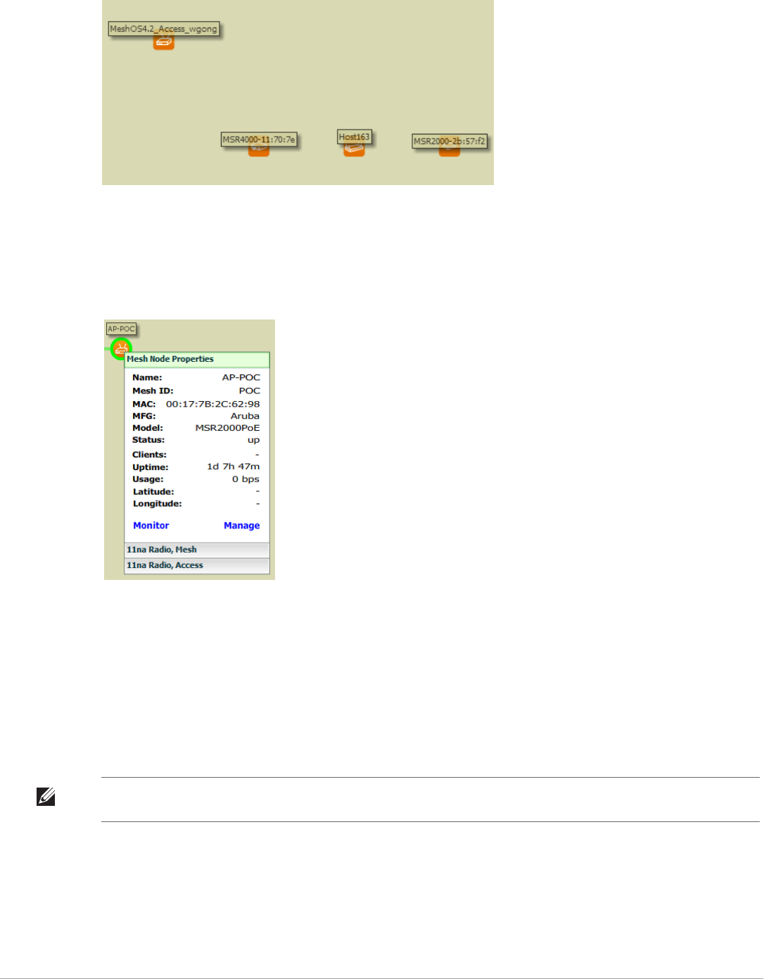
270 | Using VisualRF Dell PowerConnect W-AirWave 7.5 | User Guide
Figure 202 APs in a mesh network
Select an AirMesh’s AP icon to bring up the popup menu showing the Mesh Node Properties by default. This
window shows the node’s name, MeshID, MAC, Manufacturer, and other information. Clicking the blue
Monitor link inside this window opens the APs/Devices > Monitor page in a new tab. Clicking the blue Manage
link inside this window opens the APs/Devices > Manage page for this AP in a new tab.
Figure 203 Properties for a Mesh Gateway Illustration
For radio-level status information on an AirMesh device in your network, select the menus in the AP’s popup
window for each radio (11na Radio, Access; 11na Radio, Mesh; and so forth).
Using the Settings in the VisualRF > Setup Page
The VisualRF > Setup page, illustrated in Figure 204, configures advanced settings for VisualRF. Please
reconfigure these settings very carefully because these settings can impact your server's performance as well as
your location accuracy.
NOTE: Selecting Save will cause VisualRF to restart, disrupting or delaying the usability. This delay can last anywhere from a
minute to upwards of 30 minutes, depending on the size of the VisualRF database.
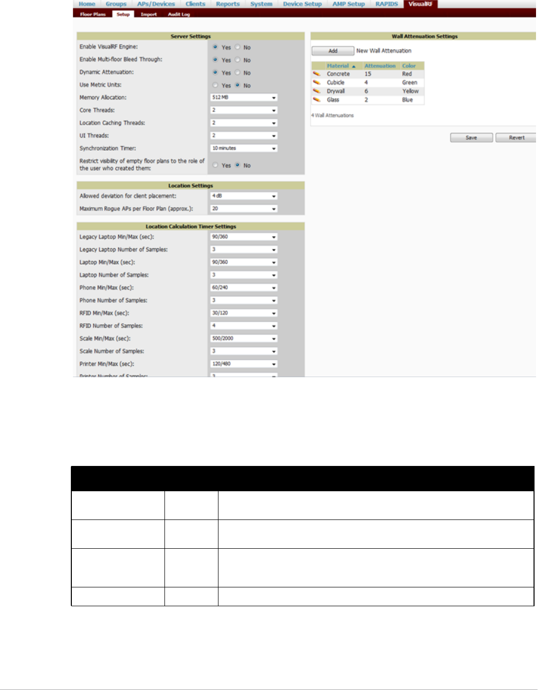
Dell PowerConnect W-AirWave 7.5 | User Guide Using VisualRF | 271
Figure 204 The VisualRF > Setup Page
Server Settings
To enable VisualRF and tune memory and performance, navigate to the Server Settings section on this page. The
settings in this section are detailed in Table 142:
Table 142 Server Settings Section of the VisualRF > Setup Page
Setting Default Description
Enable VisualRF Engine No Enables or disables the VisualRF engine. This setting must be enabled to use VisualRF.
If you do not have a license for VisualRF, this page will not appear.
Enable Multi-floor
Bleed-Through
Yes Enables or disables calculating the impact APs on floors above and below the currently
viewed floor in the Quick View.
Dynamic Attenuation Yes Incorporate AP to AP readings as well as site survey information and dynamically
recalculate the path loss of each radio to every grid cell on the floor plan, increasing
coverage and location accuracy.
Use Metric Units No Instructs the VisualRF engine to display all units of measurements in metric

272 | Using VisualRF Dell PowerConnect W-AirWave 7.5 | User Guide
Location Settings
To tune location accuracy, go to the Location Settings section on this page as described in Table 143:
Memory Allocation 512 MB The amount of memory dedicate to VisualRF. It is not dynamically allocated and all the
memory is consumed upon starting the service. Be sure to check the memory and
swap utilization in the Systems > Performance page before making any changes. The
exact amount of memory used per floor plan will vary heavily based on the size, number
of devices and number of grid cells on the floor plan.
-25 floors or less 512 MB
-25 to 50 floors 768 MB
-50 to 75 floors 1 GB
-75 to 100 floors 1.5 GB
-100 to 200 floors 3 GB
-200 to 300 floors 5 GB (64-bit only)
-Above 300 8 GB (64-bit only)
NOTE: If you see Out of Memory errors in the SSL error log on the System > Status
page, you should increase memory allocation.
Core Threads 1x number
of cores
Number of threads that calculate path loss for each floor. These threads also
regenerate a floor's RF properties when new APs, walls, or regions are added to a floor
plan.
Location Caching
Threads
1x number
of cores
Number of threads that calculate the location of all clients associated with access
points on this floor plan.
UI Threads 1x number
of cores
Number of threads that service the users accessing QuickView, as well as AirWave-to-
VisualRF communication.
NOTE: If users experience timeout errors while using QuickView, allocate additional UI
Threads.
Synchronization Timer 15 minutes This timer indicates how often VisualRF will synchronize with the APs within AirWave.
This synchronization includes checking the Up/Down status and parsing the XML.
Restrict visibility of
empty floor plans to the
role of the user who
created them
No When enabled, only the creator can view an empty floor plan.
Table 143 Location Settings Section in VisualRF > Setup
Setting Default Description
Allowed deviation
for client placement
4 dB When VisualRF locates a client or rogue it utilizes signal metrics from all the APs that hear
the client or rogue device. VisualRF builds a fingerprint location for all clients with similar
transmit-power capability. All subsequent clients that fall within the deviation is placed on
the same location fingerprint or x, y coordinates.
Example: AP1 hears Client1 at -72, and AP2 hears Client 1 at -64. VisualRF calculates the
client’s location to be at coordinates 100, 200. Client2 is heard by AP1 at -71 and AP2 at -65.
VisualRF will use the average of the difference in signals (AP1 -72 and -71) to see if the
client matches a pre-calculated location fingerprint.1+1(differences in signals)/2(#of
APs) = 1 which falls within the deviation of 2, hence the client would be located at 100,200.
Maximum Rogue
APs per Floor Plan
20 Sets the maximum number of rogues AirWave will place on a Floor. Use this filter in
combination with the RAPIDS Export Threshold configured on the RAPIDS > Setup page to
intelligently control the number of rogue devices displayed per floor.
NOTE: Increasing this value could increase the load on the server and the clutter on the
screen.
Table 142 Server Settings Section of the VisualRF > Setup Page (Continued)
Setting Default Description

Dell PowerConnect W-AirWave 7.5 | User Guide Using VisualRF | 273
Location Calculation Timer Settings
To tune the frequency for calculating device locations within the VisualRF UI, navigate to the Location
Calculation Timer Settings section. The available settings are described in Table 144:
Table 144 Location Calculation Timer Settings Section of VisualRF > Setup
Setting Default Description
Legacy Laptop Min/Max
(sec)
90/360 This timer determines how often to calculate the location for legacy laptop devices.
Taken with the data samples the calculation acts as follows:
-After the minimum timer (default is 90 seconds), check to see if the number of data
samples received from all APs that hear this client are greater than or equal to the
number of samples setting for legacy laptop devices (default of 3 data samples).
-If so (Yes to question above), then recalculate the client device's location based on
the samples received.
-If not (No to the question above), then wait until the number of sample setting is met
before recalculating. If the number of samples is never met, wait until the maximum
timer (default is 360 seconds) and then recalculate.
Legacy Laptop Number
of Samples
3 See definition above.
Laptop Min/Max (sec) 90/360 This timer determines how often to calculate the location for laptop (non-legacy)
devices. Taken with the data samples the calculation acts as follows:
-After the minimum timer (default is 90 seconds), check to see if the number of data
samples received from all APs that hear this client are greater than or equal to the
number of samples setting for legacy laptop devices (default of 3 data samples).
-If so (Yes to question above), then recalculate the client device's location based on
the samples received.
-If not (No to the question above), then wait until the number of sample setting is met
before recalculating. If the number of samples is never met, wait until the maximum
timer (default is 360 seconds) and then recalculate.
Laptop Number of
Samples
3 See definition above.
Phone Min/Max (sec) 60/240 This timer determines how often to calculate the location of phones. Taken with the
data samples the calculation acts as follows:
-After the minimum timer (default is 60 seconds), check to see if the number of data
samples received from all APs that hear this client are greater than or equal to the
number of samples setting for legacy laptop devices (default of 3 data samples).
-If so (Yes to question above), then recalculate the client device's location based on
the samples received.
-If not (No to the question above), then wait until the number of sample setting is met
before recalculating. If the number of samples is never met, wait until the maximum
timer (default is 240 seconds) and then recalculate.
Phone Number of
Samples
3 See definition above.
RFID Min/Max (sec) 30/120 This timer determines how often to calculate the location of RFIDs (such as devices
with tag readers for tracking). Taken with the data samples the calculation acts as
follows:
-After the minimum timer (default is 30 seconds), check to see if the number of data
samples received from all APs that hear this client are greater than or equal to the
number of samples setting for legacy laptop devices (default of 4 data samples).
-If so (Yes to question above), then recalculate the client device's location based on
the samples received.
-If not (No to the question above), then wait until the number of sample setting is met
before recalculating. If the number of samples is never met, wait until the maximum
timer (default is 120 seconds) and then recalculate.
RFID Number of
Samples
4 See definition above.
Scale Min/Max (sec) 500/2000
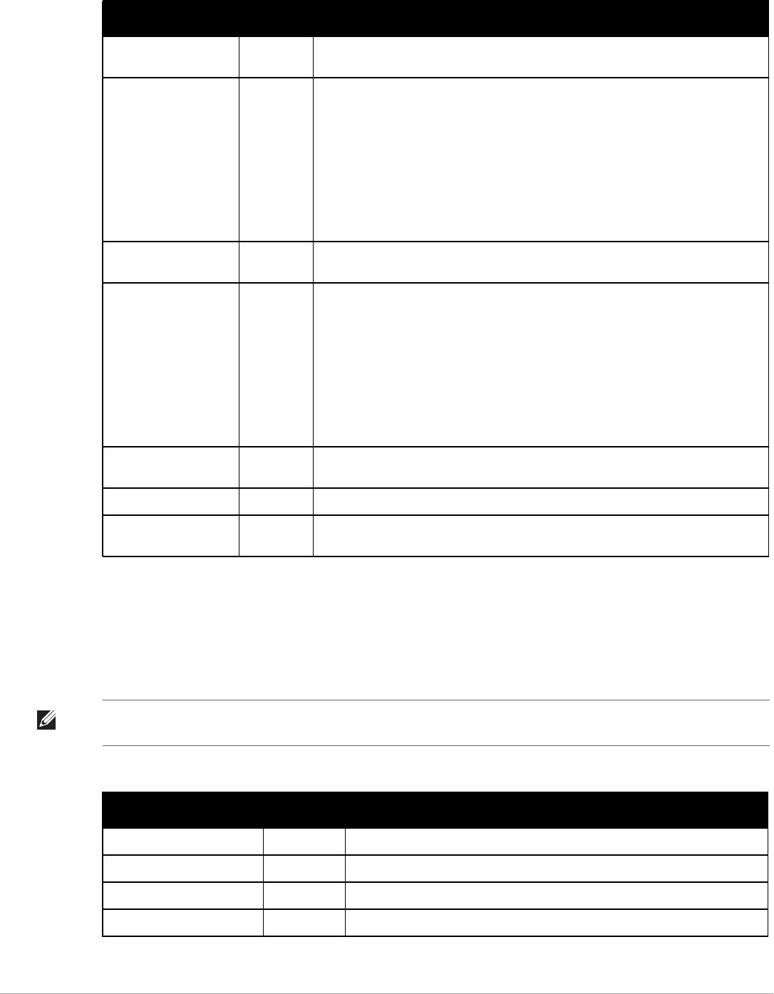
274 | Using VisualRF Dell PowerConnect W-AirWave 7.5 | User Guide
Attenuation Settings
Attenuation settings describe type and dB settings for walls within a floor plan.
To edit the wall settings and select a color for wall types within the VisualRF UI, navigate to the Wall
Attenuation Settings section and select the pencil icon next to the setting that you want to edit. The VisualRF
default attenuations and dB values are described in Table 145..
Scale Number of
Samples
3
Printer Min/Max (sec) 120/480 This timer determines how often to calculate the location of printers. Taken with the
data samples the calculation acts as follows:
-After the minimum timer (default is 120 seconds), check to see if the number of data
samples received from all APs that hear this client are greater than or equal to the
number of samples setting for legacy laptop devices (default of 3 data samples).
-If so (Yes to question above), then recalculate the client device's location based on
the samples received.
-If not (No to the question above), then wait until the number of sample setting is met
before recalculating. If the number of samples is never met, wait until the maximum
timer (default is 480 seconds) and then recalculate.
Printer Number of
Samples
3 See definition above.
Rogue Min/Max (sec) 500/2000 This timer determines how often to calculate the location of rogues. Taken with the
data samples the calculation acts as follows:
-After the minimum timer (default is 500 seconds), check to see if the number of data
samples received from all APs that hear this client are greater than or equal to the
number of samples setting for legacy laptop devices (default of 3 data samples).
-If so (Yes to question above), then recalculate the client device's location based on
the samples received.
-If not (No to the question above), then wait until the number of sample setting is met
before recalculating. If the number of samples is never met, wait until the maximum
timer (default is 2000 seconds) and then recalculate.
Rogue Number of
Samples
3 See definition above.
Default Min/Max (sec) 90/360
Default Number of
Samples
3
Table 144 Location Calculation Timer Settings Section of VisualRF > Setup (Continued)
Setting Default Description
NOTE: All of these values are global variables that cannot be overridden for individual floor plans. VisualRF uses these values to
calculate path loss and client locations. Walls within VisualRF are interpreted as pure dB loss without adjusting for wall thickness.
Table 145 Wall Attenuation Settings in VisualRF > Setup
Setting Default dB Description
Concrete Attenuation (dB) 15 Specifies the attenuation for any concrete walls drawn in VisualRF.
Cubicle Attenuation (dB) 4 Specifies the attenuation for any cubicle walls drawn in VisualRF.
Drywall Attenuation (dB) 6 Specifies the attenuation for any drywall walls drawn in VisualRF.
Glass Attenuation (dB) 6 Specifies the attenuation for any glass walls that are drawn in VisualRF.
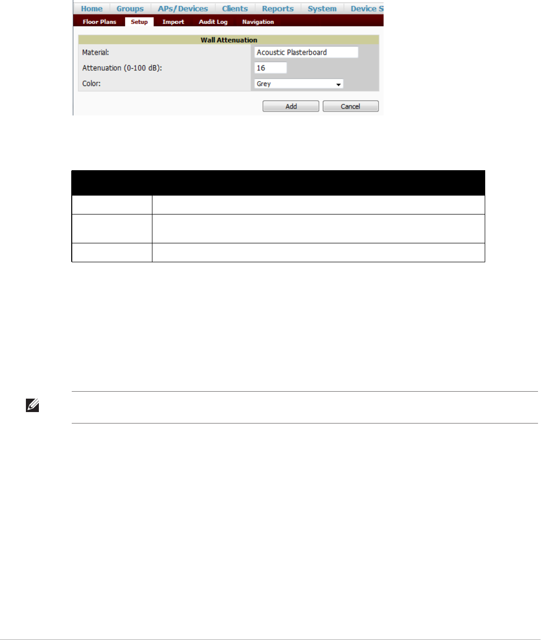
Dell PowerConnect W-AirWave 7.5 | User Guide Using VisualRF | 275
Adding a New Attenuation
In some cases, it may be necessary to create a special attenuation setting. Click on the Add button to specify a
new wall attuenation.
Figure 205 Add a New Wall Attenuation
Update the fields as described in Table 146. Click the Add button on the form when you are finished.
VisualRF Resource Utilization
When tuning the VisualRF server, use the default settings as recommended. If you do change any of these
settings, change one at a time and see how the system performs. Each time you restart VisualRF, you will notice a
delay before returning to normal processing. This delay can last anywhere from a minute to upwards of 30
minutes, depending on the size of the VisualRF database.
If you use the ‘top’ command to check on VisualRF resource utilization, ensure you use the ‘1’ and ‘H’ flags to
show cores and threads. Remember ‘top’ also takes 1-2 minutes to normalize and provide accurate data.
Configuring QuickView Personal Preferences
To configure your personal preferences in QuickView, select the Preferences icon on the VisualRF > Floor Plans
page and choose from the following configuration options:
-General - select from the Configure Preferences for drop-down menu, as shown in Figure 206.
Table 146 New Wall Attenuation in VisualRF > Setup
Setting Description
Material Specify the type of material for the new wall.
Attenuation (0-100
dB)
Specify the attenuation decibel value.
Color Select a color for the new wall.
NOTE: It is normal for VisualRF to consume 20% of each core with a combination of threads. It will utilize excess CPU cycles on all
cores when required.
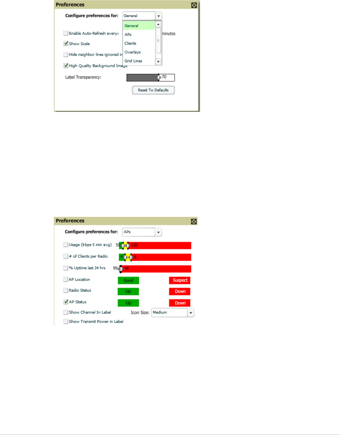
276 | Using VisualRF Dell PowerConnect W-AirWave 7.5 | User Guide
Figure 206 QuickView Preferences Page Illustration (General preferences selected)
Enable auto-refresh toggle. If enabled, specify the Refresh Interval in
Show Scale
Hide neighbor lines ignored in location calculation
High Quality Background Image - you can disable to increase rendering speed
Label Transparency - specify the transparancy level for labels in the floor plan
Reset to Defaults - launches a dialog box asking you to verify whether to reset all preferences to the default
values. Select Yes to reset all preferences or Cancel to leave preferences as configured.
-APs - select from the Configure Preferences for drop-down menu:
Figure 207 QuickView Preferences Page Illustration (APs preferences selected)
Usage - select the kbps threshold for normal (green), high (yellow), and excessive (red)
# of Clients per Radio - select the number of number of clients per radio for normal (green), high (yellow),
and excessive (red)
% of Uptime for the last 24 hours for normal (green) and excessive (red)
AP Location - specify whether to display green for a good location or red for a suspect location within a
floor plan
Radio Status - specify whether to display red or green depending on the status of the radios within the AP
AP Status - specify whether to display red or green in relation to up/down status of AP
Icon Size - select the size of the AP icon display on the floor plan
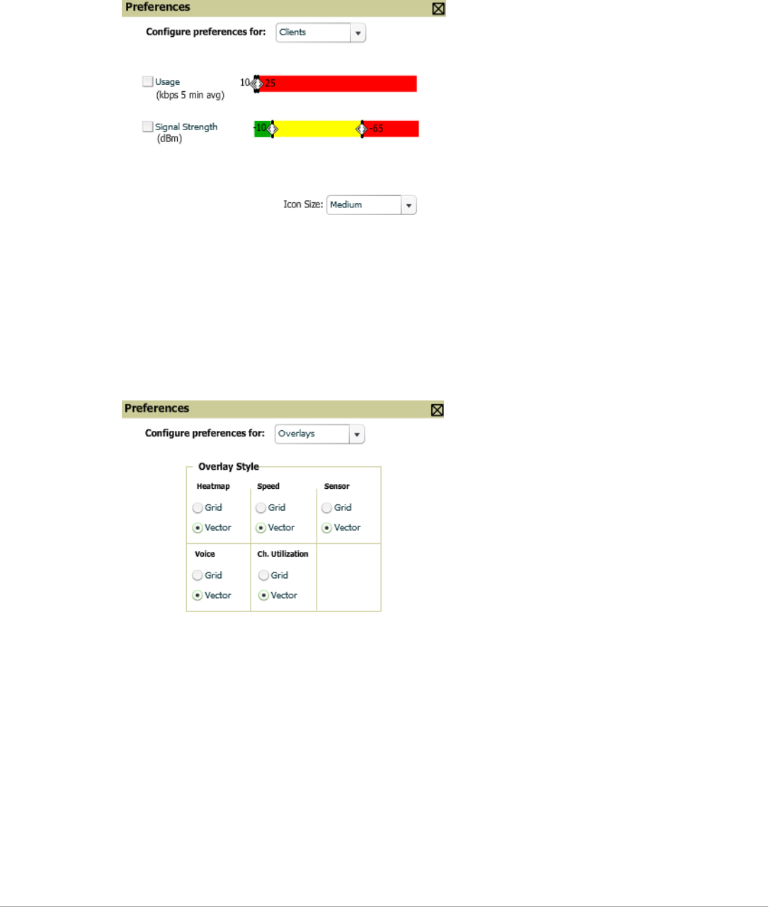
Dell PowerConnect W-AirWave 7.5 | User Guide Using VisualRF | 277
Show Channel in Label - view the channel info within the AP label
Show Transmit Power in Label - view transmit power within the AP label
-Clients - select from the Configure Preferences for drop-down menu.
Figure 208 QuickView Preferences Page Illustration (Clients preferences selected)
Usage - select the kbps threshold for normal (green), high (yellow), and excessive (red).
Signal Strength - select the dBm client threshold between excellent and poor
Icon Size - select the size of the client device icon display on the floor plan
-Overlays - select display type for Heatmap, Speed, Sensor, Voice, and Ch. Utilization
Figure 209 QuickView Preferences Page Illustration (Overlays preferences selected)
Grid - non vector overlay
Vector - provides a smoother overlay with mouse-over capabilities
-Grid Lines - Toggle grid lines on or off
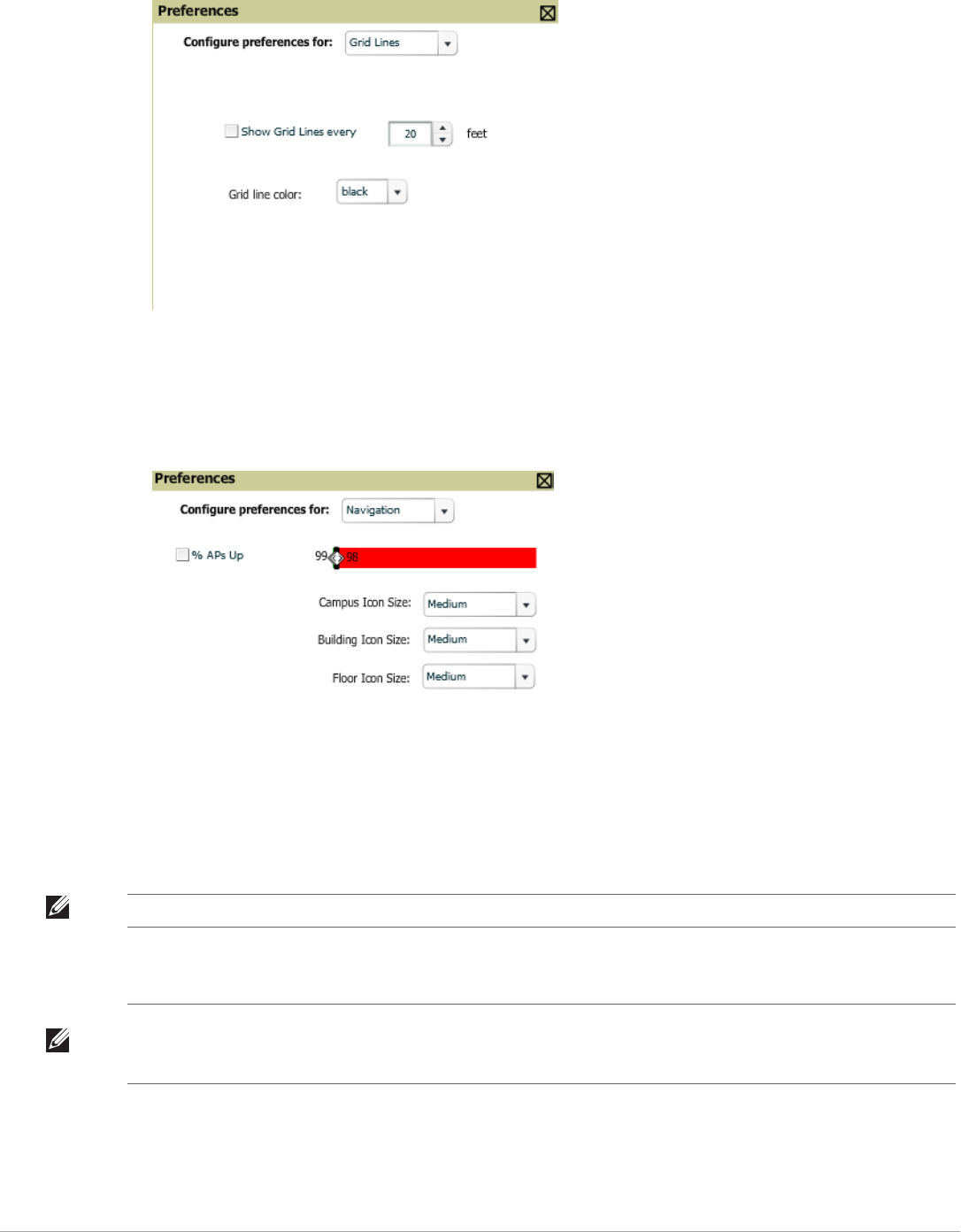
278 | Using VisualRF Dell PowerConnect W-AirWave 7.5 | User Guide
Figure 210 QuickView Preferences Page Illustration (Grid Lines preferences selected)
Show Grid Lines - if enabled, specify the number of feet between grid lines
Color of grid lines - select a color for grid lines
-Navigation - select from the Configure Preferences drop-down menu (campus and buildings).
Figure 211 QuickView Preferences Page Illustration (Navigation preferences selected)
% of APs Up for the last 24 hours for normal (green) and excessive (red)
Icon Size for campus, building and floor - specify Tiny, Small, Medium, Large, or Huge icons
NOTE: These preferences are stored in the database, so they will be retained across browsers and machines.
NOTE: The remaining sections in this chapter apply to networks, campuses, buildings, and floor plans that have already been set
up in VisualRF. If you do not yet have any of this information in VisualRF for your network, refer to “Planning and Provisioning” on
page 292.

Dell PowerConnect W-AirWave 7.5 | User Guide Using VisualRF | 279
Increasing Location Accuracy
The Location Service will use all RF information available to increase location accuracy of clients, tags, and rogue
devices. Understanding your infrastructure's inherent capabilities helps you learn the extra effort required to
ensure location accuracy.
There are three key elements read from controllers or access points that increase location accuracy:
-Signal strength of a client as heard by the AP of association
-Signal strength of a client as heard by APs other than the AP of association
-Signal strength at which an AP hears other APs.
These factors are detailed further in Table 147:
AirWave provides four main methods to increase accuracy once your access points are deployed:
-Adding Exterior Walls - increases location accuracy by reducing the statistical probability of placements
outside the office confines. See “Adding Exterior Walls” on page280.
-Client Training for Stationary Devices - ensures non-mobile clients like desktops or scales will always remain
in a defined static location. Statically assigning non-mobile devices reduces the CPU load on your server
because VisualRF does not evaluate any signal metrics for this MAC address when associated with an AP on
the floor plan. See “Location Training for Stationary Devices” on page281.
-Remote Client Surveys - provides additional attenuation inputs for corners and low-coverage areas without
the burden of actually carrying a laptop to the physical location. See “Adding Client Surveys” on page281.
-Location Probability Regions - Probability regions will increase or decrease the chances of a device being
located within the region. See “Adding Location Probability Regions” on page283.
Table 147 Elements Read From Controllers to Increase Location Accuracy
MFG/Model Client Signal Associated AP AP-to-AP Signals
(Dynamic Attenuation)
Unassociated
Client Signal
Rogue AP
Signal
Dell Yes Yes Yes Yes
Cisco LWAPP Yes Yes Yes Yes
Cisco IOS Yes No No With WLSE
Cisco VxWorks Yes No No No
Trapeze Yes No No Yes
Meru No No No Yes
Proxim Yes Yes Yes Yes
Symbol Auton. AP Yes No No Yes
Symbol Thin AP Yes No Yes Yes
Proxim AP-2000 Yes No Yes Yes
Proxim AP-4000 Yes Yes Yes Yes
ProCurve WeSM Yes Yes No Yes
ProCurve 530 Yes Yes Yes Yes
ProCurve 420 Yes Yes No Yes
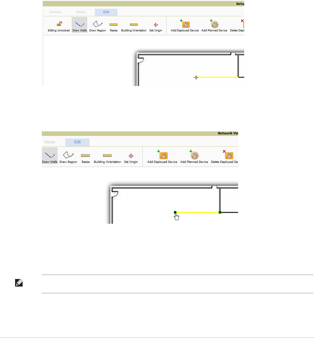
280 | Using VisualRF Dell PowerConnect W-AirWave 7.5 | User Guide
Adding Exterior Walls
Because VisualRF utilizes much existing RF information, generally only external walls are required for accurate
client locations. VisualRF's Dynamic Attenuation feature uses AP-to-AP information to calculate attenuation for
interior areas, negating the need to enter interior walls. If your devices support AP-to-AP information in the table
above, you should only draw exterior walls.
1. Select Draw Walls button in the Edit menu.
2. The cursor changes to a crosshair. Use this to draw the wall directly over the floor plan, as shown in Figure 212:
Figure 212 Drawing a wall
l
3. To move or resize the wall, select the Draw Walls button in the Edit menu again. The cursor changes to a
hand, and the ends of the wall is highlighted. Click and drag the end point handles to change the wall, as
shown in Figure 213:
Figure 213 Moving and resizing an existing wall
To change the attenuation of a wall, right-click the wall and select the appropriate building material.
To delete a wall, select the wall and press the Delete key. You can also right-click on a wall and select
Delete This Wall from the popup menu.
4. Once all walls are provisioned on the floor plan, select Save (floppy disk icon above the zoom bar).
NOTE: Drawing only outside walls is recommended. If you are seeing inaccurate client locations or heat maps after entering
exterior walls, proceed to Client Surveys. If you still experience problems, then you can proceed to adding interior walls.
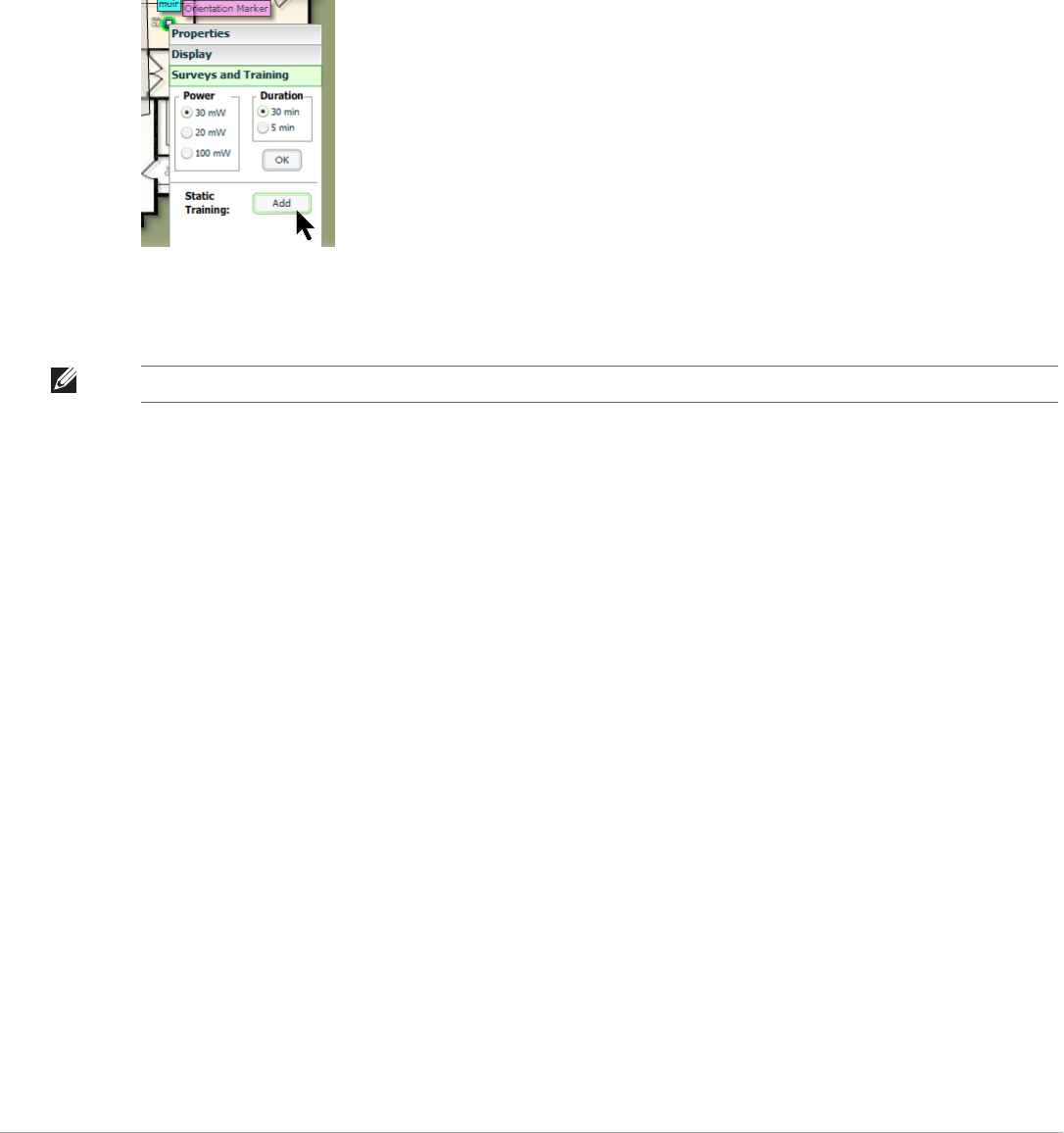
Dell PowerConnect W-AirWave 7.5 | User Guide Using VisualRF | 281
Location Training for Stationary Devices
QuickView provides the ability to statically assign a permanent x,y coordinate to stationary devices like PCs,
Scales, and Point-of-Sale terminals. This will reduce the calculation requirements on the VisualRF location
service and increase the accuracy of the RF characteristics of individual floor plans.
1. Drag the client device to the proper location.
2. Select the device and a popup menu appears. From that menu, select Surveys and Training.
3. Click the Add button for Static Training, as shown in Figure 214:
Figure 214 Surveys and Training menu for a client device
To remove a statically trained device, select client, and select the Surveys and Training option. Select Delete
button (which will have replaced the Add button) for Static Training.
Adding Client Surveys
Client surveys provide a method for increasing the accuracy of the attenuation grid by taking real signal samplings
from client devices associated with the WLAN.
Key differentiators of AirWave’s client surveys are:
1. They take readings from the access points and not the client.
2. They take numerous samples.
This produces a more accurate representation because signals obtained from the client's card (the signal level at
which a client hears the AP) can vary from vendor to vendor. The signal levels at which APs can hear a client are
already normalized. Using multiple samples alleviates spikes or troughs that come from using a single sample.
To start a client survey, follow these steps:
1. Drag the client to the proper location.
2. Select the client to see the Properties pop-up menu, as shown in Figure 215:
NOTE: The static locations are automatically saved, so the Save icon (floppy disk) will not appear.
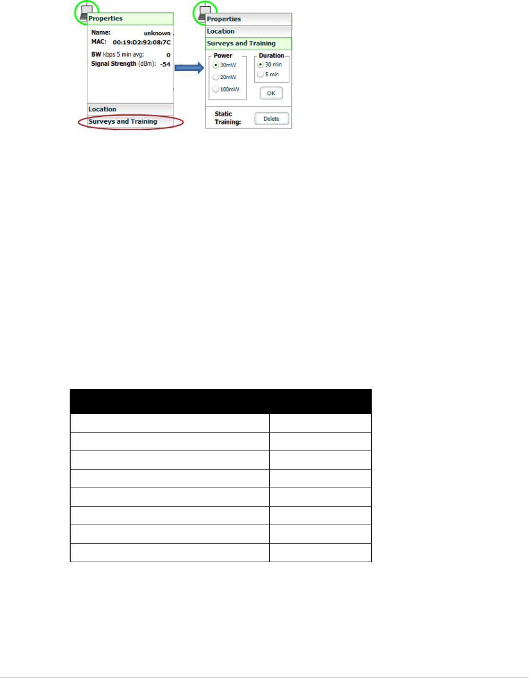
282 | Using VisualRF Dell PowerConnect W-AirWave 7.5 | User Guide
Figure 215 Client Surveys
3. Select the Surveys and Training option.
4. Select the appropriate transmit power for the wireless client. Leave the default to 30mW if you are unsure.
5. Select the Duration or the time that you want to sample the client's signal measurements. Longer durations
will increase Path Loss accuracy and location accuracy.
6. Select OK to begin the survey.
To display survey locations, select the Display menu and select Surveys. Note the following information about
this procedure:
-Ensure the client will remain in the same location for at least the duration of the survey.
-You should delete and resurvey an area or a floor plan after a remodel or significant interior movement.
-Surveys should be conducted during normal business hours to reflect normal RF activity on the floor.
-11a clients automatically inherit the proper transmit power from the 11g configuration. Example: 30mW Pre-
2006 laptops equate to 20mW for 11a clients.
-AirWave dynamically assigns a transmit power to every client based on OUI as shown in Table 148. This step
increases the accuracy for surveys by allowing an override.
Adding Regions
You can specify regions for areas designated as Wiring Closets and for Location Testing, Location Probability,
and Planning.
Table 148 Auto-assigned Client Type and Transmit Power
Client Type Transmit Power 11g
Pre-2006 Laptops 30 mW
Post -2006 Laptops 100 mW
SOHO WLAN Cards (D-Link, Net Gear, LINKSYS) 30 mW
RFID Tags 10 mW
PDA 20 mW
iPhone 20 mW
Desktop 100 mW
Cisco Cards 100 mW
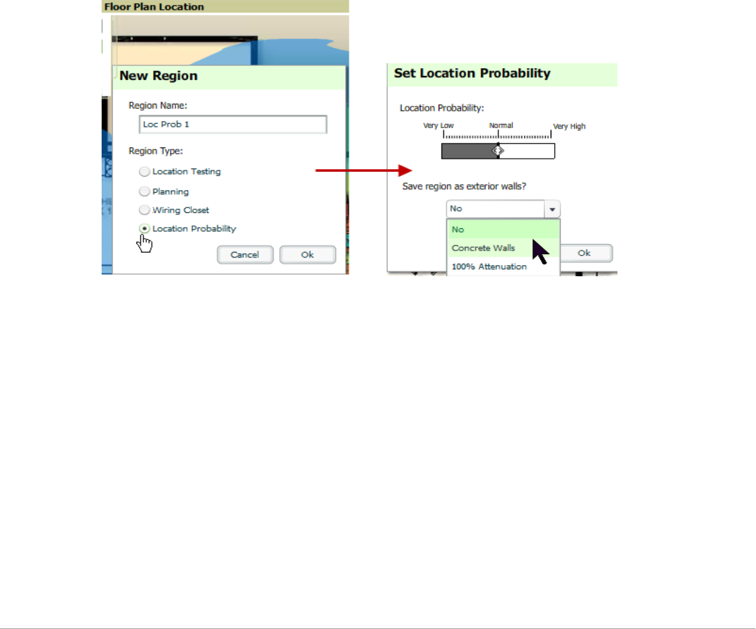
Dell PowerConnect W-AirWave 7.5 | User Guide Using VisualRF | 283
Adding Location Probability Regions
Location probability regions are optional regions that can be used to increase the accuracy of device location in
VisualRF.
VisualRF calculates device locations based on probability. VisualRF determines the probability of a device being
located in every grid cell and places the device where the probability is the highest.
Probability regions will add or remove up to 20% chance from the device location probability. They can be used to
push users into regions where they are more likely to be located, like conference rooms and cubical farms, or they
can be used to pull users out of regions where they are less likely to be like parking lots and courtyards.
To add a probability region to a floor plan, follow these steps:
1. Select the Edit menu and click the Draw Region option.
2. Outline the desired probability region. Double click or Ctrl+click to end the outline process.
3. Name the region, select a Region Type of Location Probability and select OK.
4. Move the location probability slider to the desired level, as shown on Figure 216. Very Low will decrease the
probability of a device being placed in that region by 20%. Very High will increase the probability of a device
being placed in that region by 20%.
Figure 216 Adding a New Location Probability Region
5. Optionally, you can save the location region as the exterior walls. 100% attenuation can be selected to force
VisualRF to only place devices inside of the selected region. No device will ever be placed outside of the
probability region when 100% attenuation is selected. 100% attenuation is only recommended for tall
buildings where it is extremely unlikely that any user is located outside of the building. No heat map or
attenuation grid is calculated for devices outside of the 100% attenuation region.
Adding a Wiring Closet
To add a Wiring Closet to VisualRF, follow these steps:
1. In the Edit menu, select the Draw Region option.
2. Outline the desired region. Double click or press Ctrl+click to end the outline process.
3. Name the region, select a Region Type of Wiring Closet, and select OK, as shown in Figure 217.
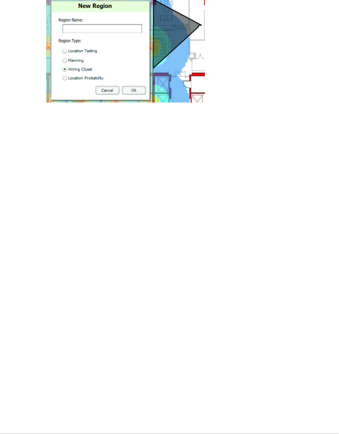
284 | Using VisualRF Dell PowerConnect W-AirWave 7.5 | User Guide
Figure 217 Adding a new Wiring Closet Region
Now that the Wiring Closet is defined you will see a green WiringCloset icon on your floor plan. Double click
that icon to navigate into the wired closet.
1. Add a rack to the wired closet by selecting the Add Empty Rack icon and dragging it to the background.
2. To add a planned device, select the Add Planned Device icon to view the Manually Provision Rack Gear
menu. Select the device type in the Type menu, and then find the device you want to add. Drag it into the
rack at the appropriate location.
3. To add a wired device that is currently being monitored by AirWave, select Add Deployed Device.
4. Locate the device to be added.
5. Drag the device to the appropriate location in the rack, as shown in Figure 218.
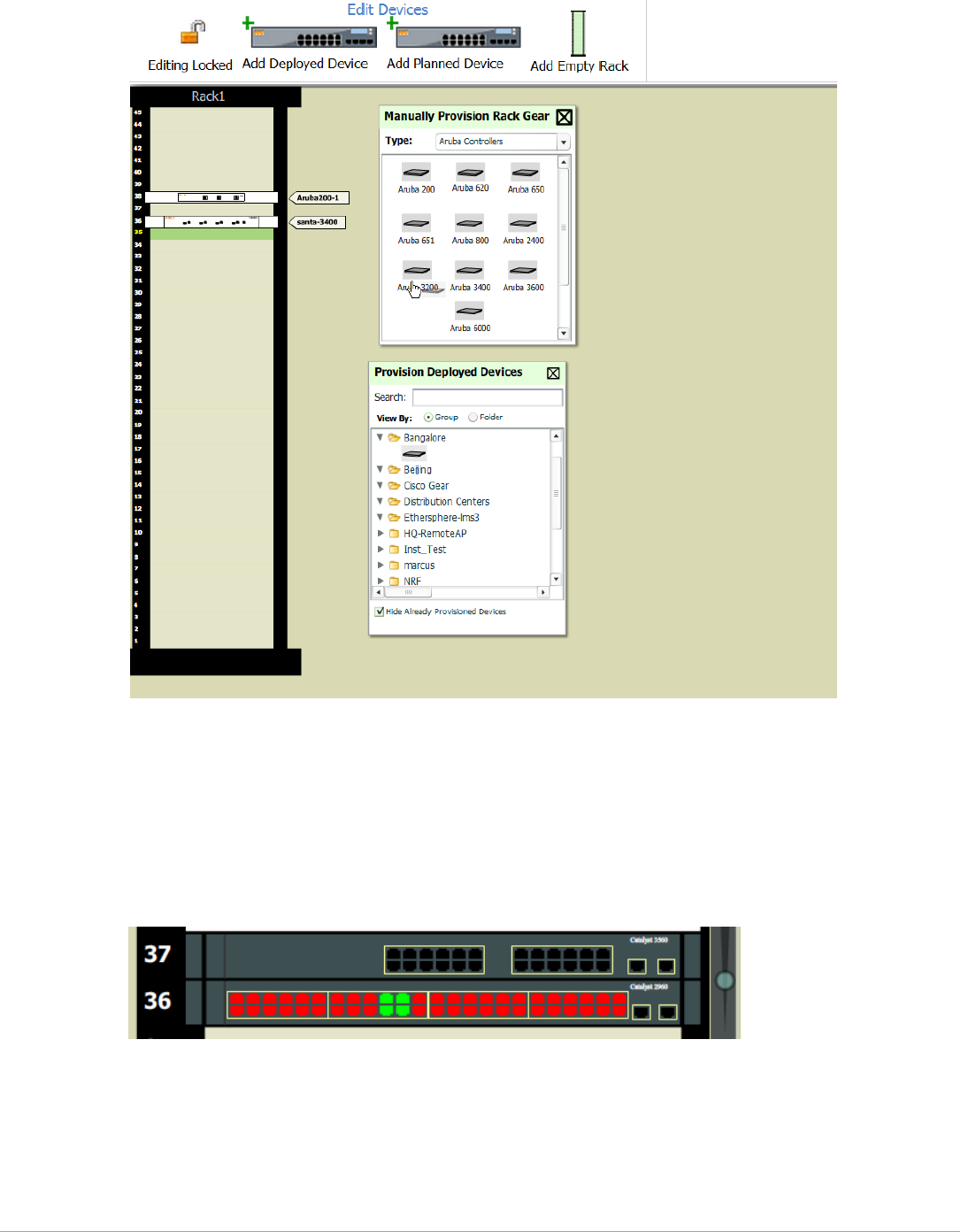
Dell PowerConnect W-AirWave 7.5 | User Guide Using VisualRF | 285
Figure 218 Provisioning Devices
Wired devices that are added to a wired closet are included in any BOM report covering that floor.
Viewing Port Status on Deployed Switches
Deployed switches on a rack will display the port status as red (down) and green (up) interface icons, which
corresponds with the operationally up devices on the APs/Devices > Interfaces list. Planned switches do not
display these status indicators in VisualRF.
Figure 219 Deployed switch showing red and green port status icons
Fine-Tuning Location Service in VisualRF > Setup
There are several options on the VisualRF > Setup page which increase client location accuracy. All of these
items will increase the processing requirements for the location service and could negatively impact the overall
performance of AirWave.
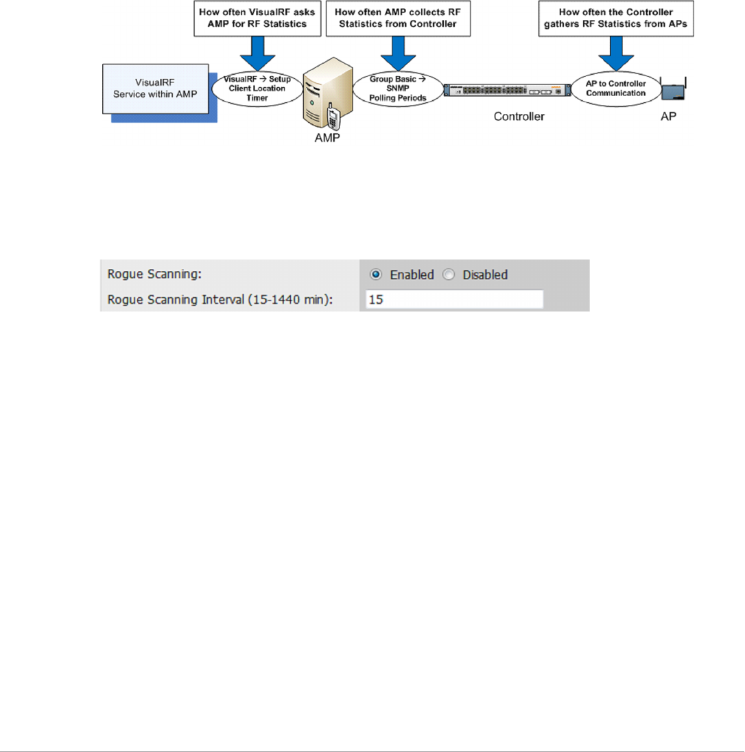
286 | Using VisualRF Dell PowerConnect W-AirWave 7.5 | User Guide
-Grid Size - decreasing the grid size will enable the location to place clients in a small grid which will increase
accuracy. You can right-click on a floor plan within a building view and change this setting.
-Dynamic Attenuation - enabling dynamic attenuation (which is on by default) instructs the location service
to sample the current RF environment and to dynamically adjust Path Loss.
Configuring Infrastructure
Ensure that the hardware is configured to retrieve the RF information and that it provides this information on a
timely basis. There are three unique timing mechanisms which impact location accuracy: how often the
infrastructure collects and correlates RF statistics in their MIB, how often the AirWave queries those MIB entries,
and how often VisualRF service queries AirWave for this RF information.
Figure 220 Timing Factors Impacting Location Accuracy
These best practices are recommended when configuring hardware infrastructure:
-For legacy autonomous APs, ensure on the Group > Radio page that Rogue Scanning is enabled and the
interval is accurate, as shown in Figure 221:
Figure 221 Group Rogue Scanning Configuration
-For thin APs, ensure that the controllers are configured to gather RF information from the thin APs
frequently.
-For Cisco LWAPP, navigate to Groups > Cisco WLC Config page in AirWave. Navigate the tree control to
the Wireless section, and for each PHY navigate to RRM > General section.
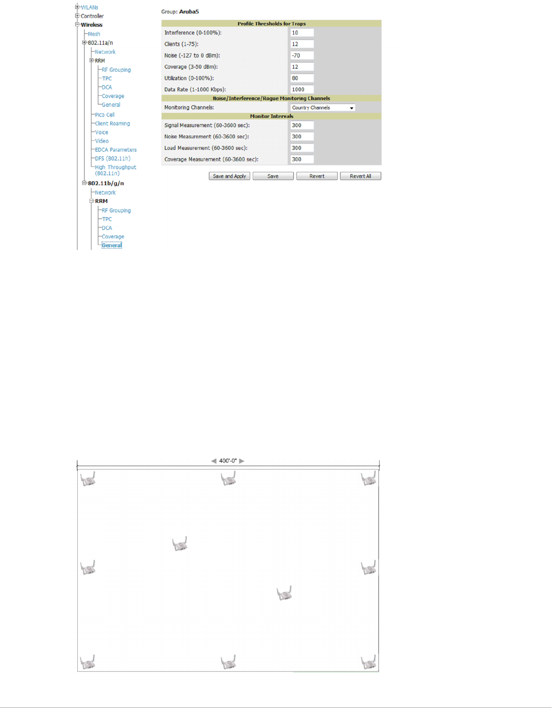
Dell PowerConnect W-AirWave 7.5 | User Guide Using VisualRF | 287
Figure 222 WLC RRM Configuration in AirWave
-Review the values in the Monitor Intervals section. These should be configured to a recommended setting of
180 for better accuracy.
Deploying APs for Client Location Accuracy
Deploying access points for client location accuracy can be different than deploying access points for capacity.
Follow these guidelines for best results:
-Ensure that at least 3 radios can hear each client devices at -85 dBm or below
-Ensure that you deploy an access point approximately every 3,500 square feet.
-For square or rectangular floor plans ensure access points are deployed on the exterior walls of each floor with
access points in the middle as well.
Refer to Figure 223 for an example.
Figure 223 Rectangular Floor Plan AP Deployment
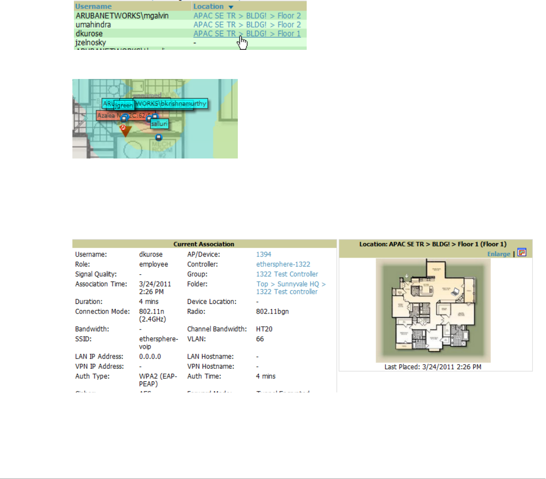
288 | Using VisualRF Dell PowerConnect W-AirWave 7.5 | User Guide
Using QuickView to Assess RF Environments
QuickView has four distinct views or entry points: client view, access point view, floor plan view, and network,
campus, and building view.
This section contains the following corresponding topics:
-“Viewing a Wireless User’s RF Environment” on page288
-“Viewing an AP’s Wireless RF Environment” on page289
-“Viewing a Floor Plan’s RF Environment” on page290
-“Viewing a Network, Campus, Building’s RF Environment” on page291
Viewing a Wireless User’s RF Environment
1. Navigate to Users > List in AirWave.
2. Click the link under the Location column for the user of interest, as shown in Figure 224. A QuickView
window of that location opens and indicates the client with a Username label, as shown in Figure 225:
Figure 224 Link to user’s thumbnail (the Location column)
Figure 225 QuickView of the selected device
You can also access this information from the Clients > Client Detail page by selecting the QuickView
thumbnail, located next to the Current Association section of this page as shown in Figure 226:
Figure 226 QuickView thumbnail in Clients > Client Detail
This view is focused on the wireless user enabling you quick resolution of a user's issues and therefore disables
most RF objects by default.
-Users - only the user in focus is displayed
-APs - only the access point in which the focus client is associated with is displayed
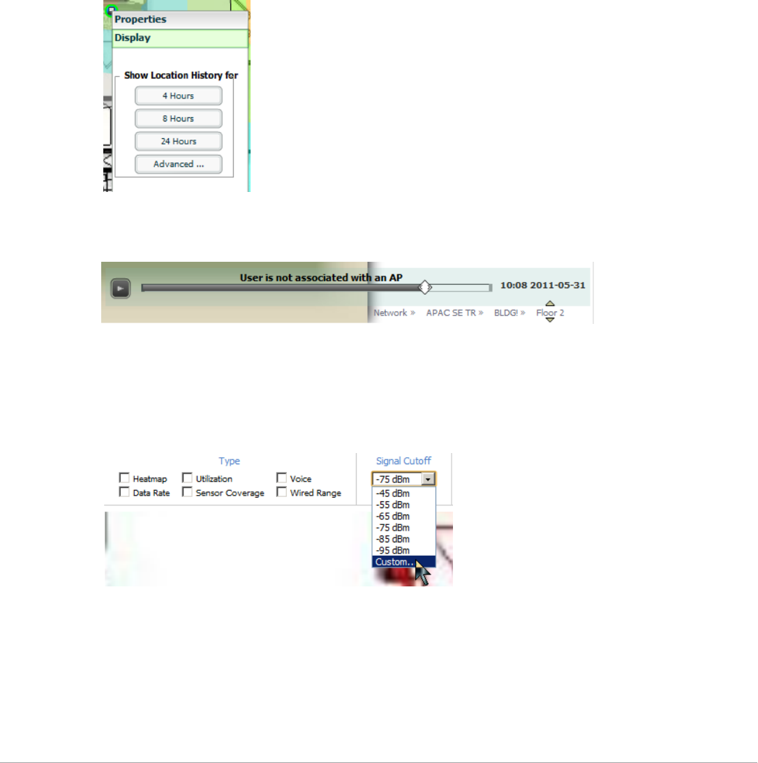
Dell PowerConnect W-AirWave 7.5 | User Guide Using VisualRF | 289
-Radios - the heatmap represents only the radio to which the client in focus is associated
-Rogues - all rogues are off
-Client/Rogue Surveys - all surveys are off
-Walls - all walls are displayed
-Lines - client to AP of association
-Labels - all labels are disabled
Tracking Location History
Select a client icon in the floor plan and select Display from the pop-up menu shown in Figure 227:
Figure 227 Show Location History
A location history player, illustrated in Figure 228, appears at the bottom of the QuickView window.
Figure 228 Location History Player
Checking Signal Strength to Client Location
1. On a floor plan, locate the Signal Cutoff menu.
2. Select the desired signal level to display, as shown in Figure 229. The heatmap updates immediately.
Figure 229 Signal Cutoff dBm Dropdown Menu
Viewing an AP’s Wireless RF Environment
To view an access point's RF environment from APs/Devices > Monitor page:
1. Select a device of interest from APs/Devices > List, or any other AirWave page that lists your APs. The APs/
Devices > Monitor page opens.
2. Click on the QuickView thumbnail showing the location of the AP, shown on the right side of Figure 230:
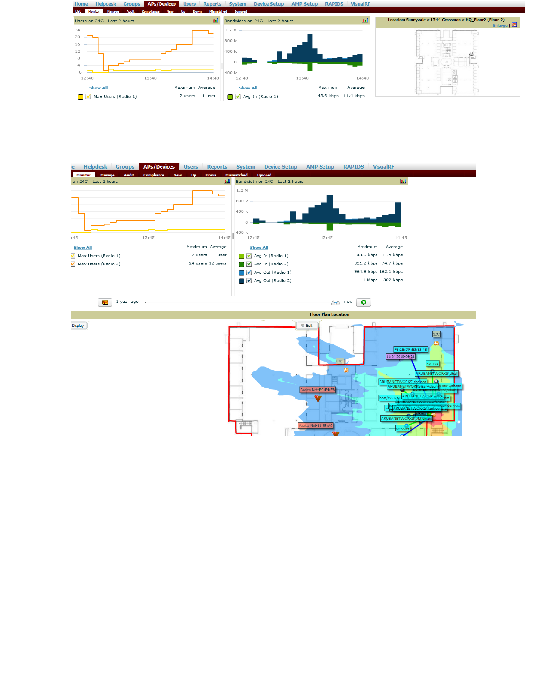
290 | Using VisualRF Dell PowerConnect W-AirWave 7.5 | User Guide
Figure 230 QuickView Thumbnail in APs/Devices > Monitor page for an AP
A fully interactive QuickView display opens below the thumbnail on the same page (not in a new window), as
shown in Figure 231:
Figure 231 Full QuickView in APs/Devices > Monitor page for an AP (partial view)
This view is focused on enabling quick resolution of AP issues and therefore disables many RF objects by
default as follows:
Clients - only clients associated with radios within access point of focus are displayed
APs - only the access point in focus is displayed
Radios - the heatmap represents all radios within the access point of focus
Rogues - all rogues are off
Client/Rogue Surveys - all surveys are off
Walls - all walls on displayed
Lines - client to AP of association are displayed
Labels - all labels are disabled
Viewing a Floor Plan’s RF Environment
View a floor plan's RF environment from VisualRF > Floor Plans page. This page has a fixed sorting filter of
Campus, then Building, then Floor number.
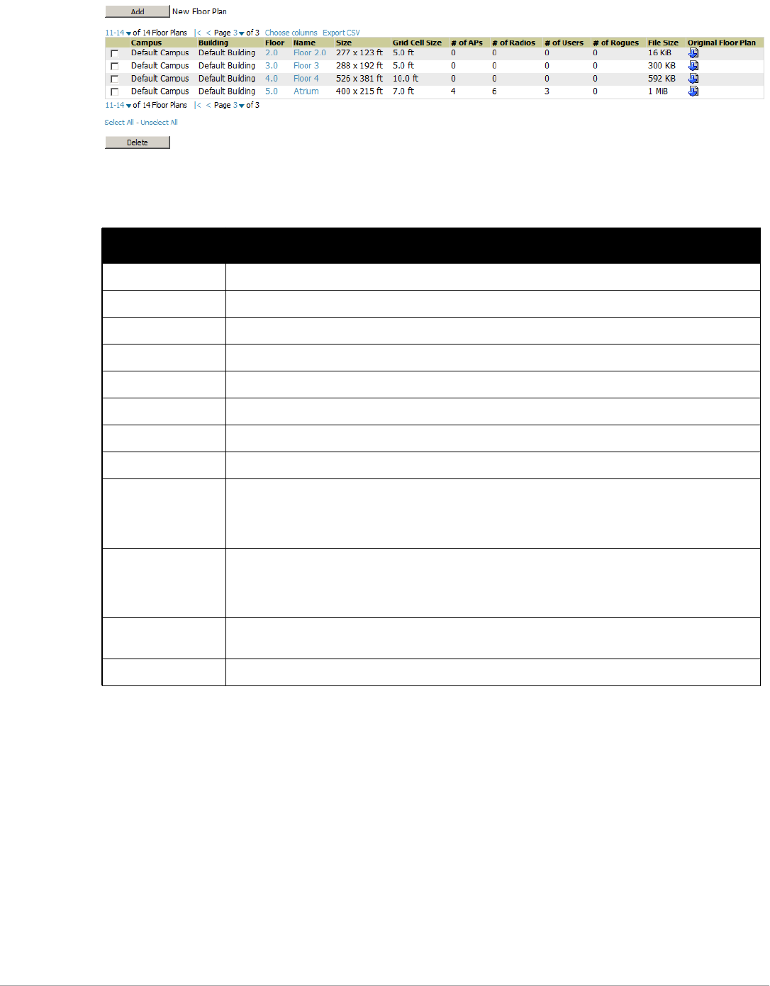
Dell PowerConnect W-AirWave 7.5 | User Guide Using VisualRF | 291
Figure 232 Floor Plans List View
The VisualRF > Floor Plans page provides a snapshot of how VisualRF is performing, as described in Table 149:
Viewing a Network, Campus, Building’s RF Environment
To view floors from a geographical perspective:
1. Navigate to the VisualRF > Floor Plans page.
2. Click on each network, campus, or building successively to drill down further until you reach the floor plan.
This navigation provides information in each view as follows:
Network View - Contains all campuses within your WLAN
Campus View - All buildings within a campus
Building View - All floors within a building
Floor Plan View - All regions, wiring closets, WiFi tags within the floor
Table 149 Floor Plans list columns
Field Description
Campus Campus associated to the floor.
Building Building associated to the floor.
Floor Floor number. The decimal place can be used for mezzanine levels.
Name Optional name of a floor. (If the name is not changed, it displays the name as Floor [Number] by default.)
Size The height and width in feet of the floor plan, including white space.
Grid Cell Size The size of the grid cells, in feet.
# of APs The number of access points on the floor.
# of Radios The number of radios associated with access points on the floor.
# of Users The number of wireless users associated with access points on the floor.
NOTE: Locating users consumes significant VisualRF resources. A floor with hundreds or thousands of
clients can take a long time to process.
# of Rogues The number of rogue devices heard by access points on the floor. This number reflects the filters
configured on the VisualRF > Setup. This means that while APs on the floor might hear more rogue
devices, they are being filtered because of weak signal, they haven't been heard recently, or they are
ad-hoc.
File Size The floor plan background or image reported, in kilobytes. The larger the file, the longer it will take to
render in the canvas.
Original Floor Plan A link to download the original image background file.
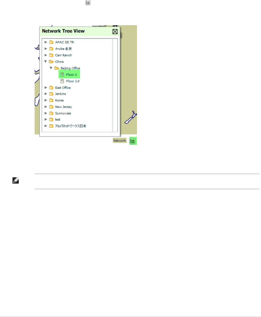
292 | Using VisualRF Dell PowerConnect W-AirWave 7.5 | User Guide
Viewing Campuses, Buildings, or Floors from a Tree View
As an alternative to using QuickView, you can use the Tree View to view floors from a hierarchical tree, as follows:
1. Navigate to the VisualRF > Floor Plans page.
2. Select the Tree icon ( )at the top right of any view. The Network Tree View window, shown in Figure 233,
appears on the screen.
Figure 233 Network Tree View - Floor highlighted
3. Use the arrows to drill down into the folders to select the Campus, Building, or Floor. Select the folder or floor
plan icon to open the view you have selected. The Network Tree View window will remain on the screen until
you close it.
Planning and Provisioning
VisualRF provides the capability to plan campuses, buildings, floors, and access points prior to the actual access
point deployment. The following procedure describes the workflow:
-“Creating a New Campus” on page293
-“Creating a New Building in a Campus” on page293
-“Importing a Floor Plan” on page295
-“Editing a Floor Plan Image” on page296
-“Provisioning Existing Access Points onto the Floor Plan” on page298
-“Automatically Provisioning APs onto a Floor Plan” on page299
-“Tweaking a Planning Region” on page301
-“Printing a Bill of Materials Report” on page302
NOTE: If you prefer not to use background maps for your campus or building placements, click a background and select Auto-
Arrange to move the campuses, buildings from their placements into an alphabetically-sorted list.
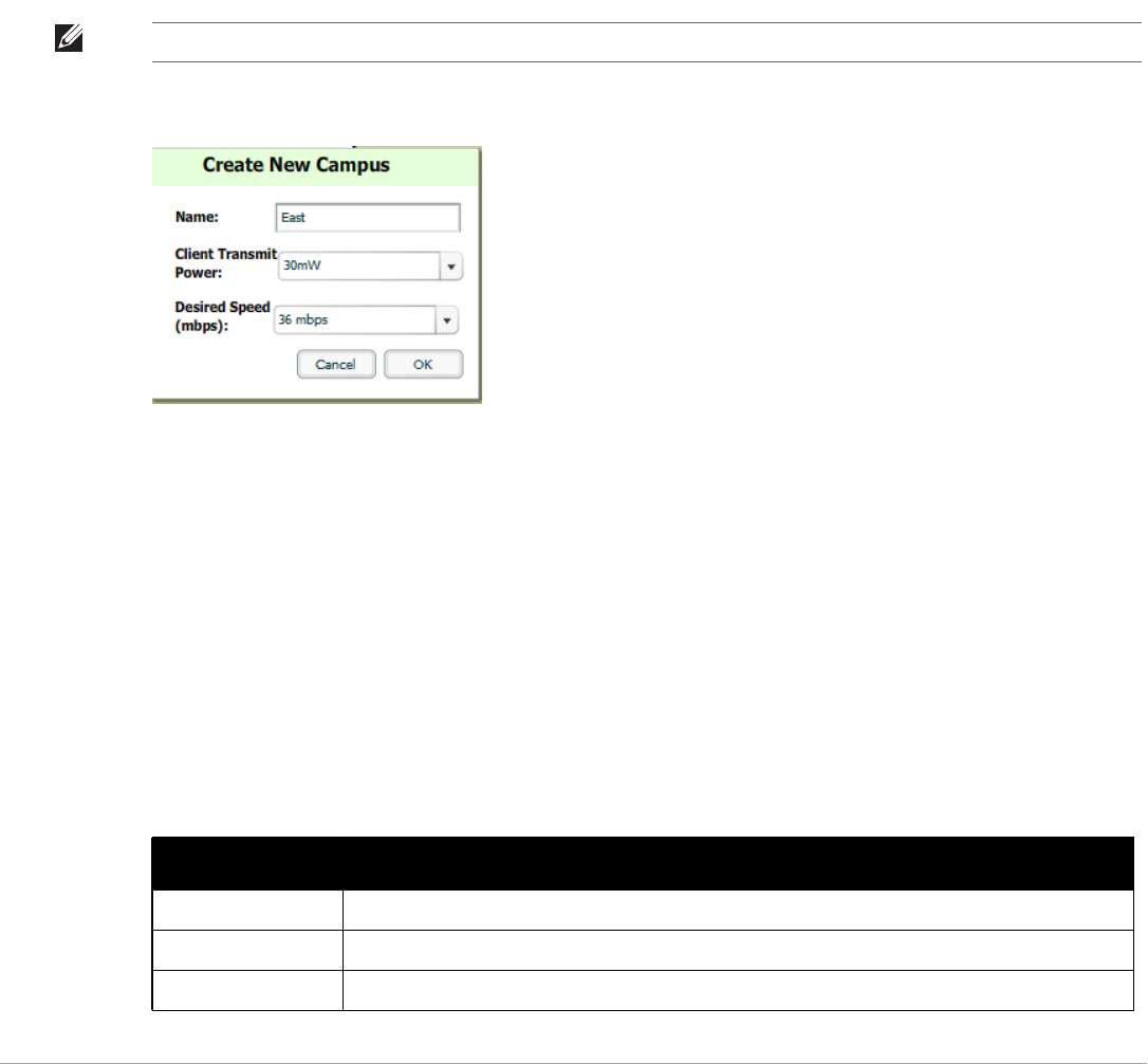
Dell PowerConnect W-AirWave 7.5 | User Guide Using VisualRF | 293
Creating a New Campus
Floors are associated with a building, and buildings are associated with a campus. In order to create a new floor,
you must first create a campus with at least one building.
To create and place your campus, follow these steps:
1. Navigate to VisualRF > Floor Plans.
2. Select the Add Campus button located above the floor plan on the top left. The Create New Campus
window, illustrated in Figure 234, appears.
3. Enter the following campus information:
Name of the campus
Client Transmit Power - used in auto placement of access points onto floors within this campus. The
range is 30mW to 100mW.
Desired Speed (mbps)- used in auto placement of access points onto floors within this campus. The range
is 6 to 200 mbps.
Figure 234 Create New Campus window
4. Select OK to save. You will see a new Campus icon appear on the campus canvas.
5. Add appropriate network geographical background or upload a personalized image by right-clicking on the
background.
Set Map - Allows you to browse with the included maps.
Auto Arrange Campuses -Arranges the campus in alphabetical order across the background.
6. Drag the new Campus icon to the appropriate location on the map background.
Creating a New Building in a Campus
1. Select the newly created Campus icon from the previous step. When the blank campus area opens, select the
Add New Building icon.
2. When the New Building window appears, enter the following information:
NOTE: Buildings and floors inherit transmit power and speed from the campus.
Table 150 New Building Fields and Descriptions
Field Description
Name Name of the building; located on an existing campus.
Campus Lists all campuses configured on your AirWave.
Longitude & Latitude These fields are used to represent a building on Google Earth.
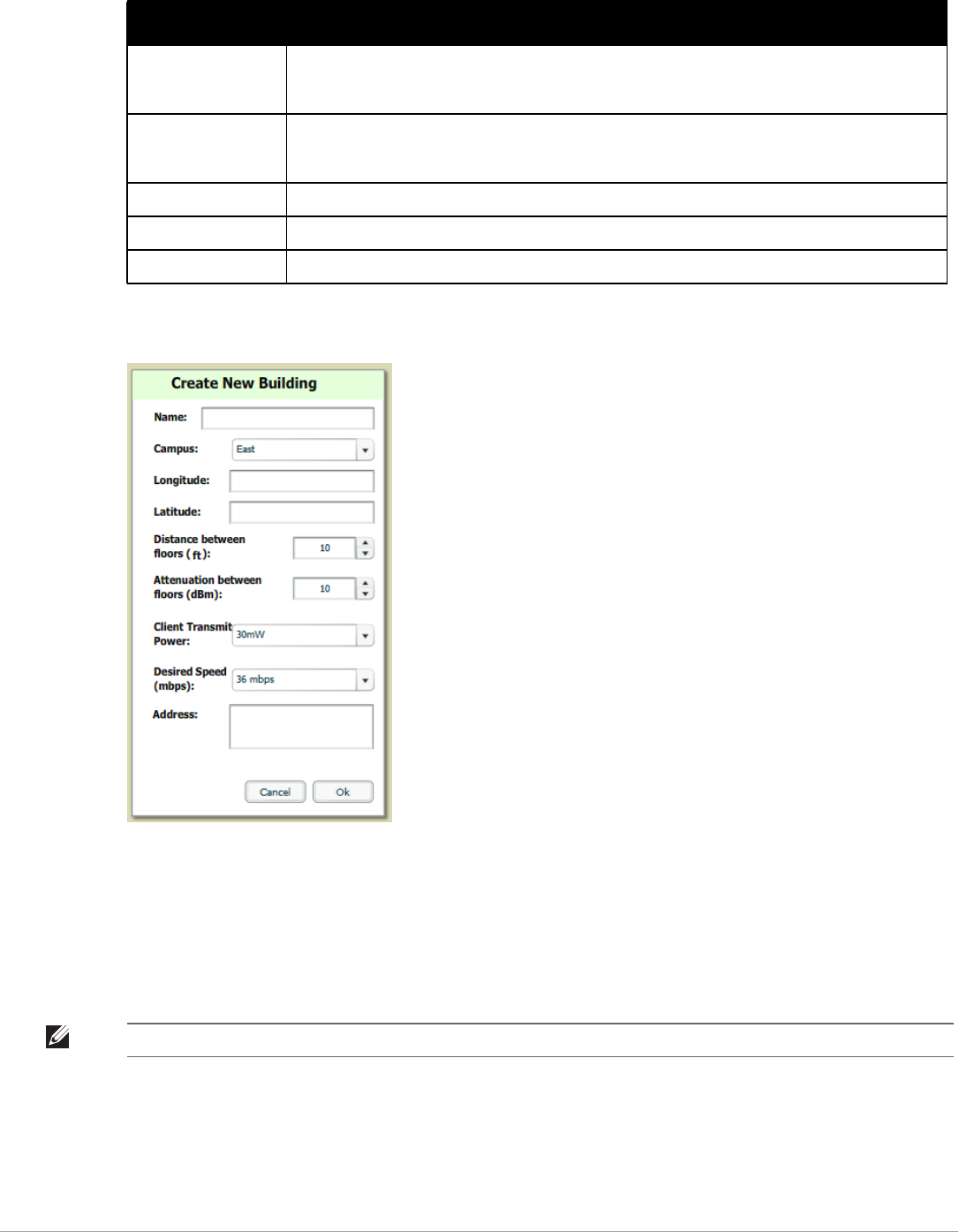
294 | Using VisualRF Dell PowerConnect W-AirWave 7.5 | User Guide
Figure 235 Create New Building Window
3. Select OK to save. A new Building icon will appear in the upper-left corner of the canvas.
4. Drag the Building icon to the appropriate location on the map background.
5. Add appropriate geographical background or upload a personalized image by right-clicking on the background
in your Network or in any Campus. The Set Map option allows you to browse and select an included map, or
you can import your own by selecting the Custom button. This launches the image wizard. With this wizard,
you can upload an image, specify color or greyscale, and crop your custom background..
6. To change building types, navigate to the new building by selecting the Building icon. This opens the Building
page. This page is a blank canvas without a background.
7. Right-click on the background of the Building page and select Set Building Type.
8. Select a building type of Rectangular, Circular, Rectangular Prism, or Square.
Distance between
floors
The normal distance between floors in the building. This value can be overridden as each floor is
created, but this is the default value for every new floor added to the system. This data element can be
imported or exported to external planning tools like Ekahau. It is not currently utilized by AirWave.
Attenuation between
floors
Enter the attenuation loss in decibels between floors. This value can be overridden as each floor is
created, but this is the default value for every new floor added to the system. This data element can
be imported or exported to external planning tools like Ekahau. It is not currently utilized by AirWave.
Client Transmit Power This value is used when auto-provisioning access points onto a floor plan.
Desired Speed Speed will determine the new access points when auto-provisioning.
Address Building or Campus address (optional)
Table 150 New Building Fields and Descriptions (Continued)
Field Description
NOTE: QuickView automatically saves background map images, campus locations, building locations, and building types.
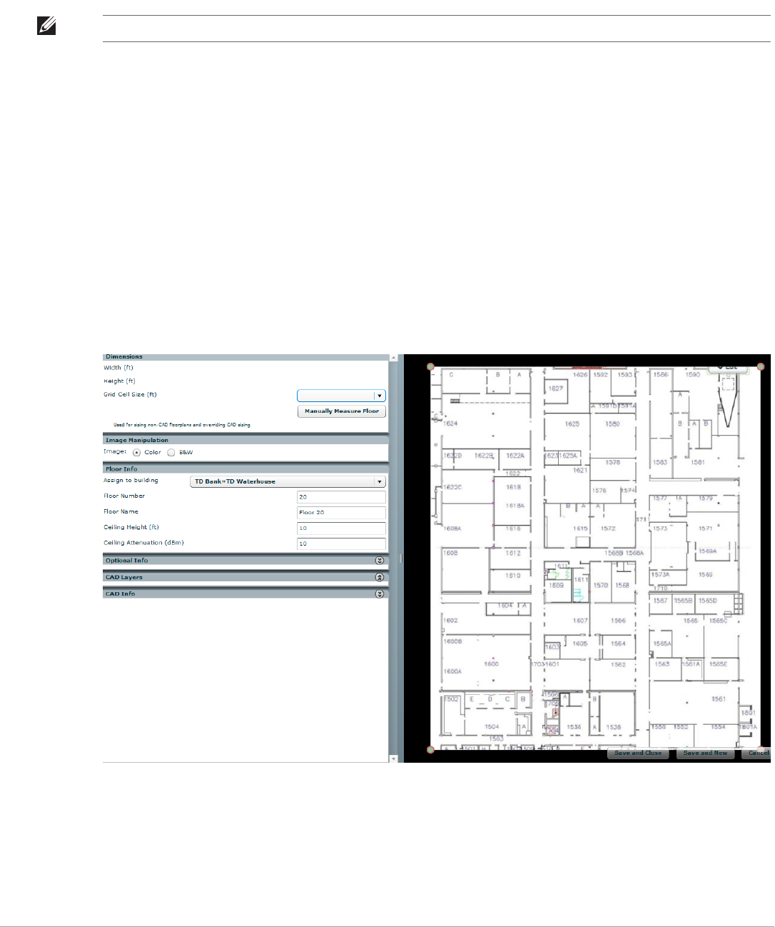
Dell PowerConnect W-AirWave 7.5 | User Guide Using VisualRF | 295
You are now ready to import your floor plan.
Importing a Floor Plan
The following steps show how to import a floor plan background image file.
1. In VisualRF > Floor Plans, click the Add Floorplan icon (displays when viewing a Building) or use the Add
button above the floor plan list at the bottom of the page.
2. Select Choose File to locate a floor plan image file from your hard drive. The following file types are
supported:
-CAD (NOTE: CAD floor plans must be generated from an AutoCAD source file.)
-GIF
-JPEG
-PNG
-PDF - Single page only. (NOTE: PDF floor plans must be generated from a source file. Other PDFs, such
as those scanned from a printer, will not import properly.)
3. In VisualRF, select Upload. This opens the image file along with VisualRF planning tools on the left side.
Figure 236 Floor Plan Imported into VisualRF
-When importing RF plans, be sure that the devices to be included are also available in the device catalog.
If the floor plan does not require cropping, sizing, or layer control, then click Save and Close to begin
provisioning APs or Save and New to upload a new floor plan.
NOTE: When importing RF plans, be sure that the devices to be included are also available in the device catalog.

296 | Using VisualRF Dell PowerConnect W-AirWave 7.5 | User Guide
If the floor plan does require cropping, sizing, or layer control, then proceed to the next procedure.
Editing a Floor Plan Image
There are many ways to edit a floor plan that you have uploaded, as explained in the following topics:
-“Cropping the Floor Plan Image” on page296
-“Sizing a Non-CAD Floor Plan” on page296
-“Removing Color from a Floor Plan Image” on page297
-“Assigning Campus, Building and Floor Numbers” on page297
-“Assigning Optional Planner, Owner, or Installer Information for the Floor Plan” on page298
-“Controlling the Layers in the Uploaded Floor Plan (CAD only)” on page298
-“Error Checking of CAD Images” on page298
-“Last Steps in Editing an Uploaded Image” on page298
Cropping the Floor Plan Image
Cropping is available from within the Upload Wizard. Use the cropping handles (red circles) to remove extra
white space around the floor plan. VisualRF will calculate an attenuation grid for the entire map including white
space. Reducing the white space on a floor plan will increase location accuracy and decrease the load an on the
server. A good rule of thumb would be about ½ inch white space, if possible, on all sides.
VisualRF dissects each floor plan into a grid consisting of cells specified in this setting. The Core Thread service
calculates the path loss for every radio to every cell on the floor plan.
By default the importation wizard allocates 2,500 grid cells to each site based on dimensions. If you have a site
that is 250 ft. by 100 ft, the Floor Plan importation wizard would calculate the grid cell size at 10 feet. 250 ft. x
100 ft. = 25,000 ft. 25,000 ft. / 2,500 ft. = 10 ft.
Other items worth noting:
-If this is a CAD file, then the Floor Plan creation wizard will automatically inherit height and width from the
drawing.
-If this is a non-CAD file, then the height and width is zero.
-CAD files are converted to a JPG with a resolution of 4096 horizontal pixels at 100% quality prior to cropping.
If you crop, then you will lose clarity.
-CAD files must be generated from AutoCAD and may not exceed 10 MB.
-Metric CAD files are supported.
-Importing GIF files for floor plans can result in blank QuickView thumbnails.
Sizing a Non-CAD Floor Plan
You should not have to resize a CAD drawing unless you see nonsensical dimensions. To resize a non-CAD image
if you already know the dimensions, follow these steps:
1. Select the Manually Measure Floor button in the Dimensions section. The pointer changes to a cross-hair
icon.
NOTE: Floor plans can be added (imported), edited, and deleted. Currently, functionality does not exist to replace a floor plan. If
you want to import a newer floor plan to replace a current one, you must first delete the original plan and then add the new plan.
NOTE: Decreasing the grid cell size will increase accuracy, but it also increase CPU consumption by the floor caching threads and
the location caching threads. Check the System > Performance page to ensure your server is functioning properly when you make
a change to this setting.
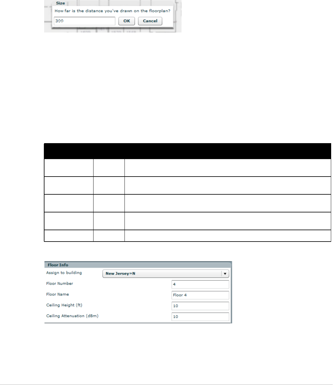
Dell PowerConnect W-AirWave 7.5 | User Guide Using VisualRF | 297
2. Locate two points within the floor plan that you know the distance. Most door jams (door openings) are 3
feet.
3. Select and hold to establish the first point and drag your mouse to the second point and release.
4. A distance dialogue box appears. Enter the proper length in feet, as shown in Figure 237.
Figure 237 Manually Measuring a Floor Plan
5. Select OK.
Floor plans can be resized in VisualRF after they have been uploaded. Within VisualRF you will also be able to
zoom in on a room or doorway to increase the accuracy of your sizing.
Removing Color from a Floor Plan Image
To remove color, locate the Image Manipulation section and select B&W in the Image field.
Assigning Campus, Building and Floor Numbers
Locate the Floor Info Section and assign the following information, as detailed in Table 151 and illustrated in
Figure 238:
Figure 238 Entering Floor Info for the Uploaded Floor Plan Image
Table 151 Assigning numbers
Setting Default Description
Building drop-down N/A Use this drop-down to associate the floor with a building which associate it to a Campus as
well.
Floor Number 0.0 The floor number. You can enter negative numbers for basements.
NOTE: Each floor plan within a building must have a unique floor number.
Floor Name Floor
[Number]
A descriptive name for the floor. It inherits the floor number as a name if nothing is entered.
Ceiling Height 10 Specifies the height from the floor to the ceiling. This will default to the ceiling height for the
building, but you can override here if needed for atria or basements.
Ceiling Attenuation 20 Specifies the attenuation characteristics in dB of the ceiling or the floor above.
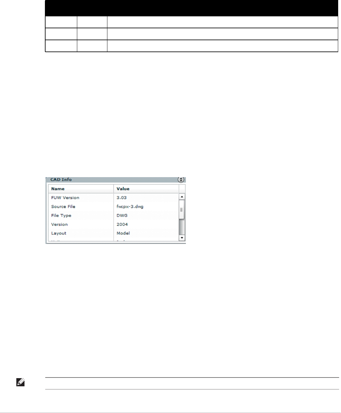
298 | Using VisualRF Dell PowerConnect W-AirWave 7.5 | User Guide
Assigning Optional Planner, Owner, or Installer Information for the Floor Plan
Locate the Optional Information section and enter the following information in Table 152:
Controlling the Layers in the Uploaded Floor Plan (CAD only)
Follow these steps for CAD images:
1. Find the CAD Layers section on the page.
2. Unselect the layers which are not required. There is slight delay because each request makes a round trip to
the server.
Error Checking of CAD Images
VisualRF will check for errors in your uploaded CAD image. You can view any issues as follows:
1. Locate the CAD Info section, as shown in Figure 239.
2. Review the CAD version, units of measurement, and raw width and height numbers.
Figure 239 Checking for CAD errors
Last Steps in Editing an Uploaded Image
Click the Save and Close button to begin provisioning APs or Save and New to upload another floor plan. After
clicking Save and Close, you are redirected back into QuickView where you can provision APs, Wiring Closets,
and wired infrastructure.
Provisioning Existing Access Points onto the Floor Plan
To provision existing AP in your network onto the floor plan you just uploaded, follow these steps:
1. Navigate to VisualRF > Floor Plans.
2. Select the floor plan you have uploaded using the floor number or name links in the list.
3. Select the Add Deployed Device icon in the Edit menu. A pop-up window list of devices in your AirWave
appears, as shown on 5.
4. Select whether to navigate by Group or by Folder in the View By field.
Table 152 Optional Information for the Floor Plan
Setting Default Description
Owner N/A The owner of the floor (used in diagnostics and alerts).
Planner N/A The person in charge of planning the RF layout for the floor.
Installer N/A The person in charge of installing RF equipment for the floor.
NOTE: Wired-only access device, such as RAP-5, do not have any radios and, therefore, should not be included on a floor plan.
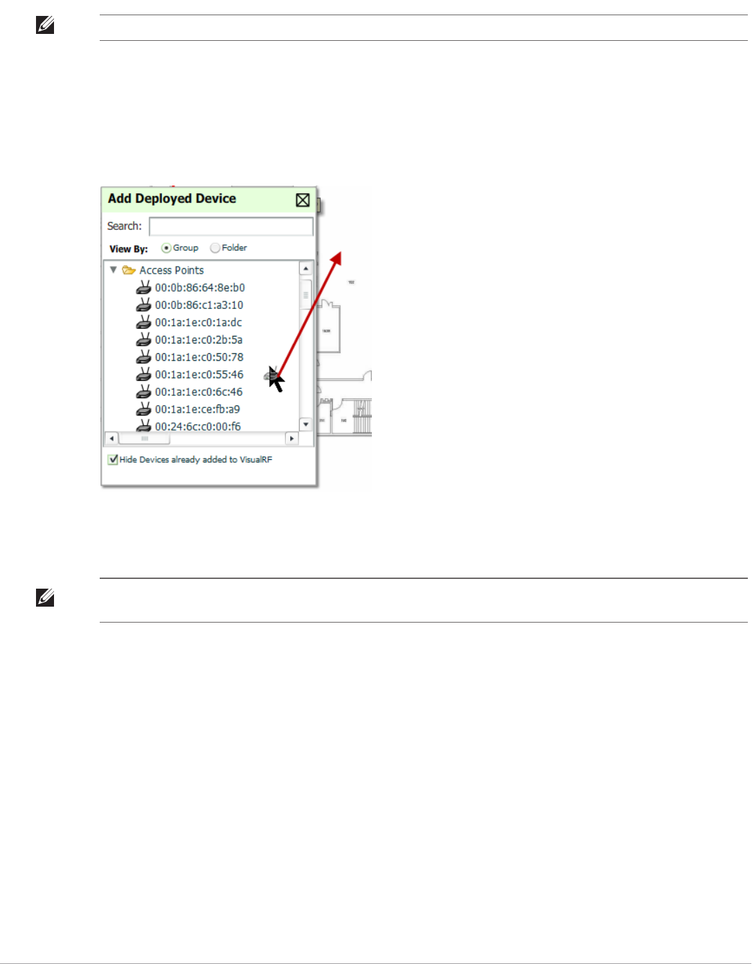
Dell PowerConnect W-AirWave 7.5 | User Guide Using VisualRF | 299
5. Select whether to navigate by Group or by Folder in the View By field.
6. Expand the Group or Folder containing the access points which need to be provisioned on this floor plan.
Note that by default, devices that have already been added to VisualRF are hidden. To show them, clear the
“Hide Devices already added to VisualRF” checkbox at the bottom of the list.
7. Click and drag an AP to its proper location on the floor, as shown in Figure 240:
Figure 240 Provisioning APs onto the Floor Plan
8. Once all APs are provisioned on the floor plan, select Save (floppy disk icon) in the top right of the QuickView
window.
Automatically Provisioning APs onto a Floor Plan
To automatically provision your access points onto your floor plan:
1. Select Draw Region from the Edit menu. A new provisioning popup appears as shown in 4. with a crosshair
pointer.
NOTE: Alternatively, you can use the Search field.
NOTE: The floor is submitted to one of the core threads to recalculate path loss and then to one of the location caching threads to
recalculate client locations. All changes may not be visible on a refresh until this process complete.
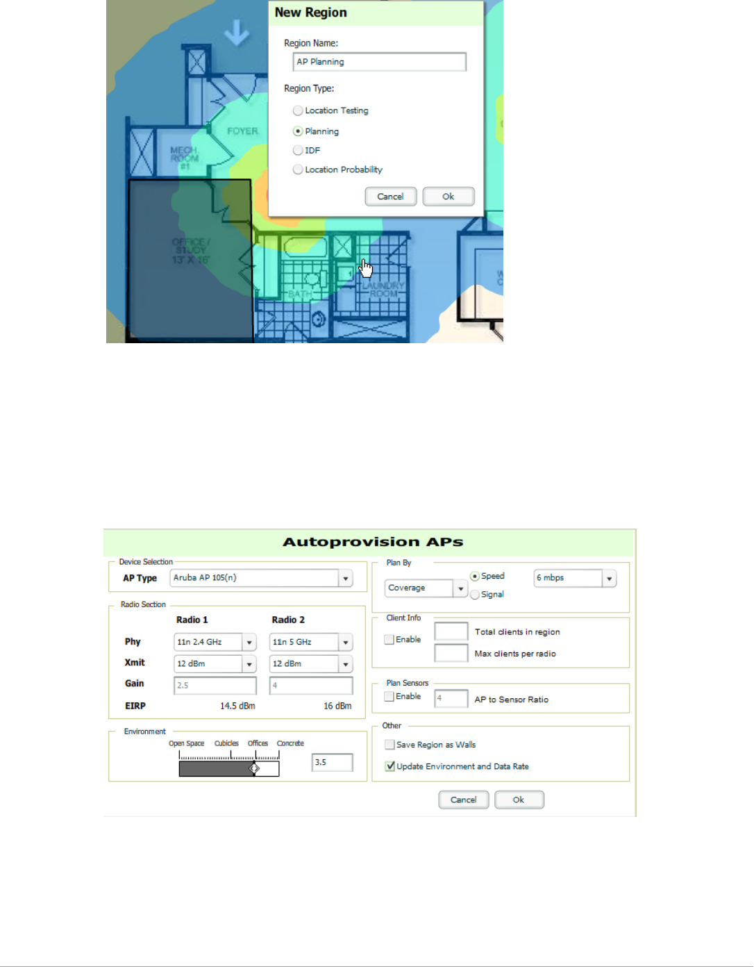
300 | Using VisualRF Dell PowerConnect W-AirWave 7.5 | User Guide
Figure 241 Planning Region Drawing and Selection Illustration
2. Draw your polygon as follows:
Left-click to initiate the process. The tool will automatically shade in your provisioning area.
Complete the polygon by double-clicking.
3. Once you have finished drawing the region, enter a name for the region and select a Region Type of Planning.
Then select OK. The following image displays.
Figure 242 Autoprovisioning APs

Dell PowerConnect W-AirWave 7.5 | User Guide Using VisualRF | 301
4. Enter the following information into the Autoprovision APs window as described in Table 153:
5. Wheen you’re finished selecting the desired options, select OK.
Tweaking a Planning Region
If the planning layout does not meet your expectations, you can edit by right-clicking within the region to see the
following options:
-Delete Planned APs in the Region - Deletes only provisioned APs in the region
-Reprovision APs - Remove all planned APs inside this region and prompts for new information to replan the
region
-Delete the Region - Deletes the region and all planned APs
Table 153 Fields in the Autoprovision APs Window
Field Description
Device Selection
AP Type The type of AP used in this planning region.
Radio Section
Phy Whether they PHY is set to 11n or no radio.
Xmit Transmit power of the APs.
Gain Gain of the APs.
EIRP EIRP of the APs.
Environment A range from 1-4 that best describes whether the environment is related to an office space, cubicles,
offices, or concrete. Decimal points are allowed.
Plan By Section
Coverage Plan Coverage by Speed or Signal.
Location Plan for location accuracy. This mode will result in additional APs placed near the edge of the region
to aid in location calculation.
Number of APs Number of APs to place in the planning region.
Client Info Section
Enable Whether to enable planning by user capacity.
Total clients in region Set the anticipated number of clients that will be stationed in a region.
Max clients per radio The maximum number of clients supported by each radio.
Plan Sensors
Section
Enable Whether to enable to plan sensors into the region.
AP to Sensor Ratio Specify the number of sensors per AP to use when planning the region.
Other Section
Save Region as Walls Whether to save the edges of the planning region as walls.
Update Environment
and Data Rate
Whether to update the environment and data rate in case of changes.

302 | Using VisualRF Dell PowerConnect W-AirWave 7.5 | User Guide
-Edit the region - Change the name of the region
-Copy the Region to floors above - Will copy the region and auto plan for floors above.
To replicate a floor plan, follow these steps:
1. Navigate back to the Building view by clicking on the navigation tags in the bottom-right corner of the
window.
2. Right-click the floor and select Duplicate.
3. Enter the following information:
Starting and ending floors
Select the toggles to copy walls, regions, data rates (speeds), and AP placement
4. Select OK to save your changes.
5. Manually refresh page and your is redirected to the VisualRF > Floor Plan page. The Building view will
reflect the new floors.
Auto-Matching Planned Devices
You can right-click a campus, building, or network icon and select the Auto-Match Planned Devices option to
efficiently match planned APs to managed APs. If you select this option for a campus, then all planned APs in
that campus are checked. If used on a building, then all the APs in that building are checked. If used on a floor,
then all APs on that floor are checked.
Planned devices first attempt to auto-match on MAC address, and then by name. The VisualRF MAC address
checks against all of the LAN MAC addresses of a deployed AP.
Printing a Bill of Materials Report
You can generate a Bill of Materials (BOM) Report from within VisualRF in Word format. Follow these steps:
1. Navigate back to the Network view.
2. Right select Campus icon and select Show Bill of Materials. A generating report popup appears.
3. Select options such as heatmap, speed, sensor coverage, wired range, and summary.
4. Select OK. A BOM report appears in Microsoft Word as illustrated in Figure 243:
NOTE: The starting floor will add one to the highest floor in the building and the ending floor defaults to 10 more than the starting
floor.
NOTE: The starting floor will add one to the highest floor in the building and the ending floor defaults to 10 more than the starting
floor.
NOTE: You should see all replicate floors with matching number of access points.
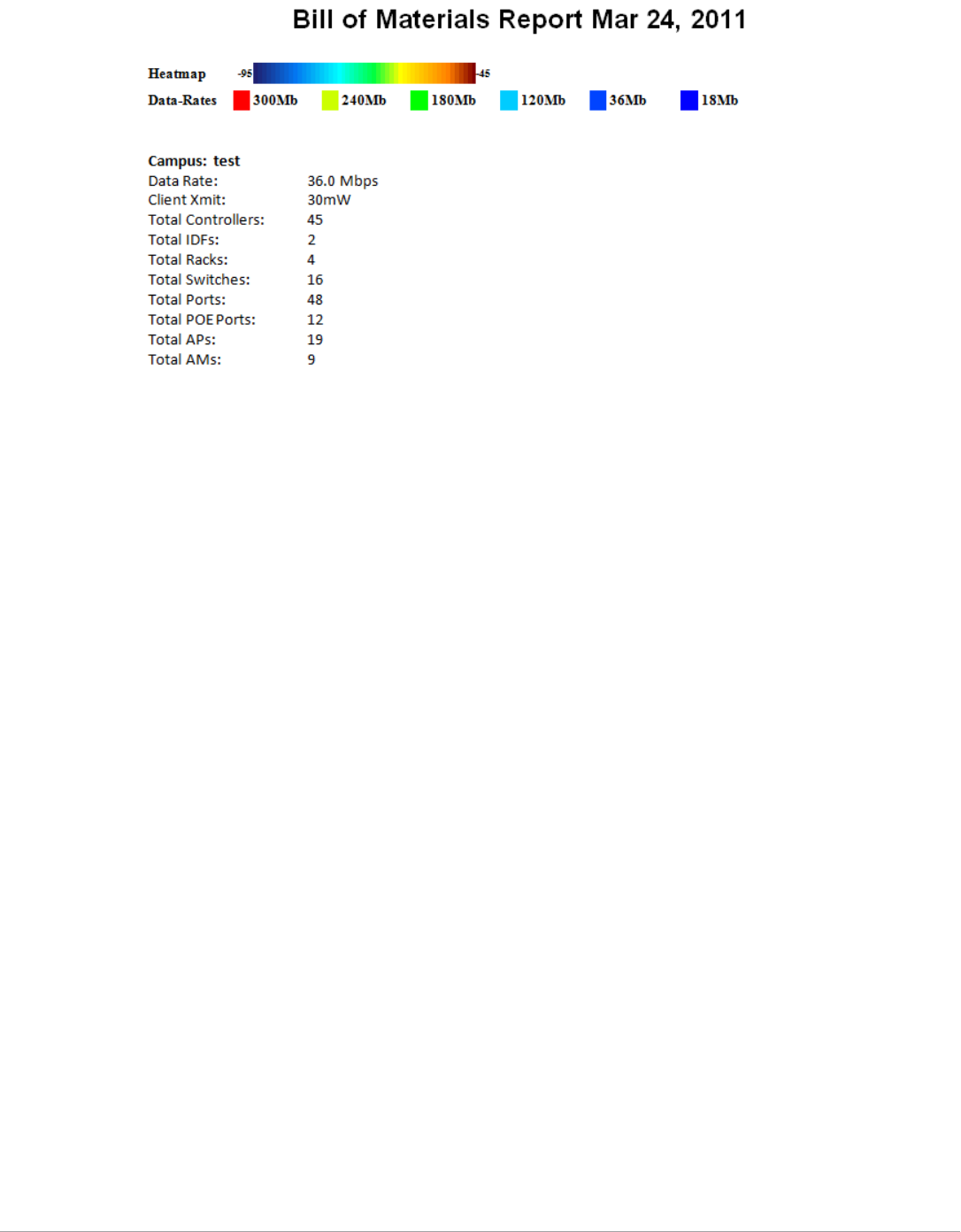
Dell PowerConnect W-AirWave 7.5 | User Guide Using VisualRF | 303
Figure 243 Bill of Materials Report Illustration
Importing and Exporting in VisualRF
Exporting a campus
To export a campus from VisualRF so you can import it into another AirWave, follow these steps:
1. Navigate back to the Network view.
2. Right-click the Campus icon.
3. Select Export. An object selection window appears.
4. Select the objects to export and select Export. A File Download window appears.
5. Select Save and save the zipped file to your local hard drive for importation to another AirWave.
At this point, you are ready to deploy a production AirWave and manage devices by importing your exported
campus and matching the access points to your plan.
Importing from CAD
The Floor Plan Upload Wizard (FUW) should inherit all pertinent information from your CAD file if you follow
this procedure:
1. Determine UNITS - all modern CAD versions (2001 and newer) support UNITS
2. Determine MEASURE - Legacy CAD versions (2000 and older) used a Imperial or Metric system.
If UNITS are 0 or undefined, then the standard dictates defaulting to MEASURE value
If MEASURE is 0 or undefined, then the standard dictates defaulting to English and inches
3. Find MODEL VIEW - If the drawing contains multiple views the FUW will default to the Model view
4. Determine Bounding Box - FUW will encompass all lines and symbols on the drawing and create a bounding
box which is generally smaller than entire drawing. It is based on the UNITS or MEASUREMENT above.
5. Convert to JPG - FUW will convert the bounding box area to a JPG file with a resolution of 4096 horizontal
pixels at 100% quality.
6. Start Web UI of FUW Step #1 - This is the cropping step.
This and all subsequent steps use the converted JPG file. The greater the floor plan dimensions, the less clarity
the background image provides.

304 | Using VisualRF Dell PowerConnect W-AirWave 7.5 | User Guide
Batch Importing CAD Files
This process provides the ability to automatically upload many CAD files and auto provision existing walls and
access points, and contains the following topics:
-“Requirements” on page304
-“Pre Processing Steps” on page304
-“Upload Processing Steps” on page304
-“Post Processing Steps” on page304
-“Sample Upload Instruction XML File” on page305
-“Common Importation Problems” on page305
Requirements
-Operating System: Client machine must be Windows XP, Windows Vista, or Windows 7
-Flash: Version 9 or later
Pre Processing Steps
1. Increase Memory Allocation in VisualRF > Setup as follows:
25 floors or less - 512 MB
25 to 75 floors - 1 GB
More than 75 floors - 1.5 GB
2. Massage the output data.
3. Increase the Location Caching Timer to 1 hour so that VisualRF does not overload the server calculating
client locations while calculating path loss and process floor plan images.
Upload Processing Steps
1. Create CAD XML files which contain drawing filename, dimensions and optional information like device
manufacture and model, device coordinates, wall coordinates and building material. This step is usually
performed by your facilities or CAD department. The output of AutoCAD will not be properly formed XML,
so you may need to massage the output data.
2. Copy all CAD drawings and corresponding XML files into a single directory on Windows machine. All files
must be in a single directory.
3. Compress all files into a single *.zip file.
4. Open your browser and navigate to your AirWave: https://<AirWave_NAME>/visualrf/site_batch.
5. Select Browse to launch the File Explorer Window.
6. Select the zip file containing the upload instructions and click the Open button. The File Explorer Window
will disappear you will return to the Batch Floor Upload Wizard.
7. Select Next.
8. The application validates the following information
Well-formed XML
All drawing files are accessible
All APs are present
All Building and Campuses are present
9. If there are any errors, none of the floor plans are created.
Post Processing Steps
1. Decrease the Location Caching Timer to previous value.

Dell PowerConnect W-AirWave 7.5 | User Guide Using VisualRF | 305
2. Review the VisualRF > Floor Plans page to ensure server is keeping up.
Sample Upload Instruction XML File
<?xml version="1.0" encoding="ISO-8859-1"?>
<visualrf:site_batch xmlns:visualrf="http://www.airwave.com" xmlns:xsi="http://
www.w3.org/2001/XMLSchema-instance" version="1" origin="lower-left">
<floor name="1st Floor" number="43" building-name="Library" campus-
name="University">
<image filename="blueprint1.dwg"/>
<access-points>
<access-point name="ART.1.1" x="190.26" y="222.31"/>
<access-point name="ART.1.2" x="136.12" y="208.60"/>
<access-point name="ART.1.3" x="75.02" y="221.47"/>
<access-point name="ART.1.4" x="73.41" y="132.48"/>
<access-point name="ART.1.9" x="196.67" y="98.34"/>
<access-point name="ART.1.8" x="179.07" y="55.97"/>
<access-point name="ART.1.7" x="119.64" y="56.12"/>
<access-point name="ART.1.6" x="74.53" y="56.36"/>
<access-point name="ART.1.5" x="59.18" y="38.01"/>
</access-points>
</floor>
<floor name="2nd Floor" number="44" building-name="Library" campus-
name="University">
<image filename="blueprint2.dwg"/>
<access-points>
<access-point name="ART.2.12" x="196.31" y="92.19"/>
<access-point name="ART.2.11" x="204.82" y="55.78"/>
<access-point name="ART.2.10" x="133.08" y="55.81"/>
<access-point name="ART.2.9" x="73.79" y="55.78"/>
<access-point name="ART.2.8" x="73.72" y="104.26"/>
<access-point name="ART.2.7" x="73.91" y="134.88"/>
<access-point name="ART.2.6" x="73.83" y="162.72"/>
<access-point name="ART.2.5" x="73.82" y="183.61"/>
<access-point name="ART.2.4" x="63.74" y="125.48"/>
</access-points>
</floor>
</visualrf:site_batch>
Common Importation Problems
-Improper or undefined UNITS or MEASURE
-Text embedded into the Model view which causes an inconsistent bounding box
-Large dimensions which cause grainy resolution upon zoom
-Legacy CAD versions prior to Release 15 or AutoCAD 2000.
Importing from a Dell PowerConnect W-Series Controller
The instructions below will enable you to seamlessly migrate all building, campus, and floor plan information
previously entered into a Dell PowerConnect W-Series controller.
Pre-Conversion Checklist
Prior to importing floor plans, ensure that VisualRF's memory allocation is sufficient for the anticipated number
of floor plans.

306 | Using VisualRF Dell PowerConnect W-AirWave 7.5 | User Guide
To change the memory allocation, navigate to the VisualRF > Setup page and configure the memory allocation
accordingly. Memory allocation should equal .5 GB for 1-75 floor plans, 1 GB for 76-250 floor plans, 1.5 GB for
251-500 floor plans, and 2 GB for 501-1,000 floor plans.
Process on Controller
1. On the controller's UI, navigate to the Plan > Building List page.
2. Select the buildings to be exported and select Export.
3. When the dialog box appears, make sure that you have included all images and select Save to a file.
Process on AirWave
1. Navigate to VisualRF > Import.
2. Select the Import floor plans from a Dell PowerConnect W-Series link.
3. Select the Begin Importing Floor Plans link.
4. When prompted for input file, use the file saved from the controller process.
VisualRF Location APIs
VisualRF provides the following location APIs:
Site Inventory: https://[amp_host]/visualrf/site.xml?site_id=...
-You can find the site_id from the Floor Plan List query defined on the XML API page
-This interface provides floor details including access points, walls, regions, surveys, etc.
-The corresponding example XML and schema are attached in visualrf_site_inventory.*
Device Location: https://[amp_host]/visualrf/location.xml?mac=...
-Provide the radio MAC of the client to locate.
-The corresponding site where the user was placed is provided along with the dimensions
-If a client is heard on multiple floors, it will only be placed on the floor that contains the AP it is associated
with.
Sample Device Location Response
<visualrf:device_location version="1" xmlns:visualrf="www.example.com">
<device mac="00:13:02:C2:39:28" name="Peter"
site_id="4f674301-4b47-4ac6-8417-4eba3f7df3a6"
site_name="NewYork">
<site-width>124.51</site-width>
<site-height>161.14</site-height>
<x>82.50</x>
<y>37.50</y>
</device>
</visualrf:device_location>
Sample Site Inventory Response
<amp:amp_site_inventory version="1"
xmlns:amp=http://www.example.com
xmlns:xsi="http://www.w3.org/2001/XMLSchema-instance">
NOTE: Importing a large number of floor plans can impact performance of the AirWave server. VisualRF must create a thumbnail,
provision APs, create attenuation grid, and locate all clients on each imported floor plan. This can cause the VisualRF > Floor Plans
page to be unresponsive.

Dell PowerConnect W-AirWave 7.5 | User Guide Using VisualRF | 307
<site id="b45e7a49-23b5-4db0-891a-2e60bff90d2c" version="677">
<name>Remax</name>
<uom>ft</uom>
<width>314.45</width> <height>425.88</height>
<property name="site_owner" value="" format="" />
<property name="name" value="Remax" format="" />
<property name="installer" value="" format="" />
<property name="planner" value="" format="" />
<image type="background">
<filename>/var/example/snapshot/b45e7a49-23-2e6d2c.677/background.jpg</filename>
<relative-url>/snapshot/b423b5-4db0-891a2e0d2c.677/background.jpg</relative-url>
<pixel-width>1151</pixel-width>
<pixel-height>1557</pixel-height>
</image>
<image type="thumbnail">
<filename>/var/example/snapshot/b45e7a49891af90d2c.677/thumb.jpg</filename>
<relative-url>/snapshot/b45e7a49-23b5-4db0-891a2c.677/thumb.jpg</relative-url>
<pixel-width>230</pixel-width>
<pixel-height>311</pixel-height>
</image>
<ap id="12615" name="AP-4000M-1">
<x>118.97</x> <y>130.38</y>
<total-bandwidth>0</total-bandwidth>
<total-clients>0</total-clients>
<status>down</status>
<uptime>0.0</uptime>
<radio index="1" phy="g" mac="00:20:A6:5A:63:66" beamwidth="0.0"
gain="1.5" antenna="" orientation="0.0" mount="Ceiling" valid="false">
<discovering-radio id="11276" index="1" dBm="-85" />
<discovering-radio id="11828" index="1" dBm="-93" />
</radio>
</ap>
</site>
</amp:amp_site_inventory>
About VisualRF Plan
Overview
VisualRF Plan is a standalone Windows client that can be used for planning sites that do not yet use the AirWave
service on the Web. You can use VisualRF Plan to do basic planning procedures like adding a floor plan,
provisioning APs, and generating a Bill of Materials (BOM) report.
VisualRF Plan is free to use for anyone with a Dell support account. No license is required.
The client can be downloaded from the Dell Support Center.
Minimum requirements
Must be installed on a Windows machine with the following minimum specifications:
-250 MB Hard drive storage space
-2 GB RAM
-2.0 GHz dual-core CPU
NOTE: If installing VisualRF Plan on a VMWare virtual machine hosted by a Mac computer, you must disable Folder Sharing.

308 | Using VisualRF Dell PowerConnect W-AirWave 7.5 | User Guide
Installation
To install VisualRF Plan after you have downloaded it from the Dell support site:
1. The installer will prompt you for the location of the data directory. You must have access to the directory you
choose for the installation.
2. Choose a directory for auto-backup. The default is user directory.
3. Follow the rest of the instructions on your installation screen.
Differences between VisualRF and VisualRF Plan online
Table 154 VisualRF Plan vs. VisualRF Online
Feature VisualRF VisualRF Plan
Hardware sizing X
Installation required X
How to plan a site X X
Navigation X X
Track users X
Track interferers X
VisualRF APIs X
Location accuracy X
QuickView preferences X
Resource utilization X
Add external walls X X
Client surveys X
Wiring Closet X X
View deployed switches X
View signal strength X
Planning and provisioning X X
Import and Export X X

Dell PowerConnect W-AirWave 7.5 | User Guide Setting Up Dell PowerConnect-W Instant in AirWave | 309
Appendix A
Setting Up Dell PowerConnect-W
Instant in AirWave
This appendix describes the Dell PowerConnect W-Instant access point and Virtual Controller system, and the
procedure to integrate this system with AirWave. The appendix contains the following topics:
-“Overview of Dell PowerConnect W-Instant” on page309
-“Using Dell PowerConnect W-Instant with AirWave” on page309
-“Setting up Dell PowerConnect-W Instant” on page310
-“Remaining Manual Admin Tasks in AirWave” on page313
-“Adding Additional Instant APs to AirWave” on page315
-“Changing the Mode to Monitor Only for New Instant Devices” on page316
-“AirWave Pages with Instant-Specific Features” on page317
-“Other Available Features” on page317
-“Known Issues of the Dell PowerConnect-W Instant Integration with AirWave” on page317
Overview of Dell PowerConnect W-Instant
Dell PowerConnect W-Instant is a system of access points (W-IAP92, 93, 104, 105, 134, or 135) per Layer 2
subnet. Dell PowerConnect W-Instant IAPs are controlled by a single IAP that serves a dual role as a primary
Virtual Controller, eliminating the need for dedicated controller hardware. This system can be deployed through
a simplified setup process appropriate for smaller organizations, or for multiple geographically-dispersed locations
without an on-site administrator.
Only the first IAP/Virtual Controller you add to the network must be configured; the subsequent IAPs will all
inherit the necessary configuration information from the Virtual Controller. Dell PowerConnect W-Instant
continually monitors the network to determine which IAP should function as the Virtual Controller at any time,
and the Virtual Controller will move from IAP to IAP as necessary without impacting network performance.
The Virtual Controller technology in Dell PowerConnect W-Instant is capable of IAP auto discovery, 802.1X
authentication, role- and device-based policy enforcement, rogue detection, and Adaptive Radio Management
(ARM).
Using Dell PowerConnect W-Instant with AirWave
AirWave can be used to provision and manage a multi-site deployment of Instant networks. For example, if you
have 100 retail offices that require Instant to provide WLAN connectivity at each office, AirWave can be used to
provision all the 100 offices from a central site and also give the administrator the ability to monitor these
geographically dispersed Instant networks using an AirWave server (depending on the scalability
recommendations for AirWave).
With a distributed deployment where multiple locations each have an Dell PowerConnect W-Instant Virtual
Controller and IAPs, AirWave serves as a centralized management console. AirWave provides all functionality for
normal WLAN deployments including long-term trend reporting, PCI compliance, configuration auditing, role-
based administration, location services, RF visualization, and many other features.
Integrating Dell PowerConnect W-Instant systems into AirWave is unique from the setup of any other device
class due to the following considerations:

310 | Setting Up Dell PowerConnect-W Instant in AirWave Dell PowerConnect W-AirWave 7.5 | User Guide
-Discovery: AirWave does not discover Dell PowerConnect W-Instant devices via scanning (SNMP or HTTP)
the network. Each Dell PowerConnect W-Instant deployment will automatically check-in to the AirWave
configured within the IAP’s user interface. The first Virtual Controller for an organization will automatically
appear as a new device in AirWave. Subsequent IAPs are discovered via the Virtual Controller, just like
standard controller/thin AP deployments.
-Auto-provisioning: The first authorized Virtual Controller requires manual authorization into AirWave via
shared secret to ensure security. Along with the shared secret, the Virtual Controller sends an Organization
String which automatically initializes and organizes the IAPs in AirWave. Unlike the traditional infrastructure
of a physical controller and thin APs, Dell PowerConnect W-Instant automates many tedious steps of
developing a complex hierarchical structure of folders, config groups, templates, admin users, and admin roles
for Dell PowerConnect W-Instant.
-Communication via HTTPS: Because Dell PowerConnect W-Instant devices may be deployed behind NAT-
enabled firewalls, Virtual Controllers “push” data to AirWave via HTTPS. AirWave initiates no connections
to Dell PowerConnect W-Instant devices via SNMP, TFTP, SSH, and the like. This enables quick remote
setup without having to modify firewall rules.
-Virtual controller listed as separate device: The Virtual Controller is listed as an additional device, even
though it is part of the existing set of IAPs. If you have 10 physical IAPs, AirWave will list 10 Dell
PowerConnect W-Instant IAPs and one Dell PowerConnect W-Instant Virtual Controller. You can identify
the IAP acting as the Virtual Controller by their identical LAN MAC addresses in APs/Devices > List pages,
Device Inventory reports, and any other AirWave pages that list your network devices.
Refer to the Dell PowerConnect W-Instant Data Sheet for full operational and regulatory specifications, hardware
capabilities, antenna plots, and radio details.
Setting up Dell PowerConnect-W Instant
You can set up Dell PowerConnect W-Instant either manually or automatically (through DHCP). The automatic
setup is most suited for a multi-site Instant deployment. Both options are summarized here, but refer to the Dell
PowerConnect W-Instant Quick Start Guide, the Dell PowerConnect W-Instant Professional Installation Guide,
and the Dell PowerConnect W-Instant Access Point Installation Guides for 90, 100, and 130 Series IAPs for
information on setting up the hardware and configuring the network..
For each remote location, an on-site installer is required to physically mount the IAPs, connect to the Dell
PowerConnect W-Instant SSID, configure the WLAN, configure the names of the IAPs, and enter the
information in the first IAP’s user interface that will enable communication with AirWave.
An AirWave administrator sends an Organization String and Shared Secret key along with AirWave’s IP address
to the on-site installer. The AirWave admin later validates the first Virtual Controller's Organization String and
its Shared Secret when it appears in the APs/Devices > New list. The administrator also enables user roles to
administer the Dell PowerConnect W-Instant systems, makes any other changes in AirWave as necessary.
NOTE: A device that is added as a virtual controller does not count as a license for AirWave.
NOTE: The first Instant network that is added to AirWave includes the ‘golden’ configuration that is used as a template to
provision other Instant networks at other locations as the locations are brought online. It is recommended that the ‘golden’
configuration is validated and pre-tested in a non-production environment prior to applying it to a production network. Users
have the option to add additional devices into managed mode automatically by setting the Automatically Authorized Virtual
Controller Mode option to Manage Read/Write on the AMP Setup > General page. Refer to “AMP Setup > General” on
page 27 for more information. It is also important to note that any changes that are made to the template variables will have
to be manually applied to each deployed device.

Dell PowerConnect W-AirWave 7.5 | User Guide Setting Up Dell PowerConnect-W Instant in AirWave | 311
Setting up Dell PowerConnect W-Instant Manually
When setting up Dell PowerConnect W-Instant manually, you will be requested to provide an Organization
string, the AirWave IP address, and a Shared Key.
Creating your Organization String
The Organization String is a set of colon-separated strings created by the AirWave administrator to accurately
represent the deployment of each Dell PowerConnect W-Instant system. This string is entered into the Dell
PowerConnect W-Instant UI by the on-site installer.
The format of the Organization String is “Org:subfolder1:subfolder2...” and so on, up to 31 characters long.
“Org,” the top-level string, is generally the name of your organization and is used to automatically generate the
following (if not already present) in AirWave:
-AirWave Role: “Org Admin” (initially disabled)
-AirWave User: “Org Admin” (assigned to the role “Org Admin”)
-Folder: “Org” (under the Top folder in AirWave)
-Configuration Group: “Org”
Additional strings in the Organization String are used to create a hierarchy of subfolders under the folder named
“Org”:
-subfolder1 would be a folder under the “Org” folder
-subfolder2 would be a folder under subfolder1
To create your Organization String, consider the plan of how your Dell PowerConnect W-Instant IAPs are to be
physically distributed. As a best practice, the Organization String should mirror your company's geographical or
internal reporting structure. For example, if you plan to deploy Dell PowerConnect W-Instant in four stores in
two different cities for Acme Corporation, your Organization Strings might look like these:
-Acme:New York:Times Square Store
-Acme:New York:Queens Store
-Acme:San Francisco:Sunset Store
-Acme:San Francisco:SOMA Store
The Shared Secret Key
The Shared Secret key is used by the administrator to manually authorize the first Virtual Controller for an
organization that appears in the APs/Devices > New page in AirWave. Any string is acceptable, but this string
must be the same for all devices in your organization.
At this point, the admin in our example should send the Organization String, Shared Secret key, and AirWave IP
address to the on-site installers setting up Dell PowerConnect W-Instant hardware inside the storefronts.
Entering the Organization String and AirWave Information into the IAP
For the initial IAP/Virtual Controller set up in each location, the on-site installer logs in to the first IAP's web
interface via the Dell PowerConnect W-Instant configuration SSID, and navigates to Settings > AirWave. The
installer then enters the correct Organization String, the AirWave IP address, and the Shared Secret key, as
shown in Figure 244. Perform the following steps to set up AirWave in Instant.
1. Log into your IAP.
NOTE: Always ensure the protection of your organization’s shared secret. Knowledge of this shared secret, the organization
string, and communication protocol could allow a rogue device to masquerade as an Dell PowerConnect W-Instant device.
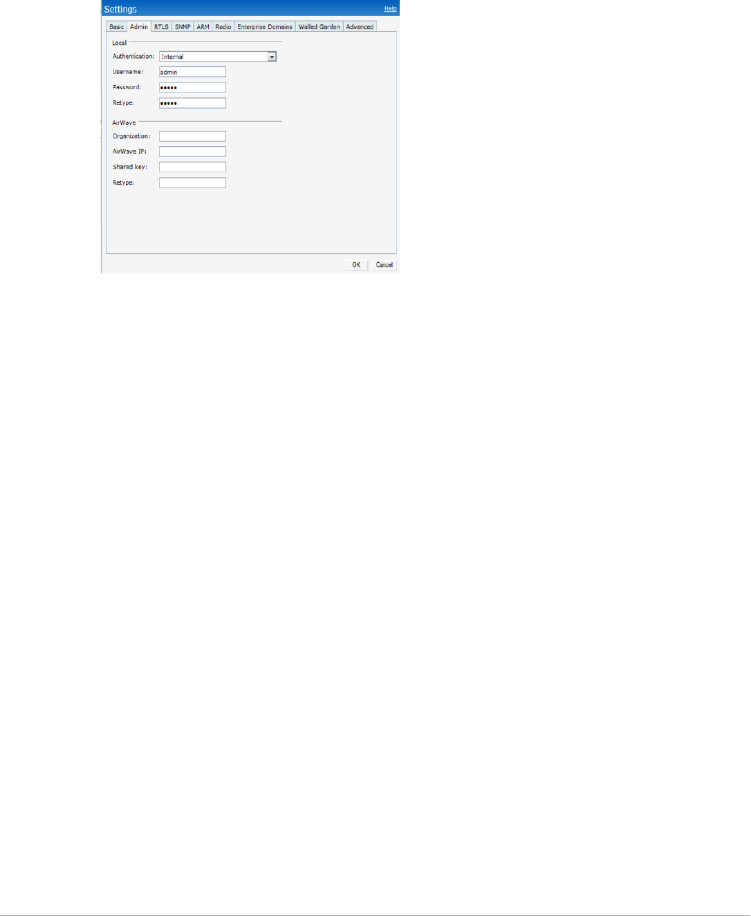
312 | Setting Up Dell PowerConnect-W Instant in AirWave Dell PowerConnect W-AirWave 7.5 | User Guide
2. Click on either the Set up Now at the bottom of the UI or on the Settings tab in the top right corner. This
opens the Settings menu.
Figure 244 Dell PowerConnect W-Instant > Settings page.
3. Locate the AirWave section on the Admin tab.
4. Enter the Origanization string, the AirWave IP address, and the Shared key.
5. Click OK when you are finished.
Setting up Dell PowerConnect W-Instant Automatically
Instant can be configured automatically using DHCP options 60 and 43.
The Dell PowerConnect W-Instant Virtual Controller initiates DHCP request with the DHCP option 60 string
‘DellPowerConnectWInstant.’ If the DHCP server is configured to recognize this option 60 string, it will return
an option 43 string containing the organization, AirWave IP, and pre-shared key (Organization is optional). The
three pieces of information should be specified using comma separators without any spaces. For example,
option 43 text "TME-Instant,10.169.240.8,dell123"
The AirWave information in the option 43 will be used to connect to AirWave, if AirWave is not otherwise
configured manually on the Virtual Controller.
The organization string can be hierarchical and define sub-folders for different stores. This supports an
architecture that is required to manage multiple branches or stores where individual stores can be managed by
local administrators.
DHCP server options:
ip dhcp pool IAP-Pool
default-router 10.169.241.1
option 60 text "DellInstantAP"
option 43 text "Acme:Store1,10.169.240.8,dell123"
network 10.169.241.0 255.255.255.0
authoritative
!
ip dhcp pool IAP-Pool2
default-router 10.169.242.1
option 60 text "DellInstantAP"
option 43 text "Acme:Store2,10.169.240.8,dell123"
network 10.169.242.0 255.255.255.0
authoritative
In the example configuration shown above, the following group and folder structure is created on AirWave:
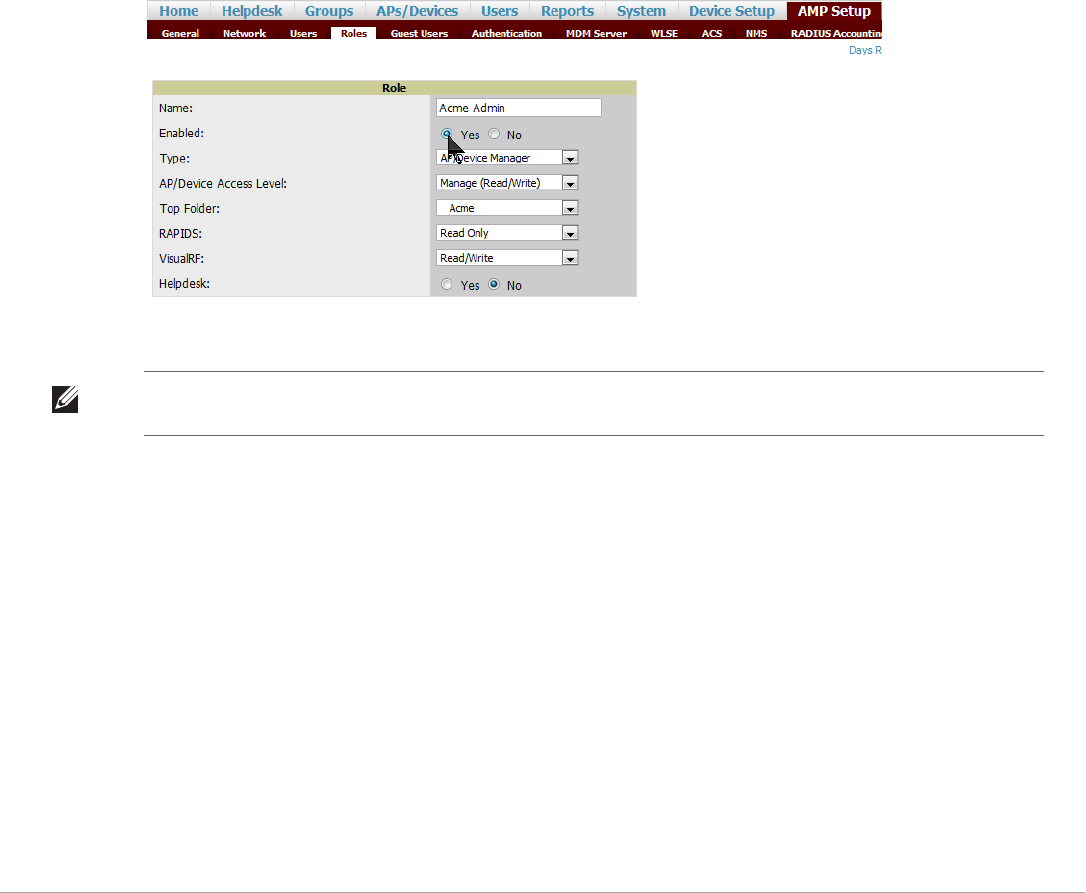
Dell PowerConnect W-AirWave 7.5 | User Guide Setting Up Dell PowerConnect-W Instant in AirWave | 313
-A group called Acme is created.
-A top-level folder called Acme is created.
-Two sub-folders called Store1 and Store2 are created which will contain the IAPs.
Reset your IAP to factory default state and reboot the IAP. You will see that the IAP will create a new role
automatically with the name that you have used in option 43. It will append the name with ‘Admin’ so it becomes
“Acme Admin”.
Remaining Manual Admin Tasks in AirWave
Once the setup is complete, what remains is to enable the newly created role, verify the shared secret, and add the
device.
Enabling the IAP Role
As stated previously, new IAP devices can be added to AirWave automatically. The Admin will then complete the
following tasks.
1. Enable the newly created Admin User Role in AMP Setup > Roles, as shown in Figure 245.
Figure 245 Enable Admin User Roles in AMP Setup > Roles
2. In Groups > Template for the newly created group, verify the first Virtual Controller's auto-created template.
3. Evaluate, approve, or ignore incoming Virtual Controllers with a different top level Organization String and/or
Shared Secret in the APs/Devices > New list. Subsequent IAPs are auto-authorized if they have an
Organization/Shared Secret key that matches the Shared Secret key of any existing authorized Virtual
Controller in the top-level Organization String.
4. Set the initial Virtual Controller to Manage Read/Write mode and push the good configuration to the
subsequent IAPs.
5. Set up AirWave users to have access to specific folders, if desired.
Verifying the Shared Secret
After the role is enabled, the Dell PowerConnect W-Instant device will appear in the APs/Devices > New page,
the admin user should mouse over the value under the Type column to verify the device’s Shared Secret with
AirWave, as shown in Figure 246.
NOTE: NOTE: The auto-created template is most useful if the first Virtual Controller for the top-level Organization String is fully
configured on-site before it is pointed at AirWave in the Virtual Controller’s UI.
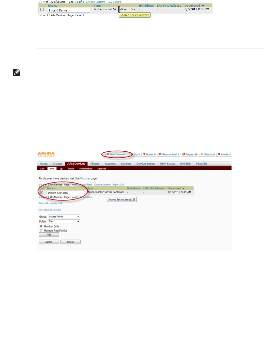
314 | Setting Up Dell PowerConnect-W Instant in AirWave Dell PowerConnect W-AirWave 7.5 | User Guide
Figure 246 Mouseover the Dell PowerConnect W- Instant Type to Indicate Shared Secret
If the incoming Shared Secret matches the one you created, select Add, then Save and Apply in the confirmation
page.
Adding the Instant Device to AirWave
After the first Instant device receives the AirWave server information from the DHCP server or after AirWave
server information is manually configured, the Instant device appear as a new device in AirWave. As shown, this
virtual controller is added in Monitor Only mode.
Figure 247 A new Instant device in AirWave
1. Click Add to add the device. A Group and Folder do not have to be selected. The Instant device will
automatically get added to the new group that was created.
2. Select Apply Changes Now to add the Instant device to the group.
Resolving Mismatches
The new device will appear in AirWave as two devices: the first is the Virtual Controller for that Instant network,
and the second is the access point itself. In some cases, the Instant device shows up as having Mismatched
configuration. This occurs when the AirWave information was received from Instant via the DHCP server (i.e,
was not manually configured).
Clicking on the mismatched device opens the audit page of the device, showing the reason for the mismatch. The
configuration shows the desired configuration versus the current Instant configuration. As shown in the following
image, the AirWave IP address, shared secret, and organization string has to be provisioned on the Instant device.
NOTE: With an Organization specified, you do not have to select any Group or Folder from the drop-down menus on the APs/
Devices > New page. In fact, if you do change the Group/Folder drop-down menus, all Organization-specified Virtual
Controllers will ignore these values and will use the folder/group values from the Organization String instead. If you select
Add for some non-Dell PowerConnect W-Instant devices as well as some Organization-specified Virtual Controllers, the drop-
down menus will apply to the non-IAPs but not the Virtual Controllers. If you have any Virtual Controllers with no Organization
specified the first time they communicate with AirWave, then they will be placed in the Folder/Group drop-box values you
have selected.
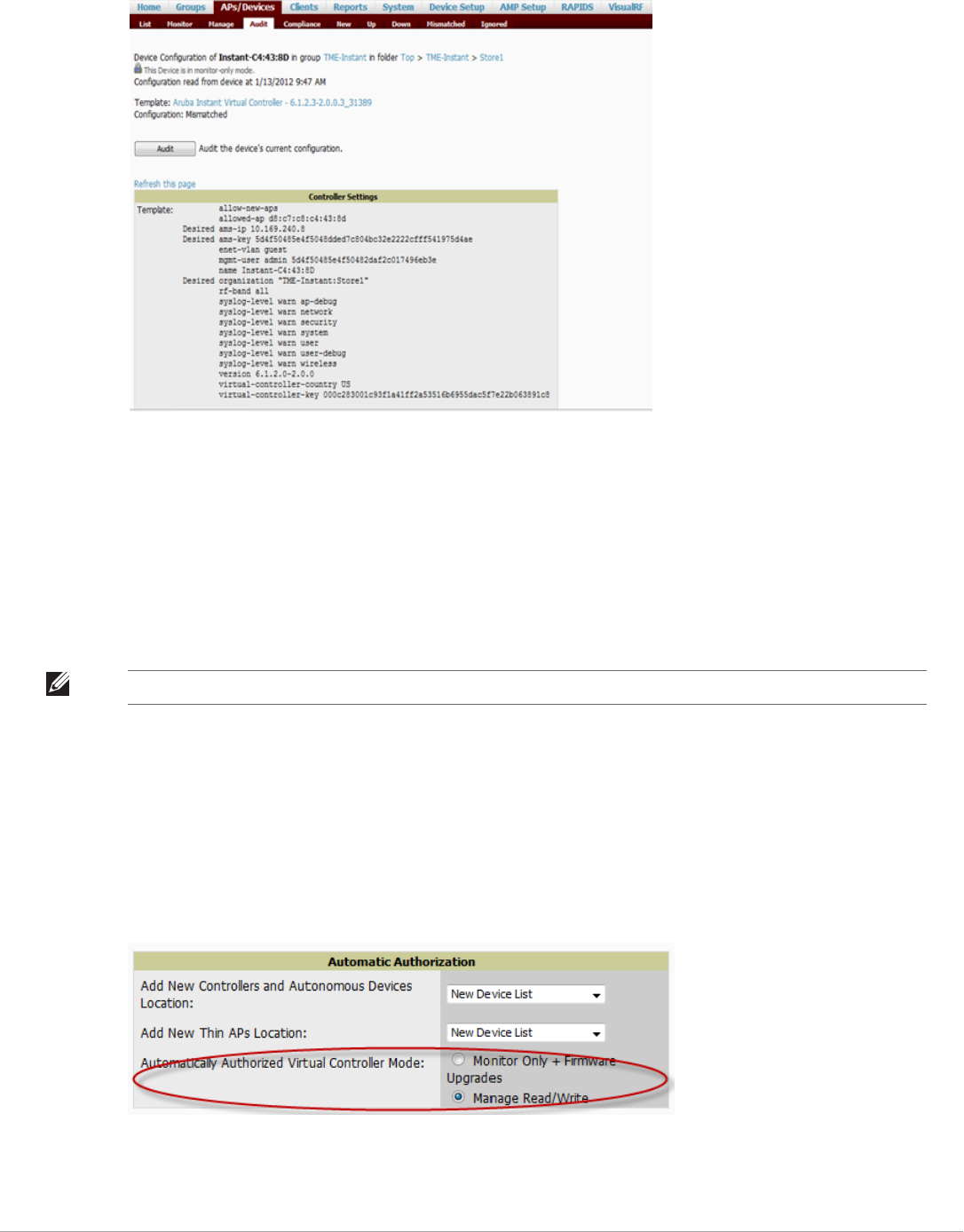
Dell PowerConnect W-AirWave 7.5 | User Guide Setting Up Dell PowerConnect-W Instant in AirWave | 315
Figure 248 Audit page
Perform the following steps to resolve the mismatch.
1. Navigate to the AP/Devices->Manage page for that Instant device.
2. Change the the Management Mode option to Manage Read/Write.
3. Click on Save and Apply at the bottom on the page.
4. When the Confirm changes page opens, click on Apply Changes Now for the changes take effect.
Upon completion, the configuration will be synced to the Instant network. The status of the device will initially
display as ‘Verifying’ during this process. The status will change to ‘Good’ after the provisioning is successful.
Adding Additional Instant APs to AirWave
After the first Instant device has been provisioned and set up in AirWave, additional Instant networks can be
added and provisioned automatically. To do this, set the Automatically Authorized Virtual Controller Mode
option to Manage Read/Write on the AMP Setup > General page. Refer to “AMP Setup > General” on page27
for more information.
Figure 249 Setting devices to Manage Read/Write mode
When the second Instant contacts AirWave using the DHCP server options as described previously, it shows up
on AirWave as shown below. Because the devices are in Manage Read/Write mode, there is no need for manual
NOTE: This is the same process for any configuration change sync that is done in future.
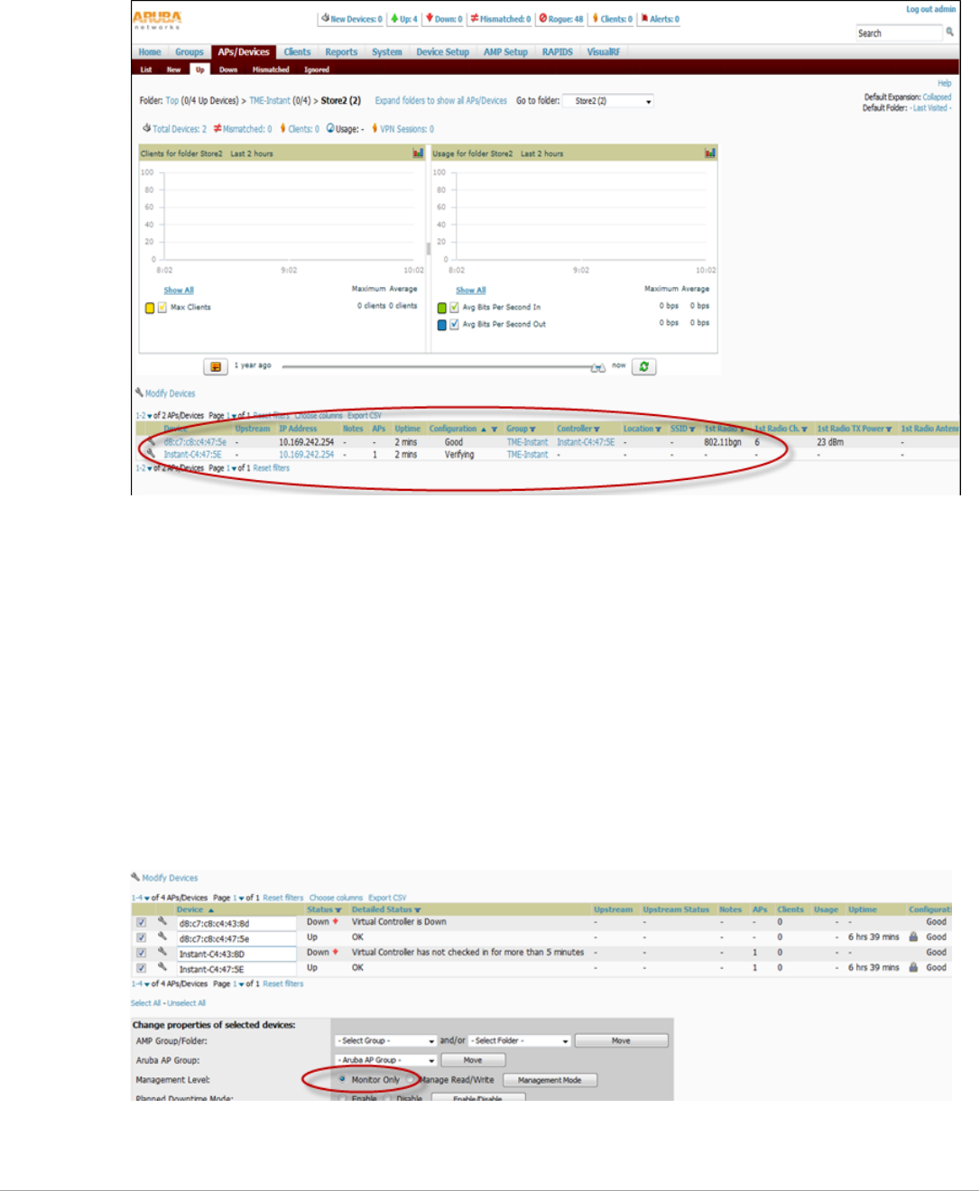
316 | Setting Up Dell PowerConnect-W Instant in AirWave Dell PowerConnect W-AirWave 7.5 | User Guide
intervention to provision these new Instant networks. The new networks will automatically be placed into the
same group (if this is the desired configuration), but a new folder will be created to contain these devices.
Figure 250 Adding a new Instant device to AirWave
The golden template configuration from the first Instant network is used to provision the second Instant network
in the new folder. When provisioning is complete, the status of the device will change from Verifying to Good.
Changing the Mode to Monitor Only for New Instant Devices
A best practice for using Instant in AirWave is to change the mode for new devices to Monitor Only. This ensures
that the configuration for the new devices does not get unintentionally overwritten.
1. Navigate to AP/Devices list page.
2. Filter by the folder name.
3. Select all devices and put them into monitor mode.
4. Click Save at the bottom of the page.
Figure 251 Changing the mode Monitor Only

Dell PowerConnect W-AirWave 7.5 | User Guide Setting Up Dell PowerConnect-W Instant in AirWave | 317
AirWave Pages with Instant-Specific Features
The following is a summary of AirWave pages affected by Dell PowerConnect W-Instant support:
-APs/Devices > New: When an Dell PowerConnect W-Instant device appears in the APs/Devices > New
page, an admin user can mouse over the value on the Type column to display the device's Shared Secret with
AirWave.
-APs/Devices > List: The Virtual Controller is listed as an additional device, even though it is part of the
existing set of IAPs. You can identify the IAP acting as the Virtual Controller by their identical LAN MAC
addresses.
-Clients > Client Detail: Once IAPs are serving clients, the IAPs can use user-agent strings to extract
operating systems and device descriptions of its clients, and then populate the Device Description and Device
OS fields in Clients > Client Detail.
-APs/Devices > Audit: Dell PowerConnect W-Instant configuration fetching can be performed in APs/
Devices > Audit. The running configuration is stored on the IAP and verified by the template.
-APs/Devices > Monitor > Radio Statistics: The Radio Statistics page for Dell PowerConnect W-Instant
devices displays CPU Utilization, Channel Utilization, Bandwidth, Power, and MAC/Phy Error statistics.
-RAPIDS: Because Dell PowerConnect W-Instant does not support mitigation or high-level rogue reporting, it
does not synchronize classification. All rogue devices are reported and stored in the AirWave for evaluation
based on high-level rule sets. Dell PowerConnect W-Instant currently does not match wireless BSSIDs to
local MAC addresses within an IAP's ARP table, and does not currently support IDS event notification.
-Reports: Dell PowerConnect W-Instant Virtual Controllers appear as a separate device in the Device
Inventory Report and most other reports that list devices.
Other Available Features
Firmware Image Management
AirWave pushes firmware to the Dell PowerConnect W-Instant Virtual Controller, and the Virtual Controller
pushes the firmware to the rest of its IAPs. When using AirWave to manage IAPs, you can upgrade the firmware
by loading the firmware onto AirWave and then scheduling an upgrade from AirWave.
Intrusion Detection System
AirWave automatically detects rogue IAPs irrespective of their location in the network. It prevents authorized
IAPs from being detected as rogue IAPs, and tracks and correlates the IDS events to provide a comprehensive
picture of your network’s security.
Known Issues of the Dell PowerConnect-W Instant Integration with
AirWave
If the Organization String configured on the Dell PowerConnect W-Instant device is different than what is
statically written in the template, AirWave will overwrite the configured Organization String to match the
template.
NOTE: AirWave does not provide a Device Uptime report for Dell PowerConnect W-Instant devices.

318 | Setting Up Dell PowerConnect-W Instant in AirWave Dell PowerConnect W-AirWave 7.5 | User Guide

Dell PowerConnect W-AirWave 7.5 | User Guide Index | 319
Index
Numerics
802.11 counters ........................72, 127, 128, 129, 202
A
AAA Servers ........................................................67, 77
Access Points
Adding with CSV File.....................................115
ACLs, see groups
ACS
Integrating .........................................................61
Servers ................................................................61
Active BSSIDs........................................................131
Adaptive Radio Management ...............................126
Adding a New Attenuation
VisualRF Settings............................................275
adding widgets..........................................................23
Administrative Roles .................................................4
Air Monitor ..............................................................66
AirMesh
templates..........................................................165
Alert Summary table......................................119, 200
alerts
Viewing ............................................................200
Warning Behavior, Setting................................27
AMON data collection............................................34
Antenna Diversity ..................................................142
AP Interface Polling Period ..................................128
AP/Device Manager role..........................................37
APs
Enabling Automatic Discovery.......................112
ARM ...............................................126, 128, 129, 151
ARM Events table..................................................129
Association History table ......................................213
Attenuation Settings
VisualRF Setup ...............................................274
audit
Configuring Iintervals.......................................28
device configuration ....................................... 136
PCI Compliance ............................................... 63
Audit (Read Only)................................................... 39
authentication priority............................................ 44
Auto Detect Upstream Device setting ................. 141
Automatic Authorization .......................... 29, 77, 110
available widgets ...................................................... 24
B
Backups .................................................................. 229
Restoring from a Backup ................................ 230
Running on Demand ...................................... 230
Using Failover ................................................. 230
Browser, Supported.................................................... 5
C
CDP, polling interval for device discovery .......... 112
Channel Busy Threshold......................................... 30
Choose Columns link.............................................. 20
Cipher .................................................................... 125
Cisco
ACS.................................................................... 47
Catalyst.............................................. 67, 155, 168
Configuring IOS Templates................... 160, 165
Dynamic AP Management ............................. 144
IOS................................... 48, 58, 67, 75, 140, 155
Safe Flag in Firmware Upgrade...................... 148
Wireless Domain Services................................. 56
WLC ...................................................... 55, 67, 76
WLSE......................................................... 56, 279
Cisco Discovery Protocol
see CDP ........................................................... 112
Cisco IOS
Templates ........................................................ 165
Client Transmit Power, see VisualRF.................. 266
Comparing Device Groups ..................................... 98
Configuration Change Jobs, Viewing .......... 139, 222
Configuration Compliance chart......................... 217
Connected Users table .......................................... 135
Containment, managing rogue AP....................... 177

320 | Index Dell PowerConnect W-AirWave 7.5 | User Guide
CSV File, adding multiple devices with ..............115
Current Association...............................................213
D
Dashboard
Customizing Display ........................................23
Date and Time
Configuring .........................................................6
Deauthenticate Client...........................................213
Dell Overrides ........................................................153
Dell PowerConnect W-Instant .............................309
templates..........................................................164
Detected Interfering Devices................................130
Device Events...........................................................33
Device OUI score...................................................179
Device Troubleshooting Hint .................................30
Device Type Setup...................................................55
devices.....................................................................107
adding manually ..............................................112
communication settings....................................50
discovering, managing, and troubleshooting.107
folders...............................................................136
importing via CSV ..........................................116
individual support and firmware upgrades ....147
modifying.........................................................101
status ................................................................140
troubleshooting a newly discovered device....149
verifying....................................................118, 136
DHCP, using..........................................................143
Discovery
Automatic AP ..................................................112
Discovery Events table...........................................186
Disk Space charts...................................................226
DNS Hostname Lifetime ........................................30
E
editing interfaces ...................................................134
Error fetching existing configuration ...................150
Expand folders to show all APs.............................118
Export CSV..............................................................22
external logging........................................................32
F
Failover.......................................................3, 227, 230
Firefox.........................................................................5
firewall,configuring ................................................... 9
firmware
MD5 Checksum ................................................ 53
specifying minimum versions for APs.............. 97
uploading..................................................... 52, 54
firmware upgrade jobs,viewing.............................. 222
firmware upgrades in monitor-only mode.............. 33
Folders.................................................................... 136
FTP Server,enabling................................................ 34
fully qualified domain names................................. 30
G
getting started with AirWave .................................. 17
Global Dell PowerConnect W Configuration..... 151
Global Groups
with Master Console....................................... 228
Global Templates .................................................. 170
Google Chrome ......................................................... 5
Google Earth.................................... 16, 122, 141, 293
Groups.............................................................. 67–105
Changing Multiple Group Configurations..... 99
Comparing......................................................... 98
Configuring Basic Group Settings................... 70
Configuring Group AAA Servers...................... 77
Configuring Group SSIDs and VLANS .......... 82
Configuring Radio Settings.............................. 85
Configuring Security Settings.......................... 79
Deleting ............................................................. 99
Deleting a Group .............................................. 99
Global Groups........................................... 69, 104
MAC ACLs........................................................ 97
Overview ............................................................ 68
Radio Settings ................................................... 85
Security .............................................................. 79
Viewing .............................................................. 69
groups
Configuring Group Templates....................... 155
Guest Access Sponsor role....................................... 41
Guest User Configuration....................................... 31
Guest Users .............................................................. 33
H
hardware requirements .............................................. 5
Heatmap, see VisualRF
Historical Data Retention ...................................... 32
HP ProCurve.................................................... 77, 155

Dell PowerConnect W-AirWave 7.5 | User Guide Index | 321
HTTP Timeout ........................................................51
I
IAP..........................................................................309
ICMP settings..........................................................52
IDS Events .............................................................201
ignore device ..........................................................117
Incidents.................................................................201
Instant
Dell PowerConnect W ....................................309
templates..........................................................164
Interface Monitoring page ....................................134
Interfering Devices ..................................................33
Internet Explorer .......................................................5
IP address
adding and assigning...........................................8
iPhone.....................................................................228
L
LDAP
authentication ...................................................43
configuring authentication and authorization 48
Licenses ..................................................................122
Linux CentOS 5
installing ..............................................................6
localization...............................................................18
Location Calculation Timer Settings
VisualRF Setup ...............................................273
Location Settings
VisualRF Setup ...............................................272
Logging out ............................................................232
Login message, configuring.....................................44
logs
ARM Events.....................................................129
async_logger.....................................................191
audit ...................................................................32
config_pusher ..................................................191
error_log ...........................................................191
syslog ..................................................................32
M
MAC/Phy errors .....................................................128
Maintenance windows.............................77, 103, 144
Manage (Read/Write)..............................................39
Managed AMPs
adding...............................................................228
Master Console.................................................. 3, 226
Public Portal.................................................... 227
Master Console and Failover.................................... 3
Mesh
Device-to-Device Link Polling......................... 72
Gateway ........................................................... 122
in VisualRF...................................................... 269
Mode................................................................ 122
Monitoring ...................................................... 131
Proxim................................................................ 95
message-of-the-day .................................................. 44
Modify Devices link .............................................. 135
Monitor (Read Only).............................................. 39
monitoring
mesh devices .................................................... 131
wired devices.................................................... 132
wireless devices ................................................ 120
N
navigation................................................................. 10
understanding the UI........................................ 19
Network integration with AMP ................................ 3
network settings
defining.............................................................. 35
Nightly Maintenance Time setting ........................ 29
NMS ......................................................................... 62
non-UTF8 characters............................................... 31
NTP .......................................................................... 75
O
Open controller web UI link................................. 213
Organization String............................................... 311
OUI......................................................................... 179
P
pagination records
setting, resetting................................................ 21
pagination widget, using ......................................... 22
password
changing default root.......................................... 8
PCI Compliance
Default Credential Compliance ...................... 65
PCI Requirements ............................................ 64
Physical Interfaces table........................................ 134
planned maintenance mode ......................... 138, 140
Poll Now button .................................................... 121

322 | Index Dell PowerConnect W-AirWave 7.5 | User Guide
product overview
Configuring Date and Time...............................6
defining a scan.................................................109
executing a scan...............................................110
navigating...........................................................10
protocols and ports ....................................................9
Proxim 4900M..........................................................88
Q
Quick Links....................................................213, 217
R
Radio Enabled option ...........................................143
Radio Role field.....................................................152
radio settings
Configuring for Groups ....................................85
radio statistics ................................................ 126–131
Radio table .............................................................123
RADIUS ...................................................................77
authentication ...................................................43
configuring authentication and authorization45,
46
integrating..........................................................46
RADIUS Authentication Issues............................201
Radius/ARM/IDS Events retention........................33
RAPIDS............................................................14, 173
audit log ...........................................................188
enabling..............................................................31
overview................................................................2
score override ...................................................187
setup .................................................................175
viewing ignored rogues....................................186
Recent Events table ...............................................126
Replace Hardware button......................................150
reports.....................................................................233
Capacity Planning...........................................238
Client Session..................................................256
Configuration Audit .......................................240
Creating, Running, and Emailing..................233
Custom.............................................................237
Defining Custom Reports ..............................257
Dell License.....................................................238
Device Summary..............................................241
Device Uptime.........................................243, 317
emailing and exporting ...................................261
IDS Events.......................................................244
Inventory..........................................................245
Memory and CPU Utilization........................247
Network Usage.................................................247
New Clients ..................................................... 250
New Rogue Devices......................................... 248
RADIUS Authentication Issues ..................... 252
RF Health Report ........................................... 253
Rogue Clients.................................................. 255
Rogue Containment Audit............................. 256
transferring with FTP ..................................... 262
Restoring from Backup.......................................... 230
RF Health Report.................................................. 253
RFprotect license................................................... 151
Rogue AP Discovery Events.................................... 32
Rogue Association History table........................... 213
rogue classification ................................................ 173
Rogue Client Associations table........................... 185
rogue clients........................................... 185, 199, 255
rogue scanning
enabling in Groups > Radio .................... 88, 286
Roles ........................................................................... 4
root password,changing ............................................. 8
routers and switches............................................... 132
Adding with a CSV File.................................. 115
RTLS Collector ....................................................... 34
Run a command menu .......................................... 213
S
scan credentials...................................................... 109
scan sets.................................................................. 109
scanning
defining credentials ........................................ 108
security
auditing PCI compliance ................................. 63
Configuring ACS servers .................................. 61
Configuring Group Security Settings.............. 79
configuring group SSIDs and VLANs.............. 82
configuring LDAP............................................. 43
configuring RADIUS ........................................ 43
configuring TACACS+ .................................... 43
integrating NMS ............................................... 62
RAPIDS and rogue classification................... 173
Server Settings
VisualRF Setup ............................................... 271
servers
specifying general settings ................................ 27
Severe Alert .............................................................. 27
Shared Secret key................................................... 311

Dell PowerConnect W-AirWave 7.5 | User Guide Index | 323
Signal Cutoff..................................................266, 289
Signal Quality ........................................................125
single sign-on ...............................39, 40, 44, 122, 123
Smarthost ...............................................................261
SNMP
Fetcher .............................................................225
polling period ..............................................72, 73
Port...................................................................114
Rate Limiting for Monitored Devices .............35
read-write ...........................................................52
timeout setting ..................................................51
Trap ..................................................................150
v3 Informs..........................................................51
Software updates......................................................29
SOTI MobiControl ...............................................214
Spectrum Analysis..................................................151
SSIDs........................................................................82
inactive...............................................................33
SSL Certificates.....................................................143
static IPs, assigning..................................................74
Static Routes ............................................................37
Supported Browsers ...................................................5
switches
virtual interfaces..............................................145
Symbol..............................................................88, 155
Syslog ................................................................32, 191
system status, viewing ............................................189
T
TACACS+ .........................................................46, 77
configuring authentication...............................43
integrating..........................................................43
Telnet/SSH Timeout ...............................................51
Tempaltes
Cisco IOS.........................................................165
Templates
AirMesh............................................................165
Dell PowerConnect W-Instant.......................164
templates ................................................................156
Adding......................................................157, 171
Configuring a Global Template.....................170
Configuring Cisco IOS Templates ................165
Configuring for Groups ..................................155
Global Template Variables.............................171
Variables ..........................................................171
Top Header Stats .....................................................19
Transmit Power Level............................................ 142
trap types................................................................ 130
Trapeze................................................................... 155
triggers ............................................................ 193–200
U
UI
understanding the navigation bar .................... 19
Unexpected LAN MAC Address........................... 150
unignore a device................................................... 117
Universal devices,adding....................................... 117
User Account, Configuring ................................... 221
User Data Polling Period ...................................... 128
User Idle Timeout ................................................... 44
user interface
AMP Setup > Device Type Setup ................... 55
AMP Setup > General ............................. 27, 151
AMP Setup > Network..................................... 35
AMP Setup > NMS.......................................... 62
AMP Setup > Roles.................................... 38, 42
AMP Setup > Users.................................... 42, 43
APs/Devices > Audit112, 122, 136, 137, 138, 160
APs/Devices > Ignored................................... 118
APs/Devices > Interfaces ............... 133, 134, 145
APs/Devices > List ......................................... 119
APs/Devices > New................. 111, 112, 117, 311
Buttons and Icons ............................................. 16
Clients > Clients Detail ................................ 215
Clients > Connected...................................... 203
Clients > Diagnostics..................................... 214
Clients > Guest Users .................................... 207
Clients > Tags ................................................ 209
Clients > User Detail..................................... 213
Clients > VPN Sessions ................................. 209
Configuration Change Confirmation ........... 100
Device Setup > Add ............................... 112, 116
Device Setup > Communication ........ 50, 51, 52
Device Setup > Discover................ 108, 109, 110
Device Setup > Firmware Files ....................... 52
Flash Graphs...................................................... 23
flash graphs.................................................. 23, 27
Group SNMP Polling Period ..................... 72, 73
Groups > Basic ........... 71, 72, 74, 75, 76, 77, 104
Groups > Cisco WLC Config ......................... 88
Groups > Firmware .......................................... 98
Groups > List.................................................... 69
Groups > MAC ACL ....................................... 97
Groups > Proxim Mesh.................................... 95
Groups > PTMP............................................... 95
Groups > Radio ................................................ 86

324 | Index Dell PowerConnect W-AirWave 7.5 | User Guide
Groups > Security.............................................79
Groups > SSIDs................................................82
Groups > Templates...............156, 157, 171, 172
Help....................................................................15
Home................................................................216
Home > License..............................................218
Home > Managed AMPs ...............................228
Home > Overview...........................................216
Home > Search .......................................218, 219
Home > User Info.....................................26, 220
Home Overview ...........................................23, 27
Master Console................................................226
Master Console > Groups > Basic................229
Master Console > Groups > Basic, Managed229
Page Sections
Activity section............................................15
Navigation section ......................................12
Status section ..............................................11
Radio Statistics................................................126
RAPIDS > Audit Log .....................................188
RAPIDS > List................................................183
RAPIDS > Rogue APs (Detail), Score Override187
RAPIDS > Score Override .............................187
RAPIDS > Setup ............................................175
Reports > Definitions ............................236, 258
Reports > Generated > Port Usage...............252
System ..............................................................189
System > Alerts .........................................32, 201
System > Backups...........................................229
System > Configuration Change Jobs...139, 222
System > Event Logs ......................................192
System > Events Log ......................................126
System > Firmware Upgrade Jobs..................222
System > Performance....................................223
System > Status ..............................................189
System > Syslog and Traps.............................191
System > Trigger Detail .................................194
System > Triggers ...........................................193
View AP Credentials .......................................150
user roles...................................................................37
creating...............................................................38
VisualRF ............................................................38
users
creating...............................................................41
V
Vendor-Specific Device Settings ............................30
View Device Credentials link ...............................150
Virtual controller ...................................................309
VisualRF...............................................................2, 14
Adding Exterior Walls.....................................280
APIs ..................................................................306
Auto-Arrange feature....................................... 292
Auto-Match Planned Devices ........................ 302
Autoprovisioning............................................. 299
Checking Signal Strength............................... 289
Client Transmit Power ................................... 266
Cllient Surveys ................................................ 281
Data Set menu................................................. 266
Device Types ................................................... 267
Display Menu.................................................. 267
Edit Menu ....................................................... 268
Editing a Ffloor Plan Image........................... 296
Enabling .................................................... 31, 265
Floors ............................................................... 266
Frequencies...................................................... 267
Icons................................................................. 265
importing a floor plan..................................... 295
Importing and Exporting................................ 303
Increasing Location Accuracy ........................ 279
Interferers ........................................................ 267
location history................................................ 289
location probability regions............................ 283
Location Service.............................................. 279
location training.............................................. 281
Mesh................................................................. 267
Mesh View ............................................... 265, 269
Navigation ....................................................... 265
Network View .................................................. 266
New building ................................................... 293
New Campus ................................................... 293
Overlays ........................................................... 266
Overview .......................................................... 263
Planning and Provisioning ............................. 292
Preferences....................................................... 275
Printing a BOM .............................................. 302
provisioning existing APs................................ 298
QuickView ............................................... 126, 265
Removing color ............................................... 297
roles .................................................................... 38
Sensors ............................................................. 267
Setup page ....................................................... 270
Terninology ..................................................... 264
Tree view.......................................................... 291
View a floor plan RF environment ................ 290
Viewing a wireless user.................................... 288
VisualRF Plan ................................................. 307
Wired Range.................................................... 266
Wiring Closet .................................................. 283
VisualRF Settings
Adding a New Attenuation............................. 275
VisualRF Setup
Attenuation Settings....................................... 274
Location Calculation Timer Settings............ 273
Location Settings ............................................ 272

Dell PowerConnect W-AirWave 7.5 | User Guide Index | 325
Resource Utilization .......................................275
Server Settings .................................................271
VLANs ......................................................................82
Voice overlay ..........................................................266
W
Watched AMPs ......................................................231
WDS Role...............................................................143
Web Auth bundles .............................................50, 55
widgets
adding.................................................................23
available .............................................................24
Wired Devices
Monitoring.......................................................132
Wired Interfaces table ...........................................123

326 | Index Dell PowerConnect W-AirWave 7.5 | User Guide
