Dell Poweredge 4X00 Users Manual 3252ubk
6x00 to the manual 1a64948b-e21a-4a2e-801d-bb6d499230fb
2015-02-09
: Dell Dell-Poweredge-4X00-Users-Manual-544211 dell-poweredge-4x00-users-manual-544211 dell pdf
Open the PDF directly: View PDF ![]() .
.
Page Count: 37
ZZZGHOOFRP
'HOO3RZHU(GJH[
DQG[6\VWHPV
5$&.
,167$//$7,21*8,'(

_________________
Information in this document is subject to change without notice.
© 1999 Dell Computer Corporation. All rights reserved.
Reproduction in any manner whatsoever without the written permission of Dell Computer Corpo-
ration is strictly forbidden.
Trademarks used in this text: Dell, the DELL logo, PowerVault, and PowerEdge are trademarks of
Dell Computer Corporation.
Other trademarks and trade names may be used in this document to refer to either the entities
claiming the marks and names or their products. Dell Computer Corporation disclaims any propri-
etary interest in trademarks and trade names other than its own.
August 1999 P/N 3252U Rev. A00
iii
6DIHW\,QVWUXFWLRQV
Use the following safety guidelines to ensure your own personal safety and to help
protect your computer or storage system from potential damage.
1RWHV1RWLFHV&DXWLRQVDQG:DUQLQJV
Throughout this guide, blocks of text may be accompanied by an icon and printed in
bold type or in italic type. These blocks are notes, notices, cautions, and warnings,
and they are used as follows:
NOTE: A NOTE indicates important information that helps you make better use of
your computer system.
127,&($127,&(LQGLFDWHVHLWKHUSRWHQWLDOGDPDJHWRKDUGZDUHRUORVV
RIGDWDDQGWHOOV\RXKRZWRDYRLGWKHSUREOHP
&$87,21$&$87,21LQGLFDWHVDSRWHQWLDOO\KD]DUGRXVVLWXDWLRQZKLFKLI
QRWDYRLGHGPD\UHVXOWLQPLQRURUPRGHUDWHLQMXU\
:$51,1*$:$51,1*LQGLFDWHVDSRWHQWLDOO\KD]DUGRXVVLWXDWLRQZKLFK
LIQRWDYRLGHGFRXOGUHVXOWLQGHDWKRUVHULRXVERGLO\LQMXU\
6DIHW\&DXWLRQDQG:DUQLQJV
Observe the following caution and warnings while servicing this system:
&$87,217KHUHLVDGDQJHURIDQHZEDWWHU\H[SORGLQJLILWLVLQFRUUHFWO\
LQVWDOOHG5HSODFHWKHEDWWHU\RQO\ZLWKWKHVDPHRUHTXLYDOHQWW\SHUHFRP
PHQGHGE\WKHPDQXIDFWXUHU'LVFDUGXVHGEDWWHULHVDFFRUGLQJWRWKH
PDQXIDFWXUHU·VLQVWUXFWLRQV
:$51,1*7KHSRZHUVXSSOLHVLQ\RXUFRPSXWHURUVWRUDJHV\VWHPPD\
SURGXFHKLJKYROWDJHVDQGHQHUJ\KD]DUGVZKLFKFDQFDXVHERGLO\KDUP
2QO\WUDLQHGVHUYLFHWHFKQLFLDQVDUHDXWKRUL]HGWRUHPRYHWKHFRPSXWHU
FRYHUVDQGDFFHVVDQ\RIWKHFRPSRQHQWVLQVLGHWKHFRPSXWHU7KLVZDUQLQJ
DSSOLHVWR'HOO3RZHU(GJH[[[RUKLJKHUVHUYHUVDQG'HOO3RZHU9DXOW[[6
VWRUDJHV\VWHPV

iv
:$51,1*7KLVV\VWHPPD\KDYHPRUHWKDQRQHSRZHUVXSSO\FDEOH7R
UHGXFHWKHULVNRIHOHFWULFDOVKRFNDWUDLQHGVHUYLFHWHFKQLFLDQPXVWGLVFRQ
QHFWDOOSRZHUVXSSO\FDEOHVEHIRUHVHUYLFLQJWKHV\VWHP
'µ/(l,7¥832=251¨1©7HQWRV\VWÅPPÕzHPÉWYÉFHQDS½MHFÉFKNDEHOÕ.H
VQÉzHQÉUL]LNDÖUD]XHOHNWULFNÙPSURXGHPMHQXWQÅDE\vNROHQÙVHUYLVQÉWHFKQLN
SÔHGSURY½GÈQÉPVHUYLVXV\VWÅPXRGSRMLOYvHFKQ\QDS½MHFÉNDEHO\
$'9$56(/'HWWHV\VWHPNDQKDYHPHUHHQGHWVWU¡PIRUV\QLQJVNDEHO)RU
DWUHGXFHUHULVLNRHQIRUHOHNWULVNVW¡GE¡UHQSURIHVVLRQHOVHUYLFHWHNQLNHU
IUDNREOHDOOHVWU¡PIRUV\QLQJVNDEOHUI¡UV\VWHPHWVHUYLFHUHV
9$52,7867lVVlMlUMHVWHOPlVVlYRLROODXVHDPSLNXLQ\NVLYLUWDMRKWR6lK
N|LVNXYDDUDQSLHQHQWlPLVHNVLDPPDWWLWDLWRLVHQKXROWRKHQNLO|QRQ
LUURWHWWDYDNDLNNLYLUWDMRKGRWHQQHQMlUMHVWHOPlQKXROWDPLVWD
²³¨§¶²³¨©§¨°«¨§ÃÐÐÃâÔËÔÕÈÏÃÏÑÉÈÕËÏÈÕßÐÈÔÍÑÎßÍÑÍÃÄÈÎÈÌ
àÎÈÍÕÓÑÒËÕÃÐËâ¥ÑËÊÄÈÉÃÐËÈàÎÈÍÕÓËÚÈÔÍÑÆÑÖÇÃÓÃÍÅÃÎË×ËÙËÓÑÅÃÐÐÞÌ
ÕÈØÐËÍÇÑÎÉÈÐÑÕÍÎáÚËÕßÅÔÈÍÃÄÈÎËàÎÈÍÕÓÑÒËÕÃÐËâÒÓÈÉÇÈÚÈÏÒÓËÔÕÖÒËÕß
ÍÑÄÔÎÖÉËÅÃÐËáÔËÔÕÈÏÞ
2675=((1,(6\VWHPWHQPRHPLHÂZLÆFHMQLMHGHQNDEHO]DVLODQLD$E\
]PQLHMV]\ÂU\]\NRSRUDHQLDSUGHPSU]HGQDSUDZOXENRQVHUZDFMV\VWHPX
ZV]\VWNLHNDEOH]DVLODQLDSRZLQQ\E\ÂRGF]RQHSU]H]SU]HV]NRORQHJRWHFKQLND
REVXJL
$'9$56(/'HWHUPXOLJDWGHWWHV\VWHPHWKDUPHUHQQpQVWU¡POHGQLQJ
8QQJnIDUHIRUVW¡W(QHUIDUHQVHUYLFHWHNQLNHUPnNREOHIUDDOOHVWU¡POHG
QLQJHUI¡UGHWXWI¡UHVVHUYLFHSnV\VWHPHW
9$51,1*'HWWDV\VWHPNDQKDIOHUDQlWNDEODU(QEHK|ULJVHUYLFHWHNQLNHU
PnVWHNRSSODORVVDOODQlWNDEODULQQDQVHUYLFHXWI|UVI|UDWWPLQVNDULVNHQ
I|UHOHNWULVNDVW|WDU
$GGLWLRQDO6DIHW\3UHFDXWLRQV
To reduce the risk of bodily injury, electrical shock, fire, and damage to the equipment,
observe the following precautions.
*HQHUDO3UHFDXWLRQV
Observe the following general precautions for using and working with your system:
Observe and follow service markings. Do not service any Dell product except as
explained in your Dell system documentation. Opening or removing covers that
are marked with the triangular symbol with a lightning bolt may expose you to
electrical shock. Components inside these compartments should be serviced
only by a Dell authorized service technician.

v
If any of the following conditions occur, unplug the product from the electrical
outlet and replace the part or contact your Dell authorized service provider:
The power cable, extension cable, or plug is damaged.
An object has fallen into the product.
The product has been exposed to water.
The product has been dropped or damaged.
The product does not operate correctly when you follow the operating
instructions.
Keep your system components away from radiators and heat sources. Also, do
not block cooling vents.
Do not spill food or liquids on your system components, and never operate the
product in a wet environment. If the computer gets wet, see the appropriate
chapter in your troubleshooting guide or contact a Dell-authorized service
provider.
Do not push any objects into the openings of your system components. Doing so
can cause fire or electric shock by shorting out interior components.
Use the product only with Dell products or other Dell-approved equipment.
Allow the product to cool before removing covers or touching internal
components.
Use the correct external power source. Operate the product only from the type
of power source indicated on the electrical ratings label. If you are not sure of the
type of power source required, consult your Dell service provider or local power
company.
To help avoid damaging your system components, be sure the voltage selection
switch (if provided) on the power supply is set to match the power available at
your location:
115 volts (V)/60 hertz (Hz) in most of North and South America and some Far
Eastern countries such as South Korea and Taiwan
100 V/50 Hz in eastern Japan and 100 V/60 Hz in western Japan
230 V/50 Hz in most of Europe, the Middle East, and the Far East
Also be sure that your monitor and attached devices are electrically rated to oper-
ate with the power available in your location.
Use only approved power cable(s). If you have not been provided with a power
cable for your computer or storage system or for any AC-powered option
intended for your system, purchase a power cable that is approved for use in your
country. The power cable must be rated for the product and for the voltage and
current marked on the products electrical ratings label. The voltage and current
rating of the cable should be greater than the ratings marked on the product.

vi
To help prevent electric shock, plug the system components and peripheral
power cables into properly grounded electrical outlets. These cables are
equipped with three-prong plugs to help ensure proper grounding. Do not use
adapter plugs or remove the grounding prong from a cable. If you must use an
extension cable, use a three-wire cable with properly grounded plugs.
Observe extension cable and power strip ratings. Make sure that the total
ampere rating of all products plugged into the extension cable or power strip
does not exceed 80 percent of the extension cable or power strip ampere ratings
limit.
Do not use appliance/voltage converters or kits sold for appliances with your Dell
product.
To help protect your system components from sudden, transient increases and
decreases in electrical power, use a surge suppressor, line conditioner, or un-
interruptible power supply (UPS).
Position system cables and power cables carefully; route system cables and the
power cable and plug so that they cannot be stepped on or tripped over. Be sure
that nothing rests on your system components cables or power cable.
Do not modify power cables or plugs. Consult a licensed electrician or your
power company for site modifications. Always follow your local/national wiring
rules.
To help avoid possible damage to the system board, wait 5 seconds after turning
off the system before removing a component from the system board or discon-
necting a peripheral device from the computer.
Handle batteries carefully. Do not disassemble, crush, puncture, short external
contacts, dispose of in fire or water, or expose batteries to temperatures higher
than 60 degrees Celsius (140 degrees Fahrenheit). Do not attempt to open or ser-
vice batteries; replace batteries only with batteries designated for the product.
Turn down the volume before using headphones or other audio devices.
3UHFDXWLRQVIRU6HUYHUDQG6WRUDJH6\VWHPV
Observe the following additional safety guidelines for your system:
Unless your installation and/or troubleshooting documentation specifically allows
it, do not remove enclosure covers, attempt to override the safety interlocks, or
access any components inside the system. Depending on your system, installa-
tion and repairs may be done only by individuals who are qualified to service your
computer or storage system equipment and trained to deal with products capa-
ble of producing hazardous energy levels.
When connecting or disconnecting power to hot-pluggable power supplies, if
offered with your Dell product, observe the following guidelines:
Install the power supply before connecting the power cable to the power
supply.
Unplug the power cable before removing the power supply.

vii
If the system has multiple sources of power, disconnect power from the sys-
tem by unplugging all power cables from the power supplies.
Move products with care; ensure that all casters and/or stabilizers are firmly con-
nected to the computer or storage system. Avoid sudden stops and uneven
surfaces.
3UHFDXWLRQVIRU5DFN0RXQWDEOH3URGXFWV
Observe the following precautions for rack stability and safety. Also refer to the rack
installation documentation accompanying the system and the rack for specific warn-
ing and/or caution statements and procedures.
:$51,1*,QVWDOOLQJ'HOOV\VWHPFRPSRQHQWVLQD'HOOUDFNZLWKRXWWKH
IURQWDQGVLGHVWDELOL]HUVLQVWDOOHGFRXOGFDXVHWKHUDFNWRWLSRYHUSRWHQ
WLDOO\UHVXOWLQJLQERGLO\LQMXU\XQGHUFHUWDLQFLUFXPVWDQFHV7KHUHIRUH
DOZD\VLQVWDOOWKHVWDELOL]HUVEHIRUHLQVWDOOLQJFRPSRQHQWVLQWKHUDFN
$IWHULQVWDOOLQJV\VWHPFRPSRQHQWVLQDUDFNQHYHUSXOOPRUHWKDQRQH
FRPSRQHQWRXWRIWKHUDFNRQLWVVOLGHDVVHPEOLHVDWRQHWLPH7KHZHLJKW
RIPRUHWKDQRQHH[WHQGHGFRPSRQHQWFRXOGFDXVHWKHUDFNWRWLSRYHUDQG
LQMXUHVRPHRQH
NOTE: Dells server and storage systems are certified as components for use in Dells
rack cabinet using the Dell customer rack kit. The final installation of Dell systems and
rack kits in any other brand of rack cabinet has not been approved by any safety agen-
cies. It is the customers responsibility to have the final combination of Dell systems
and rack kits for use in other brands of rack cabinets evaluated for suitability by a certi-
fied safety agency.
System rack kits are intended to be installed in a Dell rack by trained service tech-
nicians. If you install the kit in any other rack, be sure that the rack meets the
specifications of a Dell rack.
Do not move large racks by yourself. Due to the height and weight of the rack,
Dell recommends a minimum of two people to accomplish this task.
Before working on the rack, make sure that the stabilizers are secure to the rack,
extend to the floor, and that the full weight of the rack rests on the floor. Install
front and side stabilizers on a single rack or front stabilizers for joined multiple
racks before working on the rack.
Always load the rack from the bottom up, and load the heaviest item in the rack
first.
Make sure that the rack is level and stable before extending a component from
the rack.
Extend only one component at a time from the rack.
Use caution when pressing the component rail release latches and sliding a com-
ponent into or out of a rack; the slide rails can pinch your fingers.
After a component is inserted into the rack, carefully extend the rail into a locking
position, and then slide the component into the rack.

viii
Do not overload the AC supply branch circuit that provides power to the rack. The
total rack load should not exceed 80 percent of the branch circuit rating.
Ensure that proper airflow is provided to components in the rack.
Do not step on or stand on any system/component when servicing other
systems/components in a rack.
3UHFDXWLRQVIRU3URGXFWV:LWK0RGHPV
7HOHFRPPXQLFDWLRQVRU/RFDO$UHD1HWZRUN2SWLRQV
Observe the following guidelines when working with options:
Do not connect or use a modem or telephone during a lightning storm. There
may be a risk of electrical shock from lightning.
Never connect or use a modem or telephone in a wet environment.
Do not plug a modem or telephone cable into the network interface controller
(NIC) receptacle.
Disconnect the modem cable before opening a product enclosure, touching or
installing internal components, or touching an uninsulated modem cable or jack.
Do not use a telephone line to report a gas leak while you are in the vicinity of the
leak.
3UHFDXWLRQVIRU3URGXFWV:LWK/DVHU'HYLFHV
Observe the following precautions for laser devices:
Do not open any panels, operate controls, make adjustments, or perform proce-
dures on a laser device other than those specified in the products
documentation.
Only authorized service technicians should repair laser devices.
:KHQ:RUNLQJ,QVLGH<RXU&RPSXWHU
Before you remove the computer covers, perform the following steps in the sequence
indicated.
127,&(6RPH'HOOV\VWHPVFDQEHVHUYLFHGRQO\E\WUDLQHGVHUYLFHWHFKQL
FLDQVEHFDXVHRIKLJKYROWDJHVDQGHQHUJ\KD]DUGV'RQRWDWWHPSWWR
VHUYLFHWKHFRPSXWHUV\VWHP\RXUVHOIH[FHSWDVH[SODLQHGLQWKLVJXLGHDQG
HOVHZKHUHLQ'HOOGRFXPHQWDWLRQ$OZD\VIROORZLQVWDOODWLRQDQGVHUYLFH
LQVWUXFWLRQVFORVHO\

ix
127,&(7RKHOSDYRLGSRVVLEOHGDPDJHWRWKHV\VWHPERDUGZDLWVHF
RQGVDIWHUWXUQLQJRIIWKHV\VWHPEHIRUHUHPRYLQJDFRPSRQHQWIURPWKH
V\VWHPERDUGRUGLVFRQQHFWLQJDSHULSKHUDOGHYLFHIURPWKHFRPSXWHU
1. Turn off your computer and any devices.
2. Ground yourself by touching an unpainted metal surface on the chassis, such as
the metal around the card-slot openings at the back of the computer, before
touching anything inside your computer.
While you work, periodically touch an unpainted metal surface on the computer
chassis to dissipate any static electricity that might harm internal components.
3. Disconnect your computer and devices from their power sources. Also, discon-
nect any telephone or telecommunication lines from the computer.
Doing so reduces the potential for personal injury or shock.
In addition, take note of these safety guidelines when appropriate:
When you disconnect a cable, pull on its connector or on its strain-relief loop, not
on the cable itself. Some cables have a connector with locking tabs; if you are dis-
connecting this type of cable, press in on the locking tabs before disconnecting
the cable. As you pull connectors apart, keep them evenly aligned to avoid bend-
ing any connector pins. Also, before you connect a cable, make sure that both
connectors are correctly oriented and aligned.
Handle components and cards with care. Dont touch the components or con-
tacts on a card. Hold a card by its edges or by its metal mounting bracket. Hold a
component such as a microprocessor chip by its edges, not by its pins.
&$87,217KHUHLVDGDQJHURIDQHZEDWWHU\H[SORGLQJLILWLVLQFRUUHFWO\
LQVWDOOHG5HSODFHWKHEDWWHU\RQO\ZLWKWKHVDPHRUHTXLYDOHQWW\SHUHFRP
PHQGHGE\WKHPDQXIDFWXUHU'LVFDUGXVHGEDWWHULHVDFFRUGLQJWRWKH
PDQXIDFWXUHU·VLQVWUXFWLRQV
3URWHFWLQJ$JDLQVW(OHFWURVWDWLF'LVFKDUJH
Static electricity can harm delicate components inside your computer. To prevent
static damage, discharge static electricity from your body before you touch any of
your computers electronic components, such as the microprocessor. You can do so
by touching an unpainted metal surface on the computer chassis.
As you continue to work inside the computer, periodically touch an unpainted metal
surface to remove any static charge your body may have accumulated.
You can also take the following steps to prevent damage from electrostatic discharge
(ESD):
When unpacking a static-sensitive component from its shipping carton, do not
remove the component from the antistatic packing material until you are ready to
install the component in your computer. Just before unwrapping the antistatic
packaging, be sure to discharge static electricity from your body.

x
When transporting a sensitive component, first place it in an antistatic container
or packaging.
Handle all sensitive components in a static-safe area. If possible, use antistatic
floor pads and workbench pads.
The following notice may appear throughout this document to remind you of these
precautions:
127,&(6HH´3URWHFWLQJ$JDLQVW(OHFWURVWDWLF'LVFKDUJHµLQWKHVDIHW\
LQVWUXFWLRQVDWWKHIURQWRIWKLVJXLGH
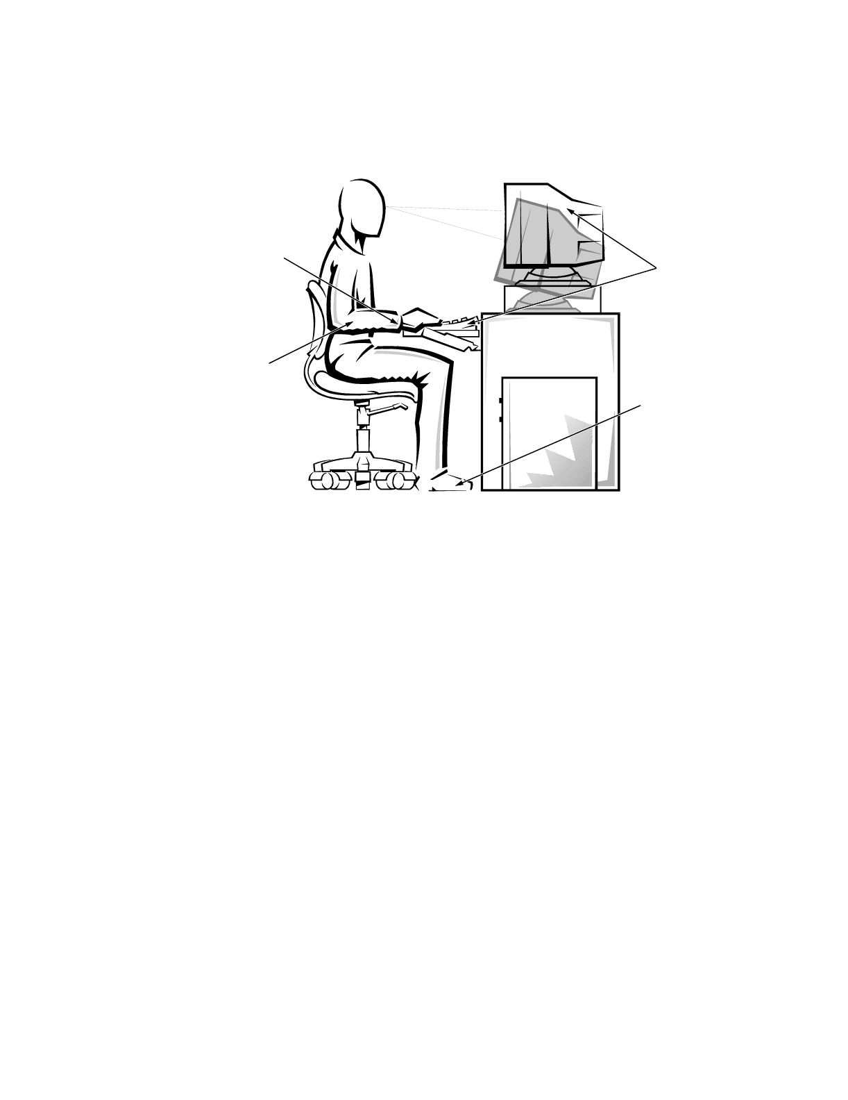
(UJRQRPLF&RPSXWLQJ+DELWV
&$87,21,PSURSHURUSURORQJHGNH\ERDUGXVHPD\UHVXOWLQLQMXU\
&$87,219LHZLQJWKHPRQLWRUVFUHHQIRUH[WHQGHGSHULRGVRIWLPHPD\
UHVXOWLQH\HVWUDLQ
For comfort and efficiency, observe the following ergonomic guidelines when you set
up and use your computer system:
Position your system so that the monitor and keyboard are directly in front of you
as you work. Special shelves are available (from Dell and other sources) to help
you correctly position your keyboard.
Set the monitor at a comfortable viewing distance (usually 510 to 610 millimeters
[20 to 24 inches] from your eyes).
Make sure that the monitor screen is at eye level or slightly lower when you sit in
front of the monitor.
Adjust the tilt of the monitor, its contrast and brightness settings, and the lighting
around you (such as overhead lights, desk lamps, and the curtains or blinds on
nearby windows) to minimize reflections and glare on the monitor screen.
Use a chair that provides good lower back support.
Keep your forearms horizontal with your wrists in a neutral, comfortable position
while you use the keyboard or mouse.
Always leave space to rest your hands while you use the keyboard or mouse.
Let your upper arms hang naturally at your sides.
Sit erect, with your feet resting on the floor and your thighs level.
When sitting, make sure the weight of your legs is on your feet and not on the
front of your chair seat. Adjust your chairs height or use a footrest, if necessary,
to maintain proper posture.
Vary your work activities. Try to organize your work so that you do not have to
type for extended periods of time. When you stop typing, try to do things that
use both hands.
xi
monitor screen at or below eye level
wrists relaxed and flat
arms at desk level
monitor and
keyboard
positioned
directly
in front of user
feet flat on
the floor

xii

xiii
&RQWHQWV
Before You Begin . . . . . . . . . . . . . . . . . . . . . . . . . . . . . . . . . . . . . . . . . . . . . . . . . . . .3
Recommended Tools . . . . . . . . . . . . . . . . . . . . . . . . . . . . . . . . . . . . . . . . . . . . .3
Installing the Rack Kit . . . . . . . . . . . . . . . . . . . . . . . . . . . . . . . . . . . . . . . . . . . . . . . . .3
Removing the Doors From a 24-U or 42-U Rack . . . . . . . . . . . . . . . . . . . . . . . . .3
Installing the Slide Assemblies in the Rack . . . . . . . . . . . . . . . . . . . . . . . . . . . . .7
Installing the PowerEdge System in the Rack. . . . . . . . . . . . . . . . . . . . . . . . . . . . . .11
Installing the Rails and Rack Adapters . . . . . . . . . . . . . . . . . . . . . . . . . . . . . . . .11
Installing the Computer . . . . . . . . . . . . . . . . . . . . . . . . . . . . . . . . . . . . . . . . . . .13
Installing the Cable Tray . . . . . . . . . . . . . . . . . . . . . . . . . . . . . . . . . . . . . . . . . . .15
Installing the Cable-Management Arm. . . . . . . . . . . . . . . . . . . . . . . . . . . . . . . .15
Replacing the Rack Doors . . . . . . . . . . . . . . . . . . . . . . . . . . . . . . . . . . . . . . . . .18
Reversing the 24-U Door. . . . . . . . . . . . . . . . . . . . . . . . . . . . . . . . . . . . . . .19
,QGH[
)LJXUHV Figure 1. Rack Kit Contents . . . . . . . . . . . . . . . . . . . . . . . . . . . . . . . . . . . . . . . . .2
Figure 2. Opening the Latch on the Door . . . . . . . . . . . . . . . . . . . . . . . . . . . . . . .4
Figure 3. Removing the 42-U Rack Doors. . . . . . . . . . . . . . . . . . . . . . . . . . . . . . .5
Figure 4. Removing the 24-U Rack Doors. . . . . . . . . . . . . . . . . . . . . . . . . . . . . . .6
Figure 5. One Rack Unit . . . . . . . . . . . . . . . . . . . . . . . . . . . . . . . . . . . . . . . . . . . .7
Figure 6. Determining Where to Install the Slide Assemblies . . . . . . . . . . . . . . .8
Figure 7. Installing the Slide Assemblies . . . . . . . . . . . . . . . . . . . . . . . . . . . . . . .9
Figure 8. Installing a Cage Nut . . . . . . . . . . . . . . . . . . . . . . . . . . . . . . . . . . . . . .11
Figure 9. Installing the Rack Adapters and Rails. . . . . . . . . . . . . . . . . . . . . . . . .12
Figure 10. Installing the Computer in the Rack. . . . . . . . . . . . . . . . . . . . . . . . . . .14
Figure 11. Installing the Cable Tray. . . . . . . . . . . . . . . . . . . . . . . . . . . . . . . . . . . .15
Figure 12. Installing the Cable-Management Arm . . . . . . . . . . . . . . . . . . . . . . . .16
Figure 13. Reversing the Cable-Management Arm. . . . . . . . . . . . . . . . . . . . . . . .18

xiv

Dell PowerEdge 4x00 and 6x00 Systems Rack Installation Guide 1
'HOO3RZHU(GJH[DQG
[6\VWHPV5DFN,QVWDOODWLRQ
*XLGH
This installation guide provides instructions for trained service technicians installing
one or more Dell PowerEdge 4x00 and 6x00 computer systems in a Dell rack. One
rack kit is required for each PowerEdge system to be installed in the rack. The rack kit
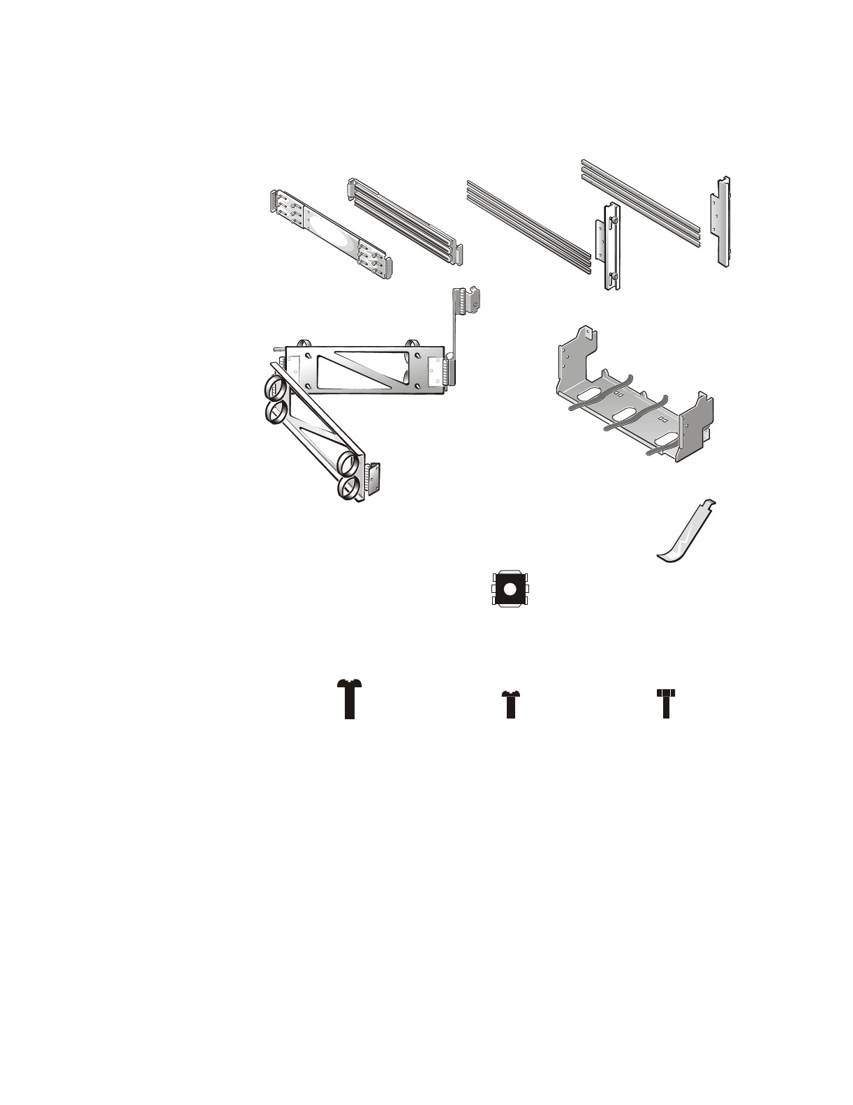
includes the following items (see Figure 1):
One pair of slide assemblies with mounting brackets*
Six rails*
Two rack adapters
One cable-management arm
One cable tray
One cage-nut installation tool
Nine 10-32 x 0.5-inch pan-head Phillips-head screws*
Thirty-three 10-32 x 0.25-inch pan-head Phillips-head screws*
Five 6-32 x 0.25-inch pan-head Phillips-head screws
Two 10-32 cage nuts*
* If you purchased a Dell rack with your PowerEdge system, some of the hardware may be pre-
installed in the rack.
NOTE: The nonmetric screws called out in illustrations and referenced in procedural
steps are identified first by size and then by the number of threads per inch. For exam-
ple, a #10 Phillips-head screw with 32 threads per inch is identified as a 10-32 screw.
2 Dell PowerEdge 4x00 and 6x00 Systems Rack Installation Guide
)LJXUH5DFN.LW&RQWHQWV
cage-nut installation tool
cable-management arm
slide assemblies (1 pair)*
rack adapters (2)
10-32 cage nuts (2)*
10-32 x 0.25-inch screws (33)*
rails (6)*
10-32 x 0.5-inch screws (9)*
* If you purchased a Dell rack with your PowerEdge system, some of the hardware may be pre-
installed in the rack.
cable tray
6-32 x 0.25-inch screws (5)

Dell PowerEdge 4x00 and 6x00 Systems Rack Installation Guide 3
%HIRUH<RX%HJLQ
Before you begin installing your PowerEdge system in the rack, carefully read Safety
Instructions found earlier in this guide.
5HFRPPHQGHG7RROV
To install the rack kit, you need the following tools:
A #2 Phillips screwdriver
A flat-blade screwdriver
The cage-nut installation tool included in the rack kit
A measuring tape
The Dell rack template
,QVWDOOLQJWKH5DFN.LW
NOTES: If you purchased a Dell rack along with your PowerEdge system, the slide
assemblies may be preinstalled in the rack.
For instructions on installing the PowerEdge system itself, see Installing the
PowerEdge System in the Rack found later in this guide.
To install the slide assemblies in the rack, perform the following steps:
1. Remove the racks front and back doors.
2. Install the slide assemblies in the rack.
The subsections that follow include instructions for performing these tasks.
5HPRYLQJWKH'RRUV)URPD8RU85DFN
You must remove the doors from the rack to provide access to the interior of the rack
and to prevent damage to the doors while installing the kit. To remove the doors, per-
form the following steps.
&$87,217RSUHYHQWSHUVRQDOLQMXU\GXHWRWKHVL]HDQGZHLJKWRIWKH
GRRUVQHYHUDWWHPSWWRUHPRYHWKHGRRUVE\\RXUVHOI
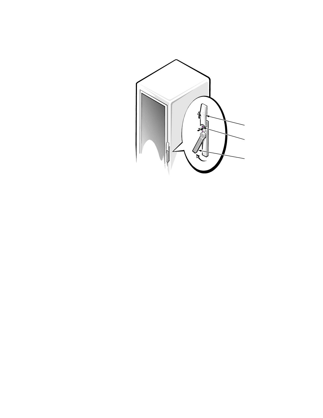
1. Open the latch on the front door (see Figure 2).
Slide the latchs push-button cover up as far as it will go, press the push button,
rotate the handle clockwise until the latch releases, and then pull the door open.
4 Dell PowerEdge 4x00 and 6x00 Systems Rack Installation Guide
)LJXUH2SHQLQJWKH/DWFKRQWKH'RRU
2. Remove the front door of the rack.
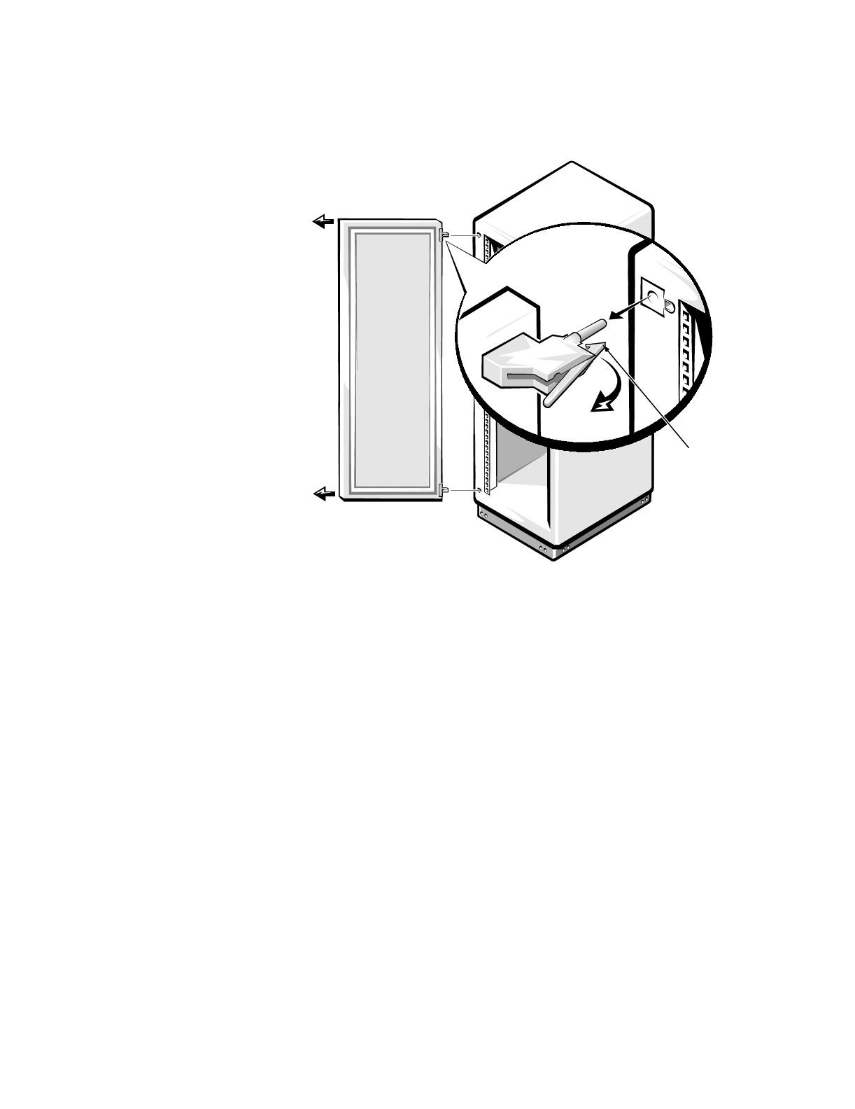
If you have a 42-unit (U [1.75 inches]) rack, perform the following steps (see
Figure 3):
a. One person should grasp the top of the door to stabilize it. The other person
should grasp the bottom of the door.
b. The person holding the bottom of the door should press the release lever on
the bottom hinge and then pull the bottom of the door away from the rack a
few inches.
c. The person holding the top of the door should press the release lever on the
top hinge and then pull the door away from the rack.
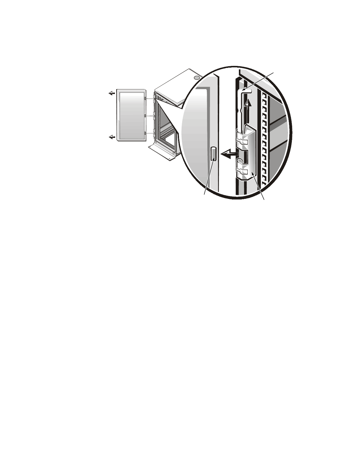
If you have a 24-U rack, perform the following steps (see Figure 4):
a. With the door open, lift out and fully retract all hinge pins.
b. Lift the door out carefully.
Repeat steps 1 and 2 to remove the back door from the rack.
Store the doors in an area where they will not fall over while you install the kit.
push button
push-button
cover
handle
Dell PowerEdge 4x00 and 6x00 Systems Rack Installation Guide 5
)LJXUH5HPRYLQJWKH85DFN'RRUV
hinge
release
lever
6 Dell PowerEdge 4x00 and 6x00 Systems Rack Installation Guide
)LJXUH5HPRYLQJWKH85DFN'RRUV
hinge insert
hinge pin
hinge
Dell PowerEdge 4x00 and 6x00 Systems Rack Installation Guide 7
,QVWDOOLQJWKH6OLGH$VVHPEOLHVLQWKH5DFN
NOTE: If the slide assemblies were preinstalled by Dell, you may skip this section.
Use the Dell rack template to determine where you want to install the slide assem-
blies. The rack template is the same height as the computer chassis.
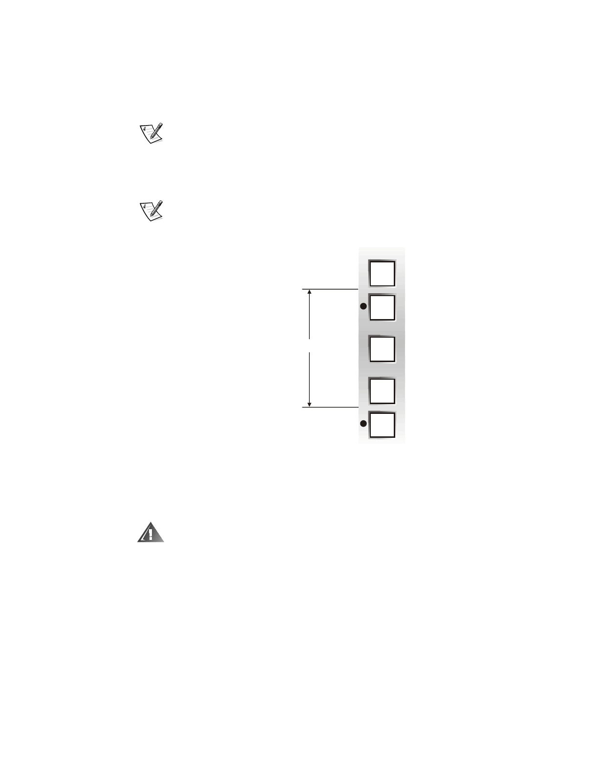
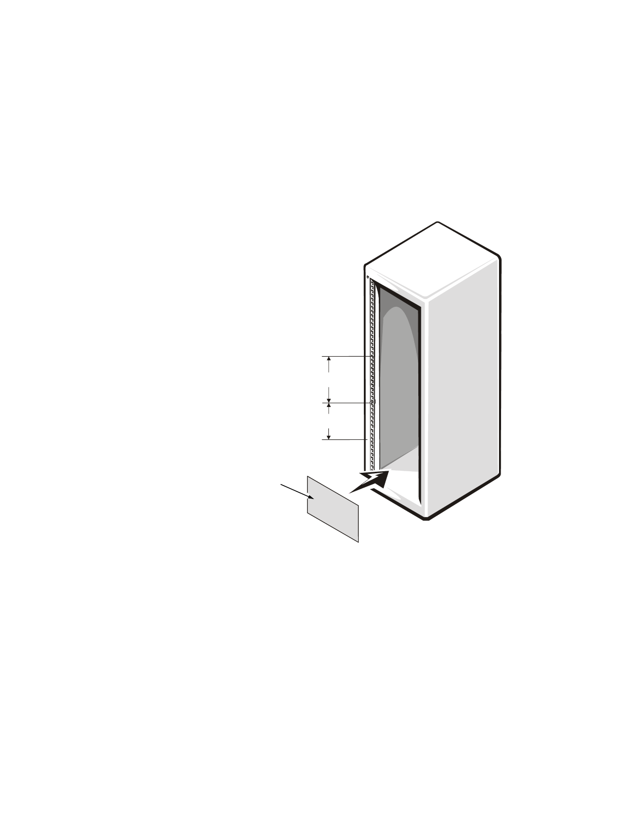
You must allow 7 U (12.25 inches) of vertical space for each PowerEdge system you
install in the rack (see Figure 6).
NOTE: The rails of the rack are marked by small indentations in 1-U increments (see
Figure 5).
)LJXUH2QH5DFN8QLW
For more information, see the Dell Rack Advisor software available on the Dell Web
site at http://www.dell.com.
:$51,1*,I\RXDUHLQVWDOOLQJPRUHWKDQRQHFRPSXWHULQVWDOOWKHVOLGH
DVVHPEOLHVVRWKDWWKHILUVWFRPSXWHULVLQVWDOOHGLQWKHORZHVWDYDLODEOH
SRVLWLRQLQWKHUDFN
To install the slide assemblies in the rack, perform the following steps:
1. Place the front of the template over the front of the front rack rails (see Figure 6).
Position the bottom of the template in line with the desired bottom position of
the computer chassis.
2. Mark the upper- and lower-mounting positions for the slide brackets and the cage
nuts as shown on the template.
1 unit (1.75 inches)
8 Dell PowerEdge 4x00 and 6x00 Systems Rack Installation Guide
3. Turn the template over and place the back of the template over the front side of
the back rack rails in the same position as you placed it on the front rack rail.
4. Mark the upper- and lower-mounting positions for the slide brackets as shown on
the template.
After determining where to install the PowerEdge system, mark the racks front and
back vertical rails with a felt-tipped marker or masking tape where the systems lower
edge will be located.
)LJXUH'HWHUPLQLQJ:KHUHWR,QVWDOOWKH6OLGH$VVHPEOLHV
12.25 inches
12.25 inches
7 U (12.25 inches) between
slide assemblies (drawing
is not to scale)
template
Dell PowerEdge 4x00 and 6x00 Systems Rack Installation Guide 9
5. Using a Phillips screwdriver, slightly loosen the slide alignment screws that hold
the front slide-assembly mounting bracket to the exterior slide (see Figure 7).
NOTE: Do not adjust the back slide-assembly mounting brackets. Doing so will
prevent the computer from aligning properly with the rack. Make adjustments
only to the front slide-assembly mounting brackets.
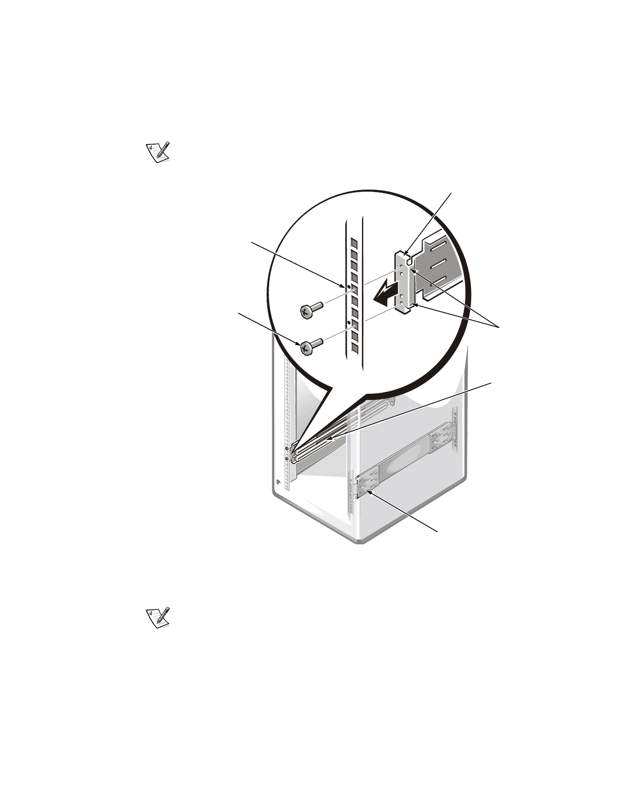
)LJXUH,QVWDOOLQJWKH6OLGH$VVHPEOLHV
6. Install the slide assemblies in the rack.
NOTES: When installing the slide assemblies, be sure that the green plastic
stops at the ends of the channels are at the back of the rack and that the green
push buttons (on the interior slide) are near the front of the rack (see Figure 10).
If the slide assembly is completely extended and locked in position, press the
spring located on the inside of the interior slide (near the end with the green plas-
tic stop) to release the slide so that it can be returned to the retracted position.
slide-assembly
mounting-bracket
flange
10-32 x 0.5-inch
screws (2)
vertical rail
slide alignment screws
IURQWRIUDFN
slide
assemblies
(2)
alignmen
t
marks

10 Dell PowerEdge 4x00 and 6x00 Systems Rack Installation Guide
a. Position the mounting-bracket flange at the back of the slide assembly so
that the alignment marks are aligned with the indentations on the rack.
Secure the mounting bracket with two 10-32 x 0.5-inch Phillips-head screws.
Do not completely tighten the two screws until you install the computer and
verify that the width between the slide assemblies is correct.
b. Position the mounting-bracket flange at the front of the slide assembly so
that the alignment marks are aligned with the indentations on the rack.
Secure the mounting bracket with two 10-32 x 0.5-inch Phillips-head screws.
c. If necessary, adjust the slide assemblys length until the mounting-bracket
flange fits snugly against the back of the rails on both ends.
d. Tighten the slide alignment screw you loosened in step 5.
7. Repeat steps 5 and 6 to install the second slide assembly.
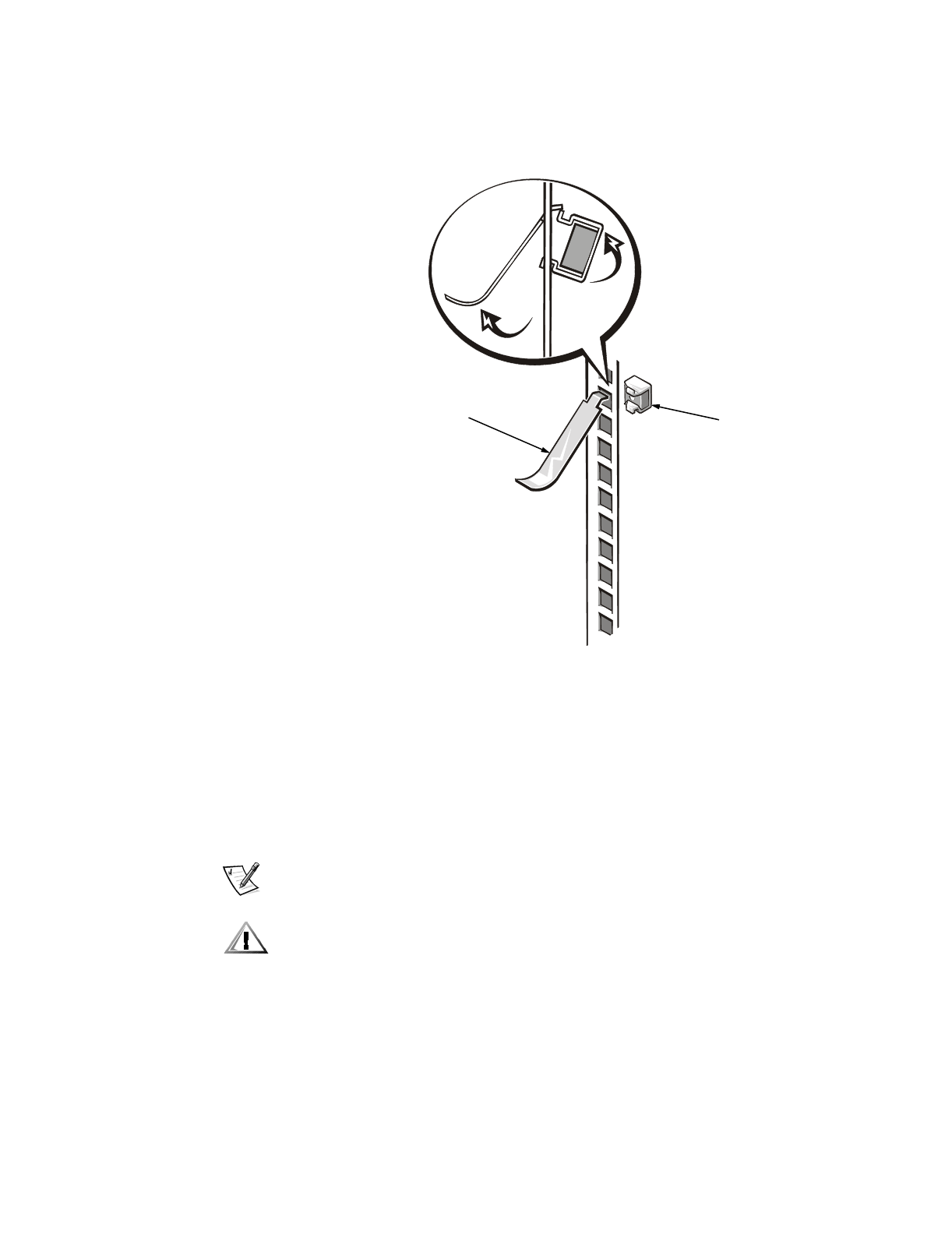
8. Install the cage nuts (see Figure 8):
a. Insert the lower lip of the cage nut over the bottom of the opening in the
back of a rail as shown in Figure 8. Then insert the small end of the cage-nut
installation tool through the opening in the rail (from the front), and hook the
tool over the top lip of the cage nut.
b. Push in on the cage nut while rotating the tool up and pulling it back toward
you (see Figure 8) until the top lip of the cage nut snaps into position.
c. Repeat steps a and b to install the remaining cage nuts.
Dell PowerEdge 4x00 and 6x00 Systems Rack Installation Guide 11
)LJXUH,QVWDOOLQJD&DJH1XW
,QVWDOOLQJWKH3RZHU(GJH6\VWHPLQWKH
5DFN
The subsections that follow include instructions for installing the PowerEdge system.
,QVWDOOLQJWKH5DLOVDQG5DFN$GDSWHUV
NOTE: If the rails are preinstalled by Dell, you may skip this section.
To install the rails and rack adapters on the computer, perform the following steps.
&$87,217KHFRPSXWHUZHLJKVDSSUR[LPDWHO\NLORJUDPVNJ
SRXQGV>OE@ZKHQIXOO\ORDGHG7RSUHYHQWSHUVRQDOLQMXU\GRQRW
DWWHPSWWRPRYHWKHFRPSXWHUE\\RXUVHOI
cage nut
cage-nut
installation tool
12 Dell PowerEdge 4x00 and 6x00 Systems Rack Installation Guide
1. Remove the feet from the computer:
a. Lay the computer on its left side on a piece of foam or cardboard (to prevent
damage to the computer).
b. Using a small flat-blade screwdriver, unscrew the screw securing each foot.
c. From outside of the computer chassis, pull each foot from the chassis.
2. Remove the rubber plugs from the screw holes on the computers side panel.
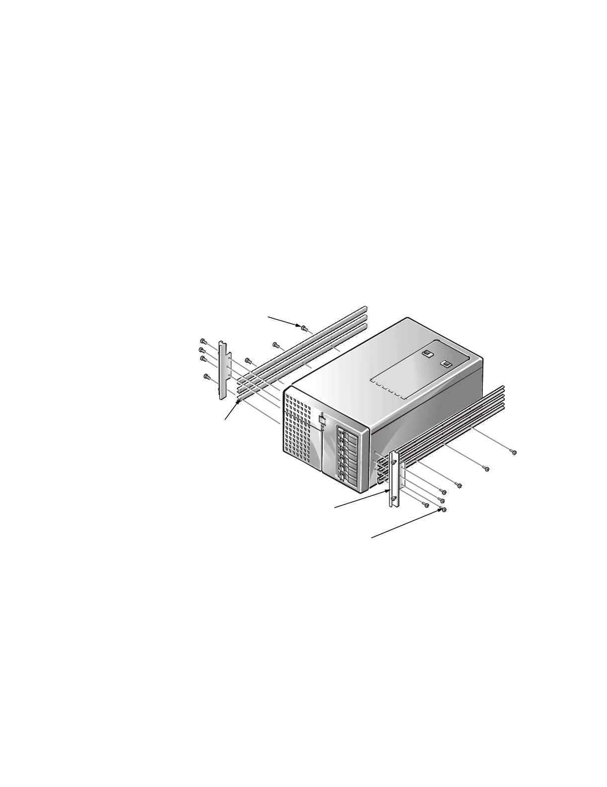
3. Install three rails on one side of the computer (see Figure 9).
Orient each rail so that the three holes on the end of the rail are near the back of
the computer. Attach each rail with four 10-32 x 0.25-inch Phillips-head screws.
4. Tighten the 10-32 X 0.25-inch screw finger tight so that each of the rails are able
to move up and down slightly.
)LJXUH,QVWDOOLQJWKH5DFN$GDSWHUVDQG5DLOV
5. Install the rack adapter on the computer (see Figure 9).
Secure the adapter to the computer with three 10-32 x 0.25-inch Phillips-head
screws.
6. Repeat steps 3 through 5 to install the rails and rack adapters on the opposite
side of the computer.
UDFNDGDSWHUV
[LQFKVFUHZV
VHFXULQJHDFKUDFNDGDSWHU
UDLOV
10-32 x 0.25-inch screws (4)
securing each rail

Dell PowerEdge 4x00 and 6x00 Systems Rack Installation Guide 13
,QVWDOOLQJWKH&RPSXWHU
To install the computer in the rack, perform the following steps.
:$51,1*,I\RXDUHLQVWDOOLQJPRUHWKDQRQHFRPSXWHULQVWDOOWKHILUVW
FRPSXWHULQWKHORZHVWDYDLODEOHSRVLWLRQLQWKHUDFN1HYHUSXOOPRUHWKDQ
RQHFRPSRQHQWRXWRIWKHUDFNDWDWLPH
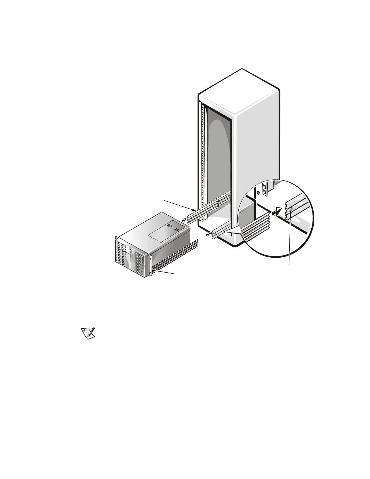
1. Pull the two interior slide assemblies out of the rack until they lock in the
extended position.
&$87,21%HFDXVHRIWKHVL]HDQGZHLJKWRIWKHFRPSXWHUQHYHUDWWHPSWWR
LQVWDOOWKHFRPSXWHULQWKHVOLGHDVVHPEOLHVE\\RXUVHOI
2. Lift the computer into position, and insert the computers rails into the channels
of the interior slides (see Figure 10).
The holes in the slide-assembly mounting brackets allow for adjustment if the
width between the slide assemblies is not correct. Adjust the width so that the
computer slides easily into place.
The interior slide should move freely and not bind.
14 Dell PowerEdge 4x00 and 6x00 Systems Rack Installation Guide
)LJXUH,QVWDOOLQJWKH&RPSXWHULQWKH5DFN
3. Slide the computer into the rack until the lock engages.
At this time, the computer should not move either in or out.
NOTE: As you push the computer into the interior slides, the slide assemblies
lock in the extended position. Press the green push button near the end of each
interior slide to release the locks (see Figure 10), and then slide the computer
completely into the rack.
4. Tighten all the slide-assembly mounting screws securely.
After you tighten all the mounting screws, slide the computer into and out of the
rack a few times to ensure that none of the adjustments changed as you tight-
ened the screws.
interior slide
green push button
thumbscrews (4)
Dell PowerEdge 4x00 and 6x00 Systems Rack Installation Guide 15
5. Slide the computer out into the locked position, and then tighten the screws on
the three rails on each side of the computer.
After you tighten all the screws on the rails on each side of the computer, slide
the computer into and out of the rack a few times to ensure that none of the
adjustments changed as you tightened the screws.
6. Slide the computer completely into the rack, and tighten the four thumbscrews
to hold the computer in position (see Figure 10).
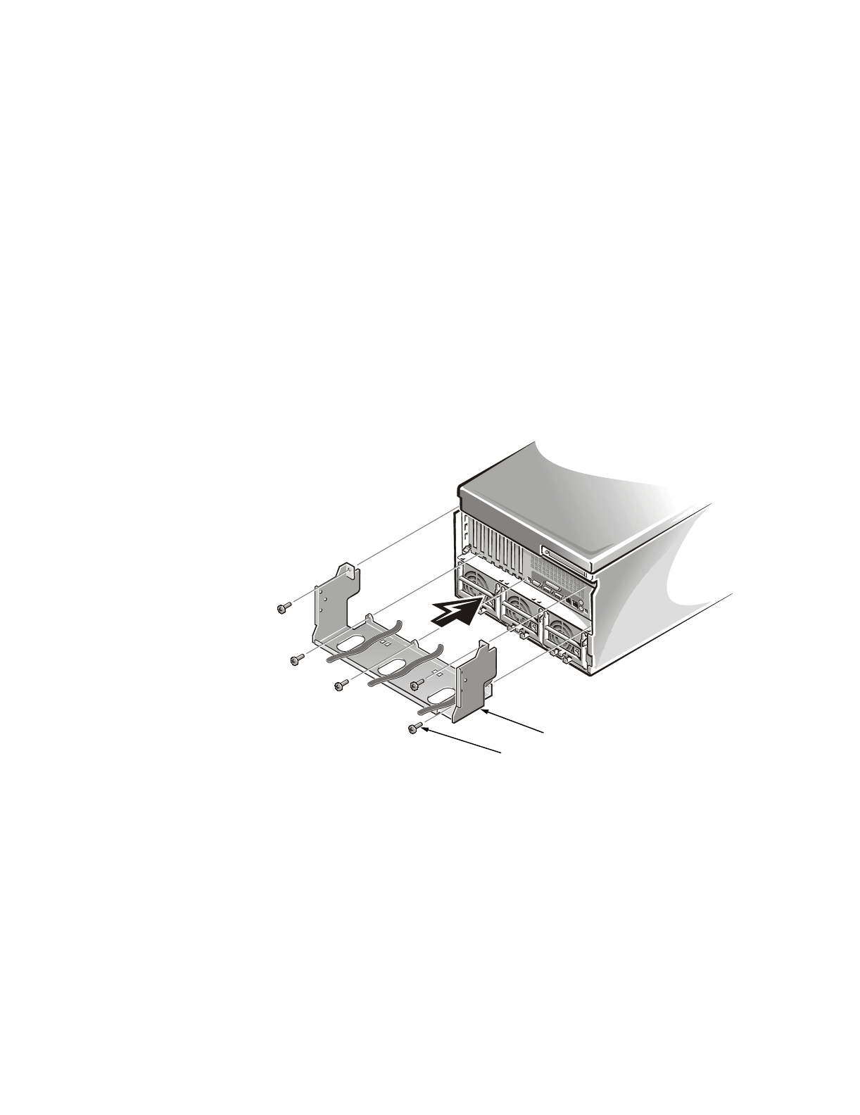
,QVWDOOLQJWKH&DEOH7UD\
Install the cable tray on the back of the PowerEdge system using five 6-32 x 0.25-inch
Phillips-head screws to secure the tray to the computer chassis (see Figure 11).
127,&(7KHFDEOHWUD\DQGLWVPRXQWLQJDUHQRWVWXUG\HQRXJKWRVXSSRUW
WKHZHLJKWRIWKH3RZHU(GJHFKDVVLVVRGRQRWJUDVSWKHFDEOHWUD\ZKHQ
OLIWLQJWKHV\VWHP<RXVKRXOGOLIWWKHV\VWHPRQO\E\WKHFKDVVLVHGJHV
)LJXUH,QVWDOOLQJWKH&DEOH7UD\
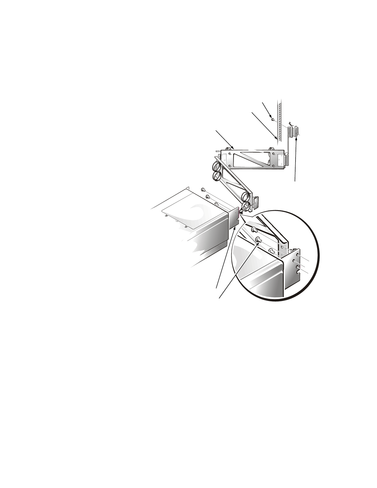
,QVWDOOLQJWKH&DEOH0DQDJHPHQW$UP
To install the cable-management arm on the PowerEdge computer, perform the fol-
lowing steps:
1. Attach the right-angle bracket of the cable-management arm to the vertical rail
(see Figure 12).
6-32 x 0.25-inch screws (5)
cable tray
EDFNRIFRPSXWHU
16 Dell PowerEdge 4x00 and 6x00 Systems Rack Installation Guide
Use the cable tray that you installed on the computer chassis to determine the
proper placement of the cable-management arm. Use one 10-32 x 0.5-inch
Phillips-head screw to attach the cable-management arm to the vertical rail.
)LJXUH,QVWDOOLQJWKH&DEOH0DQDJHPHQW$UP
2. Attach the other end of the cable-management arm to the cable tray (see
Figure 12).
Align the hinge on the arm with the three holes on the vertical edge of the cable
tray and secure the arm with three 10-32 x 0.25-inch Phillips-head screws.
3. Connect the cables to the computer.
For details, see the Installation and Troubleshooting Guide and Users Guide that
came with the computer.
cable-management arm
10-32 x 0.25-inch screws (3)
EDFNRIFRPSXWHU
vertical rail
right-angle
bracket
cable tray
10-32 x 0.5-inch screw

Dell PowerEdge 4x00 and 6x00 Systems Rack Installation Guide 17
4. Secure the cables.
Route the cables along the cable-management arm, and secure the cables to the
cable-management arm with the Velcro strips attached to the arm.
5. Slide the computer into and out of the rack to verify that the cables are routed
correctly.
Make sure that the cables are not pinched in the cable-management arm joints.
NOTES: You will feel resistance as the rails thread themselves into the ball-
bearing cages in the slide assembliesthis resistance is normal. Continue to
push the computer inward until it slides completely into the rack and is fully
seated. (You may have to pull the computer partially out and push it back into the
rack to fully thread the ball-bearing cages.) When the computer is fully inserted in
the rack, the back of the four captive thumbscrews should mate with the cage
nuts on the racks front vertical rails.
As you pull the computer out to its furthest extension, the slide assemblies will
lock in the extended position. To push the computer back into the rack, press the
green push buttons near the front of both interior slides (see Figure 10) and
simultaneously push in on the computer.
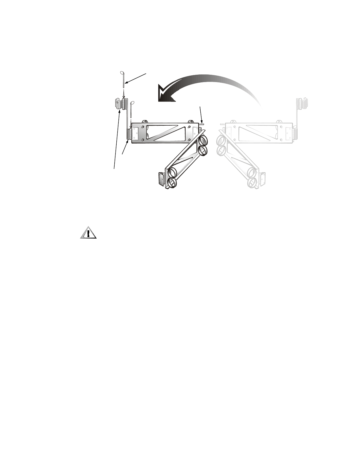
To reverse the installation of the cable-management arm, perform the following steps:
1. Turn over the cable-management arm (see Figure 13).
2. Remove the pull pins from the offset hinge of the cable-management arm.
3. Remove the rail-mounting plate.
NOTE: Make note of the orientation of the rail-mounting plate to the vertical rail.
4. Pull the hinge away from the cable-management arm assembly.
5. Position the opposite side of the offset hinge next to the cable-management arm
assembly.
6. Replace the pull pin with the ring facing up.
7. Replace the rail-mounting plate in the same orientation to the vertical rail.
8. Replace the second pull pin with the ring facing up.
Follow the procedure for the installation of the cable-management arm. The opposite
vertical rail and the opposite side of the cable tray are used for reverse installation of
the cable-management arm.
18 Dell PowerEdge 4x00 and 6x00 Systems Rack Installation Guide
)LJXUH5HYHUVLQJWKH&DEOH0DQDJHPHQW$UP
5HSODFLQJWKH5DFN'RRUV
&$87,217RSUHYHQWSHUVRQDOLQMXU\GXHWRWKHVL]HDQGZHLJKWRIWKH
GRRUVQHYHUDWWHPSWWRUHSODFHWKHGRRUVE\\RXUVHOI
To replace the 42-U racks front and back doors, perform the following steps:
1. Lift the front door into position, and align the hinges with the holes in the rack as
shown in Figure 3.
2. Slide the hinges into the holes in the rack until the hinge release levers lock the
hinges into position.
3. Verify that the hinges are latched.
4. Close the door latch by rotating the handle counterclockwise until it stops, push
in the handle until it locks in position, and then slide the cover down over the
push button (see Figure 2).
5. Repeat steps 1 through 4 to install the back door.
To replace the 24-U racks front and back doors, perform the following steps:
1. Lift the front door into position, and align the hinges with the hinge insert in the
rack as shown in Figure 4.
2. Slide the hinge pins into the hinge insert in the rack until the hinges lock into
position.
3. Repeat steps 1 and 2 to install the back door.
pull pin
latch pin
offset
hinge
rail-mounting
plate

Dell PowerEdge 4x00 and 6x00 Systems Rack Installation Guide 19
5HYHUVLQJWKH8'RRU
If you want to reverse the door on the 24-U rack so that the handle is on the other
side, perform the following steps:
1. Remove the hinges and door brackets from the door frame.
2. Replace the hinges and door brackets on the opposite side and switch the lock to
the opposite side.
3. Replace the door.

20 Dell PowerEdge 4x00 and 6x00 Systems Rack Installation Guide

Index 1
,QGH[
&
cable tray
installing15
cable-management arm
installing15
cage nuts
installing10
cautionsiii
computer
installing in rack13
installing rails and rack adapters11
weight11
contents of rack kit1
'
doors
opening latch3
removing3
replacing18
(
electrostatic discharge. See ESD
ESDix
,
installing
cable tray15
cable-management arm15
cage nuts10
computer13
doors18
rack adapters11
rack kit3
rails11
slide assemblies79
.
kit contents
illustrated2
list of1
1
notational conventionsiii
notesiii
noticesiii
5
rack adapters
installing11

2 Dell Dimension Systems Users Guide
rack doors
removing3
rack kit contents
illustrated2
list of1
rack kit installation
cable-management arm15
rack adapters11
rails11
slide assemblies79
rails
installing11
removing the rack doors3
reversing the 24-U door19
reversing the cable-management arm17
6
safety instructions
for preventing ESDix
health considerationsx
slide assemblies
adjustments10
installing79
7
tools
recommended3
:
warningsiii
ZZZGHOOFRP
3ULQWHGLQWKH86$
3185HY$
+
