Dell Poweredge 500Sc Installation And Troubleshooting Guide
2015-01-05
: Dell Dell-Poweredge-500Sc-Installation-And-Troubleshooting-Guide-136896 dell-poweredge-500sc-installation-and-troubleshooting-guide-136896 dell pdf
Open the PDF directly: View PDF ![]() .
.
Page Count: 65
Dell™PowerEdge™500SCSystemsInstallationandTroubleshootingGuide
Introduction
Other Documents You May Need
Getting Help
Indicators, Messages, and Codes
Start-Up Routine
Checking Connections and Switches
System Messages
System Beep Codes
Warning Messages
Diagnostics Messages
Alert Log Messages From the System Management Server Agent
Finding Software Solutions
Installing and Configuring Software
Using Software
Running the System Diagnostics
Features of the System Diagnostics
When to Use the System Diagnostics
Starting the System Diagnostics
How to Use the System Diagnostics
How to Use the Device Groups Menu
Device Groups Menu Options
Error Messages
TroubleshootingYourSystem
Safety First—For You and Your System
Removing and Replacing the System Cover and Support Beam
Removing and Replacing the Bezel
Checking the Equipment
Inside the System
Responding to a System Management Server Agent Message
Troubleshooting a Wet System
Troubleshooting a Damaged System
Troubleshooting the System Battery
Troubleshooting the Power Supply
Troubleshooting the Cooling Fan
Troubleshooting Expansion Cards
Troubleshooting System Memory
Troubleshooting the Video Subsystem
Troubleshooting the System Board
Troubleshooting the Diskette Drive
Troubleshooting CD and DVD Drives
Troubleshooting Hard Drives
Installing System Board Options
Removing and Replacing the Fan Assembly
Adding and Replacing Expansion Cards
Adding Memory
Upgrading the Microprocessor
Replacing the System Battery
Installing Drives
Configuring the EIDE Subsystem
Configuring the Boot Device
Connecting Drives
Removing and Reinstalling the Drive Cage
Adding or Replacing Hard Drives
Adding or Replacing Other Drives
Getting Help
Help Overview
Dell Contact Numbers
Jumpers and Connectors
Jumpers—A General Explanation
System-Board Jumpers
Disabling a Forgotten Password
Abbreviations and Acronyms
Figures
Tables
Notes, Notices, Cautions, and Warnings
Information in this document is subject to change without notice.
©2001DellComputerCorporation.Allrightsreserved.
Reproduction in any manner whatsoever without the written permission of Dell Computer Corporation is strictly forbidden.
Trademarks used in this text: Dell, the DELL logo, PowerEdge, Dell OpenManage, Dimension, Inspiron, Dell Precision, Optiplex, Latitude, and DellWare are trademarks of Dell Computer
NOTE: A NOTE indicates important information that helps you make better use of your computer.
NOTICE: A NOTICE indicates either potential damage to hardware or loss of data and tells you how to avoid the problem.
CAUTION: A CAUTION indicates a potentially hazardous situation which, if not avoided, may result in minor or moderate injury.
WARNING: A WARNING indicates a potentially hazardous situation which, if not avoided, may result in severe injury.

Corporation; Intel is a registered trademark of Intel Corporation; Microsoft, MS-DOS, Windows NT, and Windows are registered trademarks of Microsoft Corporation; Novell and
NetWare are registered trademarks of Novell, Inc.
Other trademarks and trade names may be used in this document to refer to either the entities claiming the marks and names or their products. Dell Computer Corporation
disclaims any proprietary interest in trademarks and trade names other than its own.
June 2001

Back to Contents Page
Figures
Dell™PowerEdge™500SCSystemsInstallationandTroubleshootingGuide
Figure 2-1. Bezel Indicators
Figure 2-2. Back-Panel Features
Figure 5-1. Removing the System Cover
Figure 5-2. Removing and Replacing the Support Beam
Figure 5-3. Removing and Replacing the Bezel
Figure 5-4. NIC Indicators
Figure 5-5. Inside the System
Figure 6-1. System Board Features
Figure 6-2. Removing the Cooling Shroud
Figure 6-3. Removing the Fan
Figure 6-4. Removing the Filler Bracket
Figure 6-5. Installing Expansion Cards
Figure 6-6. Seating an Expansion Card
Figure 6-7. Memory Module Sockets
Figure 6-8. Installing a Memory Module
Figure 6-9. Removing a Memory Module
Figure 6-10. Securing Clip
Figure 6-11. Removing the Microprocessor
Figure 6-12. Pin-1 Identification
Figure 6-13. Installing the Microprocessor
Figure 6-14. Installing the Heat-Sink
Figure 6-15. Installing the Battery
Figure 7-1. Drive Bays
Figure 7-2. Connecting the Power Cable
Figure 7-3. Connecting the Interface Cable
Figure 7-4. Removing and Reinstalling the Drive Cage
Figure 7-5. Adding or Removing a Hard Drive in the Lower 3.5-inchBay
Figure 7-6. Adding or Replacing a Hard Drive in the Upper 3.5-inchBay
Figure 7-7. Removing the Hard Drive and Drive Bracket
Figure 7-8. Detaching or Attaching the Hard Drive
Figure 7-9. Removing the Drive Bracket
Figure 7-10. Removing the Insert
Figure 7-11. Adding or Removing a 5.25-inch Device
Figure 7-12. Removing and Installing a Diskette Drive
Figure A-1. Jumpers
Figure A-2. System-Board Jumpers
Back to Contents Page

Back to Contents Page
Tables
Dell™PowerEdge™500SCSystemsInstallationandTroubleshootingGuide
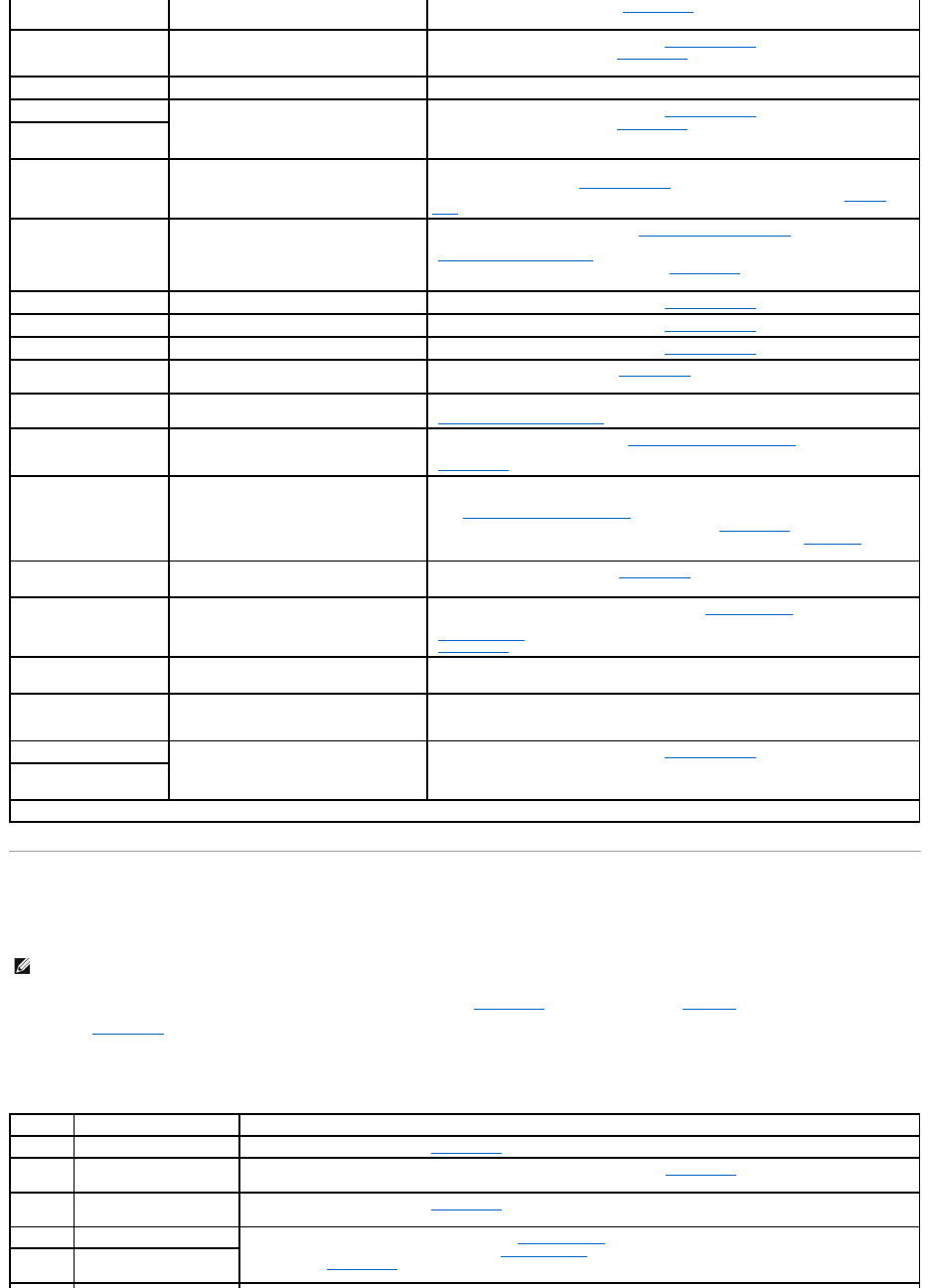
Table 2-1. Start-Up Routine Indications
Table 2-2. System Messages
Table 2-3. System Beep Codes
Table 3-1. IRQ Line Assignment Defaults
Table 4-1. Options
Table 4-2. Devices Options
Table 6-1. System Board Connectors and Sockets
Table 6-2.SampleMemoryModuleConfigurations
Table A-1. System-BoardJumperSettings
Back to Contents Page
Back to Contents Page
Jumpers and Connectors
Dell™PowerEdge™500SCSystemsInstallationandTroubleshootingGuide
Jumpers—A General Explanation
System-Board Jumpers
Disabling a Forgotten Password
This section provides specific information about the jumpers on the system board.
Jumpers—A General Explanation
Jumpers provide a convenient and reversible way of reconfiguring the circuitry on a printed circuit board. When reconfiguring the system, you may need to
change jumper settings on the system board. You may also need to change jumper settings on expansion cards or drives.
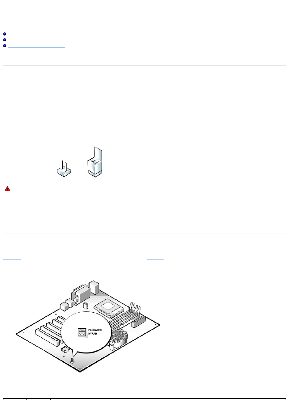
Jumpers
Jumpers are small blocks on a circuit board with two or more pins emerging from them. Plastic plugs containing a wire fit down over the pins. The wire connects
the pins and creates a circuit. To change a jumper setting, pull the plug off its pin(s) and carefully fit it down onto the pin(s) indicated. FigureA-1 shows an
example of a jumper.
Figure A-1. Jumpers
A jumper is referred to as open or unjumpered when the plug is pushed down over only one pin or if there is no plug at all. When the plug is pushed down
over two pins, the jumper is referred to as jumpered. The jumper setting is often shown in text as two numbers, such as 1-2. The number 1 is printed on the
circuit board so that you can identify each pin number based on the location of pin 1.
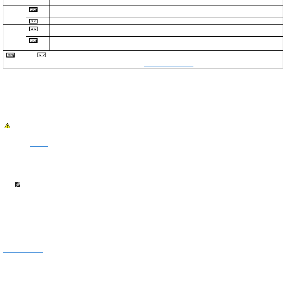
FigureA-2 shows the location and default settings of the jumper blocks on the system board. See TableA-1 for the designations, default settings, and
functions of the system's jumpers.
System-Board Jumpers
FigureA-2 shows the location of the configuration jumpers on the system board. TableA-1 lists the function of these jumpers.
Figure A-2. System-Board Jumpers
WARNING: Make sure the system is turned off before you change a jumper setting. Otherwise, damage to the system or unpredictable results
may occur.
Table A-1. System-BoardJumperSettings
Disabling a Forgotten Password
The system's software security features include a system password and a setup password, which are discussed in "Using the System Setup Program," in the
User's Guide. A password jumper on the system board enables these password features or disables them and clears any password(s) currently in use.
To disable a forgotten system password or setup password, perform the following steps.
1. Remove the system cover.
2. Refer to FigureA-2 for the location of the password jumper (labeled "PASSWORD") on the system board.
3. Remove the jumper plug from the PASSWORD jumper.
4. Replace the system cover, and then reconnect the system to an electrical outlet and turn it on.
The existing passwords are not disabled (erased) until the system boots with the PASSWORD jumper plug removed. However, before you assign a new
system and/or setup password, you must install the jumper plug.
5. Repeat step 1.
6. Install the jumper plug on the PASSWORD jumper.
7. Replace the system cover, and then reconnect the system and peripherals to their electrical outlets and turn them on.
8. Assign a new system and/or setup password.
To assign a new system password using the System Setup program, see "Assigning a System Password" in the User's Guide.
Back to Contents Page
Jumper
Setting
Description
PASSWORD
(default)
The password feature is enabled.
The password feature is disabled.
NVRAM
(default)
The configuration settings are retained at system boot.
The configuration settings are cleared at next system boot. (If the configuration settings become corrupted to the point where the
system will not boot, install the jumper plug and boot the system. Remove the jumper before restoring the configuration
information.)
jumpered unjumpered
NOTE: For the full name of an abbreviation or acronym used in this table, see "Abbreviations and Acronyms."
CAUTION: See "Protecting Against Electrostatic Discharge" in your System Information document.
NOTE: If you assign a new system and/or setup password with the jumper plug still removed, the system disables the new password(s) the next
time it boots.

Back to Contents Page
Abbreviations and Acronyms
Dell™PowerEdge™500SCSystemsInstallationandTroubleshootingGuide
The following list defines or identifies technical terms, abbreviations, and acronyms used in Dell user documents.
A
ampere(s)
AC
alternating current
ACPI
Advanced Configuration and Power Interface
ADC
analog-to-digital converter
BIOS
basic input/output system
bpi
bits per inch
bps
bits per second
C
Celsius
CD
compact disc
cm
centimeter(s)
CMOS
complementary metal-oxide semiconductor
C.O.D.
collect on delivery
CPU
central processing unit
DAT
digital audio tape
dB
decibel(s)
dBA
adjusted decibel(s)
DC
direct current
DIMM
dual in-line memory module

DIN
Deutsche Industrie Norm
DMA
direct memory access
DOC
Department of Communications (in Canada)
dpi
dots per inch
DRAM
dynamic random-access memory
DS/DD
double-sided double-density
DS/HD
double-sided high-density
ECC
error checking and correction
EDO
extended-data out
EGA
enhanced graphics adapter
EIDE
enhanced integrated drive electronics
EMI
electromagnetic interference
EMM
expanded memory manager
ESD
electrostatic discharge
ESM
embedded server management
F
Fahrenheit
FAT
file allocation table
FCC
Federal Communications Commission
ft
feet
g
gram(s)

G
gravities
GB
gigabyte(s)
GUI
graphical user interface
h
hexadecimal
Hz
hertz
I/O
input/output
ICBM
inter-chassis management bus
ID
identification
IDE
integrated drive electronics
IRQ
interrupt request
ISA
Industry-Standard Architecture
K
kilo- (1024)
KB
kilobyte(s)
KB/sec
kilobyte(s) per second
Kb
kilobit(s)
Kbps
kilobit(s) per second
kg
kilogram(s)
kHz
kilohertz
LAN
local area network
lb
pound(s)
LED

light-emitting diode
LIF
low insertion force
LN
load number
lpi
lines per inch
LVD
low voltage differential
m
meter(s)
mA
milliampere(s)
mAh
milliampere-hour(s)
MB
megabyte(s)
Mb
megabit(s)
Mbps
megabit(s) per second
MBR
master boot record
MDA
monochrome display adapter
MGA
monochrome graphics adapter
MHz
megahertz
mm
millimeter(s)
ms
millisecond(s)
mV
millivolt(s)
NIC
network interface controller
NiCad
nickel cadmium
NiMH

nickel-metal hydride
ns
nanosecond(s)
NTFS
NT File System
NVRAM
nonvolatile random-access memory
PCI
Peripheral Component Interconnect
PDU
power distribution unit
PGA
pin grid array
POST
power-on self-test
ppm
pages per minute
RAID
redundant arrays of independent disks
RAM
random-access memory
RCU
Resource Configuration Utility
RFI
radio frequency interference
ROM
read-only memory
rpm
revolutions per minute
RTC
real-time clock
SCSI
small computer system interface
SDS
Scalable Disk System
sec
second(s)
SEC
single-edge contact
SDRAM
synchronous dynamic random-access memory

SNMP
Simple Network Management Protocol
SRAM
static random-access memory
SSU
system setup utility
tpi
tracks per inch
TSR
terminate-and-stay-resident
UPS
uninterruptible power supply
V
volt(s)
VAC
volt(s) alternating current
VDC
volt(s) direct current
VGA
video graphics array
VRAM
video random-access memory
W
watt(s)
WH
watt-hour(s)
Z
ZIF
zero insertion force
Back to Contents Page
Back to Contents Page
Introduction
Dell™PowerEdge™500SCSystemsInstallationandTroubleshootingGuide
Other Documents You May Need
Getting Help
Your system is a high-speed server that offers significant service and upgrade features. Your system includes the following service features:
lEmbedded server management hardware, which monitors temperatures and voltages throughout the system and notifies you if the system overheats, if
a system cooling fan malfunctions, or a power supply fails
lSystem diagnostics, which checks for hardware problems (if the system can boot)
The following system upgrade options are offered:
lExpansion-card options
lAdditional memory
lMicroprocessors
Other Documents You May Need
Besides this Installation and Troubleshooting Guide, the following documentation is included with your system:
lUser's Guide, which describes system features and technical specifications, the system setup program, and software support utilities.
lServer management documentation, which describes the features, requirements, installation, and basic operation of the server management software.
Refer to the software's online help for information about the alert messages issued by the software.
lSystem Information document, which includes important safety, regulatory, and warranty information.
You may also have one or more of the following documents.
lOperating system documentation is included with the system if you ordered the operating system software with your system. This documentation
describes how to install (if necessary), configure, and use the operating system software.
lDocumentation is included with any options you purchase separately from the system. This documentation includes information that you need to
configure and install these options in your system.
lTechnical information files—sometimes called "readme" files—may be installed on the hard drive to provide last-minute updates about technical changes
to the system or advanced technical reference material intended for experienced users or technicians.
Getting Help
If at any time you do not understand a procedure described in this guide, or if your system does not perform as expected, a number of tools are available to
help you. For more information on these help tools, see "Getting Help."
Back to Contents Page
NOTE: Documentation updates are sometimes included with the system to describe changes to the system or software. Always read these updates
before consulting any other documentation because the updates often contain information that supersedes the information in the other documents.
Back to Contents Page
Indicators, Messages, and Codes
Dell™PowerEdge™500SCSystemsInstallationandTroubleshootingGuide
Start-Up Routine
Checking Connections and Switches
System Messages
System Beep Codes
Warning Messages
Diagnostics Messages
Alert Log Messages From the System Management Server Agent
Application programs, operating systems, and the system itself are capable of identifying problems and alerting you to them. When a problem occurs, a
message may appear on the monitor screen or a beep code may sound.
Several different types of messages can indicate when the system is not functioning properly:
lSystem messages
lSystem beep codes
lWarning messages
lDiagnostics messages
lAlert messages
This section also describes each type of message and lists the possible causes and actions you can take to resolve any problems indicated by a message.
Performing some initial checks and procedures can solve many basic system problems. The system indicators and the back-panel features are illustrated in
Figure2-1 and Figure2-2.
Start-Up Routine
Looking at and listening to the system is important in determining the source of a problem. Look and listen during the system's start-up routine for the
indications described in Table2-1.
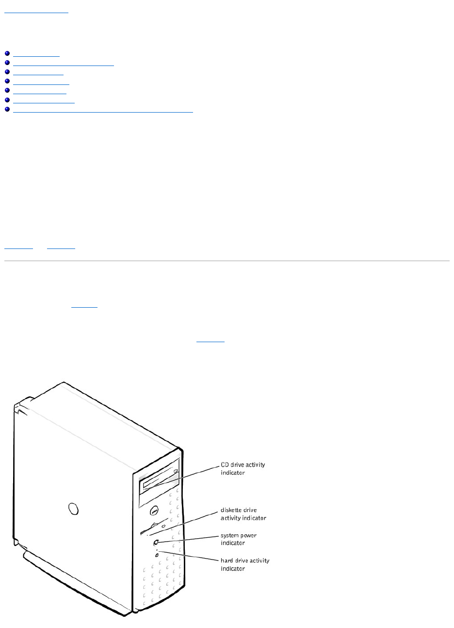
Bezel Indicators
When the bezel is in place on the system, it has four indicators (see Figure2-1). There is a CD drive activity indicator, diskette drive activity indicator, hard drive
activity indicator, and system power indicator.
Figure 2-1. Bezel Indicators
Look and listen for the indications described in Table2-1.
Checking Connections and Switches
Improperly set switches, controls, and loose or improperly connected cables are the most likely source of problems for the system, monitor, or other
peripherals (such as a printer, keyboard, mouse, or other external equipment). A quick check of all the switches, controls, and cable connections can easily
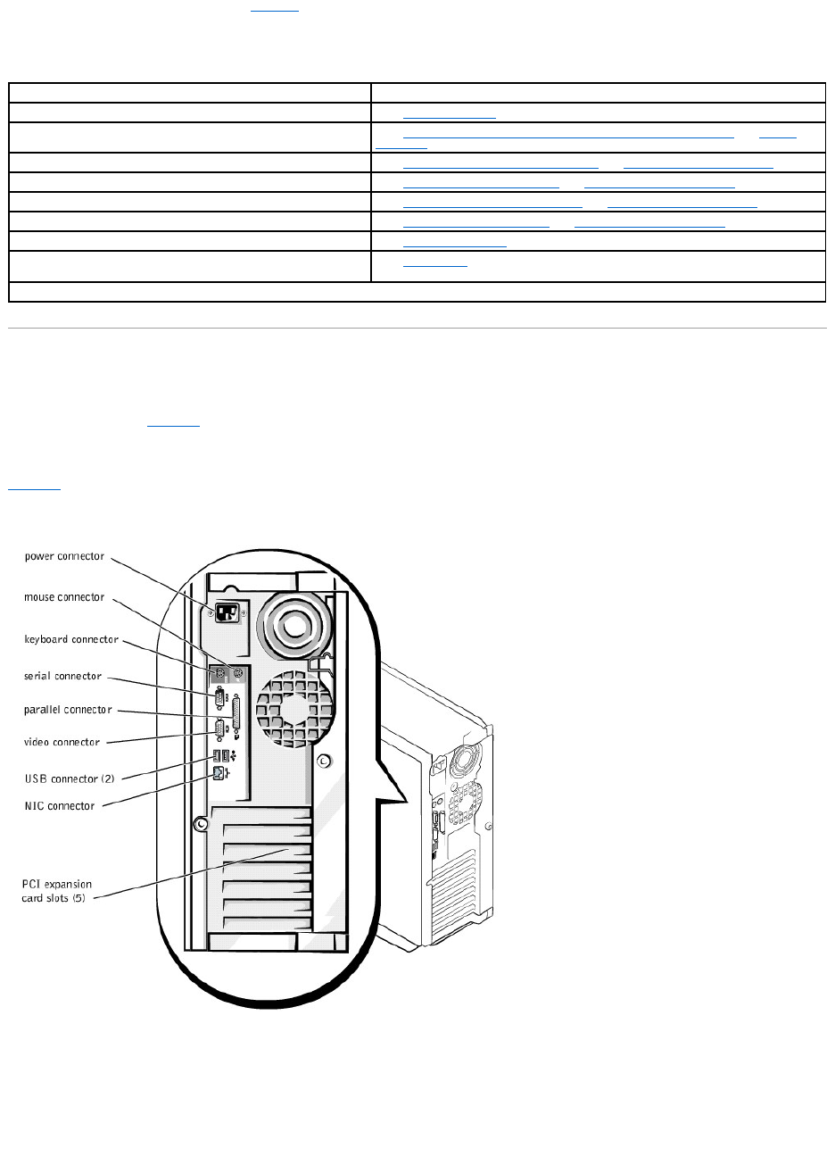
solve these problems. See Figure2-2 for the back-panel features and connectors.
Back-Panel Features
Figure2-2 shows the back-panel features of the system.
Figure 2-2. Back-Panel Features
Complete the following procedure to check all the connections and switches:
Checking Specific System Problems
1. Turn off the system, including any attached peripherals. Disconnect all the power cables from their electrical outlets.
2. If the system is connected to a PDU, turn the PDU off and then on again.
If it is not receiving power, plug it into another electrical outlet. If it still is not receiving power, try another PDU.
Table 2-1. Start-UpRoutineIndications
Look/Listen for:
Action
An error message
See "System Messages."
Alert messages from the system management server agent software
See "Alert Log Messages From the System Management Server Agent" in "System
Messages."
The monitor's power indicator
See "Troubleshooting the Video Subsystem" in "TroubleshootingYourSystem."
The keyboard indicators
See "Troubleshooting the Keyboard" in "TroubleshootingYourSystem."
The diskette-drive activity indicator
See "Troubleshooting the Diskette Drive" in "TroubleshootingYourSystem."
The hard drive activity indicators
See "Troubleshooting Hard Drives" in "TroubleshootingYourSystem."
A series of beeps
See "System Beep Codes."
An unfamiliar constant scraping or grinding sound when you access
a drive
See "Getting Help," for instructions on obtaining technical assistance.
NOTE: For the full name of an abbreviation or acronym used in this table, see "Abbreviations and Acronyms."
3. Reconnect the system to the electrical outlet or PDU.
4. Is the monitor working properly?
See "Troubleshooting the Video Subsystem."
5. Is the keyboard working properly?
See "Troubleshooting the Keyboard."
6. Are the mouse and printer working properly?
See "Troubleshooting the Basic I/O Functions."
System Messages
System messages alert you to a possible operating system problem or to a conflict between the software and hardware. Table2-2 lists the system error
messages that can occur and the probable cause for each message.
NOTE: If you receive a system message that is not listed in Table2-2, check the documentation for the application program that is running when the
message appears and/or the operating system documentation for an explanation of the message and recommended action.
Table 2-2. System Messages
Message
Cause
Corrective Action
Address mark not found
Faulty diskette, CD-ROM, or hard drive
subsystem (defective system board).
Replace the system board. See "Getting Help," for instructions on obtaining
technical assistance.
Alert! Maximum memory
size exceeded. Limiting
memory size to 2 GB
System supports up to 2 GB of memory.
Remove a memory module pair so that the maximum amount of memory is 2 GB or
less. See "Adding Memory" in "Installing System Board Options."
Alert! Single-bit
memory error previously
detected in xxxx xxxxh
Improperly seated or faulty memory
modules.
Remove and reseat the memory modules. See "Adding Memory" in "Installing
System Board Options." If the problem persists, replace the memory modules. See
"Adding Memory" in "Installing System Board Options." If the problem persists, see
"Getting Help," for instructions on obtaining technical assistance.
Alert! Previous
processor thermal
failure
The microprocessor exceeded its
recommended operating temperature
during the previous operating session.
Remove and replace the defective microprocessor. See "Replacing the
Microprocessor" in "Installing System Board Options."
Alert! Primary
processor is out of rev
System detected that the primary
processor is not the correct revision.
Replace the microprocessor. See "Replacing the Microprocessor" in "Installing
System Board Options."
Alert! Processor
thermal probe failure
detected
Faulty processor or defective system
board.
Replace the defective microprocessor. See "Replacing the Microprocessor" in
"Installing System Board Options." If the problem persists, the system is defective.
See "Getting Help," for instructions on obtaining technical assistance.
Alert! Unsupported
memory in DIMM slot(s)
Unsupported memory module(s) installed
in specified slot(s).
Replace one or more memory modules so that the memory module pairs are the
same type. See "Adding Memory" in "Installing System Board Options."
Alert! Uncorrectable
memory error previously
detected in xxxx xxxxh
Improperly seated or faulty memory
modules.
Remove and reseat the memory modules. See "Adding Memory" in "Installing
System Board Options." If the problem persists, replace the memory modules. See
"Adding Memory" in "Installing System Board Options." If the problem persists, see
"Getting Help," for instructions on obtaining technical assistance.
Attachment failed to
respond
Diskette drive or hard drive controller
cannot send data to associated drive.
Replace the defective drive. See "Installing Drives." If the problem persists, see
"Getting Help," for instructions on obtaining technical assistance.
Auxiliary device
failure
Mouse cable connector loose or improperly
connected, defective mouse.
Check the mouse cable connection. "Checking Connections and Switches." If the
problem persists, replace the mouse. See "Getting Help," for instructions on
obtaining technical assistance.
Bad command or file
name
Command entered does not exist, is faulty,
or is not in pathname specified.
Faulty command and syntax, or incorrect filename.
Bad error-correction
code(ECC) on disk read
Controller has failed
Faulty diskette, CD-ROM, or hard drive
subsystem (defective system board).
Replace the system board. See "Getting Help," for instructions on obtaining
technical assistance.
Boot: Couldn't find
NTLDR
A nonbootable diskette formatted with
Win-dowsNTwasdetectedinthediskette
drive.
A nonbootable diskette is preventing the system from booting. Remove the diskette
to boot the system from the hard drive or from a bootable diskette.
CAUTION! NVRAM_CLR
jumper is installed on
system board. Please
run SETUP
The NVRAM jumper is installed.
Remove the NVRAM jumper. See "FigureA-2" for jumper location. Run the System
Setup program to correct the diskette drive type. See "Using the System Setup
Program," in the User's Guide for instructions.
CD-ROM drive not found
Improperly connected or missing CD drive.
Check that the CD drive unit is seated properly against the interposer board on the
peripheral cage. See "Inside the System" in "Troubleshooting Your System" for the
location of the CD drive. Replace the drive. See "Installing Drives." If the problem
persists, see "Getting Help," for instructions on obtaining technical assistance.
Data error
Faulty diskette, diskette drive, or hard
drive.
Replace the diskette, diskette drive, or hard drive. See "Installing Drives."
Decreasing available
memory
One or more memory modules improperly
seated or faulty.
Remove and reseat the memory modules. See "Adding Memory" in "Installing
System Board Options." If the problem persists, replace the memory modules. See
"Adding Memory" in "Installing System Board Options." If the problem persists, see
"Getting Help," for instructions on obtaining technical assistance.
Diskette drive 0 seek
failure
Faulty or improperly inserted diskette,
incorrect configuration settings in System
Setup program, loose diskette drive
interface cable.
Replace the diskette. Run the System Setup program to correct the diskette drive
type. See "Using the System Setup Program," in the User's Guide for instructions.
Check the interface cable and power cable connections to the system board. See
"Installing Drives."
Diskette drive 1 seek
failure
Diskette read failure
Faulty diskette, faulty or improperly
connected diskette drive.
Check the interface cable and power cable connections to the system board. See
"Installing Drives."
Diskette subsystem
reset failed
Faulty diskette controller (defective system
board).
Replace the system board. See "Installing Drives," for instructions on obtaining
technical assistance.
Diskette write
protected
Diskette write-protect feature activated.
Move the write-protect tab on the diskette.
Drive not ready
Diskette missing from or improperly
inserted in diskette drive.
Reinsert or replace the diskette.
Gate A20 failure
Faulty keyboard controller (defective
system board).
Replace the system board. See "Getting Help," for instructions on obtaining
technical assistance.
General failure
Operating system corrupted or not
installed properly.
Reinstall the operating system.
Hard disk controller
failure
Incorrect configuration settings in System
Setup program, improperly connected hard
drive, faulty hard drive controller
subsystem (defective system board), or
loose power cable.
Check the hard drive configuration settings in the System Setup program. See
"Using the System Setup Program," in the User's Guide for instructions. Reinstall the
hard drive. See "Installing Drives." Check the interface cable and power cable
connections to the system board. See "Installing Drives."
Hard disk drive read
failure
Hard disk failure
Invalid configuration
information - please
run SETUP program
Incorrect configuration settings in System
Setup program, faulty battery, or NVRAM
jumper is installed.
Check the System Setup configuration settings. See "Using the System Setup
Program," in the User's Guide for instructions. Replace the battery. See "Replacing
the System Battery" in "Installing System Board Options." Remove the NVRAM
jumper. See "FigureA-2" for jumper location.
Invalid CPU speed
detected
Microprocessor not supported by system.
Install a correct version of the microprocessor in the specified microprocessor
connector. See "Replacing the Microprocessor" in "Installing System Board Options."
Invalid NVRAM
configuration, resource
reallocated
System detected and corrected a resource
conflict when system resources were
allocated using the System Setup program.
No action is required.
I/O parity interrupt at
address
Expansion card improperly installed or
faulty.
Reinstall the expansion cards. See "Installing Expansion Cards" in "Installing
System Board Options." If the problem persists, replace the expansion card. See
"Removing Expansion Cards" in "Installing System Board Options."
Keyboard failure
Keyboard cable connector loose or
improperly connected, defective keyboard,
or defective keyboard/mouse controller
(defective system board).
Check the keyboard cable connection. Replace the keyboard. If the problem
persists, replace the system board. See "Getting Help," for instructions on obtaining
technical assistance.
Keyboard data line
failure
Keyboard stuck key
failure
Keyboard clock line
failure
Keyboard controller
failure
Defective keyboard/mouse controller
(defective system board).
Replace the system board. See "Getting Help," for instructions on obtaining
technical assistance.
Memory address line
failure at address,
read value expecting
value
Faulty or improperly seated memory
modules or defective system board.
Remove and reseat the memory modules. See "Adding Memory" in "Installing
System Board Options." If the problem persists, replace the memory modules. See
"Adding Memory" in "Installing System Board Options." If the problem persists, see
"Getting Help," for instructions on obtaining technical assistance.
Memory data line
failure at address,
read value expecting
value
Memory double word
logic failure at
address, read value
expecting value
Memory odd/even logic
failure at address,
read value expecting
value
Memory write/read
failure at address,
read value expecting
value
Memory allocation error
Faulty application program.
Restart the application program.
Memory parity interrupt
at address
Improperly seated or faulty memory
modules.
Remove and reseat the memory modules. See "Adding Memory" in "Installing
System Board Options." If the problem persists, replace the memory modules. See
"Adding Memory" in "Installing System Board Options." If the problem persists, see
"Getting Help," for instructions on obtaining technical assistance.
Memory tests terminated
by keystroke
POST memory test terminated by pressing
the spacebar.
No action is required.
No boot device
available
Faulty diskette, diskette subsystem, hard
drive, hard drive subsystem, or no boot
disk in drive A.
Replace the diskette or hard drive. See "Installing Drives." If the problem persists,
replace the system board. See "Getting Help," for instructions on obtaining technical
assistance.
No boot sector on hard
drive
Incorrect configuration settings in System
Setup program, or no operating system on
hard drive.
Check the hard drive configuration settings in the System Setup program. See
"Using the System Setup Program," in the User's Guide for instructions.
System Beep Codes
When an error that cannot be reported on the monitor occurs during a boot routine, the system may emit a series of beeps that identify the problem.
When a beep code is emitted, record it on a copy of the Diagnostics Checklist in "Getting Help," and then look it up in Table2-3. If you are unable to resolve
the problem by looking up the meaning of the beep code, use the system diagnostics to identify a more serious cause. If you are still unable to resolve the
problem, see "Getting Help," for instructions on obtaining technical assistance.
No timer tick interrupt
Defective system board.
Replace the system board. See, "Getting Help," for instructions on obtaining
technical assistance.
Non-system disk or disk
error
Faulty diskette, diskette subsystem, or
hard drive subsystem.
Replace the diskette or hard drive. See "Installing Drives." If the problem persists,
replace the system board. See "Getting Help," for instructions on obtaining technical
assistance.
Not a boot diskette
No operating system on diskette.
Use a bootable diskette.
Read fault
Faulty diskette, diskette subsystem, or
hard drive subsystem (defective system
board).
Replace the diskette or hard drive. See "Installing Drives." If the problem persists,
replace the system board. See "Getting Help," for instructions on obtaining technical
assistance.
Requested sector not
found
Reset failed
Improperly connected diskette drive, CD
drive, hard drive, or power cable.
Check the interface cable and power cable connections to the diskette drive, CD
drive, or hard drive. See "Installing Drives." Reinstall the hard drive. Check the
interface cable and power cable connections to the system board. See "Getting
Help."
ROM bad checksum =
address
Expansion card improperly installed or
faulty.
Reinstall the expansion cards. See "Installing Expansion Cards" in "Installing
System Board Options." If the problem persists, replace the expansion card. See
"Removing Expansion Cards" in "Installing System Board Options." If the problem
persists, replace the system board. See "Getting Help," for instructions on obtaining
technical assistance.
Sector not found
Defective sectors on diskette or hard drive.
Replace the diskette or hard drive. See "Installing Drives."
Seek error
Defective sectors on diskette or hard drive.
Replace the diskette or hard drive. See "Installing Drives."
Seek operation failed
Faulty diskette or hard drive.
Replace the diskette or hard drive. See "Installing Drives."
Shutdown failure
Defective system board.
Replace the system board. See "Getting Help," for instructions on obtaining
technical assistance.
System halted
System microprocessor is not supported.
Replace the unsupported microprocessor with a supported microprocessor. See
"Replacing the Microprocessor" in "Installing System Board Options."
Time-of-day clock
stopped
Defective battery or faulty chip (defective
system board).
Replace the system battery. See "Replacing the System Battery" in "Installing
System Board Options." If the problem persists, replace the system board. See
"Getting Help," for instructions on obtaining technical assistance.
Time-of-day not set -
please run SETUP
program
Incorrect Time or Date settings, defective
system battery, or NVRAM jumper is
installed.
Check the Time and Date settings. See "Using the System Setup Program," in the
User's Guide for instructions. If the problem persists, replace the system battery.
See "Replacing the System Battery" in "Installing System Board Options." If the
problem persists, replace the system board. See "Getting Help," for instructions on
obtaining technical assistance. Remove the NVRAM jumper. See "FigureA-2" for
jumper location.
Timer chip counter 2
failed
Defective system board.
Replace the system board. See "Getting Help," for instructions on obtaining
technical assistance.
Unexpected interrupt in
protected mode
Improperly seated memory modules or
faulty keyboard/mouse controller chip
(defective system board).
Remove and reseat the memory modules. See "Adding Memory" in "Installing
System Board Options." If the problem persists, replace the memory modules. See
"Adding Memory" in "Installing System Board Options." If the problem persists, see
"Getting Help," for instructions on obtaining technical assistance.
Unsupported CPU speed
in CMOS
Microprocessor not supported by BIOS.
Upgrade the BIOS. See "Using the System Setup Program," in the User's Guide for
instructions.
Utility partition not
available
<F10> key was pressed during POST, but
no utility partition exists on the boot hard
drive.
Create a utility partition on the boot hard drive. See "Using the Dell OpenManage
Server Assistant CD" in your User's Guide.
Write fault
Faulty diskette or hard drive.
Replace the diskette or hard drive. See "Installing Drives."
Write fault on selected
drive
NOTE: For the full name of an abbreviation or acronym used in this table, see "Abbreviations and Acronyms."
NOTE: If the system boots without a keyboard, mouse, or monitor attached, the system will not issue beep codes related to these peripherals.
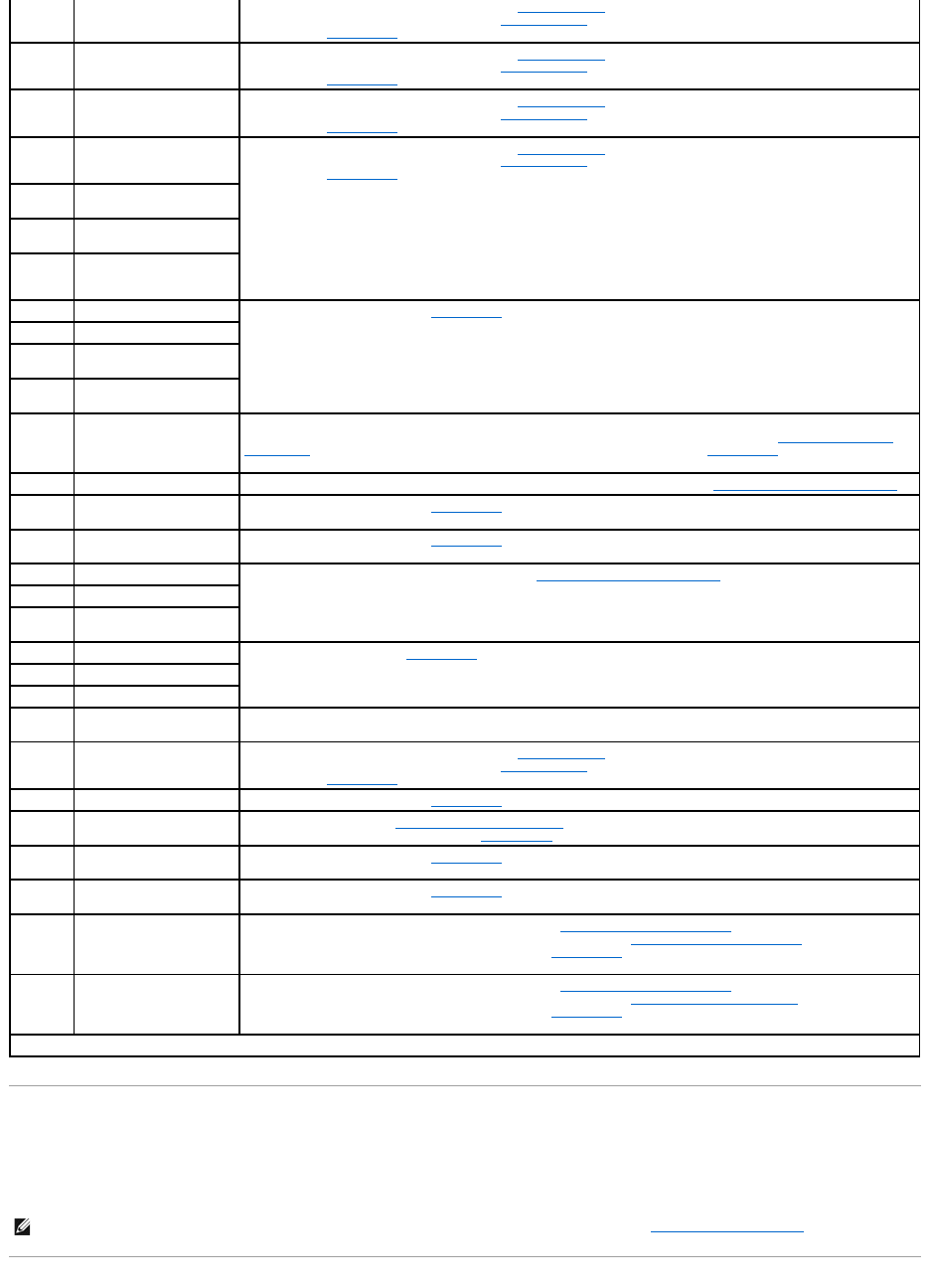
Table 2-3. System Beep Codes
Code
Cause
Corrective Action
1-1-3
CMOS write/read failure
Replace the system board. See "Getting Help," for instructions on obtaining technical assistance.
1-1-4
BIOS checksum failure
This fatal error usually requires that you replace the BIOS firmware. See "Getting Help," for instructions on obtaining
technical assistance.
1-2-1
Programmable interval-
timer failure
Replace the system board. See "Getting Help," for instructions on obtaining technical assistance.
1-2-2
DMA initialization failure
Remove and reseat the memory modules. See "Adding Memory" in "Installing System Board Options." If the problem
persists, replace the memory modules. See "Adding Memory" in "Installing System Board Options." If the problem
persists, see "Getting Help," for instructions on obtaining technical assistance.
1-2-3
DMA page register
write/read failure
Warning Messages
A warning message alerts you to a possible problem and asks you to take corrective action before the system continues a task. For example, before you
format a diskette, a message may warn you that you may lose all data on the diskette, as a way to protect against inadvertently erasing or writing over the
data. These warning messages usually interrupt the procedure and require you to respond by typing y (yes) or n (no).
1-3-1
Main-memory refresh
verification failure
Remove and reseat the memory modules. See "Adding Memory" in "Installing System Board Options." If the problem
persists, replace the memory modules. See "Adding Memory" in "Installing System Board Options." If the problem
persists, see "Getting Help," for instructions on obtaining technical assistance.
1-3-2
No memory installed
Remove and reseat the memory modules. See "Adding Memory" in "Installing System Board Options." If the problem
persists, replace the memory modules. See "Adding Memory" in "Installing System Board Options." If the problem
persists, see "Getting Help," for instructions on obtaining technical assistance.
1-3-3
Chip or data line failure in
the first 64 KB of main
memory
Remove and reseat the memory modules. See "Adding Memory" in "Installing System Board Options." If the problem
persists, replace the memory modules. See "Adding Memory" in "Installing System Board Options." If the problem
persists, see "Getting Help," for instructions on obtaining technical assistance.
1-3-4
Odd/even logic failure in
thefirst64KBofmain
memory
Remove and reseat the memory modules. See "Adding Memory" in "Installing System Board Options." If the problem
persists, replace the memory modules. See "Adding Memory" in "Installing System Board Options." If the problem
persists, see "Getting Help," for instructions on obtaining technical assistance.
1-4-
Address line failure in the
first 64 KB of main memory
1-4-2
Parity failure in the first 64
KB of main memory
2-1-1
through
2-4-4
Bit failure in the first 64 KB
of main memory
3-1-1
Slave DMA-register failure
Replace the system board. See "Getting Help," for instructions on obtaining technical assistance.
3-1-2
Master DMA-register failure
3-1-3
Master interrupt-mask
register failure
3-1-4
Slave interrupt-mask
register failure
3-2-4
Keyboard-controller test
failure
Check the keyboard cable and connector for proper connection. If the problem persists, run the keyboard test in the
system diagnostics to determine whether the keyboard or keyboard controller is faulty. See "Running the System
Diagnostics." If the keyboard controller is faulty, replace the system board. See "Getting Help," for instructions on
obtaining technical assistance.
3-3-1
CMOS failure
Run the system board test in the system diagnostics to isolate the problem. See "Running the System Diagnostics."
3-3-2
System configuration check
failure
Replace the system board. See "Getting Help," for instructions on obtaining technical assistance.
3-3-3
Keyboard controller not
detected
Replace the system board. See "Getting Help," for instructions on obtaining technical assistance.
3-3-4
Screen initialization failure
Run the video test in the system diagnostics. See "Running the System Diagnostics."
3-4-2
Screen-retrace test failure
3-4-3
Search for video ROM
failure
4-2-1
No timer tick
Replace the system board. "Getting Help," for instructions on obtaining technical assistance.
4-2-2
Shutdown failure
4-2-3
Gate A20 failure
4-2-4
Unexpected interrupt in
protected mode
Ensure that all expansion cards are properly seated, and then reboot the system.
4-3-1
Improperly seated or faulty
memory modules
Remove and reseat the memory modules. See "Adding Memory" in "Installing System Board Options." If the problem
persists, replace the memory modules. See "Adding Memory" in "Installing System Board Options." If the problem
persists, see "Getting Help," for instructions on obtaining technical assistance.
4-3-3
Defective system board
Replace the system board. See "Getting Help," for instructions on obtaining technical assistance.
4-3-4
Time-of-day clock stopped
Replace the battery. See "Replacing the System Battery" in "Installing System Board Options." If the problem
persists, replace the system board. See "Getting Help," for instructions on obtaining technical assistance.
4-4-1
I/O chip set failure
(defective system board)
Replace the system board. See "Getting Help," for instructions on obtaining technical assistance.
4-4-2
Parallel-port test failure
(defective system board)
Replace the system board. See "Getting Help," for instructions on obtaining technical assistance.
4-4-3
Math coprocessor failure
(defective microprocessor)
Remove and reseat the specified microprocessor. See "Upgrading the Microprocessor" in "Installing System Board
Options." If the problem persists, replace the microprocessor. See "Upgrading the Microprocessorr" in "Installing
System Board Options." If the problem persists, see "Getting Help," for instructions on obtaining technical
assistance.
4-4-4
Cache test failure
(defective microprocessor)
Remove and reseat the specified microprocessor. See "Upgrading the Microprocessor" in "Installing System Board
Options." If the problem persists, replace the microprocessor. See "Replacing the Microprocessor" in "Installing
System Board Options." If the problem persists, see "Getting Help," for instructions on obtaining technical
assistance.
NOTE: For the full name of an abbreviation or acronym used in this table, see "Abbreviations and Acronyms."
NOTE: Warning messages are generated by either the application program or the operating system. See "Finding Software Solutions," and the
documentation that accompanied the operating system and application program for more information on warning messages.

Diagnostics Messages
When you run a test group or subtest in the system diagnostics, an error message may result. These particular error messages are not covered in this
section. Record the message on a copy of the Diagnostics Checklist (see "Getting Help"), and then follow the instructions in that section for obtaining technical
assistance.
Alert Log Messages From the System Management Server Agent
The optional system management software generates alert messages for your system. For example, the server agent generates messages that appear in the
SNMP trap log file. Alert messages consist of information, status, warning, and failure messages for drive, temperature, fan, and power conditions. More
information about alert messages is provided in the system management software documentation found on the Online Documentation CD that shipped with
your system.
Back to Contents Page

Back to Contents Page
Finding Software Solutions
Dell™PowerEdge™500SCSystemsInstallationandTroubleshootingGuide
Installing and Configuring Software
Using Software
Because most systems have several application programs installed in addition to the operating system, isolating a software problem can be confusing.
Software errors can also appear to be hardware malfunctions at first.
Software problems can result from the following circumstances:
lImproper installation or configuration of an application program
lInput errors
lDevice drivers that may conflict with certain application programs
lInterrupt conflicts between devices
You can confirm that a system problem is caused by software by running the system diagnostics. See "Running the System Diagnostics." If all tests in the test
group are completed successfully, the problem is most likely caused by software.
This section provides some general guidelines for analyzing software problems. For detailed troubleshooting information on a particular application program,
see the documentation that accompanied the software or consult the support service for the software.
Installing and Configuring Software
Use virus-scanning software to check newly acquired application programs and files for viruses before installing the application programs on the system's hard
drive. Viruses can quickly use all available system memory, damage and/or destroy data stored on the hard drive, and permanently affect the performance of
the application programs they infect. Several commercial virus-scanning programs are available for purchase.
Before installing an application program, read its documentation to learn how the application program works, what hardware it requires, and what its defaults
are. An application program usually includes installation instructions in its accompanying documentation and a software installation routine.
The software installation routine assists users in transferring the appropriate application program files to the system's hard drive. Installation instructions may
provide details about how to configure the operating system to successfully run the application program. Always read the installation instructions before
running an application program's installation routine.
When you run the installation routine, be prepared to respond to prompts for information about how the system's operating system is configured, what type
of system you have, and what peripherals are connected to the system.
Using Software
The following subsections discuss errors that can occur as a result of software operation or configuration.
Error Messages
Error messages can be produced by an application program, the operating system, or the system. "Indicators, Messages, and Codes" discusses the error
messages that are generated by the system. If you receive an error message that is not listed in "Indicators, Messages, and Codes," check the operating
system or application program documentation.
Input Errors
If a specific key or set of keys is pressed at the wrong time, an application program may give you unexpected results. See the documentation that came with
the application program to make sure that the values or characters you are entering are valid.
Make sure that the operating environment is set up to accommodate the application programs you use. Keep in mind that whenever you change the
parameters of the system's operating environment, you may affect the successful operation of the application programs. Sometimes, after modifying the
operating environment, you may need to reinstall an application program that no longer runs properly.
Application Program Conflicts
Some application programs may leave portions of their setup information behind, even though you have exited from them. As a result, other application
programs cannot run. Rebooting the system can confirm whether these application programs are the cause of the problem.
Device drivers, which are application programs that use specialized subroutines, can cause problems with the system. For example, a variation in the way the
data is sent to the monitor may require a special screen driver application program that expects a certain kind of video mode or monitor. In such cases, you
may have to develop an alternate method of running that particular application program—by creating a start-up file made especially for that application
program, for example. Call the support service for the software you are using to help you with this problem.
Avoiding Interrupt Assignment Conflicts
Problems can arise if two devices attempt to use the same IRQ line. To avoid this type of conflict, check the documentation for the IRQ line's default for each
installed expansion card. Then consult Table3-1 to configure the card for one of the available IRQ lines.
Back to Contents Page
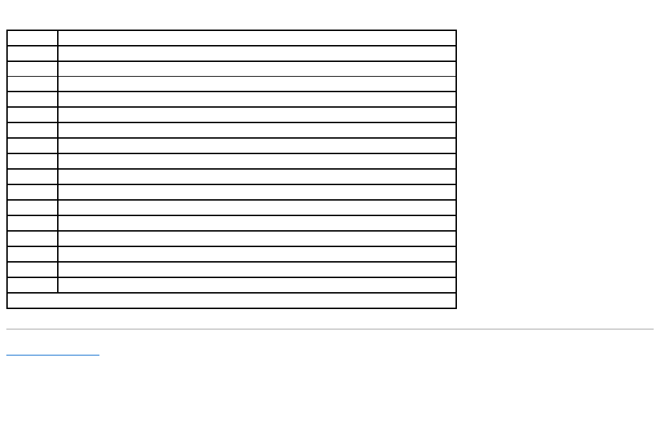
Table 3-1. IRQ Line Assignment Defaults
IRQ Line
Used By/Available
IRQ0
Used by the system timer
IRQ1
Used by the keyboard controller
IRQ2
Used by interrupt controller 1 to enable IRQ8 through IRQ15
IRQ3
Available
IRQ4
Used by serial port 1 (COM1 – COM4)
IRQ5
Available unless used by USB ports
IRQ6
Used by the diskette drive controller
IRQ7
Used by the primary parallel port
IRQ8
Used by the real-time clock
IRQ9
Reserved for ACPI functions
IRQ10
Available
IRQ11
Available
IRQ12
Used by the PS/2 mouse port if the mouse is enabled in the System Setup program
IRQ13
Used by the math coprocessor
IRQ14
Primary IDE controller (IDE 1)
IRQ15
Secondary IDE controller (IDE 2)
NOTE: For the full name of an abbreviation or acronym used in this table, see "Abbreviations and Acronyms."
Back to Contents Page
Running the System Diagnostics
Dell™PowerEdge™500SCSystemsInstallationandTroubleshootingGuide
Features of the System Diagnostics
When to Use the System Diagnostics
Starting the System Diagnostics
How to Use the System Diagnostics
How to Use the Device Groups Menu
Device Groups Menu Options
Error Messages
The system diagnostics provided with your system helps you check the system's hardware without any additional equipment and without destroying any data.
By using the diagnostics, you can have confidence in the system's operation. If you find a problem that you cannot solve by yourself, the diagnostic tests can
provide you with important information you will need when talking to a technical assistance representative.
Features of the System Diagnostics
The system diagnostics provide a series of menus and options from which you choose particular device groups or devices. You can also control the sequence in
which the tests are run. The diagnostic menus also have these helpful features:
lOptions that let you run tests individually or collectively
lAn option that allows you to choose the number of times a test is repeated
lThe ability to display or print test results or to save them in a file
lOptions to temporarily suspend testing if an error is detected or to terminate testing when an adjustable error limit is reached
lHelp messages that briefly describe each test and its parameters
lStatus messages that inform you whether device group or device tests are completed successfully
lError messages that appear if any problems are detected
When to Use the System Diagnostics
Whenever a major component or device in the system does not function properly, you may have a component failure. As long as the microprocessor and the
input and output components of the system (the monitor, keyboard, and diskette drive) are working, you can use the system diagnostics. If you know what
component(s) you need to test, simply select the appropriate diagnostic device group(s) or subtest(s). If you are unsure about the scope of the problem, read
the rest of the information in this section.
Starting the System Diagnostics
YoucanrunthesystemdiagnosticsfromeithertheutilitypartitiononyourharddriveorfromasetofdiskettesthatyoucreatefromtheDell OpenManage
ServerAssistantCD.
To run the diagnostics from the utility partition, perform the following steps:
1. Start the utility partition by pressing <F10> during POST.
2. From the utility partition's main menu, select the Run System Diagnostics option from Run System Utilities.
See "Utility Partition" in "Using the DellOpenManageServerAssistantCD," in the User's Guide for additional information about the utility partition.
To run the system diagnostics from the diskettes, perform the following steps:
1. Create a set of diagnostics diskettes using the Dell OpenManage Server Assistant CD.
See "Using the DellOpenManageServerAssistantCD" in the User's Guide for instructions on creating diagnostics diskettes.
2. Boot the system from the first diagnostics diskette.
If the system fails to boot, see "Getting Help," for instructions on obtaining technical assistance.
When you start the diagnostics a message is displayed telling you that the diagnostics is loading. The Diagnostics menu appears. The menu allows you to run
all or specific diagnostic tests or to exit the system diagnostics.
For a quick check of the system, select Test All Devices and then select Quick Tests. This option runs only the device tests that do not require user
NOTICE: Use the system diagnostics to test only your system. If you use this program with other systems, incorrect system responses or error
messages may result.
NOTE: Before you read the rest of this section, you may want to start the system diagnostics so that you can see it on your monitor screen.
interaction and that do not take a long time to run. Dell recommends that you choose this option first to increase the chance of tracing the source of the
problem quickly. For a complete check of the system, select Test All Devices and then select Extended Tests. To check a particular area of the system, choose
Advanced Testing.
Selecting Exit to MS-DOS exits the diagnostics and returns you to the MS-DOS® operating system environment.
To select an option from the Diagnostics menu, highlight the option and press <Enter>, or press the key that corresponds to the highlighted letter in the
option you choose.
How to Use the System Diagnostics
When you select Advanced Testing from the Diagnostics menu, the main screen of the diagnostics appears.
Information on the main screen of the diagnostics is presented in the following areas:
lTwo lines at the top of the main screen identify the diagnostics and give its version number.
lOn the left side of the screen, the Device Groups area lists the diagnostic device groups in the order they will run if you select All under the Run Tests
submenu. Press the up- or down-arrow key to highlight a device group.
lOn the right side of the screen, the Devices for Highlighted Group area lists the specific devices within a particular test group.
lTwo lines at the bottom of the screen make up the menu area. The first line lists the menu options you can select; press the left- or right-arrow key to
highlight an option. The second line gives information about the highlighted option.
How to Use the Device Groups Menu
The Device Groups menu at the bottom of the screen provides options that enable you to select and run specific diagnostic tests from the diagnostics main
screen. Press the left- and right-arrow keys to select the options on the menu. As you move from one menu option to another, a brief explanation of the
highlighted option appears on the bottom line of the screen.
If you want more information about a device group or device, highlight the Help option and press <Enter>. After you read the information, press <Esc> to
return to the previous screen.
Device Groups Menu Options
Five options are listed at the bottom of the diagnostics main screen: Run Tests, Devices, Select, Config, and Help.
There are two ways to select a menu option:
lLook on the screen to see which letter in the option is capitalized, and type that letter (for example, type r to select the Run option).
lMove the highlight to the option you want to select by pressing the left- or right-arrow key, and then press <Enter>.
Whenever one of the options is selected, additional choices become available.
The following subsections explain the menu options as listed from left to right in the Device Groups menu.
Run Tests
Run Tests displays seven options: One, All, Select, Options, Results, Errors, and Help. If you select One, all the devices within the highlighted device group
are run. If you select All, all of the tests in all of the device group tests are run. (The device group tests are run in the same order as they are listed.) If you
choose Select, only the selected device groups or the devices that you selected within the device groups are run. Before you test any device groups or
devices, consider setting global parameters within Options. Table4-1 lists all of the possible values for each option. Global parameters offer you greater
control over how the device group tests or device tests are run and how results are reported. Help displays a series of help options, including Menu, Keys,
Device Group, Device, Test, and Versions.
Table 4-1. Options
Option
PossibleValues
Number of Times to Repeat Test(s)
0001 through 9999 or 0000, which loops indefinitely until you press <Ctrl><Break>.
The default is 1.
Maximum Errors Allowed
0000 through 9999, where 0000 means that there is no error limit. The default is 1.
Pause for User Response
Yes, No
Allows you to decide whether tests will wait for user input.
The default is Yestowaitforuserinput.
Message Logging
None, Errors, All
Determines if any test results are saved to a file. The default is None.
Message Logging File Name
Specifies the name of the logging file if the Message Logging option is selected.
The default is A: RESULT.
Devices
Most of the device groups consist of several devices. Use the Devices option to select individual devices within the device group(s).
When you select Devices, the following options are displayed: Run Tests, Tests, Select, Parameters, and Help. Table4-2 lists all of the possible values for
each option.
Select
The Select option in the Device Groups menu allows you to choose one or more devices from a particular device group. Three options are displayed: One, All,
and Help.
Config
Choosing Config from the Device Groups menu displays information about the particular device that is highlighted.
Error Messages
When you run a test in the diagnostics, error messages may result. Record the messages on a copy of the Diagnostics Checklist; also see "Getting Help," for
instructions on obtaining technical assistance and informing the technical assistance representative of these messages.
Back to Contents Page
Display Detailed Messages
Yes, No
Enables or disables detailed messages.
Table 4-2.DevicesOptions
Option
Functions
Run Tests
Displays five options: One, All, Select, Options, Results, Errors, and Help.
Tests
Allows you to select individual devices to tailor the testing process to your particular needs. You can choose one or more devices from the list.
When you choose Tests, four options are displayed: Run Tests, Select, Parameters, and Help.
Select
Allows you to choose one or more devices from a particular device group. Three options are displayed: One, All, and Help.
Parameters
Determines how a particular test runs.
Help
Displays a list of help topics.
Back to Contents Page
TroubleshootingYourSystem
Dell™PowerEdge™500SCSystemsInstallationandTroubleshootingGuide
If your system is not working as expected, begin troubleshooting using the procedures in this section. This section guides you through some initial checks and
procedures that can solve basic system problems and provides troubleshooting procedures for components inside the system. Before you start any of the
procedures in this section, take the following steps:
lLay the system on its side.
lRead the "Safety Instructions" in your System Information document.
lRead "Running the System Diagnostics" for information about running diagnostics.
Safety First—For You and Your System
The procedures in this guide require that you remove the cover and work inside the system. While working inside the system, do not attempt to service the
system except as explained in this guide and elsewhere in your system documentation. Always follow the instructions closely. Make sure to review all of the
procedures in "Safety Instructions" in your System Information document.
Working inside the system is safe—if you observe the following precaution.
Removing and Replacing the System Cover and Support Beam
The system is enclosed by a bezel and a cover. To upgrade or troubleshoot the system, remove the system cover and support beam to gain access to internal
components.
Removing the System Cover and Support Beam
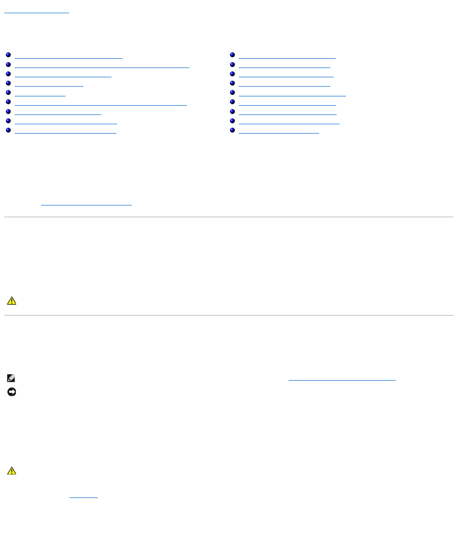
1. Lay the system on its right side, with the system foot stand off the edge of the work surface.
2. Loosen the captive thumbscrew that secures the cover to the back of the system.
3. Face the front of the system. Use your thumbs to press in both latches while pushing the cover backward. Move the cover back slightly, and then lift it
straight up (see Figure5-1).
If necessary, use both hands and work one side at a time.
Figure 5-1. Removing the System Cover
Safety First—For You and Your System
Removing and Replacing the System Cover and Support Beam
Removing and Replacing the Bezel
Checking the Equipment
Inside the System
Responding to a System Management Server Agent Message
Troubleshooting a Wet System
Troubleshooting a Damaged System
Troubleshooting the System Battery
Troubleshooting the Power Supply
Troubleshooting the Cooling Fan
Troubleshooting Expansion Cards
Troubleshooting System Memory
Troubleshooting the Video Subsystem
Troubleshooting the System Board
Troubleshooting the Diskette Drive
Troubleshooting CD and DVD Drives
Troubleshooting Hard Drives
CAUTION: See "Protecting Against Electrostatic Discharge" in the "Safety Instructions" in your System Information document before performing
any procedure which requires you to open the cover.
NOTE: Before you begin any of the procedures in this section, follow the safety instructions in "Safety First—For You and Your System."
NOTICE: To avoid damaging the system board, disconnect the power cable from the electrical outlet and from the back of the system, then press the
power button before you remove the system cover. The system board continues to receive a small amount of power when the system is turned off and
attached to an electrical outlet.
CAUTION: To prevent cuts, keep your hands clear of the metal edges on the system as you slide back the cover.
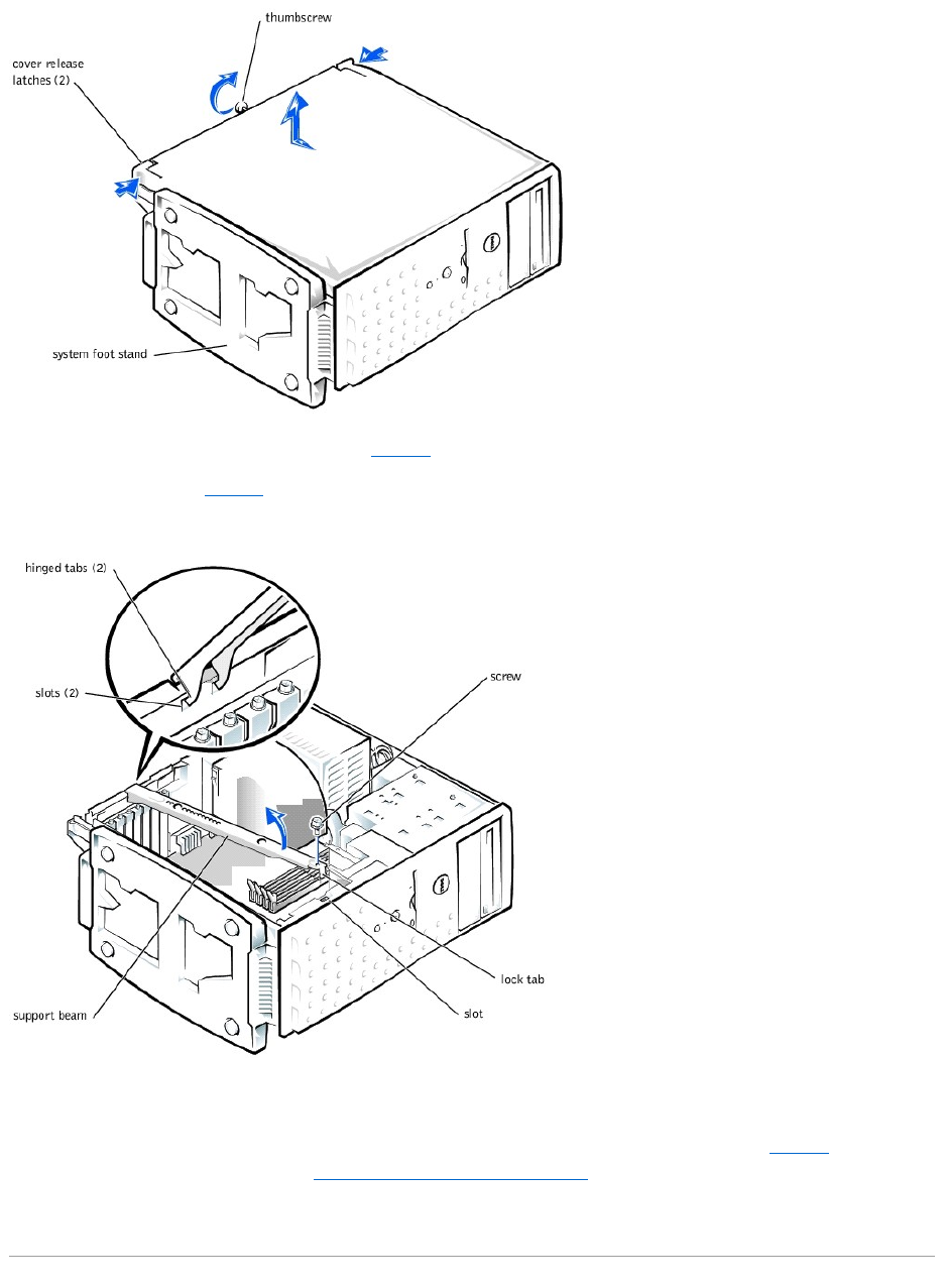
4. Remove the screw from the support beam as shown in Figure5-2.
5. Pull the front end of the support beam until it snaps free from its fastener. Rotate the front of the beam upward until the hinged tabs on the back of the
beam clear their slots (see Figure5-2).
Figure 5-2. Removing and Replacing the Support Beam
Replacing the System Cover and Support Beam
1. Check that no tools or parts are left inside the system.
2. Slip the support beam's hinged tabs into their slots and lower the beam until the lock tab snaps into the retaining slot (see Figure5-2).
3. Replace the screw you removed in step 4 of "Removing the System Cover and Support Beam."
4. Fit the cover over the sides of the chassis and slide the cover forward until it locks in place.
5. Secure the cover with the thumbscrew.
Removing and Replacing the Bezel
The front bezel has status and attention indicators. You must remove the system cover in order to remove the bezel.
Removing the Bezel
1. Remove the system cover (see "Removing the System Cover and Support Beam").
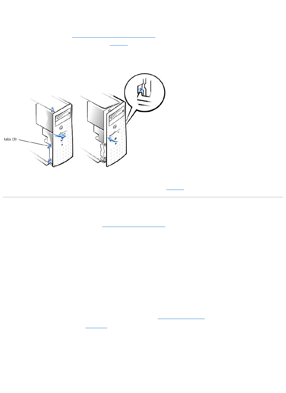
2. Press the three tabs along the side of the bezel (see Figure5-3).
3. Swing the bezel away from the system, disengage the hooks, and carefully pull the bezel away from the system.
Figure 5-3. Removing and Replacing the Bezel
Replacing the Bezel
Insert the bezel hooks into the system slots, and snap the bezel back onto the system (see Figure5-3).
Checking the Equipment
This section provides troubleshooting procedures for equipment that connects directly to the I/O panel of the system, such as the monitor, keyboard, or
mouse. Before you perform any of the procedures, see "Checking Connections and Switches" in "Indicators, Messages, and Codes."
Troubleshooting the Video Subsystem
Problem
lMonitor
lMonitor interface cable
lVideo memory
lVideo logic
Action
1. Check the system and power connections to the monitor.
2. Run the video tests in the system diagnostics.
If the tests run successfully, the problem is not related to video hardware. Go to "Finding Software Solutions."
If the tests did not run successfully see "Getting Help" for instructions on obtaining technical assistance.
Troubleshooting the Keyboard
Problem
lA system error message indicates a keyboard problem
Action
1. Look at the keyboard and the keyboard cable for any signs of damage.
2. Press and release each key on the keyboard.

If the keyboard and its cable appear to be free of physical damage, and the keys work, go to step 4.
If the keyboard or its cable are damaged, continue to step 3.
3. Swap the faulty keyboard with a working keyboard.
If the problem is resolved, the keyboard must be replaced. See "Getting Help," for instructions on obtaining technical assistance.
4. Run the keyboard test in the system diagnostics.
If you can use the keyboard to select the keyboard test, go to step 6.
If you cannot use the keyboard to select the keyboard test, continue to step 5.
5. Swap the faulty keyboard with a working keyboard.
6. Did the keyboard test run successfully?
If the problem is resolved, the keyboard must be replaced. If the problem is not resolved, the keyboard controller on the system board is faulty. See
"Getting Help," for instructions on obtaining technical assistance.
Troubleshooting the Basic I/O Functions
Problem
lA system error message indicates an I/O port problem
lA device connected to the port does not function properly
Action
1. Check the system setup. See "Using the System Setup Program" in the User's Guide for instructions.
If the system setup is correct, go to step 4.
2. Change the necessary statements in the system setup. If the port problem is confined to a particular application program, see the application
program's documentation for specific port configuration requirements.
3. Reboot the system from the diagnostics diskette, and run the serial port test and/or the parallel port test in the system diagnostics.
If the tests did not run successfully, see "Getting Help," for instructions on obtaining technical assistance.
4. If the problem persists, see one of the following procedures, "Troubleshooting a Parallel Printer" or "Troubleshooting a Serial I/O Device," depending on
the malfunctioning device.
Troubleshooting a Serial I/O Device
Problem
lDevice connected to the serial ports is not working
Action
1. Turn off the system and any peripheral devices connected to the serial port.
2. Swap the interface cable with a known working cable.
If the problem is resolved, the interface cable must be replaced. See "Getting Help," for instructions on obtaining technical assistance.
3. Turn off the system and the serial device, and swap the device with a comparable device.
4. Turn on the power to the system and the serial device.
If the problem is resolved, the serial device must be replaced. If the problem is not resolved, see "Getting Help," for instructions on obtaining technical
assistance.
Troubleshooting a Parallel Printer
Problem
lParallel printer is not working
Action
1. Turn off the power from the printer and the system.
2. Swap the parallel printer interface cable with a known working cable.
3. Turn on the power to the printer and the system.
4. Attempt to print with the printer.
If the print operation is successful, the interface cable must be replaced. See "Getting Help," for instructions on obtaining technical assistance.
5. Run the printer's self-test.
If the self-test is not successful, the printer is probably defective. If the printer was purchased from Dell, see "Getting Help," for instructions on obtaining
technical assistance.
6. Attempt to print on the parallel printer.
If the print operation is not successful, the see "Getting Help," for instructions on obtaining technical assistance.
Troubleshooting a USB Device
Problem
lA system error message indicates a problem
lDevice connected to the port is not working
Action
1. Enter the System Setup program, and check that the USB ports are enabled. See "Using the System Setup Program" in the User's Guide for instructions.
2. Turn off the system and any USB devices.
If there is only one USB device connected to the system, go to step 5.
3. Disconnect the USB devices, and connect the malfunctioning device to the other port.
4. Apply power to the system and the reconnected device.
If the problem is resolved, the USB port may be defective. See "Getting Help," for instructions on obtaining technical assistance.
5. If possible, swap the interface cable with a known working cable.
If the problem is resolved, the interface cable must be replaced. See "Getting Help," for instructions on obtaining technical assistance.
6. Turn off the system and the USB device, and swap the device with a comparable device.
7. Turn on the power to the system and the USB device.
If the problem is resolved, the USB device must be replaced. If the problem is not resolved, see "Getting Help," for instructions on obtaining technical
assistance.
Troubleshooting the Integrated NIC
Problem
lNIC cannot communicate with the network
Action
1. Enter the System Setup program and confirm that the NIC is enabled.
See "Using the System Setup Program" in the User's Guide for instructions.
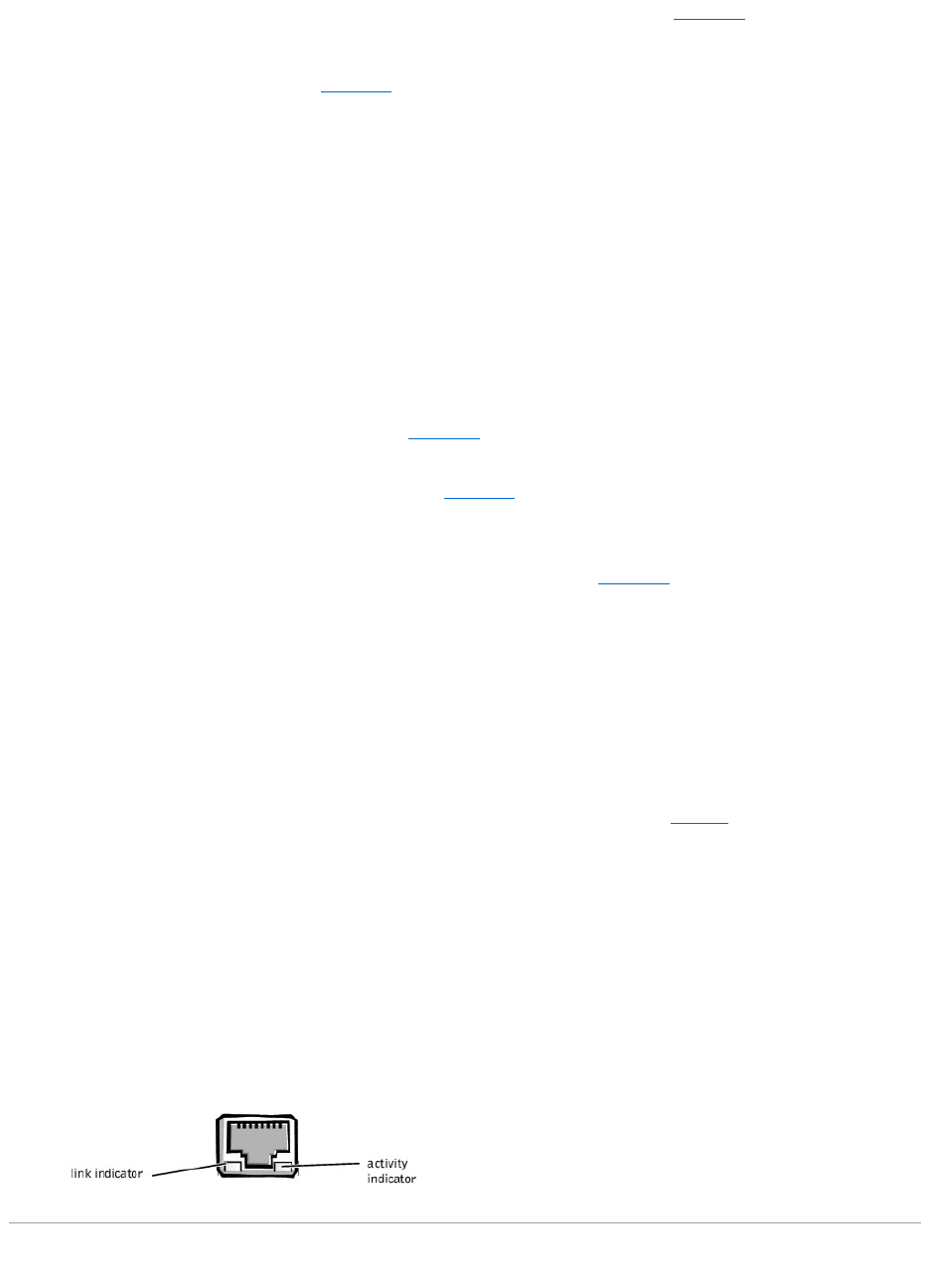
2. Check the two indicators on the left and right corners of the NIC connector on the system's back-panel (see Figure5-4).
The green link indicator shows that the adapter is connected to a valid link partner. The amber activity indicator lights if network data is being sent or
received.
¡If the link indicator is not on, check all cable connections.
¡Try changing the auto-negotiation setting, if possible.
¡Try another port on the switch or hub.
3. If the activity indicator does not light, the network driver files might be damaged or deleted.
4. Reinstall the drivers.
5. Make sure the appropriate drivers are installed and the protocols are bound.
Figure 5-4. NIC Indicators
Inside the System
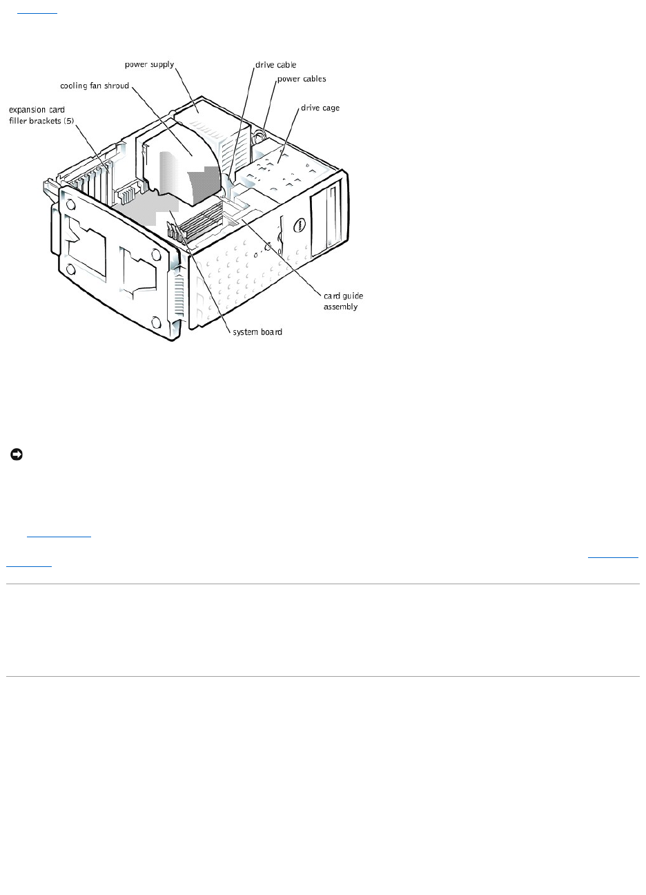
In Figure5-5, the system cover and front bezel are removed to provide an interior view of the system.
Figure 5-5. Inside the System
The system board holds the system's control circuitry and other electronic components. Several hardware options such as the microprocessor and memory are
installed directly on the system board. The system board can accommodate up to five PCI expansion cards (two cards at 64-bit/66 MHz or 64-bit/33 MHz, and
three cards at 32-bit/33 MHz).
The drive cage contains two externally accessible, 5.25-inch drive bays that provide space for up to two drives, including a CD or DVD drive and one other
device, such as a tape drive. The drive cage also provides space for up to two 1-inch IDE hard drives.
Additionally, the card guide assembly provides two additional brackets for a 3.5-inch diskette drive and a 1-inch IDE hard drive.
When you look inside the system, note the DC power cables leading from the power supply. The power cables supply power to the system board, drives, and
any expansion cards that connect to external peripheral.
The wide ribbon cables are the interface cables for internal drives. For the diskette drive, an interface cable connects the drive to an interface connector on the
system board or on an expansion card. For IDE devices, interface cables connect the devices to an IDE connector on the system board (for more information,
see "Installing Drives").
During an installation or troubleshooting procedure, you may be required to change a jumper. For information on the system board jumpers, see "Jumpers and
Connectors."
Responding to a System Management Server Agent Message
The optional system management server agent monitors critical system voltages and temperatures, the system cooling fans, and the status of the hard drives
in the system. The server agent generates alert messages that appear in the alert log window. For information about the alert log window and options, see
the system management server agent documentation.
Troubleshooting a Wet System
Problem
lLiquid spills
lSplashes
lExcessive humidity
Action
1. Turn off the system, including any attached peripherals, and disconnect the system from the electrical outlet.
2. Remove the system cover.
3. Remove all expansion cards installed in the system.
4. Let the system dry thoroughly for at least 24 hours.
NOTICE: Do not install a hard drive in the lower card-guide assembly bracket next to the card guides. Installing a drive in the lower card-guide
assembly bracket is not supported in this system.
5. Replace the system cover, reconnect the system to the electrical outlet, and turn on the system.
If the system does not start up properly, see "Getting Help," for instructions on obtaining technical assistance.
6. If the system starts up normally, shut down the system and reinstall all expansion cards you removed in step 3.
7. Run the system board tests in the system diagnostics to confirm that the system is working properly.
If the tests did not complete successfully, see "Getting Help," for instructions on obtaining technical assistance.
Troubleshooting a Damaged System
Problem
lSystem dropped or damaged
Action
1. Check the expansion-card connections to the system board.
2. Make sure that all cables are properly connected and that all components are properly seated in their connectors and sockets.
3. Run the system board tests in the system diagnostics.
If the tests did not complete successfully, see "Getting Help," for instructions on obtaining technical assistance.
Troubleshooting the System Battery
Problem
lError message shows problem with the battery
lSystem Setup program loses the system configuration information
lSystem date and time will not stay current
Action
1. Check the connection of the coin cell battery to the system board.
See "Replacing the System Battery" in "Installing System Board Options."
2. If the problem is not resolved by reseating the battery, replace the battery.
If the problem is not resolved by replacing the battery, see "Getting Help," for instructions on obtaining technical assistance.
Troubleshooting the Power Supply
Problem
lGreen power indicator on the system bezel is not lit
lServer management application program issues a power supply-related error message
Action
1. Check the power outlet and power cable (see "Checking Connections and Switches" in "Indicators, Messages, and Codes").
2. Turn off the system, including any attached peripherals, and disconnect all the power cables from the electrical outlets.
3. Remove the system cover. See "Replacing the System Cover and Support Beam."
4. Check the power cable connection to the POWER connector on the system board.
If the problem is not resolved, see "Getting Help," for instructions on obtaining technical assistance.
Troubleshooting the Cooling Fan
WARNING: There is a danger of a new battery exploding if it is incorrectly installed. Replace the battery only with the same or equivalent type
recommended by the manufacturer. Discard used batteries according to the manufacturer's instructions.
CAUTION: See "Protecting Against Electrostatic Discharge" in your System Information document.

Problem
lFan not operating
lServer management application program issues a fan-related error message
Action
1. Turn off the system, including any attached peripherals, and disconnect all the power cables from the electrical outlets.
2. Remove the system cover (see "Removing the System Cover and Support Beam").
3. Check the fan cable connection to the SYS_FAN2 connector on the system board.
If the problem is not resolved, see "Getting Help," for instructions on obtaining technical assistance.
Troubleshooting Expansion Cards
Problem
lError message indicates an expansion-card problem
lExpansion card seems to perform incorrectly or not at all
Action
1. Turn off the system, including any attached peripherals, and disconnect all the power cables from the electrical outlets.
2. Remove the system cover (see "Removing the System Cover and Support Beam").
3. Verify that each expansion card is firmly seated in its connector.
4. Verify that any appropriate cables are firmly connected to their corresponding connectors on the expansion cards.
5. Install the system cover.
6. Connect the system to an electrical outlet and turn on the system. If the problem still exists, go to step 7.
7. Turn off the system and disconnect the system from its electrical outlet.
8. Remove the system cover.
9. Remove all expansion cards installed in the system.
10. Install the system cover.
11. Connect the system to an electrical outlet and turn on the system.
12. Run the system memory tests in the system diagnostics.
If the tests do not complete successfully, see "Getting Help," for information on obtaining technical assistance.
13. Reinstall one of the expansion cards you removed in step 9 (see "Installing Expansion Cards" in Installing System Board Options").
14. Replace the system cover, reconnect the system to the electrical outlet, and turn on the system.
If the problem still exists, repeat steps 13 and 14 for each of the remaining expansion cards.
If you have reinstalled all of the expansion cards and the system memory tests are still failing, see "Getting Help," for information on obtaining technical
assistance.
Troubleshooting System Memory
Problem
lFaulty memory module
lFaulty system board
Action
1. Turn on the power to the system, including any attached peripherals.
If there is not an error message, go to step 4.
2. Enter the System Setup program to check the system memory setting.
See "Using the System Setup Program," in the User's Guide for instructions.
3. Iftheamountofmemoryinstalleddoesmatchthesystemmemorysetting,gotostep8.
4. Turn off the system, including any attached peripherals, and disconnect the system from its electrical outlet.

5. Remove the system cover (see "Removing the System Cover and Support Beam").
6. Reseat the memory modules in their sockets.
7. Replace the system cover, reconnect the system to the electrical outlet, and turn on the system.
8. Enter the System Setup program and check the system memory again.
9. Does the amount of memory installed match the system memory?
If the amount of memory installed does not match the system memory setting, continue to step 10.
10. Reboot the system, and observe the monitor screen and the Num Lock, Caps Lock, and Scroll Lock indicators on the keyboard.
If the monitor screen remains blank, and the Num Lock, Caps Lock, and Scroll Lock indicators on the keyboard remain on, continue to step 11.
If the monitor screen does not remain blank, and the Num Lock, Caps Lock, and Scroll Lock indicators on the keyboard remain on, continue to step 16.
11. Repeat steps 4 and 5.
12. Swap the memory module in socket DIMM_A with one of the same capacity.
13. Replace the system cover, reconnect the system to the electrical outlet, and turn on the system.
14. Reboot the system, and observe the monitor screen and the indicators on the keyboard.
15. If the problem still exists, repeat steps 12 through 14 for each memory module installed.
If the problem is not resolved, see "Getting Help," for instructions on obtaining technical assistance.
16. Run the system memory test in the system diagnostics.
If the test does not complete successfully, see "Getting Help," for instructions on obtaining technical assistance.
Troubleshooting the Video Subsystem
Problem
lMonitor not operating
lMonitor interface cable not connected correctly or is faulty
lVideo logic problems
Action
1. Check the system and power connections to the monitor.
2. Run the video tests in the system diagnostics.
If the tests run successfully, the problem is not related to video hardware. See "Finding Software Solutions."
If the tests did not run successfully see "Getting Help," for instructions on obtaining technical assistance.
Troubleshooting the System Board
Problem
lError message indicating a system board problem
Action
1. Turn off the system, including any attached peripherals, and disconnect the system from its electrical outlet.
2. Remove the system cover (see "Removing the System Cover and Support Beam").
3. Remove all expansion cards.
4. Replace the system cover, reconnect the system to power, and turn on the system.
5. Run the system board tests in the system diagnostics.
If the tests does not run successfully, see "Getting Help," for instructions on obtaining technical assistance.
6. Turn off the system, disconnect it from power, and remove the system cover.
CAUTION: See "Protecting Against Electrostatic Discharge" in the safety instructions in your System Information document.
NOTE: There are multiple configurations for the memory modules; see "Memory Module Installation Guidelines" in "Installing System Board Options." The
following steps are an example of one configuration.

7. Reinstall one of the expansion cards that you removed in step 3 (see "Installing Expansion Cards" in Installing System Board Options").
8. Replace the system cover, reconnect the system to the electrical outlet, and turn on the system.
9. Run the system board tests again.
Did the tests run successfully?
If the tests does not complete successfully, see "Getting Help," for instructions on obtaining technical assistance.
10. Repeatsteps7through9fortheremainingexpansioncardsthatyouremovedinstep3.
If you have reinstalled all of the expansion cards and the problem still persists, see "Getting Help," for instructions on obtaining technical assistance.
Troubleshooting the Diskette Drive
Problem
lError message indicating a diskette drive problem during execution of either the boot routine or the system diagnostics
Action
1. Enter the System Setup program, and verify that the system is configured correctly. See "Using the System Setup Program" in the User's Guide for
instructions.
2. Run the diskette drive tests in the system diagnostics to see whether the diskette drive now works correctly.
3. Turn off the system, including any attached peripherals, and disconnect the system from its electrical outlet.
4. Remove the system cover.
5. Verify that the diskette drive interface cable is securely connected between the diskette drive assembly and the system board.
6. Replace the system cover, reconnect the system to the electrical outlet, and turn on the system, including any attached peripherals.
7. Run the diskette drive tests in the system diagnostics to determine whether the diskette drive works correctly.
8. If the drive still does not work, remove all expansion cards.
9. Run the diskette drive tests in the system diagnostics to determine whether the diskette drive now works correctly.
If the test ran successfully, an expansion card may be conflicting with the diskette drive logic, or you may have a faulty expansion card. Continue to step
11.
If the test failed, see "Getting Help," for instructions on obtaining technical assistance.
10. Reinstall one of the expansion cards you removed in step 9.
11. Retest and run the diskette drives test in the system diagnostics to determine whether the diskette drive subsystem now works correctly.
12. Repeat steps 11 and 12 until all expansion cards have been reinstalled or until one of the expansion cards prevents the system from booting from the
diagnostics diskette.
If the problem is not resolved, see "Getting Help," for instructions on obtaining technical assistance.
Troubleshooting CD and DVD Drives
Problem
lSystem cannot read data from CD
lCD drive indicator fails to flash during boot
Action
1. Turn off the system, including any attached peripherals, and disconnect the system from its electrical outlet.
2. Remove the system cover.
3. Verify that the CD drive interface cable is securely connected between the CD drive assembly and the system board.
4. Replace the system cover, reconnect the system to the electrical outlet, and turn on the system, including any attached peripherals.
5. Run the IDE devices tests in the system diagnostics to determine whether the CD drive now works correctly.
If the problem is not resolved, see "Getting Help," for instructions on obtaining technical assistance.
Troubleshooting Hard Drives
Problem

lThe drive itself
Action
1. Turn off the system, including any attached peripherals, and disconnect the system from its electrical outlet.
2. Remove the system cover.
3. Verify that the hard drive interface cable is securely connected between the hard drive assembly and the system board.
4. Replace the system cover, reconnect the system to the electrical outlet, and turn on the system, including any attached peripherals.
5. Run the IDE devices tests in the system diagnostics to determine whether the hard drive now works correctly.
If the problem is not resolved, see "Getting Help," for instructions on obtaining technical assistance.
Back to Contents Page
CAUTION: This troubleshooting procedure can destroy data stored on the hard drive. Before you proceed, back up all the files on the hard drive.
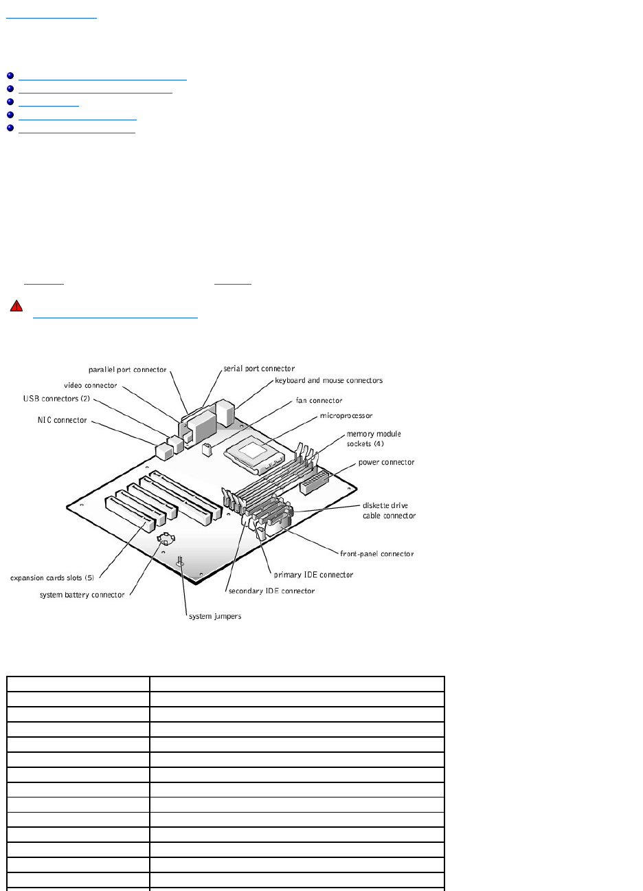
Back to Contents Page
Installing System Board Options
Dell™PowerEdge™500SCSystemsInstallationandTroubleshootingGuide
Removing and Replacing the Fan Assembly
Adding and Replacing Expansion Cards
Adding Memory
Upgrading the Microprocessor
Replacing the System Battery
This section describes how to install or replace the following options:
lExpansion cards
lMemory modules
lMicroprocessor
lFan assembly and cooling shroud
lPower supply
lSystem battery
Use Figure6-1 to locate the system board features. Table6-1 describes the system board connectors and sockets.
Figure 6-1. System Board Features
WARNING: Before you perform this procedure, you must turn off the system and disconnect it from its power source. For more information, see
"Safety First— For You and Your System" in "Troubleshooting Your System."
Table 6-1.SystemBoardConnectorsandSockets
Connector or Socket
Description
BATTERY
System battery connector
COM1
Serial port connectors
DIMM_x
Memory module sockets (DIMM_A–DIMM_D)
SLOT_n
Expansion card connectors (SLOT_1–SLOT_5)
LAN1
NIC connector
SYS_FAN2
Fan connector
PRIMARY IDE
Primary IDE connector
SECONDARY IDE
Secondary IDE connector
FDD
Diskette drive cable connector
KY
Keyboard connector
MS
Mouse connector
FRONT PANEL
System front panel connector
LPT
Parallel port connector
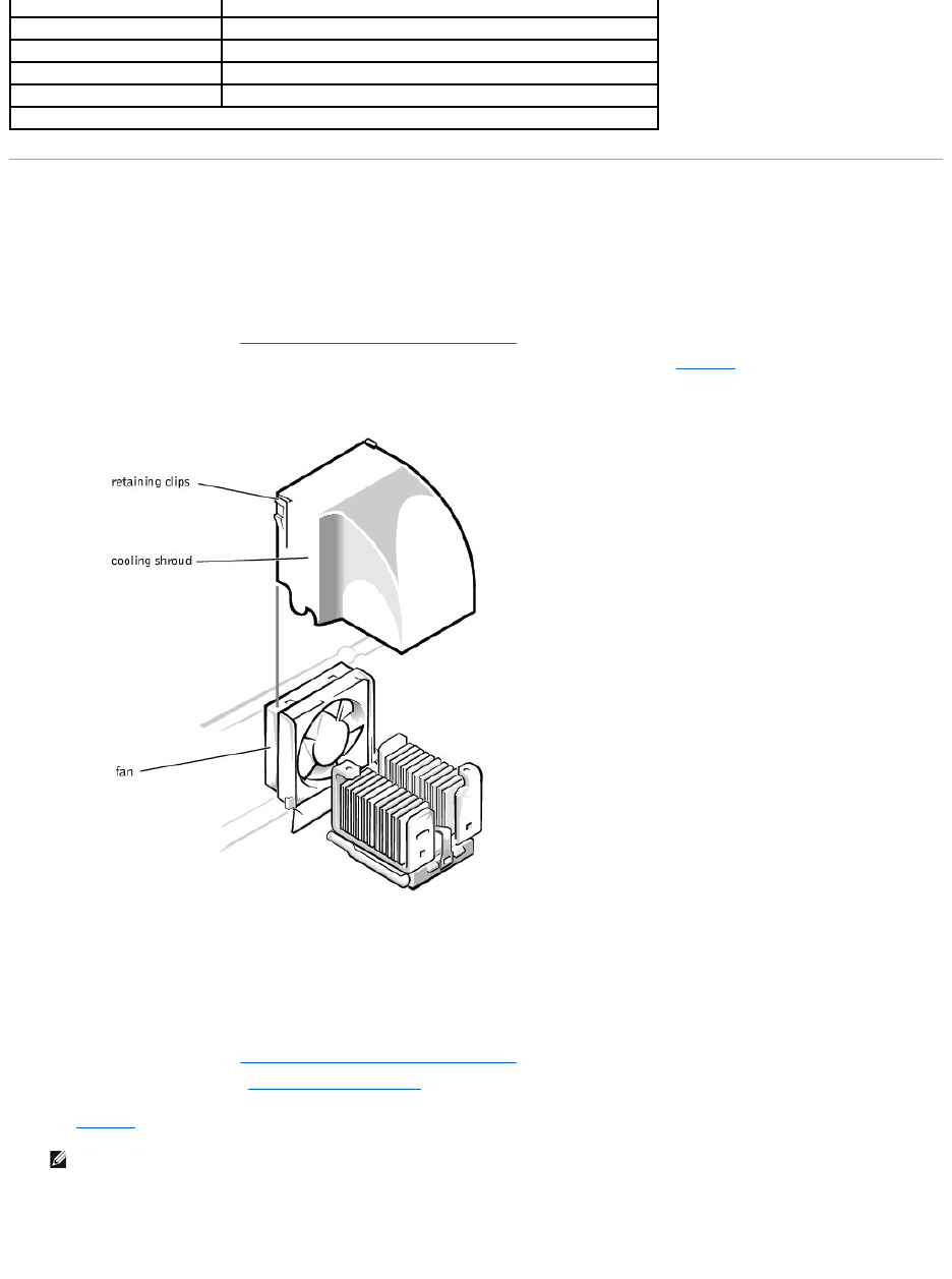
Removing and Replacing the Fan Assembly
The fan assembly consists of a fan and a cooling shroud. The cooling shroud is used to improve airflow over the microprocessor.
Removing the Cooling Shroud
1. Turn off the system, including any peripherals, and disconnect the power cable from the electrical outlet.
2. Remove the system cover (see "Removing the System Cover and Support Beam" in "Troubleshooting Your System").
3. Remove the shroud by squeezing the retaining clips on the top of the shroud and lifting it straight up (see Figure6-2).
Figure 6-2. Removing the Cooling Shroud
Replacing the Cooling Shroud
Place the shroud in the fan assembly guide slots and slide the shroud straight down until the retaining clips snap in place.
Removing the Fan
1. Turn off the system, including any peripherals, and disconnect the power cable from the electrical outlet.
2. Remove the system cover (see "Removing the System Cover and Support Beam" in "Troubleshooting Your System").
3. Remove the cooling shroud (see "Removing the Cooling Shroud").
4. While pushing the fan assembly upward, press the two release buttons on the back of the system and lift the fan assembly out of its retaining brackets
(see Figure6-3).
5. After the fan has been released from the retaining brackets, disconnect the fan cable from the SYS_FAN2 connector on the system board and lift the fan
out of the system.
Figure 6-3. Removing the Fan
POWER
Power connector
CPU
Microprocessor socket
USB
USB connector
VGA
Video connector
J12
System jumpers
NOTE: For the full name of an abbreviation or acronym used in this table, see "Abbreviations and Acronyms."
NOTE: Do not lift the fan out of the system until you have disconnected the fan cable from the system board.
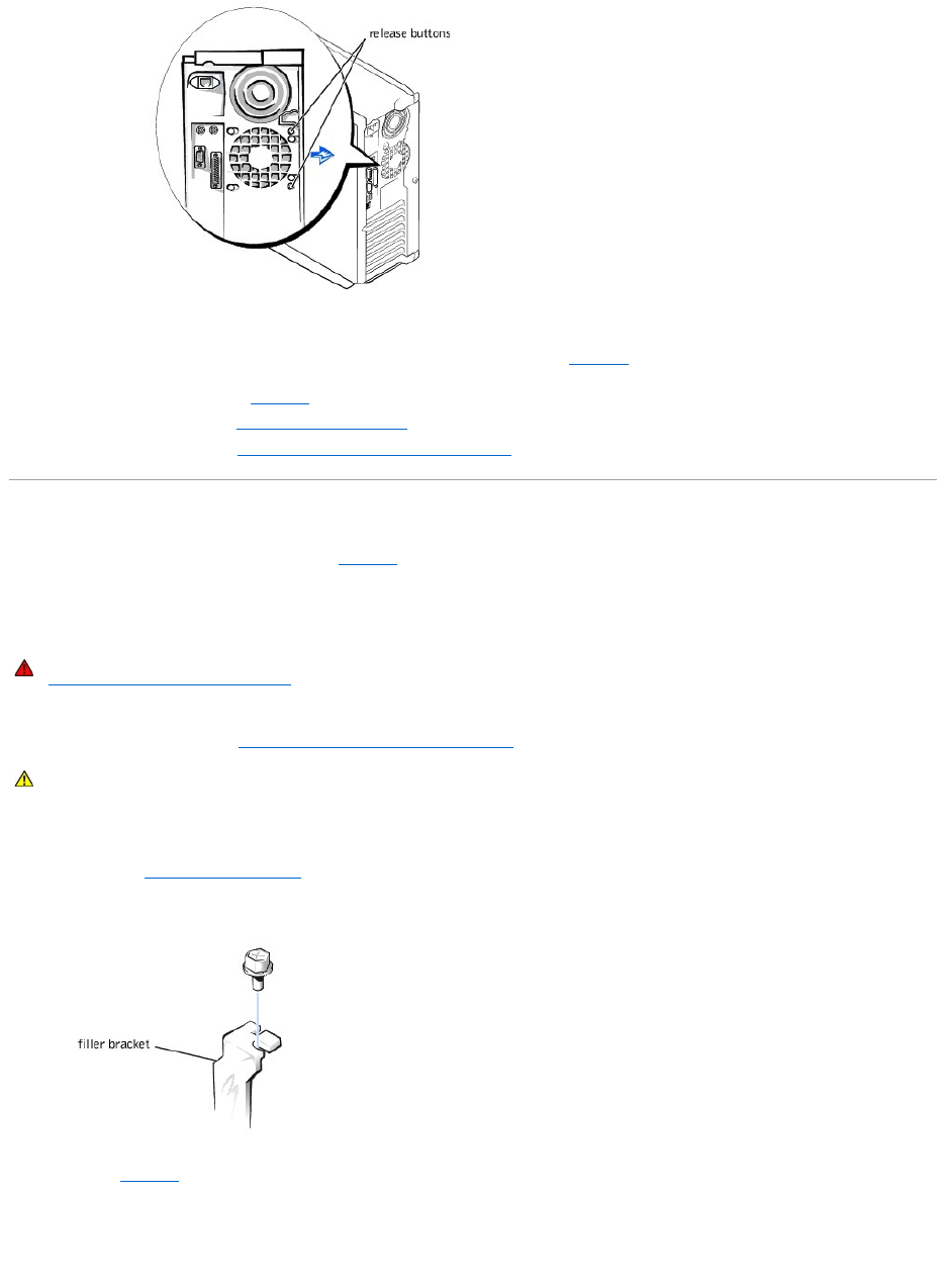
Replacing the Fan
1. Connect the fan power cable to the fan connector (SYS_FAN2) on the system board (see Figure6-1).
2. Align the brackets on the back of the fan with the corresponding holes in the back-panel, and gently push down until the fan is firmly seated and the
release buttons are engaged (see Figure6-3).
3. Install the cooling shroud (see "Replacing the Cooling Shroud").
4. Replace the system cover (see "Replacing the System Cover and Support Beam").
Adding and Replacing Expansion Cards
Expansion cards are installed on the system board (see Figure6-1). There are five expansion card slots available.
The card guide assembly is used to help secure the expansion cards.
Installing Expansion Cards
1. Turn off the system, including any attached peripherals, and disconnect the system from the electrical outlet.
2. Remove the system cover (see "Removing the System Cover and Support Beam" in "Troubleshooting Your System").
See the documentation that came with the expansion card for information on configuring the card, making internal connections, or otherwise customizing
the card for your system.
3. Unscrew and remove the filler bracket for the card slot you want to use. Save the screw to use when installing the expansion card later in this
procedure (see "Removing the Filler Bracket").
Figure 6-4. Removing the Filler Bracket
4. Align the cutout on the bottom of the card with the crossbar in the system board connector. Gently rock the card into the connector until it is fully
seated (see Figure6-5).
If the card is full-length, insert the front end of the card into the corresponding card guide at the front of the system as you insert the card into its
connector.
Figure 6-5. Installing Expansion Cards
WARNING: Before you perform this procedure, you must turn off the system and disconnect it from its power source. For more information, see
"Safety First— For You and Your System" in "Troubleshooting Your System."
CAUTION: See "Protecting Against Electrostatic Discharge" in the safety instructions in your System Information document.
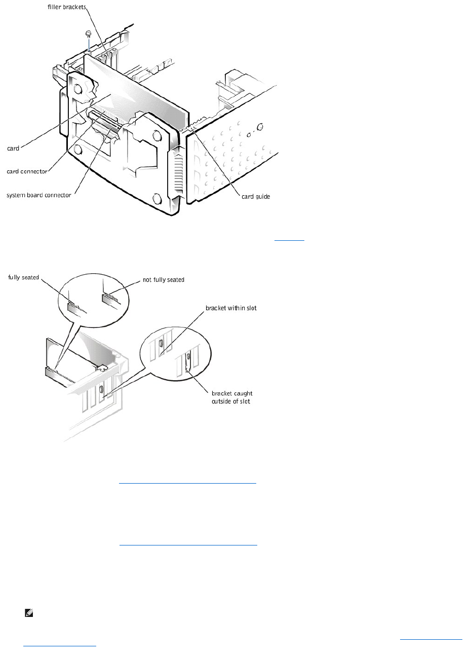
Make sure that the card is fully seated and that its bracket is within the card slot (see Figure6-6).
Figure 6-6. Seating an Expansion Card
5. Secure the bracket on the end of the card with the screw you removed in step 3.
6. Connect any cables required for the card as described in the card documentation.
7. Replace the system cover (see "Replacing the System Cover and Support Beam" in "Troubleshooting Your System").
8. Plug your system and devices into their electrical outlets, and turn them on.
9. Install any drivers required for the card as described in the card documentation.
Removing Expansion Cards
1. Remove the system cover (see "Removing the System Cover and Support Beam" in "Troubleshooting Your System").
2. Disconnect any cables connected to the expansion card.
3. Remove the screw from the card bracket.
4. Grasp the card by its top corners, and lift it from the system board.
5. If you are removing the card permanently, install a metal filler bracket over the empty card-slot opening.
6. Replace the system cover, and then reconnect the system and peripherals to their power sources and turn on the system (see "Replacing the System
Cover and Support Beam" in "Troubleshooting Your System").
NOTE: Installing a filler bracket over an empty expansion slot is necessary to maintain Federal Communications Commission (FCC) certification of
the system. The brackets also keep dust and dirt out of the system and aid in proper cooling and airflow inside the system.
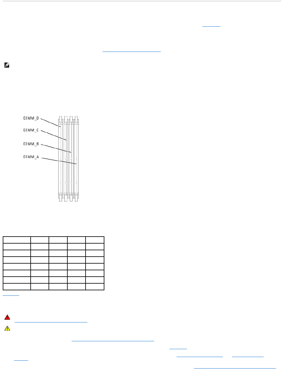
Adding Memory
The four memory module sockets on the system board can accommodate 64 MB to 2 GB of registered SDRAM (see Figure6-1).
Memory Upgrade Kits
The system is upgradable to 2 GB by installing combinations of 64-, 128-, 256-, and 512-MB registered memory modules. If you receive an error message
stating that maximum memory has been exceeded, see "Indicators, Messages, and Codes," for detailed information. You can purchase memory upgrade kits
as needed.
Memory Module Installation Guidelines
For optimum operation, install the memory modules starting with the DIMM_A socket (furthest from the microprocessor) and working toward the DIMM_D
socket, leaving no open sockets between installed memory modules.
Figure 6-7. Memory Module Sockets
Table6-2 illustrates several sample memory configurations based on these guidelines.
Performing a Memory Upgrade
1. Remove the system cover (see "Removing the System Cover and Support Beam" in "Troubleshooting Your System").
2. Locate the memory module sockets in which you will install or replace memory modules. Figure6-7 shows the order of the memory module sockets.
3. Install or replace the memory module as necessary to reach the desired memory total (see "Installing Memory Modules" or "Removing Memory
Modules").
4. Replace the system cover, reconnect the system to the electrical outlet, and turn on the system (see "Replacing the System Cover and Support Beam"
in "Troubleshooting Your System"). After the system completes the POST routine, it runs a memory test.
The system detects that the new memory does not match the system configuration information, which is stored in NVRAM. The monitor displays an error
message that ends with the following words:
NOTE: The memory modules must be PC-133 compliant.
Table 6-2.SampleMemoryModuleConfigurations
Total Memory
DIMM_A
DIMM_B
DIMM_C
DIMM_D
64 MB
64 MB
—
—
—
128 MB
128 MB
—
—
—
256 MB
128 MB
128 MB
—
—
512 MB
256 MB
256 MB
—
—
768 MB
256 MB
256 MB
256 MB
—
1 GB
256 MB
256 MB
256 MB
256 MB
2 GB
512 MB
512 MB
512 MB
512 MB
WARNING: Before you perform this procedure, you must turn off the system and disconnect it from its power source. For more information, see
"Safety First— For You and Your System" in "Troubleshooting Your System."
CAUTION: See "Protecting Against Electrostatic Discharge" in the safety instructions in your System Information document.
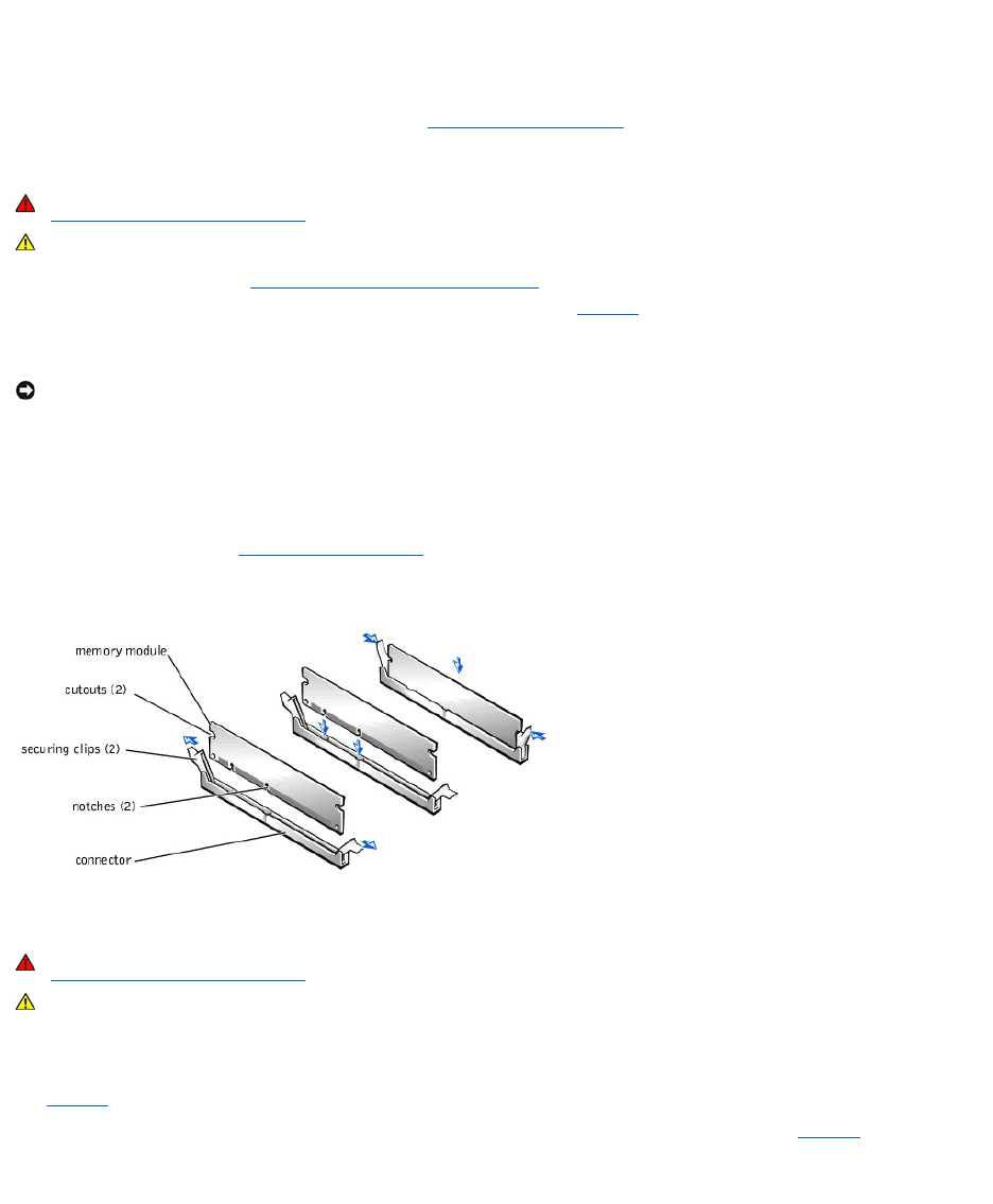
Press <F1> to continue; <F2> to enter System Setup
5. Press <F2> to enter the System Setup program, and check the System Memory setting in the system data box on the System Setup screens. The
system should have already changed the value in the System Memory setting to reflect the newly installed memory.
6. If the System Memory value is incorrect, one or more of the memory modules may not be installed properly. Repeat steps 1 through 4, checking to
make sure that the memory modules are firmly seated in their sockets.
7. Run the system memory test in the system diagnostics (see "Running the System Diagnostics").
Installing Memory Modules
1. Remove the system cover (see "Removing the System Cover and Support Beam" in "Troubleshooting Your System").
2. Press down and outward on the ejectors on the memory module socket, as shown in Figure6-8, to allow the memory module to be inserted into the
socket.
3. Align the notches on the bottom of the module with the crossbars in the connector.
4. Insert the module straight down into the connector, making sure that it fits into the vertical guides at each end of the connector. Press firmly on the
ends until the memory module snaps into place.
When the memory module is properly seated in the socket, the ejectors on the memory module socket should align with the ejectors on the other
sockets with memory modules installed.
5. Repeat steps 2 through 4 of this procedure to install the remaining memory modules.
6. Perform steps 4 through 7 of "Performing a Memory Upgrade."
Figure 6-8. Installing a Memory Module
Removing Memory Modules
1. Remove the system cover.
2. Locate the memory module sockets in which you will remove memory modules.
Figure6-7 shows the order of the memory module sockets.
3. Press down and outward on the ejectors on each end of the socket until the memory module pops out of the socket (see Figure6-9).
Figure 6-9. Removing a Memory Module
WARNING: Before you perform this procedure, you must turn off the system and disconnect it from its power source. For more information, see
"Safety First— For You and Your System" in "Troubleshooting Your System."
CAUTION: See "Protecting Against Electrostatic Discharge" in the safety instructions in your System Information document.
NOTICE: To avoid breaking the memory module, do not press near the middle of the module.
WARNING: Before you perform this procedure, you must turn off the system and disconnect it from its power source. For more information, see
"Safety First— For You and Your System" in "Troubleshooting Your System."
CAUTION: See "Protecting Against Electrostatic Discharge" in the safety instructions in your System Information document.
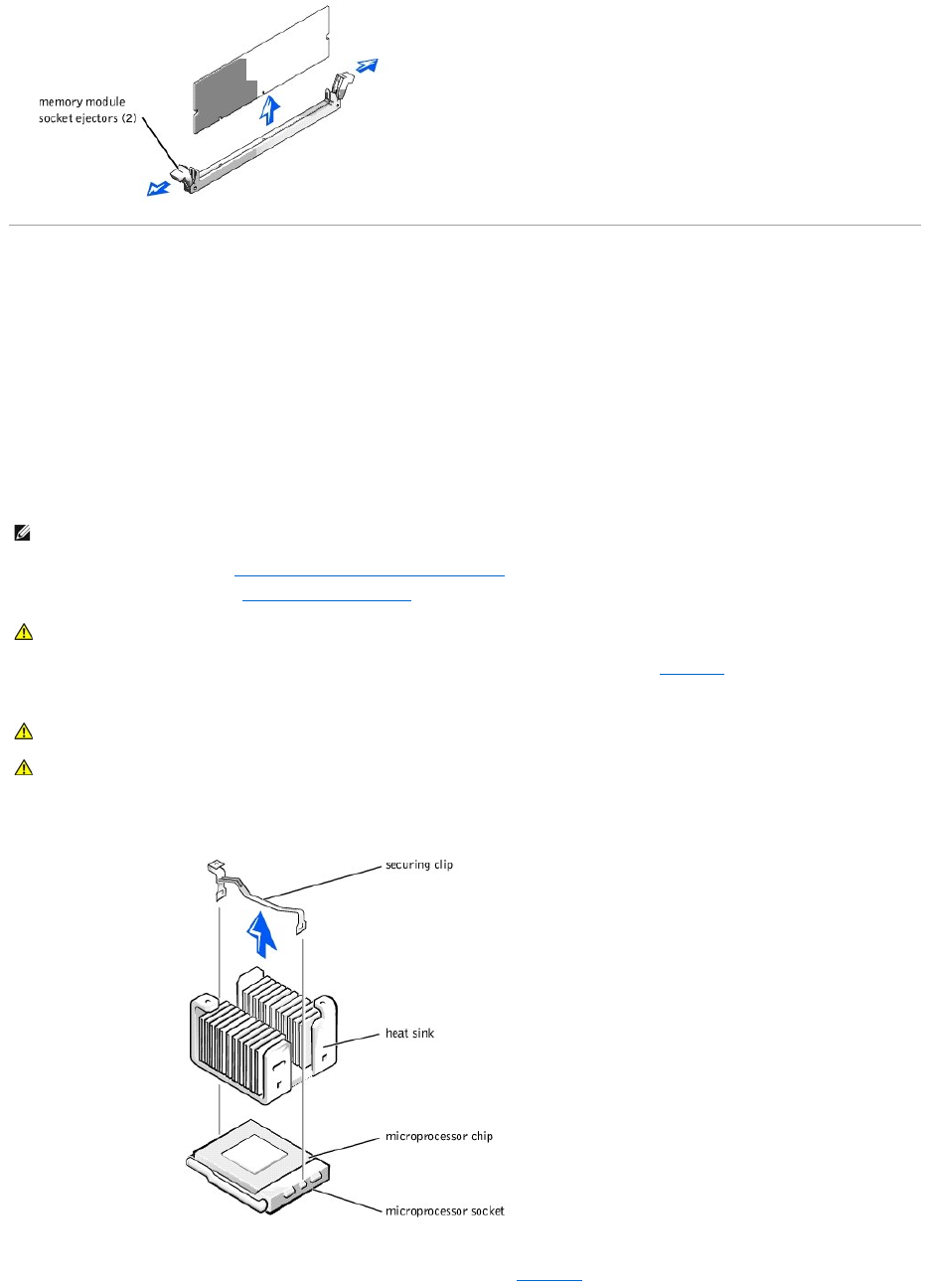
Upgrading the Microprocessor
To take advantage of future options in speed and functionality, you can upgrade the system microprocessor.
The microprocessor and its associated L2 cache memory are contained in a PGA package that is installed in a ZIF socket on the system board. The following
subsection describes how to upgrade or replace the microprocessor.
Replacing the Microprocessor
The following items are included in the microprocessor upgrade kit:
lA microprocessor
lA heat sink
lA securing clip
1. Remove the system cover (see "Removing the System Cover and Support Beam" in "Troubleshooting Your System").
2. Remove the cooling shroud (see "Removing the Cooling Shroud" in "Troubleshooting Your System").
3. Press down on the heat-sink securing clip to release the clip from the retaining tab on the ZIF socket (see Figure6-10).
4. Remove the securing clip.
Figure 6-10. Securing Clip
5. Remove the heat sink.
6. Pull the socket release lever straight up until the microprocessor is released (see Figure6-11).
NOTE: Dell recommends that only a technically knowledgeable person perform this procedure.
CAUTION: See "Protecting Against Electrostatic Discharge" in the safety instructions in your System Information document.
CAUTION: Never remove the heat sink from a microprocessor unless you intend to remove the microprocessor. The heat sink is necessary to
maintain proper thermal conditions.
CAUTION: The microprocessor and heat sink can become extremely hot. Be sure the microprocessor has had sufficient time to cool before
handling.
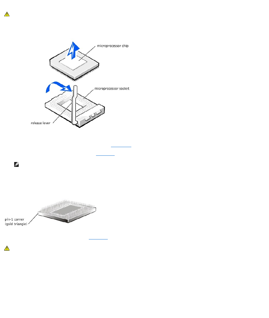
7. Lift the microprocessor out of the socket and leave the release lever up so that the socket is ready for the new microprocessor.
Figure 6-11. Removing the Microprocessor
8. Unpack the new microprocessor.
If any of the pins on the microprocessor appear bent, see "Getting Help," for instructions on obtaining technical assistance.
9. Align the pin-1 corner of the microprocessor (see Figure6-12) with the pin-1 corner of the microprocessor socket.
Identify the pin-1 corner of the microprocessor by locating the tiny gold triangle that extends from one corner of the large central rectangular area. The
goldtrianglepointstowardpin1,whichisalsouniquelyidentifiedbyasquarepad.
Figure 6-12. Pin-1 Identification
10. Install the microprocessor in the socket (see Figure6-13).
If the release lever on the microprocessor socket is not all the way up, move it to that position now.
With the pin-1 corners of the microprocessor and socket aligned, set the microprocessor lightly in the socket and make sure all pins are matched with
the correct holes in the socket. Because the system uses a ZIF micro-processor socket, there is no need to use force (which could bend the pins if the
microprocessor is misaligned). When the microprocessor is positioned correctly, it should drop down into the socket with minimal pressure.
When the microprocessor is fully seated in the socket, rotate the socket release lever back down until it snaps into place, securing the microprocessor.
Figure 6-13. Installing the Microprocessor
CAUTION: Be careful not to bend any of the pins when removing the microprocessor. Bending the pins can permanently damage the
microprocessor.
NOTE: Identifying the pin-1 corners is critical to positioning the microprocessor correctly.
CAUTION: Positioning the microprocessor incorrectly can permanently damage the microprocessor and the system when you turn on the system.
When placing the microprocessor in the socket, be sure that all of the pins on the microprocessor go into the corresponding holes. Be careful not
to bend the pins.
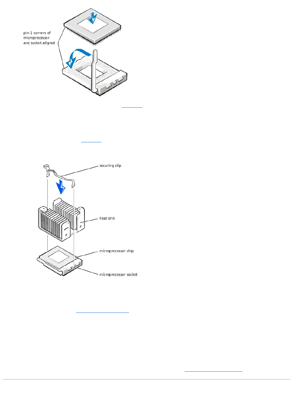
11. Place the new heat sink on top of the microprocessor (see Figure6-14).
lIf the heat sink provided has a foil thermal interface material strip on the bottom of the heat sink, place the heat sink on the microprocessor.
lIf the heat sink provided has a thermal grease tab, remove the tab and place the heat sink on the microprocessor.
lIf heat sink thermal grease is provided, clean the heat sink and apply the thermal grease before placing the heat sink on the microprocessor.
12. Orient the securing clip as shown in Figure6-14.
Figure 6-14. Installing the Heat-Sink
13. Hook the end of the clip without the heat-sink latch to the tab on the edge of the socket facing the front of the system.
14. Push down and pivot the heat-sink latch until the hole on the clip latches onto the ZIF socket tab.
15. Make sure that the latches engage.
16. Replace the cooling shroud (see "Replacing the Cooling Shroud" in "Troubleshooting Your System").
17. Reconnect your system and peripherals to their power sources, and turn on system.
18. Press <F2> to enter the System Setup program, and check that the PROCESSOR 1 category matches the new system configuration.
See the system User's Guide for instructions.
19. As the system boots, it detects the presence of the new processor and automatically changes the system configuration information in the System Setup
program.
20. Enter the System Setup program, and confirm that the top line in the system data area correctly identifies the installed processor. See "Using the
System Setup Program" in your User's Guide.
21. Run the system diagnostics to verify that the new microprocessor is operating correctly (see "Running the System Diagnostics").
Replacing the System Battery
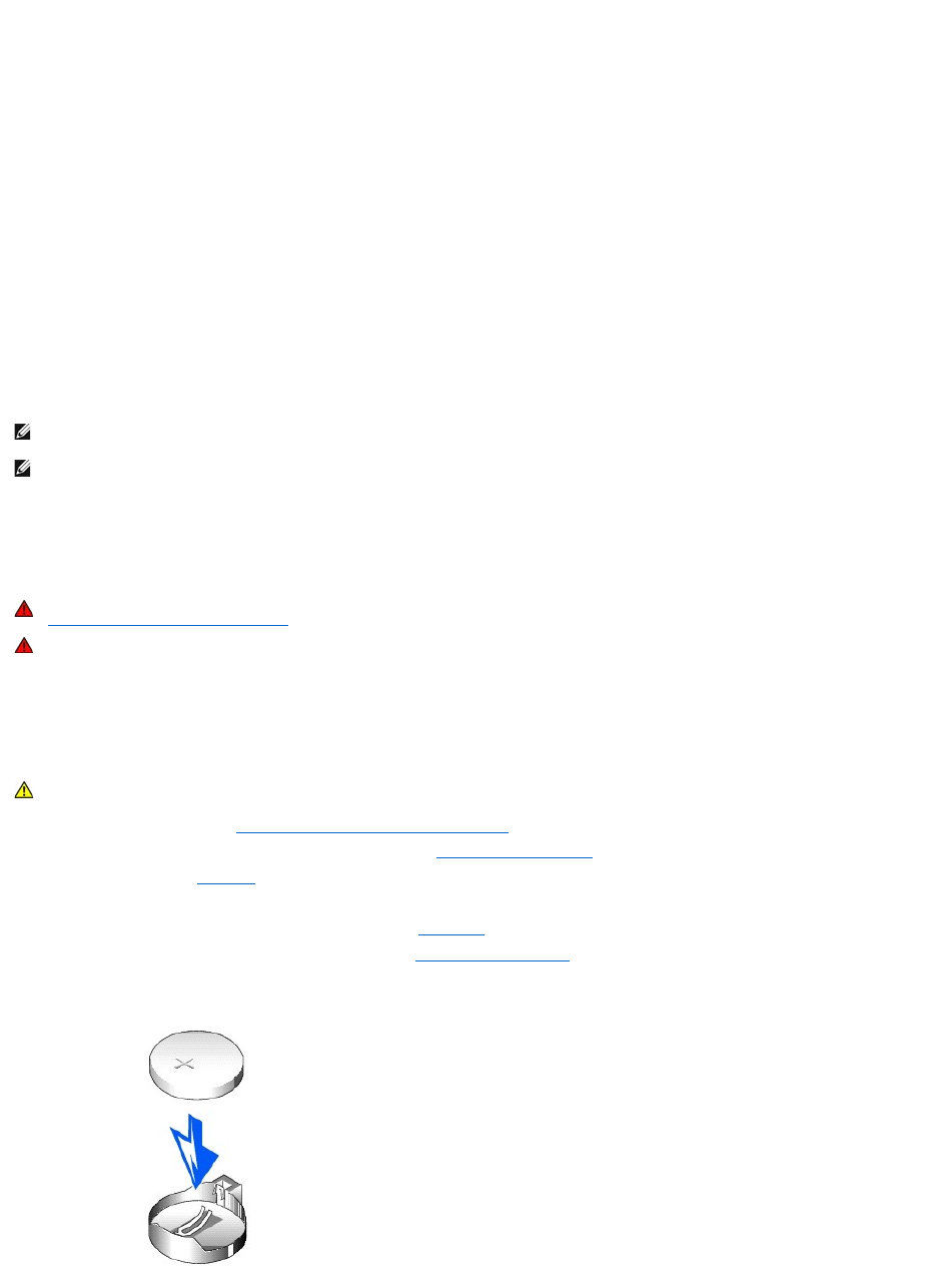
The system battery maintains system configuration, date, and time information in a special section of memory when you turn off the system. The operating life
of the battery ranges from 2 to 5 years. You may need to replace the battery if an incorrect time or date is displayed during the boot routine along with the
following or similar message:
Time-of-day not set -- please run SETUP program
Strike the F1 key to continue, F2 to run the setup utility
or
System CMOS checksum bad -- Run SETUP
Strike the F1 key to continue, F2 to run the setup utility
or
Invalid configuration information -- please run SETUP program
Strike the F1 key to continue, F2 to run the setup utility
To determine if the battery needs replacing:
1. Reenter the time and date through the System Setup program.
2. Turn off and disconnect the system from the electrical outlet for a few hours.
3. Reconnect and turn the system on again.
4. Enter the System Setup program.
If the date and time are not correct in the System Setup program, replace the battery.
You can operate the system without a battery; however, the system configuration information maintained by the battery in NVRAM is erased each time you
shut down the system. Therefore, you must reenter the system configuration information and reset the options each time the system boots until you replace
the battery.
The battery is a 3.0-volt (V), coin-cell battery. To remove the battery, perform the following steps.
1. Enter the System Setup program and, if possible, make a printed copy of the System Setup screens.
See "Using the System Setup Program," in the User's Guide for instructions.
2. Shut down the system, including any attached peripherals, and disconnect the system from the electrical outlet.
3. Remove the system cover (see "Removing the System Cover and Support Beam" in "Troubleshooting Your System").
4. Remove any expansion cards that limit access to the battery (see "Removing Expansion Cards").
5. Remove the battery (see Figure6-1, for the battery location).
6. Pry the battery out of its socket with your fingers or with a blunt, nonconductive object such as a plastic screwdriver.
7. Install the new battery with the side labeled "+" facing up (see Figure6-15).
8. Replace any expansion cards that you removed in step 4 (see "Installing Expansion Cards").
Figure 6-15. Installing the Battery
NOTE: Some software may cause the system time to speed up or slow down. If the system seems to operate normally except for the time kept in the
System Setup program, the problem may be caused by software rather than by a defective battery.
NOTE: If the system is turned off for long periods of time (for weeks or months), the NVRAM may lose its system configuration information. This situation
is not caused by a defective battery.
WARNING: Before you perform this procedure, you must turn off the system and disconnect it from its power source. For more information, see
"Safety First— For You and Your System" in "Troubleshooting Your System."
WARNING: There is a danger of a new battery exploding if it is incorrectly installed. Replace the battery only with the same or equivalent type
recommended by the manufacturer. Discard used batteries according to the manufacturer's instructions.
CAUTION: See "Protecting Against Electrostatic Discharge" in the safety instructions in your System Information document.

9. Replace the system cover, and then reconnect the system and peripherals to their power sources and turn on the system power.
10. Enter the System Setup program to confirm that the battery is operating properly.
11. Enter the correct time and date through the System Setup program's Time and Date settings.
Also reenter any system configuration information that is no longer displayed on the System Setup screens, and then exit the System Setup program.
12. To test the newly installed battery, power down and disconnect the system from the electrical source for at least an hour.
13. After an hour, connect the system to an electrical source and turn on the power.
14. Enter the System Setup program and if the time and date are still incorrect, see "Getting Help," for instructions on obtaining technical assistance.
Back to Contents Page
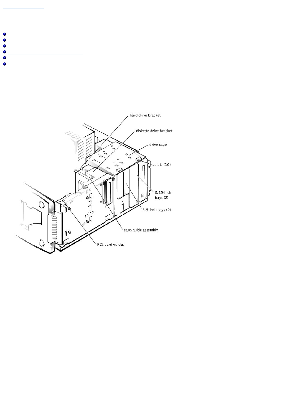
Back to Contents Page
Installing Drives
Dell™PowerEdge™500SCSystemsInstallationandTroubleshootingGuide
Configuring the EIDE Subsystem
Configuring the Boot Device
Connecting Drives
Removing and Reinstalling the Drive Cage
Adding or Replacing Hard Drives
Adding or Replacing Other Drives
Your system has six drive bays for installing the following types of drives (see Figure7-1):
lThe externally accessible drive bays at the front of the system consist of a 3.5-inch drive bay that accommodates one 3.5-inch diskette drive (standard)
and two 5.25-inch, half height drive bays that can accommodate two 5.25-inch devices— typically a CD drive and one other device, such as a tape drive.
lThere are three internally accessible 3.5-inch bays that can hold up to three 1-inch EIDE hard drives.
Figure 7-1. Drive Bays
The following sections contain general information and information that you will need in several of the installation procedures. The remaining sections address
each type of drive removal and installation.
Configuring the EIDE Subsystem
The enhanced integrated drive electronics (EIDE) subsystem includes two IDE interfaces (primary and secondary), each of which can support up to two IDE
devices such as high-capacity hard drives, CD drives, DVD drives, and tape drives.
All IDE devices should be configured for the Cable Select jumper position, which assigns master and slave status to devices by their position on the interface
cable. In this configuration, the drive attached to the last connector on the interface cable is the master or boot drive (drive 0) and the drive attached to the
middle connector on the interface cable is the slave drive (drive 1). The drive jumpers are located on the back of each IDE drive. See the drive's documentation
for instructions on setting the Cable Select jumper position.
Configuring the Boot Device
If you plan to boot the system from a hard drive, the hard drive must be attached to the primary IDE controller. The device that the system boots from is
determined by the boot order specified in the System Setup program.
The System Setup program provides options that the system uses to scan for installed boot devices. Refer to the User's Guide for information about the
System Setup program.
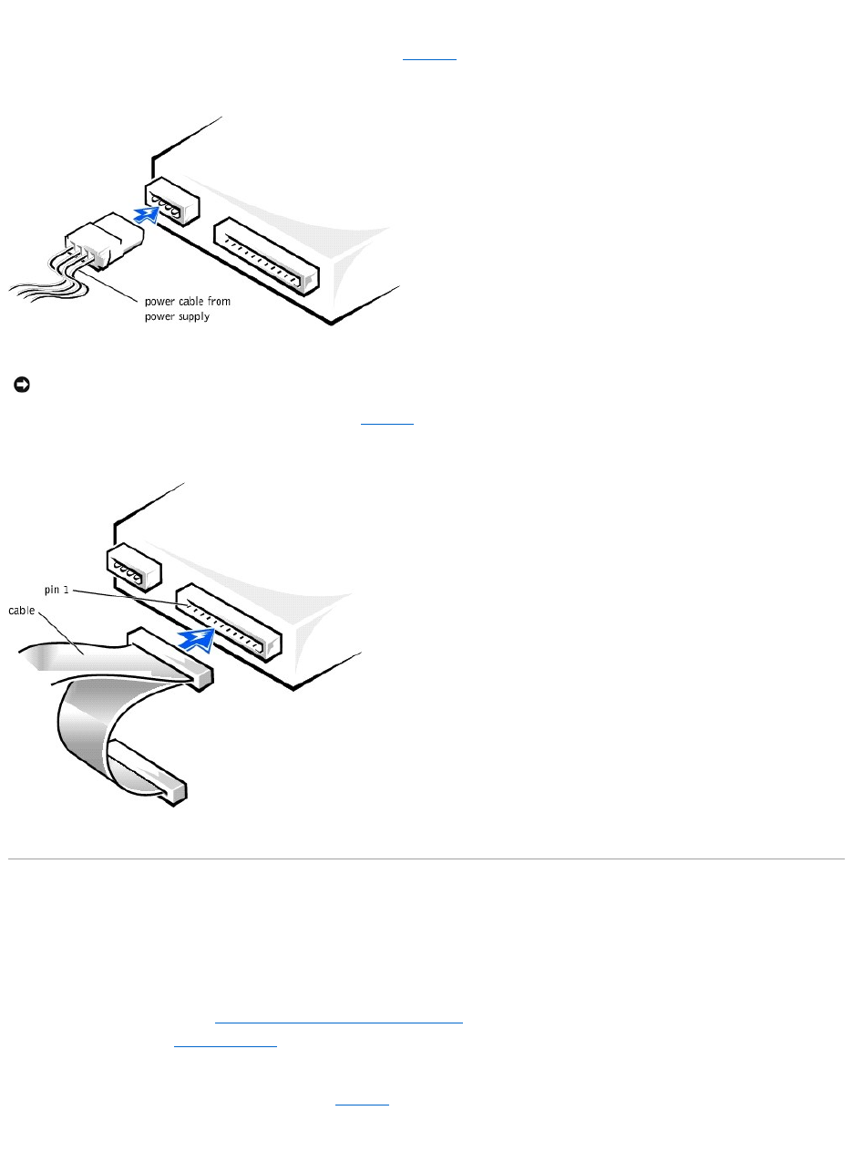
Connecting Drives
When installing a drive, you connect two cables—a DC power cable and an interface cable—to the back of the drive. Your drive's power input connector (to
which you connect the DC power cable) resembles the connector shown in Figure7-2.
Figure 7-2. Connecting the Power Cable
Your drive's interface connector resembles the connector shown in Figure7-3.
Figure 7-3. Connecting the Interface Cable
Removing and Reinstalling the Drive Cage
The drive cage has two 5.25-inch bays and two 3.5-inch bays.
Removing the Drive Cage
1. Turn off the system, including any external devices, and disconnect the system from its electrical outlet.
2. Remove the system cover (see "Removing the System Cover and Support Beam" in "Troubleshooting Your System").
3. Remove the bezel (see "Removing the Bezel" in "Troubleshooting Your System").
4. Disconnect the interface cable and the power cable from all drives installed in the drive cage. Note the location and orientation of all cables attached to
the drives.
5. Remove the screw from the side of the drive cage (see Figure7-4). Pull the drive cage toward you to unlock it from the system. Lift out the drive cage.
Figure 7-4. Removing and Reinstalling the Drive Cage
NOTICE: When you attach the interface cable to the drive, match the colored strip on the cable with pin 1 on the drive.
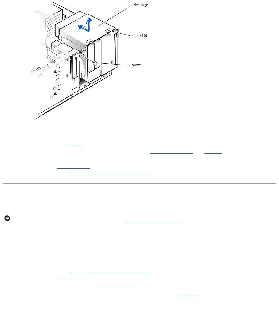
Reinstalling the Drive Cage
1. With the slots on the drive cage extending slightly beyond the front of the system, lower the drive cage and slide it toward the back of the system until
the cage locks into place (see Figure7-4).
2. Secure the drive cage to the system with the screw you removed in step 5 of "Removing the Drive Cage" (see Figure7-4).
3. Connect the interface cable and the power cable to all drives installed in the drive cage.
4. Replace the bezel (see "Replacing the Bezel" in "Troubleshooting Your System").
5. Replace the system cover (see "Replacing the System Cover and Support Beam" in "Troubleshooting Your System").
Adding or Replacing Hard Drives
Your system includes bays or brackets for up to three 1-inch IDE hard drives.
Adding or Replacing Hard Drives in the Drive Cage
Each of the two 3.5-inch bays in the drive cage can accommodate a 1-inch IDE hard drive.
Removing a Hard Drive From the Lower 3.5-Inch Bay
1. Turn off the system, including any external devices, and disconnect the system from its electrical outlet.
2. Remove the system cover (see "Removing the System Cover and Support Beam" in "Troubleshooting Your System").
3. Remove the bezel (see "Removing the Bezel" in "Troubleshooting Your System").
4. Remove the drive cage from the system (see "Removing the Drive Cage").
5. Remove the three drive-mounting screws, two from the bottom and one from the left side (see Figure7-5).
Figure 7-5. Adding or Removing a Hard Drive in the Lower 3.5-inchBay
NOTICE: When replacing a hard drive, set the jumpers on the replacement hard drive to match the jumpers on the hard drive you removed. For
additional information about jumper settings on IDE drives, see "Configuring the EIDE Subsystem."
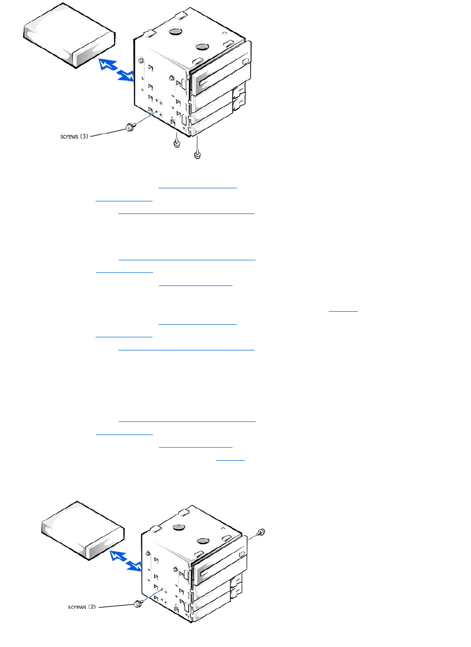
6. Slide the hard drive out of the back of the drive cage.
7. Reinstall the drive cage into the system (see "Reinstalling the Drive Cage").
8. Replace the bezel (see "Replacing the Bezel" in "Troubleshooting Your System").
9. Replace the system cover (see "Replacing the System Cover and Support Beam" in "Troubleshooting Your System").
Installing a Hard Drive in the Lower 3.5-inch Bay
1. Turn off the system, including any external devices, and disconnect the system from its electrical outlet.
2. Remove the system cover (see "Removing the System Cover and Support Beam" in "Troubleshooting Your System").
3. Remove the bezel (see "Removing the Bezel" in "Troubleshooting Your System").
4. Remove the drive cage from the system (see "Removing the Drive Cage").
5. Slide the drive into the back opening of the bay over the two small grooves on the bottom of the bay.
6. Secure the drive with three drive-mounting screws, two from the bottom and one from the left side (see Figure7-5).
7. Reinstall the drive cage into the system (see "Reinstalling the Drive Cage").
8. Replace the bezel (see "Replacing the Bezel" in "Troubleshooting Your System").
9. Replace the system cover (see "Replacing the System Cover and Support Beam" in "Troubleshooting Your System").
10. Plug your system and any external devices into their electrical outlets, and turn them on.
11. See the drive documentation for instructions on installing any software required for hard drive operation.
Removing a Hard Drive From the Upper 3.5-inch Bay
1. Turn off the system, including any external devices, and disconnect the system from its electrical outlet.
2. Remove the system cover (see "Removing the System Cover and Support Beam" in "Troubleshooting Your System").
3. Remove the bezel (see "Removing the Bezel" in "Troubleshooting Your System").
4. Remove the drive cage from the system (see "Removing the Drive Cage").
5. Remove the two screws securing the drive to the drive cage (see Figure7-6). Insert your screwdriver into the reticular slot on the right side of the drive
cage to access the screw securing the right side of the drive.
Figure 7-6. Adding or Replacing a Hard Drive in the Upper 3.5-inchBay
6. Slide the hard drive out the back of the drive cage.
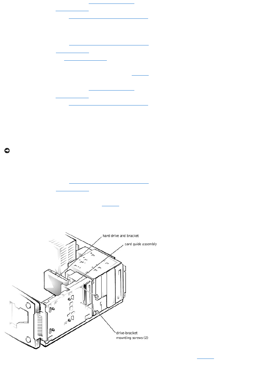
7. Reinstall the drive cage in the system (see "Reinstalling the Drive Cage").
8. Replace the bezel (see "Replacing the Bezel" in "Troubleshooting Your System").
9. Replace the system cover (see "Replacing the System Cover and Support Beam" in "Troubleshooting Your System").
Installing a Hard Drive in the Upper 3.5-inch Bay
1. Turn off the system, including any external devices, and disconnect the system from its electrical outlet.
2. Remove the system cover (see "Removing the System Cover and Support Beam" in "Troubleshooting Your System").
3. Remove the bezel (see "Removing the Bezel" in "Troubleshooting Your System").
4. Remove the drive cage (see "Removing the Drive Cage").
5. Slide the hard drive into the bay through the back of the drive cage.
6. Secure the hard drive to the drive cage with two screws as shown in Figure7-6. To secure the screw on the right side of the drive, you must position
the screw over the screw hole through the back of the drive cage while inserting your screwdriver into the reticular slot on the right side of the drive
cage.
7. Reinstall the drive cage in the system (see "Reinstalling the Drive Cage").
8. Replace the bezel (see "Replacing the Bezel" in "Troubleshooting Your System").
9. Replace the system cover (see "Replacing the System Cover and Support Beam" in "Troubleshooting Your System").
10. Plug your system and any external devices into their electrical outlets, and turn them on.
11. See the drive documentation for instructions on installing any software required for hard drive operation.
Adding or Replacing a Hard Drive in the Card Guide Assembly
The 3.5-inch bracket next to the floppy drive accommodates a 1-inch IDE hard drive.
Removing a Hard Drive From the Card Guide Assembly Bracket
1. Turn off the system, including any external devices, and disconnect the system from its electrical outlet.
2. Remove the system cover (see "Removing the System Cover and Support Beam" in "Troubleshooting Your System").
3. Remove the bezel (see "Removing the Bezel" in "Troubleshooting Your System").
4. Disconnect the interface cable and the power cable from the hard drive.
5. Remove the screws securing the drive bracket (see Figure7-7).
6. Slide the drive bracket and hard drive toward the back of the system and lift them out of the system.
Figure 7-7. Removing the Hard Drive and Drive Bracket
7. Remove the screw securing the hard drive to the drive bracket, and rotate the drive out of the bracket (see Figure7-8).
Figure 7-8. Detaching or Attaching the Hard Drive
NOTICE: Do not install a hard drive in the lower card-guide assembly bracket next to the card guides. Installing a drive in the lower card-guide
assembly bracket is not supported in this system.
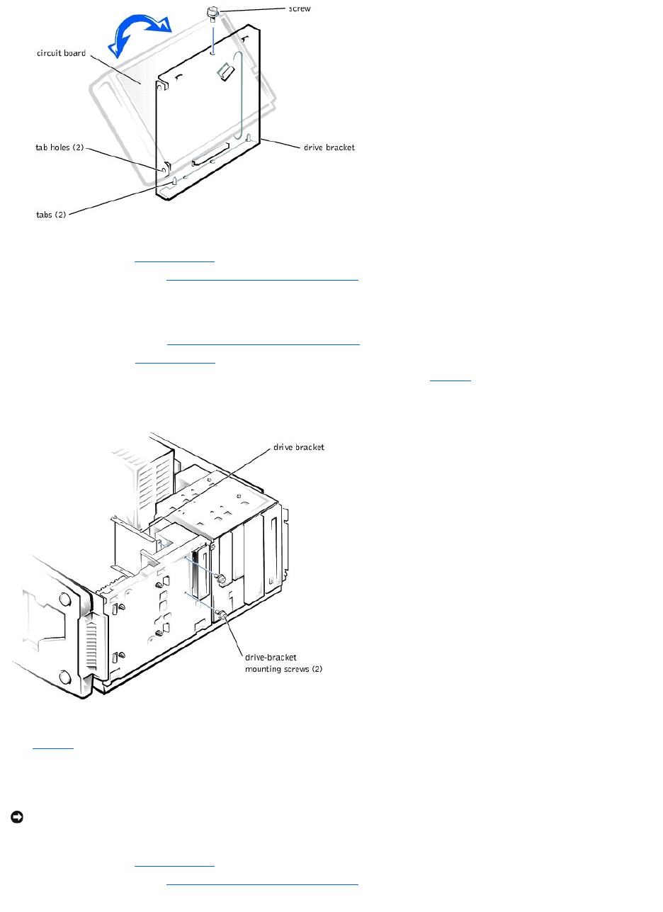
.
8. Align the bracket tabs with the slots in the system, and slide the bracket into place. Secure the bracket with the screws you removed in step 5.
9. Replace the bezel (see "Replacing the Bezel" in "Troubleshooting Your System").
10. Replace the system cover (see "Replacing the System Cover and Support Beam" in "Troubleshooting Your System").
Installing a Hard Drive in the Card Guide Assembly Bracket
1. Turn off the system, including any external devices, and disconnect the system from its electrical outlet.
2. Remove the system cover (see "Removing the System Cover and Support Beam" in "Troubleshooting Your System").
3. Remove the bezel (see "Removing the Bezel" in "Troubleshooting Your System").
4. Remove the screws securing the upper drive bracket, and lift the bracket out of the system (see Figure7-9).
Figure 7-9. Removing the Drive Bracket
5. Orient the drive with its circuit board facing the inside of the bracket.
6. Align the bracket tabs with the two tab holes in the side of the drive, and rotate the drive into the bracket. Then secure the screw as illustrated in
Figure7-8.
7. Align the bracket tabs with the slots in the system, and slide the hard drive and bracket into place. Secure the bracket with the screws you removed in
step 4.
8. Connect a power cable to the hard drive.
9. Connect an interface cable to the hard drive.
10. Replace the bezel (see "Replacing the Bezel" in "Troubleshooting Your System").
11. Replace the system cover (see "Replacing the System Cover and Support Beam" in "Troubleshooting Your System").
12. Plug your system and any external devices into their electrical outlets, and turn them on.
NOTICE: When you attach the interface cable to the hard drive, match the colored strip on the cable with pin 1 on the drive.
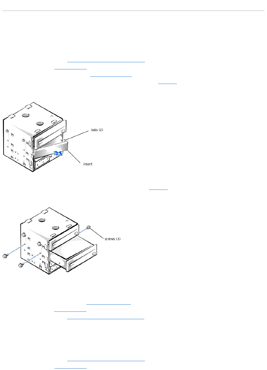
13. See the drive documentation for instructions on installing any software required for drive operation.
Adding or Replacing Other Drives
Your system includes a diskette drive and a CD drive. You can add drives, such as DVD drives and tape drives, using the procedures in the following sections.
Adding 5.25-Inch Devices
1. Turn off the system, including any external devices, and disconnect the system from its electrical outlet.
2. Remove the system cover (see "Removing the System Cover and Support Beam" in "Troubleshooting Your System").
3. Remove the bezel (see "Removing the Bezel" in "Troubleshooting Your System").
4. Remove the drive cage from the system (see "Removing the Drive Cage").
5. Press in the two tabs on the insert, and rotate the insert toward you to remove it (see Figure7-10).
Figure 7-10. Removing the Insert
6. Slide the new drive into the bay, and secure the drive with the three screws (see Figure7-11).
Figure 7-11. Adding or Removing a 5.25-inch Device
7. Reinstall the drive cage in the system (see "Reinstalling the Drive Cage").
8. Replace the bezel (see "Replacing the Bezel" in "Troubleshooting Your System").
9. Replace the system cover (see "Replacing the System Cover and Support Beam" in "Troubleshooting Your System").
10. Plug your system and any external devices into their electrical outlets, and turn them on.
11. See the drive documentation for instructions on installing any software required for drive operation.
Removing 5.25-Inch Devices
1. Turn off the system, including any external devices, and disconnect the system from its electrical outlet.
2. Remove the system cover (see "Removing the System Cover and Support Beam" in "Troubleshooting Your System").
3. Remove the bezel (see "Removing the Bezel" in "Troubleshooting Your System").
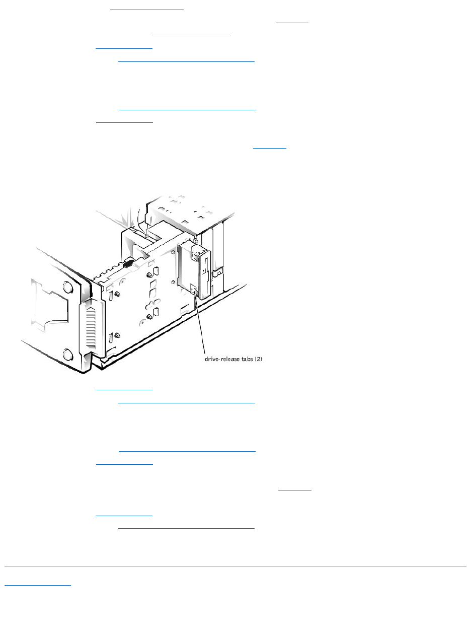
4. Remove the drive cage (see "Removing the Drive Cage").
5. Remove the three drive-mounting screws and slide the drive out of the drive bay (see Figure7-11).
6. Reinstall the drive cage in the system (see "Reinstalling the Drive Cage").
7. Replace the bezel (see "Replacing the Bezel" in "Troubleshooting Your System").
8. Replace the system cover (see "Replacing the System Cover and Support Beam" in "Troubleshooting Your System").
Removing the Diskette Drive
1. Turn off the system, including any external devices, and disconnect the system from its electrical outlet.
2. Remove the system cover (see "Removing the System Cover and Support Beam" in "Troubleshooting Your System").
3. Remove the bezel (see "Removing the Bezel" in "Troubleshooting Your System").
4. Disconnect the power and interface cables from the back of the diskette drive.
5. Press the two drive-release tabs, and slide the drive out of the drive bay (see Figure7-12).
Figure 7-12. Removing and Installing a Diskette Drive
6. Replace the bezel (see "Replacing the Bezel" in "Troubleshooting Your System").
7. Replace the system cover (see "Replacing the System Cover and Support Beam" in "Troubleshooting Your System").
Installing a Diskette Drive
1. Turn off the system, including any external devices, and disconnect the system from its electrical outlet.
2. Remove the system cover (see "Removing the System Cover and Support Beam" in "Troubleshooting Your System").
3. Remove the bezel (see "Removing the Bezel" in "Troubleshooting Your System").
4. Before you install the new diskette drive, transfer the drive-release tabs from the drive you removed to the replacement drive.
5. Slide the diskette drive into the drive bay until the two drive-release tabs engage (see Figure7-12).
6. Connect a power cable and the diskette drive interface cable to the diskette drive.
7. Replace the bezel (see "Replacing the Bezel" in "Troubleshooting Your System").
8. Replace the system cover (see "Replacing the System Cover and Support Beam" in "Troubleshooting Your System").
9. Plug your system and any external devices into their electrical outlets, and turn them on.
10. See the drive documentation for instructions on installing any software required for drive operation.
Back to Contents Page
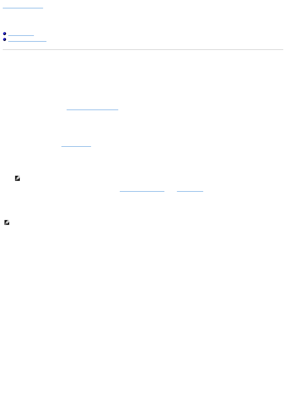
Back to Contents Page
Getting Help
Dell™PowerEdge™500SCSystemsInstallationandTroubleshootingGuide
Help Overview
Dell Contact Numbers
Help Overview
This section describes the tools Dell provides to help you when you have a problem with your system. It also tells you when and how to contact Dell for
technical or customer assistance.
Technical Assistance
If you need assistance with a technical problem, perform the following steps:
1. Complete the procedures in "TroubleshootingYourSystem."
2. Run the system diagnostics.
3. Make a copy of the Diagnostics Checklist, and fill it out.
4. Use Dell's extensive suite of online services available at Dell's website (http://www.dell.com) for help with installation and troubleshooting
procedures.
For more information, see "World Wide Web."
5. If the preceding steps have not resolved the problem, call Dell for technical assistance.
When prompted by Dell's automated telephone system, enter your Express Service Code to route the call directly to the proper support personnel. If
you do not have an Express Service Code, open the Dell Accessories folder, double-click the Express Service Code icon, and follow the directions.
For instructions on using the technical support service, see "Technical Support Service" and "Before You Call."
Help Tools
Dell provides a number of tools to assist you. These tools are described in the following sections.
World Wide Web
The Internet is your most powerful tool for obtaining information about your system and other Dell products. Through the Internet, you can access most of the
services described in this section, including AutoTech, TechFax, order status, technical support, and product information.
You can access Dell's support website at http://support.dell.com. To select your country, click the map that appears. The Welcome to support.dell.com page
opens. Enter your system information to access help tools and information.
Dell can be accessed electronically using the following addresses:
lWorld Wide Web
http://www.dell.com/
http://www.dell.com/ap/ (for Asian/Pacific countries only)
http://www.euro.dell.com (for Europe only)
http://www.dell.com/la (for Latin American countries)
lAnonymous file transfer protocol (FTP)
ftp.dell.com/
Log in as user:anonymous, and use your e-mail address as your password.
lElectronic Support Service
support@us.dell.com
apsupport@dell.com (for Asian/Pacific countries only)
support.euro.dell.com (for Europe only)
lElectronic Quote Service
NOTE: Dell's Express Service Code system may not be available in all countries.
NOTE: Some of the following tools are not always available in all locations outside the continental U.S. Please call your local Dell representative for
information on availability.
sales@dell.com
apmarketing@dell.com (for Asian/Pacific countries only)
lElectronic Information Service
info@dell.com
AutoTech Service
Dell's automated technical support service—AutoTech—provides recorded answers to the questions most frequently asked by Dell customers about their
portable and desktop computer systems.
When you call AutoTech, you use your touch-tone telephone to select the subjects that correspond to your questions.
The AutoTech service is available 24 hours a day, seven days a week. You can also access this service through the technical support service. For the telephone
number to call, see "Dell Contact Numbers."
TechFax Service
Dell takes full advantage of fax technology to serve you better. Twenty-four hours a day, seven days a week, you can call the Dell TechFax line toll-free for all
kinds of technical information.
Using a touch-tone phone, you can select from a full directory of topics. The technical information you request is sent within minutes to the fax number you
designate. For the TechFax telephone number to call, see "Dell Contact Numbers."
Automated Order-Status System
You can call this automated service to check on the status of any Dell products that you have ordered. A recording prompts you for the information needed to
locate and report on your order. For the telephone number to call, see "Dell Contact Numbers."
Technical Support Service
Dell's industry-leading hardware technical-support service is available 24 hours a day, seven days a week, to answer your questions about Dell hardware.
Our technical support staff pride themselves on their track record: more than 90 percent of all problems and questions are taken care of in just one toll-free
call,usuallyinlessthan10minutes.Whenyoucall,ourexpertscanrefertorecordskeptonyourDellsystemtobetterunderstandyourparticularquestion.
Our technical support staff use computer-based diagnostics to provide fast, accurate answers to questions.
To contact Dell's technical support service, see "Before You Call" and then call the number for your country as listed in "Dell Contact Numbers."
Problems With Your Order
If you have a problem with your order, such as missing parts, wrong parts, or incorrect billing, contact Dell for customer assistance. Have your invoice or
packing slip handy when you call. For the telephone number to call, see "Dell Contact Numbers."
Product Information
If you need information about additional products available from Dell, or if you would like to place an order, visit Dell's website at http://www.dell.com/. For
the telephone number to call to speak to a sales specialist, see "Dell Contact Numbers."
Returning Items for Warranty Repair or Credit
Prepare all items being returned, whether for repair or credit, as follows:
1. Call Dell to obtain an authorization number, and write it clearly and prominently on the outside of the box.
For the telephone number to call, see "Dell Contact Numbers."
2. Include a copy of the invoice and a letter describing the reason for the return.
3. Include a copy of the Diagnostics Checklist indicating the tests you have run and any error messages reported by the system diagnostics.
4. Include any accessories that belong with the item(s) being returned (such as power cables, software diskettes, and guides) if the return is for credit.
5. Pack the equipment to be returned in the original (or equivalent) packing materials.
You are responsible for paying shipping expenses. You are also responsible for insuring any product returned, and you assume the risk of loss during
shipment to Dell. Collect-on-delivery (C.O.D.) packages are not accepted.
Returns that are missing any of the preceding requirements will be refused at our receiving dock and returned to you.
Before You Call
Remember to fill out the Diagnostics Checklist. If possible, turn on your system before you call Dell for technical assistance and call from a telephone at or near
the system. You may be asked to type some commands at the keyboard, relay detailed information during operations, or try other troubleshooting steps
possible only at the system itself. Make sure that the system documentation is available.
NOTE: Have your Express Service Code ready when you call. The code helps Dell's automated-support telephone system direct your call more efficiently.
CAUTION: Before servicing any components inside your system, see "Safety First—For You and Your System."
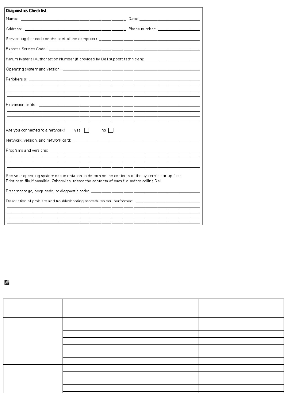
Dell Contact Numbers
The following table provides country-specific access codes and telephone numbers, websites, and e-mail addresses that you can use to contact Dell.
The codes required depend on where you are calling from as well as the destination of your call; in addition, each country has a different dialing protocol. If
you need assistance in determining which codes to use, contact a local or an international operator.
NOTE: Toll-free numbers are for use only within the country for which they are listed. Area codes are most often used to call long distance within your
own country (not internationally)—in other words, when your call originates in the same country you are calling.
Country (City)
International Access Code
Country Code
City Code
Department Name or Service Area,
Website and E-mail Address
Area Codes,
LocalNumbers,andTollFreeNumbers
Australia (Sydney)
International Access Code:
0011
Country Code: 61
City Code: 2
Home and Small Business
1-300-65-55-33
Government and Business
tollfree:1-800-633-559
Preferred Accounts Division (PAD)
tollfree:1-800-060-889
Customer Care
tollfree:1-800-819-339
Corporate Sales
tollfree:1-800-808-385
Transaction Sales
tollfree:1-800-808-312
Fax
tollfree:1-800-818-341
Austria (Vienna)
International Access Code: 900
Country Code: 43
Home/Small Business Sales
0179567602
Home/Small Business Fax
0179567605
Home/Small Business Customer Care
0179567603
Preferred Accounts/Corporate Customer Care
06608056

City Code: 1
Home/Small Business Technical Support
0179567604
Preferred Accounts/Corporate Technical Support
06608779
Switchboard
01491040
Website: http://support.euro.dell.com
E-mail: tech_support_germany@dell.com
Belgium (Brussels)
International Access Code: 00
Country Code: 32
City Code: 2
Technical Support
024819288
Customer Care
024819119
Home/Small Business Sales
tollfree:080016884
Corporate Sales
024819100
Fax
024819299
Switchboard
024819100
Website: http://support.euro.dell.com
E-mail: tech_be@dell.com
Brazil
International Access Code:
0021
Country Code: 55
City Code: 51
Customer Support, Technical Support
0800 90 3355
Sales
0800 90 3366
Website: http://www.dell.com/br
Brunei
Country Code: 673
Customer Technical Support (Penang, Malaysia)
604 633 4966
Customer Service (Penang, Malaysia)
604 633 4949
Transaction Sales (Penang, Malaysia)
604 633 4955
Canada (North York, Ontario)
International Access Code: 011
Automated Order-Status System
tollfree:1-800-433-9014
AutoTech (Automated technical support)
tollfree:1-800-247-9362
Customer Care (From outside Toronto)
tollfree:1-800-387-5759
Customer Care (From within Toronto)
416758-2400
Customer Technical Support
tollfree:1-800-847-4096
Sales (Direct Sales—from outside Toronto)
tollfree:1-800-387-5752
Sales (Direct Sales—from within Toronto)
416 758-2200
Sales (Federal government, education, and medical)
tollfree:1-800-567-7542
Sales (Major Accounts)
tollfree:1-800-387-5755
TechFax
tollfree:1-800-950-1329
Chile (Santiago)
Country Code: 56
City Code: 2
Sales, Customer Support, and Technical Support
tollfree:1230-020-4823
China (Xiamen)
Country Code: 86
City Code: 592
Technical Support
tollfree:8008582437
Customer Experience
tollfree:8008582060
Home and Small Business
tollfree:8008582222
Preferred Accounts Division
tollfree:8008582062
Large Corporate Accounts
tollfree:8008582999
Czech Republic (Prague)
International Access Code: 00
Country Code: 420
City Code: 2
Technical Support
02 22 83 27 27
Customer Care
02 22 83 27 11
Fax
02 22 83 27 14
TechFax
02 22 83 27 28
Switchboard
02 22 83 27 11
Website: http://support.euro.dell.com
E-mail: czech_dell@dell.com
Denmark (Horsholm)
International Access Code: 00
Country Code: 45
Technical Support
45170182
Relational Customer Care
45170184
Home/Small Business Customer Care
32875505
Switchboard
45170100
Fax Technical Support (Upplands Vasby, Sweden)
46 0 859005594
Fax Switchboard
45170117
Website: http://support.euro.dell.com
E-mail: den_support@dell.com
E-mail Support for Servers: Nordic_server_support@dell.com
Finland (Helsinki)
International Access Code: 990
Technical Support
0925331360
Technical Support Fax
0925331381
Country Code: 358
City Code: 9
Relational Customer Care
0925331338
Home/Small Business Customer Care
0969379194
Fax
0925331399
Switchboard
0925331300
Website: http://support.euro.dell.com
E-mail: fin_support@dell.com
France (Paris/Montpellier)
International Access Code: 00
Country Code: 33
City Code: (1) (4)
Home and Small Business
Technical Support
0825387270
Customer Care
0825823833
Switchboard
0825004700
Switchboard (Alternative)
0499754000
Sales
0825004700
Fax
0825004701
Website: http://support.euro.dell.com
E-mail: web_fr_tech@dell.com
Corporate
Technical Support
0825004719
Customer Care
0825338339
Switchboard
0155947100
Sales
0155947100
Fax
0155947101
Website: http://support.euro.dell.com
E-mail: web_fr_tech@dell.com
Germany (Langen)
International Access Code: 00
Country Code: 49
City Code: 6103
Technical Support
06103766-7200
Home/Small Business Customer Care
0180-5-224400
Global Segment Customer Care
06103766-9570
Preferred Accounts Customer Care
06103766-9420
Large Accounts Customer Care
06103766-9560
Public Accounts Customer Care
06103766-9555
Switchboard
06103766-7000
Website: http://support.euro.dell.com
E-mail: tech_support_germany@dell.com
Hong Kong
International Access Code: 001
Country Code: 852
Technical Support
tollfree:800964107
Customer Service (Penang, Malaysia)
6046334949
Transaction Sales
tollfree:800964109
Corporate Sales
tollfree:800964108
Ireland (Cherrywood)
International Access Code: 16
Country Code: 353
City Code: 1
Technical Support
0870 908 0800
Home User Customer Care
01 204 4095
Small Business Customer Care
012044026
Corporate Customer Care
01 204 4003
Sales
01 286 0500
SalesFax
012040144
Fax
0870 907 5590
Switchboard
012860500
Website: http://support.euro.dell.com
E-mail: dell_direct_support@dell.com
Italy (Milan)
International Access Code: 00
Country Code: 39
City Code: 02
Home and Small Business
Technical Support
0257782690
Customer Care
0269682114
Fax
0269682113
Switchboard
0269682112
Website: http://support.euro.dell.com
E-mail: web_it_tech@dell.com
Corporate
Technical Support
0257782690
Customer Care
0257782555
Fax
0257503530
Switchboard
02577821
Website: http://support.euro.dell.com
E-mail: web_it_tech@dell.com
Japan (Kawasaki)
International Access Code: 001
Country Code: 81
City Code: 44
Technical Support (Server)
tollfree:0120-1984-35
TechnicalSupport(Dimension™andInspiron™)
Technical Support Outside of Japan (Dimension and Inspiron)
tollfree:0120-1982-26
81-44-520-1435
TechnicalSupport(DellPrecision™,OptiPlex™andLatitude™)
Technical Support Outside of Japan (Dell Precision, OptiPlex, and Latitude)
tollfree:0120-1984-33
81-44-556-3894
24-Hour Automated Order Service
044556-3801
Customer Care
044556-4240
Home and Small Business Group Sales
044556-3344
Business Sales Division (up to 400 employees)
044 556-3344
Preferred Accounts Division Sales (over 400 employees)
044556-3433
Large Corporate Accounts Sales (over 3500 employees)
044556-3430
Government, Education, and Medical Sales
044 556-1469
Dell Global Japan
044 556-3469
Individual User
044 556-3344
Faxbox Service
044556-3490
Switchboard
044556-4300
Website: http://support.jp.dell.com
Korea (Seoul)
International Access Code: 001
Country Code: 82
City Code: 2
Technical Support
tollfree:080-200-3800
Sales
tollfree:080-200-3600
Customer Service (Seoul, Korea)
tollfree:080-200-3800
Customer Service (Penang, Malaysia)
604 633 4949
Fax
2194-6202
Switchboard
2194-6000
Latin America
Customer Technical Support (Austin, Texas, U.S.A.)
512728-4093
Customer Service (Austin, Texas, U.S.A.)
512728-3619
Fax (Technical Support and Customer Service)(Austin, Texas, U.S.A.)
512728-3883
Sales (Austin, Texas, U.S.A.)
512728-4397
SalesFax (Austin, Texas, U.S.A.)
512728-4600
or512728-3772
Luxembourg
International Access Code: 00
Country Code: 352
Technical Support (Brussels, Belgium)
024819288
Home/Small Business Sales (Brussels, Belgium)
tollfree:080016884
Corporate Sales (Brussels, Belgium)
024819100
Customer Care (Brussels, Belgium)
024819119
Fax (Brussels, Belgium)
024819299
Switchboard (Brussels, Belgium)
024819100
Website: http://support.euro.dell.com
E-mail: tech_be@dell.com
Macau
Country Code: 853
Technical Support
tollfree:0800582
Customer Service (Penang, Malaysia)
604 633 4949
Transaction Sales
tollfree:0800581
Malaysia (Penang)
International Access Code: 00
Country Code: 60
City Code: 4
Technical Support
tollfree:1800888298
Customer Service
046334949
Transaction Sales
tollfree:1800888202
Corporate Sales
tollfree:1800888213
Mexico
International Access Code: 95
Country Code: 52
City Code: 5
Automated Order-Status System (Austin, Texas, U.S.A.)
512728-0685
AutoTech (Automated technical support) (Austin, Texas, U.S.A.)
512728-0686
Customer Technical Support
525228-7870
Sales
525228-7811
ortollfree:91-800-900-37
ortollfree:91-800-904-49
Customer Service
525228-7878
Main
525228-7800
Netherlands (Amsterdam)
Technical Support
0205818838
International Access Code: 00
Country Code: 31
City Code: 20
Customer Care
0205818740
Home/Small Business Sales
tollfree:0800-0663
Home/Small Business Sales Fax
0206827171
Corporate Sales
0205818818
Corporate Sales Fax
0206868003
Fax
0206868003
Switchboard
0205818818
Website: http://support.euro.dell.com
E-mail: tech_nl@dell.com
New Zealand
International Access Code: 00
Country Code: 64
Home and Small Business
0800446255
Government and Business
0800444617
Sales
0800441567
Fax
0800441566
Norway (Lysaker)
International Access Code: 00
Country Code: 47
Technical Support
67116882
Relational Customer Care
67117514
Home/Small Business Customer Care
23162298
Switchboard
67116800
Fax Technical Support (Upplands Vasby, Sweden)
4608559005594
Fax Switchboard
67116865
Website: http://support.euro.dell.com
E-mail: nor_support@dell.com
E-mail Support for Servers: Nordic_server_support@dell.com
Poland (Warsaw)
International Access Code: 011
Country Code: 48
City Code: 22
Technical Support
225795700
Customer Care
225795999
Sales
225795999
Fax
225795998
Switchboard
225795999
Website: http://support.euro.dell.com
E-mail: pl_support@dell.com
Portugal
International Access Code: 00
Country Code: 35
Technical Support
35800834077
Customer Care
800 300 415 or
35800834075
Sales
800300410or800300411or800300412
or
351 214 220 710
Fax
351214240112
E-mail: es_support@dell.com
Singapore (Singapore)
International Access Code: 005
Country Code: 65
Technical Support
tollfree:8006011051
Customer Service (Penang, Malaysia)
6046334949
Transaction Sales
tollfree:8006011054
Corporate Sales
tollfree:8006011053
South Africa (Johannesburg)
International Access Code:
09/091
Country Code: 27
City Code: 11
Technical Support
0117097710
Customer Care
0117097707
Sales
0117097700
Fax
0117090495
Switchboard
0117097700
Website: http://support.euro.dell.com
E-mail: dell_za_support@dell.com
Southeast Asian and Pacific
Countries
Customer Technical Support, Customer Service, and Sales (Penang,
Malaysia)
6046334810
Spain (Madrid)
International Access Code: 00
Country Code: 34
City Code: 91
Home and Small Business
Technical Support
902100130
Customer Care
902118540
Sales
902118541
Switchboard
902118541
Fax
902118539
Website: http://support.euro.dell.com
E-mail: web_esp_tech@dell.com
Corporate
Technical Support
902100130
Customer Care
902118546
Switchboard
917229200
Fax
917229583
Website: http://support.euro.dell.com
E-mail: web_esp_tech@dell.com
Sweden (Upplands Vasby)
International Access Code: 00
Country Code: 46
City Code: 8
Technical Support
0859005199
Relational Customer Care
0859005642
Home/Small Business Customer Care
0858770527
Fax Technical Support
0859005594
Sales
0859005185
Website: http://support.euro.dell.com
E-mail: swe_support@dell.com
E-mail Support for Latitude and Inspiron: Swe-nbk_kats@dell.com
E-mail Support for OptiPlex: Swe_kats@dell.com
E-mail Support for Servers: Nordic_server_support@dell.com
Switzerland (Geneva)
International Access Code: 00
Country Code: 41
City Code: 22
Technical Support (Home and Small Business)
0844811411
Technical Support (Corporate)
0844822844
Customer Care (Home and Small Business)
0848802202
Customer Care (Corporate)
0848821721
Fax
0227990190
Switchboard
0227990101
Website: http://support.euro.dell.com
E-mail: swisstech@dell.com
Taiwan
International Access Code: 002
Country Code: 886
Technical Support
tollfree:0080601255
Technical Support (Servers)
tollfree:0080601256
Transaction Sales
tollfree:0080651228
or080033556
Corporate Sales
tollfree:0080651227
or080033555
Thailand
International Access Code: 001
Country Code: 66
Technical Support
tollfree:088006007
Customer Support (Penang, Malaysia)
604 633 4949
Sales
tollfree:088006009
U.K. (Bracknell)
International Access Code: 010
Country Code: 44
City Code: 1344
Technical Support (Corporate/Preferred Accounts/PAD [1000+ employees])
08709080500
Technical Support (Direct/PAD and General)
08709080800
Global Accounts Customer Care
01344723186
Home and Small Business Customer Care
08709060010
Corporate Customer Care
08709080500
Preferred Accounts (500-5000 employees) Customer Care
01344723196
Central Government Customer Care
01344723193
Local Government Customer Care
01344723194
Home/Small Business Sales
08709074000
Corporate/Public Sector Sales
01344860456
Website: http://support.euro.dell.com
E-mail: dell_direct_support@dell.com
U.S.A. (Austin, Texas)
International Access Code: 011
Country Code: 1
Automated Order-Status System
tollfree:1-800-433-9014
AutoTech (for portable and desktop computers)
tollfree:1-800-247-9362
Dell Home and Small Business Group (for portable and desktop computers):
Customer Technical Support (Return Material Authorization Numbers)
tollfree:1-800-624-9896
Customer Technical Support (Home sales purchased via
http://www.dell.com)
tollfree:1-877-576-3355
Customer Service (Credit Return Authorization Numbers)
tollfree:1-800-624-9897
National Accounts (systems purchased by established Dell national accounts [have your account number handy], medical
institutions, or value-added resellers [VARs]):
Customer Service and Technical Support (Return Material Authorization
Numbers)
tollfree:1-800-822-8965
Public Americas International (systems purchased by governmental agencies [local, state, or federal] or educational
institutions):
Back to Contents Page
Customer Service and Technical Support (Return Material Authorization
Numbers)
tollfree:1-800-234-1490
Dell Sales
tollfree:1-800-289-3355
ortollfree:1-800-879-3355
Spare Parts Sales
tollfree:1-800-357-3355
DellWare™
tollfree:1-800-753-7201
Desktop and Portable Fee-Based Technical Support
tollfree:1-800-433-9005
Server Fee-Based Technical Support
tollfree:1-800-967-0765
Sales (Catalogs)
toll free: 1-800-426-5150
Fax
tollfree:1-800-727-8320
TechFax
tollfree:1-800-950-1329
Dell Services for the Deaf, Hard-of-Hearing, or Speech-Impaired
tollfree:1-877-DELLTTY
(1-877-335-5889)
Switchboard
512338-4400
Dellnet Technical Support
tollfree:1-877-Dellnet
(1-877-335-5638)
Back to Contents Page
Dell™PowerEdge™500SCSystemsInstallationandTroubleshootingGuide
Notes, Notices, Cautions, and Warnings
Notes, Notices, Cautions, and Warnings
Back to Contents Page
NOTE: A NOTE indicates important information that helps you make better use of your computer.
NOTICE: A NOTICE indicates either potential damage to hardware or loss of data and tells you how to avoid the problem.
CAUTION: A CAUTION indicates a potentially hazardous situation which, if not avoided, may result in minor or moderate injury.
WARNING: A WARNING indicates a potentially hazardous situation which, if not avoided, may result in severe injury.
