Dell Precision R5400 Mid 2008 Service Manual
2014-11-13
: Dell Dell-Precision-R5400-Mid-2008-Service-Manual-111102 dell-precision-r5400-mid-2008-service-manual-111102 dell pdf
Open the PDF directly: View PDF ![]() .
.
Page Count: 64
DellPrecision™R5400ServiceManual
Notes, Notices, and Cautions
IfyoupurchasedaDell™nSeriescomputer,anyreferencesinthisdocumenttoMicrosoft®Windows®operating systems are not applicable.
Information in this document is subject to change without notice.
©2008DellInc.Allrightsreserved.
Reproduction of these materials in any manner whatsoever without the written permission of Dell Inc. is strictly forbidden.
Trademarks used in this text: Dell, the DELL logo, Inspiron, Dell Precision, DellConnect, Dimension, OptiPlex, Latitude, PowerEdge, PowerVault, PowerApp, Dell OpenManage and the YOURS
IS HERE logo are trademarks of Dell Inc.; Bluetooth is a registered trademark of Bluetooth SIG Inc. and is used by Dell under license; Microsoft, Windows, and Windows Vista, and the
Windows Start button logo are either trademarks or registered trademarks of Microsoft Corporation in the United States and/or other countries.
Other trademarks and trade names may be used in this document to refer to either the entities claiming the marks and names or their products. Dell Inc. disclaims any
proprietary interest in trademarks and trade names other than its own.
Model WMTE01
June2008Rev.A00
Troubleshooting
Power Distribution Unit
Before Working on Your Computer
Expansion-Card Cages
Front Bezel
Expansion Cards
Computer Cover
Expansion-Card Riser Board
Optical Drive
Remote Access Host Card (Optional)
Hard Drives
System Memory
Power Supply
Processors
Control Panel Assembly
Battery
Speaker
System Board
Mid-Support Brace
Finding Information
Cooling Shroud
Getting Help
Cooling Fans
NOTE: A NOTE indicates important information that helps you make better use of your computer.
NOTICE: A NOTICE indicates either potential damage to hardware or loss of data and tells you how to avoid the problem.
CAUTION: A CAUTION indicates a potential for property damage, personal injury, or death.
Back to Contents Page
Battery
DellPrecision™R5400ServiceManual
Replacing the Battery
The computer battery is a 3.0-V, coin-cell battery.
Replacing the Battery
1. Perform the steps in Before Working on Your Computer.
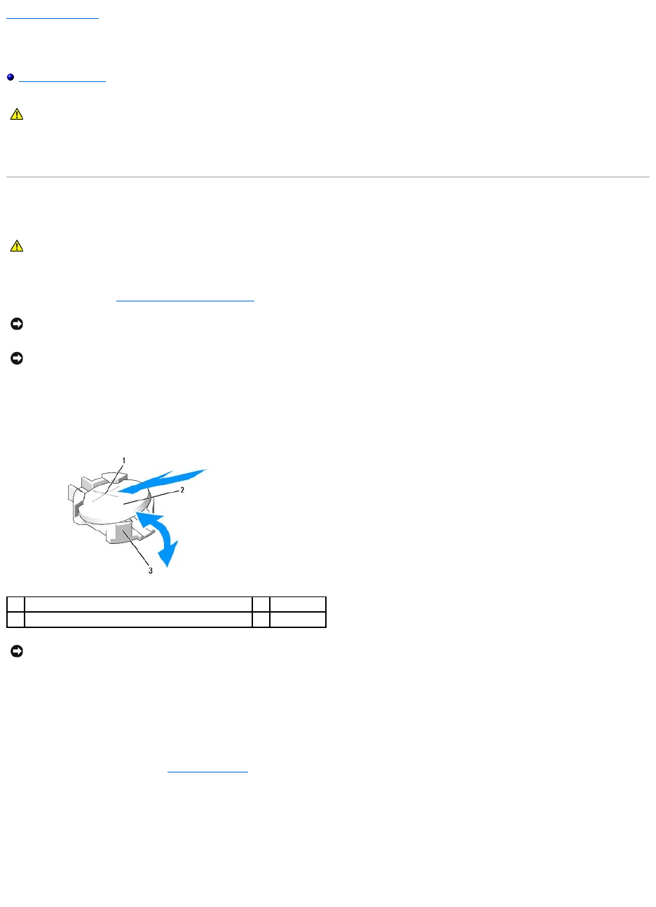
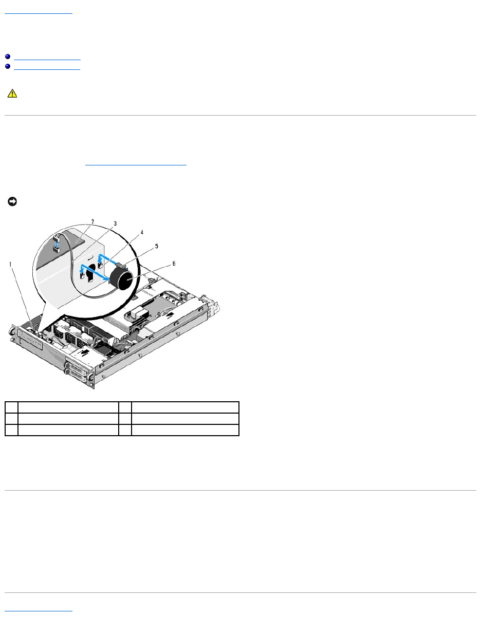
2. Remove the battery.
a. Support the battery connector by pressing down firmly on the positive side of the connector.
b. While supporting the battery connector, press the battery toward the positive side of the connector and pry it up out of the securing tabs at the
negative side of the connector.
3. Install the new battery.
a. Support the battery connector by pressing down firmly on the positive side of the connector.
b. Hold the battery with the "+" facing up, and slide it under the securing tabs at the positive side of the connector.
c. Press the battery straight down into the connector until it snaps into place.
4. Replace the computer cover (see Replacing the Cover).
5. Reconnect the computer to its electrical outlet and turn the computer on, including any attached peripherals.
6. Enter the system setup program to confirm that the battery is operating properly (see the Dell Technology Guide for information about accessing and
using the system setup program).
7. Enter the correct time and date in the system setup program's Time and Date fields.
8. Exit the system setup program.
CAUTION: Only trained service technicians are authorized to remove the computer cover and access any of the components inside the computer.
Before working inside the computer, read the safety information that shipped with the computer. For additional safety best practices information,
see the Regulatory Compliance Homepage at www.dell.com/regulatory_compliance.
CAUTION: There is a danger of a new battery exploding if it is incorrectly installed. Replace the battery only with the same or equivalent type
recommended by the manufacturer. Discard used batteries according to the manufacturer's instructions. See the safety information that shipped
with the computer for additional information.
NOTICE: If you pry the battery out of its socket with a blunt tool, be careful not to touch the system board with the object. Ensure that the object is
inserted between the battery and the socket before you attempt to pry out the battery. Otherwise, you may damage the system board by prying off
the socket or by breaking circuit traces on the system board.
NOTICE: To avoid damage to the battery connector, you must firmly support the connector while installing or removing a battery.
1
positive side of battery connector
2
battery
3
negative side of battery connector
NOTICE: To avoid damage to the battery connector, you must firmly support the connector while installing or removing a battery.

9. To test the newly installed battery, turn off the computer and disconnect it from the electrical outlet for at least an hour.
10. After an hour, reconnect the computer to its electrical outlet and turn it on.
11. Enter the system setup program and if the time and date are still incorrect, see Contacting Dell for instructions on obtaining technical assistance.
Back to Contents Page
Back to Contents Page
Before Working on Your Computer
DellPrecision™R5400ServiceManual
Recommended Tools
What You Need to Know For Your Safety
This document provides procedures for removing and installing components in your computer. Unless otherwise noted, each procedure assumes that:
lYou have performed the steps in this section.
lYou have read the safety information that shipped with your computer.
lWhen replacing a component, you have already removed the original, if installed.
Recommended Tools
The procedures in this document may require the following tools:
lSmall flat-blade screwdriver
lPhillips screwdriver
lSmall plastic scribe
lFlash BIOS update (see the Dell Support website at support.dell.com)
What You Need to Know For Your Safety
Use the following safety guidelines to help protect your computer from potential damage and to help ensure your own personal safety.
1. Shut down your computer.
lIn Microsoft Windows Vista®, click Start , click the arrow icon, and then click Shut Down to turn off your computer.
lIn Microsoft® Windows® XP, click Start® Shutdown® Shutdown.
2. Disconnect your computer and all attached devices from their electrical outlets.
3. Disconnect any network cables from the computer.
4. If applicable, remove the computer from the rack (see the Rack Installation Guide for instructions).
CAUTION: Only trained service technicians are authorized to remove the computer cover and access any of the components inside the computer.
Before working inside the computer, read the safety information that shipped with the computer. For additional safety best practices information,
see the Regulatory Compliance Homepage at www.dell.com/regulatory_compliance.
NOTE: The color of your computer and certain components may appear differently than shown in this document.
CAUTION: Before you begin any of the procedures in this section, follow the safety instructions that shipped with your computer. For additional
safety best practices information, see the Regulatory Compliance Homepage at www.dell.com/regulatory_compliance.
NOTICE: Only a certified service technician should perform repairs on your computer. Only trained service technicians are authorized to remove the
computer cover and access any of the components inside the computer. Damage due to servicing that is not authorized by Dell is not covered by your
warranty.
NOTICE: To avoid electrostatic discharge, ground yourself by using a wrist grounding strap or by periodically touching an unpainted metal surface, such
as a connector on the back of the computer.
NOTICE: Handle components and cards with care. Do not touch the components or contacts on a card. Hold a card by its edges or by its metal
mounting bracket. Hold a component such as a processor by its edges, not by its pins.
NOTICE: When disconnecting a cable, pull on the cable's connector or on its strain-relief loop, not on the cable itself. For cable connectors with locking
tabs, press inward on the locking tabs to release the connector. When connecting a cable, ensure that the connectors are correctly oriented and
aligned to avoid damage to the connector and/or the connector's pins.
NOTE: Ensure that the computer is off and not in a power management mode. If you cannot shut down the computer using the operating system,
press and hold the power button for 6 seconds.
NOTICE: To disconnect a network cable, first unplug the cable from your computer, and then unplug it from the network wall jack.

5. Remove the front bezel, if attached (see Removing the Front Bezel).
6. Remove the computer cover (see Removing the Cover).
7. When you complete your work inside the computer, replace the computer cover and the front bezel, and reconnect your computer and peripherals to
their electrical outlets.
Back to Contents Page
CAUTION: To guard against electrical shock, always unplug your computer from the electrical outlet before removing the cover.
NOTICE: Before touching anything inside your computer, ground yourself by touching an unpainted metal surface, such as the metal at the back of the
computer. While you work, periodically touch an unpainted metal surface to dissipate any static electricity that could harm internal components.
Back to Contents Page
Front Bezel
DellPrecision™R5400ServiceManual
Removing the Front Bezel
Replacing the Front Bezel
A lock on the front bezel restricts access to the power button, optical drive, two front-panel USB connectors, and the hard drive(s). An array of lights located
on the front panel and accessible through the front bezel displays the computer's status.
The computer ships with the bezel unattached, and so it must be attached during initial setup of the computer.
Removing the Front Bezel
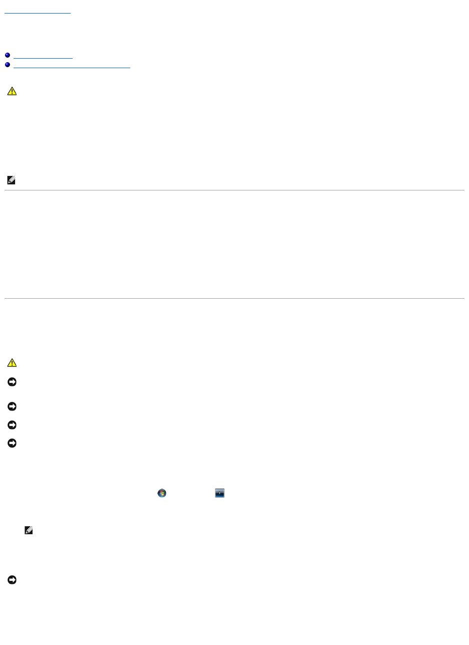
1. Using the bezel key, unlock the front bezel.
2. Press the tab at the left end of the bezel.
3. Rotate the left end of the bezel away from the computer to release the right end of the bezel.
4. Pull the bezel away from the computer.
Replacing the Front Bezel
To replace the front bezel, perform the above steps in reverse.
Back to Contents Page
CAUTION: Only trained service technicians are authorized to remove the computer cover and access any of the components inside the computer.
Before working inside the computer, read the safety information that shipped with the computer. For additional safety best practices information,
see the Regulatory Compliance Homepage at www.dell.com/regulatory_compliance.
1
status lights
2
front bezel lock
NOTE: If you are installing a new replacement bezel, the bezel keys can be found clipped inside the bezel where they were stored during shipment.
Back to Contents Page
Mid-Support Brace
DellPrecision™R5400ServiceManual
Removing the Mid-Support Brace
Replacing the Mid-Support Brace
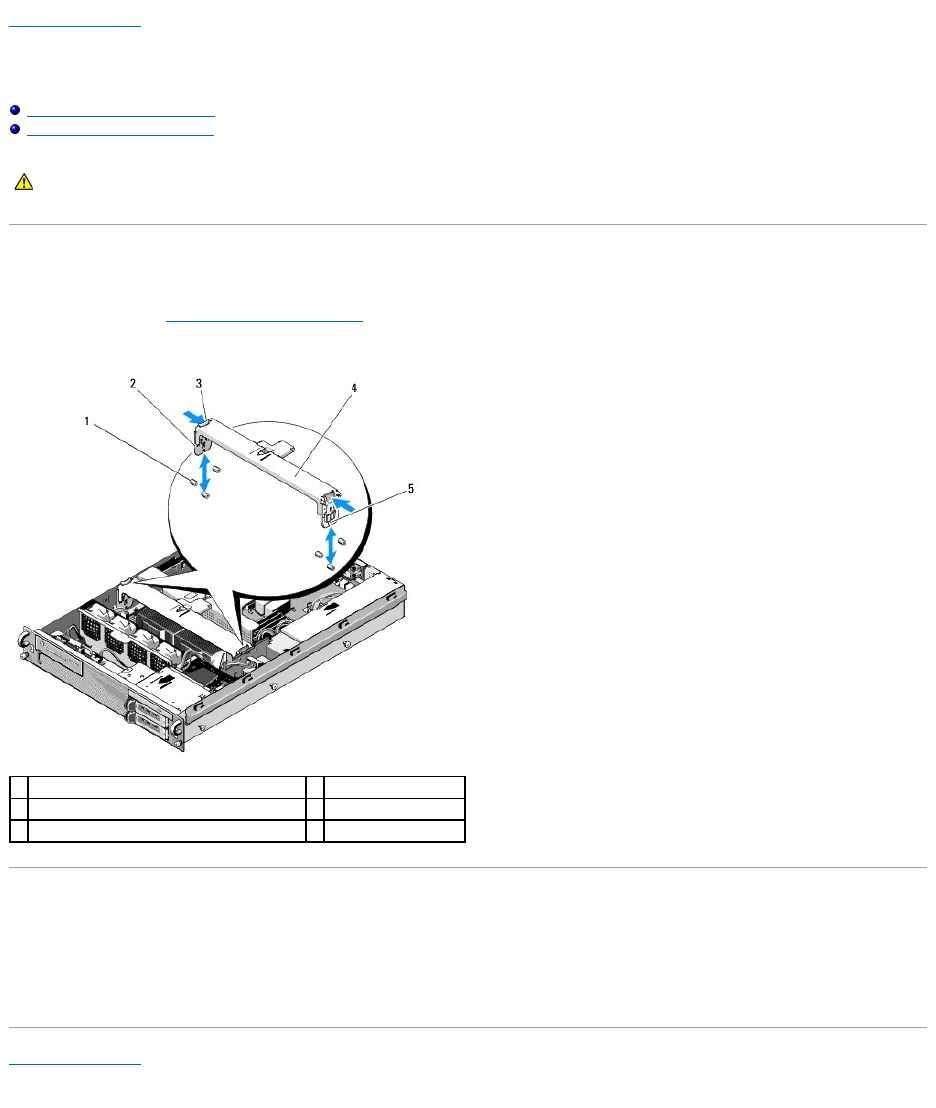
Removing the Mid-Support Brace
1. Perform the steps in Before Working on Your Computer.
2. Press inward on the blue release latches at each end of the brace, and lift the brace from the computer.
Replacing the Mid-Support Brace
1. Align the brace so that the vertical members slide down between the guiding pins.
2. Slide the brace down until it snaps into place.
Back to Contents Page
CAUTION: Only trained service technicians are authorized to remove the computer cover and access any of the components inside the computer.
Before working inside the computer, read the safety information that shipped with the computer. For additional safety best practices information,
see the Regulatory Compliance Homepage at www.dell.com/regulatory_compliance.
1
guiding pins (6, 3 on each side of chassis)
2
vertical members (2)
release latches (2)
4
mid-support brace
5
notch (2, one at each end of brace)
Back to Contents Page
Expansion-Card Cages
DellPrecision™R5400ServiceManual
Removing an Expansion-Card Cage
Replacing an Expansion-Card Cage
Your computer has two expansion-card cages: one labeled "outer" and one labeled "center." The procedure for removing each cage is identical.
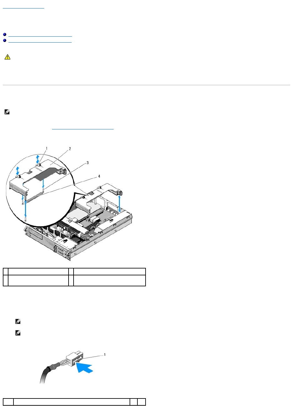
Removing an Expansion-Card Cage
1. Perform the steps in Before Working on Your Computer.
2. Pull upward the two blue release latches on the expansion-card cage.
3. Lift the cage straight up, but not completely out of the chassis until you disconnect any cables attached to the expansion cards.
4. Disconnect cables attached to any expansion cards installed in the cage, and lift the cage completely out of the chassis.
CAUTION: Only trained service technicians are authorized to remove the computer cover and access any of the components inside the computer.
Before working inside the computer, read the safety information that shipped with the computer. For additional safety best practices information,
see the Regulatory Compliance Homepage at www.dell.com/regulatory_compliance.
NOTE: You must remove all expansion cards from the expansion-card cage before removing the expansion-card cage from the computer.
1
release latches (2)
2
expansion-card cage
3
guide posts on system board
(3)
4
riser-board connector on system
board
NOTE: On the outer cage only, guide power connectors P5 and/or P6, as applicable, through the openings on one end of the cage as you lift the
cage completely out of the chassis.
NOTE: To disconnect power cables, squeeze the release tab on the cable connector. Avoid pulling directly on the cables themselves.
1
release tab on cable connector

Replacing an Expansion-Card Cage
1. Reconnect cables that attach to any expansion cards installed in the cage, if applicable.
2. Align the guides on each end of the expansion-card cage with the guide posts on the system board, and lower the cage.
3. Press the cage downward to seat the riser board into the riser board connector on the system board.
4. Press the blue release latches downward into the cage.
Back to Contents Page
NOTE: The outer expansion-card cage has two openings on one end for threading the power cables P5 and/or P6 if required for any installed
expansion cards.
NOTE: The center expansion-card cage has three guides for three posts on the system board, and the outer card cage has only two guides for
two posts on the system board.
Back to Contents Page
Expansion Cards
DellPrecision™R5400ServiceManual
Expansion Card Installation Guidelines
Installing an Expansion Card
Removing an Expansion Card
The computer is available with either one or two PCI Express (PCIe) cards installed in the outer expansion-card cage. The center expansion-card cage has two
configuration options:
lOne PCIe and one PCI-X card
lOne PCI and one PCI-X
Expansion Card Installation Guidelines
Installing an Expansion Card
1. Perform the steps in Before Working on Your Computer.
2. Unpack the expansion card and prepare it for installation.
For instructions, see the documentation accompanying the card.
3. Remove the expansion-card cage (see Removing an Expansion-Card Cage).
4. Open the expansion-card latch and remove the filler bracket.
5. Install the expansion card:
a. If the expansion card is full length, align its front edge with the front card guide.
CAUTION: Only trained service technicians are authorized to remove the computer cover and access any of the components inside the computer.
Before working inside the computer, read the safety information that shipped with the computer. For additional safety best practices information,
see the Regulatory Compliance Homepage at www.dell.com/regulatory_compliance.
NOTE: The expansion-card slots are not hot-pluggable.
NOTE: All expansion card slots support full-length expansion cards.
NOTE: Your computer supports up to two RAID expansion cards to manage external storage.
NOTE: The procedure for installing expansion cards into the outer and center expansion-card cages is the same.
1
expansion-card cage
2
expansion-card latch
3
filler bracket
b. Position the expansion card so that the card-edge connector aligns with the expansion-card connector on the expansion-card riser board.
c. Insert the card-edge connector firmly into the expansion-card connector until the card is fully seated.
d. When the card is seated in the connector, close the expansion-card latch.
6. Connect any expansion-card cables for the new card, as well as already- installed cards.
See the documentation that came with the card for information about its cable connections.
Removing an Expansion Card
1. Perform the steps in Before Working on Your Computer.
2. Remove the expansion-card cage (see Removing an Expansion-Card Cage).
3. Release the expansion card:
a. Open the expansion-card latch.
b. Grasp the expansion card by its top corners, and remove it from the expansion-card connector.
4. If you are removing the card permanently, install a metal filler bracket over the empty expansion-slot opening and close the expansion-card latch.
Back to Contents Page
1
center expansion-card cage
2
front card guide
3
expansion-card latch
4
expansion card
5
card-edge connector
6
expansion-card connector on riser board
NOTE: You must install a filler bracket over an empty expansion slot to maintain Federal Communications Commission (FCC) certification of the
computer. The brackets also keep dust and dirt out of the computer and aid in proper cooling and airflow inside the computer.
Back to Contents Page
Computer Cover
DellPrecision™R5400ServiceManual
Removing the Cover
Replacing the Cover
Removing the Cover
1. Turn off the computer and attached peripherals, and disconnect the computer from the electrical outlet and peripherals.
2. Remove the front bezel, if attached (see Removing the Front Bezel).
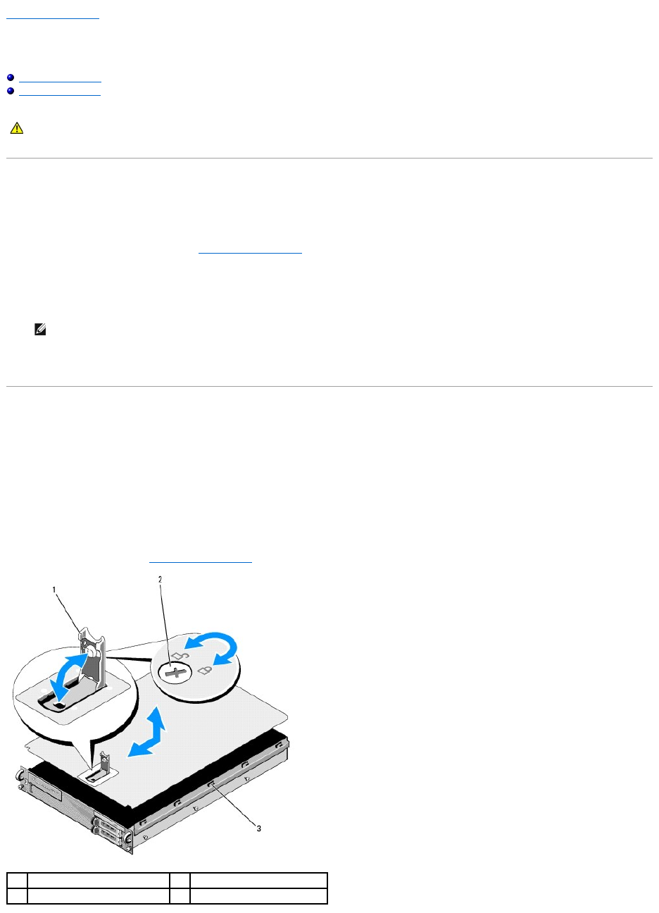
3. To remove the computer cover, turn the latch release lock counter- clockwise to the unlocked position.
4. Lift the latch on top of the computer.
5. Grasp the cover on both sides and carefully lift the cover away from the chassis.
Replacing the Cover
1. Lift up the latch on the cover.
2. Place the cover on top of the computer and offset the cover slightly back so that it clears the chassis J hooks and lays flush on the computer chassis.
3. Push down the latch to lever the cover into the closed position.
4. Rotate the latch release lock in a clockwise direction to secure the cover.
5. Replace the front bezel (see Replacing the Front Bezel).
CAUTION: Only trained service technicians are authorized to remove the computer cover and access any of the components inside the computer.
Before working inside the computer, read the safety information that shipped with the computer. For additional safety best practices information,
see the Regulatory Compliance Homepage at www.dell.com/regulatory_compliance.
NOTE: The cover slides slightly toward the back of the computer when you lift the latch.
1
latch
2
latch release lock
3
alignment J hooks

Back to Contents Page
Control Panel Assembly
DellPrecision™R5400ServiceManual
Removing the Control Panel Assembly
Replacing the Control Panel Assembly
Removing the Control Panel Assembly
1. Perform the steps in Before Working on Your Computer.
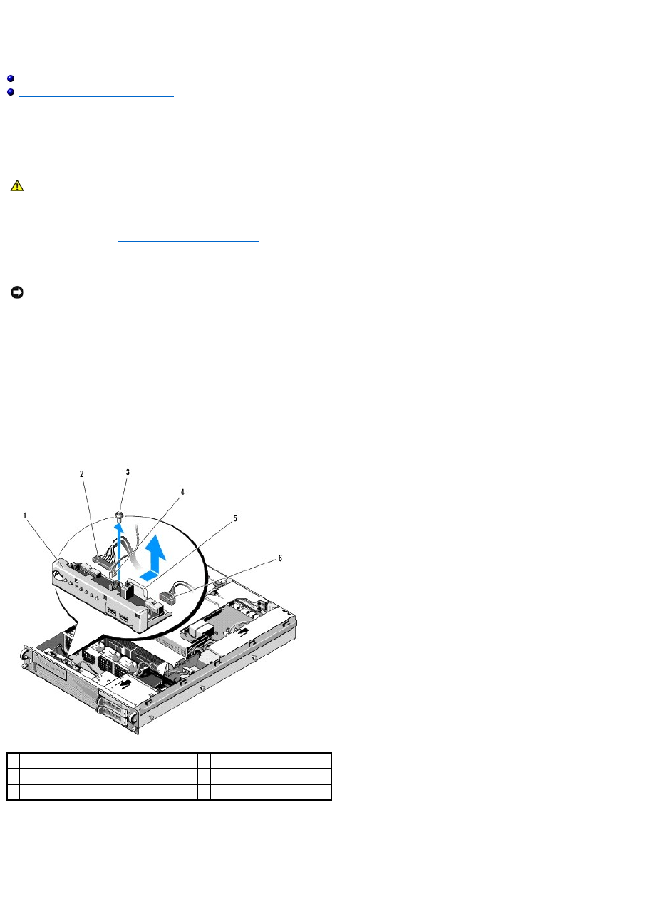
2. Disconnect the control panel cable from the control panel board.
a. Squeeze the plastic tabs on the ends of the cable connector.
b. Gently work the connector out of the socket.
c. Disconnect the speaker cable from the control panel board.
d. Disconnect the front USB-connector cable from the control panel board.
e. Remove the screw that secures the control panel assembly to the computer chassis.
f. Grasp the metal tab/handle to slide the assembly back, and lift the assembly from the chassis.
Replacing the Control Panel Assembly
1. Place the control panel assembly in the computer chassis, slide it forward until the screw holes align and the power button fits in its front-panel opening,
and replace the securing screw.
2. Connect the front USB-connector cable to the control panel board.
CAUTION: Only trained service technicians are authorized to remove the computer cover and access any of the components inside the computer.
Before working inside the computer, read the safety information that shipped with the computer. For additional safety best practices information,
see the Regulatory Compliance Homepage at www.dell.com/regulatory_compliance.
NOTICE: To avoid damage to the cable, pull on the connector, not the cable, to unseat the connector.
1
control panel assembly
2
control panel cable
3
control-panel assembly securing screw
4
speaker cable
5
metal tab/handle
6
front USB-connector cable

Back to Contents Page
Cooling Fans
DellPrecision™R5400ServiceManual
Removing a Fan Pair
Replacing a Cooling Fan Pair
The computer includes four cooling fans. The fans are paired and must be removed two fans at a time; fans 1 and 2 are paired, and fans 3 and 4 are paired.
Removing a Fan Pair
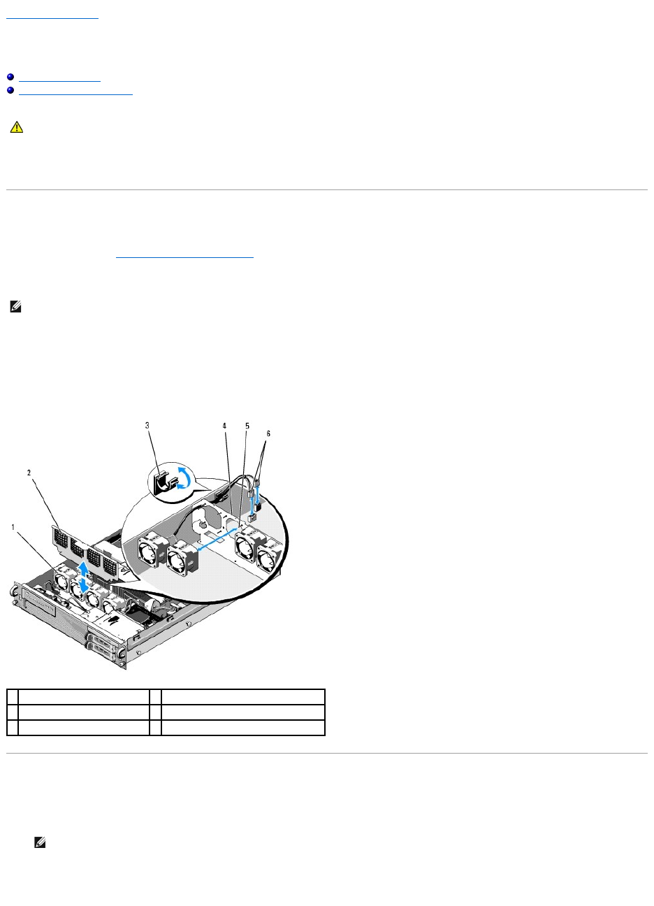
1. Perform the steps in Before Working on Your Computer.
2. Lift the removable fan bracket out of the chassis and set it aside.
3. Slide one fan horizontally toward the front of the computer, gently rocking it up and down to ease the four corners of the fan off the corner pin supports.
4. Slide the corresponding fan in the pair similarly to remove it from its pin supports.
5. Disconnect the corresponding fan cable connectors from the system board, and lift the fan pair out of the chassis.
Replacing a Cooling Fan Pair
1. Slip each fan in the pair onto the four corner-support pins for each fan.
2. Route the fan cable pair over the appropriate corner slot in the top of the (unremovable) fan bracket at the back of the fans, and reconnect the cable
connectors to the system board.
CAUTION: Only trained service technicians are authorized to remove the computer cover and access any of the components inside the computer.
Before working inside the computer, read the safety information that shipped with the computer. For additional safety best practices information,
see the Regulatory Compliance Homepage at www.dell.com/regulatory_compliance.
NOTE: The fans must be removed in pairs.
1
fans (4)
2
fan bracket (removable)
3
cable clip
4
fan bracket (unremovable)
5
corner support pins (4 per fan)
6
fan cables connecting to system board
NOTE: Ensure that the fan-number labels are facing upward.

Back to Contents Page
Finding Information
DellPrecision™R5400ServiceManual
Back to Contents Page
NOTE: Some features or media may be optional and may not ship with your computer. Some features or media may not be available in certain countries.
NOTE: Additional information may ship with your computer.
Document/Media/Label
Contents
Service Tag/Express Service Code
The Service Tag/Express Service Code is located on your computer.
lUse the Service Tag to identify your computer when you use
support.dell.com or contact support.
lEnter the Express Service Code to direct your call when contacting
support
NOTE: Your Service Tag/Express Service Code is located on your
computer.
Drivers and Utilities Media
The Drivers and Utilities media is a CD or DVD that may have shipped with your
computer.
lA diagnostic program for your computer
lDrivers for your computer
NOTE: Drivers and documentation updates can be found at
support.dell.com.
lDesktop System Software (DSS)
lReadme files
NOTE: Readme files may be included on your media to provide last-
minute updates about technical changes to your computer or advanced
technical-reference material for technicians or experienced users.
Operating System Media
The Operating System media is a CD or DVD that may have shipped with your
computer.
Reinstall your operating system
Safety, Regulatory, Warranty, and Support Documentation
This type of information may have shipped with your computer. For additional
regulatory information, see the Regulatory Compliance Homepage at
www.dell.com/regulatory_compliance.
lWarranty information
lTerms and Conditions (U.S. only)
lSafety instructions
lRegulatory information
lErgonomics information
lEnd User License Agreement
Service Manual
The Service Manual for your computer can be found at support.dell.com.
lHow to remove and replace parts
lHow to configure computer settings
lHow to troubleshoot and solve problems
Dell Technology Guide
The Dell Technology Guide is available at support.dell.com.
lAbout your operating system
lUsing and maintaining devices
lUnderstanding technologies such as RAID, Internet, Bluetooth®
wireless technology, e-mail, networking, and more.
Microsoft® Windows® License Label
Your Microsoft Windows License is located on your computer.
lProvides your operating system product key.
Back to Contents Page
Hard Drives
DellPrecision™R5400ServiceManual
Replacing a Hard Drive
Installing a Second Hard-Drive
Your computer can accommodate up to two 3.5-inch SATA hard drives. The hard drive power cables connect to the system board through a power cable
assembly.
Hard drives are installed in special drive carriers that fit in the hard-drive bays.
You may need to use different programs than those provided with the operating system to partition and format SATA hard drives.
When you format a high-capacity hard drive, allow enough time for the formatting to be completed. Long format times for these drives are normal. A 9-GB hard
drive, for example, can take up to 2.5 hours to format.
Replacing a Hard Drive
1. Perform the steps in Before Working on Your Computer.
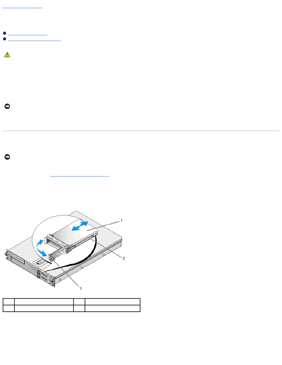
2. Remove the hard-drive carrier from the hard-drive bay:
a. Squeeze the release latch on the drive-carrier door and rotate it open.
b. Pull the door to slide the carrier out of the bay.
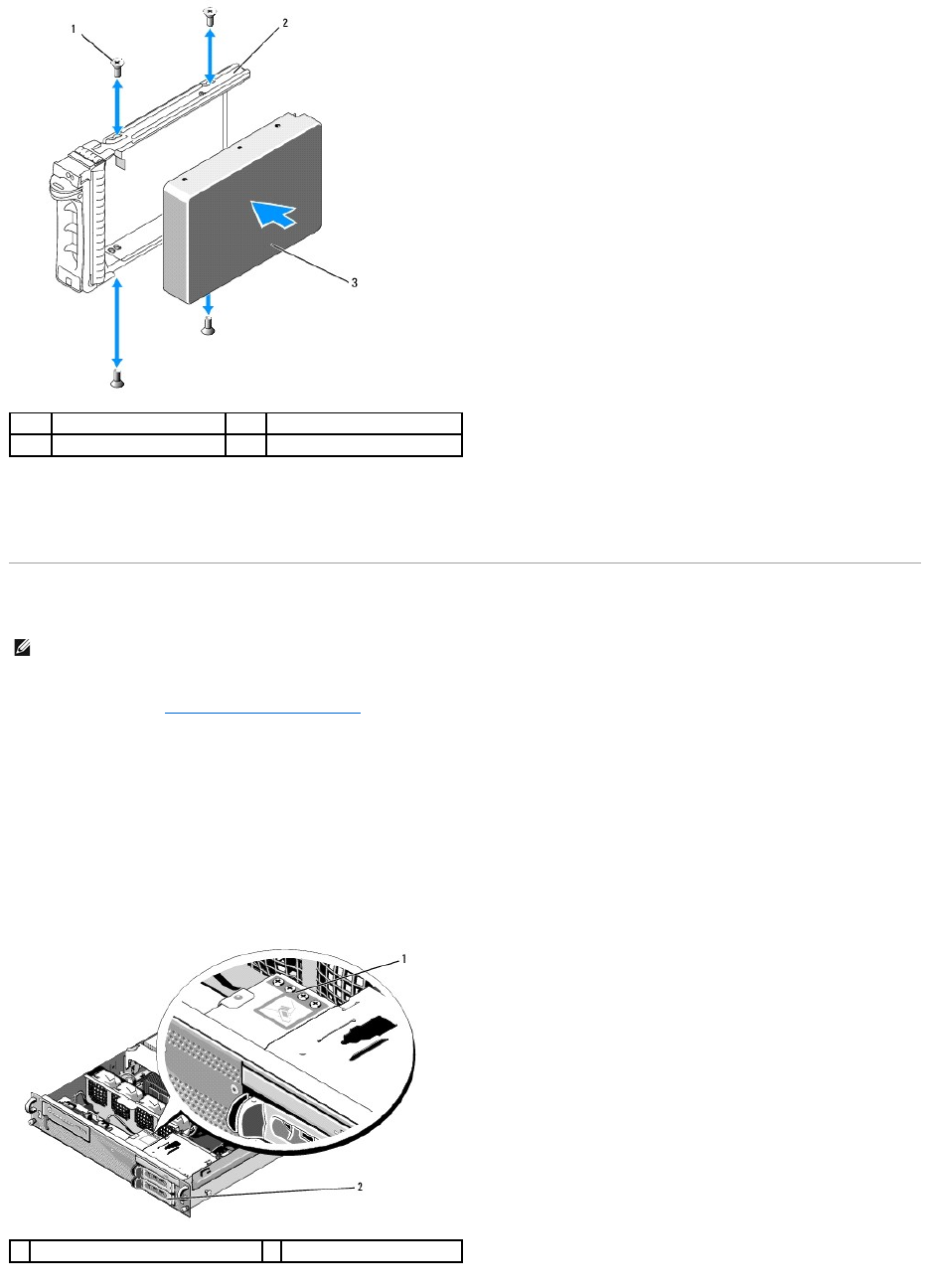
3. Remove the four screws from the side rails on the carrier, and separate the hard drive from the carrier.
4. Install the replacement hard drive in the carrier:
a. Slide the drive into the carrier, ensuring that the drive connectors are accessible at the back of the carrier.
b. Align the screw holes on the hard drive with the holes on the hard- drive carrier.
c. Attach the four screws to secure the hard drive to the carrier.
CAUTION: Only trained service technicians are authorized to remove the computer cover and access any of the components inside the computer.
Before working inside the computer, read the safety information that shipped with the computer. For additional safety best practices information,
see the Regulatory Compliance Homepage at www.dell.com/regulatory_compliance.
NOTICE: Do not turn off or reboot your computer while the drive is being formatted. Doing so can cause a drive failure.
NOTICE: The drives in your computer are not hot-pluggable. Ensure that you turn off the computer and disconnect the power cable from the AC power
source before you remove a hard drive.
1
hard drive
2
drive carrier
3
release latch
5. Insert the hard-drive carrier into the drive bay until the carrier contacts the back of the bay.
6. Close the handle to lock the drive in place.
Installing a Second Hard-Drive
1. Perform the steps in Before Working on Your Computer.
2. Remove the empty hard-drive carrier from the hard-drive bay:
a. Squeeze the release latch on the drive-carrier door and rotate it open.
b. Slide the carrier out of the bay.
3. Install the new hard drive in the carrier:
a. Slide the drive into the carrier, ensuring that the drive connectors are accessible at the back of the carrier.
b. Align the screw holes on the hard drive with the holes on the hard- drive carrier.
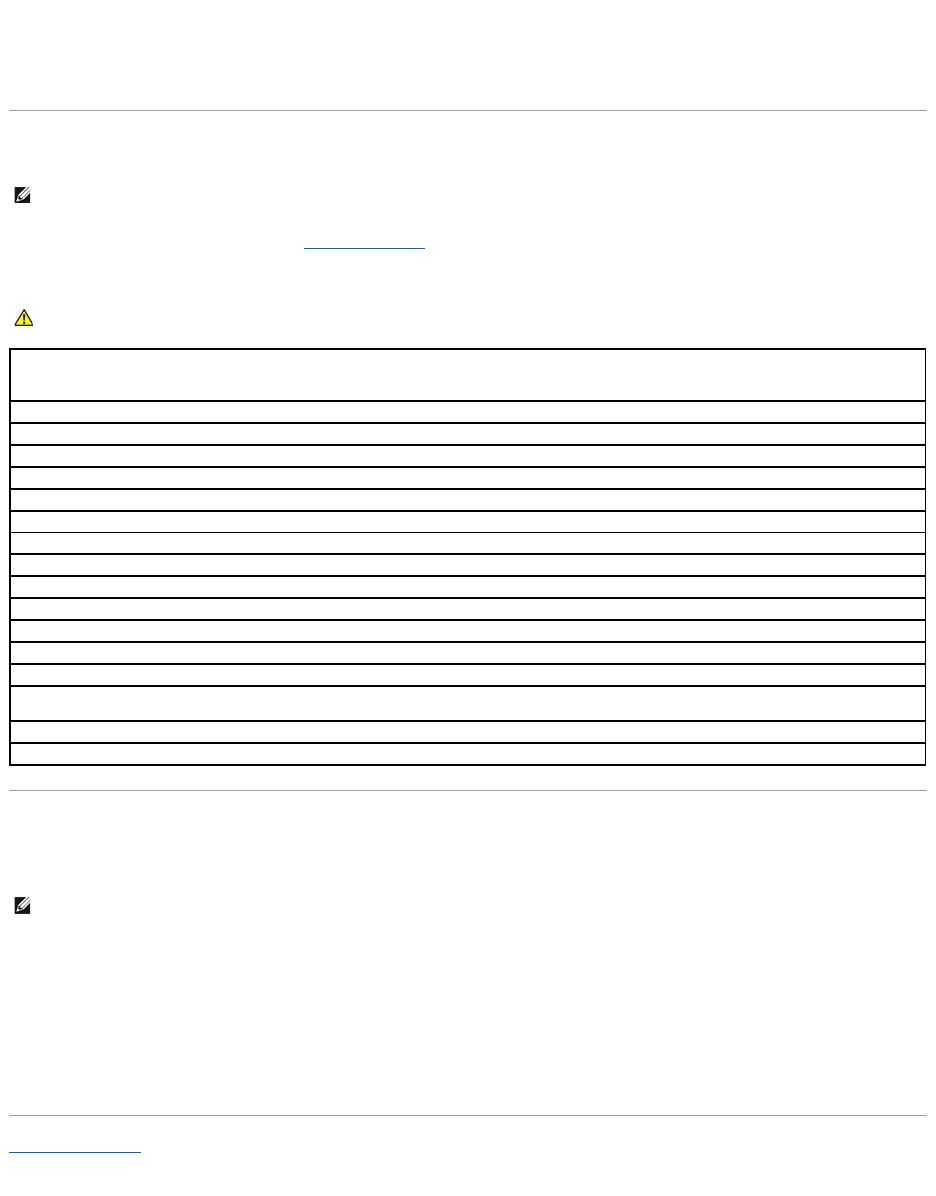
c. Remove the four screws from their storage location on the chassis, and use them to secure the drive in the carrier
1
screws (4)
2
drive carrier
3
hard drive
NOTE: Four screws for installing a hard drive in the second drive carrier are provided in their storage location on the chassis, next to the drive cage.
Also, installation instructions are illustrated on the inside of the drive carrier for your convenience.
1
screws for second hard drive (4)
2
second hard drive carrier


Back to Contents Page
Getting Help
DellPrecision™R5400ServiceManual
Obtaining Assistance
Problems With Your Order
Product Information
Returning Items for Warranty Repair or Credit
Before You Call
Contacting Dell
Obtaining Assistance
If you experience a problem with your computer, you can complete the following steps to diagnose and troubleshoot the problem:
1. See Solving Problems for information and procedures that pertain to the problem your computer is experiencing.
2. See Dell Diagnostics for procedures on how to run Dell Diagnostics.
3. Fill out the Diagnostics Checklist.
4. Use Dell's extensive suite of online services available at Dell Support (support.dell.com) for help with installation and troubleshooting procedures. See
Online Services for a more extensive list of Dell Support online.
5. If the preceding steps have not resolved the problem, see Contacting Dell.
When prompted by Dell's automated telephone computer, enter your Express Service Code to route the call directly to the proper support personnel. If you do
not have an Express Service Code, open the Dell Accessories folder, double-click the Express Service Code icon, and follow the directions.
For instructions on using the Dell Support, see Technical Support and Customer Service.
Technical Support and Customer Service
Dell'ssupportserviceisavailabletoansweryourquestionsaboutDell™hardware.Oursupportstaffusescomputer-based diagnostics to provide fast,
accurate answers.
To contact Dell's support service, see Before You Call, and then see the contact information for your region or go to support.dell.com.
DellConnect™
DellConnect is a simple online access tool that allows a Dell service and support associate to access your computer through a broadband connection, diagnose
your problem and repair it all under your supervision. For more information, go to support.dell.com and click DellConnect.
Online Services
You can learn about Dell products and services at the following websites:
www.dell.com
www.dell.com/ap (Asian/Pacific countries only)
www.dell.com/jp (Japan only)
www.euro.dell.com (Europe only)
www.dell.com/la (Latin American and Caribbean countries)
CAUTION: If you need to remove the computer cover, first disconnect the computer power and modem cables from all electrical outlets. Follow
the safety instructions that shipped with your computer.
NOTE: Call Dell Support from a telephone at or near the affected computer so that the support staff can assist you with any necessary procedures.
NOTE: Dell's Express Service Code computer may not be available in all countries.
NOTE: Some of the following services are not always available in all locations outside the continental U.S. Call your local Dell representative for
information on availability.

www.dell.ca (Canada only)
You can access Dell Support through the following websites and e-mail addresses:
lDell Support websites:
support.dell.com
support.jp.dell.com (Japan only)
support.euro.dell.com (Europe only)
lDell Support e-mail addresses:
mobile_support@us.dell.com
support@us.dell.com
la-techsupport@dell.com (Latin America and Caribbean countries only)
apsupport@dell.com (Asian/Pacific countries only)
lDell Marketing and Sales e-mail addresses:
apmarketing@dell.com (Asian/Pacific countries only)
sales_canada@dell.com (Canada only)
lAnonymous file transfer protocol (FTP):
ftp.dell.com – log in as user anonymous, and use your e-mail address as your password
AutoTech Service
Dell's automated support service—AutoTech—provides recorded answers to the questions most frequently asked by Dell customers about their laptop and
desktop computers.
When you call AutoTech, use your touch-tone telephone to select the subjects that correspond to your questions. For the telephone number to call for your
region, see Contacting Dell.
Automated Order-Status Service
To check on the status of any Dell products that you have ordered, you can go to support.dell.com, or you can call the automated order-status service. A
recording prompts you for the information needed to locate and report on your order. For the telephone number to call for your region, see Contacting Dell.
Problems With Your Order
If you have a problem with your order, such as missing parts, wrong parts, or incorrect billing, contact Dell for customer assistance. Have your invoice or
packing slip available when you call. For the telephone number to call for your region, see Contacting Dell.
Product Information
If you need information about additional products available from Dell, or if you would like to place an order, visit the Dell website at www.dell.com. For the
telephone number to call for your region or to speak to a sales specialist, see Contacting Dell.
Returning Items for Warranty Repair or Credit
Prepare all items being returned, whether for repair or credit, as follows:
1. Call Dell to obtain a Return Material Authorization Number, and write it clearly and prominently on the outside of the box.
For the telephone number to call for your region, see Contacting Dell. Include a copy of the invoice and a letter describing the reason for the return.
2. Include a copy of the Diagnostics Checklist (see Diagnostics Checklist), indicating the tests that you have run and any error messages reported by the
Dell Diagnostics (see Contacting Dell).
3. Include any accessories that belong with the item(s) being returned (power cables, software disks, guides, and so on) if the return is for credit.
4. Pack the equipment to be returned in the original (or equivalent) packing materials.
You are responsible for paying shipping expenses. You are also responsible for insuring any product returned, and you assume the risk of loss during shipment
to Dell. Collect On Delivery (C.O.D.) packages are not accepted.
Returns that are missing any of the preceding requirements will be refused at Dell's receiving dock and returned to you.
Before You Call
Remember to fill out the Diagnostics Checklist (see Diagnostics Checklist). If possible, turn on your computer before you call Dell for assistance and call from a
telephone at or near the computer. You may be asked to type some commands at the keyboard, relay detailed information during operations, or try other
troubleshooting steps possible only at the computer itself. Ensure that the computer documentation is available.
Contacting Dell
For customers in the United States, call 800-WWW-DELL (800-999-3355).
Dell provides several online and telephone-based support and service options. Availability varies by country and product, and some services may not be
available in your area. To contact Dell for sales, technical support, or customer service issues:
1. Visit support.dell.com, and verify your country or region in the Choose A Country/Region drop-down menu at the bottom of the page.
2. Click Contact Us on the left side of the page, and select the appropriate service or support link based on your need.
3. Choose the method of contacting Dell that is convenient for you.
Back to Contents Page
NOTE: Have your Express Service Code ready when you call. The code helps Dell's automated-support telephone computer direct your call more
efficiently. You may also be asked for your Service Tag (located on the back or bottom of your computer).
CAUTION: Before working inside your computer, follow the safety instructions in the documentation that shipped with your computer.
Diagnostics Checklist
Name:
Date:
Address:
Phone number:
Service Tag (bar code on the back or bottom of the computer):
Express Service Code:
Return Material Authorization Number (if provided by Dell support technician):
Operating system and version:
Devices:
Expansion cards:
Are you connected to a network? Yes No
Network, version, and network adapter:
Programs and versions:
See your operating system documentation to determine the contents of the computer's start-up files. If the computer is connected to a printer, print each
file. Otherwise, record the contents of each file before calling Dell.
Error message, beep code, or diagnostic code:
Description of problem and troubleshooting procedures you performed:
NOTE: If you do not have an active Internet connection, you can find contact information on your purchase invoice, packing slip, bill, or Dell product
catalog.
Back to Contents Page
System Memory
DellPrecision™R5400ServiceManual
General Memory Module Installation Guidelines
Non-Optimal Memory Configurations
Installing Memory Modules
Removing Memory Modules
You can upgrade your system memory to a maximum of 32 GB. The four memory sockets are located on the system board under the cooling shroud parallel to
the power supply bay. You can purchase memory upgrade kits from Dell.
General Memory Module Installation Guidelines
To ensure optimal performance of your computer, observe the following guidelines when configuring your system memory.
lUse only qualified fully buffered DIMMs (FBDs). FBDs can be either single-ranked or dual-ranked. FBDs marked with a 1R are single-ranked and FBDs
marked with a 2R are dual-ranked.
lA minimum of two identical FBDs must installed.
lDIMM sockets must be populated by lowest number first.
lFBDs must be installed in pairs of matched memory size, speed, and technology, and the total number of FBDs in the configuration must total two or
four. For best computer performance, all four FBDs should be identical memory size, speed, and technology.
Non-Optimal Memory Configurations
Computer performance can be affected if your memory configuration does not conform to the preceding installation guidelines. Your computer may issue an
error message during start-up stating that your memory configuration is non-optimal.
Installing Memory Modules
1. Perform the steps in Before Working on Your Computer.
2. Remove the memory cooling shroud (see Removing the Cooling Shroud.)
3. Locate the memory module sockets on the system board.
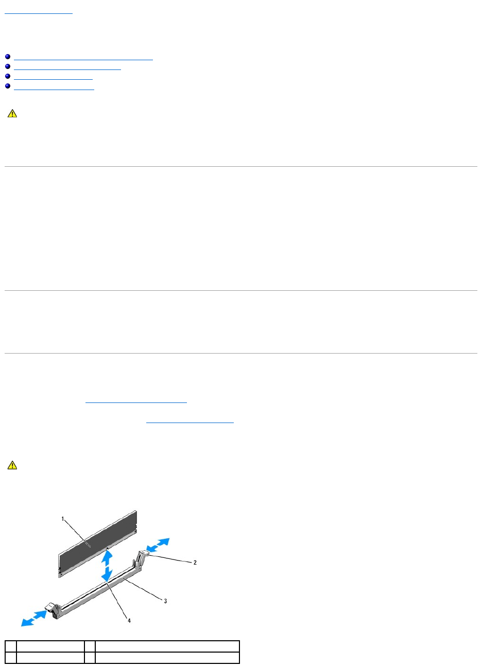
4. Press the ejectors on the memory module socket down and out to allow the memory module to be inserted into the socket.
CAUTION: Only trained service technicians are authorized to remove the computer cover and access any of the components inside the computer.
Before working inside the computer, read the safety information that shipped with the computer. For additional safety best practices information,
see the Regulatory Compliance Homepage at www.dell.com/regulatory_compliance.
CAUTION: The DIMMs are hot to the touch for some time after the computer has been powered down. Allow time for the DIMMs to cool before
handling them. Handle the DIMMs by the card edges and avoid touching the DIMM components.
1
memory module
2
memory-module socket ejectors (2)
3
socket
4
alignment key

5. Align the memory module's edge connector with the alignment key on the memory module socket, and insert the memory module into the socket.
6. Press down on the memory module with your thumbs while pulling up on the ejectors with your index fingers to lock the memory module into the socket.
When the memory module is properly seated in the socket, the ejectors on the memory module socket align with the ejectors on the other sockets that
have memory modules installed.
7. Repeat step 3 through step 6 of this procedure to install the remaining memory modules.
8. Replace the memory cooling shroud (see Replacing the Cooling Shroud).
9. (Optional) Enter the system setup program, and check the System Memory setting on the main system setup program screen (the Dell Technology
Guide for instructions on accessing and using the system setup program).
The computer should have already changed the value to reflect the newly installed memory.
10. If the value is incorrect, one or more of the memory modules may not be installed properly. Repeat step 2 through step 9 of this procedure, checking to
ensure that the memory modules are firmly seated in their sockets.
11. Run the system memory test in the computer diagnostics (see Dell Diagnostics).
Removing Memory Modules
1. Perform the steps in Before Working on Your Computer.
2. Remove the memory cooling shroud (see Removing the Cooling Shroud).
3. Locate the memory module sockets on the system board.
4. Press down and out on the ejectors on each end of the socket until the memory module pops out of the socket.
5. Replace the memory cooling shroud (see Replacing the Cooling Shroud).
Back to Contents Page
NOTE: The memory module socket has an alignment key that allows you to install the memory module in the socket in only one way.
NOTICE: Never operate your computer with the memory cooling shroud removed. Overheating of the computer can develop quickly resulting in a
shutdown of the computer and the loss of data.
CAUTION: Only trained service technicians are authorized to remove the computer cover and access any of the components inside the computer.
Before working inside the computer, read the safety information that shipped with the computer. For additional safety best practices information,
see the Regulatory Compliance Homepage at www.dell.com/regulatory_compliance.
CAUTION: The DIMMs are hot to the touch for some time after the computer has been powered down. Allow the DIMMs to cool before handling
them. Handle the DIMMs by the card edges, and avoid touching the DIMM components.
NOTICE: Never operate your computer with the memory cooling shroud removed. Overheating of the computer can develop quickly resulting in a
shutdown of the computer and the loss of data.
Back to Contents Page
Optical Drive
DellPrecision™R5400ServiceManual
Removing the Optical Drive
Installing the Optical Drive
An optical drive is mounted on a tray that slides into the front panel and connects to the system board through a SATA data cable and power cable assembly.
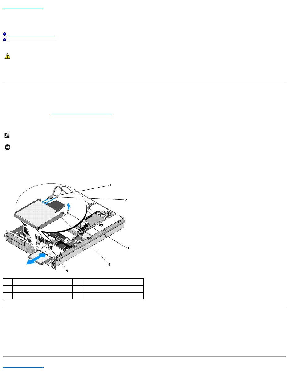
Removing the Optical Drive
1. Perform the steps in Before Working on Your Computer.
2. Disconnect the optical-drive SATA data cable.
3. Disconnect the power cable from the back of the drive.
4. Lift the blue tray-release tab and slide the drive tray out through the front of the computer.
Installing the Optical Drive
1. Slide the drive tray into the optical drive bay, from the front of the computer, until the tray snaps into place.
2. Connect the optical-drive SATA data cable and the power cable to the connectors on the back of the drive.
Back to Contents Page
CAUTION: Only trained service technicians are authorized to remove the computer cover and access any of the components inside the computer.
Before working inside the computer, read the safety information that shipped with the computer. For additional safety best practices information,
see the Regulatory Compliance Homepage at www.dell.com/regulatory_compliance.
NOTE: Remove the SATA data cable before you remove the power cable. Doing so makes it easier to grasp the power cable connector without straining
the power cable.
NOTICE: Ensure that you grasp only the cable connector when you disconnect the power cable. Tugging on the cable can damage it.
1
SATA data cable
2
power cable
3
tray-release tab
4
optical-drive tray
5
optical drive
Back to Contents Page
Power Distribution Unit
DellPrecision™R5400ServiceManual
Removing the Power Distribution Unit
Replacing the Power Distribution Unit
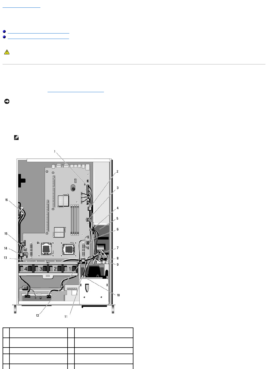
Removing the Power Distribution Unit
1. Perform the steps in Before Working on Your Computer.
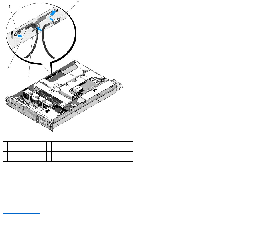
2. Disconnect the power cable connector labeled "P9" from the back of the optical drive.
3. Disconnect the hard-drive power cable(s) at the connector(s) labeled "P8" (upper hard drive) and "P7" (lower hard drive, if installed).
CAUTION: Only trained service technicians are authorized to remove the computer cover and access any of the components inside the computer.
Before working inside the computer, read the safety information that shipped with the computer. For additional safety best practices information,
see the Regulatory Compliance Homepage at www.dell.com/regulatory_compliance.
NOTICE: Pull on the connector and not on the power cable to disconnect the connector from the back of the optical drive.
NOTE: Do not disconnect the power cables directly from the back of the hard drives, as it is not necessary for removal of the power distribution
unit.
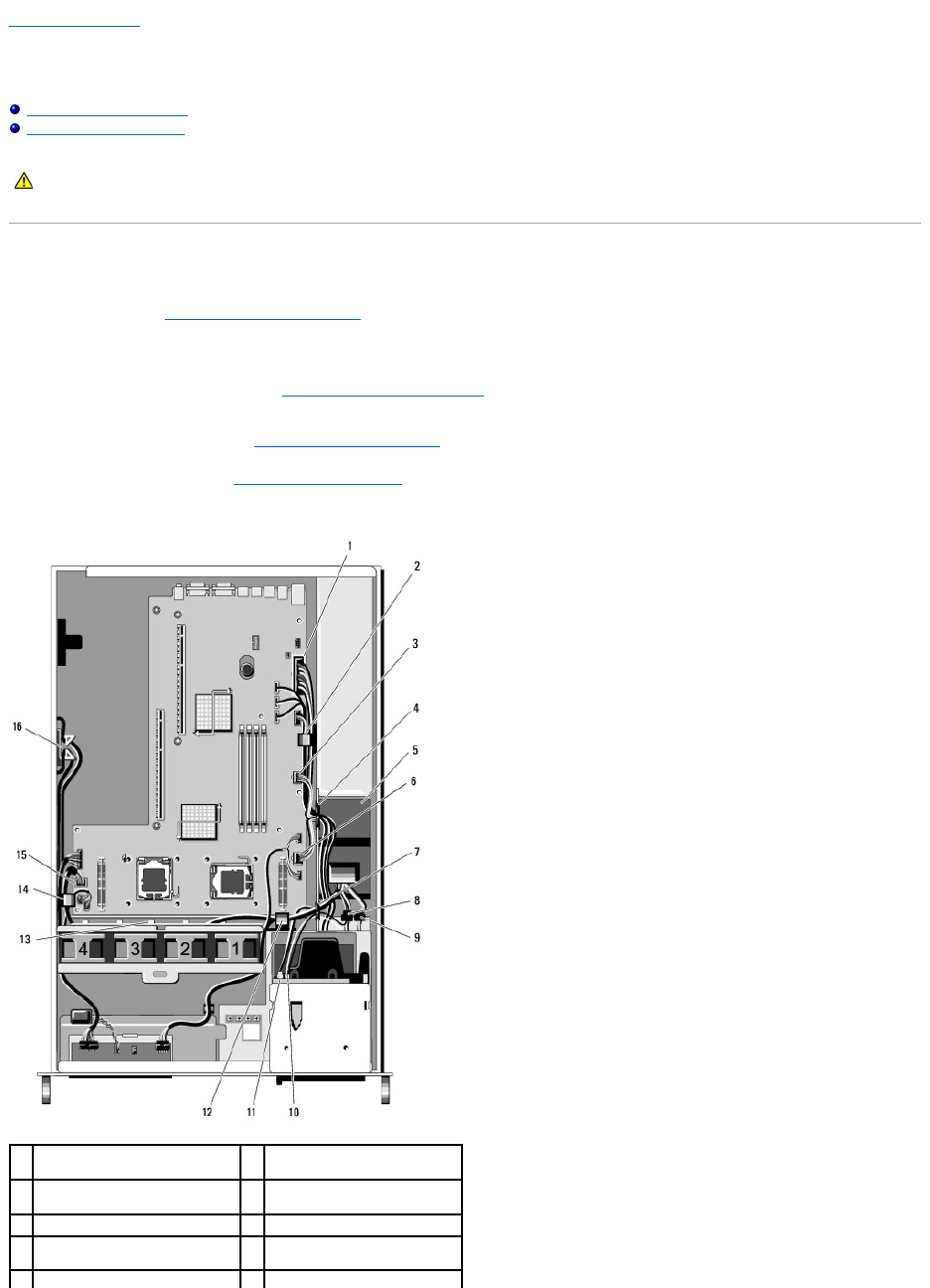
1
power-cable connector P1
2
cable-routing clip (power cable
P1)
3
power-cable connector P2
4
cable-routing portal (power
cables P1, P2, and P3)
5
power distribution unit
6
power-cable connector P3
7
cable-routing portal (power
cables P4, P5, and P6)
8
hard-drive (lower) power cable
connector (P7)
9
hard-drive (upper) power cable
10
optical-drive power cable
4. Disengage the power supply and slide it partway out of the power supply bay (see Removing the Power Supply).
5. Remove both expansion-card cages (see Removing an Expansion-Card Cage), ensuring that you disconnect the power cable connectors labeled "P5"
and "P6" from any expansion cards installed in the card cages.
6. Remove the mid-support brace (see Removing the Mid-Support Brace).
7. Remove the cooling shroud (see Removing the Cooling Shroud).
8. Disconnect the power cable connectors labeled "P1," "P2," "P3," and "P4" from the system board.
9. Unscrew the three captive screws on the power distribution unit that secure it to the bottom of the chassis.
10. Disengage the power cables from the cable clips, cable-routing channels, and cable-routing portals on the chassis as you lift the power distribution unit
out of the chassis, easing the power cables along behind it.
Replacing the Power Distribution Unit
1. Lower the power distribution unit onto the screw mounts on the bottom of the chassis, and tighten the three captive screws.
2. Reconnect the hard-drive power cable(s) to power-cable connector P8 (hard drive in upper bay) and connector P7 (hard drive in lower bay, if applicable).
3. Reconnect the optical-drive power-cable connector P9 to the back of the optical drive.
4. Tuck connectors P7 and P8 and their cables down into the space between the power distribution unit and the back of the hard drives.
connector (P8)
connector (P9)
11
optical-drive SATA data cable
12
cable-routing clip (power cables
P4, P5, and P6)
13
cable-routing channel (power
cables P4, P5, and P6)
14
cable-routing clip (power cables
P4, P5, and P6)
15
power-cable connector P4
16
storage for power cables P5 and
P6 (when not in use)
NOTE: If power cables P5 and P6 are not connected to any expansion card, ensure that you disengage them from their storage shelf in the side
wall of the chassis.
NOTE: Each portal has an arm that hinges up and down over the opening.
1
power cables
2
captive screws (3)
3
power distribution unit
4
cable-routing portals (2)
CAUTION: Only trained service technicians are authorized to remove the computer cover and access any of the components inside the computer.
Before working inside the computer, read the safety information that shipped with the computer. For additional safety best practices information,
see the Regulatory Compliance Homepage at www.dell.com/regulatory_compliance.
5. Reroute the power cables for connectors P1, P2, and P3 into the cable- routing portal next to the power distribution unit.
6. Insert the power cable for connector P1 into the cable -routing clip beside the power supply bay.
7. Reroute the power cables for connectors P4, P5, and P6 into the:
lRemaining cable-routing portal
lCable-routing channel alongside the four fans, at the bottom of the chassis
lCable-routing clips on the chassis at either end of the cable-routing channel.
8. Replace the cooling shroud (see Replacing the Cooling Shroud).
9. Reconnect the power cable connectors labeled "P1," "P2," "P3," and "P4" to the system board.
10. Thread connectors P5 and P6, as applicable if being used, through the cable-routing openings in the outer expansion-card cage, and reconnect the
cable(s) to the expansion cards(s), if installed.
NOTE: If power-cable connectors P5 and P6 are not being used, store them in the channel provided in the side of the chassis, using the cable
guide to route them out of the way of the outer expansion-card cage and the mid-support brace.
11. Reinstall the outer expansion-card cage, followed by the center expansion- card cage (see Replacing an Expansion-Card Cage).
12. Replace the mid-support brace (see Replacing the Mid-Support Brace).
13. Reinstall the power supply (see Replacing the Power Supply).
Back to Contents Page
1
power-cable
connector P5
2
power-cable connector P6
3
cable guide
4
storage shelf for power cables P5 and P6
(when not in use)
Back to Contents Page
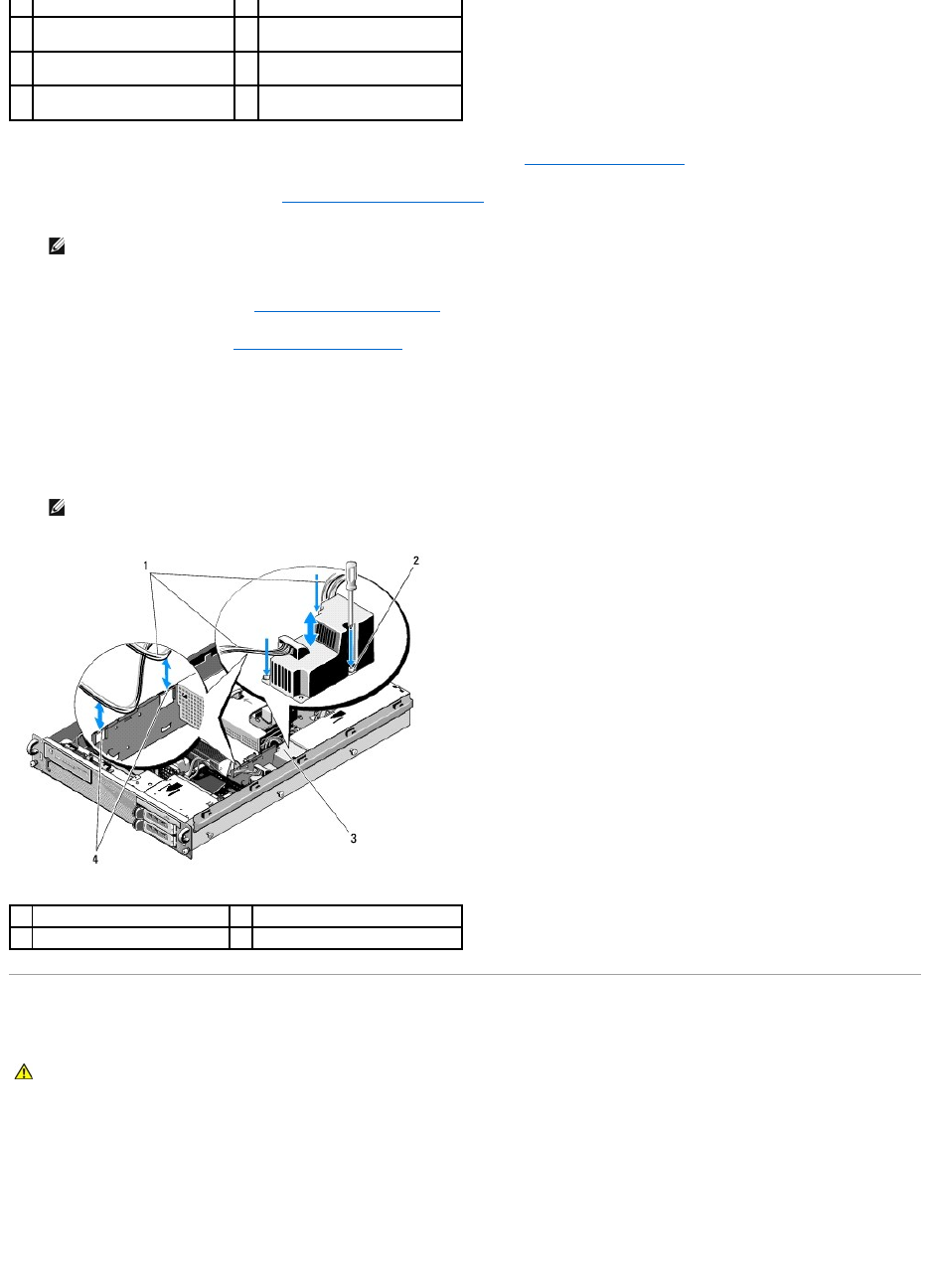
Processors
DellPrecision™R5400ServiceManual
Removing a Processor
Installing a Processor
Your computer can accommodate two processors. You can upgrade your processor(s) to take advantage of future options in speed and functionality. Each
processor and its associated internal cache memory are contained in a land grid array (LGA) package that is installed in a ZIF socket on the system board.
Removing a Processor
1. Prior to upgrading your computer, download the latest computer BIOS version on support.dell.com.
2. Perform the steps in Before Working on Your Computer.
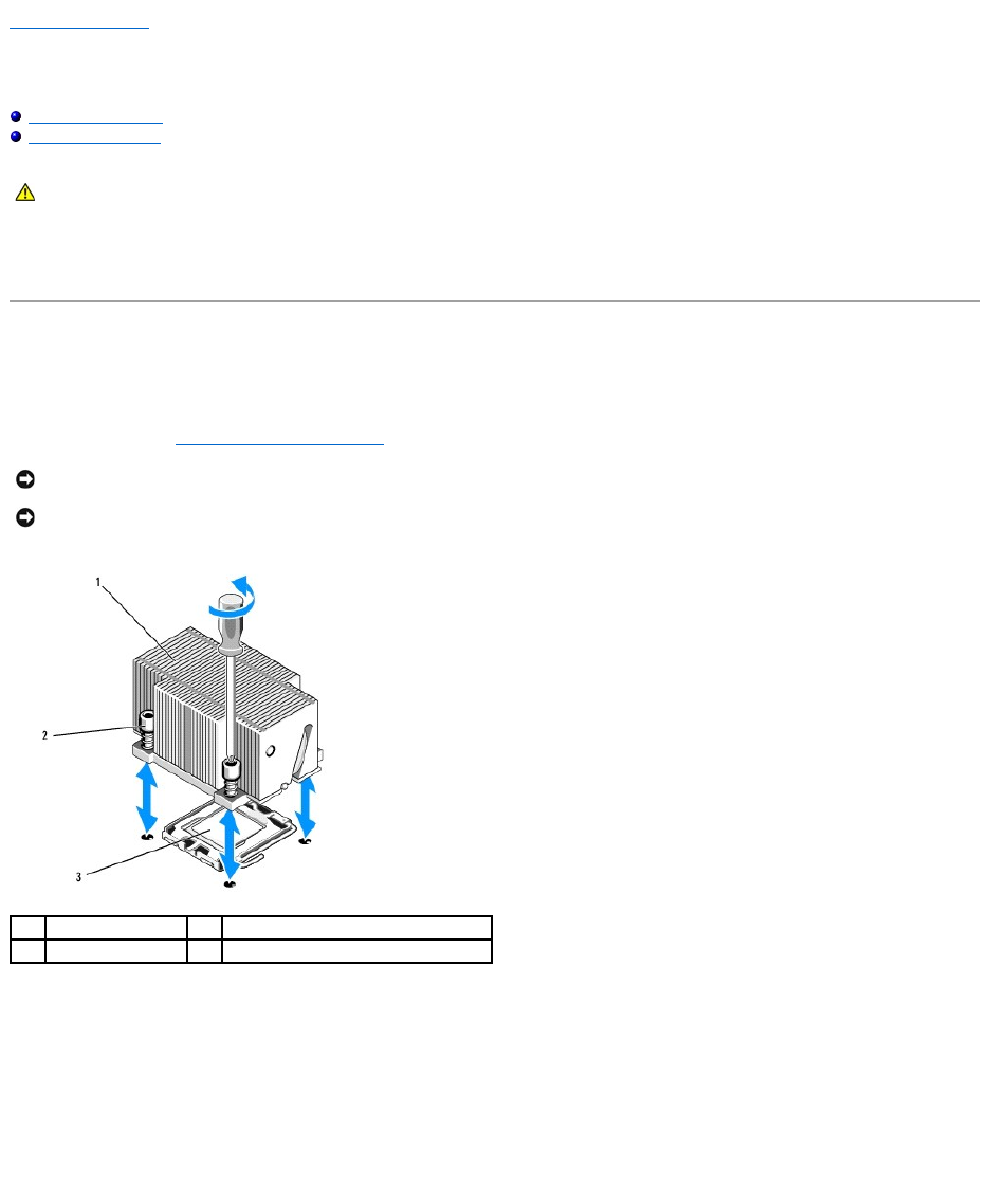
3. Wait 30 seconds for the heat sink and thermal grease to cool enough to allow the heat sink to be loosened from the processor.
4. If the heat sink does not easily separate from the processor, carefully rotate the heat sink in a clockwise, then counterclockwise direction until it
releases from the processor. Do not pry the heat sink from the processor.
5. Lift the heat sink off of the processor and set the heat sink aside.
6. Press down and outward to disengage the socket-release lever, and rotate it 90 degrees upward until the processor is released from the socket.
7. Rotate the processor shield upward and out of the way.
CAUTION: Only trained service technicians are authorized to remove the computer cover and access any of the components inside the computer.
Before working inside the computer, read the safety information that shipped with the computer. For additional safety best practices information,
see the Regulatory Compliance Homepage at www.dell.com/regulatory_compliance.
NOTICE: When you remove the heat sink, the possibility exists that the processor might adhere to the heat sink and be removed from the socket. It is
recommended that you remove the heat sink while the processor is still warm.
NOTICE: Never remove the heat sink from a processor unless you intend to also remove the processor. The heat sink is necessary to maintain proper
thermal conditions.
1
heat sink
2
retention screws (4)
3
processor
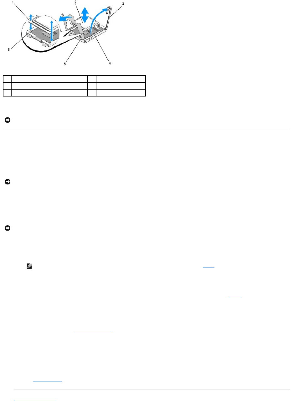
8. Lift the processor out of the socket and leave the release lever up so that the socket is ready for the new processor.
Installing a Processor
1. Unpack the new processor.
2. Install the processor in the socket.
a. If you are installing a second processor in a socket that was previously unoccupied, remove the black-plastic socket protector from the processor
shield.
b. If the release lever on the processor socket is not positioned all the way up, move it to that position.
c. With the processor and the ZIF socket keys aligned, set the processor lightly into the socket.
d. Lower the processor shield.
e. When the processor is fully seated in the socket, rotate the socket- release lever back down until it snaps into place, securing the processor.
3. Install the heat sink.
a. If you receive a heat sink and pre-applied thermal grease with your processor kit, remove the protective sheet from the thermal grease layer on
the bottom of the heat sink.
If you did not receive a replacement heat sink with your processor kit, do the following:
¡Using a clean lint-free cloth, remove the existing thermal grease from the heat sink you removed in step 5.
¡Open the grease packet included with your processor kit and apply thermal grease evenly to the top of the processor.
nPlace the heat sink on the processor.
nTighten the retention screws on the heat sink.
4. Replace the computer cover (see Replacing the Cover) and reboot the computer.
As the computer boots, it detects the presence of the new processor and automatically changes the computer configuration information in the
system setup program.
5. Press <F2> to enter the system setup program, and check that the processor information matches the new computer configuration (see the Dell
Technology Guide for information about accessing and using the system setup program).
6. Run the computer diagnostics to verify that the new processor operates correctly.
See Dell Diagnostics for information about running the diagnostics.
Back to Contents Page
1
notches in processor (2)
2
processor
3
socket-release lever
4
ZIF socket
5
processor shield
6
socket keys (2)
NOTICE: Be careful not to bend any of the pins on the ZIF socket when removing the processor. Bending the pins can permanently damage the system
board.
NOTICE: Positioning the processor incorrectly can permanently damage the system board or the processor when you turn it on. When placing the
processor in the socket, be careful not to bend the pins in the socket.
NOTICE: Do not use force to seat the processor. When the processor is positioned correctly, it engages easily into the socket.
NOTE: If you did not receive a replacement heat sink, use the heat sink that you removed in step 5.


Back to Contents Page
Processors
DellPrecision™R5400ServiceManual
Removing a Processor
Installing a Processor
Your computer can accommodate two processors. You can upgrade your processor(s) to take advantage of future options in speed and functionality. Each
processor and its associated internal cache memory are contained in a land grid array (LGA) package that is installed in a ZIF socket on the system board.
Removing a Processor
1. Prior to upgrading your computer, download the latest computer BIOS version on support.dell.com.
2. Perform the steps in Before Working on Your Computer.
3. Wait 30 seconds for the heat sink and thermal grease to cool enough to allow the heat sink to be loosened from the processor.
4. If the heat sink does not easily separate from the processor, carefully rotate the heat sink in a clockwise, then counterclockwise direction until it
releases from the processor. Do not pry the heat sink from the processor.
5. Lift the heat sink off of the processor and set the heat sink aside.
6. Press down and outward to disengage the socket-release lever, and rotate it 90 degrees upward until the processor is released from the socket.
7. Rotate the processor shield upward and out of the way.
CAUTION: Only trained service technicians are authorized to remove the computer cover and access any of the components inside the computer.
Before working inside the computer, read the safety information that shipped with the computer. For additional safety best practices information,
see the Regulatory Compliance Homepage at www.dell.com/regulatory_compliance.
NOTICE: When you remove the heat sink, the possibility exists that the processor might adhere to the heat sink and be removed from the socket. It is
recommended that you remove the heat sink while the processor is still warm.
NOTICE: Never remove the heat sink from a processor unless you intend to also remove the processor. The heat sink is necessary to maintain proper
thermal conditions.
1
heat sink
2
retention screws (4)
3
processor
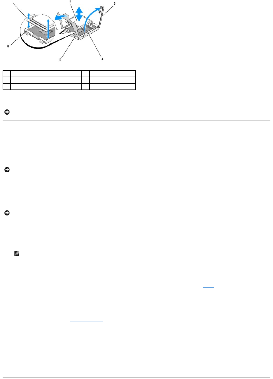
8. Lift the processor out of the socket and leave the release lever up so that the socket is ready for the new processor.
Installing a Processor
1. Unpack the new processor.
2. Install the processor in the socket.
a. If you are installing a second processor in a socket that was previously unoccupied, remove the black-plastic socket protector from the processor
shield.
b. If the release lever on the processor socket is not positioned all the way up, move it to that position.
c. With the processor and the ZIF socket keys aligned, set the processor lightly into the socket.
d. Lower the processor shield.
e. When the processor is fully seated in the socket, rotate the socket- release lever back down until it snaps into place, securing the processor.
3. Install the heat sink.
a. If you receive a heat sink and pre-applied thermal grease with your processor kit, remove the protective sheet from the thermal grease layer on the
bottom of the heat sink.
If you did not receive a replacement heat sink with your processor kit, do the following:
¡Using a clean lint-free cloth, remove the existing thermal grease from the heat sink you removed in step 5.
¡Open the grease packet included with your processor kit and apply thermal grease evenly to the top of the processor.
¡Place the heat sink on the processor.
¡Tighten the retention screws on the heat sink.
lReplace the computer cover (see Replacing the Cover) and reboot the computer.
As the computer boots, it detects the presence of the new processor and automatically changes the computer configuration information in the system
setup program.
5. Press <F2> to enter the system setup program, and check that the processor information matches the new computer configuration (see the Dell
Technology Guide for information about accessing and using the system setup program).
6. Run the computer diagnostics to verify that the new processor operates correctly.
See Dell Diagnostics for information about running the diagnostics.
1
notches in processor (2)
2
processor
3
socket-release lever
4
ZIF socket
5
processor shield
6
socket keys (2)
NOTICE: Be careful not to bend any of the pins on the ZIF socket when removing the processor. Bending the pins can permanently damage the system
board.
NOTICE: Positioning the processor incorrectly can permanently damage the system board or the processor when you turn it on. When placing the
processor in the socket, be careful not to bend the pins in the socket.
NOTICE: Do not use force to seat the processor. When the processor is positioned correctly, it engages easily into the socket.
NOTE: If you did not receive a replacement heat sink, use the heat sink that you removed in step 5.

Back to Contents Page
Power Supply
DellPrecision™R5400ServiceManual
Removing the Power Supply
Replacing the Power Supply
Your computer supports one power supply rated at an output of 800 to 900 W.
Removing the Power Supply
1. Perform the steps in Before Working on Your Computer.
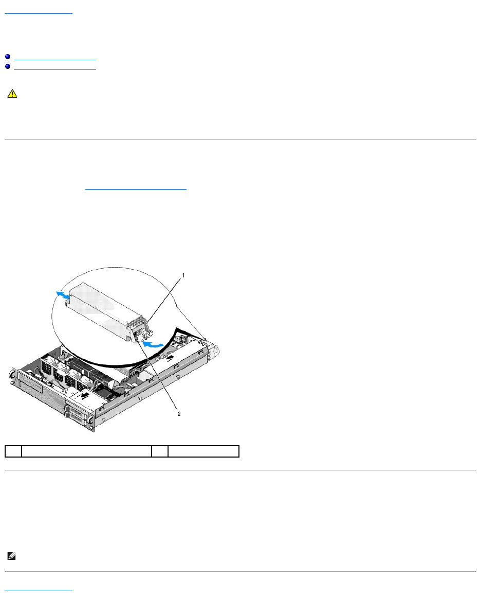
2. Disconnect the power cable from the power supply and remove the cable from the cable retention bracket.
3. At the back of the computer, release the locking tab on the left side of the power supply by pressing in toward the right, and rotate the power-supply
handle up until the power supply is released from the chassis.
4. Pull the power supply straight back to clear the chassis.
Replacing the Power Supply
1. With the power-supply handle in the extended position, slide the new power supply into the chassis.
2. Rotate the handle down until it is completely flush with the power-supply faceplate and the locking tab engages.
Back to Contents Page
CAUTION: Only trained service technicians are authorized to remove the computer cover and access any of the components inside the computer.
Before working inside the computer, read the safety information that shipped with the computer. For additional safety best practices information,
see the Regulatory Compliance Homepage at www.dell.com/regulatory_compliance.
1
power-supply handle
2
locking tab
NOTE: After installing a new power supply, allow several seconds for the computer to recognize the power supply and determine whether it is working
properly. The power supply status indicator turns green to signify that the power supply is functioning properly.
Back to Contents Page
Remote Access Host Card (Optional)
DellPrecision™R5400ServiceManual
Installing the Host Card
Removing a Host Card
This section describes how to install and/or remove and replace the host card and connect the two-wire cable required for the Dell remote access solution
available for your computer. For instructions on configuring the host card and remote access portal that make up the complete remote access solution, see the
Setting Up the Remote Access Solution guide that accompanied the host card.
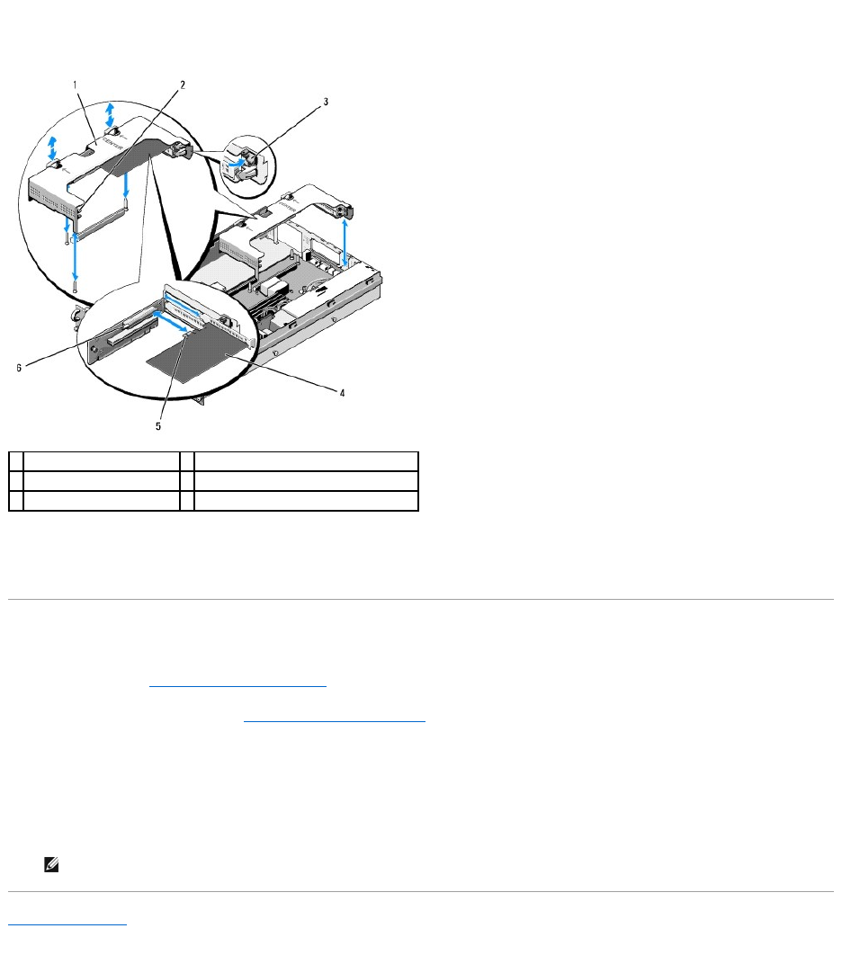
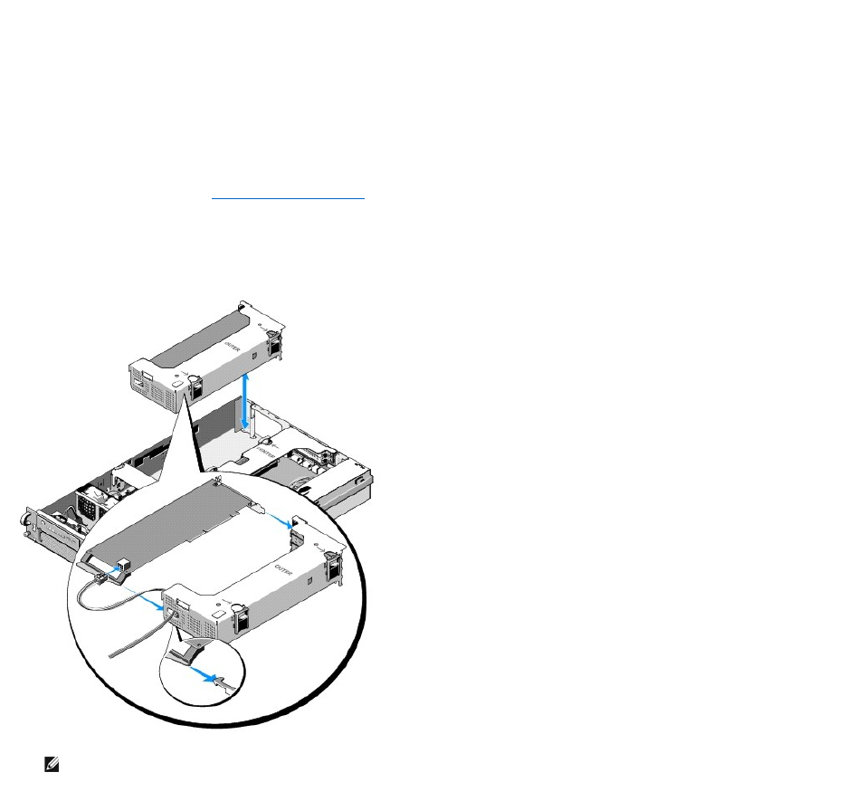
Installing the Host Card
1. Perform the steps in Before Working on Your Computer.
2. Unpack the host card and prepare it for installation.
For instructions, see the documentation accompanying the card
3. Remove the center expansion-card cage (see Removing an Expansion- Card Cage).
4. Open the top expansion-card latch and remove the filler bracket.
5. Install the host card:
c. Position the card so that the card-edge connector aligns with the expansion-card connector on the riser board.
d. Insert the card-edge connector firmly into the connector on the riser board until the card is fully seated.
e. When the card is seated in the connector, close the expansion-card latch.
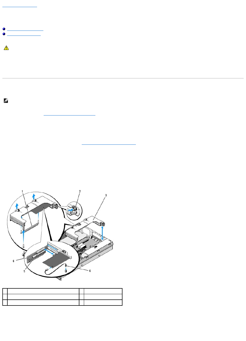
6. Connect the two-wire cable (included with the host card kit) to the card and to the system board.
7. Reconnect any expansion-card cables for already-installed expansion cards.
See the documentation that came with the card for information about its cable connections.
CAUTION: Only trained service technicians are authorized to remove the computer cover and access any of the components inside the computer.
Before working inside the computer, read the safety information that shipped with the computer. For additional safety best practices information,
see the Regulatory Compliance Homepage at www.dell.com/regulatory_compliance.
NOTE: Install the host card in the center expansion-card cage only.
1
riser-board connector on system board
2
expansion-card latch
3
center expansion-card cage
4
two-wire cable
5
expansion-card connector on riser board
6
riser board

Removing a Host Card
1. Perform the steps in Before Working on Your Computer.
2. Remove the center expansion-card cage (see Removing an Expansion- Card Cage).
3. Release the expansion card:
a. Open the expansion-card latch.
b. Grasp the expansion card by its top corners, and remove it from the expansion-card connector.
4. If you are removing the card permanently, install a metal filler bracket over the empty expansion-slot opening and close the expansion-card latch.
Back to Contents Page
NOTE: Remember to disconnect the two-wire cable from the system board.
NOTE: You must install a filler bracket over an empty expansion slot to maintain Federal Communications Commission (FCC) certification of the
computer. The brackets also keep dust and dirt out of the computer and aid in proper cooling and airflow inside the computer.
Back to Contents Page
Expansion-Card Riser Board
DellPrecision™R5400ServiceManual
Removing the Center Riser Board
Replacing the Center Riser Board
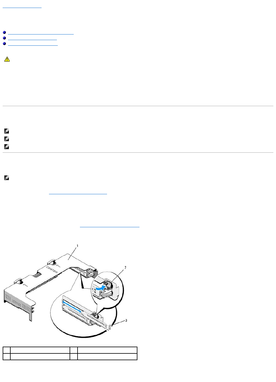
Removing the Center Riser Board
1. Perform the steps in Before Working on Your Computer.
2. Remove the center expansion-card cage from the computer (see Removing an Expansion-Card Cage).
3. Remove all expansion cards from the expansion-card riser board (see Removing an Expansion Card).
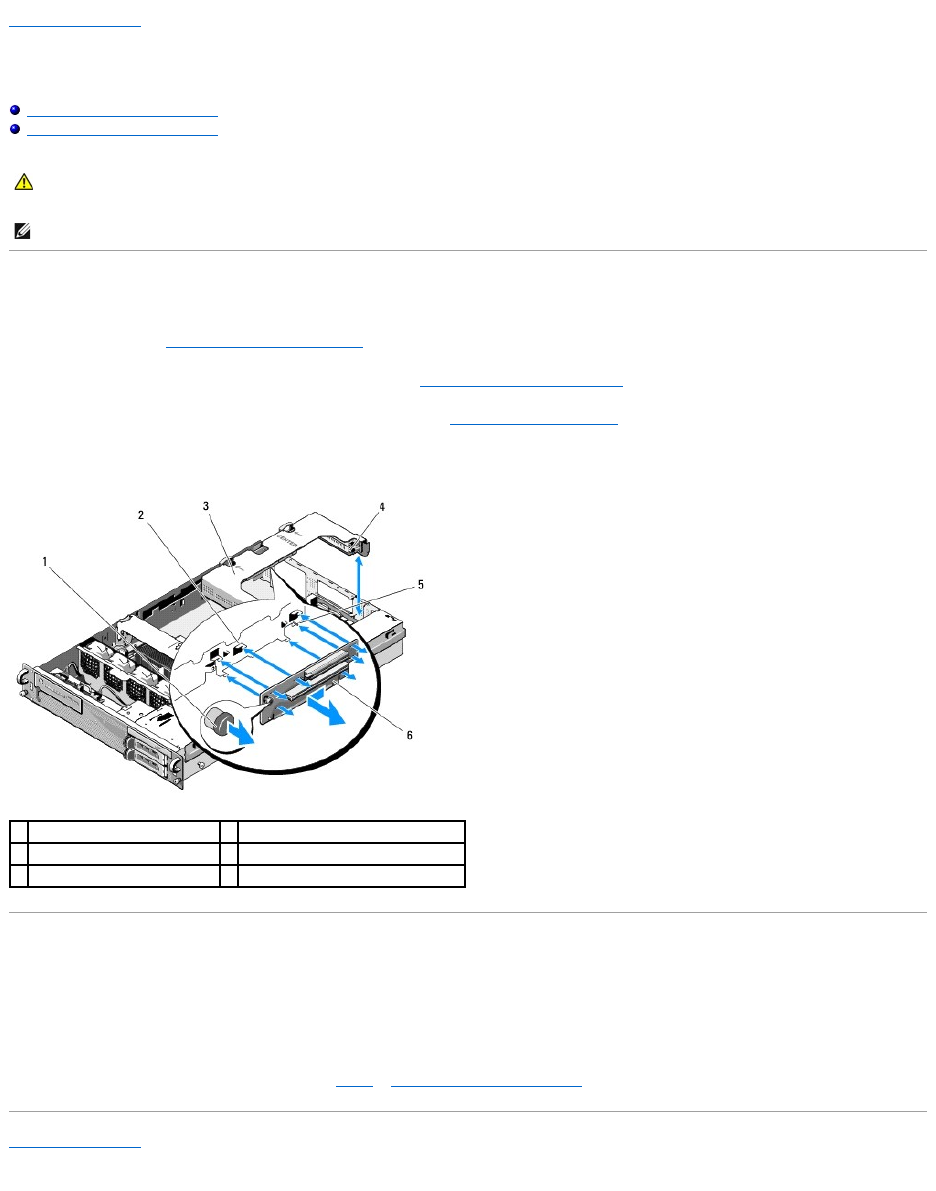
4. While lifting the blue spring-loaded release knob on the riser board, slide the board horizontally, away from the expansion-card latch end of the cage,
until the riser board is freed from the five guide hooks.
Replacing the Center Riser Board
1. Holding the riser board by the release knob, place the board so that the guide pin fits in the corresponding hole in the board.
2. With the release knob raised, slide the board toward the expansion-card latches until the guide hooks and release knob click securely into place.
3. Replace any expansion cards that you removed in step 3 of Removing the Center Riser Board.
Back to Contents Page
CAUTION: Only trained service technicians are authorized to remove the computer cover and access any of the components inside the computer.
Before working inside the computer, read the safety information that shipped with the computer. For additional safety best practices information,
see the Regulatory Compliance Homepage at www.dell.com/regulatory_compliance.
NOTE: The riser board can be replaced in the center expansion-card cage only, not the outer cage.
1
spring-loaded release knob
2
guide hooks (5)
3
center expansion-card cage
4
expansion-card latch end of cage
5
guide pin
6
riser board
Back to Contents Page
Cooling Shroud
DellPrecision™R5400ServiceManual
Removing the Cooling Shroud
Replacing the Cooling Shroud
The cooling shroud produces and directs airflow over the memory modules (DIMMs).
Removing the Cooling Shroud
1. Perform the steps in Before Working on Your Computer.
2. Remove the mid-support brace (see Removing the Mid-Support Brace).
3. Remove the center expansion-card cage (see Removing an Expansion- Card Cage).
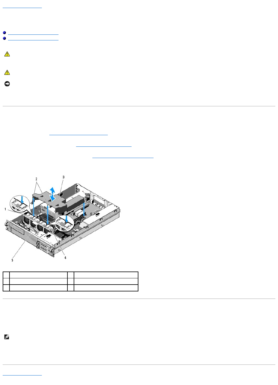
4. Lift the shroud upward and out of the chassis.
Replacing the Cooling Shroud
1. Align the shroud above the computer so that, when installed, the hooks will hang over the fan bracket.
2. Lowertheshroudstraightdownintothecomputer,withonehookcenteredbetweenfan1andfan2,andtheotherhookcenteredbetweenfan3and
fan 4.
Back to Contents Page
CAUTION: Only trained service technicians are authorized to remove the computer cover and access any of the components inside the computer.
Before working inside the computer, read the safety information that shipped with the computer. For additional safety best practices information,
see the Regulatory Compliance Homepage at www.dell.com/regulatory_compliance.
CAUTION: The DIMMs are hot to the touch for some time after the computer has been powered down. Allow the DIMMs to cool before handling
them.
NOTICE: Never operate your computer with the memory cooling shroud removed. Overheating of the computer can develop quickly, resulting in a
shutdown of the computer and the loss of data.
1
fans (4)
2
shroud hooks (2)
3
cooling shroud
4
fan bracket (unremovable)
5
fan bracket (removable)
NOTE: The fans are labeled 1, 2, 3, and 4.

Back to Contents Page
Speaker
DellPrecision™R5400ServiceManual
Removing the Speaker
Replacing the Speaker
Removing the Speaker
1. Perform the steps in Before Working on Your Computer.
2. Disconnect the speaker cable from the control panel board.
3. To gain access to the speaker, disconnect the control panel cable from the control panel board.
4. Press back on the speaker release tab so that you can slide the speaker up out of the chassis.
Replacing the Speaker
1. Slide the speaker down into the retaining brackets until the release tab snaps into place.
2. Connect the speaker cable to the control panel board.
3. Connect the control panel cable to the control panel board.
Back to Contents Page
CAUTION: Only trained service technicians are authorized to remove the computer cover and access any of the components inside the computer.
Before working inside the computer, read the safety information that shipped with the computer. For additional safety best practices information,
see the Regulatory Compliance Homepage at www.dell.com/regulatory_compliance.
NOTICE: Pull on the connector to disconnect the cable. Do not pull on the cable to unseat the connector. Doing so can damage the cable.
1
control panel cable
2
control panel board
3
speaker cable
4
retaining brackets (2)
5
speaker release tab
6
speaker
Back to Contents Page
System Board
DellPrecision™R5400ServiceManual
Removing the System Board
Installing the System Board
Removing the System Board
1. Perform the steps in Before Working on Your Computer.
2. Remove the power cable from the power supply at the back of the computer.
3. Remove both expansion-card cages (see Removing an Expansion-Card Cage), ensuring that you disconnect the power cables labeled "P5" and P6" from
any expansion cards installed in the card cages.
4. Remove the mid-support brace (see Removing the Mid-Support Brace).
5. Remove the cooling shroud (see Removing the Cooling Shroud).
6. Disconnect the power cables labeled "P1," "P2," "P3," and "P4" from the system board.
CAUTION: Only trained service technicians are authorized to remove the computer cover and access any of the components inside the computer.
Before working inside the computer, read the safety information that shipped with the computer. For additional safety best practices information,
see the Regulatory Compliance Homepage at www.dell.com/regulatory_compliance.
1
power-cable connector P1
2
cable-routing clip (power cable
P1)
3
power-cable connector P2
4
cable-routing portal (power
cables P1, P2, and P3)
5
power distribution unit
6
power-cable connector P3
7
cable-routing portal (power cables
P4, P5, and P6)
8
hard-drive (upper) power cable
connector (P8)
9
hard-drive (lower) power cable
10
optical-drive power cable
7. Remove the memory modules (see Removing Memory Modules).
8. Remove the heat sink(s) and processor(s) (see Removing a Processor).
9. Disconnect the control-panel cable from the system board.
10. Disconnect the four fan connectors from the system board.
11. Disconnect the front USB cable connector from the system board.
12. Disconnect the SATA_0, SATA_1, and SATA_2 data-cable connectors from the system board.
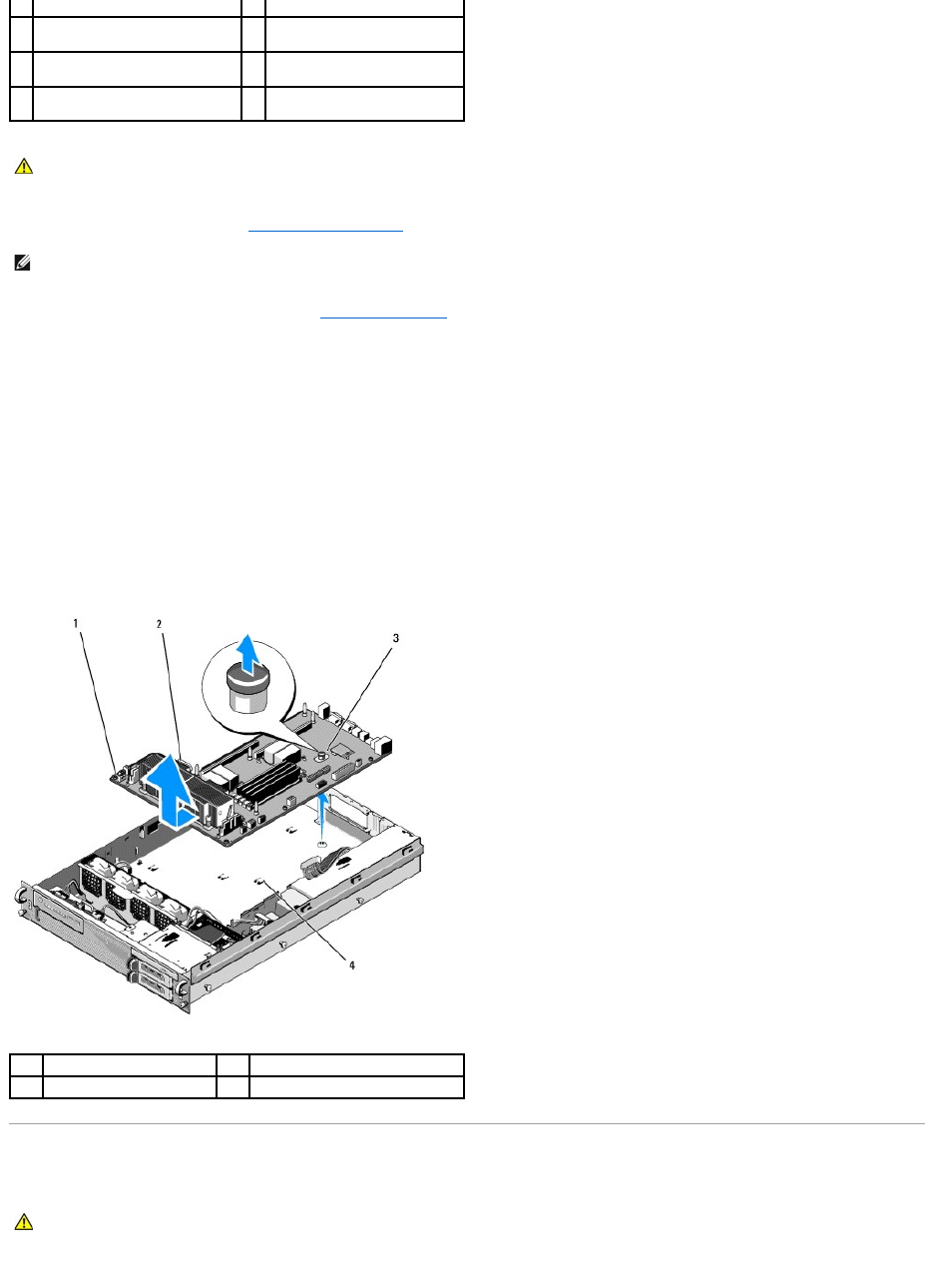
13. Remove the system board:
a. Pull up on the system-board tray release knob.
b. While pulling up on the release knob, use the metal tab/handle to slide the system-board tray toward the front of the chassis.
c. Lift the system-board tray at a 45-degree angle as you slide the system- board tray away from the power-supply bay, and remove it from the
chassis.
Installing the System Board
connector (P7)
connector (P9)
11
SATA data cable connector
12
cable-routing clip (power cables
P4, P5, and P6)
13
cable-routing channel (power
cables P4, P5, and P6)
14
cable-routing clip (power cables
P4, P5, and P6)
15
power-cable connector P4
storage for power cables P5 and
P6
CAUTION: The DIMMs are hot to the touch for some time after the computer has been powered down. Allow time for the DIMMs to cool before
handling them. Handle the DIMMs by the card edges and avoid touching the DIMM components.
NOTE: While removing the memory modules, record the memory module socket locations to ensure proper installation.
1
system board
2
metal tab/handle
3
release knob
4
securing tabs
CAUTION: Only trained service technicians are authorized to remove the computer cover and access any of the components inside the computer.
Before working inside the computer, read the safety information that shipped with the computer. For additional safety best practices information,
see the Regulatory Compliance Homepage at www.dell.com/regulatory_compliance.

1. Holding the system board by the blue release knob and the metal tab/handle, lower the system-board tray into the chassis at a 45-degree angle
toward the power-supply bay until the tray sits flat on the bottom of the chassis.
2. Ensure that all nine system-board tray securing-tabs are fully inserted into the nine system-board securing slots on the bottom of the chassis.
3. Slide the system-board tray toward the back of the chassis until the plunger in the release knob locks into position.
4. Replace the heat sink(s) and processor(s) (see Installing a Processor).
5. Replace the memory modules (see Installing Memory Modules).
6. Reconnect the control-panel cable to the system board.
7. Reconnect the four fan connectors to the system board.
8. Reconnect the front USB cable connector to the system board.
9. Reconnect the SATA_0, SATA_1, and SATA_2 data connectors to the system board.
10. Reconnect the power cables labeled "P1," "P2," "P3," and "P4" to the system board.
11. Replace the cooling shroud (see Replacing the Cooling Shroud).
12. Replace the expansion-card cages (see Replacing an Expansion-Card Cage).
13. Replace the mid-support brace (see Replacing the Mid-Support Brace).
14. Replace the computer cover (see Replacing the Cover).
Back to Contents Page

Back to Contents Page
DellPrecision™R5400ServiceManual
IfyoupurchasedaDell™nSeriescomputer,anyreferencesinthisdocumenttoMicrosoft®Windows®operating systems are not applicable.
Information in this document is subject to change without notice.
©2008DellInc.Allrightsreserved.
Reproduction of these materials in any manner whatsoever without the written permission of Dell Inc. is strictly forbidden.
Trademarks used in this text: Dell, the DELL logo, Inspiron, Dell Precision, DellConnect, Dimension, OptiPlex, Latitude, PowerEdge, PowerVault, PowerApp, Dell OpenManage and the YOURS
IS HERE logo are trademarks of Dell Inc.; Bluetooth is a registered trademark of Bluetooth SIG Inc. and is used by Dell under license; Microsoft, Windows, and Windows Vista, and the
Windows Start button logo are either trademarks or registered trademarks of Microsoft Corporation in the United States and/or other countries.
Other trademarks and trade names may be used in this document to refer to either the entities claiming the marks and names or their products. Dell Inc. disclaims any
proprietary interest in trademarks and trade names other than its own.
June2008Rev.A00
Back to Contents Page
NOTE: A NOTE indicates important information that helps you make better use of your computer.
NOTICE: A NOTICE indicates either potential damage to hardware or loss of data and tells you how to avoid the problem.
CAUTION: A CAUTION indicates a potential for property damage, personal injury, or death.
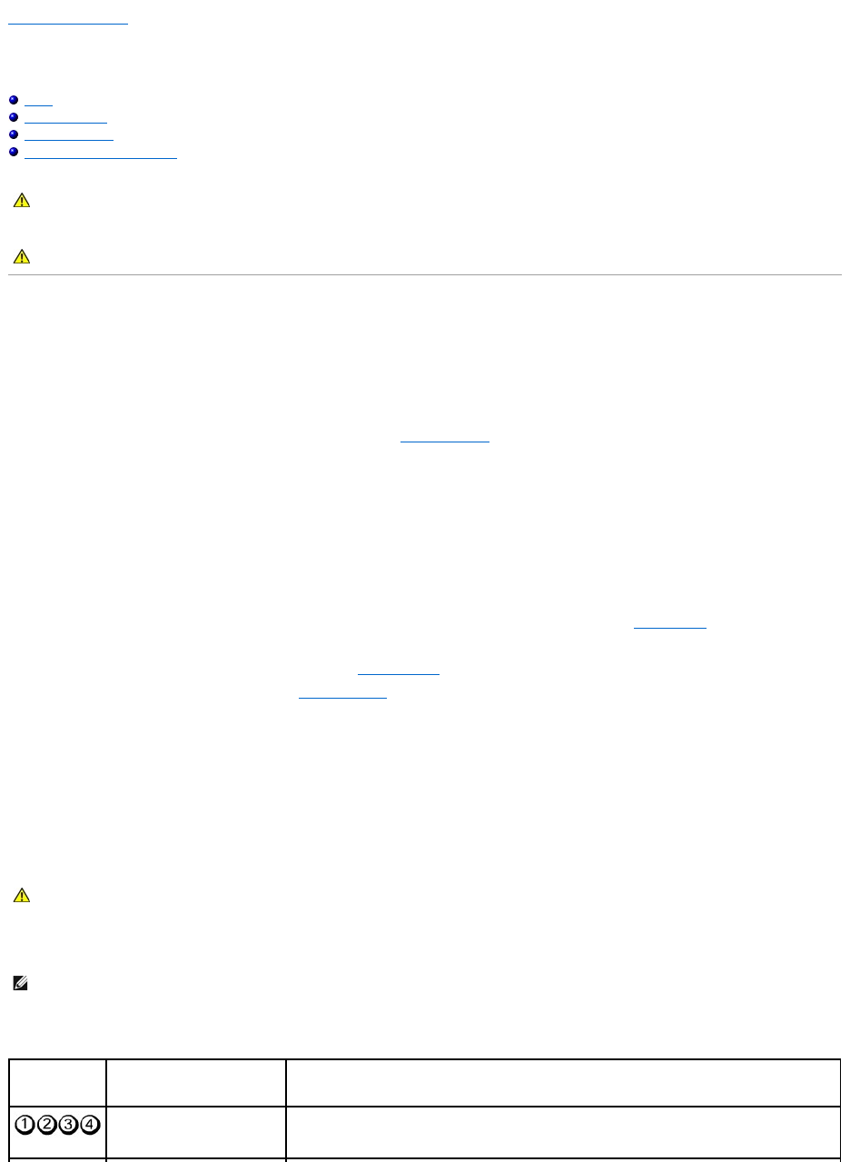
Back to Contents Page
Troubleshooting
DellPrecision™R5400ServiceManual
Tools
Dell Diagnostics
Solving Problems
Dell Technical Update Service
Tools
Power Lights
The power button light located on the front of the computer illuminates and blinks or remains solid to indicate different states:
lIf the power light is green and the computer is not responding, see Diagnostic Lights.
lIf the power light is blinking green, the computer is in standby mode. Press a key on the keyboard, move the mouse, or press the power button to
resume normal operation.
lIf the power light is off, the computer is either turned off or is not receiving power.
¡Reseat the power cable into both the power connector on the back of the computer and the electrical outlet.
¡If the computer is plugged into a power strip, ensure that the power strip is plugged into an electrical outlet and that the power strip is turned
on.
¡Bypass power protection devices, power strips, and power extension cables to verify that the computer turns on properly.
¡Ensure that the electrical outlet is working by testing it with another device, such as a lamp.
¡Ensure that the main power cable and front panel cable are securely connected to the system board (see System Board).
lIf the power light is steady amber, a device may be malfunctioning or incorrectly installed.
¡Remove and then reinstall the memory modules (see System Memory).
¡Remove and then reinstall any cards (see Expansion Cards).
lEliminate interference. Some possible causes of interference are:
¡Power, keyboard, and mouse extension cables
¡Too many devices on a power strip
¡Multiple power strips connected to the same electrical outlet
Diagnostic Lights
To help troubleshoot a problem, your computer has four lights labeled 1, 2, 3, and 4 on the front panel. When the computer starts normally, the lights flash,
and then turn off. If the computer malfunctions, use the sequence of the lights to help identify the problem.
Diagnostic Light Codes During POST
CAUTION: Only trained service technicians are authorized to remove the computer cover and access any of the components inside the computer.
Before working inside your computer, read the safety information that shipped with your computer. For additional safety best practices
information, see the Regulatory Compliance Homepage at www.dell.com/regulatory_compliance.
CAUTION: Always unplug your computer from the electrical outlet before opening the cover.
CAUTION: Before working inside your computer, read the safety information that shipped with your computer. For additional safety best
practices information, see the Regulatory Compliance Homepage on www.dell.com at www.dell.com/regulatory_compliance.
NOTE: After the computer completes POST, all four lights turn off before booting to the operating system.
Light Pattern
Problem Description
Suggested Resolution
The computer is in a normal off
condition or a possible pre-BIOS
failure has occurred.
Plug the computer into a working electrical outlet and press the power button.
Beep Codes
Your computer may emit a series of beeps during start-up if the monitor cannot display errors or problems. For example, one possible beep code may consist
of three short, repeated beeps indicating that the computer has encountered a possible system board failure.
If your computer emits a series of beeps during start-up:
1. Write down the beep code.
2. Run the Dell Diagnostics to further identify the problem (see Dell Diagnostics).
A possible BIOS failure has
occurred; the computer is in the
recovery mode.
lRun the BIOS Recovery utility, wait for recovery completion, and then restart the computer.
lIf the problem persists, contact Dell (see Contacting Dell).
A possible processor failure has
occurred.
lReseat the processor (see Processors).
lIf the problem persists, contact Dell (see Contacting Dell).
Memory modules are detected,
but a memory failure has
occurred.
lIf two or more memory modules are installed, remove the modules (see System Memory), then
reinstall one module and restart the computer. If the computer starts normally, continue to install
additional memory modules (one at a time) until you have identified a faulty module or reinstalled
all modules without error.
lIf available, install working memory of the same type into your computer (see System Memory).
lIf the problem persists, contact Dell (see Contacting Dell).
A possible graphics card failure
has occurred.
lReseat any installed graphics cards (see Expansion Cards).
lIf available, install a working graphics card into your computer.
lIf the problem persists, contact Dell (see Contacting Dell).
A possible hard drive failure has
occurred.
lReseat all power and data cables and restart the computer.
lIf the problem persists, contact Dell (see Contacting Dell).
A possible USB failure has
occurred.
lReinstall all USB devices, check cable connections, and then restart the computer.
lIf the problem persists, contact Dell (see Contacting Dell).
No memory modules are
detected.
lIf two or more memory modules are installed, remove the modules (see System Memory), then
reinstall one module and restart the computer. If the computer starts normally, continue to install
additional memory modules (one at a time) until you have identified a faulty module or reinstalled
all modules without error.
lIf available, install working memory of the same type into your computer (see System Memory).
lIf the problem persists, contact Dell (see Contacting Dell).
System board failure has
occurred.
lContact Dell (see Contacting Dell).
Memory modules are detected,
but a memory configuration or
compatibility error exists.
lEnsure that no special requirements for memory module/connector placement exist (see System
Memory).
lEnsure that the memory you are using is supported by your computer (see System Memory).
lIf the problem persists, contact Dell (see Contacting Dell).
A possible system board
resource and/or hardware
failure has occurred.
lSee your computer's Setup and Quick Reference Guide for instructions on restoring the operating
system.
lIf the problem persists, contact Dell (see Contacting Dell).
A possible expansion card failure
has occurred.
1. Determine if a conflict exists by removing an expansion card (not a graphics card) and restarting
the computer (see Expansion Cards).
2. If the problem persists, reinstall the card you removed, then remove a different card and restart
the computer.
3. Repeat this process for each expansion card installed. If the computer starts normally,
troubleshoot the last card removed from the computer for resource conflicts (see your computer's
Setup and Quick Reference Guide for instructions on restoring the operating system).
4. If the problem persists, contact Dell (see Contacting Dell).
Another failure has occurred.
lEnsure that all hard drive and CD/DVD drive cables are properly connected to the system board
(see System Board).
lIf there is an error message on the screen identifying a problem with a device (such as the hard
drive), check the device to make sure it is functioning properly.
lIf the operating system is attempting to boot from a device (such as the CD/DVD drive), check
the system setup program (see the Dell Technology Guide) to ensure that the boot sequence is
correct for the devices installed on your computer.
lIf the problem persists, contact Dell (see Contacting Dell).
Code
Cause
2 short, 1 long
BIOS checksum error
1 long, 3 short, 2 short
Memory error
System Messages
Alert! Previous attempts at booting this computer have failed at checkpoint [nnnn]. For help in resolving this problem, please note this checkpoint and
contact Dell Technical Support —
The computer failed to complete the boot routine three consecutive times for the same error (see Contacting Dell for assistance).
CMOS checksum error — Possible motherboard failure or RTC battery low. Replace the battery (see Replacing the Battery or see Contacting Dell for
assistance).
CPU fan failure — Processor fan failure. Replace the processor fan (see Processors).
Hard-disk read failure — Possible hard drive failure during hard drive boot test (see Contacting Dell for assistance).
Keyboard failure — Keyboard failure or keyboard cable loose (see Keyboard Problems).
No boot device available — The computer cannot detect a bootable device or partition.
¡If the hard drive is your boot device, ensure that the cables are connected and that the drive is installed properly and partitioned as a boot
device.
¡Enter the system setup program and ensure that the boot sequence information is correct (see the Dell Technology Guide for instructions on
accessing and using the system setup program).
No timer tick interrupt — A chip on the system board might be malfunctioning or motherboard failure (see Contacting Dell for assistance).
NOTICE – Hard Drive SELF MONITORING SYSTEM has reported that a parameter has exceeded its normal operating range. Dell recommends that you
back up your data regularly. A parameter out of range may or may not indicate a potential hard drive problem. —
S.M.A.R.T error, possible HDD failure. This feature can be enabled or disabled in the system setup program (see the Dell Technology Guide for instructions on
accessing and using the system setup program).
1 short
F12 key pressed
Code
(repetitive
short beeps)
Description
Suggested Resolution
1
BIOS checksum failure.
Possible system board
failure.
Contact Dell (see Contacting Dell).
2
No memory modules are
detected.
lIf two or more memory modules are installed, remove the modules (see System Memory), then reinstall
one module and restart the computer. If the computer starts normally, continue to install additional
memory modules (one at a time) until you have identified a faulty module or reinstalled all modules
without error.
lIf available, install working memory of the same type into your computer (see System Memory).
lIf the problem persists, contact Dell (see Contacting Dell).
3
Possible system board
failure.
Contact Dell (see Contacting Dell).
4
RAM Read/Write failure.
lEnsure that no special requirements for memory module/connector placement exist (see System
Memory).
lEnsure that the memory you are using is supported by your computer (see System Memory).
lIf the problem persists, contact Dell (see Contacting Dell).
5
Real time clock failure.
Possible battery or system
board failure.
lReplace the battery (see Replacing the Battery).
lIf the problem persists, contact Dell (see Contacting Dell).
6
Video BIOS Test Failure.
Contact Dell (see Contacting Dell).
NOTE: If the message you received is not listed in the table, see the documentation for either the operating system or the program that was running
when the message appeared.

Hardware Troubleshooter
If a device is either not detected during the operating system setup or is detected, but incorrectly configured, you can use the Hardware Troubleshooter to
resolve the incompatibility.
Windows® Vista®:
1. Click the Windows Vista start button , and click Help and Support.
2. Type hardware troubleshooter in the search field and press <Enter> to start the search.
3. In the search results, select the option that best describes the problem and follow the remaining troubleshooting steps.
Windows XP:
1. Click Start® Help and Support.
2. Type hardware troubleshooter in the search field and press <Enter> to start the search.
3. In the Fix a Problem section, click Hardware Troubleshooter.
4. In the Hardware Troubleshooter list, select the option that best describes the problem and click Next to follow the remaining troubleshooting steps.
Dell Diagnostics
When to Use the Dell Diagnostics
If you experience a problem with your computer, perform the checks in Solving Problems, and then run the Dell Diagnostics before contacting Dell for
assistance.
Start the Dell Diagnostics from your hard drive or from the Drivers and Utilities media provided with your computer.
Starting the Dell Diagnostics From Your Hard Drive
Before running the Dell Diagnostics, enter the system setup program (see the Dell Technology Guide for instructions) to review your computer's configuration
information, and ensure that the device you want to test is displayed in the system setup program and is active.
The Dell Diagnostics is located on a separate diagnostic utility partition on your hard drive.
1. Ensure that the computer is connected to an electrical outlet that is known to be working properly.
2. Turn on (or restart) your computer.
3. When the DELL logo appears, press <F12> immediately.
If you wait too long and the operating system logo appears, continue to wait until you see the Microsoft Windows desktop, then shut down your
computer and try again.
4. Use the up- and down-arrow keys to select Diagnostics from the boot menu and then press <Enter>.
The computer runs the Pre-boot System Assessment (PSA), a series of initial tests of your system board, keyboard, display, memory, hard drive, and so
on.
lAnswer any questions that appear.
lIf failures are detected, write down the error code(s) and see Contacting Dell.
CAUTION: Before working inside your computer, read the safety information that shipped with your computer. For additional safety best
practices information, see the Regulatory Compliance Homepage on www.dell.com at www.dell.com/regulatory_compliance.
NOTE: The Drivers and Utilities media is optional and may not ship with your computer.
NOTE: The Dell Diagnostics only operate on Dell computers.
NOTE: If your computer does not display a screen image, contact Dell (see Contacting Dell).
NOTE: Keyboard failure may result when a key is held down for extended periods of time. To avoid possible keyboard failure, press and release
<F12> in even intervals to open the Boot Device Menu.

lIf the Pre-boot System Assessment completes successfully, the following message appears: "Booting Dell Diagnostic Utility Partition.
Press any key to continue."
5. Press any key to start the Dell Diagnostics from the diagnostics utility partition on your hard drive.
6. Press <Tab> to select Test Computer and then press <Enter>.
7. At the Dell Diagnostics Main Menu, left-click with the mouse, or press <Tab> and then <Enter>, to select the test you want to run (see Dell Diagnostics
Main Menu).
8. After all tests have completed, close the test window to return to the Dell Diagnostics Main Menu.
9. Close the Main Menu window to exit the Dell Diagnostics and restart the computer.
Starting the Dell Diagnostics From the Drivers and Utilities Media
Before running the Dell Diagnostics, enter the system setup program (see the Dell Technology Guide for instructions) to review your computer's configuration
information, and ensure that the device you want to test is displayed in the system setup program and is active.
1. Insert the Drivers and Utilities media into the optical drive.
2. Restart your computer.
3. When the DELL logo appears, press <F12> immediately.
If you wait too long and the operating system logo appears, continue to wait until you see the Microsoft Windows desktop, then shut down your
computer and try again.
4. When the boot device list appears, use the up- or down- arrow keys to highlight Onboard or USB CD-ROM Drive, and then press <Enter>.
5. Press any key to confirm that you want to start from the CD/DVD.
If you wait too long and the operating system logo appears, continue to wait until you see the Microsoft Windows desktop, then shut down your
computer and try again.
6. Type 1 to Run the 32 Bit Dell Diagnostics.
7. At the Dell Diagnostics Menu, type 1 to select Dell 32-bit Diagnostics for Resource CD (graphical user interface).
8. Press <Tab> to select Test Computer and then press <Enter>.
9. At the Dell Diagnostics Main Menu, left-click with the mouse, or press <Tab> and then <Enter>, to select the test you want to run (see Dell Diagnostics
Main Menu).
10. After all tests have completed, close the test window to return to the Dell Diagnostics Main Menu.
NOTE: If you see a message stating that no diagnostics utility partition has been found, run the Dell Diagnostics from your Drivers and Utilities
media (see Starting the Dell Diagnostics From the Drivers and Utilities Media).
NOTE: It is recommended that you select Test Computer to run a complete test on your computer. Selecting Test Memory initiates the extended
memory test, which can take up to thirty minutes or more to complete. When the test completes, record the test results and then press any key to
return to the previous menu.
NOTE: Write down any error codes and problem descriptions exactly as they appear and follow the instructions on the screen.
NOTE: Keyboard failure may result when a key is held down for extended periods of time. To avoid possible keyboard failure, press and release
<F12> in even intervals to open the Boot Device Menu.
NOTE: Using the one-time boot menu changes the boot sequence for the current boot only. Upon restart, the computer boots according to the
boot sequence specified in the system setup program.
NOTE: It is recommended that you select Test Computer to run a complete test on your computer. Selecting Test Memory initiates the extended
memory test, which can take up to thirty minutes or more to complete. When the test completes, record the test results and then press any key to
return to the previous menu.
NOTE: Write down any error codes and problem descriptions exactly as they appear and follow the instructions on the screen.
11. Close the Main Menu window to exit the Dell Diagnostics and restart the computer.
12. Remove the Drivers and Utilities media from the optical drive.
Dell Diagnostics Main Menu
After the Dell Diagnostics loads the following menu appears:
Press <Tab> to select the test you want to run and then press <Enter>.
After Test Computer is selected, the following menu appears:
For any problem encountered during a test, a message appears with an error code and a description of the problem. Write down the error code and problem
description exactly as it appears and follow the instructions on the screen. If you cannot resolve the problem, contact Dell (see Contacting Dell).
The following tabs provide additional information for tests run from the Custom Test or Symptom Tree option:
Solving Problems
Follow these tips when troubleshooting your computer:
lIf you added or removed a part before the problem started, review the installation procedures and ensure that the part is correctly installed.
Option
Function
Test Memory
Run the stand-alone memory test
Test Computer
Run computer diagnostics
Exit
Exit the diagnostics
NOTE: It is recommended that you select Test Computer to run a complete test on your computer. Selecting Test Memory initiates the extended
memory test, which can take up to thirty minutes or more to complete. When the test completes, record the test results and then press any key to
return to this menu.
Option
Function
Express Test
Performs a quick test of devices in the computer. This typically can take 10 to 20 minutes.
NOTE: The Express Test requires no interaction on your part. Run Express Test first to increase the possibility of tracing a problem quickly.
Extended Test
Performs a thorough check of devices in the computer. This typically can take an hour or more.
NOTE: The Extended Test periodically requires your input to answer specific questions.
Custom Test
Use to test a specific device or customize the tests to be run.
Symptom Tree
This option allows you to select tests based on a symptom of the problem you are having. This option lists the most common symptoms.
NOTE: It is recommended that you select Extended Test to perform a more thorough check of devices in the computer.
NOTE: When contacting Dell support, have your Service Tag ready. The Service Tag for your computer is located at the top of each test screen.
Tab
Function
Results
Displays the results of the test and any error conditions encountered.
Errors
Displays error conditions encountered, error codes, and the problem description.
Help
Describes the test and any requirements for running the test.
Configuration
Displays the hardware configuration for the selected device.
The Dell Diagnostics obtains configuration information for all devices from the system setup program, memory, and various internal tests, and
displays the information in the device list in the left pane of the screen.
NOTE: The device list may not display the names of all components installed on your computer or all devices attached to your computer.
Parameters
Allows you to customize the test, if applicable, by changing the test settings.

lIf a peripheral device does not work, ensure that the device is properly connected.
lIf an error message appears on the screen, write down the exact message. This message may help support personnel diagnose and fix the problem(s).
lIf an error message occurs in a program, see the program's documentation.
Battery Problems
Replace the battery — If you have to repeatedly reset time and date information after turning on the computer, or if an incorrect time or date displays during
start-up, replace the battery (see Replacing the Battery). If the battery still does not work properly, contact Dell (see Contacting Dell).
Drive Problems
Ensure that Microsoft®Windows Recognizes the drive —
Windows Vista:
lClick the Windows Vista Start button and click Computer.
Windows XP:
lClick Start and click My Computer.
If the drive is not listed, perform a full scan with your antivirus software to check for and remove viruses. Viruses can sometimes prevent Windows from
recognizing the drive.
Test the drive —
lInsert another disc to eliminate the possibility that the original drive is defective.
lInsert a bootable disc and restart the computer.
Clean the drive or disk — See the Dell Technology Guide for instructions.
Check the cable connections
Run the Hardware Troubleshooter — See Hardware Troubleshooter.
Run the Dell Diagnostics — See Dell Diagnostics.
Optical drive problems
Adjust the Windows volume control —
lClick the speaker icon in the lower-right corner of your screen.
lEnsure that the volume is turned up by clicking the slidebar and dragging it up.
lEnsure that the sound is not muted by clicking any boxes that are checked.
NOTE: TheproceduresinthisdocumentwerewrittenfortheWindowsdefaultview,sotheymaynotapplyifyousetyourDell™computertothe
Windows Classic view.
CAUTION: There is a danger of a new battery exploding if it is incorrectly installed. Replace the battery only with the same or equivalent type
recommended by the manufacturer. Discard used batteries according to the manufacturer's instructions.
CAUTION: Before working inside your computer, read the safety information that shipped with your computer. For additional safety best
practices information, see the Regulatory Compliance Homepage on www.dell.com at www.dell.com/regulatory_compliance.
CAUTION: Before working inside your computer, read the safety information that shipped with your computer. For additional safety best
practices information, see the Regulatory Compliance Homepage on www.dell.com at www.dell.com/regulatory_compliance.
NOTE: High-speed optical drive vibration is normal and may cause noise, which does not indicate a defect in the drive or the media.
NOTE: Because of different regions worldwide and different disc formats, not all DVD titles work in all DVD drives.

Check the speakers and subwoofer — See Sound and Speaker Problems.
Problems writing to an optical drive
Close other programs — The optical drive must receive a steady stream of data during the writing process. If the stream is interrupted, an error occurs. Try
closing all programs before you write to the optical.
Turn off standby mode in Windows before writing to a disc — See the Dell Technology Guide or search for the keyword standby in Windows Help and Support
for information on power management modes.
Hard drive problems
Run Check Disk —
Windows Vista:
1. Click Start and click Computer.
2. Right-click Local Disk C:.
3. Click Properties® Tools® Check Now.
The User Account Control window may appear. If you are an administrator on the computer, click Continue; otherwise, contact your administrator to
continue the desired action.
4. Follow the instructions on the screen.
Windows XP:
1. Click Start and click My Computer.
2. Right-click Local Disk C:.
3. Click Properties® Tools® Check Now.
4. Click Scan for and attempt recovery of bad sectors and click Start.
E-Mail and Internet Problems
Check the Microsoft Outlook®Express security settings — If you cannot open your e-mail attachments:
1. In Outlook Express, click Tools® Options® Security.
2. Click Do not allow attachments to remove the checkmark, as needed.
Ensure that you are connected to the Internet — Ensure that you have subscribed to an Internet provider. With the Outlook Express e-mail program open,
click File. If Work Offline has a checkmark next to it, click the checkmark to remove it and connect to the Internet. For help, contact your Internet service
provider.
Error Messages
If the error message is not listed, see the documentation for the operating system or the program that was running when the message appeared.
A filename cannot contain any of the following characters: \ / : * ? " < > | — Do not use these characters in filenames.
A required .DLL file was not found — The program that you are trying to open is missing an essential file. To remove and then reinstall the program:
Windows Vista:
CAUTION: Before working inside your computer, read the safety information that shipped with your computer. For additional safety best
practices information, see the Regulatory Compliance Homepage on www.dell.com at www.dell.com/regulatory_compliance.
NOTE: Do not plug a telephone cable into the network adapter connector (see your computer's Setup and Quick Reference Guide for illustrations
identifying the connectors on your computer).
CAUTION: Before working inside your computer, read the safety information that shipped with your computer. For additional safety best
practices information, see the Regulatory Compliance Homepage on www.dell.com at www.dell.com/regulatory_compliance.
1. Click Start ® Control Panel® Programs® Programs and Features.
2. Select the program you want to remove.
3. Click Uninstall.
4. See the program documentation for installation instructions.
Windows XP:
1. Click Start® Control Panel® Add or Remove Programs® Programs and Features.
2. Select the program you want to remove.
3. Click Uninstall.
4. See the program documentation for installation instructions.
drive letter :\ is not accessible. The device is not ready — The drive cannot read the disk. Insert a disk into the drive and try again.
Insert bootable media — Insert a bootable CD or DVD.
Not enough memory or resources. Close some programs and try again — Close all windows and open the program that you want to use. In some cases,
you may have to restart your computer to restore computer resources. If so, run the program that you want to use first.
Operating system not found — Contact Dell (see Contacting Dell).
IEEE 1394 Device Problems
Ensure that the cable for the IEEE 1394 device is properly inserted into the device and into the connector on the computer
Ensure that the IEEE 1394 device is recognized by Windows —
Windows Vista:
1. Click Start ® Control Panel® Hardware and Sound.
2. Click Device Manager.
Windows XP:
1. Click Start and click Control Panel.
2. Under Pick a Category, click Performance and Maintenance® Computer® Computer Properties ® Hardware® Device Manager.
If your IEEE 1394 device is listed, Windows recognizes the device.
If you have problems with a Dell IEEE 1394 device — Contact Dell (see Contacting Dell).
If you have problems with an IEEE 1394 device not provided by Dell — ContacttheIEEE1394devicemanufacturer.
Keyboard Problems
Check the keyboard cable —
lEnsure that the keyboard cable is firmly connected to the computer.
lShut down the computer (see Before Working on Your Computer), reconnect the keyboard cable as shown on the setup diagram for your computer, and
then restart the computer.
lEnsure that the cable is not damaged or frayed and check cable connectors for bent or broken pins. Straighten any bent pins.
lRemove any keyboard extension cables and connect the keyboard directly to the computer.
Test the keyboard — Connect a properly working keyboard to the computer, then try using the keyboard.
CAUTION: Before working inside your computer, read the safety information that shipped with your computer. For additional safety best
practices information, see the Regulatory Compliance Homepage on www.dell.com at www.dell.com/regulatory_compliance.
NOTE: Your computer supports only IEEE 1394a standard.
CAUTION: Before working inside your computer, read the safety information that shipped with your computer. For additional safety best
practices information, see the Regulatory Compliance Homepage on www.dell.com at www.dell.com/regulatory_compliance.

Run the Hardware Troubleshooter — See Hardware Troubleshooter.
Lockups and Software Problems
The computer does not start up
Check the diagnostic lights — See Diagnostic Lights.
Ensure that the power cable is firmly connected to the computer and to the electrical outlet
The computer stops responding
Turn the computer off — If you are unable to get a response by pressing a key on your keyboard or moving your mouse, press and hold the power button for
at least 8 to 10 seconds (until the computer turns off), and then restart your computer.
A program stops responding
End the program —
1. Press <Ctrl><Shift><Esc> simultaneously to access the Task Manager.
2. Click the Applications tab.
3. Click to select the program that is no longer responding.
4. Click End Task.
A program crashes repeatedly
Check the software documentation — If necessary, uninstall and then reinstall the program.
A program is designed for an earlier Windows operating system
Run the Program Compatibility Wizard —
Windows Vista:
The Program Compatibility Wizard configures a program so that it runs in an environment similar to non-Windows Vista operating system environments.
1. Click Start ® Control Panel® Programs® Use an older program with this version of Windows.
2. In the welcome screen, click Next.
3. Follow the instructions on the screen.
Windows XP:
The Program Compatibility Wizard configures a program so that it runs in an environment similar to non-XP operating system environments.
1. Click Start® All Programs® Accessories® Program Compatibility Wizard® Next.
2. Follow the instructions on the screen.
A solid blue screen appears
CAUTION: Before working inside your computer, read the safety information that shipped with your computer. For additional safety best
practices information, see the Regulatory Compliance Homepage on www.dell.com at www.dell.com/regulatory_compliance.
NOTICE: You may lose data if you are unable to perform an operating system shutdown.
NOTE: Most software includes installation instructions in its documentation or on a CD or DVD.

Turn the computer off — If you are unable to get a response by pressing a key on your keyboard or moving your mouse, press and hold the power button for
at least 8 to 10 seconds (until the computer turns off), and then restart your computer.
Other software problems
Check the software documentation or contact the software manufacturer for troubleshooting information —
lEnsure that the program is compatible with the operating system installed on your computer.
lEnsure that your computer meets the minimum hardware requirements needed to run the software. See the software documentation for information.
lEnsure that the program is installed and configured properly.
lVerify that the device drivers do not conflict with the program.
lIf necessary, uninstall and then reinstall the program.
Back up your files immediately
Use a virus-scanning program to check the hard drive, CDs, or DVDs
Save and close any open files or programs and shut down your computer through the Start menu
Memory Problems
If you receive an insufficient memory message —
lSave and close any open files and exit any open programs you are not using to see if that resolves the problem.
lSee the software documentation for minimum memory requirements. If necessary, install additional memory (see System Memory).
lReseat the memory modules (see System Memory) to ensure that your computer is successfully communicating with the memory.
lRun the Dell Diagnostics (see Dell Diagnostics).
If you experience other memory problems —
lReseat the memory modules (see System Memory) to ensure that your computer is successfully communicating with the memory.
lEnsure that you are following the memory installation guidelines (see System Memory).
lEnsure that the memory you are using is supported by your computer. For more information about the type of memory supported by your computer,
see System Memory.
lRun the Dell Diagnostics (see Dell Diagnostics).
Mouse Problems
Check the mouse cable —
lEnsure that the cable is not damaged or frayed and check cable connectors for bent or broken pins. Straighten any bent pins.
lRemove any mouse extension cables, and connect the mouse directly to the computer.
lVerify that the mouse cable is connected as shown on the setup diagram for your computer.
Restart the computer —
1. Simultaneously press <Ctrl><Esc> to display the Start menu.
2. Press <u>, press the up- and down-arrow keys to highlight Shut down or Turn Off, and then press <Enter>.
3. After the computer turns off, reconnect the mouse cable as shown on the setup diagram.
4. Turn on the computer.
Test the mouse — Connect a properly working mouse to the computer, then try using the mouse.
Check the mouse settings —
Windows Vista:
CAUTION: Before working inside your computer, read the safety information that shipped with your computer. For additional safety best
practices information, see the Regulatory Compliance Homepage on www.dell.com at www.dell.com/regulatory_compliance.
CAUTION: Before working inside your computer, read the safety information that shipped with your computer. For additional safety best
practices information, see the Regulatory Compliance Homepage on www.dell.com at www.dell.com/regulatory_compliance.

1. Click Start ® Control Panel® Hardware and Sound® Mouse.
2. Adjust the settings as needed.
Windows XP
1. Click Start® Control Panel® Mouse.
2. Adjust the settings as needed.
Reinstall the mouse driver — See the Dell Technology Guide for instructions on manually installing a device driver.
Run the Hardware Troubleshooter — See Hardware Troubleshooter.
Network Problems
Check the network cable connector — Ensure that the network cable is firmly inserted into the network connector on the back of the computer and the
network jack.
Check the network lights on the back of the computer — If the link integrity light is off, no network communication is occurring. Replace the network cable.
Restart the computer and log on to the network again
Check your network settings — Contact your network administrator or the person who set up your network to verify that your network settings are correct
and that the network is functioning.
Run the Hardware Troubleshooter — See Hardware Troubleshooter.
Power Problems
If the power light is green and the computer is not responding — See Diagnostic Lights.
If the power light is blinking green — The computer is in standby mode. Press a key on the keyboard, move the mouse, or press the power button to resume
normal operation.
If the power light is off — The computer is either turned off or is not receiving power.
lReseat the power cable in the power connector on the back of the computer and the electrical outlet.
lBypass power strips, power extension cables, and other power protection devices to verify that the computer turns on properly.
lEnsure that any power strips being used are plugged into an electrical outlet and are turned on.
lEnsure that the electrical outlet is working by testing it with another device, such as a lamp.
lEnsure that the main power cable and control panel cable are securely connected to the system board.
If the power light is blinking amber — The computer is receiving electrical power, but an internal power problem may exist.
Ensure that all components and cables are properly installed and securely connected to the system board.
If the power light is steady amber — A device may be malfunctioning or incorrectly installed.
lRemove and then reinstall all memory modules (see System Memory).
lRemove and then reinstall any expansion cards, including graphics cards (see Expansion Cards).
Eliminate interference — Some possible causes of interference are:
CAUTION: Before working inside your computer, read the safety information that shipped with your computer. For additional safety best
practices information, see the Regulatory Compliance Homepage on www.dell.com at www.dell.com/regulatory_compliance.
CAUTION: Before working inside your computer, read the safety information that shipped with your computer. For additional safety best
practices information, see the Regulatory Compliance Homepage on www.dell.com at www.dell.com/regulatory_compliance.

lPower, keyboard, and mouse extension cables
lToo many devices connected to the same power strip
lMultiple power strips connected to the same electrical outlet
Printer Problems
Check the printer documentation — See the printer documentation for setup and troubleshooting information.
Ensure that the printer is turned on
Check the printer cable connections —
lSee the printer documentation for cable connection information.
lEnsure that the printer cables are securely connected to the printer and the computer.
Test the electrical outlet — Ensure that the electrical outlet is working by testing it with another device, such as a lamp.
Verify that the printer is recognized by Windows —
Windows Vista:
1. Click Start ® Control Panel® Hardware and Sound® Printer.
2. If the printer is listed, right-click the printer icon.
3. Click Properties and click Ports.
4. Adjust the settings, as needed.
Windows XP:
1. Click Start® Control Panel® Printers and Other Hardware® View installed printers or fax printers.
2. If the printer is listed, right-click the printer icon.
3. Click Properties® Ports. For a parallel printer, ensure that the Print to the following port(s): setting is LPT1 (Printer Port). For a USB printer, ensure
that the Print to the following port(s): setting is USB.
Reinstall the printer driver — See the printer documentation for information on reinstalling the printer driver.
Scanner Problems
Check the scanner documentation — See the scanner documentation for setup and troubleshooting information.
Unlock the scanner — Ensure that your scanner is unlocked (if the scanner has a locking tab or button).
Restart the computer and try the scanner again
Check the cable connections —
lSee the scanner documentation for information on cable connections.
lEnsure that the scanner cables are securely connected to the scanner and the computer.
Verify that the scanner is recognized by Microsoft Windows —
Windows Vista:
CAUTION: Before working inside your computer, read the safety information that shipped with your computer. For additional safety best
practices information, see the Regulatory Compliance Homepage on www.dell.com at www.dell.com/regulatory_compliance.
NOTE: If you need technical assistance for your printer, contact the printer's manufacturer.
CAUTION: Before working inside your computer, read the safety information that shipped with your computer. For additional safety best
practices information, see the Regulatory Compliance Homepage on www.dell.com at www.dell.com/regulatory_compliance.
NOTE: If you need technical assistance for your scanner, contact the scanner's manufacturer.

1. Click Start ® Control Panel® Hardware and Sound® Scanners and Cameras.
2. If the scanner is listed, Windows recognizes the scanner.
Windows XP:
1. Click Start® Control Panel® Printers and Other Hardware® Scanners and Cameras.
2. If your scanner is listed, Windows recognizes the scanner.
Reinstall the scanner driver — See the scanner documentation for instructions.
Sound and Speaker Problems
No sound from speakers
Ensure that the subwoofer and the speakers are turned on — See the setup diagram supplied with the speakers. If your speakers have volume controls,
adjust the volume, bass, or treble to eliminate distortion.
Adjust the Windows volume control — Click or double-click the speaker icon in the lower-right corner of your screen. Ensure that the volume is turned up and
that the sound is not muted.
Disconnect headphones from the headphone connector — Sound from the speakers is automatically disabled when headphones are connected to the
computer's front-panel headphone connector.
Test the electrical outlet — Ensure that the electrical outlet is working by testing it with another device, such as a lamp.
Eliminate possible interference — Turn off nearby fans, fluorescent lights, or halogen lamps to check for interference.
Run the speaker diagnostics
Reinstall the sound driver — See your computer's Setup and Quick Reference Guide for instructions on reinstalling software.
Run the Hardware Troubleshooter — See Hardware Troubleshooter.
No sound from headphones
Check the headphone cable connection — Ensure that the headphone cable is securely inserted into the headphone connector (see your computer's Setup
and Quick Reference Guide for illustrations identifying each connector).
Adjust the Windows volume control — Click or double-click the speaker icon in the lower-right corner of your screen. Ensure that the volume is turned up and
that the sound is not muted.
Video and Monitor Problems
The screen is blank
CAUTION: Before working inside your computer, read the safety information that shipped with your computer. For additional safety best
practices information, see the Regulatory Compliance Homepage on www.dell.com at www.dell.com/regulatory_compliance.
CAUTION: Before working inside your computer, read the safety information that shipped with your computer. For additional safety best
practices information, see the Regulatory Compliance Homepage on www.dell.com at www.dell.com/regulatory_compliance.
NOTICE: If your computer came with a PCI graphics card installed, removal of the card is not necessary when installing additional graphics cards;
however, the card is required for troubleshooting purposes. If you remove the card, store it in a safe and secure location. For information about your
graphics card, go to support.dell.com.

The screen is difficult to read
Check the monitor cable connection —
lEnsure that the monitor cable is connected to the correct graphics card (for dual graphics card configurations).
lIf you are using the optional DVI-to-VGA adapter, ensure that the adapter is correctly attached to the graphics card and monitor.
lEnsure that the monitor cable is connected as shown on the setup diagram for your computer.
lRemove any video extension cables and connect the monitor directly to the computer.
lSwap the computer and monitor power cables to determine if the monitor's power cable is defective.
lCheck the connectors for bent or broken pins (it is normal for monitor cable connectors to have missing pins).
Check the monitor power light —
lIf the power light is lit or blinking, the monitor has power.
lIf the power light is off, firmly press the button to ensure that the monitor is turned on.
lIf the power light is blinking, press a key on the keyboard or move the mouse to resume normal operation.
Test the electrical outlet — Ensure that the electrical outlet is working by testing it with another device, such as a lamp.
Check the diagnostic lights — See Diagnostic Lights.
Check the monitor settings — See the monitor documentation for instructions on adjusting the contrast and brightness, demagnetizing (degaussing) the
monitor, and running the monitor self-test.
Move the subwoofer away from the monitor — If your speaker system includes a subwoofer, ensure that the subwoofer is positioned at least 60 centimeters
(2 feet) away from the monitor.
Move the monitor away from external power sources — Fans, fluorescent lights, halogen lamps, and other electrical devices can cause the screen image to
appear shaky. Turn off nearby devices to check for interference.
Rotate the monitor to eliminate sunlight glare and possible interference
Adjust the Windows display settings —
Windows Vista:
1. Click Start ® Control Panel® Hardware and Sound® Personalization® Display Settings.
2. Adjust Resolution and Colors settings, as needed.
Windows XP:
1. Click Start® Control Panel® Appearance and Themes.
2. Click the area you want to change or click the Display icon.
3. Try different settings for Color quality and Screen resolution.
3D image quality is poor
Check the graphics card power cable connection — Ensure that the power cable for the graphics card(s) is correctly attached to the card.
Check the monitor settings — See the monitor documentation for instructions on adjusting the contrast and brightness, demagnetizing (degaussing) the
monitor, and running the monitor self-test.
Dell Technical Update Service
The Dell Technical Update service provides proactive e-mail notification of software and hardware updates for your computer. The service is free and can be
customized for content, format, and how frequently you receive notifications.
NOTE: For troubleshooting procedures, see the monitor's documentation.