Dell Xps 730 Service Manual
2014-11-13
: Dell Dell-Xps-730-Service-Manual-111202 dell-xps-730-service-manual-111202 dell pdf
Open the PDF directly: View PDF ![]() .
.
Page Count: 110 [warning: Documents this large are best viewed by clicking the View PDF Link!]
- Technical Overview
- Before You Begin
- Replacing the Computer Stand
- Replacing the Computer Cover
- Replacing the Theater Lighting Unit
- Replacing Memory Module(s)
- Replacing a PCI/PCI Express Card
- Replacing Drives
- Replacing the Heat Sink Assembly
- Replacing the Processor
- Replacing Fans
- Replacing the Master Control Board
- Replacing the System Board
- Replacing the Power Supply
- Replacing the Battery
- System Setup
www.dell.com | support.dell.com
Dell™ XPS™ 730/730X Service Manual
Model DCDO

Notes, Cautions, and Warnings
NOTE: A NOTE indicates important information that helps you make better use of
your computer.
CAUTION: A CAUTION indicates potential damage to hardware or loss of data if
instructions are not followed.
WARNING: A WARNING indicates a potential for property damage, personal
injury, or death.
If you purchased a Dell™ n Series computer, any references in this document to
Microsoft
®
Windows
®
operating systems are not applicable.
____________________
Information in this document is subject to change without notice.
© 2008 Dell Inc. All rights reserved.
Reproduction of these materials in any manner whatsoever without the written permission of Dell Inc.
is strictly forbidden.
Trademarks used in this text: Dell, the DELL logo, and XPS are trademarks of Dell Inc.; Microsoft
and Windows, are either trademarks or registered trademarks of Microsoft Corporation in the United
States and/or other countries.
Other trademarks and trade names may be used in this document to refer to either the entities claiming
the marks and names or their products. Dell Inc. disclaims any proprietary interest in trademarks and
trade names other than its own.
Model DCDO
November 2008 Rev. A00

Contents 3
Contents
1 Technical Overview . . . . . . . . . . . . . . . . . . 7
Inside View of Your Computer . . . . . . . . . . . . . . . 7
System Board Components . . . . . . . . . . . . . . . . 8
Dell™ XPS™ 730 . . . . . . . . . . . . . . . . . . . 8
Dell XPS 730X . . . . . . . . . . . . . . . . . . . . 10
Master Control Board . . . . . . . . . . . . . . . . . . 12
2 Before You Begin. . . . . . . . . . . . . . . . . . . 13
Technical Specifications . . . . . . . . . . . . . . . . 13
Recommended Tools. . . . . . . . . . . . . . . . . . . 13
Turning Off Your Computer. . . . . . . . . . . . . . . . 13
Safety Instructions . . . . . . . . . . . . . . . . . . . . 14
3 Replacing the Computer Stand . . . . . . . . 15
4 Replacing the Computer Cover . . . . . . . . 17
5 Replacing the Theater Lighting Unit . . . . 19
Replacing the Batteries . . . . . . . . . . . . . . . . . 19

4Contents
Replacing the Theater Lighting Card . . . . . . . . . . 20
6 Replacing Memory Module(s) . . . . . . . . 23
7 Replacing a PCI/PCI Express Card . . . . 27
Removing a PCI Express Graphics Card From a
Multi Graphics Card Configuration . . . . . . . . . . . 28
Installing Graphics Cards for Multi Graphics Card . . . 31
Replacing the PCI and PCI Express Cards. . . . . . . . 35
8 Replacing Drives . . . . . . . . . . . . . . . . . . 43
Replacing a Hard Drive . . . . . . . . . . . . . . . . . 43
Replacing the Drive Panel . . . . . . . . . . . . . . . . 51
Replacing a Floppy Drive (XPS 730 Only) . . . . . . . . 53
Replacing a Media Card Reader. . . . . . . . . . . . . 62
9 Replacing the Heat Sink Assembly . . . . 67
Replacing the Air Cooled Heat Sink Assembly . . . . . 67
Replacing the Liquid Cooling Heat Sink Assembly . . . 69
10 Replacing the Processor . . . . . . . . . . . . 73
Removing the Processor . . . . . . . . . . . . . . . . . 74
Installing the Processor . . . . . . . . . . . . . . . . . 75

Contents 5
11 Replacing Fans . . . . . . . . . . . . . . . . . . . . 77
Removing the Card Slot and
Processor Fan Shrouds. . . . . . . . . . . . . . . 77
Replacing the Card Slot Fan Assembly. . . . . . . 77
Replacing the Processor Fan Assembly . . . . . . 79
Replacing the Hard Drive Fan . . . . . . . . . . . 80
12 Replacing the Master Control Board . . . 83
13 Replacing the System Board . . . . . . . . . . 85
14 Replacing the Power Supply . . . . . . . . . . 89
15 Replacing the Battery . . . . . . . . . . . . . . . 93
16 System Setup . . . . . . . . . . . . . . . . . . . . . . 95
Overview . . . . . . . . . . . . . . . . . . . . . . . . . 95
Entering System Setup . . . . . . . . . . . . . . . . . . 95
System Setup Screens . . . . . . . . . . . . . . . 95
System Setup Options—Dell™ XPS™ 730 . . . . . . . 97
System Setup Options—Dell XPS 730X . . . . . . . . . 99
Boot Sequence. . . . . . . . . . . . . . . . . . . . . . 103
Option Settings . . . . . . . . . . . . . . . . . . . 103
Changing Boot Sequence for the
Current Boot . . . . . . . . . . . . . . . . . . . . 103
Changing Boot Sequence for Future Boots . . . . 104

Technical Overview 7
1
Technical Overview
WARNING: Before working inside your computer, read the safety information
that shipped with your computer. For additional safety best practices information,
see the Regulatory Compliance Homepage at
www.dell.com/regulatory_compliance.
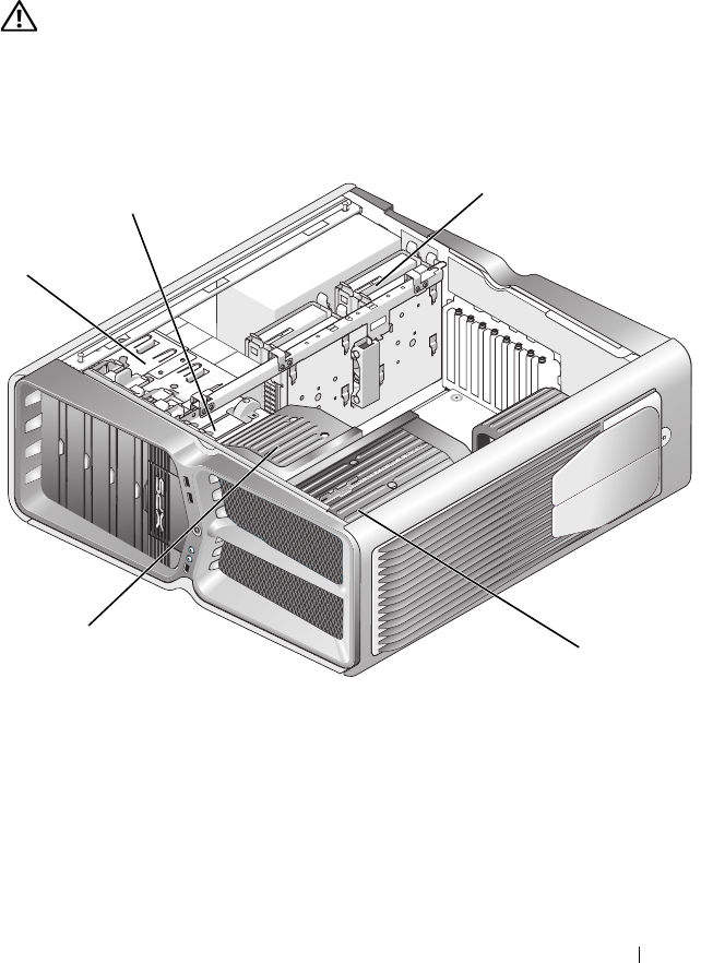
Inside View of Your Computer
1 optical drive bays (4) 2 floppy drive/media card reader
3 hard drive bays (4) 4 processor cooling solution: liquid
cooling assembly (shown) or air
cooling assembly
5 card fan
1
3
4
5
2
8Technical Overview
System Board Components
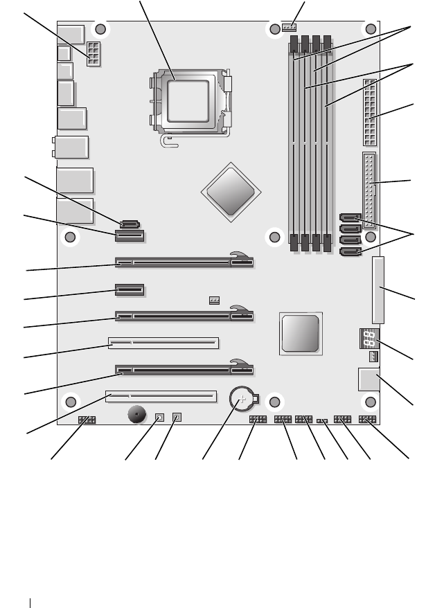
Dell™ XPS™ 730
2
4
5
6
7
10
12 11
13
17
19
20
21
22
27
23
14
16 15
24
25
26
29
8
9
28
3
1
18

Technical Overview 9
1 CPU socket 2 system board CPU fan header
3 DIMMs 0 and 1 (DIMM 0-1) 4 DIMMs 2 and 3 (DIMM 2-3)
5 ATX power connector
(ATX_PWR)
6 IDE connector (IDE)
7 SATA ports 3-6 (SATA 3-6) 8 floppy header (FLOPPY)
9 BIOS debug codes (PORT 80
DECODER)
10 SATA ports 1-2 (SATA 1-2)
11 font panel connector (FRONT
PNL)
12 serial port header (SERIAL
PORT)-unused
13 reset CMOS jumper (RESET
CMOS)
14 internal USB header 1 (USB)
15 internal USB header 2 (USB) 16 1394 header
17 battery socket 18 power button (POWER)
19 reset button (RESET) 20 front panel audio header (FP
Audio)
21 PCI slot 1 (PCI SLOT 1) 22 PCIe x16 (Generation 2) slot 2
(PCIe x16_2)
23 PCI slot 2 (PCI SLOT 2) 24 PCIe x16 (Generation 1) slot 3
(PCIe x16_3)
25 PCIe x1 slot (PCIe x1) 26 PCIe x16 (Generation 2) slot 1
(PCIe x16_1)
27 PCIe x1 slot (PCIe x1) 28 internal eSATA header
29 CPU power header
10 Technical Overview
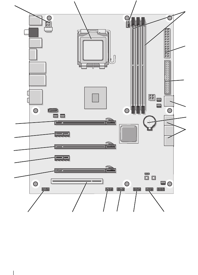
Dell XPS 730X
2
4
5
13
15
16
17
18
19
20
6
3
1
8
9
12
7
11
14 10

Technical Overview 11
1 CPU socket 2 system board CPU fan header
3 DIMMs 1, 3, and 5 4 ATX power connector
(ATX_PWR)
5 IDE connector (IDE) 6 SATA port 4 (SATA 4)
7 battery socket 8 SATA ports 1-3 (SATA 1-3)
9 internal USB header 1 (USB) 10 internal USB header 2 (USB)
11 internal USB header 3 (USB) 12 1394 header
13 PCI slot 1 (PCI SLOT 1) 14 front panel audio header (FP
Audio)
15 PCIe slot 5 (PCI_E5) 16 PCIe slot 4 (PCI_E4)
17 PCIe slot 3 (PCI_E3) 18 PCIe slot 2 (PCI_E2)
19 PCIe slot 1 (PCI_E1) 20 CPU power header
12 Technical Overview
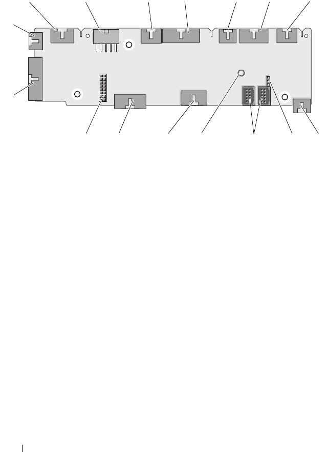
Master Control Board
1internal LED header
(INTERNAL_LED)
2power header (POWER)
3front top LED header
(FRONT_TOP_LED)
4front bottom right LED IO
header (BOT_RT_LED)
5PCI cage fan header
(FAN_CAGE)
6power button board header
(CON_PWR_BTN)
7rear PCI LED header
(REAR_PCI_LED)
8hard drive fan (FAN_HDD)
9factory defaults jumper
(FACTORY_DEFAULT)
10 internal USB headers
(USB_FLEXBAY 1-2)
11 system AC power LED
indicator
12 USB input header (USB_MB)
13 system board front panel IO
header (MB_IO_HDR)
14 H2C liquid cooling header
(H2C)
15 rear IO LED connector
(CONN_REAR)
16 front CPU fan header
(FAN_CPU_FRONT)
12 34567
8910121314
15
16
11

Technical Overview 13

14 Technical Overview

Before You Begin 13
2
Before You Begin
This chapter provides procedures for removing and installing the components
in your computer. Unless otherwise noted, each procedure assumes that the
following conditions exist:
• You have performed the steps in "Turning Off Your Computer" on page 13
and "Safety Instructions" on page 14.
• You have read the safety information that ships with your computer
.
• A component can be replaced or—if purchased separately—installed by
performing the removal procedure in reverse order.
Technical Specifications
For information on technical specifications of your computer, see the Quick
Reference Guide that shipped with your computer or see the Dell Support
website at support.dell.com.
Recommended Tools
The procedures in this document may require the following tools:
• Small Phillips screwdriver
• Small flat-blade screwdriver
Turning Off Your Computer
CAUTION: To avoid losing data, save and close all open files and exit all open
programs before you turn off your computer.
1
Shut down the operating system:
2
Ensure that the computer and all attached devices are turned off. If your
computer and attached devices did not automatically turn off when you
shut down your operating system, press and hold the power button for
about 4 seconds to turn them off.

14 Before You Begin
Safety Instructions
Use the following safety guidelines to help protect your computer from
potential damage and to help to ensure your own personal safety.
WARNING: Before working inside your computer, read the safety information
that shipped with your computer. For additional safety best practices information,
see the Regulatory Compliance Homepage at
www.dell.com/regulatory_compliance.
CAUTION: Only a certified service technician should perform repairs on your
computer. Damage due to servicing that is not authorized by Dell is not covered by
your warranty.
CAUTION: When you disconnect a cable, pull on its connector or on its pull-tab,
not on the cable itself. Some cables have connectors with locking tabs; if you are
disconnecting this type of cable, press in on the locking tabs before you
disconnect the cable. As you pull connectors apart, keep them evenly aligned to
avoid bending any connector pins. Also, before you connect a cable, ensure that
both connectors are correctly oriented and aligned.
CAUTION: To avoid damaging the computer, perform the following steps before
you begin working inside the computer.
1
Ensure that the work surface is flat and clean to prevent the computer
cover from being scratched.
2
Turn off your computer (see "Turning Off Your Computer" on page 13).
CAUTION: To disconnect a network cable, first unplug the cable from your
computer and then unplug the cable from the network device.
3
Disconnect all telephone or network cables from the computer.
4
Disconnect your computer and all attached devices from their electrical
outlets.
5
Press and hold the power button while the system is unplugged to ground
the system board.
CAUTION: Before touching anything inside your computer, ground yourself by
touching an unpainted metal surface, such as the metal at the back of the
computer. While you work, periodically touch an unpainted metal surface to
dissipate static electricity, which could harm internal components.
Replacing the Computer Stand 15
3
Replacing the Computer Stand
WARNING: Your computer is heavy and can be difficult to maneuver. Seek
assistance before attempting to lift, move, or tilt the computer and always lift
correctly to avoid injury; avoid bending over while lifting.
WARNING: The computer stand should be installed at all times to ensure
maximum system stability. Failure to install the stand could result in the computer
tipping over, potentially resulting in bodily injury or damage to the computer.
1
Follow the procedures in "Before You Begin" on page 13.
2
Loosen the captive screw securing the stand to the base of the computer.
3
Gently slide the stand back, towards the rear of the computer, then pull
the stand away from the computer to remove it.
16 Replacing the Computer Stand
4
To replace the computer stand, perform the removal procedure in reverse
order.

Replacing the Computer Cover 17
4
Replacing the Computer Cover
WARNING: Before working inside your computer, read the safety information
that shipped with your computer. For additional safety best practices information,
see the Regulatory Compliance Homepage at
www.dell.com/regulatory_compliance.
WARNING: To guard against electrical shock, always unplug your computer from
the electrical outlet before removing the cover.
WARNING: Do not operate your equipment with any cover(s) (including computer
covers, bezels, filler brackets, front-panel inserts, etc.) removed.
CAUTION: Ensure that sufficient space exists to support the system with the
cover removed—at least 30 cm (1 ft.) of desk top space.
1
Follow the procedures in "Before You Begin" on page 13.
2
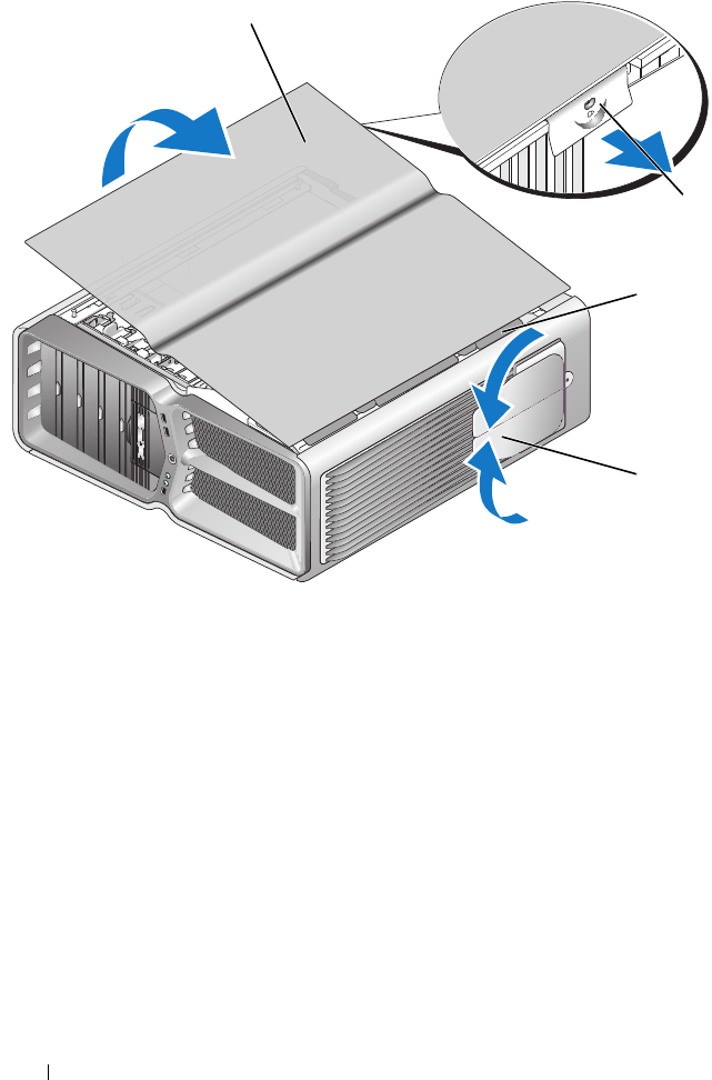
Pull back on the cover release latch.
18 Replacing the Computer Cover
3
With the cover release latch pulled back, grip the sides of the cover, then
pivot the top of the cover up and away from the computer.
4
Slide the cover forward and up to remove it from the hinge slots, then set
it aside in a secure and protected location.
5
To replace the computer cover, perform the removal procedure in reverse
order.
1 computer cover 2 cover release latch
3 cover hinge tabs 4 stabilizing feet (closed)
2
3
1
4
Replacing the Theater Lighting Unit 19
5
Replacing the Theater Lighting Unit
WARNING: Before working inside your computer, read the safety information
that shipped with your computer. For additional safety best practices information,
see the Regulatory Compliance Homepage at
www.dell.com/regulatory_compliance.
WARNING: To guard against electrical shock, always unplug your computer from
the electrical outlet before removing the cover.
WARNING: Do not operate your equipment with any cover(s) (including computer
covers, bezels, filler brackets, front-panel inserts, etc.) removed.
CAUTION: Ensure that sufficient space exists to support the system with the
cover removed—at least 30 cm (1 ft.) of desk top space.
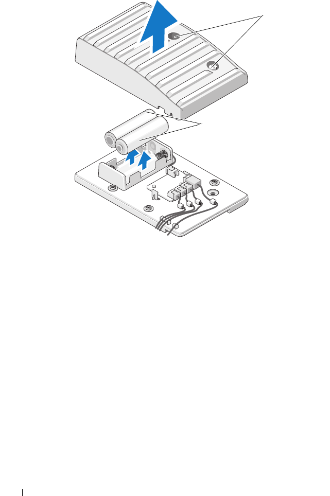
Replacing the Batteries
WARNING: A new battery can explode if it is incorrectly installed. Replace the
battery only with the same or equivalent type recommended by the manufacturer.
Discard used batteries according to the manufacturer's instructions.
1
Follow the procedures in "Before You Begin" on page 13.
2
Remove the computer cover (see "Replacing the Computer Cover" on
page 17).
20 Replacing the Theater Lighting Unit
3
Remove the two captive screws and lift the cover of the battery unit.
4
Replace the batteries with a new pair.
5
Replace the cover of the battery unit and ensure that the screws are secure.
6
Replace the computer cover (see "Replacing the Computer Cover" on
page 17).
7
Connect your computer and devices to electrical outlets, and then turn
them on.
Replacing the Theater Lighting Card
1
Follow the procedures in "Before You Begin" on page 13.
2
Remove the computer cover (see "Replacing the Computer Cover" on
page 17).
1captive screws 2batteries
2
1
Replacing the Theater Lighting Unit 21
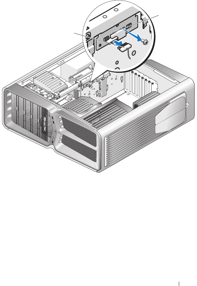
3
Disconnect the
theater lighting card connector.
4
Remove the screw securing the theater lighting card to the chassis and lift
the card out of the slot.
5
Replace the theater lighting card in its slot and tighten the screw.
6
Replace the computer cover (see "Replacing the Computer Cover" on
page 17).
1theater lighting card 2theater lighting card
connector
1
2

22 Replacing the Theater Lighting Unit
7
Connect your computer and devices to electrical outlets, and then turn
them on.
Replacing Memory Module(s) 23
6
Replacing Memory Module(s)
WARNING: Before working inside your computer, read the safety information
that shipped with your computer. For additional safety best practices information,
see the Regulatory Compliance Homepage at
www.dell.com/regulatory_compliance.
1
Follow the procedures in "Before You Begin" on page 13.
2
Remove the computer cover (see "Replacing the Computer Cover" on
page 17).
3
Locate the memory modules on the system board (see "System Board
Components" on page 8).
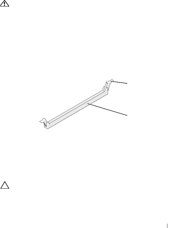
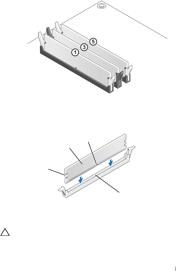
4
Press out the securing clip at each end of the memory module connector.
5
Grasp the module and pull it upwards.
If the module is difficult to remove, gently ease the module back and forth
to remove it from the connector.
CAUTION: Do not install ECC memory modules.
6
Ensure that you install a single memory module in DIMM connector 0, the
connector closest to the processor, before you install modules in any other
connector.
1securing clip 2memory module connector
1
2
24 Replacing Memory Module(s)
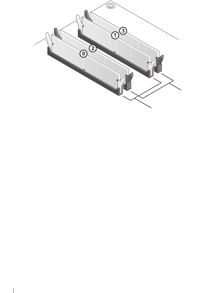
Dell™ XPS™ 730:
A matched pair of modules in DIMM
connectors 0 and 1
B matched pair of memory modules in
DIMM connectors 2 and 3
A
B
Replacing Memory Module(s) 25
Dell XPS 730X:
7
Align the notch on the bottom of the module with the tab in the
connector.
CAUTION: To avoid damage to the memory module, press the module straight
down into the connector while you apply equal force to each end of the module.
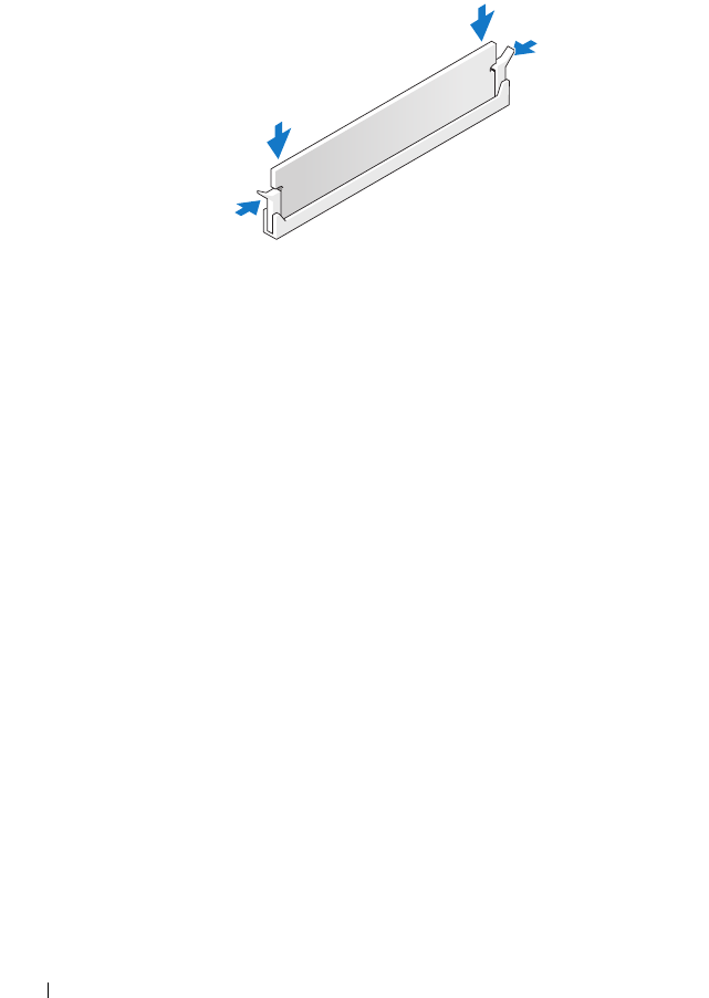
8
Insert the module into the connector until the module snaps into position.
1cutouts (2) 2memory module
3notch 4tab
3
2
1
4
26 Replacing Memory Module(s)
If you insert the module correctly, the securing clips snap into the cutouts
at each end of the module.
9
Replace the computer cover (see "Replacing the Computer Cover" on
page 17).
10
Connect your computer and devices to electrical outlets, and then turn
them on.
If the message appears stating that memory size has changed, press <F1>
to continue.
11
Log on to your computer.
12
Right-click the
My Computer
icon on your Microsoft
®
Windows
®
desktop and click
Properties
.
13
Click the
General
tab.
14
To verify that the memory is installed correctly, check the amount of
memory (RAM) listed.
Replacing a PCI/PCI Express Card 27
7
Replacing a PCI/PCI Express Card
WARNING: Before working inside your computer, read the safety information
that shipped with your computer. For additional safety best practices information,
see the Regulatory Compliance Homepage at
www.dell.com/regulatory_compliance.
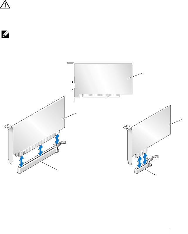
NOTE: If a graphics card is installed in each of the PCIe x16 card slots in the multi-
graphics configuration, the PCIe x1 and one PCI card slot are not accessible for
use.
1 PCI card 2 PCIe x1 card
3 PCIe x1 card slot 4 PCIe x16 card slot
5 PCIe x16 card
1
2
5
4
3
28 Replacing a PCI/PCI Express Card
Removing a PCI Express Graphics Card From a
Multi Graphics Card Configuration
NOTE: This section deals with dual and triple configurations of PCIe x16 graphics
cards only. For removal of any other type of PCI or PCIe cards, see "Replacing the
PCI and PCI Express Cards" on page 35.
1
Follow the procedures in "Before You Begin" on page 13.
2
Remove the computer cover (see "Replacing the Computer Cover" on
page 17).
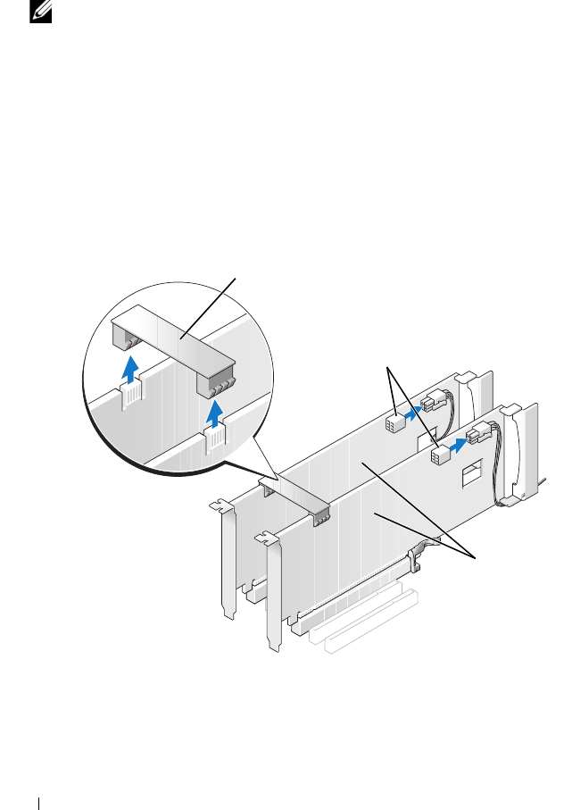
3
Gently securing both graphics cards with one hand, remove the graphics
card bridge (if present) with your other hand by pulling it up and away
from the computer. Set it aside.
Repeat if removing two bridges from a triple card configuration.
1 graphics card bridge 2 power connectors (2)
3 dual-PCIe graphics cards
1
3
2
Replacing a PCI/PCI Express Card 29
4
Disconnect any cables connected to the card.
5
Remove the captive screws on top of the PCI card fan shroud and remove
the shroud.
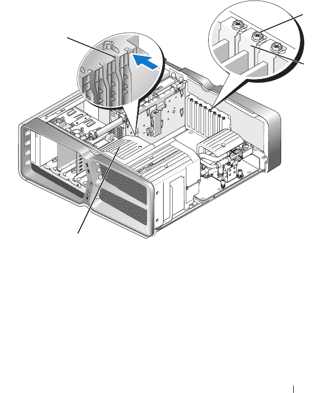
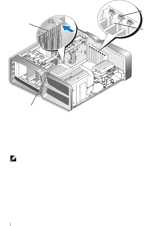
6
Remove the card retention screw(s) on the top of the card retainer at the
appropriate card slot and pivot the card retainer back through the chassis
wall.
1 retention screw 2 card retainer
3 alignment guide 4 fan bracket
2
3
4
1
3
4
30 Replacing a PCI/PCI Express Card
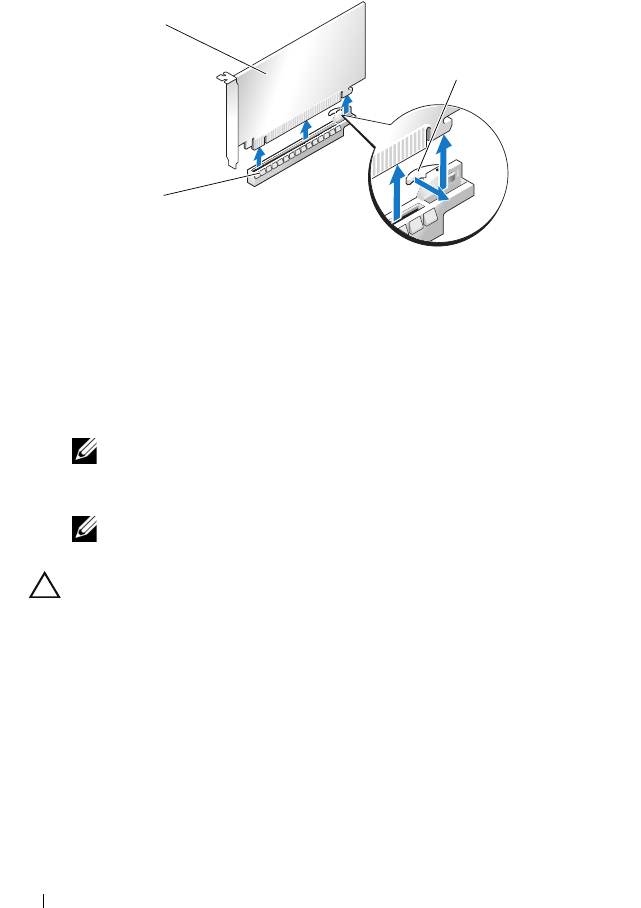
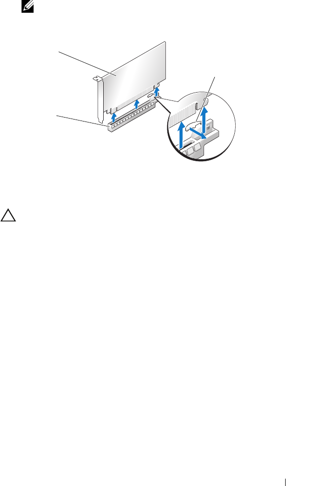
7
Press the securing tab (if present) on the system board connector as you
grasp the card by its top corners, and then ease the card straight out of the
connector.
8
Install a filler bracket in the empty card-slot opening. If you are replacing
the card, see "Installing Graphics Cards for Multi Graphics Card" on
page 31.
NOTE: Installing filler brackets over empty card-slot openings is necessary to
maintain FCC certification of the computer. The brackets also keep dust and
dirt out of your computer.
NOTE: The graphics card bridge (not present in all multi-graphics
configurations) is not necessary in a single graphics card configuration.
CAUTION: Do not route card cables over or behind the cards. Cables routed over
the cards can prevent the computer cover from closing properly or cause damage
to the equipment.
9
Replace the PCI card fan shroud, replace the computer cover (see
"Replacing the Computer Cover" on page 17), reconnect the computer
and devices to electrical outlets, and then turn them on.
1 PCIe x16 card 2 securing tab
3 PCIe x16 card slot
1
3
2

Replacing a PCI/PCI Express Card 31
Installing Graphics Cards for Multi Graphics Card
NOTE: To upgrade to or downgrade from a dual- or triple-graphics card
configuration, you may need additional parts that can be ordered from Dell.
This section pertains to using dual and triple PCIe graphics cards to take
advantage of NVIDIA’s SLI (Scalable Link Interface). For installation of other
types of PCI or PCIe cards, see "Replacing a PCI/PCI Express Card" on
page 27.
Some expansion card slots will not be available for use if a dual-slot graphics
card is installed in any of the PCIe x16 card slots. If you are upgrading from a
single-slot graphics card to a dual-slot graphics card, you will need to remove
any card installed in these expansion slots. To remove a PCIe card, see
"Replacing the PCI and PCI Express Cards" on page 35.
CAUTION: For information about upgrading your system to use NVIDIA SLI
(Scalable Link Interface) multi-graphics technology, see the Dell support website
at support.dell.com.
1
Follow the procedures in "Before You Begin" on page 13.
2
Remove the computer cover (see "Replacing the Computer Cover" on
page 17).
3
Remove the captive screws on top of the PCI card fan shroud and remove
the shroud.
4
Remove the filler bracket or existing graphics card to create a card-slot
opening.
NOTE: If you are upgrading to a multi-graphics card configuration and have a
card installed in the PCIe x1 card slot, remove the card (see "Replacing the
PCI and PCI Express Cards" on page 35).
5
Install two SLI-ready graphics cards into the two outer PCIe x16 slots on
the system board.
32 Replacing a PCI/PCI Express Card
6
Prepare the cards for installation.
See the documentation that came with the cards for information on
configuring them, making internal connections, or otherwise customizing
them for your computer.
7
Position each card so that it is aligned with the slot and that the securing
tab (if present) is aligned with the slot.
NOTE: If the card is full length, insert the card guide into the alignment slot on
the fan bracket.
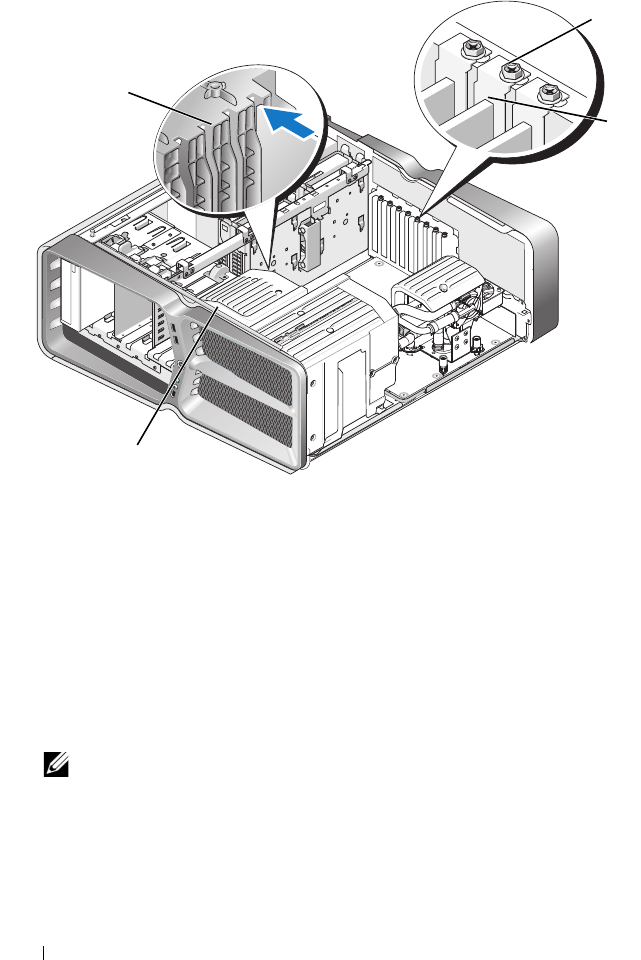
1 retention screw 2 card retainer
3 alignment guide 4 fan bracket
1
2
3
4
Replacing a PCI/PCI Express Card 33
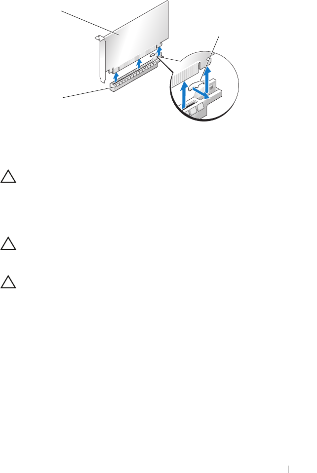
CAUTION: Ensure that you release the securing tab to seat the card. If the card is
not installed correctly, you may damage the system board.
Gently pull the securing tab (if present) and place the card in the
connector. Press down firmly and ensure that the card is fully seated in the
slot.
CAUTION: Do not route card cables over or behind the cards. Cables routed over
the cards can prevent the computer cover from closing properly or cause damage
to the equipment.
CAUTION: An incorrectly attached graphics power cable may result in degraded
graphics performance.
8
Screw in the card retention screw(s) on the top of the card retainer at the
appropriate card slot.
9
Repeat for additional graphics cards.
Connect the PCIe supplementary power connectors from the system
power supply to each of the graphics cards. See the documentation for the
card for information about the card’s cable connections.
10
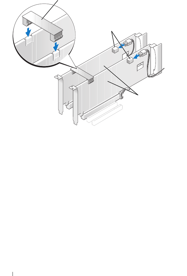
Install the NVIDIA SLI connector across the two outer graphics cards.
Each SLI-ready graphics card has an SLI connector tab on its upper side.
Press firmly on each connector so that it completely covers the connector
tab.
1 PCIe x16 card 2 securing tab
3 PCIe x16 card slot
1
3
2
34 Replacing a PCI/PCI Express Card
11
If present, lower the graphics card bridge that lays over the installed cards
and snap it into place.
12
Replace the computer cover (see "Replacing the Computer Cover" on
page 17), reconnect the computer and devices to electrical outlets, and
then turn them on.
1 graphics card bridge 2 power connectors (2)
3 dual-PCIe graphics cards
1
3
2

Replacing a PCI/PCI Express Card 35
Replacing the PCI and PCI Express Cards
CAUTION: To avoid electrostatic discharge and damage to internal components,
ground yourself by using a wrist grounding strap or by periodically touching an
unpainted metal surface on the computer chassis.
CAUTION: If your computer came with a PCI graphics card installed, removal of
the card is not necessary when installing additional graphics cards; however, the
card is required for troubleshooting purposes. If you remove the card, store it in a
safe and secure location.
1
Follow the procedures in "Before You Begin" on page 13.
2
Remove the computer cover (see "Replacing the Computer Cover" on
page 17).
3
Disconnect any cables connected to the card.
4
If the card is a full length, remove the captive screws on top of the PCI
card fan shroud and remove the shroud.
5
Remove the card retention screw.
36 Replacing a PCI/PCI Express Card
6
Press the securing tab (if present) on the system board connector as you
grasp the card by its top corners, and then ease the card out of the
connector.
NOTE: If the card is full length, press the securing tab on the end of the
alignment guides on the fan bracket.
1 retention screw 2 card retainer
3 alignment guide 4 fan bracket
1
2
3
4
Replacing a PCI/PCI Express Card 37
7
Install a filler bracket in the empty card-slot opening. If you are replacing
the card, see "Replacing a PCI/PCI Express Card" on page 27.
NOTE: Installing filler brackets over empty card-slot openings is necessary to
maintain FCC certification of the computer. The brackets also keep dust and
dirt out of your computer.
CAUTION: Do not route card cables over or behind the cards. Cables routed over
the cards can prevent the computer cover from closing properly or cause damage
to the equipment.
8
Reinstall the card retention screw.
9
Reinstall the card slot fan shroud.
10
Replace the computer cover (see "Replacing the Computer Cover" on
page 17), reconnect the computer and devices to electrical outlets, and
then turn them on.
11
Uninstall the driver for the card that you removed.
CAUTION: If you have or are upgrading to the optional multi-graphics
configuration, see "Installing Graphics Cards for Multi Graphics Card" on page 31
to install a graphics card.
12
If present, press the tab on the graphics card bridge that lays over the
installed cards and rotate it upwards to gain full access to the card.
1 PCIe x16 card 2 securing tab
3 PCIe x16 card slot
1
3
2
38 Replacing a PCI/PCI Express Card
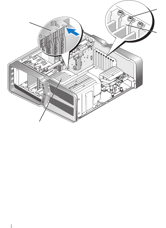
13
Press down the tab on the top of the graphics card bridge at the
appropriate card slot and pivot the graphics card bridge back through the
chassis wall.
14
Remove the filler bracket or existing card (see "Replacing the PCI and PCI
Express Cards" on page 35) to create a card-slot opening.
15
Prepare the card for installation.
See the documentation that came with the card for information on
configuring the card, making internal connections, or otherwise
customizing it for your computer.
16
Position the card so that it is aligned with the slot and the securing tab (if
present) is aligned with the slot.
1 retention screw 2 card retainer
3 alignment guide 4 fan bracket
1
2
3
4
Replacing a PCI/PCI Express Card 39
NOTE: If the card is full length, insert the card guide into the alignment slot on
the fan bracket.
CAUTION: Ensure that you release the securing tab to seat the card. If the card is
not installed correctly, you may damage the system board.
17
Gently pull the securing tab (if present) and place the card in the
connector. Press down firmly and ensure that the card is fully seated in the
slot.
1 PCIe x16 card 2 securing tab
3 PCIe x16 card slot
1
3
2
40 Replacing a PCI/PCI Express Card
CAUTION: Do not route card cables over or behind the cards. Cables routed over
the cards can prevent the computer cover from closing properly or cause damage
to the equipment.
CAUTION: An incorrectly attached graphics power cable may result in degraded
graphics performance.
18
Connect any cables that should be attached to the card.
See the documentation for the card for information about the card’s cable
connections.
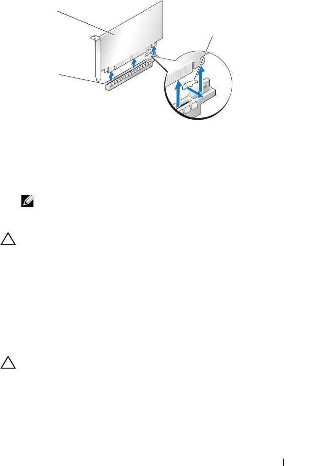
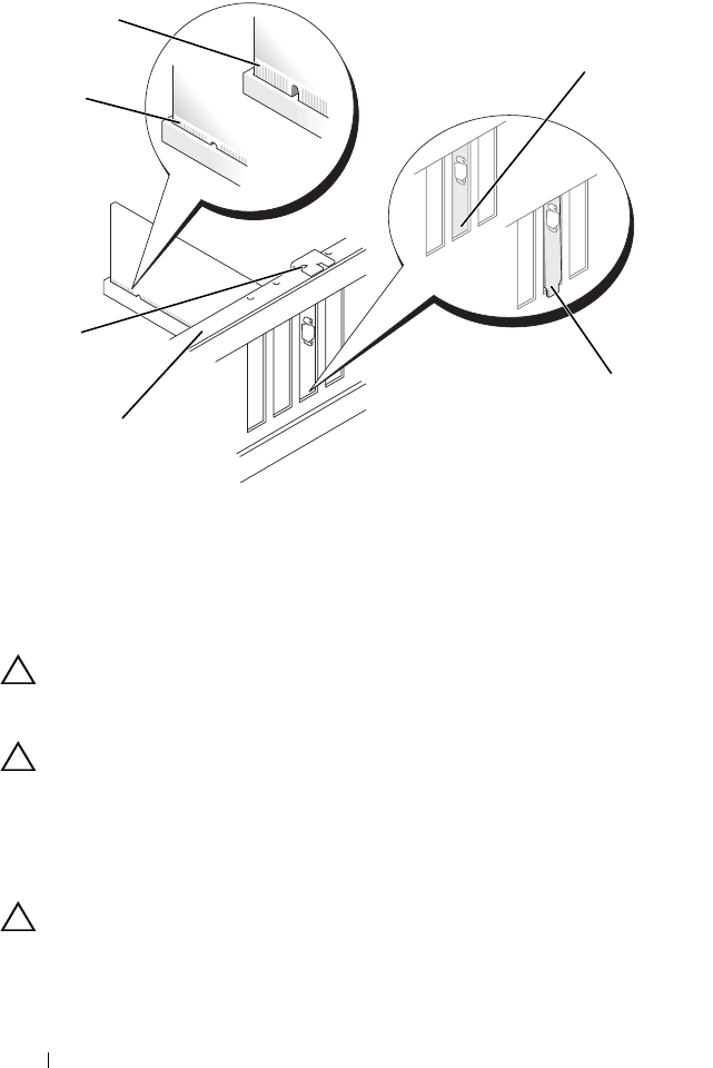
CAUTION: Before rotating the card retainer back into place, ensure that the tops
of all cards and filler brackets are flush with the alignment bar and the notch in
the top of each card or filler bracket fits around the alignment guide.
1 card connector (seated) 2 card connector (not seated)
3 bracket properly aligned within slot 4 bracket improperly aligned outside of
slot
5 alignment bar 6 alignment guide
1
2
4
3
6
5

Replacing a PCI/PCI Express Card 41
19
Rotate the graphics card bridge back into its original position; push its tip
so that its tab clicks into place.
20
If present, lower the graphics card bridge that lays over the installed cards
and snap it into place.
21
Replace the computer cover (see "Replacing the Computer Cover" on
page 17), reconnect the computer and devices to electrical outlets, and
then turn them on.
22
Install any drivers required for the card as described in the card
documentation.

42 Replacing a PCI/PCI Express Card

Replacing Drives 43
8
Replacing Drives
WARNING: Before working inside your computer, read the safety information
that shipped with your computer. For additional safety best practices information,
see the Regulatory Compliance Homepage at
www.dell.com/regulatory_compliance.
Replacing a Hard Drive
WARNING: To guard against electrical shock, always unplug your computer from
the electrical outlet before removing the cover.
CAUTION: If you are replacing a hard drive that contains data that you want to
keep, back up your files before you begin this procedure.
1
Follow the procedures in "Before You Begin" on page 13.
2
Remove the computer cover (see "Replacing the Computer Cover" on
page 17).
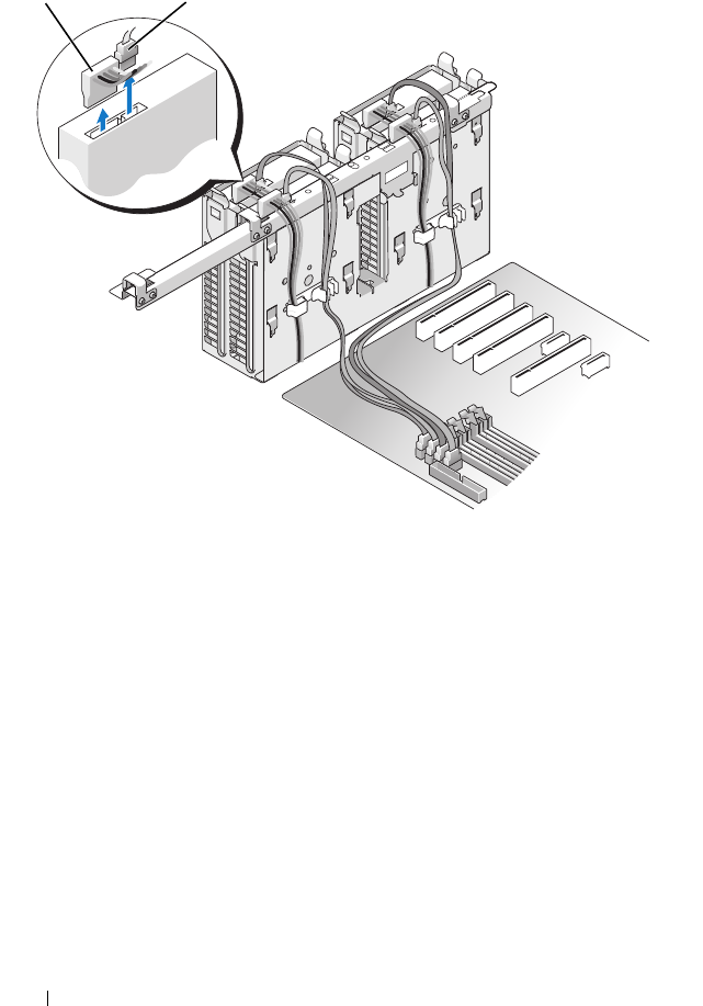
3
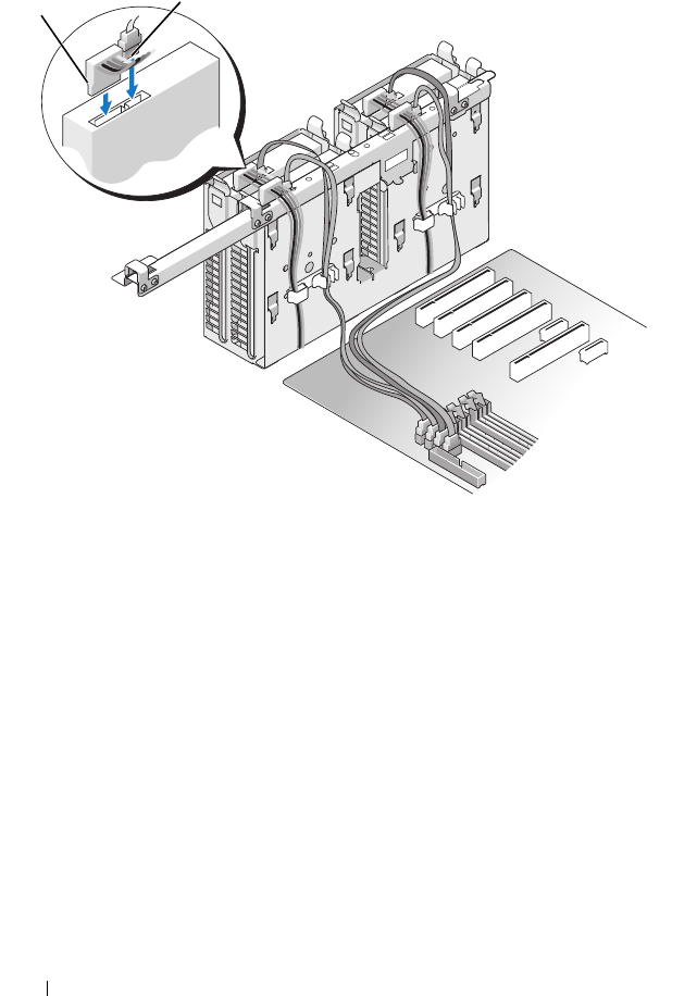
Disconnect the power cable and the data cable from the hard drive.
44 Replacing Drives
Dell™ XPS™ 730:
1 power cable 2 data cable
1 2
Replacing Drives 45
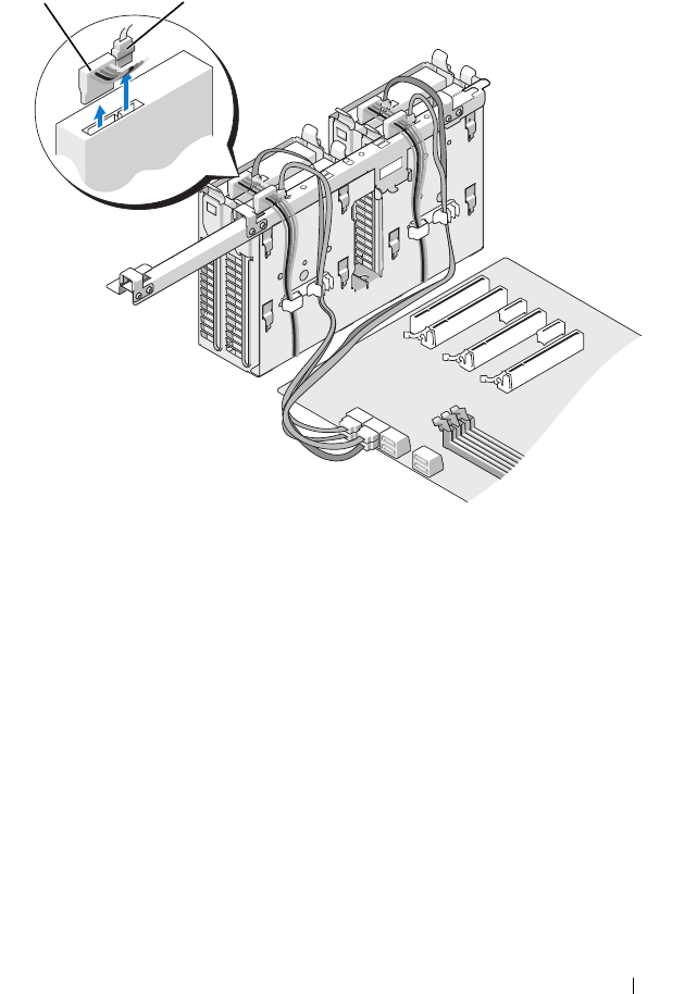
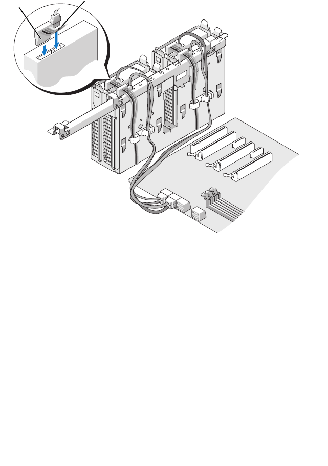
Dell XPS 730X:
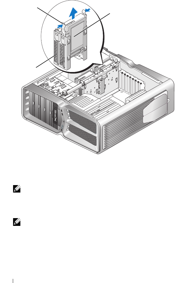
4
Press the blue tabs on each side of the hard drive bracket toward each other
and slide the drive up and out of the hard drive bay.
1 power cable 2 data cable
1 2
46 Replacing Drives
NOTE: If a hard drive bracket is installed inside the hard drive bay, remove
the bracket before you install a new hard drive.
5
Prepare the new hard drive for installation and check the documentation
for the hard drive to verify that the drive is configured for your computer.
NOTE: If the hard drive you are installing does not have the hard drive bracket
attached, use your original hard drive bracket; snap the bracket onto the new
drive.
1 blue tabs (2) 2 hard drive
3 hard drive bay
1
3
2
Replacing Drives 47
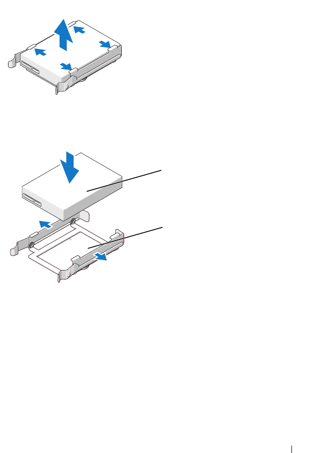
3.5" hard drive:
Removal:
Replacement:
1 hard drive 2 hard drive bracket
2
1
48 Replacing Drives
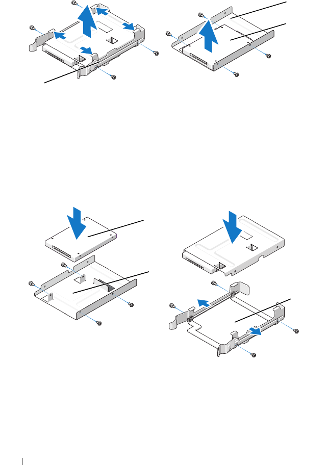
2.5" hard drive:
Removal:
Replacement:
1 hard drive cage 2 hard drive
3 hard drive bracket
1 hard drive 2 hard drive bracket
3 hard drive cage
1
2
3
1
2
3
Replacing Drives 49
6
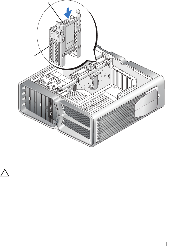
Verify that the hard drive bay is empty and unobstructed.
7
Slide the hard drive into the hard drive bay until it clicks securely into
place.
CAUTION: Ensure that all connectors are properly cabled and firmly seated.
8
Connect the power cable to the hard drive.
9
Connect the hard drive data cable to the hard drive.
1 hard drive 2 hard drive bay
1
2
50 Replacing Drives
Dell XPS 730:
1 power cable 2 data cable
12
Replacing Drives 51
Dell XPS 730X:
10
Replace the computer cover (see "Replacing the Computer Cover" on
page 17).
11
Connect the computer and devices to electrical outlets, and turn them on.
See the documentation that came with the drive for instructions on
installing any software required for drive operation.
Replacing the Drive Panel
1
Follow the procedures in "Before You Begin" on page 13.
2
Remove the computer cover (see "Replacing the Computer Cover" on
page 17).
1 power cable 2 data cable
12
52 Replacing Drives
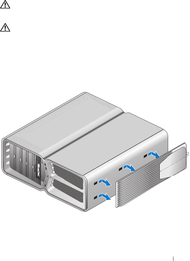
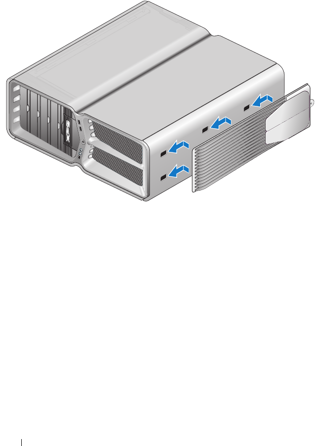
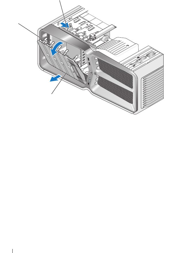
3
Grasp the drive release latch and slide it towards the base of the computer
until the drive panel snaps open.
4
Pivot the drive panel outward and lift it from its side hinges.
5
Set the drive panel aside in a secure location.
6
To install the new drive panel, align the drive panel tabs with the side door
hinges.
1 drive release latch 2 drive panel
3 drive panel tabs
2
1
3
Replacing Drives 53
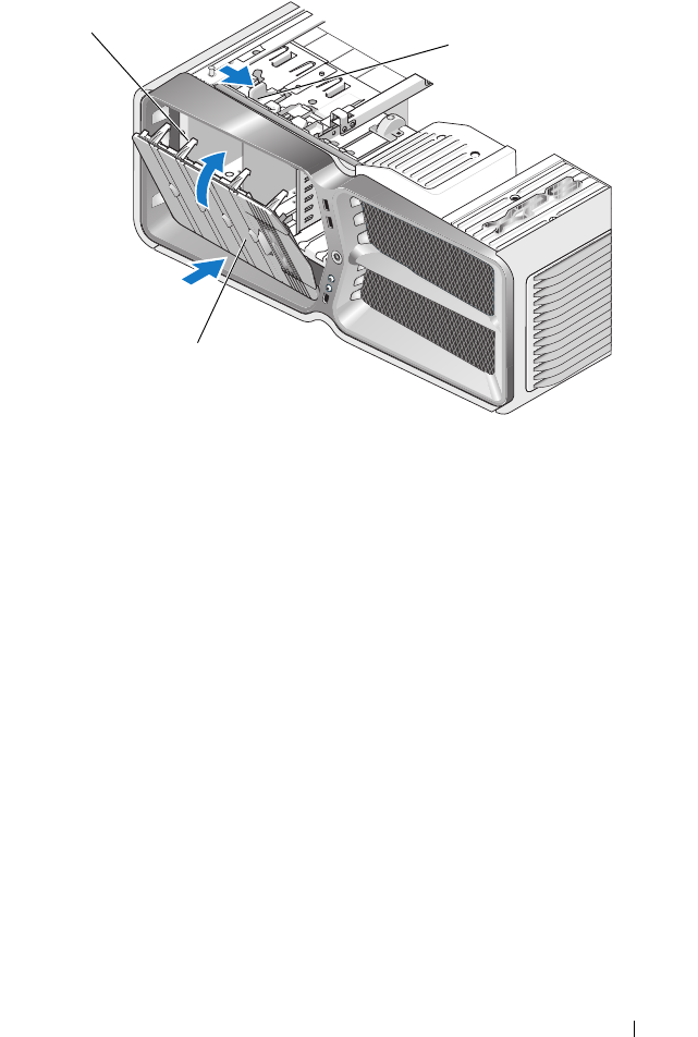
7
Rotate the drive panel toward the computer until it snaps into place on the
drive panel.
8
Replace the computer cover (see "Replacing the Computer Cover" on
page 17).
Replacing a Floppy Drive (XPS 730 Only)
1
Follow the procedures in "Before You Begin" on page 13.
2
Remove the computer cover (see "Replacing the Computer Cover" on
page 17).
3
Remove the drive panel (see "Replacing the Drive Panel" on page 51).
4
Disconnect the power and data cables from the back of the floppy drive.
1 drive release latch 2 drive panel
3 drive panel tabs
2
1
3
54 Replacing Drives
5
Slide the drive release latch towards the base of the computer to release
the shoulder screw, and then slide the drive out of the drive bay.
1 power cable 2 floppy drive data cable
1
2
Replacing Drives 55
6
If no screws are attached to the new floppy drive, check the inside of the
drive panel for shoulder screws. If screws are present, attach the screws to
the new drive.
1 drive release latch 2 floppy drive
1
2
1
2
56 Replacing Drives
7
Slide the floppy drive into the drive bay until it clicks into place.
8
Connect the power and data cables to the back of the floppy drive.
9
Check all cable connections and fold cables out of the way to avoid
blocking airflow between the fan and cooling vents.
10
Replace the drive panel (see "Replacing the Drive Panel" on page 51).
11
Replace the computer cover (see "Replacing the Computer Cover" on
page 17).
12
Connect your computer and devices to their electrical outlets, and turn
them on.
1 floppy drive 2 shoulder screws (4)
1 drive release latch 2 floppy drive
1
2

Replacing Drives 57
See the documentation that came with the drive for instructions on
installing any software required for drive operation.
13
Enter system setup (see "System Setup" on page 97), and select the
appropriate
Diskette Drive
option.
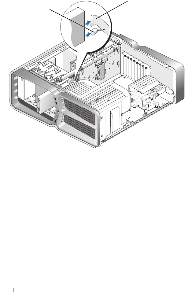
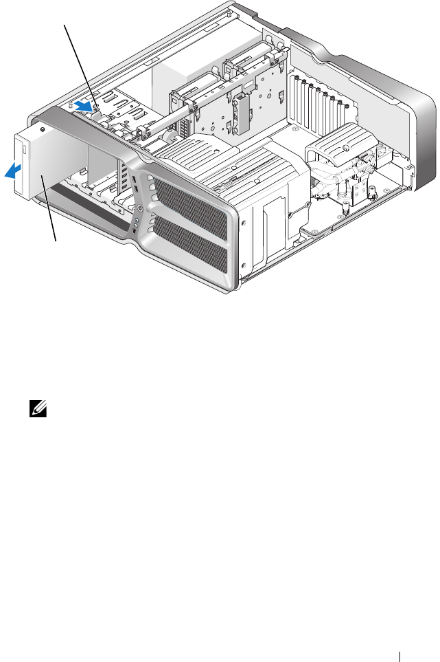
Replacing an Optical Drive
1
Follow the procedures in "Before You Begin" on page 13.
2
Remove the computer cover (see "Replacing the Computer Cover" on
page 17).
3
Remove the drive panel (see "Replacing the Drive Panel" on page 51).
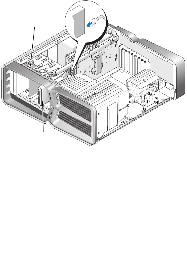
4
Disconnect the power and data cables from the back of the drive.
NOTE: If you are uninstalling your only optical drive and will not replace it at
this time, disconnect the data cable from the system board and set it aside.
58 Replacing Drives
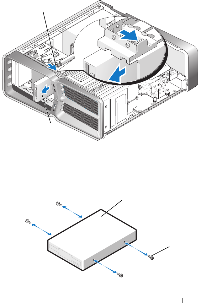
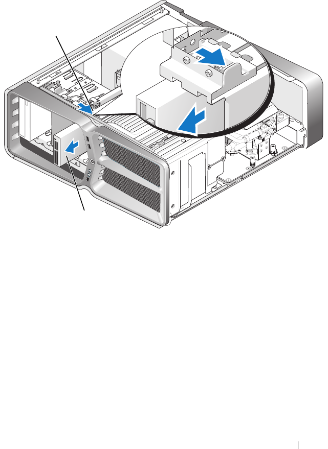
5
Slide the drive release latch towards the base of the computer to release
the shoulder screw, and then slide the optical drive out of the drive bay.
1 data cable 2 power cable
2
1
Replacing Drives 59
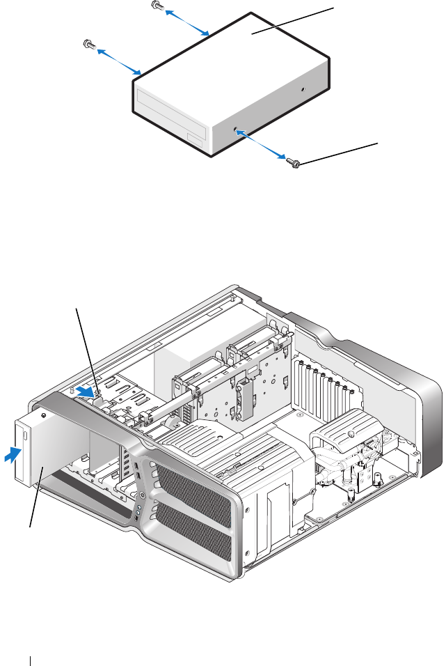
6
To replace the optical drive, prepare the drive for installation and check the
documentation that accompanied the drive to verify that the drive is
configured for your computer.
NOTE: If you are installing an IDE drive, configure the drive for the cable
select setting.
7
If no screws are attached to the drive, check the inside of the drive panel
for screws and, if screws are present, attach the screws to the new drive.
1 drive release latch 2 optical drive
1
2
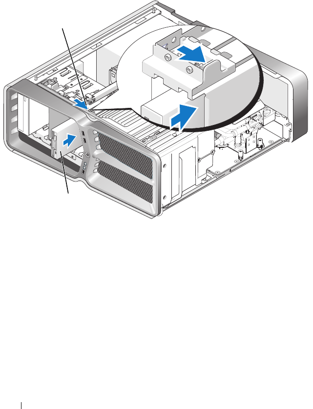
60 Replacing Drives
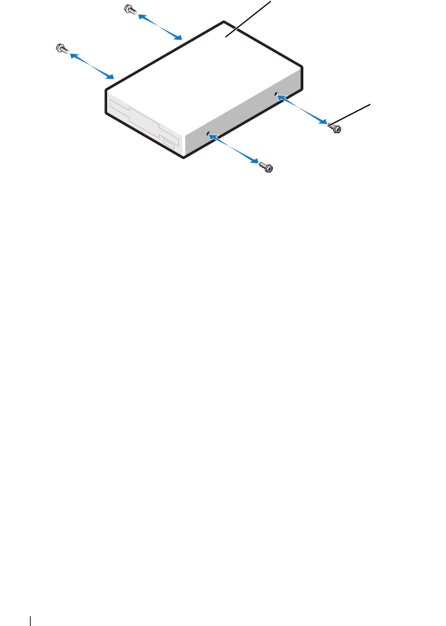
8
Gently slide the drive into the drive bay until you hear a click or feel the
drive securely installed.
1 optical drive 2 shoulder screws (3)
1 drive release latch 2 optical drive
2
1
1
2
Replacing Drives 61
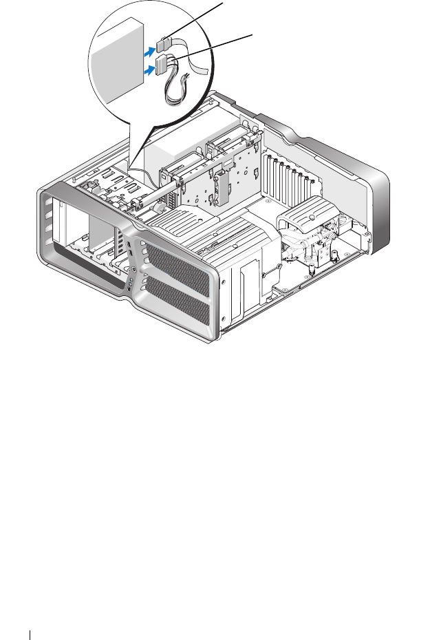
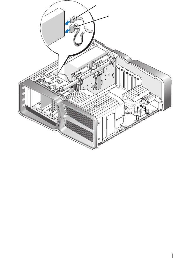
9
Attach the power and data cables to the optical drive.
To locate the system board connector, see "System Board Components" on
page 8.
10
Check all cable connections and fold cables out of the way to avoid
blocking airflow between the fan and cooling vents.
11
Replace the drive panel (see "Replacing the Drive Panel" on page 51).
12
Replace the computer cover (see "Replacing the Computer Cover" on
page 17).
13
Connect your computer and devices to their electrical outlets, and turn
them on.
1 power cable 2 data cable
2
1
62 Replacing Drives
See the documentation that came with the drive for instructions on
installing any software required for drive operation.
14
Enter system setup (see "System Setup" on page 97) and select the
appropriate
Drive
option.
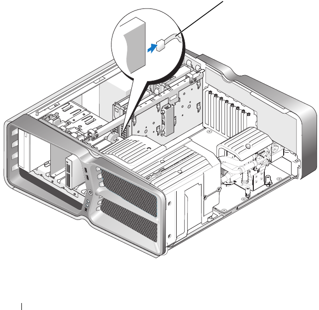
Replacing a Media Card Reader
1
Follow the procedures in "Before You Begin" on page 13.
2
Remove the computer cover (see "Replacing the Computer Cover" on
page 17).
3
Remove the drive panel (see "Replacing the Drive Panel" on page 51).
4
Disconnect the cable from the back of the Media Card Reader.
1 media card reader cable
1
Replacing Drives 63
5
Slide the drive release latch towards the base of the computer to release
the shoulder screw, and then slide the media card reader out of the drive
bay.
1 drive release latch 2 media card reader
1
2
64 Replacing Drives
6
If no screws are attached to the new Media Card Reader, check the inside
of the drive panel for shoulder screws. If screws are present, attach the
screws to the new card reader.
7
Slide the Media Card Reader into the drive bay until it clicks into place.
1 media card reader 2 shoulder screws (4)
1
2
Replacing Drives 65
8
Attach the cable to the back of the Media Card Reader.
9
Check all cable connections and fold cables out of the way to avoid
blocking airflow between the fan and cooling vents.
10
Replace the drive panel (see "Replacing the Drive Panel" on page 51).
11
Replace the computer cover (see "Replacing the Computer Cover" on
page 17).
12
Connect your computer and devices to their electrical outlets, and turn
them on.
See the documentation that came with the drive for instructions on
installing any software required for drive operation.
1 drive release latch 2 media card reader
1
2


Replacing the Heat Sink Assembly 67
9
Replacing the Heat Sink Assembly
WARNING: Before working inside your computer, read the safety information that
shipped with your computer. For additional safety best practices information, see
the Regulatory Compliance Homepage at www.dell.com/regulatory_compliance.
CAUTION: Do not perform the following steps unless you are familiar with
hardware removal and replacement. Performing these steps incorrectly could
damage your system board. For technical service, see the
Setup Guide
.
Your computer uses one of the following types of processor cooling solutions,
air-cooling or H2Ceramic (also called H2C or Hot-to-Cold) liquid-cooling
system.
Replacing the Air Cooled Heat Sink Assembly
1
Follow the procedures in "Before You Begin" on page 13.
2
Remove the computer cover (see "Replacing the Computer Cover" on
page 17).
WARNING: The processor heat sink can get very hot during normal operation. Be
sure that the heat sink has had sufficient time to cool before you touch it.
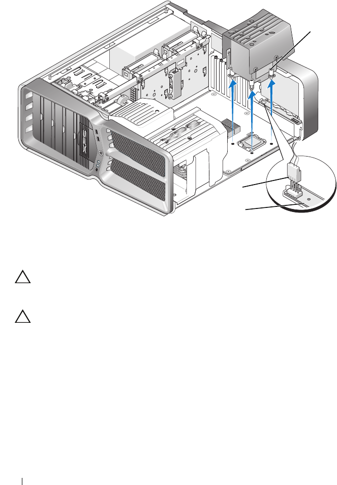
3
Loosen the four captive screws that secure the heatsink to the chassis.
4
Gently lift the heat sink assembly out of the chassis. You may have to
gently twist the heat sink to fully disengage the heat sink assembly.
5
Disconnect the fan cable from the rear fan connector on the LED circuit
board at the back of the chassis.
68 Replacing the Heat Sink Assembly
CAUTION: The processor heat sink is attached to the processor fan shroud. When
you remove the processor fan shroud, lay it upside down or on its side to avoid
damaging the heat sink thermal interface.
CAUTION: Ensure that adequate thermal grease is applied to the top of the
processor. Thermal grease is critical for ensuring adequate thermal bonding,
which is a requirement for optimal processor operation.
6
To replace the air cooled heat sing assembly, apply thermal grease to the
top of the processor as needed.
7
Align the screw holes on the heat sink assembly with the holes on the base
of the computer, then tighten the four screws to secure the assembly.
8
Connect the fan cable to the rear fan connector on the LED circuit board.
9
Replace the computer cover (see "Replacing the Computer Cover" on
page 17).
1 fan power connector 2 LED circuit board
3 captive screws (4)
3
1
2

Replacing the Heat Sink Assembly 69
Replacing the Liquid Cooling Heat Sink Assembly
WARNING: The liquid cooling assembly is responsible for cooling the system
board chipset in addition to the CPU. If the liquid cooling assembly is replaced
with an assembly other than the original, a cooling solution must be installed to
avoid overheating the chipset. Failure to install a cooling solution, either third-
party or Dell provided, may result in damage to your system and render the system
inoperable.
1
Follow the procedures in "Before You Begin" on page 13.
2
Remove the computer cover (see "Replacing the Computer Cover" on
page 17).
WARNING: The processor heat sink can get very hot during normal operation. Be
sure that the heat sink has had sufficient time to cool before you touch it.
3
Observe the following cautions when working with the liquid cooling
assembly.
• The liquid cooling assembly is not user serviceable or upgradeable. All
required service should be done by qualified service personnel only.
• The liquid cooling assembly in your system contains a non-refillable
coolant. In the event of a coolant leak, shut down your system
immediately. Unplug your system from the power outlet and contact
Dell Technical Support.
• In the event of skin contact with the coolant, wash your skin with soap
and water. Seek medical attention if irritation develops.
• In the event of eye contact with the coolant, rinse your eyes
immediately with water, with your eyelids open, for 15 minutes. Seek
medical attention if irritation persists.
4
Disconnect the liquid cooling cable from the H2C connector on the
Master Control Board (see "Master Control Board" on page 12).
CAUTION: The processor heat sink is attached to the liquid cooling assembly.
When you remove the liquid cooling assembly, lay it upside down or on its side to
avoid damaging the heatsink thermal interface.
5
Loosen the screws on the liquid cooling assembly, then lift the assembly
out of the computer and set it aside.
70 Replacing the Heat Sink Assembly
CAUTION: Ensure that adequate thermal grease is applied to the top of the
processor. Thermal grease is critical for ensuring adequate thermal bonding,
which is a requirement for optimal processor operation.
6
To install the liquid cooling heat sink assembly, apply thermal grease to the
top of the processor as needed.
7
Align the screw holes on the liquid cooling assembly with the holes on the
base of the computer, then tighten the six screws to secure the assembly.
8
Connect the liquid cooling cable to the H2C connector on the Master
Control Board (see "Master Control Board" on page 12).
9
Close the computer cover (see "Replacing the Computer Cover" on
page 17).
10
Connect your computer and devices to electrical outlets, and turn
them on.
1 liquid cooling assembly 2 captive screws
2
1

Replacing the Heat Sink Assembly 71

72 Replacing the Heat Sink Assembly
Replacing the Processor 73
10
Replacing the Processor
WARNING: Before working inside your computer, read the safety information that
shipped with your computer. For additional safety best practices information, see
the Regulatory Compliance Homepage at www.dell.com/regulatory_compliance.
CAUTION: Do not perform the following steps unless you are familiar with
hardware removal and replacement. Performing these steps incorrectly could
damage your system board. For technical service, see the
Setup Guide
.
1
Follow the procedures in "Before You Begin" on page 13.
2
Remove the computer cover (see "Replacing the Computer Cover" on
page 17).
WARNING: Despite having a plastic shield, the heat sink assembly may be very
hot during normal operation. Be sure that it has had sufficient time to cool before
you touch it.
3
Disconnect the power cables from the ATX_POWER and ATX_CPU
connectors (see "System Board Components" on page 8) on the system
board.
4
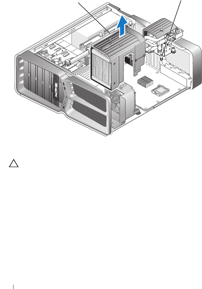
Remove the processor fan and heat sink assembly from the computer (see
"Replacing the Processor Fan Assembly" on page 79).
NOTE: Unless a new heat sink is required for the new processor, reuse the
original heat sink assembly when you replace the processor.
5
Press and push the release lever down and out to release it from the tab
that secures it.
6
Open the processor cover, if applicable.
74 Replacing the Processor
Removing the Processor
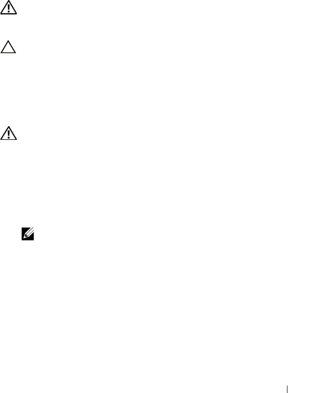
CAUTION: When removing or replacing the processor, do not touch any of the
pins inside the socket or allow any object to fall on the pins in the socket.
7
Lift the processor to remove it from the socket, place it aside in a safe and
secure place.
Leave the release lever extended in the release position so that the socket is
ready for the new processor.
8
Unpack the new processor, being careful not to touch the underside of
the processor.
1processor cover 2processor
3socket 4release lever
1
2
3
4
Replacing the Processor 75
Installing the Processor
9
If the release lever on the socket is not fully extended, move it to that
position.
CAUTION: Socket pins are delicate. To avoid damage, ensure that the processor
is aligned properly with the socket, and do not use excessive force when you
install the processor. Be careful not to touch or bend the pins on the system board.
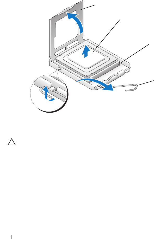
10
Orient the front and rear alignment-notches on the processor with the
front and rear alignment-notches on the socket.
11
Align the pin-1 corners of the processor and socket.
1processor cover 2tab
3processor 4socket
5center cover latch 6release lever
7front alignment-notch 8processor pin-1 indicator
9rear alignment notch
1
3
4
6
87
9
2
5

76 Replacing the Processor
CAUTION: To avoid damage, ensure that the processor aligns properly with the
socket, and do not use excessive force when you install the processor.
12
Set the processor lightly in the socket and ensure that the processor is
positioned correctly.
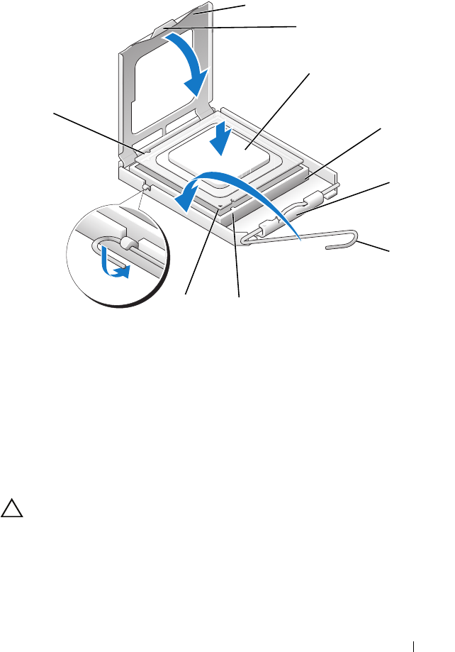
13
When the processor is fully seated in the socket, close the processor cover,
if applicable.
Ensure that the tab on the processor cover is positioned underneath the
center cover latch on the socket.
14
Pivot the socket release lever back towards the socket, and snap it into
place to secure the processor.
15
Clean the thermal grease from the bottom of the heat sink.
CAUTION: Ensure that you apply new thermal grease. New thermal grease is
critical for ensuring adequate thermal bonding, which is a requirement for optimal
processor operation.
16
Apply the new thermal grease to the top of the processor.
17
Install the processor fan and heat sink assembly (see "Replacing the Heat
Sink Assembly" on page 67).
CAUTION: Ensure that the processor fan and heat sink assembly is correctly
seated and secure.
18
Replace the computer cover (see"Replacing the Computer Cover" on
page 17).
19
Connect your computer and devices to electrical outlets, and then turn
them on.

Replacing Fans 77
11
Replacing Fans
WARNING: Before working inside your computer, read the safety information
that shipped with your computer. For additional safety best practices information,
see the Regulatory Compliance Homepage at
www.dell.com/regulatory_compliance.
WARNING: To guard against likelihood of electric shock, laceration by moving
fan blades or other unexpected injuries, always unplug your computer from the
electrical outlet before removing the cover.
Removing the Card Slot and Processor Fan Shrouds
1
Follow the procedures in "Before You Begin" on page 13.
2
Remove the computer cover (see "Replacing the Computer Cover" on
page 17).
3
Remove the captive screws on top of the shroud you are removing and lift
the shroud out of the chassis.
Replacing the Card Slot Fan Assembly
1
Remove the card slot fan shroud (see "Removing the Card Slot and
Processor Fan Shrouds" on page 77).
2
Remove any full-length expansion cards (see "Replacing the PCI and PCI
Express Cards" on page 35).
3
Disconnect the fan cable from the FAN_CAGE connector on the system
board.
4
Remove the front and back screws on the base of the fan cage.
5
Pull the fan cage to towards the rear of the chassis to disengage the cage
tabs.
6
Lift the cage off the chassis.
78 Replacing Fans
7
To install the card slot fan assembly, connect the fan cable to the
FAN_CAGE connector on the system board (see "Master Control Board"
on page 12).
8
Align the fan cage tabs with the slots in the chassis. Insert the tabs and
push the cage towards the front of the chassis.
9
Screw in the fan retention screws on the front and back of the fan cage.
10
Replace any expansion cards that you removed (see "Replacing a PCI/PCI
Express Card" on page 27).
11
Replace the PCI card fan shroud and captive screws on top of it.
1 cage housing 2 fan cage
3 screws (2)
1
2
3
Replacing Fans 79
12
Replace the computer cover (see "Replacing the Computer Cover" on
page 17).
13
Connect your computer and devices to electrical outlets, and then turn
them on.
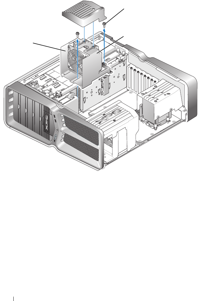
Replacing the Processor Fan Assembly
1
Remove the card slot fan shroud (see "Removing the Card Slot and
Processor Fan Shrouds" on page 77).
1 processor fan shroud 2 captive screws (2)
2
1

80 Replacing Fans
2
Remove the processor fan shroud (see "Removing the Card Slot and
Processor Fan Shrouds
" on page 77
)
3
Disconnect the fan cable from the FAN_CPU_FRONT connector on the
Master Control Board (see "Master Control Board" on page 12).
4Loosen the captive screws securing the processor fan shroud to the
chassis, then rotate the shroud back.
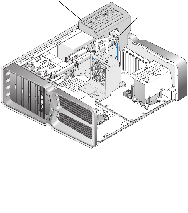
5
To Install the processor fan assembly, align the hinge slots on the processor
fan shroud with the hinge guides on the chassis.
6
Gently rotate the processor fan shroud towards the fan, and then tighten
the two captive screws.
7
Connect the fan cable to the rear fan connector on the LED circuit board
at the back of the chassis.
8
Replace the processor fan shroud on top o the processor fan assembly, and
then tighten the two captive screws.
9
Replace the computer cover (see "Replacing the Computer Cover" on
page 17).
10
Connect your computer and devices to electrical outlets, and turn
them on.
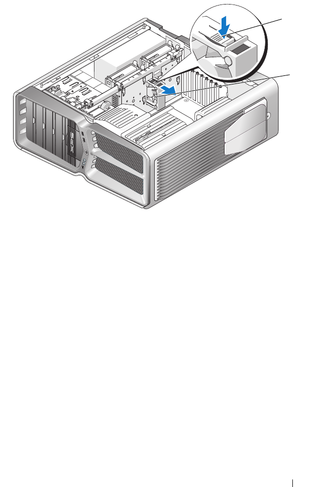
Replacing the Hard Drive Fan
1
Follow the procedures in "Before You Begin" on page 13.
2
Remove the computer cover (see "Replacing the Computer Cover" on
page 17).
3
Remove all installed memory modules (see "Replacing Memory
Module(s)" on page 23).
4
Disconnect the fan cable from the FAN_CPU_FRONT connector on the
Master Control Board (see "Master Control Board" on page 12).
5
Press the release latch on the hard drive fan and slide it away from the hard
drive bays and lift to remove from the computer.
Replacing Fans 81
6
To install the hard drive fan, slide the fan between the hard drive bays until
it snaps into place.
7
Connect the fan cable to the FAN_HDD connector on the Master Control
Board (see "Master Control Board" on page 12).
8
Replace the computer cover (see "Replacing the Computer Cover" on
page 17).
9
Connect your computer and devices to electrical outlets, and then turn
them on.
1 hard-drive fan release latch 2 hard drive fan
2
1

82 Replacing Fans

Replacing the Master Control Board 83
12
Replacing the Master Control Board
WARNING: Before working inside your computer, read the safety information
that shipped with your computer. For additional safety best practices information,
see the Regulatory Compliance Homepage at
www.dell.com/regulatory_compliance
1
Follow the procedures in "Before You Begin" on page 13.
2
Remove the computer cover (see "Replacing the Computer Cover" on
page 17).
3
Remove the fan shrouds (see "Removing the Card Slot and Processor Fan
Shrouds" on page 77).
4
Remove the card slot assembly (see "Replacing the Card Slot Fan
Assembly" on page 77).
5
Remove the processor fan assembly (see "Replacing the Processor Fan
Assembly" on page 79).
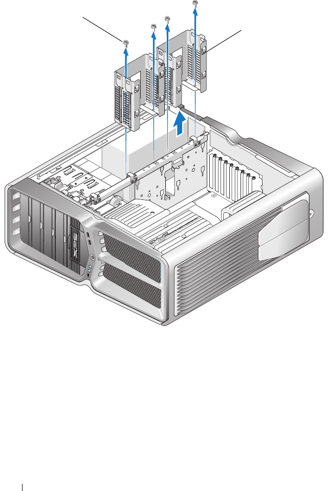
6
Disconnect all cables from the master control board.
7
Remove three screws that secure the master control panel to the metal
tray.
84 Replacing the Master Control Board
8
Lift the master control board out.
9
To replace the master control board, Orient the board on the metal tray.
10
Replace the three screws to secure the master control board assembly to
the metal tray.
11
Reconnect all cables to the master control board.
12
Replace the processor fan assembly (see "Replacing the Processor Fan
Assembly" on page 79).
13
Replace the card slot fan assembly (see "Replacing the Card Slot Fan
Assembly" on page 77).
14
Replace the fan shrouds.
15
Replace the computer cover (see "Replacing the Computer Cover" on
page 17).
1 master control board 2 Screws (3)
1
2

Replacing the System Board 85
13
Replacing the System Board
WARNING: Before working inside your computer, read the safety information
that shipped with your computer. For additional safety best practices information,
see the Regulatory Compliance Homepage at
www.dell.com/regulatory_compliance
1
Follow the procedures in "Before You Begin" on page 13.
2
Remove the computer cover (see "Replacing the Computer Cover" on
page 17).
3
Remove any full-length expansion cards (see "Replacing the PCI and PCI
Express Cards" on page 35).
4
Remove any additional components that may restrict access to the system
board.
5
Disconnect all cables from the system board.
CAUTION: If you are replacing the system board, visually compare the
replacement system board to the existing system board to make sure that you have
the correct part.
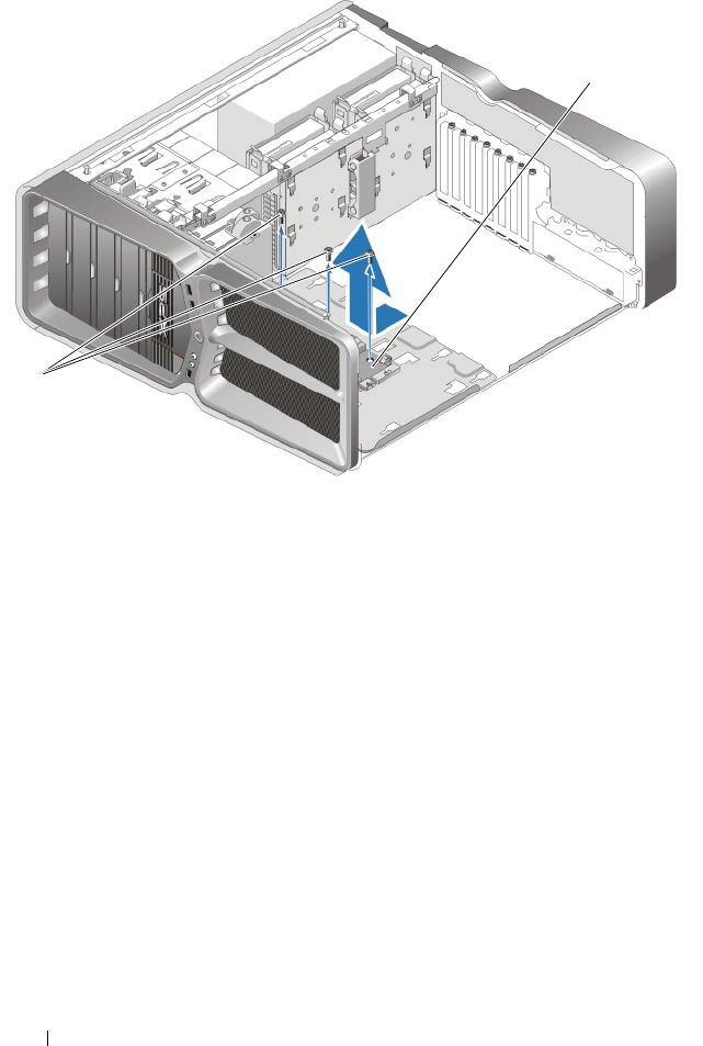
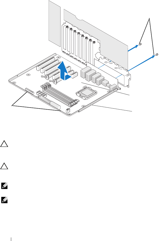
6
Remove the two screws securing the system board assembly to the chassis,
then pull on the two tabs to slide the system board assembly towards the
front of the computer.
86 Replacing the System Board
CAUTION: The system board and metal tray are connected and are removed as
one piece.
7
Carefully, lift the system board assembly up and out of the computer.
CAUTION: If you are replacing the system board, visually compare the
replacement system board to the existing system board to make sure that you have
the correct part.
NOTE: Some components and connectors on replacement system boards may be
in different locations than corresponding connectors on the existing system board.
NOTE: Jumper settings on replacement system boards are preset by the factory.
8
Transfer components from the existing system board to the replacement
system board, if applicable.
1 screws (2) 2 system board
3 metal tray 4 tabs
1
4
2
3

Replacing the System Board 87
9
Orient the system board assembly by aligning the notches on the bottom
of the assembly with the tabs on the computer.
10
Slide the system board assembly toward the back of the computer until the
assembly clicks into place.
11
Replace the two screws to secure the system board assembly to the chassis.
12
Replace any expansion cards that you removed (see "Replacing a PCI/PCI
Express Card" on page 27).
13
Replace any additional components that you removed from the system
board.
14
Reconnect all cables to the system board.
15
Replace the computer cover (see "Replacing the Computer Cover" on
page 17).
16
Connect your computer and devices to electrical outlets, and then turn
them on.
17
Flash the system BIOS, as needed.
NOTE: For information on flashing the system BIOS, see support.dell.com.

88 Replacing the System Board

Replacing the Power Supply 89
14
Replacing the Power Supply
WARNING: Before working inside your computer, read the safety information
that shipped with your computer. For additional safety best practices information,
see the Regulatory Compliance Homepage on www.dell.com at the following
location: www.dell.com/regulatory_compliance.
WARNING: To guard against electrical shock, always unplug your computer from
the electrical outlet before removing the cover.
1
Follow the procedures in "Before You Begin" on page 13.
2
Remove the computer cover (see "Replacing the Computer Cover" on
page 17).
3
Remove all hard drives installed in the interior hard drive bays (see
"Replacing a Hard Drive" on page 43).
4
Remove the hard drive fan, if applicable (see "Replacing the Hard Drive
Fan" on page 80).
5
Remove the two screws that attach the forward hard drive bay to the
chassis.
6
Remove the forward hard drive bay from the chassis.
90 Replacing the Power Supply
7
Remove the four screws that attach the power supply to the back of the
computer chassis.
8
Disconnect the power supply harness from the power supply by depressing
the two tabs and pulling the harness away from the power supply.
1 screws (4) 2 hard drive bays
1
2
Replacing the Power Supply 91
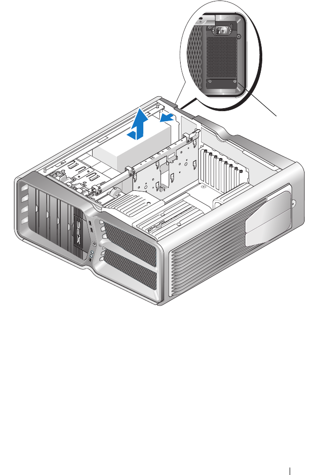
9
Slide the power supply towards the front of the computer to free it from
the securing tabs on the computer chassis.
10
Slide the power supply toward the hard drive bay area, so that it will clear
the protruding lip of the chassis and lift the power supply from the
computer.
11
To replace the power supply, slide the new power supply into place,
ensuring that the tabs on the rear wall of the computer chassis latch into
place.
1 power supply screws (4)
1

92 Replacing the Power Supply
12
Replace the four screws that secure the power supply to the back of the
computer chassis.
13
Reconnect the power supply harness to the power supply.
14
Replace the two hard drive bays.
15
Replace all hard drives installed in the interior hard drive bays (see
"Replacing a Hard Drive" on page 43).
16
Replace the hard drive fan, if applicable (see "Replacing the Hard Drive
Fan" on page 80).
17
Reconnect each of the DC power cables that were previously connected,
carefully rerouting them as you found them.
18
Replace the computer cover (see "Replacing the Computer Cover" on
page 17).
19
Connect your computer and devices to electrical outlets, and then turn
them on.
Replacing the Battery 93
15
Replacing the Battery
WARNING: Before working inside your computer, read the safety information
that shipped with your computer. For additional safety best practices information,
see the Regulatory Compliance Homepage at
www.dell.com/regulatory_compliance.
WARNING: A new battery can explode if it is incorrectly installed. Replace the
battery only with the same or equivalent type recommended by the manufacturer.
Discard used batteries according to the manufacturer’s instructions.
1
Record all the screens in system setup (see "System Setup" on page 97) so
that you can restore the correct settings in step 10.
2
Follow the procedures in "Before You Begin" on page 13.
3
Remove the computer cover (see "Replacing the Computer Cover" on page 17).
4
Locate the battery socket (see "System Board Components" on page 8).
CAUTION: If you pry the battery out of its socket with a blunt object, be careful
not to touch the system board with the object. Ensure that the object is inserted
between the battery and the socket before you attempt to pry out the battery.
Otherwise, you may damage the system board by prying off the socket or by
breaking circuit traces on the system board.
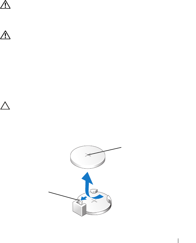
1battery (positive side) 2battery release lever
1
2
94 Replacing the Battery
5
Carefully press the battery release lever away from the battery and the
battery will pop out.
6
Remove the battery from the system and properly dispose of the battery.
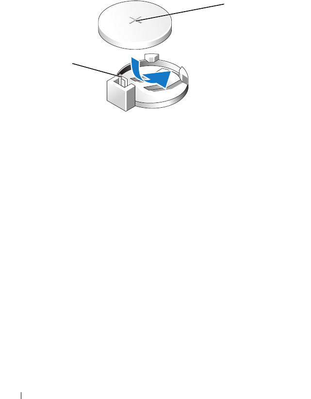
7
Insert the new battery into the socket with the side labeled "+" facing up,
then snap the battery into place.
8
Replace the computer cover (see "Replacing the Computer Cover" on
page 17).
9
Connect your computer and devices to electrical outlets, and then turn
them on.
10
Enter system setup (see "System Setup" on page 97) and restore the
settings you recorded in step 1.
1battery (positive side) 2battery release lever
1
2

System Setup 97
16
System Setup
Overview
Use System Setup to:
• change the system configuration information after you add, change, or
remove any hardware in your computer.
• set or change a user-selectable option such as the user password.
• read the current amount of memory or set the type of hard drive installed.
Before you use System Setup, it is recommended that you write down the
system setup screen information for future reference.
CAUTION: Do not change the settings in system setup unless you are an expert
computer user. Certain changes can cause your computer to work incorrectly.
Entering System Setup
1
Turn on (or restart) your computer.
2
When the DELL logo appears, press <F2> immediately.
NOTE: Keyboard failure may result when a key on the keyboard is held down
for extended periods of time. To avoid possible keyboard failure, press and
release <F2> in even intervals until the system setup screen appears.
If you wait too long and the operating system logo appears, continue to
wait until you see the Microsoft
®
Windows
®
desktop, then shut down
your computer and try again.

98 System Setup
System Setup Options—Dell™ XPS™ 730
NOTE: Depending on your computer and installed devices, the items listed in this
section may, or may not appear exactly as listed.
Main
System Date Displays the current date in the mm:dd:yy format.
System Time Displays the time in the hh:mm:ss format.
SATA 0 Displays the SATA 0 drive integrated in the system.
SATA 1 Displays the SATA 1 drive integrated in the system.
System Info Displays the BIOS version number and date, system model
name and the service tag of the computer.
Memory Info Indicates amount of installed memory, usable memory, memory
speed, memory channel mode (dual or single), and the type of
memory technology used.
Advanced
CPU Type Displays the processor type.
CPU Speed Displays the processor speed.
Cache L2 Displays the processor L2 cache size.
Advanced
Chipset
Features
Displays the video memory size.
Integrated
Peripherals
Allows you to enable or disable these integrated devices:
HD
Audio
,
Onboard LAN connector
,
Onboard LAN Boot ROM
,
and
Side logo
. Serial ATA Configuration can be set to IDE or
AHCI mode.
CPU
Configuration
Allows you to enable or disable the CPU features that enhance
the performance of the system.
USB
Configuration
Allows you to enable or disable the USB controller.

System Setup 99
Power
ACPI Suspend
Type
Specifies the ACPI suspend type. The default is S3.
Auto Power On Allows you to enable or disable an alarm to turn on the
computer automatically.
AC Recovery Specifies the behaviour of the system after recovering from a
power loss.
• Power on — The computer turns on after it recovers from a
power failure.
• Power off — The computer remains powered off.
• Last state— The computer returns the power state it was in
before the power failure.
HDD Acoustic
Mode
Determines the acoustic mode at which the hard drive
operates.
Bypass — Do nothing (needed for older drives).
Quiet — The hard drive operates at its most quiet setting.
Performance — The hard drive operates at its maximum speed.
NOTE: Switching to performance mode may cause an increase in
noise produced by the drive, but does not affect the drive's
performance.
Boot
Boot Device
Priority
Sets the boot priority among the available devices.
Hard Disk Boot
Priority
Sets the hard drive boot priority. The items displayed are
dynamically updated according to the hard drives detected.
CD/DVD Boot
Priority
Sets the optical drive boot priority. The items displayed are
dynamically updated according to the optical drives detected.
Boot Settings
Configuration
Allows the BIOS to skip certain tests while booting. This
decreases the time needed to boot the system.
Security Allows you to set or change the supervisor password.

100 System Setup
System Setup Options—Dell XPS 730X
Exit
Exit Options Provides options to Save Changes and Exit, Discard Changes
and Exit, Load Optimal Defaults, and Discard Changes.
System Information
Product Name XPS 730X.
BIOS Version Displays the BIOS version number and date information.
Input Service
tag
Allows you to input the service tag.
Service Tag Displays the service tag of the computer.
Asset Tag Displays the Asset tag of the computer.
Memory
Installed
Indicates amount of memory installed.
Memory
Available
Indicates the amount of usable memory.
Memory
Techonology
Indicates the type of memory technology used.
Memory Speed Indicates the memory speed.
CPU ID/ u Code
ID
Displays the processor type.
CPU Speed Displays the processor speed.
Current
QuickPath
Interconnect
(QPI) speed
Displays the QPI Speed.
Cache L2 Displays the processor L2 cache size.
Standard CMOS Features

System Setup 101
System Time
(hh:mm:ss)
Displays the current time.
System Date
(mm:dd:yy)
Displays thecurrent date.
SATA 1 Displays the SATA 1 drive integrated in the system.
SATA 2 Displays the SATA 2 drive integrated in the system.
SATA 3 Displays the SATA 3 drive integrated in the system.
SATA 4 Displays the SATA 4 drive integrated in the system.
SATA 5 Displays the SATA 5 drive integrated in the system.
SATA 6 Displays the SATA 6 drive integrated in the system.
SATA 7 Displays the SATA 7 drive integrated in the system.
SATA 8 Displays the SATA 8 drive integrated in the system.
IDE Master Displays the IDE Master installed in the system.
IDE Slave Displays the IDE Slave installed in the system.
Advanced BIOS Features
Boot up
NumLock Status
Select power-on state for num-lock.
ACPI APIC
support
Include ACPI APIC table pointer to RSDT pointer list.
Boot Configuration Features
1st Boot
Device
Displays the first boot device.
2nd Boot
Device
Displays the second boot device.
Hard Disk
Drives
Sets the hard drive boot priority. The items displayed are
dynamically updated according to the hard drives detected.
CD/DVD Drives Sets the CD/DVD drive boot priority. The items displayed are
dynamically updated according to the hard drives detected.

102 System Setup
CPU Configuration
XD Bit
Capability
Enable XD Bit Capability to allow the processor to distinguish
between the bits of code that should be executed and the ones
that cannot be executed.
C1E Support The Enhanced Halt State (C1E) reduces the processor speed
down to its lowest multiplier when the load on the processor is
reduced.
Max CPUID
Value Limit
Limits the max value the processor standard CPUID function
will support.
Intel(R)
Speedstep (tm)
tech
If enabled, the processor clock speed and core voltage are
adjusted dynamically based on the processor load.
Integrated Devices
USB Functions Allows you to enable or disable the integrated USB controller.
HD Audio
Controller
Allows you to enable or disable the integrated audio controller.
Onboard
IEEE1394
Controller
Allows you to enable or disable the onboard IEEE1394
controller.
LAN1 BCM5784
Device
Allows you to enable or disable the onboard network controller.
LAN1 Option
ROM
Allows you to enable or disable the network controllers boot
option.
LAN2 BCM5784
Device
Allows you to enable or disable the onboard network controller.
LAN2 Option
ROM
Allows you to enable or disable the network controllers boot
option.
Configure
SATA#1-6 as
Allows you to configure the operating mode of the integrated
hard drive controller.
AHCI CD/DVD
Boot TIme out
Allows you to set the wait time for SATA CD/DVD in AHCI
mode.

System Setup 103
Power Management Setup
Suspend Mode This option sets the energy-saving mode of the ACPI function.
AC Recovery This option sets what action the PC takes when power is
restored.
Remote Wakeup This option sets the system to wake up from an onboard LAN,
PCIE-X1 LAN card, or a PCI LAN card.
Auto Power On This option allows the computer to start up at a certain time.
Frequency/Voltage Control
QPI Links
SPeed
Allows you to change the QuickPath Interconnect (QPI) Links
to full-speed or slow-mode.
QPI Frequency Allows you to change the (QPI) frequency.
Memory
Frequency
Allows you to force a DDR3 frequency slower than the detected
frequency.
Uncore Ratio Allows you to adjust the Uncore Ratio.
CPU Core (Non-
Turbo)Ratio
Sets the ratio between CPU Core Clock and the FSB
Frequency.
BIOS Security Features
Change
Supervisor
Password
Allows you to change the supervisor password.
Change User
Password
Allows you to change the user password. You cannot use the
user password to enter the BIOS setup, during POST.
Exit
Exit Options Provides options to Save Changes and Exit, Discard Changes
and Exit, Load Optimal Defaults, and Discard Changes.

104 System Setup
Boot Sequence
This feature allows you to change the boot sequence for the bootable devices
installed on your computer.
Option Settings
•
Hard Drive
— The computer attempts to boot from the primary hard
drive. If no operating system is on the drive, the computer attempts to
boot from the next bootable device in the boot sequence.
•
CD Drive
— The computer attempts to boot from the CD drive. If no CD
is in the drive, or if the CD has no operating system, the computer
attempts to boot from the next bootable device in the boot sequence.
•
USB Flash Device —
The computer attempts to boot from the USB drive.
If no USB is in the drive the computer attempts to boot from the next
bootable device in the boot sequence.
NOTE: To boot to a USB device, the device must be bootable. To ensure that
your device is bootable, check the device documentation.
NOTE: An error message is generated only after the computer attempts to
boot from every device in the boot sequence and no operating system is found.
Changing Boot Sequence for the Current Boot
For example, you can use this feature to boot your computer from the CD
drive so that you can run the Dell Diagnostics from the Driver and Utilities
media and then from the hard drive when the diagnostic tests are complete.
You can also use this feature to boot your computer to a USB device such as a
memory key, or CD-RW drive.
1
If you are booting to a USB device, connect the USB device to a USB
connector.
2
Turn on (or restart) your computer.
3
When the DELL logo appears, press <F12> immediately.
NOTE: Keyboard failure may result when a key on the keyboard is held down
for an extended period of time. To avoid possible keyboard failure, press and
release <F12> in even intervals until the Boot Device Menu appears.

System Setup 105
If you wait too long and the operating system logo appears, continue to
wait until you see the Microsoft Windows desktop, then shut down your
computer and try again.
4
At the
Boot Device Menu
, use the up- and down- arrow keys or press the
appropriate number on the keyboard to highlight the device that is to be
used for the current boot only, and then press <Enter>.
For example, if you are booting to a USB memory key, highlight
USB Flash
Device
and press <Enter>.
NOTE: To boot to a USB device, the device must be bootable. To ensure that
your device is bootable, check the device documentation.
Changing Boot Sequence for Future Boots
1
Enter system setup (see "Entering System Setup" on page 97).
2
Use the arrow keys to highlight the
Boot Sequence
menu option and press
<Enter> to access the menu.
NOTE: Make a note of your current boot sequence in case you want to
restore it.
3
Press the up- and down-arrow keys to move through the list of devices.
4
Press the spacebar to enable or disable a device.
5
Press plus (+) or minus (–) to move a selected device up or down the list.
Clearing CMOS Settings
NOTE: This procedure does not clear or reset system and setup passwords.
1
Follow the procedures in "Before You Begin" on page 13.
2
Power down the computer and remove the power cord.
3
Power off all external peripherals.
4
Remove the computer cover (see "Replacing the Computer Cover" on
page 17).
5
Locate the Reset CMOS jumpers on the system board (see "System Board
Components" on page 8).
6
Remove jumper from pins 2 and 3.
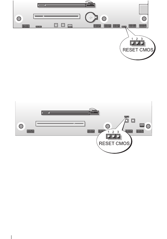

System Setup 107

108 System Setup

System Setup 109

110 System Setup
