Dell Alienware Aurora Alx Service Manual (English Only) User En Us
Dell-Alienware-Aurora-Alx-Late-2009-Service-Manual-110564 dell-alienware-aurora-alx-late-2009-service-manual-110564
User Manual: Dell alienware-aurora-alx - Alienware Aurora ALX Service Manual (English only)
Open the PDF directly: View PDF ![]() .
.
Page Count: 117 [warning: Documents this large are best viewed by clicking the View PDF Link!]
- CHAPTER 1: BEFORE YOU BEGIN
- CHAPTER 2: LEFT SIDE-PANEL
- CHAPTER 3: TECHNICAL OVERVIEW
- CHAPTER 4: SHROUDS
- CHAPTER 5: DRIVE(S)
- CHAPTER 6: PCI-EXPRESS CARD(S)
- CHAPTER 7: MEMORY MODULE(S)
- CHAPTER 8: FANS
- CHAPTER 9: PROCESSOR LIQUID-COOLING ASSEMBLY
- CHAPTER 10: PROCESSOR
- CHAPTER 11: POWER SUPPLY
- CHAPTER 12: BATTERY
- CHAPTER 13: SYSTEM BOARD
- CHAPTER 14: MASTER I/O BOARD
- CHAPTER 15: TOP LIGHTING-BOARD
- CHAPTER 16: RIGHT SIDE-PANEL(S)
- CHAPTER 17: ACTIVE-VENTING ASSEMBLY
- CHAPTER 18: FRONT BEZEL
- CHAPTER 19: BACK BEZEL
- CHAPTER 20: BLUETOOTH ASSEMBLY
- CHAPTER 21: TOP I/O PANEL
- CHAPTER 22: SYSTEM SETUP
- APPENDIX A: CONTACTING ALIENWARE
01 01
/
ALIENWARE® AURORA
SERVICE MANUAL

02 02
/
e contents herein are subject to change without notice.
©2009-2010 Dell Inc. All rights reserved.
Reproduction of these materials in any manner whatsoever without the prior
written permission of Dell Inc. is strictly prohibited.
Trademarks used in this manual:
Alienware
is a registered trademark of Alienware
Corporation;
Dell
and the
DELL
logo are trademarks of Dell Inc.;
Bluetooth
is
a registered trademark owned by Bluetooth SIG, Inc. and is used by Dell under
license;
Microsoft
,
Windows
, and the
Windows
start button logo are either
trademarks or registered trademarks of Microsoft Corporation in the United
States and/or other countries;
Intel
and
SpeedStep
are registered trademarks of
Intel Corporation in the U.S. and other countries.
Other trademarks and trade names may be used in this manual to refer to either
the entities claiming the marks and names or their products. Dell Inc. disclaims
any proprietary interest in trademarks and trade names other than its own.
Model: D0IM Type: D0IM001; D0IM002 Rev. A01 FEBRUARY 2010
Notes, Cautions, and Warnings
NOTE: A NOTE indicates important information that helps you make better
use of your computer.
CAUTION: A CAUTION indicates either potential damage to hardware or
loss of data and tells you how to avoid the problem.
WARNING: A WARNING indicates a potential for property damage,
personal injury, or death.
03 03
/
CONTENTS
CONTENTS
CHAPTER 1: BEFORE YOU BEGIN ......................................... 6
Recommended Tools .............................................. 7
Turning O Your Computer ........................................ 7
Before Working Inside Your Computer . . . . . . . . . . . . . . . . . . . . . . . . . . . . . . 8
CHAPTER 2: LEFT SIDE-PANEL .......................................... 9
Removing the Left Side-Panel .....................................11
Replacing the Left Side-Panel......................................11
CHAPTER 3: TECHNICAL OVERVIEW .....................................12
Inside View of Your Computer ..................................... 13
System Board Components....................................... 14
Master I/O Board Components .................................... 15
CHAPTER 4: SHROUDS .................................................16
Opening the PCI Shroud .......................................... 18
Closing the PCI Shroud ........................................... 18
Removing the Drive-Bay Shroud .................................. 19
Replacing the Drive-Bay Shroud................................... 19
CHAPTER 5: DRIVE(S) .................................................20
Removing the Hard Drive(s) ......................................22
Replacing the Hard Drive(s).......................................24
Removing the Optical Drive(s) ....................................25
Replacing the Optical Drive(s).....................................26
Removing the Media Card Reader .................................27
Replacing the Media Card Reader .................................29
CHAPTER 6: PCI-EXPRESS CARD(S) ....................................30
Removing the PCI-Express Card(s) ................................32
Replacing the PCI-Express Card(s).................................33
CHAPTER 7: MEMORY MODULE(S)......................................35
Removing the Memory Module(s) .................................37
Replacing the Memory Module(s) .................................38
04 04
/
CONTENTS
CHAPTER 13: SYSTEM BOARD ..........................................66
Removing the System Board......................................68
Replacing the System Board ......................................69
CHAPTER 14: MASTER I/O BOARD ......................................70
Removing the Master I/O Board...................................72
Replacing the Master I/O Board ...................................73
CHAPTER 15: TOP LIGHTING-BOARD.................................... 74
Removing the Top Lighting-Board ................................76
Replacing the Top Lighting-Board.................................76
CHAPTER 16: RIGHT SIDE-PANEL(S) .....................................77
Removing the Right Side-Panel(s) ................................79
Replacing the Right Side-Panel(s)................................. 81
CHAPTER 17: ACTIVE-VENTING ASSEMBLY ..............................82
Removing the Active-Venting Assembly ...........................84
Replacing the Active-Venting Assembly ...........................87
CHAPTER 18: FRONT BEZEL ............................................88
Removing the Front Bezel ........................................90
Replacing the Front Bezel ........................................92
CHAPTER 8: FANS .....................................................40
Removing the Hard-Drive Fan Assembly...........................42
Replacing the Hard-Drive Fan Assembly ...........................43
Removing the PCI-Fan Assembly..................................44
Replacing the PCI-Fan Assembly ..................................45
CHAPTER 9: PROCESSOR LIQUID-COOLING ASSEMBLY...................46
Removing the Processor Liquid-Cooling Assembly .................48
Replacing the Processor Liquid-Cooling Assembly .................49
CHAPTER 10: PROCESSOR .............................................50
Removing the Processor..........................................52
Replacing the Processor ..........................................53
CHAPTER 11: POWER SUPPLY ..........................................55
Removing the Power Supply . . . . . . . . . . . . . . . . . . . . . . . . . . . . . . . . . . . . . . 57
Replacing the Power Supply ......................................59
CHAPTER 12: BATTERY ................................................60
Removing the Coin-Cell Battery ...................................62
Replacing the Coin-Cell Battery ...................................63
Removing the eater-Lighting Batteries .........................64
Replacing the eater-Lighting Batteries..........................65
05 05
/
CONTENTS
CHAPTER 19: BACK BEZEL .............................................93
Removing the Back Bezel.........................................95
Replacing the Back Bezel .........................................97
CHAPTER 20: BLUETOOTH ASSEMBLY..................................98
Removing the Bluetooth Assembly...............................100
Replacing the Bluetooth Assembly............................... 101
CHAPTER 21: TOP I/O PANEL ..........................................102
Removing the Top I/O Panel .....................................104
Replacing the Top I/O Panel......................................105
CHAPTER 22: SYSTEM SETUP .........................................106
Conguring the BIOS ............................................107
Clearing Forgotten Passwords and CMOS Settings .................114
APPENDIX A: CONTACTING ALIENWARE ................................117
CHAPTER 1: BEFORE YOU BEGIN
06 06
/
is manual provides procedures for removing and installing the components
in your computer. Unless otherwise noted, each procedure assumes that the
following conditions exist:
You have performed the steps in “Turning O Your Computer” on page • 7 and
“Before Working Inside Your Computer” on page 8.
You have read the safety information that shipped with your computer.•
A component can be replaced or—if purchased separately—installed by •
performing the removal procedure in reverse order.
CHAPTER 1: BEFORE YOU BEGIN
CHAPTER 1: BEFORE YOU BEGIN

07 07
/
CHAPTER 1: BEFORE YOU BEGIN
Turning O Your Computer
CAUTION: To avoid losing data, save and close all open les and exit all
open programs before you turn o your computer.
Save and close all open les and exit all open programs.1.
Click 2. Start → Shut Down.
e computer turns o after the operating system shutdown process 3.
nishes.
Ensure that the computer is turned o. If your computer did not 4.
automatically turn o when you shut down the operating system, press and
hold the power button until the computer turns o.
Recommended Tools
e procedures in this document may require the following tools:
Small at-blade screwdriver•
Phillips screwdriver•
BIOS executable update program available at • support.dell.com
08 08
/
CHAPTER 1: BEFORE YOU BEGIN
Ensure that the work surface is at and clean.1.
Turn o your computer (see “Turning O Your Computer” on page 2. 7).
CAUTION: To disconnect a network cable, rst unplug the cable from
your computer and then unplug the cable from the network device.
Disconnect all telephone or network cables from the computer.3.
Disconnect your computer and all attached devices from their electrical 4.
outlets.
Disconnect all attached devices from your computer.5.
Press and eject any installed cards from the Media Card Reader.6.
Press and hold the power button to ground the system board.7.
CAUTION: Before touching anything inside your computer, ground
yourself by touching an unpainted metal surface, such as the metal at the
back of the computer. While you work, periodically touch an unpainted
metal surface to dissipate static electricity, which could harm internal
components.
NOTE: For better access to components within your computer, lay your
computer on its side.
Before Working Inside Your Computer
Use the following safety guidelines to help protect your computer from potential
damage and to help to ensure your own personal safety.
WARNING: Before you begin any of the procedures in this section, follow
the safety instructions that shipped with your computer. For additional
safety best practices information, see the Regulatory Compliance
Homepage at www.dell.com/regulatory_compliance.
CAUTION: Only a certied service technician should perform repairs on
your computer. Damage due to servicing that is not authorized by Dell is
not covered by your warranty.
CAUTION: When you disconnect a cable, pull on its connector or on its
pull-tab, not on the cable itself. Some cables have connectors with locking
tabs; if you are disconnecting this type of cable, press in on the locking
tabs before you disconnect the cable. As you pull connectors apart, keep
them evenly aligned to avoid bending any connector pins. Also, before
you connect a cable, ensure that both connectors are correctly oriented
and aligned.
CAUTION: To avoid damaging the computer, perform the following steps
before you begin working inside the computer.
CHAPTER 2: LEFT SIDE-PANEL
09 09
/
CHAPTER 2: LEFT SIDE-PANEL
CHAPTER 2: SIDE PANEL

010 010
/
CHAPTER 2: LEFT SIDE-PANEL
Left Side-Panel
WARNING: Before working inside your computer, read the safety
information that shipped with your computer. For additional safety best
practices information, see the Regulatory Compliance Homepage at
www.dell.com/regulatory_compliance.
WARNING: To guard against likelihood of electric shock, laceration by
moving fan blades, or other unexpected injuries, always unplug your
computer from the electrical outlet before removing the side panel(s).
WARNING: Do not operate your computer with any cover(s) (including
computer covers, bezels, ller brackets, front-panel inserts, etc.)
removed.
CAUTION: Only a certied service technician should perform repairs on
your computer. Damage due to servicing that is not authorized by Dell™
is not covered by your warranty.
011 011
/
CHAPTER 2: LEFT SIDE-PANEL
1
3
2
4
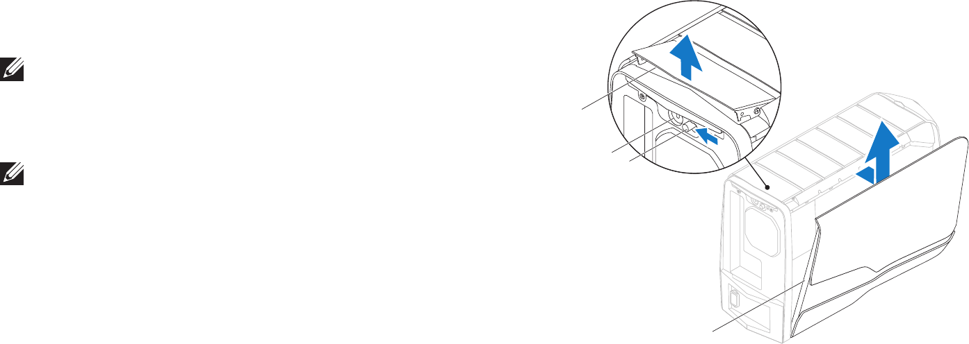
1 release panel 2 security cable slot
3 latch 4 left side-panel
Removing the Left Side-Panel
Follow the instructions in “Before You Begin” on page 1. 6.
NOTE: Ensure that you remove the security cable from the security cable
slot (if applicable).
Slide the latch to unlock the release panel.2.
Lift the release panel to open the left-side panel.3.
Place the left side-panel in a secure location.4.
NOTE: eater lighting (available only in Alienware Aurora ALX) turns on
automatically when the left side-panel is removed.
Replacing the Left Side-Panel
Follow the instructions in “Before You Begin” on page 1. 6.
Align the tabs on the left side-panel with the slots on the side of the 2.
computer and push the panel in place.
Slide the latch to lock the release panel.3.
CHAPTER 3: TECHNICAL OVERVIEW
012 012
/
CHAPTER 3: TECHNICAL OVERVIEW
CHAPTER 3: TECHNICAL OVERVIEW
013 013
/
CHAPTER 3: TECHNICAL OVERVIEW
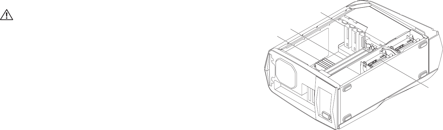
1
2
3
4
1 memory module(s) 2 graphic cards (2)
3 optical drives (3) 4 hard drives (4)
Inside View of Your Computer
WARNING: Before working inside your computer, read the safety
information that shipped with your computer. For additional safety best
practices information, see the Regulatory Compliance Homepage at
www.dell.com/regulatory_compliance.
014 014
/
CHAPTER 3: TECHNICAL OVERVIEW
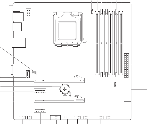
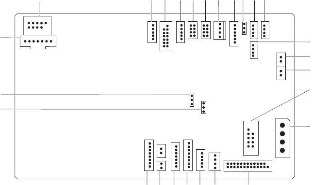
1processor power connector (PWR2) 2processor socket (CPU)
3processor fan connector (MB_CPU_FAN) 4memory-module connector (DIMM2)
(Aurora and Aurora ALX )
memory-module connector (DIMM3)
(Aurora-R2)
5memory-module connector (DIMM1) 6memory-module connector (DIMM4)
7memory-module connector (DIMM3)
(Aurora and Aurora ALX)
memory-module connector (DIMM2)
(Aurora-R2)
8memory-module connector (DIMM6)
(Aurora and Aurora ALX only)
9memory-module connector (DIMM5)
(Aurora and Aurora ALX only)
10 main power connector (PWR1)
11 password jumper (PASSWORD) 12 serial ATA drive connectors (SATA1_2)
13 serial ATA drive connectors (SATA3_4) 14 serial ATA drive connectors (SATA5_6)
15 front panel connector (FRONT_PANEL) 16 USB connector (USB1)
17 USB connector (USB2) 18 USB connector (USB3)
19 Low pin count debug header (LPC1) 20 IEEE 1394 connector (1394)
21 PCI-Express x1 connector (SLOT4) 22 S/PDIF connector (SPDIF)
(Aurora and Aurora ALX only)
23 front audio connector (FRONT AUDIO) 24 PCI-Express x16 connector (SLOT3)
25 CMOS jumper (CLEAR_CMOS) 26 PCI-Express x1 connector (SLOT2)
27 battery socket (BAT1) 28 PCI-Express x16 connector (SLOT1)
29 eSATA connector (ESATA) 30 processor cooling assembly
connector (CHIPSET_FAN)
System Board Components
2021
2223
24
25
27
26
28
29
30
12 3 456 7 8 9
10
12
11
13
14
15
16
17
1819
015 015
/
CHAPTER 3: TECHNICAL OVERVIEW
1flexbay connector (FLEXBAY) 2drive-bay shroud battery connector
(FRONT_BEZEL)
3 active-vent connector
(ACTIVE_VENT)
4AlienHead connector (HEAD1)
5front-bezel right connector
(FRONT_RIGHT)
6front-bezel left connector
(FRONT_LEFT)
7PCI-fan connector (FAN_PCI) 8 left side-panel contact board
connector (SIDE_L)
9power-select connector (PWR_SEL) 10 Bluetooth® connector (BLUETOOTH)
11 power-LED board connector (BLINK) 12 wireless connector (WIRELESS)
13 hard-drive LED connector
(HDD_LED1)
14 hard-drive LED connector
(HDD_LED2)
15 USB connector (MB_USB) 16 main-power connector (PWR1)
17 system-board lighting (MB_MIO) 18 hard-drive fan connector (FAN_HDD)
19 right side-panel connector
(SIDE_R)
20 vent-motor connector
(VENT_MOTOR1)
21 vent sensors (VENT_SW) 22 ODD sensors (ODD_SW)
23 vent-motor sensor connector
(VENT_MOTOR2)
24 internal theater-lighting connector
(BAT2)
25 front-default connector
(FACTORY_DEFAULT)
26 graphics-pump connector
(GFX_PUMP)
Master I/O Board Components
5
4
3
2
12
13
14
15
16
25
24
26
1678 9 10 11
17
18
19
2021
22
23
CHAPTER 4: SHROUDS
016 016
/
CHAPTER 5: SHROUDS
CHAPTER 4: SHROUDS

017 017
/
CHAPTER 4: SHROUDS
Shrouds
WARNING: Before working inside your computer, read the safety
information that shipped with your computer. For additional safety best
practices information, see the Regulatory Compliance Homepage at
www.dell.com/regulatory_compliance.
WARNING: Do not operate your computer with any cover(s) (including
computer covers, bezels, ller brackets, front-panel inserts, etc.)
removed.
WARNING: To guard against electrical shock, always unplug your
computer from the electrical outlet before removing the side panel(s).
CAUTION: Only a certied service technician should perform repairs on
your computer. Damage due to servicing that is not authorized by Dell™
is not covered by your warranty.
018 018
/
CHAPTER 4: SHROUDS
Opening the PCI Shroud
Follow the instructions in “Before You Begin” on page 1. 6.
Remove the left side-panel (see “Removing the Left Side-Panel“ on page 2. 11).
Press the release button and rotate the PCI shroud away from the chassis.3.
Closing the PCI Shroud
Follow the instructions in “Before You Begin” on page 1. 6.
Lower the PCI shroud into the chassis until it clicks into place.2.
Replace the left side-panel (see “Replacing the Left Side-Panel“ on page 3. 11).
Connect your computer and devices to electrical outlets and then turn 4.
them on.
1
2
1 release button 2 PCI shroud
019 019
/
CHAPTER 4: SHROUDS
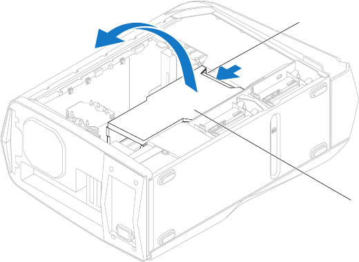
2
1
1 tabs (2) 2 drive-bay shroud
Removing the Drive-Bay Shroud
Follow the instructions in “Before You Begin” on page 1. 6.
Remove the left side-panel (see “Removing the Left Side-Panel“ on page 2. 11).
Open the PCI shroud (see “Opening the PCI Shroud” on page 3. 18).
Press the tabs and slide the drive-bay shroud towards the back of the 4.
chassis.
Disconnect the drive-bay shroud battery cable from the connector on the 5.
master I/O board.
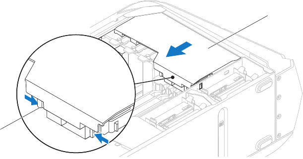
Replacing the Drive-Bay Shroud
Follow the instructions in “Before You Begin” on page 1. 6.
Connect the drive-bay shroud battery cable to the connector on the master 2.
I/O board.
Align the drive-bay shroud with the slots on the chassis.3.
Slide the drive-bay shroud toward the front of the chassis until it clicks into 4.
place.
Close the PCI shroud (see “Closing the PCI Shroud” on page 5. 18).
Replace the left side-panel (see “Replacing the Left Side-Panel“ on page 6. 11).
Connect your computer and devices to electrical outlets and then turn 7.
them on.
CHAPTER 5: DRIVE(S)
020 020
/
CHAPTER 6: DRIVE(S)
CHAPTER 5: DRIVE(S)
021 021
/
CHAPTER 5: DRIVE(S)
Drive(s)
WARNING: Before working inside your computer, read the safety
information that shipped with your computer. For additional safety best
practices information, see the Regulatory Compliance Homepage at
www.dell.com/regulatory_compliance.
WARNING: Do not operate your computer with any cover(s) (including
computer covers, bezels, ller brackets, front-panel inserts, etc.)
removed.
WARNING: To guard against electrical shock, always unplug your
computer from the electrical outlet before removing the side panel(s).
WARNING: If you remove the hard drive from the computer when the
drive is hot, do not touch the metal housing of the hard drive.
CAUTION: Only a certied service technician should perform repairs on
your computer. Damage due to servicing that is not authorized by Dell™
is not covered by your warranty.
CAUTION: To prevent data loss, turn o your computer (see “Turning
O Your Computer” on page 7) before removing the hard drive. Do not
remove the hard drive while the computer is on or in Sleep state.
CAUTION: Hard drives are extremely fragile. Exercise care when handling
the hard drive.
CAUTION: To avoid electrostatic discharge, ground yourself by using a
wrist grounding strap or by periodically touching an unpainted metal
surface (such as a connector on the back of the computer).
NOTE: Dell does not guarantee compatibility or provide support for hard
drives from sources other than Dell or Alienware.
NOTE: If you are installing a hard drive from a source other than Dell or
Alienware, you need to install an operating system, drivers, and utilities on
the new hard drive.
022 022
/
CHAPTER 5: DRIVE(S)
Removing the Hard Drive(s)
CAUTION: If you are replacing a hard drive that contains data you want
to keep, back up your les before you begin this procedure.
Follow the instructions in “Before You Begin” on page 1. 6.
Remove the left side-panel (see “Removing the Left Side-Panel“ on page 2. 11).
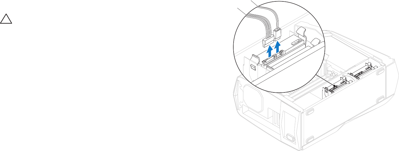
Disconnect the power and data cables from the hard-drive assembly 3.
(if applicable).
2
1
1 power cable 2 data cable
023 023
/
CHAPTER 5: DRIVE(S)
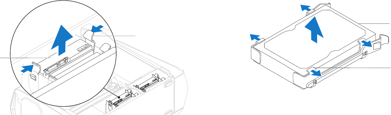
Press the release tabs and slide the hard-drive assembly out of the hard- 4.
drive cage.
1
2
1 hard-drive assembly 2 release tabs (2)
Remove the hard drive out of the hard-drive bracket by releasing the tabs 5.
and lifting the hard drive out of the bracket (if applicable).
2
1
1 hard drive 2 tabs (4)
024 024
/
CHAPTER 5: DRIVE(S)
Replacing the Hard Drive(s)
Follow the instructions in “Before You Begin” on page 1. 6.
See the documentation that shipped with your new hard drive and ensure 2.
that the jumper positioning is correct.
Snap the hard-drive bracket on to the new hard drive (if applicable).3.
Slide the hard-drive assembly into the hard-drive cage until the release tabs 4.
snap into place.
Connect the power and data cables to the hard-drive assembly 5.
(if applicable).
Replace the left side-panel (see “Replacing the Left Side-Panel“ on page 6. 11).
Connect your computer and devices to electrical outlets and then turn 7.
them on.
025 025
/
CHAPTER 5: DRIVE(S)
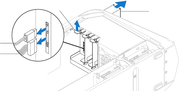
2
34
1
1 power cable 2 data cable
3 securing tab 4 optical drive
Removing the Optical Drive(s)
Follow the instructions in “Before You Begin” on page 1. 6.
Press the AlienHead on the front of your computer to lower the drive panel.2.
Remove the left side-panel (see “Removing the Left Side-Panel“ on page 3. 11).
Open the PCI shroud (see “Opening the PCI Shroud” on page 4. 18).
Disconnect the power and data cables from the optical drive (if applicable).5.
Lift the securing tab and slide the optical drive out through the front of the 6.
computer.
026 026
/
CHAPTER 5: DRIVE(S)
Replacing the Optical Drive(s)
Follow the instructions in “Before You Begin” on page 1. 6.
Remove the new optical drive from its packaging. Save the original 2.
packaging for storing or shipping the optical drive.
Remove the optical-drive bay ller (if applicable).3.
Lift the securing tab and slide the optical drive through the front of the 4.
computer until the securing tab snaps into place.
Connect the power and data cables to the optical drive (if applicable).5.
Close the PCI shroud (see “Closing the PCI Shroud” on page 6. 18).
Replace the left side-panel (see “Replacing the Left Side-Panel“ on page 7. 11).
Lift the drive panel towards the top of your computer.8.
Connect your computer and devices to electrical outlets and then turn 9.
them on.
027 027
/
CHAPTER 5: DRIVE(S)
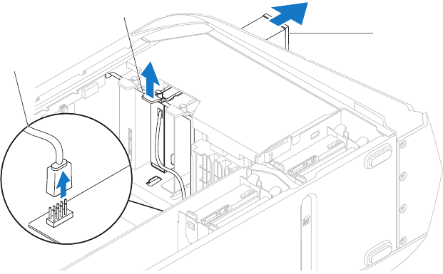
3
1
2
1FlexBay USB cable 2 securing tab
3FlexBay dock
Removing the Media Card Reader
Follow the instructions in “Before You Begin” on page 1. 6.
Press the AlienHead on the front of your computer to lower the drive panel.2.
Remove the left side-panel (see “Removing the Left Side-Panel“ on page 3. 11).
Open the PCI shroud (see “Opening the PCI Shroud” on page 4. 18).
Disconnect the FlexBay USB cable from the connector on the master I/O 5.
board.
Lift the securing tab and slide the FlexBay dock out through the front of the 6.
computer.
028 028
/
CHAPTER 5: DRIVE(S)
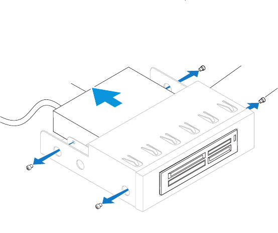
13
2
1 Media Card Reader 2 FlexBay dock
3 screws (4)
Remove the four screws that secure the Media Card Reader to the FlexBay 7.
dock.
Slide the Media Card Reader out of the FlexBay dock.8.
029 029
/
CHAPTER 5: DRIVE(S)
Replacing the Media Card Reader
Follow the instructions in “Before You Begin” on page 1. 6.
Remove the new Media Card Reader from its packaging. Save the original 2.
packaging for storing or shipping the Media Card Reader.
Slide the Media Card Reader into the FlexBay dock.3.
Replace the four screws that secure the Media Card Reader to the FlexBay 4.
dock.
Lift the securing tab and slide the FlexBay dock through the front of the 5.
computer until the securing tab snaps into place.
Connect the FlexBay USB cable to the connector on the master I/O board.6.
Close the PCI shroud (see “Closing the PCI Shroud” on page 7. 18).
Replace the left side-panel (see “Replacing the Left Side-Panel“ on page 8. 11).
Lift the drive panel towards the top of your computer.9.
Connect your computer and devices to electrical outlets and then turn 10.
them on.
CHAPTER 6: PCI-EXPRESS CARD(S)
030 030
/
CHAPTER 6: PCI EXPRESS CARD(S)
CHAPTER 6: PCI-EXPRESS CARD(S)

031 031
/
CHAPTER 6: PCI-EXPRESS CARD(S)
PCI-Express Card(s)
WARNING: Before working inside your computer, read the safety
information that shipped with your computer. For additional safety best
practices information, see the Regulatory Compliance Homepage at
www.dell.com/regulatory_compliance.
WARNING: Do not operate your computer with any cover(s) (including
computer covers, bezels, ller brackets, front-panel inserts, etc.)
removed.
WARNING: To guard against electrical shock, always unplug your
computer from the electrical outlet before removing the side panel(s).
CAUTION: Only a certied service technician should perform repairs on
your computer. Damage due to servicing that is not authorized by Dell™
is not covered by your warranty.
032 032
/
CHAPTER 6: PCI-EXPRESS CARD(S)
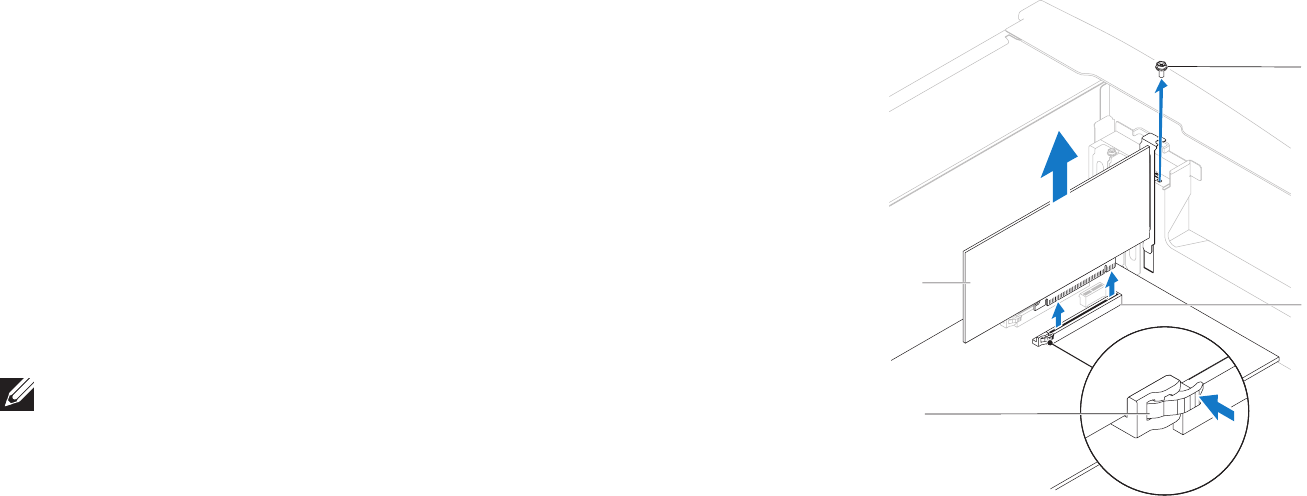
4
3
2
1
1 screw 2 card connector
3 securing tab 4 card
Removing the PCI-Express Card(s)
Follow the instructions in “Before You Begin” on page 1. 6.
Remove the left side-panel (see “Removing the Left Side-Panel“ on page 2. 11).
Open the PCI shroud (see “Opening the PCI Shroud” on page 3. 18).
Locate the PCI-Express card on the system board (see “System Board 4.
Components“ on page 14).
Disconnect any cables connected to the card (if applicable). 5.
Remove the screw that secures the card to the chassis.6.
Remove the card.7.
For a PCI-Express x1 card, grasp the card by its top corners, and ease it •
out the card connector.
For a PCI-Express x16 card, press the securing tab on the card •
connector as you grasp the card by its top corners, and then ease the
card out of the card connector.
NOTE: If you are not replacing a card, install a ller bracket in the empty
card-slot opening.
034 034
/
CHAPTER 6: PCI-EXPRESS CARD(S)
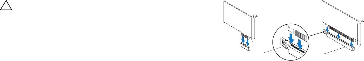
12
1 securing tab 2 card connector
CAUTION: To prevent damage to the PCI-Express card ensure that the
memory module securing clips are in the closed position.
Align the card with the card connector on the system board. 3.
Place the card in the connector and press down rmly. Ensure that the card 4.
is rmly seated in the slot. If you are installing the PCI-Express x16 card,
push the securing tab and insert the card in the connector.
Connect any cables that should be attached to the card (if applicable). 5.
For information about the card’s cable connections, see the documentation
that shipped with the card.
Replace the screw that secures the card to the chassis.6.
Close the PCI shroud (see “Closing the PCI Shroud” on page 7. 18).
Replace the left side-panel (see “Replacing the Left Side-Panel“ on page 8. 11).
Connect your computer and devices to electrical outlets and then turn 9.
them on.

CHAPTER 7: MEMORY MODULE(S)
035 035
/
You can increase your computer memory by installing memory modules
on the system board. See the specications in your
Desktop Manual
at
support.dell.com/manuals for information on the type of memory supported
by your computer. Install only memory modules that are supported by your
computer.
NOTE: Memory modules purchased from Dell or Alienware are covered
under your computer warranty.
CHAPTER 4: MEMORY MODULE(S)
CHAPTER 7: MEMORY MODULE(S)

036 036
/
CHAPTER 7: MEMORY MODULE(S)
Memory Module(s)
WARNING: Before working inside your computer, read the safety
information that shipped with your computer. For additional safety best
practices information, see the Regulatory Compliance Homepage at
www.dell.com/regulatory_compliance.
WARNING: Do not operate your computer with any cover(s) (including
computer covers, bezels, ller brackets, front-panel inserts, etc.)
removed.
WARNING: To guard against electrical shock, always unplug your
computer from the electrical outlet before removing the side panel(s).
CAUTION: Only a certied service technician should perform repairs on
your computer. Damage due to servicing that is not authorized by Dell™
is not covered by your warranty.
037 037
/
CHAPTER 7: MEMORY MODULE(S)
Removing the Memory Module(s)
Follow the instructions in “Before You Begin” on page 1. 6.
Remove the left side-panel (see “Removing the Left Side-Panel“ on page 2. 11).
Locate the memory-module connectors on the system board (see “System 3.
Board Components“ on page 14).
WARNING: e memory module(s) may become very hot during normal
operation. Allow the memory module(s) to cool before touching them.
NOTE: For better access to the memory module(s), remove the graphics
card if the card is full length.
To remove the graphics card, see “Removing the PCI-Express Card(s)” on 4.
page 32.
Spread apart the securing clips at both ends of the memory-module 5.
connector.
Lift the memory module o the memory-module connector. If the memory 6.
module is difcult to remove, gently ease the memory module back and
forth to remove it from the memory-module connector.
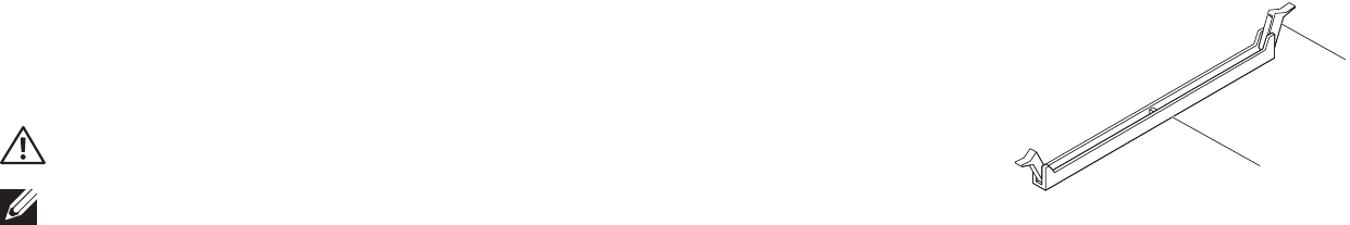
1
2
1 memory-module connector 2 securing clips (2)
038 038
/
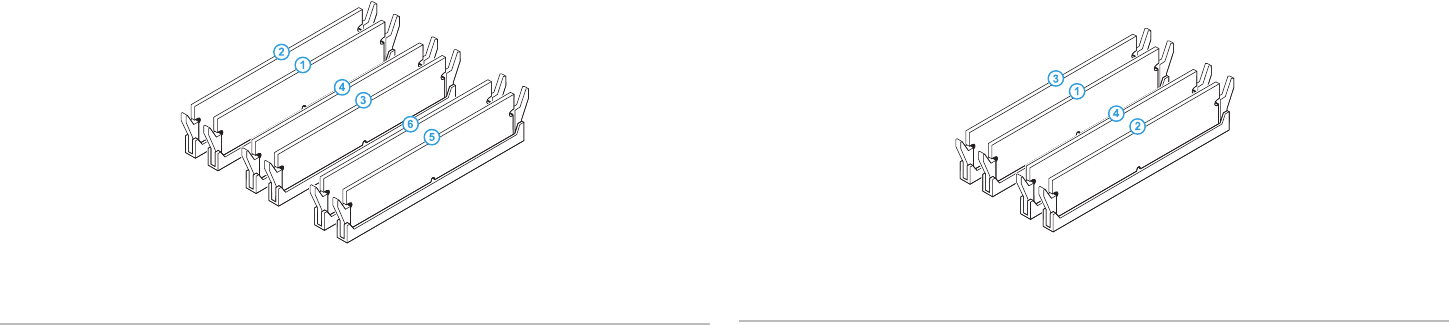
CHAPTER 7: MEMORY MODULE(S)
Aurora-R2
Type Slots
1066 MHz and I333 MHz DDR3 Slots 1 and 2 or slots 1 — 4
Replacing the Memory Module(s)
Follow the instructions in “Before You Begin” on page 1. 6.
Recommended memory conguration:
Aurora/Aurora ALX
Type Slots
1066 MHz and I333 MHz DDR3 Slots 1, 3, and 5 or slots 1 — 6
1600 MHz XMP Slots 1, 3, and 5
039 039
/
Insert the memory module into the memory-module connector until the 3.
memory module snaps into position.
If you insert the memory module correctly, the securing clips snap into the
cutouts at each end of the memory module.
NOTE If the memory module is not installed properly, the computer may
not boot.
To replace the graphics card, see “Replacing the PCI-Express Card(s)” on 4.
page 33.
Replace the left side-panel (see “Replacing the Left Side-Panel“ on page 5. 11).
Connect your computer and devices to electrical outlets and then turn 6.
them on.
As the computer boots, it detects the additional memory and automatically
updates the system conguration information.
To conrm the amount of memory installed in the computer:
Click Start → Control Panel→ System and Security→ System.
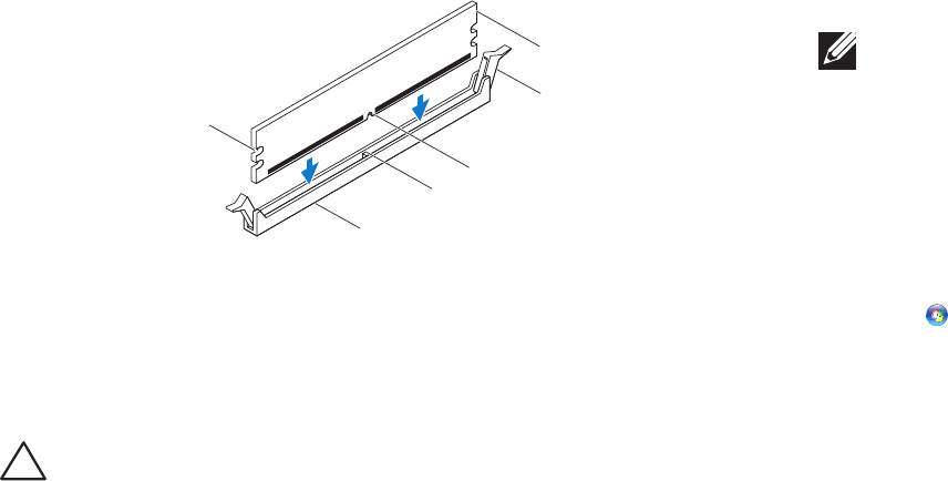
Align the notch on the bottom of the memory module with the tab on the 2.
memory-module connector.
2
3
4
6
5
1
1 cutouts 2 memory-module connector
3 tab 4 notch
5 securing clips (2) 6 memory module
CAUTION: To avoid damage to the memory module, press the memory
module straight down into the memory-module connector while you
apply equal force to each end of the memory module.
CHAPTER 7: MEMORY MODULE(S)
CHAPTER 8: FANS
040 040
/
CHAPTER 8: FANS
CHAPTER 8: FANS

041 041
/
CHAPTER 8: FANS
Fans
WARNING: Before working inside your computer, read the safety
information that shipped with your computer. For additional safety best
practices information, see the Regulatory Compliance Homepage at
www.dell.com/regulatory_compliance.
WARNING: To guard against electrical shock, always unplug your
computer from the electrical outlet before removing the side panel(s).
WARNING: Do not operate your computer with any cover(s) (including
computer covers, bezels, ller brackets, front-panel inserts, etc.)
removed.
CAUTION: Only a certied service technician should perform repairs on
your computer. Damage due to servicing that is not authorized by Dell™
is not covered by your warranty.
042 042
/
CHAPTER 8: FANS
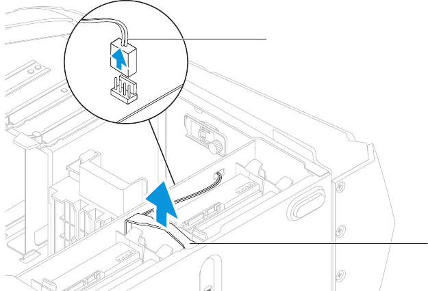
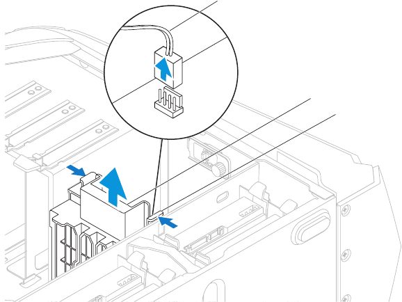
1
2
1 hard-drive fan assembly cable 2 hard-drive fan assembly
Removing the Hard-Drive Fan Assembly
Follow the instructions in “Before You Begin” on page 1. 6.
Remove the left side-panel (see “Removing the Left Side-Panel“ on page 2. 11).
Open the PCI shroud (see “Opening the PCI Shroud” on page 3. 18).
Remove the drive-bay shroud (see “Removing the Drive-Bay Shroud” on 4.
page 19).
Disconnect the hard-drive fan assembly cable from the connector on the 5.
master I/O board. Make note of the cable routing before disconnecting the
cable.
Lift the hard-drive fan assembly out of the chassis.6.
043 043
/
CHAPTER 8: FANS
Replacing the Hard-Drive Fan Assembly
Follow the instructions in “Before You Begin” on page 1. 6.
Push the hard-drive fan assembly into the hard-drive fan assembly bay.2.
Route the cable through the slot in the hard-drive bay.3.
Connect the hard-drive fan assembly cable to the connector on the master 4.
I/O board.
Replace the drive-bay shroud (see “Replacing the Drive-Bay Shroud” on 5.
page 19).
Close the PCI shroud (see “Closing the PCI Shroud” on page 6. 18).
Replace the left side-panel (see “Replacing the Left Side-Panel“ on page 7. 11).
Connect your computer and devices to electrical outlets and then turn 8.
them on.
044 044
/
CHAPTER 8: FANS
1
2
3
1 PCI-fan assembly cable 2 PCI-fan assembly
3 tabs (2)
Removing the PCI-Fan Assembly
Follow the instructions in “Before You Begin” on page 1. 6.
Remove the left side-panel (see “Removing the Left Side-Panel“ on page 2. 11).
Open the PCI shroud (see “Opening the PCI Shroud” on page 3. 18).
Remove the drive-bay shroud (see “Removing the Drive-Bay Shroud” on 4.
page 19).
Remove full-length PCI-Express cards, if any (see “Removing the PCI-Express 5.
Card(s)” on page 32).
Disconnect the PCI-fan assembly cable from the connector on the master 6.
I/O board.
Press the tabs and lift the PCI-fan assembly out of the chassis.7.
045 045
/
CHAPTER 8: FANS
Replacing the PCI-Fan Assembly
Follow the instructions in “Before You Begin” on page 1. 6.
Align the PCI-fan assembly with the metal bracket on the chassis.2.
Slide the PCI-fan assembly into the chassis.3.
Connect the PCI-fan assembly cable to the connector on the master 4.
I/O board.
Replace full-length PCI-Express cards, if any (see “Replacing the PCI-Express 5.
Card(s)” on page 33).
Replace the drive-bay shroud (see “Replacing the Drive-Bay Shroud” on 6.
page 19).
Close the PCI shroud (see “Closing the PCI Shroud” on page 7. 18).
Replace the left side-panel (see “Replacing the Left Side-Panel“ on page 8. 11).
Connect your computer and devices to electrical outlets and then turn 9.
them on.
CHAPTER 9: PROCESSOR LIQUID-COOLING ASSEMBLY
046 046
/
CHAPTER 9: PROCESSOR LIQUID-COOLING
ASSEMBLY
CHAPTER 9: LIQUID COOLING ASSEMBLY

047 047
/
CHAPTER 9: PROCESSOR LIQUID-COOLING ASSEMBLY
Processor Liquid-Cooling Assembly
WARNING: Before working inside your computer, read the safety
information that shipped with your computer. For additional safety best
practices information, see the Regulatory Compliance Homepage at
www.dell.com/regulatory_compliance.
WARNING: To guard against electrical shock, always unplug your
computer from the electrical outlet before removing the side panel(s).
WARNING: Do not operate your computer with any cover(s) (including
computer covers, bezels, ller brackets, front-panel inserts, etc.)
removed.
CAUTION: Only a certied service technician should perform repairs on
your computer. Damage due to servicing that is not authorized by Dell™
is not covered by your warranty.
CAUTION: To avoid electrostatic discharge, ground yourself by using a
wrist grounding strap or by periodically touching an unpainted metal
surface (such as a connector on the back of the computer).
048 048
/
CHAPTER 9: PROCESSOR LIQUID-COOLING ASSEMBLY
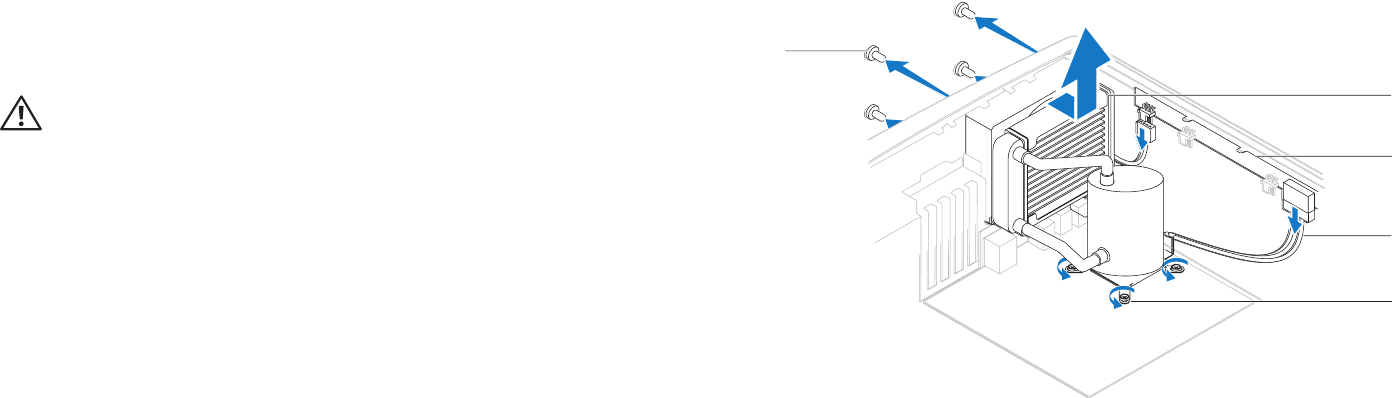
3
4
1
2
5
1 processor liquid-cooling assembly 2 top lighting-board
3 cables (2) 4 captive screws (4)
5 screws (4)
Removing the Processor Liquid-Cooling Assembly
Follow the instructions in “Before You Begin” on page 1. 6.
Remove the left side-panel (see “Removing the Left Side-Panel“ on page 2. 11).
WARNING: Despite having a plastic shield, the processor liquid-cooling
assembly may be very hot during normal operation. Ensure that it has
had sufcient time to cool before you touch it.
Disconnect the processor liquid-cooling assembly cable from the connectors 3.
(SYS FAN and CPU PUMP) on the top-lighting board.
Loosen the four captive screws that secure the processor liquid-cooling 4.
assembly to the system board.
Remove the four screws that secure the processor liquid-cooling assembly 5.
to the chassis rear wall.
Slide and lift the processor liquid-cooling assembly away from the chassis.6.
049 049
/
CHAPTER 9: PROCESSOR LIQUID-COOLING ASSEMBLY
Replacing the Processor Liquid-Cooling Assembly
Follow the instructions in “Before You Begin” on page 1. 6.
Align the screw holes on the processor liquid-cooling assembly with the 2.
screw holes on the chassis rear wall.
Replace the four screws that secure the processor liquid-cooling assembly 3.
to the chassis rear wall.
Tighten the four captive screws that secure the processor liquid-cooling 4.
assembly to the system board.
Connect the processor liquid-cooling assembly cables to the connectors 5.
(SYS FAN and CPU PUMP) on the top lighting-board.
Replace the left side-panel (see “Replacing the Left Side-Panel“ on page 6. 11).
Connect your computer and devices to electrical outlets and then turn 7.
them on.
CHAPTER 10: PROCESSOR
050 050
/
CHAPTER 9: PROCESSOR
CHAPTER 10: PROCESSOR

051 051
/
CHAPTER 10: PROCESSOR
Processor
WARNING: Before working inside your computer, read the safety
information that shipped with your computer. For additional safety best
practices information, see the Regulatory Compliance Homepage at
www.dell.com/regulatory_compliance.
WARNING: To guard against electrical shock, always unplug your
computer from the electrical outlet before removing the side panel(s).
CAUTION: Only a certied service technician should perform repairs on
your computer. Damage due to servicing that is not authorized by Dell™
is not covered by your warranty.
CAUTION: To avoid electrostatic discharge, ground yourself by using a
wrist grounding strap or by periodically touching an unpainted metal
surface (such as a connector on the back of the computer).
052 052
/
CHAPTER 10: PROCESSOR
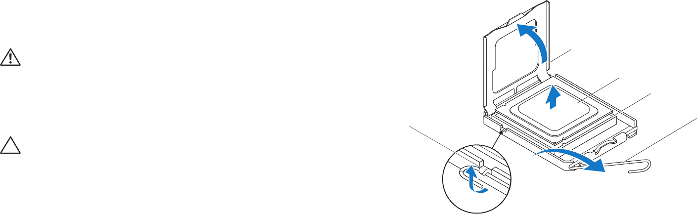
1
3
4
5
2
1 processor cover 2 processor
3 socket 4 release lever
5 tab
Removing the Processor
Follow the instructions in “Before You Begin” on page 1. 6.
Remove the left side-panel (see “Removing the Left Side-Panel“ on page 2. 11).
WARNING: Despite having a plastic shield, the processor liquid-cooling
assembly may be very hot during normal operation. Ensure that it has
had sufcient time to cool before you touch it.
Remove the processor liquid-cooling assembly (see “Removing the 3.
Processor Liquid-Cooling Assembly” on page 48).
Press and push the release lever down and out and release it from the tab 4.
that secures it.
CAUTION: When removing the processor, do not touch any of the pins
inside the socket or allow any objects to fall on the pins in the socket.
Open the processor cover and gently lift the processor to remove it from the 5.
socket.
Leave the release lever extended in the release position so that the socket is 6.
ready for the new processor.
053 053
/
CHAPTER 10: PROCESSOR
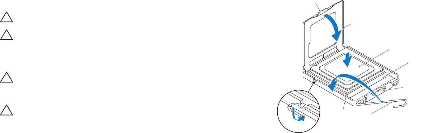
2
4
6
3
1
7
5
1 tab 2 processor cover
3 processor 4 socket
5 center-cover latch 6 release lever
7 processor pin-1 indicator
Replacing the Processor
CAUTION: When replacing the processor, do not touch any of the pins inside
the socket or allow any objects to fall on the pins in the socket.
CAUTION: Ground yourself by touching an unpainted metal surface on
the back of the computer.
Follow the instructions in “Before You Begin” on page 1. 6.
Unpack the new processor. Ensure that you do not to touch the underside of 2.
the processor.
CAUTION: You must position the processor correctly in the socket to
avoid permanent damage to the processor and the computer when you
turn on the computer.
Extend the release lever on the processor socket if it is not fully extended.3.
CAUTION: Socket pins are delicate. To avoid damage, ensure that the
processor is aligned properly with the socket, and do not use excessive
force when you replace the processor. Be careful not to touch or bend
the pins on the system board.
Align the pin-1 corners of the processor and socket. 4.
Set the processor lightly in the socket and ensure that the processor is 5.
positioned correctly.
054 054
/
CHAPTER 10: PROCESSOR
When the processor is fully seated in the socket, close the processor cover.6.
Ensure that the tab on the processor cover is positioned underneath the
center-cover latch on the socket.
Pivot the socket release lever back towards the socket, and snap it into place 7.
to secure the processor.
Clean the thermal grease from the bottom of the processor liquid-cooling 8.
assembly.
CAUTION: Ensure that you apply new thermal grease. New thermal
grease is critical for ensuring adequate thermal bonding, which is a
requirement for optimal processor operation.
Apply the new thermal grease to the top of the processor. 9.
Replace the processor liquid-cooling assembly (see “Replacing the Processor 10.
Liquid-Cooling Assembly” on page 49).
CAUTION: Ensure that the processor liquid-cooling assembly is correctly
seated and secured.
Replace the left side-panel (see “Replacing the Left Side-Panel“ on page 11. 11).
Connect your computer and devices to electrical outlets, and then turn 12.
them on.
CHAPTER 11: POWER SUPPLY
055 055
/
CHAPTER 10: POWER SUPPLY
CHAPTER 11: POWER SUPPLY

056 056
/
CHAPTER 11: POWER SUPPLY
Power Supply
WARNING: Before working inside your computer, read the safety
information that shipped with your computer. For additional safety best
practices information, see the Regulatory Compliance Homepage at
www.dell.com/regulatory_compliance.
WARNING: To guard against electrical shock, always unplug your
computer from the electrical outlet before removing the side panel(s).
WARNING: Do not operate your computer with any cover(s) (including
computer covers, bezels, ller brackets, front-panel inserts, etc.)
removed.
CAUTION: Only a certied service technician should perform repairs on
your computer. Damage due to servicing that is not authorized by Dell™
is not covered by your warranty.

057 057
/
CHAPTER 11: POWER SUPPLY
Removing the Power Supply
Follow the instructions in “Before You Begin” on page 1. 6.
Remove the left side-panel (see “Removing the Left Side-Panel“ on page 2. 11).
Lift the tab and slide the power-supply cover towards the back of the 3.
chassis.
Lift the power-supply cover away from the chassis.4.
1
2
1 tab 2 power-supply cover
058 058
/
CHAPTER 11: POWER SUPPLY
Disconnect the DC wire harness and the AC power cable from the power 5.
supply.
Loosen the four captive screws that secure the power supply to the back of 6.
the chassis.
Slide the power supply through the back of the chassis.7.
1
2
1 power supply 2 captive screws (4)
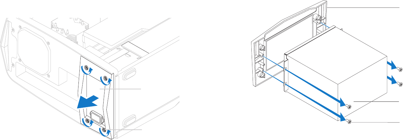
Remove the four screws that secure the power supply to the bezel.8.
Remove the bezel from the power supply.9.
2
3
1
1 bezel 2 power supply
3 screws (4)
059 059
/
CHAPTER 11: POWER SUPPLY
Replacing the Power Supply
Follow the instructions in “Before You Begin” on page 1. 6.
Replace the four screws that secure the power supply to the bezel.2.
Slide the power supply into the chassis through the back of the computer.3.
Tighten the four captive screws that secure the power supply to the back of 4.
the chassis.
Connect the DC wire harness and the AC power cable to the power supply.5.
Align the tabs on the power-supply cover with the slots on the power supply.6.
Slide the power-supply cover towards the slots until it locks in place.7.
Replace the left side-panel (see “Replacing the Left Side-Panel“ on page 8. 11).
Connect your computer and devices to electrical outlets, and then turn 9.
them on.
CHAPTER 12: BATTERY
060 060
/
CHAPTER 14: COIN CELL BATTERY
CHAPTER 12: BATTERY

061 061
/
CHAPTER 12: BATTERY
Battery
WARNING: Before working inside your computer, read the safety
information that shipped with your computer. For additional safety best
practices information, see the Regulatory Compliance Homepage at
www.dell.com/regulatory_compliance.
WARNING: Do not operate your computer with any cover(s) (including
computer covers, bezels, ller brackets, front-panel inserts, etc.)
removed.
WARNING: To guard against electrical shock, always unplug your
computer from the electrical outlet before removing the side panel(s).
CAUTION: Only a certied service technician should perform repairs on
your computer. Damage due to servicing that is not authorized by Dell™
is not covered by your warranty.
062 062
/
CHAPTER 12: BATTERY
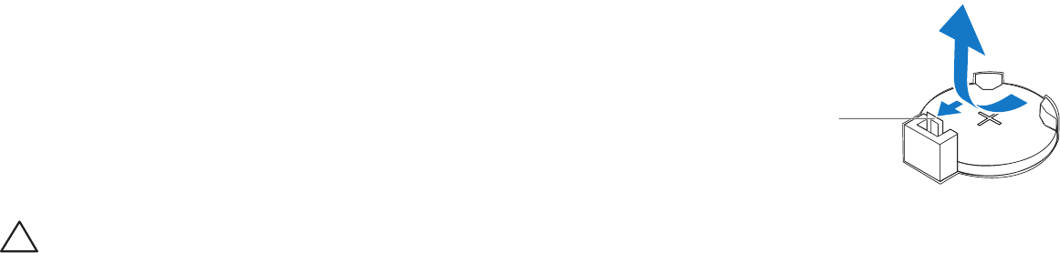
1
1 battery release lever
Removing the Coin-Cell Battery
Record all the screens in system setup (see “System Setup” on page 1. 107)
so that you can restore the correct settings after the new battery has been
installed.
Follow the instructions in “Before You Begin” on page 2. 6.
Remove the left side-panel (see “Removing the Left Side-Panel“ on page 3. 11).
Open the PCI shroud (see “Opening the PCI Shroud“ on page 4. 18).
Remove any PCI-Express cards (see “Removing the PCI-Express Card(s)” on 5.
page 32).
Locate the battery socket (see “System Board Components” on page 6. 14).
CAUTION: If you pry the battery out of its socket with a blunt object,
be careful not to touch the system board with the object. Ensure that
the object is inserted between the battery and the socket before you
attempt to pry out the battery. Otherwise, you may damage the system
board by prying o the socket or by breaking circuit traces on the system
board.
Press the battery release lever to remove the battery.7.
063 063
/
CHAPTER 12: BATTERY
Connect your computer and devices to electrical outlets and then turn 6.
them on.
Enter system setup (see “Entering System Setup” on page 7. 107) and restore
the settings you recorded before removing the battery.
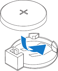
Replacing the Coin-Cell Battery
Follow the instructions in “Before You Begin” on page 1. 6.
Insert the new battery (CR2032) into the socket with the side labeled “+” 2.
facing up, and press the battery into place.
Replace the PCI-Express cards (see “Replacing the PCI-Express Card(s)” on 3.
page 33).
Close the PCI shroud (see “Closing the PCI Shroud“ on page 4. 18).
Replace the left side-panel (see “Replacing the Left Side-Panel“ on page 5. 11).
064 064
/
CHAPTER 12: BATTERY
1
2
1 theater-lighting
battery-compartment door
2 drive-bay shroud
Removing the eater-Lighting Batteries
Follow the instructions in “Before You Begin” on page 1. 6.
Remove the left side-panel (see “Removing the Left Side-Panel“ on page 2. 11).
Open the PCI shroud (see “Opening the PCI Shroud“ on page 3. 18).
Remove the drive-bay shroud (see “Removing the Drive-Bay Shroud” on 4.
page 19).
Turn the drive-bay shroud over.5.
Open the theater-lighting battery compartment door.6.
Remove the two batteries (AA rechargeable) from the theater-lighting 7.
battery compartment.
065 065
/
CHAPTER 12: BATTERY
Replacing the eater-Lighting Batteries
Follow the instructions in “Before You Begin” on page 1. 6.
Insert the two new batteries (AA rechargeable) in the theater-lighting 2.
battery compartment.
Close the theater-lighting battery-compartment door. 3.
Replace the drive-bay shroud (see “Replacing the Drive-Bay Shroud” on 4.
page 19).
Close the PCI shroud (see “Closing the PCI Shroud“ on page 5. 18).
Replace the left side-panel (see “Replacing the Left Side-Panel“ on page 6. 11).
Connect your computer and devices to electrical outlets, and then turn 7.
them on.
CHAPTER 13: SYSTEM BOARD
066 066
/
CHAPTER 11: SYSTEM BOARD
CHAPTER 13: SYSTEM BOARD

067 067
/
CHAPTER 13: SYSTEM BOARD
System Board
WARNING: Before working inside your computer, read the safety
information that shipped with your computer. For additional safety best
practices information, see the Regulatory Compliance Homepage at
www.dell.com/regulatory_compliance.
WARNING: Do not operate your computer with any cover(s) (including
computer covers, bezels, ller brackets, front-panel inserts, etc.)
removed.
WARNING: To guard against electrical shock, always unplug your
computer from the electrical outlet before removing the side panel(s).
CAUTION: Only a certied service technician should perform repairs on
your computer. Damage due to servicing that is not authorized by Dell™
is not covered by your warranty.
068 068
/
CHAPTER 13: SYSTEM BOARD
Removing the System Board
Record all the screens in system setup (see “System Setup” on page 1. 107) so
that you can restore the correct settings.
Follow the instructions in “Before You Begin” on page 2. 6.
Remove the left side-panel (see “Removing the Left Side-Panel“ on page 3. 11).
Open the PCI shroud (see “Opening the PCI Shroud“ on page 4. 18).
Remove any PCI-Express cards (see “Removing the PCI-Express Card(s)” on 5.
page 32).
WARNING: Despite having a plastic shield, the processor liquid-cooling
assembly may be very hot during normal operation. Ensure that it has
had sufcient time to cool before you touch it.
Remove the processor liquid-cooling assembly (see “Removing the 6.
Processor Liquid-Cooling Assembly” on page 48).
Remove the processor (see “Removing the Processor” on page 7. 52).
Remove the memory modules (see “Removing the Memory Module(s)” on 8.
page 37).
CAUTION: Carefully note the routing and location of each cable before
you disconnect it, so that you are sure to re-route the cables correctly.
An incorrectly routed or a disconnected cable could lead to computer
problems.
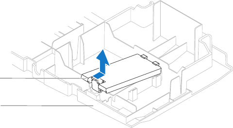
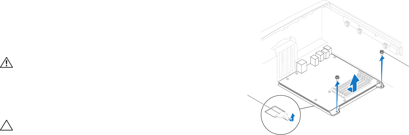
1
2
1 latch 2 screws (2)

069 069
/
CHAPTER 13: SYSTEM BOARD
Replacing the System Board
Follow the instructions in “Before You Begin” on page 1. 6.
Slide the system board towards the back of the chassis and engage the 2.
latches that secure it to the chassis.
Replace the two screws that secure the system board to the chassis.3.
Route and connect the cables that you disconnected from the system board. 4.
NOTE: For information on system board connectors, see “System Board
Components” on page 14.
Replace the memory modules (see “Replacing the Memory Module(s)” on 5.
page 38).
Replace the processor (see “Replacing the Processor” on page 6. 53).
Replace the processor liquid-cooling assembly (see “Replacing the Processor 7.
Liquid-Cooling Assembly” on page 49).
Replace the PCI-Express cards (see “Replacing the PCI-Express Card(s)” on 8.
page 33).
Close the PCI shroud (see “Closing the PCI Shroud“ on page 9. 18).
Replace the left side-panel (see “Replacing the Left Side-Panel“ on page 10. 11).
Connect your computer and devices to electrical outlets, and then turn 11.
them on.
Disconnect all cables from the system board. 9.
Remove the two screws that secure the system board to the chassis.10.
Slide the system board towards the front of the chassis to disengage it from 11.
the latches that secure it to the chassis.
Lift the system board out of the chassis.12.
CHAPTER 14: MASTER I/O BOARD
070 070
/
CHAPTER 12: MASTER I/O BOARD
CHAPTER 14: MASTER I/O BOARD

071 071
/
CHAPTER 14: MASTER I/O BOARD
Master I/O Board
WARNING: Before working inside your computer, read the safety
information that shipped with your computer. For additional safety best
practices information, see the Regulatory Compliance Homepage at
www.dell.com/regulatory_compliance.
WARNING: To guard against electrical shock, always unplug your
computer from the electrical outlet before removing the side panel(s).
WARNING: Do not operate your equipment with any cover(s) (including
side panels, bezels, ller brackets, front-panel inserts, etc.) removed.
CAUTION: Only a certied service technician should perform repairs on
your computer. Damage due to servicing that is not authorized by Dell™
is not covered by your warranty.
CAUTION: To avoid electrostatic discharge, ground yourself by using a
wrist grounding strap or by periodically touching an unpainted metal
surface (such as a connector on the back of the computer).
072 072
/
CHAPTER 14: MASTER I/O BOARD
Removing the Master I/O Board
Follow the instructions in “Before You Begin” on page 1. 6.
Remove the left side-panel (see “Removing the Left Side-Panel“ on page 2. 11).
Open the PCI shroud (see “Opening the PCI Shroud“ on page 3. 18).
Remove the drive-bay shroud (see “Removing the Drive-Bay Shroud” on 4.
page 19).
Remove the PCI-fan assembly (see “Removing the PCI-Fan Assembly” on 5.
page 44).
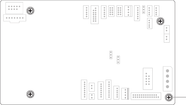
Disconnect all cables from the connectors on the master I/O board. Note 6.
the routing of all cables as you remove them so that you can re-route them
correctly after installing the new master I/O board.
Remove the four screws that secure the master I/O board to the chassis.7.
Remove the master I/O board out of the chassis.8.
1
1 screws (4)

073 073
/
CHAPTER 14: MASTER I/O BOARD
Replacing the Master I/O Board
Follow the instructions in “Before You Begin” on page 1. 6.
Place the master I/O board in the chassis.2.
Replace the four screws that secure the master I/O board to the chassis.3.
Route and connect the cables that you removed from the connectors on the 4.
master I/O board.
NOTE: For information on master I/O board connectors, see “Master I/O
Board Components” on page 15.
Replace the PCI-fan assembly (see “Replacing the PCI-Fan Assembly” on 5.
page 45).
Replace the drive-bay shroud (see “Replacing the Drive-Bay Shroud” on 6.
page 19).
Close the PCI shroud (see “Closing the PCI Shroud“ on page 7. 18).
Replace the left side-panel (see “Replacing the Left Side-Panel“ on page 8. 11).
Connect your computer and devices to electrical outlets, and then turn 9.
them on.
CHAPTER 15: TOP LIGHTING-BOARD
074 074
/
CHAPTER 13: TOP LIGHTING BOARD
CHAPTER 15: TOP LIGHTING-BOARD

075 075
/
CHAPTER 15: TOP LIGHTING-BOARD
Top Lighting-Board
WARNING: Before working inside your computer, read the safety
information that shipped with your computer. For additional safety best
practices information, see the Regulatory Compliance Homepage at
www.dell.com/regulatory_compliance.
WARNING: To guard against electrical shock, always unplug your
computer from the electrical outlet before removing the side panel(s).
CAUTION: Only a certied service technician should perform repairs on
your computer. Damage due to servicing that is not authorized by Dell™
is not covered by your warranty.
CAUTION: Do not operate your computer with any cover(s) (including
computer covers, bezels, ller brackets, front-panel inserts, etc.)
removed.
076 076
/
CHAPTER 15: TOP LIGHTING-BOARD
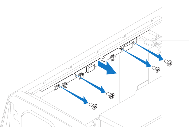
1
2
1 top lighting-board 2 screws (4)
Removing the Top Lighting-Board
Follow the instructions in “Before You Begin” on page 1. 6.
Remove the left side-panel (see “Removing the Left Side-Panel“ on page 2. 11).
Disconnect all cables from the connectors on the top lighting-board.3.
Remove the four screws that secure the top lighting-board to the chassis.4.
Pull the top lighting-board away from the chassis.5.
Replacing the Top Lighting-Board
Follow the instructions in “Before You Begin” on page 1. 6.
Replace the four screws that secure the top lighting-board to the chassis.2.
Connect the cables to the connectors on the top lighting-board.3.
Replace the left side-panel (see “Replacing the Left Side-Panel“ on page 4. 11).
Connect your computer and devices to electrical outlets and then turn 5.
them on.
CHAPTER 16: RIGHT SIDE-PANEL(S)
077 077
/
CHAPTER 16: RIGHT SIDE-PANEL(S)
CHAPTER 16: RIGHT SIDE PANEL

078 078
/
CHAPTER 16: RIGHT SIDE-PANEL(S)
Right Side-Panel(s)
WARNING: Before working inside your computer, read the safety
information that shipped with your computer. For additional safety best
practices information, see the Regulatory Compliance Homepage at
www.dell.com/regulatory_compliance.
WARNING: Do not operate your computer with any cover(s) (including
computer covers, bezels, ller brackets, front-panel inserts, etc.)
removed.
WARNING: To guard against electrical shock, always unplug your
computer from the electrical outlet before removing the side panel(s).
CAUTION: Only a certied service technician should perform repairs on
your computer. Damage due to servicing that is not authorized by Dell™
is not covered by your warranty.
079 079
/
CHAPTER 16: RIGHT SIDE-PANEL(S)
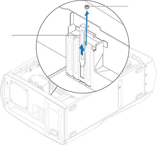
1
1 screws (3)
Removing the Right Side-Panel(s)
Follow the instructions in “Before You Begin” on page 1. 6.
Remove the left side-panel (see “Removing the Left Side-Panel“ on page 2. 11).
Open the PCI shroud (see “Opening the PCI Shroud“ on page 3. 18).
Remove the drive-bay shroud (see “Removing the Drive-Bay Shroud” on 4.
page 19).
Remove the power-supply cover (see “Removing the Power Supply“ on 5.
page 57).
Remove the hard-drive fan assembly (see “Removing the Hard-Drive Fan 6.
Assembly” on page 42).
Remove the three screws that secure the right side-panel(s) to the chassis.7.
080 080
/
CHAPTER 16: RIGHT SIDE-PANEL(S)
Place the chassis in an upright position.8.
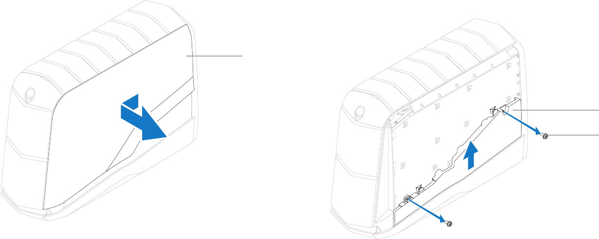
Slide and pull the right top-panel away from the chassis.9.
1
1 right top-panel
Disconnect the lighting-board cable from the connector on the master I/O 10.
board.
Remove the two screws that secure the lighting board to the chassis.11.
Lift the lighting board up and away from the chassis. 12.
1
2
1 lighting board 2 screws (2)
081 081
/
CHAPTER 16: RIGHT SIDE-PANEL(S)
Replacing the Right Side-Panel(s)
Follow the instructions in “Before You Begin” on page 1. 6.
Align the right bottom-panel to the bottom of the computer and slide it into 2.
position.
Slide the lighting board into position and replace the two screws that secure 3.
the lighting board to the chassis.
Connect the lighting-board cable to the connector on the master I/O board. 4.
Slide the right top-panel into position.5.
Place the chassis on its side.6.
Replace the three screws that secure the right side-panel(s) to the chassis.7.
Replace the power-supply cover (see “Replacing the Power Supply“ on 8.
page 59).
Replace the hard-drive fan assembly (see “Replacing the Hard-Drive Fan 9.
Assembly” on page 43).
Replace the drive-bay shroud (see “Replacing the Drive-Bay Shroud” on 10.
page 19).
Close the PCI shroud (see “Closing the PCI Shroud“ on page 11. 18).
Replace the left side-panel (see “Replacing the Left Side-Panel“ on page 12. 11).
Connect your computer and devices to electrical outlets and then turn 13.
them on.
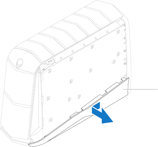
Slide and pull the right bottom-panel away from the chassis.13.
1
1 right bottom-panel
CHAPTER 17: ACTIVE-VENTING ASSEMBLY
082 082
/
CHAPTER 17: ACTIVE VENTING ASSEMBLY
CHAPTER 17: ACTIVE-VENTING ASSEMBLY

083 083
/
CHAPTER 17: ACTIVE-VENTING ASSEMBLY
Active-Venting Assembly
WARNING: Before working inside your computer, read the safety
information that shipped with your computer. For additional safety best
practices information, see the Regulatory Compliance Homepage at
www.dell.com/regulatory_compliance.
WARNING: Do not operate your computer with any cover(s) (including
computer covers, bezels, ller brackets, front-panel inserts, etc.)
removed.
WARNING: To guard against electrical shock, always unplug your
computer from the electrical outlet before removing the side panel(s).
CAUTION: Only a certied service technician should perform repairs on
your computer. Damage due to servicing that is not authorized by Dell™
is not covered by your warranty.
084 084
/
CHAPTER 17: ACTIVE-VENTING ASSEMBLY
1
1 screw
Removing the Active-Venting Assembly
NOTE: Active-venting assembly is available only in Alienware Aurora ALX.
Follow the instructions in “Before You Begin” on page 1. 6.
Remove the left side-panel (see “Removing the Left Side-Panel“ on page 2. 11).
Open the PCI shroud (see “Opening the PCI Shroud“ on page 3. 18).
Remove the drive-bay shroud (see “Removing the Drive-Bay Shroud” on 4.
page 19).
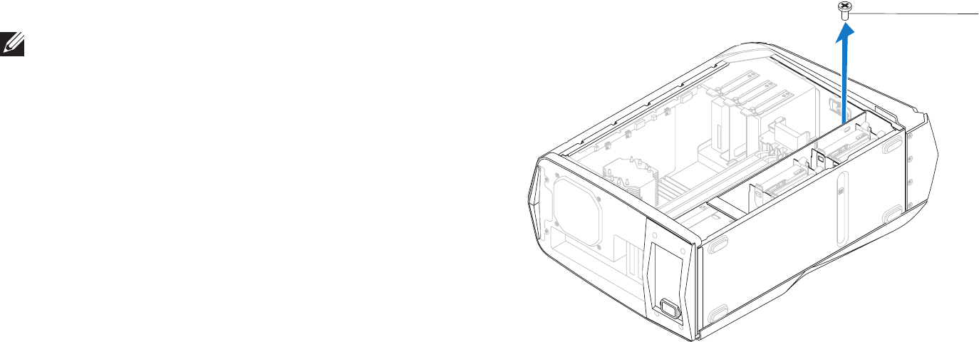
Remove the screw that secures the right top-panel to the chassis.5.
085 085
/
CHAPTER 17: ACTIVE-VENTING ASSEMBLY
Place the chassis in an upright position.8.
Remove the right top-panel.9.
1
1 right top-panel
Remove the top lighting-board (see “Removing the Top Lighting-Board” on 6.
page 76).
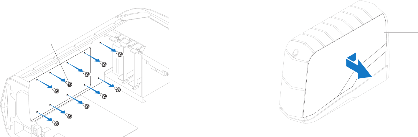
Remove the ten screws that secure the active-venting assembly to the 7.
chassis.
1
1 screws (10)
086 086
/
CHAPTER 17: ACTIVE-VENTING ASSEMBLY
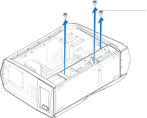
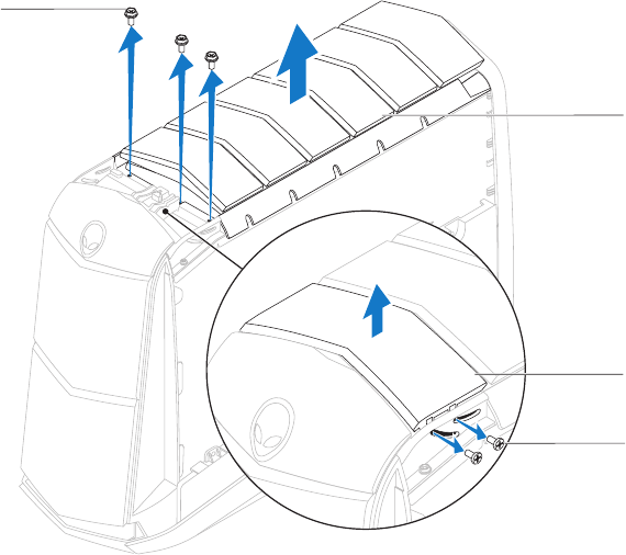
Remove the two screws that secure the top panel to the chassis.10.
Lift the top panel away from the chassis.11.
Remove the three screws that secure the active-venting assembly to the 12.
chassis.
Disconnect the cables that connect the active-venting assembly to the 13.
connectors on the master I/O board.
Lift the active-venting assembly away from the chassis.14.
2
3
4
1
1 screws (3) 2 active-venting assembly
3 top panel 4 top-panel screws (2)
087 087
/
CHAPTER 17: ACTIVE-VENTING ASSEMBLY
Replace the screw that secures the right top-panel to the chassis.10.
Replace the drive-bay shroud (see “Replacing the Drive-Bay Shroud” on 11.
page 19).
Close the PCI shroud (see “Closing the PCI Shroud“ on page 12. 18).
Replace the left side-panel (see “Replacing the Left Side-Panel“ on page 13. 11).
Connect your computer and devices to electrical outlets and then turn 14.
them on.
Replacing the Active-Venting Assembly
Follow the instructions in “Before You Begin” on page 1. 6.
Place the active-venting assembly on the top of the chassis.2.
Connect the active-venting assembly cables to the connectors on the 3.
master I/O board.
Replace the three screws that secure the active-venting assembly to the 4.
chassis.
Align the top panel with the slots in the chassis and replace the two screws 5.
that secure the top panel to the chassis.
Replace the right top-panel.6.
Lay the chassis on its side.7.
Replace the ten screws that secure the active-venting assembly to the top 8.
of the chassis.
Replace the top lighting-board (see “Replacing the Top Lighting-Board” on 9.
page 76).
CHAPTER 18: FRONT BEZEL
088 088
/
CHAPTER 18: FRONT BEZEL
CHAPTER 18: FRONT BEZEL

089 089
/
CHAPTER 18: FRONT BEZEL
Front Bezel
WARNING: Before working inside your computer, read the safety
information that shipped with your computer. For additional safety best
practices information, see the Regulatory Compliance Homepage at
www.dell.com/regulatory_compliance.
WARNING: Do not operate your computer with any cover(s) (including
computer covers, bezels, ller brackets, front-panel inserts, etc.)
removed.
WARNING: To guard against electrical shock, always unplug your
computer from the electrical outlet before removing the side panel(s).
CAUTION: Only a certied service technician should perform repairs on
your computer. Damage due to servicing that is not authorized by Dell™
is not covered by your warranty.
090 090
/
CHAPTER 18: FRONT BEZEL
1
1 screws (7)
Removing the Front Bezel
Follow the instructions in “Before You Begin” on page 1. 6.
Remove the left side-panel (see “Removing the Left Side-Panel“ on page 2. 11).
Open the PCI shroud (see “Opening the PCI Shroud“ on page 3. 18).
Remove the drive-bay shroud (see “Removing the Drive-Bay Shroud” on 4.
page 19).
Remove the right side-panel(s) (see “Removing the Right Side-Panel(s)” on 5.
page 79).
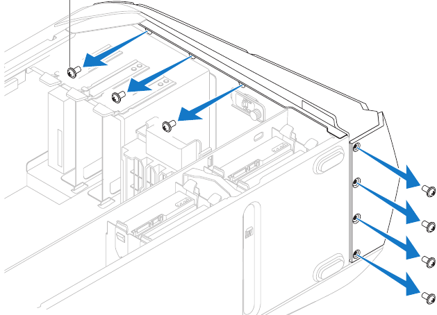
Remove the seven screws that secure the front bezel to the chassis.6.
Disconnect the front bezel cables from the connectors on the master I/O 7.
board. Note the cable routing before disconnecting the cables.
091 091
/
CHAPTER 18: FRONT BEZEL
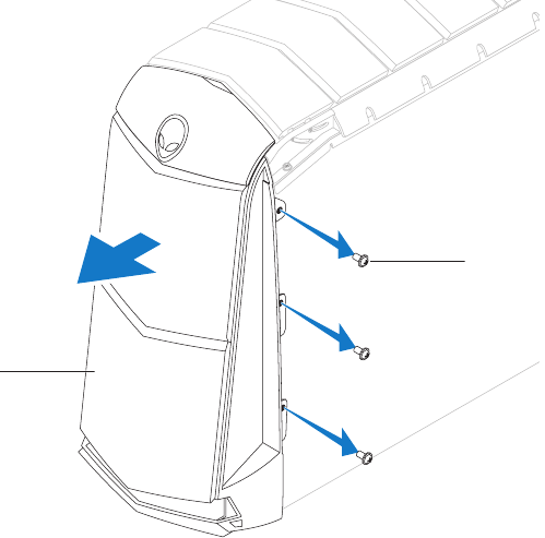
2
1
1 front bezel 2 screws (3)
Place the chassis in an upright position.8.
Remove the three screws on the right side that secure the front bezel to the 9.
chassis.
Pull the front bezel away from the chassis.10.
092 092
/
CHAPTER 18: FRONT BEZEL
Replacing the Front Bezel
Follow the instructions in “Before You Begin” on page 1. 6.
Align the front bezel with the front of the chassis.2.
Replace the three screws on the right side that secure the front bezel to the 3.
chassis.
Lay the chassis on its side.4.
Connect the front-bezel cables to the connectors on the master I/O board. 5.
Replace the seven screws that secure the front bezel to the chassis.6.
Replace the right side-panel(s) (see “Replacing the Right Side-Panel(s)” on 7.
page 81).
Replace the drive-bay shroud (see “Replacing the Drive-Bay Shroud” on 8.
page 19).
Close the PCI shroud (see “Closing the PCI Shroud“ on page 9. 18).
Replace the left side-panel (see “Replacing the Left Side-Panel“ on page 10. 11).
Connect your computer and devices to electrical outlets and then turn 11.
them on.
CHAPTER 19: BACK BEZEL
093 093
/
CHAPTER 16: BACK PANEL
CHAPTER 19: BACK BEZEL

094 094
/
CHAPTER 19: BACK BEZEL
Back Bezel
WARNING: Before working inside your computer, read the safety
information that shipped with your computer. For additional safety best
practices information, see the Regulatory Compliance Homepage at
www.dell.com/regulatory_compliance.
WARNING: Do not operate your computer with any cover(s) (including
computer covers, bezels, ller brackets, front-panel inserts, etc.)
removed.
WARNING: To guard against electrical shock, always unplug your
computer from the electrical outlet before removing the side panel(s).
CAUTION: Only a certied service technician should perform repairs on
your computer. Damage due to servicing that is not authorized by Dell™
is not covered by your warranty.
095 095
/
CHAPTER 19: BACK BEZEL
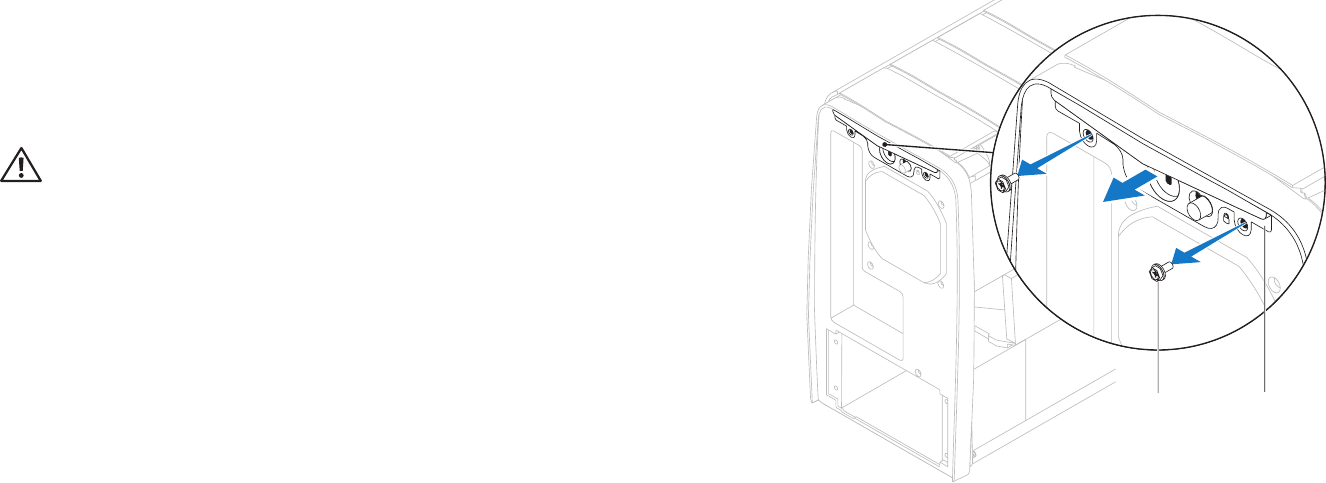
2
1
1 screws (2) 2 security lock panel
Removing the Back Bezel
Follow the instructions in “Before You Begin” on page 1. 6.
Remove the left side-panel (see “Removing the Left Side-Panel“ on page 2. 11).
Remove the power supply (see “Removing the Power Supply“ on page 3. 57).
WARNING: Despite having a plastic shield, the processor liquid-cooling
assembly may be very hot during normal operation. Ensure that it has
had sufcient time to cool before you touch it.
Remove the processor liquid-cooling assembly (see “Removing the 4.
Processor Liquid-Cooling Assembly“ on page 48).
Remove the two screws that secure the security lock panel to the chassis. 5.
Pull the security lock panel away from the chassis.6.
096 096
/
CHAPTER 19: BACK BEZEL
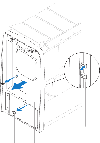
3
12
1 screws (2) 2 back bezel
3 tabs
Remove the two screws that secure the back bezel to the chassis.7.
Release the tabs that secure the back bezel to the chassis.8.
Pull the back bezel away from the chassis.9.
097 097
/
CHAPTER 19: BACK BEZEL
Replacing the Back Bezel
Follow the instructions in “Before You Begin” on page 1. 6.
Align the tabs on the back bezel with the slots on the chassis.2.
Push the back bezel into place.3.
Replace the two screws that secure the back bezel to the chassis.4.
Replace the two screws that secure the security lock panel to the chassis.5.
Replace the processor liquid-cooling assembly (see “Replacing the Processor 6.
Liquid-Cooling Assembly“ on page 49).
Replace the power supply (see “Replacing the Power Supply“ on page 7. 59).
Replace the left side-panel (see “Replacing the Left Side-Panel“ on page 8. 11).
Connect your computer and devices to electrical outlets, and then turn 9.
them on.
CHAPTER 20: BLUETOOTH ASSEMBLY
098 098
/
CHAPTER 18: FRONT BEZEL
CHAPTER 20: BLUETOOTH ASSEMBLY

099 099
/
CHAPTER 20: BLUETOOTH ASSEMBLY
Bluetooth Assembly
WARNING: Before working inside your computer, read the safety
information that shipped with your computer. For additional safety best
practices information, see the Regulatory Compliance Homepage at
www.dell.com/regulatory_compliance.
WARNING: Do not operate your computer with any cover(s) (including
computer covers, bezels, ller brackets, front-panel inserts, etc.)
removed.
WARNING: To guard against electrical shock, always unplug your
computer from the electrical outlet before removing the side panel(s).
CAUTION: Only a certied service technician should perform repairs on
your computer. Damage due to servicing that is not authorized by Dell™
is not covered by your warranty.
0100 0100
/
CHAPTER 20: BLUETOOTH ASSEMBLY
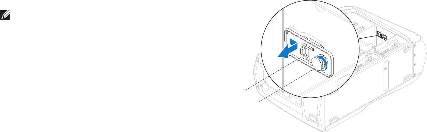
2
1
1 Bluetooth assembly 2 thumbscrew
Removing the Bluetooth Assembly
NOTE: e Bluetooth® assembly is available on your computer only if you
ordered it while purchasing your computer.
Follow the instructions in “Before You Begin” on page 1. 6.
Remove the left side-panel (see “Removing the Left Side-Panel“ on page 2. 11).
Open the PCI shroud (see “Opening the PCI Shroud“ on page 3. 18).
Remove the drive-bay shroud (see “Removing the Drive-Bay Shroud” on 4.
page 19).
Disconnect the Bluetooth assembly cable from the connector on the master 5.
I/O board.
Loosen the thumbscrew that secures the Bluetooth assembly to the 6.
chassis.
Slide and pull the Bluetooth assembly away from the front of the chassis.7.
0101 0101
/
CHAPTER 20: BLUETOOTH ASSEMBLY
Replacing the Bluetooth Assembly
Follow the instructions in “Before You Begin” on page 1. 6.
Align the tabs on the Bluetooth assembly with the slots on the chassis.2.
Tighten the thumbscrew that secures the Bluetooth assembly to the 3.
chassis.
Connect the Bluetooth assembly cable to the connector on the master I/O 4.
board.
Replace the drive-bay shroud (see “Replacing the Drive-Bay Shroud” on 5.
page 19).
Close the PCI shroud (see “Closing the PCI Shroud“ on page 6. 18).
Replace the left side-panel (see “Replacing the Left Side-Panel” on page 7. 11).
Connect your computer and devices to electrical outlets and then turn 8.
them on.
CHAPTER 21: TOP I/O PANEL
0102 0102
/
CHAPTER 20: TOP I/O
CHAPTER 21: TOP I/O PANEL

0103 0103
/
CHAPTER 21: TOP I/O PANEL
Top I/O Panel
WARNING: Before working inside your computer, read the safety
information that shipped with your computer. For additional safety best
practices information, see the Regulatory Compliance Homepage at
www.dell.com/regulatory_compliance.
WARNING: Do not operate your computer with any cover(s) (including
computer covers, bezels, ller brackets, front-panel inserts, etc.)
removed.
WARNING: To guard against electrical shock, always unplug your
computer from the electrical outlet before removing the side panel(s).
CAUTION: Only a certied service technician should perform repairs on
your computer. Damage due to servicing that is not authorized by Dell™
is not covered by your warranty.
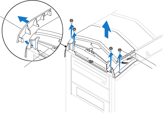
0104 0104
/
CHAPTER 21: TOP I/O PANEL
3
1
4
2
1 panel insert 2 top I/O panel
3 screws (4) 4 top panel
Removing the Top I/O Panel
Follow the instructions in “Before You Begin” on page 1. 6.
Remove the left side-panel (see “Removing the Left Side-Panel“ on page 2. 11).
Open the PCI shroud (see “Opening the PCI Shroud“ on page 3. 18).
Remove the drive-bay shroud (see “Removing the Drive-Bay Shroud” on 4.
page 19).
Remove the PCI-fan assembly (see “Removing the PCI-Fan Assembly” on 5.
page 44).
Remove any PCI-Express cards (see “Removing the PCI-Express Card(s)” on 6.
page 32).
Remove the active-venting assembly (see “ Removing the Active-Venting 7.
Assembly” on page 84).
Remove the right side-panel(s) (see “Removing the Right Side-Panel(s)” on 8.
page 79).
Remove the front bezel (see “Removing the Front Bezel” on page 9. 90).
Pull the panel insert away from the chassis.10.
Remove the four screws that secure the top I/O panel to the chassis.11.
Disconnect the top I/O panel cables from the connectors on the system 12.
board and master I/O board.
Remove the top I/O panel.13.
0105 0105
/
CHAPTER 21: TOP I/O PANEL
Replace the PCI-fan assembly (see “Replacing the PCI-Fan Assembly” on 10.
page 45).
Replace the drive-bay shroud (see “Replacing the Drive-Bay Shroud” on 11.
page 19).
Close the PCI shroud (see “Closing the PCI Shroud“ on page 12. 18).
Replace the left side-panel (see “Replacing the Left Side-Panel” on page 13. 11).
Connect your computer and devices to electrical outlets and then turn 14.
them on.
Replacing the Top I/O Panel
Follow the instructions in “Before You Begin” on page 1. 6.
Align and replace the top I/O panel.2.
Connect the top I/O panel cables to the connectors on the system board and 3.
master I/O board.
Replace the four screws that secure the top I/O panel to the chassis.4.
Push the panel insert into position.5.
Replace the front bezel (see “Replacing the Front Bezel” on page 6. 92).
Replace the active-venting assembly (see “Replacing the Active-Venting 7.
Assembly” on page 87).
Replace the right side-panel(s) (see “Replacing the Right Side-Panel(s)” on 8.
page 81).
Replace the PCI-Express cards (see “Replacing the PCI-Express Card(s)” on 9.
page 33).
CHAPTER 22: SYSTEM SETUP
0106 0106
/
CHAPTER 21: SYSTEM SETUP
CHAPTER 22: SYSTEM SETUP

0107 0107
/
CHAPTER 22: SYSTEM SETUP
Entering System Setup
Turn on (or restart) your computer.1.
NOTE: Keyboard failure may result when a key on the keyboard is held down
for extended periods of time. To avoid possible keyboard failure, press and
release <F2> in even intervals until the System Setup screen appears.
While the computer is booting, press <F2> immediately before the operating 2.
system logo appears to access the BIOS Setup Utility.
NOTE: If an error occurs during POST (Power On Self Test), press <F2>
when the prompt appears to enter the BIOS Setup Utility.
NOTE: If you wait too long and the operating system logo appears, continue
to wait until you see the Microsoft® Windows® desktop, then shut down
your desktop and try again.
System Setup Screens
e BIOS Setup Utility displays current or changeable conguration information
for your desktop.
Key functions appear at the bottom of the BIOS Setup Utility screen and lists
keys and their functions within the active eld.
Conguring the BIOS
System Setup
e System Setup options allow you to:
Change the system conguration information after you add, change, or •
remove any hardware in your computer.
Set or change a user-selectable option.•
View the amount of memory installed.•
Set the type of hard drive installed.•
Before you change the System Setup settings, it is recommended that you write
down the current System Setup information for future reference.
CAUTION: Do not change the settings in System Setup unless you are
an expert computer user. Certain changes can cause your computer to
work incorrectly.

0108 0108
/
CHAPTER 22: SYSTEM SETUP
System Information
Current (QPI) Speed
(available on Aurora and
Aurora ALX only)
Displays the QPI speed.
Current (DMI) Speed
(available on Aurora-R2 only) Displays the DMI speed.
Cache L2 Displays the processor L2 cache size.
Cache L3 Displays the processor L3 cache size.
Standard CMOS Features
System Time (hh:mm:ss) Displays the current time.
System Date (mm:dd:yy) Displays current date.
SATA 1 Displays the SATA 1 drive integrated in the
computer.
SATA 2 Displays the SATA 2 drive integrated in the
computer
SATA 3 Displays the SATA 3 drive integrated in the
computer.
SATA 4 Displays the SATA 4 drive integrated in the
computer.
System Setup Options
NOTE: e items listed in this section may or may not appear exactly as
listed depending on your computer model and installed devices.
System Information
Product Name Displays the product name.
BIOS Version Displays the BIOS version number and date
information.
Service Tag Displays the service tag of the computer.
Asset Tag Displays the asset tag of the computer.
Memory Installed Displays the amount of memory installed on
the computer.
Memory Available Displays the amount of memory available on
the computer.
Memory Technology Displays the type of memory technology
used.
Memory Speed Displays the memory speed.
CPU ID/u Code ID Displays the processor type.
CPU Speed Displays the processor speed.

0109 0109
/
CHAPTER 22: SYSTEM SETUP
CPU Conguration
XD Bit Capability Enable XD Bit Capability to allow the processor
to distinguish between the bits of code that
can be executed and the ones that cannot be
executed.
Intel® Speedstep™ tech If enabled, the processor clock speed and core
voltage are adjusted dynamically based on
the processor load.
Intel® C State Tech If enabled, C State: Processor idle is set to
C2/C3/C4.
Intel® HT Technology
(available on Aurora-R2 only) If disabled only one thread per enabled core is
active.
Standard CMOS Features
SATA 5 Displays the SATA 5 drive integrated in the
computer
SATA 6 Displays the SATA 6 drive integrated in the
computer.
Wait for ‘F1’ If
Errors If enabled, the system will HALT during boot
to display system errors.
Advanced BIOS Features
NumLock Status Select power-on state for num-lock.
ACPI APIC support Include ACPI APIC table pointer to RSDT
pointer list.
OptionROM Display
Screen Allows you to enable or disable the RAID
Option ROM screen during POST.
Boot Conguration Features
1st Boot Device Displays the rst boot device.
2nd Boot Device Displays the second boot device.
Hard Disk Drives Sets the hard drive boot priority. e items
displayed are dynamically updated according
to the hard drives detected.
CD/DVD Drives Sets the CD/DVD drive boot priority.

0110 0110
/
CHAPTER 22: SYSTEM SETUP
Integrated Devices
Congure SATA#1-6 as
(available on Aurora and Aurora ALX
only)
Allows you to congure the integrated
hard drive controller to AHCI or RAID.
SATA Mode
(available on Aurora-R2 only) Allows you to congure the integrated
hard drive controller to AHCI or RAID.
AHCI CD/DVD Boot Time out Allows you to set the wait time for
SATA or CD/DVD in AHCI mode.
Power Management Setup
Suspend Mode Sets the energy-saving mode of the
ACPI function.
AC Recovery Sets what action the computer takes
when power is restored.
Remote Wakeup
(available on Aurora and Aurora ALX
only)
Sets the system to wake up from an
onboard LAN, PCIE-X1 LAN card, or a
PCI LAN card.
Auto Power On Allows the computer to start up at a
certain time.
Integrated Devices
USB Functions Allows you to enable or disable the
integrated USB controller.
HD Audio Controller Allows you to enable or disable the
integrated audio controller.
Onboard IEEE1394 Controller Allows you to enable or disable the
onboard IEEE 1394 controller.
LAN1 BCM5784 Device
(available on Aurora and Aurora ALX
only)
Allows you to enable or disable the
onboard LAN controller.
Onboard LAN Controller
(available on Aurora-R2 only) Allows you to enable or disable the
onboard LAN controller.
LAN1 Option ROM
(available on Aurora and Aurora ALX
only)
Allows you to enable and disable the
network controller’s boot option.
Onboard LAN Boot ROM
(available on Aurora-R2 only) Allows you to enable and disable the
network controller’s boot option.
SiL3132 E-Sata Device
(available on Aurora and Aurora ALX
only)
Allows you to enable and disable the
e-SATA controller.
JMicron-362 E-SATA Device
(available on Aurora-R2 only) Allows you to enable and disable the
e-SATA controller.

0111 0111
/
CHAPTER 22: SYSTEM SETUP
Frequency/Voltage Control
Overvoltage Conguration Allows you to access the overvoltage
conguration submenu
Load Level1 OC Setting Allows you to restore the Level 1
overclocking settings that were
shipped from the factory (only
displayed with an XE processor).
Advance DRAM Conguration Submenu
Memory-Z Opens submenu to display the SPD
conguration for each memory
module.
Advanced Memory Settings Allows you to toggle to Manual mode
and set all of the timing parameters.
tCL Displays the Column Address Strobe
Latency (editable in Manual Mode).
tRCD Displays timing of RAS to CAS delay
(editable in Manual Mode).
tRP Displays timing of RAS Precharge
(editable in Manual Mode).
tRAS Displays timing of Row Address Strobe
(editable in Manual Mode).
Frequency/Voltage Control
CPU Speed Displays the current processor speed.
Memory Speed Displays the current memory speed.
Current QPI Speed
(available on Aurora and Aurora ALX
only)
Displays current QPI speed.
Current DMI Speed
(available on Aurora-R2 only) Displays current DMI speed.
QPI Frequency
(available on Aurora and Aurora ALX
only)
Allows you to change the QPI
frequency.
DMI Frequency
(available on Aurora-R2 only) Allows you to change the DMI
frequency.
Memory Ratio Allows you to change the memory
ratio.
Core (Non-Turbo) Ratio Displays the ratio between the
processor core clock and the FSB
frequency.
Advance DRAM Conguration Allows you to access the advance
DRAM conguration submenu
Overclock Conguration Allows you to access the overclock
conguration submenu

0112 0112
/
CHAPTER 22: SYSTEM SETUP
Overclock Conguration Submenu
Adjust CPU BClk (MHz) Allows you to adjust BClk of processor.
Spread Spectrum Enable/disable spread spectrum
modulation.
Adjust PCI Frequency (MHz)
(available on Aurora and Aurora ALX
only)
Allows you to adjust PCI frequency.
Adjust PCI-E Frequency (MHz) Allows you to adjust PCI-E frequency.
Intel® TurboMode tech If enabled, allows processor to run at
faster frequencies than marked.
[1-4] Core CPU Turbo Ratio
Limit
(available on Aurora and Aurora ALX
only)
Limit ratio for cores 1-4
(XE processors only).
Turbo Mode TDC Limit
Override Allows you to program the current
thresholds for the processor while in
turbo mode.
Turbo Mode TDP Limit
Override Allows you to program the power
thresholds for the processor while in
turbo mode.
Advance DRAM Conguration Submenu
tRFC Displays timing of Refresh to Archive/
Refresh cycle time (editable in Manual
Mode).
tWR Displays timing of Write Recover
(editable in Manual Mode).
tWTR Displays Write to Read delay (editable
in Manual Mode).
tRRD Displays RAS to RAS Delay (editable in
Manual Mode).
tRTP Displays Read to Precharge command
delay (editable in Manual Mode).
1T/2T Timing Displays the Command Rate (editable
in Manual Mode).

0113 0113
/
CHAPTER 22: SYSTEM SETUP
BIOS Security Features
Change Supervisor Password Allows you to change the supervisor
password.
Change User Password Allows you to change the user
password. You cannot use the user
password to enter the BIOS setup,
during POST.
Exit
Exit Options Provides options to Save Changes
and Exit, Discard Changes and Exit,
Load Optimal Defaults, and Discard
Changes.
Overvoltage Conguration Submenu
CPU Temperature Sensor Displays the processor temperature in
Celsius and Fahrenheit.
VCore Displays processor core voltage.
Dynamic CPU VCore Offset Processor core voltage oset.
DDR3 Memory Voltage Adjust the DDR3 memory voltage.
IOH Voltage Adjust the IOH voltage.
QPI and Uncore Voltage
(available on Aurora and Aurora ALX
only)
Adjust QPI and uncore voltage.
DMI and Uncore Voltage
(available on Aurora-R2 only) Adjust DMI and uncore voltage.
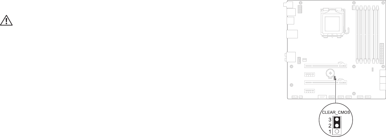
0114 0114
/
CHAPTER 22: SYSTEM SETUP
Clearing Forgotten Passwords and CMOS Settings
Follow the instructions in “Before You Begin” on page 1. 6.
WARNING: e computer must be disconnected from the electrical
outlet to clear the CMOS setting.
Remove the left side-panel (see “Removing the Left Side-Panel” on page 2. 11).
Reset the current password and CMOS settings: 3.
Locate the 3-pin CMOS or password-reset jumper on the system board a.
(see “System Board Components” on page 14).
Remove the jumper plug from the CMOS or password-reset jumper b.
pins 2 and 3.
Place the jumper plug on the CMOS or password-reset jumper c.
pins 1 and 2 and wait for approximately ve seconds.
Remove the jumper plug and replace it on the CMOS or password reset d.
jumper pins 2 and 3.
CMOS:
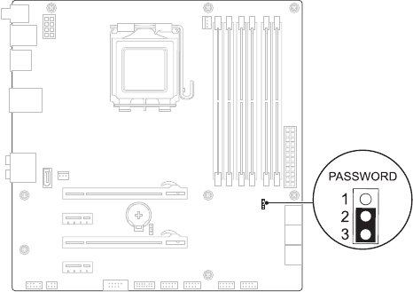

0116 0116
/
CHAPTER 22: SYSTEM SETUP
A list of results appear on the screen. Click 4. BIOS.
Click 5. Download Now to download the latest BIOS le.
e File Download window appears.
Click 6. Save to save the le on your desktop. e le downloads to your
desktop.
Click 7. Close if the Download Complete window appears.
e le icon appears on your desktop and is titled the same as the
downloaded BIOS update le.
Double-click the le icon on the desktop and follow the procedures that 8.
appear on the screen.
Flashing the BIOS
e BIOS may require ashing when an update is available or when replacing the
system board. To ash the BIOS:
Turn on the computer.1.
Go to 2. support.dell.com/support/downloads.
Locate the BIOS update le for your computer:3.
- If you have your computer’s Service Tag:
Click a. Enter a Service Tag.
Enter your computer’s Service Tag in the b. Enter a service tag: eld, click
Go, and proceed to step 6.
- If you do not have your computer’s Service Tag:
Click a. Select Your Product Model in the Select Your Entry Method list.
Select the type of product in the b. Select Your Product Family list.
Select the product brand in the c. Select Your Product Line list.
Select the product model number in the d. Select Your Product Model list.
NOTE: If you have selected a dierent model and want to start over again,
click Start Over on the top right of the menu.
Click e. Conrm.

0117 0117
/
APPENDIX A: CONTACTING ALIENWARE
Websites
You can learn about Alienware® products and services on the following websites:
www.dell.com•
www.dell.com/ap• (Asian/Pacic countries only)
www.dell.com/jp• (Japan only)
www.euro.dell.com• (Europe only)
www.dell.com/la• (Latin American and Caribbean countries)
www.dell.ca• (Canada only)
You can access Alienware Support through the following websites:
support.dell.com•
support.jp.dell.com• (Japan only)
support.euro.dell.com• (Europe only)
support.la.dell.com• (Argentina, Brazil, Chile, Mexico)
APPENDIX A: CONTACTING ALIENWARE
NOTE: If you do not have an active Internet connection, you can nd
contact information on your purchase invoice, packing slip, bill, or Dell
product catalog.
Dell provides several online and telephone-based support and service options.
Because availability varies by country and product, some services may not be
available in your area.
To contact Dell for sales, technical support, or customer service issues:
Visit 1. www.dell.com/contactdell.
Select your country or region.2.
Select the appropriate service or support link based on your need.3.
Choose the method of contacting Dell that is convenient for you.4.
NOTE: For telephone support in the United States, call 1-800-Alienware.
