Dell Alienware Aurora R6 Desktop Liquid Cooling Module User Manual Release Notes En Us
alienware-aurora-r6-desktop - Aurora R6 Liquid Cooling Module alienware-aurora-r6-desktop_release-notes_en-us
User Manual: Dell alienware-aurora-r6-desktop - Aurora R6 Liquid Cooling Module
Open the PDF directly: View PDF ![]() .
.
Page Count: 25

Aurora R6
Liquid Cooling Module
Computer Model: Alienware Aurora R6
Regulatory Model: D23M
Regulatory Type: D23M001

Notes, cautions, and warnings
NOTE: A NOTE indicates important information that helps you
make better use of your product.
CAUTION: A CAUTION indicates either potential damage to
hardware or loss of data and tells you how to avoid the problem.
WARNING: A WARNING indicates a potential for property damage,
personal injury, or death.
Copyright © 2017 Dell Inc. or its subsidiaries. All rights reserved. Dell, EMC, and
other trademarks are trademarks of Dell Inc. or its subsidiaries. Other trademarks may
be trademarks of their respective owners.
2017 - 03
Rev. A00
Contents
Before working inside your computer....................... 4
Before you begin .........................................................................4
Safety instructions........................................................................4
Recommended tools.................................................................... 5
Installing liquid cooling module.................................6
After working inside your computer........................ 24
Getting help and contacting Alienware................... 25
Self-help resources.................................................................... 25
Contacting Alienware..................................................................25
3
Before working inside your
computer
NOTE: The images in this document may differ from your computer
depending on the configuration you ordered.
Before you begin
1 Save and close all open files and exit all open applications.
2 Shut down your computer.
Windows 10: Click or tap Start → Power → Shut down.
NOTE: If you are using a different operating system, see the
documentation of your operating system for shut-down
instructions.
3 Disconnect your computer and all attached devices from their electrical
outlets.
4 Disconnect all cables such as telephone cables, network cables, and so on,
from your computer.
5 Disconnect all attached devices and peripherals, such as keyboard, mouse,
monitor, and so on, from your computer.
6 Remove any media card and optical disc from your computer, if applicable.
7 After the computer is unplugged, press and hold the power button for 5
seconds to ground the system board.
Safety instructions
Use the following safety guidelines to protect your computer from potential
damage and ensure your personal safety.
WARNING: Before working inside your computer, read the safety
information that shipped with your computer. For more safety best
practices, see the Regulatory Compliance home page at
www.dell.com/regulatory_compliance.
4

WARNING: Disconnect all power sources before opening the
computer cover or panels. After you finish working inside the
computer, replace all covers, panels, and screws before connecting to
the electrical outlet.
CAUTION: To avoid damaging the computer, ensure that the work
surface is flat and clean.
CAUTION: To avoid damaging the components and cards, handle
them by their edges, and avoid touching pins and contacts.
CAUTION: You should only perform troubleshooting and repairs as
authorized or directed by the Dell technical assistance team. Damage
due to servicing that is not authorized by Dell is not covered by your
warranty. See the safety instructions that shipped with the product or
at www.dell.com/regulatory_compliance.
CAUTION: Before touching anything inside your computer, ground
yourself by touching an unpainted metal surface, such as the metal at
the back of the computer. While you work, periodically touch an
unpainted metal surface to dissipate static electricity, which could
harm internal components.
CAUTION: When you disconnect a cable, pull on its connector or on
its pull tab, not on the cable itself. Some cables have connectors with
locking tabs or thumb-screws that you must disengage before
disconnecting the cable. When disconnecting cables, keep them
evenly aligned to avoid bending any connector pins. When
connecting cables, ensure that the ports and connectors are correctly
oriented and aligned.
CAUTION: Press and eject any installed card from the media-card
reader.
Recommended tools
The procedures in this document may require the following tools:
• Philips screwdriver
• Flat-head screwdriver
• Plastic scribe
5
Installing liquid cooling module
NOTE: Ensure that you remove the security cable and security screw
from the security-cable slot—if applicable.
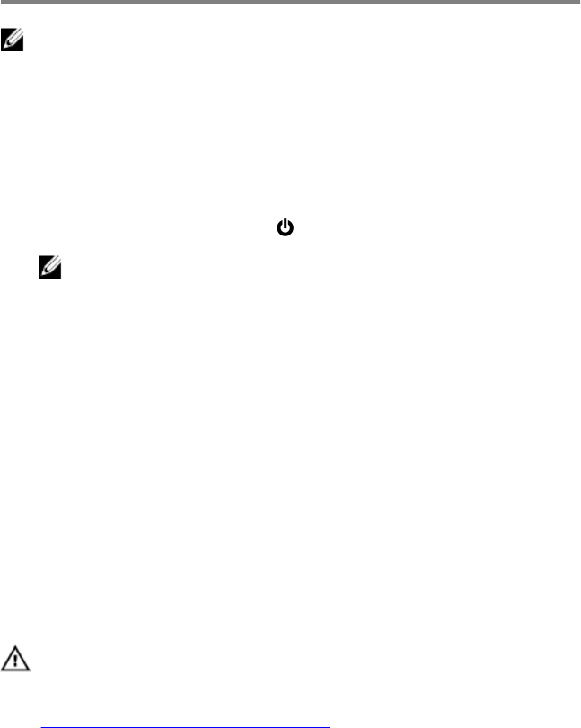
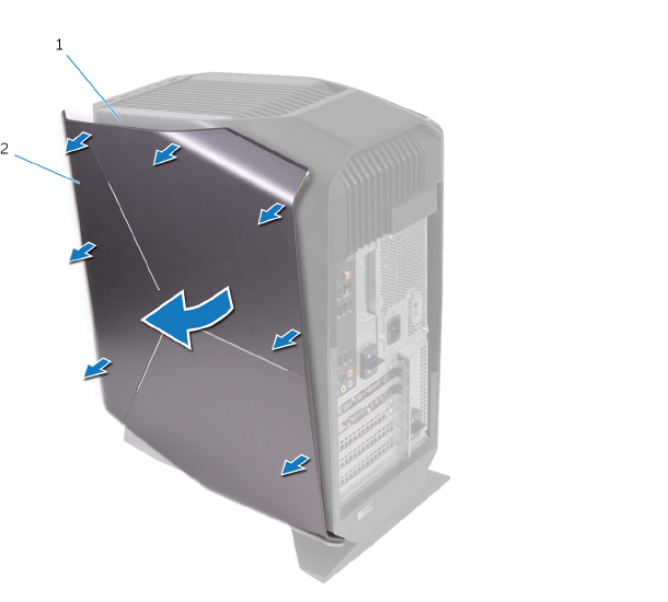
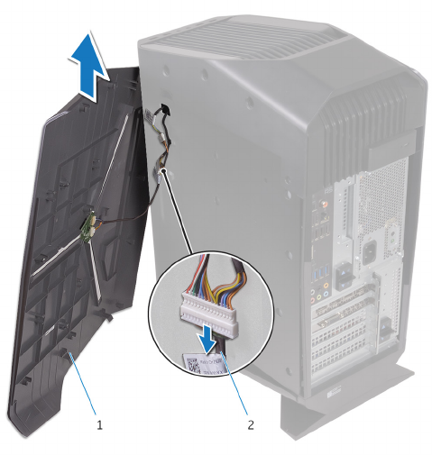
1 Pull the side-panel release latch.
2 Release the left-side cover away from the chassis and then lift it from the
computer.
Figure 1. Removing the left-side cover
1 side-panel release latch 2 top cover
3 left-side cover
3 Lay the computer on the right side.
6
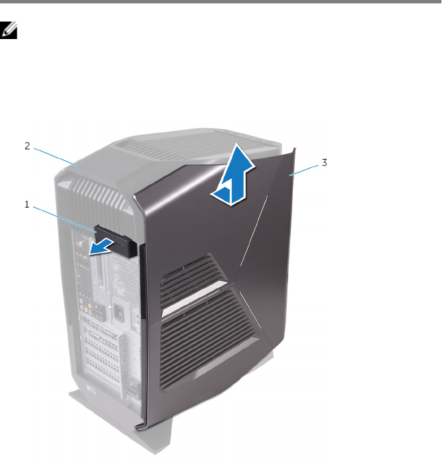
4 Slide the power-supply unit cage release latches towards the unlock
position.
Figure 2. Sliding the power-supply unit cage release latches
1 power-supply unit 2 chassis
3 power-supply unit cage
release cage latches (2)
7
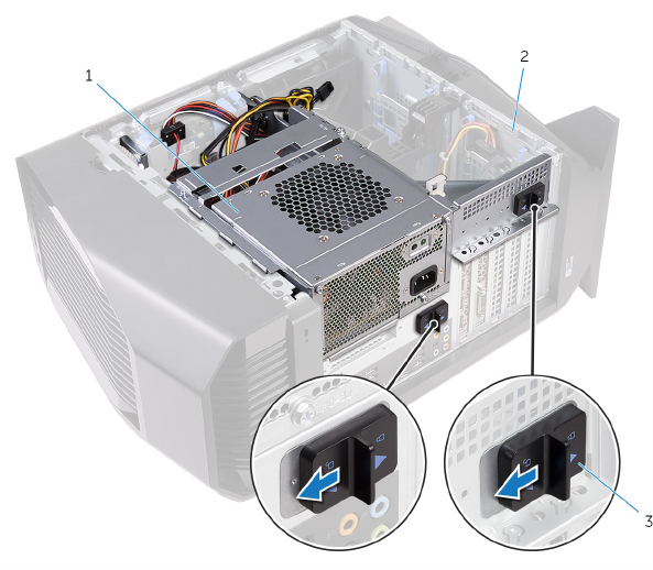
5 Lift the power-supply unit cage while pressing and holding the graphics-card
bracket.
Figure 3. Rotating the power-supply unit
1 power-supply unit cage 2 graphics-card bracket
3 chassis
8
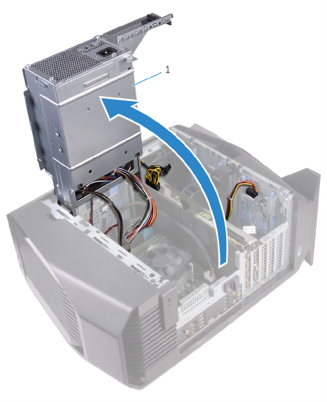
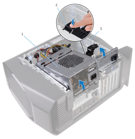
6 Rotate the power-supply unit cage away from the chassis.
Figure 4. Rotating the power-supply unit
1 power-supply unit
7 Disconnect the processor-fan cable from the system board.
8 In a nonadjacent sequence, loosen the captive screws that secure the
processor fan and heat-sink assembly to the system board.
9
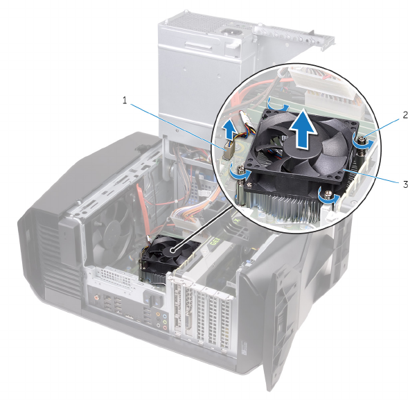
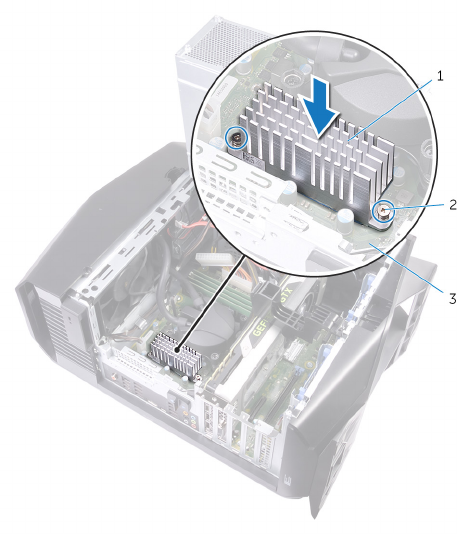
9 Lift the processor fan and heat-sink assembly off the system board.
Figure 5. Removing the processor fan and heat sink assembly
1 processor-fan cable 2 captive screws (4)
3 processor fan and heat-sink
assembly
10 Remove the screw that secures the top-chassis fan to the chassis.
11 Disconnect the top-chassis fan cable from the system board.
10
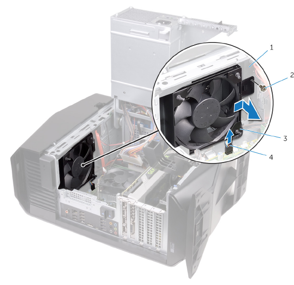
12 Remove the top-chassis fan from the chassis.
Figure 6. Removing the top-chassis fan
1 chassis 2 screw
3 top-chassis fan 4 top-chassis fan cable
13 Rotate the power-supply unit cage towards the chassis until the unit snaps
into place.
14 Stand the computer right side up.
11
15 Carefully pry around the edges of the right-side cover from the chassis.
Figure 7. Removing the right-side cover
1 chassis 2 right-side cover
16 Disconnect the lighting cable from the right-side cover.
12
17 Lift the right-side cover off the chassis.
Figure 8. Removing the right-side cover
1 right-side cover 2 lighting cable
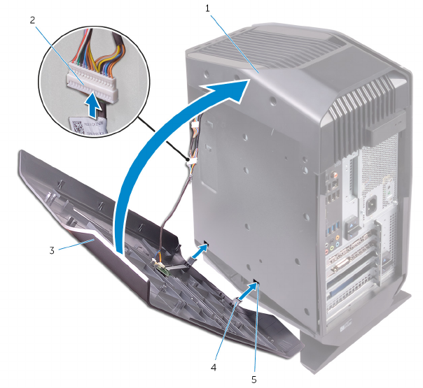
18 Remove the screws that secure the top cover to the chassis.
19 Disconnect the lighting cable from the top cover.
13
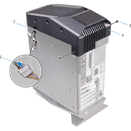
20 Slide the lighting cable through the slot on the chassis.
Figure 9. Removing the top cover
1 lighting cable 2 chassis
3 screws (2) 4 top cover
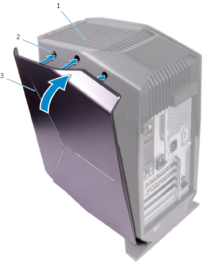
21 Starting from the back, release the tabs on the top cover from the slots on
the chassis.
14
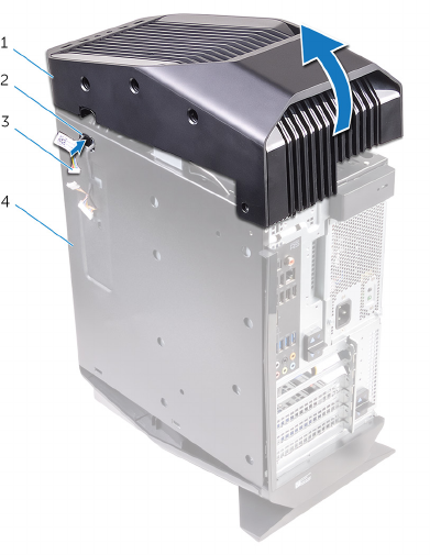
22 Lift the top cover off the chassis.
Figure 10. Removing the top cover
1 top cover 2 slot
3 lighting cable 4 chassis
23 Lay the computer on the right side.
24 Slide the radiator and fan assembly into the radiator and fan cage.
25 Align the screw holes on the radiator and fan assembly with the screw holes
on the radiator and fan cage.
26 Replace the screws that secure the radiator and fan assembly to the
radiator and fan cage.
27 Align the screw holes on the processor cooler with the screw holes on the
system board.
15
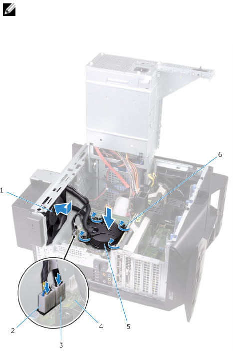
28 In sequential order (indicated on the processor cooler), tighten the captive
screws that secure the processor cooler to the system board.
NOTE: Torque the screws at 6.9 +/-1.15 kilogram-force centimeter
(6 +/-1 pound force inch).
29 Connect the processor-cooling assembly cables to the system board.
Figure 11. Replacing the processor-cooling assembly
1 radiator fan 2 radiator-fan cable
3 processor-cooling assembly
cable
4 system board
5 processor-cooling assembly 6 captive screws (4)
16
30 Align the screw holes on the VR heatsink with the screw holes on the
system board.
31 Tighten the captive screws that secure the VR heatsink to the system board.
Figure 12. Replacing the VR heatsink
1 VR heatsink 2 captive screws (4)
3 system board
32 Rotate the power-supply unit cage towards the chassis until the unit snaps
into place.
17
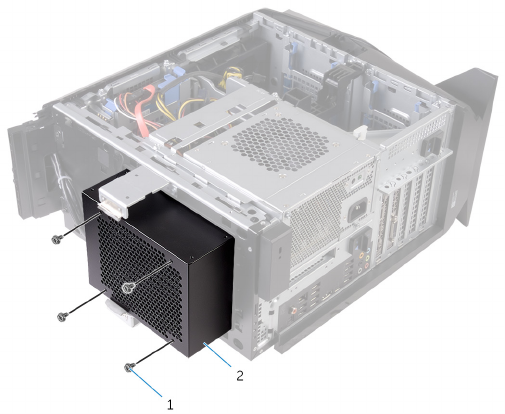
33 Replace the screws that secure the radiator and fan assembly to the
radiator and fan cage.
Figure 13. Replacing the processor-cooling assembly
1 screws (4) 2 radiator and fan cage
34 Slide the lighting cable through the slot on the chassis.
18
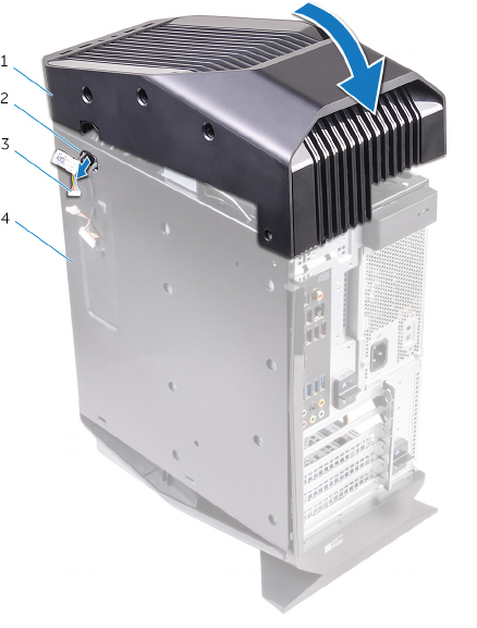
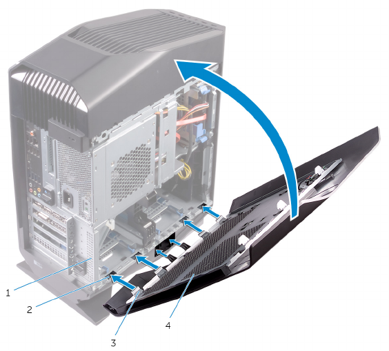
35 Align the tabs on the top cover with the slots on the chassis and snap the
top cover into place.
Figure 14. Replacing the top cover
1 top cover 2 slot
3 lighting cable 4 chassis
36 Connect the lighting cable to the top cover.
19
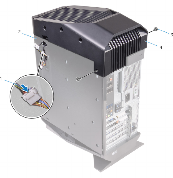
37 Replace the screws that secure the top cover to the chassis.
Figure 15. Replacing the top cover
1 lighting cable 2 chassis
3 screws (2) 4 top cover
20
38 Connect the lighting cable to the right-side cover.
Figure 16. Connecting the lighting cable
a chassis
b lighting cable
c right-side cover
d tabs
e slots
21
39 Align the tabs on the right-side cover with the slots on the chassis and snap
the right-side cover to lock it in place.
Figure 17. Replacing the right-side cover
a chassis
b slots
c right-side cover
40 Align the tabs on the left-side cover with the slots on the chassis.
22
41 Snap the left-side cover to lock it in place.
Figure 18. Replacing the left-side cover
1 chassis 2 slots
3 tabs 4 left-side cover
23

After working inside your
computer
CAUTION: Leaving stray or loose screws inside your computer may
severely damage your computer.
1 Replace all screws and ensure that no stray screws remain inside your
computer.
2 Connect any external devices, peripherals, or cables you removed before
working on your computer.
3 Replace any media cards, discs, or any other parts that you removed before
working on your computer.
4 Connect your computer and all attached devices to their electrical outlets.
5 Turn on your computer.
24

Getting help and contacting
Alienware
Self-help resources
You can get information and help on Alienware products and services using
these online self-help resources:
Table 1. Self-help resources
Information about Alienware products
and services
www.alienware.com
Troubleshooting information, user
manuals, setup instructions, product
specifications, technical help blogs,
drivers, software updates, and so on
www.alienware.com/gamingservices
Videos providing step-by-step
instructions to service your computer
www.youtube.com/alienwareservices
Contacting Alienware
To contact Alienware for sales, technical support, or customer service issues,
see www.alienware.com.
NOTE: Availability varies by country and product, and some services
may not be available in your country.
NOTE: If you do not have an active internet connection, you can find
contact information on your purchase invoice, packing slip, bill, or
Dell product catalog.
25
