Dell Edge Gateway 5000 Series Installation And Operation Manual User Gateway5000 Users Guide En Us
User Manual: Dell dell-edge-gateway-5000 Dell Edge Gateway5000 Series Installation and Operation Manual
Open the PDF directly: View PDF ![]() .
.
Page Count: 106 [warning: Documents this large are best viewed by clicking the View PDF Link!]
- Dell Edge Gateway 5000 Series Installation and Operation Manual
- Overview
- System views
- Setting up your Dell Edge Gateway
- Setting up your operating system
- Windows 10 IoT Enterprise LTSB
- Snappy Ubuntu Core 15 and 16
- Overview
- Boot up and log in
- Restoring Ubuntu Snappy
- Updating operating system and applications
- Ubuntu core OS basic function
- UEFI capsule update
- Watchdog Timer
- Security
- Accessing Snappy Store/Snapweb
- Cloud LED On/Off
- Serial Port
- Minicom
- Expansion IO Module
- Zigbee
- Controller Area Network
- Network Manager – Ubuntu Core 15
- Network Manager – Ubuntu Core 16
- Flashing a new OS image
- Flashing the BIOS
- Wind River Linux
- System specifications
- I/O Module Overview
- Power Module Overview
- Enclosure Overview
- Setting up the ZigBee dongle
- BIOS defaults
- Other documents you may need
- Contacting Dell

Dell Edge Gateway
5000 Series
Installation and Operation Manual
Computer Model: Dell Edge Gateway 5000\5100
Regulatory Model: N01G\N02G
Regulatory Type: N01G001\N02G001

Notes, cautions, and warnings
NOTE: A NOTE indicates important information that helps you make better use of your product.
CAUTION: A CAUTION indicates either potential damage to hardware or loss of data and tells you how to avoid the
problem.
WARNING: A WARNING indicates a potential for property damage, personal injury, or death.
© 2016-2018 Dell Inc. or its subsidiaries. All rights reserved. Dell, EMC, and other trademarks are trademarks of Dell Inc. or its subsidiaries.
Other trademarks may be trademarks of their respective owners.
2018 - 01
Rev. A03

Contents
1 Overview......................................................................................................................... 6
2 System views.................................................................................................................. 7
System—Front...................................................................................................................................................................7
System—Front (LED indicators)........................................................................................................................................ 8
System—Bottom............................................................................................................................................................... 8
Serial port (RS232) connector mapping....................................................................................................................... 9
CANbus port connector mapping................................................................................................................................. 9
RS485 connector mapping...........................................................................................................................................9
RS422/485 connector mapping..................................................................................................................................10
System—Bottom (DIP switches)......................................................................................................................................10
System—Top..................................................................................................................................................................... 11
Intrusion-detection connector mapping....................................................................................................................... 11
HDMI connector mapping........................................................................................................................................... 12
System—Left................................................................................................................................................................... 13
24 V AC/DC power port..............................................................................................................................................14
19.5 V DC power adapter port.....................................................................................................................................14
System—Right................................................................................................................................................................. 15
3 Setting up your Dell Edge Gateway................................................................................16
Professional installation instructions..................................................................................................................................16
Instructions d'installation professionnelles......................................................................................................................... 17
Federal Communication Commission Interference Statement........................................................................................... 17
Industry Canada Statement.............................................................................................................................................. 18
Setting up the Edge Gateway........................................................................................................................................... 19
Powering on the Edge Gateway .................................................................................................................................19
Mounting the Edge Gateway on the wall....................................................................................................................22
Mounting the Edge Gateway on a DIN rail..................................................................................................................24
Inserting a micro-SIM card and activating your mobile broadband..............................................................................26
4 Setting up your operating system..................................................................................30
Windows 10 IoT Enterprise LTSB......................................................................................................................................30
Overview....................................................................................................................................................................30
Boot up and log in...................................................................................................................................................... 30
Restoring Windows 10 IoT Enterprise LTSB................................................................................................................30
Windows 10 IoT Enterprise LTSB basic functions....................................................................................................... 30
Common port mappings..............................................................................................................................................31
Snappy Ubuntu Core 15 and 16.........................................................................................................................................32
Overview....................................................................................................................................................................32
Boot up and log in...................................................................................................................................................... 32
Restoring Ubuntu Snappy...........................................................................................................................................33
Updating operating system and applications...............................................................................................................33
3

Ubuntu core OS basic function...................................................................................................................................34
UEFI capsule update...................................................................................................................................................35
Watchdog Timer.........................................................................................................................................................36
Security...................................................................................................................................................................... 37
Accessing Snappy Store/Snapweb.............................................................................................................................37
Cloud LED On/O......................................................................................................................................................38
Serial Port ................................................................................................................................................................. 38
Minicom..................................................................................................................................................................... 39
Expansion IO Module .................................................................................................................................................40
Zigbee........................................................................................................................................................................ 40
Controller Area Network.............................................................................................................................................40
Network Manager – Ubuntu Core 15.......................................................................................................................... 41
Network Manager – Ubuntu Core 16..........................................................................................................................42
Flashing a new OS image........................................................................................................................................... 44
Flashing the BIOS.......................................................................................................................................................44
Wind River Linux.............................................................................................................................................................. 45
Overview....................................................................................................................................................................45
Boot up and login....................................................................................................................................................... 45
Restoring Wind River Linux........................................................................................................................................ 46
Wind River Linux Basic Functions...............................................................................................................................47
5 System specications....................................................................................................61
Component types............................................................................................................................................................. 61
Operating systems............................................................................................................................................................ 61
Processor..........................................................................................................................................................................61
Memory............................................................................................................................................................................62
Drives and removable storage.......................................................................................................................................... 62
Communications—WLAN antenna...................................................................................................................................62
Communications—WWAN antenna................................................................................................................................. 64
Graphics/video controller.................................................................................................................................................68
External ports and connectors......................................................................................................................................... 68
Dimensions and weight.....................................................................................................................................................69
Product dimensions and weight................................................................................................................................. 69
Packaging dimensions and weight..............................................................................................................................69
Mounting dimensions..................................................................................................................................................70
Environmental and operating conditions........................................................................................................................... 70
Environmental conditions—System............................................................................................................................70
Environmental conditions—IO module........................................................................................................................ 71
Environmental conditions - Power module..................................................................................................................72
Environmental conditions - Enclosure.........................................................................................................................73
Operating conditions.................................................................................................................................................. 73
Power...............................................................................................................................................................................74
Power adaptor (optional)............................................................................................................................................74
3.0 V CMOS coin-cell battery..................................................................................................................................... 74
Security............................................................................................................................................................................75
Software.......................................................................................................................................................................... 75
4

Environmental...................................................................................................................................................................75
Service and support......................................................................................................................................................... 75
6 I/O Module Overview.................................................................................................... 77
IO module (optional) views............................................................................................................................................... 77
IO module—Front.......................................................................................................................................................77
IO module—Top..........................................................................................................................................................78
IO module—Bottom................................................................................................................................................... 79
Setting up the IO module..................................................................................................................................................79
Installing the PCIe card into the IO module.................................................................................................................82
7 Power Module Overview............................................................................................... 85
Power module (optional) views........................................................................................................................................ 85
Power module—Front................................................................................................................................................86
Power module—Bottom.............................................................................................................................................87
Power module—Top...................................................................................................................................................89
Power module—Right................................................................................................................................................90
Setting up the power module...........................................................................................................................................90
Specications - Power Module.........................................................................................................................................93
8 Enclosure Overview...................................................................................................... 95
Enclosure (optional) view................................................................................................................................................. 95
Enclosure - Side......................................................................................................................................................... 95
Setting up the enclosure.................................................................................................................................................. 96
9 Setting up the ZigBee dongle ...................................................................................... 101
10 BIOS defaults............................................................................................................. 102
General........................................................................................................................................................................... 102
System conguration......................................................................................................................................................102
Security.......................................................................................................................................................................... 102
Secure Boot....................................................................................................................................................................103
Performance...................................................................................................................................................................103
Power Management....................................................................................................................................................... 103
POST Behavior............................................................................................................................................................... 104
Maintenance...................................................................................................................................................................104
11 Other documents you may need................................................................................. 105
12 Contacting Dell...........................................................................................................106
Regulatory and environmental compliance......................................................................................................................106
5

1
Overview
The Dell Edge Gateway 5000/5100 series allows you to connect to network enabled devices wired or wirelessly, and manage them
remotely in your existing network ecosystem. The system can also be mounted on the wall using the Dell approved wall mount kit or
mounted into your existing rack infrastructure using the DIN-rail mounting bracket. The system runs on Windows 10 Enterprise,
Ubuntu Snappy, or the Wind River Linux operating systems. As part of a complete interoperable building automation system, the
Edge Gateway provides precise monitoring and control of connected points. The I/O expansion module provides the Edge Gateway
with extra inputs and an output module. The power expansion module provides the Edge Gateway with power redundancy options
by allowing you to connect a 24V AC/DC, a 19.5V DC, and a battery back up simultaneously.
If the Edge Gateway is set up as a web server, it oers the capability for conguration from a web browser. Congure I/Os, set up
objects, and monitor present values from a browser.
6
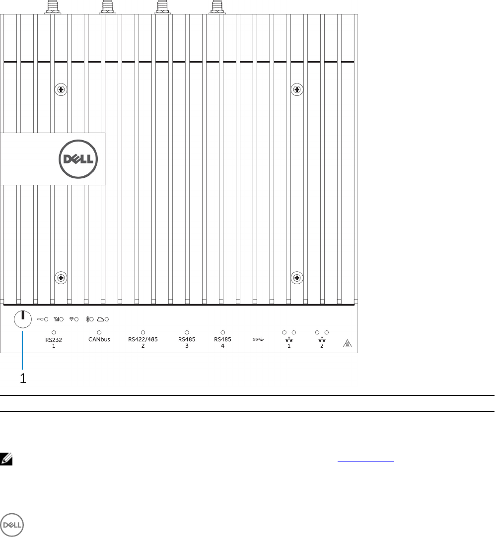
System—Front (LED indicators)
Features
1 Power status LED Indicates the power‑state of the system.
2 Mobile broadband status LED Indicates the mobile broadband status and network activity.
3 Wireless status LED Indicates the wireless connectivity status and network activity.
4 Bluetooth status LED Indicates the Bluetooth status and activity.
5 Cloud connection status LED Indicates the cloud connection status.
6 Network status LED Indicates the connectivity status and network activity.
7 Network status LED Indicates the connectivity status and network activity.
8 RS485 port status LED Provides the status of the RS485 port connections.
9 RS485 port status LED Provides the status of the RS485 port connections.
10 RS422/485 port status LED Provides the status of the RS422/485 port connections.
11 CANbus port status LED Provides the status of the CANbus port connection.
12 Serial port status LED Provides the status of the serial port connection.
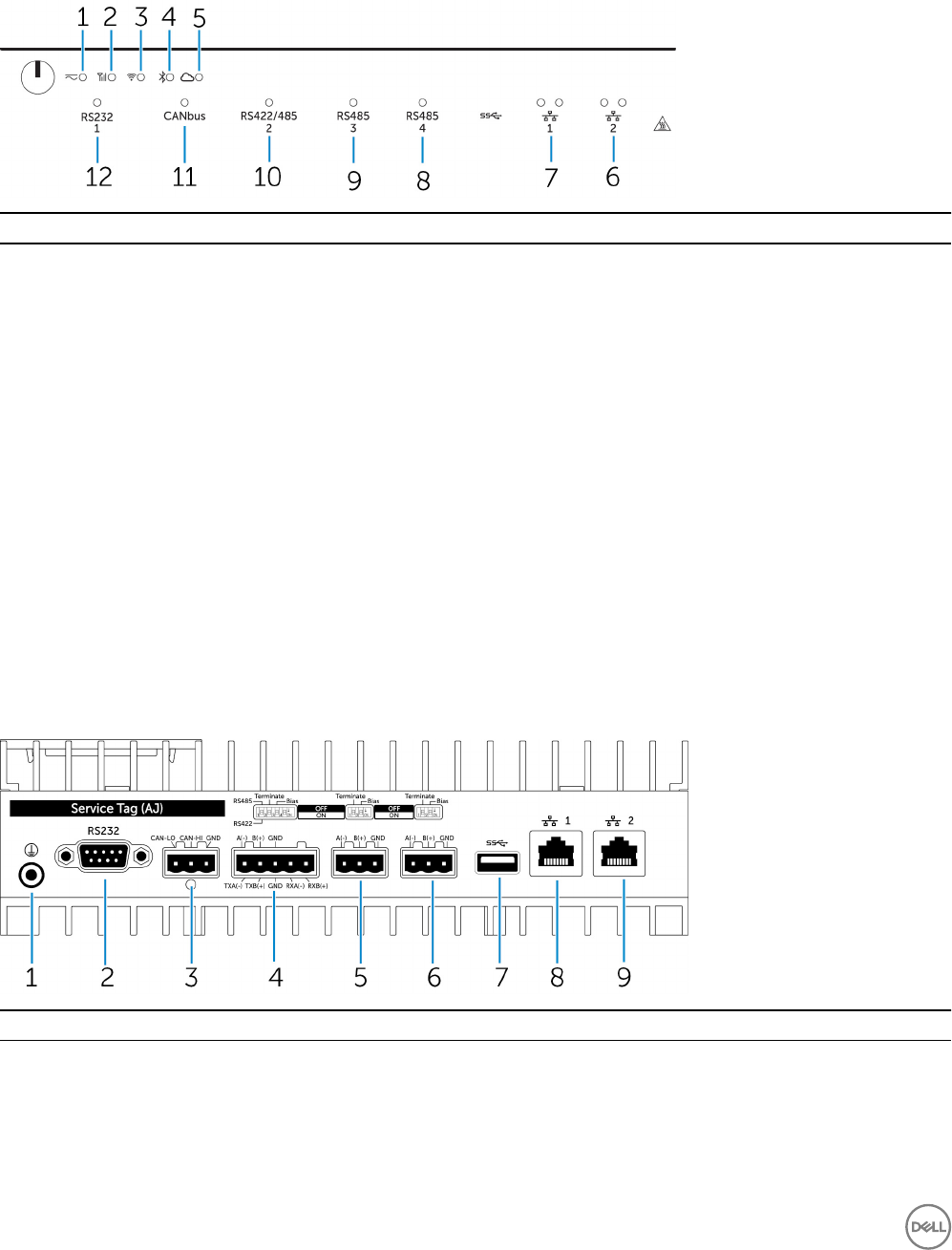
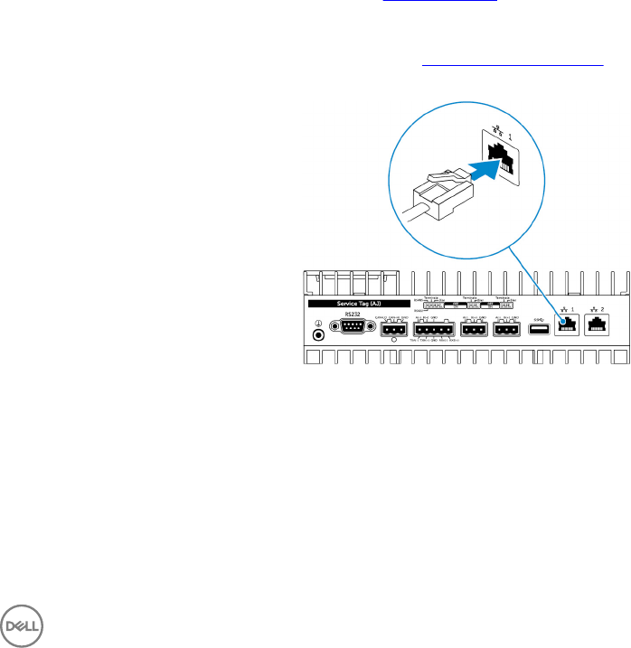
System—Bottom
Features
1 Earth ground Connect the grounding cable to the system.
2 Serial port Connect to a serial port enabled device such as a printer.
3 CANbus port Connect to a CANbus port enabled device or dongle.
4 RS422/485 port Connect a RS422/485 device.
8
Features
5 RS485 port Connect a RS485 device.
6 RS485 port Connect a RS485 device.
7 USB 3.0 port Connect a USB 3.0 device.
8 Network port Connect an Ethernet (RJ45) cable from a router or a broadband
modem for network or internet access.
9 Network port Connect an Ethernet (RJ45) cable from a router or a broadband
modem for network or internet access.
NOTE: For more details about the DIP switches on the bottom of the system, see DIP switches.
NOTE: For RS422 and RS485:
• Termination is 120-ohms between the members of the dierential pair when enabled.
• Bias is 4.7k pull-up (5V) / pull-down (Gnd) when enabled.
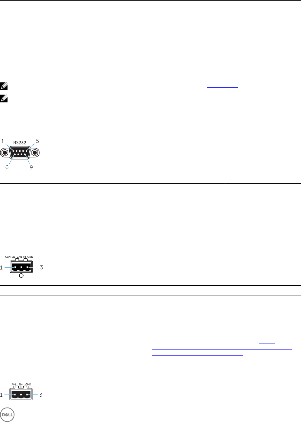
Serial port (RS232) connector mapping
Pin Signal Pin Signal
1 DCD 6 DSR
2 RXD 7 RTS
3 TXD 8 CTS
4 DTR 9 RI
5 GND
CANbus port connector mapping
PIN Signal
1 CAN-LO
2 CAN-HI
3 GND
Connector vendor part number Molex 39530-5503
For more information about the connector, see http://
www.molex.com/molex/products/datasheet.jsp?part=active/
0395305503_TERMINAL_BLOCKS.xml
RS485 connector mapping
9
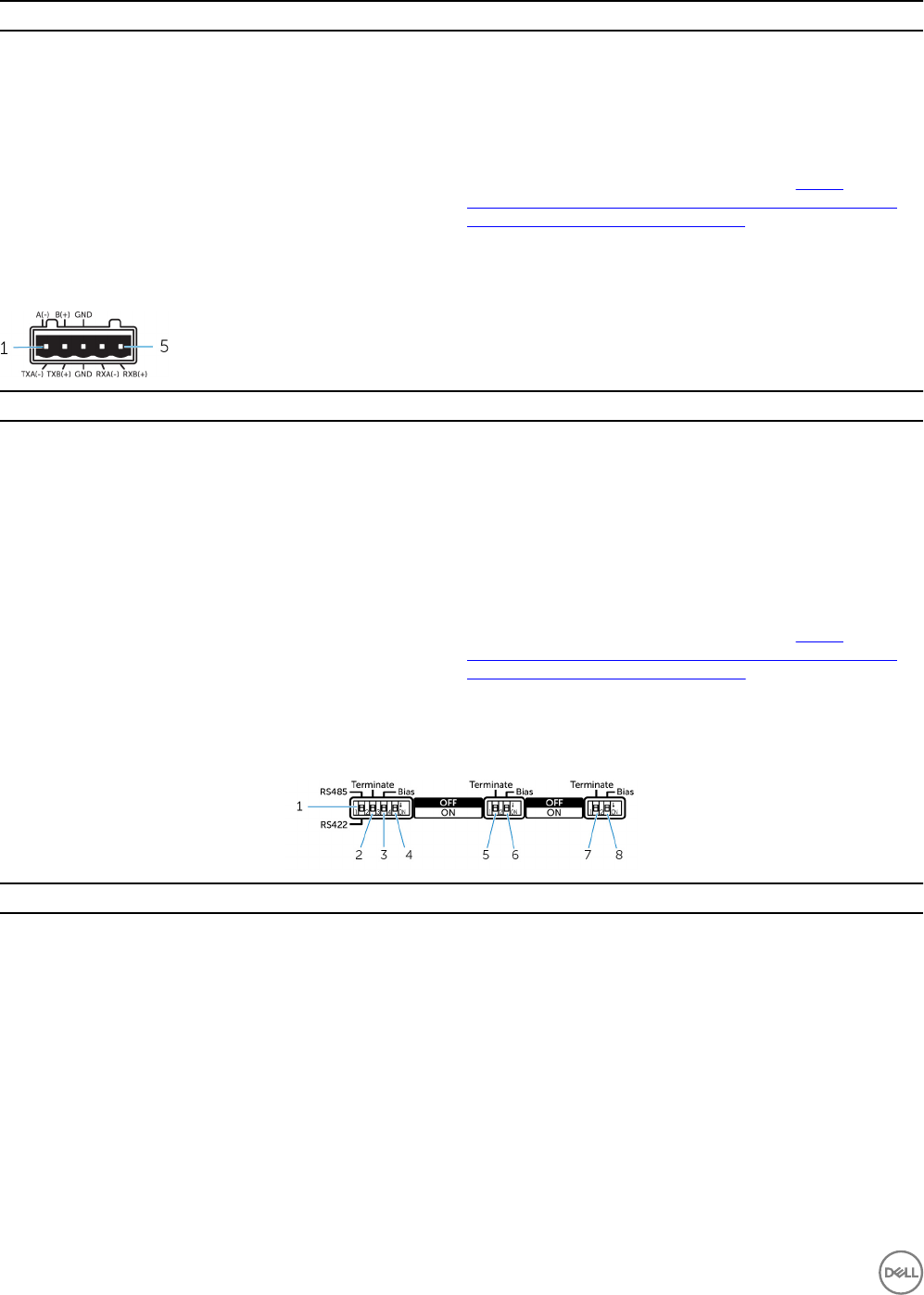
Pin Signal
1 A(-)
2 B(+)
3 GND
Connector Vendor part number Molex 359530-5503
For more information about the connector, see http://
www.molex.com/molex/products/datasheet.jsp?part=active/
0395305503_TERMINAL_BLOCKS.xml
RS422/485 connector mapping
Pin Signal
1 TXA(-) / A(-)
2 TXB(+) / B(+)
3 GND
4 RXA(-)
5 RXB(+)
Connector Vendor part number Molex 359530-5505
For more information about the connector, see http://
www.molex.com/molex/products/datasheet.jsp?part=active/
0395305505_TERMINAL_BLOCKS.xml
System—Bottom (DIP switches)
Feature
1 RS422/RS485 port toggle switch Toggle between RS422 or RS485 standard.
2 RS422/RS485 port resistor switch Enable/disable the dierential termination resistor.
3 RS422/RS485 port bias resistor switch Enable/disable the bias resistor for the RS422/RS485 port.
4 ePSA diagnostic switch When the position of the switch changes, the system starts in ePSA
(Enhanced Preboot System Assessment) mode on the next start.
5 RS485 port resistor switch Enable/disable the dierential termination resistor for RS485.
6 RS485 port bias resistor switch Enable/disable the bias resistor for the RS485 port.
7 RS485 port resistor switch Enable/disable the dierential termination resistor for RS485.
8 RS485 port bias resistor switch Enable/disable the bias resistor for the RS485 port.
10
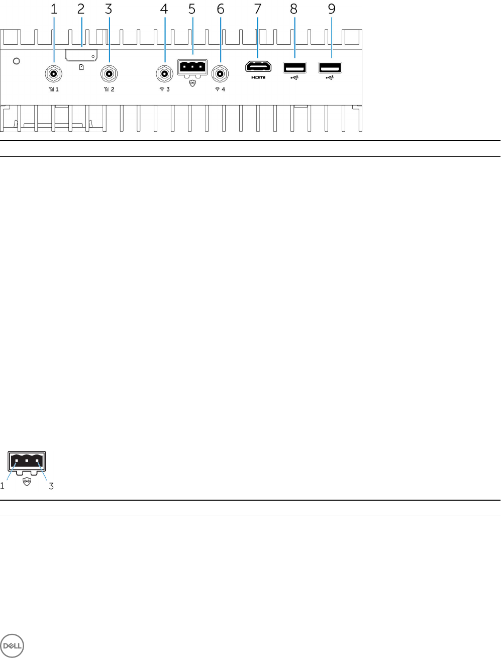
System—Top
Features
1 Mobile broadband antenna port (port one) Connect an antenna to increase the range and strength of the
mobile broadband signals.
2 Micro-SIM card slot Insert a micro-SIM card to connect to a mobile broadband
network.
3 Mobile broadband antenna port (port two) Connect an antenna to increase the range and strength of the
mobile broadband signals.
4 Wi-Fi antenna port (port three) Connect an antenna to increase the range and strength of Wi-Fi
signals.
5 Intrusion detection connector Connect an intrusion detection switch to detect any intrusion
into the system.
6 Wi-Fi antenna port (port four) Connect an antenna to increase the range and strength of Wi-Fi
signals.
7 HDMI port Connect a monitor or other HDMI device. Provides video and
audio output. Hot-plugging is supported on Windows 10 and
Ubuntu only.
8 USB 2.0 port Connect a USB 2.0 device.
9 USB 2.0 port Connect a USB 2.0 device.
Intrusion-detection connector mapping
Pin Signal
1 GND
2 Intrusion detection
3 Cable detection
11

HDMI connector mapping
Pin Signal
1 TMDS Data2+
2 TMDS Data2 Shield
3 TMDS Data2−
4 TMDS Data1+
5 TMDS Data1 Shield
6 TMDS Data1−
7 TMDS Data0+
8 TMDS Data0 Shield
9 TMDS Data0−
10 TMDS Clock+
11 TMDS Clock Shield
12 TMDS Clock−
13 CEC
14 Reserved
15 SCL
16 SDA
17 Ground
18 +5 V (min. 0.055 A)
19 Hot Plug Detect
12
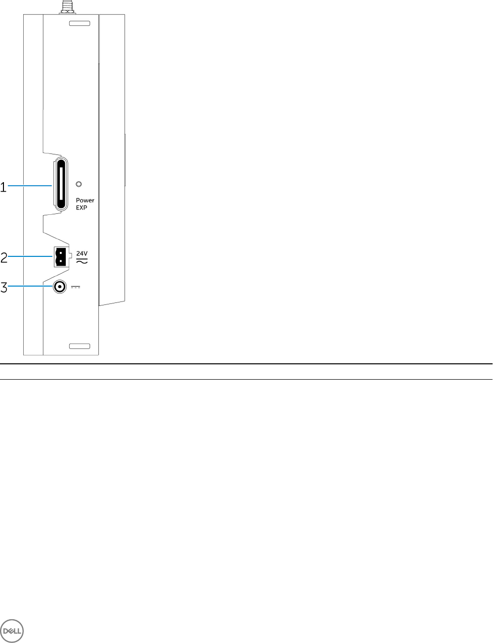
System—Left
Features
1 Power module expansion port Connect an external power module for increased power options.
2 24 V AC/DC power Phoenix connector Connect an 24 V AC/DC power connector to provide power to
your system.
3 19.5 V DC power adapter port Connect a 19.5 V DC power adapter connector to provide power
to your system.
13
24 V AC/DC power port
19.5 V DC power adapter port
14
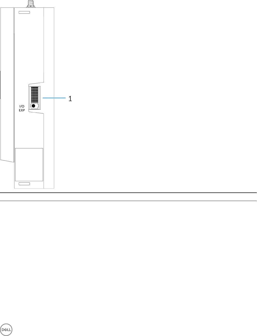
System—Right
Features
1 IO expansion port Connect an external expansion module for additional IO ports.
15
3
Setting up your Dell Edge Gateway
WARNING: Before you begin any of the procedures in this section, read the safety information that shipped with your
system. For additional best practices information, go to www.dell.com/regulatory_compliance.
WARNING: When installing the Gateway, the responsible party or integrator shall use the AC Adapter provided with the
Dell Edge Gateway, or connect to a 24Vac or 24Vdc power source already present as part of the clients installation.
WARNING: The Dell AC Adapter (full-wave rectied and have no built-in isolation transformer) is acceptable for use up to
ambient temperature of 40°C and is a limited power source, SELV/Limited Energy Circuit, Class 2 power source. If
ambient temperature of the installation exceeds 40 °C then use the 24Vac or 24Vdc power available as part of the
installation.
WARNING: Always make sure that the available power source matches the required input power of the Dell Edge
Gateway, check the input power markings next to power connector(s) before making connections. The 24 V power
source must be compliant with local Electrical Codes and Regulations.
WARNING: To ensure the protection provided by Dell Edge Gateway is not impaired, do not use or install the system in
any manner other than that which is specied in this manual.
WARNING: When installing the Gateway use acable appropriate for the load currents: 3-core cable rated 5 A at 90 °C
(194 °F) minimum, which conform to either IEC 60227 or IEC 60245. The system accepts cables from 0.8 to 2.5 mm (18
to 14 AWG).
WARNING: The symbol indicates hot surface or adjacent hot surface that can obtain temperature during normal
use that can cause a burn. Allow equipment to cool o or use protective gloves when handling to reduce risk of a burn.
WARNING: If a battery is included as part of System/Network, battery must be must be installed with appropriate
enclosure in accordance with local Fire and Electrical Codes and Laws.
WARNING: When installing the Power Module, use a cable appropriate for the load currents: 3-core cable rated 15 A at
90 °C (194 °F) minimum, which conform to either IEC60227 or IEC 60245. The Gateway accepts cables of 14 AWG
minimum.
WARNING: Before installing that all of three power inputs (Terminal Block/Power Jack/Battery Input) in power module
shall be protected by the 20 A fuses or circuit-breakers(over current protection device) in front of this system.
WARNING: The system is for installation in a suitable industrial enclosure (provides electrical, mechanical and re hazard
protection).
WARNING: The core module only can be wall mounted (without the need for an additional enclosure)
WARNING: Only Sealed Lead Acid (SLA) battery rated 50Ah (or less) shall be used
Professional installation instructions
Installation personnel
This product is designed for specic applications and needs to be installed by qualied personnel with RF and regulatory related
knowledge. The general user shall not attempt to install or change the setting.
Installation location
The product shall be installed at a location where the radiating antenna is kept 20 cm from nearby persons in its normal operation
condition in order to meet regulatory RF exposure requirements.
16

External antenna
Use only the antenna(s) which have been approved by the applicant. Non-approved antenna(s) may produce unwanted spurious or
excessive RF transmitting power which may lead to a violation of FCC/IC limits and is prohibited.
Installation procedure
Please refer to user’s manual for the detail.
WARNING: Please carefully select the installation position and make sure that the nal output power does not exceed
the limits set forth in relevant rules. The violation of these rules could possibly lead to serious federal penalties.
Instructions d'installation professionnelles
Le personnel d'installation
Ce produit est conçu pour des applications spéciques et doit être installé par un personnel qualié avec RF et connaissances
connexes réglementaire. L'utilisateur ne doit pas tenter générale d'installer ou de modier le réglage.
Lieu d'installation
Le produit doit être installé à un endroit où l'antenne de rayonnement est maintenue à 20 cm de personnes à proximité dans son état
de fonctionnement normal, an de répondre aux exigences réglementaires d'exposition aux radiofréquences.
Antenne externe
Utilisez uniquement l'antenne(s) qui ont été approuvés par le demandeur. Antenne (s) peuvent produire de l'énergie RF parasite
indésirable ou excessive transmission qui peut conduire à une violation des normes de la FCC / IC est interdite et non-approuvé.
Procédure d'installation
ATTENTION: S'il vous plaît choisir avec soin la position d'installation et assurez-vous que la puissance de sortie nal ne
dépasse pas les limites xées dans les règles pertinentes. La violation de ces règles pourrait conduire à des sanctions fédérales
graves.
Federal Communication Commission Interference Statement
This device complies with Part 15 of the FCC Rules. Operation is subject to the following two conditions: (1) This device may not
cause harmful interference, and (2) this device must accept any interference received, including interference that may cause
undesired operation.
This equipment has been tested and found to comply with the limits for a Class B digital device, pursuant to Part 15 of the FCC
Rules. These limits are designed to provide reasonable protection against harmful interference in a residential installation. This
equipment generates, uses and can radiate radio frequency energy and, if not installed and used in accordance with the instructions,
may cause harmful interference to radio communications. However, there is no guarantee that interference will not occur in a
particular installation. If this equipment does cause harmful interference to radio or television reception, which can be determined by
turning the equipment o and on, the user is encouraged to try to correct the interference by one of the following measures:
• Reorient or relocate the receiving antenna.
• Increase the separation between the equipment and receiver.
• Connect the equipment into an outlet on a circuit dierent from that to which the receiver is connected.
• Consult the dealer or an experienced radio/TV technician for help.
FCC Caution:
• Any changes or modications not expressly approved by the party responsible for compliance could void the user's authority to
operate this equipment.
17

• This transmitter must not be co-located or operating in conjunction with any other antenna or transmitter.
Radiation Exposure Statement:
This equipment complies with FCC radiation exposure limits set forth for an uncontrolled environment. This equipment should be
installed and operated with minimum distance 20cm between the radiator & your body.
NOTE: The country code selection is for non-US model only and is not available to all US model. Per FCC regulation, all
WiFi product marketed in US must xed to US operation channels only.
Industry Canada Statement
This device complies with Industry Canada license-exempt RSS standard(s). Operation is subject to the following two conditions:
1. this device may not cause interference, and
2. this device must accept any interference, including interference that may cause undesired operation of the device.
Le présent appareil est conforme aux CNR d'Industrie Canada applicables aux appareils radio exempts de licence. L'exploitation est
autorisée aux deux conditions suivantes:
1. l'appareil ne doit pas produire de brouillage, et
2. l'utilisateur de l'appareil doit accepter tout brouillage radioélectrique subi, même si le brouillage est susceptible d'en
compromettre le fonctionnement.
This Class B digital apparatus complies with Canadian ICES-003.
Cet appareil numérique de la classe B est conforme à la norme NMB-003 du Canada.
This device complies with RSS-210 of Industry Canada. Operation is subject to the condition that this device does not cause harmful
interference.
Cet appareil est conforme à la norme RSS-210 d'Industrie Canada. L'opération est soumise à la condition que cet appareil ne
provoque aucune interférence nuisible.
This device and its antenna(s) must not be co-located or operating in conjunction with any other antenna or transmitter, except
tested built-in radios.
Cet appareil et son antenne ne doivent pas être situés ou fonctionner en conjonction avec une autre antenne ou un autre émetteur,
exception faites des radios intégrées qui ont été testées.
The County Code Selection feature is disabled for products marketed in the US/Canada.
La fonction de sélection de l'indicatif du pays est désactivée pour les produits commercialisés aux États-Unis et au Canada.
Radiation Exposure Statement: This equipment complies with IC radiation exposure limits set forth for an uncontrolled environment.
This equipment should be installed and operated with minimum distance 20cm between the radiator & your body.
Déclaration d'exposition aux radiations: Cet équipement est conforme aux limites d'exposition aux rayonnements IC établies pour
un environnement non contrôlé. Cet équipement doit être installé et utilisé avec un minimum de 20 cm de distance entre la source de
rayonnement et votre corps.
Caution:
1. The device for operation in the band 5150-5250 MHz is only for indoor use to reduce the potential for harmful interference to
co-channel mobile satellite systems;
2. The maximum antenna gain permitted for devices in the bands 5250-5350 MHz and 5470-5725 MHz shall comply with the
eirp limit; and
18
3. The maximum antenna gain permitted for devices in the band 5725-5825 MHz shall comply with the eirp limits specied for
point-to-point and non point-to-point operation as appropriate.
4. The worst-case tilt angle(s) necessary to remain compliant with the eirp elevation mask requirement set forth in Section
6.2.2(3) shall be clearly indicated.
5. Users should also be advised that high-power radars are allocated as primary users (i.e. priority users) of the bands 5250-5350
MHz and 5650-5850 MHz and that these radars could cause interference and/or damage to LE-LAN devices.
Avertissement:
1. Les dispositifs fonctionnant dans la bande 5150-5250 MHz sont réservés uniquement pour une utilisation à l’intérieur an de
réduire les risques de brouillage préjudiciable aux systèmes de satellites mobiles utilisant les mêmes canaux;
2. Le gain maximal d’antenne permis pour les dispositifs utilisant les bandes 5250-5350 MHz et 5470-5725 MHz doit se
conformer à la limite de p.i.r.e.;
3. Le gain maximal d’antenne permis (pour les dispositifs utilisant la bande 5725-5825 MHz) doit se conformer à la limite de p.i.r.e.
spéciée pour l’exploitation point à point et non point à point, selon le cas.
4. Les pires angles d’inclinaison nécessaires pour rester conforme à l’exigence de la p.i.r.e. applicable au masque d’élévation, et
énoncée à la section 6.2.2 3), doivent être clairement indiqués.
5. De plus, les utilisateurs devraient aussi être avisés que les utilisateurs de radars de haute puissance sont désignés utilisateurs
principaux (c.-à-d., qu’ils ont la priorité) pour les bandes 5250-5350 MHz et 5650-5850 MHz et que ces radars pourraient
causer du brouillage et/ou des dommages aux dispositifs LAN-EL.
Setting up the Edge Gateway
Powering on the Edge Gateway
1. Install the Edge Gateway on the wall mount using a wall mounting kit.
or
Install the Edge Gateway on the rack infrastructure using DIN-rail mounting brackets.
2. Connect a network cable—optional.
3. Install the WLAN antenna to enable the wireless connections—optional.
19
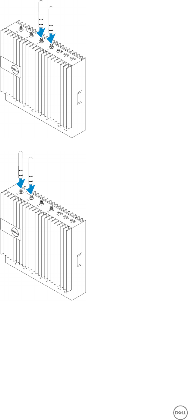
4. Install the WWAN antenna to enable the wireless connections—optional.
5. Connect a display to the Edge Gateway (if necessary).
20
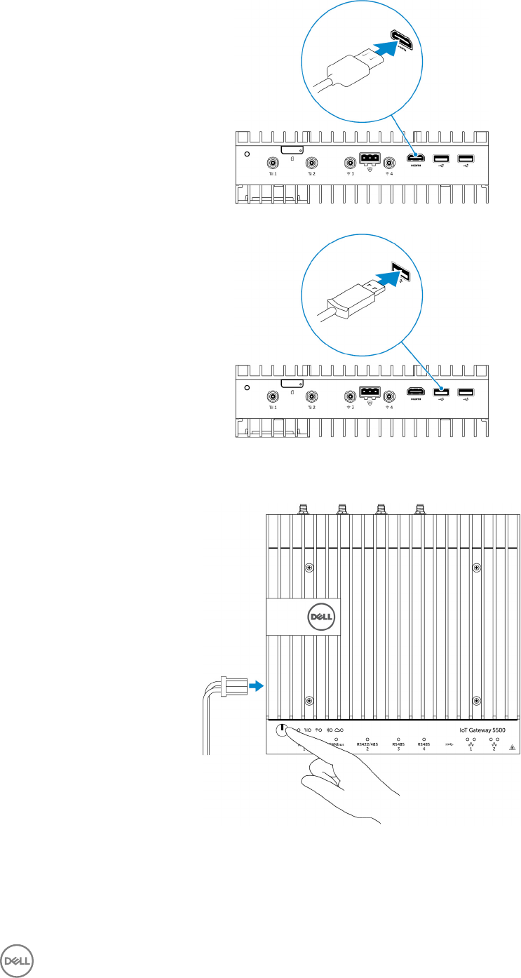
6. Connect a keyboard and mouse if accessing the Edge Gateway directly.
7. Connect a grounding cable to the Gateway (if necessary).
8. Connect a SELV/limited energy circuit power source to the Edge Gateway and press the power button to turn it on.
24 V AC/DC
or
19.5 V DC
21

9. If setting up the Edge Gateway for the rst time, complete the operating system setup.
NOTE: The Edge Gateway is shipped with either Windows 10 Enterprise, Ubuntu Snappy, or Wind River Linux
operating systems.
NOTE: On Windows 10 OS, select
Do this later
when prompted to enter the product key.
NOTE: The default username and password for Ubuntu-Snappy-Core is
ubuntu
.
NOTE: The default username and password for Wind River is
root
.
10. Connect and congure devices using the RS422/RS485 ports.
NOTE: Turn on the corresponding dip switches to enable the RS422/R485 ports.
NOTE: After the Edge Gateway setup is complete, reinstall the dust covers on any unused ports.
Mounting the Edge Gateway on the wall
You can mount the Edge Gateway on a wall by using mounting brackets.
1. Secure the two mounting brackets to the back of the Edge Gateway by using four screws.
22
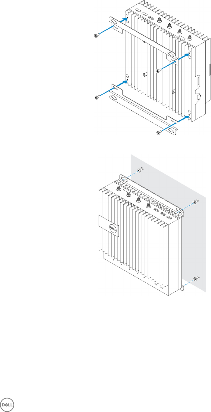
2. Drill four holes in the wall that correspond to the holes in the mounting bracket, then place the Edge Gateway against the wall
and align the holes in the mounting brackets with the holes in the wall.
3. Tighten the screws to secure the Edge Gateway to the wall.
23
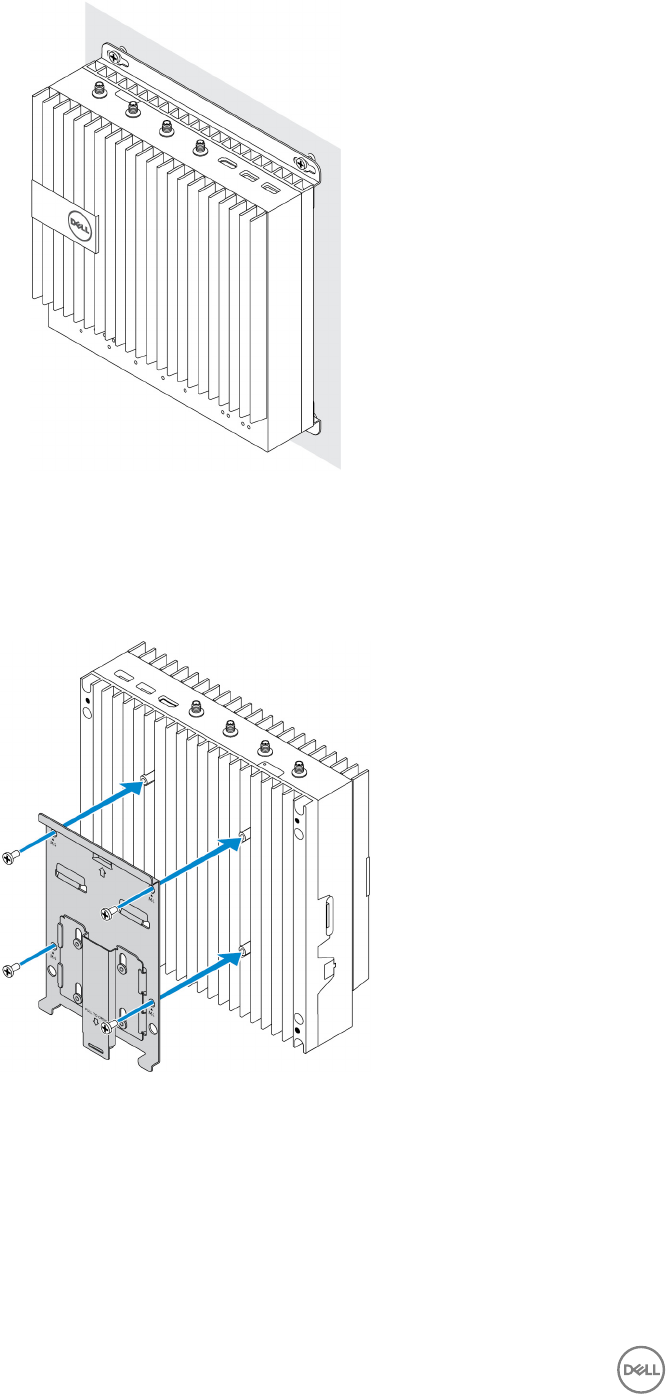
Mounting the Edge Gateway on a DIN rail
The Edge Gateway can be mounted on a DIN rail. The DIN rail bracket mounts to the back of the Edge Gateway.
1. Align the screw holes on the DIN rail mount to the back of the Edge Gateway, place the screws on the DIN rail mount and
secure it to the Edge Gateway.
2. Pull down on the tab to release the latch on the DIN rail mount.
24
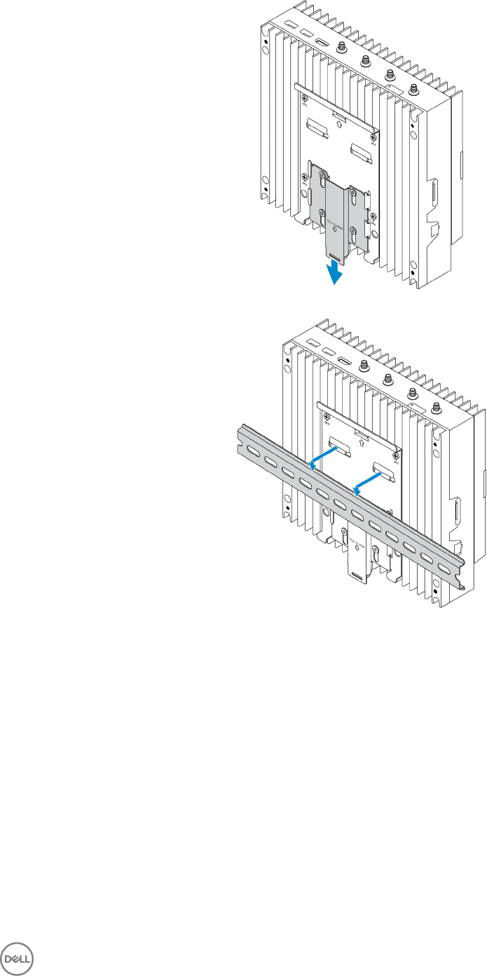
3. Mount the Edge Gateway on a DIN rail.
4. Secure the Edge Gateway to the DIN rail by pressing the latch.
25
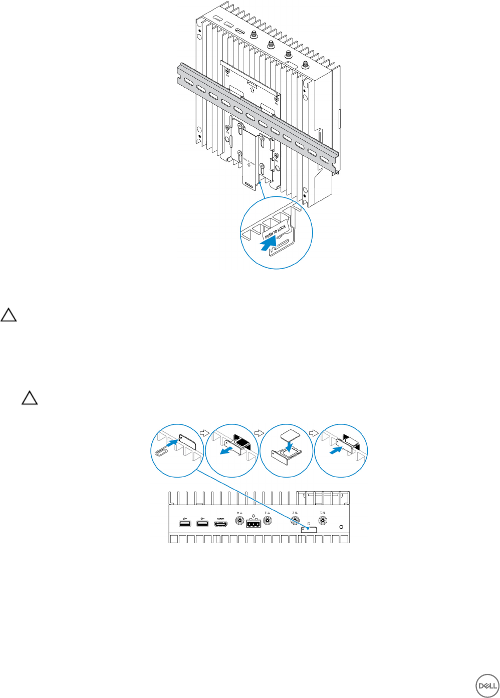
Inserting a micro-SIM card and activating your mobile broadband
CAUTION: Dell recommends that you insert the micro-SIM card before powering on the Edge Gateway.
1. Shut down your Edge Gateway.
2. Locate the micro-SIM card slot.
3. Use a paper clip or SIM eject tool to eject the micro-SIM card tray.
4. Place the micro-SIM card on the tray.
CAUTION: Ensure that the micro-SIM card is aligned as shown in the image.
5. Close the micro-SIM card tray.
6. Turn on your Edge Gateway.
7. Connect to a mobile network.
Windows operating system
If the Edge Gateway is shipped with HSPA+ (DW5580) WWAN card:
a. Launch the Telit Mobile Broadband Manager.
26

b. Click the play button to connect to your HSPA+ network.
NOTE: Click the information button to view the International Mobile Equipment Identity (IMEI) and
Integrated Circuit Card Identier (ICCID) information.
Click the stop to disconnect from your HSPA+ network.
If the Edge Gateway is shipped with LTE Verizon (DW5812) WWAN or LTE AT&T (DW5813) card:
a. Select the network icon from the taskbar and then click Cellular.
b. Select your Mobile Broadband Carrier → Advanced Options.
c. Make a note of the International Mobile Equipment Identity (IMEI) and the Integrated Circuit Card Identier (ICCID).
Ubuntu operating system
a. Open the Terminal window.
b. Go to super user mode by entering:$sudo su -
c. Congure the Mobile Broadband connection prole:
#nmcli con add type gsm ifname ttyACM3 con-name <connection name> apn <apn> user
<user name> password <password>
d. Connect to the mobile network: #nmcli con up connection name
NOTE: To view the IMEI and ICCID number use the mmcli -m 0 --command=+CIMI command.
To disconnect from the mobile network: #nmcli con downconnection name.
Wind River operating system
If the Edge Gateway is shipped with HSPA+ (DW5580) WWAN card:
a. Open the Terminal window.
b. Congure the Mobile Broadband APN prole:
#uci set network.wwan.apn="<apn>"
#uci commit network
c. Connect to the mobile network: #ifup wwan
NOTE: To view the IMEI and ICCID number use the AT+IMEISV command.
To disconnect from the mobile network: #ifdown wwan.
If the Edge Gateway is shipped with LTE Verizon (DW5812) WWAN card:
Open the Terminal window.
a. In the terminal type AT+IMEISV to open the Minicom terminal.
The Minicom terminal opens with the following text:
Welcome to minicom 2.7
OPTIONS: I18n
Compiled on Dec 17 2015, 16:20:45.
Port /dev/ttyACM0, 21:33:05
Press CTRL-A Z for help on special keys
b. Type the AT+cgdcont command with PDP Context Identier, “Packet Data Protocol type”, and “Access Point Name”
parameters and press Enter.
27

Example: at+cgdcont=3,"IPV4V6","vzwinternet".
NOTE: If the command runs successfully, the message OK appears.
c. Congure the Network Control Mode with the at#ncm command.
Example: at#ncm=1,3.
d. Activate the Packet Data Protocol with the at+cgact command.
Example: at+cgact=1,3.
e. To view the PDP Context Read Dynamic Parameters, that is, bearer_id, apn, ip_addr, subnet_mask, gw_addr,
DNS_prim_addr, DNS_sec_addr, P-CSCF_prim_addr, and P-CSCF_sec_addr parameters, run the at+cgcontrdp
command.
Example: at+cgcontrdp=3
+CGCONTRDP: 3,7,"vzwinternet.mnc480.mcc311.gprs","100.106.47.7.255.0.0.0","100.1
06.47.8","198.224.157.135","0.0.0.0","0.0.0.0","0.0.00"
f. Exit the Minicom module.
g. In the Linux terminal congure the connection with the following commands
root@WR-IntelligentDevice:~# ifconfig wwan0 ip_addr netmask subnet_mask up
root@WR-IntelligentDevice:~# route add default gw gw_addr wwan0
root@WR-IntelligentDevice:~# echo nameserver DNS_prim_addr >>/etc/resolv.conf
Example:
root@WR-IntelligentDevice:~# ifconfig wwan0 100.106.47.7 netmask 255.0.0.0 up
root@WR-IntelligentDevice:~# route add default gw 100.106.47.8 wwan0
root@WR-IntelligentDevice:~# echo nameserver 198.224.157.135 >>/etc/resolv.conf
h. Log in to the Minicom module using the minicom -D /dev/ttyACM0 command.
i. Connect to the mobile network using the at+cgdata command.
Example:at+cgdata="M-RAW_IP",3
NOTE: To view the IMEI and ICCID number use the AT+IMEISV command.
To disconnect from the mobile network
a. Open the Minicom terminal.
b. Enter the at+cgdata="M-RAW_IP",3 command.
c. Close the Minicom terminal.
d. Enter the root@WR-IntelligentDevice:~# ifconfig wwan0 down command.
If the Edge Gateway is shipped with LTE AT&T (DW5813) WWAN card:
a. Open the Terminal window.
b. In the terminal type minicom -D /dev/ttyACM0 to open the Minicom terminal.
The Minicom terminal opens with the following text:
Welcome to minicom 2.7
OPTIONS: I18n
Compiled on Dec 17 2015, 16:20:45.
Port /dev/ttyACM0, 21:33:05
Press CTRL-A Z for help on special keys
c. Type the AT+cgdcont command with PDP Context Identier, “Packet Data Protocol type”, and “Access Point Name”
parameters and press Enter.
28

Example: at+cgdcont=3,"IPV4V6","broadband".
NOTE: If the command runs successfully, the message OK appears.
d. Congure the Network Control Mode with the at#ncm command.
Example: at#ncm=1,3.
e. Activate the Packet Data Protocol with the at+cgact command.
Example: at+cgact=1,3.
f. To view the PDP Context Read Dynamic Parameters, that is, bearer_id, apn, ip_addr, subnet_mask, gw_addr,
DNS_prim_addr, DNS_sec_addr, P-CSCF_prim_addr, and P-CSCF_sec_addr parameters, run the at+cgcontrdp
command.
Example: at+cgcontrdp=3
+CGCONTRDP: 3,7,"broadband.mnc480.mcc311.gprs","100.106.47.7.255.0.0.0","100.1
06.47.8","198.224.157.135","0.0.0.0","0.0.0.0","0.0.00"
g. Exit the Minicom module.
h. In the Linux terminal congure the connection with the following commands
root@WR-IntelligentDevice:~# ifconfig wwan0 ip_addr netmask subnet_mask up
root@WR-IntelligentDevice:~# route add default gw gw_addr wwan0
root@WR-IntelligentDevice:~# echo nameserver DNS_prim_addr >>/etc/resolv.conf
Example:
root@WR-IntelligentDevice:~# ifconfig wwan0 100.106.47.7 netmask 255.0.0.0 up
root@WR-IntelligentDevice:~# route add default gw 100.106.47.8 wwan0
root@WR-IntelligentDevice:~# echo nameserver 198.224.157.135 >>/etc/resolv.conf
i. Log in to the Minicom module using the minicom -D /dev/ttyACM0 command.
j. Connect to the mobile network using the at+cgdata command.
Example:at+cgdata="M-RAW_IP",3
To disconnect from the mobile network
a. Open the Minicom terminal.
b. Enter the at+cgdata="M-RAW_IP",3 command.
c. Close the Minicom terminal.
d. Enter the root@WR-IntelligentDevice:~# ifconfig wwan0 down command.
Replacing the micro-SIM card
CAUTION: Removing the micro-SIM card while it is in use may cause data loss or result in application errors.
1. Using a paper clip or SIM eject tool, eject the micro-SIM card tray.
2. Remove the micro-SIM card from the micro-SIM card tray.
3. Replace the micro-SIM card tray into the Gateway.
29

4
Setting up your operating system
CAUTION: To prevent operating system corruption from sudden power loss, use the operating system to gracefully shut
down the Edge Gateway.
Windows 10 IoT Enterprise LTSB
Overview
The Edge Gateway supports both Windows 10 IoT Enterprise LTSB 2015 and Windows 10 IoT Enterprise LTSB 2016 editions. For
more information on Windows 10 operating system, see https://support.microsoft.com/en-us.
Boot up and log in
1. Connect a keyboard, mouse, and monitor to the Edge Gateway.
2. Power on the Edge Gateway.
The system boots to the Windows 10 IoT Enterprise LTSB operating system.
3. Select your regional settings.
NOTE: If prompted for a product key, and one is already entered, select Do this later.
4. Read and Agree to the End User License Agreement.
5. Connect to an available wireless or wired network.
6. Create a user account.
Restoring Windows 10 IoT Enterprise LTSB
You can restore Windows 10 IoT Enterprise LTSB on the Edge Gateway using the recovery Operating System image on the boot
partition which resets the run-time image back to the factory image.
1. Connect a keyboard, mouse, and monitor to the Edge Gateway.
2. Power on the Edge Gateway and boot to the operating system’s desktop.
3. Click the Start icon, hold the Shift key and click Restart.
4. Select Troubleshoot → Reset this PC.
5. Select Reset this PC → Remove everything.
6. Select Fully clean the drive → Reset.
Windows 10 IoT Enterprise LTSB basic functions
BIOS update
BIOS updates for the Edge Gateway may be downloaded from www.dell.com/support. The download includes an executable that
can run from a local machine.
Watchdog Timer
The Watchdog Timer for Windows 10 IoT Enterprise LTSB is controlled from the BIOS setting.
1. Enter the BIOS during boot by pressing F2.
30

2. Access BIOS setting Watchdog Timer to enable or disable The Watchdog Timer.
TPM support
Windows 10 IoT Enterprise LTSB supports TPM 2.0. For more information on TPM resources, see https://technet.microsoft.com/en-
us/library/cc749022(v=ws.10).aspx
System Shut down and Restart
1. Click the Start icon.
2. Click Power then select Restart or Shut down.
LAN/WLAN network conguration
1. Click the Start icon.
2. Type Settings and click Settings.
3. Select Network & Internet.
WWAN network conguration
Follow the Service Manual to install and congure the WWAN module and the corresponding carrier SIM card for the system. After
the WWAN module and the SIM cards are installed:
1. Click the Start icon.
2. Type Settings and click Settings.
3. Select Network & Internet
4. Locate the WWAN connection in the Wi-Fi section and select the entry to connect and disconnect from the WWAN adapter.
Bluetooth conguration
1. Click the Start icon.
2. Type Settings and click Settings.
3. Select Devices from the Settings menu and, then select Bluetooth from the menu on the left panel.
Common port mappings
Serial port mapping
The table shows the serial port mapping on the Edge Gateway 5000/5100 with the factory-installed Windows 10 IoT Enterprise
LTSB. For dip switch settings on the Edge Gateway for RS422 and RS485 ports, see DIP Switches.
No. Port Type Connector Device Node
1 RS232 DB9 COM1
2 RS422_485 5-pin terminal COM2
3 RS485 3-pin terminal COM3
4 RS485 3-pin terminal COM4
Edge Gateway I/O module GPIO mapping
The GPIOs on the external I/O Module for the Edge Gateway are behind the PIC microcontroller. The PIC microcontroller is exposed
to the host system and to the host OS as a USB-HID device. Software applications developed to communicate with the GPIOs may
use the protocol dened in the above set of references to communicate with the GPIO modules.
Edge Gateway I/O module PCIe expansion mapping
The PCIe slot on the external I/O module for the Edge Gateway is driven directly from the host PCIe bus. Since PCIe expansion is
generic, there are no PCIe device-specic drivers integrated into the Windows 10 IoT Enterprise LTSB OS image. If a specic PCIe
31

card is to be used on this slot, contact the vendor of that PCIe card to verify if they have the required drivers for Windows 10 IoT
Enterprise LTSB.
Snappy Ubuntu Core 15 and 16
Overview
Ubuntu Snappy Core is a Linux OS distribution that is an entirely new mechanism for managing a system and its applications.
The Edge Gateway supports the following Ubuntu Snappy Linux OS distribution:
• Ubuntu Core 15
• Ubuntu Core 16
For more information on Ubuntu Snappy Core OS, see
•www.ubuntu.com/cloud/snappy
•www.ubuntu.com/desktop/snappy
•www.ubuntu.com/internetofthings
Pre-requisites
Infrastructure
An active connection to the internet is needed to update the Ubuntu Snappy Core operating system as well as applications (snaps)
Prior knowledge
• Familiarity with Unix\Linux commands
• Knowledge of how to use the serial communication protocol
• Knowledge of how to use a terminal emulator (for example; PuTTY)
• Knowledge of your network settings (proxy URL, ports, name servers, and so on)
Boot up and log in
NOTE: The Ubuntu Snappy Core operating system has no graphical user interface
Power on the Edge Gateway. When prompted to log in to the OS, enter the default credentials. The default username and password
for Ubuntu Snappy Core is ubuntu.
For example (Ubuntu 15):
Ubuntu 15.04 localhost.localdomain tty1
localhost login: ubuntu
Password:
Press Enter, the following text is displayed:
Ubuntu 15.04 localhost.localdomain tty1
localhost login: ubuntu
Password
Last login: Mon Nov 2 16:47:43 UTC 2015 on tty1
Welcome to snappy Ubuntu Core, a transactionally updated Ubuntu
* See http://ubuntu.com/snappy
It’s a brave new world her in snappy Ubuntu Core! This machine
does not use apt-get or deb packages. Please see ‘snappy –help’
for app installation and transactional updates
32

(plano)ubuntu@localhost:~$
For example (Ubuntu 16):
Ubuntu 16 on 127.0.0.1 (tty1)
localhost login: ubuntu
Password:
Restoring Ubuntu Snappy
CAUTION: Following the steps deletes all the data on your system.
The following steps refer to dierent methods through which the Ubuntu Snappy Core operating system can be restored to the
factory image.
External Storage
On supported platforms, you can download the factory image from www.dell.com to restore your Edge Gateway by external media
kit. For more information, see http://www.dell.com/support/article/us/en/19/SLN301761.
Factory OS recovery image
You can restore Ubuntu Snappy Core on the Edge Gateway using the recovery OS image on the boot partition. Reset the system
back to the factory image if you encounter any of the following situations:
• You are unable to start the operating system.
• The operating system is damaged.
Connect a keyboard, mouse, and monitor to the Edge Gateway, or connect to the Edge Gateway through a KVM session.
1. Power on the Edge Gateway.
2. Press F12 when the Dell logo is displayed on the screen to enter the boot menu.
3. Select Factory Restore from the boot menu.
CAUTION: The next step deletes all the data on your system.
4. Press Y when prompted Factory Restore will delete all user data, are you sure? [Y/N].
The system restoration starts and reinstalls the OS on your Edge Gateway.
Updating operating system and applications
After enabling the network connections, and connecting to the internet, it is a recommended to have the latest OS components and
applications installed. To update Ubuntu Snappy, run the (plano)ubuntu@localhost:~$ sudo snappy update command.
Viewing operating system and application versions
Run the command,
(plano)ubuntu@localhost:~$ sudo uname –a
Returns
Linux ubuntu.localdomain 3.19.0-47-generic #53-Ubuntu SMP Mon Jan 18 14:02:48 UTC 2016
x86_64 x86_64 x86_64 GNU/Linux
Run the command,
(plano)ubuntu@localhost:~$ sudo snappy info
Returns
Linux power5000.localdomain 3.19.0-47-generic #53-Ubuntu SMP Mon Jan 18 14:02:48 UTC 2016
x86_64 x86_64 x86_64 GNU/Linux
33

Run the command,
(plano)ubuntu@localhost:~$ snappy list -v
Returns
Name Date Version Developer
ubuntu-core 2015-10-13 7 ubuntu
bluez 2015-10-20 5.34-2 canonical*
network-namager 2015-10-20 0.2 canonical*
plano-uefi-fw-tools 2015-10-20 0.5 canonical*
webdm 2015-10-20 0.9.2
canonical*
plano-webdm 2015-10-20 1.7 canonical*
NOTE: Check if a newer version of the software is available. For more information on checking for updates, see Updating
operating system and applications.
Ubuntu core OS basic function
Basic Commands
NOTE: For more information about Ubuntu commands, see https://snapcraft.io/.
Table 1. Basic commands
Action Ubuntu Core 15 Ubuntu Core 16
Viewing system attributes #sudo snappy info #sudo snap version
Updating the image to the latest Release #sudo snappy update #sudo snap update
Viewing a list of all the snaps that are
currently installed
#sudo snappy search #sudo snap find
Viewing a list of service commands that
are available
#sudo snappy service help N/A
Viewing a set an attribute to a snap N/A #sudo snap set <snap>
<attribute>=<value>
Querying attributes from a snap N/A #sudo snap get <snap>
Rebooting the system #sudo reboot Run the command:
admin@localhost:$ sudo reboot
returns:
System reboot successfully
Shutting down the system #sudo poweroff Run the command:
admin@localhost:$ sudo
poweroff
The system shuts down successfully.
Add a new user if libnss-extrausers is
pre-installed
$sudo adduser --extrausers
testuser
$sudo adduser --extrausers
testuser
Change a user’s password $sudo passwd <user-name> $sudo passwd <user-name>
Disable or remove cloud-init service $sudo mount –o remount,rw /
$sudo /usr/bin/apt-get
remove cloud-
init
N/A
34

Action Ubuntu Core 15 Ubuntu Core 16
Adjust grub conguration $sudo mount –o remount,rw /
$sudo vi /boot/grub/grub.cfg
N/A
Re-mount the Ubuntu Snappy 16 root le
system as read only
N/A Snappy 16 rootfs is Read-Only
Accessing the built-in help N/A admin@localhost:~$ sudo snap
--help
Listing the installed snaps N/A admin@localhost:~$ sudo snap
list
Updating the system name N/A admin@localhost:$ network-
manager.nmcli general
hostname <NAME>
Changing the time zone N/A When the system arrives from the factory,
the operating system is usually set to the
UTC time zone.
To change the time zone to your location,
run the command:
admin@localhost:~$ sudo
timedatectl --help
the help le above will tell you commands
you need to know.
Root user credential N/A Run the command:
admin@localhost:$ sudo su -
Returns:
$ admin@localhost:~# sudo su
–
$ root@localhost:~#
Identifying the System Service Tag N/A Run the command:
admin@localhost:$ cat /sys/
class/dmi/id/product_serial
The system tag is printed.
Identifying the system vendor N/A Run the command:
admin@localhost:$ cat /sys/
class/dmi/id/board_vendor
returns
Dell Inc.
The system tag is printed.
UEFI capsule update
The fwupgmgr tool or commands are used to update the UEFI BIOS on the system. The UEFI BIOS for this platform is released
through online Linux Vendor File System (LVFS) based methods
Dell recommends that you enable the UEFI Capsule update by default so that it is running in the background to keep the system
BIOS up to date.
35

NOTE: For more information about fwupd commands, see www.fwupd.org/users.
Without an internet connection
1. Download the latest .cab le from secure-lvfs.rhcloud.com/lvfs/devicelist.
2. Check the current BIOS details.
$ sudo uefi-fw-tools.fwupdmgr get-devices
3. Copy the rmware.cab le to /root/snap/ue-fw-tools/common/ folder.
$ sudo cp firmware.cab /root/snap/uefi-fw-tools/common/
4. Check the details of the BIOS from the .cab le.
$ sudo uefi-fw-tools.fwupdmgr get-details [Full path of firmware.cab]
5. Apply the update.
$ sudo uefi-fw-tools.fwupdmgr install [Full path of firmware.cab] -v
6. Restart the system.
$ sudo reboot
With an internet connection
1. Connect and login to the Edge Gateway.
2. Check the current BIOS details.
$sudo uefi-fw-tools.fwupdmgr get-devices
3. Check if the update is available from LVFS service.
$sudo uefi-fw-tools.fwupdmgr refresh
4. Download the BIOS from the www.dell.com/support.
$sudo uefi-fw-tools.fwupdmgr get-updates
5. Apply the update.
$sudo uefi-fw-tools.fwupdmgr update -v
6. Restart the system.
$ sudo reboot
Watchdog Timer
NOTE: For more information about Watchdog Timer (WDT) commands, see www.sat.dundee.ac.uk/~psc/watchdog/
Linux-Watchdog.html.
Dell recommends that you enable the WDT by default to activate the fail-safe circuitry. Snappy, a WDT-compatible operating system
provides the capability to detect and recover the system from malfunctions or unexpected crashes.
To check daemon status, run the command:
admin@localhost:$ systemctl show | grep –i watchdog
Returns:
RuntimeWatchdogUSec=1min
ShutdownWatchdogUSec=10min
NOTE: The default value is 10. The actual value should be greater than 0.
To congure the timer, run the command:
admin@localhost:$ sudo vi /etc/systemd/system.conf.d/watchdog.conf
36
Security
Trusted Platform Module (TPM)
NOTE: For more information about the TPM, see https://developer.ubuntu.com/en/snappy/guides/security-whitepaper/.
TPM is only supported on devices that have TPM hardware installed on products with Snappy-enhanced security support. The TPM
on/o setting is congurable in the BIOS and manageable in the operating system.
If TPM is turned o, the device node (/dev/tpm0) does not exist.
(plano)ubuntu@localhost:~$ ls /dev/tpm0
ls: cannot access /dev/tpm0: No such file or directory
If TPM is turned on, the device node (/dev/tpm0) exists.
(plano)ubuntu@localhost:~$ ls /dev/tpm0
/dev/tpm0
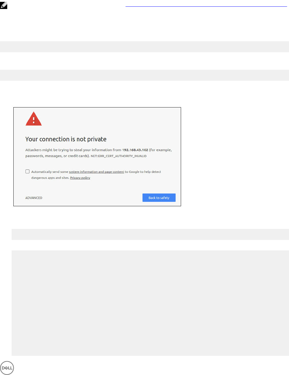
Accessing Snappy Store/Snapweb
1. Enter ip_address:4200 in a browser.
2. Select Advanced, then select proceed to the ip_address(unsafe).
3. Using the default login of 'admin', keeping the password blank, open Terminal and ssh remote login
lo@lo-latitude-E7470:~$ ssh admin@10.101.46.209
admin@10.101.46.209's password:
4. While running sudo snapweb.generate-token, copy the token.
lo@lo-latitude-E7470:~$ ssh admin@10.101.46.209
admin@10.101.46.209's password:
Welcome to Ubuntu 16.04.1 LTS (GNU/Linux 4.4.0-45-generic x86_64)
* Documentation: https://help.ubuntu.com
* Management: https://landscape.canonical.com
* Support: https://ubuntu.com/advantage
Welcome to Snappy Ubuntu Core, a transactionally updated Ubuntu.
* See https://ubuntu.com/snappy
It's a brave new world here in Snappy Ubuntu Core! This machine does not use apt-get or
deb packages. Please see 'snap --hwlp' for app installation and transactional updates.
Last login: Tue Nov 01:10:12 2016 from 10.101.46.187
Admin@localhost:~$ sudo snapweb.generate-toen
Snapweb Access Token:
GtYaoevIodhTgHDyFWczWtYkEhDYROpX0pf27K62TtTOVooUwRuQ)IgBB7ECznCP
37
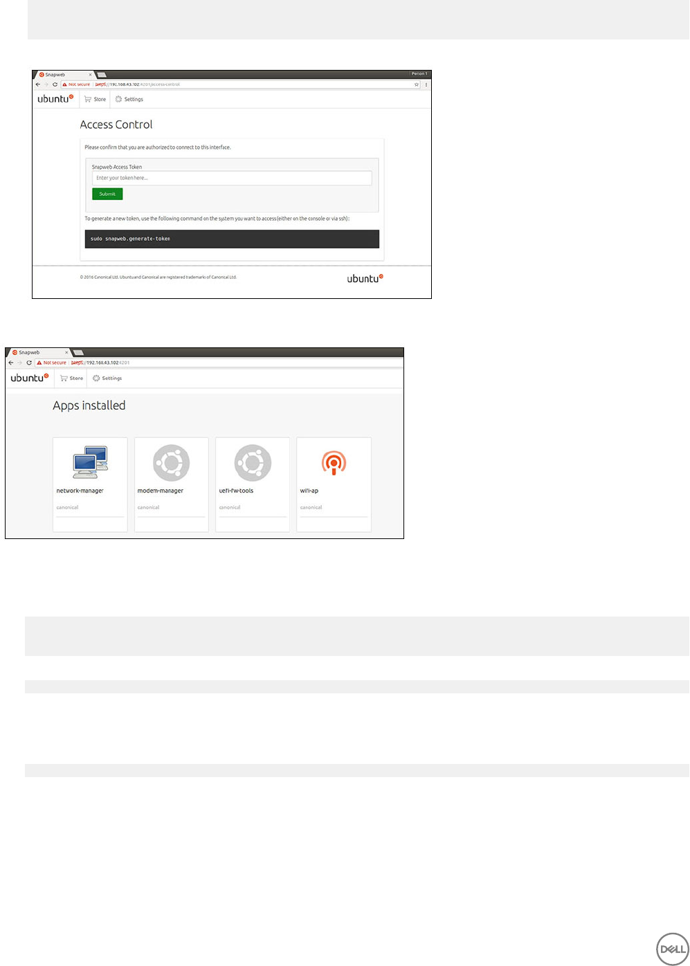
Use the above token in the Snapweb interface to be granted access.
admin@localhost:~$
5. Paste the token on the web page and click Submit.
You can now access the snapweb.
Cloud LED On/O
1. To export Cloud LED PIN, run the command:
#sudo su –
#echo 346 > /sys/class/gpio/export
#echo out > /sys/class/gpio/gpio346/direction
2. To turn on Cloud LED, run the command:
#echo 1 > /sys/class/gpio/gpio346/value
or
To turn o Cloud LED, run the command:
#echo 0 > /sys/class/gpio/gpio346/value
Serial Port
Serial device nodes mapping.
38

Table 2. Serial device nodes mapping table.
Port Type Connector Device Node
RS232 DB9 /dev/ttyS6
RS422_485 5 pin terminal /dev/ttyS4
RS485 3 pin terminal /dev/ttyS5
RS485 3 pin terminal /dev/ttyS2
Execute the #sudo chmod 777 /dev/ttyS# command on two systems, where # is port number corresponding to ports being
used.
• On one of the systems, execute the #cat < /dev/ttyS# command, this will put system A waiting for transmission.
• On the other system, execute the #echo "test" > /dev/ttyS# command, this will let system B send out transmission.
Minicom
Minicom is a terminal emulation program which allows the host machine to communicate with and debug the serial port on headless
systems, such as the Edge Gateway. The following steps help you to setup Minicom.
1. Install Minicom.
$ sudo snap install classic --devmode --beta
$ sudo classic.create
$ sudo classic
$ (classic) sudo apt-get update
$ (classic) sudo apt-get install minicom
2. Set Minicom.
$ sudo minicom -s
3. Select Serial port setup.
4. Press A to edit the Serial Device to ttyUSB0. This can be any other value if there is more than one USB serial cable attached.
Then, press Enter to exit:
A - Serial Device : /dev/ttyUSB0
5. Press F to disable Hardware Flow Control to No.
6. Press E to edit Baud rate/Parity/Bits.
7. Press E to congure Baud rate as 115200.
a. Press Q to congure Stopbits as 8-N-1. Press Enter to exit.
+---------[Comm Parameters]---------+
|Current: 115200 8N1
|
|
|
|
|
Speed
A: <next>
B: <prev>
C: 9600
D: 38400
E: 115200
Parity
L: None
M: Even
N: Odd
O: Mark
P: Space
Data
S: 5
T: 6
U: 7
V: 8
|
|
|
|
| |
|Stopbits |
39

|W: 1 Q: 8-N-1 |
|X: 2 R: 7-E-1 |
| |
|Choice, or <Enter> to exit?_ |
8. Press Enter to complete the settings.
9. Select Save setup as d.
10. Select Exit from minicom.
Start Minicom as a terminal program
$ sudo minicom
Welcome to minicom 2.7
OPTIONS: T18n
Compiled on Feb 7 2017, 13:37:27.
Port /dev/ttylUSB0, 15:06:26
Press CTRL-A Z for help on special keys
Exit Minicom
1. In terminal mode, press Ctrl+A.
A message bar is displayed at the bottom of the terminal window.
2. Press X to exit.
Expansion IO Module
PCIe
The PCIe slot on the external IO Module for the Edge Gateway is driven directly from the host PCIe bus. Since it is generic PCIe
expansion, there are no PCIe device-specic drivers integrated into the OS image. If there is specic PCIe card used on this slot,
contact the Vendor of that PCIe card for drivers.
GPIO
The GPIOs on the external IO Module for the Edge Gateway are behind PIC microcontroller. The PIC microcontroller is exposed to
the host system and to the host OS as a USB-HID device. Software application developed to communicate with the GPIOs may use
the protocol dened in following set of references to communicate with the GPIO modules. There is no native application software
available on the factory OS image that communicates with the IO Module GPIOs.
Zigbee
NOTE: This feature is only supported if hardware module presented.
The OS provides the capability of mutual communication between user space application and physical module. If there is a specic
Zigbee programming requirement of user mode application, contact the hardware provider of that module for API Documentation.
Controller Area Network
NOTE: This feature is only supported if hardware module presented.
The OS provides the capability of mutual communication between user space application and physical module. If there is a specic
Controller Area Network (CAN) bus programming requirement of user mode application, contact the hardware provider of that
module for API documentation.
To nd the device bus iver dmesg (if hardware is presented):
•#dmesg | grep –i microchip
40

•for i in /sys/class/hidraw/*; do udevadm info $i --attribute-walk | grep -q 'CANBus HID
Device' && echo path: /dev/$(basename $i); done
Network Manager – Ubuntu Core 15
Network-Manager is a native Ubuntu Snappy Connection Manger, the application handles multiple network devices, provides
detection and conguration for system to automatically connect to network.
A command line utility nmcli is included with Network-Manager to support non-graphical user interface.
WWAN (nmcli example)
•Congure the Mobile Broadband connection prole — #nmcli con add type gsm ifname ttyACM3 con-name
<connection name> apn <apn> user <user name> password <password>
• Connect to the mobile network — #nmcli con up <connection name>
WLAN (nmcli example)
•Congure the system to connect to unencrypted Wi–Fi network —
#nmcli dev wifi connect $SSID ifname $WIFI_INTERFACE
#iw dev $WIFI_INTERFACE link
#nmcli dev disconnect $WIFI_INTERFACE
•Congure the system to connect to WPA-encrypted Wi–Fi network —
#nmcli dev wifi connect $SSID password $PSK ifname $WIFI_INTERFACE
#iw dev $WIFI_INTERFACE link
#nmcli dev disconnect $WIFI_INTERFACE
Software enabled Access Point (SoftAP)
This feature depends on the wireless module and it’s associated driver to act as a wireless access point.
1. Login to Ubuntu Snappy, make sure the system is connected to internet.
2. Run the #sudo snappy seach softap command to nd the application from the Ubuntu Snappy Store
3. Run the #sudo snappy install sw-access-point command to install the application.
After the snap is installed, the service should be running as default conguration below:
SSID: Ubuntu
Open-authentication
802.11n 2.4GHz (G mode)
IP Address: 10.0.60.1
DHCP Range: 10.0.60.3-20
DNS server: 10.0.60.1
Gateway: 10.0.60.1
Bluetooth
To connect to a Bluetooth device like a Bluetooth keyboard:
1. Run the #bluetoothctl -a command to start bluetoothctl console.
The bluetoothctl console is opened.
2. Run the $power on command to power on the Bluetooth device.
3. Register the agent for keyboard:
$agent KeyboardOnly
$default-agent
4. Run the $pairable on command to put the Bluetooth controller in pair-able mode.
5. Run the $scan on command to scan nearby Bluetooth device.
6. Run the $scan off command to stop scanning after Bluetooth keyboard is found.
7. Run the $pair <MAC address of bluetooth keyboard> command to pair the Bluetooth keyboard.
8. Enter PIN Code on Bluetooth keyboard if needed.
41

9. Run the $trust <MAC address of bluetooth keyboard> command to turst the Bluetooth keyboard.
10. Run the $connect <MAC address of bluetooth keyboard> command to connect the to the Bluetooth keyboard.
11. Run the $quit command to quit the bluetoothctl console.
Network Manager – Ubuntu Core 16
Network-Manager is a native Ubuntu Snappy Connection Manager, the application handles multiple network devices, provides
detection and conguration for the system to automatically connect to the network.
A command line utility nmcli is included with Network-Manager to support non-graphical user interface.
NOTE: For more information about Network-Manager, see https://wiki.archlinux.org/index.php/NetworkManager
Connecting through WWAN
NOTE: For more information on conguring and connecting through WWAN, see https://docs.ubuntu.com/core/en/
stacks/network/network-manager/docs/congure-cellular-connections.
1. Check if a modem is present and identify the modem index number.
$ sudo modem-manager.mmcli –L
2. Check the modem status and identify the primary port.
$ sudo modem-manager.mmcli -m <x>
NOTE:
<x>
refers to the modem index number. Replace
<x>
with the actual modem index after running the
command at step 1.
3. Create a prole.
$ sudo network-manager.nmcli c add con-name test type gsm ifname <primary port> apn
internet
NOTE: Depending on the return results from step 2, replace
<primary port >
after ifname with the actual primary
port name.
4. Check the WWAN status.
$ network-manager.nmcli r wwan
5. Turn on WWAN.
$ sudo network-manager.nmcli r wwan on
6. Find wwan0 in the interface list.
$ ifconfig -a
7. Enable the connection prole.
$ sudo network-manager.nmcli c up test
8. Check the Network Manager status.
$ network-manager.nmcli d
9. Disable the connection prole.
$ sudo network-manager.nmcli c down test
10. Check the Network Manager status.
$ network-manager.nmcli d
Connecting through WLAN
1. Run the command to show a list of network interfaces like eth0, eth1, wlan0, mlan0, and so on:
$ network-manager.nmcli d
2. Run the command to show a list of network interfaces like eth0, eth1, wlan0, mlan0, and so on:
$ network-manager.nmcli d
3. Run the command to show a list of available wireless access points.
$ network-manager.nmcli device wifi list
4. Wireless connection with nmcli: Run the following commands and replace $SSID, $PSK, and $WIFI_INTERFACE of your
environment.
42

• Connect:
$ sudo network-manager.nmcli dev wifi connect $SSID password $PSK ifname
$WIFI_INTERFACE
• Disconnect:
$ sudo network-manager.nmcli dev disconnect $WIFI_INTERFACE
Connecting through Software-enabled Access Point (SoftAP)
This feature depends on the wireless module and its associated driver to function as a wireless access point.
NOTE: For more information on SoftAP, see https://docs.ubuntu.com/core/en/stacks/network/wi-ap/docs/index.
1. Login to Ubuntu Snappy. Make sure that the system is connected to the internet.
2. Run the command to nd the application from the Ubuntu Snappy Store.
#sudo snap seach wifi-ap
3. Run the command to install the application.
#sudo snap install wifi-ap
4. After snap is installed, run the command to set the network interface used to operate the access point on.
$ sudo wifi-ap.config set wifi.interface mlan0
5. Run the command to enable the access point and restart the service.
$ wifi-ap.config set disabled=false
WiFi-AP default SSID Ubuntu is now visible to clients.
Bluetooth
To connect to a Bluetooth device like a Bluetooth keyboard:
1. Run the command to start bluetoothctl console.
#bluetoothctl -a
The bluetoothctl console is opened.
2. Run the command to power on the Bluetooth device.
$power on
3. Register the agent for the keyboard:
$agent KeyboardOnly
$default-agent
4. Run the command to put the Bluetooth controller in pair-able mode.
$pairable on
5. Run the command to scan nearby Bluetooth device.
$scan on
6. Run the command to stop scanning after the Bluetooth keyboard is found.
$scan off
7. Run the command to pair the Bluetooth keyboard.
$pair <MAC address of Bluetooth keyboard>
8. Enter the PIN code on the Bluetooth keyboard, if needed.
9. Run the command to trust the Bluetooth keyboard.
$trust <MAC address of Bluetooth keyboard>
10. Run the command to connect the to the Bluetooth keyboard.
$connect <MAC address of Bluetooth keyboard>
11. To quit the bluetoothctl console.
$quit
43

Flashing a new OS image
Pre-requisites
• USB 2.0 or USB 3.0 ash drive (4 GB minimum)
• Ubuntu Core 16.04 or 15.04 ISO
NOTE: You can download the latest version of the Ubuntu ISO le from http://releases.ubuntu.com.
• A released Ubuntu Core 16.04 or 15.04 image from Dell or Canonical: <unique name>.img.xz
• Dell Edge Gateway 5000 series hardware
• LCD monitor
• USB keyboard
• USB mouse
• HDMI cable
• Two Ethernet cables
• Ubuntu workstation with Ubuntu 14.04 release or higher.
Flashing new Ubuntu OS image
1. Download the latest Ubuntu Core iso image from www.releases.ubuntu.com.
2. Insert a USB ash drive into Ubuntu Workstation.
3. Type Startup Disk Creator in the Unity Dash. Start the Startup Disk Creator application.
a. Select ubuntu-16.04-desktop-amd64.iso or ubuntu-15.04-desktop-amd64.iso, in the top pane Source disk image (.iso) or
CD. If the .iso le is not listed there, click Other to locate and select the .iso le.
NOTE: It is not necessary to erase the USB ash drive, however it is advisable that you do so.
b. Click Erase.
c. Select the rst bootable partition on the USB device as the disk to use.
d. The bootable partition should be formatted as either an FAT16 or FAT32 le system. This is the default for most USB ash
drives.
e. Click Make Startup Disk.
The message USB drive created successfully is displayed.
4. Unmount by right-clicking on the USB device icon on the Unity launcher. Choose Safely Remove the USB drive, and remove
the USB ash drive.
5. Remove (if it still inserted) and reinsert the USB ash drive.
6. Copy the downloaded image le <unique name>.img.xz to the USB drive root directory.
7. Unmount and remove USB ash drive from the Ubuntu Workstation.
8. Insert USB ash drive into the Edge Gateway.
9. Turn on and boot-up the Edge Gateway.
10. Choose your preferred language and click on Try Ubuntu.
Ubuntu live desktop should appear.
11. Flash Ubuntu Core Image to the Edge Gateway:
a. Start the Terminal application. It can be found by typing Terminal in the Unity Dash.
CAUTION: dd command erases the content of the drive it writes to.
b. Type the following command (plano)ubuntu@localhost:~$ sudo xzcat /cdrom/ stlouis-<version
>.img.xz | sudo dd of=/dev/xyz bs=32M ; sync—where “xyz” is the name of the drive on the system.
12. Reboot the system, and remove USB drive.
Ubuntu Core is now installed on your Edge Gateway.
Flashing the BIOS
Prerequisites
44
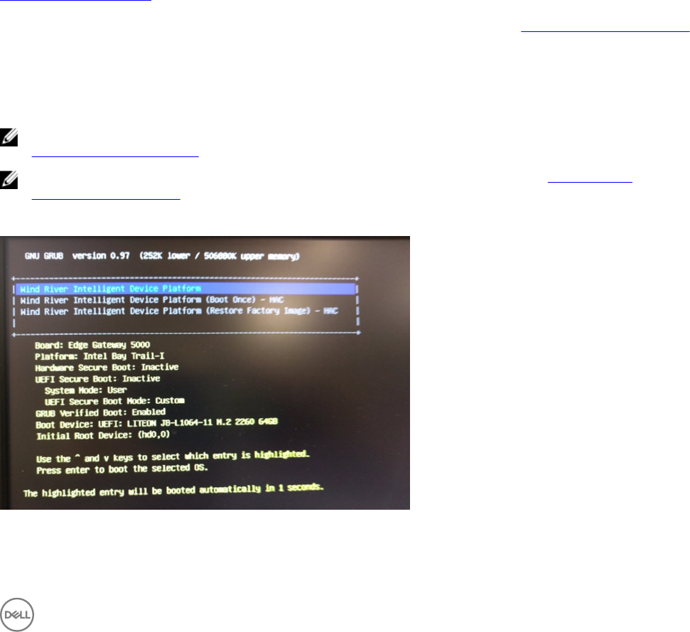
• Download the latest BIOS le from www.dell.com/support.
• USB 2.0 or USB 3.0 ash drive (4 GB minimum)
• Power o the Edge Gateway.
1. On a separate computer, unzip the BIOS update le that you have downloaded from www.dell.com/support.
2. Open the extracted le folder Edge_Gateway5000_1.X.X.
3. Copy the BIOS update le labeled as Edge_Gateway5000_1.X.X.exe to a USB ash drive.
4. Insert the USB ash drive in one of the available USB ports on the Edge Gateway.
5. Power on the Edge Gateway.
6. When the Dell logo is displayed on the screen, press F12 to enter the one-time boot screen.
7. On the one-time boot screen, select Flash the BIOS .
8. On the next screen, select the BIOS le (Edge_Gateway5000_1.X.X.exe) on the USB key.
9. Start the ash process.
Wind River Linux
Overview
The Edge Gateway is shipped with Wind River Linux IDP-XT version 3.1. For more information on Wind River operating system, see
www.windriver.com/support.
For generic details and references on running Wind River Linux IDP 3.1 on a Gateway product, see www.intel.com/gatewaytraining.
Boot up and login
Before conguring the Wind River OS, connect a keyboard, mouse, and monitor to the Edge Gateway, or connect to the Edge
Gateway through a KVM session, Dell Wyse Cloud Client Manager (CCM), or Dell Command | Monitor (DCM).
NOTE: For more information about using the CCM, see the CCM documentation available at
www.cloudclientmanager.com.
NOTE: For more information about using the DCM, see the DCM documentation available at www.dell.com/
clientsystemsmanagement.
Power On the Edge Gateway to boot into Wind River Linux OS. The Wind River Linux does not have a graphical user interface (GUI).
Log into the OS on the terminal with the following default credentials.
• root@WR-IDP-xxxx login: root (where xxxx is the version of the Wind River Linux)
45
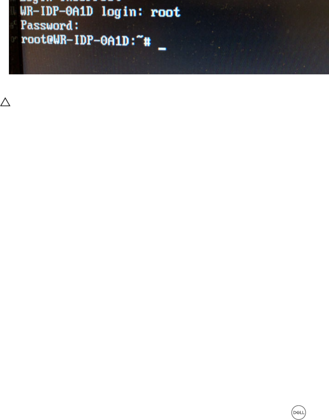
• Password: root
Restoring Wind River Linux
CAUTION: Following these steps deletes all the data on your system.
You can restore Wind River Linux on the Edge Gateway using the recovery OS image on the boot partition which resets the run-time
image back to the factory image if you encounter any of the following situations:
• You are unable to start Wind River Linux
• The Wind River Linux operating system is damaged.
Connect a keyboard, mouse, and monitor to the Edge Gateway, or connect to the Edge Gateway through a KVM session, Dell Wyse
Cloud Client Manager (CCM), or Dell Command | Monitor (DCM).
1. Boot to the OS menu
2. Choose the Wind River Intelligent Device Platform (Restore Factory Image) option and press Enter.
This restores the run-time image back to factory OS image state.
46
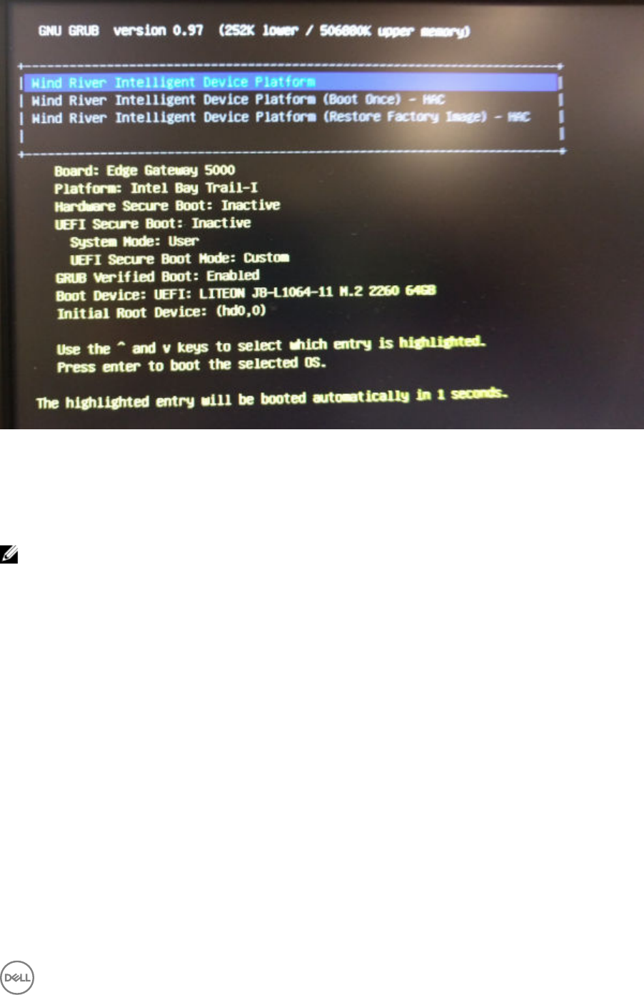
Wind River Linux Basic Functions
Preinstalled Packages
Run the root@WR-IDP-xxxx:~# rpm -qa command to list all the packages installed on the Wind River Linux OS.
NOTE: If you are looking for a specic package, you have to pipe the output of the root@WR-IDP-xxxx:~# rpm -qa
command to search for that specic package.
Expected result: Device: xxxx-xxxxxxxx-xxxx-xxxx-xxxx-xxxxxxxxxxxx-xxxx
UEFI Capsule update capability
Run the fwupgmgr tool/commands are used to update UEFI BIOS rmware on the system. The UEFI BIOS for this system is
released through online Linux Vendor File System based methods.
Operation command: root@WR-IDP-xxxx:~# fwupdmgr get-devices
Expected result: (Device found) Device: xxxx-xxxxxxxx-xxxx-xxxx-xxxx-xxxxxxxxxxxx-xxxx
Watchdog Timer
Running the root@WR-IDP-xxxx:~# systemctl status watchdog command displays the status of Watchdog timer
service.
Expected result: Example of the output is shown below.
47
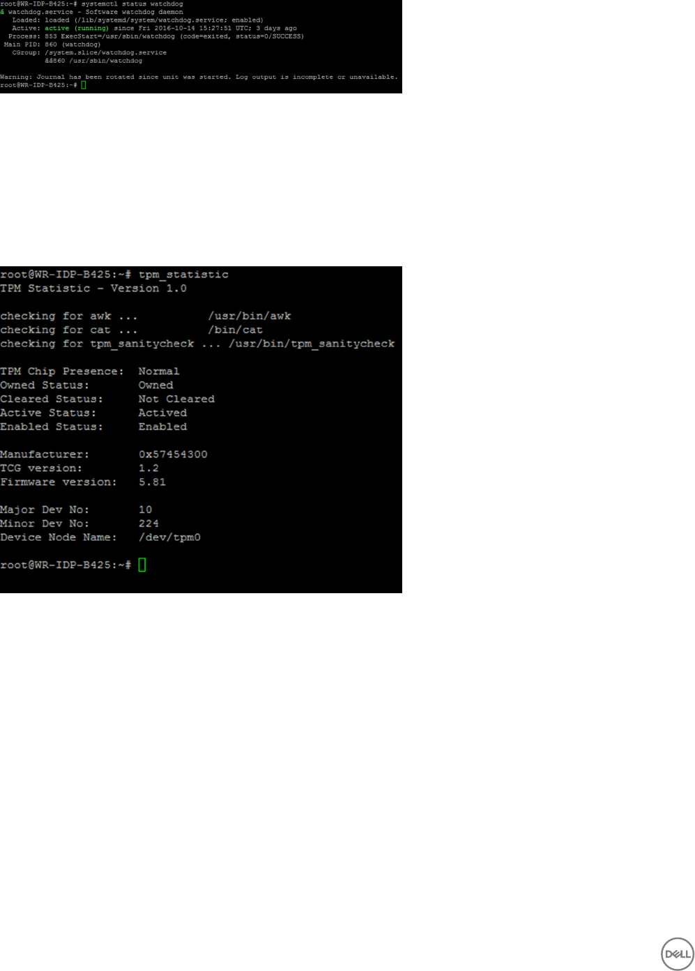
TPM support (HW TPM module dependency)
Run the root@WR-IDP-xxxx:~# tpm_statistic command displays the status of TPM service.
If the TPM is functional and enabled in the BIOS, below would be the expected results, when tpm_statistic command is
executed.
Expected result: The expected result is for TPM Chip Presence: Normal. Example of the response to the above command should be
similar to the output shown below.
System reboot
To reboot the system, as a root user logged in to the system, enter the root@WR-IDP-xxxx:~# reboot reboot at the
command prompt.
Expected result: System reboots back to the login prompt successfully.
System PowerO
Run the root@WR-IDP-xxxx:~# shutdown now command to shuts down the system.
Expected result: System shuts down successfully.
Network Interface
To determine the default supported network interface, type the root@WR-IDP-xxxx:~# ifconfig at the command prompt.
Expected result: The following are the default network interfaces supported out of the box.
•br-lan
•eth0
•eth1
48
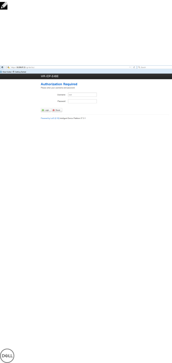
•lo
•wlan0
Network conguration and default setup
The following commands can be used to congure dierent network interfaces on the system with Wind River Linux on it.
Network conguration on Wind River Linux IDP 3.1 environment can be performed through the LuCi web interface.
NOTE: The LuCi web interface supported in the default OS image.
The user can reach the LuCi web interface on the system using the
https://< IP-Address-of-eth0-interface-of-the-gateway >
following URL from a dierent system with a web browser and the system should be on the same network or connected to the
system’s network through proxy.
The default login credentials to the LuCi web interface are root/root. The IP address of the eth0 network port can be identied
by performing the ifconfigcommand on the Linux terminal.
Network interface conguration
The Edge Gateway contains the following default network congurations:
•br-lan — Bridged LAN Interface
•eth0 — Wired LAN interface 0
•eth1 — Wired LAN Interface 1
•lo — Loop back interface
•wlan0 — Wireless LAN (or Wi-Fi) interface mode
eth0 — Wired LAN Interface. By default eth0 interface is congured to be DHCP client interface. When this ethernet port is
connected to a DHCP server, this interface obtains an IP address from the DHCP server.
Run the root@WR-IDP-xxxx:~# ifconfig eth0 command to identify the IP address. The network IP interface information is
available under inet addr: x.x.x.x where x.x.x.x is the IP address of the system.
eth1 — Wired LAN interface. The default conguration for the second wired ethernet interface eth1 serves as DHCP server and
provides IP addresses to any device requesting IP address from the system. The devices requesting DHCP addresses get IP
addresses in the range of 192.168.1.x subnet. The default DHCP server is at 192.168.1.1 address. For reconguring this
network interface by logging in to the LuCi web interface.
Wlan0 — Wireless LAN or Wi-Fi interface. The default conguration for the WLAN0 interface on the system with Wind River Linux
is in access point (AP) mode. The mode can be changed to client mode through LuCi web interface.
Br-lan — The bridged LAN interface. By default, the bridge interface is congured to bridge ethernet eth1 and the WLAN0
interface, so any devices that would like to connect to the system in WiFi mode or through eth1 wired mode can obtain IP addresses
49
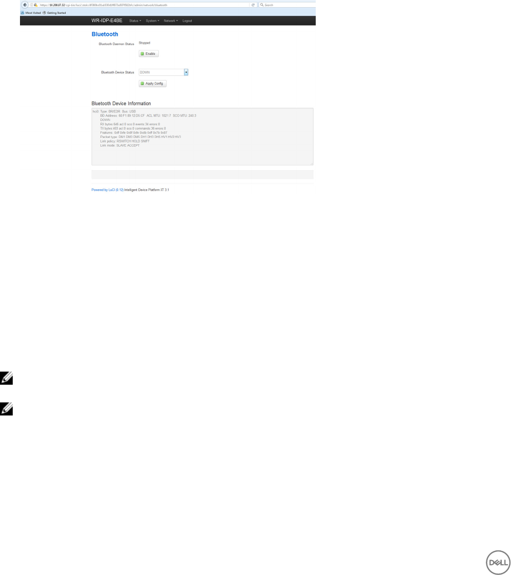
through the system. The issued IP addresses by the access point and eth1 interface are in the 192.168.1.x subnet. The default
access point SSID for the access point is IDPDK-5591. The bridge conguration can be modied using LuCi web interface. Follow
Intel/Wind River’s documentation for more details on conguring, WAN, WLAN, and br-LAN network interfaces using LuCi web
interface.
Bluetooth conguration
The system supports an integrated Bluetooth network interface. The Bluetooth network can be congured using LuCI web interface
on the Wind River Linux OS. To congure Bluetooth interface on the system with Wind River Linux OS.
1. Log in to the LuCI web interface as identied in the steps referenced in the previous sections.
2. Bluetooth conguration is supported under Network tab drop-down menu Bluetooth of the Web Interface.
• Enable Bluetooth interface in this page and hit Scan to identify nearby other Bluetooth enabled devices.
Wireless WAN network interface conguration
Add-on modules can be installed on the edge gateway system to get Wireless WAN (WWAN) connectivity.
• 4G-LTE — Interface using Telit LE910 module for carrier AT&T
• 4G-LTE — Interface using Telit LE910 module for carrier Verizon
• HSPA+ — Interface using Telit HE910 module
LE910 WWAN connection conguration
Follow the Service Manual to install the LE910 module and the corresponding carrier SIM card in the system. After the module and
SIM card is installed, activate the WWAN connectivity by:
NOTE: The default Wind River Linux OS image currently uses AT commands to congure WWAN interface and LTE
connectivity.
NOTE: LuCi web interface currently does not support conguring the WWAN interface.
Identifying installed WWAN module and Carrier
To identify the serial interface on the installed LE910 module’s tty ACM interface, using dmesg command: # dmesg | grep –i
ttyacm
The system may contain more than one USB ACM device other than Telit LE910 or Telit HE910 module. Based on the output for the
dmesg command, identify the ttyacm ports that were enumerated, for example, below is the output for dmesg | grep –i
ttypacm command for more than one USB ACM device on the system.
50
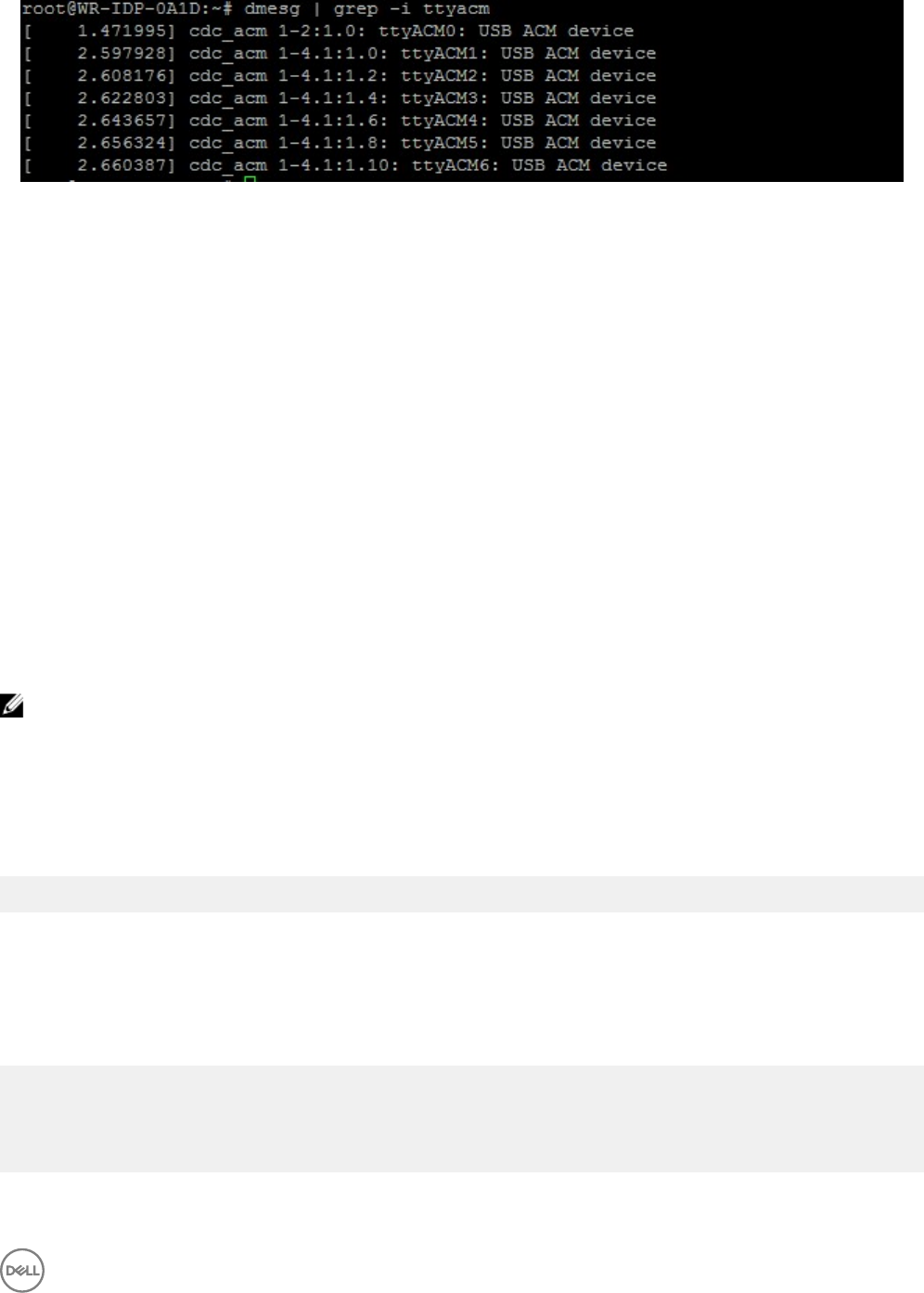
Launch minicom terminal utility on the system with one of the USB ACM device port to identify that we have the correct USB ACM
device for Telit LE910 device before conguring the device, e.g. below shows how to launch minicom with ttyACM1 as interface:
•# minicom –D /dev/ttyACM1
• Inside minicom, type the following AT command to identify if it is the “Telit” device AT+GMI
• If the response to the above command is Telit, then you have identied the correct device ttyacm port.
• If the output is not Telit or Error, then you have to exit out of minicom and start minicom with a dierent port like e.g. /dev/
ttyACM0 or /dev/ttyACM3 etc,
• Example of starting minicom with /dev/ttyACM1 as port of communication below.
root@WR-IDP-0A1D:~# root@WR-IDP-0A1D:~# minicom -D /dev/ttyACM1
Conguring the WWAN carrier parameters
Inside minicom terminal, the following AT commands have to be issued in sequence to congure the LTE module, the line with
DESCRIPTION are references to the AT commands to type and are not to be entered as a part of the AT commands themselves
DESCRIPTION: Check that the SIM is inserted and PIN is unlocked using the at+cpin? command
DESCRIPTION: If the SIM is locked with a PIN the at+cpin=”1234” AT command can be used to unlock the SIM. Where the SIM
PIN is 1234, if the PIN is dierent, use appropriate PIN number in the command below.
DESCRIPTION : Setting up the APN. NCM can be activated using every available CID,
NOTE: Skip this step for Verizon as it is preprogrammed (use AT+CGDCONT? to identify if the CID3 is vzwinternet).
The at+cgdcont=3,"IP","broadband" command has to be issued for AT&T based SIM. In the command, 3 is the
CID(Connection ID), this can be between 1 to 5, 3 is shown to keep the value consistent between VZ and ATT based solution. IP in
the command indicates the TCP-IP protocol. broadband in the command is the name assigned by AT&T as a network ID or APN to
connect to logically, this name is assigned by the carrier.
DESCRIPTION : Check the state of the modem
at+cops?
at+cgatt?
DESCRIPTION: Run the at#ncm=1,3 command to enable NCM on CID 3 (this command must be sent on a USB instance (in this
case USB0 or USB3)
DESCRIPTION: Run the at#ncm=1,3 to activete the PDP context.
DESCRIPTION: Read IP address, Gateway address and DNS address from the module
at+cgcontrdp=3
REPONSE:
+CGCONTRDP:
3,6,"vzwinternet.mnc480.mcc311.gprs","100.176.244.64.255.255.255.0","100.176.244.65","10.133
.17.210","0.0.0.0","0.0.0.0","0.0.0.0"
OK
Establishing LTE WWAN connectivity
51

Description: The following are a capture from a sample session that was performed on a Dell Edge Gateway platform with default
Wind River Linux OS image to establish LTE connectivity using Verizon LE910 module and Verizon SIM card. The commands
highlighted were typed and the other is response from the system. For AT&T LE910 module and AT&T SIM environment use
“broadband” to replace “vzwinternet” in the following set of commands.
In order to open up additional Linux terminal in Wind River Linux, press Alt-F2 key, this will take you to another Linux login prompt.
Login using your root/root credentials.
Command typing is highlighted in Itlaics
root@WR-IntelligentDevice:~# minicom -D /dev/ttyACM0
Welcome to minicom 2.7
OPTIONS: I18n
Compiled on 16:20:45.
Port /dev/ttyACM0, 21:33:05
Press CTRL-A Z for help on special keys
at+cgdcont=3,"IPV4V6","vzwinternet"
OK
at+cgdcont?
+CGDCONT: 1,"IPV4V6","vzwims","",0,0
+CGDCONT: 2,"IPV4V6","vzwadmin","",0,0
+CGDCONT: 3,"IPV4V6","vzwinternet","",0,0
OK
at#ncm=1,3
OK
at+cgact=1,3
OK
at+cgcontrdp=3
+CGCONTRDP: 3,7,"vzwinternet.mnc480.mcc311.gprs","100.106.47.7.255.0.0.0","100.1
06.47.8","198.224.157.135","0.0.0.0","0.0.0.0","0.0.0.0"
+CGCONTRDP: 3,7,"vzwinternet.mnc480.mcc311.gprs","254.128.0.0.0.0.0.0.0.0.0.71.4
6.110.1.1.255.255.255.255.255.255.255.255.0.0.0.0.0.0.0.0","0.0.0.0.0.0.0.0.0.0.
0.0.0.0.0.0","198.224.157.135","0.0.0.0.0.0.0.0.0.0.0.0.0.0.0.0","0.0.0.0.0.0.0.
0.0.0.0.0.0.0.0.0","0.0.0.0.0.0.0.0.0.0.0.0.0.0.0.0"
OK
^A X Y
root@WR-IntelligentDevice:~# ifconfig wwan0 100.106.47.7 netmask 255.0.0.0 up
root@WR-IntelligentDevice:~# route add default gw 100.106.47.8 wwan0
root@WR-IntelligentDevice:~# echo nameserver 198.224.157.135 >>/etc/resolv.conf
root@WR-IntelligentDevice:~# minicom -D /dev/ttyACM0
Welcome to minicom 2.7
OPTIONS: I18n
Compiled on Dec 17 2015, 16:20:45.
Port /dev/ttyACM0, 21:33:05
Press CTRL-A Z for help on special keys
at+cgdata="M-RAW_IP",3
CONNECT
OK
^A X Y
root@WR-IntelligentDevice:~# ping 8.8.8.8
PING 8.8.8.8 (8.8.8.8) 56(84) bytes of data.
64 bytes from 8.8.8.8: icmp_seq=1 ttl=52 time=36.9 ms
64 bytes from 8.8.8.8: icmp_seq=3 ttl=52 time=33.5 ms
64 bytes from 8.8.8.8: icmp_seq=4 ttl=52 time=31.2 ms
64 bytes from 8.8.8.8: icmp_seq=5 ttl=52 time=32.6 ms
^C
--- 8.8.8.8 ping statistics ---
5 packets transmitted, 4 received, 20% packet loss, time 4004ms
rtt min/avg/max/mdev = 31.276/33.585/36.903/2.078 ms
Disable WWAN0 Connection
52

Description: The following method can be used to disable or delete the WWAN connection that was setup using the descriptions
mentioned in the previous sections.
1. Launch minicom as dened in the other sections and choose the appropriate ttyACM port for the Telit module
2. Inside the minicom terminal send the following AT commands
At+gmi (to make sure it is the Telit module)
At+cgatt=0 (Response should be NO CARRIER)
AT+cgatt=1
3. Exit out of the minicom terminal by pressing Ctrl-A, Z and X.
4. On the Linux prompt enter the # ifconfig wwan0 down command to disable wwan0.
Sample Session to disable WWAN0 Connection:
root@WR-IntelligentDevice:~# minicom -D /dev/ttyACM0
Welcome to minicom 2.7
OPTIONS: I18n
Compiled on Dec 17 2015, 16:20:45.
Port /dev/ttyACM0, 21:33:05
Press CTRL-A Z for help on special keys
at+cgact=0,3
OK
^A X Y
root@WR-IntelligentDevice:~# ifconfig wwan0 down
HE910 (HSPA+) WWAN connection conguration
Description: Follow the hardware installation guide to install the HE910 module and the corresponding carrier SIM card in the system.
Once the hardware module and the SIM are installed follow the instructions below to activate 3G HSPA+ connectivity.
The HSPA connection on Wind River Linux can be activated using the following UCI command set or through LuCi web interface.
Below are samples steps to congure 3G WWAN interface:
1. Checking the network conguration.
root@WR-IDP-XXXX:~# cat /etc/config/network
...
config interface 'wwan'
option ifname '3g-wwan'
option proto '3g'
option device '/dev/ttyACM0'
option ppp_redial 'demand'
option defaultroute '1'
option peerdns '1'
option service 'umts_first'
option sconnservice 'UMTS'
option dialnumber '*99***1#'
config device 'modem_cell'
option name 'modem_cell'
option present 'Yes'
option protoall '3g'
option pppddev '/dev/ttyACM0'
option statedev '/dev/ttyACM3'
option Manufacturer 'Telit'
option Product 'HE910'
option Vendor '1bc7'
option ProdID '0021'
option SerialNumber '357164040868450'
option Rev '12.00.004'
config device 'sim_card'
option name 'sim_card'
option present 'No
53
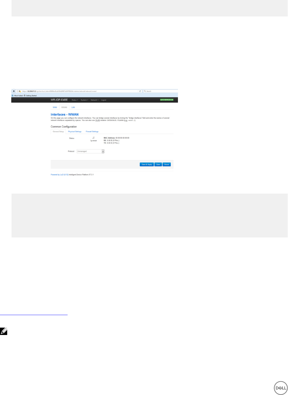
2. Add apn according to the SIM card operator. For e.g. "3gnet" for China Unicom
root@WR-IDP-XXXX:~# uci set network.wwan.apn="3gnet"
root@WR-IDP-XXXX:~# uci commit network
root@WR-IDP-XXXX:~# uci get network.wwan.apn3gnet
3. Setup WWAN interface.
restart wwan interface: root@WR-IDP-XXXX:~# ifdown wwan ; ifup wwan
or
restart all interfaces: root@WR-IDP-XXXX:~# systemctl restart netifd
4. Step 2 and Step 3 can also be performed through in LuCi web interface.
On the WWAN tab. Set APN rst, and then click Save & Apply button to apply the changes as shown in the sample LuCi web
interface.
5. Check the 3g-wwan interface is ready.
root@WR-IDP-XXXX:~# ifconfig 3g-wwan
3g-wwanLink encap:Point-to-Point Protocol
inet addr:10.3.203.207 P-t-P:10.3.203.207 Mask:255.255.255.255
UP POINTOPOINT RUNNING NOARP MULTICAST MTU:1500 Metric:1
RX packets:238 errors:0 dropped:0 overruns:0 frame:0
TX packets:322 errors:0 dropped:0 overruns:0 carrier:0
collisions:0 txqueuelen:3
RX bytes:35017 (34.1 KiB) TX bytes:35054 (34.2 KiB)
Register Edge Gateway at Intel Developer Hub
The Dell Edge Gateway 5000 series with Wind River Linux IDP 3.1 supports Developer Hub portal within the Gateway. This portal can
be used for performing variety of conguration functions on the Gateway along with using it for developing software layers on top of
the base Wind River Linux OS Image, sensor devices integration to the gateway and hardening of the combined application / base
OS image for deployment.
The developer portal has to be used for registering the Edge Gateway 5000 at Intel Marketplace to obtain credentials to connect to
the software package update repository. The following are the two key URLs required for developer solutions on the Edge Gateway
using Wind River Linux IDP.
http://shopiotmarketplace.com : This is registration site for registering your Gateway device with Wind River Linux and obtaining
credentials for Windshare repository access for package updates.
NOTE: For Dell Edge Gateway with Wind River Linux OS image solution, your (customer’s) Dell point of contact should
have already registered your contact information at Intel IoT Marketplace and you should have received notication from
Intel marketplace on procedure for you to get login credentials to Windshare repository from where software packages
and updates to Wind River Linux OS can be obtained. If you have not received notication from Intel IoT Marketplace,
contact your Dell sales point of contact to get you registered.
54

Some of the detailed documentation on how to develop for Wind River Linux OS image based Gateway 5000 solution and how to
utilize built in Developer Hub are available at www.intel.com/gatewaytraining please refer to that site for more details.
The following steps gives basic guidelines to follow once you receive your Dell Edge Gateway 5000 product with Wind River Linux
IDP 3.1 base OS image.
The Dell Edge Gateway 5000 product with Wind River Linux IDP 3.1 base image from the factory is shipped with particular version of
the RCPL package(RCPL 13) from Wind River. The RCPL versions from Wind River are periodically updated by the Wind River team
and it is recommended for the Edge Gateway user/customers to upgrade to the latest version of RCPL by following the procedure/
steps indicated below before developing software stack and middleware on top of the OS image. The latest RCPL image provides
security updates and other bug xes for the software packages.
• Connect the Ethernet WAN port ETH1 of your Dell Edge Gateway 5000 series platform that came with factory installed Wind
River Linux OS image to an internet connected router that can assign a DHCP address to the Gateway’s ETH1 interface. Make
sure this connection has direct internet access outside of rewall and proxy connection during initial setup.
• Login into the OS using default root/root credentials on the Gateway. Find out the IP address of the ETH1 interface using
ifcong.
• In the linux prompt enter the root@WR-IDP-XXXX:~# smart update command to update the package cache and default
repository channel. The smart update command updates the cache of already included update channels and repository.
• Enter the root@WR-IDP-XXXX: smart channel --list to list the default channels supported by the factory image on
the Edge Gateway.
• At this point, with another browser enabled PC system connected to the same network as the Gateway , type in the IP address
of ETH1 interface on the browser URL address, i.e. http://<IP-Address-ETH1-Interface>. Default evaluation of this was
performed using Google Chrome browser, if available use Chrome browser.
• A pop-up window shows up with requiring the user to login. Log in to the browser window using "gwuser" as username and
"gwuser" as password.
• Read license agreement and follow instructions to continue.
55
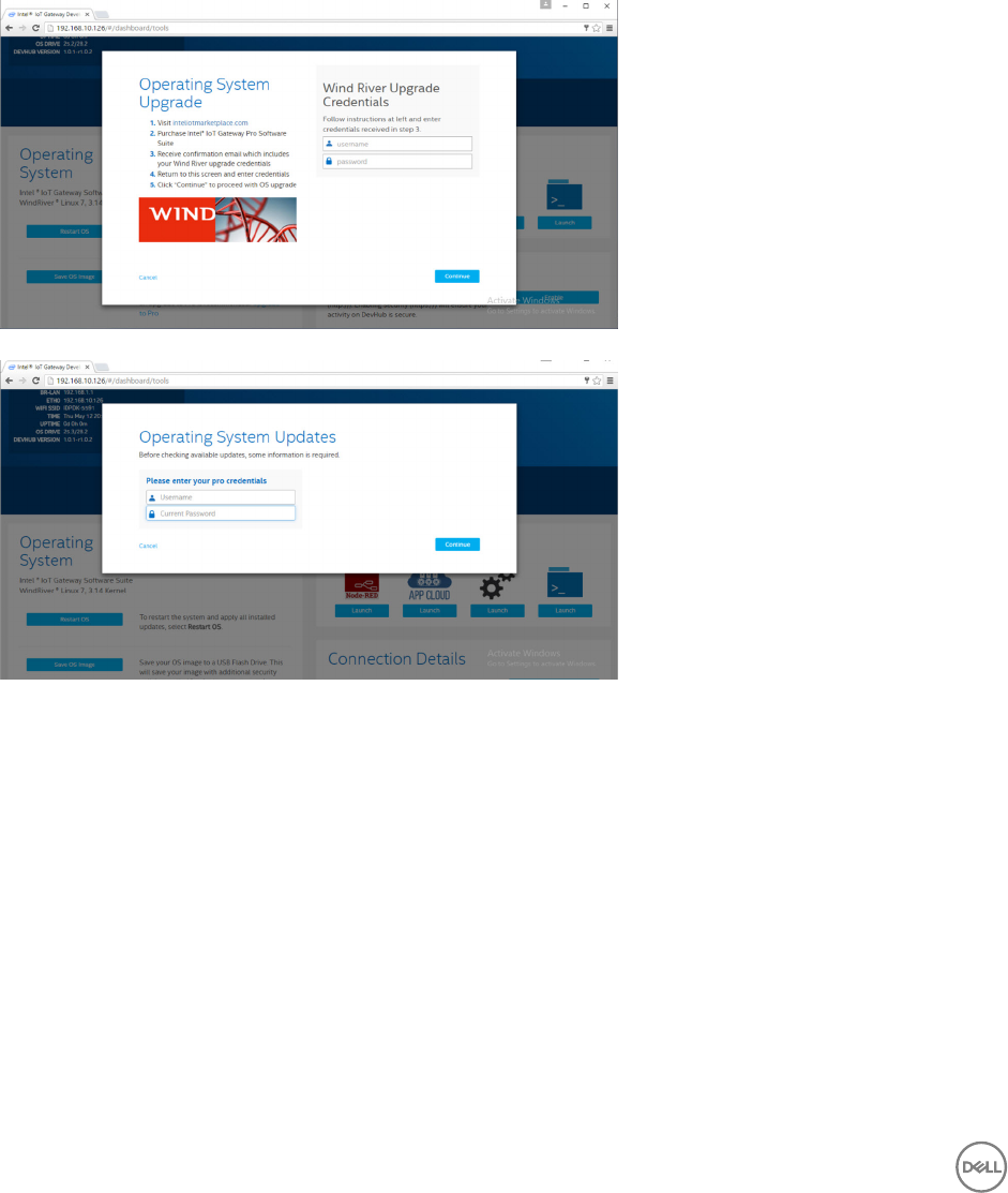
• Select the packages tab inside the IoT Developer Hub, search for iot-developer-hub package and select to update that
package only, it is not necessary to update other packages at this time. Give few minutes for package to download and update.
• After update if the browser session terminates or logs the user out, follow the procedure above to log back in into the web
interface. Since the update might be happening it might take couple of minutes to re-connect for the web interface to respond,
wait until the interface allows to log the user back in.
• Once logged back into the developer hub, go into the "Administration" tab and choose "Upgrade to Pro" option. This tab updates
all the Pro Packages from Wind River that are already licensed and available free to install with the Gateway 5000 series product
with Wind River OS license.
– When Upgrade to Pro is selected, the user will be asked to enter Wind River credentials for Windshare repository. The user’s
sales contact at Dell should have already registered your contact information with Intel/Wind River and the user should have
received email notication from Intel / Wind River describing the procedure and process to obtain the Windshare repository
credential from Intel/Wind River.
– If you have not gotten such email, contact your sales contact at Dell to get you through the registration process to obtain
credentials for the Windshare repository.
– When the WindShare credentials are entered, additional set of repositories from where packages can be downloaded are
added to the channel list. The additional set of channels can be reviewed by using the smart command in the Linux prompt –
smart channel –-list.
• Once the Wind River credentials are entered during the Upgrade to Pro package selection, the upgrade process should continue
and would take some amount of time to complete. Wait for few minutes for the upgrade to complete.
• Once upgrade to Pro packages are complete, exit out of the browser and clear browser cookies and cache, re-login back into the
Developer Hub using the procedure described above and under "Administration " tab choose "Install OS Updates". The system
might ask for Windshare Pro credentials, re-enter the Windshare repository credentials obtained as describe in the steps above.
• At this point the system should check for update availability in the Windshare repository and would indicate if any updates are
available, if available initiate the update process using the Install OS Updates. Such updates could take possibly up to an hour or
more depending on your network connection. Let the system update to complete and make sure the internet connection is
continuous.
56
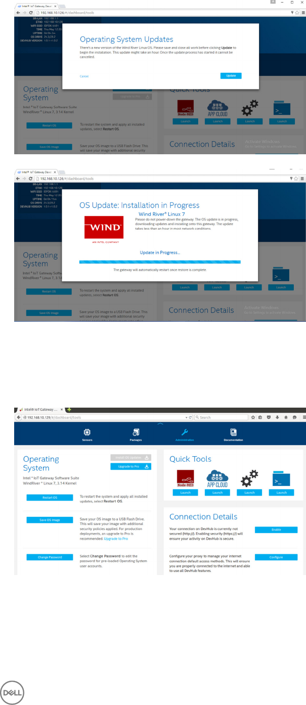
• Once the update of the OS is complete, the Gateway should reboot and now the system should be upgraded to the latest RCPL
release available for the Gateway 5000 product at the Windshare repository. At this point the user should have an environment
ready to develop other layers of applications on top of the Gateway 5000 system.
Below are some of the sample screenshots of the Developer Hub web interface described in the steps above.
Below are some of the sample screenshots of the Developer Hub web interface described in the steps above.
57

• The package tab indicates installed packages on the platform, update to the packages can be performed and additional
repository channels can be added through the developer hub portal.
Common port mappings on Edge Gateway 5000 with Wind River OS
Serial Port Mapping
Description: The following table show the serial port mapping on the Edge Gateway 5000 platform installed with Dell factory installed
Wind River Linux OS image. For dip switch setting on the Edge Gateway for RS422 and RS485 ports please refer to appropriate
hardware installation guide document.
NOTE: Device nodes are ordered by port position starting from the leftmost RS232 port.
Table 3. Device nodes of serial ports on the Dell Edge Gateway 5000 series
No. Port Type Connector Device Node
1 RS232 DB9 /dev/ttyS0
2 RS422_485 5 pin terminal /dev/ttyS4
3 RS485 3 pin terminal /dev/ttyS5
4 RS485 3 pin terminal /dev/ttyS2
Edge Gateway I/O Module GPIO Mapping
Description: The GPIOs on the Gateway are managed through GPIO driver on the OS. The cloud LED on the Gateway is attached to
one of the GPIOs and below are the steps on how to control the cloud LED in Wind River Linux OS.
1. Export Cloud LED PIN:
root@WR-IDP-XXXX:~# echo 346 > /sys/class/gpio/export
root@WR-IDP-XXXX:~# echo out > /sys/class/gpio/gpio346/direction
2. Turn on Cloud LED:
root@WR-IDP-XXXX:~# echo 1 > /sys/class/gpio/gpio346/value
3. Turn o Cloud LED:
root@WR-IDP-XXXX:~# echo 0 > /sys/class/gpio/gpio346/value
Edge Gateway I/O Module based GPIO Mapping
Description: The GPIOs on the external I/O module for the Edge Gateway are behind PIC microcontroller. The PIC microcontroller is
exposed to the host system and to the host OS as a USB-HID device. Software application developed to communicate with the
GPIOs may use the protocol dened in following set of references to communicate with the GPIO modules. There are no native
application software available on the factory OS image that communicates with the IO module GPIOs.
58
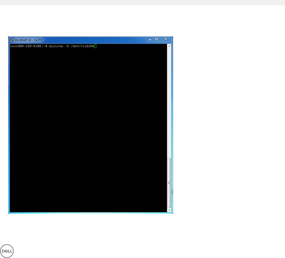
The I/O module GPIO mapping and references will be provided as a separate technical sheet and article and will be released at the
support web portal for user/customer reference.
Edge Gateway I/O Module PCIe expansion mapping
Description: The PCIe slot on the external I/O module for the Edge Gateway are driven directly from the host PCIe bus. Since it is
generic PCIe expansion there are no PCIe device specic drivers integrated into the Wind River Linux OS image. If there are specic
PCIe card used on this slot, contact the vendor of that PCIe card to verify if they have Linux drivers and if that is a kernel mode
driver such driver may have to be ported to Wind River Linux OS environment which uses 3.14 Linux kernel version on the Wind River
Linux OS image shipped from the factory on the Gateway.
Edge Gateway Zigbee Module Functions
Description: The Edge Gateway supports a USB Zigbee dongle as an optional add-on hardware. When the Zigbee dongle is present
on the system it is enumerated to the OS as a USB device and accessed through cdc_acm kernel driver layer on the Wind River
Linux host. There are no native application software on the factory installed OS image to perform Zigbee protocol for this device. A
basic communication with the Zigbee module can be veried using minicom terminal interface application as well as to get basic
information from the Zigbee dongle.
For example: The following command would launch minicom with device /dev/ttyACM6 assuming the Zigbee dongle is enumerated
into /dev/ttyACM6 port.
root@WR-IDP-XXXX:~# minicom –D /dev/ttyACM6
The Screenshot below shows the response from the Zigbee dongle when the Zigbee USB dongle is enumerated under /dev/
ttyACM6 port.
• Sending an AT command inside minicom session should return an OK from the device.
• Sending an ATI command inside the minicom session should return the module information like “Telegesis ETRX 3588” etc.
59

Edge Gateway CAN Module Functions
Description: The Edge Gateway supports an optional CAN module that is mounted inside the Gateway itself. The CAN module is
enumerated to the OS as a USB device as USB HID device to the Linux kernel driver layer on the Wind River Linux host. There are
no native application software on the factory installed OS image to perform CAN protocol for this device.
The CAN module presence on the Gateway can be identied by issuing “lsusb” command in the Linux prompt and looking for
“Microchip Technology Inc.,” based device.
For CAN communication protocols and software API references a separate set of references and articles will be provided outside of
this document.
60

5
System specications
NOTE: Oerings may vary by country; not all congurations are available in all regions.
Component types
Component 5000 5100
PCB Standard FR4 Isola 370HR
CPU Intel E3B25/E3827 Intel E3B25/E3827
Memory Dell-managed Dell-managed
BIOS Flash Dell-managed 128 MB SPI FLASH Dell-managed 128 MB SPI FLASH
Super I/O Fintek F81960D-I Fintek F81960D-I
LAN on system-board Realtek RTL81191-CG Realtek RTL81191-CG
TPM Nuvoton NPCT6SO series Nuvoton NPCT6S4 series
SSD 60D3 LITEON 60D3 LITEON
WLAN MURATA/ LBEE5ZZ1EN MURATA/LBEE5ZZ1EN
WWAN TELIT/HE910, TELIT/LE910-SV, TELIT/
LE910
TELIT/HE910, TELIT/LE910-SV, TELIT/
LE910
Coin-cell battery CR2032 BR2032
Operating systems
Supported operating systems:
• Microsoft Windows 10 IoT Enterprise LTSB
• Ubuntu Core 16.04 and 15.04
• Wind River Linux IDP-XT 3.1
Processor
5000/5100
Intel Atom E3825 X
Intel Atom E3827 X
61

Memory
5000 5100
Type DDR3L DDR3L
Memory channel Single/dual Single/dual
Minimum memory 2 GB 2 GB
Maximum system memory 8 GB 4 GB
Drives and removable storage
5000/5100
Supported number of mSATA hard drives (maximum) 1
32GB M.2 Solid State Drive X
64GB M.2 Solid State Drive X
NOTE: For hard drives, ‘GB’ means 1 billion bytes; actual capacity varies with pre-loaded material and operating
environment and will be lower.
Communications—WLAN antenna
General specications
Antenna type PCB Dipole
Number of ports 2
Frequency (GHz) 2.4 to 2.5 4.9 to 5.9
Voltage Standing Wave Ratio (VSWR) 2:1 2:1
Isolation (dB) > 20 > 20
Peak gain 3.5 dBi 5.0 dBi
Average gain on sphere (3D) > -4 dBi > -5 dBi
Polarization Linear
Eciency > 55% > 55%
Mechanical and environmental specications
Height 105.60 mm (4.16 in)
Diameter 36.20 mm (1.43 in)
IPX class IP65
62

Mechanical and environmental specications
Mounting Wall mounted
Connector type SMA male
Antenna color White
Cable type Plenum rated low loss RG58
Cable color White
Mounting bracket Swivel type (plastic)
Mounting bracket length (approximate) 175 mm (6.89 in)
Mounting bracket color Black
Pig tail length 500 mm ± 10 mm (19.69 in ± 0.39 in)
Coaxial cable specication
Impedance 50 ± 2.00 ohms
Structural return loss -16 dB or better from 100-2500 MHz un-terminated sample
(direct bridge method)
Nominal RTL reference -16 dB or better to 6.0 GHz
Dielectric Foam FEP
Dielectric (outer diameter) 2.79 mm ± 0.076 mm (0.110 in ± 0.003 in)
Velocity of propagation 80%
Center conductor Solid copper, 0.94 mm ± 0.025 mm (0.037 in ± 0.001 in)
Shield #1 Foil, aluminium/poly tape, adhered to dielectric
Diameter over foil 3.02 mm ± 0.07 mm (0.119 in ± 0.003 in)
Shield #2 Braid, 90% 36-AWG tin/copper
Outer jacket Plenum PVDF, o-white, lead-free, and UV stable
Outer diameter 4.52 mm ± 0.15 mm (0.178 in ± 0.006 in)
PLENUM rating CMP(ETL)C(ETL)
Attenuation dB/100 feet (nominal reference values) • 8.0 dB@ 450 MHz
• 12.5 dB @900 MHz
• 19.6 dB@ l.8 GHz
• 23.6 dB @ 2.5 GHz
• 23.0 dB @ 3.0 GHz
• 27.5 dB @ 4.0 GHz
• 31.0 dB @ 5.0 GHz
• 35.0 dB @ 6.0 GHz
Installation temperature -20°C (-4°F) to +65°C (149°F)
Operating temperature -30°C (-22°F) to +65°C (149°F)
CC pullout 6 pound-force minimum, 16 pound-force maximum
63

Coaxial cable specication
Jacket pullout 4.5 pound-force minimum on 76.2 mm (3 in) section at 12.7 mm
(0.5 in) per minute
Minimum bend radius 12.7 mm (0.5 in) static bend
Leakage -90 dB
Communications—WWAN antenna
General specications
Antenna
type
PCB Dipole
Number of
ports
2
Frequency
(MHz)
698-803 791-862 824-894 880-960 1710- 1880 1850- 1990 1710- 2155 1920- 2170 2500-
2690
VSWR 2:1
Isolation
(dB)
> 15
Peak gain < 5.0dBi < 5.0dBi <5.0dBi < 3.7dBi < 5.0dBi < 3.3dBi <3.3dBi < 5.0dBi < 5.0dBi
Average
gain on
sphere
(3D)
> -3 dBi
Polarization Linear
Eciency > 40%
Mechanical and environmental specications
Height 254 mm (10 in)
Diameter 41 mm (1.61 in)
Weight 820 g (with mounting holder)
IPX class IP65
Mounting Wall mounted
Connector type SMA male
Antenna color White
Cable type Plenum rated low loss RG58
Cable color White
64

Mechanical and environmental specications
Mounting bracket Swivel type (plastic)
Mounting bracket length (approximate) 175 mm (6.89 in)
Mounting bracket color Black
Pig tail length 1000 mm (39.37 in)
Coaxial cable specication
Impedance 50 ± 2.0 ohms
Structural return loss -16 dB or better from 100-2500 MHZ un-terminated sample (direct bridge
method)
Nominal RTL reference -16 dB or better to 6.0 GHz
Dielectric Foam FEP
Dielectric (outer diameter) 2.79 mm ± 0.076 mm (0.110 in ± 0.003 in)
Velocity of propagation 80%
Center conductor Solid copper, 0.94 mm ± 0.025 mm (0.037 in ± 0.001 in)
Shield #1 Foil, aluminium/poly tape, adhered to dielectric
Diameter over foil 3.02 mm ± 0.07 mm (0.119 in ± 0.003 in)
Shield #2 Braid, 90% 36-AWG tin/copper
Outer jacket Plenum PVDF, o-white, lead-free, and UV stable
Outer diameter 4.52 mm ± 0.15 mm (0.178 in ± 0.006 in)
Outer Jacket Plenum PVDF, O-white, lead free, and UV stable
Outer Diameter 4.52 mm ± 0.15 mm (0.178 in ± 0.006 in)
PLENUM rating CMP(ETL)C(ETL)
Attenuation dB/100 feet (nominal reference values) • 8.0 dB@ 450 MHz
• 12.5 dB @900 MHz
• 19.6 dB@ l.8 GHz
• 23.6 dB @ 2.5 GHz
• 23.0 dB @ 3.0 GHz
• 27.5 dB @ 4.0 GHz
• 31.0 dB @ 5.0 GHz
• 35.0 dB @ 6.0 GHz
Installation temperature -20°C (-4°F) to +65°C (149°F)
Operating temperature -30°C (-22°F) to +65°C (149°F)
CC pullout 6 pound-force minimum, 16 pound-force maximum
Jacket pullout 4.5 pound-force minimum on 76.2 mm (3 in) section at 12.7 mm (0.5 in)
per minute
Minimum bend radius 12.7 mm (0.5 in) static bend
Leakage -90 dB
65

Measured antenna peak gain (antenna only)
Main antenna Auxiliary antenna
Frequency (MHz) Horizontal (dBi) Vertical (dBi) Horizontal (dBi) Vertical (dBi)
698 0.09 0.63 1.19 1.12
704 -0.11 0.66 0.89 0.91
710 -0.27 0.60 0.51 0.78
716 -0.08 0.55 0.42 0.86
734 0.17 0.57 0.68 0.97
740 0.35 0.60 0.86 0.99
746 0.38 0.92 1.00 1.03
734 0.49 1.12 1.16 1.10
740 0.67 1.42 1.39 1.11
746 0.95 1.56 1.51 1.20
756 1.48 2.10 1.63 1.53
765 1.81 2.42 1.64 1.63
772 1.93 2.47 1.40 1.57
777 2.00 2.50 1.33 1.60
782 1.85 2.36 1.02 1.48
787 1.67 2.25 0.73 1.43
791 1.62 2.21 0.90 1.37
806 1.69 2.34 1.68 1.61
821 1.70 2.02 1.97 1.91
824 1.63 1.93 1.91 1.91
836 1.65 1.65 1.80 1.71
849 1.63 1.46 1.79 1.40
862 1.65 1.34 2.01 1.19
869 1.60 1.26 2.07 1.04
880 1.72 1.24 2.16 1.09
894 1.69 1.06 2.15 0.96
66

Measured antenna peak gain (antenna only)
900 1.71 1.00 2.13 0.94
915 1.65 1.03 1.87 0.82
925 1.57 1.16 1.61 0.74
940 1.30 1.36 1.24 0.60
960 1.43 1.31 0.98 0.69
1710 2.19 2.18 1.83 2.39
1730 2.25 2.29 1.66 2.36
1750 1.90 2.15 1.39 2.29
1770 1.33 1.91 0.97 1.83
1785 0.88 1.76 0.66 1.50
1805 0.40 1.59 0.34 1.26
1840 -0.12 1.49 -0.01 1.18
1850 -0.06 1.58 0.04 1.18
1880 0.36 1.65 0.51 1.49
1910 0.72 1.76 0.90 1.81
1920 0.86 1.85 0.91 1.99
1930 1.01 1.89 0.95 2.15
1950 1.29 2.16 0.99 2.28
1960 1.23 2.32 0.91 2.29
1980 0.98 2.43 0.95 2.19
1995 0.35 2.22 0.74 1.80
2110 0.72 1.06 1.37 1.28
2140 0.82 1.08 1.58 1.31
2170 1.15 1.22 1.85 1.18
2300 2.23 2.40 2.97 1.63
2325 1.76 2.18 2.48 1.74
2350 1.44 1.74 2.08 1.66
2375 1.26 1.59 1.84 1.46
67

Measured antenna peak gain (antenna only)
2400 1.29 1.91 1.85 1.63
2500 3.17 2.75 2.94 2.47
2515 3.11 2.62 2.78 2.47
2535 2.88 2.42 2.55 2.48
2555 2.51 2.09 2.18 2.46
2570 2.21 1.91 1.92 2.46
2570 2.21 1.91 1.92 2.46
2595 1.89 1.65 1.56 2.45
2620 1.69 1.68 1.44 2.35
2620 1.69 1.68 1.44 2.35
2630 1.80 1.76 1.43 2.41
2655 1.78 1.82 1.63 2.60
2680 1.98 2.20 2.02 2.59
2690 2.07 2.38 2.17 2.55
Graphics/video controller
5000/5100
Intel integrated graphics
External ports and connectors
NOTE: For locations of ports and connectors, see system views.
NOTE: For RS422 and RS485:
• Termination is 120-ohms between the members of the dierential pair when enabled.
• Bias is 4.7k pull-up (5V) / pull-down (Gnd) when enabled.
Number of ports Connector vendor part number
RS-232 1 None
RS-485 2 Molex 39530-5503
RS-422/RS-485 combo (congurable via
DIP switches)
1 Molex 39530-5505
Network connector (RJ-45)–Dual gigabit
ethernet
2 None
HDMI Port 1.4 1 None
68

Number of ports Connector vendor part number
Line out for headphones or speakers None None
Universal audio jack None None
USB 2.0 2 None
USB 3.0 1 None
CANBus (3–pin Phoenix connector) 1 Molex 39530-5503
Dimensions and weight
NOTE: System weight and shipping weight are based on a typical conguration and may vary depending on PC
conguration. A typical conguration includes: integrated graphics, one hard drive, and one optical drive.
Product dimensions and weight
5000 5100 IO module Power module IP65 rugged
enclosure
Volume (Liters) 3.167 L 3.675 L 2.14 L 1.634 L 13.62 L
Weight 3.0 kg (6.6 lb) 3.3 kg (7.3 lb) 1.2 kg (2.6 lb) 1.4 kg (3.1 lb) 6.3 kg (13.9 lb)
Height 228.4 mm (8.99 in) 228.4 mm (8.99 in) 207.60 mm (8.17 in) 117.80 mm (4.64 in) 388 mm (15.28 in)
Width 216 mm (8.50 in) 216 mm (8.50 in) 216 mm (8.50 in) 216 mm (8.50 in) 440 mm (17.46 in)
Depth 64.20 mm (2.52 in) 74.50 mm (2.93 in) 47.70 mm (1.88 in) 64.20 mm (2.53 in) 79.80 mm (3.14 in)
NOTE: The dimensions for the enclosure do not include the latches and wall bracket on the back of the enclosure. The
wall bracket adds 5 mm (0.04 inches) to the depth.
Packaging dimensions and weight
5000 5100 IO Module Power module IP65 rugged
enclosure
Height 34.4 cm (13.56 in) 34.4 cm (13.56 in) 25.4 cm (10 in) 25.4 cm (10 in) 52.7 cm (20.75 in)
Width 29.5 cm (11.63 in) 29.5 cm (11.63 in) 13.2 cm (5.2 in) 11.4 cm (4.49 in) 15.9 cm (6.26 in)
Depth 15.6 cm (6.13 in) 15.6 cm (6.13 in) 18.1 cm (7.12 in) 18.1 cm (7.12 in) 52 cm (20.47 in)
Shipping weight
(includes packaging
materials)
3.8 kg (8.38 lb) 3.8 kg (8.38 lb) 1.48 kg ( 3.26 lb) 1.63 kg ( 3.59 lb) 7.79 kg (17.17 lb)
69

Mounting dimensions
5000 5100 IO module Power module IP65 rugged
enclosure
Height 246 mm (9.69 in) 246 mm (9.69 in) 246 mm (9.69 in) 246 mm (9.69 in) 458.2 mm (18.04 in)
Width 228.4 mm (8.99 in) 228.4 mm (8.99 in) 228.2 mm (8.98 in) 130.8 mm (5.15 in) 405.6 mm (15.97 in)
Depth 72.7 mm (2.86 in) 83 mm (3.27 in) 56.2 mm (2.21 in) 72.7 mm (2.86 in) 91.8 mm (3.61 in)
Environmental and operating conditions
Environmental conditions—System
Ingress protection rating IP50
Temperature range:
Operating (with a maximum temperature gradation of
15°C per hour)
Edge Gateway 5000
• -30°C to 50°C (22°F to 158°F) when connected to a 24 V
AC/DC power source.
• -30°C to 70°C (22°F to 158°F) when connected to a
power adapter or battery.
Edge Gateway 5100
• -30°C to 50°C (22°F to 158°F) when connected to a 24 V
AC/DC power source.
• -30°C to 70°C (22°F to 158°F) when connected to a
power adapter or battery.
NOTE: The maximum operating temperature is derated
1°C/305 m (1000 ft) above sea level altitude.
Non-operating (with a maximum temperature gradation
of 15°C per hour)
-40°C to 85°C (-40°F to 185 °F)
Relative humidity (maximum):
Operating (with maximum humidity gradation of 10%
per hour)
10% to 90% (non-condensing)
Non-operating (with maximum humidity gradation of
10% per hour)
5% to 95% (non-condensing)
Altitude (maximum, unpressurized):
Operating -15.20 m to 5000 m (-50 ft to 16,404 ft)
NOTE: The maximum operating temperature is derated
1°C/305 m (1000 ft) above sea level altitude.
Storage -15.20 m to 10,668 m (-50 ft to 35,000 ft)
70

Environmental conditions—IO module
Environmental requirements
Ingress protection rating IP50
NOTE: Enclosure meets IP50 with the pre-installed PCIe
blank bracket. System IP rating depends on the PCIe
card IP rating.
Temperature range:
Operating (with a maximum temperature gradation of
15°C per hour)
-30°C to 70°C (-22°F to 158°F)
NOTE: The maximum operating temperature is derated
1°C/305 m(1000 ft) above sea level altitude.
NOTE: The enclosure meets this specication without a
PCIe card. Operating temperature may change if a PCIe
card is installed.
NOTE: Any component to be installed in the IO module
shall have a still air temperature rating that is equal to or
higher than the PCIe card temperature rating. For IO
modules without PCIe cards, use a system ambient
temperature of +3°C (+37.4°F) to determine the inside
air temperature.
Non-operating -40°C to 85°C (-40°F to 185 °F)
Relative humidity (maximum):
Operating (with maximum humidity gradation of 10%
per hour)
10% to 90% (non-condensing)
Non-operating ((with maximum humidity gradation of
10% per hour)
5% to 95% (non-condensing)
Altitude (maximum, unpressurized):
Operating -15.2 m to 5000 m (-50 ft to 16,404 ft)
NOTE: The maximum operating temperature is derated
1°C/305 m (1000 ft) above sea level altitude.
Storage -15.20 m to 10,668 m (-50 ft to 35,000 ft)
Supported PCIe card power—PCIe card temperatures and power ratings must meet following requirements:
71

System ambient after altitude
derating (°C)
Maximum supported power
dissipation (W) for 85°C or
above still air rated PCIe
cards
Maximum supported power
dissipation (W) for 70°C still
air rated PCIe cards
Maximum supported power
dissipation (W) for 55°C still
air rated PCIe cards
20 15 12 8
25 14 10 6
30 13 9 5
35 12 8 4
40 10 6 3
45 9 5 2
50 8 4 1
55 6 3 Not supported
60 5 2 Not supported
65 4 1 Not supported
70 3 Not supported Not supported
NOTE: PCIe cards must support still air environment and must not require active cooling.
NOTE: PCIe cards rated above 25 W are not supported regardless of temperature rating.
NOTE: If a PCIe card is rated at a temperature that is not shown in the table, use interpolation to calculate the maximum
supported power.
NOTE: If a PCIe card is rated at a temperature greater than 85°C, it shall be treated as an 85°C rated card in
determining the supported power.
Environmental conditions - Power module
Environmental requirements
Ingress protection rating IP50
Temperature range:
Operating (with a maximum temperature gradation of
15°C per hour)
• -30°C to 70°C (-22°F to 158°F) when connected to a 24V
AC/DC power source.
• 0°C to 40°C (-22°F to 104°F) when connected to a power
adapter or battery.
NOTE: The maximum operating temperature is derated
1°C/305m(1000ft) above sea level altitude.
Non-operating -40°C to 85°C (-40°F to 185 °F)
Relative humidity (maximum):
Operating (with maximum humidity gradation of 10%
per hour)
10% to 90% (non-condensing)
Non-operating ((with maximum humidity gradation of
10% per hour)
5% to 95% (non-condensing)
Altitude (maximum, unpressurized):
Operating -15.2m to 5000m (-50ft to 16,404ft)
72

Environmental requirements
NOTE: The maximum operating temperature is derated
1°C/305m (1000ft) above sea level altitude.
Storage -15.20 m to 10,668 m (-50 ft to 35,000 ft)
Environmental conditions - Enclosure
Ingress protection rating IP65
NOTE: Require IP65 or above conduit connection.
Temperature range:
Operating (with a maximum temperature gradation of
15°C per hour)
• Edge Gateway 5000: 0°C to 45°C (32°F to 113°F)
• Edge Gateway 5100: -30°C to 70°C (-22°F to 158°F)
NOTE: The maximum operating temperature is derated
1°C/305 m (1000 ft) above sea level altitude.
NOTE: The maximum operating temperature is derated
18°C (32.4°F) under direct solar thermal load.
Non-operating (with a maximum temperature gradation
of 15°C per hour)
-40°C to 85°C (-40°F to 185 °F)
Relative humidity (maximum):
Operating (with maximum humidity gradation of 10%
per hour)
10% to 90% (non-condensing)
Non-operating (with maximum humidity gradation of
10% per hour)
5% to 95% (non-condensing)
Altitude (maximum, unpressurized):
Operating -15.2 m to 5000 m (-50 ft to 16,404 ft)
NOTE: The maximum operating temperature is derated
1°C/305 m (1000 ft) above sea level altitude.
Storage -15.2 m to 10,668 m (-50 ft to 35,000 ft)
Operating conditions
Maximum vibration
5000 5100
Operational 1.54 Grms, 15 min/side 1.54 Grms, 60 min/side
Maximum shock
5000 5100
Operational 40G, 2ms 40G, 2ms
Non-operational 160g, 2ms Half Sine Shock 160g, 2ms Half Sine Shock
73

Maximum altitude
5000 5100
Operational -15.20 m to 5000 m (-50 ft to 16,404 ft) -15.20 m to 5000 m (-50 ft to 16,404 ft)
Non-operational –15.2 to 10,668 m (–50 to 35,000 ft) –15.2 to 10,668 m (–50 to 35,000 ft)
Power
Power adaptor (optional)
General parameters
Power supply EPS Level V
Wattage 65 W
AC input voltage range 90-264 Vac
AC input current (low AC range/high AC range) 1.7 A/1.0 A
AC input frequency 47 Hz/63 Hz
Average eciency (ESTAR 5.2 compliant) 87%
DC parameters
+19.5 v output 19.5 V/ 3.34 A
Total power (maximum) 65 W
BTUs/h (based on PSU max wattage) 222 BTU
Power-input tolerances
24V AC/DC +10% to -25% (26.4 V to 18 V)
Power module—Battery connector • Charging—Charging shuts down when the battery voltage
reaches 14 V.
• Powering the system—System will shutdown is the voltage
from the battery is below 10 V.
3.0 V CMOS coin-cell battery
Brand Type Voltage Composition
JHIH HONG CR2032
(for Edge Gateway 5000)
3 V Lithium
PANASONIC CR2032
(for Edge Gateway 5000)
3 V Lithium
MITSUBISHI CR2032 3 V Lithium
74

Brand Type Voltage Composition
(for Edge Gateway 5000)
SHUNWO & KTS CR2032
(for Edge Gateway 5000)
3 V Lithium
PANASONIC BR2032
(for Edge Gateway 5100)
3 V Lithium
NOTE: Dell recommends checking or replacing the coin-cell battery prior to operation if the system has been
disconnected from a power source for more than two years.
Security
5000/5100
Trusted Platform Module (TPM) • TPM 1.2
• TPM 2.0 (for Windows 10 only)
Chassis Intrusion Switch Available when system is installed in (optional) enclosure. When
enclosure door is opened, a message appears in the BIOS during
Power-On Self-Test (POST), indicating door is open. A log is also
created.
NOTE: TPM is not available in all countries. Depending on your country regulations, TPM system boards may be
unavailable.
Software
5000/5100
Dell Edge Device Manager (systems management) Optional
Environmental
NOTE: For more details on Dell environmental features, see Dell's Environmental Compliance.
5000/5100
BFR/PVC-free No
Service and support
NOTE: For more details on Dell service plans, see Dell service plans
5000/5100
One year base hardware warranty, with mail-in service Included
Basic extensions up to ve years, with mail-in service Available
75

5000/5100
ProSupport extensions up to ve years, with next business day
on-site service
Available
NOTE: For a copy of our guarantees or limited warranties, write to ‘Dell USA L.P., Attn: Warranties, One Dell Way, Round
Rock, TX 78682’. For more information, visit www.dell.com/warranty.
NOTE: Service may be provided by third-party. A technician will be dispatched if necessary following phone-based
troubleshooting. Subject to parts availability, geographical restrictions and terms of service contract. Service timing
dependent upon time of day call placed to Dell U.S.
76
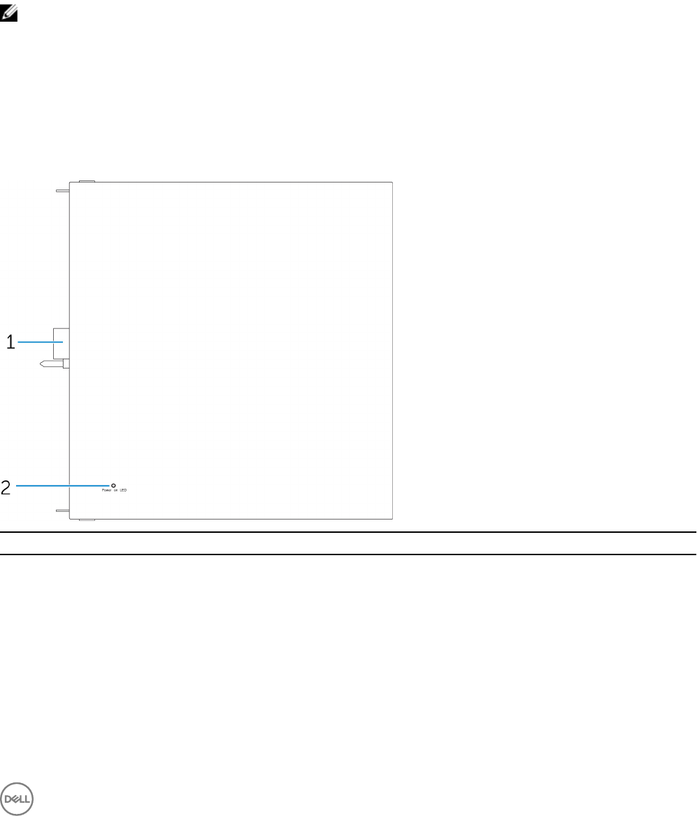
6
I/O Module Overview
The I/O module allows you to install a PCIe x1 card and adds additional ports to your Dell Edge Gateway.
NOTE: The power module is required to be installed with the Dell Edge Gateway to enable and use the I/O expansion
module.
IO module (optional) views
IO module—Front
Features
1 IO module expansion connector and guide pin Connect the IO module to the Edge Gateway.
2 Power status light Indicates the power state of the IO module and the Edge
Gateway.
77
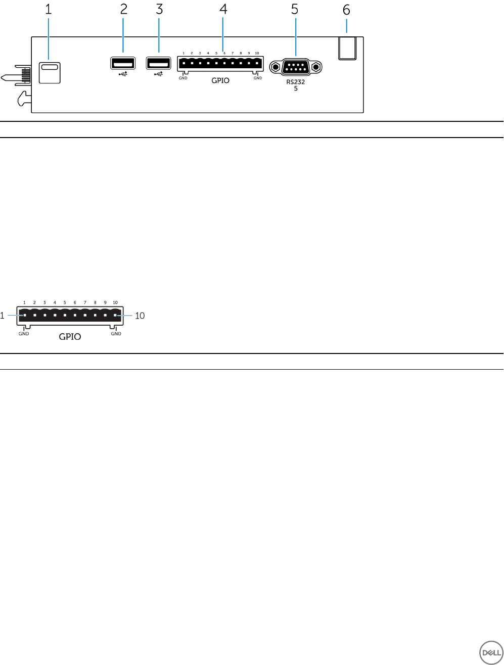
IO module—Top
Features
1 Top release latch Push both the top and bottom release latches to disconnect the
power module from the Edge Gateway.
2 USB 2.0 port For USB 2.0 devices.
3 USB 2.0 port For USB 2.0 devices.
4 GPIO port Connect a GPIO 8–pin cable.
5 RS232 port Connect an RS232 cable.
6 Cable routing slot Route any cable(s) that has to be connected to the PCI card
installed in the IO module.
GPIO connector mapping
Pin Signal PIC Pin Full Pin Name
1 GND
2 GPIO 1 AN22/RPE5/PMD5/RE5
3 GPIO 2 AN23/PMD6/RE6
4 GPIO 3 AN27/PMD7/RE7
5 GPIO 4 AN16/C1IND/RPG6/SCK2/
PMA5/RG6
6 GPIO 5 AN17/C1INC/RPG7/
PMA4/RG7
7 GPIO 6 AN18/C2IND/RPG8/
PMA3/RG8
8 GPIO 21 AN8/RPB8/CTED10/RB8
9 GPIO 22 AN9/RPB9/CTED4/
PMA7/RB9
10 GND
78
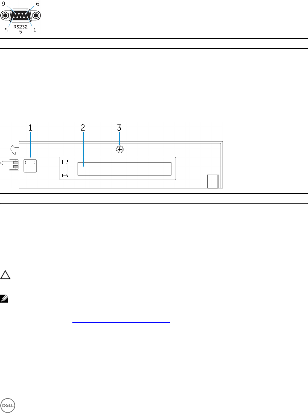
RS232 port on IO expansion module connector mapping
Pin Signal Pin Signal
1 DCD 6 DSR
2 RXD 7 RTS
3 TXD 8 CTS
4 DTR 9 RI
5 GND
IO module—Bottom
Features
1 Bottom release latch Push both the top and bottom release latches to disconnect the
power module from the Edge Gateway.
2 PCIe x1 card slot Install PCIe x1 card on the IO module.
3 IO module cover removal screw Remove the screw to open the box and install the PCIe card.
Setting up the IO module
CAUTION: Before touching anything inside the system, ground yourself by touching an unpainted metal surface. While
you work, periodically touch an unpainted metal surface to dissipate static electricity, which could harm internal
components.
NOTE: Install the PCIe expansion card in the IO expansion module before mounting it on wall mount or DIN rail.
1. Install the PCIe expansion card in the IO expansion module—optional.
For more information, see Installing the PCIe card into the IO module.
2. Attach either wall-mount brackets or a DIN rail mount to the power module as needed.
3. Remove the screw and the dust cap covering the power module expansion port on the Edge Gateway connector.
79
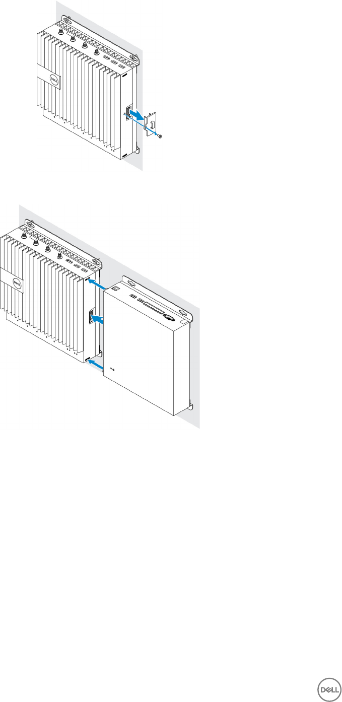
4. Align the power module guide pins to the power module port on the Edge Gateway and slide the power module toward the
Edge Gateway until fully seated.
5. Ensure the top and bottom latches are locked to secure the module to the Edge Gateway.
80
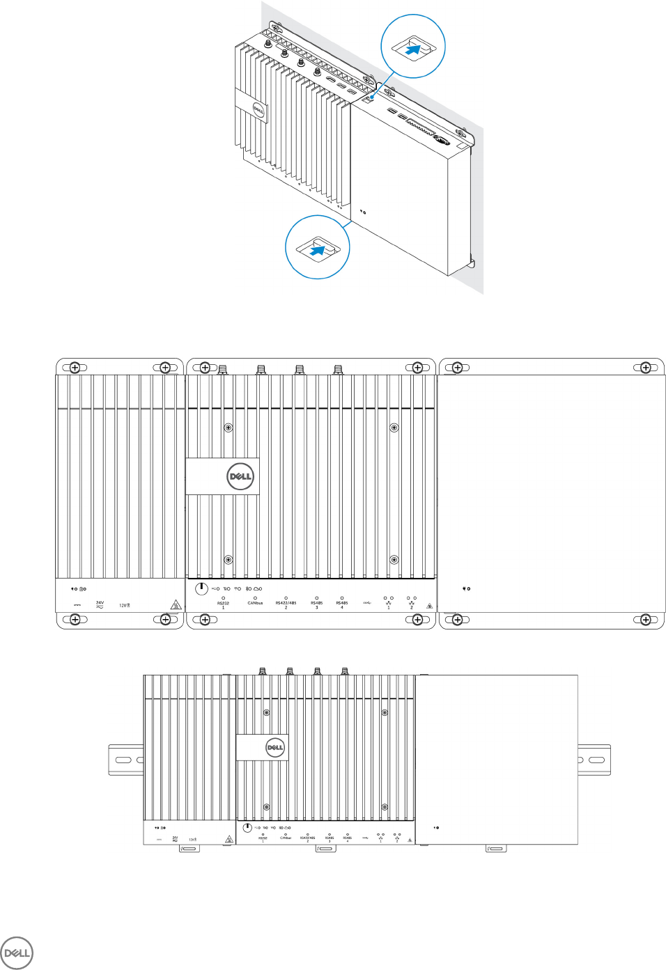
6. Install the Edge Gateway and the IO module along with the power module at a desired location using a wall-mount bracket or
the DIN rail mount.
Wall mount bracket
DIN rail mount
7. Connect to a power source, and press the power button.
81
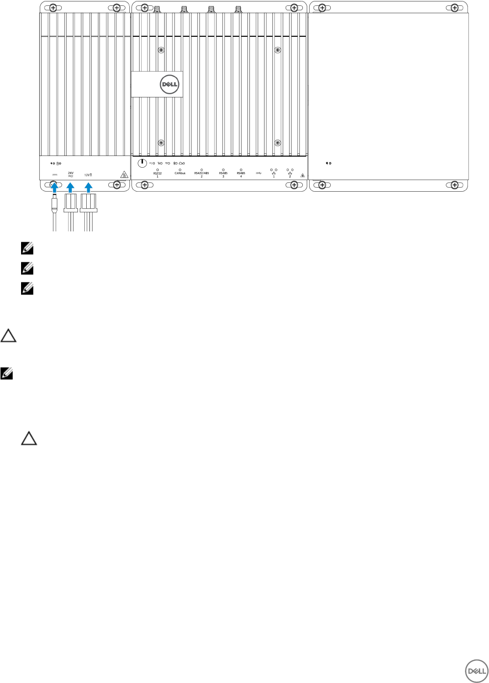
NOTE: Connect a power cable to the 24 V AC/DC or 19.5 V DC power adapter port on the power module.
NOTE: The power adapter and sealed lead-acid battery is sold separately.
NOTE: To enable and use the IO expansion module, you must also install the power module.
Installing the PCIe card into the IO module
CAUTION: Electrical and electronic devices are sensitive to electrostatic discharge (ESD). Exposure to ESD can harm
your device and potentially cause it not to function properly. Ensure that you are properly grounded before handling the
mobile broadband card.
NOTE: Install the PCIe expansion card in the IO expansion module before mounting it on a wall mount or DIN rail.
1. Open the IO module.
a. Remove the dust caps and loosen the access cover screw that secures the IO expansion module to the cover.
b. Slide the module in the direction shown, and then carefully lift the top cover from the module.
CAUTION: Remove the cover carefully to avoid damaging the LED light cable, which is mounted on the bottom of
the cover.
82
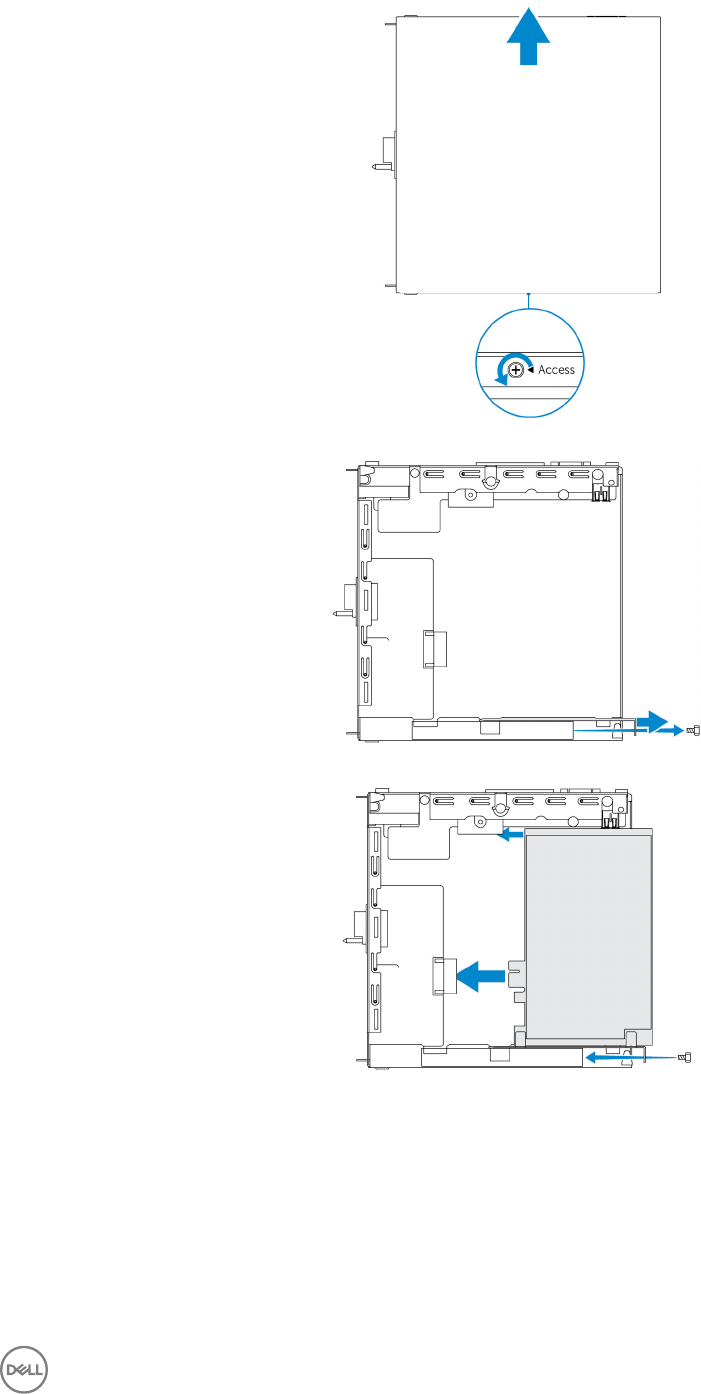
2. Remove the PCIe expansion card-slot cover.
3. Install the PCIe card into the PCIe expansion card slot on the IO expansion module and secure with a screw.
4. Replace the cover on the IO expansion module.
83
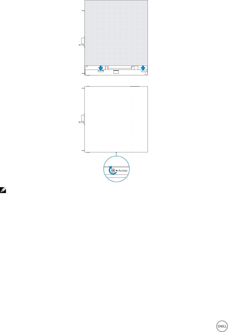
5. Tighten the screw that secures the cover to the IO expansion module.
NOTE: Replace the dust caps on any unused ports and connectors.
84

7
Power Module Overview
The power module allows you to connect additional power sources to your Dell Edge Gateway. The power module allows you to
connect to all three power sources, that is, the 24V AC/DC, 19.5 VDC, and a battery.
NOTE: The Power Module is required to be installed with the Dell Edge Gateway to enable and use the I/O expansion
module.
Power module (optional) views
85
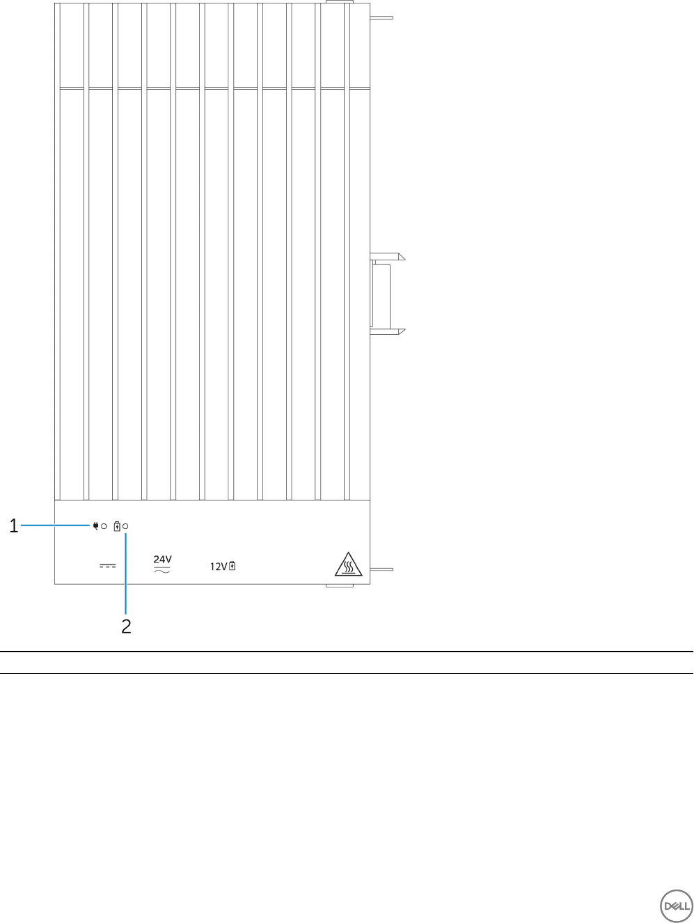
Power module—Front
Features
1 Power status LED Indicates the power‑state of the power module and the Edge
Gateway.
2 Battery status LED Indicates the power‑state of the attached battery.
86
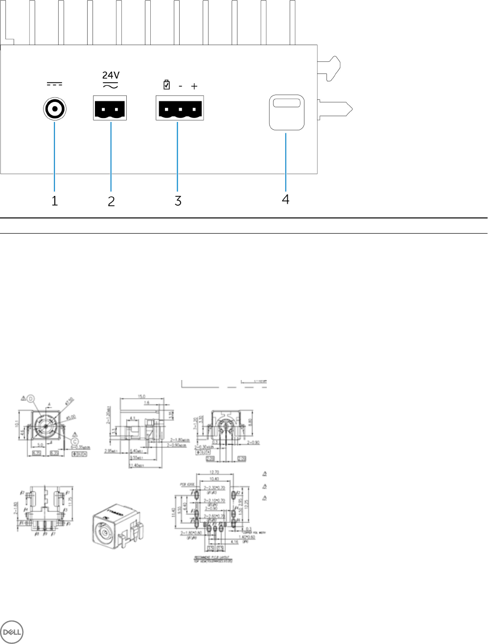
Power module—Bottom
Features
1 19.5 V DC power adapter port Connect a 19.5 V DC power adapter to provide power to your
Edge Gateway.
2 24 V AC/DC power port Connect a 24 V AC/DC power source to power your Edge
Gateway.
3 Sealed lead-acid battery port Connect an external battery to the power module to provide
back-up power in case of power interruption.
4 Bottom release-latch Push both the top and bottom release-latches to disconnect the
power module from the Edge Gateway.
19.5 V DC power adapter port
87
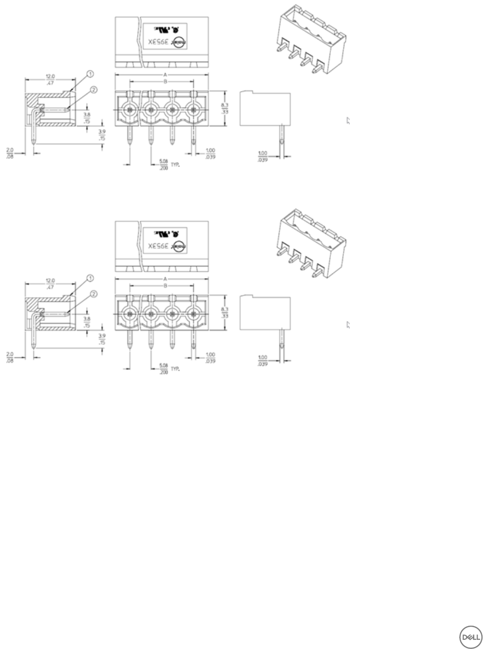
24 V AC/DC power port
Sealed lead-acid battery port
88
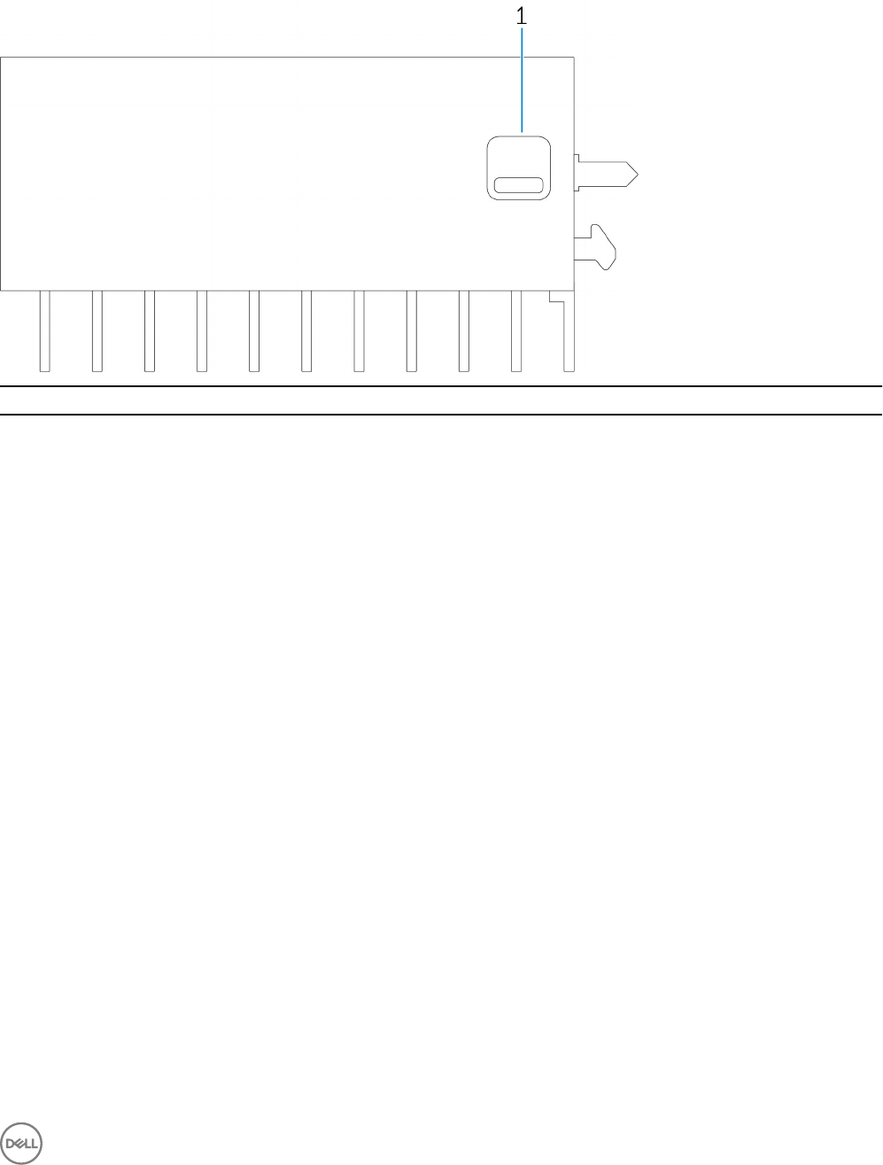
Power module—Top
Features
1 Top release latch Push both the top and bottom release latches to disconnect the
power module from the Edge Gateway.
89
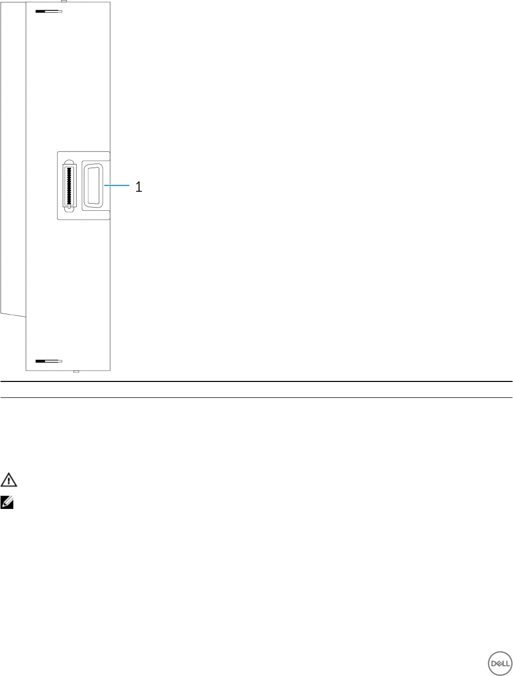
Power module—Right
Features
1 Edge Gateway expansion port Connect the power module to the Edge Gateway for increased
power options and to power the IO expansion module.
Setting up the power module
WARNING: Before installing the power module, shut down the Edge Gateway and disconnect the power cable.
NOTE: To enable and use the IO expansion module, you must also install the power module.
1. Attach either wall-mount brackets or a DIN rail mounts to the power module as needed.
2. Remove the screw and the dust-cap covering the power module expansion port on the Edge Gateway connector.
90
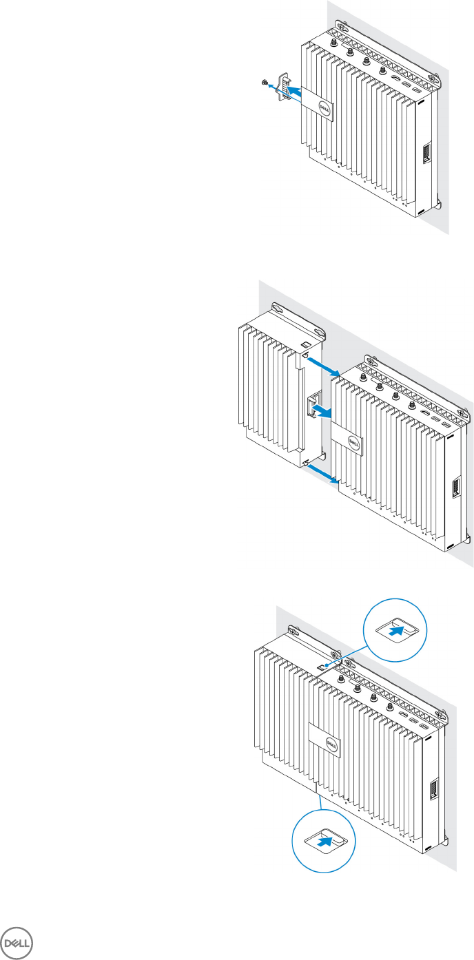
3. Align the power module guide pins to the power module port on the Edge Gateway and slide the power module until fully
seated.
4. Ensure the top and bottom latches are locked to secure the module to the Edge Gateway.
5. Secure the power module to the wall or to the DIN rail.
91
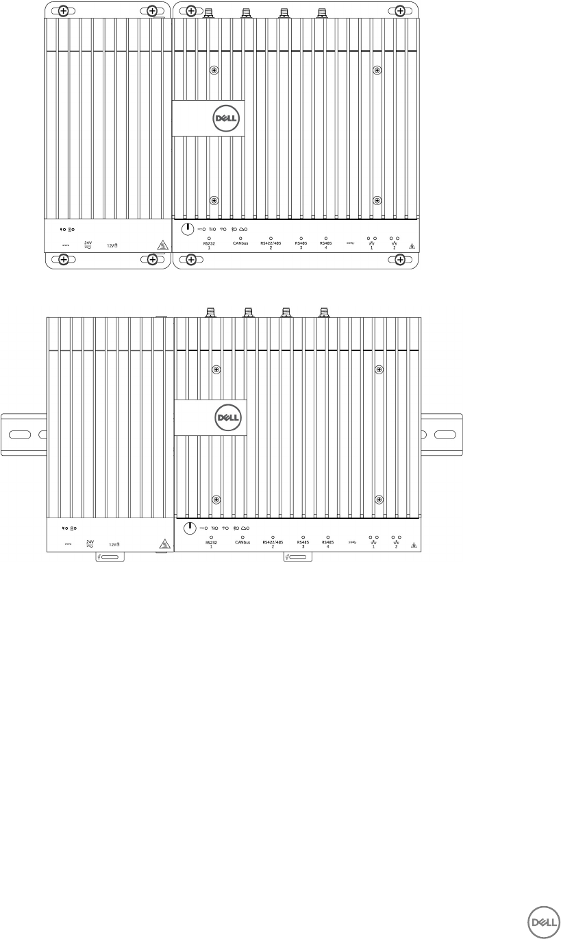
Wall mount bracket
DIN rail
6. Connect the power sources and press the power button on the Edge Gateway.
92
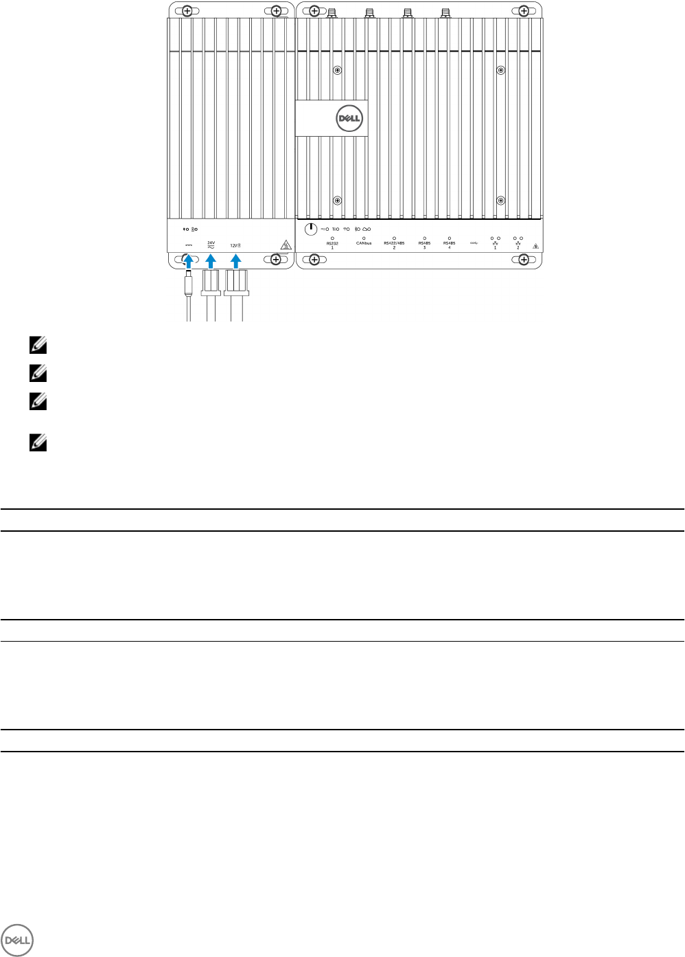
NOTE: You can connect the power cable to the 24V AC/DC, 19 VDC, and a battery simultaneously.
NOTE: The power adapter and sealed lead-acid battery are sold separately.
NOTE: Installing the battery is optional. Dell recommends that you connect a sealed 12V lead-acid battery to the
power module.
NOTE: The 12V lead-acid battery is not sold by Dell.
Specications - Power Module
Dimensions
Height 117.80 mm (4.64 inches)
Width 216 mm (8.50 inches)
Depth 64.20 mm (2.53 inches)
Power requirements
Terminal block connector input voltage/current 24 VAC (50 Hz–60 Hz) or 24 VDC / 15A
Power adapter input voltage/current 19.5 VDC / 6.67A
Battery connector port 12VDC / 15A
Environmental requirements
Ingress Protection Rating IP50
Temperature range:
Operating (with a maximum temperature gradation of
15°C per hour)
• -30°C to 70°C (-22°F to 158°F) when connected to a 24V
AC/DC power source.
• -30°C to 40°C (-22°F to 104°F) when connected to a
power adapter or battery.
93

Environmental requirements
NOTE: The maximum operating temperature is derated
1°C/305m(1000ft) above sea level altitude.
Non-operating -40°C to 70 °C (-40°F to 158°F)
Relative humidity (maximum):
Operating (with maximum humidity gradation of 10%
per hour)
10% to 90% (non-condensing)
Non-operating ((with maximum humidity gradation of
10% per hour)
5% to 95% (non-condensing)
Altitude (maximum, unpressurized):
Operating -15.2m to 5000m (-50ft to 16,404ft)
NOTE: The maximum operating temperature is derated
1°C/305m (1000ft) above sea level altitude.
Storage -15.20 m to 10,668 m (-50 ft to 35,000 ft)
94
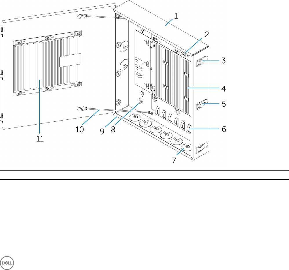
8
Enclosure Overview
The rugged enclosure allows you to install the Dell Edge Gateway in harsh environment’s, like locations that are subjected to high
temperature variation, dust particle, and humidity.
Enclosure (optional) view
Enclosure - Side
Features
1 Rugged enclosure Install the Edge Gateway in the rugged enclosure when using in
harsh environments condition.
2 Intrusion detection switch Detects unauthorized system access.
3 Door securing latch (3) Secure the enclosure.
4 Thermal ribs Dissipates the heat generated by the system.
5 Latch lock-out Secure the system with a padlock.
95
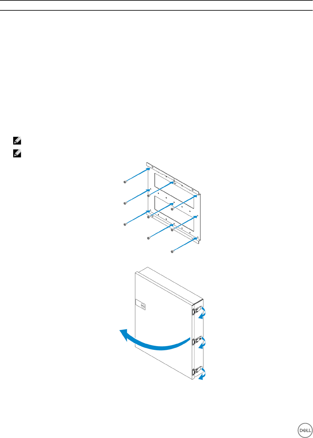
Features
6 Cable tie-o (17) To prevent accidental cable disconnection, tie all cables to the
cable tie-o guides.
7 Cable conduit openings (8) Route the cables through the conduits (1 inch and 0.75 inch
diameter).
8 Primary ground (internal) Connect the grounding cable to the system.
9 Primary ground (external) Connect the grounding cable to the system.
10 Door-stop cables (2) Restricts the door from opening.
11 Door thermal ribs Dissipates the heat generated by the system.
Setting up the enclosure
1. Install the enclosure’s wall-mount bracket at a desired location and secure it to the wall using the wall-mount screws.
NOTE: Ensure that the notch on the bracket is on the top.
NOTE: The wall-mount screws are not included with the enclosure.
2. Open the enclosure.
3. Place the enclosure on the wall-mount bracket, and align the tab on the back of the enclosure so that it ts into the notch on
the wall bracket.
96
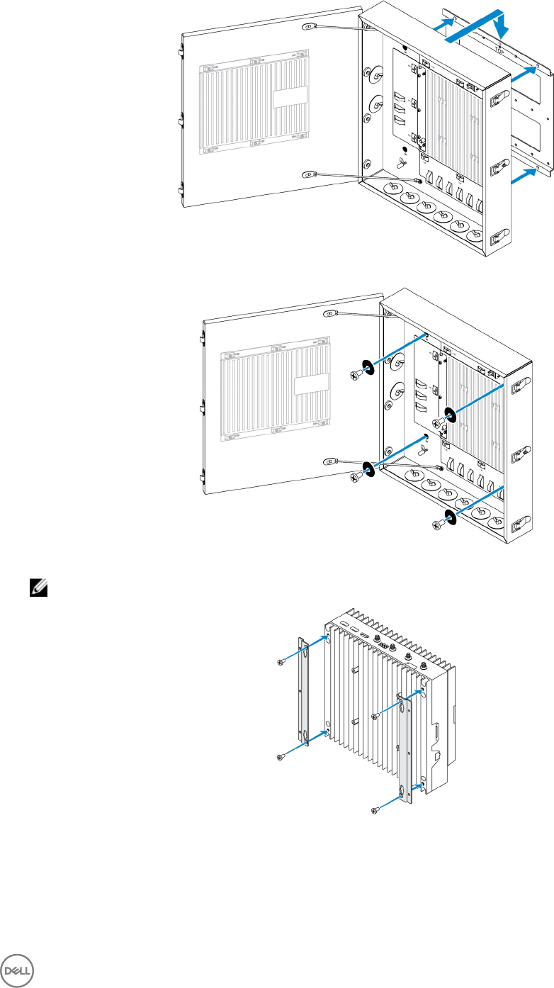
4. Secure the enclosure to the wall bracket by using the rubber washers and screws.
5. Secure the enclosure mounting brackets to the Edge Gateway by using the screws.
NOTE: Before attaching the brackets to the Edge Gateway, note the correct orientation of the brackets.
6. Position the Edge Gateway onto the enclosure’s two locator pins, and then place and tighten the screws to secure the Edge
Gateway to the enclosure.
97
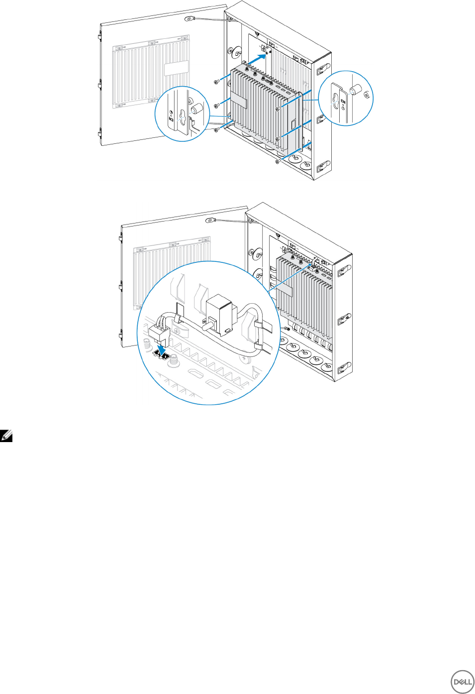
7. Connect the intrusion switch to the system.
8. Remove the desired conduit plugs on the bottom or the left side of the enclosure and install the wiring conduits.
NOTE: To ensure that dust and water does not enter the enclosure, install a conduit rated as IP65.
98
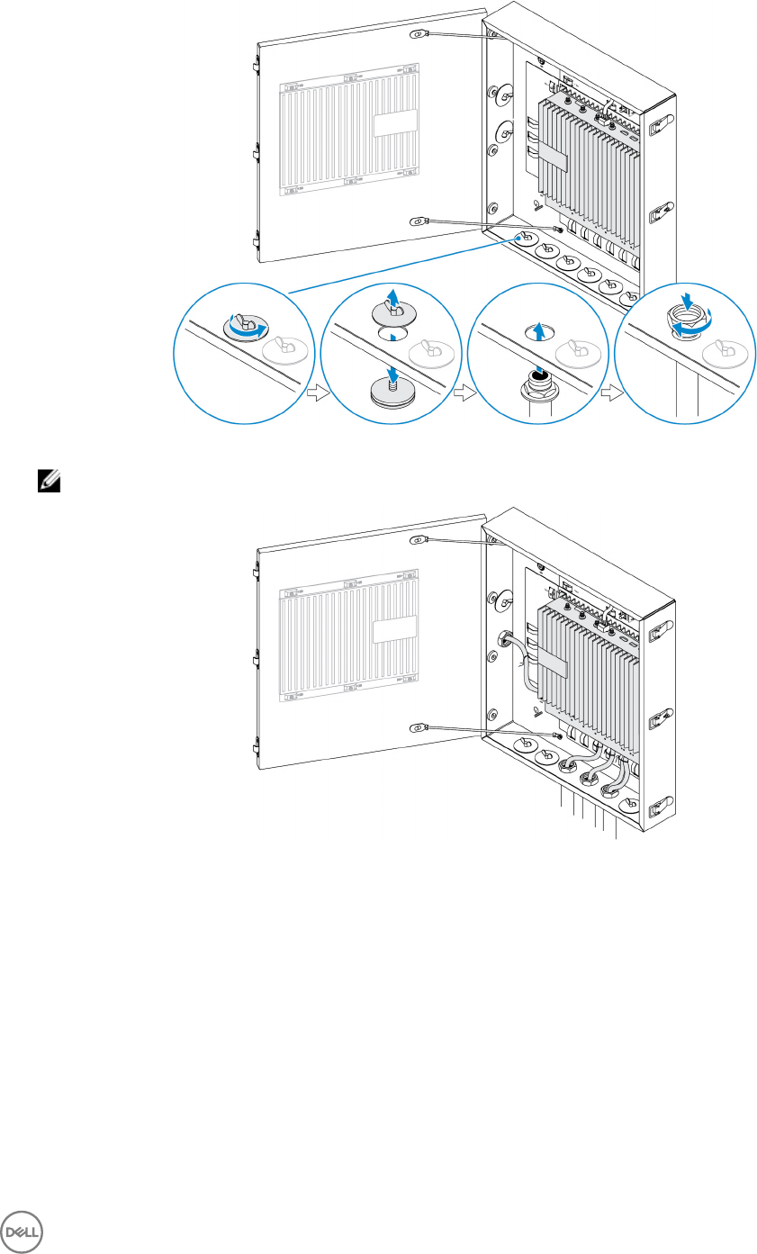
9. Route the cables through the conduits and connect the cables to the desired connectors.
NOTE: To reduce the risk of accidental cable disconnection, tie all cables to the cable tie-o guides.
10. Close and securely latch the enclosure door.
99
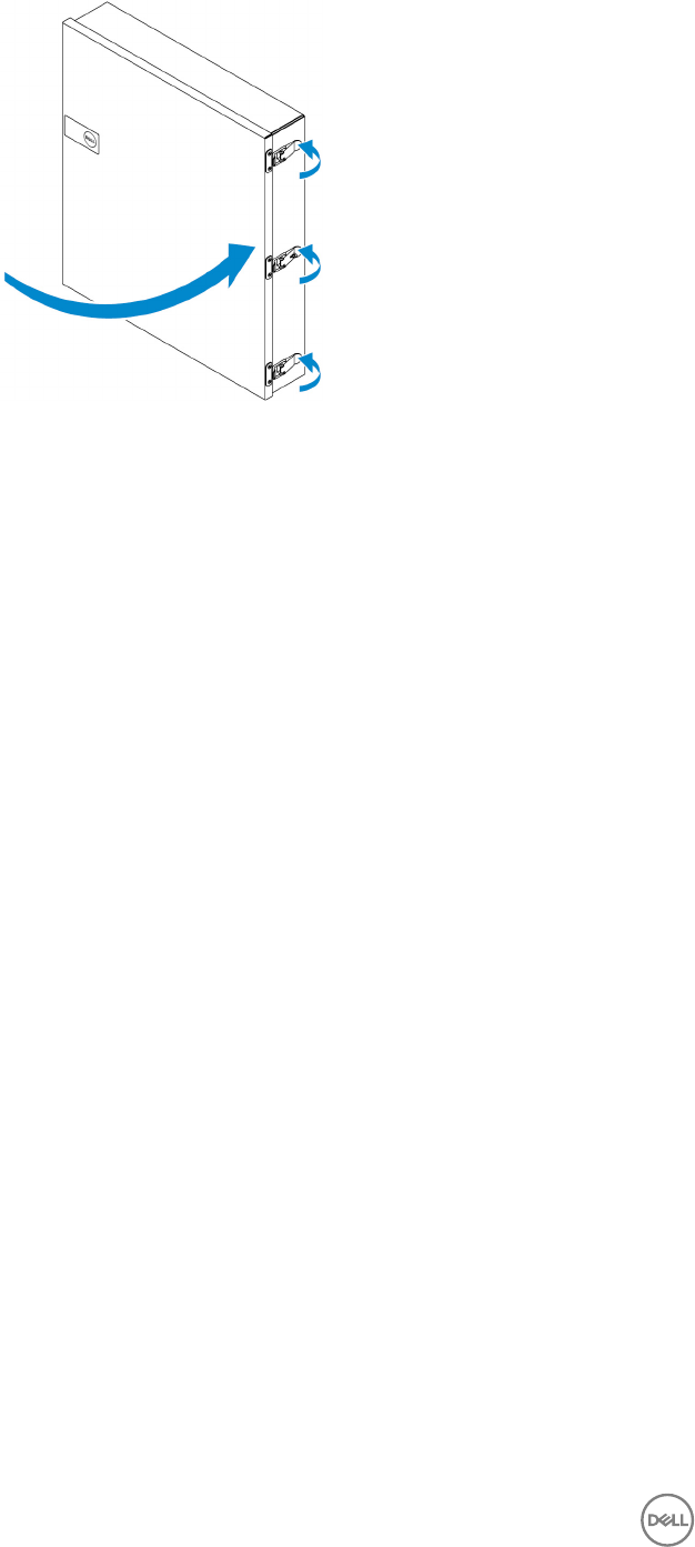
100
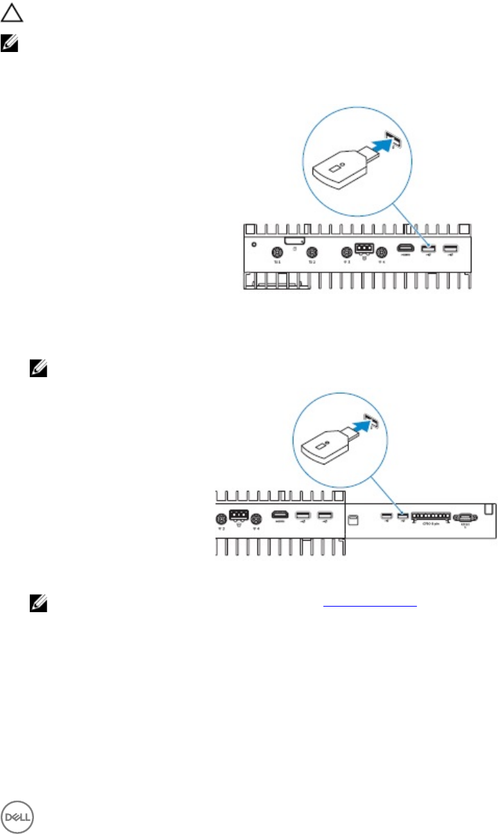
9
Setting up the ZigBee dongle
CAUTION: Do not connect the ZigBee dongle if the Edge Gateway is installed inside the enclosure.
NOTE: Do not connect the ZigBee dongle to the internal USB port of the IO expansion module.
1. Shut down your Edge Gateway.
2. Connect the ZigBee dongle to any external USB port on your Edge Gateway.
or
Connect the ZigBee dongle to any external USB port on the IO module.
NOTE: Do not connect the ZigBee dongle to the internal USB port of the IO expansion module.
3. Turn on the Edge Gateway and complete the setup.
NOTE: For ZigBee development information, see www.silabs.com/.
101

10
BIOS defaults
General
These settings are set at the factory and are not congurable.
System conguration
5000 5100
Integrated NIC Enabled w/PXE Enabled w/PXE
Integrated NIC 2 Disabled Disabled
Serial port Enabled Enabled
I/O Module Enabled Enabled
SATA Operation AHCI AHCI
Drives Enabled (SSD-1) Enabled (SSD-1)
SMART Reporting Disabled Disabled
USB Conguration Enabled (Boot support, front USB ports,
rear USB ports)
Enabled (Boot support, front USB ports,
rear USB ports)
Miscellaneous Devices Enabled (WWAN, WLAN, Bluetooth,
CANBus)
Enabled (WWAN, WLAN, Bluetooth,
CANBus)
Power Button Disabled Disabled
Watchdog Timer Support Disabled Disabled
Security
5000 5100
Admin Password Not set Not set
System Password Not set Not set
Internal HDD password Not set Not set
Strong Password Disabled Disabled
Password Conguration 4~32 character length 4~32 character length
102

5000 5100
Password Bypass Disabled Disabled
Password Change Enabled Enabled
TPM 1.2 Security Enabled
Disabled (PPI Bypass for Enable
Commands, PPI Bypass for Disable
Commands, Clear)
Enabled
Disabled (PPI Bypass for Enable
Commands, PPI Bypass for Disable
Commands, Clear)
TPM 2.0 Security Enabled
Disabled (PPI Bypass for Enable
Commands, PPI Bypass for Disable
Commands, Attestation Enable, Key
Storage Enable, SHA-256, Clear)
Enabled
Disabled (PPI Bypass for Enable
Commands, PPI Bypass for Disable
Commands, Attestation Enable, Key
Storage Enable, SHA-256, Clear)
Chassis Intrusion Disabled Disabled
CPU XD Support Enabled Enabled
OROM Keyboard Access Enabled Enabled
Admin Setup Lockout Disabled Disabled
Secure Boot
5000 5100
Secure Boot Enable Disabled Disabled
Expert Key Management Disabled Disabled
Performance
5000 5100
Intel SpeedStep Enabled Enabled
C-States Control Enabled Enabled
Limit CPUID Value Disabled Disabled
Power Management
5000 5100
AC Recovery (Desktop) Power o Power o
Auto On Time Disabled Disabled
Wake on LAN/WLAN Disabled: Turns the system on from
hibernation (S4) and power o (S5) state
Disabled: Turns the system on from
hibernation (S4) and power o (S5) state
103

NOTE: With USB wake support from power o (S5), a wired keyboard or mouse is able to wake the system if connected
to the designated USB port (marked with the Smart Power On icon). For wireless keyboard and mice, if both devices
share the same USB dongle and the dongle is inserted into the designated USB port, both keyboard and mouse can wake
the system. For wireless keyboard only or mouse only, either can wake the system as long as the dongle is inserted into
the designated USB port.
POST Behavior
5000 5100
Keyboard Errors Enabled Enabled
Fastboot Thorough Thorough
Numlock LED Enabled Enabled
Extend BIOS POST Time 0 seconds 0 seconds
Warnings and Errors Prompt on Warnings and Errors Prompt on Warnings and Errors
Maintenance
5000 5100
Service tag Set by the factory Set by the factory
Asset tag Optional user entry Optional user entry
SERR message Enabled Enabled
BIOS Downgrade Enabled Enabled
Data Wipe Disabled Disabled
BIOS Recovery Enabled Enabled
104

11
Other documents you may need
Besides this Installation and Operations Manual, you may need to see the following guides available at https://www.dell.com/
support/manuals.
•Dell Edge Device Manager Getting Started Guide
•Dell SupportAssist For Dell OpenManage Essentials Quick Start Guide
•Dell Command | Monitor User's Guide
Additionally, for more information on using Dell Data Protection | Encryption see the documentation for the software at https://
www.dell.com/support/manuals.
105

12
Contacting Dell
To contact Dell for sales, technical assistance, or customer service issues:
1. Go to www.dell.com/contactdell.
2. Verify your country or region in the drop-down list at the bottom of the page.
3. Select the appropriate service or support link based on your requirement or choose the method of contacting Dell that is
convenient for you.
Dell provides several online and telephone-based support and service options. Availability varies by country and product, and
some services may not be available in your area.
NOTE: If you do not have an active internet connection, you can nd the contact information on your purchase
invoice, packing slip, bill, or Dell product catalog.
Regulatory and environmental compliance
Product-related conformity assessment and regulatory authorizations including Product Safety, Electromagnetic Compatibility
(EMC), Ergonomics, and Communication Devices relevant to this product, as well as the Data Sheet for this product, are available at
dell.com/regulatory_compliance.
Details of Dell’s environmental stewardship program to conserve product energy consumption, reduce or eliminate materials for
disposal, prolong product life span and provide eective and convenient equipment recovery solutions may be viewed at
www.dell.com/environment. Product-related conformity assessment, regulatory authorizations, and information encompassing
Environmental, Energy Consumption, Noise Emissions, Product Materials Information, Packaging, Batteries, and Recycling relevant to
this product may be viewed by clicking the Design for Environment link on the webpage.
106
