Dell Poweredge C1100 Using The Baseboard Management Controller User Manual Power Edge Setup Guide3 In Id
User Manual: Dell poweredge-c1100 - PowerEdge C1100 Using the Baseboard Management Controller
Open the PDF directly: View PDF ![]() .
.
Page Count: 32

www.dell.com | support.dell.com
Dell™ PowerEdge™ Systems
Using the Baseboard
Management Controller

Notes, Cautions, and Warnings
NOTE: A NOTE indicates important information that helps you make better use of your computer.
CAUTION: A CAUTION indicates potential damage to hardware or loss of data if instructions are not followed.
WARNING: A WARNING indicates a potential for property damage, personal injury, or death.
____________________
Information in this document is subject to change without notice.
© 2009 Dell Inc. All rights reserved.
Reproduction of these materials in any manner whatsoever without the written permission of Dell Inc. is strictly forbidden.
Trademarks used in this text: Dell, the DELL logo, PowerEdge are trademarks of Dell Inc.; Microsoft, Windows, and Internet Explorer are
registered trademarks of Microsoft Corporation; Linux is the registered trademark of Linus Torvalds; Java is a registered trademark of Sun
Microsystems, Inc. or its subsidiaries in the United States and other countries.in the United States and other countries.
Other trademarks and trade names may be used in this document to refer to either the entities claiming the marks and names or their products.
Dell Inc. disclaims any proprietary interest in trademarks and trade names other than its own.
December 2009 Rev. A00

Contents 3
Contents
Introduction . . . . . . . . . . . . . . . . . . . . . . . . . . . . . . . . . . . . 5
BMC key Features and Functions . . . . . . . . . . . . . . . . . . . . . . . . . 5
Using the Web UI. . . . . . . . . . . . . . . . . . . . . . . . . . . . . . . . . . 5
Logging into the Web User Interface . . . . . . . . . . . . . . . . . . . . . . . 6
System Features . . . . . . . . . . . . . . . . . . . . . . . . . . . . . . . . . . 6
System Summary . . . . . . . . . . . . . . . . . . . . . . . . . . . . . . . 6
Component Information. . . . . . . . . . . . . . . . . . . . . . . . . . . . 7
Power Management . . . . . . . . . . . . . . . . . . . . . . . . . . . . . 7
System Event Log . . . . . . . . . . . . . . . . . . . . . . . . . . . . . . . 7
Firmware Update . . . . . . . . . . . . . . . . . . . . . . . . . . . . . . . 9
Sensors . . . . . . . . . . . . . . . . . . . . . . . . . . . . . . . . . . . . . . . 9
Fan Probes Information . . . . . . . . . . . . . . . . . . . . . . . . . . . 10
Temperature Probes . . . . . . . . . . . . . . . . . . . . . . . . . . . . 10
Voltage Probes . . . . . . . . . . . . . . . . . . . . . . . . . . . . . . . 11
Console . . . . . . . . . . . . . . . . . . . . . . . . . . . . . . . . . . . . . . 12
Console Redirection and Virtual Media . . . . . . . . . . . . . . . . . . 12
iBMC KVM . . . . . . . . . . . . . . . . . . . . . . . . . . . . . . . . . . . . 13
File. . . . . . . . . . . . . . . . . . . . . . . . . . . . . . . . . . . . . . 13
View . . . . . . . . . . . . . . . . . . . . . . . . . . . . . . . . . . . . . 13
Macros . . . . . . . . . . . . . . . . . . . . . . . . . . . . . . . . . . . 14
Tools. . . . . . . . . . . . . . . . . . . . . . . . . . . . . . . . . . . . . 14
iBMC Virtual Media . . . . . . . . . . . . . . . . . . . . . . . . . . . . . . . 15
Virtualizing Devices . . . . . . . . . . . . . . . . . . . . . . . . . . . . . 16
Mapping a Virtual Media Drive . . . . . . . . . . . . . . . . . . . . . . . 16
Unmapping a Virtual Media Drive . . . . . . . . . . . . . . . . . . . . . 16
Console Redirect Configuration . . . . . . . . . . . . . . . . . . . . . . . . . 16
Email Alert Destination . . . . . . . . . . . . . . . . . . . . . . . . . . . 17
Network Configuration. . . . . . . . . . . . . . . . . . . . . . . . . . . . . . 17
Platform Events . . . . . . . . . . . . . . . . . . . . . . . . . . . . . . . 19
Serial Over LAN Configuration . . . . . . . . . . . . . . . . . . . . . . . 20
Services . . . . . . . . . . . . . . . . . . . . . . . . . . . . . . . . . . . 20

4Contents
Web Server . . . . . . . . . . . . . . . . . . . . . . . . . . . . . . . . . 20
SSL Main Menu . . . . . . . . . . . . . . . . . . . . . . . . . . . . . . . 21
Platform Event Alerts . . . . . . . . . . . . . . . . . . . . . . . . . . . . 23
Users . . . . . . . . . . . . . . . . . . . . . . . . . . . . . . . . . . . . 24
IPMI 1.5 / 2.0 Command Support List. . . . . . . . . . . . . . . . . . . . . . . 24

Using the Baseboard Management Controller 5
Introduction
This section introduces the A BMC and includes the requirements for web-based graphical user
interface (GUI), keyboard, video, and mouse (KVM), and virtual media.
BMC Key Features and Functions
The following lists the supported features of the BMC:
• IPMI v1.5 and v2.0
• Out-of-band monitoring and control for sever management over LAN
• Dedicated 10/100 NIC for remote management over a network
• Information report includes main board part number, product name, manufacturer, etc.
• Health status/hardware monitoring report
• Events log, view, and clear
• Event notification using chassis LED indicator and Platform Event Trap (PET)
• Platform Event Filtering (PEF) to take selected action for selected events, including NMI and
SMI
• Chassis management including power control and status report, front panel buttons, LED
control, Secure Mode, and Boot Option
• Watchdog and auto server re-start and recovery
• Multi-session user and alert destination for LAN channel
• IPMB connector to enable advanced server management communication with BMC
Using the Web UI
The BMC firmware features an embedded web server, enabling users to connect to the BMC using
an Internet browser (Microsoft
®
Internet Explorer™) without needing to install KVM and virtual
storage software on a remote console.
Web-based GUI is supported on the following browsers:
Microsoft Windows:
• Internet Explorer 6 and 7
• Mozilla
®
Firefox
®
2.0 or later
Linux:
Mozilla Firefox 2.0 or later
NOTE: Before using the web user interface, ensure that the firewall settings are configured to enable
access to the following ports: 8890 (KVM), 9000 (storage), 9001, 9002, and 9003.

6Using the Baseboard Management Controller
www.dell.com | support.dell.com
Logging into the Web User Interface
Enter the BMC-embedded server IP address or URL into the address bar of the web browser. The
BMC interface has a default of (DHCP\Static). Enter the system BIOS setup with <F2> to
change these settings.
When connecting to the BMC, the login screen prompts for the username and password. This
authentication with Secure Sockets Layer (SSL) protection prevents unauthorized intruders from
gaining access to the BMC web server. Once authentication is passed, you can manage the server by
privilege. At the same time, the PHP Hypertext Preprocessor (PHP) records all user information,
including user ID and privilege.
System Features
System Summary
The
System Summary
tab enables you to view the firmware version, hardware version, and IPv4
information. Click the
System
tab to view the Remote Management Controller.
Table 1-1. BMC Information
BMC Information Description
Date/Time Current time in the form:
Day MMM DD HH:MM:SS:HH YYYY
Firmware Version Dell Remote Management Controller firmware version.
Firmware Updated Date the firmware was last flashed in the form:
Day MMM DD HH:MM:SS:HH YYYY
MAC Address MAC address for the Baseboard Management Controller.
Table 1-2. IPv4 Information
IPv4 Information Description
Enabled Yes or No
IP Address The 32-bit address that identifies the NIC to a host. The value is in
the dot separated format, such as 143.166.154.127.
Gateway The address of a router or a switch. The value is in the dot separated
format, such as 143.166.154.1.
Subnet Mask The Subnet Mask identifies the parts of the IP Address that are the
Extended Network Prefix and the Host Number. The value is in the
dot separated format, such as 255.255.0.0.

Using the Baseboard Management Controller 7
Component Information
Server Board Information
Including Serial Number, BIOS Version, Product ID, Manufacturer and Manufacture Date.
CPU Information
Including CPU ID, Status, Socket, Manufacturer, Model and Frequency.
Memory Information
Including Memory ID, Status, Socket, Module Size, Model and Frequency.
Power Management
This feature enables the administrator to power on or power down the system remotely.
Select a
Power Control Operation
.
Click
Apply
to enable the selected
Power Control Operation
.
System Event Log
The System Event Log (SEL) page displays system events that occur on the managed system. The
SEL is generated by the Baseboard Management Controller (iBMC) or BIOS on the managed
system.
Table 1-3. Power Status
Power Status Description
Power Status Yes or No
Table 1-4. Power Control Operation Options
Power Control Operation Description
Power On System Powers on the system.
Power Off System Powers off the system.
Reset System Reboots system without powering off (warm boot).
Power Cycle
System
Powers off, then reboots system (cold boot).
NMI Sends Non-Masking Interrupt to halt system operation.
Soft Shutdown Shuts down system.
8Using the Baseboard Management Controller
www.dell.com | support.dell.com
The SEL lists the following information about system events: severity, a date/time stamp, and a
short description. The list can be sorted by clicking any column heading in the SEL. Subsequent
clicks on the column headings reverse the sort order.
Table 1-5 describes the severity conditions by icon.
Click
System Event Log
to view specific event information. Table 1-6 shows the available functions
located at the top right corner of the screen.
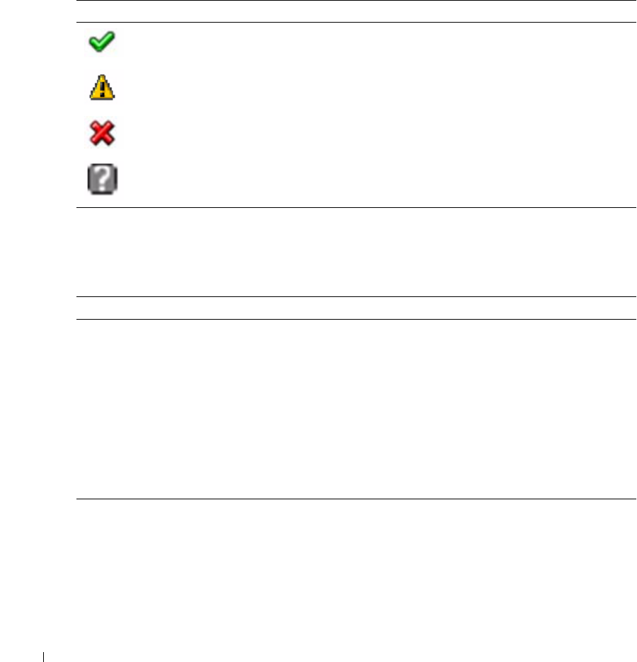
Table 1-5. Severity Condition Icons
Icon Description
Normal event
Non-critical event
Critical event
Unknown
Table 1-6. System Event Log Functions
Function Description
Print Prints the SEL in the sort order that appears on screen.
Clear Log Clears the SEL.
NOTE: The Clear Log button only appears if you have permission.
Save As Opens a pop-up window that enables you to save the SEL to a
directory of your choice. The severity of the condition is indicated and
saved in the log file.
The Date/Time is stored in ascending order. Blank dates from the
screen are saved as <System Boot> in the file.
Refresh Reloads the SEL page

Using the Baseboard Management Controller 9
Firmware Update
Use the Firmware Update feature to upgrade to the latest firmware version. The following data is
included in the iBMC firmware package:
• Compiled iBMC firmware code and data
• Web-based user interface, JPEG, and other user interface data files
• Default configuration files
NOTE: The firmware update retains the current iBMC settings.
Updating the iBMC Firmware
NOTE: Before beginning the firmware update, download the latest firmware version and save it on your
local system. During the process of firmware update, the AC power of the managed system cannot be
unplugged and the Web GUI cannot be closed.
1
Browse to, or Enter the path on your system where the firmware image file resides.
Example:
C:\Updates\V1.0\<image_name>
The default firmware image name is
firmimg.ast2050.dcs
.
2
Select the
Update Type
as
Normal
or
Forced
(The default value is
Normal
).
Normal:
An update operation will occur only when the BMC validates the target board, target
product and version number.
Forced:
Forced update makes the BMC update the image without validating target board,
target product and version number.
3
Click
Update
.
The update might take several minutes. When the update is completed, a dialog box appears.
4
Click
OK
to close the session and automatically log out.
5
After the iBMC resets, click
Log In
to log in to the iBMC again.
Sensors
The
Sensor
menu provides information about system hardware such as the fan speed, internal
temperature, and voltage.
10 Using the Baseboard Management Controller
www.dell.com | support.dell.com
Fan Probes Information
Table 1-7 shows the icons for the fan probes.
View the status and readings of the fan probes. There might be one or more fans, numbered [1
through
n
], measured in revolutions per minute (RPM).
Temperature Probes
Table 1-9 shows the icons for the temperature probes.
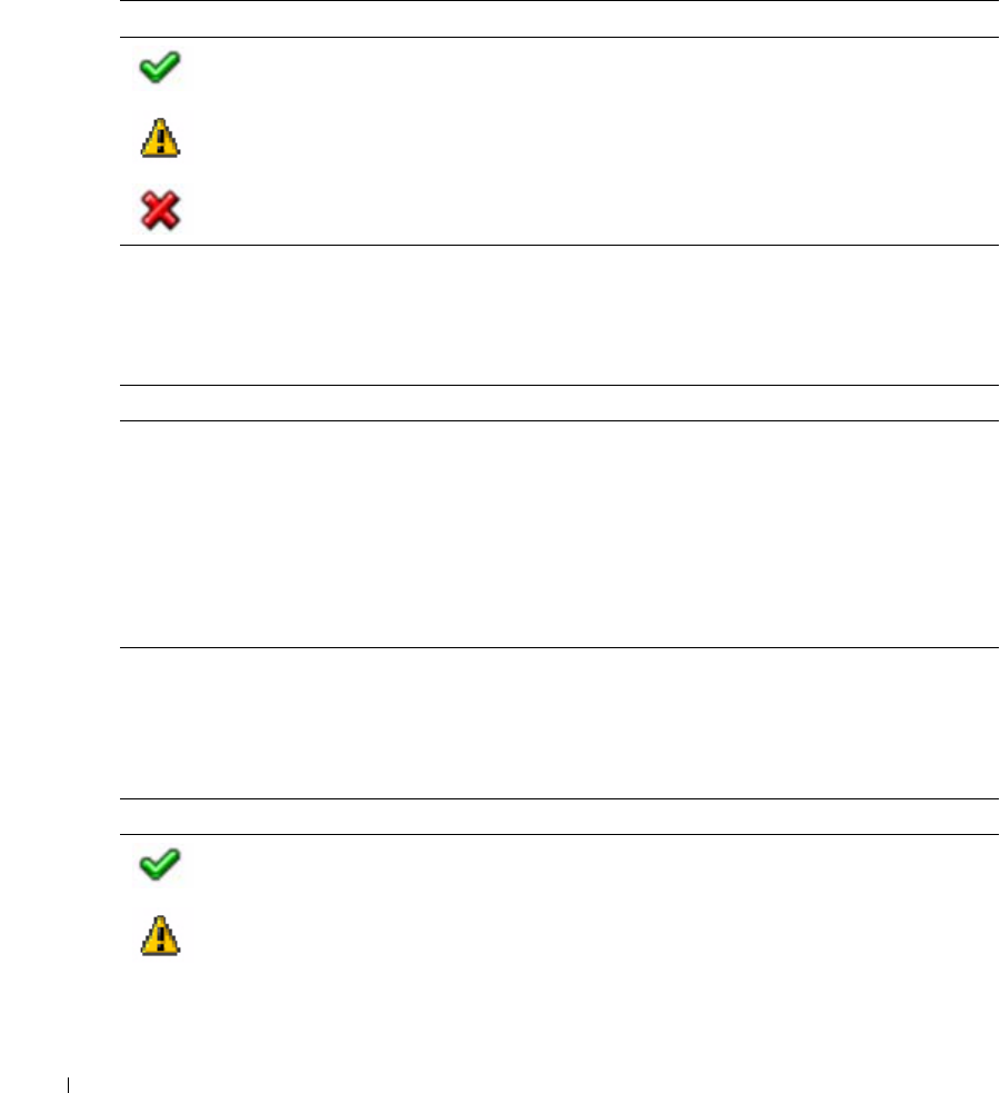
Table 1-7. Fan Probe Status Icons
Icon Description
OK
Warning alert issued
Failure alert issued
Table 1-8. Fan Probe Status Icons
Item Description
Status See Table 1-7.
Probe Name Name of the sensor.
Reading The number of revolutions per minute (RPM).
Warning Threshold Minimum and maximum threshold, measured in RPM, at which a
warning alert is issued.
Failure Threshold Minimum and maximum threshold, measured in RPM, at which a
failure alert is issued.
Table 1-9. Temperature Probe Status Icons
Icon Description
OK
Warning alert issued
Using the Baseboard Management Controller 11
View the status and readings of the temperature probes. The temperature probes might be
implementation dependent.
Voltage Probes
Table 1-11 shows the icons for the voltage probes.
View the status and readings of the voltage probes. The configuration of the probes might be
implementation dependent. There might be one or more processors, numbered [1 through n],
measured in volts.
The following are typical voltage probes. Your system might have these and/or others present.
• CPU [n] VCORE
• System Board 0.9V PG
Failure alert issued
Table 1-10. Probe List Table
Item Description
Status See Table 1-9.
Probe Name Name of the sensor.
Reading The current temperature, measured in degrees centigrade.
Warning Threshold Minimum and maximum threshold, measured in degrees centigrade,
at which a warning alert is issued.
Failure Threshold Minimum and maximum threshold, measured in degrees centigrade,
at which a failure alert is issued.
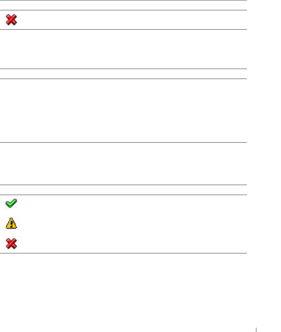
Table 1-11. Voltage Probe Status Icons
Icon Description
OK
Warning alert issued
Failure alert issued
Table 1-9. Temperature Probe Status Icons
Icon Description

12 Using the Baseboard Management Controller
www.dell.com | support.dell.com
• System Board 1.5V ESB2 PG
• System Board 1.5V PG
• System Board 1.8V PG
• System Board 3.3V PG
• System Board 5V PG
• System Board Backplane PG
• System Board CPU VTT
• System Board Linear PG
Console
Console Redirection and Virtual Media
The
Console Redirection
page enables you to use the display, mouse, and keyboard on the local
management station to control the corresponding devices on a remote managed system. You can
run a maximum of four simultaneous console redirection sessions.
NOTE: Before you can use the console redirection feature, your browser must have the Java Video
Viewer installed. This feature needs Java 1.5.15 or later installed on the host system. If the iBMC detects
that the Java Video Viewer is not installed, you are prompted to install it.
NOTE: Sometimes the Console is referred to as the Session Viewer.
NOTE: The recommended display resolution on the management station (or client) is at least 1280 x 1024
pixels at 60 Hz with 32 bit color. You cannot view the console in full screen mode if your monitor resolution
is less than this minimum.
Table 1-12. Voltage Probe List
Item Description
Status See Table 1-11.
Probe Name Name of the sensor.
Reading Good indicates that the current voltage is between the minimum and
maximum warning thresholds.
Table 1-13. Console Redirection Descriptions
Item Description
Console Redirection Enabled Yes indicates that Console Redirection is enabled.
Video Encryption Enabled Yes indicates that Video Encryption is enabled.
Max Sessions Displays the maximum number of console redirection sessions that
are possible.

Using the Baseboard Management Controller 13
The
Virtual Media
page allows you to virtualize a diskette image or drive. Virtual media enables a
floppy image, floppy drive or CD/DVD drive on your system to be available on the managed
system's console as if the floppy image or drive were present on the local system.
The
Virtual Media
page displays the floppy image, floppy drive, CD/DVD drive, or ISO image on
the management console that is currently virtualized.
iBMC KVM
The iBMC KVM client's main menu consist of five menu options which are used to provide access
to functions available through the viewer:
File
,
View
,
Macros
,
Tools
, and
Help
. To launch a KVM
session, click
Launch KVM
.
File
To capture an image, click
Capture to File
from the
File
menu. A dialog box is displayed that
enables you to save the file to a specified location.
Exit
To close the Java Video Viewer, select
Exit
from the
File
menu.
View
The
View
menu contains the following options:
Refresh
,
Full Screen Mode/Windowed Mode
, and
Fit
.
Refresh
To refresh the view of the Java Video Viewer
,
click
Refresh
from the
View
menu. This results in the
Java Video Viewer requesting a reference video frame from the server.
Full Screen/Windowed
To enable full screen mode for the Java Video Viewer, select
Full Screen
from the
View
menu. To
exit full screen mode, select
Windowed
from the
View
menu.
Table 1-14. Virtual Media Descriptions
Item Description
Max Sessions Specify a number of sessions to support simultaneously.
Active Sessions The current number of console redirection sessions.
Virtual Media Encryption Enable and disable Video Encryption.

14 Using the Baseboard Management Controller
www.dell.com | support.dell.com
Fit
To resize the Java Video Viewer window to the minimum size that is need to display the server's
video, select the
Fit
menu item from the
View
menu. This menu item is not available in full screen
mode.
Macros
The
Macros
menu, consists of a drop-down list of the various keyboard shortcuts available on the
remote system. When you select the macro or the hotkey specified for the macro, the macro is
executed on the remote system. The Java Video Viewer creates the following macros the first time
the session is launched:
• <Ctrl><Alt><Delete>
• <Alt><Tab>
•<Alt><Esc>
• <Ctrl><Esc>
•<Alt><Space>
• <Alt><Enter>
• <Alt><Hyphen>
•<Alt><F4>
•<PrtScn>
•<Alt><PrtScn>
•<F1>
•<Pause>
•<Tab>
• <Cntrl-Enter>
•<SysReq>
• <Alt-SysReq>
• <Alt-L Shift-RShift-Esc>
• <Ctrl><Alt><Backspace>
•<Alt-F
n
> (Where F represents the keys F1 to F12)
• <Ctrl-Alt-F
n
> (Where F represents the keys F1 to F12)

Using the Baseboard Management Controller 15
Tools
Session Options
The
Sessions
Options
window provides additional session viewer control adjustments for the
following:
Video Quality
,
General
, and
Mouse
.
Video Quality
Compression Mode
You can select two levels of video quality.
•
YUV420
– lower quality and higher compression
•
YUV444
– higher quality and lower compression
Network Statistics
This menu option will launch a dialog which displays performance statistics for the viewer. The
values displayed are:
Frame Rate
and
Bandwidth
.
General
You can control the following features from the
General
tab.
Keyboard Pass Through Mode
Select
Pass all keystrokes to target
to pass the management station's keystrokes to the remote
system.
NOTE: Some keystrokes are intercepted by the management station operating system and will not be
passed on.
Mouse
Mouse Acceleration
Perform the steps below to optimize mouse performance depending upon your operating system:
1
In the
Sessions
Options
window, click the
Mouse
tab.
2
Depending on the operating system, select the
Mouse Acceleration
option.
3
Click
Apply
.
4
Click
OK
to close the
Session Options
window.
iBMC Virtual Media
The
Virtual Media
page displays the floppy image, floppy drive, CD/DVD drive, or ISO image on
the management console that is currently virtualized.

16 Using the Baseboard Management Controller
www.dell.com | support.dell.com
NOTE: You must have Access Virtual Media permission to virtualize or disconnect a drive.
NOTE: You can enable virtual media for one floppy/drive image and one CD/DVD drive/image. Only one
drive/image for each media type can be virtualized at a time. A USB key/flash drive is treated as a floppy
drive.
Virtualizing Devices
The
Virtual Media
client displays the list of devices available for mapping in the main window. To
virtualize a device click in the checkbox in the
Mapped
column of the table. The device maps to
the server at this point. To unmap, deactivate the checkbox. With writable devices you also have
the option of mapping them as read only. To do this, select the
Read Only
checkbox for the device
before it is mapped. ISO and floppy images can be added by clicking
Add Image...
and then
selecting the image file with the dialog that is displayed. The image is added to the list of available
devices. The
Details
button displays a panel that list the virtual devices and also displays read/write
activity for each device.
Mapping a Virtual Media Drive
You can select a drive to become a virtual media drive by clicking on the
Mapped
check box for a
particular drive. Mapped drives can be limited to read only capability by checking the
Read Only
checkbox for that mapped drive before the drive is mapped. After the drive is mapped, the
Read
Only
checkbox is not available. CD/DVD Drives and ISO images are always read only which cannot
be changed.
Unmapping a Virtual Media Drive
To unmap a virtual media drive, click on the
Mapped
check box for a particular drive. Because
some interaction might be going on with the drive, you must confirm the action before the drive is
unmmapped.
NOTE: The assigned virtual drive letter (Microsoft® Windows®) or device special file (Red Hat®
Enterprise Linux®) may not be the same as the drive letter on this system (management console).
Console Redirect Configuration
NOTE: Before you can use the console redirection feature, your browser must have the Java Video
Viewer installed. This feature needs Java 1.5.15 or later installed on the host system. If the iBMC detects
that the Java Video Viewer is not installed, you are prompted to install it.
The
Console Redirection
page allows you to use the display, mouse, and keyboard on the local
management station to control the corresponding devices on a remotely managed system. You can
run a maximum of four simultaneous console redirection sessions.
NOTE: The recommended display resolution on the managed system is at least 1280 x 1024 pixels at 60
Hz with 32 bit color. You may not view the console in full screen mode if your monitor resolution is less
than the minimum.

Using the Baseboard Management Controller 17
View the following information provided on the
Console Redirection
page to ensure that a console
redirection session is available.
Email Alert Destination
When the Dell Remote Management Controller senses a platform event, such as an environmental
warning or a component failure, an alert message can be sent to one or more email addresses. The
Email Alert Destination
window enables you to enter email addresses, IP addresses, and to activate
the alerts for each address.
To set up a destination to receive alerts, perform the following steps:
1
Click an
Email Alert Number
.
The
Set Email Alert
window displays.
2
Enable/Disable the alert email address, enter the destination email address, and enter a brief
description for the
Subject
of the email.
3
Click
Apply Changes
.
4
Click
Go Back To the Email Alert Destination Page
.
5
Enter the
SMTP (e-mail) Server IP Address
settings.
6
Click
Apply Changes
.
Table 1-15. Console Redirection Configuration
Item Description
Enabled Checked indicates enabled; unchecked indicates disabled.
Max Sessions View the maximum number of console redirection sessions that are
possible.
Active Sessions View the number of active console sessions.
Video Encryption Enabled Checked indicates enabled; unchecked indicates disabled.
Table 1-16. Destination Email Address
Item Description
Email Alert Number You can set up to four email destinations to receive alerts.
State Enabled indicates that the email address settings are active.
Disabled indicates that the email address settings are not active.
Destination Email Address The email address that receives the alert messages.

18 Using the Baseboard Management Controller
www.dell.com | support.dell.com
Network Configuration
NOTE: To change any of the settings on the Network Configuration page, you must have permission to
configure iBMC.
NOTE: The Dell Remote Management Controller is fully IPMI 2.0 compliant. You can configure the Dell
Remote Management Controller IPMI using your browser or by using an open source utility, such as
ipmitool.
Table 1-17. Common Settings
Settings Description
Register iBMC on DNS When checked, register this address with the Domain Name Server
(DNS).
DNS iBMC Name Name to use when registering with DNS.
Use DHCP for DNS Domain
Name
Enable / disable acquisition of DNS from DHCP.
DNS Domain Name Domain name to be used if it was not acquired from DHCP.
Table 1-18. IPv4 Settings
Settings Description
IPv4 Enabled If NIC enabled, this selects IPv4 protocol support, and the other fields
in this section to be enabled.
DHCP Enabled Enable / disable using DHCP for this function.
IP Address Use this IP address.
Gateway Setup the gateway of the iBMC.
Subnet Mask Subnet mask
Use DHCP to obtain DNS server
addresses
Enable / disable using DHCP for this function.
Preferred DNS Server Specify the IP address of the preferred DNS server.
Alternate DNS Server Specify the alternative IP address to be used when the preferred DNS
server is not available.

Using the Baseboard Management Controller 19
Platform Events
All alert settings can be enabled or disabled. To change the setting for all alerts, perform the
following steps:
1
Enter all event actions and alerts.
2
To activate all alert settings that have been defined in the
Set Platform Events
window, mark
the
Enable Platform Event Filter
alerts checkbox.
3
To deactivate all alert settings that have been defined in the
Set Platform Events
window,
clear the
Enable Platform Event Filter
alerts checkbox.
4
Click
Apply Changes
.
The
Platform Event Filters List
displays the actions that execute when an event occurs. An event
occurs when the status of a system element is outside a set limit. The event list also indicates if an
alert is enabled or disabled for each event.
Table 1-21 provides the Actions and Alerts that can occur when an event is out of bounds. Only one
action can be set for each event.
Table 1-19. IPMI Settings
Settings Description
Enable IPMI Over LAN Enable IPMI LAN Channel
Channel Privilege Level Limit The maximum privilege level that can be accepted on the LAN
Channel.
Encryption Key Format: 0 to 20 bytes (even number of hexadecimal characters, no
blank spaces are allowed).
Table 1-20. VLAN Settings
Settings Description
Enable VLAN ID If enabled, only matched VLAN ID traffic is accepted.
VLAN ID VLAN ID field of 802.1g fields. Enter a valid value for Virtual LAN ID
(must be a number from 1 to 4094).
Priority Priority field of 802.1g fields. Enter a number from 0 to 7 to set the
Priority of the Virtual LAN ID.

20 Using the Baseboard Management Controller
www.dell.com | support.dell.com
To set up the actions and alerts, perform the following steps:
1
Click the
Event
name in the
Platform Event Filters List
.
The
Set Platform Events
window for that event opens.
2
Set the
Shutdown Action
and
Alert Setting
for the event.
3
Repeat steps 1 and 2 for each event.
4
To enable the settings, see the platform event filters configuration procedure.
Serial Over LAN Configuration
To configure the
Serial Over LAN Configuration Advanced Setting
s, select values for each
attribute in Table 1-22, and click
Apply Changes
.
To enable and configure the
Serial Over LAN Configuration
, click
Return to Serial Over LAN
Configuration Page
at the bottom of the window.
Table 1-21. Platform Event Filters List
Action Description
Reboot System When an event occurs, the system restarts (a warm boot).
Power Cycle System When an event occurs, the system shuts down, powers off, and
restarts (a cold boot).
Power Off System When an event occurs, the system shuts down and powers off.
Generate Alert An alert or platform event trap is sent when the event occurs. The
email server and address to which the alert is sent, can be set in the
Configuration Email Alert Settings window.
Event trap destinations can be set in the Configuration Trap
Settings window.
Table 1-22. Serial Over LAN configuration
Item Description
Enable Serial Over LAN Checked indicates enabled; Unchecked indicates disabled
Baud rate Select a IPMI data speed of 9600 bps, 19.2 kbps, 38.4 kbps, 57.6 kbps,
or 115.2 kbps
Privilege level Select the IPMI Serial Over LAN minimum user privilege:
Administrator, Operator, or User.

Using the Baseboard Management Controller 21
Services
The
Services
page enables you to view and change the interface. After entering the attribute's
values, click
Apply Changes
at the bottom of the page.
Web Server
The web server support four simultaneous sessions.
NOTE: To modify these settings, you must have permission to configure iBMC.
SSL Main Menu
Use this page to generate a certificate signing request (CSR), upload a server certificate to the
iBMC firmware, or view an existing server certificate.
NOTE: You must have Configure iBMC permission to generate or upload a server certificate.
Use the
Certificate Management
page to generate a certificate signing request (CSR) to send to a
certificate authority (CA). The CSR information is stored on the iBMC firmware.
A CSR is a digital request to a CA for a secure server certificate. Secure server certificates ensure
the identity of a remote system and ensure that information exchanged with the remote system
cannot be viewed or changed by others. To ensure the security for your Dell Remote Management
Controller, it is strongly recommended that you generate a CSR, submit the CSR to a CA, and
upload the certificate returned from the CA.
After the CA approves the CSR and sends you a certificate, you must upload the certificate to the
iBMC firmware. The CSR information stored on the iBMC firmware must match the information
contained in the certificate.
Table 1-23. Web Server Settings
Settings Description
Max Sessions Maximum number of simultaneous sessions allowed for this system.
Active Sessions Number of current sessions on the system, less than or equal to the
Max Sessions.
Timeout The time, in seconds, that a connection is allowed to remain idle. The
session is cancelled when the timeout is reached. Changes to the
timeout setting do not affect the current session. When you change
the timeout setting, you must log out and log in again to make the
new setting effective. Timeout range is 60 to 3600 seconds.

22 Using the Baseboard Management Controller
www.dell.com | support.dell.com
To generate a CSR, enter a value in the field for each CSR attribute and click
Generate
.
NOTE: Each new CSR overwrites any previous CSR on the firmware. For a certificate authority to accept
your CSR, the CSR in the firmware must match the certificate returned from the CA.
Table 1-24. Certification Management Page Options
Settings Description
Generate a New Certificate
Signing Request (CSR)
Select the option and click Next to open the CSR page that enables
you to generate a CSR to send to a CA to request a secure Web
certificate.
NOTE: Each new CSR overwrites any pervious CSR on the firmware. For
a CA to accept your CSR, the CSR in the firmware must match the
certificate returned from the CA.
Upload Server Certificate Select the option and click Next to open the Certificate Upload page
where you can upload an existing certificate that your company has
title to, and uses to control access to the iBMC.
NOTE: Only X509, Base 64 encoded certificates are accepted by the
iBMC. DER encoded certificates are not. Uploading a new certificate
replaces the default certificate you received with your Dell Remote
Management Controller.
View Server Certificate Select the option and click Next to open the View Server Certificate
page where you can view the current server certificate.
Table 1-25. Certification Attributes
Attributes Description
Common Name The exact name being certified (usually the Web server's domain
name, for example, http://www.xyzcompany.com/). Only
alphanumeric characters, hyphens, underscores, and periods are valid.
Spaces are not valid.
Organization Name The name associated with this organization. Only alphanumeric
characters, hyphens, underscores, periods, and spaces are valid.
Organization Unit The name associated with an organizational unit, such as a
department. Only alphanumeric characters, hyphens, underscores,
periods, and spaces are valid.
Locality The city or other location of the entity being certified. Only
alphanumeric characters and spaces are valid. Do not separate words
using an underscore or some other character.
State Name The state or province where the entity that is applying for a
certification is located. Only alphanumeric characters and spaces are
valid. Do not use abbreviations.

Using the Baseboard Management Controller 23
The
Certificate Upload
page enables you to upload a server certificate to the iBMC.
To upload a server certificate:
1
Click
Browse
, select the file.
2
Click
Apply
.
3
Click
Go Back
to the
SSL Main Menu
.
Platform Event Alerts
The
Set Platform Events
window enables you to specify a
Shutdown Action
to occur when an
event reaches a critical level. There can be different severities of an event. For instance, you could
specify no shutdown action and issue an email alert if a temperature probe warning occurs, or you
could specify a
Power Off System
and issue an email alert if a temperature probe failure occurs.
The current event settings can be viewed on the
Platform Events
window by clicking
System
Alert Management
Platform Event Filters List
. To set a shutdown action or generate alerts,
click the event in the
Platform Events
window.
NOTE: Alert Management on platform event Automatic System Recovery does not support any of the
options under Shutdown Action.
Country Code The name of the country where the entity applying for certification is
located.
Email (optional) Your company's email address. You can enter any email address you
want to have associated with the CSR.
Table 1-26. Certification Attribute Options
Options Description
Print Prints the contents of the window's data area using your system's Print
manager.
Go Back to the SSL Main Menu Returns to the SSL Main Menu page.
Generate Generates a CSR and then prompts you to either open it or save it in
the directory you specify.
Table 1-25. Certification Attributes
Attributes Description

24 Using the Baseboard Management Controller
www.dell.com | support.dell.com
Use a shutdown action to protect your system if a condition exists on the server beyond a specified
threshold. To specify a shutdown action for the current event, perform the following steps:
1
Select a shutdown action that occurs when the current event occurs.
2
Enable or disable alerts using the
Generate Alert
option. To set the mail server IP address and
Email address for alerts, click the
Email Alert Settings
option in the
Alerts
page.
3
Click
Apply Changes
.
4
Click
Go Back To Platform Events
Page
to continue setting up event alerts.
The alert setting for the current event can be enabled or disabled. The alert can be an email, an
SNMP trap, or both. To change the setting for this alert, do the following:
1
Select the
Shutdown Action
for this event.
2
Set the alert for the event.
a
To issue an alert for this event, select the
Enable
checkbox in the
Generate Alert
area.
b
To turn off the alert for this event, clear the
Enable
checkbox in the
Generate Alert
area.
3
Click
Apply Changes
.
Users
The
Users
page enables you to view information and configure existing iBMC users. To change the
settings for a user, click their user ID number, in the
Users
list.
NOTE: You must have Configure Users permission to configure a iBMC user; otherwise these options are
not available
Table 1-28 displays the
Users
list for existing iBMC users.
Table 1-27. Platform Event - Shutdown Actions
Shutdown Actions Description
None No action for this event.
Reboot System When an event occurs, the system restarts (a warm boot).
Power Cycle System When an event occurs, the system shuts down, powers off, and
restarts (a cold boot).
Power Off System When an event occurs, the system shuts down and powers off.

Using the Baseboard Management Controller 25
IPMI 1.5 / 2.0 Command Support List
Table 1-29 shows the IPMI commands.
Table 1-28. iBMC User Information
Information Description
User ID Displays a sequential user ID number.
State Displays the login state of the user. Enabled or Disabled (Default).
User Name Displays the login name of the user.
iBMC Privilege Displays the group (privilege level) to which the user is assigned
(Administrator, Operator, User, Custom, or None).
IPMI LAN Privilege Displays the IPMI LAN privilege level to which the user is assigned
(Administrator, Operator, User, or None).
Serial Over LAN Allow/Disallow the user to use IPMI Serial over LAN.
Table 1-29. IPMI Device Global Commands
Commands NetFn CMD O/M Supported
Get Device ID App 01h M Yes
Cold Reset App 02h O Yes
Warm Reset App 03h O No
Get Self Test Results App 04h M Yes
Manufacture Test On App 05h O Yes
Set ACPI Power State App 06h O Yes
Get ACPI Power State App 07h O Yes
Get Device GUID App 08h O Yes
Broadcast Commands:
Broadcast ‘Get Device ID’ App 01h M Yes

26 Using the Baseboard Management Controller
www.dell.com | support.dell.com
Table 1-30 shows the BMC commands.
Table 1-30. BMC Device and Messaging Commands
Commands NetFn CMD O/M Supported
Set BMC Global Enables App 2Eh M Yes
Get BMC Global Enables App 2Fh M Yes
Clear Message Buffer Flags App 30h M Yes
Get Message Buffer Flags App 31h M Yes
Enable Message Channel
Receive
App 32h O Yes
Get Message App 33h M Yes
Send Message App 34h M Yes
Read Event Message Buffer App 35h O Yes
Get BT Interface Capabilities App 36h M No
Get System GUID App 37h M Yes
Get Channel Authentication
Capabilities
App 38h M Yes
Get Session Challenge App 39h M Yes
Activate Session Command App 3Ah M Yes
Set Session Privilege Level
Command
App 3Bh M Yes
Close Session App 3Ch M Yes
Get Session Information App 3Dh M Yes
Get Authentication Code
Command
App 3Fh O Yes
Set Channel Access Commands App 40h M Yes
Get Channel Access Commands App 41h M Yes
Get Channel Info Command App 42h M Yes
Set User Access Commands App 43h M Yes
Get User Access Commands App 44h M Yes
Set User Name Commands App 45h M Yes
Get User Name Commands App 46h M Yes
Set User Password Commands App 47h M Yes
Active Payload Command App 48h M Yes

Using the Baseboard Management Controller 27
Table 1-31 shows the BMC watchdog timer commands.
Deactivate Payload Command App 49h M Yes
Get Payload Activation Status App 4Ah M Yes
Get Payload Instance Info
Command
App 4Bh M Yes
Set User Payload Access App 4Ch M Yes
Get User Payload Access App 4Eh M Yes
Get Channel Payload Support App 4Fh M Yes
Get Channel Payload Version App 50h M Yes
Master Write-Read I2C App 52h M Yes
Get Channel Cipher Suites App 54h O Yes
Suspend/Resume Payload
Encryption
App 55h O Yes
Set Channel Security Keys App 56h O Yes
Get System Interface
Capabilities
App 57h O No
Table 1-31. BMC Watchdog Timer Commands
Commands NetFn CMD O/M Supported
Reset Watchdog Timer App 22h M Yes
Set Watchdog Timer App 24h M Yes
Get Watchdog Timer App 25h M Yes
Table 1-30. BMC Device and Messaging Commands
Commands NetFn CMD O/M Supported

28 Using the Baseboard Management Controller
www.dell.com | support.dell.com
Table 1-32 shows the chassis commands.
Table 1-33 shows the event commands.
Table 1-32. Chassis Commands
Commands NetFn CMD O/M Supported
Get Chassis Capabilities Chassis 00h M Yes
Get Chassis Status Chassis 01h M Yes
Chassis Control Chassis 02h M Yes
Chassis Reset Chassis 03h O No
Chassis Identify Chassis 04h O Yes
Set Chassis Capabilities Chassis 05h O Yes
Set Power Restore Policy Chassis 06h O Yes
Get System Reset Cause Chassis 07h M Yes
Set System Boot Options Chassis 08h M Yes
Get System Boot Options Chassis 09h M Yes
Set Front Panel Button Enable Chassis 0Ah M Yes
Set Power Cycle Interval Chassis 0Bh M Yes
Get POH Counter Chassis 0Fh O No
Table 1-33. Event Commands
Commands NetFn CMD O/M Supported
Set Event Receiver S/E 00h M M
Get Event Receiver S/E 01h M M
Platform Event S/E 02h M M

Using the Baseboard Management Controller 29
Table 1-34 shows the SEL commands.
NOTE: Support for Partial Add SEL is not required when Add SEL is supported.
Table 1-35 shows the SDR repository commands.
Table 1-34. SEL Commands
Commands NetFn CMD O/M Supported
Get SEL Info Storage 40h M Yes
Get SEL Allocation Info Storage 41h O No
Reserve SEL Storage 42h O Yes
Get SEL Entry Storage 43h M Yes
Add SEL Entry Storage 44h M Yes
Partial Add SEL Entry Storage 45h M No1
Delete SEL Entry Storage 46h O Yes
Clear SEL Storage 47h M Yes
Get SEL Time Storage 48h M Yes
Set SEL Time Storage 49h M Yes
Get Auxiliary Log Status Storage 5Ah O No
Set Auxiliary Log Status Storage 5Bh O No
Table 1-35. SDR Repository Commands
Commands NetFn CMD O/M Supported
Get SDR Repository Info Storage 20h M Yes
Get SDR Repository Allocation
Info
Storage 21h O No
Reserve SDR Repository Storage 22h M Yes
Get SDR Storage 23h M Yes
Add SDR Storage 24h M No
Partial ADD SDR Storage 25h O Yes
Delete SDR Storage 26h O No
Clear SDR Repository Storage 27h M Yes
Get SDR Repository Time Storage 28h O Yes
Set SDR Repository Time Storage 29h O Yes

30 Using the Baseboard Management Controller
www.dell.com | support.dell.com
Table 1-36 shows the FRU inventory device commands.
Table 1-37 shows the sensory device commands.
Enter SDR Repository Update
Mode
Storage 2Ah O No
Exit SDR Repository Update
Mode
Storage 2Bh O No
Run Initialization Agent Storage 2Ch O Yes
Table 1-36. FRU Inventory Device Commands
Commands NetFn CMD O/M Supported
Get FRU Inventory Area Info Storage 10h M Yes
Read FRU Inventory Data Storage 11h M Yes
Write FRU Inventory Data Storage 12h M Yes
Table 1-37. Sensory Device Commands
Commands NetFn CMD O/M Supported
Get Device SDR Info S/E 20h O No
Get Device SDR S/E 21h O No
Reserve Device SDR Repository S/E 22h O No
Get Sensor Reading Factors S/E 23h O Yes
Set Sensor Hysteresis S/E 24h O Yes
Get Sensor Hysteresis S/E 25h O Yes
Set Sensor Threshold S/E 26h O Yes
Get Sensor Threshold S/E 27h O Yes
Set Sensor Event Enable S/E 28h O Yes
Get Sensor Event Enable S/E 29h O Yes
Re-arm Sensor Events S/E 2Ah O Yes
Get Sensor Event Status S/E 2Bh O Yes
Get Sensor Reading S/E 2Ch M Yes
Set Sensor Type S/E 2Dh O No
Table 1-35. SDR Repository Commands
Commands NetFn CMD O/M Supported

Using the Baseboard Management Controller 31
Table 1-38 shows the LAN commands.
Table 1-39 shows the PEF/PET alerting commands.
Get Sensor Type S/E 2Eh O No
Set Sensor Reading and Event
Status
S/E 2Fh M Yes
Table 1-38. LAN Commands
Commands NetFn CMD O/M Supported
Set LAN Configuration
Parameters (Note: Parameter 9
and 25 are not supported.
Transport 01h M Yes
Get LAN Configuration
Parameters (Note: Parameter 9
and 25 are not supported.
Transport 02h M Yes
Suspend BMC ARP Transport 03h O No
Get IP/UDP/RMCP Statistics Transport 04h O No
Table 1-39. PEF/PET Alerting Commands
Commands NetFn CMD O/M Supported
Get PEF Capabilities S/E 10h M Yes
Arm PEF Postpone Timer S/E 11h M Yes
Set PEF Configuration
Parameters
S/E 12h M Yes
Get PEF Configuration
Parameters
S/E 13h M Yes
Set Last Processed Event ID S/E 14h M Yes
Get Last Processed Event ID S/E 15h M Yes
Alert Immediate S/E 16h M Yes
PET Acknowledge S/E 17h M Yes
Table 1-37. Sensory Device Commands
Commands NetFn CMD O/M Supported

32 Using the Baseboard Management Controller
www.dell.com | support.dell.com
