Dell Poweredge C6145 Hardware Owner’s Manual User Power Edge Owner's En Us
User Manual: Dell poweredge-c6145 Dell PowerEdge C6145 Hardware Owner’s Manual
Open the PDF directly: View PDF ![]() .
.
Page Count: 250 [warning: Documents this large are best viewed by clicking the View PDF Link!]

Regulatory Model B05S
Dell PowerEdge C6145
Systems
Hardware Owner’s
Manual

Notes, Cautions, and Warnings
NOTE: A NOTE indicates important information that helps you make
better user of your computer.
CAUTION: A CAUTION indicates potential damage to hardware or loss
of data if instructions are not followed.
WARNING: A WARNING indicates a potential for property damage,
personal injury, or death.
Information in this publication is subject to change without notice.
© 2013 Dell Inc. All rights reserved.
Reproduction of these materials in any manner whatsoever without the written permission of
Dell Inc. is strictly forbidden.
Trademarks used in this text: Dell™, the DELL logo, and PowerEdge™ are trademarks of Dell
Inc. AMD® is a registered trademark of Advanced Micro Devices, Inc.
Other trademarks and trade names may be used in this publication to refer to either the entities
claiming the marks and names or their products. Dell Inc. disclaims any proprietary interest in
trademarks and trade names other than its own.
Regulatory Model B05S
November 2013 Rev. A06
Contents | 3
Contents
1 About Your System ...................................................................... 11
Accessing System Features During Startup ................................................. 11
Front-Panel Features and Indicators .............................................................. 12
Hard-Drive Indicator Patterns ......................................................................... 15
Back-Panel Features and Indicators ............................................................. 18
NIC Indicator Codes .......................................................................................... 20
Power and System Board Indicator Codes ................................................... 22
Power Supply Indicator Codes ....................................................................... 23
BMC Heart Beat LED ......................................................................................... 24
Post Error Code .................................................................................................. 25
Collecting System Event Log (SEL) for Investigation ........................... 25
Post Error Code Event .............................................................................. 43
Other Information You May Need ........................................................... 44
Recovery Mode .................................................................................................. 45
2 Using the System Setup Program ............................................ 46
Start Menu .......................................................................................................... 46
System Setup Options at Boot ......................................................................... 46
Console Redirection ......................................................................................... 47
Main Menu ......................................................................................................... 49
Main Screen .............................................................................................. 49
BIOS Firmware .......................................................................................... 50
System Firmware ...................................................................................... 50
4 |Contents
Product Information.................................................................................. 50
Processor ................................................................................................... 51
System Memory ........................................................................................ 51
Advanced Menu ................................................................................................ 52
CPU Configuration .................................................................................... 53
Power Management Maximum Performance ...................................... 56
Power Management OS Control ............................................................. 57
Power Management Advanced Platform Management Link ............. 58
Memory Configuration ............................................................................. 59
IDE Configuration ...................................................................................... 60
USB Configuration .................................................................................... 64
PCI Configuration ...................................................................................... 65
Hyper Transport Configuration ............................................................... 69
I/O Virtualization ........................................................................................ 70
Boot Menu .......................................................................................................... 71
Boot Settings Configuration .................................................................... 72
Boot Device Priority.................................................................................. 74
Hard Disk Drives ....................................................................................... 75
Removable Drives ..................................................................................... 76
CD/DVD Drives .......................................................................................... 77
USB Drives ................................................................................................. 78
Network Drives ......................................................................................... 79
Security Menu ................................................................................................... 80
Server Menu ....................................................................................................... 82
System Management ............................................................................... 84
Remote Access Configuration ................................................................ 85
Contents | 5
IPMI Configuration ................................................................................... 87
Exit Menu............................................................................................................ 91
Command Line Interface for Setup Options .................................................. 92
3 Installing System Components ............................................... 103
Safety Instructions .......................................................................................... 103
Recommended Tools ...................................................................................... 103
Inside the System ............................................................................................ 104
Hard Drives ....................................................................................................... 105
Removing a Hard-Drive Blank ............................................................... 105
Installing a Hard-Drive Blank ................................................................ 106
Removing a Hard-Drive Carrier ............................................................. 106
Installing a Hard-Drive Carrier .............................................................. 107
Removing a Hard Drive From a Hard-Drive Carrier ............................ 108
Installing a Hard Drive Into a Hard-Drive Carrier ............................... 109
Power Supplies ............................................................................................... 110
Removing a Power Supply ..................................................................... 113
Installing a Power Supply ...................................................................... 114
System-Board Assembly ................................................................................ 115
Removing a System-Board Assembly .................................................. 115
Installing a System-Board Assembly ................................................... 116
Air Ducts ........................................................................................................... 116
Removing the Air Duct ........................................................................... 116
Installing the Air Duct ............................................................................. 117
Heat Sinks ........................................................................................................ 118
Removing the Heat Sink ......................................................................... 118
6 |Contents
Installing the Heat Sink .......................................................................... 119
Processors........................................................................................................ 121
Removing a Processor ........................................................................... 122
Installing a Processor ............................................................................ 124
Expansion-Card Assembly and Expansion Card ........................................ 125
Removing the Expansion Card .............................................................. 125
Installing the Expansion Card ................................................................ 127
LSI 9260-8i Card ............................................................................................... 129
Removing the LSI 9260-8i Card .............................................................. 129
Installing the LSI 9260-8i Card ............................................................... 132
Cable Routing for LSI 9260-8i Card ....................................................... 133
LSI 9260-8i RAID Battery (Optional) .............................................................. 135
Removing the LSI 9260-8i RAID Battery ............................................... 135
Installing the LSI 9260-8i RAID Battery ................................................ 136
Removing the LSI 9260-8i RAID Battery Carrier .................................. 137
Installing the LSI 9260-8i RAID Battery Carrier ................................... 138
LSI 9265-8i Card ............................................................................................... 139
Removing the LSI 9265-8i Card .............................................................. 139
Installing the LSI 9265-8i Card ............................................................... 142
Cable Routing for LSI 9265-8i Card ....................................................... 143
LSI 9265-8i RAID Battery (Optional) .............................................................. 145
Removing the LSI 9265-8i RAID Battery Assembly ............................. 145
Installing the LSI 9265-8i RAID Battery Assembly .............................. 146
Removing the LSI 9265-8i RAID Battery ............................................... 147
Installing the LSI 9265-8i RAID Battery ................................................ 148
Expansion-Card Connector ............................................................................ 149
Contents | 7
Removing the Expansion-Card Connector........................................... 149
Installing the Expansion-Card Connector ............................................ 150
Mezzanine Card ............................................................................................... 151
Removing the SAS Mezzanine Card ..................................................... 151
Installing the SAS Mezzanine Card ...................................................... 153
Cable Routing for SAS Mezzanine Card .............................................. 154
Removing the 10GbE Mezzanine Card ................................................. 155
Installing the 10GbE Mezzanine Card ................................................... 157
Removing the Mellanox Card ................................................................ 158
Installing the Mellanox Card ................................................................. 160
Mezzanine-Card Bridge Board ...................................................................... 161
Removing the Mezzanine-Card Bridge Board .................................... 161
Installing the Mezzanine-Card Bridge Board ...................................... 162
System Memory ............................................................................................... 163
Supported DIMM Configuration ........................................................... 163
Removing the Memory Modules ........................................................... 166
Installing the Memory Modules ............................................................ 167
System Battery ................................................................................................. 169
Replacing the System Battery ............................................................... 169
System Board ................................................................................................... 171
Removing a System Board..................................................................... 171
Installing a System Board ...................................................................... 172
Opening and Closing the System .................................................................. 173
Opening the System................................................................................ 174
Closing the System ................................................................................. 174
Cooling Fans ..................................................................................................... 175
8 |Contents
Removing a Cooling Fan ......................................................................... 175
Installing a Cooling Fan .......................................................................... 176
Middle Planes .................................................................................................. 177
Removing the Middle Planes ................................................................. 177
Installing the Middle Planes .................................................................. 182
Backplanes ...................................................................................................... 184
Removing the 3.5" Hard-Drive Backplane ............................................ 184
Installing the 3.5" Hard-Drive Backplane ............................................. 187
Power Distribution Boards ............................................................................ 188
Removing a Power Distribution Board ................................................. 188
Installing a Power Distribution Board .................................................. 190
Cable Routing for Power Distribution Board ....................................... 191
Fan Controller Board ....................................................................................... 192
Removing the Fan Controller Board ..................................................... 192
Installing the Fan Controller Board....................................................... 193
Cable Routing for Fan Control Board .................................................... 194
Expander Card (Optional) ............................................................................... 195
Removing the Expander Card ................................................................ 195
Installing the Expander Card ................................................................. 199
Front Panels ..................................................................................................... 200
Removing the Front Panel ...................................................................... 200
Installing the Front Panel ....................................................................... 203
Sensor Boards ................................................................................................. 204
Removing the Sensor Board for 3.5” Hard Drive System .................. 204
Installing the Sensor Board for 3.5” Hard Drive System ................... 206
Removing the Sensor Board for 2.5” Hard Drive System .................. 208
Contents | 9
Installing the Sensor Board for 2.5” Hard Drive System ................... 210
4 Troubleshooting Your System ................................................. 212
Safety First – For You and Your System ....................................................... 212
Installation Problems ..................................................................................... 212
Troubleshooting System Startup Failure ..................................................... 213
Troubleshooting External Connections ....................................................... 213
Troubleshooting the Video Subsystem ........................................................ 213
Troubleshooting a USB Device ..................................................................... 213
Troubleshooting a Serial I/O Device ............................................................ 214
Troubleshooting a NIC .................................................................................... 215
Troubleshooting a Wet System ..................................................................... 216
Troubleshooting a Damaged System ........................................................... 217
Troubleshooting the System Battery ............................................................ 217
Troubleshooting Power Supplies ................................................................. 218
Troubleshooting System Cooling Problems ................................................ 219
Troubleshooting a Fan .................................................................................... 220
Troubleshooting System Memory ................................................................. 220
Troubleshooting a Hard Drive ....................................................................... 222
Troubleshooting a Storage Controller ......................................................... 223
Troubleshooting Expansion Cards ................................................................ 225
Troubleshooting Processors ......................................................................... 226
IRQ Assignment Conflicts .............................................................................. 228
5 Jumpers and Connectors ......................................................... 229
System Board Connectors .............................................................................. 229
Backplane Connectors ................................................................................... 231
10 |Contents
3.5" Hard-Drive Backplane With CPLD ................................................. 231
3.5" Hard-Drive Backplane With Expander .......................................... 232
2.5" Hard-Drive Backplane With Expander .......................................... 233
2.5" Hard-Drive Backplane Expander Card Connectors .................... 234
Middle Plane Connectors .............................................................................. 235
Expansion Card Connectors .......................................................................... 236
SAS Mezzanine Card Connectors ................................................................. 237
10GbE Mezzanine Card Connectors .............................................................. 238
Fan Controller Board Connectors ................................................................. 239
Power Distribution Board Connectors ......................................................... 240
Sensor Board Connectors .............................................................................. 241
Switch and Jumper Settings ......................................................................... 242
System Configuration Switch Settings ................................................ 242
3.5" Backplane With CPLD Jumper Settings ....................................... 243
3.5" Backplane With Expander Jumper Settings ................................ 244
2.5" Backplane Expander Card Jumper Settings ................................ 245
6 Getting Help ................................................................................ 246
Contacting Dell ................................................................................................ 246
7 Index ............................................................................................ 247

1
About Your System | 11
About Your System
Accessing System Features During Startup
The following keystrokes provide access to system features during startup.
Keystroke
Description
<F2>
Enters the System Setup program. See ―Start Menu‖ on page 46.
<F11>
Enters the BIOS Boot Manager. See ―System Setup Options at
Boot‖ on page 46.
<F12>
Starts Preboot eXecution Environment (PXE) boot.
<Ctrl><C>
Enters the SAS 2008 Daughter Card Configuration Utility. For
more information, see the SAS adapter documentation.
<Ctrl><H>
Enters the LSI 9260 configuration utility. For more information,
see the documentation for your SAS RAID card.
<Ctrl><H>
Enters the LSI 9265 Card Configuration Utility. For more
information, see the documentation for your SAS RAID card.
<Ctrl><S>
Enters the utility to configure NIC settings for PXE boot. For
more information, see the documentation for your integrated
NIC.
<Ctrl><HOME>
BIOS recovery during Boot Block.
12 |About Your System
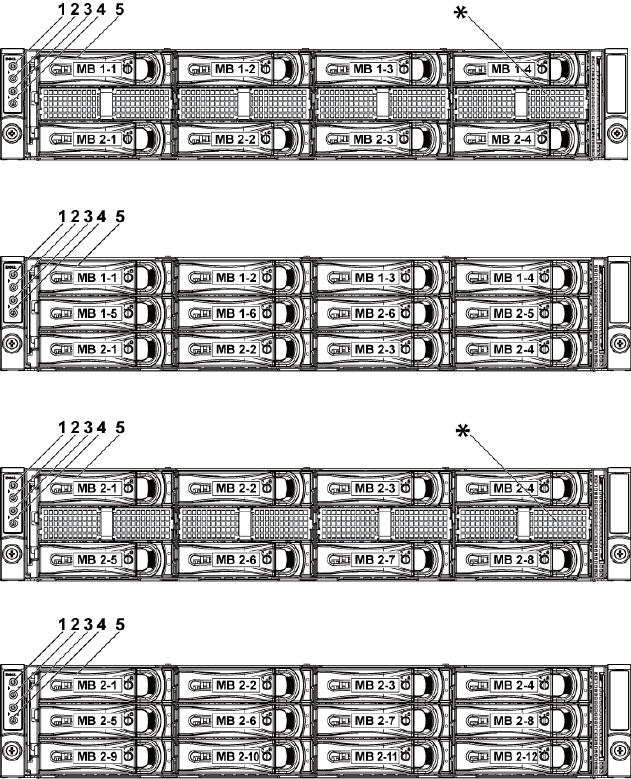
Front-Panel Features and Indicators
Figure 1-1. Front Panel−3.5” x8 Hard Drives With Two Motherboards
Figure 1-2. Front Panel−3.5” x12 Hard Drives With Two Motherboards
Figure 1-3. Front Panel−3.5” x8 Hard Drives With One Motherboard
Figure 1-4. Front Panel−3.5” x12 Hard Drives With One Motherboard
About Your System | 13
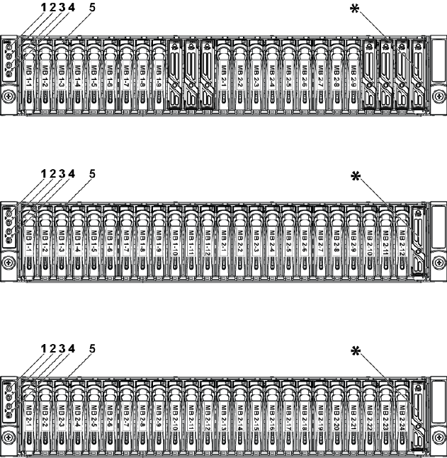
Figure 1-5. Front Panel−2.5” x18 Hard Drives With Two Motherboards
Figure 1-6. Front Panel−2.5” x24 Hard Drives With Two Motherboards
Figure 1-7. Front Panel−2.5” x24 Hard Drives With One Motherboard
14 |About Your System
Item
Indicator, Button
Or Connector
Icon
Description
1,3
Power-on indicator/
power button
(motherboards 1,2)
The power-on indicator lights
when the system power is on.
The power button controls the
DC power supply output to the
system.
NOTE: When powering on the
system, the video monitor can take
from several seconds to over 2
minutes to display an image,
depending on the amount of
memory installed in the system.
NOTE: On ACPI-compliant
operating systems, turning off the
system using the power button
causes the system to perform a
graceful shutdown before power to
the system is turned off.
NOTE: To force an ungraceful
shutdown, press and hold the
power button for 5 seconds.
2,4
System identification
indicator/button
(motherboards 1,2)
The identification button can be
used to locate a particular system
and motherboard within a chassis.
When the button is pushed, the
blue system status indicator on
the front blinks until the button
is pushed again.
5
Hard Drives
Up to twelve hot-swappable 3.5"
hard drives.
Up to twenty four hot-swappable
2.5" hard drives.
*
Drive Cover
Different for 2.5" hard drive
system and 3.5" hard drive system.
About Your System | 15
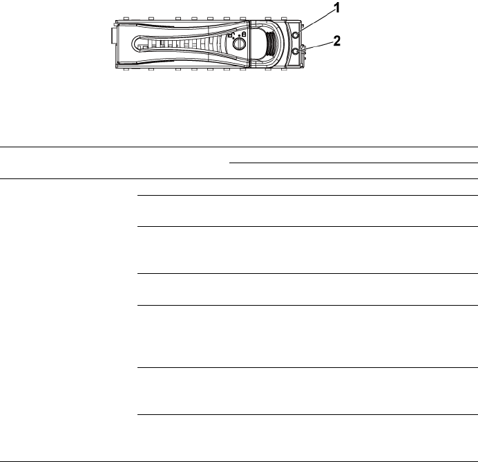
Hard-Drive Indicator Patterns
Figure 1-8. Hard-Drive Indicators
1
hard-drive activity indicator
(green)
2
hard-drive status indicator (green and
amber)
Table 1-1. Hard-Drive Status Indicators−For 3.5" Hard-Drive Backplane With CPLD
Controller
HDD Type
Function
Activity LED
Status LED
Green
Green
Amber
LSI 9260/
LSI 9265
SAS
Slot Empty
Off
Off
Off
Drive On-
line/Access
Blinking
when active
On
Off
Drive Failed
Off/
Blinking
when active
Off
On 150 ms
Off 150 ms
Drive
Rebuilding
Blinking
when active
On 400 ms
Off 100 ms
Off
Drive
Rebuilding
Abort
Off/
Blinking
when active
On 3000 ms
Off 3000 ms
Off 3000 ms
Off 3000 ms
Off 3000 ms
Off 3000 ms
On 3000 ms
Off 3000 ms
Predicted
Failure
(SMART)
Off/
Blinking
when active
On 500 ms
Off 500 ms
Off 1000 ms
Off 500 ms
On 500 ms
Off 1000 ms
Drive Identify/
Preparing for
removal
Blinking
when active
On 250 ms
Off 250 ms
Off

16 |About Your System
Table 1-2. Hard-Drive Status Indicators−For 3.5" Hard-Drive Backplane With Expander
Controller
HDD Type
Function
Activity LED
Status LED
Green
Green
Amber
LSI 9260/
LSI 9265
SAS
Slot Empty
Off
Off
Off
Drive On-
line/Access
Blinking
when active
On
Off
Drive Failed
Off/
Blinking
when active
Off
On 125 ms
Off 125 ms
Drive
Rebuilding
Blinking
when active
On 400 ms
Off 100 ms
Off
Drive
Rebuilding
Abort
Off/
Blinking
when active
On 3000 ms
Off 3000 ms
Off 3000 ms
Off 3000 ms
Off 3000 ms
Off 3000 ms
On 3000 ms
Off 3000 ms
Predicted
Failure
(SMART)
Off/
Blinking
when active
On 500 ms
Off 500 ms
Off 1000 ms
Off 500 ms
On 500 ms
Off 1000 ms
Drive Identify/
Preparing for
removal
Blinking
when active
On 250 ms
Off 250 ms
Off

About Your System | 17
Table 1-3. Hard-Drive Status Indicators−For 2.5" Hard-Drive Backplane With Expander
Controller
HDD Type
Function
Activity LED
Status LED
Green
Green
Amber
LSI 9260/
LSI 9265
SAS
Slot Empty
Off
Off
Off
Drive On-
line/Access
Blinking
when active
On
Off
Drive Failed
Off/
Blinking
when active
Off
On 125 ms
Off 125 ms
Drive
Rebuilding
Blinking
when active
On 400 ms
Off 100 ms
Off
Drive
Rebuilding
Abort
Off/
Blinking
when active
On 3000 ms
Off 3000 ms
Off 3000 ms
Off 3000 ms
Off 3000
ms
Off 3000
ms
On 3000 ms
Off 3000
ms
Predicted
Failure
(SMART)
Off/
Blinking
when active
On 500 ms
Off 500 ms
Off 1000 ms
Off 500 ms
On 500 ms
Off 1000
ms
Drive Identify/
Preparing for
removal
Blinking
when active
On 250 ms
Off 250 ms
Off
18 |About Your System
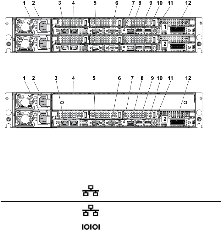
Back-Panel Features and Indicators
Figure 1-9. Back Panel−Two Motherboards
Figure 1-10. Back Panel−One Motherboard
Item
Indicator, Button
Or Connector
Icon
Description
1
Power supply 2
1100 W/1400 W
2
Power supply 1
1100 W/1400 W
3
NIC connector 1
Embedded 10/100/1000 NIC connectors.
4
NIC connector 2
Embedded 10/100/1000 NIC connectors.
5
Serial port
Connects a serial device to the system.
About Your System | 19
Item
Indicator, Button
Or Connector
Icon
Description
6
VGA port
Connects a VGA display to the system.
7
System
identification
indicator
Both the system management software
and the identification buttons located on
the front can cause the indicator to flash
blue to identify a particular system and
system board. Lights amber when the
system needs attention due to a problem.
8
BMC management
port
Dedicated management port.
9
USB port 0
Connects USB devices to the system. The
ports are USB 2.0-compliant.
10
USB port 1
Connects USB devices to the system. The
ports are USB 2.0-compliant.
11
Power On/Off
button
The power button controls the DC power
supply output to the system.
NOTE: When powering on the system, the
video monitor can take from several
seconds to over 2 minutes to display an
image, depending on the amount of memory
installed in the system.
NOTE: On ACPI-compliant operating
systems, turning off the system using the
power button causes the system to perform
a graceful shutdown before power to the
system is turned off.
NOTE: To force an ungraceful shutdown,
press and hold the power button for five
seconds.
12
IPASS connector
Connects to external PCIE devices or a
PCIE bus extender port.
20 |About Your System
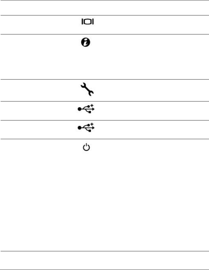
NIC Indicator Codes
Figure 1-11. NIC Indicators
1
speed indicator
2
link/activity indicator
NIC Status Indicator (Speed)
Condition
Solid green
Linking at 100 Mbps speed
Blinking green
Port identification with 10 or 100 Mbps speed
Solid amber
Linking at 1 Gbps speed
Blinking amber
Port identification with 1 Gbps speed
Off
Linking at 10 Mbps speed when the
link/activity LED is green; no link when the
link/activity LED is off.
NIC Status Indicator (Link/Activity)
Condition
Solid green
LAN linking/No access
Blinking green
LAN accessing
Off
No link
About Your System | 21
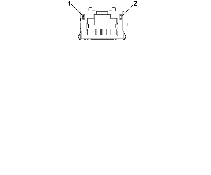
Figure 1-12. NIC Indicators (BMC Management Port)
1
speed indicator
2
link/activity indicator
NIC Status Indicator (Speed)
Condition
Green
Linking at 100 Mbps speed
Off
Linking at 10 Mbps speed when the
link/activity LED is solid green;
no link when the link/activity LED is off
NIC Status Indicator (Link/Activity)
Condition
Green
LAN linking/Accessing
Off
No link

22 |About Your System
Power and System Board Indicator Codes
The LEDs on the system front panel and back panel display status codes
during system startup. For location of the LEDs on the front panel, see
Figure 1-1 for 3.5" hard drive and Figure 1-6 for 2.5" hard drive systems. For
location of the LEDs on the back panel, see Figure 1-9.
Table 1-4 lists the status associated with the status codes.
Table 1-4. Status Indicator Codes
Component
Indicator
Condition
Power-on
indicator
Green
Solid
Blinking
Off
Power On S0/S1
BMC critical condition event in Power On
mode S0/S1
Power Off mode S4/S5
Amber
Blinking
Off
BMC Critical condition event in Power On
mode S0/S1
BMC Critical condition event in Power Off
mode S4/S5
Power On S0/S1
Power Off S4/S5
System
identification
indicator
Blue
Solid
Off
IPMI through Chassis Identify Command On
or ID Button Press ID On
IPMI through Chassis Identify Command Off
or ID Button Press ID Off
About Your System | 23
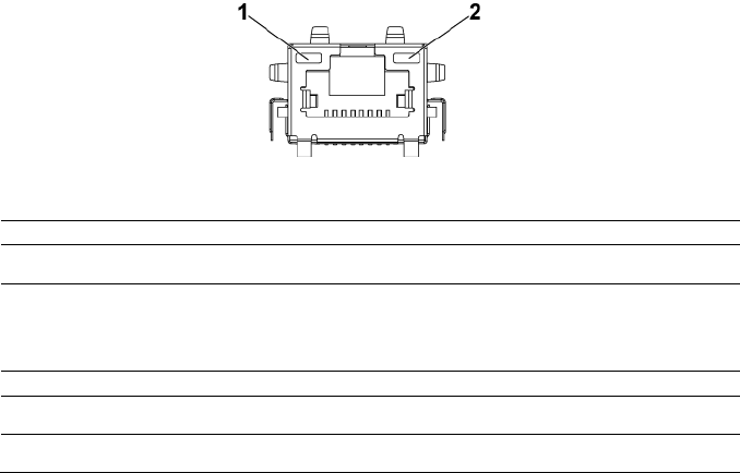
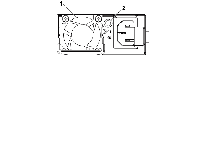
Power Supply Indicator Codes
Figure 1-13. Power Supply Status Indicator
1
power supply
2
AC power LED
AC Power LED
Condition
Solid green
Power supply is on (AC OK/DC OK) or in standby mode (100
VAC-120 VAC for 1023 W, 200 VAC-240 VAC for 1100 W, 200
VAC-240 VAC for 1400 W)
Solid yellow
Power supply is at fault condition
(UVP/OVP/OCP/SCP/OTP/Fan Fault)
Off
Power supply is off or AC input voltage is out of normal
operating range (100 VAC-120 VAC for 1023 W, 200 VAC-240
VAC for 1100 W, 200 VAC-240 VAC for 1400 W)
24 |About Your System
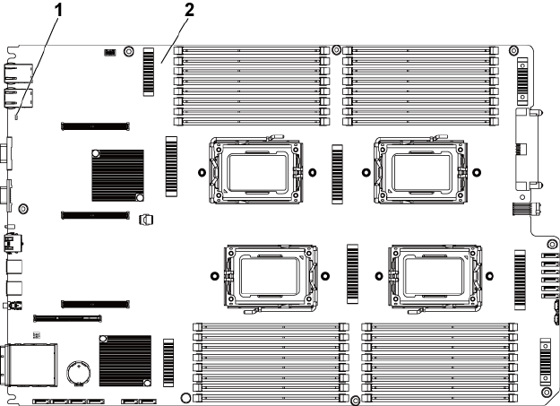
BMC Heart Beat LED
The system board provides BMC heart beat LED (CR2) for BMC debugs.
The BMC heart beat LED is green. When the system AC power is on, this
LED will light. When BMC firmware is ready, the BMC heart beat LED
will blink.
Figure 1-14. BMC Heart Beat LED
1
BMC heart beat LED
2
system board

About Your System | 25
Post Error Code
Collecting System Event Log (SEL) for Investigation
Whenever possible, the BIOS will output the current boot progress codes
on the video screen. Progress codes are 32-bit quantities plus optional data.
The 32-bit numbers include class, subclass, and operation information. The
class and subclass fields point to the type of hardware that is being
initialized. The operation field represents the specific initialization activity.
Based on the data bit availability to display progress codes, a progress code
can be customized to fit the data width. The higher the data bit, the higher
the granularity of information that can be sent on the progress port. The
progress codes may be reported by the system BIOS or option ROMs.
The Response section in the following table is divided into three types:
1 Warning or Not an error – The message is displayed on the screen. An
error record is logged to the SEL. The system will continue booting
with a degraded state. The user may want to replace the erroneous unit.
2 Pause – The message is displayed on the screen, an error is logged to
the SEL, and user input is required to continue. The user can take
immediate corrective action or choose to continue booting.
3 Halt – The message is displayed on the screen, an error is logged to the
SEL, and the system cannot boot unless the error is resolved. The user
needs to replace the faulty part and restart the system.
Error Code
Error Message
Error Cause
Recovery Method
0000h
Timer Error
Timer8254 failed
Board repair
0003h
CMOS Battery Low
CMOS battery low
Change battery
0004h
CMOS Setting Wrong
Diagnostic status byte
shown an error
Load CMOS
default setting
0005h
CMOS Checksum Bad
CMOS checksum
incorrect or BIOS update
Load CMOS
default setting
000Bh
CMOS Memory Size
Wrong
Base memory size error
Change DIMM or
board repair
000Ch
RAM Read/Write Test
Failed
No usable system
memory
Change DIMM

26 |About Your System
Error Code
Error Message
Error Cause
Recovery Method
0012h
CMOS Date/Time Not
Set
Indicate invalid
date/time in CMOS
diagnostic status byte
Reset Date/Time
0040h
Refresh Timer Test
Failed
Unrecoverable system-
board failure
Board repair
0041h
Display Memory Test
Failed
Unrecoverable system-
board failure
Board repair
0044h
DMA Controller Error
Unrecoverable system-
board failure
Board repair
0045h
DMA-1 Error
Unrecoverable system-
board failure
Board repair
0046h
DMA-2 Error
Unrecoverable system-
board failure
Board repair
0048h
Password Check Failed
Preboot user password
violation
Clear password by
switch
004Ah
ADM Module Error
Unspecified
Board repair
004Bh
Language Module Error
7
Unspecified
Board repair
005Dh
S.M.A.R.T. Command
Failed
S.M.A.R.T. Status BAD,
Backup and Replace
HDD/ATAPI/IDE device
failure
Change HDD
005Eh
Password Check Failed
Other preboot password
violation
Clear password by
switch
0060h
Primary Master Hard
Disk Error
HDD/ATAPI/IDE device
failure
Change HDD
0061h
Primary Slave Hard Disk
Error
HDD/ATAPI/IDE device
failure
Change HDD
0062h
Secondary Master Hard
Disk Error
HDD/ATAPI/IDE device
failure
Change HDD
0063h
Secondary Slave Hard
Disk Error
HDD/ATAPI/IDE device
failure
Change HDD
0080h
Primary Master Drive-
ATAPI Incompatible
HDD/ATAPI/IDE device
failure
Change HDD
0081h
Primary Slave Drive-
ATAPI Incompatible
HDD/ATAPI/IDE device
failure
Change HDD

About Your System | 27
Error Code
Error Message
Error Cause
Recovery Method
0082h
Secondary Master
Drive-ATAPI
Incompatible
HDD/ATAPI/IDE device
failure
Change HDD
0083h
Secondary Slave Drive-
ATAPI Incompatible
HDD/ATAPI/IDE device
failure
Change HDD
0166h
CPU Frequency
mismatch!
CPU mix installed is not
support
Install same model
CPU
0167h
CPUID mismatch!
CPU mix installed is not
support
Install same model
CPU
0168h
L1 cache size mismatch!
CPU mix installed is not
support
Install same model
CPU
0169h
L2 cache size mismatch!
CPU mix installed is not
support
Install same model
CPU
016Ah
CPU Patch level
mismatch!
CPU mix installed is not
support
Install same model
CPU
4168h
DIMM CRC Error or be
ignore POST Error
DIMM bad
Change DIMM
4169h
DIMM Chip Select
Disable, Test Fail
DIMM bad
Change DIMM
5120h
CMOS cleared by
jumper
CMOS clear by jumper
No action
5122h
Password cleared by
jumper
Password clear by jumper
No action
8104h
Warning! Port 60h/64h
emulation is not
supported by this USB
Host Controller!!!
Not supported by the HC
Board repair
8105h
Warning! EHCI
controller disabled. It
requires 64 bit data
support in the BIOS.
Check whether this host
controller needs 64 bit
data structure or not
Board repair
8601h
Error: BMC Not
Responding
BMC chip does not find
Board repair
8701h
Insufficient Runtime
space for MPS data!!
System may operate in
PIC or Non-MPS mode.
Failed to copy the
MPTable to F000 or
E000 shadow RAM
Board repair
8702h
No enough APIC ID in
Check APIC failed
Board repair

28 |About Your System
Error Code
Error Message
Error Cause
Recovery Method
range 0-0Fh can be
assigned to IO APICs.
(Re-assigning CPUs‘
local APIC ID may solve
this issue)
MPS Table is not built!
System may operate in
PIC or Non-MPS mode.
BMC
Sensor#
Sensor
Name
Event
Event Log
Sensor Type: Temperature
61h
Processor 1
Temp
Upper non-critical event
asserted
Processor 1 Temp
Temperature Upper Non-
Critical - Going High -
Asserted
Upper critical event
asserted
Processor 1 Temp
Temperature Upper
Critical - Going High -
Asserted
Upper non-recoverable
event asserted
Processor 1 Temp
Temperature Upper Non-
Recoverable - Going High
- Asserted
Upper non-critical event
deasserted
Processor 1 Temp
Temperature Upper Non-
Critical - Going High -
Deasserted
Upper critical event
deasserted
Processor 1 Temp
Temperature Upper
Critical - Going High -
Deasserted
Upper non-recoverable
event deasserted
Processor 1 Temp
Temperature Upper Non-
Recoverable - Going High

About Your System | 29
Sensor#
Sensor
Name
Event
Event Log
- Deasserted
62h
Processor 2
Temp
Upper non-critical event
asserted
Processor 2 Temp
Temperature Upper Non-
Critical - Going High -
Asserted
Upper critical event
asserted
Processor 2 Temp
Temperature Upper
Critical - Going High -
Asserted
Upper non-recoverable
event asserted
Processor 2 Temp
Temperature Upper Non-
Recoverable - Going High
- Asserted
Upper non-critical event
deasserted
Processor 2 Temp
Temperature Upper Non-
Critical - Going High -
Deasserted
Upper critical event
deasserted
Processor 2 Temp
Temperature Upper
Critical - Going High -
Deasserted
Upper non-recoverable
event deasserted
Processor 2 Temp
Temperature Upper Non-
Recoverable - Going High
- Deasserted
63h
Processor 3
Temp
Upper non-critical event
asserted
Processor 1 Temp
Temperature Upper Non-
Critical - Going High -
Asserted
Upper critical event
asserted
Processor 1 Temp
Temperature Upper
Critical - Going High -
Asserted

30 |About Your System
Sensor#
Sensor
Name
Event
Event Log
Upper non-recoverable
event asserted
Processor 1 Temp
Temperature Upper Non-
Recoverable - Going High
- Asserted
Upper non-critical event
deasserted
Processor 1 Temp
Temperature Upper Non-
Critical - Going High -
Deasserted
Upper critical event
deasserted
Processor 1 Temp
Temperature Upper
Critical - Going High -
Deasserted
Upper non-recoverable
event deasserted
Processor 1 Temp
Temperature Upper Non-
Recoverable - Going High
- Deasserted
64h
Processor 4
Temp
Upper non-critical event
asserted
Processor 2 Temp
Temperature Upper Non-
Critical - Going High -
Asserted
Upper critical event
asserted
Processor 2 Temp
Temperature Upper
Critical - Going High -
Asserted
Upper non-recoverable
event asserted
Processor 2 Temp
Temperature Upper Non-
Recoverable - Going High
- Asserted
Upper non-critical event
deasserted
Processor 2 Temp
Temperature Upper Non-
Critical - Going High -
Deasserted
Upper critical event
deasserted
Processor 2 Temp
Temperature Upper
Critical - Going High -
Deasserted

About Your System | 31
Sensor#
Sensor
Name
Event
Event Log
Upper non-recoverable
event deasserted
Processor 2 Temp
Temperature Upper Non-
Recoverable - Going High
- Deasserted
21h
MLB TEMP
1
Upper non-critical event
asserted
MLB TEMP 1
Temperature Upper Non-
Critical - Going High -
Asserted
Upper critical event
asserted
MLB TEMP 1
Temperature Upper
Critical - Going High -
Asserted
Upper non-recoverable
event asserted
MLB TEMP 1
Temperature Upper Non-
Recoverable - Going High
- Asserted
Upper non-critical event
deasserted
MLB TEMP 1
Temperature Upper Non-
Critical - Going High -
Deasserted
Upper critical event
deasserted
MLB TEMP 1
Temperature Upper
Critical - Going High -
Deasserted
Upper non-recoverable
event deasserted
MLB TEMP 1
Temperature Upper Non-
Recoverable - Going High
- Deasserted
22h
MLB TEMP
2
Upper non-critical event
asserted
MLB TEMP 2
Temperature Upper Non-
Critical - Going High -
Asserted
Upper critical event
asserted
MLB TEMP 2
Temperature Upper
Critical - Going High -
Asserted

32 |About Your System
Sensor#
Sensor
Name
Event
Event Log
Upper non-recoverable
event asserted
MLB TEMP 2
Temperature Upper Non-
Recoverable - Going High
- Asserted
Upper non-critical event
deasserted
MLB TEMP 2
Temperature Upper Non-
Critical - Going High -
Deasserted
Upper critical event
deasserted
MLB TEMP 2
Temperature Upper
Critical - Going High -
Deasserted
Upper non-recoverable
event deasserted
MLB TEMP 2
Temperature Upper Non-
Recoverable - Going High
- Deasserted
23h
MLB TEMP
3
Upper non-critical event
asserted
MLB TEMP 3
Temperature Upper Non-
Critical - Going High -
Asserted
Upper critical event
asserted
MLB TEMP 3
Temperature Upper
Critical - Going High -
Asserted
Upper non-recoverable
event asserted
MLB TEMP 3
Temperature Upper Non-
Recoverable - Going High
- Asserted
Upper non-critical event
deasserted
MLB TEMP 3
Temperature Upper Non-
Critical - Going High -
Deasserted
Upper critical event
deasserted
MLB TEMP 3
Temperature Upper
Critical - Going High -
Deasserted

About Your System | 33
Sensor#
Sensor
Name
Event
Event Log
Upper non-recoverable
event deasserted
MLB TEMP 3
Temperature Upper Non-
Recoverable - Going High
- Deasserted
24h
MLB TEMP
4
Upper non-critical event
asserted
MLB TEMP 2
Temperature Upper Non-
Critical - Going High -
Asserted
Upper critical event
asserted
MLB TEMP 2
Temperature Upper
Critical - Going High -
Asserted
Upper non-recoverable
event asserted
MLB TEMP 2
Temperature Upper Non-
Recoverable - Going High
- Asserted
Upper non-critical event
deasserted
MLB TEMP 2
Temperature Upper Non-
Critical - Going High -
Deasserted
Upper critical event
deasserted
MLB TEMP 2
Temperature Upper
Critical - Going High -
Deasserted
Upper non-recoverable
event deasserted
MLB TEMP 2
Temperature Upper Non-
Recoverable - Going High
- Deasserted
2Ah
FCB
Ambient1
Upper critical event
asserted
FCB Ambient1
Temperature Upper
Critical - Going High -
Asserted
Sensor Type: Voltage
14h
PS 12V
Lower non-critical event
asserted
PS 12V Voltage Lower
Non-Critical - Going Low -
Asserted

34 |About Your System
Sensor#
Sensor
Name
Event
Event Log
Lower critical event
asserted
PS 12V Voltage Lower
Critical - Going Low -
Asserted
Lower non-recoverable
event asserted
PS 12V Voltage Lower
Non-Recoverable - Going
Low - Asserted
Upper non-critical event
asserted
PS 12V Voltage Upper
Non-Critical - Going High
- Asserted
Upper critical event
asserted
PS 12V Voltage Upper
Critical - Going High -
Asserted
Upper non-recoverable
event asserted
PS 12V Voltage Upper
Non-Recoverable - Going
High - Asserted
Lower non-critical event
deasserted
PS 12V Voltage Lower
Non-Critical - Going Low -
Deasserted
Lower critical event
deasserted
PS 12V Voltage Lower
Critical - Going Low -
Deasserted
Lower non-recoverable
event deasserted
PS 12V Voltage Lower
Non-Recoverable - Going
Low - Deasserted
Upper non-critical event
deasserted
PS 12V Voltage Upper
Non-Critical - Going High
- Deasserted
Upper critical event
deasserted
PS 12V Voltage Upper
Critical - Going High -
Deasserted
Upper non-recoverable
event deasserted
PS 12V Voltage Upper
Non-Recoverable - Going
High - Deasserted
15h
PS 5V
Lower non-critical event
asserted
PS 5V Voltage Lower Non-
Critical - Going Low -
Asserted

About Your System | 35
Sensor#
Sensor
Name
Event
Event Log
Lower critical event
asserted
PS 5V Voltage Lower
Critical - Going Low -
Asserted
Lower non-recoverable
event asserted
PS 5V Voltage Lower Non-
Recoverable - Going Low -
Asserted
Upper non-critical event
asserted
PS 5V Voltage Upper Non-
Critical - Going High -
Asserted
Upper critical event
asserted
PS 5V Voltage Upper
Critical - Going High -
Asserted
Upper non-recoverable
event asserted
PS 5V Voltage Upper Non-
Recoverable - Going High
- Asserted
Lower non-critical event
deasserted
PS 5V Voltage Lower Non-
Critical - Going Low -
Deasserted
Lower critical event
deasserted
PS 5V Voltage Lower
Critical - Going Low -
Deasserted
Lower non-recoverable
event deasserted
PS 5V Voltage Lower Non-
Recoverable - Going Low -
Deasserted
Upper non-critical event
deasserted
PS 5V Voltage Upper Non-
Critical - Going High -
Deasserted
Upper critical event
deasserted
PS 5V Voltage Upper
Critical - Going High -
Deasserted
Upper non-recoverable
event deasserted
PS 5V Voltage Upper Non-
Recoverable - Going High
- Deasserted
16h
STBY 3.3V
Lower non-critical event
asserted
STBY 3.3V Voltage Lower
Non-Critical - Going Low -
Asserted

36 |About Your System
Sensor#
Sensor
Name
Event
Event Log
Lower critical event
asserted
STBY 3.3V Voltage Lower
Critical - Going Low -
Asserted
Lower non-recoverable
event asserted
STBY 3.3V Voltage Lower
Non-Recoverable - Going
Low - Asserted
Upper non-critical event
asserted
STBY 3.3V Voltage Upper
Non-Critical - Going High
- Asserted
Upper critical event
asserted
STBY 3.3V Voltage Upper
Critical - Going High -
Asserted
Upper non-recoverable
event asserted
STBY 3.3V Voltage Upper
Non-Recoverable - Going
High - Asserted
Lower non-critical event
deasserted
STBY 3.3V Voltage Lower
Non-Critical - Going Low -
Deasserted
Lower critical event
deasserted
STBY 3.3V Voltage Lower
Critical - Going Low -
Deasserted
Lower non-recoverable
event deasserted
STBY 3.3V Voltage Lower
Non-Recoverable - Going
Low - Deasserted
Upper non-critical event
deasserted
STBY 3.3V Voltage Upper
Non-Critical - Going High
- Deasserted
Upper critical event
deasserted
STBY 3.3V Voltage Upper
Critical - Going High -
Deasserted
Upper non-recoverable
event deasserted
STBY 3.3V Voltage Upper
Non-Recoverable - Going
High - Deasserted
17h
PS 3.3V
Lower non-critical event
asserted
PS 5V Voltage Lower Non-
Critical - Going Low -
Asserted

About Your System | 37
Sensor#
Sensor
Name
Event
Event Log
Lower critical event
asserted
PS 5V Voltage Lower
Critical - Going Low -
Asserted
Lower non-recoverable
event asserted
PS 5V Voltage Lower Non-
Recoverable - Going Low -
Asserted
Upper non-critical event
asserted
PS 5V Voltage Upper Non-
Critical - Going High -
Asserted
Upper critical event
asserted
PS 5V Voltage Upper
Critical - Going High -
Asserted
Upper non-recoverable
event asserted
PS 5V Voltage Upper Non-
Recoverable - Going High
- Asserted
Lower non-critical event
deasserted
PS 5V Voltage Lower Non-
Critical - Going Low -
Deasserted
Lower critical event
deasserted
PS 5V Voltage Lower
Critical - Going Low -
Deasserted
Lower non-recoverable
event deasserted
PS 5V Voltage Lower Non-
Recoverable - Going Low -
Deasserted
Upper non-critical event
deasserted
PS 5V Voltage Upper Non-
Critical - Going High -
Deasserted
Upper critical event
deasserted
PS 5V Voltage Upper
Critical - Going High -
Deasserted
Upper non-recoverable
event deasserted
PS 5V Voltage Upper Non-
Recoverable - Going High
- Deasserted
18h
STBY 1.2V
Lower non-critical event
asserted
STBY 3.3V Voltage Lower
Non-Critical - Going Low -
Asserted

38 |About Your System
Sensor#
Sensor
Name
Event
Event Log
Lower critical event
asserted
STBY 3.3V Voltage Lower
Critical - Going Low -
Asserted
Lower non-recoverable
event asserted
STBY 3.3V Voltage Lower
Non-Recoverable - Going
Low - Asserted
Upper non-critical event
asserted
STBY 3.3V Voltage Upper
Non-Critical - Going High
- Asserted
Upper critical event
asserted
STBY 3.3V Voltage Upper
Critical - Going High -
Asserted
Upper non-recoverable
event asserted
STBY 3.3V Voltage Upper
Non-Recoverable - Going
High - Asserted
Lower non-critical event
deasserted
STBY 3.3V Voltage Lower
Non-Critical - Going Low -
Deasserted
Lower critical event
deasserted
STBY 3.3V Voltage Lower
Critical - Going Low -
Deasserted
Lower non-recoverable
event deasserted
STBY 3.3V Voltage Lower
Non-Recoverable - Going
Low - Deasserted
Upper non-critical event
deasserted
STBY 3.3V Voltage Upper
Non-Critical - Going High
- Deasserted
Upper critical event
deasserted
STBY 3.3V Voltage Upper
Critical - Going High -
Deasserted
Upper non-recoverable
event deasserted
STBY 3.3V Voltage Upper
Non-Recoverable - Going
High - Deasserted
19h
PS 1.1V
Lower non-critical event
asserted
PS 5V Voltage Lower Non-
Critical - Going Low -
Asserted

About Your System | 39
Sensor#
Sensor
Name
Event
Event Log
Lower critical event
asserted
PS 5V Voltage Lower
Critical - Going Low -
Asserted
Lower non-recoverable
event asserted
PS 5V Voltage Lower Non-
Recoverable - Going Low -
Asserted
Upper non-critical event
asserted
PS 5V Voltage Upper Non-
Critical - Going High -
Asserted
Upper critical event
asserted
PS 5V Voltage Upper
Critical - Going High -
Asserted
Upper non-recoverable
event asserted
PS 5V Voltage Upper Non-
Recoverable - Going High
- Asserted
Lower non-critical event
deasserted
PS 5V Voltage Lower Non-
Critical - Going Low -
Deasserted
Lower critical event
deasserted
PS 5V Voltage Lower
Critical - Going Low -
Deasserted
Lower non-recoverable
event deasserted
PS 5V Voltage Lower Non-
Recoverable - Going Low -
Deasserted
Upper non-critical event
deasserted
PS 5V Voltage Upper Non-
Critical - Going High -
Deasserted
Upper critical event
deasserted
PS 5V Voltage Upper
Critical - Going High -
Deasserted
Upper non-recoverable
event deasserted
PS 5V Voltage Upper Non-
Recoverable - Going High
- Deasserted
Sensor Type: Power Supply

40 |About Your System
Sensor#
Sensor
Name
Event
Event Log
A6h
PSU 1
Present
Presence detected
PSU 1 Present Presence
detected - Deasserted
Configuration Error
PSU 1 Present
Configuration Error -
Asserted
A7h
PSU 2
Present
Presence detected
PSU 2 Present Presence
detected - Deasserted
Configuration Error
PSU 2 Present
Configuration Error -
Asserted
Sensor Type: Processor
41h
CPU1Status
Thermal Trip
CPU1Status Processor
Therman Trip - Asserted
42h
CPU2Status
Thermal Trip
CPU2Status Processor
Therman Trip - Asserted
43h
CPU3Status
Thermal Trip
CPU3Status Processor
Therman Trip - Asserted
44h
CP42Status
Thermal Trip
CPU4Status Processor
Therman Trip - Asserted
Sensor Type: Power Unit
74h
AC Pwr On
AC lost event deasserted
AC Pwr On Power Unit
AC Lost - Deasserted
A8h
PSU 1 AC
Status
AC lost event asserted
PSU 1 AC Status Power
Unit AC Lost - Asserted
A9h
PSU 2 AC
Status
AC lost event asserted
PSU 2 AC Status Power
Unit AC Lost - Asserted
Sensor Type: System Event
71h
PEF Action
Alert
PEF Action System Event
PEF Action Alert -
Asserted
power off
PEF Action System Event
PEF Action power off -

About Your System | 41
Sensor#
Sensor
Name
Event
Event Log
Asserted
reset
PEF Action System Event
PEF Action reset -
Asserted
power cycle
PEF Action System Event
PEF Action power cycle -
Asserted
Diagnostic Interrupt
(NMI)
PEF Action System Event
PEF Action Diagnostic
Interrupt (NMI) - Asserted
Sensor Type: System ACPI Power State
73h
ACPI Pwr
State
Legacy ON state
ACPI Pwr State System
ACPI Power State Legacy
ON State - Asserted
Legacy OFF state
ACPI Pwr State System
ACPI Power State Legacy
OFF State - Asserted
Sensor Type: WatchDog2
72h
WatchDog2
Timer expired
WatchDog2 Watchdog 2
Timer expired - Asserted
Hard Reset
WatchDog2 Watchdog 2
Hard Reset - Asserted
Power Down
WatchDog2 Watchdog 2
Power Down - Asserted
Power Cycle
WatchDog2 Watchdog 2
Power Cycle - Asserted
Timer interrupt
WatchDog2 Watchdog 2
Timer interrupt - Asserted
Sensor Type: Event Logging Disable
40h
SEL
Fullness
All Event Logging
Disabled
All Event Logging
Disabled - Asserted

42 |About Your System
Sensor#
Sensor
Name
Event
Event Log
SEL Full
SEL Full - Asserted
SEL Almost Full
SEL Almost Full -
Asserted
Sensor Type: Platform Security Violation Attempt
75h
Security
Out-of-band Access
Password Violation
Out-of-band Access
Password Violation -
Asserted
BIOS
Sensor#
Sensor
Name
Event
Event Log (Web UI output)
Sensor Type: System Firmware Progress (formerly POST Error)
06h
POST Error
Code Event
POST Error Code Event
Unknown BIOS POST
Progress Error - Asserted
Sensor Type: OEM Reserved
81h
POST
START
Event
POST START Event
Unknown OEM
RESERVED E/R Type
Code : 70h - Asserted
Sensor Type: System Event
85h
POST OK
Event
POST OK Event
Unknown System Event
OEM System Boot Event -
Asserted
Sensor Type: Memory
60h
Memory
Correctable ECC/other
correctable memory
error
Correctable ECC/other
correctable memory error -
Asserted
Uncorrectable
ECC/other
uncorrectable memory
error
Uncorrectable ECC/other
uncorrectable memory
error - Asserted

About Your System | 43
Sensor#
Sensor
Name
Event
Event Log (Web UI output)
Correctable Memory
error logging limit
reached
Correctable Memory error
logging limit reached -
Asserted
Memory Single/Multi
bits Error Event (Single
bit)(DIMM Number-
CPUx/Chx/DIMx)
Unknown Memory
Correctable ECC -
Asserted
FCB
Sensor#
Sensor
Name
Event
Event Log (Web UI output)
Sensor Type: Fan
01h
FCB FAN1
Lower critical event
asserted
FCB FAN1 Lower Critical
- Going Low - Asserted
02h
FCB FAN2
Lower critical event
asserted
FCB FAN2 Lower Critical
- Going Low - Asserted
03h
FCB FAN3
Lower critical event
asserted
FCB FAN3 Lower Critical
- Going Low - Asserted
04h
FCB FAN4
Lower critical event
asserted
FCB FAN4 Lower Critical
- Going Low - Asserted
Post Error Code Event
The BIOS logs the event to the BMC if POST error is detected.
Here is an example of event with POST error code 4168h for ―Memory
Ignore‖.
The following table shows the post error code event structure:
Byte
Item
Data
1-2
Record ID
-
3
Record Type
-
44 |About Your System
Byte
Item
Data
4-7
Timestamp
-
8-9
Generator ID
0x31
10
Event Message Format Version
0x04 (IPMI 2.0)
11
Sensor Type
0x0F (POST Error)
12
Sensor Number
0x06
13
Event Direction/Event Type
0x6F
14
Event Data 1
0xA0
15
Event Data 2
0x68 (Lower 8 bits)
16
Event Data 3
0x41 (Upper 8 bits)
Other Information You May Need
WARNING: See the safety and regulatory information that shipped with your
system. Warranty information may be included within this document or as a
separate document.
The
Getting Started Guide
provides an overview of rack installation, system
features, setting up your system, and technical specifications.
NOTE: Always check for updates on support.dell.com/manuals and read the
updates first because they often supersede information in other documents.

About Your System | 45
Recovery Mode
NOTE: Boot block will be reserved.
A BIOS recovery can be accomplished from one of the following devices: an
USB Disk-On-Key or the CD-ROM. The recovery media must include the
BIOS image file AMIBOOT.ROM in the root directory.
Two conditions will cause the system to enter the recovery mode:
Press a hot key <Ctrl><Home>.
Damage the ROM image, which will cause the system to enter the
recovery mode and update the system ROM without the boot
block.
The recovery modes are shown as below:
1. Insert or plug-in the recovery media with the AMIBOOT.ROM file.
2. Power on the system, press <Ctrl><Home> and then wait for the
recovery process finished.
3. Restart the system and load the BIOS defaulted configurations.
2
46 | Using the System Setup Program
Using the System Setup Program
Start Menu
The system employs the latest AMI CMOS BIOS, which is stored in Flash
memory. The Flash memory supports the Plug and Play specification, and
contains a System Setup program, the Power On Self Test (POST) routine,
and the PCI auto-configuration utility.
This system board supports system BIOS shadowing, enabling the BIOS to
execute from 64-bit onboard write-protected DRAM.
This Setup utility should be executed under the following conditions:
When changing the system configuration, configure for items such
as:
– Hard drives, diskette drives, and peripherals.
– Password protection from unauthorized use.
– Power management features.
When a configuration error is detected by the system and you are
prompted to make changes to the Setup utility.
When redefining the communication ports to prevent any
conflicts.
When changing the password or making other changes to the
security setup.
NOTE: Only items in brackets [ ] can be modified. Items that are not in brackets
are display only.
System Setup Options at Boot
<F2>
Initiate Setup during POST
<F9>
Load optimal (for example, CMOS) defaults
<F10>
Save settings and exit in BIOS Setup
Using the System Setup Program | 47
Console Redirection
The console redirection allows a remote user to diagnose and fix problems
on a server, which has not successfully booted the OS. The centerpiece of
the console redirection is the BIOS Console. The BIOS Console is a Flash
ROM-resident utility that redirects input and output over a serial or
modem connection.
The BIOS supports console redirection to a serial port. If serial port-based
headless server support is provided by the system, the system must provide
support for redirection of all BIOS-driven console I/O to the serial port. The
driver for the serial console must be capable of supporting the functionality
documented in the ANSI Terminal Definition.
Please refer to the following steps to set console redirection:
1 Enter the BIOS setup menu.
2 Select server.
3 Select remote access configuration.
4 Enable Remote Access.
5 Select serial port number:
When COM1 is selected:
1) Connect the rs-232 cable between the server and the local
computer.
2) The local computer will have the ability to monitor the server
screen synchronically through executing the super terminal
application.
When COM2 is selected (SOL):
1) Check BMC IP from server -> IPMI configuration ->IP
Address (current IP address in BMC).
a) Make sure BMC NIC under the IPMI configuration. If
users select shared NIC, make sure the LAN cable has
been plugged in the shared port.
If users have the DHCP server, select BMC IP address
source to DHCP.
If users set IP address source to static, enter the BMC
themselves in IP address-> IP address.
48 | Using the System Setup Program
b) Make sure BMC NIC under the IPMI configuration. If
users select dedicated NIC, make sure the LAN cable has
been plugged in the dedicated port.
If users have the DHCP server, select BMC IP address
source to DHCP.
If users set IP address source to static, enter the BMC
themselves in IP address-> IP address.
Users should take their own risk if they set IP address by
themselves. Improper IP setting may cause that they cannot
implement communication with BMC over LAN.
2) The remote clients should install ipmitool under their
operating systems.
3) Execute IPMITOOL with BMC IP, username, password and
sol parameter like below format:
ipmotool –I <interface> -U <username> -P <password> -
H <Host iP> sol activate
4) Remote users will have the ability to monitor server screen
synchronically through executing the super terminal
application.
COM2 is always workable no matter what kind of NIC is selected.
Users only need to make sure BMC current IP exists and IPMI
command through LAN is workable, then SOL is workable.
In Figure 1-9, BMC default shared-NIC port is item 3; BMC
dedicated port is item 8; and COM1 is item 5.
For detailed configuration of Console Redirection, please refer to ―Remote
Access Configuration‖ on page 85.
Using the System Setup Program | 49
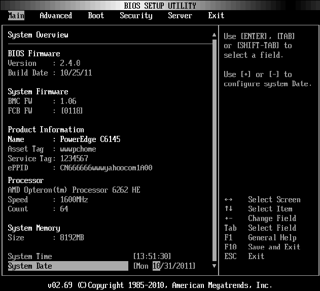
Main Menu
The main menu displays information about your system boards and BIOS.
Main Screen
50 | Using the System Setup Program
NOTE: The information about BMC/FCB/Asset Tag/Service Tag/ePPID shown in
the main menu is different in each server.
NOTE: The options for the System Setup program change based on the system
configuration.
NOTE: The System Setup program defaults are listed under their respective
options in the following sections, where applicable.
BIOS Firmware
Option
Description
Version
Displays the BIOS version.
Build Date
Displays the BIOS build date.
System Firmware
Option
Description
BMC FW
Displays the system BMC firmware version.
FCB FW
Displays the system FCB firmware version.
Product Information
Option
Description
Name
Displays the name of the product.
AssetTag
Displays the asset tag of the product.
ServiceTag
Displays the service tag of the product.
ePPID
Displays the ePPID of the product.

Using the System Setup Program | 51
Processor
Option
Description
Name
Displays the processor name.
Speed
Displays the maximum speed of the processor.
Count
Displays the physical processor count.
System Memory
Option
Description
Size
Displays the total system memory size installed on the system
board.
System Date
Displays the current date.
System Time
Displays the current time.
52 | Using the System Setup Program
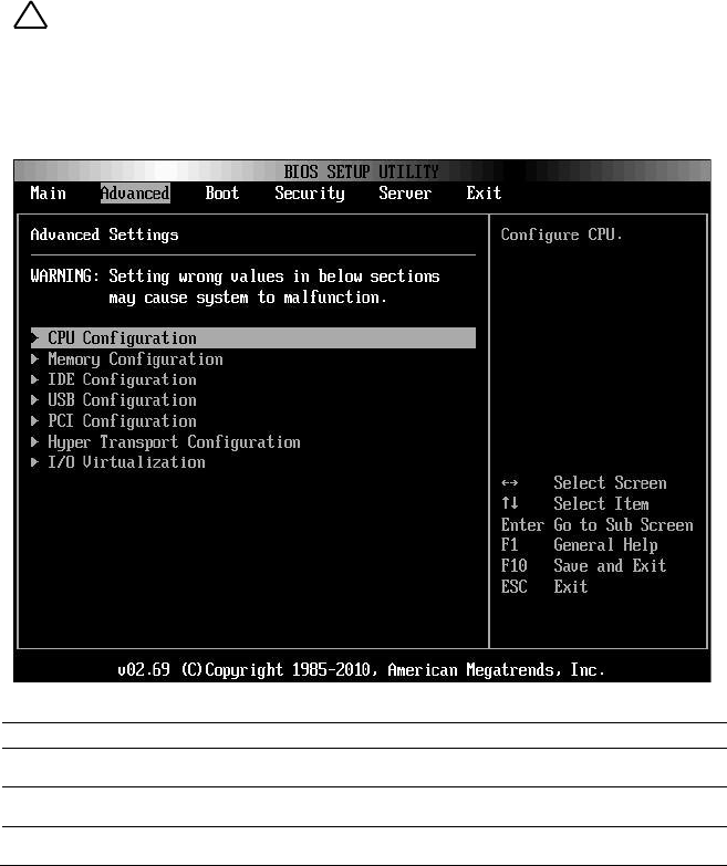
Advanced Menu
This option displays a table of items that defines advanced information
about your system.
CAUTION: Making incorrect settings to items on these pages may cause the
system to malfunction. Unless you have experience adjusting these items, we
recommend that you leave these settings at the default values. If making settings
to items on these pages causes your system to malfunction or prevents the
system from booting, open BIOS and choose Load Optimal Defaults in the Exit
menu to boot up normally.
Option
Description
CPU Configuration
Configure CPU.
Memory Configuration
Configure memory.
IDE Configuration
Configure the IDE device(s).
Using the System Setup Program | 53
Option
Description
USB Configuration
Configure the USB support.
PCI Configuration
Configure PCI.
Hyper Transport Configuration
Configure Hyper Transport. Power cycle is
recommended after change setting.
I/O Virtualization
I/O virtualization.
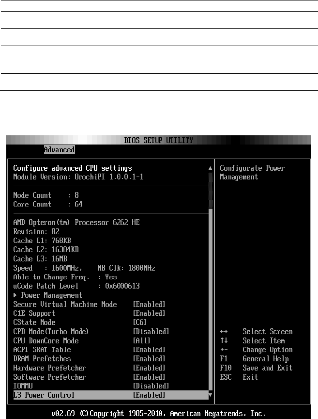
CPU Configuration
Scroll to this item and press Enter to view the following screen:

54 | Using the System Setup Program
Option
Description
Module Version
Displays the current processor module version.
Node Count
Displays the node count.
Core Count
Displays the processor core count.
Revision
Displays the processor version.
Cache L1
Displays the size of CPU L1.
Cache L2
Displays the size of CPU L2.
Cache L3
Displays the size of CPU L3.
Speed
Displays the frequency of CPU.
Able to Change Freq.
Displays the capability of frequency change.
uCode Patch Level
Displays the ucode patch level.
Power Management
This field sets the system Power Management to
Maximum Performance mode, OS Control mode, or
Advanced Platform Management Link mode. When set
to APML mode, you can change setting of PSU Power
Capping options.
Secure Virtual Machine
Mode
(Enabled default)
Select this item to enable or disable the function of
securing virtual machine mode (SVM).
C1E Support
(Enabled default)
Select this item to enable or disable the ―Enhanced Halt
State‖.
CState Mode
(C6 default)
Specifies the method of C-State enablement. Only for
Family 15h CPU.
CPB Mode (Turbo Mode)
(Disabled default)
Specifies the method of core performance boost
enablement. Only for Family 15h CPU.
CPU DownCore Mode
(All default)
Select this item to cold reset the system after options are
changed.
ACPI SRAT Table
(Enabled default)
Select this item to enable or disable the building of ACPI
SRAT table.

Using the System Setup Program | 55
Option
Description
DRAM Prefetcher
(Enabled default)
Select this item to enable or disable DRAM Prefetcher.
Hardware Prefetcher
(Enabled default)
Select this item to enable or disable the hardware
prefetcher. For UP platforms, leave it enabled; For
DP/MP servers, it may be used to tune performance to
the specific application.
Software Prefetcher
(Enabled default)
Select this item to enable or disable the HW Prefetcher
Training on Software Prefetch.
IOMMU
(Disabled default)
Select this item to enable or disable the IOMMU.
L3 Power Control
(Enabled default)
Select this item to enable or disable the L3 Power
Control.
56 | Using the System Setup Program
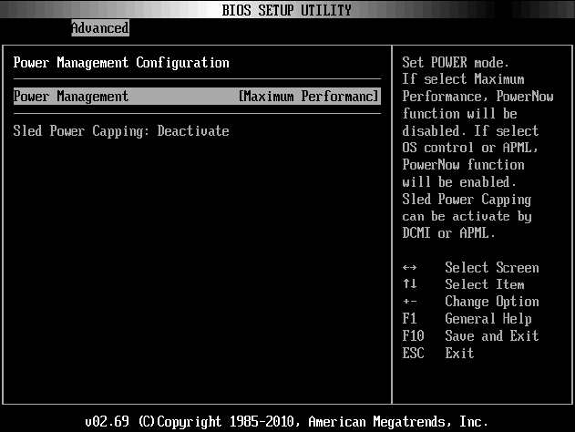
Power Management Maximum Performance
Scroll to this item and press Enter to view the following screen:
Using the System Setup Program | 57
Option
Description
Power Management
(Maximum Performance
default)
Set Power mode. If select Maximum Performance
PowerNow function will be disabled. If select OS control
or APML, PowerNow function will be enabled. Sled
Power Capping can be activate by DCMI or APML.
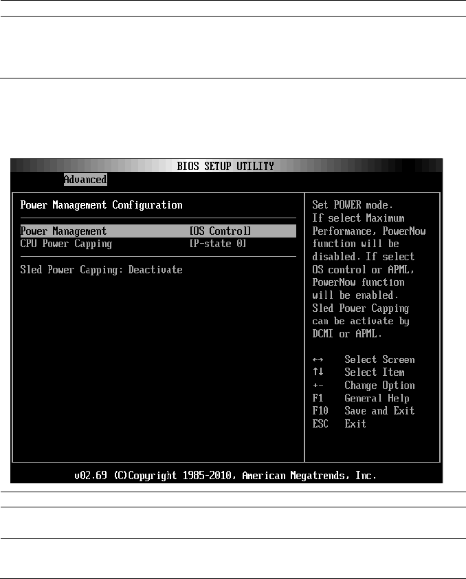
Power Management OS Control
Scroll to this item and press Enter to view the following screen:
Option
Description
OS Control
Select Power Management to OS control mode.
CPU Power Capping
(P-state 0 default)
Sets CPU Power Capping. This option decides the
highest performance P-state in OS.
58 | Using the System Setup Program
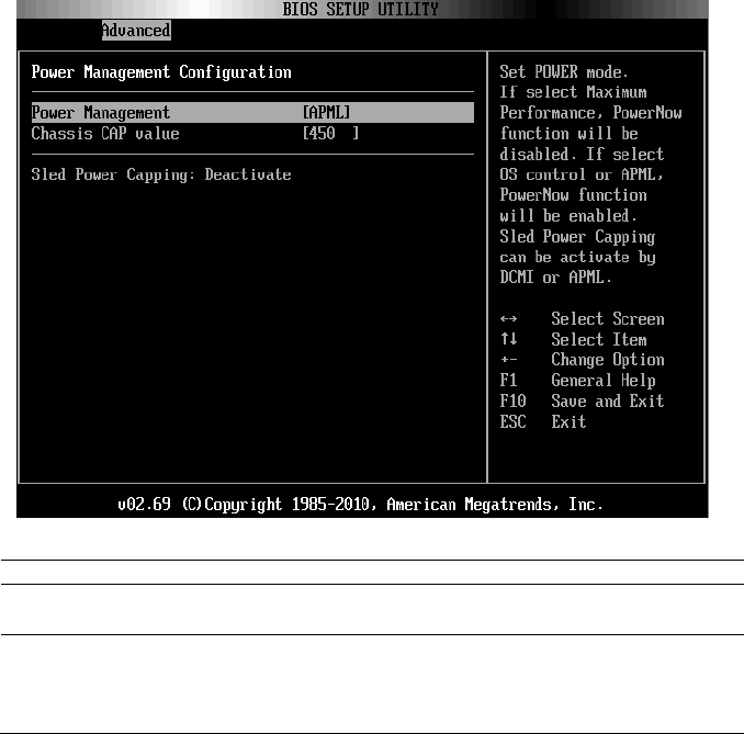
Power Management Advanced Platform Management Link
Scroll to this item and press Enter to view the following screen:
Option
Description
APML
Selects Power Management to AMD Advanced
Platform Management Link mode.
Chassis CAP value
The setting controls PSU power with the power
wattage limit ranging from 450 to 2800 W.
The value is sent to BMC by IPMI command and BMC
controls PSU power.
Using the System Setup Program | 59
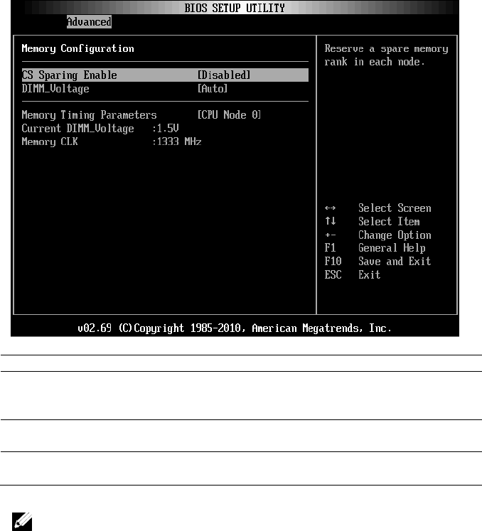
Memory Configuration
Scroll to this item and press Enter to view the following screen:
Option
Description
CS Sparing Enable
(Disabled default)
Reserves a spare memory rank in each channel. This
item will become grey if the memory population
cannot support memory sparing.
DIMM Voltage
(Auto default)
Controls the DIMM voltage.
Memory Timing Parameter
(CPU Node 0 default)
Selects the timing parameters of which node to be
displayed.
NOTE: The item will become gray if the Memory population cannot support
memory sparing.
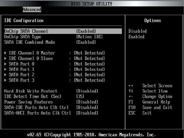
60 | Using the System Setup Program
IDE Configuration
Scroll to this item and press Enter to view the following screen:
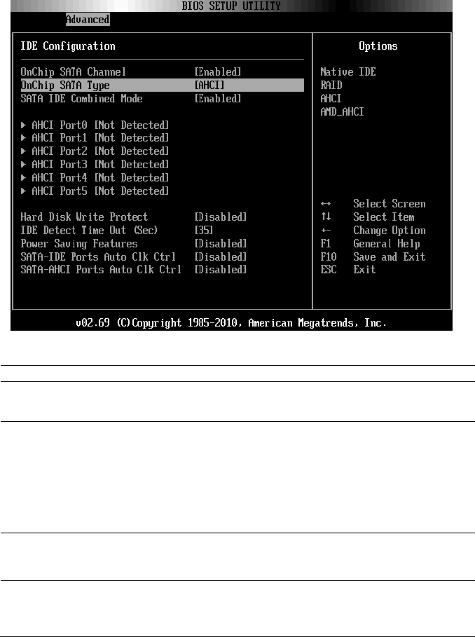
Using the System Setup Program | 61
Option
Description
OnChip SATA Channel
(Enabled default)
Select this item to enable or disable Onboard SATA
controller.
OnChip SATA Type
(Native IDE default)
Native IDE: Native mode.
AMD_AHCI: Use AMD AHCI option ROM.
IDE->AMD_AHCI: No AHCI option ROM, use
AMD AHCI driver (need load driver when install OS,
windows 2008 R2 had native support.)
RAID: Use RAID option ROM.
SATA IDE Combined Mode
(Enabled default)
Two SATA (Port 4 and Port 5) share one IDE channel
(could be either Primary or Secondary channel) from
IDE (PATA) controller.
Hard Disk Write Protect
(Disabled default)
Select this item to disable/enable device write
protection. This will be effective only if device is
accessed through BIOS.

62 | Using the System Setup Program
Option
Description
IDE Detect Time Out(Sec)
(35 Sec. default)
Select the time out value for detecting ATA/ATAPI
device(s).
Power Saving Features
(Disabled default)
Disables/Enables power saving features in SB. As
general rule, this feature should be disabled for
desktop and enabled for mobile.
SATA-IDE Ports Auto Clk
Ctrl
(Disabled default)
When this option is enabled, the system shuts down
the clocks for unused SATA ports in IDE. This enables
some power savings.
Note: When users shut down the clocks, the hot-plug
function for that port will not work.
SATA-AHCI Ports Auto Clk
Ctrl
(Disabled default)
When this option is enabled, the system shuts down
the clocks for unused SATA ports in AHCI modes.
This enables some power savings.
Note: When users shut down the clocks, the hot-plug
function for that port will not work.
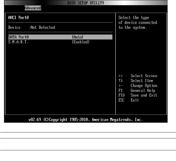
Using the System Setup Program | 63
AHCI Port0
Scroll to this item and press Enter to view the following screen:
Option
Description
SATA Port0
(Auto default)
Select SATA Port0 to Auto.
S.M.A.R.T
S.M.A.R.T stands for Self-Monitoring Analysis and
Reporting Technology.
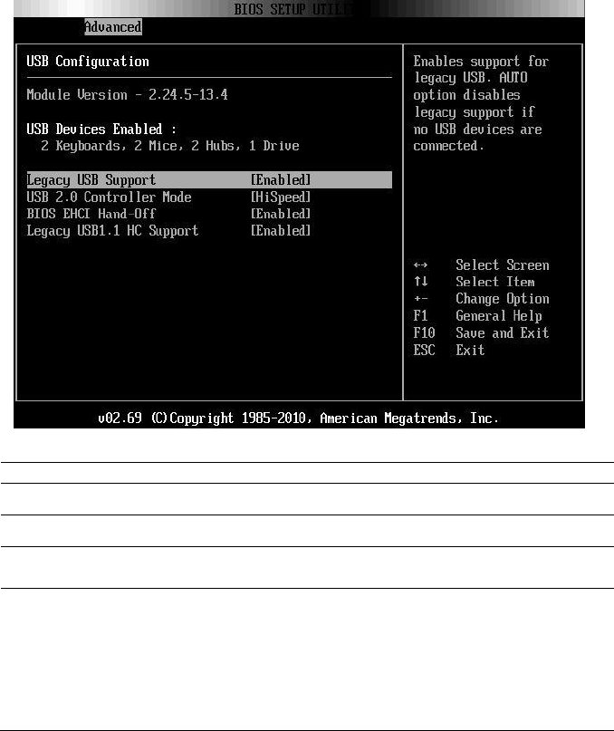
64 | Using the System Setup Program
USB Configuration
Scroll to this item and press Enter to view the following screen:
Option
Description
Module Version
Displays the module version.
USB Devices Enabled
Displays USB devices currently detected.
Legacy USB Support
(Enabled default)
Select this item to enable or disable legacy USB support.
USB 2.0 Controller Mode
(Hispeed default)
Configure the USB 2.0 controller in HiSpeed (480 Mbps)
or FullSpeed (12 Mbps).
If user uses USB device (Floppy, CDROM) to install
RedHat Linux 9.0, please change USB 2.0 Controller
Mode to FullSpeed to workaround it, because RedHat
Linux 9.0 is not supported completely for hand-off
function.
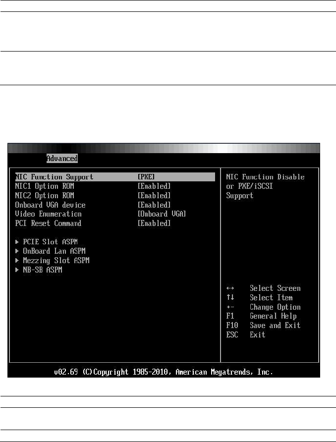
Using the System Setup Program | 65
Option
Description
BIOS EHCI Hand-Off
(Enabled default)
This is a workaround for operating systems without EHCI
hand-off support. The EHCI ownership change should
claim by EHCI driver.
Legacy USB1.1 HC
Support
(Enabled default)
Select these items to enable or disable the USB 1.1 HC.
PCI Configuration
Scroll to this item and press Enter to view the following screen:
Option
Description
NIC Function Support
(PXE default)
NIC for PXE or iSCSI Option ROM support.
NIC1 Option ROM
Disables or enables Option ROM. The ―NIC1 Option

66 | Using the System Setup Program
Option
Description
(Enabled default)
ROM‖ is shown in SETUP screen when PXE or iSCSI
is set.
NIC2 Option ROM
(Enabled default)
Sets OnBoard 82576EB and disables/enables Option
ROM. The ―NIC2 Option ROM‖ is shown in SETUP
screen when PXE is set.
Onboard VGA device
(Enabled default)
Sets onboard VGA chip. The remote KVM function
cannot work if this setting is disabled.
Video Enumeration
(Onboard VGA default)
Sets Video enumeration.
PCI Reset Command
(Enabled default)
Resets the PCI device which behind the HIC card,
such as PEC410x GPGPU systems.
PCIE-Slot ASPM
Sets PCIE-Slot ASPM.
Onboard LAN ASPM
Sets Onboard LAN ASPM.
Mezzing Slot ASPM
Sets Mezzing Slot ASPM.
NB-SB ASPM
Sets NB-SB ASPM.
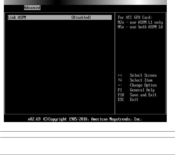
Using the System Setup Program | 67
PCIE Slot/Onboard LAN/Mezzing Slot ASPM
Scroll to one of these three items and press Enter to view the following
screen:
Option
Description
Link ASPM
(Disabled default)
For ATI GFX Card:
M2x – use ASPM L1 only
M5x - use both ASPM L0
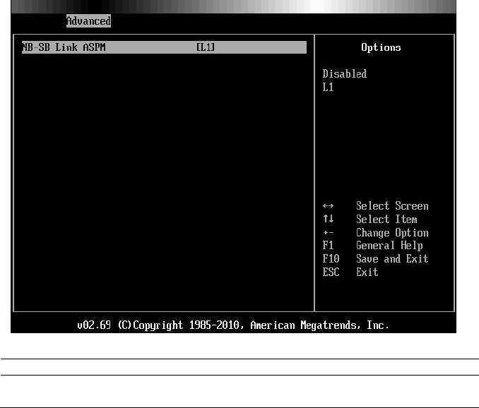
68 | Using the System Setup Program
NB-SB Port Features
Scroll to this item and press Enter to view the following screen:
Option
Description
Link ASPM
(L1 default)
Sets this item to L1 or to disable.
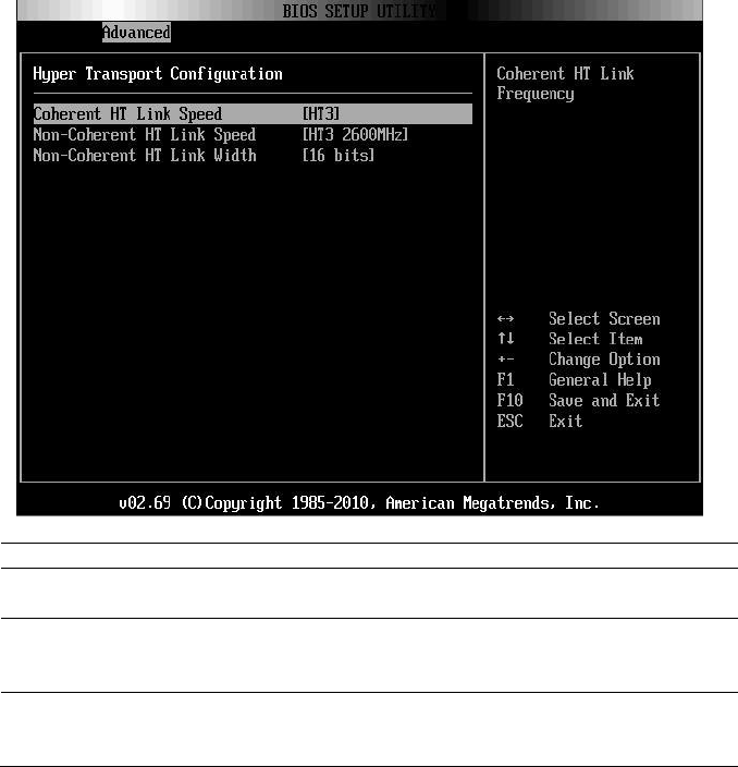
Using the System Setup Program | 69
Hyper Transport Configuration
Option
Description
Coherent HT Link Speed
(HT3 default)
Coherent HT Link Frequency
Non-Coherent HT Link
Speed
(HT3 2600MHz default)
Non-Coherent HT Link Frequency
Non-Coherent HT Link
Width
(16 bits default)
Non-Coherent HT Link Width
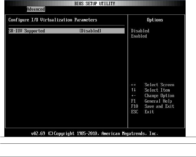
70 | Using the System Setup Program
I/O Virtualization
Option
Description
SR-IOV Supported
(Disabled default)
Sets this item to enable or to disabe.
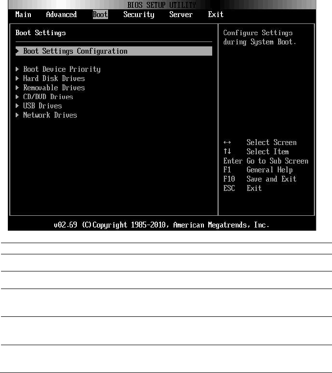
Using the System Setup Program | 71
Boot Menu
This page enables you to set POST boot parameters.
Scroll to this item and press Enter to view the following screen:
Option
Description
Boot Settings Configuration
Configure Settings during System Boot.
Boot Device Priority
Specifies the Boot Device Priority sequence
Hard Disk Drives
Specifies the Boot Device Priority Sequence from
available Hard Drives.
Removable Drives
Specifies the Boot Device Priority sequence from
available Removable Drives.
CD/DVD Drives
Specifies the Boot Device Priority sequence from
available CD/DVD Drives.
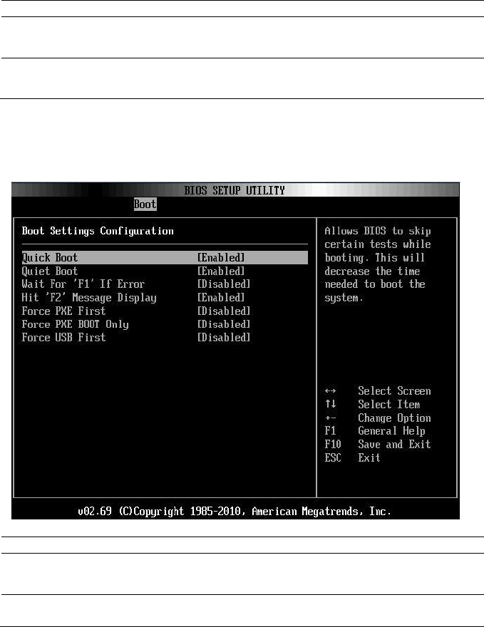
72 | Using the System Setup Program
Option
Description
USB Drives
Specifies the Boot Device Priority sequence from
available USB Drives.
Network Drives
Specifies the Boot Device Priority sequence from
available Network Drives.
Boot Settings Configuration
Select this item and press Enter to view the following submenu items:
Option
Description
Quick Boot
(Enabled default)
Allow BIOS to skip certain tests while booting, which
will decrease the time needed to boot the system.
Quiet Boot
(Enabled default)
Disabled: displays normal POST messages.
Enabled: displays OEM logo instead of POST

Using the System Setup Program | 73
Option
Description
messages.
Wait For ‗F1‘ if Error
(Disabled default)
Wait for F1 key to be pressed if error occurs.
Hit ‗F2‘ Message Display
(Enabled default)
Displays ―Press F2 to run Setup‖ in POST.
Force PXE first
(Disabled default)
Forces the system to boot by PXE first.
Force PXE Boot only
(Disabled default)
Forces the system to boot by PXE only.
Force USB First
(Disabled default)
Forces the system to boot from USB first.
NOTE: The following list shows the priority of the boot options (high to low):
“Force PXE BOOT Only”
Select boot device by pop menu (press F11 during POST)
“Force PXE First”, press F12 during POST
“Force USB First”
boot order in setup menu
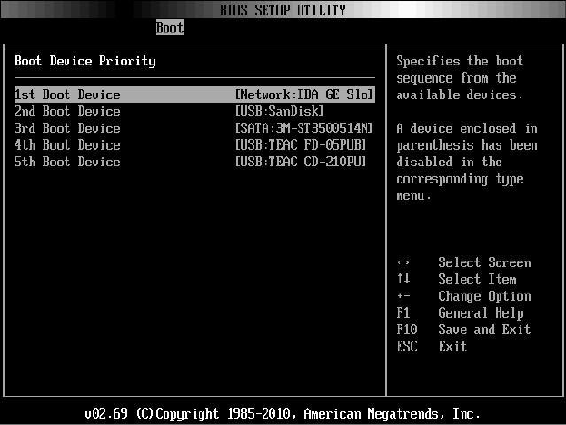
74 | Using the System Setup Program
Boot Device Priority
Select this item and press Enter to view the following submenu items:
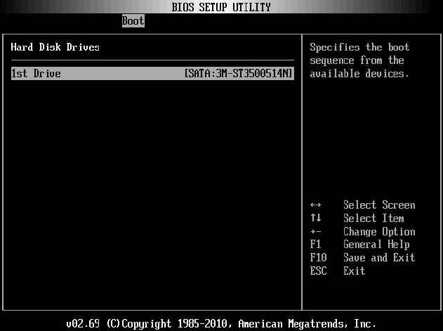
Using the System Setup Program | 75
Hard Disk Drives
Scroll to this item and press Enter to view the following screen:
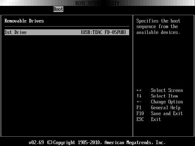
76 | Using the System Setup Program
Removable Drives
Scroll to this item and press Enter to view the following screen:
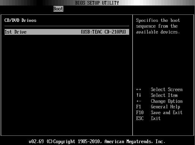
Using the System Setup Program | 77
CD/DVD Drives
Scroll to this item and press Enter to view the following screen:
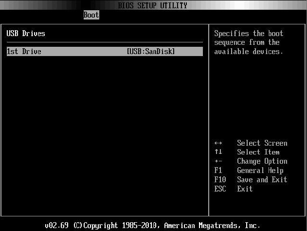
78 | Using the System Setup Program
USB Drives
Scroll to this item and press Enter to view the following screen:
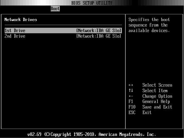
Using the System Setup Program | 79
Network Drives
Scroll to this item and press Enter to view the following screen:
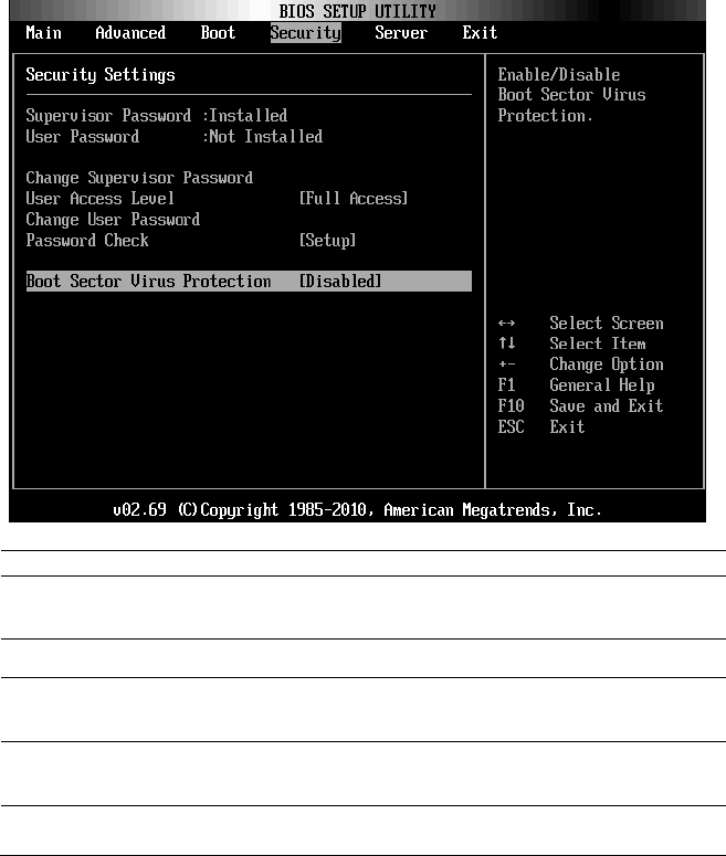
80 | Using the System Setup Program
Security Menu
This page enables you to set the security parameters.
Scroll to this item and press Enter to view the following screen:
Option
Description
Supervisor Password
Displays whether the supervisor password is installed or
not.
User Password
Displays whether the user password is installed or not.
User Access Level
(Full Access default)
Sets the access level for users.
Change Supervisor
Password
Installs or changes the password.
Change User Password
Installs or changes the password.
This item is only shown when the supervisor password is

Using the System Setup Program | 81
Option
Description
set.
Password Check
(Setup default)
Setup: Checks password while invoking setup.
Always: Checks password while invoking setup as well as
on each boot.
This item is only shown when the supervisor password is
set.
Boot Sector Virus
Protection
(Disabled default)
Enables or disables Boot Sector Virus Protection.
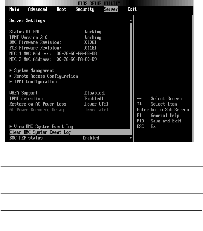
82 | Using the System Setup Program
Server Menu
This page enables you to configure Server parameters.
Scroll to this item and press Enter to view the following screen:
Option
Description
WHEA Support
(Disabled default)
Enables or disables Windows Hardware Error
Architecture.
IPMI detection
Enables IPMI detection. BMC will be detected by
OSs which support plug and play loading of an IPMI
driver. Do not enable if your OS does not support this
driver.
Restore on AC Power Loss
(Power Off default)
System action to take on AC power loss recovery.
AC Power Recovery Delay
(Immediate default)
Select the time of system power on after BMC
initiate.
Immediate: Power on directly after BMC initiate.

Using the System Setup Program | 83
Option
Description
Random: Randomly select time to power on.
User define: User selects the time.
The ―Delay Time‖ will be shown in the Setup screen
when ―AC Power Recovery Delay‖ is set to ―User
define‖. The value of Delay Time will change to 30
after rebooted if it is less than 30. The value of Delay
Time will change to 255 after rebooted if it is larger
than 255.
View BMC System Event Log
View all events in the BMC Event Log.
It will take a maximum of 15 seconds to read all
BMC SEL records.
Clear BMC System Event Log
Clears the BMC System Event Log.
BMC PEF Status
(Disabled default)
Enables or disables the BMC PEF status.
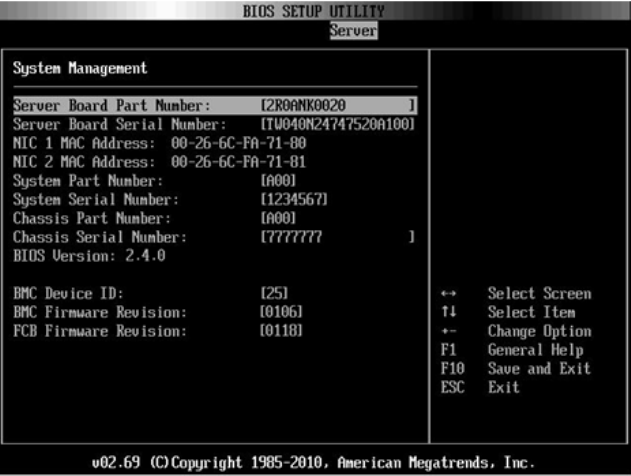
84 | Using the System Setup Program
System Management
Scroll to this item and press Enter to view the following screen:
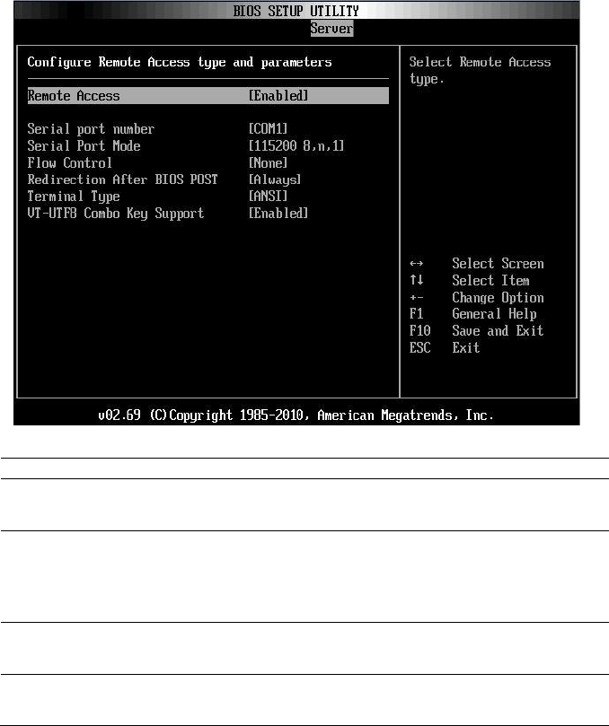
Using the System Setup Program | 85
Remote Access Configuration
Scroll to this item and press Enter to view the following screen:
Option
Description
Remote Access
(Disabled default)
Select remote access type.
Serial Port Number
(COM1 default)
Select serial port for console redirection.
Make sure the selected port is enabled.
When ―Serial Port Number‖ is set to ―COM2‖, the
setting will support SOL.
Serial Port Mode
(115200 8,n,1 default)
Select serial port settings.
Flow Control
(None default)
Select flow control for console redirection.
When setting ―Flow Control‖ to ―Software‖, the

86 | Using the System Setup Program
Option
Description
Hyper Terminal on remote side will be discontinued
when <Ctrl>+<S> key is pressed. But onboard NIC
PXE Option ROM Configuration is also set when
<Ctrl>+<S> key is pressed. Suggest user change the
―Setup Key Stroke‖ to <Ctrl>+<B> in PXE
OPROM Configuration. The Hyper Terminal on
remote side will be discontinued when <Ctrl>+<S>
key is pressed.
Redirection After BIOS
POST
(Always default)
Disabled: Turns off the redirection after POST.
Always: Redirection is always active. (Some operating
systems may not work if set to Always.)
Terminal Type
(ANSI default)
Select the target terminal type.
VT-UTF8 Combo Key
Support
(Enabled default)
Enables or disables VT-UTF8 combination key support
for ANSI/VT100 terminals.
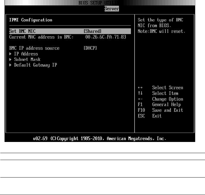
Using the System Setup Program | 87
IPMI Configuration
Scroll to this item and press Enter to view the following screen:
Option
Description
Set BMC NIC
(Shared default)
Sets the type of BMC NIC from BIOS.
BMC will reset.
BMC IP address source
(DHCP default)
Sets BMC IP address source from BIOS.
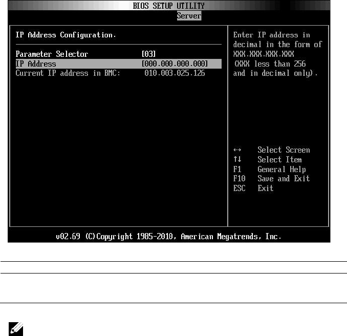
88 | Using the System Setup Program
IP Address Configuration
Select IP Address item in the IPMI Configuration screen to view the
following submenu:
Option
Description
IP Address
Enter IP address in decimal in the form of
XXX.XXX.XXX.XXX (XXX less than 256 and in decimal only).
NOTE: When BMC IP status is static, this item is userful.
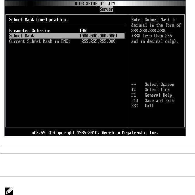
Using the System Setup Program | 89
Subnet Mask Configuration
Select Subnet Mask item in the IPMI Configuration screen to view the
following submenu:
Option
Description
Subnet Mask
Enter Subnet Mask in decimal in the form of
XXX.XXX.XXX.XXX (XXX less than 256 and in
decimal only).
NOTE: When BMC IP status is static, this item is userful.
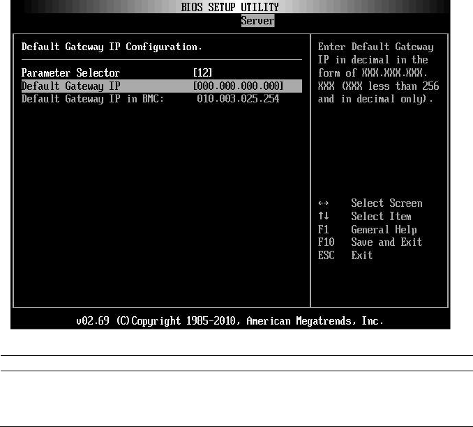
90 | Using the System Setup Program
Default Gateway IP Configuration:
Select Default Gateway IP item in the IPMI Configuration screen to view
the following submenu:
Option
Description
Default Gateway IP
Enter Default Gateway IP in decimal in the form of
XXX.XXX.XXX.XXX (XXX less than 256 and in
decimal only).
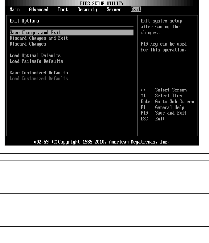
Using the System Setup Program | 91
Exit Menu
Scroll to this item and press Enter to view the following screen:
Option
Description
Save Changes and Exit
Exit system setup after saving the changes. F10 key can
be used for this operation.
Discard Changes and Exit
Exit system setup without saving any changes. ESC key
can be used for this operation.
Discard Changes
Discards changes done so far to any of the setup
questions. F7 key can be used for this operation.
Load Optimal Defaults
Loads optimal default values for all the setup questions.
F9 key can be used for this operation.
Load Failsafe Defaults
Loads Failsafe Default values for all the setup questions.
F8 key can be used for this operation.

92 | Using the System Setup Program
Option
Description
Save Customized Defaults
Saves the changes as User Defaults.
Load Customized Defaults
Loads the User Defaults to all the setup options.
Command Line Interface for Setup Options
The options of SETUP menu allow users to control by system configuration
utility (syscfg). The utility is included in Dell OpenManage Deployment
Toolkit (DTK).
Users can use the utility as following:
To change the SETUP option by D4 token:
./syscfg –t=D4_token_id
(Example: ./syscfg -t=0x002D to enable NIC1 Option ROM)
To check token activity status:
./syscfg --
istokenactive=D4_token_id
(Example: ./syscfg --istokenactive=0x002D to check the token activity
status of NIC1 Option ROM)
To change the SETUP option through BMC memory directly:
./impitool raw <command> <data>
(Example: ./impitool raw 0xc 1 1 3 10 106 42 120 to set IP address of
BMC LAN port as 10.106.42.120)
Table 2-1. The D4 Token Table
Token
Setup Option
Description
002D
NIC1 Option ROM
Enable the system‘s primary embedded
network interface controller (full function),
including its PXE boot-ROM.
002E
NIC Function Support
Disable the system‘s onboard network
interface controller.
0051
BOOTSEQ_DSKT
For the next system boot, set the IPL
priority to: diskette, hard drive, IDE
CD-ROM, option ROMs (if the devices are
available)
0052
BOOTSEQ_HDONLY
For the next system boot, set the IPL
priority to: hard drive then option

Using the System Setup Program | 93
Token
Setup Option
Description
ROMs (if the devices are available)
0053
BOOTSEQ_DEVLST
For the next system boot, set the IPL
priority to: diskette, IDE CD-ROM,
hard drive, option ROMs (if the devices are
available)
0054
BOOTSEQ_CDROM
For the next system boot, set the IPL
priority to: IDE CD-ROM, diskette,
hard drive, option ROMs (if the devices are
available)
005C
TOKEN_RBU_EN
Enable the system BIOS, on the next
reboot, to search for an operating-system-
initiated BIOS update image.
005Dh
TOKEN_RBU_DIS
Disable the BIOS update. This value is set
by the BIOS on each reboot of the system.
006E
NIC1 Option ROM
Enable the system‘s primary embedded
network interface controller, but does not
enable the NIC‘s associated PXE or RPL
boot-ROM.
0087
Onboard VGA
prior Onboard VGA when system power on
0088
Add-in VGA
prior Add-in VGA when system power on
009B
Legacy USB Support
Enable USB emulation
009C
Legacy USB Support
Disable USB emulation
00A1
Restore on AC power Loss
After an AC power loss, when AC power is
restored, the system will stay off.
00A2
Restore on AC power Loss
After an AC power loss, when AC power is
restored, the system will return to the state
was in when power was lost.
00A3
Restore on AC power Loss
After an AC power loss, when AC power is
restored, the system will power on.
00BB
NIC2 Option ROM
Enable the system‘s secondary embedded
network interface controller, but does not
enable the NIC‘s associated PXE or RPL
boot-ROM.
00BC
NIC2 Option ROM
Enable the system‘s secondary embedded
network interface controller (full-function),
including its PXE boot-ROM.
00BF
Remote Access
Serial Console Redirection Off.

94 | Using the System Setup Program
Token
Setup Option
Description
00C0
Remote Access
Serial Console Redirection On, output to
COM1. See also token D7h.
00CA
CS Sparing Enabled
Disable Redundant memory.
00CB
CS Sparing Enabled
Enable Redundant memory.
00D7
Serial port number
Console redirection to COM2.
00D8
Load Optimal Default
Load Optimal Default.
0135
OnChip SATA Channel
Disable Onboard SATA controller(s).
0137
OnChip SATA type
Onboard SATA controller(s) is set to Native
IDE mode.
0138
OnChip SATA type
Onboard SATA controller(s) is set to AHCI
mode.
0139
OnChip SATA type
Onboard SATA controller(s) is set to RAID
mode
013B
OnChip SATA Channel
Enable Onboard SATA controller(s).
0173
Hardware Prefetcher
Disable CPU HW Prefetcher.
0174
Hardware Prefetcher
Enable CPU HW Prefetcher.
01C4
ACPI SRAT Table
Disable for ACPI SRAT Table.
01C5
ACPI SRAT Table
Enable for ACPI SRAT Table.
021F
Power Management
This will set max. performance.
0221
Power Management
Allow OS to control p-state.
0222
Power Management
Enable APML control.
0224
Onboard VGA device
Enable onboard VGA chip.
0225
Onboard VGA device
Disable onboard VGA chip, the BMC
remote KVM function can not work.
0231
CPU DownCore Mode
Enable CPU 4 cores only.
0232
CPU DownCore Mode
Enable CPU 2 cores only.
024D
Wait For ‗F1‘ If Error
Enable the BIOS from prompting for F1/F2
on error. BIOS pauses at F1/F2 prompt.
024E
Wait For ‗F1‘ If Error
Disable the BIOS from prompting for F1/F2
on error. BIOS pauses at F1/F2 prompt.
024F
Quiet Boot
Enable the display of the splash or summary
screen, rather than the detail of the POST
flow.
0250
Quiet Boot
Disable the display of the splash or

Using the System Setup Program | 95
Token
Setup Option
Description
summary screen. The user is able to see the
detail of the POST messages.
026F
CPU DownCore Mode
Enable CPU 6 cores only.
0270
CPU DownCore Mode
Enable CPU 8 core only.
0271
CPU DownCore Mode
Enable CPU 10 cores only.
0272
CPU DownCore Mode
Enable CPU 12 cores only.
0273
CPU DownCore Mode
Enable CPU cores to All.
02A1
C1E Support
Enable CPU C1E support.
02A2
C1E Support
Disable CPU C1E support.
02AD
SR-IOV Supported
Enable SR-IOV Supported
02AE
SR-IOV Supported
Disable SR-IOV Supported
02B6
1.5V DIMM_Voltage
set DIMM voltage to Force 1.5V
02B7
1.35V DIMM_Voltage
set DIMM voltage to Force 1.35V
02B8
Auto DIMM_Voltage
Auto detect DIMM voltage
401A
Terminal Type
The BIOS console redirection, if enabled,
operates in VT100 emulation model. See
also tokens BFh, C0h, and D7h.
401B
Terminal Type
The BIOS console redirection, if enabled,
operates in ANSI emulation model. See also
tokens BFh, C0h, and D7h.
401C
Redirection After BIOS POST
The BIOS console redirection, if enabled,
continues to operate after the
OS boot hand-off.
401D
Redirection After BIOS POST
The BIOS console redirection, if enabled,
operates during the BIOS boot only and is
disabled prior to OS boot hand-off. See also
tokens BFh, C0h, D7h, 401Ah and 401Bh.
4022
Force PXE First
Whenever the system boots from BIOS, the
first PXE-capable device is inserted as the
first device in the boot sequence. Enabling
this feature causes the BIOS operation to
occur on the next and all subsequent boots
and causes a change in the system‘s defined
boot sequence (unlike tokens 93h and 94h).
The BIOS chooses the first PXE-capable

96 | Using the System Setup Program
Token
Setup Option
Description
device as the system‘s onboard network
controller, if present and enabled, or the first
bootable network device found in the
system‘s standard PCI search order —
whichever comes first.
4023
Force PXE First
Disable the PXE boot override and the
system boot sequence is in effect.
4031
Quick Boot
Enabled, skip the system memory tests.
4032
Quick Boot
Disabled, execute the system memory tests.
4033
Serial Port Mode
Console Redirection baud rate will be set to
115,200 bits per second.
4034
Serial Port Mode
Console Redirection baud rate will be set to
57,600 bits per second.
4035
Serial Port Mode
Console Redirection baud rate will be set to
19,200 bits per second.
4036
Serial Port Mode
Console Redirection baud rate will be set to
9,600 bits per second.
4816
Force PXE BOOT Only
Disable Force PXE Boot only.
4817
Force PXE BOOT Only
Enable Force PXE Boot only.
481B
NIC Function Support
Onboard NIC support PXE ROM.
481C
NIC Function Support
Onboard NIC support iSCSI ROM.
481D
Flow Control
Set serial port flow control to none.
481E
Flow Control
Set serial port flow control to hardware.
481F
Flow Control
Set serial port flow control to software.
4820
VT-UTF8 Combo Key
Support
Disable VT-UTF8 combo key support.
4821
VT-UTF8 Combo Key
Support
Enable VT-UTF8 combo key support.
4822
BMC NIC
Share BMC NIC.
4823
BMC NIC
Dedicate BMC NIC.
4824
BMC IP address source
Set BMC IP address to static.
4825
BMC IP address source
Set BMC IP address to DHCP.
4826
WHEA Support
Disable Windows 2008 R2 WHEA support.
4827
WHEA Support
Enable Windows 2008 R2 WHEA support.

Using the System Setup Program | 97
Token
Setup Option
Description
482A
Serial port number
Console redirection to COM1.
482B
Terminal Type
The BIOS console redirection, if enabled,
operates in VT-UTF8 emulation model. See
also tokens BFh, C0h, and D7h.
4832
OnChip SATA type
Onboard SATA controller(s) is set to
AMD_AHCI mode
4840
Force USB First
Disable USB drivers as first boot device.
4841
Force USB First
Enable USB to be the first boot device, the
priority is higher than PXE. It will take
effect on next boot.
4842
Redirection After BIOS POST
The BIOS console redirection, if enabled,
continues to operate until boot loader.
4843
IPMI Detection
Disable for BMC DUP execute.
4844
IPMI Detection
Normally, enable IPMI detection.
4856
IOMMU
Disable IOMMU device.
4857
IOMMU
Enable IOMMU device.
4858
Secure Virtual Machine Mode
Enable Secure Virtual Machine Mode.
4859
Secure Virtual Machine Mode
Disable Secure Virtual Machine Mode.
485E
USB 2.0 Controller Mode
Set USB controller mode to Full speed.
485F
USB 2.0 Controller Mode
Set USB controller mode to High speed.
4860
BIOS EHCI Hand-Off
Enable USB EHCI Hand-Off.
4861
BIOS EHCI Hand-Off
Disable USB EHCI Hand-Off.
4866
CPU Power Capping
Set CPU power state limit to P0.
4867
CPU Power Capping
Set CPU power state limit to P1.
4868
CPU Power Capping
Set CPU power state limit to P2.
4869
CPU Power Capping
Set CPU power state limit to P3.
486A
CPU Power Capping
Set CPU power state limit to P4.
486E
PSU Power Capping
Disable BMC power support throttle
control.
486F
PSU Power Capping
Enable BMC power support throttle
control.
4871
SATA-AHCI Ports Auto Clk
Ctrl
Disable SATA-AHCI port clock control.
4872
SATA-AHCI Ports Auto Clk
Enable SATA-AHCI port clock control.

98 | Using the System Setup Program
Token
Setup Option
Description
Ctrl
4873
SATA-IDE Ports Auto Clk
Ctrl
Disable SATA-IDE port clock control.
4874
SATA-IDE Ports Auto Clk
Ctrl
Enable SATA-IDE port clock control.
4877
L3 Power Control
Disable the clock stop for an idle subcache.
4878
L3 Power Control
Enable the clock stop for an idle subcache.
4883
NB-SB Link ASPM
Disable NB-SB link ASPM.
4884
NB-SB Link ASPM
Set NB-SB link ASPM to L1.
4887
Coherent HT Link Speed
Set Coherent HT link to HT1.
4888
Coherent HT Link Speed
Set Coherent HT link to HT3.
4891
Power Saving Features
Disable dynamic power saving function for
SATA core clock.
4892
Power Saving Features
Enable dynamic power saving function for
SATA core clock.
48A2
Non-Coherent HT Link
Speed
Set Non-Coherent HT Link Speed to HT1
1200Mhz.
48A4
Non-Coherent HT Link
Speed
Set Non-Coherent HT Link Speed to HT3
2000Mhz.
48A5
Non-Coherent HT Link
Speed
Set Non-Coherent HT Link Speed to HT3
2600Mhz.
48A6
Non-Coherent HT Link
Width
Set Non-Coherent HT Link Width 8 bits.
48A7
Non-Coherent HT Link
Width
Set Non-Coherent HT Link Width 16 bits.
48B9
DRAM Prefetcher
Disable DRAM prefetcher.
48BA
DRAM Prefetcher
Enable DRAM prefetcher.
48BD
Software Prefetcher
Disable HW Prefetcher Training on SW.
48BE
Software Prefetcher
Enable HW Prefetcher Training on SW.
5001
PCIE-Slot ASPM
Disable PCIE-Slot ASPM.
5002
PCIE-Slot ASPM
Set PCIE-Slot ASPM to L0.
5003
PCIE-Slot ASPM
Set PCIE-Slot ASPM to L1.
5004
PCIE-Slot ASPM
Set PCIE-Slot ASPM to L0 & L1.
5021
Onboard Lan ASPM
Disable Onboard NIC ASPM.

Using the System Setup Program | 99
Token
Setup Option
Description
5022
Onboard Lan ASPM
Set Onboard NIC ASPM to L0.
5023
Onboard Lan ASPM
Set Onboard NIC ASPM to L1.
5024
Onboard Lan ASPM
Set Onboard NIC ASPM to L0 & L1.
5091
Mezzing Slot ASPM
Disable Mezzing Slot ASPM.
5092
Mezzing Slot ASPM
Set Mezzing Slot ASPM to L0.
5093
Mezzing Slot ASPM
Set Mezzing Slot ASPM to L1.
5094
Mezzing Slot ASPM
Set Mezzing Slot ASPM to L0 & L1.
5097
SATA IDE Combined Mode
Disable SATA IDE combined mode, if only
AHCI mode is used, the item needs to be
set disabled for port4 & port5.
5098
SATA IDE Combined Mode
Enabled, two SATA ports (port 4 & port 5)
share one IDE channel.
5103
PCI Reset
Enabled PCI Reset.
5104
PCI Reset
Disabled PCI Reset.
50A0
CPU DownCore Mode (only
for Family15h CPU)
Enable CPU 2 cores only.
50A1
CPU DownCore Mode (only
for Family15h CPU)
Enable CPU 4 cores only.
50A2
CPU DownCore Mode (only
for Family15h CPU)
Enable CPU 8 cores only.
50A3
CPU DownCore Mode (only
for Family15h CPU)
Enable CPU 12 cores only.
51A4
Cstate Mode
Set CPU Cstate to Disabled.
51A5
Cstate Mode
Set CPU Cstate to C6.
51A6
CPB Mode
Set CPB Mode to Disabled.
51A7
CPB Mode
Set CPB Mode to Auto.
100 | Using the System Setup Program
Table 2-2. The IPMI Command Table
IPMI Command
Setup Option
Description
ipmitool raw 0x34 0xB1
<Byte1:4>
Byte 1 - Power
Management Enable(01h
enable)
Byte 2 - Power Capping
Enable(01h enable)
Byte 3 - Current Chassis
Power Capping Value(Low
Byte)
Byte 4 - Current Chassis
Power Capping
Value(High Byte)
SET POWER
MANAGEMENT
BEHAVIOR
The setting controls PSU Power, its
range limited in 450˜2000 W. The
value is sent to BMC by IPMI
command and BMC will control
PSU power. This setting can be seen
when ―Power Management‖ is
selected to ―APML‖ mode and the
system board at location 2 in the
chassis.
ipmitool raw 0xc 1 1 3 <IP
Address>
IP Address
Use this option to input BMC LAN
port IP address.
ipmitool raw 0xc 1 1 6
<Subnet Mask>
Subnet Mask
Use this option to input BMC LAN
port subnet mask address.
ipmitool raw 0xc 1 1 12
<IP Address>
GateWay Address
Use this option to input BMC LAN
port Gateway address.
ipmitool raw 0x30 1
Return: ID
ipmitool raw 0x30 3 ID
0x11 0x2 0 0 0 1 <Delay
Mode>
Power Staggering
AC Recovery
Configures power recovery behavior.
This item can be seen when
―Remote on AC Power Loss‖ is
selected in ―Power On‖ or ―Last
State‖.
This parameter is only effective if
the Power Policy is not set to always
off.
0x00: Immediate Power On (No
Delay) : Default
0x01: Auto (Random), the auto
generated delay time must be in the
range of Minimum Power On Delay
and Maximum Power On Delay.
0x02: User Defined, the user
defined delay time must be in the
range of Minimum Power On Delay
and Maximum Power On Delay.
ipmitool raw 0x30 1
Minimum Power
Configures time for power on delay,

Using the System Setup Program | 101
IPMI Command
Setup Option
Description
Return: ID
ipmitool raw 0x30 3 ID
0x11 0x4 0 0 0 1 <LSB
timer> <HSB timer>
On Delay
the setting range of delay time is
0˜255 Sec.
ipmitool raw 0x30 1
Return: ID
ipmitool raw 0x30 3 ID
0x11 0x5 0 0 0 1 <LSB
timer> <HSB timer>
Maximum Power
On Delay
Configures time for power on delay,
the setting range of delay time is
0˜255 Sec.
ipmitool raw 0x30 1
Return: ID
ipmitool raw 0x30 3 ID
0x11 0x3 0 0 0 1 <LSB
timer> <HSB timer>
Power On Delay
Configures time for power on delay,
the setting range of delay time is
0˜255 Sec.
ipmitool raw 0x0a 0x42
Return: ID1 ID2
ipmitool raw 0x0a 0x47
ID1 ID2 0x43 0x4C 0x52
0xAA
Clear BMC
System Event
Log
Clears all events in the BMC Event
Log.
ipmitool raw 0x34 0x11
Response:
Byte 1 – completion code
Byte 2 – Board ID
Get Board ID
Identify MLB‘s Board ID in chassis.

102 | Using the System Setup Program
Table 2-3. The Power Management Settings
Setup Menu
Performance
Settings
Power Optimized
Settings
Option
D4
Token
Option
D4
Token
CPU
Configuration
L3 Power Control
Enabled
4878
Disabled
4877
DRAM Prefetcher
Enabled
48BA
Disabled
48B9
Hardware Prefetcher
Enabled
0174
Disabled
0173
Software Prefetcher
Enabled
48BE
Disabled
48BD
CPU
Configuration
->Power
Management
Power Management
Max.
Performance
021F
OS
Control
P-State 4
0221
486A
CPU
Configuration
->CPB
Mode(Turbo
Mode)
CPB Mode(Turbo
Mode)
Auto
51A7
Disabled
51A6
SATA
Configuration
Power Saving Features
Disabled
4891
Enabled
4892
SATA-AHCI Ports
Auto Clk Ctrl
Disabled
4871
Enabled
4872
SATA-IDE Ports Auto
Clk Ctrl
Disabled
4873
Enabled
4874
Hyper
Transport
Configuration
Coherent HT Link
Speed
HT3
4888
HT1
4887
Non-Coherent HT
Link Speed
HT3
2600MHz
48A5
HT1
1200Mhz
48A2
Non-Coherent HT
Link Width
16 bits
48A7
8 bit
48A6
PCI
Configuration
-> Active
State Power
Management
Configuration
PCI-E Slot ASPM
Disabled
5001
L0s & L1
5004
Onboard LAN ASPM
Disabled
5021
L0s & L1
5024
Mezzing Slot ASPM
Disabled
5091
L0s & L1
5094
NB-SB Link ASPM
Disabled
4883
L1
4884

3
Installing System Components | 103
Installing System Components
Safety Instructions
WARNING: Working on systems that are still connected to a power supply can
be extremely dangerous.
CAUTION: System components and electronic circuit boards can be damaged by
discharge of static electricity.
CAUTION: Many repairs may only be done by a certified service technician. You
should only perform troubleshooting and simple repairs as authorized in your
product documentation, or as directed by the online or telephone service and
support team. Damage due to servicing that is not authorized by Dell is not
covered by your warranty. Read and follow the safety instructions that came with
the product.
To avoid injury to yourself or damage to system, follow these guidelines:
Always disconnect the system from the power outlet whenever you are
working inside the system.
If possible, wear a grounded wrist strap as you work inside the system.
Or discharge any static electricity by touching the bare metal chassis of
system case, or the bare metal body of any other grounded appliance.
Hold electronic circuit boards by the edges only. Do not touch the
components on the board unless it is necessary to do so. Do not flex or
stress the circuit board.
Leave all components inside the static-proof packaging until you are
ready to use the component for the installation.
Recommended Tools
#1 Phillips screwdriver
#2 Phillips screwdrivers
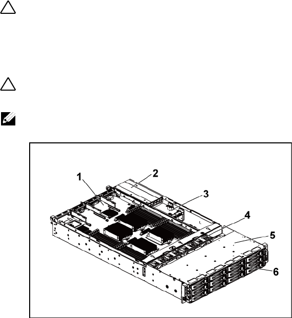
104 | Installing System Components
Inside the System
CAUTION: Many repairs may only be done by a certified service technician. You
should only perform troubleshooting and simple repairs as authorized in your
product documentation, or as directed by the online or telephone service and
support team. Damage due to servicing that is not authorized by Dell is not
covered by your warranty. Read and follow the safety instructions that came with
the product.
CAUTION: This system must be operated with the system cover installed to
ensure proper cooling.
NOTE: The illustration in this section shows a system with 3.5" hard drives.
Figure 3-1. Inside the System
1
system-board assembly (2)
2
power supply (2)
3
power distribution board (2)
4
cooling fan (4)
5
hard-drive bay
6
hard drive (12)
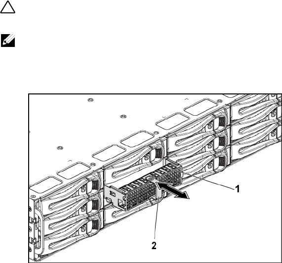
Installing System Components | 105
Hard Drives
The installation and removal procedures for the 3.5" hard drive and the 2.5"
hard drive are similar. Following is an example showing the replacement
procedure of a 3.5" hard drive.
Removing a Hard-Drive Blank
CAUTION: To maintain proper system cooling, all empty hard-drive bays must
have drive blanks installed.
NOTE: This section is applicable to systems with hot-swappable hard drives only.
1 Using the release handle, pull the hard-drive blank out of the hard-
drive bay. See Figure 3-2.
Figure 3-2. Removing or Installing a Hard-Drive Blank
1
hard-drive blank
2
release handle

106 | Installing System Components
Installing a Hard-Drive Blank
1 Slide the hard-drive blank into the drive bay until the hard-drive blank
makes contact with the backplane. See Figure 3-2.
Removing a Hard-Drive Carrier
CAUTION: Many repairs may only be done by a certified service technician. You
should only perform troubleshooting and simple repairs as authorized in your
product documentation, or as directed by the online or telephone service and
support team. Damage due to servicing that is not authorized by Dell is not
covered by your warranty. Read and follow the safety instructions that came with
the product.
1 Turn the lock lever counterclockwise until it points to the unlock
symbol.
2 Slide the release button to open the release handle. See Figure 3-3.
3 Using the release handle, pull the hard-drive carrier out of the hard-
drive bay.
CAUTION: To maintain proper system cooling, all empty hard-drive bays must
have drive blanks installed.
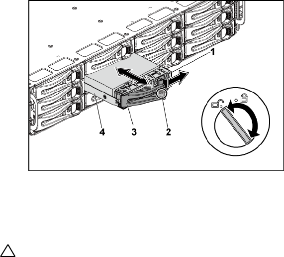
Installing System Components | 107
Figure 3-3. Removing and Installing a Hard-Drive Carrier
1
release button
2
lock lever
3
release handle
4
hard-drive carrier
Installing a Hard-Drive Carrier
CAUTION: Many repairs may only be done by a certified service technician. You
should only perform troubleshooting and simple repairs as authorized in your
product documentation, or as directed by the online or telephone service and
support team. Damage due to servicing that is not authorized by Dell is not
covered by your warranty. Read and follow the safety instructions that came with
the product.
1 With the lever on the hard-drive carrier open, slide the hard-drive
carrier into the drive bay until the hard-drive carrier makes contact
with the backplane. See Figure 3-3.
2 Close the release handle to lock the hard drive in place.
3 Turn the lock lever clockwise to the lock symbol. See Figure 3-3.

108 | Installing System Components
Removing a Hard Drive From a Hard-Drive Carrier
CAUTION: Many repairs may only be done by a certified service technician. You
should only perform troubleshooting and simple repairs as authorized in your
product documentation, or as directed by the online or telephone service and
support team. Damage due to servicing that is not authorized by Dell is not
covered by your warranty. Read and follow the safety instructions that came with
the product.
CAUTION: Combining SATA and SAS hard drives in the same system configuration
is not supported.
CAUTION: Use only hard drives that have been tested and approved for use with
the SAS/SATA backplane.
CAUTION: When installing a hard-drive carrier, ensure that the adjacent drives are
fully installed. Inserting a hard-drive carrier and attempting to lock its handle next
to a partially installed carrier can damage the partially installed carrier's shield
spring and make it unusable.
CAUTION: To prevent data loss, ensure that your operating system
supports hot-swappable drive installation. See the documentation supplied with
the operating system.
1 Remove the four screws. See Figure 3-4.
2 Lift the hard drive out of the hard-drive carrier.
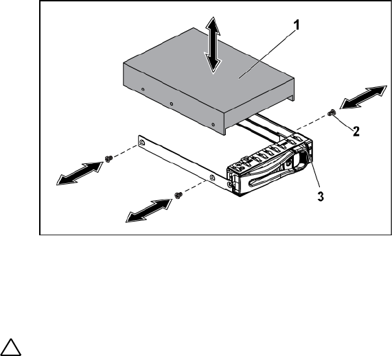
Installing System Components | 109
Figure 3-4. Removing and Installing a Hard Drive From the Hard-Drive Carrier
1
hard drive
2
screw (4)
3
hard-drive carrier
Installing a Hard Drive Into a Hard-Drive Carrier
CAUTION: Many repairs may only be done by a certified service technician. You
should only perform troubleshooting and simple repairs as authorized in your
product documentation, or as directed by the online or telephone service and
support team. Damage due to servicing that is not authorized by Dell is not
covered by your warranty. Read and follow the safety instructions that came with
the product.
1 Place the hard drive into the hard-drive carrier. See Figure 3-4.
2 Secure the hard drive to the hard-drive carrier with four screws. See
Figure 3-4.
110 | Installing System Components
Power Supplies
NOTE: The following table lists the maximum supported configuration
where power supply redundancy is guaranteed.
NOTE: Configurations higher than indicated in the table may change the
power supply mode to non-redundant. In non-redundant mode if the power
requirement exceeds the installed system power capacity, the BIOS will
throttle the CPUs. Also, if CPU Power Capping is enabled, then CPU
throttling occurs on configurations that exceed the cap value.
Table 3-1. PSU and Motherboard Support Matrix for 3.5” HDD Backplane With CPLD /
2-Node Configuration
PSU
1 Motherboard
2 Motherboards
1100 W
Up to four 140W processors,
sixteen 32G memory modules,
and three 3.5" SAS hard drives
Up to two 115W processors/MLB,
eight 32G memory modules/MLB, and
four 3.5" SAS hard drives
1400 W
Up to four 140W processors,
thirty-two 32G memory
modules, and six 3.5" SAS hard
drives
Up to four 85W processors/MLB,
sixteen 32G memory modules/MLB,
and four 3.5" SAS hard drives
Table 3-2. PSU and Motherboard Support Matrix for 3.5” HDD Backplane With
Expander / 1-Node Configuration
PSU
1 Motherboard
1100 W
Up to four 85W processors/MLB, sixteen 32G memory modules/MLB, and
twelve 3.5" SAS hard drives
1400 W
Up to four 140W processors, thirty-two 32G memory modules, and twelve
3.5" SAS hard drives
NOTE: The following table lists the detailed power supply configurations
regarding to the different quantity of the DIMMs and HDDs.
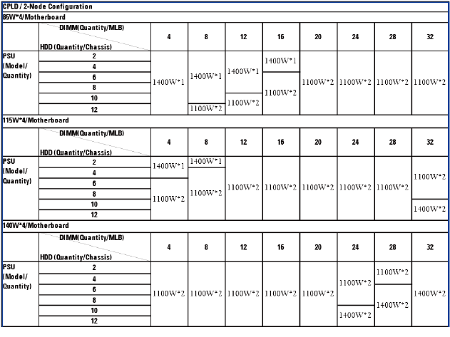
Installing System Components | 111
Table 3-3. PSU Model and Quantity with CPLD / 2-Node Configuration
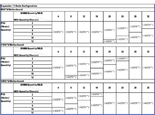
112 | Installing System Components
Table 3-4. PSU Model and Quantity with Expander / 1-Node Configuration
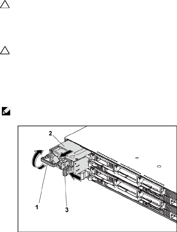
Installing System Components | 113
Removing a Power Supply
CAUTION: Many repairs may only be done by a certified service technician. You
should only perform troubleshooting and simple repairs as authorized in your
product documentation, or as directed by the online or telephone service and
support team. Damage due to servicing that is not authorized by Dell is not
covered by your warranty. Read and follow the safety instructions that came with
the product.
CAUTION: The System requires at least one power supply to operate normally.
1 Turn off the system, including any attached peripherals, and
disconnect the system from the electrical outlet.
2 Disconnect the power cable from power source and the power supply.
3 Press the release lever and using the handle, slide the power supply out
of the system. See Figure 3-5.
NOTE: Removing the power supply may require considerable force.
Figure 3-5. Removing and Installing a Power Supply
1
handle
2
power supply
3
release lever

114 | Installing System Components
Installing a Power Supply
CAUTION: Many repairs may only be done by a certified service technician. You
should only perform troubleshooting and simple repairs as authorized in your
product documentation, or as directed by the online or telephone service and
support team. Damage due to servicing that is not authorized by Dell is not
covered by your warranty. Read and follow the safety instructions that came with
the product.
CAUTION: The System requires at least one power supply to operate normally.
1 Verify that both power supplies are of the same type and have the same
maximum output power.
NOTE: The maximum output power is printed on the power supply label.
2 Slide the new power supply into the chassis until the power supply is
fully seated and the release lever snaps into place. See Figure 3-5.
3 Connect the power cable to the power supply and plug the cable into a
power outlet.
NOTE: When installing a new power supply in a system with two power
supplies, allow several seconds for the system to recognize the power
supply and determine its status.
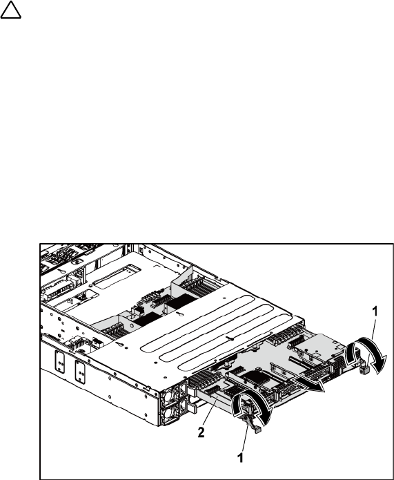
Installing System Components | 115
System-Board Assembly
Removing a System-Board Assembly
CAUTION: Many repairs may only be done by a certified service technician. You
should only perform troubleshooting and simple repairs as authorized in your
product documentation, or as directed by the online or telephone service and
support team. Damage due to servicing that is not authorized by Dell is not
covered by your warranty. Read and follow the safety instructions that came with
the product.
1 Recommend to turn off the system, including any attached peripherals,
and disconnect the system from its electrical outlet.
2 Disconnect all the external cables from the system board.
3 Rotate down the retaining latches on both sides of the system-board
assembly to the very bottom, and slide the system-board assembly out
of the chassis. See Figure 3-6.
Figure 3-6. Removing and Installing a System-Board Assembly
1
retaining latch (2)
2
system-board assembly

116 | Installing System Components
Installing a System-Board Assembly
CAUTION: Many repairs may only be done by a certified service technician. You
should only perform troubleshooting and simple repairs as authorized in your
product documentation, or as directed by the online or telephone service and
support team. Damage due to servicing that is not authorized by Dell is not
covered by your warranty. Read and follow the safety instructions that came with
the product.
1 Slide the system-board assembly into the chassis until it snaps into
place. See Figure 3-6.
2 Rotate the retaining latches on both sides of the system-board
assembly upwards to the top to secure the system-board assembly with
the chassis. See Figure 3-6.
3 Reconnect all the external cables to the system board.
4 Reconnect the system to its electrical outlet and turn on the system,
including any attached peripherals.
Air Ducts
Removing the Air Duct
CAUTION: Many repairs may only be done by a certified service technician. You
should only perform troubleshooting and simple repairs as authorized in your
product documentation, or as directed by the online or telephone service and
support team. Damage due to servicing that is not authorized by Dell is not
covered by your warranty. Read and follow the safety instructions that came with
the product.
1 Recommend to turn off the system, including any attached peripherals,
and disconnect the system from its electrical outlet.
2 Remove the system-board assembly. See ―Removing a System-Board
Assembly" on page 115.
3 Squeeze and remove the rivets that secure the air ducts to the system-
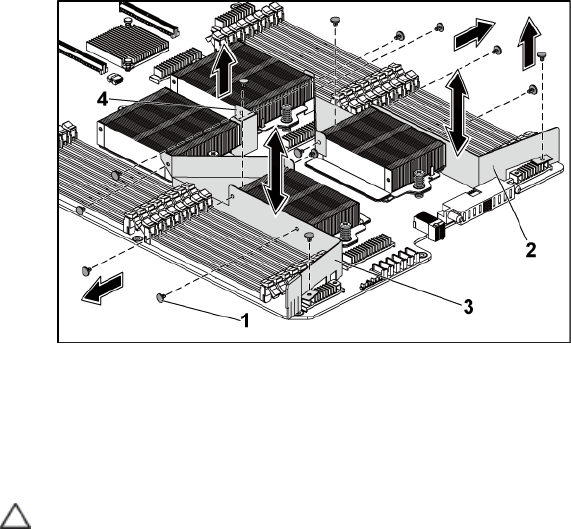
Installing System Components | 117
board assembly and heat sinks. See Figure 3-7.
4 Gently lift air ducts out of the system-board assembly. See Figure 3-7.
Figure 3-7. Removing and Installing the Air Ducts
1
rivet (6 for each of air ducts 1 and 2,
and 2 for air duct 3)
2
air duct 2
3
air duct 1
4
air duct 3
Installing the Air Duct
CAUTION: Many repairs may only be done by a certified service technician. You
should only perform troubleshooting and simple repairs as authorized in your
product documentation, or as directed by the online or telephone service and
support team. Damage due to servicing that is not authorized by Dell is not
covered by your warranty. Read and follow the safety instructions that came with
the product.

118 | Installing System Components
NOTE: The air duct configuration differs with the number of processors installed
on the system board. For two-processor configuration, only the air duct 3 is
installed between the processors 1 and 2; for four-processor configuration, the air
ducts 1, 2 and 3 should all be installed. The Figure 3-7 shows the four-processor
configuration.
1 Align the air ducts to the system-board assembly and heat sinks by the
rivet holes. See Figure 3-7.
2 Replace the rivets to secure the air ducts to the system-board assembly
and heat sinks. See Figure 3-7.
Heat Sinks
Removing the Heat Sink
CAUTION: Many repairs may only be done by a certified service technician. You
should only perform troubleshooting and simple repairs as authorized in your
product documentation, or as directed by the online or telephone service and
support team. Damage due to servicing that is not authorized by Dell is not
covered by your warranty. Read and follow the safety instructions that came with
the product.
1 Recommend to turn off the system, including any attached peripherals,
and disconnect the system from its electrical outlet.
2 Remove the system-board assembly. See ―Removing a System-Board
Assembly" on page 115.
3 Remove the air ducts. See ―Removing the Air Duct" on page 116.
WARNING: The heat sink may be hot to touch for some time after the system has
been powered down. Allow the heat sink to cool before removing it.
CAUTION: Never remove the heat sink from a processor unless you intend to
remove the processor. The heat sink is necessary for proper thermal conditions.
4 Using a Phillips screwdriver, loosen one of the heat-sink retention
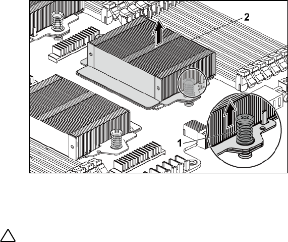
Installing System Components | 119
screws. See Figure 3-8.
Wait for 30 seconds for the heat sink to loosen from the processor.
5 Remove the other heat-sink retention screw.
6 Gently lift the heat sink off the processor and set the heat sink aside
with thermal grease side facing up.
Figure 3-8. Removing and Installing the Heat Sink
1
screw (2)
2
heat sink
Installing the Heat Sink
CAUTION: Many repairs may only be done by a certified service technician. You
should only perform troubleshooting and simple repairs as authorized in your
product documentation, or as directed by the online or telephone service and
support team. Damage due to servicing that is not authorized by Dell is not
covered by your warranty. Read and follow the safety instructions that came with
the product.
1 Using a clean lint-free cloth, remove thermal grease from the heat sink.
2 Apply new thermal grease evenly to the center of the top new processor.

120 | Installing System Components
CAUTION: Using excess thermal grease can cause grease to contact the
processor shield, which can cause contamination of the processor socket.
3 Place the heat sink on the processor. Make sure the guide pin is
inserted through the slot of the heat sink. See Figure 3-8.
4 Using a Phillips screwdriver, tighten the two heat-sink retention screws.
5 Install the system-board assembly. See "Installing a System-Board
Assembly" on page 116.
6 Reconnect the system to its electrical outlet and turn on the system,
including any attached peripherals.
7 Install the air ducts. See "Installing the Air Duct" on page 117.

Installing System Components | 121
Processors
The following tables list the limited configurations of the C6145 system for
proper thermal conditions:
Table 3-5. Limited Configuration Matrix for Proper Thermal Condition on 2-Node System
Processor
(G34 TDP)
Hard Drive
QTY
Note
85 W
3.5" x12
2.5" x24
No PCI-E card on PCI-E slot 2
3.5‖ x8
2.5" x18
Support PCI-E cards on PCI-E slot 2 and slot 3
3.5" hard-drive blank and carrier should be put on the
four slots in the second row of the hard-drive slots as
Figure 1-1.
2.5" hard-drive blank and carrier should be put on the
hard-drive ID 10-12 and 22-24 as Figure 1-5.
115 W
3.5‖ x8
2.5" x18
Support PCI-E cards on PCI-E slot 2 and slot 3
3.5" hard-drive blank and carrier should be put on the
four slots in the second row of the hard-drive slots as
Figure 1-1.
2.5" hard-drive blank and carrier should be put on the
hard-drive ID 10-12 and 22-24 as Figure 1-5.
140 W
3.5" x8
No PCI-E card on PCI-E slot 2.
3.5" hard-drive blank and carrier should be put on the
four slots in the second row of the hard-drive slots as
Figure 1-1 and allow max ambient 30oC.
122 | Installing System Components
Table 3-6. Limited Configuration Matrix for Proper Thermal Condition on 1-Node
System
Processor
(G34 TDP)
Hard Drive
QTY
Note
85 W
3.5" x12
2.5" x24
115 W
3.5" x12
2.5" x24
140 W
3.5" x8
3.5" hard-drive blank and carrier should be put on the
four slots in the second row of the hard-drive slots as
Figure 1-3 and allow max ambient 30oC.
Removing a Processor
CAUTION: Many repairs may only be done by a certified service technician. You
should only perform troubleshooting and simple repairs as authorized in your
product documentation, or as directed by the online or telephone service and
support team. Damage due to servicing that is not authorized by Dell is not
covered by your warranty. Read and follow the safety instructions that came with
the product.
NOTE: If you are upgrading your processors, prior to upgrading your system,
download and install the latest system BIOS version from support.dell.com. Follow
the instructions included in the file downloaded to install the update on your
system.
1 Recommend to turn off the system, including any attached peripherals,
and disconnect the system from its electrical outlet.
2 Remove the system-board assembly. See "Removing a System-Board
Assembly" on page 115.
3 Remove the heat sink, see "Removing the Heat Sink" on page 118.
CAUTION: The processor is held in its socket under strong pressure. Be aware
that the release lever can spring up suddenly if not firmly grasped.
4 Position your thumb firmly over the processor socket-release lever and
release the lever from the locked position. Rotate the lever 90 degrees
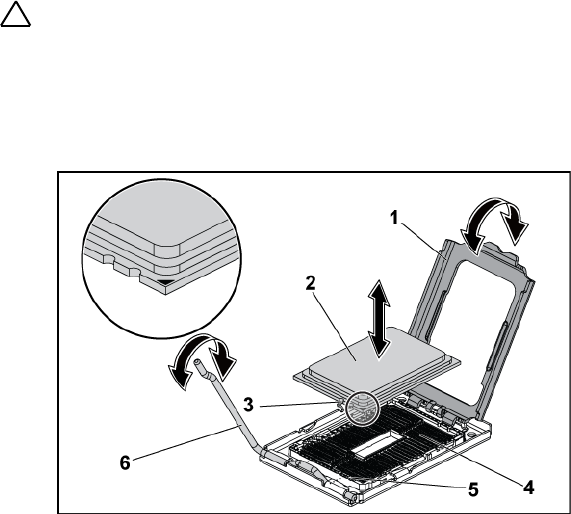
Installing System Components | 123
upward until the processor is released from the socket. See Figure 3-9.
5 Rotate the processor shield upward and out of the way. See Figure 3-9.
6 Lift the processor out of the socket and leave the socket-release lever
up so that the socket is ready for the new processor.
CAUTION: Be careful not to bend any of the pins on the ZIF socket when removing
the processor. Bending the pins can permanently damage the system board. Be
sure to properly align the processor notch to the socket and insert straight down.
Do not move from side to side.
Figure 3-9. Removing and Installing a Processor
1
processor shield
2
processor
3
notch in processor (2)
4
ZIF socket
5
socket key (2)
6
socket-release lever

124 | Installing System Components
Installing a Processor
CAUTION: Many repairs may only be done by a certified service technician. You
should only perform troubleshooting and simple repairs as authorized in your
product documentation, or as directed by the online or telephone service and
support team. Damage due to servicing that is not authorized by Dell is not
covered by your warranty. Read and follow the safety instructions that came with
the product.
NOTE: When installing only one processor, the processor must be installed in the
processor0 (for the socket location, see “System Board Connectors” on page
229).
NOTE: If you are upgrading your processors, prior to upgrading your system,
download and install the latest system BIOS version from support.dell.com. Follow
the instructions included in the file download to install the update on your system.
1 Unpack the processor if it has not been used previously.
If the processor has already been used, remove any thermal grease from
the top of the processor using a lint-free cloth.
2 Align the processor with the socket keys on the ZIF socket. See Figure
3-9.
CAUTION: Positioning the processor incorrectly can permanently damage the
system board or the processor. Be careful not to bend the pins in the ZIF socket.
3 With the release lever on the processor socket in the open position,
align the processor with the socket keys and set the processor lightly in
the socket. See Figure 3-9.
CAUTION: Do not use force to seat the processor. When the processor is
positioned correctly, it engages easily into the socket.
4 Close the processor shield.
5 Rotate the socket release lever down until it snaps into place.
6 Using a clean lint-free cloth, remove the thermal grease from the heat
sink.
7 Apply thermal grease evenly to the center of the top of the new

Installing System Components | 125
processor.
CAUTION: Using excess thermal grease can cause grease to contact the
processor shield, which can cause contamination of the processor socket.
8 Place the heat sink on the processor. See Figure 3-8.
9 Using a Phillips screwdriver, tighten the heat-sink retention screws. See
Figure 3-8.
10 Install the air duct(s). See "Installing the Air Duct" on page 117.
11 Install the system-board assembly. See "Installing a System-Board
Assembly" on page 116.
12 Reconnect the system to its electrical outlet and turn on the system,
including any attached peripherals.
13 Press <F2> to enter the System Setup program, and check that the
processor information matches the new system configuration. See
"System Setup Options at Boot" on page 46.
Expansion-Card Assembly and Expansion Card
Removing the Expansion Card
CAUTION: Many repairs may only be done by a certified service technician. You
should only perform troubleshooting and simple repairs as authorized in your
product documentation, or as directed by the online or telephone service and
support team. Damage due to servicing that is not authorized by Dell is not
covered by your warranty. Read and follow the safety instructions that came with
the product.
1 Recommend to turn off the system, including any attached peripherals,
and disconnect the system from its electrical outlet.
2 Remove the system-board assembly. See "Removing a System-Board
Assembly" on page 115.
3 Remove the three screws that secure the expansion-card assembly. See
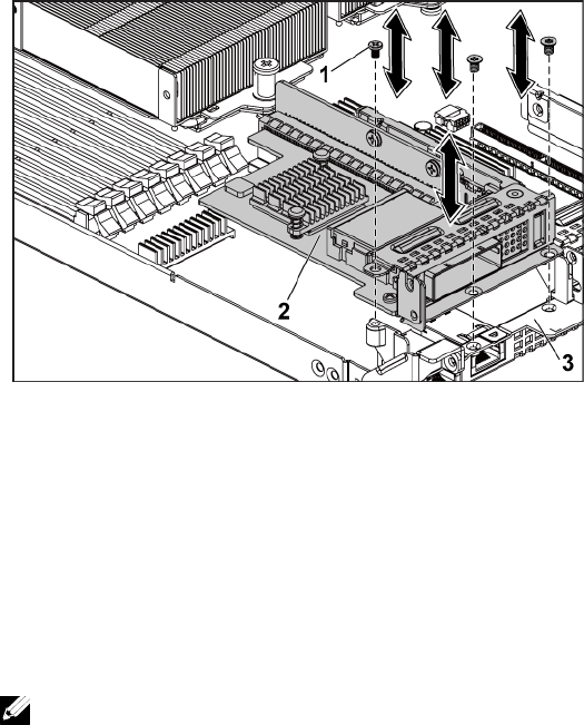
126 | Installing System Components
Figure 3-10.
4 Lift the expansion-card assembly out of the system-board assembly.
See Figure 3-10.
Figure 3-10. Removing the Expansion-Card Assembly
1
screw (3)
2
expansion-card assembly
3
system-board assembly
5 Remove the screw that secures the expansion card to the expansion-
card cage.
6 Grasp the expansion card by its edges, and carefully remove it from the
expansion-card connector.
7 If you are removing the card permanently, install a metal filler bracket
over the empty expansion slot opening, and close the expansion-card
latch.
NOTE: You must install a filler bracket over an empty expansion slot to
maintain Federal Communications Commission (FCC) certification of the
system. The brackets also keep dust and dirt out of the system and aid in
proper cooling and airflow inside the system.
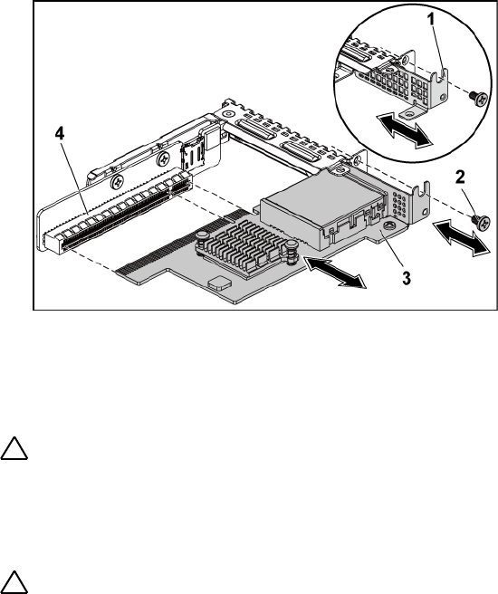
Installing System Components | 127
Figure 3-11. Removing the Expansion Card
1
metal filler bracket
2
screw
3
expansion card
4
expansion-card connector
Installing the Expansion Card
CAUTION: Many repairs may only be done by a certified service technician. You
should only perform troubleshooting and simple repairs as authorized in your
product documentation, or as directed by the online or telephone service and
support team. Damage due to servicing that is not authorized by Dell is not
covered by your warranty. Read and follow the safety instructions that came with
the product.
CAUTION: Expansion cards can only be installed in the slots on the expansion-
card riser. Do not attempt to install expansion cards directly into the riser
connector on the system board.
1 Unpack the expansion card and prepare it for installation. For
instructions, see the documentation accompanying the card.
2 Recommend to turn off the system, including any attached peripherals,
and disconnect the system from its electrical outlet.

128 | Installing System Components
3 Remove the system-board assembly. See "Removing a System-Board
Assembly" on page 115.
4 Remove the three screws that secure the expansion-card assembly. See
Figure 3-10.
5 Lift the expansion-card assembly away from the system-board assembly.
See Figure 3-10.
6 Grasp the filler bracket by its edges, and carefully remove it from the
expansion-card connector. See Figure 3-11.
NOTE: Keep this bracket in case you need to remove the expansion card.
Filler brackets must be installed over empty expansion-cards slots to
maintain FCC certification of the system. The brackets also keep dust and
dirt out of the system and aid in proper cooling and airflow inside the
system.
7 Holding the card by its edges, position the card so that the card-edge
connector aligns with the expansion-card connector on the expansion-
card assembly.
8 Insert the card-edge connector firmly into the expansion-card
connector until the card is fully seated.
9 Replace the screw securing the expansion card.
10 Place the expansion-card assembly into the system-board assembly.
11 Replace the three screws that secure the expansion-card assembly.
12 Install the system-board assembly. See "Installing a System-Board
Assembly" on page 116.
13 Reconnect the system to its electrical outlet and turn on the system,
including any attached peripherals.

Installing System Components | 129
LSI 9260-8i Card
NOTE: The LSI 9260-8i card assembly should include the BBU interposer card
which is connected to the RAID battery. The illustrations in this section are just
for your removal and installation reference. For more information of the RAID
battery, see “LSI 9260-8i RAID Battery (Optional)” on page 135.
Removing the LSI 9260-8i Card
CAUTION: Many repairs may only be done by a certified service technician. You
should only perform troubleshooting and simple repairs as authorized in your
product documentation, or as directed by the online or telephone service and
support team. Damage due to servicing that is not authorized by Dell is not
covered by your warranty. Read and follow the safety instructions that came with
the product.
1 Remove the system-board assembly. See "Removing a System-Board
Assembly" on page 115.
2 Disconnect the two SAS/SGPIO cables connecting to the LSI 9260-8i
card assembly.
3 Remove the three screws that secure the LSI 9260-8i card assembly.
See Figure 3-12.
4 Lift the LSI 9260-8i card assembly out of the system-board assembly.
See Figure 3-12.
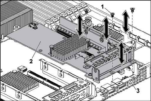
130 | Installing System Components
Figure 3-12. Removing the LSI 9260-8i Card Assembly
1
screw (3)
2
LSI 9260-8i-card assembly
3
system-board assembly
5 Remove the screw securing the LSI 9260-8i card.
6 Grasp the LSI 9260-8i card by its edges, and carefully remove it from
the expansion-card connector.
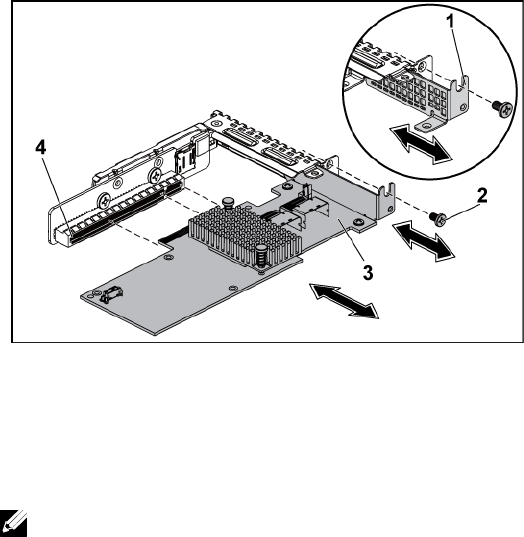
Installing System Components | 131
Figure 3-13. Removing the LSI 9260-8i Card
1
expansion-card slot cover
2
screw
3
LSI 9260-8i card
4
expansion-card connector
7 If you are removing the card permanently, install a metal filler bracket
over the empty expansion slot opening, and close the expansion-card
latch.
NOTE: You must install a filler bracket over an empty expansion slot to
maintain Federal Communications Commission (FCC) certification of the
system. The brackets also keep dust and dirt out of the system and aid in
proper cooling and airflow inside the system.
8 Remove the BBU interposer card by unscrewing the three screws.
9 Lift the BBU interposer card away from the LSI9260-8i card.
10 Disconnect the RAID battery cable from the BBU interposer card.
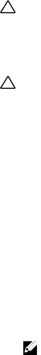
132 | Installing System Components
Installing the LSI 9260-8i Card
CAUTION: Many repairs may only be done by a certified service technician. You
should only perform troubleshooting and simple repairs as authorized in your
product documentation, or as directed by the online or telephone service and
support team. Damage due to servicing that is not authorized by Dell is not
covered by your warranty. Read and follow the safety instructions that came with
the product.
CAUTION: Expansion cards can only be installed in the slots on the expansion-
card riser. Do not attempt to install expansion cards directly into the riser
connector on the system board.
1 Unpack the LSI 9260-8i card and prepare it for installation. For
instructions, see the documentation accompanying the card.
2 Recommend to turn off the system, including any attached peripherals,
and disconnect the system from its electrical outlet.
3 Remove the system-board assembly. See "Removing a System-Board
Assembly" on page 115.
4 Connect the RAID battery cable to the BBU interposer card. See
Figure 3-14.
5 Attach the BBU interposer card onto the LSI 9260-8i card by securing
the three screws coming with the RAID battery. For the installation
steps of the RAID battery, see ―LSI 9260-8i RAID Battery (Optional)‖
on page 135.
6 Remove the screw securing the filler bracket. Grasp the filler bracket by
its edges, and carefully remove it from the expansion-card connector.
NOTE: Keep this bracket in case you need to remove the expansion card.
Filler brackets must be installed over empty expansion-cards slots to
maintain FCC certification of the system. The brackets also keep dust and
dirt out of the system and aid in proper cooling and airflow inside the
system.
7 Connect the two SAS/SGPIO cables to the LSI 9260-8i card assembly.

Installing System Components | 133
See Figure 3-14.
8 Holding the card by its edges, position the card so that the card-edge
connector aligns with the expansion-card connector.
9 Insert the card-edge connector firmly into the expansion-card
connector until the card is fully seated.
10 Replace the screw securing the LSI 9260-8i card.
11 Place the LSI 9260-8i card assembly into the system-board assembly.
12 Replace the three screws that secure the LSI 9260-8i card assembly.
13 Install the system-board assembly. See "Installing a System-Board
Assembly" on page 116.
Cable Routing for LSI 9260-8i Card
1 Connect the mini-SAS&SGPIO cable to the LSI 9260-8i card, and
connect the other end of the cable to the corresponding connectors on
the system board. Make sure the cables should go through the cable
clip ring. See Figure 3-14.
2 Connect the RAID battery cable to the BBU interposer card on the LSI
9260-8i card, and connect the other end of the cable to the
corresponding connector on the RAID battery.
NOTE: When connecting the RAID battery cable, the BBU interposer card
should be installed on the LSI 9260-8i card. The BBU interposer card in the
figure below is just for you reference.
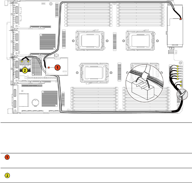
134 | Installing System Components
Figure 3-14. Cable Routing for LSI 9260-8i Card
Item
Cable
From
(LSI 9260-8i Card)
To
(RAID Battery and HDD
to Backplane SATAII
Connectors)
RAID battery
cable
RAID battery connector
(J4)
RAID battery
connector
SAS/SGPIO
cable
Mini-SAS connector A &
Mini-SAS connector B
SATAII connectors
0~5 and SGPIO A&B

Installing System Components | 135
LSI 9260-8i RAID Battery (Optional)
Removing the LSI 9260-8i RAID Battery
CAUTION: Many repairs may only be done by a certified service technician. You
should only perform troubleshooting and simple repairs as authorized in your
product documentation, or as directed by the online or telephone service and
support team. Damage due to servicing that is not authorized by Dell is not
covered by your warranty. Read and follow the safety instructions that came with
the product.
NOTE: The information in this section applies only to systems intalled with the LSI
9260-8i card.
1 Recommend to turn off the system, including any attached peripherals,
and disconnect the system from the electrical outlet.
2 Remove the system-board assembly. See ―Removing a System-Board
Assembly‖ on page 115.
3 Disconnect the cable connecting to the LSI 9260-8i card.
4 Press the LSI 9260-8i RAID battery latch and lift the RAID battery to
release it from the LSI 9260-8i RAID battery carrier. See Figure 3-15.
5 Slide and lift the LSI 9260-8i RAID battery away from the LSI 9260-8i
RAID battery carrier. See Figure 3-15.
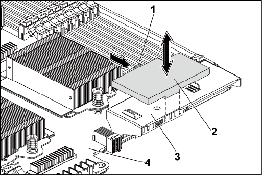
136 | Installing System Components
Figure 3-15. Removing and Installing the LSI 9260-8i RAID Battery
1
RAID battery latch
2
LSI 9260-8i RAID battery
3
LSI 9260-8i RAID battery carrier
4
system-board assembly
Installing the LSI 9260-8i RAID Battery
1 Insert the LSI 9260-8i RAID battery into the battery carrier until the
RAID battery latch locks into place. See Figure 3-15.
2 Connect the cable connecting to the LSI 9260-8i card.
3 Install the system-board assembly. See ―Installing a System-Board
Assembly‖ on page 116.
4 Reconnect the system to the electrical outlet and turn the system on,
including any attached peripherals.

Installing System Components | 137
Removing the LSI 9260-8i RAID Battery Carrier
CAUTION: Many repairs may only be done by a certified service technician. You
should only perform troubleshooting and simple repairs as authorized in your
product documentation, or as directed by the online or telephone service and
support team. Damage due to servicing that is not authorized by Dell is not
covered by your warranty. Read and follow the safety instructions that came with
the product.
NOTE: The information in this section applies only to systems with the optional
RAID controller card.
1 Recommend to turn off the system, including any attached peripherals,
and disconnect the system from the electrical outlet.
2 Remove the system-board assembly. See ―Removing a System-Board
Assembly‖ on page 115.
3 Remove the LSI 9260-8i RAID battery. See ―Removing the LSI 9260-8i
RAID Battery‖ on page 135.
4 Remove the two screws securing the LSI 9260-8i RAID battery carrier
to the interposer extender, and lift the LSI 9260-8i RAID battery
carrier away from the interposer extender. See Figure 3-16.
138 | Installing System Components
Figure 3-16. Removing and Installing the LSI 9260-8i RAID Battery Carrier
1
screw (2)
2
LSI 9260-8i RAID battery carrier
3
system-board assembly
Installing the LSI 9260-8i RAID Battery Carrier
1 Place the LSI 9260-8i RAID battery carrier in position on the interposer
extender. See Figure 3-16.
2 Replace the screws securing the LSI 9260-8i RAID battery carrier to the
interposer extender. See Figure 3-16.
3 Install the LSI 9260-8i RAID battery into the LSI 9260-8i RAID battery
carrier. See ―Installing the LSI 9260-8i RAID Battery‖ on page 136.
4 Install the system-board assembly. See ―Installing a System-Board
Assembly‖ on page 116.
5 Reconnect the system to the electrical outlet and turn the system on,
including any attached peripherals.

Installing System Components | 139
LSI 9265-8i Card
NOTE: The LSI 9265-8i card assembly should include the BBU interposer card
which is connected to the RAID battery. The illustrations in this section are just
for your removal and installation reference. For more information of the RAID
battery, see “LSI 9265-8i RAID Battery (Optional)” on page 145.
Removing the LSI 9265-8i Card
CAUTION: Many repairs may only be done by a certified service technician. You
should only perform troubleshooting and simple repairs as authorized in your
product documentation, or as directed by the online or telephone service and
support team. Damage due to servicing that is not authorized by Dell is not
covered by your warranty. Read and follow the safety instructions that came with
the product.
1 Remove the system-board assembly. See "Removing a System-Board
Assembly" on page 115.
2 Disconnect the two SAS/SGPIO cables connecting to the LSI 9265-8i
card assembly.
3 Remove the three screws that secure the LSI 9265-8i card assembly.
See Figure 3-17.
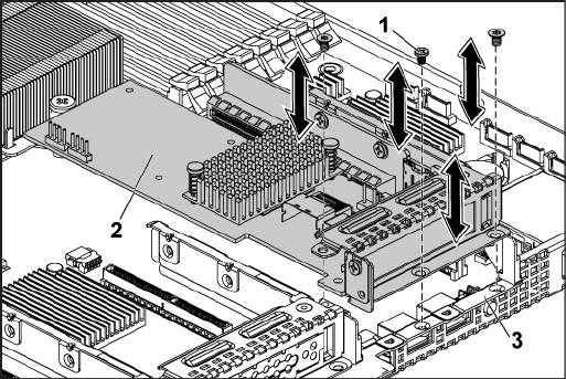
140 | Installing System Components
4 Lift the LSI 9265-8i card assembly out of the system-board assembly.
See Figure 3-17.
Figure 3-17. Removing the LSI 9265-8i Card Assembly
1
screw (3)
2
LSI 9265-8i-card assembly
3
system-board assembly
5 Remove the screw securing the LSI 9265-8i card. See Figure 3-18.
6 Grasp the LSI 9265-8i card by its edges, and carefully remove it from
the expansion-card connector. See Figure 3-18.
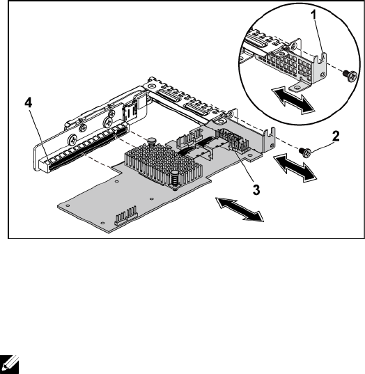
Installing System Components | 141
Figure 3-18. Removing the LSI 9265-8i Card
1
expansion-card slot cover
2
screw
3
LSI 9265-8i card
4
expansion-card connector
7 If you are removing the card permanently, install a metal filler bracket
over the empty expansion slot opening, and close the expansion-card
latch.
NOTE: You must install a filler bracket over an empty expansion slot to
maintain Federal Communications Commission (FCC) certification of the
system. The brackets also keep dust and dirt out of the system and aid in
proper cooling and airflow inside the system.
8 Remove the BBU interposer card by unscrewing the three screws.
9 Lift the BBU interposer card away from the LSI9265-8i card.
10 Disconnect the RAID battery cable from the BBU interposer card.

142 | Installing System Components
Installing the LSI 9265-8i Card
CAUTION: Many repairs may only be done by a certified service technician. You
should only perform troubleshooting and simple repairs as authorized in your
product documentation, or as directed by the online or telephone service and
support team. Damage due to servicing that is not authorized by Dell is not
covered by your warranty. Read and follow the safety instructions that came with
the product.
CAUTION: Expansion cards can only be installed in the slots on the expansion-
card riser. Do not attempt to install expansion cards directly into the riser
connector on the system board.
1 Unpack the LSI 9265-8i card and prepare it for installation. For
instructions, see the documentation accompanying the card.
2 Recommend to turn off the system, including any attached peripherals,
and disconnect the system from its electrical outlet.
3 Remove the system-board assembly. See "Removing a System-Board
Assembly" on page 115.
4 Connect the RAID battery cable to the BBU interposer card. See
Figure 3-19.
5 Attach the BBU interposer card onto the LSI 9265-8i card by securing
the three screws coming with the RAID battery. For the installation
steps of the RAID battery, see ―LSI 9265-8i RAID Battery (Optional)‖
on page 145.
6 Remove the screw securing the filler bracket. Grasp the filler bracket by
its edges, and carefully remove it from the expansion-card connector.
NOTE: Keep this bracket in case you need to remove the expansion card.
Filler brackets must be installed over empty expansion-cards slots to
maintain FCC certification of the system. The brackets also keep dust and
dirt out of the system and aid in proper cooling and airflow inside the
system.
7 Connect the two SAS/SGPIO cables to the LSI 9265-8i card assembly.

Installing System Components | 143
See Figure 3-19.
8 Holding the card by its edges, position the card so that the card-edge
connector aligns with the expansion-card connector.
9 Insert the card-edge connector firmly into the expansion-card
connector until the card is fully seated.
10 Replace the screw securing the LSI 9265-8i card.
11 Place the LSI 9265-8i card assembly into the system-board assembly.
12 Replace the three screws that secure the LSI 9265-8i card assembly.
13 Install the system-board assembly. See "Installing a System-Board
Assembly" on page 116.
Cable Routing for LSI 9265-8i Card
1 Connect the mini-SAS&SGPIO cable to the LSI 9265-8i card, and
connect the other end of the cable to the corresponding connectors on
the system board. Make sure the cables should go through the cable
clip ring. See Figure 3-19.
2 Connect the RAID battery cable to the BBU interposer card on the LSI
9265-8i card, and connect the other end of the cable to the
corresponding connector on the RAID battery.
NOTE: When connecting the RAID battery cable, the BBU interposer card
should be installed on the LSI 9265-8i card. The BBU interposer card in the
figure below is just for you reference.
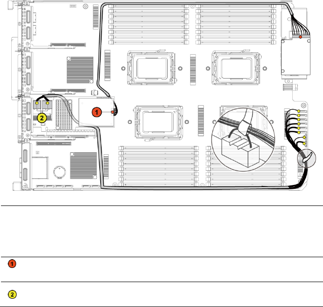
144 | Installing System Components
Figure 3-19. Cable Routing for LSI 9265-8i Card
Item
Cable
From
(LSI 9265-8i Card)
To
(RAID Battery and HDD
to Backplane SATAII
Connectors)
RAID battery
cable
RAID battery connector
(J4)
RAID battery
connector
SAS/SGPIO
cable
Mini-SAS connector A &
Mini-SAS connector B
SATAII connectors
0~5 and SGPIO A&B

Installing System Components | 145
LSI 9265-8i RAID Battery (Optional)
Removing the LSI 9265-8i RAID Battery Assembly
CAUTION: Many repairs may only be done by a certified service technician. You
should only perform troubleshooting and simple repairs as authorized in your
product documentation, or as directed by the online or telephone service and
support team. Damage due to servicing that is not authorized by Dell is not
covered by your warranty. Read and follow the safety instructions that came with
the product.
NOTE: The information in this section applies only to systems with the optional
RAID controller card.
1 Recommend to turn off the system, including any attached peripherals,
and disconnect the system from the electrical outlet.
2 Remove the system-board assembly. See ―Removing a System-Board
Assembly‖ on page 115.
3 Disconnect the cable connecting to the LSI 9265-8i card.
4 Remove the two screws securing the LSI 9265-8i RAID battery
assembly to the system-board assembly, and lift the LSI 9265-8i RAID
battery assembly away from the system-board assembly. See Figure 3-
20.
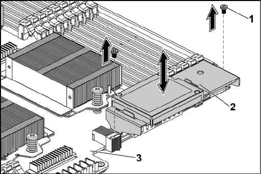
146 | Installing System Components
Figure 3-20. Removing and Installing the LSI 9265-8i RAID Battery Assembly
1
screw (2)
2
LSI 9265-8i RAID battery assembly
3
system-board assembly
Installing the LSI 9265-8i RAID Battery Assembly
1 Place the LSI 9265-8i RAID battery assembly in position on the
system-board assembly. See Figure 3-20.
2 Replace the screws securing the LSI 9265-8i RAID battery assembly to
the system-board assembly. See Figure 3-20.
3 Connect the cable connecting to the LSI 9265-8i card.
4 Install the system-board assembly. See ―Installing a System-Board
Assembly‖ on page 116.
5 Reconnect the system to the electrical outlet and turn the system on,
including any attached peripherals.

Installing System Components | 147
Removing the LSI 9265-8i RAID Battery
CAUTION: Many repairs may only be done by a certified service technician. You
should only perform troubleshooting and simple repairs as authorized in your
product documentation, or as directed by the online or telephone service and
support team. Damage due to servicing that is not authorized by Dell is not
covered by your warranty. Read and follow the safety instructions that came with
the product.
NOTE: The information in this section applies only to systems intalled with the LSI
9265-8i card.
1 Recommend to turn off the system, including any attached peripherals,
and disconnect the system from the electrical outlet.
2 Remove the system-board assembly. See ―Removing a System-Board
Assembly‖ on page 115.
3 Disconnect the cable connecting to the LSI 9265-8i card.
4 Remove the LSI 9265-8i RAID battery assembly from the system-board
assembly. See ―Removing the LSI 9265-8i RAID Battery Assembly‖ on
page 145.
5 Remove the three screws that secure the RAID battery and lift the
RAID battery away from the LSI 9265-8i RAID battery carrier. See
Figure 3-21.
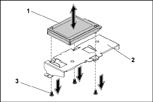
148 | Installing System Components
Figure 3-21. Removing and Installing the LSI 9265-8i RAID Battery
1
LSI 9265-8i RAID battery
2
LSI 9265-8i RAID battery carrier
3
screw (3)
Installing the LSI 9265-8i RAID Battery
1 Attach the RAID battery onto the RAID battery carrier. See Figure 3-
21.
2 Replace the screws securing the RAID battery. See Figure 3-21.
3 Connect the cable connecting to the LSI 9265-8i card.
4 Install the system-board assembly. See ―Installing a System-Board
Assembly‖ on page 116.
5 Remove the LSI 9265-8i RAID battery assembly from the system-board
assembly. See ―Installing the LSI 9265-8i RAID Battery Assembly‖ on
page 146.
6 Reconnect the system to the electrical outlet and turn the system on,
including any attached peripherals.

Installing System Components | 149
Expansion-Card Connector
Removing the Expansion-Card Connector
CAUTION: Many repairs may only be done by a certified service technician. You
should only perform troubleshooting and simple repairs as authorized in your
product documentation, or as directed by the online or telephone service and
support team. Damage due to servicing that is not authorized by Dell is not
covered by your warranty. Read and follow the safety instructions that came with
the product.
1 Recommend to turn off the system, including any attached peripherals,
and disconnect the system from its electrical outlet.
2 Remove the system-board assembly. See "Removing a System-Board
Assembly" on page 115.
3 Remove the expansion card. See "Removing the Expansion Card" on
page 125.
4 Remove the two screws securing the expansion-card connector to the
expansion-card bracket. See Figure 3-22.
5 Pull the expansion-card connector away from the expansion-card
bracket. See Figure 3-22.
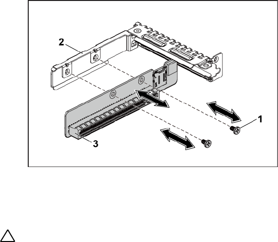
150 | Installing System Components
Figure 3-22. Removing and Installing the Expansion-Card Connector
1
screw (2)
2
expansion-card bracket
3
expansion-card connector
Installing the Expansion-Card Connector
CAUTION: Many repairs may only be done by a certified service technician. You
should only perform troubleshooting and simple repairs as authorized in your
product documentation, or as directed by the online or telephone service and
support team. Damage due to servicing that is not authorized by Dell is not
covered by your warranty. Read and follow the safety instructions that came with
the product.
1 Place the expansion-card connector into the expansion-card bracket.
See Figure 3-22.
2 Replace the two screws securing the expansion-card connector to the
expansion-card bracket. See Figure 3-22.
3 Install expansion card. See ―Installing the Expansion Card‖ on page
127.
4 Install the system-board assembly. See "Installing a System-Board

Installing System Components | 151
Assembly" on page 116.
5 Reconnect the system to its electrical outlet and turn on the system,
including any attached peripherals.
Mezzanine Card
Removing the SAS Mezzanine Card
CAUTION: Many repairs may only be done by a certified service technician. You
should only perform troubleshooting and simple repairs as authorized in your
product documentation, or as directed by the online or telephone service and
support team. Damage due to servicing that is not authorized by Dell is not
covered by your warranty. Read and follow the safety instructions that came with
the product.
1 Recommend to turn off the system, including any attached peripherals,
and disconnect the system from its electrical outlet.
2 Remove the system-board assembly. See "Removing a System-Board
Assembly" on page 115.
3 Disconnect all the cables from the SAS mezzanine card.
4 Remove the three screws that secure the SAS mezzanine-card assembly
to the system-board assembly. See Figure 3-23.
5 Remove the SAS mezzanine-card assembly away from the mezzanine-
card bridge board on the system-board assembly. See Figure 3-23.
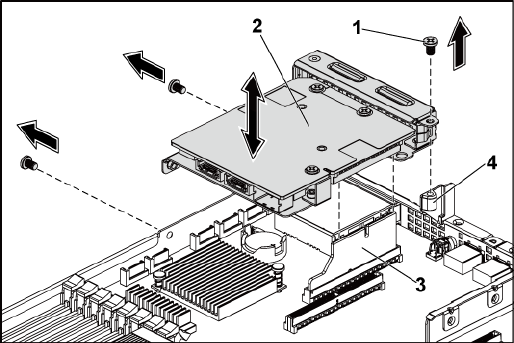
152 | Installing System Components
Figure 3-23. Removing and Installing the SAS Mezzanine-Card Assembly
1
screw (3)
2
SAS mezzanine-card assembly
3
mezzanine-card bridge board
4
system-board assembly
6 Remove the three screws that secure the SAS mezzanine card to the
bracket. See Figure 3-24.
7 Remove SAS mezzanine card away from the bracket. See Figure 3-24.
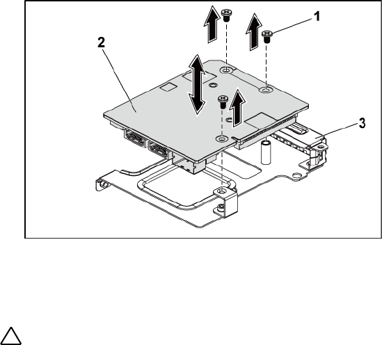
Installing System Components | 153
Figure 3-24. Removing and Installing the SAS Mezzanine Card
1
screw (3)
2
SAS mezzanine card
3
SAS mezzanine-card bracket
Installing the SAS Mezzanine Card
CAUTION: Many repairs may only be done by a certified service technician. You
should only perform troubleshooting and simple repairs as authorized in your
product documentation, or as directed by the online or telephone service and
support team. Damage due to servicing that is not authorized by Dell is not
covered by your warranty. Read and follow the safety instructions that came with
the product.
1 Align the SAS mezzanine card to the bracket by the three screw holes.
See Figure 3-24.
2 Replace the three screws to that secure the SAS mezzanine card to the
bracket. See Figure 3-24.
3 Install the SAS mezzanine-card assembly to the mezzanine-card bridge
board on the system-board assembly. See Figure 3-23.
4 Replace the three screws that secure the SAS mezzanine-card assembly
to the system-board assembly. See Figure 3-23.
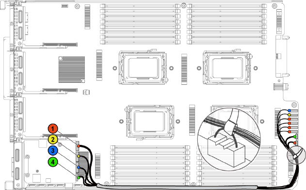
154 | Installing System Components
5 Reconnect all the cables to the SAS mezzanine card.
6 Install the system-board assembly. See "Installing a System-Board
Assembly" on page 116.
7 Reconnect the system to its electrical outlet and turn on the system,
including any attached peripherals.
Cable Routing for SAS Mezzanine Card
1 Reconnect all the cables to the SAS mezzanine card. Make sure the
cables should go through the cable clip ring. See Figure 3-25.
Figure 3-25. Cable Routing for SAS Mezzanine Card
Installing System Components | 155
Item
Cable
From
(SAS Mezzanine Card)
To
(HDD to Backplane
SATAII Connectors)
SAS/SGPIO
cable
SAS_ports 0~3
SATAII connectors
1~4 and SGPIO A
SAS cable
SAS_port 4
SATAII connector 5
SAS cable
SAS_port 5
SATAII connector 6
SGPIO cable
SGPIO B
SGPIO B
Removing the 10GbE Mezzanine Card
CAUTION: Many repairs may only be done by a certified service technician. You
should only perform troubleshooting and simple repairs as authorized in your
product documentation, or as directed by the online or telephone service and
support team. Damage due to servicing that is not authorized by Dell is not
covered by your warranty. Read and follow the safety instructions that came with
the product.
1 Recommend to turn off the system, including any attached peripherals,
and disconnect the system from its electrical outlet.
2 Remove the system-board assembly. See "Removing a System-Board
Assembly" on page 115.
3 Disconnect all the cables from the 10GbE mezzanine card.
4 Remove the three screws that secure the 10GbE mezzanine-card
assembly. See Figure 3-26.
5 Lift the 10GbE mezzanine-card assembly away from the mezzanine-
card bridge board on the system board. See Figure 3-26.
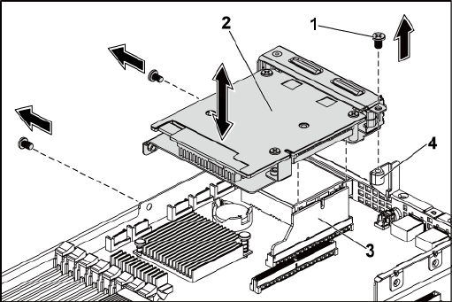
156 | Installing System Components
Figure 3-26. Removing and Installing the 10GbE Mezzanine-Card Assembly
1
screw (3)
2
10GbE mezzanine-card assembly
3
mezzanine-card bridge board
4
system-board assembly
6 Remove the three screws that secure the 10GbE mezzanine card to the
bracket. See Figure 3-27.
7 Remove the 10GbE mezzanine card from the bracket. See Figure 3-27.
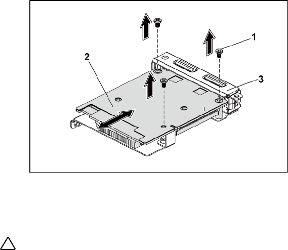
Installing System Components | 157
Figure 3-27. Removing and Installing the 10GbE Mezzanine Card
1
screw (3)
2
10GbE mezzanine card
3
10GbE mezzanine-card bracket
Installing the 10GbE Mezzanine Card
CAUTION: Many repairs may only be done by a certified service technician. You
should only perform troubleshooting and simple repairs as authorized in your
product documentation, or as directed by the online or telephone service and
support team. Damage due to servicing that is not authorized by Dell is not
covered by your warranty. Read and follow the safety instructions that came with
the product.
1 Put the two ports of the 10GbE mezzanine card through the two slots
of the bracket. See Figure 3-27.
2 Install the three screws to secure the 10GbE mezzanine card to the
bracket. See Figure 3-27.
3 Install the 10GbE mezzanine-card assembly to the mezzanine-card
bridge board on the system-board assembly. See Figure 3-26.
4 Install the three screws to secure the 10GbE mezzanine-card assembly

158 | Installing System Components
to the system-board assembly. See Figure 3-26.
5 Reconnect all the cables to the 10GbE mezzanine card.
6 Install the system-board assembly. See "Installing a System-Board
Assembly" on page 116.
7 Reconnect the system to its electrical outlet and turn on the system,
including any attached peripherals.
Removing the Mellanox Card
CAUTION: Many repairs may only be done by a certified service technician. You
should only perform troubleshooting and simple repairs as authorized in your
product documentation, or as directed by the online or telephone service and
support team. Damage due to servicing that is not authorized by Dell is not
covered by your warranty. Read and follow the safety instructions that came with
the product.
1 Recommend to turn off the system, including any attached peripherals,
and disconnect the system from its electrical outlet.
2 Remove the system-board assembly. See "Removing a System-Board
Assembly" on page 115.
3 Disconnect all the cables from the Mellanox card.
4 Remove the three screws that secure the Mellanox card assembly. See
Figure 3-28.
5 Lift the Mellanox card assembly away from the mezzanine-card bridge
board on the system board. See Figure 3-28.
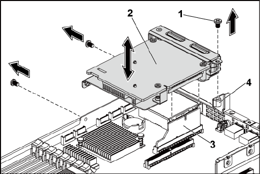
Installing System Components | 159
Figure 3-28. Removing and Installing the Mellanox Card Assembly
1
screw (3)
2
Mellanox card assembly
3
mezzanine-card bridge board
4
system-board assembly
6 Remove the three screws that secure the Mellanox card to the bracket.
See Figure 3-29.
7 Remove the Mellanox card from the bracket. See Figure 3-29.
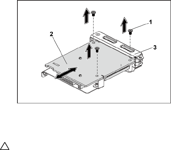
160 | Installing System Components
Figure 3-29. Removing and Installing the Mellanox Card
1
screw (3)
2
Mellanox card
3
mezzanine-card bracket
Installing the Mellanox Card
CAUTION: Many repairs may only be done by a certified service technician. You
should only perform troubleshooting and simple repairs as authorized in your
product documentation, or as directed by the online or telephone service and
support team. Damage due to servicing that is not authorized by Dell is not
covered by your warranty. Read and follow the safety instructions that came with
the product.
1 Put the two ports of the Mellanox card through the two slots of the
bracket. See Figure 3-29.
2 Install the three screws to secure the Mellanox card to the bracket. See
Figure 3-29.
3 Install the Mellanox card assembly to the mezzanine-card bridge board
on the system-board assembly. See Figure 3-28.
4 Install the three screws to secure the Mellanox card assembly to the

Installing System Components | 161
system-board assembly. See Figure 3-28.
5 Reconnect all the cables to the Mellanox card.
6 Install the system-board assembly. See "Installing a System-Board
Assembly" on page 116.
Reconnect the system to its electrical outlet and turn on the system,
including any attached peripherals.
Mezzanine-Card Bridge Board
Removing the Mezzanine-Card Bridge Board
CAUTION: Many repairs may only be done by a certified service technician. You
should only perform troubleshooting and simple repairs as authorized in your
product documentation, or as directed by the online or telephone service and
support team. Damage due to servicing that is not authorized by Dell is not
covered by your warranty. Read and follow the safety instructions that came with
the product.
1 Recommend to turn off the system, including any attached peripherals,
and disconnect the system from its electrical outlet.
2 Remove the system-board assembly. See "Removing a System-Board
Assembly" on page 115.
3 Remove the mezzanine card. See ―Removing the SAS Mezzanine Card‖
on page 151 and ―Removing the 10GbE Mezzanine Card‖ on page 154.
4 Pull the mezzanine-card bridge board away from the mezzanine slot on
the system board. See Figure 3-30.
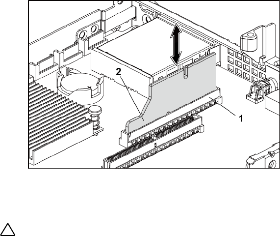
162 | Installing System Components
Figure 3-30. Removing and Installing the Mezzanine-Card Bridge Board
1
mezzanine slot
2
mezzanine-card bridge board
Installing the Mezzanine-Card Bridge Board
CAUTION: Many repairs may only be done by a certified service technician. You
should only perform troubleshooting and simple repairs as authorized in your
product documentation, or as directed by the online or telephone service and
support team. Damage due to servicing that is not authorized by Dell is not
covered by your warranty. Read and follow the safety instructions that came with
the product.
1 Install the mezzanine-card bridge board into the mezzanine slot on the
system board. See Figure 3-30.
2 Install the mezzanine card. See "Installing the SAS Mezzanine Card"
on page 151 and "Installing the 10GbE Mezzanine Card" on page 156.
3 Install the system-board assembly. See "Installing a System-Board
Assembly" on page 116.
4 Reconnect the system to its electrical outlet and turn on the system,
including any attached peripherals.
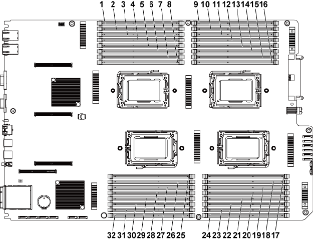
Installing System Components | 163
System Memory
Each system board has thirty-two unbuffered or registered DDR3-DIMM
slots for the installation of up to thirty-two DDR3-800/1066/1333/1600
memory chips to support the four processors. See "System Board
Connectors" on page 229 for the location of the memory modules.
Supported DIMM Configuration
For the sequence of the thirty-two DIMM sockets, see Figure 3-31. When
you insert the SR/DR DIMM(s), always start with CHA_DIMM1. See Table
3-7 for possible memory configuration.
Figure 3-31. Memory Slot Locations

164 | Installing System Components
1
DIMM A1_CHA
2
DIMM A2_CHA
3
DIMM A3_CHB
4
DIMM A4_CHB
5
DIMM A5_CHC
6
DIMM A6_CHC
7
DIMM A7_CHD
8
DIMM A8_CHD
9
DIMM C1_CHA
10
DIMM C2_CHA
11
DIMM C3_CHB
12
DIMM C4_CHB
13
DIMM C5_CHC
14
DIMM C6_CHC
15
DIMM C7_CHD
16
DIMM C8_CHD
17
DIMM D8_CHD
18
DIMM D7_CHD
19
DIMM D6_CHC
20
DIMM D5_CHC
21
DIMM D4_CHB
22
DIMM D3_CHB
23
DIMM D2_CHA
24
DIMM D1_CHA
25
DIMM B8_CHD
26
DIMM B7_CHD
27
DIMM B6_CHC
28
DIMM B5_CHC
29
DIMM B4_CHB
30
DIMM B3_CHB
31
DIMM B2_CHA
32
DIMM B1_CHA
NOTE: For the thermal concern, each DIMM socket needs to be installed with a
real or dummy DIMM.
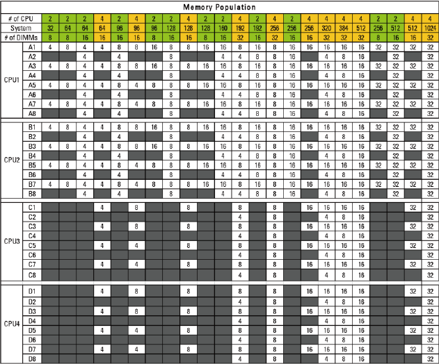
Installing System Components | 165
Table 3-7. Memory Module Configurations and Limitation (Memory Unit=GB)

166 | Installing System Components
Removing the Memory Modules
WARNING: The memory modules are hot to the touch for some time after the
system has been powered down. Allow time for the memory modules to cool
before handling them. Handle the memory modules by the card edges and avoid
touching the components on the memory module.
CAUTION: Many repairs may only be done by a certified service technician. You
should only perform troubleshooting and simple repairs as authorized in your
product documentation, or as directed by the online or telephone service and
support team. Damage due to servicing that is not authorized by Dell is not
covered by your warranty. Read and follow the safety instructions that came with
the product.
1 Recommend to turn off the system, including any attached peripherals,
and disconnect the system from the electrical outlet.
2 Remove the system-board assembly. See "Removing a System-Board
Assembly" on page 115.
3 Locate the memory module sockets. See Figure 3-31.
4 Press down and out on the ejectors on each end of the socket until the
memory module pops out of the socket. See Figure 3-32.
5 Handle each memory module only on either card edge, making sure not
to touch the middle of the memory module.
6 Install the system-board assembly. See "Installing a System-Board
Assembly" on page 116.
7 Reconnect the system to the electrical outlet and turn the system on,
including any attached peripherals.

Installing System Components | 167
Installing the Memory Modules
WARNING: The memory modules are hot to the touch for some time after the
system has been powered down. Allow time for the memory modules to cool
before handling them. Handle the memory modules by the card edges and avoid
touching the components on the memory module.
CAUTION: Many repairs may only be done by a certified service technician. You
should only perform troubleshooting and simple repairs as authorized in your
product documentation, or as directed by the online or telephone service and
support team. Damage due to servicing that is not authorized by Dell is not
covered by your warranty. Read and follow the safety instructions that came with
the product.
1 Recommend to turn off the system, including any attached peripherals,
and disconnect the system from its electrical outlet.
2 Remove the system-board assembly. See "Removing a System-Board
Assembly" on page 115.
3 Locate the memory module sockets. See Figure 3-31.
4 Press the ejectors on the memory module socket down and out, as
shown in Figure 3-32, to allow the memory module to be inserted into
the socket.
5 Handle each memory module only on either card edge, making sure not
to touch the middle of the memory module.
6 Align the memory module's edge connector with the alignment key of
the memory module socket, and insert the memory module in the
socket. See Figure 3-32.
NOTE: The memory module socket has an alignment key that allows you to install
the memory module in the socket in only one way.
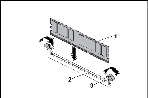
168 | Installing System Components
Figure 3-32. Installing and Removing a DIMM
1
memory module
2
memory module socket
3
memory module socket ejector (2)
7 Press down on the memory module with your thumbs to lock the
memory module into the socket. See Figure 3-32.
When the memory module is properly seated in the socket, the ejectors
on the memory module socket align with the ejectors on the other
sockets that have memory modules installed.
8 Repeat step 4 through step 7 of this procedure to install the remaining
memory modules in the approved configurations. See Table 3-7.
9 Install the system-board assembly. See "Installing a System-Board
Assembly" on page 116.
10 Start up the system. Press <F2> to enter the System Setup program.
Check the System Memory settings on the main System Setup screen.
The system should have already changed the value to reflect the newly
installed memory.
11 If the value is incorrect, one or more of the memory modules may not

Installing System Components | 169
be installed properly. Repeat step 2 through step 10 of this procedure,
to ensure that the memory modules are firmly seated in their sockets.
System Battery
Replacing the System Battery
WARNING: There is a danger of a new battery exploding if it is incorrectly
installed. Replace the battery only with the same or equivalent type
recommended by the manufacturer. See your safety information for additional
information.
CAUTION: Many repairs may only be done by a certified service technician. You
should only perform troubleshooting and simple repairs as authorized in your
product documentation, or as directed by the online or telephone service and
support team. Damage due to servicing that is not authorized by Dell is not
covered by your warranty. Read and follow the safety instructions that came with
the product.
1 Recommend to turn off the system, including any attached peripherals,
and disconnect the system from the electrical outlet.
2 Remove the system-board assembly. See "Removing a System-Board
Assembly" on page 115.
3 Locate the battery location. See ―System Board Connectors‖ on page
229.
CAUTION: To avoid damage to the battery connector, you must firmly support the
connector while installing or removing a battery.
4 Gently pull the retention clip over the battery to the positive side of
the connector and lift the battery out of the connector. See Figure 3-33.
5 Hold the new battery with the ―+‖ facing the retention clip on the
battery connector. See Figure 3-33.
6 Gently pull the retention clip towards the positive side of the
connector and slide the battery into the connector until the retention
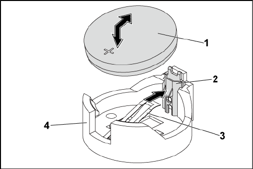
170 | Installing System Components
clip snaps into place. See Figure 3-33.
Figure 3-33. Replacing the System Battery
1
system battery
2
positive side of battery connector
3
retention clip
4
negative side of battery connector
7 Install the system-board assembly. See ―Installing a System-Board
Assembly‖ on page 116.
8 Reconnect the system to the electrical outlet and turn the system on,
including any attached peripherals.
9 Enter the System Setup program to confirm that the battery is
operating properly. See ―Using the System Setup Program‖ on page 46.
10 Enter the correct time and date in the System Setup program‘s Time
and Date fields.
11 Exit the System Setup program.

Installing System Components | 171
System Board
Removing a System Board
CAUTION: Many repairs may only be done by a certified service technician. You
should only perform troubleshooting and simple repairs as authorized in your
product documentation, or as directed by the online or telephone service and
support team. Damage due to servicing that is not authorized by Dell is not
covered by your warranty. Read and follow the safety instructions that came with
the product.
1 Recommend to turn off the system and attached peripherals, and
disconnect the system from the electrical outlet.
2 Remove the system-board assembly. See "Removing a System-Board
Assembly" on page 115.
3 Remove the air ducts. See "Removing the Air Duct" on page 116.
4 Remove the heat sink. See "Removing the Heat Sink" on page 118.
5 Remove the expansion-card assembly. See "Removing the Expansion
Card" on page 125.
6 If installed, remove the SAS mezzanine card or 10GbE mezzanine card.
See "Removing the SAS Mezzanine Card" on page 151 or "Removing
the 10GbE Mezzanine Card " on page 154.
7 Disconnect the hard drive and power cables from the system board.
8 Remove the eight screws and then slide the system board. See Figure 3-
34.
CAUTION: Do not lift the system board by grasping a memory module, processor,
or other components.
9 Grasp the system board by the edges and lift the system board away
from the system-board assembly. See Figure 3-34.
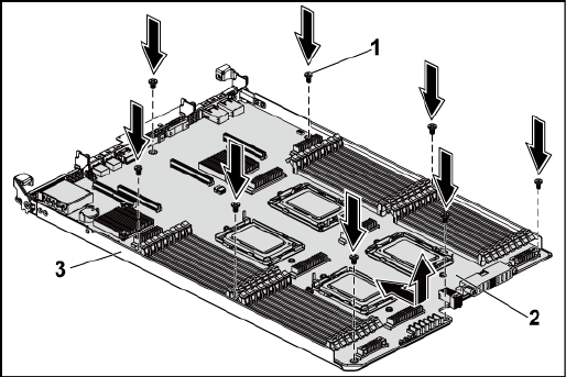
172 | Installing System Components
Figure 3-34. Removing and Installing the System Board
1
screw (8)
2
system board
3
system-board assembly
Installing a System Board
1 Unpack the new system board.
2 Holding the system board by the edges, slide the system board into the
system-board assembly. See Figure 3-34.
3 Replace the eight screws to secure the system board to the system-
board assembly. See Figure 3-34.
4 Transfer the processors to the new system board. See "Removing a
Processor" on page 122 and "

Installing System Components | 173
6 Installing a Processor" on page 124.
7 Remove the memory modules and transfer them to the same locations
on the new board. See "Removing the Memory Modules" on page 166
and "Installing the Memory Modules" on page 167.
8 Replace the air ducts. See "Installing the Air Duct" on page 117.
9 Connect the hard drive and power cables to the system board.
10 If applicable, install the SAS mezzanine card. See "Installing the SAS
Mezzanine Card" on page 153.
11 Install the expansion-card assembly. See Figure 3-11 on page 127.
12 Install the system-board assembly. See "Installing a System-Board
Assembly" on page 116.
13 Reconnect the system to its electrical outlet and turn on the system,
including any attached peripherals.
Opening and Closing the System
WARNING: Whenever you need to lift the system, get others to assist you. To
avoid injury, do not attempt to lift the system by yourself.
CAUTION: This system must be operated with the system cover installed to
ensure proper cooling.
CAUTION: Many repairs may only be done by a certified service technician. You
should only perform troubleshooting and simple repairs as authorized in your
product documentation, or as directed by the online or telephone service and
support team. Damage due to servicing that is not authorized by Dell is not
covered by your warranty. Read and follow the safety instructions that came with
the product.
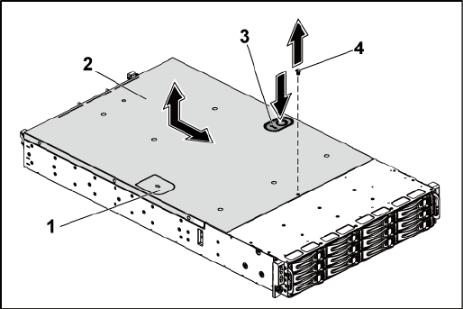
174 | Installing System Components
Opening the System
1 Recommend to turn off the system, including any attached peripherals,
and disconnect the system from the electrical outlet.
2 Remove the securing screw from the system cover. See Figure 3-35.
3 Press the cover release latch lock. See Figure 3-35.
4 Grasp cover on both the sides with your palm on the traction pad, slide
out and lift the cover away from the system. See Figure 3-35.
Figure 3-35. Opening and Closing the System
1
traction pad
2
system cover
3
cover release latch lock
4
securing screw
Closing the System
1 Place the cover on the chassis and slide it to the front of the chassis
until it snaps into place. See Figure 3-35.
2 Secure the cover with the securing screw. See Figure 3-35.

Installing System Components | 175
Cooling Fans
Removing a Cooling Fan
WARNING: Do not attempt to operate the system without the cooling fans.
WARNING: The cooling fan can continue to spin for some time after the system
has been powered down. Allow time for the fan to stop spinning before removing
it from the system.
CAUTION: Many repairs may only be done by a certified service technician. You
should only perform troubleshooting and simple repairs as authorized in your
product documentation, or as directed by the online or telephone service and
support team. Damage due to servicing that is not authorized by Dell is not
covered by your warranty. Read and follow the safety instructions that came with
the product.
1 Recommend to turn off the system, including any attached peripherals,
and disconnect the system from its electrical outlet.
2 Open the system. See "Opening the System" on page 174.
3 Disconnect the fan‘s power cable from the fan-controller board.
Note the routing of the cable through the tabs on the chassis as you
remove them from the system. You must route these cables properly
when you replace them to prevent the cables from being pinched or
crimped.
4 Lift the fan out of the cooling-fan bracket.
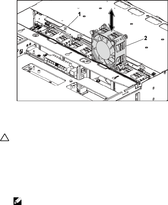
176 | Installing System Components
Figure 3-36. Removing and Installing a Cooling Fan
1
cooling-fan bracket
2
cooling fans (4)
Installing a Cooling Fan
CAUTION: Many repairs may only be done by a certified service technician. You
should only perform troubleshooting and simple repairs as authorized in your
product documentation, or as directed by the online or telephone service and
support team. Damage due to servicing that is not authorized by Dell is not
covered by your warranty. Read and follow the safety instructions that came with
the product.
1 Align the cooling fan and slide it in the cooling-fan bracket until the
cooling fan is firmly seated. See Figure 3-36.
NOTE: The fan blades should face the front panel of the system.
2 Connect the fan‘s power cable to the connector on the fan-controller
board. See Figure 3-48.
You must route these cables properly through the tabs on the chassis to
prevent them from being pinched or crimped.

Installing System Components | 177
3 Close the system. See "Closing the System" on page 174.
4 Reconnect the system to its electrical outlet and turn on the system,
including any attached peripherals.
Middle Planes
Removing the Middle Planes
CAUTION: Many repairs may only be done by a certified service technician. You
should only perform troubleshooting and simple repairs as authorized in your
product documentation, or as directed by the online or telephone service and
support team. Damage due to servicing that is not authorized by Dell is not
covered by your warranty. Read and follow the safety instructions that came with
the product.
1 Recommend to turn off the system, including any attached peripherals,
and disconnect the system from its electrical outlet.
2 Open the system. See "Opening the System" on page 174.
3 Remove the system-board assemblies. See "Removing a System-Board
Assembly" on page 115.
4 Remove the cooling fans. See "Removing a Cooling Fan" on page 175.
5 Lift the cooling-fan bracket out of the chassis. See Figure 3-37.
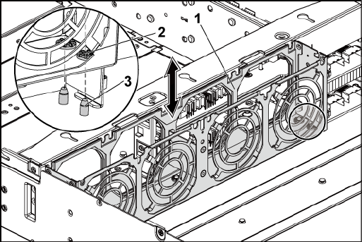
178 | Installing System Components
Figure 3-37. Removing and Installing the Cooling-Fan Bracket
1
cooling-fan bracket
2
locking-tab hole (6)
3
locking tab (6)
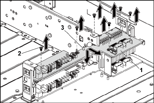
Installing System Components | 179
6 Remove the screws that secure the upper middle plane to the middle
plane holder. See Figure 3-38.
7 Disconnect all the cables from the upper middle plane.
Note the routing of the cable underneath the tabs on the chassis as you
remove them from the system. You must route these cables properly
when you replace them to prevent the cables from being pinched or
crimped.
8 Lift the upper middle plane out. See Figure 3-38.
Figure 3-38. Removing and Installing the Upper Middle Plane
1
upper middle plane
2
screw (6)
3
stand-off on middle plane holder (2)
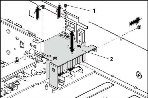
180 | Installing System Components
9 Remove the screws that secure the mid-plane holder support to the
chassis. See Figure 3-39.
10 Lift the mid-plane holder support out of the chassis. See Figure 3-39.
Figure 3-39. Removing and Installing the Mid-plane Holder Support
1
screw (3)
2
mid-plane holder support
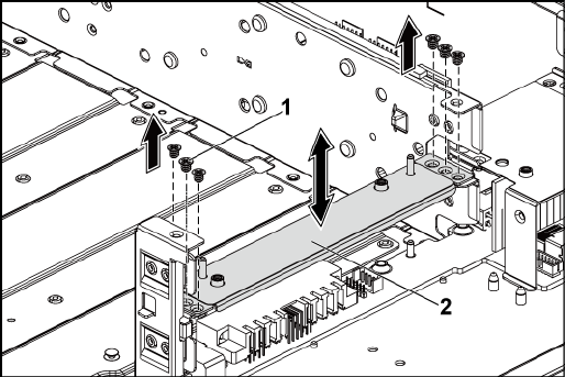
Installing System Components | 181
11 Remove the screws that secure the mid-plane holder to the chassis. See
Figure 3-40.
12 Lift the mid-plane holder out of the chassis. See Figure 3-40.
Figure 3-40. Removing and Installing the Mid-plane Holder
1
screw (6)
2
mid-plane holder
13 Remove the screws that secure the lower middle plane to the chassis.
See Figure 3-41.
14 Disconnect all the cables from the lower middle plane.
Note the routing of the cable underneath the tabs on the chassis as you
remove them from the system. You must route these cables properly
when you replace them to prevent the cables from being pinched or
crimped.
15 Lift the lower middle plane out of the chassis. See Figure 3-41.
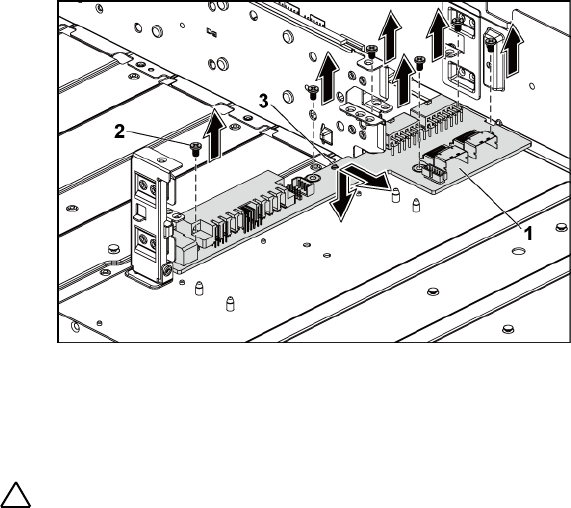
182 | Installing System Components
Figure 3-41. Removing and Installing the Lower Middle Plane
1
lower middle plane
2
screw (6)
3
stand-off on the chassis (2)
Installing the Middle Planes
CAUTION: Many repairs may only be done by a certified service technician. You
should only perform troubleshooting and simple repairs as authorized in your
product documentation, or as directed by the online or telephone service and
support team. Damage due to servicing that is not authorized by Dell is not
covered by your warranty. Read and follow the safety instructions that came with
the product.
1 Place the lower middle plane into the chassis. Make sure that the two
stand-offs on the chassis are inserted through the slot on the lower
middle plane. See Figure 3-41.
2 Replace the screws that secure the lower middle plane to the chassis.
See Figure 3-41.
3 Connect all the cables to the lower middle plane.
Installing System Components | 183
You must route these cables properly through the tabs on the chassis to
prevent them from being pinched or crimped.
4 Place the upper middle plane holder into the chassis. See Figure 3-40.
5 Replace the screws that secure the middle plane holder to the chassis.
See Figure 3-40.
16 Place the middle plane holder support into the chassis. See Figure 3-39.
6 Replace the screws that secure the middle plane holder support to the
chassis. See Figure 3-39.
7 Place the upper middle plane on the middle plane holder. Make sure
that the two stand-offs on the middle plane holder are inserted through
the slot on the upper middle plane. See Figure 3-38.
8 Replace the screws that secure the upper middle plane to the middle
plane holder. See Figure 3-38.
9 Connect all the cables to the upper middle plane.
You must route these cables properly through the tabs on the chassis to
prevent them from being pinched or crimped.
10 Align the locking-tab holes on the cooling-fan bracket to the
corresponding locking tabs on the chassis, and then press down the
cooling-fan bracket into the chassis until secured firmly. See Figure 3-
37.
11 Replace the cooling fans. See "Installing a Cooling Fan" on page 176.
12 Replace the system-board assemblies. See "Installing a System-Board
Assembly" on page 116.
13 Close the system, see "Closing the System" on page 174.
14 Reconnect the system to its electrical outlet and turn on the system,
including any attached peripherals.

184 | Installing System Components
Backplanes
NOTE: This section describes the replacement of 3.5" hard-drive backplane, with
the 3.5 " hard-drive backplane with CPLD as example. For replacement information
about 2.5" hard-drive backplanes, see "Expander Card (Optional)" on page 195.
Removing the 3.5" Hard-Drive Backplane
CAUTION: Many repairs may only be done by a certified service technician. You
should only perform troubleshooting and simple repairs as authorized in your
product documentation, or as directed by the online or telephone service and
support team. Damage due to servicing that is not authorized by Dell is not
covered by your warranty. Read and follow the safety instructions that came with
the product.
1 Recommend to turn off the system, including any attached peripherals,
and disconnect the system from its electrical outlet.
2 Remove all the hard drives. See ―Removing a Hard-Drive Carrier‖ on
page 106.
3 Open the system. See "Opening the System" on page 174.
CAUTION: To prevent damage to the drives and backplane, you must remove the
hard drives from the system before removing the backplane.
CAUTION: You must note the number of each hard drive and temporarily label
them before removal so that you can replace them in the same locations.
4 Remove the screws that secure the hard-drive cage to the chassis. See
Figure 3-42.
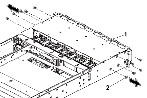
Installing System Components | 185
Figure 3-42. Removing and Installing the 3.5" Hard-Drive Cage (1)
1
3.5" hard-drive cage
2
screw (10)
5 Remove the screws that secure the front-panel assemblies to the chassis.
See Figure 3-43.
6 Disconnect all the cables from the backplane. See Figure 5-3 for 3.5"
hard drives and Figure 5-7 for 2.5" hard drives.
Note the routing of the cable underneath the tabs on the chassis as you
remove them from the system. You must route these cables properly
when you replace them to prevent the cables from being pinched or
crimped.
7 Disconnect front panel cables from the fan controller board. See Figure
3-48.
Note the routing of the cable underneath the tabs on the chassis as you
remove them from the system. You must route these cables properly
when you replace them to prevent the cables from being pinched or
crimped.
8 Remove the hard-drive cage from the chassis. See Figure 3-43.

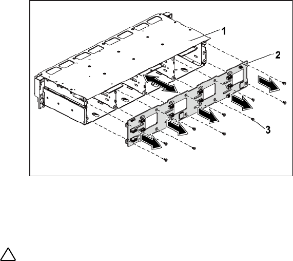
Installing System Components | 187
Figure 3-44. Removing and Installing the Backplane From the Hard-Drive Cage
1
3.5" hard-drive cage
2
3.5" hard-drive backplane
3
screw (10)
Installing the 3.5" Hard-Drive Backplane
CAUTION: Many repairs may only be done by a certified service technician. You
should only perform troubleshooting and simple repairs as authorized in your
product documentation, or as directed by the online or telephone service and
support team. Damage due to servicing that is not authorized by Dell is not
covered by your warranty. Read and follow the safety instructions that came with
the product.
1 Install the backplane into the hard-drive cage. See Figure 3-44.
2 Replace the screws that secure the backplane to the hard-drive cage.
See Figure 3-44.
3 Replace the hard-drive cage into the chassis. See Figure 3-43.
4 Replace the screws that secure the front-panel assemblies to the chassis.
See Figure 3-43.
5 Connect all cables to the backplane. See Figure 5-3 for 3.5" hard drives.

188 | Installing System Components
You must route these cables properly through the tabs on the chassis to
prevent them from being pinched or crimped.
6 Connect front panel cables to the fan controller board. See Figure 3-48.
You must route these cables properly through the tabs on the chassis to
prevent them from being pinched or crimped.
7 Replace the screws that secure the hard-drive cage. See Figure 3-42.
8 Close the system, see "Closing the System" on page 174.
9 Replace the hard drives. See "Installing a Hard Drive Into a Hard-Drive
Carrier" on page 109.
10 Reconnect the system to its electrical outlet and turn on the system,
including any attached peripherals.
Power Distribution Boards
Removing a Power Distribution Board
CAUTION: Many repairs may only be done by a certified service technician. You
should only perform troubleshooting and simple repairs as authorized in your
product documentation, or as directed by the online or telephone service and
support team. Damage due to servicing that is not authorized by Dell is not
covered by your warranty. Read and follow the safety instructions that came with
the product.
NOTE: This system has two power distribution boards. The procedure to remove
and install both the power distribution boards is similar. To access the second
power distribution board at the bottom, remove the power distribution board at
the top.
1 Recommend to turn off the system, including any attached peripherals,
and disconnect the system from its electrical outlet.
2 Open the system. See "Opening the System" on page 174.
3 Remove the power supply. See "Removing a Power Supply" on page 110.
4 Disconnect all the cables from the first power distribution board. See
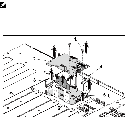
Installing System Components | 189
Figure 3-46.
5 Remove the screws securing the first power distribution board to the
system. See Figure 3-45.
6 Lift the power distribution board out of the system. See Figure 3-45.
NOTE: To remove the second power distribution board that is below the first
power distribution board, remove the power distribution board connector
and angle the board before lifting.
Figure 3-45. Removing and Installing a Power Distribution Board
1
screw (4)
2
1st power distribution board
3
power distribution board bridge board
4
screw (4)
5
2nd power distribution board
6
stand-off on the chassis
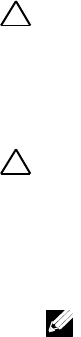
190 | Installing System Components
Installing a Power Distribution Board
CAUTION: Many repairs may only be done by a certified service technician. You
should only perform troubleshooting and simple repairs as authorized in your
product documentation, or as directed by the online or telephone service and
support team. Damage due to servicing that is not authorized by Dell is not
covered by your warranty. Read and follow the safety instructions that came with
the product.
CAUTION: If removed, you must replace the second power distribution board at
the bottom and the power distribution board-connector before replacing the first
power distribution board at the top.
1 If removed, first place the second power distribution board in the
system. See Figure 3-45. Otherwise skip to step 5.
NOTE: To install the second power distribution board that is below the first
power distribution board, angle the board during installation.
2 Replace the screws securing the second power distribution board to the
system. See Figure 3-45.
3 Replace the power distribution board bridge board. See Figure 3-45.
4 Connect all the cables to the second power distribution board. See
Figure 3-46.
You must route these cables properly to prevent them from being
pinched or crimped.
5 Replace the screws securing the first power distribution board to the
system. See Figure 3-45.
6 Connect all the cables to the first power distribution board. See Figure
3-46
You must route these cables properly through the tabs on the chassis to
prevent them from being pinched or crimped.
7 Replace the power supply. See "Installing a Power Supply" on page 114.
8 Close the system. See "Closing the System" on page 174.
Installing System Components | 191
9 Reconnect the system to its electrical outlet and turn on the system,
including any attached peripherals.
Cable Routing for Power Distribution Board
Figure 3-46. Cable Routing−Power Distribution Board
Item
Cable
From
(Power Distribution
Boards)
To
PMBus to
power
distribution
board cables
PMbus connectors (J6)
Fan Control Board
Main power
cables
Main power connectors
(J2, J3)
Middle Plane
System fan
board power
System fan board power
connectors (J7)
Fan Control Board
192 | Installing System Components
Item
Cable
From
(Power Distribution
Boards)
To
cables
Hard-drive
backplane
power cables
Hard-drive backplane
power connectors (J5)
Backplane
Fan Controller Board
Removing the Fan Controller Board
CAUTION: Many repairs may only be done by a certified service technician. You
should only perform troubleshooting and simple repairs as authorized in your
product documentation, or as directed by the online or telephone service and
support team. Damage due to servicing that is not authorized by Dell is not
covered by your warranty. Read and follow the safety instructions that came with
the product.
1 Recommend to turn off the system, including any attached peripherals,
and disconnect the system from its electrical outlet.
2 Open the system. See "Opening the System" on page 174.
3 Disconnect the cables from the power distribution boards.
4 Disconnect the cables from the fan controller board. See Figure 3-48.
Note the routing of the cable underneath the tabs on the chassis as you
remove them from the system. You must route these cables properly
when you replace them to prevent the cables from being pinched or
crimped.
5 Reconnect the cables from the power distribution boards.
6 Remove the screw securing the fan controller board to the chassis. See
Figure 3-47.
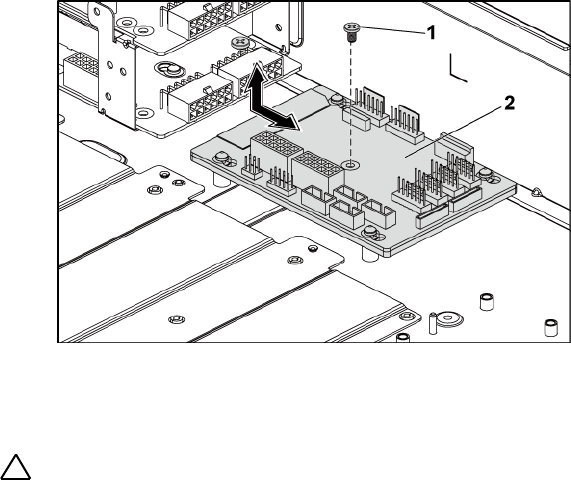
Installing System Components | 193
7 Slide and lift the fan controller board out of the chassis. See Figure 3-
47.
Figure 3-47. Removing and Installing the Fan Controller Board
1
screw
2
fan controller board
Installing the Fan Controller Board
CAUTION: Many repairs may only be done by a certified service technician. You
should only perform troubleshooting and simple repairs as authorized in your
product documentation, or as directed by the online or telephone service and
support team. Damage due to servicing that is not authorized by Dell is not
covered by your warranty. Read and follow the safety instructions that came with
the product.
1 Place the fan controller board into the chassis and slide it into place.
See Figure 3-47.
2 Replace the screw to secure the fan controller board to the chassis. See
Figure 3-47.
3 Connect all the cables to the fan controller board. See Figure 3-48.
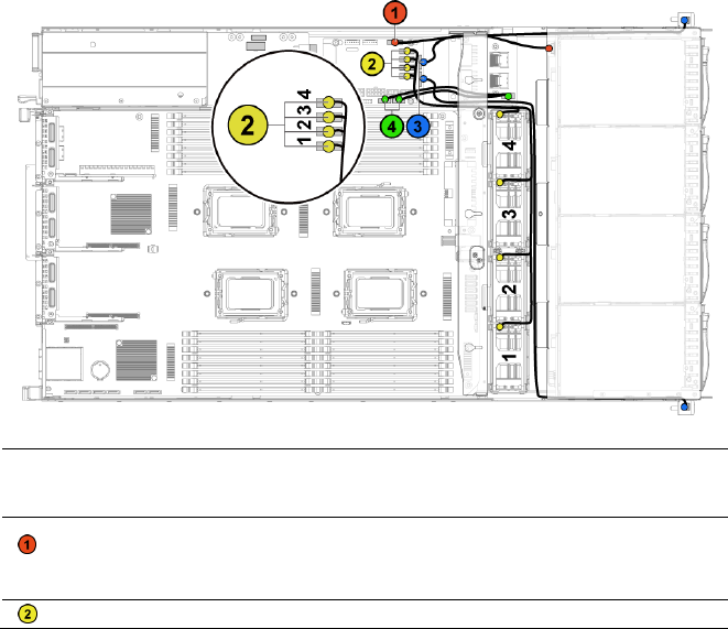
194 | Installing System Components
You must route these cables properly through the tabs on the chassis to
prevent them from being pinched or crimped.
4 Replace the power distribution boards. See "Installing a Power
Distribution Board" on page 190.
5 Close the system. See "Closing the System" on page 174.
6 Reconnect the system to its electrical outlet and turn on the system,
including any attached peripherals.
Cable Routing for Fan Control Board
Figure 3-48. Cable Routing−Fan Control Board
Item
Cable
From
(Fan Control Board)
To
Hard-drive
backplane I2C
cable
Hard-drive backplane
connector (J17)
Backplane
System fan
System fan connectors
System fans
Installing System Components | 195
Item
Cable
From
(Fan Control Board)
To
cables
(J12, J19, J11, J16)
Front panel
cables
Front-panel connectors
(J31, J32)
Front panels
Front panel
to
motherboard
cables
Front-panel connectors
for system board (J23,
J24)
Middle Planes
Expander Card (Optional)
NOTE: The information in this section uses the 2.5" SATA2 and SAS backplane with
expander as example.
Removing the Expander Card
CAUTION: Many repairs may only be done by a certified service technician. You
should only perform troubleshooting and simple repairs as authorized in your
product documentation, or as directed by the online or telephone service and
support team. Damage due to servicing that is not authorized by Dell is not
covered by your warranty. Read and follow the safety instructions that came with
the product.
1 Recommend to turn off the system, including any attached peripherals,
and disconnect the system from its electrical outlet.
2 Remove all the hard drives. See ―Removing a Hard-Drive Carrier‖ on
page 106.
3 Open the system. See "Opening the System" on page 174.
CAUTION: To prevent damage to the drives and backplane, you must remove the
hard drives from the system before removing the backplane.
CAUTION: You must note the number of each hard drive and temporarily label
them before removal so that you can replace them in the same locations.
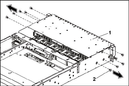
196 | Installing System Components
4 Remove the screws that secure the 2.5" hard-drive cage to the chassis.
See Figure 3-49.
Figure 3-49. Removing and Installing the 2.5" Hard-Drive Cage (1)
1
2.5" hard-drive cage
2
screw (10)
5 Remove the screws that secure the front-panel assemblies to the chassis.
See Figure 3-49.
6 Disconnect all the cables from the backplane. See Figure 5-7 for 2.5"
hard drives.
Note the routing of the cable underneath the tabs on the chassis as you
remove them from the system. You must route these cables properly
when you replace them to prevent the cables from being pinched or
crimped.
7 Disconnect all the cables from the expander card.
Note the routing of the cable underneath the tabs on the chassis as you
remove them from the system. You must route these cables properly
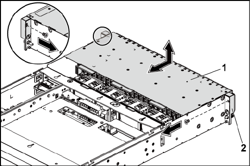
Installing System Components | 197
when you replace them to prevent the cables from being pinched or
crimped.
8 Disconnect front panel cables from the fan controller board. See Figure
3-48.
Note the routing of the cable underneath the tabs on the chassis as you
remove them from the system. You must route these cables properly
when you replace them to prevent the cables from being pinched or
crimped.
9 Remove the hard-drive cage from the chassis. See Figure 3-50.
Figure 3-50. Removing and Installing the Hard-Drive Cage (2)
1
2.5" hard-drive cage
2
front-panel assembly (2)
10 Remove the screws that secure the backplane to the hard-drive cage.
See Figure 3-51.
11 Remove the backplane with the expander card from the hard-drive cage.
See Figure 3-51.
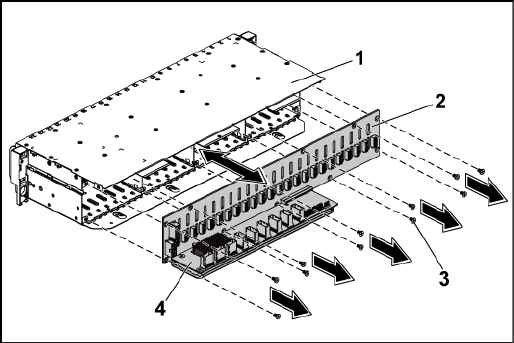
198 | Installing System Components
Figure 3-51. Removing and Installing the Backplane with the Expander Card
1
2.5" hard-drive cage
2
2.5" hard-drive backplane
3
screw (11)
4
expander card
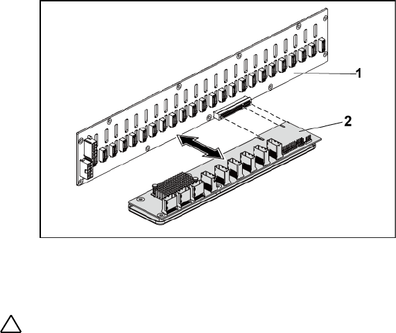
Installing System Components | 199
12 Remove the expander card from the 2.5" hard-drive backplane. See
Figure 3-52.
Figure 3-52. Removing and Installing the Expander Card From the Backplane
1
2.5" hard-drive backplane
2
expander card
Installing the Expander Card
CAUTION: Many repairs may only be done by a certified service technician. You
should only perform troubleshooting and simple repairs as authorized in your
product documentation, or as directed by the online or telephone service and
support team. Damage due to servicing that is not authorized by Dell is not
covered by your warranty. Read and follow the safety instructions that came with
the product.
1 Install the expander card into the 2.5" hard-drive backplane. See Figure
3-52.
2 Install the 2.5" hard-drive backplane into the hard-drive cage. See
Figure 3-51.
3 Replace the screws that secure the backplane to the hard-drive cage.

200 | Installing System Components
See Figure 3-51.
4 Replace the hard-drive cage into the chassis. See Figure 3-50.
5 Replace the screws that secure the front-panel assemblies to the chassis.
See Figure 3-50.
Connect all the cables to the backplane. See Figure 5-3 for 2.5" hard
drives. You must route these cables properly through the tabs on the
chassis to prevent them from being pinched or crimped.
6 Connect all the cables to the expander card.
You must route these cables properly through the tabs on the chassis to
prevent them from being pinched or crimped.
7 Connect front panel cables to the fan controller board. See Figure 3-48.
You must route these cables properly through the tabs on the chassis to
prevent them from being pinched or crimped.
8 Replace the screws that secure the hard-drive cage. See Figure 3-49.
9 Close the system, see "Closing the System" on page 174.
10 Replace the hard drives. See "Installing a Hard Drive Into a Hard-Drive
Carrier" on page 109.
11 Reconnect the system to its electrical outlet and turn on the system,
including any attached peripherals.
Front Panels
Removing the Front Panel
CAUTION: Many repairs may only be done by a certified service technician. You
should only perform troubleshooting and simple repairs as authorized in your
product documentation, or as directed by the online or telephone service and
support team. Damage due to servicing that is not authorized by Dell is not
covered by your warranty. Read and follow the safety instructions that came with
the product.
Installing System Components | 201
1 Recommend to turn off the system, including any attached peripherals,
and disconnect the system from the electrical outlet.
2 Remove all the hard drives. See "Removing a Hard-Drive Carrier‖ on
page 106.
3 Open the system. See "Opening the System" on page 174.
4 Disconnect all the cables from the backplane. See Figure 5-3 for 3.5"
hard drives and Figure 5-7 for 2.5" hard drives.
Note the routing of the cable underneath the tabs on the chassis as you
remove them from the system. You must route these cables properly
when you replace them to prevent the cables from being pinched or
crimped.
5 Disconnect front panel cables from the fan controller board. See Figure
3-48.
Note the routing of the cable underneath the tabs on the chassis as you
remove them from the system. You must route these cables properly
when you replace them to prevent the cables from being pinched or
crimped.
6 Remove the screws that secure the hard-drive cage to the chassis. See
Figure 3-42.
7 Remove the screws that secure the front-panel assembly to the chassis.
See Figure 3-43.
8 Remove the hard-drive cage from the chassis. See Figure 3-43.
9 Remove the screws that secure the front-panel assembly to the hard-
drive cage. See Figure 3-53.
10 Remove the front-panel assembly from the hard-drive cage. See Figure
3-53.

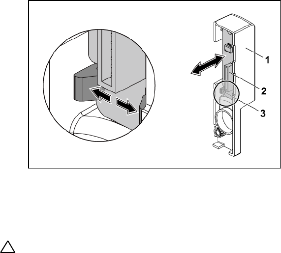
Installing System Components | 203
Figure 3-54. Removing and Installing a Front Panel
1
front-panel assembly
2
front panel
3
retention hooks
Installing the Front Panel
CAUTION: Many repairs may only be done by a certified service technician. You
should only perform troubleshooting and simple repairs as authorized in your
product documentation, or as directed by the online or telephone service and
support team. Damage due to servicing that is not authorized by Dell is not
covered by your warranty. Read and follow the safety instructions that came with
the product.
1 Push aside the retention hooks on the front-panel assembly and place
the front panel into the front-panel assembly. See Figure 3-54.
2 Replace the front-panel assembly into the hard-drive cage. See Figure
3-53.
3 Replace the screws that secure the front-panel assembly to the hard-
drive cage. See Figure 3-53.

204 | Installing System Components
4 Replace the hard-drive cage into the chassis. See Figure 3-43.
5 Replace the screws that secure the front-panel assembly to the chassis.
See Figure 3-43.
6 Replace the screws that secure the hard-drive cage to the chassis. See
Figure 3-42.
7 Connect front panel cables to the fan controller board. See Figure 3-48.
You must route these cables properly through the tabs on the chassis to
prevent them from being pinched or crimped.
8 Connect all the cables to the backplane. See Figure 5-3 for 3.5" hard
drives and Figure 5-7 for 2.5" hard drives.
You must route these cables properly through the tabs on the chassis to
prevent them from being pinched or crimped.
9 Close the system. See "Closing the System" on page 174.
10 Replace the hard drives. See "Installing a Hard Drive Into a Hard-Drive
Carrier" on page 109.
11 Reconnect the system to its electrical outlet and turn on the system,
including any attached peripherals.
Sensor Boards
Removing the Sensor Board for 3.5” Hard Drive System
CAUTION: Many repairs may only be done by a certified service technician. You
should only perform troubleshooting and simple repairs as authorized in your
product documentation, or as directed by the online or telephone service and
support team. Damage due to servicing that is not authorized by Dell is not
covered by your warranty. Read and follow the safety instructions that came with
the product.
1 Recommend to turn off the system, including any attached peripherals,
and disconnect the system from the electrical outlet.
Installing System Components | 205
2 Remove all the hard drives. See "Removing a Hard-Drive Carrier" on
page 106.
3 Open the system. See "Opening the System" on page 174.
4 Disconnect all the cables from the backplane. See Figure 5-3 for 3.5"
hard drives.
Note the routing of the cable underneath the tabs on the chassis as you
remove them from the system. You must route these cables properly
when you replace them to prevent the cables from being pinched or
crimped.
5 Disconnect front panel cables from the fan controller board. See Figure
3-48.
Note the routing of the cable underneath the tabs on the chassis as you
remove them from the system. You must route these cables properly
when you replace them to prevent the cables from being pinched or
crimped.
6 Remove the hard drive cage from the chassis. See Figure 3-43.
7 Disconnect the cable from the sensor board.
8 Remove the screw that secures the sensor board to the hard-drive cage.
See Figure 3-55.
9 Remove the sensor board from the hard-drive cage. See Figure 3-55.
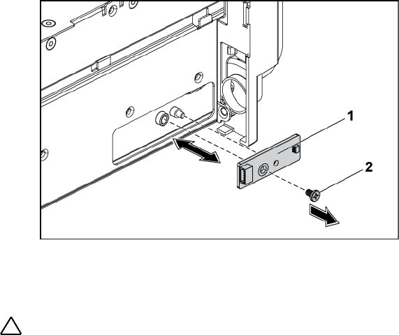
206 | Installing System Components
Figure 3-55. Removing and Installing the Sensor Board
1
sensor board
2
screw
Installing the Sensor Board for 3.5” Hard Drive System
CAUTION: Many repairs may only be done by a certified service technician. You
should only perform troubleshooting and simple repairs as authorized in your
product documentation, or as directed by the online or telephone service and
support team. Damage due to servicing that is not authorized by Dell is not
covered by your warranty. Read and follow the safety instructions that came with
the product.
1 Replace the sensor board into the hard-drive cage. See Figure 3-55.
2 Replace the screw that secures the sensor board to the hard-drive cage.
See Figure 3-55.
3 Connect the sensor board cable to the sensor board.
4 Replace the hard-drive cage into the chassis. See Figure 3-43.
5 Replace the screws that secure the hard-drive cage to the chassis. See
Figure 3-43.
6 Connect all the cables to the backplane. See Figure 5-3 for 3.5" hard
Installing System Components | 207
drives.
You must route these cables properly through the tabs on the chassis to
prevent them from being pinched or crimped.
7 Connect front panel cables to the fan controller board. See Figure 3-48.
You must route these cables properly through the tabs on the chassis to
prevent them from being pinched or crimped.
8 Close the system. See "Closing the System" on page 174.
9 Replace the hard drives. See "Installing a Hard Drive Into a Hard-Drive
Carrier" on page 109.
10 Reconnect the system to its electrical outlet and turn on the system,
including any attached peripherals.

208 | Installing System Components
Removing the Sensor Board for 2.5” Hard Drive System
CAUTION: Many repairs may only be done by a certified service technician. You
should only perform troubleshooting and simple repairs as authorized in your
product documentation, or as directed by the online or telephone service and
support team. Damage due to servicing that is not authorized by Dell is not
covered by your warranty. Read and follow the safety instructions that came with
the product.
1 Recommend to turn off the system, including any attached peripherals,
and disconnect the system from the electrical outlet.
2 Remove all the hard drives. See "Removing a Hard-Drive Carrier" on
page 106.
3 Open the system. See "Opening the System" on page 174.
4 Disconnect all the cables from the backplane. See Figure 5-7 for 2.5"
hard drives.
Note the routing of the cable underneath the tabs on the chassis as you
remove them from the system. You must route these cables properly
when you replace them to prevent the cables from being pinched or
crimped.
5 Disconnect front panel cables from the fan controller board. See Figure
3-48.
Note the routing of the cable underneath the tabs on the chassis as you
remove them from the system. You must route these cables properly
when you replace them to prevent the cables from being pinched or
crimped.
6 Remove the hard-drive cage from the chassis. See Figure 3-43.
7 Disconnect the cable from the sensor-board assembly.
8 Remove the screws that secure the sensor-board assembly to the hard-
drive cage. See Figure 3-56.
9 Remove the sensor-board assembly from the hard-drive cage. See
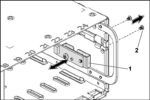
Installing System Components | 209
Figure 3-56.
Figure 3-56. Removing and Installing the Sensor-Board Assembly
1
sensor-board assembly
2
screw (2)
10 Remove the screw that secures the sensor board to the sensor-board
holder. See Figure 3-57.
11 Remove the sensor board from sensor-board holder. See Figure 3-57.
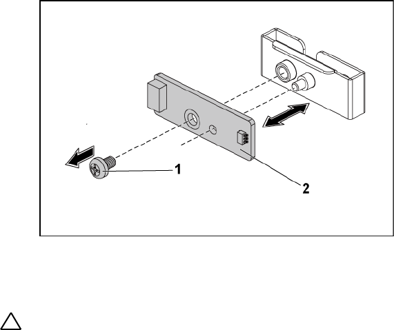
210 | Installing System Components
Figure 3-57. Removing and Installing the Sensor Board
1
screw
2
sensor board
Installing the Sensor Board for 2.5” Hard Drive System
CAUTION: Many repairs may only be done by a certified service technician. You
should only perform troubleshooting and simple repairs as authorized in your
product documentation, or as directed by the online or telephone service and
support team. Damage due to servicing that is not authorized by Dell is not
covered by your warranty. Read and follow the safety instructions that came with
the product.
1 Replace the sensor board into the sensor-board holder. Make sure that
the stand-off on the sensor-board holder is inserted into the slot on the
sensor board. See Figure 3-57.
2 Replace the sensor-board assembly into the hard-drive cage. See Figure
3-56.
3 Replace the screw that secures the sensor board to the hard-drive cage.
See Figure 3-56.
Installing System Components | 211
4 Connect the sensor board cable to the sensor board.
5 Replace the hard-drive cage into the chassis. See Figure 3-43.
6 Replace the screws that secure the hard-drive cage to the chassis. See
Figure 3-42.
7 Connect all the cables to the backplane. See Figure 5-7 for 2.5" hard
drives.
You must route these cables properly through the tabs on the chassis to
prevent them from being pinched or crimped.
8 Connect front panel cables to the fan controller board. See Figure 3-48.
You must route these cables properly through the tabs on the chassis to
prevent them from being pinched or crimped.
9 Close the system. See "Closing the System" on page 174.
10 Replace the hard drives. See "Installing a Hard Drive Into a Hard-Drive
Carrier" on page 109.
11 Reconnect the system to its electrical outlet and turn on the system,
including any attached peripherals.

4
212 |Troubleshooting Your System
Troubleshooting Your System
Safety First – For You and Your System
WARNING: Whenever you need to lift the system, get others to assist you. To
avoid injury, do not attempt to lift the system by yourself.
WARNING: Before removing the system cover, disconnect all power, then unplug
the AC power cord, and then disconnect all peripherals, and all LAN lines.
CAUTION: Many repairs may only be done by a certified service technician. You
should only perform troubleshooting and simple repairs as authorized in your
product documentation, or as directed by the online or telephone service and
support team. Damage due to servicing that is not authorized by Dell is not
covered by your warranty. Read and follow the safety instructions that came with
the product.
Installation Problems
Perform the following checks when you troubleshoot installation problems:
Check all cable and power connections (including all rack cable
connections).
Unplug the power cord and wait for one minute. Then reconnect the
power cord and try again.
If the network is reporting an error, verify that the system has enough
memory and disk space.
Remove all added peripherals, one at a time, and try to turn on the
system. If after removing a peripheral the system works, it may be a
problem with the peripheral or a configuration problem between the
peripheral and the system. Contact the peripheral vendor for assistance.
If the system does not power on, check the LED display. If the power
LED is not on, you may not be receiving AC power. Check the AC
power cord to make sure that it is securely connected.
Troubleshooting Your System | 213
Troubleshooting System Startup Failure
If your system halts during startup, especially after installing an operating
system or reconfiguring your system‘s hardware, check for invalid memory
configurations. These could cause the system to halt at startup without any
video output. See "System Memory" on page 154.
For all other startup issues, note any system messages that appear onscreen,
see "Using the System Setup Program‖ on page 46 for more information.
Troubleshooting External Connections
Ensure that all external cables are securely attached to the external
connectors on your system before troubleshooting any external devices. See
Figure 1-1, Figure 1-6, and Figure 1-9 for the front- and back-panel
connectors on your system.
Troubleshooting the Video Subsystem
1 Check the system and power connections to the monitor.
2 Check the video interface cabling from the system to the monitor.
Troubleshooting a USB Device
Use the following steps to troubleshoot a USB keyboard and/or mouse.
For other USB devices, go to step 5.
1 Disconnect the keyboard and mouse cables from the system briefly and
reconnect them.
2 Connect the keyboard/mouse to the USB port(s) on the opposite side
of the system.
3 If the problem is resolved, restart the system, enter the System Setup
214 |Troubleshooting Your System
program, and check if the nonfunctioning USB ports are enabled.
4 Replace the keyboard/mouse with another working keyboard/mouse.
If the problem is resolved, replace the faulty keyboard/mouse.
If the problem is not resolved, proceed to the next step to begin
troubleshooting the other USB devices attached to the system.
5 Power down all attached USB devices, and disconnect them from the
system.
6 Restart the system and, if your keyboard is functioning, enter the
system setup program. Verify that all USB ports are enabled. See "USB
Configuration" on page 64.
If your keyboard is not functioning, you can also use remote access. If
the system is not accessible, see "Switch and Jumper Settings" on page
242 for instructions on setting the NVRAM_CLR jumper inside your
system and restoring the BIOS to the default settings.
7 Reconnect and power on each USB device one at a time.
8 If a device causes the same problem, power down the device, replace
the USB cable, and power up the device.
If the problem persists, replace the device.
If all troubleshooting fails, see "Getting Help" on page 246.
Troubleshooting a Serial I/O Device
1 Turn off the system and any peripheral devices connected to the serial
port.
2 Swap the serial interface cable with another working cable, and turn on
the system and the serial device.
If the problem is resolved, replace the interface cable.
3 Turn off the system and the serial device, and swap the device with a
comparable device.
Troubleshooting Your System | 215
4 Turn on the system and the serial device.
If the problem is resolved, replace the serial device.
If the problem persists, see "Getting Help" on page 246.
Troubleshooting a NIC
1 Restart the system and check for any system messages pertaining to the
NIC controller.
2 Check the appropriate indicator on the NIC connector. See "NIC
Indicators (BMC Management Port)" on page 21.
If the link indicator does not light, check all cable connections.
If the activity indicator does not light, the network driver files
might be damaged or missing.
Remove and reinstall the drivers if applicable. See the NIC's
documentation.
Change the auto-negotiation setting, if possible.
Use another connector on the switch or hub.
If you are using a NIC card instead of an integrated NIC, see the
documentation for the NIC card.
3 Ensure that the appropriate drivers are installed and the protocols are
bound. See the NIC's documentation.
4 Enter the System Setup program and confirm that the NIC ports are
enabled. See "Using the System Setup Program" on page 46.
5 Ensure that the NICs, hubs, and switches on the network are all set to
the same data transmission speed. See the documentation for each
network device.
6 Ensure that all network cables are of the proper type and do not exceed
the maximum length.
If all troubleshooting fails, see "Getting Help" on page 246.

216 |Troubleshooting Your System
Troubleshooting a Wet System
CAUTION: Many repairs may only be done by a certified service technician. You
should only perform troubleshooting and simple repairs as authorized in your
product documentation, or as directed by the online or telephone service and
support team. Damage due to servicing that is not authorized by Dell is not
covered by your warranty. Read and follow the safety instructions that came with
the product.
1 Turn off the system and attached peripherals, and disconnect the
system from the electrical outlet.
2 Open the system. See "Opening the System" on page 174.
3 Disassemble components from the system. See "Installing System
Components" on page 103.
Hard drives
SAS backplane
Expansion-card
Power supplies
Fans
Air ducts
Processors and heat sinks
Memory modules
4 Let the system dry thoroughly for at least 24 hours.
5 Reinstall the components you removed in step 3.
6 Close the system. See "Closing the System" on page 174.
7 Reconnect the system to the electrical outlet, and turn on the system
and attached peripherals.
If the system does not start properly, see "Getting Help" on page 246.
8 If the system starts properly, shut down the system and reinstall the
expansion card that you removed. See "Installing the Expansion Card"
on page 127.
9 If the system fails to start, see "Getting Help" on page 246.

Troubleshooting Your System | 217
Troubleshooting a Damaged System
CAUTION: Many repairs may only be done by a certified service technician. You
should only perform troubleshooting and simple repairs as authorized in your
product documentation, or as directed by the online or telephone service and
support team. Damage due to servicing that is not authorized by Dell is not
covered by your warranty. Read and follow the safety instructions that came with
the product.
1 Turn off the system and attached peripherals, and disconnect the
system from the electrical outlet.
2 Open the system. See "Opening the System" on page 174.
3 Ensure that the following components are properly installed:
Expansion-card assembly
Power supplies
Fans
Processors and heat sinks
Air ducts
Memory modules
Hard-drive carriers
4 Ensure that all cables are properly connected.
5 Close the system. See "Closing the System" on page 174.
6 If the system fails to start, see "Getting Help" on page 246.
Troubleshooting the System Battery
NOTE: If the system is turned off for long periods of time (for weeks or months),
the NVRAM may lose its system configuration information. This situation is
caused by a defective battery.
1 Re-enter the time and date through the System Setup program.
See ―System Setup Options at Boot‖ on page 46.
2 Turn off the system and disconnect it from the electrical outlet for

218 |Troubleshooting Your System
at least one hour.
3 Reconnect the system to the electrical outlet and turn on the
system.
4 Enter the System Setup program.
If the date and time are not correct in the System Setup program,
replace the battery. See ―Replacing the System Battery‖ on page 169.
CAUTION: Many repairs may only be done by a certified service technician. You
should only perform troubleshooting and simple repairs as authorized in your
product documentation, or as directed by the online or telephone service and
support team. Damage due to servicing that is not authorized by Dell is not
covered by your warranty. Read and follow the safety instructions that came with
the product.
If the problem is not resolved by replacing the battery, see ―Getting
Help" on page 246.
NOTE: Some software may cause the system time to speed up or slow down. If
the system seems to operate normally except for the time kept in the System
Setup program, the problem may be caused by software rather than by a
defective battery.
Troubleshooting Power Supplies
1 Identify the faulty power supply by the power supply's fault indicator.
See "Power and System Board Indicator Codes" on page 22.
CAUTION: At least one power supply must be installed for the system to operate.
Operating the system with only one power supply installed for extended periods of
time can cause the system to overheat.
2 Reseat the power supply by removing and reinstalling it. See "Power
Supplies" on page 110.

Troubleshooting Your System | 219
NOTE: After installing a power supply, allow several seconds for the system
to recognize the power supply and to determine if it is working properly. The
power indicator turns green to signify that the power supply is functioning
properly.
If the problem persists, replace the faulty power supply.
3 If all troubleshooting fails, see "Getting Help" on page 246.
Troubleshooting System Cooling Problems
CAUTION: Many repairs may only be done by a certified service technician. You
should only perform troubleshooting and simple repairs as authorized in your
product documentation, or as directed by the online or telephone service and
support team. Damage due to servicing that is not authorized by Dell is not
covered by your warranty. Read and follow the safety instructions that came with
the product.
Ensure that none of the following conditions exist:
System cover, air duct, drive blank, power supply blank, or front or
back filler panel is removed.
Ambient temperature is too high.
External airflow is obstructed.
Cables inside the system obstruct airflow.
An individual cooling fan is removed or has failed. See
"Troubleshooting a Fan" on page 220.

220 |Troubleshooting Your System
Troubleshooting a Fan
CAUTION: Many repairs may only be done by a certified service technician. You
should only perform troubleshooting and simple repairs as authorized in your
product documentation, or as directed by the online or telephone service and
support team. Damage due to servicing that is not authorized by Dell is not
covered by your warranty. Read and follow the safety instructions that came with
the product.
1 Locate the faulty fan indicated by the diagnostic software.
2 Turn off the system and all attached peripherals.
3 Open the system. See "Opening the System" on page 174.
4 Reseat the fan's power cable.
5 Restart the system.
If the fan functions properly, close the system. See "Closing the
System" on page 174.
6 If the fan does not function, turn off the system and install a new fan.
See "Cooling Fans" on page 175.
7 Restart the system.
If the problem is resolved, close the system. See "Closing the System"
on page 174.
If the replacement fan does not operate, see "Getting Help" on page
246.
Troubleshooting System Memory
1 If the system is not operational, turn off the system and attached
peripherals, and unplug the system from the power source. Wait at
least10 seconds and then reconnect the system to power.
2 Turn on the system and attached peripherals and note the messages on
the screen.
Troubleshooting Your System | 221
Go to step 11 if an error message appears indicating a fault with a
specific memory module.
3 Enter the System Setup program and check the system memory
settings. See "System Memory" on page 51. Make any changes to the
memory settings, if needed.
If the memory settings match the installed memory but a problem is
still indicated, go to step 11.
4 Turn off the system and attached peripherals, and disconnect the
system from the electrical outlet.
5 Remove the system-board assembly. See "Removing a System-Board
Assembly" on page 115.
6 Check the memory channels and ensure that they are populated
correctly. See "Supported DIMM Configuration" on page 163.
7 Reseat the memory modules in their sockets. See "Installing the
Memory Modules" on page 167.
8 Install the system-board assembly. See "Installing a System-Board
Assembly" on page 116.
9 Reconnect the system to its electrical outlet, and turn on the system
and attached peripherals.
10 Enter the System Setup program and check the system memory
settings. See "System Memory" on page 51.
If the problem is not resolved, proceed with the next step.
11 Recommend to turn off the system and attached peripherals, and
disconnect the system from the power source.
12 Remove the system-board assembly. See "Removing a System-Board
Assembly" on page 115.
13 If a diagnostic test or error message indicates a specific memory
module as faulty, swap or replace the module.
14 To troubleshoot an unspecified faulty memory module, replace the

222 |Troubleshooting Your System
memory module in the first DIMM socket with a module of the same
type and capacity. See "Installing the Memory Modules" on page 167.
15 Install the system-board assembly. See "Removing a System-Board
Assembly" on page 115.
16 Reconnect the system to its electrical outlet, and turn on the system
and attached peripherals.
17 As the system boots, observe any error message that appears and the
diagnostic indicators on the front of the system.
18 If the memory problem is still indicated, repeat step 11 through step 17
for each memory module installed.
If the problem persists after all memory modules have been checked,
see "Getting Help" on page 246.
Troubleshooting a Hard Drive
CAUTION: Many repairs may only be done by a certified service technician. You
should only perform troubleshooting and simple repairs as authorized in your
product documentation, or as directed by the online or telephone service and
support team. Damage due to servicing that is not authorized by Dell is not
covered by your warranty. Read and follow the safety instructions that came with
the product.
CAUTION: This troubleshooting procedure can destroy data stored on the hard
drive. Before you proceed, back up all files on the hard drive.
1 If your system has a RAID controller and your hard drives are
configured in a RAID array, perform the following steps:
a. Restart the system and enter the host adapter configuration utility
program by pressing <Ctrl><H> for LSI 9260 / 9265 or
<Ctrl><C> for a SAS controller.
See the documentation supplied with the host adapter for
information about the configuration utility.

Troubleshooting Your System | 223
b. Ensure that the hard drive(s) have been configured correctly for
the RAID array.
c. Take the hard drive offline and reseat the drive. See "Removing a
Hard Drive From a Hard-Drive Carrier" on page 108.
d. Exit the configuration utility and allow the system to boot to the
operating system.
2 Ensure that the required device drivers for your controller card are
installed and are configured correctly. See the operating system
documentation for more information.
3 Restart the system, enter the System Setup program, and verify that
the controller is enabled and the drives appear in the System Setup
program.
See "Using the System Setup Program‖ on page 46.
If the problem persists, see "Getting Help" on page 246.
Troubleshooting a Storage Controller
NOTE: When troubleshooting a SAS RAID controller, also see the documentation
for your operating system and the controller.
1 Enter the System Setup program and ensure that the SAS controller is
enabled. See "Using the System Setup Program" on page 46.
2 Restart the system and press the applicable key sequence to enter the
configuration utility program.
<Ctrl><C> for a SAS controller
<Ctrl><H> for a LSI 9260-8i card or a LSI 9265-8i card
See the controller's documentation for information about configuration
settings.
3 Check the configuration settings, make any necessary corrections, and
restart the system.

224 |Troubleshooting Your System
CAUTION: Many repairs may only be done by a certified service technician. You
should only perform troubleshooting and simple repairs as authorized in your
product documentation, or as directed by the online or telephone service and
support team. Damage due to servicing that is not authorized by Dell is not
covered by your warranty. Read and follow the safety instructions that came with
the product.
4 Turn off the system and attached peripherals, and disconnect the
system from its electrical outlet.
5 Remove the system-board assembly. See "Removing a System-Board
Assembly" on page 115.
6 Ensure that the controller card is firmly seated into the system board
connector. See "Installing the Expansion Card" on page 127.
7 If you have a battery-cached SAS RAID controller, ensure that the
RAID battery is properly connected and, if applicable, the memory
module on the RAID card is properly seated.
8 Ensure that the cables are firmly connected to the storage controller
and the SAS backplane board.

Troubleshooting Your System | 225
9 Install the system-board assembly. See "Installing a System-Board
Assembly" on page 116.
10 Reconnect the system to its electrical outlet, and turn on the system
and attached peripherals.
If the problem persists, see "Getting Help" on page 246.
Troubleshooting Expansion Cards
NOTE: When troubleshooting an expansion card, see the documentation for your
operating system and the expansion card.
CAUTION: Many repairs may only be done by a certified service technician. You
should only perform troubleshooting and simple repairs as authorized in your
product documentation, or as directed by the online or telephone service and
support team. Damage due to servicing that is not authorized by Dell is not
covered by your warranty. Read and follow the safety instructions that came with
the product.
1 Turn off the system and attached peripherals, and disconnect the
system from the electrical outlet.
2 Remove the system-board assembly. See "Removing a System-Board
Assembly" on page 115.
3 Ensure that each expansion card is firmly seated in its connector. See
"Installing the Expansion Card" on page 127.
4 Install the system-board assembly. See "Installing a System-Board
Assembly" on page 116.
5 Reconnect the system to the electrical outlet, and turn on the system
and attached peripherals.
6 If the problem is not resolved, see "Getting Help" on page 246.

226 |Troubleshooting Your System
Troubleshooting Processors
CAUTION: Many repairs may only be done by a certified service technician. You
should only perform troubleshooting and simple repairs as authorized in your
product documentation, or as directed by the online or telephone service and
support team. Damage due to servicing that is not authorized by Dell is not
covered by your warranty. Read and follow the safety instructions that came with
the product.
1 Turn off the system and attached peripherals, and disconnect the
system from the electrical outlet.
2 Remove the system-board assembly. See "Removing a System-Board
Assembly" on page 115.
3 Ensure that each processor and heat sink is properly installed. See "
Troubleshooting Your System | 227
5 Installing a Processor" on page 124.
6 Install the system-board assembly. See "Installing a System-Board
Assembly" on page 116.
7 Reconnect the system to the electrical outlet, and turn on the system
and attached peripherals.
8 If the problem persists, turn off the system and attached peripherals,
and disconnect the system from the electrical outlet.
9 Remove the system-board assembly. See "Removing a System-Board
Assembly" on page 115.
10 Remove the other processor(s) and leave only processor 1 in the
processor socket 1. See "Removing a Processor" on page 122.
11 Install the system-board assembly. See "Installing a System-Board
Assembly" on page 116.
12 Reconnect the system to the electrical outlet, and turn on the system
and attached peripherals.
13 If the problem persists, remove processor 1 and install another removed
processor in the processor socket 1. See "Removing a Processor" on page
122 and "

228 |Troubleshooting Your System
15 Installing a Processor" on page 124.
16 Repeat step 9 and step 10.
If the problem persists, repeat step 11 and 12 with other removed
processors (if present) one by one.
17 If the problem stops by one of the tested processors, the processor(s)
tested before is (are) faulty. See "Getting Help" on page 246.
18 If you have tested all the processors and the problem persists, the
system board is faulty. See "Getting Help" on page 246.
IRQ Assignment Conflicts
Most PCI devices can share an IRQ with another device, but they cannot
use an IRQ simultaneously. To avoid this type of conflict, see the
documentation for each PCI device for specific IRQ requirements.
Table 4-1. Assignment Specific IRQ Requirements
IRQ Line
Assignment
IRQ Line
Assignment
IRQ0
8254 timer
IRQ8
RTC
IRQ1
Keyboard controller
IRQ9
SCI
IRQ2
Cascade for IRQ9
IRQ10
USB controller, NIC
IRQ3
Serial port
IRQ11
VGA, USB controller
IRQ4
Serial port
IRQ12
Mouse controller
IRQ5
Free
IRQ13
Processor
IRQ6
Free
IRQ14
Primary IDE controller
IRQ7
USB controller
IRQ15
Secondary IDE controller
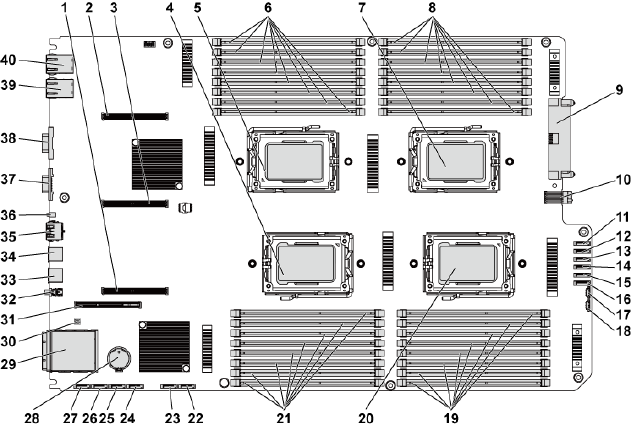
5
Jumpers and Connectors | 229
Jumpers and Connectors
System Board Connectors
This section provides specific information about the system jumpers. It also
provides some basic information on jumpers and switches and describes the
connectors on the various boards in the system.
Figure 5-1. System Board Connectors
230 | Jumpers and Connectors
1
PCI-E x16 slot 3
2
PCI-E x16 slot 1
3
PCI-E x16 slot 2
4
processor 2
5
processor 1
6
DIMM sockets for processor 1
7
processor 3
8
DIMM sockets for processor 3
9
main power connector
10
signal board to board connector
11
hard drive to backplane SATAII
connector 5
12
hard drive to backplane SATAII
connector 4
13
hard drive to backplane SATAII
connector 3
14
hard drive to backplane SATAII
connector 2
15
hard drive to backplane SATAII
connector 1
16
hard drive to backplane SATAII
connector 0
17
SGPIO connector 2
18
SGPIO connector 1
19
DIMM sockets for processor 4
20
processor 4
21
DIMM sockets for processor 2
22
onboard SATAII connector 5
23
onboard SATAII connector 4
24
onboard SATAII connector 3
25
onboard SATAII connector 2
26
onboard SATAII connector 1
27
onboard SATAII connector 0
28
system battery
29
IPASS connector
30
system configuration jumper
31
PCI-E x16 mezzanine card slot
32
power button
33
USB port 1
34
USB port 0
35
BMC management port
36
ID LED
37
VGA port
38
serial port
39
NIC 2
40
NIC 1
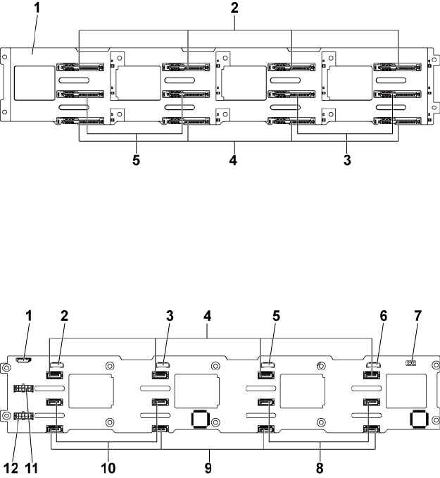
Jumpers and Connectors | 231
Backplane Connectors
3.5" Hard-Drive Backplane With CPLD
Figure 5-2. Front View of the Backplane
1
3.5” backplane with CPLD
2
SATAII and SAS connectors 1-4 (from
left to right) for system board 1
3
SATAII and SAS connectors 6-5
(from left to right) for system board 2
4
SATAII and SAS connectors 1-4 (from
left to right) for system board 2
5
SATAII and SAS connectors 5-6 (from
left to right) for system board 1
Figure 5-3. Back View of the Backplane
1
fan controller board connector
2
SGPIO connector 4
3
SGPIO connector 3
4
SATAII hard-drive connectors 1-4
for system board 1 (from right to left)
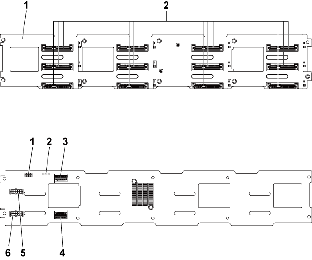
232 | Jumpers and Connectors
5
SGPIO connector 2
6
SGPIO connector 1
7
backplane jumper
8
SATAII hard-drive connectors 5-6
(from right to left) for system board 1
9
SATAII hard-drive connectors 1-4
(from right to left) for system board 2
10
SATAII hard-drive connectors 6-5
for system board 2 (from right to left)
11
backplane power connector for
power supply 1
12
backplane power connector for
power supply 2
3.5" Hard-Drive Backplane With Expander
Figure 5-4. Front View of the Backplane
1
3.5” backplane with
expander
2
SATAII and SAS connectors 1-4, 5-8, and 9-12 (from
left to right, and from up to down)
Figure 5-5. Back View of the Backplane
1
backplane jumper
2
UART connector
3
Mini-SAS ports 4-5
4
Mini-SAS port 0-3
5
backplane power connector for
power supply 1
6
backplane power connector for
power supply 2
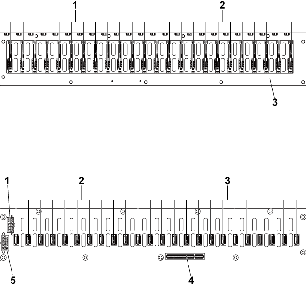
Jumpers and Connectors | 233
2.5" Hard-Drive Backplane With Expander
Figure 5-6. Front View of the Backplane
1
SATAII and SAS connectors 1-12
(from left to right) for system board 1
2
SATAII and SAS connectors 1-12
(from left to right) for system board 2
3
2.5” backplane with expander
Figure 5-7. Back View of the Backplane
1
power-supply connector 1
2
SATAII hard-drive connectors 1-12
(from right to left) for system board 2
3
SATAII hard-drive connectors 1-12
(from right to left) for system board 1
4
PCI-E x8 connector
5
power-supply connector 2
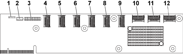
234 | Jumpers and Connectors
2.5" Hard-Drive Backplane Expander Card Connectors
Figure 5-8. 2.5" Hard-Drive Backplane Expander Card
1
UART connector
2
expander card jumper
3
JTAG connector
4
mini-SAS connector 1 (port 1-4)
5
mini-SAS connector 2 (port 5-8)
6
mini-SAS connector 3 (port 9-12)
7
mini-SAS connector 4 (port 13-16)
8
mini-SAS connector 5 (port 17-20)
9
mini-SAS connector 6 (port 21-24)
10
system board 1 mini-SAS connector
11
system board 2 mini-SAS connector
12
system board 4 mini-SAS connector
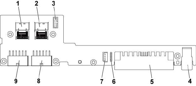
Jumpers and Connectors | 235
Middle Plane Connectors
Figure 5-9. Middle Plane Connectors
1
Mini-SAS connector for hard drive
1-4
2
Mini-SAS connector for hard drive
5- 6
3
fan controller board connector
4
signal connector
5
middle plane to system board power
connector
6
CPLD JTAG to system board
7
IPMB connector
8
power connector 2
9
power connector 1
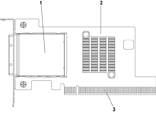
236 | Jumpers and Connectors
Expansion Card Connectors
Figure 5-10. Expansion Card Connectors
1
PCI-E Gen 2 x16 iPass connector
2
expansion card (HIC card)
3
PCI-E Gen 2 x16 golden fingers
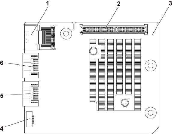
Jumpers and Connectors | 237
SAS Mezzanine Card Connectors
Figure 5-11. SAS Mezzanine Card Connectors
1
Mini-SAS connector
2
PCI-E Gen2 x8 connector
3
SAS mezzanine card
4
SGPIO connector B
5
SAS port 5
6
SAS port 4
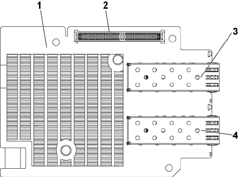
238 | Jumpers and Connectors
10GbE Mezzanine Card Connectors
Figure 5-12. 10GbE Mezzanine Card Connectors
1
10GbE mezzanine card
2
PCI-E Gen2 x8 connector
3
SFP + port 1
4
SFP + port 0
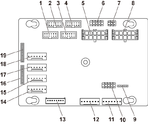
Jumpers and Connectors | 239
Fan Controller Board Connectors
Figure 5-13. Fan Controller Board Connectors
1
front-panel connector for system
board 4 not used
2
front-panel connector for system
board 2
3
front-panel connector for system
board 3 not used
4
front-panel connector for system
board 1
5
system fan board power connector 1
6
*FCB firmware recovery and PS-ON
connector
7
system fan speed control jumper
8
system fan board power connector 2
9
FCB firmware update connector
10
product ID select and power
throttling disable jumper
11
PMbus connector 2
12
PMbus connector 1
13
hard-drive backplane connector
14
system fan connector 4
15
system fan connector 3
16
front-panel connector 2
17
system fan connector 2
18
system fan connector 1
19
front-panel connector 1
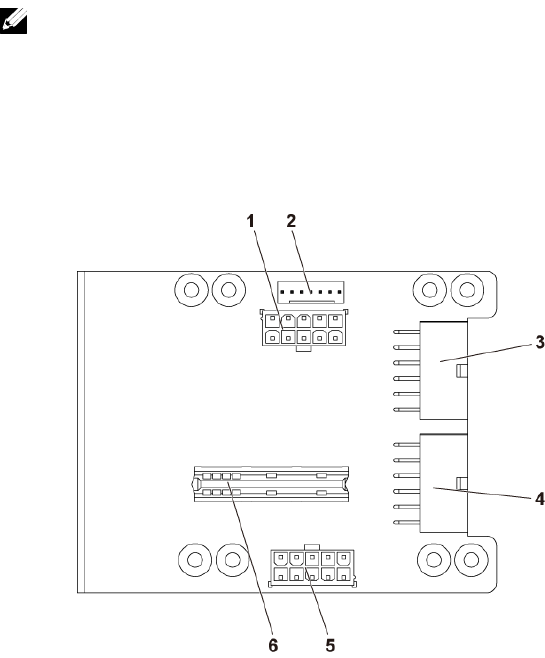
240 | Jumpers and Connectors
NOTE: Pin 9 and pin 10 of FCB firmware recovery and PS-ON connector are used
for firmware recovery, and pin 1-8 are used for debug when pin 9 and pin 10 are
shorted by jumper.
Power Distribution Board Connectors
Figure 5-14. Power Distribution Board Connectors
1
hard-drive backplane power
connector
2
PMbus connector
3
main power connector 1
4
main power connector 2
5
system fan board power connector
6
bridge card connector
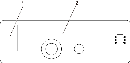
Jumpers and Connectors | 241
Sensor Board Connectors
Figure 5-15. Sensor Board Connectors
1
power connector
2
sensor board
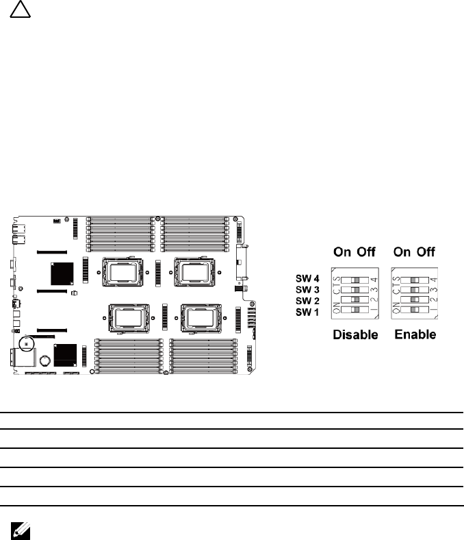
242 | Jumpers and Connectors
Switch and Jumper Settings
CAUTION: Many repairs may only be done by a certified service technician. You
should only perform troubleshooting and simple repairs as authorized in your
product documentation, or as directed by the online or telephone service and
support team. Damage due to servicing that is not authorized by Dell is not
covered by your warranty. Read and follow the safety instructions that came with
the product.
System Configuration Switch Settings
The function of system configuration switch installed on each system board
is shown below:
Figure 5-16. System Configuration Switch
Table 5-1. System Configuration Switch
Jumper
Function
Off
On
SW 1
NVRAM Clear
*Disable
Enable
SW 2
System Reset
*Disable
Enable
SW 3
Clear Password Enable
*Disable
Enable
SW 4
BMC NMI Enable
*Disable
Enable
NOTE: The * in the table of system configuration jumper describes the default
status and the default state is not active state.
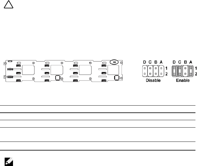
Jumpers and Connectors | 243
3.5" Backplane With CPLD Jumper Settings
CAUTION: Many repairs may only be done by a certified service technician. You
should only perform troubleshooting and simple repairs as authorized in your
product documentation, or as directed by the online or telephone service and
support team. Damage due to servicing that is not authorized by Dell is not
covered by your warranty. Read and follow the safety instructions that came with
the product.
Figure 5-17. Jumpers Installed on 3.5" Backplane With CPLD
Table 5-2. Jumpers Installed on 3.5" Backplane With CPLD
Jumper
Function
Off
On
A
LED Control
*Disable
Enable
B
Reserved
−
−
C
Protocol Select
*I2C Protocol Selected
SGPIO Protocol
Selected
D
MLB Mode Select
*Normal Operation
LED Test
NOTE: The * in the table of backplane jumper describes the default status
and the default state is not active state.
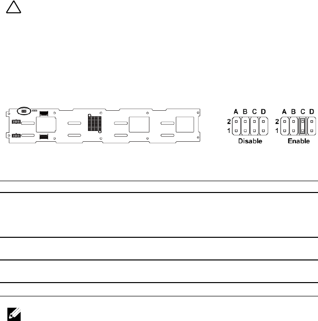
244 | Jumpers and Connectors
3.5" Backplane With Expander Jumper Settings
CAUTION: Many repairs may only be done by a certified service technician. You
should only perform troubleshooting and simple repairs as authorized in your
product documentation, or as directed by the online or telephone service and
support team. Damage due to servicing that is not authorized by Dell is not
covered by your warranty. Read and follow the safety instructions that came with
the product.
Figure 5-18. Jumpers Installed on 3.5" Backplane With Expander
Table 5-3. Jumpers Installed on 3.5" Backplane With Expander
Jumper
Function
Off
On
A
Project_select <1>
Reserved for factory setting
Reserved for factory
setting
B
Project_select <0>
Reserved for factory setting
Reserved for factory
setting
C
BOB_UART_SEL
*General UART Port
Selected
Serial Debug Port
Selected
D
NC_J14_PIN7
No function
NOTE: The * in the table of backplane jumper describes the default status
and the default state is not active state.
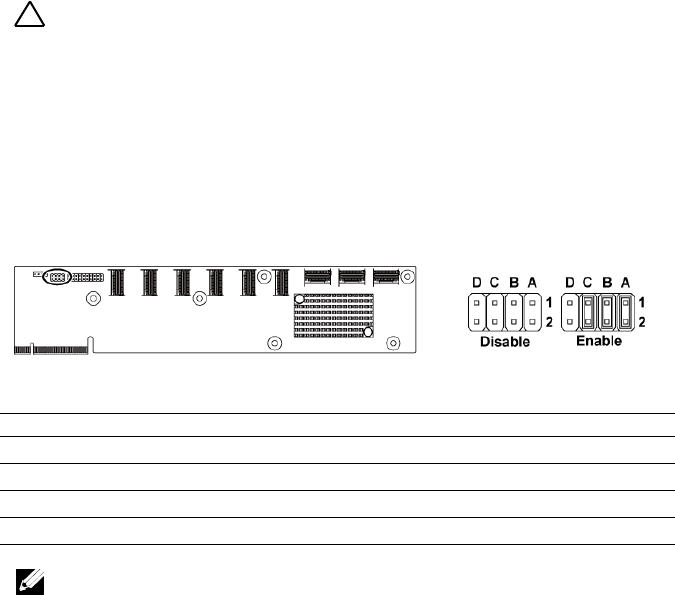
Jumpers and Connectors | 245
2.5" Backplane Expander Card Jumper Settings
CAUTION: Many repairs may only be done by a certified service technician. You
should only perform troubleshooting and simple repairs as authorized in your
product documentation, or as directed by the online or telephone service and
support team. Damage due to servicing that is not authorized by Dell is not
covered by your warranty. Read and follow the safety instructions that came with
the product.
The function of jumper installed on the expander card for 2.5" backplane is
shown below:
Figure 5-19. Jumpers Installed on 2.5” Backplane Expander Card
Table 5-4. Jumpers Installed on 2.5” Backplane Expander Card
Jumper
Function
Off
On
A
SAS Card Selection
*Disable
Enable
B
MLB Mode Selection
*Disable
Enable
C
UART Selection
*Disable
Enable
D
Reserved
−
−
NOTE: The * in the table of system configuration jumper describes the default
status and the default state is not active state.

6
246 | Getting Help
Getting Help
Contacting Dell
For customers in the United States, call 800-WWW-DELL (800-999-3355).
NOTE: If you do not have an active Internet connection, you can find contact
information on your purchase invoice, packing slip, bill, or Dell product catalog.
Dell provides several online and telephone-based support and service
options. Availability varies by country and product, and some services may
not be available in your area. To contact Dell for sales, technical support, or
customer service issues:
1 Visit support.dell.com. Click your country/region at the bottom of the
page. For a full listing of country/region, click All. Click All Support
from Support menu.
2 Select the appropriate service or support link based on your need.
3 Choose the method of contacting Dell that is convenient for you.
7
Index | 247
Index
A
about your system, 11
B
back panel features, 17
backplane
installing, 187
removing, 184
backplane jumper settings, 243, 244
batteries
troubleshooting, 217
battery (system)
replacing, 169
blank
hard drive, 105
C
Cable Routing for Fan Control Board,
194
Cable Routing for Power Distribution
Board, 191
collecting system event log, 25
contacting dell, 246
cooling fans
installing, 176
removing, 175
troubleshooting, 220
D
damaged systems
troubleshooting, 217
daughter card
installing, 153, 157, 160
removing, 151, 155, 158
Dell
contacting, 246
drive blank
installing, 106
removing, 105
E
expansion card
installing, 127, 132, 142
removing, 125, 129, 139
troubleshooting, 225
expansion card connector
installing, 150
removing, 149
F
fan controller board removing, 192
features and indicators
front panel, 12
front panel features, 12
front panel installing, 203
front panel removing, 200
248 | Index
H
hard drive
installing hot-swap hard drive, 107
removing, 106
removing a hot-swap hard drive,
106
troubleshooting, 222
heat sink installing, 119
heat sink removing, 118
heat sinks
installing, 119
removing, 118
I
indicator codes
AC power, 23
hard-drive indicator, 15
NIC, 20
NIC (Management Port), 21
power and system board, 22
indicators
back panel, 17
front panel, 12
installing
backplanes, 187
cooling fans, 176
expander card, 199
expansion card, 127, 132, 142
expansion card connector, 150
front panel, 203
hard drive blank, 106
heat sink, 119
hot-swap hard drive, 107
memory modules, 167
middle planes, 182
power supply, 114
processor, 124
SAS daughter card, 153, 157, 160
sensor board, 206
system board, 172
system board assembly, 116
Installing the Mezzanine-Card Bridge
Board, 162
K
keyboards
troubleshooting, 213
L
LEDs
BMC heart beat, 24
M
memory
troubleshooting, 220
memory modules
installing, 167
removing, 166
memory modules (DIMMs)
configuring, 163
middle planes
installing, 182
removing, 177
N
NICs
troubleshooting, 215
P
phone numbers, 246
Index | 249
POST
accessing system features, 11
power distribution board
removing, 188
power supplies
installing, 114
removing, 113
processor
installing, 124
removing, 122
processors
troubleshooting, 226
R
removing
backplanes, 184
cooling fans, 175
daughter card, 151, 155, 158
expander card, 195
expansion card, 125, 129, 139
expansion card connector, 149
fan controller board, 192
front panel, 200
hard drive, 106
hard drive blank, 105
heat sink, 118
hot-swap hard drive, 106
memory modules (DIMMs), 166
middle planes, 177
power distribution board, 188
power supply, 113
processor, 122
sensor board, 204
system board, 171
system board assembly, 115
Removing the Mellanox Card, 158
Removing the Mezzanine-Card Bridge
Board, 161
replacing
system battery, 169
S
safety, 103
SAS controller daughter card
troubleshooting, 223
SAS RAID controller daughter card
troubleshooting, 223
startup
accessing system features, 11
support
contacting Dell, 246
system
closing, 174
opening, 174
system board
connectors, 229
installing, 172
jumper settings, 242
removing, 171
system board assembly
installing, 116
removing, 115
system cooling
troubleshooting, 219
system features
accessing, 11
system setup
boot settings configuration, 72
memory configuration, 56, 57, 58,
59
PCI configuration, 65, 67, 68
processor configuration, 53
processor settings, 51
remote access configuration, 85
250 | Index
SATA configuration, 60, 63
system memory, 51
USB configuration, 64
T
telephone number, 246
troubleshooting
cooling fans, 220
damaged system, 217
expansion card, 225
external connections, 213
hard drive, 222
keyboard, 213
memory, 220
NIC, 215
processors, 226
SAS RAID controller daughter card,
223
sequence, 212
system battery, 217
system boot issues, 25
system cooling, 219
video, 213
wet system, 216
V
video
troubleshooting, 213
W
warranty, 44
wet system
troubleshooting, 216
