Dell Poweredge C6400 Integrated Remote Access Controller 9 Version 3.15.15.15 User's Guide User Manual Power Edge Installation And Service Idrac9 Lifecycle V3151515 Users En Us
poweredge-c6400 - Integrated Dell Remote Access Controller 9 Version 3.15.15.15 User's Guide idrac9-lifecycle-controller-v3.15.15.15_user's guide_en-us
User Manual: Dell poweredge-c6400 Dell PowerEdge C6400 Dell PowerEdge C6400 Installation and Service Manual
Open the PDF directly: View PDF ![]() .
.
Page Count: 341 [warning: Documents this large are best viewed by clicking the View PDF Link!]
- Integrated Dell Remote Access Controller 9 Version 3.15.15.15 User's Guide
- Overview
- Benefits of using iDRAC with Lifecycle Controller
- Key features
- New in this release
- How to use this guide
- Supported web browsers
- iDRAC licenses
- Licensed features in iDRAC8 and iDRAC9
- Interfaces and protocols to access iDRAC
- iDRAC port information
- Other documents you may need
- Social media reference
- Contacting Dell
- Accessing documents from Dell support site
- Logging in to iDRAC
- Customizable security banner
- Logging in to iDRAC as local user, Active Directory user, or LDAP user
- Logging in to iDRAC as a local user using a smart card
- Logging in to iDRAC using Single Sign-On
- Accessing iDRAC using remote RACADM
- Accessing iDRAC using local RACADM
- Accessing iDRAC using firmware RACADM
- Viewing system health
- Logging in to iDRAC using public key authentication
- Multiple iDRAC sessions
- Accessing iDRAC using SMCLP
- Secure default password
- Changing the default login password
- Enabling or disabling default password warning message
- IP Blocking
- Enabling or disabling OS to iDRAC Pass-through using web interface
- Enabling or disabling alerts using RACADM
- Setting up managed system
- Setting up iDRAC IP address
- Modifying local administrator account settings
- Setting up managed system location
- Optimizing system performance and power consumption
- Setting up management station
- Configuring supported web browsers
- Updating device firmware
- Updating firmware using iDRAC web interface
- Scheduling automatic firmware updates
- Updating device firmware using RACADM
- Updating firmware using CMC web interface
- Updating firmware using DUP
- Updating firmware using remote RACADM
- Updating firmware using Lifecycle Controller Remote Services
- Updating CMC firmware from iDRAC
- Viewing and managing staged updates
- Rolling back device firmware
- Backing up server profile
- Importing server profile
- Monitoring iDRAC using other Systems Management tools
- Support Server Configuration Profile — Import and Export
- Secure Boot Configuration from BIOS Settings or F2
- BIOS recovery
- Configuring iDRAC
- Viewing iDRAC information
- Modifying network settings
- FIPS mode
- Configuring services
- Configuring TLS
- Using VNC client to manage remote server
- Configuring front panel display
- Configuring time zone and NTP
- Setting first boot device
- Enabling or disabling OS to iDRAC Pass-through
- Obtaining certificates
- Configuring multiple iDRACs using RACADM
- Disabling access to modify iDRAC configuration settings on host system
- Viewing iDRAC and managed system information
- Viewing managed system health and properties
- Viewing system inventory
- Viewing sensor information
- Monitoring performance index of CPU, memory, and input output modules
- Checking the system for Fresh Air compliance
- Viewing historical temperature data
- Viewing network interfaces available on host OS
- Viewing network interfaces available on host OS using RACADM
- Viewing FlexAddress mezzanine card fabric connections
- Viewing or terminating iDRAC sessions
- Setting up iDRAC communication
- Communicating with iDRAC through serial connection using DB9 cable
- Switching between RAC serial and serial console while using DB9 cable
- Communicating with iDRAC using IPMI SOL
- Communicating with iDRAC using IPMI over LAN
- Enabling or disabling remote RACADM
- Disabling local RACADM
- Enabling IPMI on managed system
- Configuring Linux for serial console during boot
- Supported SSH cryptography schemes
- Configuring user accounts and privileges
- Recommended characters in user names and passwords
- Configuring local users
- Configuring Active Directory users
- Prerequisites for using Active Directory authentication for iDRAC
- Supported Active Directory authentication mechanisms
- Standard schema Active Directory overview
- Configuring Standard schema Active Directory
- Extended schema Active Directory overview
- Configuring Extended schema Active Directory
- Testing Active Directory settings
- Configuring generic LDAP users
- System Lockdown Mode
- Configuring iDRAC for Single Sign-On or smart card login
- Configuring iDRAC to send alerts
- iDRAC 9 Group Manager
- Managing logs
- Monitoring and managing power
- Inventorying, monitoring, and configuring network devices
- Inventorying and monitoring network devices
- Inventorying and monitoring FC HBA devices
- Dynamic configuration of virtual addresses, initiator, and storage target settings
- Supported cards for IO Identity Optimization
- Supported NIC firmware versions for IO Identity Optimization
- Virtual or Flex Address and Persistence Policy behavior when iDRAC is set to Flex Address mode or Console mode
- System behavior for FlexAddress and IO Identity
- Enabling or disabling IO Identity Optimization
- Configuring persistence policy settings
- Managing storage devices
- Understanding RAID concepts
- Supported controllers
- Supported enclosures
- Summary of supported features for storage devices
- Inventorying and monitoring storage devices
- Viewing storage device topology
- Managing physical disks
- Managing virtual disks
- Managing controllers
- Configuring controller properties
- Importing or auto importing foreign configuration
- Clearing foreign configuration
- Resetting controller configuration
- Switching the controller mode
- 12 Gbps SAS HBA adapter operations
- Monitoring predictive failure analysis on drives
- Controller operations in non-RAID mode or HBA mode
- Running RAID configuration jobs on multiple storage controllers
- Manage Preserved cache
- Managing PCIe SSDs
- Managing enclosures or backplanes
- Choosing operation mode to apply settings
- Viewing and applying pending operations
- Storage devices — apply operation scenarios
- Blinking or unblinking component LEDs
- BIOS Settings
- Configuring and using virtual console
- Using iDRAC Service Module
- Installing iDRAC Service Module
- Supported operating systems for iDRAC Service Module
- iDRAC Service Module monitoring features
- Redfish profile support for network attributes
- Operating system information
- Replicate Lifecycle logs to OS log
- Automatic system recovery options
- Windows Management Instrumentation providers
- Remote iDRAC Hard Reset
- In-band Support for iDRAC SNMP Alerts
- iDRAC access via Host OS
- Coexistence of OpenManage Server Administrator and iDRAC Service Module
- Using iDRAC Service Module from iDRAC web interface
- Using iDRAC Service Module from RACADM
- Using iDRAC Service Module on Windows Nano OS
- Using USB port for server management
- Using iDRAC Quick Sync 2
- Managing virtual media
- Installing and using VMCLI utility
- Managing vFlash SD card
- Using SMCLP
- Deploying operating systems
- Troubleshooting managed system using iDRAC
- Using diagnostic console
- Viewing post codes
- Viewing boot and crash capture videos
- Viewing logs
- Viewing last system crash screen
- Viewing System status
- Hardware trouble indicators
- Viewing system health
- Checking server status screen for error messages
- Restarting iDRAC
- Erasing system and user data
- Resetting iDRAC to factory default settings
- SupportAssist Integration in iDRAC
- Frequently asked questions
- System Event Log
- Network security
- Active Directory
- Single Sign-On
- Smart card login
- Virtual console
- Virtual media
- vFlash SD card
- SNMP authentication
- Storage devices
- iDRAC Service Module
- RACADM
- Permanently setting the default password to calvin
- Miscellaneous
- When an OS is installed, hostname may or may not appear/change automatically.
- How to find an iDRAC IP address for a blade server?
- How to find the CMC IP address related to the blade server?
- How to find iDRAC IP address for rack and tower server?
- iDRAC network connection is not working.
- Inserted the blade server into the chassis and pressed the power switch, but it did not power on.
- How to retrieve an iDRAC administrative user name and password?
- How to change the name of the slot for the system in a chassis?
- iDRAC on blade server is not responding during boot.
- When attempting to boot the managed server, the power indicator is green, but there is no POST or no video.
- Use case scenarios
- Troubleshooting an inaccessible managed system
- Obtaining system information and assess system health
- Setting up alerts and configuring email alerts
- Viewing and exporting System Event Log and Lifecycle Log
- Interfaces to update iDRAC firmware
- Performing graceful shutdown
- Creating new administrator user account
- Launching servers remote console and mounting a USB drive
- Installing bare metal OS using attached virtual media and remote file share
- Managing rack density
- Installing new electronic license
- Applying IO Identity configuration settings for multiple network cards in single host system reboot

Integrated Dell Remote Access Controller 9
Version 3.15.15.15 User's Guide

Notes, cautions, and warnings
NOTE: A NOTE indicates important information that helps you make better use of your product.
CAUTION: A CAUTION indicates either potential damage to hardware or loss of data and tells you how to avoid the problem.
WARNING: A WARNING indicates a potential for property damage, personal injury, or death.
Copyright © 2017 Dell Inc. or its subsidiaries. All rights reserved. Dell, EMC, and other trademarks are trademarks of Dell Inc. or its subsidiaries. Other
trademarks may be trademarks of their respective owners.
2017 - 12
Rev. A00

Contents
1 Overview.......................................................................................................................................................16
Benets of using iDRAC with Lifecycle Controller....................................................................................................... 16
Key features.......................................................................................................................................................................17
New in this release............................................................................................................................................................19
How to use this guide......................................................................................................................................................20
Supported web browsers................................................................................................................................................20
Supported OS and Hypervisors............................................................................................................................... 20
iDRAC licenses ................................................................................................................................................................ 20
Types of licenses........................................................................................................................................................ 20
Methods for acquiring licenses................................................................................................................................. 21
License operations......................................................................................................................................................21
Licensed features in iDRAC8 and iDRAC9....................................................................................................................22
Interfaces and protocols to access iDRAC....................................................................................................................28
iDRAC port information...................................................................................................................................................30
Other documents you may need.....................................................................................................................................31
Social media reference.................................................................................................................................................... 32
Contacting Dell.................................................................................................................................................................32
Accessing documents from Dell support site............................................................................................................... 32
2 Logging in to iDRAC.....................................................................................................................................34
Customizable security banner........................................................................................................................................ 34
Logging in to iDRAC as local user, Active Directory user, or LDAP user................................................................... 35
Logging in to iDRAC as a local user using a smart card.............................................................................................. 35
Logging in to iDRAC as an Active Directory user using a smart card..................................................................36
Logging in to iDRAC using Single Sign-On .................................................................................................................. 36
Logging in to iDRAC SSO using iDRAC web interface.......................................................................................... 36
Logging in to iDRAC SSO using CMC web interface.............................................................................................37
Accessing iDRAC using remote RACADM.................................................................................................................... 37
Validating CA certicate to use remote RACADM on Linux..................................................................................37
Accessing iDRAC using local RACADM.........................................................................................................................37
Accessing iDRAC using rmware RACADM................................................................................................................. 38
Viewing system health.....................................................................................................................................................38
Logging in to iDRAC using public key authentication.................................................................................................. 38
Multiple iDRAC sessions..................................................................................................................................................39
Accessing iDRAC using SMCLP.....................................................................................................................................39
Secure default password.................................................................................................................................................39
Resetting default iDRAC password locally..............................................................................................................39
Resetting default iDRAC password remotely......................................................................................................... 40
Changing the default login password.............................................................................................................................41
Changing the default login password using web interface.................................................................................... 41
Changing the default login password using RACADM........................................................................................... 41
Changing the default login password using iDRAC settings utility...................................................................... 42
Enabling or disabling default password warning message ......................................................................................... 42
Contents 3

IP Blocking........................................................................................................................................................................ 42
Enabling or disabling OS to iDRAC Pass-through using web interface..................................................................... 43
Enabling or disabling alerts using RACADM..................................................................................................................43
3 Setting up managed system.........................................................................................................................44
Setting up iDRAC IP address..........................................................................................................................................44
Setting up iDRAC IP using iDRAC settings utility.................................................................................................. 45
Setting up iDRAC IP using the CMC web interface.............................................................................................. 47
Enabling provisioning server..................................................................................................................................... 48
Conguring servers and server components using Auto Cong......................................................................... 49
Using hash passwords for improved security.........................................................................................................54
Modifying local administrator account settings........................................................................................................... 56
Setting up managed system location............................................................................................................................ 56
Setting up managed system location using web interface................................................................................... 56
Setting up managed system location using RACADM.......................................................................................... 56
Setting up managed system location using iDRAC settings utility...................................................................... 56
Optimizing system performance and power consumption......................................................................................... 57
Modifying thermal settings using iDRAC web interface........................................................................................57
Modifying thermal settings using RACADM...........................................................................................................58
Modifying thermal settings using iDRAC settings utility.......................................................................................62
Setting up management station.....................................................................................................................................62
Accessing iDRAC remotely....................................................................................................................................... 62
Conguring supported web browsers........................................................................................................................... 63
Conguring Internet Explorer................................................................................................................................... 63
Conguring Mozilla Firefox....................................................................................................................................... 64
Conguring web browsers to use virtual console..................................................................................................65
Viewing localized versions of web interface...........................................................................................................68
Updating device rmware...............................................................................................................................................68
Updating rmware using iDRAC web interface......................................................................................................70
Scheduling automatic rmware updates..................................................................................................................71
Updating device rmware using RACADM............................................................................................................. 72
Updating rmware using CMC web interface........................................................................................................ 72
Updating rmware using DUP..................................................................................................................................73
Updating rmware using remote RACADM............................................................................................................ 73
Updating rmware using Lifecycle Controller Remote Services.......................................................................... 73
Updating CMC rmware from iDRAC......................................................................................................................74
Viewing and managing staged updates......................................................................................................................... 74
Viewing and managing staged updates using iDRAC web interface....................................................................74
Viewing and managing staged updates using RACADM.......................................................................................75
Rolling back device rmware.......................................................................................................................................... 75
Rollback rmware using iDRAC web interface....................................................................................................... 75
Rollback rmware using CMC web interface......................................................................................................... 76
Rollback rmware using RACADM...........................................................................................................................76
Rollback rmware using Lifecycle Controller.......................................................................................................... 76
Rollback rmware using Lifecycle Controller-Remote Services........................................................................... 76
Recovering iDRAC......................................................................................................................................................77
Backing up server prole.................................................................................................................................................77
4Contents

Backing up server prole using iDRAC web interface........................................................................................... 77
Backing up server prole using RACADM...............................................................................................................78
Scheduling automatic backup server prole...........................................................................................................78
Importing server prole................................................................................................................................................... 79
Easy Restore...............................................................................................................................................................79
Importing server prole using iDRAC web interface..............................................................................................80
Importing server prole using RACADM.................................................................................................................80
Restore operation sequence.....................................................................................................................................80
Monitoring iDRAC using other Systems Management tools.......................................................................................81
Support Server Conguration Prole — Import and Export ..................................................................................... 81
Secure Boot Conguration from BIOS Settings or F2.................................................................................................81
Acceptable le formats.............................................................................................................................................. 81
BIOS recovery.................................................................................................................................................................. 82
4 Conguring iDRAC.......................................................................................................................................83
Viewing iDRAC information.............................................................................................................................................84
Viewing iDRAC information using web interface....................................................................................................84
Viewing iDRAC information using RACADM...........................................................................................................85
Modifying network settings............................................................................................................................................85
Modifying network settings using web interface...................................................................................................85
Modifying network settings using local RACADM.................................................................................................85
Conguring IP ltering...............................................................................................................................................86
FIPS mode.........................................................................................................................................................................87
Dierence between FIPS-mode supported and FIPS-validated.......................................................................... 87
Enabling FIPS Mode...................................................................................................................................................87
Disabling FIPS mode..................................................................................................................................................88
Conguring services........................................................................................................................................................88
Conguring services using web interface...............................................................................................................88
Conguring services using RACADM......................................................................................................................89
Enabling or disabling HTTPS redirection.................................................................................................................89
Conguring TLS............................................................................................................................................................... 89
Conguring TLS using web interface......................................................................................................................90
Conguring TLS using RACADM............................................................................................................................. 90
Using VNC client to manage remote server.................................................................................................................90
Conguring VNC server using iDRAC web interface............................................................................................. 91
Conguring VNC server using RACADM.................................................................................................................91
Setting up VNC viewer with SSL encryption..........................................................................................................91
Setting up VNC viewer without SSL encryption....................................................................................................91
Conguring front panel display....................................................................................................................................... 91
Conguring LCD setting............................................................................................................................................92
Conguring system ID LED setting..........................................................................................................................93
Conguring time zone and NTP.....................................................................................................................................93
Conguring time zone and NTP using iDRAC web interface............................................................................... 93
Conguring time zone and NTP using RACADM...................................................................................................93
Setting rst boot device................................................................................................................................................. 94
Setting rst boot device using web interface........................................................................................................ 94
Setting rst boot device using RACADM............................................................................................................... 94
Contents 5

Setting rst boot device using virtual console.......................................................................................................95
Enabling last crash screen........................................................................................................................................ 95
Enabling or disabling OS to iDRAC Pass-through........................................................................................................95
Supported cards for OS to iDRAC Pass-through ................................................................................................. 96
Supported operating systems for USB NIC............................................................................................................96
Enabling or disabling OS to iDRAC Pass-through using web interface............................................................... 97
Enabling or disabling OS to iDRAC Pass-through using RACADM......................................................................98
Enabling or disabling OS to iDRAC Pass-through using iDRAC settings utility.................................................. 98
Obtaining certicates...................................................................................................................................................... 98
SSL server certicates..............................................................................................................................................99
Generating a new certicate signing request....................................................................................................... 100
Uploading server certicate.....................................................................................................................................101
Viewing server certicate........................................................................................................................................ 101
Uploading custom signing certicate.....................................................................................................................102
Downloading custom SSL certicate signing certicate ....................................................................................102
Deleting custom SSL certicate signing certicate............................................................................................. 103
Conguring multiple iDRACs using RACADM............................................................................................................. 103
Disabling access to modify iDRAC conguration settings on host system.............................................................104
5 Viewing iDRAC and managed system information.......................................................................................105
Viewing managed system health and properties........................................................................................................105
Viewing system inventory..............................................................................................................................................105
Viewing sensor information...........................................................................................................................................106
Monitoring performance index of CPU, memory, and input output modules..........................................................107
Monitoring performance index of CPU, memory, and input output modules using web interface................ 108
Monitoring performance index for of CPU, memory, and input output modules using RACADM................. 109
Checking the system for Fresh Air compliance..........................................................................................................109
Viewing historical temperature data.............................................................................................................................109
Viewing historical temperature data using iDRAC web interface........................................................................110
Viewing historical temperature data using RACADM........................................................................................... 110
Conguring warning threshold for inlet temperature............................................................................................110
Viewing network interfaces available on host OS.......................................................................................................110
Viewing network interfaces available on host OS using web interface...............................................................111
Viewing network interfaces available on host OS using RACADM............................................................................111
Viewing FlexAddress mezzanine card fabric connections.......................................................................................... 111
Viewing or terminating iDRAC sessions........................................................................................................................112
Terminating iDRAC sessions using web interface..................................................................................................112
6 Setting up iDRAC communication............................................................................................................... 113
Communicating with iDRAC through serial connection using DB9 cable................................................................ 114
Conguring BIOS for serial connection.................................................................................................................. 114
Enabling RAC serial connection...............................................................................................................................115
Enabling IPMI serial connection basic and terminal modes..................................................................................115
Switching between RAC serial and serial console while using DB9 cable................................................................117
Switching from serial console to RAC serial...........................................................................................................117
Switching from RAC serial to serial console...........................................................................................................117
Communicating with iDRAC using IPMI SOL...............................................................................................................117
6Contents

Conguring BIOS for serial connection.................................................................................................................. 118
Conguring iDRAC to use SOL................................................................................................................................118
Enabling supported protocol....................................................................................................................................119
Communicating with iDRAC using IPMI over LAN.....................................................................................................122
Conguring IPMI over LAN using web interface.................................................................................................. 123
Conguring IPMI over LAN using iDRAC settings utility..................................................................................... 123
Conguring IPMI over LAN using RACADM......................................................................................................... 123
Enabling or disabling remote RACADM........................................................................................................................124
Enabling or disabling remote RACADM using web interface...............................................................................124
Enabling or disabling remote RACADM using RACADM......................................................................................124
Disabling local RACADM................................................................................................................................................ 124
Enabling IPMI on managed system.............................................................................................................................. 124
Conguring Linux for serial console during boot........................................................................................................ 124
Enabling login to the virtual console after boot....................................................................................................125
Supported SSH cryptography schemes...................................................................................................................... 126
Using public key authentication for SSH............................................................................................................... 127
7 Conguring user accounts and privileges.................................................................................................... 131
Recommended characters in user names and passwords......................................................................................... 131
Conguring local users...................................................................................................................................................132
Conguring local users using iDRAC web interface............................................................................................. 132
Conguring local users using RACADM.................................................................................................................132
Conguring Active Directory users...............................................................................................................................134
Prerequisites for using Active Directory authentication for iDRAC....................................................................135
Supported Active Directory authentication mechanisms.................................................................................... 136
Standard schema Active Directory overview........................................................................................................136
Conguring Standard schema Active Directory....................................................................................................138
Extended schema Active Directory overview....................................................................................................... 139
Conguring Extended schema Active Directory...................................................................................................142
Testing Active Directory settings............................................................................................................................150
Conguring generic LDAP users.................................................................................................................................. 150
Conguring generic LDAP directory service using iDRAC web-based interface............................................. 150
Conguring generic LDAP directory service using RACADM..............................................................................151
Testing LDAP directory service settings.................................................................................................................151
8 System Lockdown Mode............................................................................................................................ 153
9 Conguring iDRAC for Single Sign-On or smart card login......................................................................... 155
Prerequisites for Active Directory Single Sign-On or smart card login....................................................................155
Registering iDRAC as a computer in Active Directory root domain................................................................... 155
Generating Kerberos keytab le............................................................................................................................. 156
Creating Active Directory objects and providing privileges.................................................................................156
Conguring iDRAC SSO login for Active Directory users.......................................................................................... 157
Conguring iDRAC SSO login for Active Directory users using web interface................................................. 157
Conguring iDRAC SSO login for Active Directory users using RACADM........................................................ 157
Conguring iDRAC smart card login for local users................................................................................................... 157
Uploading smart card user certicate....................................................................................................................157
Contents 7

Uploading trusted CA certicate for smart card.................................................................................................. 158
Conguring iDRAC smart card login for Active Directory users............................................................................... 158
Enabling or disabling smart card login..........................................................................................................................158
Enabling or disabling smart card login using web interface.................................................................................159
Enabling or disabling smart card login using RACADM........................................................................................159
Enabling or disabling smart card login using iDRAC settings utility....................................................................159
10 Conguring iDRAC to send alerts..............................................................................................................160
Enabling or disabling alerts............................................................................................................................................160
Enabling or disabling alerts using web interface...................................................................................................160
Enabling or disabling alerts using RACADM...........................................................................................................161
Enabling or disabling alerts using iDRAC settings utility.......................................................................................161
Filtering alerts ................................................................................................................................................................. 161
Filtering alerts using iDRAC web interface.............................................................................................................161
Filtering alerts using RACADM................................................................................................................................162
Setting event alerts........................................................................................................................................................162
Setting event alerts using web interface...............................................................................................................162
Setting event alerts using RACADM......................................................................................................................162
Setting alert recurrence event......................................................................................................................................162
Setting alert recurrence events using RACADM.................................................................................................. 162
Setting alert recurrence events using iDRAC web interface...............................................................................163
Setting event actions.....................................................................................................................................................163
Setting event actions using web interface............................................................................................................163
Setting event actions using RACADM................................................................................................................... 163
Conguring email alert, SNMP trap, or IPMI trap settings....................................................................................... 163
Conguring IP alert destinations............................................................................................................................ 164
Conguring email alert settings.............................................................................................................................. 165
Conguring WS Eventing.............................................................................................................................................. 167
Conguring Redsh Eventing........................................................................................................................................167
Monitoring chassis events.............................................................................................................................................167
Monitoring chassis events using the iDRAC web interface.................................................................................167
Monitoring chassis events using RACADM...........................................................................................................168
Alerts message IDs.........................................................................................................................................................168
11 iDRAC 9 Group Manager............................................................................................................................ 171
Group Manager................................................................................................................................................................171
Summary View................................................................................................................................................................ 172
Manage Logins................................................................................................................................................................173
Add a New User........................................................................................................................................................173
Change User Password............................................................................................................................................173
Delete User................................................................................................................................................................173
Congure Alerts ............................................................................................................................................................. 174
Export...............................................................................................................................................................................174
Discovered Servers View...............................................................................................................................................175
Jobs View........................................................................................................................................................................ 175
Jobs Export..................................................................................................................................................................... 176
Group Information Panel................................................................................................................................................176
8Contents

Group Settings................................................................................................................................................................176
Actions on a selected Server.........................................................................................................................................177
Group Manager Single Sign On...............................................................................................................................178
Group Manager Concepts — Controlling System................................................................................................178
Group Manager Concepts — Backup System..................................................................................................... 178
12 Managing logs...........................................................................................................................................179
Viewing System Event Log............................................................................................................................................179
Viewing System Event Log using web interface...................................................................................................179
Viewing System Event Log using RACADM..........................................................................................................179
Viewing System Event Log using iDRAC settings utility......................................................................................180
Viewing Lifecycle log .....................................................................................................................................................180
Viewing Lifecycle log using web interface..............................................................................................................181
Viewing Lifecycle log using RACADM.....................................................................................................................181
Exporting Lifecycle Controller logs................................................................................................................................181
Exporting Lifecycle Controller logs using web interface.......................................................................................181
Exporting Lifecycle Controller logs using RACADM.............................................................................................182
Adding work notes..........................................................................................................................................................182
Conguring remote system logging..............................................................................................................................182
Conguring remote system logging using web interface.....................................................................................182
Conguring remote system logging using RACADM............................................................................................182
13 Monitoring and managing power............................................................................................................... 183
Monitoring power........................................................................................................................................................... 183
Monitoring performance index of CPU, memory, and input output modules using web interface................ 183
Monitoring performance index for of CPU, memory, and input output modules using RACADM................. 184
Setting warning threshold for power consumption....................................................................................................184
Setting warning threshold for power consumption using web interface...........................................................184
Executing power control operations............................................................................................................................ 184
Executing power control operations using web interface................................................................................... 185
Executing power control operations using RACADM.......................................................................................... 185
Power capping................................................................................................................................................................185
Power capping in Blade servers..............................................................................................................................185
Viewing and conguring power cap policy............................................................................................................186
Conguring power supply options................................................................................................................................ 187
Conguring power supply options using web interface....................................................................................... 187
Conguring power supply options using RACADM.............................................................................................. 187
Conguring power supply options using iDRAC settings utility.......................................................................... 187
Enabling or disabling power button.............................................................................................................................. 188
Multi-Vector Cooling...................................................................................................................................................... 188
14 Inventorying, monitoring, and conguring network devices.......................................................................190
Inventorying and monitoring network devices............................................................................................................190
Monitoring network devices using web interface................................................................................................ 190
Monitoring network devices using RACADM....................................................................................................... 190
Connection View....................................................................................................................................................... 191
Inventorying and monitoring FC HBA devices............................................................................................................ 193
Contents 9

Monitoring FC HBA devices using web interface.................................................................................................193
Monitoring FC HBA devices using RACADM........................................................................................................193
Dynamic conguration of virtual addresses, initiator, and storage target settings.................................................193
Supported cards for IO Identity Optimization.......................................................................................................194
Supported NIC rmware versions for IO Identity Optimization..........................................................................195
Virtual or Flex Address and Persistence Policy behavior when iDRAC is set to Flex Address mode or
Console mode........................................................................................................................................................... 195
System behavior for FlexAddress and IO Identity................................................................................................ 196
Enabling or disabling IO Identity Optimization.......................................................................................................197
Conguring persistence policy settings.................................................................................................................198
15 Managing storage devices.........................................................................................................................201
Understanding RAID concepts.....................................................................................................................................202
What is RAID............................................................................................................................................................ 203
Organizing data storage for availability and performance.................................................................................. 204
Choosing RAID levels ............................................................................................................................................. 204
Comparing RAID level performance.......................................................................................................................210
Supported controllers..................................................................................................................................................... 211
Supported RAID controllers..................................................................................................................................... 211
Supported non-RAID controllers............................................................................................................................. 211
Supported enclosures.................................................................................................................................................... 212
Summary of supported features for storage devices................................................................................................ 212
Inventorying and monitoring storage devices............................................................................................................. 214
Monitoring storage devices using web interface..................................................................................................214
Monitoring storage devices using RACADM.........................................................................................................215
Monitoring backplane using iDRAC settings utility...............................................................................................215
Viewing storage device topology..................................................................................................................................215
Managing physical disks................................................................................................................................................ 215
Assigning or unassigning physical disk as global hot spare................................................................................. 215
Converting a physical disk to RAID or non-RAID mode....................................................................................... 217
Erasing physical disks............................................................................................................................................... 217
Erasing SED device data..........................................................................................................................................218
Rebuild Physical Disk................................................................................................................................................219
Managing virtual disks................................................................................................................................................... 219
Creating virtual disks............................................................................................................................................... 220
Editing virtual disk cache policies........................................................................................................................... 221
Deleting virtual disks................................................................................................................................................222
Checking virtual disk consistency..........................................................................................................................222
Initializing virtual disks............................................................................................................................................. 223
Encrypting virtual disks........................................................................................................................................... 224
Assigning or unassigning dedicated hot spares....................................................................................................224
Managing virtual disks using web interface..........................................................................................................226
Managing virtual disks using RACADM................................................................................................................. 227
Managing controllers.....................................................................................................................................................228
Conguring controller properties........................................................................................................................... 228
Importing or auto importing foreign conguration...............................................................................................230
Clearing foreign conguration................................................................................................................................ 232
10 Contents

Resetting controller conguration......................................................................................................................... 233
Switching the controller mode............................................................................................................................... 233
12 Gbps SAS HBA adapter operations.................................................................................................................. 234
Monitoring predictive failure analysis on drives....................................................................................................235
Controller operations in non-RAID mode or HBA mode......................................................................................235
Running RAID conguration jobs on multiple storage controllers......................................................................236
Manage Preserved cache.......................................................................................................................................236
Managing PCIe SSDs.................................................................................................................................................... 236
Inventorying and monitoring PCIe SSDs............................................................................................................... 237
Preparing to remove PCIe SSD..............................................................................................................................238
Erasing PCIe SSD device data............................................................................................................................... 239
Managing enclosures or backplanes............................................................................................................................240
Conguring backplane mode..................................................................................................................................240
Viewing universal slots............................................................................................................................................ 243
Setting SGPIO mode...............................................................................................................................................243
Set Enclosure Asset Tag......................................................................................................................................... 244
Set Enclosure Asset Name..................................................................................................................................... 244
Choosing operation mode to apply settings............................................................................................................... 244
Choosing operation mode using web interface....................................................................................................244
Choosing operation mode using RACADM...........................................................................................................245
Viewing and applying pending operations...................................................................................................................245
Viewing, applying, or deleting pending operations using web interface............................................................245
Viewing and applying pending operations using RACADM.................................................................................246
Storage devices — apply operation scenarios...........................................................................................................246
Blinking or unblinking component LEDs...................................................................................................................... 247
Blinking or unblinking component LEDs using web interface............................................................................. 247
Blinking or unblinking component LEDs using RACADM....................................................................................248
16 BIOS Settings ..........................................................................................................................................249
Apply................................................................................................................................................................................249
Discard changes ............................................................................................................................................................249
Apply and Reboot ......................................................................................................................................................... 249
Apply At Next Reboot .................................................................................................................................................. 249
Delete All Pending Values ............................................................................................................................................ 250
Pending Value ................................................................................................................................................................250
Modifying Bios Conguration ......................................................................................................................................250
17 Conguring and using virtual console........................................................................................................ 251
Supported screen resolutions and refresh rates.........................................................................................................251
Conguring virtual console...........................................................................................................................................252
Conguring virtual console using web interface..................................................................................................252
Conguring virtual console using RACADM......................................................................................................... 252
Previewing virtual console............................................................................................................................................ 252
Launching virtual console............................................................................................................................................. 252
Launching virtual console using web interface.................................................................................................... 253
Launching virtual console using a URL................................................................................................................. 253
Contents 11

Disabling warning messages while launching virtual console or virtual media using Java or ActiveX
plug-in....................................................................................................................................................................... 254
Using virtual console viewer.........................................................................................................................................254
HTML5 based virtual console................................................................................................................................ 254
Synchronizing mouse pointers................................................................................................................................257
Passing all keystrokes through virtual console for Java or ActiveX plug-in..................................................... 258
18 Using iDRAC Service Module.................................................................................................................... 261
Installing iDRAC Service Module.................................................................................................................................. 261
Installing iDRAC Service Module from iDRAC Express and Basic...................................................................... 261
Installing iDRAC Service Module from iDRAC Enterprise................................................................................... 262
Supported operating systems for iDRAC Service Module........................................................................................262
iDRAC Service Module monitoring features...............................................................................................................262
Redsh prole support for network attributes.....................................................................................................263
Operating system information................................................................................................................................263
Replicate Lifecycle logs to OS log..........................................................................................................................263
Automatic system recovery options......................................................................................................................263
Windows Management Instrumentation providers..............................................................................................264
Remote iDRAC Hard Reset.................................................................................................................................... 265
In-band Support for iDRAC SNMP Alerts............................................................................................................ 266
iDRAC access via Host OS..................................................................................................................................... 267
Coexistence of OpenManage Server Administrator and iDRAC Service Module............................................268
Using iDRAC Service Module from iDRAC web interface........................................................................................ 269
Using iDRAC Service Module from RACADM............................................................................................................269
Using iDRAC Service Module on Windows Nano OS............................................................................................... 269
19 Using USB port for server management................................................................................................... 270
Accessing iDRAC interface over direct USB connection..........................................................................................270
Conguring iDRAC using server conguration prole on USB device.....................................................................271
Conguring USB management port settings........................................................................................................ 271
Importing Server Conguration Prole from USB device ..................................................................................273
20 Using iDRAC Quick Sync 2.......................................................................................................................275
Conguring iDRAC Quick Sync 2.................................................................................................................................275
Conguring iDRAC Quick Sync 2 settings using web interface.........................................................................276
Conguring iDRAC Quick Sync 2 settings using RACADM................................................................................ 276
Conguring iDRAC Quick Sync 2 settings using iDRAC settings utility............................................................ 276
Using mobile device to view iDRAC information........................................................................................................ 277
21 Managing virtual media.............................................................................................................................278
Supported drives and devices...................................................................................................................................... 279
Conguring virtual media.............................................................................................................................................. 279
Conguring virtual media using iDRAC web interface.........................................................................................279
Conguring virtual media using RACADM............................................................................................................ 279
Conguring virtual media using iDRAC settings utility........................................................................................ 279
Attached media state and system response........................................................................................................ 280
Accessing virtual media.................................................................................................................................................280
12 Contents

Launching virtual media using virtual console......................................................................................................280
Launching virtual media without using virtual console........................................................................................ 281
Adding virtual media images....................................................................................................................................281
Viewing virtual device details................................................................................................................................. 282
Resetting USB..........................................................................................................................................................282
Mapping virtual drive...............................................................................................................................................282
Unmapping virtual drive.......................................................................................................................................... 283
Setting boot order through BIOS.................................................................................................................................283
Enabling boot once for virtual media...........................................................................................................................284
22 Installing and using VMCLI utility............................................................................................................. 285
Installing VMCLI.............................................................................................................................................................285
Running VMCLI utility................................................................................................................................................... 285
VMCLI syntax.................................................................................................................................................................285
VMCLI commands to access virtual media .........................................................................................................286
VMCLI operating system shell options .................................................................................................................286
23 Managing vFlash SD card.........................................................................................................................288
Conguring vFlash SD card..........................................................................................................................................288
Viewing vFlash SD card properties........................................................................................................................288
Enabling or disabling vFlash functionality............................................................................................................. 289
Initializing vFlash SD card....................................................................................................................................... 290
Getting the last status using RACADM................................................................................................................. 291
Managing vFlash partitions........................................................................................................................................... 291
Creating an empty partition.................................................................................................................................... 291
Creating a partition using an image le.................................................................................................................292
Formatting a partition..............................................................................................................................................293
Viewing available partitions.....................................................................................................................................294
Modifying a partition............................................................................................................................................... 294
Attaching or detaching partitions.......................................................................................................................... 295
Deleting existing partitions..................................................................................................................................... 296
Downloading partition contents.............................................................................................................................296
Booting to a partition...............................................................................................................................................297
24 Using SMCLP.......................................................................................................................................... 298
System management capabilities using SMCLP........................................................................................................298
Running SMCLP commands........................................................................................................................................ 298
iDRAC SMCLP syntax...................................................................................................................................................299
Navigating the map address space.............................................................................................................................. 301
Using show verb.............................................................................................................................................................301
Using the -display option.........................................................................................................................................301
Using the -level option............................................................................................................................................ 302
Using the -output option........................................................................................................................................ 302
Usage examples.............................................................................................................................................................302
Server power management....................................................................................................................................302
SEL management.................................................................................................................................................... 303
Map target navigation.............................................................................................................................................304
Contents 13

25 Deploying operating systems................................................................................................................... 306
Deploying operating system using remote le share................................................................................................. 306
Managing remote le share.................................................................................................................................... 306
Conguring remote le share using web interface.............................................................................................. 307
Conguring remote le share using RACADM..................................................................................................... 308
Deploying operating system using virtual media........................................................................................................308
Installing operating system from multiple disks....................................................................................................309
Deploying embedded operating system on SD card................................................................................................. 309
Enabling SD module and redundancy in BIOS......................................................................................................309
26 Troubleshooting managed system using iDRAC........................................................................................ 310
Using diagnostic console............................................................................................................................................... 310
Reset iDRAC and Reset iDRAC to default ............................................................................................................310
Scheduling remote automated diagnostics............................................................................................................ 311
Scheduling remote automated diagnostics using RACADM............................................................................... 312
Viewing post codes........................................................................................................................................................ 312
Viewing boot and crash capture videos.......................................................................................................................312
Conguring video capture settings........................................................................................................................ 313
Viewing logs.................................................................................................................................................................... 313
Viewing last system crash screen.................................................................................................................................313
Viewing System status...................................................................................................................................................313
Viewing system front panel LCD status.................................................................................................................314
Viewing system front panel LED status.................................................................................................................314
Hardware trouble indicators.......................................................................................................................................... 314
Viewing system health................................................................................................................................................... 315
Checking server status screen for error messages....................................................................................................315
Restarting iDRAC............................................................................................................................................................315
Resetting iDRAC using iDRAC web interface....................................................................................................... 315
Resetting iDRAC using RACADM...........................................................................................................................315
Erasing system and user data....................................................................................................................................... 315
Resetting iDRAC to factory default settings...............................................................................................................316
Resetting iDRAC to factory default settings using iDRAC web interface......................................................... 316
Resetting iDRAC to factory default settings using iDRAC settings utility......................................................... 317
27 SupportAssist Integration in iDRAC.......................................................................................................... 318
SupportAssist Registration............................................................................................................................................318
Contact and Shipping Information..........................................................................................................................318
Primary Contact Information...................................................................................................................................318
Secondary Contact Information............................................................................................................................. 319
End User License Agreement..................................................................................................................................319
Installing Service Module...............................................................................................................................................319
Server OS Proxy Information........................................................................................................................................319
SupportAssist..................................................................................................................................................................319
Service Request Portal.................................................................................................................................................. 319
Collection Log................................................................................................................................................................. 319
Generating SupportAssist Collection........................................................................................................................... 319
14 Contents

Generating SupportAssist Collection manually using iDRAC web interface.....................................................320
Settings............................................................................................................................................................................321
Collection Settings......................................................................................................................................................... 321
Contact Information....................................................................................................................................................... 321
28 Frequently asked questions......................................................................................................................322
System Event Log..........................................................................................................................................................322
Network security........................................................................................................................................................... 323
Why am I unable to complete operations that involve a remote CIFS share?..................................................323
Active Directory..............................................................................................................................................................323
Single Sign-On............................................................................................................................................................... 325
Smart card login.............................................................................................................................................................326
Virtual console................................................................................................................................................................326
Virtual media...................................................................................................................................................................329
vFlash SD card............................................................................................................................................................... 332
SNMP authentication....................................................................................................................................................332
Storage devices..............................................................................................................................................................332
iDRAC Service Module..................................................................................................................................................332
RACADM.........................................................................................................................................................................334
Permanently setting the default password to calvin................................................................................................. 335
Miscellaneous.................................................................................................................................................................335
When an OS is installed, hostname may or may not appear/change automatically. ...................................... 335
How to nd an iDRAC IP address for a blade server?........................................................................................ 335
How to nd the CMC IP address related to the blade server?......................................................................... 336
How to nd iDRAC IP address for rack and tower server?................................................................................336
iDRAC network connection is not working...........................................................................................................336
Inserted the blade server into the chassis and pressed the power switch, but it did not power on............. 337
How to retrieve an iDRAC administrative user name and password?...............................................................337
How to change the name of the slot for the system in a chassis?................................................................... 337
iDRAC on blade server is not responding during boot.........................................................................................337
When attempting to boot the managed server, the power indicator is green, but there is no POST or
no video.....................................................................................................................................................................337
29 Use case scenarios.................................................................................................................................. 338
Troubleshooting an inaccessible managed system.................................................................................................... 338
Obtaining system information and assess system health......................................................................................... 339
Setting up alerts and conguring email alerts............................................................................................................339
Viewing and exporting System Event Log and Lifecycle Log...................................................................................339
Interfaces to update iDRAC rmware......................................................................................................................... 339
Performing graceful shutdown.....................................................................................................................................339
Creating new administrator user account.................................................................................................................. 340
Launching servers remote console and mounting a USB drive............................................................................... 340
Installing bare metal OS using attached virtual media and remote le share......................................................... 340
Managing rack density..................................................................................................................................................340
Installing new electronic license...................................................................................................................................340
Applying IO Identity conguration settings for multiple network cards in single host system reboot ................ 341
Contents 15

Overview
The Integrated Dell Remote Access Controller (iDRAC) is designed to make server administrators more productive and improve the overall
availability of Dell servers. iDRAC alerts administrators to server issues, helps them perform remote server management, and reduces the
need for physical access to the server.
iDRAC with Lifecycle Controller technology is part of a larger data center solution that helps keep business critical applications and
workloads available always. The technology allows administrators to deploy, monitor, manage, congure, update, troubleshoot and remediate
Dell servers from any location, and without the use of agents. It accomplishes this regardless of operating system or hypervisor presence or
state.
Several products work with the iDRAC and Lifecycle Controller to simplify and streamline IT operations, such as:
• Dell Management plug-in for VMware vCenter
• Dell Repository Manager
• Dell Management Packs for Microsoft System Center Operations Manager (SCOM) and Microsoft System Center Conguration
Manager (SCCM)
• BMC Bladelogic
• Dell OpenManage Essentials/OpenManage Enterprise
• Dell OpenManage Power Center
The iDRAC is available in the following variants:
• iDRAC Basic (available by default for 200-500 series servers)
• iDRAC Express (available by default on all 600 and higher series of rack or tower servers, and all blade servers)
• iDRAC Enterprise (available on all server models)
For more information, see the iDRAC Overview and Feature Guide available at dell.com/support/manuals.
Topics:
•Benets of using iDRAC with Lifecycle Controller
• Key features
• New in this release
• How to use this guide
• Supported web browsers
• iDRAC licenses
• Licensed features in iDRAC8 and iDRAC9
• Interfaces and protocols to access iDRAC
• iDRAC port information
• Other documents you may need
• Social media reference
• Contacting Dell
• Accessing documents from Dell support site
Benets of using iDRAC with Lifecycle Controller
The benets include:
1
16 Overview

• Increased Availability — Early notication of potential or actual failures that help prevent a server failure or reduce recovery time after
failure.
• Improved Productivity and Lower Total Cost of Ownership (TCO) — Extending the reach of administrators to larger numbers of distant
servers can make IT sta more productive while driving down operational costs such as travel.
• Secure Environment — By providing secure access to remote servers, administrators can perform critical management functions while
maintaining server and network security.
• Enhanced Embedded Management through Lifecycle Controller – Lifecycle Controller provides deployment and simplied serviceability
through Lifecycle Controller GUI for local deployment and Remote Services (WSMan) interfaces for remote deployment integrated with
Dell OpenManage Essentials and partner consoles.
For more information about Lifecycle Controller GUI, see Lifecycle Controller User’s Guide and for remote services, see Lifecycle Controller
Remote Services User’s Guide available at dell.com/idracmanuals.
Key features
The key features of iDRAC include:
NOTE: Some of the features are available only with iDRAC Enterprise license. For information on the features available for a
license, see iDRAC licenses .
Inventory and Monitoring
• View managed server health.
• Inventory and monitor network adapters and storage subsystem (PERC and direct attached storage) without any operating system
agents.
• View and export system inventory.
• View sensor information such as temperature, voltage, and intrusion.
• Monitor CPU state, processor automatic throttling, and predictive failure.
• View memory information.
• Monitor and control power usage.
• Support for SNMPv3 gets and alerts.
• For blade servers: launch Chassis Management Controller (CMC) web interface, view CMC information, and WWN/MAC addresses.
NOTE: CMC provides access to iDRAC through the M1000E Chassis LCD panel and local console connections. For more
information, see
Chassis Management Controller User’s Guide
available at dell.com/support/manuals.
• View network interfaces available on host operating systems.
• iDRAC9 provides improved monitoring and management functionality with Quick Sync 2. You need OpenManage Mobile app congured
in your Android or iOS mobile device.
Deployment
• Manage vFlash SD card partitions.
•Congure front panel display settings.
• Manage iDRAC network settings.
•Congure and use virtual console and virtual media.
• Deploy operating systems using remote le share, virtual media, and VMCLI.
• Enable auto-discovery.
• Perform server conguration using the export or import XML or JSON prole feature through RACADM, WSMan and Redsh. For
more information, see the Lifecycle Controller Remote Services Quick Start Guide.
•Congure persistence policy for virtual addresses, initiator, and storage targets.
• Remotely congure storage devices attached to the system at run-time.
• Perform the following operations for storage devices:
• Physical disks: Assign or unassign physical disk as a global hot spare.
• Virtual disks:
Overview 17

• Create virtual disks.
• Edit virtual disks cache policies.
• Check virtual disk consistency.
• Initialize virtual disks.
• Encrypt virtual disks.
• Assign or unassign dedicated hot spare.
• Delete virtual disks.
• Controllers:
•Congure controller properties.
• Import or auto-import foreign conguration.
• Clear foreign conguration.
• Reset controller conguration.
• Create or change security keys.
• PCIe SSD devices:
• Inventory and remotely monitor the health of PCIe SSD devices in the server.
• Prepare the PCIe SSD to be removed.
• Securely erase the data.
• Set the backplane mode (unied or split mode).
• Blink or unblink component LEDs.
• Apply the device settings immediately, at next system reboot, at a scheduled time, or as a pending operation to be applied as a
batch as part of the single job.
Update
• Manage iDRAC licenses.
• Update BIOS and device rmware for devices supported by Lifecycle Controller.
• Update or rollback iDRAC rmware and Lifecycle Controller rmware using a single rmware image.
• Manage staged updates.
• Back up and restore server prole.
• Access iDRAC interface over direct USB connection.
•Congure iDRAC using Server Conguration Proles on USB device.
Maintenance and Troubleshooting
• Perform power-related operations and monitor power consumption.
• Optimize system performance and power consumption by modifying the thermal settings.
• No dependency on OpenManage Server Administrator for generation of alerts.
• Log event data: Lifecycle and RAC logs.
• Set email alerts, IPMI alerts, remote system logs, WS Eventing logs, Redsh event, and SNMP traps (v1, v2c, and v3) for events and
improved email alert notication.
• Capture last system crash image.
• View boot and crash capture videos.
• Out-of-band monitor and alert the performance index of CPU, memory, and I/O modules.
•Congure warning threshold for inlet temperature and power consumption.
• Use iDRAC Service Module to:
• View operating system information.
• Replicate Lifecycle Controller logs to operating system logs.
• Automatic system recovery options.
• Enable or disable status of Full Power Cycle for all System components except the PSU.
• Remotely hard-reset iDRAC
18 Overview

• Enable in-band iDRAC SNMP alerts
• Access iDRAC using host OS (experimental feature)
• Populate Windows Management Instrumentation (WMI) information.
• Integrate with SupportAssist collection. This is applicable only if iDRAC Service Module Version 2.0 or later is installed.
• Prepare to remove NVMe PCIe SSD.
• Generate SupportAssist collection in the following ways:
• Automatic — Using iDRAC Service Module that automatically invokes the OS Collector tool.
• Manual — Using OS Collector tool.
Dell Best Practices regarding iDRAC
• iDRACs are intended to be on a separate management network; they are not designed nor intended to be placed on or connected to
the internet. Doing so could expose the connected system to security and other risks for which Dell is not responsible.
• Along with locating iDRACs on a separate management subnet, users should isolate the management subnet/vLAN with technologies
such as rewalls, and limit access to the subnet/vLAN to authorized server administrators.
Secure Connectivity
Securing access to critical network resources is a priority. iDRAC implements a range of security features that includes:
• Custom signing certicate for Secure Socket Layer (SSL) certicate.
• Signed rmware updates.
• User authentication through Microsoft Active Directory, generic Lightweight Directory Access Protocol (LDAP) Directory Service, or
locally administered user IDs and passwords.
• Two-factor authentication using the Smart–Card logon feature. The two-factor authentication is based on the physical smart card and
the smart card PIN.
• Single Sign-On and Public Key Authentication.
• Role-based authorization, to congure specic privileges for each user.
• SNMPv3 authentication for user accounts stored locally in the iDRAC. It is recommended to use this, but it is disabled by default.
• User ID and password conguration.
• Default login password modication.
• Set user passwords and BIOS passwords using one-way hash format for improved security.
• FIPS 140-2 Level 1 capability.
• Support for TLS 1.2, 1.1, and 1.0. To enhance security, default setting is TLS 1.1 and higher.
• SMCLP and web interfaces that support 128 bit and 40-bit encryption (for countries where 128 bit is not acceptable), using the TLS 1.2
standard.
NOTE: To ensure a secure connection, Dell recommends using TLS 1.1 and higher.
• Session time-out conguration (in seconds).
•Congurable IP ports (for HTTP, HTTPS, SSH, Telnet, Virtual Console, and Virtual Media).
NOTE: Telnet does not support SSL encryption and is disabled by default.
• Secure Shell (SSH) that uses an encrypted transport layer for higher security.
• Login failure limits per IP address, with login blocking from that IP address when the limit is exceeded.
• Limited IP address range for clients connecting to iDRAC.
• Dedicated Gigabit Ethernet adapter available on rack and tower servers (additional hardware may be required).
New in this release
• Added support for Boot Optimized Storage Solution (BOSS) controllers—inventory, conguration, update, and monitoring.
• Added support to update the NVDIMM rmware.
• Security update:
• Removed TLS 1.0 for Port 5900.
• Port 5900 is closed when vMedia or vConsole is disabled.
Overview 19

• Option to dynamically disable the front USB ports using iDRAC web interface.
• Added support for IP blocking using iDRAC web interface.
• Improved keyboard pass-through support and added more keystrokes to the exception list in virtual console using HTML5.
How to use this guide
The contents of this user's guide enable you to perform various tasks using:
• iDRAC web interface — Only the task-related information is provided here. For information about the elds and options, see the iDRAC
Online Help that you can access from the web interface.
• RACADM — The RACADM command or the object that you must use is provided here. For more information, see the iDRAC RACADM
Command Line Reference Guide available at dell.com/idracmanuals.
• iDRAC Settings Utility — Only the task-related information is provided here. For information about the elds and options, see the
iDRAC Settings Utility Online Help that you can access when you click Help in the iDRAC Settings GUI (press <F2> during boot, and
then click iDRAC Settings on the System Setup Main Menu page).
•Redsh — Only the task-related information is provided here. For information about the elds and options, see the Redsh Reference
Guide available at dell.com/idracmanuals.
Supported web browsers
iDRAC is supported on the following browsers:
• Internet Explorer/Edge
• Mozilla Firefox
• Google Chrome
• Safari
For the list of supported versions, see the iDRAC Release Notes available at dell.com/idracmanuals.
Supported OS and Hypervisors
iDRAC is supported on the following OS, Hypervisors:
• Microsoft
• VMware
• Citrix
• RedHat
• SuSe
NOTE: For the list of supported versions, see the
iDRAC Release Notes
available at dell.com/idracmanuals.
iDRAC licenses
iDRAC features are available based on iDRAC Express (default) or iDRAC Enterprise (can be purchased). Only licensed features are
available in the interfaces that allow you to congure or use iDRAC. For more information, see Licensed features in iDRAC8 and iDRAC9.
Types of licenses
The types of licenses oered are:
• 30-day evaluation — Evaluation licenses are duration based and the timer runs when power is applied to the system. This license
cannot be extended.
20 Overview

• Perpetual — The license is bound to the Service Tag and is permanent.
Methods for acquiring licenses
Use any of the following methods to acquire the licenses:
• Email — License is attached to an email that is sent after requesting it from the technical support center.
• License Self-service portal — A link to the Self-Service Portal is available from iDRAC. Click this link to open Dell Digital Locker. The Dell
Digital Locker allows you to view and manage your products, software, and licensing information in one location.
• Point-of-sale — License is acquired while placing the order for a system.
License operations
Before you perform the license management tasks, ensure that you acquire the licenses. For more information, see the Overview and
Feature Guide available at dell.com/support/manuals.
NOTE: If you have purchased a system with all the licenses pre-installed, then license management is not required.
You can perform the following licensing operations using iDRAC, RACADM, WSMan, Redsh and Lifecycle Controller-Remote Services for
one-to-one license management, and Dell License Manager for one-to-many license management:
• View — View the current license information.
• Import — After acquiring the license, store the license in a local storage and import it into iDRAC using one of the supported interfaces.
The license is imported if it passes the validation checks.
NOTE: After importing the license, you need to re-login to the iDRAC. This is applicable only for iDRAC web interface.
• Export — Exports the installed license for backup. For more information, see the iDRAC Online Help.
• Delete — Deletes the license. For more information, see the iDRAC Online Help.
• Learn More — Learn more about an installed license, or the licenses available for a component installed in the server. It allows you to
visit delltechcenter.com.
NOTE: For the Learn More option to display the correct page, ensure that *.dell.com is added to the list of Trusted Sites in the
Security Settings. For more information, see the Internet Explorer help documentation.
For one-to-many license deployment, you can use Dell License Manager. For more information, see the Dell License Manager User’s Guide
available at dell.com/support/manuals.
License component state or condition and available operations
The following table provides the list of license operations available based on the license state or condition:
Table 1. License operations based on state and condition
License/Component state
or condition
Import Export Delete Replace Learn More
Non-administrator login No No No No Yes
Active license Yes Yes Yes Yes Yes
Expired license No Yes Yes Yes Yes
License installed but
component missing
No Yes Yes No Yes
Overview 21

Managing licenses using iDRAC web interface
To manage the licenses using the iDRAC web interface, go to Conguration > Licenses.
The Licensing page displays the licenses that are associated to devices, or the licenses that are installed but the device is not present in
the system. For more information on importing, exporting, or deleting a license, see the iDRAC Online Help.
Managing licenses using RACADM
To manage licenses using RACADM, use the license subcommand. For more information, see the iDRAC RACADM Command Line
Interface Reference Guide available at dell.com/idracmanuals.
Licensed features in iDRAC8 and iDRAC9
The following table lists the iDRAC8 and iDRAC9 features that are enabled based on the license purchased:
Table 2. Licensed features in iDRAC8 and iDRAC9
Feature iDRAC8
Basic
iDRAC9
Basic
iDRAC8
Express
iDRAC9
Express
iDRAC8
Express for
Blades
iDRAC9
Express for
Blades
iDRAC8
Enterprise
iDRAC9
Enterprise
Interfaces / Standards
Redsh Yes Yes Yes Yes Yes Yes Yes Yes
IPMI 2.0 Yes Yes Yes Yes Yes Yes Yes Yes
DCMI 1.5 Yes Yes Yes Yes Yes Yes Yes Yes
Web-based GUI Yes Yes Yes Yes Yes Yes Yes Yes
RACADM command line
(local/remote)
Yes Yes Yes Yes Yes Yes Yes Yes
SMASH-CLP (SSH-only) Yes Yes Yes Yes Yes Yes Yes Yes
Telnet Yes Yes Yes Yes Yes Yes Yes Yes
SSH Yes Yes Yes Yes Yes Yes Yes Yes
Serial Redirection Yes Yes Yes Yes Yes Yes Yes Yes
WSMan Yes Yes Yes Yes Yes Yes Yes Yes
Network Time Protocol No No Yes Yes Yes Yes Yes Yes
Connectivity
Shared NIC (LOM) Yes Yes Yes Yes N/A N/A Yes Yes1
Dedicated NIC2Yes Yes Yes Yes Yes Yes Yes2Yes2
VLAN tagging Yes Yes Yes Yes Yes Yes Yes Yes
IPv4 Yes Yes Yes Yes Yes Yes Yes Yes
IPv6 Yes Yes Yes Yes Yes Yes Yes Yes
DHCP Yes Yes Yes Yes Yes Yes Yes Yes
DHCP with zero touch No No No No No No Yes Yes
22 Overview

Feature iDRAC8
Basic
iDRAC9
Basic
iDRAC8
Express
iDRAC9
Express
iDRAC8
Express for
Blades
iDRAC9
Express for
Blades
iDRAC8
Enterprise
iDRAC9
Enterprise
Dynamic DNS Yes Yes Yes Yes Yes Yes Yes Yes
OS pass-through Yes Yes Yes Yes Yes Yes Yes Yes
iDRAC Direct -Front
panel USB
Yes Yes Yes Yes Yes Yes Yes Yes
Connection View No Yes No Yes No Yes No Yes
NFS v4 No Yes No Yes No Yes No Yes
SMB3.0 with NTLMv1
and NTLMv2
No Yes No Yes No Yes No Yes
Security
Role-based authority Yes Yes Yes Yes Yes Yes Yes Yes
Local users Yes Yes Yes Yes Yes Yes Yes Yes
SSL encryption Yes Yes Yes Yes Yes Yes Yes Yes
IP blocking No No Yes Yes Yes Yes Yes Yes
Directory services (AD,
LDAP)
No No No No No No Yes Yes
Two-factor
authentication (smart
card)
No No No No No No Yes Yes
Single sign-On No No Yes No No No Yes Yes
PK authentication (for
SSH)
No No Yes Yes Yes Yes Yes Yes
FIPS 140-2 Yes Yes Yes Yes Yes Yes Yes Yes
Secure UEFI boot -
certicate management
No Yes No Yes No Yes No Yes
Lock down mode No No No No No No No Yes
Customizable Security
Policy Banner - login
page
No Yes No Yes No Yes No Yes
iDRAC Quick Sync 2 -
optional auth for read
operations
No Yes No Yes No Yes No Yes
iDRAC Quick Sync 2 -
add mobile device
number to LCL
No Yes No Yes No Yes No Yes
Remote Presence
Power control Yes Yes Yes Yes Yes Yes Yes Yes
Boot control Yes Yes Yes Yes Yes Yes Yes Yes
Serial-over-LAN Yes Yes Yes Yes Yes Yes Yes Yes
Overview 23

Feature iDRAC8
Basic
iDRAC9
Basic
iDRAC8
Express
iDRAC9
Express
iDRAC8
Express for
Blades
iDRAC9
Express for
Blades
iDRAC8
Enterprise
iDRAC9
Enterprise
Virtual Media No No No No Yes Yes Yes Yes
Virtual Folders No No No No No No Yes Yes
Remote File Share No No No No No No Yes Yes
HTML5 access to Virtual
Console
No No No No Yes Yes Yes Yes
Virtual Console No No No No Yes Yes 6 users Yes
VNC connection to OS No No No No No No Yes Yes
Quality/bandwidth
control
No No No No No No Yes Yes
Virtual Console
collaboration (up to six
simultaneous users)
No No No No No No Yes Yes
Virtual Console chat No No No No No No Yes Yes 2,3
Virtual Flash partitions No No No No No No Yes 1,2 Yes
Group Manager No No No No No No No Yes
HTTP / HTTPS support
along with NFS/CIFS
No Yes No Yes No Yes No Yes
Power and Thermal
Real-time power meter Yes Yes Yes Yes Yes Yes Yes Yes
Power thresholds and
alerts
No Yes Yes Yes Yes Yes Yes Yes
Real-time power
graphing
No No Yes Yes Yes Yes Yes Yes
Historical power
counters
No No Yes Yes Yes Yes Yes Yes
Power capping No No No No No No Yes Yes
Power Center integration No No No No No No Yes Yes
Temperature monitoring Yes Yes Yes Yes Yes Yes Yes Yes
Temperature graphing No No Yes Yes Yes Yes Yes Yes
Health Monitoring
Full agent-free
monitoring
Yes Yes Yes Yes Yes Yes Yes Yes
Predictive failure
monitoring
Yes Yes Yes Yes Yes Yes Yes Yes
24 Overview

Feature iDRAC8
Basic
iDRAC9
Basic
iDRAC8
Express
iDRAC9
Express
iDRAC8
Express for
Blades
iDRAC9
Express for
Blades
iDRAC8
Enterprise
iDRAC9
Enterprise
SNMPv1, v2, and v3
(traps and gets)
Yes Yes Yes Yes Yes Yes Yes Yes
Email Alerting No No Yes Yes Yes Yes Yes Yes
Congurable thresholds Yes Yes Yes Yes Yes Yes Yes Yes
Fan monitoring Yes Yes Yes Yes Yes Yes Yes Yes
Power Supply monitoring Yes Yes Yes Yes Yes Yes Yes Yes
Memory monitoring Yes Yes Yes Yes Yes Yes Yes Yes
CPU monitoring Yes Yes Yes Yes Yes Yes Yes Yes
RAID monitoring Yes Yes Yes Yes Yes Yes Yes Yes
NIC monitoring Yes Yes Yes Yes Yes Yes Yes Yes
HD monitoring
(enclosure)
Yes Yes Yes Yes Yes Yes Yes Yes
Out of Band
Performance Monitoring
No No No No No No Yes Yes
Alerts for excessive SSD
wear No Yes No Yes No Yes No Yes
Customizable settings
for Exhaust Temperature No Yes No Yes No Yes No Yes
Update
Remote agent-free
update
Yes Yes Yes Yes Yes Yes Yes Yes
Embedded update tools Yes Yes Yes Yes Yes Yes Yes Yes
Sync with repository
(scheduled updates) No No No No No No Yes Yes
Auto-update No No No No No No Yes Yes
Improved PSU rmware
updates
No Yes No Yes No Yes Yes
Deployment and Conguration
Local conguration via
F10
Yes Yes Yes Yes Yes Yes Yes Yes
Embedded OS
deployment tools Yes Yes Yes Yes Yes Yes Yes Yes
Overview 25

Feature iDRAC8
Basic
iDRAC9
Basic
iDRAC8
Express
iDRAC9
Express
iDRAC8
Express for
Blades
iDRAC9
Express for
Blades
iDRAC8
Enterprise
iDRAC9
Enterprise
Embedded conguration
tools Yes Yes Yes Yes Yes Yes Yes Yes
Auto-Discovery Yes No Yes Yes Yes Yes Yes Yes
Remote OS deployment No No Yes Yes Yes Yes Yes Yes
Embedded driver pack Yes Yes Yes Yes Yes Yes Yes Yes
Full conguration
inventory
Yes Yes Yes Yes Yes Yes Yes Yes
Inventory export Yes Yes Yes Yes Yes Yes Yes Yes
Remote conguration Yes Yes Yes Yes Yes Yes Yes Yes
Zero-touch conguration No No No No No No Yes Yes
System Retire/
Repurpose
Yes Yes Yes Yes Yes Yes Yes Yes
Server Conguration
Prole in GUI
No Yes No Yes No Yes No Yes
Diagnostics, Service, and Logging
Embedded diagnostic
tools Yes Yes Yes Yes Yes Yes Yes Yes
Part Replacement
NOTE: After
performing part
replacement on
RAID hardware,
once the process
is complete for
replacing
rmware and
conguration,
Lifecycle Logs
reports double
part replacement
entries which is
expected
behavior.
Yes No Yes Yes Yes Yes Yes Yes
Server Conguration
Backup No No No No No No Yes Yes
Easy Restore (system
conguration)
Yes Yes Yes Yes Yes Yes Yes Yes
Server Conguration
Restore
No Yes No Yes Yes Yes Yes Yes
26 Overview

Feature iDRAC8
Basic
iDRAC9
Basic
iDRAC8
Express
iDRAC9
Express
iDRAC8
Express for
Blades
iDRAC9
Express for
Blades
iDRAC8
Enterprise
iDRAC9
Enterprise
Easy Restore Auto
Timeout
Yes Yes Yes Yes No Yes Yes Yes
LED Health status
indicators
Yes Yes 5Yes Yes 5No N/A Yes Yes 5
LCD screen (iDRAC9
requires optional)
Yes Yes 5Yes Yes 5N/A N/A Yes Yes 5
Quick Sync (require NFC
bezel, 13G only)
Yes N/A Yes N/A No N/A Yes N/A
iDRAC Quick Sync 2
(BLE/Wi-Fi hardware) N/A Yes N/A Yes No Yes N/A Yes
iDRAC Direct (front USB
management port) Yes Yes Yes Yes Yes Yes Yes Yes
iDRAC Service Module
(iSM) embedded N/A Yes N/A Yes No Yes N/A Yes
iSM to in-band alert
forwarding to consoles
No Yes No Yes No Yes No Yes
SupportAssist Collection
(embedded)
Yes Yes Yes Yes Yes Yes Yes Yes
Crash screen capture No No Yes Yes Yes Yes Yes Yes
Crash video capture4N/A No N/A No No No Yes Yes
Boot capture No No No No No No Yes Yes
Manual reset for iDRAC
(LCD ID button) Yes Yes Yes Yes Yes Yes Yes Yes
Remote reset for iDRAC
(requires iSM)
Yes Yes Yes Yes Yes Yes Yes Yes
Virtual NMI Yes Yes Yes Yes Yes Yes Yes Yes
OS watchdog4Yes Yes Yes Yes Yes Yes Yes Yes
System Event Log Yes Yes Yes Yes Yes Yes Yes Yes
Lifecycle Log Yes Yes Yes Yes Yes Yes Yes Yes
Enhanced Logging in
Lifecycle Controller Log
Yes Yes Yes Yes Yes Yes Yes Yes
Work notes Yes Yes Yes Yes Yes Yes Yes Yes
Remote Syslog No No No No No No Yes Yes
License management Yes Yes Yes Yes Yes Yes Yes Yes
Overview 27

[1] Requires vFlash SD card media.
[2] 500 series and lower rack and tower servers require a hardware card to enable this feature; this hardware is oered at additional cost.
[3] Remote agent-free update feature is available only using IPMI.
[4] Available only using IPMI.
[5] Requires OMSA agent on target server.
Interfaces and protocols to access iDRAC
The following table lists the interfaces to access iDRAC.
NOTE: Using more than one interface at the same time may generate unexpected results.
Table 3. Interfaces and protocols to access iDRAC
Interface or Protocol Description
iDRAC Settings Utility
(F2)
Use the iDRAC Settings utility to perform pre-OS operations. It has a subset of the features that are available
in iDRAC web interface along with other features.
To access iDRAC Settings utility, press <F2> during boot and then click iDRAC Settings on the System
Setup Main Menu page.
Lifecycle Controller (F10) Use Lifecycle Controller to perform iDRAC congurations. To access Lifecycle Controller, press <F10> during
boot and go to System Setup > Advanced Hardware Conguration > iDRAC Settings. For more
information, see Lifecycle Controller User’s Guide available at dell.com/idracmanuals.
iDRAC web Interface Use the iDRAC web interface to manage iDRAC and monitor the managed system. The browser connects to
the web server through the HTTPS port. Data streams are encrypted using 128-bit SSL to provide privacy
and integrity. Any connection to the HTTP port is redirected to HTTPS. Administrators can upload their own
SSL certicate through an SSL CSR generation process to secure the web server. The default HTTP and
HTTPS ports can be changed. The user access is based on user privileges.
CMC web Interface In addition to monitoring and managing the chassis, use the CMC web interface to:
• View the status of a managed system
• Update iDRAC rmware
•Congure iDRAC network settings
• Log in to iDRAC web interface
• Start, stop, or reset the managed system
• Update BIOS, PERC, and supported network adapters
Server LCD Panel/
Chassis LCD Panel
Use the LCD on the server front panel to:
• View alerts, iDRAC IP or MAC address, user programmable strings.
• Set DHCP
•Congure iDRAC static IP settings.
For blade servers, the LCD is on the chassis front panel and is shared between all the blades.
To reset iDRAC without rebooting the server, press and hold the System Identication button for 16
seconds.
NOTE: LCD panel is only available with rack or tower systems that support front bezel. For blade
servers, the LCD is on the chassis front panel and is shared between all the blades.
28 Overview

Interface or Protocol Description
RACADM Use this command-line utility to perform iDRAC and server management. You can use RACADM locally and
remotely.
• Local RACADM command-line interface runs on the managed systems that have Server Administrator
installed. Local RACADM communicates with iDRAC through its in-band IPMI host interface. Since it is
installed on the local managed system, users are required to log in to the operating system to run this
utility. A user must have a full administrator privilege or be a root user to use this utility.
• Remote RACADM is a client utility that runs on a management station. It uses the out-of-band network
interface to run RACADM commands on the managed system and uses the HTTPs channel. The –r
option runs the RACADM command over a network.
• Firmware RACADM is accessible by logging in to iDRAC using SSH or telnet. You can run the rmware
RACADM commands without specifying the iDRAC IP, user name, or password.
• You do not have to specify the iDRAC IP, user name, or password to run the rmware RACADM
commands. After you enter the RACADM prompt, you can directly run the commands without the racadm
prex.
Redsh The Redsh Scalable Platforms Management API is a standard dened by the Distributed Management Task
Force (DMTF). Redsh is a next-generation systems management interface standard, which enables scalable,
secure, and open server management. It is a new interface that uses RESTful interface semantics to access
data that is dened in model format to perform out-of-band systems management. It is suitable for a wide
range of servers ranging from stand-alone servers to rack mount and bladed environments and for large scale
cloud environments.
Redsh provides the following benets over existing server management methods:
• Increased simplicity and usability
• High data security
• Programmable interface that can be easily scripted
• Follows widely-used standards
For more information, see the following:
•Redsh API Reference Guide available at dell.com/support/manuals.
WSMan The LC-Remote Service is based on the WSMan protocol to do one-to-many systems management tasks.
You must use WSMan client such as WinRM client (Windows) or the OpenWSMan client (Linux) to use the
LC-Remote Services functionality. You can also use Power Shell and Python to script to the WSMan
interface.
Web Services for Management (WSMan) are a Simple Object Access Protocol (SOAP)–based protocol used
for systems management. iDRAC uses WSMan to convey Distributed Management Task Force (DMTF)
Common Information Model (CIM)–based management information. The CIM information denes the
semantics and information types that can be modied in a managed system. The data available through
WSMan is provided by iDRAC instrumentation interface mapped to the DMTF proles and extension proles.
For more information, see the following:
• Lifecycle Controller-Remote Services User’s Guide available at dell.com/idracmanuals.
• Lifecycle Controller Integration Best Practices Guide available at dell.com/support/manuals.
• Lifecycle Controller page on Dell TechCenter — delltechcenter.com/page/Lifecycle+Controller
• Lifecycle Controller WSMan Script Center — delltechcenter.com/page/Scripting+the+Dell+Lifecycle
+Controller
• MOFs and Proles — delltechcenter.com/page/DCIM.Library
• DTMF website — dmtf.org/standards/proles/
SSH Use SSH to run RACADM and SMCLP commands. It provides the same capabilities as the Telnet console
using an encrypted transport layer for higher security. The SSH service is enabled by default on iDRAC. The
SSH service can be disabled in iDRAC. iDRAC only supports SSH version 2 with the RSA host key algorithm.
A unique 1024-bit RSA host key is generated when you power-up iDRAC for the rst time.
Overview 29

Interface or Protocol Description
Telnet Use Telnet to access iDRAC where you can run RACADM and SMCLP commands. For details about
RACADM, see iDRAC RACADM Command Line Interface Reference Guide available at dell.com/
idracmanuals. For details about SMCLP, see Using SMCLP.
NOTE: Telnet is not a secure protocol and is disabled by default. Telnet transmits all data, including
passwords in plain text. When transmitting sensitive information, use the SSH interface.
VMCLI Use the Virtual Media Command Line Interface (VMCLI) to access a remote media through the management
station and deploy operating systems on multiple managed systems.
IPMITool Use the IPMITool to access the remote system’s basic management features through iDRAC. The interface
includes local IPMI, IPMI over LAN, IPMI over Serial, and Serial over LAN. For more information on IPMITool,
see the Dell OpenManage Baseboard Management Controller Utilities User’s Guide at dell.com/
idracmanuals.
NOTE: IPMI version 1.5 is not supported.
SMCLP Use Server Management Workgroup Server Management-Command Line Protocol (SMCLP) to perform
systems management tasks. This is available through SSH or Telnet. For more information about SMCLP, see
Using SMCLP.
NTLM iDRAC allows NTLM to provide authentication, integrity, and condentiality to the users. NT LAN Manager
(NTLM) is a suite of Microsoft security protocols and it works in a Windows network.
SMB iDRAC9 supports the Server Message Block (SMB) Protocol. This is a network le sharing protocol and the
default minimum SMB version supported is 2.0, SMBv1 is no longer supported.
NFS iDRAC9 supports Network File System (NFS). This is a distributed lesystem protocol that enables users to
mount remote directories on the servers.
iDRAC port information
The following ports are required to remotely access iDRAC through rewalls. These are the default ports iDRAC listens to for connections.
Optionally, you can modify most of the ports. To do this, see Conguring services.
Table 4. Ports iDRAC listens for connections
Port Number Function
22* SSH
23* Telnet
80* HTTP
443* HTTPS
623 RMCP/RMCP+
161* SNMP
5900* Virtual Console keyboard and mouse redirection, Virtual Media, Virtual Folders, and Remote File Share
5901 VNC
When VNC feature is enabled, the port 5901 opens.
* Congurable port
30 Overview

The following table lists the ports that iDRAC uses as a client.
Table 5. Ports iDRAC uses as client
Port Number Function
25* SMTP
53 DNS
68 DHCP-assigned IP address
69 TFTP
162* SNMP trap
445 Common Internet File System (CIFS)
636 LDAP Over SSL (LDAPS)
2049 Network File System (NFS)
123 Network Time Protocol (NTP)
3269 LDAPS for global catalog (GC)
* Congurable port
Other documents you may need
In addition to this guide, the following documents available on the Dell Support website at dell.com/support/manuals provide additional
information about the setup and operation of iDRAC in your system.
• The iDRAC Online Help provides detailed information about the elds available on the iDRAC web interface and the descriptions for the
same. You can access the online help after you install iDRAC.
• The Redsh API Reference Guide provides information about Redsh API.
• The iDRAC RACADM Command Line Interface Reference Guide provides information about the RACADM sub-commands, supported
interfaces, and iDRAC property database groups and object denitions.
• The Systems Management Overview Guide provides brief information about the various software available to perform systems
management tasks.
• The Dell Remote Access Conguration Tool User’s Guide provides information on how to use the tool to discover iDRAC IP addresses in
your network and perform one-to-many rmware updates and active directory congurations for the discovered IP addresses.
• The Dell Systems Software Support Matrix provides information about the various Dell systems, the operating systems supported by
these systems, and the Dell OpenManage components that can be installed on these systems.
• The iDRAC Service Module Installation Guide provides information to install the iDRAC Service Module.
• The Dell OpenManage Server Administrator Installation Guide contains instructions to help you install Dell OpenManage Server
Administrator.
• The Dell OpenManage Management Station Software Installation Guide contains instructions to help you install Dell OpenManage
management station software that includes Baseboard Management Utility, DRAC Tools, and Active Directory Snap-In.
• The Dell OpenManage Baseboard Management Controller Management Utilities User’s Guide has information about the IPMI
interface.
• The Release Notes provides last-minute updates to the system or documentation or advanced technical reference material intended for
experienced users or technicians.
• The Glossary provides information about the terms used in this document.
The following system documents are available to provide more information:
Overview 31

• The safety instructions that came with your system provide important safety and regulatory information. For additional regulatory
information, see the Regulatory Compliance home page at dell.com/regulatory_compliance. Warranty information may be included
within this document or as a separate document.
• The Rack Installation Instructions included with your rack solution describe how to install your system into a rack.
• The Getting Started Guide provides an overview of system features, setting up your system, and technical specications.
• The Owner’s Manual provides information about system features and describes how to troubleshoot the system and install or replace
system components.
Social media reference
To know more about the product, best practices, and information about Dell solutions and services, you can access the social media
platforms such as Dell TechCenter. You can access blogs, forums, whitepapers, how-to videos, and so on from the iDRAC wiki page at
www.delltechcenter.com/idrac.
For iDRAC and other related rmware documents, see dell.com/idracmanuals and dell.com/esmmanuals.
Contacting Dell
NOTE: If you do not have an active Internet connection, you can nd contact information on your purchase invoice, packing slip,
bill, or Dell product catalog.
Dell provides several online and telephone-based support and service options. Availability varies by country and product, and some services
may not be available in your area. To contact Dell for sales, technical support, or customer service issues:
1 Go to Dell.com/support.
2 Select your support category.
3 Verify your country or region in the Choose a Country/Region drop-down list at the bottom of the page.
4 Select the appropriate service or support link based on your need.
Accessing documents from Dell support site
You can access the required documents in one of the following ways:
• Using the following links:
• For all Enterprise Systems Management documents — Dell.com/SoftwareSecurityManuals
• For OpenManage documents — Dell.com/OpenManageManuals
• For Remote Enterprise Systems Management documents — Dell.com/esmmanuals
• For iDRAC and Lifecycle Controller documents — Dell.com/idracmanuals
• For OpenManage Connections Enterprise Systems Management documents — Dell.com/
OMConnectionsEnterpriseSystemsManagement
• For Serviceability Tools documents — Dell.com/ServiceabilityTools
• For Client Command Suite Systems Management documents — Dell.com/DellClientCommandSuiteManuals
• From the Dell Support site:
a Go to Dell.com/Support/Home.
b Under Select a product section, click Software & Security.
c In the Software & Security group box, click the required link from the following:
•Enterprise Systems Management
•Remote Enterprise Systems Management
•Serviceability Tools
•Dell Client Command Suite
•Connections Client Systems Management
d To view a document, click the required product version.
32 Overview

• Using search engines:
• Type the name and version of the document in the search box.
Overview 33

Logging in to iDRAC
You can log in to iDRAC as an iDRAC user, a Microsoft Active Directory user, or a Lightweight Directory Access Protocol (LDAP) user. You
can also log in using Single Sign-On or Smart Card.
To improve security, each system is shipped with a unique password for iDRAC, which is available on the system information tag. This
unique password improves security of iDRAC and your server. The default user name is root.
While ordering the system, you can choose to retain the legacy password—calvin—as the default password. If you choose to retain the
legacy password, the password is not available on the system information tag.
In this version, DHCP is enabled by default and iDRAC IP address is assigned dynamically.
NOTE:
• You must have Login to iDRAC privilege to log in to iDRAC.
• iDRAC GUI does not support browser buttons such as Back, Forward, or Refresh.
NOTE: For information about recommended characters for user names and passwords, see Recommended characters in user
names and passwords.
To change the default password, see Changing the default login password.
Customizable security banner
You can customize the security notice that appears on the login page. You can use RACADM, Redsh, or WSMan to customize the notice.
Depending on the language you use, the notice can be either 1024 or 512 UTF-8 characters long.
Topics:
• Logging in to iDRAC as local user, Active Directory user, or LDAP user
• Logging in to iDRAC as a local user using a smart card
• Logging in to iDRAC using Single Sign-On
• Accessing iDRAC using remote RACADM
• Accessing iDRAC using local RACADM
• Accessing iDRAC using rmware RACADM
• Viewing system health
• Logging in to iDRAC using public key authentication
• Multiple iDRAC sessions
• Accessing iDRAC using SMCLP
• Secure default password
• Changing the default login password
• Enabling or disabling default password warning message
• IP Blocking
• Enabling or disabling OS to iDRAC Pass-through using web interface
• Enabling or disabling alerts using RACADM
2
34 Logging in to iDRAC

Logging in to iDRAC as local user, Active Directory
user, or LDAP user
Before you log in to iDRAC using the web interface, ensure that you have congured a supported web browser and the user account is
created with the required privileges.
NOTE: The user name is not case-sensitive for an Active Directory user. The password is case-sensitive for all users.
NOTE: In addition to Active Directory, openLDAP, openDS, Novell eDir, and Fedora-based directory services are supported.
NOTE: LDAP authentication with OpenDS is supported. The DH key must be larger than 768 bits.
To log in to iDRAC as local user, Active Directory user, or LDAP user:
1 Open a supported web browser.
2 In the Address eld, type https://[iDRAC-IP-address] and press Enter.
NOTE: If the default HTTPS port number (port 443) changes, enter: https://[iDRAC-IP-address]:[port-number]
where [iDRAC-IP-address] is the iDRAC IPv4 or IPv6 address and [port-number] is the HTTPS port number.
The Login page is displayed.
3 For a local user:
• In the Username and Password elds, enter your iDRAC user name and password.
• From the Domain drop-down menu, select This iDRAC.
4 For an Active Directory user, in the User name and Password elds, enter the Active Directory user name and password. If you have
specied the domain name as a part of the username, select This iDRAC from the drop-down menu. The format of the user name can
be: <domain>\<username>, <domain>/<username>, or <user>@<domain>.
For example, dell.com\john_doe, or JOHN_DOE@DELL.COM.
If the domain is not specied in the user name, select the Active Directory domain from the Domain drop-down menu.
5 For an LDAP user, in the Username and Password elds, enter your LDAP user name and password. Domain name is not required for
LDAP login. By default, This iDRAC is selected in the drop-down menu.
6 Click Submit. You are logged in to iDRAC with the required user privileges.
If you log in with Congure Users privileges and the default account credentials, and if the default password warning feature is
enabled, the Default Password Warning page is displayed allowing you to easily change the password.
Logging in to iDRAC as a local user using a smart card
Before you log in as a local user using Smart Card, make sure to:
• Upload user smart card certicate and the trusted Certicate Authority (CA) certicate to iDRAC.
• Enable smart card logon.
The iDRAC web interface displays the smart card logon page for users who are congured to use the smart card.
NOTE: Depending on the browser settings, you are prompted to download and install the smart card reader ActiveX plug-in when
using this feature for the rst time.
To log in to iDRAC as a local user using a smart card:
1 Access the iDRAC web interface using the link https://[IP address].
The iDRAC Login page is displayed prompting you to insert the smart card.
NOTE: If the default HTTPS port number (port 443) changes, type: https://[IP address]:[port number] where,
[IP address] is the IP address for the iDRAC and [port number] is the HTTPS port number.
2 Insert the smart card into the reader and click Login.
Logging in to iDRAC 35

A prompt is displayed for the smart card’s PIN. A password is not required.
3 Enter the Smart Card PIN for local smart card users.
You are logged in to the iDRAC.
NOTE: If you are a local user for whom Enable CRL check for Smart Card Logon is enabled, iDRAC attempts to download
the certicate revocation list (CRL) and checks the CRL for the user's certicate. The login fails if the certicate is listed as
revoked in the CRL or if the CRL cannot be downloaded for some reason.
Logging in to iDRAC as an Active Directory user using a smart
card
Before you log in as an Active Directory user using smart card, ensure that you:
• Upload a Trusted Certicate Authority (CA) certicate (CA-signed Active Directory certicate) to iDRAC.
•Congure the DNS server.
• Enable Active Directory login.
• Enable smart card login.
To log in to iDRAC as an Active Directory user using smart card:
1 Log in to iDRAC using the link https://[IP address].
The iDRAC Login page is displayed prompting you to insert the smart card.
NOTE: If the default HTTPS port number (port 443) is changed, type: https://[IP address]:[port number]
where, [IP address] is the iDRAC IP address and [port number] is the HTTPS port number.
2 Insert the smart card and click Login.
A prompt is displayed for the smart card's PIN.
3 Enter the PIN and click Submit.
You are logged in to iDRAC with your Active Directory credentials.
NOTE:
If the smart card user is present in Active Directory, an Active Directory password is not required.
Logging in to iDRAC using Single Sign-On
When Single Sign-On (SSO) is enabled, you can log in to iDRAC without entering your domain user authentication credentials, such as user
name and password.
Logging in to iDRAC SSO using iDRAC web interface
Before logging in to iDRAC using Single Sign-On, ensure that:
• You have logged in to your system using a valid Active Directory user account.
• Single Sign-On option is enabled during Active Directory conguration.
To log in to iDRAC using web interface:
1 Log in to your management station using a valid Active Directory account.
2 In a web browser, type https://[FQDN address].
36 Logging in to iDRAC

NOTE: If the default HTTPS port number (port 443) has been changed, type: https://[FQDN address]:[port
number] where [FQDN address] is the iDRAC FQDN (iDRACdnsname.domain. name) and [port number] is the
HTTPS port number.
NOTE: If you use IP address instead of FQDN, SSO fails.
iDRAC logs you in with appropriate Microsoft Active Directory privileges, using your credentials that were cached in the operating
system when you logged in using a valid Active Directory account.
Logging in to iDRAC SSO using CMC web interface
Using the SSO feature, you can launch the iDRAC web interface from the CMC web interface. A CMC user has the CMC user privileges
when launching iDRAC from CMC. If the user account is present in CMC and not in iDRAC, the user can still launch iDRAC from CMC.
If iDRAC network LAN is disabled (LAN Enabled = No), SSO is not available.
If the server is removed from the chassis, iDRAC IP address is changed, or there is a problem in iDRAC network connection, the option to
Launch iDRAC is grayed-out in the CMC web interface.
For more information, see the Chassis Management Controller User’s Guide available at dell.com/support/manuals.
Accessing iDRAC using remote RACADM
You can use remote RACADM to access iDRAC using RACADM utility.
For more information, see the iDRAC RACADM Command Line Interface Reference Guide available at dell.com/idracmanuals.
If the management station has not stored the iDRAC’s SSL certicate in its default certicate storage, a warning message is displayed
when you run the RACADM command. However, the command is executed successfully.
NOTE: The iDRAC certicate is the certicate iDRAC sends to the RACADM client to establish the secure session. This
certicate is either issued by a CA or self-signed. In either case, if the management station does not recognize the CA or signing
authority, a warning is displayed.
Validating CA certicate to use remote RACADM on Linux
Before running remote RACADM commands, validate the CA certicate that is used for secure communications.
To validate the certicate for using remote RACADM:
1 Convert the certicate in DER format to PEM format (using openssl command-line tool):
openssl x509 -inform pem -in [yourdownloadedderformatcert.crt] –outform pem -out
[outcertfileinpemformat.pem] –text
2 Find the location of the default CA certicate bundle on the management station. For example, for RHEL5 64 bit, it is /etc/pki/tls/
cert.pem.
3 Append the PEM formatted CA certicate to the management station CA certicate.
For example, use the cat command: cat testcacert.pem >> cert.pem
4 Generate and upload the server certicate to iDRAC.
Accessing iDRAC using local RACADM
For information to access iDRAC using local RACADM, see the iDRAC RACADM Command Line Interface Reference Guide available at
dell.com/idracmanuals.
Logging in to iDRAC 37

Accessing iDRAC using rmware RACADM
You can use SSH or Telnet interfaces to access iDRAC and run rmware RACADM commands. For more information, see the iDRAC
RACADM Command Line Interface Reference Guide available at dell.com/idracmanuals.
Viewing system health
Before you perform a task or trigger an event, you can use RACADM to check if the system is in a suitable state. To view the remote
service status from RACADM, use the getremoteservicesstatus command.
Table 6. Possible values for system status
Host System Lifecycle Controller (LC) Real Time Status Overall Status
• Powered O
• In POST
• Out of POST
• Collecting System Inventory
• Automated Task Execution
• Lifecycle Controller Unied
Server Congurator
• Server has halted at F1/F2
error prompt because of a
POST error
• Server has halted at
F1/F2/F11 prompt because
there are no bootable
devices available
• Server has entered F2 setup
menu
• Server has entered F11 Boot
Manager menu
• Ready
• Not Initialized
• Reloading data
• Disabled
• In Recovery
• In Use
• Ready
• Not Ready
• Ready
• Not Ready
1 Read/Write: Read Only
2 User Privilege: Login User
3 License Required: iDRAC Express or iDRAC Enterprise
4 Dependency: None
Logging in to iDRAC using public key authentication
You can log in to the iDRAC over SSH without entering a password. You can also send a single RACADM command as a command line
argument to the SSH application. The command line options behave like remote RACADM since the session ends after the command is
completed.
For example:
Logging in:
ssh username@<domain>
or
ssh username@<IP_address>
where IP_address is the IP address of the iDRAC.
38 Logging in to iDRAC

Sending RACADM commands:
ssh username@<domain> racadm getversion
ssh username@<domain> racadm getsel
Multiple iDRAC sessions
The following table provides the number of iDRAC sessions that are possible using the various interfaces.
Table 7. Multiple iDRAC sessions
Interface Number of Sessions
iDRAC Web Interface 6
Remote RACADM 4
Firmware RACADM/SMCLP SSH - 2
Telnet - 2
Serial - 1
Accessing iDRAC using SMCLP
SMCLP is the default command line prompt when you log in to iDRAC using Telnet or SSH. For more information, see Using SMCLP.
Secure default password
All supported systems are shipped with a unique default password for iDRAC, unless you choose to set calvin as the password while
ordering the system. The unique password helps improve the security of iDRAC and your server. To further enhance security, it is
recommended that you change the default password.
The unique password for your system is available on the system information tag. To locate the tag, see the documentation for your server
at dell.com/support/manuals.
NOTE: For PowerEdge C6420, M640, and FC640, the default password is
calvin
.
NOTE: Resetting iDRAC to the factory default settings reverts the default password to the one that the server was shipped with.
If you have forgotten the password and do not have access to the system information tag, there are a few methods to reset the password
locally or remotely.
Resetting default iDRAC password locally
If you have physical access to the system, you can reset the password using the following:
• iDRAC Setting utility (System Setup)
• Local RACADM
• OpenManage Mobile
• Server management USB port
• USB-NIC
Logging in to iDRAC 39

Resetting default password using the iDRAC Settings utility
Access this utility using the System Setup of your server. For more information, see the System Setup section of your system
documentation at dell.com/support/manuals.
Resetting default password using local RACADM
1 Log in to the host OS installed on the system.
2 Access the local RACADM interface.
3 Follow the instructions in Changing the default login password using RACADM.
Resetting default password using OpenManage Mobile
You can use the OpenManage Mobile (OMM) to log in and change the default password. To log in to iDRAC using OMM, scan the QR code
on the system information tag. For more information about using OMM, see the OMM documentation at Dell.com/openmanagemanuals.
NOTE: Scanning the QR code logs you into iDRAC only if the default credentials are at default values. If you have changed them
from the default values, enter the updated credentials.
Resetting default password using the server management USB port
NOTE: These steps require that the USB management port is enabled and congured.
Using Server Conguration Prole le
Create a Server Conguration Prole (SCP) le with a new password for the default account, place it on a memory key, and use the server
management USB port on the server to upload the SCP le. For more information on creating the le, see Using USB port for server
management.
Accessing iDRAC using a laptop
Connect a laptop to the server management USB port and access iDRAC to change the password. For more information, see Accessing
iDRAC interface over direct USB connection.
Changing default password using USB-NIC
If you have access to a keyboard, mouse, and a display device, connect to the server using the USB-NIC to access the iDRAC interface and
change the default password.
1 Connect the devices to the system.
2 Use a supported browser to access the iDRAC interface using the iDRAC IP.
3 Follow the instructions in Changing the default login password using web interface.
Resetting default iDRAC password remotely
If you do not have physical access to the system, you can reset the default password remotely.
40 Logging in to iDRAC

Remote — Provisioned system
If you have an operating system installed on the system, use a remote desktop client to log in to the server. After you log into the server,
use any of the local interfaces such as RACADM or web interface to change the password.
Remote — Non-provisioned system
If there is no operating system installed on the server and if you have a PXE setup available, use PXE and then use RACADM to reset the
password.
Changing the default login password
The warning message that allows you to change the default password is displayed if:
• You log in to iDRAC with Congure User privilege.
• The default password warning feature is enabled.
• The default iDRAC user name and password are provided on the system information tag.
A warning message is also displayed when you log in to iDRAC using SSH, Telnet, remote RACADM, or the Web interface. For Web
interface, SSH, and Telnet, a single warning message is displayed for each session. For remote RACADM, the warning message is displayed
for each command.
NOTE: For information on recommended characters for user names and passwords, see Recommended characters in user names
and passwords.
Changing the default login password using web interface
When you log in to the iDRAC web interface, if the Default Password Warning page is displayed, you can change the password. To do this:
1 Select the Change Default Password option.
2 In the New Password eld, enter the new password.
NOTE: For information on recommended characters for user names and passwords, see Recommended characters in user
names and passwords.
3 In the Conrm Password eld, enter the password again.
4 Click Continue.
The new password is congured and you are logged in to iDRAC.
NOTE: Continue is enabled only if the passwords entered in the New Password and Conrm Password elds match.
For information about the other elds, see the iDRAC Online Help.
Changing the default login password using RACADM
To change the password, run the following RACADM command:
racadm set iDRAC.Users.<index>.Password <Password>
where, <index> is a value from 1 to 16 (indicates the user account) and <password> is the new user dened password.
NOTE: The index for the default account is 2.
For more information, see the iDRAC RACADM Command Line Interface Reference Guide available at dell.com/idracmanuals.
Logging in to iDRAC 41

NOTE: For information on recommended characters for user names and passwords, see Recommended characters in user names
and passwords.
Changing the default login password using iDRAC settings
utility
To change the default login password using iDRAC settings utility:
1 In the iDRAC Settings utility, go to User Conguration.
The iDRAC Settings User Conguration page is displayed.
2 In the Change Password eld, enter the new password.
NOTE: For information on recommended characters for user names and passwords, see Recommended characters in user
names and passwords.
3 Click Back, click Finish, and then click Yes.
The details are saved.
Enabling or disabling default password warning
message
You can enable or disable the display of the default password warning message. To do this, you must have Congure Users privilege.
IP Blocking
You can use IP blocking to dynamically determine when excessive login failures occur from an IP address and block or prevent the IP
address from logging into the iDRAC9 for a preselected time span. IP blocking includes:
• The number of allowable login failures.
• The timeframe in seconds when these failures must occur.
• The amount of time, in seconds, when the IP address is prevented from establishing a session after the total allowable number of
failures is exceeded.
As consecutive login failures accumulate from a specic IP address, they are tracked by an internal counter. When the user logs in
successfully, the failure history is cleared and the internal counter is reset.
NOTE: When consecutive login attempts are refused from the client IP address, some SSH clients may display the following
message:
ssh exchange identification: Connection closed by remote host
.
Table 8. Login Retry Restriction Properties
Property Denition
iDRAC.IPBlocking.BlockEnable Enables the IP blocking feature. When consecutive failures
iDRAC.IPBlocking.FailCount
from a single IP address are encountered within a specic amount of
time
iDRAC.IPBlocking.FailWindow
42 Logging in to iDRAC

Property Denition
all further attempts to establish a session from that address are
rejected for a certain timespan
iDRAC.IPBlocking.PenaltyTime
iDRAC.IPBlocking.FailCount Sets the number of login failures from an IP address before the login
attempts are rejected.
iDRAC.IPBlocking.FailWindow The time, in seconds during which the failed attempts are counted.
When the failures occur beyond this time period, the counter gets
reset.
iDRAC.IPBlocking.PenaltyTime Denes the timespan in seconds when all login attempts from an IP
address with excessive failures are rejected.
Enabling or disabling OS to iDRAC Pass-through using
web interface
To enable OS to iDRAC Pass-through using Web interface:
1 Go to iDRAC Settings > Connectivity > Network > OS to iDRAC Pass-through.
The OS to iDRAC Pass-through page is displayed.
2 Select any of the following options to enable OS to iDRAC pass-through:
•LOM — The OS to iDRAC pass-through link between the iDRAC and the host operating system is established through the LOM or
NDC.
•USB NIC — The OS to iDRAC pass-through link between the iDRAC and the host operating system is established through the
internal USB bus.
To disable this feature, select Disabled.
3 If you select LOM as the pass-through conguration, and if the server is connected using dedicated mode, enter the IPv4 address of
the operating system.
NOTE: If the server is connected in shared LOM mode, then the OS IP Address eld is disabled.
NOTE: If the VLAN is enabled on the iDRAC, the LOM-Passthrough will only function in shared LOM mode with VLAN
tagging congured on the host.
4 If you select USB NIC as the pass-through conguration, enter the IP address of the USB NIC.
The default value is 169.254.1.1. It is recommended to use the default IP address. However, if this IP address conicts with an IP
address of other interfaces of the host system or the local network, you must change it.
Do not enter 169.254.0.3 and 169.254.0.4 IPs. These IPs are reserved for the USB NIC port on the front panel when a A/A cable is
used.
5 Click Apply.
6 Click Test Network Conguration to check if the IP is accessible and the link is established between the iDRAC and the host
operating system.
Enabling or disabling alerts using RACADM
Use the following command:
racadm set iDRAC.IPMILan.AlertEnable <n>
n=0 — Disabled
n=1 — Enabled
Logging in to iDRAC 43

Setting up managed system
If you need to run local RACADM or enable Last Crash Screen capture, install the following from the Dell Systems Management Tools and
Documentation DVD:
• Local RACADM
• Server Administrator
For more information about Server Administrator, see Dell OpenManage Server Administrator User’s Guide available at dell.com/support/
manuals.
Topics:
• Setting up iDRAC IP address
• Modifying local administrator account settings
• Setting up managed system location
• Optimizing system performance and power consumption
• Setting up management station
•Conguring supported web browsers
• Updating device rmware
• Viewing and managing staged updates
• Rolling back device rmware
• Backing up server prole
• Importing server prole
• Monitoring iDRAC using other Systems Management tools
• Support Server Conguration Prole — Import and Export
• Secure Boot Conguration from BIOS Settings or F2
• BIOS recovery
Setting up iDRAC IP address
You must congure the initial network settings based on your network infrastructure to enable the communication to and from iDRAC. You
can set up the IP address using one of the following interfaces:
• iDRAC Settings utility
• Lifecycle Controller (see Lifecycle Controller User’s Guide)
• Dell Deployment Toolkit (see Dell Deployment Toolkit User’s Guide)
• Chassis or Server LCD panel (see the system’s Hardware Owner’s Manual)
NOTE: In case of blade servers, you can congure the network setting using the Chassis LCD panel only during initial
conguration of CMC. After the chassis is deployed, you cannot recongure iDRAC using the Chassis LCD panel.
• CMC Web interface (see Dell Chassis Management Controller Firmware User’s Guide)
In case of rack and tower servers, you can set up the IP address or use the default iDRAC IP address 192.168.0.120 to congure initial
network settings, including setting up DHCP or the static IP for iDRAC.
In case of blade servers, the iDRAC network interface is disabled by default.
3
44 Setting up managed system

After you congure iDRAC IP address:
• Ensure that you change the default user name and password.
• Access iDRAC through any of the following interfaces:
• iDRAC Web interface using a supported browser (Internet Explorer, Firefox, Chrome, or Safari)
• Secure Shell (SSH) — Requires a client such as PuTTY on Windows. SSH is available by default in most of the Linux systems and
hence does not require a client.
• Telnet (must be enabled, since it is disabled by default)
• IPMITool (uses IPMI command) or shell prompt (requires Dell customized installer in Windows or Linux, available from Systems
Management Documentation and Tools DVD or dell.com/support)
Setting up iDRAC IP using iDRAC settings utility
To set up the iDRAC IP address:
1 Turn on the managed system.
2 Press <F2> during Power-on Self-test (POST).
3 In the System Setup Main Menu page, click iDRAC Settings.
The iDRAC Settings page is displayed.
4 Click Network.
The Network page is displayed.
5 Specify the following settings:
• Network Settings
• Common Settings
• IPv4 Settings
• IPv6 Settings
• IPMI Settings
• VLAN Settings
6 Click Back, click Finish, and then click Yes.
The network information is saved and the system reboots.
Conguring the network settings
To congure the network settings:
NOTE: For information about the options, see the
iDRAC Settings Utility Online Help
.
1 Under Enable NIC, select the Enabled option.
2 From the NIC Selection drop-down menu, select one of the following ports based on the network requirement:
•Dedicated — Enables the remote access device to use the dedicated network interface available on the Remote Access Controller
(RAC). This interface is not shared with the host operating system and routes the management trac to a separate physical
network, enabling it to be separated from the application trac.
This option implies that iDRAC's dedicated network port routes its trac separately from the server's LOM or NIC ports. About
managing network trac, the Dedicated option allows iDRAC to be assigned an IP address from the same subnet or dierent
subnet in comparison to the IP addresses assigned to the Host LOM or NICs.
NOTE: In blade servers, the Dedicated option is displayed as Chassis (Dedicated).
•LOM1
•LOM2
•LOM3
•LOM4
Setting up managed system 45

NOTE: In the case of rack and tower servers, two LOM options (LOM1 and LOM2) or all four LOM options are available
depending on the server model. In blade servers with two NDC ports, two LOM options (LOM1 and LOM2) are available and
on server with four NDC ports, all four LOM options are available.
NOTE: Shared LOM is not supported on the
Intel 2P X520–k bNDC 10 G
if they are used in a full-height server with two
NDCs because they do not support hardware arbitration.
3 From the Failover Network drop-down menu, select one of the remaining LOMs. If a network fails, the trac is routed through the
failover network.
For example, to route the iDRAC network trac through LOM2 when LOM1 is down, select LOM1 for NIC Selection and LOM2 for
Failover Network.
NOTE: If you have selected Dedicated in NIC Selection drop-down menu, the option is grayed-out.
4 Under Auto Negotiation, select On if iDRAC must automatically set the duplex mode and network speed.
This option is available only for dedicated mode. If enabled, iDRAC sets the network speed to 10, 100, or 1000 Mbps based on the
network speed.
5 Under Network Speed, select either 10 Mbps or 100 Mbps.
NOTE: You cannot manually set the Network Speed to 1000 Mbps. This option is available only if Auto Negotiation option is
enabled.
6 Under Duplex Mode, select Half Duplex or Full Duplex option.
NOTE: If you enable Auto Negotiation, this option is grayed-out.
Common settings
If network infrastructure has DNS server, register iDRAC on the DNS. These are the initial settings requirements for advanced features
such as Directory services—Active Directory or LDAP, Single Sign On, and smart card.
To register iDRAC:
1 Enable Register DRAC on DNS.
2 Enter the DNS DRAC Name.
3 Select Auto Cong Domain Name to automatically acquire domain name from DHCP. Else, provide the DNS Domain Name.
Conguring the IPv4 settings
To congure the IPv4 settings:
1 Select Enabled option under Enable IPv4.
NOTE: In the 14th generation of the PowerEdge servers, DHCP is enabled by default.
2 Select Enabled option under Enable DHCP, so that DHCP can automatically assign the IP address, gateway, and subnet mask to
iDRAC. Else, select Disabled and enter the values for:
• Static IP Address
• Static Gateway
• Static Subnet Mask
3 Optionally, enable Use DHCP to obtain DNS server address, so that the DHCP server can assign the Static Preferred DNS Server
and Static Alternate DNS Server. Else, enter the IP addresses for Static Preferred DNS Server and Static Alternate DNS Server.
Conguring the IPv6 settings
Based on the infrastructure setup, you can use IPv6 address protocol.
46 Setting up managed system

To congure the IPv6 settings:
1 Select Enabled option under Enable IPv6.
2 For the DHCPv6 server to automatically assign the IP address, gateway, and subnet mask to iDRAC, select Enabled option under
Enable Auto-conguration.
NOTE: You can congure both static IP and DHCP IP at the same
time.
3 In the Static IP Address 1 box, enter the static IPv6 address.
4 In the Static Prex Length box, enter a value between 0 and 128.
5 In the Static Gateway box, enter the gateway address.
NOTE: If you congure static IP, the current IP address 1 displays static IP and the IP address 2 displays dynamic IP. If you
clear the static IP settings, the current IP address 1 displays dynamic IP.
6 If you are using DHCP, enable DHCPv6 to obtain DNS Server addresses to obtain Primary and Secondary DNS server addresses
from DHCPv6 server. You can congure the following if required:
• In the Static Preferred DNS Server box, enter the static DNS server IPv6 address.
• In the Static Alternate DNS Server box, enter the static alternate DNS server.
Conguring the IPMI settings
To enable the IPMI Settings:
1 Under Enable IPMI Over LAN, select Enabled.
2 Under Channel Privilege Limit, select Administrator, Operator, or User.
3 In the Encryption Key box, enter the encryption key in the format 0 to 40 hexadecimal characters (without any blanks characters.)
The default value is all zeros.
VLAN settings
You can congure iDRAC into the VLAN infrastructure. To congure VLAN settings, perform the following steps:
NOTE: On blade servers that are set as Chassis (Dedicated), the VLAN settings are read-only and can be changed only using
CMC. If the server is set in shared mode, you can congure VLAN settings in shared mode in iDRAC.
1 Under Enable VLAN ID, select Enabled.
2 In the VLAN ID box, enter a valid number from 1 to 4094.
3 In the Priority box, enter a number from 0 to 7 to set the priority of the VLAN ID.
NOTE: After enabling VLAN, the iDRAC IP is not accessible for some time.
Setting up iDRAC IP using the CMC web interface
To set up the iDRAC IP address using the Chassis Management Controller (CMC) Web interface:
NOTE: You must have Chassis Conguration Administrator privilege to set up iDRAC network settings from CMC. The CMC
option is applicable only for blade servers.
1 Log in to the CMC Web interface.
2 Go to iDRAC Settings > Settings > CMC.
The Deploy iDRAC page is displayed.
3 Under iDRAC Network Settings, select Enable LAN and other network parameters as per requirements. For more information, see
CMC online help.
4 For additional network settings specic to each blade server, go to Server Overview > <server name>.
The Server Status page is displayed.
Setting up managed system 47

5 Click Launch iDRAC and go to iDRAC Settings > Connectivity > Network.
6 In the Network page, specify the following settings:
• Network Settings
• Common Settings
• IPV4 Settings
• IPV6 Settings
• IPMI Settings
• VLAN Settings
• Advanced Network Settings
NOTE: For more information, see
iDRAC Online Help
.
7 To save the network information, click Apply.
For more information, see the Chassis Management Controller User’s Guide available at dell.com/support/manuals.
Enabling provisioning server
The provisioning server feature allows newly installed servers to automatically discover the remote management console that hosts the
provisioning server. The provisioning server provides custom administrative user credentials to iDRAC so that the unprovisioned server can
be discovered and managed from the management console. For more information about provisioning server, see the Lifecycle Controller
Remote Services User’s Guide available at dell.com/idracmanuals.
Provisioning server works with a static IP address. DHCP, DNS server, or the default DNS host name discovers the provisioning server. If
DNS is specied, the provisioning server IP is retrieved from DNS and the DHCP settings are not required. If the provisioning server is
specied, discovery is skipped so neither DHCP nor DNS is required.
You can enable the Provisioning Server feature using iDRAC Settings Utility or using Lifecycle Controller. For information on using Lifecycle
Controller, see Lifecycle Controller User’s Guide available at dell.com/idracmanuals.
If the Provisioning Server feature is not enabled on the factory-shipped system, the default administrator account (the default iDRAC user
name and password are provided on the system badge) is enabled. Before enabling Provisioning Server, make sure to disable this
administrator account. If the Provisioning Server feature in Lifecycle Controller is enabled, all the iDRAC user accounts are disabled until the
provisioning server is discovered.
To enable provisioning server using iDRAC Settings utility:
1 Turn on the managed system.
2 During POST, press F2, and go to iDRAC Settings > Remote Enablement.
The iDRAC Settings Remote Enablement page is displayed.
3 Enable auto-discovery, enter the provisioning server IP address, and click Back.
NOTE: Specifying the provisioning server IP is optional. If it is not set, it is discovered using DHCP or DNS settings (step 7).
4 Click Network.
The iDRAC Settings Network page is displayed.
5 Enable NIC.
6 Enable IPv4.
NOTE: IPv6 is not supported for auto-discovery.
7 Enable DHCP and get the domain name, DNS server address, and DNS domain name from DHCP.
NOTE: Step 7 is optional if the provisioning server IP address (step 3) is provided.
48 Setting up managed system

Conguring servers and server components using Auto Cong
The Auto Cong feature congures and provisions all the components in a server in a single operation. These components include BIOS,
iDRAC, and PERC. Auto Cong automatically imports a Server Conguration Prole (SCP) XML or JSON le containing all congurable
parameters. The DHCP server that assigns the IP address also provides the details for accessing the SCP le.
SCP les are created by conguring a gold conguration server. This conguration is then exported to a shared NFS, CIFS, HTTP or
HTTPS network location that is accessible by the DHCP server and the iDRAC of the server being congured. The SCP le name can be
based on the Service Tag or model number of the target server or can be given as a generic name. The DHCP server uses a DHCP server
option to specify the SCP le name (optionally), SCP le location, and the user credentials to access the le location.
When the iDRAC obtains an IP address from the DHCP server that is congured for Auto Cong, iDRAC uses the SCP to congure the
server’s devices. Auto Cong is invoked only after the iDRAC gets its IP address from the DHCP server. If it does not get a response or an
IP address from the DHCP server, then Auto Cong is not invoked.
HTTP and HTTPS le sharing options are supported for iDRAC rmware 3.00.00.00 or later. Details of the HTTP or HTTPS address need to
be provided. In case the proxy is enabled on the server, the user needs to provide further proxy settings to allow HTTP or HTTPS to
transfer information. The -s option ag is updated as:
Table 9. Dierent Share Types and pass in values
-s (ShareType) pass in
NFS 0 or nfs
CIFS 2 or cifs
HTTP 5 or http
HTTPS 6 or https
NOTE: HTTPS certicates are not supported with Auto Cong. Auto Cong ignores certicate warnings.
Following list describes the required and optional parameters to pass in for the string value:
-f (Filename): name of exported Server Conguration Prole le. This is required for iDRAC rmware versions prior to 2.20.20.20.
-n (Sharename): name of network share. This is required for NFS or CIFS.
-s (ShareType): pass in either 0 for NFS, 2 for CIFS, 5 for HTTP and 6 for HTTPS. This is a mandatory eld for iDRAC rmware
versions 3.00.00.00.
-i (IPAddress): IP address of the network share. This is a mandatory eld.
-u (Username): username that has access to network share. This is a mandatory eld for CIFS.
-p (Password): user password that has access to network share. This is a mandatory eld for CIFS.
-d (ShutdownType): either 0 for graceful or 1 for forced (default setting: 0). This is an optional eld.
-t (Timetowait): time to wait for the host to shutdown (default setting: 300). This is an optional eld.
-e (EndHostPowerState): either 0 for OFF or 1 for ON (default setting 1). This is an optional eld.
The additional option ags are supported in iDRAC rmware 3.00.00.00 or later to enable the conguration of HTTP proxy parameters and
set the retry timeout for accessing the Prole le:
—pd (ProxyDefault): Use default proxy setting. This is an optional eld.
Setting up managed system 49

—pt (ProxyType): The user can pass in http or socks (default setting http). This is an optional eld.
—ph (ProxyHost): IP address of the proxy host. This is an optional eld.
—pu (ProxyUserName): username that has access to the proxy server. This is required for proxy support.
—pp (ProxyPassword): user password that has access to the proxy server. This is required for proxy support.
—po (ProxyPort): port for the proxy server (default setting is 80). This is an optional eld.
—to (Timeout): species the retry timeout in minutes for obtaining cong le (default is 60 minutes).
For iDRAC rmware 3.00.00.00 or later, JSON format Prole les are supported. The following le names will be used if the Filename
parameter is not present:
• <service tag>-cong.xml, Example: CDVH7R1-cong.xml
• <model number>-cong.xml, Example: R640-cong.xml
•cong.xml
• <service tag>-cong.json, Example:CDVH7R1-cong.json
• <model number>-cong.json, Example: R630-cong.json
•cong.json
NOTE: More information about HTTP can be found in the
14G Support for HTTP and HTTPS across IDRAC/LC Interface
white
paper at delltechcenter.com.
NOTE:
• Auto Cong can only be enabled when DHCPv4 and the Enable IPV4 options are enabled.
• Auto Cong and Auto Discovery features are mutually exclusive. Disable Auto Discovery for Auto Cong to work.
• The Auto Cong is disabled after a server has carried out an Auto Cong operation.
If all the Dell PowerEdge servers in the DHCP server pool are of the same model type and number, then a single SCP le (cong.xml) is
required. The cong.xml le name is used as the default SCP le name. In addition to .xml le, .json les can also be used with 14G systems.
The le can be cong.json.
The user can congure individual servers requiring dierent conguration les mapped using individual server Service Tags or server
models. In an environment that has dierent servers with specic requirements, dierent SCP le names can be used to distinguish each
server or server type. For example, if there are two server models to congure — PowerEdge R740s and PowerEdge R540s, use two SCP
les, R740-cong.xml and R540-cong.xml.
NOTE: iDRAC server conguration agent automatically generates the conguration lename using the server Service Tag, model
number, or the default lename — cong.xml.
NOTE: If none of these les are on the network share, then the server conguration prole import job is marked as failed for le
not found.
Auto Cong sequence
1 Create or modify the SCP le that congures the attributes of Dell servers.
2 Place the SCP le in a share location that is accessible by the DHCP server and all the Dell servers that are assigned IP address from
the DHCP server.
3 Specify the SCP le location in vendor-option 43 eld of DHCP server.
4 The iDRAC while acquiring IP address advertises vendor class identier. (Option 60)
5 The DHCP server matches the vendor class to the vendor option in the dhcpd.conf le and sends the SCP le location and, if
specied the SCP le name to the iDRAC.
6 The iDRAC processes the SCP le and congures all the attributes listed in the le.
50 Setting up managed system

DHCP options
DHCPv4 allows many globally dened parameters to be passed to the DHCP clients. Each parameter is known as a DHCP option. Each
option is identied with an option tag, which is a 1-byte value. Option tags 0 and 255 are reserved for padding and end of options,
respectively. All other values are available for dening options.
The DHCP Option 43 is used to send information from the DHCP server to the DHCP client. The option is dened as a text string. This text
string is set to contain the values of the SCP lename, share location and the credentials to access the location. For example,
option myname code 43 = text;
subnet 192.168.0.0 netmask 255.255.255.0 {
# default gateway
option routers 192.168.0.1;
option subnet-mask 255.255.255.0;
option nis-domain "domain.org";
option domain-name "domain.org";
option domain-name-servers 192.168.1.1;
option time-offset -18000; #Eastern Standard Time
option vendor-class-identifier "iDRAC";
set vendor-string = option vendor-class-identifier;
option myname "-f system_config.xml -i 192.168.0.130 -u user -p password -n cifs -s 2 -d 0 -
t 500";
where, -i is the location of the Remote File Share and –f is the le name in the string along with the credentials to the Remote File Share.
The DHCP Option 60 identies and associates a DHCP client with a particular vendor. Any DHCP server congured to take action based on
a client’s vendor ID should have Option 60 and Option 43 congured. With Dell PowerEdge servers, the iDRAC identies itself with vendor
ID: iDRAC. Therefore, you must add a new ‘Vendor Class’ and create a ‘scope option’ under it for ‘code 60,’ and then enable the new scope
option for the DHCP server.
Conguring option 43 on Windows
To congure option 43 on Windows:
1 On the DHCP server, go to Start > Administration Tools > DHCP to open the DHCP server administration tool.
2 Find the server and expand all items under it.
3 Right-click on Scope Options and select Congure Options.
The Scope Options dialog box is displayed.
4 Scroll down and select 043 Vendor Specic Info.
5 In the Data Entry eld, click anywhere in the area under ASCII and enter the IP address of the server that has the share location,
which contains the SCP le.
The value appears as you type it under the ASCII, but it also appears in binary to the left.
6 Click OK to save the conguration.
Conguring option 60 on Windows
To congure option 60 on Windows:
1 On the DHCP server, go to Start > Administration Tools > DHCP to open the DHCP server administration tool.
2 Find the server and expand the items under it.
3 Right-click on IPv4 and choose Dene Vendor Classes.
4 Click Add.
A dialog box with the following elds is displayed:
•Display name:
•Description:
•ID: Binary: ASCII:
5 In the Display name: eld, type iDRAC.
Setting up managed system 51

6 In the Description: eld, type Vendor Class.
7 Click in the ASCII: section and type iDRAC.
8 Click OK and then Close.
9 On the DHCP window, right-click IPv4 and select Set Predened Options.
10 From the Option class drop-down menu, select iDRAC (created in step 4) and click Add.
11 In the Option Type dialog box, enter the following information:
•Name — iDRAC
•Data Type — String
•Code — 060
•Description — Dell vendor class identier
12 Click OK to return to the DHCP window.
13 Expand all items under the server name, right-click Scope Options and select Congure Options.
14 Click the Advanced tab.
15 From the Vendor class drop-down menu, select iDRAC. The 060 iDRAC is displayed in the Available Options column.
16 Select 060 iDRAC option.
17 Enter the string value that must be sent to the iDRAC (along with a standard DHCP provided IP address). The string value helps in
importing the correct SCP le.
For the option’s DATA entry, String Value setting, use a text parameter that has the following letter options and values:
•Filename (–f) — Indicates the name of the exported Server Conguration Prole(SCP) le.
•Sharename (-n) — Indicates the name of the network share.
•ShareType (-s) —
Alongside supporting NFS and CIFS-based le sharing, iDRAC rmware 3.00.00.00 or later also supports accessing prole les by
using HTTP and HTTPS. The -s option ag is updated as follows:
-s (ShareType): type nfs or 0 for NFS; cifs or 2 for CIFS; http or 5 for HTTP; or https or 6 for HTTPS (mandatory).
•IPAddress (-i) — Indicates the IP address of the le share.
NOTE: Sharename (-n), ShareType (-s), and IPAddress (-i) are required attributes that must be passed. -n is
not required for HTTP or HTTPs.
•Username (-u) — Indicates the user name required to access the network share. This information is required only for CIFS.
•Password (-p) — Indicates the password required to access the network share. This information is required only for CIFS.
•ShutdownType (-d) — Indicates the mode of shutdown. 0 indicates Graceful shutdown and 1 indicates Forced shutdown.
NOTE: The default setting is 0.
•Timetowait (-t) — Indicates the time the host system waits before shutting down. The default setting is 300.
•EndHostPowerState (-e) — Indicates the power state of the host. 0 indicates OFF and 1 indicates ON. The default setting
is 1.
NOTE: ShutdownType (-d), Timetowait (-t), and EndHostPowerState (-e) are optional attributes.
NFS: -f system_cong.xml -i 192.168.1.101 -n /nfs_share -s 0 -d 1
CIFS: -f system_cong.xml -i 192.168.1.101 -n cifs_share -s 2 -u <USERNAME> -p <PASSWORD> -d 1 -t 400
HTTP: -f system_cong.json -i 192.168.1.101 -s 5
HTTP: -f http_share/system_cong.xml -i 192.168.1.101 -s http
HTTP: -f system_cong.xml -i 192.168.1.101 -s http -n http_share
HTTPS: -f system_cong.json -i 192.168.1.101 -s https
52 Setting up managed system

Conguring option 43 and option 60 on Linux
Update the /etc/dhcpd.conf le. The steps to congure the options are similar to the steps for Windows:
1 Set aside a block or pool of addresses that this DHCP server can allocate.
2 Set the option 43 and use the name vendor class identier for option 60.
option myname code 43 = text;
subnet 192.168.0.0 netmask 255.255.0.0 {
#default gateway
option routers 192.168.0.1;
option subnet-mask 255.255.255.0;
option nis-domain "domain.org";
option domain-name "domain.org";
option domain-name-servers 192.168.1.1;
option time-offset -18000; # Eastern Standard Time
option vendor-class-identifier "iDRAC";
set vendor-string = option vendor-class-identifier;
option myname "-f system_config.xml -i 192.168.0.130 -u user -p password -n cifs -s 2 -d
0 -t 500";
range dynamic-bootp 192.168.0.128 192.168.0.254;
default-lease-time 21600;
max-lease-time 43200;
}
}
The following are the required and optional parameters that must be passed in the vendor class identier string:
• Filename (–f) — Indicates the name of the exported Server Conguration Prole le.
NOTE: For more information on le naming rules, see Conguring servers and server components using Auto
Cong.
• Sharename (-n) — Indicates the name of the network share.
• ShareType (-s) — Indicates the share type. 0 indicates NFS and 2 indicates CIFS.
• IPAddress (-i) — Indicates the IP address of the le share.
NOTE: Sharename (-n), ShareType (-s), and IPAddress (-i) are required attributes that must be passed. -n is not required
for HTTP or HTTPs.
• Username (-u) — Indicates the user name required to access the network share. This information is required only for CIFS.
• Password (-p) — Indicates the password required to access the network share. This information is required only for CIFS.
NOTE: Example for Linux NFS and CIFS share:
•NFS: -f system_cong.xml -i 192.168.0.130 -n /nfs -s 0 -d 0 -t 500
•CIFS: -f system_cong.xml -i 192.168.0.130 -n sambashare/cong_les -s 2 -u user -p password -d 1 -t
400
Ensure that you use NFS2 or NFS3 for NFS network share
• ShutdownType (-d) — Indicates the mode of shutdown. 0 indicates Graceful shutdown and 1 indicates Forced shutdown.
NOTE: The default setting is 0.
• Timetowait (-t) — Indicates the time the host system waits before shutting down. The default setting is 300.
• EndHostPowerState (-e) — Indicates the power state of the host. 0 indicates OFF and 1 indicates ON. The default setting is 1.
NOTE: ShutdownType (-d), Timetowait (-t), and EndHostPowerState (-e) are optional attributes.
The following is an example of a static DHCP reservation from a dhcpd.conf le:
host my_host {
hardware ethernet b8:2a:72:fb:e6:56;
fixed-address 192.168.0.211;
Setting up managed system 53

option host-name "my_host";
option myname " -f r630_raid.xml -i 192.168.0.1 -n /nfs -s 0 -d 0 -t 300";
}
NOTE: After editing the dhcpd.conf le, make sure to restart the dhcpd service to apply the
changes.
Prerequisites before enabling Auto Cong
Before enabling the Auto cong feature, make sure that following are already set:
• Supported network share (NFS, CIFS, HTTP and HTTPS) is available on the same subnet as the iDRAC and DHCP server. Test the
network share to ensure that it can be accessed and that the rewall and user permissions are set correctly.
• Server conguration prole is exported to the network share. Also, make sure that the necessary changes in the SCP le are complete
so that proper settings can be applied when the Auto Cong process is initiated.
• DHCP server is set and the DHCP conguration is updated as required for iDRAC to call the server and initiate the Auto Cong feature.
Enabling Auto Cong using iDRAC web interface
Make sure that DHCPv4 and the Enable IPv4 options are enabled and Auto-discovery is disabled.
To enable Auto Cong:
1 In the iDRAC web interface, go to iDRAC Settings > Connectivity > Network > Auto Cong.
The Network page is displayed.
2 In the Auto Cong section, select one of the following options from the Enable DHCP Provisioning drop-down menu:
•Enable Once — Congures the component only once using the SCP le referenced by the DHCP server. After this, Auto Cong is
disabled.
•Enable once after reset — After the iDRAC is reset, congures the components only once using the SCP le referenced by the
DHCP server. After this, Auto Cong is disabled.
•Disable — Disables the Auto Cong feature.
3 Click Apply to apply the setting.
The network page automatically refreshes.
Enabling Auto Cong using RACADM
To enable Auto Cong feature using RACADM, use the iDRAC.NIC.AutoConfig object.
For more information, see the iDRAC RACADM Command Line Interface Reference Guide available at dell.com/idracmanuals.
For more information on the Auto Cong feature, see the Zero-Touch Bare Metal Server Provisioning using Dell iDRAC with Lifecycle
Controller Auto Cong white paper available at the delltechcenter.com/idrac.
Using hash passwords for improved security
On PowerEdge servers with iDRAC version 3.00.00.00, you can set user passwords and BIOS passwords using a one-way hash format. The
user authentication mechanism is not aected (except for SNMPv3 and IPMI) and you can provide the password in plain text format.
With the new password hash feature:
• You can generate your own SHA256 hashes to set iDRAC user passwords and BIOS passwords. This allows you to have the SHA256
values in the server conguration prole, RACADM, and WSMan. When you provide the SHA256 password values, you cannot
authenticate through SNMPv3 and IPMI.
54 Setting up managed system

NOTE: Remote RACADM or WSMan or Redsh cannot be used for Hash password Conguration / Replacement for IDRAC.
You can use SCP for Hash Password Conguration / Replacement on Remote RACADM or WSMan or Redsh.
• You can set up a template server including all the iDRAC user accounts and BIOS passwords using the current plain text mechanism.
After the server is set up, you can export the server conguration prole with the password hash values. The export includes the hash
values required for SNMPv3 authentication. Importing this prole results in losing the IPMI authentication for users who have the
hashed password values set and the F2 IDRAC interface shows that the user account is disabled.
• The other interfaces such as IDRAC GUI will show the user accounts enabled.
You can generate the hash password with and without Salt using SHA256.
You must have Server Control privileges to include and export hash passwords.
If access to all accounts is lost, use iDRAC Settings Utility or local RACADM and perform reset iDRAC to default task.
If the password of the iDRAC user account is set with the SHA256 password hash only and not the other hashes (SHA1v3Key or
MD5v3Key), then authentication through SNMP v3 is not available.
Hash password using RACADM
To set hash passwords, use the following objects with the set command:
• iDRAC.Users.SHA256Password
• iDRAC.Users.SHA256PasswordSalt
Use the following command to include the hash password in the exported server conguration prole:
racadm get -f <file name> -l <NFS / CIFS share> -u <username> -p <password> -t <filetype> --
includePH
You must set the Salt attribute when the associated hash is set.
NOTE: The attributes are not applicable to the INI conguration le.
Hash password in server conguration prole
The new hash passwords can be optionally exported in the server conguration prole.
When importing server conguration prole, you can uncomment the existing password attribute or the new password hash attribute(s). If
both are uncommented an error is generated and the password is not set. A commented attribute is not applied during an import.
Generating hash password without SNMPv3 and IPMI authentication
Hash password can be generated without SNMPv3 and IPMI authentication with or without salt. Both require SHA256.
To generate hash password with salt:
1 For the iDRAC user accounts, you must salt the password using SHA256.
When you salt the password, a 16-bytes binary string is appended. The Salt is required to be 16 bytes long, if provided. Once
appended, it becomes a 32 character string. The format is "password"+"salt", for example:
Password = SOMEPASSWORD
Salt = ALITTLEBITOFSALT—16 characters are appended
2 Open a Linux command prompt, and run the following command:
Generate Hash-> echo-n SOMEPASSWORDALITTLEBITOFSALT|sha256sum -><HASH>
Generate Hex Representation of Salt -> echo -n ALITTLEBITOFSALT | xxd –p -> <HEX-SALT>
set iDRAC.Users.4.SHA256Password <HASH>
set iDRAC.Users.4.SHA256PasswordSalt <HEX-SALT>
Setting up managed system 55

3 Provide hash value and salt in the imported server conguration prole, the RACADM commands, Redsh, or WSMan.
NOTE: If you wish to clear a previously salted password, then ensure that the password-salt is explicitly set to an empty
string i.e.
set iDRAC.Users.4.SHA256Password
ca74e5fe75654735d3b8d04a7bdf5dcdd06f1c6c2a215171a24e5a9dcb28e7a2
set iDRAC.Users.4.SHA256PasswordSalt
4 After setting the password, the normal plain text password authentication works except that SNMP v3 and IPMI authentication fails
for the iDRAC user accounts that had passwords updated with hash.
Modifying local administrator account settings
After setting the iDRAC IP address, you can modify the local administrator account settings (that is, user 2) using the iDRAC Settings
utility. To do this:
1 In the iDRAC Settings utility, go to User Conguration.
The iDRAC Settings User Conguration page is displayed.
2 Specify the details for User Name, LAN User Privilege, Serial Port User Privilege, and Change Password.
For information about the options, see the iDRAC Settings Utility Online Help.
3 Click Back, click Finish, and then click Yes.
The local administrator account settings are congured.
Setting up managed system location
You can specify the location details of the managed system in the data center using the iDRAC Web interface or iDRAC Settings utility.
Setting up managed system location using web interface
To specify the system location details:
1 In the iDRAC web interface, go to System > Details > System Details.
The System Details page is displayed.
2 Under System Location, enter the location details of the managed system in the data center.
For information about the options, see the iDRAC Online Help.
3 Click Apply. The system location details are saved in iDRAC.
Setting up managed system location using RACADM
To specify the system location details, use the System.Location group objects.
For more information, see the iDRAC RACADM Command Line Interface Reference Guide available at dell.com/idracmanuals.
Setting up managed system location using iDRAC settings
utility
To specify the system location details:
1 In the iDRAC Settings utility, go to System Location.
The iDRAC Settings System Location page is displayed.
2 Enter the location details of the managed system in the data center. For information about the options, see the iDRAC Settings Utility
Online Help.
56 Setting up managed system

3 Click Back, click Finish, and then click Yes.
The details are saved.
Optimizing system performance and power
consumption
The power required to cool a server can contribute a signicant amount to the overall system power. Thermal control is the active
management of system cooling through fan speed and system power management to make sure that the system is reliable while minimizing
system power consumption, airow, and system acoustic output. You can adjust the thermal control settings and optimize against the
system performance and performance-per-Watt requirements.
Using the iDRAC Web interface, RACADM, or the iDRAC Settings Utility, you can change the following thermal settings:
• Optimize for performance
• Optimize for minimum power
• Set the maximum air exhaust temperature
• Increase airow through a fan oset, if required
• Increase airow through increasing minimum fan speed
Modifying thermal settings using iDRAC web interface
To modify the thermal settings:
1 In the iDRAC Web interface, go to Conguration > System Settings > Hardware Settings > Fans conguration.
The Fan Setup page is displayed.
2 Specify the following:
•Thermal Prole — Select the thermal prole:
•Default Thermal Prole Settings — Implies that the thermal algorithm uses the same system prole settings that is dened
under System BIOS > System BIOS Settings > System Prole Settings page.
By default, this is set to Default Thermal Prole Settings. You can also select a custom algorithm, which is independent of the
BIOS prole. The options available are:
•Maximum Performance (Performance Optimized) :
• Reduced probability of memory or CPU throttling.
• Increased probability of turbo mode activation.
• Generally, higher fan speeds at idle and stress loads.
•Minimum Power (Performance per Watt Optimized):
• Optimized for lowest system power consumption based on optimum fan power state.
• Generally, lower fan speeds at idle and stress loads.
NOTE: Selecting Maximum Performance or Minimum Power, overrides thermal settings associated to System Prole
setting under System BIOS > System BIOS Settings.System Prole Settings page.
•Maximum Exhaust Temperature Limit — From the drop-down menu, select the maximum exhaust air temperature. The values
are displayed based on the system.
The default value is Default, 70°C (158 °F).
This option allows the system fans speeds to change such that the exhaust temperature does not exceed the selected exhaust
temperature limit. This cannot always be guaranteed under all system operating conditions due to dependency on system load and
system cooling capability.
•Fan Speed Oset — Selecting this option allows additional cooling to the server. In case hardware is added (example, new PCIe
cards), it may require additional cooling. A fan speed oset causes fan speeds to increase (by the oset % value) over baseline fan
speeds calculated by the Thermal Control algorithm. Possible values are:
•Low Fan Speed — Drives fan speeds to a moderate fan speed.
Setting up managed system 57

•Medium Fan Speed — Drives fan speeds close to medium.
•High Fan Speed — Drives fan speeds close to full speed.
•Max Fan Speed — Drives fan speeds to full speed.
•O — Fan speed oset is set to o. This is the default value. When set to o, the percentage does not display. The default fan
speed is applied with no oset. Conversely, the maximum setting will result in all fans running at maximum speed.
The fan speed oset is dynamic and based on the system. The fan speed increase for each oset is displayed next to each option.
The fan speed oset increases all fan speeds by the same percentage. Fan speeds may increase beyond the oset speeds based
on individual component cooling needs. The overall system power consumption is expected to increase.
Fan speed oset allows you to increase the system fan speed with four incremental steps. These steps are equally divided
between the typical baseline speed and the maximum speed of the server system fans. Some hardware congurations results in
higher baseline fan speeds, which results in osets other than the maximum oset to achieve maximum speed.
The most common usage scenario is non-standard PCIe adapter cooling. However, the feature can be used to increase system
cooling for other purposes.
•Minimum Fan Speed in PWM (% of Max) — Select this option to ne tune the fan speed. Using this option, you can set a higher
baseline system fan speed or increase the system fan speed if other custom fan speed options are not resulting in the required
higher fan speeds.
•Default — Sets minimum fan speed to default value as determined by the system cooling algorithm.
•Custom — Enter the percentage value.
The allowable range for minimum fan speed PWM is dynamic based on the system conguration. The rst value is the idle speed
and the second value is the conguration max (which may or may not be 100% based on system conguration).
System fans can run higher than this speed as per thermal requirements of the system but not lower than the dened minimum
speed. For example, setting Minimum Fan Speed at 35% limits the fan speed to never go lower than 35% PWM.
NOTE: 0% PWM does not indicate fan is o. It is the lowest fan speed that the fan can
achieve.
The settings are persistent, which means that once they are set and applied, they do not automatically change to the default setting
during system reboot, power cycling, iDRAC, or BIOS updates. The custom cooling options may not be supported on all servers. If the
options are not supported, they are not displayed or you cannot provide a custom value.
3 Click Apply to apply the settings.
The following message is displayed:
It is recommended to reboot the system when a thermal profile change has been made. This is
to ensure all power and thermal settings are activated.
Click Reboot Later or Reboot Now.
NOTE: You must reboot the system for the settings to take eect.
Modifying thermal settings using RACADM
To modify the thermal settings, use the objects in the system.thermalsettings group with the set sub command as provided in the
following table.
58 Setting up managed system

Table 10. Thermal Settings
Object Description Usage Example
AirExhaustTemp Allows you to set the maximum
air exhaust temperature limit.
Set to any of the following
values (based on the system):
• 0 — Indicates 40°C
• 1 — Indicates 45°C
• 2 — Indicates 50°C
• 3 — Indicates 55°C
• 4 — Indicates 60°C
• 255 — Indicates 70°C
(default)
To check the existing setting on
the system:
racadm get
system.thermalsettings.
AirExhaustTemp
The output is:
AirExhaustTemp=70
This output indicates that the
system is set to limit the air
exhaust temperature to 70°C.
To set the exhaust temperature
limit to 60°C:
racadm set
system.thermalsettings.
AirExhaustTemp 4
The output is:
Object value modified
successfully.
If a system does not support a
particular air exhaust
temperature limit, then when you
run the following command:
racadm set
system.thermalsettings.
AirExhaustTemp 0
The following error message is
displayed:
ERROR: RAC947: Invalid
object value specified.
Make sure to specify the value
depending on the type of object.
For more information, see
RACADM help.
To set the limit to the default
value:
racadm set
system.thermalsettings.
AirExhaustTemp 255
FanSpeedHighOffsetVal • Getting this variable reads
the fan speed oset value in
%PWM for High Fan Speed
Oset setting.
• This value depends on the
system.
• Use FanSpeedOffset
object to set this value using
index value 1.
Values from 0-100 racadm get
system.thermalsettings
FanSpeedHighOffsetVal
A numerical value, for example
66, is returned. This value
indicates that when you use the
following command, it applies a
fan speed oset of High (66%
Setting up managed system 59

Object Description Usage Example
PWM) over the baseline fan
speed
racadm set
system.thermalsettings
FanSpeedOffset 1
FanSpeedLowOffsetVal • Getting this variable reads
the fan speed oset value in
%PWM for Low Fan Speed
Oset setting.
• This value depends on the
system.
• Use FanSpeedOffset
object to set this value using
index value 0.
Values from 0-100 racadm get
system.thermalsettings
FanSpeedLowOffsetVal
This returns a value such as “23”.
This means that when you use
the following command, it
applies a fan speed oset of Low
(23% PWM) over baseline fan
speed
racadm set
system.thermalsettings
FanSpeedOffset 0
FanSpeedMaxOffsetVal • Getting this variable reads
the fan speed oset value in
%PWM for Max Fan Speed
Oset setting.
• This value depends on the
system.
• Use FanSpeedOffset to
set this value using index
value 3
Values from 0-100 racadm get
system.thermalsettings
FanSpeedMaxOffsetVal
This returns a value such as
“100”. This means that when you
use the following command, it
applies a fan speed oset of Max
(meaning full speed, 100%
PWM). Usually, this oset results
in fan speed increasing to full
speed.
racadm set
system.thermalsettings
FanSpeedOffset 3
FanSpeedMediumOffsetVal • Getting this variable reads
the fan speed oset value in
%PWM for Medium Fan
Speed Oset setting.
• This value depends on the
system.
• Use FanSpeedOffset
object to set this value using
index value 2
Values from 0-100 racadm get
system.thermalsettings
FanSpeedMediumOffsetVal
This returns a value such as “47”.
This means that when you use
the following command, it
applies a fan speed oset of
Medium (47% PWM) over
baseline fan speed
racadm set
system.thermalsettings
FanSpeedOffset 2
FanSpeedOffset • Using this object with get
command displays the
existing Fan Speed Oset
value.
• Using this object with set
command allows setting the
required fan speed oset
value.
• The index value decides the
oset that is applied and the
FanSpeedLowOffsetVal,
FanSpeedMaxOffsetVal,
FanSpeedHighOffsetVa
l, and
Values are:
• 0 — Low Fan Speed
• 1 — High Fan Speed
• 2 — Medium Fan Speed
• 3 — Max Fan Speed
• 255 — None
To view the existing setting:
racadm get
system.thermalsettings.
FanSpeedOffset
To set the fan speed oset to
High value (as dened in
FanSpeedHighOffsetVal)
racadm set
system.thermalsettings.
FanSpeedOffset 1
60 Setting up managed system

Object Description Usage Example
FanSpeedMediumOffset
Val objects (dened earlier)
are the values at which the
osets are applied.
MFSMaximumLimit Read Maximum limit for MFS Values from 1 — 100 To display the highest value that
can be set using
MinimumFanSpeed option:
racadm get
system.thermalsettings.
MFSMaximumLimit
MFSMinimumLimit Read Minimum limit for MFS Values from 0 to
MFSMaximumLimit
Default is 255 (means None)
To display the lowest value that
can be set using
MinimumFanSpeed option.
racadm get
system.thermalsettings.
MFSMinimumLimit
MinimumFanSpeed • Allows conguring the
Minimum Fan speed that is
required for the system to
operate.
• It denes the baseline (oor)
value for fan speed and
system allows fans to go
lower than this dened fan
speed value.
• This value is %PWM value
for fan speed.
Values from
MFSMinimumLimit to
MFSMaximumLimit
When get command reports 255,
it means user congured oset is
not applied.
To make sure that the system
minimum speed does not
decrease lower than 45% PWM
(45 must be a value between
MFSMinimumLimit to
MFSMaximumLimit):
racadm set
system.thermalsettings.
MinimumFanSpeed 45
ThermalProfile • Allows you to specify the
Thermal Base Algorithm.
• Allows you to set the system
prole as required for thermal
behavior associated to the
prole.
Values:
• 0 — Auto
• 1 — Maximum performance
• 2 — Minimum Power
To view the existing thermal
prole setting:
racadm get
system.thermalsettings.
ThermalProfile
To set the thermal prole to
Maximum Performance:
racadm set
system.thermalsettings.
ThermalProfile 1
ThirdPartyPCIFanRespons
e• Thermal overrides for third-
party PCI cards.
• Allows you to disable or
enable the default system
fan response for detected
third-party PCI cards.
• You can conrm the
presence of third-party PCI
card by viewing the message
ID PCI3018 in the Lifecycle
Controller log.
Values:
• 1 — Enabled
• 0 — Disabled
NOTE: The default value
is 1.
To disable any default fan speed
response set for a detected
third-party PCI card:
racadm set
system.thermalsettings.
ThirdPartyPCIFanRespons
e 0
Setting up managed system 61

Modifying thermal settings using iDRAC settings utility
To modify the thermal settings:
1 In the iDRAC Settings utility, go to Thermal.
The iDRAC Settings Thermal page is displayed.
2 Specify the following:
• Thermal Prole
• Maximum Exhaust Temperature Limit
• Fan Speed Oset
• Minimum Fan Speed
The settings are persistent, which means that once they are set and applied, they do not automatically change to the default setting
during system reboot, power cycling, iDRAC, or BIOS updates. A few Dell servers may or may not support some or all of these custom
user cooling options. If the options are not supported, they are not displayed or you cannot provide a custom value.
3 Click Back, click Finish, and then click Yes.
The thermal settings are congured.
Setting up management station
A management station is a computer used for accessing iDRAC interfaces to remotely monitor and manage the PowerEdge server(s).
To set up the management station:
1 Install a supported operating system. For more information, see the release notes.
2 Install and congure a supported Web browser. For more information, see the release notes.
3 Install the latest Java Runtime Environment (JRE) (required if Java plug-in type is used to access iDRAC using a Web browser).
NOTE: You need Java 8 or later to use this feature and to launch iDRAC Virtual Console over an IPv6 network.
4 From the Dell Systems Management Tools and Documentation DVD, install Remote RACADM and VMCLI from the SYSMGMT folder.
Else, run Setup on the DVD to install Remote RACADM by default and other OpenManage software. For more information about
RACADM, see iDRAC RACADM Command Line Interface Reference Guide available at dell.com/idracmanuals.
5 Install the following based on the requirement:
• Telnet
• SSH client
• TFTP
• Dell OpenManage Essentials
Accessing iDRAC remotely
To remotely access iDRAC Web interface from a management station, make sure that the management station is in the same network as
iDRAC. For example:
• Blade servers — The management station must be on the same network as CMC. For more information on isolating CMC network
from the managed system’s network, see Chassis Management Controller User’s Guide available at dell.com/support/manuals.
• Rack and tower servers — Set the iDRAC NIC to Dedicated or LOM1 and make sure that the management station is on the same
network as iDRAC.
To access the managed system’s console from a management station, use Virtual Console through iDRAC Web interface.
62 Setting up managed system

Conguring supported web browsers
NOTE: For information about the supported browsers and their versions, see the
Release Notes
available at dell.com/
idracmanuals.
Most features of iDRAC web interface can be accessed using these browsers with default settings. For certain feature to work, you must
change a few settings. These settings include disabling pop-up blockers, enabling Java, ActiveX, or HTML5 plug-in support and so on.
If you are connecting to iDRAC web interface from a management station that connects to the Internet through a proxy server, congure
the web browser to access the Internet from through this server.
NOTE: If you use Internet Explorer or Firefox to access the iDRAC web interface, you may need to congure certain settings as
described in this section. You can use other supported browsers with their default settings.
NOTE: Blank proxy settings are treated equivalent to No proxy.
Conguring Internet Explorer
This section provides details about conguring Internet Explorer (IE) to ensure you can access and use all features of the iDRAC web
interface. These settings include:
• Resetting security settings
• Adding iDRAC IP to trusted sites
•Conguring IE to enable Active Directory SSO
• Disabling IE Enhanced Security Conguration
Resetting Internet Explorer security settings
Ensure that Internet Explorer (IE) settings are set to Microsoft-recommended defaults and customize the settings as described in this
section.
1 Open IE as an administrator or using an administrator account.
2 Click Tools Internet Options Security Local Network or Local intranet.
3 Click Custom Level, select Medium-Low, and click Reset. Click OK to conrm.
Adding iDRAC IP to the trusted-sites list
When you access iDRAC Web interface, you are prompted to add iDRAC IP address to the list of trusted domains if the IP address is
missing from the list. When completed, click Refresh or relaunch the web browser to establish a connection to iDRAC web interface. If you
are not prompted to add the IP, it is recommended that you add the IP manually to the trusted-sites list.
NOTE: When connecting to the iDRAC web interface with a certicate the browser does not trust, the browser's certicate
error warning may display a second time after you acknowledge the rst warning.
To add iDRAC IP address to the trusted-sites list:
1 Click Tools > Internet Options > Security > Trusted sites > Sites.
2 Enter the iDRAC IP address to the Add this website to the zone.
3 Click Add, click OK, and then click Close.
4 Click OK and then refresh your browser.
Setting up managed system 63

Conguring Internet Explorer to enable Active Directory SSO
To congure the browser settings for Internet Explorer:
1 In Internet Explorer, navigate to Local Intranet and click Sites.
2 Select the following options only:
• Include all local (intranet) sites not listed on other zones.
• Include all sites that bypass the proxy server.
3 Click Advanced.
4 Add all relative domain names that will be used for iDRAC instances that is part of the SSO conguration (for example,
myhost.example.com.)
5 Click Close and click OK twice.
Disabling Internet Explorer Enhanced Security Conguration
To ensure that you can download log les and other local elements using the web interface, it is recommended to disable Internet Explorer
Enhanced Security Conguration from Windows features. For information about disabling this feature on your version of Windows, see
Microsoft's documentation.
Conguring Mozilla Firefox
This section provides details about conguring Firefox to ensure you can access and use all features of the iDRAC web interface. These
settings include:
• Disabling whitelist feature
•Conguring Firefox to enable Active Directory SSO
Disabling whitelist feature in Firefox
Firefox has a "whitelist" security feature that requires user permission to install plug-ins for each distinct site that hosts a plug-in. If enabled,
the whitelist feature requires you to install a Virtual Console viewer for each iDRAC you visit, even though the viewer versions are identical.
To disable the whitelist feature and avoid unnecessary plug-in installations, perform the following steps:
1 Open a Firefox Web browser window.
2 In the address eld, enter about:config and press <Enter>.
3 In the Preference Name column, locate and double-click xpinstall.whitelist.required.
The values for Preference Name, Status, Type, and Value change to bold text. The Status value changes to user set and the Value
changes to false.
4 In the Preferences Name column, locate xpinstall.enabled.
Make sure that Value is true. If not, double-click xpinstall.enabled to set Value to true.
Conguring Firefox to enable Active Directory SSO
To congure the browser settings for Firefox:
1 In Firefox address bar, enter about:config.
2 In Filter, enter network.negotiate.
3 Add the domain name to network.negotiate-auth.trusted-uris (using comma separated list.)
4 Add the domain name to network.negotiate-auth.delegation-uris (using comma separated list.)
64 Setting up managed system

Conguring web browsers to use virtual console
To use Virtual Console on your management station:
1 Make sure that a supported version of the browser (Internet Explorer (Windows), or Mozilla Firefox (Windows or Linux), Google
Chrome, Safari) is installed.
For more information about the supported browser versions, see the Release Notes available at dell.com/idracmanuals.
2 To use Internet Explorer, set IE to Run As Administrator.
3 Congure the Web browser to use ActiveX, Java, or HTML5 plug-in.
ActiveX viewer is supported only with Internet Explorer. HTML5 or a Java viewer is supported on any browser.
NOTE: You need Java 8 or later to use this feature and to launch iDRAC Virtual Console over an IPv6 network.
4 Import the root certicates on the managed system to avoid the pop-ups that prompt you to verify the certicates.
5 Install the compat-libstdc++-33-3.2.3-61 related package.
NOTE: On Windows, the compat-libstdc++-33-3.2.3-61 related package may be included in the .NET framework package or
the operating system package.
6 If you are using MAC operating system, select the Enable access for assistive devices option in the Universal Access window.
For more information, see the MAC operating system documentation.
Conguring Internet Explorer to use HTML5-based plug-in
The HTML5 virtual console and virtual media APIs are created by using HTML5 technology. The following are the advantages of HTML5
technology:
• Installation is not required on the client workstation.
• Compatibility is based on browser and is not based on the operating system or installed components.
• Compatible with most of the desktops and mobile platforms.
• Quick deployment and the client is downloaded as part of a web page.
You must congure Internet Explorer (IE) settings before you launch and run HTML5 based virtual console and virtual media applications.
To congure the browser settings:
1 Disable pop-up blocker. To do this, click Tools > Internet Options > Privacy and clear the Turn on Pop-up Blocker check-box.
2 Start the HTML5 virtual console using any of the following methods:
• In IE, click Tools > Compatibility View Settings and clear the Display intranet sites in Compatibility View check-box.
• In IE using an IPv6 address, modify the IPv6 address as follows:
https://[fe80::d267:e5ff:fef4:2fe9]/ to https://fe80--d267-e5ff-fef4-2fe9.ipv6-
literal.net/
• Direct HTML5 virtual console in IE using an IPv6 address, modify the IPv6 address as follows:
https://[fe80::d267:e5ff:fef4:2fe9]/console to https://fe80--d267-e5ff-fef4-2fe9.ipv6-
literal.net/console
3 To display the Title Bar information in IE, go to Control Panel > Appearance and Personalization > Personalization > Window
Classic
Conguring the web browser to use Java plug-in
Install a Java Runtime Environment (JRE) if you are using Firefox or IE and want to use the Java Viewer.
NOTE: Install a 32-bit or 64-bit JRE version on a 64-bit operating system or a 32-bit JRE version on a 32-bit operating system.
To congure IE to use Java plug-in:
Setting up managed system 65

• Disable automatic prompting for le downloads in Internet Explorer.
• Disable Enhanced Security Mode in Internet Explorer.
Conguring IE to use ActiveX plug-in
You must congure the IE browser settings before you start and run ActiveX based Virtual Console and Virtual Media applications. The
ActiveX applications are delivered as signed CAB les from the iDRAC server. If the plug-in type is set to Native-ActiveX type in Virtual
console, when you try to start the Virtual Console, the CAB le is downloaded to the client system and ActiveX based Virtual Console is
started. Internet Explorer requires some congurations to download, install, and run these ActiveX based applications.
On 64-bit operating systems, you can install both 32-bit or 64-bit versions of Internet Explorer. You may use either of 32-bit or 64-bit,
however, you must install the corresponding plug-in. For example, if you install the plug-in in the 64-bit browser and then open the viewer
in a 32-bit browser, you must install the plug-in again.
NOTE: You can use ActiveX plug-in only with Internet Explorer.
NOTE: To use ActiveX plug-in on systems with Internet Explorer 9, before conguring Internet Explorer, ensure that you disable
the Enhanced Security Mode in Internet Explorer or in the server manager in Windows Server operating systems.
For ActiveX applications in Windows 7, Windows 2008, and Windows 10 congure the following Internet Explorer settings to use the
ActiveX plug-in:
1 Clear the browser’s cache.
2 Add iDRAC IP or host name to the Local Internet site list.
3 Reset the custom settings to Medium-low or change the settings to allow installation of signed ActiveX plug-ins.
4 Enable the browser to download encrypted content and to enable third-party browser extensions. To do this, go to Tools > Internet
Options > Advanced, clear the Do not save encrypted pages to disk option, and select the Enable third-party browser extensions
option.
NOTE: Restart Internet Explorer for the Enable third-party browser extension setting to take eect.
5 Go to Tools > Internet Options > Security and select the zone in which you want to run the application.
6 Click Custom level. In the Security Settings window, do the following:
• Select Enable for Automatic prompting for ActiveX controls.
• Select Prompt for Download signed ActiveX controls.
• Select Enable or Prompt for Run ActiveX controls and plugins.
• Select Enable or Prompt for Script ActiveX controls marked safe for scripting.
7 Click OK to close the Security Settings window.
8 Click OK to close the Internet Options window.
NOTE: On systems with Internet Explorer 11, ensure that you add the iDRAC IP by clicking Tools > Compatibility View
settings.
NOTE:
• The varying versions of Internet Explorer share Internet Options. Therefore, after you add the server to the list of trusted
sites for one browser the other browser uses the same setting.
• Before installing the ActiveX control, Internet Explorer may display a security warning. To complete the ActiveX control
installation procedure, accept the ActiveX control when Internet Explorer prompts you with a security warning.
• If you get the error Unknown Publisher while launching Virtual Console, it may be caused because of the change to the
code-signing certicate path. To resolve this error, you must download an addition key. Use a search engine to search for
Symantec SO16958 and, from the search results, follow the instructions on the Symantec website.
Additional settings for Windows Vista or newer Microsoft operating systems
The Internet Explorer browsers in Windows Vista or newer operating systems have an additional security feature called Protected Mode.
66 Setting up managed system

To launch and run ActiveX applications in Internet Explorer browsers with Protected Mode:
1 Run IE as an administrator.
2 Go to Tools > Internet Options > Security > Trusted Sites.
3 Make sure that the Enable Protected Mode option is not selected for Trusted Sites zone. Alternatively, you can add the iDRAC
address to sites in the Intranet zone. By default, protected mode is turned o for sites in Intranet Zone and Trusted Sites zone.
4 Click Sites.
5 In the Add this website to the zone eld, add the address of your iDRAC and click Add.
6 Click Close and then click OK.
7 Close and restart the browser for the settings to take eect.
Clearing browser cache
If you have issues when operating the Virtual Console, (out of range errors, synchronization issues, and so on) clear the browser’s cache to
remove or delete any old versions of the viewer that may be stored on the system and try again.
NOTE: You must have administrator privilege to clear the browser’s cache.
Clearing earlier Java versions
To clear older versions of Java viewer in Windows or Linux, do the following:
1 At the command prompt, run javaws-viewer or javaws-uninstall.
The Java Cache viewer is displayed.
2 Delete the items titled iDRAC Virtual Console Client.
Importing CA certicates to management station
When you launch Virtual Console or Virtual Media, prompts are displayed to verify the certicates. If you have custom Web server
certicates, you can avoid these prompts by importing the CA certicates to the Java or ActiveX trusted certicate store.
Importing CA certicate to Java trusted certicate store
To import the CA certicate to the Java trusted certicate store:
1 Launch the Java Control Panel.
2 Click Security tab and then click Certicates.
The Certicates dialog box is displayed.
3 From the Certicate type drop-down menu, select Trusted Certicates.
4 Click Import, browse, select the CA certicate (in Base64 encoded format), and click Open.
The selected certicate is imported to the Web start trusted certicate store.
5 Click Close and then click OK. The Java Control Panel window closes.
Importing CA certicate to ActiveX trusted certicate store
You must use the OpenSSL command line tool to create the certicate Hash using Secure Hash Algorithm (SHA). It is recommended to use
OpenSSL tool 1.0.x and later since it uses SHA by default. The CA certicate must be in Base64 encoded PEM format. This is one-time
process to import each CA certicate.
To import the CA certicate to the ActiveX trusted certicate store:
1 Open the OpenSSL command prompt.
2 Run a 8 byte hash on the CA certicate that is currently in-use on the management station using the command: openssl x509 -
in (name of CA cert) -noout -hash
Setting up managed system 67

An output le is generated. For example, if the CA certicate le name is cacert.pem, the command is:
openssl x509 –in cacert.pem –noout –hash
The output similar to “431db322” is generated.
3 Rename the CA le to the output le name and include a “.0" extension. For example, 431db322.0.
4 Copy the renamed CA certicate to your home directory. For example, C:\Documents and Settings\<user> directory.
Viewing localized versions of web interface
iDRAC web interface is supported in the following languages:
• English (en-us)
• French (fr)
• German (de)
• Spanish (es)
• Japanese (ja)
•Simplied Chinese (zh-cn)
The ISO identiers in parentheses denote the supported language variants. For some supported languages, resizing the browser window to
1024 pixels wide is required to view all features.
iDRAC Web interface is designed to work with localized keyboards for the supported language variants. Some features of iDRAC Web
interface, such as Virtual Console, may require additional steps to access certain functions or letters. Other keyboards are not supported
and may cause unexpected problems.
NOTE: See the browser documentation on how to congure or setup dierent languages and view localized versions of iDRAC
Web interface.
Updating device rmware
Using iDRAC, you can update the iDRAC, BIOS, and all device rmware that is supported by using Lifecycle Controller update such as:
• Fibre Channel (FC) cards
• Diagnostics
• Operating System Driver Pack
• Network Interface Card (NIC)
• RAID Controller
• Power Supply Unit (PSU)
• NVMe PCIe devices
• SAS/SATA hard drives
• Backplane update for internal and external enclosures
• OS Collector
CAUTION: The PSU rmware update may take several minutes depending on the system conguration and PSU model. To avoid
damaging the PSU, do not interrupt the update process or power on the system during PSU rmware update.
You must upload the required rmware to iDRAC. After the upload is complete, the current version of the rmware installed on the device
and the version being applied is displayed. If the rmware being uploaded is not valid, an error message is displayed. Updates that do not
require a reboot are applied immediately. Updates that require a system reboot are staged and committed to run on the next system reboot.
Only one system reboot is required to perform all updates.
After the rmware is updated, the System Inventory page displays the updated rmware version and logs are recorded.
The supported rmware image le types are:
68 Setting up managed system

•.exe — Windows-based Dell Update Package (DUP)
•.d9 — Contains both iDRAC and Lifecycle Controller rmware
For les with .exe extension, you must have the System Control privilege. The Remote Firmware Update licensed feature and Lifecycle
Controller must be enabled.
For les with .d9 extension, you must have the Congure privilege.
NOTE: After upgrading the iDRAC rmware, you may notice a dierence in the time stamp displayed in the Lifecycle Controller
log until the iDRAC time is reset using NTP. The Lifecycle log displays the BIOS time until the iDRAC time is reset.
You can perform rmware updates by using the following methods:
• Uploading a supported image type, one at a time, from a local system or network share.
• Connecting to an FTP, TFTP, HTTP or HTTPS site or a network repository that contains Windows DUPs and a corresponding catalog
le.
You can create custom repositories by using the Dell Repository Manager. For more information, see Dell Repository Manager Data
Center User's Guide. iDRAC can provide a dierence report between the BIOS and rmware installed on the system and the updates
available in the repository. All applicable updates contained in the repository are applied to the system. This feature is available with
iDRAC Enterprise license.
• Scheduling recurring automated rmware updates by using the catalog le and custom repository.
There are multiple tools and interfaces that can be used to update the iDRAC rmware. The following table is applicable only to iDRAC
rmware. The table lists the supported interfaces, image-le types, and whether Lifecycle Controller must be in enabled state for the
rmware to be updated.
Table 11. Image le types and dependencies
.D9 Image iDRAC DUP
Interface Supported Requires LC enabled Supported Requires LC enabled
BMCFW64.exe utility Yes No No N/A
Racadm FWUpdate
(old)
Yes No No N/A
Racadm Update (new) Yes Yes Yes Yes
iDRAC UI Yes Yes Yes Yes
WSMan Yes Yes Yes Yes
In-band OS DUP No N/A Yes No
The following table provides information on whether a system restart is required when rmware is updated for a particular component:
NOTE: When multiple rmware updates are applied through out-of-band methods, the updates are ordered in the most ecient
possible manner to reduce unnecessary system restart.
Table 12. Firmware update — supported components
Component Name Firmware Rollback
Supported? (Yes or No)
Out-of-band — System
Restart Required?
In-band — System
Restart Required?
Lifecycle Controller
GUI — Restart
Required?
Diagnostics No No No No
OS Driver Pack No No No No
iDRAC with Lifecycle
Controller
Yes No No* Yes
BIOS Yes Yes Yes Yes
RAID Controller Yes Yes Yes Yes
Setting up managed system 69

Component Name Firmware Rollback
Supported? (Yes or No)
Out-of-band — System
Restart Required?
In-band — System
Restart Required?
Lifecycle Controller
GUI — Restart
Required?
BOSS Yes Yes Yes Yes
NVDIMM No Yes Yes Yes
Backplanes Yes Yes Yes Yes
Enclosures Yes Yes No Yes
NIC Yes Yes Yes Yes
Power Supply Unit Yes Yes Yes Yes
CPLD No Yes Yes Yes
FC Cards Yes Yes Yes Yes
NVMe PCIe SSD drives Yes No No No
SAS/SATA hard drives No Yes Yes No
CMC (on PowerEdge FX2
servers)
No Yes Yes Yes
OS Collector No No No No
* Indicates that though a system restart is not required, iDRAC must be restarted to apply the updates. iDRAC communication and
monitoring may temporarily be interrupted.
When you check for updates, the version marked as Available does not always indicate that it is the latest version available. Before you
install the update, ensure that the version you choose to install is newer than the version currently installed. If you want to control the
version that iDRAC detects, create a custom repository using Dell Repository Manager (DRM) and congure iDRAC to use that repository
to check for updates.
Updating rmware using iDRAC web interface
You can update the device rmware using rmware images available on the local system, from a repository on a network share (CIFS, NFS,
HTTP or HTTPS), or from FTP.
Updating single device rmware
Before updating the rmware using single device update method, make sure that you have downloaded the rmware image to a location on
the local system.
NOTE: Ensure that the le name for the single component DUP does not have any blank space.
To update single device rmware using iDRAC web interface:
1 Go to Maintenance > System Update.
The Firmware Update page is displayed.
2 On the Update tab, select Local as the File Location.
3 Click Browse, select the rmware image le for the required component, and then click Upload.
4 After the upload is complete, the Update Details section displays each rmware le uploaded to iDRAC and its status.
If the rmware image le is valid and was successfully uploaded, the Contents column displays a plus icon ( ) icon next to the
rmware image le name. Expand the name to view the Device Name, Current, and Available rmware version information.
5 Select the required rmware le and do one of the following:
• For rmware images that do not require a host system reboot, click Install. For example, iDRAC rmware le.
• For rmware images that require a host system reboot, click Install and Reboot or Install Next Reboot.
70 Setting up managed system

• To cancel the rmware update, click Cancel.
When you click Install, Install and Reboot, or Install Next Reboot, the message Updating Job Queue is displayed.
6 To display the Job Queue page, click Job Queue. Use this page to view and manage the staged rmware updates or click OK to
refresh the current page and view the status of the rmware update.
NOTE: If you navigate away from the page without saving the updates, an error message is displayed and all the uploaded
content is lost.
Scheduling automatic rmware updates
You can create a periodic recurring schedule for iDRAC to check for new rmware updates. At the scheduled date and time, iDRAC
connects to the specied destination, checks for new updates, and applies or stages all applicable updates. A log le is created on the
remote server, which contains information about server access and staged rmware updates.
It is recommended that you create a repository using Dell Repository Manager (DRM) and congure iDRAC to use this repository to check
for and perform rmware updates. Using an internal repository enables you to control the rmware and versions available to iDRAC and
helps avoid any unintended rmware changes.
NOTE: For more information about DRM, see delltechcenter.com/repositorymanager.
iDRAC Enterprise license is required to schedule automatic updates.
You can schedule automatic rmware updates using the iDRAC web interface or RACADM.
NOTE: IPv6 address is not supported for scheduling automatic rmware updates.
Scheduling automatic rmware update using web interface
To schedule automatic rmware update using web Interface:
NOTE: Do not create the next scheduled occurrence of an automatic update job if a job is already Scheduled. It overwrites the
current scheduled job.
1 In the iDRAC web interface, go to Maintenance > System Update > Automatic Update.
The Firmware Update page is displayed.
2 Click the Automatic Update tab.
3 Select the Enable Automatic Update option.
4 Select any of the following options to specify if a system reboot is required after the updates are staged:
•Schedule Updates — Stage the rmware updates but do not reboot the server.
•Schedule Updates and reboot Server — Enables server reboot after the rmware updates are staged.
5 Select any of the following to specify the location of the rmware images:
•Network — Use the catalog le from a network share (CIFS, NFS, HTTP or HTTPS, TFTP). Enter the network share location
details.
NOTE: While specifying the network share settings, it is recommended to avoid special characters for user name and
password or percent encode the special characters.
•FTP — Use the catalog le from the FTP site. Enter the FTP site details.
•HTTP or HTTPS — Allows catalog le streaming and via HTTP and HTTPS le transfer.
6 Based on the selection in step 5, enter the network settings or the FTP settings.
For information about the elds, see the iDRAC Online Help.
7 In the Update Window Schedule section, specify the start time for the rmware update and the frequency of the updates (daily,
weekly, or monthly).
For information about the elds, see the iDRAC Online Help.
8 Click Schedule Update.
Setting up managed system 71

The next scheduled job is created in the job queue. Five minutes after the rst instance of the recurring job starts, the job for the next
time period is created.
Scheduling automatic rmware update using RACADM
To schedule automatic rmware update, use the following commands:
• To enable automatic rmware update:
racadm set lifecycleController.lcattributes.AutoUpdate.Enable 1
• To view the status of automatic rmware update:
racadm get lifecycleController.lcattributes.AutoUpdate
• To schedule the start time and frequency of the rmware update:
racadm AutoUpdateScheduler create -u username –p password –l <location> [-f catalogfilename -
pu <proxyuser> -pp<proxypassword> -po <proxy port> -pt <proxytype>] -time < hh:mm> [-dom < 1
– 28,L,’*’> -wom <1-4,L,’*’> -dow <sun-sat,’*’>] -rp <1-366> -a <applyserverReboot (1-enabled
| 0-disabled)>
For example,
• To automatically update rmware using a CIFS share:
racadm AutoUpdateScheduler create -u admin -p pwd -l //1.2.3.4/CIFS-share –f cat.xml -time
14:30 -wom 1 -dow sun -rp 5 -a 1
• To automatically update rmware using FTP:
racadm AutoUpdateScheduler create -u admin -p pwd -l ftp.mytest.com -pu puser –pp puser –
po 8080 –pt http –f cat.xml -time 14:30 -wom 1 -dow sun -rp 5 -a 1
• To view the current rmware update schedule:
racadm AutoUpdateScheduler view
• To disable automatic rmware update:
racadm set lifecycleController.lcattributes.AutoUpdate.Enable 0
• To clear the schedule details:
racadm AutoUpdateScheduler clear
• Upload the update le from a remote HTTP share:
racadm update -f <updatefile> -u admin -p mypass -l http://1.2.3.4/share
• Upload the update le from a remote HTTPS share:
racadm update -f <updatefile> -u admin -p mypass -l https://1.2.3.4/share
Updating device rmware using RACADM
To update device rmware using RACADM, use the update subcommand. For more information, see the RACADM Reference Guide for
iDRAC and CMC available at dell.com/idracmanuals.
Examples:
• To generate a comparison report using an update repository:
racadm update –f catalog.xml –l //192.168.1.1 –u test –p passwd --verifycatalog
• To perform all applicable updates from an update repository using myle.xml as a catalog le and perform a graceful reboot:
racadm update –f “myfile.xml” –b “graceful” –l //192.168.1.1 –u test –p passwd
• To perform all applicable updates from an FTP update repository using Catalog.xml as a catalog le:
racadm update –f “Catalog.xml” –t FTP –e 192.168.1.20/Repository/Catalog
Updating rmware using CMC web interface
You can update iDRAC rmware for blade servers using the CMC Web interface.
72 Setting up managed system

To update iDRAC rmware using the CMC Web interface:
1 Log in to CMC Web interface.
2 Go to iDRAC Settings > Settings > CMC.
The Deploy iDRAC page is displayed.
3 Click Launch iDRAC Web interface and perform iDRAC Firmware Update.
Updating rmware using DUP
Before you update rmware using Dell Update Package (DUP), make sure to:
• Install and enable the IPMI and managed system drivers.
• Enable and start the Windows Management Instrumentation (WMI) service if your system is running Windows operating system,
NOTE: While updating the iDRAC rmware using the DUP utility in Linux, if you see error messages such as usb 5-2:
device descriptor read/64, error -71 displayed on the console, ignore them.
•If the system has ESX hypervisor installed, then for the DUP le to run, make sure that the "usbarbitrator" service is stopped using
command: service usbarbitrator stop
To update iDRAC using DUP:
1 Download the DUP based on the installed operating system and run it on the managed system.
2 Run the DUP.
The rmware is updated. A system restart is not required after rmware update is complete.
Updating rmware using remote RACADM
1 Download the rmware image to the TFTP or FTP server. For example, C:\downloads\rmimg.d9
2 Run the following RACADM command:
TFTP server:
• Using fwupdate command:
racadm -r <iDRAC IP address> -u <username> -p <password> fwupdate -g -u -a <path>
path the location on the TFTP server where rmimg.d9 is stored.
• Using update command:
racadm -r <iDRAC IP address> -u <username> -p <password> update —f <filename>
FTP server:
• Using fwupdate command:
racadm -r <iDRAC IP address> -u <username> -p <password> fwupdate –f <ftpserver IP>
<ftpserver username> <ftpserver password> –d <path>
path the location on the FTP server where rmimg.d9 is stored.
• Using update command:
racadm -r <iDRAC IP address> -u <username> -p <password> update —f <filename>
For more information, see the iDRAC RACADM Command Line Interface Reference Guide available at dell.com/idracmanuals.
Updating rmware using Lifecycle Controller Remote Services
For information to update the rmware using Lifecycle Controller–Remote Services, see Lifecycle Controller Remote Services Quick Start
Guide available at dell.com/idracmanuals.
Setting up managed system 73

Updating CMC rmware from iDRAC
In the PowerEdge FX2/FX2s chassis, you can update the rmware for the Chassis Management Controller and any component that can
be updated by CMC and shared by the servers from iDRAC.
Before applying the update, make sure that:
• Servers are not allowed to power-up by CMC.
• Chassis with LCD must display a message indicating “update is in-progress”.
• Chassis without LCD must indicate the update progress using LED blinking pattern.
• During the update, chassis action power commands are disabled.
The updates for components such as Programmable System-on-Chip (PSoC) of IOM that requires all the servers to be idle, the update is
applied on the next chassis power-up cycle.
CMC settings to update CMC rmware from iDRAC
In the PowerEdge FX2/FX2s chassis, before performing the rmware update from iDRAC for CMC and its shared components, do the
following:
1 Launch the CMC Web interface
2 Go to iDRAC Settings > Settings > CMC.
The Deploy iDRAC page is displayed.
3 From the Chassis Management at Server Mode , select Manage and Monitor, and the click Apply.
iDRAC settings to update CMC rmware
In the PowerEdge FX2/FX2s chassis, before updating the rmware for CMC and its shared components from iDRAC, do the following
settings in iDRAC:
1 Go to iDRAC Settings > Settings > CMC.
2 Click on Chassis Management Controller Firmware Update
The Chassis Management Controller Firmware Update Settings page is displayed.
3 For Allow CMC Updates Through OS and Lifecycle Controller, select Enabled to enable CMC rmware update from iDRAC.
4 Under Current CMC Setting, make sure that Chassis Management at Server Mode option displays Manage and Monitor. You can
set this in CMC.
Viewing and managing staged updates
You can view and delete the scheduled jobs including conguration and update jobs. This is a licensed feature. All jobs queued to run during
the next reboot can be deleted.
Viewing and managing staged updates using iDRAC web
interface
To view the list of scheduled jobs using iDRAC web interface, go to Maintenance > Job Queue. The Job Queue page displays the status of
jobs in the Lifecycle Controller job queue. For information about the displayed elds, see the iDRAC Online Help.
74 Setting up managed system

To delete job(s), select the job(s) and click Delete. The page is refreshed and the selected job is removed from the Lifecycle Controller job
queue. You can delete all the jobs queued to run during the next reboot. You cannot delete active jobs, that is, jobs with the status Running
or Downloading.
You must have Server Control privilege to delete jobs.
Viewing and managing staged updates using RACADM
To view the staged updates using RACADM, use jobqueue sub-command. For more information, see the iDRAC RACADM Command Line
Interface Reference Guide available at dell.com/idracmanuals.
Rolling back device rmware
You can roll back the rmware for iDRAC or any device that Lifecycle Controller supports, even if the upgrade was previously performed
using another interface. For example, if the rmware was upgraded using the Lifecycle Controller GUI, you can roll back the rmware using
the iDRAC web interface. You can perform rmware rollback for multiple devices with one system reboot.
On Dell’s 14th generation PowerEdge servers that have a single iDRAC and Lifecycle Controller rmware, rolling back the iDRAC rmware
also rolls back the Lifecycle Controller rmware.
It is recommended to keep the rmware updated to ensure you have the latest features and security updates. You may need to rollback an
update or install an earlier version if you encounter any issues after an update. To install an earlier version, use Lifecycle Controller to check
for updates and select the version you want to install.
You can perform rmware rollback for the following components:
• iDRAC with Lifecycle Controller
• BIOS
• Network Interface Card (NIC)
• Power Supply Unit (PSU)
• RAID Controller
• Backplane
NOTE: You cannot perform rmware rollback for Diagnostics, Driver Packs, and CPLD.
Before rolling back the rmware, make sure that:
• You have Congure privilege to roll back iDRAC rmware.
• You have Server Control privilege and have enabled Lifecycle Controller to roll back rmware for any other device other than the
iDRAC.
• Change the NIC mode to Dedicated if the mode is set as Shared LOM.
You can roll back the rmware to the previously installed version using any of the following methods:
• iDRAC web interface
• CMC web interface
• RACADM CLI — iDRAC and CMC
• Lifecycle Controller GUI
• Lifecycle Controller-Remote Services
Rollback rmware using iDRAC web interface
To roll back device rmware:
1 In the iDRAC Web interface, go to Maintenance > System Update > Rollback.
Setting up managed system 75

The Rollback page displays the devices for which you can rollback the rmware. You can view the device name, associated devices,
currently installed rmware version, and the available rmware rollback version.
2 Select one or more devices for which you want to rollback the rmware.
3 Based on the selected devices, click Install and Reboot or Install Next Reboot. If only iDRAC is selected, then click Install.
When you click Install and Reboot or Install Next Reboot, the message “Updating Job Queue” is displayed.
4 Click Job Queue.
The Job Queue page is displayed, where you can view and manage the staged rmware updates.
NOTE:
• While in rollback mode, the rollback process continues in the background even if you navigate away from this page.
An error message appears if:
• You do not have Server Control privilege to rollback any rmware other than the iDRAC or Congure privilege to rollback iDRAC
rmware.
• Firmware rollback is already in-progress in another session.
• Updates are staged to run or already in running state.
If Lifecycle Controller is disabled or in recovery state and you try to perform a rmware rollback for any device other than iDRAC, an
appropriate warning message is displayed along with steps to enable Lifecycle Controller.
Rollback rmware using CMC web interface
To roll back using the CMC Web interface:
1 Log in to CMC Web interface.
2 Go to iDRAC Settings > Settings > CMC.
The Deploy iDRAC page is displayed.
3 Click Launch iDRAC and perform device rmware rollback as mentioned in the Rollback rmware using iDRAC web interface.
Rollback rmware using RACADM
1 Check the rollback status and the FQDD using the swinventory command:
racadm swinventory
For the device for which you want to rollback the rmware, the Rollback Version must be Available. Also, note the FQDD.
2 Rollback the device rmware using:
racadm rollback <FQDD>
For more information, see iDRAC RACADM Command Line Interface Reference Guide available at dell.com/idracmanuals.
Rollback rmware using Lifecycle Controller
For information, see Lifecycle Controller User’s Guide available at dell.com/idracmanuals.
Rollback rmware using Lifecycle Controller-Remote Services
For information, see Lifecycle Controller Remote Services Quick Start Guide available at dell.com/idracmanuals.
76 Setting up managed system

Recovering iDRAC
iDRAC supports two operating system images to make sure a bootable iDRAC. In the event of an unforeseen catastrophic error and you
lose both boot paths:
• iDRAC bootloader detects that there is no bootable image.
• System Health and Identify LED is ashed at ~1/2 second rate. (LED is located on the back of a rack and tower servers and on the
front of a blade server.)
• Bootloader is now polling the SD card slot.
• Format an SD card with FAT using a Windows operating system, or EXT3 using a Linux operating system.
• Copy rmimg.d9 to the SD card.
• Insert the SD card into the server.
• Bootloader detects the SD card, turns the ashing LED to solid amber, reads the rmimg.d9, reprograms iDRAC, and then reboots
iDRAC.
Backing up server prole
You can back up the system conguration, including the installed rmware images on various components such as BIOS, RAID, NIC, iDRAC,
Lifecycle Controller, and Network Daughter Cards (NDCs) and the conguration settings of those components. The backup operation also
includes the hard disk conguration data, motherboard, and replaced parts. The backup creates a single le that you can save to a vFlash
SD card or network share (CIFS, NFS, HTTP or HTTPS).
You can also enable and schedule periodic backups of the rmware and server conguration based on a certain day, week, or month.
You can reset iDRAC even when a server-prole backup or restore operation is in progress.
Backup feature is licensed and is available with the iDRAC Enterprise license.
Before performing a backup operation, make sure that:
• Collect System Inventory On Reboot (CSIOR) option is enabled. If you initiate a back operation while CSIOR is disabled, the following
message is displayed:
System Inventory with iDRAC may be stale,start CSIOR for updated inventory
• To perform backup on a vFlash SD card:
• vFlash SD card is inserted, enabled, and initialized.
• vFlash SD card has at least 100 MB free space to store the backup le.
The backup le contains encrypted user sensitive data, conguration information, and rmware images that you can use for import server
prole operation.
Backup events are recorded in the Lifecycle Log.
NOTE: If you are exporting the server prole using NFS on Windows 10 operating system and face issues accessing the exported
server prole, enable Client for NFS in Windows Features.
Backing up server prole using iDRAC web interface
To back up the server prole using iDRAC Web interface:
1 Go to iDRAC Settings > Settings > Backup and Export Server Prole.
The Backup and Export Server Prole page is displayed.
2 Select one of the following to save the backup le image:
•Network Share to save the backup le image on a CIFS or NFS share.
Setting up managed system 77

•HTTP or HTTPS to save the backup le image to a local le via HTTP/S le transfer.
NOTE: Once you mount the NFS share, within iDRAC the non-root user cannot write to the share. This is to make iDRAC
more secure.
3 Enter the backup File Name , Backup File Passphrase (optional), Conrm Passphrase details.
4 If Network is selected as the le location, enter the network settings accordingly.
NOTE: While specifying the network share settings, it is recommended to avoid special characters for user name and
password or percent encode the special characters.
For information about the elds, see the iDRAC Online Help.
Backing up server prole using RACADM
To back up the server prole using RACADM, use the systemcong backup command.
For more information, see the iDRAC RACADM Command Line Interface Reference Guide available at dell.com/idracmanuals.
Scheduling automatic backup server prole
You can enable and schedule periodic backups of the rmware and server conguration based on a certain day, week, or month.
Before scheduling automatic backup server prole operation, make sure that:
• Lifecycle Controller and Collect System Inventory On Reboot (CSIOR) option is enabled.
• Network Time Protocol (NTP) is enabled so that time drift does not aect the actual times of scheduled jobs running and when the
next scheduled job is created.
• To perform backup on a vFlash SD card:
• A Dell supported vFlash SD card is inserted, enabled, and initialized.
• vFlash SD card has enough space to store the backup le.
NOTE: IPv6 address is not supported for scheduling automatic backup server prole.
Scheduling automatic backup server prole using web interface
To schedule automatic backup server prole:
1 In the iDRAC Web interface, go to iDRAC Settings > Settings > Backup and Export Server Prole.
The Backup and Export Server Prole page is displayed.
2 Select one of the following to save the backup le image:
•Network to save the backup le image on a CIFS or NFS share.
•HTTP or HTTPS to save the backup le image using HTTP/S le transfer.
3 Enter the backup File Name, Backup File Passphrase (optional) and Conrm Passphrase.
4 If Network is selected as the le location, enter the network settings.
NOTE: While specifying the network share settings, it is recommended to avoid special characters for user name and
password or percent encode the special characters.
For information about the elds, see the iDRAC Online Help
5 Click Backup Now.
A recurring job is represented in the job queue with a start date and time of the next scheduled backup operation. Five minutes after
the rst instance of the recurring job starts, the job for the next time period is created. The backup server prole operation is
performed at the scheduled date and time.
78 Setting up managed system

Scheduling automatic backup server prole using RACADM
To enable automatic backup use the command:
racadm set lifecyclecontroller.lcattributes.autobackup Enabled
To schedule a backup server prole operation:
racadm systemconfig backup –f <filename> <target> [-n <passphrase>] -time <hh:mm> -dom
<1-28,L,’*’> -dow<*,Sun-Sat> -wom <1-4, L,’*’> -rp <1-366>-mb <Max Backups>
To view the current backup schedule:
racadm systemconfig getbackupscheduler
To disable automatic backup, use the command:
racadm set LifeCycleController.lcattributes.autobackup Disabled
To clear the backup schedule:
racadm systemconfig clearbackupscheduler
For more information, see the iDRAC RACADM Command Line Interface Reference Guide available at dell.com/idracmanuals.
Importing server prole
You can use the backup image le to import or restore the conguration and rmware for the same server without rebooting the server.
Import feature is not licensed.
NOTE: For the restore operation, the system Service Tag and the Service Tag in the backup le must be identical. The restore
operation applies to all system components that are same and present in the same location or slot as captured in the backup le.
If components are dierent or not in the same location, they are not modied and restore failures is logged to the Lifecycle Log.
Before performing an import operation, make sure that Lifecycle Controller is enabled. If Lifecycle Controller is disabled, and if you initiate
the import operation, the following message is displayed:
Lifecycle Controller is not enabled, cannot create Configuration job.
When the import is in-progress, if you initiate an import operation again, the following error message is displayed:
Restore is already running
Import events are recorded in the Lifecycle Log.
Easy Restore
After you replace the motherboard on your server, Easy Restore allows you to automatically restore the following data:
• System Service Tag
• Licenses data
• UEFI Diagnostics application
• System conguration settings—BIOS, iDRAC, and NIC
Easy Restore uses the Easy Restore ash memory to back up the data. When you replace the motherboard and power on the system, the
BIOS queries the iDRAC and prompts you to restore the backed-up data. The rst BIOS screen prompts you to restore the Service Tag,
licenses, and UEFI diagnostic application. The second BIOS screen prompts you to restore system conguration settings. If you choose not
to restore data on the rst BIOS screen and if you do not set the Service Tag by another method, the rst BIOS screen is displayed again.
The second BIOS screen is displayed only once.
Setting up managed system 79

NOTE:
• System congurations settings are backed-up only when CSIOR is enabled. Ensure that Lifecycle Controller and CSIOR are
enabled.
• System Erase does not clear the data from the Easy Restore ash memory.
• Easy Restore does not back up other data such as rmware images, vFlash data, or add-in cards data.
Importing server prole using iDRAC web interface
To import the server prole using iDRAC web interface:
1 Go to iDRAC Settings > Settings > Import Server Prole.
The Import Server Prole page is displayed.
2 Select one of the following to specify the location of the backup le:
•Network Share to save the backup le image on a CIFS or NFS share.
•HTTP/ HTTPS to save the backup le image to a local le via HTTP/S le transfer.
3 Enter the backup File Name, Backup File Passphrase (optional) and Conrm Passphrase details.
4 Enter the backup File Name and decryption passphrase (optional).
5 If Network is selected as the le location, enter the network settings.
NOTE: While specifying the network share settings, it is recommended to avoid special characters for user name and
password or percent encode the special characters.
For information about the elds, see the iDRAC Online Help.
6 Select one of the following for Virtual disks conguration and hard disk data:
•Preserve - Preserves the RAID level, virtual disk, controller attributes, and hard disk data in the system and restores the system to
a previously known state using the backup image le.
•Delete and Replace - Deletes and replaces the RAID level, virtual disk, controller attributes, and hard disk conguration information
in the system with the data from the backup image le.
7 Click Import.
The import server prole operation is initiated.
Importing server prole using RACADM
To import the server prole using RACADM, use the systemcong restore command.
For more information, see the iDRAC RACADM Command Line Interface Reference Guide available at dell.com/idracmanuals.
Restore operation sequence
The restore operation sequence is:
1 Host system shuts down.
2 Backup le information is used to restore the Lifecycle Controller.
3 Host system turns on.
4 Firmware and conguration restore process for the devices is completed.
5 Host system shuts down.
6 iDRAC rmware and conguration restore process is completed.
7 iDRAC restarts.
8 Restored host system turns on to resume normal operation.
80 Setting up managed system

Monitoring iDRAC using other Systems Management
tools
You can discover and monitor iDRAC using Dell Management Console or Dell OpenManage Essentials. You can also use Dell Remote Access
Conguration Tool (DRACT) to discover iDRACs, update rmware, and set up Active Directory. For more information, see the respective
user’s guides.
Support Server Conguration Prole — Import and
Export
Server Conguration Prole (SCP) allows you to import and export server conguration les.
User can import and export from local management station, and from a Network Share via CIFS, NFS, HTTP or HTTPS. Using SCP, you
can select and import or export component level congurations for BIOS, NIC and RAID. You can import and export SCP to the local
management station or to a CIFS, NFS, HTTP, or HTTPS network share. You can either import and export individual proles of iDRAC,
BIOS, NIC, and RAID, or all of them together as a single le.
User can specify preview import or export of the SCP where the job is running and conguration result is generated but none of the
conguration has applied.
A job is created once the import or export is initiated through the GUI. The status of the jobs can be viewed on the Job Queue page.
NOTE: Only Host Name or IP Address are accepted for destination address.
NOTE: You can browse to a specic location to import the server conguration les. You need to select the correct server
conguration le that you want to import. For example, import.xml.
NOTE: Depending on the exported le format (that you selected), the extension is added automatically. For example,
export_system_config.xml.
Secure Boot Conguration from BIOS Settings or F2
UEFI Secure Boot is a technology that eliminates a major security void that may occur during a hando between the UEFI rmware and
UEFI operating system (OS). In UEFI Secure Boot, each component in the chain is validated and authorized against a specic certicate
before it is allowed to load or run. Secure Boot removes the threat and provides software identity checking at every step of the boot—
Platform rmware, Option Cards, and OS BootLoader.
The Unied Extensible Firmware Interface (UEFI) Forum—an industry body that develops standards for pre-boot software—denes
Secure Boot in the UEFI specication. Computer system vendors, expansion card vendors, and operating system providers collaborate on
this specication to promote interoperability. As a portion of the UEFI specication, Secure Boot represents an industry-wide standard for
security in the pre-boot environment.
When enabled, UEFI Secure Boot prevents the unsigned UEFI device drivers from being loaded, displays an error message, and does not
allow the device to function. You must disable Secure Boot to load the unsigned device drivers.
On the Dell 14th generation and later versions of PowerEdge servers, you can enable or disable the Secure Boot feature by using dierent
interfaces (RACADM, WSMAN, REDFISH, and LC-UI).
Acceptable le formats
The Secure Boot policy contains only one key in PK, but multiple keys may reside in KEK. Ideally, either the platform manufacturer or
platform owner maintains the private key corresponding to the public PK. Third parties (such as OS providers and device providers)
Setting up managed system 81

maintain the private keys corresponding to the public keys in KEK. In this way, platform owners or third parties may add or remove entries
in the db or dbx of a specic system.
The Secure Boot policy uses db and dbx to authorize pre-boot image le execution. For an image le to get executed, it must associate
with a key or hash value in db, and not associate with a key or hash value in dbx. Any attempts to update the contents of db or dbx must be
signed by a private PK or KEK. Any attempts to update the contents of PK or KEK must be signed by a private PK.
Table 13. Acceptable le formats
Policy Component Acceptable File Formats Acceptable File Extensions Max records allowed
PK X.509 Certicate (binary DER
format only) 1.cer
2.der
3 .crt
One
KEK X.509 Certicate (binary DER
format only)
Public Key Store
1.cer
2.der
3.crt
4.pbk
More than one
DB and DBX X.509 Certicate (binary DER
format only)
EFI image (system BIOS will
calculate and import image
digest)
1.cer
2.der
3.crt
4.efi
More than one
The Secure Boot Settings feature can be accessed by clicking System Security under System BIOS Settings. To go to System BIOS
Settings, press F2 when the company logo is displayed during POST.
• By default, Secure Boot is Disabled and the Secure Boot policy is set to Standard. To congure the Secure Boot Policy, you must enable
Secure Boot.
• When the Secure Boot mode is set to Standard, it indicates that the system has default certicates and image digests or hash loaded
from the factory. This caters to the security of standard rmware, drivers, option-roms, and boot loaders.
• To support a new driver or rmware on a server, the respective certicate must be enrolled into the DB of Secure Boot certicate store.
Therefore, Secure Boot Policy must be congured to Custom.
When the Secure Boot Policy is congured as Custom, it inherits the standard certicates and image digests loaded in the system by
default, which you can modify. Secure Boot Policy congured as Custom allows you to perform operations such as View, Export, Import,
Delete, Delete All, Reset, and Reset All. Using these operations, you can congure the Secure Boot Policies.
Conguring the Secure Boot Policy to Custom enables the options to manage the certicate store by using various actions such as Export,
Import, Delete, Delete All, Reset, and Rest All on PK, KEK, DB, and DBX. You can select the policy (PK / KEK / DB / DBX) on which you
want to make the change and perform appropriate actions by clicking the respective link. Each section will have links to perform the Import,
Export, Delete, and Reset operations. Links are enabled based on what is applicable, which depends on the conguration at the point of
time. Delete All and Reset All are the operations that have impact on all the policies. Delete All deletes all the certicates and image digests
in the Custom policy, and Rest All restores all the certicates and image digests from Standard or Default certicate store.
BIOS recovery
The BIOS recovery feature allows you to manually recover the BIOS from a stored image. The BIOS is checked when the system is
powered-on and if a corrupt or compromised BIOS is detected, an error message is displayed. You can then initiate the process of BIOS
recovery using RACADM. To perform a manual BIOS recovery, see the iDRAC RACADM Command Line Interface Reference Guide available
at Dell.com/idracmanuals.
82 Setting up managed system

Conguring iDRAC
iDRAC enables you to congure iDRAC properties, set up users, and set up alerts to perform remote management tasks.
Before you congure iDRAC, make sure that the iDRAC network settings and a supported browser is congured, and the required licenses
are updated. For more information about the licensable feature in iDRAC, see iDRAC licenses .
You can congure iDRAC using:
• iDRAC Web Interface
• RACADM
• Remote Services (see Lifecycle Controller Remote Services User’s Guide)
• IPMITool (see Baseboard Management Controller Management Utilities User’s Guide)
To congure iDRAC:
1 Log in to iDRAC.
2 Modify the network settings if required.
NOTE: If you have congured iDRAC network settings, using iDRAC Settings utility during iDRAC IP address setup, then
ignore this step.
3 Congure interfaces to access iDRAC.
4 Congure front panel display.
5 Congure System Location if required.
6 Congure time zone and Network Time Protocol (NTP) if required.
7 Establish any of the following alternate communication methods to iDRAC:
• IPMI or RAC serial
• IPMI serial over LAN
• IPMI over LAN
• SSH or Telnet client
8 Obtain the required certicates.
9 Add and congure iDRAC users with privileges.
10 Congure and enable e-mail alerts, SNMP traps, or IPMI alerts.
11 Set the power cap policy if required.
12 Enable the Last Crash Screen.
13 Congure virtual console and virtual media if required.
14 Congure vFlash SD card if required.
15 Set the rst boot device if required.
16 Set the OS to iDRAC Pass-through if required.
Topics:
• Viewing iDRAC information
• Modifying network settings
• FIPS mode
•Conguring services
•Conguring TLS
4
Conguring iDRAC 83

• Using VNC client to manage remote server
•Conguring front panel display
•Conguring time zone and NTP
• Setting rst boot device
• Enabling or disabling OS to iDRAC Pass-through
• Obtaining certicates
•Conguring multiple iDRACs using RACADM
• Disabling access to modify iDRAC conguration settings on host system
Viewing iDRAC information
You can view the basic properties of iDRAC.
Viewing iDRAC information using web interface
In the iDRAC Web interface, go to iDRAC Settings > Overview to view the following information related to iDRAC. For information about
the properties, see iDRAC Online Help.
iDRAC Details
• Device Type
• Hardware Version
• Firmware Version
• Firmware Update
• RAC time
• IPMI version
• Number of Possible Sessions
• Number of Current Sessions
• IPMI Version
iDRAC Service Module
• Status
Connection View
• State
• Switch Connection ID
• Switch Port Connection ID
Current Network Settings
• iDRAC MAC Address
• Active NIC Interface
• DNS Domain Name
Current IPv4 Setting
• IPv4 Enabled
• DHCP
• Current IP Address
• Current Subnet Mask
• Current Gateway
• Use DHCP to Obtain DNS Server Address
84 Conguring iDRAC

• Current Preferred DNS Server
• Current Alternate DNS Server
Current IPv6 Settings
• IPv6 Enable
•Autoconguration
• Current IP Address
• Current IP Gateway
• Link Local Address
• Use DHCPv6 to obtain DNS
• Current Preferred DNS Server
• Current Alternate DNS Server
Viewing iDRAC information using RACADM
To view iDRAC information using RACADM, see getsysinfo or get sub-command details provided in the iDRAC RACADM Command
Line Interface Reference Guide available at dell.com/idracmanuals.
Modifying network settings
After conguring the iDRAC network settings using the iDRAC Settings utility, you can also modify the settings through the iDRAC Web
interface, RACADM, Lifecycle Controller, Dell Deployment Toolkit, and Server Administrator (after booting to the operating system). For
more information on the tools and privilege settings, see the respective user’s guides.
To modify the network settings using iDRAC Web interface or RACADM, you must have Congure privileges.
NOTE: Changing the network settings may terminate the current network connections to iDRAC.
Modifying network settings using web interface
To modify the iDRAC network settings:
1 In the iDRAC Web interface, go to iDRAC Settings > Connectivity > Network > Network Settings.
The Network page is displayed.
2 Specify the network settings, common settings, IPv4, IPv6, IPMI, and/or VLAN settings as per your requirement and click Apply.
If you select Auto Dedicated NIC under Network Settings, when the iDRAC has its NIC Selection as shared LOM (1, 2, 3, or 4) and a
link is detected on the iDRAC dedicated NIC, the iDRAC changes its NIC selection to use the dedicated NIC. If no link is detected on
the dedicated NIC, then the iDRAC uses the shared LOM. The switch from shared to dedicated time-out is ve seconds and from
dedicated to shared is 30 seconds. You can congure this time-out value using RACADM or WSMan.
For information about the various elds, see the iDRAC Online Help.
Modifying network settings using local RACADM
To generate a list of available network properties, use the command
racadm get iDRAC.Nic
To use DHCP to obtain an IP address, use the following command to write the object DHCPEnable and enable this feature.
racadm set iDRAC.IPv4.DHCPEnable 1
Conguring iDRAC 85

The following example shows how the command may be used to congure the required LAN network properties:
racadm set iDRAC.Nic.Enable 1
racadm set iDRAC.IPv4.Address 192.168.0.120
racadm set iDRAC.IPv4.Netmask 255.255.255.0
racadm set iDRAC.IPv4.Gateway 192.168.0.120
racadm set iDRAC.IPv4.DHCPEnable 0
racadm set iDRAC.IPv4.DNSFromDHCP 0
racadm set iDRAC.IPv4.DNS1 192.168.0.5
racadm set iDRAC.IPv4.DNS2 192.168.0.6
racadm set iDRAC.Nic.DNSRegister 1
racadm set iDRAC.Nic.DNSRacName RAC-EK00002
racadm set iDRAC.Nic.DNSDomainFromDHCP 0
racadm set iDRAC.Nic.DNSDomainName MYDOMAIN
NOTE: If iDRAC.Nic.Enable is set to 0, the iDRAC LAN is disabled even if DHCP is enabled.
Conguring IP ltering
In addition to user authentication, use the following options to provide additional security while accessing iDRAC:
• IP ltering limits the IP address range of the clients accessing iDRAC. It compares the IP address of an incoming login to the specied
range and allows iDRAC access only from a management station whose IP address is within the range. All other login requests are
denied.
• When repeated login failures occur from a particular IP address, it prevents the address from logging in to iDRAC for a preselected time
span. If you unsuccessfully log in up to two times, you are allowed to log in again only after 30 seconds. If you unsuccessfully log in
more than two times, you are allowed to log in again only after 60 seconds.
As login failures accumulate from a specic IP address, they are registered by an internal counter. When the user successfully logs in, the
failure history is cleared and the internal counter is reset.
NOTE: When login attempts are prevented from the client IP address, few SSH clients may display the message: ssh
exchange identification: Connection closed by remote host.
NOTE: If you are using Dell Deployment Toolkit (DTK), see the
Dell Deployment Toolkit User’s Guide
for the privileges.
Congure IP ltering using iDRAC web interface
You must have Congure privilege to perform these steps.
To congure IP ltering:
1 In iDRAC Web interface, go to iDRAC Settings > Connectivity > Network > Network Settings > Advanced Network Settings.
The Network page is displayed.
2 Click Advanced Network Settings.
The Network Security page is displayed.
3 Specify the IP ltering settings using IP Range Address and IP Range Subnet Mask.
For more information about the options, see iDRAC Online Help.
4 Click Apply to save the settings.
Federal Information Processing Standards — FIPS is a set of standards used by the United States government agencies and
contractors. FIPS Mode is intended to meet the requirements of FIPS 140-2 level 1. For more information about FIPS, refer to the FIPS
User Guide for iDRAC and CMC.
NOTE: Enabling FIPS Mode resets iDRAC to the default settings.
Conguring IP ltering using RACADM
You must have Congure privilege to perform these steps.
86 Conguring iDRAC

To congure IP ltering, use the following RACADM objects in the iDRAC.IPBlocking group:
• RangeEnable
• RangeAddr
• RangeMask
The RangeMask property is applied to both the incoming IP address and to the RangeAddr property. If the results are identical, the
incoming login request is allowed to access iDRAC. Logging in from IP addresses outside this range results in an error.
The login proceeds if the following expression equals zero:
RangeMask & (<incoming-IP-address> ^ RangeAddr)
&Bitwise AND of the quantities
^Bitwise exclusive-OR
Examples for IP Filtering
The following RACADM commands block all IP addresses except 192.168.0.57:
racadm set iDRAC.IPBlocking.RangeEnable 1
racadm set iDRAC.IPBlocking.RangeAddr 192.168.0.57
racadm set iDRAC.IPBlocking.RangeMask 255.255.255.255
To restrict logins to a set of four adjacent IP addresses (for example, 192.168.0.212 through 192.168.0.215), select all but the lowest two bits
in the mask:
racadm set iDRAC.IPBlocking.RangeEnable 1
racadm set iDRAC.IPBlocking.RangeAddr 192.168.0.212
racadm set iDRAC.IPBlocking.RangeMask 255.255.255.252
The last byte of the range mask is set to 252, the decimal equivalent of 11111100b.
For more information, see the iDRAC RACADM Command Line Reference Guide available at dell.com/idracmanuals.
FIPS mode
FIPS is a computer security standard that United States government agencies and contractors must use. Starting from version iDRAC
2.40.40.40, iDRAC supports enabling FIPS mode.
iDRAC will be ocially certied to support FIPS mode in the future.
Dierence between FIPS-mode supported and FIPS-validated
Software that has been validated by completing the Cryptographic Module Validation Program is referred to as FIPS-validated. Because of
the time it takes to complete FIPS-validation, not all versions of iDRAC are validated. For information about the latest status of FIPS-
validation for iDRAC, see the Cryptographic Module Validation Program page on the NIST website.
Enabling FIPS Mode
CAUTION: Enabling FIPS mode resets iDRAC to factory-default settings. If you want to restore the settings, back up the server
conguration prole (SCP) before you enable FIPS mode, and restore the SCP after iDRAC restarts.
NOTE: If you reinstall or upgrade iDRAC rmware, FIPS mode gets disabled.
Conguring iDRAC 87

Enabling FIPS mode using web interface
1 On the iDRAC web interface, navigate to iDRAC Settings > Connectivity > Network > Network Settings > Advanced Network
Settings.
2 In FIPS Mode, select Enabled and click Apply.
NOTE: Enabling FIPS Mode resets iDRAC to the default settings.
3 A message appears prompting you to conrm the change. Click OK.
iDRAC restarts in FIPS mode. Wait for at least 60 seconds before you reconnect to iDRAC.
4 Install a trusted certicate for iDRAC.
NOTE: The default SSL certicate is not allowed in FIPS
mode.
NOTE: Some iDRAC interfaces, such as the standards-compliant implementations of IPMI and SNMP, do not support FIPS-
compliance.
Enabling FIPS mode using RACADM
Use RACADM CLI to execute the following command:
racadm set iDRAC.Security.FIPSMode <Enable>
Disabling FIPS mode
To disable FIPS mode, you must reset iDRAC to the factory-default settings.
Conguring services
You can congure and enable the following services on iDRAC:
Local Conguration Disable access to iDRAC conguration (from the host system) using Local RACADM and iDRAC Settings utility.
Web Server Enable access to iDRAC web interface. If you disable the web interface, remote RACADM also gets disabled. Use
local RACADM to re-enable the web server and remote RACADM.
SSH Access iDRAC through rmware RACADM.
Telnet Access iDRAC through rmware RACADM.
Remote RACADM Remotely access iDRAC.
Redsh Enables support for Redsh RESTful API.
SNMP Agent Enables support for SNMP queries (GET, GETNEXT, and GETBULK operations) in iDRAC.
Automated System
Recovery Agent
Enable Last System Crash Screen.
VNC Server Enable VNC server with or without SSL encryption.
Conguring services using web interface
To congure the services using iDRAC Web interface:
1 In the iDRAC Web interface, go to iDRAC Settings > Services.
88 Conguring iDRAC

The Services page is displayed.
2 Specify the required information and click Apply.
For information about the various settings, see the iDRAC Online Help.
NOTE: Do not select the Prevent this page from creating additional dialogs check-box. Selecting this option prevents you
from conguring services.
Conguring services using RACADM
To enable and congure services using RACADM, use the set command with the objects in the following object groups:
• iDRAC.LocalSecurity
• iDRAC.LocalSecurity
• iDRAC.SSH
• iDRAC.Webserver
• iDRAC.Telnet
• iDRAC.Racadm
• iDRAC.SNMP
For more information about these objects, see iDRAC RACADM Command Line Interface Reference Guide available at dell.com/
idracmanuals.
Enabling or disabling HTTPS redirection
If you do not want automatic redirection from HTTP to HTTPs due to certicate warning issue with default iDRAC certicate or as a
temporary setting for debugging purpose, you can congure iDRAC such that redirection from http port (default is 80) to https port
(default is 443) is disabled. By default, it is enabled. You have to log out and log in to iDRAC for this setting to take eect. When you disable
this feature, a warning message is displayed.
You must have Congure iDRAC privilege to enable or disable HTTPS redirection.
An event is recorded in the Lifecycle Controller log le when this feature is enabled or disabled.
To disable the HTTP to HTTPS redirection:
racadm set iDRAC.Webserver.HttpsRedirection Disabled
To enable HTTP to HTTPS redirection:
racadm set iDRAC.Webserver.HttpsRedirection Enabled
To view the status of the HTTP to HTTPS redirection:
racadm get iDRAC.Webserver.HttpsRedirection
Conguring TLS
By default, iDRAC is congured to use TLS 1.1 and higher. You can congure iDRAC to use any of the following:
• TLS 1.0 and higher
• TLS 1.1 and higher
• TLS 1.2 only
NOTE: To ensure a secure connection, Dell recommends using TLS 1.1 and higher.
Conguring iDRAC 89

Conguring TLS using web interface
1 Go to iDRAC Settings > Services.
2 Click the Services tab and then click Web Server.
3 In the TLS Protocol drop-down, select the TLS version and click Apply.
Conguring TLS using RACADM
To check the version of TLS congured:
racadm get idrac.webserver.tlsprotocol
To set the version of TLS:
racadm set idrac.webserver.tlsprotocol <n>
<n>=0 TLS 1.0 and Higher
<n>=1 TLS 1.1 and Higher
<n>=2 TLS 1.2 Only
Using VNC client to manage remote server
You can use a standard open VNC client to manage the remote server using both desktop and mobile devices such as Dell Wyse
PocketCloud. When servers in data centers stop functioning, the iDRAC or the operating system sends an alert to the console on the
management station. The console sends an email or SMS to a mobile device with required information and launches VNC viewer application
on the management station. This VNC viewer can connect to OS/Hypervisor on the server and provide access to keyboard, video and
mouse of the host server to perform the necessary remediation. Before launching the VNC client, you must enable the VNC server and
congure the VNC server settings in iDRAC such as password, VNC port number, SSL encryption, and the time out value. You can
congure these settings using iDRAC Web interface or RACADM.
NOTE: VNC feature is licensed and is available in the iDRAC Enterprise license.
You can choose from many VNC applications or Desktop clients such as the ones from RealVNC or Dell Wyse PocketCloud.
2 VNC client sessions can be activated at the same time. Second one is in Read-Only mode.
If a VNC session is active, you can only launch the Virtual Media using Launch Virtual Console and not the Virtual Console Viewer.
If video encryption is disabled, the VNC client starts RFB handshake directly, and a SSL handshake is not required. During VNC client
handshake (RFB or SSL), if another VNC session is active or if a Virtual Console session is open, the new VNC client session is rejected.
After completion of the initial handshake, VNC server disables Virtual Console and allows only Virtual Media. After termination of the VNC
session, VNC server restores the original state of Virtual Console (enabled or disabled).
NOTE:
• When iDRAC NIC is in shared mode and the host system is power cycled, the network connection is lost for a few seconds. During
this time, if you perform any action in the active VNC client, the VNC session may close. You must wait for timeout (value
congured for the VNC Server settings in the Services page in iDRAC Web interface) and then re-establish the VNC connection.
• If the VNC client window is minimized for more than 60 seconds, the client window closes. You must open a new VNC session. If
you maximize the VNC client window within 60 seconds, you can continue to use it.
90 Conguring iDRAC

Conguring VNC server using iDRAC web interface
To congure the VNC server settings:
1 In the iDRAC Web interface, go to Conguration > Virtual Console.
The Virtual Console page is displayed.
2 In the VNC Server section, enable the VNC server, specify the password, port number, and enable or disable SSL encryption.
For information about the elds, see the iDRAC Online Help.
3 Click Apply.
The VNC server is congured.
Conguring VNC server using RACADM
To congure the VNC server, use the set command with the objects in VNCserver.
For more information, see the iDRAC RACADM Command Line Interface Reference Guide available at dell.com/idracmanuals.
Setting up VNC viewer with SSL encryption
While conguring the VNC server settings in iDRAC, if the SSL Encryption option was enabled, then the SSL tunnel application must be
used along with the VNC Viewer to establish the SSL encrypted connection with iDRAC VNC server.
NOTE: Most of the VNC clients do not have built-in SSL encryption support.
To congure the SSL tunnel application:
1 Congure SSL tunnel to accept connection on <localhost>:<localport number>. For example, 127.0.0.1:5930.
2 Congure SSL tunnel to connect to <iDRAC IP address>:<VNC server port Number>. For example, 192.168.0.120:5901.
3 Start the tunnel application.
To establish connection with the iDRAC VNC server over the SSL encrypted channel, connect the VNC viewer to the localhost (link
local IP address) and the local port number (127.0.0.1:<local port number>).
Setting up VNC viewer without SSL encryption
In general, all Remote Frame Buer (RFB) compliant VNC Viewers connect to the VNC server using the iDRAC IP address and port
number that is congured for the VNC server. If the SSL encryption option is disabled when conguring the VNC server settings in iDRAC,
then to connect to the VNC Viewer do the following:
In the VNC Viewer dialog box, enter the iDRAC IP address and the VNC port number in the VNC Server eld.
The format is <iDRAC IP address:VNC port number>
For example, if the iDRAC IP address is 192.168.0.120 and VNC port number is 5901, then enter 192.168.0.120:5901.
Conguring front panel display
You can congure the front panel LCD and LED display for the managed system.
For rack and tower servers, two types of front panels are available:
• LCD front panel and System ID LED
Conguring iDRAC 91

• LED front panel and System ID LED
For blade servers, only the System ID LED is available on the server front panel since the blade chassis has the LCD.
Conguring LCD setting
You can set and display a default string such as iDRAC name, IP, and so on or a user-dened string on the LCD front panel of the managed
system.
Conguring LCD setting using web interface
To congure the server LCD front panel display:
1 In iDRAC Web interface, go to Congurations > System Settings > Hardware Settings > Front Panel conguration.
2 In LCD Settings section, from the Set Home Message drop-down menu, select any of the following:
• Service Tag (default)
• Asset Tag
• DRAC MAC Address
• DRAC IPv4 Address
• DRAC IPv6 Address
• System Power
• Ambient Temperature
• System Model
• Host Name
• User Dened
• None
If you select User Dened, enter the required message in the text box.
If you select None, home message is not displayed on the server LCD front panel.
3 Enable Virtual Console indication (optional). If enabled, the Live Front Panel Feed section and the LCD panel on the server displays the
Virtual console session active message when there is an active Virtual Console session.
4 Click Apply.
The server LCD front panel displays the congured home message.
Conguring LCD setting using RACADM
To congure the server LCD front panel display, use the objects in the System.LCD group.
For more information, see the iDRAC RACADM Command Line Interface Reference Guide available at dell.com/idracmanuals.
Conguring LCD setting using iDRAC settings utility
To congure the server LCD front panel display:
1 In the iDRAC Settings utility, go to Front Panel Security.
The iDRAC Settings.Front Panel Security page is displayed.
2 Enable or disable the power button.
3 Specify the following:
• Access to the front panel
• LCD message string
92 Conguring iDRAC

• System power units, ambient temperature units, and error display
4 Enable or disable the virtual console indication.
For information about the options, see the iDRAC Settings Utility Online Help.
5 Click Back, click Finish, and then click Yes.
Conguring system ID LED setting
To identify a server, enable or disable System ID LED blinking on the managed system.
Conguring system ID LED setting using web interface
To congure the System ID LED display:
1 In iDRAC Web interface, go to Conguration > System Settings > Hardware Settings > Front Panel conguration. The System ID
LED Settings page is displayed.
2 In System ID LED Settings section, select any of the following options to enable or disable LED blinking:
• Blink O
• Blink On
• Blink On 1 Day Timeout
• Blink On 1 Week Timeout
• Blink On 1 Month Timeout
3 Click Apply.
The LED blinking on the front panel is congured.
Conguring system ID LED setting using RACADM
To congure system ID LED, use the setled command.
For more information, see the iDRAC RACADM Command Line Interface Reference Guide available at dell.com/idracmanuals.
Conguring time zone and NTP
You can congure the time zone on iDRAC and synchronize the iDRAC time using Network Time Protocol (NTP) instead of BIOS or host
system times.
You must have Congure privilege to congure time zone or NTP settings.
Conguring time zone and NTP using iDRAC web interface
To congure time zone and NTP using iDRAC web interface:
1 Go to iDRAC Settings > Settings > Time zone and NTP Settings.
The Time zone and NTP page is displayed.
2 To congure the time zone, from the Time Zone drop-down menu, select the required time zone, and then click Apply.
3 To congure NTP, enable NTP, enter the NTP server addresses, and then click Apply.
For information about the elds, see iDRAC Online Help.
Conguring time zone and NTP using RACADM
To congure time zone and NTP, use the set command with the objects in the iDRAC.Time and iDRAC.NTPCongGroup group.
Conguring iDRAC 93

For more information, see the iDRAC RACADM Command Line Interface Reference Guide available at dell.com/idracmanuals.
Setting rst boot device
You can set the rst boot device for the next boot only or for all subsequent reboots. If you set the device to be used for all subsequent
boots, it remains as the rst boot device in the BIOS boot order until it is changed again either from the iDRAC web interface or from the
BIOS boot sequence.
You can set the rst boot device to one of the following:
• Normal Boot
• PXE
• BIOS Setup
• Local Floppy/Primary Removable Media
• Local CD/DVD
• Hard Drive
• Virtual Floppy
• Virtual CD/DVD/ISO
• Local SD Card
• Lifecycle Controller
• BIOS Boot Manager
• UEFI Device Path
• UEFI HTTP
NOTE:
• BIOS Setup (F2), Lifecycle Controller (F10), and BIOS Boot Manager (F11) cannot be set as permanent boot device.
• The rst boot device setting in iDRAC Web Interface overrides the System BIOS boot settings.
Setting rst boot device using web interface
To set the rst boot device using iDRAC Web interface:
1 Go to Conguration > System Settings > Hardware Settings > First Boot Device.
The First Boot Device page is displayed.
2 Select the required rst boot device from the drop-down list, and click Apply.
The system boots from the selected device for subsequent reboots.
3 To boot from the selected device only once on the next boot, select Boot Once. Thereafter, the system boots from the rst boot
device in the BIOS boot order.
For more information about the options, see the iDRAC Online Help.
Setting rst boot device using RACADM
• To set the rst boot device, use the iDRAC.ServerBoot.FirstBootDevice object.
• To enable boot once for a device, use the iDRAC.ServerBoot.BootOnce object.
For more information about these objects, see the iDRAC RACADM Command Line Interface Reference Guide available at dell.com/
idracmanuals.
94 Conguring iDRAC

Setting rst boot device using virtual console
You can select the device to boot from as the server is being viewed in the Virtual Console viewer before the server runs through its boot-
up sequence. Boot-once is supported by all devices listed in Setting rst boot device.
To set the rst boot device using Virtual Console:
1 Launch Virtual Console.
2 In the Virtual Console Viewer, from the Next Boot menu, set the required device as the rst boot device.
Enabling last crash screen
To troubleshoot the cause of a crash on the managed system, you can capture the system crash image using iDRAC.
NOTE: For information about Server Administrator, see the
Dell OpenManage Server Administrator Installation Guide
at
dell.com/support/manuals.
1 From the Dell Systems Management Tools and Documentation DVD or from the Dell Support website, install Server Administrator or
iDRAC Service Module (iSM) on the managed system.
2 In the Windows startup and recovery window, make sure that the automatic reboot option is not selected.
For more information, see Windows documentation.
3 Use Server Administrator to enable the Auto Recovery timer, set the Auto Recovery action to Reset, Power O, or Power Cycle, and
set the timer in seconds (a value between 60 - 480).
4 Enable the Auto Shutdown and Recovery (ASR) option using one of the following:
• Server Administrator — See the Dell OpenManage Server Administrator User’s Guide.
• Local RACADM — Use the command racadm config -g cfgRacTuning -o cfgRacTuneAsrEnable 1
5 Enable Automated System Recovery Agent. To do this, go to iDRAC Settings > Services > Automated System Recovery Agent,
select Enabled, and click Apply.
Enabling or disabling OS to iDRAC Pass-through
In servers that have Network Daughter Card (NDC) or embedded LAN On Motherboard (LOM) devices, you can enable the OS to iDRAC
Pass-through feature. This feature provides a high-speed bi-directional in-band communication between iDRAC and the host operating
system through a shared LOM, a dedicated NIC, or through the USB NIC. This feature is available for iDRAC Enterprise license.
NOTE: iDRAC Service Module (iSM) provides more features for managing iDRAC through the operating system. For more
information, see the
iDRAC Service Module Installation Guide
available at dell.com/support/manuals.
When enabled through dedicated NIC, you can launch the browser in the host operating system and then access the iDRAC Web interface.
The dedicated NIC for the blade servers is through the Chassis Management Controller.
Switching between dedicated NIC or shared LOM does not require a reboot or reset of the host operating system or iDRAC.
You can enable this channel using:
• iDRAC Web interface
• RACADM or WSMan (post operating system environment)
• iDRAC Settings utility (pre-operating system environment)
If the network conguration is changed through iDRAC Web interface, you must wait for at least 10 seconds before enabling OS to iDRAC
Pass-through.
If you are conguring the server using a Server Conguration Prole through RACADM, WSMan or Redsh and if the network settings are
changed in this le, then you must wait for 15 seconds to either enable OS to iDRAC Pass-through feature or set the OS Host IP address.
Before enabling OS to iDRAC Pass-through, make sure that:
Conguring iDRAC 95

• iDRAC is congured to use dedicated NIC or shared mode (that is, NIC selection is assigned to one of the LOMs).
• Host operating system and iDRAC are in the same subnet and same VLAN.
• Host operating system IP address is congured.
• A card that supports OS to iDRAC Pass-through capability is installed.
• You have the Congure privilege.
When you enable this feature:
• In shared mode, the host operating system's IP address is used.
• In dedicated mode, you must provide a valid IP address of the host operating system. If more than one LOM is active, enter the rst
LOM’s IP address.
If the OS to iDRAC Pass-through feature does not work after it is enabled, ensure that you check the following:
• The iDRAC dedicated NIC cable is connected properly.
• At least one LOM is active.
NOTE: Use the default IP address. Ensure that the IP address of the USB NIC interface is not in the same network subnet as the
iDRAC or host OS IP addresses. If this IP address conicts with an IP address of other interfaces of the host system or the local
network, you must change it.
NOTE: Do not use 169.254.0.3 and 169.254.0.4 IP addresses. These IP addresses are reserved for the USB NIC port on the front
panel when an A/A cable is used.
Supported cards for OS to iDRAC Pass-through
The following table provides a list of cards that support the OS to iDRAC Pass-through feature using LOM.
Table 14. OS to iDRAC Pass-through using LOM — supported cards
Category Manufacturer Type
NDC Broadcom • 5720 QP rNDC 1G BASE-T
Intel • x520/i350 QP rNDC 1G BASE-T
In-built LOM cards also support the OS to iDRAC pass-through feature.
Supported operating systems for USB NIC
The operating systems supported for USB NIC are:
• Server 2012 R2 Foundation Edition
• Server 2012 R2 Essentials Edition
• Server 2012 R2 Standard Edition
• Server 2012 R2 Datacenter Edition
• Server 2012 for Embedded Systems (Base and R2 w/ SP1)
• Server 2016 Essentials Edition
• Server 2016 Standard Edition
• Server 2016 Datacenter Edition
• RHEL 7.3
• RHEL 6.9
• SLES 12 SP2
96 Conguring iDRAC

• ESXi 6.0 U3
• vSphere 2016
• XenServer 7.1
For Linux operating systems, congure the USB NIC as DHCP on the host operating system before enabling USB NIC.
For vSphere, you must install the VIB le before enabling USB NIC.
Installing VIB le
For vSphere operating systems, before enabling the USB NIC, you must install the VIB le.
To install the VIB le:
1 Using Win-SCP, copy the VIB le to /tmp/ folder of the ESX-i host operating system.
2 Go to the ESXi prompt and run the following command:
esxcli software vib install -v /tmp/ iDRAC_USB_NIC-1.0.0-799733X03.vib --no-sig-check
The output is:
Message: The update completed successfully, but the system needs to be rebooted for the
changes to be effective.
Reboot Required: true
VIBs Installed: Dell_bootbank_iDRAC_USB_NIC_1.0.0-799733X03
VIBs Removed:
VIBs Skipped:
3 Reboot the server.
4 At the ESXi prompt, run the command: esxcfg-vmknic –l.
The output displays the usb0 entry.
Enabling or disabling OS to iDRAC Pass-through using web
interface
To enable OS to iDRAC Pass-through using Web interface:
1 Go to iDRAC Settings > Connectivity > Network > OS to iDRAC Pass-through.
The OS to iDRAC Pass-through page is displayed.
2 Select any of the following options to enable OS to iDRAC pass-through:
•LOM — The OS to iDRAC pass-through link between the iDRAC and the host operating system is established through the LOM or
NDC.
•USB NIC — The OS to iDRAC pass-through link between the iDRAC and the host operating system is established through the
internal USB bus.
To disable this feature, select Disabled.
3 If you select LOM as the pass-through conguration, and if the server is connected using dedicated mode, enter the IPv4 address of
the operating system.
NOTE: If the server is connected in shared LOM mode, then the OS IP Address eld is disabled.
NOTE: If the VLAN is enabled on the iDRAC, the LOM-Passthrough will only function in shared LOM mode with VLAN
tagging congured on the host.
4 If you select USB NIC as the pass-through conguration, enter the IP address of the USB NIC.
The default value is 169.254.1.1. It is recommended to use the default IP address. However, if this IP address conicts with an IP
address of other interfaces of the host system or the local network, you must change it.
Do not enter 169.254.0.3 and 169.254.0.4 IPs. These IPs are reserved for the USB NIC port on the front panel when a A/A cable is
used.
Conguring iDRAC 97

5 Click Apply.
6 Click Test Network Conguration to check if the IP is accessible and the link is established between the iDRAC and the host
operating system.
Enabling or disabling OS to iDRAC Pass-through using
RACADM
To enable or disable OS to iDRAC Pass-through using RACADM, use the objects in the iDRAC.OS-BMC group.
For more information, see the iDRAC RACADM Command Line Interface Reference Guide available at dell.com/idracmanuals.
Enabling or disabling OS to iDRAC Pass-through using iDRAC
settings utility
To enable or disable OS to iDRAC Pass-through using iDRAC Settings Utility:
1 In the iDRAC Settings utility, go to Communications Permissions.
The iDRAC Settings.Communications Permissions page is displayed.
2 Select any of the following options to enable OS to iDRAC pass-through:
•LOM — The OS to iDRAC pass-through link between the iDRAC and the host operating system is established through the LOM or
NDC.
•USB NIC — The OS to iDRAC pass-through link between the iDRAC and the host operating system is established through the
internal USB bus.
To disable this feature, select Disabled.
NOTE: The LOM option can be selected only of the card supports OS to iDRAC pass-through capability. Else, this option is
grayed-out.
3 If you select LOM as the pass-through conguration, and if the server is connected using dedicated mode, enter the IPv4 address of
the operating system.
NOTE: If the server is connected in shared LOM mode, then the OS IP Address eld is disabled.
4 If you select USB NIC as the pass-through conguration, enter the IP address of the USB NIC.
The default value is 169.254.1.1. However, if this IP address conicts with an IP address of other interfaces of the host system or the
local network, you must change it. Do not enter 169.254.0.3 and 169.254.0.4 IPs. These IPs are reserved for the USB NIC port on the
front panel when a A/A cable is used
5 Click Back, click Finish, and then click Yes.
The details are saved.
Obtaining certicates
The following table lists the types of certicates based on the login type.
Table 15. Types of certicate based on login type
Login Type Certicate Type How to Obtain
Single Sign-on using Active Directory Trusted CA certicate Generate a CSR and get it signed from a
Certicate Authority
98 Conguring iDRAC

Login Type Certicate Type How to Obtain
SHA-2 certicates are also supported.
Smart Card login as a local or Active
Directory user • User certicate
• Trusted CA certicate
• User Certicate — Export the smart
card user certicate as Base64-
encoded le using the card
management software provided by
the smart card vendor.
• Trusted CA certicate — This
certicate is issued by a CA.
SHA-2 certicates are also supported.
Active Directory user login Trusted CA certicate This certicate is issued by a CA.
SHA-2 certicates are also supported.
Local User login SSL Certicate Generate a CSR and get it signed from a
trusted CA
NOTE: iDRAC ships with a
default self-signed SSL server
certicate. The iDRAC Web
server, Virtual Media, and Virtual
Console use this certicate.
SHA-2 certicates are also supported.
SSL server certicates
iDRAC includes a web server that is congured to use the industry-standard SSL security protocol to transfer encrypted data over a
network. An SSL encryption option is provided to disable weak ciphers. Built upon asymmetric encryption technology, SSL is widely
accepted for providing authenticated and encrypted communication between clients and servers to prevent eavesdropping across a
network.
An SSL-enabled system can perform the following tasks:
• Authenticate itself to an SSL-enabled client
• Allow the two systems to establish an encrypted connection
NOTE: If SSL encryption is set to 256-bit or higher and 168–bit or higher, the cryptography settings for your virtual machine
environment (JVM, IcedTea) may require installing the Unlimited Strength Java Cryptography Extension Policy Files to permit
usage of iDRAC plugins such as vConsole with this level of encryption. For information about installing the policy les, see the
documentation for Java.
iDRAC Web server has a Dell self-signed unique SSL digital certicate by default. You can replace the default SSL certicate with a
certicate signed by a well-known Certicate Authority (CA). A Certicate Authority is a business entity that is recognized in the
Information Technology industry for meeting high standards of reliable screening, identication, and other important security criteria.
Examples of CAs include Thawte and VeriSign. To initiate the process of obtaining a CA-signed certicate, use either iDRAC Web interface
or RACADM interface to generate a Certicate Signing Request (CSR) with your company’s information. Then, submit the generated CSR
to a CA such as VeriSign or Thawte. The CA can be a root CA or an intermediate CA. After you receive the CA-signed SSL certicate,
upload this to iDRAC.
For each iDRAC to be trusted by the management station, that iDRAC’s SSL certicate must be placed in the management station’s
certicate store. Once the SSL certicate is installed on the management stations, supported browsers can access iDRAC without
certicate warnings.
You can also upload a custom signing certicate to sign the SSL certicate, rather than relying on the default signing certicate for this
function. By importing one custom signing certicate into all management stations, all the iDRACs using the custom signing certicate are
Conguring iDRAC 99

trusted. If a custom signing certicate is uploaded when a custom SSL certicate is already in-use, then the custom SSL certicate is
disabled and a one-time auto-generated SSL certicate, signed with the custom signing certicate, is used. You can download the custom
signing certicate (without the private key). You can also delete an existing custom signing certicate. After deleting the custom signing
certicate, iDRAC resets and auto-generates a new self-signed SSL certicate. If a self-signed certicate is regenerated, then the trust
must be re-established between that iDRAC and the management workstation. Auto-generated SSL certicates are self-signed and have
an expiration date of seven years and one day and a start date of one day in the past (for dierent time zone settings on management
stations and the iDRAC).
The iDRAC Web server SSL certicate supports the asterisk character (*) as part of the left-most component of the Common Name when
generating a Certicate Signing Request (CSR). For example, *.qa.com, or *.company.qa.com. This is called a wildcard certicate. If a
wildcard CSR is generated outside of iDRAC, you can have a signed single wildcard SSL certicate that you can upload for multiple iDRACs
and all the iDRACs are trusted by the supported browsers. While connecting to iDRAC Web interface using a supported browser that
supports a wildcard certicate, the iDRAC is trusted by the browser. While launching viewers, the iDRACs are trusted by the viewer clients.
Generating a new certicate signing request
A CSR is a digital request to a Certicate Authority (CA) for a SSL server certicate. SSL server certicates allow clients of the server to
trust the identity of the server and to negotiate an encrypted session with the server.
After the CA receives a CSR, they review and verify the information the CSR contains. If the applicant meets the CA’s security standards,
the CA issues a digitally-signed SSL server certicate that uniquely identies the applicant’s server when it establishes SSL connections
with browsers running on management stations.
After the CA approves the CSR and issues the SSL server certicate, it can be uploaded to iDRAC. The information used to generate the
CSR, stored on the iDRAC rmware, must match the information contained in the SSL server certicate, that is, the certicate must have
been generated using the CSR created by iDRAC.
Generating CSR using web interface
To generate a new CSR:
NOTE: Each new CSR overwrites any previous CSR data stored in the rmware. The information in the CSR must match the
information in the SSL server certicate. Else, iDRAC does not accept the certicate.
1 In the iDRAC Web interface, go to iDRAC Settings > Connectivity > SSL > SSL certicate, select Generate Certicate Signing
Request (CSR) and click Next.
The Generate a New Certicate Signing Request page is displayed.
2 Enter a value for each CSR attribute.
For more information, see iDRAC Online Help.
3 Click Generate.
A new CSR is generated. Save it to the management station.
Generating CSR using RACADM
To generate a CSR using RACADM, use the set command with the objects in the iDRAC.Security group, and then use the sslcsrgen
command to generate the CSR.
For more information, see the iDRAC RACADM Command Line Interface Reference Guide available at dell.com/idracmanuals.
100 Conguring iDRAC

Uploading server certicate
After generating a CSR, you can upload the signed SSL server certicate to the iDRAC rmware. iDRAC must be reset to apply the
certicate. iDRAC accepts only X509, Base 64 encoded Web server certicates. SHA-2 certicates are also supported.
CAUTION: During reset, iDRAC is not available for a few minutes.
Uploading server certicate using web interface
To upload the SSL server certicate:
1 In the iDRAC Web interface, go to iDRAC Settings > Connectivity > SSL > SSL certicate, select Upload Server Certicate and
click Next.
The Certicate Upload page is displayed.
2 Under File Path, click Browse and select the certicate on the management station.
3 Click Apply.
The SSL server certicate is uploaded to iDRAC.
4 A pop-up message is displayed asking you to reset iDRAC immediately or at a later time. Click Reset iDRAC or Reset iDRAC Later as
required.
iDRAC resets and the new certicate is applied. The iDRAC is not available for a few minutes during the reset.
NOTE: You must reset iDRAC to apply the new certicate. Until iDRAC is reset, the existing certicate is
active.
Uploading server certicate using RACADM
To upload the SSL server certicate, use the sslcertupload command. For more information, see the RACADM Command Line Reference
Guide for iDRAC available at dell.com/idracmanuals.
If the CSR is generated outside of iDRAC with a private key available, then to upload the certicate to iDRAC:
1 Send the CSR to a well-known root CA. CA signs the CSR and the CSR becomes a valid certicate.
2 Upload the private key using the remote racadm sslkeyupload command.
3 Upload the signed certicate to iDRAC using the remote racadm sslcertupload command.
The new certicate is uploaded iDRAC. A message is displayed asking you to reset iDRAC.
4 Run the racadm racreset command to reset iDRAC.
iDRAC resets and the new certicate is applied. The iDRAC is not available for a few minutes during the reset.
NOTE: You must reset iDRAC to apply the new certicate. Until iDRAC is reset, the existing certicate is
active.
Viewing server certicate
You can view the SSL server certicate that is currently being used in iDRAC.
Viewing server certicate using web interface
In the iDRAC Web interface, go to iDRAC Settings > Connectivity > SSL > SSL Certicate. The SSL page displays the SSL server
certicate that is currently in use at the top of the page.
Conguring iDRAC 101

Viewing server certicate using RACADM
To view the SSL server certicate, use the sslcertview command.
For more information, see the iDRAC RACADM Command Line Interface Reference Guide available at dell.com/idracmanuals.
Uploading custom signing certicate
You can upload a custom signing certicate to sign the SSL certicate. SHA-2 certicates are also supported.
Uploading custom signing certicate using web interface
To upload the custom signing certicate using iDRAC web interface:
1 Go to iDRAC Settings > Connectivity > SSL.
The SSL page is displayed.
2 Under Custom SSL Certicate Signing Certicate, click Upload Signing Certicate.
The Upload Custom SSL Certicate Signing Certicate page is displayed.
3 Click Choose File and select the custom SSL certicate signing certicate le.
Only Public-Key Cryptography Standards #12 (PKCS #12) compliant certicate is supported.
4 If the certicate is password protected, in the PKCS#12 Password eld, enter the password.
5 Click Apply.
The certicate is uploaded to iDRAC.
6 A pop-up message is displayed asking you to reset iDRAC immediately or at a later time. Click Reset iDRAC or Reset iDRAC Later as
required.
After iDRAC resets, the new certicate is applied. The iDRAC is not available for a few minutes during the reset.
NOTE: You must reset iDRAC to apply the new certicate. Until iDRAC is reset, the existing certicate is
active.
Uploading custom SSL certicate signing certicate using RACADM
To upload the custom SSL certicate signing certicate using RACADM, use the sslcertupload command, and then use the racreset
command to reset iDRAC.
For more information, see the iDRAC RACADM Command Line Reference Guide available at www.dell.com/idracmanuals.
Downloading custom SSL certicate signing certicate
You can download the custom signing certicate using iDRAC Web interface or RACADM.
Downloading custom signing certicate
To download the custom signing certicate using iDRAC Web interface:
1 Go to iDRAC Settings > Connectivity > SSL.
The SSL page is displayed.
2 Under Custom SSL Certicate Signing Certicate, select Download Custom SSL Certicate Signing Certicate and click Next.
A pop-up message is displayed that allows you to save the custom signing certicate to a location of your choice.
102 Conguring iDRAC

Downloading custom SSL certicate signing certicate using RACADM
To download the custom SSL certicate signing certicate, use the sslcertdownload subcommand. For more information, see the iDRAC
RACADM Command Line Interface Reference Guide available at dell.com/idracmanuals.
Deleting custom SSL certicate signing certicate
You can also delete an existing custom signing certicate using iDRAC Web interface or RACADM.
Deleting custom signing certicate using iDRAC web interface
To delete the custom signing certicate using iDRAC web interface:
1 Go to iDRAC Settings > Connectivity > SSL.
The SSL page is displayed.
2 Under Custom SSL Certicate Signing Certicate, select Delete Custom SSL Certicate Signing Certicate and click Next.
3 A pop-up message is displayed asking you to reset iDRAC immediately or at a later time. Click Reset iDRAC or Reset iDRAC Later as
required.
After iDRAC resets, a new self-signed certicate is generated.
Deleting custom SSL certicate signing certicate using RACADM
To delete the custom SSL certicate signing certicate using RACADM, use the sslcertdelete subcommand. Then, use the racreset
command to reset iDRAC.
For more information, see the iDRAC RACADM Command Line Reference Guide available at www.dell.com/idracmanuals.
Conguring multiple iDRACs using RACADM
You can congure one or more iDRACs with identical properties using RACADM. When you query a specic iDRAC using its group ID and
object ID, RACADM creates a conguration le from the retrieved information. Import the le to other iDRACs to identically congure them.
NOTE:
• The conguration le contains information that is applicable for the particular server. The information is organized under various
object groups.
• Some conguration les contain unique iDRAC information, such as the static IP address, that you must modify before you import
the le into other iDRACs.
You can also use the System Conguration Prole (SCP) to congure multiple iDRACs using RACADM. SCP le contains the component
conguration information. You can use this le to apply the conguration for BIOS, iDRAC, RAID, and NIC by importing the le into a target
system. For more information, see XML Conguration Workow white paper available at dell.com/support/manuals or at the Dell Tech
Center.
To congure multiple iDRACs using the conguration le:
1 Query the target iDRAC that contains the required conguration using the following command:.
racadm get -f <file_name>.xml -t xml -c iDRAC.Embedded.1
The command requests the iDRAC conguration and generates the conguration le.
NOTE: Redirecting the iDRAC conguration to a le using get -f is only supported with the local and remote RACADM
interfaces.
Conguring iDRAC 103

NOTE: The generated conguration le does not contain user passwords.
The get command displays all conguration properties in a group (specied by group name and index) and all conguration properties
for a user.
2 Modify the conguration le using a text editor, if required.
NOTE: It is recommended that you edit this le with a simple text editor. The RACADM utility uses an ASCII text parser. Any
formatting confuses the parser, which may corrupt the RACADM database.
3 On the target iDRAC, use the following command to modify the settings:
racadm set -f <file_name>.xml -t xml
This loads the information into the other iDRAC. You can use set command to synchronize the user and password database with
Server Administrator.
4 Reset the target iDRAC using the command: racadm racreset
Disabling access to modify iDRAC conguration
settings on host system
You can disable access to modify the iDRAC conguration settings through Local RACADM or iDRAC Settings utility. However, you can
view these conguration settings. To do this:
1 In iDRAC Web interface, go to iDRAC Settings > Services > Local Congurations.
2 Select one or both of the following:
•Disable the iDRAC Local Conguration using iDRAC Settings — Disables access to modify the conguration settings in iDRAC
Settings utility.
•Disable the iDRAC Local Conguration using RACADM — Disables access to modify the conguration settings in Local
RACADM.
3 Click Apply.
NOTE: If access is disabled, you cannot use Server Administrator or IPMITool to perform iDRAC congurations. However,
you can use IPMI Over LAN.
104 Conguring iDRAC

Viewing iDRAC and managed system information
You can view iDRAC and managed system’s health and properties, hardware and rmware inventory, sensor health, storage devices,
network devices, and view and terminate user sessions. For blade servers, you can also view the ex address information.
Topics:
• Viewing managed system health and properties
• Viewing system inventory
• Viewing sensor information
• Monitoring performance index of CPU, memory, and input output modules
• Checking the system for Fresh Air compliance
• Viewing historical temperature data
• Viewing network interfaces available on host OS
• Viewing network interfaces available on host OS using RACADM
• Viewing FlexAddress mezzanine card fabric connections
• Viewing or terminating iDRAC sessions
Viewing managed system health and properties
When you log in to the iDRAC web interface, the System Summary page allows you to view the managed system's health, basic iDRAC
information, preview the virtual console, add and view work notes, and quickly launch tasks such as power on or o, power cycle, view logs,
update and rollback rmware, switch on or switch o the front panel LED, and reset iDRAC.
To access the System Summary page, go to System > Overview > Summary. The System Summary page is displayed. For more
information, see the iDRAC Online Help.
You can also view the basic system summary information using the iDRAC Settings utility. To do this, in iDRAC Settings utility, go to System
Summary. The iDRAC Settings System Summary page is displayed. For more information, see the iDRAC Settings Utility Online Help.
Viewing system inventory
You can view information about the hardware and rmware components installed on the managed system. To do this, in iDRAC web
interface, go to System > Inventories. For information about the displayed properties, see the iDRAC Online Help.
The Hardware Inventory section displays the information for the following components available on the managed system:
• iDRAC
• RAID controller
• Batteries
• CPUs
• DIMMs
• HDDs
• Backplanes
• Network Interface Cards (integrated and embedded)
• Video card
• SD card
5
Viewing iDRAC and managed system information 105

• Power Supply Units (PSUs)
• Fans
• Fibre Channel HBAs
• USB
• NVMe PCIe SSD devices
The Firmware Inventory section displays the rmware version for the following components:
• BIOS
• Lifecycle Controller
• iDRAC
• OS driver pack
• 32-bit diagnostics
• System CPLD
• PERC controllers
• Batteries
• Physical disks
• Power supply
• NIC
• Fibre Channel
• Backplane
• Enclosure
• PCIe SSDs
NOTE: Software inventory displays only the last 4 bytes of the rmware version. For example, if the rmware version is
FLVDL06, the rmware inventory displays DL06.
NOTE: On the Dell PowerEdge FX2/FX2s servers, the naming convention of the CMC version displayed in the iDRAC GUI diers
from the version displayed on the CMC GUI. However, the version remains the same.
When you replace any hardware component or update the rmware versions, make sure to enable and run the Collect System Inventory
on Reboot (CSIOR) option to collect the system inventory on reboot. After a few minutes, log in to iDRAC, and navigate to the System
Inventory page to view the details. It may take up to 5 minutes for the information to be available depending on the hardware installed on
the server.
NOTE: CSIOR option is enabled by default.
NOTE: Conguration changes and rmware updates that are made within the operating system may not reect properly in the
inventory until you perform a server restart.
Click Export to export the hardware inventory in an XML format and save it to a location of your choice.
Viewing sensor information
The following sensors help to monitor the health of the managed system:
•Batteries — Provides information about the batteries on the system board CMOS and storage RAID On Motherboard (ROMB).
NOTE: The Storage ROMB battery settings are available only if the system has a ROMB with a battery.
•Fan (available only for rack and tower servers) — Provides information about the system fans — fan redundancy and fans list that
display fan speed and threshold values.
•CPU — Indicates the health and state of the CPUs in the managed system. It also reports processor automatic throttling and
predictive failure.
•Memory — Indicates the health and state of the Dual In-line Memory Modules (DIMMs) present in the managed system.
•Intrusion — Provides information about the chassis.
•Power Supplies (available only for rack and tower servers) — Provides information about the power supplies and the power supply
redundancy status.
106 Viewing iDRAC and managed system information

NOTE: If there is only one power supply in the system, the power supply redundancy is set to Disabled.
•Removable Flash Media — Provides information about the Internal SD Modules; vFlash and Internal Dual SD Module (IDSDM).
• When IDSDM redundancy is enabled, the following IDSDM sensor status is displayed — IDSDM Redundancy Status, IDSDM SD1,
IDSDM SD2. When redundancy is disabled, only IDSDM SD1 is displayed.
• If IDSDM redundancy is initially disabled when the system is powered on or after an iDRAC reset, the IDSDM SD1 sensor status is
displayed only after a card is inserted.
• If IDSDM redundancy is enabled with two SD cards present in the IDSDM, and the status of one SD card is online while the status
of the other card is oine. A system reboot is required to restore redundancy between the two SD cards in the IDSDM. After the
redundancy is restored, the status of both the SD cards in the IDSDM is online.
• During the rebuilding operation to restore redundancy between two SD cards present in the IDSDM, the IDSDM status is not
displayed since the IDSDM sensors are powered o.
NOTE: If the host system is rebooted during IDSDM rebuild operation, the iDRAC does not display the IDSDM
information. To resolve this, rebuild IDSDM again or reset the iDRAC.
• System Event Logs (SEL) for a write-protected or corrupt SD card in the IDSDM module are not repeated until they are cleared by
replacing the SD card with a writable or good SD card, respectively.
•Temperature — Provides information about the system board inlet temperature and exhaust temperature (only applies to rack servers).
The temperature probe indicates whether the status of the probe is within the preset warning and critical threshold value.
•Voltage — Indicates the status and reading of the voltage sensors on various system components.
The following table provides information about viewing the sensor information using iDRAC web interface and RACADM. For information
about the properties that are displayed on the web interface, see the iDRAC Online Help.
NOTE: The Hardware Overview page displays data only for sensors present on your system.
Table 16. Sensor information using web interface and RACADM
View sensor information For Using web interface Using RACADM
Batteries Dashboard > System Health > Batteries Use the getsensorinfo command.
For power supplies, you can also use the
System.Power.Supply command with the
get subcommand.
For more information, see the iDRAC
RACADM Command Line Interface
Reference Guide available at dell.com/
idracmanuals.
Fan Dashboard > > System Health > Fans
CPU Dashboard > System Health > CPU
Memory Dashboard > System Health > Memory
Intrusion Dashboard > System Health > Intrusion
Power Supplies > Hardware > Power Supplies
Removable Flash Media Dashboard > System Health > Removable
Flash Media
Temperature Dashboard > System Health > Power/
Thermal > Temperatures
Voltage Dashboard > System Health > Power/
Thermal > Voltages
Monitoring performance index of CPU, memory, and
input output modules
In Dell’s 14th generation Dell PowerEdge servers, Intel ME supports Compute Usage Per Second (CUPS) functionality. The CUPS
functionality provides real-time monitoring of CPU, memory, and I/O utilization and system-level utilization index for the system. Intel ME
Viewing iDRAC and managed system information 107

allows out-of-band (OOB) performance monitoring and does not consume CPU resources. The Intel ME has a system CUPS sensor that
provides computation, memory, and I/O resource utilization values as a CUPS Index. iDRAC monitors this CUPS index for the overall
system utilization and also monitors the instantaneous utilization index of the CPU, Memory, and I/O.
NOTE: This feature is not supported on PowerEdge R930 servers.
The CPU and chipset have dedicated Resource monitoring Counters (RMC). The data from these RMCs is queried to obtain utilization
information of system resources. The data from RMCs is aggregated by the node manager to measure the cumulative utilization of each of
these system resources that is read from iDRAC using existing intercommunication mechanisms to provide data through out-of-band
management interfaces.
The Intel sensor representation of performance parameters and index values is for complete physical system. Therefore, the performance
data representation on the interfaces is for the complete physical system, even if the system is virtualized and has multiple virtual hosts.
To display the performance parameters, the supported sensors must be present in the server.
The four system utilization parameters are:
•CPU Utilization — Data from RMCs for each CPU core is aggregated to provide cumulative utilization of all the cores in the system.
This utilization is based on time spent in active and inactive states. A sample of RMC is taken every six seconds.
•Memory Utilization — RMCs measure memory trac occurring at each memory channel or memory controller instance. Data from
these RMCs is aggregated to measure the cumulative memory trac across all the memory channels on the system. This is a measure
of memory bandwidth consumption and not amount of memory utilization. iDRAC aggregates it for one minute, so it may or may not
match the memory utilization that other OS tools, such as top in Linux, show. Memory bandwidth utilization that the iDRAC shows is an
indication of whether workload is memory intensive or not.
•I/O Utilization — There is one RMC per root port in the PCI Express Root Complex to measure PCI Express trac emanating from or
directed to that root port and the lower segment. Data from these RMCs is aggregated for measuring PCI express trac for all PCI
Express segments emanating from the package. This is measure of I/O bandwidth utilization for the system.
•System Level CUPS Index — The CUPS index is calculated by aggregating CPU, Memory, and I/O index considering a predened load
factor of each system resource. The load factor depends on the nature of the workload on the system. CUPS Index represents the
measurement of the compute headroom available on the server. If the system has a large CUPS Index, then there is limited headroom
to place more workload on that system. As the resource consumption decreases, the system’s CUPS index decreases. A low CUPS
index indicates that there is a large compute headroom and the server can receive new workloads and the server is in a lower power
state to reduce power consumption. Workload monitoring can then be applied throughout the data center to provide a high-level and
holistic view of the data center’s workload, providing a dynamic data center solution.
NOTE: The CPU, memory, and I/O utilization indexes are aggregated over one minute. Therefore, if there are any instantaneous
spikes in these indexes, they may be suppressed. They are indication of workload patterns not the amount of resource utilization.
The IPMI, SEL, and SNMP traps are generated if the thresholds of the utilization indexes are reached and the sensor events are enabled.
The sensor event ags are disabled by default. It can be enabled using the standard IPMI interface.
The required privileges are:
• Login privilege is required to monitor performance data.
•Congure privilege is required for setting warning thresholds and reset historical peaks.
• Login privilege and Enterprise license are required to read historical statics data.
Monitoring performance index of CPU, memory, and input
output modules using web interface
To monitor the performance index of CPU, memory, and I/O modules, in the iDRAC web interface, go to System > Performance.
•System Performance section — Displays the current reading and the warning reading for CPU, Memory and I/O utilization index, and
system level CUPS index in a graphical view.
•System Performance Historical Data section:
• Provides the statistics for CPU, memory, IO utilization, and the system level CUPS index. If the host system is powered o, then the
graph displays the power o line below 0 percent.
• You can reset the peak utilization for a particular sensor. Click Reset Historical Peak. You must have Congure privilege to reset the
peak value.
108 Viewing iDRAC and managed system information

•Performance Metrics section:
• Displays status and present reading
• Displays or species the warning threshold utilization limit. You must have server congure privilege to set the threshold values.
For information about the displayed properties, see the iDRAC Online Help.
Monitoring performance index for of CPU, memory, and input
output modules using RACADM
Use the SystemPerfStatistics sub command to monitor performance index for CPU, memory, and I/O modules. For more information, see
the iDRAC RACADM Command Line Reference Guide available at dell.com/esmmanuals.
Checking the system for Fresh Air compliance
Fresh Air cooling directly uses outside air to cool systems in the data center. Fresh Air compliant systems can operate above its normal
ambient operating range (temperatures up to 113 °F (45 °C)).
NOTE: Some servers or certain congurations of a server may not be Fresh Air compliant. See the specic server manual for
details related to Fresh Air compliance or contact Dell for more details.
To check the system for Fresh Air compliance:
1 In the iDRAC Web interface, go to System > Overview > Cooling > Temperature overview.
The Temperature overview page is displayed.
2 See the Fresh Air section that indicates whether the server is fresh air compliant or not.
Viewing historical temperature data
You can monitor the percentage of time the system has operated at ambient temperature that is greater than the normally supported fresh
air temperature threshold. The system board temperature sensor reading is collected over a period of time to monitor the temperature. The
data collection starts when the system is rst powered on after it is shipped from the factory. The data is collected and displayed for the
duration when the system is powered on. You can track and store the monitored temperature for the last seven years.
NOTE: You can track the temperature history even for systems that are not Fresh-Air compliant. However, the threshold limits
and fresh air related warnings generated are based on fresh air supported limits. The limits are 42ºC for warning and 47ºC for
critical. These values correspond to 40ºC and 45ºC fresh air limits with 2ºC margin for accuracy.
Two xed temperature bands are tracked that are associated to fresh air limits:
• Warning band — Consists of the duration a system has operated above the temperature sensor warning threshold (42ºC). The system
can operate in the warning band for 10% of the time for 12 months.
• Critical band — Consists of the duration a system has operated above the temperature sensor critical threshold (47ºC). The system
can operate in the critical band for 1% of the time for 12 months which also increments time in the warning band.
The collected data is represented in a graphical format to track the 10% and 1% levels. The logged temperature data can be cleared only
before shipping from the factory.
An event is generated if the system continues to operate above the normally supported temperature threshold for a specied operational
time. If the average temperature over the specied operational time is greater than or equal to the warning level (> = 8%) or the critical
level (> = 0.8%), an event is logged in the Lifecycle Log and the corresponding SNMP trap is generated. The events are:
• Warning event when the temperature was greater than the warning threshold for duration of 8% or more in the last 12 months.
• Critical event when the temperature was greater than the warning threshold for duration of 10% or more in the last 12 months.
• Warning event when the temperature was greater than the critical threshold for duration of 0.8% or more in the last 12 months.
• Critical event when the temperature was greater than the critical threshold for duration of 1% or more in the last 12 months.
Viewing iDRAC and managed system information 109

You can also congure iDRAC to generate additional events. For more information, see the Setting alert recurrence event section.
Viewing historical temperature data using iDRAC web interface
To view historical temperature data:
1 In the iDRAC Web interface, go to System > Overview > Cooling > Temperature overview.
The Temperature overview page is displayed.
2 See the System Board Temperature Historical Data section that provides a graphical display of the stored temperature (average and
peak values) for the last day, last 30 days, and last year.
For more information, see the iDRAC Online Help.
NOTE: After an iDRAC rmware update or iDRAC reset, some temperature data may not be displayed in the
graph.
Viewing historical temperature data using RACADM
To view historical data using RACADM, use the inlettemphistory command.
For more information, see the iDRAC RACADM Command Line Reference Guide available at dell.com/idracmanuals.
Conguring warning threshold for inlet temperature
You can modify the minimum and maximum warning threshold values for the system board inlet temperature sensor. If reset to default
action is performed, the temperature thresholds are set to the default values. You must have Congure user privilege to set the warning
threshold values for the inlet temperature sensor.
Conguring warning threshold for inlet temperature using web interface
To congure warning threshold for inlet temperature:
1 In the iDRAC Web interface, go to System > Overview > Cooling > Temperature overview.
The Temperature overview page is displayed.
2 In the Temperature Probes section, for the System Board Inlet Temp, enter the minimum and maximum values for the Warning
Threshold in Centigrade or Fahrenheit. If you enter the value in centigrade, the system automatically calculates and displays the
Fahrenheit value. Similarly, if you enter Fahrenheit, the value for Centigrade is displayed.
3 Click Apply.
The values are congured.
NOTE: Changes to default thresholds are not reected in the historical data chart since the chart limits are for fresh air limit
values only. Warnings for exceeding the custom thresholds are dierent from warning associated to exceeding fresh air
thresholds.
Viewing network interfaces available on host OS
You can view information about all the network interfaces that are available on the host operating system such as the IP addresses that are
assigned to the server. The iDRAC Service Module provides this information to iDRAC. The OS IP address information includes the IPv4
and IPv6 addresses, MAC address, Subnet mask or prex length, the FQDD of the network device, network interface name, network
interface description, network interface status, network interface type (Ethernet, tunnel, loopback, and so on.), Gateway address, DNS
server address, and DHCP server address.
110 Viewing iDRAC and managed system information

NOTE: This feature is available with iDRAC Express and iDRAC Enterprise licenses.
To view the OS information, make sure that:
• You have Login privilege.
• iDRAC Service Module is installed and running on the host operating system.
• OS Information option is enabled in the iDRAC Settings > Overview > iDRAC Service Module page.
iDRAC can display the IPv4 and IPv6 addresses for all the interfaces congured on the Host OS.
Depending on how the Host OS detects the DHCP server, the corresponding IPv4 or IPv6 DHCP server address may not be displayed.
Viewing network interfaces available on host OS using web
interface
To view the network interfaces available on the host OS using Web interface:
1 Go to System > Host OS > Network Interfaces.
The Network Interfaces page displays all the network interfaces that are available on the host operating system.
2 To view the list of network interfaces associated with a network device, from the Network Device FQDD drop-down menu, select a
network device and click Apply.
The OS IP details are displayed in the Host OS Network Interfaces section.
3 From the Device FQDD column, click on the network device link.
The corresponding device page is displayed from the Hardware > Network Devices section, where you can view the device details.
For information about the properties, see the iDRAC Online Help.
4 Click the icon to display more details.
Similarly, you can view the host OS network interface information associated with a network device from the Hardware > Network
Devices page. Click View Host OS Network Interfaces.
NOTE: For the ESXi host OS in the iDRAC Service Module v2.3.0 or later, the Description column in the Additional Details
list is displayed in the following format:
<List-of-Uplinks-Configured-on-the-vSwitch>/<Port-Group>/<Interface-name>
Viewing network interfaces available on host OS using
RACADM
Use the gethostnetworkinterfaces command to view the network interfaces available on the host operating systems using RACADM. For
more information, see the iDRAC RACADM Command Line Reference Guide available at dell.com/esmmanuals.
Viewing FlexAddress mezzanine card fabric
connections
In blade servers, FlexAddress allows the use of persistent, chassis-assigned World Wide Names and MAC addresses (WWN/MAC) for each
managed server port connection.
You can view the following information for each installed embedded Ethernet and optional mezzanine card port:
• Fabrics to which the cards are connected.
• Type of fabric.
• Server-assigned, chassis-assigned, or remotely assigned MAC addresses.
Viewing iDRAC and managed system information 111

To view the Flex Address information in iDRAC, congure and enable the Flex Address feature in Chassis Management Controller (CMC).
For more information, see the Dell Chassis Management Controller User Guide available at dell.com/support/manuals. Any existing Virtual
Console or Virtual Media session terminates if the FlexAddress setting is enabled or disabled.
NOTE: To avoid errors that may lead to an inability to turn on the managed system, you
must
have the correct type of mezzanine
card installed for each port and fabric connection.
The FlexAddress feature replaces the server–assigned MAC addresses with chassis–assigned MAC addresses and is implemented for
iDRAC along with blade LOMs, mezzanine cards and I/O modules. The iDRAC FlexAddress feature supports preservation of slot specic
MAC address for iDRACs in a chassis. The chassis–assigned MAC address is stored in CMC non–volatile memory and is sent to iDRAC
during an iDRAC boot or when CMC FlexAddress is enabled.
If CMC enables chassis–assigned MAC addresses, iDRAC displays the MAC address on any of the following pages:
•System > Details > iDRAC Details.
•System > Server > WWN/MAC.
•iDRAC Settings > Overview > Current Network Settings.
CAUTION: With FlexAddress enabled, if you switch from a server–assigned MAC address to a chassis–assigned MAC address
and vice–versa, iDRAC IP address also changes.
Viewing or terminating iDRAC sessions
You can view the number of users currently logged in to iDRAC and terminate the user sessions.
Terminating iDRAC sessions using web interface
The users who do not have administrative privileges must have Congure iDRAC privilege to terminate iDRAC sessions using iDRAC Web
interface.
To view and terminate the iDRAC sessions:
1 In the iDRAC Web interface, go to iDRAC Settings > users > Sessions.
The Sessions page displays the session ID, username, IP address, and session type. For more information about these properties, see
the iDRAC Online Help.
2 To terminate the session, under the Terminate column, click the Trashcan icon for a session.
Terminating iDRAC sessions using RACADM
You must have administrator privileges to terminate iDRAC sessions using RACADM.
To view the current user sessions, use the getssninfo command.
To terminate a user session, use the closessn command.
For more information, see the iDRAC RACADM Command Line Interface Reference Guide available at dell.com/idracmanuals.
112 Viewing iDRAC and managed system information

Setting up iDRAC communication
You can communicate with iDRAC using any of the following modes:
• iDRAC Web Interface
• Serial connection using DB9 cable (RAC serial or IPMI serial) — For rack and tower servers only
• IPMI Serial Over LAN
• IPMI Over LAN
• Remote RACADM
• Local RACADM
• Remote Services
NOTE: To ensure that Local RACADM import or export commands work properly, ensure that the USB mass-storage host is
enabled in the operating system. For information about enabling USB storage host, see the documentation for your operating
system.
The following table provides an overview of the supported protocols, supported commands, and pre-requisites:
Table 17. Communication modes — summary
Mode of Communication Supported Protocol Supported Commands Pre-requisite
iDRAC Web Interface Internet Protocol (https) N/A Web Server
Serial using Null modem DB9
cable
Serial Protocol RACADM
SMCLP
IPMI
Part of iDRAC rmware
RAC Serial or IPMI Serial is
enabled
IPMI Serial Over LAN Intelligent Platform Management
Bus protocol
SSH
Telnet
IPMI IPMITool is installed and IPMI
Serial Over LAN is enabled
IPMI over LAN Intelligent Platform Management
Bus protocol
IPMI IPMITool is installed and IPMI
Settings is enabled
SMCLP SSH
Telnet
SMCLP SSH or Telnet on iDRAC is
enabled
Remote RACADM https Remote RACADM Remote RACADM is installed and
enabled
Firmware RACADM SSH
Telnet
Firmware RACADM Firmware RACADM is installed
and enabled
Local RACADM IPMI Local RACADM Local RACADM is installed
Remote Services 1WSMan WinRM (Windows) WinRM is installed (Windows) or
OpenWSMan is installed (Linux)
6
Setting up iDRAC communication 113

Mode of Communication Supported Protocol Supported Commands Pre-requisite
OpenWSMan (Linux)
Redsh Various browser plug-ins, CURL
(Windows and Linux), Python
request and JSON modules
Plug-ins, CURL, Python modules
are installed
[1] For more information, see the Lifecycle Controller Remote Services User’s Guide available at dell.com/idracmanuals.
Topics:
• Communicating with iDRAC through serial connection using DB9 cable
• Switching between RAC serial and serial console while using DB9 cable
• Communicating with iDRAC using IPMI SOL
• Communicating with iDRAC using IPMI over LAN
• Enabling or disabling remote RACADM
• Disabling local RACADM
• Enabling IPMI on managed system
•Conguring Linux for serial console during boot
• Supported SSH cryptography schemes
Communicating with iDRAC through serial connection
using DB9 cable
You can use any of the following communication methods to perform systems management tasks through serial connection to rack and
tower servers:
• RAC Serial
• IPMI Serial — Direct Connect Basic mode and Direct Connect Terminal mode
NOTE: In case of blade servers, the serial connection is established through the chassis. For more information, see the
Chassis
Management Controller User’s Guide
available at dell.com/support/manuals.
To establish the serial connection:
1 Congure the BIOS to enable serial connection.
2 Connect the Null Modem DB9 cable from the management station’s serial port to the managed system’s external serial connector.
NOTE: Server power cycle is required from vConsole or GUI for any change in Baud-rate.
3 Make sure that the management station’s terminal emulation software is congured for serial connection using any of the following:
• Linux Minicom in an Xterm
• Hilgraeve’s HyperTerminal Private Edition (version 6.3)
Based on where the managed system is in its boot process, you can see either the POST screen or the operating system screen. This
is based on the conguration: SAC for Windows and Linux text mode screens for Linux.
4 Enable RAC serial or IPMI serial connections in iDRAC.
Conguring BIOS for serial connection
To congure BIOS for Serial Connection:
114 Setting up iDRAC communication

NOTE: This is applicable only for iDRAC on rack and tower servers.
1 Turn on or restart the system.
2 Press F2.
3 Go to System BIOS Settings > Serial Communication.
4 Select External Serial Connector to Remote Access device.
5 Click Back, click Finish, and then click Yes.
6 Press Esc to exit System Setup.
Enabling RAC serial connection
After conguring serial connection in BIOS, enable RAC serial in iDRAC.
NOTE: This is applicable only for iDRAC on rack and tower servers.
Enabling RAC serial connection using web interface
To enable RAC serial connection:
1 In the iDRAC Web interface, go to iDRAC Settings > Network > Serial.
The Serial page is displayed.
2 Under RAC Serial, select Enabled and specify the values for the attributes.
3 Click Apply.
The RAC serial settings are congured.
Enabling RAC serial connection using RACADM
To enable RAC serial connection using RACADM, use the set command with the object in the iDRAC.Serial group.
Enabling IPMI serial connection basic and terminal modes
To enable IPMI serial routing of BIOS to iDRAC, congure IPMI Serial in any of the following modes in iDRAC:
NOTE: This is applicable only for iDRAC on rack and tower servers.
• IPMI basic mode — Supports a binary interface for program access, such as the IPMI shell (ipmish) that is included with the Baseboard
Management Utility (BMU). For example, to print the System Event Log using ipmish via IPMI Basic mode, run the following command:
ipmish -com 1 -baud 57600 -flow cts -u <username> -p <password> sel get
NOTE: The default iDRAC user name and password are provided on the system badge.
• IPMI terminal mode — Supports ASCII commands that are sent from a serial terminal. This mode supports limited number of
commands (including power control) and raw IPMI commands that are typed as hexadecimal ASCII characters. It allows you to view the
operating system boot sequences up to BIOS, when you login to iDRAC through SSH or Telnet. You need to logout from the IPMI
terminal using [sys pwd -x], below are the example for IPMI Terminal mode commands.
•[sys tmode]
•[sys pwd -u root calvin]
•[sys health query -v]
•[18 00 01]
•[sys pwd -x]
Setting up iDRAC communication 115
Enabling serial connection using web interface
Make sure to disable the RAC serial interface to enable IPMI Serial.
To congure IPMI Serial settings:
1 In the iDRAC Web interface, go to iDRAC Settings > Connectivity > Serial.
2 Under IPMI Serial, specify the values for the attributes. For information about the options, see the iDRAC Online Help.
3 Click Apply.
Enabling serial connection IPMI mode using RACADM
To congure the IPMI mode, disable the RAC serial interface and then enable the IPMI mode.
racadm set iDRAC.Serial.Enable 0
racadm set iDRAC.IPMISerial.ConnectionMode <n>
n=0 — Terminal Mode
n=1 — Basic Mode
Enabling serial connection IPMI serial settings using RACADM
1 Change the IPMI serial-connection mode to the appropriate setting using the command.
racadm set iDRAC.Serial.Enable 0
2 Set the IPMI Serial baud rate using the command.
racadm set iDRAC.IPMISerial.BaudRate <baud_rate>
Parameter Allowed values (in bps)
<baud_rate> 9600, 19200, 57600, and 115200.
3 Enable the IPMI serial hardware ow control using the command.
racadm set iDRAC.IPMISerial.FlowContro 1
4 Set the IPMI serial channel minimum privilege level using the command.
racadm set iDRAC.IPMISerial.ChanPrivLimit <level>
Parameter Privilege level
<level> = 2 User
<level> = 3 Operator
<level> = 4 Administrator
5 Ensure that the serial MUX (external serial connector) is set correctly to the remote access device in the BIOS Setup program to
congure BIOS for serial connection.
For more information about these properties, see the IPMI 2.0 specication.
Additional settings for ipmi serial terminal mode
This section provides additional conguration settings for IPMI serial terminal mode.
Conguring additional settings for IPMI serial terminal mode using web interface
To set the Terminal Mode settings:
1 In the iDRAC Web interface, go to iDRAC Settings > Connectivity > Serial.
116 Setting up iDRAC communication

The Serial page is displayed.
2 Enable IPMI serial.
3 Click Terminal Mode Settings.
The Terminal Mode Settings page is displayed.
4 Specify the following values:
• Line editing
• Delete control
• Echo Control
• Handshaking control
• New line sequence
• Input new line sequences
For information about the options, see the iDRAC Online Help.
5 Click Apply.
The terminal mode settings are congured.
6 Make sure that the serial MUX (external serial connector) is set correctly to the remote access device in the BIOS Setup program to
congure BIOS for serial connection.
Conguring additional settings for IPMI serial terminal mode using RACADM
To congure the Terminal Mode settings, use the set command with the objects in the idrac.ipmiserial group.
For more information, see the iDRAC RACADM Command Line Interface Reference Guide available at dell.com/idracmanuals.
Switching between RAC serial and serial console while
using DB9 cable
iDRAC supports Escape key sequences that allow switching between RAC Serial Interface communication and Serial Console on rack and
tower servers.
Switching from serial console to RAC serial
To switch to RAC Serial Interface communication mode when in Serial Console Mode, press Esc+Shift, 9.
The key sequence directs you to the iDRAC Login prompt (if the iDRAC is set to RAC Serial mode) or to the Serial Connection mode
where terminal commands can be issued if iDRAC is set to IPMI Serial Direct Connect Terminal Mode.
Switching from RAC serial to serial console
To switch to Serial Console Mode when in RAC Serial Interface Communication Mode, press Esc+Shift, Q.
When in terminal mode, to switch the connection to the Serial Console mode, press Esc+Shift, Q.
To go back to the terminal mode use, when connected in Serial Console mode, press Esc+Shift, 9.
Communicating with iDRAC using IPMI SOL
IPMI Serial Over LAN (SOL) allows a managed system’s text-based console serial data to be redirected over iDRAC’s dedicated or shared
out-of-band ethernet management network. Using SOL you can:
• Remotely access operating systems with no time-out.
Setting up iDRAC communication 117

• Diagnose host systems on Emergency Management Services (EMS) or Special Administrator Console (SAC) for Windows or Linux
shell.
• View the progress of a servers during POST and recongure the BIOS setup program.
To setup the SOL communication mode:
1 Congure BIOS for serial connection.
2 Congure iDRAC to Use SOL.
3 Enable a supported protocol (SSH, Telnet, IPMItool).
Conguring BIOS for serial connection
NOTE: This is applicable only for iDRAC on rack and tower servers.
1 Turn on or restart the system.
2 Press F2.
3 Go to System BIOS Settings > Serial Communication.
4 Specify the following values:
• Serial Communication — On With Console Redirection
• Serial Port Address — COM2.
NOTE: You can set the serial communication eld to On with serial redirection via com1 if serial device2 in the serial port
address eld is also set to com1.
• External serial connector — Serial device 2
• Failsafe Baud Rate — 115200
• Remote Terminal Type — VT100/VT220
• Redirection After Boot — Enabled
5 Click Back and then click Finish.
6 Click Yes to save the changes.
7 Press <Esc> to exit System Setup.
NOTE: BIOS sends the screen serial data in 25 x 80 format. The SSH window that is used to invoke the console com2
command must be set to 25 x 80. Then, the redirected screen appears correctly.
NOTE: If the boot loader or operating system provides serial redirection such as GRUB or Linux, then the BIOS Redirection
After Boot setting must be disabled. This is to avoid potential race condition of multiple components accessing the serial
port.
Conguring iDRAC to use SOL
You can specify the SOL settings in iDRAC using Web interface, RACADM, or iDRAC Settings utility.
Conguring iDRAC to use SOL using iDRAC web interface
To congure IPMI Serial over LAN (SOL):
1 In the iDRAC Web interface, go to iDRAC Settings > Connectivity > Serial Over LAN.
The Serial over LAN page is displayed.
2 Enable SOL, specify the values, and click Apply.
The IPMI SOL settings are congured.
3 To set the character accumulate interval and the character send threshold, select Advanced Settings.
The Serial Over LAN Advanced Settings page is displayed.
118 Setting up iDRAC communication

4 Specify the values for the attributes and click Apply.
The IPMI SOL advanced settings are congured. These values help to improve the performance.
For information about the options, see the iDRAC Online Help.
Conguring iDRAC to use SOL using RACADM
To congure IPMI Serial over LAN (SOL):
1 Enable IPMI Serial over LAN using the command.
racadm set iDRAC.IPMISol.Enable 1
2 Update the IPMI SOL minimum privilege level using the command.
racadm set iDRAC.IPMISol.MinPrivilege <level>
Parameter Privilege level
<level> = 2 User
<level> = 3 Operator
<level> = 4 Administrator
NOTE: To activate IPMI SOL, you must have the minimum privilege dened in IMPI SOL. For more information, see the IPMI
2.0 specication.
3 Update the IPMI SOL baud rate using the command.
racadm set iDRAC.IPMISol.BaudRate <baud_rate>
NOTE: To redirect the serial console over LAN, make sure that the SOL baud rate is identical to the managed system’s baud
rate.
Parameter Allowed values (in bps)
<baud_rate> 9600, 19200, 57600, and 115200.
4 Enable SOL for each user using the command.
racadm set iDRAC.Users.<id>.SolEnable 2
Parameter Description
<id> Unique ID of the user
NOTE: To redirect the serial console over LAN, ensure that the SOL baud rate is identical to the baud rate of the managed
system.
Enabling supported protocol
The supported protocols are IPMI, SSH, and Telnet.
Enabling supported protocol using web interface
To enable SSH or Telnet, go to iDRAC Settings > Services and select Enabled for SSH or Telnet, respectively.
To enable IPMI, go to iDRAC Settings > Connectivity and select IPMI Settings. Make sure that the Encryption Key value is all zeroes or
press the backspace key to clear and change the value to NULL characters.
Enabling supported protocol using RACADM
To enable the SSH or Telnet, use the following commands.
Setting up iDRAC communication 119

• Telnet
racadm set iDRAC.Telnet.Enable 1
• SSH
racadm set iDRAC.SSH.Enable 1
To change the SSH port
racadm set iDRAC.SSH.Port <port number>
You can use tools such as:
• IPMItool for using IPMI protocol
• Putty/OpenSSH for using SSH or Telnet protocol
SOL using IPMI protocol
The IPMI-based SOL utility and IPMItool use RMCP+ delivered using UDP datagrams to port 623. The RMCP+ provides improved
authentication, data integrity checks, encryption, and the ability to carry multiple types of payloads while using IPMI 2.0. For more
information, see http://ipmitool.sourceforge.net/manpage.html.
The RMCP+ uses an 40-character hexadecimal string (characters 0-9, a-f, and A-F) encryption key for authentication. The default value is
a string of 40 zeros.
An RMCP+ connection to iDRAC must be encrypted using the encryption Key (Key Generator Key). You can congure the encryption key
using the iDRAC Web interface or iDRAC Settings utility.
To start SOL session using IPMItool from a management station:
NOTE: If required, you can change the default SOL time-out at iDRAC Settings > Services.
1 Install IPMITool from the Dell Systems Management Tools and Documentation DVD.
For installation instructions, see the Software Quick Installation Guide.
2 At the command prompt (Windows or Linux), run the following command to start SOL from iDRAC:
ipmitool -H <iDRAC-ip-address> -I lanplus -U <login name> -P <login password> sol activate
This command connected the management station to the managed system's serial port.
3 To quit a SOL session from IPMItool, press ~ and then . (period).
NOTE: If a SOL session does not terminate, reset iDRAC and allow up to two minutes to complete booting.
SOL using SSH or Telnet protocol
Secure Shell (SSH) and Telnet are network protocols used to perform command line communications to iDRAC. You can parse remote
RACADM and SMCLP commands through either of these interfaces.
SSH has improved security over Telnet. iDRAC only supports SSH version 2 with password authentication, and is enabled by default. iDRAC
supports up to two SSH sessions and two Telnet sessions at a time. It is recommended to use SSH as Telnet is not a secure protocol. You
must use Telnet only if you cannot install an SSH client or if your network infrastructure is secure.
Use open-source programs such as PuTTY or OpenSSH that support SSH and Telnet network protocols on a management station to
connect to iDRAC.
NOTE: Run OpenSSH from a VT100 or ANSI terminal emulator on Windows. Running OpenSSH at the Windows command
prompt does not result in full functionality (that is, some keys do not respond and no graphics are displayed).
Before using SSH or Telnet to communicate with iDRAC, make sure to:
1 Congure BIOS to enable Serial Console.
2 Congure SOL in iDRAC.
120 Setting up iDRAC communication

3 Enable SSH or Telnet using iDRAC Web interface or RACADM.
Telnet (port 23)/ SSH (port 22) client <−−> WAN connection <−−> iDRAC
The IPMI-based SOL that uses SSH or Telnet protocol eliminates the need for an additional utility because the serial to network
translation happens within iDRAC. The SSH or Telnet console that you use must be able to interpret and respond to the data arriving
from the serial port of the managed system. The serial port usually attaches to a shell that emulates an ANSI- or VT100/VT220–
terminal. The serial console is automatically redirected to the SSH or Telnet console.
Using SOL from PuTTY on Windows
NOTE: If required, you can change the default SSH or Telnet time-out at iDRAC Settings > Services.
To start IPMI SOL from PuTTY on a Windows management station:
1 Run the following command to connect to iDRAC
putty.exe [-ssh | -telnet] <login name>@<iDRAC-ip-address> <port number>
NOTE: The port number is optional. It is required only when the port number is reassigned.
2 Run the command console com2 or connect to start SOL and boot the managed system.
A SOL session from the management station to the managed system using the SSH or Telnet protocol is opened. To access the iDRAC
command-line console, follow the ESC key sequence. Putty and SOL connection behavior:
• While accessing the managed system through putty during POST, if the Function keys and keypad option on putty is set to:
• VT100+ — F2 passes, but F12 cannot pass.
• ESC[n~ — F12 passes, but F2 cannot pass.
• In Windows, if the Emergency Management System (EMS) console is opened immediately after a host reboot, the Special Admin
Console (SAC) terminal may get corrupted. Quit the SOL session, close the terminal, open another terminal, and start the SOL
session using the same command.
Using SOL from OpenSSH or Telnet on Linux
To start SOL from OpenSSH or Telnet on a Linux management station:
NOTE: If required, you can change the default SSH or Telnet session time-out at iDRAC Settings > Services.
1 Start a shell.
2 Connect to iDRAC using the following command:
• For SSH: ssh <iDRAC-ip-address> -l <login name>
• For Telnet: telnet <iDRAC-ip-address>
NOTE: If you have changed the port number for the Telnet service from the default (port 23), add the port number to the
end of the Telnet command.
3 Enter one of the following commands at the command prompt to start SOL:
•connect
•console com2
This connects iDRAC to the managed system’s SOL port. Once a SOL session is established, iDRAC command line console is not
available. Follow the escape sequence correctly to open the iDRAC command line console. The escape sequence is also printed on the
screen as soon as a SOL session is connected. When the managed system is o, it takes sometime to establish the SOL session.
NOTE: You can use console com1 or console com2 to start SOL. Reboot the server to establish the connection.
The console -h com2 command displays the contents of the serial history buer before waiting for input from the keyboard or
new characters from the serial port.
Setting up iDRAC communication 121

The default (and maximum) size of the history buer is 8192 characters. You can set this number to a smaller value using the
command:
racadm set iDRAC.Serial.HistorySize <number>
4 Quit the SOL session to close an active SOL session.
Using Telnet virtual console
Some Telnet clients on the Microsoft operating systems may not display the BIOS setup screen correctly when BIOS Virtual Console is set
for VT100/VT220 emulation. If this issue occurs, change the BIOS console to ANSI mode to update the display. To perform this procedure
in the BIOS setup menu, select Virtual Console > Remote Terminal Type > ANSI.
When you congure the client VT100 emulation window, set the window or application that is displaying the redirected Virtual Console to
25 rows x 80 columns to make sure correct text display. Else, some text screens may be garbled.
To use Telnet virtual console:
1 Enable Telnet in Windows Component Services.
2 Connect to the iDRAC using the command
telnet <IP address>:<port number>
Parameter Description
<IP address> IP address for the iDRAC
<port number> Telnet port number (if you are using a new port)
Conguring backspace key for your Telnet session
Depending on the Telnet client, using the Backspace key may produce unexpected results. For example, the session may echo ^h.
However, most Microsoft and Linux Telnet clients can be congured to use the Backspace key.
To congure a Linux Telnet session to use the <Backspace> key, open a command prompt and type stty erase ^h. At the prompt,
type telnet.
To congure Microsoft Telnet clients to use the Backspace key:
1 Open a command prompt window (if required).
2 If you are not running a Telnet session, type telnet. If you are running a Telnet session, press Ctrl+].
3 At the prompt, type set bsasdel.
The message Backspace will be sent as delete is displayed.
Disconnecting SOL session in iDRAC command line console
The commands to disconnect a SOL session are based on the utility. You can exit the utility only when a SOL session is completely
terminated.
To disconnect a SOL session, terminate the SOL session from the iDRAC command line console.
• To quit SOL redirection, press Enter, Esc, T.
The SOL session closes.
• To quit a SOL session from Telnet on Linux, press and hold Ctrl+].
A Telnet prompt is displayed. Type quit to exit Telnet.
If a SOL session is not terminated completely in the utility, other SOL sessions may not be available. To resolve this, terminate the command
line console in the Web interface under iDRAC Settings > Connectivity > Serial Over LAN.
Communicating with iDRAC using IPMI over LAN
You must congure IPMI over LAN for iDRAC to enable or disable IPMI commands over LAN channels to any external systems. If IPMI over
LAN is not congured, then external systems cannot communicate with the iDRAC server using IPMI commands.
122 Setting up iDRAC communication
NOTE: IPMI also supports IPv6 address protocol for Linux-based operating systems.
Conguring IPMI over LAN using web interface
To congure IPMI over LAN:
1 In the iDRAC Web interface, go to iDRAC Settings > Connectivity.
The Network page is displayed.
2 Under IPMI Settings, specify the values for the attributes and click Apply.
For information about the options, see the iDRAC Online Help.
The IPMI over LAN settings are congured.
Conguring IPMI over LAN using iDRAC settings utility
To congure IPMI over LAN:
1 In the iDRAC Settings Utility, go to Network.
The iDRAC Settings Network page is displayed.
2 For IPMI Settings, specify the values.
For information about the options, see the iDRAC Settings Utility Online Help.
3 Click Back, click Finish, and then click Yes.
The IPMI over LAN settings are congured.
Conguring IPMI over LAN using RACADM
1 Enable IPMI over LAN.
racadm set iDRAC.IPMILan.Enable 1
NOTE: This setting determines the IPMI commands that are executed using IPMI over LAN interface. For more information,
see the IPMI 2.0 specications at intel.com.
2 Update the IPMI channel privileges.
racadm set iDRAC.IPMILan.PrivLimit <level>
Parameter Privilege level
<level> = 2 User
<level> = 3 Operator
<level> = 4 Administrator
3 Set the IPMI LAN channel encryption key ,if required.
racadm set iDRAC.IPMILan.EncryptionKey <key>
Parameter Description
<key> 20-character encryption key in a valid hexadecimal format.
NOTE: The iDRAC IPMI supports the RMCP+ protocol. For more information, see the IPMI 2.0 specications at intel.com.
Setting up iDRAC communication 123

Enabling or disabling remote RACADM
You can enable or disable remote RACADM using the iDRAC Web interface or RACADM. You can run up to ve remote RACADM sessions
in parallel.
NOTE: Remote RACADM is enabled by default.
Enabling or disabling remote RACADM using web interface
1 In iDRAC Web interface, go to iDRAC Settings > Services.
2 Under Remote RACADM, select the desired option and click Apply.
The remote RACADM is enabled or disabled based on the selection.
Enabling or disabling remote RACADM using RACADM
NOTE: It is recommended to run these commands using local RACADM or rmware RACADM.
• To disable remote RACADM:
racadm set iDRAC.Racadm.Enable 0
• To enable remote RACADM:
racadm set iDRAC.Racadm.Enable 1
Disabling local RACADM
The local RACADM is enabled by default. To disable, see Disabling access to modify iDRAC conguration settings on host system.
Enabling IPMI on managed system
On a managed system, use the Dell Open Manage Server Administrator to enable or disable IPMI. For more information, see the Dell Open
Manage Server Administrator’s User Guide at dell.com/support/manuals.
NOTE: From iDRAC v2.30.30.30 or later, IPMI supports IPv6 address protocol for Linux-based operating systems.
Conguring Linux for serial console during boot
The following steps are specic to the Linux GRand Unied Bootloader (GRUB). Similar changes are required if a dierent boot loader is
used.
NOTE: When you congure the client VT100 emulation window, set the window or application that is displaying the redirected
Virtual Console to 25 rows x 80 columns to make sure the correct text displays. Else, some text screens may be garbled.
Edit the /etc/grub.conf le as follows:
1 Locate the General Setting sections in the le and add the following:
serial --unit=1 --speed=57600 terminal --timeout=10 serial
2 Append two options to the kernel line:
kernel ............. console=ttyS1,115200n8r console=tty1
3 Disable GRUB's graphical interface and use the text-based interface. Else, the GRUB screen is not displayed in RAC Virtual Console. To
disable the graphical interface, comment-out the line starting with splashimage.
124 Setting up iDRAC communication

The following example provides a sample /etc/grub.conf le that shows the changes described in this procedure.
# grub.conf generated by anaconda
# Note that you do not have to rerun grub after making changes to this file
# NOTICE: You do not have a /boot partition. This means that all
# kernel and initrd paths are relative to /, e.g.
# root (hd0,0)
# kernel /boot/vmlinuz-version ro root=/dev/sdal
# initrd /boot/initrd-version.img
#boot=/dev/sda
default=0
timeout=10
#splashimage=(hd0,2)/grub/splash.xpm.gz
serial --unit=1 --speed=57600
terminal --timeout=10 serial
title Red Hat Linux Advanced Server (2.4.9-e.3smp) root (hd0,0)
kernel /boot/vmlinuz-2.4.9-e.3smp ro root=/dev/sda1 hda=ide-scsi console=ttyS0
console=ttyS1,115200n8r
initrd /boot/initrd-2.4.9-e.3smp.img
title Red Hat Linux Advanced Server-up (2.4.9-e.3) root (hd0,00)
kernel /boot/vmlinuz-2.4.9-e.3 ro root=/dev/sda1 s
initrd /boot/initrd-2.4.9-e.3.im
4 To enable multiple GRUB options to start Virtual Console sessions through the RAC serial connection, add the following line to all
options:
console=ttyS1,115200n8r console=tty1
The example shows console=ttyS1,57600 added to the rst option.
NOTE: If the boot loader or operating system provides serial redirection such as GRUB or Linux, then the BIOS Redirection
After Boot setting must be disabled. This is to avoid potential race condition of multiple components accessing the serial
port.
Enabling login to the virtual console after boot
In the le /etc/inittab, add a new line to congure agetty on the COM2 serial port:
co:2345:respawn:/sbin/agetty -h -L 57600 ttyS1 ansi
The following example shows a sample le with the new line.
#inittab This file describes how the INIT process should set up
#the system in a certain run-level.
#Author:Miquel van Smoorenburg
#Modified for RHS Linux by Marc Ewing and Donnie Barnes
#Default runlevel. The runlevels used by RHS are:
#0 - halt (Do NOT set initdefault to this)
#1 - Single user mode
#2 - Multiuser, without NFS (The same as 3, if you do not have #networking)
#3 - Full multiuser mode
#4 - unused
#5 - X11
#6 - reboot (Do NOT set initdefault to this)
id:3:initdefault:
#System initialization.
si::sysinit:/etc/rc.d/rc.sysinit
l0:0:wait:/etc/rc.d/rc 0
l1:1:wait:/etc/rc.d/rc 1
l2:2:wait:/etc/rc.d/rc 2
l3:3:wait:/etc/rc.d/rc 3
l4:4:wait:/etc/rc.d/rc 4
l5:5:wait:/etc/rc.d/rc 5
l6:6:wait:/etc/rc.d/rc 6
#Things to run in every runlevel.
Setting up iDRAC communication 125

ud::once:/sbin/update
ud::once:/sbin/update
#Trap CTRL-ALT-DELETE
ca::ctrlaltdel:/sbin/shutdown -t3 -r now
#When our UPS tells us power has failed, assume we have a few
#minutes of power left. Schedule a shutdown for 2 minutes from now.
#This does, of course, assume you have power installed and your
#UPS is connected and working correctly.
pf::powerfail:/sbin/shutdown -f -h +2 "Power Failure; System Shutting Down"
#If power was restored before the shutdown kicked in, cancel it.
pr:12345:powerokwait:/sbin/shutdown -c "Power Restored; Shutdown Cancelled"
#Run gettys in standard runlevels
co:2345:respawn:/sbin/agetty -h -L 57600 ttyS1 ansi
1:2345:respawn:/sbin/mingetty tty1
2:2345:respawn:/sbin/mingetty tty2
3:2345:respawn:/sbin/mingetty tty3
4:2345:respawn:/sbin/mingetty tty4
5:2345:respawn:/sbin/mingetty tty5
6:2345:respawn:/sbin/mingetty tty6
#Run xdm in runlevel 5
#xdm is now a separate service
x:5:respawn:/etc/X11/prefdm -nodaemon
In the le /etc/securetty add a new line with the name of the serial tty for COM2:
ttyS1
The following example shows a sample le with the new line.
NOTE: Use the Break Key Sequence (~B) to execute the Linux Magic SysRq key commands on serial console using IPMI Tool.
vc/1
vc/2
vc/3
vc/4
vc/5
vc/6
vc/7
vc/8
vc/9
vc/10
vc/11
tty1
tty2
tty3
tty4
tty5
tty6
tty7
tty8
tty9
tty10
tty11
ttyS1
Supported SSH cryptography schemes
To communicate with iDRAC using SSH protocol, it supports multiple cryptography schemes listed in the following table.
126 Setting up iDRAC communication

Table 18. SSH cryptography schemes
Scheme Type Algorithms
Asymmetric Cryptography
Public key ssh-rsa
ecdsa-sha2-nistp256
Symmetric Cryptography
Key Exchange curve25519-sha256@libssh.org
ecdh-sha2-nistp256
ecdh-sha2-nistp384
ecdh-sha2-nistp521
die-hellman-group-exchange-sha256
die-hellman-group14-sha1
Encryption chacha20-poly1305@openssh.com
aes128-ctr
aes192-ctr
aes256-ctr
aes128-gcm@openssh.com
aes256-gcm@openssh.com
MAC hmac-sha1
hmac-ripemd160
umac-64@openssh.com
Compression None
NOTE: If you enable OpenSSH 7.0 or later, DSA public key support is disabled. To ensure better security for iDRAC, Dell
recommends not enabling DSA public key support.
Using public key authentication for SSH
iDRAC supports the Public Key Authentication (PKA) over SSH. This is a licensed feature. When the PKA over SSH is set up and used
correctly, you must enter the user name while logging into iDRAC. This is useful for setting up automated scripts that perform various
functions. The uploaded keys must be in RFC 4716 or OpenSSH format. Else, you must convert the keys into that format.
In any scenario, a pair of private and public key must be generated on the management station. The public key is uploaded to iDRAC local
user and private key is used by the SSH client to establish the trust relationship between the management station and iDRAC.
You can generate the public or private key pair using:
•PuTTY Key Generator application for clients running Windows
•ssh-keygen CLI for clients running Linux.
Setting up iDRAC communication 127

CAUTION: This privilege is normally reserved for users who are members of the Administrator user group on iDRAC. However,
users in the ‘Custom’ user group can be assigned this privilege. A user with this privilege can modify any user’s conguration.
This includes creation or deletion of any user, SSH Key management for users, and so on. For these reasons, assign this privilege
carefully.
CAUTION: The capability to upload, view, and/ or delete SSH keys is based on the ’Congure Users’ user privilege. This privilege
allows user(s) to congure another user's SSH key. You should grant this privilege carefully.
Generating public keys for Windows
To use the PuTTY Key Generator application to create the basic key:
1 Start the application and select RSA for the key type.
2 Enter the number of bits for the key. The number of bits must be between 2048 and 4096 bits.
3 Click Generate and move the mouse in the window as directed.
The keys are generated.
4 You can modify the key comment eld.
5 Enter a passphrase to secure the key.
6 Save the public and private key.
Generating public keys for Linux
To use the ssh-keygen application to create the basic key, open a terminal window and at the shell prompt, enter ssh-keygen –t rsa
–b 2048 –C testing
where:
•-t is rsa.
•–b species the bit encryption size between 2048 and 4096.
•–C allows modifying the public key comment and is optional.
NOTE: The options are case-sensitive.
Follow the instructions. After the command executes, upload the public le.
CAUTION: Keys generated from the Linux management station using ssh-keygen are in non-4716 format. Convert the keys into
the 4716 format using ssh-keygen -e -f /root/.ssh/id_rsa.pub > std_rsa.pub. Do not change the permissions of
the key le. The conversion must be done using default permissions.
NOTE: iDRAC does not support ssh-agent forward of keys.
Uploading SSH keys
You can upload up to four public keys per user to use over an SSH interface. Before adding the public keys, make sure that you view the
keys if they are set up, so that a key is not accidentally overwritten.
When adding new public keys, make sure that the existing keys are not at the index where the new key is added. iDRAC does not perform
checks to make sure previous key(s) are deleted before a new key(s) are added. When a new key is added, it is usable if the SSH interface
is enabled.
Uploading SSH keys using web interface
To upload the SSH keys:
1 In the iDRAC Web interface, go to iDRAC Settings > Users > Local Users.
128 Setting up iDRAC communication

The Local Users page is displayed.
2 In the User ID column, click a user ID number.
The Users Main Menu page is displayed.
3 Under SSH Key Congurations, select Upload SSH Key(s) and click Next.
The Upload SSH Key(s) page is displayed.
4 Upload the SSH keys in one of the following ways:
• Upload the key le.
• Copy the contents of the key le into the text box
For more information, see iDRAC Online Help.
5 Click Apply.
Uploading SSH keys using RACADM
To upload the SSH keys, run the following command:
NOTE: You cannot upload and copy a key at the same time.
• For local RACADM: racadm sshpkauth -i <2 to 16> -k <1 to 4> -f <filename>
• From remote RACADM using Telnet or SSH: racadm sshpkauth -i <2 to 16> -k <1 to 4> -t <key-text>
For example, to upload a valid key to iDRAC User ID 2 in the rst key space using a le, run the following command:
$ racadm sshpkauth -i 2 -k 1 -f pkkey.key
NOTE: The -f option is not supported on telnet/ssh/serial RACADM.
Viewing SSH keys
You can view the keys that are uploaded to iDRAC.
Viewing SSH keys using web interface
To view the SSH keys:
1 In Web interface, go to iDRAC Settings > Users.
The Local Users page is displayed.
2 In the User ID column, click a user ID number.
The Users Main Menu page is displayed.
3 Under SSH Key Congurations, select View/Remove SSH Key(s) and click Next.
The View/Remove SSH Key(s) page is displayed with the key details.
Deleting SSH keys
Before deleting the public keys, make sure that you view the keys if they are set up, so that a key is not accidentally deleted.
Deleting SSH keys using web interface
To delete the SSH key(s):
1 In Web interface, go to iDRAC Settings > Users.
The Local Users page is displayed.
2 In the ID column, select a user ID number, click Edit.
The Edit User page is displayed.
Setting up iDRAC communication 129

3 Under SSH Key Congurations, select a SSH Key and click Edit.
The SSH Key page displays the Edit From details.
4 Select Remove for the key(s) you want to delete, and click Apply.
The selected key(s) is deleted.
Deleting SSH keys using RACADM
To delete the SSH key(s), run the following commands:
•Specic key — racadm sshpkauth -i <2 to 16> -d -k <1 to 4>
• All keys — racadm sshpkauth -i <2 to 16> -d -k all
130 Setting up iDRAC communication

Conguring user accounts and privileges
You can setup user accounts with specic privileges (role-based authority) to manage your system using iDRAC and maintain system
security. By default iDRAC is congured with a local administrator account. The default iDRAC user name and password are provided with
the system badge. As an administrator, you can setup user accounts to allow other users to access iDRAC. For more information see the
documentation for the server.
You can setup local users or use directory services such as Microsoft Active Directory or LDAP to setup user accounts. Using a directory
service provides a central location for managing authorized user accounts.
iDRAC supports role-based access to users with a set of associated privileges. The roles are administrator, operator, read only, or none. The
role denes the maximum privileges available.
Topics:
• Recommended characters in user names and passwords
•Conguring local users
•Conguring Active Directory users
•Conguring generic LDAP users
Recommended characters in user names and
passwords
This section provides details about the recommended characters while creating and using user names and passwords.
NOTE: The password must include one uppercase and one lower case letter, one number and a special character.
Use the following characters while creating user names and passwords:
Table 19. Recommended characters for user names
Characters Length
0-9
A-Z
a-z
- ! # $ % & ( ) * / ; ? @ [ \ ] ^ _ ` { | } ~ + < = >
1–16
Table 20. Recommended characters for passwords
Characters Length
0-9
A-Z
a-z
1–20
7
Conguring user accounts and privileges 131

Characters Length
' - ! " # $ % & ( ) * , . / : ; ? @ [ \ ] ^ _ ` { | } ~ + < = >
NOTE: You may be able to create user names and passwords that include other characters. However, to ensure compatibility with
all interfaces, Dell recommends using only the characters listed here.
NOTE: The characters allowed in user names and passwords for network shares are determined by the network-share type.
iDRAC supports valid characters for network share credentials as dened by the share type, except <, >, and , (comma).
NOTE: To improve security, it is recommended to use complex passwords that have eight or more characters and include
lowercase alphabets, uppercase alphabets, numbers, and special characters. It is also recommended to regularly change the
passwords, if possible.
Conguring local users
You can congure up to 16 local users in iDRAC with specic access permissions. Before you create an iDRAC user, verify if any current
users exist. You can set user names, passwords, and roles with the privileges for these users. The user names and passwords can be
changed using any of the iDRAC secured interfaces (that is, web interface, RACADM or WSMan). You can also enable or disable SNMPv3
authentication for each user.
Conguring local users using iDRAC web interface
To add and congure local iDRAC users:
NOTE: You must have Congure Users permission to create an iDRAC user.
1 In the iDRAC Web interface, go to iDRAC Settings > User.
The Local Users page is displayed.
2 In the User ID column, select a user ID number and click Edit.
NOTE: User 1 is reserved for the IPMI anonymous user and you cannot change this
conguration.
The User Conguration page is displayed.
3 Add User Account Settings and Advanced Settings details to congure the user account.
NOTE: Enable the user ID and specify the user name, password, and user role (access privileges) for the user. You can also
enable LAN privilege level, Serial port privilege level, serial over LAN status, SNMPv3 authentication, authentication type
and the privacy type for the user. For more information about the options, see the
iDRAC Online Help
.
4 Click Save. The user is created with the required privileges.
Conguring local users using RACADM
NOTE: You must be logged in as user root to execute RACADM commands on a remote Linux system.
You can congure single or multiple iDRAC users using RACADM.
To congure multiple iDRAC users with identical conguration settings, follow these procedures:
• Use the RACADM examples in this section as a guide to create a batch le of RACADM commands and then execute the batch le on
each managed system.
• Create the iDRAC conguration le and execute the racadm set command on each managed system using the same conguration le.
If you are conguring a new iDRAC or if you have used the racadm racresetcfg command, then check for the default iDRAC user name and
password on the system badge. The racadm racresetcfg command resets the iDRAC to the default values.
132 Conguring user accounts and privileges

NOTE: Users can be enabled and disabled over time. As a result, a user may have a dierent index number on each iDRAC.
To verify if a user exists, type the following command once for each index (1–16):
racadm get iDRAC.Users.<index>.UserName
Several parameters and object IDs are displayed with their current values. The key eld is iDRAC.Users.UserName=. If a user name is
displayed after =, that index number is taken.
NOTE: You can utilize
racadm get -f <myfile.cfg>
and view or edit the
myfile.cfg
le, which includes all iDRAC conguration parameters.
To enable SNMP v3 authentication for a user, use SNMPv3AuthenticationType, SNMPv3Enable, SNMPv3PrivacyType objects. For more
information, see the RACADM Command Line Interface Guide available at dell.com/idracmanuals.
If you use the Server Conguration Prole le to congure users, use the AuthenticationProtocol, ProtocolEnable, and PrivacyProtocol
attributes to enable SNMPv3 authentication.
Adding iDRAC user using RACADM
1 Set the index and user name.
racadm set idrac.users.<index>.username <user_name>
Parameter Description
<index> Unique index of the user
<user_name> User name
2 Set the password.
racadm set idrac.users.<index>.password <password>
3 Set the user privileges.
For more information, see the iDRAC RACADM Command Line Interface Reference Guide available at dell.com/idracmanuals.
4 Enable the user.
racadm set.idrac.users.<index>.enable 1
To verify, use the following command:
racadm get idrac.users.<index>
For more information, see the iDRAC RACADM Command Line Interface Reference Guide available at dell.com/idracmanuals.
Enabling iDRAC user with permissions
To enable a user with specic administrative permissions (role-based authority):
1 Locate an available user index.
racadm get iDRAC.Users <index>
2 Type the following commands with the new user name and password.
racadm set iDRAC.Users.<index>.Privilege <user privilege bit mask value>
NOTE: The default privilege value is 0, which indicates the user has no privileges enabled. For a list of valid bit-mask values
for specic user privileges, see the
iDRAC RACADM Command Line Interface Reference Guide
available at dell.com/
idracmanuals.
Conguring user accounts and privileges 133

Conguring Active Directory users
If your company uses the Microsoft Active Directory software, you can congure the software to provide access to iDRAC, allowing you to
add and control iDRAC user privileges to your existing users in your directory service. This is a licensed feature.
NOTE: Using Active Directory to recognize iDRAC users is supported on the Microsoft Windows 2000, Windows Server 2003,
and Windows Server 2008 operating systems.
You can congure user authentication through Active Directory to log in to the iDRAC. You can also provide role-based authority, which
enables an administrator to congure specic privileges for each user.
The iDRAC role and privilege names have changed from earlier generation of servers. The role names are:
Table 21. iDRAC roles
Current Generation Prior Generation Privileges
Administrator Administrator Login, Congure, Congure Users, Logs, System Control, Access Virtual
Console, Access Virtual Media, System Operations, Debug
Operator Power User Login, Congure, System Control, Access Virtual Console, Access Virtual
Media, System Operations, Debug
Read Only Guest User Login
None None None
Table 22. iDRAC user privileges
Current Generation Prior Generation Description
Login Login to iDRAC Enables the user to log in to iDRAC.
Congure Congure iDRAC Enables the user to congure iDRAC.
Congure Users Congure Users Enables the user to allow specic users to access the system.
Logs Clear Logs Enables the user to clear only the System Event Log (SEL).
System Control Control and congure system Allows power cycling the host system.
Access Virtual Console Access Virtual Console
Redirection (for blade servers)
Access Virtual Console (for
rack and tower servers)
Enables the user to run Virtual Console.
Access Virtual Media Access Virtual Media Enables the user to run and use Virtual Media.
System Operations Test Alerts Allows user initiated and generated events, and information is sent as an
asynchronous notication and logged.
Debug Execute Diagnostic Commands Enables the user to run diagnostic commands.
134 Conguring user accounts and privileges

Prerequisites for using Active Directory authentication for
iDRAC
To use the Active Directory authentication feature of iDRAC, make sure that you have:
• Deployed an Active Directory infrastructure. See the Microsoft website for more information.
• Integrated PKI into the Active Directory infrastructure. iDRAC uses the standard Public Key Infrastructure (PKI) mechanism to
authenticate securely into the Active Directory. See the Microsoft website for more information.
• Enabled the Secure Socket Layer (SSL) on all domain controllers that iDRAC connects to for authenticating to all the domain
controllers.
Enabling SSL on domain controller
When iDRAC authenticates users with an Active Directory domain controller, it starts an SSL session with the domain controller. At this
time, the domain controller must publish a certicate signed by the Certicate Authority (CA)—the root certicate of which is also
uploaded into iDRAC. For iDRAC to authenticate to any domain controller—whether it is the root or the child domain controller—that
domain controller must have an SSL-enabled certicate signed by the domain’s CA.
If you are using Microsoft Enterprise Root CA to automatically assign all your domain controllers to an SSL certicate, you must:
1 Install the SSL certicate on each domain controller.
2 Export the Domain Controller Root CA Certicate to iDRAC.
3 Import iDRAC Firmware SSL Certicate.
Installing SSL certicate for each domain controller
To install the SSL certicate for each controller:
1 Click Start > Administrative Tools > Domain Security Policy.
2 Expand the Public Key Policies folder, right-click Automatic Certicate Request Settings and click Automatic Certicate Request.
The Automatic Certicate Request Setup Wizard is displayed.
3 Click Next and select Domain Controller.
4 Click Next and click Finish. The SSL certicate is installed.
Exporting domain controller root CA certicate to iDRAC
NOTE: If your system is running Windows 2000 or if you are using standalone CA, the following steps may vary.
To export the domain controller root CA certicate to iDRAC:
1 Locate the domain controller that is running the Microsoft Enterprise CA service.
2 Click Start > Run.
3 Enter mmc and click OK.
4 In the Console 1 (MMC) window, click File (or Console on Windows 2000 systems) and select Add/Remove Snap-in.
5 In the Add/Remove Snap-In window, click Add.
6 In the Standalone Snap-In window, select Certicates and click Add.
7 Select Computer and click Next.
8 Select Local Computer, click Finish, and click OK.
9 In the Console 1 window, go to Certicates Personal Certicates folder.
10 Locate and right-click the root CA certicate, select All Tasks, and click Export....
Conguring user accounts and privileges 135

11 In the Certicate Export Wizard, click Next, and select No do not export the private key.
12 Click Next and select Base-64 encoded X.509 (.cer) as the format.
13 Click Next and save the certicate to a directory on your system.
14 Upload the certicate you saved in step 13 to iDRAC.
Importing iDRAC rmware SSL certicate
iDRAC SSL certicate is the identical certicate used for iDRAC Web server. All iDRAC controllers are shipped with a default self-signed
certicate.
If the Active Directory Server is set to authenticate the client during an SSL session initialization phase, you need to upload iDRAC Server
certicate to the Active Directory Domain controller. This additional step is not required if the Active Directory does not perform a client
authentication during an SSL session’s initialization phase.
NOTE: If your system is running Windows 2000, the following steps may vary.
NOTE: If iDRAC rmware SSL certicate is CA-signed and the certicate of that CA is already in the domain controller's Trusted
Root Certicate Authority list, do not perform the steps in this section.
To import iDRAC rmware SSL certicate to all domain controller trusted certicate lists:
1 Download iDRAC SSL certicate using the following RACADM command:
racadm sslcertdownload -t 0x1 -f <RAC SSL certificate>
2 On the domain controller, open an MMC Console window and select Certicates > Trusted Root Certication Authorities.
3 Right-click Certicates, select All Tasks and click Import.
4 Click Next and browse to the SSL certicate le.
5 Install iDRAC SSL Certicate in each domain controller’s Trusted Root Certication Authority.
If you have installed your own certicate, make sure that the CA signing your certicate is in the Trusted Root Certication Authority
list. If the Authority is not in the list, you must install it on all your domain controllers.
6 Click Next and select whether you want Windows to automatically select the certicate store based on the type of certicate, or
browse to a store of your choice.
7 Click Finish and click OK. The iDRAC rmware SSL certicate is imported to all domain controller trusted certicate lists.
Supported Active Directory authentication mechanisms
You can use Active Directory to dene iDRAC user access using two methods:
•Standard schema solution, which uses Microsoft’s default Active Directory group objects only.
•Extended schema solution, which has customized Active Directory objects. All the access control objects are maintained in Active
Directory. It provides maximum exibility to congure user access on dierent iDRACs with varying privilege levels.
Standard schema Active Directory overview
As shown in the following gure, using standard schema for Active Directory integration requires conguration on both Active Directory and
iDRAC.
136 Conguring user accounts and privileges
Figure 1. Conguration of iDRAC with active directory standard schema
In Active Directory, a standard group object is used as a role group. A user who has iDRAC access is a member of the role group. To give
this user access to a specic iDRAC, the role group name and its domain name need to be congured on the specic iDRAC. The role and
the privilege level are dened on each iDRAC and not in the Active Directory. You can congure up to ve role groups in each iDRAC. Table
reference no shows the default role group privileges.
Table 23. Default role group privileges
Role Groups Default Privilege Level Permissions Granted Bit Mask
Role Group 1 None Log in to iDRAC, Congure
iDRAC, Congure Users, Clear
Logs, Execute Server Control
Commands, Access Virtual
Console, Access Virtual Media,
Test Alerts, Execute Diagnostic
Commands
0x000001
Role Group 2 None Log in to iDRAC, Congure
iDRAC, Execute Server Control
Commands, Access Virtual
Console, Access Virtual Media,
Test Alerts, Execute Diagnostic
Commands
0x000000f9
Role Group 3 None Log in to iDRAC 0x00000001
Role Group 4 None No assigned permissions 0x00000000
Role Group 5 None No assigned permissions 0x00000000
NOTE: The Bit Mask values are used only when setting Standard Schema with the RACADM.
Single domain versus multiple domain scenarios
If all the login users and role groups, including the nested groups, are in the same domain, then only the domain controllers’ addresses must
be congured on iDRAC. In this single domain scenario, any group type is supported.
Conguring user accounts and privileges 137

If all the login users and role groups, or any of the nested groups, are from multiple domains, then Global Catalog server addresses must be
congured on iDRAC. In this multiple domain scenario, all the role groups and nested groups, if any, must be a Universal Group type.
Conguring Standard schema Active Directory
To congure iDRAC for an Active Directory login access:
1 On an Active Directory server (domain controller), open the Active Directory Users and Computers Snap-in.
2 Create a group or select an existing group. Add the Active Directory user as a member of the Active Directory group to access iDRAC.
3 Congure the group name, domain name, and the role privileges on iDRAC using the iDRAC web interface or RACADM.
Conguring Active Directory with Standard schema using iDRAC web
interface
NOTE: For information about the various elds, see the
iDRAC Online Help
.
1 In the iDRAC web interface, go to iDRAC Settings > Users > Directory Services.
The Directory Service page is displayed.
2 Select the Microsoft Active Directory option and then click Edit.
The Active Directory Conguration and Management page is displayed.
3 Click Congure Active Directory.
The Active Directory Conguration and Management Step 1 of 4 page is displayed.
4 Optionally, enable certicate validation and upload the CA-signed digital certicate used during initiation of SSL connections when
communicating with the Active Directory (AD) server. For this, the Domain Controllers and Global Catalog FQDN must be specied.
This is done in the next steps. And hence the DNS should be congured properly in the network settings.
5 Click Next.
The Active Directory Conguration and Management Step 2 of 4 page is displayed.
6 Enable Active Directory and specify the location information about Active Directory servers and user accounts. Also, specify the time
iDRAC must wait for responses from Active Directory during iDRAC login.
NOTE: If certicate validation is enabled, specify the Domain Controller Server addresses and the Global Catalog FQDN.
Make sure that DNS is congured correctly under iDRAC Settings > Network.
7 Click Next. The Active Directory Conguration and Management Step 3 of 4 page is displayed.
8 Select Standard Schema and click Next.
The Active Directory Conguration and Management Step 4a of 4 page is displayed.
9 Enter the location of Active Directory global catalog server(s) and specify privilege groups used to authorize users.
10 Click a Role Group to congure the control authorization policy for users under the standard schema mode.
The Active Directory Conguration and Management Step 4b of 4 page is displayed.
11 Specify the privileges and click Apply.
The settings are applied and the Active Directory Conguration and Management Step 4a of 4 page is displayed.
12 Click Finish. The Active Directory settings for standard schema are congured.
Conguring Active Directory with Standard schema using RACADM
1 Use the following commands:
racadm set iDRAC.ActiveDirectory.Enable 1
racadm set iDRAC.ActiveDirectory.Schema 2
racadm set iDRAC.ADGroup.Name <common name of the role group>
racadm set iDRAC.ADGroup.Domain <fully qualified domain name>
racadm set iDRAC.ADGroup.Privilege <Bit-mask value for specific RoleGroup permissions>
138 Conguring user accounts and privileges

racadm set iDRAC.ActiveDirectory.DomainController1 <fully qualified domain name or IP
address of the domain controller>
racadm set iDRAC.ActiveDirectory.DomainController2 <fully qualified domain name or IP
address of the domain controller>
racadm set iDRAC.ActiveDirectory.DomainController3 <fully qualified domain name or IP
address of the domain controller>
racadm set iDRAC.ActiveDirectory.GlobalCatalog1 <fully qualified domain name or IP address
of the domain controller>
racadm set iDRAC.ActiveDirectory.GlobalCatalog2 <fully qualified domain name or IP address
of the domain controller>
racadm set iDRAC.ActiveDirectory.GlobalCatalog3 <fully qualified domain name or IP address
of the domain controller>
• Enter the Fully Qualied Domain Name (FQDN) of the domain controller, not the FQDN of the domain. For example, enter
servername.dell.com instead of dell.com.
• For bit-mask values for specic Role Group permissions, see Default role group privileges.
• You must provide at least one of the three domain controller addresses. iDRAC attempts to connect to each of the congured
addresses one-by-one until it makes a successful connection. With Standard Schema, these are the addresses of the domain
controllers where the user accounts and the role groups are located.
• The Global Catalog server is only required for standard schema when the user accounts and role groups are in dierent domains. In
multiple domain case, only the Universal Group can be used.
• If certicate validation is enabled, the FQDN or IP address that you specify in this eld must match the Subject or Subject
Alternative Name eld of your domain controller certicate.
• To disable the certicate validation during SSL handshake, use the following command:
racadm set iDRAC.ActiveDirectory.CertValidationEnable 0
In this case, no Certicate Authority (CA) certicate needs to be uploaded.
• To enforce the certicate validation during SSL handshake (optional), use the following command:
racadm set iDRAC.ActiveDirectory.CertValidationEnable 1
In this case, you must upload the CA certicate using the following command:
racadm sslcertupload -t 0x2 -f <ADS root CA certificate>
NOTE: If certicate validation is enabled, specify the Domain Controller Server addresses and the Global Catalog FQDN.
Ensure that DNS is congured correctly under Overview > iDRAC Settings > Network.
Using the following RACADM command may be optional.
racadm sslcertdownload -t 0x1 -f <RAC SSL certificate>
2 If DHCP is enabled on iDRAC and you want to use the DNS provided by the DHCP server, enter the following command:
racadm set iDRAC.IPv4.DNSFromDHCP 1
3 If DHCP is disabled on iDRAC or you want manually enter the DNS IP address, enter the following RACADM command:
racadm set iDRAC.IPv4.DNSFromDHCP 0
racadm set iDRAC.IPv4.DNSFromDHCP.DNS1 <primary DNS IP address>
racadm set iDRAC.IPv4.DNSFromDHCP.DNS2 <secondary DNS IP address>
4 If you want to congure a list of user domains so that you only need to enter the user name when logging in to the web interface, use
the following command:
racadm set iDRAC.UserDomain.<index>.Name <fully qualified domain name or IP Address of the
domain controller>
You can congure up to 40 user domains with index numbers between 1 and 40.
Extended schema Active Directory overview
Using the extended schema solution requires the Active Directory schema extension.
Conguring user accounts and privileges 139

Best practices for extended schema
The extended schema uses Dell association objects to join iDRAC and permission. This allows you to use iDRAC based on the overall
permissions granted. The default Access Control List (ACL) of Dell Association objects allows Self and Domain Administrators to manage
the permissions and scope of iDRAC objects.
By default, the Dell Association objects do not inherit all permissions from the parent Active Directory objects. If you enable inheritance for
the Dell Association object, the inherited permissions for that association object are granted to the selected users and groups. This may
result in unintended privileges being provided to the iDRAC.
To use the Extended Schema securely, Dell recommends not enabling inheritance on Dell Association objects within the extended schema
implementation.
Active directory schema extensions
The Active Directory data is a distributed database of attributes and classes. The Active Directory schema includes the rules that determine
the type of data that can be added or included in the database. The user class is one example of a class that is stored in the database.
Some example user class attributes can include the user’s rst name, last name, phone number, and so on. You can extend the Active
Directory database by adding your own unique attributes and classes for specic requirements. Dell has extended the schema to include
the necessary changes to support remote management authentication and authorization using Active Directory.
Each attribute or class that is added to an existing Active Directory Schema must be dened with a unique ID. To maintain unique IDs
across the industry, Microsoft maintains a database of Active Directory Object Identiers (OIDs) so that when companies add extensions to
the schema, they can be guaranteed to be unique and not to conict with each other. To extend the schema in Microsoft's Active
Directory, Dell received unique OIDs, unique name extensions, and uniquely linked attribute IDs for the attributes and classes that are added
into the directory service:
• Extension is: dell
• Base OID is: 1.2.840.113556.1.8000.1280
• RAC LinkID range is: 12070 to 12079
Overview of iDRAC schema extensions
Dell has extended the schema to include an Association, Device, and Privilege property. The Association property is used to link together
the users or groups with a specic set of privileges to one or more iDRAC devices. This model provides an administrator maximum exibility
over the dierent combinations of users, iDRAC privileges, and iDRAC devices on the network without much complexity.
For each physical iDRAC device on the network that you want to integrate with Active Directory for authentication and authorization,
create at least one association object and one iDRAC device object. You can create multiple association objects, and each association
object can be linked to as many users, groups of users, or iDRAC device objects as required. The users and iDRAC user groups can be
members of any domain in the enterprise.
However, each association object can be linked (or, may link users, groups of users, or iDRAC device objects) to only one privilege object.
This example allows an administrator to control each user’s privileges on specic iDRAC devices.
iDRAC device object is the link to iDRAC rmware for querying Active Directory for authentication and authorization. When iDRAC is added
to the network, the administrator must congure iDRAC and its device object with its Active Directory name so that users can perform
authentication and authorization with Active Directory. Additionally, the administrator must add iDRAC to at least one association object for
users to authenticate.
The following gure shows that the association object provides the connection that is needed for the authentication and authorization.
140 Conguring user accounts and privileges

Figure 2. Typical setup for active directory objects
You can create as many or as few association objects as required. However, you must create at least one Association Object, and you must
have one iDRAC Device Object for each iDRAC device on the network that you want to integrate with Active Directory for Authentication
and Authorization with iDRAC.
The Association Object allows for as many or as few users and/or groups as well as iDRAC Device Objects. However, the Association
Object only includes one Privilege Object per Association Object. The Association Object connects the Users who have Privileges on iDRAC
devices.
The Dell extension to the ADUC MMC Snap-in only allows associating the Privilege Object and iDRAC Objects from the same domain with
the Association Object. The Dell extension does not allow a group or an iDRAC object from other domains to be added as a product
member of the Association Object.
When adding Universal Groups from separate domains, create an Association Object with Universal Scope. The Default Association objects
created by the Dell Schema Extender Utility are Domain Local Groups and they do not work with Universal Groups from other domains.
Users, user groups, or nested user groups from any domain can be added into the Association Object. Extended Schema solutions support
any user group type and any user group nesting across multiple domains allowed by Microsoft Active Directory.
Accumulating privileges using Extended Schema
The Extended Schema Authentication mechanism supports Privilege Accumulation from dierent privilege objects associated with the
same user through dierent Association Objects. In other words, Extended Schema Authentication accumulates privileges to allow the user
the super set of all assigned privileges corresponding to the dierent privilege objects associated with the same user.
The following gure provides an example of accumulating privileges using Extended Schema.
Conguring user accounts and privileges 141
Figure 3. Privilege accumulation for a user
The gure shows two Association Objects—A01 and A02. User1 is associated to iDRAC2 through both association objects.
Extended Schema Authentication accumulates privileges to allow the user the maximum set of privileges possible considering the assigned
privileges of the dierent privilege objects associated to the same user.
In this example, User1 has both Priv1 and Priv2 privileges on iDRAC2. User1 has Priv1 privileges on iDRAC1 only. User2 has Priv1 privileges
on both iDRAC1 and iDRAC2. In addition, this gure shows that User1 can be in a dierent domain and can be a member of a group.
Conguring Extended schema Active Directory
To congure Active Directory to access iDRAC:
1 Extend the Active Directory schema.
2 Extend the Active Directory Users and Computers Snap-in.
3 Add iDRAC users and their privileges to Active Directory.
4 Congure iDRAC Active Directory properties using iDRAC Web interface or RACADM.
Extending Active Directory schema
Extending your Active Directory schema adds a Dell organizational unit, schema classes and attributes, and example privileges and
association objects to the Active Directory schema. Before you extend the schema, make sure that you have the Schema Admin privileges
on the Schema Master FSMO-Role-Owner of the domain forest.
NOTE: The schema extension for this product is dierent from the previous generations. The earlier schema does not work with
this product.
NOTE: Extending the new schema has no impact on previous versions of the product.
You can extend your schema using one of the following methods:
• Dell Schema Extender utility
• LDIF script le
If you use the LDIF script le, the Dell organizational unit is not added to the schema.
The LDIF les and Dell Schema Extender are on your Dell Systems Management Tools and Documentation DVD in the following respective
directories:
142 Conguring user accounts and privileges

• DVDdrive :\SYSMGMT\ManagementStation\support\OMActiveDirectory_Tools\Remote_Management_Advanced\LDIF_Files
• <DVDdrive>: \SYSMGMT\ManagementStation\support\OMActiveDirectory_Tools\Remote_Management_Advanced\Schema
Extender
To use the LDIF les, see the instructions in the readme included in the LDIF_Files directory.
You can copy and run the Schema Extender or LDIF les from any location.
Using Dell Schema Extender
CAUTION: The Dell Schema Extender uses the SchemaExtenderOem.ini le. To make sure that the Dell Schema Extender utility
functions properly, do not modify the name of this le.
1 In the Welcome screen, click Next.
2 Read and understand the warning and click Next.
3 Select Use Current Log In Credentials or enter a user name and password with schema administrator rights.
4 Click Next to run the Dell Schema Extender.
5 Click Finish.
The schema is extended. To verify the schema extension, use the MMC and the Active Directory Schema Snap-in to verify that the
Classes and attributes exist. See the Microsoft documentation for details about using the MMC and the Active Directory Schema
Snap-in.
Classes and attributes
Table 24. Class denitions for classes added to the active directory schema
Class Name Assigned Object Identication Number (OID)
delliDRACDevice 1.2.840.113556.1.8000.1280.1.7.1.1
delliDRACAssociation 1.2.840.113556.1.8000.1280.1.7.1.2
dellRAC4Privileges 1.2.840.113556.1.8000.1280.1.1.1.3
dellPrivileges 1.2.840.113556.1.8000.1280.1.1.1.4
dellProduct 1.2.840.113556.1.8000.1280.1.1.1.5
Table 25. DelliDRACdevice class
OID 1.2.840.113556.1.8000.1280.1.7.1.1
Description Represents the Dell iDRAC device. iDRAC must be congured as
delliDRACDevice in Active Directory. This conguration enables
iDRAC to send Lightweight Directory Access Protocol (LDAP)
queries to Active Directory.
Class Type Structural Class
SuperClasses dellProduct
Attributes dellSchemaVersion
dellRacType
Conguring user accounts and privileges 143

Table 26. delliDRACAssociationObject class
OID 1.2.840.113556.1.8000.1280.1.7.1.2
Description Represents the Dell Association Object. The Association Object
provides the connection between the users and the devices.
Class Type Structural Class
SuperClasses Group
Attributes dellProductMembers
dellPrivilegeMember
Table 27. dellRAC4Privileges class
OID 1.2.840.113556.1.8000.1280.1.1.1.3
Description Denes the privileges (Authorization Rights) for iDRAC
Class Type Auxiliary Class
SuperClasses None
Attributes dellIsLoginUser
dellIsCardCongAdmin
dellIsUserCongAdmin
dellIsLogClearAdmin
dellIsServerResetUser
dellIsConsoleRedirectUser
dellIsVirtualMediaUser
dellIsTestAlertUser
dellIsDebugCommandAdmin
Table 28. dellPrivileges class
OID 1.2.840.113556.1.8000.1280.1.1.1.4
Description Used as a container Class for the Dell Privileges (Authorization
Rights).
Class Type Structural Class
SuperClasses User
Attributes dellRAC4Privileges
144 Conguring user accounts and privileges

Table 29. dellProduct class
OID 1.2.840.113556.1.8000.1280.1.1.1.5
Description The main class from which all Dell products are derived.
Class Type Structural Class
SuperClasses Computer
Attributes dellAssociationMembers
Table 30. List of attributes added to the active directory schema
Attribute Name/Description Assigned OID/Syntax Object Identier Single Valued
dellPrivilegeMember
List of dellPrivilege Objects that belong
to this Attribute.
1.2.840.113556.1.8000.1280.1.1.2.1
Distinguished Name (LDAPTYPE_DN
1.3.6.1.4.1.1466.115.121.1.12)
FALSE
dellProductMembers
List of dellRacDevice and
DelliDRACDevice Objects that belong to
this role. This attribute is the forward link
to the dellAssociationMembers
backward link.
Link ID: 12070
1.2.840.113556.1.8000.1280.1.1.2.2
Distinguished Name (LDAPTYPE_DN
1.3.6.1.4.1.1466.115.121.1.12)
FALSE
dellIsLoginUser
TRUE if the user has Login rights on the
device.
1.2.840.113556.1.8000.1280.1.1.2.3
Boolean (LDAPTYPE_BOOLEAN
1.3.6.1.4.1.1466.115.121.1.7)
TRUE
dellIsCardCongAdmin
TRUE if the user has Card Conguration
rights on the device.
1.2.840.113556.1.8000.1280.1.1.2.4
Boolean (LDAPTYPE_BOOLEAN
1.3.6.1.4.1.1466.115.121.1.7)
TRUE
dellIsUserCongAdmin
TRUE if the user has User Conguration
rights on the device.
1.2.840.113556.1.8000.1280.1.1.2.5
Boolean (LDAPTYPE_BOOLEAN
1.3.6.1.4.1.1466.115.121.1.7)
TRUE
delIsLogClearAdmin
TRUE if the user has Log Clearing rights
on the device.
1.2.840.113556.1.8000.1280.1.1.2.6
Boolean (LDAPTYPE_BOOLEAN
1.3.6.1.4.1.1466.115.121.1.7)
TRUE
dellIsServerResetUser
TRUE if the user has Server Reset rights
on the device.
1.2.840.113556.1.8000.1280.1.1.2.7
Boolean (LDAPTYPE_BOOLEAN
1.3.6.1.4.1.1466.115.121.1.7)
TRUE
dellIsConsoleRedirectUser
TRUE if the user has Virtual Console
rights on the device.
1.2.840.113556.1.8000.1280.1.1.2.8
Boolean (LDAPTYPE_BOOLEAN
1.3.6.1.4.1.1466.115.121.1.7)
TRUE
Conguring user accounts and privileges 145

Attribute Name/Description Assigned OID/Syntax Object Identier Single Valued
dellIsVirtualMediaUser
TRUE if the user has Virtual Media rights
on the device.
1.2.840.113556.1.8000.1280.1.1.2.9
Boolean (LDAPTYPE_BOOLEAN
1.3.6.1.4.1.1466.115.121.1.7)
TRUE
dellIsTestAlertUser
TRUE if the user has Test Alert User
rights on the device.
1.2.840.113556.1.8000.1280.1.1.2.10
Boolean (LDAPTYPE_BOOLEAN
1.3.6.1.4.1.1466.115.121.1.7)
TRUE
dellIsDebugCommandAdmin
TRUE if the user has Debug Command
Admin rights on the device.
1.2.840.113556.1.8000.1280.1.1.2.11
Boolean (LDAPTYPE_BOOLEAN
1.3.6.1.4.1.1466.115.121.1.7)
TRUE
dellSchemaVersion
The Current Schema Version is used to
update the schema.
1.2.840.113556.1.8000.1280.1.1.2.12
Case Ignore String
(LDAPTYPE_CASEIGNORESTRING
1.2.840.113556.1.4.905)
TRUE
dellRacType
This attribute is the Current RAC Type
for the delliDRACDevice object and the
backward link to the
dellAssociationObjectMembers forward
link.
1.2.840.113556.1.8000.1280.1.1.2.13
Case Ignore String
(LDAPTYPE_CASEIGNORESTRING
1.2.840.113556.1.4.905)
TRUE
dellAssociationMembers
List of dellAssociationObjectMembers
that belong to this Product. This attribute
is the backward link to the
dellProductMembers linked attribute.
Link ID: 12071
1.2.840.113556.1.8000.1280.1.1.2.14
Distinguished Name (LDAPTYPE_DN
1.3.6.1.4.1.1466.115.121.1.12)
FALSE
Installing Dell extension to the Active Directory users and computers snap-
in
When you extend the schema in Active Directory, you must also extend the Active Directory Users and Computers Snap-in so the
administrator can manage iDRAC devices, users and user groups, iDRAC associations, and iDRAC privileges.
When you install your systems management software using the Dell Systems Management Tools and Documentation DVD, you can extend
the Snap-in by selecting the Active Directory Users and Computers Snap-in option during the installation procedure. See the Dell
OpenManage Software Quick Installation Guide for additional instructions about installing systems management software. For 64-bit
Windows Operating Systems, the Snap-in installer is located under:
<DVDdrive>:\SYSMGMT\ManagementStation\support\OMActiveDirectory_SnapIn64
For more information about the Active Directory Users and Computers Snap-in, see Microsoft documentation.
Adding iDRAC users and privileges to Active Directory
Using the Dell-extended Active Directory Users and Computers Snap-in, you can add iDRAC users and privileges by creating device,
association, and privilege objects. To add each object, perform the following:
146 Conguring user accounts and privileges

• Create an iDRAC device Object
• Create a Privilege Object
• Create an Association Object
• Add objects to an Association Object
Creating iDRAC device object
To create iDRAC device object:
1 In the MMC Console Root window, right-click a container.
2 Select New > Dell Remote Management Object Advanced.
The New Object window is displayed.
3 Enter a name for the new object. The name must be identical to iDRAC name that you enter while conguring Active Directory
properties using iDRAC Web interface.
4 Select iDRAC Device Object and click OK.
Creating privilege object
To create a privilege object:
NOTE: You must create a privilege object in the same domain as the related association object.
1 In the Console Root (MMC) window, right-click a container.
2 Select New > Dell Remote Management Object Advanced.
The New Object window is displayed.
3 Enter a name for the new object.
4 Select Privilege Object and click OK.
5 Right-click the privilege object that you created, and select Properties.
6 Click the Remote Management Privileges tab and assign the privileges for the user or group.
Creating association object
To create association object:
NOTE: iDRAC association object is derived from the group and its scope is set to Domain Local.
1 In the Console Root (MMC) window, right-click a container.
2 Select New > Dell Remote Management Object Advanced.
This New Object window is displayed.
3 Enter a name for the new object and select Association Object.
4 Select the scope for the Association Object and click OK.
5 Provide access privileges to the authenticated users for accessing the created association objects.
Providing user access privileges for association objects
To provide access privileges to the authenticated users for accessing the created association objects:
1 Go to Administrative Tools > ADSI Edit. The ADSI Edit window is displayed.
2 In the right-pane, navigate to the created association object, right-click and select Properties.
3 In the Security tab, click Add.
4 Type Authenticated Users, click Check Names, and click OK. The authenticated users is added to the list of Groups and user
names.
5 Click OK.
Conguring user accounts and privileges 147

Adding objects to association object
Using the Association Object Properties window, you can associate users or user groups, privilege objects, and iDRAC devices or iDRAC
device groups.
You can add groups of users and iDRAC devices.
Adding users or user groups
To add users or user groups:
1 Right-click the Association Object and select Properties.
2 Select the Users tab and click Add.
3 Enter the user or user group name and click OK.
Adding privileges
To add privileges:
Click the Privilege Object tab to add the privilege object to the association that denes the user’s or user group’s privileges when
authenticating to an iDRAC device. Only one privilege object can be added to an Association Object.
1 Select the Privileges Object tab and click Add.
2 Enter the privilege object name and click OK.
3 Click the Privilege Object tab to add the privilege object to the association that denes the user’s or user group’s privileges when
authenticating to an iDRAC device. Only one privilege object can be added to an Association Object.
Adding iDRAC devices or iDRAC device groups
To add iDRAC devices or iDRAC device groups:
1 Select the Products tab and click Add.
2 Enter iDRAC devices or iDRAC device group name and click OK.
3 In the Properties window, click Apply and click OK.
4 Click the Products tab to add one iDRAC device connected to the network that is available for the dened users or user groups. You
can add multiple iDRAC devices to an Association Object.
Conguring Active Directory with Extended schema using iDRAC web
interface
To congure Active Directory with extended schema using Web interface:
NOTE: For information about the various elds, see the
iDRAC Online Help
.
1 In the iDRAC Web interface, go to iDRAC Settings > Users > Directory Services > Microsoft Active Directory. Click Edit
The Active Directory Conguration and Management Step 1 of 4 page is displayed.
2 Optionally, enable certicate validation and upload the CA-signed digital certicate used during initiation of SSL connections when
communicating with the Active Directory (AD) server.
3 Click Next.
The Active Directory Conguration and Management Step 2 of 4 page is displayed.
4 Specify the location information about Active Directory (AD) servers and user accounts. Also, specify the time iDRAC must wait for
responses from AD during login process.
148 Conguring user accounts and privileges

NOTE:
• If certicate validation is enabled, specify the Domain Controller Server addresses and the FQDN. Make sure that DNS is
congured correctly under iDRAC Settings > Network
• If the user and iDRAC objects are in dierent domains, then do not select the User Domain from Login option. Instead select
Specify a Domain option and enter the domain name where the iDRAC object is available.
5 Click Next. The Active Directory Conguration and Management Step 3 of 4 page is displayed.
6 Select Extended Schema and click Next.
The Active Directory Conguration and Management Step 4 of 4 page is displayed.
7 Enter the name and location of the iDRAC device object in Active Directory (AD) and click Finish.
The Active Directory settings for extended schema mode is congured.
Conguring Active Directory with Extended schema using RACADM
To congure Active Directory with Extended Schema using the RACADM:
1 Use the following commands:
racadm set iDRAC.ActiveDirectory.Enable 1
racadm set iDRAC.ActiveDirectory.Schema 2
racadm set iDRAC.ActiveDirectory.RacName <RAC common name>
racadm set iDRAC.ActiveDirectory.RacDomain <fully qualified rac domain name>
racadm set iDRAC.ActiveDirectory.DomainController1 <fully qualified domain name or IP
address of the domain controller>
racadm set iDRAC.ActiveDirectory.DomainController2 <fully qualified domain name or IP
address of the domain controller>
racadm set iDRAC.ActiveDirectory.DomainController3 <fully qualified domain name or IP
address of the domain controller>
• Enter the Fully Qualied Domain Name (FQDN) of the domain controller, not the FQDN of the domain. For example, enter
servername.dell.com instead of dell.com.
• You must provide at least one of the three addresses. iDRAC attempts to connect to each of the congured addresses one-by-one
until it makes a successful connection. With Extended Schema, these are the FQDN or IP addresses of the domain controllers
where this iDRAC device is located.
• To disable the certicate validation during SSL handshake, use the following command:
racadm set iDRAC.ActiveDirectory.CertValidationEnable 0
In this case, you do not have to upload a CA certicate.
• To enforce the certicate validation during SSL handshake (optional):
racadm set iDRAC.ActiveDirectory.CertValidationEnable 1
In this case, you must upload a CA certicate using the following command:
racadm sslcertupload -t 0x2 -f <ADS root CA certificate>
NOTE: If certicate validation is enabled, specify the Domain Controller Server addresses and the FQDN. Ensure that DNS
is congured correctly under iDRAC Settings > Network.
Using the following RACADM command may be optional:
racadm sslcertdownload -t 0x1 -f <RAC SSL certificate>
2 If DHCP is enabled on iDRAC and you want to use the DNS provided by the DHCP server, enter the following command:
racadm set iDRAC.IPv4.DNSFromDHCP 1
3 If DHCP is disabled in iDRAC or you want to manually input your DNS IP address, enter the following command:
racadm set iDRAC.IPv4.DNSFromDHCP 0
racadm set iDRAC.IPv4.DNSFromDHCP.DNS1 <primary DNS IP address>
racadm set iDRAC.IPv4.DNSFromDHCP.DNS2 <secondary DNS IP address>
4 If you want to congure a list of user domains so that you only need to enter the user name during log in to iDRAC web interface, use
the following command:
racadm set iDRAC.UserDomain.<index>.Name <fully qualified domain name or IP Address of the
domain controller>
You can congure up to 40 user domains with index numbers between 1 and 40.
Conguring user accounts and privileges 149

Testing Active Directory settings
You can test the Active Directory settings to verify whether your conguration is correct, or to diagnose the problem with a failed Active
Directory log in.
Testing Active Directory settings using iDRAC web interface
To test the Active Directory settings:
1 In iDRAC Web Interface, go to iDRAC Settings > Users > Directory Services > Microsoft Active Directory, click Test.
The Test Active Directory Settings page is displayed.
2 Click Test.
3 Enter a test user's name (for example, username@domain.com) and password and click Start Test. A detailed test results and the
test log displays.
If there is a failure in any step, examine the details in the test log to identify the problem and a possible solution.
NOTE: When testing Active Directory settings with Enable Certicate Validation checked, iDRAC requires that the Active
Directory server be identied by the FQDN and not an IP address. If the Active Directory server is identied by an IP
address, certicate validation fails because iDRAC is not able to communicate with the Active Directory server.
Testing Active Directory settings using RACADM
To test the Active Directory settings, use the testfeature command.
For more information, see the iDRAC RACADM Command Line Interface Reference Guide available at dell.com/idracmanuals.
Conguring generic LDAP users
iDRAC provides a generic solution to support Lightweight Directory Access Protocol (LDAP)-based authentication. This feature does not
require any schema extension on your directory services.
To make iDRAC LDAP implementation generic, the commonality between dierent directory services is utilized to group users and then
map the user-group relationship. The directory service specic action is the schema. For example, they may have dierent attribute names
for the group, user, and the link between the user and the group. These actions can be congured in iDRAC.
NOTE: The Smart Card based Two Factor Authentication (TFA) and the Single Sign-On (SSO) logins are not supported for
generic LDAP Directory Service.
Conguring generic LDAP directory service using iDRAC web-
based interface
To congure the generic LDAP directory service using Web interface:
NOTE: For information about the various elds, see the
iDRAC Online Help
.
1 In the iDRAC Web interface, go to iDRAC Settings > Users > Directory Services > Generic LDAP Directory Service, click Edit.
The Generic LDAP Conguration and Management Step 1 of 3 page displays the current generic LDAP settings.
2 Optionally, enable certicate validation and upload the digital certicate used during initiation of SSL connections when communicating
with a generic LDAP server.
150 Conguring user accounts and privileges

NOTE: In this release, non-SSL port based LDAP bind is not supported. Only LDAP over SSL is supported.
3 Click Next.
The Generic LDAP Conguration and Management Step 2 of 3 page is displayed.
4 Enable generic LDAP authentication and specify the location information about generic LDAP servers and user accounts.
NOTE: If certicate validation is enabled, specify the LDAP Server’s FQDN and make sure that DNS is congured correctly
under iDRAC Settings > Network.
NOTE: In this release, nested group is not supported. The rmware searches for the direct member of the group to match
the user DN. Also, only single domain is supported. Cross domain is not supported.
5 Click Next.
The Generic LDAP Conguration and Management Step 3a of 3 page is displayed.
6 Click Role Group.
The Generic LDAP Conguration and Management Step 3b of 3 page is displayed.
7 Specify the group distinguished name, the privileges associated with the group, and click Apply.
NOTE: If you are using Novell eDirectory and if you have used these characters—#(hash), "(double quotes), ;(semi colon),
> (greater than), , (comma), or <(lesser than)—for the Group DN name, they must be escaped.
The role group settings are saved. The Generic LDAP Conguration and Management Step 3a of 3 page displays the role group
settings.
8 If you want to congure additional role groups, repeat steps 7 and 8.
9 Click Finish. The generic LDAP directory service is congured.
Conguring generic LDAP directory service using RACADM
To congure the LDAP directory service, use the objects in the iDRAC.LDAP and iDRAC.LDAPRole groups.
For more information, see the iDRAC RACADM Command Line Interface Reference Guide available at dell.com/idracmanuals.
Testing LDAP directory service settings
You can test the LDAP directory service settings to verify whether your conguration is correct, or to diagnose the problem with a failed
LDAP log in.
Testing LDAP directory service settings using iDRAC web interface
To test the LDAP directory service settings:
1 In iDRAC Web Interface, go to iDRAC Settings > Users > Directory Services > Generic LDAP Directory Service.
The Generic LDAP Conguration and Management page displays the current generic LDAP settings.
2 Click Test.
3 Enter the user name and password of a directory user that is chosen to test the LDAP settings. The format depends on the Attribute
of User Login is used and the user name entered must match the value of the chosen attribute.
NOTE: When testing LDAP settings with Enable Certicate Validation checked, iDRAC requires that the LDAP server be
identied by the FQDN and not an IP address. If the LDAP server is identied by an IP address, certicate validation fails
because iDRAC is not able to communicate with the LDAP server.
NOTE: When generic LDAP is enabled, iDRAC rst tries to login the user as a directory user. If it fails, local user lookup is
enabled.
Conguring user accounts and privileges 151

The test results and the test log are displayed.
Testing LDAP directory service settings using RACADM
To test the LDAP directory service settings, use the testfeature command. For more information, see the iDRAC RACADM Command
Line Interface Reference Guide available at dell.com/idracmanuals.
152 Conguring user accounts and privileges

System Lockdown Mode
System Lockdown mode is supported by iDRAC 9 and later versions. This feature enables you to make sure that once a system is
provisioned as needed then it should not drift from that specic conguration. This feature can help protect from unintentional or malicious
changes. The lockdown mode is applicable to both conguration and rmware updates. In the lockdown state all the Dell tools will make
sure to block any attempt to change the system conguration. An error message will be displayed in case there is any such attempt.
NOTE: After the System Lockdown mode is enabled, users cannot change any conguration settings. System Settings elds
remains disabled.
Lockdown mode can be enabled or disabled from the following interfaces:
• iDRAC UI
• iDRAC Racadm
• iDRAC WSMan
• iDRAC SCP (System Conguration Prole)
• iDRAC Redsh
• Using F2 during iDRAC setup
NOTE: To enable lockdown mode the user need to have iDRAC enterprise license and system control privileges.
There are some critical tasks that can be performed even the system is in the lockdown mode. The following operations are allowed when
system is in lockdown mode:
• Power cap setting
• System power operations ( power on/o, reset)
• Identify operations (Chassis or PERC)
• Part replacement
• Running diagnostics
• Modular operations (Vlan conguration, ex address)
• Group Manager passcode
The following table lists the functional and non-functional features, interfaces, and utilities that are aected by lockdown mode:
Table 31. Items aected by lockdown mode
Disabled Remain functional
• OMSA/OMSS
• IPMI
• DRAC/LC
• RACADM
• WSMan
• DTK-Syscfg
•Redsh
• OpenManage Essentials
• BIOS (F2 settings become read-only)
• All Vendor tools that have direct access to the device
• PERC
• PERC CLI
• DTK-RAIDCFG
• F2/Ctrl+R
• NVMe
• DTK-RAIDCFG
• F2/Ctrl+R
• BOSS-S1
• Marvell CLI
• F2/Ctrl+R
• Part replacement, Easy Restore, and system board replacement
8
System Lockdown Mode 153

Disabled Remain functional
• Power capping
• System power operations ( power on, o, reset)
• Identify devices (chassis and PERC)
• ISM/OMSA settings (OS BMC enable, watchdog ping, OS name, OS
version)
• Modular operations (VLAN conguration, ex addressing)
• Group Manager passcode
154 System Lockdown Mode

Conguring iDRAC for Single Sign-On or smart
card login
This section provides information to congure iDRAC for Smart Card login (for local users and Active Directory users), and Single Sign-On
(SSO) login (for Active Directory users.) SSO and smart card login are licensed features.
iDRAC supports Kerberos based Active Directory authentication to support Smart Card and SSO logins. For information on Kerberos, see
the Microsoft website.
Topics:
• Prerequisites for Active Directory Single Sign-On or smart card login
•Conguring iDRAC SSO login for Active Directory users
•Conguring iDRAC smart card login for local users
•Conguring iDRAC smart card login for Active Directory users
• Enabling or disabling smart card login
Prerequisites for Active Directory Single Sign-On or
smart card login
The prerequisites to Active Directory based SSO or Smart Card logins are:
• Synchronize iDRAC time with the Active Directory domain controller time. If not, kerberos authentication on iDRAC fails. You can use
the Time zone and NTP feature to synchronize the time. To do this, see Conguring time zone and NTP.
• Register iDRAC as a computer in the Active Directory root domain.
• Generate a keytab le using the ktpass tool.
• To enable Single Sign-On for Extended schema, make sure that the Trust this user for delegation to any service (Kerberos only)
option is selected on the Delegation tab for the keytab user. This tab is available only after creating the keytab le using ktpass utility.
•Congure the browser to enable SSO login.
• Create the Active Directory objects and provide the required privileges.
• For SSO, congure the reverse lookup zone on the DNS servers for the subnet where iDRAC resides.
NOTE: If the host name does not match the reverse DNS lookup, Kerberos authentication fails.
•Congure the browser to support SSO login. For more information, see Single Sign-On.
NOTE: Google Chrome and Safari do not support Active Directory for SSO login.
Registering iDRAC as a computer in Active Directory root
domain
To register iDRAC in Active Directory root domain:
1 Click iDRAC Settings > Connectivity > Network.
9
Conguring iDRAC for Single Sign-On or smart card login 155

The Network page is displayed.
2 You can select IPv4 Settings or IPv6 Settings based on the IP settings.
3 Provide a valid Preferred/Alternate DNS Server IP address. This value is a valid DNS server IP address that is part of the root
domain.
4 Select Register iDRAC on DNS.
5 Provide a valid DNS Domain Name.
6 Verify that network DNS conguration matches with the Active Directory DNS information.
For more information about the options, see the iDRAC Online Help.
Generating Kerberos keytab le
To support the SSO and smart card login authentication, iDRAC supports the conguration to enable itself as a kerberized service on a
Windows Kerberos network. The Kerberos conguration on iDRAC involves the same steps as conguring a non–Windows Server Kerberos
service as a security principal in Windows Server Active Directory.
The ktpass tool (available from Microsoft as part of the server installation CD/DVD) is used to create the Service Principal Name (SPN)
bindings to a user account and export the trust information into a MIT–style Kerberos keytab le, which enables a trust relation between an
external user or system and the Key Distribution Centre (KDC). The keytab le contains a cryptographic key, which is used to encrypt the
information between the server and the KDC. The ktpass tool allows UNIX–based services that support Kerberos authentication to use the
interoperability features provided by a Windows Server Kerberos KDC service. For more information on the ktpass utility, see the Microsoft
website at: technet.microsoft.com/en-us/library/cc779157(WS.10).aspx
Before generating a keytab le, you must create an Active Directory user account for use with the -mapuser option of the ktpass
command. Also, you must have the same name as iDRAC DNS name to which you upload the generated keytab le.
To generate a keytab le using the ktpass tool:
1 Run the ktpass utility on the domain controller (Active Directory server) where you want to map iDRAC to a user account in Active
Directory.
2 Use the following ktpass command to create the Kerberos keytab le:
C:\> ktpass.exe -princ HTTP/idrac7name.domainname.com@DOMAINNAME.COM -mapuser DOMAINNAME
\username -mapOp set -crypto AES256-SHA1 -ptype KRB5_NT_PRINCIPAL -pass [password] -out c:
\krbkeytab
The encryption type is AES256-SHA1. The principal type is KRB5_NT_PRINCIPAL. The properties of the user account to which the
Service Principal Name is mapped to must have Use AES 256 encryption types for this account property enabled.
NOTE: Use lowercase letters for the iDRACname and Service Principal Name. Use uppercase letters for the domain name as
shown in the example.
3 Run the following command:
C:\>setspn -a HTTP/iDRACname.domainname.com username
A keytab le is generated.
NOTE: If you nd any issues with iDRAC user for which the keytab le is created, create a new user and a new keytab le. If
the same keytab le which was initially created is again executed, it does not congure correctly.
Creating Active Directory objects and providing privileges
Perform the following steps for Active Directory Extended schema based SSO login:
1 Create the device object, privilege object, and association object in the Active Directory server.
2 Set access privileges to the created privilege object. It is recommended not to provide administrator privileges as this could bypass
some security checks.
3 Associate the device object and privilege object using the association object.
4 Add the preceding SSO user (login user) to the device object.
156 Conguring iDRAC for Single Sign-On or smart card login

5 Provide access privilege to Authenticated Users for accessing the created association object.
Conguring iDRAC SSO login for Active Directory
users
Before conguring iDRAC for Active Directory SSO login, make sure that you have completed all the prerequisites.
You can congure iDRAC for Active Directory SSO when you setup an user account based on Active Directory.
Conguring iDRAC SSO login for Active Directory users using
web interface
To congure iDRAC for Active Directory SSO login:
NOTE: For information about the options, see the
iDRAC Online Help
.
1 Verify whether the iDRAC DNS name matches the iDRAC Fully Qualied Domain Name. To do this, in iDRAC Web interface, go to
iDRAC Settings > Network > Common Settings and see the DNS iDRAC Name property.
2 While conguring Active Directory to setup a user account based on standard schema or extended schema, perform the following two
additional steps to congure SSO:
• Upload the keytab le on the Active Directory Conguration and Management Step 1 of 4 page.
• Select Enable Single Sign-On option on the Active Directory Conguration and Management Step 2 of 4 page.
Conguring iDRAC SSO login for Active Directory users using
RACADM
To enable SSO, complete the steps to congure Active Directory, and run the following command:
racadm set iDRAC.ActiveDirectory.SSOEnable 1
Conguring iDRAC smart card login for local users
To congure iDRAC local user for smart card login:
1 Upload the smart card user certicate and trusted CA certicate to iDRAC.
2 Enable smart card login.
Uploading smart card user certicate
Before you upload the user certicate, make sure that the user certicate from the smart card vendor is exported in Base64 format. SHA-2
certicates are also supported.
Uploading smart card user certicate using web interface
To upload smart card user certicate:
1 In iDRAC Web interface, go to iDRAC Settings > Users > Smart Card.
Conguring iDRAC for Single Sign-On or smart card login 157

NOTE: The Smart Card log-On feature requires the conguration of the local and/or Active Directory user
certicate.
2 Under Congure Smart Card Logon, select Enabled With Remote RACADM to enable the conguration..
3 Enable Enable CRL Check for Smart Card Logon.
4 Click Apply.
Uploading smart card user certicate using RACADM
To upload smart card user certicate, use the usercertupload object. For more information, see the iDRACRACADM Command Line
Interface Reference Guide available at dell.com/idracmanuals.
Uploading trusted CA certicate for smart card
Before you upload the CA certicate, make sure that you have a CA-signed certicate.
Uploading trusted CA certicate for smart card using web interface
To upload trusted CA certicate for smart card login:
1 In iDRAC Web interface, go to iDRAC Settings > Network > User Authentication > Local Users.
The Users page is displayed.
2 In the User ID column, click a user ID number.
The Users Main Menu page is displayed.
3 Under Smart Card Congurations, select Upload Trusted CA Certicate and click Next.
The Trusted CA Certicate Upload page is displayed.
4 Browse and select the trusted CA certicate, and click Apply.
Uploading trusted CA certicate for smart card using RACADM
To upload trusted CA certicate for smart card login, use the usercertupload object. For more information, see the iDRAC RACADM
Command Line Interface Reference Guide available at dell.com/idracmanuals.
Conguring iDRAC smart card login for Active
Directory users
Before conguring iDRAC Smart Card login for Active Directory users, make sure that you have completed the required prerequisites.
To congure iDRAC for smart card login:
1 In iDRAC Web interface, while conguring Active Directory to set up an user account based on standard schema or extended schema,
on the Active Directory Conguration and Management Step 1 of 4 page:
• Enable certicate validation.
• Upload a trusted CA-signed certicate.
• Upload the keytab le.
2 Enable smart card login. For information about the options, see the iDRAC Online Help.
Enabling or disabling smart card login
Before enabling or disabling smart card login for iDRAC, make sure that:
158 Conguring iDRAC for Single Sign-On or smart card login

• You have congure iDRAC permissions.
• iDRAC local user conguration or Active Directory user conguration with the appropriate certicates is complete.
NOTE: If smart card login is enabled, then SSH, Telnet, IPMI Over LAN, Serial Over LAN, and remote RACADM are disabled.
Again, if you disable smart card login, the interfaces are not enabled automatically.
Enabling or disabling smart card login using web interface
To enable or disable the Smart Card logon feature:
1 In the iDRAC web interface, go to iDRAC Settings > Users > Smart Card.
The Smart Card page is displayed.
2 From the Congure Smart Card Logon drop-down menu, select Enabled to enable smart card logon or select Enabled With Remote
RACADM. Else, select Disabled.
For more information about the options, see the iDRAC Online Help.
3 Click Apply to apply the settings.
You are prompted for a Smart Card login during any subsequent logon attempts using the iDRAC web interface.
Enabling or disabling smart card login using RACADM
To enable smart card login, use the set command with objects in the iDRAC.SmartCard group.
For more information, see the iDRAC RACADM Command Line Interface Reference Guide available at dell.com/idracmanuals.
Enabling or disabling smart card login using iDRAC settings
utility
To enable or disable the Smart Card logon feature:
1 In the iDRAC Settings utility, go to Smart Card.
The iDRAC Settings Smart Card page is displayed.
2 Select Enabled to enable smart card logon. Else, select Disabled. For more information about the options, see iDRAC Settings Utility
Online Help.
3 Click Back, click Finish, and then click Yes.
The smart card logon feature is enabled or disabled based on the selection.
Conguring iDRAC for Single Sign-On or smart card login 159

Conguring iDRAC to send alerts
You can set alerts and actions for certain events that occur on the managed system. An event occurs when the status of a system
component is greater than the pre-dened condition. If an event matches an event lter and you have congured this lter to generate an
alert (e-mail, SNMP trap, IPMI alert, remote system logs, Redsh event, or WS events), then an alert is sent to one or more congured
destinations. If the same event lter is also congured to perform an action (such as reboot, power cycle, or power o the system), the
action is performed. You can set only one action for each event.
To congure iDRAC to send alerts:
1 Enable alerts.
2 Optionally, you can lter the alerts based on category or severity.
3 Congure the e-mail alert, IPMI alert, SNMP trap, remote system log, Redsh event, operating system log, and/or WS-event settings.
4 Enable event alerts and actions such as:
• Send an email alert, IPMI alert, SNMP traps, remote system logs, Redsh event, operating system log, or WS events to congured
destinations.
• Perform a reboot, power o, or power cycle the managed system.
Topics:
• Enabling or disabling alerts
• Filtering alerts
• Setting event alerts
• Setting alert recurrence event
• Setting event actions
•Conguring email alert, SNMP trap, or IPMI trap settings
•Conguring WS Eventing
•Conguring Redsh Eventing
• Monitoring chassis events
• Alerts message IDs
Enabling or disabling alerts
For sending an alert to congured destinations or to perform an event action, you must enable the global alerting option. This property
overrides individual alerting or event actions that is set.
Enabling or disabling alerts using web interface
To enable or disable generating alerts:
1 In iDRAC Web interface, go to Conguration > System Settings > Alert Conguration.
The Alerts page is displayed.
2 Under Alerts section:
• Select Enable to enable alert generation or perform an event action.
• Select Disable to disable alert generation or disable an event action.
3 Click Apply to save the setting.
10
160 Conguring iDRAC to send alerts

Enabling or disabling alerts using RACADM
Use the following command:
racadm set iDRAC.IPMILan.AlertEnable <n>
n=0 — Disabled
n=1 — Enabled
Enabling or disabling alerts using iDRAC settings utility
To enable or disable generating alerts or event actions:
1 In the iDRAC Settings utility, go to Alerts.
The iDRAC Settings Alerts page is displayed.
2 Under Platform Events, select Enabled to enable alert generation or event action. Else, select Disabled. For more information about
the options, see iDRAC Settings Utility Online Help.
3 Click Back, click Finish, and then click Yes.
The alert settings are congured.
Filtering alerts
You can lter alerts based on category and severity.
Filtering alerts using iDRAC web interface
To lter the alerts based on category and severity:
NOTE: Even if you are a user with read-only privileges, you can lter the alerts.
1 In iDRAC Web interface, go to Conguration > System Settings > Alerts and Remote System Log Conguration.
2 Under Alerts and Remote System Log Conguration section, select Filter:
• System Health — System Health category represents all the alerts that are related to hardware within the system chassis.
Examples include temperature errors, voltage errors, device errors.
• Storage Health — Storage Health category represents alerts that are related to the storage subsystem. Examples include,
controller errors, physical disk errors, virtual disk errors.
•Conguration — Conguration category represents alerts that are related to hardware, rmware and software conguration
changes. Examples include, PCI-e card added/removed, RAID conguration changed, iDRAC license changed.
• Audit — Audit category represents the audit log. Examples include, user login/logout information, Password authentication failures,
session info, power states.
• Updates — Update category represents alerts that are generated due to rmware/Driver upgrades/downgrades.
NOTE: This doesn’t represent rmware inventory.
• Work Notes
3 Select one or more of the following severity levels:
• Informational
• Warning
• Critical
4 Click Apply.
The Alert Results section displays the results based on the selected category and severity.
Conguring iDRAC to send alerts 161

Filtering alerts using RACADM
To lter the alerts, use the eventlters command. For more information, see the iDRAC RACADM Command Line Interface Reference
Guide available at dell.com/idracmanuals.
Setting event alerts
You can set event alerts such as e-mail alerts, IPMI alerts, SNMP traps, remote system logs, operating system logs, and WS events to be
sent to congured destinations.
Setting event alerts using web interface
To set an event alert using the web interface:
1 Make sure that you have congured the e-mail alert, IPMI alert, SNMP trap settings, and/or remote system log settings.
2 In iDRAC Web interface, go to Conguration > System Settings > Alerts and Remote System Log Conguration.
3 Under Category, select one or all of the following alerts for the required events:
• Email
• SNMP Trap
• IPMI Alert
• Remote System Log
• WS Eventing
• OS Log
•Redsh Event
4 Select Action.
The setting is saved.
5 Optionally, you can send a test event. In the Message ID to Test Event eld, enter the message ID to test if the alert is generated and
click Test. For the list of message IDs, see the Event Messages Guide available at dell.com/support/manuals.
Setting event alerts using RACADM
To set an event alert, use the eventlters command. For more information, see the iDRAC RACADM Command Line Interface Reference
Guide available at dell.com/idracmanuals.
Setting alert recurrence event
You can congure iDRAC to generate additional events at specic intervals if the system continues to operate at a temperature which is
greater than the inlet temperature threshold limit. The default interval is 30 days. The valid range is 0 to 366 days. A value of ‘0’ indicates no
event recurrence.
NOTE: You must have Congure iDRAC privilege to set the alert recurrence value.
Setting alert recurrence events using RACADM
To set the alert recurrence event using RACADM, use the eventlters command. For more information, see the iDRAC RACADM
Command Line Interface Reference Guide available at dell.com/idracmanuals.
162 Conguring iDRAC to send alerts

Setting alert recurrence events using iDRAC web interface
To set the alert recurrence value:
1 In iDRAC Web interface, go to Conguration > System Settings > Alert Recurrence.
2 In the Recurrence column, enter the alert frequency value for the required category, alert, and severity type(s).
For more information, see the iDRAC Online help.
3 Click Apply.
The alert recurrence settings are saved.
Setting event actions
You can set event actions such as perform a reboot, power cycle, power o, or perform no action on the system.
Setting event actions using web interface
To set an event action:
1 In iDRAC Web interface, go to Conguration > System Settings > Alert and Remote System Log Conguration.
2 From the Actions drop-down menu, for each event select an action:
• Reboot
• Power Cycle
• Power O
• No Action
3 Click Apply.
The setting is saved.
Setting event actions using RACADM
To congure an event action, use the eventlters command. For more information, see the iDRAC RACADM Command Line Interface
Reference Guide available at dell.com/idracmanuals.
Conguring email alert, SNMP trap, or IPMI trap
settings
The management station uses Simple Network Management Protocol (SNMP) and Intelligent Platform Management Interface (IPMI) traps
to receive data from iDRAC. For systems with large number of nodes, it may not be ecient for a management station to poll each iDRAC
for every condition that may occur. For example, event traps can help a management station with load balancing between nodes or by
issuing an alert if an authentication failure occurs. SNMP v1, v2, and v3 formats are supported.
You can congure the IPv4 and IPv6 alert destinations, email settings, and SMTP server settings, and test these settings. You can also
specify the SNMP v3 user to whom you want to send the SNMP traps.
Before conguring the email, SNMP, or IPMI trap settings, make sure that:
• You have Congure RAC permission.
• You have congured the event lters.
Conguring iDRAC to send alerts 163
Conguring IP alert destinations
You can congure the IPv6 or IPv4 addresses to receive the IPMI alerts or SNMP traps.
For information about the iDRAC MIBs required to monitor the servers using SNMP, see the SNMP Reference Guide available at dell.com/
support/manuals.
Conguring IP alert destinations using web interface
To congure alert destination settings using Web interface:
1 In iDRAC Web interface, go to Conguration > System Settings > SNMP and E-mail Settings.
2 Select the State option to enable an alert destination (IPv4 address, IPv6 address, or Fully Qualied Domain Name (FQDN)) to receive
the traps.
You can specify up to eight destination addresses. For more information about the options, see the iDRAC Online Help.
3 Select the SNMP v3 user to whom you want to send the SNMP trap.
4 Enter the iDRAC SNMP community string (applicable only for SNMPv1 and v2) and the SNMP alert port number.
For more information about the options, see the iDRAC Online Help.
NOTE: The Community String value indicates the community string to use in a Simple Network Management Protocol
(SNMP) alert trap sent from iDRAC. Make sure that the destination community string is the same as the iDRAC community
string. The default value is Public.
5 To test whether the IP address is receiving the IPMI or SNMP traps, click Send under Test IPMI Trap and Test SNMP Trap
respectively.
6 Click Apply.
The alert destinations are congured.
7 In the SNMP Trap Format section, select the protocol version to be used to send the traps on the trap destination(s) — SNMP v1,
SNMP v2, or SNMP v3 and click Apply.
NOTE: The SNMP Trap Format option applies only for SNMP Traps and not for IPMI Traps. IPMI Traps are always sent in
SNMP v1 format and is not based on the congured SNMP Trap Format option.
The SNMP trap format is congured.
Conguring IP alert destinations using RACADM
To congure the trap alert settings:
1 To enable traps:
racadm set idrac.SNMP.Alert.<index>.Enable <n>
Parameter Description
<index> Destination index. Allowed values are 1 through 8.
<n>=0
<n>=1
Disable the trap
Enable the trap
2 To congure the trap destination address:
racadm set idrac.SNMP.Alert.<index>.DestAddr <Address>
Parameter Description
<index> Destination index. Allowed values are 1 through 8.
164 Conguring iDRAC to send alerts

Parameter Description
<Address> A valid IPv4, IPv6, or FQDN address
3 Congure the SNMP community name string:
racadm set idrac.ipmilan.communityname <community_name>
Parameter Description
<community_name> The SNMP Community Name.
4 To congure SNMP destination:
• Set the SNMP trap destination for SNMPv3:
racadm set idrac.SNMP.Alert.<index>.DestAddr <IP address>
• Set SNMPv3 users for trap destinations:
racadm set idrac.SNMP.Alert.<index>.SNMPv3Username <user_name>
• Enable SNMPv3 for a user:
racadm set idrac.users.<index>.SNMPv3Enable Enabled
5 To test the trap, if required:
racadm testtrap -i <index>
For more information, see the iDRAC RACADM Command Line Interface Reference Guide available at dell.com/idracmanuals.
Conguring IP alert destinations using iDRAC settings utility
You can congure alert destinations (IPv4, IPv6, or FQDN) using the iDRAC Settings utility. To do this:
1 In the iDRAC Settings utility, go to Alerts.
The iDRAC Settings Alerts page is displayed.
2 Under Trap Settings, enable the IP address(es) to receive the traps and enter the IPv4, IPv6, or FQDN destination address(es). You
can specify up to eight addresses.
3 Enter the community string name.
For information about the options, see the iDRAC Settings Utility Online Help.
4 Click Back, click Finish, and then click Yes.
The alert destinations are congured.
Conguring email alert settings
You can congure the email address to receive the email alerts. Also, congure the SMTP server address settings.
NOTE: If your mail server is Microsoft Exchange Server 2007, ensure that the iDRAC domain name is congured for the mail
server to receive the email alerts from iDRAC.
NOTE: Email alerts support both IPv4 and IPv6 addresses. The iDRAC DNS Domain Name must be specied when using IPv6.
NOTE: If you are using an external SMTP server, ensure that iDRAC can communicate with that server. If the server is
unreachable, the error RAC0225 is displayed while trying to send a test mail.
Conguring email alert settings using web interface
To congure the email alert settings using Web interface:
1 In iDRAC Web interface, go to Conguration > System Settings > SMTP (E-mail) Conguration.
2 Type a valid email address.
3 Click Send under Test Email to test the congured email alert settings.
4 Click Apply.
Conguring iDRAC to send alerts 165
5 For SMTP (E-mail) Server Settings provide the following details:
• SMTP (E-mail) Server IP Address or FQDN/DNS Name
• SMTP Port Number
• Authentication
• Username
6 Click Apply. For more information about the options, see the iDRAC Online Help.
Conguring email alert settings using RACADM
1 To enable email alert:
racadm set iDRAC.EmailAlert.Enable.[index] [n]
Parameter Description
index Email destination index. Allowed values are 1 through 4.
n=0
n=1
Disables email alerts.
Enables email alerts.
2 To congure email settings:
racadm set iDRAC.EmailAlert.Address.[index] [email-address]
Parameter Description
index Email destination index. Allowed values are 1 through 4.
email-address Destination email address that receives the platform event alerts.
3 To congure a custom message:
racadm set iDRAC.EmailAlert.CustomMsg.[index] [custom-message]
Parameter Description
index Email destination index. Allowed values are 1 through 4.
custom-message Custom message
4 To test the congured email alert, if required:
racadm testemail -i [index]
Parameter Description
index Email destination index to be tested. Allowed values are 1 through 4.
For more information, see the iDRAC RACADM Command Line Interface Reference Guide available at dell.com/idracmanuals.
Conguring SMTP email server address settings
You must congure the SMTP server address for email alerts to be sent to specied destinations.
Conguring SMTP email server address settings using iDRAC web interface
To congure the SMTP server address:
1 In iDRAC Web interface, go to Conguaration > System Settings > Alert Conguration > SNMP (E-mail Conguration).
2 Enter the valid IP address or fully qualied domain name (FQDN) of the SMTP server to be used in the conguration.
3 Select the Enable Authentication option and then provide the user name and password (of a user who has access to SMTP server).
4 Enter the SMTP port number.
For more information about the elds, see the iDRAC Online Help.
5 Click Apply.
166 Conguring iDRAC to send alerts

The SMTP settings are congured.
Conguring SMTP email server address settings using RACADM
To congure the SMTP email server:
racadm set iDRAC.RemoteHosts.SMTPServerIPAddress <SMTP E-mail Server IP Address>
Conguring WS Eventing
The WS Eventing protocol is used for a client service (subscriber) to register interest (subscription) with a server (event source) for
receiving messages containing the server events (notications or event messages). Clients interested in receiving the WS Eventing
messages can subscribe with iDRAC and receive Lifecycle Controller job related events.
The steps required to congure WS Eventing feature to receive WS Eventing messages for changes related to Lifecycle Controller jobs are
described in the Web service Eventing Support for iDRAC 1.30.30 specication document. In addition to this specication, see the
DSP0226 (DMTF WS Management Specication), Section 10 Notications (Eventing) document for the complete information on the WS
Eventing protocol. The Lifecycle Controller related jobs are described in the DCIM Job Control Prole document.
Conguring Redsh Eventing
The Redsh eventing protocol is used for a client service (subscriber) to register interest (subscription) with a server (event source) for
receiving messages containing the Redsh events (notications or event messages). Clients interested in receiving the Redsh eventing
messages can subscribe with iDRAC and receive Lifecycle Controller job related events.
Monitoring chassis events
On the PowerEdge FX2/FX2s chassis, you can enable the Chassis Management and Monitoring setting in iDRAC to perform chassis
management and monitoring tasks such as monitoring chassis components, conguring alerts, using iDRAC RACADM to pass CMC
RACADM commands, and updating the chassis management rmware. This setting allows you to manage the servers in the chassis even if
the CMC is not on the network. You can set the value to Disabled to forward the chassis events. By default, this setting is set as Enabled.
NOTE: For this setting to take eect, you must ensure that in CMC, the Chassis Management at Server setting must be set to
Monitor or Manage and Monitor.
When the Chassis Management and Monitoring option is set to Enabled, iDRAC generates and logs chassis events. The events generated
are integrated into the iDRAC event subsystem and alerts are generated similar to the rest of the events.
CMC also forwards the events generated to iDRAC. In case the iDRAC on the server is not functional, CMC queues the rst 16 events and
logs the rest in the CMC log. These 16 events are sent to iDRAC as soon as Chassis monitoring is set to enabled.
In instances where iDRAC detects that a required CMC functionality is absent, a warning message is displayed informing you that certain
features may not be functional without a CMC rmware upgrade.
Monitoring chassis events using the iDRAC web interface
To monitor chassis events using the iDRAC web interface, perform the following steps:
NOTE: This section appears only for PowerEdge FX2/FX2s chassis and if Chassis Management at Server mode is set to Monitor
or Manage and Monitor in CMC.
1 On the CMC interface, click Chassis Overview > Setup > General.
2 From the Chassis Management at Server Mode drop-down menu, select Manage and Monitor, and click Apply.
3 Launch the iDRAC web interface, click Overview > iDRAC Settings > CMC.
4 Under the Chassis Management at Server section, ensure that Capability from iDRAC drop-down box is set to Enabled.
Conguring iDRAC to send alerts 167

Monitoring chassis events using RACADM
This setting is applicable only for PowerEdge FX2/FX2s servers and if Chassis Management at Server mode is set to Monitor or Manage
and Monitor in CMC.
To monitor chassis events using iDRAC RACADM:
racadm get system.chassiscontrol.chassismanagementmonitoring
For more information, see the iDRAC RACADM Command Line Interface Reference Guide available at dell.com/idracmanuals.
Alerts message IDs
The following table provides the list of message IDs that are displayed for the alerts.
Table 32. Alert message IDs
Message ID Description
AMP Amperage
ASR Auto Sys Reset
BAR Backup/Restore
BAT Battery Event
BIOS BIOS Management
BOOT BOOT Control
CBL Cable
CPU Processor
CPUA Proc Absent
CTL Storage Contr
DH Cert Mgmt
DIS Auto-Discovery
ENC Storage Enclosr
FAN Fan Event
FSD Debug
HWC Hardware Cong
IPA DRAC IP Change
ITR Intrusion
JCP Job Control
168 Conguring iDRAC to send alerts

Message ID Description
LC Lifecycle Controller
LIC Licensing
LNK Link Status
LOG Log event
MEM Memory
NDR NIC OS Driver
NIC NIC Cong
OSD OS Deployment
OSE OS Event
PCI PCI Device
PDR Physical Disk
PR Part Exchange
PST BIOS POST
PSU Power Supply
PSUA PSU Absent
PWR Power Usage
RAC RAC Event
RDU Redundancy
RED FW Download
RFL IDSDM Media
RFLA IDSDM Absent
RFM FlexAddress SD
RRDU IDSDM Redundancy
RSI Remote Service
SEC Security Event
SEL Sys Event Log
SRD Software RAID
SSD PCIe SSD
Conguring iDRAC to send alerts 169

Message ID Description
STOR Storage
SUP FW Update Job
SWC Software Cong
SWU Software Change
SYS System Info
TMP Temperature
TST Test Alert
UEFI UEFI Event
USR User Tracking
VDR Virtual Disk
VF vFlash SD card
VFL vFlash Event
VFLA vFlash Absent
VLT Voltage
VME Virtual Media
VRM Virtual Console
WRK Work Note
170 Conguring iDRAC to send alerts

iDRAC 9 Group Manager
iDRAC Group Manager feature is available for Dell's 14th generation servers to oer simplied basic management of iDRACs and associated
servers on the associated servers on the local network using the iDRAC GUI. Group Manager allows 1XMany console experience without
involving a separate application. It allows the users to view the details of a set of servers by permitting more powerful management than by
inspecting servers visually for faults and other manual methods.
Group manager is a licensed feature and part of the Enterprise license. Only iDRAC admin users can access the Group Manager
functionality.
NOTE: For better user experience Group Manager supports up to 100 server nodes.
Topics:
• Group Manager
• Summary View
• Manage Logins
•Congure Alerts
• Export
• Discovered Servers View
• Jobs View
• Jobs Export
• Group Information Panel
• Group Settings
• Actions on a selected Server
Group Manager
To use Group Manager feature, you need to enable the Group Manager from iDRAC index page or on the Group Manager Welcome
screen. The group manager welcome screen provides options listed in the below table.
Table 33. Options in Group Manager
Option Description
Join Existing Group Allows you to join an existing group, you need to know the
GroupName and Passcode to join a specic group.
NOTE: Passwords are associated to iDRAC user
credentials. Whereas, a passcode is associated to a group
to establish authenticated device communication between
dierent iDRACs in the same group.
Create New Group Allows you to create a new group. The specic iDRAC which has
created the group would be the master (primary controller) of the
group.
Disable Group Manager for this System You can select this option in case you do not want to join any group
from a specic system. However, you can access Group Manager at
any point of time by selecting Open Group Manager from the
11
iDRAC 9 Group Manager 171

Option Description
iDRAC index page. Once you disable the group manager, user needs
to wait for 60 seconds to perform any further group manager
operations.
Once the group manager feature is enabled, that iDRAC allows you the option to create or join an iDRAC local group. More than one iDRAC
group can be setup in the local network but an individual iDRAC can only be a member of one group at a time. To change group (join a new
group) the iDRAC must rst leave its current group and then join the new group. The iDRAC from where the group was created gets
chosen as the primary controller of the group by default. The user does not dene a dedicated group manager primary controller to control
that group. The primary controller hosts the group manager web interface and provides the GUI based work ows. The iDRAC members
self-select a new primary controller for the group if the current primary goes oine for a prolonged duration, but that does not have any
impact on the end user. You can normally access the group manager from all iDRAC members by clicking group manager from the iDRAC
index page.
Summary View
You need to have administrator privileges to access group manager pages. If a non-administrator user logs onto the iDRAC, the group
manager section does not appear with their credentials. The group manager home page (summary view) is broadly categorized as three
sections. The rst section shows rollup summary with aggregated summary details.
• Total number of servers in the local group.
• Chart showing number of servers per server model.
• Doughnut chart showing the servers per their health status (clicking on a chart section lters the server list to show only the servers
with selected health).
• Warning box if there is a duplicate group detected in the local network. Duplicate group is typically the group with the same name but
with a dierent passcode. This warning box does not appear if there is no duplicate group.
• Displays the iDRACs, that are controlling the group (Primary and Secondary controller).
The second section provides buttons for actions that are taken on the group as whole and the third section displays the list of all iDRACs in
the group.
It shows all the systems in the group and their current health status and allows the user to take corrective action as needed. Server
attributes specic to a server is described in the below table.
Table 34. Server Attributes
Server Attribute Description
Health Indicates the health status of that specic server.
Host Name Displays the Server name.
iDRAC IP Address Displays the exact IPV4 and IPV6 addresses.
Service Tag Displays the Service Tag information.
Model Displays the Model number of the Dell Server.
iDRAC Displays the iDRAC version.
Last Status Update Displays the time stamp when the server Status was last updated.
The System Information panel provides further details on the server like iDRAC network connectivity status, server host power state,
express service code, operating system, asset tag, node ID, IDRAC DNS name, Server BIOS version, Server CPU information, System
memory and location information. You may double click on a row or click on the launch iDRAC button to perform a single sign on redirect to
the selected iDRAC index page. On the selected server, virtual console can be accessed or server power actions can be performed from
More Actions dropped down list.
Manage iDRAC user logins, Alert conguration and group inventory export are the group actions supported.
172 iDRAC 9 Group Manager

Manage Logins
Use this section to Add New User, Change User Password and Delete User from the Group.
Group jobs including Manage Logins are one time congurations of the servers. Group manager uses SCP and jobs to make any changes.
Every iDRAC in the group owns an individual job in its job queue for each Group Manager job. Group Manager does not detect changes on
member iDRACs or lock member congurations.
NOTE: Group jobs does not congure or override the lockdown mode for any specic iDRAC.
Leaving a group does not change local user or change settings on a member iDRAC.
Add a New User
Use this section to create and add a new user prole on all the servers in that group. A group job would be created to add the user to all
servers in that group. The status of group job can be found at GroupManager > Jobs page.
NOTE: By default iDRAC is congured with a local administrator account. You can access further information for each parameter
with local administrator account.
For more information see, Conguring user accounts and privileges.
Table 35. New User Options
Option Description
New User Information Allows you to provide the new user's information details.
iDRAC Permissions Allows you to dene the user's role for future usage.
Advanced User Settings Allows you to set (IPMI) user privileges and helps you to enable
SNMP.
NOTE: Any member iDRAC with system lockdown enabled, that is part of the same group returns an error that the user
password was not updated.
Change User Password
Use this section to change the password information for the user. You can see the Users detail with the User Name, Role and Domain
information for individual user. A group job would be created to change the user password on all the servers in that group. The status of
group job can be found at GroupManager > Jobs page.
If user already exists then the password can be updated. Any member iDRAC with system lockdown enabled, that is part of the group
returns an error that the user password was not updated. If the user does not exist, then an error is returned to group manager indicating
that the user does not exist on the system. The list of users shown in Group Manager GUI is based on the current user list on the iDRAC
that is acting as the primary controller. It does not show all users for all iDRACs.
Delete User
Use this section to delete users from all the group servers. A group job would be created to delete users from all the group servers. The
status of group job can be found at GroupManager > Jobs page.
If user already exists on a member iDRAC then the user can be deleted. Any member iDRAC with system lockdown enabled that is part of
the group returns an error that the user is not deleted. If the user does not exist then it shows a successful deletion for that iDRAC. The list
iDRAC 9 Group Manager 173

of users shown in Group Manager GUI is based on the current user list on the iDRAC which is acting as the primary controller. It does not
show all users for all iDRACs.
Congure Alerts
Use this section to congure e-mail alerts. By default alerting is disabled. However, you can enable the alerting anytime. A group job would
be created to apply the e-mail alert conguration to all the group servers. The status of group job can be monitored at GroupManager >
Jobs page. Group manager email alert congures email alerts on all members. It sets the SMTP server settings on all members in the same
group. Each iDRAC is congured separately. Email conguration is not globally saved. Current values are based on the iDRAC that is acting
as a primary controller. Leaving a group does not recongure email alerts.
For more information on Conguring Alerts, see Conguring iDRAC to send alerts.
Table 36. Conguring alerts options
Option Description
SMTP (Email) Server Address Settings Allows you to congure Server IP Address, SMTP Port Number and
enable the authentication. In case you are enabling authentication,
you need to provide username and password.
Email Addresses Allows you to congure multiple Email IDs to receive email
notications about system status change. You can send one test
email to the congured account from the system.
Alert Categories Allows you to select multiple alert categories to receive email
notications.
NOTE: Any member iDRAC with system lockdown enabled, that is part of the same group returns an error that the user
password was not updated.
Export
Use this section to export the Group Summary to the local system. The information can be exported to a csv le format. It contains data
related to each individual system in the group. Export includes the following information in csv format. Server details:
• Health
• Host Name
• iDRAC IPV4 Address
• iDRAC IPV6 Address
• Asset Tag
• Model
• iDRAC Firmware Version
• Last Status Update
• Express Service Code
• iDRAC Connectivity
• Power State
• Operating System
• Service Tag
• Node ID
• iDRAC DNS Name
• BIOS Version
• CPU Details
• System Memory(MB)
• Location Details
174 iDRAC 9 Group Manager

NOTE: In case, you are using Internet Explorer, disable the Enhanced Security settings to successfully download the csv le.
Discovered Servers View
After creating the local group, iDRAC group manager noties all other iDRACs on the local network that a new group has been created. For
iDRACs to be displayed under Discovered Servers, group manager feature should be enabled in each iDRAC. Discovered Servers View
displays the list of the iDRACs detected on the same network, which can be part of any group. If an iDRAC does not show up in the
discovered systems list then the user must logon to the specic iDRAC and join the group. The iDRAC that created the group will be shown
as the only member in the essentials view until more iDRACs are joined to the group.
NOTE: Discovered servers view at the Group manager console allows you to onboard one or more servers listed in the view in to
that group. The progress of the activity can be tracked from GroupManager > Jobs. Alternatively you can logon to the iDRAC
and select the group you would like to onboard from the drop down list to join that group. You can access the GroupManager
welcome screen from iDRAC index page.
Table 37. Group onboard options
Option Description
Onboard and Change Login Select a specic row and select the Onboard and Change Login
option to get the newly discovered systems to the group. You must
provide the admin logon credentials for the new systems to join the
group. If the system has the default password, you need to change
it while onboarding it to a group.
Group onboarding allows you to apply the same group alert settings
to the new systems.
Ignore Allows you to ignore the systems from the discovered servers list, in
case you do not want to add them in any group.
Un-Ignore Allows you to select the systems that you would like to reinstate in
the discovered servers list.
Rescan Allows you to scan and generate the list of discovered servers at
any time.
Jobs View
Jobs view allows the user to track the progress of a group job, helps with simple recovery steps to correct connectivity induced failures. It
also shows the history of the last group actions that were performed as an audit log. The user can use the jobs view to track the progress
of the action across the group or to cancel an action that is schedule to occur in the future. The Jobs view allows the user to view the
status of the last 50 jobs that have been run and any success or failures that has occurred.
Table 38. Jobs View
Option Description
Status Shows the job's status and the state of the ongoing job.
Job Displays the Job's name.
ID Displays the Job's ID.
Start Time Displays the start time.
End Time Displays the end time.
Actions • Cancel — A scheduled job can be cancelled, before it moves to
running state. A running job can be stopped by using the stop
button.
iDRAC 9 Group Manager 175

Option Description
• Rerun — Allows the user to rerun the job in case the job is in
failure state.
• Remove — Allows the user to remove the completed old jobs.
Export You can export the group job information to the local system for
future references. The jobs list can be exported to csv le format. It
contains data related to individual job.
NOTE: For each job entry, the list of systems provide details up to 100 systems. Each system entry contains Hostname, Service
Tag, Member Job Status and Message if in case the job failed.
All Group actions that create jobs are performed on all the group members with immediate eect. You can perform the following tasks:
• Add/Edit/Remove users
•Congure email alerts
• Change group passcode and name
NOTE: Group jobs complete quickly as long as all members are online and accessible. It may take 10 minutes from job start to job
complete. A job will wait and retry for up to 10 hours for the systems that are not accessible.
NOTE: While an onboarding job is running no other Job can be scheduled. Jobs include:
• Add New User
• Change User Password
• Delete User
•Congure Alerts
• Onboard additional systems
• Change Group Passcode
• Change Group Name
Attempting to invoke another Job while an Onboarding task is active, consequences GMGR0039 error code. Once the
onboarding task has made its rst attempt to onboard all the new systems, Jobs can be created at any point in time.
Jobs Export
You can export the log to the local system for further references. The jobs list can be exported to a csv le format. It contains all the data
related to each job.
NOTE: Exported CSV les are available only in English.
Group Information Panel
Group Information panel in the top right of group manager summary view shows a consolidated group summary. Current group
conguration can be edited from the Group Settings page accessible by clicking Group Settings button. It shows how many systems are
there in the group. It also provides the information about the Primary and the Secondary controller of the Group.
Group Settings
Group settings page provides a listing of selected group attributes.
176 iDRAC 9 Group Manager

Table 39. Group setting attributes
Group Attribute Description
Group Name Displays the name of that Group.
Number of Systems Displays the total number of systems in that group.
Created on Displays the time stamp details.
Created by Displays the details of Group admin.
Controlling System Displays the Service Tag of the system, that acts as the controlling
system and coordinates the group management tasks.
Backup System Displays the Service Tag of the system, that acts as the backup
system. In case the controlling system is unavailable, it takes up
roles of the controlling system.
Allows the user to perform actions listed on the table below on the group. A group conguration job would be created for these actions
(change group name, change group passcode, remove the members and delete the group). The status of group job can be viewed or
modied from GroupManager > Jobs page.
Table 40. Group setting actions
Actions Description
Change Name Allows you to change the Current Group Name with a New Group
Name.
Change Passcode Allows you to change the existing group password by entering a
New Group Passcode and validating that password by Reenter
New Group Passcode.
Remove Systems Allows you to remove multiple systems from the group at a time.
Delete Group Allows you to delete the group. To use any feature of group
manager, the user should have administrator privileges. Any pending
jobs will be stopped in case the group is deleted.
Actions on a selected Server
On the Summary page, you can double click on a row to launch iDRAC for that server through a single sign on redirect. Ensure to turn o
the popup blocker in the browser settings. You can perform following actions on the selected server by clicking appropriate item from the
More Actions drop down list.
Table 41. Actions on a selected Server
Option Description
Graceful Shutdown Shuts down the operating system and powers o the system.
Cold Reboot Powers o, then reboots the system.
Virtual Console Launches Virtual Console with single sign on a new browser
window.
NOTE: Disable Popup blocker from the browser to use this
functionality.
iDRAC 9 Group Manager 177

Group Manager Single Sign On
All iDRACs in the group trust each other based on the shared passcode secret and shared group name. As a result an administrator user at
a group member IDRAC is grant administrator level privileges at any group member iDRAC when accessed through Group Manager web
interface single sign on. iDRACs logs <user>-<SVCTAG> as the user that logged on into peer members. <SVCTAG> is the service tag of
the iDRAC where the user rst logged in.
Group Manager Concepts — Controlling System
• Automatically selected — by default the rst iDRAC congured for Group Manager.
• Provides Group Manager GUI workow.
• Keeps track of all members.
• Coordinates tasks.
• If a user logs in to any member and clicks on Open Group Manager the browser will be redirected to the primary controller.
Group Manager Concepts — Backup System
• Primary controller automatically selects a secondary controller to take over if the primary goes oine for an extended period of time (10
mins or more).
• If both primary and secondary goes oine for an extended duration (for more than 14 mins) a new primary and secondary controller
gets elected.
• Keeps a copy of the group manager cache of all the groups members and tasks.
• The controlling system and backup system are automatically determined by group manager.
• No user conguration or involvement required.
178 iDRAC 9 Group Manager

Managing logs
iDRAC provides Lifecycle log that contains events related to system, storage devices, network devices, rmware updates, conguration
changes, license messages, and so on. However, the system events are also available as a separate log called System Event Log (SEL). The
lifecycle log is accessible through iDRAC Web interface, RACADM, and WSMan interface.
When the size of the lifecycle log reaches 800 KB, the logs are compressed and archived. You can only view the non-archived log entries,
and apply lters and comments to non-archived logs. To view the archived logs, you must export the entire lifecycle log to a location on
your system.
Topics:
• Viewing System Event Log
• Viewing Lifecycle log
• Exporting Lifecycle Controller logs
• Adding work notes
•Conguring remote system logging
Viewing System Event Log
When a system event occurs on a managed system, it is recorded in the System Event Log (SEL). The same SEL entry is also available in
the LC log.
Viewing System Event Log using web interface
To view the SEL, in iDRAC Web interface, go to Maintenance > System Event Log.
The System Event Log page displays a system health indicator, a time stamp, and a description for each event logged. For more
information, see the iDRAC Online Help.
Click Save As to save the SEL to a location of your choice.
NOTE: If you are using Internet Explorer and if there is a problem when saving, download the Cumulative Security Update for
Internet Explorer. You can download it from the Microsoft Support website at support.microsoft.com.
To clear the logs, click Clear Log.
NOTE: Clear Log only appears if you have Clear Logs permission.
After the SEL is cleared, an entry is logged in the Lifecycle Controller log. The log entry includes the user name and the IP address from
where the SEL was cleared.
Viewing System Event Log using RACADM
To view the SEL:
racadm getsel <options>
If no arguments are specied, the entire log is displayed.
12
Managing logs 179

To display the number of SEL entries: racadm getsel -i
To clear the SEL entries: racadm clrsel
For more information, see iDRAC RACADM Command Line Interface Reference Guide available at dell.com/idracmanuals.
Viewing System Event Log using iDRAC settings utility
You can view the total number of records in the System Event Log (SEL) using the iDRAC Settings Utility and clear the logs. To do this:
1 In the iDRAC Settings Utility, go to System Event Log.
The iDRAC Settings.System Event Log displays the Total Number of Records.
2 To clear the records, select Yes. Else, select No.
3 To view the system events, click Display System Event Log.
4 Click Back, click Finish, and then click Yes.
Viewing Lifecycle log
Lifecycle Controller logs provide the history of changes related to components installed on a managed system. You can also add work notes
to each log entry.
The following events and activities are logged:
• All
• System Health — System Health category represents all the alerts that are related to hardware within the system chassis.
• Storage — Storage Health category represents alerts that are related to the storage subsystem.
• Updates — Update category represents alerts that are generated due to rmware/Driver upgrades/downgrades.
• Audit — Audit category represents the audit log.
•Conguration — Conguration category represents alerts that are related to hardware, rmware and software conguration changes.
• Work Notes
When you log in to or log out of iDRAC using any of the following interfaces, the log-in, log-out, or login failure events are recorded in the
Lifecycle logs:
• Telnet
• SSH
• Web interface
• RACADM
•Redsh
• SM-CLP
• IPMI over LAN
• Serial
• Virtual console
• Virtual media
You can view and lter logs based on the category and severity level. You can also export and add a work note to a log event.
NOTE: Lifecycle logs for Personality Mode change is generated only during the warm boot of the host.
If you initiate conguration jobs using RACADM CLI or iDRAC web interface, the Lifecycle log contains information about the user, interface
used, and the IP address of the system from which you initiate the job.
180 Managing logs

Viewing Lifecycle log using web interface
To view the Lifecycle Logs, click Maintenance > Lifecycle Log. The Lifecycle Log page is displayed. For more information about the
options, see the iDRAC Online Help.
Filtering Lifecycle logs
You can lter logs based on category, severity, keyword, or date range.
To lter the lifecycle logs:
1 In the Lifecycle Log page, under the Log Filter section, do any or all of the following:
• Select the Log Type from the drop-down list.
• Select the severity level from the Severity drop-down list.
• Enter a keyword.
• Specify the date range.
2 Click Apply.
The ltered log entries are displayed in Log Results.
Adding comments to Lifecycle logs
To add comments to the Lifecycle logs:
1 In the Lifecycle Log page, click the + icon for the required log entry.
The Message ID details are displayed.
2 Enter the comments for the log entry in the Comment box.
The comments are displayed in the Comment box.
Viewing Lifecycle log using RACADM
To view Lifecycle logs, use the lclog command.
For more information, see the iDRAC RACADM Command Line Interface Reference Guide available at dell.com/idracmanuals.
Exporting Lifecycle Controller logs
You can export the entire Lifecycle Controller log (active and archived entries) in a single zipped XML le to a network share or to the local
system. The zipped XML le extension is .xml.gz. The le entries are ordered sequentially based on their sequence numbers, ordered from
the lowest sequence number to the highest.
Exporting Lifecycle Controller logs using web interface
To export the Lifecycle Controller logs using the Web interface:
1 In the Lifecycle Log page, click Export.
2 Select any of the following options:
•Network — Export the Lifecycle Controller logs to a shared location on the network.
•Local — Export the Lifecycle Controller logs to a location on the local system.
Managing logs 181

NOTE: While specifying the network share settings, it is recommended to avoid special characters for user name and
password or percent encode the special characters.
For information about the elds, see the iDRAC Online Help.
3 Click Export to export the log to the specied location.
Exporting Lifecycle Controller logs using RACADM
To export the Lifecycle Controller logs, use the lclog export command.
For more information, see the iDRAC RACADM Command Line Interface Reference Guide available at dell.com/support/manuals.
Adding work notes
Each user who logs in to iDRAC can add work notes and this is stored in the lifecycle log as an event. You must have iDRAC logs privilege
to add work notes. A maximum of 255 characters are supported for each new work note.
NOTE: You cannot delete a work note.
To add a work note:
1 In the iDRAC Web interface, go to Dashboard > Notes > add note.
The Work Notes page is displayed.
2 Under Work Notes, enter the text in the blank text box.
NOTE: It is recommended not to use too many special characters.
3 Click Save.
The work note is added to the log. For more information, see the iDRAC Online Help.
Conguring remote system logging
You can send lifecycle logs to a remote system. Before doing this, make sure that:
• There is network connectivity between iDRAC and the remote system.
• The remote system and iDRAC is on the same network.
Conguring remote system logging using web interface
To congure the remote syslog server settings:
1 In the iDRAC Web interface, go to Conguration > System Settings > Remote Syslog Settings.
The Remote Syslog Settings page is displayed
2 Enable remote syslog, specify the server address, and the port number. For information about the options, see the iDRAC Online Help.
3 Click Apply.
The settings are saved. All logs written to the lifecycle log are also simultaneously written to congured remote server(s).
Conguring remote system logging using RACADM
To congure the remote system-logging settings, use the set command with the objects in the iDRAC.SysLog group.
For more information, see the iDRAC RACADM Command Line Interface Reference Guide available at dell.com/idracmanuals.
182 Managing logs

Monitoring and managing power
You can use iDRAC to monitor and manage the power requirements of the managed system. This helps to protect the system from power
outages by appropriately distributing and regulating the power consumption on the system.
The key features are:
•Power Monitoring — View the power status, history of power measurements, the current averages, peaks, and so on for the managed
system.
•Power Capping — View and set the power cap for the managed system, including displaying the minimum and maximum potential
power consumption. This is a licensed feature.
•Power Control — Enables you to remotely perform power control operations (such as, power on, power o, system reset, power cycle,
and graceful shutdown) on the managed system.
•Power Supply Options — Congure the power supply options such as redundancy policy, hot spare, and power factor correction.
Topics:
• Monitoring power
• Setting warning threshold for power consumption
• Executing power control operations
• Power capping
•Conguring power supply options
• Enabling or disabling power button
• Multi-Vector Cooling
Monitoring power
iDRAC monitors the power consumption in the system continuously and displays the following power values:
• Power consumption warning and critical thresholds.
• Cumulative power, peak power, and peak amperage values.
• Power consumption over the last hour, last day or last week.
• Average, minimum, and maximum power consumption.
• Historical peak values and peak timestamps.
• Peak headroom and instantaneous headroom values (for rack and tower servers).
NOTE: The histogram for the system power consumption trend (hourly, daily, weekly) is maintained only while iDRAC is running.
If iDRAC is restarted, the existing power consumption data is lost and the histogram is restarted.
Monitoring performance index of CPU, memory, and input
output modules using web interface
To monitor the performance index of CPU, memory, and I/O modules, in the iDRAC web interface, go to System > Performance.
•System Performance section — Displays the current reading and the warning reading for CPU, Memory and I/O utilization index, and
system level CUPS index in a graphical view.
13
Monitoring and managing power 183

•System Performance Historical Data section:
• Provides the statistics for CPU, memory, IO utilization, and the system level CUPS index. If the host system is powered o, then the
graph displays the power o line below 0 percent.
• You can reset the peak utilization for a particular sensor. Click Reset Historical Peak. You must have Congure privilege to reset the
peak value.
•Performance Metrics section:
• Displays status and present reading
• Displays or species the warning threshold utilization limit. You must have server congure privilege to set the threshold values.
For information about the displayed properties, see the iDRAC Online Help.
Monitoring performance index for of CPU, memory, and input
output modules using RACADM
Use the SystemPerfStatistics sub command to monitor performance index for CPU, memory, and I/O modules. For more information, see
the iDRAC RACADM Command Line Reference Guide available at dell.com/esmmanuals.
Setting warning threshold for power consumption
You can set the warning threshold value for the power consumption sensor in the rack and tower systems. The warning/critical power
threshold for rack and tower systems may change, after the system is power-cycled, based on PSU capacity and redundancy policy.
However, the warning threshold must not exceed the critical threshold even if Power Supply Unit capacity of the redundancy policy is
changed.
The warning power threshold for blade systems is set to CMC power allocation.
If reset to default action is performed, the power thresholds will be set to default.
You must have Congure user privilege to set the warning threshold value for power consumption sensor.
NOTE: The Warning Threshold value is reset to the default value after performing a racreset or an iDRAC update.
Setting warning threshold for power consumption using web
interface
1 In the iDRAC Web interface, go to System > Overview > Present Power Reading and Thresholds.
2 In the Present Power Reading and Thresholds section, click Edit Warning Threshold.
The Edit Warning Threshold page is displayed.
3 In the Warning Threshold column, enter the value in Watts or BTU/hr.
The values must be lower than the Failure Threshold values. The values are rounded o to the nearest value that is divisible by 14. If
you enter Watts, the system automatically calculates and displays the BTU/hr value. Similarly, if you enter BTU/hr, the value for Watts
is displayed.
4 Click Save. The values are congured.
Executing power control operations
iDRAC enables you to remotely perform a power-on, power o, reset, graceful shutdown, Non-Masking Interrupt (NMI), or power cycle
using the Web interface or RACADM.
184 Monitoring and managing power

You can also perform these operations using Lifecycle Controller Remote Services or WSMan. For more information, see the Lifecycle
Controller Remote Services Quick Start Guide available at dell.com/idracmanuals and the Dell Power State Management prole document
available at delltechcenter.com.
Server power-control operations initiated from iDRAC are independent of the power-button behavior congured in the BIOS. You can use
the PushPowerButton function to gracefully shut down the system, or power it on, even if the BIOS is congured to do nothing when the
physical power button is pressed.
Executing power control operations using web interface
To perform power control operations:
1 In iDRAC web interface, go to Conguration > Power Control. The Power Control options are displayed.
2 Select the required power operation:
• Power On System
• Power O System
• NMI (Non-Masking Interrupt)
• Graceful Shutdown
• Reset System (warm boot)
• Power Cycle System (cold boot)
3 Click Apply. For more information, see the iDRAC Online Help.
Executing power control operations using RACADM
To perform power actions, use the serveraction command.
For more information, see the iDRAC RACADM Command Line Interface Reference Guide available at dell.com/idracmanuals.
Power capping
You can view the power threshold limits that covers the range of AC and DC power consumption that a system under heavy workload
presents to the datacenter. This is a licensed feature.
Power capping in Blade servers
Before a blade server in a PowerEdge M1000e or PowerEdge VRTX chassis powers up, iDRAC provides CMC with its power requirements.
It is higher than the actual power that the blade can consume and is calculated based on limited hardware inventory information. It may
request that a smaller power range after the server is powered up based on the actual power consumed by the server. If the power
consumption increases over time and if the server is consuming power near its maximum allocation, iDRAC may request an increase of the
maximum potential power consumption thus increasing the power envelope. iDRAC only increases its maximum potential power
consumption request to CMC. It does not request for a lesser minimum potential power if the consumption decreases. iDRAC continues to
request for more power if the power consumption exceeds the power allocated by CMC.
After, the system is powered on and initialized, iDRAC calculates a new power requirement based on the actual blade conguration. The
blade stays powered on even if the CMC fails to allocate new power request.
CMC reclaims any unused power from lower priority servers and then allocates the reclaimed power to a higher priority infrastructure
module or a server.
If there is not enough power allocated, the blade server does not power on. If the blade has been allocated enough power, the iDRAC turns
on the system power.
Monitoring and managing power 185

Viewing and conguring power cap policy
When power cap policy is enabled, it enforces user-dened power limits for the system. If not, it uses the hardware power protection policy
that is implemented by default. This power protection policy is independent of the user dened policy. The system performance is
dynamically adjusted to maintain power consumption close to the specied threshold.
Actual power consumption may be less for light workloads and momentarily may exceed the threshold until performance adjustments are
completed. For example, for a given system conguration, the Maximum Potential Power Consumption is 700W and the Minimum Potential
Power Consumption is 500W. You can specify and enable a Power Budget Threshold to reduce consumption from its current 650W to
525W. From that point onwards, the system's performance is dynamically adjusted to maintain power consumption so as to not exceed the
user-specied threshold of 525W.
If the power cap value is set to be lower than the minimum recommended threshold, iDRAC may not be able maintain the requested power
cap.
You can specify the value in Watts, BTU/hr, or as a percentage (%) of the recommended maximum power limit.
When setting the power cap threshold in BTU/hr, the conversion to Watts is rounded to the nearest integer. When reading the power cap
threshold back, the Watts to BTU/hr conversion is again rounded in this manner. As a result, the value written could be nominally dierent
than the value read; for example, a threshold set to 600 BTU/hr will be read back as 601 BTU/hr.
Conguring power cap policy using web interface
To view and congure the power policies:
1 In iDRAC Web interface, go to Conguration > Power Management > Power Cap Policy.
The current power policy limit is displayed under the Power Cap Limits section.
2 Select Enable under Power Cap.
3 Under Power Cap Limits section, enter the maximum power limit in Watts and BTU/hr or the maximum % of recommended system
limit.
4 Click Apply to apply the values.
Conguring power cap policy using RACADM
To view and congure the current power cap values, use the following objects with the set command:
• System.Power.Cap.Enable
• System.Power.Cap.Watts
• System.Power.Cap.Btuhr
• System.Power.Cap.Percent
For more information, see the iDRAC RACADM Command Line Interface Reference Guide available at dell.com/idracmanuals.
Conguring power cap policy using iDRAC settings utility
To view and congure power policies:
1 In iDRAC Settings utility, go to Power Conguration.
NOTE: The Power Conguration link is available only if the server power supply unit supports power
monitoring.
186 Monitoring and managing power

The iDRAC Settings Power Conguration page is displayed.
2 Select Enabled to enable the Power Cap Policy Else, select Disabled.
3 Use the recommended settings, or under User Dened Power Cap Policy, enter the required limits.
For more information about the options, see the iDRAC Settings Utility Online Help.
4 Click Back, click Finish, and then click Yes.
The power cap values are congured.
Conguring power supply options
You can congure the power supply options such as redundancy policy, hot spare, and power factor correction.
Hot spare is a power supply feature that congures redundant Power Supply Units (PSUs) to turn o depending on the server load. This
allows the remaining PSUs to operate at a higher load and eciency. This requires PSUs that support this feature, so that it quickly powers
ON when needed.
In a two PSU system, either PSU1 or PSU2 can be congured as the primary PSU.
After Hot Spare is enabled, PSUs can become active or go to sleep based on load. If Hot Spare is enabled, asymmetric electrical current
sharing between the two PSUs is enabled. One PSU is awake and provides the majority of the current; the other PSU is in sleep mode and
provides a small amount of the current. This is often called 1 + 0 with two PSUs and hot spare enabled. If all PSU-1s are on Circuit-A and all
PSU-2s are on Circuit-B, then with hot spare enabled (default hot spare factory conguration), Circuit-B has much less load and triggers
the warnings. If hot spare is disabled, the electrical current sharing is 50-50 between the two PSUs, the Circuit-A and Circuit-B normally
has the same load.
Power factor is the ratio of real power consumed to the apparent power. When power factor correction is enabled, the server consumes a
small amount of power when the host is OFF. By default, power factor correction is enabled when the server is shipped from the factory.
Conguring power supply options using web interface
To congure the power supply options:
1 In iDRAC Web interface, go to Conguration > Power Management > Power Conguration.
2 Under Power Redundancy Policy, select the required options. For more information, see iDRAC Online Help.
3 Click Apply. The power supply options are congured.
Conguring power supply options using RACADM
To congure the power supply options, use the following objects with the set command:
• System.Power.RedundancyPolicy
• System.Power.Hotspare.Enable
• System.Power.Hotspare.PrimaryPSU
• System.Power.PFC.Enable
For more information, see the iDRAC RACADM Command Line Interface Reference Guide available at dell.com/idracmanuals.
Conguring power supply options using iDRAC settings utility
To congure the power supply options:
1 In iDRAC Settings utility, go to Power Conguration.
Monitoring and managing power 187

NOTE: The Power Conguration link is available only if the server power supply unit supports power
monitoring.
The iDRAC Settings Power Conguration page is displayed.
2 Under Power Supply Options:
• Enable or disable power supply redundancy.
• Enable or disable hot spare.
• Set the primary power supply unit.
• Enable or disable power factor correction. For more information about the options, see the iDRAC Settings Utility Online Help.
3 Click Back, click Finish, and then click Yes.
The power supply options are congured.
Enabling or disabling power button
To enable or disable the power button on the managed system:
1 In iDRAC Settings utility, go to Front Panel Security.
The iDRAC Settings Front Panel Security page is displayed.
2 Select Enabled to enable the power button or Disabled to disable it.
3 Click Back, click Finish, and then click Yes.
The settings are saved.
Multi-Vector Cooling
Multi-Vector Cooling implements multi-prong approach to Thermal Controls in Dell EMC Server Platforms. It includes (but not limited to):
• Large set of sensors (thermal, power, inventory etc.) that allows accurate interpretation of real-time system thermal state at various
locations within the server. It displays only a small subset of sensors that are relevant to users need based on the conguration.
• Intelligent and adaptive closed loop control algorithm optimizes fan response to maintain component temperatures. It also conserves fan
power, airow consumption, and acoustics.
• Using fan zone mapping, cooling can be initiated for the components when it requires. Thus, it results maximum performance without
compromising the eciency of power utilization.
• Accurate representation of slot by slot PCIe airow in terms of LFM metric (Linear Feet per Minute - an accepted industry standard on
how PCIe card airow requirement is specied). Display of this metric in various iDRAC interfaces allows user to:
a know the maximum LFM capability of each slot within the server.
b know what approach is being taken for PCIe cooling for each slot (airow controlled, temperature controlled).
c know the minimum LFM being delivered to a slot, if the card is a 3rd Party Card (user dened custom card).
d dial in custom minimum LFM value for the 3rd Party Card allowing more accurate denition of the card cooling needs for which
the user is better aware of through their custom card specication.
• Displays real-time system airow metric (CFM, cubic feet per minute) in various iDRAC interfaces to the user to enable datacenter
airow balancing based on aggregation of per server CFM consumption.
• Allows custom thermal settings like Thermal Proles (Maximum Performance vs. Maximum Performance per Watt, Sound Cap), custom
fan speed options (minimum fan speed, fan speed osets) and custom Exhaust Temperature settings.
a Most of these settings allow additional cooling over the baseline cooling generated by thermal algorithms and do not allow fan
speeds to go below system cooling requirements.
NOTE: One exception to above statement is for fan speeds that are added for 3rd Party PCIe cards. The thermal
algorithm provision airow for 3rd party cards may be more or less than the actual card cooling needs and customer may
ne tune the response for the card by entering the LFM corresponding to the 3rd Party Card.
b Custom Exhaust Temperature option limits exhaust temperature to customer desired settings.
NOTE: It is important to note that with certain congurations and workloads, it may not be physically possible to reduce
exhaust below a desired set point (e.g. Custom exhaust setting of 45C with a high inlet temp {e.g. 30C} and a loaded
cong {high system power consumption, low airow}).
c Sound Cap option is new in the 14th generation of PowerEdge server. It limits CPU power consumption and controls fan speed
and acoustical ceiling. This is unique for acoustical deployments and may result in reduced system performance.
188 Monitoring and managing power

• System layout and design enables increased airow capability (by allowing high power) and dense system congurations. It provides
less system restrictions and increased feature density.
a Streamlined airow permits ecient airow to fan power consumption ratio.
• Custom fans are designed for higher eciency, better performance, longer life and less vibration. It also delivers better acoustics
outcome.
a Fans are capable of long life (in general it may run for more than 5 years), even if it runs at full speed all the time.
• Custom heat-sinks are designed for optimize component cooling at minimum (required) airow yet supports high performance CPUs.
Monitoring and managing power 189

Inventorying, monitoring, and conguring
network devices
You can inventory, monitor, and congure the following network devices:
• Network Interface Cards (NICs)
• Converged Network Adapters (CNAs)
• LAN On Motherboards (LOMs)
• Network Daughter Cards (NDCs)
• Mezzanine cards (only for blade servers)
Before you disable NPAR or an individual partition on CNA devices, ensure that you clear all I/O identity attributes (Example: IP address,
virtual addresses, initiator, and storage targets) and partition-level attributes (Example: Bandwidth allocation). You can disable a partition
either by changing the VirtualizationMode attribute setting to NPAR or by disabling all personalities on a partition.
Depending on the type of installed CNA device, the settings of partition attributes may not be retained from the last time the partition was
active. Set all I/O identity attributes and partition-related attributes when enabling a partition. You can enable a partition by either changing
the VirtualizationMode attribute setting to NPAR or by enabling a personality (Example: NicMode) on the partition.
Topics:
• Inventorying and monitoring network devices
• Inventorying and monitoring FC HBA devices
• Dynamic conguration of virtual addresses, initiator, and storage target settings
Inventorying and monitoring network devices
You can remotely monitor the health and view the inventory of the network devices in the managed system.
For each device, you can view the following information of the ports and enabled partitions:
• Link Status
• Properties
• Settings and Capabilities
• Receive and Transmit Statistics
• iSCSI, FCoE initiator, and target information
Monitoring network devices using web interface
To view the network device information using Web interface, go to System > Overview > Network Devices. The Network Devices page is
displayed. For more information about the displayed properties, see iDRAC Online Help.
Monitoring network devices using RACADM
To view information about network devices, use the hwinventory and nicstatistics commands.
14
190 Inventorying, monitoring, and conguring network devices

For more information, see the iDRAC RACADM Command Line Interface Reference Guide available at dell.com/idracmanuals.
Additional properties may be displayed when using RACADM or WSMan in addition to the properties displayed in the iDRAC web interface.
Connection View
Manually checking and troubleshooting the servers’ networking connections is unmanageable in a datacenter environment. iDRAC9
streamlines the job with iDRAC Connection View. This feature allows you to remotely check and troubleshoot network connections from
the same centralized GUI that you are using for deploying, updating, monitoring, and maintaining the servers. Connection View in iDRAC9
provide details of the physical mapping of switch ports to server’s network ports and iDRAC (integrated Dell Remote Access Controller)
dedicated port connections. All supported network cards are visible in Connection View, irrespective of the brand.
Instead of manually checking and troubleshooting the server's networking connections, you can view and manage network cable
connections remotely.
The Connection View provides the information of the switch ports which are connected to the server ports, and iDRAC dedicated port.
The server network ports include those on PowerEdge LOM, NDC, Mezz cards, and PCIe add-in cards.
To View network devices connection view, navigate to System > Network Device > Network Device FQDD > Ports and Partitioned
ports .
You can click iDRAC Settings > Overview > Connection View to view the Connection View.
Also, you can click iDRAC Settings > Connectivity > Common Settings > Switch Connection View to enable or disable the connection
view.
Connection View can be explored with racadm SwitchConnection View command and it can also be viewed with winrm command.
Field or Option Description
Enabled Select Enabled, to enable Connection View. By default the Enabled option is selected.
State Displays Enabled, if you enable the connection view option from the Connection View from iDRAC settings.
Switch Connection
ID
Displays the LLDP chassis ID of the switch through which the device port is connected.
Switch Port
Connection ID
Displays the LLDP port ID of the switch port to which the device port is connected.
NOTE: Switch Connection ID and Switch Port Connection ID are available once the Connection View is enabled and the Link is
connected. The associated network card needs to be compatible with the Connection View. Only users with iDRAC Congure
privilege can modify the Connection View settings.
Refresh Connection View
Use Refresh Connection View to get the latest information of Switch Connection ID and Switch Port Connection ID.
NOTE: If iDRAC has switch connection and switch port connection information for server network port or iDRAC network port
and due to some reason, the switch connection and switch port connection information is not refreshed for 5min, then the
switch connection and switch port connection information is shown as stale (last known good data) data for all user interfaces.
In the UI, you see yellow bang which is a natural representation and it does not indicate any warning.
Inventorying, monitoring, and conguring network devices 191

Connection View Possible Values
Possible
Connection View
Data
Description
Feature Disabled Connection view feature is disabled, to view the connection view data enable the feature.
No Link Indicates that the link associated with network controller port is down.
Not Available LLDP is not enabled on the switch. Check whether LLDP is enabled on the switch port.
Not Supported Network controller does not support Connection view feature.
Stale Data Last known good data, either the Network controller port link is down or the system is powered o. Use the
refresh option to refresh the connection view details to get the latest data.
Valid Data Displays the Valid Switch Connection ID and the Switch Port Connection ID information.
Connection View Supported Network Controllers
Following cards or controllers support Connection View feature.
Manufacturer Type
Broadcom • 57414 rNDC 25GE
• 57416/5720 rNDC 10GbE
• 57412/5720 rNDC 10GbE
• 57414 PCIe FH/LP 25GE
• 57412 PCIe FH/LP 10GbE
• 57416 PCIe FH/LP 10GbE
Intel • X710 bNDC 10Gb
• X710 DP PCIe 10Gb
• X710 QP PCIe 10Gb
• X710 + I350 rNDC 10Gb+1Gb
• X710 rNDC 10Gb
• X710 bNDC 10Gb
• XL710 PCIe 40Gb
• XL710 OCP Mezz 10Gb
• X710 PCIe 10Gb
Mellanox • MT27710 rNDC 40Gb
• MT27710 PCIe 40Gb
• MT27700 PCIe 100Gb
QLogic • QL41162 PCIe 10GE 2P
• QL41112 PCIe 10GE 2P
• QL41262 PCIe 25GE 2P
192 Inventorying, monitoring, and conguring network devices

Inventorying and monitoring FC HBA devices
You can remotely monitor the health and view the inventory of the Fibre Channel Host Bus Adapters (FC HBA) devices in the managed
system. The Emulex and QLogic FC HBAs are supported. For each FC HBA device, you can view the following information for the ports:
• Link Status and Information
• Port Properties
• Receive and Transmit Statistics
NOTE: Emulex FC8 HBAs are not supported.
Monitoring FC HBA devices using web interface
To view the FC HBA device information using Web interface, go to System > Overview > Network Devices > Fibre Channel. For more
information about the displayed properties, see iDRAC Online Help.
The page name also displays the slot number where the FC HBA device is available and the type of FC HBA device.
Monitoring FC HBA devices using RACADM
To view the FC HBA device information using RACADM, use the hwinventory command.
For more information, see the iDRAC RACADM Command Line Interface Reference Guide available at dell.com/idracmanuals.
Dynamic conguration of virtual addresses, initiator,
and storage target settings
You can dynamically view and congure the virtual address, initiator and storage target settings, and apply a persistence policy. It allows the
application to apply the settings based on power state changes (that is, operating system restart, warm reset, cold reset, or AC cycle) and
also based on persistence policy setting for that power state. This provides more exibility in deployments that need rapid re-conguration
of system workloads to another system.
The virtual addresses are:
• Virtual MAC Address
• Virtual iSCSI MAC Address
• Virtual FIP MAC Address
• Virtual WWN
• Virtual WWPN
NOTE: When you clear the persistence policy, all the virtual addresses are reset to the default permanent address set at the
factory.
NOTE: Some cards with the virtual FIP, virtual WWN, and virtual WWPN MAC attributes, the virtual WWN and virtual WWPN
MAC attributes are automatically congured when you congure virtual FIP.
Using the IO Identity feature, you can:
• View and congure the virtual addresses for network and bre channel devices (for example, NIC, CNA, FC HBA).
•Congure the initiator (for iSCSI and FCoE) and storage target settings (for iSCSI, FCoE, and FC).
• Specify persistence or clearance of the congured values over a system AC power loss, cold, and warm system resets.
Inventorying, monitoring, and conguring network devices 193

The values congured for virtual addresses, initiator and storage targets may change based on the way the main power is handled during
system reset and whether the NIC, CNA, or FC HBA device has auxiliary power. The persistence of IO identity settings can be achieved
based on the policy setting made using iDRAC.
Only if the I/O identity feature is enabled, the persistence policies take eect. Each time the system resets or powers on, the values are
persisted or cleared based on the policy settings.
NOTE: After the values are cleared, you cannot re-apply the values before running the conguration job.
Supported cards for IO Identity Optimization
The following table provides the cards that support the I/O Identity Optimization feature.
Table 42. Supported cards for I/O Identity Optimization
Manufacturer Type
Broadcom • 5719 Mezz 1GB
• 5720 PCIe 1 GB
• 5720 bNDC 1 GB
• 5720 rNDC 1 GB
• 57414 PCIe 25GbE
Intel • i350 DP FH PCIe 1GB
• i350 QP PCIe 1GB
• i350 QP rNDC 1GB
• i350 Mezz 1GB
• i350 bNDC 1GB
• x520 PCIe 10GB
• x520 bNDC 10GB
• x520 Mezz 10GB
• x520 + i350 rNDC 10GB+1GB
• X710 bNDC 10GB
• X710 QP bNDC 10GB
• X710 PCIe 10 GB
• X710 + I350 rNDC 10GB+1GB
• X710 rNDC 10GB
• XL710 QSFP DP LP PCIe 40GE
• XL710 QSFP DP FH PCIe 40GE
• X550 DP BT PCIe 2 x 10 Gb
• X550 DP BT LP PCIe 2 x 10 Gb
Mellanox • ConnectX-3 Pro 10G Mezz 10GB
• ConnectX-4 LX 25GE SFP DP rNDC 25GB
• ConnectX-4 LX 25GE DP FH PCIe 25GB
• ConnectX-4 LX 25GE DP LP PCIe 25GB
Qlogic • 57810 PCIe 10GB
• 57810 bNDC 10GB
• 57810 Mezz 10GB
• 57800 rNDC 10GB+1GB
• 57840 rNDC 10GB
• 57840 bNDC 10GB
194 Inventorying, monitoring, and conguring network devices

Manufacturer Type
• QME2662 Mezz FC16
• QLE 2692 SP FC16 Gen 6 HBA FH PCIe FC16
• SP FC16 Gen 6 HBA LP PCIe FC16
• QLE 2690 DP FC16 Gen 6 HBA FH PCIe FC16
• DP FC16 Gen 6 HBA LP PCIe FC16
• QLE 2742 DP FC32 Gen 6 HBA FH PCIe FC32
• DP FC32 Gen 6 HBA LP PCIe FC32
• QLE2740 PCIe FC32
Emulex • LPe15002B-M8 (FH) PCIe FC8
• LPe15002B-M8 (LP) PCIe FC8
• LPe15000B-M8 (FH) PCIe FC8
• LPe15000B-M8 (LP) PCIe FC8
• LPe31000-M6-SP PCIe FC16
• LPe31002-M6-D DP PCIe FC16
• LPe32000-M2-D SP PCIe FC32
• LPe32002-M2-D DP PCIe FC32
Supported NIC rmware versions for IO Identity Optimization
In 14th generation Dell PowerEdge servers, the required NIC rmware is available by default.
The following table provides the NIC rmware versions for the I/O identity optimization feature.
Virtual or Flex Address and Persistence Policy behavior when
iDRAC is set to Flex Address mode or Console mode
The following table describes the Virtual Address Management (VAM) conguration and Persistence Policy behavior, and the
dependencies.
Table 43. Virtual/Flex Address and Persistence Policy behavior
Flex Address
Feature State in
CMC
Mode set in iDRAC IO Identity Feature
State in iDRAC
SCP Persistence Policy Clear Persistence
Policy — Virtual
Address
Flex Address enabled FlexAddress Mode Enabled Virtual address
management (VAM)
congured
Congured VAM
persists
Set to Flex Address
Flex Address enabled FlexAddress Mode Enabled VAM not congured Set to Flex Address No persistence — Is
set to Flex Address
Flex Address enabled Flex Address Mode Disabled Congured using the
path provided in
Lifecycle Controller
Set to Flex Address
for that cycle
No persistence — Is
set to Flex Address
Flex Address enabled Flex Address Mode Disabled VAM not congured Set to Flex Address Set to Flex Address
Flex Address disabled Flex Address Mode Enabled VAM congured Congured VAM
persists
Persistence only —
clear is not possible
Inventorying, monitoring, and conguring network devices 195

Flex Address
Feature State in
CMC
Mode set in iDRAC IO Identity Feature
State in iDRAC
SCP Persistence Policy Clear Persistence
Policy — Virtual
Address
Flex Address disabled Flex Address Mode Enabled VAM not congured Set to hardware
MAC address
No persistence
supported. Depends
on card behavior
Flex Address disabled Flex Address Mode Disabled Congured using the
path provided in
Lifecycle Controller
Lifecycle Controller
conguration persists
for that cycle
No persistence
supported. Depends
on card behavior
Flex Address disabled Flex Address Mode Disabled VAM not congured Set to hardware
MAC address
Set to hardware
MAC address
Flex Address enabled Console Mode Enabled VAM congured Congured VAM
persists
Both persistence and
clear must work
Flex Address enabled Console Mode Enabled VAM not congured Set to hardware
MAC address
Set to hardware
MAC address
Flex Address enabled Console Mode Disabled Congured using the
path provided in
Lifecycle Controller
Lifecycle Controller
conguration persists
for that cycle
No persistence
supported. Depends
on card behavior
Flex Address disabled Console Mode Enabled VAM congured Congured VAM
persists
Both persistence and
clear must work
Flex Address disabled Console Mode Enabled VAM not congured Set to hardware
MAC address
Set to hardware
MAC address
Flex Address disabled Console Mode Disabled Congured using the
path provided in
Lifecycle Controller
Lifecycle Controller
conguration persists
for that cycle
No persistence
supported. Depends
on card behavior
Flex Address enabled Console Mode Disabled VAM not congured Set to hardware
MAC address
Set to hardware
MAC address
System behavior for FlexAddress and IO Identity
Table 44. System behavior for FlexAddress and I/O Identity
Type FlexAddress Feature
State in CMC
IO Identity Feature
State in iDRAC
Availability of
Remote Agent VA
for the Reboot
Cycle
VA Programming
Source
Reboot Cycle VA
Persistence
Behavior
Server with FA-
equivalent
Persistence
Enabled Disabled FlexAddress from
CMC
Per FlexAddress spec
N/A, Enabled, or
Disabled
Enabled Yes - New or
Persisted
Remote Agent Virtual
Address
Per FlexAddress spec
No Virtual Address
Cleared
Disabled Disabled
Server with VAM
Persistence Policy
Feature
Enabled Disabled FlexAddress from
CMC
Per FlexAddress spec
Enabled Enabled Yes — New or
Persisted
Remote Agent Virtual
Address
Per Remote Agent
Policy Setting
196 Inventorying, monitoring, and conguring network devices

Type FlexAddress Feature
State in CMC
IO Identity Feature
State in iDRAC
Availability of
Remote Agent VA
for the Reboot
Cycle
VA Programming
Source
Reboot Cycle VA
Persistence
Behavior
No FlexAddress from
CMC
Per FlexAddress spec
Disabled Enabled Yes — New or
Persisted
Remote Agent Virtual
Address
Per Remote Agent
Policy Setting
No Virtual Address
Cleared
Disabled Disabled
Enabling or disabling IO Identity Optimization
Normally, after the system boots, the devices are congured and then after a reboot the devices are initialized. You can enable the I/O
Identity Optimization feature to achieve boot optimization. If it is enabled, it sets the virtual address, initiator, and storage target attributes
after the device is reset and before it is initialized, thus eliminating a second BIOS restart. The device conguration and boot operation
occur in a single system start and is optimized for boot time performance.
Before enabling I/O identity optimization, make sure that:
• You have the Login, Congure, and System Control privileges.
• BIOS, iDRAC, and network cards are updated to the latest rmware.
After enabling I/O Identity Optimization feature, export the Server Conguration Prole le from iDRAC, modify the required I/O Identity
attributes in the SCP le, and import the le back to iDRAC.
For the list of I/O Identity Optimization attributes that you can modify in the SCP le, see the NIC Prole document available at
delltechcenter.com/idrac.
NOTE: Do not modify non I/O Identity Optimization attributes.
Enabling or disabling IO Identity Optimization using web interface
To enable or disable I/O Identity Optimization:
1 In the iDRAC Web interface, go to Conguration > System Settings > Hardware Settings > I/O Identity Optimization.
The I/O Identity Optimization page is displayed.
2 Click the I/O Identity Optimization tab, select the Enable option to enable this feature. To disable, clear this option.
3 Click Apply to apply the setting.
Enabling or disabling IO Identity Optimization using RACADM
To enable I/O Identity Optimization, use the command:
racadm set idrac.ioidopt.IOIDOptEnable Enabled
After enabling this feature, you must restart the system for the settings to take eect.
To disable I/O Identity Optimization, use the command:
racadm set idrac.ioidopt.IOIDOptEnable Disabled
Inventorying, monitoring, and conguring network devices 197

To view the I/O Identity Optimization setting, use the command:
racadm get iDRAC.IOIDOpt
Conguring persistence policy settings
Using IO identity, you can congure policies specifying the system reset and power cycle behaviors that determine the persistence or
clearance of the virtual address, initiator, and storage target settings. Each individual persistence policy attribute applies to all ports and
partitions of all applicable devices in the system. The device behavior changes between auxiliary powered devices and non-auxiliary
powered devices.
NOTE: The Persistence Policy feature may not work when set to default, if the VirtualAddressManagement attribute is set to
FlexAddress mode on iDRAC and if the FlexAddress feature is disabled in CMC. Ensure that you set the
VirtualAddressManagement attribute to Console mode in iDRAC or enable the FlexAddress feature in CMC.
You can congure the following persistence policies:
• Virtual Address: Auxiliary powered devices
• Virtual Address: Non-Auxiliary powered devices
• Initiator
• Storage target
Before applying the persistence policy, make sure to:
• Inventory the network hardware at least once, that is, enabled Collect System Inventory On Restart.
• Enable I/O Identity Optimization.
Events are logged to the Lifecycle Controller log when:
• I/O Identity Optimization is enabled or disabled.
• Persistence policy is changed.
• Virtual address, initiator and target values are set based on the policy. A single log entry is logged for the congured devices and the
values that are set for those devices when the policy is applied.
Event actions are enabled for SNMP, email, or WS-eventing notications. Logs are also included in the remote syslogs.
Default values for persistence policy
Table 45. Default values for persistence policy
Persistence Policy AC Power Loss Cold Boot Warm Boot
Virtual Address: Auxiliary
Powered Devices
Not selected Selected Selected
Virtual Address: Non-Auxiliary
Powered Devices
Not selected Not selected Selected
Initiator Selected Selected Selected
Storage Target Selected Selected Selected
NOTE: When a persistent policy is disabled and when you perform the action to lose the virtual address, re-enabling the
persistent policy does not retrieve the virtual address. You must set the virtual address again after you enable the persistent
policy.
198 Inventorying, monitoring, and conguring network devices

NOTE: If there is a persistence policy in eect and the virtual addresses, initiator, or storage targets are set on a CNA-device
partition, do not reset or clear the values congured for virtual addresses, initiator, and storage targets before changing the
VirtualizationMode or the personality of the partition. The action is performed automatically when you disable the persistence
policy. You can also use a conguration job to explicitly set the virtual address attributes to 0s and the initiator and storage
targets values as dened in iSCSI initiator and storage target default values.
Conguring persistence policy settings using iDRAC web interface
To congure the persistence policy:
1 In the iDRAC Web interface, go to Conguration > System Settings > I/O Identity Optimization.
2 Click I/O Identity Optimization tab.
3 In the Persistence Policy section, select one or more of the following for each persistence policy:
•Warm Reset - The virtual address or target settings persist when warm reset condition occurs.
•Cold Reset - The virtual address or target settings persist when cold reset conditions occur.
•AC Power Loss - The virtual address or target settings persist when AC power loss conditions occur.
4 Click Apply.
The persistence policies are congured.
Conguring persistence policy settings using RACADM
To set persistence policy, use the following racadm object with the set sub command:
• For virtual addresses, use iDRAC.IOIDOpt.VirtualAddressPersistencePolicyAuxPwrd and
iDRAC.IOIDOpt.VirtualAddressPersistencePolicyNonAuxPwrd objects
• For initiator, use iDRAC.IOIDOPT.InitiatorPersistencePolicy object
• For storage targets, use iDRAC.IOIDOpt.StorageTargetPersistencePolicy object
For more information, see the iDRAC RACADM Command Line Interface Reference Guide available at dell.com/esmmanuals.
iSCSI initiator and storage target default values
The following tables provide the list of default values for iSCSI initiator and storage targets when the persistence policies are cleared.
Table 46. iSCSI initiator —default values
iSCSI Initiator Default Values in IPv4 mode Default Values in IPv6 mode
IscsiInitiatorIpAddr 0.0.0.0 ::
IscsiInitiatorIpv4Addr 0.0.0.0 0.0.0.0
IscsiInitiatorIpv6Addr :: ::
IscsiInitiatorSubnet 0.0.0.0 0.0.0.0
IscsiInitiatorSubnetPrex 0 0
IscsiInitiatorGateway 0.0.0.0 ::
IscsiInitiatorIpv4Gateway 0.0.0.0 0.0.0.0
IscsiInitiatorIpv6Gateway :: ::
Inventorying, monitoring, and conguring network devices 199

iSCSI Initiator Default Values in IPv4 mode Default Values in IPv6 mode
IscsiInitiatorPrimDns 0.0.0.0 ::
IscsiInitiatorIpv4PrimDns 0.0.0.0 0.0.0.0
IscsiInitiatorIpv6PrimDns :: ::
IscsiInitiatorSecDns 0.0.0.0 ::
IscsiInitiatorIpv4SecDns 0.0.0.0 0.0.0.0
IscsiInitiatorIpv6SecDns :: ::
IscsiInitiatorName Value Cleared Value Cleared
IscsiInitiatorChapId Value Cleared Value Cleared
IscsiInitiatorChapPwd Value Cleared Value Cleared
IPVer Ipv4
Table 47. ISCSI storage target attributes — default values
iSCSI Storage Target Attributes Default Values in IPv4 mode Default Values in IPv6 mode
ConnectFirstTgt Disabled Disabled
FirstTgtIpAddress 0.0.0.0 ::
FirstTgtTcpPort 3260 3260
FirstTgtBootLun 0 0
FirstTgtIscsiName Value Cleared Value Cleared
FirstTgtChapId Value Cleared Value Cleared
FirstTgtChapPwd Value Cleared Value Cleared
FirstTgtIpVer Ipv4
ConnectSecondTgt Disabled Disabled
SecondTgtIpAddress 0.0.0.0 ::
SecondTgtTcpPort 3260 3260
SecondTgtBootLun 0 0
SecondTgtIscsiName Value Cleared Value Cleared
SecondTgtChapId Value Cleared Value Cleared
SecondTgtChapPwd Value Cleared Value Cleared
SecondTgtIpVer Ipv4
200 Inventorying, monitoring, and conguring network devices

Managing storage devices
Starting with iDRAC 3.15.15.15 release, iDRAC supports Boot Optimized Storage Solution (BOSS) controller in the 14th generation of
PowerEdge servers. BOSS controllers are designed specically for booting the operating system of the server. These controllers support
limited RAID features and the conguration is staged.
NOTE: BOSS controllers support only RAID level1.
iDRAC has expanded its agent-free management to include direct conguration of the PERC controllers. It enables you to remotely
congure the storage components attached to your system at run-time. These components include RAID and non-RAID controllers and the
channels, ports, enclosures, and disks attached to them. For the 14th generation of PowerEdge servers, PERC 9 and PERC 10 controllers
are supported.
The complete storage subsystem discovery, topology, health monitoring, and conguration are accomplished in the Comprehensive
Embedded Management (CEM) framework by interfacing with the internal and external PERC controllers through the MCTP protocol over
I2C interface. For real-time conguration, CEM supports PERC9 controllers and above. The rmware version for PERC9 controllers must
be 9.1 or later.
NOTE: The S140 or Software RAID (SWRAID) is not supported by CEM and thus is not supported in the iDRAC GUI. SWRAID
can be managed using the WSMan API and RACADM.
Using iDRAC, you can perform most of the functions that are available in OpenManage Storage Management including real-time (no
reboot) conguration commands (for example, create virtual disk). You can completely congure RAID before installing the operating
system.
You can congure and manage the controller functions without accessing the BIOS. These functions include conguring virtual disks and
applying RAID levels and hot spares for data protection. You can initiate many other controller functions such as rebuilds and
troubleshooting. You can protect your data by conguring data-redundancy or assigning hot spares.
The storage devices are:
• Controllers — Most operating systems do not read and write data directly from the disks, but instead send read and write instructions
to a controller. The controller is the hardware in your system that interacts directly with the disks to write and retrieve data. A controller
has connectors (channels or ports) which are attached to one or more physical disks or an enclosure containing physical disks. RAID
controllers can span the boundaries of the disks to create an extended amount of storage space— or a virtual disk — using the
capacity of more than one disk. Controllers also perform other tasks, such as initiating rebuilds, initializing disks, and more. To complete
their tasks, controllers require special software known as rmware and drivers. In order to function properly, the controller must have
the minimum required version of the rmware and the drivers installed. Dierent controllers have dierent characteristics in the way
they read and write data and execute tasks. It is helpful to understand these features to most eciently manage the storage.
• Physical disks or physical devices — Reside within an enclosure or are attached to the controller. On a RAID controller, physical disks or
devices are used to create virtual disks.
• Virtual disk — It is storage created by a RAID controller from one or more physical disks. Although a virtual disk may be created from
several physical disks, it is viewed by the operating system as a single disk. Depending on the RAID level used, the virtual disk may retain
redundant data if there is a disk failure or have particular performance attributes. Virtual disks can only be created on a RAID controller.
• Enclosure — It is attached to the system externally while the backplane and its physical disks are internal.
• Backplane — It is similar to an enclosure. In a Backplane, the controller connector and physical disks are attached to the enclosure, but
it does not have the management features (temperature probes, alarms, and so on) associated with external enclosures. Physical disks
can be contained in an enclosure or attached to the backplane of a system.
In addition to managing the physical disks contained in the enclosure, you can monitor the status of the fans, power supply, and
temperature probes in an enclosure. You can hot-plug enclosures. Hot-plugging is dened as adding of a component to a system while the
operating system is still running.
15
Managing storage devices 201

The physical devices connected to the controller must have the latest rmware. For the latest supported rmware, contact your service
provider.
Storage events from PERC are mapped to SNMP traps and WSMan events as applicable. Any changes to the storage congurations are
logged in the Lifecycle Log.
Table 48. PERC capability
PERC Capability CEM conguration Capable Controller
(PERC 9.1 or later)
CEM conguration Non-capable Controller
(PERC 9.0 and lower)
Real-time NOTE: For the 14th generation of
PowerEdge servers, PERC 9 and
PERC 10 controllers are supported.
If there is no existing pending or scheduled
jobs for the controller, then conguration is
applied.
If there are pending or scheduled jobs for
that controller, then the jobs have to be
cleared or you must wait for the jobs to be
completed before applying the conguration
at run-time. Run-time or real-time means, a
reboot is not required.
Conguration is applied. An error message is
displayed. Job creation is not successful and
you cannot create real-time jobs using Web
interface.
Staged If all the set operations are staged, the
conguration is staged and applied after
reboot or it is applied at real-time.
Conguration is applied after reboot
Topics:
• Understanding RAID concepts
• Supported controllers
• Supported enclosures
• Summary of supported features for storage devices
• Inventorying and monitoring storage devices
• Viewing storage device topology
• Managing physical disks
• Managing virtual disks
• Managing controllers
• Managing PCIe SSDs
• Managing enclosures or backplanes
• Choosing operation mode to apply settings
• Viewing and applying pending operations
• Storage devices — apply operation scenarios
• Blinking or unblinking component LEDs
Understanding RAID concepts
Storage Management uses the Redundant Array of Independent Disks (RAID) technology to provide Storage Management capability.
Understanding Storage Management requires an understanding of RAID concepts, as well as some familiarity with how the RAID controllers
and operating system view disk space on your system.
202 Managing storage devices

What is RAID
RAID is a technology for managing the storage of data on the physical disks that reside or are attached to the system. A key aspect of
RAID is the ability to span physical disks so that the combined storage capacity of multiple physical disks can be treated as a single,
extended disk space. Another key aspect of RAID is the ability to maintain redundant data which can be used to restore data in the event of
a disk failure. RAID uses dierent techniques, such as striping, mirroring, and parity, to store and reconstruct data. There are dierent RAID
levels that use dierent methods for storing and reconstructing data. The RAID levels have dierent characteristics in terms of read/write
performance, data protection, and storage capacity. Not all RAID levels maintain redundant data, which means for some RAID levels lost
data cannot be restored. The RAID level you choose depends on whether your priority is performance, protection, or storage capacity.
NOTE: The RAID Advisory Board (RAB) denes the specications used to implement RAID. Although RAB denes the RAID
levels, commercial implementation of RAID levels by dierent vendors may vary from the actual RAID specications. An
implementation of a particular vendor may aect the read and write performance and the degree of data redundancy.
Hardware and software RAID
RAID can be implemented with either hardware or software. A system using hardware RAID has a RAID controller that implements the RAID
levels and processes data reads and writes to the physical disks. When using software RAID provided by the operating system, the
operating system implements the RAID levels. For this reason, using software RAID by itself can slow the system performance. You can,
however, use software RAID along with hardware RAID volumes to provide better performance and variety in the conguration of RAID
volumes. For example, you can mirror a pair of hardware RAID 5 volumes across two RAID controllers to provide RAID controller
redundancy.
RAID concepts
RAID uses particular techniques for writing data to disks. These techniques enable RAID to provide data redundancy or better performance.
These techniques include:
• Mirroring — Duplicating data from one physical disk to another physical disk. Mirroring provides data redundancy by maintaining two
copies of the same data on dierent physical disks. If one of the disks in the mirror fails, the system can continue to operate using the
unaected disk. Both sides of the mirror contain the same data always. Either side of the mirror can act as the operational side. A
mirrored RAID disk group is comparable in performance to a RAID 5 disk group in read operations but faster in write operations.
• Striping — Disk striping writes data across all physical disks in a virtual disk. Each stripe consists of consecutive virtual disk data
addresses that are mapped in xed-size units to each physical disk in the virtual disk using a sequential pattern. For example, if the
virtual disk includes ve physical disks, the stripe writes data to physical disks one through ve without repeating any of the physical
disks. The amount of space consumed by a stripe is the same on each physical disk. The portion of a stripe that resides on a physical
disk is a stripe element. Striping by itself does not provide data redundancy. Striping in combination with parity does provide data
redundancy.
• Stripe size — The total disk space consumed by a stripe not including a parity disk. For example, consider a stripe that contains 64KB
of disk space and has 16KB of data residing on each disk in the stripe. In this case, the stripe size is 64KB and the stripe element size is
16KB.
• Stripe element — A stripe element is the portion of a stripe that resides on a single physical disk.
• Stripe element size — The amount of disk space consumed by a stripe element. For example, consider a stripe that contains 64KB of
disk space and has 16KB of data residing on each disk in the stripe. In this case, the stripe element size is 16KB and the stripe size is
64KB.
• Parity — Parity refers to redundant data that is maintained using an algorithm in combination with striping. When one of the striped
disks fails, the data can be reconstructed from the parity information using the algorithm.
• Span — A span is a RAID technique used to combine storage space from groups of physical disks into a RAID 10, 50, or 60 virtual disk.
RAID levels
Each RAID level uses some combination of mirroring, striping, and parity to provide data redundancy or improved read and write
performance. For specic information on each RAID level, see Choosing raid levels.
Managing storage devices 203

Organizing data storage for availability and performance
RAID provides dierent methods or RAID levels for organizing the disk storage. Some RAID levels maintain redundant data so that you can
restore data after a disk failure. Dierent RAID levels also entail an increase or decrease in the I/O (read and write) performance of a
system.
Maintaining redundant data requires the use of additional physical disks. The possibility of a disk failure increases with an increase in the
number of disks. Since the dierences in I/O performance and redundancy, one RAID level may be more appropriate than another based on
the applications in the operating environment and the nature of the data being stored.
When choosing a RAID level, the following performance and cost considerations apply:
• Availability or fault-tolerance — Availability or fault-tolerance refers to the ability of a system to maintain operations and provide access
to data even when one of its components has failed. In RAID volumes, availability or fault-tolerance is achieved by maintaining
redundant data. Redundant data includes mirrors (duplicate data) and parity information (reconstructing data using an algorithm).
• Performance — Read and write performance can be increased or decreased depending on the RAID level you choose. Some RAID
levels may be more appropriate for particular applications.
• Cost eciency — Maintaining the redundant data or parity information associated with RAID volumes requires additional disk space. In
situations where the data is temporary, easily reproduced, or non-essential, the increased cost of data redundancy may not be justied.
• Mean Time Between Failure (MTBF) — Using additional disks to maintain data redundancy also increases the chance of disk failure at
any given moment. Although this option cannot be avoided in situations where redundant data is a requirement, it does have
implications on the workload of the system support sta within your organization.
• Volume — Volume refers to a single disk non-RAID virtual disk. You can create volumes using external utilities like the O-ROM <Ctrl>
<r>. Storage Management does not support the creation of volumes. However, you can view volumes and use drives from these
volumes for creation of new virtual disks or Online Capacity Expansion (OCE) of existing virtual disks, provided free space is available.
Choosing RAID levels
You can use RAID to control data storage on multiple disks. Each RAID level or concatenation has dierent performance and data
protection characteristics.
NOTE: The H3xx PERC controllers do not support RAID levels 6 and 60.
The following topics provide specic information on how each RAID level store data as well as their performance and protection
characteristics:
•Raid level 0 (striping)
•Raid level 1 (mirroring)
•Raid level 5 (striping with distributed parity)
•Raid level 6 (striping with additional distributed parity)
•Raid level 50 (striping over raid 5 sets)
•Raid level 60 (striping over raid 6 sets)
•Raid level 10 (striping over mirror sets)
RAID level 0 - striping
RAID 0 uses data striping, which is writing data in equal-sized segments across the physical disks. RAID 0 does not provide data
redundancy.
204 Managing storage devices
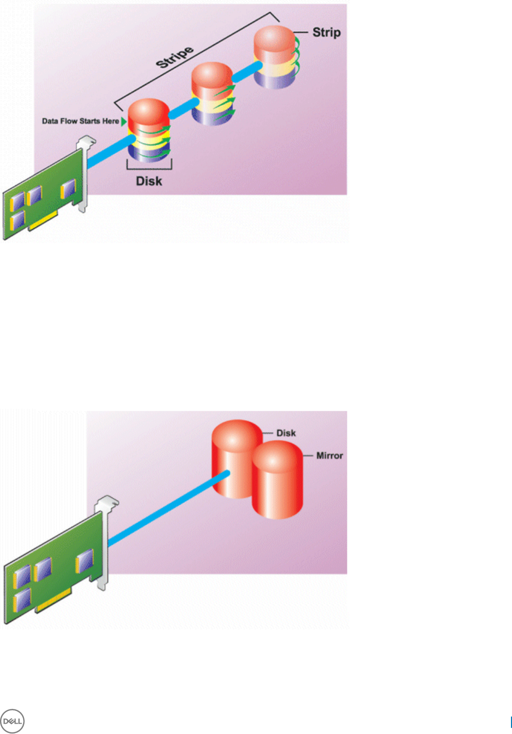
RAID 0 characteristics:
• Groups n disks as one large virtual disk with a capacity of (smallest disk size) *n disks.
• Data is stored to the disks alternately.
• No redundant data is stored. When a disk fails, the large virtual disk fails with no means of rebuilding the data.
• Better read and write performance.
RAID level 1 - mirroring
RAID 1 is the simplest form of maintaining redundant data. In RAID 1, data is mirrored or duplicated on one or more physical disks. If a
physical disk fails, data can be rebuilt using the data from the other side of the mirror.
RAID 1 characteristics:
• Groups n + n disks as one virtual disk with the capacity of n disks. The controllers currently supported by Storage Management allow
the selection of two disks when creating a RAID 1. Because these disks are mirrored, the total storage capacity is equal to one disk.
• Data is replicated on both the disks.
Managing storage devices 205
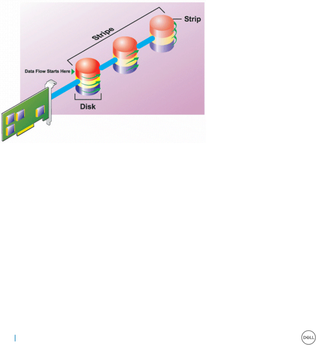
• When a disk fails, the virtual disk still works. The data is read from the mirror of the failed disk.
• Better read performance, but slightly slower write performance.
• Redundancy for protection of data.
• RAID 1 is more expensive in terms of disk space since twice the number of disks are used than required to store the data without
redundancy.
RAID level 5 or striping with distributed parity
RAID 5 provides data redundancy by using data striping in combination with parity information. Rather than dedicating a physical disk to
parity, the parity information is striped across all physical disks in the disk group.
RAID 5 characteristics:
• Groups n disks as one large virtual disk with a capacity of (n-1) disks.
• Redundant information (parity) is alternately stored on all disks.
• When a disk fails, the virtual disk still works, but it is operating in a degraded state. The data is reconstructed from the surviving disks.
• Better read performance, but slower write performance.
• Redundancy for protection of data.
RAID level 6-striping with additional distributed parity
RAID 6 provides data redundancy by using data striping in combination with parity information. Similar to RAID 5, the parity is distributed
within each stripe. RAID 6, however, uses an additional physical disk to maintain parity, such that each stripe in the disk group maintains
two disk blocks with parity information. The additional parity provides data protection in the event of two disk failures. In the following
image, the two sets of parity information are identied as P and Q.
206 Managing storage devices
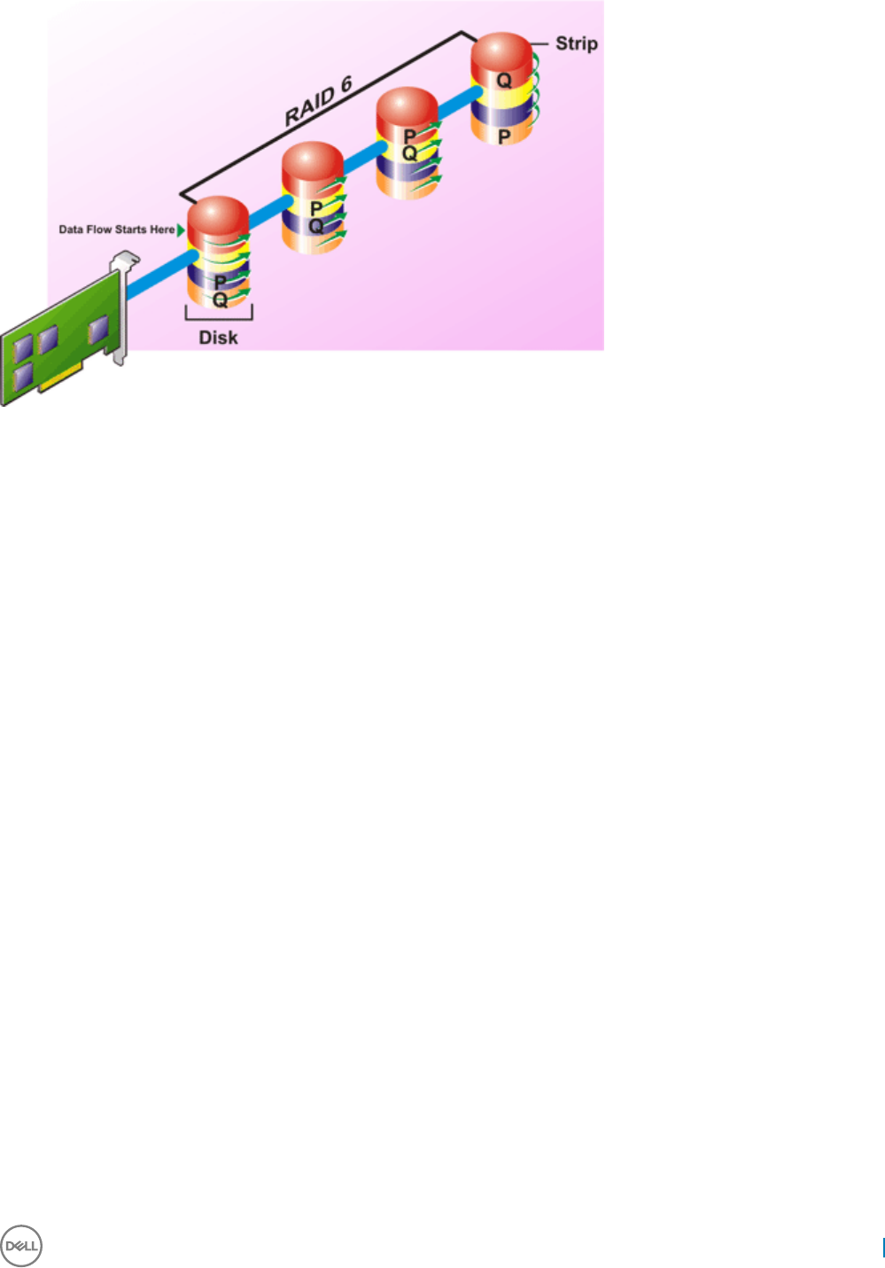
RAID 6 characteristics:
• Groups n disks as one large virtual disk with a capacity of (n-2) disks.
• Redundant information (parity) is alternately stored on all disks.
• The virtual disk remains functional with up to two disk failures. The data is reconstructed from the surviving disks.
• Better read performance, but slower write performance.
• Increased redundancy for protection of data.
• Two disks per span are required for parity. RAID 6 is more expensive in terms of disk space.
RAID level 50 - striping over RAID 5 sets
RAID 50 is striping over more than one span of physical disks. For example, a RAID 5 disk group that is implemented with three physical
disks and then continues on with a disk group of three more physical disks would be a RAID 50.
It is possible to implement RAID 50 even when the hardware does not directly support it. In this case, you can implement more than one
RAID 5 virtual disks and then convert the RAID 5 disks to dynamic disks. You can then create a dynamic volume that is spanned across all
RAID 5 virtual disks.
Managing storage devices 207
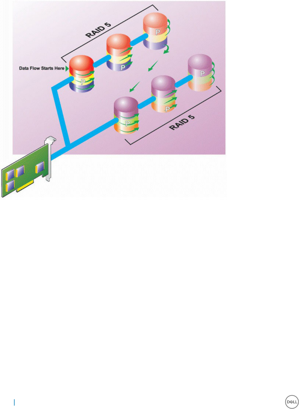
RAID 50 characteristics:
• Groups n*s disks as one large virtual disk with a capacity of s*(n-1) disks, where s is the number of spans and n is the number of disks
within each span.
• Redundant information (parity) is alternately stored on all disks of each RAID 5 span.
• Better read performance, but slower write performance.
• Requires as much parity information as standard RAID 5.
• Data is striped across all spans. RAID 50 is more expensive in terms of disk space.
RAID level 60 - striping over RAID 6 sets
RAID 60 is striping over more than one span of physical disks that are congured as a RAID 6. For example, a RAID 6 disk group that is
implemented with four physical disks and then continues on with a disk group of four more physical disks would be a RAID 60.
208 Managing storage devices
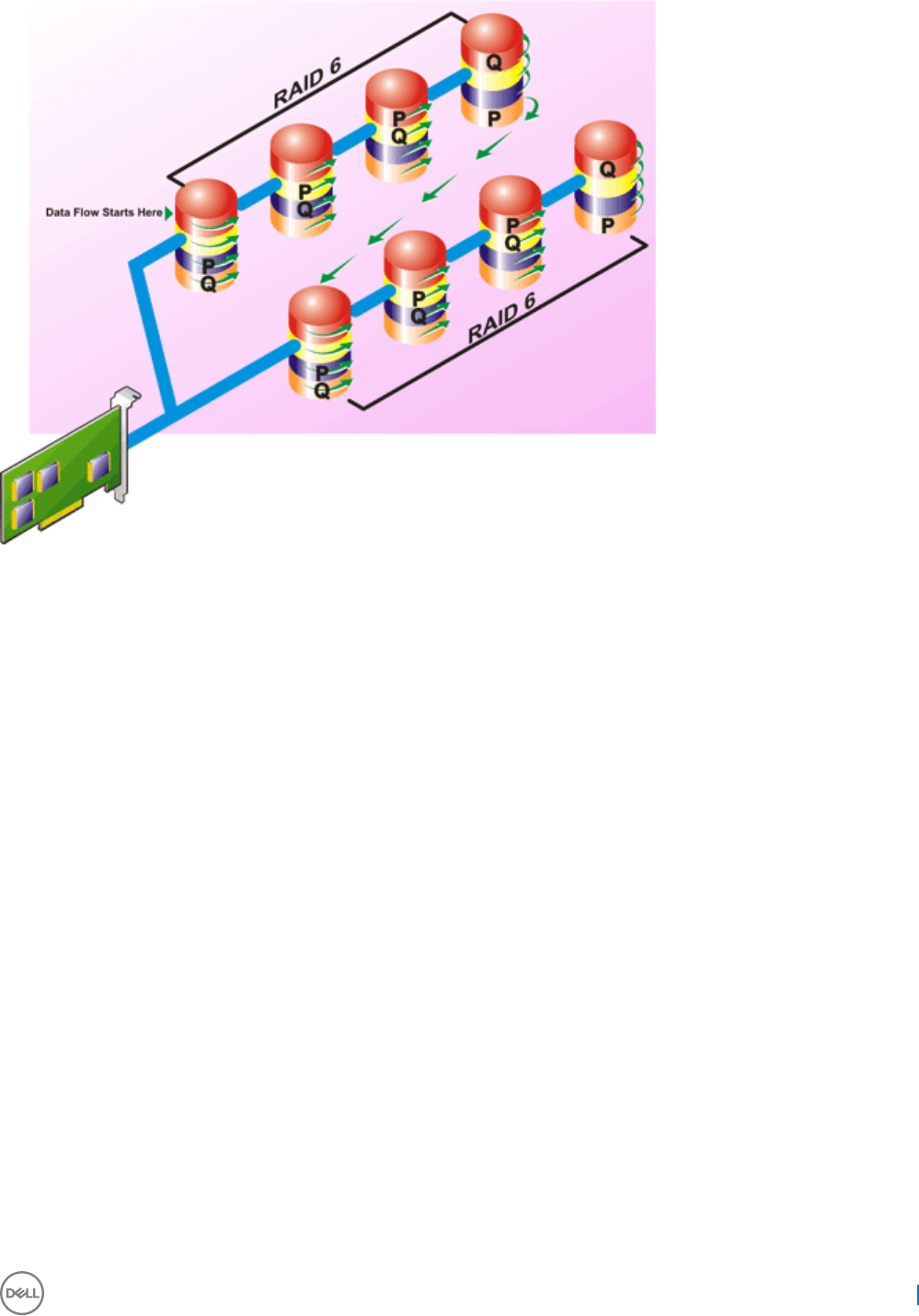
RAID 60 characteristics:
• Groups n*s disks as one large virtual disk with a capacity of s*(n-2) disks, where s is the number of spans and n is the number of disks
within each span.
• Redundant information (parity) is alternately stored on all disks of each RAID 6 span.
• Better read performance, but slower write performance.
• Increased redundancy provides greater data protection than a RAID 50.
• Requires proportionally as much parity information as RAID 6.
• Two disks per span are required for parity. RAID 60 is more expensive in terms of disk space.
RAID level 10 - striped with mirrors
The RAB considers RAID level 10 to be an implementation of RAID level 1. RAID 10 combines mirrored physical disks (RAID 1) with data
striping (RAID 0). With RAID 10, data is striped across multiple physical disks. The striped disk group is then mirrored onto another set of
physical disks. RAID 10 can be considered a mirror of stripes.
Managing storage devices 209
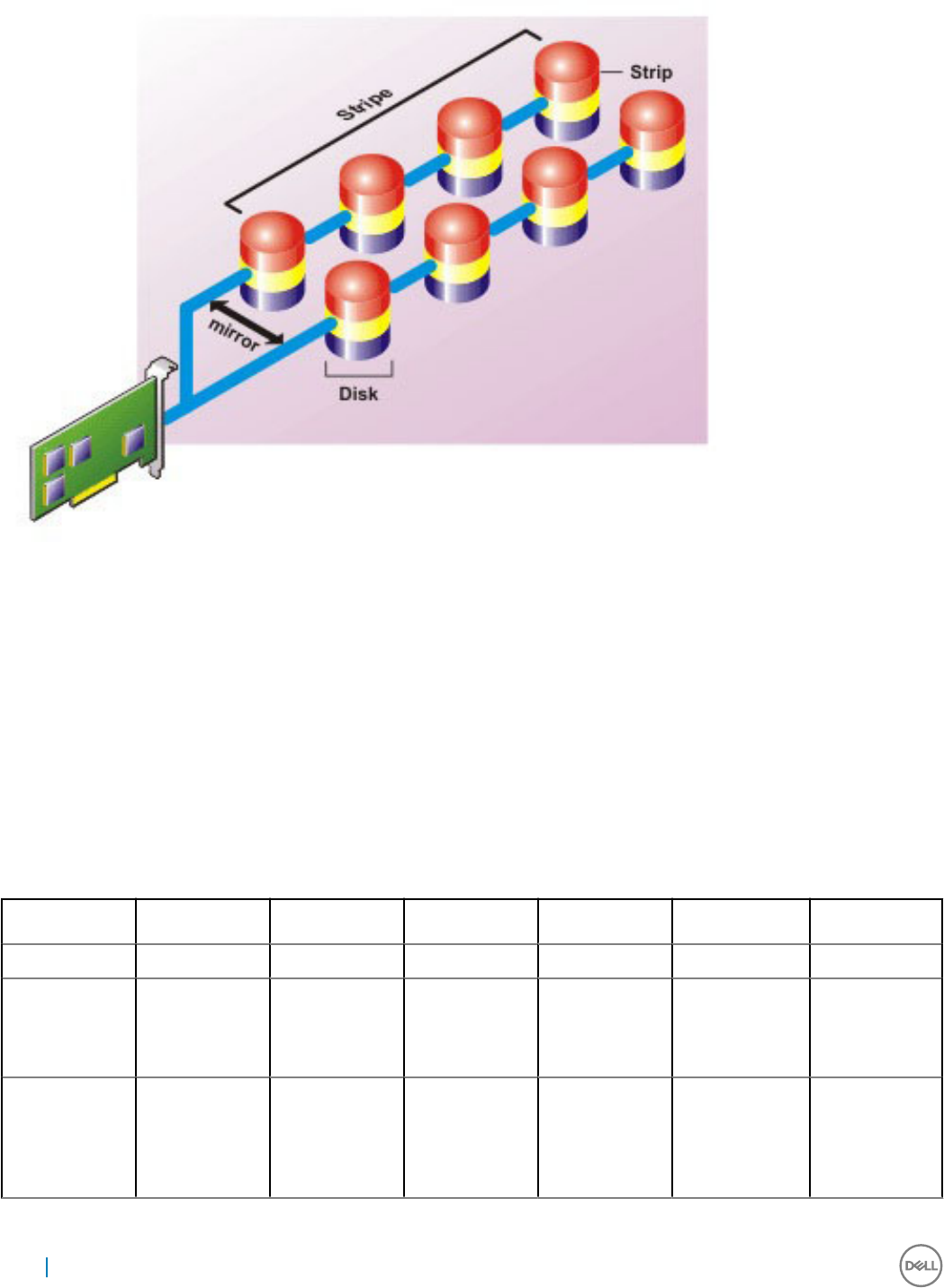
RAID 10 characteristics:
• Groups n disks as one large virtual disk with a capacity of (n/2) disks, where n is an even integer.
• Mirror images of the data are striped across sets of physical disks. This level provides redundancy through mirroring.
• When a disk fails, the virtual disk still works. The data is read from the surviving mirrored disk.
• Improved read performance and write performance.
• Redundancy for protection of data.
Comparing RAID level performance
The following table compares the performance characteristics associated with the more common RAID levels. This table provides general
guidelines for choosing a RAID level. Evaluate your specic environment requirements before choosing a RAID level.
Table 49. RAID level performance comparison
RAID Level Data Availability Read
Performance
Write
Performance
Rebuild
Performance
Minimum Disks
Required
Suggested Uses
RAID 0 None Very Good Very Good N/A N Noncritical data.
RAID 1 Excellent Very Good Good Good 2N (N = 1) Small databases,
database logs,
and critical
information.
RAID 5 Good Sequential reads:
good.
Transactional
reads: Very good
Fair, unless using
writeback cache
Fair N + 1 (N = at least
two disks)
Databases and
other read
intensive
transactional
uses.
210 Managing storage devices

RAID Level Data Availability Read
Performance
Write
Performance
Rebuild
Performance
Minimum Disks
Required
Suggested Uses
RAID 10 Excellent Very Good Fair Good 2N x X Data intensive
environments
(large records).
RAID 50 Good Very Good Fair Fair N + 2 (N = at
least 4)
Medium sized
transactional or
data intensive
uses.
RAID 6 Excellent Sequential reads:
good.
Transactional
reads: Very good
Fair, unless using
writeback cache
Poor N + 2 (N = at
least two disks)
Critical
information.
Databases and
other read
intensive
transactional
uses.
RAID 60 Excellent Very Good Fair Poor X x (N + 2) (N =
at least 2)
Critical
information.
Medium sized
transactional or
data intensive
uses.
N = Number of physical disks
X = Number of RAID sets
Supported controllers
Supported RAID controllers
The iDRAC interfaces support the following BOSS controllers:
• BOSS-S1 Adapter
• BOSS-S1 Modular (for blade servers)
The iDRAC interfaces support the following PERC10 controllers:
• PERC H740P Mini
• PERC H740P Adapter
• PERC H840 Adapter
The iDRAC interfaces support the following PERC9 controllers:
• PERC H330 Mini
• PERC H330 Adapter
• PERC H730P Mini
• PERC H730P Adapter
Supported non-RAID controllers
The iDRAC interface supports 12 Gbps SAS HBA external controller and HBA330 Mini or Adapter controllers.
Managing storage devices 211

Supported enclosures
iDRAC supports MD1400, and MD1420 enclosures.
NOTE: Redundant Array of Inexpensive Disks (RBODS) that are connected to HBA controllers are not supported.
NOTE: For iDRAC version 3.00.00.00, daisy chain of enclosures is not supported for H840. Only one enclosure per port is
allowed.
Summary of supported features for storage devices
The following tables provide the features supported by the storage devices through iDRAC.
NOTE: Features such as prepare to remove and blink or unblink component LED are not applicable for HHHL PCIe SSD cards.
Table 50. Supported features for storage controllers
Feature PERC 10 PERC 9
H740P Mini H740P
Adapter
H840
Adapter
H330 Mini H330
Adapter
H730P
Mini
H730P
Adapter
FD33xS
Assign or unassign physical
disk as a global hot spare
Real-time Real-time Real-time Real-time Real-time Real-time Real-time Real-time
Convert to RAID/Non RAID, Real-time Real-time Real-time Real-time Real-time Real-time Real-time Real-time
Rebuild Real-time Real-time Real-time Real-time Real-time Real-time Real-time Real-time
Cancel Rebuild Real-time Real-time Real-time Real-time Real-time Real-time Real-time Real-time
Create virtual disks Real-time Real-time Real-time Real-time Real-time Real-time Real-time Real-time
Rename virtual disks
Edit virtual disks cache
policies
Real-time Real-time Real-time Real-time Real-time Real-time Real-time Real-time
Check virtual disk
consistency
Real-time Real-time Real-time Real-time Real-time Real-time Real-time Real-time
Cancel check consistency Real-time Real-time Real-time Real-time Real-time Real-time Real-time Real-time
Initialize virtual disks Real-time Real-time Real-time Real-time Real-time Real-time Real-time Real-time
Cancel initialization Real-time Real-time Real-time Real-time Real-time Real-time Real-time Real-time
Encrypt virtual disks Real-time Real-time Real-time Not
applicable
Not
applicable
Real-time Real-time Real-time
Assign or unassign dedicated
hot spare
Real-time Real-time Real-time Real-time Real-time Real-time Real-time Real-time
Delete virtual disks Real-time Real-time Real-time Real-time Real-time Real-time Real-time Real-time
Cancel Background
Initialization
Real-time Real-time Real-time Real-time Real-time Real-time Real-time Real-time
Online Capacity Expansion Real-time Real-time Real-time Real-time Real-time Real-time Real-time Real-time
RAID Level Migration Real-time Real-time Real-time Real-time Real-time Real-time Real-time Real-time
Discard Preserved Cache Real-time Real-time Real-time Not
applicable
Not
applicable
Real-time Real-time Real-time
212 Managing storage devices

Feature PERC 10 PERC 9
H740P Mini H740P
Adapter
H840
Adapter
H330 Mini H330
Adapter
H730P
Mini
H730P
Adapter
FD33xS
Set Patrol Read Mode Real-time Real-time Real-time Real-time Real-time Real-time Real-time Real-time
Manual Patrol Read Mode Real-time Real-time Real-time Real-time Real-time Real-time Real-time Real-time
Patrol Read Uncongured
Areas
Real-time Real-time Real-time Real-time
(only in
web
interface)
Real-time
(only in
web
interface)
Real-time
(only in
web
interface)
Real-time
(only in
web
interface)
Real-time
(only in
web
interface)
Check Consistency Mode Real-time Real-time Real-time Real-time Real-time Real-time Real-time Real-time
Copyback Mode Real-time Real-time Real-time Real-time Real-time Real-time Real-time Real-time
Load Balance Mode Real-time Real-time Real-time Real-time Real-time Real-time Real-time Real-time
Check Consistency Rate Real-time Real-time Real-time Real-time Real-time Real-time Real-time Real-time
Rebuild Rate Real-time Real-time Real-time Real-time Real-time Real-time Real-time Real-time
BGI Rate Real-time Real-time Real-time Real-time Real-time Real-time Real-time Real-time
Reconstruct Rate Real-time Real-time Real-time Real-time Real-time Real-time Real-time Real-time
Import foreign conguration Real-time Real-time Real-time Real-time Real-time Real-time Real-time Real-time
Auto-import foreign
conguration
Real-time Real-time Real-time Real-time Real-time Real-time Real-time Real-time
Clear foreign conguration Real-time Real-time Real-time Real-time Real-time Real-time Real-time Real-time
Reset controller
conguration
Real-time Real-time Real-time Real-time Real-time Real-time Real-time Real-time
Create or change security
keys
Real-time Real-time Real-time Not
applicable
Not
applicable
Real-time Real-time Real-time
Inventory and remotely
monitor the health of PCIe
SSD devices
Not
applicable
Not
applicable
Not
applicable
Not
applicable
Not
applicable
Not
applicable
Not
applicable
Not
applicable
Prepare the PCIe SSD to be
removed
Not
applicable
Not
applicable
Not
applicable
Not
applicable
Not
applicable
Not
applicable
Not
applicable
Not
applicable
Securely erase the data for
PCIe SSD
Not
applicable
Not
applicable
Not
applicable
Not
applicable
Not
applicable
Not
applicable
Not
applicable
Not
applicable
Congure Backplane mode
(split/unied)
Real-time Real-time Real-time Real-time Real-time Real-time Real-time Real-time
Blink or unblink component
LEDs
Real-time Real-time Real-time Real-time Real-time Real-time Real-time Real-time
Switch controller mode Not
applicable
Not
applicable
Not
applicable
Staged Staged Staged Staged Staged
T10PI support for Virtual
Disks
Not
applicable
Not
applicable
Not
applicable
Not
applicable
Not
applicable
Not
applicable
Not
applicable
Not
applicable
NOTE: PERC 10 no longer supports convert drives to non-RAID, convert controller to HBA mode and RAID 10 uneven span
support.
Managing storage devices 213

Table 51. Supported features for storage devices
Feature PCIe SSD BOSS
Create virtual disks Not applicable Staged
Reset controller conguration Not applicable Staged
Fast Initialization Not applicable Staged
Delete virtual disks Not applicable Staged
Full Initialization Not applicable Not applicable
Inventory and remotely monitor the health of
PCIe SSD devices
Real-time Not applicable
Prepare the PCIe SSD to be removed Real-time Not applicable
Securely erase the data for PCIe SSD Staged Not applicable
Blink or unblink component LEDs Real-time Not applicable
Inventorying and monitoring storage devices
You can remotely monitor the health and view the inventory of the following Comprehensive Embedded Management (CEM) enabled
storage devices in the managed system using iDRAC web interface:
• RAID controllers, non-RAID controllers, BOSS controllers and PCIe extenders
• Enclosures that include Enclosure Management Modules (EMMs), power supply, fan probe, and temperature probe
• Physical disks
• Virtual disks
• Batteries
The recent storage events and topology of storage devices are also displayed.
Alerts and SNMP traps are generated for storage events. The events are logged in the Lifecycle Log.
NOTE: For an accurate inventory of BOSS controllers, ensure that Collect System Inventory On Reboot Operation (CSIOR) is
completed. CSIOR is enabled by default.
NOTE: If you enumerate the enclosure view's WSMan command on a system while one PSU-cable is removed, the primary status
of the enclosure view is reported as Healthy instead of Warning.
NOTE: The storage health rollup follows the same convention of Dell EMC OpenManage product. For more information see the
Dell EMC OpenManage Server Administrator Users Guide
available at dell.com/openmanagemanuals.
NOTE: Physical disks in system with multiple backplanes may be listed under a dierent backplane. Use the blink function to
identify the disks.
Monitoring storage devices using web interface
To view the storage device information using Web interface:
• Go to Storage > Overview > Summary to view the summary of the storage components and the recently logged events. This page is
automatically refreshed every 30 seconds.
• Go to Storage > Overview > Controllers to view the RAID controller information. The Controllers page is displayed.
• Go to Storage > Overview > Physical Disks to view physical disk information. The Physical Disks page is displayed.
• Go to Storage > Overview > Virtual Disks to view virtual disk information. The Virtual Disks page is displayed.
• Go to Storage > Overview > Enclosures to view the enclosure information. The Enclosures page is displayed.
You can also use lters to view specic device information.
214 Managing storage devices

NOTE: The storage hardware list is not displayed in case the system does not have storage devices with CEM support.
NOTE: When NVMe SSDs are in RAID (behind S140) mode, web interface does not display NVMe SSD’s slot information in the
Enclosure page. Refer Physical Disks page for the details.
For more information on the displayed properties and to use the lter options, see iDRAC Online Help.
Monitoring storage devices using RACADM
To view the storage device information, use the storage command.
For more information, see the iDRAC RACADM Command Line Reference Guide available at dell.com/idracmanuals.
Monitoring backplane using iDRAC settings utility
In the iDRAC Settings utility, go to System Summary. The iDRAC Settings.System Summary page is displayed. The Backplane Inventory
section displays the backplane information. For information about the elds, see the iDRAC Settings Utility Online Help.
Viewing storage device topology
You can view the hierarchical physical containment view of the key storage components, that is, a list of controllers, enclosures connected
to the controller and a link to the physical disk contained in each enclosure. The physical disks attached directly to the controller are also
displayed.
To view the storage device topology, go to Storage > Overview. The Overview page displays the hierarchical representation of the storage
components in the system. The available options are:
• Controllers
• Physical Disks
• Virtual Disks
• Enclosures
Click the links to view the respective component details.
Managing physical disks
You can perform the following for physical disks:
• View physical disk properties.
• Assign or unassign physical disk as a global hot-spare.
• Convert to RAID capable disk.
• Convert to non-RAID disk.
• Blink or unblink the LED.
• Rebuild physical disk
• Cancel rebuild physical disk
• Cryptographic erase
Assigning or unassigning physical disk as global hot spare
A global hot spare is an unused backup disk that is part of the disk group. Hot spares remain in standby mode. When a physical disk that is
used in a virtual disk fails, the assigned hot spare is activated to replace the failed physical disk without interrupting the system or requiring
your intervention. When a hot spare is activated, it rebuilds the data for all redundant virtual disks that were using the failed physical disk.
Managing storage devices 215

NOTE: From iDRAC v2.30.30.30 or later, you can add global hot spares when virtual disks are not created.
You can change the hot spare assignment by unassigning a disk and choosing another disk as needed. You can also assign more than one
physical disk as a global hot spare.
Global hot spares must be assigned and unassigned manually. They are not assigned to specic virtual disks. If you want to assign a hot
spare to a virtual disk (it replaces any physical disk that fails in the virtual disk), then see Assigning or unassigning dedicated hot spares.
When deleting virtual disks, all assigned global hot spares may be automatically unassigned when the last virtual disk associated with the
controller is deleted.
If you reset the conguration, the virtual disks are deleted and all the hot spares are unassigned.
You must be familiar with the size requirements and other considerations associated with hot spares.
Before assigning a physical disk as a global hot spare:
• Make sure that Lifecycle Controller is enabled.
• If there are no disk drives available in ready state, insert additional disk drives and make sure that the drives are in ready state.
• If physical disks are in non-RAID mode convert them to RAID mode using iDRAC interfaces such as iDRAC web interface, RACADM,
Redsh or WSMan, or <CTRL+R>.
NOTE: During POST, you can press <F2> to enter System Setup. <CTRL+R> option is no longer supported for PERC 10, only
works with PERC 9.
If you have assigned a physical disk as a global hot spare in Add to Pending Operation mode, the pending operation is created but a job is
not created. Then, if you try to unassign the same disk as global hot spare, the assign global hot spare pending operation is cleared.
If you have unassigned a physical disk as a global hot spare in Add to Pending Operation mode, the pending operation is created but a job is
not created. Then, if you try to assign the same disk as a global hot spare, the unassign global hot spare pending operation is cleared.
If the last VD is deleted, the global hot spares also returns to ready state.
If a PD is already a global hot spares, user can still assign it again as a global hot spares.
Assigning or unassigning global hot spare using web interface
To assign or unassign a global hot spare for a physical disk drive:
1 In the iDRAC web interface, go to Overview > Storage > Physical Disks > Setup.
The Setup Physical Disk page is displayed.
2 From the Controller drop-down menu, select the controller to view the associated physical disks.
3 To assign as a global hotspare, from the drop-down menus in the Action-Assign to All column, select Global Hotspare for one or more
physical disks.
4 To unassign a hot spare, from the drop-down menus in the Action-Assign to All column, select Unassign Hotspare for one or more
physical disks.
5 From the Apply Operation Mode drop-down menu, select when you want to apply the settings.
6 Click Apply.
Based on the selected operation mode, the settings are applied.
Assigning or unassigning global hot spare using RACADM
Use the storage command and specify the type as global hot spare.
For more information, see the iDRAC RACADM Command Line Reference Guide available at dell.com/idracmanuals.
216 Managing storage devices

Converting a physical disk to RAID or non-RAID mode
Converting a physical disk to RAID mode enables the disk for all RAID operations. When a disk is in a non-RAID mode, the disk is exposed to
the operating system unlike uncongured good disks and is used in a direct pass-through mode.
PERC 10 is not supported to convert drives to non-RAID.
You can convert the physical disk drives to RAID or non-RAID mode by:
• Using iDRAC interfaces such as iDRAC web interface, RACADM, Redsh or WSMan.
• Pressing <Ctrl+R> while restarting the server and selecting the required controller.
NOTE: If the physical drives connected to a PERC controller are in non-RAID mode, the size of the disk displayed in the iDRAC
interfaces, such as iDRAC GUI, RACADM, Redsh and WSMan, may be slightly less than the actual size of the disk. However,
you can use the full capacity of the disk to deploy operating systems.
NOTE: Hot plugged disks in H330 are always in non-RAID mode. In other RAID controllers, they are always in RAID mode.
Converting physical disks to RAID capable or non-RAID mode using the
iDRAC web interface
To convert the physical disks to RAID mode or non-RAID mode, perform the following steps:
1 In the iDRAC web interface, click Storage > Overview > Physical Disks.
2 Click Advanced Filter.
An elaborated list is displayed that allows you to congure dierent parameters.
3 From the Group By drop-down menu, select an enclosure or virtual disks.
The parameters associated with the enclosure or the VD are displayed.
4 Click Apply, once you select all the desired parameters. For more information about the elds, see the iDRAC Online Help.
The settings are applied based on the option selected in the operation mode.
Converting physical disks to RAID capable or non-RAID mode using
RACADM
Depending on whether you want to convert to RAID or Non-RAID mode, use the following RACADM commands
• To convert to RAID mode, use the racadm storage converttoraid command.
• To convert to Non-RAID mode, use the racadm storage converttononraid command.
NOTE: On the S140 controller, you can only use the RACADM interface to convert the drives from non-RAID to RAID mode. The
supported Software RAID modes are Windows or Linux Mode.
For more information about the commands, see the iDRAC RACADM Command Line Reference Guide available at dell.com/esmmanuals.
Erasing physical disks
The System Erase feature allows you to erase the contents of the physical drives. This feature is accessible using RACADM or the LC GUI.
Physical drives on the server are grouped into two categories.
• Secure erase drives— Includes drives that provide cryptographic erase such as ISE and SED SAS and SATA drives, and PCIe SSDs.
• Overwrite erase drives— Includes all drives that do not support cryptographic erase.
The RACADM SystemErase sub-command includes options for the following categories:
Managing storage devices 217

• The SecureErasePD option cryptographically erases all the secure erase drives.
• The OverwritePD option overwrites data on all drives.
Before performing SystemErase, use the following command to check the erase capability of all physical disks for a server:
# racadm storage get pdisks –o –p SystemEraseCapability
To erase ISE and SED drives, use this command:
# racadm systemerase –secureerasepd
To erase overwrite erase drives, use the following command:
# racadm systemerase -overwritepd
NOTE: RACADM SystemErase removes all the virtual disks from the physical disks that are erased by the above commands.
NOTE: RACADM SystemErase causes the server to restart in order to perform the erase operations.
NOTE: Individual PCIe SSD or SED devices can be erased using the iDRAC GUI or RACADM. For more information, see the
Erasing PCIe SSD device data
and the
Erasing SED device data
section.
For information on the System Erase function within the Lifecycle Controller GUI, see the Lifecycle Controller User's Guide available at
dell.com/idracmanuals.
Erasing SED device data
NOTE: This operation is not supported when SED device is a part of a Virtual Disk. The target SED device must be removed from
the virtual disk prior to performing device erase.
Cryptographic Erase permanently erases all data present on the disk. Performing a Cryptographic Erase on an SED overwrites all blocks and
results in permanent loss of all data on the SED. During Cryptographic Erase, the host is unable to access the SED. SED device erase can
be performed either in real time or be applied after a system reboot.
If the system reboots or experiences a power loss during cryptographic erase, the operation is canceled. You must reboot the system and
restart the process.
Before erasing SED device data, ensure that:
• Lifecycle Controller is enabled.
• You have Server Control and Login privileges.
• Selected SED drive is not part of a virtual disk.
NOTE:
• Erasing SEDs can be performed either as a real time or as a staged operation.
• After the SED drive is erased, it may still be displayed as active within the OS due to data caching. If this occurs, reboot the OS and
the erased SED drive will no longer be displayed or report any data.
• Cryptographic erase feature is supported for SEDs for 14th generation PowerEdge servers.
Erasing SED device data using web interface
To erase the data on the SED device:
1 In the iDRAC Web interface, go to Storage > Overview > Physical Disks.
The Physical Disk page is displayed.
2 From the Controller drop-down menu, select the controller to view the associated SEDs.
3 From the drop-down menus, select Cryptographic Erase for one or more SEDs.
If you have selected Cryptographic Erase and you want to view the other options in the drop-down menu, then select Action and
then click the drop-down menu to view the other options.
218 Managing storage devices

4 From the Apply Operation Mode drop-down menu, select one of the following options:
•Apply Now — Select this option to apply the actions immediately with no system reboot required.
•At Next Reboot — Select this option to apply the actions during the next system reboot.
•At Scheduled Time — Select this option to apply the actions at a scheduled day and time:
•Start Time and End Time — Click the calendar icons and select the days. From the drop-down menus, select the time. The
action is applied between the start time and end time.
• From the drop-down menu, select the type of reboot:
• No Reboot (Manually Reboot System)
• Graceful Shutdown
• Force Shutdown
• Power Cycle System (cold boot)
5 Click Apply.
If the job is not created, a message indicating that the job creation was not successful is displayed. Also, the message ID and the
recommended response action is displayed.
If the job is created successfully, a message indicating that the job ID is created for the selected controller is displayed. Click Job
Queue to view the progress of the job in the Job Queue page.
If pending operation is not created, an error message is displayed. If pending operation is successful and job creation is not successful,
then an error message is displayed.
Erasing SED device data using RACADM
To securely erase an SED device:
racadm storage cryptographicerase:<SED FQDD>
To create the target job after executing the cryptographicerase command:
racadm jobqueue create <SED FQDD> -s TIME_NOW -realtime
To create the target staged job after executing the cryptographicerase command:
racadm jobqueue create <SED FQDD> -s TIME_NOW -e <start_time>
To query the job ID returned:
racadm jobqueue view -i <job ID>
For more information, see the iDRAC RACADM Command Line Reference Guide available at dell.com/idracmanuals.
Rebuild Physical Disk
Rebuild Physical Disk is the ability to reconstruct the contents of a failed disk. This is true only when auto rebuild option is set to false. If
there is a redundant virtual disk, the rebuild operation can reconstruct the contents of a failed physical disk. A rebuild can take place during
normal operation, but it degrades performance.
Cancel Rebuild can be used to cancel a rebuild that is in progress. If you cancel a rebuild, the virtual disk remains in a degraded state. The
failure of an additional physical disk can cause the virtual disk to fail and may result in data loss. It is recommended to perform a rebuild on
the failed physical disk at the earliest.
In case, you cancel the rebuild of a physical disk that is assigned as a hot spare, reinitiate the rebuild on the same physical disk in order to
restore the data. Canceling the rebuild of a physical disk and then assigning another physical disk as a hot spare does not cause the newly
assigned hot spare to rebuild the data.
Managing virtual disks
You can perform the following operations for the virtual disks:
Managing storage devices 219

• Create
• Delete
• Edit policies
• Initialize
• Check consistency
• Cancel check consistency
• Encrypt virtual disks
• Assign or unassign dedicated hot spares
• Blink and unblink virtual disk
• Cancel background initialization
• Online capacity expansion
• RAID level migration
NOTE: You can manage and monitor 192 virtual disks if auto-conguration is enabled through PERC controller BIOS, Human
Interface Infrastructure (HII), and Dell OpenManage Server Administrator (OMSA).
NOTE: PERC 10 count is less since it does not support daisy chain arrangements.
Creating virtual disks
To implement RAID functions, you must create a virtual disk. A virtual disk refers to storage created by a RAID controller from one or more
physical disks. Although a virtual disk may be created from several physical disks, it is seen by the operating system as a single disk.
Before creating a virtual disk, you should be familiar with the information in Considerations Before Creating Virtual Disks.
You can create a Virtual Disk using the Physical Disks attached to the PERC controller. To create a Virtual Disk, you must have the Server
Control user privilege. You can create a maximum of 64 virtual drives and a maximum of 16 virtual drives in the same drive group.
You cannot create a virtual disk if:
• Physical disk drives are not available for virtual disk creation. Install additional physical disk drives.
• Maximum number of virtual disks that can be created on the controller has been reached. You must delete at least one virtual disk and
then create a new virtual disk.
• Maximum number of virtual disks supported by a drive group has been reached. You must delete one virtual disk from the selected
group and then create a new virtual disk.
• A job is currently running or scheduled on the selected controller. You must wait for this job to complete or you can delete the job
before attempting a new operation. You can view and manage the status of the scheduled job in the Job Queue page.
• Physical disk is in non-RAID mode. You must convert to RAID mode using iDRAC interfaces such as iDRAC web interface, RACADM,
Redsh, WSMan, or <CTRL+R>.
NOTE: If you create a virtual disk in Add to Pending Operation mode and a job is not created, and then if you delete the Virtual
disk, then the create pending operation for the virtual disk is cleared.
NOTE: RAID 6 and 60 are not supported in H330.
Considerations before creating virtual disks
Before creating virtual disks, consider the following:
• Virtual disk names not stored on controller—The names of the virtual disks that you create are not stored on the controller. This means
that if you reboot using a dierent operating system, the new operating system may rename the virtual disk using its own naming
conventions.
• Disk grouping is a logical grouping of disks attached to a RAID controller on which one or more virtual disks are created, such that all
virtual disks in the disk group use all of the physical disks in the disk group. The current implementation supports the blocking of mixed
disk groups during the creation of logical devices.
220 Managing storage devices

• Physical disks are bound to disk groups. Therefore, there is no RAID level mixing on one disk group.
• There are limitations on the number of physical disks that can be included in the virtual disk. These limitations depend on the controller.
When creating a virtual disk, controllers support a certain number of stripes and spans (methods for combining the storage on physical
disks). Because the number of total stripes and spans is limited, the number of physical disks that can be used is also limited. The
limitations on stripes and spans aect the RAID levels as follows:
• Maximum number of spans aects RAID 10, RAID 50, and RAID 60.
• Maximum number of stripes aects RAID 0, RAID 5, RAID 50, RAID 6, and RAID 60.
• Number of physical disks in a mirror is always 2. This aects RAID 1 and RAID 10.
• Cannot create virtual disks on PCIe SSDs.
Creating virtual disks using web interface
To create virtual disk:
1 In the iDRAC Web interface, go to Storage > Overview > Virtual DisksAdvanced Filter.
2 In the Virtual Disk section, do the following:
a From the Controller drop-down menu, select the controller for which you want to create the virtual disk.
b From the Layout drop-down menu, select the RAID level for the Virtual Disk.
Only those RAID levels supported by the controller appear in the drop-down menu and it is based on the RAID levels are available
based on the total number of physical disks available.
c Select the Media Type, Stripe Size, Read Policy, Write Policy, Disk Cache Policy, .
Only those values supported by the controller appear in the drop-down menus for these properties.
d In the Capacity eld, enter the size of the virtual disk.
The maximum size is displayed and then updated as disks are selected.
e The Span Count eld is displayed based on the selected physical disks (step 3). You cannot set this value. It is automatically
calculated after selecting disks for multi-raid level. If you have selected RAID 10 and if the controller supports uneven RAID 10,
then the span count value is not displayed. The controller automatically sets the appropriate value.
3 In the Select Physical Disks section, select the number of physical disks.
For more information about the elds, see the iDRAC Online Help
4 From the Apply Operation Mode drop-down menu, select when you want to apply the settings.
5 Click Create Virtual Disk.
Based on the selected Apply Operation Mode, the settings are applied.
NOTE: You can use alphanumeric characters, spaces, dashes, and underscores in the disk name. Any other special
characters that you enter are removed while creating the virtual disk.
Creating virtual disks using RACADM
Use the racadm storage createvd command.
For more information, see the iDRAC RACADM Command Line Reference Guide available at dell.com/idracmanuals.
Editing virtual disk cache policies
You can change the read, write, or disk cache policy of a virtual disk.
NOTE: Some of the controllers do not support all read or write policies. Therefore, when a policy is applied, an error message is
displayed.
The read policies indicate whether the controller must read sequential sectors of the virtual disk searching for data:
•Adaptive Read Ahead — The controller initiates read ahead only if the two most recent reads requests accessed sequential sectors of
the disk. If subsequent read requests access random sectors of the disk, the controller reverts to no read ahead policy. The controller
continues to evaluate whether read requests are accessing sequential sectors of the disk, and initiates read ahead if necessary.
Managing storage devices 221

•Read Ahead — The controller reads sequential sectors of the virtual disk when seeking data. Read ahead policy may improve system
performance if the data is written to the sequential sectors of the virtual disk.
•No Read Ahead — Selecting no read ahead policy indicates that the controller should not use read ahead policy.
The write policies specify if the controller sends a write-request completion signal when the data is in the cache or after it has been written
to the disk.
•Write Through — The controller sends a write-request completion signal only after the data is written to the disk. Write-through
caching provides better data security than write-back caching, since the system assumes that the data is available only after it has
been safely written to the disk.
•Write Back — The controller sends a write-request completion signal as soon as the data is in the controller cache but has not yet
been written to disk. Write back caching may provide improved performance since subsequent read requests can retrieve data quickly
from the cache then from the disk. However, data loss may occur in the event of a system failure which prevents that data from being
written on a disk. Other applications may also experience problems when actions assume that the data is available on the disk.
•Force Write Back — The write cache is enabled regardless of whether the controller has a battery. If the controller does not have a
battery and force write-back caching is used, data loss may occur in the event of a power failure.
The Disk Cache policy applies to readings on a specic virtual disk. These settings do not aect the read-ahead policy.
NOTE:
• Controller non-volatile cache and battery backup of controller cache aects the read-policy or the write policy that a controller can
support. All PERCs do not have battery and cache.
• Read ahead and write back requires cache. Therefore, if the controller does not have cache, it does not allow you to set the policy
value.
Similarly, if the PERC has cache but not battery and the policy is set that requires accessing cache, then data loss may occur if
base of power o. So few PERCs may not allow that policy.
Therefore, depending upon the PERC, the policy value is set.
Deleting virtual disks
Deleting a virtual disk destroys all information including le systems and volumes residing on the virtual disk and removes the virtual disk
from the controller’s conguration. When deleting virtual disks, all assigned global hot spares may be automatically unassigned when the
last virtual disk associated with the controller is deleted. When deleting the last virtual disk of a disk group, all assigned dedicated hot
spares automatically become global hot spares.
If you delete all the VDs for a global hotspare, then the global hotspare gets automatically deleted.
You must have the Login and Server Control privilege to perform delete virtual disks.
When this operation is allowed, you can delete a boot virtual drive. It is done from sideband and the independent of the operating system.
Hence, a warning message appears before you delete the virtual drive.
If you delete a virtual disk and immediately create a new virtual disk with all the same characteristics as the one that was deleted, the
controller recognizes the data as if the rst virtual disk were never deleted. In this situation, if you do not want the old data after recreating
a new virtual disk, re-initialize the virtual disk.
Checking virtual disk consistency
This operation veries the accuracy of the redundant (parity) information. This task only applies to redundant virtual disks. When necessary,
the check consistency task rebuilds the redundant data. If the virtual drive has a degraded status, running a check consistency may be able
to return the virtual drive to ready status. You can perform a consistency check using the web interface or RACADM.
You can also cancel the check consistency operation. The cancel check consistency is a real-time operation.
You must have Login and Server Control privilege to check consistency of virtual disks.
222 Managing storage devices

NOTE: Consistency check is not supported when the drives are set up in RAID0 mode.
Initializing virtual disks
Initializing virtual disks erases the all the data on the disk but does not change the virtual disk conguration. You must initialize a virtual disk
that is congured before it is used.
NOTE: Do not initialize virtual disks when attempting to recreate an existing conguration.
You can perform a fast initialization, a full Initialization, or cancel the initialization operation.
NOTE: The cancel initialization is a real-time operation. You can cancel the initialization using only the iDRAC Web interface and
not RACADM.
Fast initialization
The fast initialize operation initializes all physical disks included in the virtual disk. It updates the metadata on the physical disks so that all
disk space is available for future write operations. The initialize task can be completed quickly because the existing information on the
physical disks is not erased, although future write operations overwrite any information that remains on the physical disks.
Fast initialization only deletes the boot sector and stripe information. Perform a fast initialize only if you are constrained for time or the hard
drives are new or unused. Fast Initialization takes less time to complete (usually 30-60 seconds).
CAUTION: Performing a fast initialize causes existing data to be inaccessible.
The fast initialize task does not write zeroes to the disk blocks on the physical disks. It is because the Fast Initialize task does not perform a
write operation, it causes less degradation to the disk.
A fast initialization on a virtual disk overwrites the rst and last 8 MB of the virtual disk, clearing any boot records or partition information.
The operation takes only 2-3 seconds to complete and is recommended when you are recreating virtual disks.
A background initialization starts ve minutes after the Fast Initialization is completed.
Full or slow initialization
The full initialization (also called slow initialize) operation initializes all physical disks included in the virtual disk. It updates the metadata on
the physical disks and erases all existing data and le systems. You can perform a full initialization after creating the virtual disk. In
comparison with the fast initialize operation, you may want to use the full initialize if you have trouble with a physical disk or suspect that it
has bad disk blocks. The full initialize operation remaps bad blocks and writes zeroes to all disk blocks.
If full initialization of a virtual disk is performed, background initialization is not required. During full initialization, the host is not able to
access the virtual disk. If the system reboots during a full initialization, the operation terminates and a background initialization process
starts on the virtual disk.
It is always recommended to do a full initialization on drives that previously contained data. Full initialization can take up to 1-2 minutes per
GB. The speed of initialization depends on the controller model, speed of hard drives, and the rmware version.
The full initialize task initializes one physical disk at a time.
NOTE: Full initialize is supported only in real-time. Only few controllers support full initialization.
Managing storage devices 223

Encrypting virtual disks
When encryption is disabled on a controller (that is, the security key is deleted), manually enable encryption for virtual disks created using
SED drives. If the virtual disk is created after encryption is enabled on a controller, the virtual disk is automatically encrypted. It is
automatically congured as an encrypted virtual disk unless the enabled encryption option is disabled during the virtual disk creation.
You must have Login and Server Control privilege to manage the encryption keys.
NOTE: Though encryption is enabled in the controllers, user needs to manually enable encryption on the VD if VD is created from
iDRAC. Only if the VD is created from OMSA, it would be automatically encrypted.
Assigning or unassigning dedicated hot spares
A dedicated hot spare is an unused backup disk that is assigned to a virtual disk. When a physical disk in the virtual disk fails, the hot spare
is activated to replace the failed physical disk without interrupting the system or requiring your intervention.
You must have Login and Server Control privilege to run this operation.
You can assign only 4K drives as hot spare to 4K virtual disks.
If you have assigned a physical disk as a dedicated hot spare in Add to Pending Operation mode, the pending operation is created but a job
is not created. Then, if you try to unassign the dedicated hot spare, the assign dedicated hot spare pending operation is cleared.
If you have unassigned a physical disk as a dedicated hot spare in Add to Pending Operation mode, the pending operation is created but a
job is not created. Then, if you try to assign the dedicated hot spare, the unassign dedicated hot spare pending operation is cleared.
NOTE: While the log export operation is in progress, you cannot view information about dedicated hot spares on the Manage
Virtual Disks page. After the log export operation is complete, reload or refresh the Manage Virtual Disks page to view the
information.
Rename VD
To change the name of a Virtual Disk, the user must have System Control privilege. The virtual disk name can contain only alphanumeric
characters, spaces, dashes and underscores. The maximum length of the name depends on the individual controller. In most cases, the
maximum length is 15 characters. The name cannot start with a space, end with a space, or be left blank. Every time a virtual disk is
renamed, an LC Log gets created.
Edit Disk capacity
Online Capacity Expansion (OCE) allows you to increase the storage capacity of selected RAID levels while the system remains online. The
controller redistributes the data on the array(called Reconguration), placing new space available at the end of each RAID array.
Online Capacity Expansion (OCE) can be achieved in two ways:
• If free space is available on the smallest physical drive on the virtual disks group after starting LBA of Virtual disks, the virtual disk´s
capacity can be expanded within that free space. This option allows you to enter the new increased virtual disk size. If disk group in a
virtual disk has space available only before starting LBA, then Edit Disk Capacity in same disk group is not permitted even though there
is Available Space on a physical drive.
• A virtual disk's capacity can also be expanded by adding additional compatible physical disks to the existing virtual disk group. This
option does not allow you to enter the new increased virtual disk size. New increased virtual disk size is calculated and displayed to the
user based on the used disk space of existing physical disk group on a particular virtual disk, existing raid level of the virtual disk and the
number of new drives added to the virtual disk.
Capacity Expansion allows user to specify the nal VD size. Internally nal VD size is conveyed to PERC in percentage (this percentage is
the space user would like to use from empty space left in the array for the local disk to expand). Because of this percentage logic nal VD
224 Managing storage devices

size after reconguration completes may be dierent from what user provided for scenario where user is not giving maximum VD size
possible as the nal VD size (percentage turns out to be less than 100%). User does not see dierence in this entered VD size and nal VD
size after reconguration, if maximum possible VD size is entered by user.
Raid Level Migration
RAID Level Migration (RLM) refers to changing a virtual disk´s RAID level. iDRAC9 provides an option to increase the VD size using RLM. In
a way, RLM allows migrating the RAID level of a virtual disk which in turn may increase the size of virtual disk.
RAID level migration is the process of converting a VD with one RAID Level to another. When you migrate a VD to a dierent Raid Level,
the user data on it is redistributed to the format of the new conguration.
This conguration is supported by both staged and realtime.
The below table describes possible recongurable VD layouts while reconguring (RLM) a VD with addition of disks and without addition of
disks.
Table 52. Possible VD Layout
Source VD Layout Possible target VD Layout with Disk Add Possible target VD Layout Without disk
addition
R0 (single disk) R1 NA
R0 R5/R6 NA
R1 R0/R5/R6 R0
R5 R0/R6 R0
R6 R0/R5 R0/R5
Permitted operations when OCE or RLM is going on
The following operations are allowed when OCE/RLM is going on:
Table 53. Permitted operations
From Controller End behind which
a VD is going through OCE/RLM
From VD End (which is going
through OCE/RLM)
From any other Ready State
Physical Disk on the same
controller
From any other VD (which
is not going through OCE/
RLM) End on the same
controller
Reset Conguration Delete Blink Delete
Export Log Blink Unblink Blink
Set Patrol Read Mode Unblink Assign Global Hot Spare Unblink
Start Patrol Read Convert to non-RAID Disks Rename
Change Controller Properties Change Policy
Manage Physical Disk Power Slow Initialize
Convert to RAID Capable Disks Fast Initialize
Convert to Non-RAID Disks Replace Member Disk
Managing storage devices 225

Change Controller Mode
OCE and RLM Restrictions or Limitations
Following are the common limitations for OCE and RLM:
• OCE/RLM is restricted to the scenario where the disk group contains only one VD.
• OCE is not supported on RAID50 and RAID60. RLM is not supported on RAID10,RAID50 and RAID60.
• If the controller already contains the maximum number of virtual disks, you cannot perform a RAID level migration or capacity expansion
on any virtual disk.
• The controller changes the write cache policy of all virtual disks undergoing a RLM/OCE to Write-Through until RLM/OCE is complete.
•Reconguring Virtual Disks typically impacts disk performance until the reconguration operation is complete.
• The total number of physical disks in a disk group cannot exceed 32.
• If any background operation (like BGI/rebuild/copyback/patrol read ) is already running on the corresponding VD/PD then
Reconguration (OCE/RLM) is not allowed at that time.
• Any kind of disk migration when Reconguration (OCE/RLM) is on progress on drives associated with VD causes reconguration to fail.
• Any new drive added for OCE/RLM becomes part of the VD after reconstruction completes. But State for those new drive changes to
Online just after reconstruction starts.
Cancel Initialization
This feature is the ability to cancel the background initialization on a virtual disk. On PERC controllers, the background initialization of
redundant virtual disk starts automatically after a virtual disk is created. The background initialization of redundant virtual disk prepares the
virtual disk for parity information and improves write performance. However, some processes such as creating a virtual disk cannot be run
while the background initialization is in progress. Cancel Initialization provides the ability to cancel the background initialization manually.
Once cancelled, the background initialization automatically restarts within 0 to 5 minutes.
NOTE: Background initialization is not applicable for RAID 0 virtual disks.
Managing virtual disks using web interface
1 In the iDRAC web interface, go to Storage > Overview > Virtual Disks > Advanced Filter.
2 From the Virtual Disks, select the controller for which you want to manage the virtual disks.
3 For one or more Virtual Disks, from each Action drop-down menu, select an action.
You can specify more than one action for a virtual drive. When you select an action, an additional Action drop-down menu is displayed.
Select another action from this drop-down menu. The action that is already selected does not appear in the additional Action drop-
down menus. Also, the Remove link is displayed next to the selected action. Click this link to remove the selected action.
•Delete
•Edit Policy: Read Cache — Change the read cache policy to one of the following options:
•No Read Ahead — Indicates that for the given volume, no read ahead policy is used.
•Read Ahead — Indicates that for the given volume, the controller reads sequentially ahead of the requested data and stores
the additional data in cache memory, anticipating a data requirement. This speeds up sequential data reads, but there is less
improvement when accessing random data.
•Adaptive Read Ahead — Indicates that for the given volume, the control uses the Read-Ahead cache policy if the two most
recent disks accesses occurred in sequential sectors. If the read requests are random, the controller returns to No Read Ahead
mode.
•Edit Policy: Write Cache — Change the write cache policy to one of the following options:
•Write Through — Indicates that for the given volume, the controller sends a data transfer completion signal to the host
system when the disk subsystem has received all the data in a transaction.
226 Managing storage devices

•Write Back — Indicates that for the given volume, the controller sends a data transfer completion signal to the host system
when the controller cache has received all the data in a transaction. The controller then writes the cached data to the storage
device in the background.
•Force Write Back — When using force write-back caching, the write cache is enabled regardless of whether the controller
has a battery. If the controller does not have a battery and force write-back caching is used, data loss may occur in the event
of a power failure.
•Edit Policy: Disk Cache — Change the disk cache policy to one of the following options:
•Default — Indicates that the disk is using its default write cache mode. For SATA disks, this is enabled and for SAS disks this is
disabled.
•Enabled — Indicates that the disk’s write cache is enabled. This increases performance and the probability of data loss if there
is power loss.
•Disabled — Indicates that the disk’s write cache is disabled. This decreases performance and the probability of data loss.
•Initialize: Fast — Updates the metadata on the physical disks so that all the disk space is available for future write operations. The
initialize option can be completed quickly because existing information on the physical disks is not erased, although future write
operations overwrites any information that remains on the physical disks.
•Initialize: Full — All existing data and le systems are erased.
NOTE: The Initialize: Full option is not applicable for PERC H330 controllers.
•Check Consistency — To check the consistency of a virtual disk, select Check Consistency from the corresponding drop-down
menu.
NOTE: Consistency check is not supported on drives set up in RAID0 mode.
•Encrypt Virtual Disk — Encrypts the virtual disk drive. If the controller is encryption capable, you can create, change or delete the
security keys.
NOTE: The Encrypt Virtual Disk option is available only if the virtual disk is created using the Self-Encrypting Drive (SED)
drives.
•Manage Dedicated Hotspares — Assign or unassign a physical disk as a dedicated hot spare. Only the valid dedicated hot spares
are displayed. If there are no valid dedicated hot spares, then this section does not appear in the drop-down menu.
For more information about these options, see the iDRAC Online Help.
4 From the Apply Operation Mode drop-down menu, select when you want to apply the settings.
5 Click Apply.
Based on the selected operation mode, the settings are applied.
The other options are:
RAID Level Migration — Displays the Disk Name, Current RAID Level, and size of the virtual disk. Allows you to select a New RAID
Level. User may have to add additional drives to existing Virtual disks to migrate to new raid level. This feature is not applicable on
RAID 10, 50 and 60.
Managing virtual disks using RACADM
Use the following commands to manage virtual disks:
• To delete virtual disk:
racadm storage deletevd:<VD FQDD>
• To initialize virtual disk:
racadm storage init:<VD FQDD> -speed {fast|full}
• To check consistency of virtual disks (not supported on RAID0):
racadm storage ccheck:<vdisk fqdd>
To cancel the consistency check:
racadm storage cancelcheck: <vdisks fqdd>
• To encrypt virtual disks:
racadm storage encryptvd:<VD FQDD>
Managing storage devices 227

• To assign or unassign dedicated hot spares:
racadm storage hotspare:<Physical Disk FQDD> -assign <option> -type dhs -vdkey: <FQDD of VD>
<option>=ye
s
Assign hot spare
<Option>=no Unassign hot spare
Managing controllers
You can perform the following for controllers:
•Congure controller properties
• Import or auto import foreign conguration
• Clear foreign conguration
• Reset controller conguration
• Create, change, or delete security keys
• Discard preserved cache
Conguring controller properties
You can congure the following properties for the controller:
• Patrol read mode (auto or manual)
• Start or stop patrol read if patrol read mode is manual
• Patrol read uncongured areas
• Check consistency mode
• Copyback mode
• Load balance mode
• Check consistency rate
• Rebuild rate
• BGI rate
• Reconstruct rate
• Enhanced auto import foreign conguration
• Create or change security keys
You must have Login and Server Control privilege to congure the controller properties.
Patrol read mode considerations
Patrol read identies disk errors to avoid disk failures, data loss, or corruption.
The Patrol Read does not run on a physical disk in the following circumstances:
• The physical disk is not included in a virtual disk or assigned as a hot spare.
• The physical disk is included in a virtual disk that is undergoing one of the following:
• A rebuild
• A reconguration or reconstruction
• A background initialization
• A check consistency
In addition, the Patrol Read operation suspends during heavy I/O activity and resumes when the I/O is complete.
228 Managing storage devices

NOTE: For more information on how often the Patrol Read operation runs when in auto mode, see the respective controller
documentation.
NOTE: Patrol read mode operations such as Start and Stop are not supported if there are no virtual disks available in the
controller. Though you can invoke the operations successfully using the iDRAC interfaces, the operations fail when the
associated job is started.
Load balance
The Load Balance property provides the ability to automatically use both controller ports or connectors connected to the same enclosure to
route I/O requests. This property is available only on SAS controllers.
Bgi rate
On PERC controllers, background initialization of a redundant virtual disk begins automatically within 0 to 5 minutes after the virtual disk is
created. The background initialization of a redundant virtual disk prepares the virtual disk to maintain redundant data and improves write
performance. For example, after the background initialization of a RAID 5 virtual disk completes, the parity information has been initialized.
After the background initialization of a RAID 1 virtual disk completes, the physical disks are mirrored.
The background initialization process helps the controller identify and correct problems that may occur with the redundant data later. In this
regard, the background initialization process is similar to a check consistency. The background initialization should be allowed to run to
completion. If cancelled, the background initialization automatically restarts within 0 to 5 minutes. Some processes such as read and write
operations are possible while the background initialization is running. Other processes, such as creating a virtual disk, cannot be run
concurrently with a background initialization. These processes cause the background initialization to cancel.
The background initialization rate, congurable between 0% and 100%, represents the percentage of the system resources dedicated to
running the background initialization task. At 0%, the background initialization has the lowest priority for the controller, takes the most time
to complete, and is the setting with the least impact to system performance. A background initialization rate of 0% does not mean that the
background initialization is stopped or paused. At 100%, the background initialization is the highest priority for the controller. The
background initialization time is minimized and is the setting with the most impact to system performance.
Check consistency
The Check Consistency task veries the accuracy of the redundant (parity) information. This task only applies to redundant virtual disks.
When necessary, the Check Consistency task rebuilds the redundant data. If the virtual disk is in a Failed Redundancy state, running a
check consistency may be able to return the virtual disk to a Ready state.
The check consistency rate, congurable between 0% and 100%, represents the percentage of the system resources dedicated to running
the check consistency task. At 0%, the check consistency has the lowest priority for the controller, takes the most time to complete, and is
the setting with the least impact to system performance. A check consistency rate of 0% does not mean that the check consistency is
stopped or paused. At 100%, the check consistency is the highest priority for the controller. The check consistency time is minimized and is
the setting with the most impact to system performance.
Create or change security keys
When conguring the controller properties, you can create or change the security keys. The controller uses the encryption key to lock or
unlock access to SED. You can create only one encryption key for each encryption-capable controller. The security key is managed using
the Local Key Management (LKM) feature. LKM is used to generate the key ID and the password or key required to secure the virtual disk.
If you are using LKM, you must create the encryption key by providing the Security Key Identier and the Passphrase.
This task is not supported on PERC hardware controllers running in HBA mode.
Managing storage devices 229

If you create the security key-in Add to Pending Operation mode and a job is not created, and then if you delete the security key, the create
security key pending operation is cleared.
Conguring controller properties using web interface
1 In the iDRAC web interface, go to Storage > Overview > Controllers.
The Setup Controllers page is displayed.
2 In the Controller section, select the controller that you want to congure.
3 Specify the required information for the various properties.
The Current Value column displays the existing values for each property. You can modify this value by selecting the option from the
Action drop-down menu for each property.
For information about the elds, see the iDRAC Online Help.
4 From the Apply Operation Mode, select when you want to apply the settings.
5 Click Apply.
Based on the selected operation mode, the settings are applied.
Conguring controller properties using RACADM
• To set Patrol Read Mode:
racadm set storage.controller.<index>.PatrolReadMode {Automatic | Manual | Disabled}
• If Patrol read mode is set to manual, use the following commands to start and stop Patrol read Mode:
racadm storage patrolread:<Controller FQDD> -state {start|stop}
NOTE: Patrol read mode operations such as Start and Stop are not supported if there are no virtual disks available in the
controller. Though you can invoke the operations successfully using the iDRAC interfaces, the operations will fail when the
associated job is started.
• To specify the Check Consistency Mode, use Storage.Controller.CheckConsistencyMode object.
• To enable or disable the Copyback Mode, use Storage.Controller.CopybackMode object.
• To enable or disable the Load Balance Mode, use Storage.Controller.PossibleloadBalancedMode object.
• To specify the percentage of the system's resources dedicated to perform a check consistency on a redundant virtual disk, use
Storage.Controller.CheckConsistencyRate object.
• To specify the percentage of the controller's resources dedicated to rebuild a failed disk, use Storage.Controller.RebuildRate object
• To specify the percentage of the controller's resources dedicated to perform the background initialization (BGI) of a virtual disk after it
is created, useStorage.Controller.BackgroundInitializationRate object
• To specify the percentage of the controller's resources dedicated to reconstruct a disk group after adding a physical disk or changing
the RAID level of a virtual disk residing on the disk group, use Storage.Controller.ReconstructRate object
• To enable or disable the enhanced auto import of foreign conguration for the controller, use
Storage.Controller.EnhancedAutoImportForeignCong object
• To create, modify, or delete security key to encrypt virtual drives:
racadm storage createsecuritykey:<Controller FQDD> -key <Key id> -passwd <passphrase>
racadm storage modifysecuritykey:<Controller FQDD> -key <key id> -oldpasswd <old passphrase> -
newpasswd <new passphrase>
racadm storage deletesecuritykey:<Controller FQDD>
Importing or auto importing foreign conguration
A foreign conguration is data residing on physical disks that have been moved from one controller to another. Virtual disks residing on
physical disks that have been moved are considered to be a foreign conguration.
230 Managing storage devices

You can import foreign congurations so that virtual disks are not lost after moving Physical Disks. A foreign conguration can be imported
only if it contains a virtual disk that is in either Ready or Degraded state or a hotspare that is dedicated to a virtual disk which can be
imported or is already present.
All of the virtual disk data must be present, but if the virtual disk is using a redundant RAID level, the additional redundant data is not
required.
For example, if the foreign conguration contains only one side of a mirror in a RAID 1 virtual disk, then the virtual disk is in a Degraded state
and can be imported. If the foreign conguration contains only one physical disk that was originally congured as a RAID 5 using three
physical disks, then the RAID 5 virtual disk is in a Failed state and cannot be imported.
In addition to virtual disks, a foreign conguration may consist of a physical disk that was assigned as a hot spare on one controller and then
moved to another controller. The Import Foreign Conguration task imports the new physical disk as a hot spare. If the physical disk was
set as a dedicated hot spare on the previous controller, but the virtual disk to which the hot spare was assigned is no longer present in the
foreign conguration, then the physical disk is imported as a global hot spare.
If any foreign congurations locked using Local Key manager (LKM) are Detected, then import foreign conguration operation is not
possible in iDRAC in this release. You must unlock the drives through CTRL-R and then continue to import foreign conguration from
iDRAC.
The Import Foreign Conguration task is only displayed when the controller has detected a foreign conguration. You can also identify
whether a physical disk contains a foreign conguration (virtual disk or hot spare) by checking the physical disk state. If the physical disk
state is Foreign, then the physical disk contains all or some portion of a virtual disk or has a hot spare assignment.
NOTE: The task of importing foreign conguration imports all virtual disks residing on physical disks that have been added to the
controller. If more than one foreign virtual disk is present, all the congurations are imported.
PERC9 controller provides support for auto import of foreign conguration without requiring user interactions. The auto import can be
enabled or disabled. If enabled, the PERC controller can auto import any foreign conguration detected without manual intervention. If
disabled the PERC does not auto import any foreign conguration.
You must have Login and Server Control privilege to import foreign congurations.
This task is not supported on PERC hardware controllers running in HBA mode.
NOTE: It is not recommended to remove an external enclosure cable while the operating system is running on the system.
Removing the cable could result in a foreign conguration when the connection is re-established.
You can manage foreign congurations in the following cases:
• All the physical disks in a conguration are removed and re-inserted.
• Some of the physical disks in a conguration are removed and re-inserted.
• All the physical disks in a virtual disk are removed, but at dierent times, and then re-inserted.
• The physical disks in a non-redundant virtual disk are removed.
The following constraints apply to the physical disks that are considered for import:
• The drive state of a physical disk can change from the time the foreign conguration is scanned to when the actual import occurs. The
foreign import occurs only on drives that are in the Uncongured Good state.
• Drives in the failed or oine state cannot be imported.
• The rmware does not allow you to import more than eight foreign congurations.
Importing foreign conguration using web interface
To import foreign conguration:
1 In the iDRAC Web interface, go to Storage > Overview > Controllers.
2 In the Enhanced Auto Import Foreign Congsection, from the Controller menu, select the controller that you want to congure.
Managing storage devices 231

3 From the Apply Operation Mode drop-down menu, select when you want to import.
4 Click Import Foreign Conguration.
Based on the selected operation mode, the conguration is imported.
To automatically import foreign congurations, in the Congure Controller Properties section, enable the Enhanced Auto Import
Foreign Cong option, select the Apply Operation Mode and click Apply.
NOTE: You must reboot the system after enabling Enhanced Auto Import Foreign Cong option for the foreign
congurations to be imported.
Importing foreign conguration using RACADM
To import foreign conguration:
racadm storage importconfig:<Controller FQDD>
For more information, see the iDRAC RACADM Command Line Reference Guide available at dell.com/idracmanuals.
Clearing foreign conguration
After moving a physical disk from one controller to another, you may nd that the physical disk contains all or some portion of a virtual disk
(foreign conguration). You can identify whether a previously used physical disk contains a foreign conguration (virtual disk) by checking
the physical disk state. If the physical disk state is Foreign, then the physical disk contains all or some portion of a virtual disk. You can clear
or erase the virtual disk information from the newly attached physical disks.
The Clear Foreign Conguration operation permanently erases all data residing on the physical disks that are added to the controller. If more
than one foreign virtual disk is present, all the congurations are erased. You may prefer to import the virtual disk rather than destroy the
data. An initialization must be performed to remove foreign data. If you have an incomplete foreign conguration which cannot be imported,
you can use the Clearing Foreign Conguration option to erase the foreign data on the physical disks.
Clearing foreign conguration using web interface
To clear the foreign conguration:
1 In the iDRAC web interface, go to Overview > Storage > Controllers > Setup.
The Setup Controllers page is displayed.
2 In the Foreign Conguration section, from the Controller drop-down menu, select the controller for which you want to clear the
foreign conguration.
3 From the Apply Operation Mode drop-down menu, select when you want to clear the data.
4 Click Clear.
Based on the selected operation mode, the virtual disks residing on the physical disk is erased.
Clearing foreign conguration using RACADM
To clear foreign conguration:
racadm storage clearconfig:<Controller FQDD>
For more information, see the iDRAC RACADM Command Line Reference Guide available at dell.com/idracmanuals.
232 Managing storage devices

Resetting controller conguration
You can reset the conguration for a controller. This operation deletes virtual disk drives and unassigns all hot spares on the controller. It
does not erase any data other than removing the disks from the conguration. Reset conguration also does not remove any foreign
congurations. The real-time support of this feature is available only in PERC 9.1 rmware. Reset conguration does not erase any data. You
may recreate the exact same conguration without an initialize operation which may result in the data being recovered. You must have
server control privilege.
NOTE: Resetting the controller conguration does not remove a foreign conguration. To remove a foreign conguration,
perform clear conguration operation.
Resetting controller conguration using web interface
To reset the controller conguration:
1 In the iDRAC Web interface, go to Storage > Overview > Controllers.
2 From the Actions, select Reset Conguration for one or more controllers.
3 For each controller, from the Apply Operation Mode drop-down menu, select when you want to apply the settings.
4 Click Apply.
Based on the selected operation mode, the settings are applied.
Resetting controller conguration using RACADM
To reset the controller conguration:
racadm storage resetconfig:<Controller FQDD>
For more information, see the iDRAC RACADM Command Line Reference Guide available at dell.com/idracmanuals.
Switching the controller mode
NOTE: Switching the controller mode is not supported for PERC 10 controllers.
On PERC 9.1 controllers, you can change the personality of the controller by switching the mode from RAID to HBA. The controller
operates similar to a HBA controller where the drivers are passed through the operating system. The controller mode change is a staged
operation and does not occur in real time. Before you change the mode of the controller from RAID to HBA, ensure that:
• The RAID controller supports the controller mode change. The option to change the controller mode is not available on controllers
where the RAID personality requires a license.
• All virtual disks must be deleted or removed.
• Hot spares must be deleted or removed.
• Foreign congurations must be deleted or cleared.
• All physical disks that are in a failed state, must be removed or the pinned cache needs to be cleared.
• Any local security key associated with SEDs must be deleted.
• The controller must not have preserved cache.
• You have server control privileges to switch the controller mode.
NOTE: Ensure that you back up the foreign conguration, security key, virtual disks, and hot spares before you switch the mode
as the data is deleted.
NOTE: Ensure that a CMC license is available for PERC FD33xS and FD33xD storage sleds before you change the controller
mode. For more information on CMC license for the storage sleds, see the
Dell Chassis Management Controller Version 1.2 for
PowerEdge FX2/FX2s User's Guide
available at dell.com/support/manuals.
Managing storage devices 233

Exceptions while switching the controller mode
The following list provides the exceptions while setting the controller mode using the iDRAC interfaces such as web interface, RACADM,
and WSMan:
• If the PERC controller is in RAID mode, you must clear any virtual disks, hot spares, foreign congurations, controller keys, or preserved
cache before changing it to HBA mode.
• You cannot congure other RAID operations while setting the controller mode. For example, if the PERC is in RAID mode and you set
the pending value of the PERC to HBA mode, and you try to set the BGI attribute, the pending value is not initiated.
• When you switch the PERC controller from HBA to RAID mode, the drives remain in Non-RAID state and are not automatically set to
Ready state. Additionally, the RAIDEnhancedAutoImportForeignCong attribute is automatically set to Enabled.
The following list provides the exceptions while setting the controller mode using the Server Conguration Prole feature using the WSMan
or RACADM interface:
• Server Conguration Prole feature allows you to congure multiple RAID operations along with setting the controller mode. For
example, if the PERC controller is in HBA mode, you can edit the export Server Conguration Prole (SCP) to change the controller
mode to RAID, convert drives to ready and create a virtual disk.
• While changing the mode from RAID to HBA, the RAIDaction pseudo attribute is set to update (default behavior). The attribute runs
and creates a virtual disk which fails. The controller mode is changed, however, the job is completed with errors. To avoid this issue, you
must comment out the RAIDaction attribute in the SCP le.
• When the PERC controller is in HBA mode, if you run import preview on export SCP which is edited to change controller mode to RAID,
and try creating a VD, the virtual disk creation fails. Import preview does not support validating stacking RAID operations with changing
controller mode.
Switching the controller mode using the iDRAC web interface
To switch the controller mode, perform the following steps:
1 In the iDRAC web interface, click Storage > Overview > Controllers.
2 On the Controllers page, click Setup > Controller Mode.
The Current Value column displays the current setting of the controller.
3 From the drop-down menu, select the controller mode you want to switch to, and click Apply.
Reboot the system for the change to take eect.
Switching the controller mode using RACADM
To switch the controller mode using RACADM, run the following commands.
• To view the current mode of the controller:
$ racadm get Storage.Controller.1.RequestedControllerMode[key=<Controller_FQDD>]
The following output is displayed:
RequestedControllerMode = NONE
• To set the controller mode as HBA:
$ racadm set Storage.Controller.1.RequestedControllerMode HBA [Key=<Controller_FQDD>]
For more information, see the iDRAC RACADM Command Line Interface Reference Guide available at dell.com/idracmanuals.
12 Gbps SAS HBA adapter operations
The non-RAID controllers are the HBAs that do not have few RAID capabilities. They do not support virtual disks.
14G iDRAC interface supports 12 Gbps SAS HBA controller, and HBA330 (integrated and adapter) controllers.
234 Managing storage devices

You can perform the following for non-RAID controllers:
• View controller, physical disks, and enclosure properties as applicable for the non-RAID controller. Also, view EMM, fan, power supply
unit, and temperature probe properties associated with the enclosure. The properties are displayed based on the type of controller.
• View software and hardware inventory information.
• Update rmware for enclosures behind the 12 Gbps SAS HBA controller (staged)
• Monitor the polling or polling frequency for physical disk SMART trip status when there is change detected
• Monitor the physical disks hot plug or hot removal status
• Blink or unblink LEDs
NOTE:
• You must perform Collect System Inventory On Reboot (CSIOR) operation before inventorying or monitoring the non-RAID
controllers.
• Reboot the system after performing a rmware update.
• Real-time monitoring for SMART enabled drives and SES enclosure sensors is only done for the 12 Gbps SAS HBA controllers and
HBA330 internal controllers.
Monitoring predictive failure analysis on drives
Storage management supports Self Monitoring Analysis and Reporting Technology (SMART) on physical disks that are SMART-enabled.
SMART performs predictive failure analysis on each disk and sends alerts if a disk failure is predicted. The controllers check physical disks
for failure predictions and, if found, pass this information to iDRAC. iDRAC immediately logs an alert.
Controller operations in non-RAID mode or HBA mode
If the controller is in non-RAID mode (HBA mode), then:
• Virtual disks or hot spares are not available.
• Security state of the controller is disabled.
• All physical disks are in non-RAID mode.
You can perform the following operations if the controller is in non-RAID mode:
• Blink/unblink the physical disk.
•Congure all properties including the following:
• Load balanced mode
• Check consistency mode
• Patrol read mode
• Copyback mode
• Controller boot mode
• Enhanced auto import foreign conguration
• Rebuild rate
• Check consistency rate
• Reconstruct rate
• BGI rate
• Enclosure or backplane mode
• Patrol read uncongured areas
• View all properties that are applicable to a RAID controller expect for virtual disks.
• Clear foreign conguration
Managing storage devices 235

NOTE: If an operation is not supported in non-RAID mode, an error message is displayed.
You cannot monitor the enclosure temperature probes, fans, and power supplies when the controller is in non-RAID mode.
Running RAID conguration jobs on multiple storage
controllers
While performing operations on more than two storage controllers from any supported iDRAC interface, make sure to:
• Run the jobs on each controller individually. Wait for each job to complete before starting the conguration and job creation on the next
controller.
• Schedule multiple jobs to run at a later time using the scheduling options.
Manage Preserved cache
The Managed Preserved Cache feature is a controller option which provides the user an option to discard the controller cache data. In the
write-back policy, data is written to the cache before being written to the physical disk. If the virtual disk goes oine or is deleted for any
reason, the data in the cache gets deleted.
The PREC Controller preserves the data written on the preserved or dirty cache in an event of power failure or cable disconnect until you
recover the virtual disk or clear the cache.
The status of the controller is aected by the preserved cache. The controller status is displayed as degraded if the controller has
preserved cache. Discard the preserved cache is possible only if all of the following conditions are met:
• The controller does not have any foreign conguration.
• The controller does not have any oine or missing virtual disks.
• Cables to any virtual disk are not disconnected.
Managing PCIe SSDs
Peripheral Component Interconnect Express (PCIe) solid-state device (SSD) is a high-performance storage device designed for solutions
requiring low latency, high Input Output Operations per Second (IOPS), and enterprise class storage reliability and serviceability. The PCIe
SSD is designed based on Single Level Cell (SLC) and Multi-Level Cell (MLC) NAND ash technology with a high-speed PCIe 2.0 or PCIe
3.0 compliant interface. In 14th generation of PowerEdge servers, we have three dierent ways to connect SSDs. You can use an extender
to connect the SSDs via backplane, directly connect the SSDs from backplane to mother board using slimline cable without extender, and
use HHHL (Add-In) card which sits on the motherboard.
NOTE: 14th generation of PowerEdge servers are supporting Industry standard NVMe-MI specication based NVMe SSDs.
However, 13th generation of PowerEdge servers used to support Dell proprietary specication based SSDs. Adding SSDs from
any previous generation of server are not supported by iDRAC9.
Using iDRAC interfaces, you can view and congure NVMe PCIe SSDs.
The key features of PCIe SSD are:
• Hot plug capability
• High-performance device
In few of the 14th generation of PowerEdge servers, up to 32 NVMe SSDs are supported.
You can perform the following operations for PCIe SSDs:
• Inventory and remotely monitor the health of PCIe SSDs in the server
• Prepare to remove the PCIe SSD
236 Managing storage devices

• Securely erase the data
• Blink or unblink the device LED (Identify the device)
You can perform the following operations for HHHL SSDs:
• Inventory and real-time monitoring of the HHHL SSD in the server
• Failed card reporting and logging in iDRAC and OMSS
• Securely erasing the data and removing the card
• TTY logs reporting
You can perform the following operations for SSDs:
• Drive status reporting such as Online, Failed, and Oine
NOTE: Hot plug capability, prepare to remove, and blink or unblink the device LED is not applicable for HHHL PCIe SSD devices.
NOTE: When NVMe devices are controlled behind S140, prepare to remove and cryptographic erase operations are not
supported, blink and unblink are supported.
Inventorying and monitoring PCIe SSDs
The following inventory and monitoring information is available for PCIe SSDs:
• Hardware information:
• PCIe SSD Extender card
• PCIe SSD Backplane
If the system has a dedicated PCIe backplane, two FQDDs are displayed. One FQDD is for regular drives and the other is for SSDs.
If the backplane is shared (universal), only one FQDD is displayed. In case the SSDs are directly attached, the controller FQDD
reports as CPU.1, indicating that the SSD is directly attached to the CPU.
• Software inventory includes only the rmware version for the PCIe SSD.
Inventorying and monitoring PCIe SSDs using web interface
To inventory and monitor PCIe SSD devices, in the iDRAC web interface, go to Storage > Overview > Physical Disks. The Properties page
is displayed. For PCIe SSDs, the Name column displays PCIe SSD. Expand to view the properties.
Inventorying and monitoring PCIe SSDs using RACADM
Use the racadm storage get controllers:<PcieSSD controller FQDD> command to inventory and monitor PCIe SSDs.
To view all PCIe SSD drives:
racadm storage get pdisks
To view PCIe extender cards:
racadm storage get controllers
To view PCIe SSD backplane information:
racadm storage get enclosures
NOTE: For all the mentioned commands, PERC devices are also displayed.
For more information, see the iDRAC RACADM Command Line Reference Guide available at dell.com/idracmanuals.
Managing storage devices 237

Preparing to remove PCIe SSD
NOTE: This operation is not supported when PCIe SSD is congured using the S140 controller.
PCIe SSDs support orderly hot swap allowing you to add or remove a device without halting or rebooting the system in which the devices
are installed. To prevent data loss, you must use the Prepare to Remove operation before physically removing a device.
Orderly hot swap is supported only when PCIe SSDs are installed in a supported system running a supported operating system. To ensure
that you have the correct conguration for your PCIe SSD, see the system-specic owner's manual.
The Prepare to Remove operation is not supported for PCIe SSDs on the VMware vSphere (ESXi) systems and HHHL PCIe SSD devices.
NOTE: Prepare to Remove operation is supported on systems with ESXi 6.0 with iDRAC Service Module version 2.1 or higher.
The Prepare to Remove operation can be performed in real-time using iDRAC Service Module.
The Prepare to Remove operation stops any background activity and any ongoing I/O activity so that device can be removed safely. It
causes the status LEDs on the device to blink. You can safely remove the device from the system under the following conditions after you
initiate the Prepare to Remove operation:
• The PCIe SSD is blinking the safe to remove LED pattern (blinks amber).
• The PCIe SSD is no longer accessible by the system.
Before preparing the PCIe SSD for removal, ensure that:
• iDRAC Service Module is installed.
• Lifecycle Controller is enabled.
• You have Server Control and Login privileges.
Preparing to remove PCIe SSD using web interface
To prepare the PCIe SSD for removal:
1 In the iDRAC Web interface, go to Storage > Overview > Physical Disks.
The Setup Physical Disk page is displayed.
2 From the Controller drop-down menu, select the extender to view the associated PCIe SSDs.
3 From the drop-down menus, select Prepare to Remove for one or more PCIe SSDs.
If you have selected Prepare to Remove and you want to view the other options in the drop-down menu, then select Action and then
click the drop-down menu to view the other options.
NOTE: Ensure that iSM is installed and running to perform the preparetoremove operation.
4 From the Apply Operation Mode drop-down menu, select Apply Now to apply the actions immediately.
If there are jobs to be completed, then this option is grayed-out.
NOTE: For PCIe SSD devices, only the Apply Now option is available. This operation is not supported in staged mode.
5 Click Apply.
If the job is not created, a message indicating that the job creation was not successful is displayed. Also, the message ID and the
recommended response action is displayed.
If the job is created successfully, a message indicating that the job ID is created for the selected controller is displayed. Click Job
Queue to view the progress of the job in the Job Queue page.
If pending operation is not created, an error message is displayed. If pending operation is successful and job creation is not successful,
then an error message is displayed.
238 Managing storage devices

Preparing to remove PCIe SSD using RACADM
To prepare the PCIeSSD drive for removal:
racadm storage preparetoremove:<PCIeSSD FQDD>
To create the target job after executing preparetoremove command:
racadm jobqueue create <PCIe SSD FQDD> -s TIME_NOW --realtime
To query the job ID returned:
racadm jobqueue view -i <job ID>
For more information, see the iDRAC RACADM Command Line Reference Guide available at dell.com/idracmanuals.
Erasing PCIe SSD device data
NOTE: This operation is not supported when PCIe SSD is congured using the S140 controller.
Cryptographic Erase permanently erases all data present on the disk. Performing a Cryptographic Erase on an PCIe SSD overwrites all
blocks and results in permanent loss of all data on the PCIe SSD. During Cryptographic Erase, the host is unable to access the PCIe SSD.
The changes are applied after system reboot.
If the system reboots or experiences a power loss during cryptographic erase, the operation is canceled. You must reboot the system and
restart the process.
Before erasing PCIe SSD device data, make sure that:
• Lifecycle Controller is enabled.
• You have Server Control and Login privileges.
NOTE:
• Erasing PCIe SSDs can only be performed as a staged operation.
• After the drive is erased, it displays in the operating system as online but it is not initialized. You must initialize and format the drive
before using it again.
• After you hot-plug a PCIe SSD, it may take several seconds to appear on the web interface.
• Cryptographic erase feature is supported for hot-plugged PCIe SSDs for 14th generation PowerEdge servers.
Erasing PCIe SSD device data using web interface
To erase the data on the PCIe SSD device:
1 In the iDRAC Web interface, go to Storage > Overview > Physical Disks.
The Physical Disk page is displayed.
2 From the Controller drop-down menu, select the controller to view the associated PCIe SSDs.
3 From the drop-down menus, select Cryptographic Erase for one or more PCIe SSDs.
If you have selected Cryptographic Erase and you want to view the other options in the drop-down menu, then select Action and
then click the drop-down menu to view the other options.
4 From the Apply Operation Mode drop-down menu, select one of the following options:
•At Next Reboot — Select this option to apply the actions during the next system reboot.
•At Scheduled Time — Select this option to apply the actions at a scheduled day and time:
•Start Time and End Time — Click the calendar icons and select the days. From the drop-down menus, select the time. The
action is applied between the start time and end time.
Managing storage devices 239

• From the drop-down menu, select the type of reboot:
• No Reboot (Manually Reboot System)
• Graceful Shutdown
• Force Shutdown
• Power Cycle System (cold boot)
5 Click Apply.
If the job is not created, a message indicating that the job creation was not successful is displayed. Also, the message ID and the
recommended response action is displayed.
If the job is created successfully, a message indicating that the job ID is created for the selected controller is displayed. Click Job
Queue to view the progress of the job in the Job Queue page.
If pending operation is not created, an error message is displayed. If pending operation is successful and job creation is not successful,
then an error message is displayed.
Erasing PCIe SSD device data using RACADM
To securely erase a PCIe SSD device:
racadm storage secureerase:<PCIeSSD FQDD>
To create the target job after executing the secureerase command:
racadm jobqueue create <PCIe SSD FQDD> -s TIME_NOW -e <start_time>
To query the job ID returned:
racadm jobqueue view -i <job ID>
For more information, see the iDRAC RACADM Command Line Reference Guide available at dell.com/idracmanuals.
Managing enclosures or backplanes
You can perform the following for enclosures or backplanes:
• View properties
•Congure universal mode or split mode
• View slot information (universal or shared)
• Set SGPIO mode
• Set Asset Tag
• Asset Name
Conguring backplane mode
The Dell 14th generation PowerEdge servers supports a new internal storage topology, where two storage controllers (PERCs) can be
connected to a set of internal drives through a single expander. This conguration is used for high performance mode with no failover or
High Availability (HA) functionality. The expander splits the internal drive array between the two storage controllers. In this mode, virtual
disk creation only displays the drives connected to a particular controller. There are no licensing requirements for this feature. This feature is
supported only on a few systems.
Backplane supports the following modes:
•Unied mode —This is the default mode. The primary PERC controller has access to all the drives connected to the backplane even if a
second PERC controller is installed.
• Split mode — One controller has access to the rst 12 drives and the second controller has access to the last 12 drives. The drives
connected to the rst controller are numbered 0-11 while the drives connected to the second controller are numbered 12-23.
240 Managing storage devices

• Split mode 4:20 — One controller has access to the rst 4 drives and the second controller has access to the last 20 drives. The drives
connected to the rst controller are numbered 0-3 while the drives connected to the second controller are numbered 4-23.
• Split mode 8:16 — One controller has access to the rst 8 drives and the second controller has access to the last 16 drives. The drives
connected to the rst controller are numbered 0-7 while the drives connected to the second controller are numbered 8-23.
• Split mode 16:8 — One controller has access to the rst 16 drives and the second controller has access to the last 8 drives. The drives
connected to the rst controller are numbered 0-15 while the drives connected to the second controller are numbered 16-23.
• Split mode 20:4 — One controller has access to the rst 20 drives and the second controller has access to the last 4 drives. The drives
connected to the rst controller are numbered 0-19 while the drives connected to the second controller are numbered 20-23.
• Information Not Available — Controller information is not available.
iDRAC allows the split mode setting if the expander has the capability to support the conguration. Ensure that you enable this mode prior
to installing the second controller. iDRAC performs a check for expander capability prior to allowing this mode to be congured and does
not check whether the second PERC controller is present.
NOTE: Cable errors (or other errors) may appear if you put the backplane into split mode with only one PERC attached, or if you
put the backplane into Unied Mode with two PERCs attached.
To modify the setting, you must have Server Control privilege.
If any other RAID operations are in pending state or any RAID job is scheduled, you cannot change the backplane mode. Similarly, if this
setting is pending, you cannot schedule other RAID jobs.
NOTE:
• Warning messages are displayed when the setting is being changed as there is a possibility of data loss.
• LC Wipe or iDRAC reset operations do not change the expander setting for this mode.
• This operation is supported only in real-time and not staged.
• You can change the backplane conguration multiple times.
• The backplane splitting operation can cause data loss or foreign conguration if the drive association changes from one controller
to another controller.
• During the backplane splitting operation, the RAID conguration may be impacted depending on the drive association.
Any change in this setting only takes eect after a system power reset. If you change from Split mode to Unied, an error message is
displayed on the next boot as the second controller does not see any drives. Also, the rst controller will see a foreign conguration. If you
ignore the error, the existing virtual disks are lost.
Conguring backplane mode using web interface
To congure backplane mode using iDRAC web interface:
1 In the iDRAC web interface, go to Storage > Overview > Enclosures
2 From the Enclosures menu, select the controller to congure its associated enclosures.
3 In the Value column, select the required mode for the required backplane or enclosure:
•Unied Mode
• Split Mode
• Split Mode 4:20
• Split Mode 8:16
• Split Mode 16:8
• Split Mode 20:4
• Information Not Available
NOTE: For C6420, the available modes are: Split Mode and Split Mode-6:6:6:6.
For R740xd and R940, power cycle of the server is needed to apply the new backplane zone and for C6420, A/C cycle (of the blade
chassis) to apply the new backplane zone.
4 From the Apply Operation Mode drop-down menu, select Apply Now to apply the actions immediately, and then click Apply.
Managing storage devices 241

A job ID is created.
5 Go to the Job Queue page and verify that it displays the status as Completed for the job.
6 Power cycle the system for the setting to take eect.
Conguring enclosure using RACADM
To congure the enclosure or backplane, use the set command with the objects in BackplaneMode.
For example, to set the BackplaneMode attribute to split mode:
1 Run the following command to view the current backplane mode:
racadm get storage.enclosure.1.backplanecurrentmode
The output is:
BackplaneCurrentMode=UnifiedMode
2 Run the following command to view the requested mode:
racadm get storage.enclosure.1.backplanerequestedmode
The output is:
BackplaneRequestedMode=None
3 Run the following command to set the requested backplane mode to split mode:
racadm set storage.enclosure.1.backplanerequestedmode "splitmode"
The message is displayed indicating that the command is successful.
4 Run the following command to verify if the backplanerequestedmode attribute is set to split mode:
racadm get storage.enclosure.1.backplanerequestedmode
The output is:
BackplaneRequestedMode=None (Pending=SplitMode)
5 Run storage get controllers command and note down the controller instance ID.
6 Run the following command to create a job:
racadm jobqueue create <controller instance ID> -s TIME_NOW --realtime
A job ID is returned.
7 Run the following command to query the job status:
racadm jobqueue view -i JID_xxxxxxxx
where, JID_xxxxxxxx is the job ID from step 6.
The status is displayed as Pending.
Continue to query the job ID until you view the Completed status (this process may take up to three minutes).
8 Run the following command to view the backplanerequestedmode attribute value:
racadm get storage.enclosure.1.backplanerequestedmode
The output is:
BackplaneRequestedMode=SplitMode
9 Run the following command to cold reboot the server:
racadm serveraction powercycle
10 After the system completes POST and CSIOR, type the following command to verify the backplanerequestedmode:
racadm get storage.enclosure.1.backplanerequestedmode
The output is:
BackplaneRequestedMode=None
242 Managing storage devices

11 Run the following to verify is the backplane mode is set to split mode:
racadm get storage.enclosure.1.backplanecurrentmode
The output is:
BackplaneCurrentMode=SplitMode
12 Run the following command and verify that only 0–11 drives are displayed:
racadm storage get pdisks
For more information about the RACADM commands, see the iDRAC RACADM Command Line Interface Reference Guide available at
dell.com/idracmanuals.
Viewing universal slots
Some 14th generation PowerEdge server backplanes supports both SAS/SATA and PCIe SSD drives in the same slot. These slots are called
universal slots and are wired to the primary storage controller (PERC) and a PCIe extender card. The backplane rmware provides
information about the slots that support this feature. The backplane supports SAS/SATA disks or PCIe SSDs. Typically, the four higher
number slots are universal. For example, in a universal backplane that supports 24 slots, slots 0-19 support only SAS/SATA disks while slots
20-23 support either SAS/SATA or PCIe SSD.
The roll-up health status for the enclosure provides the combined health status for all the drives in the enclosure. The enclosure link on the
Topology page displays the entire enclosure information irrespective of which controller it is associated with. Because two storage
controllers (PERC and PCIe extender) can be connected to the same backplane, only the backplane associated with the PERC controller is
displayed in System Inventory page.
In the Storage > Enclosures > Properties page, the Physical Disks Overview section displays the following:
•Slot Empty — If a slot is empty.
•PCIe Capable — If there are no PCIe capable slots, this column is not displayed.
•Bus Protocol — If it is a universal backplane with PCIe SSD installed in one of the slots, this column displays PCIe.
•Hotspare — This column is not applicable for PCIe SSD.
NOTE: Hot swapping is supported for universal slots. If you want to remove a PCIe SSD drive and swap it with a SAS/SATA
drive, ensure that you rst complete the PrepareToRemove task for the PCIe SSD drive. If you do not perform this task, the host
operating system may have issues such as a blue screen, kernel panic, and so on.
Setting SGPIO mode
The storage controller can connect to the backplane in I2C mode (default setting for Dell backplanes) or Serial General Purpose Input/
Output (SGPIO) mode. This connection is required for blinking LEDs on the drives. Dell PERC controllers and backplane support both these
modes. To support certain channel adapters, the backplane mode must be changed SGPIO mode.
The SGPIO mode is only supported for passive backplanes. It is not supported for expander-based backplanes or passive backplanes in
downstream mode. Backplane rmware provides information on capability, current state, and requested state.
After LC wipe operation or iDRAC reset to default, the SGPIO mode is reset to disabled state. It compares the iDRAC setting with the
backplane setting. If the backplane is set to SGPIO mode, iDRAC changes its setting to match the backplane setting.
Server power cycle is required for any change in setting to take eect.
You must have Server Control privilege to modify this setting.
NOTE: You cannot set the SGPIO mode using iDRAC Web interface.
Managing storage devices 243

Setting SGPIO mode using RACADM
To congure the SGPIO mode, use the set command with the objects in the SGPIOMode group.
If it is set to disabled, it is I2C mode. If enabled, it is set to SGPIO mode.
For more information, see the iDRAC RACADM Command Line Interface Reference Guide available at dell.com/idracmanuals.
Set Enclosure Asset Tag
Set Enclosure Asset Tag allows you to congure Asset Tag of a storage enclosure.
User can change the Asset Tag property of the enclosure to identify enclosures. These elds are checked for invalid values and an error is
displayed if an invalid value is entered. These elds are part of the enclosure rmware; the data initially shown are the values saved in the
rmware.
NOTE: Asset Tag has a character limit of 10 that includes the null character.
NOTE: These operations are not supported on internal enclosures.
Set Enclosure Asset Name
Set Enclosure Asset Name allows the user to congure the Asset Name of a storage enclosure.
The user can change the Asset Name property of the enclosure to identify enclosures easily. These elds are checked for invalid values and
an error is displayed if an invalid value is entered. These elds are part of the enclosure rmware; the data initially shown are the values
saved in the rmware.
NOTE: Asset Name has a character limit of 32 that includes the null character.
NOTE: These operations are not supported on internal enclosures.
Choosing operation mode to apply settings
While creating and managing virtual disks, setting up physical disks, controllers, and enclosures or resetting controllers, before you apply the
various settings, you must select the operation mode. That is, specify when you want to apply the settings:
• Immediately
• During the next system reboot
• At a scheduled time
• As a pending operation to be applied as a batch as part of a single job.
Choosing operation mode using web interface
To select the operation mode to apply the settings:
1 You can select the operation mode on when you are on any of the following pages:
•Storage > Physical Disks .
•Storage > Virtual Disks
•Storage > Controllers
•Storage > Enclosures
2 Select one of the following from the Apply Operation Mode drop-down menu:
244 Managing storage devices

•Apply Now — Select this option to apply the settings immediately. This option is available for PERC 9 controllers only. If there are
jobs to be completed, then this option is grayed-out. This job take at least 2 minutes to complete.
•At Next Reboot — Select this option to apply the settings during the next system reboot.
•At Scheduled Time — Select this option to apply the settings at a scheduled day and time:
•Start Time and End Time — Click the calendar icons and select the days. From the drop-down menus, select the time. The
settings are applied between the start time and end time.
• From the drop-down menu, select the type of reboot:
• No Reboot (Manually Reboot System)
• Graceful Shutdown
• Force Shutdown
• Power Cycle System (cold boot)
•Add to Pending Operations — Select this option to create a pending operation to apply the settings. You can view all pending
operations for a controller in the Storage > Overview > Pending Operations page.
NOTE:
• The Add to Pending Operations option in not applicable for the Pending Operations page and for PCIe SSDs in the Physical
Disks > Setup page.
• Only the Apply Now option is available on the Enclosure Setup page.
3 Click Apply.
Based on the operation mode selected, the settings are applied.
Choosing operation mode using RACADM
To select the operation mode, use the jobqueue command.
For more information, see the iDRAC RACADM Command Line Reference Guide available at dell.com/idracmanuals.
Viewing and applying pending operations
You can view and commit all pending operations for the storage controller. All the settings are either applied at once, during the next
reboot, or at a scheduled time based on the selected options. You can delete all the pending operations for a controller. You cannot delete
individual pending operations.
Pending Operations are created on the selected components (controllers, enclosures, physical disks, and virtual disks).
Conguration jobs are created only on controller. In case of PCIe SSD, job is created on PCIe SSD disk and not on the PCIe Extender.
Viewing, applying, or deleting pending operations using web
interface
1 In the iDRAC web interface, go to Storage > Overview > Pending Operations.
The Pending Operations page is displayed.
2 From the Component drop-down menu, select the controller for which you want to view, commit, or delete the pending operations.
The list of pending operations is displayed for the selected controller.
NOTE:
• Pending operations are created for import foreign conguration, clear foreign conguration, security key operations, and
encrypt virtual disks. But, they are not displayed in the Pending Operations page and in the Pending Operations pop-up
message.
• Jobs for PCIe SSD cannot be created from the Pending Operations page
3 To delete the pending operations for the selected controller, click Delete All Pending Operations.
Managing storage devices 245

4 From the drop-down menu, select one of the following and click Apply to commit the pending operations:
•Apply Now — Select this option to commit all the operations immediately. This option is available for PERC 9 controllers with the
latest rmware versions.
•At Next Reboot — Select this option to commit all the operations during the next system reboot.
•At Scheduled Time — Select this option to commit the operations at a scheduled day and time.
•Start Time and End Time — Click the calendar icons and select the days. From the drop-down menus, select the time. The
action is applied between the start time and end time.
• From the drop-down menu, select the type of reboot:
• No Reboot (Manually Reboot System)
• Graceful Shutdown
• Force Shutdown
• Power Cycle System (cold boot)
5 If the commit job is not created, a message indicating that the job creation was not successful is displayed. Also, the message ID and
the recommended response action are displayed.
6 If the commit job is created successfully, a message indicating that the job ID is created for the selected controller is displayed. Click
Job Queue to view the progress of the job in the Job Queue page.
If the clear foreign conguration, import foreign conguration, security key operations, or encrypt virtual disk operations are in pending
state, and if these are the only operations pending, then you cannot create a job from the Pending Operations page. You must
perform any other storage conguration operation or use RACADM or WSMan to create the required conguration job on the required
controller.
You cannot view or clear pending operations for PCIe SSDs in the Pending Operations page. Use the racadm command to clear the
pending operations for PCIe SSDs.
Viewing and applying pending operations using RACADM
To apply pending operations, use the jobqueue command.
For more information, see the iDRAC RACADM Command Line Reference Guide available at dell.com/idracmanuals.
Storage devices — apply operation scenarios
Case 1: selected an apply operation (apply now, at next reboot, or at scheduled time) and there are no existing pending operations
If you have selected Apply Now, At Next Reboot, or At Scheduled Time and then clicked Apply, rst the pending operation is created for
the selected storage conguration operation.
• If the pending operation is successful and there are no prior existing pending operations, then the job is created. If the job is created
successfully, a message indicating that the job ID is created for the selected device is displayed. Click Job Queue to view the progress
of the job in the Job Queue page. If the job is not created, a message indicating that the job creation was not successful is displayed.
Also, the message ID and the recommended response action are displayed.
• If the pending operation creation is unsuccessful and there are no prior existing pending operations, an error message with ID and
recommended response action is displayed.
Case 2: selected an apply operation (apply now, at next reboot, or at scheduled time) and there are existing pending operations
If you have selected Apply Now, At Next Reboot, or At Scheduled Time and then clicked Apply, rst the pending operation is created for
the selected storage conguration operation.
• If the pending operation is created successfully and if there are existing pending operations, then a message is displayed.
• Click the View Pending Operations link to view the pending operations for the device.
• Click Create Job to create job for the selected device. If the job is created successfully, a message indicating that the job ID is
created for the selected device is displayed. Click Job Queue to view the progress of the job in the Job Queue page. If the job is
not created, a message indicating that the job creation was not successful is displayed. Also, the message ID and the recommended
response action is displayed.
246 Managing storage devices

• Click Cancel to not create the job and remain on the page to perform more storage conguration operations.
• If the pending operation is not created successfully and if there are existing pending operations, then an error message is displayed.
• Click Pending Operations to view the pending operations for the device.
• Click Create Job For Successful Operations to create the job for the existing pending operations. If the job is created successfully,
a message indicating that the job ID is created for the selected device is displayed. Click Job Queue to view the progress of the job
in the Job Queue page. If the job is not created, a message indicating that the job creation was not successful is displayed. Also, the
message ID and the recommended response action are displayed.
• Click Cancel to not create the job and remain on the page to perform more storage conguration operations.
Case 3: selected add to pending operations and there are no existing pending operations
If you have selected Add to Pending Operations and then clicked Apply, rst the pending operation is created for the selected storage
conguration operation.
• If the pending operation is created successfully and if there are no existing pending operations, then an information message is
displayed:
• Click OK to remain on the page to perform more storage conguration operations.
• Click Pending Operations to view the pending operations for the device. Until the job is created on the selected controller, these
pending operations are not applied.
• If the pending operation is not created successfully and if there are no existing pending operations, then an error message is displayed.
Case 4: selected add to pending operations and there are prior existing pending operations
If you have selected Add to Pending Operations and then clicked Apply, rst the pending operation is created for the selected storage
conguration operation.
• If the pending operation is created successfully and if there are existing pending operations, then an information message is displayed:
• Click OK to remain on the page to perform more storage conguration operations.
• Click Pending Operations to view the pending operations for the device.
• If the pending operation is not created successfully and if there are existing pending operations, then an error message is displayed.
• Click OK to remain on the page to perform more storage conguration operations.
• Click Pending Operations to view the pending operations for the device.
NOTE:
• At any time, if you do not see the option to create a job on the storage conguration pages, go to Storage Overview > Pending
Operations page to view the existing pending operations and to create the job on the required controller.
• Only cases 1 and 2 are applicable for PCIe SSD. You cannot view the pending operations for PCIe SSDs and hence Add to Pending
Operations option is not available. Use racadm command to clear the pending operations for PCIe SSDs.
Blinking or unblinking component LEDs
You can locate a physical disk, virtual disk drive and PCIe SSDs within an enclosure by blinking one of the Light Emitting Diodes (LEDs) on
the disk.
You must have Login privilege to blink or unblink an LED.
The controller must be real-time conguration capable. The real-time support of this feature is available only in PERC 9.1 rmware and later.
NOTE: Blink or unblink is not supported for servers without backplane.
Blinking or unblinking component LEDs using web interface
To blink or unblink a component LED:
1 In the iDRAC Web interface, go to any of the following pages as per your requirement:
Managing storage devices 247

•Storage > Overview > Physical Disks > Status– Displays the identied Physical Disks page where you can blink or unblink the
physical disks and PCIe SSDs.
•Storage > Overview > Virtual Disks > Status- Displays the identied Virtual Disks page where you can blink or unblink the virtual
disks.
2 If you select the physical disk:
• Select or deselect all component LEDs — Select the Select/Deselect All option and click Blink to start blinking the component
LEDs. Similarly, click Unblink to stop blinking the component LEDs.
• Select or deselect individual component LEDs — Select one or more component(s) and click Blink to start blinking the selected
component LED(s). Similarly, click Unblink to stop blinking the component LEDs.
3 If you select the virtual disk:
• Select or deselect all physical disk drives or PCIe SSDs — Select the Select/Deselect All option and click Blink to start blinking all
the physical disk drives and the PCIe SSDs. Similarly, click Unblink to stop blinking the LEDs.
• Select or deselect individual physical disk drives or PCIe SSDs — Select one or more physical disk drives and click Blink to start
blinking the LEDs for the physical disk drives or the PCIe SSDs. Similarly, click Unblink to stop blinking the LEDs.
4 If you are on the Identify Virtual Disk page:
• Select or deselect all virtual disks — Select the Select/Deselect All option and click Blink to start blinking the LEDs for all the
virtual disks. Similarly, click Unblink to stop blinking the LEDs.
• Select or deselect individual virtual disks — Select one or more virtual disks and click Blink to start blinking the LEDs for the virtual
disks. Similarly, click Unblink to stop blinking the LEDs.
If the blink or unblink operation is not successful, error messages are displayed.
Blinking or unblinking component LEDs using RACADM
To blink or unblink component LEDs, use the following commands:
racadm storage blink:<PD FQDD, VD FQDD, or PCIe SSD FQDD>
racadm storage unblink:<PD FQDD, VD FQDD, or PCIe SSD FQDD>
For more information, see the iDRAC RACADM Command Line Reference Guide available at dell.com/idracmanuals.
248 Managing storage devices

BIOS Settings
You can view multiple attributes, which are being used for a specic server under the BIOS Settings. You can modify dierent parameters
of each attribute from this BIOS conguration setting. Once you select one attribute, it shows dierent parameters which are related to
that specic attribute. You can modify multiple parameters of an attribute and apply changes before modifying a dierent attribute. When a
user expands a conguration group, attributes are displayed in an alphabetical order.
NOTE: Attribute level help content are dynamically generated.
Apply
Apply button remains greyed-out until any of the attributes are modied. Once you made changes to an attribute and click Apply, it allows
you to modify the attribute with required changes. In case, the request fails to set the BIOS attribute, it throws an error with corresponding
HTTP Response Status code mapped to SMIL API error or Job Creation error. A message is generated and displayed at that point. For
more information, see Event and Error Message Reference Guide for 14th Generation Dell EMC PowerEdge Servers available at dell.com/
openmanagemanuals.
Discard changes
The Discard Changes button is greyed-out until any of the attributes are modied . If you click Discard Changes button , all the recent
changes are discarded and restored with the previous or initial values.
Apply and Reboot
When a user modies value of an attribute or boot sequence, user is presented with two choices to apply the conguration; Apply and
Reboot or Apply on Next Reboot. In either of the apply options, user is redirected to the job queue page to monitor the progress of that
specic job.
A user can view auditing information related to BIOS conguration in the LC logs.
If you click Apply and Reboot, it restarts the server immediately to congure all the required changes. In case, the request fails to set the
BIOS attributes, it throws an error with corresponding HTTP Response Status code mapped to SMIL API error or Job Creation error. An
EEMI message is generated and displayed at that point.
Apply At Next Reboot
When a user modies value of an attribute or boot sequence, user is presented with two choices to apply the conguration; Apply and
Reboot or Apply on Next Reboot. In either of the apply options, user is redirected to the job queue page to monitor the progress of that
specic job.
A user can view auditing information related to BIOS conguration in the LC logs.
If you click Apply At Next Reboot , it congures all the required changes on the next restart of the server. You will not experience any
immediate modications based on the recent conguration changes until the next reboot session is taking place successfully. In case, the
request fails to set the BIOS attributes, it throws an error with corresponding HTTP Response Status code mapped to SMIL API error or
Job Creation error. An EEMI message is generated and displayed at that point.
16
BIOS Settings 249

Delete All Pending Values
Delete All pending Values button is enabled only when there are pending values based on the recent conguration changes. In case, user
decides not to apply the conguration changes, user can click Delete All Pending Values button to terminate all the modications. In case,
the request fails to remove the BIOS attributes, it throws an error with corresponding HTTP Response Status code mapped to SMIL API
error or Job Creation error. An EEMI message is generated and displayed at that point.
Pending Value
Conguration of a BIOS attribute via iDRAC is not applied immediately to BIOS. It requires a server reboot for the changes to take place.
When you modify a BIOS attribute then Pending Value gets updated. If an attribute already has a pending value (and that has been
congured) it is displayed on the GUI.
Modifying Bios Conguration
Modifying BIOS conguration results in audit log entries, which gets entered in LC logs.
250 BIOS Settings

Conguring and using virtual console
You can use the virtual console to manage a remote system using the keyboard, video, and mouse on your management station to control
the corresponding devices on a managed server. This is a licensed feature for rack and tower servers. It is available by default in blade
servers.
The key features are:
• A maximum of six simultaneous Virtual Console sessions are supported. All the sessions view the same managed server console
simultaneously.
• You can launch virtual console in a supported Web browser by using Java, ActiveX, or HTML5 plug-in.
• When you open a Virtual Console session, the managed server does not indicate that the console has been redirected.
• You can open multiple Virtual Console sessions from a single management station to one or more managed systems simultaneously.
• You cannot open two virtual console sessions from the management station to the managed server using the same plug-in.
• If a second user requests a Virtual Console session, the rst user is notied and is given the option to refuse access, allow read-only
access, or allow full shared access. The second user is notied that another user has control. The rst user must respond within thirty
seconds, or else access is granted to the second user based on the default setting. When two sessions are concurrently active, the rst
user sees a message in the upper-right corner of the screen that the second user has an active session. If neither the rst or second
user has administrator privileges, terminating the rst user's session automatically terminates the second user's session.
NOTE: The number of active virtual-console sessions displayed in the web interface is only for active web-interface sessions.
This number does not include sessions from other interfaces such as Telnet, SSH, and RACADM.
NOTE: For information about conguring your browser to access the virtual console, see Conguring web browsers to use virtual
console.
Topics:
• Supported screen resolutions and refresh rates
•Conguring virtual console
• Previewing virtual console
• Launching virtual console
• Using virtual console viewer
Supported screen resolutions and refresh rates
The following table lists the supported screen resolutions and corresponding refresh rates for a Virtual Console session running on the
managed server.
Table 54. Supported screen resolutions and refresh rates
Screen Resolution Refresh Rate (Hz)
720x400 70
640x480 60, 72, 75, 85
800x600 60, 70, 72, 75, 85
17
Conguring and using virtual console 251

Screen Resolution Refresh Rate (Hz)
1024x768 60, 70, 72, 75, 85
1280x1024 60
1920x1200 60
It is recommended that you congure the monitor display resolution to 1920x1200 pixels.
NOTE: If you have an active Virtual Console session and a lower resolution monitor is connected to the Virtual Console, the
server console resolution may reset if the server is selected on the local console. If the system is running a Linux operating
system, an X11 console may not be viewable on the local monitor. Press <Ctrl><Alt><F1> at the iDRAC Virtual Console to switch
Linux to a text console.
Conguring virtual console
Before conguring the Virtual Console, make sure that the management station is congured.
You can congure the virtual console using iDRAC Web interface or RACADM command line interface.
Conguring virtual console using web interface
To congure Virtual Console using iDRAC Web interface:
1 Go to Conguration > Virtual Console. The Virtual Console page is displayed.
2 Enable virtual console and specify the required values. For information about the options, see the iDRAC Online Help.
NOTE: If you are using Nano operating system, disable the Automatic System Lock feature on the Virtual Console page.
3 Click Apply. The virtual console is congured.
Conguring virtual console using RACADM
To congure the Virtual Console, use the set command with the objects in the iDRAC.VirtualConsole group.
For more information, see the iDRAC RACADM Command Line Interface Reference Guide available at dell.com/idracmanuals.
Previewing virtual console
Before launching the Virtual Console, you can preview the state of the Virtual Console on the System > Properties > System Summary
page. The Virtual Console Preview section displays an image showing the state of the Virtual Console. The image is refreshed every 30
seconds. This is a licensed feature.
NOTE: The Virtual Console image is available only if you have enabled Virtual Console.
Launching virtual console
You can launch the virtual console using the iDRAC Web Interface or a URL.
NOTE: Do not launch a Virtual Console session from a Web browser on the managed system.
Before launching the Virtual Console, make sure that:
• You have administrator privileges.
• Web browser is congured to use HTML5, Java, or ActiveX plug-ins.
252 Conguring and using virtual console

• Minimum network bandwidth of one MB/sec is available.
NOTE: If the embedded video controller is disabled in BIOS and if you launch the Virtual Console, the Virtual Console Viewer is
blank.
While launching Virtual Console using 32-bit or 64-bit IE browsers, use HTML5, or use the required plug-in (Java or ActiveX) that is
available in the respective browser. The Internet Options settings are common for all browsers.
While launching the Virtual Console using Java plug-in, occasionally you may see a Java compilation error. To resolve this, go to Java
control panel > General > Network Settings and select Direct Connection.
If the Virtual Console is congured to use ActiveX plug-in, it may not launch the rst time. This is because of the slow network connection
and the temporary credentials (that Virtual Console uses to connect) timeout is two minutes. The ActiveX client plug-in download time may
exceed this time. After the plug-in is successfully downloaded, you can launch the Virtual Console normally.
To launch the Virtual Console by using HTML5 plug-in, you must disable the pop-up blocker.
Launching virtual console using web interface
You can launch the virtual console in the following ways:
• Go to Conguration > Virtual Console. The Virtual Console page is displayed. Click Launch Virtual Console. The Virtual Console
Viewer is launched.
The Virtual Console Viewer displays the remote system’s desktop. Using this viewer, you can control the remote system’s mouse and
keyboard functions from your management station.
Multiple message boxes may appear after you launch the application. To prevent unauthorized access to the application, navigate through
these message boxes within three minutes. Otherwise, you are prompted to relaunch the application.
If one or more Security Alert windows appear while launching the viewer, click Yes to continue.
Two mouse pointers may appear in the viewer window: one for the managed server and another for your management station. To
synchronize the cursors, see Synchronizing mouse pointers.
Launching virtual console using a URL
To launch the Virtual Console using the URL:
1 Open a supported Web browser and in the address box, type the following URL in lower case: https://iDRAC_ip/console
2 Based on the login conguration, the corresponding Login page is displayed:
• If Single Sign On is disabled and Local, Active Directory, LDAP, or Smart Card login is enabled, the corresponding Login page is
displayed.
• If Single-Sign On is enabled, the Virtual Console Viewer is launched and the Virtual Console page is displayed in the background.
NOTE: Internet Explorer supports Local, Active Directory, LDAP, Smart Card (SC) and Single Sign-On (SSO) logins. Firefox
supports Local, AD, and SSO logins on Windows-based operating system and Local, Active Directory, and LDAP logins on
Linux-based operating systems.
NOTE: If you do not have Access Virtual Console privilege but have Access Virtual Media privilege, then using this URL
launches the Virtual Media instead of the Virtual Console.
Conguring and using virtual console 253

Disabling warning messages while launching virtual console or
virtual media using Java or ActiveX plug-in
You can disable the warning messages while launching the Virtual Console or Virtual Media using Java plug-in.
NOTE: You need Java 8 or later to use this feature and to launch iDRAC Virtual Console over an IPv6 network.
1 Initially, when you launch Virtual Console or Virtual Media using Java plug-in, the prompt to verify the publisher is displayed. Click Yes.
A certicate warning message is displayed indicating that a trusted certicate is not found.
NOTE: If the certicate is found in the operating system’s certicate store or if it is found in a previously specied user
location, then this warning message is not displayed.
2 Click Continue.
The Virtual Console Viewer or Virtual Media Viewer is launched.
NOTE: The Virtual Media viewer is launched if Virtual Console is disabled.
3 From the Tools menu, click Session Options and then Certicate tab.
4 Click Browse Path, specify the location to store the user’s certicate, click Apply, click OK, and exit from the viewer.
5 Launch Virtual Console again.
6 In the certicate warning message, select the Always trust this certicate option, and then click Continue.
7 Exit from the viewer.
8 When you re-launch Virtual Console, the warning message is not displayed.
Using virtual console viewer
The Virtual Console Viewer provides various controls such as mouse synchronization, virtual console scaling, chat options, keyboard
macros, power actions, next boot devices, and access to Virtual Media. For information to use these features, see the iDRAC Online Help.
NOTE: If the remote server is powered o, the message ’No Signal’ is displayed.
The Virtual Console Viewer title bar displays the DNS name or the IP address of the iDRAC you are connected to from the management
station. If iDRAC does not have a DNS name, then the IP address is displayed. The format is:
• For rack and tower servers:
<DNS name / IPv6 address / IPv4 address>, <Model>, User: <username>, <fps>
• For blade servers:
<DNS name / IPv6 address / IPv4 address>, <Model>, <Slot number>, User: <username>, <fps>
Sometimes the Virtual Console Viewer may display low quality video. This is due to slow network connectivity that leads to loss of one or
two video frames when you start the Virtual Console session. To transmit all the video frames and improve the subsequent video quality, do
any of the following:
• In the System Summary page, under Virtual Console Preview section, click Refresh.
• In the Virtual Console Viewer, under Performance tab, set the slider to Maximum Video Quality.
HTML5 based virtual console
NOTE: Check the release notes for the expanded OS support for HTML5.
NOTE: While using HTML5 to access virtual console, the language must be consistent across client and target keyboard layout,
OS, and browser. For example, all must be in English (US) or any of the supported languages.
254 Conguring and using virtual console

To launch the HTML5 virtual console, you must enable the virtual console feature from the iDRAC Virtual Console page and set the Virtual
Console Type option to HTML5.
You can launch virtual console as a pop-up window by using one of the following methods:
• From iDRAC Home page, click the Launch link available in the Console Preview session
• From iDRAC Virtual Console page, click Launch Virtual Console.
• From iDRAC login page, type https//<iDRAC IP>/console. This method is called as Direct Launch.
In the HTML5 virtual console, the following menu options are available:
• Add Power Control
• Boot Order
• Chat
• Keyboard
• Screen Capture
• Refresh
• Full Screen
• Disconnect Viewer
• Console Control
• Virtual Media
The Pass all keystrokes to server option is not supported on HTML5 virtual console. Use keyboard and keyboard macros for all the
functional keys.
• Console control — This has the following conguration options:
• Keyboard
• Keyboard Macros
• Aspect Ratio
• Touch Mode
• Mouse Acceleration
• Keyboard — This keyboard uses open source code. The dierence from physical keyboard is that the number keys are switched to
special character when you the Caps Lock key is enabled. Functionality remains the same and number is entered if you press the
special character when the Caps Lock key is enabled.
• Keyboard Macros — This is supported in HTML5 virtual console and are listed as the following drop-down options. Click Apply to apply
the selected key combination on the server.
• Ctrl+Alt+Del
• Ctrl+Alt+F1
• Ctrl+Alt+F2
• Ctrl+Alt+F3
• Ctrl+Alt+F4
• Ctrl+Alt+F5
• Ctrl+Alt+F6
• Ctrl+Alt+F7
• Ctrl+Alt+F8
• Ctrl+Alt+F9
• Ctrl+Alt+F10
• Ctrl+Alt+F11
• Ctrl+Alt+F12
• Alt+Tab
• Alt+ESC
Conguring and using virtual console 255

• Ctrl+ESC
• Alt+Space
• Alt+Enter
• Alt+Hyphen
• Alt+F1
• Alt+F2
• Alt+F3
• Alt+F4
• Alt+F5
• Alt+F6
• Alt+F7
• Alt+F8
• Alt+F9
• Alt+F10
• Alt+F11
• Alt+F12
• PrntScrn
• Alt+PrntScrn
• F1
• Pause
• Tab
• Ctrl+Enter
• SysRq
• Alt+SysRq
• Aspect Ratio — The HTML5 virtual console video image automatically adjusts the size to make the image visible. The following
conguration options are displayed as a drop-down list:
• Maintain
• Don’t Maintain
Click Apply to apply the selected settings on the server.
• Touch Mode — The HTML5 virtual console supports the Touch Mode feature. The following conguration options are displayed as a
drop-down list:
• Direct
• Relative
Click Apply to apply the selected settings on the server.
• Mouse Acceleration — Select the mouse acceleration based on the operating system. The following conguration options are displayed
as a drop-down list:
• Absolute (Windows, latest versions of Linux, Mac OS-X)
• Relative, no acceleration
• Relative (RHEL, earlier versions of Linux)
• Linux RHEL 6.x and SUSE Linux Enterprise Server 11 or later
Click Apply to apply the selected settings on the server.
• Virtual Media — Click Connect Virtual Media option to start the virtual media session. The virtual media menu displays the Browse
option to browse and map the ISO and IMG les.
NOTE: You cannot map physical media such USB-based drives, CD, or DVD by using the HTML5 based virtual console.
NOTE: For security reasons read/write access is disabled while accessing virtual console in HTML5. With Java or ActiveX plug-
ins, you can accept security messaging before the plug-in is given the read/write authority.
256 Conguring and using virtual console

Supported Browsers
The HTML5 virtual console is supported on the following browsers:
• Internet Explorer 11
• Chrome 36
• Firefox 30
• Safari 7.0
NOTE: It is recommended to have Mac OS version 10.10.2 (or onward) installed in the system.
For more details on supported browsers and versions, see the iDRAC Release Notes available at dell.com/idracmanuals.
Synchronizing mouse pointers
When you connect to a managed system through the Virtual Console, the mouse acceleration speed on the managed system may not
synchronize with the mouse pointer on the management station and displays two mouse pointers in the Viewer window.
When using Red Hat Enterprise Linux or Novell SUSE Linux, congure the mouse mode for Linux before you launch the Virtual Console
viewer. The operating system's default mouse settings are used to control the mouse arrow in the Virtual Console viewer.
When two mouse cursors are seen on the client Virtual Console viewer, it indicates that the server's operating system supports Relative
Positioning. This is typical for Linux operating systems or Lifecycle Controller and causes two mouse cursors if the server's mouse
acceleration settings are dierent from the mouse acceleration settings on the Virtual Console client. To resolve this, switch to single cursor
or match the mouse acceleration on the managed system and the management station:
• To switch to single cursor, from the Tools menu, select Single Cursor.
• To set the mouse acceleration, go to Tools > Session Options > Mouse. Under Mouse Acceleration tab, select Windows or Linux
based on the operating system.
To exit single cursor mode, press <F9> or the congured termination key.
NOTE: This is not applicable for managed systems running Windows operating system since they support Absolute Positioning.
When using the Virtual Console to connect to a managed system with a recent Linux distribution operating system installed, you may
experience mouse synchronization problems. This may be due to the Predictable Pointer Acceleration feature of the GNOME desktop. For
correct mouse synchronization in the iDRAC Virtual Console, this feature must be disabled. To disable Predictable Pointer Acceleration, in
the mouse section of the /etc/X11/xorg.conf le, add:
Option "AccelerationScheme" "lightweight".
If synchronization problems continue, do the following additional change in the <user_home>/.gconf/desktop/gnome/peripherals/
mouse/%gconf.xml le:
Change the values for motion_threshold and motion_acceleration to -1.
If you turn o mouse acceleration in GNOME desktop, in the Virtual Console viewer, go to Tools > Session Options > Mouse. Under
Mouse Acceleration tab, select None.
For exclusive access to the managed server console, you must disable the local console and re-congure the Max Sessions to 1 on the
Virtual Console page.
Conguring and using virtual console 257

Passing all keystrokes through virtual console for Java or
ActiveX plug-in
You can enable the Pass all keystrokes to server option and send all keystrokes and key combinations from the management station to the
managed system through the Virtual Console Viewer. If it is disabled, it directs all the key combinations to the management station where
the Virtual Console session is running. To pass all keystrokes to the server, in the Virtual Console Viewer, go to Tools > Session Options >
General tab and select the Pass all keystrokes to server option to pass the management station's keystrokes to the managed system.
The behavior of the Pass all keystrokes to server feature depends on the:
• Plug-in type (Java or ActiveX) based on which Virtual Console session is launched.
For the Java client, the native library must be loaded for Pass all keystrokes to server and Single Cursor mode to function. If the native
libraries are not loaded, the Pass all keystrokes to server and Single Cursor options are deselected. If you attempt to select either of
these options, an error message is displayed indicating that the selected options are not supported.
For the ActiveX client, the native library must be loaded for Pass all keystrokes to server function to work. If the native libraries are not
loaded, the Pass all keystrokes to server option is deselected. If you attempt to select this option, an error message is displayed
indicating that the feature is not supported
For MAC operating systems, enable the Enable access of assistive device option in Universal Access for the Pass all keystrokes to
server feature to work.
• Operating system running on the management station and managed system. The key combinations that are meaningful to the
operating system on the management station are not passed to the managed system.
• Virtual Console Viewer mode—Windowed or Full Screen.
In Full Screen mode, Pass all keystrokes to server is enabled by default.
In Windowed mode, the keys passed only when the Virtual Console Viewer is visible and is active.
When changed from Full Screen mode to Windowed mode, the previous state of Pass all keys is resumed.
Java-based virtual console session running on Windows operating system
• Ctrl+Alt+Del key is not sent to the managed system, but always interpreted by the management station.
• When Pass All Keystrokes to Server is enabled, the following keys are not sent to the managed system:
• Browser Back Key
• Browser Forward Key
• Browser Refresh key
• Browser Stop Key
• Browser Search Key
• Browser Favorites key
• Browser Start and Home key
• Volume mute key
• Volume down key
• Volume up key
• Next track key
• Previous track key
• Stop Media key
• Play/Pause media key
• Start mail key
• Select media key
258 Conguring and using virtual console

• Start Application 1 key
• Start Application 2 key
• All the individual keys (not a combination of dierent keys, but a single key stroke) are always sent to the managed system. This
includes all the Function keys, Shift, Alt, Ctrl key and Menu keys. Some of these keys aect both management station and managed
system.
For example, if the management station and the managed system is running Windows operating system, and Pass All Keys is disabled,
when you press the Windows key to open the Start Menu, the Start menu opens on both management station and managed system.
However, if Pass All Keys is enabled, then the Start menu is opened only on the managed system and not on the management station.
• When Pass All Keys is disabled, the behavior depends on the key combinations pressed and the special combinations interpreted by the
operating system on the management station.
Java based virtual console session running on Linux operating system
The behavior mentioned for Windows operating system is also applicable for Linux operating system with the following exceptions:
• When Pass all keystrokes to server is enabled, <Ctrl+Alt+Del> is passed to the operating system on the managed system.
• Magic SysRq keys are key combinations interpreted by the Linux Kernel. It is useful if the operating system on the management station
or the managed system freezes and you need to recover the system. You can enable the magic SysRq keys on the Linux operating
system using one of the following methods:
• Add an entry to /etc/sysctl.conf
• echo "1" > /proc/sys/kernel/sysrq
• When Pass all keystrokes to server is enabled, the magic SysRq keys are sent to the operating system on the managed system. The key
sequence behavior to reset the operating system, that is reboot without un-mounting or sync, depends on whether the magic SysRq is
enabled or disabled on the management station:
• If SysRq is enabled on the management station, then <Ctrl+Alt+SysRq+b> or <Alt+SysRq+b> resets the management station
irrespective of the system’s state.
• If SysRq is disabled on the management station, then the <Ctrl+Alt+SysRq+b> or <Alt+SysRq+b>keys resets the operating system
on the managed system.
• Other SysRq key combinations (example, <Alt+SysRq+k>, <Ctrl+Alt+SysRq+m>, and so on) are passed to the managed system
irrespective of the SysRq keys enabled or not on the management station.
Using SysRq magic keys through remote console
You can enable SysRq magic keys through the remote console using any of the following:
• Opensoure IPMI tool
• Using SSH/Telnet or External Serial Connector
Using opensource IPMI tool
Make sure that BIOS/iDRAC settings supports console redirection using SOL.
1 At the command prompt, run the SOL activate command:
Ipmitool –I lanplus –H <ipaddr> -U <username> -P <passwd> sol activate
The SOL session is activated.
2 After the server boots to the operating system, the localhost.localdomain login prompt appears. Log in using the operating
system user name and password.
3 If SysRq is not enabled, enable using echo 1 >/proc/sys/kernel/sysrq.
4 Run break sequence ~B.
5 Use the SysRq magic key to enable the SysRq function. For example, the following command displays the memory information on the
console:
echo m > /proc/sysrq-trigger displays
Conguring and using virtual console 259

Using SSH or Telnet or external serial connector directly connecting through serial cable
1 For telnet/SSH sessions, after logging in using the iDRAC username and password, at the /admin> prompt, run the command
console com2. The localhost.localdomain prompt appears.
2 For console redirection using external serial connector directly connected to the system through a serial cable, the
localhost.localdomain login prompt appears after the server boots to the operating system.
3 Log in using the operating system user name and password.
4 If SysRq is not enabled, enable using echo 1 >/proc/sys/kernel/sysrq.
5 Use the magic key to enable the SysRq function. For example, the following command reboots the server:
echo b > /proc/sysrq-trigger
NOTE: You do not have to run break sequence before using the magic SysRq keys.
ActiveX based virtual console session running on Windows operating
system
The behavior of the pass all keystrokes to server feature in ActiveX based Virtual Console session running on Windows operating system is
similar to the behavior explained for Java based Virtual Console session running on the Windows management station with the following
exceptions:
• When Pass All Keys is disabled, pressing F1 launches the application Help on both management station and managed system, and the
following message is displayed:
Click Help on the Virtual Console page to view the online Help
• The media keys may not be blocked explicitly.
• <Alt + Space>, <Ctrl + Alt + +>, <Ctrl + Alt + -> are not sent to the managed system and is interpreted by the operating system on the
management station.
260 Conguring and using virtual console

Using iDRAC Service Module
The iDRAC Service Module is a software application that is recommended to be installed on the server (it is not installed by default). It
complements iDRAC with monitoring information from the operating system. It complements iDRAC by providing additional data to work
with iDRAC interfaces such as the Web interface, Redsh, RACADM, and WSMan. You can congure the features monitored by the iDRAC
Service Module to control the CPU and memory consumed on the server’s operating system. Host OS command line interface has been
introduced to enable or disable status of Full Power Cycle for all System components except the PSU.
NOTE: iDRAC9 uses iSM version 3.01 and higher.
NOTE: You can use the iDRAC Service Module only if you have installed iDRAC Express or iDRAC Enterprise license.
Before using iDRAC Service Module, ensure that:
• You have login, congure, and server control privileges in iDRAC to enable or disable the iDRAC Service Module features.
• You do not disable the iDRAC Conguration using local RACADM option.
• OS to iDRAC pass-through channel is enabled through the internal USB bus in iDRAC.
NOTE:
• When iDRAC Service Module runs for the rst time, by default it enables the OS to iDRAC pass-through channel in iDRAC. If you
disable this feature after installing the iDRAC Service Module, then you must enable it manually in iDRAC.
• If the OS to iDRAC pass-through channel is enabled through LOM in iDRAC, then you cannot use the iDRAC Service Module.
Topics:
• Installing iDRAC Service Module
• Supported operating systems for iDRAC Service Module
• iDRAC Service Module monitoring features
• Using iDRAC Service Module from iDRAC web interface
• Using iDRAC Service Module from RACADM
• Using iDRAC Service Module on Windows Nano OS
Installing iDRAC Service Module
You can download and install the iDRAC Service Module from dell.com/support. You must have administrator privilege on the server’s
operating system to install the iDRAC Service Module. For information on installation, see the iDRAC Service Module Installation Guide
available at dell.com/support/manuals.
NOTE: This feature is not applicable for Dell Precision PR7910 systems.
Installing iDRAC Service Module from iDRAC Express and
Basic
From the iDRAC Service Module Setup page, click Install Service Module.
1 The Service Module Installer is available to the host operating system and a job is created in iDRAC.
18
Using iDRAC Service Module 261

For Microsoft Windows operating system or Linux operating system, log in to the server either remotely or locally.
2 Find the mounted volume labeled as "SMINST" on your device list and run the appropriate script:
• On Windows, open the command prompt and run the ISM-Win.bat batch le.
• On Linux, open the shell prompt and run the ISM-Lx.sh script le.
3 After the installation is complete, iDRAC displays the Service Module as Installed and the installation date.
NOTE: The installer will be available to the host operating system for 30 minutes. If you do not start the installation within
30 minutes, you must restart the Service Module installation.
Installing iDRAC Service Module from iDRAC Enterprise
1 On the SupportAssist Registration wizard, click Next.
2 On the iDRAC Service Module Setup page, click Install Service Module.
3 Click Launch Virtual Console and click Continue on the security warning dialog box.
4 To locate the iSM installer le, log in to the server either remotely or locally.
NOTE: The installer will be available to the host operating system for 30 minutes. If you do not start the installation within
30 minutes, you must restart the installation.
5 Find the mounted volume labeled as "SMINST" on your device list and run the appropriate script:
• On Windows, open the command prompt and run the ISM-Win.bat batch le.
• On Linux, open the shell prompt and run the ISM-Lx.sh script le.
6 Follow the instructions on the screen to complete the installation.
On the iDRAC Service Module Setup page, the Install Service Module button is disabled after the installation is complete and the
Service Module status is displayed as Running.
Supported operating systems for iDRAC Service
Module
For the list of operating systems supported by the iDRAC Service Module, see the iDRAC Service Module Installation Guide available at
dell.com/openmanagemanuals.
iDRAC Service Module monitoring features
The iDRAC Service Module (iSM) provides the following monitoring features:
•Redsh prole support for network attributes
• iDRAC Hard Reset
• iDRAC access via Host OS (Experimental Feature)
• In-band iDRAC SNMP alerts
• View operating system (OS) information
• Replicate Lifecycle Controller logs to operating system logs
• Perform automatic system recovery options
• Populate Windows Management Instrumentation (WMI) Management Providers
• Integrate with SupportAssist Collection. This is applicable only if iDRAC Service Module version 2.0 or later is installed.
• Prepare to Remove NVMe PCIe SSD. For more information.
• Remote Server Power Cycle
262 Using iDRAC Service Module

Redsh prole support for network attributes
iDRAC Service Module v2.3 or later provides additional network attributes to iDRAC, which can be obtained through the REST clients from
iDRAC. For more details, see iDRAC Redsh prole support.
Operating system information
The OpenManage Server Administrator currently shares operating system information and host name with iDRAC. The iDRAC Service
Module provides similar information such as OS name, OS version, and Fully Qualied Domain Name (FQDN) with iDRAC. By default, this
monitoring feature is enabled. It is not disabled if OpenManage Server Administrator is installed on the host OS.
In iSM version 2.0 or later, the operating system information feature is amended with the OS network interface monitoring. When iDRAC
Service Module version 2.0 or later is used with iDRAC 2.00.00.00, it starts monitoring the operating system network interfaces. You can
view this information using iDRAC web interface, RACADM, or WSMan.
Replicate Lifecycle logs to OS log
You can replicate the Lifecycle Controller Logs to the OS logs from the time when the feature is enabled in iDRAC. This is similar to the
System Event Log (SEL) replication performed by OpenManage Server Administrator. All events that have the OS Log option selected as
the target (in the Alerts page, or in the equivalent RACADM or WSMan interfaces) are replicated in the OS log using the iDRAC Service
Module. The default set of logs to be included in the OS logs is the same as congured for SNMP alerts or traps.
iDRAC Service Module also logs the events that have occurred when the operating system is not functioning. The OS logging performed
by iDRAC Service Module follows the IETF syslog standards for Linux-based operating systems.
NOTE: Starting iDRAC Service Module version 2.1, the Lifecycle Controller Logs replication location in the Windows OS logs can
be congured using the iDRAC Service Module installer. You can congure the location while installing iDRAC Service Module or
modifying the iDRAC Service Module installer.
If OpenManage Server Administrator is installed, this monitoring feature is disabled to avoid duplicate SEL entries in the OS log.
NOTE: On Microsoft Windows, if iSM events get logged under System logs instead of Application logs, restart the Windows
Event Log service or restart the host OS.
Automatic system recovery options
The Automatic system recovery feature is a hardware-based timer. If a hardware failure occurs, a notication may not be available, but the
server is reset as if the power switch was activated. ASR is implemented using a timer that continuously counts down. The Health Monitor
frequently reloads the counter to prevent it from counting down to zero. If the ASR counts down to zero, it is assumed that the operating
system has locked up and the system automatically attempts to reboot.
You can perform automatic system recovery operations such as reboot, power cycle, or power o the server after a specied time interval.
This feature is enabled only if the operating system watchdog timer is disabled. If OpenManage Server Administrator is installed, this
monitoring feature is disabled to avoid duplicate watchdog timers.
Using iDRAC Service Module 263

Windows Management Instrumentation providers
WMI is a set of extensions to the Windows Driver Model that provides an operating system interface through which instrumented
components provide information and notication. WMI is Microsoft's implementation of the Web-Based Enterprise Management (WBEM)
and Common Information Model (CIM) standards from the Distributed Management Task Force (DMTF) to manage Server hardware,
operating systems and applications. WMI Providers helps to integrate with Systems Management Consoles such as Microsoft System
Center and enables scripting to manage Microsoft Windows Servers.
You can enable or disable the WMI option in iDRAC. iDRAC exposes the WMI classes through the iDRAC Service Module providing the
server’s health information. By default, WMI information feature is enabled. The iDRAC Service Module exposes the WSMan monitored
classes in iDRAC through WMI. The classes are exposed in the root/cimv2/dcim namespace.
The classes can be accessed using any of the standard WMI client interfaces. For more information, see the prole documents.
The following examples use the DCIM_account class to illustrate the capability that WMI information feature provides in iDRAC Service
Module. For the details of the supported classes and proles, see the WSMan proles documentation available at Dell TechCenter.
Table 55. Examples of DCIM_account class
CIM Interface WinRM WMIC PowerShell
Enumerate instances of a class winrm e wmi/root/cimv2/
dcim/dcim_account
wmic /namespace:\\root
\cimv2\dcim PATH
dcim_account
Get-WmiObject
dcim_account -
namespace root/cimv2/
dcim
Get a specic instance of a
class
winrm g wmi/root/cimv2/
dcim/DCIM_Account?
CreationClassName=DCIM_
Account
+Name=iDRAC.Embedded.
1#Users.
2+SystemCreationClassNa
me=DCIM_SPComputerSyste
m+SystemName=systemmc
wmic /namespace:\\root
\cimv2\dcim PATH
dcim_account where
Name="iDRAC.Embedded.
1#Users.16"
Get-WmiObject -
Namespace root
\cimv2\dcim -Class
dcim_account -filter
"Name='iDRAC.Embedded.
1#Users.16'"
Get associated instances of an
instance
winrm e wmi/root/cimv2/
dcim/* -
dialect:association -
filter:
{object=DCIM_Account?
CreationClassName=DCIM_
Account
+Name=iDRAC.Embedded.
1#Users.
1+SystemCreationClassNa
me=DCIM_SPComputerSyste
m+SystemName=systemmc}
wmic /namespace:\\root
\cimv2\dcim PATH
dcim_account where
Name='iDRAC.Embedded.
1#Users.2' ASSOC
Get-Wmiobject -
Query "ASSOCIATORS OF
{DCIM_Account.CreationC
lassName='DCIM_Account'
,Name='iDRAC.Embedded.
1#Users.
2',SystemCreationClassN
ame='DCIM_SPComputerSys
tem',SystemName='system
mc'}" -namespace root/
cimv2/dcim
Get references of an instance winrm e wmi/root/cimv2/
dcim/* -
dialect:association –
associations -filter:
{object=DCIM_Account?
CreationClassName=DCIM_
Account
+Name=iDRAC.Embedded.
1#Users.
1+SystemCreationClassNa
me=DCIM_SPComputerSyste
m+SystemName=systemmc}
Not applicable Get-Wmiobject -Query
"REFERENCES OF
{DCIM_Account.CreationC
lassName='DCIM_Account'
,Name='iDRAC.Embedded.
1#Users.
2',SystemCreationClassN
ame='DCIM_SPComputerSys
tem',SystemName='system
mc'}" -namespace root/
cimv2/dcim
264 Using iDRAC Service Module

Remote iDRAC Hard Reset
By using iDRAC, you can monitor the supported servers for critical system hardware, rmware, or software issues. Sometimes, iDRAC may
become unresponsive due to various reasons. During such scenarios, you must turn o the server and reset iDRAC. To reset the iDRAC
CPU, you must either power o and power on the server or perform an AC power cycle.
By using the remote iDRAC hard reset feature, whenever iDRAC becomes unresponsive, you can perform a remote iDRAC reset operation
without an AC power cycle.. To reset the iDRAC remotely, make sure that you have administrative privileges on the host OS. By default, the
remote iDRAC hard reset feature is enabled. You can perform a remote iDRAC hard reset using iDRAC Web interface, RACADM, and
WSMan.
Command usage
This section provides the command usages for Windows, Linux, and ESXi operating systems to perform iDRAC hard reset.
•Windows
• Using the local Windows Management Instrumentation (WMI):
winrm i iDRACHardReset wmi/root/cimv2/dcim/DCIM_iSMService?
InstanceID=”iSMExportedFunctions”
• Using the remote WMI interface:
winrm i iDRACHardReset wmi/root/cimv2/dcim/dcim_ismservice -u:<admin-username> -p:<admin-
passwd> -r: http://<remote-hostname OR IP>/wsman -a:Basic -encoding:utf-8 -skipCACheck –
skipCNCheck
• Using the Windows PowerShell script with force and without force:
Invoke-iDRACHardReset –force
Invoke-iDRACHardReset
• Using the Program Menu shortcut:
For simplicity, iSM provides a shortcut in the Program Menu of the Windows operating system. When you select the Remote
iDRAC Hard Reset option, you are prompted for a conrmation to reset the iDRAC. After you conrm, the iDRAC is reset and the
result of the operation is displayed.
NOTE: The following warning message appears in the Event Viewer under the Application Logs category. This warning does
not require any further action.
A provider, ismserviceprovider, has been registered in the Windows Management
Instrumentation namespace Root\CIMV2\DCIM to use the LocalSystem account. This account is
privileged and the provider may cause a security violation if it does not correctly
impersonate user requests.
•Linux
iSM provides an executable command on all iSM supported Linux operating system. You can run this command by logging into the
operating system by using SSH or equivalent.
Invoke-iDRACHardReset
Invoke-iDRACHardReset –f
•ESXi
On all iSM supported ESXi operating systems, the iSM v2.3 supports a Common Management Programming Interface (CMPI) method
provider to perform the iDRAC reset remotely by using the WinRM remote commands.
winrm i iDRACHardReset http://schemas.dell.com/wbem/wscim/1/cim-schema/2/root/cimv2/dcim/
DCIM_iSMService?__cimnamespace=root/cimv2/dcim+InstanceID=
iSMExportedFunctions -u:<root-username> -p:<passwd> -r:https://<Host-IP>:443/WSMan -a:basic -
encoding:utf-8 -skipCNCheck -skipCACheck -skipRevocationcheck
NOTE: VMware ESXi operating system does not prompt for conrmation before resetting the iDRAC.
Using iDRAC Service Module 265

NOTE: Due to limitations on the VMware ESXi operating system, iDRAC connectivity is not restored completely after the
reset. Ensure that you manually reset iDRAC.
Table 56. Error Handling
Result Description
0 Success
1 Unsupported BIOS version for iDRAC reset
2 Unsupported platform
3 Access denied
4 iDRAC reset failed
In-band Support for iDRAC SNMP Alerts
By using iDRAC Service Module v2.3, you can receive SNMP alerts from the host operating system, which is similar to the alerts that are
generated by iDRAC.
You can also monitor the iDRAC SNMP alerts without conguring the iDRAC and manage the server remotely by conguring the SNMP
traps and destination on the host OS. In iDRAC Service Module v2.3 or later, this feature converts all the Lifecycle logs replicated in the OS
logs into SNMP traps.
NOTE: This feature is active only if the Lifecycle Logs replication feature is enabled.
NOTE: On Linux operating systems, this feature requires a master or OS SNMP enabled with SNMP multiplexing (SMUX)
protocol.
By default, this feature is disabled. Though the In-band SNMP alerting mechanism can coexist along with iDRAC SNMP alerting
mechanism, the recorded logs may have redundant SNMP alerts from both the sources. It is recommended to either use the in-band or
out-of-band option, instead of using both.
Command usage
This section provides the command usages for Windows, Linux, and ESXi operating systems.
•Windows operating system
• Using the local Windows Management Instrumentation (WMI):
winrm i EnableInBandSNMPTraps
wmi/root/cimv2/dcim/DCIM_iSMService?InstanceID="iSMExportedFunctions" @{state="[0/1]"}
• Using the remote WMI interface:
winrm i EnableInBandSNMPTraps wmi/root/cimv2/dcim/DCIM_iSMService?
InstanceID="iSMExportedFunctions" @{state="[0/1]"}
-u:<admin-username> -p:<admin-passwd> -r:http://<remote-hostname OR IP>/WSMan -a:Basic -
encoding:utf-8 -skipCACheck –skipCNCheck
•Linux operating system
On all iSM supported Linux operating system, iSM provides an executable command. You can run this command by logging into the
operating system by using SSH or equivalent.
Beginning with iSM 2.4.0, you can congure Agent-x as the default protocol for in-band iDRAC SNMP alerts using the following
command:
./Enable-iDRACSNMPTrap.sh 1/agentx –force
266 Using iDRAC Service Module

If –force is not specied, ensure that the net-SNMP is congured and restart the snmpd service.
• To enable this feature:
Enable-iDRACSNMPTrap.sh 1
Enable-iDRACSNMPTrap.sh enable
• To disable this feature:
Enable-iDRACSNMPTrap.sh 0
Enable-iDRACSNMPTrap.sh disable
NOTE: The --force option congures the Net-SNMP to forward the traps. However, you must congure the trap
destination.
•VMware ESXi operating system
On all iSM supported ESXi operating systems, the iSM v2.3 supports a Common Management Programming Interface (CMPI) method
provider to enable this feature remotely by using the WinRM remote commands.
winrm i EnableInBandSNMPTraps http://schemas.dell.com/wbem/wscim/1/cim-schema/2/root/cimv2/
dcim/DCIM_iSMService?
__cimnamespace=root/cimv2/dcim+InstanceID=iSMExportedFunctions -u:<user-name> -p:<passwd> -
r:https://<remote-host-name
ip-address>:443/WSMan -a:basic -encoding:utf-8 -skipCNCheck -skipCACheck -skipRevocationcheck
@{state="[0/1]"}
NOTE: You must review and congure the VMware ESXi system-wide SNMP settings for
traps.
NOTE: For more details, refer to the In-BandSNMPAlerts technical white paper available at http://en.community.dell.com/
techcenter/extras/m/white_papers.
iDRAC access via Host OS
By using this feature, you can congure and monitor the hardware parameters through iDRAC Web interface, WSMan, and RedFish
interfaces using the host IP address without conguring the iDRAC IP address. You can use the default iDRAC credentials if the iDRAC
server is not congured or continue to use the same iDRAC credentials if the iDRAC server was congured earlier.
iDRAC access via Windows Operating Systems
You can perform this task by using the following methods:
• Install the iDRAC access feature by using the webpack.
•Congure using iSM PowerShell script
Installation by using MSI
You can install this feature by using the web-pack. This feature is disabled on a typical iSM installation. If enabled, the default listening port
number is 1266. You can modify this port number within the range 1024 through 65535. iSM redirects the connection to the iDRAC. iSM
then creates an inbound rewall rule, OS2iDRAC. The listening port number is added to the OS2iDRAC rewall rule in the host operating
system, which allows incoming connections. The rewall rule is enabled automatically when this feature is enabled.
Beginning with iSM 2.4.0, you can retrieve the current status and listening-port conguration by using the following Powershell cmdlet:
Enable-iDRACAccessHostRoute –status get
The output of this command indicates whether this feature is enabled or disabled. If the feature is enabled, it displays the listening-port
number.
NOTE: Ensure that the Microsoft IP Helper Services is running on your system for this feature to function.
To access the iDRAC Web interface, use the format https://<host-name> or OS-IP>:443/login.html in the browser, where:
Using iDRAC Service Module 267

•<host-name> — Complete host name of the server on which iSM is installed and congured for iDRAC access via OS feature. You
can use the OS IP address if the host name is not present.
•443 — Default iDRAC port number. This is called the Connect Port number to which all the incoming connections on listen port
number are redirected. You can modify the port number through iDRAC Web interface, WSMan, and RACADM interfaces.
Conguration by using iSM PowerShell cmdlet
If this feature is disabled while installing iSM, you can enable the feature by using the following Windows PowerShell command provided by
iSM:
Enable-iDRACAccessHostRoute
If the feature is already congured, you can disable or modify it by using the PowerShell command and the corresponding options. The
available options are as follows:
•Status — This parameter is mandatory. The values are not case sensitive and the value can be true, false, or get.
•Port — This is the listening port number. If you do not provide a port number, the default port number (1266) is used. If the Status
parameter value is FALSE, then you can ignore rest of the parameters. You must enter a new port number that is not already congured
for this feature. The new port number settings overwrite the existing OS2iDRAC in-bound rewall rule and you can use the new port
number to connect to iDRAC. The value range is from 1024 to 65535.
•IPRange — This parameter is optional and it provides a range of IP addresses that are allowed to connect to iDRAC through the host
operating system. The IP address range format is in Classless Inter-Domain Routing (CIDR) format, which is a combination of IP address
and subnet mask. For example, 10.94.111.21/24. Access to iDRAC is restricted for IP addresses that are not within the range.
NOTE: This feature supports only IPv4 addresses.
iDRAC access via Linux Operating Systems
You can install this feature by using the setup.sh le that is available with the web-pack. This feature is disabled on a default or typical iSM
installation. To get the status of this feature, use the following command:
Enable-iDRACAccessHostRoute get-status
To install, enable, and congure this feature, use the following command:
./Enable-iDRACAccessHostRoute <Enable-Flag> [ <source-port> <source-IP-range/source-ip-range-
mask>]
<Enable-
Flag>=0
Disable
<source-port> and <source-IP-range/source-ip-range-mask> are not
required.
<Enable-
Flag>=1
Enable
<source-port> is required and <source-ip-range-mask> is optional.
<source-IP-
range>
IP range in <IP-Address/subnet-mask> format. Example: 10.95.146.98/24
Coexistence of OpenManage Server Administrator and iDRAC
Service Module
In a system, both OpenManage Server Administrator and the iDRAC Service Module can co-exist and continue to function correctly and
independently.
If you have enabled the monitoring features during the iDRAC Service Module installation, then after the installation is complete if the
iDRAC Service Module detects the presence of OpenManage Server Administrator, it disables the set of monitoring features that overlap. If
OpenManage Server Administrator is running, the iDRAC Service Module disables the overlapping monitoring features after logging to the
OS and iDRAC.
268 Using iDRAC Service Module

When you re-enable these monitoring features through the iDRAC interfaces later, the same checks are performed and the features are
enabled depending on whether OpenManage Server Administrator is running or not.
Using iDRAC Service Module from iDRAC web
interface
To use the iDRAC Service Module from the iDRAC web interface:
1 Go to IDRAC Settings > Overview > iDRAC Service Module > Congure Service Module.
The iDRAC Service Module Setup page is displayed.
2 You can view the following:
• Installed iDRAC Service Module version on the host operating system
• Connection status of the iDRAC Service Module with iDRAC.
3 To perform out-of-band monitoring functions, select one or more of the following options:
•OS Information — View the operating system information.
•Replicate Lifecycle Log in OS Log — Include Lifecycle Controller logs to operating system logs. This option is disabled if
OpenManage Server Administrator is installed on the system.
•WMI Information — Include WMI information.
•Auto System Recovery Action — Perform auto recovery operations on the system after a specied time (in seconds):
•Reboot
•Power O System
•Power Cycle System
This option is disabled if OpenManage Server Administrator is installed on the system.
Using iDRAC Service Module from RACADM
To use the iDRAC Service Module from RACADM, use the objects in the ServiceModule group.
For more information, see the iDRAC RACADM Command Line Interface Reference Guide available at dell.com/idracmanuals.
Using iDRAC Service Module on Windows Nano OS
For installation instructions, see the iDRAC Service Module Installation Guide.
To check if iSM service is running, use the following command cmdlet:
Get-Service "iDRAC Service Module"
You can view the replicated Lifecycle logs using the WMI or Windows PowerShell query:
GetCimInstance –Namespace root/cimv2 – className win32_NTLogEvent
By default, the logs are available at Event viewer > Applications and Services Logs > System.
Using iDRAC Service Module 269

Using USB port for server management
On 13th generation and later servers monitored by iDRAC, you can perform the following functions on a USB port and USB drive:
•Congure a server by using les stored on a USB drive that is inserted in to a USB port, which is monitored by an iDRAC.
NOTE: Micro B USB port is supported with iDRAC9.
NOTE:
• To manage a USB port or to congure a server by importing Server Conguration Prole (SCP) les on a USB drive, you must
have the System Control privilege. For more information about managing a USB port, read the white paper Assigning USB Ports
and Managing USB drives on 13th Generation Servers and Later.
Enter the following and click Apply.
USB Management Port Mode - On 14th generation servers, iDRAC Direct Only allows you to congure the USB port mode:
• iDRAC Direct Only — Select to indicate that a USB port must be used only by iDRAC. When a USB port is in use by an iDRAC, you
cannot reassign it to the OS.
iDRAC Managed:
iDRAC Direct Only — Select to indicate that a USB port must be used only by iDRAC. When a USB port is in use by an iDRAC, you
cannot reassign it to the OS.
• Disabled — Select to indicate that Server Conguration Prole les must not be imported.
NOTE: iDRAC9 allows you to password protect the compressed le once you use Enabled only for compressed conguration les
to compress the le before importing. You can enter a password to secure the le by using Password for Zip le option.
Topics:
• Accessing iDRAC interface over direct USB connection
•Conguring iDRAC using server conguration prole on USB device
Accessing iDRAC interface over direct USB
connection
The iDRAC direct feature allows you to directly connect your laptop to the iDRAC USB port. This feature allows you to interact directly with
the iDRAC interfaces such as the web interface, RACADM, and WSMan for advanced server management and servicing.
For a list of supported browsers and operating systems, see the Release Notes available at Dell.com/idracmanuals.
NOTE: If you are using Windows operating system, you may need to install an RNDIS driver to use this feature.
To access the iDRAC interface over the USB port:
1 Turn o any wireless networks and disconnect from any other hard wired network.
2 Ensure that the USB port is enabled. For more information, see Conguring USB management port settings.
3 Wait for the laptop and iDRAC to acquire IP address 169.254.0.4 and 169.254.0.3. It may take several seconds for the IP addresses to
be acquired.
4 Start using iDRAC network interfaces such as the web interface, RACADM, Redsh or WSMan.
19
270 Using USB port for server management

5 When iDRAC is using the USB port, the LED blinks indicating activity. The blink frequency is four per second.
6 After completing the desired actions, disconnect the USB cable from the system.
The LED turns o.
Conguring iDRAC using server conguration prole
on USB device
With the new iDRAC Direct feature, you can congure iDRAC at-the-server. First congure the USB Management port settings in iDRAC,
insert the USB device that has the server conguration prole, and then import the server conguration prole from the USB device to
iDRAC.
NOTE: You can set the USB Management port settings using the iDRAC interfaces only if there is no USB device connected to
the server.
Conguring USB management port settings
You can congure the USB port in iDRAC:
• Enable or disable a server’s USB port using BIOS setup. When you set it to either All Ports o or Front ports o, iDRAC also disables
the managed USB port. You can view the port status using in the iDRAC interfaces. If the status is disabled:
• iDRAC does not process a USB device or host connected to the managed USB port.
• You can modify the managed USB conguration, but the settings do not have eect until the front panel USB ports are enabled in
BIOS.
• Set the USB Management Port Mode that determines whether the USB port is used by iDRAC or the server OS:
• Automatic (Default): If a USB device is not supported by iDRAC or if the server conguration prole is not present on the device,
the USB port is detached from iDRAC and attached to the server. When a device is removed from the server, the port conguration
is reset and is for use by iDRAC.
• Standard OS Use: USB device is always used by the operating system.
• iDRAC Direct Only: USB device is always used by iDRAC.
You must have Server Control privilege to congure the USB management port.
When a USB device is connected, the System Inventory page displays the USB device information under the Hardware Inventory section.
An event is logged in the Lifecycle Controller logs when:
• The device is in Automatic or iDRAC mode and USB device is inserted or removed.
• USB Management Port Mode is modied.
• Device is automatically switched from iDRAC to OS.
• Device is ejected from iDRAC or OS
When a device exceeds its power requirements as allowed by USB specication, the device is detached and an over-current event is
generated with the following properties:
• Category : System Health
• Type: USB device
• Severity: Warning
• Allowed notications: Email, SNMP trap, remote syslog and WS-Eventing.
• Actions: None.
An error message is displayed and logged to Lifecycle Controller log when:
• You try to congure the USB management port without the Server Control user privilege.
• A USB device is in use by iDRAC and you attempt to modify the USB Management Port Mode.
Using USB port for server management 271

• A USB device is in use by iDRAC and you remove the device.
Conguring USB management port using web interface
To congure the USB port:
1 In the iDRAC Web interface, go to iDRAC Settings > Settings > Management USB Settings.
2 The USB Management Port Mode is set to iDRAC Direct only.
3 From the iDRAC Managed: USB SCP Conguration drop-down menu, select options to congure a server by importing Server
Conguration Prole les stored on a USB drive:
•Disabled
•Enabled only when server has default credential settings
•Enabled only for compressed conguration les
•Enabled
For information about the elds, see the iDRAC Online Help.
4 Click Apply to apply the settings.
Conguring USB management port using RACADM
To congure the USB management port, use the following RACADM sub commands and objects:
• To view the USB port status:
racadm get iDRAC.USB.PortStatus
• To view the USB port conguration:
racadm get iDRAC.USB.ManagementPortMode
• To view USB device inventory:
racadm hwinventory
• To set up overcurrent alert conguration:
racadm eventfilters
For more information, see the iDRAC RACADM Command Line Interface Reference Guide available at dell.com/idracmanuals.
Conguring USB management port using iDRAC settings utility
To congure the USB port:
1 In the iDRAC Settings Utility, go to Media and USB Port Settings.
The iDRAC Settings Media and USB Port Settings page is displayed.
2 From the USB Management Port Mode drop-down menu, do the following:
•Automatic — USB Port is used by iDRAC or the server’s operating system.
•Standard OS Use — USB port is used by the server OS.
•iDRAC Direct only — USB pot is used by iDRAC.
3 From the iDRAC Direct: USB Conguration XML drop-down menu, select options to congure a server by importing server
conguration prole stored on a USB drive:
•Disabled
•Enabled while server has default credential settings only
•Enabled
For information about the elds, see the iDRAC Settings Utility Online Help.
4 Click Back, click Finish and then click Yes to apply the settings.
272 Using USB port for server management

Importing Server Conguration Prole from USB device
Make sure to create a directory in root of the USB device called System_Conguration_XML that contains both the cong and control
les:
• Server Conguration Prole (SCP) is in the System_Conguration_XML sub-directory under the USB device root directory. This le
includes all the attribute-value pairs of the server. This includes attributes of iDRAC, PERC, RAID, and BIOS. You can edit this le to
congure any attribute on the server. The le name can be <servicetag>-cong.xml, <servicetag>-cong.json, <modelnumber>-
cong.xml, <modelnumber>-cong.json,cong.xml or cong.json.
• Control le – Includes parameters to control the import operation and does not have attributes of iDRAC or any other component in the
system. The control le contain three parameters:
• ShutdownType – Graceful, Forced, No Reboot.
• TimeToWait (in secs) – 300 minimum and 3600 maximum.
• EndHostPowerState – on/o.
Example of control.xml le:
<InstructionTable>
<InstructionRow>
<InstructionType>Configuration XML import Host control Instruction
</InstructionType>
<Instruction>ShutdownType</Instruction>
<Value>NoReboot</Value>
<ValuePossibilities>Graceful,Forced,NoReboot</ValuePossibilities>
</InstructionRow>
<InstructionRow>
<InstructionType>Configuration XML import Host control Instruction
</InstructionType>
<Instruction>TimeToWait</Instruction>
<Value>300</Value>
<ValuePossibilities>Minimum value is 300 -Maximum value is
3600 seconds.</ValuePossibilities>
</InstructionRow>
<InstructionRow>
<InstructionType>Configuration XML import Host control Instruction
</InstructionType>
<Instruction>EndHostPowerState</Instruction>
<Value>On</Value>
<ValuePossibilities>On,Off</ValuePossibilities>
</InstructionRow>
</InstructionTable>
You must have Server Control privilege to perform this operation.
NOTE: While importing the SCP, changing the USB management settings in the SCP le results in a failed job or job completed
with errors. You can comment out the attributes in the SCP to avoid the errors.
To import the server conguration prole from the USB device to iDRAC:
1 Congure the USB management port:
• Set USB Management Port Mode to Automatic or iDRAC.
• Set iDRAC Managed: USB XML Conguration to Enabled with default credentials or Enabled.
2 Insert the USB key (that has the conguration.xml and the control.xml le) to the iDRAC USB port.
3 The server conguration prole is discovered on the USB device in the System_Conguration_XML sub-directory under the USB
device root directory. It is discovered in the following sequence:
•<servicetag>-cong.xml / <servicetag>-cong.json
•<modelnum>-cong.xml / <modelnum>-cong.json
•cong.xml / cong.json
4 A server conguration prole import job starts.
If the prole is not discovered, then the operation stops.
Using USB port for server management 273

If iDRAC Managed: USB XML Conguration was set to Enabled with default credentials and the BIOS setup password is not null or
if one of the iDRAC user accounts have been modied, an error message is displayed and the operation stops.
5 LCD panel and LED, if present, display the status that an import job has started.
6 If there is a conguration that needs to be staged and the Shut Down Type is specied as No Reboot is specied in the control le,
you must reboot the server for the settings to be congured. Else, server is rebooted and the conguration is applied. Only when the
server was already powered down, then the staged conguration is applied even if the No Reboot option is specied.
7 After the import job is complete, the LCD/LED indicates that the job is complete. If a reboot is required, LCD displays the job status as
“Paused waiting on reboot”.
8 If the USB device is left inserted on the server, the result of the import operation is recorded in the results.xml le in the USB device.
LCD messages
If the LCD panel is available, it displays the following messages in a sequence:
1 Importing – When the server conguration prole is being copied from the USB device.
2 Applying — When the job is in-progress.
3 Completed — When the job has completed successfully.
4 Completed with errors — When the job has completed with errors.
5 Failed — When the job has failed.
For more details, see the results le on the USB device.
LED blinking behavior
If the USB LED is present, it indicates the following:
• Solid green – When the server conguration prole is being copied from the USB device.
• Blinking green – When the job is in-progress.
• Solid green – When the job has completed successfully.
Logs and results le
The following information is logged for the import operation:
• Automatic import from USB is logged in the Lifecycle Controller log le.
• If the USB device is left inserted, the job results are recorded in the Results le located in the USB key.
A Result le named Results.xml is updated or created in the subdirectory with the following information:
• Service tag – Data is recorded after the import operation has either returned a job ID or returned an error.
• Job ID – Data is recorded after the import operation has returned a job ID.
• Start Date and Time of Job - Data is recorded after the import operation has returned a job ID.
• Status – Data is recorded when the import operation returns an error or when the job results are available.
274 Using USB port for server management

Using iDRAC Quick Sync 2
With Dell OpenManage Mobile running on an Android or iOS mobile device, you can easily access server directly or through OME console. It
allows you to review server details and inventory, view LC and System Event logs, get automatic notications on mobile device from an
OME console, assign IP address and modify iDRAC password, congure key BIOS attributes, and take remediation actions as needed. You
can also power cycle a server, access system console, or access iDRAC GUI.
OMM can be downloaded for free from the Apple App Store, or from Google Play Store.
You must install the OpenManage Mobile application on the mobile device (supports Android 5.0+ and iOS 9.0+ mobile devices) to manage
server using iDRAC Quick Sync 2 interface.
NOTE: This section is displayed only in those servers that has Quick Sync 2 module in left rack ear.
NOTE: This feature is currently supported on mobile devices with Android operating system and Apple iOS.
In the current release, this feature is available on all 14th generation of PowerEdge servers. It requires Quick Sync 2 Left Control Panel
(embedded in Left rack ear) and Bluetooth Low Energy (and optionally Wi-Fi) enabled mobile devices. Therefore, it is a hardware up-sell
and the feature capabilities are not dependent on iDRAC software licensing.
The iDRAC Quick Sync 2 Conguration procedures:
• – iDRAC Quick Sync Access Conguration(via iDRAC GUI, iDRAC HII, racadm, WSMan)
a ›Quick Sync Access — Congure to read-write, this is the default option.
b ›Quick Sync Inactivity Timer — Congure to Enabled, this is the default option.
c ›Quick Sync Inactivity Timeout — Indicates the time after which the Quick Sync 2 mode is disabled. By default, seconds are
selected. The default value is 120 seconds. The range is 120 to 3600 seconds.
d ›Quick Sync Read Authentication — Congures to Enabled, this is the default option.
eQuick Sync WiFi — Congures to Enabled, this is the default option.
Once congured activate the Quick Sync 2 button on the Left Control Panel. Make sure the Quick Sync 2 light turns on. Access the Quick
Sync 2 Information via a mobile device (Android 5.0+ or IOS 9.0+, OMM 2.0 or above).
Using OpenManage Mobile, you can:
• View inventory information
• View monitoring information
•Congure the basic iDRAC network settings
For more information about OpenManage Mobile, see the OpenManage Mobile User’s Guide at dell.com/support/manuals.
Topics:
•Conguring iDRAC Quick Sync 2
• Using mobile device to view iDRAC information
Conguring iDRAC Quick Sync 2
Using iDRAC web interface, RACADM, WSMan and iDRAC HII you can congure iDRAC Quick Sync 2 feature to allow access to the mobile
device:
20
Using iDRAC Quick Sync 2 275

•Quick Sync Access — Congure to read-write, this is the default option.
•Quick Sync Inactivity Timer — Congure to Enabled, this is the default option.
•Quick Sync Inactivity Timeout — Indicates the time after which the Quick Sync 2 mode is disabled. By default, seconds are selected.
The default value is 120 seconds. The range is 120 to 3600 seconds.
a If enabled, you can specify a time after which the Quick Sync 2 mode is turned o. To turn on, press the activation button again.
b If disabled, the timer does not allow you to enter a time-out period.
•Quick Sync Read Authentication — Congures to Enabled, this is the default option.
•Quick Sync WiFi — Congures to Enabled, this is the default option.
You must have Server Control privilege to congure the settings. A server reboot is not required for the settings to take eect. once
congured, you can activate the Quick Sync 2 button on the Left Control Panel. Make sure the Quick Sync light turns on. Then, access the
Quick Sync Information via a mobile device.
An entry is logged to the Lifecycle Controller log when the conguration is modied.
Conguring iDRAC Quick Sync 2 settings using web interface
To congure iDRAC Quick Sync 2:
1 In the iDRAC web interface, go to Conguration > System Settings > Hardware Settings > iDRAC Quick Sync.
2 In the iDRAC Quick Sync section, from the Access menu, select one of the following to provide access to the Android or iOS mobile
device:
• Read-write
• Read-only
• Disabled
3 Enable the Timer.
4 Specify the Timeout Limit.
For more information about the elds, see the iDRAC Online Help.
5 Click Apply to apply the settings.
Conguring iDRAC Quick Sync 2 settings using RACADM
To congure the iDRAC Quick Sync 2feature, use the racadm objects in the System.QuickSync group. For more information, see the
iDRAC RACADM Command Line Reference Guide available at dell.com/esmmanuals.
Conguring iDRAC Quick Sync 2 settings using iDRAC settings
utility
To congure iDRAC Quick Sync 2:
1 In the iDRAC GUI, go to Conguration > Systems Settings > Hardware Settings > iDRAC Quick Sync.
2 In the iDRAC Quick Sync section:
• Specify the access level.
• Enable Timeout.
• Specify the User Dened Timeout Limit (the range is 120 to 3600 seconds.).
For more information about the elds, see the iDRAC Online Help.
3 Click Back, click Finish, and then click Yes.
The settings are applied.
276 Using iDRAC Quick Sync 2

Using mobile device to view iDRAC information
To view iDRAC information from the mobile device, see the OpenManage Mobile User’s Guide available at dell.com/support/manuals for
the steps.
Using iDRAC Quick Sync 2 277
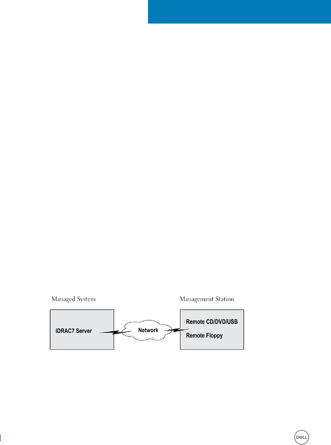
Managing virtual media
Virtual media allows the managed server to access media devices on the management station or ISO CD/DVD images on a network share
as if they were devices on the managed server.
Using the Virtual Media feature, you can:
• Remotely access media connected to a remote system over the network
• Install applications
• Update drivers
• Install an operating system on the managed system
This is a licensed feature for rack and tower servers. It is available by default for blade servers.
The key features are:
• Virtual Media supports virtual optical drives (CD/DVD), oppy drives (including USB-based drives), and USB ash drives.
• You can attach only one oppy, USB ash drive, image, or key and one optical drive on the management station to a managed system.
Supported oppy drives include a oppy image or one available oppy drive. Supported optical drives include a maximum of one
available optical drive or one ISO image le.
The following gure shows a typical Virtual Media setup.
• Virtual oppy media of iDRAC is not accessible from virtual machines.
• Any connected Virtual Media emulates a physical device on the managed system.
• On Windows-based managed systems, the Virtual Media drives are auto-mounted if they are attached and congured with a drive
letter.
• On Linux-based managed systems with some congurations, the Virtual Media drives are not auto-mounted. To manually mount the
drives, use the mount command.
• All the virtual drive access requests from the managed system are directed to the management station across the network.
• Virtual devices appear as two drives on the managed system without the media being installed in the drives.
• You can share the management station CD/DVD drive (read only), but not a USB media, between two managed systems.
• Virtual media requires a minimum available network bandwidth of 128 Kbps.
• If LOM or NIC failover occurs, then the Virtual Media session may be disconnected.
Figure 4. Virtual media setup
Topics:
• Supported drives and devices
•Conguring virtual media
• Accessing virtual media
21
278 Managing virtual media

• Setting boot order through BIOS
• Enabling boot once for virtual media
Supported drives and devices
The following table lists the drives supported through virtual media.
Table 57. Supported drives and devices
Drive Supported Storage Media
Virtual Optical Drives • Legacy 1.44 oppy drive with a 1.44 oppy diskette
• CD-ROM
• DVD
• CD-RW
• Combination drive with CD-ROM media
Virtual oppy drives • CD-ROM/DVD image le in the ISO9660 format
• Floppy image le in the ISO9660 format
USB ash drives • USB CD-ROM drive with CD-ROM media
• USB Key image in the ISO9660 format
Conguring virtual media
Before you congure the Virtual Media settings, make sure that you have congured your Web browser to use Java or ActiveX plug-in.
Conguring virtual media using iDRAC web interface
To congure virtual media settings:
CAUTION: Do not reset iDRAC when running a Virtual Media session. Otherwise, undesirable results may occur, including data
loss.
1 In the iDRAC Web interface, go to Conguration > Virtual Media > Attached Media.
2 Specify the required settings. For more information, see the iDRAC Online Help.
3 Click Apply to save the settings.
Conguring virtual media using RACADM
To congure the virtual media, use the set command with the objects in the iDRAC.VirtualMedia group.
For more information, see the RACADM Command Line Reference Guide for iDRAC available at dell.com/idracmanuals.
Conguring virtual media using iDRAC settings utility
You can attach, detach, or auto-attach virtual media using the iDRAC Settings utility. To do this:
1 In the iDRAC Settings utility, go to Media and USB Port Settings.
The iDRAC Settings Media and USB Port Settings page is displayed.
2 In the Virtual Media section, select Detach, Attach, or Auto attach based on the requirement. For more information about the
options, see iDRAC Settings Utility Online Help.
Managing virtual media 279

3 Click Back, click Finish, and then click Yes.
The Virtual Media settings are congured.
Attached media state and system response
The following table describes the system response based on the Attached Media setting.
Table 58. Attached media state and system response
Attached Media State System Response
Detach Cannot map an image to the system.
Attach Media is mapped even when Client View is closed.
Auto-attach Media is mapped when Client View is opened and unmapped when Client View is closed.
Server settings for viewing virtual devices in virtual media
You must congure the following settings in the management station to allow visibility of empty drives. To do this, in Windows Explorer,
from the Organize menu, click Folder and search options. On the View tab, deselect Hide empty drives in the Computer folder option
and click OK.
Accessing virtual media
You can access Virtual Media with or without using the Virtual Console. Before you access Virtual Media, make sure to congure your Web
browser(s).
Virtual Media and RFS are mutually exclusive. If the RFS connection is active and you attempt to launch the Virtual Media client, the
following error message is displayed: Virtual Media is currently unavailable. A Virtual Media or Remote File Share session is in use.
If the RFS connection is not active and you attempt to launch the Virtual Media client, the client launches successfully. You can then use
the Virtual Media client to map devices and les to the Virtual Media virtual drives.
Launching virtual media using virtual console
Before you launch Virtual Media through the Virtual Console, make sure that:
• Virtual Console is enabled.
• System is congured to not hide empty drives — In Windows Explorer, navigate to Folder Options, clear the Hide empty drives in the
Computer folder option, and click OK.
To access Virtual Media using Virtual Console:
1 In the iDRAC web interface, go to Conguration > Virtual Console.
The Virtual Console page is displayed.
2 Click Launch Virtual Console.
The Virtual Console Viewer is launched.
NOTE: On Linux, Java is the default plug-in type for accessing the Virtual Console. On Windows, open the .jnlp le to launch
the Virtual Console using Java.
3 Click Virtual Media > Connect Virtual Media.
The Virtual Media session is established and the Virtual Media menu displays the list of devices available for mapping.
280 Managing virtual media

NOTE: The Virtual Console Viewer window must remain active while you access the Virtual Media.
Launching virtual media without using virtual console
Before you launch Virtual Media when the Virtual Console is disabled, make sure that
• Virtual Media is in Attach state.
• System is congured to unhide empty drives. To do this, in Windows Explorer, navigate to Folder Options, clear the Hide empty drives
in the Computer folder option, and click OK.
To launch Virtual Media when Virtual Console is disabled:
1 In the iDRAC web Interface, go to Conguration > Virtual Console.
2 Click Launch Virtual Console.
The following message is displayed:
Virtual Console has been disabled. Do you want to continue using Virtual Media redirection?
3 Click OK.
The Virtual Media window is displayed.
4 From the Virtual Media menu, click Map CD/DVD or Map Removable Disk.
For more information, see Mapping virtual drive.
NOTE: The virtual device drive letters on the managed system do not coincide with the physical drive letters on the
management station.
NOTE: The Virtual Media may not function correctly on Windows operating system clients that are congured with Internet
Explorer Enhanced Security. To resolve this issue, see the Microsoft operating system documentation or contact the system
administrator.
NOTE: HTML5 plug-in is not supported for stand-alone virtual media.
Adding virtual media images
You can create a media image of the remote folder and mount it as a USB attached device to the server’s operating system. To add Virtual
Media images:
1 Click Virtual Media > Create Image....
2 In the Source Folder eld, click Browse and browse to the folder or directory to be used as the source for the image le. The image
le is on the management station or the C: drive of the managed system.
3 In the Image File Name eld, the default path to store the created image les (typically the desktop directory) appears. To change this
location, click Browse and navigate to a location.
4 Click Create Image.
The image creation process starts. If the image le location is within the source folder, a warning message is displayed indicating that
the image creation cannot proceed as the image le location within the source folder causes an innite loop. If the image le location is
not within the source folder, then the image creation proceeds.
After the image is created, a success message is displayed.
5 Click Finish.
The image is created.
When a folder is added as an image, a .img le is created on the Desktop of the management station from which this feature is used. If
this .img le is moved or deleted, then the corresponding entry for this folder in the Virtual Media menu does not work. Therefore, it is
recommended not to move or delete the .img le while the image is being used. However, the .img le can be removed after the
relevant entry is rst deselected and then removed using Remove Image to remove the entry.
Managing virtual media 281

Viewing virtual device details
To view the virtual device details, in the Virtual Console Viewer, click Tools > Stats. In the Stats window, the Virtual Media section displays
the mapped virtual devices and the read/write activity for each device. If Virtual Media is connected, this information is displayed. If Virtual
Media is not connected, the “Virtual Media is not connected” message is displayed.
If the Virtual Media is launched without using the Virtual Console, then the Virtual Media section is displayed as a dialog box. It provides
information about the mapped devices.
Resetting USB
To reset the USB device:
1 In the Virtual Console viewer, click Tools > Stats.
The Stats window is displayed.
2 Under Virtual Media, click USB Reset.
A message is displayed warning the user that resetting the USB connection can aect all the input to the target device including
Virtual Media, keyboard, and mouse.
3 Click Yes.
The USB is reset.
NOTE: iDRAC Virtual Media does not terminate even after you log out of iDRAC Web interface session.
Mapping virtual drive
To map the virtual drive:
NOTE: While using ActiveX-based Virtual Media, you must have administrative privileges to map an operating system DVD or a
USB ash drive (that is connected to the management station). To map the drives, launch IE as an administrator or add the
iDRAC IP address to the list of trusted sites.
1 To establish a Virtual Media session, from the Virtual Media menu, click Connect Virtual Media.
For each device available for mapping from the host server, a menu item appears under the Virtual Media menu. The menu item is
named according to the device type such as:
• Map CD/DVD
• Map Removable Disk
• Map Floppy Disk
NOTE: The Map Floppy Disk menu item appears on the list if the Floppy Emulation option is enabled on the Attached Media
page. When Floppy Emulation is enabled, Map Removable Disk is replaced with Map Floppy Disk.
The Map DVD/CD option can be used for ISO les and the Map Removable Disk option can be used for images.
NOTE: You cannot map physical media such USB-based drives, CD, or DVD by using the HTML5 based virtual console.
NOTE: You cannot map USB keys as virtual media disks using Virtual Console/Virtual media over a RDP session.
2 Click the device type that you want to map.
NOTE: The active session displays if a Virtual Media session is currently active from the current Web interface session, from
another Web interface session, or from VMCLI.
3 In the Drive/Image File eld, select the device from the drop-down list.
282 Managing virtual media

The list contains all the available (unmapped) devices that you can map (CD/DVD, Removable Disk, Floppy Drive) and image le types
that you can map (ISO or IMG). The image les are located in the default image le directory (typically the user’s desktop). If the
device is not available in the drop-down list, click Browse to specify the device.
The correct le type for CD/DVD is ISO and for removable disk and oppy disk it is IMG.
If the image is created in the default path (Desktop), when you select Map Removable Disk, the created image is available for
selection in the drop-down menu.
If image is created in a dierent location, when you select Map Removable Disk, the created image is not available for selection in the
drop-down menu. Click Browse to specify the image.
4 Select Read-only to map writable devices as read-only.
For CD/DVD devices, this option is enabled by default and you cannot disable it.
NOTE: The ISO and IMG les map as read-only les if you map these les by using the HTML5 virtual
console.
5 Click Map Device to map the device to the host server.
After the device/le is mapped, the name of its Virtual Media menu item changes to indicate the device name. For example, if the
CD/DVD device is mapped to an image le named foo.iso, then the CD/DVD menu item on the Virtual Media menu is named foo.iso
mapped to CD/DVD. A check mark for that menu item indicates that it is mapped.
Displaying correct virtual drives for mapping
On a Linux-based management station, the Virtual Media Client window may display removable disks and oppy disks that are not part of
the management station. To make sure that the correct virtual drives are available to map, you must enable the port setting for the
connected SATA hard drive. To do this:
1 Reboot the operating system on the management station. During POST, press <F2> to enter System Setup.
2 Go to SATA settings. The port details are displayed.
3 Enable the ports that are actually present and connected to the hard drive.
4 Access the Virtual Media Client window. It displays the correct drives that can be mapped.
Unmapping virtual drive
To unmap the virtual drive:
1 From the Virtual Media menu, do any of the following:
• Click the device that you want to unmap.
• Click Disconnect Virtual Media.
A message appears asking for conrmation.
2 Click Yes.
The check mark for that menu item does not appear indicating that it is not mapped to the host server.
NOTE: After unmapping a USB device attached to vKVM from a client system running the Macintosh operating system, the
unmapped device may be unavailable on the client. Restart the system or manually mount the device on the client system to
view the device.
NOTE: To unmap a virtual DVD drive on Linux OS, unmount the drive and eject it.
Setting boot order through BIOS
Using the System BIOS Settings utility, you can set the managed system to boot from virtual optical drives or virtual oppy drives.
NOTE: Changing Virtual Media while connected may stop the system boot sequence.
Managing virtual media 283

To enable the managed system to boot:
1 Boot the managed system.
2 Press <F2> to enter the System Setup page.
3 Go to System BIOS Settings > Boot Settings > BIOS Boot Settings > Boot Sequence.
In the pop-up window, the virtual optical drives and virtual oppy drives are listed with the standard boot devices.
4 Make sure that the virtual drive is enabled and listed as the rst device with bootable media. If required, follow the on-screen
instructions to modify the boot order.
5 Click OK, navigate back to System BIOS Settings page, and click Finish.
6 Click Yes to save the changes and exit.
The managed system reboots.
The managed system attempts to boot from a bootable device based on the boot order. If the virtual device is connected and a
bootable media is present, the system boots to the virtual device. Otherwise, the system overlooks the device—similar to a physical
device without bootable media.
Enabling boot once for virtual media
You can change the boot order only once when you boot after attaching remote Virtual Media device.
Before you enable the boot once option, make sure that:
• You have Congure User privilege.
• Map the local or virtual drives (CD/DVD, Floppy, or USB ash device) with the bootable media or image using the Virtual Media options
• Virtual Media is in Attached state for the virtual drives to appear in the boot sequence.
To enable the boot once option and boot the managed system from the Virtual Media:
1 In the iDRAC Web interface, go to Overview > Server > Attached Media.
2 Under Virtual Media, select the Enable Boot Once and click Apply.
3 Turn on the managed system and press <F2> during boot.
4 Change the boot sequence to boot from the remote Virtual Media device.
5 Reboot the server.
The managed system boots once from the Virtual Media.
284 Managing virtual media

Installing and using VMCLI utility
The Virtual Media Command Line Interface (VMCLI) utility is an interface that provides virtual media features from the management
station to iDRAC on the managed system. Using this utility you can access virtual media features, including image les and physical drives,
to deploy an operating system on multiple remote systems in a network.
The VMCLI utility supports the following features:
• Manage removable devices or images that are accessible through virtual media.
• Automatically terminate the session when the iDRAC rmware Boot Once option is enabled.
• Secure communications to iDRAC using Secure Sockets Layer (SSL).
• Execute VMCLI commands until:
• The connections automatically terminate.
• An operating system terminates the process.
NOTE: To terminate the process in Windows, use the Task Manager.
Topics:
• Installing VMCLI
• Running VMCLI utility
• VMCLI syntax
Installing VMCLI
The VMCLI utility is included in the Dell Systems Management Tools and Documentation DVD.
To install the VMCLI utility:
1 Insert the Dell Systems Management Tools and Documentation DVD into the management station’s DVD drive.
2 Follow the on-screen instructions to install DRAC tools.
3 After successful install, check install\Dell\SysMgt\rac5 folder to make sure vmcli.exe exists. Similarly, check the respective path for
UNIX.
The VMCLI utility is installed on the system.
Running VMCLI utility
• If the operating system requires specic privileges or group membership, you require similar privileges to run the VMCLI commands.
• On Windows systems, non-administrators must have Power User privileges to run the VMCLI utility.
• On Linux systems, to access iDRAC, run VMCLI utility, and log user commands, non-administrators must prex sudo to the VMCLI
commands. However, to add or edit users in the VMCLI administrators group, use the visudo command.
VMCLI syntax
The VMCLI interface is identical on both Windows and Linux systems. The VMCLI syntax is:
VMCLI [parameter] [operating_system_shell_options]
For example, vmcli -r iDRAC-IP-address:iDRAC-SSL-port
22
Installing and using VMCLI utility 285

The parameter enables VMCLI to connect to the specied server, access iDRAC, and map to the specied virtual media.
NOTE: VMCLI syntax is case-sensitive.
To ensure security, it is recommended to use the following VMCLI parameters:
•vmcli -i — Enables an interactive method of starting VMCLI. It ensures that the user name and password are not visible when
processes are examined by other users.
• vmcli -r <iDRAC-IP-address[:iDRAC-SSL-port]> -S -u <iDRAC-user-name> -p <iDRAC-user-password> -c
{< device-name > | < image-file >} — Indicates whether the iDRAC CA certicate is valid. If the certicate is not valid, a
warning message is displayed when you run this command. However, the command is executed successfully and a VMCLI session is
established. For more information on VMCLI parameters, see the VMCLI Help or the VMCLI Man pages.
VMCLI commands to access virtual media
The following table provides the VMCLI commands required for accessing dierent virtual media.
Table 59. VMCLI commands
Virtual Media Command
Floppy drive vmcli -r [RAC IP or hostname] -u [iDRAC user
name] -p [iDRAC user password] -f [device name]
Bootable oppy or USB key image vmcli -r [iDRAC IP address] [iDRAC user name]
-p [iDRAC password] -f [floppy.img]
CD drive using -f option vmcli -r [iDRAC IP address] -u [iDRAC user
name]
-p [iDRAC password] -f [device name]|[image
file]-f [cdrom - dev
]
Bootable CD/DVD image vmcli -r [iDRAC IP address] -u [iDRAC user
name]
-p [iDRAC password] -c [DVD.img]
If the le is not write-protected, Virtual Media may write to the image le. To make sure that Virtual Media does not write to the media:
•Congure the operating system to write-protect a oppy image le that must not be overwritten.
• Use the write-protection feature of the device.
When virtualizing read-only image les, multiple sessions can use the same image media simultaneously.
When virtualizing physical drives, only one session can access a given physical drive at a time.
VMCLI operating system shell options
VMCLI uses shell options to enable the following operating system features:
• stderr/stdout redirection — Redirects any printed utility output to a le.
For example, using the greater-than character (>) followed by a lename overwrites the specied le with the printed output of the
VMCLI utility.
NOTE: The VMCLI utility does not read from standard input (stdin). Hence, stdin redirection is not required.
• Background execution — By default, the VMCLI utility runs in the foreground. Use the operating system's command shell features for
the utility to run in the background.
286 Installing and using VMCLI utility

For example, under a Linux operating system, the ampersand character (&) following the command causes the program to be spawned
as a new background process. This technique is useful in script programs, as it allows the script to proceed after a new process is
started for the VMCLI command (otherwise, the script blocks until the VMCLI program is terminated).
When multiple VMCLI sessions are started, use the operating system-specic facilities for listing and terminating processes.
Installing and using VMCLI utility 287

Managing vFlash SD card
The vFlash SD card is a Secure Digital (SD) card that can be ordered and installed from the factory. You can use a card with a maximum of
16 GB capacity. After you insert the card, you must enable vFlash functionality to create and manage partitions. vFlash is a licensed feature.
NOTE: There is no limitation of the size of SD card, you can open and replace the factory installed SD card with a higher capacity
SD card. Since vFlash uses FAT32 le system, le size is limited to 4GB.
If the card is not available in the system's vFlash SD card slot, the following error message is displayed in the iDRAC Web interface at
Overview > Server > vFlash:
SD card not detected. Please insert an SD card of size 256MB or greater.
NOTE: Make sure that you only insert a vFlash compatible SD card in the iDRAC vFlash card slot. If you insert a non-compatible
SD card, the following error message is displayed when you initialize the card:
An error has occurred while initializing SD card.
The key features are:
• Provides storage space and emulates USB device (s).
• Create up to 16 partitions. These partitions, when attached, are exposed to the system as a Floppy drive, Hard Disk drive, or a CD/DVD
drive depending on the selected emulation mode.
• Create partitions from supported le system types. Supports .img format for oppy, .iso format for CD/DVD, and both .iso and .img
formats for Hard Disk emulation types.
• Create bootable USB device(s).
• Boot once to an emulated USB device.
NOTE: It is possible that a vFlash license may expire during a vFlash operation. If it happens, the on-going vFlash operations
complete normally.
NOTE: If FIPS mode is enabled, you cannot perform any vFlash actions.
Topics:
•Conguring vFlash SD card
• Managing vFlash partitions
Conguring vFlash SD card
Before conguring vFlash, make sure that the vFlash SD card is installed on the system. For information on how to install and remove the
card from your system, see the system's Hardware Owner’s Manual at dell.com/support/manuals.
NOTE: You must have Access Virtual Media privilege to enable or disable vFlash functionality, and initialize the card.
Viewing vFlash SD card properties
After vFlash functionality is enabled, you can view the SD card properties using iDRAC Web interface or RACADM.
23
288 Managing vFlash SD card

Viewing vFlash SD card properties using web interface
To view the vFlash SD card properties, in the iDRAC Web interface, go to Conguration > System Settings > Hardware Settings >
vFlash. The Card Properties page is displayed. For information about the displayed properties, see the iDRAC Online Help.
Viewing vFlash SD card properties using RACADM
To view the vFlash SD card properties using RACADM, use the get command with the following objects:
•iDRAC.vashsd.AvailableSize
•iDRAC.vashsd.Health
•iDRAC.vashsd.Licensed
•iDRAC.vashsd.Size
•iDRAC.vashsd.WriteProtect
For more information about these objects, see the iDRAC RACADM Command Line Interface Reference Guide available at dell.com/
idracmanuals.
Viewing vFlash SD card properties using iDRAC settings utility
To view the vFlash SD card properties, in the iDRAC Settings Utility, go to Media and USB Port Settings. The Media and USB Port
Settings page displays the properties. For information about the displayed properties, see the iDRAC Settings Utility Online Help.
Enabling or disabling vFlash functionality
You must enable the vFlash functionality to perform partition management.
Enabling or disabling vFlash functionality using web interface
To enable or disable the vFlash functionality:
1 In the iDRAC web interface, go to Conguration > System Settings > Hardware Settings > vFlash.
The SD Card Properties page is displayed.
2 Select or clear the vFLASH Enabled option to enable or disable the vFlash functionality. If any vFlash partition is attached, you cannot
disable vFlash and an error message is displayed.
NOTE: If vFlash functionality is disabled, SD card properties are not displayed.
3 Click Apply. The vFlash functionality is enabled or disabled based on the selection.
Enabling or disabling vFlash functionality using RACADM
To enable or disable the vFlash functionality using RACADM:
racadm set iDRAC.vflashsd.Enable [n]
n=0 Disabled
n=1 Enabled
NOTE: The RACADM command functions only if a vFlash SD card is present. If a card is not present, the following message is
displayed:
ERROR: SD Card not present
.
Managing vFlash SD card 289

Enabling or disabling vFlash functionality using iDRAC settings utility
To enable or disable the vFlash functionality:
1 In the iDRAC Settings utility, go to Media and USB Port Settings.
The iDRAC Settings . Media and USB Port Settings page is displayed.
2 In the vFlash Media section, select Enabled to enable vFlash functionality or select Disabled to disable the vFlash functionality.
3 Click Back, click Finish, and then click Yes.
The vFlash functionality is enabled or disabled based on the selection.
Initializing vFlash SD card
The initialize operation reformats the SD card and congures the initial vFlash system information on the card.
NOTE: If the SD card is write-protected, then the Initialize option is disabled.
Initializing vFlash SD card using web interface
To initialize the vFlash SD card:
1 In the iDRAC Web interface, go to Conguration > System Settings > Hardware Settings > vFlash.
The SD Card Properties page is displayed.
2 Enable vFLASH and click Initialize.
All existing contents are removed and the card is reformatted with the new vFlash system information.
If any vFlash partition is attached, the initialize operation fails and an error message is displayed.
Initializing vFlash SD card using RACADM
To initialize the vFlash SD card using RACADM:
racadm set iDRAC.vflashsd.Initialized 1
All existing partitions are deleted and the card is reformatted.
For more information, see the iDRAC RACADM Command Line Interface Reference Guide available at dell.com/idracmanuals.
Initializing vFlash SD card using iDRAC settings utility
To initialize the vFlash SD card using iDRAC Settings utility:
1 In the iDRAC Settings utility, go to Media and USB Port Settings.
The iDRAC Settings . Media and USB Port Settings page is displayed.
2 Click Initialize vFlash.
3 Click Yes. The initialization operation starts.
4 Click Back and navigate to the same iDRAC Settings . Media and USB Port Settings page to view the successful message.
All existing contents are removed and the card is reformatted with the new vFlash system information.
290 Managing vFlash SD card

Getting the last status using RACADM
To get the status of the last initialize command sent to the vFlash SD card:
1 Open a telnet, SSH, or Serial console to the system and log in.
2 Enter the command: racadm vFlashsd status
The status of commands sent to the SD card is displayed.
3 To get the last status of all the vash partitions, use the command:racadm vflashpartition status -a
4 To get the last status of a particular partition, use command:racadm vflashpartition status -i (index)
NOTE: If iDRAC is reset, the status of the last partition operation is lost.
Managing vFlash partitions
You can perform the following using the iDRAC Web interface or RACADM:
NOTE: An administrator can perform all operations on the vFlash partitions. Else, you must have Access Virtual Media privilege
to create, delete, format, attach, detach, or copy the contents for the partition.
•Creating an empty partition
•Creating a partition using an image le
•Formatting a partition
•Viewing available partitions
•Modifying a partition
•Attaching or detaching partitions
•Deleting existing partitions
•Downloading partition contents
•Booting to a partition
NOTE: If you click any option on the vFlash pages when an application such as WSMan, iDRAC Settings utility, or RACADM is
using vFlash, or if you navigate to some other page in the GUI, iDRAC may display the message: vFlash is currently in
use by another process. Try again after some time.
vFlash is capable of performing fast partition creation when there is no other on-going vFlash operation such as formatting, attaching
partitions, and so on. Therefore, it is recommended to rst create all partitions before performing other individual partition operations.
Creating an empty partition
An empty partition, when attached to the system, is similar to an empty USB ash drive. You can create empty partitions on a vFlash SD
card. You can create partitions of type Floppy or Hard Disk. The partition type CD is supported only while creating partitions using images.
Before creating an empty partition, make sure that:
• You have Access Virtual Media privilege.
• The card is initialized.
• The card is not write-protected.
• An initialize operation is not being performed on the card.
Managing vFlash SD card 291

Creating an empty partition using the web interface
To create an empty vFlash partition:
1 In iDRAC Web interface, go to Conguration > Systems Settings > Hardware Settings > vFlash > Create Empty Partition.
The Create Empty Partition page is displayed.
2 Specify the required information and click Apply. For information about the options, see the iDRAC Online Help.
A new unformatted empty partition is created that is read-only by default. A page indicating the progress percentage is displayed. An
error message is displayed if:
• The card is write-protected.
• The label name matches the label of an existing partition.
• A non-integer value is entered for the partition size, the value exceeds the available space on the card, or the partition size is
greater than 4 GB.
• An initialize operation is being performed on the card.
Creating an empty partition using RACADM
To create an empty partition:
1 Log in to the system using telnet, SSH, or Serial console.
2 Enter the command:
racadm vflashpartition create -i 1 -o drive1 -t empty -e HDD -f fat16 -s [n]
where [n] is the partition size.
By default, an empty partition is created as read-write.
Creating a partition using an image le
You can create a new partition on the vFlash SD card using an image le (available in the .img or .iso format.) The partitions are of
emulation types: Floppy (.img), Hard Disk (.img), or CD (.iso). The created partition size is equal to the image le size.
Before creating a partition from an image le, make sure that:
• You have Access Virtual Media privilege.
• The card is initialized.
• The card is not write-protected.
• An initialize operation is not being performed on the card.
• The image type and the emulation type match.
NOTE: The uploaded image and the emulation type must match. There are issues when iDRAC emulates a device with
incorrect image type. For example, if the partition is created using an ISO image and the emulation type is specied as Hard
Disk, then the BIOS cannot boot from this image.
• Image le size is less than or equal to the available space on the card.
• Image le size is less than or equal to 4 GB as the maximum partition size supported is 4 GB. However, while creating a partition using a
Web browser, the image le size must be less than 2 GB.
NOTE: The vFlash partition is an image le on a FAT32 le system. Thus, the image le has the 4 GB limitation.
NOTE: Installation of a full OS is not supported.
292 Managing vFlash SD card

Creating a partition using an image le using web interface
To create a vFlash partition from an image le:
1 In iDRAC Web interface, go to Conguration > System Settings > Hardware Settings > vFlash > Create From Image.
The Create Partition from Image File page is displayed.
2 Enter the required information and click Apply. For information about the options, see the iDRAC Online Help.
A new partition is created. For CD emulation type, a read-only partition is created. For Floppy or Hard Disk emulation type, a read-write
partition is created. An error message is displayed if:
• The card is write-protected
• The label name matches the label of an existing partition.
• The size of the image le is greater than 4 GB or exceeds the available space on the card.
• The image le does not exist or the image le extension is neither .img nor .iso.
• An initialize operation is already being performed on the card.
Creating a partition from an image le using RACADM
To create a partition from an image le using RACADM:
1 Log in to the system using telnet, SSH, or Serial console.
2 Enter the command
racadm vflashpartition create –i 1 –o drive1 –e HDD –t image –l //myserver/sharedfolder/
foo.iso –u root –p mypassword
By default, the created partition is read-only. This command is case sensitive for the image le name extension. If the le name
extension is in upper case, for example FOO.ISO instead of FOO.iso, then the command returns a syntax error.
NOTE: This feature is not supported in local RACADM.
NOTE: Creating vFlash partition from an image le located on the CFS or NFS IPv6 enabled network share is not
supported.
Formatting a partition
You can format an existing partition on the vFlash SD card based on the type of le system. The supported le system types are EXT2,
EXT3, FAT16, and FAT32. You can only format partitions of type Hard Disk or Floppy, and not CD. You cannot format read-only partitions.
Before creating a partition from an image le, ensure that:
• You have Access Virtual Media privilege.
• The card is initialized.
• The card is not write-protected.
• An initialize operation is not being performed on the card.
To format vFlash partition:
1 In iDRAC Web interface, go to Conguration > System Settings > Hardware Settings > vFlash > Format.
The Format Partition page is displayed.
2 Enter the required information and click Apply.
For information about the options, see the iDRAC Online Help.
A warning message indicating that all the data on the partition will be erased is displayed.
3 Click OK.
Managing vFlash SD card 293

The selected partition is formatted to the specied le system type. An error message is displayed if:
• The card is write-protected.
• An initialize operation is already being performed on the card.
Viewing available partitions
Make sure that the vFlash functionality is enabled to view the list of available partitions.
Viewing available partitions using web interface
To view the available vFlash partitions, in the iDRAC Web interface, go to Conguration > System Settings > Hardware Settings > vFlash
> Manage. The Manage Partitions page is displayed listing the available partitions and related information for each partition. For
information on the partitions, see the iDRAC Online Help.
Viewing available partitions using RACADM
To view the available partitions and their properties using RACADM:
1 Open a Telnet, SSH, or Serial console to the system and log in.
2 Enter the following commands:
• To list all existing partitions and its properties:
racadm vflashpartition list
• To get the status of operation on partition 1:
racadm vflashpartition status -i 1
• To get the status of all existing partitions:
racadm vflashpartition status -a
NOTE: The -a option is valid only with the status action.
Modifying a partition
You can change a read-only partition to read-write or vice-versa. Before modifying the partition, make sure that:
• The vFlash functionality is enabled.
• You have Access Virtual Media privileges.
NOTE: By default, a read-only partition is created.
Modifying a partition using web interface
To modify a partition:
1 In the iDRAC Web interface, go to Conguration > System Settings > Hardware Settings > vFlash > Manage.
The Manage Partitions page is displayed.
2 In the Read-Only column:
• Select the checkbox for the partition(s) and click Apply to change to read-only.
• Clear the checkbox for the partition(s) and click Apply to change to read-write.
The partitions are changed to read-only or read-write, based on the selections.
294 Managing vFlash SD card

NOTE: If the partition is of type CD, the state is read-only. You cannot change the state to read-write. If the partition is
attached, the check box is grayed-out.
Modifying a partition using RACADM
To view the available partitions and their properties on the card:
1 Log in to the system using telnet, SSH, or Serial console.
2 Use one of the following:
• Using set command to change the read-write state of the partition:
• To change a read-only partition to read-write:
racadm set iDRAC.vflashpartition.<index>.AccessType 1
• To change a read-write partition to read-only:
racadm set iDRAC.vflashpartition.<index>.AccessType 0
• Using set command to specify the Emulation type:
racadm set iDRAC.vflashpartition.<index>.EmulationType <HDD, Floppy, or CD-DVD>
Attaching or detaching partitions
When you attach one or more partitions, they are visible to the operating system and BIOS as USB mass storage devices. When you attach
multiple partitions, based on the assigned index, they are listed in an ascending order in the operating system and the BIOS boot order
menu.
If you detach a partition, it is not visible in the operating system and the BIOS boot order menu.
When you attach or detach a partition, the USB bus in the managed system is reset. This aects applications that are using vFlash and
disconnects the iDRAC Virtual Media sessions.
Before attaching or detaching a partition, make sure that:
• The vFlash functionality is enabled.
• An initialize operation is not already being performed on the card.
• You have Access Virtual Media privileges.
Attaching or detaching partitions using web interface
To attach or detach partitions:
1 In the iDRAC Web interface, go to Conguration > System Settings > Hardware Settings > vFlash > Manage.
The Manage Partitions page is displayed.
2 In the Attached column:
• Select the checkbox for the partition(s) and click Apply to attach the partition(s).
• Clear the checkbox for the partition(s) and click Apply to detach the partition(s).
The partitions are attached or detached, based on the selections.
Attaching or detaching partitions using RACADM
To attach or detach partitions:
1 Log in to the system using telnet, SSH, or Serial console.
2 Use the following commands:
Managing vFlash SD card 295

• To attach a partition:
racadm set iDRAC.vflashpartition.<index>.AttachState 1
• To detach a partition:
racadm set iDRAC.vflashpartition.<index>.AttachState 0
Operating system behavior for attached partitions
For Windows and Linux operating systems:
• The operating system controls and assigns the drive letters to the attached partitions.
• Read-only partitions are read-only drives in the operating system.
• The operating system must support the le system of an attached partition. Else, you cannot read or modify the contents of the
partition from the operating system. For example, in a Windows environment the operating system cannot read the partition type EXT2
which is native to Linux. Also, in a Linux environment the operating system cannot read the partition type NTFS which is native to
Windows.
• The vFlash partition label is dierent from the volume name of the le system on the emulated USB device. You can change the volume
name of the emulated USB device from the operating system. However, it does not change the partition label name stored in iDRAC.
Deleting existing partitions
Before deleting existing partition(s), make sure that:
• The vFlash functionality is enabled.
• The card is not write-protected.
• The partition is not attached.
• An initialize operation is not being performed on the card.
Deleting existing partitions using web interface
To delete an existing partition:
1 In the iDRAC Web interface, go to Conguration > System Settings > Hardware Settings > vFlash > Manage.
The Manage Partitions page is displayed.
2 In the Delete column, click the delete icon for the partition that you want to delete.
A message is displayed indicating that this action permanently deletes the partition.
3 Click OK.
The partition is deleted.
Deleting existing partitions using RACADM
To delete partitions:
1 Open a telnet, SSH, or Serial console to the system and log in.
2 Enter the following commands:
• To delete a partition:
racadm vflashpartition delete -i 1
• To delete all partitions, re-initialize the vFlash SD card.
Downloading partition contents
You can download the contents of a vFlash partition in the .img or .iso format to the:
296 Managing vFlash SD card

• Managed system (where iDRAC is operated from)
• Network location mapped to a management station.
Before downloading the partition contents, make sure that:
• You have Access Virtual Media privileges.
• The vFlash functionality is enabled.
• An initialize operation is not being performed on the card.
• For a read-write partition, it must not be attached.
To download the contents of the vFlash partition:
1 In the iDRAC Web interface, go to Conguration > System Settings > Hardware Settings > vFlash > Download.
The Download Partition page is displayed.
2 From the Label drop-down menu, select a partition that you want to download and click Download.
NOTE: All existing partitions (except attached partitions) are displayed in the list. The rst partition is selected by
default.
3 Specify the location to save the le.
The contents of the selected partition are downloaded to the specied location.
NOTE: If only the folder location is specied, then the partition label is used as the le name, along with the extension .iso
for CD and Hard Disk type partitions, and .img for Floppy and Hard Disk type partitions.
Booting to a partition
You can set an attached vFlash partition as the boot device for the next boot operation.
Before booting a partition, make sure that:
• The vFlash partition contains a bootable image (in the .img or .iso format) to boot from the device.
• The vFlash functionality is enabled.
• You have Access Virtual Media privileges.
Booting to a partition using web interface
To set the vFlash partition as a rst boot device, see Booting to a partition using web interface.
NOTE: If the attached vFlash partition(s) are not listed in the First Boot Device drop-down menu, make sure that the BIOS is
updated to the latest version.
Booting to a partition using RACADM
To set a vFlash partition as the rst boot device, use the iDRAC.ServerBoot object.
For more information, see the iDRAC RACADM Command Line Interface Reference Guide available at dell.com/idracmanuals.
NOTE: When you run this command, the vFlash partition label is automatically set to boot once
(iDRAC.ServerBoot.BootOnce is set to 1.) Boot once boots the device to the partition only once and does not keep it
persistently rst in the boot order.
Managing vFlash SD card 297

Using SMCLP
The Server Management Command Line Protocol (SMCLP) specication enables CLI-based systems management. It denes a protocol for
management commands transmitted over standard character oriented streams. This protocol accesses a Common Information Model
Object Manager (CIMOM) using a human-oriented command set. The SMCLP is a sub-component of the Distributed Management Task
Force (DMTF) SMASH initiative to streamline systems management across multiple platforms. The SMCLP specication, along with the
Managed Element Addressing Specication and numerous proles to SMCLP mapping specications, describes the standard verbs and
targets for various management task executions.
NOTE: It is assumed that you are familiar with the Systems Management Architecture for Server Hardware (SMASH) Initiative
and the Server Management Working Group (SMWG) SMCLP specications.
The SM-CLP is a subcomponent of the Distributed Management Task Force (DMTF) SMASH initiative to streamline server management
across multiple platforms. The SM-CLP specication, along with the Managed Element Addressing Specication and numerous proles to
SM-CLP mapping specications, describes the standard verbs and targets for various management task executions.
The SMCLP is hosted from the iDRAC controller rmware and supports Telnet, SSH, and serial-based interfaces. The iDRAC SMCLP
interface is based on the SMCLP Specication Version 1.0 provided by the DMTF organization.
NOTE: Information about the proles, extensions, and MOFs are available at delltechcenter.com and all DMTF information is
available at dmtf.org/standards/proles/.
SM-CLP commands implement a subset of the local RACADM commands. The commands are useful for scripting since you can execute
these commands from a management station command line. You can retrieve the output of commands in well-dened formats, including
XML, facilitating scripting and integration with existing reporting and management tools.
Topics:
• System management capabilities using SMCLP
• Running SMCLP commands
• iDRAC SMCLP syntax
• Navigating the map address space
• Using show verb
• Usage examples
System management capabilities using SMCLP
iDRAC SMCLP enables you to:
• Manage Server Power — Turn on, shut down, or reboot the system
• Manage System Event Log (SEL) — Display or clear the SEL records
• View iDRAC user accounts
• View system properties
Running SMCLP commands
You can run the SMCLP commands using SSH or Telnet interface. Open an SSH or Telnet interface and log in to iDRAC as an administrator.
The SMCLP prompt (admin ->)is displayed.
SMCLP prompts:
24
298 Using SMCLP

• yx1x blade servers use -$.
• yx1x rack and tower servers use admin->.
• yx2x blade, rack, and tower servers use admin->.
where, y is an alpha-numeric character such as M (for blade servers), R (for rack servers), and T (for tower servers) and x is a number.
This indicates the generation of Dell PowerEdge servers.
NOTE: Scripts using -$ can use these for yx1x systems, but starting with yx2x systems one script with admin-> can be used for
blade, rack, and tower servers.
iDRAC SMCLP syntax
The iDRAC SMCLP uses the concept of verbs and targets to provide systems management capabilities through the CLI. The verb indicates
the operation to perform, and the target determines the entity (or object) that runs the operation.
The SMCLP command line syntax:
<verb> [<options>] [<target>] [<properties>]
The following table provides the verbs and its denitions.
Table 60. SMCLP verbs
Verb Denition
cd Navigates through the MAP using the shell
set Sets a property to a specic value
help Displays help for a specic target
reset Resets the target
show Displays the target properties, verbs, and subtargets
start Turns on a target
stop Shuts down a target
exit Exits from the SMCLP shell session
version Displays the version attributes of a target
load Moves a binary image to a specied target address from a URL
The following table provides a list of targets.
Table 61. SMCLP targets
Target Denitions
admin1 admin domain
admin1/profiles1 Registered proles in iDRAC
admin1/hdwr1 Hardware
Using SMCLP 299

Target Denitions
admin1/system1 Managed system target
admin1/system1/capabilities1 Managed system SMASH collection capabilities
admin1/system1/capabilities1/elecap1 Managed system target capabilities
admin1/system1/logs1 Record Log collections target
admin1/system1/logs1/log1 System Event Log (SEL) record entry
admin1/system1/logs1/log1/record* An individual SEL record instance on the managed system
admin1/system1/settings1 Managed system SMASH collection settings
admin1/system1/capacities1 Managed system capacities SMASH collection
admin1/system1/consoles1 Managed system consoles SMASH collection
admin1/system1/sp1 Service Processor
admin1/system1/sp1/timesvc1 Service Processor time service
admin1/system1/sp1/capabilities1 Service processor capabilities SMASH collection
admin1/system1/sp1/capabilities1/clpcap1 CLP service capabilities
admin1/system1/sp1/capabilities1/pwrmgtcap1 Power state management service capabilities on the system
admin1/system1/sp1/capabilities1/acctmgtcap* Account management service capabilities
admin1/system1/sp1/capabilities1/rolemgtcap* Local Role Based Management capabilities
admin1/system1/sp1/capabilities1/elecap1 Authentication capabilities
admin1/system1/sp1/settings1 Service Processor settings collection
admin1/system1/sp1/settings1/clpsetting1 CLP service settings data
admin1/system1/sp1/clpsvc1 CLP service protocol service
admin1/system1/sp1/clpsvc1/clpendpt* CLP service protocol endpoint
admin1/system1/sp1/clpsvc1/tcpendpt* CLP service protocol TCP endpoint
admin1/system1/sp1/jobq1 CLP service protocol job queue
admin1/system1/sp1/jobq1/job* CLP service protocol job
admin1/system1/sp1/pwrmgtsvc1 Power state management service
admin1/system1/sp1/account1-16 Local user account
admin1/sysetm1/sp1/account1-16/identity1 Local user identity account
admin1/sysetm1/sp1/account1-16/identity2 IPMI identity (LAN) account
300 Using SMCLP

Target Denitions
admin1/sysetm1/sp1/account1-16/identity3 IPMI identity (Serial) account
admin1/sysetm1/sp1/account1-16/identity4 CLP identity account
admin1/system1/sp1/acctsvc2 IPMI account management service
admin1/system1/sp1/acctsvc3 CLP account management service
admin1/system1/sp1/rolesvc1 Local Role Base Authorization (RBA) service
admin1/system1/sp1/rolesvc1/Role1-16 Local role
admin1/system1/sp1/rolesvc1/Role1-16/privilege1 Local role privilege
admin1/system1/sp1/rolesvc2 IPMI RBA service
admin1/system1/sp1/rolesvc2/Role1-3 IPMI role
admin1/system1/sp1/rolesvc2/Role4 IPMI Serial Over LAN (SOL) role
admin1/system1/sp1/rolesvc3 CLP RBA Service
admin1/system1/sp1/rolesvc3/Role1-3 CLP role
admin1/system1/sp1/rolesvc3/Role1-3/privilege1 CLP role privilege
Navigating the map address space
Objects that can be managed with SM-CLP are represented by targets arranged in a hierarchical space called the Manageability Access
Point (MAP) address space. An address path species the path from the root of the address space to an object in the address space.
The root target is represented by a slash (/) or a backslash (\). It is the default starting point when you log in to iDRAC. Navigate down
from the root using the cd verb.
NOTE: The slash (/) and backslash (\) are interchangeable in SM-CLP address paths. However, a backslash at the end of a
command line continues the command on the next line and is ignored when the command is parsed.
For example to navigate to the third record in the System Event Log (SEL), enter the following command:
->cd /admin1/system1/logs1/log1/record3
Enter the cd verb with no target to nd your current location in the address space. The .. and . abbreviations work as they do in
Windows and Linux: .. refers to the parent level and . refers to the current level.
Using show verb
To learn more about a target use the show verb. This verb displays the target’s properties, sub-targets, associations, and a list of the SM-
CLP verbs that are allowed at that location.
Using the -display option
The show –display option allows you to limit the output of the command to one or more of properties, targets, associations, and verbs.
For example, to display just the properties and targets at the current location, use the following command:
Using SMCLP 301

show -display properties,targets
To list only certain properties, qualify them, as in the following command:
show –d properties=(userid,name) /admin1/system1/sp1/account1
If you only want to show one property, you can omit the parentheses.
Using the -level option
The show -level option executes show over additional levels beneath the specied target. To see all targets and properties in the
address space, use the -l all option.
Using the -output option
The -output option species one of four formats for the output of SM-CLP verbs: text, clpcsv, keyword, and clpxml.
The default format is text, and is the most readable output. The clpcsv format is a comma-separated values format suitable for loading into
a spreadsheet program. The keyword format outputs information as a list of keyword=value pairs one per line. The clpxml format is an
XML document containing a response XML element. The DMTF has specied the clpcsv and clpxml formats and their specications can
be found on the DMTF website at dmtf.org.
The following example shows how to output the contents of the SEL in XML:
show -l all -output format=clpxml /admin1/system1/logs1/log1
Usage examples
This section provides use case scenarios for SMCLP:
•Server power management
•SEL management
•Map target navigation
Server power management
The following examples show how to use SMCLP to perform power management operations on a managed system.
Type the following commands at the SMCLP command prompt:
• To switch o the server:
stop /system1
The following message is displayed:
system1 has been stopped successfully
• To switch on the server:
start /system1
The following message is displayed:
system1 has been started successfully
302 Using SMCLP

• To reboot the server:
reset /system1
The following message is displayed:
system1 has been reset successfully
SEL management
The following examples show how to use the SMCLP to perform SEL-related operations on the managed system. Type the following
commands at the SMCLP command prompt:
• To view the SEL:
show/system1/logs1/log1
The following output is displayed:
/system1/logs1/log1
Targets:
Record1
Record2
Record3
Record4
Record5
Properties:
InstanceID = IPMI:BMC1 SEL Log
MaxNumberOfRecords = 512
CurrentNumberOfRecords = 5
Name = IPMI SEL
EnabledState = 2
OperationalState = 2
HealthState = 2
Caption = IPMI SEL
Description = IPMI SEL
ElementName = IPMI SEL
Commands:
cd
show
Using SMCLP 303

help
exit
version
• To view the SEL record:
show/system1/logs1/log1
The following output is displayed:
/system1/logs1/log1/record4
Properties:
LogCreationClassName= CIM_RecordLog
CreationClassName= CIM_LogRecord
LogName= IPMI SEL
RecordID= 1
MessageTimeStamp= 20050620100512.000000-000
Description= FAN 7 RPM: fan sensor, detected a failure
ElementName= IPMI SEL Record
Commands:
cd
show
help
exit
version
Map target navigation
The following examples show how to use the cd verb to navigate the MAP. In all examples, the initial default target is assumed to be /.
Type the following commands at the SMCLP command prompt:
• To navigate to the system target and reboot:
cd system1 reset The current default target is /.
• To navigate to the SEL target and display the log records:
cd system1
cd logs1/log1
show
• To display current target:
type cd .
• To move up one level:
304 Using SMCLP

type cd ..
• To exit:
exit
Using SMCLP 305

Deploying operating systems
You can use any of the following utilities to deploy operating systems to managed systems:
• Remote File Share
• Virtual Media Console
Topics:
• Deploying operating system using remote le share
• Deploying operating system using virtual media
• Deploying embedded operating system on SD card
Deploying operating system using remote le share
Before you deploy the operating system using Remote File Share (RFS), make sure that:
•Congure User and Access Virtual Media privileges for iDRAC are enabled for the user.
• Network share contains drivers and operating system bootable image le, in an industry standard format such as .img or .iso.
NOTE: While creating the image le, follow standard network-based installation procedures, and mark the deployment image
as read-only to make sure that each target system boots and runs the same deployment procedure.
To deploy an operating system using RFS:
1 Using Remote File Share (RFS), mount the ISO or IMG image le to the managed system through NFS or CIFS.
2 Go to Conguration > System Settings > Hardware Settings > First Boot Device.
3 Set the boot order in the First Boot Device drop-down list to select a virtual media such as oppy, CD, DVD, or ISO.
4 Select the Boot Once option to enable the managed system to reboot using the image le for the next instance only.
5 Click Apply.
6 Reboot the managed system and follow the on-screen instructions to complete the deployment.
Managing remote le share
Using Remote File Share (RFS) feature, you can set an ISO or IMG image le on a network share and make it available to the managed
server’s operating system as a virtual drive by mounting it as a CD or DVD using NFS or CIFS. RFS is a licensed feature.
Remote le share supports only .img and .iso image le formats. A .img le is redirected as a virtual oppy and a .iso le is redirected as a
virtual CDROM.
You must have Virtual Media privileges to perform an RFS mounting.
RFS and Virtual Media features are mutually exclusive.
• If the Virtual Media client is not active, and you attempt to establish an RFS connection, the connection is established and the remote
image is available to the host operating system.
• If the Virtual Media client is active, and you attempt to establish an RFS connection, the following error message is displayed:
25
306 Deploying operating systems

Virtual Media is detached or redirected for the selected virtual drive.
The connection status for RFS is available in iDRAC log. Once connected, an RFS-mounted virtual drive does not disconnect even if you
log out from iDRAC. The RFS connection is closed if iDRAC is reset or the network connection is dropped. The Web interface and
command-line options are also available in CMC and iDRAC to close the RFS connection. The RFS connection from CMC always overrides
an existing RFS mount in iDRAC.
NOTE:
• CIFS supports both IPv4 and IPv6 addresses and NFS supports only IPv4 address.
• If you are using CIFS and are part of an Active Directory domain, enter the domain name with the IP address in the image le path.
• If you want to access a le from an NFS share, congure the following share permissions. These permissions are required because
iDRAC interfaces run in non-root mode.
• Linux: Ensure that the share permissions are set to at least Read for the Others account.
• Windows: Go to the Security tab of the share properties and add Everyone to Groups or user names eld with Read &
execute privilege.
,
• If ESXi is running on the managed system and if you mount a oppy image (.img) using RFS, the connected oppy image is not
available to the ESXi operating system.
• iDRAC vFlash feature and RFS are not related.
Conguring remote le share using web interface
To enable remote le sharing:
1 In iDRAC Web interface, go to Conguration > Virtual Media > Attached Media.
The Attached Media page is displayed.
2 Under Attached Media, select Attach or Auto Attach.
3 Under Remote File Share, specify the image le path, domain name, user name, and password. For information about the elds, see
the iDRAC Online Help.
Example for image le path:
• CIFS — //<IP to connect for CIFS le system>/<le path>/<image name>
• NFS —< IP to connect for NFS le system>/<le path>/<image name>
NOTE: To avoid I/O errors when using CIFS shares hosted on Windows 7 systems, modify the following registry keys:
• Set HKLM\SYSTEM\CurrentControlSet\Control\Session Manager\Memory Management\LargeSystemCache to 1
• Set HKLM\SYSTEM\CurrentControlSet\Services\LanmanServer\Parameters\Size to 3
NOTE: Both '/' or '\' characters can be used for the le
path.
CIFS supports both IPv4 and IPv6 addresses but NFS supports only IPv4 address.
If you are using NFS share, make sure that you provide the exact <le path> and <image name> as it is case-sensitive.
NOTE: For information on recommended characters for user names and passwords, see Recommended characters in user
names and passwords.
NOTE: The characters allowed in user names and passwords for network shares are determined by the network-share type.
iDRAC supports valid characters for network share credentials as dened by the share type, except <, >, and , (comma).
4 Click Apply and then click Connect.
After the connection is established, the Connection Status displays Connected.
Deploying operating systems 307

NOTE: Even if you have congured remote le sharing, the Web interface does not display user credential information due
to security reasons.
For Linux distributions, this feature may require a manual mount command when operating at runlevel init 3. The syntax for the
command is:
mount /dev/OS_specific_device / user_defined_mount_point
where, user_defined_mount_point is any directory you choose to use for the mount similar to any mount command.
For RHEL, the CD device (.iso virtual device) is /dev/scd0 and oppy device (.img virtual device) is /dev/sdc.
For SLES, the CD device is /dev/sr0 and the oppy device is /dev/sdc. To make sure that the correct device is used (for either
SLES or RHEL), when you connect the virtual device, on the Linux OS you must immediately run the command:
tail /var/log/messages | grep SCSI
This displays the text that identies the device (example, SCSI device sdc). This procedure also applies to Virtual Media when you are
using Linux distributions in runlevel init 3. By default, the virtual media is not auto-mounted in init 3.
Conguring remote le share using RACADM
To congure remote le share using RACADM, use:
racadm remoteimage
racadm remoteimage <options>
Options are:
–c : connect image
–d : disconnect image
–u <username>: username to access the network share
–p <password>: password to access the network share
–l <image_location>: image location on the network share; use double quotes around the location. See examples for image le path in
Conguring Remote File Share Using Web Interface section
–s : display current status
NOTE: All characters including alphanumeric and special characters are allowed as part of user name, password, and
image_location except the following characters: ’ (single quote), “(double quote), ,(comma), < (less than), and > (greater than).
NOTE: To avoid I/O errors when using CIFS shares hosted on Windows 7 systems, modify the following registry keys:
• Set HKLM\SYSTEM\CurrentControlSet\Control\Session Manager\Memory Management\LargeSystemCache to 1
• Set HKLM\SYSTEM\CurrentControlSet\Services\LanmanServer\Parameters\Size to 3
Deploying operating system using virtual media
Before you deploy the operating system using Virtual Media, make sure that:
• Virtual Media is in Attached state for the virtual drives to appear in the boot sequence.
• If Virtual Media is in Auto Attached mode, the Virtual Media application must be launched before booting the system.
• Network share contains drivers and operating system bootable image le, in an industry standard format such as .img or .iso.
308 Deploying operating systems

To deploy an operating system using Virtual Media:
1 Do one of the following:
• Insert the operating system installation CD or DVD into the management station CD or DVD drive.
• Attach the operating system image.
2 Select the drive on the management station with the required image to map it.
3 Use one of the following methods to boot to the required device:
• Set the boot order to boot once from Virtual Floppy or Virtual CD/DVD/ISO using the iDRAC Web interface.
• Set the boot order through System Setup > System BIOS Settings by pressing <F2> during boot.
4 Reboot the managed system and follow the on-screen instructions to complete the deployment.
Installing operating system from multiple disks
1 Unmap the existing CD/DVD.
2 Insert the next CD/DVD into the remote optical drive.
3 Remap the CD/DVD drive.
Deploying embedded operating system on SD card
To install an embedded hypervisor on an SD card:
1 Insert the two SD cards in the Internal Dual SD Module (IDSDM) slots on the system.
2 Enable SD module and redundancy (if required) in BIOS.
3 Verify if the SD card is available on one of the drives when you <F11> during boot.
4 Deploy the embedded operating system and follow the operating system installation instructions.
Enabling SD module and redundancy in BIOS
To enable SD module and redundancy in BIOS:
1 Press <F2> during boot.
2 Go to System Setup > System BIOS Settings > Integrated Devices.
3 Set the Internal USB Port to On. If it is set to O, the IDSDM is not available as a boot device.
4 If redundancy is not required (single SD card), set Internal SD Card Port to On and Internal SD Card Redundancy to Disabled.
5 If redundancy is required (two SD cards), set Internal SD Card Port to On and Internal SD Card Redundancy to Mirror.
6 Click Back and click Finish.
7 Click Yes to save the settings and press <Esc> to exit System Setup.
About IDSDM
Internal Dual SD Module (IDSDM) is available only on applicable platforms. IDSDM provides redundancy on the hypervisor SD card by using
another SD card that mirrors the rst SD card’s content.
Either of the two SD cards can be the master. For example, if two new SD cards are installed in the IDSDM, SD1 is active (master) card and
SD2 is the standby card. The data is written on both the cards, but the data is read from SD1. At any time if SD1 fails or is removed, SD2
automatically become the active (master) card.
You can view the status, health, and the availability of IDSDM using iDRAC Web Interface or RACADM. The SD card redundancy status and
failure events are logged to SEL, displayed on the front panel, and PET alerts are generated if alerts are enabled.
Deploying operating systems 309

Troubleshooting managed system using iDRAC
You can diagnose and troubleshoot a remote managed system using:
• Diagnostic console
• Post code
• Boot and crash capture videos
• Last system crash screen
• System event logs
• Lifecycle logs
• Front panel status
• Trouble indicators
• System health
Topics:
• Using diagnostic console
• Viewing post codes
• Viewing boot and crash capture videos
• Viewing logs
• Viewing last system crash screen
• Viewing System status
• Hardware trouble indicators
• Viewing system health
• Checking server status screen for error messages
• Restarting iDRAC
• Erasing system and user data
• Resetting iDRAC to factory default settings
Using diagnostic console
iDRAC provides a standard set of network diagnostic tools that are similar to the tools included with Microsoft Windows or Linux-based
systems. Using iDRAC Web interface, you can access the network debugging tools.
To access Diagnostics Console:
1 In the iDRAC Web interface, go to Maintenance > Diagnostics.
The Diagnostics Console Command page is displayed.
2 In the Command text box, enter a command and click Submit. For information about the commands, see the iDRAC Online Help.
The results are displayed on the same page.
Reset iDRAC and Reset iDRAC to default
1 In the iDRAC Web interface, go to Maintenance > Diagnostics.
26
310 Troubleshooting managed system using iDRAC

You have the following options:
• Click Reset iDRAC to reset the iDRAC. A normal reboot operation is performed on the iDRAC. After reboot, refresh the browser to
reconnect and log in to iDRAC.
• Click Reset iDRAC to Default Settings to reset the iDRAC to the default settings. After you click Reset iDRAC to Default
Settings,Reset iDRAC to factory default window is displayed. This action reset the iDRAC to the factory defaults. Chose any of
the following options:
1 Discard all settings, but preserve user and network settings.
2 Discard all settings and reset the default username to root and password to the shipping value (root/shipping value).
3 Discard all settings and reset the default username to root and password to calvin (root/calvin).
2 Click Continue.
Scheduling remote automated diagnostics
You can remotely invoke automated oine diagnostics on a server as a one-time event and return the results. If the diagnostics require a
reboot, you can reboot immediately or stage it for a subsequent reboot or maintenance cycle (similar to updates). When diagnostics are
run, the results are collected and stored in the internal iDRAC storage. You can then export the results to an NFS or CIFS network share
using the diagnostics export racadm command. You can also run diagnostics using the appropriate WSMan command(s). For more
information, see the WSMan documentation.
You must have iDRAC Express license to use remote automated diagnostics.
You can perform the diagnostics immediately or schedule it on a particular day and time, specify the type of diagnostics, and the type of
reboot.
For the schedule, you can specify the following:
• Start time – Run the diagnostic at a future day and time. If you specify TIME NOW, the diagnostic is run on the next reboot.
• End time - Run the diagnostic until a date and time after the Start time. If it is not started by End time, it is marked as failed with End
time expired. If you specify TIME NA, then the wait time is not applicable.
The types of diagnostic tests are:
• Express test
• Extended test
• Both in a sequence
The types of reboot are:
• Power cycle system
• Graceful shutdown (waits for operating system to turn o or for system restart)
• Forced Graceful shutdown (signals operating system to turn o and waits for 10 minutes. If the operating system does not turn o, the
iDRAC power cycles the system)
Only one diagnostic job can be scheduled or run at one time. A diagnostic job can complete successfully, complete with error, or is
unsuccessful. The diagnostic events including the results are recorded in Lifecycle Controller log. You can retrieve the results of the last
diagnostic execution using remote RACADM or WSMan.
You can export the diagnostic results of the last completed diagnostics that were scheduled remotely to a network share such as CIFS,
NFS, HTTP or HTTPS. The maximum le size is 5 MB.
You can cancel a diagnostic job when the status of the job is Unscheduled or Scheduled. If the diagnostic is running, then restart the
system to cancel the job.
Before you run the remote diagnostics, make sure that:
• Lifecycle Controller is enabled.
Troubleshooting managed system using iDRAC 311

• You have Login and Server Control privileges.
Scheduling remote automated diagnostics using RACADM
• To run the remote diagnostics and save the results on the local system, use the following command:
racadm diagnostics run -m <Mode> -r <reboot type> -s <Start Time> -e <Expiration Time>
• To export the last run remote diagnostics results, use the following command:
racadm diagnostics export -f <file name> -l <NFS / CIFS share> -u <username> -p <password>
For more information about the options, see the iDRAC RACADM Command Line Interface Reference Guide available at dell.com/
idracmanuals.
Viewing post codes
Post codes are progress indicators from the system BIOS, indicating various stages of the boot sequence from power-on-reset, and allows
you to diagnose any faults related to system boot-up. The Post Codes page displays the last system post code prior to booting the
operating system.
To view the Post Codes, go to Maintenance > Troubleshooting > Post Code.
The Post Code page displays the system health indicator, a hexadecimal code, and a description of the code.
Viewing boot and crash capture videos
You can view the video recordings of:
• Last three boot cycles — A boot cycle video logs the sequence of events for a boot cycle. The boot cycle videos are arranged in the
order of latest to oldest.
• Last crash video — A crash video logs the sequence of events leading to the failure.
This is a licensed feature.
iDRAC records fty frames during boot time. Playback of the boot screens occur at a rate of 1 frame per second. If iDRAC is reset, the boot
capture video is not available as it is stored in RAM and is deleted.
NOTE:
• You must have Access Virtual Console or administrator privileges to playback the Boot Capture and Crash Capture videos.
• The video capture time displayed in the iDRAC GUI video player may dier from the video capture time displayed in other video
players. The iDRAC GUI video player displays the time in the iDRAC time zone while all other video players display the time in the
respective operating system time zones.
NOTE: DVC boot capture les are not videos. They are sequence of screens (at 1 particular resolution) taken during the course
of the server boot. The DVC player converts these screens together to create the boot video. When you export the video from
DVC (continuous snapshot and dierences) to .mov (actual video) format, it is expected to use the same resolution, or a similar
resolution, that the video was initially encoded with. Videos need to be exported at a similar resolution that they have been
captured with.
NOTE: The reason for the delay in boot capture le availability is because the boot capture buer is not full after the host boot.
To view the Boot Capture screen, click Maintenance > Troubleshooting > Video Capture.
The Video Capture screen displays the video recordings. For more information, see the iDRAC Online Help.
312 Troubleshooting managed system using iDRAC

Conguring video capture settings
To congure the video capture settings:
1 In the iDRAC Web interface, go to Maintenance > Troubleshooting > Video Capture.
The Video Capture page is displayed.
2 From the Video Capture Settings drop-down menu, select any of the following options:
•Disable — Boot capture is disabled.
•Capture until buer full — Boot sequence is captured until the buer size has reached.
•Capture until end of POST — Boot sequence is captured until end of POST.
3 Click Apply to apply the settings.
Viewing logs
You can view System Event Logs (SELs) and Lifecycle logs. For more information, see Viewing System Event Log and Viewing Lifecycle log.
Viewing last system crash screen
The last crash screen feature captures a screenshot of the most recent system crash, saves, and displays it in iDRAC. This is a licensed
feature.
To view the last crash screen:
1 Make sure that the last system crash screen feature is enabled.
2 In iDRAC Web interface, go to Overview > Server > Troubleshooting > Last Crash Screen.
The Last Crash Screen page displays the last saved crash screen from the managed system.
Click Clear to delete the last crash screen.
NOTE: Once iDRAC is reset or an AC power cycle event occurs, then the crash capture data is cleared.
Viewing System status
The System Status summarizes the status of the following components in the system:
• Summary
• Batteries
• Cooling
• CPUs
• Front Panel
• Intrusion
• Memory
• Network Devices
• Power Supplies
• Voltages
• Removable Flash Media
• Chassis Controller
You can view the status of the managed system:
• For rack and tower servers: LCD front panel and system ID LED status or LED front panel and system ID LED status.
Troubleshooting managed system using iDRAC 313

• For blade servers: Only system ID LEDs.
Viewing system front panel LCD status
To view the LCD front panel status for applicable rack and tower servers, in iDRAC Web interface, go to System > Overview > Front
Panel. The Front Panel page is displayed.
The Front Panel section displays the live feed of the messages currently being displayed on the LCD front panel. When the system is
operating normally (indicated by solid blue color in the LCD front panel), both Hide Error and UnHide Error are grayed-out.
NOTE: You can hide or unhide the errors only for rack and tower servers.
Based on the selection, the text box displays the current value. If you select User Dened, enter the required message in the text box. The
character limit is 62. If you select None, home message is not displayed on the LCD.
To view LCD front panel status using RACADM, use the objects in the System.LCD group. For more information, see the iDRAC RACADM
Command Line Interface Reference Guide available at dell.com/idracmanuals.
Viewing system front panel LED status
To view the current system ID LED status, in iDRAC web interface, go to System > Overview > Front Panel. The Front Panel section
displays the current front panel status:
• Solid blue — No errors present on the managed system.
• Blinking blue — Identify mode is enabled (regardless of managed system error presence).
• Solid amber — Managed system is in failsafe mode.
• Blinking amber — Errors present on managed system.
When the system is operating normally (indicated by blue Health icon on the LED front panel), then both Hide Error and UnHide Error is
grayed-out. You can hide or unhide the errors only for rack and tower servers.
To view system ID LED status using RACADM, use the getled command.
For more information, see the iDRAC RACADM Command Line Interface Reference Guide available at dell.com/idracmanuals.
Hardware trouble indicators
The hardware related problems are:
• Failure to power up
• Noisy fans
• Loss of network connectivity
• Hard drive failure
• USB media failure
• Physical damage
Based on the problem, use the following methods to correct the problem:
• Reseat the module or component and restart the system
• In case of a blade server, insert the module into a dierent bay in the chassis
• Replace hard drives or USB ash drives
• Reconnect or replace the power and network cables
If problem persists, see the Hardware Owner’s Manual for specic troubleshooting information about the hardware device.
314 Troubleshooting managed system using iDRAC

CAUTION: You should only perform troubleshooting and simple repairs as authorized in your product documentation, or as
directed by online or telephone service and support team. Damage due to servicing that is not authorized by Dell is not covered
by your warranty. Read and follow the safety instructions that came with the product.
Viewing system health
iDRAC and CMC (for blade servers) Web interfaces display the status for the following:
• Batteries
• CPUs
• Cooling
• Intrusion
• Memory
• Power Supplies
• Removable Flash Media
• Voltages
• Miscellaneous
Click any component name in the Server Health section to view details about the component.
Checking server status screen for error messages
When a ashing amber LED is blinking, and a particular server has an error, the main Server Status Screen on the LCD highlights the
aected server in orange. Use the LCD navigation buttons to highlight the aected server, then click the center button. Error and warning
messages will be displayed on the second line. For the list of error messages displayed on the LCD panel, see the server’s Owner’s Manual.
Restarting iDRAC
You can perform a hard or soft iDRAC restart without turning o the server:
• Hard restart — On the server, press and hold the LED button for 15 seconds.
• Soft restart — Using iDRAC Web interface or RACADM.
Resetting iDRAC using iDRAC web interface
To restart iDRAC, do one of the following in the iDRAC Web interface:
• Go to Maintenance > Diagnostics. Click Reset iDRAC.
Resetting iDRAC using RACADM
To restart iDRAC, use the racreset command. For more information, see the RACADM Reference Guide for iDRAC and CMC available at
dell.com/support/manuals.
Erasing system and user data
NOTE: Erasing system and user data is not supported from iDRAC GUI.
You can erase system component(s) and user data for the following components:
• Lifecycle Controller Data
• Embedded Diagnostics
Troubleshooting managed system using iDRAC 315

• Embedded OS Driver Pack
• BIOS reset to default
• iDRAC reset to default
Before performing system erase, ensure that:
• You have iDRAC Server Control privilege.
• Lifecycle Controller is enabled.
The Lifecycle Controller Data option erases any content such as the LC Log, conguration database, rollback rmware, factory as-shipped
logs, and the conguration information from the FP SPI (or management riser).
NOTE: The Lifecycle Controller log contains the information about the system erase request and any information generated
when the iDRAC restarts. All previous information is removed.
You can delete individual or multiple system components using the SystemErase command:
racadm systemErase <BIOS | DIAG | DRVPACK | LCDATA | IDRAC >
where,
• bios — BIOS reset to default
• diag — Embedded Diagnostics
• drvpack — Embedded OS Driver Pack
• lcdata — Clear the Lifecycle Controller Data
• idrac — iDRAC reset to default
• overwritepd — Overwrite hard drives that do not support Instant Secure Erase (ISE)
• percnvcache — Reset controller cache
•vash — Reset vFLASH
• secureerasepd — Erase Hard Drives, SSDs, and NVMes that support ISE
• allapps — Clears all OS applications
For more information, see the iDRAC RACADM Command Line Reference Guide available at dell.com/esmmanuals.
NOTE: The Dell tech center link appears on the iDRAC GUI on Dell branded systems. If you erase system data by using WSMan
command and want the link to appear again, reboot the host manually and wait for CSIOR to run.
NOTE: After you run System Erase, the VDs may still appear. Run CSIOR after System Erase is completed and iDRAC is
rebooted.
Resetting iDRAC to factory default settings
You can reset iDRAC to the factory default settings using the iDRAC Settings utility or the iDRAC Web interface.
Resetting iDRAC to factory default settings using iDRAC web
interface
To reset iDRAC to factory default settings using the iDRAC Web interface:
1 Go to Maintenance > Diagnostics.
The Diagnostics Console page is displayed.
2 Click Reset iDRAC to Default Settings.
The completion status is displayed in percentage. iDRAC reboots and is restored to factory defaults. The iDRAC IP is reset and is not
accessible. You can congure the IP using the front panel or BIOS.
316 Troubleshooting managed system using iDRAC

Resetting iDRAC to factory default settings using iDRAC
settings utility
To reset iDRAC to factory default values using the iDRAC Settings utility:
1 Go to Reset iDRAC congurations to defaults.
The iDRAC Settings Reset iDRAC congurations to defaults page is displayed.
2 Click Yes.
iDRAC reset starts.
3 Click Back and navigate to the same Reset iDRAC congurations to defaults page to view the success message.
Troubleshooting managed system using iDRAC 317

SupportAssist Integration in iDRAC
SupportAssist allows you to create SupportAssist collections and utilize other SupportAssist features to monitor your system and
datacenter. iDRAC provides an application interfaces for gathering platform information that enables support services to resolve platform
and system problems. iDRAC helps you to generate a SupportAssist collection of the server and then export the collection to a location on
the management station (local) or to a shared network location such as Common Internet File System (CIFS) or Network File Share (NFS).
The collection is generated in the standard ZIP format. You can send this collection to technical support for troubleshooting or inventory
collection.
Topics:
• SupportAssist Registration
• Installing Service Module
• Server OS Proxy Information
• SupportAssist
• Service Request Portal
• Collection Log
• Generating SupportAssist Collection
• Settings
• Collection Settings
• Contact Information
SupportAssist Registration
For enabling automated, proactive and predictive features of SupportAssist on the system, user needs to register the system with
SupportAssist.
User can generate and save a collection locally or to network share without registration.
Contact and Shipping Information
To complete the registration, users need to provide customer data.
Primary Contact Information
Enter First Name*, Last Name*, Phone Number*, Alternate Number, Email Address*, Service Address option (allows you to add physical
address, where the device will be serviced or where replacement parts should be shipped), Company Name*, Address Line 1*, Address Line
2, City*, State*, Zip (or Postal) Code* and Country*. Check if the details are displayed correctly and make changes if you want to edit any
of the elds.
*indicates that the elds are mandatory.
27
318 SupportAssist Integration in iDRAC

Secondary Contact Information
Enter First Name, Last name, Phone Number, Alternate Number, Email Address and check if the details are displayed correctly and make
changes if you want to edit any of the elds.
NOTE: You can remove the secondary contact information at any point of time.
End User License Agreement
After providing all the required information, you need to accept the End User License Agreement (EULA) to complete the registration
process. You have the option to print the EULA for further references. You can cancel and terminate the registration process at any point of
time.
Installing Service Module
In order to register and use SupportAssist, you must have iDRAC Service Module (iSM) installed in the system. Once you initiate Service
Module Installation you can see the installation instructions. The Next button remains disabled until you successfully install iSM.
Server OS Proxy Information
In case there is an issue with the connection, then the user will be prompted to provide OS proxy information. Enter Server, Port,
Username and Password to congure the proxy settings.
SupportAssist
Once SupportAssist is congured, you can check the SupportAssist dash board to view the Service Request Summary, Warranty Status,
SupportAssist Overview, Service Requests, and Collections.
Service Request Portal
Service Request shows the Status (Open/Closed), Description, Source (Event/Phone), Service Request ID, Dispatch (Yes/No), Date
Opened and Date Closed details for each event. You can select and view further details of each event. You have the option to check
Service Request Portal to view additional information for any individual case.
Collection Log
Collection Log shows the details of Collection Date and Time, Collection Type (Manual, Scheduled, Event based), Data Collected
(Custom Selection, All Data), Collection Status (Complete with Errors, Complete), Sent Status and Sent Date and Time. You can send
the last persisted collection in iDRAC to Dell.
NOTE: The Collection Log Details are ltered to remove the Personally Identiable Information (PII).
Generating SupportAssist Collection
For generating the OS and Application logs:
• iDRAC Service Module must be installed and running in Host Operating System.
• OS Collector, which comes factory installed in iDRAC, if removed must be installed in iDRAC.
SupportAssist Integration in iDRAC 319

If you have to work with Tech Support on an issue with a server but the security policies restrict direct internet connection, then you can
provide Tech Support with necessary data to facilitate troubleshooting of the problem without having to install software or download tools
from Dell and without having access to the Internet from the server operating system or iDRAC.
You can generate a health report of the server and then export the Collection:
• To a location on the management station (local).
• To a shared network location such as Common Internet File System (CIFS) or Network File Share (NFS). To export to a network share
such as CIFS or NFS, direct network connectivity to the iDRAC shared or dedicated network port is required.
• To Dell EMC on a server that is registered with SupportAssist. For more information on SupportAssist registration, refer to the section
Registering with SupportAssist.
The SupportAssist Collection is generated in the standard ZIP format. The collection may contain the following information:
• Hardware inventory for all components (includes system component conguration and rmware details, Motherboard System Event
Logs, iDRAC state information and Lifecycle Controller logs).
• Operating system and application information.
• Storage Controller logs.
• iDRAC Debug Logs.
• It contains an HTML5 viewer, that can be accessed once the collection is complete.
• The collection provides a massive amount of detailed system information and logs in a user friendly format that can be viewed without
uploading the collection to the Tech Support site.
After the data is generated, you can view the data which contains multiple XML les and log les.
Each time the data collection is performed, an event is recorded in the Lifecycle Controller log. The event includes information such as the
user who initiated the report, interface used, and the date and time of export.
On Windows, If WMI is disabled, OS Collector collection stops with an error message.
Check the appropriate privilege levels and make sure there is no rewall or security settings that may prevent from collecting the registry or
software data.
Before generating the health report, make sure:
• Lifecycle Controller is enabled.
• Collect System Inventory On Reboot (CSIOR) is enabled.
• You have Login and Server Control privileges.
Generating SupportAssist Collection manually using iDRAC
web interface
To generate the SupportAssist collection manually:
1 In the iDRAC Web interface, go to Maintenance > SupportAssist.
2 If the server is not registered for SupportAssist, SupportAssist Registration Wizard is displayed. Click on Cancel > Cancel
Registration.
3 Click Start a Collection.
4 Select the data sets to be included in the Collection.
5 You can opt to lter the collection for PII.
6 Select the destination where Collection needs to be saved.
a If the server is registered for SupportAssist, and is connected to the internet and the Send Now option is enabled, then selecting
this option transmits the Collection to Dell EMC SupportAssist.
bSave locally option allows you to save the generated Collection in the local system.
cSave to Network option saves the generated Collection to user dened CIFS or NFS share location.
320 SupportAssist Integration in iDRAC

NOTE: If
Save to Network
is selected, and no default location is available, the provided network details will be saved as
default location for future collections. If default location already exist, then the collection will use the details specied
once only.
If Save to Network option is selected, the user provided network details is saved as defaults (if no prior network share location have
been saved) for any future collections.
7 Click Collect to proceed with Collection generation.
8 If prompted, accept the End User Level Agreement (EULA) to continue.
OS and Application Data option is grayed out and not selectable if:
• iSM is not installed or running in Host OS, or
• OS Collector has been removed from iDRAC, or
• OS-BMC pass through is disabled in iDRAC, or
• cached OS Application data is not available in iDRAC from a previous collection
Settings
This page helps you with the Collection Settings, and if registered, the Contact Information details.
Collection Settings
You can save the collections to a preferred network location. Use Set Archive Directory to set the network location. You can save the
collections to a preferred network location. Use Set Archive Directory to set the network location. Enter the type of Protocol (CIFS/NFS)
that you want to opt for, corresponding IP Address, Share Name, Domain Name, User Name and Password before you Test Network
Connection. The Test Network Connection button will conrm a connection to the destination share.
If registered, you can opt to include Identication information while sending the data to Dell in the Collection Settings.
You can enable and schedule Automatic Collection options to avoid any manual intervention and keep a periodical check of the system. By
default, when an event is triggered and support case is opened, SupportAssist is congured to automatically collect the system logs from
the device that generated the alert and upload it to Dell. You can enable or disable Automatic Collection based on events. You can schedule
the Automatic collections based on your suitable requirements. The available options are, weekly, monthly, quarterly or never. You can also
congure the date and time for the scheduled periodic events. You have the option to enable or disable ProSupport Plus
Recommendation Report while conguring the Automatic Collections.
Contact Information
This page shows the contact information details that were added during the registration of SupportAssist, and allows you to update them.
SupportAssist Integration in iDRAC 321

Frequently asked questions
This section lists the frequently asked questions for the following:
•System Event Log
•Network security
•Active Directory
•Single Sign On
•Smart card login
•Virtual console
•Virtual media
•vFlash SD card
•SNMP authentication
•Storage devices
•iDRAC Service Module
•RACADM
•Miscellaneous
Topics:
• System Event Log
• Network security
• Active Directory
• Single Sign-On
• Smart card login
• Virtual console
• Virtual media
• vFlash SD card
• SNMP authentication
• Storage devices
• iDRAC Service Module
• RACADM
• Permanently setting the default password to calvin
• Miscellaneous
System Event Log
While using iDRAC Web interface through Internet Explorer, why does SEL not save using the Save As option?
This is due to a browser setting. To resolve this:
1 In Internet Explorer, go to Tools > Internet Options > Security and select the zone you are attempting to download in.
For example, if the iDRAC device is on the local intranet, select Local Intranet and click Custom level....
2 In the Security Settings window, under Downloads make sure that the following options are enabled:
• Automatic prompting for le downloads (if this option is available)
28
322 Frequently asked questions

• File download
CAUTION: To make sure that the computer used to access iDRAC is safe, under Miscellaneous, do not enable the
Launching applications and unsafe les option.
Network security
While accessing the iDRAC Web interface, a security warning appears stating that the SSL certicate issued by the Certicate
Authority (CA) is not trusted.
iDRAC includes a default iDRAC server certicate to ensure network security while accessing through the Web-based interface and remote
RACADM. This certicate is not issued by a trusted CA. To resolve this, upload a iDRAC server certicate issued by a trusted CA (for
example, Microsoft Certicate Authority, Thawte or Verisign).
Why the DNS server not registering iDRAC?
Some DNS servers register iDRAC names that contain only up to 31 characters.
When accessing the iDRAC Web-based interface, a security warning is displayed stating that the SSL certicate host name does not
match the iDRAC host name.
iDRAC includes a default iDRAC server certicate to ensure network security while accessing through the Web-based interface and remote
RACADM. When this certicate is used, the Web browser displays a security warning because the default certicate that is issued to
iDRAC does not match the iDRAC host name (for example, the IP address).
To resolve this, upload an iDRAC server certicate issued to the IP address or the iDRAC host name. When generating the CSR (used for
issuing the certicate), make sure that the common name (CN) of the CSR matches the iDRAC IP address (if certicate issued to IP) or
the registered DNS iDRAC name (if certicate is issued to iDRAC registered name).
To make sure that the CSR matches the registered DNS iDRAC name:
1 In iDRAC Web interface, go to Overview > iDRAC Settings > Network. The Network page is displayed.
2 In the Common Settings section:
• Select the Register iDRAC on DNS option.
• In the DNS iDRAC Name eld, enter the iDRAC name.
3 Click Apply.
Why am I unable to complete operations that involve a remote
CIFS share?
Import/export or any other remote le share operations that involve a CIFS share fail if they use only SMBv1. Ensure that the SMBv2
protocol is enabled on the server providing SMB/CIFS share. Refer to the Operating System documentation on how to enable the SMBv2
protocol.
Active Directory
Active Directory login failed. How to resolve this?
To diagnose the problem, on the Active Directory Conguration and Management page, click Test Settings. Review the test results and
x the problem. Change the conguration and run the test until the test user passes the authorization step.
In general, check the following:
• While logging in, make sure that you use the correct user domain name and not the NetBIOS name. If you have a local iDRAC user
account, log into iDRAC using the local credentials. After logging in, make sure that:
Frequently asked questions 323

• The Active Directory Enabled option is selected on the Active Directory Conguration and Management page.
• The DNS setting is correct on the iDRAC Networking conguration page.
• The correct Active Directory root CA certicate is uploaded to iDRAC if certicate validation was enabled.
• The iDRAC name and iDRAC Domain name matches the Active Directory environment conguration if you are using extended
schema.
• The Group Name and Group Domain Name matches the Active Directory conguration if you are using standard schema.
• If the user and the iDRAC object is in dierent domain, then do not select the User Domain from Login option. Instead select
Specify a Domain option and enter the domain name where the iDRAC object resides.
• Check the domain controller SSL certicates to make sure that the iDRAC time is within the valid period of the certicate.
Active Directory login fails even if certicate validation is enabled. The test results display the following error message. Why does this
occur and how to resolve this?
ERROR: Can't contact LDAP server, error:14090086:SSL
routines:SSL3_GET_SERVER_CERTIFICATE:certificate verify failed: Please check the correct
Certificate Authority (CA) certificate has been uploaded to iDRAC. Please also check if the
iDRAC date is within the valid period of the certificates and if the Domain Controller Address
configured in iDRAC matches the subject of the Directory Server Certificate.
If certicate validation is enabled, when iDRAC establishes the SSL connection with the directory server, iDRAC uses the uploaded CA
certicate to verify the directory server certicate. The most common reasons for failing certication validation are:
• iDRAC date is not within the validity period of the server certicate or CA certicate. Check the iDRAC time and the validity period of
your certicate.
• The domain controller addresses congured in iDRAC does not match the Subject or Subject Alternative Name of the directory server
certicate. If you are using an IP address, read the next question. If you are using FQDN, make sure you are using the FQDN of the
domain controller and not the domain. For example, servername.example.com instead of example.com.
Certicate validation fails even if IP address is used as the domain controller address. How to resolve this?
Check the Subject or Subject Alternative Name eld of your domain controller certicate. Normally, Active Directory uses the host name
and not the IP address of the domain controller in the Subject or Subject Alternative Name eld of the domain controller certicate. To
resolve this, do any of the following:
•Congure the host name (FQDN) of the domain controller as the domain controller address(es) on iDRAC to match the Subject or
Subject Alternative Name of the server certicate.
• Reissue the server certicate to use an IP address in the Subject or Subject Alternative Name eld, so that it matches the IP address
congured in iDRAC.
• Disable certicate validation if you choose to trust this domain controller without certicate validation during the SSL handshake.
How to congure the domain controller address(es) when using extended schema in a multiple domain environment?
This must be the host name (FQDN) or the IP address of the domain controller(s) that serves the domain in which the iDRAC object
resides.
When to congure Global Catalog Address(es)?
If you are using standard schema and the users and role groups are from dierent domains, Global Catalog Address(es) are required. In this
case, you can use only Universal Group.
If you are using standard schema and all the users and role groups are in the same domain, Global Catalog Address(es) are not required.
If you are using extended schema, the Global Catalog Address is not used.
How does standard schema query work?
iDRAC connects to the congured domain controller address(es) rst. If the user and role groups are in that domain, the privileges are
saved.
If Global Controller Address(es) is congured, iDRAC continues to query the Global Catalog. If additional privileges are retrieved from the
Global Catalog, these privileges are accumulated.
324 Frequently asked questions

Does iDRAC always use LDAP over SSL?
Yes. All the transportation is over secure port 636 and/or 3269. During test setting, iDRAC does a LDAP CONNECT only to isolate the
problem, but it does not do an LDAP BIND on an insecure connection.
Why does iDRAC enable certicate validation by default?
iDRAC enforces strong security to ensure the identity of the domain controller that iDRAC connects to. Without certicate validation, a
hacker can spoof a domain controller and hijack the SSL connection. If you choose to trust all the domain controllers in your security
boundary without certicate validation, you can disable it through the Web interface or RACADM.
Does iDRAC support the NetBIOS name?
Not in this release.
Why does it take up to four minutes to log in to iDRAC using Active Directory Single Sign–On or Smart Card Login?
The Active Directory Single Sign–On or Smart Card log in normally takes less than 10 seconds, but it may take up to four minutes to log in if
you have specied the preferred DNS server and the alternate DNS server, and the preferred DNS server has failed. DNS time-outs are
expected when a DNS server is down. iDRAC logs you in using the alternate DNS server.
The Active Directory is congured for a domain present in Windows Server 2008 Active Directory. A child or sub domain is present
for the domain, the user and group is present in the same child domain, and the user is a member of that group. When trying to log in
to iDRAC using the user present in the child domain, Active Directory Single Sign-On login fails.
This may be because of the an incorrect group type. There are two kinds of Group types in the Active Directory server:
• Security — Security groups allow you to manage user and computer access to shared resources and to lter group policy settings.
• Distribution — Distribution groups are intended to be used only as email distribution lists.
Always make sure that the group type is Security. You cannot use distribution groups to assign permission on any object, however use them
to lter group policy settings.
Single Sign-On
SSO login fails on Windows Server 2008 R2 x64. What are the settings required to resolve this?
1 Run the technet.microsoft.com/en-us/library/dd560670(WS.10).aspx for the domain controller and domain policy.
2Congure the computers to use the DES-CBC-MD5 cipher suite.
These settings may aect compatibility with client computers or services and applications in your environment. The Congure
encryption types allowed for Kerberos policy setting is located at Computer Conguration > Security Settings > Local Policies >
Security Options.
3 Make sure that the domain clients have the updated GPO.
4 At the command line, type gpupdate /force and delete the old key tab with klist purge command.
5 After the GPO is updated, create the new keytab.
6 Upload the keytab to iDRAC.
You can now log in to iDRAC using SSO.
Why does SSO login fail with Active Directory users on Windows 7 and Windows Server 2008 R2?
You must enable the encryption types for Windows 7 and Windows Server 2008 R2. To enable the encryption types:
1 Log in as administrator or as a user with administrative privilege.
2 Go to Start and run gpedit.msc. The Local Group Policy Editor window is displayed.
3 Go to Local Computer Settings > Windows Settings > Security Settings > Local Policies > Security Options.
4 Right-click Network Security: Congure encryption types allowed for kerberos and select Properties.
Frequently asked questions 325

5 Enable all the options.
6 Click OK. You can now log in to iDRAC using SSO.
Perform the following additional settings for Extended Schema:
1 In the Local Group Policy Editor window, navigate to Local Computer Settings > Windows Settings > Security Settings > Local
Policies > Security Options .
2 Right-click Network Security: Restrict NTLM: Outgoing NTLM trac to remote server and select Properties.
3 Select Allow all, click OK, and close the Local Group Policy Editor window.
4 Go to Start and run cmd. The command prompt window is displayed.
5 Run the command gpupdate /force. The group policies are updated. Close the command prompt window.
6 Go to Start and run regedit. The Registry Editor window is displayed.
7 Navigate to HKEY_LOCAL_MACHINE > System > CurrentControlSet > Control > LSA .
8 In the right-pane, right-click and select New > DWORD (32-bit) Value.
9 Name the new key as SuppressExtendedProtection.
10 Right-click SuppressExtendedProtection and click Modify.
11 In the Value data eld, type 1 and click OK.
12 Close the Registry Editor window. You can now log in to iDRAC using SSO.
If you have enabled SSO for iDRAC and you are using Internet Explorer to log in to iDRAC, SSO fails and you are prompted to enter
your user name and password. How to resolve this?
Make sure that the iDRAC IP address is listed in the Tools > Internet Options > Security > Trusted sites. If it is not listed, SSO fails and
you are prompted to enter your user name and password. Click Cancel and proceed.
Smart card login
It takes up to four minutes to log into iDRAC using Active Directory Smart Card login.
The normal Active Directory Smart Card login normally takes less than 10 seconds, however it may take up to four minutes if you have
specied the preferred DNS server and the alternate DNS server in the Network page, and the preferred DNS server has failed. DNS time-
outs are expected when a DNS server is down. iDRAC logs you in using the alternate DNS server.
ActiveX plug-in unable to detect the Smart Card reader.
Make sure that the smart card is supported on the Microsoft Windows operating system. Windows supports a limited number of smart
card Cryptographic Service Providers (CSPs).
In general, check if the smart card CSPs are present on a particular client, insert the smart card in the reader at the Windows logon (Ctrl-
Alt-Del) screen and check if Windows detects the smart card and displays the PIN dialog-box.
Incorrect Smart Card PIN.
Check if the smart card is locked due to too many attempts with an incorrect PIN. In such cases, contact the smart card issuer in the
organization to get a new smart card.
Virtual console
What is the required Java version to launch Virtual Console?
You need Java 8 or later to use this feature and to launch iDRAC Virtual Console over an IPv6 network.
Virtual Console session is active even if you have logged out of iDRAC web interface. Is this the expected behavior?
Yes. Close the Virtual Console Viewer window to log out of the corresponding session.
326 Frequently asked questions

Can a new remote console video session be started when the local video on the server is turned o?
Yes.
Why does it take 15 seconds to turn o the local video on the server after requesting to turn o the local video?
It gives a local user an opportunity to take any action before the video is switched o.
Is there a time delay when turning on the local video?
No, after a local video turn ON request is received by iDRAC, the video is turned on instantly.
Can the local user also turn o or turn on the video?
When the local console is disabled, the local user cannot turn o or turn on the video.
Does switching o the local video also switch o the local keyboard and mouse?
No.
Does turning o the local console turn o the video on the remote console session?
No, turning the local video on or o is independent of the remote console session.
What privileges are required for an iDRAC user to turn on or turn o the local server video?
Any user with iDRAC conguration privileges can turn on or turn o the local console.
How to get the current status of the local server video?
The status is displayed on the Virtual Console page.
To display the status of the object iDRAC.VirtualConsole.AttachState, use the following command:
racadm get idrac.virtualconsole.attachstate
Or, use the following command from a Telnet, SSH, or a remote session:
racadm -r (iDrac IP) -u (username) -p (password) get iDRAC.VirtualConsole.AttachState
The status is also seen on the Virtual Console OSCAR display. When the local console is enabled, a green status is displayed next to the
server name. When disabled, a yellow dot indicates that iDRAC has locked the local console.
Why is the bottom of the system screen not seen from the Virtual Console window?
Make sure that the management station’s monitor resolution is set to 1280 x 1024.
Why is the Virtual Console Viewer window garbled on Linux operating system?
The console viewer on Linux requires a UTF-8 character set. Check your locale and reset the character set if required.
Why does the mouse not synchronize under the Linux text console in Lifecycle Controller?
Virtual Console requires the USB mouse driver, but the USB mouse driver is available only under the X-Window operating system. In the
Virtual Console viewer, do any of the following:
• Go to Tools > Session Options > Mouse tab. Under Mouse Acceleration, select Linux.
• Under the Tools menu, select Single Cursor option.
How to synchronize the mouse pointers on the Virtual Console Viewer window?
Before starting a Virtual Console session, make sure that the correct mouse is selected for your operating system.
Frequently asked questions 327

Make sure that the Single Cursor option under Tools in the iDRAC Virtual Console menu is selected on iDRAC Virtual Console client. The
default is two cursor mode.
Can a keyboard or mouse be used while installing a Microsoft operating system remotely through the Virtual Console?
No. When you remotely install a supported Microsoft operating system on a system with Virtual Console enabled in the BIOS, an EMS
Connection Message is sent that requires that you select OK remotely. You must either select OK on the local system or restart the
remotely managed server, reinstall, and then turn o the Virtual Console in BIOS.
This message is generated by Microsoft to alert the user that Virtual Console is enabled. To make sure that this message does not appear,
always turn o Virtual Console in the iDRAC Settings utility before remotely installing an operating system.
Why does the Num Lock indicator on the management station not reect the status of the Num Lock on the remote server?
When accessed through the iDRAC, the Num Lock indicator on the management station does not necessarily coincide with the state of the
Num Lock on the remote server. The state of the Num Lock depends the setting on the remote server when the remote session is
connected, regardless of the state of the Num Lock on the management station.
Why do multiple Session Viewer windows appear when a Virtual Console session is established from the local host?
You are conguring a Virtual Console session from the local system. This is not supported.
If a Virtual Console session is in-progress and a local user accesses the managed server, does the rst user receive a warning
message?
No. If a local user accesses the system, both have control of the system.
How much bandwidth is required to run a Virtual Console session?
It is recommended to have a 5 MBPS connection for good performance. A 1 MBPS connection is required for minimal performance.
What is the minimum system requirements for the management station to run Virtual Console?
The management station requires an Intel Pentium III 500 MHz processor with at least 256 MB of RAM.
Why does Virtual Console Viewer window sometimes displays No Signal message?
You may see this message because the iDRAC Virtual Console plug-in is not receiving the remote server desktop video. Generally, this
behavior may occur when the remote server is turned o. Occasionally, the message may be displayed due to a remote server desktop
video reception malfunction.
Why does Virtual Console Viewer window sometimes display an Out of Range message?
You may see this message because a parameter necessary to capture video is beyond the range for which the iDRAC can capture the
video. Parameters such as display resolution or refresh rate too high causes an out of range condition. Normally, physical limitations such as
video memory size or bandwidth sets the maximum range of parameters.
When starting a Virtual Console session from iDRAC web interface, why is an ActiveX security popup displayed?
iDRAC may not be in the trusted site list. To prevent the security popup from appearing every time you begin a Virtual Console session, add
iDRAC to the trusted site list in the client browser:
1 Click Tools > Internet Options > Security > Trusted sites.
2 Click Sites and enter the IP address or the DNS name of iDRAC
3 Click Add.
4 Click Custom Level.
5 In the Security Settings window, select Prompt under Download unsigned ActiveX Controls.
Why is the Virtual Console Viewer window blank?
328 Frequently asked questions

If you have Virtual Media privilege, but not Virtual Console privilege, you can start the viewer to access the virtual media feature, but the
managed server’s console is not displayed.
Why doesn’t the mouse synchronize in DOS when using Virtual Console?
The Dell BIOS is emulating the mouse driver as a PS/2 mouse. By design, the PS/2 mouse uses relative position for the mouse pointer,
which causes the lag in syncing. iDRAC has a USB mouse driver that allows absolute position and closer tracking of the mouse pointer.
Even if iDRAC passes the USB absolute mouse position to the Dell BIOS, the BIOS emulation converts it back to relative position and the
behavior remains. To x this problem, set the mouse mode to USC/Diags in the Conguration screen.
After launching the Virtual Console, the mouse cursor is active on the Virtual Console, but not on the local system. Why does this
occur and how to resolve this?
This occurs if the Mouse Mode is set to USC/Diags. Press Alt + M hot key to use the mouse on the local system. Press Alt + M again to
use the mouse on the Virtual Console.
When iDRAC web interface is launched from the CMC web interface soon after Virtual Console is launched, why does GUI session
time-out?
When launching the Virtual Console to iDRAC from the CMC web interface a popup is opened to launch the Virtual Console. The popup
closes shortly after the Virtual Console opens.
When launching both the GUI and Virtual Console to the same iDRAC system on a management station, a session time-out for the iDRAC
GUI occurs if the GUI is launched before the popup closes. If the iDRAC GUI is launched from the CMC web interface after the popup with
the Virtual Console closed, this issue does not appear.
Why does Linux SysRq key not work with Internet Explorer?
The Linux SysRq key behavior is dierent when using Virtual Console from Internet Explorer. To send the SysRq key, press the Print Screen
key and release while holding the Ctrl and Alt keys. To send the SysRq key to a remote Linux server though iDRAC, while using Internet
Explorer:
1 Activate the magic key function on the remote Linux server. You can use the following command to activate it on the Linux terminal:
echo 1 > /proc/sys/kernel/sysrq
2 Activate the keyboard pass-through mode of Active X Viewer.
3 Press Ctrl+Alt+Print Screen.
4 Release only Print Screen.
5 Press Print Screen+Ctrl+Alt.
NOTE: The SysRq feature is currently not supported with Internet Explorer and Java.
Why is the "Link Interrupted" message displayed at the bottom of the Virtual Console?
When using the shared network port during a server reboot, iDRAC is disconnected while BIOS is resetting the network card. This duration
is longer on 10 Gb cards, and is also exceptionally long if the connected network switch has Spanning Tree Protocol (STP) enabled. In this
case, it is recommended to enable "portfast" for the switch port connected to the server. In most cases, the Virtual Console restores itself.
Launching Virtual Console with HTML5 fails when browser is set to use only TLS 1.0.
Ensure that the browser is set to use TLS 1.1 or higher.
Launching Virtual Console with Java plug-in fails after the iDRAC rmware was updated.
Delete the Java cache and then launch the virtual console.
Virtual media
Why does the Virtual Media client connection sometimes drop?
Frequently asked questions 329

When a network time-out occurs, iDRAC rmware drops the connection, disconnecting the link between the server and the virtual drive.
If you change the CD in the client system, the new CD may have an autostart feature. In this case, the rmware can time out and the
connection is lost if the client system takes too long to read the CD. If a connection is lost, reconnect from the GUI and continue the
previous operation.
If the Virtual Media conguration settings are changed in the iDRAC web interface or through local RACADM commands, any connected
media is disconnected when the conguration change is applied.
To reconnect to the Virtual Drive, use the Virtual Media Client View window.
Why does a Windows operating system installation through Virtual Media take an extended amount of time?
If you are installing the Windows operating system using the Dell Systems Management Tools and Documentation DVD and the network
connection is slow, the installation procedure may require an extended amount of time to access iDRAC web interface due to network
latency. The installation window does not indicate the installation progress.
How to congure the virtual device as a bootable device?
On the managed system, access BIOS Setup and go to the boot menu. Locate the virtual CD, virtual oppy, or vFlash and change the
device boot order as required. Also, press the "spacebar" key in the boot sequence in the CMOS setup to make the virtual device bootable.
For example, to boot from a CD drive, congure the CD drive as the rst device in the boot order.
What are the types of media that can be set as a bootable device?
iDRAC allows you to boot from the following bootable media:
• CDROM/DVD Data media
• ISO 9660 image
• 1.44 Floppy disk or oppy image
• A USB key that is recognized by the operating system as a removable disk
• A USB key image
How to make the USB key a bootable device?
You can also boot with a Windows 98 startup disk and copy system les from the startup disk to the USB key. For example, from the DOS
prompt, type the following command:
sys a: x: /s
where, x: is the USB key that is required to be set as a bootable device.
The Virtual Media is attached and connected to the remote oppy. But, cannot locate the Virtual Floppy/Virtual CD device on a
system running Red Hat Enterprise Linux or the SUSE Linux operating system. How to resolve this?
Some Linux versions do not auto-mount the virtual oppy drive and the virtual CD drive in the same method. To mount the virtual oppy
drive, locate the device node that Linux assigns to the virtual oppy drive. To mount the virtual oppy drive:
1 Open a Linux command prompt and run the following command:
grep "Virtual Floppy" /var/log/messages
2 Locate the last entry to that message and note the time.
3 At the Linux prompt, run the following command:
grep "hh:mm:ss" /var/log/messages
where, hh:mm:ss is the time stamp of the message returned by grep in step 1.
4 In step 3, read the result of the grep command and locate the device name that is given to the Virtual Floppy.
5 Make sure that you are attached and connected to the virtual oppy drive.
6 At the Linux prompt, run the following command:
mount /dev/sdx /mnt/floppy
330 Frequently asked questions

where, /dev/sdx is the device name found in step 4 and /mnt/floppy is the mount point.
To mount the virtual CD drive, locate the device node that Linux assigns to the virtual CD drive. To mount the virtual CD drive:
1 Open a Linux command prompt and run the following command:
grep "Virtual CD" /var/log/messages
2 Locate the last entry to that message and note the time.
3 At the Linux prompt, run the following command:
grep "hh:mm:ss" /var/log/messages
where, hh:mm:ss is the timestamp of the message returned by grep in step 1.
4 In step 3, read the result of the grep command and locate the device name that is given to the Dell Virtual CD.
5 Make sure that the Virtual CD Drive is attached and connected.
6 At the Linux prompt, run the following command:
mount /dev/sdx /mnt/CD
where: /dev/sdx is the device name found in step 4 and /mnt/floppy is the mount point.
Why are the virtual drives attached to the server removed after performing a remote rmware update using the iDRAC web
interface?
Firmware updates cause the iDRAC to reset, drop the remote connection, and unmount the virtual drives. The drives reappear when iDRAC
reset is complete.
Why are all the USB devices detached after connecting a USB device?
Virtual media devices and vFlash devices are connected as a composite USB device to the Host USB BUS, and they share a common USB
port. Whenever any virtual media or vFlash USB device is connected to or disconnected from the host USB bus, all the Virtual Media and
vFlash devices are disconnected momentarily from the host USB bus, and then they are reconnected. If the host operating system uses a
virtual media device, do not attach or detach one or more virtual media or vFlash devices. It is recommended that you connect all the
required USB devices rst before using them.
What does the USB Reset do?
It resets the remote and local USB devices connected to the server.
How to maximize Virtual Media performance?
To maximize Virtual Media performance, launch the Virtual Media with the Virtual Console disabled or do one of the following:
• Change the performance slider to Maximum Speed.
• Disable encryption for both Virtual Media and Virtual Console.
NOTE: In this case, the data transfer between managed server and iDRAC for Virtual Media and Virtual Console will not be
secured.
• If you are using any Windows server operating systems, stop the Windows service named Windows Event Collector. To do this, go to
Start > Administrative Tools > Services. Right-click Windows Event Collector and click Stop.
While viewing the contents of a oppy drive or USB key, a connection failure message is displayed if the same drive is attached
through the virtual media?
Simultaneous access to virtual oppy drives is not allowed. Close the application used to view the drive contents before attempting to
virtualize the drive.
What le system types are supported on the Virtual Floppy Drive?
The virtual oppy drive supports FAT16 or FAT32 le systems.
Why is an error message displayed when trying to connect a DVD/USB through virtual media even though the virtual media is
currently not in use?
Frequently asked questions 331

The error message is displayed if Remote File Share (RFS) feature is also in use. At a time, you can use RFS or Virtual Media and not both.
Launching virtual media with HTML5 fails when browser is set to use only TLS 1.0.
Ensure that the browser is set to use TLS 1.1 or higher.
Virtual Media inaccessible even though iDRAC shows Virtual Media
Connection Status
as
Connected
.
If you try to access Virtual Media using ActiveX or Java plug-in while Attach Mode is set to Detach in iDRAC, then the connection status
may show as Connected. Change the Attach Mode to either Auto-attach or Attach to access the Virtual Media.
vFlash SD card
When is the vFlash SD card locked?
The vFlash SD card is locked when an operation is in-progress. For example, during an initialize operation.
SNMP authentication
Why is the message 'Remote Access: SNMP Authentication Failure' displayed?
As part of discovery, IT Assistant attempts to verify the get and set community names of the device. In IT Assistant, you have the get
community name = public and the set community name = private. By default, the SNMP agent community name for iDRAC agent is public.
When IT Assistant sends out a set request, the iDRAC agent generates the SNMP authentication error because it accepts requests only
from community = public.
To prevent SNMP authentication errors from being generated, you must enter community names that are accepted by the agent. Since the
iDRAC only allows one community name, you must use the same get and set community name for IT Assistant discovery setup.
Storage devices
Information for all the storage devices connected to the system are not displayed and OpenManage Storage Management displays
more storage devices that iDRAC. Why?
iDRAC displays information for only the Comprehensive Embedded Management (CEM) supported devices.
iDRAC Service Module
Before installing or running the iDRAC Service Module, should the OpenManage Server Administrator be uninstalled?
No you do not have to uninstall Server Administrator. Before you install or run the iDRAC Service Module, make sure that you have stopped
the features of Server Administrator that the iDRAC Service Module provides.
How to check whether iDRAC Service Module is installed in the host operating system?
To know if the iDRAC Service Module is installed on the system,
• On systems running Windows:
Open the Control Panel, verify if iDRAC Service Module is listed in the list of installed programs displayed.
• On systems running Linux:
Run the command rpm —qi dcism. If the iDRAC Service Module is installed, the status displayed is installed.
NOTE: To check if the iDRAC Service Module is installed on Red Hat Enterprise Linux 7, use the systemctl status
dcismeng.service command instead of the init.d command.
How to check the version number of the iDRAC Service Module installed in the system?
To check the version of the iDRAC Service Module in the system, do any of the following:
332 Frequently asked questions

• Click Start > Control Panel > Programs and Features. The version of the installed iDRAC Service Module is listed in the Version tab.
• Go to My Computer > Uninstall or change a program.
What is the minimum permission level required to install the iDRAC Service Module?
To install the iDRAC Service Module, you must have administrator level privileges.
On iDRAC Service Module version 2.0 and earlier, while installing the iDRAC Service Module, an error message is displayed stating
this is not a supported server. Consult the User Guide for additional information about the supported servers. How to resolve this
error?
Before installing the iDRAC Service Module, make sure that the server is a 12th generation PowerEdge server or later. Also, make sure that
you have a 64-bit system.
The following message is displayed in the OS log, even when the OS to iDRAC Pass-through over USBNIC is congured properly.
Why?
The iDRAC Service Module is unable to communicate with iDRAC using the OS to iDRAC Pass-through channel
iDRAC Service Module uses the OS to iDRAC pass-through over USB NIC feature to establish the communication with iDRAC. Sometimes,
the communication is not established though the USB NIC interface is congured with the correct IP endpoints. This may happen when
the host operating system routing table has multiple entries for the same destination mask and the USB NIC destination is not listed as the
rst one in routing order.
Table 62. Example of a routing order
Destination Gateway Genmask Flags Metric Ref Use Iface
default 10.94.148.1 0.0.0.0 UG 1024 0 0 em1
10.94.148.0 0.0.0.0 255.255.255.0 U 0 0 0 em1
link-local 0.0.0.0 255.255.255.0 U 0 0 0 em1
link-local 0.0.0.0 255.255.255.0 U 0 0 0 enp0s20u12u3
In the example enp0s20u12u3 is the USB NIC interface. The link-local destination mask is repeated and the USB NIC is not the rst one in
the order. This results in the connectivity issue between iDRAC Service Module and iDRAC over the OS to iDRAC Pass-through. To
troubleshoot the connectivity issue, make sure that the iDRAC USBNIC IPv4 address (by default it is 169.254.1.1) is reachable from the host
operating system.
If not:
• Change the iDRAC USBNIC address on a unique destination mask.
• Delete the entries that are not required from the routing table to make sure that USB NIC is chosen by route when the host wants to
reach the iDRAC USB NIC IPv4 address.
On iDRAC Service Module version 2.0 and earlier, when uninstalling iDRAC Service Module from a VMware ESXi server, the virtual
switch is named as vSwitchiDRACvusb and port group as iDRAC Network on the vSphere client. How to delete them?
While installing iDRAC Service Module VIB on a VMware ESXi server, iDRAC Service Module creates the vSwtich and Portgroup to
communicate with iDRAC over the OS to iDRAC Pass-through in USB NIC mode. After the uninstallation, the virtual switch
vSwitchiDRACvusb and the port group iDRAC Network are not deleted. To delete it manually, perform one of the following steps:
• Go to vSphere Client Conguration wizard and delete the entries.
• Go to the Esxcli and type the following commands:
• To remove port group: esxcfg-vmknic -d -p "iDRAC Network"
• To remove vSwitch: esxcfg-vswitch -d vSwitchiDRACvusb
NOTE: You can reinstall iDRAC Service Module on the VMware ESXi server as this is not a functional issue for the server.
Where is the Replicated Lifecycle log available on the operating system?
Frequently asked questions 333

To view the replicated Lifecycle logs:
Table 63. Lifecycle logs location
Operating System Location
Microsoft Windows
Event viewer > Windows Logs > System. All the iDRAC Service
Module Lifecycle logs are replicated under the source name iDRAC
Service Module.
NOTE: In iSM version 2.1 and later, Lifecycle logs are
replicated under the Lifecycle Controller Log source name.
In iSM version 2.0 and earlier, the logs are replicated
under iDRAC Service Module source name.
NOTE: The location of the Lifecycle log can be congured
using the iDRAC Service Module installer. You can
congure the location while installing iDRAC Service
Module or modifying the installer.
Red Hat Enterprise Linux, SUSE Linux, CentOS, and Citrix
XenServer
/var/log/messages
VMware ESXi /var/log/syslog.log
What are the Linux-dependent packages or executables available for installation while completing the Linux installation?
To see the list of Linux-dependent packages, see the Linux Dependencies section in the iDRAC Service Module Installation Guide.
RACADM
After performing an iDRAC reset (using the racadm racreset command), if any command is issued, the following message is
displayed. What does this indicate?
ERROR: Unable to connect to RAC at specified IP address
The message indicates that you must wait until the iDRAC completes the reset before issuing another command.
When using RACADM commands and subcommands, some errors are not clear.
You may see one or more of the following errors when using the RACADM commands:
• Local RACADM error messages — Problems such as syntax, typographical errors, and incorrect names.
• Remote RACADM error messages — Problems such as incorrect IP Address, incorrect user name, or incorrect password.
During a ping test to iDRAC, if the network mode is switched between Dedicated and Shared modes, there is no ping response.
Clear the ARP table on your system.
Remote RACADM fails to connect to iDRAC from SUSE Linux Enterprise Server (SLES) 11 SP1.
Make sure that the ocial openssl and libopenssl versions are installed. Run the following command to install the RPM packages:
rpm -ivh --force < filename >
where, filename is the openssl or libopenssl rpm package le.
For example:
rpm -ivh --force openssl-0.9.8h-30.22.21.1.x86_64.rpm
rpm -ivh --force libopenssl0_9_8-0.9.8h-30.22.21.1.x86_64.rpm
Why are the remote RACADM and web-based services unavailable after a property change?
It may take a while for the remote RACADM services and the Web-based interface to become available after the iDRAC web server resets.
334 Frequently asked questions

The iDRAC Web server is reset when:
• The network conguration or network security properties are changed using the iDRAC web user interface.
• The iDRAC.Webserver.HttpsPort property is changed, including when a racadm set -f <config file> changes it.
• The racresetcfg command is used.
• iDRAC is reset.
• A new SSL server certicate is uploaded.
Why is an error message displayed if you try to delete a partition after creating it using local RACADM?
This occurs because the create partition operation is in-progress. However, the partition is deleted after sometime and a message that the
partition is deleted is displayed. If not, wait until the create partition operation is completed and then delete the partition.
Permanently setting the default password to calvin
If your system shipped with a unique default iDRAC password but you want to set calvin as the default password, you must use the
jumpers available on the system board.
CAUTION: Changing the jumper settings permanently changes the default password to
calvin.
You cannot revert to the unique
password even if you reset iDRAC to factory settings.
For information about the jumper location and the procedure, see the documentation for your server at dell.com/support/manuals.
Miscellaneous
When an OS is installed, hostname may or may not appear/
change automatically.
There are two scenarios:
• Scenario 1: iDRAC is not showing the latest hostname once you install an OS. You need to install OMSA or iSM along with the iDRAC to
get the hostname reected.
• Scenario 2: iDRAC had a hostname for a specic OS and another dierent OS has been installed and still the hostname is appearing as
the old hostname without overwriting the hostname. The reason behind, hostname is an information which is coming from the OS,
iDRAC only saves the information. If there is a new OS has been installed, iDRAC does not reset the value of the hostname. However,
newer versions of the OSs are capable to update the hostname in iDRAC during the 1st OS startup.
How to nd an iDRAC IP address for a blade server?
NOTE: The Chassis Management Controller (CMC) option is applicable only for Blade servers.
•Using CMC web interface:
Go to Chassis > Servers > Setup > Deploy. In the table that is displayed, view the IP address for the server.
•Using the Virtual Console: Reboot the server to view the iDRAC IP address during POST. Select the "Dell CMC" console in the OSCAR
to log in to CMC through a local serial connection. CMC RACADM commands can be sent from this connection.
For more information on CMC RACADM commands, see the CMC RACADM Command Line Interface Reference Guide available at
dell.com/esmmanuals.
For more information on iDRAC RACADM commands, see the iDRAC RACADM Command Line Interface Reference Guide available at
dell.com/idracmanuals.
•Using local RACADM
Use the command: racadm getsysinfo For example:
$ racadm getniccfg -m server-1
DHCP Enabled = 1
Frequently asked questions 335

IP Address = 192.168.0.1
Subnet Mask = 255.255.255.0
Gateway = 192.168.0.1
•Using LCD:
On the main menu, highlight the server, press the check button, select the required server, and press the check button.
How to nd the CMC IP address related to the blade server?
•From iDRAC web interface:
Go to iDRAC Settings > CMC. The CMC Summary page displays the CMC IP address.
•From the Virtual Console:
Select the "Dell CMC" console in the OSCAR to log in to CMC through a local serial connection. CMC RACADM commands can be
issued from this connection.
$ racadm getniccfg -m chassis
NIC Enabled = 1
DHCP Enabled = 1
Static IP Address = 192.168.0.120
Static Subnet Mask = 255.255.255.0
Static Gateway = 192.168.0.1
Current IP Address = 10.35.155.151
Current Subnet Mask = 255.255.255.0
Current Gateway = 10.35.155.1
Speed = Autonegotiate
Duplex = Autonegotiate
NOTE: You can also perform this using remote RACADM.
For more information on CMC RACADM commands, see the CMC RACADM Command Line Interface Reference Guide available at
dell.com/esmmanuals.
For more information on iDRAC RACADM commands, see the iDRAC RACADM Command Line Interface Reference Guide available at
dell.com/idracmanuals.
How to nd iDRAC IP address for rack and tower server?
•From iDRAC web Interface:
Go to System > Details > iDRAC Details. The iDRAC Details page displays the iDRAC IP address.
•From Local RACADM:
Use the command racadm getsysinfo.
•From LCD:
On the physical server, use the LCD panel navigation buttons to view the iDRAC IP address. Go to Setup View > View > iDRAC IP >
IPv4 or IPv6 > IP.
•From OpenManage Server Administrator:
In the Server Administrator web interface, go to Modular Enclosure > System/Server Module > Main System Chassis/Main System
> Remote Access.
iDRAC network connection is not working.
For blade servers:
• Ensure that the LAN cable is connected to CMC.
• Ensure that NIC settings, IPv4 or IPv6 settings, and either Static or DHCP is enabled for your network.
For rack and tower servers:
336 Frequently asked questions

• In shared mode, ensure that the LAN cable is connected to the NIC port where the wrench symbol is present.
• In Dedicated mode, ensure that the LAN cable is connected to the iDRAC LAN port.
• Ensure that NIC settings, IPv4 and IPv6 settings and either Static or DHCP is enabled for your network.
Inserted the blade server into the chassis and pressed the
power switch, but it did not power on.
• iDRAC requires up to two minutes to initialize before the server can power on.
• Check CMC power budget. The chassis power budget may have exceeded.
How to retrieve an iDRAC administrative user name and
password?
You must restore iDRAC to its default settings. For more information, see Resetting iDRAC to factory default settings.
How to change the name of the slot for the system in a
chassis?
1 Log in to CMC web interface and go to Chassis > Servers > Setup.
2 Enter the new name for the slot in the row for your server and click Apply.
iDRAC on blade server is not responding during boot.
Remove and reinsert the server.
Check CMC web interface to see if iDRAC is displayed as an upgradable component. If it does, follow the instructions in Updating rmware
using CMC web interface.
If the problem persists, contact technical support.
When attempting to boot the managed server, the power
indicator is green, but there is no POST or no video.
This happens due to any of the following conditions:
• Memory is not installed or is inaccessible.
• CPU is not installed or is inaccessible
• Video riser card is missing or not connected properly.
Also, see error messages in iDRAC log using iDRAC web interface or from the server LCD.
Frequently asked questions 337

Use case scenarios
This section helps you in navigating to specic sections in the guide to perform typical use case scenarios.
Topics:
• Troubleshooting an inaccessible managed system
• Obtaining system information and assess system health
• Setting up alerts and conguring email alerts
• Viewing and exporting System Event Log and Lifecycle Log
• Interfaces to update iDRAC rmware
• Performing graceful shutdown
• Creating new administrator user account
• Launching servers remote console and mounting a USB drive
• Installing bare metal OS using attached virtual media and remote le share
• Managing rack density
• Installing new electronic license
• Applying IO Identity conguration settings for multiple network cards in single host system reboot
Troubleshooting an inaccessible managed system
After receiving alerts from OpenManage Essentials, Dell Management Console, or a local trap collector, ve servers in a data center are not
accessible with issues such as hanging operating system or server. Need to identify the cause to troubleshoot and bring up the server using
iDRAC.
Before troubleshooting the inaccessible system, make sure that the following prerequisites are met:
• Enable last crash screen
• Alerts are enabled on iDRAC
To identify the cause, check the following in the iDRAC web interface and re-establish the connection to the system:
NOTE: If you cannot access the iDRAC web interface, go to the server, access the LCD panel, write down the IP address or the
host name, and then perform the following operations using iDRAC web interface from your management station:
• Server’s LED status — Blinking amber or Solid amber.
• Front Panel LCD status or error message — Amber LCD or error message.
• Operating system image is seen in the Virtual Console. If you can see the image, reset the system (warm boot) and log in again. If you
are able to log in, the issue is xed.
• Last crash screen.
• Boot capture video.
• Crash capture video.
• Server Health status — Red x icons for the system components with issues.
• Storage array status — Possible array oine or failed
• Lifecycle log for critical events related to system hardware and rmware and the log entries that were logged at the time of system
crash.
• Generate Tech Support report and view the collected data.
29
338 Use case scenarios

• Use the monitoring features provided by iDRAC Service Module
Obtaining system information and assess system
health
To obtain system information and assess system health:
• In iDRAC Web interface, go to Overview > Summary to view the system information and access various links on this page to asses
system health. For example, you can check the health of the chassis fan.
• You can also congure the chassis locator LED and based on the color, assess the system health.
• If iDRAC Service Module is installed, the operating system host information is displayed.
Setting up alerts and conguring email alerts
To set up alerts and congure email alerts:
1 Enable alerts.
2 Congure the email alert and check the ports.
3 Perform a reboot, power o, or power cycle the managed system.
4 Send test alert.
Viewing and exporting System Event Log and
Lifecycle Log
To view and export lifecycle log and system event log (SEL):
1 In iDRAC Web interface, go to Maintenance > System Event Logs to view SEL and Lifecycle Log to view lifecycle log.
NOTE: The SEL is also recorded in the lifecycle log. Using the ltering options to view the
SEL.
2 Export the SEL or lifecycle log in the XML format to an external location (management station, USB, network share, and so on).
Alternatively, you can enable remote system logging, so that all the logs written to the lifecycle log are also simultaneously written to
the congured remote server(s).
3 If you are using the iDRAC Service Module, export the Lifecycle log to OS log.
Interfaces to update iDRAC rmware
Use the following interfaces to update the iDRAC rmware:
• iDRAC Web interface
•Redsh API
• RACADM CLI (iDRAC and CMC)
• Dell Update Package (DUP)
• CMC Web interface
• Lifecycle Controller–Remote Services
• Lifecycle Controller
• Dell Remote Access Conguration Tool (DRACT)
Performing graceful shutdown
To perform graceful shutdown, in iDRAC Web interface, go to one of the following locations:
• At Dashboard select Graceful Shutdown and click Apply.
Use case scenarios 339

For more information, see the iDRAC Online Help.
Creating new administrator user account
You can modify the default local administrator user account or create a new administrator user account. To modify the local administrator
user account, see Modifying local administrator account settings.
To create a new administrator account, see the following sections:
•Conguring local users
•Conguring active directory users
•Conguring generic LDAP users
Launching servers remote console and mounting a
USB drive
To launch the remote console and mount a USB drive:
1 Connect a USB ash drive (with the required image) to the management station.
2 Use the following method to launch virtual console through the iDRAC Web Interface:
• Go to Dashboard > Virtual Console and click Launch Virtual Console.
The Virtual Console Viewer is displayed.
3 From the File menu, click Virtual Media > Launch Virtual Media.
4 Click Add Image and select the image that is located on the USB ash drive.
The image is added to the list of available drives.
5 Select the drive to map it. The image on the USB ash drive is mapped to the managed system.
Installing bare metal OS using attached virtual media
and remote le share
See the Deploying operating system using remote le share section.
Managing rack density
Before you install additional servers in a rack, you must determine the remaining capacity in the rack.
To assess the capacity of a rack to add additional servers:
1 View the current power consumption data and historical power consumption data for the servers.
2 Based on the data, power infrastructure and cooling system limitations, enable the power cap policy and set the power cap values.
NOTE: It is recommended that you set a cap close to the peak, and then use that capped level to determine how much
capacity is remaining in the rack for adding more servers.
Installing new electronic license
See License operations for more information.
340 Use case scenarios

Applying IO Identity conguration settings for multiple
network cards in single host system reboot
If you have multiple network cards in a server that is part of a Storage Area Network (SAN) environment and you want to apply dierent
virtual addresses, initiator and target conguration settings to those cards, use the I/O Identity Optimization feature to reduce the time in
conguring the settings. To do this:
1 Make sure that BIOS, iDRAC, and the network cards are updated to the latest rmware version.
2 Enable IO Identity Optimization.
3 Export the Server Conguration Prole (SCP) le from iDRAC.
4 Edit the I/O Identity optimization settings in the SCP le.
5 Import the SCP le to iDRAC.
Use case scenarios 341
