Dell Poweredge C8000 Power Edge Hardware Owner's Manual User En Us
User Manual: Dell poweredge-c8000 - Power Edge C8000 Hardware Owner's Manual
Open the PDF directly: View PDF ![]() .
.
Page Count: 294 [warning: Documents this large are best viewed by clicking the View PDF Link!]
- Dell PowerEdge C8000 Hardware Owner’s Manual
- Contents
- About the System
- Accessing System Features During Startup
- Front-Panel Features and Indicators
- Back-Panel Features and Indicators
- Server Enclosure Indicator Codes
- NIC Indicator Codes
- Sled Bay Numbering
- Fan Bay Numbering
- Sled Module Configuration
- Sled Features
- Service Tag
- POST Error Codes
- System Event Log
- BMC
- Other Information You May Need
- Using the System Setup Program
- Installing System Components
- Rack Mount Configuration
- Installation Guidelines
- Recommended Tools
- Installation Tasks
- Installing the Tool-Less Rail Solution in the Rack
- Removing Sled Modules from the Server Enclosure
- Installing the Server Enclosure into the Rack
- Replacing Sled Modules in the Server Enclosure
- Installing the External PDU into the Rack
- Connecting the Power Cables
- Connecting the Server Enclosure to a Rack PDU
- Connecting a Network Switch to a Rack PDU
- Connecting the PDU to the Network
- Powering Up the Systems
- Troubleshooting
- Safety First-For You and Your System
- Installation Problems
- Troubleshooting System Startup Failure
- Troubleshooting External Connections
- Troubleshooting the Video Subsystem
- Troubleshooting a USB Device
- Troubleshooting a Serial I/O Device
- Troubleshooting a NIC
- Troubleshooting a Wet Enclosure
- Troubleshooting a Damaged Enclosure
- Troubleshooting Enclosure Fan Modules
- Troubleshooting Cooling Problems
- Troubleshooting Sled Components
- IRQ Assignment Conflicts
- Updating Firmware Images and Monitoring the PDU Power Status
- Jumpers and Connectors
- Getting Help
- Index

Dell PowerEdge C8000
Hardware Owner’s
Manual
Regulatory Model: B10S
Regulatory Type: B10S001

Notes, Cautions, and Warnings
NOTE: A NOTE indicates important information that helps you make better use of
your computer.
CAUTION: A CAUTION indicates potential damage to hardware or loss of data if
instructions are not followed.
WARNING: A WARNING indicates a potential for property damage, personal
injury, or death.
____________________
Information in this publication is subject to change without notice.
© 2014 Dell Inc. All rights reserved.
Reproduction of these materials in any manner whatsoever without the written permission of Dell Inc.
is strictly forbidden.
Trademarks used in this text: Dell™, the DELL logo, PowerEdge™ are trademarks of Dell Inc.
Intel is a registered trademark of Intel Corporation in the United State or other countries.
Other trademarks and trade names may be used in this publication to refer to either the entities claiming
the marks and names or their products. Dell Inc. disclaims any proprietary interest in trademarks and
trade names other than its own.
Regulatory Model B10S
Regulatory Type: B10S001
2014 - 01 P/N XXXXX Rev. A08

Contents 3
Contents
1 About the System . . . . . . . . . . . . . . . . . . 11
Accessing System Features During Startup. . . . . . . 12
Front-Panel Features and Indicators . . . . . . . . . . 13
Back-Panel Features and Indicators . . . . . . . . . . 15
Server Enclosure Indicator Codes. . . . . . . . . . . . 18
NIC Indicator Codes . . . . . . . . . . . . . . . . . . . 20
Sled Bay Numbering. . . . . . . . . . . . . . . . . . . 22
Fan Bay Numbering . . . . . . . . . . . . . . . . . . . 23
Sled Module Configuration . . . . . . . . . . . . . . . 24
Sled Features . . . . . . . . . . . . . . . . . . . . . . 26
Compute Sleds . . . . . . . . . . . . . . . . . . . 26
Storage Sleds. . . . . . . . . . . . . . . . . . . . 34
Power Sleds . . . . . . . . . . . . . . . . . . . . 36
Service Tag. . . . . . . . . . . . . . . . . . . . . . . . 38
Server Enclosure . . . . . . . . . . . . . . . . . . 38
Sleds . . . . . . . . . . . . . . . . . . . . . . . . 38
POST Error Codes . . . . . . . . . . . . . . . . . . . . 41
Collecting System Event Log for
Investigation . . . . . . . . . . . . . . . . . . . . 41

4Contents
System Event Log. . . . . . . . . . . . . . . . . . . . . 49
Processor Error . . . . . . . . . . . . . . . . . . . 49
Memory Ecc. . . . . . . . . . . . . . . . . . . . . 50
PCIe Error . . . . . . . . . . . . . . . . . . . . . . 52
IOH Core Error . . . . . . . . . . . . . . . . . . . 53
SB Error . . . . . . . . . . . . . . . . . . . . . . . 54
POST Start Event . . . . . . . . . . . . . . . . . . 55
POST End Event . . . . . . . . . . . . . . . . . . . 56
POST Error Code Event . . . . . . . . . . . . . . . 57
BIOS Recovery Event . . . . . . . . . . . . . . . . 58
ME Fail Event . . . . . . . . . . . . . . . . . . . . 58
SEL Generator ID . . . . . . . . . . . . . . . . . . 59
BMC . . . . . . . . . . . . . . . . . . . . . . . . . . . 60
Other Information You May Need . . . . . . . . . . . . 65
2 Using the System Setup Program . . . . . 67
System Setup Menu . . . . . . . . . . . . . . . . . . . 67
System Setup Options at Boot . . . . . . . . . . . . . . 68
Using the System Setup Program Navigation
Keys. . . . . . . . . . . . . . . . . . . . . . . . . . . . 68
General Help . . . . . . . . . . . . . . . . . . . . . . . 69
Console Redirection . . . . . . . . . . . . . . . . . . . 69
Enabling and Configuring Console
Redirection . . . . . . . . . . . . . . . . . . . . . 69
Main Menu . . . . . . . . . . . . . . . . . . . . . . . . 74
Main Screen . . . . . . . . . . . . . . . . . . . . 74
System Settings. . . . . . . . . . . . . . . . . . . 75

Contents 5
Advanced Menu . . . . . . . . . . . . . . . . . . . . . 77
Power Management . . . . . . . . . . . . . . . . 78
CPU Configuration . . . . . . . . . . . . . . . . . 88
Memory Configuration . . . . . . . . . . . . . . . 92
SATA Configuration. . . . . . . . . . . . . . . . . 95
PCI Configuration . . . . . . . . . . . . . . . . . . 98
USB Configuration . . . . . . . . . . . . . . . . . 105
Security Menu . . . . . . . . . . . . . . . . . . . . . . 107
Server Menu . . . . . . . . . . . . . . . . . . . . . . . 109
View System Log . . . . . . . . . . . . . . . . . . 115
Boot Menu . . . . . . . . . . . . . . . . . . . . . . . . 116
Exit Menu . . . . . . . . . . . . . . . . . . . . . . . . 118
Command Line Interfaces for System Setup
Options . . . . . . . . . . . . . . . . . . . . . . . . . . 120
IPMI Command List . . . . . . . . . . . . . . . . . . . 146
Power Management Settings . . . . . . . . . . . . . . 155
SNMP . . . . . . . . . . . . . . . . . . . . . . . . . . 157
About MIB and Traps. . . . . . . . . . . . . . . . 157
SNMP Support for the Server Enclosure
Fan Controller Board . . . . . . . . . . . . . . . . 157
FCB Firmware Behavior . . . . . . . . . . . . . . 159
MIB Tree Diagram for FCB . . . . . . . . . . . . . 161
FCB SNMP MIB. . . . . . . . . . . . . . . . . . . 162
SNMP Support for the External PDU Power
Management Controller Board . . . . . . . . . . . 168
PMC Firmware Behavior . . . . . . . . . . . . . . 170
MIB Tree Diagram for PMC . . . . . . . . . . . . 171
PMC SNMP MIB . . . . . . . . . . . . . . . . . . 172

6Contents
3 Installing System Components . . . . . . . 187
Safety Instructions . . . . . . . . . . . . . . . . . . . 187
About the Illustrations . . . . . . . . . . . . . . . . . 188
Recommended Tools . . . . . . . . . . . . . . . . . . 188
Inside the System. . . . . . . . . . . . . . . . . . . . 189
Sled Blank . . . . . . . . . . . . . . . . . . . . . . . 190
Removing a Double-Wide Sled Blank . . . . . . 190
Installing a Double-Wide Sled Blank . . . . . . . 190
Removing a Single-Wide Sled Blank . . . . . . . 191
Installing a Single-Wide Sled Blank . . . . . . . 191
Compute Sleds . . . . . . . . . . . . . . . . . . . . . 192
Removing a Compute Sled . . . . . . . . . . . . 192
Installing a Compute Sled. . . . . . . . . . . . . 194
Storage Sled . . . . . . . . . . . . . . . . . . . . . . 194
Removing a Storage Sled . . . . . . . . . . . . . 194
Installing a Storage Sled . . . . . . . . . . . . . 195
Power Sled . . . . . . . . . . . . . . . . . . . . . . . 196
Inside a Power Sled. . . . . . . . . . . . . . . . 198
Removing a Power Sled. . . . . . . . . . . . . . 198
Installing a Power Sled . . . . . . . . . . . . . . 200
Removing the PSU1/3 Module Assembly . . . . . 201
Installing the PSU1/3 Module Assembly . . . . . 203
Removing the PSU2/4 Module Assembly . . . . . 203
Installing the PSU2/4 Module Assembly . . . . . 204
Removing the PSU Module . . . . . . . . . . . . 205
Installing the PSU Module . . . . . . . . . . . . 206

Contents 7
Fan Modules . . . . . . . . . . . . . . . . . . . . . . . 207
Removing a Fan Module . . . . . . . . . . . . . . 207
Installing a Fan Module. . . . . . . . . . . . . . . 208
Front Panel Board . . . . . . . . . . . . . . . . . . . . 209
Removing the Front Panel Board . . . . . . . . . . 209
Installing the Front Panel Board . . . . . . . . . . 210
Fan Controller Board. . . . . . . . . . . . . . . . . . . 211
Removing the Fan Controller Board . . . . . . . . 211
Installing the Fan Controller Board . . . . . . . . . 212
Backplane/Fan Bay Cage . . . . . . . . . . . . . . . . 212
Removing the Backplane/Fan Bay Cage . . . . . . 212
Installing the Backplane/Fan Bay Cage . . . . . . 216
PDU Power Supply. . . . . . . . . . . . . . . . . . . . 217
PDU Power Supply Indicator Code . . . . . . . . . 217
Removing a PDU Power Supply . . . . . . . . . . 217
Installing a PDU Power Supply . . . . . . . . . . . 219
4 Rack Mount Configuration . . . . . . . . . . 221
Installation Guidelines . . . . . . . . . . . . . . . . . 221
Recommended Tools. . . . . . . . . . . . . . . . . . . 222
Installation Tasks . . . . . . . . . . . . . . . . . . . . 222
Installing the Tool-Less Rail Solution
in the Rack . . . . . . . . . . . . . . . . . . . . . . . . 223
Removing Sled Modules from the Server
Enclosure . . . . . . . . . . . . . . . . . . . . . . . . 228
Installing the Server Enclosure into the Rack . . . . . 228

8Contents
Replacing Sled Modules in the Server
Enclosure. . . . . . . . . . . . . . . . . . . . . . . . 230
Installing the External PDU into the Rack. . . . . . . 231
Connecting the Power Cables . . . . . . . . . . . . . 237
Connecting the Power Cables to the
Server Enclosure with Internal Power
Source . . . . . . . . . . . . . . . . . . . . . . 237
Connecting the Power Cable to the
Server Enclosure with External Power
Source . . . . . . . . . . . . . . . . . . . . . . 238
Connecting the Server Enclosure to a Rack
PDU . . . . . . . . . . . . . . . . . . . . . . . . . . . 239
Connecting a Network Switch to a Rack PDU . . . . 242
Connecting the PDU to the Network. . . . . . . . . . 243
Powering Up the Systems . . . . . . . . . . . . . . . 246
5 Troubleshooting. . . . . . . . . . . . . . . . . . . 251
Safety First—For You and Your System . . . . . . . . 251
Installation Problems . . . . . . . . . . . . . . . . . 251
Troubleshooting System Startup Failure. . . . . . . . 252
Troubleshooting External Connections . . . . . . . . 252
Troubleshooting the Video Subsystem. . . . . . . . . 252
Troubleshooting a USB Device . . . . . . . . . . . . 252
Troubleshooting a Serial I/O Device. . . . . . . . . . 253
Troubleshooting a NIC . . . . . . . . . . . . . . . . . 254

Contents 9
Troubleshooting a Wet Enclosure . . . . . . . . . . . . 255
Troubleshooting a Damaged Enclosure . . . . . . . . . 256
Troubleshooting Enclosure Fan Modules . . . . . . . . 257
Troubleshooting Cooling Problems . . . . . . . . . . . 262
Troubleshooting Sled Components . . . . . . . . . . . 267
Troubleshooting System Memory . . . . . . . . . 267
Troubleshooting a Hard-Drive . . . . . . . . . . . 269
Troubleshooting Expansion Cards . . . . . . . . . 270
Troubleshooting Processors . . . . . . . . . . . . 270
Troubleshooting the System Board . . . . . . . . 271
Troubleshooting the System Battery . . . . . . . . 272
IRQ Assignment Conflicts . . . . . . . . . . . . . . . . 273
6 Updating Firmware Images
and Monitoring the PDU Power
Status . . . . . . . . . . . . . . . . . . . . . . . . . . 275
Verifying and Updating the Fan Controller
Board Firmware Via the Compute Sled . . . . . . . . . 275
Viewing the Fan Controller Board
Firmware Version Information . . . . . . . . . . . 275
Updating the Fan Controller Board
Firmware . . . . . . . . . . . . . . . . . . . . . . 275
Verifying and Updating the Fan Controller
Board Firmware Via SNMP . . . . . . . . . . . . . . . 276
Before You Begin . . . . . . . . . . . . . . . . . . 276
Checking FCB Indicators . . . . . . . . . . . . . . 277
Resetting the FCB Network Connection . . . . . . 277
Viewing or Changing the FCB Configuration
Information . . . . . . . . . . . . . . . . . . . . . 278

10 Contents
Configuring the SNMP Traps . . . . . . . . . . . 278
Updating the FCB Firmware. . . . . . . . . . . . 279
Viewing the FCB Firmware Version
Information . . . . . . . . . . . . . . . . . . . . 280
Monitoring the External PDU Power Status
and Updating the PDU PMC Firmware. . . . . . . . . 280
Before You Begin . . . . . . . . . . . . . . . . . 280
Checking PDU Indicators . . . . . . . . . . . . . 281
Resetting the PDU Network Connection . . . . . 281
Viewing or Changing the PMC
Configuration Information. . . . . . . . . . . . . 282
Configuring the SNMP Traps . . . . . . . . . . . 282
Updating the PMC Firmware . . . . . . . . . . . 283
Viewing the PMC Firmware Version
Information . . . . . . . . . . . . . . . . . . . . 284
7 Jumpers and Connectors. . . . . . . . . . . . 285
Server Enclosure Boards . . . . . . . . . . . . . . . 285
Front Panel Board Connectors . . . . . . . . . . 285
Fan Controller Board Connectors. . . . . . . . . 286
Power Management Board Connectors . . . . . 287
8 Getting Help . . . . . . . . . . . . . . . . . . . . . . 289
Contacting Dell . . . . . . . . . . . . . . . . . . 289
Index . . . . . . . . . . . . . . . . . . . . . . . . . . . . . . 291

About the System 11
1
About the System
The PowerEdge C8000 server enclosure features ten vertically aligned sled
bays which support a full sled or a mixed sled enclosure. A full sled enclosure
can include up to five C8220X double-wide compute sleds, ten C8220
single-wide compute sleds, or five C8000XD storage sleds. A mixed sled
enclosure can support a mixture of differing sled types. To function as a
system, a compute sled is inserted into the PowerEdge C8000 server enclosure
that supports fans and is connected to an external power source or an internal
power source (power sleds). The redundant system fans are shared resources
of the sleds in the PowerEdge C8000 server enclosure.
NOTE: To ensure proper operation and cooling, all bays in the enclosure must be
populated at all times with either a sled or with a sled blank.
NOTE: Throughout this manual, the PowerEdge C8000 server enclosure is referred
to as simply the "server enclosure" or the "chassis".

12 About the System
Accessing System Features During Startup
The following keystrokes provide access to system features during startup.
The SAS/SATA card or PXE hotkey support are available only in the BIOS
boot mode. Hotkey function is not available in the Unified Extensible
Firmware Interface (UEFI) boot mode.
Keystroke Description
<F2> Enters the System Setup program. See "System Setup Menu" on
page 67.
<F11> Enters the BIOS Boot Manager or the Unified Extensible
Firmware Interface (UEFI) Boot Manager, depending on the
system's boot configuration.
<F12> Starts Preboot eXecution Environment (PXE) boot.
<Ctrl><C> Enters the LSI 2008 SAS Mezzanine Card Configuration Utility.
For more information, see the SAS adapter documentation.
<Ctrl><H> Enters the LSI 2008 SAS Mezzanine Card Configuration Utility.
For more information, see the documentation for your SAS RAID
card.
<Ctrl><S> Enters the utility to configure onboard NIC settings for PXE boot.
For more information, see the documentation for your integrated
NIC.
<Ctrl><I> Enters the onboard SAS and SATA controller’s configuration
utility.
About the System 13
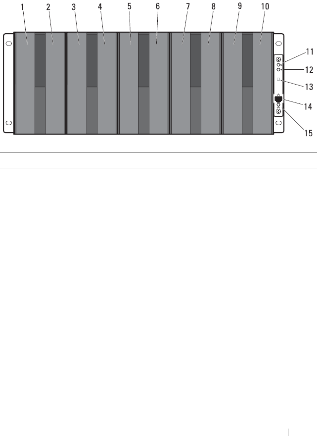
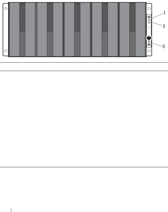
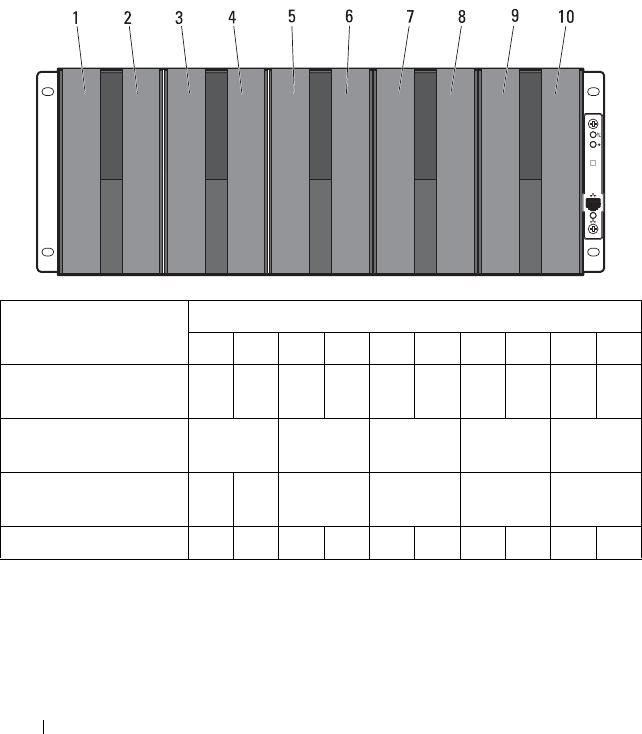
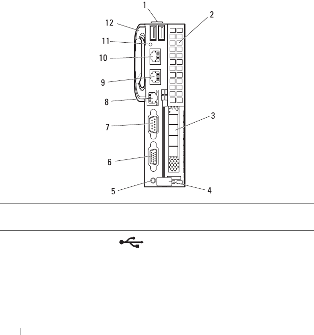
Front-Panel Features and Indicators
Figure 1-1. Front-Panel Features and Indicators
Item Feature Icon Description
1 - 10 Sled bays 1 to 10 Installs up to five C8220X compute sleds,
ten C8220 compute sleds, five C8000XD
storage sleds, or a mixture of differing sled
types.
NOTE: Sled bays 1 and 2 support installation
of two C8220 or one C8220X compute sleds.
For server enclosure with internal power
source, C8000XD storage sleds install in sled
bays 3 to 10 only.
Sled bays 5 and 6 Installs up to two power sleds or two C8220
compute sleds or a combination of the two
sled types.
NOTE: If the enclosure is configured with
only one power sled, a C8220 compute sled
or a power sled blank must be mounted into
the adjacent sled bay.
NOTE: The sled bays must always be
populated with either a sled or a sled blank
to ensure proper system cooling.

14 About the System
11 Chassis status
indicator
Indicates the power and health status of
the whole system.
12 Chassis
identification
indicator
Lights blue when the chassis ID signal is
generated.
13 Thermal sensor Monitors the inlet ambient temperature.
14 Ethernet connector Embedded 10/100 Mbit NIC connector.
15 NIC link/activity
indicator
Indicates state of the network link and
activity.
Item Feature Icon Description
About the System 15
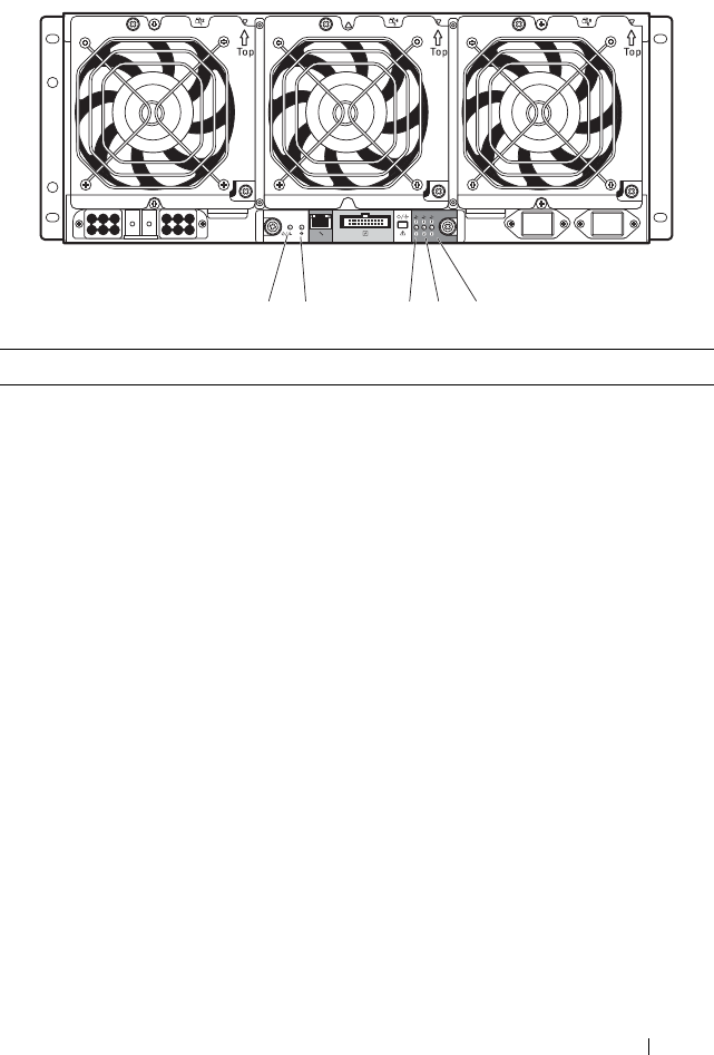
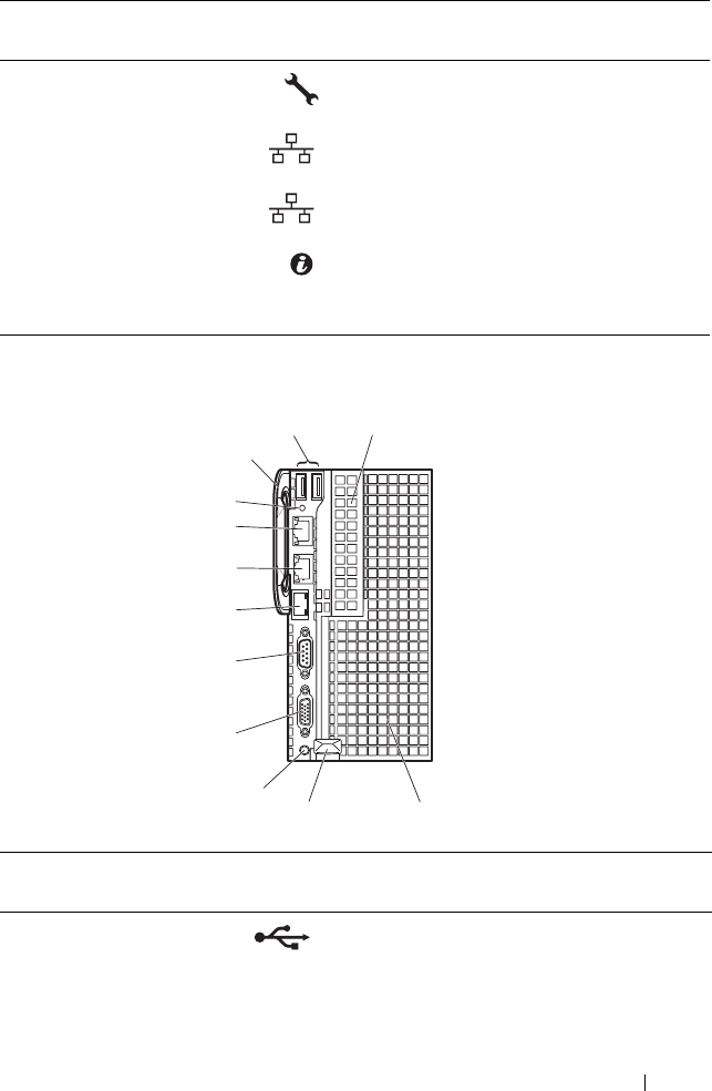
Back-Panel Features and Indicators
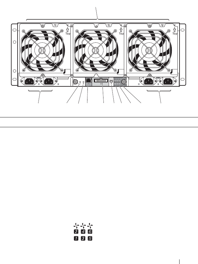
Figure 1-2. Back-Panel Features and Indicators — Server Enclosure with Internal
Power Source
Item Feature Icon Description
1 Fan modules Provides cooling solution to the enclosure.
2 AC power sockets Connect the power cables to these power
sockets. When connected to a power
source, main power is automatically
distributed to the enclosure.
NOTE: Always connect the enclosure's AC
power sockets to a single power source,
switch, or PDU.
NOTE: Before installing a compute or
storage sled to the front of the enclosure,
install the power sleds and connect power to
the enclosure.
3, 4, 5 Fan fault indicators
1 to 6
Indicates the function status of the system
fans.
1
22 3
4
5
6
7
8910
16 About the System
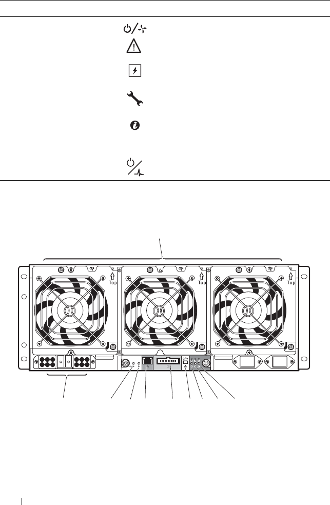
Figure 1-3. Back-Panel Features and Indicators — Server Enclosure with External
Power Source
6Service mode
button
Press this button within 4 seconds to enter
service mode.
7External PDU
connector
Connects to a PDU control connector.
8 BMC management
port
Dedicated management port.
9Chassis
identification
indicator
Lights blue when the chassis ID signal is
generated.
10 Power/event
indicator
Indicates the power and health status of the
enclosure.
Item Feature Icon Description
1
2
3
4
5
6
789
10
About the System 17
Item Feature Icon Description
1 Fan modules Provides cooling solution to the enclosure.
2, 3, 4 Fan fault indicators
1 to 6
Indicates the function status of the system
fans.
5Service mode
button
Press this button within 4 seconds to enter
service mode.
6External PDU
connector
Connects to a PDU control connector.
7 BMC management
port
Dedicated management port.
8 Chassis
identification
indicator
Lights blue when the chassis ID signal is
generated.
9Power/event
indicator
Indicates the power and health status of the
enclosure.
10 DC power socket Connect the DC power cable to this power
socket. When connected to an external
PDU, main power is automatically
distributed to the enclosure.
NOTE: Always connect the enclosure's DC
power socket to a PDU.
NOTE: Before installing a compute or
storage sled to the front of the enclosure,
connect power to the enclosure.
18 About the System
Server Enclosure Indicator Codes
The indicators on the front and back of the server enclosure displays
operational status of the enclosure, fan modules, and chassis controller
boards.
Figure 1-4. Server Enclosure Front-Panel Indicators
Item Indicator Color Status Indicator Code
1 Chassis status
indicator
Green Solid Indicates a valid power source is
connected to the server enclosure
and that the enclosure is
operational.
Off Off Power is not connected.
Amber Blinking Indicates a fault event occurred.
2 Chassis
identification
indicator
Blue Blinking Indicates a chassis ID signal is
generated.
Blue Off Chassis ID signal is not generated.
3 NIC link/activity
indicator
Green Solid Linking at 100 Mbps speed
(maximum).
Green Blinking Transmit or receive activity.
Off Off No activity.
About the System 19
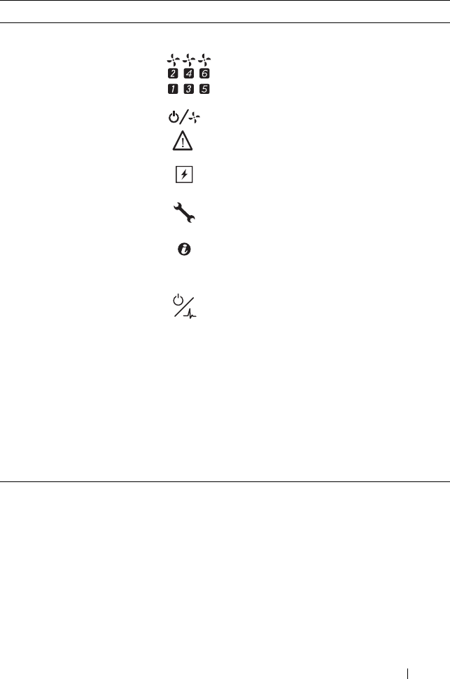
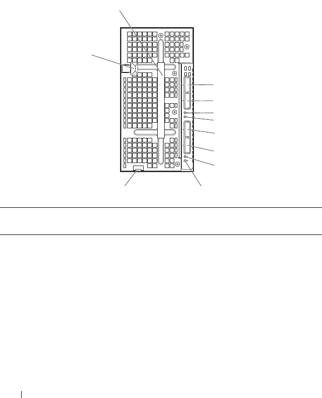
Figure 1-5. Server Enclosure Back-Panel Indicators
Item Indicator Color Status Indicator Code
1Power/event
indicator
Green Solid Indicates a valid power source is
connected to the server enclosure
and that the enclosure is
operational and power is applied to
the fan controller board.
Green Blinking Power is connected to the
enclosure but the managed devices’
or sleds’ power is off.
Amber Blinking Indicates a fault event occurred.
Off Off Power is not connected.
2Chassis
identification
indicator
Blue Blinking Indicates a chassis ID signal is
generated.
Blue Off Chassis ID signal is not generated.
3 Fan 1 and 2
fault indicator
Amber Blinking Indicates a fault event occurred in
fans 1 and 2.
Off Off Fans 1 and 2 are operational.
4 Fan 3 and 4
fault indicator
Amber Blinking Indicates a fault event occurred in
fans 3 and 4.
Off Off Fans 3 and 4 are operational.
5
4
3
21
20 About the System
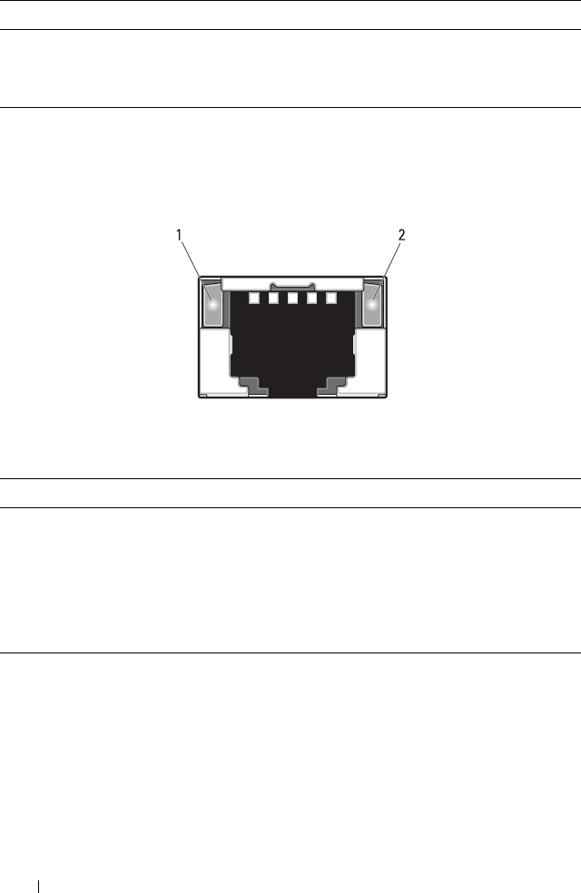
NIC Indicator Codes
Figure 1-6. NIC Indicators (Front-Panel Ethernet Connector)
5 Fan 5 and 6
fault indicator
Amber Blinking Indicates a fault event occurred in
fans 5 and 6.
Off Off Fans 5 and 6 are operational.
1 link indicator 2 activity indicator
Indicator Status Indicator Code
Link indicator Solid amber Linking at 10 Mbps port speed
Solid green Linking at 100 Mbps port speed (maximum)
Activity
indicator
Solid green No activity
Blinking green Transmit or receive activity
Off Idle
Item Indicator Color Status Indicator Code
About the System 21
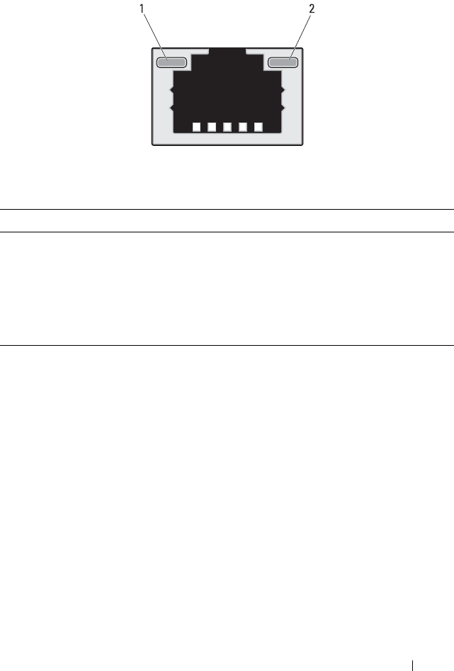
Figure 1-7. NIC Indicators (BMC management port)
1 link indicator 2 activity indicator
Indicator Status Indicator Code
Link indicator Blinking amber Linking at 10 Mbps port speed
Blinking green Linking at 100 Mbps port speed (maximum)
Activity
indicator
Solid green No activity
Blinking green Transmit or receive activity
Off Idle
22 About the System
Sled Bay Numbering
The front of the server enclosure is divided into ten vertical bays. A C8220
single-wide compute sled occupies one sled bay in the server enclosure and a
C8220X double-wide compute sled or C8000XD storage sled occupies two
sled bays in the server enclosure. When installing a sled module into the
server enclosure, you should install the sled module in sled bay 1 first, then
work toward the right of the enclosure.
Figure 1-8. Sled Bay Numbering
a. Sled bays 5 and 6 support installation of two power sleds or two C8220 compute sleds or a
combination of the two sled types.
b. For server enclosure with internal power source, install C8000XD storage sleds in sled bays 3 to 10
only.
c. Install power sleds in sled bays 5 and 6 only.
Sled module type
Sled Bays
12345
a6a78910
C8220 single-wide
compute sled
C8220X double-wide
compute sled
C8000XD storageb
sled
Power sledc
About the System 23
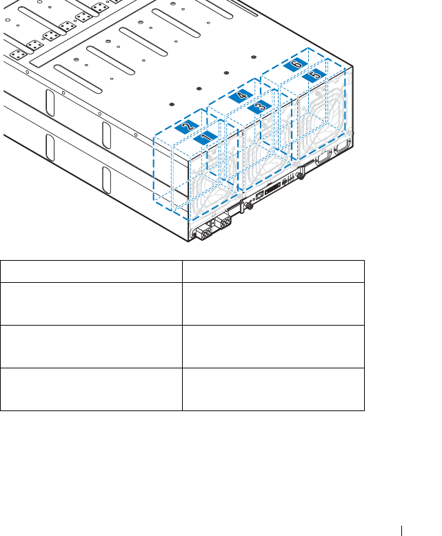
Fan Bay Numbering
The back of the PowerEdge C8000 server enclosure includes three hot-
swappable fan modules that provide the system with a redundant cooling
source. Each fan module contains two cooling fans. All three fan modules
must be installed at all times to ensure proper cooling.
Figure 1-9. Fan Bay Numbering
Fan Bay Cooling Fans
Fan module 1 Fan 2
Fan 1
Fan module 2 Fan 4
Fan 3
Fan module 3 Fan 6
Fan 5
24 About the System
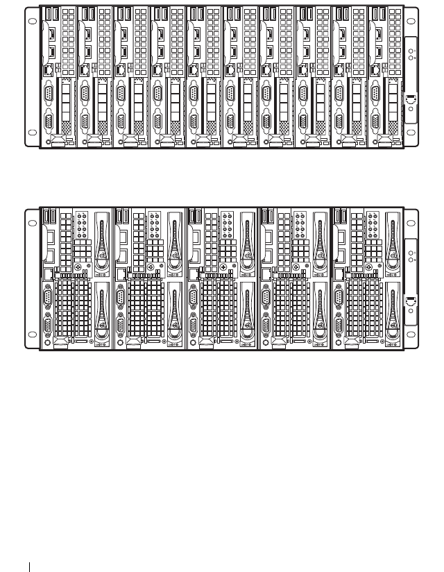
Sled Module Configuration
The following illustrations are sample sled module configurations available on
the PowerEdge C8000 server enclosure.
Figure 1-10. C8220 Single-Wide Compute Sleds
Figure 1-11. C8220X Double-Wide Compute Sleds
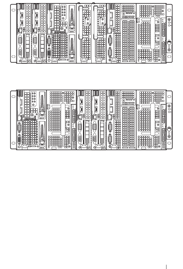
About the System 25
Figure 1-12. Mixed Sleds — Server Enclosure with Internal Power Source
Figure 1-13. Mixed Sleds — Server Enclosure with External Power Source
26 About the System
Sled Features
Compute Sleds
The PowerEdge C8000 server enclosure holds up to ten single-wide compute
sleds or five double-wide compute sleds. Each compute sled is equivalent to a
standard server built with a processor(s), memory, network interface,
baseboard management controller, and local hard-drive storage.
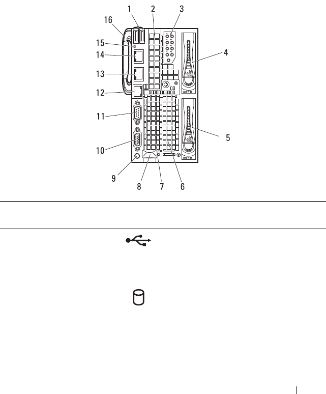
Single-Wide Compute Sled
Figure 1-14. Sled Features — C8220 Single-Wide Compute Sled
Item Indicator, Button, or
Connector
Icon Description
1 USB connectors Connects USB devices to the sled. The
ports are USB 2.0 compliant.
2 Mezzanine card
expansion slot
Installs an I/O module mezzanine card.
3 Low profile PCIe
expansion slot
Installs a low profile PCI Express x16 card.

About the System 27
4 Release latch Press to release the sled from the enclosure.
5Power-on indicator/
power button
The power-on indicator lights when the
sled power is on. The power-on indicator
lights amber when the system critical event
occurs.
NOTE: The power-on indicator lights amber
according to critical system error log (SEL)
assertion. If the SEL is full or a deassertion
event occurred while sensor monitoring is
paused (e.g. fan monitoring is paused during
system power off), the power-on indicator
turns amber. To turn off an amber LED and
reset the power-on indicator to normal
condition (solid green), either perform a
BMC cold reset or reseat the sled in the
server enclosure.
The power button turns the compute
sled on.
NOTES:
• When powering on the sled, the video
monitor can take from several seconds
to over 2 minutes to display an image,
depending on the amount of memory
installed in the system.
• On ACPI-compliant operating systems,
turning off the sled using the power
button causes the sled to perform a
graceful shutdown before power to the
sled is turned off.
• To force an ungraceful shutdown, press
and hold the power button for five
seconds.
Item Indicator, Button, or
Connector
Icon Description
28 About the System
6 VGA connector Connects a VGA display to the system.
7 Serial connector Connects a serial device to the system.
8 BMC management
port
Dedicated management port.
9 Ethernet connector 2 Embedded 10/100/1000 Mbit NIC
connector.
10 Ethernet connector 1 Embedded 10/100/1000 Mbit NIC
connector.
11 Sled identification
indicator
Lights blue to identify a particular sled and
system board.
12 Handle Hold to pull the sled from the enclosure.
Item Indicator, Button, or
Connector
Icon Description
2
1
About the System 29
Double-Wide Compute Sled
The C8220X double-wide compute sled includes two types of configuration,
a double-wide compute sled with front-access 2.5-inch hot-plug hard-drives
and a double-wide compute sled with general-purpose graphics processing
unit (GPGPU).
Figure 1-15. Sled Features — C8220X Double-Wide Compute Sled with Front-Access
Hot-Plug Hard-Drives
Item Indicator, Button, or
Connector
Icon Description
1 USB connectors Connects USB devices to the sled. The
ports are USB 2.0 compliant.
2 Mezzanine card
expansion slot
Installs an I/O module mezzanine card.
3 Hard-drive indicators
0 to 7
Indicates drive activity and status.
4, 5 Hard-drive bay Installs two 2.5-inch hot-plug hard-drives.
6, 7 Low profile PCIe
expansion slots
Installs up to two low profile PCI Express
x8 card when plugged into horizontal
expansion card connectors.
30 About the System
8 Sled release latch Press to release the sled from the
enclosure.
9Power-on indicator/
power button
The power-on indicator lights when the
sled power is on.The power-on indicator
lights amber when the system critical
event occurs.
NOTE: The power-on indicator lights amber
according to critical system error log (SEL)
assertion. If the SEL is full or a deassertion
event occurred while sensor monitoring is
paused (e.g. fan monitoring is paused during
system power off), the power-on indicator
turns amber. To turn off an amber LED and
reset the power-on indicator to normal
condition (solid green), either perform a
BMC cold reset or reseat the sled in the
server enclosure.
The power button turns the compute sled
on.
NOTES:
• When powering on the sled, the video
monitor can take from several seconds
to over 2 minutes to display an image,
depending on the amount of memory
installed in the system.
• On ACPI-compliant operating
systems, turning off the sled using the
power button causes the sled to
perform a graceful shutdown before
power to the sled is turned off.
• To force an ungraceful shutdown, press
and hold the power button for five
seconds.
10 VGA connector Connects a VGA display to the system.
11 Serial connector Connects a serial device to the system.
Item Indicator, Button, or
Connector
Icon Description
About the System 31
Figure 1-16. Sled Features — C8220X Double-Wide Compute Sled with GPGPU
12 BMC management
port
Dedicated management port.
13 Ethernet connector 2 Embedded 10/100/1000 Mbit NIC
connector.
14 Ethernet connector 1 Embedded 10/100/1000 Mbit NIC
connector.
15 Sled identification
indicator
Lights blue to identify a particular sled
and system board.
16 Handle Hold to pull the sled from the enclosure.
Item Indicator, Button, or
Connector
Icon Description
1 USB connectors Connects USB devices to the sled. The ports
are USB 2.0 compliant.
2 Mezzanine card
expansion slot
Installs an I/O module mezzanine card.
Item Indicator, Button, or
Connector
Icon Description
2
1
1
3
4
5
6
7
8
9
10
11
2
12

32 About the System
3 Sled cover/ GPGPU
card assembly
Installs up to two GPGPU cards when
plugged into horizontal GPGPU card risers.
4 Sled release latch Press to release the sled from the enclosure.
5Power-on indicator/
power button
The power-on indicator lights when the sled
power is on.The power-on indicator lights
amber when the system critical event occurs.
NOTE: The power-on indicator lights amber
according to critical system error log (SEL)
assertion. If the SEL is full or a deassertion
event occurred while sensor monitoring is
paused (e.g. fan monitoring is paused during
system power off), the power-on indicator turns
amber. To turn off an amber LED and reset the
power-on indicator to normal condition (solid
green), either perform a BMC cold reset or
reseat the sled in the server enclosure.
The power button turns the compute sled on.
NOTES:
• When powering on the sled, the video
monitor can take from several seconds to
over 2 minutes to display an image,
depending on the amount of memory
installed in the system.
• On ACPI-compliant operating systems,
turning off the sled using the power
button causes the sled to perform a
graceful shutdown before power to the
sled is turned off.
• To force an ungraceful shutdown, press
and hold the power button for five
seconds.
6 VGA connector Connects a VGA display to the system.
7 Serial connector Connects a serial device to the system.
Item Indicator, Button, or
Connector
Icon Description

About the System 33
8 BMC management
port
Dedicated management port.
9 Ethernet connector
2
Embedded 10/100/1000 Mbit NIC connector.
10 Ethernet connector
1
Embedded 10/100/1000 Mbit NIC connector.
11 Sled identification
indicator
Lights blue to identify a particular sled and
system board.
12 Handle Hold to pull the sled from the enclosure.
Item Indicator, Button, or
Connector
Icon Description
2
1
34 About the System
Storage Sleds
The C8000XD storage sled is a direct attached storage for the server
enclosure. The storage sled provides dedicated data storage to a C8220X sled
or C8220 sled. Each storage sled supports up to a maximum of 12 x 3.5-inch/
2.5-inch hard-drives or 24 x 2.5-inch SSD hard-drives.
Figure 1-17. Sled Features — C8000XD Storage Sled
Item Indicator, Button, or
Connector
Icon Description
1 Handle Hold to pull the hard-drive cage from the
sled.
2 Mini-SAS connector A2 Connects to a compute sled’s host bus
adapter (HBA) or RAID controller card.
3 Mini-SAS connector A1 Connects to a compute sled’s HBA or
RAID controller card.
1
2
3
4
5
6
7
8
910
11

About the System 35
4, 8 Sled power/status
indicator
The power-on indicator lights green
when the sled power is on and power is
applied to the SAS expander board.
The power-on indicator alternately lights
green and blinks amber when a critical
event occurs.
5, 9 Sled identification
indicator
Lights blue to identify a particular mini-
SAS connector and sled.
6 Mini-SAS connector B2 Connects to a compute sled’s HBA or
RAID controller card.
7 Mini-SAS connector B1 Connects to a compute sled’s HBA or
RAID controller card.
10 Sled release tab Press to release the sled from the
enclosure.
11 Hard-drive cage release
latch
Press to release the hard-drive cage from
the sled.
Item Indicator, Button, or
Connector
Icon Description
36 About the System
Power Sleds
You can install up to two hot-swappable power sleds in the server enclosure
that supports internal power source. Each power sled installs up to two
1400 W power supply modules that are capable of delivering 2800 W power
to the server enclosure at an input range of 200-240 V.
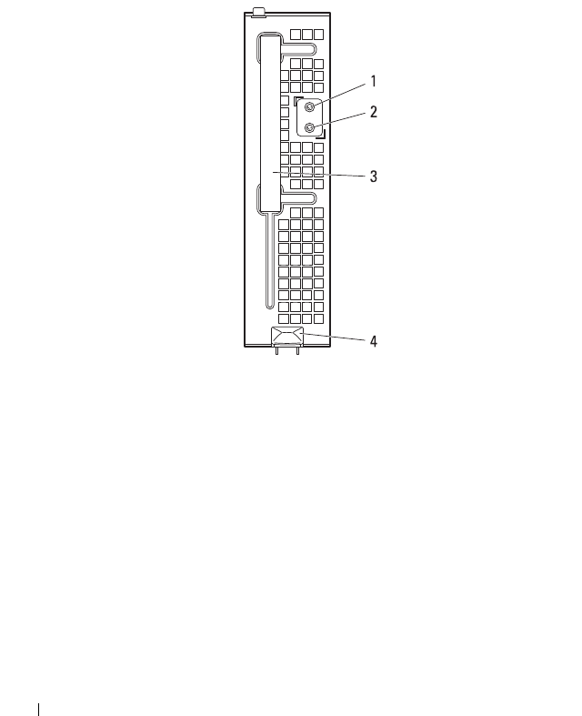
Figure 1-18. Sled Features — Power Sled

About the System 37
Item Indicator, Button, or
Connector
Icon Description
1 PSU1/3 status
indicator
The PSU1/3 status indicator lights green
indicating that a valid power source is
connected to the power supply and that
power supply is operational.
The PSU1/3 status indicator lights amber
indicating a problem with the PSU module.
• PSU module fan locked (15 s)
• PSU module over temperature protection
(OTP)
• PSU module over current protection
(OCP)
• PSU module over voltage protection
(OVP)
• PSU module under voltage protection
(UVP)
2 PSU2/4 status
indicator
The PSU2/4 status indicator lights green
indicating that a valid power source is
connected to the power supply and that
power supply is operational.
The PSU2/4 status indicator lights amber
indicating a problem with the PSU module.
• PSU module fan locked (15 s)
• PSU module over temperature protection
(OTP)
• PSU module over current protection
(OCP)
• PSU module over voltage protection
(OVP)
• PSU module under voltage protection
(UVP)
3 Handle Hold to pull the sled from the enclosure.
4 Release latch Press to release the sled from the enclosure.
38 About the System
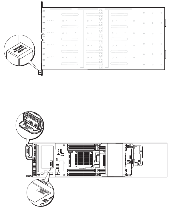
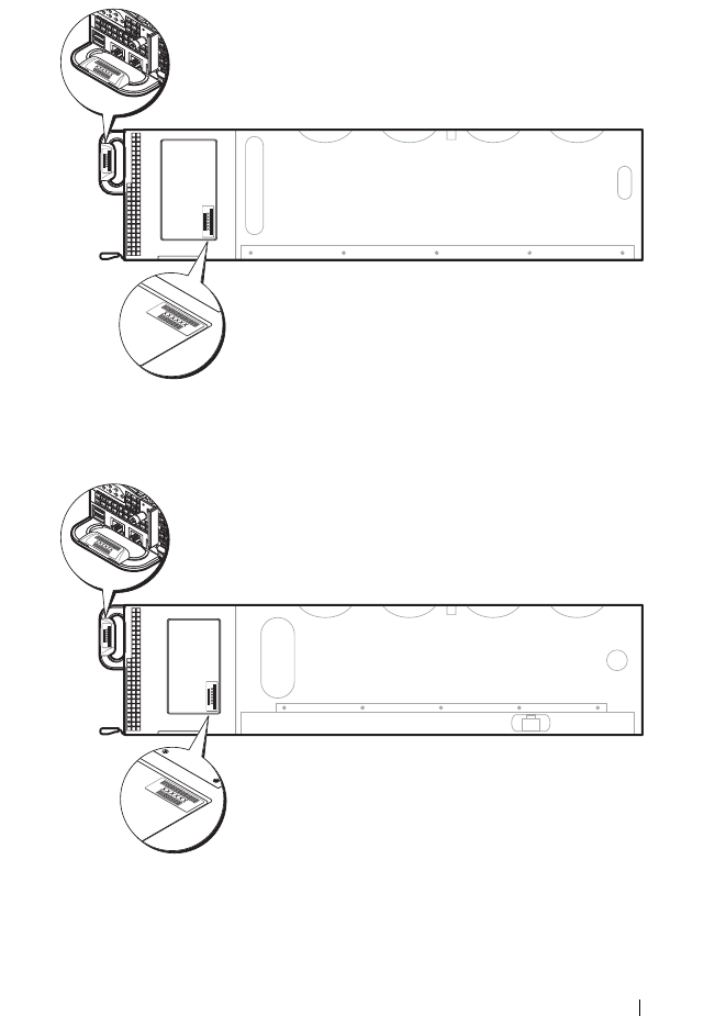
Service Tag
The following illustrations provide location of the Service Tag number on the
server enclosure, compute sleds, and storage sleds.
Server Enclosure
Figure 1-19. Service Tag Location for Server Enclosure
Sleds
Figure 1-20. Service Tag Location for C8220 Single-Wide Compute Sled
About the System 39
Figure 1-21. Service Tag Location for C8220X Double-Wide Compute Sled with 3.5-inch
(4-Drive Bay) Hard-Drives
Figure 1-22. Service Tag Location for C8220X Double-Wide Compute Sled with 2.5-inch
(8-Drive Bay) Hard-Drives
40 About the System
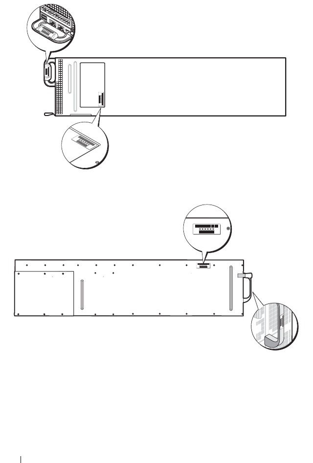
Figure 1-23. Service Tag Location for C8220X Double-Wide Compute Sled with GPGPU
Figure 1-24. Service Tag Location for C8000XD Storage Sled

About the System 41
POST Error Codes
Collecting System Event Log for Investigation
Whenever possible, the system BIOS will output the current boot progress
codes on the video screen. Progress codes are 32-bit quantities plus optional
data. The 32-bit numbers include class, subclass, and operation information.
The class and subclass fields point to the type of hardware that is being
initialized. The operation field represents the specific initialization activity.
Based on the data bit availability to display progress codes, a progress code
can be customized to fit the data width. The higher the data bit, the higher
the granularity of information that can be sent on the progress port. The
progress codes may be reported by the system BIOS or option ROMs.
The Response section in the following table may be divided into 3 types:
• Warning or Not an error – The message is displayed on the screen. An error
record is logged to the SEL. The system will continue booting with a
degraded state. The user may want to replace the erroneous unit.
• Pause – The message is displayed on the screen, an error is logged to the
SEL, and user input is required to continue. The user can take immediate
corrective action or choose to continue booting.
• Halt – The message is displayed on the screen, an error is logged to the
SEL, and the system cannot boot unless the error is resolved. The user
needs to replace the faulty part and restart the system.
Error
Code
Error Message Response Error Cause Corrective Actions
0010h Local Console
Resource
Conflict
Pause Video device
initialization
failed
See "Troubleshooting the
Video Subsystem" on
page 252.
If the problem persists, see
"Getting Help" on page 289.
0011h Local Console
Controller Error
Pause Video device
initialization
failed
See "Troubleshooting the
Video Subsystem" on
page 252.
If the problem persists, see
"Getting Help" on page 289.

42 About the System
0012h Local Console
Output Error
Pause Video device
initialization
failed
See "Troubleshooting the
Video Subsystem" on
page 252.
If the problem persists, see
"Getting Help" on page 289.
0013h ISA IO
Controller Error
Pause ISA device
initialization
failed
See "Troubleshooting
Expansion Cards" on
page 270.
If the problem persists, see
"Getting Help" on page 289.
0014h ISA IO Resource
Conflict
Pause ISA device
initialization
failed
See "Troubleshooting
Expansion Cards" on
page 270.
If the problem persists, see
"Getting Help" on page 289.
0015h ISA IO
Controller Error
Pause ISA device
initialization
failed
See "Troubleshooting
Expansion Cards" on
page 270.
If the problem persists, see
"Getting Help" on page 289.
0016h ISA Floppy
Controller Error
Pause Floppy device
initialization
failed
See "Troubleshooting a USB
Device" on page 252.
If the problem persists, see
"Getting Help" on page 289.
0017h ISA Floppy
Input Error
Pause Floppy device
initialization
failed
See "Troubleshooting a USB
Device" on page 252.
If the problem persists, see
"Getting Help" on page 289.
0018h ISA Floppy
Output Error
Pause Floppy device
initialization
failed
See "Troubleshooting a USB
Device" on page 252.
If the problem persists, see
"Getting Help" on page 289.
Error
Code
Error Message Response Error Cause Corrective Actions

About the System 43
0019h USB Read Error Pause USB port
initialization
failed
See "Troubleshooting a USB
Device" on page 252.
If the problem persists, see
"Getting Help" on page 289.
001Ah USB Write Error Pause USB port
initialization
failed
See "Troubleshooting a USB
Device" on page 252.
If the problem persists, see
"Getting Help" on page 289.
001Bh USB Interface
Error
Pause USB port
initialization
failed
See "Troubleshooting a USB
Device" on page 252.
If the problem persists, see
"Getting Help" on page 289.
001Ch Mouse Interface
Error
Pause Mouse device
initialization
failed
To enable USB device, see
"USB Configuration" on
page 105.
See "Troubleshooting a USB
Device" on page 252.
If the problem persists, see
"Getting Help" on page 289.
001Eh Keyboard Not
Detected
Pause No keyboard
detected
To enable USB device, see
"USB Configuration" on
page 105.
See "Troubleshooting a USB
Device" on page 252.
If the problem persists, see
"Getting Help" on page 289.
001Fh Keyboard
Controller Error
Pause Keyboard
controller
initialization
failed
See "Troubleshooting a USB
Device" on page 252.
If the problem persists, see
"Getting Help" on page 289.
Error
Code
Error Message Response Error Cause Corrective Actions

44 About the System
0020h Keyboard Stuck
Key Error
Pause Keyboard key
stuck
Disconnect and reconnect the
keyboard to the compute sled.
If the problem persists, see
"Getting Help" on page 289.
0021h Keyboard
Locked Error
Pause Keyboard
locked
Disconnect and reconnect the
keyboard to the compute sled.
If the problem persists, see
"Getting Help" on page 289.
0023h Memory
Correctable
Error
Pause Memory
correctable
error detected
Remove AC power to the
system for 10 seconds and
restart the system.
See "Troubleshooting System
Memory" on page 267.
If the problem persists, see
"Getting Help" on page 289.
0024h Memory
Uncorrectable
Error
Pause Memory
uncorrectable
error detected
See "Troubleshooting System
Memory" on page 267.
If the problem persists, see
"Getting Help" on page 289.
0025h Memory Non-
Specific Error
Pause Memory non-
specific error
detected
See "Troubleshooting System
Memory" on page 267.
If the problem persists, see
"Getting Help" on page 289.
0026h MP Service Self
Test Error
Pause MP service self
test error
detected
See "Troubleshooting
Processors" on page 270.
If the problem persists, see
"Getting Help" on page 289.
0027h PCI IO
Controller Error
Pause PCI device
initialization
failed
See "Troubleshooting
Expansion Cards" on
page 270.
If the problem persists, see
"Getting Help" on page 289.
Error
Code
Error Message Response Error Cause Corrective Actions

About the System 45
0028h PCI IO Read
Error
Pause PCI device
initialization
failed
See "Troubleshooting
Expansion Cards" on
page 270.
If the problem persists, see
"Getting Help" on page 289.
0029h PCI IO Write
Error
Pause PCI device
initialization
failed
See "Troubleshooting
Expansion Cards" on
page 270.
If the problem persists, see
"Getting Help" on page 289.
002Ah Serial Port Not
Detected
Pause Serial device
initialization
failed
See "Troubleshooting a Serial
I/O Device" on page 253.
If the problem persists, see
"Getting Help" on page 289.
002Bh Serial Port
Controller Error
Pause Serial device
initialization
failed
See "Troubleshooting a Serial
I/O Device" on page 253.
If the problem persists, see
"Getting Help" on page 289.
002Ch Serial Port Input
Error
Pause Serial device
initialization
failed
See "Troubleshooting a Serial
I/O Device" on page 253.
If the problem persists, see
"Getting Help" on page 289.
002Dh Serial Port
Output Error
Pause Serial device
initialization
failed
See "Troubleshooting a Serial
I/O Device" on page 253.
If the problem persists, see
"Getting Help" on page 289.
002Eh Microcode
Update Error
Pause Processor
microcode
update error
Check microcode. A BIOS
update is required.
If the problem persists, see
"Getting Help" on page 289.
Error
Code
Error Message Response Error Cause Corrective Actions

46 About the System
002Fh No Microcode
Be Updated
Pause Processor
microcode load
failed
Ensure that your processors
match and conform to the
type described in the
processor technical
specifications outlined in
your system’s Getting Started
Guide.
8012h SATA 0 Device
Not Found
Pause SATA 0 device
not found
Check if the SATA port 0 is
enabled. See "SATA
Configuration" on page 95.
Install a SATA device to SATA
port 0.
If the problem persists, see
"Getting Help" on page 289.
8013h SATA 1 Device
Not Found
Pause SATA 1 device
not found
Check if the SATA port1 is
enabled. See "SATA
Configuration" on page 95.
Install a SATA device to SATA
port 1.
If the problem persists, see
"Getting Help" on page 289.
8014h SATA 2 Device
Not Found
Pause SATA 2 device
not found
Check if the SATA port 2 is
enabled. See "SATA
Configuration" on page 95.
Install a SATA device to SATA
port 2.
If the problem persists, see
"Getting Help" on page 289.
8015h SATA 3 Device
Not Found
Pause SATA 3 device
not found
Check if the SATA port 3 is
enabled. See "SATA
Configuration" on page 95.
Install a SATA device to SATA
port 3.
If the problem persists, see
"Getting Help" on page 289.
Error
Code
Error Message Response Error Cause Corrective Actions

About the System 47
8016h SATA 4 Device
Not Found
Pause SATA 4 device
not found
Check if the SATA port 4 is
enabled. See "SATA
Configuration" on page 95.
Install a SATA device to SATA
port 4.
If the problem persists, see
"Getting Help" on page 289.
8017h SATA 5 Device
Not Found
Pause SATA 5 device
not found
Check if the SATA port 5 is
enabled. See "SATA
Configuration" on page 95.
Install a SATA device to SATA
port 5.
If the problem persists, see
"Getting Help" on page 289.
8018h Sparing Mode is
not be
Configured!!,
Please check
Memory
Configuration!!
Pause Memory
Sparing Mode
Failed
Check if the memory
configuration is set to Sparing
mode. See "Memory
Configuration" on page 92.
If the problem persists, see
"Getting Help" on page 289.
8019h Mirror Mode is
not be
Configured!!,
Please check
Memory
Configuration!!
Pause Memory Mirror
Mode Failed
Check if the memory
configuration is set to Sparing
mode. See "Memory
Configuration" on page 92.
If the problem persists, see
"Getting Help" on page 289.
8020h Supervisor and
User Passwords
have been
cleared
Pause Supervisor and
User Passwords
have been
cleared
Reset password. See the
compute sled’s
documentation for more
information.
If the problem persists, see
"Getting Help" on page 289.
Error
Code
Error Message Response Error Cause Corrective Actions

48 About the System
8021h CMOS Battery
Error
Pause No CMOS
battery
See the compute sled’s
documentation for more
information.
8100h Memory device
disabled by
BIOS
Pause Memory
Device Error
See "Troubleshooting System
Memory" on page 267.
If the problem persists, see
"Getting Help" on page 289.
Error
Code
Error Message Response Error Cause Corrective Actions

About the System 49
System Event Log
Processor Error
Message: “Processor Sensor, IERR error, Processor 1”
Table 1-1. Processor Error
Byte Field Value Description
1 NetFunLun 10h
2 Platform Event Command 02h
3 Generator ID 01h Generated by BIOS
4 Event Message Format
Version
04h Event Message Format Revision.
04h for this specification
5 Sensor Type 07h Processor
6 Sensor Number 04h Processor Sensor Number
(depends on platform)
7 Event Direction Event Type 6Fh Bit 7: 0 = Assert Event Bit 6: 0 =
Event Type Code
8 Event Data1 AXh 00h: IERR 01h: Thermal Trip
02h: FRB1/BIST Failure
03h: FRB2/Hang in POST Failure
04h: FBR3/Processor
Startup/Initialization Failure
0Ah: Processor Automatically
Throttled
9 Event Data2 XXh 00h: Processor1
01h: Processor2
02h: Processor3
04h: Processor4
10 Event Data3 FFh FFh: Not Present

50 About the System
Memory Ecc
Message: “Memory Sensor, Correctable ECC error, SBE warning threshold,
CPU1 DIMM_A1”
Table 1-2. Memory ECC
Byte Field Value Description
1 NetFunLun 10h
2 Platform Event Command 02h
3 Generator ID 01h Generated by BIOS
4 Event Message Format
Version
04h Event Message Format Revision.
04h for this specification
5 Sensor Type 0Ch Memory
6 Sensor Number 60h Memory Sensor Number (depend
on platform)
7 Event Direction Event Type 6Fh Bit 7: 0 = Assert Event
Bit 6: 0 = Event Type Code
8 Event Data1 AXh 00h: Correctable ECC Error
01h: Uncorrectable ECC Error
03h: Memory Scrub Failed
04h: Memory Device Disabled
08h: Spare

About the System 51
9 Event Data2 XXh Bit 7:4
0x00: SBE warning threshold
0x01: SBE critical threshold
0x0F: Unspecified
Bit 3:0
0x00: CPU1 DIMM A1-8 slots
(1~8)
0x01: CPU2 DIMM B1-8 slots
(9~16)
0x02: CPU3 DIMM C1-8 slots
(17~24)
0x03: CPU4 DIMM D1-8 slots
(25~32) And so on…
10 Event Data3 XXh DIMM bit-map location of bits
Bit 0=1: DIMM1 error event
Bit 1=1: DIMM2 error event …
Bit7=1: DIMM8 error event
Table 1-2. Memory ECC
Byte Field Value Description

52 About the System
PCIe Error
Message: “Critical Interrupt Sensor, PCI PERR, Device#, Function#,
Bus#”
Table 1-3. PCIe Error
Byte Field Value Description
1 NetFunLun 10h
2 Platform Event Command 02h
3 Generator ID 01h Generated by BIOS
4 Event Message Format
Version
04h Event Message Format Revision.
04h for this specification
5 Sensor Type 13h Critical Interrupt
6 Sensor Number 73h PCI Sensor ID (depend on
platform)
7 Event Direction Event Type 6Fh Bit 7: 0 = Assert Event
Bit 6: 0 = Event Type Code
8 Event Data1 AXh 04h: PCI PERR
05h: PCI SERR
07h: Bus Correctable Error
08h: Bus Uncorrectable Error
0Ah: Bus Fatal Error
9 Event Data2 XXh Bit 7:3Device Number
Bit 2:0Function Number
10 Event Data3 XXh Bit 7:0 Bus Number

About the System 53
IOH Core Error
Message: “Critical Interrupt Sensor, Fatal Error, xxxx bit, QPI[0] Error”
Table 1-4. IOH Core Error
Byte Field Value Description
1 NetFunLun 10h
2 Platform Event Command 02h
3 Generator ID 01h Generated by BIOS
4 Event Message Format
Version
04h Event Message Format Revision.
04h for this specification
5 Sensor Type C0h OEM Defined Interrupt
6 Sensor Number XXh 71h: QPI Sensor ID (depend on
platform)
72h: INT Sensor ID (depend on
platform)
7 Event Direction Event Type 6Fh Bit 7: 0 = Assert Event Bit 6: 0 =
Event Type Code
8 Event Data1 AXh 07h: Core
08h: Non-Fatal
0Ah: Fatal
9 Event Data2 XXh Local Error Bit
10 Event Data3 XXh 00h: QPI[0] Error
01h: QPI[1] Error
02h: QPI[2] Error
03h: QPI[3] Error
04h: QPI[0] Protocol Error
05h: QPI[1] Protocol Error
06h: QPI[2] Protocol Error
07h: QPI[3] Protocol Error
23h: Miscellaneous Error
24h: IOH Core Error

54 About the System
SB Error
Message: “Critical Interrupt Sensor, Correctable, MCU Parity Error”
Table 1-5. SB Error
Byte Field Value Description
1 NetFunLun 10h
2 Platform Event Command 02h
3 Generator ID 01h Generated by BIOS
4 Event Message Format
Version
04h Event Message Format Revision.
04h for this specification
5 Sensor Type 13h Critical Interrupt
6 Sensor Number 77h SB Sensor ID (depend on
platform)
7 Event Direction Event Type 6Fh Bit 7: 0 = Assert Event
Bit 6: 0 = Event Type Code
8 Event Data1 AXh 07h: Correctable
08h: Uncorrectable
9 Event Data2 XXh Bit 7:5Reserved Local error bit
number (4 ~ 0)
00000b: HT Periodic CRC Error
00001b: HT Protocol Error
00010b: HT Flow-Control Buffer
Overflow
00011b: HT Response Error
00100b: HT Per-Packet CRC Error
00101b: HT Retry Counter Error
00111b: MCU Parity Error
10 Event Data3 FFh FFh: Not Present

About the System 55
POST Start Event
Message: “System Event, POST starts with BIOS xx.xx.xx”
Table 1-6. POST Start Event
Byte Field Value Description
1 NetFunLun 10h
2 Platform Event Command 02h
3 Generator ID 01h Generated by BIOS
4 Event Message Format
Version
04h Event Message Format Revision.
04h for this specification
5 Sensor Type 12h System Event
6 Sensor Number 81h POST Start (depend on platform)
7 Event Direction Event Type 6Fh Bit 7: 0 = Assert Event
Bit 6: 0 = Event Type Code
8 Event Data1 AXh 01h: OEM System Boot Event
9 Event Data2 XXh 7~4: BIOS 1st Field Version
(0~15)
3~0: BIOS 2nd Field Version
higher 4bits (0~63)
10 Event Data3 XXh 7~6: BIOS 2nd Field Version lower
2bits (0~63)
5~0: BIOS 3rd Field Version
(0~63)

56 About the System
POST End Event
Table 1-7. POST End Event
Byte Field Value Description
1 NetFunLun 10h
2 Platform Event Command 02h
3 Generator ID 01h Generated by BIOS
4 Event Message Format
Version
04h Event Message Format Revision.
04h for this specification
5 Sensor Type 12h System Event
6 Sensor Number 85h POST End (depend on platform)
7 Event Direction Event Type 6Fh Bit 7: 0 = Assert Event
Bit 6: 0 = Event Type Code
8 Event Data1 AXh 01h: OEM System Boot Event
9 Event Data2 XXh Bit 7 = Boot Type
0b: PC Compatible Boot
(Legacy) 1b: uEFI Boot
Bit 3:0 = Boot Device
0001b: Force PXE Boot
0010b: NIC PXE Boot
0011b: Hard Disk Boot
0100b: RAID HDD Boot
0101b: USB Storage Boot
0111b: CD/DVD ROM Boot
1000b: iSCSI Boot
1001b: uEFI Shell
1010b: ePSA Diagnostic Boot
10 Event Data3 FFh FFh: Not Present

About the System 57
POST Error Code Event
Message: “System Firmware Progress, POST error code: UBLBh.”
Table 1-8. POST Error Code Event
Byte Field Value Description
1 NetFunLun 10h
2 Platform Event Command 02h
3 Generator ID 01h Generated by BIOS
4 Event Message Format
Version
04h Event Message Format Revision.
04h for this specification
5 Sensor Type 0Fh System Firmware Progress
6 Sensor Number 86h POST Error (depend on platform)
7 Event Direction Event Type 6Fh Bit 7: 0 = Assert Event
Bit 6: 0 = Event Type Code
8 Event Data1 AXh 00: System Firmware Error (POST
Error)
9 Event Data2 XXh Upper Byte
10 Event Data3 XXh Lower Byte

58 About the System
BIOS Recovery Event
ME Fail Event
Table 1-9. BIOS Recovery Event
Byte Field Value Description
1 NetFunLun 10h
2 Platform Event Command 02h
3 Generator ID 01h Generated by BIOS
4 Event Message Format
Version
04h Event Message Format Revision.
04h for this specification
5 Sensor Type 12h System Event
6 Sensor Number 89h BIOS Recovery fail (depend on
platform)
7 Event Direction Event Type 6Fh Bit 7: 0 = Assert Event Bit 6: 0 =
Event Type Code
8 Event Data1 AXh 01h: OEM BIOS recovery Event
9 Event Data2 XXh 01h:Start Recovery
02h:Recovery Success
03h:Load Image Fail
04h:Signed Fail
10 Event Data3 FFh FFh: Not Present
Table 1-10. BIOS Recovery Event
Byte Field Value Description
1 NetFunLun 10h
2 Platform Event Command 02h
3 Generator ID 01h Generated by BIOS
4 Event Message Format
Version
04h Event Message Format Revision.
04h for this specification
5 Sensor Type 12h System Event
6 Sensor Number 8Ah ME fail (depend on platform)

About the System 59
SEL Generator ID
7 Event Direction Event Type 6Fh Bit 7: 0 = Assert Event
Bit 6: 0 = Event Type Code
8 Event Data1 AXh 01h: OEM ME fail Event
9 Event Data2 XXh 01h:ME fail
10 Event Data3 FFh FFh: Not Present
Table 1-11. SEL Generator ID
Generator ID
BIOS 0x0001
BMC 0x0020
ME 0x002C
Windows 2008 0x0137
Table 1-10. BIOS Recovery Event
Byte Field Value Description

60 About the System
BMC
The following table includes an overview of the system sensors.
In the Offset column:
• SI = Sensor Initialization
• SC = Sensor Capabilities
• AM = Assertion Mask
• DM = Deassertion Mask
• RM = Reading Mask
• TM = Settable/Readable Threshold Mask
Table 1-12. Sensor Summary
Sensor
Number
Sensor Name Sensor Type Event/Reading Type Offset
01h SEL Fullness Event Logging
Disabled (10h)
Sensor-specific
(6Fh)
SI: 67h
SC: 40h
AM: 0035h
DM: 0000h
RM: 0035h
02h P1 Thermal Trip Processor (07h) Sensor-specific
(6Fh)
SI: 01h
SC: 40h
AM: 0002h
DM: 0000h
RM: 0002h
03h P2 Thermal Trip Processor (07h) Sensor-specific
(6Fh)
SI: 01h
SC: 40h
AM: 0002h
DM: 0000h
RM: 0002h

About the System 61
Table 1-13. Sensor Summary (continued)
Sensor
Number
Sensor Name Sensor Type Event/Reading Type Offset
04h CPU ERR2 Processor (07h) Sensor-specific
(6Fh)
SI: 01h
SC: 40h
AM: 0001h
DM: 0000h
RM: 0001h
05h 12V Standby Voltage (02h) Threshold (01h) SI: 7Fh
SC: 59h
AM: 7A95h
DM: 7A95h
TM: 3F3Fh
06h 5V Voltage (02h) Threshold (01h) SI: 7Fh
SC: 59h
AM: 7A95h
DM: 7A95h
TM: 3F3Fh
07h 5V Standby Voltage (02h) Threshold (01h) SI: 7Fh
SC: 59h
AM: 7A95h
DM: 7A95h
TM: 3F3Fh
08h 3.3V Voltage (02h) Threshold (01h) SI: 7Fh
SC: 59h
AM: 7A95h
DM: 7A95h
TM: 3F3Fh

62 About the System
Table 1-14. Sensor Summary (continued)
Sensor
Number
Sensor Name Sensor Type Event/Reading Type Offset
09h 3.3V Standby Voltage (02h) Threshold (01h) SI: 7Fh
SC: 59h
AM: 7A95h
DM: 7A95h
TM: 3F3Fh
0Ah Battery low Battery (29h) Sensor-specific
(6Fh)
SI: 67h
SC: 40h
AM: 0001h
DM: 0000h
RM: 0001h
41h MEZZ1 TEMP Temperature (01h) Threshold (01h) SI: 7Fh
SC: 68h
AM: 0A80h
DM: 0A80h
TM: 3838h
41h CPU1 Temp Temperature (01h) Threshold (01h) SI: 7Fh
SC: 68h
AM: 0A80h
DM: 0A80h
TM: 3838h
42h CPU2 Temp Temperature (01h) Threshold (01h) SI: 7Fh
SC: 68h
AM: 0A80h
DM: 0A80h
TM: 3838h

About the System 63
Table 1-15. Sensor Summary (continued)
Sensor
Number
Sensor Name Sensor Type Event/Reading Type Offset
43h DIMM ZONE 1
Temp
Temperature (01h) Threshold (01h) SI: 7Fh
SC: 68h
AM: 0A80h
DM: 0A80h
TM: 3838h
44h DIMM ZONE 1
Temp
Temperature (01h) Threshold (01h) SI: 7Fh
SC: 68h
AM: 0A80h
DM: 0A80h
TM: 3838h
45h PCH Temp Temperature (01h) Threshold (01h) SI: 7Fh
SC: 68h
AM: 0A80h
DM: 0A80h
TM: 3838h
60h Memory Memory (0Ch) Sensor-specific
(6Fh)
SI: 01h
SC: 40h
AM: 0023h
DM: 0000h
RM: 0023h
A0h Watchdog Watchdog 2 (23h) Sensor-specific
(6Fh)
SI: 67h
SC: 40h
AM: 000Fh
DM: 0000h
RM: 000Fh

64 About the System
Table 1-16. Sensor Summary (continued)
Sensor
Number
Sensor Name Sensor Type Event/Reading Type Offset
A1h Soft Reset System Boot/
Restart Initiated
(1Dh)
Sensor-specific
(6Fh)
SI: 01h
SC: 40h
AM: 0004h
DM: 0000h
RM: 0004h
A2h AC lost Power Unit (09h) Sensor-specific
(6Fh)
SI: 01h
SC: 40h
AM: 0010h
DM: 0000h
RM: 0010h
A3h Power off Power Unit (09h) Sensor-specific
(6Fh)
SI: 01h
SC: 40h
AM: 0002h
DM: 0000h
RM: 0002h

About the System 65
Other Information You May Need
WARNING: See the safety and regulatory information that shipped with your
system. Warranty information may be included within this document or as a
separate document.
• The Getting Started Guide provides an overview of rack installation,
system features, setting up your system, and technical specifications.
• The compute or storage sleds’ documentation provides information about
the sled features, configuring and managing the sled. This document is
available online at
dell.com
/
support
/
manuals
.
• The Baseboard Management Controller Guide provides information about
installing and using the systems management utility. This document is
available online at
dell.com
/
support
/
manuals
.
NOTE: Always check for updates on dell.com/support/manuals and read the
updates first because they often supersede information in other documents.

66 About the System

Using the System Setup Program 67
2
Using the System Setup Program
The System Setup program is the BIOS program that enables you to manage
your system hardware and specify BIOS-level options. From the System Setup
program, you can:
• Change the NVRAM settings after you add or remove hardware
• View the system hardware configuration
• Enable or disable integrated devices
• Set performance and power management thresholds
• Manage system security
System Setup Menu
The system employs the latest Insyde® BIOS, which is stored in Flash
memory. The Flash memory supports the Plug and Play specification, and
contains a System Setup program, the Power On Self Test (POST) routine,
and the PCI auto-configuration utility.
This system supports system BIOS shadowing which enables the BIOS to
execute from 64-bit onboard write-protected DRAM.
You can configure items such as:
• Hard-drives and peripherals
• Password protection
• Power management features
The Setup utility should be executed under the following conditions:
• When changing the system configuration
• When a configuration error is detected by the system and you are
prompted to make changes to the Setup utility
• When redefining the communication ports to prevent any conflicts
68 Using the System Setup Program
• When changing the password or making other changes to the security
setup
NOTE: Only items in brackets [ ] can be modified, Items that are not in brackets are
display only.
NOTE: PowerEdge C8000 server enclosure is referred to as simply the "server
enclosure" or the "chassis" in this manual.
System Setup Options at Boot
You can initiate Setup by pressing the following keys during POST:
Using the System Setup Program Navigation Keys
The following table lists the keys found in the legend bar with their
corresponding alternates and functions:
Keystroke Description
<F2> Enter the System Setup
<F8> Load customized defaults
<F9> Load optimal defaults in Setup menu
<F10> Save and exit Setup
Keys Function
F1 General Help
or Select Screen
or Select Item
Change Option/Field
Tab Select Field
Esc Exit
Enter Go to Sub Screen
Home Go to Top of Screen
End Go to Bottom of Screen
F10 Save and Exit

Using the System Setup Program 69
General Help
In addition to the Item Specific Help window, the Setup Utility also provides
a General Help screen. This screen can be called up from any menu by
pressing <F1>. The General Help screen lists the legend keys with their
corresponding alternates and functions. To exit the help window, press
<Enter> or <Esc>.
Console Redirection
The console redirection allows a remote user to diagnose and fix problems on
a server, which has not successfully booted the operating system (OS). The
centerpiece of the console redirection is the BIOS Console. The BIOS
Console is a Flash ROM-resident utility that redirects input and output over
a serial or modem connection.
The BIOS supports console redirection to a serial port. If serial port based
headless server support is provided by the system, the system must provide
support for redirection of all BIOS driven console I/O to the serial port. The
driver for the serial console must be capable of supporting the functionality
documented in the ANSI Terminal Definition.
The console redirection behavior shows a change of string displays that
reduce the data transfer rate in the serial port and cause the absence or an
incomplete POST screen. If you see an abnormal POST screen after you
connect to the console, it is recommended to press <Ctrl><R> to reflash
the screen.
Enabling and Configuring Console Redirection
Console redirection is configured through the System Setup program. There
are three options available to establish console redirection on the system.
• External serial port
• Internal serial connector as Serial Over LAN (SOL)
•BMC SOL

70 Using the System Setup Program
Enabling and Configuring Console Redirection Via COM1
To activate console redirection via COM1, you must configure the following
settings:
1
Connect the serial cable to the serial port and host system. See
"Compute
Sleds" on page 26 for the location of the serial port on the sled.
2
Press <F2> immediately after a power-on or reboot to enter System
Setup.
3
In the System Setup screen, select the
Server
menu and press <Enter>.
4
In the Server screen, select
Remote Access Configuration
and press
<Enter>.
5
In the Remote Access Configuration screen, verify the following settings:
• Remote Access: Enabled
• Serial port number: COM1
• Serial Port Mode: 115200 8,n,1
• Flow Control: None
• Redirection After BIOS POST: Always
• Terminal Type: ANSI
See "Remote Access Configuration" on page 113 for details. Make sure the
last four options syncs with the host and client.
6
Press <Esc> to return to the System Setup screen. Press <Esc> again,
and a message prompts you to save the changes.
Enabling and Configuring Console Redirection Via COM2 SOL
To activate console redirection via COM2 SOL, you must configure the
following settings:
1
Connect the serial cable to the serial port and host system. See
"Compute
Sleds" on page 26 for the location of the serial port on the sled.
2
Press <F2> immediately after a power-on or reboot to enter System
Setup.
3
In the System Setup screen, select the
Server
menu and press <Enter>.
4
In the Server screen, select
Remote Access Configuration
and press
<Enter>.

Using the System Setup Program 71
5
In the Remote Access Configuration screen, verify the following settings:
• Remote Access: Enabled
• Serial port number: COM2 as SOL
• Serial Port Mode: 115200 8, n,1
• Flow Control: None
• Redirection After BIOS POST: Always
•Terminal Type: ANSI
See "Remote Access Configuration" on page 113 for details. Make sure the
host and client are on the same network.
6
Press <Esc> to return to the System Setup screen. Press <Esc> again,
and a message prompts you to save the changes.
Enabling and Configuring Console Redirection Via BMC SOL
When using the BMC management port, you have two options for
connecting and managing servers: Dedicated-NIC mode and Shared-NIC
mode. The following procedures show the setup option of the BMC
management port through a Dedicated-NIC or Shared-NIC.
To activate console redirection via a dedicated BMC management port, you
must configure the following settings:
1
Connect the sled system board and node power distribution board with a
BMC cable.
2
Connect the network cable to the BMC management port. See
"Compute
Sleds" on page 26 for the location of the BMC management port on the
sled.
3
Press <F2> immediately after a power-on or reboot to enter System
Setup.
4
In the System Setup screen, select the
Server
menu and press <Enter>.
5
In the Server screen, select
Remote Access Configuration
and press
<Enter>.
6
In the Remote Access Configuration screen, verify the following settings:
• Remote Access: Enabled
• Serial port number: COM2 as SOL

72 Using the System Setup Program
• Serial Port Mode: 115200 8, n, 1
• Flow Control: None
• Redirection After BIOS POST: Always
• Terminal Type: ANSI
See "Remote Access Configuration" on page 113 for details. Make sure the
last four options syncs with the host and client.
7
In the Server screen, select
BMC LAN Configuration
and press <Enter>.
8
In the BMC LAN Configuration screen, verify the following settings:
• BMC LAN Port Configuration: Dedicated-NIC
• BMC NIC IP Source: DHCP or Static (Use DHCP if your network
servers are using automatic assignment of IP addresses)
• IP Address: 192.168.001.003
• Subnet Mask: 255.255.255.000
• Gateway Address: 000.000.000.000
See "Set BMC LAN Configuration" on page 111 for details. Make sure the
host and client are on the same network
9
Press <Esc> to return to the System Setup screen. Press <Esc> again,
and a message prompts you to save the changes.
To activate console redirection via a shared BMC management port, you must
configure the following settings:
1
Connect the sled system board and node power distribution board with a
BMC cable.
2
Connect the network cable to the Ethernet connector 1. See
"Compute
Sleds" on page 26 for the location of the Ethernet connector 1 on the
sled.
3
Press <F2> immediately after a power-on or reboot to enter System
Setup.
4
In the System Setup screen, select the
Server
menu and press <Enter>.
5
In the Server screen, select
Remote Access Configuration
and press
<Enter>.

Using the System Setup Program 73
6
In the Remote Access Configuration screen, verify the following settings:
• Remote Access: Enabled
• Serial port number: COM2
• Serial Port Mode: 115200 8, n, 1
• Flow Control: None
• Redirection After BIOS POST: Always
•Terminal Type: ANSI
See "Remote Access Configuration" on page 113 for details. Make sure the
last four options syncs with the host and client.
7
In the Server screen, select
BMC LAN Configuration
and press <Enter>.
8
In the BMC LAN Configuration screen, verify the following settings:
• BMC LAN Port Configuration: Shared-NIC
• BMC NIC IP Source: DHCP or Static (Use DHCP if your network
servers are using automatic assignment of IP addresses)
• IP Address: 192.168.001.003
• Subnet Mask: 255.255.255.000
• Gateway Address: 000.000.000.000
See "Set BMC LAN Configuration" on page 111 for details. Make sure the
host and client are on the same network
9
Press <Esc> to return to the System Setup screen. Press <Esc> again,
and a message prompts you to save the changes.
Serial Port Connection List
Signal Type Setup Option OS
Setting
Output
Remote
Access
Serial Port
Number
Serial Port
Address
Serial Console
Redirection
Enabled COM1 3F8h/2F8h ttyS0 Serial Port
Enabled COM1 2F8h/3F8h ttyS1
BMC Serial
Over LAN
Enabled COM2 as SOL 3F8h/2F8h ttyS1 Management
Port
Enabled COM2 as SOL 2F8h/3F8h ttyS0
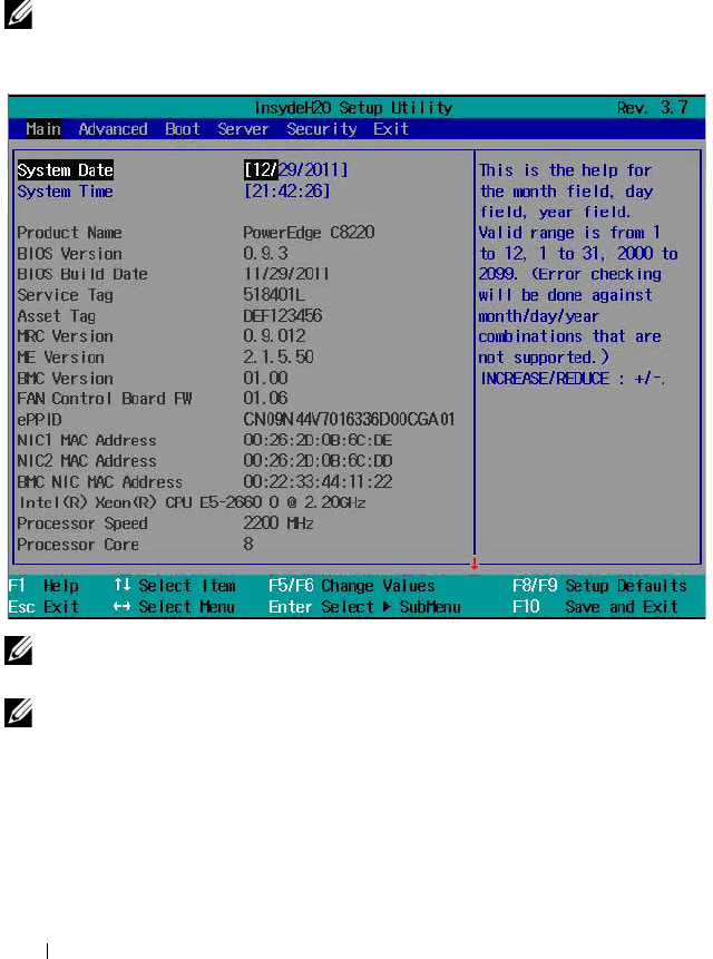
74 Using the System Setup Program
Main Menu
The main menu displays information about your system boards and BIOS.
Main Screen
NOTE: Press <Alt><H> to enter the BIOS debug mode and reset the BIOS to default
settings.
NOTE: The options for the System Setup program change based on the system
configuration.
NOTE: The System Setup program defaults are listed under their respective
options in the following sections, where applicable.

Using the System Setup Program 75
System Settings
Option Description
System Date Scroll to this item to adjust the date. Use <Enter>,
<Tab> or <Shift><Tab> to select a field. Use [+] or
[-] to configure system date.
System Time Scroll to this item to adjust the time. Use <Enter>,
<Tab> or <Shift><Tab> to select a field. Use [+] or
[-] to configure system time.
Product Name Displays the system product name.
BIOS Version Displays the BIOS version.
NOTE: Check this version number when updating BIOS from
the manufacturer.
BIOS Build Date Displays the date the BIOS was created.
Service Tag Displays the system service tag number. The service tag
field should match what is physically on the service tag of
the system.
Asset Tag Displays the system asset tag number.
MRC Version Displays the Memory Reference Code (MRC) firmware
version.
ME Version Displays the Manageability Engine (ME) firmware
version.
BMC Version Displays the Baseboard Management Controller (BMC)
firmware version.
FAN Control Board FW Displays the Fan Controller Board (FCB) firmware
version.
ePPID Displays the information from Electronic Piece Part
Identification (ePPID) label.
NIC1 MAC Address Displays the Media Access Control (MAC) address for the
NIC1 connector.
NIC2 MAC Address Displays the MAC address for the NIC2 connector.
BMC NIC MAC Address Displays the MAC address of the BMC management port.
Processor Type Displays the processor type.
Processor Speed Displays the current speed of the processor.

76 Using the System Setup Program
Processor Core Displays the processor core.
System Memory Size Displays total memory size installed on the system board.
System Memory Speed Displays the maximum speed of your system memory.
System Memory Voltage Displays the maximum voltage of your system memory.
Option Description
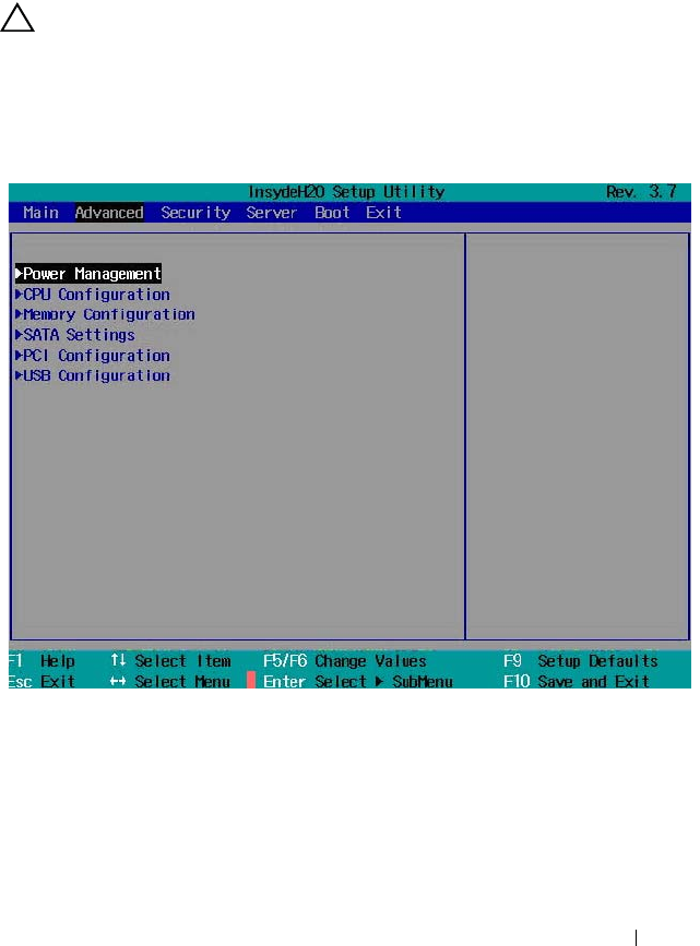
Using the System Setup Program 77
Advanced Menu
The advanced menu displays a table of items that defines advanced
information about your system. Scroll to this item and press <Enter> to view
the following screen.
CAUTION: Making incorrect settings to items on these pages may cause the
system to malfunction. Unless you have experience adjusting these items, it is
recommended that you leave these settings at the default values. If making
settings to items on these pages causes your system to malfunction or prevents the
system from booting, open BIOS and choose "Load Optimal Defaults" in the Exit
menu to boot up normally.
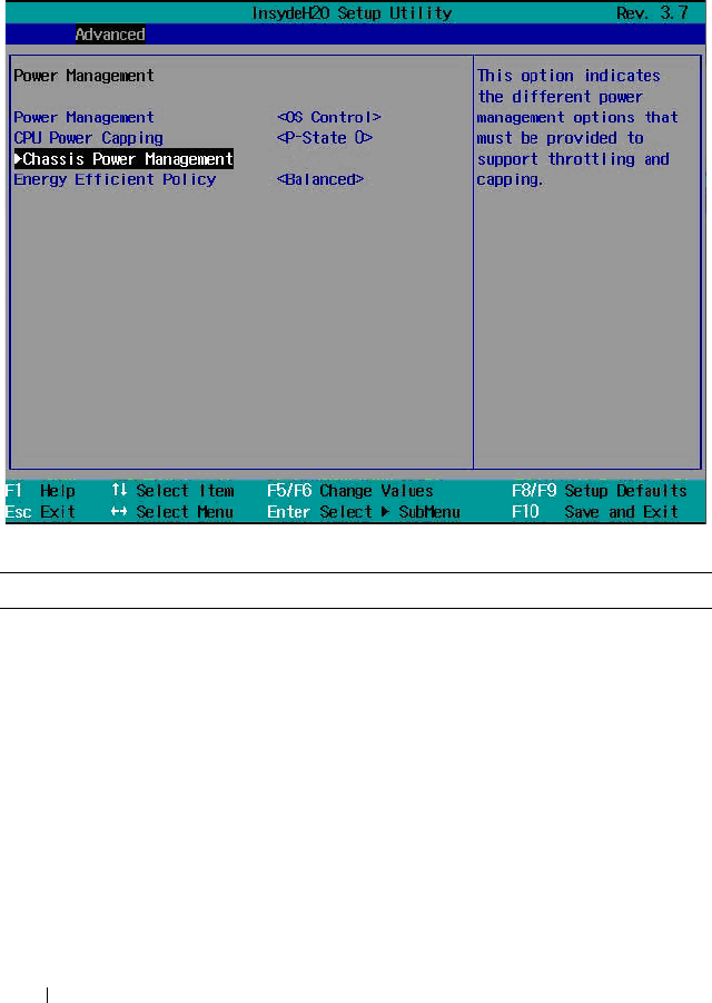
78 Using the System Setup Program
Power Management
Scroll to this item and press <Enter> to view the following screen.
Power Management
Option Description
Power Management
(OS Control default)
Select a system power management mode.
• Maximum Performance: Sets the system power
management to maximum performance.
• OS Control: Allows the operating system to control the
power management.
• Node Manager: Enables Node Manager to moderate
power consumption and performance of the processors in
the compute sled. Node manager delivers power reporting
and power capping functionality for individual compute
sleds.

Using the System Setup Program 79
CPU Power Capping
(P-State 0 default)
Select a processor performance state (P-state). Options are
[P-State 0], [P-State 1], [P-State 2], [P-State 3], and
[P-state 4].
NOTE: This option is enabled when Power Management is
set to OS Control mode.
Chassis Power
Management
Press <Enter> to set chassis power management.
This option indicates the different power management
options that control the system power consumption by
processor throttling and power capping.
Energy Efficient Policy
(
Balanced
default)
Select a power policy option.
• Max Performance: Sets the processors at the highest
performance state at all times.
• Balanced: Offers full performance and saves power by
reducing system power consumption during periods of
inactivity.
• Low Power: Use different processor power saving modes
(C-states) to reduce system power consumption.
NOTE: This option works when the OS does not support
power management control of the processor.
Option Description
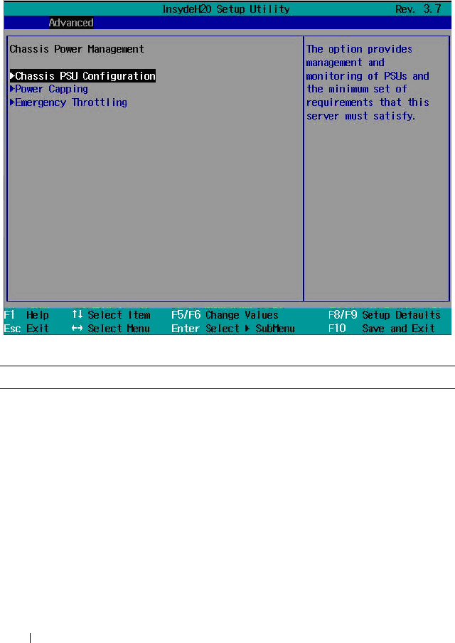
80 Using the System Setup Program
Chassis Power Management
Scroll to this item and press <Enter> to view the following screen.
Chassis Power Management
Option Description
Chassis PSU
Configuration
Press <Enter> to configure the chassis power supply.
This option provides management and monitoring of the
power supplies and the minimum set of requirements that
this server must satisfy.
Power Capping Press <Enter> to set power capping values.
This option controls system power by node manager
through the processor to limit power consumption in watts
for a sled.
NOTE: The sled’s total power consumption does not include
enclosure fan power energy use. The enclosure fan operates
at a maximum of 280 W of power.

Using the System Setup Program 81
Emergency Throttling Press <Enter> to configure the compute sled and chassis
emergency throttle functions.
This option sets the policy to take effect when the sled
detects a system emergency failure (such as fan error,
chassis critical power events, PSU critical power events,
abnormal ambient temperature, etc.).
NOTE: The FCB initiates emergency throttling when active
power supplies do not meet the maximum PSU configurations
or when the exhaust temperature control PWM output is
above 100%.
Option Description
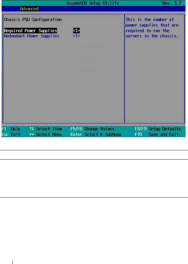
82 Using the System Setup Program
Chassis PSU Configuration
Scroll to this item and press <Enter> to view the following screen.
Chassis PSU Configuration
Refer to the Boundaries of PSU Configuration table on page 83 when
changing the configuration of the power supplies to load-shared or redundant
power.
Option Description
Required Power Supplies
(1 default)
Select the number of power supplies to provide load-shared
power to run the sleds in the enclosure. Options are [1],
[2], [3], and [4].
Redundant Power
Supplies (1 default)
Select the number of power supplies to provide power
redundancy to the enclosure. Options are [0], [1], and [2].

Using the System Setup Program 83
Boundaries of PSU Configuration
The number of power supplies required for PSU configuration is determined by the following formula:
X + N, where X is the required PSU and N is the redundant PSU.
PSU Number Required PSU (X) Redundant PSU (N)
44 0
31
22
32 1
22 0
11
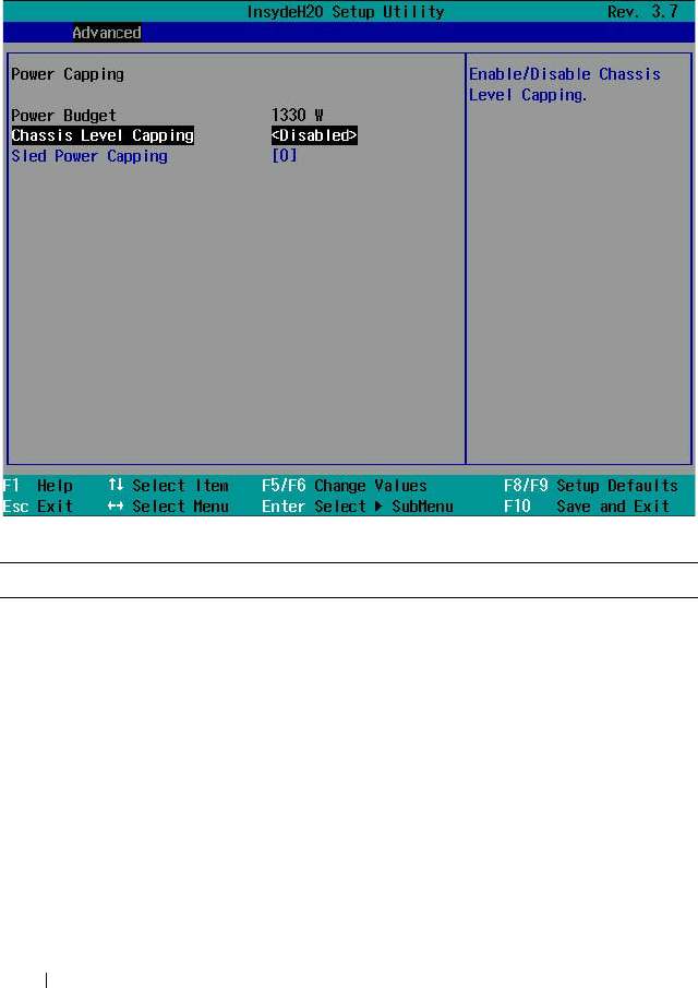
84 Using the System Setup Program
Power Capping
Scroll to this item and press <Enter> to view the following screens.
Power Capping
Option Description
Power Budget Displays the enclosure available power wattage.
It is the summary of each PSU’s capacity (i.e. based on the
number of PSUs and the maximum capacity of each PSU).
Each PSU supports a maximum output wattage of 1100 W
or 1400 W. Power budget in the enclosure must not exceed
2660 W.
The power budget is determined by the following formula,
power budget = (maximum output wattage of the
installed PSU x sum of the PSUs in the enclosure) x 0.95.
For example, in an enclosure with two PSUs the power
budget is (1400 W x 2 PSU) x 0.95 = 2660 W.
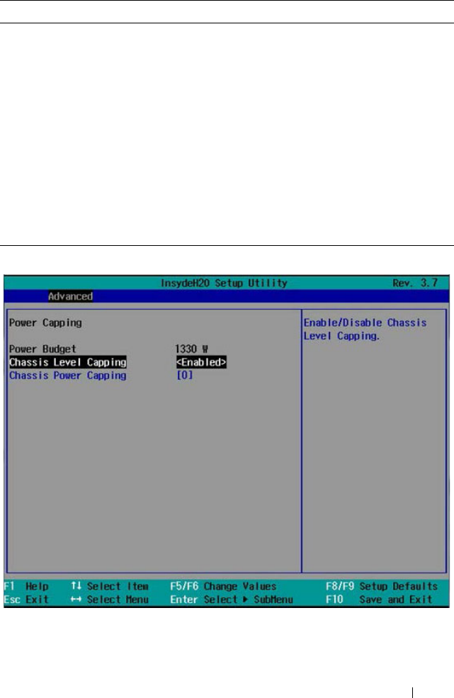
Using the System Setup Program 85
Chassis Level Capping
(Disabled default)
Set as chassis level or sled level power capping. (The
default setting is referred from BMC). The system
determines the power consumption of the enclosure and
sleds, and constantly attempts to maintain the enclosure’s
power consumption below the cap.
Sled Power Capping
(0 default)
NOTE: This option is enabled when the Chassis Level
Capping is set to Disabled.
The sled’s own power capping infrastructure is able to
determine power consumption of the sleds. When set to 0,
the power capping function is disabled. The minimum
wattage rating should not less than 100 W and the
maximum wattage rating should not be more than the
power budget value. Settings range from 100 to 1000 W.
Option Description

86 Using the System Setup Program
Power Capping
Option Description
Power Budget Displays the enclosure available power wattage.
It is the summary of each PSU’s capacity (i.e. based on the
number of PSUs and the maximum capacity of each PSU).
Each PSU supports a maximum output wattage of 1100 W
or 1400 W. Power budget in the enclosure must not exceed
2660 W.
The power budget is determined by the following formula,
power budget = (maximum output wattage of the
installed PSU x sum of the PSUs in the enclosure) x 0.95.
For example, in an enclosure with two PSUs the power
budget is (1400 W x 2 PSU) x 0.95 = 2660 W.
Chassis Level Capping
(Disabled default)
Set as chassis level or sled level power capping. (The
default setting is referred from BMC). The system
determines the power consumption of the enclosure and
sleds, and constantly attempts to maintain the enclosure’s
power consumption below the cap.
Chassis Power Capping
(0 default)
NOTE: This option is enabled when the Chassis Level
Capping is set to Enabled.
Determines the power consumption of the chassis. The
minimum wattage rating should not less than 1500 W and
the maximum wattage rating should not be more than the
power budget value. Settings range from 1500 to 9000 W.
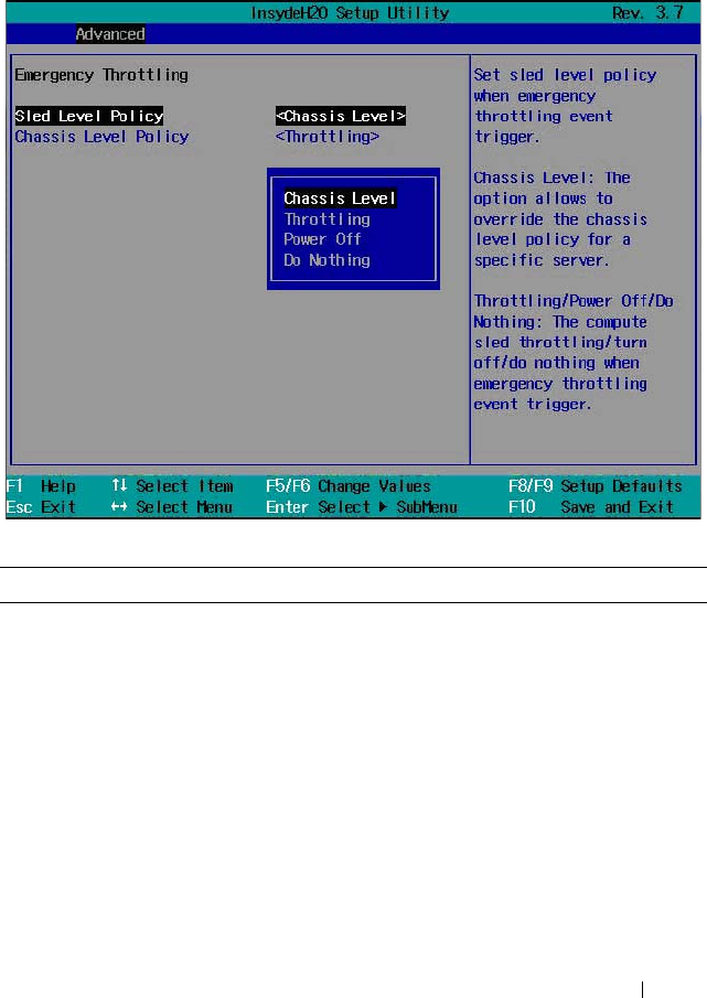
Using the System Setup Program 87
Emergency Throttling
Scroll to this item and press <Enter> to view the following screen.
Emergency Throttling
Option Description
Sled Level Policy
(Chassis Level default)
Select a sled level policy when an emergency throttle event
is triggered.
•
Chassis Level
: Overrides the chassis level policy for a
specific server.
• Throttling: Allows compute sled throttling when an
emergency throttle event is triggered.
•
Power Off
: Turns off the compute sled when an
emergency throttle event is triggered.
•
Do Nothing
: The compute sled will do nothing when an
emergency throttle event is triggered.
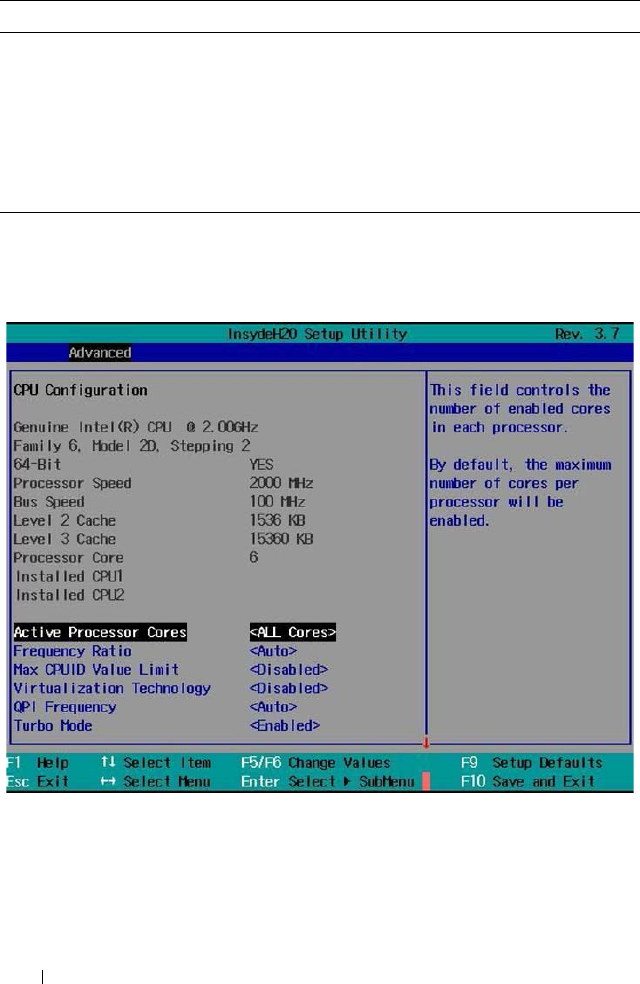
88 Using the System Setup Program
CPU Configuration
Scroll to this item and press <Enter> to view the following screen.
Chassis Level Policy
(Throttling default)
Select a chassis level policy when an emergency throttle
event is triggered. This option can be configured when the
Sled Level Policy is set to Chassis Level policy.
• Throttling: Allows server throttling when an emergency
throttle event is triggered.
•
Power Off
: Turns off the server power when an emergency
throttle event is triggered.
Option Description

Using the System Setup Program 89
CPU Configuration
Option Description
Active Processor Cores
(All Cores default)
Allows you to control the number of enabled cores in each
processor. Options are [1], [2], [4], [6], [8], [10]and [All
Cores]. (Option depends on processor core.)
Frequency Ratio
(Auto default)
Sets the frequency multipliers as maximum level.
Max CPUID Value
Limit
(Disabled default)
Some OS, which is (NT4), fails if the value returned in
EAX is > 3 when CPUID instruction is executed with
EAX=0.
When enabled, this setting limits CPUID function to 3.
When disabled, this setting disables the 3 or less.
Virtualization
Technology
(Disabled default)
Allows you to set the Virtualization Technology in
applicable CPUs.
Enabled (applicable CPUs)/Disabled (unusable in any
OS).
QPI Frequency
(Auto default)
Select the link speed. Options are [6.4GTs], [7.2GTs], and
[8.0GTs].
Tu rbo M o d e
(Enabled default)
Enables or disables processor Turbo mode.
C-States
(Enabled default)
When enabled, the processor(s) can operate in all available
power C states.
When disabled, the user power C states are not available
for the processor.
C1E State
(Enabled default)
Enables or disables the Enhanced Halt (C1E) state.
NOTE: Disable this option at your own risk. When you disable
this option, pop up message appears on the screen and
warning appears in the System Setup Help.
C6 State
(Enabled default)
Enables or disables the processor C6 state.
NOTE: Disable this option at your own risk. When you disable
this option, pop up message appears on the screen and
warning appears in the System Setup Help.

90 Using the System Setup Program
C7 State
(Enabled default)
Enables or disables the processor C7 state.
NOTE: This feature is available when the processor supports
C7 state.
NOTE: Disable this option at your own risk. When you disable
this option, a pop up message appears on the screen and
warning appears in the System Setup Help.
XD Bit Capability
(Enabled default)
Enables or disables the processor’s Execute Disable (XD)
Memory Protection Technology feature.
Direct Cache Access
(Enabled default)
Enables or disables the direct cache access.
Hyper-Threading
Techn olo gy
(Enabled default)
Enables or disables the Hyper-Threading technology.
Prefetch Configuration Press <Enter> to configure the prefetch settings.
NOTE: This feature is available when supported by the
processor.
Option Description
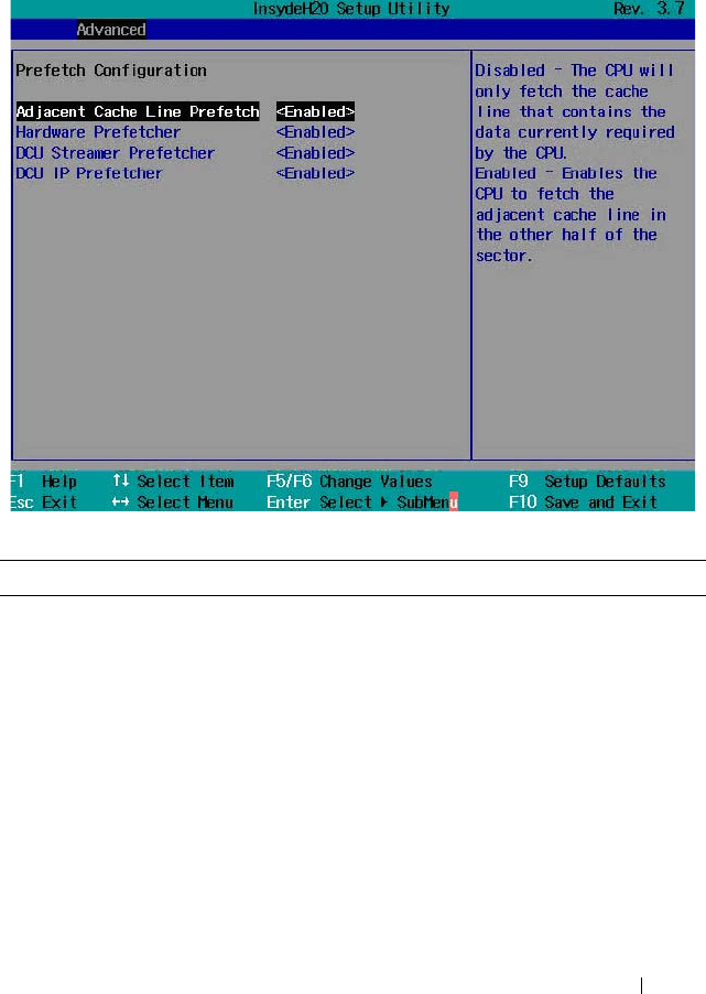
Using the System Setup Program 91
Prefetch Configuration
Scroll to this item and press <Enter> to view the following screen.
Prefetch Configuration
Option Description
Adjacent Cache Line
Prefetch
(Enabled default)
Enables or disables system optimization for sequential
memory access.
Hardware Prefetcher
(Enabled default)
Enables or disables the speculative unit within the
processor(s).
DCU Streamer
Prefetcher
(Enabled default)
Enables or disables Data Cache Unit (DCU) streamer
prefetcher.
NOTE: This feature is available when supported by the
processor.

92 Using the System Setup Program
Memory Configuration
Scroll to this item and press <Enter> to view the following screen.
Memory Configuration
DCU IP Prefetcher
(Enabled default)
Enables or disables DCU IP prefetcher.
NOTE: This feature is available when supported by the
processor.
Option Description
Memory Frequency
(Auto default)
Select an operating memory frequency. Options are
[Auto], [800], [1066], [1333], [1600], and [1866].
Memory Turbo Mode
(Disabled default)
Enables or disables the memory turbo mode.
NOTE: This feature is not available for Intel Xeon
E5-2600 v2 processors.
Option Description

Using the System Setup Program 93
Memory Throttling Mode
(Enabled default)
Enables or disables the memory to run in closed-loop
thermal throttling mode.
Memory Operating Mode
(Optimizer Mode default)
Select the type of memory operation if a valid memory
configuration is installed.
• Optimizer Mode: The two memory controllers run in
parallel 64-bit mode for improved memory
performance.
• Spare Mode: Enables memory sparing. In this mode,
one rank per channel is reserved as a spare.
If persistent correctable errors are detected on a rank,
the data from this rank is copied to the spare rank and
the failed rank is disabled.
With memory sparing enabled, the system memory
available to the operating system is reduced by one
rank per channel.
For example, in a dual-processor configuration with
sixteen 32 GB quad-rank DIMMs, the available
system memory is: 32 GB x 16(DIMMs) – 32/4 (rank
size) x 8 (channels) = 448 GB.
With sixteen 64 GB 8-rank LRDIMMs which use
Rank Multiplication(RM)=4, the available system
memory is: 64 GB x 16(DIMMs) – 64/8x4 (rank size)
x 8 (channels) = 768 GB.
• Mirror Mode: Enables memory mirroring
• Advanced ECC Mode: Controllers are joined in
128-bit mode running multi-bit advanced ECC.
Demand Scrubbing
(Enabled default)
Enables or disables DRAM scrubbing.
DRAM scrubbing is the ability to write corrected data
back to the memory once a correctable error is detected
on read transaction.
Patrol Scrubbing
(Enabled default)
Enables or disables patrol scrubbing.
Patrol scrubbing proactively searches the system
memory, repairing correctable errors.
Option Description

94 Using the System Setup Program
Memory Operating Voltage
(Auto default)
If set to Auto, the system sets the voltage to an optimal
value based on the capacity of the installed memory
modules. You can also set the voltage of the memory
module to a higher value (1.5 V) provided that the
modules support multiple voltages. Options are [Auto],
[1.5 volts], and [1.35 volts].
NOTE: BIOS will auto restrict selection if DIMM is not
supporting low voltage.
NUMA Support
(Enabled default)
Enables or disables Non-Uniform Memory Access
(NUMA) support to improve processor performance.
NOTE: This option is available for NUMA systems that
allow memory interleaving across all processor nodes.
Memory Mapped I/O
(Auto default)
Select the base address register for the PCIe memory
space. Options are [Auto], [32-bit], and [64-bit].
Memory Refresh Rate
(X1 default)
Enables or disables the 2X memory refresh rate.
Option Description
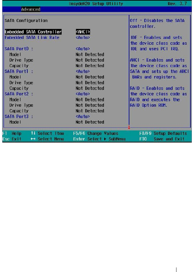
Using the System Setup Program 95
SATA Configuration
Scroll to this item and press <Enter> to view the following screen.

96 Using the System Setup Program
SATA Configuration
Option Description
Embedded SATA
Controller
(AHCI default)
Select an operation mode for the onboard SATA controller.
• Off: Disables the SATA controller. This token applies to
the first onboard SATA controller.
• IDE: Enables the SATA controller to run in IDE mode.
Sets the device class code as IDE and uses PCI IRQ
(referred as Native mode). This token applies to the first
onboard SATA controller.
• AHCI: Enables the SATA controller to run in AHCI
mode. Sets the device class code as SATA and sets up the
AHCI BARs and registers. This token applies to the first
onboard SATA controller.
• RAID: Enables the SATA controller to run in RAID mode.
Sets the device class code as RAID and executes the RAID
Option ROM. This token applies to the first onboard
SATA controller. This provides access to the RAID setup
utility during system bootup.
Embedded SATA Link
Rate (Auto default)
Select a SATA link speed.
• Auto: Sets the SATA link speed at maximum 6.0 Gbps.
• 1.5 Gbps: Sets the SATA link speed to 1.5 Gbps. For
power consumption.
• 3.0 Gbps: Sets the SATA link speed to 3.0 Gbps.
SATA Port 0
(Auto default)
When set to off, turns off the 1st Serial ATA drive
controller.
When set to auto, enables BIOS support for the 1st Serial
ATA drive controller (enabled if present, POST error if not
present).
SATA Port 1
(Auto default)
When set to off, turns off the 2nd Serial ATA drive
controller.
When set to auto, enables BIOS support for the 2nd Serial
ATA drive controller (enabled if present, POST error if not
present).

Using the System Setup Program 97
SATA Port 2
(Auto default)
When set to off, turns off the 3rd Serial ATA drive
controller.
When set to auto, enables BIOS support for the 3rd Serial
ATA drive controller (enabled if present, POST error if not
present).
SATA Port 3
(Auto default)
When set to off, turns off the 4th Serial ATA drive
controller.
When set to auto, enables BIOS support for the 4th Serial
ATA drive controller (enabled if present, POST error if not
present).
SATA Port 4
(Auto default)
When set to off, turns off the 5th Serial ATA drive
controller.
When set to auto, enables BIOS support for the 5th Serial
ATA drive controller (enabled if present, POST error if not
present).
SATA Port 5
(Auto default)
When set to off, turns off the 6th Serial ATA drive
controller.
When set to auto, enables BIOS support for the 5th Serial
ATA drive controller (enabled if present, POST error if not
present).
Power Saving Features
(Auto default)
Enables or disables the feature that allows SATA hard-
drives to initiate link power management transitions.
HDD Security Erase
(Disabled default)
Enables or disables the hard-drive security freeze lock
feature.
Option Description
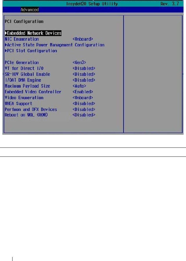
98 Using the System Setup Program
PCI Configuration
Scroll to this item and press <Enter> to view the following screen.
PCI Configuration
Option Description
Embedded Network Devices Press <Enter> to configure available network drives.
NIC Enumeration
(Onboard default)
Select a LAN boot ROM option.
• Onboard: Uses the PXE boot on NICs to boot the
system.
• Add-in: Use the PXE boot on add-in network adapters
to boot the system.
Active State Power
Management Configuration
Press <Enter> to configure power management for
PCI Express devices.

Using the System Setup Program 99
PCI Slot Configuration Press <Enter> to configure PCI Express devices.
NOTE: When you install an Intel Xeon Phi card in the
C8220X sled, BIOS automatically enables the PCI memory
64-bit decode option.
PCIe Generation
(Gen3 default)
Select a PCI signaling rate.
• Gen1: 2.5 GT/s
•Gen2: 5 GT/s
•Gen3: 8 GT/s
VT for Direct I/O
(Disabled default)
Enables or disables Intel hardware virtualization
support.
SR-IOV Global Enable
(Disabled default)
Enables or disables BIOS configuration of Single Root
I/O Virtualization (SR-IOV) devices.
I/OAT DMA Engine
(Disabled default)
If set to Enabled, the I/O Acceleration Technology
(I/OAT) feature is enabled for network controllers that
support this technology.
Maximum Payload Size
(Auto default)
Sets the maximum payload size of the PCI Express
controller. Options are Auto, 128 bytes, and 256 bytes.
Embedded Video Controller
(Enabled default)
Enables or disables the onboard video controller.
NOTE: This option should always be set to Enabled. The
remote KVM function cannot function if set to disabled.
Video Enumeration
(Onboard default)
Select video controller enumeration type.
• Onboard - The onboard video controller is used for
boot-time messages.
• Add-in - The first add-in video controller is used for
boot-time messages. Depending on the BIOS search
order and system slot layout.
WHEA Support
(Disabled default)
Enables or disables the Windows Hardware Error
Architecture (WHEA) feature.
Perfmon and DFX Devices
(Disabled default)
Enables or disables the Perfmon devices (e.g. disk
usage, memory consumption, and CPU load) DFX
devices (such as a USB adaptor) installed in the system.
Option Description
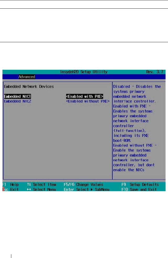
100 Using the System Setup Program
Embedded Network Devices
Scroll to this item and press <Enter> to view the following screen.
Reboot on WOL (ROW)
(Disabled default)
Enables or disables reboot on wake-on-LAN feature.
Reboot On WOL targets network controllers when the
network controller receives a magic packet. This option
displays when the network chip supports Reboot on
WOL feature.
Option Description

Using the System Setup Program 101
Embedded Network Devices
Option Description
Embedded NIC1
(Enabled with PXE
default)
Enables or disables the onboard NIC1 controller.
• Enabled with PXE: Allows you to enable the system’s
primary embedded NIC (full function), including its PXE
boot-ROM.
• Enabled without PXE: Allows you to enable the system’s
primary embedded NIC only. The NIC associated PXE or
RPL boot-ROM are disabled in this option.
• iSCSI Remote Boot: Allows you to configure the iSCSI
target and initiator variables to support iSCSI Remote
Boot. Changes take effect after the system reboots.
• Disabled: Allows you to disable the system’s primary
embedded NIC.
Embedded NIC2
(Enabled without PXE
default)
Enables or disables the onboard NIC2 controller.
• Enabled with PXE: Allows you to enable the system’s
secondary embedded NIC (full function), including its
PXE boot-ROM.
• Enabled without PXE: Allows you to enable the system’s
secondary embedded NIC only. The NIC associated PXE
or RPL boot-ROM are disabled in this option.
• iSCSI Remote Boot: Allows you to configure the iSCSI
target and initiator variables to support iSCSI Remote
Boot. Changes take effect after the system reboots.
• Disabled: Allows you to disable the system’s primary
embedded NIC.
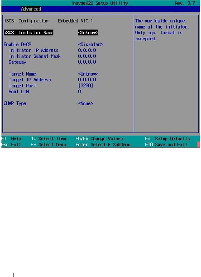
102 Using the System Setup Program
iSCSI Remote Boot
Select iSCSI Remote Boot in the Embedded NIC1/NIC2 option and press
<Enter> to view the following screen.
iSCSI Remote Boot
Option Description
iSCSI Initiator Name Displays the worldwide unique name of the initiator.
NOTE: Only iqn format is accepted.
Enable DHCP
(Disabled default)
Enables or disables the DHCP network settings.
Initiator IP Address Sets the initiator’s static IP address.
Initiator Subnet Mask Sets the subnet mask for the static IP address.
Gateway Sets the IP gateway for the static IP address.
Target Name Sets the name for the target IP.
Target IP Address Sets the target’s IP address.
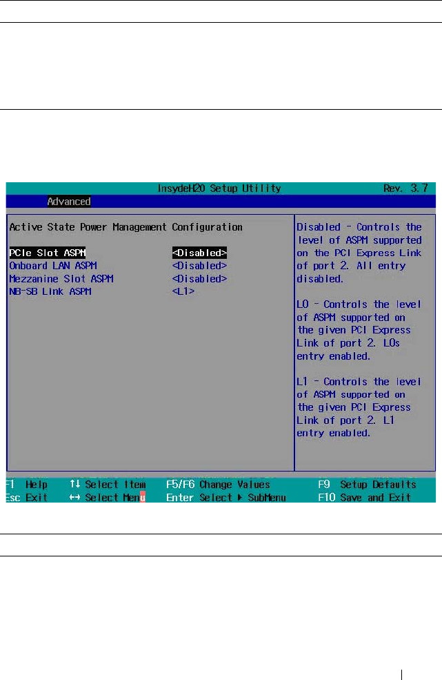
Using the System Setup Program 103
Active State Power Management Configuration
Scroll to this item and press <Enter> to view the following screen.
Active State Power Management Configuration
Target Port Sets the target port.
Boot LUN Sets the hexadecimal representation of LU number.
CHAP Type
(None default)
Select CHAP type. Options are [None], [One Way
CHAP], and [Mutual CHAP].
Option Description
PCIe Slot ASPM
(Disabled default)
Select an active state power management (ASPM)
protocol for the PCI Express slot. Options are
[Disabled] and [L1].
Onboard LAN ASPM
(Disabled default)
Select an ASPM protocol for the onboard network
controller. Options are [Disabled] and [L1].
Option Description
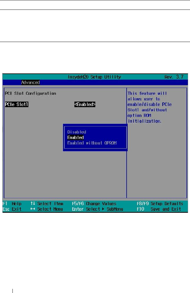
104 Using the System Setup Program
PCI Slot Configuration
Scroll to this item and press <Enter> to view the following screen.
Mezzanine Slot ASPM
(Disabled default)
Select an ASPM protocol for the mezzanine slot.
NB-SB Link ASPM
(L1 default)
Select an ASPM protocol for the northbridge and
southbridge chipsets.
Option Description
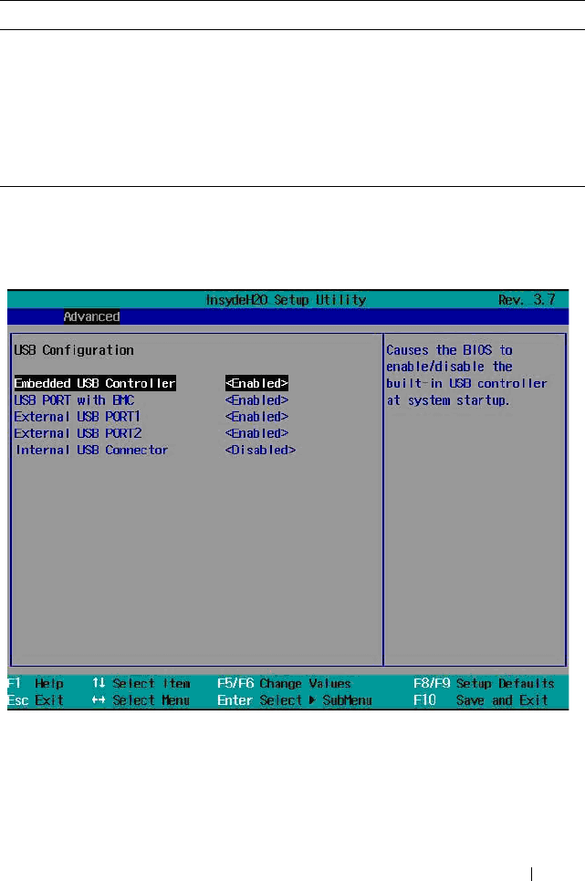
Using the System Setup Program 105
PCI Slot Configuration
USB Configuration
Scroll to this item and press <Enter> to view the following screen.
Option Description
PCIe Slot1
(Enabled default)
Enables or disables the PCI Express slot. Options are
[Disabled], [Enabled], [Enabled without OPROM].
NOTE: When you install an Intel Xeon Phi card in the
C8220X sled, BIOS automatically enables the PCI memory
64-bit decode option. You can set the GPGPU information
using IPMI commands. See Table 2-18 for more
information.

106 Using the System Setup Program
USB Configuration
Option Description
Embedded USB
Controller
(Enabled default)
Enables or disables the onboard USB controller at system
startup.
USB Port with BMC
(Enabled default)
Enables or disables internal USB port with BMC support.
External USB Port1
(Enabled default)
Enables or disables the external USB port1.
External USB Port2
(Enabled default)
Enables or disables the external USB port2.
Internal USB Connector
(Enabled default)
Enables or disables the internal USB port.
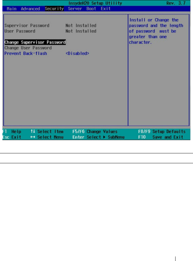
Using the System Setup Program 107
Security Menu
The security menu enables you to set the security parameters. Scroll to this
item and press <Enter> to view the following screen.
Security Settings
Option Description
Supervisor Password Indicates whether a supervisor password has been set. If
the password has been installed, Installed is displayed. If
not, Not Installed is displayed.
User Password Indicates whether a supervisor password has been set. If
the password has been installed, Installed displays. If not,
Not Installed displays.

108 Using the System Setup Program
Change Supervisor You can install a Supervisor password, and if you install a
supervisor password, you can then install a user password.
A user password does not provide access to many of the
features in the Setup utility. Note, the Change User
Password option only appears after a Supervisor password
has been set.
Select this option and press <Enter> to access the sub
menu, a dialog box appears which lets you enter a
password. You can enter no more than six letters or
numbers. Press <Enter> after you have typed in the
password. A second dialog box asks you to retype the
password for confirmation. Press <Enter> after you have
retyped it correctly. If the password confirmation is
incorrect, an error message appears. The password is stored
in NVRAM after ezPORT completes. The password is
required at boot time, or when the user enters the Setup
utility.
Change User Password Installs or changes the User password.
Prevent Back-flash
(Disabled default)
This option, when enabled, will prohibit the system BIOS
to downgrade to version 2.1.0 or earlier version.
WARNING: You will not be able to change the setting once
the feature is enabled. It is strongly recommended not
to enable this unless absolutely necessary.
NOTE: Once enabled, you cannot use the NVRAM clear
jumper to change the prevent back-flash settings to
disabled.
Option Description
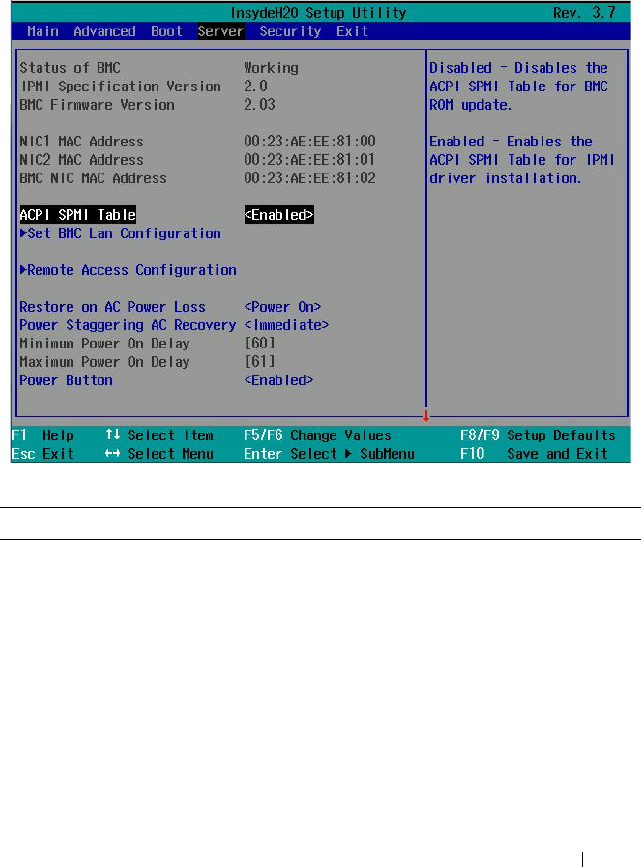
Using the System Setup Program 109
Server Menu
The server menu enables you to configure compute sled parameters. Scroll to
this item and press <Enter> to view the following screen.
Server Settings
Option Description
Status of BMC Displays BMC status.
IPMI Specification Version Displays the Intelligent Platform Management
Interface (IPMI) firmware version number.
BMC Firmware Version Displays the BMC firmware version number.
NIC1 MAC Address Displays the MAC address for the NIC1 connector.
NIC2 MAC Address Displays the MAC address for the NIC2 connector.
BMC NIC MAC Address Displays the MAC address for the BMC NIC
connector.

110 Using the System Setup Program
ACPI SPMI Table
(Enabled default)
When enabled, BIOS enables Advanced Configuration
and Power Interface (ACPI) Service Processor
Management Interface (SPMI) table for IPMI driver
installation.
When disabled, BIOS disables the ACPI SPMI table
for BMC ROM update.
Set BMC LAN
Configuration
Press <Enter> to set the BMC network.
Remote Access
Configuration
Press <Enter> to configure serial port settings related
to console redirection.
Restore on AC Power Loss
(Power On default)
Select the power state when the AC power is back.
• Power Off: System remains off until the power button
is pressed.
• Last State: System reverts to the last power state
before power loss.
• Power On: System switches back on after the AC
power loss.
Power Staggering AC
Recovery
(Immediate default)
Set the time period for the system to turn back on from
an AC power loss once power is resumed.
• Immediate: Power On (No Delay)
•Random: Auto
• User Defined: User defined delay time.
Power Button
(Enabled default)
When enabled, the power button can turn the system's
power off.
When disabled, the power button can only turn on
system power.
View System Event Log Press <Enter> to view the BMC system event log.
Event Logging
(Enabled default)
Enables or disables BIOS to log system events.
NMI on Error
(Enabled default)
Enables or disables BIOS to generate an Non-masked
Interrupt (NMI) when an uncorrectable PCI Express
error occurs.
Option Description
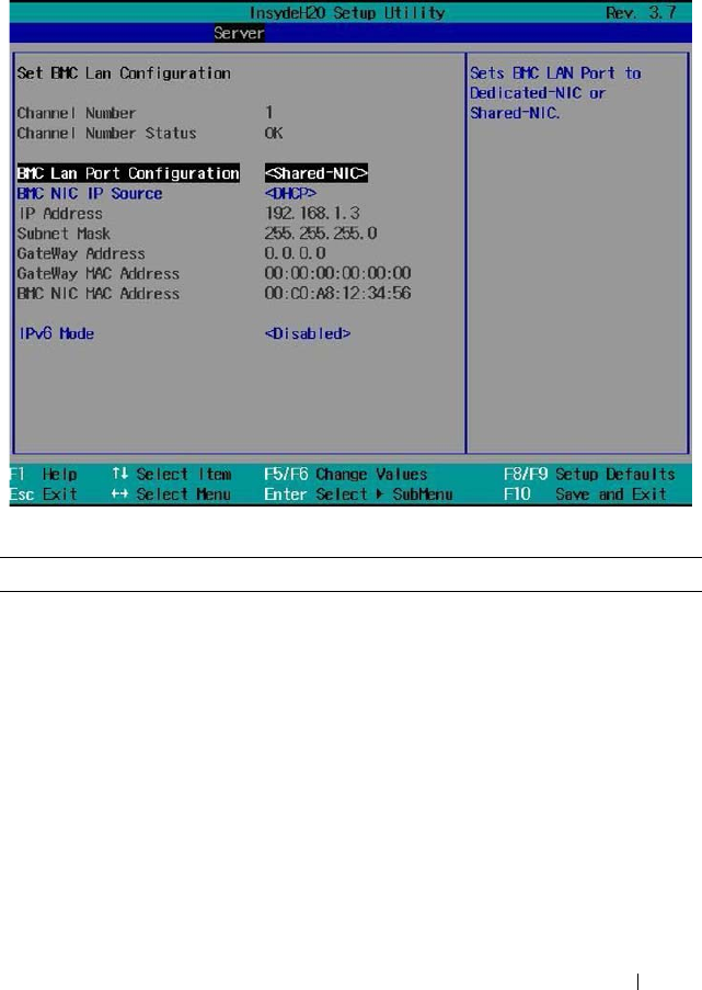
Using the System Setup Program 111
Set BMC LAN Configuration
Scroll to this item and press <Enter> to view the following screen.
Set BMC LAN Configuration
Option Description
Channel Number Displays the channel number used for BMC LAN.
Channel Number Status Displays the BMC channel number status.
BMC LAN Port
Configuration
(Shared-NIC default)
Set the BMC management port to dedicated or shared
NIC port. Options are [Dedicated NIC] and [Shared NIC].
BMC NIC IP Source
(DHCP default)
Set BMC to obtain its IP address using DHCP or establish
a static IP address.
IP Address Sets the static IP address.
Subnet Mask Sets the subnet mask for the static IP address.
Gateway Address Sets the IP gateway for the static IP address.
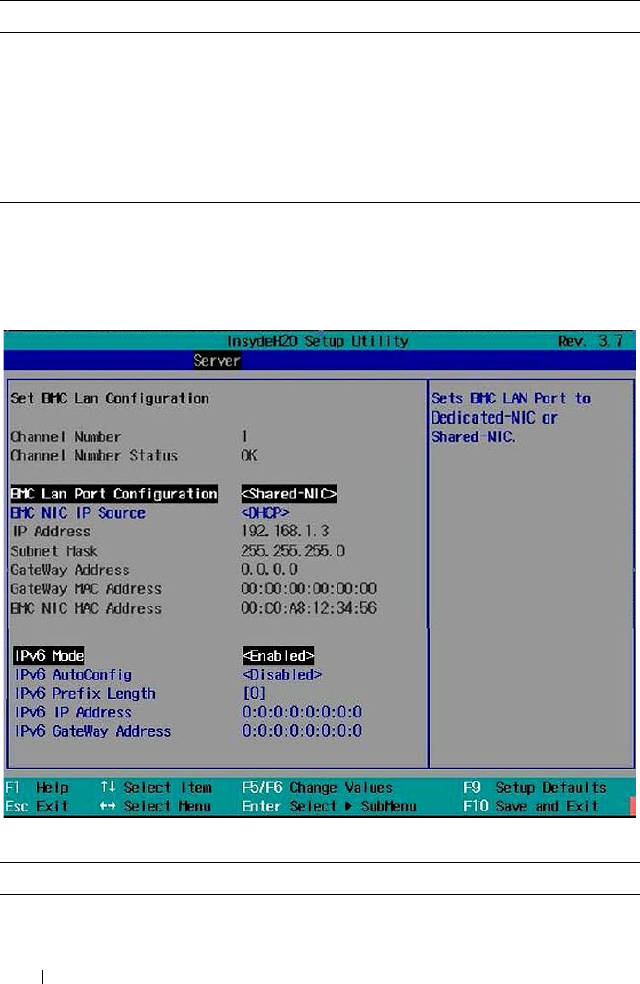
112 Using the System Setup Program
IPv6 Mode
Select Enabled in the IPv6 Mode option and press <Enter> to view the
following screen.
IPv6 Mode
Gateway MAC Address Sets the MAC address for the static IP address.
BMC NIC MAC
Address
Sets the MAC address for the BMC management port.
IPv6 Mode
(Disabled default)
Enables or disables the IPv6 internet protocol support.
If set to enabled, configure the IPv6 prefix, IP and gateway
addresses.
Option Description
IPv6 AutoConfig Enables or disables IPv6 auto configuration.
Option Description
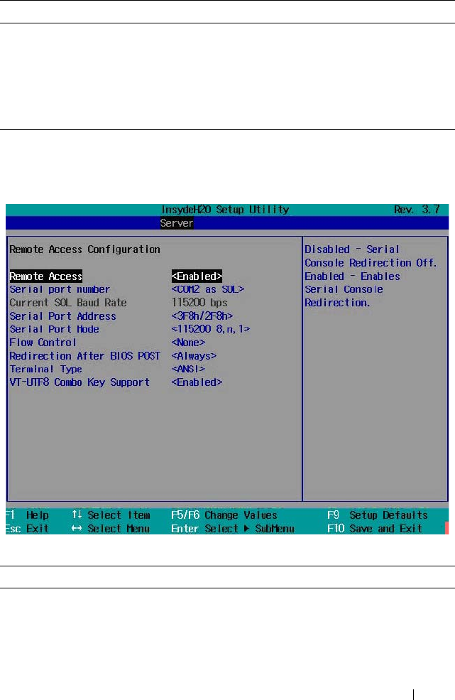
Using the System Setup Program 113
Remote Access Configuration
Scroll to this item and press <Enter> to view the following screen.
Remote Access Configuration
IPv6 Prefix Length Sets prefix length of the IPv6 address.
IPv6 IP Address Set the BMC management port to dedicated or shared
NIC port. Options are [Dedicated NIC] and [Shared NIC].
IPv6 IP Address Sets the BMC IPv6 address.
IPv6 Gateway Address Sets the MAC address for the static IPv6 address.
Option Description
Remote Access
(Enabled default)
Enables or disables serial console redirection.
Option Description

114 Using the System Setup Program
Serial port number
(COM1 default)
Select a serial port for console redirection.
• COM1: Enables console redirection via COM1. See
token D7h.
• COM2 as SOL: Enables console redirection via
COM2.
Serial Port Address
(3F8h/2F8h default)
Specifies the base I/O port address of the serial port.
•
3F8h/2F8h
: Sets the front serial port address as 0x3F8
and internal serial port address as 0x2F8.
• COM2 as SOL: Sets the front serial port address as
0x2F8 and internal serial port address as 0x3F8.
Serial Port Mode
(115200 8,n,1 as default)
Select a baud rate for the serial port. Options are
[115200 8,n,1], [57600 8,n,1], [38400 8,n,1],
[192008,n,1], and [9600 8,n,1].
Flow Control
(None default)
Select a flow control for console redirection. Options
are [None] and [Software].
Redirection After BIOS
POST (Always default)
If set to Always, the console redirection is always active.
When Disabled, console redirection is turned off after
POST.
Terminal Ty pe
(ANSI default)
Select a target terminal type for console redirection.
Options are [ANSI], [VT100], and [VT-UTF8].
VT-UTF8 Combo Key
Support (Enabled default)
Enables or disables the VT-UTF8 Combination Key
support for ANSI/VT100 terminals.
Option Description
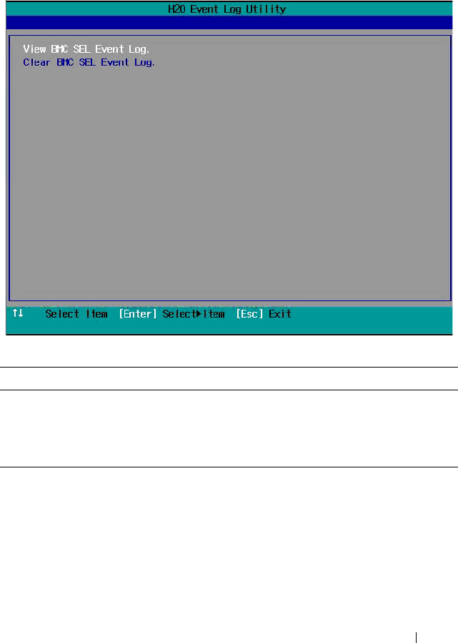
Using the System Setup Program 115
View System Log
Scroll to this item and press <Enter> to view the following screen.
View System Log
Option Description
View BMC SEL Event
Log
View all events in the BMC system event log.
Clear BMC SEL Event
Log
Deletes all records in the BMC system event log.
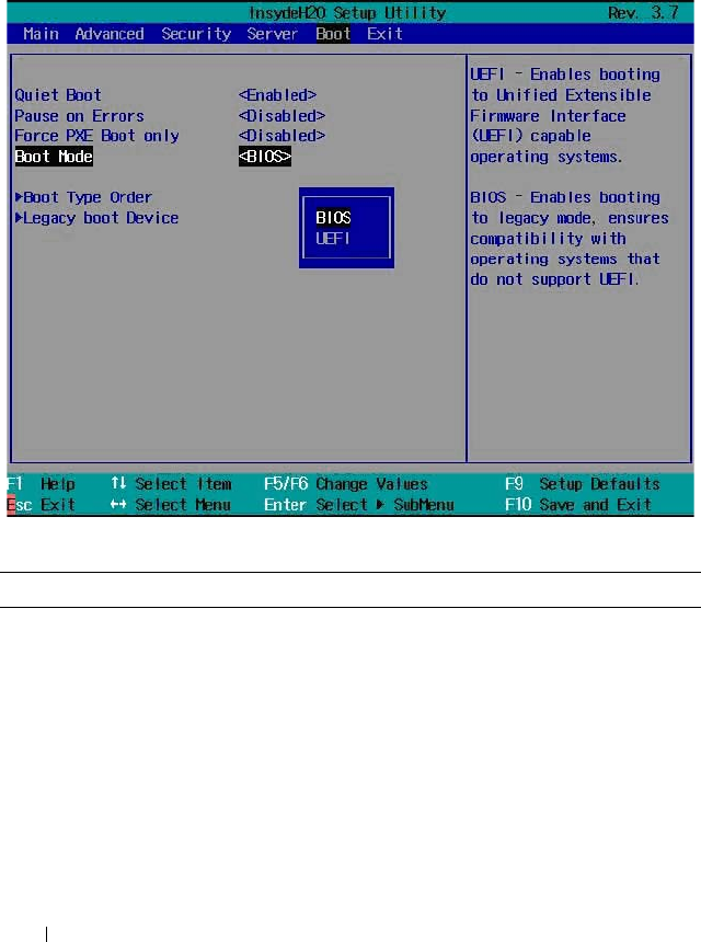
116 Using the System Setup Program
Boot Menu
The boot menu enables you to set POST boot parameters. Scroll to this item
and press <Enter> to view the following screen.
Boot Settings
Option Description
Quiet Boot
(Enabled default)
Enable this item to display the splash or summary
screen, rather than the detail of the POST flow. When
disabled, normal POST messages appear.
Pause on Errors
(Disabled default)
Enables or disables BIOS to prompt you to press <F1>
or <F2> keys on errors during POST.
Force PXE Boot only
(Disabled default)
Enables or disables PXE to be the only boot device.

Using the System Setup Program 117
Boot Mode
(BIOS default)
Select a system boot mode.
•
BIOS
: The
standard BIOS-level boot interface
•UEFI: A
n enhanced 64-bit boot interface based on
Unified Extensible Firmware Interface (UEFI)
specifications that overlays the system BIOS.
Boot Type Order Press <Enter> to set the preferred boot sequence from
the available devices.
Legacy Boot Device Press <Enter> to set the preferred boot sequence from
the available legacy USB devices.
Option Description
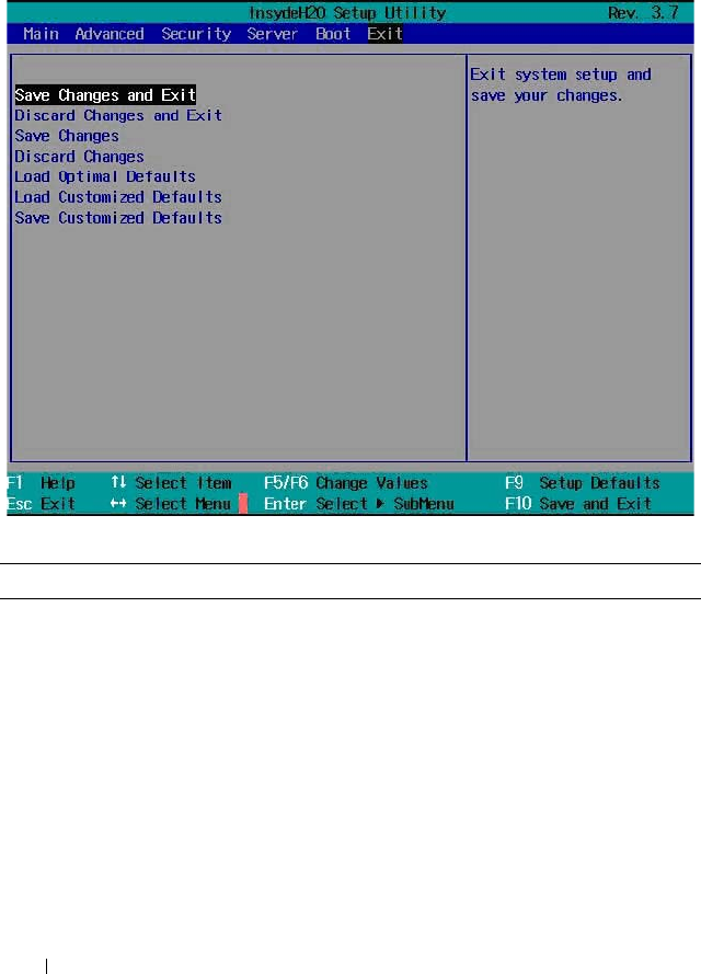
118 Using the System Setup Program
Exit Menu
Scroll to this item and press <Enter> to view the following screen.
Exit Options
Option Description
Save Changes and Exit Highlight this item and press <Enter> to save any
changes that you have made in the Setup utility and
exit the Setup utility. When the Save Changes and Exit
dialog box appears, press <Y> to save the changes and
exit, or press <N> to return to the setup main menu.
Discard Changes and Exit Highlight this item and press <Enter> to discard any
changes that you have made in the Setup utility and
exit the Setup utility. When the Discard Changes and
Exit dialog box appears, press <Y> to discard changes
and exit, or press <N> to return to the setup main
menu.

Using the System Setup Program 119
Save Changes Select this item and press <Enter> to save changes
you have made without leaving the setup utility.
Discard Changes Select this item and press <Enter> to discard any
changes you have made without leaving the setup
utility.
Load Optimal Defaults If you highlight this item and press <Enter>, a dialog
box asks if you want to install optimal settings for all
the items in the Setup utility. Press the <Y> key to
indicate Yes, and then press <Enter> to install the
optimal settings.
The optimal settings default values are quite
demanding and your system might not function
properly if you are using slower memory chips or other
kinds of low-performance components.
Load Customized Defaults Load 2nd default values from NVRAM for all the setup
parameters.
Save Customized Defaults Save all the setup parameters to NVRAM as 2nd
default values.
Option Description

120 Using the System Setup Program
Command Line Interfaces for System Setup
Options
The options in the System Setup menu allows you to control the System
Configuration Utility (syscfg). This utility is included in the Dell
OpenManage Deployment Toolkit (DTK).
See the Deployment Toolkit Version 1.3 User's Guide for additional
information about installing and using the DTK utilities, and the
Deployment Toolkit Version 1.3 Command Line Interface Reference Guide
for a complete list of all valid options, suboptions, and arguments for using
the BMCCFG.EXE to configure and manage your BMC.
You can use the system configuration utility for the following conditions:
• To change the System Setup option by D4 token:
./syscfg –t=D4_token_id
(Example: ./syscfg -t=0x002D to enable NIC1 Option ROM)
• To check token activity status:
./syscfg --istokenactive=D4_token_id
(Example: ./syscfg --istokenactive=0x002D to check the token active
status of NIC1 Option ROM)
• To directly change the System Setup option through BMC memory:
./ipmitool raw <command> <data>
(Example: ./ipmitool raw 0xc 1 1 3 10 106 42 120 to set IP address of BMC
management port as 10.106.42.120)
Table 2-1. D4 Token Table
Token Setup Option Description
002D Embedded NIC1 Enables the onboard NIC1 controller (full-function),
including its PXE boot-ROM.
002E Embedded NIC1 Disables the onboard NIC1 controller.
0051 N/A For the next system boot, set the IPL priority to: USB
storage, hard disk, CD/DVD-ROM, RAID, Network (if
the devices are available).

Using the System Setup Program 121
0052 N/A For the next system boot, set the IPL priority to: hard
disk then option ROMs (if the devices are available).
0053 N/A For the next system boot, set the IPL priority to:
Network, hard disk, RAID,USB storage, CD/DVD-
ROM (if the devices are available).
0054 N/A For the next system boot, set the IPL priority to:
CD/DVD-ROM, USB Storage, hard disk, RAID,
Network (if the devices are available).
005C N/A Enables BIOS remote update on the next reboot, to
search for an operating-system initiated BIOS update
image.
005D N/A Disables BIOS remote update on the next reboot, to
search for an operating-system initiated BIOS update
image.
006E Embedded NIC1 Enables the onboard NIC1 controller, but disables the
NIC associated PXE or RPL boot-ROM.
0087 Video
Enumeration
Allows BIOS to use the onboard video controller for
boot-time messages.
0088 Video
Enumeration
Allows BIOS to use the first add-in video controller for
boot-time messages. Depending on the BIOS search
order and system slot layout.
008C Embedded USB
Controller
Allows BIOS to enable the built-in USB controller at
system startup.
008D Embedded USB
Controller
Allows BIOS to enable the built-in USB controller at
system startup.
00A1 Restore on AC
Power Loss
System remains off until the power button is pressed.
00A2 Restore on AC
Power Loss
System reverts to the last power state before power
loss.
00A3 Restore on AC
Power Loss
System switches back on after the AC power loss.
00BA Embedded NIC2 Disables the onboard NIC2 controller.
Table 2-1. D4 Token Table
(continued)
Token Setup Option Description

122 Using the System Setup Program
00BB Embedded NIC2 Enables the onboard NIC2 controller, but disables the
NIC associated PXE or RPL boot-ROM.
00BC Embedded NIC2 Enables the onboard NIC2 controller (full-function),
including its PXE boot-ROM.
00BF Remote Access Disables serial console redirection.
00C0 Serial port
number
Enables console redirection via COM1. See token
D7h.
00C1 Power Button Enables the power button to turn off the system
power. (default)
00C2 Power Button Disables the power button to turn off the system
power.
00D1 Hyper-Threading
Technology
Enables Hyper-Threading Technology.
00D2 Hyper-Threading
Technology
Disables Hyper-Threading Technology.
00D7 Serial port
number
Enables console redirection via COM2.
00D8 Load Optimal
Defaults
Install optimal default settings for all the items in the
Setup utility on the next boot.
00FE Legacy USB
Support
Disables the system to provide legacy USB support for
the operating system.
00FF Legacy USB
Support
Enables the system to provide legacy USB support for
the operating system.
0117 SATA Port0 Turns off the 1st Serial ATA drive controller.
0118 SATA Port0 Enables BIOS support for the 1st Serial ATA drive
controller (enabled if present, POST error appears if
not present).
0119 SATA Port1 Turns off the 2nd Serial ATA drive controller.
011A SATA Port1 Enables BIOS support for the 2nd Serial ATA drive
controller (enabled if present, POST error appears if
not present).
Table 2-1. D4 Token Table
(continued)
Token Setup Option Description

Using the System Setup Program 123
011B SATA Port2 Turns off the 3rd Serial ATA drive controller.
011C SATA Port2 Enables BIOS support for the 3rd Serial ATA drive
controller (enabled if present, POST error appears if
not present).
011D SATA Port3 Turns off the 4th Serial ATA drive controller.
011E SATA Port3 Enables BIOS support for the 4th Serial ATA drive
controller (enabled if present, POST error appears if
not present).
011F SATA Port4 Turns off the 5th Serial ATA drive controller.
0120 SATA Port4 Enables BIOS support for the 5th Serial ATA drive
controller (enabled if present, POST error appears if
not present).
0121 SATA Port5 Turns off the 6th Serial ATA drive controller.
0122 SATA Port5 Enables BIOS support for the 6th Serial ATA drive
controller (enabled if present, POST error appears if
not present).
0135 Embedded SATA
Controller
Disables the SATA controller. This token applies to
the first onboard SATA controller.
0137 Embedded SATA
Controller
Enables the SATA controller to run in IDE mode. Sets
the device class code as IDE and uses PCI IRQ
(referred as Native mode). This token applies to the
first onboard SATA controller.
0138 Embedded SATA
Controller
Enables the SATA controller. Sets the device class
code as SATA and sets up the AHCI BARs and
registers. This token applies to the first onboard SATA
controller.
0139 Embedded SATA
Controller
Enables the SATA controller. Sets the device class
code as RAID and executes the RAID Option ROM.
This token applies to the first onboard SATA
controller.
013E Memory
Remapping
(3GB - 4GB)
When disabled, memory remapping relocates memory
space behind PCI hole to the space above 4 GB.
Table 2-1. D4 Token Table
(continued)
Token Setup Option Description

124 Using the System Setup Program
013F Memory
Remapping
(3GB~4GB)
When enabled, memory remapping relocates memory
space (3GB - 4 GB) to the space above 4 GB.
0140 Execute-Disable
(XD) Bit
Capability
When disabled, the Intel processors supporting the
XD feature reports the support to the operating
system.
0141 Execute-Disable
(XD) Bit
Capability
When enabled, the Intel processors supporting the
XD feature reports the support to the operating
system. If the operating system supports this extended
paging mechanism, it will provide some protection
against software viruses that exploit buffer overflows.
014A Virtualization
Technology
Allows you to disable the VT technology in applicable
processors. If disabled, the VT feature is unusable in
any OS.
014B Virtualization
Technology
Allows you to enable the VT technology in applicable
processors.
014E External USB
PORT1
Allows you to electrically disable the external USB
connector 1.
014F External USB
PORT1
Allow you to electrically enable the external USB
connector 1.
0168 Max CPUID
Value L imit
Some OS, which is (NT4), fails if the value returned
in EAX is >3 when CPUID instruction is executed
with EAX=0. This setting disables the 3 or less.
0169 Max CPUID
Value L imit
Some OS, which is (NT4), fails if the value returned
in EAX is >3 when CPUID instruction is executed
with EAX=0. This setting limits CPUID function
to 3.
016F Embedded SAS
Controller
Disables the SAS controller. This token applies to the
onboard SAS controller.
0170 Embedded SAS
Controller
Enables the SAS controller. Sets the device class code
as AHCI/RAID and executes the RAID Option ROM.
This token applies to the onboard SAS controller.
Table 2-1. D4 Token Table
(continued)
Token Setup Option Description

Using the System Setup Program 125
0171 Adjacent Cache
Line Prefetch
Disables system optimization for sequential memory
access. The processor fetches the cache line that
contains the data it currently requires.
0172 Adjacent Cache
Line Prefetch
Enables system optimization for sequential memory
access. The processor fetches the adjacent cache line
in the other half of the sector.
0173 Hardware
Prefetcher
Disables the processor’s HW prefetcher.
0174 Hardware
Prefetcher
Enables the processor’s HW prefetcher.
0178 Remote Access Enables serial console redirection.
0189 External USB
PORT2
Allows you to electrically disable the external USB
connector 2.
018A External USB
PORT2
Allow you to electrically enable the external USB
connector 2.
0199 Power Saving
Features
Disables the feature that allows SATA hard-drives to
initiate link power management transitions.
019A Power Saving
Features
Enables the feature that allows SATA hard-drives to
initiate link power management transitions.
01C4 NUMA Support Disables the NUMA support to improve processor
performance. This option is available for NUMA
systems that allow memory interleaving across all
processor nodes.
01C5 NUMA Support Enables the NUMA support to improve processor
performance. This option is available for NUMA
systems that allow memory interleaving across all
processor nodes.
01C4 Node Interleave Disables the node interleave option. This option is
available for NUMA systems that allow memory
interleaving across all processor nodes.
01C5 Node Interleave Enable the node interleave option. This option is
available for NUMA systems that allow memory
interleaving across all processor nodes.
Table 2-1. D4 Token Table
(continued)
Token Setup Option Description

126 Using the System Setup Program
01CF I/OAT DMA
Engine
Enables the I/O Acceleration Technology (I/OAT)
DMA Engine feature. Set to enabled only if the
hardware and software support I/OAT.
01D0 I/OAT DMA
Engine
Disables the I/OAT DMA Engine feature. This option
should be disabled only if the hardware and software
support I/OAT.
01DA Embedded NIC1 Enables NIC1 with iSCSI Remote Boot.
01DB Embedded NIC2 Enables NIC2 with iSCSI Remote Boot.
01EA Turbo Mode Disables memory turbo mode. It disables the
processor core to increase its frequency.
01EB Turbo Mode Enables memory turbo mode. It allows the processor
core to increase its frequency.
01F0 Embedded NIC3 Enables the onboard NIC3 controller.
01F1 Embedded NIC3 Enables the onboard NIC3 controller, but disables the
NIC associated PXE or RPL boot-ROM.
01F2 Embedded NIC3 Enables the onboard NIC3 controller (full-function),
including its PXE boot-ROM.
01F3 Embedded NIC3 Enables NIC3 with iSCSI Remote Boot.
0204 VT for Direct I/O Disables Intel Virtualization Technology for Direct
I/O (VT-d) that enhances I/O support (DMA) when
running a Virtual Machine Monitor.
0205 VT for Direct I/O Enables Intel Virtualization Technology for Direct I/O
(VT-d) that enhances I/O support (DMA) when
running a Virtual Machine Monitor.
0211 Internal USB
PORT
Disables the internal USB connector.
0212 Internal USB
PORT
Enables the internal USB connector.
021F Maximum
Performance
Sets the system power management to maximum
performance.
0221 OS Control Allows the OS to change the P-state.
Table 2-1. D4 Token Table
(continued)
Token Setup Option Description

Using the System Setup Program 127
0224 Embedded Video
Controller
Enables the onboard video controller as the primary
video device.
0225 Embedded Video
Controller
Disables the onboard video controller.
022D Boot Mode Enables booting to Unified Extensible Firmware
Interface (UEFI) capable operating systems.
022E Boot Mode Enables booting to legacy mode, ensures compatibility
with operating systems that do not support UEFI.
0231 Active Processor
Cores
Four cores of the processor are enabled This applies to
Quad-core processors only.
0232 Active Processor
Cores
Two cores of the processor are enabled. This applies to
Quad-core and Dual-core processors.
0233 Active Processor
Cores
Single core of the processor is enabled. This applies to
Quad-core and Dual-Core processors.
024B C States When enabled, the processor can operate in all
available Power C States. (default)
024C C States When disabled, there are no C states available for the
processor.
024D Pause on Errors Enables the BIOS from prompting for F1/F2 on error.
BIOS pauses at F1/F2 prompt.
024E Pause on Errors Disables the BIOS from prompting for F1/F2 on error.
BIOS pauses at F1/F2 prompt.
024F Quiet Boot Enables the display of the splash or summary screen,
rather than the detail of the POST flow.
0250 Quiet Boot Disables the display of the splash or summary screen.
The user is able to see the detail of the POST
messages.
0251 N/A The NIC1 is used for PXE boot, followed by NIC2.
0252 N/A The NIC2 is used for PXE boot, followed by NIC1.
0254 3F8h/2F8h Sets the back serial port address to 0x3F8 and internal
serial port address to 0x2F8
Table 2-1. D4 Token Table
(continued)
Token Setup Option Description

128 Using the System Setup Program
0257 2F8h/3F8h Sets the back serial port address to 0x2F8 and internal
serial port address to 0x3F8.
025D Optimizer Mode Selects optimizer mode as the memory operating
mode.
025E Spare Mode Selects spare mode as the memory operating mode.
025F Mirror Mode Selects mirror mode as the memory operating mode.
0260 Advanced ECC
Mode
Selects Advanced ECC (i.e. Lockstep, Chipkill) as the
memory operating mode.
026A Coherent HT
Link Speed
Sets to support HyperTransport 1 specification.
026B Coherent HT
Link Speed
Sets to support HyperTransport 3 specification.
026E Active Processor
Cores
This field controls the number of enabled all of cores
in each processor. By default, the maximum number
of cores per processor will be enabled.
026F Active Processor
Cores
This field controls the number of enabled 6 cores in
each processor. By default, the maximum number of
cores per processor will be enabled.
0270 Active Processor
Cores
This field controls the number of enabled 8 cores in
each processor. By default, the maximum number of
cores per processor will be enabled.
0271 Active Processor
Cores
This field controls the number of enabled 10 cores in
each processor. By default, the maximum number of
cores per processor will be enabled.
0272 Active Processor
Cores
This field controls the number of enabled 12 cores in
each processor. By default, the maximum number of
cores per processor will be enabled.
027B HT Assist Disables the Probe Filter chipset option in the System
setup. There are some applications that may lower
chipset performance when this is enabled.
027C HT Assist Enables the Probe Filter chipset option in the System
setup. There are some applications that may lower
chipset performance when this is disabled.
Table 2-1. D4 Token Table
(continued)
Token Setup Option Description

Using the System Setup Program 129
02A1 C1E State Enables the processor Enhanced Halt (C1E) state.
(default)
02A2 C1E State Disables the processor C1-E state. Do at your own
risk. When you disable this option, a warning appears
in the BIOS Setup help text and a pop up message
appears when this option is changing.
02A9 DRAM Prefetcher Disables DRAM references from triggering DRAM
prefetch requests.
02AA DRAM Prefetcher Turns on the DRAM prefetch unit in the Northbridge.
02AB HW Prefetch
Trai nin g on SW
Disables hardware prefetcher from considering
software prefetches when detecting strides for
prefetch requests.
02AC HW Prefetch
Trai nin g on SW
Enables Hardware prefetcher considers software
prefetches when detecting strides for prefetch
requests. (default)
02AD SR-IOV Global
Enable
Enables BIOS support for SRIOV devices.
02AE SR-IOV Global
Enable
Disables BIOS support for SRIOV devices.
02B6 Memory
Operating Voltage
Indicates all DIMMs in the system are operating at 1.5
volts.
02B7 Memory
Operating Voltage
Indicates all DIMMs in the system are operating at
1.35 volts.
02B8 Memory
Operating Voltage
This setting indicates the memory operating voltage
will be set automatically by the Memory initialization
code and depending upon the installed DIMM's
capability and the memory configuration of the
system. This is the default setting and will set the
Memory Operating voltage to the POR voltage.
02C5 DCU Streamer
Prefetcher
Enables the DCU Streamer Prefetcher. (default)
02C6 DCU Streamer
Prefetcher
Disables the DCU Streamer Prefetcher.
Table 2-1. D4 Token Table
(continued)
Token Setup Option Description

130 Using the System Setup Program
02C7 Data Reuse
Optimization
Sets to enable for HPC applications. (default)
02C8 Data Reuse
Optimization
Sets to disable for energy efficiency.
02C9 QPI Bandwidth
Priority
Sets to compute for computation-intensive
applications. (default)
02CA QPI Bandwidth
Priority
Sets to I/O for I/O-intensive applications.
02CE DCU IP
Prefetcher
Enables the DCU IP Prefetcher. (default)
02CF DCU IP
Prefetcher
Disables the DCU IP Prefetcher.
401A Terminal Type The BIOS console redirection, if enabled, operates in
VT100 emulation model. See tokens BFh, C0h, and
D7h.
401B Terminal Type The BIOS console redirection, if enabled, operates in
ANSI emulation model. See also tokens BFh, C0h,
and D7h.
401C Redirection After
BIOS POST
The BIOS console redirection, if enabled, continues to
operate after the OS boot hand-off.
401D Redirection After
BIOS POST
The BIOS console redirection, if enabled, operates
during the BIOS boot only and is disabled prior to OS
boot hand-off. See also tokens BFh, C0h, D7h, 401Ah,
and 401Bh.
4022 1st Boot Device Whenever the BIOS boots the system, the first PXE-
capable device is inserted as the first device in the
boot sequence. Enabling this feature causes the BIOS
operation to occur on the next and all subsequent
boots and causes a change in the system's defined
boot sequence. The BIOS chooses the first PXE-
capable device as the system's onboard network
controller, if present and enabled, or the first bootable
network device found in the system's standard PCI
search order.
Table 2-1. D4 Token Table
(continued)
Token Setup Option Description

Using the System Setup Program 131
4026 Manufacturing
Mode
Enables the manufacturing mode to bypass POST
tasks/memory tests and F1/F2 prompts on specific
error messages. Used by manufacturers only and is not
for general use.
4027 Manufacturing
Mode
Disables the manufacturing mode to bypass POST
tasks/memory tests and F1/F2 prompts on specific
error messages. Used by manufacturers only and is not
for general use.
4033 Serial Port Mode Console Redirection baud rate is set to 115,200 bits
per second.
4034 Serial Port Mode Console Redirection baud rate is set to 57,600 bits per
second
4035 Serial Port Mode Console Redirection baud rate is set to 19,200 bits per
second.
4036 Serial Port Mode Console Redirection baud rate is set to 9,600 bits per
second.
403F Clear SMBIOS
System Event Log
Deletes all records in the BMC system event log on
the next boot.
4800 Node Manager Enables the Node Manager mode for Intel processors.
4801 APML Enable the Advanced Platform Management Link
mode for AMD processors.
4802 CPU Power
Capping
To decide the highest processor performance state in
the OS. (P0-state)
4803 CPU Power
Capping
To decide the highest processor performance state in
the OS. (P1-state)
4804 CPU Power
Capping
To decide the highest processor performance state in
the OS. (P2-state)
4805 CPU Power
Capping
To decide the highest processor performance state in
the OS. (P3-state)
4806 CPU Power
Capping
To decide the highest processor performance state in
the OS. (P4-state)
Table 2-1. D4 Token Table
(continued)
Token Setup Option Description

132 Using the System Setup Program
480A C6 State Disables the processor C6 state. Do at your own risk.
When you disable this option, a warning appears in
the BIOS Setup help text and a pop up message
appears when this option is changing.
480B C6 State Enables the processor C6 state. (default)
480C L3 Cache Power
Control
Disable the clock stop for an idle subcache.
480D L3 Cache Power
Control
Enable the clock stop for an idle subcache.
480E C7 State Disables the processor C7 state. Do at your own risk.
When you disable this option, a warning appears in
the BIOS Setup help text and a pop up message
appears when this option is changing.
480F C7 State Enables the processor C7 state. (default)
4810 Non Coherent
HT Link Width
Sets the HT link to 8 bit width.
4811 Non Coherent
HT Link Width
Sets the HT link to 16 bit width.
4812 Non Coherent
HT Link Speed
Sets the HT link speed to 800 MHz.
4813 Non Coherent
HT Link Speed
Sets the HT link speed to 1000 MHz.
4814 Non Coherent
HT Link Speed
Sets the HT link speed to 1200 MHz.
4815 Non Coherent
HT Link Speed
Sets the HT link speed to 1600 MHz.
4816 Non Coherent
HT Link Speed
Sets the HT link speed to 2000 MHz.
4817 Non Coherent
HT Link Speed
Sets the HT link speed to 2600 MHz.
4820 Memory Turbo
Mode
Disables memory turbo mode.
Table 2-1. D4 Token Table
(continued)
Token Setup Option Description

Using the System Setup Program 133
4821 Memory Turbo
Mode
Enables memory turbo mode.
4822 NUMA Support Enables the node interleave option for SLES11. This
applies to NUMA systems that allow memory
interleaving across all processor nodes.
4823 Memory
Frequency
Detects the memory running speed from H/W
designed (SPD, memory population).
4824 Memory
Frequency
Sets memory running speed up to 800 MHz.
4825 Memory
Frequency
Sets memory running speed up to 1066 MHz.
4826 Memory
Frequency
Sets memory running speed up to 1333 MHz.
4827 Memory
Frequency
Sets memory running speed up to 1600 MHz.
4960 Memory
Frequency
Sets memory running speed up to 1866 MHz.
4828 Memory
Throttling Mode
Sets memory running as Open Loop Throughput
Throttling (OLTT). (default)
4829 Memory
Throttling Mode
Sets memory running as Closed Loop Thermal
Throttling (CLTT).
482A DRAM Scrubbing Disables DRAM scrubbing to write corrected data
back to the memory once a correctable error is
detected on a read transaction.
482B DRAM Scrubbing Enables Dram scrubbing to write corrected data back
to the memory once a correctable error is detected on
a read transaction.
482C Demand
Scrubbing
Disables Demand scrubbing to write corrected data
back to the memory once a correctable error is
detected on a read transaction.
Table 2-1. D4 Token Table
(continued)
Token Setup Option Description

134 Using the System Setup Program
482D Demand
Scrubbing
Enables Demand scrubbing to write corrected data
back to the memory once a correctable error is
detected on a read transaction.
482E Patrol Scrubbing Disables Patrol scrubbing to proactively search the
system memory, repairing correctable errors.
482F Patrol Scrubbing Enables Patrol scrubbing to proactively search the
system memory, repairing correctable errors.
4830 HDD Security
Erase
Sets security freeze lock to all hard-drives.
4831 HDD Security
Erase
Unlocks the security freeze lock on all hard-drives.
4832 AHCI-AMD Supports AMD inbox AHCI driver.
4833 AHCI-MS Supports Microsoft inbox AHCI driver.
4834 Embedded SATA
Link Rate
Sets the SATA link rate at maximum rate speed of
6.0 Gbps.
4835 Embedded SATA
Link Rate
Sets the SATA link rate at minimum rate speed of
1.5 Gbps. For power consumption.
4836 Embedded SATA
Link Rate
Sets the SATA link rate at minimum rate speed of
3.0 Gbps.
4840 PCIe Slot ASPM Controls the level of ASPM supported on the PCI
Express Link of port. All entry disabled.
4841 PCIe Slot ASPM Controls the level of ASPM supported on the given
PCI Express Link of port. L0s entry enabled.
4842 PCIe Slot ASPM Controls the level of ASPM supported on the given
PCI Express Link of port. L1 entry enabled.
4843 PCIe Slot ASPM Controls the level of ASPM supported on the given
PCI Express Link of port. L0s and L1 entry enabled.
4844 PCIe Slot ASPM Controls the level of ASPM supported on the given
PCI Express Link of port. L0s entry downstream
enabled.
Table 2-1. D4 Token Table
(continued)
Token Setup Option Description

Using the System Setup Program 135
4845 PCIe Slot ASPM Controls the level of ASPM supported on the given
PCI Express Link of port. L0s entry downstream and
L1 enabled
4846 Onboard LAN
ASPM
Controls the level of ASPM supported to onboard
LAN. All entry disabled.
4847 Onboard LAN
ASPM
Controls the level of ASPM supported to onboard
LAN. L0s entry enabled.
4848 Onboard LAN
ASPM
Controls the level of ASPM supported to onboard
LAN. L1 entry enabled.
4849 Onboard LAN
ASPM
Controls the level of ASPM supported to onboard
LAN. L0s and L1 entry enabled.
484A Onboard LAN
ASPM
Controls the level of ASPM supported to onboard
LAN. L0s entry downstream enabled.
484B Onboard LAN
ASPM
Controls the level of ASPM supported to onboard
LAN. L0s entry downstream and L1 enabled.
484C Mezzanine Slot
ASPM
Controls the level of ASPM supported on Mezzanine
Slot. All entry disabled.
484D Mezzanine Slot
ASPM
Controls the level of ASPM supported on Mezzanine
Slot. L0s entry enabled.
484E Mezzanine Slot
ASPM
Controls the level of ASPM supported on Mezzanine
Slot. L1 entry enabled.
484F Mezzanine Slot
ASPM
Controls the level of ASPM supported on Mezzanine
Slot. L0s and L1 entry enabled.
4850 Mezzanine Slot
ASPM
Controls the level of ASPM supported on Mezzanine
Slot. L0s entry downstream enabled.
4851 Mezzanine Slot
ASPM
Controls the level of ASPM supported on Mezzanine
Slot. L0s entry downstream and L1 enabled.
4852 NB-SB Link
ASPM
Controls the level of ASPM supported on the NB-SB.
All entry disabled.
4853 NB-SB Link
ASPM
Controls the level of ASPM supported on the NB-SB.
L1 entry enabled.
Table 2-1. D4 Token Table
(continued)
Token Setup Option Description

136 Using the System Setup Program
4854 Maximum
Payload Size
Auto detects the PCIe maximum payload size.
4855 Maximum
Payload Size
Sets the PCIe maximum payload size to 128 Bytes.
4856 Maximum
Payload Size
Sets the PCIe maximum payload size to 256 Bytes.
4857 WHEA Support Disables Windows Hardware Error Architecture.
4858 WHEA Support Enables Windows Hardware Error Architecture.
4859 NIC
Enumeration
Sets PXE boot from onboard NIC to Add-on NIC
adapter. (default)
485A NIC
Enumeration
Sets PXE boot from Add-on NIC adapter to onboard
NIC.
485B PCIe Generation Sets the PCI signaling rate at Gen3 8.0 Gigabits
bandwidth.
485C PCIe Generation Sets the PCI signaling rate at Gen2 5.0 Gigabits
bandwidth.
485D PCIe Generation Sets the PCI signaling rate at Gen1 2.5 Gigabits
bandwidth.
485E Reboot on WOL
(ROW)
Disables ROW. (default)
The ROW repurposes the Wake on LAN (WOL)
signal to reboot the system board when the system is
in S0/S3 state.
485F Reboot on WOL
(ROW)
Enables ROW.
ROW repurposes the WOL signal to reboot the
system board when the system is in S0/S3 state. When
a WOL packet is received by the NIC, the wake up
signal generated by the NIC shall cause a hardware
reboot of the system board.
4860 USB PORT with
BMC
Allows you to electrically disable the internal USB port
which contacts to BMC.
Table 2-1. D4 Token Table
(continued)
Token Setup Option Description

Using the System Setup Program 137
4861 USB PORT with
BMC
Allow the users to electrically enable the internal USB
port which contacts to BMC.
4870 Force PXE Boot
only
Disables PXE to be the boot device only.
4871 Force PXE Boot
only
Enables PXE to be the boot device only. The system
retrying to boot from PXE device.
4873 Active Processor
Cores
This field controls the number of enabled 16 cores in
each processor. By default, the maximum number of
cores per processor will be enabled.
4877 PCIe Slot1 Allows you to electrically disable PCIe Slot1.
4878 PCIe Slot1 Allows you to electrically enable PCIe Slot1 and
option ROM initialization.
4879 PCIe Slot2 Allows you to electrically disable PCIe Slot2.
487A PCIe Slot2 Allows you to electrically enable PCIe Slot2 and
option ROM initialization.
487B PCIe Slot3 Allows you to electrically disable PCIe Slot3.
487C PCIe Slot3 Allows you to electrically enable PCIe Slot3 and
option ROM initialization.
487F Mezzanine Slot Allows you to electrically disable Mezzanine Slot.
4880 Mezzanine Slot Allows you to electrically enable Mezzanine Slot and
option ROM initialization.
4881 1st Boot Device Sets the hard-drive as the first boot device.
4882 1st Boot Device Sets RAID as the first boot device.
4883 1st Boot Device Sets a USB storage device as the first boot device.
4884 1st Boot Device Sets a CD/DVD ROM as the first boot device.
4885 2nd Boot Device Sets a network device as the 2nd boot device.
4886 2nd Boot Device Sets the hard-drive as the 2nd boot device.
4887 2nd Boot Device Sets RAID as the 2nd boot device.
Table 2-1. D4 Token Table
(continued)
Token Setup Option Description

138 Using the System Setup Program
4888 2nd Boot Device Sets a USB storage device as the 2nd boot device.
4889 2nd Boot Device Sets the CD/DVD ROM as the 2nd boot device.
488A 3rd Boot Device Sets the network device as the 3rd boot device.
488B 3rd Boot Device Sets the hard-drive as the 3rd boot device.
488C 3rd Boot Device Sets RAID as the 3rd boot device.
488D 3rd Boot Device Sets a USB storage device as the 3rd boot device.
488E 3rd Boot Device Sets the CD/DVD ROM as the 3rd boot device.
488F 4th Boot Device Sets the network device as the 4th boot device.
4890 4th Boot Device Sets the hard-drive as the 4th boot device.
4891 4th Boot Device Sets RAID as the 4th boot device.
4892 4th Boot Device Sets a USB storage device as the 4th boot device.
4893 4th Boot Device Sets the CD/DVD ROM as the 4th boot device.
4894 5th Boot Device Sets the network device as the 5th boot device.
4895 5th Boot Device Sets the hard-drive as the 5th boot device.
4896 5th Boot Device Sets RAID as the 5th boot device.
4897 5th Boot Device Sets a USB storage device as the 5th boot device.
4898 5th Boot Device Sets the CD/DVD ROM as the 5th boot device.
48A0 ACPI SPMI Table Disables the ACPI SPMI Table for BMC ROM
update.
48A1 ACPI SPMI Table Enables the ACPI SPMI Table for IPMI driver
installation.
48A2 BMC LAN Port
Configuration
Sets BMC LAN Port to Dedicated-NIC.
48A3 BMC LAN Port
Configuration
Sets BMC LAN Port to Shared-NIC.
48A4 BMC NIC IP
Source
Sets BMC LAN to get LAN IP from Static mode.
Table 2-1. D4 Token Table
(continued)
Token Setup Option Description

Using the System Setup Program 139
48A5 BMC NIC IP
Source
Sets BMC LAN to get LAN IP from DHCP mode.
48A6 IPv6 Mode Disables IPv6 internet protocol support.
48A7 IPv6 Mode Enables IPv6 internet protocol support.
48A8 IPv6 AutoConfig Disables IPv6 auto configuration.
48A9 IPv6 AutoConfig Enables IPv6 auto configuration.
48AA Serial Port Mode Sets the console redirection baud rate to 3,8400 bits
per second.
48AB Flow Control Selects none as the flow control for console
redirection.
48AC Flow Control Selects hardware as the flow control for console
redirection.
48AD Flow Control Selects software as the flow control for console
redirection.
48AE Terminal Type The BIOS console redirection, if enabled, operates in
VTUTF8 emulation model. See also tokens BFh, C0h,
and D7h.
48AF VT-UTF8 Combo
Key Support
Disables VT-UTF8 Combination Key Support for
ANSI/VT100 terminals.
48B0 VT-UTF8 Combo
Key Support
Enables VT-UTF8 Combination Key Support for
ANSI/VT100 terminals.
48B1 Event logging Disables BIOS to log system events to BMC, errors
include ECC/PCI/PCIe/HT…etc.
48B2 Event logging Enables BIOS to log system events to BMC, errors
include ECC/PCI/PCIe/HT…etc.
48B3 NMI on Error Disables BIOS to generate NMI when PCIe
uncorrectable errors occur.
48B4 NMI on Error Enables BIOS to generate NMI when PCIe
uncorrectable errors occur.
Table 2-1. D4 Token Table
(continued)
Token Setup Option Description

140 Using the System Setup Program
48B5 Memory
Operating Voltage
Indicates all DIMMs in the system are operating at
1.25 volts.
48C0 Frequency Ratio Sets frequency multiplier as maximum level.
48C1 Frequency Ratio Downgrades frequency multiplier one level.
48C2 Frequency Ratio Downgrades frequency multiplier two levels.
48C3 Frequency Ratio Downgrades frequency multiplier three levels.
48C8 QPI Frequency Sets the QPI frequency runs at maximum speed.
48C9 QPI Frequency Sets the QPI frequency runs at 4.800GT.
48CA QPI Frequency Sets the QPI frequency runs at 5.866GT.
48CB QPI Frequency Sets the QPI frequency runs at 6.400GT.
48CC QPI Frequency Sets the QPI frequency runs at 7.200GT.
48CD QPI Frequency Sets the QPI frequency runs at 8.000GT.
48D0 Energy Efficient
Policy
Controls the energy efficient policy as performance
profile to configure all necessary settings. This option
is supported for processor power management that is
independent of the entire OS.
48D1 Energy Efficient
Policy
Controls the energy efficient policy as balance profile
to configure all necessary settings. This option is
supported for processor power management that is
independent of the entire OS. (default)
48D2 Energy Efficient
Policy
Controls the energy efficient policy as low power
profile to configure all necessary settings. This option
is supported for processor power management that is
independent of the entire OS.
48D3 Direct Cache
Access
Disables the Direct Cache Access.
48D4 Direct Cache
Access
Enables the Direct Cache Access.
48D8 Load Customized
Defaults
Requests a customized default of SETUP values on
the next boot.
Table 2-1. D4 Token Table
(continued)
Token Setup Option Description

Using the System Setup Program 141
48DA Save Customized
Defaults
Saves current settings to customized defaults of
SETUP on next boot.
48DB N/A Requests maximum performance settings of SETUP
values on the next boot.
48DC N/A Requests a energy efficiency settings of SETUP values
on the next boot.
48DD N/A Requests HPCC efficiency settings of SETUP values
on the next boot. Dell will provide the settings before
A-can BIOS.
48DE Shell Requests the EFI Shell as first boot device on the next
boot.
48DF Dell ePSA
Diagnostic Tool
Requests auto launches ePSA (Enhanced Preboot
System Assessment) diagnostic tool on the next boot.
48E0 N/A Use NIC3 as the 1st PXE boot device on the next boot
followed by NIC1.
48E1 N/A Use NIC4 as the 1st PXE boot device on the next boot
followed by NIC1.
48E2 N/A Use NIC5 as the 1st PXE boot device on the next boot
followed by NIC1.
48E3 N/A Use NIC6 as the 1st PXE boot device on the next boot
followed by NIC1.
48E4 N/A Use NIC7 as the 1st PXE boot device on the next boot
followed by NIC1.
48E5 N/A Use NIC8 as the 1st PXE boot device on the next boot
followed by NIC1.
48E6 N/A Use HDD1 as the 1st HDD boot device on the next
boot.
48E7 N/A Use HDD2 as the 1st HDD boot device on the next
boot.
48E8 N/A Use HDD3 as the 1st HDD boot device on the next
boot.
Table 2-1. D4 Token Table
(continued)
Token Setup Option Description

142 Using the System Setup Program
48E9 N/A Use HDD4 as the 1st HDD boot device on the next
boot.
48EA N/A Use HDD5 as the 1st HDD boot device on the next
boot.
48EB N/A Use HDD6 as the 1st HDD boot device on the next
boot.
48EC N/A Use RAID HDD1as the 1st RAID boot device on the
next boot.
48ED N/A Use RAID HDD2 as the 1st RAID boot device on the
next boot.
48EE N/A Use RAID HDD3 as the 1st RAID boot device on the
next boot.
48EF N/A Use RAID HDD4 as the 1st RAID boot device on the
next boot.
48F0 N/A Use RAID HDD5 as the 1st RAID boot device on the
next boot.
48F1 N/A Use RAID HDD6 as the 1st RAID boot device on the
next boot.
48F2 N/A Use RAID HDD7 as the 1st RAID boot device on the
next boot.
48F3 N/A Use RAID HDD8 as the 1st RAID boot device on the
next boot.
48F4 N/A Use RAID HDD9 as the 1st RAID boot device on the
next boot.
48F5 N/A Use RAID HDD10 as the 1st RAID boot device on the
next boot.
48F6 N/A Use RAID HDD11 as the 1st RAID boot device on the
next boot.
48F7 N/A Use RAID HDD12 as the 1st RAID boot device on the
next boot.
48F8 N/A Use RAID HDD13 as the 1st RAID boot device on the
next boot.
Table 2-1. D4 Token Table
(continued)
Token Setup Option Description

Using the System Setup Program 143
48F9 N/A Use RAID HDD14 as the 1st RAID boot device on the
next boot.
48FA N/A Use RAID HDD15 as the 1st RAID boot device on the
next boot.
48FB N/A Use RAID HDD16 as the 1st RAID boot device on the
next boot.
48FC N/A Use HDD7 as the 1st boot device on the next boot.
48FD N/A Use HDD8 as the 1st boot device on the next boot.
4900 PCIe Slot1 Enables the PCIe expansion slot1 without executing
the option ROM initialization.
4901 PCIe Slot2 Enables the PCIe expansion slot2 without executing
the option ROM initialization.
4902 PCIe Slot3 Enables the PCIe expansion slot3 without executing
the option ROM initialization.
4903 PCIe Slot4 Enables the PCIe expansion slot4 without executing
the option ROM initialization.
4904 Mezzanine Slot Enables the mezzanine card expansion slot without
executing the option ROM initialization.
4910 Chassis Level
Capping
Disables the chassis level capping function.
4911 Chassis Level
Capping
Enables the chassis level capping function. (default)
4912 Sled Level Policy Selects chassis level as the sled level policy when an
emergency throttling event is triggered. (default)
4913 Sled Level Policy Selects throttling as the sled level policy when an
emergency throttling event is triggered.
4914 Sled Level Policy Selects power off as the sled level policy when an
emergency throttling event is triggered.
4915 Sled Level Policy Sets sled level policy to do nothing when an
emergency throttling event is triggered.
Table 2-1. D4 Token Table
(continued)
Token Setup Option Description

144 Using the System Setup Program
4916 Chassis Level
Policy
Selects throttling as the chassis level policy when an
emergency throttling event is triggered. (default)
4917 Chassis Level
Policy
Selects power off as the chassis level policy when an
emergency throttling event is triggered.
4918 N/A Disables clock spread spectrum. (default)
4919 N/A Enables clock spread spectrum.
491A Disables the PCIe memory 64-bit decode option.
491B Enables the PCIe memory 64-bit decode option.
491C Automatically configures to PCIe memory 64-bit
decode option.
4875 Perfmon and
DFX Devices
Disables Perfmon and DFX Devices.
4876 Perfmon and
DFX Devices
Enables Perfmon and DFX Devices.
4B00h Prevent Back-
flash
When enabled, will prohibit the system BIOS to
downgrade to version 2.1.0 or earlier version.
NOTE: You will not be able to change the setting once
the feature is enabled.
4B01h Prevent Back-
flash
By default, this feature is set to disabled for the
compliance of updating the system BIOS. This token
works with the password jumper when the jumper is
set to enabled. When the setting is disabled, the
system BIOS can be updated to any revision that
contains a valid digital signature.
4961h PCIe Slot5 Allows you to electrically disable PCIe slot5.
4962h PCIe Slot5 Allows you to electrically enable PCIe slot5 and option
ROM initialization.
4964h PCIe Slot6 Allows you to electrically disable PCIe slot6.
4965h PCIe Slot6 Allows you to electrically enable PCIe slot6 and option
ROM initialization.
Table 2-1. D4 Token Table
(continued)
Token Setup Option Description

Using the System Setup Program 145
4963h PCIe Slot5 Enables the PCIe slot5 without executing the option
ROM initialization.
4966h PCIe Slot6 Enables the PCIe slot6 without executing the option
ROM initialization.
Table 2-1. D4 Token Table
(continued)
Token Setup Option Description

146 Using the System Setup Program
IPMI Command List
The following tables include all commands defined in the IPMI v2.0
specifications. All mandatory commands and some optional functions are
supported. Special functions beyond the scope of IPMI v2.0 are implemented
as original equipment manufacturer (OEM) commands.
In the O/M column:
• M = Mandatory in the IPMI spec and is implemented.
• O = Optional command supported in this implementation.
• N = Not supported in this implementation.
See the Deployment Toolkit Version 1.3 User's Guide for additional
information about installing and using the DTK utilities, and the
Deployment Toolkit Version 1.3 Command Line Interface Reference Guide
for a complete list of all valid options, suboptions, and arguments for using
the BMCCFG.EXE to configure and manage your BMC.
NOTE: For more information about the standard IPMI tool commands, see
ipmitool.sourceforge.net/manpage.html.
Table 2-2. IPMI Device Global Commands (NetFn: 0x06H)
Command NetFn Code IPMI 2.0 BMC
Get Device ID App 0x01h M Yes
Broadcast Get Device ID App 0x02h M Yes
Cold Reset App 0x03h O Yes
Warm Reset App 0x04h O No
Get Self Test Results App 0x05h M Yes
Manufacture Test On App 0x06h O Yes
Get ACPI Power State App 0x07h O Yes
Get Device GUID App 0x08h O Yes
Get NetFn Support App 0x09h O Yes
Get Command Support App 0x0Ah O Yes
Get Command Sub-function Support App 0x0Bh O Yes

Using the System Setup Program 147
Table 2-2. IPMI Device Global Commands (NetFn: 0x06H)
(continued)
Command NetFn Code IPMI 2.0 BMC
Get Configurable Commands App 0x0C O Yes
Get Configurable Command Sub-functions App 0x0Dh O Yes
Set Command Enables App 0x60h O Yes
Get Command Enables App 0x61h O Yes
Set Command Sub-function Enables App 0x62h O Yes
Get Command Sub-function Enables App 0x63h O Yes
Get OEM NetFn IANA Support App 0x64h O Yes
Table 2-3. BMC Watchdog Timer Commands (NetFn: 0x06H)
Command NetFn Code IPMI2.0 BMC
Reset Watchdog Timer App 0x22h M Yes
Set Watchdog Timer App 0x24h M Yes
Get Watchdog Timer App 0x25h M Yes
Table 2-4. BMC Device and Messaging Commands (NetFn: 0x06H)
Command NetFn Code IPMI 2.0 BMC
Set BMC Global Enables App 0x2Eh M Yes
Get BMC Global Enables App 0x2Fh M Yes
Clear Message Buffer Flags App 0x30h M Yes
Get Message Buffer Flags App 0x31h M Yes
Enable Message Channel Receive App 0x32h O Yes
Get Message App 0x33h M Yes
Send Message App 0x34h M Yes
Read Event Message Buffer App 0x35h O Yes

148 Using the System Setup Program
Table 2-5. BMC Device and Messaging Commands (NetFn: 0x 06H)
(continued)
Command NetFn Code IPMI2.0 BMC
Get BT Interface Capabilities App 0x36h M No
Get System GUID App 0x37h M Yes
Set System Info Parameters App 0x58h O Yes
Get System Info Parameters App 0x59h O Yes
Get Channel Authentication Capabilities App 0x38h O Yes
Get Session Challenge App 0x39h O Yes
Activate Session Command App 0x3Ah O Yes
Set Session Privilege Level Command App 0x3Bh O Yes
Close Session App 0x3Ch O Yes
Get Session Information App 0x3Dh O Yes
Get Authentication Code Command App 0x3Fh O Yes
Set Channel Access Commands App 0x40h O Yes
Get Channel Access Commands App 0x41h O Yes
Get Channel Info Command App 0x42h O Yes
Set User Access Commands App 0x43h O Yes
Get User Access Commands App 0x44h O Yes
Set User Name Commands App 0x45h O Yes
Get User Name Commands App 0x46h O Yes
Set User Password Commands App 0x47h O Yes
Active Payload Command App 0x48h O Yes
Deactivate Payload Command App 0x49h O Yes
Get Payload Activation Status App 0x4Ah O Yes
Get Payload Instance Info Command App 0x4Bh O Yes
Set User Payload Access App 0x4Ch O Yes
Get User Payload Access App 0x4Dh O Yes
Get Channel Payload Support App 0x4Eh O Yes

Using the System Setup Program 149
Table 2-5. BMC Device and Messaging Commands (NetFn: 0x 06H)
(continued)
Command NetFn Code IPMI2.0 BMC
Get Channel Payload Version App 0x4Fh O Yes
Get Channel OEM Payload Info App 0x50h O Yes
Master Write-Read I2C App 0x52h M Yes
Get Channel Cipher Suites App 0x54h O Yes
Suspend/Resume Payload Encryption App 0x55h O Yes
Set Channel Security Keys App 0x56h O Yes
Get System Interface Capabilities App 0x57h O No
Table 2-6. Chassis Device Commands (NetFn: 0x00H)
Command NetFn Code IPMI2.0 BMC
Get Chassis Capabilities Chassis 0x00h M Yes
Get Chassis Status Chassis 0x01h M Yes
Chassis Control Chassis 0x02h M Yes
Chassis Reset Chassis 0x03h O No
Chassis Identify Chassis 0x04h O Yes
Set Chassis Capabilities Chassis 0x05h O Yes
Set Power Restore Policy Chassis 0x06h O Yes
Get System Restart Cause Chassis 0x07h O Yes
Set System Boot Options Chassis 0x08h O Yes
Get System Boot Options Chassis 0x09h O Yes
Set Front Panel Button Enable Chassis 0x0Ah O Yes
Set Power Cycle Interval Chassis 0x0Bh O Yes
Get POH Counter Chassis 0x0Fh O No

150 Using the System Setup Program
Table 2-7. Event Commands (NetFn: 0x04H)
Command NetFn Code IPMI2.0 BMC
Set Event Receiver S/E 0x00h M Yes
Get Event Receiver S/E 0x01h M Yes
Platform Event S/E 0x02h M Yes
Table 2-8. PEF/PET Alerting Commands (NetFn: 0x04H)
Command NetFn Code IPMI2.0 BMC
Get PEF Capabilities S/E 0x10h M Yes
Arm PEF Postpone Timer S/E 0x11h M Yes
Set PEF Configuration Parameters S/E 0x12h M Yes
Get PEF Configuration Parameters S/E 0x13h M Yes
Set Last Processed Event ID S/E 0x14h M Yes
Get Last Processed Event ID S/E 0x15h M Yes
Alert Immediate S/E 0x16h O Yes
PET Acknowledge S/E 0x17h O Yes
Table 2-9. Sensory Device Commands (NetFn: 0x04H)
Command NetFn Code IPMI2.0 BMC
Get Device SDR Info S/E 0x20h O No
Get Device SDR S/E 0x21h O No
Reserve Device SDR Repository S/E 0x22h O No
Get Sensor Reading Factors S/E 0x23h O Yes
Set Sensor Hysteresis S/E 0x24h O Yes
Get Sensor Hysteresis S/E 0x25h O Yes
Set Sensor Threshold S/E 0x26h O Yes
Get Sensor Threshold S/E 0x27h O Yes
Set Sensor Event Enable S/E 0x28h O Yes

Using the System Setup Program 151
Table 2-10. Sensory Device Commands (NetFn: 0x04H)
(continued)
Command NetFn Code IPMI2.0 BMC
Get Sensor Event Enable S/E 0x29h O Yes
Set Sensor Reading and Event Status S/E 0x30h O Yes
Re-arm Sensor Events S/E 0x2Ah O Yes
Get Sensor Event Status S/E 0x2Bh O Yes
Get Sensor Reading S/E 0x2Dh M Yes
Set Sensor Type S/E 0x2Eh O No
Get Sensor Type S/E 0x2Fh O No
Table 2-11. FRU Inventory Device Commands (NetFn: 0x0AH)
Command NetFn Code IPMI2.0 BMC
Get FRU Inventory Area Info Storage 0x10h M Yes
Read FRU Inventory Data Storage 0x11h M Yes
Write FRU Inventory Data Storage 0x12h M Yes
Table 2-12. SDR Repository Commands (NetFn: 0x0AH)
Command NetFn Code IPMI2.0 BMC
Get SDR Repository Info Storage 0x20h M Yes
Get SDR Repository Allocation Info Storage 0x21h O Yes
Reserve SDR Repository Storage 0x22h M Yes
Get SDR Storage 0x23h M Yes
Add SDR Storage 0x24h M Yes
Partial ADD SDR Storage 0x25h O Yes
Delete SDR Storage 0x26h O Yes
Clear SDR Repository Storage 0x27h M Yes
Get SDR Repository Time Storage 0x28h O Yes

152 Using the System Setup Program
* Support for Partial Add SEL is not required when Add SEL is supported.
Table 2-12. SDR Repository Commands (NetFn: 0x0AH)
(continued)
Command NetFn Code IPMI2.0 BMC
Set SDR Repository Time Storage 0x29h O Yes
Enter SDR Repository Update Mode Storage 0x2Ah O No
Exit SDR Repository Update Mode Storage 0x2Bh O No
Run Initialization Agent Storage 0x2Ch O Yes
Table 2-13. SEL Commands (NetFn: 0x40H)
Command NetFn Code IPMI2.0 BMC
Get SEL Info Storage 0x40h M Yes
Get SEL Allocation Info Storage 0x41h O Yes
Reserve SEL Storage 0x42h O Yes
Get SEL Entry Storage 0x43h M Yes
Add SEL Entry Storage 0x44h M Yes
Partial Add SEL Entry Storage 0x45h M No*
Delete SEL Entry Storage 0x46h O Yes
Clear SEL Storage 0x47h M Yes
Get SEL Time Storage 0x48h M Yes
Set SEL Time Storage 0x49h M Yes
Get Auxiliary Log Status Storage 0x5Ah O No
Set Auxiliary Log Status Storage 0x5Bh O No
Get SEL Time UTC Offset Storage 0x5Ch O No
Set SEL Time UTC Offset Storage 0x5D O No

Using the System Setup Program 153
Table 2-14. LAN Device Commands (NetFn: 0x0CH)
Command NetFn Code IPMI2.0 BMC
Set LAN Configuration Parameters
(Note: Parameter 9 and 25 are not
supported.)
Transport 0x01h M Yes
Get LAN Configuration Parameters
(Note: Parameter 9 and 25 are not
supported.)
Transport 0x02h M Yes
Suspend BMC ARP Transport 0x03h O Yes
Get IP/UDP/RMCP Statistics Transport 0x04h O No
Table 2-15. Serial/Modem Device Commands (NetFn: 0x 0CH)
Command NetFn Code IPMI2.0 BMC
Set Serial/Modem Configuration Transport 0x10h M Yes
Get Serial/Modem Configuration Transport 0x11h M Yes
Set Serial/Modem Mux Transport 0x12h O Yes
Get TAP Response Codes Transport 0x13h O No
Set PPP UDP Proxy Transmit Data Transport 0x14h O No
Get PPP UDP Proxy Transmit Data Transport 0x15h O No
Send PPP UDP Proxy Packet Transport 0x16h O No
Get PPP UDP Proxy Receive Data Transport 0x17h O No
Serial/Modem Connection Active Transport 0x18h M Yes
Callback Transport 0x20h O No
SOL Activating Transport 0x19h O Yes
Set SOL Configuration Transport 0x20h O Yes
Get SOL Configuration Transport 0x21h O Yes
Set User Callback Options Transport 0x1Ah O No
Get User Callback Options Transport 0x1Bh O No
Set Serial Routing Mux Transport 0x1Ch O Yes

154 Using the System Setup Program
Table 2-16. Command Forwarding Commands (NetFn: 0x0CH)
Command NetFn Code IPMI2.0 BMC
Forwarded Command Transport 0x30h O Yes
Set Forwarded Commands Transport 0x31h O Yes
Get Forwarded Commands Transport 0x32h O Yes
Enable Forwarded Commands Transport 0x33h O Yes
Table 2-17. Firmware Update Commands (NetFn: 0x08H)
Command NetFn Code IPMI2.0 BMC
Firmware Update Phase 1 Firmware 0x10h O Yes
Firmware Update Phase 2 Firmware 0x11h O Yes
Get Firmware Update Status Firmware 0x12h O Yes
Get Firmware Version Firmware 0x13h O Yes
Set Firmware Update Status Firmware 0x16h O Yes
Firmware Update Phase 3 Firmware 0x21h O Yes
Table 2-18. GPGPU Setting Commands (NetFn: 0x30H)
Command NetFn LUN CMD Privelege
Set GPGPU ID 0x30h 0h 32h Admin
Get GPGPU ID 0x30h 0h 33h Admin
Table 2-19. Fresh Air Mode Setting Commands (NetFn: 0x30H)
Command NetFn CMD O/M Supported
Enable Fresh Air Mode Firmware 43h O Yes
Get Fresh Air Status Firmware 44h O Yes
Disable Fresh Air Mode Firmware 43h O Yes

Using the System Setup Program 155
Power Management Settings
The system BIOS provides various options for power settings to help you save energy,
maximize system performance. The following table provides a guide for power
management settings.
Table 2-20. Power Management Settings
System Setup Menu Setting Maximum Performance
(48DB)
Energy Efficiency
(48DC)
Setup Page Setting Option D4
Token
Option D4
Token
Power
Management
Power Management Max.
Performance
021F Node
Manager
4800
Energy Efficiency Policy Performance 48D0 Low
Power
48D2
CPU
Configuration
Active Processor Cores All 026E 1/2 0233/
0232
Frequency Ratio Auto 48C0 3 48C3
QPI Frequency Auto 48C8 4.80GT/s 48C9
Turbo Mode Enabled 01E8 Disabled 01EA
C State Disabled 024C Enabled 024B
C1E State Disabled 02A2 Enabled 02A1
C6 State Disabled 480A Enabled 480B
C7 State Disabled 480E Enabled 480F
Direct Cache Access Enabled 48D4 Disabled 48D3
Hyper-Threading
Technology
Enabled 00D1 Disabled 00D2
Adjacent Cache Line
Prefetch
Enabled 0172 Disabled 0171
Hardware Prefetcher Enabled 0174 Disabled 0173
DCU Streamer
Prefetcher
Enabled 02C5 Disabled 02C6
DCU IP Prefetcher Enabled 02CE Disabled 02CF

156 Using the System Setup Program
Memory
Configuration
Memory Frequency Auto 4823 800 MHz 4824
Memory Turbo Mode Enabled 4821 Disabled 4820
Memory Throttling
Mode
Disabled 4828 Enabled 4829
Memory Operating
Voltage
1.5 V 02B6 1.35V/
1.25V
02B7/
48B5
SATA
Configuration
Embedded SATA Link
State
Auto 4834 1.5 Gbps 4835
Power Saving Features Disabled 0199 Enabled 019A
PCI
Configuration
PCIe Slot ASPM Disabled 4840 L0s & L1 4843
Onboard LAN ASPM Disabled 4846 L0s & L1 4849
Mezzanine Slot ASPM Disabled 484C L0s & L1 484F
NB-SB Link ASPM Disabled 4852 L1 4853
PCIe Generation Gen3/Gen2 485B/
485C
Gen1 485D
Table 2-20. Power Management Settings
(continued)
System Setup Menu Setting Maximum Performance
(48DB)
Energy Efficiency
(48DC)
Setup Page Setting Option D4
Token
Option D4
Token

Using the System Setup Program 157
SNMP
The Simple Network Management Protocol (SNMP) is an application layer
protocol that facilitates the monitoring and management of server enclosure
and the PDU device.
About MIB and Traps
A Management Information Base (MIB) is a collection of managed
information that is organized hierarchically. Managed entities are called
managed objects and are identified by object identifiers. Network
management protocols such as SNMP use MIBs to retrieve managed
information about managed nodes or devices. The managed information is
then transmitted to management applications through SNMP.
SNMP traps are used by managed nodes or devices to asynchronously report
events to the management software. When certain types of events occur, the
managed device sends a trap to the management software.
SNMP Support for the Server Enclosure Fan Controller Board
When an error occurs in the PowerEdge C8000 server enclosure that is
populated with compute sleds, the fan controller board (FCB) provides a
status update to the compute sled's BMC, and BMC send traps to the remote
client.
When an error occurs in the server enclosure that is fully populated with 5
storage sleds, SNMP sends a trap message to the remote client.
There is a common OID (object identifiers) defined in the MIB
(Management Information Base) file. Use the SNMP utility to get the
SNMPv2-MIB file and load the MIB files that are required for managing and
monitoring the server enclosure.
FCB Network Connection
By default, the FCB is configured to automatically obtain an IP address via
DHCP server. A special button-press-sequence MUST be defined that does
not conflict with legacy fan controller uses,
• Long press in 4 seconds, service mode.
• 3 short presses in less than 5 seconds provide switch between default static
IP and reset to default

158 Using the System Setup Program
After FCB resets, all network and configuration settings restore back to their
default values. FCB is configured with the following default network settings.
• IP address: 192.168.0.120
• Subnet mask: 255.255.255.0
When the reset to default button is pressed, the FCB status and
identification indicator lights to indicate the following behaviors
• Blinking amber (500 ms off/5 s on) — Restarts the FCB firmware and reset
to factory default is completed.
• Blinking amber (250 ms off/5 s on) — Restores the default network
settings to their default values.
FCB Configuration Information
The FCB configuration information is stored in the FCB board's internal
EEPROM, instead of the Chassis FRU/EEPROM as it is board level
configuration. Please refer to file format as shown below. Keep all attributes
and key words of the configuration and only modify "value" if it is allowed.
Firmware will drop configuration file if configurations are incorrect when user
uploads the file.
For example, a configuration data should have the following information:
CONNECT.TYPE=STATIC/DHCP
IP=192.168.0.120
NETMASK=255.255.255.0
GATEWAY=192.168.0.1
TRAP.DESTINATION1=0.0.0.0
TRAP.DESTINATION2=0.0.0.0
TRAP.DESTINATION3=0.0.0.0
TRAP.DESTINATION4=0.0.0.0
TRAP.DESTINATION5=0.0.0.0
SNMP.RD.COMMUNITY.STR=public
SNMP.RW.COMMUNITY.STR=private
POWERCAPPING.R=3
POWERCAPPING.W_DELTA=20
POWERCAPPING.K_CNT=3

Using the System Setup Program 159
By default, the FCB controller uses DHCP to acquire an IP address. The
system MUST follow the same DHCP retry mechanism that exists in the
BMCs (any parameter needed for this MUST be stored in the configuration
file). DHCP client MUST retry forever.
FCB Firmware Behavior
The following table lists the FCB firmware behavior.
Table 2-21. FCB Firmware Behavior
System
Configuration
Safe Boot Code Firmware
Behavior
Operational Code Firmware
Behavior
Server enclosure
with storage sleds
only
•FCB firmware enables
network/SNMP service
•FCB firmware update is done
by TFTP via SNMP set object
property
• FCB firmware detects sled
modules during initialization
only. When you replace a
storage sled with a compute
sled, the FCB controller
needs to reset to detect the
compute sled.
• The reset to default button
works
•FCB firmware enables
network/SNMP service
• FCB firmware update is done
by TFTP via SNMP set
object property
• Use the SNMP SET/GET
commands to request for a
specific variable
• FCB firmware send traps to
remote client when critical
errors occur.
• You can download or upload
the FCB configuration
information by TFTP via
SNMP set object property
• The firmware update may fail
but not be broken if you
install a compute sled into
the server enclosure while the
FCB firmware update is in
progress
• The reset to default button
works

160 Using the System Setup Program
Server enclosure
with compute
sleds
• FCB firmware stays in safe
boot mode and waits for
BMC to update firmware.
•FCB firmware detects sled
modules during initialization
only. When you replace a
compute sled, the FCB
controller needs to reset to
detect the new sled.
• The reset to default button
does not work
•FCB firmware disables
network/SNMP service
• FCB firmware update is done
by the BMC
• FCB firmware updates status
to BMC via SC-BMC
protocol
• The firmware update may fail
but not be broken if you
install a compute sled into
the server enclosure while the
FCB firmware update is in
progress
• The reset to default button
does not work
Table 2-21. FCB Firmware Behavior
System
Configuration
Safe Boot Code Firmware
Behavior
Operational Code Firmware
Behavior
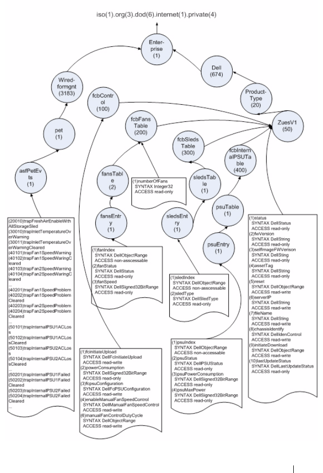
Using the System Setup Program 161
MIB Tree Diagram for FCB

162 Using the System Setup Program
FCB SNMP MIB
Table 2-22. FCB SNMP MIB
Category Object Name Read/Write Value Type Operation
FW
Safe
Boot FW
Note
Common Status read-only values:
ok, error,
safeBoot
vvFirmware Status
FW Version read-only string v Firmware Version
(OP code)
Safe Image
FW Version
read-only string v v Firmware Version
(Safe Boot code)
Asset Tag read-write string v Asset Tag, max string
length is 16 characters
Reset read-write value: start v v Firmware will reset
once this field is set
Server IP read-write IpAddress v v TFTP server IP
File Name read-write string v v max string length is
100 characters
Chassis
Identify
read-write integer v Chassis Identification
Initiate
Download
read-write value: start v Initiate download
Last Update
Status
read-only Values:
na,
successfully,
error,
imageError,
start,
downloadIn
Progress,
download
Successfully,
download
Failed,
upgradeIn
Progress
v v Last update status,
firmware will check
header (CRC23) and
image (MD5) before
update, if checksum is
incorrect, this file will
be set as imageError.

Using the System Setup Program 163
FCB
Control
fc Initiate
Upload
read-write values:
FC/CPLD/
NetConfig
vvInitiate upload
power
Consumption
read-only Integer v Power consumption
fcpsu
Configuration
read-write values:
x1n1, x2n0
v PSU Configuration,
X1n1: X+N=1+1
X2n0: X+N=2+0
enable
Manual Fan
Control
read-write values:
1/0
v Default is disabled (0)
manual Fan
Control Duty
Cycle
read-write integer v Manual Fan Control
Duty Cycle, 0 - 100,
default 100
FCB
FansTable
number Of
Fans
read-only integer v Number of FAN
fan Index not-
accessible
Fan Index
fan Status read-only values:
ok, error
vFAN Status
fan Speed Read-only integer v FAN Speed
sled Index not-
accessible
v Sled Index
FCB
Sleds
Table
sled Type read-only values:
ok, na,
storage,
dummy, psu
vSled Type
psu Index not-
accessible
vPSU Index
Table 2-22. FCB SNMP MIB
Category Object Name Read/Write Value Type Operation
FW
Safe
Boot FW
Note

164 Using the System Setup Program
FCB
Internal
PSU Table
psu Status read-only values:
ok, error, na,
acloss
v PSU Status
psu Power
Consumption
read-only integer v PSU Power
Consumption
psu Max
Power
read-only integer v PSU Max Power
FCB-Trap trap Fresh Air
Enabled With
All
StorageSled
Trap for Fresh Air
Enabled with All
Storage sleds
trap Inlet
Temperature
OverWarning
Trap for In l e t
Temperature Over
Warning
trap Inlet
Temperature
Over Warning
Cleared
Trap for In l e t
Temperature Over
Warning Cleare d
trap Fan1
Speed
Warning
Trap for Fan 1 Speed
Warning
trap Fan2
Speed
Warning
Trap for Fan 2 Speed
Warning
trap Fan3
Speed
Warning
Trap for Fan 3 Speed
Warning
trap Fan4
Speed
Warning
Trap for Fan 4 Speed
Warning
trap Fan5
Speed
Warning
Trap for Fan 5 Speed
Warning
trap Fan6
Speed
Warning
Trap for Fan 6 Speed
Warning
Table 2-22. FCB SNMP MIB
Category Object Name Read/Write Value Type Operation
FW
Safe
Boot FW
Note

Using the System Setup Program 165
trap Fan1
Speed Waring
Cleared
Trap f o r FAN 1 Speed
Warning Cle ared
trap Fan2
Speed Waring
Cleared
Trap f o r FAN 2 Speed
Warning Cle ared
trap Fan3
Speed Waring
Cleared
Trap f o r FAN 3 Speed
Warning Cle ared
trap Fan4
Speed Waring
Cleared
Trap f o r FAN 4 Speed
Warning Cle ared
trap Fan5
Speed Waring
Cleared
Trap f o r FAN 5 Speed
Warning Cle ared
trap Fan6
Speed Waring
Cleared
Trap f o r FAN 6 Speed
Warning Cle ared
trap Fan1
Speed
Problem
Trap FAN 1 Speed
Problem
trap Fan2
Speed
Problem
Trap FAN 2 Speed
Problem
trap Fan3
Speed
Problem
Trap FAN 3 Speed
Problem
trap Fan4
Speed
Problem
Trap FAN 4 Speed
Problem
trap Fan5
Speed
Problem
Trap FAN 5 Speed
Problem
trap Fan6
Speed
Problem
Trap FAN 6 Speed
Problem
Table 2-22. FCB SNMP MIB
Category Object Name Read/Write Value Type Operation
FW
Safe
Boot FW
Note

166 Using the System Setup Program
FCB-Trap trap Fan1
Speed
Problem
Cleared
Trap for FAN 1 Speed
Problem Cleared
trap Fan2
Speed
Problem
Cleared
Trap for FAN 2 Speed
Problem Cleared
trap Fan3
Speed
Problem
Cleared
Trap for FAN 3 Speed
Problem Cleared
trap Fan4
Speed
Problem
Cleared
Trap for FAN 4 Speed
Problem Cleared
trap Fan5
Speed
Problem
Cleared
Trap for FAN 5 Speed
Problem Cleared
trap Fan6
Speed
Problem
Cleared
Trap for FAN 6 Speed
Problem Cleared
trap Internal
PSU1 ACLoss
Trap for Internal
PSU1 AC Lost
trap Internal
PSU2 ACLoss
Trap for Internal
PSU2 AC Lost
trap Internal
PSU3 ACLoss
Trap for Internal
PSU3 AC Lost
trap Internal
PSU4 ACLoss
Trap for Internal
PSU4 AC Lost
trap Internal
PSU1 ACLoss
Cleared
Trap for Internal
PSU1 AC Lost
Cleared
Table 2-22. FCB SNMP MIB
Category Object Name Read/Write Value Type Operation
FW
Safe
Boot FW
Note

Using the System Setup Program 167
NOTE: In the Common category, both FC and PMC provides common OID.
FCB-Trap trap Internal
PSU2 AC
Loss Cleared
Trap for Internal
PSU2 AC Lost
Cleared
trap Internal
PSU3 AC
Loss Cleared
Trap for Internal
PSU3 AC Lost
Cleared
trap Internal
PSU4 AC
Loss Cleared
Trap for Internal
PSU4 AC Lost
Cleared
trap Internal
PSU1 Failed
Trap for Internal
PSU1 Failed
trap Internal
PSU2 Failed
Trap for Internal
PSU2 Failed
trap Internal
PSU3 Failed
Trap for Internal
PSU3 Failed
trap Internal
PSU4 Failed
Trap for Internal
PSU4 Failed
trap Internal
PSU1 Failed
Cleared
Trap for Internal
PSU1 Failed Cleared
trap Internal
PSU2 Failed
Cleared
Trap for Internal
PSU2 Failed Cleared
trap Internal
PSU3 Failed
Cleared
Trap for Internal
PSU3 Failed Cleared
trap Internal
PSU4 Failed
Cleared
Trap for Internal
PSU4 Failed Cleared
Table 2-22. FCB SNMP MIB
Category Object Name Read/Write Value Type Operation
FW
Safe
Boot FW
Note

168 Using the System Setup Program
SNMP Support for the External PDU Power Management Controller
Board
The PowerEdge C8000 server enclosure is primarily connected to an external
PDU. The external PDU includes a power management controller (PMC)
board that allows you to monitor the PDU power supply modules over the
network. When an error occurs in the PDU, the PMC via SNMPv2 send
notifications to the remote client.
There is a common OID (object identifiers) defined in the MIB
(Management Information Base) file. Use the SNMP utility to get the
SNMPv2-MIB file and load the MIB files that are required for managing and
monitoring the PDU.
PMC Network Connection
By default, the PMC is configured to automatically obtain an IP address via
DHCP server. A special button-press-sequence MUST be defined that does
not conflict with legacy fan controller,
• Long press in 4 seconds, service mode.
• 3 short presses in less than 5 seconds provide switch between default static
IP and reset to default
After PMC resets, all network and configuration settings restore back to their
default values. PMC is configured with the following default network
settings.
• IP address: 192.168.0.120
• Subnet mask: 255.255.255.0
The power/status indicator on the front of the PMC board displays the
following behaviors
• Blinking amber (500 ms off/5 s on) — Restarts the PMC firmware and
reset to factory default is completed.
• Blinking amber (250 ms off/5 s on) — Restores the default network
settings to their default values.

Using the System Setup Program 169
PMC Configuration Information
The PMC configuration information is stored in the PMC board's internal
EEPROM. You must use TFTP server to retrieve the configuration data and
then use Notepad or a text editor to view or change the configuration data.
For example, a configuration data should have the following information:
By default, the PMC controller uses DHCP to acquire an IP address. The
system MUST follow the same DHCP retry mechanism that exists in the
BMCs (any parameter needed for this MUST be stored in the configuration
file). DHCP client MUST retry forever.
CONNECT.TYPE=STATIC/DHCP
IP=192.168.0.120
NETMASK=255.255.255.0
GATEWAY=192.168.0.1
TRAP.DESTINATION1=0.0.0.0
TRAP.DESTINATION2=0.0.0.0
TRAP.DESTINATION3=0.0.0.0
TRAP.DESTINATION4=0.0.0.0
TRAP.DESTINATION5=0.0.0.0
SNMP.RD.COMMUNITY.STR=public
SNMP.RW.COMMUNITY.STR=private
M A N A G E . A C S O C K E T. A . D E FAU LT. P O W E R = O N / O F F
M A N A G E . A C S O C K E T. B . D E FA U LT. P O W E R = O N / O F F
MANAGE.ACSOCKET.C.DEFAULT.POWER=ON/OFF
MANAGE.PDU.DEFAULT.POWER=ON/OFF
MANAGE.PSU.CONFIGURATION=5+1

170 Using the System Setup Program
PMC Firmware Behavior
The following table lists the PMC firmware behavior.
Table 2-23. PMC Firmware Behavior
Safe Boot Code Firmware Behavior Operational Code Firmware Behavior
•PMC firmware enables network/SNMP
service
• PMC firmware update is done by TFTP
via SNMP set object property
• The reset to default button works
•PMC firmware enables network/SNMP
service
• PMC firmware update is done by TFTP
via SNMP set object property
• Use the SNMP SET/GET commands to
request for a specific variable
• PMC firmware send traps to remote
client when critical errors occur.
• You can download or upload the PMC
configuration information by TFTP via
SNMP set object property
• The reset to default button works
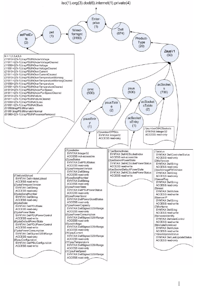
Using the System Setup Program 171
MIB Tree Diagram for PMC

172 Using the System Setup Program
PMC SNMP MIB
Table 2-24. PMC SNMP MIB
Category Object Name Read/Write Value Type Operation
FW
Safe
Boot FW
Note
Common Status read-only values:
ok, error,
safeBoot
vvFirmware Status
FW Version read-only string v Firmware Version (OP
code)
Safe Image
FW Version
read-only string v v Firmware Version
(Safe Boot code)
Asset Tag read-write string v Asset Tag, max string
length is 16 characters
Reset read-write value:
start
v v Firmware will reset
once this field is set
Server IP read-write Ip Address v v TFTP server IP
File Name read-write string v v max string length is
100 characters
Chassis
Identify
read-write integer v Chassis Identification
InitiateDownl
oad
read-write value:
start
vInitiate download

Using the System Setup Program 173
Common lastUpdateSta
tus
read-only Values:
na,
successfully,
error,
imageError,
start,
downloadIn
Progress,
download
Successfully,
downloadFai
led,
upgradeInPr
ogresspduUp
gradeSucces
sfully,
psuUpgrade
Successfully,
pduUpgrade
Failed,
psuUpgrade
Failed
pduUpgrade
Successfully,
psuUpgrade
Successfully,
pduUpgrade
Failed,
psuUpgrade
Failed
v v Last update status,
firmware will check
header (CRC23) and
image (MD5) before
update, if checksum
is incorrect, this file
will be set as image
Error.
Table 2-24. PMC SNMP MIB
Category Object Name Read/Write Value Type Operation
FW
Safe
Boot FW
Note

174 Using the System Setup Program
PMC PDU
Firmware
Version
read-only string v PDU firmware version
PDU Serial
Number
read-only string v PDU serial number,
only supports when
PDU version is
6.00.05 or later
PDU State read-only values:
ok, error,
bootLoader
vPDU state
PDU Power
State
read-write values:
on/off
vPDU power state
PDU Default
Power State
read-write values:
on/off
v PDU Default Power
State
PDU Power
Consumption
read-only integer v Total PSU power,
Unit:W
pmc Initiate
Upload
read-write vaules:
pmc, config,
pdu, psu1,
psu2,
psu3, psu4,
psu5, psu6
vvInitiate upload
pmc psu
Configuration
read-write values:
x4n2, x5n1
v PSU configuration,
x4n2: X+N=4+2
x5n1: X+N=5+1
Table 2-24. PMC SNMP MIB
Category Object Name Read/Write Value Type Operation
FW
Safe
Boot FW
Note

Using the System Setup Program 175
PSUs
Table
Number Of
Psus
read-only integer v Number of PSU
PSUIndex not-
accessible
integer v PSU index
PSUStatus read-only values:
ok, error, na,
acloss,
bootLoader
vPSU status
PSU
Firmware
Version
read-only string v PSU firmware version
PSU Serial
Number
read-only string v PSU serial number
PSU Power
State
read-only values:
on/off
vPSU power state
PSU Power
Good
read-only values: ok,
error
vPSU power good
PSU Power
Capacity
read-only integer v PSU power capacity,
Unit:W
PSU Power
Consumption
read-only integer v PSU power
consumption,
Unit:W
PSU Voltage read-only integer v PSU voltage,
Unit:mV
PSU Current read-only integer v PSU current,
Unit:mA
PSU
Temperature
read-only integer v PSU temperature,
Unit:degrees C
PSU Fan
Speed
read-only integer v PSU fan speed,
Unit:rpm
Table 2-24. PMC SNMP MIB
Category Object Name Read/Write Value Type Operation
FW
Safe
Boot FW
Note

176 Using the System Setup Program
AC
Sockets
Tab l e
Number Of
AC Sockets
read-only integer v Number of AC socket
AC Socket
Index
not-
accessible
integer v AC socket index
AC Socket
Power State
read-write values:
on/off
v AC socket power state
AC Socket
Default Power
State
read-write values:
on/off
v AC socket default
power state
PMC -
Tra p s
trap PSU1
Under
Voltage
v Trap for PSU1 under
voltage
trap PSU2
Under
Voltage
V Trap for PSU2 under
voltage
trap PSU3
Under
Voltage
v Trap for PSU3 under
voltage
trap PSU4
Under
Voltage
v Trap for PSU4 under
voltage
trap PSU5
Under
Voltage
V Trap for PSU5 under
voltage
trap PSU6
Under
Voltage
V Trap for PSU6 under
voltage
trap PSU1
Under
Voltage
Cleared
V Trap for PSU1 under
voltage cleared
trap PSU2
Under
Voltage
Cleared
V Trap for PSU2 under
voltage cleared
Table 2-24. PMC SNMP MIB
Category Object Name Read/Write Value Type Operation
FW
Safe
Boot FW
Note

Using the System Setup Program 177
PMC -
Trap s
trap PSU3
Under
Voltage
Cleared
V Trap for PSU3 under
voltage cleared
trap PSU4
Under
Voltage
Cleared
V Trap for PSU4 under
voltage cleared
trap PSU5
Under
Voltage
Cleared
V Trap for PSU5 under
voltage cleared
trap PSU6
Under
Voltage
Cleared
V Trap for PSU6 under
voltage cleared
trap PSU1
Over Voltage
V Trap for PSU1 over
voltage
trap PSU2
Over Voltage
V Trap for PSU2 over
voltage
trap PSU3
Over Voltage
V Trap for PSU3 over
voltage
trap PSU4
Over Voltage
V Trap for PSU4 over
voltage
trap PSU5
Over Voltage
V Trap for PSU5 over
voltage
trap PSU6
Over Voltage
V Trap for PSU6 over
voltage
trap PSU1
Over Voltage
Cleared
V Trap for PSU1 over
voltage cleared
trap PSU2
Over Voltage
Cleared
V Trap for PSU2 over
voltage cleared
Table 2-24. PMC SNMP MIB
Category Object Name Read/Write Value Type Operation
FW
Safe
Boot FW
Note

178 Using the System Setup Program
PMC -
Tra p s
trap PSU3
Over Voltage
Cleared
VTrap for PSU3 over
voltage cleared
trap PSU4
Over Voltage
Cleared
VTrap for PSU4 over
voltage cleared
trap PSU5
Over Voltage
Cleared
VTrap for PSU5 over
voltage cleared
trap PSU6
Over Voltage
Cleared
VTrap for PSU6 over
voltage cleared
trap PSU1
Over Current
VTrap for PSU1 over
current
trap PSU2
Over Current
VTrap for PSU 2 over
current
trap PSU3
Over Current
VTrap for PSU3 over
current
trap PSU4
Over Current
VTrap for PSU4 over
current
trap PSU5
Over Current
VTrap for PSU5 over
current
trap PSU6
Over Current
VTrap for PSU6 over
current
trap PSU1
Over Current
Cleared
VTrap for PSU1 over
current cleared
trap PSU2
Over Current
Cleared
VTrap for PSU2 over
current cleared
trap PSU3
Over Current
Cleared
VTrap for PSU3 over
current cleared
Table 2-24. PMC SNMP MIB
Category Object Name Read/Write Value Type Operation
FW
Safe
Boot FW
Note

Using the System Setup Program 179
PMC -
Trap s
trap PSU4
Over Current
Cleared
V Trap for PSU4 over
current cleared
trap PSU5
Over Current
Cleared
V Trap for PSU5 over
current cleared
trap PSU6
Over Current
Cleared
V Trap for PSU6 over
current cleared
trap PSU1
Over
Temperature
Warning
V Trap for PSU1 over
temperature warning
trap PSU2
Over
Temperature
Warning
V Trap for PSU2 over
temperature warning
trap PSU3
Over
Temperature
Warning
V Trap for PSU3 over
temperature warning
trap PSU4
Over
Temperature
Warning
V Trap for PSU4 over
temperature warning
trap PSU5
Over
Temperature
Warning
V Trap for PSU5 over
temperature warning
trap PSU6
Over
Temperature
Warning
V Trap for PSU6 over
temperature warning
Table 2-24. PMC SNMP MIB
Category Object Name Read/Write Value Type Operation
FW
Safe
Boot FW
Note

180 Using the System Setup Program
PMC -
Tra p s
trap PSU1
Over
Temperature
Wa rn in g
Cleared
VTrap for PSU1 over
temperature warning
cleared
trap PSU2
Over
Temperature
Wa rn in g
Cleared
VTrap for PSU2 over
temperature warning
cleared
trap PSU3
Over
Temperature
Wa rn in g
Cleared
VTrap for PSU3 over
temperature warning
cleared
trap PSU4
Over
Temperature
Wa rn in g
Cleared
VTrap for PSU4 over
temperature warning
cleared
trap PSU5
Over
Temperature
Wa rn in g
Cleared
VTrap for PSU5 over
temperature warning
cleared
trap PSU6
Over
Temperature
Wa rn in g
Cleared
VTrap for PSU6 over
temperature warning
cleared
trap PSU1
Over
Temperature
VTrap for PSU1 over
temperature
trap PSU2
Over
Temperature
VTrap for PSU2 over
temperature
Table 2-24. PMC SNMP MIB
Category Object Name Read/Write Value Type Operation
FW
Safe
Boot FW
Note

Using the System Setup Program 181
PMC -
Trap s
trap PSU3
Over
Temperature
V Trap for PSU3 over
temperature
trap PSU4
Over
Temperature
V Trap for PSU4 over
temperature
trap PSU5
Over
Temperature
V Trap for PSU5 over
temperature
trap PSU6
Over
Temperature
V Trap for PSU6 over
temperature
trap PSUN
Over
Temperature
Cleared
VTrap PSU1 over
temperature cleared
trap PSUN
Over
Temperature
Cleared
VTrap PSU2 over
temperature cleared
trap PSUN
Over
Temperature
Cleared
VTrap PSU3 over
temperature cleared
trap PSUN
Over
Temperature
Cleared
VTrap PSU4 over
temperature cleared
trap PSUN
Over
Temperature
Cleared
VTrap PSU5 over
temperature cleared
trap
PSUN Over
Temperature
Cleared
VTrap PSU6 over
temperature cleared
Table 2-24. PMC SNMP MIB
Category Object Name Read/Write Value Type Operation
FW
Safe
Boot FW
Note

182 Using the System Setup Program
PMC -
Tra p s
trap PSU1
Under Fan
Speed
V Trap for PSU1 under
FAN speed
trap PSU2
Under Fan
Speed
V Trap for PSU2 under
FAN speed
trap PSU3
Under Fan
Speed
V Trap for PSU3 under
FAN speed
trap PSU4
Under Fan
Speed
V Trap for PSU4 under
FAN speed
trap PSU5
Under Fan
Speed
V Trap for PSU5 under
FAN speed
trap PSU6
Under Fan
Speed
V Trap for PSU6 under
FAN speed
trap PSU1
Under Fan
Speed
Cleared
V Trap for PSU1 under
FAN speed cleared
trap PSU2
Under Fan
Speed
Cleared
V Trap for PSU2 under
FAN speed cleared
trap PSU3
Under Fan
Speed
Cleared
V Trap for PSU3 under
FAN speed cleared
trap PSU4
Under Fan
Speed
Cleared
V Trap for PSU4 under
FAN speed cleared
Table 2-24. PMC SNMP MIB
Category Object Name Read/Write Value Type Operation
FW
Safe
Boot FW
Note

Using the System Setup Program 183
PMC -
Trap s
trap PSU5
Under Fan
Speed
Cleared
V Trap for PSU5 under
FAN speed cleared
trap PSU6
Under Fan
Speed
Cleared
V Trap for PSU6 under
FAN speed cleared
Trap P SU1
Failure
V Trap for PSU1 failure
Trap P SU2
Failure
V Trap for PSU2 failure
Trap P SU3
Failure
V Trap for PSU3 failure
Trap P SU4
Failure
V Trap for PSU4 failure
Trap P SU5
Failure
V Trap for PSU5 failure
Trap P SU6
Failure
V Trap for PSU6 failure
Trap P SU1 Ac
Lost
V Trap for PSU1 AC
lost
Trap P SU2 Ac
Lost
V Trap for PSU2 AC
lost
Trap P SU3 Ac
Lost
V Trap for PSU3 AC
lost
Trap P SU4 Ac
Lost
V Trap for PSU4 AC
lost
Trap P SU5 Ac
Lost
V Trap for PSU5 AC
lost
Trap P SU6 Ac
Lost
V Trap for PSU6 AC
lost
Table 2-24. PMC SNMP MIB
Category Object Name Read/Write Value Type Operation
FW
Safe
Boot FW
Note

184 Using the System Setup Program
PMC -
Tra p s
Trap PSU
Mismatch
V A mismatch between
PSU X+N
configuration and
populated PSU
Trap PSU1
Presence
Removed
VTrap for PSU1
Presence Removed
Trap PSU2
Presence
Removed
VTrap for PSU2
Presence Removed
Trap PSU3
Presence
Removed
VTrap for PSU3
Presence Removed
Trap PSU4
Presence
Removed
vTrap for PSU4
Presence Removed
Trap PSU5
Presence
Removed
VTrap for PSU5
Presence Removed
Trap PSU6
Presence
Removed
VTrap for PSU6
Presence Removed
Trap PSU1
Failure
Cleared
V Trap for PSU1 Failure
Cleared
Trap PSU2
Failure
Cleared
V Trap for PSU2 Failure
Cleared
Trap PSU3
Failure
Cleared
V Trap for PSU3 Failure
Cleared
Trap PSU4
Failure
Cleared
V Trap for PSU4 Failure
Cleared
Table 2-24. PMC SNMP MIB
Category Object Name Read/Write Value Type Operation
FW
Safe
Boot FW
Note

Using the System Setup Program 185
PMC -
Trap s
Trap P SU5
Failure
Cleared
V Trap for PSU5 Failure
Cleared
Trap P SU6
Failure
Cleared
V Trap for PSU6 Failure
Cleared
Trap P SU1 Ac
Back
V Trap for PSU1 AC
Back
Trap P SU2 Ac
Back
V Trap for PSU2 AC
Back
Trap P SU3 Ac
Back
V Trap for PSU3 AC
Back
Trap P SU4 Ac
Back
V Trap for PSU4 AC
Back
Trap P SU5 Ac
Back
V Trap for PSU5 AC
Back
Trap P SU6 Ac
Back
V Trap for PSU6 AC
Back
Trap P SU
Mismatch
Normal
V Trap for PSU
mismatch normal
Table 2-24. PMC SNMP MIB
Category Object Name Read/Write Value Type Operation
FW
Safe
Boot FW
Note

186 Using the System Setup Program

Installing System Components 187
3
Installing System Components
Safety Instructions
WARNING: Working on systems that are still connected to a power supply can be
extremely dangerous.
CAUTION: System components and electronic circuit boards can be damaged by
discharge of static electricity.
CAUTION: Many repairs may only be done by a certified service technician. You
should only perform troubleshooting and simple repairs as authorized in your
product documentation, or as directed by the online or telephone service and
support team. Damage due to servicing that is not authorized by Dell is not covered
by your warranty. Read and follow the safety instructions that came with the
product.
To avoid injury to yourself or damage to your system, follow these guidelines:
• Always disconnect the system from the power outlet whenever you are
working inside the system.
• If possible, wear a grounded wrist strap when you are working inside the
system. Alternatively, discharge any static electricity by touching the bare
metal chassis of the system case, or the bare metal body of any other
grounded appliance.
• Hold electronic circuit boards by the edges only. Do not touch the
components on the board unless it is necessary to do so. Do not flex or
stress the circuit board.
• Leave all components inside the static-proof packaging until you are ready
to use the component for the installation.

188 Installing System Components
• Some cables have a connector with locking tabs; if you are disconnecting
this type of cable, press in on the locking tabs before you disconnect the
cable. As you pull connectors apart, keep them evenly aligned to avoid
bending any connector pins. Also, before you connect a cable, ensure that
both connectors are correctly oriented and aligned.
About the Illustrations
The illustrations used in this chapter identifies the component parts and does
not show step-by-step component removal or replacement instructions.
Recommended Tools
• #1 Phillips screwdriver
• #2 Phillips screwdriver
•Torx drivers
• Set of jeweler screwdrivers
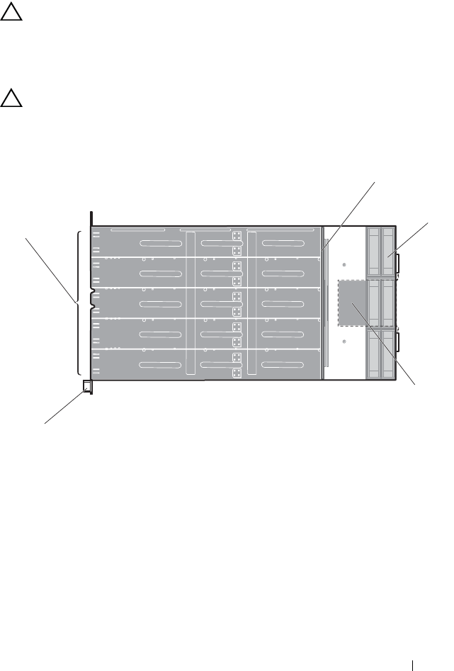
Installing System Components 189
Inside the System
CAUTION: Many repairs may only be done by a certified service technician. You
should only perform troubleshooting and simple repairs as authorized in your
product documentation, or as directed by the online or telephone service and
support team. Damage due to servicing that is not authorized is not covered by
warranty. Read and follow the safety instructions that came with the product.
CAUTION: This system must be operated with the sled or sled blank installed to
make sure of proper cooling.
Figure 3-1. Inside the Server Enclosure — Top View
1 sled bays (10) 2 power management board
3 fan modules (3 fan module sets, each
fan module with 2 fans)
4 fan controller board
5 front panel board
1
2
3
4
5
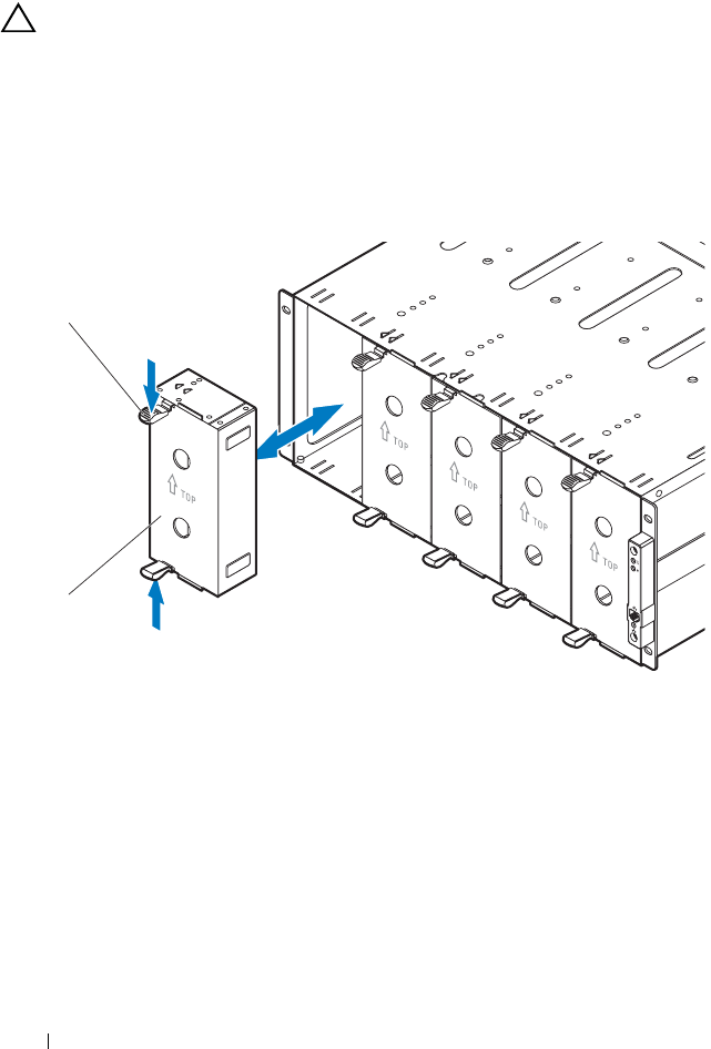
190 Installing System Components
Sled Blank
CAUTION: To ensure proper airflow in the system, if a module is removed it
should be immediately replaced with another sled or sled blank.
Removing a Double-Wide Sled Blank
Squeeze and hold the release latches and slide the blank out of the enclosure.
See Figure 3-2.
Figure 3-2. Removing and Installing a Double-Wide Sled Blank
Installing a Double-Wide Sled Blank
Hold the blank with the guide rail facing forward. Slide the blank into the
enclosure until it is fully seated and the release latches snap into place.
See Figure 3-2.
1 release latches (2) 2 double-wide sled blank
1
2
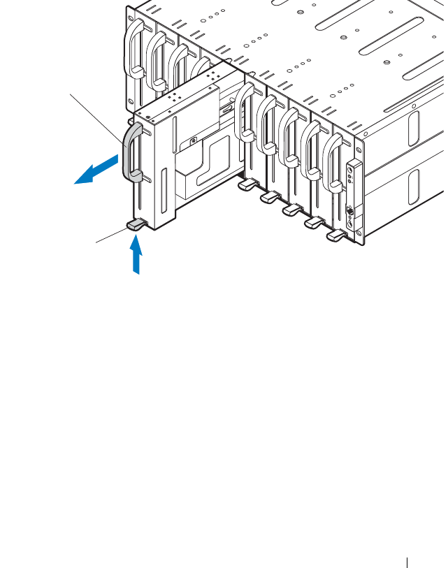
Installing System Components 191
Removing a Single-Wide Sled Blank
1
Pull up on the sled blank latch at the bottom of the sled to disengage the
sled from the server enclosure. See Figure 3-3.
2
Using the handle, slide the sled out of the enclosure. See Figure 3-3.
Figure 3-3. Removing and Installing a Single-Wide Sled Blank
Installing a Single-Wide Sled Blank
1
Orient the sled blank so that the release latch is in the bottom of the sled.
See Figure 3-3.
2
Slide the sled blank into the enclosure until the release latch snaps into
place. See Figure 3-3.
1 release latch 2 single-wide sled blank
2
1

192 Installing System Components
Compute Sleds
Removing a Compute Sled
CAUTION: Many repairs may only be done by a certified service technician. You
should only perform troubleshooting and simple repairs as authorized in your
product documentation, or as directed by the online or telephone service and
support team. Damage due to servicing that is not authorized is not covered by
warranty. Read and follow the safety instructions that came with the product.
CAUTION: To ensure proper airflow in the system, if a sled is removed it should be
immediately replaced with another sled or sled blank.
CAUTION: Operating the system without a sled or sled blank installed can cause
the enclosure to overheat. See "Installing a Double-Wide Sled Blank" on page 190.
1
Power down the sled using OS commands or the Baseboard Management
Controller, and ensure that the sled’s power is off.
When the sled is powered off, its front-panel indicator is off.
2
Pull up on the compute sled release latch at the bottom of the sled to
disengage the sled from the server enclosure. See Figure 3-4 or Figure 3-5.
3
Using the handle, slide the sled out of the enclosure. See Figure 3-4 or
Figure 3-5.
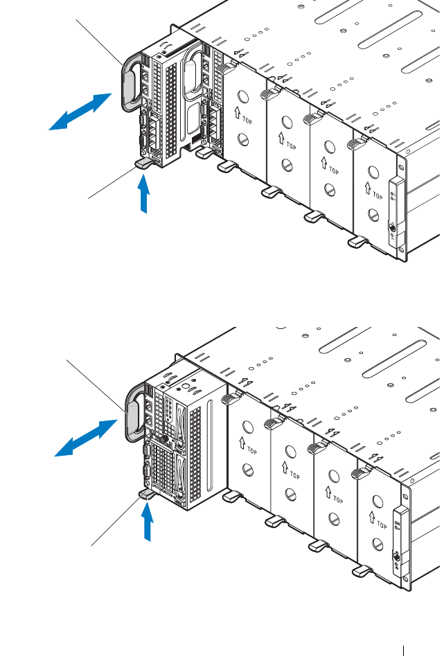
Installing System Components 193
Figure 3-4. Removing and Installing a C8220 Compute Sled
Figure 3-5. Removing and Installing a C8220X Compute Sled
1 release latch 2 handle
1 release latch 2 handle
1
2
2
1

194 Installing System Components
Installing a Compute Sled
CAUTION: Many repairs may only be done by a certified service technician. You
should only perform troubleshooting and simple repairs as authorized in your
product documentation, or as directed by the online or telephone service and
support team. Damage due to servicing that is not authorized is not covered by
warranty. Read and follow the safety instructions that came with the product.
1
Orient the sled so that the release latch is in the bottom of the sled. See
Figure 3-4 or Figure 3-5.
2
Slide the new sled into the enclosure until the sled is fully seated and the
release latch snaps into place. See Figure 3-4 or Figure 3-5.
Storage Sled
Removing a Storage Sled
CAUTION: Many repairs may only be done by a certified service technician. You
should only perform troubleshooting and simple repairs as authorized in your
product documentation, or as directed by the online or telephone service and
support team. Damage due to servicing that is not authorized is not covered by
warranty. Read and follow the safety instructions that came with the product.
CAUTION: To ensure proper airflow in the system, if a sled is removed it should be
immediately replaced with another sled or sled blank.
CAUTION: Operating the system without a sled or sled blank installed can cause
the enclosure to overheat. See "Installing a Double-Wide Sled Blank" on page 190.
1
Pull and hold the storage sled release tab at the bottom of the sled to
disengage the sled from the server enclosure. See Figure 3-6.
2
Using the handle, slide the sled out of the enclosure. See Figure 3-6.
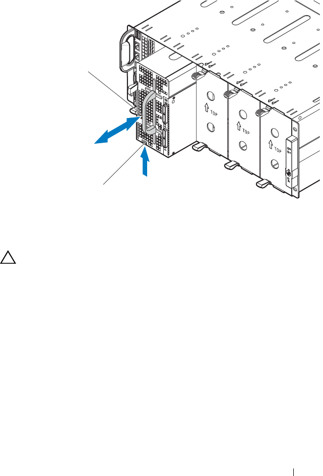
Installing System Components 195
Figure 3-6. Removing and Installing a C8000XD Storage Sled
Installing a Storage Sled
CAUTION: Many repairs may only be done by a certified service technician. You
should only perform troubleshooting and simple repairs as authorized in your
product documentation, or as directed by the online or telephone service and
support team. Damage due to servicing that is not authorized is not covered by
warranty. Read and follow the safety instructions that came with the product.
1
Orient the sled so that the release tab is in the bottom of the sled. See
Figure 3-6.
2
Slide the sled into the enclosure until the sled is fully seated and the tab
engages and locks the sled in place.
1 release tab 2 handle
1
2

196 Installing System Components
Power Sled
NOTE: This section applies to PowerEdge C8000 server enclosure with internal
power source.
Enclosure Power Guidelines
Observe the following guidelines when connecting power to the enclosure:
• Always connect the enclosure’s AC power sockets to a single power source,
switch, or PDU.
• Make sure to install the power sleds and connect power to the enclosure
before you install any other sled.
Power Sled Installation Guidelines
Follow these guidelines when installing power sleds.
• If a power supply is removed from the enclosure and the power supply
number in the enclosure is less than the required number of power
supplies, all sleds in the enclosure will be throttled until the failed PSU
module is replaced. For example, in a 2+2 PSU configuration, if three PSU
modules fail, it would trigger the sleds in the enclosure to throttle. When
the failed PSU modules are replaced the enclosure exits power throttling
mode and resume operating normally.
NOTE: Throttling reduces power consumption of the sled modules by changing the
processor duty cycle, thereby reducing sled performance. When a throttling event
occurs the event is logged in the System Event Log (SEL). See the Using the
Baseboard Management Controller Guide at dell.com/support/manuals for more
information.
• The following table lists the supported configuration where power supply
redundancy is guaranteed.
NOTE: Configurations higher than indicated in the table may change the power
supply mode to non-redundant. In non-redundant mode, if the power requirement
exceeds the installed system power capacity, BIOS will throttle the processors. If
CPU power capping is enabled, throttling can occur on processors that exceed the
cap value. See "Power Management" on page 78 for more information.

Installing System Components 197
a. In a 2+0 PSU configuration, a power sled blank or a C8220 compute sled must be installed in the
adjacent unoccupied bay to maintain proper cooling airflow in the enclosure.
Table 3-1. PSU and Power Sled Support Matrix
PSU
Config
Max.
Power
Redundant
Power
Sled
Shutdown
Maintenance Conditions
4+0 5600 W Not
supported
Required Shut down all sleds in the enclosure before
removing or replacing a power sled(s).
3+1 4200 W Supported Required Shut down all sleds in the enclosure before
removing or installing a power sled(s).
2+2 2800 W Supported Not
required
Power sleds can be removed or replaced
without powering off the sled(s) in the
enclosure.
2+1 2800 W Supported Required Shut down all sleds in the enclosure before
removing or replacing the power sled with
two PSU modules capacity.
2+0a2800 W Not
supported
Required Shut down all sleds in the enclosure before
removing or replacing a power sled(s).
1+1 1400 W Supported Not
required
Power sled can be removed or replaced
without powering off the sled in the
enclosure.
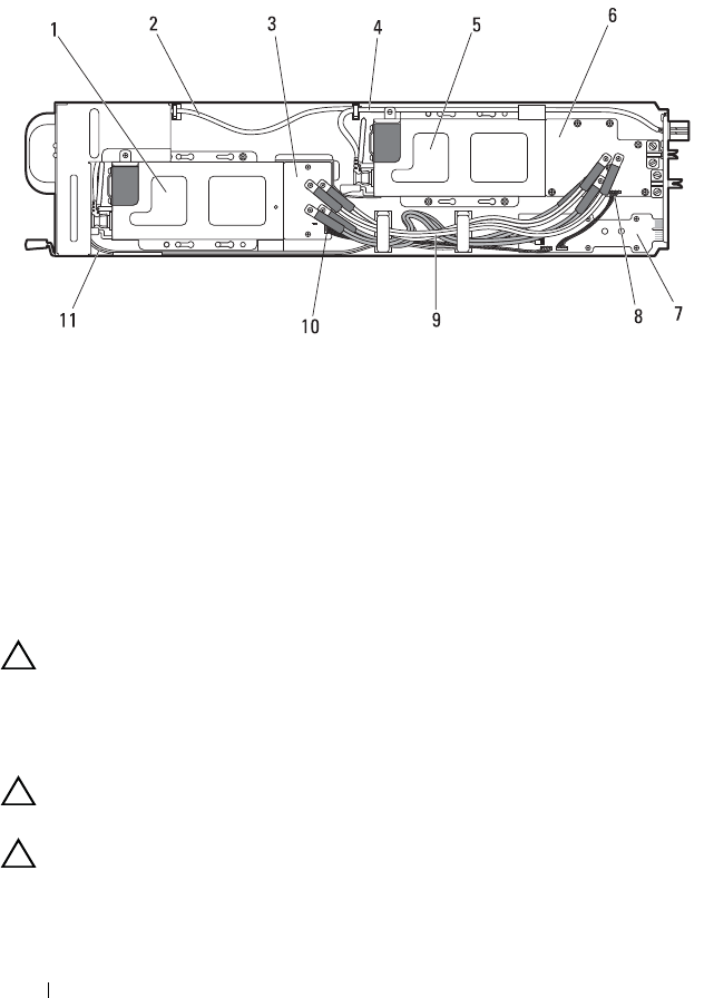
198 Installing System Components
Inside a Power Sled
Figure 3-7. Inside a Power Sled
Removing a Power Sled
CAUTION: Many repairs may only be done by a certified service technician. You
should only perform troubleshooting and simple repairs as authorized in your
product documentation, or as directed by the online or telephone service and
support team. Damage due to servicing that is not authorized is not covered by
warranty. Read and follow the safety instructions that came with the product.
CAUTION: To ensure proper airflow in the system, if a sled is removed it should be
immediately replaced with another sled or sled blank.
CAUTION: Operating the system with a power sled removed for extended periods
of time can cause the system to overheat.
1 PSU2/4 module assembly 2, 4 AC power cable
3 front power distribution board 5 PSU1/3 module assembly
6 back power distribution board 7 power interposer board
8 back power distribution board
signal cable
9 power distribution cables
10 front power distribution board
signal cable
11 LED cable

Installing System Components 199
WARNING: The PSU modules in the power sled may produce high voltages and
energy hazards, which can cause bodily harm. Only trained service technicians
are authorized to remove any components inside the power sled.
WARNING: To reduce the risk of personal injury from hot surfaces, observe the
thermal labels on each PSU module. You can also consider wearing protective
gloves.
WARNING: To reduce the risk of personal injury from electric shock hazards, do
not open the PSU modules. There are no serviceable parts inside the PSU modules.
CAUTION: Remove and replace only one power sled at a time.
NOTE: The wattage of a PSU module is listed on its regulatory label.
1
Power down all sled(s) in the server enclosure using OS commands or the
Baseboard Management Controller, and ensure the sled’s power is off.
For power sleds in redundant configuration, you can remove and replace
the power sled without shutting down the compute sleds in the enclosure.
See Table 3-1 for the power sled maintenance conditions.
2
Locate the power sled to be removed or the power sled that contains the
failed power supply module. If a power supply module is faulty the status
indicator lights up amber.
3
Wait one minute and then verify that the indicators on the enclosure and
power sled are extinguished.
4
Pull up on the power sled release latch at the bottom of the sled to
disengage the sled from the server enclosure. See Figure 3-8.
5
Using the handle, slide the sled out of the enclosure. See Figure 3-8.
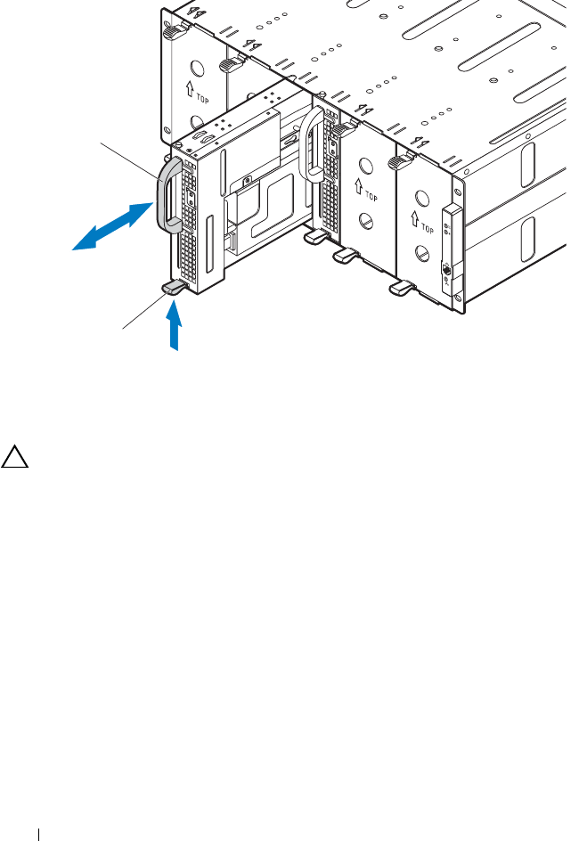
200 Installing System Components
Figure 3-8. Removing and Installing a Power Sled
Installing a Power Sled
CAUTION: Many repairs may only be done by a certified service technician. You
should only perform troubleshooting and simple repairs as authorized in your
product documentation, or as directed by the online or telephone service and
support team. Damage due to servicing that is not authorized is not covered by
warranty. Read and follow the safety instructions that came with the product.
1
Orient the sled so that the release latch is at the bottom of the sled.
See Figure 3-8.
2
Slide the new sled into the enclosure until the sled is fully seated and the
release latch snaps into place. See Figure 3-8.
1 release latch 2 handle
1
2
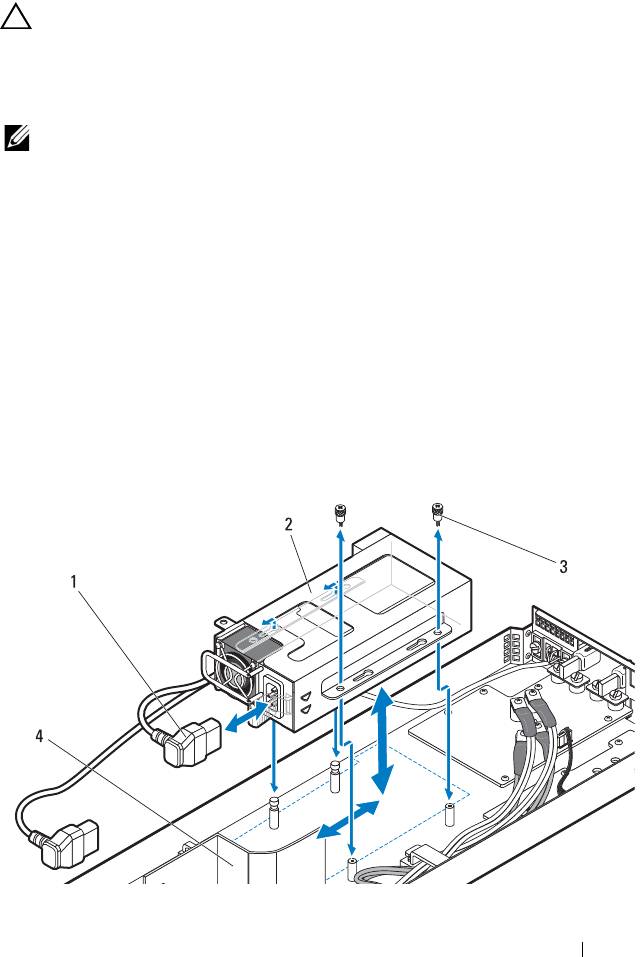
Installing System Components 201
Removing the PSU1/3 Module Assembly
CAUTION: Many repairs may only be done by a certified service technician. You
should only perform troubleshooting and simple repairs as authorized in your
product documentation, or as directed by the online or telephone service and
support team. Damage due to servicing that is not authorized is not covered by
warranty. Read and follow the safety instructions that came with the product.
NOTE: In addition to supplying power to the system, the PSU modules also have
internal fans that provide thermal cooling for the PSU modules in the power sleds.
A PSU module must be replaced if an internal fan failure occurs.
1
Remove the power sled. See "Removing a Power Sled" on page 198.
2
Remove the two screws securing the PSU1/3 module assembly.
See Figure 3-9.
3
Slide the module assembly back to free it from the metal guides on the
sled tray. See Figure 3-9.
4
Lift the module assembly from the sled tray and then disconnect the
power cable from the power supply. See Figure 3-9.
5
Remove the module assembly from the sled tray. See Figure 3-9.
Figure 3-9. Removing and Installing a PSU1/3 Module Assembly
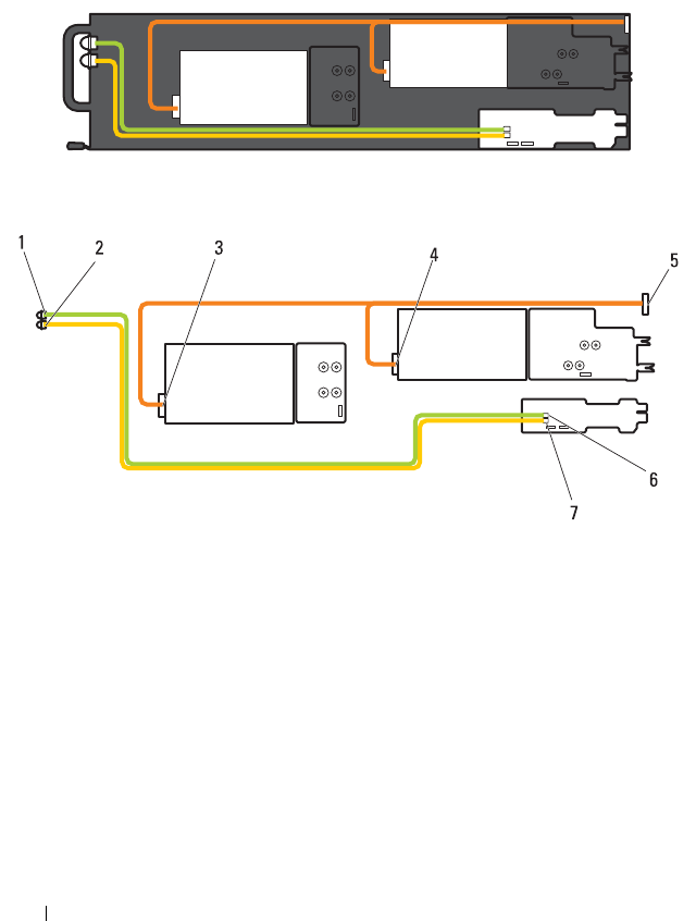
202 Installing System Components
Figure 3-10. Cable Routing for PSU1/3 Module Assembly
1 PSU power cable 2 PSU1/3 module assembly
3 thumbscrews (2) 4 air baffle
1 PSU1/3 status indicator 2 PSU2/4 status indicator
3 power connector on PSU2/4 module 4 power connector on PSU1/3 module
5 power cable 6 PSU LED connector on power
interposer board
7 PSU LED connector on power
interposer board

Installing System Components 203
Installing the PSU1/3 Module Assembly
CAUTION: Many repairs may only be done by a certified service technician. You
should only perform troubleshooting and simple repairs as authorized in your
product documentation, or as directed by the online or telephone service and
support team. Damage due to servicing that is not authorized is not covered by
warranty. Read and follow the safety instructions that came with the product.
1
Connect the power cable to the new PSU module. See Figure 3-10 for
cable routing.
2
Place the PSU module assembly on top of the sled tray.
3
Lower the module assembly so that the metal guides on the sled tray fit
into the slots on the power supply bracket.
4
Slide the module assembly forward until the metal guides engage into the
slots on the PSU bracket and ensure that the module assembly is fully
seated into the back power distribution board.
NOTE: Make sure the air baffle is properly seated and the power cable is neatly
tucked into place. See
Figure 3-9.
5
Replace the two screws securing the module assembly to the sled tray.
See Figure 3-9.
NOTE: After installing a power sled with a new PSU module, allow several seconds
for the system to recognize the power supply and to determine if it is working
properly. The status indicator turns green to signify that the module is functioning
properly.
Removing the PSU2/4 Module Assembly
CAUTION: Many repairs may only be done by a certified service technician. You
should only perform troubleshooting and simple repairs as authorized in your
product documentation, or as directed by the online or telephone service and
support team. Damage due to servicing that is not authorized is not covered by
warranty. Read and follow the safety instructions that came with the product.
1
Remove the power sled. See "Removing a Power Sled" on page 198.
2
Remove the screw and thumbscrew securing the PSU2/4 module assembly.
See Figure 3-11.
3
Slide the module assembly back to free it from the metal guides on the
sled tray.
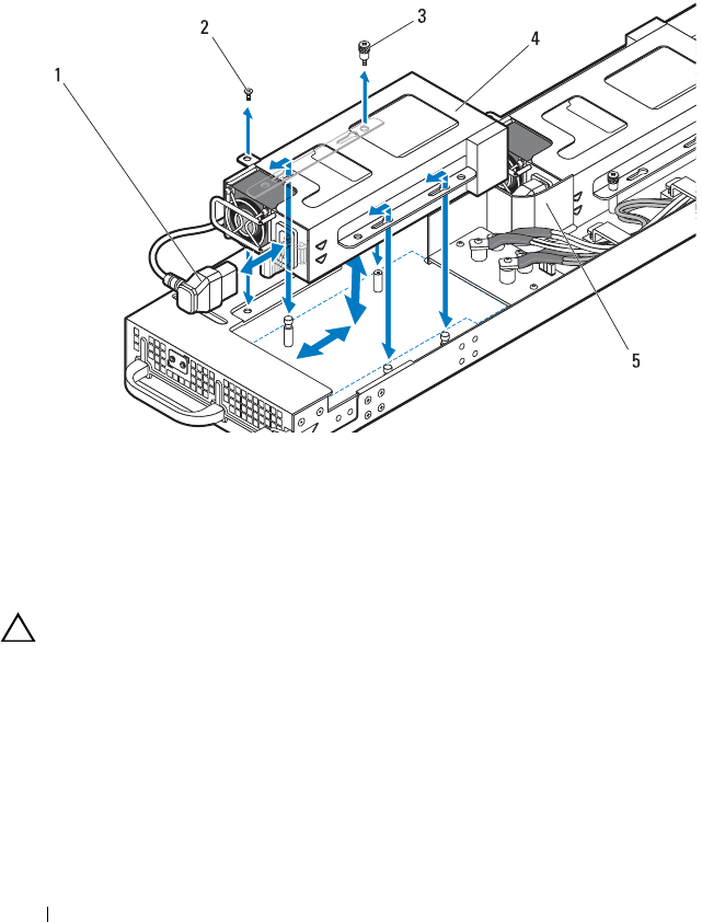
204 Installing System Components
4
Lift the module assembly from the sled tray and then disconnect the
power cable from the power supply. See Figure 3-11.
5
Remove the module assembly from the sled tray. See Figure 3-11.
Figure 3-11. Removing and Installing a PSU2/4 Module Assembly
Installing the PSU2/4 Module Assembly
CAUTION: Many repairs may only be done by a certified service technician. You
should only perform troubleshooting and simple repairs as authorized in your
product documentation, or as directed by the online or telephone service and
support team. Damage due to servicing that is not authorized is not covered by
warranty. Read and follow the safety instructions that came with the product.
1
Connect the power cable to the new PSU module. See Figure 3-10 for
cable routing.
2
Position the PSU2/4 module assembly on top of the sled tray.
1 PSU power cable 2 screw
3 thumbscrew 4 PSU2/4 module assembly
5 air baffle

Installing System Components 205
3
Slide the module assembly forward until the metal guides engage into the
slots on the PSU bracket and ensure that the module assembly is fully
seated into the front power distribution board.
NOTE: Make sure the air baffle is properly seated and the power cable is neatly
tucked into place. See Figure 3-11.
4
Replace the screws securing the module assembly to the sled tray.
See Figure 3-11.
Removing the PSU Module
CAUTION: Many repairs may only be done by a certified service technician. You
should only perform troubleshooting and simple repairs as authorized in your
product documentation, or as directed by the online or telephone service and
support team. Damage due to servicing that is not authorized is not covered by
warranty. Read and follow the safety instructions that came with the product.
NOTE: In addition to supplying power to the system, the PSU modules also have
internal fans that provide thermal cooling for the PSU modules in the power sleds. A
PSU module must be replaced if an internal fan failure occurs.
The installation and removal procedures of a power supply module on a
PSU1/3 and PSU2/4 module assembly are similar.
1
Remove the power sled. See "Removing a Power Sled" on page 198.
2
Remove the PSU module assembly containing the failed power supply.
See "Removing the PSU1/3 Module Assembly" on page 201 or "Removing
the PSU2/4 Module Assembly" on page 203.
3
Pull open the handle on the PSU module. See Figure 3-12.
4
Press down on the release lever and pull the module out of the bracket.
See Figure 3-12.
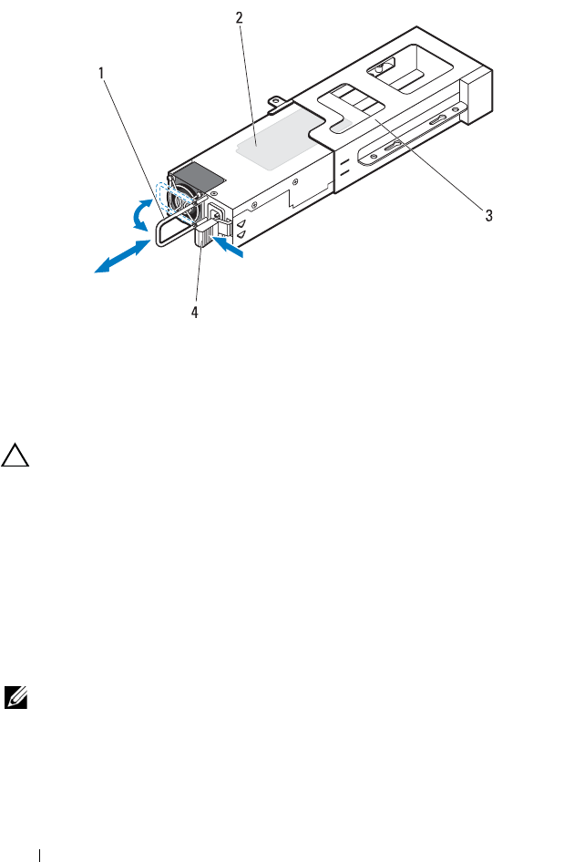
206 Installing System Components
Figure 3-12. Removing and Installing a PSU Module
Installing the PSU Module
CAUTION: Many repairs may only be done by a certified service technician. You
should only perform troubleshooting and simple repairs as authorized in your
product documentation, or as directed by the online or telephone service and
support team. Damage due to servicing that is not authorized is not covered by
warranty. Read and follow the safety instructions that came with the product.
1
Slide the new PSU module into the PSU bracket. See Figure 3-12.
2
Close the handle on the PSU module. See Figure 3-12.
3
Replace the PSU module on the sled tray. See "Installing the PSU1/3
Module Assembly" on page 203 or "Installing the PSU2/4 Module
Assembly" on page 204.
NOTE: After installing a power sled with a new PSU module, allow several seconds
for the system to recognize the power supply and to determine if it is working
properly. The status indicator turns green to signify that the module is functioning
properly.
1 handle 2 PSU module
3 PSU bracket 4 release lever

Installing System Components 207
Fan Modules
The PowerEdge C8000 server enclosure includes three pairs of hot-swappable
fan modules that provide the system with redundant cooling source. Each fan
module contains two separate cooling fans. All three fan modules must be
installed at all times to ensure proper cooling.
NOTE: If a fan module is removed from the enclosure, all sleds in the enclosure will
be throttled until the fan module is replaced. If two fan modules fail at the same time
and are not replaced within 90 seconds, the enclosure will shutdown automatically.
For more information on troubleshooting a fan module(s), see the "Troubleshooting
Enclosure Fan Modules" on page 257.
Removing a Fan Module
CAUTION: Many repairs may only be done by a certified service technician. You
should only perform troubleshooting and simple repairs as authorized in your
product documentation, or as directed by the online or telephone service and
support team. Damage due to servicing that is not authorized is not covered by
warranty. Read and follow the safety instructions that came with the product.
CAUTION: To ensure proper airflow in the system, if a fan module is removed it
should be immediately replaced with another module.
WARNING: Replace a fan module within 90 seconds to avoid system shutdown.
1
Identify the failed fan module using the back-panel fan module indicators.
See Figure 1-14.
CAUTION: Use caution when handling the fan module until the fan blades stop
spinning.
WARNING: When removing the fan module, keep your hands and fingers away
from the spinning fan blades.
2
Loosen the two thumbscrews securing the fan module you wish to replace.
3
Pull out the fan module from the fan bay. See Figure 3-13.
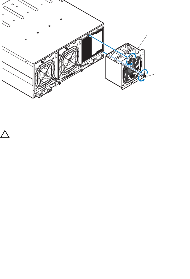
208 Installing System Components
Figure 3-13. Removing and Installing the Fan Module
Installing a Fan Module
CAUTION: Many repairs may only be done by a certified service technician. You
should only perform troubleshooting and simple repairs as authorized in your
product documentation, or as directed by the online or telephone service and
support team. Damage due to servicing that is not authorized is not covered by
warranty. Read and follow the safety instructions that came with the product.
1
Inspect the fan for debris before installing the fan in the fan bay.
2
Slide the fan module into the fan bay until it is fully seated. See
Figure 3-13.
3
Tighten the two thumbscrews to secure the fan module. See Figure 3-13.
1 fan module 2 thumbscrews (2)
1
2
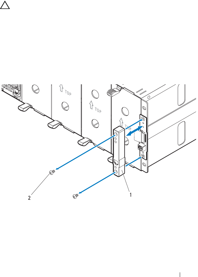
Installing System Components 209
Front Panel Board
Removing the Front Panel Board
CAUTION: Many repairs may only be done by a certified service technician. You
should only perform troubleshooting and simple repairs as authorized in your
product documentation, or as directed by the online or telephone service and
support team. Damage due to servicing that is not authorized is not covered by
warranty. Read and follow the safety instructions that came with the product.
1
Remove the two screws securing the front panel board cover. See
Figure 3-14.
2
Remove the cover from the enclosure.
Figure 3-14. Removing and Installing the Front Panel Board Cover
1 front panel board cover 2 screws (2)
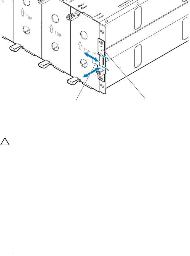
210 Installing System Components
3
Disconnect the front panel board cable. See Figure 3-15.
4
Remove the front panel board from the enclosure. See Figure 3-15.
Figure 3-15. Removing and Installing the Front Panel Board
Installing the Front Panel Board
CAUTION: Many repairs may only be done by a certified service technician. You
should only perform troubleshooting and simple repairs as authorized in your
product documentation, or as directed by the online or telephone service and
support team. Damage due to servicing that is not authorized is not covered by
warranty. Read and follow the safety instructions that came with the product.
1
Attach the new front panel board to its enclosure standoffs. See
Figure 3-15.
2
Connect the front panel board cable to the board. See Figure 3-15.
3
Position the front panel board cover over the board. See Figure 3-14
4
Replace the two screws securing the front panel board cover to the
enclosure. See Figure 3-14.
1 front panel board 2 front panel board cable
1
2
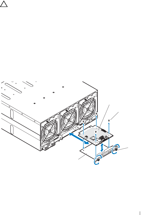
Installing System Components 211
Fan Controller Board
Removing the Fan Controller Board
CAUTION: Many repairs may only be done by a certified service technician. You
should only perform troubleshooting and simple repairs as authorized in your
product documentation, or as directed by the online or telephone service and
support team. Damage due to servicing that is not authorized is not covered by
warranty. Read and follow the safety instructions that came with the product.
1
Loosen the two thumbscrews that secure the fan controller board tray to
the server enclosure. See Figure 3-16.
2
Pull out the fan controller board tray from the enclosure.
3
Remove the four screws securing the fan controller board.
4
Remove the fan controller board from its tray. See Figure 3-16.
Figure 3-16. Removing and Installing the Fan Controller Board
1 fan controller board 2 screws (4)
3 thumbscrews (2) 4 fan controller board tray
1
2
3
4

212 Installing System Components
Installing the Fan Controller Board
CAUTION: Many repairs may only be done by a certified service technician. You
should only perform troubleshooting and simple repairs as authorized in your
product documentation, or as directed by the online or telephone service and
support team. Damage due to servicing that is not authorized is not covered by
warranty. Read and follow the safety instructions that came with the product.
NOTE: If you are installing a new fan controller board, prior to upgrading your
system, download and install the latest fan controller board firmware version from
dell.com/support. Follow the instructions included in the file download to install the
update on your system.
1
Place the fan controller board into the fan controller bay. See Figure 3-16.
2
Replace the four screws securing the fan controller board to its tray. See
Figure 3-16.
3
Insert the fan controller board assembly into its enclosure bay.
4
Secure the fan controller board assembly to the enclosure with the two
thumbscrews. See Figure 3-16.
Backplane/Fan Bay Cage
Removing the Backplane/Fan Bay Cage
CAUTION: Many repairs may only be done by a certified service technician. You
should only perform troubleshooting and simple repairs as authorized in your
product documentation, or as directed by the online or telephone service and
support team. Damage due to servicing that is not authorized is not covered by
warranty. Read and follow the safety instructions that came with the product.
1
Disconnect the server enclosure from the electrical outlet or PDU.
2
Remove the fan controller board. See "Removing the Fan Controller
Board" on page 211.
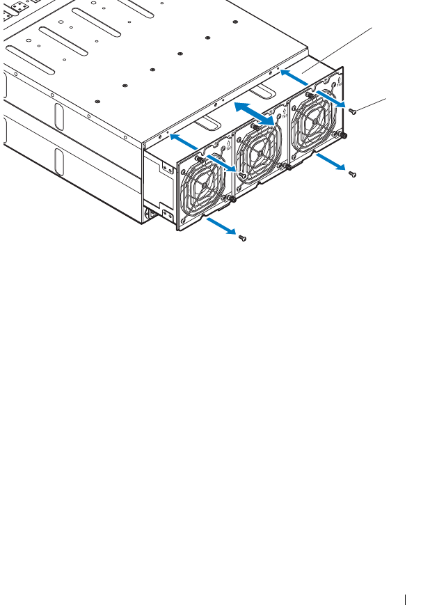
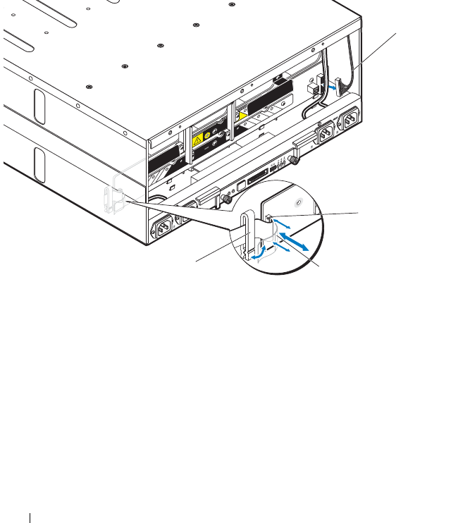
214 Installing System Components
4
Open the front panel board cable retaining clip and disconnect the cable
from the power management board. See Figure 3-18. For server enclosure
with external power source, see Figure 3-19.
5
Disconnect the fan cable from the power management board.
See Figure 3-18. For server enclosure with external power source, see
Figure 3-19.
Figure 3-18. Removing and Installing System Cables in Server Enclosure with Internal
Power Source
1 fan cable 2 front panel board connector
3 front panel board cable 4 cable retaining clip
1
2
3
4
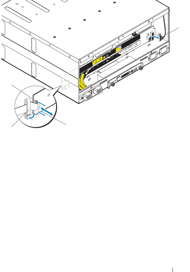
Installing System Components 215
Figure 3-19. Removing and Installing System Cables in Server Enclosure with External
Power Source
1 fan cable 2 front panel board cable
3 cable retaining clip 4 front panel board connector
1
2
3
4
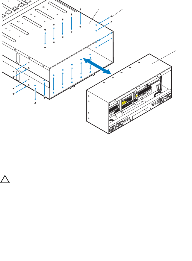
216 Installing System Components
6
Remove the twenty screws securing the backplane cage and pull it out of
the server enclosure. See Figure 3-20.
Figure 3-20. Removing and Installing the Backplane Cage
Installing the Backplane/Fan Bay Cage
CAUTION: Many repairs may only be done by a certified service technician. You
should only perform troubleshooting and simple repairs as authorized in your
product documentation, or as directed by the online or telephone service and
support team. Damage due to servicing that is not authorized is not covered by
warranty. Read and follow the safety instructions that came with the product.
1
Slide the new backplane cage into the enclosure until it is fully seated.
See Figure 3-20.
2
Secure the backplane cage to the enclosure with the twenty screws.
See Figure 3-20.
1 server enclosure 2 screws (20)
3 backplane cage
12
3

Installing System Components 217
3
Connect the front panel board cable to the power management board and
secure the cable in the retaining clip. See Figure 3-18. For server enclosure
with external power source, see Figure 3-19.
4
Connect the fan cable to the power management board. See Figure 3-18.
For server enclosure with external power source, see Figure 3-19.
5
Slide the new fan bay cage into the enclosure until it is fully seated.
See Figure 3-17.
6
Secure the fan bay cage to the enclosure with the four screws.
See Figure 3-17.
7
Reconnect the enclosure to its electrical outlet or PDU.
PDU Power Supply
The external PDU includes six power supply modules. All six power supply
modules must remain installed. Use the following procedure to remove and
replace a power supply module from the external PDU.
NOTE: The PDU device illustrations in this section is for reference only and may not
reflect the appearance of the actual device.
PDU Power Supply Indicator Code
The status indicator on the front of the power supply lights green to indicate
a valid power source is connected to the power supply and that power supply
is operational. An amber light indicates that a power supply failure event
occurred.
Removing a PDU Power Supply
CAUTION: Many repairs may only be done by a certified service technician. You
should only perform troubleshooting and simple repairs as authorized in your
product documentation, or as directed by the online or telephone service and
support team. Damage due to servicing that is not authorized is not covered by
warranty. Read and follow the safety instructions that came with the product.
CAUTION: To ensure proper airflow in the PDU, if a PSU module is removed it
should be immediately replaced with another module.
NOTE: The PDU power supply replacement procedure are provided as reference
only. See PDU device documentation for more information.
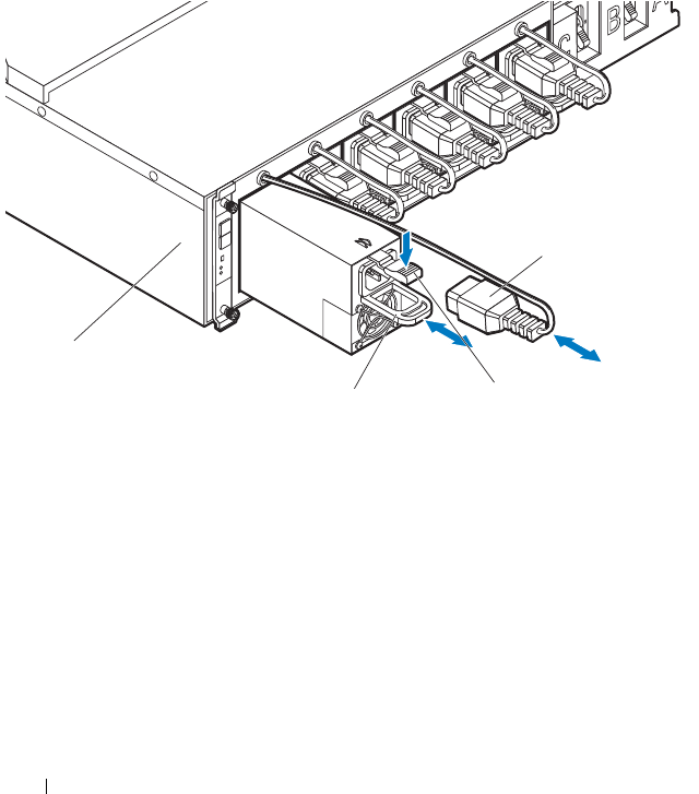
218 Installing System Components
1
Locate the failed power supply module. If a power supply module is faulty
the status indicator lights up amber.
2
Disconnect the power cable from the power supply module.
See Figure 3-21.
3
Grasp the power supply handle and press the release latch.
See Figure 3-21.
4
Slide the power supply module out of it’s bay. See Figure 3-21.
Figure 3-21. Removing and Installing a PDU Power Supply
1 power cable 2 release latch
3 power supply handle 4 PDU device
4
3
1
2

Installing System Components 219
Installing a PDU Power Supply
CAUTION: Many repairs may only be done by a certified service technician. You
should only perform troubleshooting and simple repairs as authorized in your
product documentation, or as directed by the online or telephone service and
support team. Damage due to servicing that is not authorized is not covered by
warranty. Read and follow the safety instructions that came with the product.
1
Align the new power supply module with the power supply bay.
See Figure 3-21.
2
Slide the power supply module into the bay until it is fully seated.
3
Connect the power cable to the power supply. Verify that the indicator on
the front of the power supply lights. See Figure 3-21.

220 Installing System Components

Rack Mount Configuration 221
4
Rack Mount Configuration
Your PowerEdge C8000 server enclosure can be mounted in a four-post rack
cabinet.
Installation Guidelines
Use the following safety guidelines to help ensure your own personal safety
and to help protect your system and working environment from potential
damage. See additional safety information included with your system.
WARNING: Whenever you need to lift the system, get others to assist you. To
avoid injury, do not attempt to lift the system by yourself.
WARNING: The system is not fixed to the rack or mounted on the rails. To avoid
personal injury or damage to the system, you must adequately support the system
during installation and removal.
WARNING: To avoid a potential electrical shock hazard, a third wire safety
grounding conductor is necessary for the rack installation. The rack equipment
must provide sufficient airflow to the system to maintain proper cooling.
CAUTION: Before you install the server enclosure into a rack, it is recommended
that you remove all installed sled modules from the enclosure to reduce weight
and avoid injury.
CAUTION: To prevent possible damage to the server enclosure surface and sled
modules, always place the server enclosure and sled modules on an antistatic mat
or antistatic foam.
• Prepare an antistatic mat or antistatic foam to set the PowerEdge C8000
server enclosure on during the compute or storage sled removal process.
• Ensure that proper airflow is provided to components in the rack.

222 Rack Mount Configuration
Recommended Tools
Before you begin the installation tasks, ensure that you have the following
items:
• #1 Phillips screwdriver
• #2 Phillips screwdriver
• Wrist grounding strap connected to ground
• Antistatic mat or antistatic foam
Installation Tasks
To install the rail and system into the rack, you need to perform the following
tasks.
1
"Installing the Tool-Less Rail Solution in the Rack" on page 223
2
"Removing Sled Modules from the Server Enclosure" on page 228
3
"Installing the Server Enclosure into the Rack" on page 228
4
"Replacing Sled Modules in the Server Enclosure" on page 230
5
"Installing the External PDU into the Rack" on page 231
6
"Connecting the Power Cables" on page 237
7
"Connecting the Server Enclosure to a Rack PDU" on page 239
8
"Connecting the PDU to the Network" on page 243
9
"Powering Up the Systems" on page 246

Rack Mount Configuration 223
Installing the Tool-Less Rail Solution in the Rack
NOTE: The rack rails are marked LEFT and RIGHT. The rail marked "LEFT" attaches
to the left rack posts and the rail marked "RIGHT" attaches to the right rack posts
when facing the front of the rack.
NOTE: The rail pegs must be flush with the rack posts to install properly.
1
Determine where to place the rails in the rack. Make sure there is enough
space in the rack for the 4U server enclosure. In a standard rack, the height
of a 4U chassis will span 12 rack post holes.
2
Use the marking indicated on the left and right sides of the rail to orient
the rail correctly to the rack posts.
3
Attach the left rail and stopping bracket to the rack.
a
Position left rail marked "
LEFT
" to align with its mounting holes on the
rack posts.
b
Press and hold the rail release button to open the latch on the front
end of the rail. See Figure 4-1.
c
Align the three pegs with the mounting holes on the front rack post.
See Figure 4-1.
d
Release the button when it engages to the front rack post.
See Figure 4-1.
NOTE: Make sure the rail release button is engaged correctly.
NOTE: The rails can be used in both square-hole and round-hole racks.
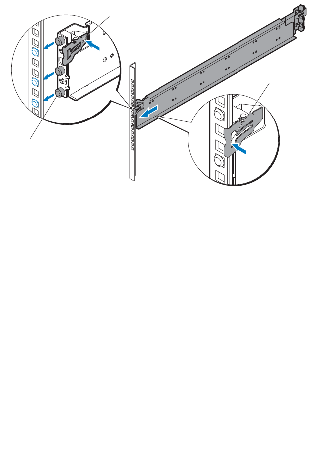
224 Rack Mount Configuration
Figure 4-1. Installing the Front End of the Rail
e
Press and hold the rail release button to open the latch on the back
end of the rail. See Figure 4-2.
f
Align the three pegs with the mounting holes on the back rack post.
See Figure 4-2.
g
Release the button when it engages to the back rack post. See
Figure 4-2.
1 rail release button 2 rail pegs (3)
3 rack post
2
1
3
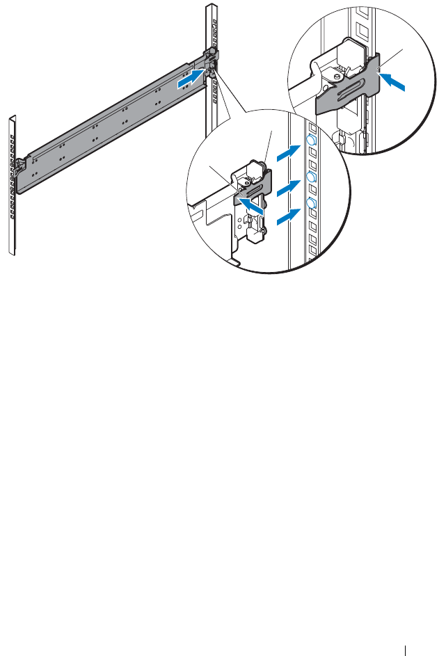
Rack Mount Configuration 225
Figure 4-2. Installing the Back End of the Rail
1 rail release button 2 rail pegs (3)
3 rack post
1
2
3
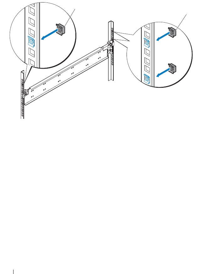
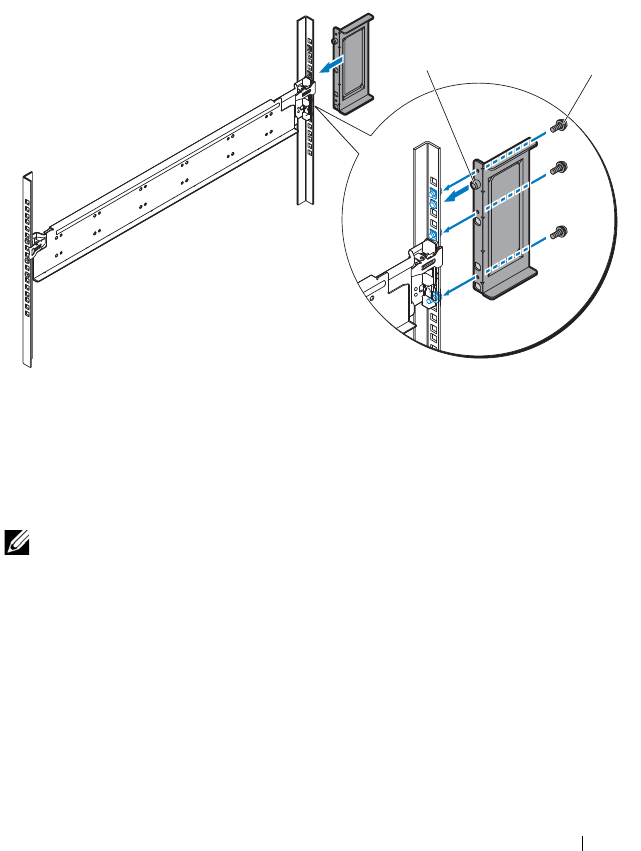
Rack Mount Configuration 227
i
Align the stopping bracket to the back rack post and secure with the
three 10-32 screws. Apply 35 in-lbs of torque to the screws.
See Figure 4-4.
Figure 4-4. Installing the Stopping Bracket
4
Attach the right rail and stopping bracket to the rack.
Use the same procedure to install the right rail and stopping bracket to the
right rack posts.
NOTE: To remove the rails, press and hold on the rail release button on the end
piece midpoint and unseat each rail.
1 stopping bracket 2 10-32 screws (3)
12

228 Rack Mount Configuration
Removing Sled Modules from the Server
Enclosure
Before you install a PowerEdge C8000 server enclosure into a rack, it is
recommended that you remove all sled modules from the enclosure to reduce
system weight and avoid injury.
For instructions on removing components from the server enclosure, refer to
the following sections.
• "Removing a Double-Wide Sled Blank" on page 190
• "Removing a Single-Wide Sled Blank" on page 191
• "Removing a Compute Sled" on page 192
• "Removing a Storage Sled" on page 194
• "Removing a Power Sled" on page 198 (for server enclosure with internal
power source only)
Installing the Server Enclosure into the Rack
WARNING: Whenever you need to lift the system, get others to assist you. To
avoid injury, do not attempt to lift the system by yourself.
CAUTION: To ensure proper operation and cooling, all bays in the enclosure must
be populated at all times with either a sled or with a sled blank.
CAUTION: To maintain proper system cooling, all empty hard-drive slots must
have hard-drive blanks installed.
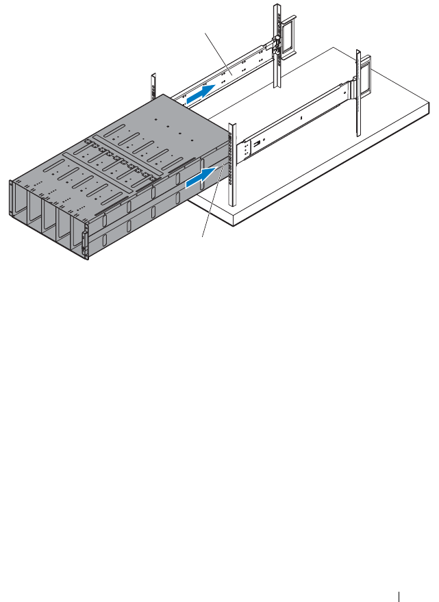
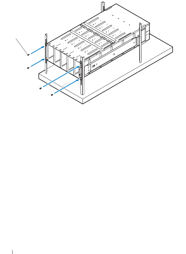
230 Rack Mount Configuration
2
Secure the front of the enclosure to the rack posts with four 10-32 screws.
See Figure 4-6.
Figure 4-6. Securing the Enclosure
Replacing Sled Modules in the Server Enclosure
For instructions on replacing sled modules in the server enclosure, refer to the
following sections.
• "Installing a Double-Wide Sled Blank" on page 190
• "Installing a Single-Wide Sled Blank" on page 191
• "Installing a Compute Sled" on page 194
• "Installing a Storage Sled" on page 195
• "Installing a Power Sled" on page 200 (for server enclosure with internal
power source only)
1 10-32 screws (4)
1
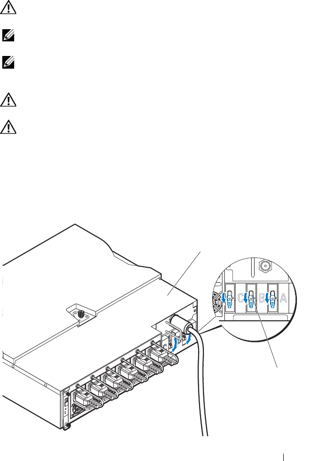
Rack Mount Configuration 231
Installing the External PDU into the Rack
WARNING: Whenever you need to lift the system, get others to assist you. To
avoid injury, do not attempt to lift the system by yourself.
NOTE: The PDU device illustrations are provided as reference only. See PDU
device documentation for more information about the PDU device.
NOTE: The PDU mounting brackets are marked L and R. The rail marked "L"
attaches to the left of the PDU device and the rail marked "R" attaches to the right of
the PDU device.
WARNING: Do not connect or disconnect power cables to the PDU device while
the PDU is energized.
WARNING: Turn off the PDU breaker switches to avoid potentially serious or
fatal electric shock.
1
Power down the PDU.
a
Turn off the PDU breaker switches by moving the A, B, and C breaker
switches to the "OFF" position.
Figure 4-7. Turning off the PDU Breaker Switches
OFFOFFOFF
1
2
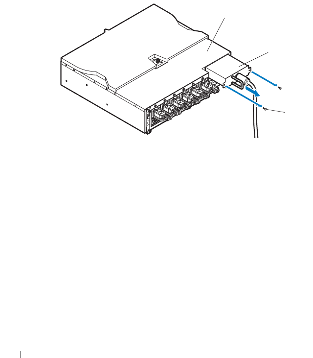
232 Rack Mount Configuration
b
Disconnect the PDU from the power source.
2
Remove the power cable interface box (PCIB) module.
a
Remove the two screws securing the PCIB module.
b
Grasp the PCIB handle and pull it out of it’s bay.
Figure 4-8. Removing the PCIB Module
1 PDU device 2 breaker switches (3)
1 PDU device 2 PCIB module
3 screw (2)
1
2
3
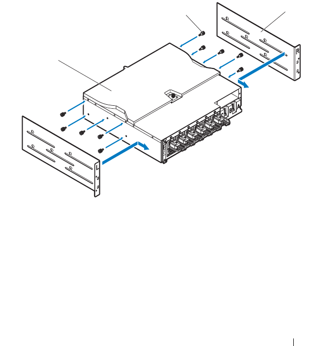
Rack Mount Configuration 233
3
Attach the mounting brackets to the sides of the PDU.
a
Affix the ten screws to the left and right sides of the PDU.
See Figure 4-9.
b
Position the left mounting bracket marked "L" to align the screw holes
with the screws on the PDU and slide the mounting bracket toward
the back of the PDU until it locks into place. See Figure 4-9.
c
Position the right mounting bracket marked "R" to align the screw
holes with the screws on the PDU and slide the mounting bracket
toward the back of the PDU until it locks into place. See Figure 4-9.
Figure 4-9. Installing the PDU Mounting Brackets
1 PDU device 2 screws (10)
3 mounting brackets (2)
1
23
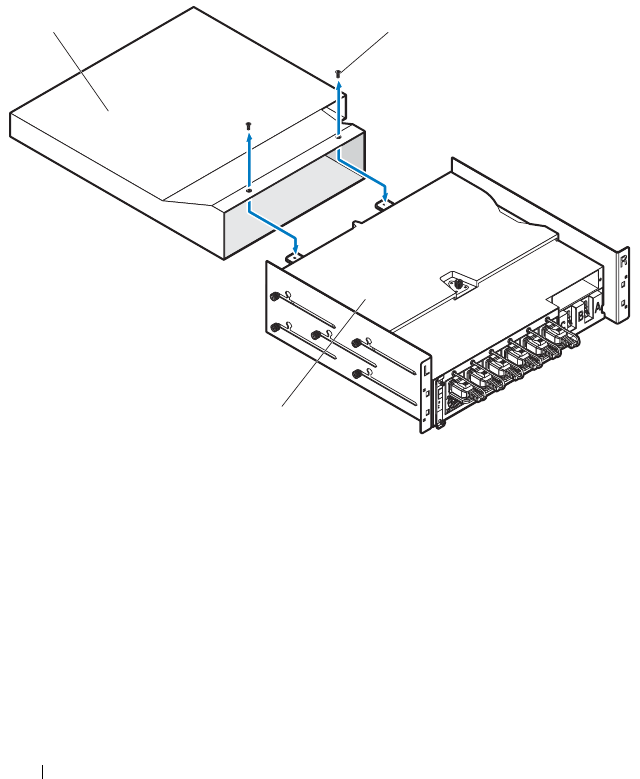
234 Rack Mount Configuration
4
Install the snorkel to the PDU.
a
Remove the air duct from the snorkel.
b
Align the air duct with the front of the PDU. See Figure 4-10.
c
Secure the air duct to the front of the PDU with the two screws.
See Figure 4-10.
Figure 4-10. Installing the Snorkel Air Duct to the PDU
1 snorkel air duct 2 screws (2)
3 PDU device
2
1
3
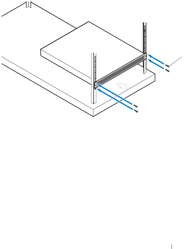
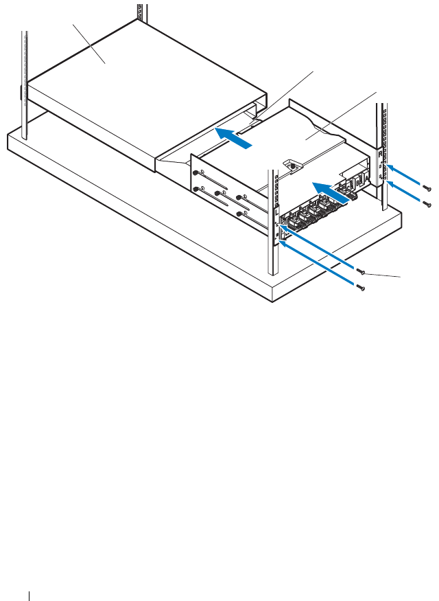
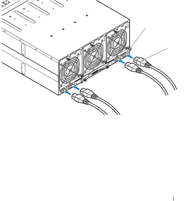
Rack Mount Configuration 237
Connecting the Power Cables
This section includes instructions on how to connect the server enclosure
with internal or external power source to an external PDU.
Connecting the Power Cables to the Server Enclosure with Internal
Power Source
1
On the back of the server enclosure, connect the power cables to the AC
power sockets. See Figure 4-13.
Figure 4-13. Connecting the Power Cables to the Server Enclosure with Internal Power
Source
2
Plug the other end of the power cables into a grounded electrical outlet or
a separate power source such as an uninterrupted power supply or the
PDU. For instructions on how to connect the power cables to the rack
PDU, see "Connecting the Server Enclosure to a Rack PDU" on page 239.
1 AC power sockets (2) 2 power cables (4)
1
2
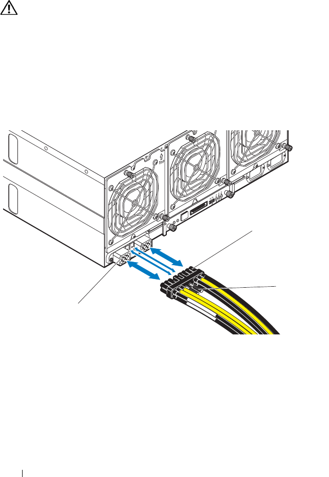
238 Rack Mount Configuration
Connecting the Power Cable to the Server Enclosure with External
Power Source
WARNING: Make sure power is turned off on all devices before making
connections.
1
On the back of the server enclosure, connect the power cable to the DC
power socket. See Figure 4-14.
2
Tighten the two center screws on the cable to secure the connection.
See Figure 4-14.
Figure 4-14. Connecting the Power Cable to the Server Enclosure with External Power
Source
3
Plug the other end of the power cables into a separate power source such as
a PDU. For instructions on how to connect the power cables to the rack
PDU, see "Connecting the Server Enclosure to a Rack PDU" on page 239.
1 power cable 2 screws (2)
3 DC power socket
1
2
3
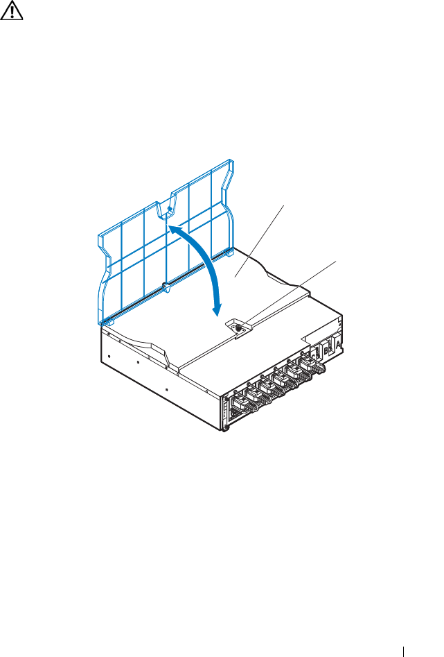
Rack Mount Configuration 239
Connecting the Server Enclosure to a Rack PDU
WARNING: Do not connect or disconnect power cables to the PDU device while
the PDU is energized. Turn off the PDU breaker switches to avoid potentially
serious or fatal electrical shock. Move the PDU A, B, and C breaker switches to
the "OFF" position.
1
Unlock the cable cover. See Figure 4-15.
2
Rotate the cover back and away from the PDU. See Figure 4-15.
Figure 4-15. Opening the PDU Cover
3
Depending on the type of power cable used, connect the server enclosure
power cable to the PDU power bus bar or the power sockets.
For connecting the power cables to the PDU’s front power socket, go to
step 6.
1 cable cover 2 lock
1
2
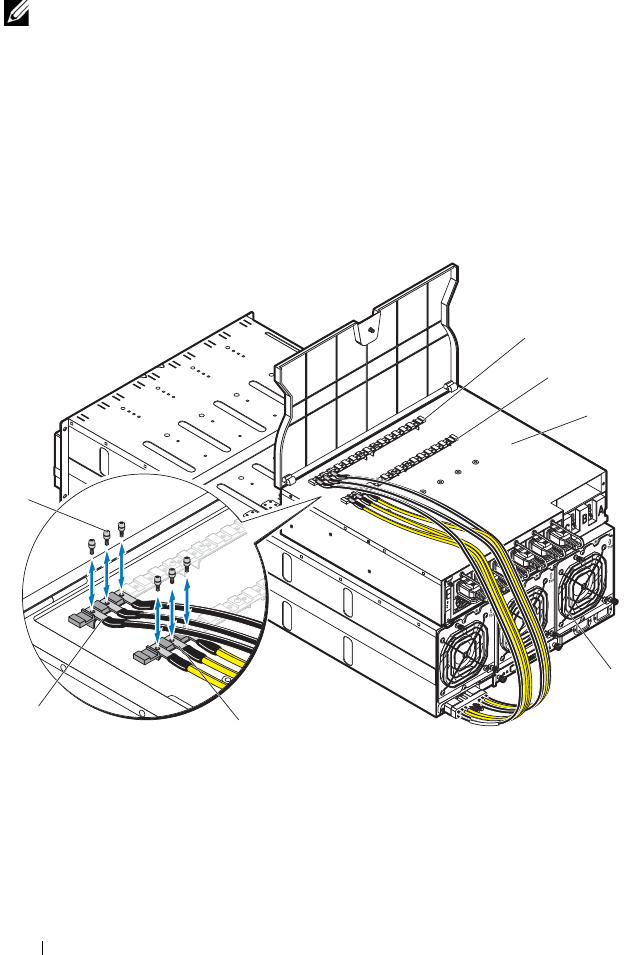
240 Rack Mount Configuration
4
Attach the server enclosure(s) power cables to the PDU power bus bar.
NOTE: The PDU device supports a maximum of five PowerEdge C8000 server
enclosures depending on the system configuration and power budget.
a
Secure the three black power cable lugs to the top power bus bar
(GND) with three screws. See Figure 4-16.
b
Secure the three yellow power cable lugs to the bottom power bus bar
(12 V) with three screws. See Figure 4-16.
c
For multiple server enclosures cable connection, see Figure 4-17.
Figure 4-16. Connecting a Single Server Enclosure to the PDU
1 screws (6) 2 power bus bar (GND)
3 power bus bar (12 V) 4 PDU device
5 server enclosure 6 yellow power cables (3)
7 black power cables (3)
1
2
3
4
5
6
7
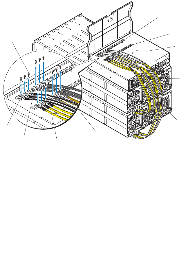
Rack Mount Configuration 241
Figure 4-17. Connecting Multiple Server Enclosures to the PDU
5
Close the cable cover and secure to the PDU. See Figure 4-15.
1 screws (12) 2 power bus bar (GND)
3 power bus bar (12 V) 4 PDU device
5 server enclosure 1 6 server enclosure 2
7 server enclosure 2 yellow power
cables (3)
8 server enclosure 1 yellow power
cables (3)
9 server enclosure 2 black power
cables (3)
10 server enclosure 1 black power
cables (3)
1
2
3
4
5
7
8
9
10
6
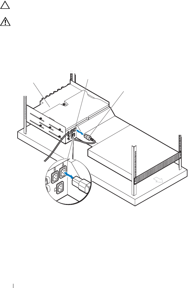
242 Rack Mount Configuration
Connecting a Network Switch to a Rack PDU
CAUTION: The PDU device’s A, B, and C power sockets are for network switches
only. Do not connect server enclosure(s) or server(s) to these sockets.
WARNING: Exceeding 3 amps per outlet could cause sudden rack level power
loss.
Connect the network switch power cable to one of the three PDU AC power
sockets. See Figure 4-18.
Figure 4-18. Connecting the Network Switch Power Cable to the PDU
1 PDU device 2 AC power sockets (3)
3 network switch’s power cable
1
3
2
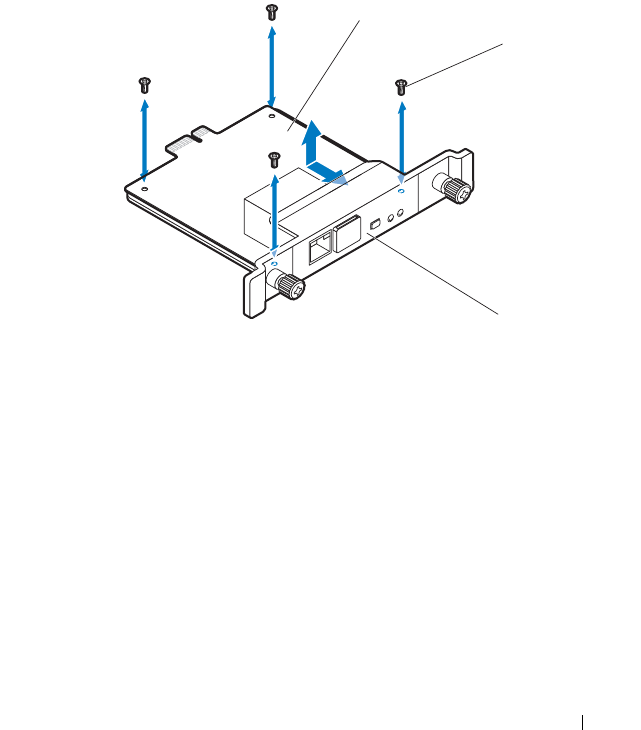
Rack Mount Configuration 243
Connecting the PDU to the Network
1
Install the power management controller (PMC) board into the PDU.
a
Unpack the PMC kit.
b
Slide the PMC board into the PMC tray. See Figure 4-19.
c
Secure the PMC board to the PMC tray with the four screws.
See Figure 4-19.
Figure 4-19. Installing the Power Management Controller Board
1 power management controller (PMC) board 2 screws (4)
3PMC tray
1
2
3
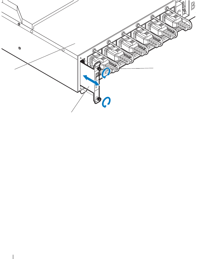
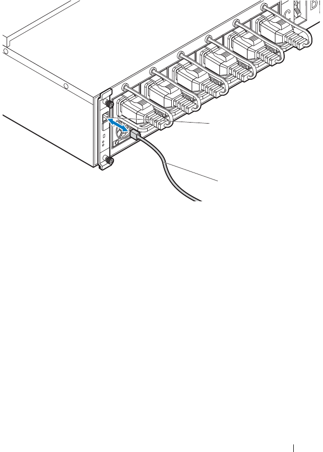
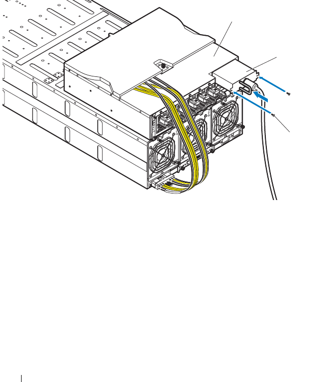
246 Rack Mount Configuration
Powering Up the Systems
1
Install the PCIB module into the PDU.
a
Insert the PCIB module into the PCIB bay. See Figure 4-22.
b
Secure the PCIB module to the PDU with the two screws.
See Figure 4-22.
Figure 4-22. Installing the PCIB Module
c
Connect the PDU to the power source.
1 PDU device 2 PCIB module
3 screws (2)
1
2
3
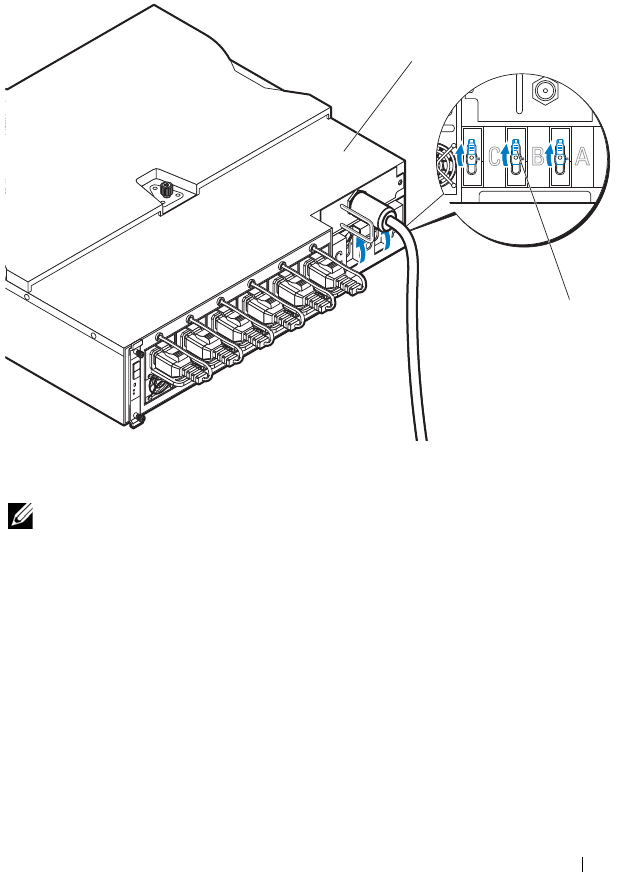
Rack Mount Configuration 247
2
Turn on the PDU breaker switches by moving the A, B, and C breaker
switches to the "ON" position. See Figure 4-23.
Figure 4-23. Turning on the PDU Breaker Switches
NOTE: The PMC board and PDU device illustrations used in this manual are
provided as reference only. See PDU device documentation for more information
about the PMC board and PDU device.
1 PDU device 2 breaker switches (3)
ONONON
1
2

248 Rack Mount Configuration
3
To enable monitoring of the PDU device over the network, turn on the
PMC board by pressing the power button, located on the PMC board. The
two indicators located on the front of the PMC board alerts you to the
condition of the PDU power supply module, PMC board and managed
sled modules.
The following table lists the PMC board indicators functions.
Indicator Icon Description
PDU
identification
indicator
The identification indicator lights blue indicating an
ON request is generated.
The identification indicator flashes blue indicating a
blink request is generated.
The identification indicator is off to indicate there is
no input power to the PDU or in normal condition.
Power/status
indicator
The power/status indicator lights green and flashes
amber (about 1 Hz) indicating that a valid power
source is connected to the PDU and PMC and that
power is applied to the sled modules in the server
enclosure.
The power/status indicator flashes green (about 1 Hz)
and flashes green and amber (about 1 Hz) indicating
the PDU is in service or sleep mode.
The power/status indicator is off to indicate there is no
input power to the PDU.
The power/status indicator flashes amber indicating
the following conditions:
•PMC status
•PMBus error
• PMC works in safe boot mode
•PDU status
• Communication error

Rack Mount Configuration 249
NOTE: When connected to a power source, main power is automatically
distributed to the PowerEdge C8000 server enclosure. After the server enclosure is
powered up the power/event indicator on the front of the enclosure will light up
green and main power is applied to all sleds in the enclosure.
4
Turn on the sleds in the server enclosure.
To turn on the C8220 or C8220X compute sled, press the power button on
each sled, or power on the sled using the baseboard management
controller. When power is applied to the sled, the power-on indicator on
front of the sled will light up green. When installed into the server
enclosure, the C8000XD storage sled automatically powers on.
The power/status indicator flashes amber indicating
the following conditions (continued):
• PSU module reading exceed threshold limits
• Power > 1480 W
• Voltage > 14.5 V
• Voltage < 10.75 V
• Current > 13 A
• Temperature > 60 °C
• Fan speed < 500 rpm
• PSU module status (from PSU STATUS_WORD)
•PSU module OVP
•PSU module OCP
•PSU module OTP
• PSU module fan fault protection (FFP)
• PSU module input over current
• PSU module input over power
• PSU module AC loss
• PSU module works in boot mode
• Communication error
Indicator Icon Description

250 Rack Mount Configuration

Troubleshooting 251
5
Troubleshooting
Safety First—For You and Your System
WARNING: Whenever you need to lift the system, get others to assist you. To
avoid injury, do not attempt to lift the system by yourself.
WARNING: Before removing the system cover, disconnect all power, then unplug
the AC power cord, and then disconnect all peripherals, and all LAN lines.
CAUTION: Many repairs may only be done by a certified service technician. You
should only perform troubleshooting and simple repairs as authorized in your
product documentation, or as directed by the online or telephone service and
support team. Damage due to servicing that is not authorized by Dell is not covered
by your warranty. Read and follow the safety instructions that came with the
product.
Installation Problems
Perform the following checks if you are troubleshooting an installation
problem:
• Check all cable and power connections (including all rack cable
connections).
• Unplug the power cord and wait for one minute. Then reconnect the
power cord and try again.
• If the network is reporting an error, verify that the system has enough
memory and disk space.
• Remove all added peripherals, one at a time, and try to turn on the system.
If after removing a peripheral the system works, it may be a problem with
the peripheral or a configuration problem between the peripheral and the
system. Contact the peripheral vendor for assistance.

252 Troubleshooting
• If the system does not power on, check the LED display. If the power LED
is not on, you may not be receiving AC power. Check the AC power cord to
make sure that it is securely connected.
Troubleshooting System Startup Failure
If your system halts during startup, especially after installing an operating
system or reconfiguring your system’s hardware, check for invalid memory
configurations. These could cause the system to halt at startup without any
video output. See the compute sled’s Hardware Owner’s Manual for
information about the "System Memory".
For all other startup issues, note any system messages that appear onscreen.
See "Using the System Setup Program" on page 67 for more information.
Troubleshooting External Connections
Ensure that all external cables are securely attached to the external
connectors on your sled before troubleshooting any external devices.
See Figure 1-1 and Figure 1-3 for the front- and back-panel connectors
on your system.
Troubleshooting the Video Subsystem
1
Check the compute sled and power connections to the monitor.
2
Check the video interface cabling from the compute sled to the monitor.
Troubleshooting a USB Device
Use the following steps to troubleshoot a USB keyboard and/or mouse. For
other USB devices, go to step 5.
1
Ensure that the compute sled is turned on.
2
Disconnect the keyboard and mouse cables from the sled briefly and
reconnect them.
3
If the problem is resolved, restart the sled, enter the System Setup
program, and check if the nonfunctioning USB ports are enabled.
4
Swap the keyboard/mouse with a known-working keyboard/mouse.

Troubleshooting 253
5
If another sled is installed, connect the USB device to the sled. If the USB
device works with a different sled, the first sled may be faulty.
If the problem is resolved, replace the faulty keyboard/mouse.
If the problem is not resolved, proceed to the next step to begin
troubleshooting the other USB devices attached to the system.
a
Power down all attached USB devices and disconnect them from the
sled.
b
Restart the sled and, if your keyboard is functioning, enter the System
Setup program. Verify that all USB ports are enabled. See "USB
Configuration" on page 105.
c
If your keyboard is not functioning, you can also use remote access. If
the system is not accessible, locate the NVRAM Clear jumper inside
your sled and restore the BIOS to the default settings.
d
Reconnect and turn on each USB device one at a time.
6
If a device causes the same problem, power down the device, replace the
USB cable, and power up the device.
If the problem persists, replace the device.
If all troubleshooting fails, see "Getting Help" on page 289.
Troubleshooting a Serial I/O Device
1
Ensure that the compute sled is turned on.
2
Check the serial device connection to the sled.
3
Swap the serial interface cable with another working cable, and turn on the
sled and the serial device.
If the problem is resolved, replace the interface cable.
4
Swap the serial device with a known-working serial device.
5
Connect the serial device to the sled.
6
Turn on the sled and the serial device.
7
If another sled is installed, connect the serial device to the sled. If the serial
device works with a different sled, the first sled may be faulty.
If the problem is resolved, replace the serial device.
If the problem persists, see "Getting Help" on page 289.

254 Troubleshooting
Troubleshooting a NIC
1
Restart the compute sled and check for any system messages pertaining to
the NIC controller.
2
Check the appropriate indicator on the NIC connector. See "NIC Indicator
Codes" on page 20.
• If the link indicator does not light, check all cable connections.
• If the activity indicator does not light, the network driver files might
be damaged or missing.
• Remove and reinstall the drivers if applicable. See the NIC's
documentation.
• Change the auto-negotiation setting, if possible.
• Use another connector on the switch or hub.
If you are using a NIC card instead of an integrated NIC, see the
documentation for the NIC card.
3
Ensure that the appropriate drivers are installed and the protocols are
bound. See the NIC's documentation.
4
Enter the System Setup program and confirm that the NIC ports are
enabled. See "Using the System Setup Program" on page 67.
5
Ensure that the NICs, hubs, and switches on the network are all set to the
same data transmission speed. See the documentation for each network
device.
6
Ensure that all network cables are of the proper type and do not exceed the
maximum length.
If all troubleshooting fails, see "Getting Help" on page 289.

Troubleshooting 255
Troubleshooting a Wet Enclosure
CAUTION: Many repairs may only be done by a certified service technician. You
should only perform troubleshooting and simple repairs as authorized in your
product documentation, or as directed by the online or telephone service and
support team. Damage due to servicing that is not authorized by Dell is not covered
by your warranty. Read and follow the safety instructions that came with the
product.
1
Turn off the sleds and attached peripherals.
2
Disconnect the enclosure from the electrical outlet or the PDU.
CAUTION: Wait until all of the indicators on the power supplies turn off before
proceeding.
3
Remove all sleds. See "Removing a Compute Sled" on page 192 or
"Removing a Storage Sled" on page 194.
4
Disassemble components from the sled. See the sled’s documentation for
more information.
5
Remove the fan modules. See "Removing a Fan Module" on page 207.
6
Remove the front panel board. See "Removing the Front Panel Board" on
page 209.
7
Remove the fan controller board. See "Removing the Fan Controller
Board" on page 211.
8
Let the enclosure dry thoroughly for at least 24 hours.
9
Reinstall the fan controller board. See "Installing the Fan Controller
Board" on page 212.
10
Reinstall the front panel board. See "Installing the Front Panel Board" on
page 210.
11
Reinstall the fan modules. See "Installing a Fan Module" on page 208.
12
Reinstall all sled components you removed in step 4.
13
Reinstall all sleds. See "Installing a Compute Sled" on page 194 or
"Installing a Storage Sled" on page 195.

256 Troubleshooting
14
Reconnect the enclosure to the electrical outlet or the PDU.
15
Turn on the sleds and attached peripherals.
16
If the system fails to start, see "Getting Help" on page 289.
Troubleshooting a Damaged Enclosure
CAUTION: Many repairs may only be done by a certified service technician. You
should only perform troubleshooting and simple repairs as authorized in your
product documentation, or as directed by the online or telephone service and
support team. Damage due to servicing that is not authorized by Dell is not covered
by your warranty. Read and follow the safety instructions that came with the
product.
1
Turn off the sleds and attached peripherals.
2
Disconnect the enclosure from the electrical outlet or the PDU.
3
Ensure that the following components are properly installed in the
enclosure:
• Power sleds
•Fan modules
• Compute or storage sleds
4
Ensure that all components are properly installed in the sled. See the sled’s
documentation for more information.
5
Ensure that all cables are properly connected.
6
Ensure that all components are properly installed and free of damage.
7
If the system fails to start, see "Getting Help" on page 289.

Troubleshooting 257
Troubleshooting Enclosure Fan Modules
CAUTION: Many repairs may only be done by a certified service technician. You
should only perform troubleshooting and simple repairs as authorized in your
product documentation, or as directed by the online or telephone service and
support team. Damage due to servicing that is not authorized by Dell is not covered
by your warranty. Read and follow the safety instructions that came with the
product.
NOTE: The fan modules are hot-swappable. Remove and replace only one fan
module at a time in a server enclosure that is turned on. Operating the system
without all three fan modules for extended periods of time can cause the system to
overheat. Review the following table before you begin to replace the fan modules.
Fan Module (Fan Controller Firmware) Thermal Behavior Per Sled
Table 5-1. Fan Module (Fan Controller Firmware) Thermal Behavior Per Sled
Fan Module
Status
BMC (Processor/Memory)/Server Enclosure Temperature Status
OK/OK OK/Fail Fail/OK Fail/Fail
Fan module
normal/OK
Close loop,
Open loop (curve A)a,
If the PWM duty
cycle value rises above
100%, sled-level
throttling is
triggered b
Close loop,
80% PWM
If close loop
PWM signal
value is > 80%,
the PWM
output will
follow the close
loop output
Open loop (curve B)c,
If the PWM duty
cycle value rises above
100%, sled-level
throttling is triggeredb
100% PWM
One fan
module fails
Close loop,
If the PWM duty
cycle value rises above
100%, sled-level
throttling is triggeredb
100% PWM 100% PWM
Open loop
(curve C)d,
If the PWM duty
cycle value rises above
100%, sled-level
throttling is triggeredb
100% PWM
System
throttling

258 Troubleshooting
a. Open loop (curve A) is fan speed control (FSC) curve with default mode.
b. Refer to the Fan Controller Firmware Response section for more information.
c. Open loop (curve B) is FSC curve with emergency mode.
d. Open loop (curve C) is FSC curve with fan failure mode.
Fan Controller Firmware Response
Refer to the tables below when troubleshooting enclosure fan noise and for
the FC firmware responses to the possible PWM duty cycle values.
Table 5-2 lists the FC firmware responses in case scenario 1:
• Interval 1 — If the calculated value of the PWM is higher than 100%, the
FC firmware will send a signal to the fan to operate at 100% duty cycle and
trigger sled throttling.
• Interval 2 — If the calculated value of the PWM duty cycle is still higher
than 100% again, the FC firmware will send a signal to the fan to operate
at 100% duty cycle and trigger sled throttling for 1 hour.
Tw o fa n
modules fail
System throttling,
After 90 seconds has
passed, the system will
be forced to shut
down
System
throttling,
After 90
seconds has
passed, the
system will be
forced to shut
down
System throttling,
After 90 seconds has
passed, the system
will be forced to shut
down
System
throttling,
After 90 seconds
has passed, the
system will be
forced to shut
down
Three fan
modules fail
System force
shutdown
System force
shutdown
System force
shutdown
System force
shutdown
Table 5-2. Case Scenario 1
Interval (30 secs) PWM Results Fan Controller Firmware Action
Interval 1 PWM > 100% 1
Sets PWM = 100%
2
Sled throttling mechanism is active
Interval 2 PWM > 100% 1
Triggers sled throttling for 1 hr.
Table 5-1. Fan Module (Fan Controller Firmware) Thermal Behavior Per Sled
Fan Module
Status
BMC (Processor/Memory)/Server Enclosure Temperature Status
OK/OK OK/Fail Fail/OK Fail/Fail

Troubleshooting 259
Table 5-3 lists the FC firmware responses in case scenario 2:
• Interval 1 — If the calculated value of the PWM is higher than 100%, the
FC firmware will send a signal to the fan to operate at 100% duty cycle and
trigger sled throttling.
• Interval 2 — If the calculated value of the PWM duty cycle is less than or
equal to 100%, the FC firmware will send a signal to the fan to operate at
the set duty cycle.
• Interval 3 — If the calculated value of the PWM duty cycle is still higher
than 100% again, the FC firmware will send a signal to the fan to operate
at 100% duty cycle and trigger sled throttling for 1 hour.
Table 5-4 lists the FC firmware responses in case scenario 3:
• Interval 1 — If the calculated value of the PWM is higher than 100%, the
FC firmware will send a signal to the fan to operate at 100% duty cycle and
trigger sled throttling.
Table 5-3. Case Scenario 2
Interval (30 secs) PWM Results Fan Controller Firmware Action
Interval 1 PWM > 100% 1
Sets PWM= 100%
2
Sled throttling mechanism is active
Interval 2 PWM 100% 1
Sets PWM duty cycle
2
Sled throttling mechanism is inactive
Interval 3 PWM > 100% 1
Sets PWM = 100%
2
Triggers sled throttling for 1 hr.
Table 5-4. Case Scenario 3
Interval (30 secs) PWM Results Fan Controller Firmware Action
Interval 1 PWM > 100% 1
Sets PWM = 100%
2
Sled throttling mechanism is active
Interval 2 PWM 100% 1
Sets PWM duty cycle
2
Sled throttling mechanism is inactive
Interval 3 PWM 100% Sets PWM duty cycle
Interval 4 PWM > 100% 1
Sets PWM = 100%
2
Sled throttling mechanism is active
Interval 5 PWM > 100% 1
Triggers sled throttling for 1 hr.

260 Troubleshooting
• Interval 2 — If the calculated value of the PWM duty cycle is less than or
equal to 100%, the FC firmware will send a signal to the fan to operate at
the set duty cycle.
• Interval 3 — If the calculated value of the PWM duty cycle is less than or
equal to 100%, the FC firmware will send a signal to the fan to operate at
the set duty cycle.
• Interval 4 — If the calculated value of the PWM duty cycle is higher than
100%, the FC firmware will send a signal to the fan to operate at 100%
duty cycle and trigger sled throttling.
• Interval 5 — If the calculated value of the PWM duty cycle is still higher
than 100% again, the FC firmware will send a signal to the fan to operate
at 100% duty cycle and trigger sled throttling for 1 hour.
Table 5-5 lists the FC firmware responses in case scenario 4:
• Interval 1 — If the calculated value of the PWM is higher than 100%, the
FC firmware will send a signal to the fan to operate at 100% duty cycle and
trigger sled throttling.
• Interval 2 — If the calculated value of the PWM duty cycle is less than or
equal to 100%, the FC firmware will send a signal to the fan to operate at
the set duty cycle.
Table 5-5. Case Scenario 4
Interval (30 secs) PWM Results Fan Controller Firmware Action
Interval 1 PWM > 100% 1
Sets PWM = 100%
2
Sled throttling mechanism is active
Interval 2 PWM 100% 1
Sets PWM duty cycle
2
Sled throttling mechanism is inactive
Interval 3 PWM 100% Sets PWM duty cycle
Interval 4 PWM > 100% 1
Sets PWM = 100%
2
Sled throttling mechanism is active
Interval 5 PWM 100% 1
Sets PWM duty cycle
2
Sled throttling mechanism is inactive
Interval 6 PWM > 100% 1
Sets PWM duty cycle = 100%
2
Triggers sled throttling for 1 hr.

Troubleshooting 261
• Interval 3 — If the calculated value of the PWM duty cycle is less than or
equal to 100%, the FC firmware will send a signal to the fan to operate at
the set duty cycle.
• Interval 4 — If the calculated value of the PWM duty cycle is higher than
100%, the FC firmware will send a signal to the fan to operate at 100%
duty cycle and trigger sled throttling.
• Interval 5 — If the calculated value of the PWM duty cycle is less than or
equal to 100%, the FC firmware will send a signal to the fan to operate at
the set duty cycle.
• Sixth interval — If the calculated value of the PWM duty cycle is still
higher than 100% again, the FC firmware will send a signal to the fan to
operate at 100% duty cycle and trigger sled throttling for 1 hour.
To troubleshoot the enclosure fan modules:
1
Locate the faulty fan module in the back of the enclosure.
2
Each fan module has indicators that identify a faulty fan. See Figure 1-5.
3
Remove the fan module. See "Removing a Fan Module" on page 207.
4
Examine the blades for debris. If debris is present, carefully remove it.
5
Reseat the fan module. See "Installing a Fan Module" on page 208.
6
If none of the fan indicators show a fault LED and the blade do not power
on, log into the BMC web interface and check for status messages.
7
If the problem is not resolved, install a new fan.
8
If the new fan does not operate, see "Getting Help" on page 289.

262 Troubleshooting
Troubleshooting Cooling Problems
PowerEdge C8000 server enclosure supports chiller-less fresh air cooling that
enables the enclosure to operate at room temperature and tolerate
temperature spikes up to 45 °C (113 °F). Fresh air cooling controls
temperature in the enclosure through fan speed. Outside air is drawn and
circulated through the enclosure interior to cool the enclosure and
components. You can use IPMI messaging to switch the air flow in the
enclosure to fresh air mode or normal operating mode.
To enable fresh air cooling in the enclosure:
1
Enter the following command:
ipmitool -I lanplus -P <password> -U <username> -H <BMC IP
address> raw <command>
where
-I lanplus is the LAN plus interface that uses the Remote Management
Control Protocol+ (RMCP+) protocol to communicate with the BMC
over an Ethernet LAN connection
-P <password> is the password for the given user ID
-U <username> is the username associated with the given user ID
-H <BMC IP address> is the BMC IP address
<command> is the command for configuring the fresh air mode
For example, the command line should have the following format:
ipmitool –I lanplus –P root -U root –H 192.168.70.58 raw 0x30 0x43 0x01
0x01
2
Enter the following command:
ipmitool –I lanplus –P root -U root –H 192.168.70.58 raw 0x30 0x43 0x01
0x01

Troubleshooting 263
To disable fresh air cooling in the enclosure:
1
Enter the following command:
ipmitool -I lanplus -P <password> -U <username> -H <BMC IP
address> raw <command>
where
-I lanplus is the LAN plus interface that uses the Remote Management
Control Protocol+ (RMCP+) protocol to communicate with the BMC
over an Ethernet LAN connection
-P <password> is the password for the given user ID
-U <username> is the username associated with the given user ID
-H <BMC IP address> is the BMC IP address
<command> is the command for configuring the fresh air mode
For example, the command line should have the following format:
ipmitool –I lanplus –P root -U root –H 192.168.70.58 raw 0x30 0x43 0x01
0x01
2
Enter the following command:
ipmitool –I lanplus –P root -U root –H 192.168.70.58 raw 0x30 0x43 0x01
0x0
To view the server enclosure fresh air status:
1
Enter the following command:
ipmitool -I lanplus -P <password> -U <username> -H <BMC IP
address> raw <command>
where
-I lanplus is the LAN plus interface that uses the Remote Management
Control Protocol+ (RMCP+) protocol to communicate with the BMC
over an Ethernet LAN connection
-P <password> is the password for the given user ID
-U <username> is the username associated with the given user ID
-H <BMC IP address> is the BMC IP address

264 Troubleshooting
<command> is the command for configuring the fresh air mode
For example, the command line should have the following format:
ipmitool –I lanplus –P root -U root –H 192.168.70.58 raw 0x30 0x43 0x01
0x01
2
You can do either of the following commands to view the server enclosure
fresh air status:
– To view the server enclosure fresh air status when the fresh air mode is
enabled, enter the following command:
ipmitool –I lanplus –P root -U root –H 192.168.70.58 raw 0x30 0x44
0x1 01
– To view the server enclosure fresh air status when the fresh air mode is
disabled, enter the following command:
ipmitool –I lanplus –P root -U root –H 192.168.70.58 raw 0x30 0x44
0x01 00

Troubleshooting 265
Air Inlet Temperature Threshold Settings
The table below lists the enclosure’s air inlet temperature thresholds and the
different fan controller firmware actions for each threshold.
Table 5-6. Enclosure Air Inlet Temperature Threshold Settings
Enclosure
Inlet
Condition
Threshold
Setting
Ambient
Temp
Threshold Level Action
Normal
mode
Upper
non-recoverable
43 °C
(109.4 °F)
Extremely high Fan controller (FC)
firmware shuts down the
system.
NOTE: The firmware reads
inlet temperature every 5 secs.
If the inlet temperature reaches
non-recoverable threshold, the
firmware will start to check the
power status for each sled and
initiate the sled for graceful
shutdown (pull-low 4 seconds).
Upper critical 41 °C
(105.8 °F)
High Chassis status indicator
lights amber.
Upper
non-critical
38 °C
(100.4 °F)
Warning Temperature events are
recorded in the SEL.
Lower
non-critical
N/A Warning Temperature events are
recorded in the SEL.
Lower critical N/A Low Chassis status indicator
lights amber.
Lower
non-recoverable
5 °C
(41 °F)
Extremely low Chassis status indicator
lights amber.

266 Troubleshooting
Fresh air
mode
Upper
non-recoverable
52 °C
(125.6 °F)
Extremely high Fan controller (FC)
firmware shuts down the
system.
NOTE: The firmware reads
inlet temperature every 5 secs.
If the inlet temperature reaches
non-recoverable threshold, the
firmware will start to check the
power status for each sled and
initiate the sled for graceful
shutdown (pull-low 4 seconds).
Upper critical 50 °C
(122 °F)
High Chassis status indicator
lights amber.
Upper
non-critical
48 °C
(118.4 °F)
Warning Temperature events are
recorded in the SEL.
Table 5-6. Enclosure Air Inlet Temperature Threshold Settings
(continued)
Enclosure
Inlet
Condition
Threshold
Setting
Ambient
Temp
Threshold Level Action

Troubleshooting 267
Troubleshooting Sled Components
The following procedures describe how to troubleshoot the following
compute sled components:
•Memory
•Hard-drives
•Expansion cards
• Processors
• System board
• Battery
Troubleshooting System Memory
CAUTION: Many repairs may only be done by a certified service technician. You
should only perform troubleshooting and simple repairs as authorized in your
product documentation, or as directed by the online or telephone service and
support team. Damage due to servicing that is not authorized by Dell is not covered
by your warranty. Read and follow the safety instructions that came with the
product.
NOTE: Invalid memory configurations can cause your system to halt at startup
without video output. See the compute sled’s Hardware Owner’s Manual for
information about the "System Memory" and verify that your memory configuration
complies with all applicable guidelines.
1
If the system is not operational, turn off the sled and attached peripherals.
2
After 10 seconds, turn on the sled and attached peripherals and note the
messages on the screen.
Go to step 11 if an error message appears indicating a fault with a specific
memory module.
3
Enter the System Setup program and check the system memory settings.
See "Main Menu" on page 74. Make any changes to the memory settings, if
needed.
If the memory settings match the installed memory but a problem is still
indicated, go to step 11.
4
Turn off the sled and attached peripherals.

268 Troubleshooting
5
Remove the sled from the enclosure. See "Removing a Compute Sled" on
page 192. See the compute sled’s documentation for more information.
6
Check the memory channels and ensure that they are populated correctly.
7
Reseat the memory modules in their sockets. See the compute sled’s
documentation for more information.
8
Reinstall the sled into the enclosure.
9
Turn on the sled and attached peripherals.
10
Enter the System Setup program and check the system memory settings.
See "Main Menu" on page 74.
If the problem is not resolved, proceed with the next step.
11
Turn off the sled and attached peripherals.
12
Remove the sled from the enclosure.
13
If a diagnostic test or error message indicates a specific memory module as
faulty, swap or replace the module.
14
To troubleshoot an unspecified faulty memory module, replace the
memory module in the first DIMM socket with a module of the same type
and capacity. See the compute sled’s documentation for more information.
15
Reinstall the sled into the enclosure.
16
Turn on the sled and attached peripherals.
17
As the system boots, observe any error message that appears and the
diagnostic indicators on the front of the system.
18
If the memory problem is still indicated, repeat step 11 through step 17 for
each memory module installed.
19
If the problem persists after all memory modules have been checked, see
"Getting Help" on page 289.

Troubleshooting 269
Troubleshooting a Hard-Drive
CAUTION: Many repairs may only be done by a certified service technician. You
should only perform troubleshooting and simple repairs as authorized in your
product documentation, or as directed by the online or telephone service and
support team. Damage due to servicing that is not authorized by Dell is not covered
by your warranty. Read and follow the safety instructions that came with the
product.
CAUTION: This troubleshooting procedure can destroy data stored on the hard-
drive. Before you proceed, back up all files on the hard-drive.
1
If your sled has a RAID controller and your hard-drives are configured in a
RAID array, perform the following steps:
a
Restart the system and enter the host adapter configuration utility
program by pressing <Ctrl><H> for a RAID controller,
<Ctrl><C> for a SAS controller, or <Ctrl><I> for the onboard
RAID controller.
See the documentation supplied with the host adapter for information
about the configuration utility.
b
Ensure that the hard-drive(s) have been configured correctly for the
RAID array.
c
Take the hard-drive offline and reseat the drive.
d
Exit the configuration utility and allow the system to boot to the
operating system.
2
Ensure that the required device drivers for your controller card are installed
and are configured correctly. See the operating system documentation for
more information.
3
Restart the system, enter the System Setup program, and verify that the
controller is enabled and the drives appear in the System Setup program.
See "Using the System Setup Program" on page 67.
4
If the problem persists, see "Getting Help" on page 289.

270 Troubleshooting
Troubleshooting Expansion Cards
CAUTION: Many repairs may only be done by a certified service technician. You
should only perform troubleshooting and simple repairs as authorized in your
product documentation, or as directed by the online or telephone service and
support team. Damage due to servicing that is not authorized by Dell is not covered
by your warranty. Read and follow the safety instructions that came with the
product.
NOTE: When troubleshooting an expansion card, see the documentation for your
operating system and the expansion card.
1
Turn off the sled and attached peripherals.
2
Remove the sled from the enclosure. See "Removing a Compute Sled" on
page 192.
3
Open the sled. See the compute sled’s documentation for more
information.
4
Ensure that each expansion card is firmly seated in its connector.
5
Reinstall the sled into the enclosure.
6
Turn on the sled and attached peripherals.
7
If the problem is not resolved, see "Getting Help" on page 289.
Troubleshooting Processors
CAUTION: Many repairs may only be done by a certified service technician. You
should only perform troubleshooting and simple repairs as authorized in your
product documentation, or as directed by the online or telephone service and
support team. Damage due to servicing that is not authorized by Dell is not covered
by your warranty. Read and follow the safety instructions that came with the
product.
1
Turn off the sled and attached peripherals.
2
Remove the sled from the server enclosure. See "Removing a Compute
Sled" on page 192.
3
Open the sled. See the compute sled’s documentation for more
information.
4
Remove the cooling shroud.
5
Ensure that each heat sink is properly installed.
6
Ensure that there is thermal grease on the heat sink and processor.

Troubleshooting 271
7
Ensure that each processor is properly installed.
8
Replace the cooling shroud.
9
Reinstall the sled into the enclosure.
10
Turn on the sled and attached peripherals.
11
If the problem persists, turn off the sled and attached peripherals.
12
Remove the sled from the enclosure.
13
Remove the cooling shroud.
14
Remove processor 2.
15
Replace the cooling shroud.
16
Reinstall the sled into the enclosure.
17
Turn on the sled and attached peripherals.
If the problem persists, the processor is faulty. See "Getting Help" on
page 289.
18
Turn off the sled and attached peripherals.
19
Remove the sled from the enclosure.
20
Remove the cooling shroud.
21
Replace processor 1 with processor 2.
22
Repeat step 12 through step 19.
If you have tested both the processors and the problem persists, the system
board is faulty. See "Getting Help" on page 289.
Troubleshooting the System Board
CAUTION: Many repairs may only be done by a certified service technician. You
should only perform troubleshooting and simple repairs as authorized in your
product documentation, or as directed by the online or telephone service and
support team. Damage due to servicing that is not authorized by Dell is not covered
by your warranty. Read and follow the safety instructions that came with the
product.
1
Remove the sled from the enclosure. See "Removing a Compute Sled" on
page 192.
2
Open the sled. See the compute sled’s documentation for more
information.

272 Troubleshooting
3
Remove the mezzanine cards. See the compute sled’s documentation for
more information.
4
Locate the NVRAM clear jumper on the system board.
5
Clear the NVRAM.
6
Close the sled.
7
If there is still a problem with the compute sled, remove and reinstall the
sled.
If the problem persists, see "Getting Help" on page 289.
Troubleshooting the System Battery
NOTE: If the system is turned off for long periods of time (for weeks or months), the
NVRAM may lose its system configuration information. This situation is caused by a
defective battery.
1
Re-enter the time and date through the System Setup program. See
"System Setup Options at Boot" on page 68.
2
Turn off the sled and remove it from the enclosure for at least one hour.
3
Reconnect the sled to the server enclosure and turn on the sled.
4
Enter the System Setup program.
If the date and time are not correct in the System Setup program, replace
the battery.
If the problem is not resolved by replacing the battery, see "Getting Help"
on page 289.
CAUTION: You should only perform troubleshooting and simple repairs as
authorized in your product documentation, or as directed by the online or
telephone service and support team. Damage due to servicing that is not
authorized by Dell is not covered by your warranty. Read and follow the safety
instructions that came with the product.
If the problem is not resolved by replacing the battery, see "Getting Help"
on page 289.
NOTE: Some software may cause the system time to speed up or slow down. If the
system seems to operate normally except for the time kept in the System Setup
program, the problem may be caused by software rather than by a defective
battery.

Troubleshooting 273
IRQ Assignment Conflicts
Most PCI devices can share an IRQ with another device, but they cannot use
an IRQ simultaneously. To avoid this type of conflict, see the documentation
for each PCI device for specific IRQ requirements.
PCI IRQ pool definition is the BIOS code assigned at run time.
IRQ Line Assignment IRQ Line Assignment
IRQ0 8254 timer IRQ8 Real-time clock
IRQ1 Keyboard controller IRQ9 PCI IRQ pool definition
IRQ2 Cascade for IRQ9 IRQ10 PCI IRQ pool definition
IRQ3 Serial port (COM2) or PCI
IRQ pool definition
IRQ11 PCI IRQ pool definition
IRQ4 Serial port (COM1) or PCI
IRQ pool definition
IRQ12 Mouse controller
IRQ5 PCI IRQ pool definition IRQ13 Processor
IRQ6 PCI IRQ pool definition IRQ14 Primary IDE controller
IRQ7 Reserve IRQ15 Secondary IDE controller

274 Troubleshooting

Updating Firmware Images and Monitoring the PDU Power Status 275
6
Updating Firmware Images and
Monitoring the PDU Power Status
Verifying and Updating the Fan Controller Board
Firmware Via the Compute Sled
Viewing the Fan Controller Board Firmware Version Information
1
Run the command line interface.
2
Enter the following command line:
cmd > fcbutil /i
Updating the Fan Controller Board Firmware
NOTE: Removing the FCB during a FCB firmware update will break the firmware
update process and could damage or corrupt the image on the FCB. Please contact
Dell for more help if this occurred.
NOTE: When updating FCB components, such as the CPLD and fan table, the
update sequence is as follows: CPLD > fan table > FCB firmware.
1
Download the latest fan controller board firmware from
dell.com/support
.
Browse to the location where you downloaded the firmware package and
extract the package.
2
Run the fan controller (FC) update utility.
–MS-DOS — FCBUTIL.EXE
– Windows — fcbutil_x64.exe
– Linux — fcbutil_linux or fcbutil_linux64

276 Updating Firmware Images and Monitoring the PDU Power Status
Sample output:
3
After the process is completed, the new firmware and fan table versions
display on the screen.
Verifying and Updating the Fan Controller Board
Firmware Via SNMP
NOTE: The following procedure applies only when there are no compute sleds
installed in the server enclosure.
When the PowerEdge C8000 server enclosure is fully populated with five
storage sleds only, you can use Simple Network Management Protocol
(SNMP) to verify and update the fan controller board (FCB) firmware. The
FCB is integrated with an Ethernet connector and supports SNMP v2c that
allows you to monitor the server enclosure status over the network and send
traps or notifications when critical situations occur.
Before You Begin
1
Install a SNMP utility on your computer. You can install a commercial or a
free SNMP utility.
[root@localhost]#./fcbutil_linux64 fcb_fw.bin
FCB Update Utility Ver 0.01.01, 2013/05/24
IPMIVer=02 FWVer=02.20 AuxFW=06000000
FCBVer=02.26 FanTableVer=01.63
Start Copy Image to BMC
100%
Wait: Copy Image to FCB and Update FCB
Done: Update Completed.
Reset BMC!
Wait: BMC Reboot and Connect to FCB
FCBVer=02.27 FanTableVer=01.63
Completed!
[root@localhost]#

Updating Firmware Images and Monitoring the PDU Power Status 277
2
Install a Trivial File Transfer Protocol (TFTP) server software on your
computer.
TFTP is a simplified form of the FTP. It is used with the SNMP v2c
command line interfaces to transfer files to and from the FCB, update the
FCB firmware and modify the FCB configuration information.
If you are using Linux, install a TFTP server from your distribution.
If you are using Windows, install a commercial or free TFTP server.
Checking FCB Indicators
The FCB status and identification indicators light to indicate an error
condition.
• Status indicator blinks amber (about 1 Hz) to indicate an error condition.
• Identification indicator blinks blue (about 1 Hz).
Resetting the FCB Network Connection
By default, the FCB is configured to automatically obtain an IP address via
DHCP server.
1
Do three short presses of the reset button within 5 seconds to change the
DHCP IP address on the FCB over to a static IP address.
After the FCB resets, all network and configuration settings restore back to
their default values. The FCB is configured with the following default
network settings:
• IP address: 192.168.0.120
• Subnet mask: 255.255.255.0
• Gateway: 192.168.0.1
The status indicator on the FCB displays the following behaviors:
• Blinking amber (500 ms off/5 s on) — Restarts the FCB firmware and
reset to factory default is completed.
• Blinking amber (250 ms off/5 s on) — Restores the default network
settings to their default values.
2
Do three short presses of the reset button within 5 seconds again to switch
static IP back to reset to default (DHCP).

278 Updating Firmware Images and Monitoring the PDU Power Status
Viewing or Changing the FCB Configuration Information
The FCB configuration information is stored in the FCB board’s internal
EEPROM. The FCB configuration file is a text (TXT) file. You must use
TFTP server to retrieve the configuration data and then use Notepad or a text
editor to view or change the configuration data.
For example, a configuration data should have the following information:
Configuring the SNMP Traps
1
Import the FCB configuration data.
2
Use a Notepad or text editor to edit the configuration data.
3
Enter an IP address in the appropriate Trap Destination field.
4
Set the SNMP read community string in SNMP RD COMMUNITY STR.
By default, the SNMP read community string is
public
.
5
Set the SMP read-write community string in SNMP RW COMMUNITY
STR. By default, the SNMP read-write community string is
private
.
6
Save the file.
7
Use the TFTP server software to upload the configuration file.
CONNECT.TYPE=STATIC/DHCP
IP=192.168.0.120
NETMASK=255.255.255.0
GATEWAY=192.168.0.1
TRAP.DESTINATION1=0.0.0.0
TRAP.DESTINATION2=0.0.0.0
TRAP.DESTINATION3=0.0.0.0
TRAP.DESTINATION4=0.0.0.0
TRAP.DESTINATION5=0.0.0.0
SNMP.RD.COMMUNITY.STR=public
SNMP.RW.COMMUNITY.STR=private
POWERCAPPING.R=3
POWERCAPPING.W_DELTA=20
POWERCAPPING.K_CNT=3

Updating Firmware Images and Monitoring the PDU Power Status 279
Updating the FCB Firmware
NOTE: The following procedure uses NET-SNMP, a free SNMP tool for Linux
systems, available at www.net-snmp.org, as an example.
NOTE: The snmpset community property command depends on the community
string data in the FCB Configuration Information. The default SNMP community
string is public.
NOTE: When updating FCB components, such as the CPLD and fan table, the
update sequence is as follows: CPLD > fan table > FCB firmware.
1
Use the TFTP server to upload the FCB firmware image into the FCB
EEPROM.
2
Launch the NET-SNMP utility.
3
Use the snmpset command to update the firmware.
a
To set TFTP Server IP address, enter the following commands.
snmpset -v 2c -c community target_ip .1.3.6.1.4.1.674.20.50.6.0 a
server_ip
b
To set Image File Name, enter the following commands.
snmpset -v 2c -c community target_ip .1.3.6.1.4.1.674.20.50.7.0 s
image_file
c
To upgrade FCB firmware, entering the following command.s
snmpset -v 2c -c community target_ip .1.3.6.1.4.1.674.20.50.100.1.0
i 1
Sample output:
[root@localhost ~]# snmpset -v 2c -c private 10.32.49.67.1.3.6.1.4.1.674.20.50.6.0 a
10.32.49.64 <- Set TFTP Server IP
SNMPv2-SMI::enterprises.674.20.50.6.0 = IpAddress: 10.32.49.64
[root@localhost ~]# snmpset -v 2c -c private 10.32.49.67.1.3.6.1.4.1.674.20.50.7.0 s
pmc.01.A.045.01.01.0001.bin <- Set Image File Name
SNMPv2-SMI::enterprises.674.20.50.7.0 = STRING: "pmc.01.A.045.01.01.0001.bin"
[root@localhost ~]# snmpset -v 2c -c private 10.32.49.67.1.3.6.1.4.1.674.20.50.100.1.0 i
1 <- Upgrade Firmware
SNMPv2-SMI::enterprises.674.20.50.500.1.0 = INTEGER: 1

280 Updating Firmware Images and Monitoring the PDU Power Status
Viewing the FCB Firmware Version Information
NOTE: The following procedure uses NET-SNMP, a free SNMP tool for Linux
systems, available at www.net-snmp.org, as an example.
1
Launch the NET-SNMP utility.
2
Use the snmpset command to view firmware version information.
snmpget -v 2c -c private 10.32.49.67 .1.3.6.1.4.1.674.20.50.2.0
Sample output:
Monitoring the External PDU Power Status and
Updating the PDU PMC Firmware
The PowerEdge C8000 server enclosure is primarily connected to an external
PDU. The external PDU includes a power management controller (PMC)
board that is integrated with an Ethernet connector and supports SNMP v2c
that allows you to monitor the PDU power supply modules over the network
and send traps or notifications when critical situations occur.
Before You Begin
1
Install a SNMP utility on your computer. You can install a commercial or a
free SNMP utility.
2
Install a TFTP server software on your computer.
TFTP is used with the SNMP v2c command line interfaces to transfer files
to and from the PDU PMC, update the PMC firmware and modify the
PMC configuration information.
If you are using Linux, install a TFTP server from your distribution.
If you are using Windows, install a commercial or free TFTP server.
[root@localhost ~]# snmpget -v 2c -c private 10.32.49.67.1.3.6.1.4.1.674.20.50.2.0
<- Get firmware Version to confirm.
SNMPv2-SMI::enterprises.674.20.50.2.0 = STRING: "V01.A.045.01.01.0001"

Updating Firmware Images and Monitoring the PDU Power Status 281
Checking PDU Indicators
The PMC power/status and identification indicators lights to indicate an
error condition.
• Power/status indicator blinks amber (about 1 Hz) to indicate an error
condition.
• Identification indicator blinks blue (about 1 Hz).
Resetting the PDU Network Connection
By default, the PMC is configured to automatically obtain an IP address via
DHCP server.
1
Do three short presses of the reset button within 5 seconds to change the
DHCP IP address on the PMC over to a static IP address.
After the PMC resets, all network and configuration settings restore back
to their default values. The PMC is configured with the following default
network settings:
• IP address: 192.168.0.120
• Subnet mask: 255.255.255.0
• Gateway: 192.168.0.1
The power/status indicator on the front of the PMC board displays the
following behaviors:
• Blinking amber (500 ms off/5 s on) — Restarts the PMC firmware and
reset to factory default is completed.
• Blinking amber (250 ms off/5 s on) — Restores the default network
settings to their default values.
2
Do three short presses of the reset button within 5 seconds again to switch
static IP back to reset to default (DHCP).

282 Updating Firmware Images and Monitoring the PDU Power Status
Viewing or Changing the PMC Configuration Information
The PMC configuration information is stored in the PDU PMC board’s
internal EEPROM. The PMC configuration file is a text (TXT) file. You must
use TFTP server to retrieve the configuration data and then use Notepad or a
text editor to view or change the configuration data.
For example, a configuration data should have the following information:
Configuring the SNMP Traps
1
Import the PDU PMC configuration data.
2
Use a Notepad or text editor to edit the configuration data.
3
Enter an IP address in the appropriate Trap Destination field.
4
Set the SNMP read community string in SNMP RD COMMUNITY STR.
By default, the SNMP read community string is
public
.
5
Set the SMP read-write community string in SNMP RW COMMUNITY
STR. By default, the SNMP read-write community string is
private
.
6
Save the file.
7
Use the TFTP server software to upload the configuration file.
CONNECT.TYPE=STATIC/DHCP
IP=192.168.0.120
NETMASK=255.255.255.0
GATEWAY=192.168.0.1
TRAP.DESTINATION1=0.0.0.0
TRAP.DESTINATION2=0.0.0.0
TRAP.DESTINATION3=0.0.0.0
TRAP.DESTINATION4=0.0.0.0
TRAP.DESTINATION5=0.0.0.0
SNMP.RD.COMMUNITY.STR=public
SNMP.RW.COMMUNITY.STR=private
MANAGE.ACSOCKET.A.DEFAULT.POWER=ON/OFF
MANAGE.ACSOCKET.B.DEFAULT.POWER=ON/OFF
MANAGE.ACSOCKET.C.DEFAULT.POWER=ON/OFF
MANAGE.PDU.DEFAULT.POWER=ON/OFF
MANAGE.PSU.CONFIGURATION=5+1

Updating Firmware Images and Monitoring the PDU Power Status 283
Updating the PMC Firmware
NOTE: The following procedure uses NET-SNMP, a free SNMP tool for Linux
systems, available at www.net-snmp.org, as an example.
1
Use the TFTP server to upload the PMC firmware image into the PMC
EEPROM.
2
Launch the NET-SNMP utility.
3
Use the snmpset command to update the firmware:
a
To set TFTP Server IP address, enter the following commands.
snmpset -v 2c -c community target_ip .1.3.6.1.4.1.674.20.50.6.0 a
server_ip
b
To set Image File Name, enter the following commands:
snmpset -v 2c -c community target_ip .1.3.6.1.4.1.674.20.50.7.0 s
image_file
c
To upgrade PMC firmware, entering the following commands:
snmpset -v 2c -c community target_ip .1.3.6.1.4.1.674.20.50.500.1.0
i 1
NOTE: The snmpset community property command depends on the community
string data in the PMC Configuration Information. The default SNMP community
string is public.
Sample output:
[root@localhost ~]# snmpset -v 2c -c private 10.32.49.67.1.3.6.1.4.1.674.20.50.6.0 a
10.32.49.64 <- Set TFTP Server IP
SNMPv2-SMI::enterprises.674.20.50.6.0 = IpAddress: 10.32.49.64
[root@localhost ~]# snmpset -v 2c -c private 10.32.49.67.1.3.6.1.4.1.674.20.50.7.0 s
pmc.01.A.045.01.01.0001.bin <- Set Image File Name
SNMPv2-SMI::enterprises.674.20.50.7.0 = STRING: "pmc.01.A.045.01.01.0001.bin"
[root@localhost ~]# snmpset -v 2c -c private 10.32.49.67.1.3.6.1.4.1.674.20.50.500.1.0 i
1 <- Upgrade Firmware
SNMPv2-SMI::enterprises.674.20.50.500.1.0 = INTEGER: 1

284 Updating Firmware Images and Monitoring the PDU Power Status
Viewing the PMC Firmware Version Information
NOTE: The following procedure uses NET-SNMP, a free SNMP tool for Linux
systems, available at www.net-snmp.org, as an example.
1
Launch the NET-SNMP utility.
2
Use the snmpset command to view firmware version information.
snmpget -v 2c -c community target_ip .1.3.6.1.4.1.674.20.50.2.0
Sample output:
[root@localhost ~]# snmpget -v 2c -c private 10.32.49.67.1.3.6.1.4.1.674.20.50.2.0
<- Get firmware Version to confirm.
SNMPv2-SMI::enterprises.674.20.50.2.0 = STRING: "V01.A.045.01.01.0001"
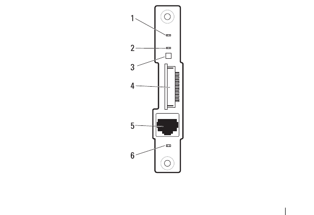
Jumpers and Connectors 285
7
Jumpers and Connectors
This section describes the connectors on the various boards in the server
enclosure.
Server Enclosure Boards
The server enclosure has three system boards that make up its building block.
• Front Panel Board
• Fan Controller Board
• Power Management Board
Front Panel Board Connectors
Figure 7-1. Front Panel Board Connectors
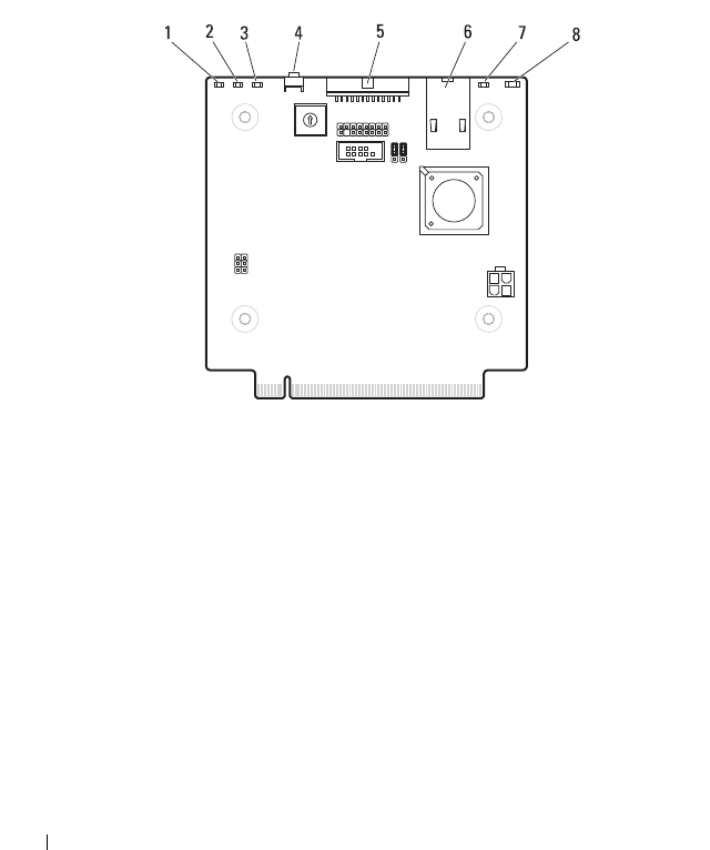
286 Jumpers and Connectors
Fan Controller Board Connectors
Figure 7-2. Fan Controller Board Connectors
1 power/event LED 2 system identification LED
3 thermal sensor 4 front panel connector
5 10/100 Mbit NIC LAN port 6 LAN activity LED
1 fan 3 fault LED 2 fan 2 fault LED
3 fan 1 fault LED 4 Service mode button
5 PDU PMBus connector 6 10/100 Mbit NIC LAN port
7 system identification LED 8 power/event LED
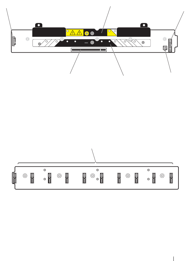
Jumpers and Connectors 287
Power Management Board Connectors
Figure 7-3. Front View of the Power Management Board
Figure 7-4. Back View of the Power Management Board
1 front panel board connector 2 power bus bar
3 system fan connector 4 power connector (debug-use only)
5 power bus bar 6 fan controller board connector
1 node power distribution board connectors 1-10
13
4
6
2
5
1

288 Jumpers and Connectors

Getting Help 289
8
Getting Help
Contacting Dell
NOTE: If you do not have an active Internet connection, you can find contact
information on your purchase invoice, packing slip, bill, or Dell product catalog.
Dell provides several online and telephone-based support and service options.
Availability varies by country and product, and some services may not be
available in your area. To contact Dell for sales, technical support, or
customer service issues:
1
Visit
dell.com/support
.
2
Select your support category.
3
Verify your country or region in the Choose a Country/Region drop-down
menu at the top of the page.
4
Select the appropriate service or support link based on your need.

290 Getting Help

FILE LOCATION: D:\Projects\User Guide\Server\Dell\Zeus\OOB\HOM\Hardware Owners
Manual\Chassis\C8000\C8000_HOM_bk0IX.fm
Index 291
Index
A
about the system, 11
B
backplane cage
installing, 216
removing, 212
C
command line interfaces, 120
compute sled
installing, 194
removing, 192
connectors
fan controller board, 286
front panel board, 285
power management board, 287
console redirection
configuring, 69
enabling, 69
D
Dell
contacting, 289
double-wide sled blank
installing, 190
removing, 190
F
fan bay cage
installing, 216
removing, 212
fan bay numbering, 23
fan controller board
connectors, 286
installing, 212
removing, 211
fan module
installing, 208
removing, 207
FCB firmware image
updating via compute sled, 275
updating via SNMP, 276
features
back panel, 15
front panel, 13
front panel board
connectors, 285
installing, 210
removing, 209

FILE LOCATION: D:\Projects\User Guide\Server\Dell\Zeus\OOB\HOM\Hardware Owners
Manual\Chassis\C8000\C8000_HOM_bk0IX.fm
292 Index
I
indicator
back-panel chassis
identification, 19
back-panel fan 1/2 fault, 19
back-panel fan 3/4 fault, 19
back-panel fan 5/6 fault, 20
back-panel power/event, 19
front panel, 13
front-panel chassis
identification, 18, 248
front-panel chassis status, 18
front-panel NIC link/activity, 18
management port, 20
PDU, 248
power, 35
power/event, 18
system identity, 35
installing
backplane cage, 216
compute sled, 194
double-wide sled blank, 190
fan bay cage, 216
fan controller board, 212
fan module, 208
front panel board, 210
PDU PCIB module, 246
PDU PMC board, 243
PDU power supply, 219
power sled, 200
PSU module, 206
PSU1/3 module assembly, 203
PSU2/4 module assembly, 204
single-wide sled blank, 191
storage sled, 195
IPMI command list, 146
M
MIB tree diagram
FCB, 161
PMC, 171
P
PDB firmware image
updating, 283
PDU
connecting to network, 243
connecting to network
switch, 242
connecting to server
enclosure, 239
powering on, 246
PDU PCIB module
installing, 246
removing, 232
PDU PMC board
installing, 243
PDU power status
monitoring, 280
PDU power supply
indicator code, 217
installing, 219
removing, 217
POST error codes, 41
power management board
connectors, 287

FILE LOCATION: D:\Projects\User Guide\Server\Dell\Zeus\OOB\HOM\Hardware Owners
Manual\Chassis\C8000\C8000_HOM_bk0IX.fm
Index 293
power management settings, 155
power sled
installing, 200
removing, 198, 200, 218
PSU module
installing, 206
removing, 205
PSU1/3 module assembly
installing, 203
removing, 201-202
PSU2/4 module assembly
installing, 204
removing, 203
R
rack installation
external PDU, 231
guidelines, 221
installation tasks, 222
server enclosure, 228
tool-less rail, 223
removing
backplane cage, 212
compute sled, 192
double-wide sled blank, 190
fan bay cage, 212
fan controller board, 211
fan module, 207
front panel board, 209-210
PDU PCIB module, 232
PDU power supply, 217
power sled, 198-218
PSU module, 205
PSU1/3 module
assembly, 201-202
PSU2/4 module assembly, 203
single-wide sled blank, 191
storage sled, 194
S
safety, 251
server enclosure
connecting to PDU, 239
server enclosure boards, 285
fan controller board, 286
front panel board, 285
power management board, 287
service tag, 38
single-wide sled blank
installing, 191
removing, 191
sled bay numbering, 22
sled features, 26
double-wide compute sled, 29
power sled, 36
single-wide compute sled, 26
storage sled, 34
sled module configuration, 24
SNMP, 157
FCB firmware behavior, 159
PMC firmware behavior, 170
SNMP MIB
FCB, 162
PMC, 172

FILE LOCATION: D:\Projects\User Guide\Server\Dell\Zeus\OOB\HOM\Hardware Owners
Manual\Chassis\C8000\C8000_HOM_bk0IX.fm
Index 294
SNMP Support
FCB, 157
PMC, 168
storage sled
installing, 195
removing, 194
system event log, 49
system features
accessing, 12
System log
See system setup screen
system sensor overview, 60
system setup
active state power management
configuration, 103
BMC LAN configuration, 111
boundaries of PSU
configuration, 83
chassis power management, 80
chassis PSU configuration, 82
CPU configuration, 88
embedded network devices, 100
emergency throttling, 87
iSCSI remote boot, 102, 112
memory configuration, 92
PCI configuration, 98
PCI slot configuration, 104
power capping, 84
power management, 78
prefetch configuration, 91
remote access configuration, 113
SATA configuration, 95
security settings, 107
USB configuration, 105
system setup program
entering, 68
general help, 69
system setup menu, 67
system setup screen
advanced, 77
boot, 116
exit, 118
main, 74
security, 107
server, 109
T
troubleshooting
damaged enclosure, 256
enclosure components, 257
expansion cards, 270
external connections, 252
fan modules, 257
hard-drive, 269
memory, 267
NIC, 254
processors, 270
serial device, 253
sled components, 267
system battery, 272
system board, 271
system startup failure, 252
USB device, 252
video, 252
wet enclosure, 255
