Dell Storage Sc5020 Setting Up Your System User Manual Setup Guide2 En Us
User Manual: Dell storage-sc5020 - Setting Up Your Dell SC5020 Storage System
Open the PDF directly: View PDF ![]() .
.
Page Count: 2
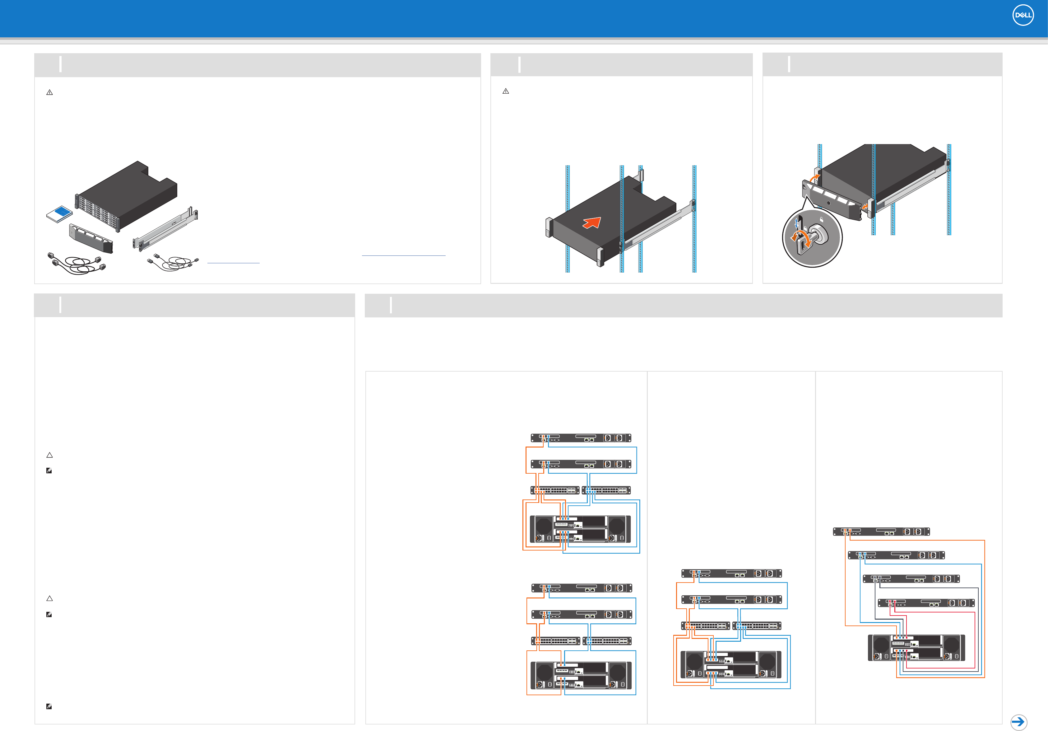
Fibre Channel and iSCSI HBA Cabling
If the storage system includes Fibre Channel or iSCSI HBAs, connect the host servers and
storage system to the corresponding Fibre Channel or Ethernet switches.
Fibre Channel 4 Port Configuration
iSCSI 4 Port Configuration
1. Connect each host server to both switches.
– Connections shown in orange belong to fault
domain 1.
– Connections shown in blue belong to fault
domain 2.
2. Connect fault domain 1 (in orange) to switch 1.
– Top storage controller: port 1 to switch 1
– Top storage controller: port 3 to switch 1
– Bottom storage controller: port 1 to switch 1
– Bottom storage controller: port 3 to switch 1
3. Connect fault domain 2 (in blue) to switch 2.
– Top storage controller: port 2 to switch 2
– Top storage controller: port 4 to switch 2
– Bottom storage controller: port 2 to switch 2
– Bottom storage controller: port 4 to switch 2
Fibre Channel 2 Port Configuration
iSCSI 2 Port Configuration
1. Connect each host server to both switches.
– Connections shown in orange belong to fault
domain 1.
– Connections shown in blue belong to fault
domain 2.
2. Connect fault domain 1 (in orange) to switch 1.
– Top storage controller: port 1 to switch 1
– Bottom storage controller: port 1 to switch 1
3. Connect fault domain 2 (in blue) to switch 2.
– Top storage controller: port 2 to switch 2
– Bottom storage controller: port 2 to switch 2
Setting Up Your Dell SC5020 Storage System
Warning! Before you set up and operate your Dell storage system, review the safety
instructions that came with your storage system.
Warning! The chassis is heavy. Do not attempt to lift
the chassis without assistance.
Use the racking instructions included with your package to mount the chassis.
Mount the storage system chassis and expansion enclosures in a manner that allows
for expansion in the rack and prevents the rack from becoming top-heavy. Secure the
storage system chassis to the rack using the mounting screws that are located behind
the latches on each chassis ear. Dell recommends mounting the storage system chassis
in the bottom of the rack.
1 2Before You Begin Mount the Chassis and Optional Enclosures
Unpack Storage Center Equipment
A Dell SC5020 storage system includes:
• Documentation
• Storage system
• Front bezel
• Rack rails
• Power cables (2)
• USB cables (2)
Develop a Configuration Plan
Before installing the storage hardware, develop a configuration plan where you can record host
server information, switch information, and network information.
Record System Information
• System management IPv4 address for Storage Center
• IPv4 address of the MGMT port on each storage controller
• Domain name
• DNS server address
• Additional IPv4 addresses if the storage system has iSCSI I/O ports
Consider Plans for Multipath/Failover
Redundancy is provided by fault domains, which allow alternate paths if a path fails. Fault
domains are determined by the number of independent Fibre Channel fabrics or iSCSI networks.
Each switch carries a separate fault domain. If a port fails, any port within the same fault domain
takes over for the failed port. Dell recommends using multipathing, so that volumes are mapped
to ports in more than one fault domain.
More Information
For operating system, host bus adapter (HBA), and switch requirements, refer to the Dell
Storage Compatibility Matrix on the Dell Tech Center at http://en.community.dell.com/
techcenter/storage.
The SC5020 storage system supports Fibre Channel, iSCSI, or SAS protocols to connect the Storage Center to host servers. Fault domains provide fault tolerance at the storage controller level. If you are using Fibre Channel,
incorporate your switch zoning strategy with the fault domains. Dell recommends using redundant cabling to avoid a single point of failure.
1. Identify the protocol being used to connect the host servers to the disk array.
2. Refer to the diagram below that corresponds to the proper protocol. These cabling guidelines ensure the configuration has redundancy and failover capability. For more information, contact Dell Technical Support.
4Prepare the Host Servers 5Cable the Host Servers to the Storage System
Refer to the Dell Storage Compatibility Matrix for a list of supported HBAs or iSCSI network adapters.
Windows and Linux Hosts
Install the HBAs or network adapters, install the drivers, and make sure that the latest supported BIOS is
installed.
Fibre Channel
1. Install the Fibre Channel HBAs in the host servers.
2. Install supported HBA drivers and make sure that HBAs have the latest supported firmware.
3. Use the Fibre Channel cabling diagrams to cable host servers to switches. Connecting host servers
directly to the storage system without using Fibre Channel switches is not supported.
iSCSI
1. Install the iSCSI HBAs or network adapters dedicated for iSCSI traffic in the host servers.
2. Install supported HBA drivers and make sure that HBAs have the latest supported firmware.
3. Use the iSCSI cabling diagrams to cable the host servers to switches. Connecting host servers directly
to the storage system without using Ethernet switches is not supported.
4. Assign IP addresses to each iSCSI port to match the subnets for each fault domain.
CAUTION: Make sure to assign the correct IP addresses to the HBAs or network adapters. Assigning IPs
to the wrong ports can cause connectivity issues.
NOTE: If using jumbo frames, enable and configure jumbo frames on all devices in the data path.
SAS
1. Install the SAS HBAs in the host servers.
2. Install supported HBA drivers and make sure that HBAs have the latest supported firmware.
3. Use the SAS cabling diagram to cable the host servers directly to the storage controllers.
VMware ESXi Hosts
Install the HBAs or network adapters and make sure that the latest supported BIOS is installed.
Fibre Channel
1. Install the Fibre Channel HBAs in the ESXi hosts.
2. Use the Fibre Channel cabling diagrams to cable ESXi hosts to switches. Connecting ESXi hosts directly
to the storage system without using Fibre Channel switches is not supported.
iSCSI
1. Install the iSCSI HBAs or network adapters dedicated for iSCSI traffic in the ESXi hosts.
2. If using network adapters, create a VMkernel port for each adapter.
3. Assign IP addresses for each adapter port to match the subnets for each fault domain.
CAUTION: Make sure to assign the correct IP addresses to the HBAs or network adapters. Assigning IPs
to the wrong ports can cause connectivity issues.
NOTE: If using jumbo frames, enable and configure jumbo frames on all devices in the data path: adapter
ports, switches, and storage system.
4. If using network adapters, configure Network Port Binding to add the VMkernel ports to the iSCSI
software initiator.
5. Use the iSCSI cabling diagrams to cable the ESXi hosts to switches. Connecting ESXi hosts directly to
the storage system without using Ethernet switches is not supported.
SAS
1. Install the SAS HBAs in the ESXi hosts.
2. Install the updated driver for 12 Gb SAS HBAs on the ESXi hosts. For more information, contact Dell
Technical Support.
3. Use the SAS cabling diagram to cable the ESXi hosts directly to the storage controllers.
NOTE: Configure access to Storage Center one ESXi host at a time.
1. Hold the bezel with the logo upright.
2. Hook the right end of the bezel into the right side of the chassis.
3. Swing the left end of the bezel toward the left side of the chassis.
4. Press the bezel into place until the release latch closes.
5. Use the key to lock the front bezel.
3Install the Bezel
SAS HBA Cabling
If the storage system includes a SAS HBA, directly connect
the host servers to the storage system.
SAS 4 Port Configuration
1. Connect fault domain 1 (in orange) to server 1.
– Top storage controller: port 1 to port on server 1
– Bottom storage controller: port 1 to port on server 1
2. Connect fault domain 2 (in blue) to server 2.
– Top storage controller: port 2 to port on server 2
– Bottom storage controller: port 2 to port on server 2
3. Connect fault domain 3 (in gray) to server 3.
– Top storage controller: port 3 to port on server 3
– Bottom storage controller: port 3 to port on server 3
4. Connect fault domain 4 (in red) to server 4.
– Top storage controller: port 4 to port on server 4
– Bottom storage controller: port 4 to port on server 4
iSCSI Mezzanine Card Cabling
If the storage system includes an iSCSI mezzanine
card, connect the host servers and storage system
to Ethernet switches.
iSCSI 4 Port Mezzanine Card
Configuration
1. Connect each host server to both Ethernet
switches.
– Connections shown in orange belong to fault
domain 1.
– Connections shown in blue belong to fault
domain 2.
2. Connect fault domain 1 (in orange) to switch 1.
– Top storage controller: port 1 to switch 1
– Top storage controller: port 3 to switch 1
– Bottom storage controller: port 1 to switch 1
– Bottom storage controller: port 3 to switch 1
3. Connect fault domain 2 (in blue) to switch 2.
– Top storage controller: port 2 to switch 2
– Top storage controller: port 4 to switch 2
– Bottom storage controller: port 2 to switch 2
– Bottom storage controller: port 4 to switch 2
Setting Up Your Dell SC5020 Storage System (continued)
To add capacity to your storage system, you can connect up to sixteen SC400 or eight SC420 expansion enclosures to an SC5020 storage system. A maximum of 222 physical disks are supported in an SC5020 storage system.
Each expansion enclosure includes two Enclosure Management Modules (EMM) in two interface slots.
NOTE: If the storage system is installed without expansion enclosures, do not interconnect the back-end SAS ports on the storage controllers.
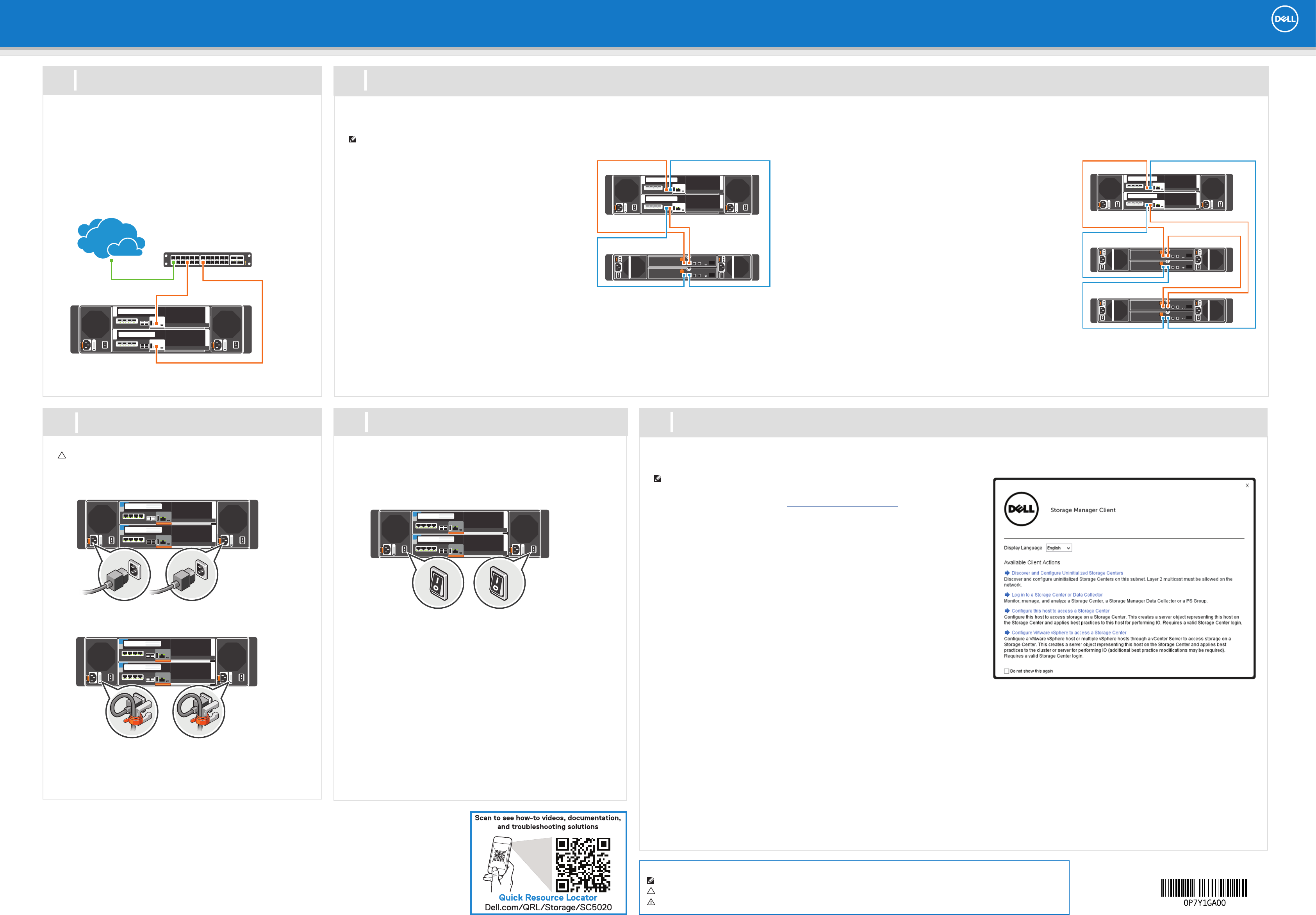
1. Power on any network switches, routers, or other standalone
components.
2. Power on any expansion enclosures that might be a part of the system.
3. Power on the storage system by turning on both power supply/cooling
fan modules.
The Dell Storage Manager Client provides access to the initial setup wizards. The wizards help you remotely discover and configure storage systems and configure connected
host servers.
NOTE: The initial setup wizards are only supported on 64-bit operating systems.
Install and Start the Dell Storage Manager Client
1. Log in to the Dell Digital Locker at www.dell.com/support/licensing, register your storage
system, and download the Windows or Linux version of the Dell Storage Manager Client.
2. Install the Dell Storage Manager Client on the host server. To discover and configure a
Storage Center, the software must be installed on a host server that is located on the same
subnet as the storage system. For host setup, the client does not have to be on the same
subnet as the storage system.
3. To start the software on a Windows computer, right-click on the Dell Storage Manager
Client shortcut and select Run as administrator.
To start the software on a Linux computer, execute the command ./Client from the
var/lib/dell/bin directory. The Dell Storage Manager Client welcome screen opens.
Discover and Configure Storage Center Wizard
1. Click the Discover and Configure Uninitialized Storage Centers link. The Discover and
Configure Storage Center wizard opens.
2. Follow the steps in the wizard to discover and configure uninitialized Storage Centers.
3. For Fibre Channel installations, the deployment wizard provides the storage controller
WWNs for zoning requirements. When prompted, create the two required zones for each
fault domain.
Configure Host Access to a Storage Center
1. For Windows and Linux servers, click the Configure this host to access a Storage Center
link and log in to the Storage Center.
For VMware ESXi servers, click Configure VMware vSphere to access a Storage Center.
2. Follow the steps in the wizard to configure the host to access the Storage Center and configure best practices for performing I/O.
3. For Fibre Channel, configure zoning to make sure that storage is visible to the host servers. Using the switch software, create a zone for each HBA connected to the
switch. In the zone, include only one HBA WWN and all of the virtual WWNs of the storage controller I/O ports connected to that switch. This is referred to as single
initiator/multiple target zoning. For hosts, you can obtain the WWNs from the operating system or use the switch software.
When the host configuration is complete, use the Dell Storage Manager Client to create and map volumes.
Related Publications
The following documentation is available on the Dell support site for the Dell SC5020 Storage System:
• Dell SC5020 Storage System Getting Started Guide
• Dell SC5020 Storage System Owner’s Manual
• Dell Storage Center Release Notes
• Dell Storage Manager Administrator's Guide
• Dell Storage Manager Installation Guide
• Dell Storage Manager Release Notes
9
7
10
Power on Storage System Components
Cable the Backend
Download, Install, and Run the Dell Storage Manager Client
Cable Multiple SC400 or SC420 Expansion Enclosures
To connect more than one expansion enclosure to the storage system:
Chain 1: A Side (Orange)
1. Connect part 1 on the top storage controller to port 1 on the top EMM of the
first expansion enclosure.
2. Connect the remaining expansion enclosures in series from port 2 to port 1
using the top EMMs.
3. Connect port 2 on the top EMM of the last expansion enclosure to port 2 on
the bottom storage controller.
Chain 1: B Side (Blue)
1. Connect port 1 on bottom storage controller to port 1 on the bottom EMM of
the first expansion enclosure.
2. Connect the remaining expansion enclosures in series from port 2 to port 1
using the bottom EMM.
3. Connect port 2 on the bottom EMM of the last expansion enclosure to port 2
on the top storage controller.
Information in this document is subject to change without notice.
Reproduction of this material in any manner whatsoever without the written permission of Dell is strictly forbidden.
© 2017 Dell Inc. or its subsidiaries. All rights reserved. Dell, EMC, and other trademarks are trademarks of Dell Inc. or its
subsidiaries. Other trademarks may be trademarks of their respective owners.
6
The Ethernet management interface of each storage controller must be
connected to a management network. The Ethernet management port
provides access to the Storage Center and is used to send emails, alerts,
SNMP traps, and support data.
1. Connect the Ethernet management port on the top storage
controller to the Ethernet switch.
2. Connect the Ethernet management port on bottom storage
controller to the Ethernet switch.
Connect to Management Network
CAUTION: Make sure that the power switches are in
the OFF position before connecting the power cables.
1. Connect the power cables to both power supply/cooling fan
modules in the storage system chassis.
2. Use the velcro straps to secure the power cables to the storage
system chassis.
3. Plug the other end of the power cables into a grounded electrical
outlet or a separate power source such as an uninterrupted power
supply (UPS) or a power distribution unit (PDU).
8Connect the Power Cables
Notes, Cautions, and Warnings
A NOTE indicates important information that helps you make better use of your product.
A CAUTION indicates potential damage to hardware or loss of data and tells you how to avoid the problem.
A WARNING indicates a potential for property damage, personal injury, or death.
Cable an SC400 or SC420 Expansion Enclosure
To connect a single expansion enclosure to the storage system:
Chain 1: A Side (Orange)
1. Connect port 1 on the top storage controller to port 1 on the top
EMM of the expansion enclosure.
2. Connect port 2 on the top EMM of the expansion enclosure to
port 2 on the bottom storage controller.
Chain 1: B Side (Blue)
1. Connect port 1 on the bottom storage controller to port 1 on the
bottom EMM of the expansion enclosure.
2. Connect port 2 on the bottom EMM of the expansion enclosure
to port 2 on the top storage controller.
