Dell Wyse 5060 Thin Client ThinOS 8.3.1 Administrator Guide User Manual OS Guide3 En Us
User Manual: Dell wyse-5060-thin-client - Dell Wyse ThinOS 8.3.1 Administrator Guide
Open the PDF directly: View PDF ![]() .
.
Page Count: 171 [warning: Documents this large are best viewed by clicking the View PDF Link!]
- Dell Wyse ThinOS Release 8.3.1 Administrator’s Guide
- Introduction
- Getting Started: Quickly Learning the Basics
- Connecting to a Remote Server
- Using Your Desktop
- Configuring Thin Client Settings and Connection Settings
- Connecting to a Printer
- Connecting to a Monitor
- Locking the Thin Client
- Signing Off and Shutting Down
- Additional Getting Started Details
- Classic Desktop Features
- Login Dialog Box Features
- Accessing System Information
- Global Connection Settings
- Configuring the Connectivity
- Configuring Thin Client Settings
- Citrix HDX RealTime Multimedia Engine (RTME)
- Advanced Details on Configuring ICA and RDP Connections
- ICA SuperCodec
- Features of RDP 8.1
- Introduction to Flash Redirection
- Introduction to TCX 7.0 Flash Redirection
- Performing Diagnostics
- Central Configuration: Automating Updates and Configurations
- CMOS Management
- Examples of Common Printing Configurations
- Security Changes
- Transport Layer Security (TLS)
- Important Notes
- Frequently Asked Questions

Dell Wyse ThinOS Release 8.3.1
Administrator’s Guide

Notes, cautions, and warnings
NOTE: A NOTE indicates important information that helps you make better use of your product.
CAUTION: A CAUTION indicates either potential damage to hardware or loss of data and tells you how to avoid the
problem.
WARNING: A WARNING indicates a potential for property damage, personal injury, or death.
Copyright © 2016 Dell Inc. or its subsidiaries. All rights reserved. Dell, EMC, and other trademarks are trademarks of Dell Inc. or its
subsidiaries. Other trademarks may be trademarks of their respective owners.
2016 - 12
Rev. A03

Contents
1 Introduction.....................................................................................................................6
About this Guide.................................................................................................................................................................6
Technical Support........................................................................................................................................................ 6
New Features.....................................................................................................................................................................7
2 Getting Started: Quickly Learning the Basics..................................................................8
Connecting to a Remote Server.........................................................................................................................................8
Connecting a Remote Server Manually........................................................................................................................ 9
Using Your Desktop............................................................................................................................................................9
Configuring Thin Client Settings and Connection Settings................................................................................................. 9
Connecting to a Printer.....................................................................................................................................................10
Connecting to a Monitor...................................................................................................................................................10
Locking the Thin Client..................................................................................................................................................... 10
Signing Off and Shutting Down........................................................................................................................................ 10
Additional Getting Started Details.....................................................................................................................................10
Zero Desktop Features................................................................................................................................................ 11
Zero Interactive Desktop Guidelines............................................................................................................................ 11
Zero Toolbar................................................................................................................................................................ 11
List of Connections.....................................................................................................................................................12
Classic Desktop Features..................................................................................................................................................13
Classic Interactive Desktop Guidelines........................................................................................................................ 13
Using the Shortcut Menu............................................................................................................................................13
Using the Desktop Menu.............................................................................................................................................14
Using the Connection Manager...................................................................................................................................14
Login Dialog Box Features.................................................................................................................................................15
Accessing System Information..........................................................................................................................................16
3 Global Connection Settings........................................................................................... 19
4 Configuring the Connectivity.........................................................................................21
Configuring the Network Settings.................................................................................................................................... 21
Configuring the General Settings................................................................................................................................ 21
Configuring the DHCP Options Settings.................................................................................................................... 23
Configuring the ENET Settings.................................................................................................................................. 24
Configuring the WLAN Settings.................................................................................................................................26
Configuring the Proxy Settings.................................................................................................................................. 28
Configuring the Remote Connections.............................................................................................................................. 29
Configuring the Broker Setup.....................................................................................................................................30
Configuring the Visual Settings...................................................................................................................................41
Configuring the General Options................................................................................................................................ 43
Configuring the Authentication settings.....................................................................................................................43
Configuring the Central Configurations............................................................................................................................58
3

Configuring the General Central Configurations ........................................................................................................59
Configuring the WDA Settings...................................................................................................................................60
Configuring the VPN Manager.........................................................................................................................................62
5 Configuring Thin Client Settings................................................................................... 66
Local Settings Menu........................................................................................................................................................ 66
Configuring the System Preferences......................................................................................................................... 66
Configuring the Display Settings................................................................................................................................ 69
Configuring the Peripherals Settings.......................................................................................................................... 74
Configuring the Printer Settings.................................................................................................................................82
Reset Features..................................................................................................................................................................91
Resetting to Factory Defaults Using G-Key Reset..................................................................................................... 92
Resetting to Factory Defaults Using Shutdown Reset............................................................................................... 92
Resetting Display Settings Using V-Key Reset...........................................................................................................92
Accessing Thin Client BIOS Settings..........................................................................................................................92
6 Citrix HDX RealTime Multimedia Engine (RTME)..........................................................93
Introduction......................................................................................................................................................................93
Installing the RTME package on ThinOS.......................................................................................................................... 94
Setting Up the RealTime Multimedia Engine (RTME) for Lync........................................................................................ 95
Verifying the RTME 1.8 Status......................................................................................................................................... 97
Verifying the RTME 2.0 Status........................................................................................................................................ 98
7 Advanced Details on Configuring ICA and RDP Connections....................................... 100
Configuring ICA Connections..........................................................................................................................................100
Configuring RDP Connections........................................................................................................................................ 104
8 ICA SuperCodec.......................................................................................................... 109
ICA 14.0.0.91....................................................................................................................................................................112
9 Features of RDP 8.1..................................................................................................... 114
Verifying the Status of VOR/H.264 ................................................................................................................................114
Work Flow of Dual Display...............................................................................................................................................115
Support Matrix for RDP 8.1............................................................................................................................................. 116
10 Introduction to Flash Redirection................................................................................117
Flash Redirection............................................................................................................................................................. 117
Basic Operations for Citrix HDX Flash Redirection ......................................................................................................... 119
Citrix HDX Flash Redirection Policies Configurations......................................................................................................125
11 Introduction to TCX 7.0 Flash Redirection.................................................................. 135
Working Status of TCX 7.0 Flash Redirection.................................................................................................................135
12 Performing Diagnostics.............................................................................................. 137
System Tools.................................................................................................................................................................. 137
Using the Trouble Shooting Options............................................................................................................................... 144
A Central Configuration: Automating Updates and Configurations................................. 150
4

How to Set Up Automatic Updates and Configurations..................................................................................................150
Using DHCP Options................................................................................................................................................ 150
B CMOS Management....................................................................................................154
CMOS Central Management: Extracting CMOS Settings to the File Server for Distribution..........................................154
CMOS Local Management: Extracting CMOS Settings to a USB Key for Distribution................................................... 155
C Examples of Common Printing Configurations............................................................ 156
Printing to Local USB or Parallel Printers........................................................................................................................156
Using the Printer Setup Dialog Box for Local USB or Parallel Printers...................................................................... 156
Printing to Non-Windows Network Printers (LPD).........................................................................................................157
Using the Printer Setup Dialog Box for Non-Windows Network Printers (LPD)....................................................... 157
Using INI Parameters for Non-Windows Network Printers (LPD)............................................................................ 158
Printing to Windows Network Printers (SMB)................................................................................................................158
Using the Printer Setup Dialog Box for Windows Network Printers (SMB)..............................................................158
Using INI Parameters for Windows Network Printers (SMB)................................................................................... 159
Using Your Thin Client as a Print Server (LPD)...............................................................................................................160
Using the Printer Setup Dialog Box for Configuring LPD Services............................................................................160
Using INI Parameters for Configuring LPD Services................................................................................................. 160
Configuring ThinPrint...................................................................................................................................................... 161
D Security Changes........................................................................................................ 162
E Transport Layer Security (TLS).................................................................................. 166
F Important Notes.......................................................................................................... 167
G Frequently Asked Questions........................................................................................170
5

1
Introduction
Thin clients running Dell Wyse ThinOS firmware are designed solely for optimal thin client security and performance. These efficient
purpose-built thin clients are virus and malware resistant and offer ultrafast access to applications, files and network resources
within Citrix, Microsoft, VMware and Dell vWorkspace environments, and other leading infrastructures. ThinOS based thin clients
are self-managed, go from power-on to fully productive in seconds, and with no published API, locally accessible file system or
browser, require no local McAfee Anti-Virus software or firewall to protect against viruses or malware.
About this Guide
This guide is intended for administrators of thin clients running Wyse ThinOS. It provides information and detailed system
configurations to help you design and manage a ThinOS environment.
Supported Products
This guide is intended for the following Dell Wyse ThinOS products:
• C10LE
• R10L
• Wyse 3010 Thin Client with ThinOS (T10)
• Wyse 3020 thin client with ThinOS (T10D)
• Wyse 3030 LT thin client with ThinOS
• Wyse 3030 LT thin client with PCoIP
• Wyse 5010 thin client with ThinOS (D10D)
• Wyse 5010 thin client with PCoIP (D10DP)
• Wyse 5040 AIO thin client (5212)
• Wyse 5040 AIO thin client with PCoIP (5213)
• Wyse 5060 thin client with ThinOS
• Wyse 5060 thin client with PCoIP
• Wyse 7010 thin client with ThinOS (Z10D)
Finding the Information You Need in this Guide
You can use either the Search window or Find toolbar to locate a word, series of words, or partial word in an active PDF document.
For detailed information on using these features, refer to the Help in your PDF reader.
Technical Support
To access Dell Wyse Cloud Client Management technical resources (self-service portal, knowledge base, software downloads,
registration, warranty extensions/RMAs, reference manuals, and so on), see http://www.dell.com/wyse/support.
For more information, you can call Customer Support at 1.800.800.9973 (toll free in U.S. and Canada). Hours of operation are from
6:00 A.M. to 5:00 P.M. Pacific Time, Monday through Friday.
6

To access Dell Enterprise Mobility Management technical resources (create a Service Request), see https://
support.software.dell.com/create-service-request.
NOTE: You need to register with Dell Support to place a service request. Check out the “Getting Started” section of Dell
Software Support at https://support.software.dell.com/essentials/getting-started, if you are new to the Dell Software
Support. For more information, you can call Technical Support at 1.800.306.9329 (toll free in U.S. and Canada) or
949.754.8000 or 949.754.8080. Hours of operation are from 5:00 A.M. to 5:00 P.M. Pacific Standard Time, Monday
through Friday.
New Features
The ThinOS 8.3.1 release consists of the following new features:
•Updates to packages (These package updates of ThinOS 8.3.1 release are applicable only to Wyse 5060 thin client with ThinOS
or Wyse 5060 thin client with PCoIP)— In ThinOS 8.3.1, the following packages are updated to a newer version:
– RTME.i386.pkg
– FR.i386.pkg
– TCX.i386.pkg
For latest package versions, see Dell Wyse ThinOS 8.3.1 Release Notes.
• ThinOS 8.3.1 release contains additional INI parameters. For more information, see Dell Wyse ThinOS 8.3.1 INI Guide.
•Dual 4K (3840 x 2160) support
Dual 3840 x 2160 is supported with Dual Display ports for 30 Hz display refresh rate. For more information on supported monitor
resolution for Wyse 5060 thin client, see Configuring the General Display Settings
7

2
Getting Started: Quickly Learning the Basics
Use the following information to quickly learn the basics and get started using your thin client:
•Connecting to a Remote Server
•Using Your Desktop
•Configuring Thin Client Settings and Connection Settings
•Connecting to a Printer
•Connecting to a Monitor
•Locking the Thin Client
•Signing Off and Shutting Down
•Additional Getting Started Details
NOTE:
ThinOS is centrally managed and configured using INI files to automatically push updates and any desired default configuration
to all supported thin clients in your environment — see Central Configuration: Automating Updates and Configurations.
If no INI files are detected, you can use local dialog boxes on each thin client to make available configurations. ThinOS will save
many of these locally configured settings such as resolution, mouse, and keyboard to persist after reboot. However, once INI
files are detected, rebooting causes ThinOS to become stateless while ignoring locally configured settings after a reboot and
then the settings contained in the INI file will be used.
Connecting to a Remote Server
On your initial connection to central configuration, we recommended that you connect using a wired connection plug in the
network-connected Ethernet cable to your thin client before starting the thin client to obtain the configurations desired by the
administrator. This wired connection will also provide any wireless configurations provided by the administrator through INI files.
If you must initially connect to central configuration through wireless, use the Wireless tab in the Network Setup dialog box to enter
the SSID and encryption configurations required or set up by the network administrator. For more information, see Configuring the
Network Settings.
Central Configuration — If you are configured for automatic detection using INI files — see
Dell Wyse ThinOS INI Guide
, your
thin client will automatically detect and connect to the configured remote services during the boot-up process. Press the power
button to turn on your thin client to see the Login dialog box. Enter your User name, Password, and Domain, and then click Login.
After authentication is successful, your available connections are presented.
NOTE:
Although the thin client will default to the Classic Desktop for INI backward compatibility, you can configure the thin client to
display the Zero Desktop by using the SysMode=VDI parameter in the INI files or by selecting the desktop option in the dialog
box. For more information, see Using Your Desktop.
Manual Connection — If you are not yet set up for central configuration, you will see the Zero Toolbar, where you can configure
the initial server connection you want using the Remote Connections dialog box before you can log in. For more information, see
Connecting to a Remote Server manually.
8

You only need to complete this manual configuration once or after reboot to factory defaults. After the thin client knows the
location of your server, it automatically connects to the server for login when you start the thin client in the future. After you
confirm that your environment is ready for deployment, you can create INI files for central configuration.
Connecting a Remote Server Manually
To connect a Remote Server manually, complete the following tasks:
1. Click the System Settings icon on the Zero Toolbar to open the System Settings menu, and then click Remote Connections
to open the Remote Connections dialog box.
2. Click the Broker Setup tab of the Remote Connections dialog box to configure one of the following connections:
• ICA or RDP connection —Select None, select ICA or RDP, click Configure Connection, and then follow the wizard.
• A specific broker server connection — Select Microsoft, Citrix Xen, Dell vWorkspace, VMware View, Amazon WorkSpaces
or Other, and then enter the IP Address for the server in the Broker Server box.
NOTE: For more details, see Configuring the Remote Connections.
3. Click OK, and then restart the thin client.
Click the Shutdown icon on the Zero Toolbar to open, and use the Shutdown dialog box to restart the thin client.
NOTE:
• If an ICA or RDP connection is configured— After thin client restarts, click the Home icon on the Zero Toolbar to
open the list of available connections. Click the ICA or RDP connection you created, and then log in.
• If a specific Broker Server connection is configured— After thin client restart, the Login dialog box appears for your
server. Enter the User name, Password, and Domain and click Login. After authentication is successful, your Zero
Toolbar is presented with your assigned connections defined by the broker server.
Using Your Desktop
What you see after logging on to the server depends on the administrator configurations.
•Users with a Classic Desktop - will see the classic ThinOS desktop with full taskbar, desktop, and Connect Manager familiar to
ThinOS users. This option is the default out-of-the-box experience and is recommended for terminal server environments with
published applications and for backward compatibility with ThinOS 6.x versions. For more information on using the Classic
Desktop, see Classic Desktop Features.
•Users with a Zero Desktop - will see the Zero Desktop with the Zero Toolbar showing the assigned list of connections from
which to select. This option is recommended for VDI and any full-screen only connections. For more information on using the
Zero Desktop, see Zero Desktop Features.
In any desktop case, you can select the desktop option you want (Classic Desktop or Zero Desktop) and create the connections you
need using the Visual Experience tab on the Remote Connections dialog box.
To open the Remote Connections dialog box, perform one of the following tasks:
•Classic Desktop — Click User Name , and then select System Setup → Remote Connections.
NOTE: User Name is the user who is logged-on and is located at the lower-left pane of the taskbar
•Zero Desktop — Click the System Settings icon on the Zero Toolbar, and then select Remote Connections.
Configuring Thin Client Settings and Connection Settings
While the use of INI files is recommended to configure thin client settings and connection settings available to users , see How to
Set Up Automatic Updates and Configurations, you can use dialog boxes on a thin client to:
• Set up your thin client hardware, look and feel, and system settings, see Configuring Thin Client Settings Locally.
9

• Configure connection settings, see Configuring Thin Client Settings Locally.
Connecting to a Printer
To connect a local printer to your thin client, be sure you obtain and use the correct adapter cables which are not included. Before
use, you may need to install the driver for the printer by following the printer driver installation instructions. For information on
connecting to printers, see Configuring the Printer Setup.
Connecting to a Monitor
Depending on your thin client model, connections to monitors can be made using either a VGA (analog) monitor port, a DVI (digital)
monitor port, or a DisplayPort (digital) and the proper Dell monitor cables/splitters/adapters. For information on configuring dual
display settings, see Configuring the Display Settings.
NOTE:
For dual-monitor supported thin clients— when using a DVI to DVI/VGA splitter, ensure that the DVI monitor will be the
primary monitor; when using a DisplayPort, ensure that the DisplayPort monitor will be the primary monitor.
Locking the Thin Client
To help ensure that no one else can access your private information without permission, ThinOS allows you to lock your thin client
so that credentials are required to unlock and use the thin client after you do one of the following:
•Unplug a signed-on smart card — If an administrator has set SCRemovalBehavior=1for the signing parameter in the INI
files and you unplug the smart card that you used to sign on to the thin client, then the thin client will lock. To unlock the thin
client for use, you must use the same smart card and your correct PIN. Note that removing a signed-on smart card can also
cause the thin client to log-off, if an administrator has set the INI files to do so in this case you must sign-on as usual to use the
thin client.
•Use Lock Terminal from the Shortcut Menu and Shutdown dialog box — On the Classic Desktop, right-click on the desktop
and select Lock Terminal, or use the Shutdown dialog box, see Classic Desktop Features. On the Zero Desktop, use the
Shutdown dialog box, see Signing Off and Shutting Down. To use the thin client, you must use your correct password.
•Use the screen saver — If an administrator has set LockTerminal=2 for the ScreenSaver parameter in the INI files and you
use the screen saver, then the thin client will lock. To open the thin client for use, you must use your correct password.
Signing Off and Shutting Down
Use the Shutdown dialog box to select the available option you want:
•Classic Desktop — Click Shutdown in the Connect Manager or Desktop Menu.
•Zero Desktop — Click the Shutdown icon on the Zero Toolbar.
NOTE: You can also configure automatic behavior after all desktop sessions are closed by using the Remote Connections
dialog box, see Central Configuration: Automating Updates and Configurations.
Additional Getting Started Details
This section includes additional details on the following:
•Zero Desktop Features
•Classic Desktop Features
•Login Dialog Box Features
10

•Accessing System Information
Zero Desktop Features
This section includes information on:
•Zero Interactive Desktop Guidelines
•Zero Toolbar
•List of Connections
Zero Interactive Desktop Guidelines
The Zero Desktop has a default background with the Zero Toolbar at the left of the screen.
The Following table lists the available Zero Desktop shortcuts.
Action Press
Display the Zero Toolbar Ctrl+Alt+UpArrow
Open a selection box for toggling between the desktop and
currently-active connections Ctrl+Alt+DownArrow
Lock the thin client Ctrl+Alt+LeftArrow
or
Ctrl+Alt+RightArrow
Keyboard shortcuts to menu commands Left-Alt+UnderlinedLetter
or
Right-Alt+UnderlinedLetter
Capture the full desktop to the clipboard Print Screen
Capture the active window to the clipboard Alt+PrintScreen
NOTE:
• You can copy and paste between application sessions and between sessions and the desktop, however, this function
depends on session server configurations.
• In addition to the standard two-button mouse, the thin client supports a Microsoft Wheel Mouse used for scrolling. Other
similar types of a wheel mouse may or may not work.
To switch the left and right buttons, use the Peripherals dialog box, see Configuring the Peripherals Settings.
Zero Toolbar
The Zero Toolbar usually appears at the left corner of the Zero Desktop. However, depending on administrator configurations, the
toolbar can be removed or hidden. It is shown only when a user moves the mouse pointer over the left edge of the desktop screen.
Administrators can configure the toolbar settings using either a dialog box, see Configuring the Remote Configurations or the
SysMode parameter in the wnos.ini file, see
Dell Wyse ThinOS INI Guide
.
11

Table 1. Toolbar icons
Icon What It Does
Home Opens the list of available connections, see List of Connections.
System Information Displays thin client system information, see Accessing System
Information .
System Settings Opens the System Settings menu to configure thin client
system settings and perform diagnostics, see Configuring the
Connectivity, Configuring Thin Client Settings Locally, Central
Configuration: Automating Updates and Configurations.
Shutdown Terminal Click the Shutdown Terminal icon to use the Shutdown options
available on the thin client, see Signing Off and Shutting Down.
Note that the Shutdown Terminal icon does not display on the
toolbar when using the Admin Mode button to configure
system settings.
NOTE:
If configured to display by an administrator, the current date and time are shown on the Zero Toolbar. The thin client is
capable of synchronizing its clock to time provided by a Simple Network Time Protocol (SNTP) server.
List of Connections
On the Zero Toolbar, you can click the Home icon to open your list of assigned connections. In some cases, the list may contain only
default connections.
Use the following guidelines depending on user privilege level, some options may not be available for use:
Table 2. Connection Options
Option What It Does
Name of the connection Opens the connection you want to use.
NOTE: All open connections display a blue icon to the
left of the connection name in the list.
Reset icon Resets the connection.
NOTE: It is useful when a connection is not functioning
properly or you need to reboot the connection.
Close icon Closes the connection.
NOTE: The Close icon is grayed out for connections
that are not open.
Edit icon Opens the Connection Settings dialog box, see Advanced
Details on Configuring ICA and RDP Connections to change the
connection options.
NOTE: Depending on user privilege level, editing options
may not be available for use.
Add Connection Allows you to configure or add new connections.
12

Configuring Global Connection Settings If you do not use INI files to provide global connection settings,
you can click Global Connection Settings to open and use the
Global Connection Settings dialog box to configure settings
that affect all of the connection in the list.
Classic Desktop Features
This section includes information on:
•Classic Interactive Desktop Guidelines
•Using the Shortcut Menu
•Using the Desktop Menu
•Using the Connect Manager
Classic Interactive Desktop Guidelines
The Classic Desktop has a Dell Wyse default background with a horizontal task bar at the bottom of the screen.
Use the following guidelines:
• Icons representing available server connections and published applications are displayed on the background. If you pause the
mouse pointer over an icon, the information about the connection will be displayed. Right-clicking on an icon opens the
Connection Settings dialog box which displays additional information about the connection. The number of icons that can be
displayed on the desktop depends on the desktop resolution and administrator configuration.
• A server connection and published application can be opened by double-clicking a desktop icon or a user can navigate to the
desktop icon they want by using tab key and pressing Enter to initiate the connection.
• Right-clicking on the desktop provides a Shortcut Menu, see Using the Shortcut Menu.
• Clicking the User Name or clicking on the desktop, opens the Desktop Menu, see Using the Desktop Menu.
NOTE: User Name is the user who is logged-on and is located at the lower-left pane of the task bar.
NOTE: If configured to display by an administrator, the volume control is displayed in the right corner of the taskbar and
the current time and date are shown when the cursor is placed on the time; the thin client is capable of synchronizing its
clock to time provided by a Simple Network Time Protocol (SNTP) server.
Using the Shortcut Menu
To use the Shortcut Menu:
1. Log in as Administrator.
2. Right-click on your desktop
The Shortcut Menu is displayed.
3. On the Shortcut Menu, you are able to view and use the following options:
a. Administrator Mode — Allows administrators to configure various settings locally on thin client.
b. Hide all windows — Brings the full desktop to the foreground.
c. Copy to clipboard — Copies an image of the full screen, current window or event log to the clipboard. The clipboard
contents can then be pasted to an ICA or an RDP session.
d. Purge clipboard — Discards the contents of the clipboard in order to free up memory.
e. Lock Terminal — Puts the thin client in a locked state if the user has signed on to the system with a password. The thin
client can only be unlocked using the same password.
f. Group Sessions — Enables you to open more than three ICA or three RDP or three ICA seamless sessions. The sessions
are displayed as a group on the taskbar
13

Using the Desktop Menu
To use the desktop menu:
1. Click your Desktop or click your User Name.
User Name is the user who is logged-on and is at the bottom-left side of the taskbar.
The desktop menu is displayed.
2. On the desktop menu, you are able to view and use the following options:
a. System Setup — Provides access to the following local system setup dialog boxes:
•Network Setup — Allows selection of DHCP or manual entry of network settings, as well as entry of locations of
servers essential to thin client operation. This menu selection is disabled for Low-privileged users. See Configuring the
Network Settings.
•Remote Connections — Allows you to configure thin client Broker connections including Microsoft, Citrix Xen, Dell
vWorkspace, VMware View, Amazon WorkSpaces or Other broker server connections. For more information, see
Configuring the Remote Connections.
•Central Configuration — Allows you to configure thin client central connection settings such as file server and optional
WDM server settings. For more information, see Configuring the Central Configurations.
•VPN Manager — Allows you to configure thin client VPN manager. For more information, see Configuring the VPN
Manager.
•System Preference — Allows user selection of thin client parameters that are matter of personal preference. For more
information, see Configuring the System Preferences
.
•Display — Allows you to configure the monitor resolution and refresh rate. For more information, see Configuring the
Display Settings.
•Peripherals — Allows you to select the peripherals settings such as keyboard, mouse, volume and touch screen
settings. For more information, see Configuring the Peripherals Settings.
•Printer — Allows configuration of network printers and local printers that are connected to the thin client. For more
information, see Configuring the Printer Settings.
b. System Information — Provides thin client system information. See Accessing System Information .
c. System Tools — Opens a submenu from which the wnos.ini and user.ini windows can be opened to view the contents of
the files. See System Tools.
d. Trouble shooting Options — Displays Performance Monitor graphs that display client CPU, Memory and Networking
information and trace route response messages. For more information, See Using the Trouble Shooting Options and System
Tools
e. Applications — Contains a submenu of all locally configured applications and is populated with published applications when
a user is signed on using either PNLite or PNAgent.
f. Shutdown — Opens the Sign-off/Shutdown/Shutdown/Restart the System dialog box. See Signing Off and Shutting
Down
Using the Connection Manager
To use the Connection Manager:
1. Click Connect Manager on the Taskbar.
• The Connect Manager has a list of connection entries and a set of command buttons available for use with the
connections.
• Non-privileged users cannot view the Connect Manager.
The Connection Manager dialog box is displayed.
14
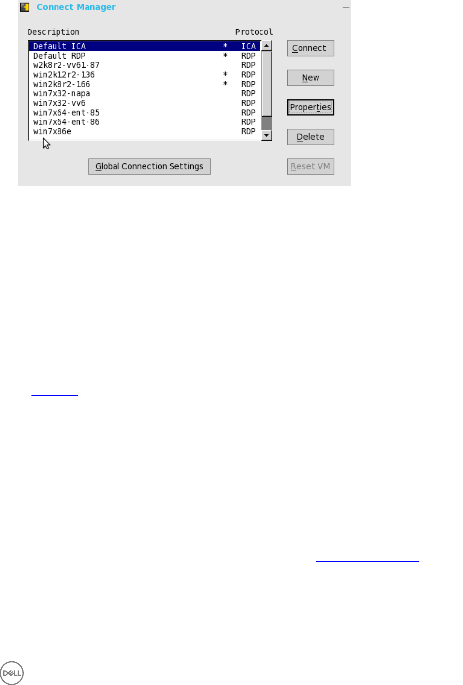
2. In the Connection Manager dialog box, use the following buttons to configure the Connection Manager settings:
a. Click Connect to select a connection from the list and make a connection.
b. Click New to open the Connection Settings dialog box either directly or through the Connection Protocol menu selection
for creating a new connection definition.
For more information on the Connection Settings dialog box, refer to Advanced Details on Configuring ICA and RDP
Connections.
The new locally defined connections are added to the connection list. Be aware of the following information:
•High-privileged user — Typically, all locally defined connection definitions are temporary and are lost when the user
logs off and when the thin client restarts or is shut down. However, if configured by an administrator (enablelocal=yes),
locally defined connection definitions can be saved in these cases.
•Stand-alone user — Locally defined connections are retained when the thin client restarts or is shut down and there is
no individual logon. Network configuration settings must be made locally.
c. Click Properties to open the Connection Settings dialog box for the selected connection
For more information on the Connection Settings dialog box, refer to Advanced Details on Configuring ICA and RDP
Connections.
Be aware of the following information:
•High-privileged user — Can view and edit the definitions for the currently selected connection. Edits are not
permanently retained when the user signs-off.
•Low-privileged user — Cannot create or edit connections, but can view connection definitions.
•Stand-alone user — Can permanently modify the persistent connections except when PNAgent/PNLite services are
used.
d. Click Sign-off to sign off from the thin client.
e. Select a connection from the list, and click delete to delete the selected connection.
f. Select a Virtual connection from the list, and click Reset VM to reset a selected virtual connection.
g. Click Global Connection Settings tab to open and use the Global Connection Settings dialog box to configure settings
that affect all of the connections in the list.
For more information on the Global Connection Settings dialog box, refer to Global Connection Settings.
Login Dialog Box Features
While the Login dialog box allows you to log on to the server, it also allows you to:
• Obtain system information.
15

• Access Admin Mode to configure thin client settings.
• Change or reset your own password and unlock your account.
• Open the Shutdown dialog box by using CTRL+ALT+DELETE.
In the Login dialog Box, use the following guidelines:
•System Information— Click the Sys Info button to open the System Information dialog box. You can view the thin client
system information such as System Version, IP Address, information on devices connected to your thin client, event logs and so
on. For more information, see Accessing System Information.
•Admin Mode — Click the Admin Mode button to configure various settings locally on the thin client other than broker desktop
configurations. For example, you can choose to manually configure the Citrix Xen Broker Server URL or override the URL that is
centrally defined by file servers by using the Remote Connections dialog box as described in Remote Connections.
–Classic Desktop — Use the Leave Administrator Mode option in the Shutdown dialog box.
–Zero Desktop — Use the Leave Administrator Mode option in the Shutdown dialog box, or use the Leave Administrator
Mode icon (X) in the upper-right pane of the System Settings menu.
NOTE: By default the Admin Mode button is not displayed on the log on dialog box. You can display it by selecting
the Show local admin button check box in the Shutdown dialog box, see Signing Off and Shutting Down.
NOTE:
By default there is no password needed for Admin Mode button use. You can password protect the Admin Mode button
(to require login credentials) by using the AdminMode parameter in a wnos.ini file, see Dell Wyse ThinOS INI Guide.
•Shutdown — Click the Shutdown button to open and use the Shutdown dialog box to sign off, shut down, restart, reset the
system setting to factory defaults, and so on. For information, see Signing Off and Shutting Down.
•Account Self-Service — Click the Account Self-Service icon shown when configured using the AccountSelfService option of
the PasswordServer INI parameter to open and use the Account Self-Service dialog box to change or reset your own password
and unlock your account. For information on INI parameter, see Dell Wyse ThinOS INI Guide.
This process assumes that the security questions and answers have been pre-registered by the user inside of their Windows
environment. Users must use HTTPS (not HTTP) for an account self-service server address such as https://IPAddress, in the
Broker Setup tab. For more information, see Configuring the Remote Connections. After answering the security questions, your new
password will be set or your account will be unlocked.
Accessing System Information
Use the System Information dialog box to view system information.
•Classic Desktop — Click System Information from the desktop menu.
•Zero Desktop — Click the System Information icon on the zero toolbar.
The System Information dialog box includes:
•General Tab — Displays general information such as System Version, Serial Number, Memory Size (Total and Free), CPU
Speed, ROM Size, Monitor, Parallel ports, Terminal Name, Boot from, Memory speed, SSD size, Resolution and Serial ports.
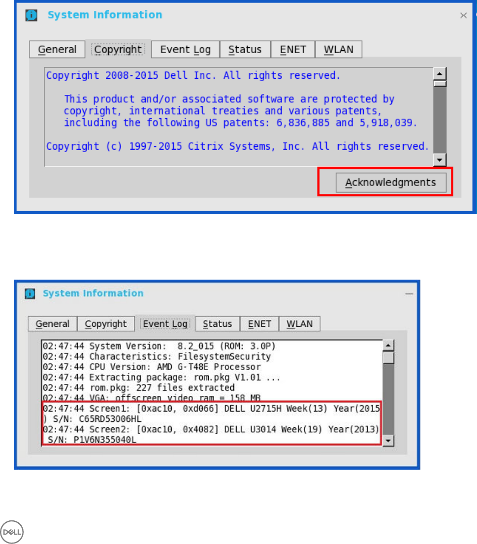
•Copyright Tab — Displays the software copyright and patent notices.
Acknowledgements button is added in the Copyright tab in System Information. This button is related to third party software
and is available only in following clients:
– Wyse 3030 LT thin client with ThinOS
– Wyse 5010 thin client with ThinOS (D10D)
16
– Wyse 5040 AIO thin client (5212)
– Wyse 5060 thin client with ThinOS
– Wyse 7010 thin client with ThinOS (Z10D)
This feature is supported on the following PCoIP enabled clients:
– Wyse 3030 LT thin client with PCoIP
– Wyse 5010 thin client with PCoIP (D10DP)
– Wyse 5040 thin client with PCoIP (5213)
– Wyse 5060 thin client with PCoIP
•Event Log Tab — Displays the thin client start-up steps normally beginning from System Version to Checking Firmware or error
Messages that are helpful for debugging problems. The details about the monitors connected to the thin client are also
displayed.
Following is the screenshot displaying the Event Log tab for Monitors details:
•Status Tab — Displays status information about TCP performance related parameters, UDP performance related parameters,
CPU Busy, System Up Time, CCM status, Free Memory, Active sessions, and WDM status.
17

•IPv6 Tab — Displays IPv6 information such as Link-local Address, IPv6 Address and IPv6 Default Gateway.
NOTE: This tab is displayed when IPv6 is enabled in the General tab of the Network Setup dialog box, see
Configuring the Network Settings.
•ENET Tab— Displays information about wired network connections.
•WLAN Tab— Displays information about wireless network connections.
18
3
Global Connection Settings
If you do not use INI files to provide central configuration (global connection settings) to users, you can use the Global Connection
Settings dialog box to configure settings that affect all of the connections in your list of connections:
• Zero Desktop — Click Global Connection Settings in the List of Connections.
• Classic Desktop — Click Global Connection Settings in the Connect Manager.
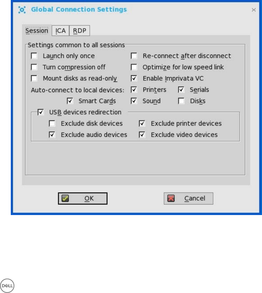
To configure the Global Connection Settings:
1. On the desktop taskbar, click Connect Manager → Global Connection Settings.
The Global Connection Settings dialog box is displayed.
2. Click the Session tab to select the check boxes you want for the options that are available to all sessions.
The Smart Card check box specifies the default setting for connecting to a smart card reader at startup.
19

NOTE:
ICA sessions always have automatic connection to attached smart card readers. When using the Disks check box for
automatic connection to connected USB sticks, use the following guidelines:
• More than one disk can be used at the same time, however, the maximum number of USB sticks including different
subareas is 12.
• Be sure to save all data and sign off from the session mapping the USB stick before removing the USB stick.
NOTE: USB devices redirection — By default, audio, video and printer devices will not use HDX USB for redirection.
You can make selections for USB device redirection on the Session tab of the Global Connection Settings dialog
box.
3. Click the ICA tab to select the check boxes you want for the options that are available to all ICA sessions. Select the audio
quality optimized for your connection.
Map to — When a drive is entered, maps a disk under the drive.
4. Click the RDP and use the following guidelines:
• Enable or disable Network Level Authentication (NLA)— The NLA authentication method verifies users before they are
allowed to connect with a full Remote Desktop connection.
• Enable or disable ForceSpan— This dual-monitor feature allows you to span the session horizontally across two monitors,
thus two monitors acting as one large monitor.
• Enable or disable Terminal Service multimedia Redirection (TSMM).
• Enable or disable Record from Local (recording from local microphone).
• Enable or disable RemoteFX.
• Select the USB Redirection Type (TCX USB or RDP USB)— TCX USB is the default. To use RDP USB, you must use a
RemoteFX session for Windows 7/Windows2008R2 session. However, RDP USB is not supported using a standard
Windows 7/Windows2008R2 session. For Windows 8 session and above, RDP USB is supported.
5. In PCoIP enabled clients, an additional tab named PCoIP is available. Select the USB device redirection type from the drop-
down list. The available values are PCoIP USB and TCX USB.
20

4
Configuring the Connectivity
This chapter helps you to understand various configuration settings for a secure connection. Connectivity menu includes:
•Configuring the Network Settings.
•Configuring the Remote Connections.
•Configuring the Central Configurations.
•Configuring the VPN Manager.
Important:
To configure the settings on Classic desktop, click System Setup from the desktop menu, and use the configuration tabs.
To configure the settings on Zero desktop, click the System Settings icon on the zero toolbar, and then use the configuration
tabs.
Configuring the Network Settings
To configure the network settings use the following options:
•Configuring the General Settings.
•Configuring the Options Settings.
•Configuring the ENET Settings.
•Configuring the WLAN Settings.
•Configuring the Proxy Settings.
Configuring the General Settings
To configure the general network settings:
1. From the desktop menu, click System Setup, and then click Network Setup.
The Network Setup dialog box is displayed.
21
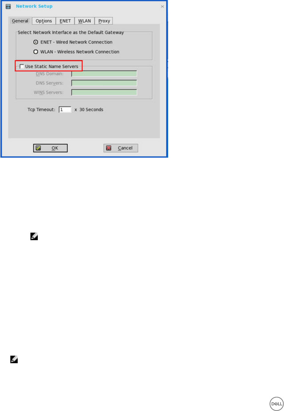
2. Click the General tab, and use the following guidelines:
a. To set the default gateway, select the type of network interface from the available options.
1. Single Network support — Either wireless or wired network is connected.
•ENET — Click this option, if you want set up the Ethernet Wired Network Connection.
•WLAN — Click this option, if you want set up the Wireless Network Connection.
• If the user use wireless network after selecting ENET connection or wired network after selecting WLAN
connection, then the system log "WLAN: set default gate way xx.xx.xx.xx" for first case and "ENET: set default
gate way xx.xx.xx.xx" for second case are printed to ensure that the UI setting reflects the actual usage.
NOTE: The User Interface (UI) will not be changed automatically.
2. Dual Network support — Both wireless and wired networks are connected. The default gateway is determined by
the UI settings.
b. Use Static Name Servers— By default, this check box is not selected (OFF=dynamicfrom DHCP).
If name servers are changed using GUI, INI or link down/ up, then the details are displayed in Event Logs.
In dynamic mode, the DNS/WINS can be merged from Ethernet and Wireless, if network is not working.
c. Enter the URL address of the DNS Domain in the DNS Domain box.
d. Enter the IP address of the DNS Server in the DNS Server box.
Use of DNS is optional. DNS allows you to specify remote systems by their host names rather than IP addresses. If a
specific IP address (instead of a name) is entered for a connection, it is used to make the connection. Enter the DNS
Domain and the network address of an available DNS Server. The function of the DNS Domain entry is to provide a default
suffix to be used in name resolution. The values for these two boxes may be supplied by a DHCP server. If the DHCP server
supplies these values, they replace any locally configured values. If the DHCP server does not supply these values, the
locally configured values will be used.
NOTE: You can enter up to 16 DNS Server addresses, separated by a semicolon, comma, or space. The first
address is for the primary DNS server and the rest are secondary DNS servers or backup DNS servers .
e. Enter the IP address of the WINS Server in the WINS Server box.
Use of WINS is optional. Enter the network address of an available WINS name server. WINS allows you to specify remote
systems by their host names rather than IP addresses. If a specific IP address (instead of a name) is entered for a
22
connection, it is used to make the connection. These entries can be supplied through DHCP, if DHCP is used. DNS and
WINS provide essentially the same function, name resolution. If both DNS and WINS are available, the thin client attempts
to resolve the name using DNS first and then WINS.
You can enter two WINS Server addresses (primary and secondary), separated by a semicolon, comma, or space.
f. Enter the digit multiplier of 30 seconds in the TCP Timeout box to set the time-out value of a TCP connection. The value
must be 1 or 2 which means the connection time-out value is from 1x30= 30 seconds to 2x30= 60 seconds. If the data for
connecting to the server is not acknowledged and the connection is time out, setting the time-out period retransmits the
sent data and again tries to connect to the server till the connection is established.
3. Click OK to save the settings.
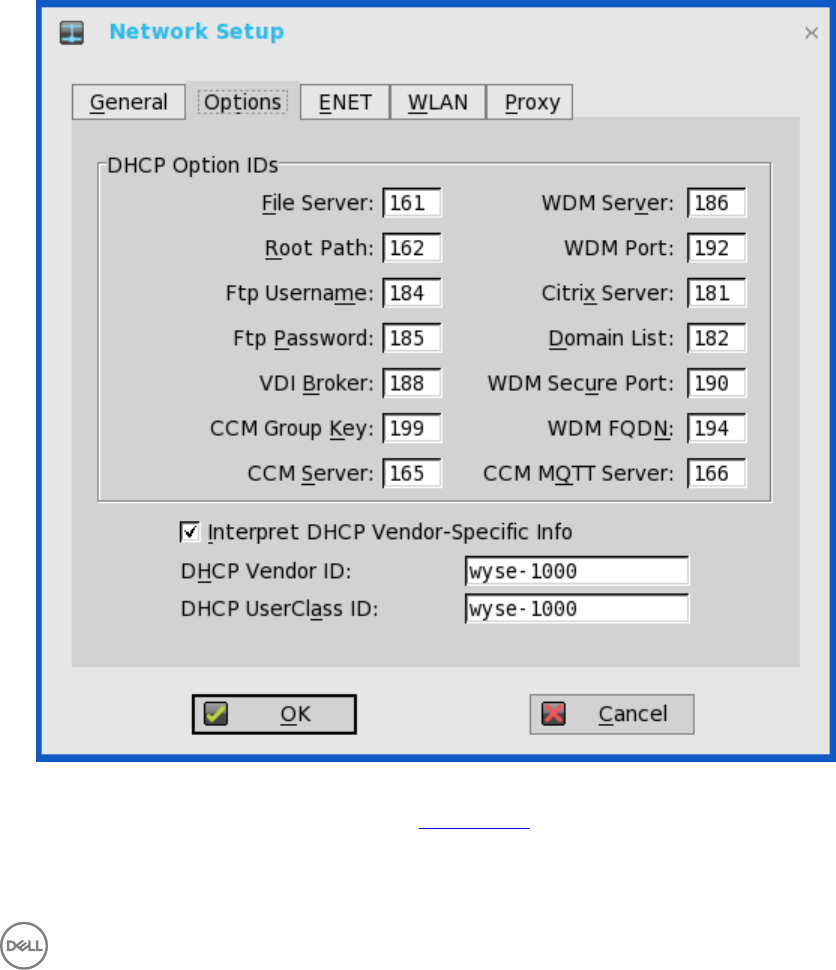
Configuring the DHCP Options Settings
To configure the options settings:
1. From the desktop menu, click System Setup, and then click Network Setup.
The Network Setup dialog box is displayed.
2. Click the Options tab, and use the following guidelines:
a. DHCP Option IDs — Enter the supported DHCP options. Each value can only be used once and must be between 128 and
254. For information about DHCP options, see DHCP Options.
b. Interpret DHCP Vendor-Specific Info — Select this check box for automatic interpretation of the vendor information.
c. DHCP Vendor ID — Shows the DHCP Vendor ID when the dynamically allocated over DHCP/BOOTP option is selected.
23
d. DHCP UserClass ID — Shows the DHCP UserClass ID when the dynamically allocated over DHCP/BOOTP option is
selected.
3. Click OK to save the settings.
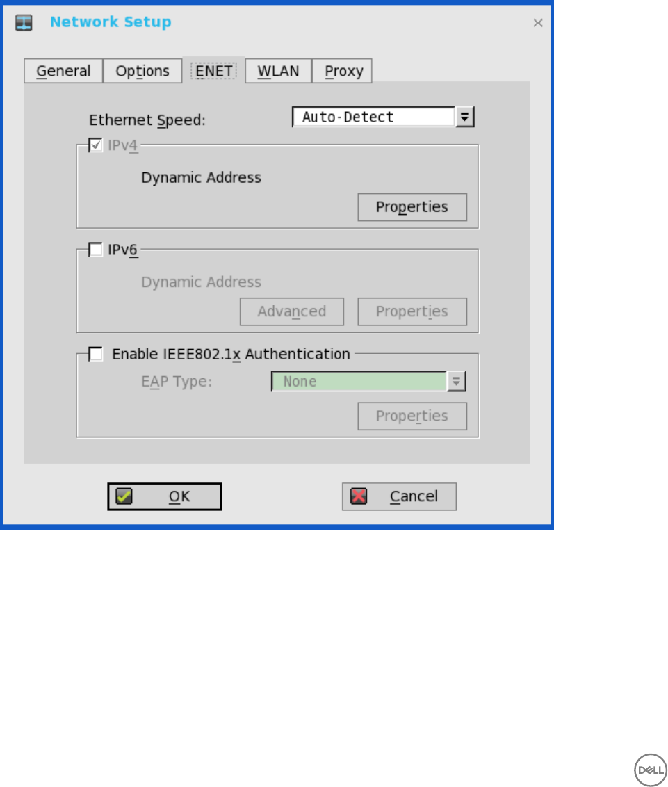
Configuring the ENET Settings
To configure the ENET settings:
1. From the desktop menu, click System Setup, and then click Network Setup.
The Network Setup dialog box is displayed.
2. Click the ENET tab, and use the following guidelines:
a. Ethernet Speed — Normally the default (Auto-Detect) should be selected, but another selection can be made if
automatic negotiation is not supported by your network equipment. Selections include Auto-Detect, 10 MB Half-Duplex,
10 MB Full-Duplex, 100 MB Half-Duplex, 100 MB Full-Duplex, and 1 GB Full-Duplex.
The 10 MB Full-Duplex option can be selected locally at the device, however, this mode may need to be negotiated
through AutoDetect.
b. The IPV4 check box is selected by default. Click Properties to set various options supported by IPV4.
•Dynamically allocated over DHCP/BOOTP — Selecting this option enables your thin client to automatically receive
information from the DHCP server. The network administrator must configure the DHCP server using DHCP options to
provide information. Any value provided by the DHCP server replaces any value entered locally on the Options tab,
however, locally entered values are used if the DHCP server fails to provide replacement values.
24

•Statically specified IP Address — Select this option to manual enter the IP Address, Subnet Mask and Default
Gateway:
–IP Address — Must be a valid network address in the server environment. The network administrator must provide
this information.
–Subnet Mask — Enter the value of the subnet mask. A subnet mask is used to gain access to machines on other
subnets. The subnet mask is used to differentiate the location of other IP addresses with two choices: same subnet
or other subnet. If the location is other subnet, messages sent to that address must be sent through the Default
Gateway, whether specified through local configuration or through DHCP. The network administrator must provide
this value.
–Default Gateway — Use of gateways is optional. Gateways are used to interconnect multiple networks (routing or
delivering IP packets between them). The default gateway is used for accessing the internet or an intranet with
multiple subnets. If no gateway is specified, the thin client can only address other systems on the same subnet.
Enter the address of the router that connects the thin client to the internet. The address must exist on the same
subnet as the thin client as defined by the IP address and the subnet mask. If DHCP is used, the address can be
supplied through DHCP.
c. Select the IPV6 check box, and then click Advanced to select various IPV6 supported setting options from the available
check boxes.
d. Click properties and use the following guidelines:
•Wait DHCP — Selecting this option enables your thin client to wait for IPV6 DHCP before the sign-in, if not selected
the system will only wait for IPV4 DHCP if enabled.
•Dynamically allocated over DHCP/BOOTP — Selecting this option enables your thin client to automatically receive
information from the DHCP server. The network administrator must configure the DHCP server (using DHCP options)
to provide information. Any value provided by the DHCP server replaces any value entered locally on the Options tab,
however, locally entered values are used if the DHCP server fails to provide replacement values.
•Statically specified IP Address — Select this option to manually enter the IP Address, Subnet Mask and Default
Gateway.
–IP Address — Must be a valid network address in the server environment. The network administrator must provide
this information.
–Subnet Mask — Enter the value of the subnet mask. For more information, see various options supported by IPV4
in this section.
–Default Gateway — Use of gateways is optional. For more information, see various options supported by IPV4 in
this section.
•DNS Servers — Use of DNS is optional. DNS allows you to specify remote systems by their host names rather than IP
addresses. If a specific IP address (instead of a name) is entered for a connection, it rather than DNS is used to make
the connection. Enter the network address of an available DNS Server. The value for this box may be supplied by a
DHCP server. If the DHCP server supplies this value, it replaces any locally configured value. If the DHCP server does
not supply this value, the locally configured value is used.
e. Select the check box to enable IEEE802.1x Authentication.
•EAP Type — If you have enabled the Enable IEEEE 802.1x authentication check box, select the EAP Type option you
want (TLS, LEAP PEAP or FAST).
•TLS — If you select the TLS option, click Properties to open and configure the Authentication Properties dialog box.
– Select the Validate Server Certificate check box because it is mandatory to validate your server certificate.
NOTE:
The CA certificate must be installed on the thin client. Also note that the server certificate text field supports
a maximum of approximately 127 characters, and supports multiple server names.
– If you select the Connect to these servers check box, the box is enabled where you can enter the IP address of
server.
25

– Click Browse to find and select the Client Certificate file and Private Key file you want.
The following kinds of server names are supported — all examples are based on Cert Common name company.wyse.com
NOTE:
Using only the FQDN, that is company.wyse.com does not work. You must use one of the options (note that
*.wyse.com is the most common option as multiple authentication servers may exist): servername.wyse.com
*.wyse.com
*wyse.com
*.com
f. LEAP — If you select the LEAP option, click Properties to open and configure the Authentication Properties dialog box.
Be sure to use the correct Username and Password for authentication. The maximum length for the username or the
password is 64 characters.
g. PEAP — If you select the PEAP option, click Properties to open and configure the Authentication Properties dialog box.
Be sure to select either EAP_GTC or EAP_MSCHAPv2, and then use the correct Username, Password and Domain.
Validate Server Certificate is optional.
NOTE:
The server certificate text box for LEAP and PEAP supports a maximum of approximately 127 characters, and
supports multiple server names.
h. FAST—If you select the FAST option, click Properties to open and configure the Authentication Properties dialog box.
Be sure to select either EAP_GTC or EAP_MSCHAPv2, and then use the correct Username, Password and Domain.
Validate Server Certificate is optional.
i. To configure EAP-GTC, enter the username only. The password or PIN is required when authenticating.
To configure EAP-MSCHAPv2, enter the username, password and domain.
Important: The domain/username in the username box is supported, but you must leave the domain box blank.
The CA certificate must be installed on the thin client and the server certificate is forced to be validated. When EAP-
MSCCHAPV2 is selected in EAP type in the Authentication Properties dialog box (for PEEP IEEE802.1x authentication),
an option to hide the domain is available for selection. Username and Password boxes are available for use, but the Domain
text box is disabled.
3. Click OK to save the settings.
Configuring the WLAN Settings
1. From the desktop menu, click System Setup, and then click Network Setup.
The Network Setup dialog box is displayed.
2. Click the WLAN tab, and use the following guidelines:
26
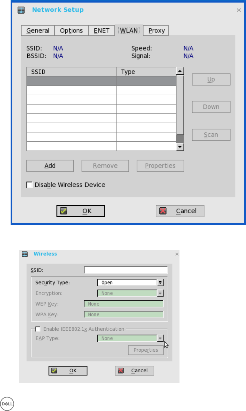
a. Add— Use this option to add and configure a new SSID connection.
You can configure the SSID connection from the available security type options.
27
b. After you configure the SSID connection, the added SSID connection is listed on the page of the WLAN tab.
c. Remove — Use this option, if you want to remove a SSID connection by selecting the SSID connection from the list.
d. Properties — Use this option to view and configure the authentication properties of a SSID connection that is displayed in
the list.
e. Select the Disable Wireless Device check box, if you want to disable a wireless device.
From ThinOS 8.3, EAP-FAST authentication is supported. During the initial connection, when there is a request for a Tunnel
PAC from the authenticator, the PAC is used to complete the authentication. Therefore, the first time connection always fails
and the following connections succeed.
•New User Interface (UI): Wireless → EAP Type → EAP - FAST; Second authentication method supports
MSCHAPv2/GTC only for EAP-FAST.
• Only automatic PAC provisioning is supported in this release. The user/machine PAC provisioning generated with Cisco
EAP-FAST utility is not supported.
3. Click OK to save the settings.
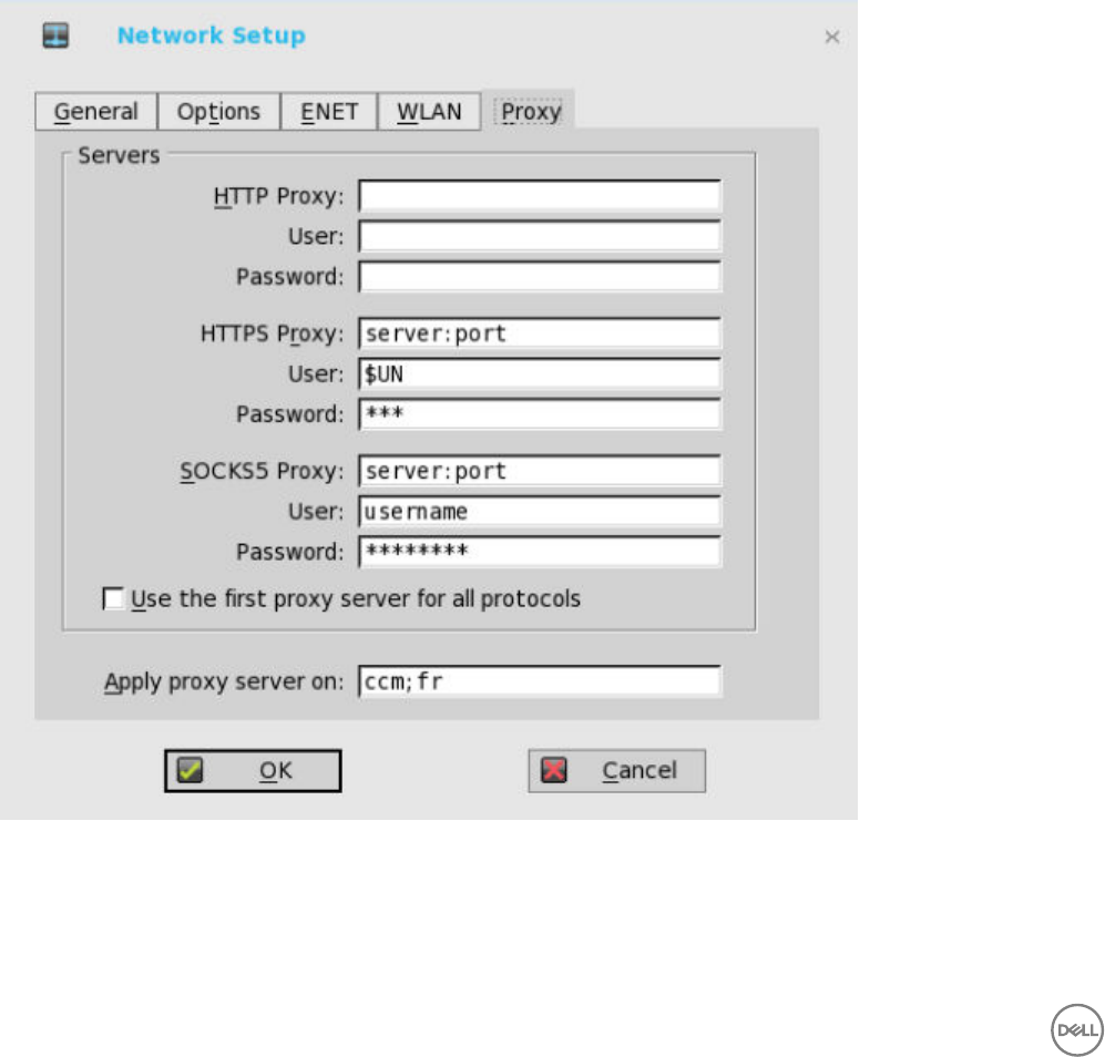
Configuring the Proxy Settings
The network Proxy tab is added to support Cloud Client Manager (CCM) and HDX Flash Redirection.
Supported Protocols
• For HDX FR, HTTP and HTTPS protocols are supported.
28

– If both are configured, the HDX FR works with HTTPS proxy.
– User credential pass through is possible with $UN/$PW.
• For CCM, HTTP, HTTPS and Socks5 (recommended) protocols are supported.
1. From the desktop menu, click System Setup, and then click Network Setup.
The Network Setup dialog box is displayed.
2. Click the Proxy tab, and use the following guidelines:
a. Enter the HTTP proxy port number or HTTPS proxy port number, Username and Password in the respective fields.
However, Credential pass through ($UN/$PW) is not recommended because it starts before user sign on.
CCM uses both HTTP/HTTPS and MQTT protocols to communicate with CCM/MQTT server. However, the HTTP proxy
cannot redirect TCP packages to MQTT server which requires a Socks5 proxy server. If there is only HTTP server
available, then the real-time command that requires MQTT will not work.
HTTP/HTTPS proxy default port is 808, and SOCK5 proxy default port is 1080.
b. Select the Use the first proxy server for all protocols check box to allow all the protocols to use the same server in
HTTP Proxy fields. Both HTTP and HTTPS proxy use the same host and port, and Socks5 proxy agent uses HTTP host
with default Socks 5 port (1080).
c. If SOCKS5 proxy is configured, then CCM proxy uses the SOCKS5 only. If SOCKS5 is not configured, then CCM proxy
searches for alternative protocols, for example, HTTP in the configuration.
d. Specify the supported applications as CCM and FR in the Apply proxy server on field.
3. Click OK to save the settings.
User Scenarios
1. Configure correct proxy server host and port.
2. Configure the user credentials according to the proxy server settings.
3. On system restart, the client checks in to the CCM server through Socks5 proxy server.
4. MQTT connection is established through Socks5 proxy server.
5. Real-time commands work fine through Socks5 proxy server.
6. Connect to the Citrix desktop, configure proxy in internet options of the browser, and then playback HDX FR through the
HTTP/HTTPS proxy authentication.
Configuring the Remote Connections
Use the Remote Connections dialog box to configure thin client remote connections including ICA, RDP, Citrix XenDesktop,
Microsoft, VMware View, Dell vWorkspace, and other broker server connections. This dialog box also enables you to configure visual
options, and general connection settings.
•Configuring the Broker Setup
•Configuring the Visual Settings
•Using the General Options
•Configuring the Authentication Settings
NOTE:
In the Classic Desktop option, the Remote Connections dialog box allows you to create default ICA and RDP connections for
use. If you want to create several ICA and RDP connections (more than the default connections), use the Connect Manager,
For more information see Using the Connect Manager.
29
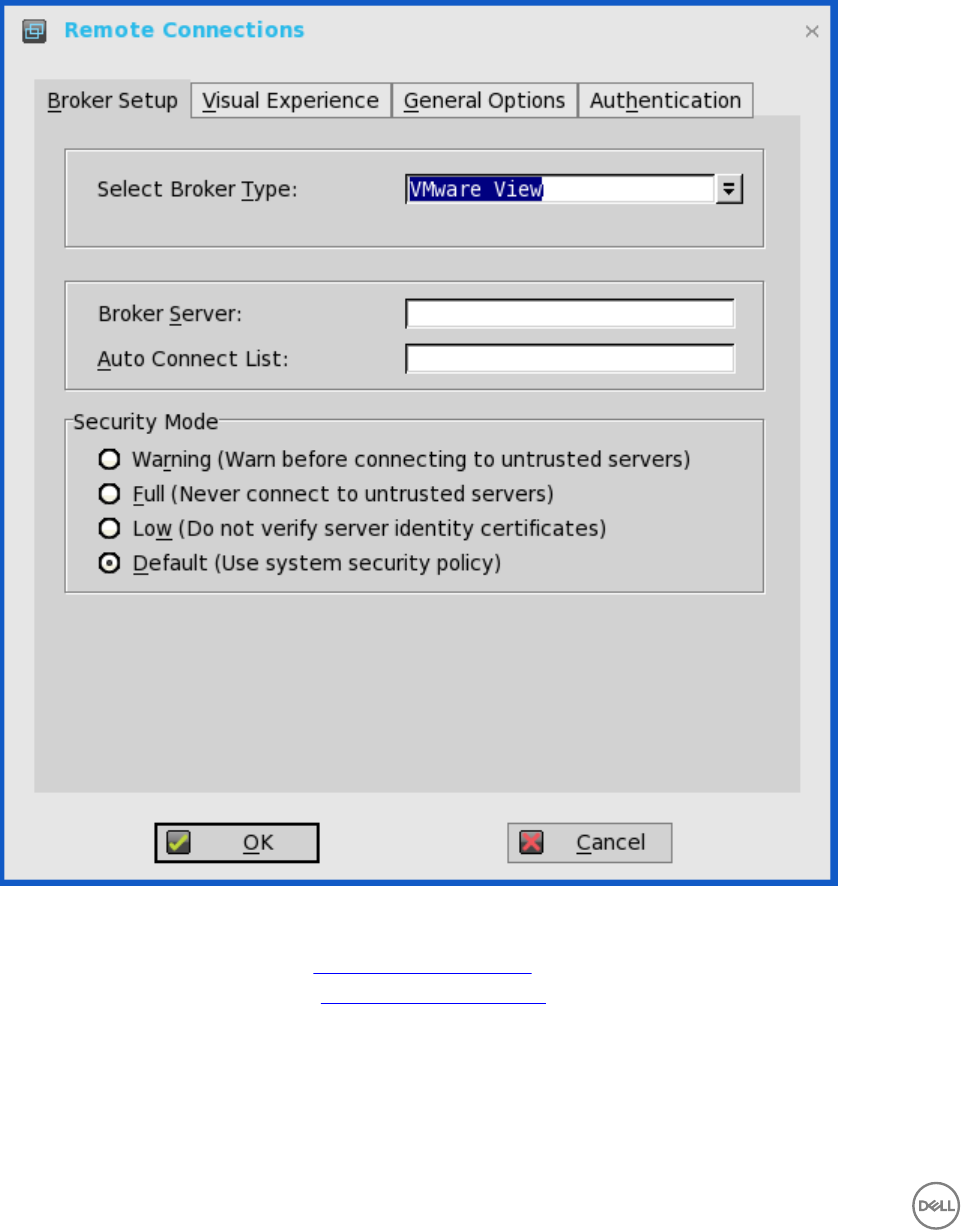
Configuring the Broker Setup
To configure the Broker setup:
1. From the desktop menu, click System Setup, and then click Remote Connections.
The Remote Connections dialog box is displayed.
2. Select Broker type from the drop-down list.
a. If you select None from the list, click either of the following connection protocols:
•ICA — For more information, see Configuring ICA Connections.
•RDP — For more information, see Configuring RDP Connections.
b. If you select the Citrix Xen, use the following guidelines:
• Select the check box to enable the StoreFront style.
•Broker Server— Enter the IP address/Hostname/FQDN of the Broker Server.
30

•Auto Connect List—Enter the name of the desktops that you want to launch automatically after logging in to the
respective broker. More than one desktop can be entered. Each desktop name is separated by semi-colon, and is case-
sensitive.
• Select the check box to enable automatic reconnection at logon.
NOTE:
If you enable the automatic reconnection, you are able to select from the reconnection options. Click either of the
options where you can connect to the disconnected sessions only or connect to both active and disconnected
sessions.
• Select the check box to enable automatic reconnection from the button menu.
NOTE: If you enable the automatic reconnection, you are able to select from the reconnection options. Click
either of the options where you can connect to the disconnected sessions only or connect to both active and
disconnected sessions.
•Account Self-Service Server— Enter the IP address of the Account self-service server.
•XenApp — Use this option, if you want to set default settings to XenApp.
•XenDesktop— Use this option, if you want to set default settings to XenDesktop.
c. If you select the VMWare view, use the following guidelines:
•Broker Server— Enter the IP address/Hostname/FQDN of the Broker Server.
•Auto Connect List—Enter the name of the desktops that you want to launch automatically after logging in to the
respective broker. More than one desktop can be entered. Each desktop name is separated by semi-colon, and is case-
sensitive.
•Security mode—Select the preferred Security mode from the following options:
–Warning —Warn Security requires FQDN address with self-signed certificate, or without any certificate, but
corresponding warning message is displayed for user to continue.
–Full—Full Security requires FQDN address with domain certificate.
–Low—Security allows FQDN/IP address with/without certificate.
–Default— Follows global security mode settings.
For PCoIP enabled clients such as Wyse 3030 LT thin client with PCoIP, Wyse 5010 thin client with PCoIP (D10DP), Wyse
5040 AIO thin client with PCoIP (5213), and Wyse 5060 thin client with PCoIP, an additional Connection Protocol drop-
down list for protocol selection is available. By default, the option is set to Server Default.
From the Connection Protocol drop-down list, select the type of protocol connection. The available options are:
•Server Default— Select this protocol connection to display the desktop with default protocol as configured in the
VMware View Admin console, for each pool in the broker. If a desktop pool is configured with default protocol as RDP
in the View Admin console, then only the RDP connection of the desktop is displayed in ThinOS after users sign in to
the device.
•All Supported—Select this protocol connection to display the desktop in both RDP and PCoIP connections, when a
desktop pool is configured to allow users to select protocol as yes. If a desktop is configured with default protocol as
PCoIP and allow user to select protocol as no, then ThinOS only displays the desktop in PCoIP connection.
•RDP only— Select this protocol connection to display only the desktop in RDP connection. If a desktop pool is
configured with default protocol as PCoIP in the View Admin console, and allow user to select protocol as no, then this
desktop is not displayed in ThinOS after user signs in to the device.
•PCoIP only—Select this protocol connection to display only the desktop in PCoIP connection, for each pool in the
broker. If a desktop pool is configured with default protocol as RDP in the View Admin console, and allow user to select
protocol as no, then this desktop is not displayed in ThinOS after user signs in to the device.
For more information about VMware Horizon View broker, see Using the VMware Horizon View broker and PCoIP.
d. If you select the Microsoft, use the following guidelines:
•Broker Server—Enter the IP address/Hostname/FQDN of the Broker Server.
31
•Auto Connect List—Enter the name of the desktops that you want to launch automatically after logging in to the
respective broker. More than one desktop can be entered. Each desktop name is separated by semi-colon, and is case-
sensitive.
e. If you select Dell vWorkspace, use the following guidelines:
•Broker Server— Enter the IP address/Hostname/FQDN of the Broker Server.
•Auto Connect List—Enter the name of the desktops that you want to launch automatically after logging in to the
respective broker. More than one desktop can be listed. Each desktop name is separated by a semi-colon, and is case-
sensitive.
• Select the check box to enable vWorkspace Gateway.
•vWorkspace Gateway— Enter the IP Address of the vWorkspace Gateway.
f. If you select Other, you must enter the IP address of the Broker server in the Broker Server box.
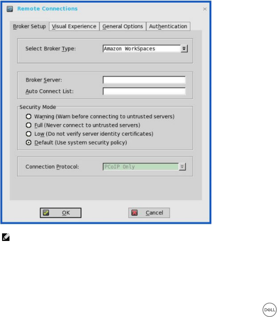
g. If you select the Amazon Workspaces, use the following guidelines:
NOTE: Amazon Workspaces connection is applicable only for PCoIP clients running ThinOS 8.3 and later
versions.
•Broker Server— Enter the IP address/Hostname/FQDN of the Broker Server.
•Auto Connect List—Enter the name of the desktops that you want to launch automatically after logging in to the
respective broker. More than one desktop can be listed. Each desktop name is separated by a semi-colon, and is case-
sensitive.
•Security mode—Select the preferred Security mode from the following options:
32

–Warning —Warn Security requires FQDN address for domain certificate installed in PCM. If certificate is not
installed on the client, corresponding warning message is displayed for you to continue.
–Full—Full Security requires FQDN address with domain certificate installed in PCM, and certificate installed on the
client.
–Low—Security allows FQDN/IP address with/without certificate.
–Default— Follows global security mode settings.
•Connection Protocol— The drop-down list is disabled for AWS broker. By default, the option is set to PCoIP Only.
NOTE: PCoIP agent is updated to v2.2.0 to support AWS WorkSpaces connection.
For information about deploying AWS WorkSpaces and AWS EC2 PCM for AWS WorkSpaces, go to www.teradici.com/
web-help/Connecting_ZC_AWS_HTML5/TER1408002_Connecting_ZC_AWS.htm#03_DeployPCM.htm%3FTocPath
%3D3.
For information about configuring the Broker Server address = “URI (https://<FQDN or IP address>) of the PCM”, go to
www.teradici.com/web-help/Connecting_ZC_AWS_HTML5/TER1408002_Connecting_ZC_AWS.htm#05_Connect.htm
%3FTocPath%3D5.
Known issues with Amazon Web Services/Workspaces
• Key combination Ctrl + Alt disconnects users from AWS session intermittently with old agent in AWS desktop. To fix
this issue, update to latest agent by rebooting the desktop.
• Each user is assigned with one WorkSpaces desktop, and therefore logon with any username returns to the single
desktop and then the session connects automatically. Disconnecting from the desktop returns user to logon screen.
3. Click OK to save the settings.
Using the VMware Horizon View broker and PCoIP
This section describes the updates on the VMware Horizon View broker and PC-over-IP (PCoIP).
The VMware Horizon View broker icon is updated and the Disclaimer window is provided. The following changes are applicable to
Wyse 3030 LT thin client with PCoIP, Wyse 5010 thin client with PCoIP (D10DP), Wyse 5040 AIO thin client with PCoIP (5213), and
Wyse 5060 thin client with PCoIP.
• PCoIP session NUM/CAP keyboard status synchronizes with the session instead of client.
• RDS desktop through PCoIP is supported in this release.
• USB redirection RDS desktop through PCoIP is not supported.
•VMware Horizon View broker
The VMware Horizon View broker icon is updated.
33
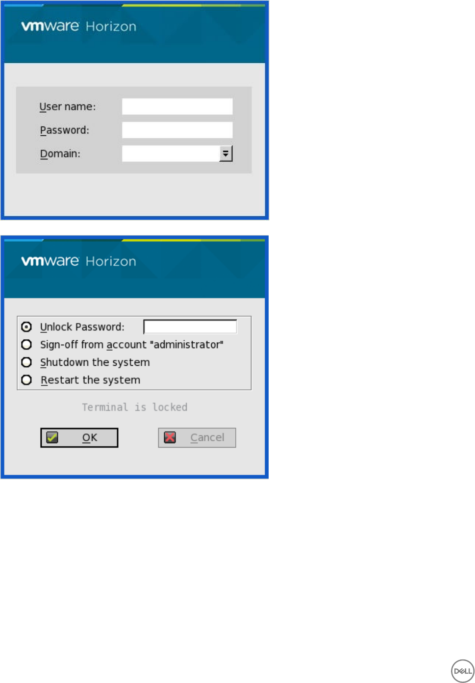
The following are the screenshots of PCoIP enabled on Wyse 3030 LT thin client with PCoIP, Wyse 5010 thin client with PCoIP
(D10DP), Wyse 5040 AIO thin client with PCoIP (5213), and Wyse 5060 thin client with PCoIP.
34
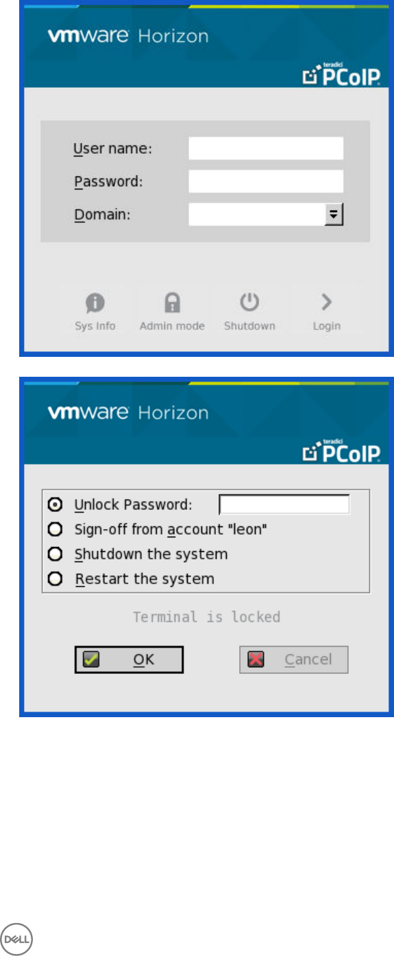
•VMware Horizon View Broker timeout— The VMware Horizon View Broker timeout does not force the user to sign out from
the broker anymore when the secure tunnel is enabled.
In earlier version of ThinOS, when the broker times out, the user session is disconnected and the user is logged out from the
broker. From ThinOS 8.2 release, ThinOS disconnects the user session from the broker, but does not force user logout. This is
because the user has local connections other than the broker desktop, and these connections are active when the broker
timeout is reached.
•The Disclaimer window— The Disclaimer window is provided in this release.
35
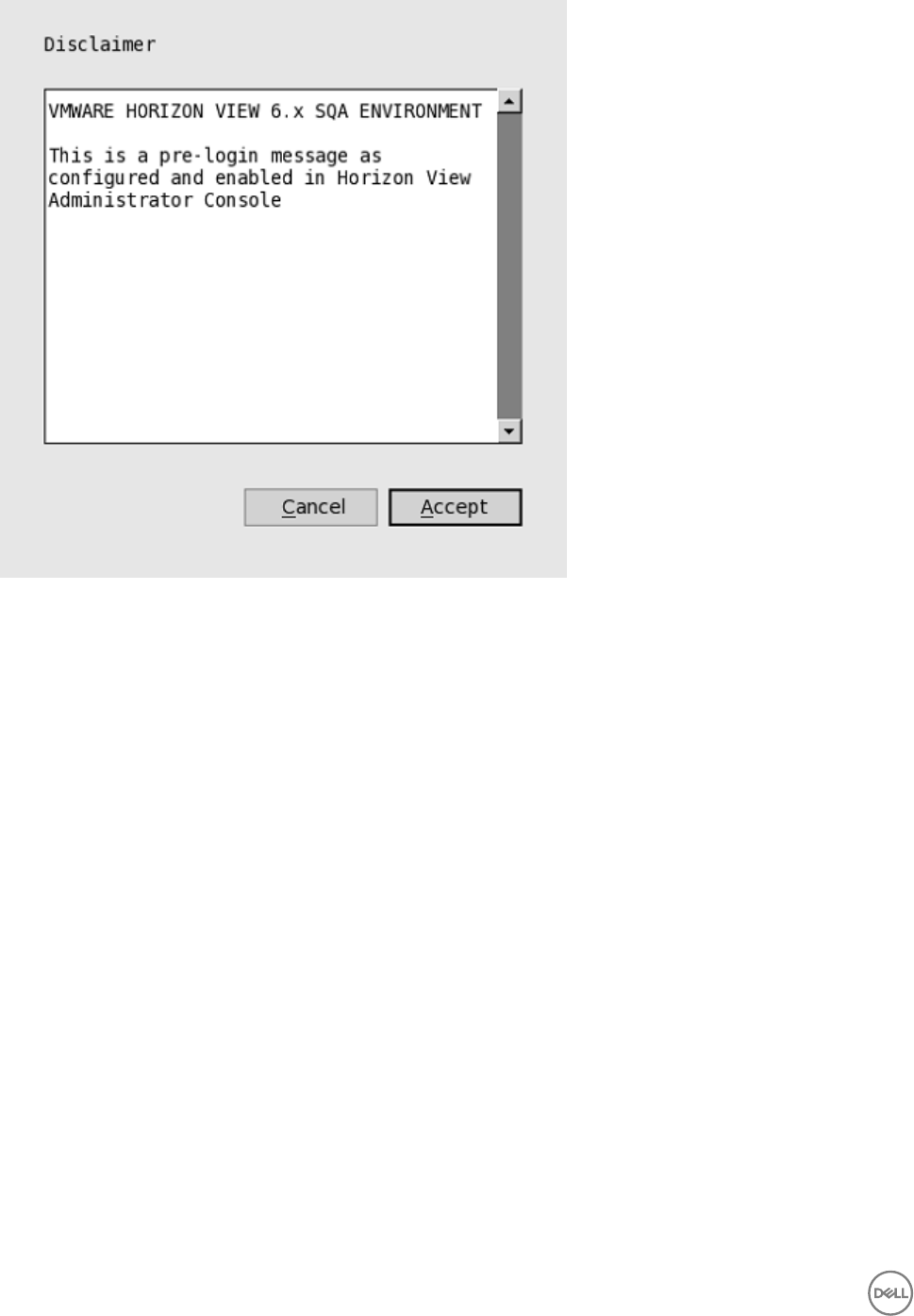
In the Disclaimer window, if you click Accept, you are directed to the user login window. If you click Cancel, the user login
window displays the message broker initialization failed.
•Changes applicable to Wyse 3030 LT thin client with PCoIP, Wyse 5010 thin client with PCoIP (D10DP), Wyse 5040 AIO
thin client with PCoIP (5213), and Wyse 5060 thin client with PCoIP.
–PCoIP session NUM/CAP keyboard status synchronizes with session instead of thin client
This is applicable for session startup only. The PCoIP session keyboard NUM/ CAP status synchronizes from remote session
to client, whereas RDP/ ICA synchronize status from local to remote session.
For example,
1. Set keyboard NUM=off in current PCoIP session.
2. Disconnect the session.
3. Set client keyboard NUM=on.
4. Reconnect to the PCoIP session.
5. The keyboard NUM status in both session and client is updated to NUM=off.
–RDS desktop through PCoIP
You can view and connect to the Remote Desktop Service (RDS) desktop through the PCoIP protocol in the broker. In
VMware Horizon View 6.0 and later versions, the RDS desktop has RDP and PCoIP connections based on server
configurations.
In Wyse 5010 thin client with PCoIP (D10DP) and Wyse 5040 AIO thin client with PCoIP (5213) running ThinOS 8.0, you can
only view the RDP connection for the RDS desktop. In ThinOS 8.2, the PCoIP connection is available for both Wyse 5010
thin client with PCoIP (D10DP) and Wyse 5040 AIO thin client with PCoIP (5213) running ThinOS 8.2 and in ThinOS 8.3, the
36
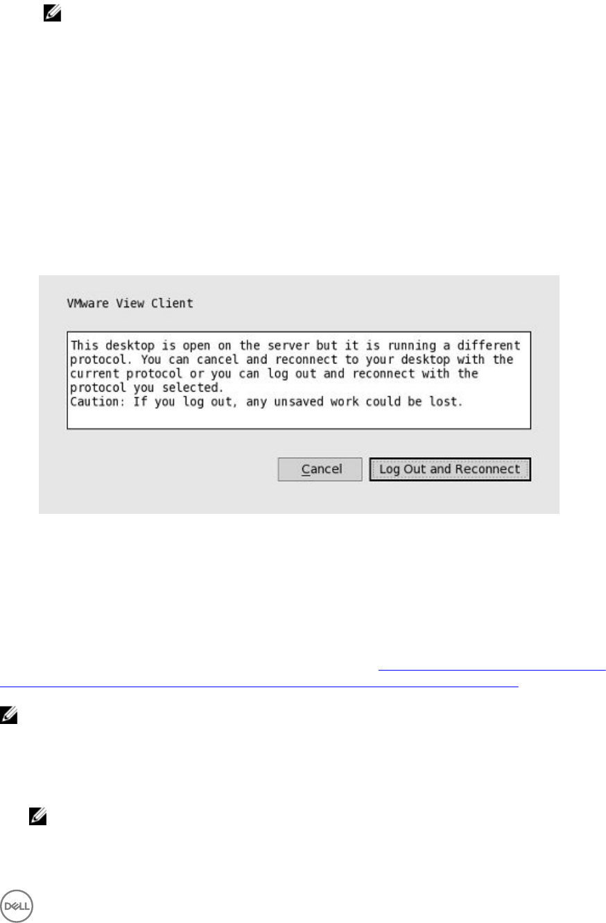
PCoIP connection is available for Wyse 3030 LT thin client with PCoIP. From 8.3.1, PCoIP connection is available for Wyse
5060 thin client with PCoIP.
NOTE:
The RDS Application over PCoIP is not supported in this version.
The RDS desktop protocol switch message dialog box is provided in this release. A typical user scenario is as follows:
1. Connect to the RDS desktop through protocol. For example, RDP.
2. Disconnect from the desktop.
3. Connect to the same RDS desktop through another protocol. For example, PCoIP.
The message dialog box is displayed, allowing you with an option to continue.
The options available are:
*Cancel— You can end the PCoIP connection, and connect to the desktop in RDP again.
*Log Out and Reconnect— You can connect to the desktop through PCoIP, and the earlier session in RDP is
logged out.
–USB redirection RDS desktop through PCoIP
This feature is not supported in this version. The same limitation applies to the VMware Horizon View Linux client as well.
Supporting the VMware Real Time Audio-Video
Use the Real-Time Audio-Video feature to run Skype and other online conference applications on the remote desktop. Using this
feature, both audio and video devices that are connected to your thin client are available to use for VoIP in remote desktop.
To know more about the VMware Real Time Audio-Video support, go to pubs.vmware.com/horizon-62-view/topic/
com.vmware.horizon-view.desktops.doc/GUID-D6FD6AD1-D326-4387-A6F0-152C7D844AA0.html.
NOTE: There is no additional configuration for ThinOS. RTAV video requires RTME package to be installed on your
device.
To validate the VMware Real Time Audio-Video, do the following:
1. Connect to the VMware PCoIP desktop with the audio and video devices.
NOTE: USB redirection must be disabled for the audio/video devices.
2. Verify the audio playback of the system using the VMware Virtual Audio.
37
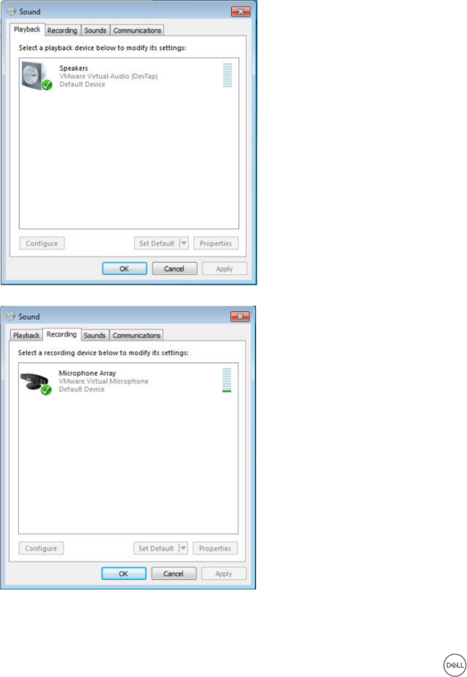
3. Verify the system audio recording using the VMware Virtual Microphone.
4. Verify the Audio settings in VoIP application.
38
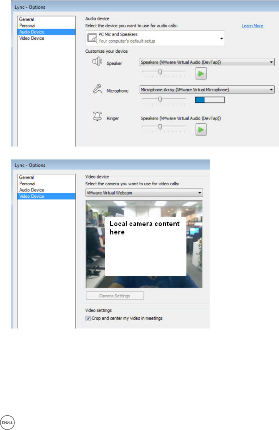
5. Verify the Video settings in VoIP application using the VMware Virtual Webcam.
6. Start the audio/video calls.
Dependencies and Known Issues
• Dependency: RTME.i386.pkg needs to be installed for RTAV video.
• The answer call button of the local audio device, supported by HDX RTME, is not supported by RTAV.
• RTAV does not support RDS desktop, for example, 2008R2/ 2012R2 according to VMware.
• Support for PCoIP protocol only. RDP protocol is not supported according to VMware.
39
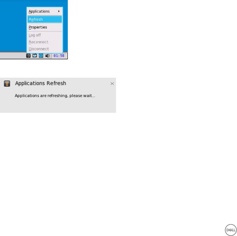
• Webcam preferences are not supported. For example, the first webcam displayed in the Camera tab in local peripheral settings
is used always.
• Camera/Video: High Definition video is not supported because of the RTAV limitation. The local camera setting does not affect
RTAV video because of the application design. Dell recommend users not to interfere with the local camera settings.
Citrix Icon Refresh
Citrix applications can be refreshed by clicking Refresh from PNMenu.
There are two methods to refresh the Citrix applications:
• Manual refresh
• Auto refresh using the INI parameter
Refreshing Citrix Applications Manually
To refresh the Citrix application manually, do the following:
1. For single StoreFront or PNAgent server, change the application in broker, and then click Refresh from PNMenu.
The following message is displayed in the lower right pane during application refresh.
2. Applications are refreshed in Session bar list, Connect Manager list and App menu list.
The following log is displayed in the Event Log window:
ICA: refresh store “xxx”…” or “ICA: refresh PNAgent”xxx”…
3. For MultiFarm (StoreFront or PNAgent servers) or Multilogon (StoreFront or PNAgent servers), select a single server to
refresh or click Refresh All to refresh all servers.
40
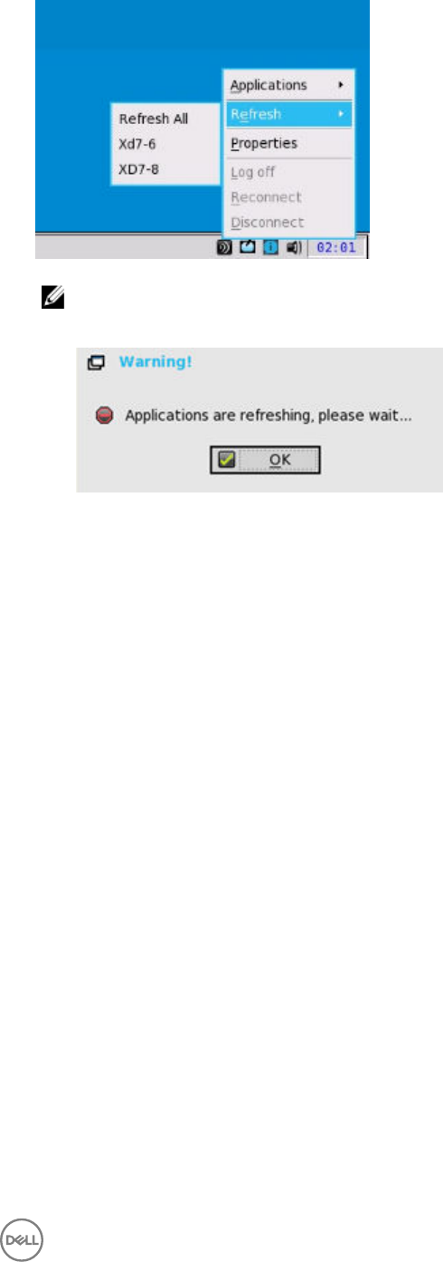
NOTE:
Warning message is displayed when you open or edit or remove applications when you refresh the applications.
4. Refresh scope covers the aspects such as, application removed, added, duplicated, disabled, enabled, icon/title change, and
on/off desktop.
Active sessions that are started are not affected by application refresh.
5. The disconnect session can be reconnected after application refresh, if Automatic reconnection at logon is enabled in remote
connection.
Refreshing the Citrix Applications Automatically Using INI Parameter
To automatically refresh the Citrix application, set the following INI parameter:
SessionConfig=ICA RefreshTimeOut=dd:hh:mm
For example, 01:01:22, means the application will start refresh automatically, every 1 day: 1 hour: 22 minutes.
Limitations of Citrix Icon Refresh
Following are the limitations of Citrix icon refresh:
• Citrix icon refresh is supported in classic mode and storefront mode only.
• Virtual Desktop Infrastructure (VDI) mode is not supported.
Configuring the Visual Settings
To configure the visual settings:
1. From the desktop menu, click System Setup, and then click Remote Connections.
The Remote Connections tab is displayed.
2. Click Visual Experience tab, and use the following guidelines:
41
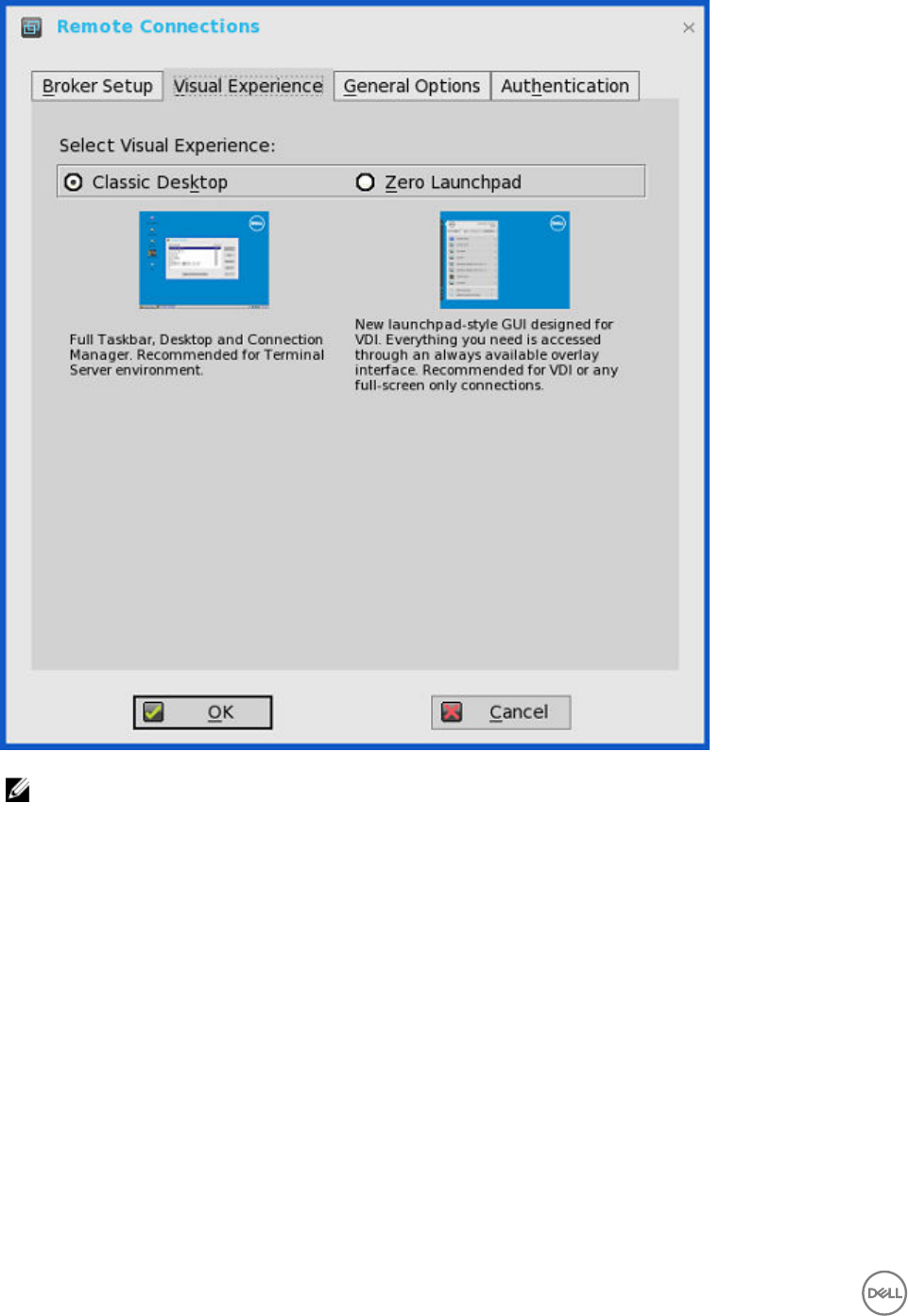
NOTE: The Visual Experience tab is grayed out, if the StoreFront Style check box is selected for a Citrix Broker
Server entered in the Broker Setup tab.
a. Classic Desktop — Displays the full taskbar, desktop and Connect Manager familiar to ThinOS users. This option is
recommended for terminal server environments and for backward compatibility with ThinOS 6.x versions.
b. Zero Launchpad — Displays the new launch pad style GUI designed for VDI use. Functionality is accessed through an
always available interface. This option is recommended for VDI and any full-screen only connections. Toolbar, hotkey and
connection icon options are also available for configuration.
If you select the Zero Launchpad, then use the following guidelines:
• Select the check box to enable Zero Toolbar activation in left pane.
– Select the button if you want to enable Zero Toolbar activation in left pane when you pause a mouse on the screen.
– Select the button if you want to enable Zero Toolbar activation in left pane only after clicking.
• Select the check box to disable hotkey to show toolbar.
• Select the check box to always disable toolbar when you have one session available.
• Select the check box to disable Home Icon.
3. Click OK to save the settings.
42
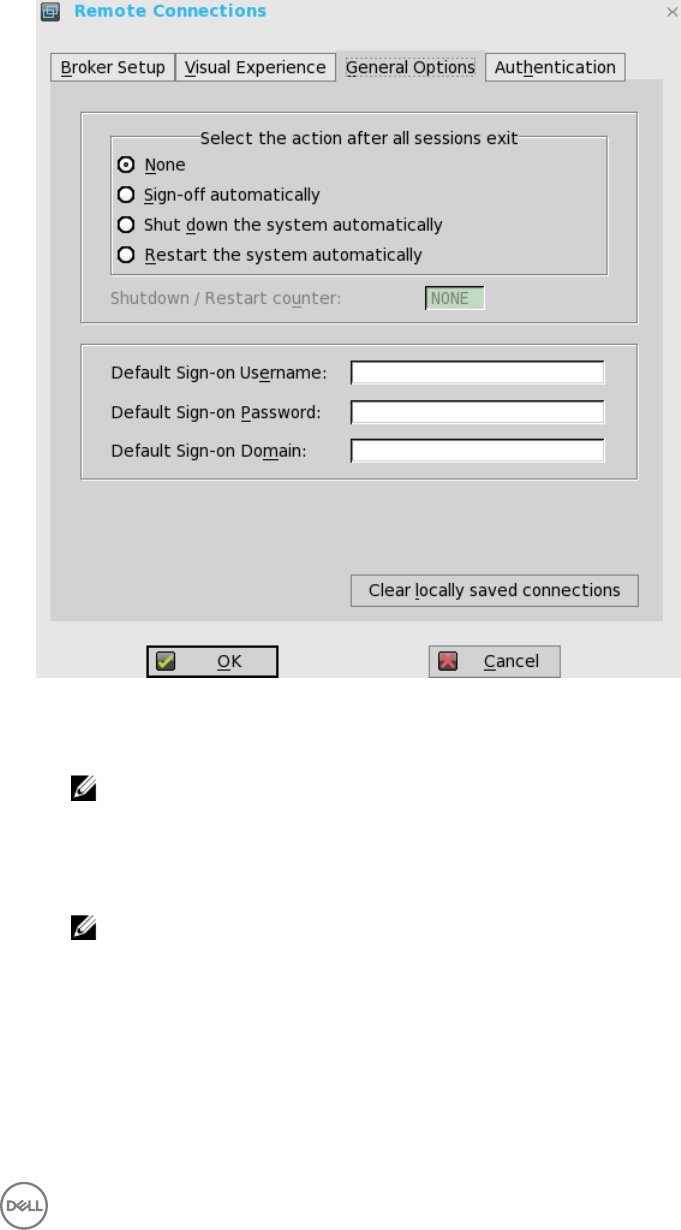
Configuring the General Options
To configure the general options:
1. From the desktop menu, click System Setup, and then click Remote Connections.
The Remote Connections dialog box is displayed.
2. Click the General Options tab, and use the following guidelines:
a. Click the available options to select the action after you exit all open desktops. The available options are None, Sign-off
automatically, Shut down the system automatically and Restart the system automatically.
NOTE: By default, None is selected and the thin client automatically returns to the terminal desktop.
b. Default Sign-on Username— Enter the Default user name.
c. Default Sign-on password— Enter the Default password.
d. Default Sign-on Domain— Enter the Default Domain.
e. Click Clear locally saved connections to clear locally saved connections.
NOTE: If you enter all three default sign-on credentials (Username, Password and Domain), you are
automatically logged on to your desktop upon system start.
Configuring the Authentication settings
To configure the authentication settings:
1. From the desktop menu, click System Setup, and then click Remote Connections.
The Remote Connections dialog box is displayed.
43
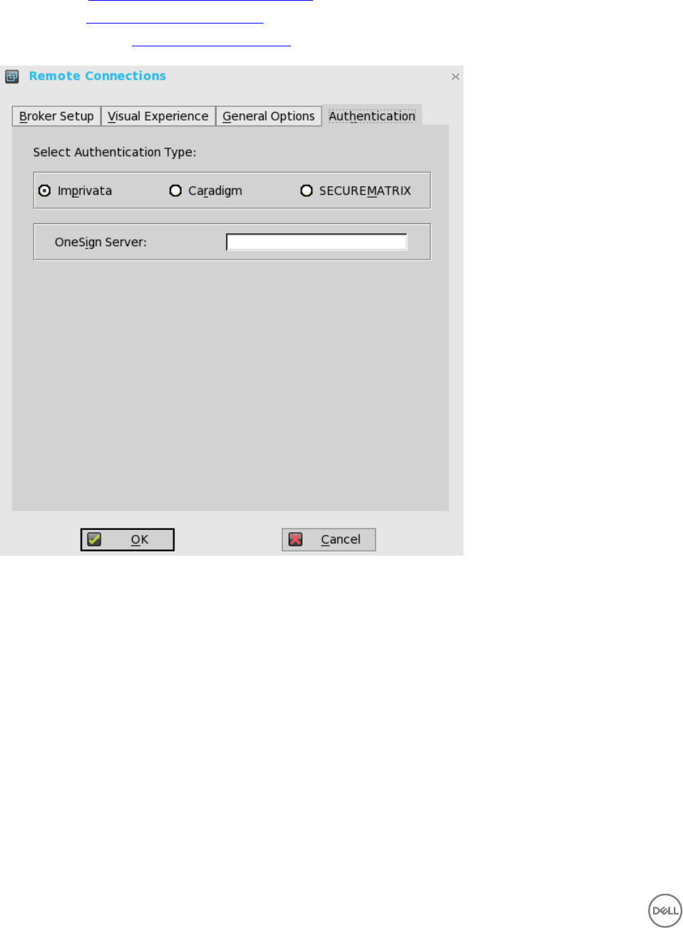
2. Click the Authentication tab, and select the authentication type.
Three types of authentication are displayed.
• Imprivata— Configuring the Imprivata OneSign Server.
• Caradigm—Configuring the Caradigm Server.
• SECUREMATRIX— Configuring SECUREMATRIX.
3. After configuring your preferred authentication, click OK to save the settings.
Configuring the Imprivata OneSign Server
OneSign Virtual Desktop Access provides a seamless authentication experience and can be combined with single sign-on for No
Click Access to desktops and applications in a virtual desktop environment.
To configure the OneSign Server, enter the details of the OneSign Server (either https://ip or https://FQDN values), reboot the
client to display the logon dialog box, and then enter credentials to open the VDI broker dialog box for logon use. You can also set
this feature in your INI file, see Dell Wyse ThinOS INI Guide.
The following OneSign features or actions are supported:
• Client and Broker Authentication
– Citrix Xen App
– Citrix Xen Desktop
44

– VMware View
• Kiosk Mode
• Fast User Switching
• Non-OneSign user VDI access
• Hotkey Disconnect
• Proximity card reader redirection
• Guided Question and Answer login
• Authenticate w/Password
• Authenticate w/Password + Password Change
• Authenticate w/Password + Password Change | New Password is Invalid
• Authenticate w/Proximity Card + Password
• Authenticate w/Proximity Card + Pin
• Authenticate w/Proximity Card + Pin | Pin not enrolled
• Authenticate w/Proximity Card Alone | Retrieve Password
• Retrieve User Identity Password
• Reset User Identity Password
• Update User Identity Password
• Enroll Proximity Card
• Lock/Unlock Terminal with Proximity CardLock/Unlock Terminal with Proximity Card
For details on Deployment in an Imprivata OneSign ProveID Environment, see Knowledge Base Solution #23254 . Go to
www.dell.com/wyse/knowledgebase and search for 23254.
ThinOS supports latest Imprivata WebAPI version 5. It includes OneSign Objects (WebAPI v4) and Fingerprint Authentication
(WebAPI v5).
Configuring objects on Imprivata Server
Imprivata WebAPI is updated from v4 to v5. From earlier version, supports configuration objects are supported that enables you to
control different aspects of client behavior. The Imprivata WebAPI feature is available on OneSign server 4.9 and later versions. The
Configuration objects control different aspects of the client behavior.
Use the following guidelines to configure the objects on Imprivata Server:
1. Configuring the General configuration object
a. On the Imprivata server, click Computer policy, and then click General tab.
b. Select the check box to allow users to shut down and restart workstation from lock screen.
NOTE: Display shutdown button and restarts commands to the user on the OneSign GINA.
The following configuration objects are supported on Imprivata server:
•Shutdown Allow
– If you enable this feature by selecting the check box, the shutdown and restart icon is shown in ThinOS login and
locked windows.
45
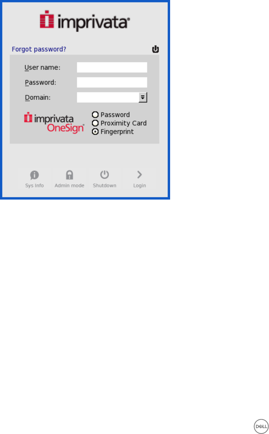
– If you clear the check box, the shutdown and restart icon is grayed out.
•FailedOneSignAuth Allow—
Only yes or no options are supported. Non-OneSign user can log in to the Broker by clicking No radio button.
•Logging Allow
– OneSign logs could output on ThinOS with this feature. An INI configuration is needed correspondingly.
– Loglevel=0/1/2/3. The default value is 0. If set to 0, logs are not displayed.
•Display name format — Account name can be shown correctly with different formats in pop-up notifications.
2. Configuring the Walkway configuration object
On the Imprivata server, click Computer policy, and then click the Walk Away tab.
•Key mouse inactivity enabled and behavior — The check box in addition to keyboard and mouse inactivity is not
supported.
•Passive proximity cards
– If you want to use proximity card to lock the computer, select the Tap to lock check box.
– If you want to lock the computer and log in as a different user. select the Switch users check box.
– INI parameter isTapToLock=0/1/2.
•–Lock warning enabled and type— The three types that are supported are: none, notification balloon and Screensaver.
* None — No warning messages are displayed.
* Notification balloon— ThinOS displays a notification window.
46
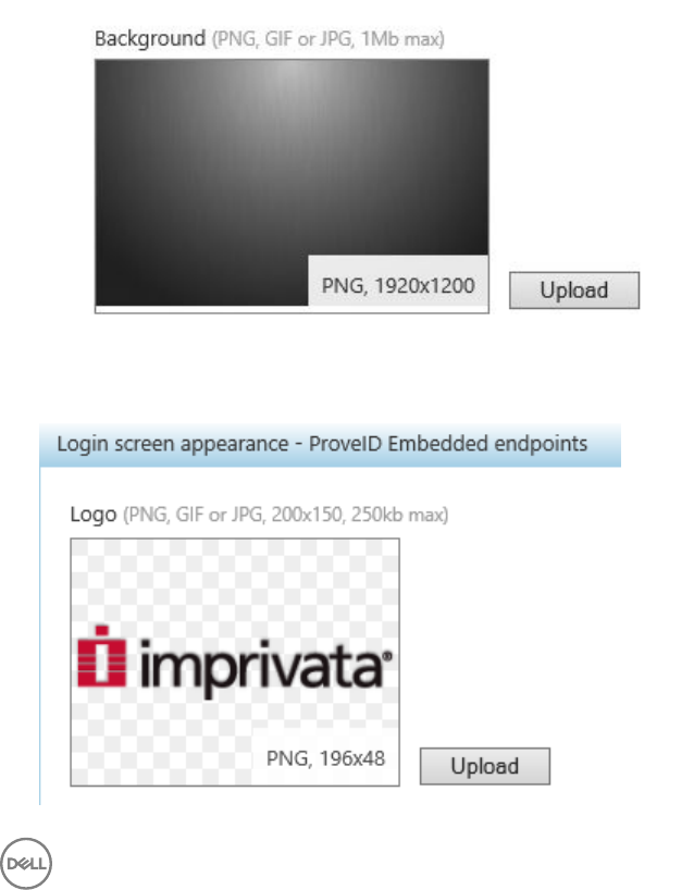
* Screensaver— Hide the display contents before the workstation locks.
–Warning message— The message can be customized.
–Lock Screen type —Only obscure type is supported.
–Hot key to lock workstation or log off user— ThinOS can support following keys:
“F1 ~ F12”, "BKSP", “DEL”, “DOWN”, “END”, “ENTER”, “ESC”, “HOME”, “INS”, “LALT”, “LEFT”, “LCONTROL”,
“NUMLOCK”, “PGDN”, “PGUP”, “RCONTROL”, “RIGHT”, RTALT”, “SPACE”, “TAB”, “UP”, “a~z”, “A~Z”, “0~9” and
modifier “+”, “%”, “^” (Shift, Alt and Control)
–Suspend action — The server configuration controls this feature on ThinOS. Therefore a new INI is added—
SuspendAction=0/1; 0 means lock, 1 means signoff.
3. Configuring the SSPR Configuration Object
The SSPR configuration object controls the Self-Service Password Reset behavior for a user. The enabled attribute specifies
whether the user is allowed to reset their password as part of emergency access. The mandatory attribute specifies whether
the user must reset their password as part of emergency access.
4. Configuring the RFIDeas configuration object
The RFIDeas configuration object controls the behavior of the RFIDeas readers. The configuration can be configured by two
ways, the computer policy of OneSign server and ThinOS INI.
5. Configuring the Custom background configuration object
On the Imprivata server, click Computer policy, and then click the Customization tab.
Custom background image impacts the wallpaper of ThinOS sign-on screen.
6. Configuring the Co-Branding configuration object
On the Imprivata server, click Computer policy , and then click Customization.
47
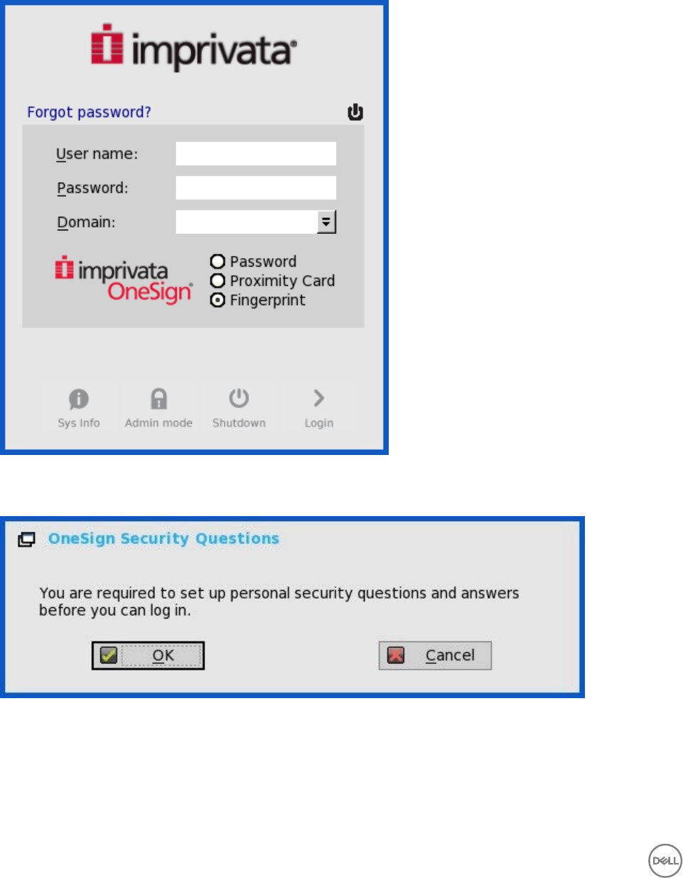
Logo image impacts all the dialog boxes in ThinOS with raw logo.
7. Configuring the SSPR Customization Configuration object
• The text displayed in sign-on UI and lock window can be customized.
• The largest size supported by ThinOS is 17 characters.
ThinOS UI:
8. Password Self-Services force enrollment feature
Selecting this check box allows you to reset the primary authentication password.
INI configuration for Imprivata OneSign Server
A new INI parameter is added to the OneSignServer=AutoAccess=command. The new value is AutoAccess=Local. When
AutoAccessis set to local, the ThinOS ignores the brokers that are set on the Imprivata OneSign Appliance and starts the broker/
connections which are defined in wnos.ini or local defined on the client. You can start the vWorkspace, Microsoft, and other ThinOS
connections while supporting Imprivata user authentication.
48
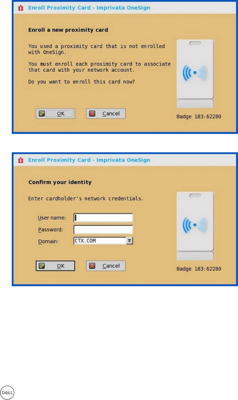
Proximity card enrollment
1. Tap the proximity card. The card enrollment page is displayed.
2. Enter the credentials and then click OK.
Proximity card is enrolled successfully.
49
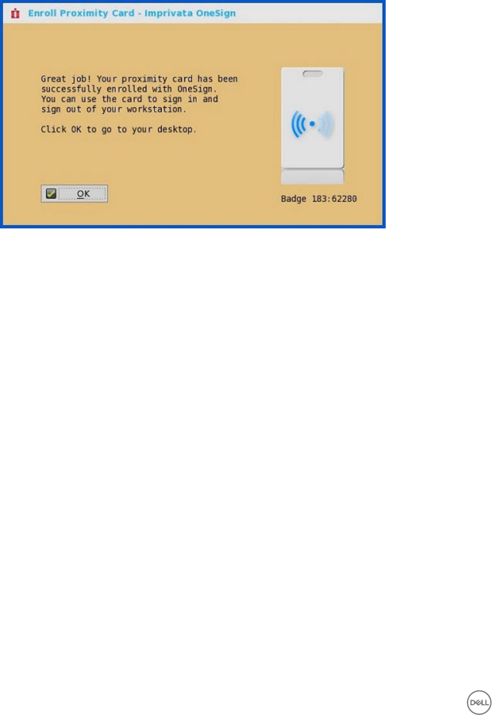
Imprivata Bio-metric Single Sign-On
Fingerprint identification feature is highly reliable, and cannot be easily replicated, altered, or misappropriated.
The prerequisites of OneSign server are:
• Imprivata v4.9 or later appliance version is needed that supports the WebAPI v5 and later versions.
• Fingerprint identification license is required.
Notes on Imprivata Bio-metric Single Sign-On
• ARM platforms (T/TD) are not supported.
• Supported protocols are RDP, ICA, and PCoIP.
• Required Fingerprint reader devices are:
– ET710 (PID 147e VID 2016)
– ET700 (PID 147e VID 3001)
Supported Scenarios
1. Signing/Unlocking the ThinOS Devices using Fingerprint Authentication.
• Configure the OneSign server on ThinOS, and then plug-in the fingerprint reader device.
• The ThinOS Fingerprint window is displayed automatically after OneSign server is initialized.
50
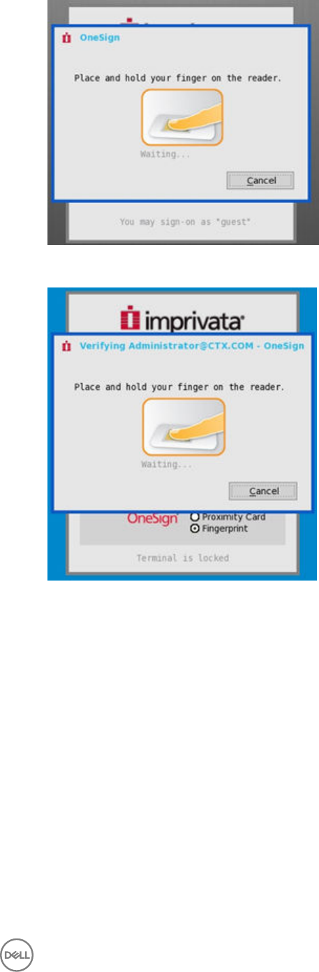
• Fingerprint authentication works on the ThinOS unlock window.
2. Unlocking the Virtual Desktop using Fingerprint Authentication.
• Enable the Imprivata Virtual Channel from ThinOS Global Connection Settings.
51
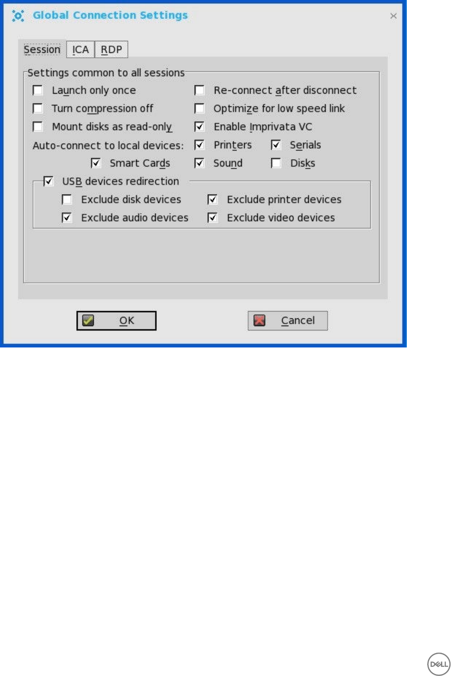
• When you lock the virtual desktop in the session, the Fingerprint window is displayed automatically.
52

3. Managing Fingerprints on virtual desktop.
• Legend Fingerprint Management is supported.
• Fingerprint management with Imprivata Confirm ID enabled is not supported. This requires both supervisor and user to
finish the enrollment and it is recommended to use Windows platform to perform this action.
To manage fingerprints, do the following:
a. Right-click the OneSign agent icon in System tray.
b. Click Manage Fingerprints, and enter the correct credentials in the displayed window to manage your Fingerprints.
53
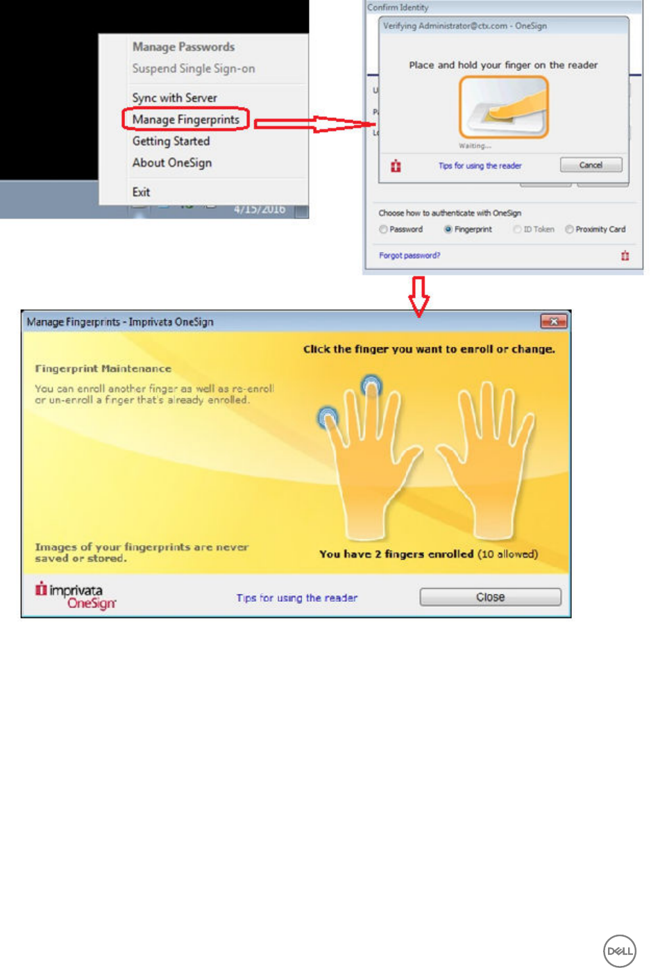
Configuring the Caradigm Server
Caradigm Single Sign-on and Context Management (SSO & CM) is the product of the Caradigm Company which provides Single
Sign-on and Context Management Services. Caradigm solution has been integrated since ThinOS 8.1.
To configure the Caradigm integration on ThinOS, do the following:
1. From the desktop menu, click System Setup, and then click Remote Connections.
The Remote Connections dialog box is displayed.
2. Click the Authentication tab, and then click Caradigm.
54
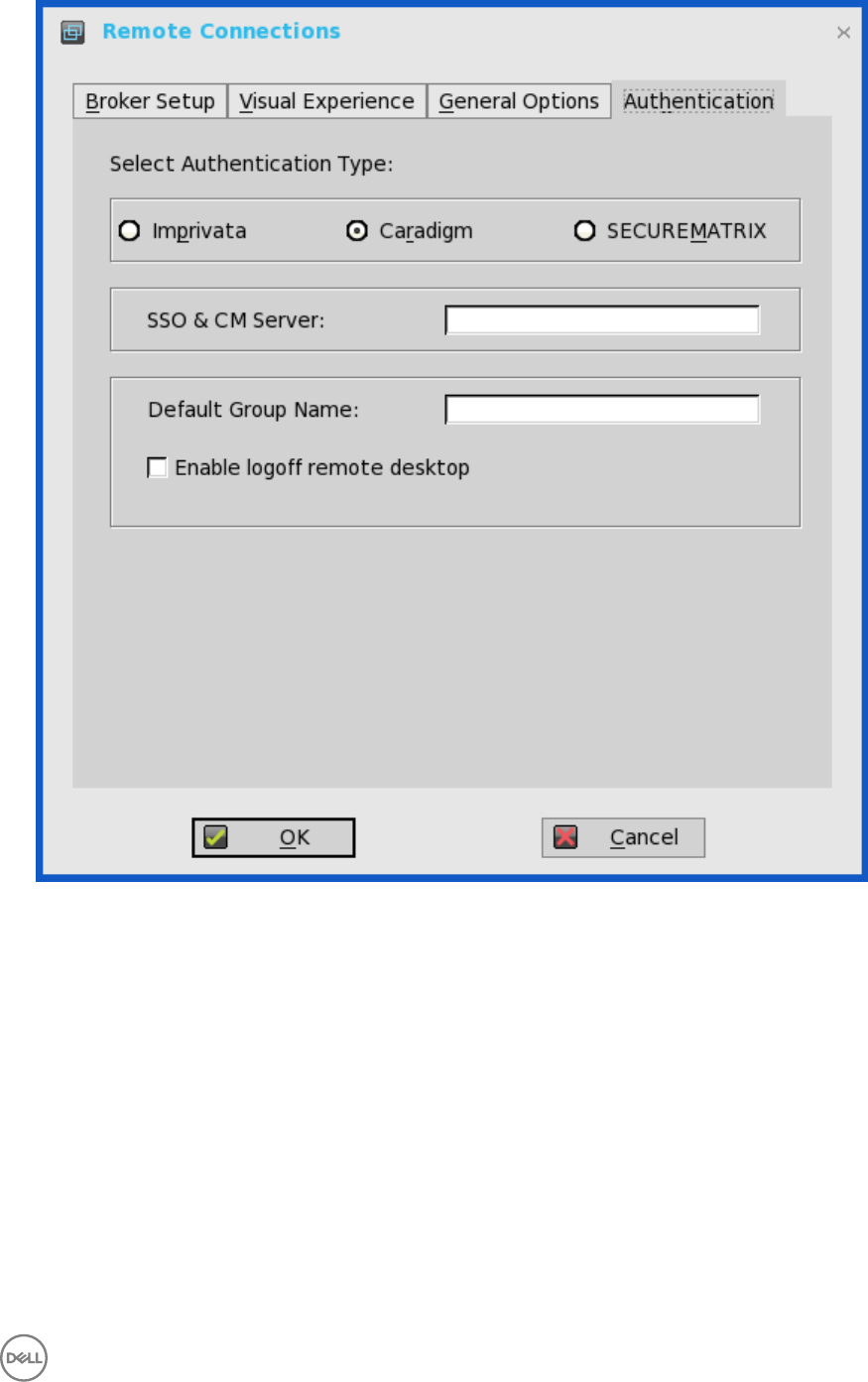
a. SSO & CM Server—Enter the IP addresses of the Single Sign-On (SSO) and Context Management (CM) Servers.
b. Default Group Name—Type the name of the default group in the Default Group Name box.
c. Enable logoff remote desktop
• Select the check box to log off the current user from the session before system sign-off.
• Clear the selection to disconnect from the session.
3. Click OK to save the settings.
Configuring the Caradigm Vault Server
To configure the Caradigm Vault Server on ThinOS:
1. From the desktop menu, click System Setup, and then click Remote Connections.
The Remote Connections dialog box is displayed.
2. Click the Authentication tab, click the Caradigm button, enter the IP address of the SSO & CM Server, and then click OK.
55
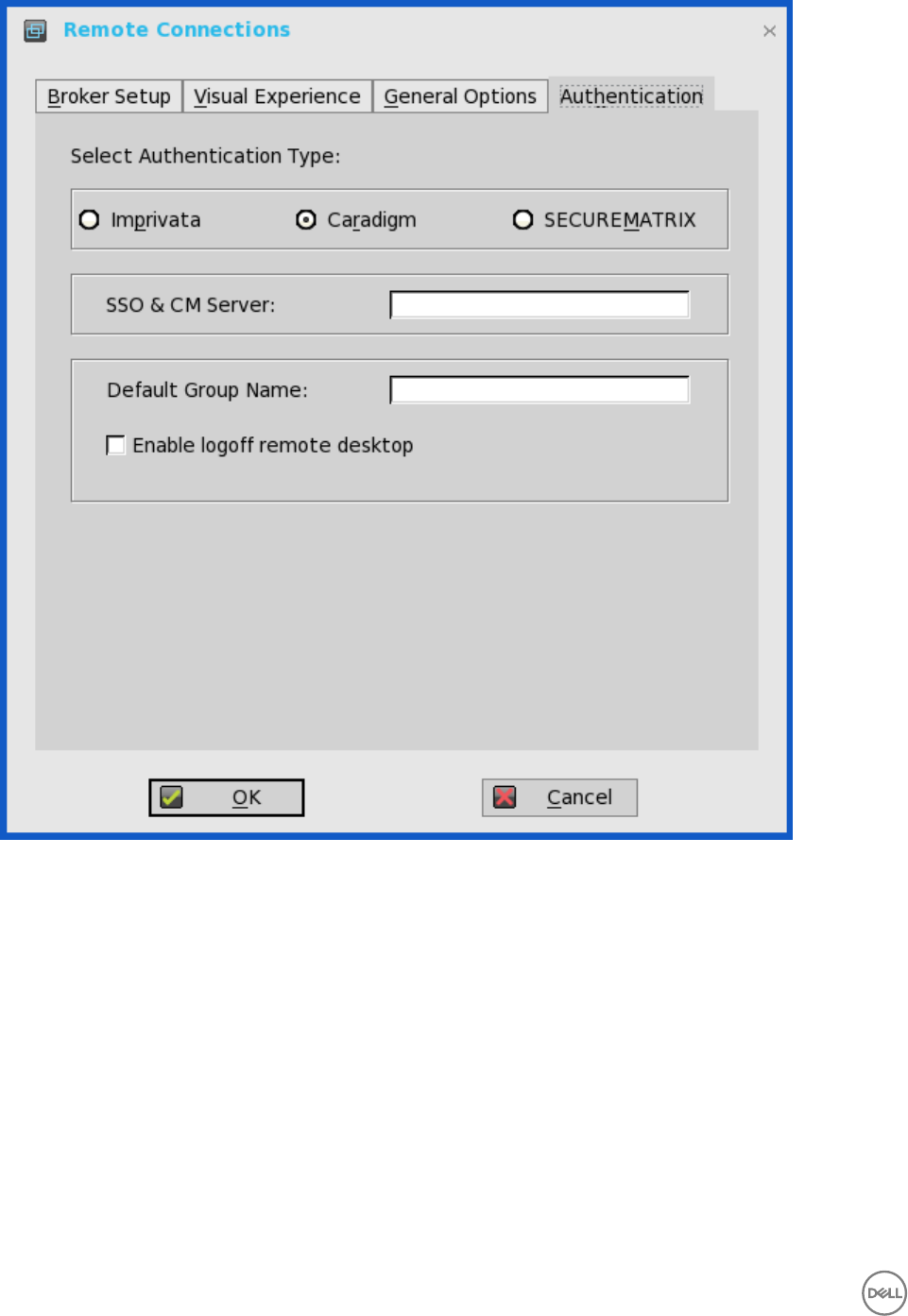
3. On the Caradigm Vault Server, use the following guidelines:
• Ensure that the Enroll unenrolled badges option is checked.
• Make sure that all Badge ID mapping entries are deleted.
56
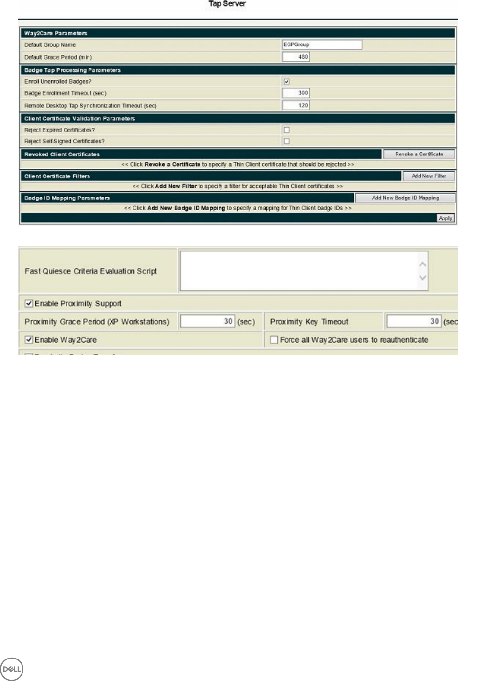
4. Click SSO&CM → Advanced Configurations , and use the following guidelines:
a. Ensure that the Enable Proximity Support check box is selected.
b. Ensure that the Enable way2care check box is selected.
5. To prepare a certificate to the Caradigm Vault Server, use the following guidelines:
The Caradigm Vault Server uses the certificate to validate the connection between the Tap Server and the thin client.
a. To raise a request for the certificate:
• The certificate should be issued by your Certificate Authority.
• Prepare the certificate in two formats:
– PFX format which has a private key.
– The other is PEM format which is text-based, Base64-encoded DER file. For Example, Caradigm.cer, Caradigm.pfx.
b. To import a certificate to the thin client, use either of the following two options:
• Click System Setup → System tools → Certificates to import certificates from USB storage or file server.
• Use INI file to import certificate.
AddCertificate=client_cert.pfx password=passpass
c. To add a certificate to Vault server:
57

Use the Thin Client Certificates page to add certificates for the thin client devices. The certificate must be a text in PEM
format, that is, a text-based Base64-encoded DER file.
• Open the DER cert file on Notepad.
• Log in to the Vault Server Admin Console, and then click Appliance → Thin Client Certificates.
• Copy the Notepad text to the Vault server
Configuration on VDI Server and Desktops
Caradigm solution of ThinOS supports the multi-types of VDI server such as VMware View Horizon 6, Citrix XenApp 6.5, Citrix
XenDesktop 5.6 and Citrix XenDesktop 7.6.
To configure the VDI server and desktop:
• Install the Caradigm desktop components in the servers and desktops.
• Indicate vault server IP, and then provide a valid security token.
• Add following lines to Service section of the \programdata\sentillion\vergence\Authenticator.ini configuration file.
TapServerIdentification=True
RemotePromptForPassword=Badge
NOTE:
From ThinOS 8.2, Wyse 5010 thin client with PCoIP (D10DP), Wyse 5040 AIO thin client with PCoIP (5213), from ThinOS 8.3,
Wyse 3030 LT thin client with PCoIP, and from ThinOS 8.3.1 Wyse 5060 thin client with PCoIP offer Caradigm SSO over
PCoIP.
SSO and CM client installed on your VDI server and desktops must be upgraded to latest version 6.2.5 in order to support this
feature.
Configuring SECUREMATRIX
SECUREMATRIX enhances the security of enterprise and cloud-based applications while providing seamless end user experience for
a one-time password (OTP) that can be used for authentication with desktops, Windows, VPNs, intranets, extranets, web servers,
e-commerce and other network resources.
To configure the SECUREMATRIX Server , enter either https://ip or https://FQDN values, reboot the client to display the log on
dialog box, and then enter credentials to open the VDI broker dialog box for logon use. You can also set this feature in your INI file,
see Dell Wyse ThinOS INI Guide. For details see SECUREMATRIX documentation.
Configuring the Central Configurations
Use the Central Configuration dialog box to configure thin client central connection settings such as file server, optional WDM
server settings, and optional Cloud Client Manager.
Use the following options to configure the central configurations:
•Configuring the General Central Configurations.
58
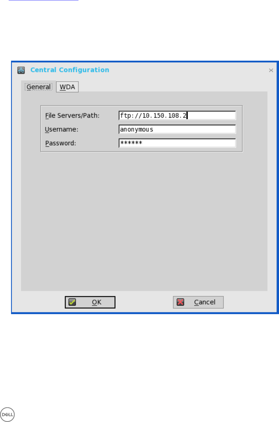
•Configuring the WDA Settings.
Configuring the General Central Configurations
To configure the general central configurations:
1. From the desktop menu, click System Setup, and then click Central Configuration.
The Central Configuration dialog box is displayed.
2. Click General tab, and use the following guidelines:
File Servers/Path, Username and Password — Enter the IP address or host name of the file server that provides the system
software and update images. The address can be supplied through DHCP, if DHCP is used.
a. File Servers/Path — Allows maximum of 128 characters. The data specifies part of the path to be used when the server is
accessed. Multiple file servers/paths may be named, as long as all data fits in the length limitation.
b. Username — Enter the username to log in to the file server. Use maximum of 15 characters.
c. Password — Enter the password to log in to the file server. Use maximum of 15 characters.
3. Click OK to save the settings.
59
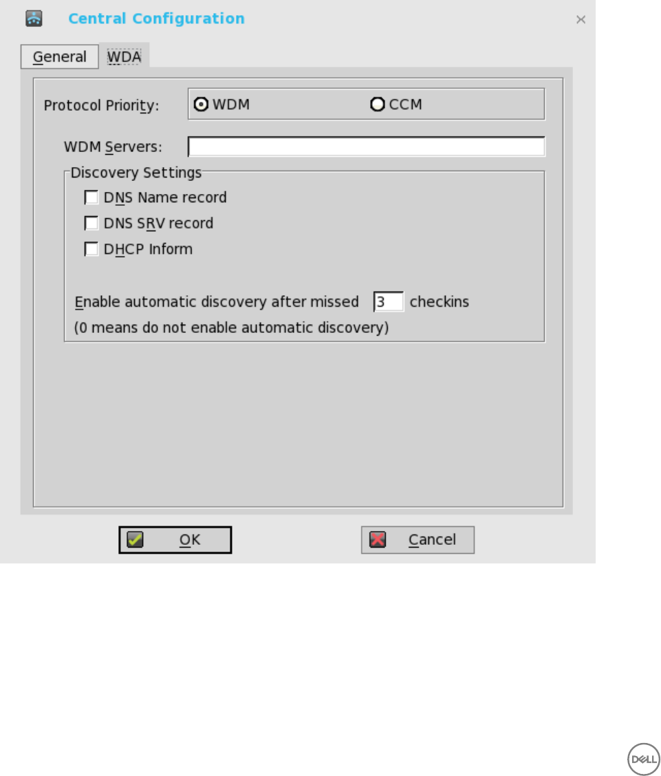
Configuring the WDA Settings
Use this tab to configure the WDM and CCM settings.
To configure the WDA settings, do the following:
1. From the desktop menu, click System Setup, and then click Central Configuration.
The Central Configuration dialog box is displayed.
2. Click WDA, and use the following guidelines.
WDM is selected by default. WDA service automatically runs after the client boot up.
If the first discovery, for example, the WDM service is not successful, then it seeks for the next priority, for example, CCM
service. This continues till a discovery is successful. If all discoveries fail, then it is started again automatically after a fixed time
(24 hours).
a. WDM Servers — Enter the IP addresses or host names, if WDM is used. Locations can also be supplied through user
profiles, if user INI profiles are used.
b. DNS Name Record — (Dynamic Discovery) Allows devices to use the DNS host name lookup method to discover a WDM
Server.
c. DHCP Inform — (Dynamic Discovery) Allows devices to use DHCP Inform to discover a WDM Server.
60
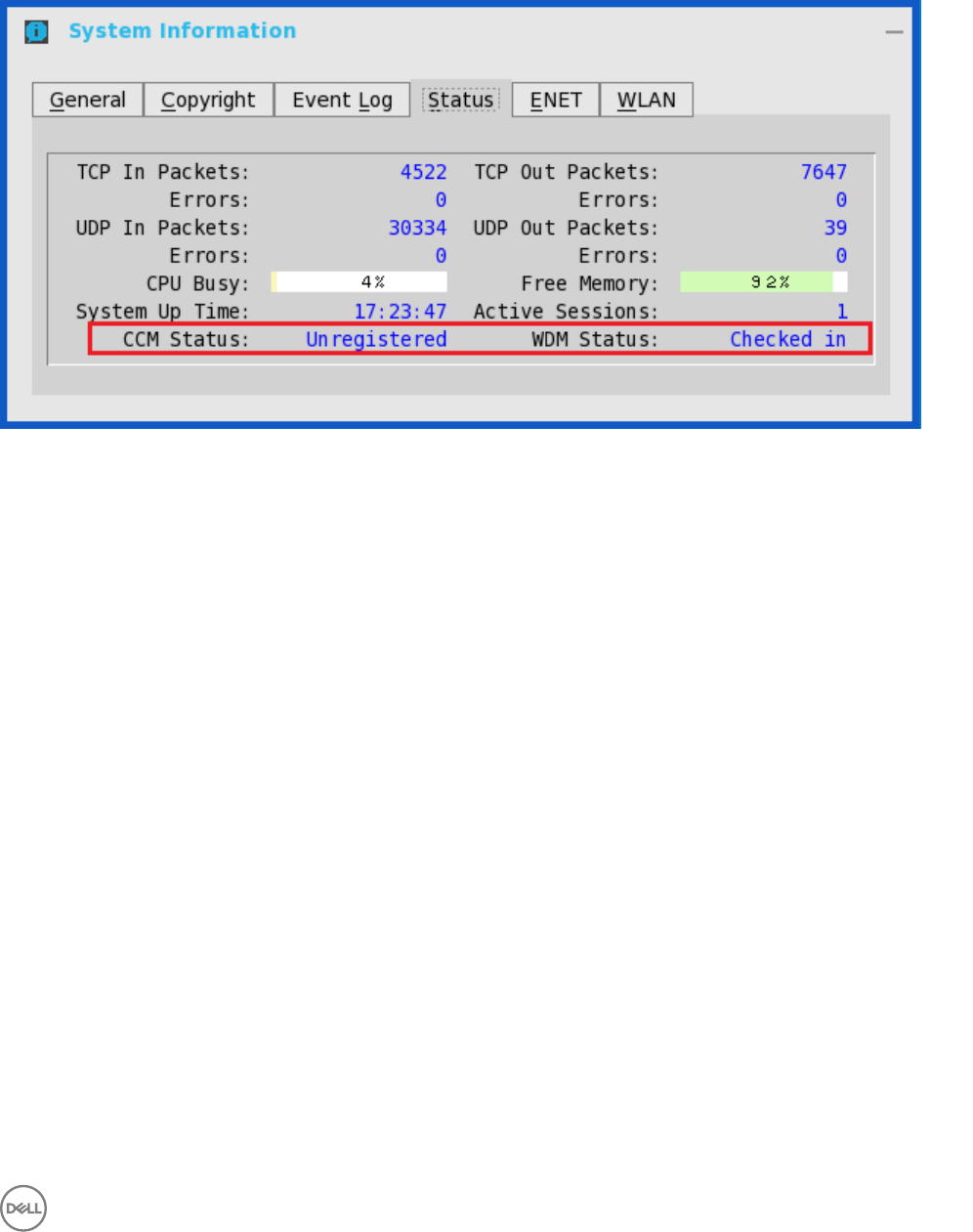
d. Enable Automatic Discovery After Missed Check-ins — Select the number of missed check-ins after which you want the
auto discovery options enabled.
3. Click OK to save the settings.
Service checked in status is displayed in System Information.
The following is the INI parameter for this feature:
WDAService={yes(default),no}Priority ={WDM(default),CCM,“WDM;CCM”,“CCM;WDM”}
To configure the CCM settings, do the following:
1. Click CCM, and use the following guidelines.
a. Enable Cloud Client Manager (CCM) — Select the check box to enable the Cloud Client Manager(CCM).
61
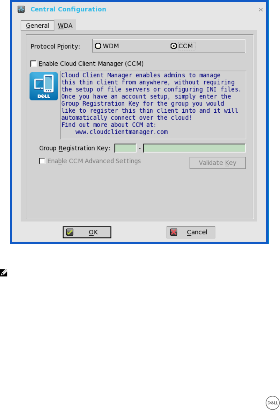
b. Group Registration Key — Enter the Group Registration Key as configured by your cloud Client Manager administrator
for the desired group.
NOTE: If you enable the Cloud Client Manager (CCM ), make sure that you have entered the Group Registration
Key and enabled the CCM Advanced Settings.
2. Click OK to save the settings.
Configuring the VPN Manager
VPN Manager is included in ThinOS 8.1 to manage VPN connections. A virtual private network (VPN) extends a private network
across a public network such as the Internet. It enables a computer or Wi-Fi-enabled device to send and receive data across shared
or public networks as if the devices are directly connected to the private network, while benefiting from the functionality, security
and management policies of the private network.
To configure the VPN Manager, use the following guidelines:
1. In Classic Mode, from the desktop menu, click System Setup → VPN Manager .
62
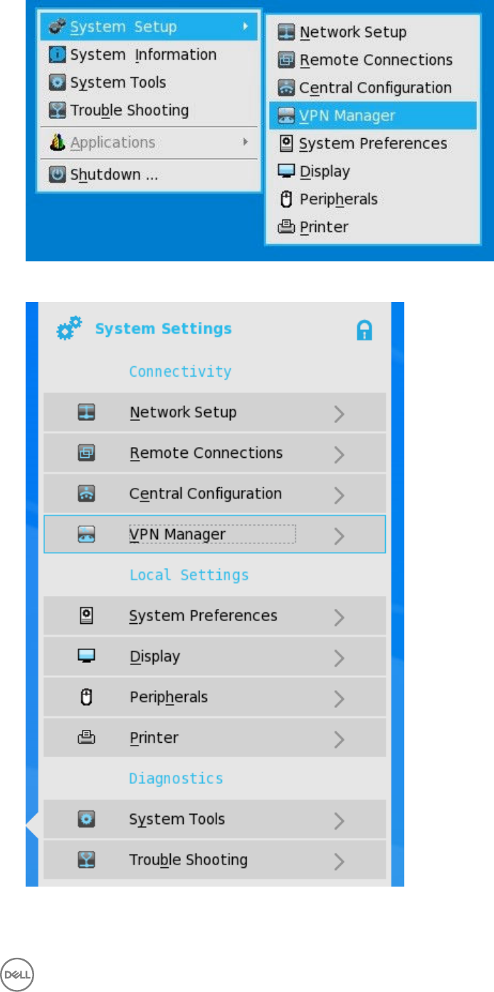
In Zero Mode, user can view the VPN Manager tab in System Settings panel.
2. Click VPN Manager.
63
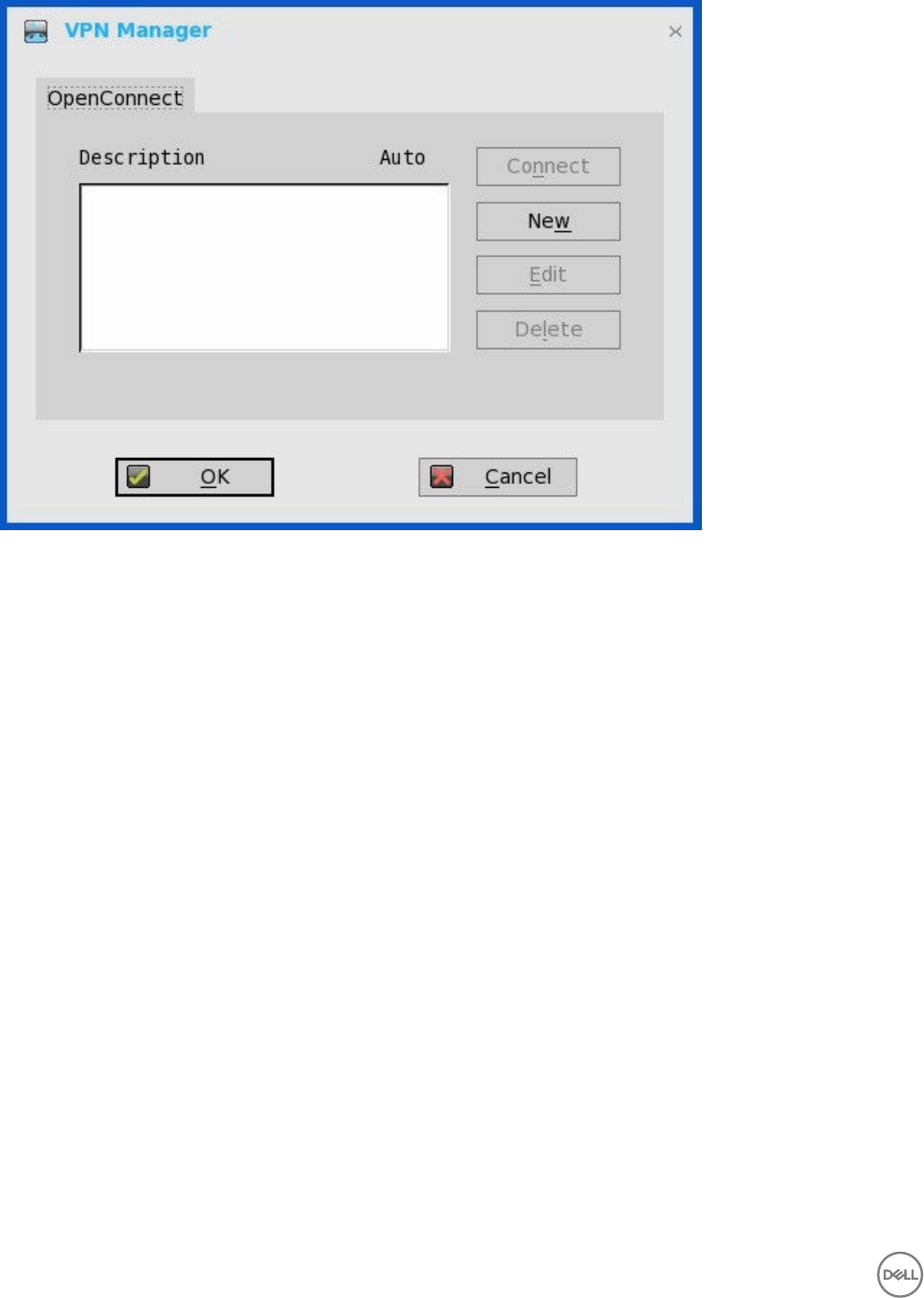
The VPN Manager dialog box is displayed.
3. Click New to create a new session.
a. Session Name (up to 21 characters) – Enter the name of the Session Name. This is not a mandatory option. If the field is
left blank, the VPN server name will be used as the session name.
b. VPN server (up to 63 characters) – Enter the IP address of the VPN Server. This is defined as either an IP address or a
host name. This is a mandatory option.
c. Login Username (up to 31 characters) – Enter the Login Username. This is a mandatory option.
d. Login Password (up to 31 characters) – Enter the password of the user. This is not a mandatory option.
e. Select the check box to Auto-connect on system startup.
f. Select the check box to show progress in detail.
g. Click OK.
64
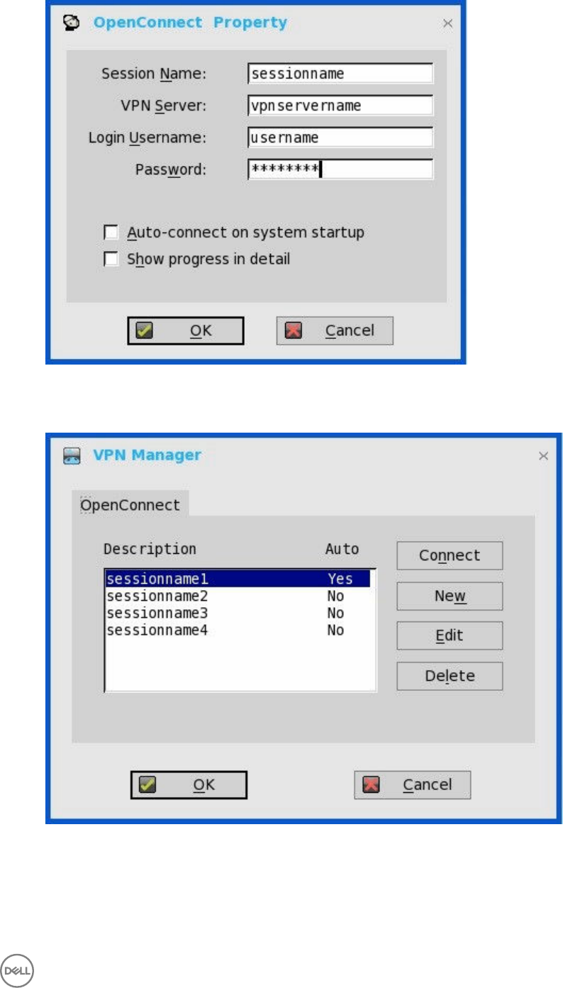
When the connections are created, the description column lists the session name and the Auto column shows which
connection is automatically connected when the unit restarts. Only one session can be set to auto-connect.
4. Click Connect.
The connection status is displayed.
65

5
Configuring Thin Client Settings
You can configure available thin client settings on the thin client using the following. Depending on user privilege level, some dialog
boxes and options may not be available for use.
•Local Settings Menu
•Reset Features
NOTE:
While it is not recommended to use dialog boxes for configuring thin client settings, they are available in case you want to
temporarily override central default configurations or you do not have the option to set up central configuration (smaller
environments). In general, it is recommended that you use central configuration to enable you to automatically push updates
and any desired default configuration to all supported thin clients in your environment, see Central Configuration: Automating
Updates and Configurations.
Local Settings Menu
Local Settings menu items include:
•Configuring the System Preferences
•Configuring the Display settings
•Configuring the Peripherals Settings
•Configuring the Printer Settings
To access the Local Settings menu:
•Zero Desktop — Click the System Settings icon on the Zero Toolbar. Administrators can also click the Admin Mode button on
the Login dialog box.
•Classic Desktop — Click User Name, and select System Setup.
NOTE: User Name is the user who is logged-on and is at the lower-left pane of the taskbar.
Configuring the System Preferences
Use the System Preference dialog box to select personal preferences such as screen saver, time/date and custom information
settings.
Use the following options to configure the System Preferences:
•Setting the General System Preference
•Setting Time and Date
•Setting the Custom Information
Setting the General System Preference
To configure the general settings for system preference:
1. From the desktop menu, click System Setup, and then click System Preferences.
66
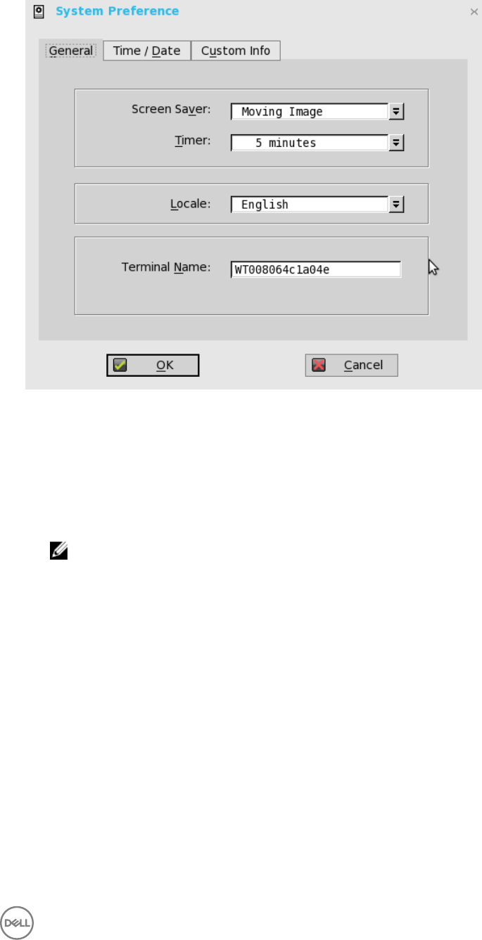
The System Preference dialog box is displayed.
2. Click the General tab, and use the following guidelines:
a. Screen Saver — Allows you to select the type of screen saver you want. The default is to Turn Off Screen.
Other selections available include Flying Bubbles , Moving Image and Showing Pictures which are screen savers with the
monitor remaining on.
b. Timer — Select a time after which the screen saver is to be activated; either disable, 1 minute, 5 minutes, 10 minutes
(default), 15 minutes, or 30 minutes.
When the thin client is left idle for the specified idle time, the screen saver is initiated.
c. Locale — Select a language to be activated for the user login-experience; either French, German, or default English.
NOTE: Locale changes the language for the user login-experience screens only displayed during boot-up and
login and not the configuration or administrator screens.
Only the following messages are applicable for French locales:
• Username/Password/Domain
• System Information
• Shut down the system, restart the system, reset the system setting to factory default
• OK, Cancel
• Initiating devices
• Looking up IP address from DHCP, Note: Pressing CTRL-ESC keys cancel out of network check
• Retry DHCP for an IP address
• Waiting for network link. Verify that network cable is plugged into back of unit
• Check Cable, No Ethernet link
• Leave administrator mode
• Connecting
• Sign off from account
67
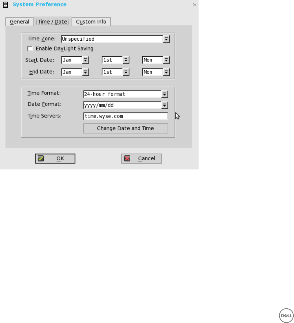
• Lock Terminal, Unlock Password
• Terminal is locked, Invalid unlock password
d. Terminal Name — Allows entry of a name for the thin client. The default is a 14-character string composed of the letters
WT followed by the thin client Ethernet MAC address.
Some DHCP servers use this value to identify the IP address lease in the DHCP Manager display.
3. Click OK to save the settings.
Setting the Time and Date
To configure the Time and Date settings:
1. From the desktop menu, click the System Setup, and then click System Preferences.
The System Preference dialog box is displayed.
2. Click the Time/Date tab, and use the following guidelines:
a. Time Zone— Select a time zone where the thin client operates from the drop-down list. Default value is Unspecified.
b. Enable Daylight Saving— Allows you to enable the daylight saving settings. When selected, the Start Date and End Date
boxes must be properly configured to define the daylight saving starting (month/week/day) and ending (month/week/
day) periods.
Use the following guidelines to enter the Start date and End date:
•Month— Specifies the month in the year from January through December.
•Week— Select 1 through 4 for the week in the month. Week last denotes the last week in the month.
•Day — Specifies the day of the week from Monday through Sunday.
c. Time Format — Allows you to select a 12 or 24-hour time format. default is 24-hour format.
d. Date Format — Allows you to select a yyyy/mm/dd (year/month/day) or dd/mm/yyyy (day/month/year) date format.
Default is yyyy/mm/dd.
e. Time Servers — List of IP addresses or host names with optional TCP port number of Time Servers.
Each entry with optional port number is specified as Name-or-IP: port, where: port is optional. If not specified, port 80 is
used. Locations can be supplied through user profiles if user profiles are used. The Time Servers provide the thin client time
68
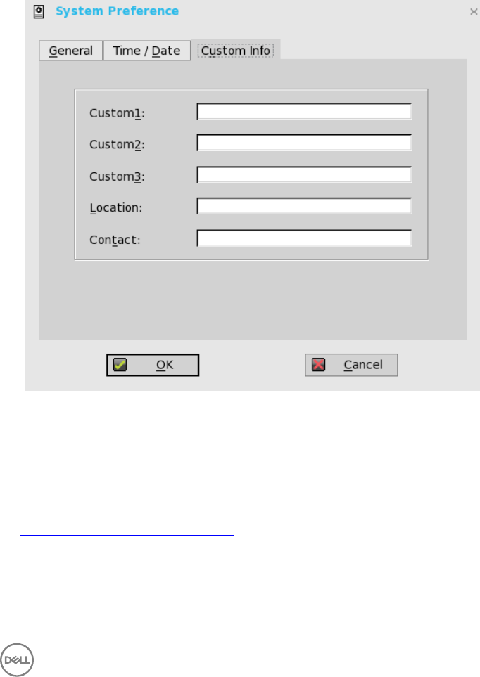
based on the settings of time zone and daylight saving information. If DHCP is used, locations can be supplied through
DHCP.
f. Change Date and Time — Allows you to change date and time for secure environments requiring a solution to outside
server access. When connecting to a file server over HTTPS, the proper time must be defined on the thin client for SSL/
certification validation.
3. Click OK to save the settings.
Setting the Custom Information
Use the Custom Info tab to enter configuration strings for use by WDM software. The configuration strings can contain information
about the location, user, administrator, and so on.
To set the custom information:
1. From the desktop menu, click System Setup, and then click System preferences.
The System preference dialog box is displayed.
2. Click the Custom Info tab to enter configuration strings used by WDM software. The configuration strings can contain
information about the location, user, administrator, and so on. Clicking OK transfers the custom field information you enter in
the dialog box to the Windows registry. The information is then available to the WDM Client Manager. For more information on
using Custom Fields and using WDM for remote administration and upgrading thin client software, see WDM documentation.
3. Click OK to save the settings.
Configuring the Display Settings
Use the Display dialog box to select the resolution and refresh rate for the monitor used with the thin client.
Use the following options to configure the Display Settings:
•Configuring the General Display Settings
•Configuring the Dual Head Settings
69
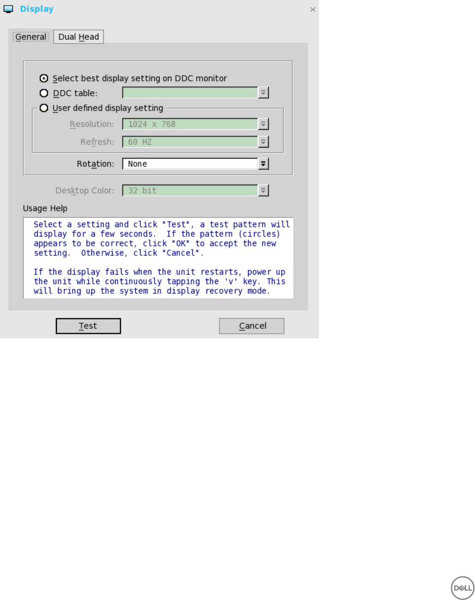
Configuring the General Display Settings
To configure the general display settings:
1. From the desktop menu, click System Setup, and then click Display.
The Display dialog box is displayed.
2. Click the General tab, and use the following guidelines:
a. Select best display setting on DDC monitor—If the monitor is VESA DDC2B (Display Data Channel) compatible, selection
of this option allows the thin client to automatically select the best resolution and refresh rate.
If your monitor is not DDC compatible, then Monitor does not support Plug and Play message is displayed. Click OK to
acknowledge the message and remove it from the screen.
b. DDC table— If the monitor is VESA DDC2B (Display Data Channel) compatible, selection of this option allows you to select
the resolution and refresh rate you want from the list.
c. User defined display setting— Select this option and select the resolution and refresh rate supported by your monitor. All
combinations are allowed.
Resolutions include:
640 x 480 (not on T10D)
800 x 600 (not on T10D)
1024 x 768
1152 x 864
70

1280 x 720
1280 x 768 (not on T10)
1280 x 1024
1360 x 768 (not on T class)
1366 x 768
1368 x 768 (not on T class)
1400 x 1050
1440 x 900
1600 x 900
1600 x 1200
1680 x 1050
1920 x 1080
1920 x 1200
1920 x 1440 (R class only)
2560 x 1080 (Single monitor only; R class and D/Z class only)
2560 x 1440 (Single monitor only; R class and D/Z class only)
2560 x 1600 (Single monitor only; R class and D/Z class only)
3840 x 2160 (Single monitor only; D/Z class only)
Refresh rate list selections include:
60 Hz (default)
75 Hz
85 Hz
d. Rotation —Select a rotation option; either None, Left turn 90 degrees, or Right turn 90 degrees.
e. Desktop Color— Only 32 bit is permitted from ThinOS 8.2. This value is selected by default.
f. Usage Help — This section contains brief instructions for using the Display dialog box and running the test. No operator
entry can be made in this box.
Make note of the instructions in the area, regarding v-key reset usage in case of display failure.
3. Click OK to save the settings.
Dual 4K (3840x2160) support
The following are the list of tested monitor resolutions supported for Wyse 5060 thin client:
640 x 480
800 x 600
71

1024 x 768
1152 x 864
1280 x 720
1280 x 768
1280 x 1024
1360 x 768
1366 x 768
1368 x 768
1400 x 1050
1440 x 900
1600 x 900
1600 x 1200
1680 x 1050
1920 x 1080
1920 x 1200
2560 x 1080
2560 x 1440
2560 x 1600
3440 x 1440
3840 x 2160
Dual 3840 x 2160 is supported with Dual Display ports for 30 Hz display refresh rate.
The following are the tested Dell monitors supporting dual 3840 x 2160 resolution:
Dell P2815Q (3840 x 2160)
Dell UP3216Q (3840 x 2160)
Configuring the Dual Head Display Settings
To configure the Dual head display settings:
1. From the desktop menu, click System Setup, and then click Display.
72
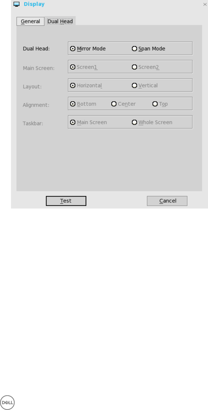
The Display dialog box is displayed.
2. Click Dual Head tab, and use the following guidelines:
This feature is applicable for supported Dual Monitor Capable Thin Clients Only.
a. Dual Head—Select Mirror Mode to have the two monitors work in a matching state, or Span Mode to have the two
monitors work separately second is extended from first.
b. Main Screen—Select which of the two monitors you want to be the main screen (Screen1 or Screen2). The other screen
is extended from the main screen.
The other screen is extended from the main screen. When using a DVI to DVI/VGA splitter with VGA and DVI monitors at
the same time, the VGA monitor will be the primary monitor.
c. Layout—Select how you want the two monitors to be oriented to each other.
Horizontal — where you move between the monitors from the left and right of the screens.
Vertical— where you move between the monitors from the top and bottom of the screens.
d. Alignment— Select how you want the monitors to be aligned Bottom, Center, or Top.
Bottom means screens are bottom-aligned in a horizontal orientation; Center means screens are center-aligned; Top means
screens are top-aligned in a horizontal orientation.
e. Taskbar (Classic Desktop Only)—Select under which screen you want the Taskbar to appear Whole Screen or Main
Screen
Gamma Supported Monitors Only— Use the Gamma Setup tab to adjust the saturation values for Red, Green and Blue on
VGA connected monitors supporting gamma settings, if you feel the default settings are too light. Be aware that the
Gamma Setup tab will be disabled once you click Save+Exit. You can enable it again by setting rgamma={1-100}
ggamma={1-100} bgamma={1-100} in the Resolution INI parameter. For more information, see Dell Wyse ThinOS INI Guide.
73
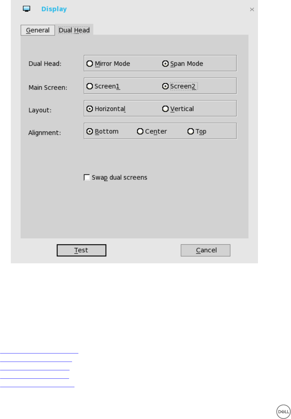
For Swap dual screens, when you set Main Screen to Screen2, an additional check box is displayed at the bottom of the tab
that allows you to swap dual screens. If you clear the check box, the Screen1 is usually the left one or the top one in dual
display. When you set Main Screen to Screen2, the main screen is changed to the right screen or bottom screen. If you
select the swap dual screens check box, you are able to set Main Screen to Screen2, but still have it at the left side or the
top side, which is considered more user friendly.
Configuring the Peripherals Settings
The Peripherals dialog box enables you to configure the settings for the Keyboard, Mouse, Audio, Serial, Camera, Touch Screen,
and Bluetooth.
•Configuring the Keyboard Settings
•Configuring the Mouse Settings
•Configuring the Audio Settings
•Configuring the Serial Settings
•Configuring the Camera Settings
74
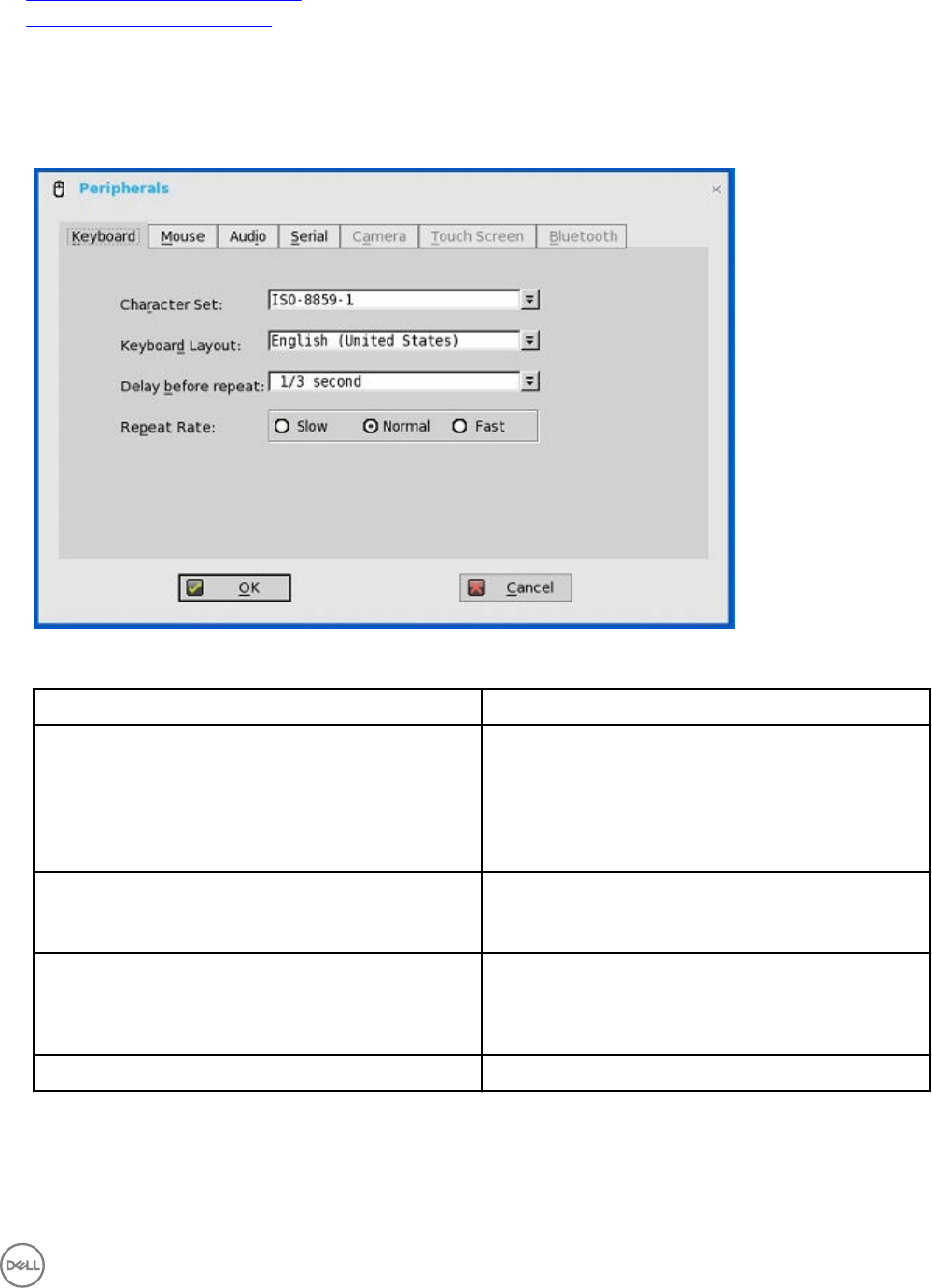
•Configuring the Touch Screen Settings
•Configuring the Bluetooth Settings
Configuring the Keyboard Settings
To configure the Keyboard settings:
1. From the desktop menu, click System Setup, and then click Peripherals.
The Peripherals dialog box is displayed.
2. Click the Keyboard tab and set the Character Set, Keyboard Layout, Delay Before Repeat and Repeat Rate parameters. The
following table explains the parameters present on the Peripherals dialog box.
Parameter Description
Character Set Specifies the character set. Each character is represented by
a number. The ASCII character set, for example, uses the
numbers 0 through 127 to represent all English characters
and special control characters. European ISO character sets
are similar to ASCII, but they contain additional characters for
European languages.
Keyboard Layout Presently the keyboard languages listed in the Keyboard
layout drop-down list are supported. The default value is
English (United States).
Delay Before Repeat Specifies the repeat parameters for held-down key. Select
the Delay before repeat value as either 1/5 second, 1/4
second, 1/3 second, 1/2 second, 3/4 second, 1 second, 2
seconds, or No Repeat. The default is 1/3 second.
Repeat Rate Select Slow, Medium, or Fast. The default value is Medium.
3. Click OK to save the settings.
75
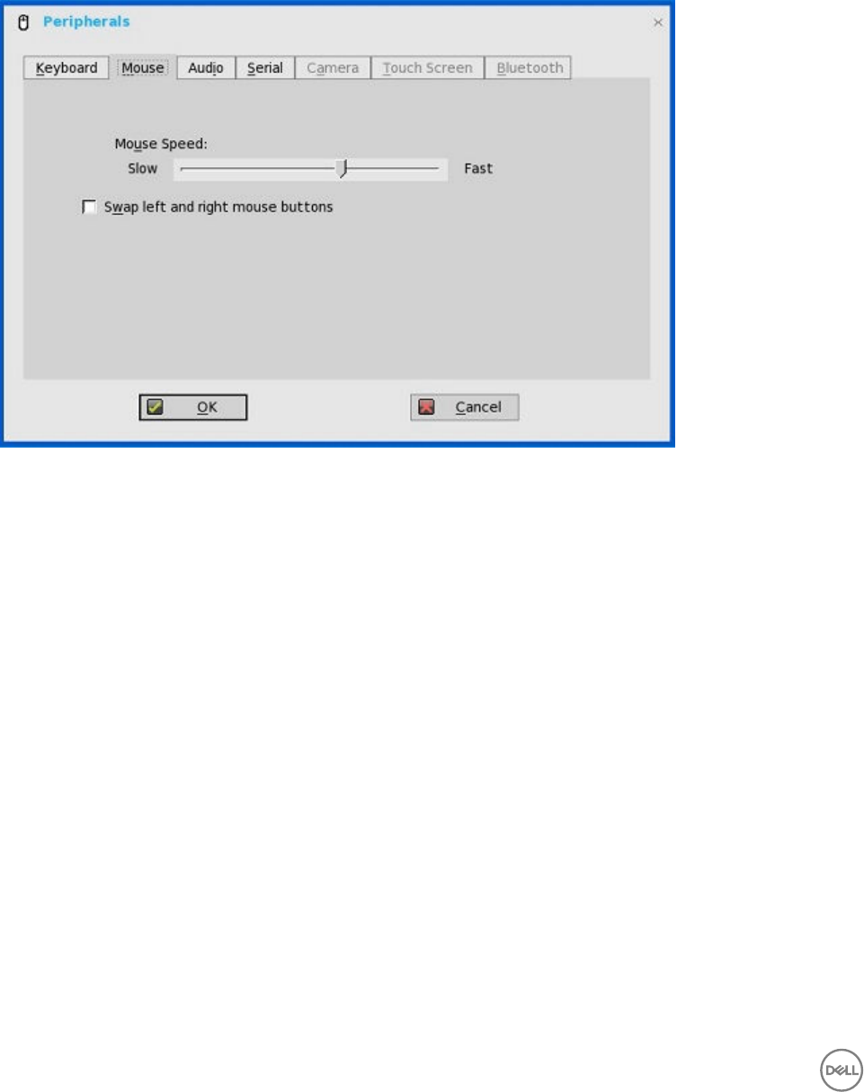
Configuring the Mouse Settings
To configure the Mouse settings:
1. From the desktop menu, click System Setup, and then click Peripherals.
The Peripherals dialog box is displayed.
2. Click the Mouse tab to select the mouse speed and mouse orientation.
3. Select the Swap left and right mouse buttons check box to swap mouse buttons for left-handed operations.
4. Click OK to save the settings.
Configuring the Audio Settings
To configure the audio settings:
1. From the desktop menu, click System Setup, and then click Peripherals.
The Peripherals dialog box is displayed.
2. Click the Audio tab to select the volume settings for connected devices.
76

a. Click the Playback Devices tab to select the type of the audio from the drop-down menu.
• Use slider to control the volume settings for the playback devices.
• Select the check box to mute.
b. Click the Recorded Devices tab to select the type of the record from the drop-down menu.
• Use slider to control the volume settings for the record devices.
• Select the check box to mute.
c. The Recorder tab allows you to do the following tasks:
• Collect information about the speaker and microphone currently being used.
• Examine the performance of the speaker and microphone currently being used.
• Export the recorded audio sample to a USB key for archiving and further analysis.
For example, the connected USB headsets are displayed in the drop-down. Select the HD Audio option for analog earphone
use, the Speaker check box to enable the internal speaker, and the Boost check box for audio enhancement.
d. Select the Speaker check box to connect the speaker.
e. Select the Boost check box to boost the connected devices.
Configuring the Serial Settings
To configure the Serial settings:
1. From the desktop menu, click System Setup, and then click Peripherals.
The Peripherals dialog box is displayed.
2. Click the Serial tab and do the following:
77
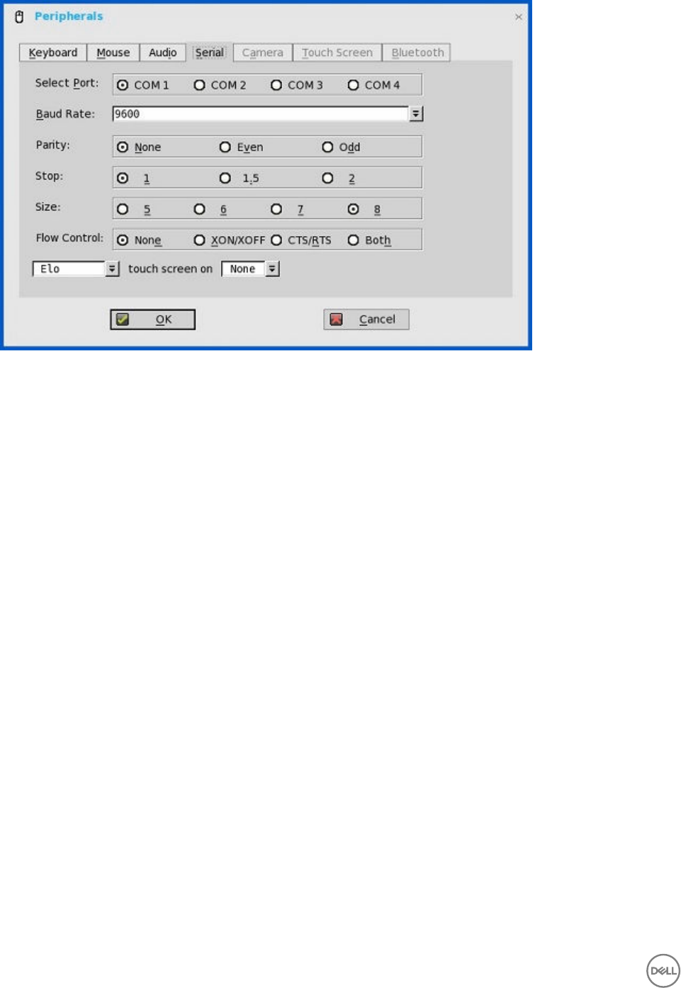
a. Select Port—Click the button to select the Port. Default is COM 1
b. Baud Rate — Select the Baud Rate from the drop-down list. Default is 9600.
c. Parity — Click the button to select the Parity.
d. Stop— Click the button to select the stop bits 1, 1.5, 2. Default value is 1.
e. Size—Click the button to select the Character size 5, 6, 7, or 8 bits. Default is 8.
f. Flow Control —Click the button to select Flow Control: Either None, XON/XOFF, CTS/RTS, or Both can be
selected .Default is None
g. Serial Touch Screen selections — Select the required touch screen from the drop-down list. Available options are ELO,
MicroTouch and FastPoint .
h. Touch Screen on — Select the required serial port ( COM port) or None from the drop-down list.
3. Click OK to save the settings.
Configuring the Camera Settings
Use the Camera tab to interface with cameras that are locally connected to the thin client (USB) and supported by a UVC driver.
When using the HDX RealTime webcam feature of XenDesktop 5 or XenApp 6, you can control options such as maximum resolution
and frames per second (10 FPS is recommended).
By default, the format of USB camera is set to RAW.
78
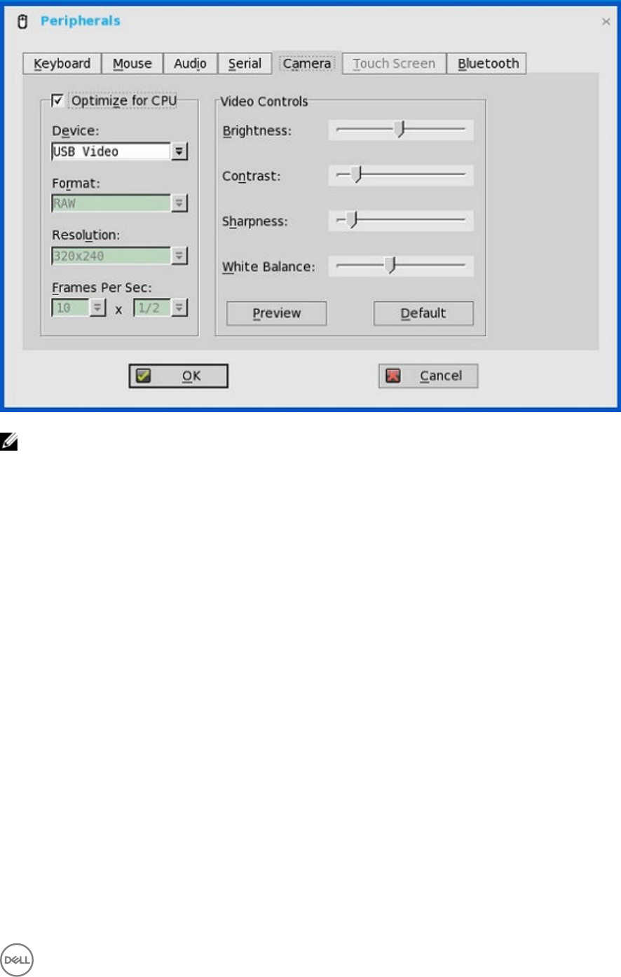
NOTE:
You can optimize performance and modify the frame rate per second, if the Optimize for CPU check box is selected—
supported values include 1/1, 1/2, 1/3, 1/4, 1/5, and 1/6– directly from the thin client (if the webcam supports Universal Video
Driver).
This feature is experimental and does not currently support central configuration (INI parameters). Also, this feature is CPU
intensive and is recommended for high performance products such as the Wyse 3030 LT thin client with ThinOS, Wyse 3030
LT thin client with PCoIP, Wyse 5010 thin client with ThinOS (D10D), Wyse 5060 thin client with ThinOS, and Wyse 5060 thin
client with PCoIP.
Configuring the Touch Screen Settings
Use the Touch Screen tab to configure touch screens that are connected to the thin client (USB). The tab is available (not grayed
out) when the thin client detects that a touch screen is attached through a USB port and the setup or calibration has not been
performed. The Touch Setup window prompts you to touch two circles on the screen to make the necessary calibration adjustment.
The adjusted calibrated values are saved in the local terminal NVRAM until the system is reset to factory default, or another type of
touch monitor is connected.
Configuring the Bluetooth Settings
The Bluetooth feature helps you to connect your thin client with Bluetooth enabled devices such as headsets and mouses.
The Intel wireless chipset 7260 comes with an integrated Bluetooth module. The ThinOS Bluetooth feature is based on this
technology. The following platforms with Intel wireless chipset 7260 support the Bluetooth feature. However, the Bluetooth smart is
not supported on ThinOS.
To configure the Bluetooth settings:
1. From the desktop menu, click System Setup, and then click Peripherals.
The Peripherals dialog box is displayed.
2. Click the Bluetooth tab, and use the following guidelines:
79
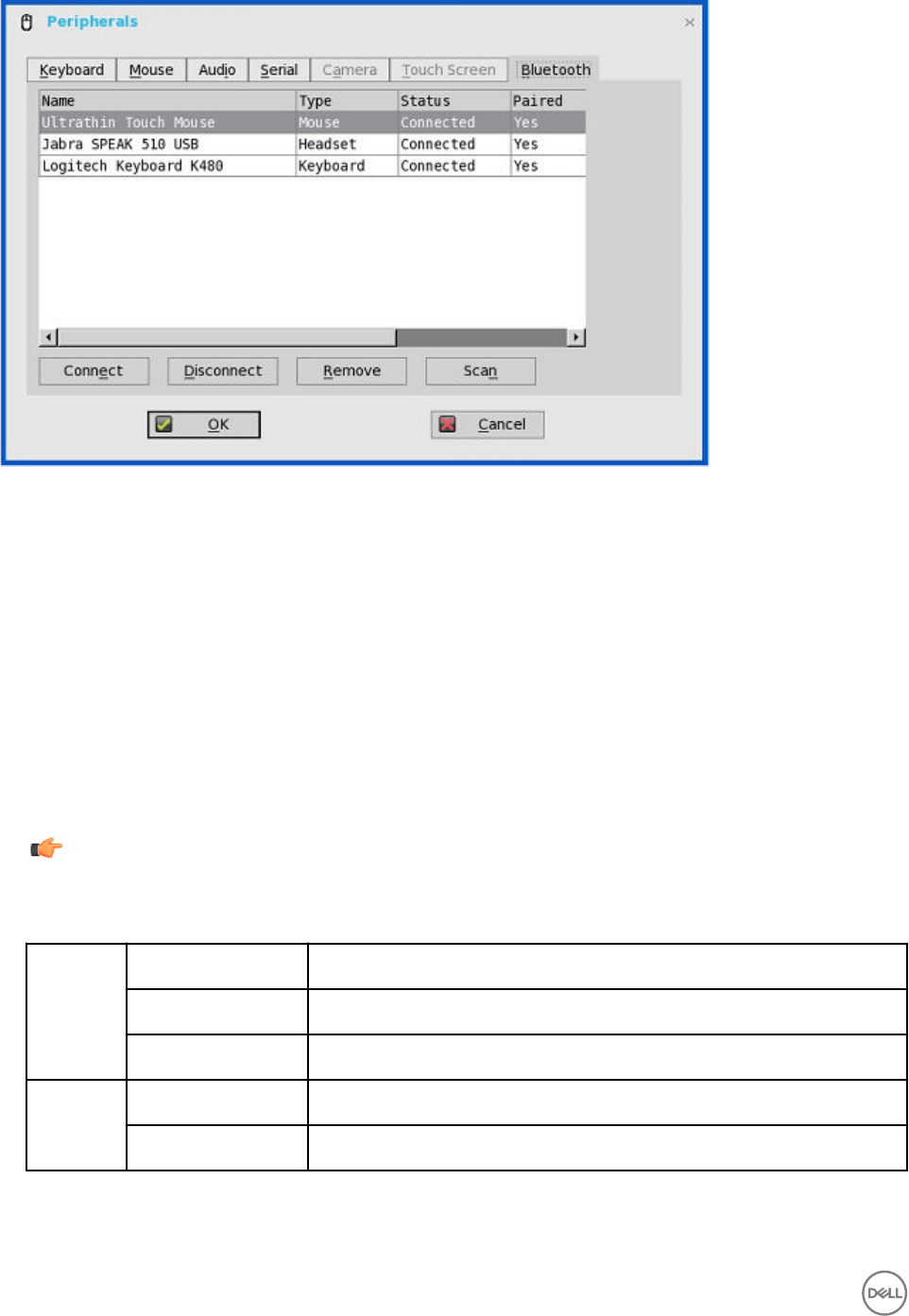
Bluetooth enabled devices, such as headsets and mouses that are available in the Thin Client environment are listed in the
Bluetooth page. The following attributes are displayed in the list.
•Name — Specifies the name of the Bluetooth enabled device.
•Type — Specifies the type of the Bluetooth enabled devices, such as headsets, mouses, and keyboards.
Both Human Interface Devices (HID) and Headset Bluetooth devices are supported in ThinOS 8.2.
–HID Type
* HID includes mouse and keyboard.
* The maximum number of HIDs that can be connected is seven.
–Headset type
* The Bluetooth headset is supported in this release.
* The maximum number of Bluetooth headsets that can be connected is one.
Important: Other types of Bluetooth devices are not scanned and supported.
•Status
— The Bluetooth page has two columns, namely, Status and Paired.
Status Connected The Bluetooth device is connected to the ThinOS device. It is ready to be used.
Connecting The Bluetooth device is connecting to the ThinOS device.
Disconnected The Bluetooth device is not connected to the ThinOS device.
Paired YES The Bluetooth device is paired with the ThinOS device.
NO The Bluetooth device is not paired with the ThinOS device.
The following are the user scenarios and corresponding Bluetooth statuses displayed on the Bluetooth page.
80

User Scenario Status
Device turned off Disconnected | Paired
Device turned on Connected | Paired
Device diconnected from ThinOS Disconnected | Not Paired
•Connect— Select a particular Bluetooth enabled device, and click Connect to connect the selected device to the thin
client. If the Bluetooth device is connected successfully, the status is displayed as Connected in the Bluetooth window.
•Disconnect— Select a particular Bluetooth enabled device that is already connected to the thin client, and click
Disconnect to disconnect the Bluetooth connection of the selected device from the thin client. If the Bluetooth device is
disconnected successfully, the status is displayed as Disonnected in the Bluetooth window.
•Remove— Select a particular Bluetooth device that is disconnected from ThinOS, and click Remove to remove the device
from the list.
•Scan— All Bluetooth devices enter into Page Scan mode. Different Bluetooth devices enter into the Page Scan mode at
different instances such as when a specific button is pressed three times or a specific button is pressed and held until the
LED turns blue.
•Auto Connect function—The Auto Connect function is designed for HIDs.
Prerequisites:
– ThinOS has no HIDs connected such as USB or Bluetooth HIDs.
– The Bluetooth HIDs are configured as Page Scan mode.
When you start the ThinOS client, the Bluetooth HIDs can connect to ThinOS automatically without scanning or pairing
operations. The Bluetooth HIDs automatically reconnects after you restart the ThinOS client.
•Reconnect function—The Reconnect function is designed for HIDs and Headsets.
When you restart the system with the Bluetooth device (HID/headset) that is already paired and connected, the Bluetooth
device automatically reconnects within a few seconds.
For example, you can hover the Bluetooth mouse, and then click a few times for the Bluetooth mouse to reconnect
successfully. The Bluetooth headset reconnects automatically, but might require you to manually close or reopen the device
on certain occasions.
Certified Devices
The following are the certified Bluetooth devices:
• Dell WM713 Bluetooth Mouse
• Dell Wireless Bluetooth Travel Mouse – WM524
• Rapoo E6100, BlueTooth keyboard
• Thinkpad Compact Bluetooth Keyboard
• Logitech Ultrathin Touch Bluetooth Mouse T630
• Logitech K480 Bluetooth keyboard
• Microsoft ARC touch Bluetooth mouse
• Logitech M557 Bluetooth mouse
• Plantronics Calisto 620-M, Bluetooth Speakerphone
• Plantronics BLACKWIRE C710, BlueTooth Headset
• Plantronics Voyager Legend UC B235 NA
• Jabra PRO 9470 NCSA, Bluetooth Headset
81

• Jabra MOTION UC+ MS / LINK 360, Bluetooth, Lync
• Jabra SUPREME UC MS /LINK 360, Bluetooth Headset
• Jabra Speak 510 MS, Bluetooth speakerphone
• Jabra EVOLVE 65 MS Stereo Headset
Known Issues of the Bluetooth feature
1. If more than two Bluetooth mouse devices are connected to ThinOS along with more than two other Bluetooth devices, it may
cause low performance of Bluetooth connectivity.
Workaround: Dell recommends using one mouse and one keyboard in ThinOS with Bluetooth connection.
2. The Bluetooth device name displays N/A sometimes.
Workaround: Remove this device from the list and re-scan.
3. The Bluetooth device status is not refreshed sometimes when wireless chipset 7260 is shut down.
Workaround: Close the ThinOS Bluetooth window and re-open it. The status is updated.
4. Only supports volume button and mute button on Bluetooth headset.
5. The performance of Bluetooth feature is low during wireless connection.
Configuring the Printer Settings
Use the Printer Setup dialog box to configure network printers and local printers that are connected to the thin client. Through its
USB ports, a thin client can support multiple printers. If more than one printer is to be used and another port is not available on your
thin client and the port that is to be used must be shared with a USB modem converter, connect a USB hub to the port.
Use the following options to configure the Printer Settings:
•Configuring the Ports Settings
•Configuring the LPDs Settings
•Configuring the SMBs Settings
•Using the Printer Setup Options
•Using the Help
•Configuring the Citrix UPD Printer
Configuring the Ports Settings
To configure the Ports settings:
1. From the desktop menu, click System Setup, and then click Printer.
The Printer Setup dialog box is displayed.
2. Click the Ports tab, and use the following guidelines:
82
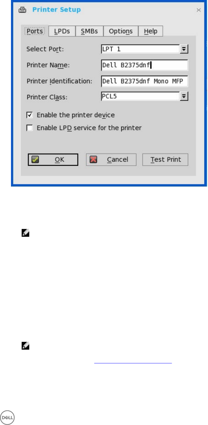
a. Select Port— Select the port you want from the list. LPT1 or LPT2 selects the connection to a direct-connected USB
printer.
b. Printer Name — (Required) Enter name you want displayed in your list of printers.
most USB direct-connected printers report/fill in their printer name automatically.
NOTE: If Enable LPD service for the printer is selected, the printer name becomes the queue name for other
clients using LPR to print to this printer.
c. Printer Identification — Enter the type or model of the printer in the exact text of the Windows printer driver name—
including capitalizations and spaces, most USB direct-connected printers report/fill in their printer identifications
automatically.
This entry must be either the device driver name for the printer under the Microsoft Windows system, or a key to map to
the device driver. If not specified, the name will be defaulted to the printer-supplied identification for standard direct-
connected USB printers or Generic / Text Only for non-USB connected printers upon connection to Windows hosts. The
driver name mapping takes place either through a printer-mapping file read by the system as part of the global profile
(wnos.ini) or by MetaFrame servers through the MetaFrame printer configuration file (\winnt\system32\wtsprnt.inf).
d. Printer Class— This is optional. Select the printer class from the list PCL5, PS, or TXT or PCL4.
e. Enable the printer device — Select this option to enable the directly-connected printer. It enables the device to display on
the remote host.
f. Enable LPD service for the printer — Select this to make the thin client an LPD (Line Printer Daemon) network print
server for LPR printing requests from the network.
NOTE:
If the thin client is to be used as an LPD printer server, DHCP must not be used and a static IP address must be
assigned to the client, see Configuring the Network Settings.
3. Click OK to save the settings.
83
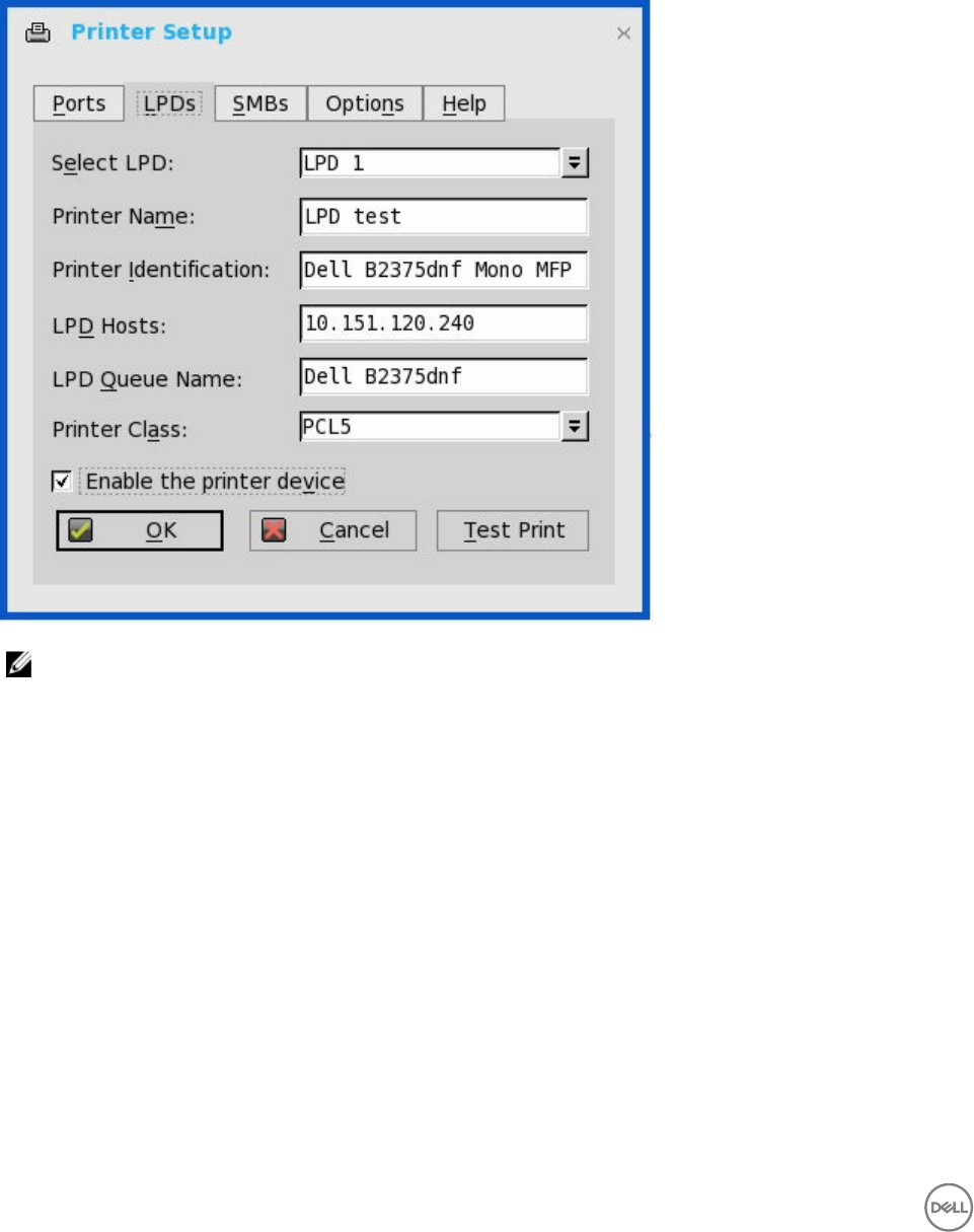
Configuring the LPDs Settings
To configure the LPDs Settings:
1. From the desktop menu, click System Setup, and then click Printer.
The Printer Setup dialog box is displayed.
2. Click the LPDs tab, and use the following guidelines when printing to a non-Windows network printer:
NOTE: Be sure to check with your vendor that the printer can accept Line Printer Request print requests.
a. Select LPD —Select the port you want from the list.
b. Printer Name —(Required) Enter name you want displayed in your list of printers.
c. Printer Identification—Enter the type or model of the printer in the exact text of the Windows printer driver name—
including capitalizations and spaces.
This name must be either the device driver name for the printer under the Microsoft Windows system, or a key to map to
the device driver. If not specified, the name will be defaulted to the printer-supplied identification for standard direct-
connected USB printers or Generic / Text for non-USB connected printers upon connection to Windows hosts. The driver
name mapping takes place either through a printer-mapping file read by the system as part of the global profile (wnos.ini)
or by MetaFrame servers through the MetaFrame printer configuration file (\winnt\system32\wtsprnt.inf).
d. LPD Hosts—The DNS or WINS name of the server for the network printer. An IP address of the printer on the network
can also be entered.
If the printer is attached to another thin client on your network, the entry in the LPD Hosts box is the name or address of
that thin client.
e. LPD Queue Name — An LPD host maintains a named queue for each supported printer. Enter the name of the queue
associated with the printer to be used.
84
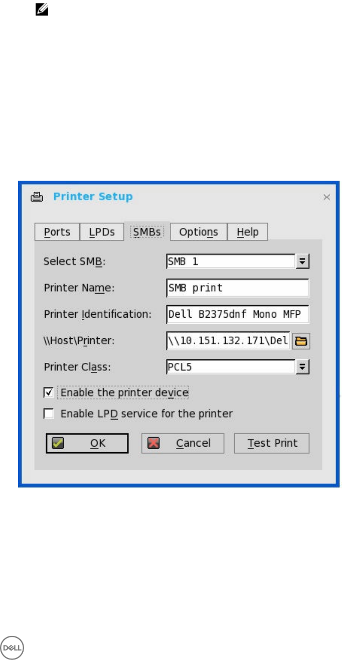
This name can be different for each vendor. This field is required and must be correct so that the network printer accepts
incoming print jobs properly. For example, auto can be used for HP LaserJet 4200n PCL6 as per documentation found on
the HP Web site.
NOTE:
If the printer is attached to another thin client on your network, the LPD Queue Name must match the content of the
Printer Name box on the thin client with the printer attached.
f. Printer Class — (Optional) Select the printer class from the list.
g. Enable the printer device — Must be selected to enable the printer. It enables the device so it displays on the remote
host.
3. Click OK to save the settings.
Configuring the SMBs settings
To configure the SMBs settings:
1. From the desktop menu, click System Setup, and then click Printer.
The Printer Setup dialog box is displayed.
2. Click SMBs tab, and use the following guidelines when printing to a Windows network printer.
a. Select SMB —Select the SMB you want from the list.
b. Printer Name —(Required) Enter the name to be displayed in your list of printers.
c. Printer Identification- Enter the type or model of the printer in the exact text of the Windows printer driver name—
including capitalizations and spaces.
This name must be either the device driver name for the printer under the Microsoft Windows system, or a key to map to
the device driver. If not specified, the name will be defaulted to the printer-supplied identification for standard direct-
connected USB printers or Generic / Text for non-USB connected printers upon connection to Windows hosts. The driver
name mapping takes place either through a printer-mapping file read by the system as part of the global profile (wnos.ini)
or by MetaFrame servers through the MetaFrame printer configuration file (\winnt\system32\wtsprnt.inf).
85
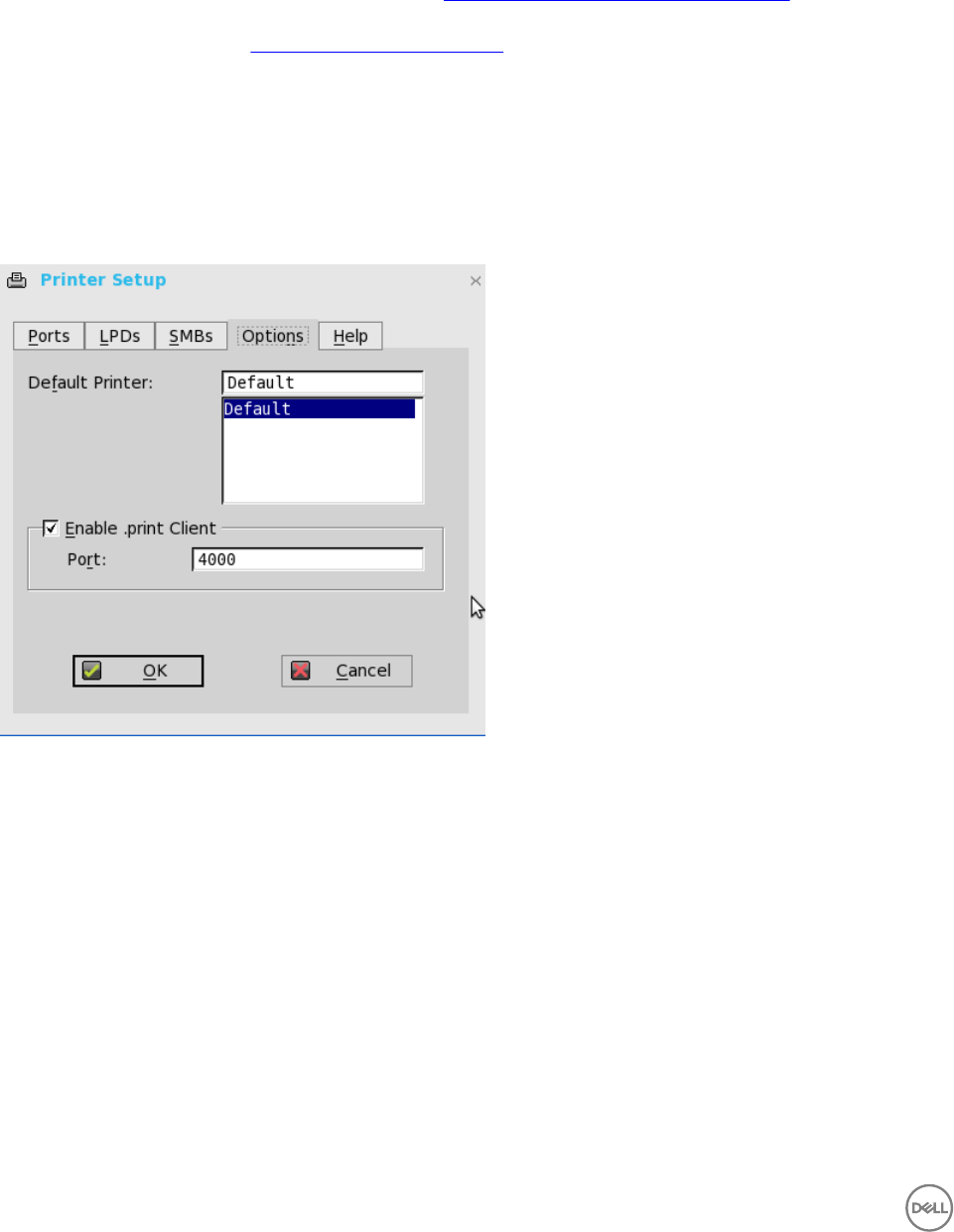
d. \\Host\Printer—Enter the Host\Printer or use the browse folder icon next to the box to browse your Microsoft
Networks and make the printer selection you want from the network printers available (the DNS name or IP address of the
Windows print server on the network).
e. Printer Class —(Optional) Select the printer class from the list.
f. Enable the printer device—Must be selected to enable the printer. It enables the device so it displays on the remote host.
g. Enable LPD service for the printer—Select this to make the thin client an LPD (Line Printer Daemon) network print
server for LPR printing requests from the network, see Using Your Thin Client as a Print Server (LPD).
If the thin client is to be used as an LPD printer server, DHCP must not be used and a static IP address must be assigned to
the thin client as described in Configuring the Network Settings.
3. Click OK to save the settings.
Using the Printer Setup Options
To configure the Printer setup options:
1. From the desktop menu, click System Setup, and then click Printer.
The Printer Setup dialog box is displayed.
2. Click the Options tab, and use the following guidelines:
a. Default Printer —Select the printer you want to be the default printer from your list of available printers.
b. Enable .print Client and Port —If you want to enable .print Client, select Enable .print Client , and then enter the port.
3. Click OK to save the settings.
Using the Help
When you click the Help tab, the following message is displayed in the text box.
Printer Identification is supplied by printer device. Change it to a Window’s printer driver name or setup a driver mapping file.
Configuring the Citrix UPD Printer
Use of Citrix Universal Printer Driver (Citrix UPD) ensures that all printers connected to a client can also be used from a virtual
desktop or application session without integrating a new printer driver in the data center. Citrix UPD is the base of Citrix Universal
Printer. It is an auto-created printer object that uses the Citrix UPD and is not tied to any specific printer defined on the client.
86
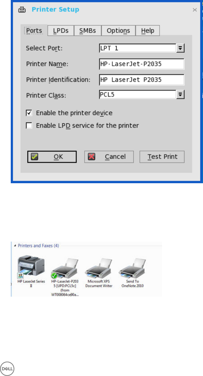
To configure the Citrix UPD usage on ThinOS:
1. Connect a printer to ThinOS client.
2. From the desktop menu, click System Setup, and then click Printer.
The Printer Setup dialog box is displayed.
3. Enter the name of the printer in the Printer Name box.
4. Enter any string of the Printer identification in the Printer Identification box.
5. Select the type of the printer class from the drop-down list, select the check box to enable the printer device and then click
OK.
6. Start a XenDesktop or XenApp application connection.
7. Open the Devices and Printers in the desktop or application, notice the printer is mapped as UPD printer by default. You can
use the HP-LaserJet-P2035 [UPD:PCL5c] to perform the print job.
Citrix UPD configuration on server
a. To enable the printer policy, use the following guidelines:
1. To enable the printer policy in XenApp 6.5– Go to the DDC Server, click Start → Citrix AppCenter .
87
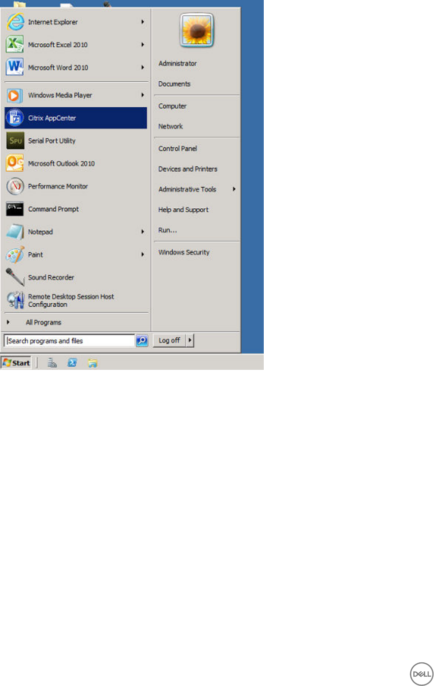
2. Click Citrix Resources → XenApp → Policies → User → Settings → Printing → Client Printers and enable the
Auto-create generic universal printer.
3. Click Printing → Drivers and set the Universal print driver usage to Use universal printing only from the drop-
down menu available.
88
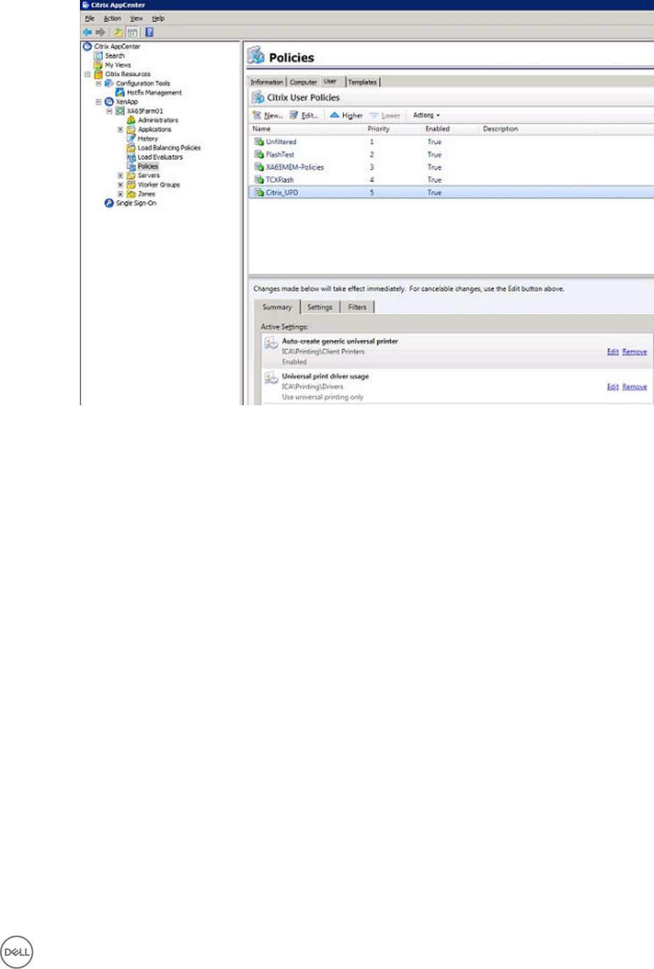
4. To enable the printer policy in XenApp/XenDesktop 7.5 and XenApp/XenDesktop 7.6:
a. Go to the Citrix DDC Server,
1. Click Citrix studio → policies and add a policy. Enable the Auto-create generic universal printer option.
2. Set the Universal print driver usage to Use universal printing only from the drop-down menu.
89
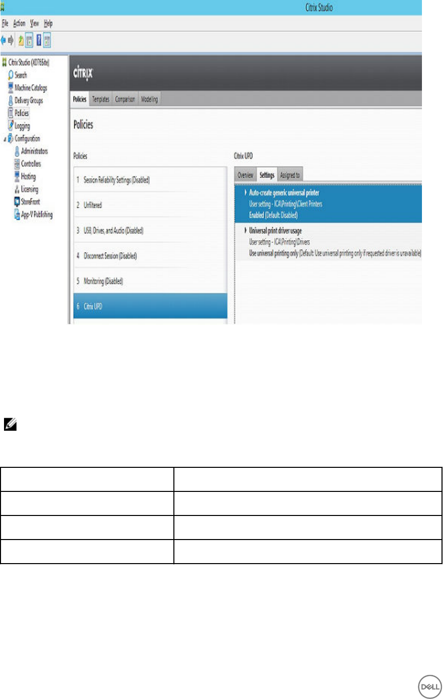
b. Check registry and make sure the same driver has been installed.
1. Check the drivers in registry of the server or desktop which you want to connect. The server or desktop must have
ps, pcl5, pcl4 drivers in the registry and the same driver must be installed on the server or desktop.
2. Go to HKEY_LOCAL_MACHINE\SOFTWARE\Citrix\UniversalPrintDrivers\. ThinOS does not support EMF and
XPS.
NOTE: The supported drivers in the following table are one of the supported drivers for Citrix UPD used in
ThinOS. One of the recommended driver is provided here as an example..
The supported drivers are listed in the following table.
Printer class Printer driver
PS HP Color LaserJet 2800 Series PS
PCL5 HP LaserJet 2200 Series PCL 5
PCL4 HP LaserJet Series II
c. If the server or desktop which you want to connect does not have these drivers, follow the steps mentioned here:
1. For example, in XenApp A6.5+2008 R2, add PCL driver in Server. Go to Device and Printers → Select any printer
→ Click Printer server properties → Driver tab and then add HP LaserJet 2200 Series PCL 5 driver.
90
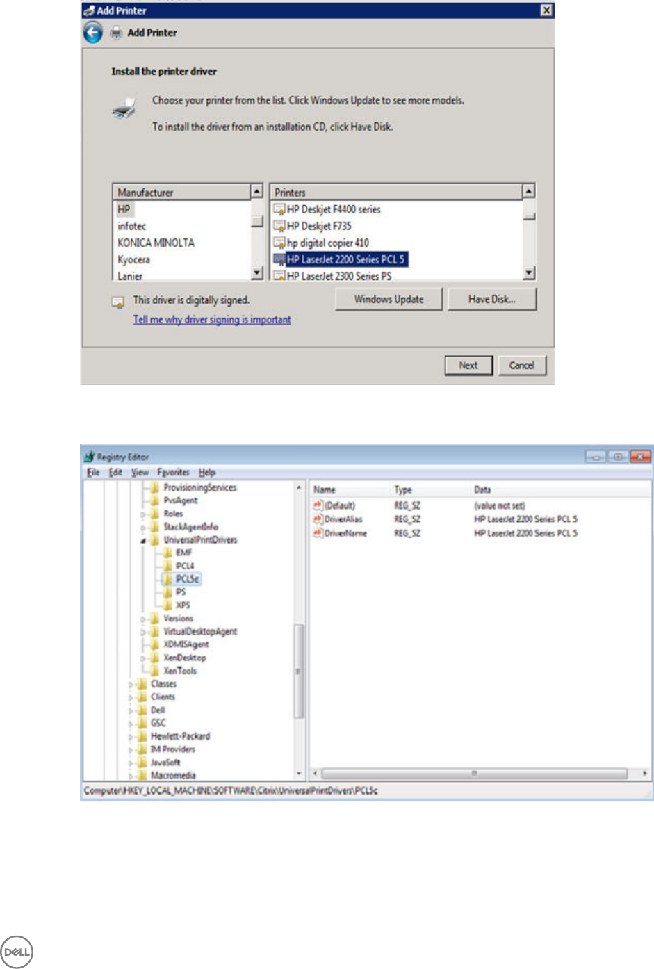

•Resetting to Factory Defaults Using Shutdown Reset
•Resetting Display Settings Using V-Key Reset
•Accessing Thin Client BIOS Settings
Resetting to Factory Defaults Using G-Key Reset
High-privileged or Stand-alone users can reset the thin client to factory default settings using the G-key reset feature.
To reset the thin client to factory default settings, restart the thin client and continuously tap the G key during the restart process.
G-key reset impacts all configuration items, including, but not limited to, both network configuration and connections defined in local
NV-RAM.
NOTE: G-key reset is disabled for Low-privileged and Non-privileged users in Lockdown mode.
Resetting to Factory Defaults Using Shutdown Reset
A High-privileged or Stand-alone user can reset the thin client to factory default settings from the Shutdown dialog box.
To reset the thin client to factory defaults:
1. From the desktop menu, click Shutdown.
The Shutdown dialog box is displayed.
2. After starting your thin client you will see a Dell logo for a short period of time.
3. Click Restart the system to restart your thin client.
4. Select the Reset the system setting to factory default check box to restore your system settings to default factory settings.
5. Click OK to save the settings.
Shutdown reset impacts all configuration items, including, but not limited to network configuration and connections defined in
local NV-RAM. However, the terminal name will not be changed.
NOTE:
Shutdown reset is disabled for Low-privileged and Non-privileged users, regardless of lock down state.
Resetting Display Settings Using V-Key Reset
If the display settings are inappropriate for the particular monitor that is connected, it is possible that the display will not function
properly when the thin client restarts. To correct this, power-on the thin client while continuously tapping the V key. This will restart
the thin client with a default/automatic display resolution.
Accessing Thin Client BIOS Settings
After starting your thin client you will see a Dell logo for a short period of time. During this period you can press and hold the Delete
key to enter the BIOS with Fireport as the password to make necessary modifications. For example, you can use the F7 key to use
Optimized Defaults (load optimal default values for all the items in the BIOS setup utility).
NOTE: This does not apply to the Wyse 3020 thin client with ThinOS (T10D) no BIOS on ARM platform — to access the
WLOADER on an ARM platform, press the power button for about four seconds until the power light turns green, and
then press the Delete key.
92
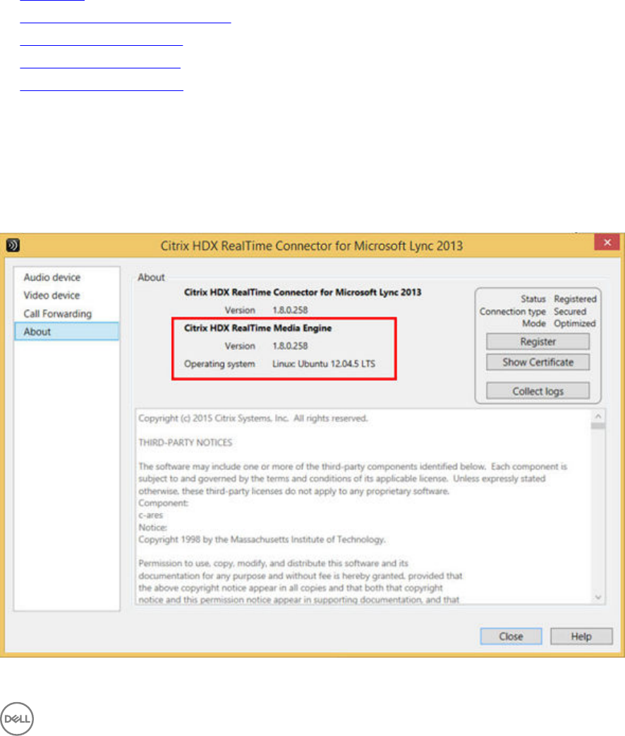
6
Citrix HDX RealTime Multimedia Engine (RTME)
RTME 1.8 was a new feature introduced in ThinOS 8.2. This is the Citrix HDX RealTime Optimization Pack 1.8 for Lync. From
ThinOS 8.3 release, the Citrix HDX RealTime Optimization Pack 2.0 (RTME 2.0) is supported. Citrix RTME 2.0 is introduced to
support Microsoft Skype for Business 2015 client/UI (only), in addition to RTME 1.8 supporting the Microsoft Lync 2010/2013
clients. This section provides information about supported platforms for RTME, installation of RTME package, Citrix remote Server/
Desktop host preparation, configuration on ThinOS, and RTME status check and troubleshooting.
•Introduction
•Installing the RTME package on ThinOS
•Setting Up the RTME for Lync
•Verifying the RTME 1.8 Status
•Verifying the RTME 2.0 Status
Introduction
The Citrix HDX RealTime Optimization pack offers high-definition audio and video calls on Lync. RTME 1.8 and 2.0 co-exist in
ThinOS 8.3 release package. From ThinOS 8.3, RTME 1.8 and 2.0 co-exist.
93
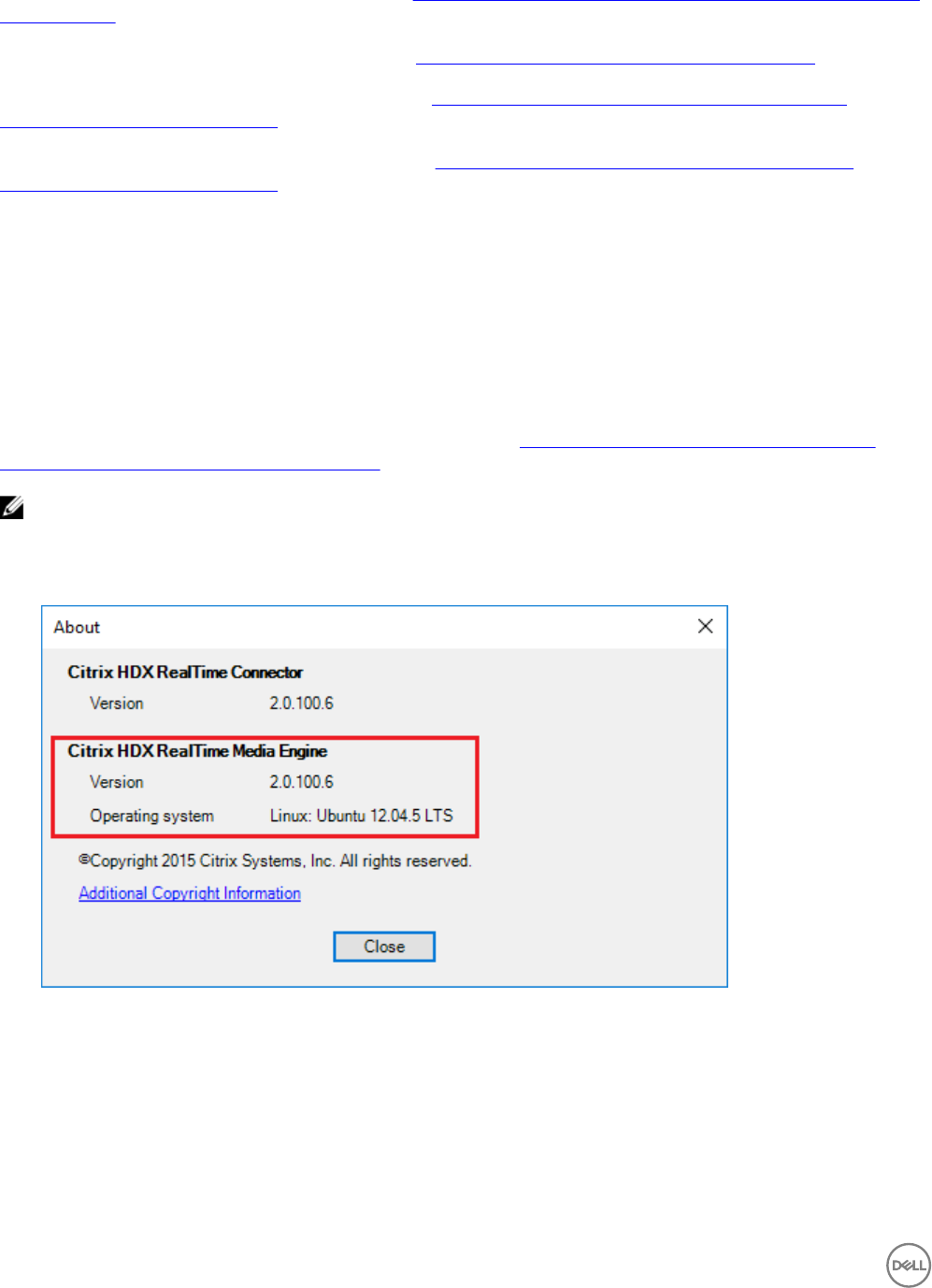
For more information about Citrix RTME 1.8 feature, go to docs.citrix.com/en-us/hdx-optimization/1-8/hdx-realtime-optimization-
pack-about.html.
For more information about Citrix RTME 2.0 feature, go to docs.citrix.com/en-us/hdx-optimization/2-0/about.html.
For information on how to use Citrix RTME 1.8 feature, go to docs.citrix.com/en-us/hdx-optimization/1-8/hdx-realtime-
optimization-pack-troubleshooting.html.
For information on how to use Citrix RTME 2.0 feature, go to docs.citrix.com/en-us/hdx-optimization/2-0/hdx-realtime-
optimization-pack-troubleshooting.html.
Supported Environments
• Citrix environment: XenDesktop and XenApp 5.6/6.5/7.x
• Desktop with RTME connector 1.8 (Lync server and client version 2010 and 2013; Skype for Business client in Lync 2013 GUI is
supported).
• Desktop with RTME connector 2.0 (Skype for Business 2015 is supported).
• Supported networks: LAN, WAN (VPN), wireless and so on.
• Supports calls between RTME clients or between RTME and standard Lync clients.
For more information about the system/environment requirements, go to docs.citrix.com/en-us/hdx-optimization/2-0/hdx-
realtime-optimization-pack-system-requirements.html.
NOTE:
RTME version 2.0.100.6 is included in the release package. If the connector version is the previous version 2.0.0.417, then the
RTME feature works and a warning sign is displayed to indicate the version difference that is displayed next to the taskbar
icon.
Installing the RTME package on ThinOS
You are required to install the RTME.i386 package for the RTME 1.8 and 2.0 feature to work on ThinOS.
To install the RTME.i386 package:
1. Upload the RTME.i386.pkg to directory \wnos\pkg\.
94
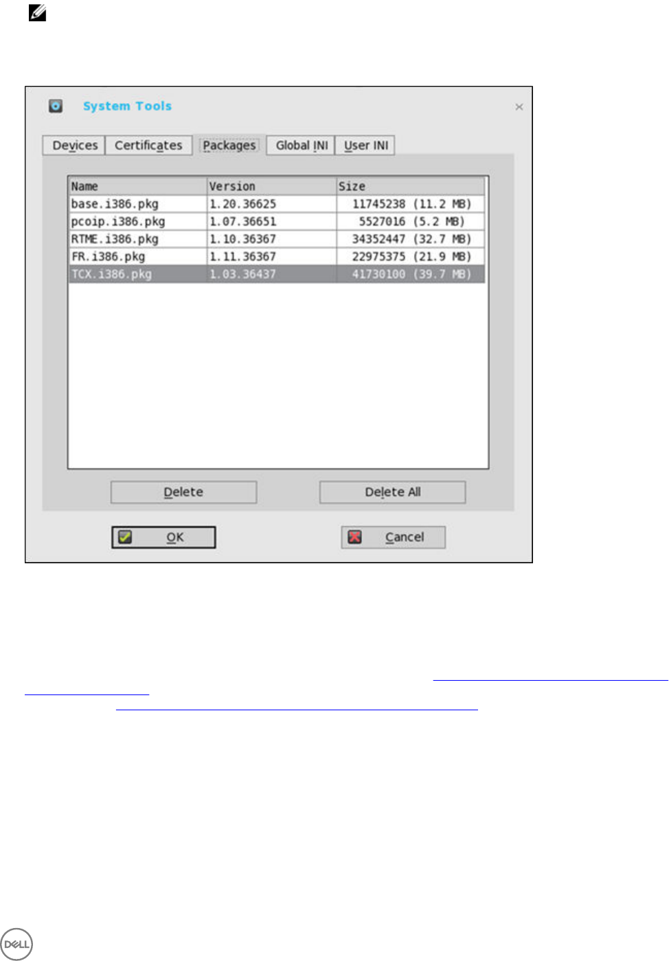
NOTE: For RTME package version, see
Dell Wyse ThinOS 8.3.1 Release Notes
.
2. You must ensure that the INI autoload is not set to value 0.
3. Restart the thin client and wait till the auto-installation of packages is complete.
The installed RTME package is displayed in the Packages window in System Tools.
Setting Up the RealTime Multimedia Engine (RTME) for Lync
This section describes how to install and use Lync on a Citrix desktop.
1. Install Citrix HDX RealTime Connector version 1.8 or 2.0 on Citrix desktop VDA/Server. For more information about installing
Citrix HDX RealTime Connector version 1.8 on Citrix Desktop VDA/Server, see docs.citrix.com/en-us/hdx-optimization/1-8/
hdx-realtime-install.html. For more information about installing Citrix HDX RealTime Connector version 2.0 on Citrix Desktop
VDA/Server, see docs.citrix.com/en-us/hdx-optimization/2-0/hdx-realtime-install.html.
95

NOTE:
• HDX RealTime Multimedia Engine is the package installed on ThinOS; it is HDX RealTime Connector for Lync that
needs to be installed or upgraded on the remote server and VDA.
• The Upgrade option from 1.7 to 1.8 is discussed at docs.citrix.com/en-us/hdx-optimization/1-8/upgrade-1-7-
to-1-8.html.
• The Firewall configuration is required on remote server and VDA. For more information, refer to docs.citrix.com/en-
us/hdx-optimization/1-8/hdx-realtime-optimization-pack-configure-firewall.html.
• To know about the technical overview of RTME 2.0, go to docs.citrix.com/en-us/hdx-optimization/2-0/hdx-
realtime-optimization-pack-about.html.
Important: The RTME 1.8 feature on ThinOS supports only HDX RealTime Connector 1.8 due to Citrix
limitation.
2. Update the ThinOS firmware to 8.3.1, and install the RTME.i386.pkg on the ThinOS client. For information about installing the
RTME package, see Installing the RTME package on ThinOS.
Important: From ThinOS 8.3, the RTME 1.8 and 2.0 co-exist in the release package, supporting both versions of
RTME connectors.
3. (This step is for RTME 1.8 only) Configure the Domain Name Server (DNS) settings on ThinOS for Lync Server.
NOTE: You must ensure that the thin client does not have USB redirection for video/audio devices in order to have
RTME working correctly.
4. Log in to your Citrix Desktop, and sign in to Lync client.
• For RTME 1.8, the RTME icon is displayed in the lower-left corner of the Lync client window.
• For RTME 2.0, the RTME icon is displayed on taskbar.
Use the Lync Application to perform the following tasks:
• Start an audio or video call
– Select user to call
– Call from the IM window
– Type a name or number to call
• Answer the call
– Audio call
– Video call
– Headset button to answer the call
• Transfer call/ mute/ hold call
• Control the video: Pause/ End/ Picture in Picture (PiP)
• Set the volume levels
• Use Dial Pad
• Make a conference call
• Help and Hang up
• Minimize/maximize or close the Lync window
• Perform Network Health check:
– For RTME 1.8, press Ctrl+N to open the Network Health window.
– For RTME 2.0, right-click the RTME icon on taskbar and select Call Statistics.
The attributes, such as received packets, sent packets, video frame rate, video resolution, audio codec, and video codec are
displayed in the above described window.
96
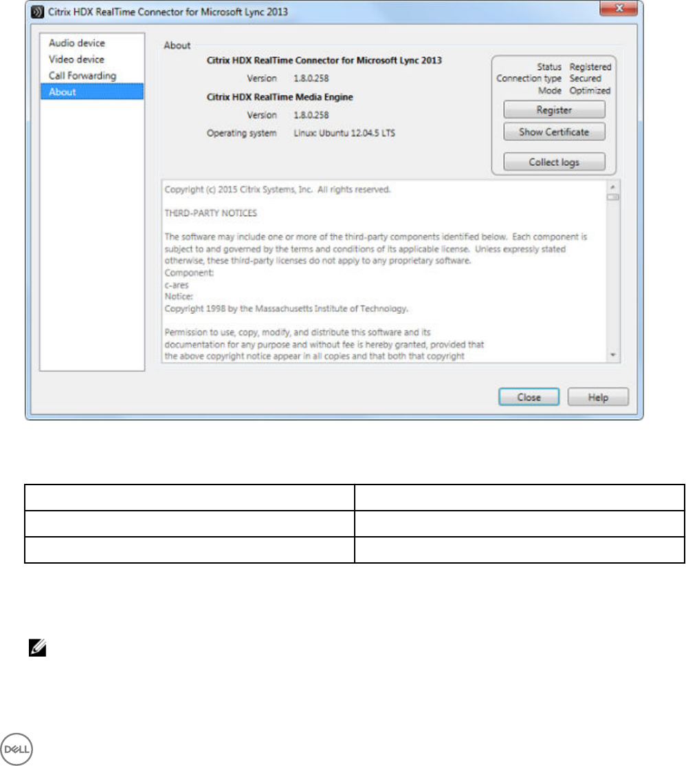
Verifying the RTME 1.8 Status
The Citrix HDX RealTime Connector for Microsoft Lync 2013 dialog box enables you to verify the RTME 1.8 status.
To view the Citrix HDX RealTime Connector for Microsoft Lync 2013 dialog box:
1. Do any of the following to view the Citrix HDX RealTime Connector for Microsoft Lync 2013 dialog box:
• Click the RTME icon in the lower-left corner of the Lync application window, and click Audio Video Settings.
• Click the Lync menu icon in the upper-right corner of the Lync application window, and click Tools → Audio Video
Settings.
The Citrix HDX RealTime Connector for Microsoft Lync 2013 dialog box is displayed.
2. Click the About tab in the Citrix HDX RealTime Connector for Microsoft Lync 2013 dialog box.
The RTMS status is displayed in the upper-right pane of the dialog box. If the RealTime Multimedia Engine is successfully
initiated between the ThinOS client and Citrix Desktop, the RTME status is displayed as follows:
Status Registered
Connection Type Secured
Mode Optimized
You can also view the Citrix HDX RealTime Connector for Microsoft Lync 2013 version and Citrix HDX RealTime Media
Engine version in the dialog box.
3. Click the Audio Device tab to configure the RTME audio settings, such as speakers, microphone, and ringer settings.
NOTE: The RTME audio device on ThinOS shows only one device from ThinOS local playback device. It can actually
work the way they are configured at ThinOS local playback device and record device. The RTME audio device for
ringtone is limited to use ThinOS local playback device. This is a known Issue.
4. Click the Video Device tab to configure the RTME video settings. From the drop-down list, select the webcam that you want
to use for video calls.
97

5. Click the Call Forwarding tab to configure the call forwarding settings.
You can configure the following options:
• Turn off call forwarding
• Forward any call to a specific number
• Simultaneously ring
NOTE: The latest call forwarding settings configured by you are displayed in the lower pane of the dialog box.
For more information about trouble shooting, go to docs.citrix.com/en-us/hdx-optimization/1-8/hdx-realtime-optimization-pack-
troubleshooting.html.
Known Issues with RTME 1.8 feature
• RTME operation system on ThinOS is displayed as Linux.
• RTME audio device on ThinOS will display only one device from ThinOS local playback device. It can actually work the way they
are configured at ThinOS local playback device and record device. The RTME audio device for ringtone is limited to use ThinOS
local playback device.
• The RTME 1.8 feature on ThinOS does not work with other versions of HDX RealTime connector due to known Citrix limitation.
• If you change the audio device during an RTME call, the audio input or output might stop responding.
• Using similar hardwares, such as Dx0D, ThinOS, Linux, and Windows (D90D7) produce similar video frame rate (20-30) and
video resolution (320-400). It produces better video quality using laptop or PC because of better CPU capability.
• In a video conference call, when different user is speaking, the on-screen video switches to the active user, but takes a few
seconds to switch over.
Certified devices
The following are the certified devices for RTME:
• Plantronics BLACKWIRE C435-M Headset
• Plantronics Calisto 620-M, Bluetooth Speakerphone
• POLYCOM Deskphone CX300
• Jabra PRO 935 MS Headset
• Jabra MOTION 360 hands free Bluetooth Headset
• Plantronics BLACKWIRE C-310M Headset
• Plantronics Voyager Legend UC B235 NA Bluetooth Headset
• Jabra UC Voice 750MS Duo (Dark) Headset
• Logitech USB Webcam 9000
• Logitech C525 HD Webcam
• Microsoft LifeCam 3.0 Cinema
• Logitech HD Webcam C310
• Logitech HD Webcam C910
• Logitech HD Webcam C920
• Logitech HD Webcam C930
Verifying the RTME 2.0 Status
This section describes the working of RTME 2.0 and how to verify the RTME status.
Salient Features of RTME 2.0
98

• Native SFB client menus and operations are available.
• Better initialization eliminates DNS confusions.
• Supports more call features, such as call delegation, and response group.
To verify the RTME status, do the following:
1. Install the correct connector on the remote desktop.
2. Install the correct package on the ThinOS device.
3. Plug-in the audio/video devices.
NOTE: HDX USB redirections are not available for the audio/video devices.
4. Connect to the remote desktop using SFB client 2015.
5. Verify the RTME connector 2.0 icon on taskbar. The status is displayed as Connected.
6. Verify the About, and Settings options from the RTME connector 2.0 menu.
7. Verify the audio/video devices from SFB client menus.
8. Establish the video/audio calls.
9. Pick up the calls by either clicking the mouse or using the headset button.
10. Verify the Call Statistics from the RTME connector 2.0 menu.
NOTE: RTME 2.0 supports various call scenarios. For more information, refer to
Citrix technical overview
.
Known Issues with RTME 2.0 feature
• RTME status dialog displays operation system as Linux.
• Only single device supported in ThinOS 8.3 release.
• RTME audio microphone confined to local audio record device.
• Changing the video/audio device during RTME call results in issue with audio input or output.
• Volume: Dell recommends you to adjust the speaker volume in SFB 2015 call window to high, and the system local playback/
record audio volume for better voice input/output. The default volume is a bit low.
• Camera/Video: The local camera setting does not affect/impact the RTME video output because of the RTME design.
99

7
Advanced Details on Configuring ICA and RDP
Connections
Use the following information when configuring ICA and RDP connections. This information assumes that the thin client does not
have a locked down privilege level.
•High-privileged user — The additional functionality provided by the Connection Settings dialog box allows testing of
connection definitions before they are entered by a network administrator into the user profile files.
•Low-privileged user — The settings for the selected connection can be viewed but cannot be edited, and new connections
cannot be defined. Connection definitions are controlled by a network administrator and are accessed by the thin client from the
user profiles on a remote server.
•Stand-alone user — The Connect Manager is available to Stand alone users because connection definitions cannot be
accessed from remote user profiles. If user profiles are available on an FTP server but are not accessed because DHCP is not
available or is not configured to provide the file server IP address, the file server IP location can be entered manually using the
Network Setup dialog box.
Configuring ICA Connections
To configure the ICA connection option you selected in the Remote Connections dialog box, perform the following tasks:
1. Click Default ICA icon on the desktop.
2. Click Settings, and then click the Connection tab.
To configure the ICA Connections, do the following:
100
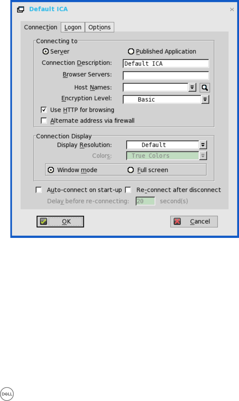
a. Server or Published Application — Select the type of connection to which the settings apply.
b. Connection Description — Enter the descriptive name that is to appear in the connection list (38 characters maximum).
c. Browser Servers — Enter a delimited (comma or semicolon) list of IP addresses or DNS-registered names of ICA servers
that contains the master browsers list, or that could refer to another server that contains the list.
The master browsers list is generated automatically by a browsing program on one of the ICA servers (selected by
negotiation between servers). It is used to provide the information displayed in the Server Name or IP box. No entry is
needed if the list is on an ICA server in the same network segment as the thin client. No entry is necessary if the connection
is to a server, or if the server name or IP contains the IP address of the server.
d. Host Name or Application Name (title depends on the Server or Published Application option selected) — You can enter a
delimited semicolon or comma-separated list of server host names or IP addresses, or you can select from the list of ICA
servers or published applications obtained from the ICA master browser. You can also use Browse next to the box to make
the selection you want.
If you enter a delimited list of servers, the thin client will attempt to connect to the next server on the list if the previous
server attempt fails. If you use the list and the selected connection fails, the thin client will attempt to connect to the next
one on the list.
101

NOTE:
The Host Name may be resolved using one of three mechanisms: ICA master browser, DNS or WINS. Master browser
is the only mechanism that can resolve a published application unless manual entry is made in DNS for the application.
DNS uses the default domain name in the network control panel to attempt to construct an FQDN but will also try to
resolve the name without using the default.
e. Encryption Level — Allows you to select the security level of communications between the thin client and the ICA server.
Basic (the default option) is the lowest level of security. Basic allows faster communication between the device and the
ICA server because it requires less processing than the higher levels of encryption.
NOTE: The encryption selection applies to the security of communications between the thin client and the ICA
server only. It is independent of the security settings of individual applications on the ICA server. For example,
most web financial transactions require the thin client to use 128-bit encryption. However, transaction
information could be exposed to a lower level of security if the thin client encryption is not also set to 128 bits.
f. Use HTTP for browsing — When selected, the thin client, by default, uses HTTP when browsing.
g. Alternate address via firewall — When selected, the thin client uses an alternate IP address returned from the ICA master
browser to get through firewalls. Used for the Windows log on when the connection is activated.
h. Display Resolution — Select the display resolution for this connection.
If you select the Published Application option, the Connection Display allows you to select the Seamless Display
Resolution option.
Colors — Select the color depth of the ICA session. If High Colors (16 bits) or True Colors is selected and the ICA server
does not support this color depth, the thin client renegotiates the color depth to the lower value, for example, 256 Colors
[8–bits].
i. Window mode and Full screen mode — Select the initial view of the application and desktop in a windowed screen or full
screen.
j. Auto-connect on start-up — When selected, automatically connects the session on start-up.
k. Reconnect after disconnect — When selected, causes the thin client to automatically reconnect to a session after a non
operator-initiated disconnect. If selected, the wait interval is that set in the Delay before reconnecting box (enter the
number of seconds 1–3600) or the user profile for yes (20 seconds) or seconds. The default is 20 seconds, if there is no INI
file description of this connection, or is a Stand-alone user, or simply omitted.
3. Click logon tab, and use the following guidelines:
102
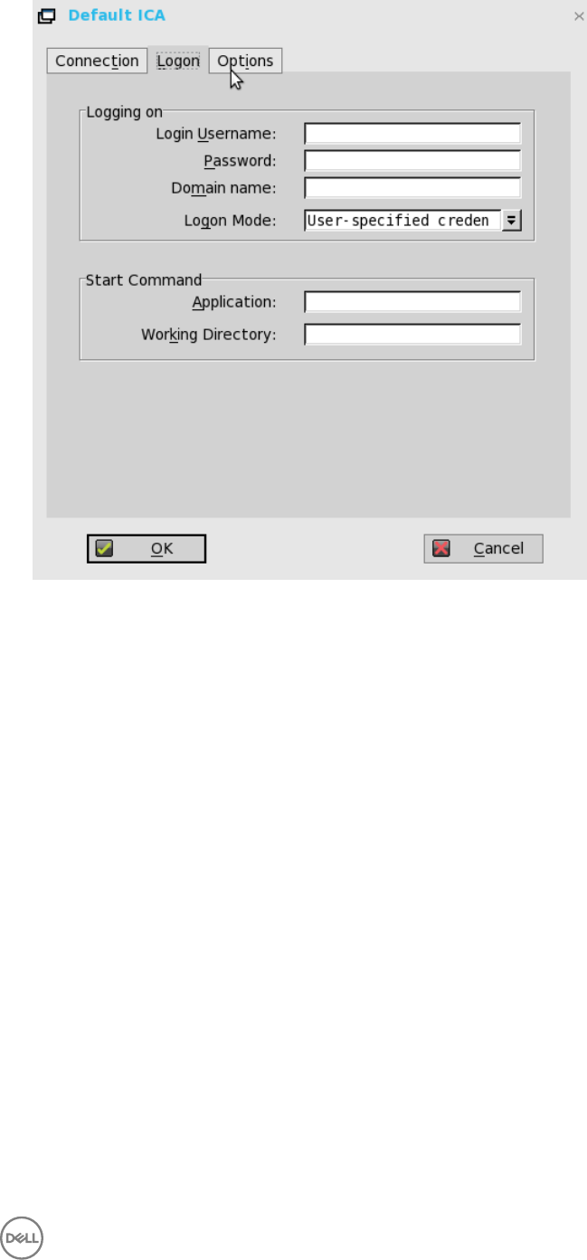
a. Logging on area — Enter Login Username, Password, Domain name, and Logon Mode.
If the Login Username, Password, and Domain name boxes are not populated, you can enter the information manually in the
ICA server login screen when the connection is made:
•Login Username — Maximum of 31 characters is allowed.
•Password — Maximum of 19 characters is allowed.
•Domain Name — Maximum of 31 characters is allowed.
•Logon Mode — Select User-specified credentials, Smart Card, or Local User.
b. Start Command area— Server Connection Option Only — This area is disabled for a Published Application option.
Application (127 characters maximum) and Working Directory (63 characters maximum) — Enter an initialization string
and arguments, including an associated working directory, that you want to start automatically on the server when the
connection is made.
4. Click Options tab and use the following guidelines:
103
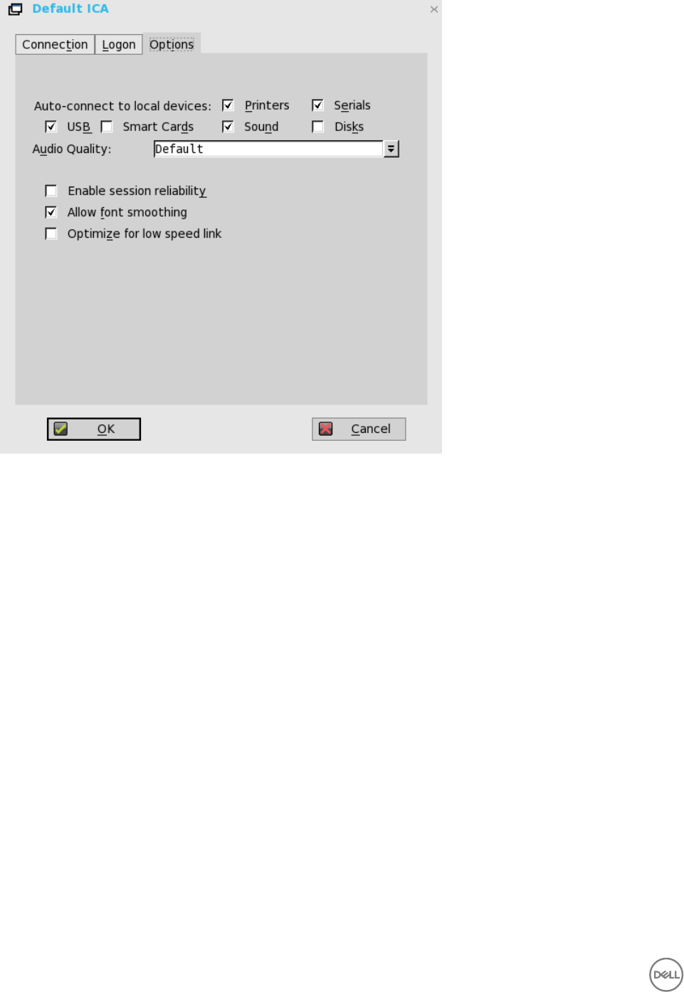
a. Autoconnect to local devices — Select any options (Printers, Serials, USB, Smart Cards, and Disks) to have the thin client
automatically connect to the devices.
b. Allow font smoothing — When selected, enables font smoothing (smooth type).
c. Optimize for low speed link — When selected, allows optimization for low-speed connections, such as reducing audio
quality and/or decreasing protocol-specific cache size. Intended for a connection spanning a WAN link or using dialup.
d. Enable session reliability — When enabled, session reliability allows a user to momentarily lose connection to the server
without having to re-authenticate upon regaining a connection. Instead of a user’s connection timing out after X seconds,
the session is kept alive on the server and is made available to the client upon regaining connectivity. Session reliability is
most relevant for wireless devices.
Configuring RDP Connections
To configure the RDP connection option you selected in the Remote Connections:
1. Click the RDP tab on the desktop.
The Default RDP dialog box is displayed.
2. Click the Connection tab, and use the following guidelines:
104
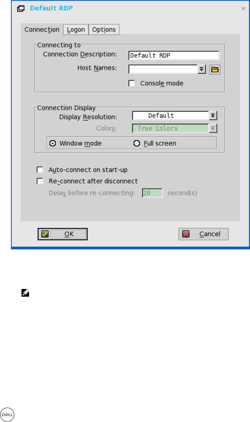
a. Connection Description— Enter the descriptive name that is to appear in the connection list (38 characters maximum).
b. Host Names— Use the list to select the valid DNS server name or the IP address of the server to which the thin client
connection is to be made you can also use Browse next to the box to make the selection you want. For example, a list of
WTS servers on the local network from which you can select.
NOTE: The server name may be resolved using one of two mechanisms: DNS, and WINS. DNS uses the default
domain name in the network control panel to attempt to construct an FQDN but will also try to resolve the name
without using the default.
c. Console mode— Select to set the RDP connection with Windows Console mode.
d. Display Resolution— Select the display resolution for this connection.
Colors—
Select the color depth of the RDP session. If High Colors (16 bits) or True Colors (32 bits) is selected and the RDP server
does not support this color depth, the thin client renegotiates the color depth to the lower value for example, 256 Colors (8
bits). The highest is 32 bits, if hardware supports it.
e. Full screen on 1 monitor and Span both monitors— Select the initial view of the application in a full screen or span.
f. Auto-connect on start-up— When selected, automatically connects the session on start-up.
g. Re-connect after disconnect—When selected, causes the thin client to automatically reconnect to a session after a non-
operator-initiated disconnect. If selected, the wait interval is that set in the Delay before re-connecting box (enter the
number of seconds 1 to 3600) or the user profile for yes (20 seconds) or seconds. The default is 20 seconds, if there is no
INI file description of this connection, or is a Stand-alone user, or is simply omitted.
105
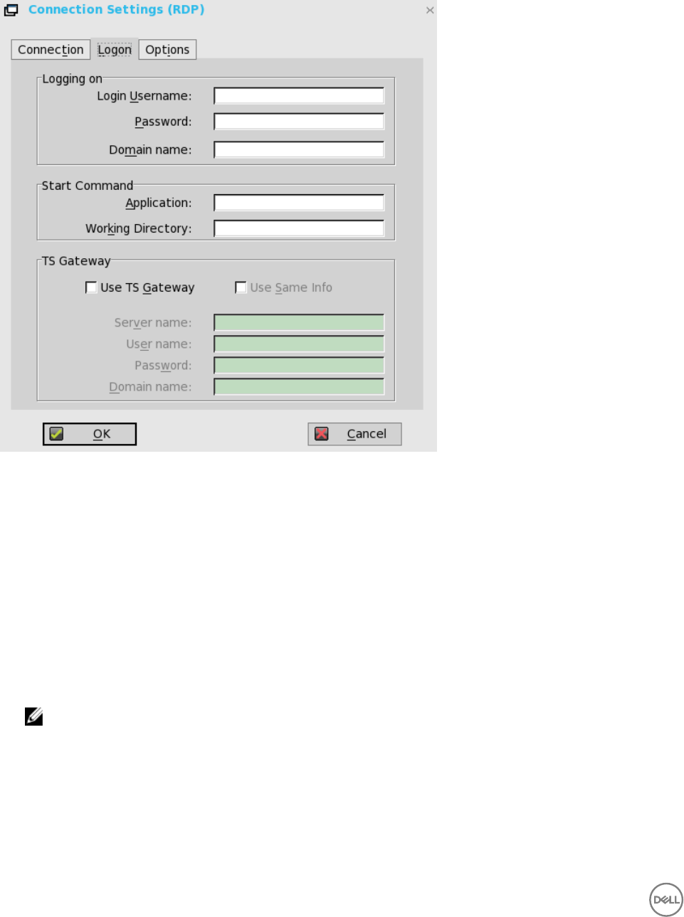
You can reset the options on the Connection tab of the Connection Settings (RDP) dialog box. To do so, click the Reset
VM command button. This command button is located in the upper-right of the dialog box. It appears only with a VDM
broker connection.
3. Click Logon tab, and use the following guidelines:
a. Logging on area —Enter login username, password, and domain name. If these boxes are not populated, you can enter the
information manually in the RDP server login screen when the connection is made. Use the following guidelines:
•Login Username — Maximum of 31 characters is allowed.
•Password — Maximum of 19 characters is allowed.
•Domain Name — Maximum of 31 characters is allowed.
b. Application —(127 characters maximum) and Working Directory (63 characters maximum)— Enter an initialization string
and arguments, including an associated working directory, that you want to start automatically on the server when the
connection is made.
c. Use TS Gateway— Enables the use of Terminal Services Gateway (TS Gateway) server when connecting. If required,
then enter the IP address or URL of the TS Gateway server in the Server name box. You can also enable Use Same Info (if
the server credentials are the same credentials as your Remote Desktop Credentials (Host remote computer credentials) in
the Login Username, Password, and Domain name fields) or disable Use Same Info and enter the Server name, User name,
Password, and Domain name of the TS Gateway server if required.
NOTE: A TS Gateway server is a type of gateway that enables authorized users to connect to remote computers
on a corporate network from any computer with an Internet connection. A TS Gateway server enables Remote
Desktop connections to a corporate network from the Internet without having to set up virtual private network
(VPN) connections. Ask your network administrator whether you need to specify a TS Gateway server.
•User Name — Enter a user name for the connection.
•Password — Enter the password.
•Domain — Enter the domain name.
106
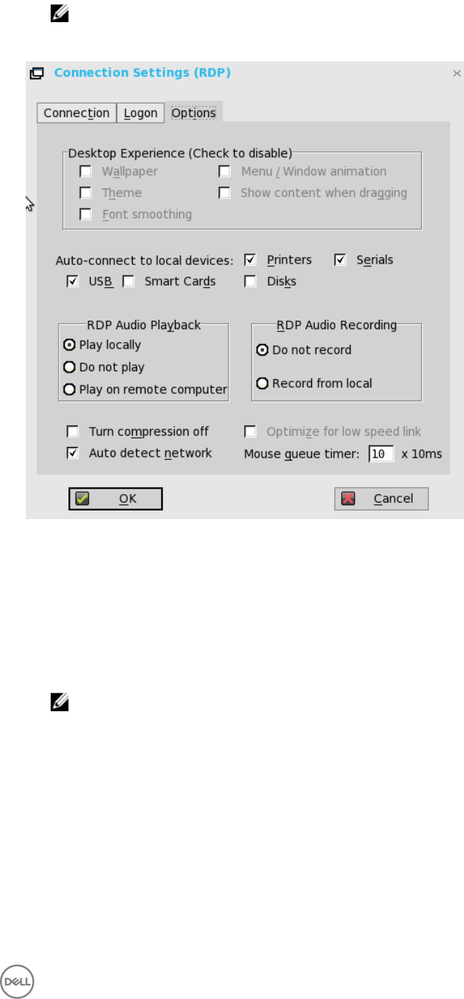
NOTE: The User name, Password, and Domain name fields are optional. If you leave any of these fields blank,
interactive login is required and users must enter the information at login time.
4. Click Options tab, and use the following guidelines:
a. Wallpaper — When selected, disables the desktop wallpaper.
b. Menu / Window animation — When selected, disables the menu or window animation.
c. Theme — When selected, disables the desktop themes.
d. Show content when dragging — By default, when you grab a Window by the title bar and move it around, the contents of
the window will move with it. Select this to disable this content view so that only the outline of the window moves when
dragging it, until you drop the window. This option can be beneficial, as it uses less processing power.
e. Font smoothing — Converts vector text to bitmap for better display.
f. Auto-connect to local devices — Select any options (Printers, Serials, USB, Smart Cards, and Disks) to have the thin
client automatically connect to the devices.
NOTE: USB — Redirects locally attached USB devices on the thin client to a Microsoft Windows terminal
server. When the user connects to the terminal server, locally attached USB devices on the thin client are
accessible.
g. RDP Audio Playback — Select the audio playback options such as Play Locally, Do not play, and Play on remote computer.
h. RDP Audio Recording — Select the audio recording options such as Do not record, and Record from local.
i. Turn compression off — When selected, turns compression off (intended for high-speed connections).
j. Optimize for low speed link —When selected, allows optimization for low-speed connections, such as reducing audio
quality and/or decreasing protocol-specific cache size. Intended for a connection spanning a WAN link or using dialup.
k. Auto detect network — When selected, turns on the auto detect network feature. This feature is enabled by default. It
also disables the Optimize for low speed link option and the Desktop Experience options by default.
l. Mouse queue timer— Specifies the default queue timer of a mouse event in an ICA or RDP session (in 1/100 of a second).
It can be used to adjust the bandwidth of a network.
5. Click OK to save the settings.
RDP Dynamic resizing
107

The windows in an RDP session can be resized directly by using the mouse.
How to work
1. Launch an RDP session (Windows 8.1/2012 r2) by using Window mode and non-default resolution.
2. Use the mouse to change the size of the session window.
Known Issues
Resizing the session window causes the MS media player’s frame region to dispatch. This is a server side issue.
108
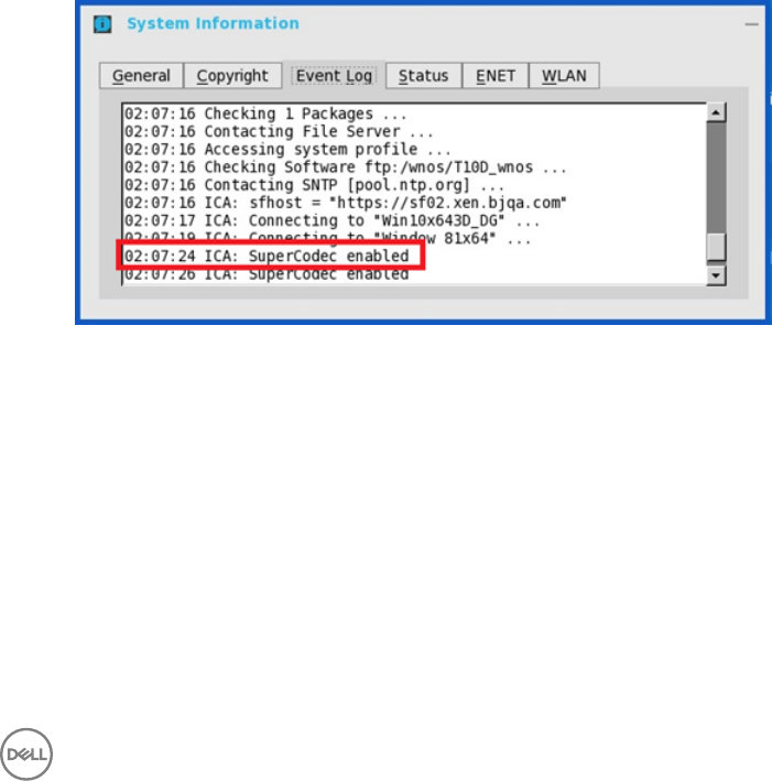
8
ICA SuperCodec
ICA SuperCodec is a H.264 decoder integrated on ThinOS ICA client side. Server encodes the session image into H.264 stream and
sends it to client side. Client decodes the H.264 stream by SuperCodec and show the image on screen. It should improve user
experience especially for HDX3DPro desktops.
Supported Environment
XenDesktop/XenApp 7.5 or later versions
Supported Platforms
All the platforms support ICA SuperCodec except on C10LE and R10L.
Verifying the working status of the ICA connections
•For Wyse 3010 Thin Client Series (T10) and Wyse 3020 Thin Client Series (T10D)
ICA SuperCodec is enabled by default when ThinOS resolution is lesser than or equal to 1920 x 1080.
a. When the feature is working, the following results are displayed:
ThinOS event log ICA: SuperCodec enabled
Click HDX Monitor → Graphics → Thinwire advanced → Encoder: DeepCompressionV2Encoder for NON-HDX3DPro
desktops or DeepCompressionEncoder for HDX3DPro desktops.
109
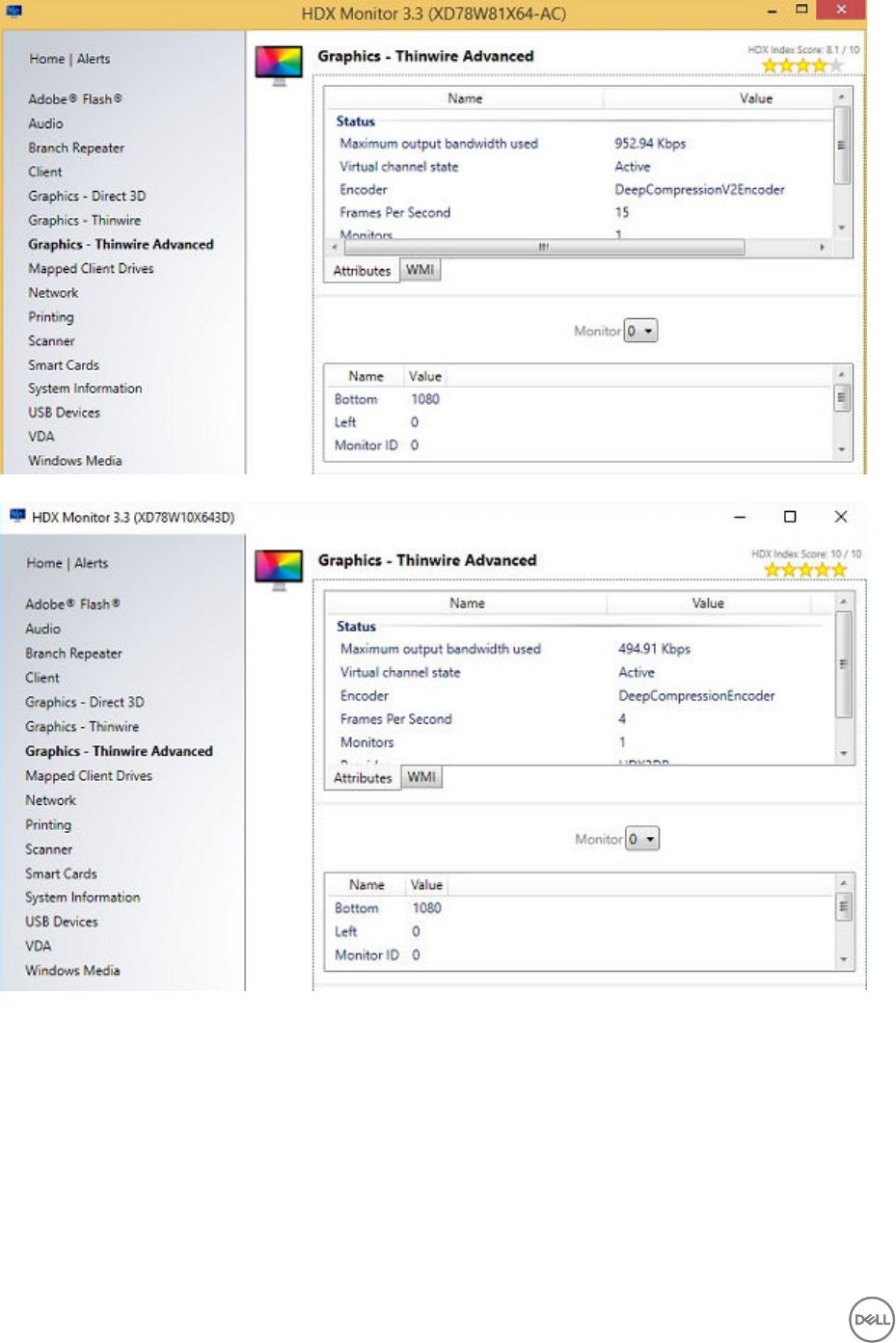
b. When the feature is disabled, you can view the following results:
ThinOS event log: System resolution exceeds hardware limitation (1920 x 1080), disable SuperCodec
110
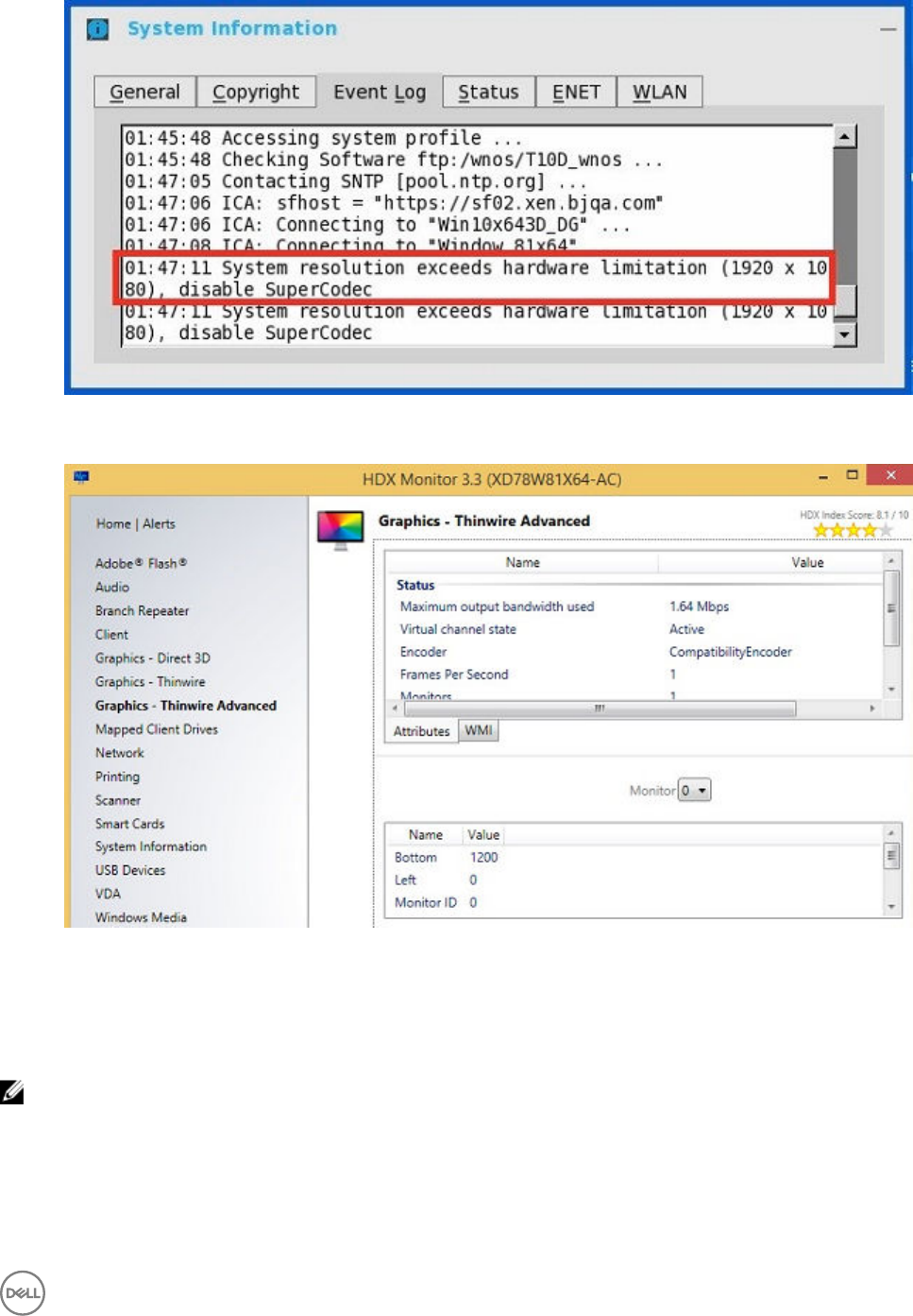
Click HDX Monitor → Graphics → Thinwire Advanced → Encoder → CompatibilityEncoder; CompatibilityEncoder.
•For other platforms except C10LE, R10L Wyse 3010 Thin Client with ThinOS (T10) and Wyse 3020 thin client with ThinOS
(T10D)
– ICA SuperCodec is always enabled without any limitation.
– ThinOS event log displays ICA: SuperCodec enabled.
NOTE: For ICA connections, there is no INI parameter.
111
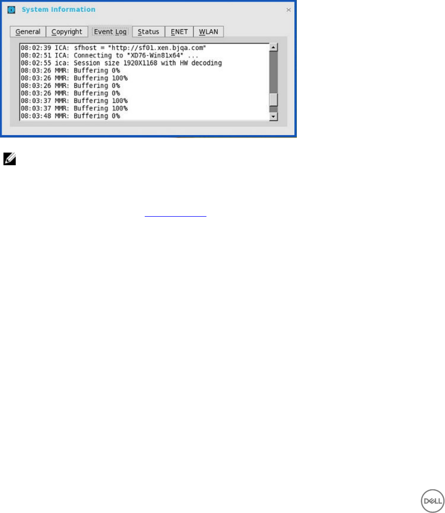
ICA 14.0.0.91
•Supported Environment
This release supports ICA connections with XenApp 7.x and later versions including XenDesktop 7.5 and later versions.
•New Features — This version of ICA has new features such as:
–Multicast support in Virtual Driver Multi-Media (VDMM)
1. Launch an ICA Desktop in XenDesktop 7.x or XenApp 7.x
2. Start multimedia and from the file menu, click Open URL.
Event logs are displayed.
NOTE: ICA multicast does not support C10 due to VIA platform limits.
3. Supported protocols: HTTP, MSB, MMS; RTSP/RTCP are not supported.
–SuperCodec support in Virtual Driver ThinWire (VDTW)
For information about SuperCodec, refer to ICA SuperCodec.
–Keyboard Timer Support
1. Add SessionConfig=ica KeyboardTimer=1000in wnos.ini.
2. Launch an ICA desktop, and then open the Notepad in the session.
3. When you try to edit something in Notepad, you will see some delay in the key input.
–Mouse Snap To position
1. Launch an ICA desktop.
2. In Control Panel, go to Mouse Settings.
3. Click Pointer Options → Snap To.
4. Enable Automatically move pointer to the default button in the dialog box, and then click OK to close the dialog box.
5. Re-open the mouse setting.
The mouse pointer snaps to OK button automatically.
–VDMM support
1. Launch an ICA desktop.
112

2. Run multimedia in session and try to play a video clip.
3. Seek the progress bar to a certain position.
4. Wait for the video clip to repeat the playback.
5. Again seek the progress bar to a certain position. User can seek to the correct position and continue to play.
113
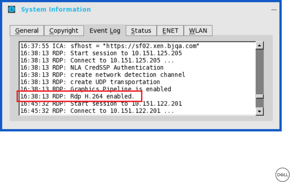
9
Features of RDP 8.1
Remote Desktop Protocol (RDP) H.264 and VOR is enabled by default for all ThinOS platforms, except C10LE and R10L.
Remote desktops such as Window 8, Window 8.1, Window 10, and Windows 2012R2 are supported in this release.
The following are the dependencies of RDP 8.1:
•Dependence 1: RDP GFX status, H.264 and VOR work only when GFX is enabled.
•Dependence 2: VOR is dynamic. So the enablement / disablement of VOR dynamically changes during the change in the video
resolution (enlarge/shrink).
•Dependence 3: H.264 enablement is decided at the beginning of connection, depending on the maximum resolution available for
the session.
The following INI parameter must be set to enable GFX, H.264 and VOR:
SessionConfig=RDP EnableGFX=yes/no EnableVOR=yes/no
enablerdph264=yes/no
Verifying the Status of VOR/H.264
• When the feature is enabled and when enablement dependencies are valid, the following screens are displayed in the Event Log
tab:
114
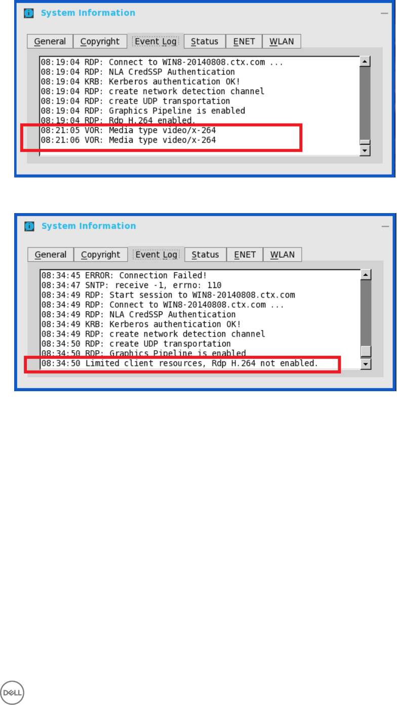
• When the feature is disabled, the following screen is displayed in the Event Log tab for disablement:
• Also, when video resolution exceeds VOR limitation, there is no event log for VOR disablement.
Work Flow of Dual Display
In dual-display, the RDP feature only works within a limited resolution.
The ‘maximum resolution possibly for the session’ for H.264 enablement is as follows:
• RDP without force span which is the same as single display.
• RDP with force span + window mode is dependent on system resolution value
• RDP with force span + full screen + default resolution is verified by system resolution x 2.
• RDP with force span + full screen + not default resolution is verified by selected resolution x 2.
115

Support Matrix for RDP 8.1
The following table displays the support matrix for RDP 8.1:
Table 3. Support Matrix for RDP 8.1
Platform Support
GFX Support
VOR Support
RDP H.
264
Default
GFX Default
VOR Default
H.264 HW/SW
decoder H.264 limits
on session
resolution
VOR limits on
video
resolution
C10LE No No No N/A N/A N/A N/A N/A N/A
R10L Yes Yes
(Gstream
er)
No Yes Yes N/A N/A N/A 1920x1200
Wyse 3010 Thin
Client with
ThinOS (T10)
Yes Yes
(FBF) Yes No Follows
GFX Follows
GFX HW only 1920x1080 1920x1080
Wyse 3020 thin
client with
ThinOS (T10D)
Yes Yes
(FBF) Yes Yes Yes Yes HW only 1920x1080 1920x1080
Wyse 3030 LT
thin client with
ThinOS / Wyse
3030 LT thin
client with
PCoIP
Yes Yes
(FBF) Yes Yes Yes Yes HW/SW
conditiona
l
1920x1200 1920x1200
Wyse 5010 thin
client with
ThinOS
(D10D) / Wyse
5010 thin client
with PCoIP
(D10DP)
Yes Yes
(FBF) Yes Yes Yes Yes HW/SW
conditiona
l
1920x1200 1920x1200
Wyse 5060 thin
client with
ThinOS / Wyse
5060 thin client
with PCoIP
Yes Yes
(FBF) Yes Yes Yes Yes HW/SW
conditiona
l
1920x1200 1920x1200
Wyse 7010 thin
client with
ThinOS (Z10D)
Yes Yes
(FBF) Yes Yes Yes Yes HW/SW
conditiona
l
1920x1200 1920x1200
116

10
Introduction to Flash Redirection
The Flash Redirection solution is to off-load flash content to the ThinOS client, and locally render and decode the flash playback.
The off-loading is conducted by Citrix HDX Flash Redirection. The local rendering and decoding process are conducted by
customized flash player and other multimedia process that runs locally on ThinOS.
Supported Environment— Supports only Citrix Connections with XenApp 6.5 and later versions and XenDesktop 7.0 and later
versions.
Supported Platforms:
• Wyse 3030 LT thin client with ThinOS
• Wyse 3030 LT thin client with PCoIP
• Wyse 5010 Thin Client with ThinOS (D10D)
• Wyse 5040 AIO Thin Client (5212)
• Wyse 5060 thin client with ThinOS
• Wyse 5060 thin client with PCoIP
• Wyse 7010 Thin Client with ThinOS (Z10D)
Flash Redirection
Required packages
User must install the following packages for the feature to work:
•base.i386.pkg— From ThinOS 8.2 release, this package is integrated into the ThinOS firmware image, and you need not
install or update it manually.
•FR.i386.pkg
Installation of packages
To install the required packages, follow the steps mentioned here:
1. Upload packages to directory \wnos\pkg\.
2. Ensure that the INI autoload is not set to 0. Set INI AutoLoad=1 AddPkg=FR in wnos.ini.
3. Restart the client to read the File Server and wait till the auto installation of packages is complete.
117
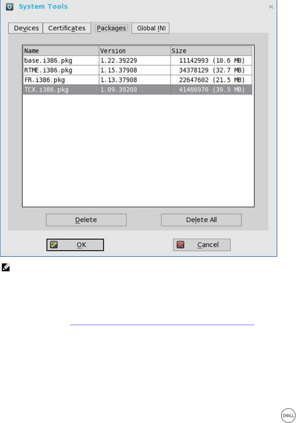
You can view the installed packages in the Packages tab in the System Tools dialog box.
NOTE: For ThinOS package versions, see
Dell Wyse ThinOS 8.3.1 Release Notes
.
4. Server configuration for Flash redirection
a. To ignore the differences in flash player versions, user must add the FlashPlayerVersionComparisonMask and
ClientFlashPlayerVersionMinimum registry key on the desktop.
If it is XenApp 6.5, IEBrowserMaximumMajorVersion registry key is required to ignore the differences in IE Browser
versions.
For more information, see docs.citrix.com/en-us/xenapp-and-xendesktop/7-9/hdx/flash-redirection.html
5. Client configuration for Flash redirection
By default, no client configuration is required. New INI parameters are added to support HDX FR Client configurations, for
example, to fetch the server side content. The newly added INI parameters are:
SessionConfig=ICA\
HDXFlashUseFlashRemoting=Never | Always (default) \
HDXFlashEnableServerSideContentFetching=Disabled (default) | Enabled \
How to verify it is working or not working
118
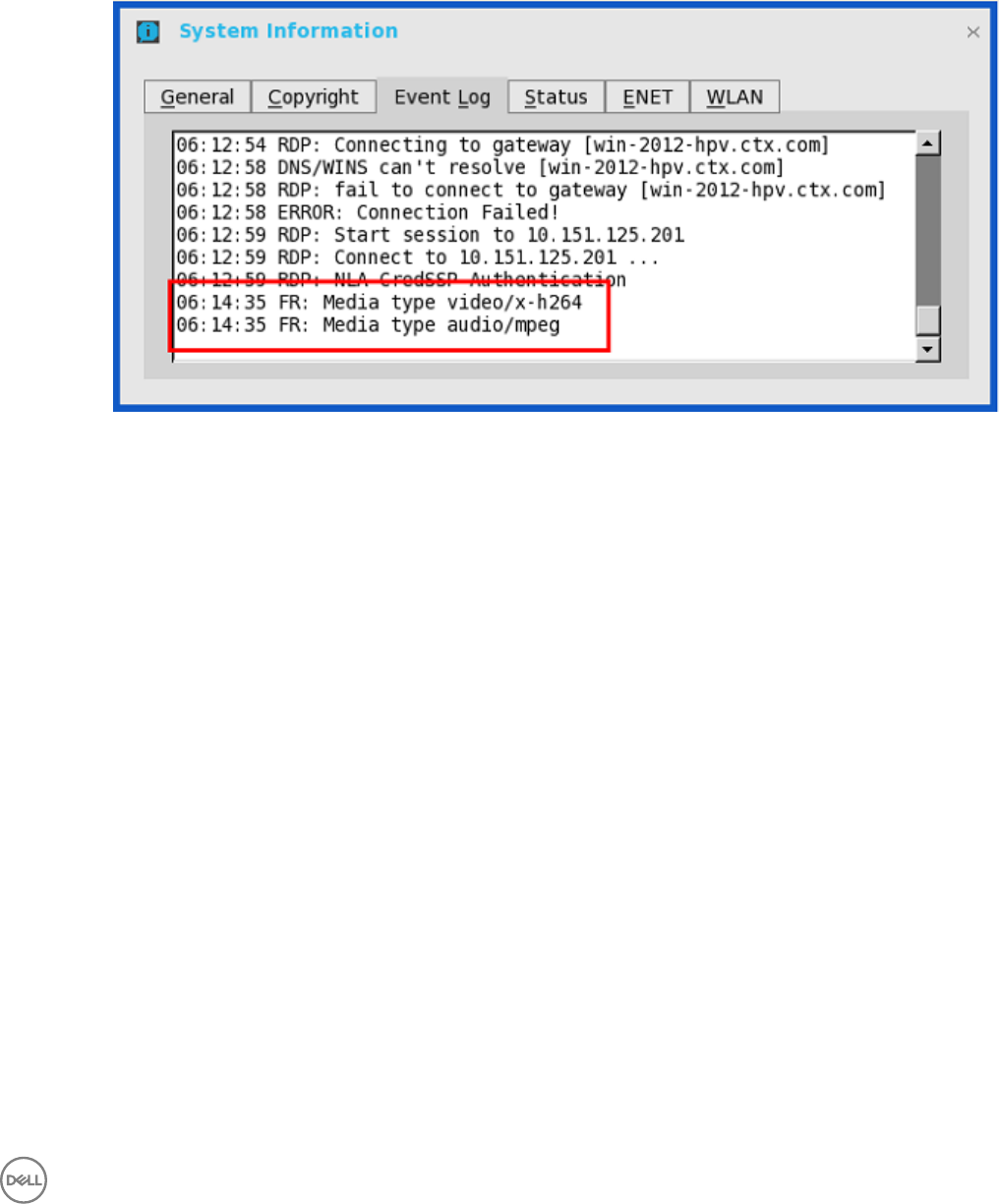
a. Right-click the flash video to know the flash player version. It displays version information of the customized player at
ThinOS client side which is 11.1.102.59. If the flash player version is different, then it is unsuccessful server rendering.
b. During the flash playback, it will display ThinOS event logs for HDX FR in the System Information dialog box.
1. FR: Media type video/x-264
2. FR: Media type audio/mpeg
Known Issues
a. Playback flash videos in Internet Explorer browser with normal security settings.
b. Playback with videos ≤ 720p; the 1080p video may show graphic issue.
c. Playback full screen video with resolution ≤ 1920 x 1200; for example, full screen playback with ThinOS resolution 1920 x
1200; in 2560 x 1600 full screen video there could be graphic issues.
d. After flash video is loaded it will stay in initial size; for example, resizing browser will not resize the video content; it is same
behavior with Citrix HDX FR Linux client.
e. Only English font is supported; for example, subtitles in other languages will not be properly displayed.
f. In some scenario the video shows no content initially; when user resizes browser the video appears normally; it is likely to
happen with x86 desktops and is a known issue for Citrix HDX FR Linux client.
g. Playback with videos that can work with HDX FR on Linux or Windows client: There are a number of videos/websites
known as not working with Citrix HDX FR solution such as msn.com, espn.com, movies.yahoo.com, and dell.com. Flash
videos simply cannot load with these websites using HDX FR solution. Some of them are working periodically; for example,
videos on dell.com were working well during this Feb/March but stopped working afterwards; the results can vary
depending on user location as well (US/Europe/Asia). It is therefore recommended to make sure the target videos work
with HDX FR on Linux or Windows, before working with it on ThinOS.
h. The solution on ThinOS is based on Citrix HDX FR Linux version. It is advised to compare with Linux client in case of any
issues.
i. Playback YouTube.com videos may run into some issues; for example, cannot show video unless user copy the URL and
paste it to the browser to visit again. In case any observation we recommend to compare with Linux client.
Basic Operations for Citrix HDX Flash Redirection
1. To disable flash version compatibility check, perform the following tasks:
119
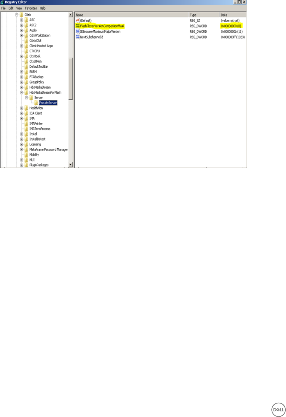
a. ThinOS client built-in Flash player version is 11.1. If the version installed on VDA/XenApp machines is higher than 11.1, then
user needs to disable flash version compatibility check for the HDX Flash redirection feature to work.
b. User can disable the version check by modifying Windows Registry Key on VDA/XenApp named
“FlashPlayerVersionComparisonMask” which is a DWORD that must be set to zero.
c. This needs to be set on each and every VDA/XenApp where the user needs the checking disabled.
The following action need to be set on d every VDA/XenApp and you need the checking disabled on.
•For a 32-bit operating system:
HKEY_LOCAL_MACHINE\SOFTWARE\Citrix\HdxMediaStreamForFlash\Server\PseudoServer
• Add the entry named FlashPlayerVersionComparisonMask with a DWORD value = 00000000 and
ClientFlashPlayerVersionMinimum"="11.0.0.
•For a 64-bit operating system: HKEY_LOCAL_MACHINE\SOFTWARE\Wow6432Node\Citrix\HdxMediaStreamForFlash
\Server\PseudoServer
• Add the entry named FlashPlayerVersionComparisonMask with a DWORD value = 00000000 and
ClientFlashPlayerVersionMinimum"="11.0.0.
• After making the modification you must restart IE on VDA/XenApp.
2. To modify maximum Internet Explorer version that HDX Flash supports:
120
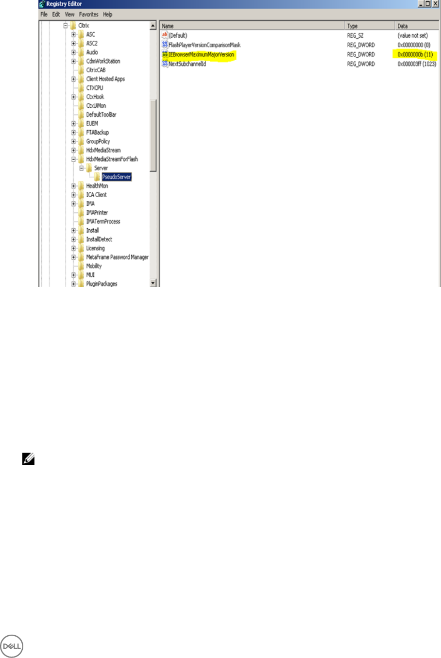
a. HDX Flash client side rendering feature does not work with Internet Explorer 11 with HDX Flash redirection enabled on
XenApp 6.5 and XenDesktop 5.6 VDA.
b. The registry key value IEBrowserMaximumMajorVersion is queried by the HDX Flash service to check for maximum
Internet Explorer version that HDX Flash supports. For Flash Redirection to work with Internet Explorer 11, set the
registry key value IEBrowserMaximumMajorVersion to 11 on the machine where HDX flash service is running. In case of
XenApp it would be the XenApp Server and in case of XenDesktop it would be the machine where VDA is installed.
c. For a 32-bit operating system:
•HKEY_LOCAL_MACHINE\SOFTWARE\Citrix\HdxMediaStreamForFlash\Server\PseudoServer.
• Add the entry named IEBrowserMaximumMajorVersion with a DWORD value = 0000000b.
d. For a 64-bit operating system:
•HKEY_LOCAL_MACHINE\SOFTWARE\Wow6432Node\Citrix\HdxMediaStreamForFlash\Server\PseudoServer.
• Add the entry named IEBrowserMaximumMajorVersion with a DWORD value = 0000000b.
NOTE: This is applicable for XenApp 6.5 and XenDesktop 5.6 VDA.
3. Use the following guidelines to create a new policy:
121
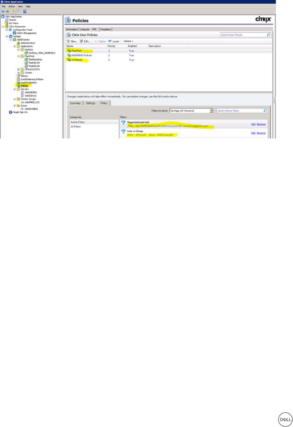
a. Launch the XenApp/XenDesktop manage console, and then go to Polices node pane.
b. User can edit ‘Unfiltered’ User Policy directly that applies to all connections. User can also view a personal policy, such as
‘FlashTest’ policy, and assign this policy to user’s own computer OU and domain user.
4. To view the list of Flash policies:
Go to Settings tab, and then select Flash Redirection. All the Flash Redirection policies are listed as shown in the following
screenshot.
122
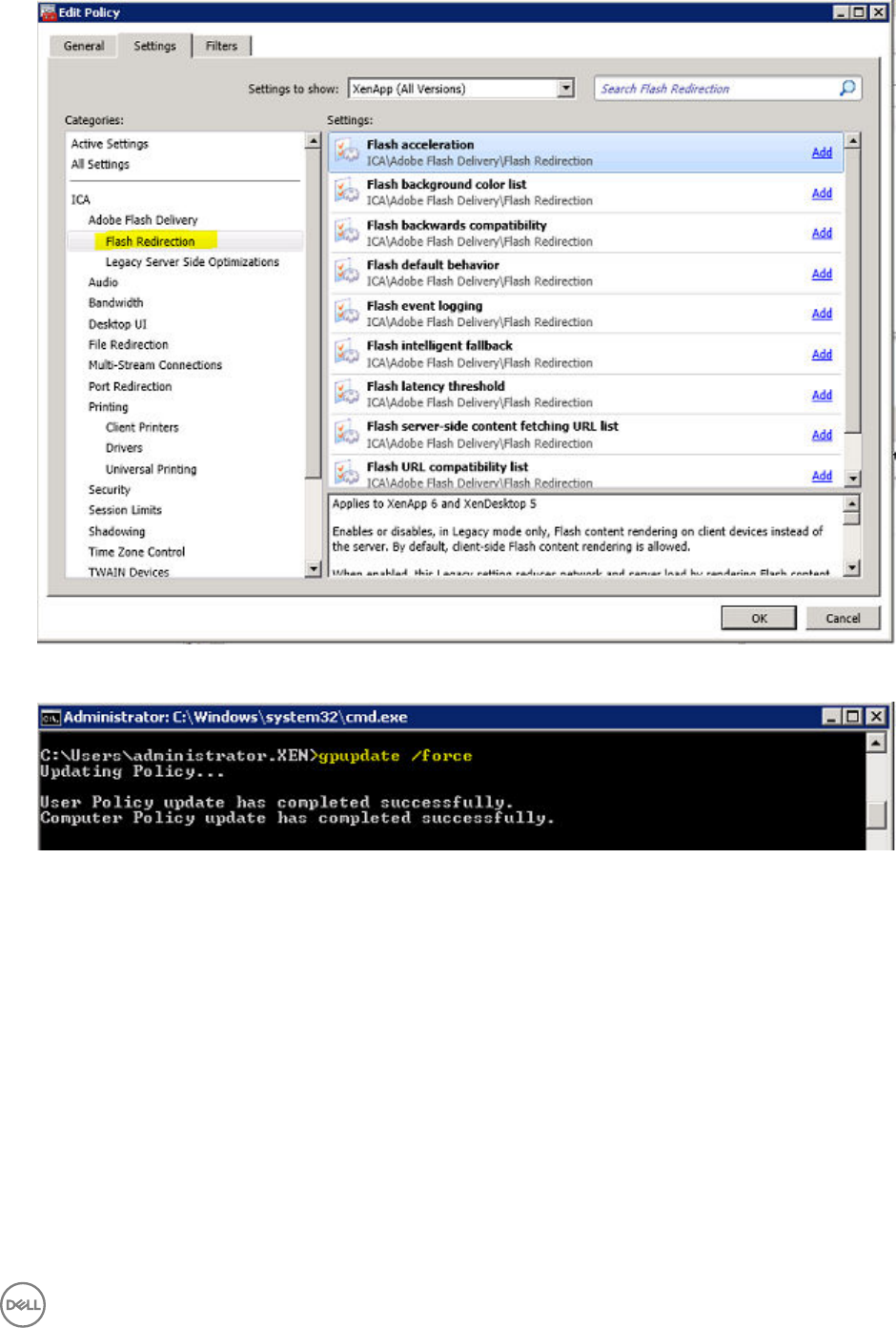
5. To activate a policy:
After modifying any Citrix policy, run the CMD command ‘gpupdate /force’ in the XenApp/VDA machine, and then reconnect
the session. The policy will be updated immediately.
6. To verify if Flash is getting client rendered OR HDX Flash redirection is working:
a. Right-click on the Flash Region to view the Flash context menu. If the Flash context menu is same as native Linux menu,
the ThinOS built-in Adobe Flash Player version is 11.1. The following screenshot shows that the Flash is getting client
rendered.
b. When flash is client rendered, the event log will display “FR”.
123
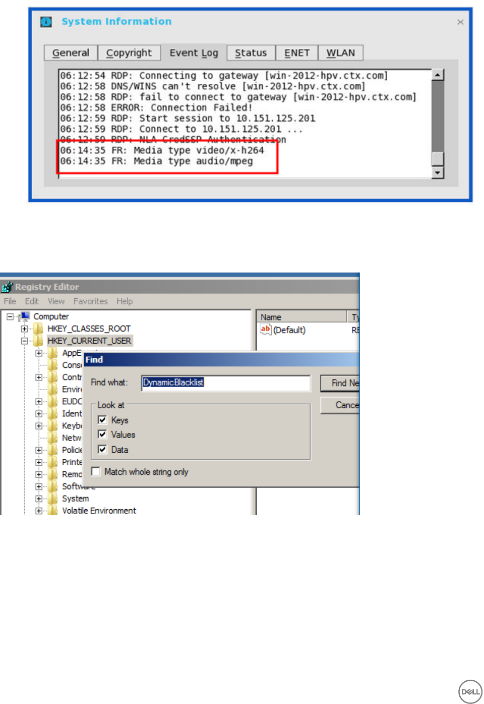
7. To delete the dynamic blacklist manually:
In Registry Editor, right-click HKEY_CURRENT_USER to find entries with Keywords ‘DynamicBlacklist’, and then delete all the
Backlist keys/records.
124
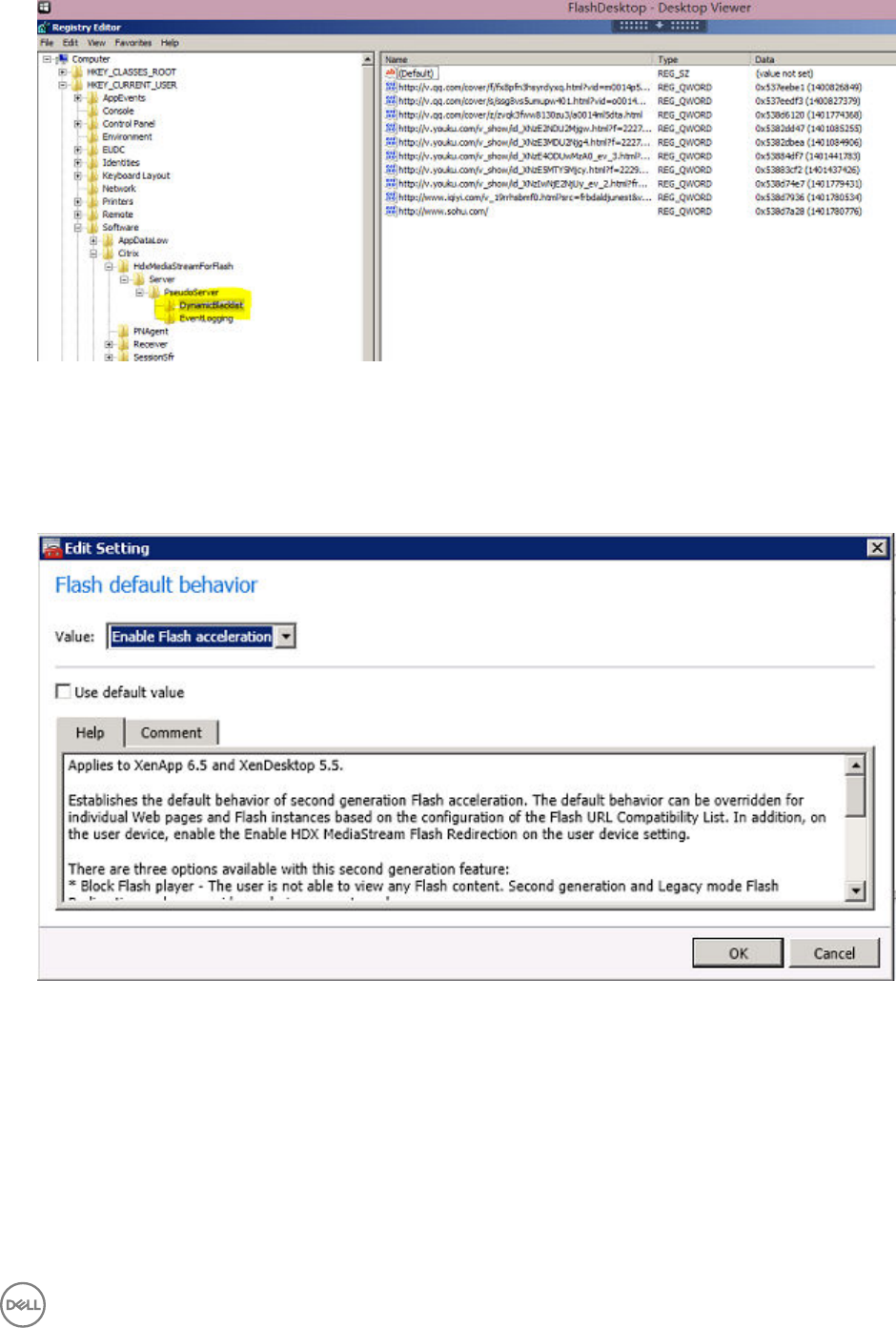
Citrix HDX Flash Redirection Policies Configurations
Policy - Flash default behavior
1. Remove all other active flash related policies in XenApp/XenDesktop server side.
2. Set Enable Flash acceleration for policy 'Flash default behavior' in XenApp/XenDesktop server side. Then run a web Flash
video in ICA session for the client to render the flash video.
125
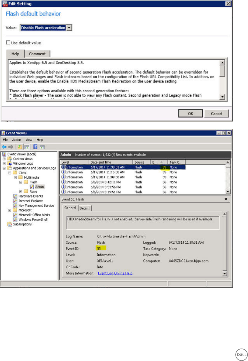
3. Set Block Flashacceleration for the policy Flash default behavior in the XenApp/XenDesktop server side, and then run a web
Flash video in ICA session, the flash video will be server rendered and event 55 generates in event viewer →
ApplicationsAndServicesLogs → Citrix → Multimedia → Flash → Admin.
4. Set Block flashplayer for policy 'Flash default behavior' in XenApp/XenDesktop server side, and then run a web Flash video in
ICA session, the flash instances are blocked and event 63 generates in event viewer → ApplicationsAndServicesLogs →
Citrix → Multimedia → Flash → Admin.
126
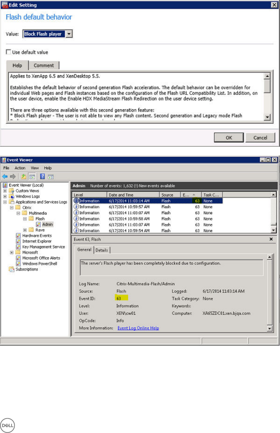
Policy - Flash URL compatibility list
1. Edit XenApp/XenDesktop policy 'Flash URL compatibility list', such as new item {Render On Client, *youku.com*, Any}, and
then access the website (For example, www.youku.com). All flash instances on the website are client rendered.
127
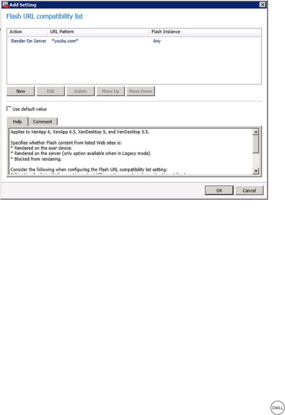
128
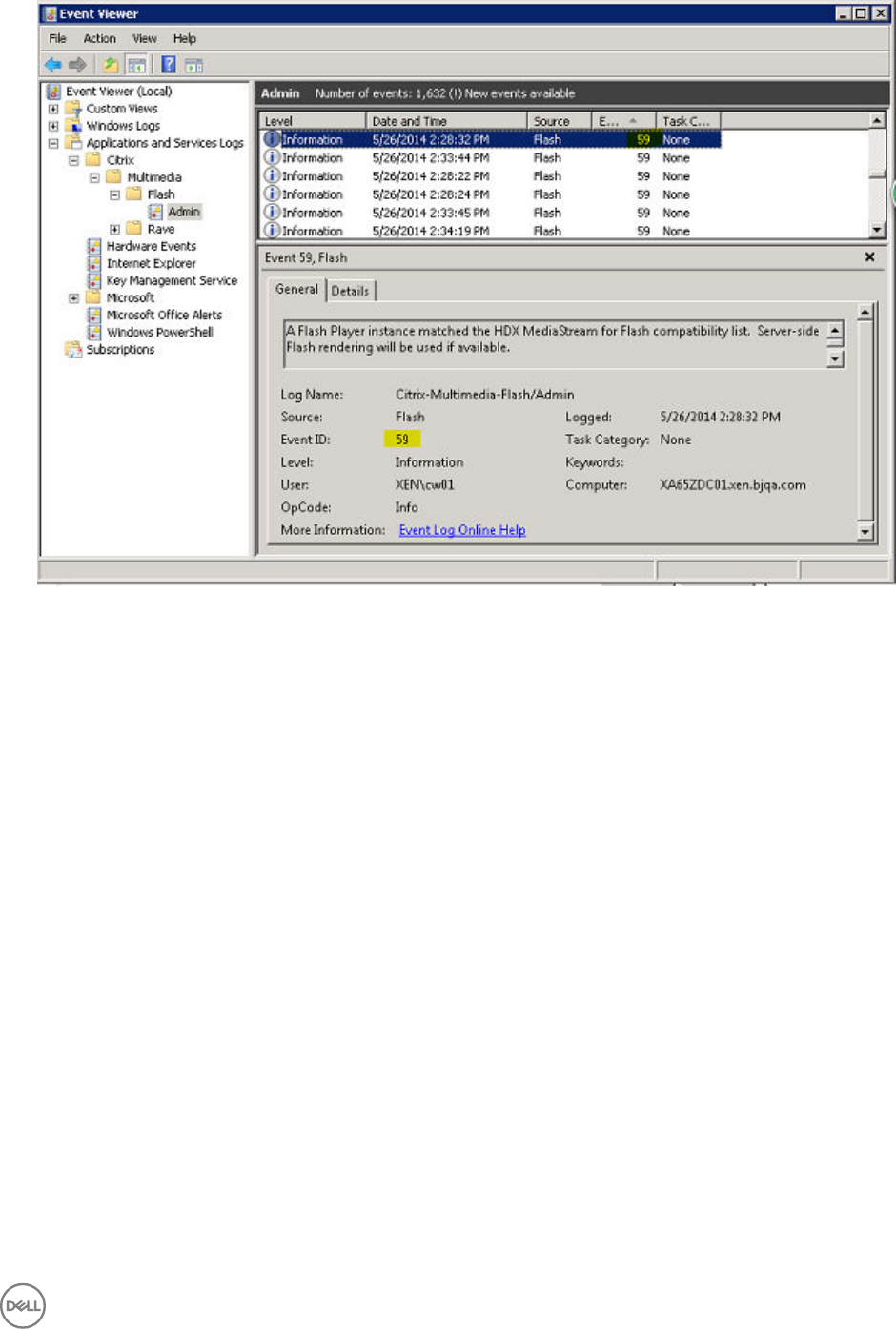
2. Edit XenApp/XenDesktop policy 'Flash URL compatibility list', such as new item {Render On Server,*youku.com*, Any}. And
then access the website (For example, www.youku.com). All flash instances on the website are server rendered, and Event 59
generates in event viewer.
3. Edit XenApp/XenDesktop policy 'Flash URL compatibility list', such as new item {Block, *youku.com*, Any}. And then access
the website (For example, www.youku.com). All flash instances on the website are blocked and Event 60 generates in event
viewer.
Policy - Flash background color list
129
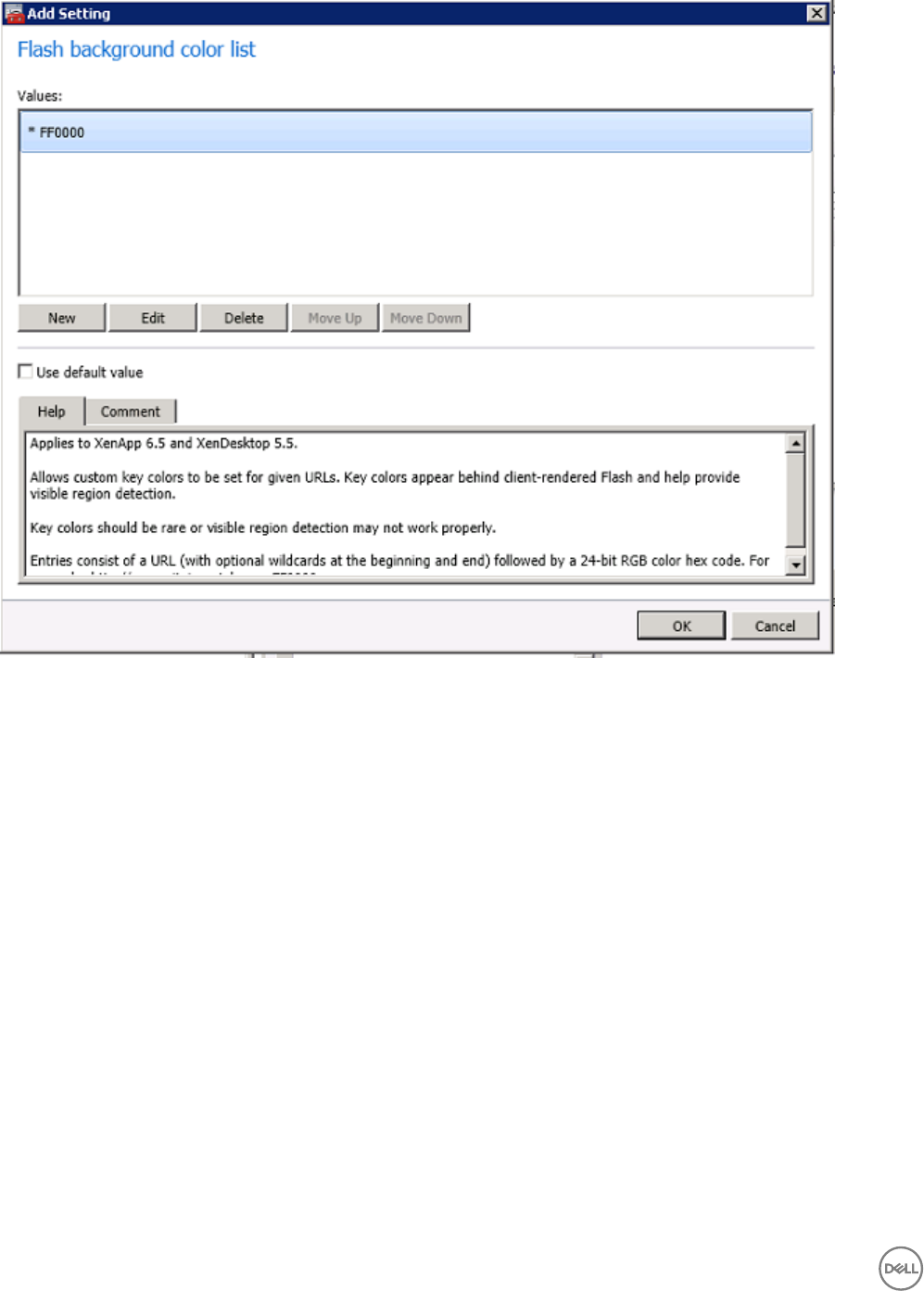
1. Edit the Flash background color list in XenApp/XenDesktoppolicy, such as new item {*FF0000}.
2. Access any web site, for example . www.youku.com to play a flash video through HDX FR, when the flash background color is
red.
Policy - Flash intelligent fallback
1. Enable the policy 'Flash intelligent fallback' in XenApp/XenDesktop server side. Run some flash websites in ICA session. Event
61 generates in event viewer → Applications And ServicesLogs → Citrix → Multimedia → Flash → Admin .
130
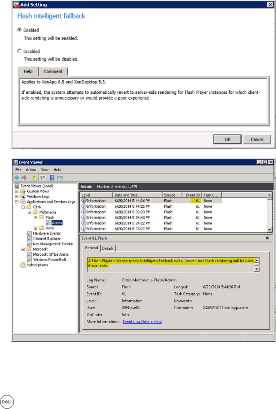
2. Disable the policy Flash intelligent fallback in XenApp/XenDesktop server side. Run some flash websites in ICA session. there
will be no new event 61 in event viewer → Applications And ServicesLogs → Citrix → Multimedia → Flash → Admin.
131
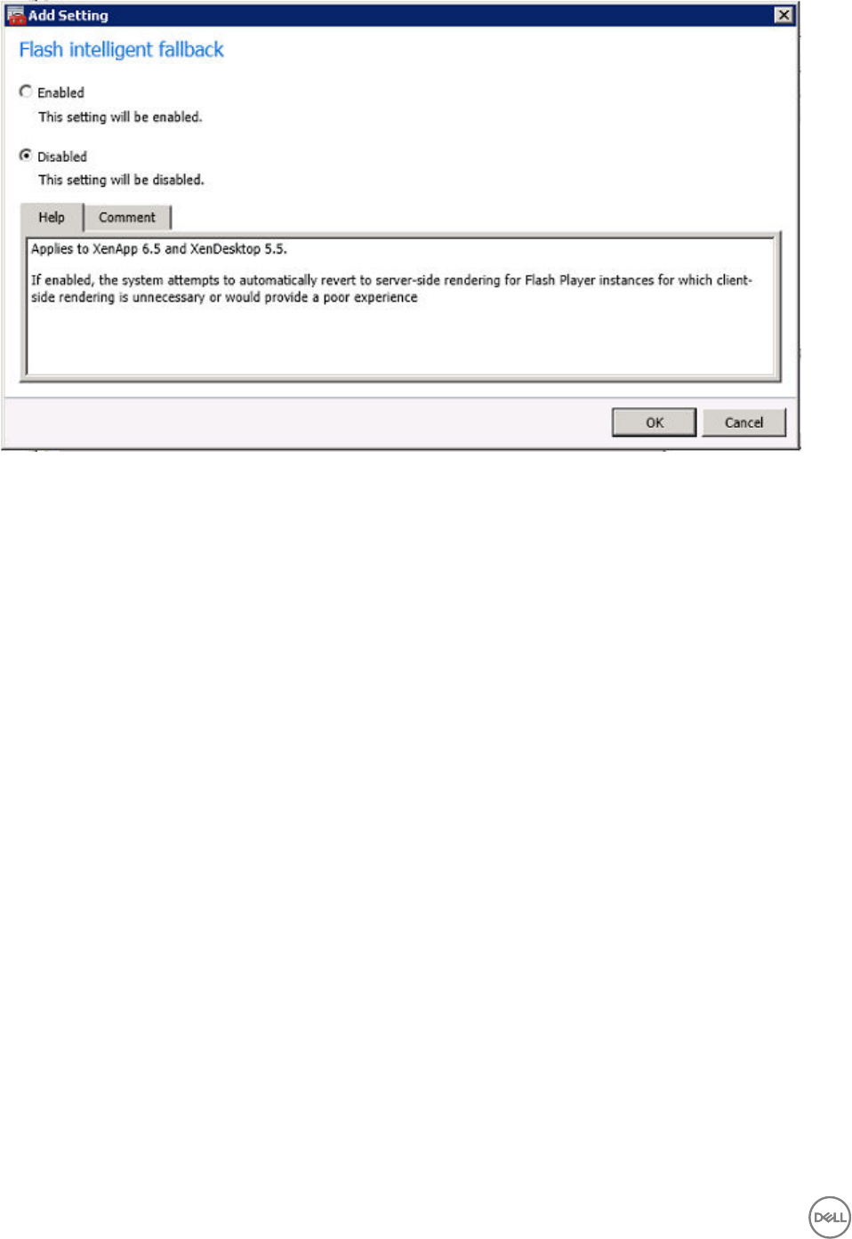
Policy - Flash server-side content fetching URL list
1. Edit the Flash server-side content fetching URL list in XenApp/XenDesktop policy, such as new item {*}
132
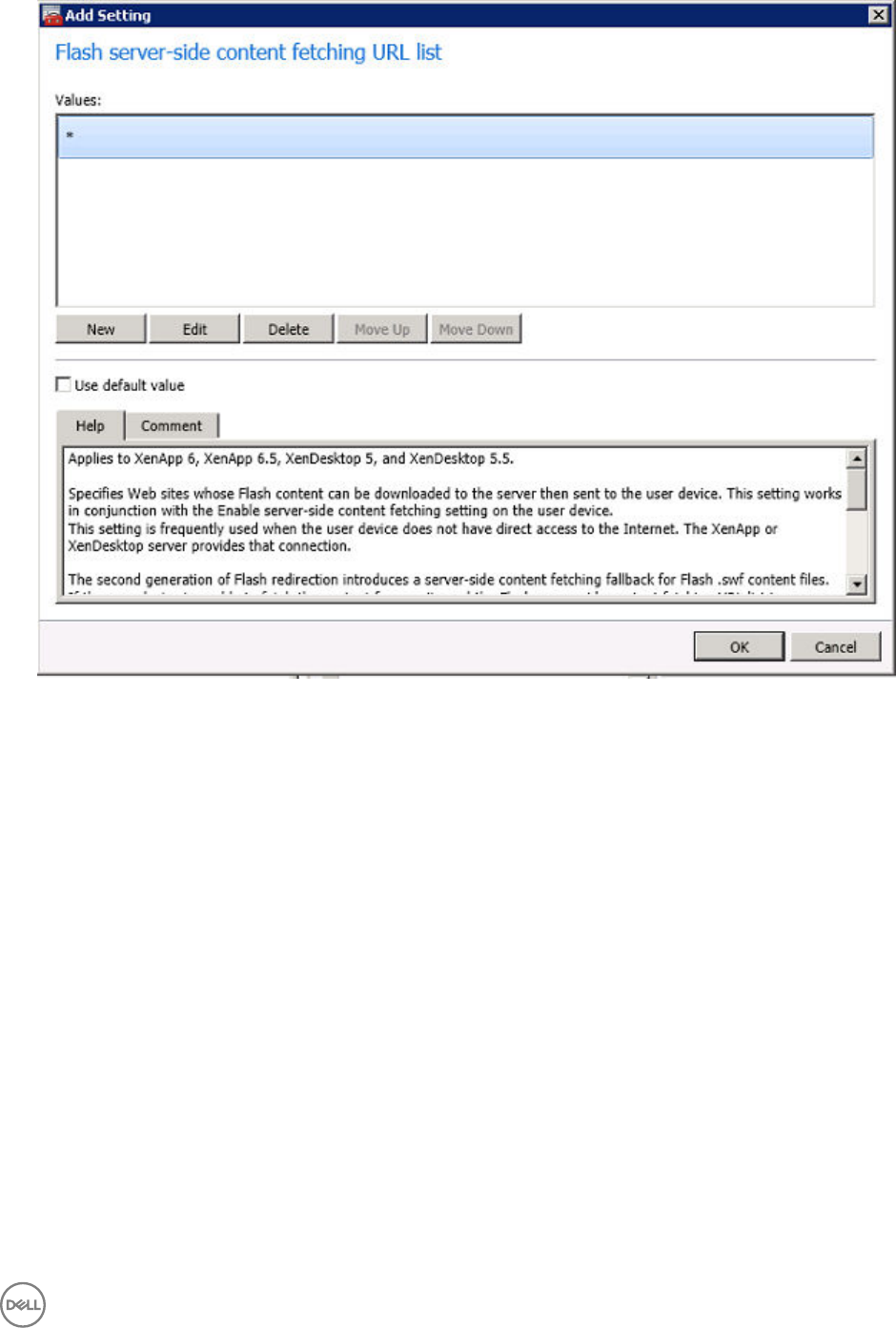
2. Set the ThinOS Lite INI using the {SessionConfig=ICA HDXFlashEnableServerSideContentFetching=Enabled}
3. Make sure that the client cannot access your testing Flash website, set an unreal DNS server to break client internet
connection. You can try to ping your website domain name for example www.youku.com that request will be timed out.
4. Access any website for example www.youku.com to play a flash video through HDX FR. The flash video can still be client
rendered employing server-side content fetching.
133
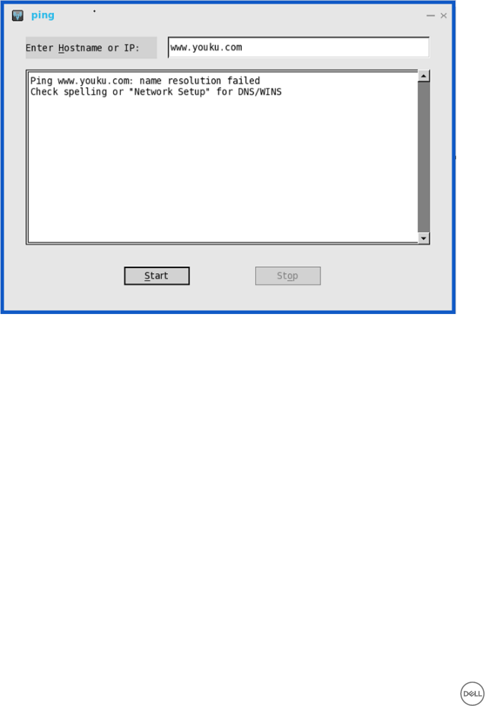
134

11
Introduction to TCX 7.0 Flash Redirection
The Dell Wyse TCX Suite 7.0 is a single software solution that provides full benefits of cloud client-computing without the limitations
of competing software suites. The TCX Flash Redirection is one of the component of TCX Suite 7.0 that enables the cloud client
users to experience improved Flash video content performance in a remote computing environment.
TCX Flash Redirection uses the client CPU to decode and render flash. TCX Flash Redirection uses the Adobe flash player plug-in
that supports the NPAPI interface on the client. TCX 7.0 Flash Redirection is supported over RDP and PCoIP protocols. TCX Flash
Redirection uses less Sever CPU cycles.
For more information about the TCX 7.0 Flash Redirection feature and Supported environment, refer to Dell Wyse TCX 7.0 Admin
Guide.
Supported Platforms
The following are the platforms that supports TCX 7.0 flash redirection:
• Wyse 3030 LT thin client with ThinOS
• Wyse 3030 LT thin client with PCoIP
• Wyse 5010 thin client with ThinOS (D10D)
• Wyse 5010 thin client with PCoIP (D10DP)
• Wyse 5040 AIO thin client (5212)
• Wyse 5040 AIO thin client with PCoIP (5213)
• Wyse 5060 thin client with ThinOS
• Wyse 5060 thin client with PCoIP
Working Status of TCX 7.0 Flash Redirection
Pre-requisites
•TCX.i386.pkg must be installed on client for the feature to work.
•TFRSServerBHO Class must be enabled in browser add-on.
•Enable Protected Mode is turned off in the Security options of Internet Explorer.
•Enable third-party browser extensions is enabled in Advanced options of Internet Explorer.
Verifying the working status of TCX 7.0 Flash Redirection
Verifying the status of TCX 7.0 Flash Redirection is similar to HDX FR.
Right-click the menu, and navigate to the Event log tab in System Information to verify whether the TCX FR is working effectively.
The following screenshot displays the TCX status log in the Event Log tab.
Use the following INI parameter to display the HW label:
MMRConfig=VIDEO flashingHW=1
135
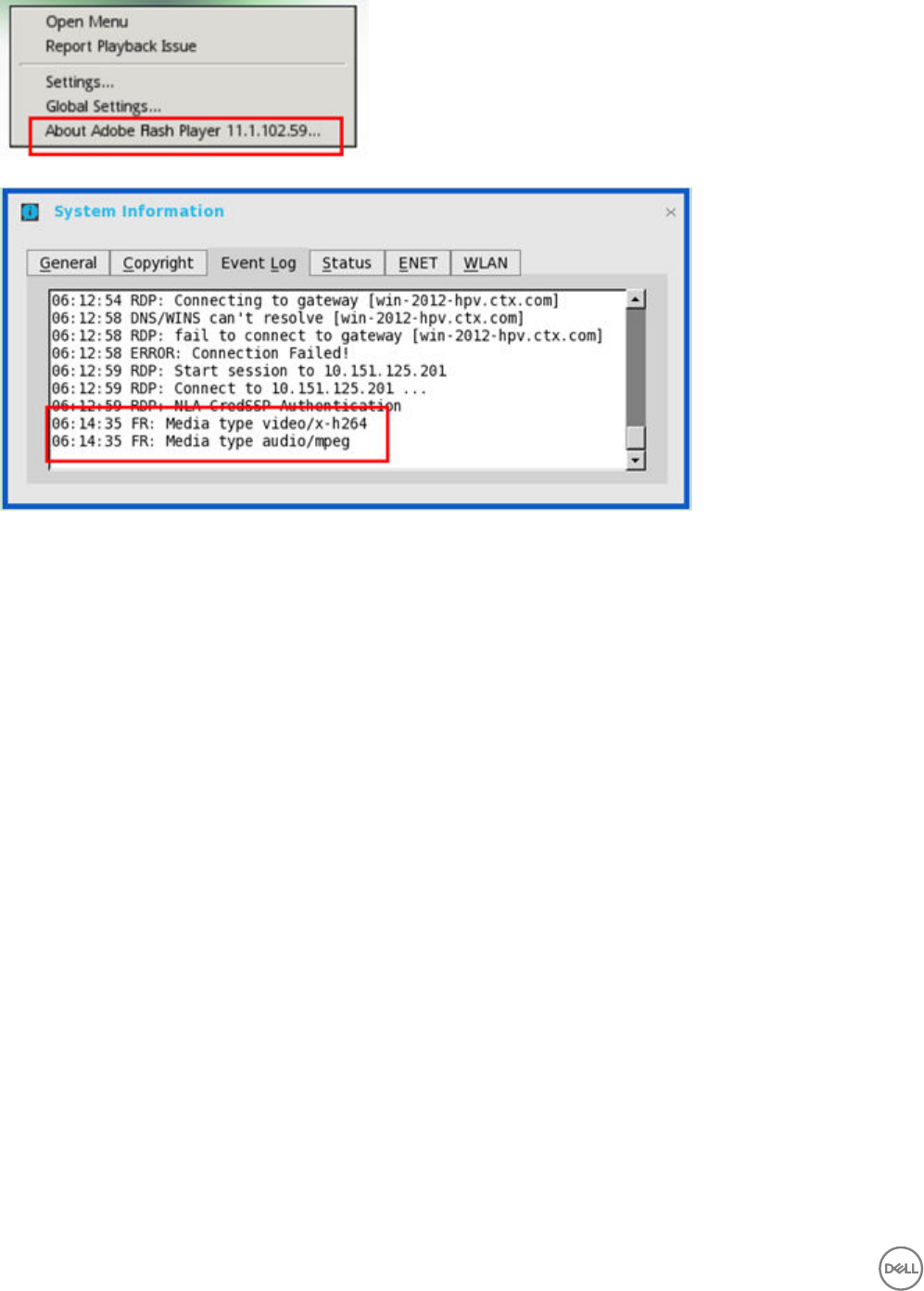
Known Issues with TCX 7.0 Flash Redirection
TCX FR on ThinOS is not working for certain flash video pages. However, the result is the same between FR over RDP, and FR over
PCoIP. Dell recommends you to validate, and block the URL that does not work, before deploying TCX FR on all the systems.
136
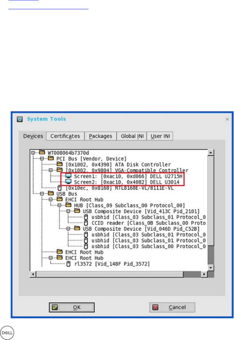
12
Performing Diagnostics
Diagnostics include:
•System Tools
•Using the Trouble Shooting Options
System Tools
Use the System Tools dialog box to view device details, package details and Global INI/User INI information. You can also import
certificates using the Certificates tab.
1. From the desktop menu, click System Tools.
The System Tools dialog box is displayed.
2. Click the Devices tab to display all the locally attached devices, including USB, Serial, and Parallel on applicable platforms. The
details about the monitors connected to the thin client are also displayed.
The Device Viewer button was previously available in the Devices tab of the System Information dialog box.
137
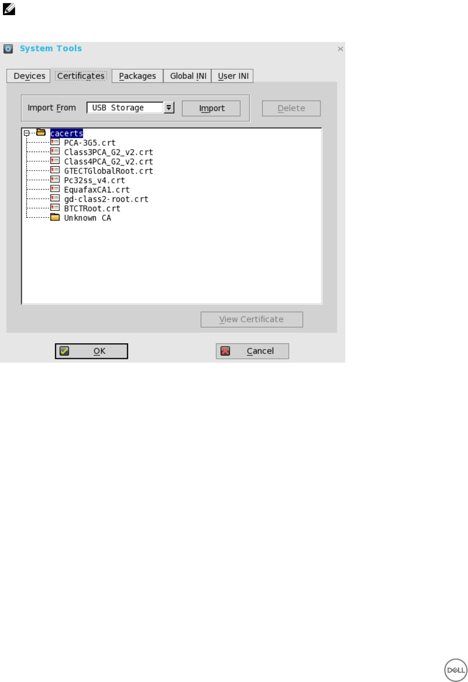
NOTE: The Mirror File Server tab has been removed from the System Tools dialog box, as it can now be viewed in
the Devices tab.
3. Click the Certificates tab, and use the following guidelines:
a. Import the certificates by selecting either USB Storage or File Server from the drop-down list, and then click Import to
import the required certificate.
b. Click Delete to delete the imported certificate.
c. Click View Certificate to view the imported certificate information such as Version, Validity, and Serial number. You can
also view the certificate path and certificate status.
4. Click the Packages tab, and use the following guidelines:
ThinOS packages that are installed on thin client are listed in the Packages tab.
138
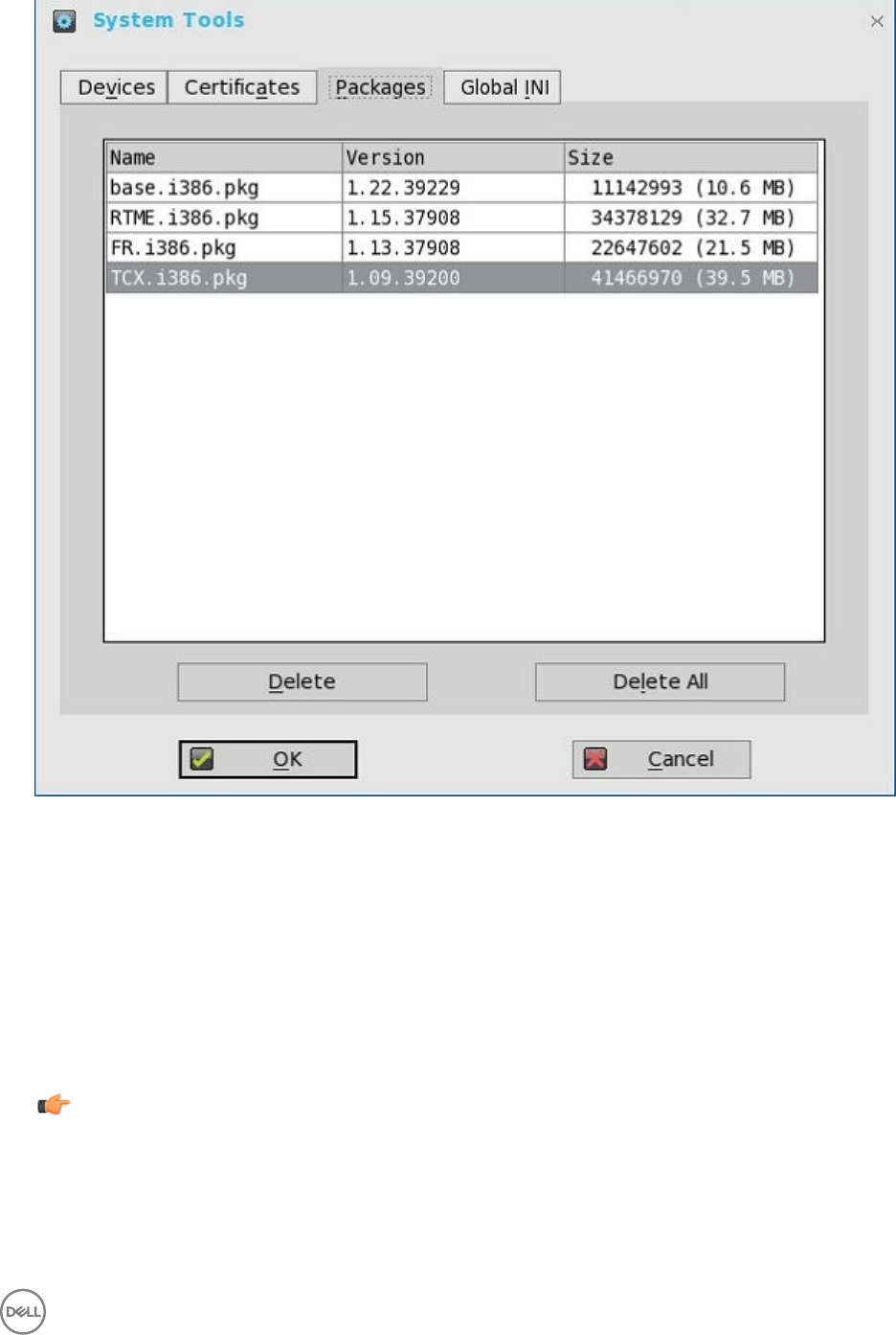
a. Click the Delete button to delete the selected package.
b. Click the Delete all button to delete all the packages.
The following packages are displayed in the Package tab:
•base.i386.pkg
•FR.i386.pkg
•RTME.i386.pkg
•pcoip.i386.pkg—This package is available only on Wyse 3030 LT thin client with PCoIP, Wyse 5010 thin client with
PCoIP (D10DP), Wyse 5040 AIO thin client with PCoIP (5213), and Wyse 5060 thin client with PCoIP.
•TCX.i386.pkg
Important: You cannot delete the base package separately. If you click Delete All, all packages are deleted including
the base package. When you click Delete All, a message is displayed prompting you to restart the device.
139
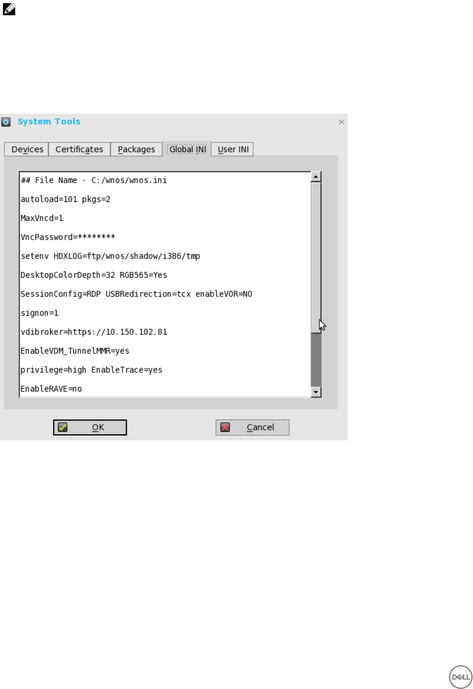
NOTE: From ThinOS 8.2 release, base.i386.pkg is mandatory for all ThinOS clients. PCoIP package is mandatory
for Wyse 5010 thin client with PCoIP (D10DP) and Wyse 5040 AIO thin client with PCoIP (5213). In ThinOS 8.3,
PCoIP package is mandatory for Wyse 3030 LT thin client with PCoIP. From ThinOS 8.3.1, PCoIP package is
mandatory for Wyse 5060 thin client with PCoIP. Other packages are optional. Base package and PCoIP package
are integrated into the ThinOS firmware image. Installing the latest ThinOS firmware image will automatically install
the latest version of these packages on ThinOS client. You cannot manually install or upgrade these embedded
packages. However, the package version details of respective packages are displayed in the Packages tab for
engineering information purpose only.
5. Click the Global INI tab to view wnos.ini information.
6. Click the User INI tab to view wnos.ini information.
7. Click the WDM INI to view the received WCM configurations.
140
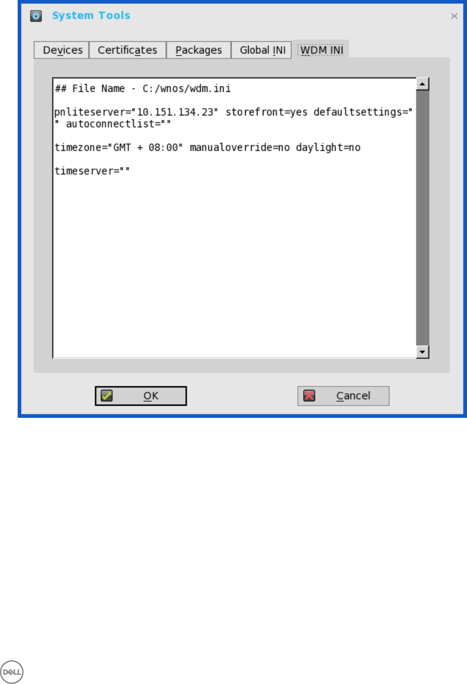
WCM function is supported from WDM for comprehensive client configuration. Without configuration from server, the client
loads the cached settings (wdm.ini), if available.
Limitation
To upgrade or downgrade firmware/image through WCM, you are required to enable WDM file server function by selecting the
WTOS INI path upon checkin (FTP/HTTPS/HTTP/CIFS) check box in the WTOS preferences in the WDM configuration
manager.
User Scenario
a. Create or edit client configurations from WCM (JSON).
141
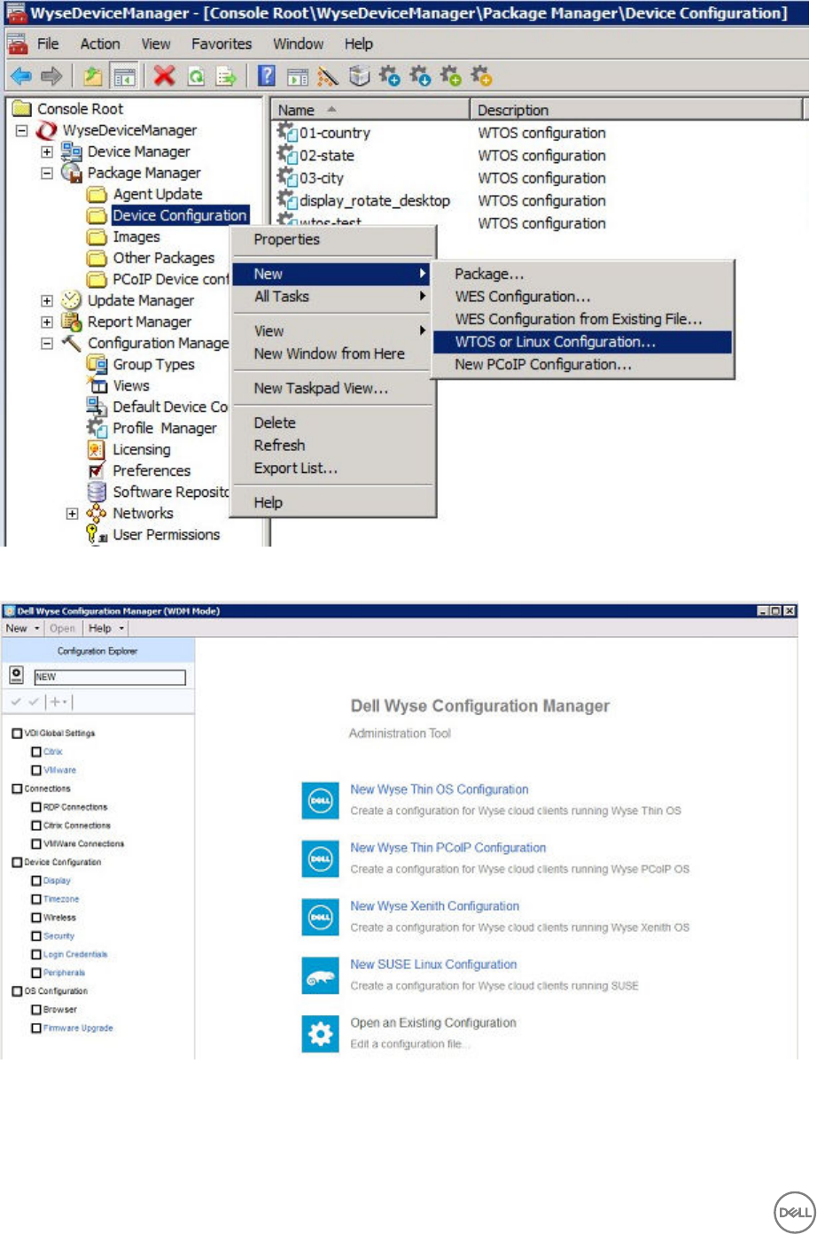
b. Select the target devices, and publish configuration settings through the Package Distribution Wizard.
142
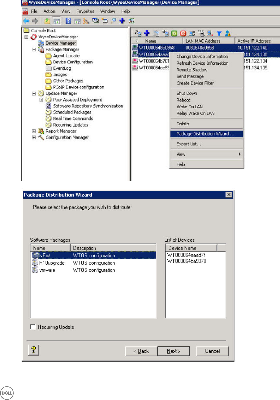
For more information about WDM Package Manager and Profile Manager, refer to the WDM Admin Guide.
143
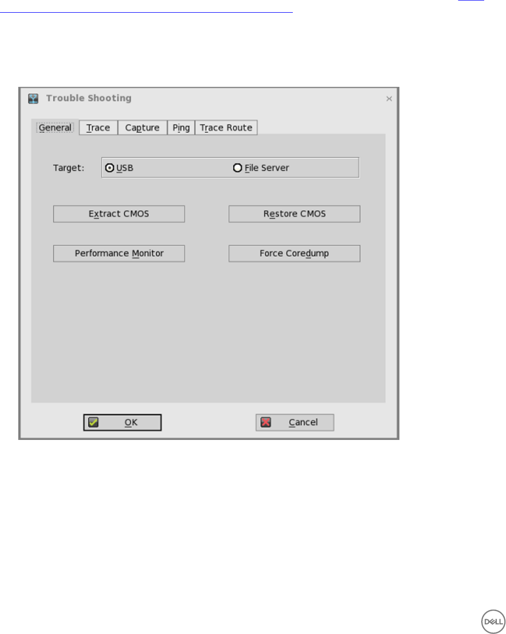
8. Click OK to save the settings.
Using the Trouble Shooting Options
Use the Trouble Shooting dialog box to configure Trace and Event log settings, performance monitor graphs that display client
CPU, Memory, and Networking information, and CMOS management extract and restore cmos settings as described in CMOS
Local Management: Extracting CMOS Settings to a USB Key for Distribution. It also allows you to view wnos.ini cached information
for troubleshooting purposes.
To use the trouble shooting options:
1. From the desktop menu, click Trouble Shooting.
The Trouble Shooting dialog box is displayed.
2. Click the General tab, and use the following guidelines:
a. Click either USB or File Server to select your target device you want to use for CMOS management.
b. Extract CMOS — Click this option to extract the CMOS settings to the USB Key or file server based on your target device
selection.
c. Restore CMOS — Click this option to write the CMOS settings from the USB Key to the target thin client.
d. Performance Monitor — Click this option to display your thin client CPU, Memory, and Networking information. The
graphs display on top of all windows.
e. Force Coredump — Use this option to forcibly generate the debug information for technical investigation when your
system is not responding.
3. Click the Trace tab to configure the trace actions and Delay on Trace. The available options for Trace action are None,
Capture, and Playback.
144
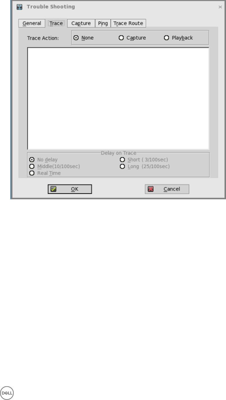
4. Click the Capture tab to configure the Export Event Log, Network Capture to USB, Wireless Capture to USB, and USB DEV
Trace.
145
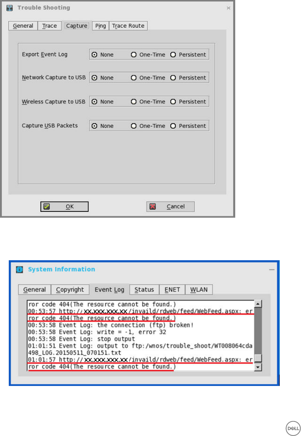
If you want to enable the error messages, use the following guidelines:
• Click either One-time or Persistent option to enable logging the unexpected error message.
• Turn off logging and then check the log file under the folder ftp:/wnos/trouble_shoot.
• Be sure to enable the Enable Trace option of the Privilege parameter in a wnos.ini file. For more information, see Dell Wyse
ThinOS INI Guide.
146
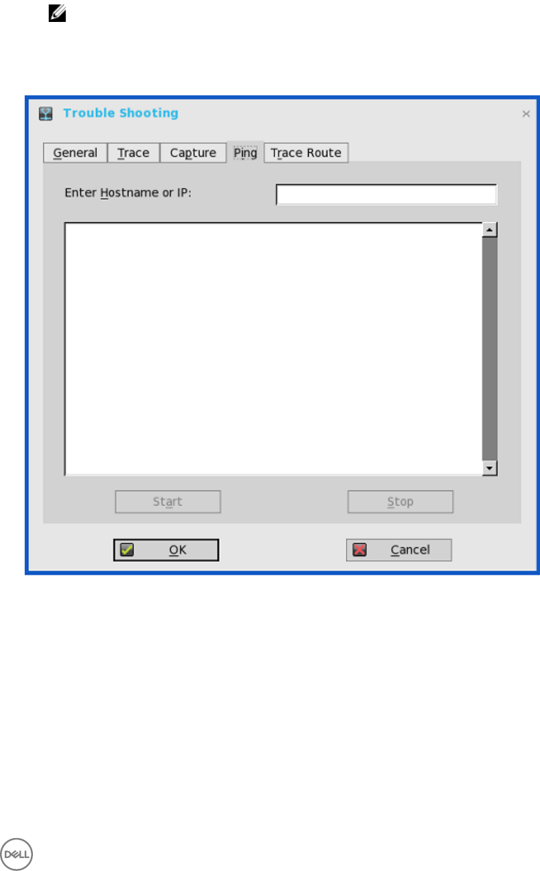
• Use the Network capture to USB option to enable the capture of network information, that is, a network trace of all traffic
coming in and out of the thin client to a USB drive that is inserted into the thin client.
After login and use of the XenDesktop server or network, you will see a ThinOS_WS.pcap file in the USB drive which you
can analyze using software such as a packet analyzer used for network troubleshooting, and analysis.
NOTE:
Ensure that you have inserted the USB drive into the thin client before selecting the Network capture to USB option.
The Network capture to USB option is automatically cleared, if there is no USB drive inserted and you exit the dialog
box, or after restarting the thin client; if needed, you must select the option again.
5. Click the Ping tab, and use the following guidelines to execute the ping diagnostic utility and display response messages:
a. Enter Hostname or IP — Enter the IP address, DNS-registered host name, or WINS-registered host name of the target to
be pinged.
b. Data area — Displays ping response messages. The ping command sends one echo request per second, calculates round
trip times and packet loss statistics, and displays a brief summary upon completing the calculation.
c. Start — Executes the ping command. If the host is operational and on the network, it responds to the echo request. By
default, echo requests are sent until interrupted by clicking Stop.
d. Stop — Terminates the ping request and leaves the Ping dialog box open, so you can read the summary posted in the data
area.
147
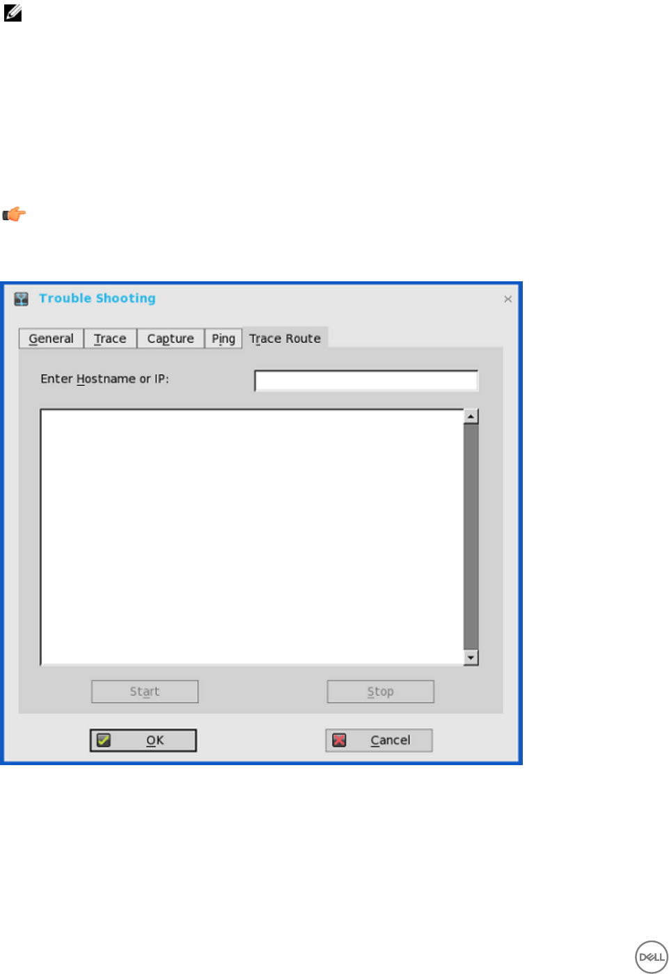
NOTE:
Ping sends an echo request to a network host. The host parameter is either a valid host name or an IP address. If the
host is operational and on the network, it responds to the echo request. Ping sends one echo request per second and
calculates round trip times and packet loss statistics. It displays a brief summary upon completion of the calculation.
The ping utility can be used to:
• Determine the status of the network and various foreign hosts.
• Track and isolate hardware and software problems.
• Test, measure, and manage networks.
• Determine the IP address of a host if only the host name is known.
Important:
Not all network equipment will respond to ping packets, as this is a common mechanism used in denial-of-service attacks.
Lack of response does not necessarily indicate that the target of the ping is unusable for other purposes.
6. Click the Trace Route tab to execute the tracert diagnostic utility and display response messages. Use the following guidelines:
a. Enter Hostname or IP — Enter the IP address, DNS-registered host name, or WINS-registered host name of the target to
be traced.
b. Data area — Displays round-trip response time and identifying information for each device in the path.
c. Start — Executes the tracert command.
d. Stop — Terminates the tracert command and leaves the Trace Route dialog box open, so that you can read the
information posted in the data area.
148

The tracert utility traces the path from your thin client to a network host. The host parameter is either a valid host name or
an IP address. The tracert utility sends out a packet of information three times to each device (routers and computers) in
the path and displays the round trip response times and identifying information in the message box.
7. Click OK to save the settings.
149

A
Central Configuration: Automating Updates and
Configurations
This appendix describes how to set up your environment to provide your thin clients running ThinOS with automatic updates and
configurations in three simple steps.
NOTE: Dell Wyse thin clients do not require device management software. They are configured to obtain their IP
address, as well as the location of firmware and configuration instructions, from a DHCP server. However, you can use
WDM for a more hands-on management of your thin clients. For information about configuring your thin clients to
communicate with a WDM server, see the WDM related INI parameters in
Dell Wyse ThinOS INI Guide
.
How to Set Up Automatic Updates and Configurations
For a thin client running ThinOS to successfully access INI files and update itself from a server, you must set up the server with the
correct folder structure where the INI files and other update files are located, direct the thin client to the server, and then reboot or
start the thin client
Once DHCP and servers are configured and available, the thin client checks (at each boot up) to see whether or not any updates
are available on a predefined server DHCP Option #161 specifies the server URL, DHCP Option #162 specifies the root path to the
server. If updates are available, the updates are automatically installed.
Using DHCP Options
This table contains the DHCP options available for use.
Table 4. DHCP Options
Option Description Notes
1 Subnet Mask Required. However, it is not required
unless the thin client must interact with
servers on a different subnet. MS DHCP
requires a subnet mask and is always send
one.
2 Time Offset Optional.
3 Router Optional, but recommended. It is not
required unless the thin client must
interact with servers on a different
subnet.
6 Domain Name Server(DNS) Optional, but recommended.
15 Domain Name Optional, but recommended. See Option
6.
28 Broadcast Address Optional.
44 WINS servers IP Address Optional.
51 Lease Time Optional, but recommended.
52 Option Overload Optional.
150

53 DHCP Message Type Recommended.
54 DHCP Server IP Address Recommended.
55 Parameter Request List Sent by thin client.
57 Maximum DHCP
Message Size
Optional (always sent by thin client).
58 T1 (renew) Time Optional, but recommended.
59 T2 (rebind) Time Optional, but recommended.
61 Client identifier Always sent.
161 File server (ftp/http/https) Optional string. Can be either the name or
the IP address of the file server. If a name
is given, the name must be resolvable by
the DNS servers specified in Option 6. If
the option provided by the server is blank
or the server provides no value for the
field, the machine on which the DHCP
server resides is assumed to also be the
file server.
162 Root path to the file server (ftp/http/
https) Optional string. If the option provided by
the server is blank and the server
provides no value for the field, a null
string is used.
\wyse\wnos is automatically appended to
the search path. For example, if you enter
pub\serversoftware, the path
searchedare pub\serversoftware\wyse
\wnos.
NOTE: You can have the \wyse
automatic component of the
search path omitted by appending
a dollar sign ($) to the entered
path. For example, if you enter pub
\serversoftware$, the path
searched will be pub
\serversoftware\wnos.
151

NOTE:
The usage or omission of a leading
slash (\) on the path is critical on
some servers. Some servers limit
access to the root path of the user
specified at login. For those servers,
the usage of the leading slash is
optional. Some *NIX servers can be
configured to allow the file user
access to the entire file system. For
those servers, specifying a leading
slash specifies that access is to start
at the root file system. Proper
matching of the file specification to
the file server in use is critical to
ensuring proper operation. A secured
Windows server requires the slash to
be specified in order to complete
proper access.
181 PNAgent/ PNLite server list Optional string. The thin client uses the
server to authenticate the Windows
credentials of the user and to obtain a list
of ICA published applications valid for the
validated credentials. The user supplies
those credentials when logging in to the
thin client.
182 NT domain list for PNAgent/ PNLite Optional string. The thin client creates a
pull-down list of domains from the
information supplied in option 182. This list
is presented at thin client login in the
order specified in the DHCP option (for
example, the first domain specified
becomes the default). The selected
domain is the one which must
authenticate the user ID and password.
Only the selected domain is used in the
authentication process. If the domain list
is incomplete and the user credentials
must be verified against a domain not in
the list, assuming that the server in option
181 is capable of authenticating against a
domain not in the list, the user has the
option of not using any of the domains
specified in option 182 and typing a
different domain name at the time of
login.
184 File server Username Optional string. Username to use when
authenticating to the server specified in
Option 161.
185 File server Password Optional string. Password to use when
authenticating to the server specified in
Option 161.
186 WDM server list Optional binary IP addresses of WDM.
This option can specify up to two WDM
servers. If two are specified, at boot time
the thin client attempts to check-in to the
first server. If it cannot contact the first
152

server, it tries to check-in to the second
server.
187 WDM server port Optional number. Byte, word, or two-
bytes array.
NOTE: The value of this option tag,
when not embedded in Vendor
Class Specific Information option,
is interpreted in reverse order
when it is sent as 2-bytes example,
the value of 0x0050 was
interpreted as 0x5000. This option
tag was used by old ThinOS
releases. New ThinOS releases still
accept this option tag for
backward compatibility.
188 Virtual Desktop Broker server Optional string.
190 WDM secure port Optional number, word or two-bytes
array. Specifies to use HTTPS to
communicate with WDM instead of
HTTP.
192 WDM server port Optional number, word or two-bytes
array.
NOTE: The value of this option tag
represents the same information as
option tag 187. The difference is
that ThinOS interprets the value of
this option tag in correct order (for
example, the value of 0x0050 is
interpreted as0x0050). If the
DHCP server provides both option
tag 192 and 187, option tag 192
takes precedence.
194 WDM FQDN Optional Fully Qualified Domain Name for
the WDM.
199 Cloud Client Manager Group Key Optional string. Can provide a CCM
Group Registration Key for the cloud
Client Manager agent. When cloud Client
Manager is disabled and the Group Key of
Cloud Client Manager is null, this option
takes effect. Cloud Client Manager uses
the optional string as the Group
Registration Key. If the Cloud Client
Manager server or MQTT server is null,
the Cloud Client Manager agent sets the
values to the default server values.
153

B
CMOS Management
This appendix includes general CMOS management information for use with the following supported versions:
• C10 BIOS version 1.0B_SPC001-0407 or later
• D10D BIOS version 3.0D or later
• R10 BIOS version 1.0H_SPC-0T51 or later
Depending on the method of distribution you want to use, complete one of the following:
•CMOS Central Management: Extracting CMOS Settings to the File Server for Distribution.
•CMOS Local Management: Extracting CMOS Settings to a USB Key for Distribution.
CMOS Central Management: Extracting CMOS Settings to the File
Server for Distribution
CMOS central management allows ThinOS administrators to easily manage CMOS settings for large deployments of thin client
devices using central configuration methodologies. The following instructions are for C10 BIOS version 1.0B_SPC001–0407.
However, the instructions are also applicable for other supported BIOS versions.
1. To prepare a Reference Drive containing BIOS version 1.0B_SPC001-0407 or later:
a. The Reference Device is a golden image you use to distribute to other thin client devices. To use Reference Drive, enter the
BIOS Setup Utility. Press the Delete key, enter the Password — Fireport (case sensitive) and press Enter. Configure the
CMOS settings, includes AutoPower, BootOrder, P-key setting, BiosPassword.
b. Save your CMOS Settings.
c. Restart your thin client device.
2. To create a CMOS INI File in a File Server:
a. In the file server, create a cmos.ini file and place it in the wnos directory/folder under the file server ini directory. Make sure
that wnos directory on the file server has upload privilege.
b. Type the following name in the cmos.ini file: Device=cmos Action=extract.
3. To reboot the Reference Device to the File Server containing the CMOS INI File:
a. On the thin client you want to use as a Reference Device, start the thin client.
b. In the Login dialog box, enter the credentials you need to access the cmos.ini file.
c. After login, to view the Event Log tab, do the following:
Click System Information icon → System Information dialog box → Event Log tab.
You can open the event log to view a CMOS: extract to C10_cmos.1.0B_SPC001 event. This means that the CMOS central
management file (containing the CMOS settings from your Reference Device) is now copied to the wnos directory/folder
on the file server. As this is a C10 BIOS version 1.0B_SPC001-0407 example, the CMOS central management file name
would be C10_cmos.1.0B_SPC001. These CMOS settings are now ready for distribution to other thin clients.
4. To prepare the File Server containing the CMOS INI File for Distribution:
a. Write the following line in the cmos.ini file for distribution on your file server: Device=cmos Action=restore
b. Save the file.
5. Log in to all Target Device to the File Server containing the CMOS INI File:
a. Start the thin client devices for which you want to distribute the Reference Device CMOS Settings.
b. To access the cmos.ini. file, enter your credentials in the Login dialog box.
c. To open Event Log, click System Information icon. In the System Information dialog box, select Event Log tab.
154

You can view the CMOS: restore from C10_cmos.1.0B_SPC001 event. This means that your Central Management file
containing the CMOS settings from your Reference Device is copied to the targeted thin client devices.
NOTE: After you target your thin client devices contain the CMOS settings you want, do not log in to the file server
containing the cmos.ini file with the restore action (unless you want to redo the restore process). Administrators
can remove the cmos.ini file to prevent from unwanted CMOS overwrites.
NOTE: It is recommended to initially complete these procedures on a file server designated to test the success of
your CMOS central management settings/process. While the central configuration method can be used to enforce
your CMOS settings in a production environment, be aware that any thin client device that logs in to the file server
that contains the cmos.ini and its extract and restore commands are subject to those commands (CMOS
overwrites).
CMOS Local Management: Extracting CMOS Settings to a USB Key
for Distribution
CMOS local management allows ThinOS administrators to easily manage CMOS settings for small deployments of thin clients using
USB Key distribution methods. The following instructions are for R10 BIOS version 1.0B_SPC001–0407. However, the instructions
are also applicable for other supported BIOS versions.
1. To prepare a Reference Drive containing BIOS version 1.0B_SPC001-0407 or later:
a. The Reference Device is a golden image you use to distribute to other thin client devices. To use Reference Drive, enter the
BIOS Setup Utility. Press the Delete key, enter the Password — Fireport (case sensitive) and press Enter. Configure the
CMOS settings, includes AutoPower, BootOrder, P-key setting, BiosPassword.
b. Save your CMOS Settings.
c. Restart your thin client device.
2. To extract the CMOS Settings to a USB Key.
a. Attach a formatted USB key on the thin client device which you want to use as a Reference Device. For example, to format
on Windows 7, attach the USB Key, right-click on the USB key, select Format, click Restore device defaults, select Quick
Format, and then click Start.
b. Use the Extract CMOS to USB GUI feature of ThinOS to extract the CMOS settings to the USB Key. On Classic Desktop:
Right-click the desktop and select Extract CMOS to USB. On Wyse Zero Desktop: In the General tab of the System Tools
dialog box (System Settings icon → System Tools → General tab), click Extract CMOS to USB.
c. Once extraction successful you see a pop-up message: CMOS: extract to R10_cmos.1.0H_SPC), properly eject and detach
the USB Key. The CMOS settings on the USB Key are now ready for distribution to other thin clients
3. To restore the CMOS Settings to your Target devices:
a. On all of the target thin clients that you want to distribute the Reference Device CMOS settings, start the thin client.
b. Use the Restore CMOS from USB GUI feature of ThinOS to write the CMOS settings from the USB Key to the target thin
client: For Classic Desktop: Right-click the desktop and select Restore CMOS from USB. For Wyse Zero Desktop: In the
General tab of the System Tools dialog box ( System Settings icon → System Tools → General tab), click Restore CMOS
from USB.
c. Once restoration successful you see a pop-up message: CMOS: restore from R10_cmos.1.0H_SPC properly eject and
detach the USB Key. The CMOS settings on the USB Key are now written to your target thin client.
155

C
Examples of Common Printing Configurations
This appendix provides examples on using the Printer Setup dialog box and ThinOS INI parameters for common printing situations.
Use these general guidelines in addition to the information provided in Configuring the Printer Setup.
Important: Host-based printers are not supported.
It includes:
•Printing to Local USB or Parallel Printers
–Using the Printer Setup Dialog Box for Local USB or Parallel Printers
–Using INI Parameters for Local USB or Parallel Printers
•Printing to Non-Windows Network Printers (LPD)
–Using the Printer Setup Dialog Box for Non-Windows Network Printers (LPD)
–Using INI Parameters for Non-Windows Network Printers
•Printing to Windows Network Printers (SMB)
–Using the Printer Setup Dialog Box for Windows Network Printers
–Using INI Parameters for Windows Network Printers
•Using Your Thin Client as a Print Server (LPD)
–using the Printer Setup Dialog Box for Configuring LPD Services
–Using INI Parameters for Configuring LPD Services
•Configuring ThinPrint
Printing to Local USB or Parallel Printers
You can print to locally attached printers through USB or Parallel ports.
Important:
Microsoft Remote Desktop Session Host (RDSH), Microsoft Terminal Services, and Citrix XenApp each have their own
printing policies that must be configured properly to allow client side printing. For details on configuring printing in these
environments, see your vendor instructions.
Using the Printer Setup Dialog Box for Local USB or Parallel Printers
In this example you have an HP LaserJet 4000 attached to a thin client USB port. When connecting USB printers, some printers fill
out the Printer Name and Printer Identification fields for you.
To Configure the Printer to print locally attached printers through USB or Parallel ports.
1. From the desktop menu, click System Setup → Printer.
The Printer Setup dialog box is displayed.
2. Click Printer Setup, and use the following guidelines for the Ports tab when printing to a local USB printer:
a. Select Port — Select LPT1 or LPT2 port.
b. Printer Name — Enter name you want displayed in your list of printers, most USB direct-connected printers report/fill in
their printer name automatically.
156

c. Printer Identification — Enter the type or model of the printer in the exact text of the Windows printer driver name —
including capitalizations and spaces most USB direct-connected printers report/fill in their printer identifications
automatically. In our example case, enter HP LaserJet 4000 Series PCL.
d. Printer Class — You can leave this as default.
e. Enable the printer device — Must be selected to enable the directly connected printer enables the device so it displays on
the remote host.
3. Click OK to save the settings.
Using INI Parameters for Local USB or Parallel Printers
Configuring local printing using ThinOS INI parameters is simple and an easy way to configure a printer for all clients in your
environment assuming every printer is the same.
Your INI parameters will look something like the following:
Printer=LPT1 \
Name="HP LaserJet 4000" \
PrinterID="HP LaserJet 4000 Series PCL" \
Enabled=yes
NOTE: The PrinterID is the exact text of the Windows printer driver name, so if a printer driver is named HP LaserJet
4000 Series PCL in Windows, then it must be exactly the same in the PrinterID field in the INI parameters including
capitalizations and spaces.
Printing to Non-Windows Network Printers (LPD)
ThinOS can print to non-Windows network printers as long as the printers can accept LPR print requests. Most workgroup printers
and large network printers have this capability be sure to check with your vendor that the printer can accept Line Printer Request
print requests.
Once your thin client is configured to print to an LPR capable printer, the client will then redirect this printer through an RDP or ICA
connection to your back end infrastructure. In this way the client will connect to your back end infrastructure and this network
printer will appear as a client local printer.
Using the Printer Setup Dialog Box for Non-Windows Network Printers (LPD)
To configure the Printer Setup dialog box for Non-Windows Network Printers (LPD).
1. From the desktop menu, click System Setup, and then click Printer.
The Printer Setup dialog box is displayed.
In this example we have an HP LaserJet 4200n attached to a thin client through LPR.
2. Click the LPDs tab and use the following guidelines when printing to a non-Windows network printer:
a. Select LPD — Select LPD1 or LPD2 port.
b. Printer Name — Enter name you want displayed in your list of printers.
c. Printer Identification — Enter the type or model of the printer in the exact text of the Windows printer driver name —
including capitalizations and spaces.
In this example, enter HP LaserJet 4200n PCL6.
d. LPD Hosts — The DNS or WINS name of the server for the network printer. An IP address of the printer on the network
can also be entered as we have used in our case example.
NOTE: If the printer is attached to another thin client on your network, the entry in the LPD Hosts box is the
name or address of that thin client.
e. LPD Queue Name — An LPD host maintains a named queue for each supported printer. Enter the name of the queue
associated with the printer used. This name can be different for each vendor. This field is required and must be correct so
that the network printer accepts incoming print jobs properly. In our case example, auto can be used for HP LaserJet
4200n PCL6 as per documentation found on the HP website.
157

NOTE: If the printer is attached to another thin client on your network, the LPD Queue Name must match the
content of the Printer Name box on the thin client with the printer attached.
f. Printer Class —You can leave this as default.
g. Enable the printer device — Must be selected to enable the printer enables the device so it displays on the remote host.
Using INI Parameters for Non-Windows Network Printers (LPD)
Configuring network printing using ThinOS INI parameters is simple and an easy way to configure a printer for all clients in your
environment assuming every printer is the same.
Your INI parameters will look something like the following:
Printer=LPD1 \
LocalName="HP LaserJet 4200n" \
Host=10.10.10.1 \
Queue=auto \
PrinterID="HP LaserJet 4200 PCL6" \
Enabled=yes
NOTE: The PrinterID is the exact text of the Windows printer driver name, so if a printer driver is named HP LaserJet
4200n PCL6 in Windows, then it must be exactly the same in the PrinterID field in the INI parameters including
capitalizations and spaces.
Printing to Windows Network Printers (SMB)
ThinOS can print to printers that are shared by Microsoft print servers. There are some configuration requirements that need to be
considered when configuring SMB printing from ThinOS which may require changes to your thin client setup.
Since connecting to a Microsoft Windows Print Server requires domain credentials, you must provide the credentials to ThinOS
either on demand as the printer is used or by administrator setup providing credentials cached from the Dell Wyse login screen, see
Example 3: Defining an SMB Printer to Use User Credentials Cached by ThinOS (Advanced) in Using INI Parameters for
Windows Network Printers (SMB). This section will discuss both methods.
Using the Printer Setup Dialog Box for Windows Network Printers (SMB)
Configuring an SMB printer is this manner forces users to enter their credentials before each printing; this means they will be
temporarily pulled out of their remote session to enter their credentials (this can be avoided by using an INI file as discussed in Using
INI Parameters for Windows Network Printers (SMB).
Enter the context of your task here (optional). This is where introductory content goes.
1. From the desktop menu, click System Setup → Printer.
The Printer setup dialog box is displayed.
2. Click the SMBS tab, and use the following guidelines when printing to a Windows network printer:
NOTE: The printer name shared by Windows must not contain any spaces or ThinOS will not be able to use it.
a. Select SMB — Select the SMB you want from the list.
b. \\Host\Printer — Click the browse folder icon next to the box to browse your Microsoft Networks and make the printer
selection you want from the network printers available the DNS name or IP address of the Windows print server on the
network. After entering required domain credentials, the Printer Setup dialog box will display
c. Printer Name — Enter name you want displayed in your list of printers.
d. Printer Identification — Enter the type or model of the printer in the exact text of the Windows printer driver name—
including capitalizations and spaces.
In example case, enter HP LaserJet 4100 Series PCL.
e. Printer Class —You can leave this as default.
f. Enable the printer device — Must be selected to enable the printer.
158

It enables the device so it displays on the remote host.
Click Test Print and you will be prompted to enter your Windows credentials, these credentials will be used to access the
printer share. This is also the same dialog box that will display for a user when they attempt to print to this printer.
Using INI Parameters for Windows Network Printers (SMB)
Configuring SMB printing using ThinOS INI parameters is simple and an easy way to configure printers shared by a Windows server
for all clients in your environment. The primary advantage of configuring SMB printing using ThinOS INI parameters is that you can
pre-define the domain account to use to authenticate the printer. The following examples discuss how the credentials can be
supplied.
1. Defining an SMB Printer with Generic User Credentials in Plain Text
Printer=SMB1 \
LocalName="Demo SMB Printer" \
Host=\\dp-dc-ftp \
Name="TechSupportPrinter" \
PrinterID="HP LaserJet 4100 Series PCL" \
Enabled=yes \
Username=Username1 \
Password=Password \
Domain=contoso
2. Defining an SMB Printer with Generic User Credentials that are Encrypted
Printer=SMB1 \
LocalName="Demo SMB Printer" \
Host=\\dp-dc-ftp \
Name="TechSupportPrinter" \
PrinterID="HP LaserJet 4100 Series PCL" \
Enabled=yes \
Username-enc=PACGOGDBPKDOPGDGKC \
Password-enc=PFDBOHDBODCJPODP \
Domain=contoso
NOTE: In order to create the encrypted passwords for use in an INI file you will want to use a program such as ConfGen.
This application has built in support for creating the encrypted strings. ConfGen can be downloaded from
technicalhelp.de/
Important: This is a non-supported tool that is linked solely for the purpose of this example.
3. Defining an SMB Printer to Use User Credentials Cached by ThinOS (Advanced)
NOTE: This method requires that the user log in to ThinOS so that the credentials can be cached for later use. The
example INI section provided below provides the minimum requirements you need.
Signon=NTLM
Connect=RDP \
Host=1.2.3.4 \
Username=$UN \
Password=$PW \
Domain=$DN \
AutoConnect=1
Printer=SMB1 \
LocalName="Demo SMB Printer" \
Host=\\dp-dc-ftp \
Name="TechSupportPrinter" \
PrinterID="HP LaserJet 4100 Series PCL" \
Enabled=yes \
Username=$UN \
Password=$PW \
Domain=$DN
159

Using Your Thin Client as a Print Server (LPD)
A ThinOS thin client can be configured as a basic network print server, to share local printers with other thin clients.
Using the Printer Setup Dialog Box for Configuring LPD Services
From the Classic Desktop mode only, a thin client can be configured to provide LPD (Line Printer Daemon) services making the thin
client a printer server on the network. Set up the thin client that is to provide LPD print services as follows:
To configure LPD Services using the Printer Setup Dialog Box.
1. From the desktop menu, click System Setup → Network Setup to open the Network Setup dialog box.
2. Enter a static IP address for the thin client.
3. From the desktop menu, click System Setup → Printer to open the Printer Setup dialog box and select any of the listed ports.
4. Select a LPT.
5. Name the printer in the Printer Name box.
6. Enter the Printer Identification type or model of the printer in the exact text of the Windows printer driver name — including
capitalizations and spaces. In our example case, enter HP LaserJet 4000 Series PCL.
7. You can leave Printer Class as default.
8. Select Enable the Printer Device.
9. Select Enable LPD service for the printer.
10. For Setting Up Windows 2003/2008 Servers, see Setting Up Windows 2003/2008 Servers.
Setting Up Windows 2003/2008 Servers
To Configure Setting the Windows 2003/2008 Servers
1. Navigate to Control Panel → Administrative Tools → Services and ensure the Microsoft TCP/IP Printing service is installed.
If it is not, install it using the Microsoft installation instructions.
2. Add the thin client as the LPD printer by completing the following:
a. Navigate to Control Panel > Printers > Add Printers > Local Printer > Create a new port and select LPR PORT.
NOTE: If you do not see LPR Port, ensure that the Microsoft TCP/IP Printing service is installed correctly.
b. Type the thin client IP address or DNS name in the Name or address of host providing LPD box.
c. Type the printer name assigned in Using the Printer Setup Dialog Box for Configuring LPD Services in the Name of
printer on that machine box.
d. Click OK, and then click NEXT.
3. After you have selected the printer, you can perform your normal printer setup for the application server. For example, select
the manufacturer printer type and printer name.
Using INI Parameters for Configuring LPD Services
Configuring LPD printing using ThinOS INI parameters is simple and an easy way to configure a ThinOS thin client to be a basic
network print server, to share local printers with other thin clients.
Your INI parameters will look something like the following:
Printer=LPT1 \
Name="HP LaserJet 4000" \
PrinterID="HP LaserJet 4000 Series PCL" \
Enabled=yes \
EnableLPD=yes
NOTE: The PrinterID is the exact text of the Windows printer driver name, so if a printer driver is named HP LaserJet
4000 Series PCL in Windows, then it must be exactly the same in the PrinterID field in the INI parameters including
capitalizations and spaces.
160

Configuring ThinPrint
No ThinPrint specific configuration is available on the thin clients. Thus to be able to use ThinPrint, users must first set up their
printers according to the user documentation, and then configure ThinPrint on the thin client using the Printer Setup dialog box.
To configure the ThinPrint, use the following guidelines:
• Use the Printer Identification field to enter a printer class (you can change the printer name as needed).
• Printer IDs are assigned (depending on the physical port) as follows:
– COM1 = 1
– COM2 = 2
– LPT1 = 3 — USB printers are detected automatically on LPT1
– LPT2 = 4
– LPD0 = 5– The LPD Queue name is transmitted as the printer name; the Printer Identification as class
– LPD1 = 6 — The LPD Queue name is transmitted as the printer name; the Printer Identification as class
– LPD2 = 7 — The LPD Queue name is transmitted as the printer name; the Printer Identification as class
– LPD3 = 8 — The LPD Queue name is transmitted as the printer name; the Printer Identification as class
– SMB1 = 9 — In the form \\host\printershare
– SMB2 = 10
– SMB3 = 11
– SMB4 = 12
To install the relevant ThinPrint product on the server use the following guidelines:
•Printer Objects Created Manually by the Administrator — After you install.print Engine, create a printer object on the server
to use the native driver and ThinPort as a printer port. You can use any protocol (TCP, RDP or ICA) because ThinOS has.print
clients for all of the protocols. The printer object needs to observe ThinPrint naming conventions, for example, HPLJ5#_:2, in
which case print jobs are sent to the local printer that has ID number .2 by referring to.print client port ID. If no ID number is
present, the.print client sends the print job to the printer set as current.
•Printer Objects Created Automatically by ThinPrint AutoConnect — When using ThinPrint AutoConnect, the thin client
identifies with the thin client ID number 84 and thus is recognized as a thin client without a local spooler. You can also set up a
template on the server that uses a native driver example, HPLJ5) and ThinPort, and then name this template as you want in the
form _#AnyName.
You can then make sure that the rules on ThinPrint Autoconnect [1] have been set to assign the desired local printers to use this
server template. The assigned printer will then be shown in the user session using the HPLJ5 driver and ThinPort; it is named
automatically according to ThinPrint naming convention with the printer name from the client side included. Alternatively, you
can also define a template name according to the client printer name (replace.AnyName. with printer name 4. and 5. above for
example, _#HP Laserjet 5 so that the local printer object.HP Laserjet 5. is mapped to this template without any rules defined on
the ThinPrint Autoconnect.
161

D
Security Changes
A new global security policy has been defined for ThinOS and this policy is applied to all secure connections (https/SSL
connections) with a few exceptions.
Purpose: To improve the security level by default and add the global configuration. This security policy integrates security setting
for each application.
INI Parameter Description
SecurityPolicy={full | warning (default) |
low}
SecuredNetworkProtocol={yes | no (default)}
TLSMinVersion={1 (default), 2, 3}
TLSMaxVesion={1, 2, 3 (default)}
Full: SSL connection need to verify server certificate. If it is
untrusted, cancel the connection.
Warning (default): SSL connection need to verify server
certificate. If it is untrusted, the user can continue or cancel
the connection.
Low: Server certificate is not verified– this is the value set for
a few applications.
After firmware is updated, the default value is set to warning
for all applicable applications immediately.
There is one exception for file server and WDM.
The old ini SecurityLevel |SecureProtocol from Privilege
segment is deleted.
All applications running on the default SSL security mode follow the global mode. In the global mode, the default value is Warning.
The affected applications include VMware View, Amazon Workspaces (AWS), File Server, WDMService, Caradigm Server, and
OneSign Server.
For more information about the security mode INI parameters, see Dell Wyse ThinOS INI Guide.
The following are the exceptions:
• File Server and WDM in factory reset state: Before loading any INI parameter, the SSL security mode is set to Low, and after
loading the INI parameter, the value is changed to follow the global mode value. For example, the default value is set to Warning,
if the value is not changed by the INI parameter.
System with previous settings (default value is set to Low) follows the global mode after the unit is upgraded. For example, the
default value is set to Warning, if the value is not changed by the INI parameter.
• VMware View and AWS brokers include own security settings (GUI and INI). From 8.3 release, an additional option is added to
follow the global mode as its new default value. The security mode GUI context is updated for better understanding.
162
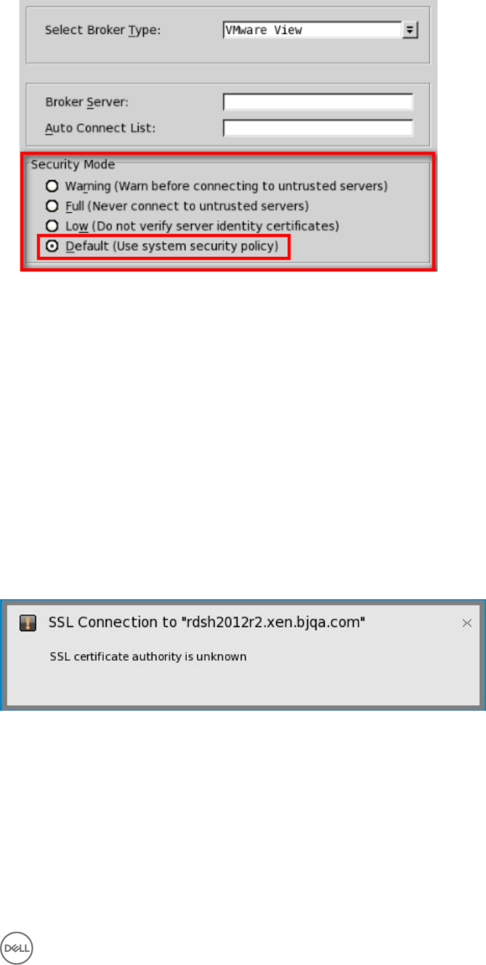
• CCM, Microsoft RDS broker, Citrix broker, and SecureMatrix are always Full.
File Server default protocol is retained as FTP without any setting from WDM/DHCP/INI and always displays the full address with
protocol prefix. For example, ftp://.
New firmware/client deploy information
• Dell recommends you to define the SecurityPolicy before upgrading to version 8.3 and later. If not, you may get warning
messages that require intervention to proceed.
• Before upgrading to version 8.3 and later, it is recommended to define the desired SSL security level and add the required
Security Policy parameters/options to global INI file.
• For SecurityPolicy=Fullor warning, you are required to add certificates from the respective File, View, AWS, WDM,
OneSign, and/or Caradigm server(s) to the ThinOS client before updating the firmware.
• The default protocol of File Server is still FTP and ftp prefix is added automatically, if the protocol is not provided.
Improved user friendly messages are displayed for errors and warnings.
The UI is not changed and only the message is modified for security errors/warnings.
In full security mode, the following warning message is displayed:
163
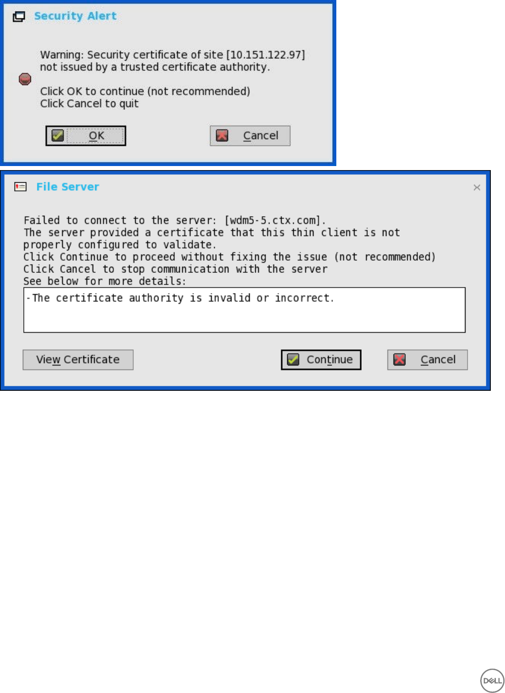
For warning security mode, the following warning messages are displayed:
The server address does not convert to http, if WDM server is set as https.
• In the previous scenario, If WDM server is configured without HTTPS, and local WDM server address is specified in HTTPS,
then the system converts it to HTTP address.
• In the current scenario, the system does not convert the WDM server address to HTTP.
164
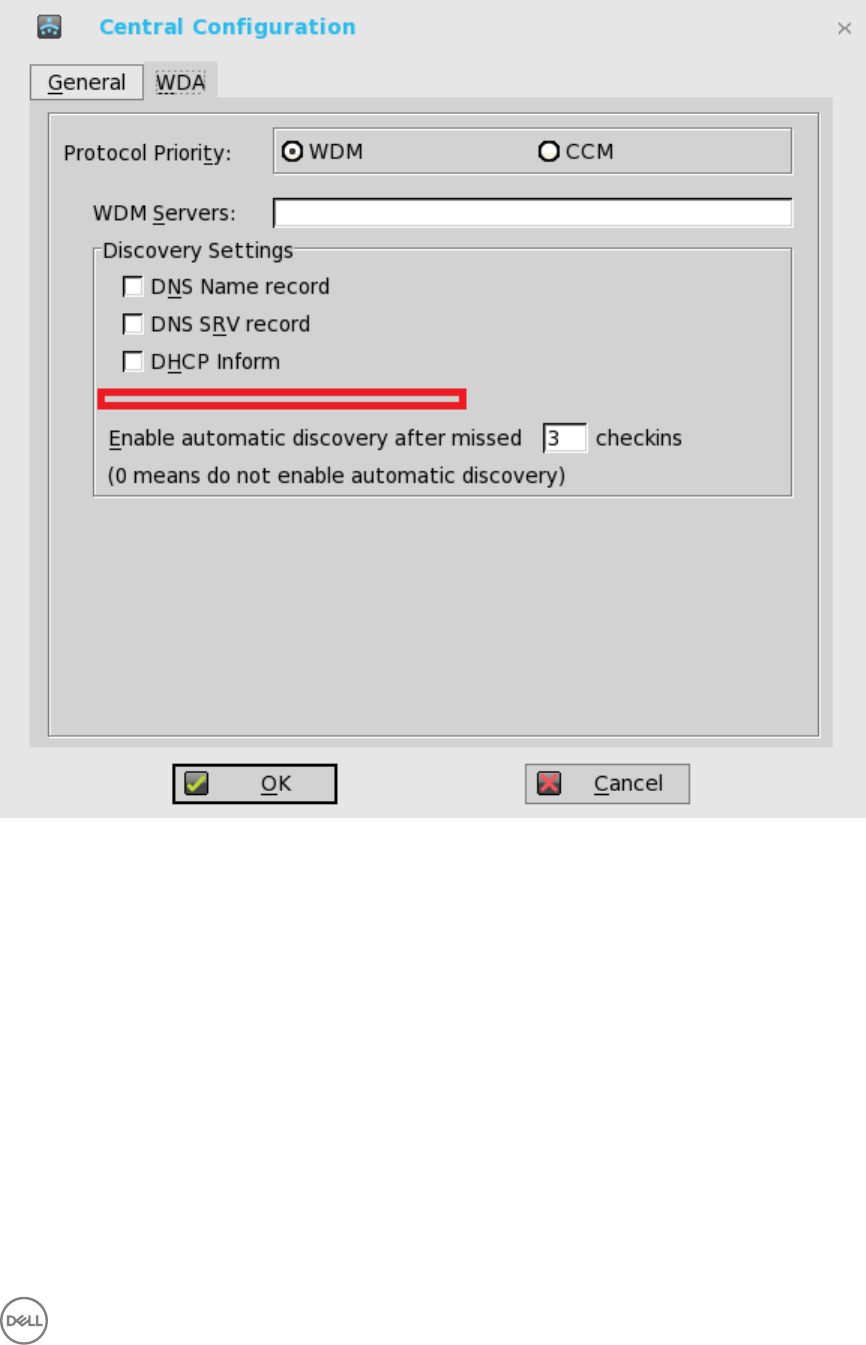
Manual discovery is removed from WDM. In the WDA tab, the Manual discovery method option is removed (Highlighted in red color
in the following screenshot).
165

E
Transport Layer Security (TLS)
Transport Layer Security (TLS) is a protocol that provides communication security between the client and server applications.
Upgrade to Transport Layer Security (TLS)— In the ThinOS 8.2 release, the TLS is upgraded from version 1.0 to version 1.2. By
default, the ThinOS client uses TLS 1.2 to secure any communication protocols, connections, or applications upon SSL/ TLS in
general and falls back to the previous SSL/ TLS version when negotiating with the server.
166

F
Important Notes
•USB 3.0 on Wyse 7010 thin client with ThinOS (Z10D)—The Wyse 7010 thin client with ThinOS (Z10D) devices support two
USB 3.0 ports. The USB 3.0 is supported on ThinOS 8.1 and compatible with USB 2.0. When USB 2.0 device is connected to 3.0
ports, the behavior of the device remains unaltered. For USB 3.0 device to connect to 3.0 ports, the device type should be of 5
Gbps. All types of USB devices work when connected to USB 3.0 port.
Known issue
– Camera preview has some known issue.
•Create INI options to change the BIOS feature— New INI Parameters are added to change the BIOS feature on the ThinOS
devices.
INI Parameters:
Device=cmos
[Password=password encrypt={no, yes}]
[BootOrder={PXE, HardDisk, USB}]
[WakeOnLan={yes, no}]
[AutoPower={yes, no}]
[BootFromUSB={yes, no}]
[USBController={yes, no}]
[COMController={yes, no}]
[PopupMenu={yes, no}]
[OnboardAudio={yes, no}]
Supported platforms:
– Wyse 3020 thin client with ThinOS (T10D)
– Wyse 3030 LT thin client with ThinOS
– Wyse 5010 thin client with ThinOS (D10D)
– Wyse 5040 AIO thin client (5212)
– Wyse 5060 thin client with ThinOS
– Wyse 7010 thin client with ThinOS (Z10D)
This feature is supported on the following PCoIP enabled clients:
– Wyse 3030 LT thin client with PCoIP
– Wyse 5010 thin client with PCoIP (D10DP)
– Wyse 5040 thin client with PCoIP (5213)
– Wyse 5060 thin client with PCoIP
NOTE: For platform Wyse 3020 thin client with ThinOS (T10D), only support options (Password/Encrypt/
BootOrder/AutoPower) are available.
•Present the Hardware configuration in ThinOS from BIOS – This feature is displayed in the General tab of System
Information. The tab displays the hardware configuration information from the BIOS. Based on the BIOS, user can view the
following six parameters related to hardware configuration:
CPU Speed, Memory Speed, ROM Size, SSD Size, Parallel Ports, and Serial ports.
Supported platforms:
167
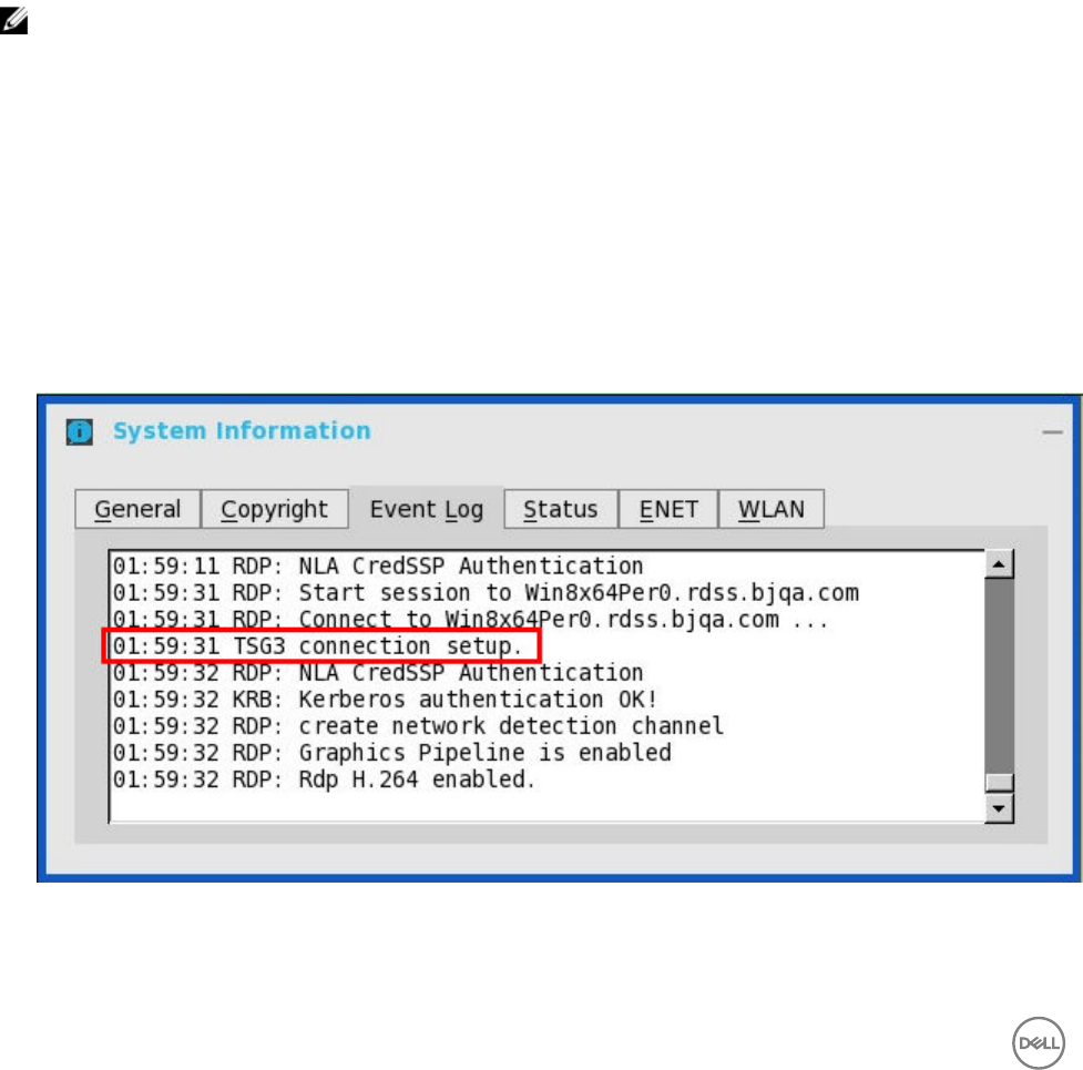
– Wyse 3030 LT thin client with ThinOS
– Wyse 5010 thin client with ThinOS (D10D)
– Wyse 5040 AIO thin client (5212)
– Wyse 5060 thin client with ThinOS
– Wyse 7010 thin client with ThinOS (Z10D)
This feature is supported on the following PCoIP enabled clients:
– Wyse 3030 LT thin client with PCoIP
– Wyse 5010 thin client with PCoIP (D10DP)
– Wyse 5040 thin client with PCoIP (5213)
– Wyse 5060 thin client with PCoIP
•Anonymous logon—This feature enables the users to log into the Storefront server configured with unauthenticated store
without Active Directory (AD) user credentials. It allows unauthenticated users to access the applications instead of AD
accounts.
NOTE: Anonymous logon is not supported with legacy mode of Storefront server.
•TS Gateway III uses HTTPS / DTLS connections
TS Gateway III is supported in Windows Server 2012R2.
Limitations
TS gateway III uses UDP transfer which is supported with desktop Windows 8 and later versions. However, the UDP transfer for
TS gateway is disabled in this release.
User scenarios
a. Connection with TS gateway configured in supported OS (e.g. Windows Server 2012R2), it uses TS gateway III and the
logs are displayed as shown in the following screenshot:
b. Connection with TS gateway configured in unsupported OS (e.g. Windows Server 2008R2), it uses TS gateway II and the
logs are displayed as shown in the following screenshot:
168
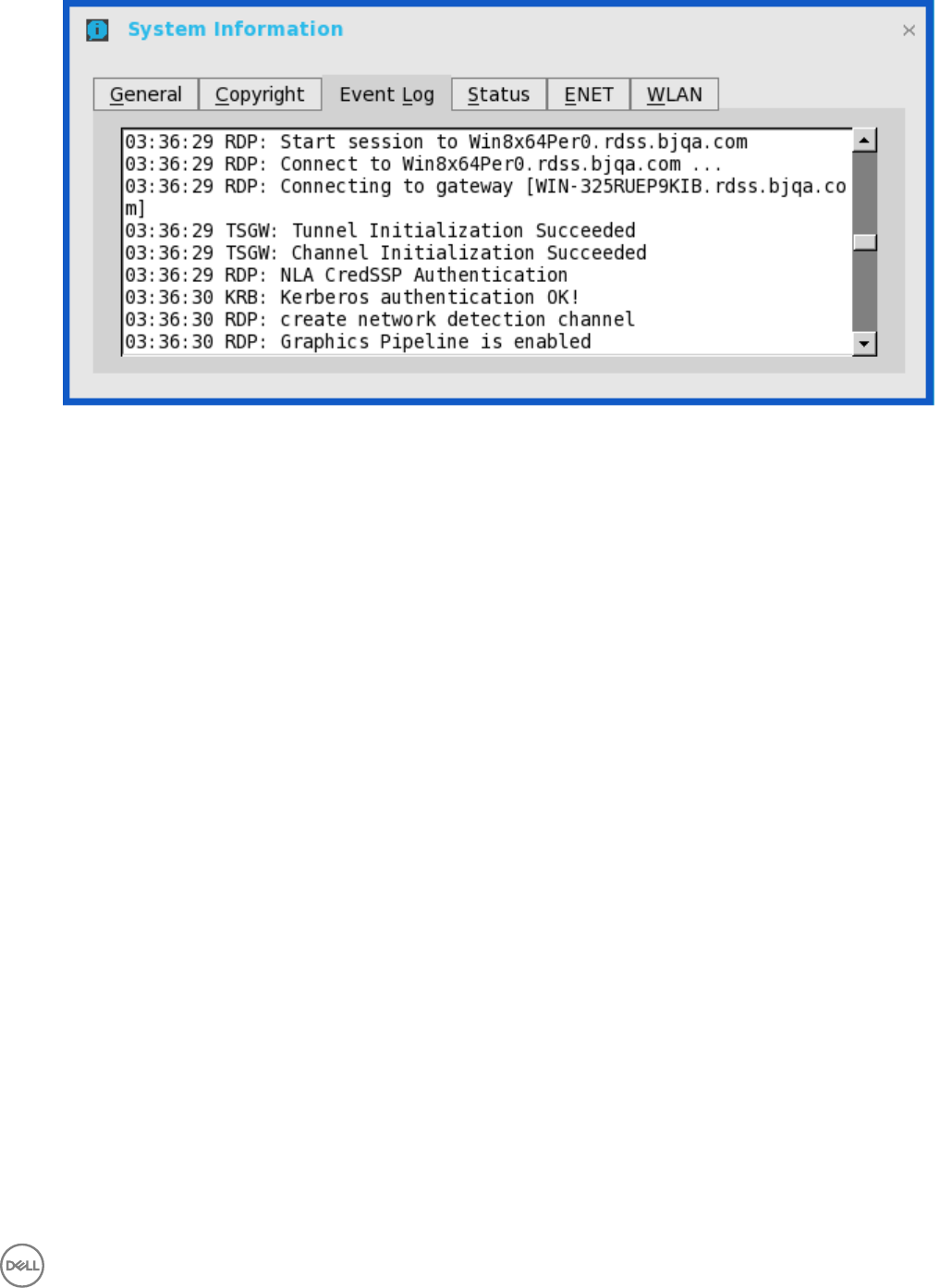
c. When remote connection with TS gateway III closed: There are no additional logs displayed in the Event Log tab.
•Linux/Windows 10 desktop support
– Linux hosted desktop in Citrix, and vWorkspace brokers is supported.
– Windows 10 desktop in multiple brokers is supported.
* Windows 10 desktop is supported in Citrix, VMware, RDS brokers.
* Windows 10 does not support MMR/TSMM over RDP protocol, but Windows 10 MMR works with the Citrix
connections.
•Server Name option—In ThinOS 8.0, the manual input DNS Servers are replaced by DHCP. From ThinOS 8.1, the manual input
DNS Servers are retained behind DHCP.
•Support for the Gemalto smartcard IDPrime MD840
Gemalto smartcard IDPrime MD830 was supported in v8.2 release. MD840 is added in this release. IDGo 800 v1.2.1 - 01 for the
Windows middleware is required for supporting Gemalto smartcard IDPrime MD840.
Known Issue: Prime MD 840 smartcard: If first container is used, then XEN broker log-on fails.
•VNC RFB version upgrade: Since ThinOS 8.0_214, the VNC RFB version has been upgraded to 3.8 for some applications like
DameWare. The VNC version is upgraded to 3.8, so it is recommended to use the DameWare software to remotely control the
thin clients. Earlier, DameWare would not work, and you would have to use other softwares such as VNC Viewer. The advantage
of using DameWare is auto configuration and easy deployment while the limitation is that it requires minimum VNC version 3.8.
169
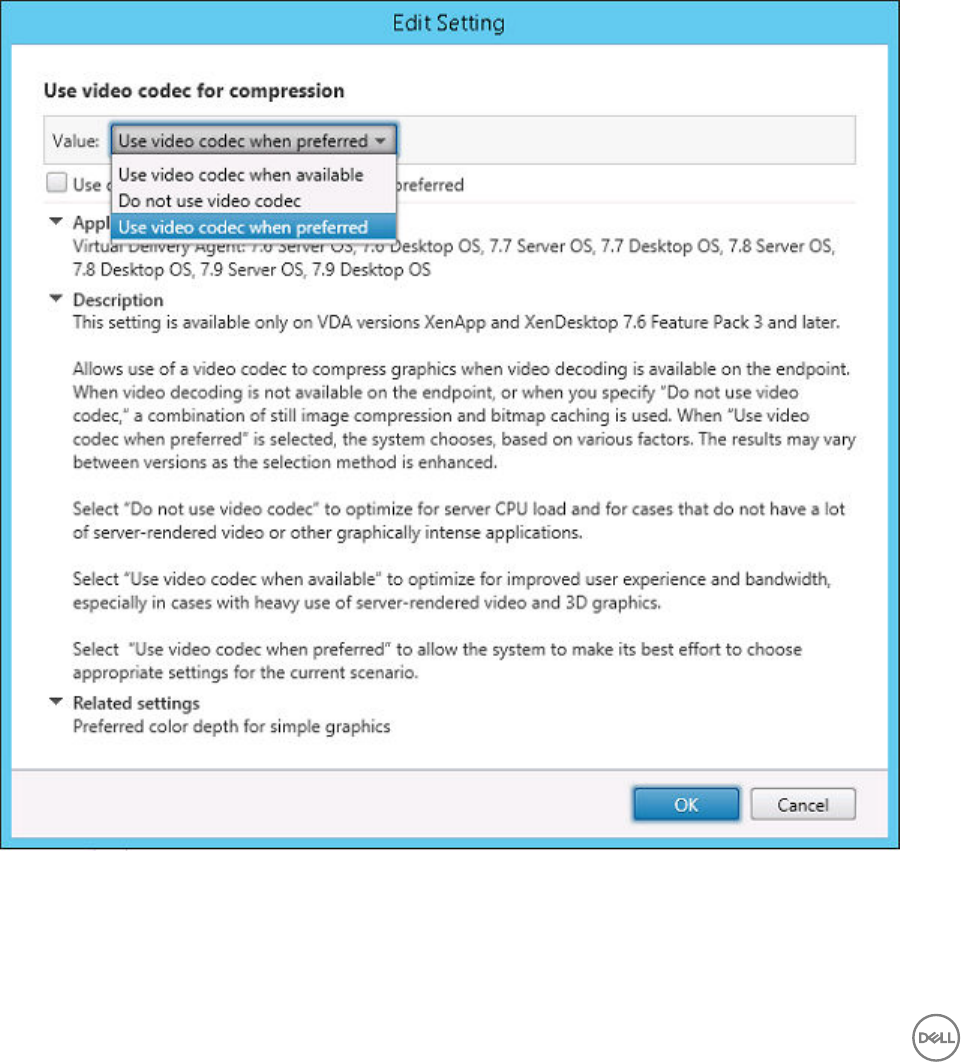
G
Frequently Asked Questions
1. How to enable USB Redirection in RDP windows 10 session?
Change policy: Go to Computer Configuration → Administrative Templates → Windows Components → Remote Desktop
Service → Remote Desktop Session Host → Device and Resource Redirection → Do not allow supported Plug and disable
Play device redirection.
2. How to enable ICA SuperCodec on XenDesktop 7.9?
Under Citrix Policy, Use video codec for compression needs to be configured to enable ICA SuperCodec on both non-HDX 3D
Pro desktop (standard VDA) and HDX 3D Pro desktop (VDA for HDX 3D Pro).
By default, Use video codec when preferred is selected. Then ICA SuperCodec is enabled on HDX 3D Pro Desktop only, but
disabled on non-HDX 3D Pro desktop. If you select Do not use video codec, ICA SuperCodec is disabled on both HDX 3D Pro
desktop and non-HDX 3D Pro desktop.
170

Although ICA SuperCodec is disabled on non-HDX 3D Pro Desktop, if you set Use video codec when preferred or Do not use
video codec, OR disabled on HDX 3D Pro Desktop if you set Do not use video codec, ThinOS may still print log ICA:
SuperCodec enabled, and this is a known issue.
If you select Use video codec when available, ICA SuperCodec is enabled for both HDX 3D Pro desktop and non-HDX 3D Pro
desktop.
171
