Dell Wyse 5060 Thin Client ThinLinux 1.0.3 Administrators Guide User Manual Linux Administrator Guide5 En Us
User Manual: Dell wyse-5060-thin-client - Dell Wyse ThinLinux 1.0.3 Administrators Guide
Open the PDF directly: View PDF ![]() .
.
Page Count: 104 [warning: Documents this large are best viewed by clicking the View PDF Link!]
- Dell Wyse ThinLinux 1.0.3 Administrator’s Guide
- Introduction
- Getting started: Basics
- Configuring thin client settings locally
- Configuring Connections locally
- Configuring and managing the browser connections
- Configuring and managing Citrix connections
- Configuring and managing VMware connections
- Configuring and managing RDP connections
- Configuring and managing the custom connections
- Configuring and managing the SSH connections
- Configuring and managing the VNC viewer connections
- Configuring and managing the Ericom PowerTerm connections
- Security settings
- Additional management configurations
- Viewing XTerm
- Imaging solutions
- Central Configuration: Automating Updates and Configurations
- DHCP options tags
- Mixed Environment Imaging – An Enhanced Method of Upgrading

Dell Wyse ThinLinux 1.0.3
Administrator’s Guide

Notes, cautions, and warnings
NOTE: A NOTE indicates important information that helps you make better use of your product.
CAUTION: A CAUTION indicates either potential damage to hardware or loss of data and tells you how to avoid the
problem.
WARNING: A WARNING indicates a potential for property damage, personal injury, or death.
Copyright © 2017 Dell Inc. or its subsidiaries. All rights reserved. Dell, EMC, and other trademarks are trademarks of Dell Inc. or its
subsidiaries. Other trademarks may be trademarks of their respective owners.
2017 - 04
Rev. A02

Contents
1 Introduction..................................................................................................................... 6
About this guide................................................................................................................................................................. 6
Key features....................................................................................................................................................................... 6
Supported platforms...........................................................................................................................................................6
Dell Technical Support........................................................................................................................................................ 7
Related Documentation and Services........................................................................................................................... 7
Dell Online Community..................................................................................................................................................7
2 Getting started: Basics....................................................................................................8
Logging in to your thin client device....................................................................................................................................8
Application overview screen......................................................................................................................................... 9
Using the taskbar........................................................................................................................................................10
Viewing system information........................................................................................................................................ 10
BIOS settings.............................................................................................................................................................. 12
Other BIOS features....................................................................................................................................................12
BIOS utility and BIOS upgrades...................................................................................................................................12
3 Conguring thin client settings locally........................................................................... 14
Changing system settings................................................................................................................................................. 14
Customizing your display.............................................................................................................................................15
Setting the date and time........................................................................................................................................... 15
Selecting the language................................................................................................................................................ 17
Conguring the addons .............................................................................................................................................. 17
Congure the power saving setting.............................................................................................................................18
Conguring desktop appliance (Power On to Power O VDI theme)..........................................................................19
Delayed update settings ............................................................................................................................................ 22
Other settings............................................................................................................................................................ 23
Peripherals........................................................................................................................................................................24
Setting the keyboard preferences...............................................................................................................................25
Setting the mouse preferences.................................................................................................................................. 25
Conguring the printer settings..................................................................................................................................26
Conguring the sound settings...................................................................................................................................28
Network........................................................................................................................................................................... 29
Conguring the wi- settings..................................................................................................................................... 30
Conguring wired network connection settings.......................................................................................................... 31
Conguring the network proxy settings......................................................................................................................36
Adding a network connection..................................................................................................................................... 37
802.1x Conguration...................................................................................................................................................39
Personalization................................................................................................................................................................. 43
Setting the desktop wallpaper.................................................................................................................................... 43
Conguring universal access...................................................................................................................................... 44
3

4 Conguring Connections locally ................................................................................... 47
Conguring and managing the browser connections........................................................................................................ 47
Conguring and managing Citrix connections...................................................................................................................49
Conguring the server connection type..................................................................................................................... 50
Conguring global Citrix settings................................................................................................................................53
Managing PAM login.................................................................................................................................................. 56
Citrix ICA Client (64-bit) RTME..................................................................................................................................56
Conguring and managing VMware connections..............................................................................................................57
Conguring and managing RDP connections....................................................................................................................63
Conguring and managing the custom connections.........................................................................................................69
Conguring and managing the SSH connections...............................................................................................................71
Conguring and managing the VNC viewer connections..................................................................................................73
Conguring and managing the Ericom PowerTerm connections.......................................................................................76
5 Security settings...........................................................................................................80
Managing SSH server preferences...................................................................................................................................80
Managing the certicates................................................................................................................................................. 81
Setting VNC server preferences ......................................................................................................................................82
Managing the accounts settings...................................................................................................................................... 83
6 Additional management congurations......................................................................... 85
Conguration management..............................................................................................................................................85
INI management............................................................................................................................................................... 87
Wyse device agent .......................................................................................................................................................... 88
SCEP conguration management.................................................................................................................................... 89
Logs and Tools ................................................................................................................................................................. 91
HAgent.............................................................................................................................................................................93
7 Viewing XTerm.............................................................................................................. 95
8 Imaging solutions.......................................................................................................... 96
ThinLinux RAW image upgrade.........................................................................................................................................96
Downgrading and force imaging................................................................................................................................. 96
Mixed environment.....................................................................................................................................................96
Preserve changes.......................................................................................................................................................96
Merlin imaging..................................................................................................................................................................96
Merlin Imaging from le server without WDM............................................................................................................ 97
A Central Conguration: Automating Updates and Congurations................................... 98
How INI les Are Employed.............................................................................................................................................. 98
Setting Up the Automatic Congurations and Updates.................................................................................................... 99
Preparing the Root Directory and Folder Structure on the Server..............................................................................99
Directing the Thin Client to the Server..................................................................................................................... 100
B DHCP options tags.......................................................................................................101
C Mixed Environment Imaging – An Enhanced Method of Upgrading............................. 103
Support details................................................................................................................................................................103
4


1
Introduction
Wyse ThinLinux from Dell simplies the user management paradigm with elegant application icons and comes with a single built-in
user to enhance user experience along with having the benets of a single-operating system. ThinLinux software combines the
security, exibility and market-leading usability of enterprise-grade Linux with Dell’s thin computing optimizations in management. It
is ideal for organizations that want to run server-based, Web-based or local applications including legacy applications without the
deployment and security concerns of a nonstandard Linux distribution.
About this guide
This guide is intended for administrators of thin clients running Dell Wyse ThinLinux . It provides information and detailed system
congurations to help you design and manage a Dell Wyse ThinLinux environment.
Key features
This section provides the details on the Key features in this release.
• BIOS
• User friendly screen
• System Setting
• Connections and VDI
• Import/Export Congurations
• Desktop Appliance
• Management Solution
• 802.1x / SCEP
• INI Conguration
• Network and Wireless modules
• Energy Star Compliance
• Add-ons compatibility
• Imaging solutions
• User, Session, and Login
• Firefox Web Browser
• System Information
Supported platforms
This section provides the information about the supported platforms.
6

Table 1. Supported platforms
Hardware Platforms Memory Conguration (Flash/RAM)
Wyse 3030 LT thin client 4 GB / 2 GB
Wyse 5020 thin client (D50Q) 8 GB / 2 GB
Wyse 5060 thin client 8 GB /4 GB
Wyse 7020 thin client (Z50Q) 8 GB / 2 GB
Dell Technical Support
To access Dell Wyse technical resources, visit www.dell.com/support/contents/us/en/19/article/Product-Support/Dell-
Subsidiaries/wyse. For more information, you can submit cases to Dell TechDirect for online case submission and self service
dispatch or contact our Support phone queue.
Related Documentation and Services
Fact Sheets containing features of the hardware products are available on the Dell Wyse website. Go to www.dell.com/wyse and
select your hardware product to locate and download the Fact Sheet.
To get support for your Wyse product, check your product Service Tag or serial number.
• For Dell service tagged products, nd knowledge base articles and drivers on the Dell Wyse product pages.
• For Non-Dell Service Tagged Products, nd all the support needed by accessing the Dell Wyse support domain.
Dell Online Community
Dell maintains an online community where users of our products can seek and exchange information about user forums. Visit the Dell
Online Community forums at: http://en.community.dell.com/techcenter/enterprise-client/wyse_general_forum/.
7
2
Getting started: Basics
Use the following information to learn the basics and get started using your thin client:
•Logging in to your Thin Client Device
•Using Your ThinLinux Desktop
•Conguring Thin Client Settings and Connections
•Viewing System Information
•BIOS settings
Logging in to your thin client device
On your initial conguration, Dell recommends that you connect by using a wired connection by plugging in the network connected
Ethernet cable to your thin client.
After you turn on your thin client, you are automatically logged in to the thinuser account. By default, the password of the thinuser
account is set to thinuser.
NOTE: In cases where a GDM login is needed (for example, AD/Domain login, PNAgent login and so on), the auto-login
option can be turned o through the GUI or by using the INI.
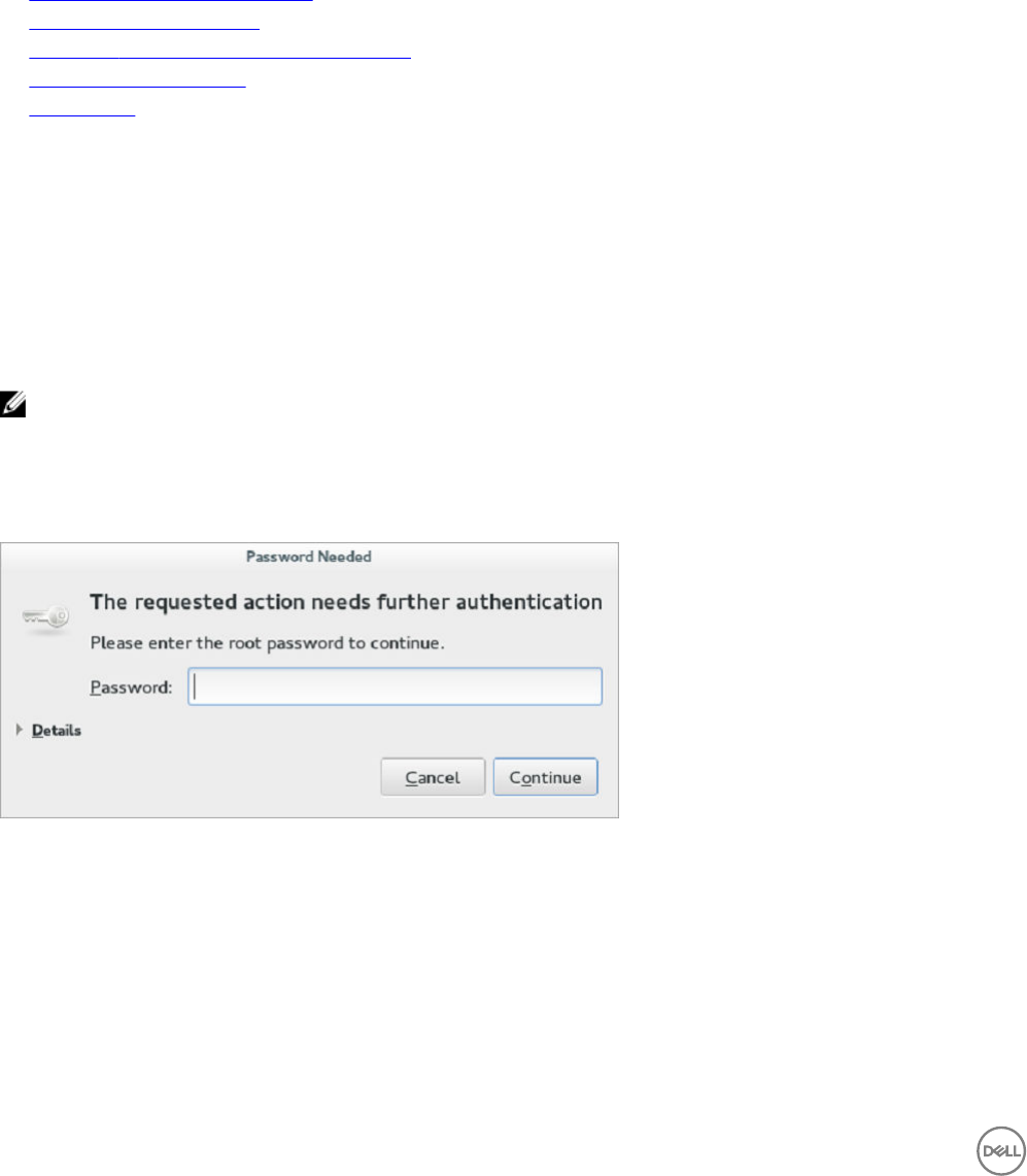
Admin mode enables you to perform system administration tasks such as adding or removing connections and setting up specic
device settings. To enter into the Admin mode, click the Switch to Admin button from Setting application screen to admin mode and
then enter the default root password in the Password Needed window. The default root password is admin.
Figure 1. Admin Password
8
Application overview screen
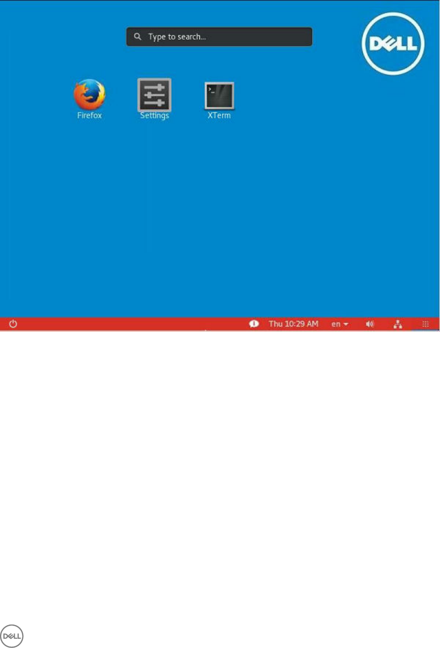
Figure 2. Application Overview Screen
The ThinLinux desktop is called the Application Overview screen. This is the default ThinLinux screen that is displayed after you log in
to the thin client (without auto-start of any connections or application).
•Application Icons— To access the application icons, click the dots on the lower-right corner of the screen. You can start the
application by clicking a particular application icon. If there are more application icons, then the icons are displayed on multiple
pages.
•Taskbar— The taskbar is displayed at the bottom of the Application Overview screen (ThinLinux Desktop).
The Application Overview Screen consists of the following screen elements:
•Search Entry— User can search for applications by typing the application name in the Search text box.
•Dual Monitor — This is applicable when you are connected to the dual monitor. The Application overview screen icons are
displayed only on the primary monitor. On the secondary monitor, only background is displayed. If an application is running on the
secondary monitor in the Desktop View, then a thumb nail of the application is displayed on the secondary monitor in the
Application overview screen.
•Firefox— Opens the Firefox Web Browser.
•Settings— The Settings Application is the integrated application for system settings in both user and admin mode. This
application icon appears in the System Application Overview screen upon system startup in both user and admin mode.
•XTerm— XTerm is the standard terminal emulator for the X Window System. Use the terminal emulator window for X to access
a text terminal and all its applications such as command line interfaces (CLI) and text user interface applications. It is applicable
for Admin User.
Desktop view:
9

This is the desktop view for running applications. The desktop automatically switches to the Desktop view mode, when you log in to
any application by clicking the icon. The system remains in this desktop view as long as there is at least one open window. When all
the windows are closed, the system automatically switches back to the Application Overview screen.
In the case of the dual monitor, the primary monitor displays the running applications and the secondary monitor displays the
background by default. You can move the application from the primary monitor to secondary monitor or from the secondary monitor
to primary monitor. You can also switch to the Desktop screen by clicking the Show Desktop button on the taskbar (even when no
applications are open). You can toggle between the Desktop screen and Application Overview screen by clicking the Show Desktop
button.
Using the taskbar
Use the taskbar to view the time, congure the volume settings, view system information, view network information, shutdown the
thin client, view keyboard settings and switch to desktop screen.
The taskbar consists of quick launch icons and taskbar buttons:
Figure 3. Taskbar
•Show Desktop – Click this button to switch between the Desktop view screen and Application Overview Screen.
•Shutdown – Use this button to shut down or restart the thin client. If you click this button, the Power O dialog box is displayed.
If you do not select any option in the dialog box, the system will power o in sixty seconds. You can cancel the power o by
clicking the Cancel button. You can restart or Power O the thin client by clicking the respective buttons.
NOTE: When auto-login is disabled or if the user has switched to the admin mode, a logout button is displayed in the
Power O dialog box and you can log out by clicking this button.
•Activities – The application icon is added to the taskbar whenever a new application is started. Taskbar displays a single icon for
a single running application. If multiple instances of the same application are running, multiple icons are displayed in the Taskbar.
Hover the mouse pointer over the Taskbar to view the tooltip for application name. The icon of the current running application
that is in focus is highlighted in the taskbar.
•Date and Time – Use this icon to view the date and time.
•Volume icon – Use this option to increase or decrease the speaker volume or mute the speaker.
•Network icon – Use this icon to view the Network details.
•Keyboard icon– Click this icon to view the available keyboard layout. You can switch between the keyboard layouts using this
option.
•System Information – Use the System Information screen to view Identity, Network, Packages, and Copyright information. For
more information, see Viewing System Information.
Viewing system information
Use the System Information GUI to view Identity, Network, Packages, and Copyright information.
To view system information:
1. Click the System Information icon on taskbar.
The System Information dialog box is displayed and the System Information GUI contains the following tabs:
• Identity tab
• Netwok tab
• Package tab
• Copyright tab
The System Information dialog box displays the following information:
10

•Identity tab—Displays identity information such as:
–System
* Current User
* Terminal Name
* Product Name
* Platform
* Build
* OS Version
* Uptime
–Hardware
* Processor
* Processor Speed
* Total Memory
* Free Memory
* Media Size
* Serial Number
–BIOS
* BIOS Version
•Network tab—Displays network information such as:
–Network Device
–Interface Information
* MAC Address
* Network Speed
* Maximum Transmission Unit (MTU)
–IP Information
* IP Address
* IPv6 Address
* Subnet Mask
* Gateway
* Domain
* Primary DNS
* Secondary DNS
* DHCP Server
* Lease
* Elapsed
•Packages tab— The packages tab shows the list of addons. The addons are listed in four columns-package, version, status and
size. The Status column has the following values:
–Original – This value species the Built in add-ons in ThinLinux image.
–Changed – This value indicates whether the add-ons are upgraded or downgraded.
–Added – This value indicates that the add-ons are installed later.
–Removed –This value indicates that the add-ons are removed from the ThinLinux image.
11

Original add-ons are shown also in Black color, add-ons upgraded from Dell| Wyse are shown in Green color, add-ons from third
party are shown in Orange, add-ons removed from the application are in Red color.
The packages can be sorted by Package, Version, Status or Size by clicking the respective buttons. By default, only Dell Wyse
packages are displayed. To view all packages, click Show All Packages button.
•Copyright tab—Displays the software copyright and patent notices.
BIOS settings
ThinLinux shares the hardware platforms with other Dell Wyse thin clients. The standard BIOS features and boot options are
common to all platforms with the following boot options:
• Boot from HardDisk –Boots from the internal SSD storage.
• Boot from USB – Boots the USB storage from any of the USB ports (this option is disable by default).
• Boot from PXE – Boots from the network through PXE.
• Boot from CLOUD – Not supported by ThinLinux.
The following are the BIOS keyboard functions while booting:
•P-Key – The key redirects to the boot menu. It is used to select or alter the temporary boot order.
•Del-key – The key redirects to the BIOS settings. The BIOS settings is protected by a password and the default password is
Fireport.
•BIOS Boot Splash – It is a BIOS feature.
Other BIOS features
•Wake-On-LAN – The default value is ON.
•Power-Loss Recovery – The default value is OFF.
•Power On PState – The default value is ON.
•Boot mode – Set the Boot mode to both (UEFI and Legacy). ThinLinux image is built for legacy mode and it does not support
the UEFI format. Hence, the device will not boot properly if the setting is changed to UEFI boot mode. The Secure Boot option is
not supported, because the image is built for legacy mode.
BIOS utility and BIOS upgrades
The BIOS Utility is used to extract the BIOS (along with its entire conguration) from the Thin Client. The extracted BIOS can be
further distributed for the purpose of BIOS password change or to upgrade the BIOS . ThinLinux provides a terminal command
createBiosCmos.sh which enables you to extract and export the BIOS.
Perform the following task to create the BIOS rpm:
1. You should switch to the Administration mode.
2. Start the Xterm window.
3. Run the following command in the Xterm window:
/etc/addons.d/BIOS_UTIL/createBiosCmos.sh
The command creates the thin client’s BIOS, including its conguration information and generates an RPM le at the following
location:/usr/src/packages/RPMS/<architecture>, where <architecture>is the device’s architecture.
For example, for Wyse 5060 thin client, the path is /usr/src/packages/RPMS/x86_64
The RPM le’s name is generated in lower case, as follows:
<device model>_bioscmos_update-<BIOS version>-<sequence #>.<architecture>.rpm
where <sequence #> is an automatically generated sequence number, starting from 1, and increments by 1 every time user
executes createBiosCmos.sh on that device.
12

For example, on Wyse 5060 with 1.0A BIOS the extracted BIOS RPM le is termed as:
5060_bioscmos_update-1.0A-1-x86_64.rpm
NOTE: <BIOS version> and <sequence #> is the RPM’s version and release numbers. These parameters inuence
the RPM’s ability to be installed on destination devices.
13

3
Conguring thin client settings locally
This chapter contains information to help you set up your thin client hardware, look and feel, and system settings. To congure your
thin client settings, click the Switch to Admin button to enter into the Admin mode. Enter the default password in the displayed
window. The default password is admin.
Click the Settings icon on the Desktop. The System Settings page is displayed.
The System Settings consists of the following tabs:
• System
• Peripherals
• Network
• Personalization
• Connections
• Security
• Management
Figure 4. System Settings
Changing system settings
On the System Settings page, click the System icon. The following tabs are displayed on the left pane of the System Settings
page.
• Display
• Date and Time
• Language
• Addons
14
• Power
• Desktop Appliance
• Update Settings
• Other Settings
Customizing your display
By default, the Customize your display screen is available in both User mode and Admin mode. Any changes to display preferences
made through this screen is saved and available for the built-in thinuser. In a Dual-monitor conguration, if both monitors are
connected, then by default, the monitors are in extended mode. The primary monitor is on the left (monitor 1) and the secondary
monitor is on the right (monitor 2). The resolutions of the monitors are auto detected by the system by analyzing the monitor’s
capabilities.
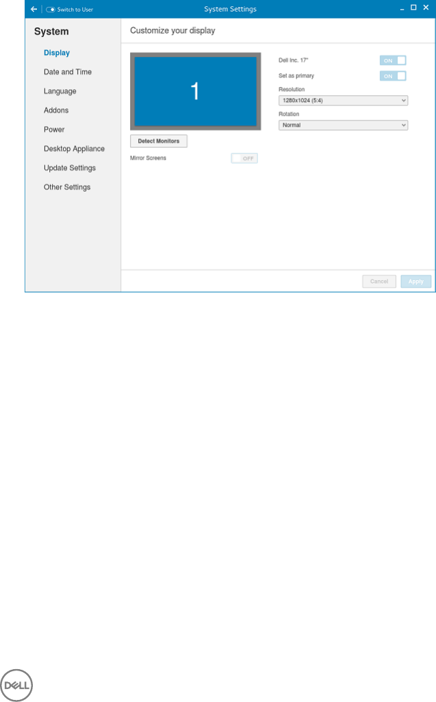
1. Click the Display tab.
The Customize Your Display page is displayed.
Figure 5. Display Settings
2. Select the preferred Resolution from the drop-down list.
3. Select the Rotation type from the drop-down list.
• Normal
• Right
• Left
• Upside-down
4. Click the ON/OFF button to switch between dual display and mirror mode in a dual monitor conguration.
5. Click the ON/OFF button to enable the Set as primary option. This option allows you to set the selected monitor as primary.
6. Click the ON/OFF button to enable the Monitor On/O option. This option allows you to switch o and switch on the
preferred monitor in a dual monitor conguration.
Setting the date and time
1. Click the Date and Time tab to set the date and time on your thin client.
The Date and Time screen enables you to set the device’s date, time, time zone and whether or not the device should sync its
time with an NTP (Network Time Protocol) server. You can either congure the Date and Time manually or automatically. The
date, month and the year along with the time is displayed on the top of the screen.
15

The Time Format can be changed by using the Time Format drop-down list, and the Time Zone can be changed by using the
Time Zone drop-down list. The default time zone is America/Los_Angeles. Both changes can be performed regardless of the
ON or OFF state of the Set Time Automatically switch.
NOTE: By default, the Date and Time screen is available only in Admin mode
Figure 6. Date and Time Settings
2. To congure the Date and Time settings manually when the Set Time Automatically switch is in OFF position.
a. Click the date eld and select the year, month and date.
Any changes performed in the date eld such as, the time format is selected as 24 Hours or an additional AM/PM format, is
displayed at the top of screen.
The time eld consists of Hour and Minute drop-down list.
b. Click Save to save the changes. Clicking Save when Set Time Automatically switch is in the OFF state also disables NTP
synchronization.
NOTE: The Date and Time screen detects whether or not the NTP daemon is activated. By default, the NTP
daemon is deactivated. The manual setting time zone/date/time page is displayed, if the NTP daemon is
deactivated. Otherwise, the auto setting time zone page is displayed.
3. To congure the Date and Time automatically:
a. Click the Set Time Automatically button, to turn on the automatic settings. Note that internet access is required to use this
option. Turning on this option activates the NTP daemon and enables the NTP daemon to start syncing the device’s time
with the specied NTP server.
b. Click the + icon to add a new NTP server. The NTP Server IP or FQDN box is displayed on the page.
c. Enter the NTP Server IP or FQDN Server IP in the NTP Server IP or FQDN box. The + icon and x icons are displayed on
the right side of the box, when you start typing the characters in the box.
• Click the + icon to add the specied NTP server/FQDN to the NTP Server list. If a proper NTP server IP is not entered,
then a warning message is displayed on the page.
• Click the x icon to clear the IP address you have entered in the box.
d. The Del, Up arrow and Down arrow icons are displayed next to the NTP Server name when you hover the mouse over a
particular NTP server in the NTP Server list.
• Click the Del icon to delete the specied NTP server from the NTP Server list.
• Click Up arrow and Down arrow to change the order of the particular NTP server in the NTP Server list.
16

NOTE:
• The Up arrow is enabled when the particular NTP server can be moved to the top in the NTP Server list and it is
disabled when the particular NTP server is listed at the top of the NTP Server list.
• Click Down arrow to change the order of the particular NTP by moving it down in the list.
• The Down arrow is enabled when the particular NTP server can be moved down in the NTP Server list and it is
disabled when the particular NTP server is listed at the bottom of the NTP Server list.
4. Click Save to save the changes. Clicking Save button when Set Time Automatically is in ON position enables NTP
synchronization
Selecting the language
By default, the Language applet is available only in Admin mode. Any changes made through Language applet is saved and continued
for the built-in thinuser.
In the Select Language box, select the language of the screen from the list of supported languages and click Save to save your
settings.
Figure 7. Language Settings
Conguring the addons
The Addons page enables you to install and remove Add-ons from INI server.
NOTE: The Addons screen is available only in Admin mode.
1. Click the + icon to Install the Add-ons.
A list of available add-ons is displayed.
17

Figure 8. Install Add-ons
2. Select the required add-ons and install them to the system. You can select multiple add-ons at a time.
3. Click the x icon to remove the Add-ons from the installed add-ons list.
Figure 9. Remove Add-ons
4. Select the add-ons that you want to remove and click Remove Add-ons.
5. Click Save to save the changes.
Congure the power saving setting
The Power Setting page enables you to set Monitor Sleep mode.
In the Turn o screen after box, select the idle time from the drop down list. The monitor is turned o after the specied idle time.
18
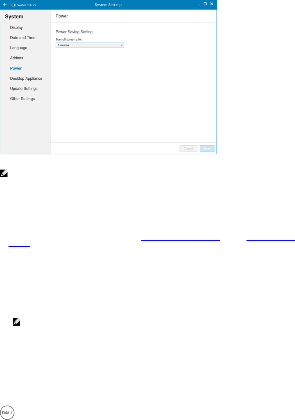
Figure 10. Power saving setting
NOTE: ThinLinux supports the display turn o and by default it is set for 4 minutes of idle time to comply with Energy
Star category. If you select never option from the drop down list, it corresponds to idle time of 0 minutes.
Conguring desktop appliance (Power On to Power O VDI theme)
We can congure Desktop Appliance using GUI, INI and DHCP. For INI conguration please refer the tags description of
DesktopAppliance, CitrixConnectionType, PNAgentServer and Storename INI parameters.
For DHCP conguration,
• 181 - congure Citrix server url - either specify pnagent url xyz.com/citrix/pnagent/cong.xml, storefront xyz.com/citrix/store/
discovery, IP/FQDN
• 203 - Type of VDI theme
• 204 - Type of Citrix server
• 205 - Storename.. For more information, see DHCP Option Tags
By default, the Desktop Appliance screen is available only in Admin mode. Any changes made through Desktop Appliance screen is
saved and continued for the built-in thinuser.
1. Click the ON/OFF button to enable or disable the VDI theme option after you log in to the session.
2. From the drop-down list, select your preferred VDI theme.
NOTE: Only Citrix theme is supported in this release.
19
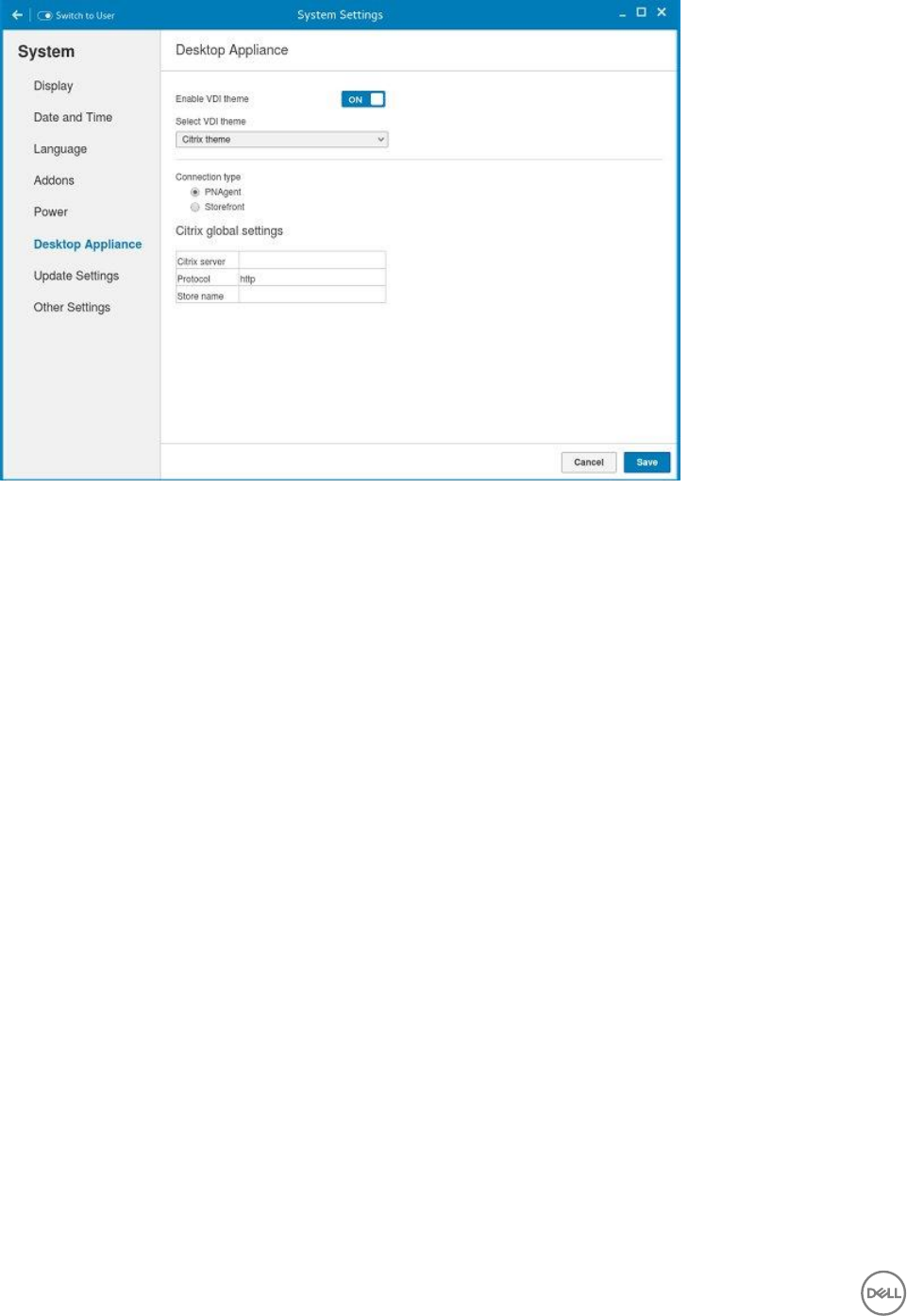
Figure 11. Desktop Appliance Settings
3. Select the type of Citrix Server.
Citrix server , Protocol and Storename can be congured from Change global settings page. Go to All connections page, select
Citrix option and then select Change global settings option to congure the Citrix settings. For more settings for Applications or
Desktops, go to All connections page, select Citrix option and then select Change global settings option to congure the
Applications or Desktops settings.
4. Click Save.
You are prompted to restart the system.
5. Click OK to save the changes and restart the system in selected theme.
6. After the system is restarted, a log on button is displayed.
a. Click the Log On button.
20
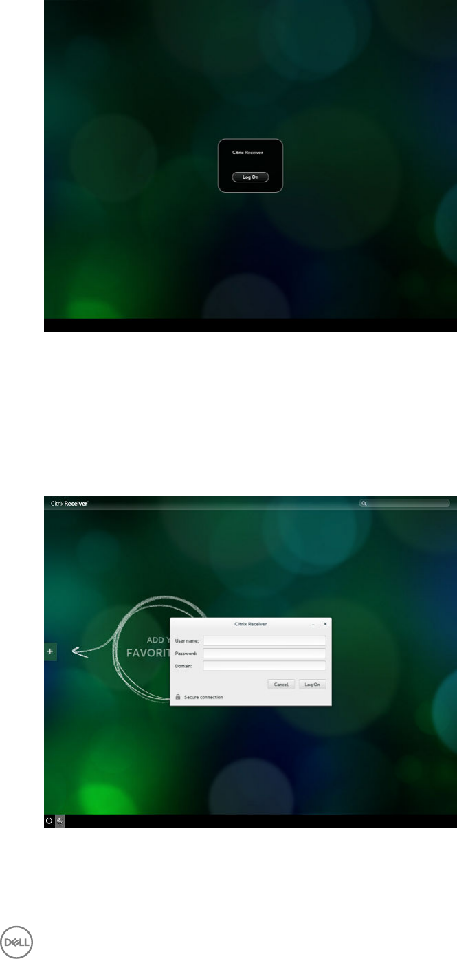
Figure 12. Log On Screen
You are required to authenticate by entering the following credentials:
• User name
• Password
• Domain
You are logged on to the Citrix receiver.
Figure 13. Authentication Screen
If the logon authentication fails, you are prompted with a screen. Click try again to query the server again.
21
NOTE: You can break kiosk mode and enter into admin mode at any point of time by using the short cut key. The
short cut key is <Control><Alt><Shift>F11.
b. After the successful login, you can add the required applications or desktops from the left + button.
c. Click the application or desktop to start it. You are prompted with an error if there as an error message.
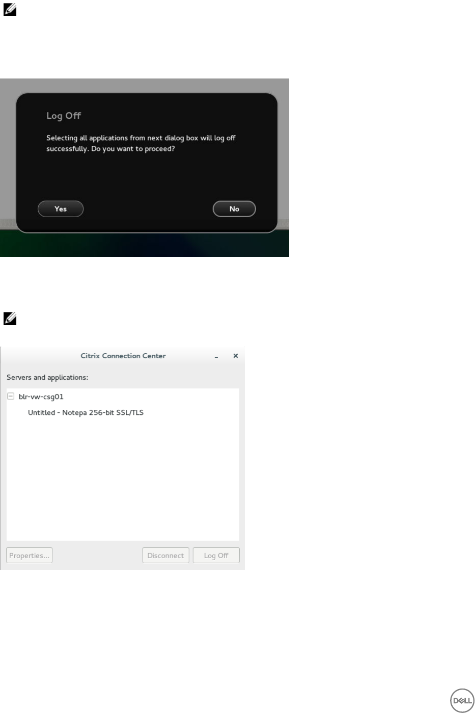
d. You can logout at any point of time by clicking the power icon on task bar. Depending on whether any application is opened,
you are prompted with an error message.
Figure 14. Log O Screen
e. If any applications are running, connection center window is displayed, select each application and either log o or
disconnect. Following which click the cross to close the control center and logo completely.
NOTE: If you do not follow above procedure to log o, you may see sessions active and running behind the
displayed log on button.
Figure 15. Citrix Connection Center
Delayed update settings
The Delayed Update Settings page enables you to set the delayed updates. By default, the Update setting screen is available in
Admin mode.
22
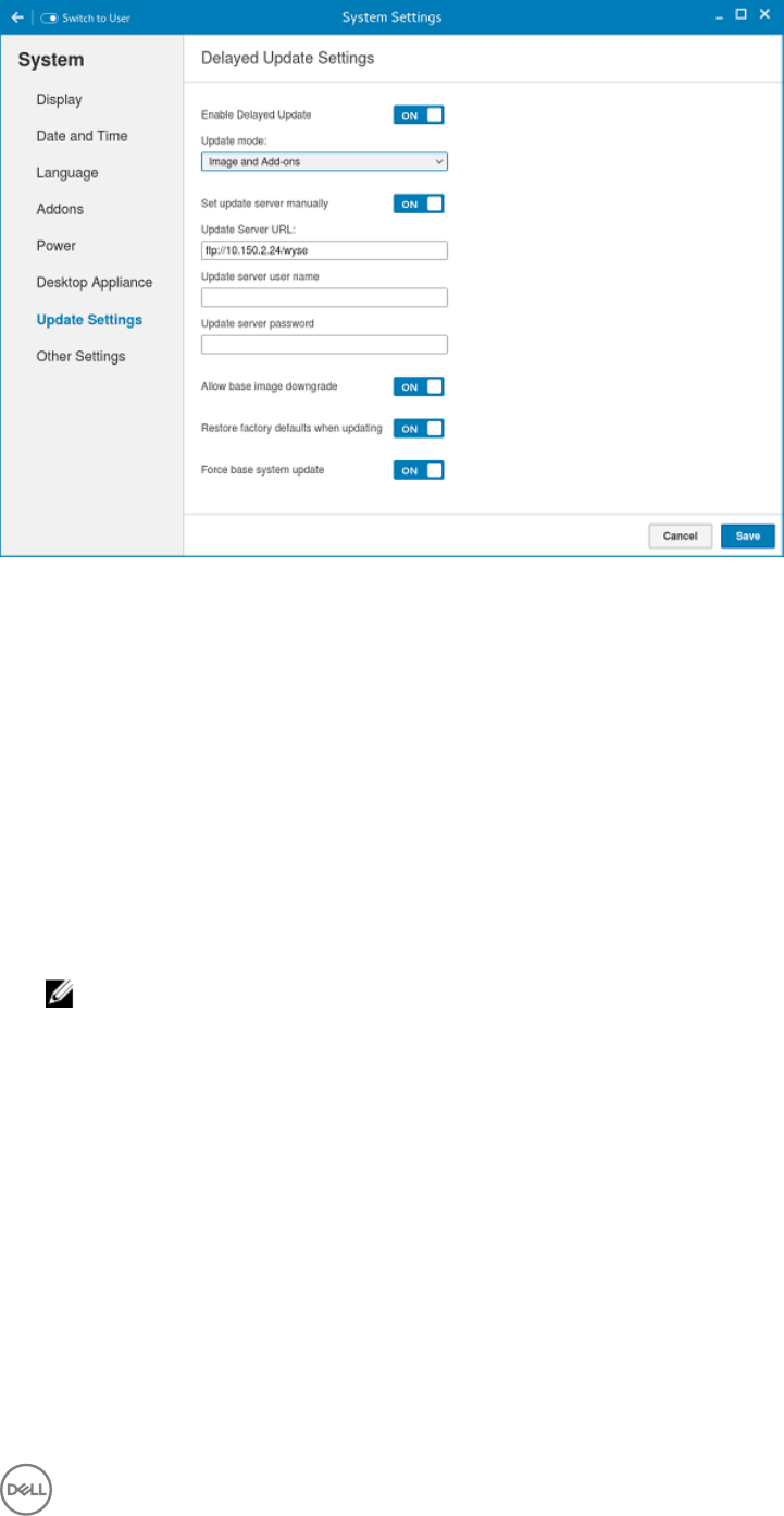
Figure 16. Delayed Update Settings
1. Click the ON/OFF button to enable or disable the Delayed update.
2. From the Update Mode drop-down list, select what you want to update.
• Image and Add-ons
• Image Only
• Add-ons Only
3. Click the ON/OFF button to enable the Set update server manually.
4. Enter the URL address of the specied server in the Update Server URL box.
5. Enter the user name of the specied server in the Update Server User Name box.
6. Enter the password of the specied server in the Update Server Password box.
7. Click the ON/OFF button to enable or disable the Allow base image downgrade, after you log in to the session.
8. Click the ON/OFF button to enable or disable the Restore factory defaults when updating, after you log in to the session.
9. Click the ON/OFF button to enable or disable the Force base system update are also enabled, after you log in to the session.
NOTE: The Force base system update option allows the thin client to accept any version of images such as, upgrade,
downgrade, and same version re-imaging. When you enable the Force base system update option, the Restore
factory defaults when updating option is automatically enabled in order to prevent re-imaging loop.
10. Click Save to save the changes.
Other settings
The Other Settings page enables you to enter the host name of the thin client to add or delete the additional entries to the /ect/
hosts le in the device.
Any changes made through Other Settings screen is saved and continued for the built-in thinuser. The Other Settings screen is
available only in Admin mode
23
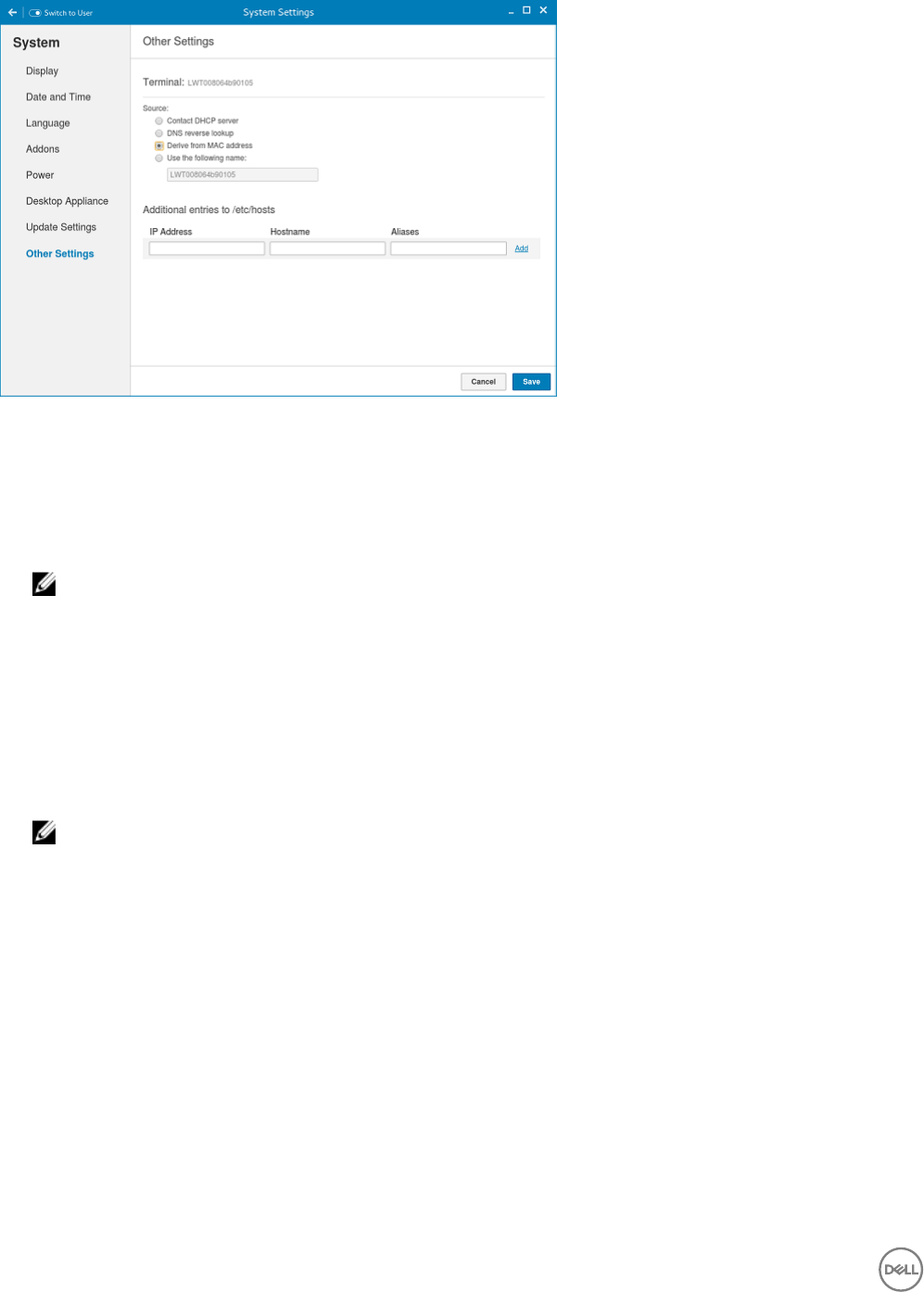
Figure 17. Other settings
•Contact DHCP server: If you set the host name of the thin client by selecting the DHCP server option, the host name is set to
the standard host-name tag received from the DHCP server. If the DHCP server does not provide the host-name tag, then the
device retains the previously set host name.
•DNS reverse lookup: . If you select DNS reverse lookup option to enter the host name of the thin client , a reverse DNS lookup
operation is performed using thin clients existing IPv4 address of the thin client and the host name is then set to the received
value.
NOTE: The previous host name is retained if the device cannot perform a successful reverse DNS look up operation
due to reasons such as, network connection is not established, DNS servers are not established or are invalid, and the
IP address is not included in the DNS server’s list.
•Derive from MAC address: Select the Derive from MAC address option to specify the thin clients host name. You can specify
the thin clients host name by using the MAC address. The eth0 of the thin client interfaces with the MAC address. It creates the
thin clients host name by extracting the MAC address from its eld separators, such as, (:) and the MAC address is prexed with
the string LWT. For example, a device with MAC address of 00:80:64:c1:8b:14 has MAC derived host name as
LWT008064c18b14. Manually specify the device host name should be used with caution. If the manually named device is to be
used as a seed device for Merlin image pulling. The changed host name is pushed to other devices resulting all devices end up
with the same host name. Only through device factory reset can recover the default back by using MAC Address
•Use the following name: This option enables you to enter the preferred host name in the box provided. When you log in to the
session, the screen displays the previous host name in the box and in the Terminal option.
NOTE: The host name entered is not authenticated, if the string entered has a white space. The rst part of the
string up to the rst white space is used to set the host name of the devices. All white spaces at the beginning of the
string are ignored and the maximum host name string size is 64.
You can set the device name by incorporating one of the following methods:The Additional entries to /etc/hosts option on the page
is used to update the entries on the thin client’s /etc/hosts le. It allows you to add to the preset default data, and to update or
delete the existing.
1. Enter the IP address, host name and Aliases in the box provided.
2. Click Add option at the right-end to update the default data.
3. Click Save to save the changes.
Peripherals
On the System Settings page, click the Peripherals icon. The following tabs are displayed on the left pane of the System Settings
page.
• Keyboard
24
• Mouse
• Printers
• Sound
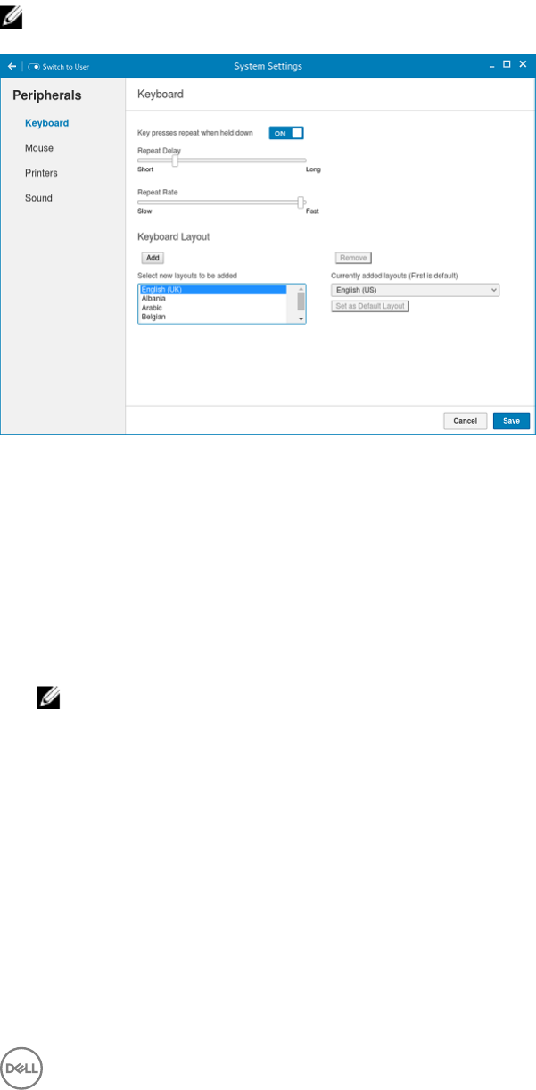
Setting the keyboard preferences
The Keyboard setting page enables you to set the Keyboard preferences and make the Keyboard layout.
NOTE: By default, the Keyboard screen is available in both User mode and Admin mode. Any changes made through
Keyboard preferences screen is saved and continued for the built-in thinuser
Figure 18. Keyboard Preferences
1. Click the ON/OFF button to disable or enable the Key presses repeat when held down option after you log in to the session.
2. Move the slider to the left to decrease the repeated delay time of the pointer or move the slider to the right to increase the
repeated delay time of the pointer.
3. Move the slider to the left to decrease the repeat rate of the pointer or move the slider to the right to increase the repeat rate
of the pointer.
4. In the keyboard layout box, select the layout you want to use and click Add to include the preferred layout in the currently
added layouts list.
5. Select the preferred keyboard layout from the currently added layouts list, and click Set as Default Layout button to set the
default layout.
NOTE: The default keyboard layout is listed on the top of the currently added layout list.
6. Click Save to save your changes.
Setting the mouse preferences
By default, the Mouse screen is available in both User mode and Admin mode. Any changes made through the Mouse preferences
screen is saved and continued for the built-in thinuser.
25
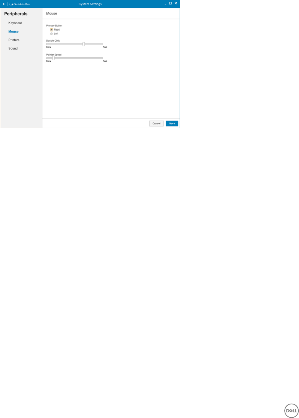
Figure 19. Mouse Preferences
The Mouse setting page enables you to set the Mouse preferences.
1. Click Right or Left to set the primary button of the mouse.
2. Move the slider to the left to increase the speed of the pointer when double-clicked or move the slider to the right to decrease
the length of double-clicked.
3. Move the slider to the left to increase the speed of the mouse pointer or move the slider to the right to decrease the speed of
the mouse pointer.
4. Click Save to save your changes.
Conguring the printer settings
By default, the Printers screen is available only in Admin mode. On the Printer setting page, click the printer icon to start the
gnome-control-center printer.
26
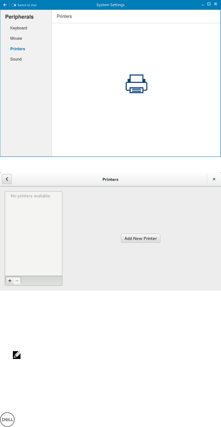
Figure 20. Printer Settings
Figure 21. Add New Printer
1. Click the printer icon.
The gnome-control-center printer dialog box is displayed.
2. Click Add New Printer button to include the new printer in the printers list available on the left pane.
The Add a new printer window is displayed.
3. Enter the address of the printer or the text to lter results.
NOTE: If a USB printer is connected, then it is displayed by default. The printer is not found if wrong address is
provided or the USB is not attached.
4. Click the Add option. Click Print Test Page to test the printer and click (- )icon to remove the printer.
27
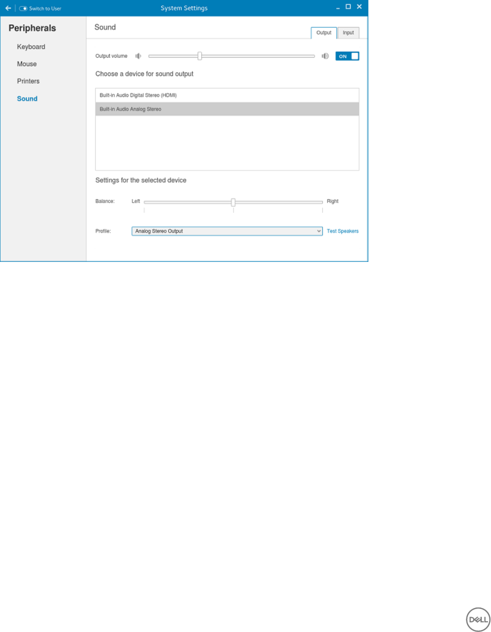
Conguring the sound settings
By default, the Sound screen is available in both User mode and Admin mode. Any changes made through Sound screen is saved and
retained for the built-in thinuser.
1. Click the Output tab to congure the audio output settings.
Figure 22. Sound Settings
a. Move the Output volume slider to adjust the output or speaker volume. Click the Output volume button to enable or disable
the output volume.
b. Select the device for sound output from the listed output devices. The default audio output is the Analog Output.
c. Based on the channels available for the selected output device and prole, you can adjust the Balance and Fade values by
moving Balance and Fade sliders respectively.
d. Select the audio prole from the drop-down list.
e. Click the Test Speakers option. A dialog box is displayed. You can perform the speaker testing by playing sample wave les.
2. Click the Input tab to congure the audio input settings.
28
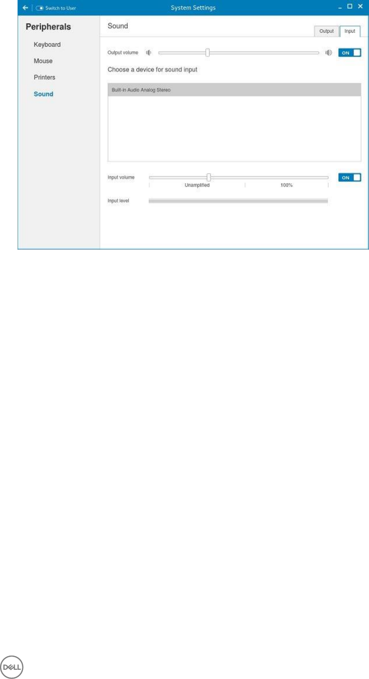
Figure 23. Sound Settings
a. Move the Output volume slider to adjust the output or speaker volume. Click the Output volume option to enable or disable
the output volume.
b. Select the device for sound input from the listed input devices. The default audio input is the Analog input.
c. Move the Input Volume slider to adjust the input or Mic volume. Click the Input volume option to enable or disable the input
volume.
d. The Input level meter bar shows the input volume peak level.
Network
On the System Settings page, click the Network tab to view the Network Settings page.
1. Click the Network icon.
29
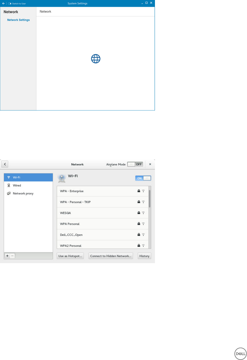
Figure 24. Network Settings
2. The Network settings page is displayed. In the left-pane, the following tabs are available for you to congure.
• Wi-Fi
• Wired
• Network proxy
Figure 25. Wi-Fi Settings
Conguring the wi- settings
To congure the Wi-Fi settings, perform the following steps:
1. In the left-pane, click Wi-Fi tab.
2. Click the ON/OFF button to enable or disable the Wi-Fi option. The list of wireless SSID is displayed if broadcast is enabled.
30
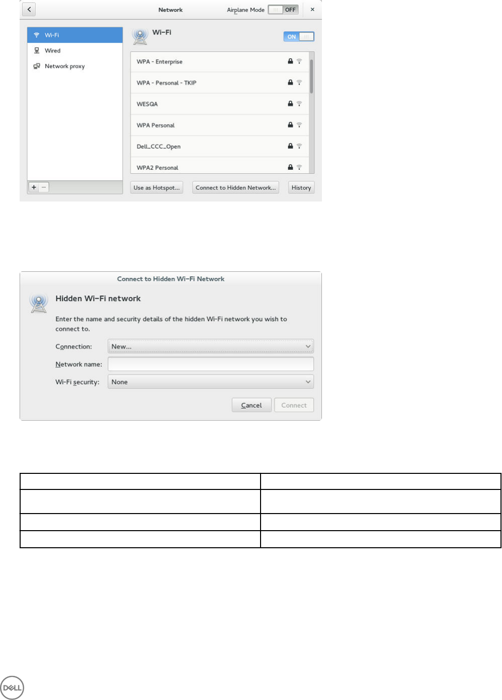
Figure 26. Wi-Fi Settings
3. To connect to Wi-Fi connection, select the preferred wireless SSID from the list displayed.
4. Click the ON/OFF button to enable or disable the Airplane Mode option after you log in to the session.
5. Click the Connect to Hidden Wi-Fi Network button. The Connect to Hidden Wi-Fi Network window is displayed.
Figure 27. Hidden Wi-Fi Network
6. Enter the name and security details of the hidden network that you want to connect to.
Table 2. Hidden network
Parameter Description
Connection From the drop-down list, select the type of connection.
Network name Enter the preferred network name.
Wi-Fi security From the drop-down list, select the security type.
7. On the Network page, click the History button to view the previous Wi-Fi connections and details.
Conguring wired network connection settings
To congure the wired connection settings, perform the following steps:
1. Click the Wired tab. The following attributes are displayed if the network cable is connected to your thin client and wired
connection is established.
• IP Address
31

• Hardware Address
• Default Route
• DNS
NOTE: After the network is disconnected, only hardware address and last used information are displayed.
2. On the lower-right corner of the page, click the Settings icon to congure the Wired Network connections.
a. In the Details tab, the following attributes are displayed.
• IP Address
• Link Speed
• Hardware Address
• Default Route
• DNS
3. Click the Security tab to congure the 802.1x security settings.
a. Click the ON button to enable the 802.1x Security for your network connection.
b. From the Authentication drop-down list, select the type of authentication you want to set for your network connection.
The available options are:
• MDS
• TLS
• FAST
• Tunneled TLS
• Protected EAP (PEAP)
c. If the authentication type is selected as MD5, you must congure the following options:
Table 3. MD5 conguration
Parameter Description
Username Enter the Username for the network connection.
Password Enter the password you want to set for the connection.
Ask for this password every time If this check box is selected, you will be prompted to enter
the password every time when you connect to the network.
Show Password Select this check box if you want to allow the user
to view the hidden password.
d. If the authentication type is selected as TLS, you must congure the following options.
Table 4. TLS
Parameter Description
Identity Enter your Identity.
User certicate Select the User certicate from the list or upload your
personal certicate stored locally.
To upload your personal certicate, click the Folder icon,
and then browse to the location where you have stored the
certicate.
CA Certicate Select the CA certicate from the list or upload your CA
certicate stored locally.
32

Parameter Description
To upload your CA certicate, click the Folder icon, and
then browse to the location where you have stored the
certicate.
Private key Select the private key from the list or upload your private
key stored locally.
To upload your private key, click the Folder icon, and then
browse to the location where you have stored the
certicate.
Private key password Enter the password that you want to set for the private key.
Show Password Select this check box if you want to allow the user
to view the hidden password.
e. If the authentication type is selected as FAST, you must congure the following options.
Table 5. FAST
Parameter Description
Anonymous identity Enter the username you want to set for Anonymous
Authentication Identity.
PAC provisioning Select this check box to enable the PAC provisioning
authentication. From the drop-down list, select any of the
following PAC provisioning options:
Anonymous – Select this option to establish a secure
anonymous TLS communication with the client and provide
it with a PAC.
Authenticated – Select this option to enable a secure
server-side authentication and provide the client with a
proxy auto-cong (PAC) le.
Both – Select this option if you want to allow both
Anonymous and Authenticated PAC provisioning.
PAC le Select the PAC le from the list or upload your CA
certicate stored locally.
To upload your PAC le, click the Folder icon, and then
choose the certicate from the location where you have
stored the certicate.
Inner authentication From the drop-down list, select the inner authentication
method you want to set. The available options are GTC and
MSCHAPv2.
Username Enter the Username for the network connection.
Password Enter the password you want to set for the connection.
Ask for this password every time If this check box is selected, you will be prompted to enter
the password every time when you connect to the network.
33

Parameter Description
Show Password Select this check box if you want to allow the user
to view the hidden password.
f. If the authentication type is selected as Tunneled TLS, you must congure the following options.
Table 6. Tunneled TLS
Parameter Description
Anonymous identity Enter the username that you want to set for Anonymous
Authentication Identity.
CA certicate Select the CA certicate from the list or upload your CA
certicate stored locally.
To upload your CA certicate, click the Folder icon, and
then browse to the location where you have stored the
certicate.
Inner authentication From the drop-down list, select the inner authentication
method that you want to set. The available options are GTC
and MSCHAPv2.
Username Enter the Username for the network connection.
Password Enter the password that you want to set for the
connection.
Ask for this password every time If this check box is selected, you will be prompted to enter
the password every time when you connect to the network.
Show Password Select this check box if you want to allow the user
to view the hidden password.
g. If the Authentication type is selected as Protected EAP (PEAP), you must congure the following options.
Table 7. Protected EAP (PEAP)
Parameter Description
Anonymous identity Enter the username you want to set for Anonymous
Authentication Identity.
CA certicate Select the CA certicate from the list or upload your CA
certicate stored locally.
To upload your CA certicate, click the Folder icon, and
then browse to the location where you have stored the
certicate.
PEAP version Select the PEAP version type you want to use for EAP
authentication. The available options are:
• Automatic
• Version 0
• Version 1
Inner authentication From the drop-down list, select the inner authentication
method that you want to set. The available options are GTC
and MSCHAPv2.
34

Parameter Description
Username Enter the Username for the network connection.
Password Enter the password that you want to set for the
connection.
Ask for this password every time If this check box is selected, you will be prompted to enter
the password every time when you connect to the network.
Show Password Select this check box if you want to allow the user
to view the hidden password.
4. Click the Identity tab and congure the following settings:
NOTE: Only Administrators are allowed to authenticate these settings by entering the admin password in the root
privilege authentication dialog box after a particular setting is changed or congured.
a. Name— Species the default name of the wired connection. If you want to set your preferred name for the connection,
enter the name and then click Apply.
b. MAC Address— Species the MAC address of the network connection.
c. Cloned Address— Species the IP address that is cloned by the router.
d. Maximum transmission unit (MTU)— Species the size (in bytes) of the largest protocol data unit that the protocol layer
can pass onwards.
e. Connect automatically— Select this check box to automatically connect to the network after you plug-in the network wire.
f. Make available to other users— Select this check box if you want to allow other users to congure these settings.
5. Click the IPv4 tab and do the following:
a. Enable the IPv4 button to congure the IPv4 settings.
b. From the Addresses drop-down menu, select the type of IPv4 conguration. The available options are:
• Automatic (DHCP)
• Manual
• Link-Local Only
c. If Automatic (DHCP) option is selected, you must congure the following options.
Table 8. Automatic (DHCP)
Parameter Description
DNS Enable the Automatic button, if you want the thin client to
automatically fetch the DNS Server.
Server Species the IP address of the DNS Server.
Click the + icon to add a new DNS server to the list.
Routes Enable the Automatic button to turn on the automatic IPv4
routing.
Address Species the Router IP address.
Netmask Species the Netmask. Netmask is used to divide an IP
address into subnets and specify the network's available
hosts.
Gateway Species the IP address of the default Gateway.
Metric Species the Metric value for the network connection.
35

Parameter Description
Use this connection only for resources on its network Select this check box, if you want to allow the wired
connection only for resources on its network.
d. If Manual option is selected, you must specify the IP address, Netmask IP and Gateway IP along with the parameters
mentioned in Table 1: Automatic (DHCP).
e. If Link-Local Only option is selected, the DNS and Routes options are disabled. This is applicable only for communications
within the host link or the host domain.
6. Click the IPv6 tab and do the following:
a. Enable the IPv6 button to congure the IPv6 settings.
b. From the Addresses drop-down menu, select the type of IPv6 conguration. The available options are:
• Automatic
• Automatic, DHCP only
• Manual
• Link-Local Only
The IPv6 conguration is similar to conguring the IPv4 Settings. For IPv4 conguration, see the IPv4 settings in this
section.
7. Click the Reset tab and do the following:
a. Click Reset to reset the settings for your network connection, including passwords. However, the previous network is
displayed as a preferred network.
b. Click Forget to remove all details relating to this network that you do not want to automatically connect to.
8. Click Apply to save your congured settings.
NOTE: Click the Add Prole tab to add a new network prole. On the right pane, you must congure the following
options:
• Security
• Identity
• IPv4
• IPv6
The conguration of all these tabs are similar to Wired Network connections congurations described in this section.
Conguring the network proxy settings
To congure the Network proxy settings, complete the following task:
1. Click the Network proxy tab.
2. From the Proxy drop-down menu, select the type of Proxy method you want to deploy. The available Proxy methods are:
• None
• Manual
• Automatic
3. If Manual proxy method is selected, you must congure the following options:
a. Enter the HTTP Proxy port details for your network connection.
b. Enter the HTTPS Proxy port details for your network connection.
c. Enter the FTP Proxy port details for your network connection.
d. Enter the SOCKS host port details for your network connection.
e. Use the Ignore Hosts option to set up proxy to ignore all local addresses.
4. If Automatic proxy method is selected, you must type the conguration URL address in the eld.
NOTE: Web Proxy Autodiscovery is used when a Conguration URL is not provided. Dell does not recommend this
option for untrusted public networks.
36

Adding a network connection
NOTE: Adding additional wired Ethernet connections is allowed but the added interface is not used in any of the
ThinLinux features.
To add a new network connection, complete the following tasks:
1. On the lower-left corner of the page, click the + icon.
The Add Network Connection dialog box is displayed. The following options are listed for you to congure.
• VPN
• Bond
• Bridge
• VLAN
2. Click VPN to add a VPN network connection. You must import a le from the stored location to congure the VPN settings.
3. Click Bond to add and congure the Bond network connection for your thin client.
a. Click the General tab to select or deselect the following check boxes.
• Automatically connect to this network when it is available.
• All users may connect to this network.
• Automatically connect to VPN when using this connection.
b. Click the Bond tab, and congure the following options:
1. Type a name for your network interface.
2. The number of bonded connections that are set up are listed here. To add a new bond connection, click the Add
button and select the type of connection you want to create. The available options are Ethernet and InniBand.
3. Select the type of Network Mode from the drop-down list. The available options are:
• Round-robin
• Active Backup
• XOR
• Broadcast
• 802.3ad
• Adaptive transmit load balancing
• Adaptive load balancing
4. Link Monitoring — Select the type of link monitoring from the drop-down list. The available options are:
• MII (recommended)
• ARP
5. Enter the time in ms for the link up delay duration.
6. Enter the time in ms for the link down delay duration.
c. Click the IPv4 Settings tab, and do the following:
1. From the drop-down list select the following method for IPv4 authentication.
• If Automatic (DHCP) method is selected, you must congure the following options:
1. Additional DNS Servers — Type the IP addresses of domain name users that are used to resolve host names.
Use commas to separate multiple domain name server addresses.
2. Additional Search Domains — Type the IP addresses of domains used when resolving host names. Use
commas to separate multiple domains.
3. DHCP client ID — Enter the ID for the DHCP client. This client identier allows the network administrator to
customize your computer’s conguration.
37

4. Require IPv4 addressing for this connection to complete — The IPv4 address is required to complete the
connection. If the IPv4 address is not available, then the connection is not congured.
5. Click the Routes button to edit IPv4 routes for Bond connection.
a. Click Add to add an IP address. After an IP is added, Netmask, Gateway and Metric specic to that IP
are displayed.
b. Select the check box if you want to ignore the automatically obtained routes.
c. Select this check box if you want to use your connection only for resources on that particular network.
• If Automatic (DHCP) addresses only method is selected, you must congure the following options:
1. DNS Servers — Type the IP addresses of domain name users that are used to resolve host names. Use
commas to separate multiple domain name server addresses.
2. Search domains — Type the IP addresses of domains that are used when resolving host names. Use commas
to separate multiple domains.
3. DHCP client ID — Enter the ID for the DHCP client. This client identier allows you to customize your
computer’s conguration.
NOTE: The other settings remain same as described in automatic (DHCP) method for IPv4
authentication.
• If Manual method is selected, you must congure the following options:
1. Click Add to add an IP address. After an IP is added, Netmask, Gateway specic to that IP are displayed.
2. DNS Servers — Type the IP addresses of domain name users that are used to resolve host names. Use
commas to separate multiple domain name server addresses.
3. Search domains — Type the IP addresses of domains used when resolving host names. Use commas to
separate multiple domains.
NOTE: The DHCP client ID option and Ignore automatically obtained routes check boxes are disabled.
The other settings remains the same as described in automatic (DHCP) method for IPv4 authentication.
• If Link-Local Only method is selected, the DNS Servers, Search domains, DHCP client ID, and Routes options are
disabled. You can select the Require IPv4 addressing for this connection to complete check box to allow the
connection to complete. The IPv4 address is required to complete the connection. If the IPv4 address is not
available, then the connection is not congured.
• If Shared to other computers method is selected, the DNS Servers, Search domains, DHCP client ID, and Routes
options are disabled. You can select the Require IPv4 addressing for this connection to complete check box to
allow the connection to complete. The IPv4 address is required to complete the connection. If the IPv4 address is
not available, then the connection is not congured.
d. Click the IPv6 Settings tab. From the drop-down list, select the following method type for IPv4 authentication. The
available options are:
• Ignore
• Automatic
• Automatic, addresses only
• Manual
• Link-Local Only
NOTE: The settings are same as conguring the IPv4 settings tab described in this section.
4. Add and congure the Bridge network connection for your thin client.
a. Click the Bridge tab, and congure the following options:
1. Interface name — Type the name for your network interface.
38

2. Bridged connections — The number of bonded connections that are set up are listed here. To add a new bond
connection, click the Add button and select the type of connection you want to create. The available options are
Ethernet, Wi-Fi, and VLAN.
3. Aging time — Enter the Aging time duration in seconds.
4. Enable STP — Select this check box to enable the Spanning Tree Protocol (STP) for your connection.
5. Priority — Enter the priority value.
6. Forward delay — Enter the forward delay duration in seconds.
7. Hello time — Enter the hello time duration in seconds.
8. Max age — Enter the value for the maximum age.
b. To congure the General tab, IPv4 Settings tab, and IPv6 Settings tab for Bridge connection, see the conguration details
for Bond connection in this section.
5. Congure the VLAN network connection for your thin client.
a. Click the VLAN tab, and congure the following options:
1. Parent interface — Type the name for your parent interface.
2. VLAN id — Enter the value for the VLAN id.
3. VLAN interface name — Type the name for your VLAN interface.
4. Cloned MAC address — Type the cloned MAC address.
5. MTU —Species the size (in bytes) of the largest protocol data unit that the protocol layer can pass onwards.
b. To congure the General tab, IPv4 Settings tab, and IPv6 Settings tab for VLAN connection, see the conguration details
for Bond connection in this section.
6. Click Save to save your settings.
802.1x Conguration
To congure the network connections:
39
NOTE: Currently, 802.1x conguration by using the Enable802 INI parameter is supported only for Wired connections and
supported authentications are EAP-PEAP (MSCHAPv2) and EAP-TLS using SCEP.
• Supported seamless 802-1x authentication works with Linux thin clients by using Active Directory domain user credentials
for EAP-MSCHAPv2 authentication, see EAP PEAP MSCHAPv2 Authentication Workow.
• EAP-TLS is certicate-based authentication which uses SCEP for certicate enrollment, see EAP TLS Authentication
Workow.
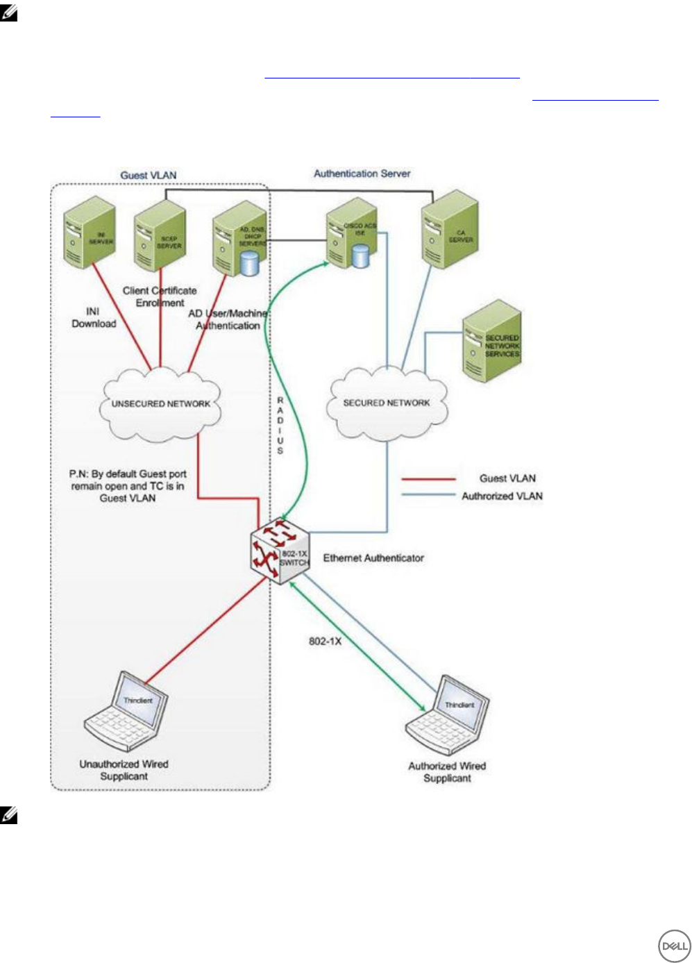
The following diagram depicts communication between the components in an 802.1x Linux thin client solution.
NOTE: EAP-TLS security requires client side and server side certicates for mutual authentication. Every user and client,
including the authentication server that participates in EAP-TLS, must have at least the following two certicates:
• Client certicate signed by the certicate authority (CA).
• Copy of the CA root certicate.
40

Important: Dell recommends you to set INI values for all the 802-1x parameters because these parameters are part of the
persistent registry which will remain across the reboot and if any parameter is not set, it will take the previously set value,
which may show inconsistent behaviors.
EAP-PEAP (MSCHAPv2) Authentication workow
When a Linux thin client is initially connected to the network, the thin client obtains Guest VLAN resources by default, that is TC
should be able to reach INI server to fetch the INI congurations required for 802-1x conguration.
Pre-requisites for EAP-PEAP (MSCHAPv2) 802-1x authentication:
• Make sure that the INI le has the congurations for 802-1x, Active Directory server, and Domain and Import certs. If you are
pushing a CA certicate by using the Dell Wyse Device Manager (WDM), the Imports Certs INI is not required, but you must be
sure that the CA certicate name is correct in the 802-1x INI parameter. For more information, see Dell Wyse ThinLinux INI Guide.
• If you are using CA certicate for 802-1x authentication, then use the ImportCerts INI parameter to import CA certicates into
the device. Ignoring CA certicate is considered as the default option, if the CA certicate name is not included in the 802–1x INI
conguration.
• Domain List INI parameter is required to display the available domains on the GDM login screen.
EAP-PEAP (MSCHAPv2) 802-1x authentication can be congured in two dierent modes:
• User Authentication
• Machine Authentication
EAP-PEAP (MSCHAPv2) — User authentication
To authenticate 802-1x by using an Active Directory username account:
1. Turn on your thin client device.
After the INI is downloaded to the thin client, you can access the domain that is congured in the INI from the domain drop-
down list on the GDM Login screen.
2. On the GDM login screen, select the domain, and then enter the user domain credentials.
3. Click Log in.
The 802-1 authentication automatically starts.
NOTE: The GDM Authentication module performs the Network Manager conguration required for 802-1x PEAP
(MSCHAPv2) authentication by using the credentials entered and 802-1x congurations from INI. Then, it
reinitializes the network to do a direct 802-1x authentication with the switch.
• If log in is successful, then the thin client gets IP address from the protected VLAN and you can start the local thin client
session (GNOME session). You can also start RDP, ICA, PCOIP sessions using the same domain credentials provided in the
GDM login. These credentials will be preexisting in the connection manager, and you need not renter the same again.
NOTE:
– If you set Is802DirectEnabled=yes, the direct authentication is enabled which will trigger the 802-1x authentication
from the GDM login screen. In this case the ActiveDirectoryServer parameter is not required.
–If you set Is802DirectEnabled=no, the 802-1x authentication is triggered after the user logs in to the thin client. In
this case you need to include the ActiveDirectoryServer parameter in the INI.
• If log in is unsuccessful, the 802-1x authentication fails and the thin client remains in the Guest VLAN.
4. When you log out or restart the device, thin client will again move to Guest VLAN by sending an EAPOL logo to switch and
disabling the 802-1x conguration at Network Connections applet.
The following is an example of the INI conguration for EAP-PEAP (MSCHAPv2) 802-1x User authentication.
For AD and Domain settings
DomainList=npac.local DisableDomain=no
For Imports Certcates
ImportCerts=no
41

For 802-1x Conguration
Enable802=yes Authentication=PEAP InnerAuthentication=MSCHAPv2 PromptPassword=no
AuthMode=User Is802DirectEnabled=yes CACertificate=SCEP PeapVersion=Auto
EAP-PEAP (MSCHAPv2) Machine authentication
To enable EAP-PEAP (MSCHAPv2) machine authentication:
• Your machine must have an account created in the Active Directory database with Hostname as the username eld.
• Set the same password for all machine/host name accounts to be created.
• The INI parameter should contain a MachinePassword Field that can be used for authentication.
To authenticate 802-1x using Machine name (Host name):
1. Turn on your thin client device.
Once the INI is downloaded to the thin client and all the 802-1x parameters for machine PEAP authentication are retrieved from
the INI server, the authentication starts in the background.
The Authentication module performs the Network Manager conguration required for 802-1x PEAP MSCHAPv2 authentication
by using the host name and password from INI and 802-1x congurations from INI.
• If 802-1x authentication is successful, then thin client gets IP Address from protected VLAN.
• If 802-1x authentication fails due to any wrong 802-1x conguration, then thin client remains in the Guest VLAN.
2. When you restart your thin client, the device moves to Guest VLAN by sending an EAPOL logo to switch and disabling the
802-1x conguration at Network Connections applet.
The following is an example of the INI conguration for EAP-PEAP (MSCHAPv2) 802-1x machine authentication:
For AD and Domain settings
DomainList=npac.local DisableDomain=no
For Imports Certicates
ImportCerts=yes Certs=npac-ca-cert.pem
For 802-1x Conguration
Enable802=yes Authentication=PEAP InnerAuthentication=MSCHAPv2 PeapVersion=Auto
PromptPassword=no CACertificate=npac-ca-cert.pem Authmode=Machine
MachinePassword=tangocharlie
EAP TLS authentication workow
When a Linux thin client is initially connected to the network, it should be able to obtain the Guest VLAN resources by default. It
should be able to reach AD, DNS, SCEP and the INI server to fetch the INI congurations required for Active Directory Domain User
Authentication, 802-1x, SCEP, and so on.
EAP-TLS 802-1x authentication can be congured in INI in two dierent modes:
• Machine Authentication.
• User Authentication.
EAP TLS – Machine authentication
The following steps are involved with 802-1x authentication:
• When the thin client restarts, it remains in the Guest VLAN and downloads the INI conguration from the INI server.
• The INI le must have the congurations for 802-1x EAP-TLS with AuthMode set for Machine Authentication and SCEP.
• After the INI is downloaded to the thin client, SCEP client enrolls the client certicate with Machine hostname and Domain
congured in the INI.
42

• 802-1x EAP-TLS machine authentication will then begin and the thin client will move to an Authorized VLAN
NOTE:
You can view the network progress icon on the taskbar.
• If 802-1x authentication fails due to any wrong 802-1x conguration, the thin client will automatically fall back to the Guest VLAN,
with a notication message Failed to connect to trusted network. Please contact your system administrator, in the right pane
of the GNOME panel. The user receives the same notication in the case of an expired CA certicate.
• When a user restarts the device, the thin client will again move to the Guest VLAN by sending an EAPOL logo to switch and
disable the 802-1x conguration at the Network Connections applet.
This is an example of the INI conguration for 802-1x TLS Machine authentication.
Enable802=yes Authentication=TLS PromptPassword=no CACertificate=scep UserCertificate=scep
PrivateKey=scep PrivateKeyPassword=ZG90MXg= AuthMode=Machine
EAP TLS User authentication
To authenticate 802-1x:
1. Turn on your thin client device.
When the thin client restarts, the thin client remains in the Guest VLAN and downloads the ini conguration from the INI server.
2. After the INI is downloaded to the thin client, you can access the domain that is congured in the INI from the domain drop-
down list on the GDM Login screen.
3. On the GDM login screen, select the domain, and then enter the user domain credentials.
Domain User authentication is performed against the AD server mentioned in the INI conguration.
4. Click Log in.
• If domain user login is successful, then the user certicate will be enrolled via SCEP, and 802-1x authentication will begin and
you can see the network progress icon on the taskbar and the thin client will move to Authorized VLAN.
• If 802-1x authentication fails due to any wrong 802-1x conguration or if the CA certicate has expired, the thin client will
automatically fall back to Guest VLAN, and a notication message Failed to connect to trusted network. Please contact
your system administrator is displayed in the right corner of GNOME panel.
• When you log out or restart the thin client, the thin client as suggested above to Guest VLAN by sending an EAPOL logo
to switch and disabling the 802-1x conguration at the Network Connections applet.
This is an example of the INI conguration for 802-1x TLS User authentication.
Enable802=yes Authentication=TLS PromptPassword=no CACertificate=scep UserCertificate=scep
PrivateKey=scep PrivateKeyPassword=ZG90MXg= AuthMode=User
Personalization
You can customize your desktop settings such as color, background in addition to enable various option that helps to improve the
look and feel of the screen. Some of the important parameters such as display settings, audio settings, typing settings and pointer
settings can be personalized.
On the System Settings page, click Personalization icon. The following tabs are listed on the left pane of the System Settings
page.
• Desktop Wallpaper
• Universal Access
Setting the desktop wallpaper
Click the Desktop Wallpaper tab.
43
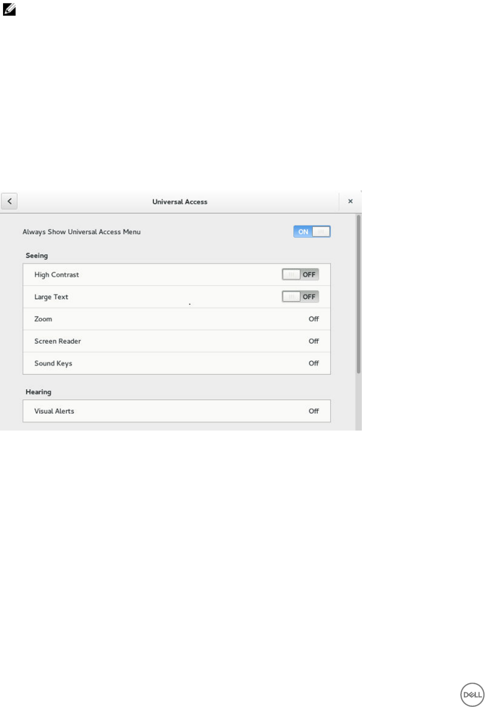
NOTE: You can add wallpapers using USB drive.
Conguring universal access
The Universal Access page allows you to congure the display settings, audio settings, typing settings and pointer settings. The
Universal Access Menu allows you to improve the look and feel of the desktop.
1. Click the desktop icon on the Universal access page.
2. Click the ON/OFF button to enable or disable the option. If enabled, the Universal Access menu can be viewed always.
3. Congure the following options:
• Seeing
• Hearing
• Typing
• Pointing and Clicking
Figure 28. Universal Access
44
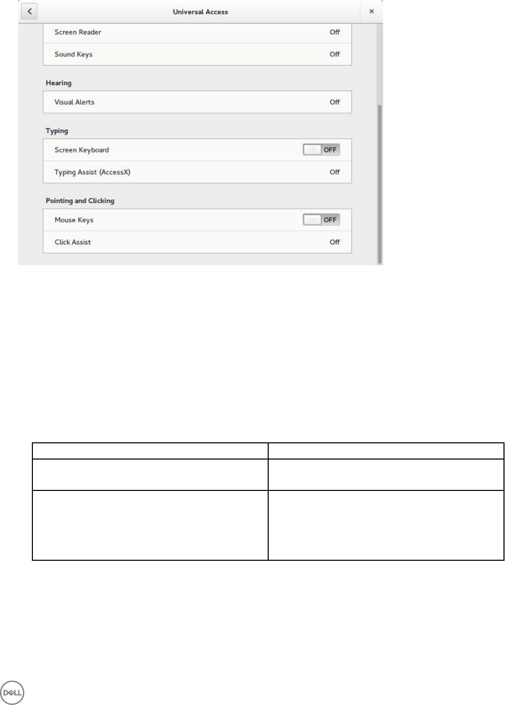
Figure 29. Universal Access
Seeing
The Seeing tab enables you to congure the display settings.
1. Click the ON/OFF button to enable or disable the High contrast option. If enabled, the contrast is increased and you can see
the dierence instantly.
2. Click the ON/OFF button to enable or disable the Large text option. If enabled, the text size is increased and you can see the
dierence instantly.
3. Click the ON/OFF button to enable or disable the zoom option. If enabled, the screen is zoomed in and you can control the
screen by using the mouse.
a. Click the Magnier tab to congure the following settings:
Table 9. Magnier
Parameter Description
Magnication Click + to increase the magnication value and click — to
decrease the magnication value.
Magnier Position Select the Magnier Position.
• If you select Follow mouse cursor, the other option is
disabled.
• If you select Screen part, select the screen resolution
from the drop-down list.
b. Click Crosshairs tab to congure the following settings:
• Move the slider to the right to increase the Thickness and Length of the crosshairs.
• Click the Color tab, and select the preferred color.
c. Click Color Eects tab to congure the following settings:
• Click the ON/OFF button to enable or disable the White on Black option.
• Move the slider to the right to increase the Brightness, Contrast and Color
d. Click Close.
45

4. Click the ON/OFF button to enable or disable the Screen Reader option. If enabled, the screen reader reads the displayed text
as you move the text.
5. Click the ON/OFF button to enable or disable the Sound Keys option. If enabled the beep sound when number lock or caps lock
is clicked is turned ON.
Hearing
This section allows you to congure the Audio alerts by providing an visual indication.
1. Click Visual Alerts to congure the visual eects.
2. Click the ON/OFF button to enable or disable the option.
3. Select the preferred options in Visual Alerts.
4. Click the Test ash tab to have a ash on the screen.
5. Click Close.
Typing
This section allows you to congure the typing settings:
1. Click the ON/OFF button to disable or enable the keyboard display on the screen.
2. Click the Typing Assist (AccessX) to congure the keyboard setting.
a. Click the ON/OFF button to enable the features using keyboard.
b. Click the ON/OFF button to enable or disable the Sticky Keys option.
c. Click the ON/OFF button to enable the long keypress and set the delay using Slow Keys option.
There is a delay between the action and the result when a key is pressed.
d. Click the ON/OFF button to enable or disable the Bounce Keys option.
This option is used to avoid using the fast duplicate keypress and set the delay.
3. Click Close.
Pointing and clicking
This section allows you to congure the Mouse settings.
1. Click the ON/OFF button to enable or disable the Mouse Keys option.
2. Click the Click Assist tab to congure the settings.
46
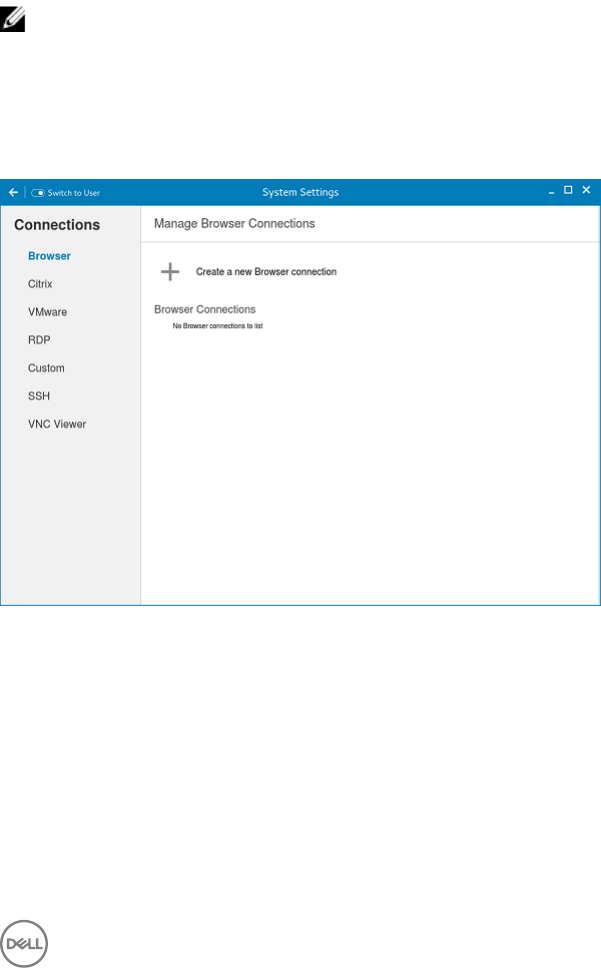
4
Conguring Connections locally
On the System Settings page, click the Connections icon. The Connections page contains the following tabs:
• Browser
• Citrix
• VMware
• RDP
• Custom
• SSH
• VNC Viewer
NOTE: The description names for all the connections can not be edited once you create the connection.
Conguring and managing the browser connections
The Browser Connections page enables you to create and manage Firefox Browser connections for your thin client.
Figure 30. Manage Browser Connections
To create a new browser connection:
1. Click the + icon to add a new browser connection.
The Browser connection page is displayed.
47
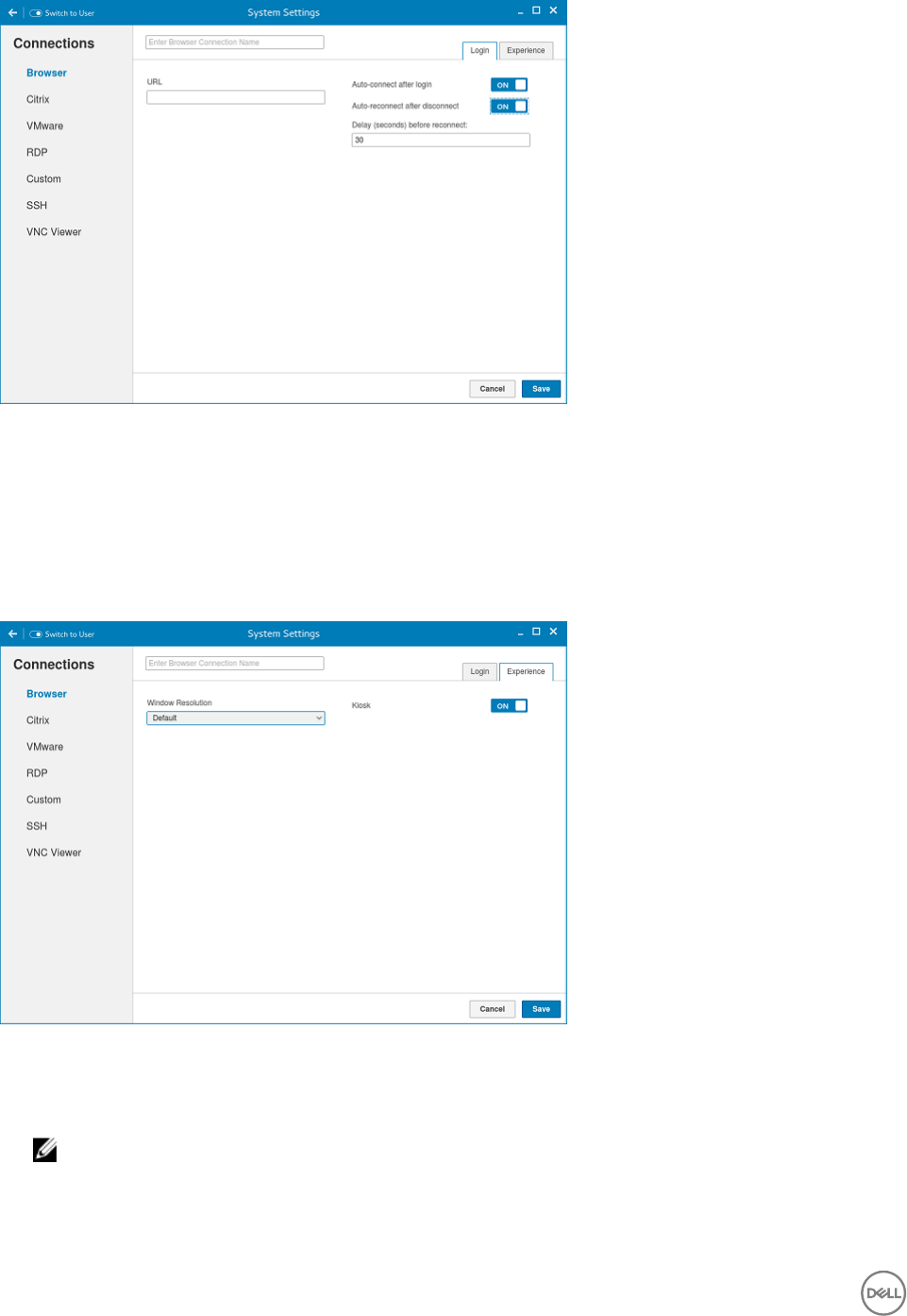
Figure 31. Browser Connection Settings
2. In the Login tab, enter the URL address of the browser connection you want to connect to.
3. Enter the name of the Browser connection for which you have specied the URL address.
4. Click the ON/OFF button to enable or disable the auto-connect option after you log in to the session.
5. Click the ON/OFF button to enable or disable the auto-reconnect option after you disconnect from the session. If the Auto-
reconnect option is enabled, you can enter the Delay duration (in seconds) to reconnect to the session. The default value is 30
seconds.
6. Click the Experience tab to set the window resolution and Kiosk mode.
Figure 32. Browser Connection Settings
a. From the drop-down list, select the window resolution you want to set for your Browser window.
b. Click the Kiosk button to enable the Kiosk mode for your browser.
NOTE: When the Kiosk is Enabled, you cannot change window resolution.
7. Click Save to save the changes.
The browser connection created by you is displayed in the Browser Connections list.
To manage a Browser connection:
48
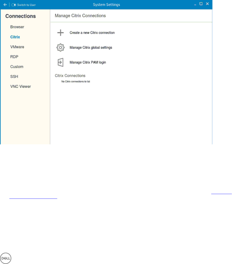
1. Hover the mouse over a particular browser connection name. The Edit, Remove, and Connect options are displayed next to the
browser connection name.
2. Click Edit to edit the URL address and other settings of the browser connection.
3. Click Remove to remove the browser connection from the list.
4. Click Connect to connect to the URL address you have specied for your browser connection. The webpage opens on your
default browser.
Conguring and managing Citrix connections
The Citrix Connections page enables you to create and manage Citrix connections both locally and globally.
Figure 33. System settings
To congure the local Citrix settings:
1. Click the + icon to add a new Citrix Connection.
The Citrix Connections page is displayed.
2. Enter the name of the Citrix connection for which you will specify the Server URL address.
3. From the Connection Type drop-down list, select any of the following connection type. For more information, see Conguring
the server connection type
• Server
• Published Application
• Storefront
4. Click Save to save the changes.
49
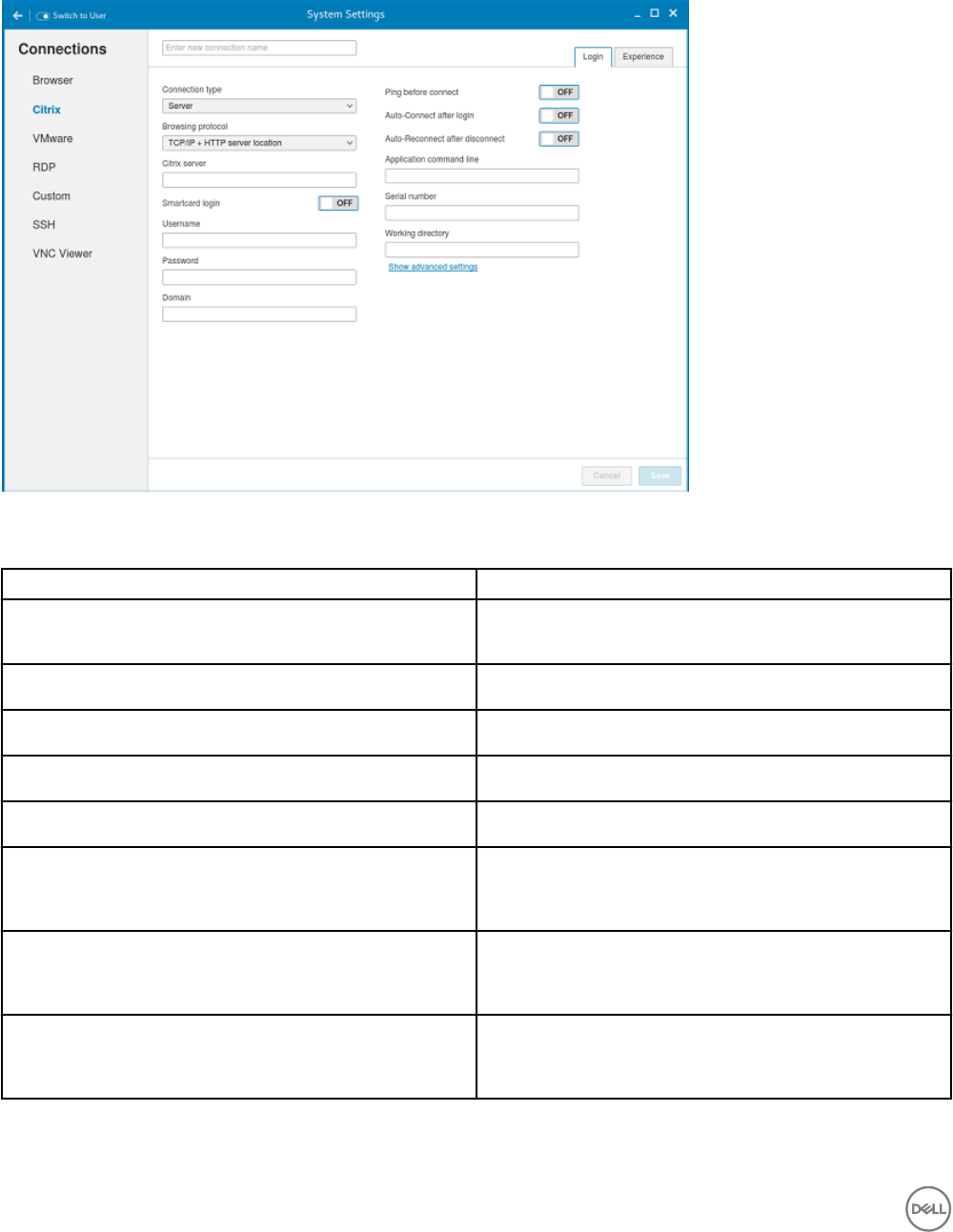
Conguring the server connection type
If Server is selected as the Connection type, the following options must be congured in the Login tab.
Figure 34. Citrix Connection Login Settings
Table 10. Server
Parameter Description
Browsing Protocol From the drop-down list, select your preferred Browsing
Protocol.
Citrix Server Enter the specic Citrix Server.
Username Enter the Username of the server.
Password Enter the Password of the server.
Domain Enter the preferred Domain for the server connection.
Ping before connect Click the ON/OFF button to enable or disable this option. If
enabled, the connection is checked before connecting to a
session.
Auto-Connect after login Click the ON/OFF button to enable or disable this option. If
enabled, the connection is automatically established after you
log in to your thin client.
Auto-Reconnect after disconnect Click the ON/OFF button to enable or disable this option. If
enabled, the connection is automatically established after you
disconnect from the session.
50
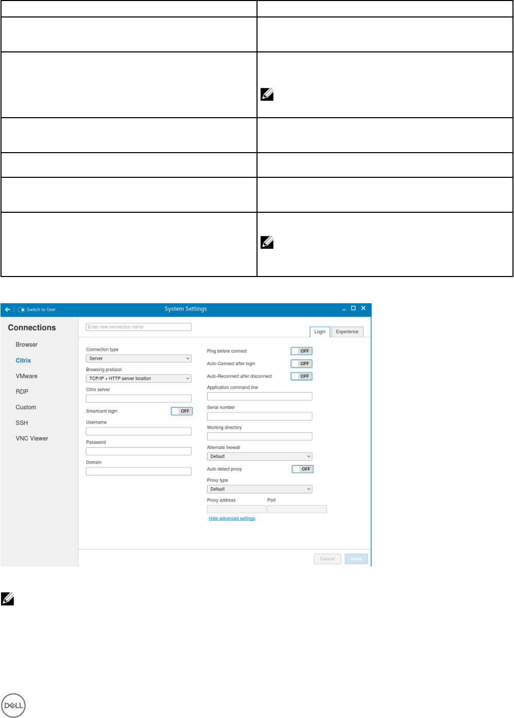
Parameter Description
When disconnect, reconnect Select the amount of time in seconds to delay the reconnection
attempt after a disconnection occurs.
Smartcard login Click the ON button to enable smart card login to the thin client.
The User Name, Password, and Domain are not required.
NOTE: Smart Card Login is applicable only for Server
and Storefront Connections
Smartcard type This eld is enabled when you select Smart Card Login. Select
the type of smart card you are using from the drop-down list.
Application command line Enter the command line for the program on the server.
Serial number Enter the serial number for environments that require the thin
client license serial number.
Working directory Enter the working directory for the program.
NOTE:
Working Directory is applicable only for Server
Connections.
Click the Show advance settings to view and congure the advanced options for your Citrix server connection.
Figure 35. Citrix Connection Advanced Settings
NOTE:
The advanced options are available only for Server Connections.
51

Table 11. Advanced options
Parameter Description
Alternate Firewall From the drop-down list, Select Yes to use an alternate address
for rewalls.
Auto-detect proxy Click the ON button to automatically detect the proxy type.
Click the OFF button to manually enter the proxy type.
Proxy type From the drop-down list, Select a proxy type.
Proxy Address From the drop-down list, Select a proxy address.
Note: If you select Secure (HTTPS) or SOCKS as the Proxy
Type, you must enter the Proxy Address and Port.
If Published Application or Storefront is selected as the Connection Type, the following options must be congured in addition to
the options listed for Server Connections Table.
•Store Name: Enter your preferred store name. Multiple store names are not supported.
NOTE:
–SmartCard Login option is not available for Published applications.
– The Storefront option is applicable only for Citrix XenDesktop 7.0 and later versions. Select this option to specify the
name of a Store Front server to display the applications available in that sever.
–Smart card type option is not applicable for Server connections.
The following options must be congured in the Experience tab.
Figure 36. Citrix Connection Experience Settings
Table 12. Experience
Parameter Description
Windows resolution Select the Windows resolution that you want to use on your
monitor. The available resolutions are:
52

Parameter Description
Default
640X480
800X600
1024X768
1280X1024
1600X1200
Full Screen
Seamless
Colors Species the number of colors to display for each pixel. Select
the session color mode to get the faster display performance on
your monitor. The available options are:
256
Best quality (64k)
16 million
Encryption Species the connection security level. Select the preferred
option.
Basic
RC5(128 bit- login only)
RC5(40 bit)
RC5(56 bit)
RC5(128 bit)
NOTE: The highest level is 128-bit security and the
lowest level is Basic.
Enable middle button paste login Click the ON/OFF button to enable or disable this option. If
enabled, you can use the mouse middle click to paste content
into your text documents.
Compression Click the ON/OFF button to enable or disable this option.
Optimize for low bandwidth Click the ON/OFF button to enable or disable this option.
Sound Click the ON/OFF button to enable or disable this option.
Conguring global Citrix settings
When you log out and log in, you are prompted for credentials to log in to a Citrix session for the selected domain.
When you successfully log in, all the applications and desktops on the remote session are listed on the local desktop.
1. Click Manage Citrix Global Settings.
53

The Manage Citrix Global Settings page is displayed.
2. On the Login tab, congure the following options to enable Citrix PAM login and enable the PAM login using the slider, in the
Managing PAM login page. The Domain details also need to be provided in the Managing PAM login page.
a. Enter the Citrix server.
b. From the drop-down list, select the required browsing protocol. The available options are:
• TCP/IP + HTTP server location
• TCP/IP
• SSL/TLS + HTTPS server location
c. Enter the storename.
d. Click Show Advance Settings to view and congure the advanced options.
1. Click the ON/OFF button to enable or disable the Use Alternate address for rewalls option. If enabled, an alternate
address can be used for rewall conguration.
2. Click the ON button to automatically detect the proxy type or click the OFF button to manually enter the proxy type.
3. From the drop-down list, select a proxy type
3. On Experience tab, congure the following options.
a. Click the ON/OFF button to enable or disable the Application Reconnection option. If enabled, the connection is
automatically re-established after you disconnect from the session.
b. Select the Windows resolution you can use to get the best display on your monitor.
c. If you come across over-scrolling when using certain published applications, increase the adjustment by 100 until the display
improves.
NOTE: The maximum scroll adjustment is 1000.
d. Click the ON/OFF button to enable or disable the PrintScreen option. Select the option to use the Print Screen key to
capture an image of the desktop to the Clipboard.
e. Use this section to map hotkeys on the thin client.
• From the drop-down list, select the preferred keyboard shortcuts.
– If you select Direct option for handling keyboard shortcuts, then from the drop-down list, Select the direct key to
handle keyboard shortcuts.
– If you select Direct in Full Desktops only or Translated option for handling keyboard shortcuts, then complete the
following steps:
1. Click the Hotkeys tab to map hotkeys on the thin client.
2. Select a Hotkey option using the Hotkey lists for each function you want.
4. Click the Peripherals tab, and congure the following options:
a. Drive Mapping:
•Dynamic Mapping: Dynamic client drive mapping enables virtual desktops to access mass storage devices, such as USB
ash drives, congured on the endpoint. The virtual (not local) desktop is responsible for controlling USB drives and
displaying them in the user interface. When a USB drive is connected to an endpoint, it is automatically mounted and
freely accessible. USB drives accessed using dynamic client drive mapping are treated as network drives. For this
reason, you cannot check, reformat, or perform other local operations on them.
54
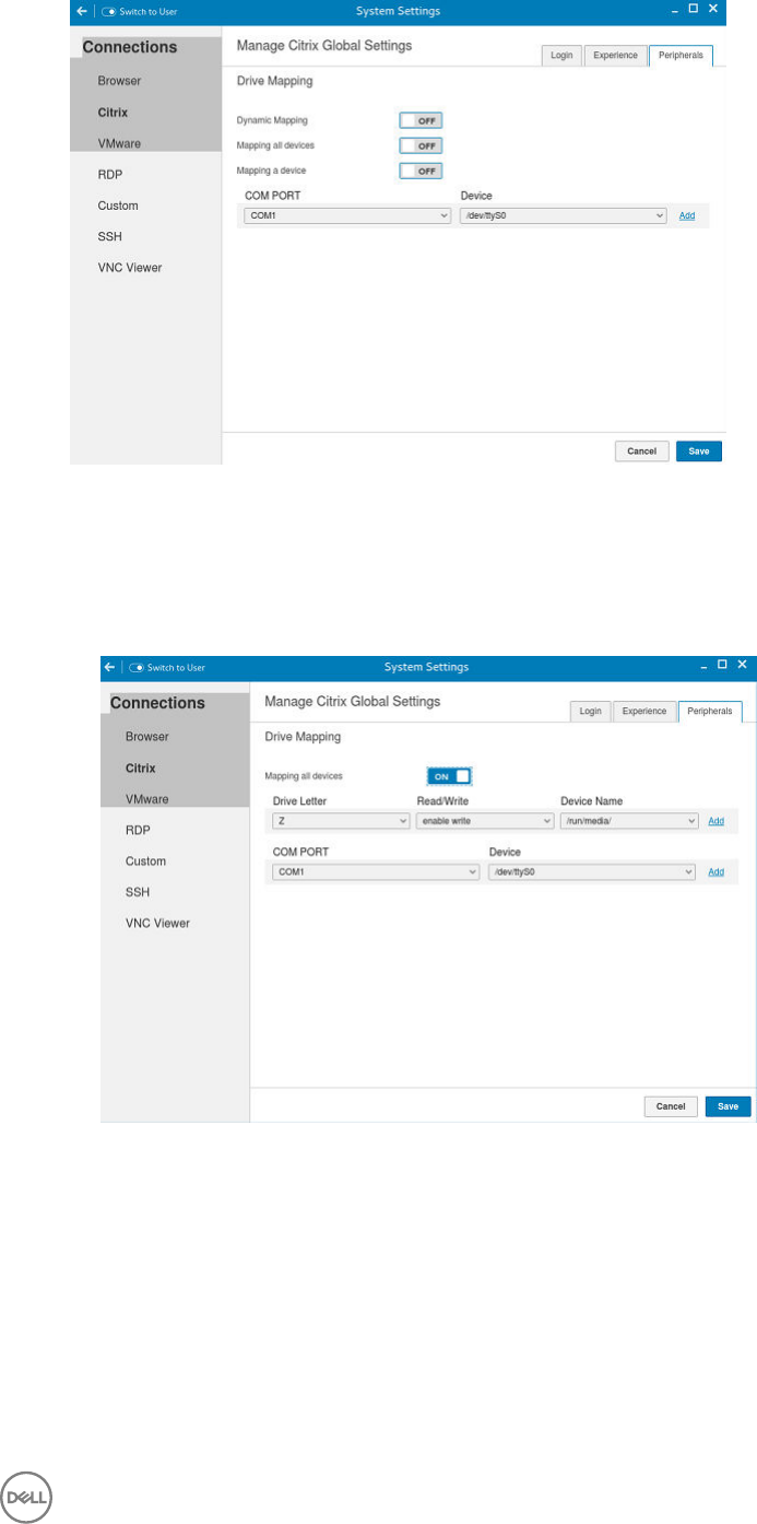
Figure 37. Citrix Global Settings
•Mapping all devices: This option is same as above but the you will be given an option to select the drive letter and read-
write permissions for the drives. When this option is enabled all the usb storage devices which are mounted on /run/
media/ will be mapped to the Citrix session. You are provided the option to choose the drive letter and read or write
permissions for the drives which have been mounted on to the thin client. The device name value remains constant
as /run/media/.
Figure 38. Citrix Global Settings
•Mapping a single device: Unlike the previous two options ,this option enables you to select an individual device which
should be redirected to the session. The device name lists all the devices that has been successfully mounted on to the
thin client. You will be able to select a drive letter and read-write permission for individual drives which redirects to the
session.
55
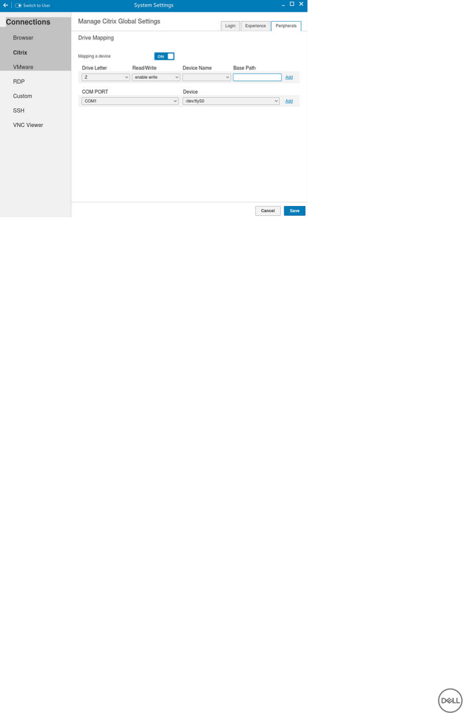
Figure 39. Citrix Global Settings
b. COM Ports: Click the COM Ports tab to map COM ports on the server to devices on the thin client, and to view and
manage the list of current COM ports including the device information that are mapped on the thin client.
To add a COM port, complete the following tasks:
a. From the COM Port list, select a COM Port—1 to 4.
b. Select a device from the Device list.
c. Click OK to add the COM port and device to the list of available COM Ports.
To delete a COM port, complete the following tasks:
a. Select a COM Port from the list of available COM Ports.
b. Click Delete.
5. Click Save to save the changes.
Managing PAM login
1. Click PAM Login
The Manage PAM Login Settings page is displayed. The PAM login page displays the settings that are used for PNAgent
server connection. It allows you to enable or disable the PAM login and also to enter the domain for PNAgent server.
2. Click the ON/OFF button to enable Citrix PAM login option.
3. Click the ON/OFF button to enable or disable the Show All Apps option.
4. Enable the Enable Citrix PAM login option to enter the Citrix server domain.
The Citrix Global Settings table provides you the information about Citrix server, protocol, and Store Name and you are
restricted from editing the content.
5. Click Save to save the changes.
Citrix ICA Client (64-bit) RTME
Starting from HDX RTME 2.1, Citrix supports 64–bit Linux operating systems. Hence there is no need to install any optional 32-bit
add-ons, as it is now packaged along with base image. This feature is enabled by default.
Features of RTME 2.1
56

The following are the features of RTME (Real Time Media Engine):
• Improved audio and video quality:
– Support for H.264 Scalable Video Coding (SVC): SVC handles the transmission of video over varied network and device
environments. The sending system includes dierent levels for the information transmitted such as frames per second, image
size, and quality granularity. The receiving device selects the required information from the transmission and optimizes the
experience on those devices.
– SILK audio codec: Delivers higher audio quality across a wide range of network environments, including the public Internet
and mobile networks.
– Improved audio and video quality over lossy connections: By enabling the forward error correction (FEC), we provide higher-
quality content over lossy connections.
• Support for 64-bit architecture: Linux 64-bit operating systems are now supported for the Real-Time Media Engine.
• Endpoint identication for location services:
– Enhanced 9-1-1 (E9-1-1) and E999, E100, and so on: An international emergency dispatch feature that associates a 911 (or an
international emergency) call with a specic location information. This information includes street address and the oor
number for oce buildings. Responders are directed to the correct emergency location. For more information, see
Technet.microsoft.com/en-us/library/dn951423.aspx.
– Support for Quality of Experience (QoE) reporting: Use Quality of Experience data to keep a record of the quality of your
users' audio and video calls, including:
* Number of network packets lost
* Background noise
* Amount of jitter (dierences in packet delay)
* Names of devices used for a call
* Names of devices used for a call
* ICE Warning ags
* Endpoint statistics
– Skype for Business users can communicate with Skype users: Skype for Business users can communicate with Skype users.
– Flexible upgrades: Simplied backward compatibility for upgrading from version 2.0.x
– Fallback mode control: You can disable fallback mode or limit fallback control to server-side media processing for audio only
(no video), which reduces CPU impact.
– Administrator control of system notication balloons: You can enable or disable the system notication balloons the
Optimization Pack displays.
– The Real-Time Optimization Pack About page: The following information can be viewed in the About page:
* Status of Real-Time Optimization Pack
* Skype for Business version number
* Operating systems on which the Real-Time Connector and Real-Time Media Engine are running
NOTE: In the fallback mode, the version and operating system elds for Real-Time Connector and Real-Time
Media Engine display the same values because the Real-Time Optimization Pack uses the Real-Time Media Engine
within the Real-Time connector.
– Localization: Real-Time Media Engine installers for Linux 64-bit OS are localized and available in German, French, Spanish,
Japanese, and Simplied Chinese.
– Skype for Business 2016: The current Skype for Business 2016 client does not support Real-Time Optimization pack.
Conguring and managing VMware connections
The VMware connections page enables you to create and manage the View client 3.5 connections.
To congure the VMware Settings complete the following task:
57
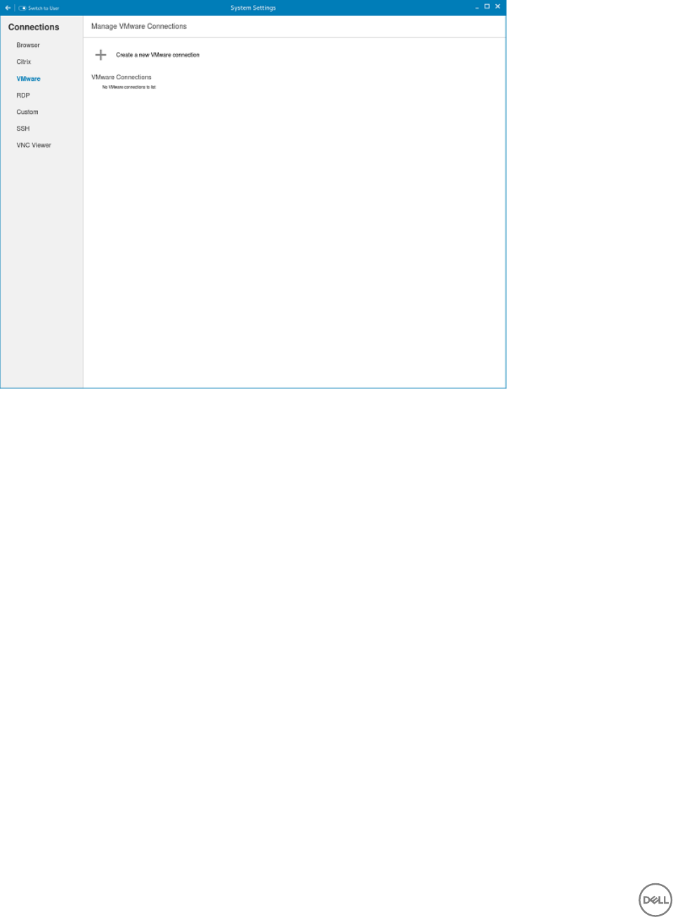
1. Click the + icon to add a new VMware Connection.
The VMware Connections page is displayed.
Figure 40. VMware Connections Settings
2. Enter the name of the VMware connection.
3. Congure the following options in the Login tab.
58
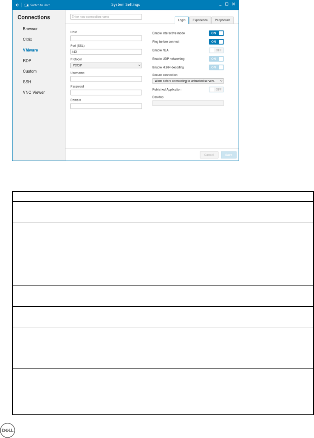
Figure 41. VMware Login Settings
Table 13. Login
Parameter Description
Host Enter the host name or IP address or FQDN of the Horizon
of the VMware View Server.
Port Enter the port number of the host.
Protocol From the drop-down list, select the specic protocol. The
available options are:
• PCOIP
• RDP
• Blast
Username Enter the User ID that is used to log in to the remote Horizon
server.
Password Enter the password that is used to log in to the remote
Horizon server.
Published Application Click the ON/OFF button to enable or disable this option.
If enabled, specify the Published Application name.
If disabled, specify the Published desktop name.
Enable interactive mode Click the ON/OFF button to enable or disable this option.
If enabled, then after a successful connection to the server, it
displays all the published application and desktop icons. You
can start the applications or desktop sessions based on your
choice
59

Parameter Description
If disabled, then the Published Applications option is enabled
in the Login tab, and selecting that option enables you to
directly start the application or desktop that you specify.
Ping before connect Click the ON/OFF button to enable or disable this option. If
enabled, it pings the connection is checked in server IP/
FQDN before connecting to a session.
Enable NLA This option is available to congure when you select the
protocol as RDP. Click the ON/OFF button to enable or
disable this option. Enable the Network Level Authentication
(NLA), if NLA is enabled on your remote computer. Your
remote computer requires NLA user authentication before
you establish a full Remote Desktop connection and the login
screen is displayed.
Enable UDP networking This option is available to congure when you select the
protocol as Blast. Click the ON/OFF button to enable or
disable this option. Select this option to allow UDP
networking in Horizon Client. When this option is selected
(the default setting), Horizon Client uses UDP networking, if
UDP connectivity is available. If the UDP networking is
blocked, Horizon Client uses TCP networking. Deselect this
option to always use TCP networking. .This option is
applicable only for VMware Blast protocol.
NOTE: UDP is disabled by default on a Horizon
remote desktop. For UDP to work, it must be enabled
on the desktop, the client, and the Blast Secure
Gateway (BSG)
Enable H.264 decoding Click the ON/OFF button to enable or disable this option.
Select this option to allow H.264 decoding in Horizon Client.
When this option is selected (the default setting), Horizon
Client uses H.264 decoding, if the agent supports H.264
software encoding. If the agent does not support H.264
software encoding, Horizon Client uses JPG/PNG decoding.
Deselect this option to always use JPG/PNG decoding. This
option is applicable only for VMware Blast protocol.
Secure connection Click the Secure Preferences tab and select any of the
options that determine how the client should proceed when it
cannot verify that your connection to the server is secure.
Domain Enter the Domain name. It is used to log in the remote
Horizon server.
Desktop If interactive mode is disabled, you can specify Published
desktop name.
Application If interactive mode is disabled, you can specify Published
application name.
4. The following options must be congured in the Experience tab.
60
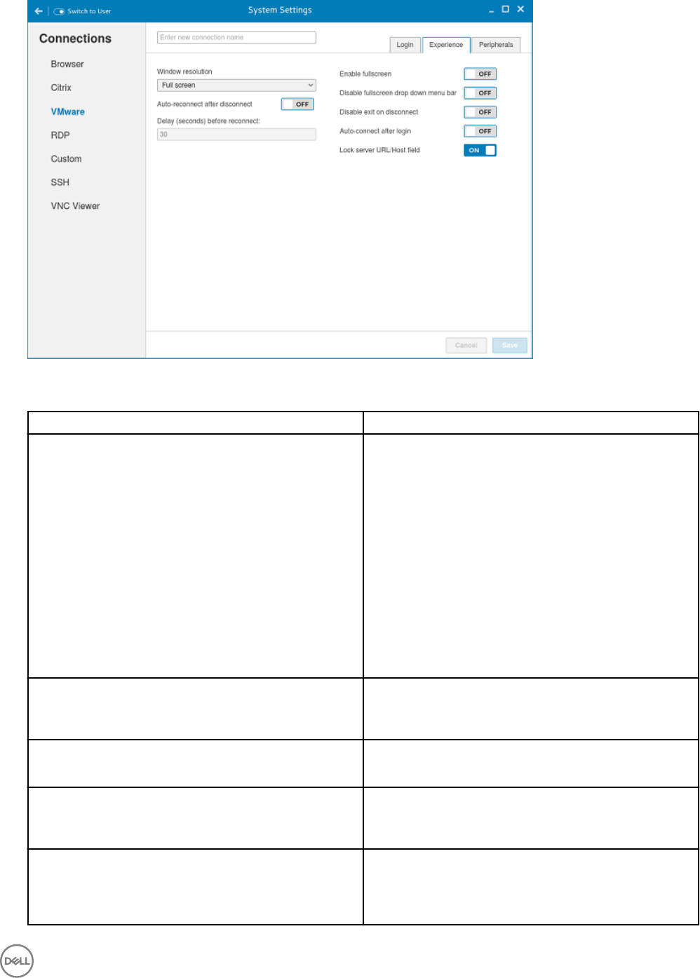
Figure 42. VMware Experience Settings
Table 14. Experience
Parameter Description
Windows resolution Select the Windows resolution that you want to get the best
display on your monitor. The available resolutions are:
Use All Monitors
Full Screen
Large Screen
Small Screen
1024 X 768
800 X 600
640 X 480
Auto-Reconnect after disconnect Click the ON/OFF button to enable or disable this option. If
enabled, the connection is automatically re-established after
you disconnect from the session.
Delay (seconds) before reconnect Select the amount of time in seconds to delay the
reconnection attempt after a disconnection occurs.
Enable fullscreen Click the ON/OFF button to enable or disable this option.
Select this option to view the remote session in full screen
mode in all the monitors.
Disable fullscreeen drop down menu bar Click the ON/OFF button to enable or disable this option.
Select this option to disable the drop-down menu bar in the
full screen mode.
61
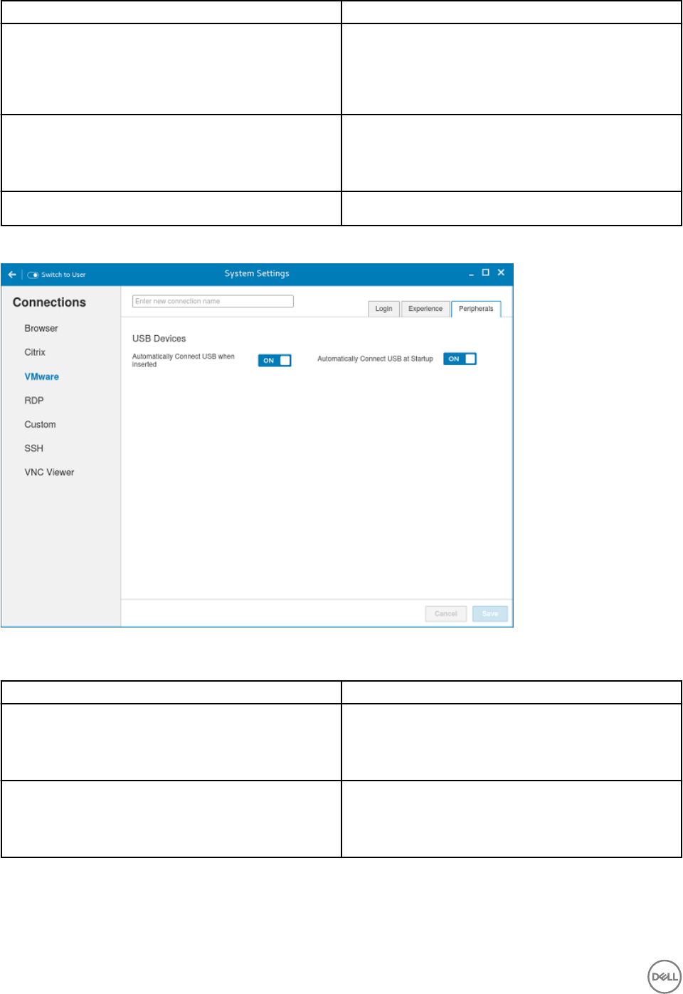
Parameter Description
Disable exit on the disconnect Click the ON/OFF button to enable or disable this option.
Select this option if you do not want the Horizon server to
retry connecting if there is a connection error. You can
typically select this option if you use kiosk mode.
Auto-connect after login Click the ON/OFF button to enable or disable this option.
Select this option to reconnect automatically after a
disconnection occurs.
Lock server URL/Host eld Click the ON/OFF button to enable or disable this option.
5. Congure the following options in the Peripherals tab:
Figure 43. VMware Peripherals Settings
Table 15. Peripherals
Parameter Description
Automatically Connect USB when inserted
Click the ON/OFF button to enable or disable this option.
Select this option if you want to automatically connect your
USB key to the thin client after you plug-in the USB key.
Automatically Connect USB at Startup Click the ON/OFF button to enable or disable this option.
Select this option if you want to automatically connect your
USB key to the thin client when you start the system.
6. Click Save to save the settings.
62

Conguring and managing RDP connections
The RDP connections page enables you to create and manage the RDP connection. The main RDP page has options to create an
RDP connection and modify existing connections:
To congure the RDP Settings complete the following tasks:
1. Click the + icon to add a new RDP Connection.
The RDP Connections page is displayed.
Figure 44. RDP Connection Settings
2. Enter the name of the RDP connection.
3. Congure the following tasks in the Login tab.
63

Figure 45. RDP Login Settings
Table 16. RDP login settings
Parameter Description
Server Enter the IP address or FQDN of the RDP server to which
you want to establish a connection.
Username Enter the Username to log in to the RDP Server.
Password Enter the Password to log in to the RDP Server.
Domain Enter the Domain to log in to the RDP Server.
Use RD Gateway Select to enable and congure an RD Gateway to connect to
your remote computers, if required by your network
administrator and then do one of the following:
• To congure the RD Server, and then Use Remote
Desktop Credentials for RD Gateway—Enter the RD
Server IP address or URL of the Remote Desktop
Gateway server, and then select the Use Remote Desktop
credentials for RD Gateway check box, if the server
credentials are the same credentials as your RDP host
remote computer credentials.
• To congure the RD Server, and then Manually enter RD
User Name, RD Password, RD Domain—Enter the RD
Server IP address or URL of the Remote Desktop
Gateway server. Clear the Use Remote Desktop
credentials for RD Gateway check box and then manually
enter the Username, Password, and Domain of the RD
Gateway server, if required.
64

Parameter Description
NOTE: An RD Gateway server is a type of gateway
that enables authorized users to connect to remote
computers on a corporate network from any
computer with an Internet connection. An RD
Gateway server enables Remote Desktop connections
to a corporate network from the Internet without
having to set up virtual private network (VPN)
connections. Ask your network administrator whether
you need to specify an RD Gateway server.
RemoteApp Enter the Remote Application name.
Application Command Line Enter the command line for the program on the server.
Working Directory Enter the Working Directory for the program.
NOTE: Working Directory is applicable only for Server
Connections.
Ping Before Connect Click the ON/OFF button to enable or disable this option. If
enabled, the connection is checked before connecting to a
session.
Auto-Connect after login Click the ON/OFF button to enable or disable this option. If
enabled, the connection is automatically established after you
log in to your thin client.
Auto-reconnect after disconnect Click the ON/OFF button to enable or disable this option. If
enabled, the connection is automatically re-established after
you disconnect from the session. If the Auto-reconnect
option is enabled, you must enter the Delay duration (in
seconds) when you reconnect to the session. The default
time duration is 30 seconds.
Notify when disconnected Click the ON/OFF button to enable or disable this option. It
noties when the connection is disconnected.
Network Level Authentication (NLA) Click the ON/OFF button to enable or disable this option.
Enable the Network Level Authentication (NLA), if NLA is
enabled on your remote computer. Your remote computer
requires NLA user authentication before you establish a full
Remote Desktop connection and the login screen is displayed.
Smart card login Click the ON button to enable smart card login to the thin
client. The User Name, Password, and Domain are not
required.
4. The following options can be congured in the Experience tab.
65

Figure 46. RDP Experience Settings
Figure 47. RDP Experience Settings
66

Table 17. RDP Experience Settings
Parameter Description
Window Resolution Select the Windows resolution you can use to get the best
display on your monitor. The available options are:
Default
640X480
800X600
1024X768
1280X1024
1600X1200
Full Screen
Colors Species the number of colors to display for each pixel.
Select the session color mode to get the faster display
performance on your monitor. The available options are:
High Color (15 bit)
High Color (16 bit)
True Color (24 bit)
Best Quality (32 bit)
Speed Level Select a speed level to describe the network connection.
• Modem
• Broadband
• LAN
• Custom
Sounds Select the relevant option from the drop-down list. You can
choose to redirect the audio on the remote session to the
local device, or not allow the audio to play on the remote
session on the local device, or leave the audio playing on the
remote session.
•O
• Local
• Remote
Encryption Level Select an encryption level, either Normal or None.
For servers with data encryption settings, you must select
Normal for the encryption level.
NOTE:
Wallpaper Click the ON/OFF button to enable or disable this option.
Font Smoothing Click the ON/OFF button to enable or disable this option.
Menu and Window Animation Click the ON/OFF button to enable or disable this option.
67

Parameter Description
Remote FX Click the ON/OFF button to enable or disable this option.
Show window content while dragging Click the ON/OFF button to enable or disable this option.
This option shows the window content when the user drags
the window on screen.
Subsampling Click the ON/OFF button to enable or disable this option. It
enables color space conversion required for Chroma
subsampling.
Chroma Subsampling is the practice of encoding/
compressing images for a higher transmission experience.
Grab Keyboard Events Click the ON/OFF button to enable or disable this option. It
enables all keyboard events within the connection window to
be sent to the connection’s applications.
Compression Click the ON/OFF button to enable or disable this option.
Low Bandwidth Click the ON/OFF button to enable or disable this option. If
enabled, following options are automatically disabled:
Wallpaper
Font Smoothing
Menu and Window Animation
Remote FX
Show window content while dragging
Subsampling
Enables low-bandwidth optimization.
NT4 Compatible Click the ON/OFF button to enable or disable this option.
5. Congure the following tasks in the Peripherals tab.
68
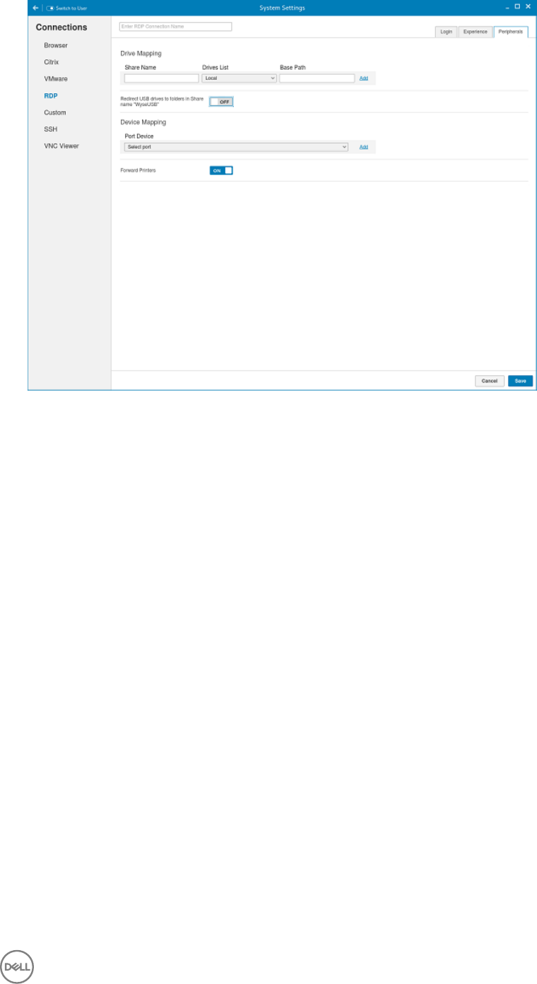
Figure 48. RDP Peripherals Settings
•Drive Mapping: Drive mapping tab is used to share map names on the server to USB mass storage devices attached to the
thin client, and to view and manage the list of current server share names including the drive information mapped on the
thin client.
a. Enter the share name.
b. The List includes the available drives.
c. The Base path is an entry to a directory within the drive.
d. Click the ON/OFF button to enable or disable the Redirect all USB drives to folders in Share named ‘WyseUSB’ option. If
enabled, it redirects all USB drives to folders in Share name WyseUSB. You can redirect all your USB drives such as USB
Floppy, USB CDROM, USB Disk or Memory stick, and local or mounted disk to the folders in share name WyseUSB and if
this is enabled Individual Drive Mapping is disabled.
•Device Mapping: Device mapping tab is used to map devices to ports on the thin client, and to view and manage the list of
current devices that are mapped on the thin client.
a. Select your preferred port devices.
b. Click the ON/OFF button to enable or disable the Forward Printers option.
6. Click Save to save the changes.
Conguring and managing the custom connections
The Custom Connections page enables you to create and manage the Custom connection based on shell commands. The main
Custom page has options to create a Custom connection.
To congure the Custom Settings, complete the following task:
1. Click the + icon to add a new Custom Connection.
The Custom Connections page is displayed.
69
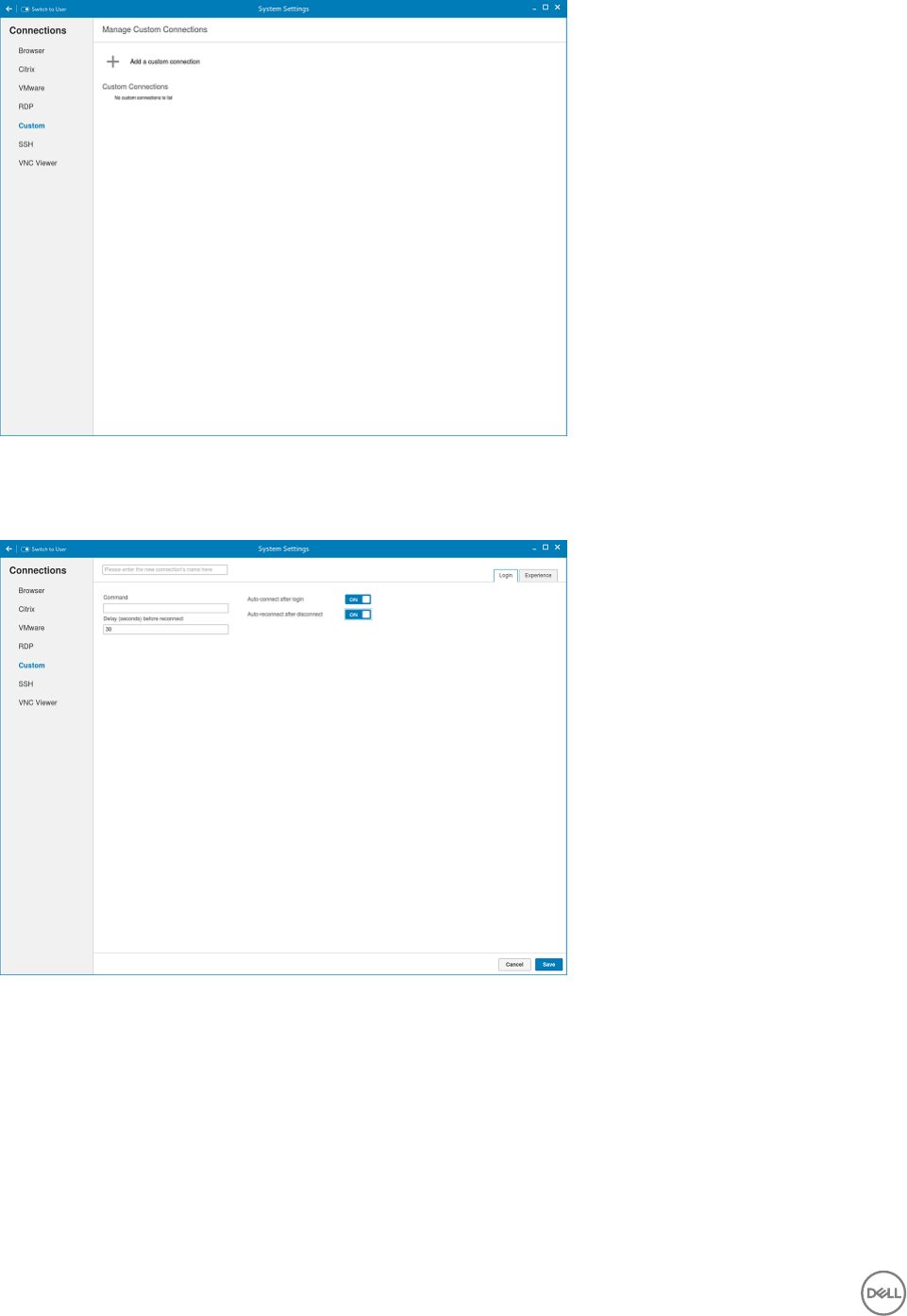
Figure 49. Custom Connections Settings
2. Enter the name of the Custom connection.
3. The following options must be congured in the Login tab.
Figure 50. Custom Connection Login Settings
a. Enter the shell command. The shell command is performed when you click the connection icon on the desktop.
b. Click the ON/OFF button to enable or disable the Auto-connect after login option. If enabled, the connection is
automatically connected after you log in to your thin client.
c. Click the ON/OFF button to enable or disable the Auto-reconnect after disconnected option. If enabled, the connection is
automatically re-connected after you disconnect from the session.
d. Select the amount of time in seconds to delay the reconnection attempt after a disconnection occurs.
4. The following options must be congured in the Experience tab.
70

Figure 51. Custom Connections Experience Settings
a. Click the ON/OFF button to enable or disable the Run in terminal window option.
5. Click Save to save the changes.
Conguring and managing the SSH connections
The SSH connections page enables you to create and manage the SSH connections. The main SSH connections page has options
to create an SSH connection.
To congure the SSH connection, complete the following task:
1. Click the + icon to add a new SSH Connection.
The SSH Connections page is displayed.
71
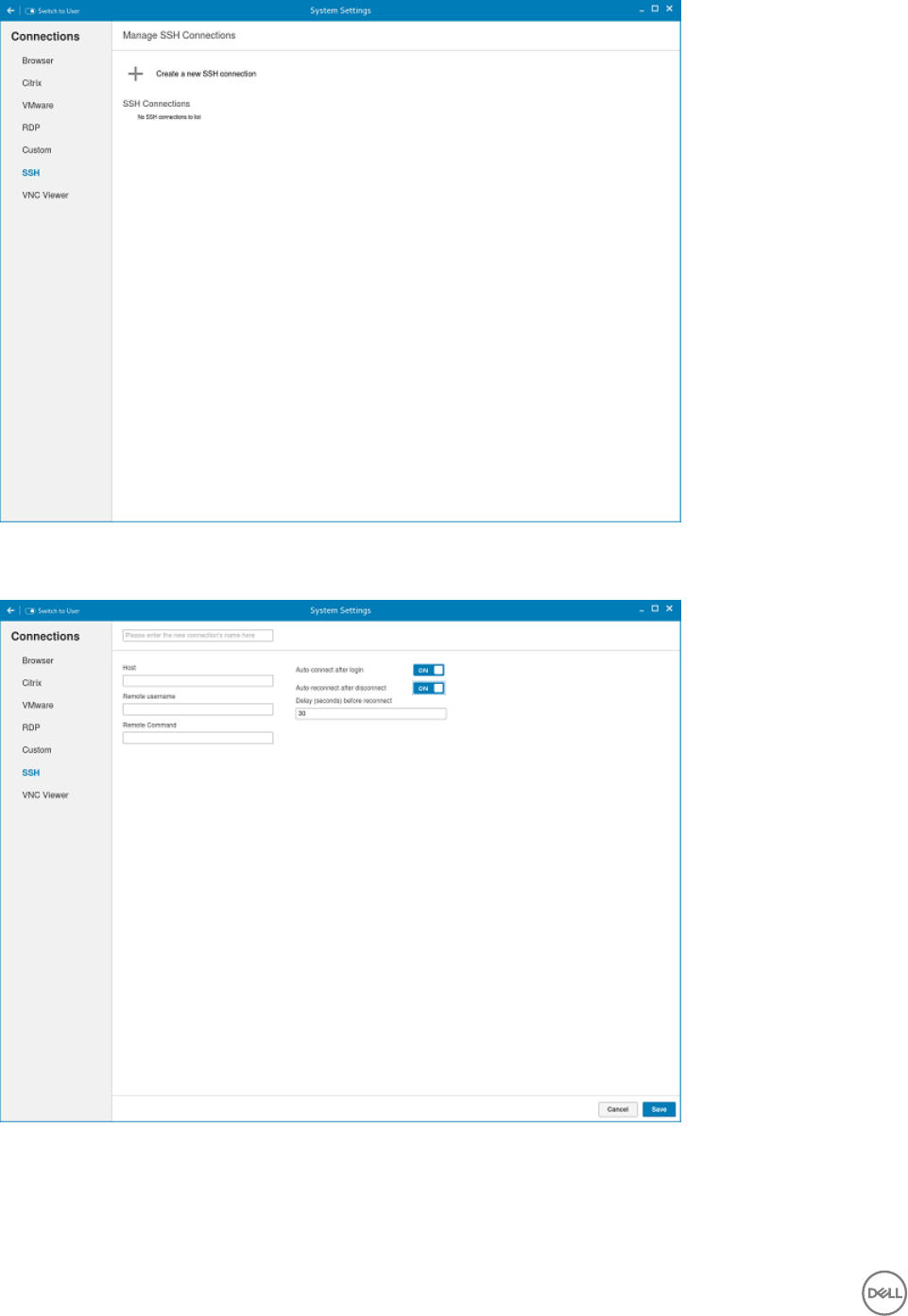
Figure 52. SSH Connections Settings
2. Enter the name of the SSH connection.
Figure 53. SSH Connections Settings
3. Enter the IP address or FQDN of the SSH server that you want to connect to.
4. Enter the Username to log in to the remote SSH Server.
5. Enter the command to run the program.
72
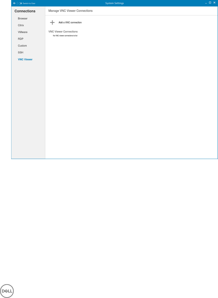
6. Click the ON/OFF button to enable or disable the Auto-connect after login option. If enabled, the connection is automatically
connected after you log in to your thin client.
7. Click the ON/OFF button to enable or disable the Auto-reconnect after disconnected option. If enabled, the connection is
automatically re-connected after you disconnect from the session.
8. Select the amount of time in seconds to delay the reconnection attempt after a disconnection occurs.
9. Click Save to save the changes.
Conguring and managing the VNC viewer connections
The VNC Viewer connections page enables you to create and manage the VNC connections. The main VNC connections page has
options to create a VNC connection.
To congure the VNC Viewer Settings, complete the following task:
1. Click the + icon to add a new SSH Connection. The VNC Viewer Connections page is displayed.
Figure 54. VNC Viewer Connections Settings
2. Enter the name of the VNC connection.
3. The following options must be congured in the Login tab.
73
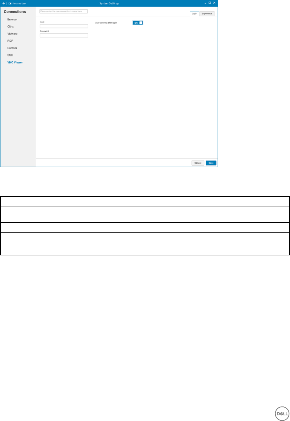
Figure 55. VNC Viewer Login Settings
Table 18. VNC viewer login settings
Parameter Description
Host Enter the IP address or FQDN of the VNC server which you
want to connect.
Password Enter the password to log in to the remote VNC Server.
Auto-connect after login Click the ON/OFF button to enable or disable this option. If
enabled, the connection is automatically connected after you
log in to your thin client.
4. The following options must be congured in the Experience tab.
74

Figure 56. VNC Viewer Experience Settings
Table 19. VNC viewer experience settings
Parameter Description
Colors Species the number of colors to display for each pixel.
Select the session color mode to get the faster display
performance on your monitor. The available options are:\
• True color (full color)
• 8 colors (very low)
• 64 colors (low)
• 256 colors(medium)
JPEG quality From the drop-down list, select the preferred value. The
range for JPEG quality is 0-9, with 0 being poor quality and 9
being the best quality.
Compression level From the drop-down list, select the preferred value. The
range for compression level is 1–6. The 1 value explains the
fast quality and 6 value explains the best quality.
Full screen Click the ON/OFF button to enable or disable this option. If
enabled, the connection is started in the full screen mode.
It is not in the kiosk mode, click the standard VNC viewer f8
key to exit the full screen mode.
NOTE:
Shared Click the ON/OFF button to enable or disable this option. If
enabled, the connected desktop is in share mode.
75
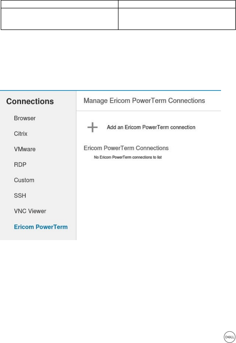
Parameter Description
View only Click the ON/OFF button to enable or disable this option. If
enabled, the connection is in view-only mode. Mouse and
keyboard input to the remote machine is disabled.
5. Click Save to save the changes.
Conguring and managing the Ericom PowerTerm connections
The Ericom PowerTerm connections page enables you to create and manage the Ericom PowerTerm connections. The main Ericom
PowerTerm connections page has options to create a Ericom PowerTerm connection.
The Ericom PowerTerm is an optional add-on. You must install 32–bit runtime add-on before installing Ericom PowerTerm add-on.
To congure the Ericom PowerTerm Connection Settings, complete the following task:
1. Click the + icon to add a new Ericom PowerTerm Connection. The Ericom PowerTerm Connections page is displayed.
Figure 57. Ericom PowerTerm Connection Settings
2. Enter the name of the Ericom PowerTerm connection.
3. The following options must be congured in the Login tab .
76
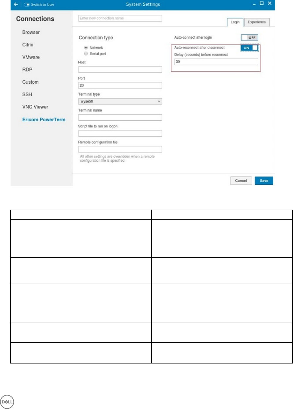
Figure 58. Ericom PowerTerm Login Settings
Table 20. Ericom PowerTerm Login Settings
Parameter Description
Connection type On the Connection Type page, click the Network or Serial
Port radio button depending upon the requirement. By
default, the Network option is selected. Serial Port radio
button is disabled if the application does not detect any active
serial ports.
Host Enter the Ericom server host’s IP or FQDN address in the
Host eld. This eld is hidden, if the connection is through
Serial Port.
Port Specify the port number used to connect the Ericom server
in the Port eld. This is available if the connection is through
the network. In case of Serial Port, this eld displays as COM
port and the available serial ports are listed in the drop-down
list.
Terminal type Select the terminal type to be emulated from the drop-down
list in the Terminal Type eld.
Terminal name Type the name of the Ericom PowerTerm terminal window in
the Terminal Name eld
77
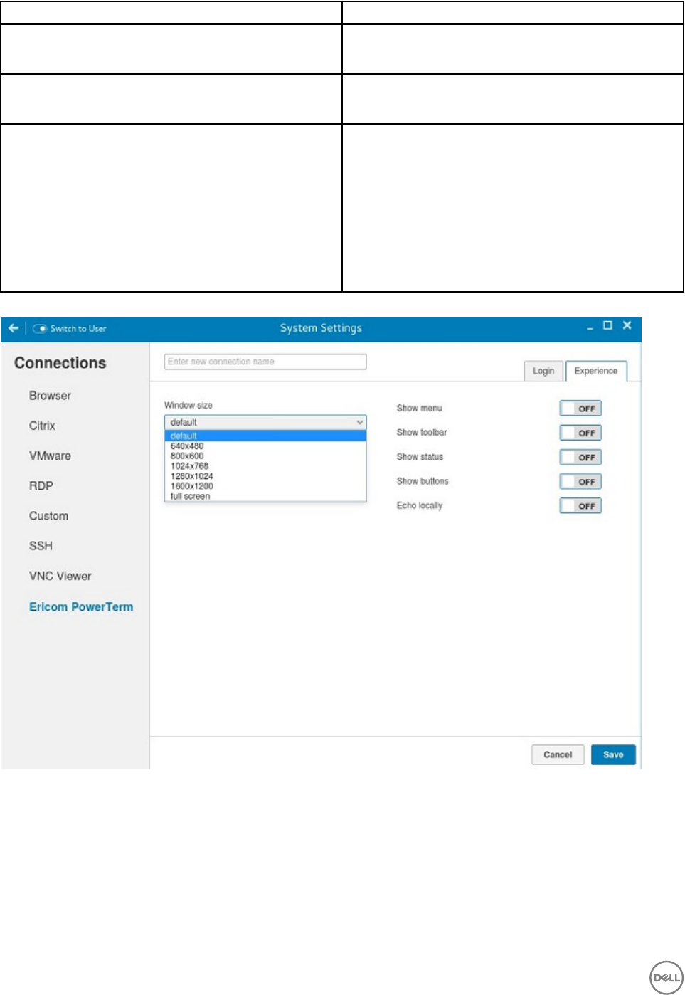
Parameter Description
Script le to run on logon Specify the path of the script le (if any) to be executed in
the remote system in the Script le to run on Logon eld.
Remote conguration le Specify the location of the remote conguration les in the
Remote conguration le eld.
Auto-connect after login a. Click the ON/OFF button to enable or disable the Auto-
connect after login option. If enabled, the connection is
automatically connected after you log in to your thin
client.
b. Click the ON/OFF button to enable or disable the Auto-
reconnect after disconnected option. If enabled, the
connection is automatically re-connected after you
disconnect from the session.
c. Select the amount of time in seconds to delay the
reconnection attempt after a disconnection occurs.
4. The following options must be congured in the Experience tab.
Figure 59. Ericom PowerTerm Experience Settings
78
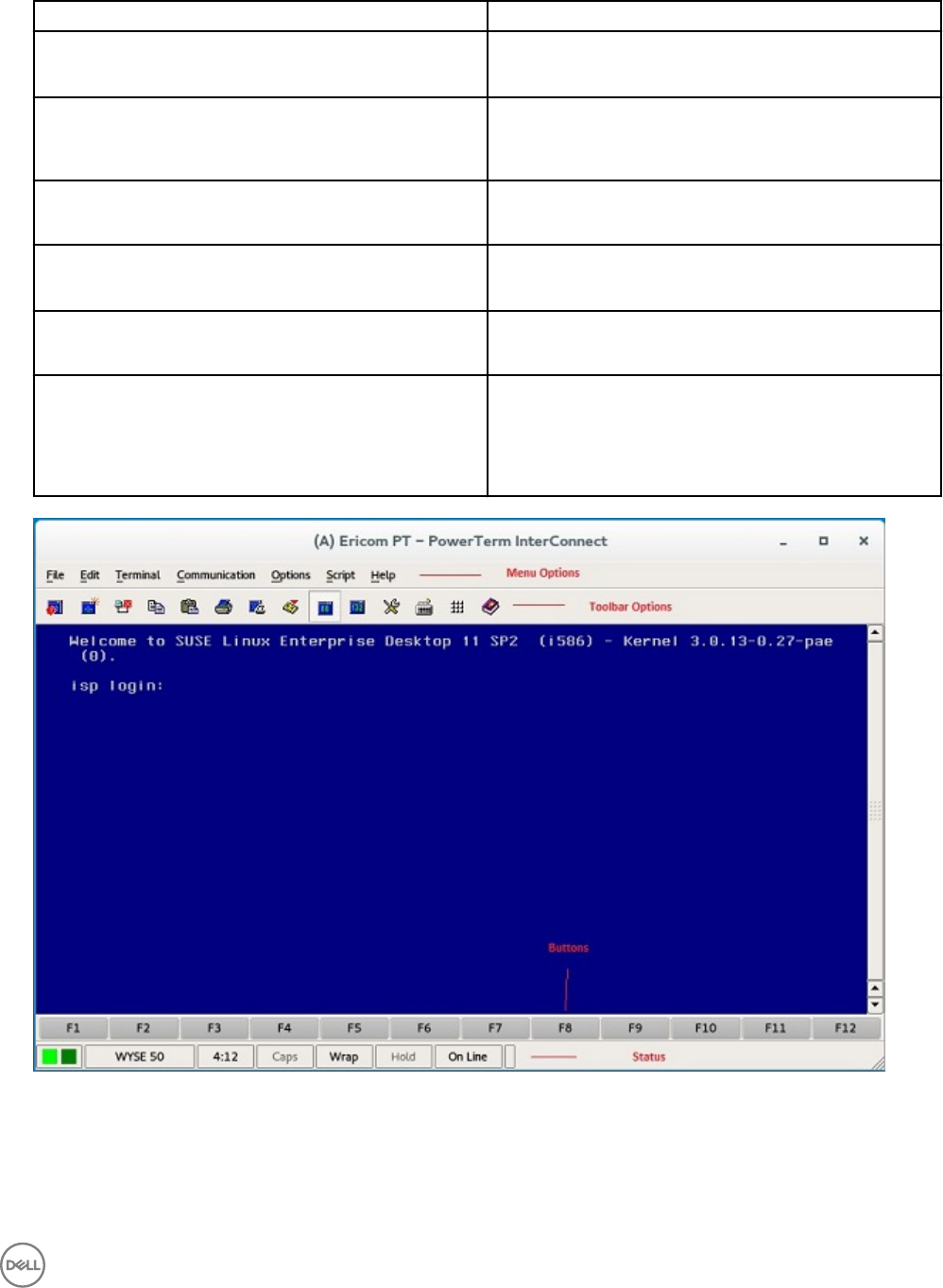
Table 21. Ericom PowerTerm Experience Settings
Parameter Description
Window size Select the desired terminal window size from the drop-down
list in the Window Size eld.
Show menu Click the ON/OFF button to enable or disable this option. It
enables the top menu option on the Ericom PowerTerm
window.
Show toolbar Click the ON/OFF button to enable or disable this option. It
enables the toolbar option on the Ericom PowerTerm window.
Show status Click the ON/OFF button to enable or disable this option. It
enables the status bar on the Ericom PowerTerm window.
Show buttons Click the ON/OFF button to enable or disable this option. It
enables the soft buttons on the Ericom PowerTerm window.
Echo locally When the connection is congured through Serial Port then
additional option Echo locally option will be available on the
Experience tab. If this option is set to ON, it will set the local
echo option of the generated Ericom PowerTerm terminal
window.
Figure 60. Ericom PT — PowerTerm Interconnect
79
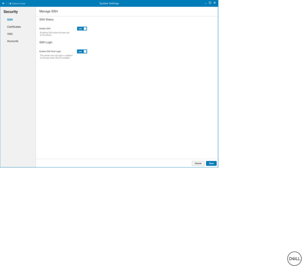
5
Security settings
On the System Settings page, click the Security icon. The following tabs are listed on the left pane of the System Settings page.
• SSH
•Certicates
• VNC
• Accounts
Managing SSH server preferences
By default, SSH Server is disabled on the thin client. The Managing the SSH server screen is available only in Admin mode. It enables
to congure the SSH server on the thin client.
Figure 61. SSH Status
Congure the following options. These options describes about the status of SSH server.
1. Click the ON/OFF button to enable the Enable SSH option. If enabled, the SSH server starts working.
2. Click the ON/OFF button to enable or disable the Enable SSH Root Login option. When the Enable SSH option is enabled, the
Enable SSH Root Login option is not enabled automatically.
3. Click Save to save the changes.
80

Managing the certicates
1. Click the + icon to import a new certicate.
The Import Certicate page is displayed.
Figure 62. Import Certicates
2. Select the preferred Import Source option.
• Remote Server
• Local Devices
a. Remote server
Figure 63. Import Certicates Remote Server
1. If you select Remote server option, the remote server information is displayed.
81
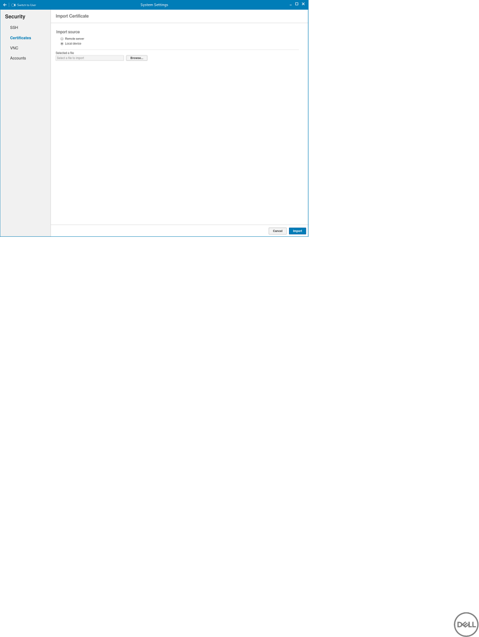
a. Enter the Importing server URL. The supported protocols are ftp, http, and https.
b. Browse the required Certicate File.
c. Click the ON/OFF button to enable or disable the Sever from default registry option.
2. User Anonymous: Click the ON/OFF button to enable or disable this option. If disabled, enter the Username and
password required for the server.
b. Local Devices
Figure 64. Import Certicates Local Device
1. Click the Browse tab and navigate to the certicate that you want to use.
2. Click OK.
c. Click Import to import the certicates.
The installed certicates are shown as, Filename: certicate name.
d. To remove a certicate, move the cursor over it and click Remove.
Setting VNC server preferences
Use the VNC server page to congure the VNC server preferences.
82

Figure 65. VNC Server Preferences
To congure the VNC server preferences:
1. Click the ON/OFF button to enable or disable the Enable VNC option.
2. Click the ON/OFF button to enable or disable the conrmation for accessing each VNC connection option.
3. Click the ON/OFF button to enable or disable the Require the user to enter this password option. If enabled, you can enter the
password. Maximum length is 8 characters.
4. Click the ON/OFF button to enable or disable the option to show the VNC access warning at start of the connection.
5. Click Save to save the changes.
Managing the accounts settings
The Accounts management is a system built-in user account management and is available in admin mode only.
83
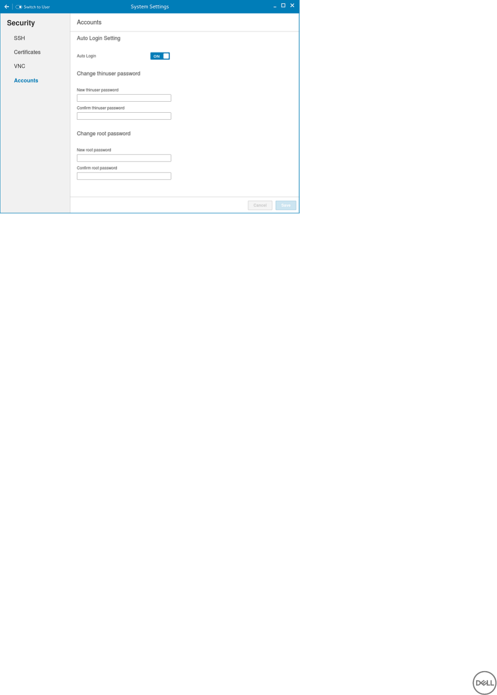
Figure 66. Account Settings
To manage the account setting, complete the following task:
1. Click the ON/OFF button to enable or disable the Auto Login option.
2. Enter the following details to Change thinuser password:
• New thinuser password
•Conrm thinuser password.
3. Enter the following details to Change root password:
• New root password
•Conrm root password
84
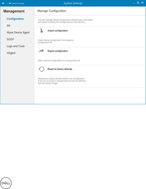
6
Additional management congurations
On the System Settings page, click the Management icon. The following tabs are listed on the left pane of the System Settings
page.
•Conguration
• INI
• Wyse Device Agent
• SCEP
• Logs and Tool
• HAgent
Conguration management
You can manage the device conguration stored locally. Use import and export options to deploy the conguration to the other
devices.
Figure 67. Conguration Management
1. Click the + icon to import device conguration from provided conguration le. The Import Device conguration page is
displayed and you are prompted to restart the system.
2. Select the preferred Import Source option.
• Remote Server
• USB Devices
a. Remote server
85
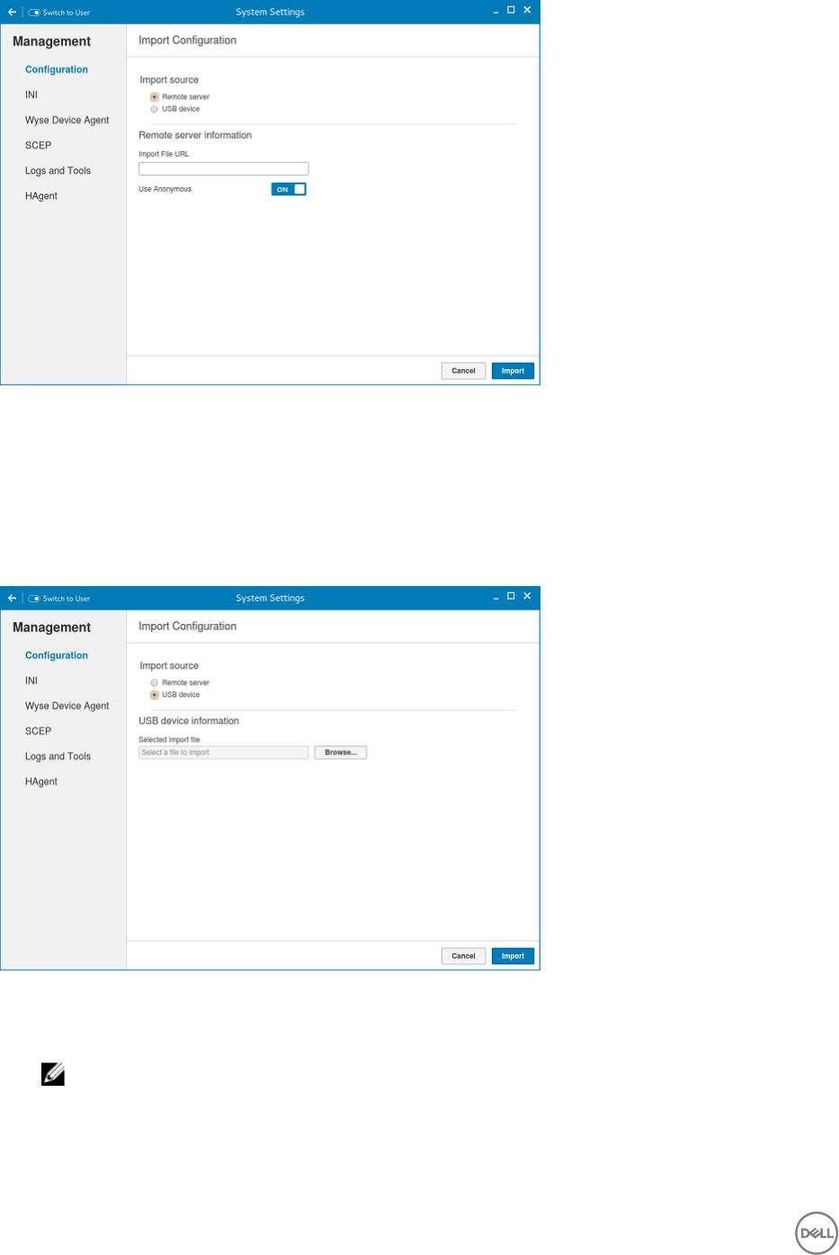
Figure 68. Import Conguration Remote Server
1. If you select Remote server option, the remote server information is displayed. Enter the Importing le URL. The
supported URLs are ftp, http, and https.
2. Click the ON/OFF button to enable or disable the Use Anonymous option. If disable, enter the Username and
password required for the server.
3. Click Import to import the conguration.
b. USB Devices
Figure 69. Import Conguration USB Device
1. Click the Browse tab.
NOTE: You must insert the USB device to import the les.
2. Click Import to import the conguration.
3. Click the icon to Export device conguration to a conguration le. The Export device conguration page is displayed.
4. Select the preferred Export Destination option.
• Remote Server
86
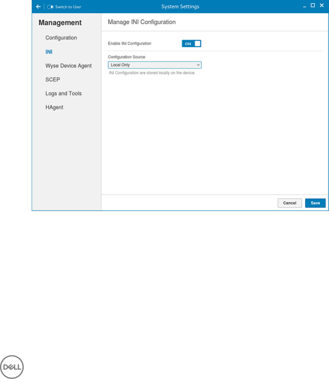
• USB Devices
a. Remote server
1. If you select Remote server option, the remote server information is displayed. Enter the Conguration le, and export
server URL. The supported URLs are ftp, http, and https.
2. Click the ON/OFF button to enable or disable the Use Anonymous option. If disable, enter the Username and
password required for the server.
3. Click Export to export the conguration.
b. USB Devices
1. Click the Browse tab. Use the folders and command buttons to nd and specify the export path and le you want to
use.
2. Click OK.
5. Click the icon to Reset to factory defaults.
a. A warning message is displayed. If you click OK the system is automatically restarted. Resetting to factory defaults aects
only conguration, it will not uninstall or reinstall add-ons that are dierent than the factory image.
INI management
On the Manage INI Conguration page, complete the following task:
1. Click the ON/OFF button to enable or disable the Enable INI Conguration option. By enabling INI Conguration you can
manage this device by conguration les stored on the server or locally.
2. From the drop-down list, select the Conguration source.
a. Select the Local only source as Conguration source. The INI conguration is stored locally on the device.
Figure 70. INI Conguration
b. Select the Server only source as Conguration source.
• Click the ON/OFF button to enable or disable the Specify server details manually option. The INI Conguration
downloads from the server during every restart of your thin client. If enabled, enter the Server URL, Username and
password for the secure server.
c. Click the ON/OFF button to enable or disable the Server and Local option. The INI Conguration downloads from the server
during every restart of your thin client and if the server is not available, local conguration is used. If enabled, enter the
Server URL, Username and password for the secure server.
87

Figure 71. INI Conguration
3. Click Save to save the changes.
Wyse device agent
The Wyse Device Agent (WDA) on the ThinLinux device supports only the features of Cloud Client Manager (CCM) device
management solution. Wyse Device Agent is for conguring the CCM (Cloud Client Manager) client settings and registering a
ThinLinux device into CCM and it is available only for admin user.
Figure 72. Wyse Device Agent (CCM)
If the device is not registered to a CCM server, the Wyse Device Agent screen shows the registration status as Not Registered.
1. In the CCM Server input box, enter the URL of CCM server you want to connect to.
2. In the MQTT Server input box, enter the IP address or hostname of Message Queue Telemetry Transport (MQTT) server.
88

3. In the Group Token input boxes, enter your group registration key to manage your ThinLinux device. This is a unique key for
registering your thin client device. Thin clients can be directly registered to Groups directly and must have a Group Registration
Key enabled to perform this action.
4. Do one of the following options:
• Click Register to register your thin client on CCM server. When your thin client is successfully registered, the status is
shown as Registered with green color icon next to the Registration Status label, and caption of Register button changes to
Unregister.
• Click Unregister, if you want to remove your thin client from the CCM management system. If Unregister fails, a dialog box
for Force Unregister conrmation is displayed. Click Yes to forcefully unregister your device which is managed by CCM.
When you perform Register or Unregister or Force Unregister from Agent screen, the applet should not be closed until
Registration Status. After successful registration, you can access the CCM management server screen where you can view
and manage Device Asset Details, Real-Time commands, and Troubleshooting information of your registered thin client.
Directing the Thin Client to CCM Server:
• To direct your thin client to CCM server, you must provide CCM/MQTT server details and Group registration Key. These
details is discovered by Wyse Device Agent using any of the following ways:
– DHCP Scope options
– Using INI parameter
– Using the Wyse Device Agent screen
• Directing the thin client to CCM Server using DHCP Scope options. The CCM/MQTT server details and Group Registration
Key that are required for CCM registration can be obtained by querying the DHCP server with following option tags:
– 199 – Scope option for Group Token (type = String, value = CCM-group-key).
– 165 – Scope option for CCM server.
– 166 – Scope option for MQTT server.
• Directing the thin client to CCM Server using INI parameters, INI syntax for CCM conguration:
– CCMEnable={yes,no} CCMServer=<CCM Server URL> GroupRegistrationKey=<tenant code-group code>
MQTTServer=<MQTT server>[:<MQTT port>]
NOTE:
When INI discovery method is used for registering the device, if you want to unregister the device, you must delete the INI
parameters and restart the device rst and then unregister the device. Else you have to perform the unregister process
twice. For more information, see ThinLinux INI Guide .
SCEP conguration management
1. Click the + icon to add a new certicate.
89

Figure 73. SCEP Conguration
Figure 74. SCEP Conguration
2. Enter the Server URL, Certicate name and CA Distinguished name.
3. Click Save to save the changes.
4. Select the certicate and click Enroll.
90
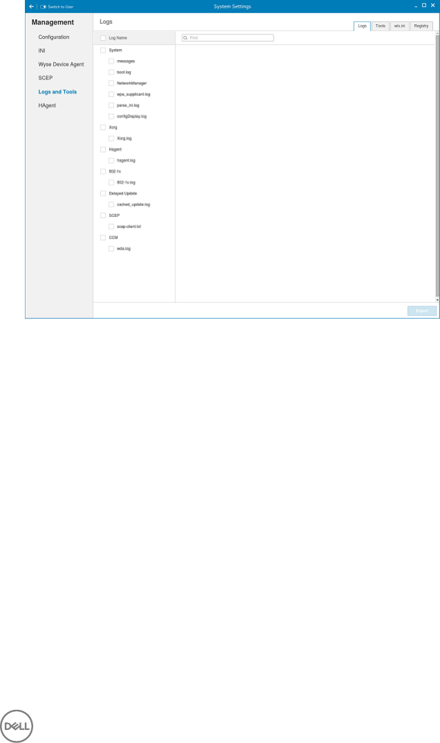
Logs and Tools
Logs and Tools section provides the tools for troubleshooting and diagnostics purpose. By default the Logs and Tools screen is
available only for admin mode.
1. Click the Logs tab to view and export system logs.
The Logs tab shows a list of system logs from where you can select a particular log le to view the contents and search text
within the content.
2. Check the check box shown on the left side of Log le name to select log les and click the Export button to export logs into a
USB drive or remote le server.
You can choose one of the following options from export dialog to export logs.
Figure 75. Logs and Tools
a. Select an option to Export logs:
• If you select Remote server option, enter remote le server URL in Export server URL input box and enter your
credentials if Use anonymous switch button is not enabled.
• If you select USB Drive option.
1. Click the Browse tab. The File browser dialog box is displayed. Select a directory from listed USB drive.
2. Click Export to export the logs.
3. Click the Tools tab to congure the following:
91
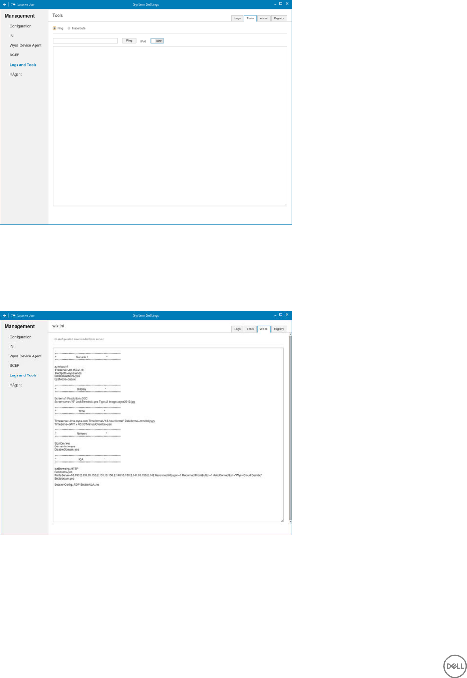
Figure 76. Logs and Tools Ping Option
a. Enter or select a destination from the drop-down list and click Ping.
b. Enter or select a destination from the drop down list and click Trace Route.
The Output of Ping or Traceroute appears in the text area
4. Click the Wlx.ini tab to view the contents of wlx.ini le downloaded from INI server:
Figure 77. Logs and Tools Wlx.ini Option
5. Click the Registry tab to view contents of device registry. You can navigate through dierent types of registry by choosing
appropriate ones from the Registry drop-down list. Available options are:
•Temporary - To view contents of temporary registry
•Save - To view contents of save registry
•Permanent - To view contents of permanent registry
Select the Registry option from the drop-down list and the contents of the device registry selected by you are displayed.
92
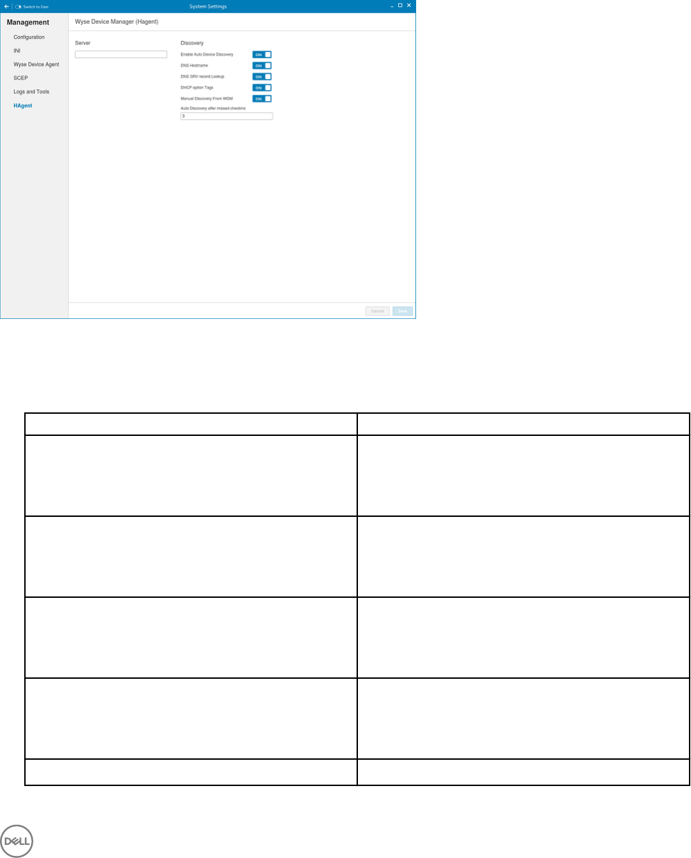
HAgent
WDM is a device management solution which helps you to manage cloud clients securely from remote infrastructure. WDM
management solution involves both server and client components where client software also known as HAgent should be installed
on each thin client device for management through WDM.
Figure 78. HAgent Settings
1. On Wyse Device Manager (HAgent) page, enter the Wyse Device Manager Server name in input box.
2. The following options can be congured. This is an admin only conguration in the thin client.
Table 22. Wyse Device Manager Server
Parameter Description
Enable Auto Device Discovery Click the ON/OFF button to enable or disable this option.
This option enables or disables the discovery of Thin Clients
by DNS Hostname , DNS SRV record Lookup , DHCP option
Tags.
DNS Hostname Click the ON/OFF button to enable or disable this option.
This option will take eect if Enable Auto Device Discovery is
in OFF state. When this option is in ON state, then the clients
are discoverable using DNS Host name.
DNS SRV record Lookup Click the ON/OFF button to enable or disable this option.
Auto Device Discovery is in OFF state. When this option is in
ON state, then the clients are discoverable using DNS SRV
record lookup.
DHCP option Tags Click the ON/OFF button to enable or disable this option.
This option will take eect if Enable Auto Device Discovery is
in OFF state. When this option is in ON state, then the clients
are discoverable using DHCP options Tags.
Manual Discovery From WDM Click the ON/OFF button to enable or disable this option.
93

Parameter Description
If this option is enabled, the WDM server will be able to
discover the client through manual discovery.
Auto Discovery after missed checkins Enter the Auto Discovery after missed checkins.
The allowable number of missed check-in attempts before
going for auto discovery of Wyse Device Manager.
3. Click Save to save the changes.
94

7
Viewing XTerm
XTerm is the standard terminal emulator for the X Window System. Use the terminal emulator window for X to access a text terminal
and all its applications such as command line interface (CLI) and text user interface applications.
NOTE: By default, XTerm is available only in Admin mode.
To use the Xterm option:
1. In the Application overview screen, click Xterm.
The terminal emulator window is displayed.
2. Type help and press Enter to display a verbose message describing XTerm options.
95

8
Imaging solutions
ThinLinux will be using Delay Update as the default image and add-on upgrade mechanism.
ThinLinux RAW image upgrade
ThinLinux image is a tar ball of raw image, kernel and initrd. The raw image contains one ext4 read-write partition. The kernel and
initrd is downloaded to existing system and used for image upgrade during next boot. ThinLinux can not be downgraded to SLETC11
SP3 using raw image. To upgrade SLETC11 SP3 to ThinLinux, use DELAYED_UPDATE method.
To upgrade ThinLinux using raw image, the image les should be on ftp or http server. The Server URL and upgrading options can be
congured through INI and or admin GUI. The ThinLinux image supports Wyse 7020, Wyse 5020, Wyse 3030 LT, and Wyse 5060
platforms.
Raw image upgrade is done only through delayed update. Delayed update is a service started by network. It downloads the image
and add-ons in background. Once it is ready, you will be prompted to restart the device. After the system is restarted, it is switched
to upgrading mode, in which the hard drive is ashed with the new image. The device is restarted into new system after upgrading.
The maximum size of the available storage is increased.
To upgrade from SLETC11, DELAYED_UPDATE add-on should be a newer version. Upgrading SLETC follows the above steps but the
changes are not preserved when upgrading from SLETC SP3 to ThinLinux. Downgrading ThinLinux back to SLETC11 is not
supported by raw image.
Downgrading and force imaging
Image downgrading does not take place unless INI parameter ,Update.AllowDowngrade=yes is specied or enabled through
GUI. The imaging process does not take place if the checksum of image le is the same as that of base image, unless force imaging
is enabled through GUI. The setting of forcing is reset after imaging. The force imaging of the same version of image is not
supported by INI because it causes a non-stop imaging of the same image when INI exists.
Mixed environment
RAW imaging - Through DelayedUpdate.URL only. Please see ThinLinux INI guide. $PLATFORM macro has to be specied to
DelayedUpdate.URL and the raw image and addons need to be put under that directory.
Preserve changes
Preserving changes is enabled by default. It can be changed through INI, Update.Preserve, or through GUI
Merlin imaging
Merlin imaging is supported through WSI, WDM and USB Imaging Tool. For more information, please refer to Wyse Device Manager
Administration Guide or USB Firmware Tool Users Guide.
96

Merlin Imaging from le server without WDM
To create and use merlin.rsp and merlin.img les to perform merlin imaging on device from FileServer, complete the following tasks:
1. Extract and copy Merlin image rsp and contents on any FileServer location, for example, 1.0.3_5060_merlin.rsp and
bios.img, commandsXml.xml, part1Image1.img, part1Image2.img
2. Rename the RSP le which is available in Merlin Image folder, for example, from 1.0.3_5060_merlin.rsp to
merlin.rsp.
3. Create tar le with merlin image contents, bios.img, commandsXml.xml, part1Image1.img,
part1Image2.img, for example, merlin.tar.
4. Gzip the above tar le, for example, merlin.tar.gz
5. Rename the zip le to merlin.img.
6. Copy both merlin.rsp and merlin.img les in FTP path under $PLATFORM sub-directory. Merlin imaging is platform
dependent so put the image under the correct <PLATFORM> subfolder.
7. Provide this path as value for MerlinUpdate.URL parameter in INI le, and if needed provide credentials for FTP server using
MerlinUpdate.Username and MerlinUpdate.Password parameters and restart TC, for example, if device model is
Wyse 5060 thin client then copy the image and rsp le under ftp://<IP>/<directory>/5060/ folder but mention URL as ftp://
<IP>/<directory>/. The Macro $PLATFORM is automatically appended.
NOTE: Merlin imaging through FileServer works only when you provide URL using INI parameters; if you provide the
same values in Update Settings page, the imaging does not work.
After restart, Merlin image is downloaded through Delayed Update. A notication is displayed after Merlin image ready. The
Merlin imaging takes place after restart. Merlin image is not downloaded, if Delayed Update is disabled.
Notes and Limitations:
• If the image version on TC and Merlin image version on FTP server are the same, then imaging does not take place.
• Downgrading is always allowed for Merlin image. There is no force imaging for Merlin.
• Changes are not preserved after Merlin imaging.
• If both raw and Merlin images are available at specied URL, Merlin image upgrading has higher priority.
97

A
Central Conguration: Automating Updates and
Congurations
This appendix describes how to set up your environment to provide your thin clients running Dell Wyse Enhanced SLE ThinLinux with
automatic updates and congurations.
It includes:
•How INI les Are Employed
•Setting Up Automatic Congurations and Updates
NOTE: Dell thin clients do not require device management software. They are congured to obtain their IP address, as
well as the location of rmware and conguration instructions, from a DHCP server. However, you can use WDM or the
Dell Wyse USB Firmware Tool for a more hands-on management of client congurations and updates.
How INI les Are Employed
INI les that are created and maintained by the network administrator, determine how the thin client is congured and updated. The
thin client accesses INI les from the server during the initialization process. Typically, INI les are accessed through FTP, HTTP, and
HTTPS; if no protocol is specied, the default is anonymous FTP.
Important: The INI le processing hierarchy is as follows:
•Scenario 1 — MAC.ini exists. The MAC.ini le is processed and if the Include=WLX.ini statement is included, then the
WLX.ini le is processed.
•Scenario 2 — WLX.ini exists. The WLX.ini le is processed.
•Scenario 3 — No ini les exist. Local conguration is applied.
INI les are employed as follows:
•wlx.ini — This is the global INI le. One wlx.ini le is available to all users. It contains global parameters for all thin clients
accessing the server. If the operating system cannot nd wlx.ini, it defaults to wnos.ini.
•MAC.ini — This le can be used for device-specic conguration. If the thin client locates this INI le that is stored in the same
directory as wlx.ini, wlx.ini is not accessed, unless you use the include=wlx.ini parameter.
NOTE:
The placement of the include=wlx.ini parameter within the MAC.ini le dictates which value takes priority for a same
specic parameter that is contained in both the wlx.ini le and the MAC.ini le but is dened dierently that is dierent
values for the same parameter.
For example, if the wlx.ini le has parameterA=valueB, and the MAC.ini le has the same parameterA=valueC, then:
– If the include=wlx.ini parameter is included in the MAC.ini le before the parameterA=valueC statement, then the wlx.ini
parameterA=valueB is discarded and parameterA=valueC from the MAC.ini le is the nal value used.
– If the include=wlx.ini parameter is included in the MAC.ini le after the parameterA=valueC statement, then the
MAC.ini parameterA=valueC is discarded and parameterA=valueB from the wlx.ini le is the nal value used.
When a thin client is initialized, it accesses the global wlx.ini le. For detailed information on constructing and using INI les, see
Reference Guide: Dell Wyse ThinLinux INI guide
98

NOTE:
If both PNLite and a user prole are being used, the username must be dened in the Windows domain that is used. Also the
password must be the same for the domain and the prole.
Setting Up the Automatic Congurations and Updates
For a Dell thin client running Dell Wyse Enhanced SLE ThinLinux to successfully access INI les and update itself from a server, you
must set up the server with the correct folder structure where the INI les and other update les are located, direct the thin client to
the server, and then reboot or start the thin client.
After DHCP and servers are congured and available, the thin client checks at each restart to see whether or not any updates are
available on a predened server. If updates are available, the updates are automatically installed.
NOTE: DCHP Option #161 species the server URL, DCHP Option #162 species the root path to the server.
This involves two tasks:
1. Preparing the Root Directory and Folder Structure on the Server
2. Directing the Thin Client to the Server
Preparing the Root Directory and Folder Structure on the Server
To prepare the root directory and folder structure on the server:
1. Set up the following folder structure on your server under the C:/inetpub/ftproot folder for FTP or C:/inetpub/wwwroot folder
for HTTP or HTTPS and place your INI les and other necessary les inside the structure as noted.
2. This list describes the folder structure, starting with the root directory.
Table 23. Root directory
/wyse/ The root directory. It stores the wlx2 folder and the addons
folder
It also stores the following les, which are used for imaging
and updating devices:
• thin-linux-<version>.raw
• thin-linux.info
/wyse/wlx2 The main INI conguration folder. It stores the following:
• wlx.ini le or MAC.ini le
• bitmap folder
• certs folder
• ini folder
/wyse/wlx2/bitmap The folder where you can place custom images you plan to
use.
/wyse/wlx2/certs The folder where you can place the CA certicates that can
be imported to a thin client.
NOTE: To import the certicates to the thin clients,
use the Certs and ImportCerts INI parameters.
/wyse/addons The folder where you can place the add-ons you want to use.
It also stores the directory le and the *.rpm packages
99

available to be installed on the thin client. The directory le
should list all available add-ons. The directory le is required in
the addons folder to guarantee that add-ons are properly
located.
NOTE: If you want to do an update with the Preserve
changes option enabled, ensure that your addons
folder includes a copy of your current add-ons. The
system may require two reboots to fully update the
rmware and add-ons while preserving local changes.
Be sure to create/activate the two required MIME Types— .ini and .,under IIS on a per site basis to enable downloading. Also be
sure your Web server can identify the le types used by Dell thin clients.
3. On your IIS server, use the File Types menu to add a New Type.
4. In the File Type dialog box, Use the following details :
a. To create/activate the .ini MIME Type—Enter the Associated extension .ini and Content type (MIME) text/plain.
b. Click OK to apply the settings.
c. To create/activate the . MIME Type—Enter the Associated extension . and Content type (MIME) text/plain.
d. Click OK to apply the settings.
For detailed instructions on adding the .ini and . MIME Types, see Knowledge Base Solution #21581 , go to www.dell.com/
wyse/knowledgebase and search for 21581.
Directing the Thin Client to the Server
After you set up the folder structure and populate it with the correct les, direct the thin client to the location of the server by the
following way:
• DHCP
Important: We recommend you use DHCP to direct the thin client to Server.
To direct the thin client to the server:
Using DHCP — When using DHCP to direct the thin client to the location of the server, information about the server and root
directory is obtained from the following DHCP options:
a. 161 — The server.
b. 162 — Root path to the server-ftp/http/https.
• If no root path is dened, /wyse is assumed
• If a root path is dened, the additional path will be appended to the URL supplied by option 161.
c. 184 — Server username to the server specied in option 161. This is optional.
d. 185 — Server password to the server specied in option 161. This is optional.
Important:
Check-in for rmware updates is done early in the boot process. For that reason, changes in DHCP information may not
be propagated to a unit until a full boot is completed. However, you can avoid this by forcing a renewing of the DHCP
lease, which makes sure that the unit has the latest le-server location before the next rmware check.
Simply, right-click the Network Manager icon, click Enable Networking to disable it, right-click the Wireless Manager
icon, and then click Enable Networking to enable it again and the DHCP lease is renewed.
For general instructions on adding DHCP Options #161 and #162, see Knowledge Base Solution #16132, go to www.dell.com/
wyse/knowledgebase and search for 16132.
After you start your thin client, the device will look in the dened root path for the latest available image and update if necessary.
Additionally, it will check the directory le in the addons folder to see if any updates for installed add-ons are dened. Add-ons that
exist in the addons folder but are not listed in the directory le, will be ignored during update check-in.
100

B
DHCP options tags
Use the guidelines shown in the Table when creating and adding the DHCP options.
Table 24. DHCP options tags
Option Description Notes
1 Client identier Always sent.
2 Time Oset Optional.
3 Router Optional but recommended. It is not
required unless the thin client must
interact with servers on a dierent
subnet.
6 Domain Name Server (DNS) Optional but recommended.
12 Host Name/Terminal Name Optional string. The host name or terminal
name to be set.
15 Domain Name Optional but recommended. See Option 6.
28 Broadcast Address Optional.
44 WINS servers IP Address Optional.
51 Lease Time Optional but recommended.
52 Option Overload Optional.
53 DHCP Message Type Recommended.
54 DHCP Server IP Address Recommended.
55 Parameter Request List Sent by appliance.
57 Maximum DHCP Message Size Optional — always sent by thin client.
58 T1 (renew) Time Optional but recommended.
59 T2 (rebind) Time Optional but recommended.
61 Client identier Always sent.
161 Server (ftp/http/https) Optional string. If this is an IP address or
resolvable host name, the protocol is
assumed to be FTP; however, it may be
the leading portion of a URL that species
another protocol. If using the URL form, it
should not include a trailing slash, for
example, http://server.example.com or
ftp://192.168.0.1.
162 Root path to the server (ftp/ http/https) Optional string. The relative directory
starting from the root directory must be
given. For example, on an FTP server, the
full directory may be C:/Inetpub/ftproot/
wyse, where wyse is the directory that
contains the rmware. In this example,
101

Option Description Notes
the correct string value for this DHCP
option is /wyse.
On a Linux server, an FTP user-based
directory might be /home/test/wyse. In
this example, if the FTP user is test, then
the FTP root path is /wyseand not the full
path (/home/test/wyse). This value
should use URL path notation.
NOTE: URL path notation-Start
with a forward slash, /, and use a
forward slash as folder separators.
165 CCM server Recommended.
166 MQTT server Recommended.
181 Citrix Server FQDN/IP Optional string. IP address or FQDN of
the Citrix Server which will be used by
Citrix PAM Login and Desktop Appliance
Mode.
182 Wyse Admin List Optional string. DHCP equivalent of the
DomainList ini le parameter.
184 Server Username Optional string. Username to use when
authenticating to the server specied in
Option.
185 Server Password Optional string. Password to use when
authenticating to the server specied in
Option.
186 WDM IP Address Optional binary IP address of the WDM
server. This option can specify up to one
WDM server.
191 XenDesktop DDC URL Optional string. For more information.
194 WDM FQDN Optional FQDN of the WDM server. This
option can specify up to one WDM server.
199 CCM Group Token Recommended.
203 Type of VDI theme Type of VDI theme used by Desktop
Appliance mode. The possible values are
Citrix/none. None will disable Desktop
Appliance mode.
204 Type of Citrix server pnagent/storefront
205 Citrix server storename Optional, storename congured on Citrix
server. Applicable only for Citrix storefront
server.
102

C
Mixed Environment Imaging – An Enhanced
Method of Upgrading
This appendix details the improved method of upgrading a mixed environment of cloud clients using the mixed_env_upgrade addon
that is installed on the cloud client and the DelayedUpdate.URL=/…./$PLATFORM/…. key that is contained in the ini le. This new
method improves the upgrade process so that there is control over limiting the upgrade to particular platforms of thin clients in the
network.
When thin clients running on dierent platforms,for example, Wyse 5020 thin client, Wyse 7020 thin client, Wyse 3030 LT thin client,
and Wyse 5060 thin client, are in the same network and are upgraded using a single upgrade image on the server, the thin clients
that are incompatible with the current image will not upgrade properly. The problem occurs because all the thin clients are looking in
the same path on the server for the upgrade image. The new method of upgrading, addresses this issue and provides a way of
upgrading only thin clients in the network for which the upgrade is intended. The mixed_env_upgrade addon will parse the ini
setting and set the root path on the thin client. This root path will be relative to the type of thin client platform, and therefore after
setting the root path, the thin clients will be looking in dierent locations on the server for the upgrade image intended for their
specic platform.
NOTE:
The new add-on code will be added under the wyse/addons directory. The addon is an ini parser. If the $PLATFORM is found
in the DelayedUpdate.URL then the parser will replace the $PLATFORM with the thin clients platform type and set the root
path to the value of DelayedUpdate.URL. For example, if the platform type is Wyse 7020, then the delayed update URL will be
set to /…./Z50Q/…. Platform types include Wyse 5020 thin client , Wyse 7020 thin client, Wyse 5060 thin client, and Wyse
3030 LT thin client.
For ini setting:
DelayedUpdate.URL =/xyz/$PLATFORM/dir1/dir2/
The Wyse 7020 thin client will obtain the image from:
ftp://xx.xx.xx.xx/xyz/Z50Q/dir1/dir2/
The Wyse 3030 LT thin client will obtain the image from:
ftp://xx.xx.xx.xx/xyz/3030 LT/dir1/dir2/
NOTE: No image should be put in the wyse root directory (default root path) when using this method.
Support details
The following is supported:
• INI upgrades using FTP, HTTP, or HTTPS on Wyse 5020 (SP3 only), Wyse 7020 (SP3 only), and previous versions of ThinLinux
on Wyse 3030 LT thin client, Wyse 5020 thin client (D50Q), and Wyse 7020 thin client (Z50Q) cloud client platforms.
• Image, Image plus addons, and addons upgrades.
The following is NOT supported:
• upgrades on the T and PC Extender cloud client platforms.
103

• upgrades using WDM.
For example, the following is the directory structure of the image and addons under the root path:
The Wyse 7010 cloud client will upgrade from:
…./Z50D/.…/ latest-image.raw
latest-image.raw
/addons/directory
*.rpm
The Z50S will upgrade from:
…./Z50S/.…/ latest-image.raw
latest-image.raw
/addons/directory
*.rpm
The le directory lists the names of the all the addons which are to be updated.
NOTE: No image should be put in the wyse root directory when using this method.
Directories on the Server
Administrator must create the following directories on the FTP server.
For example:
ftp or http or https://ipaddress/
..../Z50Q/.…/
thin-linux-x.x.x.raw
thin-linux.info
/addons/directory
…./D50Q/.…/
thin-linux-x.x.x.raw
thin-linux.info
/addons/directory
…./3030 LT/.…/
thin-linux-x.x.x.raw
thin-linux.info
/addons/directory
Important:
…. represents any level of directories. For example the above path can be set by the administrator as ftp://
server_ip_address/xyz/Z50Q/abc/qrt/.
The image for the Wyse 7020 thin client will be in the directory ftp://server_ip_address/.../Z50Q/.../ and for the Wyse 5020
thin client the image will be in the directory ftp://server_ip_address/.../D50Q/.../.
For ThinLinux images, the Delayed Update will download the image upon network reset or reboot and prompt the user for the
upgrade..
104
