Users Manual

TrignoTM Wireless
Biofeedback System

User’s Guide
PM-W01
Copyright © 2017 by Delsys Incorporated
MAN-031-0-1

5
Important Information ............................................................................... 7
Intended Use ........................................................................................................... 7
Contraindications .................................................................................................... 7
Technical Service and Support ................................................................................ 7
Warnings and Precautions ...................................................................................... 8
Device Information .................................................................................................. 8
PC Requirements ................................................................................................... 10
Trigno System Overview .......................................................................... 11
System Components.............................................................................................. 11
Trigno Avanti™ Sensor Features ............................................................................ 11
Onboard EMG Sensor ...................................................................................................... 12
Inertial Measurement Unit .............................................................................................. 12
Data Synchronization ....................................................................................................... 12
Wireless Communication ................................................................................................. 12
Rechargeable Battery ....................................................................................................... 12
Sealed Enclosure .............................................................................................................. 12
Internal Magnetic Switch ................................................................................................. 12
Sensor LED Feedback States ............................................................................................ 13
Base Station Features ............................................................................................ 14
Base Station LED Feedback States.................................................................................... 14
Getting Started with the Trigno System ................................................... 15
Software Installation ............................................................................................. 15
Powering the Base Station .................................................................................... 15
Charging the Sensors ............................................................................................. 15
Turning the Sensor ON .......................................................................................... 16
Turning the Sensors OFF........................................................................................ 17
Pairing the Sensors with the Base Station ............................................................. 17
Acquiring Data with the System ............................................................................ 18
Configuring the Trigno Sensors ........................................................................................ 18
Using the Wireless EMG Sensors .............................................................. 19
Orienting the EMG Sensors on the Skin ................................................................ 19
Cleaning the Sensor Site ........................................................................................ 19
Applying the Trigno Adhesive Skin Interfaces ....................................................... 19
Using the Analog Outputs ........................................................................ 21
Analog Output Connectors .................................................................................... 21
Channels 1-16, EMG Signals ............................................................................................. 21
Channels 1-64, all Signals ................................................................................................. 21
Configuration Options for Trigno System ................................................. 23
Trigno System Information .................................................................................... 23
Transmission Frequencies ................................................................................................ 23
Firmware Version ............................................................................................................. 23
Serial Number .................................................................................................................. 23
Network Size .................................................................................................................... 23
Launch Test Panel ............................................................................................................ 23
Trigno System Settings .......................................................................................... 24
Frequency Set .................................................................................................................. 24
Audible Warnings ............................................................................................................. 24
Maintenance and Care ............................................................................. 25
Trigno Sensors ....................................................................................................... 25
Trigno Base Station................................................................................................ 25
Specifications ........................................................................................... 26
Appendix I ................................................................................................ 27
Mains Isolation ...................................................................................................... 27
7
Important Information
Intended Use
The TrignoTM Wireless Biofeedback System is a battery-powered
biofeedback device that enables researchers and clinicians to acquire
EMG and related signals from subjects for biofeedback and research
purposes. They are intended for relaxation training and muscle
reeducation. Interpretation of the EMG and supporting signals by a
qualified individual is required.
Rx ONLY
Contraindications
DO NOT USE on Patients with implanted electronic devices of
any kind, including cardiac pace-makers or similar assistive
devices, electronic infusion pumps, and implanted stimulators.
DO NOT USE on irritated skin or open wounds.
DO NOT USE on Patients with allergies to Silver.
DO NOT USE in critical care applications.
Technical Service and Support
For information and assistance visit our web site at:
www.delsys.com
Contact us at:
E-mail: support@delsys.com
Telephone: (508) 545 8200
8 Trigno™ System User’s Guide
Warnings and Precautions
Consult all accompanying documents for precautionary statements and
other important information.
Consult accompanying user’s guide for detailed instructions.
Keep the device dry. The ingress of liquids into the device may compromise
the safety features of the device.
Handle with care.
Sensitive electronic device. Avoid static discharges. Do not operate or store
near strong electrostatic, electromagnetic, magnetic or radioactive fields.
Interference from external sources may decrease the signal-to-noise ratio
or result in corrupted data.
Connect only to Delsys-approved devices.
Connecting a patient to high-frequency surgical equipment while using
Delsys EMG systems may result in burns at the site of the EMG sensor
contacts
Immediately discontinue device use if skin irritation or discomfort occurs.
Immediately discontinue device use if a change in the device’s
performance is noted. Contact Delsys technical support for assistance.
Delsys Inc. guarantees the safety, reliability, and performance of the
equipment only if assembly, modifications and repairs are carried out by
authorized technicians; the electrical installation complies with the
appropriate requirements; and the equipment is used in accordance with
the instructions for use.
Device contains a Lithium-Polymer battery. Do not damage, crush, burn,
freeze or otherwise mishandle the device. Recharge only with the
approved power supply and recharger.
Trigno Systems should be stored and operated between 5 and 50 degrees
Celsius due to the presence of an internal Lithium Polymer rechargeable
cell. Storing or operating the device, and consequently the cell, outside of
this temperature range may compromise the integrity and the safety
features of the cell.
Device Information
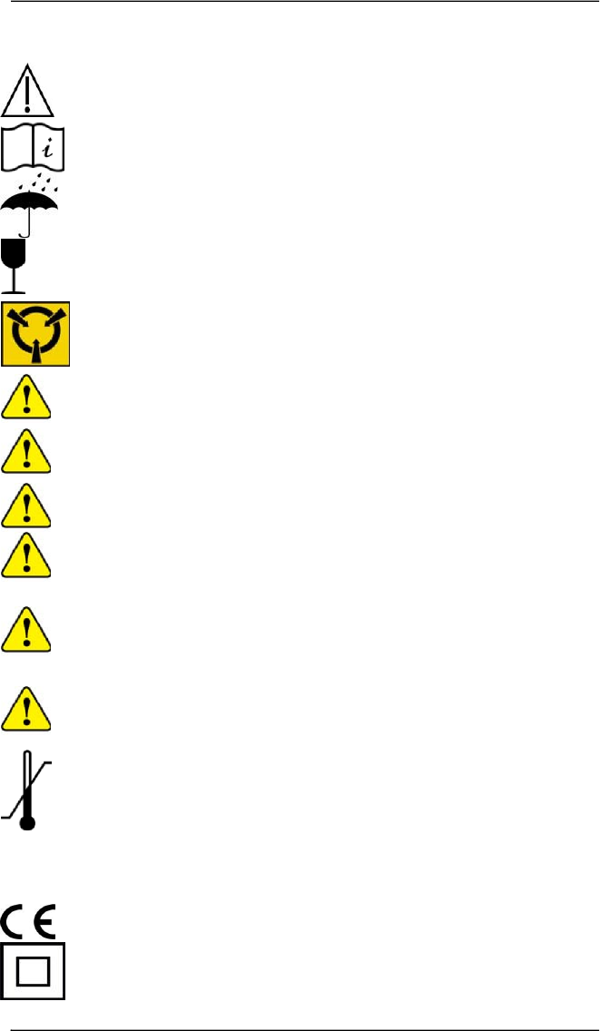
Complies with Requirements put forth by the Medical Device Directive
93/42/EEC. Class I device, Annex VII. Type BF device (IEC 60601-1)
Isolated device, (Class II, IEC 60601-1)

9
Type BF Equipment.
Date of Manufacturing (appears on device)
Serial Number (appears on device)
Dispose the device according to local rules for electronic waste.
Authorized Representative:
EMERGO EUROPE
Prinsessegracht 20, 2514 AP The Hague
The Netherlands
FCC ID: W4P-SP-W02 (Trigno Base Station)
FCC ID: W4P-SP-W06 (Trigno “Avanti” Sensor)
IC: 8138A-DST03 (Model: Trigno Wireless Biofeedback System)
This device complies with Part 15 of the FCC Rules and Industry Canada’s
RSS-210 License Exempt Standards. Operation is subject to the following
two conditions: (1) This device may not cause harmful interference. and (2)
this device must accept any interference received, including interference
that may cause undesired operation.
This Class B digital apparatus complies with Canadian ICES-003.
Cet appareil est conforme à des règlements d'Industrie Canada exempts de
licence standard RSS (s). Son fonctionnement est soumis aux deux
conditions suivantes: (1) Ce dispositif ne doit pas causer d'interférences
nuisibles, et (2) cet appareil doit accepter toute interférence reçue, y
compris les interférences pouvant entraîner un fonctionnement
indésirable.
Cet appareil numériqué de la classe B est conformé à la norme NMB-003
du Canada
This product complies with FCC OET Bulletin 65 radiation exposure limits
set forth for an uncontrolled environment.
To reduce potential radio interference to other users, the antenna type and
its gain should be so chosen that the equivalent isotropically radiated
power (EIRP) is not more than that required for successful communication.
This equipment has been tested and found to comply with the limits for a
Class B digital device, pursuant to Part 15 of the FCC Rules. These limits are
designed to provide reasonable protection against harmful interference in
a residential installation. This equipment generates, uses, and can radiate
radio frequency energy and, if not installed and used in accordance with
the instructions, may cause harmful interference to radio communications.
There is no guarantee that interference will not occur in a particular
installation. If this equipment does cause harmful interference to radio or
television reception, which can be determined by turning the equipment
off and on, the user is encouraged to try to correct the interference by one
or more of the following measures: Reorient or relocate the receiving

10 Trigno™ System User’s Guide
antenna; increase the separation between the equipment and receiver;
Connect the equipment into outlet on a separate circuit.
Pursuant to FCC 15.21 of the FCC rules, changes not expressly approved by
Delsys Inc. could void the User’s authority to operate the equipment.
PC Requirements
• EMGworks 4.3 or later
• Windows 7, 8.1, 10
• One USB 2.0 port
• At least 2.0 GHz processor clock speed
• At least 2 GB system memory
• 1280x1024 (SXGA) display resolution or better
• 50 GB hard disk storage (minimum)

11
Trigno System Overview
The TrignoTM Wireless Biofeedback System is a device designed to make EMG
(electromyographic) and biofeedback signal detection reliable and easy. The
system transmits signals from the Trigno Avanti™ sensors to a receiving base
station using a time-synchronized wireless protocol which minimizes data
latency across sensors. The core architecture of the Trigno System is designed
to support high fidelity EMG signals, along with complementary biofeedback
signals such as movement data, force signals, contact pressure events and
timing and triggering information. The system is also capable of integrating with
3rd party lab equipment through a variety of interfaces which include analog
signal generation, triggering scenarios and digital integration through the
Trigno SDK (Software Development Kit) and the Trigno API (Application Program
Interface). Refer to the specific component senor User Guides for operational
details of these system elements.
System Components
1) Trigno Avanti™ Wireless Sensors
2) Trigno Base Station
3) Power Supply
4) Personal Computer
5) Adhesive Skin Interfaces
6) USB Cable
Trigno Avanti™ Sensor Features
Each Trigno Avanti™ Sensor is equipped with the following capabilities and
design features:
• on board configurable precision EMG sensor
• built-in 9-axis inertial measurement unit (IMU)
• inter-sensor latency < 1 sample period
• wireless transmission range 20+m1
• self-contained rechargeable battery
• battery charge monitoring and status indicator
• software selectable operational modes
• environmentally sealed enclosure
• low power mode
• auto shutoff
• internal magnetic switch
• LED User Feedback
1
communication distance is dependent on the RF operating environment.

12 Trigno™ System User’s Guide
Onboard EMG Sensor
Trigno Avanti™ sensors support a low noise, high fidelity sensing circuit for
detecting EMG (electromyographic) biofeedback signals from the surface of the
skin when muscles contract. The sensor bandwidth can be selected between
10-850Hz or 20-450 Hz and the input range of the sensor can be selected
between 22mV or 11mV depending on user needs.
Inertial Measurement Unit
Trigno Avanti™ Sensors have a built-in 9 DOF inertial measurement unit which
can relay acceleration, rotation and earth magnetic field (compass)
information. Users can use this information to discern movement activity time-
synchronized with the EMG signals. One of 4 ranges can be selected for each
sensor to span ±2g to ±16g for accelerometer outputs and ±250°/s to ±2000°/s
for gyroscope outputs.
Data Synchronization
Data from each sensor and from each channel within a sensor are time
synchronized over the Trigno wireless communication protocol so no time skew
between data exists. A maximum of 16 sensors can stream data to a host base
station at one time.
Wireless Communication
The Trigno wireless communication scheme offers robust data transmission for
up to 16 sensors with a nominal distance of 20m. Under optimal environmental
conditions (no RF path obstructions or interfering sources), this nominal
distance can be notably superseded. The Trigno communication protocol is
robust to sharing RF space with common 2.4 GHz devices such as routers, smart
phones and WiFi devices.
Rechargeable Battery
Sensors contain a sealed rechargeable lithium polymer battery for multiple
hours of continuous use which can be extended when making use of low power
modes. Actual duration will depend on usage conditions. Charge status is
conveniently reported through the wireless communication.
Sealed Enclosure
The environmentally sealed enclosure protects the electronics from the ingress
of liquids and other environmental elements, and provides a high standard of
user safety and durability.
Internal Magnetic Switch
The Trigno Avanti sensors are equipped with an internal magnetic switch which
is used to perform RF pairing operations and can be used to the turn the sensors
off. To activate the internal magnetic switch, the sensor must be placed on the
magnet label located on the Base Station charging cradle. The internal magnetic
switch will only react when the software is performing an RF pairing operation,
13
or if it is exercised within 3 seconds of pulling a sensor out of a charging pocket.
Exposure to any magnetic fields outside of these 2 qualifying conditions will be
ignored by the sensor. The internal magnetic switch is a feature which removes
the need for a mechanical button resulting in improvements to sensor
durability and performance.
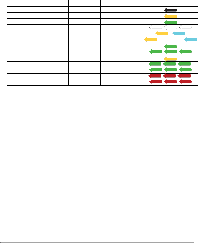
Sensor LED Feedback States
Trigno Avanti sensors indicate their status through various LED Arrow colors
and blink patterns as indicated in the table below. Each of these states is
described in subsequent sections of this User Guide.
State
Color
Pattern
Arrow Display
1
Power Off
Off
none
2
Charging
Amber
solid
3
Charge Complete
Green
solid
4
Identification Mode
White
rapid flash
/ /
5
Scan
Amber/Cyan
slow flash
/
6
Low Power Scan
Amber/Cyan
occasional flash
/
7
Data Collection
Green
slow flash
8
Configuration Change
Green
rapid flash (3x)
//
9
Pairing
Amber
solid
10
Pairing Success
Green
rapid flash (≥6x)
///
//
11
Pairing Fail
Red
double flash(≥3x)
///
//
1) Power Off: No LED arrow activity is present when the sensor is off.
2) Charging: Sensor Charging in the Trigno Base Station is denoted by
continuous amber LED arrow illumination
3) Charge Complete: Once the internal sensor battery has been full recharged,
the LED arrow illuminates to continuous green.
4) Identification Mode: The arrowed blinks whites upon this software
command so that it can be easily identified and located.
5) Scan: upon power up the sensor actively searches for a host to connect to.
6) Low Power Scan: If no host is found after 5 minutes in the active scan mode,
the sensor decreases it’s scan rate to conserve battery charge.
7) Data Collection: Sensor is sampling and streaming data to host.
8) Configuration Change: Sensor acknowledges change in configuration sensor
from host.
9) Pairing: Sensor is performing a pair operation with the host.
10) Pairing Success: sensor successfully completes pair operation with host.
11) Pairing Fail: pair operation did not complete successfully with host.

14 Trigno™ System User’s Guide
Base Station Features
Each Base Station is equipped with the following features:
• recharging cradle for 16 sensors
• high speed USB communication with PC
• 64-channel analog outputs
• ± 5V analog output range
• detachable antenna
• full trigger capability (Start/Stop, Input/Output)
• communication & power feedback LEDs
• convenient carry case design
• Medical Grade Universal Power Supply.
Recharging Cradle: The Trigno Base Station is equipped with 16 charge pockets
which can accommodate Trigno sensors for charging. The pockets are keyed so
that sensors can only be inserted in one orientation.
Medical Power Supply: The system includes a universal 12V medical grade
power supply for operating the base station. International plug adapters are
included for connection to local mains power requirements.
USB Communication: The Base Station compiles data received from the active
wireless sensors and transfers it over a USB 2.0 compliant connection to a
Windows PC.
Analog Outputs: The Base Station is equipped with two 68-poisition analog
output connectors that can be used to interface with analog data acquisition
systems. Biofeedback signals acquired by the wireless sensors are made
available as analog signals spanning a ±5V range.
Trigger Capability: The Base Station is equipped with a trigger port that can be
used to synchronize the starting and stopping data streams with 3rd party
equipment. The Trigger Module is required for making device connections.
Base Station LED Feedback States
Trigno Base Stations are equipped with 2 LEDs, indicating power on/off and
communication function as described in the table below:
State
Color
Pattern
Arrow Display
1
Power Off
Off
none
2
Standby
Green
solid
3
Data Streaming
Green
flashing
/
4
Mode Change
Green
3x flash
/
/
/
5
Communication Error
Green
double flash
/
15
Getting Started with the Trigno System
Software Installation
The Trigno EMG system is controlled by a PC through the USB port, and thus
requires software. Trigno Systems include a Delsys Software DVD containing
EMGworks Signal Acquisition and Analysis Software for interacting with the
system
Install EMGworks from the Delsys Software DVD or from www.delsys.com prior
to connecting the Trigno Base Station to the computer.
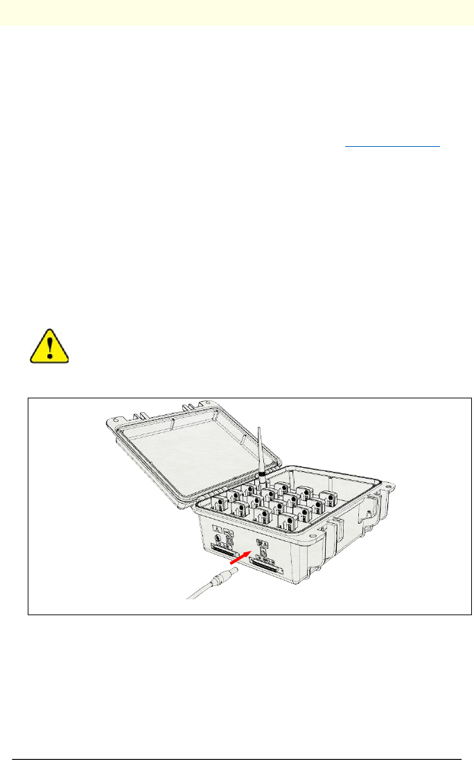
Powering the Base Station
Trigno Systems are equipped with a universal medical power supply and are
provided with interchangeable country-specific plug adapters. Connect the
Trigno power supply to the circular DC jack located on the side of the Base
Station. Energize the power supply by connecting it to a Mains outlet or to an
isolation transformer. The power LED on the Base Station will illuminate
anytime power is applied.
Trigno System are specifically designed and approved to
function only with the Power Supply provided. Power Supply
substitutions constitute a violation of the medical safety
approvals and will void the warranty.
Figure 1: Connecting the SC-P05 power supply to the Base Station.
Charging the Sensors
All sensors are fitted with a sealed lithium polymer cell and are charged with
the provided base station powered from a universal medical grade power
supply. A full charge will generally require 3 hours or less to complete,
depending on the battery age, usage history and particular charge conditions.
The sensor arrow will glow amber during charging and illuminate green upon
charge completion. It is recommended to keep sensors docked and charging
16 Trigno™ System User’s Guide
even when not in use in order to maximize battery life, as sensor batteries will
self-discharge with time and will degrade if left uncharged for extended periods
of time.
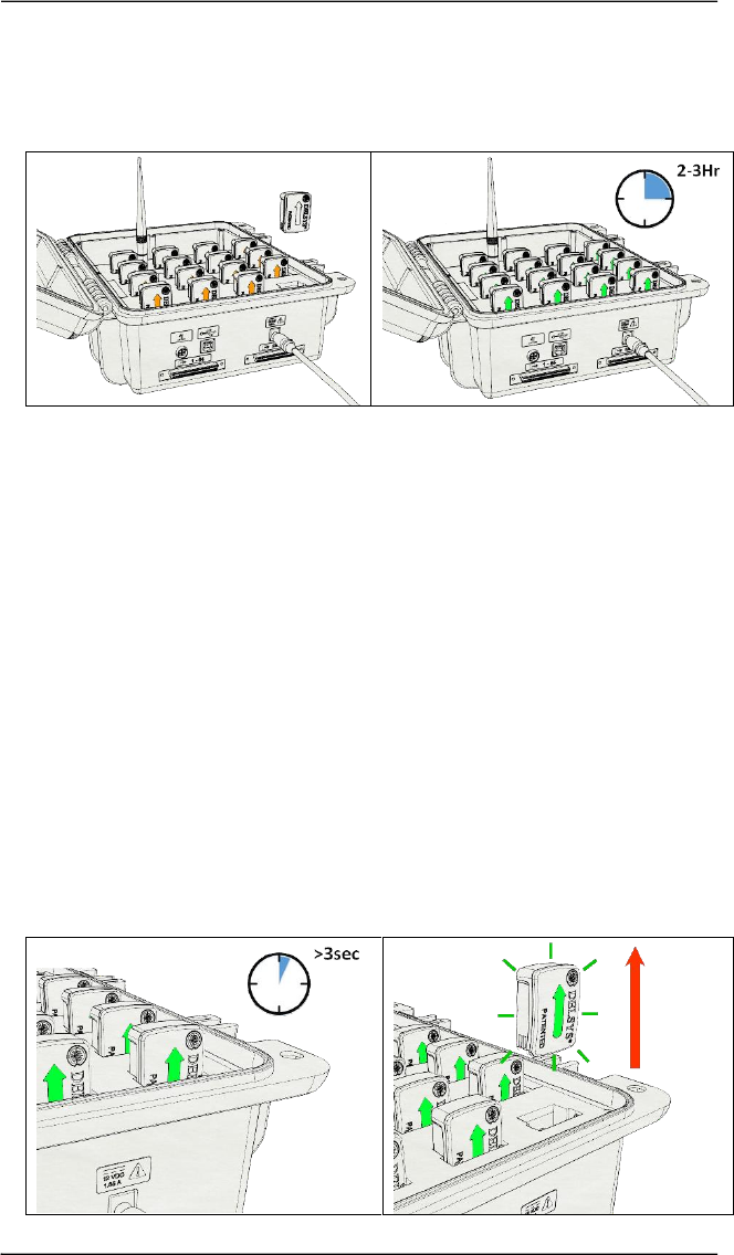
Figure 2: Docking a sensor in the charge cradle (left). When docked, sensors will turn off and
begin battery charging indicated by an amber LED indicator. Once fully charged, the sensor
LED indicator shows green (right).
Battery Performance
Battery performance and longevity is subject to a myriad of factors, which
include charge/discharge conditions, usage scenarios, number of
charge/discharge cycles, environmental temperature factors, and cell
manufacturing parameters which are subject to statistical variations. Typical
industry expectations assume an 80% charge capacity derating after 2-years or
300 charge/discharge cycles. Sensors are equipped with battery charge
monitoring and automatic sensor turn off when charge is depleted to avoid
deep discharge scenarios. Storage at temperature outside the 5-40°C may
damage the battery.
Turning the Sensor ON
Trigno Avanti sensors are automatically turned on when they are removed from
a powered charging dock. The sensors must be docked for a minimum of 3
seconds in the charge cradle in order for the self-powering scheme to activate
upon undocking.
17
Figure 3: Ensure sensors are docked and charging for a minimum of 3 seconds and
then removed from the charge cradle to turn on.
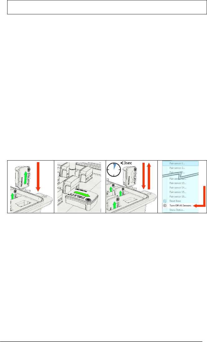
Turning the Sensors OFF
There are 4 mechanisms that will turn the sensors off:
a) Dock Sensors in Charger: docking the sensors in the charge cradle will
automatically turn the wireless communication system of the sensor off and
engage the battery charging circuit.
b) Undock and Activate Magnetic Switch: Sensors can be turned off by
activating the internal magnetic switch within 3 seconds of undocking a sensor
from an active charge pocket.
c) Dock and Undock Sensors <3s: Docking and undocking the sensors in less
than 3 seconds will turn the sensors off. Plugging and unplugging the power
connector within 3 seconds will turn off all docked sensors.
d) Software Issued Command: Sensors that are paired with the base station
and are communicating with the host software application can be turned off by
way of an “off” command sent from the software application. Please refer to
the software user guide for more information.
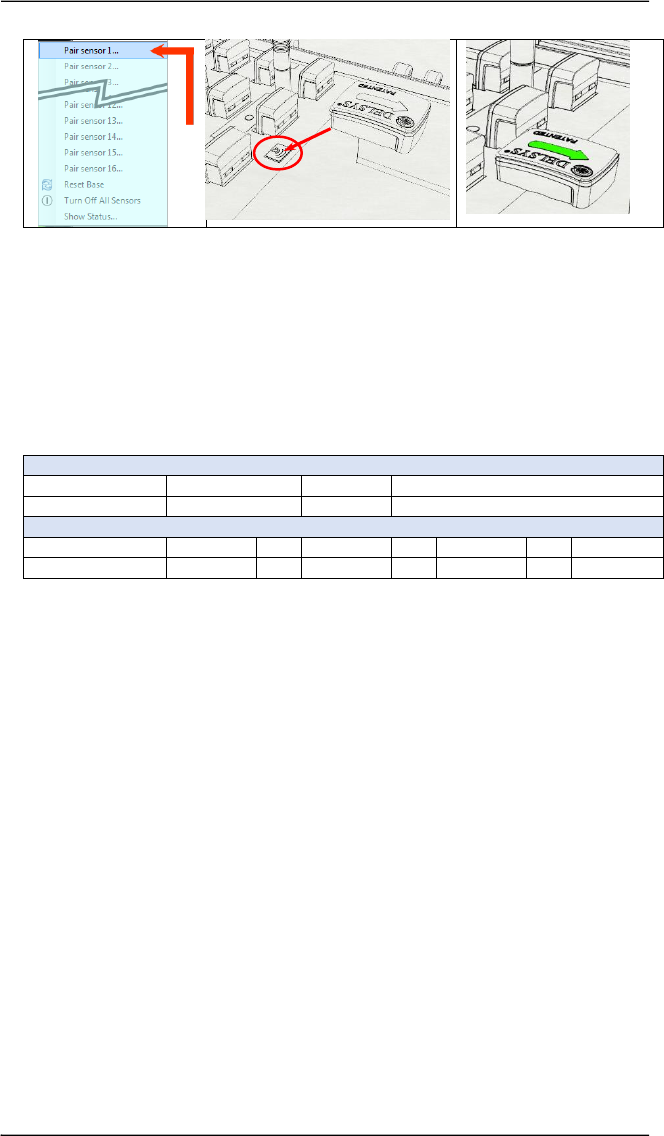
Pairing the Sensors with the Base Station
Data acquisition functions of the sensor, wireless transmission to the base
station and data transfer from the base station to the software require the
sensors to be paired to the base station. The pairing process links the unique ID
of the sensor to the unique ID of the base station to establish a wireless data
link. Pairing information is retained after the base station and sensors are
powered off. Pairing is initiated through the software pairing command and
completed by activating the internal magnetic switch in the sensor. The
magnetic switch in the sensor is activated by tapping the sensor over the built-
in magnet of the base station.
b)
d)
a)
c)
18 Trigno™ System User’s Guide
Acquiring Data with the System
Refer to the software user guide and help information for detailed explanation
of software functions. Data collection and sensors configuration is initiated
through the software.
Configuring the Trigno Sensors
Once paired to the system, EMG data and IMU data from sensor can be
configured in the following ways:
Electromyographic (EMG) Sensing Ranges
Input Range
11 mV
or
22 mV
Bandwidth
20-450 Hz
or
10-850 Hz
Inertial Measurement Unit (IMU) Ranges
Accelerometer
±2 g
or
±4 g
or
±8 g
or
±16 g
Gyroscope
±250 dps
or
±500 dps
or
±1000 dps
or
±2000 dps
Note that the magnetometer has a fixed range of ±4900uT.
a)
c)
b)
19
Using the Wireless EMG Sensors
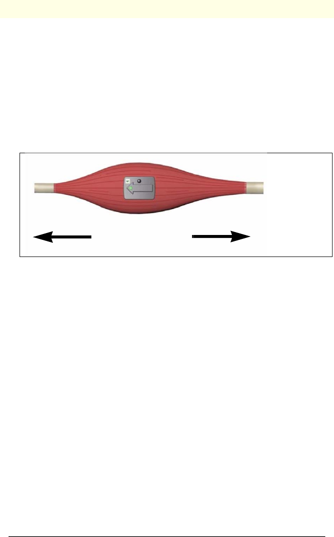
Orienting the EMG Sensors on the Skin
Trigno EMG Sensors employ 4 silver bar contacts for detecting the EMG signal
at the skin surface. For maximum signal amplitude, it is important to orient
these bars perpendicular to the muscle fiber direction. The top of the sensor is
shaped with an arrow to aid in the determination of this orientation. The arrow
should be placed parallel to the muscle fibers underneath the sensor. The
sensor should also be placed in the center of the muscle belly away from
tendons and the edge of the muscle. The sensor is easily attached to the skin
using the Delsys Adhesive Sensor Interface.
Figure 6. EMG Sensors must be properly oriented with the muscle fibers. Align the
sensor’s arrow with the direction of the underlying muscle fibers.
Cleaning the Sensor Site
Prior to affixing the EMG sensor on the surface of the skin, the sensor site must
be properly cleaned to remove dry dermis and any skin oils. Wiping the skin
prior to sensor application helps ensure a high quality signal. If excessive hair is
present, it will also be necessary to shave the site. In cases where the skin is
excessively dry, it may be useful to dislodge dry skin cells by dabbing the site
with medical tape. The dry cells will attach the tape’s adhesive when it is
removed. Be sure to wipe with isopropyl alcohol to remove any adhesive
residue that may remain.
Applying the Trigno Adhesive Skin Interfaces
Trigno System are supplied with specially-designed adhesive interfaces to
simplify sensor attachment. These hypo-allergenic interfaces are manufactured
from medical grade adhesive approved for dermatological applications. Usage
of the interface promotes a high quality electrical connection between the
sensor bars and the skin, minimizing motion artifacts and the ill-effects of line
interference. To ensure a strong bond with the skin, it is advised to remove
excessive hair and wipe the skin area and the EMG Sensor with isopropyl
muscle-fiber direction

20 Trigno™ System User’s Guide
alcohol to remove oils and surface residues. Allow the skin to dry completely
before applying the interfaces.
Adhesive Sensor Interfaces are for single use only.
Immediately discontinue use if skin irritation or discomfort occurs.
All Adhesive Sensor Interfaces and Reference Electrodes are for
single use only. Discard after using. Reseal storage bag to maintain
freshness.
Do not use on Patients with allergies to silver.
Do not apply over open wounds or irritated skin.
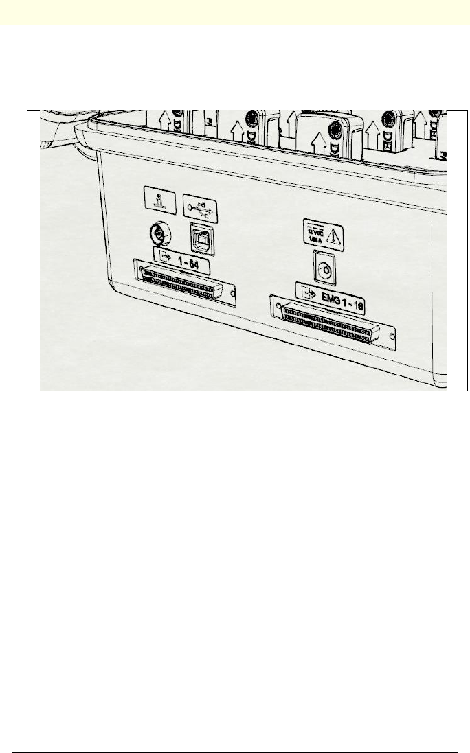
21
Using the Analog Outputs
The Trigno System provides simultaneous analog signal reconstruction of data
being detected by all active sensors. These signals are made available on the
68-pin connectors located on the Base Station and range cover the +/-5V range
.
Figure 4: Analog Output Connectors on Base Station.
Analog Output Connectors
Channels 1-16, EMG Signals
The pinout of this connector replicates the pinout of the Bagnoli desktop EMG
systems to facilitate connectivity between shared equipment for the Channels
1-16. This connector is a 1.27mm, PCS series connector and is compatible
National Instruments data acquisition modules.
Channels 1-64, all Signals
This connector makes available all 64 analog output channels in the 68-pin
connector. This connector is a 1.27mm, PCS series connector and is compatible
National Instruments data acquisition modules.
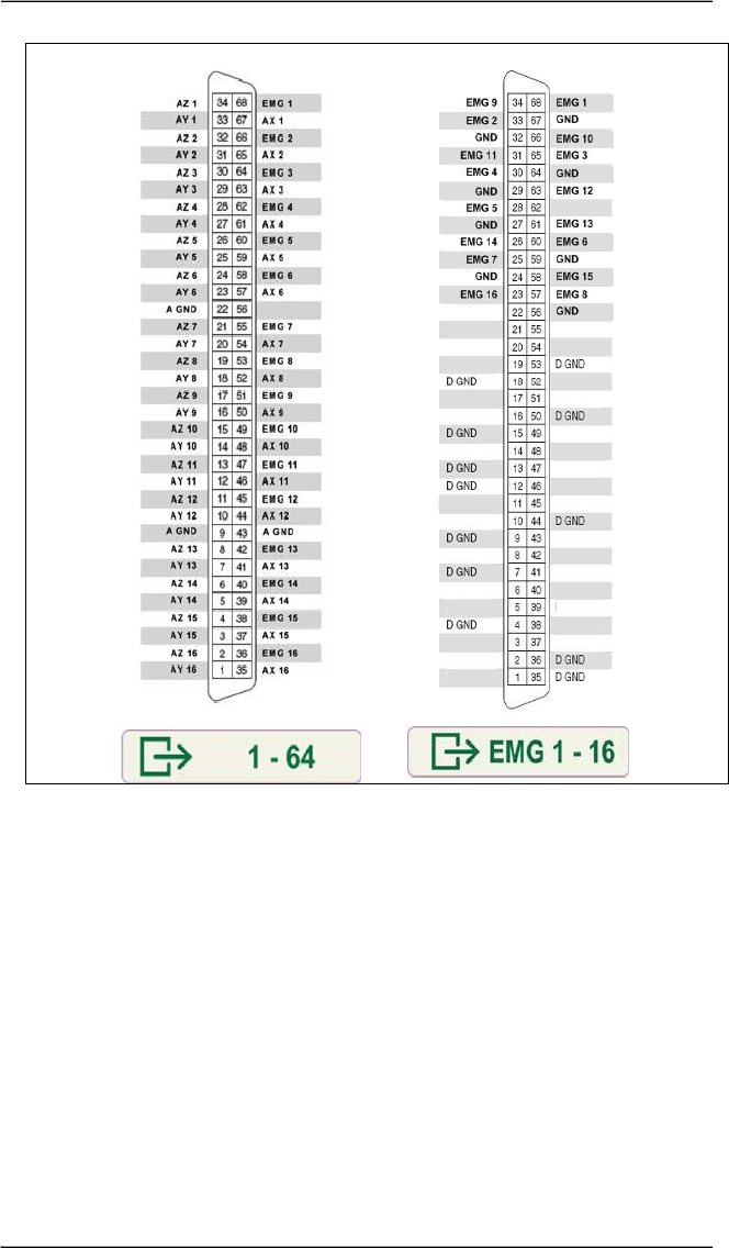
22 Trigno™ System User’s Guide
Figure 5: Pinouts of the analog output connectors
23
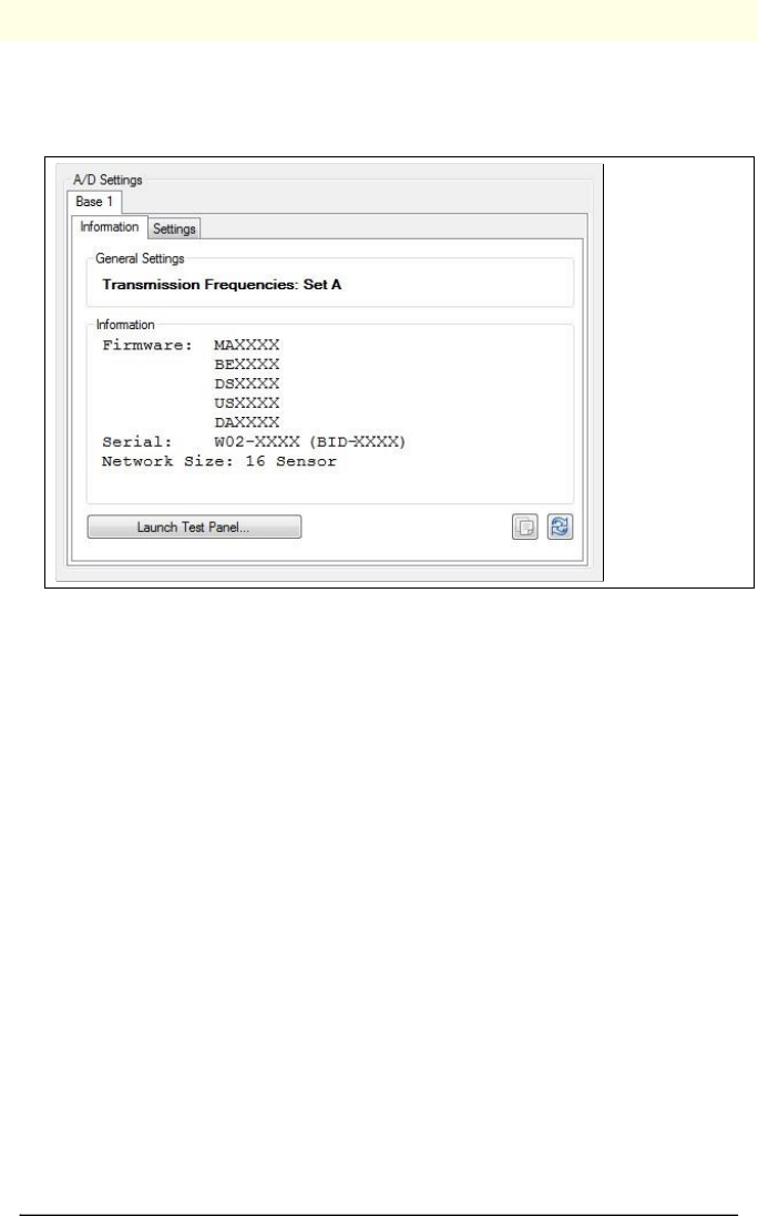
Configuration Options for Trigno System
Trigno System Information
The Information tab presents information pertaining to the system and its
settings.
Figure 6: Trigno System panel.
Transmission Frequencies
Wireless communication occurs on varieties of frequencies throughout the
acceptable 2.4 GHz spectrum. Four frequency sets are available (“A”, “B”, “C”
and “D”) and are displayed in this field.
Firmware Version
The current firmware version is shown in this field.
Serial Number
Each Trigno Base Station has a unique serial number and identifier address
which is shown in this field.
Network Size
This field indicates the number of sensors supported by this base.
Launch Test Panel
Places the Trigno Base Station in a test mode to assist with verification of analog
output signal connections. Each of the 64 analog output channels is configured
to produce a unique sinusoid which can be verified by properly sampling these
channels with secondary acquisition system.

24 Trigno™ System User’s Guide
Trigno System Settings
The Settings tab allows several system parameters to be modified as needed.
Figure 7: Trigno System Settings panel.
Frequency Set
Use this setting to change the frequencies being used for wireless
communication. The default set is “A”. The frequency set should only be
changed if nearby sources are interfering with Trigno communications or the
particular operating environment is causing significant path loss on the current
frequency set. Note that changing the communication frequency set will
require sensor re-pairing. Frequencies within the sets are defined by the system
and cannot be changed by the User.
Audible Warnings
This option will generate an audible “ping” along with a small message,
whenever a sensor falls out of range or it’s battery is excessively low.
25
Maintenance and Care
Trigno Sensors
Trigno sensor are encased in a sealed polycarbonate enclosure. The following
points should be kept in mind when handling the sensors.
• All sensors should be visually inspected before each use to ensure that
no mechanical deterioration has occurred.
• The sensors can be cleaned with isopropyl alcohol swabs. Ensure that
the sensor contacts remain clean at all times for proper operation.
• While the sensors are sealed and are water-resistant, these should
never be completely submerged in any liquid.
• The sensor contacts are made of pure silver and are quite soft. Care
should be taken to preserve the integrity of these contacts. Do not
scrape or dent these contacts.
Handle the sensors with care: do not drop them on the ground or
step on them.
Do not submerge the sensors in any liquid under any circumstance.
The sensors contain sensitive electronic circuitry. Static discharges
and intense magnetic fields should be avoided to prevent the risk of
irreparable damage to the sensors
Trigno Base Station
The Trigno System is designed to provide years of reliable service when proper
care is followed. While the Base Station enclosure is made of durable plastic,
the following points should be kept in mind during its use and handling:
• The device and its accessories should be visually inspected before
every use to ensure that no mechanical deterioration has occurred.
• The Base Station can be easily cleaned with isopropyl alcohol swabs if
necessary. Do not expose the base station to any liquid. It is not a
sealed device.
• The units are not shockproof and should not be dropped or be
subjected to excessive forces or accelerations.
The recharging Base Station is not water-resistant. Under no
circumstance should this unit be exposed to water or any other type
of liquids.

26 Trigno™ System User’s Guide
Specifications
RF Frequency Band
2400-2483 MHz (ISM band)
Dimension
27 x 37 x 13 mm
Mass
14.7 g
Temperature Range(1)
5 - 50 degrees Celsius
EMG Signal Input Range
11mV / 22mV r.t.i.
EMG Signal Bandwidth
20-450 Hz / 10-850 Hz
EMG Contact Dimensions
5x1 mm
Contact Material(2)
99.99% silver
Accelerometer Range
±2g, ±4g, ±8g, ±16g
Gyroscope Range
±250 dps, ±500 dps. ±1000dps, ±2000dps
Magnetometer Range
±4900 uT
Inter-Sensor Delay
< 1 sample period
Intra-Channel Delay
< 1 sample period
Analog Output Range
± 5 V
Analog Output Bandwidth (Ch. 1-16)
DC-500 Hz
Analog Output Bandwidth (Ch. 17-64)
DC-50 Hz
Analog Output Group Delay (Ch. 1-16)
48 ms
Analog Output Group Delay (Ch. 17-64)
96 ms
1) Exposure beyond these temperature limits may damage the rechargeable battery.
2) Sensor skin contacts are made from pure silver and should not be used if allergic reactions to silver are expected or found to occur.
27
Appendix I
Mains Isolation
The Trigno Base Station is provided with Medical Grade isolated power supply
which is compliant with IEC60601 series of harmonized standards for Medical
Devices. However, full compliance with IEC60601-1 Basic Safety for Medical
Devices requires that the PC operating the software be isolated as well. This
stems from the basic requirement to have all patients electrically isolated from
equipment within their reach, and since the PC running the Trigno Software is
conceivably within their reach, it too must be isolated.
Delsys does not supply isolation transformers for Personal
Computers and their peripherals.
Delsys recommends model IS1000HG manufactured by Tripp Lite
(www.tripplite.com) for this task. This device is a medial grade
isolation transformer capable of delivering up to 1000 W. A smaller
similar version for 500W is also available (IS500HG). Similar products
compliant with IEC60601-1 are acceptable.