Delta Electronics orporated DFWM-GIN00 Wi-Fi module User Manual
Delta Electronics Incorporated Wi-Fi module
User manual

DFWM-GIN00
User Manual Sheet of 17 July. 16, 2014
Proprietary Information and Specifications are Subject to Change
1
User Manual
DFWM-GIN00
An IEEE 802.11b/g/n Low-Power Wireless
System-On-Chip module
DFWM-GIN00
User Manual Sheet of 17 July. 16, 2014
Proprietary Information and Specifications are Subject to Change
2
This document describes a simple method for characterizing DFWM-GIN00 WLAN module based
RF parameters, such as transmitted spectra and receiver sensitivity. It will be described step by step
below that how to control and setup.
Step 1 : Extract to CDM20814_WHQL_Certified.zip, it is a USB to UART driver, then setup it.
Step 2 : Setup teraterm_utf8-4.58.exe program, this program can help to send command to module.
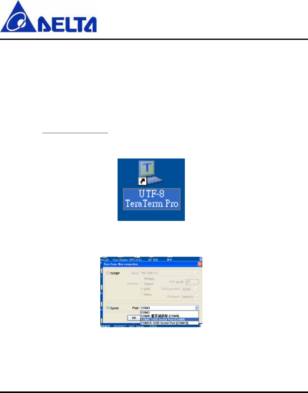
Step 3 : Double click UTF-8 execute file as shown below, it will occur after completing step2 install.
Figure 1
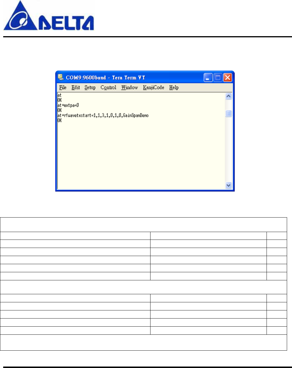
Step 4 : When implement UTF-8, selecting Serial port correctly.
Figure 2
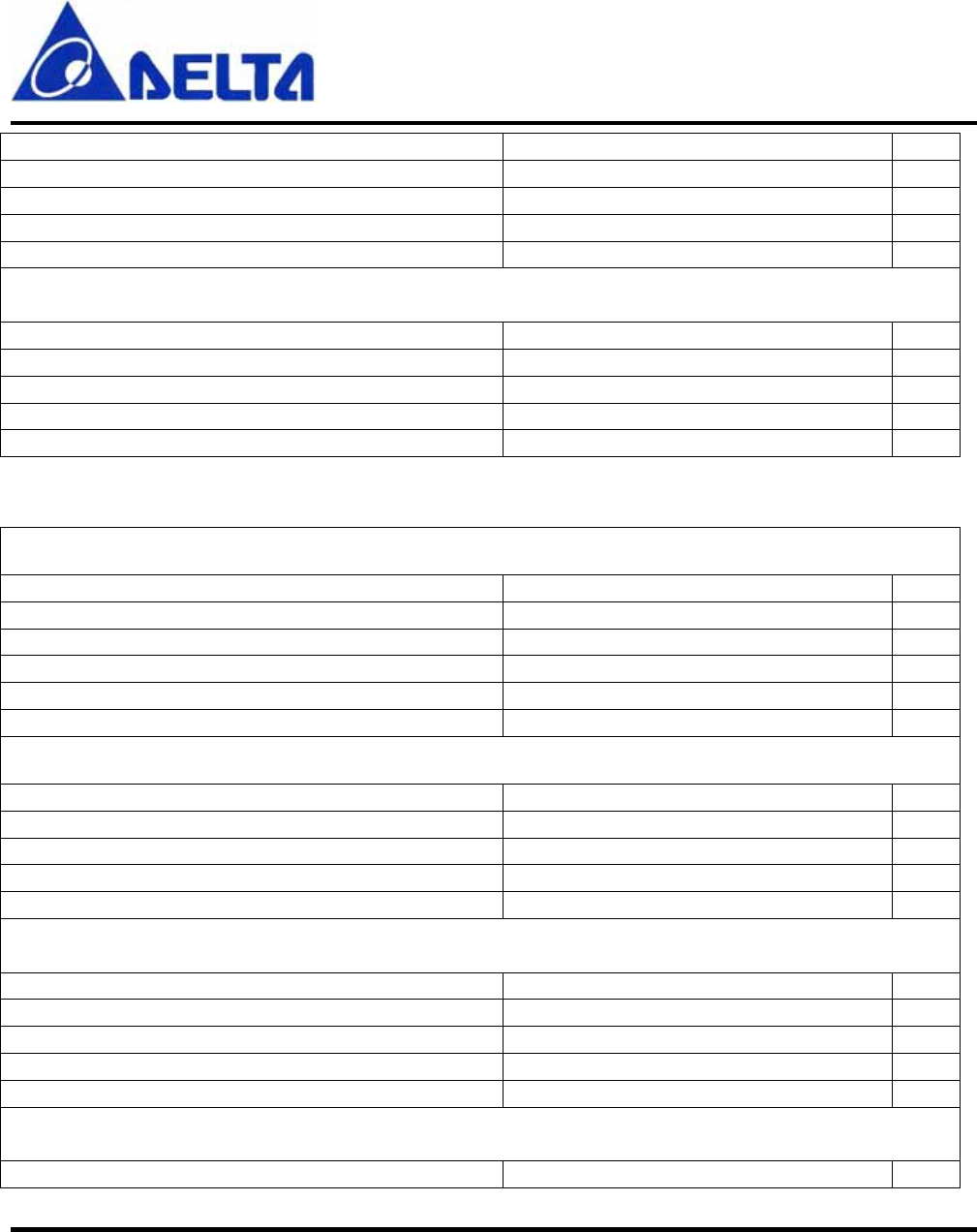
Step 5 : After entering UTF-8, send command at. If connection is successful, it will reply ok.
DFWM-GIN00
User Manual Sheet of 17 July. 16, 2014
Proprietary Information and Specifications are Subject to Change
3
Step 6 : Now any legal command can be keyed in and if UTF-8 reply ok, the command is implemented
successful like below figure.
Figure 3
802.11b, Transmitter command:
Transmitted Tx at 11Mbps
Command Action
at+wrfteststart Start up internal Power Amplifier
at+wtx100test=1,0,11,0,0,0,0,1,1,0,0,1,3,1 Continuous Tx Channel 1, 11Mbps
at+wtx100test=6,0,11,0,0,0,0,1,1,0,0,1,3,1 Continuous Tx Channel 6, 11Mbps
at+wtx100test=11,0,11,0,0,0,0,1,1,0,0,1,3,1 Continuous Tx Channel 11, 11Mbps
At+reset Transmitter off
Transmitted Tx at 5.5Mbps
at+wrfteststart Start up internal Power Amplifier
at+wtx100test=1,0,14,0,0,0,0,1,1,0,0,1,2,1 Continuous Tx Channel 1, 5.5Mbps
at+wtx100test=6,0,14,0,0,0,0,1,1,0,0,1,2,1 Continuous Tx Channel 6, 5.5Mbps
at+wtx100test=11,0,14,0,0,0,0,1,1,0,0,1,2,1 Continuous Tx Channel 11, 5.5Mbps
At+reset Transmitter off
Transmitted Tx at 2Mbps
DFWM-GIN00
User Manual Sheet of 17 July. 16, 2014
Proprietary Information and Specifications are Subject to Change
4
at+wrfteststart Start up internal Power Amplifier
at+wtx100test=1,0,9,0,0,0,0,1,1,0,0,1,1,1 Continuous Tx Channel 1, 2Mbps
at+wtx100test=6,0,9,0,0,0,0,1,1,0,0,1,1,1 Continuous Tx Channel 6, 2Mbps
at+wtx100test=11,0,9,0,0,0,0,1,1,0,0,1,1,1 Continuous Tx Channel 11, 2Mbps
At+reset Transmitter off
Transmitted Tx at 1Mbps
at+wrfteststart Start up internal Power Amplifier
at+wtx100test=1,0,18,0,0,0,0,1,1,0,0,1,0,1 Continuous Tx Channel 1, 1Mbps
at+wtx100test=6,0,18,0,0,0,0,1,1,0,0,1,0,1 Continuous Tx Channel 6, 1Mbps
at+wtx100test=11,0,18,0,0,0,0,1,1,0,0,1,0,1 Continuous Tx Channel 11, 1Mbps
At+reset Transmitter off
802.11g, Transmitter command:
Transmitted Tx at 54Mbps
Command Action
at+wrfteststart Start up internal Power Amplifier
at+wtx100test=1,0,19,0,0,0,0,1,0,0,0,1,4,0 Continuous Tx Channel 1, 54Mbps
at+wtx100test=6,0,19,0,0,0,0,1,0,0,0,1,4,0 Continuous Tx Channel 6, 54Mbps
at+wtx100test=11,0,19,0,0,0,0,1,0,0,0,1,4,0 Continuous Tx Channel 11, 54Mbps
At+reset Transmitter off
Transmitted Tx at 48Mbps
at+wrfteststart Start up internal Power Amplifier
at+wtx100test=1,0,24,0,0,0,0,1,0,0,0,1,0,0 Continuous Tx Channel 1, 48Mbps
at+wtx100test=6,0,24,0,0,0,0,1,0,0,0,1,0,0 Continuous Tx Channel 6, 48Mbps
at+wtx100test=11,0,24,0,0,0,0,1,0,0,0,1,0,0 Continuous Tx Channel 11, 48Mbps
At+reset Transmitter off
Transmitted Tx at 36Mbps
at+wrfteststart Start up internal Power Amplifier
at+wtx100test=1,0,25,0,0,0,0,1,0,0,0,1,5,0 Continuous Tx Channel 1, 36Mbps
at+wtx100test=6,0,25,0,0,0,0,1,0,0,0,1,5,0 Continuous Tx Channel 6, 36Mbps
at+wtx100test=11,0,25,0,0,0,0,1,0,0,0,1,5,0 Continuous Tx Channel 11, 36Mbps
At+reset Transmitter off
Transmitted Tx at 24Mbps
at+wrfteststart Start up internal Power Amplifier

DFWM-GIN00
User Manual Sheet of 17 July. 16, 2014
Proprietary Information and Specifications are Subject to Change
5
at+wtx100test=1,0,26,0,0,0,0,1,0,0,0,1,1,0 Continuous Tx Channel 1, 24Mbps
at+wtx100test=6,0,26,0,0,0,0,1,0,0,0,1,1,0 Continuous Tx Channel 6, 24Mbps
at+wtx100test=11,0,26,0,0,0,0,1,0,0,0,1,1,0 Continuous Tx Channel 11, 24Mbps
At+reset Transmitter off
Transmitted Tx at 18Mbps
Command Action
at+wrfteststart Start up internal Power Amplifier
at+wtx100test=1,0,27,0,0,0,0,1,0,0,0,1,6,0 Continuous Tx Channel 1, 18Mbps
at+wtx100test=6,0,27,0,0,0,0,1,0,0,0,1,6,0 Continuous Tx Channel 6, 18Mbps
at+wtx100test=11,0,27,0,0,0,0,1,0,0,0,1,6,0 Continuous Tx Channel 11, 18Mbps
At+reset Transmitter off
Transmitted Tx at 12Mbps
at+wrfteststart Start up internal Power Amplifier
at+wtx100test=1,0,27,0,0,0,0,1,0,0,0,1,2,0 Continuous Tx Channel 1, 12Mbps
at+wtx100test=6,0,27,0,0,0,0,1,0,0,0,1,2,0 Continuous Tx Channel 6, 12Mbps
at+wtx100test=11,0,27,0,0,0,0,1,0,0,0,1,2,0 Continuous Tx Channel 11, 12Mbps
At+reset Transmitter off
Transmitted Tx at 9Mbps
at+wrfteststart Start up internal Power Amplifier
at+wtx100test=1,0,27,0,0,0,0,1,0,0,0,1,7,0 Continuous Tx Channel 1, 9Mbps
at+wtx100test=6,0,27,0,0,0,0,1,0,0,0,1,7,0 Continuous Tx Channel 6, 9Mbps
at+wtx100test=11,0,27,0,0,0,0,1,0,0,0,1,7,0 Continuous Tx Channel 11, 9Mbps
At+reset Transmitter off
Transmitted Tx at 6Mbps
at+wrfteststart Start up internal Power Amplifier
at+wtx100test=1,0,27,0,0,0,0,1,0,0,0,1,3,0 Continuous Tx Channel 1, 6Mbps
at+wtx100test=6,0,27,0,0,0,0,1,0,0,0,1,3,0 Continuous Tx Channel 6, 6Mbps
at+wtx100test=11,0,27,0,0,0,0,1,0,0,0,1,3,0 Continuous Tx Channel 11, 6Mbps
At+reset Transmitter off
802.11n, Transmitter command:
Transmitted Tx at MCS7
Command Action
at+wrfteststart Start up internal Power Amplifier

DFWM-GIN00
User Manual Sheet of 17 July. 16, 2014
Proprietary Information and Specifications are Subject to Change
6
at+wtx100test=1,0,18,0,0,0,0,1,0,0,0,1,7,2 Continuous Tx Channel 1, 72Mbps
at+wtx100test=6,0,18,0,0,0,0,1,0,0,0,1,7,2 Continuous Tx Channel 6, 72Mbps
at+wtx100test=11,0,18,0,0,0,0,1,0,0,0,1,7,2 Continuous Tx Channel 11, 72Mbps
At+reset Transmitter off
Transmitted Tx at MCS6
at+wrfteststart Start up internal Power Amplifier
at+wtx100test=1,0,20,0,0,0,0,1,0,0,0,1,6,2 Continuous Tx Channel 1, 65Mbps
at+wtx100test=6,0,20,0,0,0,0,1,0,0,0,1,6,2 Continuous Tx Channel 6, 65Mbps
at+wtx100test=11,0,20,0,0,0,0,1,0,0,0,1,6,2 Continuous Tx Channel 11, 65Mbps
At+reset Transmitter off
Transmitted Tx at MCS5
at+wrfteststart Start up internal Power Amplifier
at+wtx100test=1,0,24,0,0,0,0,1,0,0,0,1,5,2 Continuous Tx Channel 1, 57.8Mbps
at+wtx100test=6,0,24,0,0,0,0,1,0,0,0,1,5,2 Continuous Tx Channel 6, 57.8Mbps
at+wtx100test=11,0,24,0,0,0,0,1,0,0,0,1,5,2 Continuous Tx Channel 11, 57.8Mbps
At+reset Transmitter off
Transmitted Tx at MCS4
at+wrfteststart Start up internal Power Amplifier
at+wtx100test=1,0,25,0,0,0,0,1,0,0,0,1,4,2 Continuous Tx Channel 1, 43.3Mbps
at+wtx100test=6,0,25,0,0,0,0,1,0,0,0,1,4,2 Continuous Tx Channel 6, 43.3Mbps
at+wtx100test=11,0,25,0,0,0,0,1,0,0,0,1,4,2 Continuous Tx Channel 11, 43.3Mbps
At+reset Transmitter off
Transmitted Tx at MCS3
Command Action
at+wrfteststart Start up internal Power Amplifier
at+wtx100test=1,0,27,0,0,0,0,1,0,0,0,1,3,2 Continuous Tx Channel 1, 28.9Mbps
at+wtx100test=6,0,27,0,0,0,0,1,0,0,0,1,3,2 Continuous Tx Channel 6, 28.9Mbps
at+wtx100test=11,0,27,0,0,0,0,1,0,0,0,1,3,2 Continuous Tx Channel 11, 28.9Mbps
At+reset Transmitter off
Transmitted Tx at MCS2
at+wrfteststart Start up internal Power Amplifier
at+wtx100test=1,0,27,0,0,0,0,1,0,0,0,1,2,2 Continuous Tx Channel 1, 21.7Mbps
at+wtx100test=6,0,27,0,0,0,0,1,0,0,0,1,2,2 Continuous Tx Channel 6, 21.7Mbps
at+wtx100test=11,0,27,0,0,0,0,1,0,0,0,1,2,2 Continuous Tx Channel 11, 21.7Mbps
At+reset Transmitter off
DFWM-GIN00
User Manual Sheet of 17 July. 16, 2014
Proprietary Information and Specifications are Subject to Change
7
Transmitted Tx at MCS1
at+wrfteststart Start up internal Power Amplifier
at+wtx100test=1,0,27,0,0,0,0,1,0,0,0,1,1,2 Continuous Tx Channel 1, 14.4Mbps
at+wtx100test=6,0,27,0,0,0,0,1,0,0,0,1,1,2 Continuous Tx Channel 6, 14.4Mbps
at+wtx100test=11,0,27,0,0,0,0,1,0,0,0,1,1,2 Continuous Tx Channel 11, 14.4Mbps
At+reset Transmitter off
Transmitted Tx at MCS0
at+wrfteststart Start up internal Power Amplifier
at+wtx100test=1,0,27,0,0,0,0,1,0,0,0,1,0,2 Continuous Tx Channel 1, 7.2Mbps
at+wtx100test=6,0,27,0,0,0,0,1,0,0,0,1,0,2 Continuous Tx Channel 6, 7.2Mbps
at+wtx100test=11,0,27,0,0,0,0,1,0,0,0,1,0,2 Continuous Tx Channel 11, 7.2Mbps
At+reset Transmitter off
CW Transmitter command:
at+wrfteststart Start up internal Power Amplifier
at+wcarwavtest=1,0,20,0,0 CW Tx Channel 1
at+wcarwavtest=6,0,20,0,0 CW Tx Channel 6
at+wcarwavtest=11, 0,20,0,0 CW Tx Channel 11
At+reset Transmitter off
Received command
Command Action
AT+WRXTEST= 1,0,4294930106,00:11:22:33:44:55,0 Rx on channel 1
AT+WRXTEST= 6,0,4294930106,00:11:22:33:44:55,0 Rx on channel 6
AT+WRXTEST= 11,0,4294930106,00:11:22:33:44:55,0 Rx on channel 11
At+wrxstop Stop action
DFWM-GIN00
User Manual Sheet of 17 July. 16, 2014
Proprietary Information and Specifications are Subject to Change
8
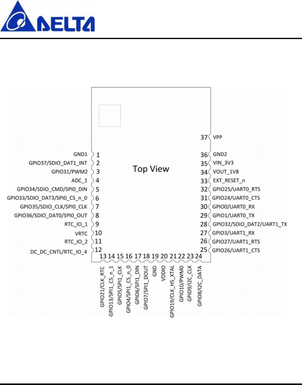
Device Pin-out Diagram (Module top view)
DFWM-GIB0x Device Pin-out Diagram (Module top view)
DFWM-GIN00
User Manual Sheet of 17 July. 16, 2014
Proprietary Information and Specifications are Subject to Change
9
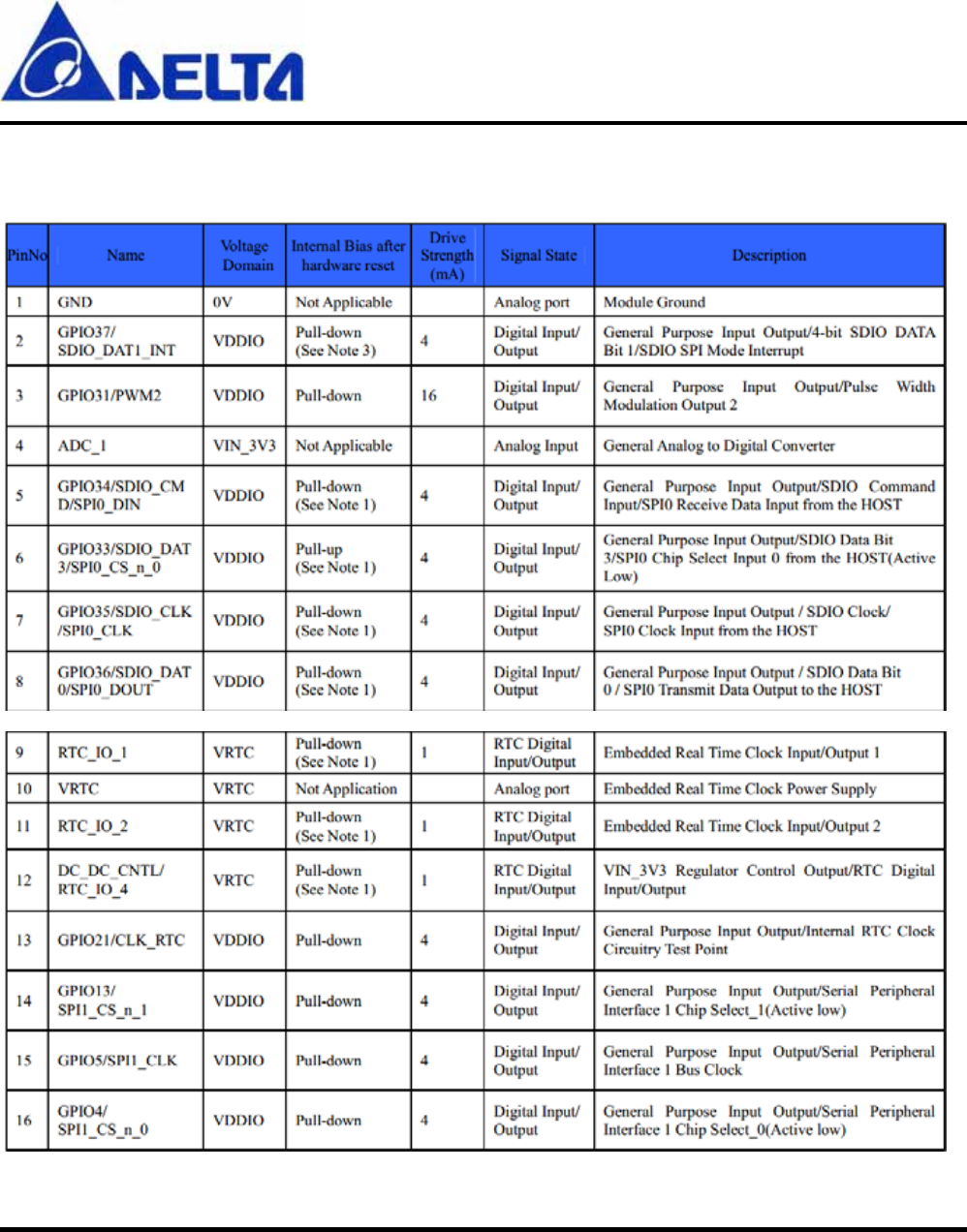
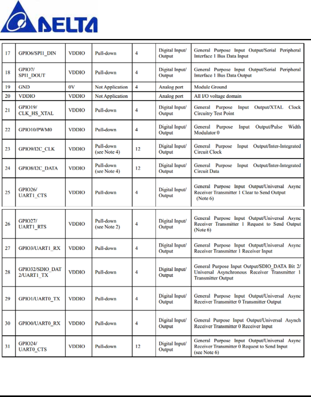
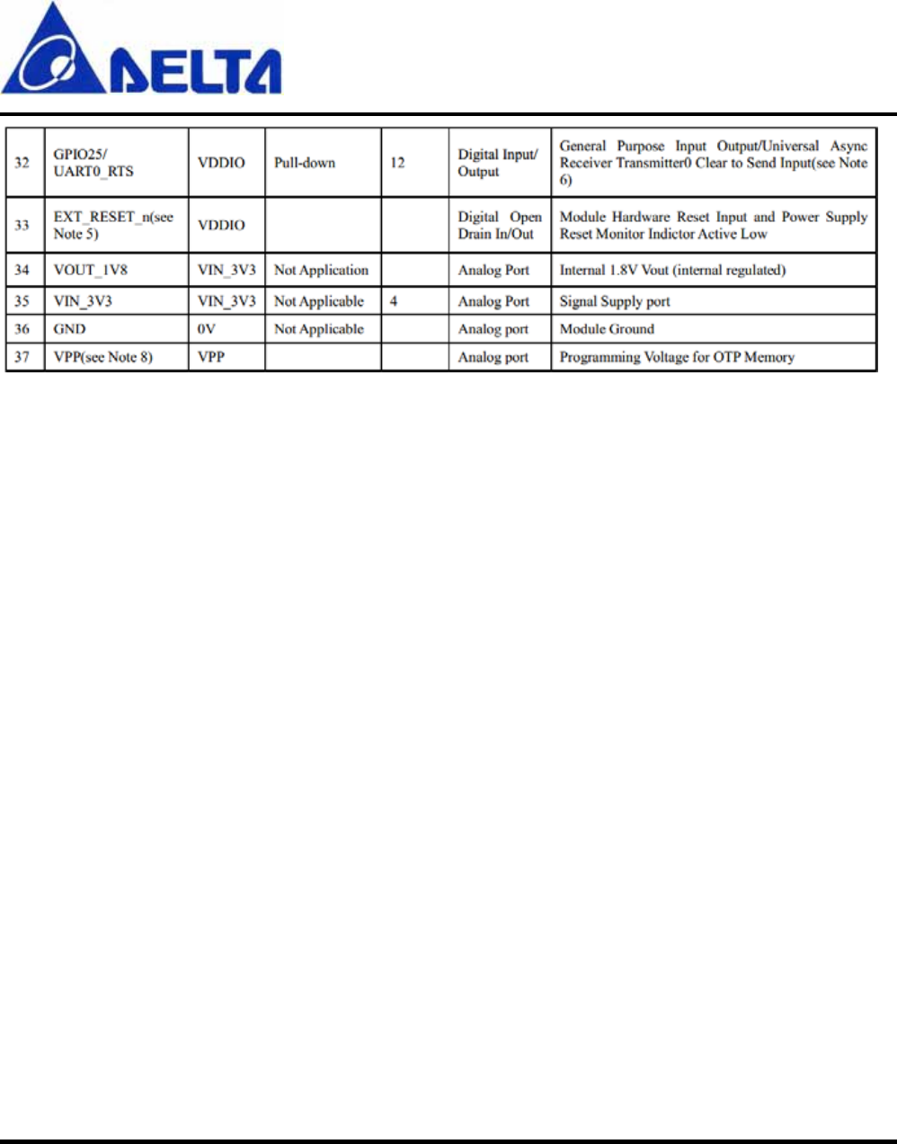
Module Pins Description
DFWM-GIN00
User Manual Sheet of 17 July. 16, 2014
Proprietary Information and Specifications are Subject to Change
10
DFWM-GIN00
User Manual Sheet of 17 July. 16, 2014
Proprietary Information and Specifications are Subject to Change
11
DFWM-GIN00
User Manual Sheet of 17 July. 16, 2014
Proprietary Information and Specifications are Subject to Change
12
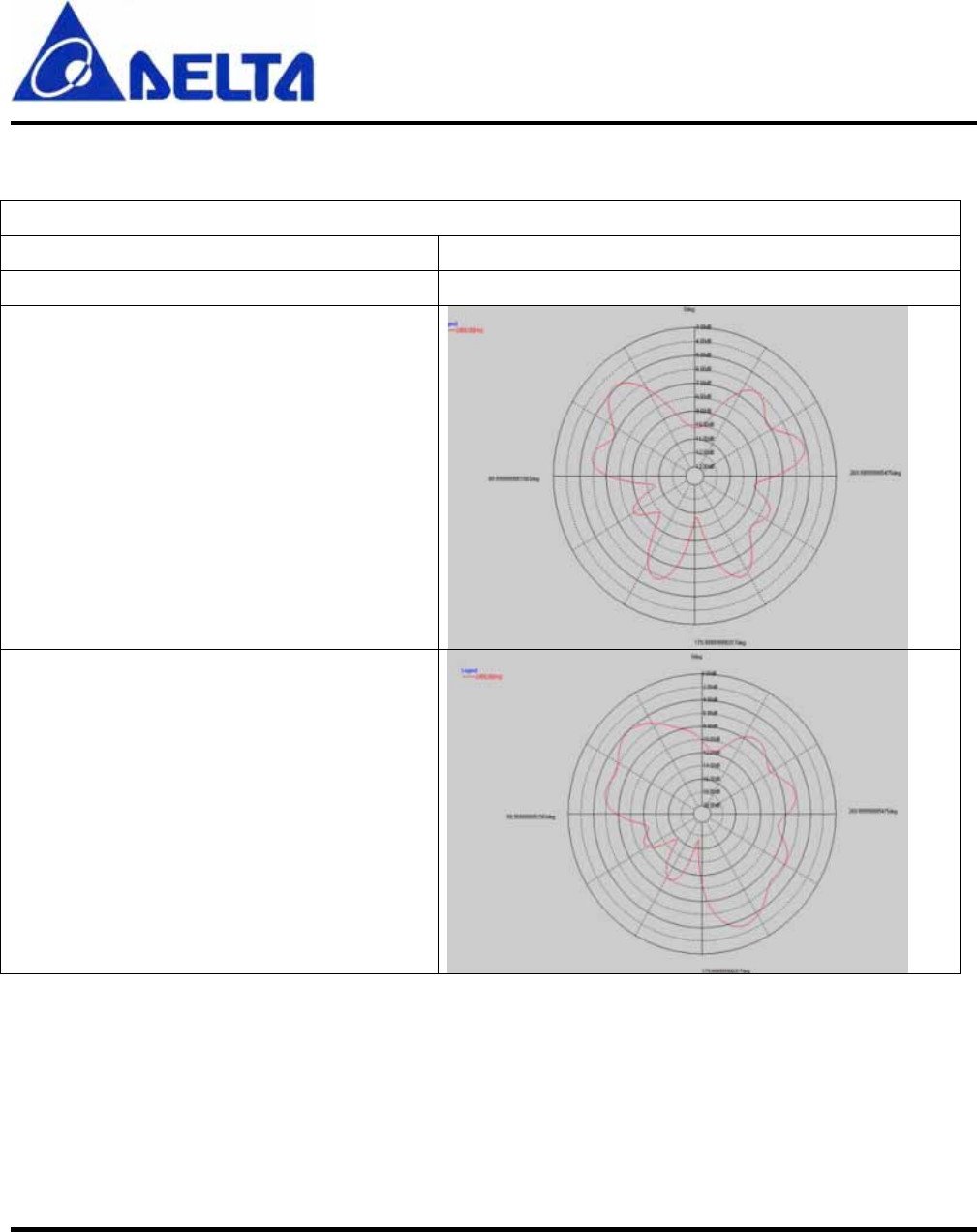
Antenna Information
PCB Antenna
Frequency range 2400 MHz – 2500 MHz
Peak gain -3.06 dBi
EIRP(2450MHz)-XY cut
EIRP(2450MHz)-XZ cut
DFWM-GIN00
User Manual Sheet of 17 July. 16, 2014
Proprietary Information and Specifications are Subject to Change
13
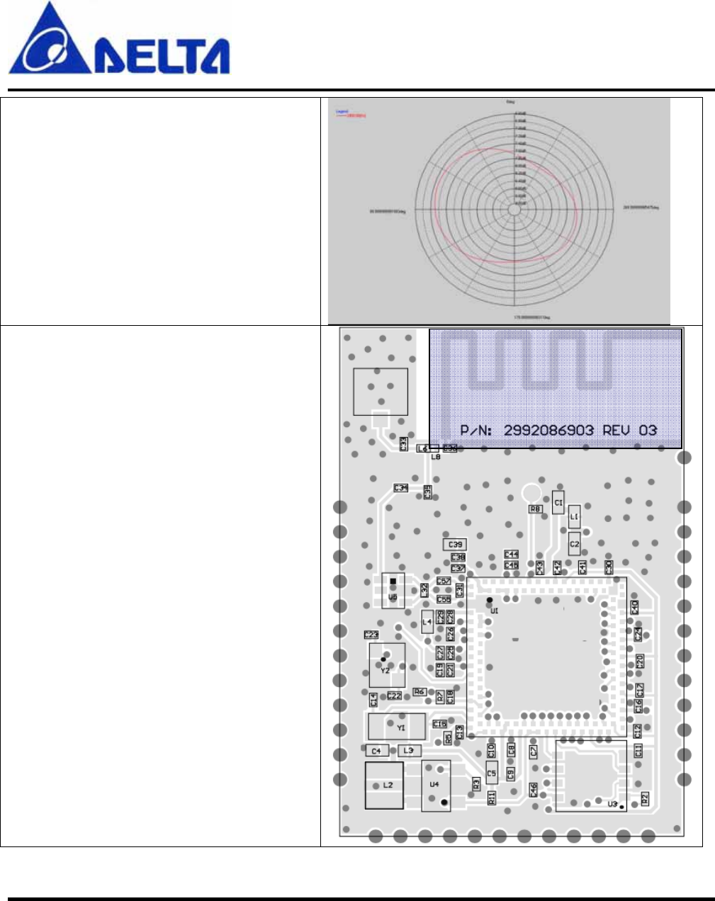
EIRP(2450MHz)-YZ cut
Antenna Location

DFWM-GIN00
User Manual Sheet of 17 July. 16, 2014
Proprietary Information and Specifications are Subject to Change
14
Canada, Industry Canada (IC) Notices
This Class B digital apparatus complies with Canadian ICES-003 and RSS-210.
Operation is subject to the following two conditions : (1) this device may not cause interference,
and (2) this device must accept any interference, including interference that may cause undesired
operation of the device.
Radio Frequency (RF) Exposure Information
The radiated output power of the Wireless Device is below the Industry Canada (IC) radio
frequency exposure limits. The Wireless Device should be used in such a
manner such that the potential for human contact during normal operation is minimized.
This device has been certified for use in Canada. Status of the listing in the
Industry Canada’s REL (Radio Equipment List) can be found at the following web address:
http://www.ic.gc.ca/app/sitt/reltel/srch/nwRdSrch.do?lang=eng
Additional Canadian information on RF exposure also can be found at the following web address:
http://www.ic.gc.ca/eic/site/smt-gst.nsf/eng/sf08792.html

DFWM-GIN00
User Manual Sheet of 17 July. 16, 2014
Proprietary Information and Specifications are Subject to Change
15
Canada, avis d'Industry Canada (IC)
Cet appareil numérique de classe B est conforme aux normes canadiennes ICES-003
et RSS-210.
Son fonctionnement est soumis aux deux conditions suivantes : (1) cet appareil ne doit pas causer
d'interférence et (2) cet appareil doit accepter toute interférence, notamment les interférences qui
peuvent affecter son fonctionnement.
Informations concernant l'exposition aux fréquences radio (RF)
La puissance de sortie émise par l’appareil de sans fil est inférieure à la limite d'exposition aux
fréquences radio d'Industry Canada (IC). Utilisez l’appareil de sans fil de façon à minimiser les
contacts humains lors du fonctionnement normal.
Ce périphérique est homologué pour l'utilisation au Canada. Pour consulter l'entrée
correspondant à l’appareil dans la liste d'équipement radio (REL - Radio Equipment List) d'Industry
Canada rendez-vous sur:
http://www.ic.gc.ca/app/sitt/reltel/srch/nwRdSrch.do?lang=eng
Pour des informations supplémentaires concernant l'exposition aux RF au Canada rendez-vous sur :
http://www.ic.gc.ca/eic/site/smt-gst.nsf/eng/sf08792.html

DFWM-GIN00
User Manual Sheet of 17 July. 16, 2014
Proprietary Information and Specifications are Subject to Change
16
Federal Communications Commission (FCC) Statement
You are cautioned that changes or modifications not expressly approved by the part responsible for
compliance could void the user’s authority to operate the equipment.
Section 15.105 (a) for Class A Device
For a Class A digital device or peripheral, the instructions furnished the user shall include the following
or similar statement, placed in a prominent location in the text of the manual:
NOTE: This equipment has been tested and found to comply with the limits for a Class A digital device,
pursuant to Part 15 of the FCC Rules. These limits are designed to provide reasonable protection against
harmful interference when the equipment is operated in a commercial environment. This equipment
generates, uses, and can radiate radio frequency energy and, if not installed and used in accordance with
the instruction manual, may cause harmful interference to radio communications. Operation of this
equipment in a residential area is likely to cause harmful interference in which case the user will be
required to correct the interference at his own expense.
15.105(b) for Class B Device (usual)
Federal Communications Commission (FCC) Statement
This equipment has been tested and found to comply with the limits for a Class B digital device,
pursuant to part 15 of the FCC rules. These limits are designed to provide reasonable protection against
harmful interference in a residential installation. This equipment generates, uses and can radiate radio
frequency energy and, if not installed and used in accordance with the instructions, may cause harmful
interference to radio communications. However, there is no guarantee that interference will not occur in
a particular installation. If this equipment does cause harmful interference to radio or television
reception, which can be determined by turning the equipment off and on, the user is encouraged to try to
correct the interference by one or more of the following measures:
-Reorient or relocate the receiving antenna.
-Increase the separation between the equipment and receiver.
-Connect the equipment into an outlet on a circuit different from that to which the receiver is connected.

DFWM-GIN00
User Manual Sheet of 17 July. 16, 2014
Proprietary Information and Specifications are Subject to Change
17
-Consult the dealer or an experienced radio/TV technician for help.
Part 15.19(a)(3) unlicensed project (WLAN Device)
This device complies with Part 15 of the FCC Rules. Operation is subject to the following two
conditions:
1) this device may not cause harmful interference, and
2) this device must accept any interference received, including interference that may cause undesired
operation of the device.
End Product Labeling:
The final end product must be labeled in a visible area with the following: “Contains FCC ID:
H79DFWM-GIN00”.
Manual Information That Must be Included:
The OEM integrator has to be aware not to provide information to the end user regarding how to install
or remove. This RF module in the user’s manual of the end product which integrates this module. The
user’s manual for OEM Integrators must include the following information in a prominent location
FCC RF Radiation Exposure Statement:
This equipment complies with FCC radiation exposure limits set forth for an uncontrolled environment.
This equipment should be installed and operated with minimum distance 20cm between the radiator &
your body. This transmitter must not be co-located or operating in conjunction with any other antenna or
transmitter.