Delta Electronics AP541N01 Dual-band Single-radio AP User Manual AP541N QSG
Delta Networks, Inc. Dual-band Single-radio AP AP541N QSG
Manual
Quick Start Guide
REVIEW DRAFT — CISCO CONFIDENTIAL
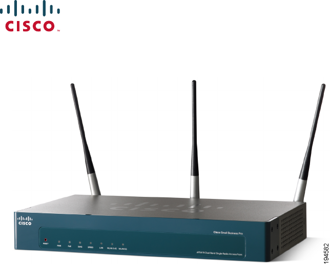
Cisco Small Business Pro
AP541N Dual-band Single-radio Access Point
Quick Start Guide
Package Contents
•AP541N Dual-band Single-radio Access Point that includes an IEEE
802.11a/b/g/n radio.
•Three Antennas (These might be black or black-and-silver. This does not
affect performance.)
•Screws and Wallboard Anchors
•Grey Cat 5e Ethernet cable
•Power supply
•This quick start guide and companion notices
•Product CD-ROM
Cisco AP541N Dual-band Single-radio Access Point Quick Start Guide 1
REVIEW DRAFT — CISCO CONFIDENTIAL
Welcome
Thank you for choosing the Cisco AP541N. The Cisco AP541N, part of the
Cisco Smart Business Communications System (SBCS), is a wireless
network communications device.
This guide is designed to familiarize you with the general layout of the
access point, how to deploy the device in your network, and access the
configuration interface. Your access point has more features or
functionality than what is described in this guide. For additional
configuration information, see the Cisco AP541N Administration Guide
available at www.cisco.com/go/TBD.

2 Cisco AP541N Dual-band Single-radio Access Point Quick Start Guide
REVIEW DRAFT — CISCO CONFIDENTIAL
Before You Begin
Decide if you are going to configure the device by using a static IP address
or the IP address assigned by a network DHCP server.
NOTE It is expected that a static IP address to be assigned to the
access point is based on the network topology and known prior
to installation.
If while displaying the configuration window the IP address is
changed, either by a DHCP server or manually, you will loose
connectivity between the PC and the access point.
Also make sure that you have the following equipment and services:
•Tools for installing the hardware
•PC with Microsoft Internet Explorer (version 6 and higher), Firefox
(version 3 or higher), or Safari (for Mac).
•TBD
•TBD
•Need Eng to provide the information for this section.
1
Cisco AP541N Dual-band Single-radio Access Point Quick Start Guide 3
REVIEW DRAFT — CISCO CONFIDENTIAL
Getting to Know the Cisco
AP541N
This section describes the exterior of the access point.
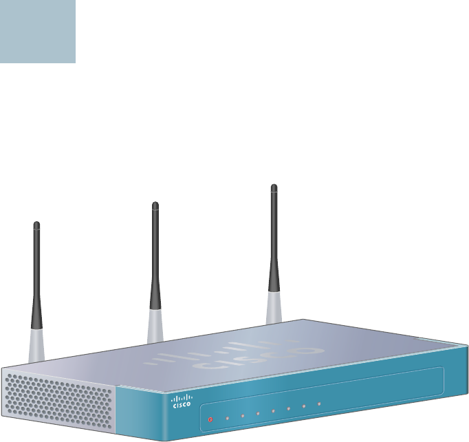
Front Panel LEDs
PWR—Lights green while the access point is powered on. Blinks during a
firmware upgrade.
PoE—Lights green when Power-over-Ethernet (PoE) is powering the
access point.
Diag—Lights red during the power-on-self-test (POST) or the system is
otherwise not ready.
Speed—The LAN LED light is off when the LAN port data speed is zero or
10 Mbps. Lights amber to indicate the LAN port data speed is 100 Mbps.
Lights green to indicate the LAN port data speed is 1000 Mbps.
LAN—Lights solid green when a link is established. Blinks green when the
port is passing traffic.
WLAN 2.4G—Lights solid green when a 2.4 GHz wireless network link is
established. Blinks green when the link is passing traffic. The light is off
when the 2.4 GHz radio is off.
2
PWR PoE DIAG SPEED LAN WLAN 2.4G WLAN 5G
RESET
Cisco Small Business Pro
AP54 1N Dual Band Single Radio Access Point
235174
4 Cisco AP541N Dual-band Single-radio Access Point Quick Start Guide
REVIEW DRAFT — CISCO CONFIDENTIAL
WLAN 5.0G—Lights solid green when a 5.0 GHz wireless network link is
established. Blinks green when the link is passing traffic. The light is off
when the 5.0 GHz radio is off.
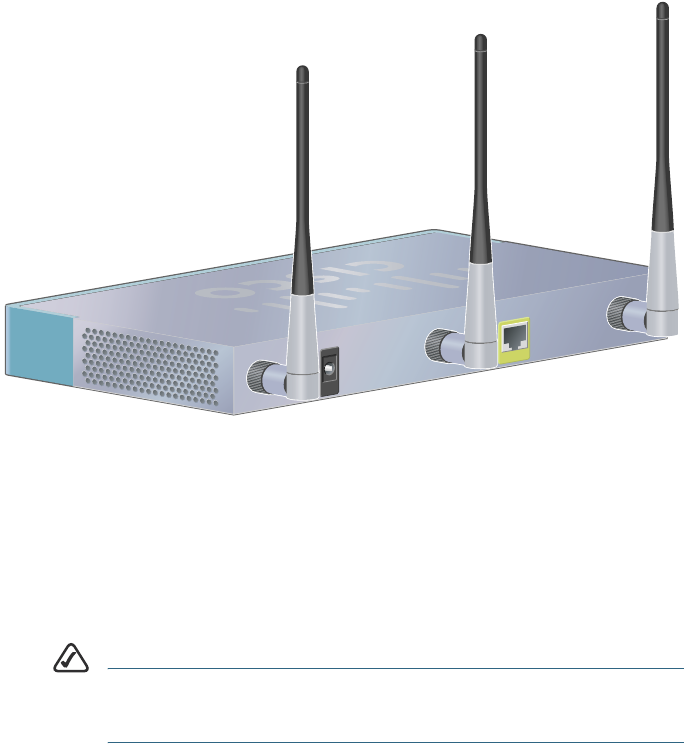
Back Panel Ports
Ethernet Port—The access point is equipped with an auto-sensing, Gigabit
Ethernet (802.3) port used for configuration and wired network
communications. Auto-sensing technology enables the port to
automatically detect the speed and duplex settings of the device
connected to it, and adjust its speed and duplex settings to match the
settings of the connected device. The Gigabit Ethernet port accepts an
RJ-45 connector and supports Power-over-Ethernet (PoE).
NOTE We recommend using Cat5e or better cable. Also, do not
exceed the maximum cabling distance of 328 feet (100
meters) per segment.
ANT01, ANT02, and ANT03—BNC connectors that accept the antennas
provided with the access point.
235175
Ethernet
Power
Cisco AP541N Dual-band Single-radio Access Point Quick Start Guide 5
REVIEW DRAFT — CISCO CONFIDENTIAL
Installing the Cisco AP541N
The access point can be placed on a wall, a flat surface, a ceiling, or in a
ceiling plenum space. A ceiling mount kit is available for this device
(SKU#). Do not deploy the device in a location where any of the following
conditions exist:
High Ambient Temperature—The ambient temperature must not
exceed 104 degrees Fahrenheit (40C).
Reduced Air Flow—The air flow must be adequate to prevent
overheating.
Mechanical Overloading—The device should be level, stable, and
secure to avoid it sliding or shifting out of position.
Circuit Overloading—Adding the device to the power outlet or a PoE
port must not overload that circuit or PoE device.
NOTE We recommend using Cat5e or better cable. Also, do not
exceed the maximum cabling distance of 328 feet (100
meters).
To place the access point on a desktop, install the four rubber feet
(included) on the bottom of the access point. Place the device on a flat
surface.
To prepare the device, do the following:
STEP 1Attach the antennas to the RP-TNC connectors labeled ANT101,
ANT102, and ANT103. The antennas are all the same, so which
antenna is attached to what connector is of no consequence.
STEP 2Determine where you want to locate the access point. If you are
using AC power, make sure the location is within reach of an AC
power outlet.
STEP 3Keep enough ventilation space for the access point and check for
any environmental restrictions.
3
6 Cisco AP541N Dual-band Single-radio Access Point Quick Start Guide
REVIEW DRAFT — CISCO CONFIDENTIAL
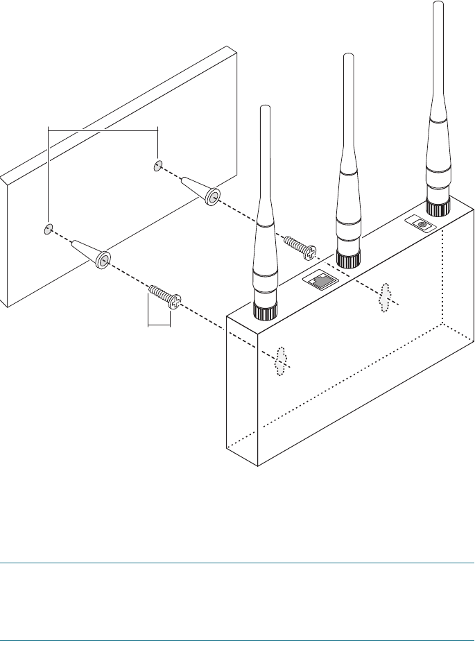
Wall Mounting
Before you begin, you need 2 wallboard screws (included) to mount the
access point. We recommend using screws with a minimum of 4mm width
at the head and a shaft diameter of at least 1.5mm.
WARNING Cisco is not responsible for damages incurred by insecure wall-
mounting.
To mount the access point to the wall:
STEP 1Determine where you want to mount the access point. Verify that
the surface is smooth, flat, dry, and sturdy.
STEP 2Drill two pilot holes into the surface 5.75 inches (146 mm) apart,
and with a minimum of 4.0 inches (101 mm) of clearance.
STEP 3Insert a screw into each hole, leaving a gap between the surface
and the base of the screw head of at least 0.1 inches (3 mm).
STEP 4Place the access point wall-mount slots over the screws and slide
the access point down until the screws fit snugly into the wall-
mount slots.
Cisco AP541N Dual-band Single-radio Access Point Quick Start Guide 7
REVIEW DRAFT — CISCO CONFIDENTIAL
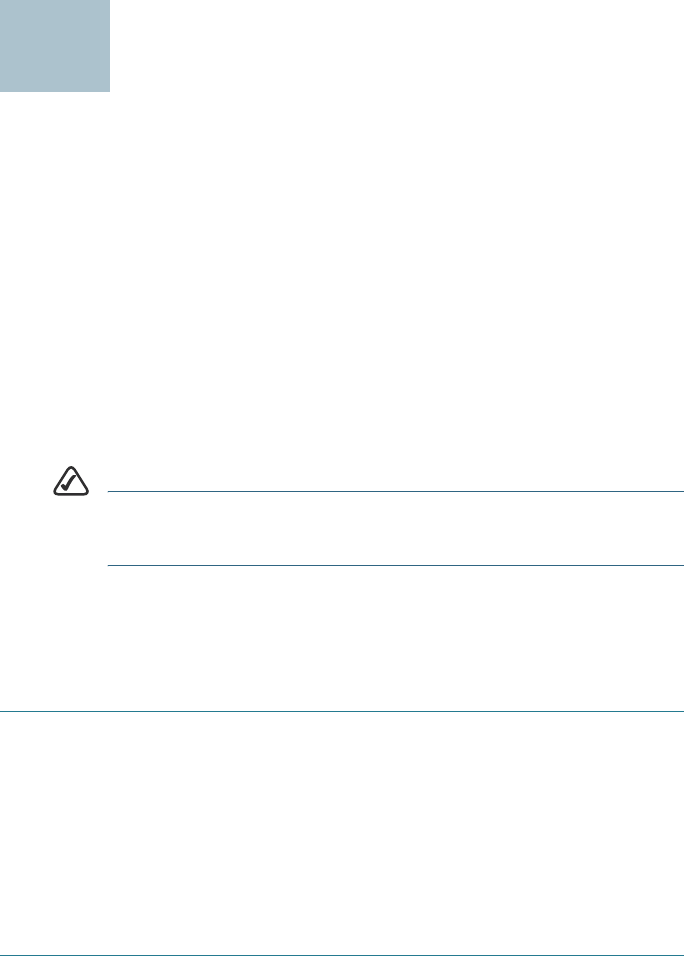
Flat Surface Installation
To prepare the device for placement the device on a flat surface, do the
following:
STEP 1Install the four rubber feet (included) on the bottom of the device.
STEP 2Place the access point on a desktop near an AC power source,
unless you are using PoE.
235432
15 cm15 cm15 cm
17 mm
Ethernet
Power

8 Cisco AP541N Dual-band Single-radio Access Point Quick Start Guide
REVIEW DRAFT — CISCO CONFIDENTIAL
Connecting the Equipment
This section describes the process for connecting the device to power
and the network.
STEP 1Attach the power cord to the power connector and outlet (if used).
STEP 2Connect a network Ethernet cable to the access point Ethernet
port.
STEP 3Connect the other end of the Ethernet cable to your network or the
Ethernet port of the PC you are using to configure the access point.
WARNING DHCP is enabled by default. If a DHCP server is running on your
network and you have not turned DHCP off, the device will
accept a new IP address when it is connected to your network.
You must use this IP address to configure the device.
Verifying the Hardware
Installation
To verify the hardware installation, complete the following tasks:
• Check the cable connections.
•Check the LED states, as described in Getting to Know the Cisco
AP541N, page 3.
NOTE If you need help resolving a problem, visit the Cisco Small
Business Support Community at www.cisco.com/go/
smallbizsupport. For technical documentation and other links, see
Where to Go From Here, page 14.
4
5
Cisco AP541N Dual-band Single-radio Access Point Quick Start Guide 9
REVIEW DRAFT — CISCO CONFIDENTIAL
Getting Started with the
Configuration
This section contains information for starting the configuration utility to
provision the access point features. It also describes enabling the radio
that is turned off by default.
You can display the configuration utility by entering the access point IP
address in the URL field of a Web browser. The access point IP address is
the:
•factory default access point static IP address, if it has not been
changed in a previous configuration or replaced by an IP address
assigned by a DHCP server running on the network.
•dynamically assigned IP address allocated to the access point by a
DHCP server.
TIP If you deploy the Cisco AP541N in a Cisco Small Business
Pro network that is running DHCP, you can use
Cisco Configuration Assistant 2.0 or higher to discover the
Cisco AP541N IP address.
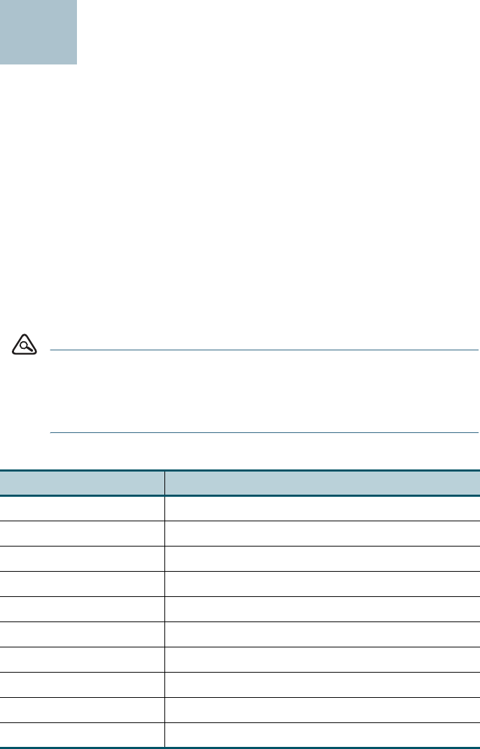
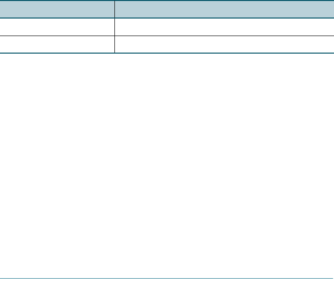
The factory defaults are:
Parameter Default Value
username cisco
password cisco
IP connection type DHCP
default IP 192.168.10.10
subnetmask 255.255.255.0
default gateway 192.168.10.1
data VLAN 1
voice VLAN 100
radio Off
data SSID cisco–data (VLAN 1)
6
10 Cisco AP541N Dual-band Single-radio Access Point Quick Start Guide
REVIEW DRAFT — CISCO CONFIDENTIAL
Display the Configuration GUI and Enable the
Radio
For security reasons, the radio is off by default. This procedure describes
how to access the GUI and enable the radio.
Before you begin:
• Verify that you have a power source for theCisco AP541N. If you will be
deploying the Cisco AP541N by using PoE, it might be necessary to
temporarily power the device by using the provided power supply or
by connecting it to a hub or switch that provides PoE.
•The Cisco AP541N IP address is required. If the IP address is unknown,
you can reset the device to use the static default Cisco AP541N IP
address by using the “Returning the Cisco AP541N to the Factory
Default Settings” procedure.
To configure the access point by using a PC directly connected to the
Cisco AP541N or connected through a hub or switch:
STEP 1Power on the PC and configure the PC IP address to an IP address
in the same subnetwork. The default Cisco AP541N IP address is
192.168.10.10. For example, you can set the:
PC IP address to 192.168.10.250
PC IP subnet mask to 255.255.255.0
PC Default Gateway to 192.168.10.10.
STEP 2Connect an Ethernet cable to an Ethernet port on the PC.
STEP 3Connect the other end of the PC Ethernet cable to an Ethernet port
on a switch, hub, or the Cisco AP541N Ethernet port. If you
connected the PC through a switch or a hub, connect the Cisco
AP541N to that device by using another Ethernet cable.
STEP 4Power on the access point.
STEP 5Open a Web browser window. If you are prompted to install an
Active-X plug-in when connecting to the device, follow the
prompts to accept the plug-in.
voice SSID cisco-voice (VLAN 100)
wireless security None
Parameter Default Value

Cisco AP541N Dual-band Single-radio Access Point Quick Start Guide 11
REVIEW DRAFT — CISCO CONFIDENTIAL
STEP 6Enter the Cisco AP541N IP address in the address bar and press
Enter. For example, enter http://192.168.10.10. The login window
displays.
STEP 7Enter the default username cisco and the default password cisco.
(Passwords are case sensitive.) The configuration window displays.
NOTE We recommend that you change the username and password.
STEP 8Click Wireless > Basic Settings.
STEP 9Click the Radio Interface On radio button.
STEP 10 Click Update. A warning displays, indicating that you might loose
connectivity. Because you are configuring the access point by
using a wired connection, this will not occur unless enabling the
radio establishes a network connection and the IP address is
changed by the DHCP server.
STEP 11 Click OK to continue.
The the configuration is updated and WLAN LED lights green. You
can configure additional parameters or close the window.
Troubleshoot Your Connection
If you cannot display the configuration utility, you can test the ability of the
PC to communicate with the access point by using ping. To use ping on a
PC running Windows:
STEP 1Verify that the Cisco AP541N is powered on and the LEDs indicate
the appropriate links.
STEP 2Open a command window by using Start > Run and enter cmd.
STEP 3At the Command window prompt enter ping and the access
point IP address. For example ping
192.168.10.10
.
If successful, you should get a reply similar to the following:
Pinging 192.168.10.10 with 32 bytes of data:
Reply from 192.168.10.10: bytes=32 time<1ms TTL=128
If it fails, you should get a reply similar to the following:

12 Cisco AP541N Dual-band Single-radio Access Point Quick Start Guide
REVIEW DRAFT — CISCO CONFIDENTIAL
Pinging 192.168.10.10 with 32 bytes of data:
Request timed out.
Possible Cause of Failure
The most likely cause of connectivity failure is an incorrect IP address.
DHCP is enabled on the Cisco AP541N by default. When a DHCP server is
enabled on your network and the access point is connected to the
network, the DHCP server replaces the default static IP address with a
DHCP server–assigned IP address.
You might lose connectivity between the PC and the access point,
because the Web browser is pointed to the wrong IP address.
Or, your PC is configured with a static IP address that is not in the same
subnet as the access point.
If the access point is not in a Cisco Small Business Pro network, you can
query the DHCP server for the new IP address or disconnect the access
point from the network and reset the device to use the static default
access point IP address by using the “Returning the Cisco AP541N to
the Factory Default Settings” procedure.
If the access point is connected to a Cisco Small Business Pro network,
the IP address can be discovered by using Cisco Configuration Assistant
2.0 or higher. Use the procedure in the Cisco Configuration Assistant 2.1
Smart Business Communications System Administrator Guide, available at
http://www.cisco.com/en/US/docs/net_mgmt/
cisco_configuration_assistant/version2_1/feature/guide/
cca_feature_guide.pdf.

Cisco AP541N Dual-band Single-radio Access Point Quick Start Guide 13
REVIEW DRAFT — CISCO CONFIDENTIAL
Returning the Cisco AP541N
to the Factory Default
Settings
To use the Reset button to reboot or reset the access point, do the
following:
•To reboot the access point, press the Reset button for less than 10
seconds.
•To restore the access point to the factory default settings:
1. Disconnect the access point from the network or disable all DHCP
servers on your network.
2. With the power on, press-and-hold the Reset button for more than
10 seconds.
7

14 Cisco AP541N Dual-band Single-radio Access Point Quick Start Guide
REVIEW DRAFT — CISCO CONFIDENTIAL
Where to Go From Here
Support
Cisco Small Business Support
Community
www.cisco.com/go/smallbizsupport
Online Technical Support and
Documentation (Login Required)
www.cisco.com/support
Phone Support Contacts www.cisco.com/en/US/support/tsd_cisco_
small_business_support_center_contacts.html
Software Downloads
(Login Required)
Go to tools.cisco.com/support/downloads,
and enter the model number in the Software
Search box.
Product Documentation
Cisco AP541N Access Point www.cisco.com/en/US/docs/wireless/
access_point/csbap/AP541N/quick_start/
guide/AP541N_QSG.pdf
Cisco Small Business
Cisco Partner Central for Small
Business (Partner Login
Required)
www.cisco.com/web/partners/sell/smb
Cisco Small Business Home www.cisco.com/smb
Marketplace www.cisco.com/go/marketplace
8

Americas Headquarters
Cisco Systems, Inc.
170 West Tasman Drive
San Jose, CA 95134-1706
USA
http://www.cisco.com
Tel: 408 526-4000
800 553-NETS (6387)
Fax: 408 527-0883
Cisco, Cisco Systems, the Cisco logo, and the Cisco Systems logo are registered trademarks
or trademarks of Cisco Systems, Inc. and/or its affiliates in the United States and certain other
countries. All other trademarks mentioned in this document or Website are the property of
their respective owners. The use of the word partner does not imply a partnership relationship
between Cisco and any other company. (0705R)
© 2009 Cisco Systems, Inc. All rights reserved.
Printed in the USA on recycled paper containing 10% postconsumer waste.
78-19028-01
REVIEW DRAFT — CISCO CONFIDENTIAL
Federal Communication Commission Interference
Statement
This equipment has been tested and found to comply with the limits for a
Class B digital device, pursuant to Part 15 of the FCC Rules. These
limits are designed to provide reasonable protection against harmful
interference when the equipment is operated in a commercial
environment. This equipment generates, uses and can radiate radio
frequency energy and, if not installed and used in accordance with the
instructions, may cause harmful interference to radio communications.
Operation of this equipment in a residential area is likely to cause
harmful interference in which case the user will be required to correct the
interference at his own expense.
If this equipment does cause harmful interference to radio or television
reception, which can be determined by turning the equipment off and on,
the user is encouraged to try to correct the interference by one of the
following measures:
- Reorient or relocate the receiving antenna.
- Increase the separation between the equipment and receiver.
- Connect the equipment into an outlet on a circuit different from that
to which the receiver is connected.
- Consult the dealer or an experienced radio/TV technician for help.
FCC Caution: Any changes or modifications not expressly approved by
the party responsible for compliance could void the user's authority to
operate this equipment.
For operation within 5.15 ~ 5.25GHz frequency range, it is restricted to
indoor environment.
This device complies with Part 15 of the FCC Rules. Operation is subject
to the following two conditions: (1) This device may not cause harmful
interference, and (2) this device must accept any interference received,
including interference that may cause undesired operation.
IMPORTANT NOTE:
Radiation Exposure Statement:
This equipment complies with FCC radiation exposure limits set forth for
an uncontrolled environment. This equipment should be installed and
operated with minimum distance 20cm between the radiator & your body.
This transmitter must not be co-located or operating in conjunction with
any other antenna or transmitter.
The availability of some specific channels and/or operational frequency
bands are country dependent and are firmware programmed at the
factory to match the intended destination. The firmware setting is not
accessible by the end user.
Industry Canada statement
This device complies with RSS-210 of the Industry Canada Rules.
Operation is subject to the following two conditions: (1) This device may
not cause harmful interference, and (2) this device must accept any
interference received, including interference that may cause undesired
operation.
IMPORTANT NOTE:
Radiation Exposure Statement:
This equipment complies with IC radiation exposure limits set forth for an
uncontrolled environment. This equipment should be installed and
operated with minimum distance 20cm between the radiator & your body.
Caution:
The device for the band 5150-5250 MHz is only for indoor usage to
reduce potential for harmful interference to co-channel mobile satellite
systems.
High power radars are allocated as primary users (meaning they have
priority) of 5250-5350 MHz and 5650-5850 MHz and these radars could
cause interference and/or damage to LE-LAN devices.
This device has been designed to operate with an antenna having a
maximum gain of 2 dB. Antenna having a higher gain is strictly prohibited
per regulations of Industry Canada. The required antenna impedance is
50 ohms.