Delta Electronics Ac Motor Drive Vfd E Users Manual Preface
Delta-Ac-Motor-Drive-Vfd-E-Users-Manual-244784 delta-ac-motor-drive-vfd-e-users-manual-244784
VFD-E to the manual 167b3a34-ea52-4ee4-8ed9-4aff2c1f2516
2015-01-24
: Delta-Electronics Delta-Electronics-Ac-Motor-Drive-Vfd-E-Users-Manual-338891 delta-electronics-ac-motor-drive-vfd-e-users-manual-338891 delta-electronics pdf
Open the PDF directly: View PDF ![]() .
.
Page Count: 363 [warning: Documents this large are best viewed by clicking the View PDF Link!]
- Preface
- Table of Contents
- Chapter 1 Introduction
- 1.1 Receiving and Inspection
- 1.2 Preparation for Installation and Wiring
- 1.3 Dimensions
- Chapter 2 Installation and Wiring
- Chapter 3 Keypad and Start Up
- Chapter 4 Parameters
- Chapter 5 Troubleshooting
- 5.1 Over Current (OC)
- 5.2 Ground Fault
- 5.3 Over Voltage (OV)
- 5.4 Low Voltage (Lv)
- 5.5 Over Heat (OH)
- 5.6 Overload
- 5.7 Keypad Display is Abnormal
- 5.8 Phase Loss (PHL)
- 5.9 Motor cannot Run
- 5.10 Motor Speed cannot be Changed
- 5.11 Motor Stalls during Acceleration
- 5.12 The Motor does not Run as Expected
- 5.13 Electromagnetic/Induction Noise
- 5.14 Environmental Condition
- 5.15 Affecting Other Machines
- Chapter 6 Fault Code Information and Maintenance
- Appendix A Specifications
- Appendix B Accessories
- B.1 All Brake Resistors & Brake Units Used in AC Motor Drives
- B.2 No-fuse Circuit Breaker Chart
- B.3 Fuse Specification Chart
- B.4 AC Reactor
- B.5 Zero Phase Reactor (RF220X00A)
- B.6 Remote Controller RC-01
- B.7 PU06
- B.8 KPE-LE02
- B.9 Extension Card
- B.10 Fieldbus Modules
- B.11 DIN Rail
- Appendix C How to Select the Right AC Motor Drive
- Appendix D How to Use PLC Function
- D.1 PLC Overview
- D.2 Start-up
- D.3 Ladder Diagram
- D.4 PLC Devices
- D.4.1 Summary of DVP-PLC Device Number
- D.4.2 Devices Functions
- D.4.3 Value, Constant [K] / [H]
- D.4.4 The Function of Auxiliary Relay
- D.4.5 The Function of Timer
- D.4.6 The Features and Functions of Counter
- D.4.7 Register Types
- D.4.8 Special Auxiliary Relays
- D.4.9 Special Registers
- D.4.10 Communication Addresses for Devices (only for PLC2 mode)
- D.4.11 Function Code (only for PLC2 mode)
- D.5 Commands
- D.5.1 Basic Commands
- D.5.2 Output Commands
- D.5.3 Timer and Counters
- D.5.4 Main Control Commands
- D.5.5 Rising-edge/falling-edge Detection Commands of Contact
- D.5.6 Rising-edge/falling-edge Output Commands
- D.5.7 End Command
- D.5.8 Explanation for the Commands
- D.5.9 Description of the Application Commands
- D.5.10 Explanation for the Application Commands
- D.5.11 Special Application Commands for the AC Motor Drive
- D.6 Error Code
- Appendix E CANopen Function


Preface
Thank you for choosing DELTA’s high-performance VFD-E Series. The VFD-E Series is
manufactured with high-quality components and materials and incorporate the latest microprocessor
technology available.
This manual is to be used for the installation, parameter setting, troubleshooting, and daily
maintenance of the AC motor drive. To guarantee safe operation of the equipment, read the following
safety guidelines before connecting power to the AC motor drive. Keep this operating manual at
hand and distribute to all users for reference.
To ensure the safety of operators and equipment, only qualified personnel familiar with AC motor
drive are to do installation, start-up and maintenance. Always read this manual thoroughly before
using VFD-E series AC Motor Drive, especially the WARNING, DANGER and CAUTION notes.
Failure to comply may result in personal injury and equipment damage. If you have any questions,
please contact your dealer.
PLEASE READ PRIOR TO INSTALLATION FOR SAFETY.
DANGER!
1. AC input power must be disconnected before any wiring to the AC motor drive is made.
2. A charge may still remain in the DC-link capacitors with hazardous voltages, even if the power
has been turned off. To prevent personal injury, please ensure that power has turned off before
opening the AC motor drive and wait ten minutes for the capacitors to discharge to safe voltage
levels.
3. Never reassemble internal components or wiring.
4. The AC motor drive may be destroyed beyond repair if incorrect cables are connected to the
input/output terminals. Never connect the AC motor drive output terminals U/T1, V/T2, and
W/T3 directly to the AC mains circuit power supply.
5. Ground the VFD-E using the ground terminal. The grounding method must comply with the laws
of the country where the AC motor drive is to be installed. Refer to the Basic Wiring Diagram.
6. VFD-E series is used only to control variable speed of 3-phase induction motors, NOT for 1-
phase motors or other purpose.
7. VFD-E series shall NOT be used for life support equipment or any life safety situation.

WARNING!
1. DO NOT use Hi-pot test for internal components. The semi-conductor used in AC motor drive
easily damage by high-voltage.
2. There are highly sensitive MOS components on the printed circuit boards. These components
are especially sensitive to static electricity. To prevent damage to these components, do not
touch these components or the circuit boards with metal objects or your bare hands.
3. Only qualified persons are allowed to install, wire and maintain AC motor drives.
CAUTION!
1. Some parameters settings can cause the motor to run immediately after applying power.
2. DO NOT install the AC motor drive in a place subjected to high temperature, direct sunlight,
high humidity, excessive vibration, corrosive gases or liquids, or airborne dust or metallic
particles.
3. Only use AC motor drives within specification. Failure to comply may result in fire, explosion or
electric shock.
4. To prevent personal injury, please keep children and unqualified people away from the
equipment.
5. When the motor cable between AC motor drive and motor is too long, the layer insulation of the
motor may be damaged. Please use a frequency inverter duty motor or add an AC output
reactor to prevent damage to the motor. Refer to appendix B Reactor for details.
6. The rated voltage for AC motor drive must be ≤ 240V (≤ 480V for 460V models) and the short
circuit must be ≤ 5000A RMS (≤10000A RMS for the ≥ 40hp (30kW) models).
DeviceNet is a registered trademark of the Open DeviceNet Vendor Association, Inc. Lonwork is a
registered trademark of Echelon Corporation. Profibus is a registered trademark of Profibus
International. CANopen is a registered trademark of CAN in Automation (CiA). Other trademarks
belong to their respective owners.

Table of Contents
Preface ............................................................................................................. i
Table of Contents .......................................................................................... iii
Chapter 1 Introduction................................................................................ 1-1
1.1 Receiving and Inspection ................................................................... 1-2
1.1.1 Nameplate Information................................................................ 1-2
1.1.2 Model Explanation ...................................................................... 1-2
1.1.3 Series Number Explanation ........................................................ 1-3
1.1.4 Drive Frames and Appearances ................................................. 1-3
1.1.5 Remove Instructions ................................................................... 1-6
1.2 Preparation for Installation and Wiring ............................................... 1-8
1.2.1 Ambient Conditions..................................................................... 1-8
1.2.2 DC-bus Sharing: Connecting the DC-bus of the AC Motor Drives in
Parallel............................................................................................... 1-11
1.3 Dimensions....................................................................................... 1-12
Chapter 2 Installation and Wiring ..............................................................2-1
2.1 Wiring ................................................................................................. 2-2
2.2 External Wiring ................................................................................. 2-12
2.3 Main Circuit ...................................................................................... 2-13
2.3.1 Main Circuit Connection............................................................ 2-13
2.3.2 Main Circuit Terminals .............................................................. 2-16
2.4 Control Terminals ............................................................................. 2-17
Chapter 3 Keypad and Start Up ..................................................................3-1
3.1 Keypad ...............................................................................................3-1
3.2 Operation Method ...............................................................................3-2
3.3 Trial Run .............................................................................................3-3
Chapter 4 Parameters..................................................................................4-1
4.1 Summary of Parameter Settings.........................................................4-2
4.2 Parameter Settings for Applications..................................................4-32
4.3 Description of Parameter Settings ....................................................4-37
4.4 Different Parameters for VFD*E*C Models .....................................4-152
Chapter 5 Troubleshooting .........................................................................5-1
5.1 Over Current (OC) ..............................................................................5-1
5.2 Ground Fault.......................................................................................5-2
5.3 Over Voltage (OV) ..............................................................................5-2
5.4 Low Voltage (Lv).................................................................................5-3
5.5 Over Heat (OH)...................................................................................5-4
5.6 Overload .............................................................................................5-4
5.7 Keypad Display is Abnormal...............................................................5-5
5.8 Phase Loss (PHL)...............................................................................5-5
5.9 Motor cannot Run ...............................................................................5-6
5.10 Motor Speed cannot be Changed .....................................................5-7
5.11 Motor Stalls during Acceleration .......................................................5-8
5.12 The Motor does not Run as Expected ..............................................5-8
5.13 Electromagnetic/Induction Noise ......................................................5-9
5.14 Environmental Condition...................................................................5-9
5.15 Affecting Other Machines................................................................5-10
Chapter 6 Fault Code Information and Maintenance................................ 6-1
6.1 Fault Code Information....................................................................... 6-1
6.1.1 Common Problems and Solutions............................................... 6-1
6.1.2 Reset .......................................................................................... 6-6
6.2 Maintenance and Inspections............................................................. 6-6
Appendix A Specifications ........................................................................ A-1
Appendix B Accessories ........................................................................... B-1
B.1 All Brake Resistors & Brake Units Used in AC Motor Drives..............B-1
B.1.1 Dimensions and Weights for Brake Resistors ............................ B-4
B.2 No-fuse Circuit Breaker Chart ............................................................B-8
B.3 Fuse Specification Chart ....................................................................B-9
B.4 AC Reactor ......................................................................................B-10
B.4.1 AC Input Reactor Recommended Value...................................B-10
B.4.2 AC Output Reactor Recommended Value................................ B-11
B.4.3 Applications ..............................................................................B-12
B.5 Zero Phase Reactor (RF220X00A) ..................................................B-14
B.6 Remote Controller RC-01.................................................................B-15
B.7 PU06................................................................................................B-16
B.7.1 Description of the Digital Keypad VFD-PU06 ........................... B-16
B.7.2 Explanation of Display Message...............................................B-16
B.7.3 Operation Flow Chart ............................................................... B-17
B.8 KPE-LE02 ........................................................................................B-18
B.8.1 Description of the Digital Keypad KPE-LE02............................ B-18
B.8.2 How to Operate the Digital Keypad .......................................... B-20
B.8.3 Reference Table for the 7-segment LED Display of the Digital
Keypad ...............................................................................................B-21
B.9 Extension Card................................................................................ B-22
B.9.1 Relay Card................................................................................B-22
B.9.2 Digital I/O Card .........................................................................B-23
B.9.3 Analog I/O Card ........................................................................B-23
B.9.4 Communication Card ................................................................B-23
B.9.5 Speed Feedback Card ..............................................................B-24
B.10 Fieldbus Modules .......................................................................... B-24
B.10.1 DeviceNet Communication Module (CME-DN01) ...................B-24
B.10.1.1 Panel Appearance and Dimensions ................................B-24
B.10.1.2 Wiring and Settings .........................................................B-25
B.10.1.3 Mounting Method ............................................................B-25
B.10.1.4 Power Supply ..................................................................B-26
B.10.1.5 LEDs Display...................................................................B-26
B.10.2 LonWorks Communication Module (CME-LW01) ...................B-26
B.10.2.1 Introduction .....................................................................B-27
B.10.2.2 Dimensions .....................................................................B-27
B.10.2.3 Specifications ..................................................................B-27
B.10.2.4 Wiring ..............................................................................B-28
B.10.2.5 LED Indications ...............................................................B-28
B.10.3 Profibus Communication Module (CME-PD01).......................B-28
B.10.3.1 Panel Appearance...........................................................B-29
B.10.3.2 Dimensions .....................................................................B-30
B.10.3.3 Parameters Settings in VFD-E ........................................B-30
B.10.3.4 Power Supply..................................................................B-30
B.10.3.5 PROFIBUS Address .......................................................B-30
B.10.4 CME-COP01 (CANopen)........................................................B-31
B.10.4.1 Product Profile ................................................................ B-31
B.10.4.2 Specifications..................................................................B-31
B.10.4.3 Components ...................................................................B-32
B.10.4.4 LED Indicator Explanation & Troubleshooting ................ B-33
B.11 DIN Rail..........................................................................................B-35
B.11.1 MKE-DRA............................................................................... B-35
B.11.2 MKE-DRB............................................................................... B-36
B.11.3 MKE-EP..................................................................................B-36
Appendix C How to Select the Right AC Motor Drive.............................. C-1
C.1 Capacity Formulas.............................................................................C-2
C.2 General Precaution............................................................................C-4
C.3 How to Choose a Suitable Motor .......................................................C-5
Appendix D How to Use PLC Function..................................................... D-1
D.1 PLC Overview....................................................................................D-1
D.1.1 Introduction ................................................................................D-1
D.1.2 Ladder Diagram Editor – WPLSoft .............................................D-1
D.2 Start-up ..............................................................................................D-2
D.2.1 The Steps for PLC Execution .....................................................D-2
D.2.2 Device Reference Table.............................................................D-3
D.2.3 WPLSoft Installation ...................................................................D-4
D.2.4 Program Input.............................................................................D-5
D.2.5 Program Download .................................................................... D-5
D.2.6 Program Monitor ........................................................................ D-6
D.2.7 The Limit of PLC ........................................................................ D-6
D.3 Ladder Diagram ................................................................................ D-8
D.3.1 Program Scan Chart of the PLC Ladder Diagram...................... D-8
D.3.2 Introduction................................................................................ D-8
D.3.3 The Edition of PLC Ladder Diagram ........................................ D-11
D.3.4 The Example for Designing Basic Program ............................. D-14
D.4 PLC Devices ................................................................................... D-19
D.4.1 Summary of DVP-PLC Device Number ................................... D-19
D.4.2 Devices Functions ................................................................... D-20
D.4.3 Value, Constant [K] / [H] .......................................................... D-21
D.4.4 The Function of Auxiliary Relay ............................................... D-22
D.4.5 The Function of Timer.............................................................. D-22
D.4.6 The Features and Functions of Counter .................................. D-23
D.4.7 Register Types......................................................................... D-24
D.4.8 Special Auxiliary Relays .......................................................... D-25
D.4.9 Special Registers..................................................................... D-26
D.4.10 Communication Addresses for Devices (only for PLC2 mode) .. D-
27
D.4.11 Function Code (only for PLC2 mode) .................................... D-28
D.5 Commands...................................................................................... D-28
D.5.1 Basic Commands..................................................................... D-28
D.5.2 Output Commands................................................................... D-29
D.5.3 Timer and Counters ................................................................. D-29
D.5.4 Main Control Commands..........................................................D-29
D.5.5 Rising-edge/falling-edge Detection Commands of Contact ......D-29
D.5.6 Rising-edge/falling-edge Output Commands............................D-30
D.5.7 End Command .........................................................................D-30
D.5.8 Explanation for the Commands ................................................D-30
D.5.9 Description of the Application Commands................................D-45
D.5.10 Explanation for the Application Commands............................D-46
D.5.11 Special Application Commands for the AC Motor Drive .........D-58
D.6 Error Code .......................................................................................D-65
Appendix E CANopen Function .................................................................E-1
E.1 Overview ............................................................................................E-2
E.1.1 CANopen Protocol...................................................................... E-2
E.1.2 RJ-45 Pin Definition....................................................................E-3
E.1.3 Pre-Defined Connection Set.......................................................E-3
E.1.4 CANopen Communication Protocol ............................................ E-4
E.1.4.1 NMT (Network Management Object) ..................................E-4
E.1.4.2 SDO (Service Data Object)................................................. E-6
E.1.4.3 PDO (Process Data Object)................................................ E-7
E.1.4.4 EMCY (Emergency Object).................................................E-9
E.2 How to Control by CANopen............................................................E-13
This page intentionally left blank

Revision June 2008, 04EE, SW--PW V1.11/CTL V2.11 1-1
Chapter 1 Introduction
The AC motor drive should be kept in the shipping carton or crate before installation. In order to
retain the warranty coverage, the AC motor drive should be stored properly when it is not to be used
for an extended period of time. Storage conditions are:
CAUTION!
1. Store in a clean and dry location free from direct sunlight or corrosive fumes.
2. Store within an ambient temperature range of -20 °C to +60 °C.
3. Store within a relative humidity range of 0% to 90% and non-condensing environment.
4. Store within an air pressure range of 86 kPA to 106kPA.
5. DO NOT place on the ground directly. It should be stored properly. Moreover, if the surrounding
environment is humid, you should put exsiccator in the package.
6. DO NOT store in an area with rapid changes in temperature. It may cause condensation and
frost.
7. If the AC motor drive is stored for more than 3 months, the temperature should not be higher
than 30 °C. Storage longer than one year is not recommended, it could result in the degradation
of the electrolytic capacitors.
8. When the AC motor drive is not used for longer time after installation on building sites or places
with humidity and dust, it’s best to move the AC motor drive to an environment as stated above.
Chapter 1 Introduction|
1-2 Revision June 2008, 04EE, SW--PW V1.11/CTL V2.11
1.1 Receiving and Inspection
This VFD-E AC motor drive has gone through rigorous quality control tests at the factory before
shipment. After receiving the AC motor drive, please check for the following:
Check to make sure that the package includes an AC motor drive, the User Manual/Quick
Start and CD.
Inspect the unit to assure it was not damaged during shipment.
Make sure that the part number indicated on the nameplate corresponds with the part
number of your order.
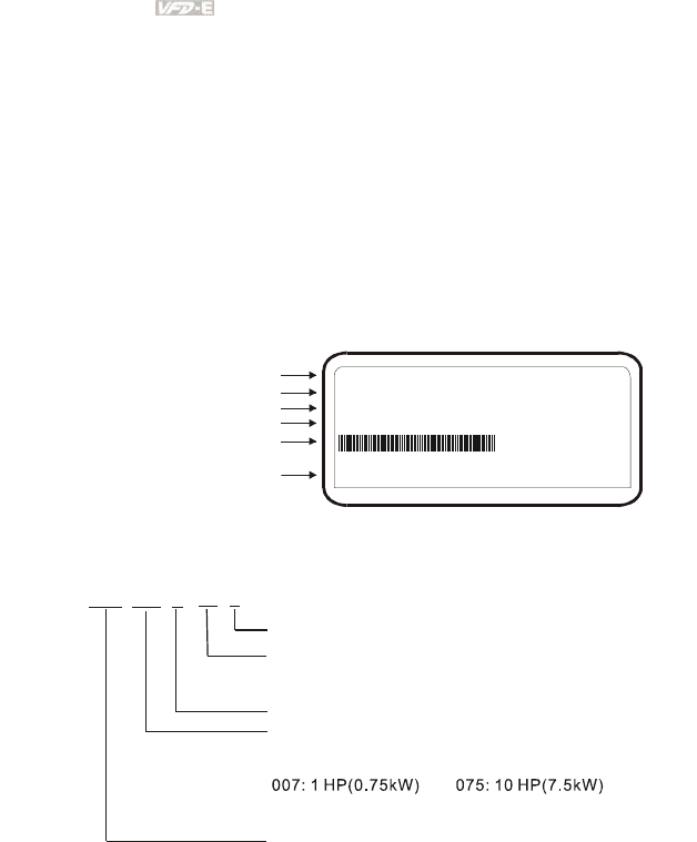
1.1.1 Nameplate Information
Example for 1HP/0.75kW 3-phase 230V AC motor drive
MODEL VFD007E23A
:
INPUT :3PH 200-240V 50/60Hz 5.1A
OUTPUT :3PH 0-240V 4.2A 1.6kVA 0.75kW/1HP
FREQUENCY RANGE : 0.1~400Hz
Serial Number & Bar Code
AC Drive Model
Input Spec.
Output Spec.
Output Frequency Range
007E23A0T5011230
01.03
02.03
Software Version
Power Board
Control Board
1.1.2 Model Explanation
VFD A
Version Type
23
Mains Input Voltage
11:115 Single phaseV 21: phase230V Single
23:230 Three phaseV
E
E Series
007
Applicable motor capacity
004: 0.5 HP(0.4kW)
015: 2 HP(1.5kW)
022: 3 HP(2.2kW)
Series Name ( ariable requency rive)
VF D
43:460 Three phaseV
002: 0.25 HP(0.2kW)
055: 7.5 HP(5.5kW)
110: 15 HP(11kW)
037: 5 HP(3.7kW)
A: Standard drive
C: CANopen
P: Cold plate drive (frame A only)
T: Frame A, built-in brake chopper
Chapter 1 Introduction|
Revision June 2008, 04EE, SW--PW V1.11/CTL V2.11 1-3
1.1.3 Series Number Explanation
0177T007E23A
Production number
Production year 2007
Production factory
Production week
T: Taoyuan, W: Wujiang
Model
230V 3-phase 1HP(0.75kW)
If the nameplate information does not correspond to your purchase order or if there are
any problems, please contact your distributor.
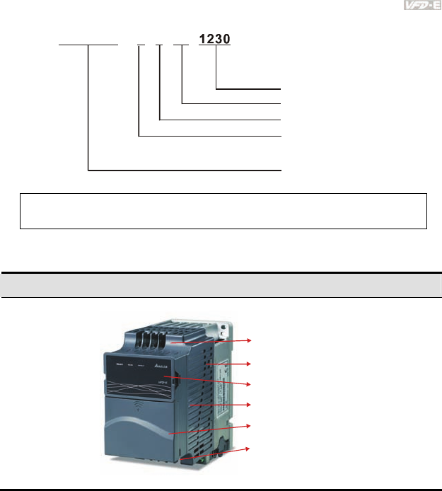
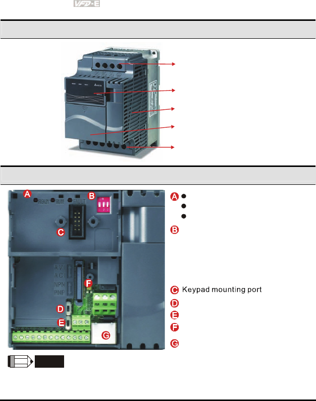
1.1.4 Drive Frames and Appearances
0.25-2HP/0.2-1.5kW (Frame A)
Input terminals
(R/L1, S/L2, T/L3)
Case body
Keypad cover
Control board case
Output terminals
(U/T1, V/T2, W/T3)
Control board cover
Chapter 1 Introduction|
1-4 Revision June 2008, 04EE, SW--PW V1.11/CTL V2.11
1-15HP/0.75-11kW (Frame B&C)
Input terminals cover
(R/L1, S/L2, T/L3)
Case body
Keypad cover
Output terminals cover
(U/T1, V/T2, W/T3)
Control board cover
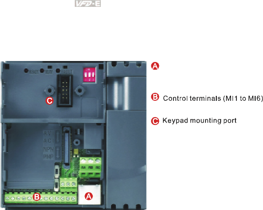
Internal Structure
1.
2.
3.
READY: power indicator
RUN: status indicator
FAULT: fault indicator
NPN/PNP
RS485 port (RJ-45)
Switch to ON for 50Hz, refer to
P 01.00 to P01.02 for details
Switch to ON for free run to stop
refer to P02.02
Switch to ON for setting frequency
source to ACI (P 02.00=2)
ACI terminal (ACI/AVI2 switch )
Mounting port for extension card
NOTE
The LED “READY” will light up after applying power. The light won’t be off until the capacitors are
discharged to safe voltage levels after power off.
Chapter 1 Introduction|
Revision June 2008, 04EE, SW--PW V1.11/CTL V2.11 1-5
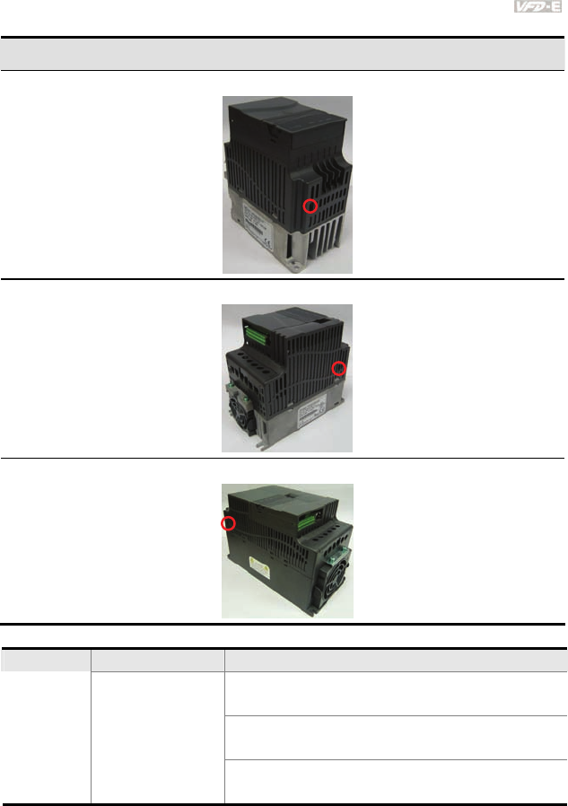
RFI Jumper Location
Frame A: near the output terminals (U/T1, V/T2, W/T3)
Frame B: above the nameplate
Frame C: above the warning label
Frame Power range Models
VFD002E11A/21A/23A, VFD004E11A/21A/23A/43A,
VFD007E21A/23A/43A, VFD015E23A/43A
VFD002E11C/21C/23C, VFD004E11C/21C/23C/43C,
VFD007E21C/23C/43C, VFD015E23C/43C
A 0.25-2hp (0.2-1.5kW)
VFD002E11T/21T/23T, VFD004E11T/21T/23T/43T,
VFD007E21T/23T/43T, VFD015E23T/43T
Chapter 1 Introduction|
1-6 Revision June 2008, 04EE, SW--PW V1.11/CTL V2.11
Frame Power range Models
VFD002E11P/21P/23P, VFD004E11P/21P/23P/43P,
VFD007E21P/23P/43P, VFD015E23P
B 1-5hp (0.75-3.7kW)
VFD007E11A, VFD015E21A, VFD022E21A/23A/43A,
VFD037E23A/43A, VFD007E11C, VFD015E21C,
VFD022E21C/23C/43C, VFD037E23C/43C
C 7.5-15hp (5.5-11kW) VFD055E23A/43A, VFD075E23A/43A, VFD110E43A,
VFD055E23C/43C, VFD075E23C/43C, VFD110E43C
RFI Jumper
RFI Jumper: The AC motor drive may emit the electrical noise. The RFI jumper is used to suppress
the interference (Radio Frequency Interference) on the power line.
Main power isolated from earth:
If the AC motor drive is supplied from an isolated power (IT power), the RFI jumper must be cut off.
Then the RFI capacities (filter capacitors) will be disconnected from ground to prevent circuit damage
(according to IEC 61800-3) and reduce earth leakage current.
CAUTION!
1. After applying power to the AC motor drive, do not cut off the RFI jumper. Therefore,
please make sure that main power has been switched off before cutting the RFI jumper.
2. The gap discharge may occur when the transient voltage is higher than 1,000V. Besides,
electro-magnetic compatibility of the AC motor drives will be lower after cutting the RFI
jumper.
3. Do NOT cut the RFI jumper when main power is connected to earth.
4. The RFI jumper cannot be cut when Hi-pot tests are performed. The mains power and
motor must be separated if high voltage test is performed and the leakage currents are
too high.
5. To prevent drive damage, the RFI jumper connected to ground shall be cut off if the AC
motor drive is installed on an ungrounded power system or a high resistance-grounded
(over 30 ohms) power system or a corner grounded TN system.
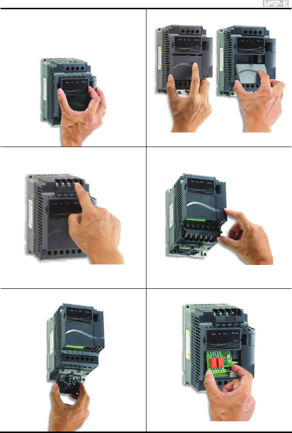
1.1.5 Remove Instructions
Chapter 1 Introduction|
Revision June 2008, 04EE, SW--PW V1.11/CTL V2.11 1-7
Remove Keypad
1. Press and hold in the tabs on each side
of the cover.
2. Pull the cover up to release.
Remove Front Cover
Step 1 Step 2
Remove RST Terminal Cover
(For Frame B and Frame C)
For frame A, it doesn’t have cover and can be
wired directly.
Remove UVW Terminal Cover
(For Frame B and Frame C)
For frame A, it doesn’t have cover and can be
wired directly.
Remove Fan Remove Extension Card
Chapter 1 Introduction|
1-8 Revision June 2008, 04EE, SW--PW V1.11/CTL V2.11
1.2 Preparation for Installation and Wiring
1.2.1 Ambient Conditions
Install the AC motor drive in an environment with the following conditions:
Air Temperature: -10 ~ +50°C (14 ~ 122°F) for UL & cUL
-10 ~ +40°C (14 ~ 104°F) for side-by-side mounting
Relative Humidity: <90%, no condensation allowed
Atmosphere
pressure: 86 ~ 106 kPa
Installation Site
Altitude: <1000m
Operation
Vibration: <20Hz: 9.80 m/s2 (1G) max
20 ~ 50Hz: 5.88 m/s2 (0.6G) max
Temperature: -20°C ~ +60°C (-4°F ~ 140°F)
Relative Humidity: <90%, no condensation allowed
Atmosphere
pressure: 86 ~ 106 kPa
Storage
Transportation
Vibration: <20Hz: 9.80 m/s2 (1G) max
20 ~ 50Hz: 5.88 m/s2 (0.6G) max
Pollution
Degree 2: good for a factory type environment.
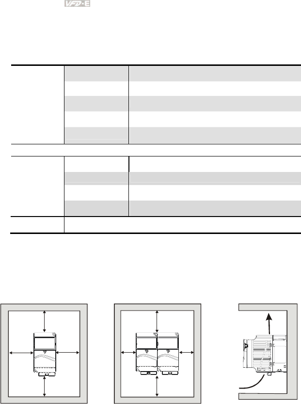
Minimum Mounting Clearances
Frame A Mounting Clearances
Option 1 (-10 to +50°C) Option 2 (-10 to +40°C) Air flow
120mm
120mm
50mm
50mm
120mm
120mm
50mm
50mm
Air Flow
Chapter 1 Introduction|
Revision June 2008, 04EE, SW--PW V1.11/CTL V2.11 1-9
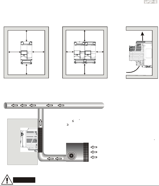
Frame B and C Mounting Clearances
Option 1 (-10 to +50°C) Option 2 (-10 to +40°C) Air flow
150mm
150mm
50mm
50mm
150mm
150mm
50mm
50mm
Air Flow
For VFD-E-P series: heat sink system example
Duct temperature
Air flow speed
40
2m/sec
C
User
1. Flatness <0.1mm
2. Roughness <6um
3. Grease 10um~12um
4. Screw torque: 16Kgf-cm
5. Recommended temperature <80
's heat sink should comply
with following conditions:
C
fan
AC motor drive
dust collector
Air-extracting apparatus
Control panel
CAUTION!
1. Operating, storing or transporting the AC motor drive outside these conditions may cause
damage to the AC motor drive.
2. Failure to observe these precautions may void the warranty!
3. Mount the AC motor drive vertically on a flat vertical surface object by screws. Other directions
are not allowed.
4. The AC motor drive will generate heat during operation. Allow sufficient space around the unit
for heat dissipation.
Chapter 1 Introduction|
1-10 Revision June 2008, 04EE, SW--PW V1.11/CTL V2.11
5. The heat sink temperature may rise to 90°C when running. The material on which the AC motor
drive is mounted must be noncombustible and be able to withstand this high temperature.
6. When AC motor drive is installed in a confined space (e.g. cabinet), the surrounding
temperature must be within 10 ~ 40°C with good ventilation. DO NOT install the AC motor drive
in a space with bad ventilation.
7. Prevent fiber particles, scraps of paper, saw dust, metal particles, etc. from adhering to the
heatsink.
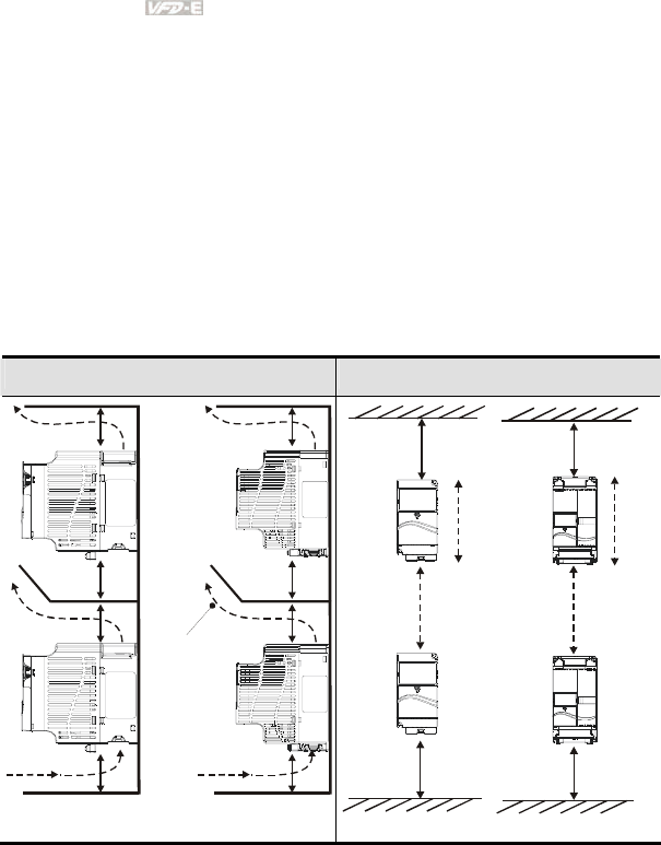
8. When installing multiple AC more drives in the same cabinet, they should be adjacent in a row
with enough space in-between. When installing one AC motor drive below another one, use a
metal separation between the AC motor drives to prevent mutual heating.
Installation with Metal Separation Installation without Metal Separation
120mm
120mm
120mm
120mm
150mm
150mm
150mm
150mm
Air flow
Frame
A
Frame B and C
120mm
120mm
150mm
150mm
A
B
AB
Frame A Frame B and C
Chapter 1 Introduction|
Revision June 2008, 04EE, SW--PW V1.11/CTL V2.11 1-11
1.2.2 DC-bus Sharing: Connecting the DC-bus of the AC Motor Drives
in Parallel
1. This function is not for VFD-E-T series.
2. The AC motor drives can absorb mutual voltage that generated to DC bus when
deceleration.
3. Enhance brake function and stabilize the voltage of the DC bus.
4. The brake module can be added to enhance brake function after connecting in parallel.
5. Only the same power system can be connected in parallel.
6. It is recommended to connect 5 AC motor drives in parallel (no limit in horsepower).
U V W U V W U V W U V W
IM IM IM IM
Power 115/208/220/230/380/440/480 (depend on models)
power should be applied at the same time
(only the same power system can be connected in parallel)
Br ak e
module
For frame A, terminal + (-) is connected to the terminal + (-) of the brake module.
For frame B and C, terminal +/B1 (-) is connected to the terminal + (-) of the brake module.
Chapter 1 Introduction|
1-12 Revision June 2008, 04EE, SW--PW V1.11/CTL V2.11
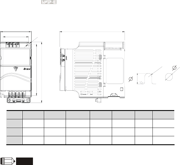
1.3 Dimensions
(Dimensions are in millimeter and [inch])
W
W1
H1
H
D
D
Frame W W1 H H1 D Ø ØD
A 72.0[2.83] 60.0[2.36] 142.0[5.59] 120.0[4.72] 152.0[5.98] 5.2[0.04] 7.6[0.06]
B 100.0[3.94] 89.0[3.50] 174.0[6.86] 162.0[6.38] 152.0[5.98] 5.5[0.22] 9.3[0.36]
C 130.0[5.12] 116.0[4.57] 260.0[10.24] 246.5[9.70] 169.2[6.66] 5.5[0.22] 9.8[0.38]
NOTE
Frame A: VFD002E11A/21A/23A, VFD004E11A/21A/23A/43A, VFD007E21A/23A/43A,
VFD015E23A/43A, VFD002E11C/21C/23C, VFD004E11C/21C/23C/43C, VFD007E21C/23C/43C,
VFD015E23C/43C, VFD002E11T/21T/23T, VFD004E11T/21T/23T/43T, VFD007E21T/23T/43T,
VFD015E23T/43T
Frame B: VFD007E11A, VFD015E21A, VFD022E21A/23A/43A, VFD037E23A/43A, VFD007E11C,
VFD015E21C, VFD022E21C/23C/43C, VFD037E23C/43C
Frame C: VFD055E23A/43A, VFD075E23A/43A, VFD110E43A, VFD055E23C/43C,
VFD075E23C/43C, VFD110E43C
Chapter 1 Introduction|
Revision June 2008, 04EE, SW--PW V1.11/CTL V2.11 1-13
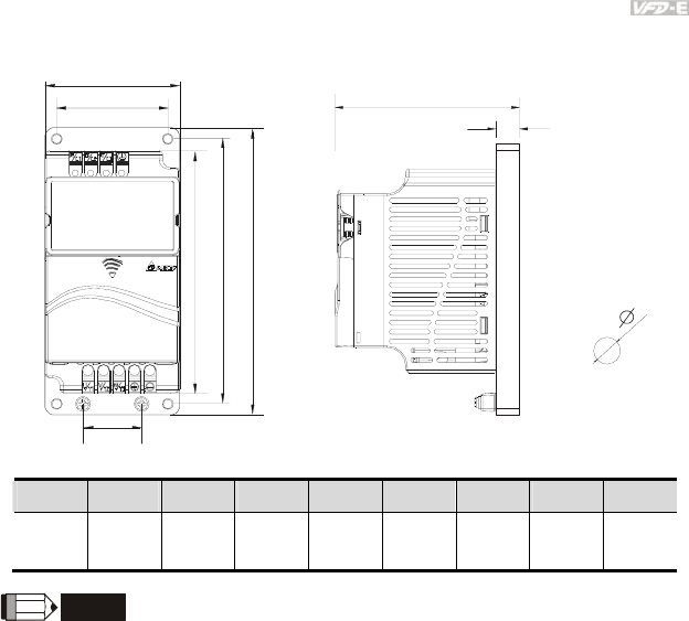
Dimensions for VFD-E-P series
W
W1
H2 H
D
D1
W2
H1
Unit: mm [inch]
W W1 W2 H H1 H2 D D1 Ø
72.0
[2.83]
56.0
[2.20]
30.0
[1.18]
155.0
[6.10]
143.0
[5.63]
130.0
[5.12]
111.5
[4.39]
9.5
[0.37]
5.3
[0.21]
NOTE
Frame A: VFD002E11P/21P/23P, VFD004E11P/21P/23P/43P, VFD007E11P/21P/23P/43P,
VFD015E23P/43P

Chapter 1 Introduction|
1-14 Revision June 2008, 04EE, SW--PW V1.11/CTL V2.11
This page intentionally left blank

Revision June 2008, 04EE, SW--PW V1.11/CTL V2.11 2-1
Chapter 2 Installation and Wiring
After removing the front cover, check if the power and control terminals are clear. Be sure to observe
the following precautions when wiring.
General Wiring Information
Applicable Codes
All VFD-E series are Underwriters Laboratories, Inc. (UL) and Canadian Underwriters
Laboratories (cUL) listed, and therefore comply with the requirements of the National
Electrical Code (NEC) and the Canadian Electrical Code (CEC).
Installation intended to meet the UL and cUL requirements must follow the instructions
provided in “Wiring Notes” as a minimum standard. Follow all local codes that exceed UL
and cUL requirements. Refer to the technical data label affixed to the AC motor drive and
the motor nameplate for electrical data.
The "Line Fuse Specification" in Appendix B, lists the recommended fuse part number for
each VFD-E Series part number. These fuses (or equivalent) must be used on all
installations where compliance with U.L. standards is a required.
CAUTION!
1. Make sure that power is only applied to the R/L1, S/L2, T/L3 terminals. Failure to comply may
result in damage to the equipment. The voltage and current should lie within the range as
indicated on the nameplate.
2. All the units must be grounded directly to a common ground terminal to prevent lightning strike
or electric shock.
3. Please make sure to fasten the screw of the main circuit terminals to prevent sparks which is
made by the loose screws due to vibration.
4. Check following items after finishing the wiring:
A. Are all connections correct?
B. No loose wires?
C. No short-circuits between terminals or to ground?

Chapter 2 Installation and Wiring|
2-2 Revision June 2008, 04EE, SW--PW V1.11/CTL V2.11
DANGER!
1. A charge may still remain in the DC bus capacitors with hazardous voltages even if the power
has been turned off. To prevent personal injury, please ensure that the power is turned off and
wait ten minutes for the capacitors to discharge to safe voltage levels before opening the AC
motor drive.
2. Only qualified personnel familiar with AC motor drives is allowed to perform installation, wiring
and commissioning.
3. Make sure that the power is off before doing any wiring to prevent electric shock.
2.1 Wiring
Users must connect wires according to the circuit diagrams on the following pages. Do not plug a
modem or telephone line to the RS-485 communication port or permanent damage may result. The
pins 1 & 2 are the power supply for the optional copy keypad only and should not be used for RS-485
communication.
Chapter 2 Installation and Wiring|
Revision June 2008, 04EE, SW--PW V1.11/CTL V2.11 2-3
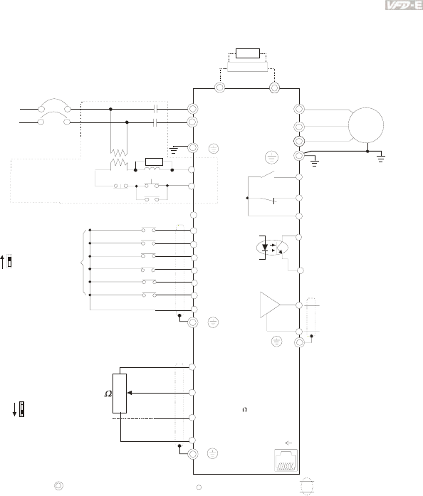
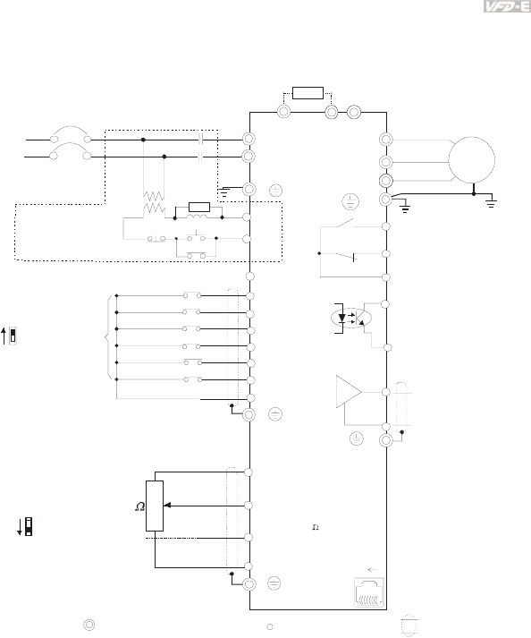
Figure 1 for models of VFD-E Series
VFD002E11A/21A, VFD004E11A/21A, VFD007E21A, VFD002E11C/21C, VFD004E11C/21C,
VFD007E21C, VFD002E11P/21P, VFD004E11P/21P, VFD007E21P
AVI
ACI
ACM
+
+10V
5K
3
2
1
Power supply
+10V 20mA
Master Frequency
0 to 10V 47K
Analog Signal Common E
Main circuit (power) terminals Control circuit terminals Shielded leads & Cable
E
R(L1)
S(L2)
Fuse/NFB(None Fuse Breaker)
SA
OFF ON
MC
MC
RB
RC
Recommended Circuit
when power supply
is turned OFF by a
fault output
R(L1)
S(L2)
E
Analog Multi-function Output
Te r m i n a l
factory setting: Analog freq.
/ c ur ren t meter
0~10VDC/2mA
U(T1)
V(T2)
W(T3)
IM
3~
AFM
ACM
RA
RB
RC
Motor
Factory setting:
Drive is in operation
48V50mA Max.
Multi-function
Photocoulper Output
Analog Signal common
E
E
MO1
MCM
MI1
MI2
MI3
MI4
MI6
MI5
DCM
+24V
FWD/Stop
REV/Stop
Multi-step 1
Multi-step 2
Multi-step 3
Multi-step 4
Digital Signal Common
Factory
setting
Sw2
AVI
ACI
Factory setting:
ACI Mode
ACI/AVI switch
When switching to AVI,
it indicates AVI2
-
81
Sw1
NPN
PNP
Factory setting:
NPN Mode
Please refer to Figure 7
for wiring of NPN
mode and PNP
mode.
BUE
brake unit
(optional)
BR
brake resisto
r
(opti onal)
Multi-function contact output
Refer to chapter 2.4 for details.
Fac tory setting is
malfunction indication
Factory setting: output frequency
4-20mA/0-10V
RS-485 serial interface
(NOT for VFD*E*C models)
1: Reserved
2: EV
5: SG+
6: Reserved
7: Reserved
8: Reserved
3: GND
4: SG-
For VFD*E*C models,
please refer to figure 8.
Chapter 2 Installation and Wiring|
2-4 Revision June 2008, 04EE, SW--PW V1.11/CTL V2.11
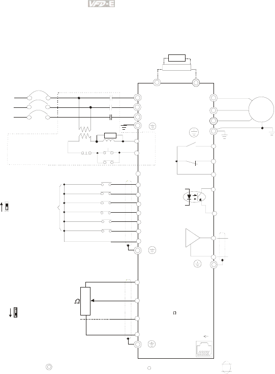
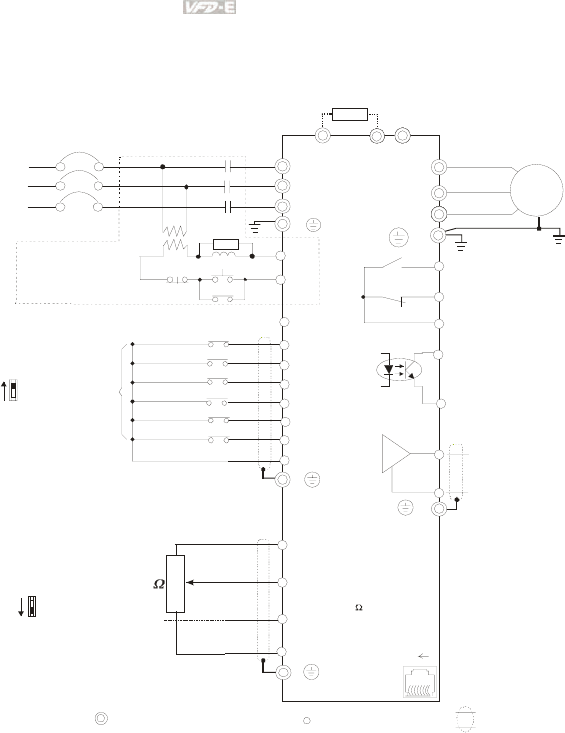
Figure 2 for models of VFD-E Series
VFD002E23A, VFD004E23A/43A, VFD007E23A/43A, VFD015E23A/43A, VFD002E23C,
VFD004E23C/43C, VFD007E23C/43C, VFD015E23C/43C, VFD002E23P, VFD004E23P/43P,
VFD007E23P/43P, VFD015E23P
AVI
ACI
ACM
+
+10V
5K
3
2
1
Power supply
+10V 20m A
Master Frequency
0 to 10V 47K
Analog Signal Common E
Main circuit (power) terminals Con tr ol circu it terminals Shielded leads & Cable
E
R(L1)
S(L2)
Fuse/NFB(No Fuse Breaker)
SA
OFF ON
MC
MC
RB
RC
Recommended Circuit
when power supply
is turned OFF by a
fault output
R(L1)
S(L2)
E
Analog Multi-function Output
Terminal
factory setting: Analog freq.
/ current meter
0~10VDC/2mA
U(T1)
V(T2)
W(T3)
IM
3~
AFM
ACM
RA
RB
RC
Motor
Factory setting:
Driv e is in operation
48V50mA Max.
Multi-function
Photocoulper Output
Analog Signal common
E
E
MO1
MCM
MI1
MI2
MI3
MI4
MI6
MI5
DCM
+24V
FWD/Stop
REV/Stop
Multi-step 1
Multi-step 2
Multi-step 3
Multi-step 4
Digital Signal Common
Factory
setting
Sw2
AVI
ACI
Factory setting:
ACI Mode
ACI/AVI switch
When switching to AVI,
it indicates AVI2
-
81
Sw1
NPN
PNP
Factory setting:
NPN Mode
Please refer to Figure 7
for wiring of NPN
mode and PNP
mode.
BUE
brake unit
(optional)
BR
brake resisto
r
(opti onal)
Multi-function contact output
Refer to chapter 2.4 for details.
Fac tory setting is
malfunction indication
Factory setting: output frequency
4-20mA/0-10V
T(L3)
T(L3)
RS-485 serial interface
(NOT for VFD*E*C models)
1: Reserved
2: EV
5: SG+
6: Reserved
7: Reserved
8: Reserved
3: GND
4: SG-
For VFD*E*C models,
please refer to figure 8.
Chapter 2 Installation and Wiring|
Revision June 2008, 04EE, SW--PW V1.11/CTL V2.11 2-5
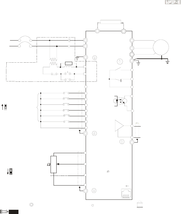
Figure 3 for models of VFD-E Series
VFD007E11A, VFD015E21A, VFD022E21A, VFD007E11C, VFD015E21C, VFD022E21C
AVI
ACI
ACM
+/B1
+10V
5K
3
2
1
Power supply
+10V 20mA
Master Frequency
0 to 10V 47K
Analog Signal Common E
Main circuit (power) terminals Control circuit terminals Shielded leads & Cable
E
R(L1)
S(L2)
Fuse/NFB(No Fuse Breaker)
SA
OFF ON
MC
MC
RB
RC
Recommended Circuit
when power supply
is turned OFF by a
fault output
R(L1)
S(L2)
E
Analog Multi-function
Output Terminal
factory setting: Analog
freq./ current meter
0~10VDC/ 2mA
U(T1)
V(T2)
W(T3)
IM
3~
AFM
ACM
RA
RB
RC
Motor
Factory setting:
Drive is in operation
48V50mA Max.
Multi-function
Photocoulper Output
Analog Signal common
E
E
MO1
MCM
MI1
MI2
MI3
MI4
MI6
MI5
DCM
+24V
FWD/Stop
REV/Stop
Multi-step 1
Multi-step 2
Multi-step 3
Multi-step 4
Digital Signal Common
Factory
setting
Sw2
AVI
ACI
Factory setting:
ACI Mode
ACI/AVI switch
When switching to AVI,
it indicates AVI2
-
81
Sw1
NPN
PNP
Factory setting:
NPN Mode
Please refer to Figure 7
for wiring of NPN
mode and PNP
mode.
brake resisto
r
(optional)
Multi-function contact output
Refer to chapter2.4 for details.
Factory setting is
malfunction indication
Factory setting: output
frequency
4-20mA/0-10V
BR
B2
RS-485 s erial interfac e
(NOT for VFD*E*C models)
1: Reserved
2: EV
5: SG+
6: Reserved
7: Reserved
8: Reserved
3: GND
4: SG -
For VFD*E*C models,
please refer to figure 8.
Chapter 2 Installation and Wiring|
2-6 Revision June 2008, 04EE, SW--PW V1.11/CTL V2.11
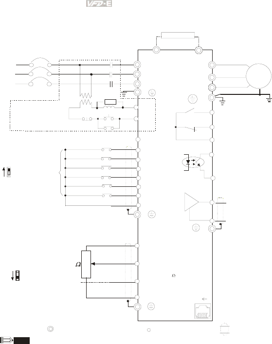
Figure 4 for models of VFD-E Series
VFD022E23A/43A, VFD037E23A/43A, VFD055E23A/43A, VFD075E23A/43A, VFD110E43A,
VFD022E23C/43C, VFD037E23C/43C, VFD055E23C/43C, VFD075E23C/43C, VFD110E43C
AVI
ACI
ACM
+/B1
+10V
5K
3
2
1
Power supply
+10V 20mA
Master Frequency
0 to 10V 47K
Analog Signal Common E
Main circ uit (power) terminals Control circuit terminals Shielded leads & Cable
E
R(L1)
S(L2)
Fuse/NFB(No Fuse Breaker)
SA
OFF ON
MC
MC
RB
RC
Recommended Circuit
when power supply
is turned OFF by a
fault output
R(L1)
S(L2)
E
Analog Multi-function
Output Terminal
factory setting: Analog
freq./ current meter
0~10VDC/ 2mA
U(T1)
V(T2)
W(T3)
IM
3~
AFM
ACM
RA
RB
RC
Motor
Factory setting:
Drive is in operation
48V50mA Max.
Multi-function
Photocoulper Output
Analog S ignal common
E
E
MO1
MCM
MI1
MI2
MI3
MI4
MI6
MI5
DCM
+24V
FWD/Stop
REV/Stop
Multi-step 1
Multi-step 2
Multi-step 3
Multi-step 4
Digital Signal Common
Factory
setting
Sw2
AVI
ACI
Factory setting:
ACI Mode
ACI/AVI switch
When switching to AVI,
it indicates AVI2
-
81
Sw1
NPN
PNP
Factory setting:
NPN Mode
Please refer to Figure 7
for wiring of NPN
mode and PNP
mode.
brake resisto
r
(o pti onal)
Multi-function contact output
Refer to chapter2.4 for details.
Factory setting is
malfunction indication
Factory setting: output
frequency
4-20mA/0-10V
T(L3)
T(L3)
BR
B2
RS-485 serial interface
(NOT for VFD*E*C models)
1: Reserved
2: EV
5: SG+
6: Reserved
7: Reserved
8: Reserved
3: GND
4: SG-
For VFD*E*C models,
please refer to figure 8.
Chapter 2 Installation and Wiring|
Revision June 2008, 04EE, SW--PW V1.11/CTL V2.11 2-7
Figure 5 for models of VFD-E Series
VFD002E11T/21T, VFD004E11A/21T, VFD007E21T
AVI
ACI
ACM
B1
+10V
5K
3
2
1
Power supply
+10V 20mA
Master Frequency
0 to 10V 47K
Analog Signal Common E
Main circuit (power) terminals Control circuit terminals Shielded leads & Cable
E
R(L1)
S(L2)
Fuse/NFB(No Fuse Breaker)
SA
OFF ON
MC
MC
RB
RC
Recommended Circuit
when power supply
is turned OFF by a
fault output
R(L1)
S(L2)
E
Analog Multi-function
Output Terminal
factory setting: Analog
freq./ current meter
0~10VDC/2mA
U(T1)
V(T2)
W(T3)
IM
3~
AFM
ACM
RA
RB
RC
Motor
Factory setting:
Drive is in operation
48V50mA Max.
Multi-function
Photocoulper Output
Analog Signal common
E
E
MO1
MCM
MI1
MI2
MI3
MI4
MI6
MI5
DCM
+24V
FWD/Stop
REV/Stop
Multi-step 1
Multi-step 2
Multi-step 3
Multi-step 4
Digital Signal Common
Factory
setting
Sw2
AVI
ACI
Factory setting:
ACI Mode
ACI/AVI switch
When switching to AVI,
it indicates AVI2
B2
RS-485
Serial interface
1: Reserved
2: EV
5: SG+
6: Reserved
7: Reserved
8: Reserved
3: GND
4: SG -
81
Sw1
NPN
PNP
Factory setting:
NPN Mode
Please refer to Figure 7
for wiring of NPN
mode and PNP
mode.
BR
brake resistor
(optional)
Multi-function contact output
Refer to chapter2.4 for details.
Factory setting is
malfunction indication
Factory setting: output
frequency
4-20mA/0-10V
NOTE
For VFD-E-T series, the braking resistor can be used by connecting terminals (B1 and B2) directly. But
it can't connect DC-BUS in parallel.
Chapter 2 Installation and Wiring|
2-8 Revision June 2008, 04EE, SW--PW V1.11/CTL V2.11
Figure 6 for models of VFD-E Series
VFD002E23T, VFD004E23T/43T, VFD007E23T/43T, VFD015E23T/43T
AVI
ACI
ACM
B1
+10V
5K
3
2
1
Power supply
+10V 20mA
Master Frequency
0 to 10V 47K
Analog Signal Common E
Main circuit (power) terminals Control circuit terminals Shielded leads & Cable
E
R(L1)
S(L2)
Fuse/NFB(No Fuse B reaker)
SA
OFF ON
MC
MC
RB
RC
Recommended Circuit
when power supply
is turned OFF by a
fault output
R(L1)
S(L2)
E
Analog Multi-function
Output Terminal
factory setti ng: Analog
freq./ current meter
0~10VDC/2mA
U(T1)
V(T2)
W(T3)
IM
3~
AFM
ACM
RA
RB
RC
Motor
Factory setting:
Drive is in operation
48V50mA Max.
Multi-function
Photocoulper Output
Analog Signal common
E
E
MO1
MCM
MI1
MI2
MI3
MI4
MI6
MI5
DCM
+24V
FWD/Stop
REV/Stop
Multi-step 1
Multi-step 2
Multi-step 3
Multi-step 4
Digital Signal Common
Factory
setting
Sw2
AVI
ACI
Factory setting:
ACI Mode
ACI/AVI switch
When switching to AVI,
it indicates AVI2
B2
RS-485
Serial interface
1: Reserved
2: EV
5: SG+
6: Reserved
7: Reserved
8: Reserved
3: GND
4: SG -
81
Sw1
NPN
PNP
Factory setting:
NPN Mode
Please refer to Figure 7
for wiring of NPN
mode and PNP
mode.
BR
brake resistor
(optional)
Multi-function contact output
Refer to chapter2.4 for details.
Factory setting is
malfunction indication
Factory setting: output
frequency
4-20mA/0-10V
T(L3)
T(L3)
NOTE For VFD-E-T series, the braking resistor can be used by connecting terminals (B1 and B2) directly. But
it c a n't co nnec t D C- BUS i n parallel.

Chapter 2 Installation and Wiring|
Revision June 2008, 04EE, SW--PW V1.11/CTL V2.11 2-9
Figure 7 Wiring for NPN mode and PNP mode
A. NPN mode without external power
Factory
setting
NPN
PNP
B. NPN mode with external power
Factory
setting
NPN
PNP
24
Vdc
-
+
C. PNP mode without external power
Sw1
Factory
setting
NPN
PNP
Chapter 2 Installation and Wiring|
2-10 Revision June 2008, 04EE, SW--PW V1.11/CTL V2.11
D. PNP mode with external power
Sw1
Factory
setting
NPN
PNP
24
Vdc
-
+
Figure 8 RJ-45 pin definition for VFD*E*C models
PIN Signal Description
1 CAN_H CAN_H bus line (dominant high)
2 CAN_L CAN_L bus line (dominant low)
3 CAN_GND Ground / 0V /V-
4 SG+ 485 communication
5 SG- 485 communication
7 CAN_GND Ground / 0V /V-
CAUTION!
1. The wiring of main circuit and control circuit should be separated to prevent erroneous actions.
2. Please use shield wire for the control wiring and not to expose the peeled-off net in front of the
terminal.
3. Please use the shield wire or tube for the power wiring and ground the two ends of the shield
wire or tube.
4. Damaged insulation of wiring may cause personal injury or damage to circuits/equipment if it
comes in contact with high voltage.
5. The AC motor drive, motor and wiring may cause interference. To prevent the equipment
damage, please take care of the erroneous actions of the surrounding sensors and the
equipment.
6. When the AC drive output terminals U/T1, V/T2, and W/T3 are connected to the motor terminals
U/T1, V/T2, and W/T3, respectively. To permanently reverse the direction of motor rotation,
switch over any of the two motor leads.
Chapter 2 Installation and Wiring|
Revision June 2008, 04EE, SW--PW V1.11/CTL V2.11 2-11
7. With long motor cables, high capacitive switching current peaks can cause over-current, high
leakage current or lower current readout accuracy. To prevent this, the motor cable should be
less than 20m for 3.7kW models and below. And the cable should be less than 50m for 5.5kW
models and above. For longer motor cables use an AC output reactor.
8. The AC motor drive, electric welding machine and the greater horsepower motor should be
grounded separately.
9. Use ground leads that comply with local regulations and keep them as short as possible.
10. No brake resistor is built in the VFD-E series, it can install brake resistor for those occasions
that use higher load inertia or frequent start/stop. Refer to Appendix B for details.
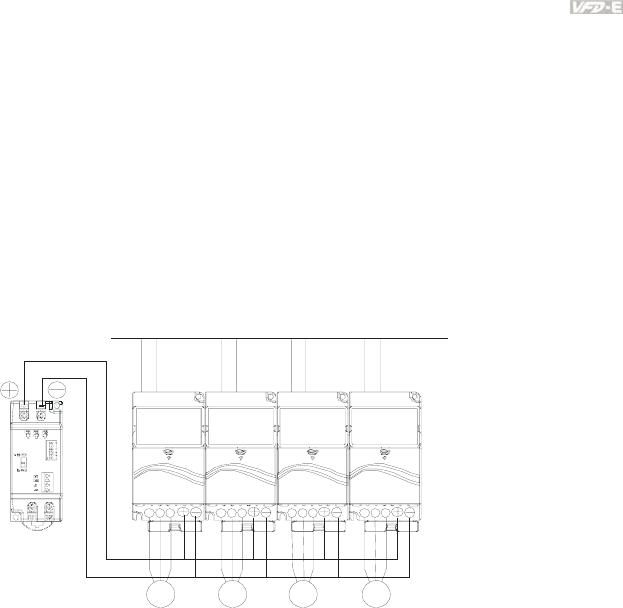
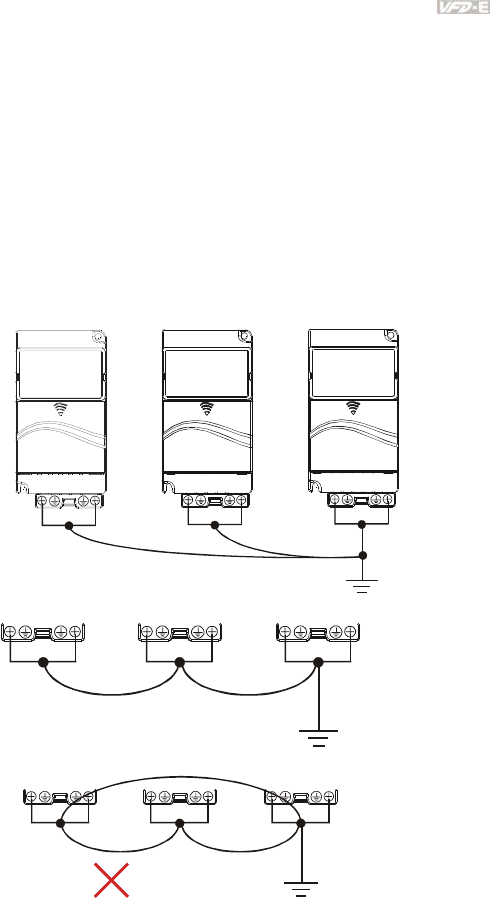
11. Multiple VFD-E units can be installed in one location. All the units should be grounded directly
to a common ground terminal, as shown in the figure below. Ensure there are no ground
loops.
Excellent
Good
Not allowed
Chapter 2 Installation and Wiring|
2-12 Revision June 2008, 04EE, SW--PW V1.11/CTL V2.11
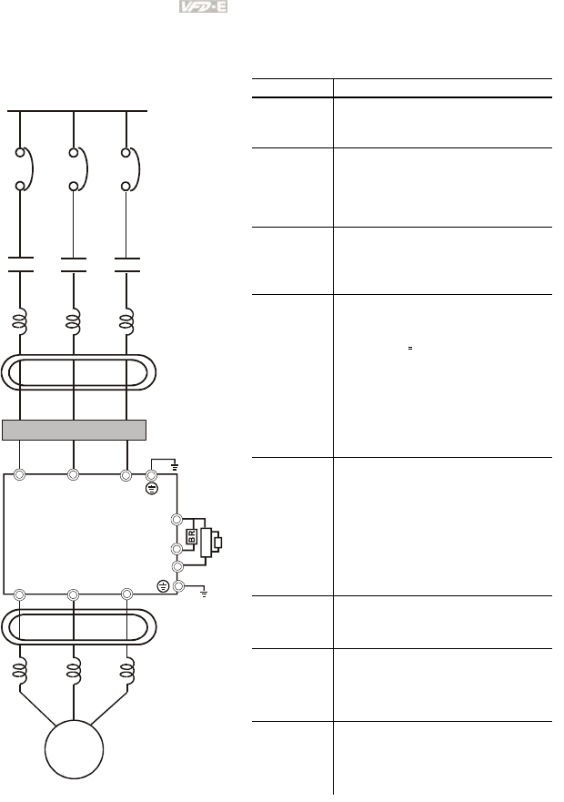
2.2 External Wiring
Motor
Output AC
Line Reactor
Power Suppl
y
Magnetic
contactor
Input AC
Line Reactor
EMI Filter
R/L1 S/L2 T/L3
U/T1 V/T2 W/T3
+/B1
B2
Zero-phase
Reactor
Zero-phase
Reactor
FUSE/NFB
-
BR
BUE
Brake
resistor
Brake unit
Items Explanations
Power
supply
Please follow the specific power
supply requirements shown in
Appendix A.
Fuse/NFB
(Optional)
There may be an inrush current
during power up. Please check the
chart of Appendix B and select the
correct fuse with rated current. Use of
an NFB is optional.
Magnetic
contactor
(Optional)
Please do not use a Magnetic
contactor as the I/O switch of the AC
motor drive, as it will reduce the
operating life cycle of the AC drive.
Input AC
Line Reactor
(Optional)
Used to improve the input power
factor, to reduce harmonics and
provide protection from AC line
disturbances. (surges, switching
spikes, short interruptions, etc.). AC
line reactor should be installed when
the power supply capacity is 500kVA
or more or advanced capacity is
activated .The wiring distance should
be ≤ 10m. Refer to appendix B for
details.
Zero-phase
Reactor
(Ferrite Core
Common
Choke)
(Optional)
Zero phase reactors are used to
reduce radio noise especially when
audio equipment is installed near the
inverter. Effective for noise reduction
on both the input and output sides.
Attenuation quality is good for a wide
range from AM band to 10MHz.
Appendix B specifies the zero phase
reactor. (RF220X00A)
EMI filter To reduce electromagnetic
interference.
Brake
resistor and
Brake unit
(Optional)
Used to reduce the deceleration time
of the motor. Please refer to the chart
in Appendix B for specific Brake
resistors.
Output AC
Line Reactor
(Optional)
Motor surge voltage amplitude
depends on motor cable length. For
applications with long motor cable
(>20m), it is necessary to install a
reactor at the inverter output side
Chapter 2 Installation and Wiring|
Revision June 2008, 04EE, SW--PW V1.11/CTL V2.11 2-13
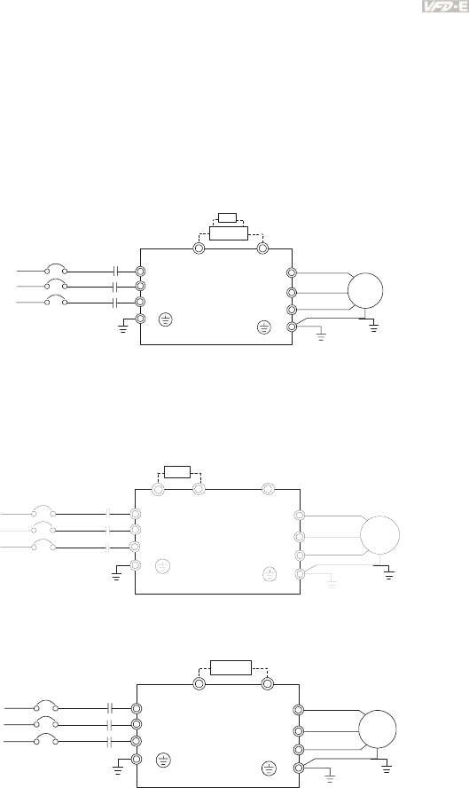
2.3 Main Circuit
2.3.1 Main Circuit Connection
Figure 1
For frame A: VFD002E11A/21A/23A, VFD004E11A/21A/23A/43A, VFD007E21A/23A/43A,
VFD015E23A/43A, VFD002E11C/21C/23C, VFD004E11C/21C/23C/43C,
VFD007E21C/23C/43C, VFD002E11P/21P/23P, VFD004E11P/21P/23P/43P,
VFD007E11P/21P/23P/43P, VFD015E23P
R(L1)
S(L2)
T(L3)
R
S
T
U(T1)
V(T2)
W(T3)
IM
3~
MC
E
E
+-
No fuse breaker
(NFB)
Brake Resistor(Optional)
Motor
BUE
BR
Brake Unit
(Optional)
Figure 2
For frame B: VFD007E11A, VFD015E21A, VFD022E21A/23A/43A, VFD037E23A/43A,
VFD007E11C, VFD015E21C, VFD022E21C/23C/43C, VFD037E23C/43C
For frame C: VFD055E23A/43A, VFD075E23A/43A, VFD110E43A, VFD055E23C/43C,
VFD075E23C/43C, VFD110E43C
R(L1)
S(L2)
T(L3)
R
S
T
U(T1)
V(T2)
W(T3)
IM
3~
MC
E
E
B2 -
No fuse breaker
(NF B)
Brake Resistor(Optional)
Motor
+/B1
BR
Figure 3
For Frame A: VFD002E11T/21T/23T, VFD004E11T/21T/23T/43T, VFD007E21T/23T/43T,
VFD015E23T/43T
R(L1)
S(L2)
T(L3)
R
S
T
U(T1)
V(T2)
W(T3)
IM
3~
MC
E
E
B1 B2
No fuse breaker
(NFB)
Brake Resistor
(Optional)
Motor
BR
Chapter 2 Installation and Wiring|
2-14 Revision June 2008, 04EE, SW--PW V1.11/CTL V2.11
Terminal Symbol Explanation of Terminal Function
R/L1, S/L2, T/L3 AC line input terminals (1-phase/3-phase)
U/T1, V/T2, W/T3 AC drive output terminals for connecting 3-phase induction motor
+/B1~ B2 Connections for Brake resistor (optional)
+/B1, - Connections for External Brake unit (BUE series)
Earth connection, please comply with local regulations.
CAUTION!
Mains power terminals (R/L1, S/L2, T/L3)
Connect these terminals (R/L1, S/L2, T/L3) via a no-fuse breaker or earth leakage breaker
to 3-phase AC power (some models to 1-phase AC power) for circuit protection. It is
unnecessary to consider phase-sequence.
It is recommended to add a magnetic contactor (MC) in the power input wiring to cut off
power quickly and reduce malfunction when activating the protection function of AC motor
drives. Both ends of the MC should have an R-C surge absorber.
Please make sure to fasten the screw of the main circuit terminals to prevent sparks
which is made by the loose screws due to vibration.
Please use voltage and current within the regulation shown in Appendix A.
When using a general GFCI (Ground Fault Circuit Interrupter), select a current sensor
with sensitivity of 200mA or above, and not less than 0.1-second operation time to avoid
nuisance tripping. For the specific GFCI of the AC motor drive, please select a current
sensor with sensitivity of 30mA or above.
Do NOT run/stop AC motor drives by turning the power ON/OFF. Run/stop AC motor
drives by RUN/STOP command via control terminals or keypad. If you still need to
run/stop AC drives by turning power ON/OFF, it is recommended to do so only ONCE per
hour.
Do NOT connect 3-phase models to a 1-phase power source.
Output terminals for main circuit (U, V, W)
Chapter 2 Installation and Wiring|
Revision June 2008, 04EE, SW--PW V1.11/CTL V2.11 2-15
The factory setting of the operation direction is forward running. The methods to control
the operation direction are: method 1, set by the communication parameters. Please refer
to the group 9 for details. Method2, control by the optional keypad KPE-LE02. Refer to
Appendix B for details.
When it needs to install the filter at the output side of terminals U/T1, V/T2, W/T3 on the
AC motor drive. Please use inductance filter. Do not use phase-compensation capacitors
or L-C (Inductance-Capacitance) or R-C (Resistance-Capacitance), unless approved by
Delta.
DO NOT connect phase-compensation capacitors or surge absorbers at the output
terminals of AC motor drives.
Use well-insulated motor, suitable for inverter operation.
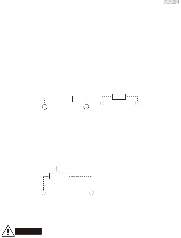
Terminals [+/B1, B2] for connecting brake resistor
B2
BR
+/B1
or
B2
BR
B1
for models VFDxxExxT
Connect a brake resistor or brake unit in applications with frequent deceleration ramps,
short deceleration time, too low brake torque or requiring increased brake torque.
If the AC motor drive has a built-in brake chopper (frame B, frame C and VFDxxxExxT
models), connect the external brake resistor to the terminals [+/B1, B2].
Models of frame A don’t have a built-in brake chopper. Please connect an external
optional brake unit (BUE-series) and brake resistor. Refer to BUE series user manual for
details.
BUE
BR
+-
Brake resistor/unit(optional)
Please refer to Appendix B for details.
Connect the terminals [+(P), -(N)] of the brake unit to the AC motor drive terminals [+/B1, -
]. The length of wiring should be less than 5m with cable.
When not used, please leave the terminals [+/B1, -] open.
WARNING!
Short-circuiting [B2] or [-] to [+/B1] can damage the AC motor drive.
Chapter 2 Installation and Wiring|
2-16 Revision June 2008, 04EE, SW--PW V1.11/CTL V2.11
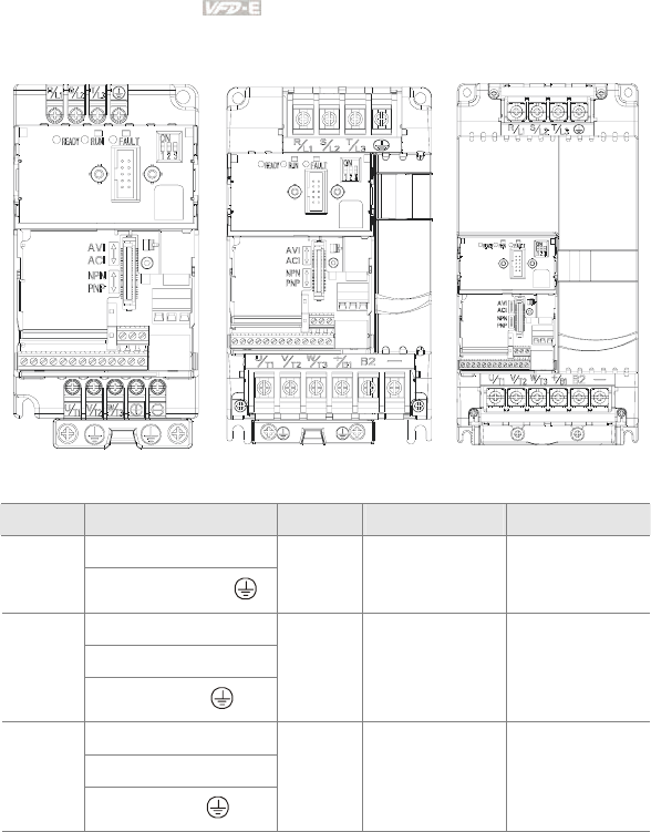
2.3.2 Main Circuit Terminals
Frame A Frame B Frame C
Frame Power Terminals Torque Wire Wire type
R/L1, S/L2, T/L3
A
U/T1, V/T2, W/T3,
14kgf-cm
(12in-lbf)
12-14 AWG.
(3.3-2.1mm2) Copper only, 75oC
R/L1, S/L2, T/L3
U/T1, V/T2, W/T3
B
+/B1, B2, -,
18kgf-cm
(15.6in-lbf)
8-18 AWG.
(8.4-0.8mm2) Copper only, 75oC
R/L1, S/L2, T/L3
U/T1, V/T2, W/T3
C
+/B1, B2, -
30kgf-cm
(26in-lbf)
8-16 AWG.
(8.4-1.3mm2) Copper only, 75oC
Chapter 2 Installation and Wiring|
Revision June 2008, 04EE, SW--PW V1.11/CTL V2.11 2-17
NOTE
Frame A: VFD002E11A/21A/23A, VFD004E11A/21A/23A/43A, VFD007E21A/23A/43A,
VFD015E23A/43A, VFD002E11C/21C/23C, VFD004E11C/21C/23C/43C, VFD007E21C/23C/43C,
VFD015E23C/43C, VFD002E11T/21T/23T, VFD004E11T/21T/23T/43T, VFD007E21T/23T/43T,
VFD015E23T/43T, VFD002E11P/21P/23P, VFD004E11P/21P/23P/43P, VFD007E21P/23P/43P,
VFD015E23P
Frame B: VFD007E11A, VFD015E21A, VFD022E21A/23A/43A, VFD037E23A/43A, VFD007E11C,
VFD015E21C, VFD022E21C/23C/43C, VFD037E23C/43C
Frame C: VFD055E23A/43A, VFD075E23A/43A, VFD110E43A, VFD055E23C/43C,
VFD075E23C/43C, VFD110E43C
For frame C: To connect 6 AWG (13.3 mm2) wires, use Recognized Ring Terminals
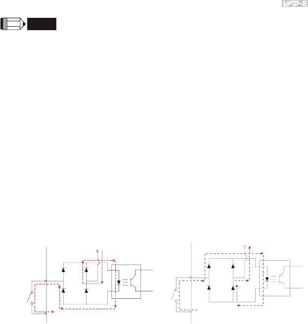
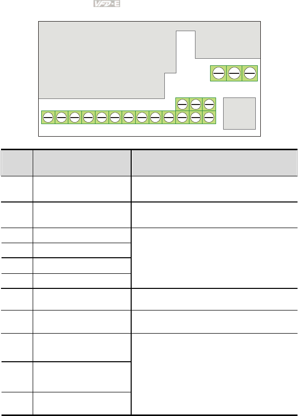
2.4 Control Terminals
Circuit diagram for digital inputs (NPN current 16mA.)
+24
NPN Mode
multi-input
terminal
Internal CircuitDCM
+24V
Multi-Input
Terminal
DCM
Internal Circuit
PNP Mode
Chapter 2 Installation and Wiring|
2-18 Revision June 2008, 04EE, SW--PW V1.11/CTL V2.11
The position of the control terminals
RS-485
10VMI1 MI2 MI3 MI4 MI5 MI6
DCM
24V
DCM ACM
AVI ACI
AFM MCM MO1
RA RB RC
Terminal symbols and functions
Terminal
Symbol Terminal Function Factory Settings (NPN mode)
ON: Connect to DCM
MI1 Forward-Stop command ON: Run in MI1 direction
OFF: Stop acc. to Stop Method
MI2 Reverse-Stop command ON: Run in MI2 direction
OFF: Stop acc. to Stop Method
MI3 Multi-function Input 3
MI4 Multi-function Input 4
MI5 Multi-function Input 5
MI6 Multi-function Input 6
Refer to Pr.04.05 to Pr.04.08 for programming the
Multi-function Inputs.
ON: the activation current is 5.5mA.
OFF: leakage current tolerance is 10μA.
+24V DC Voltage Source +24VDC, 20mA used for PNP mode.
DCM Digital Signal Common Common for digital inputs and used for NPN
mode.
RA Multi-function Relay output
(N.O.) a
RB Multi-function Relay output
(N.C.) b
RC Multi-function Relay common
Resistive Load:
5A(N.O.)/3A(N.C.) 240VAC
5A(N.O.)/3A(N.C.) 24VDC
Inductive Load:
1.5A(N.O.)/0.5A(N.C.) 240VAC
1.5A(N.O.)/0.5A(N.C.) 24VDC
Refer to Pr.03.00 for programming
Chapter 2 Installation and Wiring|
Revision June 2008, 04EE, SW--PW V1.11/CTL V2.11 2-19
Terminal
Symbol Terminal Function Factory Settings (NPN mode)
ON: Connect to DCM
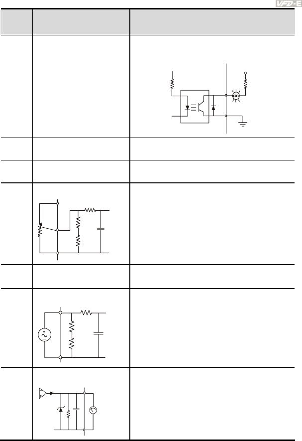
MO1 Multi-function Output 1
(Photocoupler)
Maximum 48VDC, 50mA
Refer to Pr.03.01 for programming
MO1-DCM
Mo1
MCM
Max: 48Vdc
50mA
internal circuit
MCM Multi-function output common Common for Multi-function Outputs
+10V Potentiometer power supply +10VDC 3mA
AVI
Analog voltage Input
ACM
AVI
+10V
internal circuit
AVI circuit
Impedance: 47kΩ
Resolution: 10 bits
Range: 0 ~ 10VDC =
0 ~ Max. Output Frequency
(Pr.01.00)
Selection: Pr.02.00, Pr.02.09, Pr.10.00
Set-up: Pr.04.11 ~ Pr.04.14, 04.19~04.23
ACM Analog control signal
(common) Common for AVI, ACI, AFM
ACI
Analog current Input
ACM
ACI
internal circuit
ACI circuit
Impedance: 250Ω
Resolution: 10 bits
Range: 4 ~ 20mA =
0 ~ Max. Output Frequency
(Pr.01.00)
Selection: Pr.02.00, Pr.02.09, Pr.10.00
Set-up: Pr.04.15 ~ Pr.04.18
AFM
Analog output meter
A
FM
A
CM
0~10V
Max. 2mA
potentiometer
ACM circuit
internal circuit
0 to 10V, 2mA
Impedance: 100kΩ
Output current 2mA max
Resolution: 8 bits
Range: 0 ~ 10VDC
Function: Pr.03.03 to Pr.03.04
NOTE: Control signal wiring size: 18 AWG (0.75 mm2) with shielded wire.

Chapter 2 Installation and Wiring|
2-20 Revision June 2008, 04EE, SW--PW V1.11/CTL V2.11
Analog inputs (AVI, ACI, ACM)
Analog input signals are easily affected by external noise. Use shielded wiring and keep it
as short as possible (<20m) with proper grounding. If the noise is inductive, connecting
the shield to terminal ACM can bring improvement.
If the analog input signals are affected by noise from the AC motor drive, please connect
a capacitor (0.1
μ
F and above) and ferrite core as indicated in the following diagrams:
C
A
VI/ACI
ACM
ferrite core
wind each wires 3 times or more around the core
Digital inputs (MI1~MI6, DCM)
When using contacts or switches to control the digital inputs, please use high quality
components to avoid contact bounce.
Digital outputs (MO1, MCM)
Make sure to connect the digital outputs to the right polarity, see wiring diagrams.
When connecting a relay to the digital outputs, connect a surge absorber or fly-back diode
across the coil and check the polarity.
General
Keep control wiring as far away as possible from the power wiring and in separate
conduits to avoid interference. If necessary let them cross only at 90º angle.
The AC motor drive control wiring should be properly installed and not touch any live
power wiring or terminals.
DANGER!
Damaged insulation of wiring may cause personal injury or damage to circuits/equipment if it comes
in contact with high voltage.
Chapter 2 Installation and Wiring|
Revision June 2008, 04EE, SW--PW V1.11/CTL V2.11 2-21
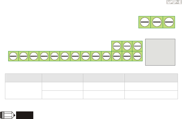
The specification for the control terminals
RS-485 port
10VMI1 MI
2
MI3 MI4 MI5 MI6
DCM
24V
DCM
A
CM
AVI ACI
AFM MCM MO1
RA RB RC
The position of the control terminals
Terminals 2
Terminals 1
Frame Control Terminals Torque Wire
Terminals 1 5 kgf-cm (4.4 in-lbf) 12-24 AWG (3.3-0.2mm2)
A, B, C
Terminals 2 2 kgf-cm (1.7 in-lbf) 16-24 AWG (1.3-0.2mm2)
NOTE
Frame A: VFD002E11A/21A/23A, VFD004E11A/21A/23A/43A, VFD007E21A/23A/43A,
VFD015E23A/43A, VFD002E11C/21C/23C, VFD004E11C/21C/23C/43C, VFD007E21C/23C/43C,
VFD015E23C/43C, VFD002E11T/21T/23T, VFD004E11T/21T/23T/43T, VFD007E21T/23T/43T,
VFD015E23T/43T, VFD002E11P/21P/23P, VFD004E11P/21P/23P/43P, VFD007E21P/23P/43P,
VFD015E23P
Frame B: VFD007E11A, VFD015E21A, VFD022E21A/23A/43A, VFD037E23A/43A, VFD007E11C,
VFD015E21C, VFD022E21C/23C/43C, VFD037E23C/43C
Frame C: VFD055E23A/43A, VFD075E23A/43A, VFD110E43A, VFD055E23C/43C,
VFD075E23C/43C, VFD110E43C

Chapter 2 Installation and Wiring|
2-22 Revision June 2008, 04EE, SW--PW V1.11/CTL V2.11
This page intentionally left blank
Revision June 2008, 04EE, SW--PW V1.11/CTL V2.11 3-1
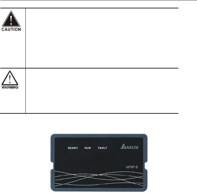
Chapter 3 Keypad and Start Up
Make sure that the wiring is correct. In particular, check that the
output terminals U/T1, V/T2, W/T3. are NOT connected to power
and that the drive is well grounded.
Verify that no other equipment is connected to the AC motor drive
Do NOT operate the AC motor drive with humid hands.
Please check if READY LED is ON when power is applied. Check if
the connection is well when option from the digital keypad KPE-
LE02.
It should be stopped when fault occurs during running and refer to
“Fault Code Information and Maintenance” for solution. Please do
NOT touch output terminals U, V, W when power is still applied to
L1/R, L2/S, L3/T even when the AC motor drive has stopped. The
DC-link capacitors may still be charged to hazardous voltage
levels, even if the power has been turned off.
3.1 Keypad
There are three LEDs on the keypad:
LED READY: It will light up after applying power. The light won’t be off until the capacitors are
discharged to safe voltage levels after power off.
LED RUN: It will light up when the motor is running.
LED FAULT: It will light up when fault occurs.
Chapter 3 Keypad and Start Up|
3-2 Revision June 2008, 04EE, SW--PW V1.11/CTL V2.11
3.2 Operation Method
The operation method can be set via communication, control terminals and optional keypad KPE-
LE02.
RS485 port (RJ-45)
It needs to use VFD-USB01 or
IFD8500 converter to connect
to the PC.
Chapter 3 Keypad and Start Up|
Revision June 2008, 04EE, SW--PW V1.11/CTL V2.11 3-3
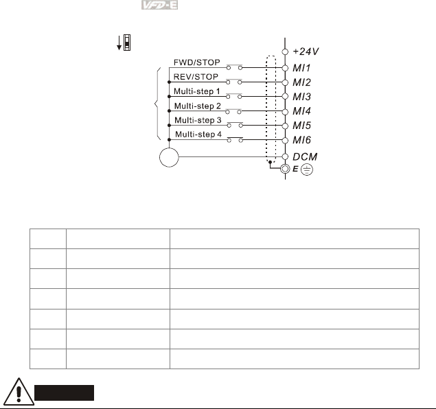
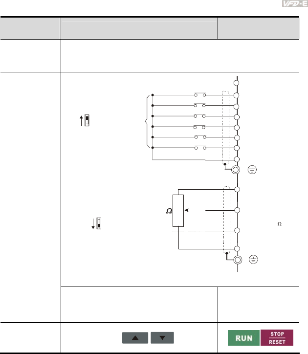
3.3 Trial Run
The factory setting of the operation source is from the external terminal (Pr.02.01=2).
1. Both MI1-DCM and MI2-DCM need to connect a switch for switching FWD/STOP and
REV/STOP.
2. Please connect a potentiometer among AVI, 10V and DCM or apply power 0-10Vdc to
AVI-DCM (as shown in figure 3-1)
Operation
Method Frequency Source Operation Command
Source
Operate from the
communication
When setting communication by the PC, it needs to use VFD-USB01 or
IFD8500 converter to connect to the PC.
Refer to the communication address 2000H and 2101H setting for details.
* Don't apply the mains voltage directly
to above terminals.
E
MI1
MI2
MI3
MI4
MI6
MI5
DCM
+24V
FWD/Stop
REV/Stop
Multi-step 1
Multi-step 2
Multi-step 3
Multi-step 4
Digital Signal Common
Factory
setting
Sw1
NPN
PNP
Factory setting:
NPN Mode
A
VI
A
CI
A
CM
+10V
5K
3
2
1
Power supply
+10V 3mA
Master Frequency
0 to 10V 47K
Analog Signal Common
E
Sw2
AVI
ACI
Factory setting:
ACI Mode
ACI/AVI switch
When switching to AVI,
it indicates AVI2
4-20mA/0-10V
Figure 3-1
Operate from
external signal
MI3-DCM (Set Pr.04.05=10)
MI4-DCM (Set Pr.04.06=11)
External terminals input:
MI1-DCM
MI2-DCM
Operate from the
optional keypad
(KPE-LE02)
Chapter 3 Keypad and Start Up|
3-4 Revision June 2008, 04EE, SW--PW V1.11/CTL V2.11
3. Setting the potentiometer or AVI-DCM 0-10Vdc power to less than 1V.
4. Setting MI1=On for forward running. And if you want to change to reverse running, you
should set MI2=On. And if you want to decelerate to stop, please set MI1/MI2=Off.
5. Check following items:
Check if the motor direction of rotation is correct.
Check if the motor runs steadily without abnormal noise and vibration.
Check if acceleration and deceleration are smooth.
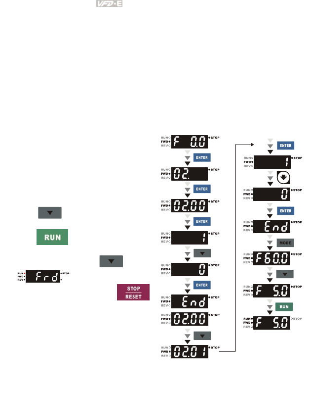
If you want to perform a trial run by using optional digital keypad, please operate by the following
steps.
1. Connect digital keypad to AC motor drive
correctly.
2. After applying the power, verify that LED
display shows F 0.0Hz.
3. Set Pr.02.00=0 and Pr.02.01=0. (Refer to
Appendix B operation flow for detail)
4. Press key to set frequency to
around 5Hz.
5. Press key for forward running.
And if you want to change to reverse
running, you should press in
page. And if you want to
decelerate to stop, please press
key.
6. Check following items:
Check if the motor direction of rotation
is correct.
Check if the motor runs steadily
without abnormal noise and vibration.
Check if acceleration and deceleration
are smooth.
If the results of trial run are normal, please start the formal run.

Revision June 2008, 04EE, SW--PW V1.11/CTL V2.11 4-1
Chapter 4 Parameters
The VFD-E parameters are divided into 14 groups by property for easy setting. In most applications,
the user can finish all parameter settings before start-up without the need for re-adjustment during
operation.
The 14 groups are as follows:
Group 0: User Parameters
Group 1: Basic Parameters
Group 2: Operation Method Parameters
Group 3: Output Function Parameters
Group 4: Input Function Parameters
Group 5: Multi-Step Speed Parameters
Group 6: Protection Parameters
Group 7: Motor Parameters
Group 8: Special Parameters
Group 9: Communication Parameters
Group 10: PID Control Parameters
Group 11: Multi-function Input/Output Parameters for Extension Card
Group 12: Analog Input/Output Parameters for Extension Card
Group 13: PG function Parameters for Extension Card

Chapter 4 Parameters|
4-2 Revision June 2008, 04EE, SW--PW V1.11/CTL V2.11
4.1 Summary of Parameter Settings
: The parameter can be set during operation.
Group 0 User Parameters
Parameter Explanation Settings Factory
Setting Customer
00.00 Identity Code of the
AC motor drive Read-only ##
00.01 Rated Current
Display of the AC
motor drive
Read-only #.#
0: Parameter can be read/written
1: All parameters are read only
6: Clear PLC program (NOT for VFD*E*C
models)
9: All parameters are reset to factory settings
(50Hz, 230V/400V or 220V/380V depends on
Pr.00.12)
00.02 Parameter Reset
10: All parameters are reset to factory
settings (60Hz, 220V/440V)
0
0: Display the frequency command value
(Fxxx)
1: Display the actual output frequency (Hxxx)
2: Display the content of user-defined unit
(Uxxx)
3: Multifunction display, see Pr.00.04
4: FWD/REV command
00.03 Start-up Display
Selection
5: PLCx (PLC selections: PLC0/PLC1/PLC2)
(NOT for VFD*E*C models)
0
0: Display the content of user-defined unit
(Uxxx)
1: Display the counter value (c)
2: Display PLC D1043 value (C) (NOT for
VFD*E*C models)
3: Display DC-BUS voltage (u)
00.04 Content of Multi-
function Display
4: Display output voltage (E)
0

Chapter 4 Parameters|
Revision June 2008, 04EE, SW--PW V1.11/CTL V2.11 4-3
Parameter Explanation Settings Factory
Setting Customer
5: Display PID analog feedback signal value
(b) (%)
6: Output power factor angle (n)
7: Display output power (P)
8: Display the estimated value of torque as it
relates to current (t)
9: Display AVI (I) (V)
10: Display ACI / AVI2 (i) (mA/V)
11: Display the temperature of IGBT (h) (°C)
12: Display AVI3/ACI2 level (I.)
13: Display AVI4/ACI3 level (i.)
14: Display PG speed in RPM (G)
15: Display motor number (M)
00.05 User-Defined
Coefficient K 0. 1 to 160.0 1.0
00.06 Power Board
Software Version
Read-only #.##
00.07 Control Board
Software Version
Read-only #.##
00.08 Password Input 0 to 9999 0
00.09 Password Set 0 to 9999 0
0: V/f Control
00.10 Control Method
1: Vector Control
0
00.11 Reserved
00.12 50Hz Base Voltage
Selection
0: 230V/400V
1: 220V/380V 0
Group 1 Basic Parameters
Parameter Explanation Settings Factory
Setting Customer
01.00 Maximum Output
Frequency (Fmax) 50.00 to 600.0 Hz 60.00

Chapter 4 Parameters|
4-4 Revision June 2008, 04EE, SW--PW V1.11/CTL V2.11
Parameter Explanation Settings Factory
Setting Customer
01.01
Maximum Voltage
Frequency (Fbase)
(Motor 0)
0.10 to 600.0 Hz 60.00
115V/230V series: 0.1V to 255.0V 220.0
01.02
Maximum Output
Voltage (Vmax)
(Motor 0) 460V series: 0.1V to 510.0V 440.0
01.03 Mid-Point Frequency
(Fmid) (Motor 0) 0.10 to 600.0 Hz 1.50
115V/230V series: 0.1V to 255.0V 10.0
01.04 Mid-Point Voltage
(Vmid) (Motor 0) 460V series: 0.1V to 510.0V 20.0
01.05
Minimum Output
Frequency (Fmin)
(Motor 0)
0.10 to 600.0 Hz 1.50
115V/230V series: 0.1V to 255.0V 10.0
01.06
Minimum Output
Voltage (Vmin)
(Motor 0) 460V series: 0.1V to 510.0V 20.0
01.07 Output Frequency
Upper Limit
0.1 to 120.0% 110.0
01.08 Output Frequency
Lower Limit
0.0 to100.0 % 0.0
01.09 Accel Time 1 0.1 to 600.0 / 0.01 to 600.0 sec 10.0
01.10 Decel Time 1 0.1 to 600.0 / 0.01 to 600.0 sec 10.0
01.11 Accel Time 2 0.1 to 600.0 / 0.01 to 600.0 sec 10.0
01.12 Decel Time 2 0.1 to 600.0 / 0.01 to 600.0 sec 10.0
01.13 Jog Acceleration
Time
0.1 to 600.0 / 0.01 to 600.0 sec 1.0
01.14 Jog Deceleration
Time
0.1 to 600.0 / 0.01 to 600.0 sec 1.0
01.15 Jog Frequency 0.10 Hz to Fmax (Pr.01.00) Hz 6.00
0: Linear Accel/Decel
1: Auto Accel, Linear Decel
2: Linear Accel, Auto Decel
3: Auto Accel/Decel (Set by load)
01.16
Auto acceleration /
deceleration (refer
to Accel/Decel time
setting)
4: Auto Accel/Decel (set by Accel/Decel
Time setting)
0

Chapter 4 Parameters|
Revision June 2008, 04EE, SW--PW V1.11/CTL V2.11 4-5
Parameter Explanation Settings Factory
Setting Customer
01.17 Acceleration S-
Curve 0.0 to 10.0 / 0.00 to 10.00 sec 0.0
01.18 Deceleration S-
Curve 0.0 to 10.0 / 0.00 to 10.00 sec 0.0
0: Unit: 0.1 sec
01.19 Accel/Decel Time
Unit 1: Unit: 0.01 sec
0
01.20 Delay Time at 0Hz
for Simple Position
0.00 to 600.00 sec 0.00
01.21 Delay Time at 10Hz
for Simple Position
0.00 to 600.00 sec 0.00
01.22 Delay Time at 20Hz
for Simple Position
0.00 to 600.00 sec 0.00
01.23 Delay Time at 30Hz
for Simple Position
0.00 to 600.00 sec 0.00
01.24 Delay Time at 40Hz
for Simple Position
0.00 to 600.00 sec 0.00
01.25 Delay Time at 50Hz
for Simple Position
0.00 to 600.00 sec 0.00
01.26
Maximum Voltage
Frequency (Fbase)
(Motor 1)
0.10 to 600.0 Hz 60.00
115V/230V series: 0.1V to 255.0V 220.0
01.27
Maximum Output
Voltage (Vmax)
(Motor 1) 460V series: 0.1V to 510.0V 440.0
01.28
Mid-Point
Frequency (Fmid)
(Motor 1)
0.10 to 600.0 Hz 1.50
115V/230V series: 0.1V to 255.0V 10.0
01.29 Mid-Point Voltage
(Vmid) (Motor 1) 460V series: 0.1V to 510.0V 20.0
01.30
Minimum Output
Frequency (Fmin)
(Motor 1)
0.10 to 600.0 Hz 1.50
115V/230V series: 0.1V to 255.0V 10.0
01.31
Minimum Output
Voltage (Vmin)
(Motor 1) 460V series: 0.1V to 510.0V 20.0
01.32
Maximum Voltage
Frequency (Fbase)
(Motor 2)
0.10 to 600.0 Hz 60.00

Chapter 4 Parameters|
4-6 Revision June 2008, 04EE, SW--PW V1.11/CTL V2.11
Parameter Explanation Settings Factory
Setting Customer
115V/230V series: 0.1V to 255.0V 220.0
01.33
Maximum Output
Voltage (Vmax)
(Motor 2) 460V series: 0.1V to 510.0V 440.0
01.34
Mid-Point
Frequency (Fmid)
(Motor 2)
0.10 to 600.0 Hz 1.50
115V/230V series: 0.1V to 255.0V 10.0
01.35 Mid-Point Voltage
(Vmid) (Motor 2) 460V series: 0.1V to 510.0V 20.0
01.36
Minimum Output
Frequency (Fmin)
(Motor 2)
0.10 to 600.0 Hz 1.50
115V/230V series: 0.1V to 255.0V 10.0
01.37
Minimum Output
Voltage (Vmin)
(Motor 2) 460V series: 0.1V to 510.0V 20.0
01.38
Maximum Voltage
Frequency (Fbase)
(Motor 3)
0.10 to 600.0 Hz 60.00
115V/230V series: 0.1V to 255.0V 220.0
01.39
Maximum Output
Voltage (Vmax)
(Motor 3) 460V series: 0.1V to 510.0V 440.0
01.40
Mid-Point
Frequency (Fmid)
(Motor 3)
0.10 to 600.0 Hz 1.50
115V/230V series: 0.1V to 255.0V 10.0
01.41 Mid-Point Voltage
(Vmid) (Motor 3) 460V series: 0.1V to 510.0V 20.0
01.42
Minimum Output
Frequency (Fmin)
(Motor 3)
0.10 to 600.0 Hz 1.50
115V/230V series: 0.1V to 255.0V 10.0
01.43
Minimum Output
Voltage (Vmin)
(Motor 3) 460V series: 0.1V to 510.0V 20.0

Chapter 4 Parameters|
Revision June 2008, 04EE, SW--PW V1.11/CTL V2.11 4-7
Group 2 Operation Method Parameters
Parameter Explanation Settings Factory
Setting Customer
02.00
Source of First
Master Frequency
Command
0: Digital keypad UP/DOWN keys or Multi-
function Inputs UP/DOWN. Last used
frequency saved.
1: 0 to +10V from AVI
2: 4 to 20mA from ACI or 0 to +10V from
AVI2
3: RS-485 (RJ-45)/USB communication
4: Digital keypad potentiometer
5: CANopen communication
1
0: Digital keypad
1: External terminals. Keypad STOP/RESET
enabled.
2: External terminals. Keypad STOP/RESET
disabled.
3: RS-485 (RJ-45)/USB communication.
Keypad STOP/RESET enabled.
4: RS-485 (RJ-45)/USB communication.
Keypad STOP/RESET disabled.
02.01
Source of First
Operation
Command
5: CANopen communication. Keypad
STOP/RESET disabled.
1
0: STOP: ramp to stop; E.F.: coast to stop
1: STOP: coast to stop; E.F.: coast to stop
2: STOP: ramp to stop; E.F.: ramp to stop
02.02 Stop Method
3: STOP: coast to stop; E.F.: ramp to stop
0
02.03
PWM Carrier
Frequency
Selections
1 to 15kHz 8
0: Enable forward/reverse operation
1: Disable reverse operation
02.04 Motor Direction
Control
2: Disabled forward operation
0
0: Disable. Operation status is not changed
even if operation command source Pr.02.01
is changed.
02.05 Line Start Lockout
1: Enable. Operation status is not changed
even if operation command source Pr.02.01
is changed.
1

Chapter 4 Parameters|
4-8 Revision June 2008, 04EE, SW--PW V1.11/CTL V2.11
Parameter Explanation Settings Factory
Setting Customer
2: Disable. Operation status will change if
operation command source Pr.02.01 is
changed.
3: Enable. Operation status will change if
operation command source Pr.02.01 is
changed.
0: Decelerate to 0 Hz
1: Coast to stop and display “AErr”
02.06 Loss of ACI Signal
(4-20mA)
2: Continue operation by last frequency
command
1
0: by UP/DOWN Key
1: Based on accel/decel time
2: Constant speed (Pr.02.08)
02.07 Up/Down Mode
3: Pulse input unit (Pr.02.08)
0
02.08
Accel/Decel Rate of
Change of
UP/DOWN
Operation with
Constant Speed
0.01~10.00 Hz 0.01
02.09
Source of Second
Frequency
Command
0: Digital keypad UP/DOWN keys or Multi-
function Inputs UP/DOWN. Last used
frequency saved.
1: 0 to +10V from AVI
2: 4 to 20mA from ACI or 0 to +10V from
AVI2
3: RS-485 (RJ-45)/USB communication
4: Digital keypad potentiometer
5: CANopen communication
0
02.10
Combination of the
First and Second
Master Frequency
Command
0: First Master Frequency Command
1: First Master Frequency Command+
Second Master Frequency Command
2: First Master Frequency Command -
Second Master Frequency Command
0
02.11 Keypad Frequency
Command
0.00 to 600.0Hz 60.00
02.12
Communication
Frequency
Command
0.00 to 600.0Hz
60.00

Chapter 4 Parameters|
Revision June 2008, 04EE, SW--PW V1.11/CTL V2.11 4-9
Parameter Explanation Settings Factory
Setting Customer
0: Save Keypad & Communication
Frequency
1: Save Keypad Frequency only
02.13
The Selections for
Saving Keypad or
Communication
Frequency
Command
2: Save Communication Frequency only
0
0: by Current Freq Command
1: by Zero Freq Command
02.14
Initial Frequency
Selection (for
keypad &
RS485/USB) 2: by Frequency Display at Stop
0
02.15
Initial Frequency
Setpoint (for keypad
& RS485/USB)
0.00 ~ 600.0Hz 60.00
02.16
Display the Master
Freq Command
Source
Read Only
Bit0=1: by First Freq Source (Pr.02.00)
Bit1=1: by Second Freq Source (Pr.02.09)
Bit2=1: by Multi-input function
Bit3=1: by PLC Freq command (NOT for
VFD*E*C models)
##
02.17
Display the
Operation
Command Source
Read Only
Bit0=1: by Digital Keypad
Bit1=1: by RS485 communication
Bit2=1: by External Terminal 2/3 wire mode
Bit3=1: by Multi-input function
Bit4=1: by PLC Operation Command (NOT
for VFD*E*C models)
##
Group 3 Output Function Parameters
Parameter Explanation Settings Factory
Setting Customer
0: No function
1: AC drive operational
2: Master frequency attained
03.00
Multi-function
Output Relay (RA1,
RB1, RC1)
3: Zero speed
8
4: Over torque detection
5: Base-Block (B.B.) indication
6: Low-voltage indication
03.01
Multi-function
Output Terminal
MO1
7: Operation mode indication
1

Chapter 4 Parameters|
4-10 Revision June 2008, 04EE, SW--PW V1.11/CTL V2.11
Parameter Explanation Settings Factory
Setting Customer
8: Fault indication
9: Desired frequency 1 attained
10: Terminal count value attained
11: Preliminary count value attained
12: Over Voltage Stall supervision
13: Over Current Stall supervision
14: Heat sink overheat warning
15: Over Voltage supervision
16: PID supervision
17: Forward command
18: Reverse command
19: Zero speed output signal
20: Warning(FbE,Cexx, AoL2, AUE, SAvE)
21: Brake control (Desired frequency
attained)
22: Drive ready
23: Desired frequency 2 attained
03.02 Desired Frequency
1 Attained
0.00 to 600.0Hz 0.00
0: Analog frequency meter
03.03
Analog Output
Signal Selection
(AFM) 1: Analog current meter 0
03.04 Analog Output Gain 1 to 200% 100
03.05 Terminal Count
Value
0 to 9999 0
03.06 Preliminary Count
Value 0 to 9999 0
0: Terminal count value attained, no EF
display
03.07
EF Active When
Terminal Count
Value Attained 1: Terminal count value attained, EF active
0
0: Fan always ON
1: 1 minute after AC motor drive stops, fan
will be OFF
03.08 Fan Control
2: Fan ON when AC motor drive runs, fan
OFF when AC motor drive stops
0

Chapter 4 Parameters|
Revision June 2008, 04EE, SW--PW V1.11/CTL V2.11 4-11
Parameter Explanation Settings Factory
Setting Customer
3: Fan ON when preliminary heatsink
temperature attained
Read only
Bit0=1:RLY used by PLC
Bit1=1:MO1 used by PLC
Bit2=1:MO2/RA2 used by PLC
Bit3=1:MO3/RA3 used by PLC
Bit4=1:MO4/RA4 used by PLC
Bit5=1:MO5/RA5 used by PLC
Bit6=1:MO6/RA6 used by PLC
03.09
The Digital Output
Used by PLC
(NOT for VFD*E*C
models)
Bit7=1:MO7/RA7 used by PLC
##
Read only
Bit0=1:AFM used by PLC
Bit1=1: AO1 used by PLC
03.10
The Analog Output
Used by PLC
(NOT for VFD*E*C
models)
Bit2=1: AO2 used by PLC
##
03.11 Brake Release
Frequency 0.00 to 20.00Hz 0.00
03.12 Brake Engage
Frequency 0.00 to 20.00Hz 0.00
03.13
Display the Status of
Multi-function
Output Terminals
Read only
Bit0: RLY Status
Bit1: MO1 Status
Bit2: MO2/RA2 Status
Bit3: MO3/RA3 Status
Bit4: MO4/RA4 Status
Bit5: MO5/RA5 Status
Bit6: MO6/RA6 Status
Bit7: MO7/RA7 Status
##
03.14 Desired Frequency
2 Attained 0.00 to 600.0Hz 0.00
Group 4 Input Function Parameters

Chapter 4 Parameters|
4-12 Revision June 2008, 04EE, SW--PW V1.11/CTL V2.11
Parameter Explanation Settings Factory
Setting Customer
04.00 Keypad
Potentiometer Bias 0.0 to 100.0 % 0.0
04.01
Keypad
Potentiometer Bias
Polarity
0: Positive bias
1: Negative bias 00
04.02 Keypad
Potentiometer Gain 0.1 to 200.0 % 100.0
0: No negative bias command
04.03
Keypad
Potentiometer
Negative Bias,
Reverse Motion
Enable/Disable 1: Negative bias: REV motion enabled
0
0: 2-wire: FWD/STOP, REV/STOP
1: 2-wire: FWD/REV, RUN/STOP
04.04 2-wire/3-wire
Operation Control
Modes
2: 3-wire operation
0
0: No function 1
1: Multi-Step speed command 1
04.05 Multi-function Input
Terminal (MI3)
2: Multi-Step speed command 2
3: Multi-Step speed command 3 2
4: Multi-Step speed command 4
04.06 Multi-function Input
Terminal (MI4)
5: External reset
6: Accel/Decel inhibit 3
7: Accel/Decel time selection command
04.07 Multi-function Input
Terminal (MI5)
8: Jog Operation
9: External base block 4
10: Up: Increment master frequency
04.08 Multi-function Input
Terminal (MI6)
11: Down: Decrement master frequency
12: Counter Trigger Signal
13: Counter reset
14: E.F. External Fault Input
15: PID function disabled
16: Output shutoff stop

Chapter 4 Parameters|
Revision June 2008, 04EE, SW--PW V1.11/CTL V2.11 4-13
Parameter Explanation Settings Factory
Setting Customer
17: Parameter lock enable
18: Operation command selection (external
terminals)
19: Operation command selection(keypad)
20: Operation command selection
(communication)
21: FWD/REV command
22: Source of second frequency command
23: Run/Stop PLC Program (PLC1) (NOT for
VFD*E*C models)
23: Quick Stop (Only for VFD*E*C models)
24: Download/execute/monitor PLC Program
(PLC2) (NOT for VFD*E*C models)
25: Simple position function
26: OOB (Out of Balance Detection)
27: Motor selection (bit 0)
28: Motor selection (bit 1)
04.09 Multi-function Input
Contact Selection
Bit0:MI1
Bit1:MI2
Bit2:MI3
Bit3:MI4
Bit4:MI5
Bit5:MI6
Bit6:MI7
Bit7:MI8
Bit8:MI9
Bit9:MI10
Bit10:MI11
Bit11:MI12
0:N.O., 1:N.C.
P.S.:MI1 to MI3 will be invalid when it is 3-
wire control.
0
04.10
Digital Terminal
Input Debouncing
Time
1 to 20 (*2ms) 1
04.11 Min AVI Voltage 0.0 to 10.0V 0.0
04.12 Min AVI Frequency 0.0 to 100.0% 0.0

Chapter 4 Parameters|
4-14 Revision June 2008, 04EE, SW--PW V1.11/CTL V2.11
Parameter Explanation Settings Factory
Setting Customer
04.13 Max AVI Voltage 0.0 to 10.0V 10.0
04.14 Max AVI Frequency 0.0 to 100.0% 100.0
04.15 Min ACI Current 0.0 to 20.0mA 4.0
04.16 Min ACI Frequency 0.0 to 100.0% 0.0
04.17 Max ACI Current 0.0 to 20.0mA 20.0
04.18 Max ACI Frequency 0.0 to 100.0% 100.0
0: ACI
04.19 ACI/AVI2 Selection
1: AVI2
0
04.20 Min AVI2 Voltage 0.0 to 10.0V 0.0
04.21 Min AVI2 Frequency 0.0 to 100.0% 0.0
04.22 Max AVI2 Voltage 0.0 to 10.0V 10.0
04.23 Max AVI2
Frequency 0.0 to 100.0% 100.0
Read only
Bit0=1:MI1 used by PLC
Bit1=1:MI2 used by PLC
Bit2=1:MI3 used by PLC
Bit3=1:MI4 used by PLC
Bit4=1:MI5 used by PLC
Bit5=1:MI6 used by PLC
Bit6=1: MI7 used by PLC
Bit7=1: MI8 used by PLC
Bit8=1: MI9 used by PLC
Bit9=1: MI10 used by PLC
Bit10=1: MI11 used by PLC
04.24
The Digital Input
Used by PLC
(NOT for VFD*E*C
models)
Bit11=1: MI12 used by PLC
##

Chapter 4 Parameters|
Revision June 2008, 04EE, SW--PW V1.11/CTL V2.11 4-15
Parameter Explanation Settings Factory
Setting Customer
Read only
Bit0=1:AVI used by PLC
Bit1=1:ACI/AVI2 used by PLC
Bit2=1: AI1 used by PLC
04.25
The Analog Input
Used by PLC
(NOT for VFD*E*C
models)
Bit3=1: AI2 used by PLC
##
Read only
Bit0: MI1 Status
Bit1: MI2 Status
Bit2: MI3 Status
Bit3: MI4 Status
Bit4: MI5 Status
Bit5: MI6 Status
Bit6: MI7 Status
Bit7: MI8 Status
Bit8: MI9 Status
Bit9: MI10 Status
Bit10: MI11 Status
04.26
Display the Status
of Multi-function
Input Terminal
Bit11: MI12 Status
##
04.27
Internal/External
Multi-function Input
Terminals Selection
0~4095 0
04.28 Internal Terminal
Status
0~4095 0
Group 5 Multi-Step Speeds Parameters
Parameter Explanation Settings Factory
Setting Customer
05.00 1st Step Speed
Frequency
0.00 to 600.0 Hz 0.00
05.01 2nd Step Speed
Frequency
0.00 to 600.0 Hz 0.00

Chapter 4 Parameters|
4-16 Revision June 2008, 04EE, SW--PW V1.11/CTL V2.11
Parameter Explanation Settings Factory
Setting Customer
05.02 3rd Step Speed
Frequency
0.00 to 600.0 Hz 0.00
05.03 4th Step Speed
Frequency
0.00 to 600.0 Hz 0.00
05.04 5th Step Speed
Frequency
0.00 to 600.0 Hz 0.00
05.05 6th Step Speed
Frequency
0.00 to 600.0 Hz 0.00
05.06 7th Step Speed
Frequency
0.00 to 600.0 Hz 0.00
05.07 8th Step Speed
Frequency
0.00 to 600.0 Hz 0.00
05.08 9th Step Speed
Frequency
0.00 to 600.0 Hz 0.00
05.09 10th Step Speed
Frequency
0.00 to 600.0 Hz 0.00
05.10 11th Step Speed
Frequency
0.00 to 600.0 Hz 0.00
05.11 12th Step Speed
Frequency
0.00 to 600.0 Hz 0.00
05.12 13th Step Speed
Frequency
0.00 to 600.0 Hz 0.00
05.13 14th Step Speed
Frequency
0.00 to 600.0 Hz 0.00
05.14 15th Step Speed
Frequency
0.00 to 600.0 Hz 0.00
Group 6 Protection Parameters
Parameter Explanation Settings Factory
Setting Custome
r
115/230V series: 330.0V to 410.0V 390.0V
460V series: 660.0V to 820.0V 780.0V
06.00 Over-Voltage Stall
Prevention
0.0: Disable over-voltage stall prevention
06.01
Over-Current Stall
Prevention during
Accel
0:Disable
20 to 250% 170

Chapter 4 Parameters|
Revision June 2008, 04EE, SW--PW V1.11/CTL V2.11 4-17
Parameter Explanation Settings Factory
Setting Custome
r
06.02
Over-Current Stall
Prevention during
Operation
0:Disable
20 to 250% 170
0: Disabled
1: Enabled during constant speed operation.
After the over-torque is detected, keep
running until OL1 or OL occurs.
2: Enabled during constant speed operation.
After the over-torque is detected, stop
running.
0
3: Enabled during accel. After the over-torque
is detected, keep running until OL1 or OL
occurs.
06.03
Over-Torque
Detection Mode
(OL2)
4: Enabled during accel. After the over-torque
is detected, stop running.
06.04 Over-Torque
Detection Level 10 to 200% 150
06.05 Over-Torque
Detection Time 0.1 to 60.0 sec 0.1
0: Standard motor (self cooled by fan)
1: Special motor (forced external cooling)
06.06
Electronic Thermal
Overload Relay
Selection
2: Disabled
2
06.07 Electronic Thermal
Characteristic 30 to 600 sec 60
0: No fault
1: Over current (oc)
2: Over voltage (ov)
3: IGBT Overheat (oH1)
06.08 Present Fault
Record
4: Power Board Overheat (oH2)
5: Overload (oL)
6: Overload1 (oL1)
7: Motor over load (oL2)
8: External fault (EF) 06.09 Second Most
Recent Fault Record
9: Current exceeds 2 times rated current
during accel.(ocA)
0

Chapter 4 Parameters|
4-18 Revision June 2008, 04EE, SW--PW V1.11/CTL V2.11
Parameter Explanation Settings Factory
Setting Custome
r
10: Current exceeds 2 times rated current
during decel.(ocd)
11: Current exceeds 2 times rated current
during steady state operation (ocn)
12: Ground fault (GFF)
13: Reserved
14: Phase-Loss (PHL)
15: Reserved
16: Auto Acel/Decel failure (CFA)
17: SW/Password protection (codE)
18: Power Board CPU WRITE failure (cF1.0)
19: Power Board CPU READ failure (cF2.0)
06.10 Third Most Recent
Fault Record
20: CC, OC Hardware protection failure
(HPF1)
21: OV Hardware protection failure (HPF2)
22: GFF Hardware protection failure (HPF3)
06.11 Fourth Most Recent
Fault Record
23: OC Hardware protection failure (HPF4)
24: U-phase error (cF3.0)
25: V-phase error (cF3.1)
06.12 Fifth Most Recent
Fault Record 26: W-phase error (cF3.2)
27: DCBUS error (cF3.3)
28: IGBT Overheat (cF3.4)
29: Power Board Overheat (cF3.5)
30: Control Board CPU WRITE failure (cF1.1)
31: Control Board CPU WRITE failure (cF2.1)
32: ACI signal error (AErr)
33: Reserved
34: Motor PTC overheat protection (PtC1)
35-39: Reserved
40: Communication time-out error of control
board and power board (CP10)

Chapter 4 Parameters|
Revision June 2008, 04EE, SW--PW V1.11/CTL V2.11 4-19
Group 7 Motor Parameters
Parameter Explanation Settings Factory
Setting Custome
r
07.00 Motor Rated Current
(Motor 0)
30 %FLA to 120% FLA FLA
07.01 Motor No-Load
Current (Motor 0) 0%FLA to 99% FLA 0.4*FLA
07.02
Torque
Compensation
(Motor 0)
0.0 to 10.0 0.0
07.03 Slip Compensation
(Used without PG)
(Motor 0)
0.00 to 10.00 0.00
07.04 Motor Parameters
Auto Tuning
0: Disable
1: Auto tuning R1
2: Auto tuning R1 + no-load test
0
07.05
Motor Line-to-line
Resistance R1
(Motor 0)
0~65535 mΩ 0
07.06 Motor Rated Slip
(Motor 0) 0.00 to 20.00 Hz 3.00
07.07 Slip Compensation
Limit 0 to 250% 200
07.08
Torque
Compensation Time
Constant
0.01 ~10.00 Sec 0.10
07.09 Slip Compensation
Time Constant 0.05 ~10.00 sec 0.20
07.10
Accumulative Motor
Operation Time
(Min.)
0 to 1439 Min. 0
07.11
Accumulative Motor
Operation Time
(Day)
0 to 65535 Day 0
07.12 Motor PTC
Overheat Protection
0: Disable
1: Enable 0
07.13
Input Debouncing
Time of the PTC
Protection
0~9999(*2ms) 100

Chapter 4 Parameters|
4-20 Revision June 2008, 04EE, SW--PW V1.11/CTL V2.11
Parameter Explanation Settings Factory
Setting Custome
r
07.14
Motor PTC
Overheat Protection
Level
0.1~10.0V 2.4
07.15
Motor PTC
Overheat Warning
Level
0.1~10.0V 1.2
07.16
Motor PTC
Overheat Reset
Delta Level
0.1~5.0V 0.6
07.17 Treatment of the
Motor PTC
Overheat
0: Warn and RAMP to stop
1: Warn and COAST to stop
2: Warn and keep running
0
07.18 Motor Rated Current
(Motor 1) 30 %FLA to 120% FLA FLA
07.19 Motor No-Load
Current (Motor 1) 0%FLA to 99% FLA 0.4*FLA
07.20
Torque
Compensation
(Motor 1)
0.0 to 10.0 0.0
07.21
Slip Compensation
(Used without PG)
(Motor 1)
0.00 to 10.00 0.00
07.22
Motor Line-to-line
Resistance R1
(Motor 1)
0~65535 mΩ 0
07.23 Motor Rated Slip
(Motor 1) 0.00 to 20.00 Hz 3.00
07.24 Motor Pole Number
(Motor 1) 2 to 10 4
07.25 Motor Rated Current
(Motor 2) 30 %FLA to 120% FLA FLA
07.26 Motor No-Load
Current (Motor 2) 0%FLA to 99% FLA 0.4*FLA
07.27
Torque
Compensation
(Motor 2)
0.0 to 10.0 0.0
07.28
Slip Compensation
(Used without PG)
(Motor 2)
0.00 to 10.00 0.00

Chapter 4 Parameters|
Revision June 2008, 04EE, SW--PW V1.11/CTL V2.11 4-21
Parameter Explanation Settings Factory
Setting Custome
r
07.29
Motor Line-to-line
Resistance R1
(Motor 2)
0~65535 mΩ 0
07.30 Motor Rated Slip
(Motor 2) 0.00 to 20.00 Hz 3.00
07.31 Motor Pole Number
(Motor 3) 2 to 10 4
07.32 Motor Rated Current
(Motor 3) 30 %FLA to 120% FLA FLA
07.33 Motor No-Load
Current (Motor 3) 0%FLA to 99% FLA 0.4*FLA
07.34
Torque
Compensation
(Motor 3)
0.0 to 10.0 0.0
07.35
Slip Compensation
(Used without PG)
(Motor 3)
0.00 to 10.00 0.00
07.36
Motor Line-to-line
Resistance R1
(Motor 3)
0~65535 mΩ 0
07.37 Motor Rated Slip
(Motor 3) 0.00 to 20.00 Hz 3.00
07.38 Motor Pole Number
(Motor 3) 2 to 10 4
Group 8 Special Parameters
Parameter Explanation Settings Factory
Setting Custome
r
08.00 DC Brake Current
Level 0 to 100% 0
08.01 DC Brake Time
during Start-Up 0.0 to 60.0 sec 0.0
08.02 DC Brake Time
during Stopping 0.0 to 60.0 sec 0.0
08.03
Start-Point for DC
Brake
0.00 to 600.0Hz 0.00

Chapter 4 Parameters|
4-22 Revision June 2008, 04EE, SW--PW V1.11/CTL V2.11
Parameter Explanation Settings Factory
Setting Custome
r
0: Operation stops after momentary power
loss
1: Operation continues after momentary
power loss, speed search starts with the
Master Frequency reference value
08.04
Momentary Power
Loss Operation
Selection
2: Operation continues after momentary
power loss, speed search starts with the
minimum frequency
0
08.05 Maximum Allowable
Power Loss Time 0.1 to 5.0 sec 2.0
08.06 Base-block Speed
Search
0: Disable speed search
1: Speed search starts with last frequency
command
2: Starts with minimum output frequency
1
08.07 B.B. Time for Speed
Search 0.1 to 5.0 sec 0.5
08.08 Current Limit for
Speed Search 30 to 200% 150
08.09 Skip Frequency 1
Upper Limit 0.00 to 600.0 Hz 0.00
08.10 Skip Frequency 1
Lower Limit 0.00 to 600.0 Hz 0.00
08.11 Skip Frequency 2
Upper Limit 0.00 to 600.0 Hz 0.00
08.12 Skip Frequency 2
Lower Limit 0.00 to 600.0 Hz 0.00
08.13 Skip Frequency 3
Upper Limit 0.00 to 600.0 Hz 0.00
08.14 Skip Frequency 3
Lower Limit 0.00 to 600.0 Hz 0.00
08.15 Auto Restart After
Fault
0 to 10 (0=disable) 0
08.16 Auto Reset Time at
Restart after Fault
0.1 to 6000 sec 60.0
0: Disable
08.17 Auto Energy Saving 1: Enable
0

Chapter 4 Parameters|
Revision June 2008, 04EE, SW--PW V1.11/CTL V2.11 4-23
Parameter Explanation Settings Factory
Setting Custome
r
0: AVR function enable
1: AVR function disable
2: AVR function disable for decel.
08.18 AVR Function
3: AVR function disable for stop
0
115V / 230V series: 370.0to 430.0V 380.0
08.19 Software Brake
Level 460V series: 740.0 to 860.0V 760.0
08.20
Compensation
Coefficient for Motor
Instability
0.0~5.0
0.0
08.21 OOB Sampling Time 0.1 to 120.0 sec 1.0
08.22 Number of OOB
Sampling Times
00 to 32 20
08.23 OOB Average
Sampling Angle
Read only #.#
08.24 DEB Function 0: Disable
1: Enable 0
08.25 DEB Return Time 0 to 250 sec 0
Group 9 Communication Parameters
Parameter Explanation Settings Factory
Setting Custome
r
09.00 Communication
Address 1 to 254 1
0: Baud rate 4800bps
1: Baud rate 9600bps
2: Baud rate 19200bps
09.01 Transmission Speed
3: Baud rate 38400bps
1
0: Warn and keep operating
1: Warn and ramp to stop
2: Warn and coast to stop
09.02 Transmission Fault
Treatment
3: No warning and keep operating
3

Chapter 4 Parameters|
4-24 Revision June 2008, 04EE, SW--PW V1.11/CTL V2.11
Parameter Explanation Settings Factory
Setting Custome
r
09.03 Time-out Detection 0.1 ~ 120.0 seconds
0.0: Disable 0.0
0: 7,N,2 (Modbus, ASCII)
1: 7,E,1 (Modbus, ASCII)
2: 7,O,1 (Modbus, ASCII)
3: 8,N,2 (Modbus, RTU)
4: 8,E,1 (Modbus, RTU)
09.04 Communication
Protocol
5: 8,O,1 (Modbus, RTU)
0
6: 8,N,1 (Modbus, RTU)
7: 8,E,2 (Modbus, RTU)
8: 8,O,2 (Modbus, RTU)
9: 7,N,1 (Modbus, ASCII)
10: 7,E,2 (Modbus, ASCII)
11: 7,O,2 (Modbus, ASCII)
09.05 Reserved
09.06 Reserved
09.07 Response Delay
Time
0 ~ 200 (unit: 2ms) 1
09.08 Transmission Speed
for USB Card
0: Baud rate 4800 bps
1: Baud rate 9600 bps
2: Baud rate 19200 bps
3: Baud rate 38400 bps
4: Baud rate 57600 bps
2
09.09
Communication
Protocol for USB
Card
0: 7,N,2 for ASCII
1: 7,E,1 for ASCII
2: 7,O,1 for ASCII
3: 8,N,2 for RTU
4: 8,E,1 for RTU
5: 8,O,1 for RTU
1

Chapter 4 Parameters|
Revision June 2008, 04EE, SW--PW V1.11/CTL V2.11 4-25
Parameter Explanation Settings Factory
Setting Custome
r
09.09
Communication
Protocol for USB
Card
6: 8,N,1 (Modbus, RTU)
7: 8,E,2 (Modbus, RTU)
8: 8,O,2 (Modbus, RTU)
9: 7,N,1 (Modbus, ASCII)
10: 7,E,2 (Modbus, ASCII)
11: 7,O,2 (Modbus, ASCII)
09.10
Transmission Fault
Treatment for USB
Card
0: Warn and keep operating
1: Warn and ramp to stop
2: Warn and coast to stop
3: No warning and keep operating
0
09.11 Time-out Detection
for USB Card
0.1 ~ 120.0 seconds
0.0: Disable 0.0
09.12
COM port for PLC
Communication
(NOT for VFD*E*C
models)
0: RS485
1: USB card 0
Group 10 PID Control Parameters
Parameter Explanation Settings Factory
Setting Custome
r
0: Disable PID operation
1: Keypad (based on Pr.02.00)
2: 0 to +10V from AVI
3: 4 to 20mA from ACI or 0 to +10V from
AVI2
10.00 PID Set Point
Selection
4: PID set point (Pr.10.11)
0
10.01 Input Terminal for
PID Feedback
0: Positive PID feedback from external
terminal AVI (0 ~ +10VDC)
1: Negative PID feedback from external
terminal AVI (0 ~ +10VDC)
2: Positive PID feedback from external
terminal ACI (4 ~ 20mA)/ AVI2 (0 ~
+10VDC).
3: Negative PID feedback from external
terminal ACI (4 ~ 20mA)/ AVI2 (0 ~
+10VDC).
0

Chapter 4 Parameters|
4-26 Revision June 2008, 04EE, SW--PW V1.11/CTL V2.11
Parameter Explanation Settings Factory
Setting Custome
r
10.02 Proportional Gain
(P) 0.0 to 10.0 1.0
10.03 Integral Time (I) 0.00 to 100.0 sec (0.00=disable) 1.00
10.04 Derivative Control
(D)
0.00 to 1.00 sec 0.00
10.05 Upper Bound for
Integral Control 0 to 100% 100
10.06 Primary Delay Filter
Time 0.0 to 2.5 sec 0.0
10.07 PID Output Freq
Limit 0 to 110% 100
10.08
PID Feedback
Signal Detection
Time
0.0 to 3600 sec (0.0 disable) 60.0
0: Warn and RAMP to stop
1: Warn and COAST to stop
10.09
Treatment of the
Erroneous PID
Feedback Signals
2: Warn and keep operation
0
10.10 Gain Over the PID
Detection Value 0.0 to 10.0 1.0
10.11 Source of PID Set
point
0.00 to 600.0Hz 0.00
10.12 PID Offset Level 1.0 to 50.0% 10.0
10.13 Detection Time of
PID Offset 0.1 to 300.0 sec 5.0
10.14 Sleep/Wake Up
Detection Time 0.0 to 6550 sec 0.0
10.15 Sleep Frequency 0.00 to 600.0 Hz 0.00
10.16 Wakeup Frequency 0.00 to 600.0 Hz 0.00
0: By PID control
10.17
Minimum PID
Output Frequency
Selection 1: By minimum output frequency (Pr.01.05)
0
Group 11 Parameters for Extension Card

Chapter 4 Parameters|
Revision June 2008, 04EE, SW--PW V1.11/CTL V2.11 4-27
Parameter Explanation Settings Factory
Setting Customer
0: No function
1: AC drive operational
2: Master frequency attained
11.00
Multi-function
Output Terminal
MO2/RA2
3: Zero speed
0
4: Over torque detection
5: Base-Block (B.B.) indication
6: Low-voltage indication
11.01 Multi-function
Output Terminal
MO3/RA3
7: Operation mode indication
0
8: Fault indication
9: Desired frequency 1 attained
10: Terminal count value attained
11.02
Multi-function
Output Terminal
MO4/RA4
11: Preliminary count value attained
0
12: Over Voltage Stall supervision
13: Over Current Stall supervision
14: Heat sink overheat warning
11.03 Multi-function
Output Terminal
MO5/RA5
15: Over Voltage supervision
0
16: PID supervision
17: Forward command
18: Reverse command
11.04 Multi-function
Output Terminal
MO6/RA6
19: Zero speed output signal
0
20: Warning(FbE,Cexx, AoL2, AUE, SAvE)
21: Brake control (Desired frequency
attained)
0
22: Drive ready
11.05
Multi-function
Output Terminal
MO7/RA7
23: Desired frequency 2 attained
0: No function 0
1: Multi-Step speed command 1
11.06 Multi-function Input
Terminal (MI7)
2: Multi-Step speed command 2
3: Multi-Step speed command 3 0 11.07 Multi-function Input
Terminal (MI8)
4: Multi-Step speed command 4

Chapter 4 Parameters|
4-28 Revision June 2008, 04EE, SW--PW V1.11/CTL V2.11
Parameter Explanation Settings Factory
Setting Customer
5: External reset
6: Accel/Decel inhibit 0
7: Accel/Decel time selection command
11.08 Multi-function Input
Terminal (MI9)
8: Jog Operation
9: External base block 0
10: Up: Increment master frequency
11.09 Multi-function Input
Terminal (MI10)
11: Down: Decrement master frequency
12: Counter Trigger Signal 0
13: Counter reset
14: E.F. External Fault Input
11.10 Multi-function Input
Terminal (MI11)
15: PID function disabled
16: Output shutoff stop 0
17: Parameter lock enable
18: Operation command selection (external
terminals)
19: Operation command selection (keypad)
20: Operation command selection
(communication)
21: FWD/REV command
22: Source of second frequency command
23: Run/Stop PLC Program (PLC1)
(NOT for VFD*E*C models)
23: Quick Stop (Only for VFD*E*C models)
11.11 Multi-function Input
Terminal (MI12)
24: Download/execute/monitor PLC Program
(PLC2) (NOT for VFD*E*C models)
25: Simple position function
26: OOB (Out of Balance Detection)
27: Motor selection (bit 0)
28: Motor selection (bit 1)

Chapter 4 Parameters|
Revision June 2008, 04EE, SW--PW V1.11/CTL V2.11 4-29
Group 12: Analog Input/Output Parameters for Extension Card
Parameter Explanation Settings Factory
Setting Customer
0: Disabled
1: Source of the 1st frequency
2: Source of the 2nd frequency
3: PID Set Point (PID enable)
4: Positive PID feedback
12.00 AI1 Function
Selection
5: Negative PID feedback
0
0: ACI2 analog current (0.0 ~ 20.0mA)
12.01 AI1 Analog Signal
Mode 1: AVI3 analog voltage (0.0 ~ 10.0V)
1
12.02 Min. AVI3 Input
Voltage 0.0 to 10.0V 0.0
12.03 Min. AVI3 Scale
Percentage 0.0 to 100.0% 0.0
12.04 Max. AVI3 Input
Voltage 0.0 to 10.0V 10.0
12.05 Max. AVI3 Scale
Percentage 0.0 to 100.0% 100.0
12.06 Min. ACI2 Input
Current 0.0 to 20.0mA 4.0
12.07 Min. ACI2 Scale
Percentage 0.0 to 100.0% 0.0
12.08 Max. ACI2 Input
Current 0.0 to 20.0mA 20.0
12.09 Max. ACI2 Scale
Percentage 0.0 to 100.0% 100.0
12.10 AI2 Function
Selection
0: Disabled
1: Source of the 1st frequency
2: Source of the 2nd frequency
3: PID Set Point (PID enable)
4: Positive PID feedback
5: Negative PID feedback
0
0: ACI3 analog current (0.0 ~ 20.0mA)
12.11 AI2 Analog Signal
Mode 1: AVI4 analog voltage (0.0 ~ 10.0V)
1

Chapter 4 Parameters|
4-30 Revision June 2008, 04EE, SW--PW V1.11/CTL V2.11
Parameter Explanation Settings Factory
Setting Customer
12.12 Min. AVI4 Input
Voltage 0.0 to 10.0V 0.0
12.13 Min. AVI4 Scale
Percentage 0.0 to 100.0% 0.0
12.14 Max. AVI4 Input
Voltage 0.0 to 10.0V 10.0
12.15 Max. AVI4 Scale
Percentage 0.0 to 100.0% 100.0
12.16 Min. ACI3 Input
Current 0.0 to 20.0mA 4.0
12.17 Min. ACI3 Scale
Percentage 0.0 to 100.0% 0.0
12.18 Max. ACI3 Input
Current 0.0 to 20.0mA 20.0
12.19 Max. ACI3 Scale
Percentage 0.0 to 100.0% 100.0
0: AVO1
1: ACO1 (analog current 0.0 to 20.0mA)
12.20 AO1 Terminal
Analog Signal Mode
2: ACO1 (analog current 4.0 to 20.0mA)
0
0: Analog Frequency
12.21 AO1 Analog Output
Signal 1: Analog Current (0 to 250% rated current)
0
12.22 AO1 Analog Output
Gain 1 to 200% 100
0: AVO2
1: ACO2 (analog current 0.0 to 20.0mA)
12.23 AO2 Terminal
Analog Signal Mode
2: ACO2 (analog current 4.0 to 20.0mA)
0
0: Analog Frequency
12.24 AO2 Analog Output
Signal 1: Analog Current (0 to 250% rated current)
0
12.25 AO2 Analog Output
Gain 1 to 200% 100

Chapter 4 Parameters|
Revision June 2008, 04EE, SW--PW V1.11/CTL V2.11 4-31
Group 13: PG function Parameters for Extension Card
Parameter Explanation Settings Factory
Setting Customer
0: Disabled
1: Single phase
2: Forward/Counterclockwise rotation
13.00 PG Input
3: Reverse/Clockwise rotation
0
13.01 PG Pulse Range 1 to 20000 600
13.02 Motor Pole Number
(Motor 0) 2 to 10 4
13.03 Proportional Gain
(P) 0.0 to 10.0 1.0
13.04 Integral Gain (I) 0.00 to 100.00 sec 1.00
13.05
Speed Control
Output Frequency
Limit
0.00 to 100.00Hz 10.00
13.06 Speed Feedback
Display Filter 0 to 9999 (*2ms) 500
13.07
Detection Time for
Feedback Signal
Fault
0.0: disabled
0.1 to 10.0 sec 1
0: Warn and RAMP to stop
1: Warn and COAST to stop
13.08
Treatment of the
Feedback Signal
Fault
2: Warn and keep operation
1
13.09 Speed Feedback
Filter 0 to 9999 (*2ms) 16
0: PG card
13.10 Source of the High-
speed Counter 1: PLC (NOT for VFD*E*C models)
Read
Only

Chapter 4 Parameters|
4-32 Revision June 2008, 04EE, SW--PW V1.11/CTL V2.11
4.2 Parameter Settings for Applications
Speed Search
Applications Purpose Functions Related
Parameters
Windmill, winding
machine, fan and all
inertia loads
Restart free-
running motor
Before the free-running motor is
completely stopped, it can be restarted
without detection of motor speed. The
AC motor drive will auto search motor
speed and will accelerate when its
speed is the same as the motor speed.
08.04~08.08
DC Brake before Running
Applications Purpose Functions Related
Parameters
When e.g. windmills,
fans and pumps rotate
freely by wind or flow
without applying power
Keep the free-
running motor at
standstill.
If the running direction of the free-
running motor is not steady, please
execute DC brake before start-up.
08.00
08.01
Energy Saving
Applications Purpose Functions Related
Parameters
Punching machines
fans, pumps and
precision machinery
Energy saving and
less vibrations
Energy saving when the AC motor
drive runs at constant speed, yet full
power acceleration and deceleration
For precision machinery it also helps
to lower vibrations.
08.17
Multi-step Operation
Applications Purpose Functions Related
Parameters
Conveying machinery Cyclic operation by
multi-step speeds.
To control 15-step speeds and duration
by simple contact signals.
04.05~04.08
05.00~05.14
Switching acceleration and deceleration times
Applications Purpose Functions Related
Parameters
Auto turntable for
conveying machinery
Switching
acceleration and
deceleration times
by external signal
When an AC motor drive drives two or
more motors, it can reach high-speed
but still start and stop smoothly.
01.09~01.12
04.05~04.08
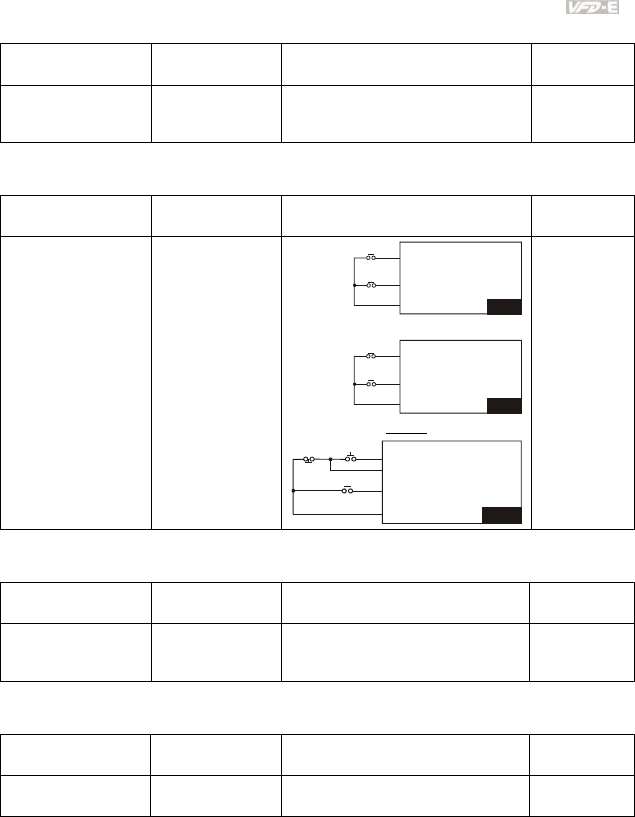
Chapter 4 Parameters|
Revision June 2008, 04EE, SW--PW V1.11/CTL V2.11 4-33
Overheat Warning
Applications Purpose Functions Related
Parameters
Air conditioner Safety measure
When AC motor drive overheats, it
uses a thermal sensor to have
overheat warning.
03.00~03.01
04.05~04.08
Two-wire/three-wire
Applications Purpose Functions Related
Parameters
General application
To run, stop,
forward and
reverse by external
terminals
V
FD-E
MI1:("OPEN":STOP)
("CLOSE":FWD)
MI2:("OPEN": STOP)
("CLOSE": REV)
DCM
FWD/STOP
REV/STOP
V
FD-E
MI1:("OPEN":STOP)
("CLOSE":RUN)
MI2:("OPEN": FWD)
("CLOSE": REV)
DCM
RUN/STOP
FWD/REV
3-wire
V
FD-E
MI3:("OPEN":STOP)
MI1 ("CLOSE":RUN):
MI2:("OPEN": FWD)
("CLOSE": REV)
DCM
STO
P
REV/FWD
RUN
02.00
02.01
02.09
04.04
Operation Command
Applications Purpose Functions Related
Parameters
General application
Selecting the
source of control
signal
Selection of AC motor drive control by
external terminals, digital keypad or
RS485.
02.01
04.05~04.08
Frequency Hold
Applications Purpose Functions Related
Parameters
General application Acceleration/
deceleration pause
Hold output frequency during
Acceleration/deceleration
04.05~04.08

Chapter 4 Parameters|
4-34 Revision June 2008, 04EE, SW--PW V1.11/CTL V2.11
Auto Restart after Fault
Applications Purpose Functions Related
Parameters
Air conditioners,
remote pumps
For continuous and
reliable operation
without operator
intervention
The AC motor drive can be
restarted/reset automatically up to 10
times after a fault occurs.
08.15~08.16
Emergency Stop by DC Brake
Applications Purpose Functions Related
Parameters
High-speed rotors
Emergency stop
without brake
resistor
AC motor drive can use DC brake for
emergency stop when quick stop is
needed without brake resistor. When
used often, take motor cooling into
consideration.
08.00
08.02
08.03
Over-torque Setting
Applications Purpose Functions Related
Parameters
Pumps, fans and
extruders
To protect
machines and to
have continuous/
reliable operation
The over-torque detection level can be
set. Once OC stall, OV stall and over-
torque occurs, the output frequency
will be adjusted automatically. It is
suitable for machines like fans and
pumps that require continuous
operation.
06.00~06.05
Upper/Lower Limit Frequency
Applications Purpose Functions Related
Parameters
Pump and fan
Control the motor
speed within
upper/lower limit
When user cannot provide
upper/lower limit, gain or bias from
external signal, it can be set
individually in AC motor drive.
01.07
01.08
Skip Frequency Setting
Applications Purpose Functions Related
Parameters
Pumps and fans To prevent
machine vibrations
The AC motor drive cannot run at
constant speed in the skip frequency
range. Three skip frequency ranges
can be set.
08.09~08.14

Chapter 4 Parameters|
Revision June 2008, 04EE, SW--PW V1.11/CTL V2.11 4-35
Carrier Frequency Setting
Applications Purpose Functions Related
Parameters
General application Low noise
The carrier frequency can be
increased when required to reduce
motor noise.
02.03
Keep Running when Frequency Command is Lost
Applications Purpose Functions Related
Parameters
Air conditioners For continuous
operation
When the frequency command is lost
by system malfunction, the AC motor
drive can still run. Suitable for
intelligent air conditioners.
02.06
Output Signal during Running
Applications Purpose Functions Related
Parameters
General application Provide a signal for
running status
Signal available to stop braking (brake
release) when the AC motor drive is
running. (This signal will disappear
when the AC motor drive is free-
running.)
03.00~03.01
Output Signal in Zero Speed
Applications Purpose Functions Related
Parameters
General application Provide a signal for
running status
When the output frequency is lower
than the min. output frequency, a
signal is given for external system or
control wiring.
03.00~03.01
Output Signal at Desired Frequency
Applications Purpose Functions Related
Parameters
General application Provide a signal for
running status
When the output frequency is at the
desired frequency (by frequency
command), a signal is given for
external system or control wiring
(frequency attained).
03.00~03.01

Chapter 4 Parameters|
4-36 Revision June 2008, 04EE, SW--PW V1.11/CTL V2.11
Output Signal for Base Block
Applications Purpose Functions Related
Parameters
General application Provide a signal for
running status
When executing Base Block, a signal
is given for external system or control
wiring.
03.00~03.01
Overheat Warning for Heat Sink
Applications Purpose Functions Related
Parameters
General application For safety
When heat sink is overheated, it will
send a signal for external system or
control wiring.
03.00~03.01
Multi-function Analog Output
Applications Purpose Functions Related
Parameters
General application Display running
status
The value of frequency, output
current/voltage can be read by
connecting a frequency meter or
voltage/current meter.
03.06
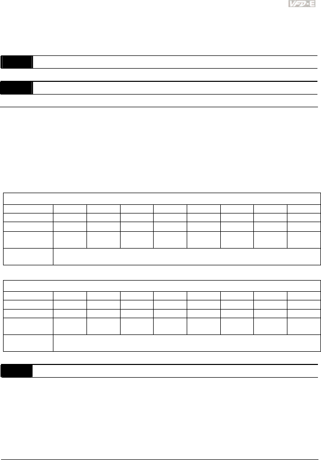
Chapter 4 Parameters|
Revision June 2008, 04EE, SW--PW V1.11/CTL V2.11 4-37
4.3 Description of Parameter Settings
Group 0: User Parameters This parameter can be set during operation.
00.00 Identity Code of the AC Motor Drive
Settings Read Only Factory setting: ##
00.01 Rated Current Display of the AC Motor Drive
Settings Read Only Factory setting: #.#
Pr. 00.00 displays the identity code of the AC motor drive. The capacity, rated current, rated
voltage and the max. carrier frequency relate to the identity code. Users can use the following
table to check how the rated current, rated voltage and max. carrier frequency of the AC motor
drive correspond to the identity code.
Pr.00.01 displays the rated current of the AC motor drive. By reading this parameter the user
can check if the AC motor drive is correct.
115V/230V Series
kW 0.2 0.4 0.75 1.5 2.2 3.7 5.5 7.5
HP 0.25 0.5 1.0 2.0 3.0 5.0 7.5 10
Pr.00-00 0 2 4 6 8 10 12 14
Rated Output
Current (A) 1.6 2.5 4.2 7.5 11.0 17 25 33
Max. Carrier
Frequency 15kHz
460V Series
kW 0.4 0.75 1.5 2.2 3.7 5.5 7.5 11
HP 0.5 1.0 2.0 3.0 5.0 7.5 10 15
Pr.00-00 3 5 7 9 11 13 15 17
Rated Output
Current (A) 1.5 2.5 4.2 5.5 8.5 13 18 24
Max. Carrier
Frequency 15kHz
00.02 Parameter Reset
Factory Setting: 0
Settings 0 Parameter can be read/written
1 All parameters are read-only
6 Clear PLC program (NOT for VFD*E*C models)
9 All parameters are reset to factory settings (50Hz, 230V/400V or
220V/380V depends on Pr.00.12)
10 All parameters are reset to factory settings (60Hz, 115V/220V/440V)
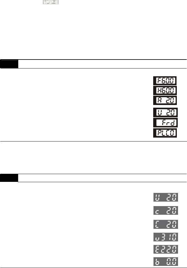
Chapter 4 Parameters|
4-38 Revision June 2008, 04EE, SW--PW V1.11/CTL V2.11
This parameter allows the user to reset all parameters to the factory settings except the fault
records (Pr.06.08 ~ Pr.06.12).
50Hz: Pr.01.00 and Pr.01.01 are set to 50Hz and Pr.01.02 will be set by Pr.00.12.
60Hz: Pr.01.00 and Pr.01.01 are set to 60Hz and Pr.01.02 is set to 115V, 230V or 460V.
When Pr.00.02=1, all parameters are read-only. To write all parameters, set Pr.00.02=0.
00.03 Start-up Display Selection
Factory Setting: 0
Settings 0 Display the frequency command value (Fxxx)
1 Display the actual output frequency (Hxxx)
2 Display the output current in A supplied to the motor
(Axxx)
3 Display the content of user-defined unit (Uxxx)
4 FWD/REV command
5 PLCx (PLC selections: PLC0/PLC1/PLC2)
(NOT for VFD*E*C models)
This parameter determines the start-up display page after power is applied to the drive.
For setting 5, PLC0: disable, PLC1: run PLC, PLC2: read/write PLC programs into AC motor
drive.
00.04 Content of Multi-function Display
Factory Setting: 0
Settings 0 Display the content of user-defined unit (Uxxx)
1
Display the counter value which counts the number of
pulses on TRG terminal
2
Display PLC D1043 value (C)
(NOT for VFD*E*C models)
3
Display the actual DC BUS voltage in VDC of the AC
motor drive
4
Display the output voltage in VAC of terminals U/T1,
V/T2, W/T3 to the motor.
5 Display PID analog feedback signal value in %
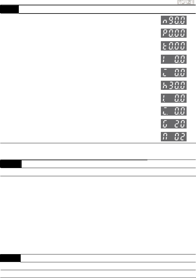
Chapter 4 Parameters|
Revision June 2008, 04EE, SW--PW V1.11/CTL V2.11 4-39
00.04 Content of Multi-function Display
6
Display the power factor angle in º of terminals U/T1,
V/T2, W/T3 to the motor
7
Display the output power in kW of terminals U, V and W
to the motor.
8
Display the estimated value of torque in Nm as it relates
to current.
9
Display the signal of AVI analog input terminal (V).
10
Display the signal of ACI analog input terminal (mA)or
display the signal of AVI2 analog input terminal-(V).
11
Display the temperature of IGBT (h) in °C
12 Display AVI3/ACI2 level (I.)
13 Display AVI4/ACI3 level (i.)
14 Display PG speed in RPM (G)
15 Display motor number (M)
When Pr00.03 is set to 03, the display is according to the setting of Pr00.04.
00.05 User Defined Coefficient K Unit: 0. 1
Settings 0. 1 to d 160.0 Factory Setting: 1.0
The coefficient K determines the multiplying factor for the user-defined unit.
The display value is calculated as follows:
U (User-defined unit) = Actual output frequency * K (Pr.00.05)
Example:
A conveyor belt runs at 13.6m/s at motor speed 60Hz.
K = 13.6/60 = 0.22 (0.226667 rounded to 1 decimal), therefore Pr.00.05=0.2
With Frequency command 35Hz, display shows U and 35*0.2=7.0m/s.
(To increase accuracy, use K=2.2 or K=22.7 and disregard decimal point.)
00.06 Power Board Software Version
Settings Read Only
Display #.##

Chapter 4 Parameters|
4-40 Revision June 2008, 04EE, SW--PW V1.11/CTL V2.11
00.07 Control Board Software Version
Settings Read Only
Display #.##
00.08 Password Input Unit: 1
Settings 0 to 9999 Factory Setting: 0
Display 0~2 (times of wrong password)
The function of this parameter is to input the password that is set in Pr.00.09. Input the correct
password here to enable changing parameters. You are limited to a maximum of 3 attempts.
After 3 consecutive failed attempts, a blinking “codE” will show up to force the user to restart
the AC motor drive in order to try again to input the correct password.
00.09 Password Set Unit: 1
Settings 0 to 9999 Factory Setting: 0
Display 0 No password set or successful input in Pr. 00.08
1 Password has been set
To set a password to protect your parameter settings.
If the display shows 0, no password is set or password has been correctly entered in Pr.00.08.
All parameters can then be changed, including Pr.00.09.
The first time you can set a password directly. After successful setting of password the display
will show 1.
Be sure to record the password for later use.
To cancel the parameter lock, set the parameter to 0 after inputting correct password into Pr.
00.08.
The password consists of min. 1 digits and max. 4 digits.
How to make the password valid again after decoding by Pr.00.08:
Method 1: Re-input original password into Pr.00.09 (Or you can enter a new password if you
want to use a changed or new one).
Method 2: After rebooting, password function will be recovered.
Password Decode Flow Chart
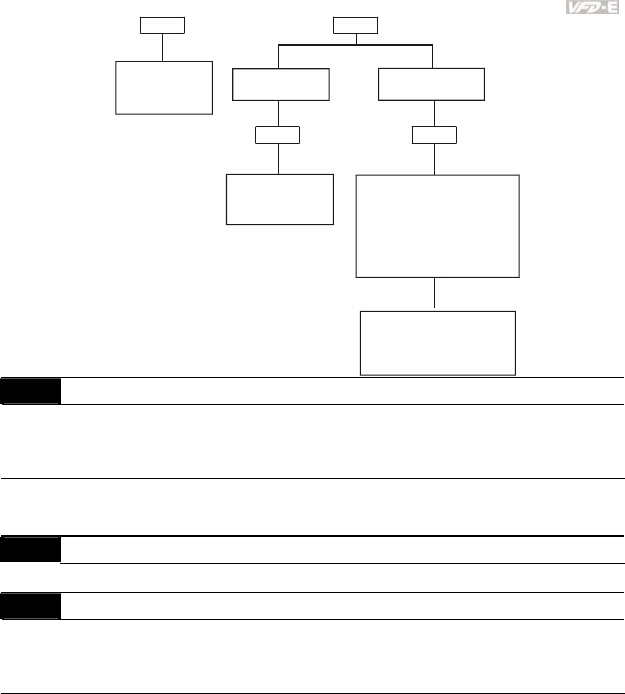
Chapter 4 Parameters|
Revision June 2008, 04EE, SW--PW V1.11/CTL V2.11 4-41
3 chances to enter the correct
password.
1st time displays "1" if
password is incorrect.
2nd time displays "2", if
password is incorrect.
3rd time displays " code"
(blinking)
If the password was entered
incorrectly after three tries,
the keypad will be locked.
Turn the power OFF/ON to
re-enter the password.
Incorrect Password
END
Displays 0 when
entering correct
password into
Pr.00.08.
00.09 00.08
00.08
Displays 0 when
enterin
g
correct
password into
Pr.00.08.
Correct Password
END
00.09
00.10 Control Method
Factory Setting: 0
Settings 0 V/f Control
1 Vector Control
This parameter determines the control method of the AC motor drive.
00.11 Reserved
00.12 50Hz Base Voltage Selection
Factory Setting: 0
Settings 0
230V/400V
1
220V/380V
This parameter determines the base voltage for 50Hz.

Chapter 4 Parameters|
4-42 Revision June 2008, 04EE, SW--PW V1.11/CTL V2.11
Group 1: Basic Parameters
01.00 Maximum Output Frequency (Fmax) Unit: 0.01
Settings 50.00 to 600.0 Hz Factory Setting: 60.00
This parameter determines the AC motor drive’s Maximum Output Frequency. All the AC
motor drive frequency command sources (analog inputs 0 to +10V and 4 to 20mA) are scaled
to correspond to the output frequency range.
01.01 Maximum Voltage Frequency (Fbase) (Motor 0) Unit: 0.01
Settings 0.10 to 600.0Hz Factory Setting: 60.00
This value should be set according to the rated frequency of the motor as indicated on the
motor nameplate. Maximum Voltage Frequency determines the v/f curve ratio. For example, if
the drive is rated for 460 VAC output and the Maximum Voltage Frequency is set to 60Hz, the
drive will maintain a constant ratio of 7.66 V/Hz (460V/60Hz=7.66V/Hz). This parameter value
must be equal to or greater than the Mid-Point Frequency (Pr.01.03).
01.02 Maximum Output Voltage (Vmax) (Motor 0) Unit: 0.1
Settings 115V/230V series 0.1 to 255.0V Factory Setting: 220.0
460V series 0.1 to 510.0V Factory Setting: 440.0
This parameter determines the Maximum Output Voltage of the AC motor drive. The Maximum
Output Voltage setting must be smaller than or equal to the rated voltage of the motor as
indicated on the motor nameplate. This parameter value must be equal to or greater than the
Mid-Point Voltage (Pr.01.04).
01.03 Mid-Point Frequency (Fmid) (Motor 0) Unit: 0.01
Settings 0.10 to 600.0Hz Factory Setting: 1.50
This parameter sets the Mid-Point Frequency of the V/f curve. With this setting, the V/f ratio
between Minimum Frequency and Mid-Point frequency can be determined. This parameter
must be equal to or greater than Minimum Output Frequency (Pr.01.05) and equal to or less
than Maximum Voltage Frequency (Pr.01.01).
This setting must be greater than Pr.01.05.

Chapter 4 Parameters|
Revision June 2008, 04EE, SW--PW V1.11/CTL V2.11 4-43
01.04 Mid-Point Voltage (Vmid) (Motor 0) Unit: 0.1
Settings 115V/230V series 0.1 to 255.0V Factory Setting: 10.0
460V series 0.1 to 510.0V Factory Setting: 20.0
This parameter sets the Mid-Point Voltage of any V/f curve. With this setting, the V/f ratio
between Minimum Frequency and Mid-Point Frequency can be determined. This parameter
must be equal to or greater than Minimum Output Voltage (Pr.01.06) and equal to or less than
Maximum Output Voltage (Pr.01.02).
This setting should be greater than Pr.01.06.
01.05 Minimum Output Frequency (Fmin) (Motor 0) Unit: 0.01
Settings 0.10 to 600.0Hz Factory Setting: 1.50
This parameter sets the Minimum Output Frequency of the AC motor drive. This parameter
must be equal to or less than Mid-Point Frequency (Pr.01.03).
The settings of 01.03, 01.04, and 01.06 are invalid in Vector Control mode.
01.06 Minimum Output Voltage (Vmin) (Motor 0) Unit: 0.1
Settings 115V/230V series 0.1 to 255.0V Factory Setting: 10.0
460V series 0.1 to 510.0V Factory Setting: 20.0
This parameter sets the Minimum Output Voltage of the AC motor drive. This parameter must
be equal to or less than Mid-Point Voltage (Pr.01.04).
The settings of Pr.01.01 to Pr.01.06 have to meet the condition of Pr.01.02 ≥ Pr.01.04 ≥
Pr.01.06 and Pr.01.01 ≥ Pr.01.03 ≥ Pr.01.05.
In vector control mode (Pr.00.10 is set to 1), Pr.01.03, Pr.01.04 and Pr.01.06 are disabled.
01.07 Output Frequency Upper Limit Unit: 0.1
Settings 0.1 to 120.0% Factory Setting: 110.0
This parameter must be equal to or greater than the Output Frequency Lower Limit (Pr.01.08).
The Maximum Output Frequency (Pr.01.00) is regarded as 100%.
Output Frequency Upper Limit value = (Pr.01.00 * Pr.01.07)/100.
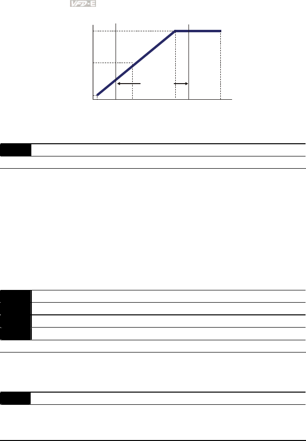
Chapter 4 Parameters|
4-44 Revision June 2008, 04EE, SW--PW V1.11/CTL V2.11
01.05 01.03 01.01
01.06
01.04
01.02
01.00
01.07
01.08
V
/f Curve
Voltage
Frequency
Output Frequency
Lower Limit
Output Frequency
Upper Limit
The limit of
Output
Frequency
Mid-point
Freq.
Maximum
Output
Frequency
Maximum
Output
Voltag e
Mid-point
Voltage
Minimum
Output
Voltag e
Minimum
Output
Freq.
Maximum Voltage
Frequency
(Base Frequency)
01.08 Output Frequency Lower Limit Unit: 0.1
Settings 0.0 to 100.0% Factory Setting: 0.0
The Upper/Lower Limits are to prevent operation errors and machine damage.
If the Output Frequency Upper Limit is 50Hz and the Maximum Output Frequency is 60Hz, the
Output Frequency will be limited to 50Hz.
If the Output Frequency Lower Limit is 10Hz, and the Minimum Output Frequency (Pr.01.05) is
set to 1.0Hz, then any Command Frequency between 1.0-10Hz will generate a 10Hz output
from the drive.
This parameter must be equal to or less than the Output Frequency Upper Limit (Pr.01.07).
The Output Frequency Lower Limit value = (Pr.01.00 * Pr.01.08) /100.
01.09 Acceleration Time 1 (Taccel 1) Unit: 0.1/0.01
01.10 Deceleration Time 1 (Tdecel 1) Unit: 0.1/0.01
01.11 Acceleration Time 2 (Taccel 2) Unit: 0.1/0.01
01.12 Deceleration Time 2 (Tdecel 2) Unit: 0.1/0.01
Settings 0.1 to 600.0 sec / 0.01 to 600.0 sec Factory Setting: 10.0
Acceleration/deceleration time 1 or 2 can be switched by setting the external terminals MI3~
MI12 to 7 (set Pr.04.05~Pr.04.08 to 7 or Pr.11.06~Pr.11.11 to 7).
01.19 Accel/Decel Time Unit
Factory Setting: 0
Settings 0 Unit: 0.1 sec
1 Unit: 0.01 sec
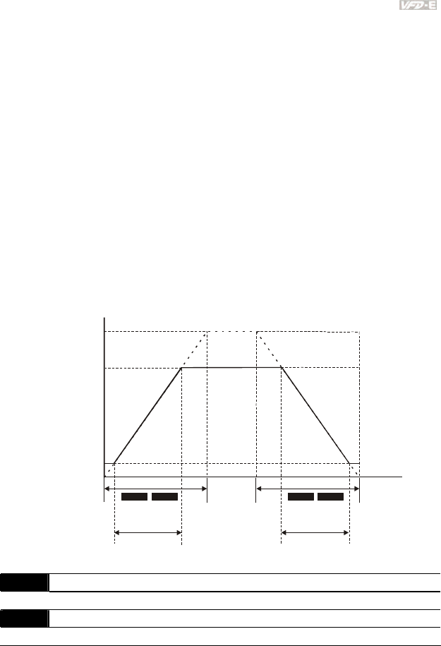
Chapter 4 Parameters|
Revision June 2008, 04EE, SW--PW V1.11/CTL V2.11 4-45
The Acceleration Time is used to determine the time required for the AC motor drive to ramp
from 0 Hz to Maximum Output Frequency (Pr.01.00). The rate is linear unless S-Curve is
“Enabled”; see Pr.01.17.
The Deceleration Time is used to determine the time required for the AC motor drive to
decelerate from the Maximum Output Frequency (Pr.01.00) down to 0 Hz. The rate is linear
unless S-Curve is “Enabled.”, see Pr.01.18.
The Acceleration/Deceleration Time 1, 2, 3, 4 are selected according to the Multi-function Input
Terminals Settings. See Pr.04.05 to Pr.04.08 for more details.
In the diagram shown below, the Acceleration/Deceleration Time of the AC motor drive is the
time between 0 Hz to Maximum Output Frequency (Pr.01.00). Suppose the Maximum Output
Frequency is 60 Hz, Minimum Output Frequency (Pr.01.05) is 1.0 Hz, and
Acceleration/Deceleration Time is 10 seconds. The actual time for the AC motor drive to
accelerate from start-up to 60 Hz and to decelerate from 60Hz to 1.0Hz is in this case 9.83
seconds. ((60-1) * 10/60=9.83secs).
01.00
01.09 01.11 01.10 01.12
Frequency
Time
Accel. Time Decel. Time
The definition of
Accel./Decel. Time
Max. output
Frequency
setting
operation
frequency
Min. output
frequency
01.05
Resulting Resulting
Accel. Time Decel. Time
Resulting Accel./Decel. Time
0 Hz
01.13 Jog Acceleration Time Unit: 0.1/0.01
Settings 0.1 to 600.0/0.01 to 600.0 sec Factory Setting: 1.0
01.14 Jog Deceleration Time Unit: 0.1/0.01
Settings 0.1 to 600.0/0.01 to 600.0 sec Factory Setting: 1.0
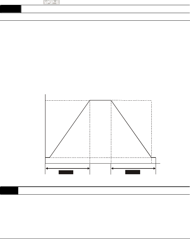
Chapter 4 Parameters|
4-46 Revision June 2008, 04EE, SW--PW V1.11/CTL V2.11
01.15 Jog Frequency Unit: 0.01
Settings 0.10 to Fmax (Pr.01.00)Hz Factory Setting: 6.00
Only external terminal JOG (MI3 to MI12) can be used. When the Jog command is “ON”, the
AC motor drive will accelerate from Minimum Output Frequency (Pr.01.05) to Jog Frequency
(Pr.01.15). When the Jog command is “OFF”, the AC motor drive will decelerate from Jog
Frequency to zero. The used Accel/Decel time is set by the Jog Accel/Decel time (Pr.01.13,
Pr.01.14).
Before using the JOG command, the drive must be stopped first. And during Jog operation,
other operation commands are not accepted, except commands via the FORWARD,
REVERSE and STOP keys on the digital keypad.
01.13
01.12
01.21
Frequency
Time
JOG Accel. Time JOG Decel. Time
The definition of JOG Accel./Decel. Time
01.15
JOG
Frequency
Min. output
frequency
01.05
0 Hz
01.14
01.16 Auto-Acceleration / Deceleration
Factory Setting: 0
Settings 0 Linear acceleration / deceleration
1 Auto acceleration, linear Deceleration.
2 Linear acceleration, auto Deceleration.
3 Auto acceleration / deceleration (set by load)
4 Auto acceleration / deceleration (set by Accel/Decel Time setting)
With Auto acceleration / deceleration it is possible to reduce vibration and shocks during
starting/stopping the load.
During Auto acceleration the torque is automatically measured and the drive will accelerate to
the set frequency with the fastest acceleration time and the smoothest starting current.
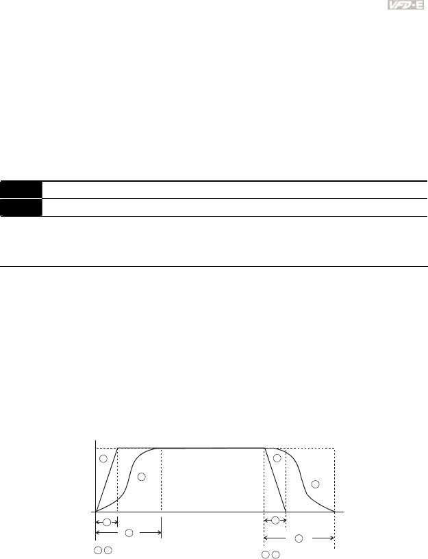
Chapter 4 Parameters|
Revision June 2008, 04EE, SW--PW V1.11/CTL V2.11 4-47
During Auto deceleration, regenerative energy is measured and the motor is smoothly stopped
with the fastest deceleration time.
But when this parameter is set to 04, the actual accel/decel time will be equal to or more than
parameter Pr.01.09 ~Pr.01.12.
Auto acceleration/deceleration makes the complicated processes of tuning unnecessary. It
makes operation efficient and saves energy by acceleration without stall and deceleration
without brake resistor.
In applications with brake resistor or brake unit, Auto deceleration shall not be used.
01.17 Acceleration S-Curve Unit: 0.1/0.01
01.18 Deceleration S-Curve Unit: 0.1/0.01
Factory Setting: 0
Settings 0.0 S-curve disabled
0.1 to 10.0/0.01 to 10.00 S-curve enabled (10.0/10.00 is the smoothest)
This parameter is used to ensure smooth acceleration and deceleration via S-curve.
The S-curve is disabled when set to 0.0 and enabled when set to 0.1 to 10.0/0.01 to 10.00.
Setting 0.1/0.01 gives the quickest and setting 10.0/10.00 the longest and smoothest S-curve.
The AC motor drive will not follow the Accel/Decel Times in Pr.01.09 to Pr.01.12.
The diagram below shows that the original setting of the Accel/Decel Time is only for reference
when the S-curve is enabled. The actual Accel/Decel Time depends on the selected S-curve
(0.1 to 10.0).
The total Accel. Time=Pr.01.09 + Pr.01.17 or Pr.01.11 + Pr.01.17
The total Decel. Time=Pr.01.10 + Pr.01.18 or Pr.01.12 + Pr.01.18
3
12
4
1
3
4
2
1 2 3 4
Disable S curve Enable S curve
A
cceleration/deceleration Characteristics
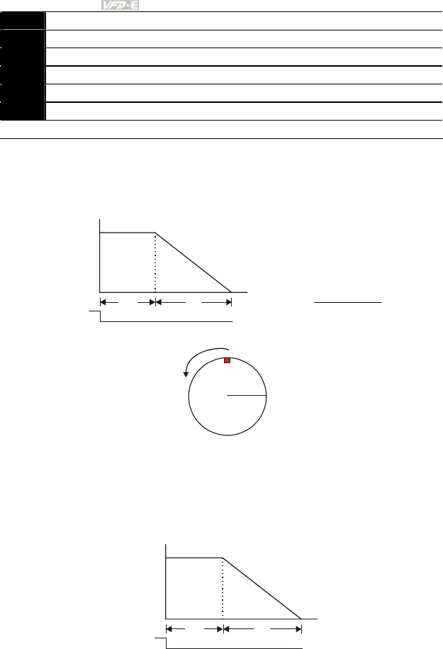
Chapter 4 Parameters|
4-48 Revision June 2008, 04EE, SW--PW V1.11/CTL V2.11
01.20 Delay Time at 0Hz for Simple Position Unit: 0.01
01.21 Delay Time at 10Hz for Simple Position Unit: 0.01
01.22 Delay Time at 20Hz for Simple Position Unit: 0.01
01.23 Delay Time at 30Hz for Simple Position Unit: 0.01
01.24 Delay Time at 40Hz for Simple Position Unit: 0.01
01.25 Delay Time at 50Hz for Simple Position Unit: 0.01
Settings 0.00 to 600.00 sec Factory Setting: 0.00
This simple position function is calculated by the measure of operation area. When the multi-
function input terminal is set to 25 and it is ON, it will start to decelerate after getting the delay
time from Pr.01.20 to Pr.01.25 and get the final position.
This is simple position function NOT the precision position function.
f
t
MI=25
t2tx
(
)
⎟
⎠
⎞
⎜
⎝
⎛++
×= 2
S2
ttt
fxx
Assume that the radius of the 4-pole motor is r and rotation speed is n (rpm).
r
n
Example 1:
Assume that motor speed is 50Hz, the delay time at 50Hz is 2 sec (Pr.01.25=2) and the
deceleration time from 50Hz to 0Hz is 10 seconds.
The rotation speed n = 120 X 50 /4 (rpm/min) = 25 rpm/sec
The revolution numbers = (25 X (2+12))/2 = 175 (revolutions)
f
(Hz)
t
MI=25 2sec 10sec
50
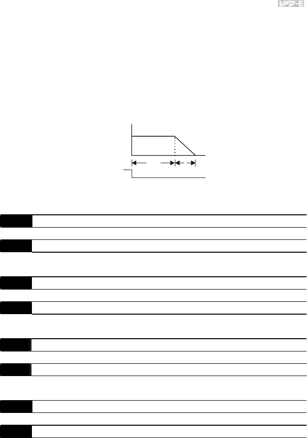
Chapter 4 Parameters|
Revision June 2008, 04EE, SW--PW V1.11/CTL V2.11 4-49
Therefore, the distance = revolution numbers X circumference = 175 X 2π r
It also means that the motor will stop to the original position after 175 circles.
Example 2:
Assume that motor speed is 1.5Hz, the delay time at 10Hz is 10 sec (Pr.01.21=10) and the
deceleration time from 60Hz to 0Hz is 40 seconds.
The delay time at 1.5Hz is 1.5 sec and the deceleration from 1.5Hz to 0Hz is 1 sec.
The rotation speed n = 120 X 1.5 /4 (rpm/min) = 1.5/2 rpm/sec = 0.75 rpm/sec
The revolution numbers = (1.5/2X (1.5+2.5))/2 = 1.5 (revolutions)
f
(Hz)
t
MI=25 1.5sec 1sec
1.5
Therefore, the distance = revolution numbers X circumference = 1.5 X 2π r
It also means that the motor will stop after running 1.5 circles.
01.26 Maximum Voltage Frequency (Fbase) (Motor 1) Unit: 0.01
Settings 0.10 to 600.0Hz Factory Setting: 60.00
01.27 Maximum Output Voltage (Vmax) (Motor 1) Unit: 0.1
Settings 115V/230V series 0.1 to 255.0V Factory Setting: 220.0
460V series 0.1 to 510.0V Factory Setting: 440.0
01.28 Mid-Point Frequency (Fmid) (Motor 1) Unit: 0.01
Settings 0.10 to 600.0Hz Factory Setting: 1.50
01.29 Mid-Point Voltage (Vmid) (Motor 1) Unit: 0.1
Settings 115V/230V series 0.1 to 255.0V Factory Setting: 10.0
460V series 0.1 to 510.0V Factory Setting: 20.0
01.30 Minimum Output Frequency (Fmin) (Motor 1) Unit: 0.01
Settings 0.10 to 600.0Hz Factory Setting: 1.50
01.31 Minimum Output Voltage (Vmin) (Motor 1) Unit: 0.1
Settings 115V/230V series 0.1 to 255.0V Factory Setting: 10.0
460V series 0.1 to 510.0V Factory Setting: 20.0
01.32 Maximum Voltage Frequency (Fbase) (Motor 2) Unit: 0.01
Settings 0.10 to 600.0Hz Factory Setting: 60.00
01.33 Maximum Output Voltage (Vmax) (Motor 2) Unit: 0.1
Settings 115V/230V series 0.1 to 255.0V Factory Setting: 220.0

Chapter 4 Parameters|
4-50 Revision June 2008, 04EE, SW--PW V1.11/CTL V2.11
460V series 0.1 to 510.0V Factory Setting: 440.0
01.34 Mid-Point Frequency (Fmid) (Motor 2) Unit: 0.01
Settings 0.10 to 600.0Hz Factory Setting: 1.50
01.35 Mid-Point Voltage (Vmid) (Motor 2) Unit: 0.1
Settings 115V/230V series 0.1 to 255.0V Factory Setting: 10.0
460V series 0.1 to 510.0V Factory Setting: 20.0
01.36 Minimum Output Frequency (Fmin) (Motor 2) Unit: 0.01
Settings 0.10 to 600.0Hz Factory Setting: 1.50
01.37 Minimum Output Voltage (Vmin) (Motor 2) Unit: 0.1
Settings 115V/230V series 0.1 to 255.0V Factory Setting: 10.0
460V series 0.1 to 510.0V Factory Setting: 20.0
01.38 Maximum Voltage Frequency (Fbase) (Motor 3) Unit: 0.01
Settings 0.10 to 600.0Hz Factory Setting: 60.00
01.39 Maximum Output Voltage (Vmax) (Motor 3) Unit: 0.1
Settings 115V/230V series 0.1 to 255.0V Factory Setting: 220.0
460V series 0.1 to 510.0V Factory Setting: 440.0
01.40 Mid-Point Frequency (Fmid) (Motor 3) Unit: 0.01
Settings 0.10 to 600.0Hz Factory Setting: 1.50
01.41 Mid-Point Voltage (Vmid) (Motor 3) Unit: 0.1
Settings 115V/230V series 0.1 to 255.0V Factory Setting: 10.0
460V series 0.1 to 510.0V Factory Setting: 20.0
01.42 Minimum Output Frequency (Fmin) (Motor 3) Unit: 0.01
Settings 0.10 to 600.0Hz Factory Setting: 1.50
01.43 Minimum Output Voltage (Vmin) (Motor 3) Unit: 0.1
Settings 115V/230V series 0.1 to 255.0V Factory Setting: 10.0
460V series 0.1 to 510.0V Factory Setting: 20.0
The V/f curve of motor 0 to motor 3 can be selected by setting the multi-function input
terminals MI3~MI6 (Pr.04.05 to Pr.04.08) to 27 and 28.
Group 2: Operation Method Parameters
02.00 Source of First Master Frequency Command
Factory Setting: 1
02.09 Source of Second Master Frequency Command
Factory Setting: 0
Settings 0 Digital keypad UP/DOWN keys or Multi-function Inputs UP/DOWN.
Last used frequency saved. (Digital keypad is optional)
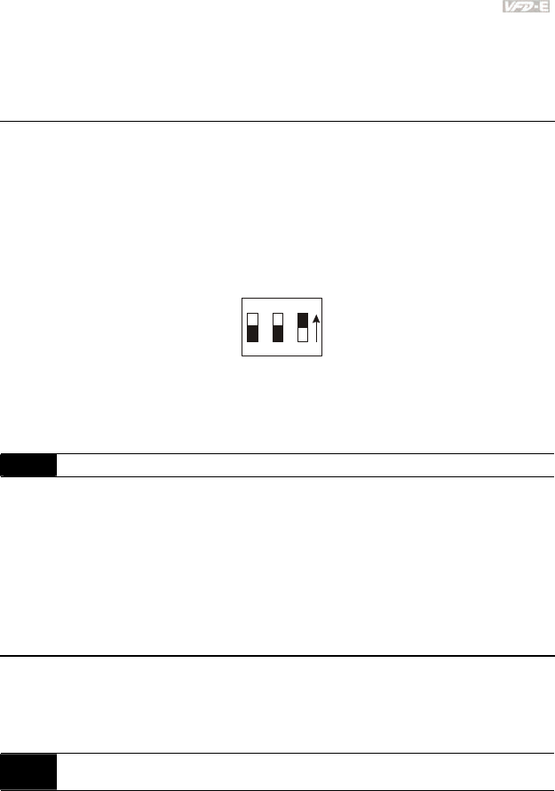
Chapter 4 Parameters|
Revision June 2008, 04EE, SW--PW V1.11/CTL V2.11 4-51
1 0 to +10V from AVI
2 4 to 20mA from ACI or 0 to +10V from AVI2
3 RS-485 (RJ-45)/USB communication
4 Digital keypad potentiometer
5 CANopen communication
These parameters set the Master Frequency Command Source of the AC motor drive.
The factory setting for master frequency command is 1. (digital keypad is optional.)
Setting 2: use the ACI/AVI switch on the AC motor drive to select ACI or AVI2. When setting to
AVI, AVI2 is indicated.
When the 3rd switch on the upper-right corner is set to be ON as shown in the following
diagram, the source of first master frequency command (Pr.02.00) will force setting to 2. This
setting(Pr.02.00) can’t be changed till the 3rd switch is set to be OFF.
ON
123
When the AC motor drive is controlled by external terminal, please refer to Pr.02.05 for details.
The first /second frequency/operation command is enabled/disabled by Multi Function Input
Terminals. Please refer to Pr.04.05 ~ 04.08.
02.01 Source of First Operation Command
Factory Setting: 1
Settings 0 Digital keypad (Digital keypad is optional)
1 External terminals. Keypad STOP/RESET enabled.
2 External terminals. Keypad STOP/RESET disabled.
3 RS-485 (RJ-45)/USB communication. Keypad STOP/RESET
enabled.
4 RS-485 (RJ-45)/USB communication. Keypad STOP/RESET
disabled.
5 CANopen communication. Keypad STOP/RESET disabled.
The factory setting for source of first operation command is 1. (digital keypad is optional.)
When the AC motor drive is controlled by external terminal, please refer to Pr.02.05/Pr.04.04
for details.
02.10 Combination of the First and Second Master Frequency
Command
Factory Setting: 0
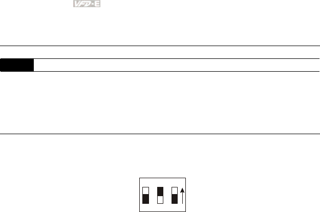
Chapter 4 Parameters|
4-52 Revision June 2008, 04EE, SW--PW V1.11/CTL V2.11
Settings 0 First Master Frequency Command Only
1 First Master Frequency + Second Master Frequency
2 First Master Frequency - Second Master Frequency
02.02 Stop Method
Factory Setting: 0
Settings 0 STOP: ramp to stop E.F.: coast to stop
1 STOP: coast to stop E.F.: coast to stop
2 STOP: ramp to stop E.F.: ramp to stop
3 STOP: coast to stop E.F.: ramp to stop
When the 2nd switch on the upper-right corner is set to be ON as shown in the following
diagram, the motor stop method (Pr.02.02) will force setting to 1. This setting (Pr.02.02) can’t
be changed till the 2nd switch is set to be OFF.
ON
123
The parameter determines how the motor is stopped when the AC motor drive receives a valid
stop command or detects External Fault.
Ramp: the AC motor drive decelerates to Minimum Output Frequency (Pr.01.05)
according to the deceleration time and then stops.
Coast: the AC motor drive stops the output instantly upon command, and the motor
free runs until it comes to a complete standstill.
The motor stop method is usually determined by the characteristics of the motor load and
how frequently it is stopped.
(1) It is recommended to use “ramp to stop” for safety of personnel or to prevent
material from being wasted in applications where the motor has to stop after the
drive is stopped. The deceleration time has to be set accordingly.
(2) If motor free running is allowed or the load inertia is large, it is recommended to
select “coast to stop”. For example: blowers, punching machines, centrifuges
and pumps.
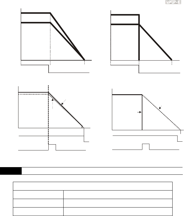
Chapter 4 Parameters|
Revision June 2008, 04EE, SW--PW V1.11/CTL V2.11 4-53
RUN STOP RUN STOP
Frequency Frequency
Time
Time
output
frequency output
frequency
motor
speed motor
speed
operation
command
operation
command
stops according to
decel eration time free run to stop
ramp to stop and free run to stop
EF
Frequency Frequency
frequency output
motor
speed
EF
operation
command
stops according to
decel eration time
When Pr.02.02 is set to 2 or 3
frequency
output
free run to stop
operation
command
When Pr.02.02 is set to 0 or 1
motor
speed
02.03 PWM Carrier Frequency Selections Unit: 1
115V/230V/460V Series
Power 0.25 to 15hp (0.2kW to 11kW)
Setting Range 1 to 15 kHz
Factory Setting 8 kHz
This parameter determines the PWM carrier frequency of the AC motor drive.
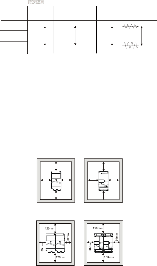
Chapter 4 Parameters|
4-54 Revision June 2008, 04EE, SW--PW V1.11/CTL V2.11
1kHz
8kHz
15kHz
Carrier
Frequency
Acoustic
Noise
Electromagnetic
Noise or leakage
current
Heat
Dissipation
Current
Wave
Significant
Minimal
Significant
Minimal
Minimal
Significant
Minimal
Significant
From the table, we see that the PWM carrier frequency has a significant influence on the
electromagnetic noise, AC motor drive heat dissipation, and motor acoustic noise.
The PWM carrier frequency will be decreased automatically by heat sink temperature and
output current of the AC motor drive. It is used as a necessary precaution to prevent the AC
motor drive from overheating and thus extends IGBT’s life. Example for 460V models: Assume
the carrier frequency to be 15kHz, the ambient temperature is 50 degrees C with a single AC
motor drive(mounting method A). If the output current exceeds 80% * rated current, the AC
motor drive will decrease the carrier frequency automatically according to the following chart. If
output current is 100% * rated current, the carrier frequency will decrease from 15kHz to
12kHz.
Mounting method
Method
A
120mm
120mm
50mm
50mm
150mm
150mm
50mm
50mm
Frame B & CFrame A
Frame A
Method B
Frame B & C
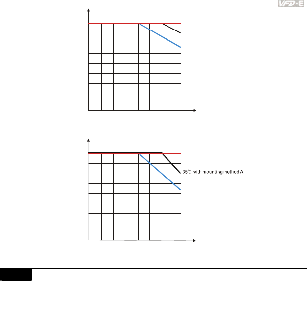
Chapter 4 Parameters|
Revision June 2008, 04EE, SW--PW V1.11/CTL V2.11 4-55
40%
50%
60%
For 115V/230V Series
80%
90%
100%
2kHz
4kHz 8kHz
10kHz
12kHz
14kHz 15kHz6kHz
70%
Rated Current (%)
Carrier
Frequency
50 with mounting method A
℃
40 with mounting method B
℃
35 with mounting method A
℃
25 with mounting method B
℃
25 with mounting method A
℃
15 with mounting method B
℃
40%
50%
60%
For 460V Series
80%
90%
100%
70%
Carrier
Frequency
Rated Current (%)
2kHz 4kHz 8kHz10kHz
12kHz
14kHz15kHz
6kHz
50 with mounting method A
℃
40 with mounting method B
℃
25 with mounting method B
℃
25 with mounting method A
℃
15 with mounting method B
℃
02.04 Motor Direction Control
Factory Setting: 0
Settings 0 Forward/Reverse operation enabled
1 Reverse operation disabled
2 Forward operation disabled
This parameter is used to disable one direction of rotation of the AC motor drive direction of
rotation.
Chapter 4 Parameters|
4-56 Revision June 2008, 04EE, SW--PW V1.11/CTL V2.11
02.05 Line Start Lockout
Factory Setting: 1
Settings 0 Disable. Operation status is not changed even if operation
command source Pr.02.01 is changed.
1 Enable. Operation status is not changed even if operation command
source Pr.02.01 is changed.
2 Disable. Operation status will change if operation command source
Pr.02.01 is changed.
3 Enable. Operation status will change if operation command source
Pr.02.01 is changed.
This parameter determines the response of the drive upon power on and operation command
source is changed.
Pr.02.05 Start lockout (Run when power is ON) Operation status when operation
command source is changed
0 Disable (AC motor drive will run) Keep previous status
1 Enable (AC motor drive doesn’t run) Keep previous status
2 Disable (AC motor drive will run) Change according to the new
operation command source
3 Enable (AC motor drive doesn’t run) Change according to the new
operation command source
When the operation command source is from external terminal and operation command is ON
(MI1/MI2-DCM=closed), the AC motor drive will operate according to Pr.02.05 after power is
applied. <For terminals MI1 and MI2 only>
1. When Pr.02.05 is set to 0 or 2, AC motor drive will run immediately.
2. When Pr.02.05 is set to 1 or 3, AC motor drive will remain stopped until operation
command is received after previous operation command is cancelled.
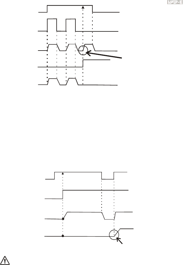
Chapter 4 Parameters|
Revision June 2008, 04EE, SW--PW V1.11/CTL V2.11 4-57
RUN RUN
STOP
STOP
Pr.02.01=1 or 2
This action will follow MI1/DCM
or MI2/DCM status
(ON is close/OFF is open)
ON OFF
MI1-DCM (close)
Pr.02.01=0
output frequency
Pr.02.05=0 or 2
Change operation
command source
output frequency
Pr.02.05=1 or 3
When the operation command source isn’t from the external terminals, independently from
whether the AC motor drive runs or stops, the AC motor drive will operate according to
Pr.02.05 if the two conditions below are both met.
1. When operation command source is changed to external terminal (Pr.02.01=1 or 2)
2. The status of terminal and AC motor drive is different.
And the operation of the AC motor drive will be:
1. When setting 0 or 1, the status of AC motor drive is not changed by the terminal status.
2. When setting 2 or 3, the status of AC motor drive is changed by the terminal status.
It needs to received a run command
after previous command is cancelled
ON OFF
MI1-DCM (close)
power is applied
output frequency
Pr.02.05=0 or 1
output frequency
Pr.02.05=2 or 3
ON
OFF ON
it will run
it won't run
when power is applied
The Line Start Lockout feature does not guarantee that the motor will never start under this
condition. It is possible the motor may be set in motion by a malfunctioning switch.
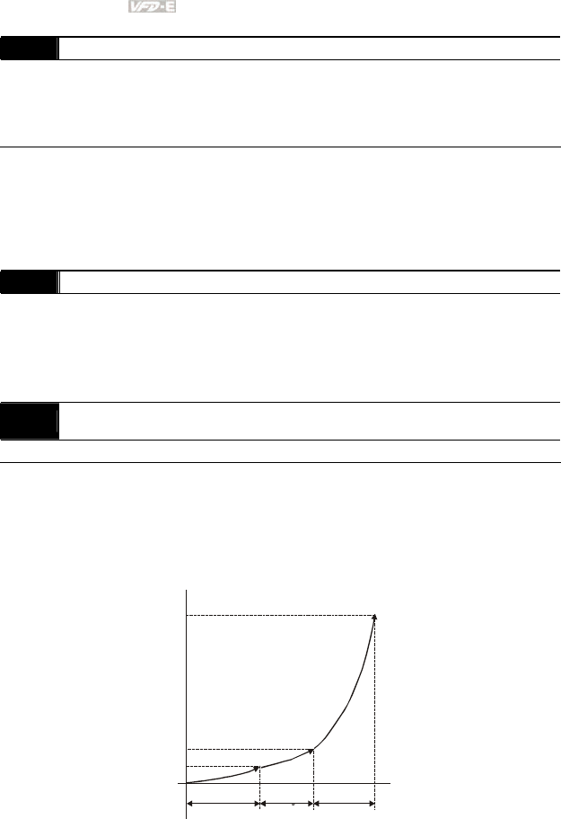
Chapter 4 Parameters|
4-58 Revision June 2008, 04EE, SW--PW V1.11/CTL V2.11
02.06 Loss of ACI Signal (4-20mA)
Factory Setting: 0
Settings 0 Decelerate to 0Hz
1 Coast to stop and display “AErr”
2 Continue operation by the last frequency command
This parameter determines the behavior when ACI is lost.
When set to 1, it will display warning message “AErr” on the keypad in case of loss of ACI
signal and execute the setting. When ACI signal is recovered, the warning message will stop
blinking. Please press “RESET” key to clear it.
02.07 Up/Down Mode
Factory Setting: 0
Settings 0 By digital keypad up/down keys mode
1 Based on Accel/Decel Time acc. to Pr.01.09 to 01.12
2 Constant speed (acc. to Pr. 02.08)
3 Pulse input unit (acc. to Pr. 02.08)
02.08 Accel/Decel Rate of Change of UP/DOWN Operation with
Constant Speed
Unit: 0.01
Settings 0.01~10.00 Hz/2ms Factory Setting: 0.01
These parameters determine the increase/decrease of the master frequency when operated
via the Multi-function Inputs when Pr.04.05~Pr.04.08 are set to 10 (Up command) or 11 (Down
command).
When Pr.02.07 is set to 0: increase/decrease the frequency by using UP/DOWN key. It is valid
only when the AC motor drive is running.
0
9.0Hz
50.0Hz
600Hz
4.34 s 3.28 s 3.68 s t (sec)

Chapter 4 Parameters|
Revision June 2008, 04EE, SW--PW V1.11/CTL V2.11 4-59
When Pr.02.07 is set to 1: increase/decrease the frequency by acceleration/deceleration
settings. It is valid only when the AC motor drive is running.
When Pr.02.07 is set to 2: increase/decrease the frequency by Pr.02.08.
When Pr.02.07 is set to 3: increase/decrease the frequency by Pr.02.08 (unit: pulse input).
02.11 Keypad Frequency Command Unit: 0.01
Settings 0.00 to 600.0Hz Factory Setting: 60.00
This parameter can be used to set frequency command or read keypad frequency command.
02.12 Communication Frequency Command Unit: 0.01
Settings 0.00 to 600.0Hz Factory Setting: 60.00
This parameter can be used to set frequency command or read communication frequency
command.
02.13 The Selections for Saving Keypad or Communication Frequency
Command
Factory Setting: 0
Settings 0 Save Keypad & Communication Frequency
1 Save Keypad Frequency only
2 Save Communication Frequency only
This parameter is used to save keypad or RS-485 frequency command.
02.14 Initial Frequency Selection (for keypad & RS485/USB)
Factory Setting: 0
Settings 0 By Current Freq Command
1 By Zero Freq Command
2 By Frequency Display at Stop
02.15 Initial Frequency Setpoint (for keypad & RS485/USB) Unit: 0.01
Settings 0.00 ~ 600.0Hz Factory Setting: 60.00
These parameters are used to determinate the frequency at stop:
When setting Pr.02.14 to 0: the initial frequency will be current frequency.
When setting Pr.02.14 to 1: the initial frequency will be 0.
When setting Pr.02.14 to 2: the initial frequency will be Pr.02.15.

Chapter 4 Parameters|
4-60 Revision June 2008, 04EE, SW--PW V1.11/CTL V2.11
02.16 Display the Master Freq Command Source
Settings Read Only Factory setting: ##
You can read the master frequency command source by this parameter.
Display Value Bit Function
1 Bit0=1 Master Freq Command Source by First Freq Source (Pr.02.00).
2 Bit1=1 Master Freq Command Source by Second Freq Source (Pr.02.09).
4 Bit2=1 Master Freq Command Source by Multi-input function
8 Bit3=1
Master Freq Command Source by PLC Freq command
(NOT for VFD*E*C models)
02.17 Display the Operation Command Source
Settings Read Only Factory setting: ##
You can read the operation source by this parameter.
Display Value Bit Function
1 Bit0=1 Operation Command Source by Digital Keypad
2 Bit1=1 Operation Command Source by RS485 communication
4 Bit2=1 Operation Command Source by External Terminal
8 Bit3=1 Operation Command Source by Multi-input function
16 Bit4=1
Operation Command Source by PLC Operation Command
(NOT for VFD*E*C models)

Chapter 4 Parameters|
Revision June 2008, 04EE, SW--PW V1.11/CTL V2.11 4-61
Group 3: Output Function Parameters
03.00 Multi-function Output Relay (RA1, RB1, RC1)
Factory Setting: 8
03.01 Multi-function Output Terminal MO1
Factory Setting: 1
Settings Function Description
0 No Function
1 AC Drive Operational Active when the drive is ready or RUN command is “ON”.
2 Master Frequency
Attained
Active when the AC motor drive reaches the output
frequency setting.
3 Zero Speed Active when Command Frequency is lower than the
Minimum Output Frequency.
4 Over-Torque Detection
Active as long as over-torque is detected. (Refer to Pr.06.03
~ Pr.06.05)
5 Baseblock (B.B.)
Indication
Active when the output of the AC motor drive is shut off
during baseblock. Base block can be forced by Multi-function
input (setting 09).
6 Low-Voltage Indication
Active when low voltage(Lv) is detected.
7 Operation Mode
Indication
Active when operation command is controlled by external
terminal.
8 Fault Indication Active when a fault occurs (oc, ov, oH, oL, oL1, EF, cF3,
HPF, ocA, ocd, ocn, GFF).
9 Desired Frequency 1
Attained Active when the desired frequency 1(Pr.03.02) is attained.
10 Terminal Count Value
Attained Active when the counter reaches Terminal Count Value.
11 Preliminary Count Value
Attained Active when the counter reaches Preliminary Count Value.
12 Over Voltage Stall
supervision Active when the Over Voltage Stall function operating

Chapter 4 Parameters|
4-62 Revision June 2008, 04EE, SW--PW V1.11/CTL V2.11
Settings Function Description
13 Over Current Stall
supervision Active when the Over Current Stall function operating
14 Heat Sink Overheat
Warning
When heatsink overheats, it will signal to prevent OH turn off
the drive. When it is higher than 85oC (185oF), it will be ON.
15 Over Voltage supervision Active when the DC-BUS voltage exceeds level
16 PID supervision Active when the PID feedback signal is abnormal (Refer to
Pr.10.12 and Pr.13.)
17 Forward command Active when the direction command is FWD
18 Reverse command Active when the direction command is REV
19 Zero Speed Output
Signal Active when the drive is standby or stop
20
Communication Warning
(FbE,Cexx, AoL2, AUE,
SAvE)
Active when there is a Communication Warning
21 Brake Control (Desired
Frequency Attained)
Active when output frequency ≥Pr.03.11. Deactivated when
output frequency ≤Pr.03.12 after STOP command.
22 Drive Ready Active when the drive is on and no abnormality detected.
23 Desired Frequency 2
Attained Active when the desired frequency 1(Pr.03.14) is attained.
03.02 Desired Frequency 1 Attained Unit: 0.01
03.14 Desired Frequency 2 Attained Unit: 0.01
Settings 0.00 to 600.0 Hz Factory Setting: 0.00
If a multi-function output terminal is set to function as Desired Frequency Attained (Pr.03.00 to
Pr.03.01=09), then the output will be activated when the programmed frequency is attained.
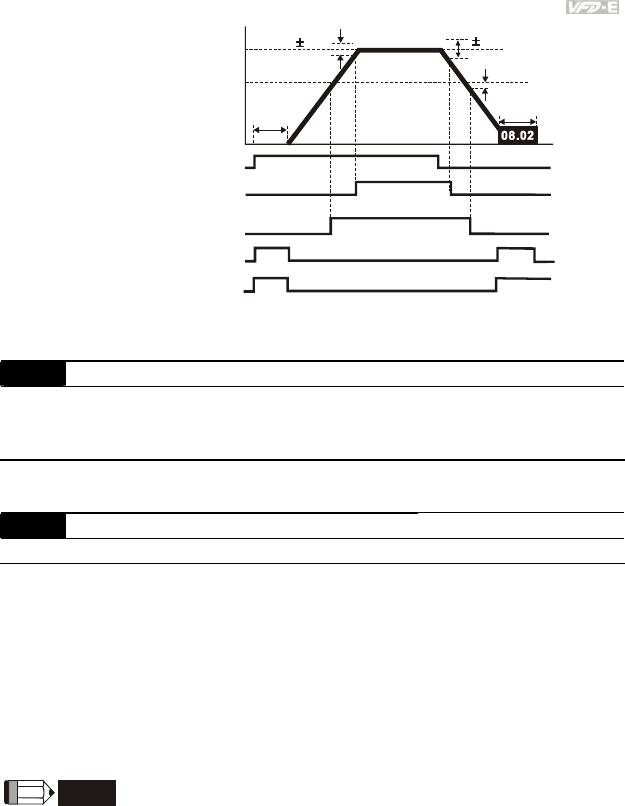
Chapter 4 Parameters|
Revision June 2008, 04EE, SW--PW V1.11/CTL V2.11 4-63
-2Hz
4Hz
2Hz
OFF
OFF
ON
ON
OFF
ON
OFF ON OFF
OFF ON OFF
ON
ON
detection
range
Frequency
master
frequency
desired
frequency
03.02/03.14
detection range detection
range
DC braking ti
m
during stop
Time
waiting time
for
frequency
run/stop
setting 2
master freq. attained
(output signal)
setting 9/23
desired freq. attained
setting 03 zero speed indication
setting 19 zero speed indication
output timing chart of multiple function terminals
when settin
g
to fre
q
uenc
y
attained or zero s
p
eed indication
03.03 Analog Output Signal (AFM)
Factory Setting: 0
Settings 0 Analog Frequency Meter (0 to Maximum Output Frequency)
1 Analog Current Meter (0 to 250% of rated AC motor drive current)
This parameter sets the function of the AFM output 0~+10VDC (ACM is common).
03.04 Analog Output Gain Unit: 1
Settings 1 to 200% Factory Setting: 100
This parameter sets the voltage range of the analog output signal AFM.
When Pr.03.03 is set to 0, the analog output voltage is directly proportional to the output
frequency of the AC motor drive. With Pr.03.04 set to 100%, the Maximum Output Frequency
(Pr.01.00) of the AC motor drive corresponds to +10VDC on the AFM output.
Similarly, if Pr.03.03 is set to 1, the analog output voltage is directly proportional to the output
current of the AC drive. With Pr.03.04 set to 100%, then 2.5 times the rated current
corresponds to +10VDC on the AFM output.
NOTE
Any type of voltmeter can be used. If the meter reads full scale at a voltage less than 10V, Pr.
03.04 should be set using the following formula:
Pr. 03.04 = ((meter full scale voltage)/10) x 100%
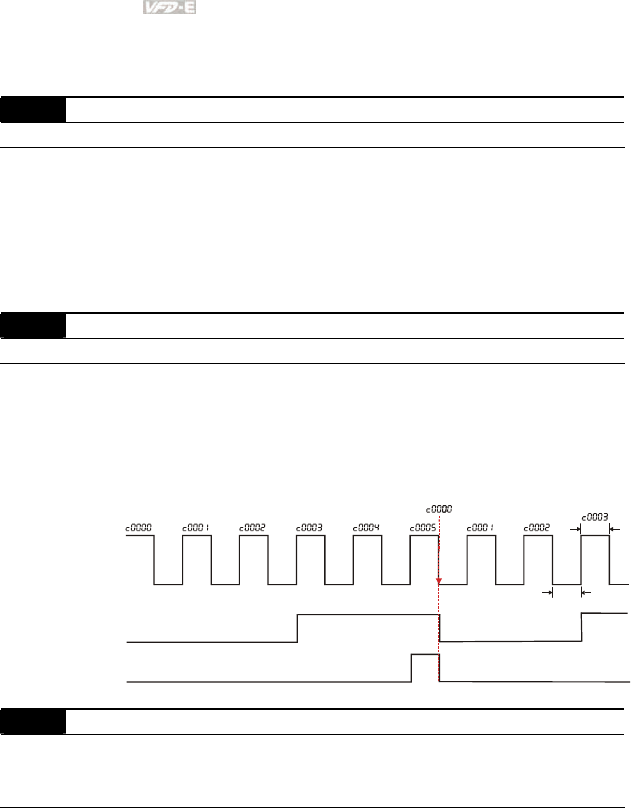
Chapter 4 Parameters|
4-64 Revision June 2008, 04EE, SW--PW V1.11/CTL V2.11
For Example: When using the meter with full scale of 5 volts, adjust Pr.03.04 to 50%. If
Pr.03.03 is set to 0, then 5VDC will correspond to Maximum Output Frequency.
03.05 Terminal Count Value Unit: 1
Settings 0 to 9999 Factory Setting: 0
This parameter sets the count value of the internal counter. To increase the internal counter,
one of Pr.04.05 to 04.08 should be set to 12. Upon completion of counting, the specified output
terminal will be activated. (Pr.03.00 to Pr.03.01 set to 10).
When the display shows c555, the drive has counted 555 times. If display shows c555•, it
means that real counter value is between 5,550 and 5,559.
03.06 Preliminary Count Value Unit: 1
Settings 0 to 9999 Factory Setting: 0
When the counter value reaches this value, the corresponding multi-function output terminal
will be activated, provided one of Pr.03.00 to Pr.03.01 set to 11 (Preliminary Count Value
Setting). This multi-function output terminal will be deactivated upon completion of Terminal
Count Value Attained.
The timing diagram:
Te r mi n a l C o u nt Va l u e
(Pr. 03.00~Pr. 03.01=10)
Preliminary Count Value
(Pr. 03.00~Pr. 03.01=11)
Display
(Pr.00.04=1)
TRG
Counter Trigger
The width of trigger signal
should not be less than
2ms(<250 Hz)
2msec
2msec
Ex:03.05=5,03.06=3
03.07 EF Active when Terminal Count Value Attained
Factory Setting: 0
Settings 0 Terminal count value attained, no EF display
1 Terminal count value attained, EF active
If this parameter is set to 1 and the desired value of counter is attained, the AC drive will treat
it as a fault. The drive will stop and show the “EF” message on the display.

Chapter 4 Parameters|
Revision June 2008, 04EE, SW--PW V1.11/CTL V2.11 4-65
03.08 Fan Control
Factory Setting: 0
Settings 0 Fan always ON
1 1 minute after AC motor drive stops, fan will be OFF
2 Fan ON when AC motor drive runs, fan OFF when AC motor drive
stops
3 Fan ON when preliminary heatsink temperature attained
This parameter determines the operation mode of the cooling fan.
03.09 The Digital Output Used by PLC (NOT for VFD*E*C models)
Settings Read Only Factory setting: ##
Bit0=1: RLY used by PLC
Bit1=1: MO1 used by PLC
Bit2=1: MO2/RA2 used by PLC
Bit3=1: MO3/RA3 used by PLC
Bit4=1: MO4/RA4 used by PLC
Bit5=1: MO5/RA5 used by PLC
Bit6=1: MO6/RA6 used by PLC
Bit7=1: MO7/RA7 used by PLC
The equivalent 8-bit is used to display the status (used or not used) of each digital output. The
value that Pr.03.09 displays is the result after converting 8-bit binary into decimal value.
For standard AC motor drive, it only has 2-bit (bit0 and bit1). When extension card is installed,
the number of the digital output terminals will increase according to the extension card. The
maximum number of the digital output terminals is shown as follows.
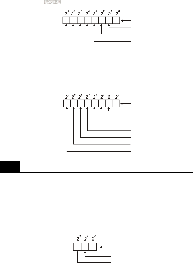
Chapter 4 Parameters|
4-66 Revision June 2008, 04EE, SW--PW V1.11/CTL V2.11
1 0
Weights
Bit Relay 1
MO1
3 25 47 6
MO2/RA2
MO3/RA3
MO4/RA4
MO5/RA5
MO6/RA6
MO7/RA7
0=not used
1=Used by PLC
For example: when Pr.03.09 is set to 3 (decimal) = 00000011 (binary) that indicates Relay1
and MO1 are used by PLC. (Pr.03.09= 20+21=3)
1 1
Weights
Bit Relay 1
MO1
0 00 00 0
MO2/RA2
MO3/RA3
MO4/RA4
MO5/RA5
MO6/RA6
MO7/RA7
0=not used
1=Used by PLC
03.10 The Analog Output Used by PLC (NOT for VFD*E*C models)
Settings Read Only Factory setting: ##
Bit0=1: AFM used by PLC
Bit1=1: AO1 used by PLC
Bit2=1: AO2 used by PLC
The equivalent 1-bit is used to display the status (used or not used) of each analog output. The
value that Pr.03.10 displays is the result after converting 1-bit binary into decimal value.
0
Weights
Bit
0=not used
1=Used by PLC
AFM
12
AO1 (optional)
AO2 (optional)
For Example:
If Pr.03.10 displays 1, it means that AFM is used by PLC.
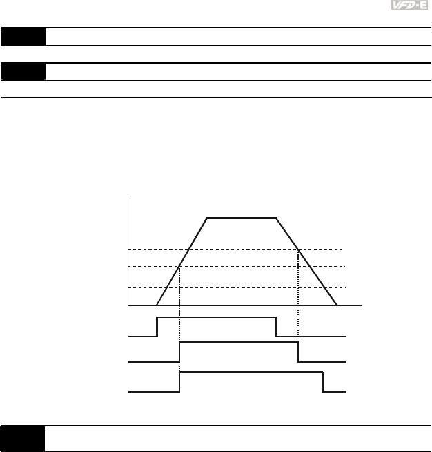
Chapter 4 Parameters|
Revision June 2008, 04EE, SW--PW V1.11/CTL V2.11 4-67
03.11 Brake Release Frequency Unit: 0.01
Settings 0.00 to 600.0Hz Factory Setting: 0.00
03.12 Brake Engage Frequency Unit: 0.01
Settings 0.00 to 600.0Hz Factory Setting: 0.00
These two parameters are used to set control of mechanical brake via the output terminals
(Relay or MO1) when Pr.03.00~03.01 is set to 21. Refer to the following example for details.
Example:
1. Case 1: Pr.03.12 ≥ Pr.03.11
2. Case 2: Pr.03.12 ≤ Pr.03.11
Case 1: Pr.03.12
Case 2: Pr.03.12
Pr. 03.11
Frequency
Output
Time
Run/Stop
Case 1: MO1=21
Case 2: MO1=21
Note: MO1: setting value of Pr.03.01
03.13 Display the Status of Multi-function Output Terminals
Settings Read Only Factory setting: ##
Bit0: RLY Status
Bit1: MO1 Status
Bit2: MO2/RA2 Status
Bit3: MO3/RA3 Status
Bit4: MO4/RA4 Status
Bit5: MO5/RA5 Status
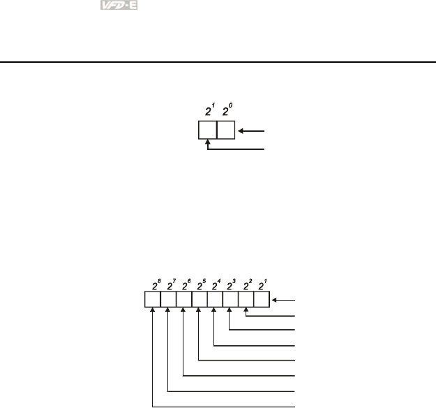
Chapter 4 Parameters|
4-68 Revision June 2008, 04EE, SW--PW V1.11/CTL V2.11
Bit6: MO6/RA6 Status
Bit7: MO7/RA7 Status
For standard AC motor drive (without extension card), the multi-function output terminals are
falling-edge triggered and Pr.03.13 will display 3 (11) for no action.
1 0
Weights
Bit
0=Active
1=Off
Relay 1
MO1
For Example:
If Pr.03.13 displays 2, it means Relay 1 is active.
The display value 2 =bit 1 X 21
When extension card is installed, the number of the multi-function output terminals will
increase according to the extension card. The maximum number of the multi-function output
terminals is shown as follows.
1 0
Weights
Bit Relay 1
MO1
3 25 47 6
MO2/RA2
MO3/RA3
MO4/RA4
MO5/RA5
MO6/RA6
MO7/RA7
0=Active
1=Off
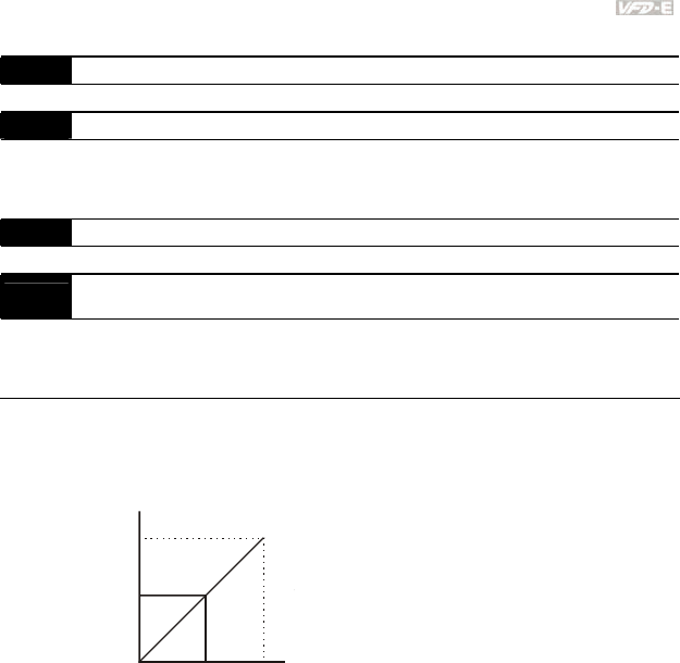
Chapter 4 Parameters|
Revision June 2008, 04EE, SW--PW V1.11/CTL V2.11 4-69
Group 4: Input Function Parameters
04.00 Keypad Potentiometer Bias Unit: 0. 1
Settings 0.0 to 100.0% Factory Setting: 0.0
04.01 Keypad Potentiometer Bias Polarity
Factory Setting: 0
Settings 0 Positive Bias
1 Negative Bias
04.02 Keypad Potentiometer Gain Unit: 0.1
Settings 0.1 to 200.0% Factory Setting: 100.0
04.03 Keypad Potentiometer Negative Bias, Reverse Motion
Enable/Disable
Factory Setting: 0
Settings 0 No Negative Bias Command
1 Negative Bias: REV Motion Enabled
Example 1: Standard application
This is the most used setting. The user only needs to set Pr.02.00 to 04. The frequency command
comes from keypad potentiometer.
60Hz
0Hz
0V 5V 10V
Pr.01.00=60Hz--Max. output Freq.
Potentiometer
Pr.04.00 =0%--Bias adjustment
Pr.04.01 =0--Positive bias
Pr.04.02 =100%--Input gain
Pr.04.03 =0--No negative bias command
30Hz
Example 2: Use of bias
This example shows the influence of changing the bias. When the input is 0V the output frequency is
10 Hz. At mid-point a potentiometer will give 40 Hz. Once the Maximum Output Frequency is reached,
any further increase of the potentiometer or signal will not increase the output frequency. (To use the
full potentiometer range, please refer to Example 3.) The value of external input voltage/current 0-
8.33V corresponds to the setting frequency 10-60Hz.
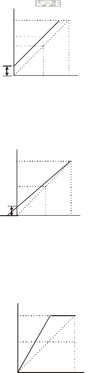
Chapter 4 Parameters|
4-70 Revision June 2008, 04EE, SW--PW V1.11/CTL V2.11
60Hz
0Hz
0V 5V 10V
Pr.01.00=60Hz--Max. output Freq.
Potentiometer
Pr.04.00 =16.7%--Bias adjustment
Pr.04.01 =0--Positive bias
Pr.04.02 =100%--Input gain
Pr.04.03 =0--No negative bias command
Gain:100%
Bias adjustment:((10Hz/60Hz)/(Gain/100%))*100%=16.7%
10Hz
Bias
Adjustment
40Hz
Example 3: Use of bias and gain for use of full range
This example also shows a popular method. The whole scale of the potentiometer can be used as
desired. In addition to signals of 0 to 10V, the popular voltage signals also include signals of 0 to 5V,
or any value under 10V. Regarding the setting, please refer to the following examples.
60Hz
0Hz
0V 5V 10V
Pr.01.00=60Hz--Max. output Freq.
Potentiometer
Pr.04.00 =20.0%--Bias adjustment
Pr.04.01 =0--Positive bias
Pr.04.02 =83.3%--Input gain
Pr.04.03 =0--No negative bias command
Gain:(10V/(10V+2V))*100%=83.3%
Bias adjustment:((10Hz/60Hz)/(Gain/100%))*100%=20.0%
10Hz
Bias
Adjustment
-2V
XV
Example 4: Use of 0-5V potentiometer range via gain adjustment
This example shows a potentiometer range of 0 to 5 Volts. Instead of adjusting gain as example
below, you can set Pr. 01.00 to 120Hz to achieve the same results.
Pr.01.00=60Hz--Max. output Freq.
Potentiometer
Pr.04.00 =0.0%--Bias adjustment
Pr.04.01 =0--Positive bias
Pr.04.02 =200%--Input gain
Pr.04.03 =0--No negative bias command
Gain:(10V/5V)*100%=200%
60Hz
0Hz 0V 5V
30Hz
Gain
adjustment
10V
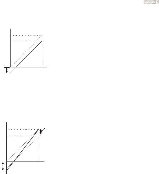
Chapter 4 Parameters|
Revision June 2008, 04EE, SW--PW V1.11/CTL V2.11 4-71
Example 5: Use of negative bias in noisy environment
In this example, a 1V negative bias is used. In noisy environments it is advantageous to use negative
bias to provide a noise margin (1V in this example).
60Hz
0Hz
0V 10V
Pr.01.00=60Hz--Max. output Freq.
Potentiometer
Pr.04.00 =10.0%--Bias adjustment
Pr.04.01 =1--Negative bias
Pr.04.02 =100%--Input gain
Pr.04.03 =0--No negative bias command
Gain:100%
Bias adjustment:((6Hz/60Hz)/(Gain/100%))*100%=10.0%
Negative
bias 6Hz 1V
54Hz
Example 6: Use of negative bias in noisy environment and gain adjustment to use full
potentiometer range
In this example, a negative bias is used to provide a noise margin. Also a potentiometer frequency
gain is used to allow the Maximum Output Frequency to be reached.
60Hz
0Hz
0V 10V
Pr.01.00=60Hz--Max. output Freq.
Negative
bias 6.6Hz 1V
Bias
adjustment
Potentiometer
Pr.04.00 =10.0%--Bias adjustment
Pr.04.01 =1--Negative bias
Pr.04.02 =111%--Input gain
Pr.04.03 =0--No negative bias command
Gain:(10V/9V)*100%=111%
Bias adjustment:((6.6Hz/60Hz)/(Gain/100%))*100%=10.0%
Example 7: Use of 0-10V potentiometer signal to run motor in FWD and REV direction
In this example, the input is programmed to run a motor in both forward and reverse direction. The
motor will be idle when the potentiometer position is at mid-point of its scale. Using the settings in this
example disables the external FWD and REV controls.

Chapter 4 Parameters|
4-72 Revision June 2008, 04EE, SW--PW V1.11/CTL V2.11
Pr.01.00=60Hz--Max. output Freq.
Potentiometer
Pr.04.00 =50.0%--Bias adjustment
Pr.04.01 =1--Negative bias
Pr.04.02 =200%--Input gain
Pr.04.03 =1--Negative bias: REV motion enabled
Gain:(10V/5V)*100%=200%
Bias adjustment:((60Hz/60Hz)/(Gain/100%))*100%=200%
60Hz
30Hz
0Hz
0V
5V 10V
30Hz
60Hz
REV
FWD
Example 8: Use negative slope
In this example, the use of negative slope is shown. Negative slopes are used in applications for
control of pressure, temperature or flow. The sensor that is connected to the input generates a large
signal (10V) at high pressure or flow. With negative slope settings, the AC motor drive will slow stop
the motor. With these settings the AC motor drive will always run in only one direction (reverse). This
can only be changed by exchanging 2 wires to the motor.
60Hz
0Hz
0V 10V
Pr.01.00=60Hz--Max. output Freq.
Potentiometer
Pr.04.00 =100%--Bias adjustment
Pr.04.01 =0--Positive bias
Pr.04.02 =100%--Input gain
Pr.04.03 =1--Negative bias: REV motion enabled
Gain:(10V/10V)*100%=100%
Bias adjustment:((60Hz/60Hz)/(Gain/100%))*100%=100%
negative slope
04.11 Minimum AVI Voltage Unit: 0.1
Settings 0.0 to 10.0V Factory Setting: 0.0
04.12 Minimum AVI Frequency (percentage of Pr.01.00) Unit: 0.1
Settings 0.0 to 100.0% Factory Setting: 0.0
04.13 Maximum AVI Voltage Unit: 0.1
Settings 0.0 to 10.0V Factory Setting: 10.0
04.14 Maximum AVI Frequency (percentage of Pr. 01.00) Unit: 0.1
Settings 0.0 to 100.0% Factory Setting: 100.0
04.15 Minimum ACI Current Unit: 0.1
Settings 0.0 to 20.0mA Factory Setting: 4.0
04.16 Minimum ACI Frequency (percentage of Pr. 01.00) Unit: 0.1
Settings 0.0 to 100.0% Factory Setting: 0.0
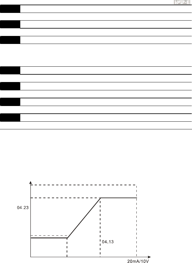
Chapter 4 Parameters|
Revision June 2008, 04EE, SW--PW V1.11/CTL V2.11 4-73
04.17 Maximum ACI Current Unit: 0.01
Settings 0.0 to 20.0mA Factory Setting: 20.0
04.18 Maximum ACI Frequency (percentage of Pr. 01.00) Unit: 0.1
Settings 0.0 to 100.0% Factory Setting: 100.0
04.19 ACI Terminal Mode Selection
Factory Setting: 0
Settings 0 ACI
1 AVI2
04.20 Minimum AVI2 Voltage Unit: 0.1
Settings 0.0 to 10.0V Factory Setting: 0.0
04.21 Minimum AVI2 Frequency (percentage of Pr.1-00) Unit: 0.1
Settings 0.0 to 100.0% Factory Setting: 0.0
04.22 Maximum AVI2 Voltage Unit: 0.1
Settings 0.0 to 10.0V Factory Setting: 10.0
04.23 Maximum AVI2 Frequency (percentage of Pr.1-00) Unit: 0.1
Settings 0.0 to 100.0% Factory Setting: 100.0
Please note the ACI/AVI switch on the AC motor drive. Switch to ACI for 4 to 20mA analog
current signal (ACI) (Pr.04.19 should be set to 0) and AVI for analog voltage signal (AVI2)
(Pr.04.19 should be set to 1).
The above parameters are used to set the analog input reference values. The min and max
frequencies are based on Pr.01.00 (during open-loop control) as shown in the following.
01.00
analog input
04.14
04.18
04.12
04.16
04.21 04.11
04.15
04.20
04.17
04.22
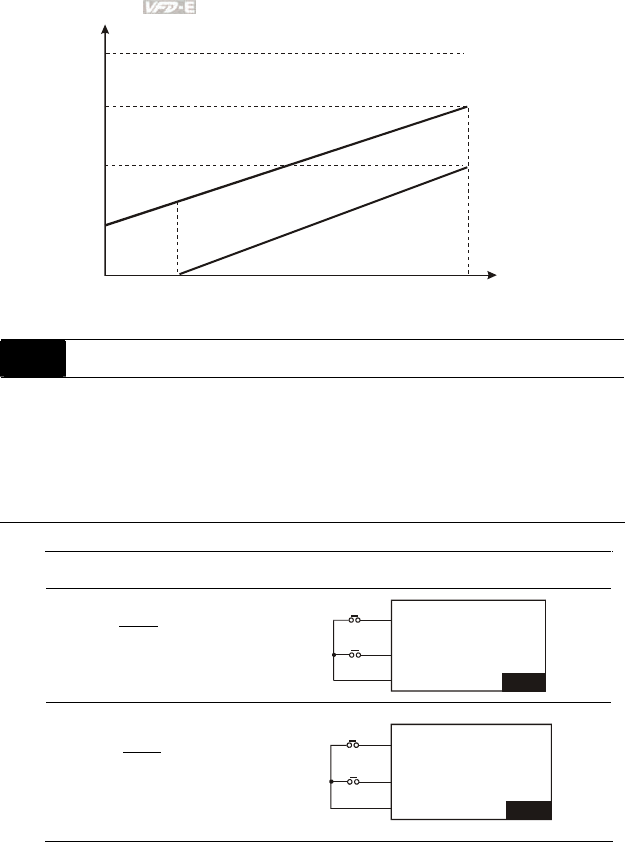
Chapter 4 Parameters|
4-74 Revision June 2008, 04EE, SW--PW V1.11/CTL V2.11
01.00=60.00 Hz
AVI
ACI
analog input
04.14=70
04.18=50
04.12=30
04.16=0
04.11=0V 04.15=4mA 04.13=10V
04.17=20mA
04.04 Multi-function Input Terminal (MI1, MI2) 2-wire/ 3-wire Operation Control Modes
Factory Setting: 0
Settings 0 2-wire: FWD/STOP, REV/STOP
1 2-wire: FWD/REV, RUN/STOP
2 3-wire Operation
There are three different types of control modes:
04.04 External Terminal
0
2-wire
FWD /STOP
REV / STOP
V
FD-E
MI1:("OPEN":STOP)
("CLOSE":FWD)
MI2:("OPEN": STOP)
("CLOSE": REV)
DCM
FWD/STOP
REV/STOP
1
2-wire
FWD/ REV
RUN / STOP
V
FD-E
MI1:("OPEN":STOP)
("CLOSE":RUN)
MI2:("OPEN": FWD)
("CLOSE": REV)
DCM
RUN/STOP
FWD/REV
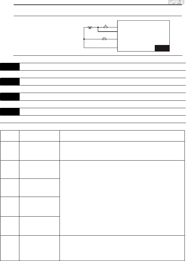
Chapter 4 Parameters|
Revision June 2008, 04EE, SW--PW V1.11/CTL V2.11 4-75
04.04 External Terminal
2 3-wire
V
FD-E
MI3:("OPEN":STOP)
MI1 ("CLOSE":RUN):
MI2:("OPEN": FWD)
("CLOSE": REV)
DCM
STO
P
REV/FWD
RUN
04.05 Multi-function Input Terminal (MI3)
Factory Setting: 1
04.06 Multi-function Input Terminal (MI4)
Factory Setting: 2
04.07 Multi-function Input Terminal (MI5)
Factory Setting: 3
04.08 Multi-function Input Terminal (MI6)
Factory Setting: 4
Settings Function Description
0 No Function Any unused terminals should be programmed to 0 to insure they
have no effect on operation.
1 Multi-Step Speed
Command 1
2 Multi-Step Speed
Command 2
3 Multi-Step Speed
Command 3
4 Multi-Step Speed
Command 4
These four inputs select the multi-speed defined by Pr.05.00 to
Pr.05.14 as shown in the diagram at the end of this table.
NOTE: Pr.05.00 to Pr.05.14 can also be used to control output
speed by programming the AC motor drive’s internal PLC
function. There are 17 step speed frequencies (including
Master Frequency and Jog Frequency) to select for
application.
5 External Reset
The External Reset has the same function as the Reset key on
the Digital keypad. After faults such as O.H., O.C. and O.V. are
cleared this input can be used to reset the drive.

Chapter 4 Parameters|
4-76 Revision June 2008, 04EE, SW--PW V1.11/CTL V2.11
Settings Function Description
6 Accel/Decel Inhibit
When the command is active, acceleration and deceleration is
stopped and the AC motor drive maintains a constant speed.
7
Accel/Decel Time
Selection
Command
Used to select the one of 2 Accel/Decel Times (Pr.01.09 to
Pr.01.12). See explanation at the end of this table.
8 Jog Operation
Control
Parameter value 08 programs one of the Multi-function Input
Terminals MI3 ∼ MI6 (Pr.04.05~Pr.04.08) for Jog control.
NOTE: Programming for Jog operation by 08 can only be
done while the motor is stopped. (Refer to parameter
Pr.01.13~Pr.01.15)
9
External Base
Block
(Refer to Pr. 08.06)
Parameter value 09 programs a Multi-function Input Terminals for
external Base Block control.
NOTE: When a Base-Block signal is received, the AC motor
drive will block all output and the motor will free run. When
base block control is deactivated, the AC drive will start its
speed search function and synchronize with the motor
speed, and then accelerate to Master Frequency.
10 UP: Increase
Master Frequency
11 DOWN: Decrease
Master Frequency
Increase/decrease the Master Frequency each time an input is
received or continuously when the input stays active. When both
inputs are active at the same time, the Master Frequency
increase/decrease is halted. Please refer to Pr.02.07, 02.08. This
function is also called “motor potentiometer”.
12 Counter Trigger
Parameter value 12 programs one of the Multi-function Input
Terminals MI3~MI6 (Pr.04.05~Pr.04.08) to increment the AC
drive’s internal counter. When an input is received, the counter is
incremented by 1.
13 Counter Reset When active, the counter is reset and inhibited. To enable
counting the input should be OFF. Refer to Pr.03.05 and 03.06.
14 External Fault
Parameter value 14 programs one of the Multi-function Input
Terminals MI3~MI6 (Pr.04.05~Pr.04.08) to be External Fault
(E.F.) inputs.

Chapter 4 Parameters|
Revision June 2008, 04EE, SW--PW V1.11/CTL V2.11 4-77
Settings Function Description
15 PID function
disabled
When an input ON with this setting is ON, the PID function will be
disabled.
16 Output Shutoff Stop
AC motor drive will stop output and the motor free run if one of
these settings is enabled. If the status of terminal is changed, AC
motor drive will restart from 0Hz.
17 Parameter lock
enable
When this setting is enabled, all parameters will be locked and
write parameters is disabled.
18
Operation
Command
Selection (Pr.02.01
setting/external
terminals)
ON: Operation command via Ext. Terminals
OFF: Operation command via Pr.02.01 setting
When the settings 18, 19 and 20 are ON at the same time, the
priority should be setting 18 > setting19 > setting20.
19
Operation
Command
Selection (Pr 02.01
setting/Digital
Keypad)
ON: Operation command via Digital Keypad
OFF: Operation command via Pr.02.01 setting
When the settings 18, 19 and 20 are ON at the same time, the
priority should be setting 18 > setting19 > setting20.
20
Operation
Command
Selection (Pr 02.01
setting/
Communication)
ON: Operation command via Communication
OFF: Operation command via Pr.02.01 setting
When the settings 18, 19 and 20 are ON at the same time, the
priority should be setting 18 > setting19 > setting20.
21 Forward/Reverse
This function has top priority to set the direction for running (If
“Pr.02.04=0”)
22
Source of second
frequency
command enabled
Used to select the first/second frequency command source. Refer
to Pr.02.00 and 02.09.
ON: 2nd Frequency command source
OFF: 1st Frequency command source

Chapter 4 Parameters|
4-78 Revision June 2008, 04EE, SW--PW V1.11/CTL V2.11
Settings Function Description
23
Run/Stop PLC
Program (PLC1)
(NOT for VFD*E*C
models)
ON: Run PLC Program
OFF: Stop PLC Program
When AC motor drive is in STOP mode and this function is
enabled, it will display PLC1 in the PLC page and execute PLC
program. When this function is disabled, it will display PLC0 in the
PLC page and stop executing PLC program. The motor will be
stopped by Pr.02.02.
When operation command source is external terminal, the keypad
cannot be used to change PLC status. And this function will be
invalid when the AC Motor drive is in PLC2 status.
23
Quick Stop
(ONLY for
VFD*E*C models)
It is only valid when Pr.02.01 is set to 5 in VFD*E*C models.
24
Download/Execute/
Monitor PLC
Program (PLC2)
(NOT for VFD*E*C
models)
When AC motor drive is in STOP mode and this function is
enabled, it will display PLC2 in the PLC page and you can
download/execute/monitor PLC. When this function is disabled, it
will display PLC0 in the PLC page and stop executing PLC
program. The motor will be stopped by Pr.02.02.
When operation command source is external terminal, the keypad
cannot be used to change PLC status. And this function will be
invalid when the AC Motor drive is in PLC1 status.
25 Simple position
function
This function should be used with Pr.01.20~Pr.01.25 for simple
position. Refer to Pr.01.25 for details.
26 OOB (Out of
Balance Detection)
The OOB (Out Of Balance Detection) function can be used with
PLC for washing machine. When this setting is enabled, it will get
Δθ value from the settings of Pr.08.21 and Pr.08.22. PLC or host
controller will decide the motor speed by this t Δθ value (Pr.08.23)
27 Motor selection (bit
0)
28 Motor selection (bit
1)
When this setting is enabled, it can be used for motor selection
(Pr. 01.01~01.06, 01.26~01.43, 07.18~07.38, 07.00~07.06).
For example: MI1=27, MI2=28
When MI1 and MI2 are OFF, it selects motor 0.
When MI1 is ON and MI2 is OFF, it selects motor 1.
When MI1 is OFF and MI2 is ON, it selects motor 2.
When MI1 and MI2 are ON, it selects motor 3.
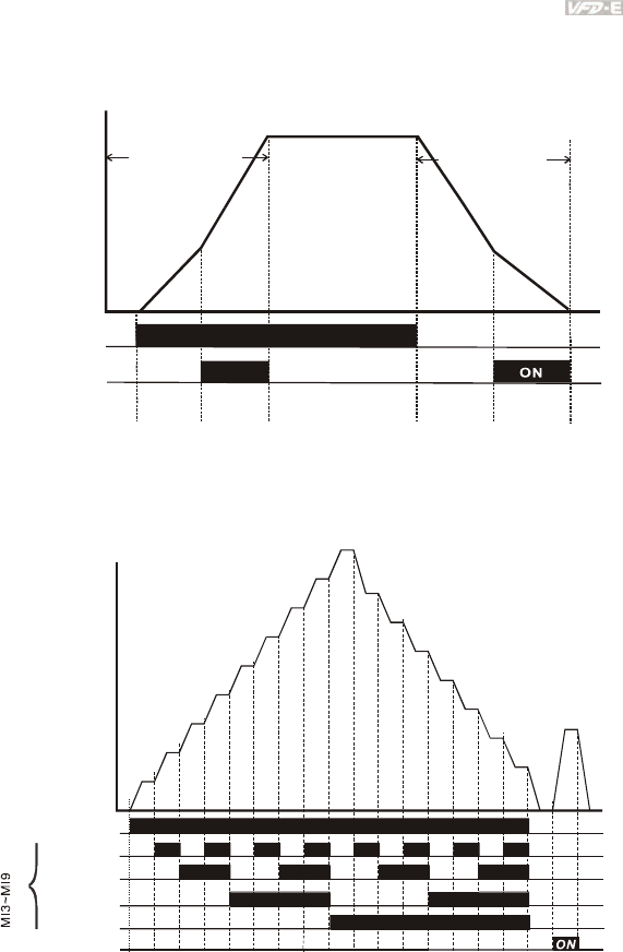
Chapter 4 Parameters|
Revision June 2008, 04EE, SW--PW V1.11/CTL V2.11 4-79
Accel/Decel Time Selection
Frequency
Time
Acceleration Delceleration
Accel time 1
Accel time 2
Decel time 1
Decel time 2
01.09
01.11 01.10
01.12
Master
Freq.
11
22
OFF
OFF
ON
ON
RUN/STOP
PU External terminal
communication
Accel/Decel time 1 & 2
Multi-function Input
Terminals Pr.04.05 to
Pr.04.08(MI3 to MI6)
A
ccel/Decel Time and Multi-function Input Terminals
Multi-Step Speed
ON ON ON ON ON ON ON ON
ONONONON
ON
ON
ON
ON
05.00
05.01
05.02
05.03
05.04
05.05
05.06
05.07
05.08
05.09
05.10
05.11
05.12
05.13
05.14
01.15
OFF
OFF
OFF
OFF
OFF
123456789101112131415
Multi-function
terminals
04.05~04.08
Frequency
Master Speed
JOG Freq.
2nd speed
( 2)MI3 to MI6
1st speed
( to MI6 1)MI3
Jog Freq.
Multi-speed via External Terminals
Run/Stop
PU/external terminals
/communication
3rd speed
( 3)MI3 to MI6
4th speed
( 4)MI3 to MI6
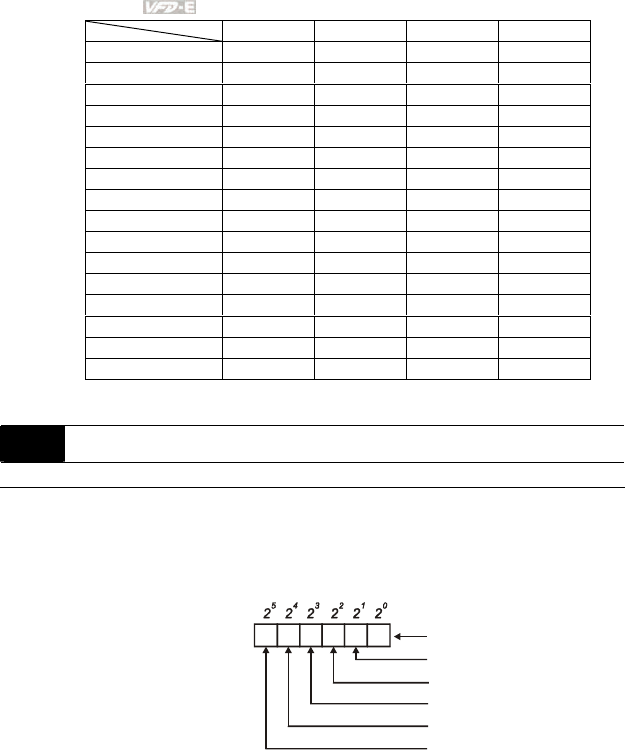
Chapter 4 Parameters|
4-80 Revision June 2008, 04EE, SW--PW V1.11/CTL V2.11
04.09 Multi-function Input Contact Selection Unit: 1
Settings 0 to 4095 Factory Setting: 0
This parameter can be used to set the status of multi-function terminals (MI1~MI6 (N.O./N.C.)
for standard AC motor drive).
The MI1~MI3 setting will be invalid when the operation command source is external terminal
(2/3wire).
12345 0
0=N.O
1=N.C
MI1
MI2
MI3
MI4
MI5
MI6
Weights
Bit
The Setting method: It needs to convert binary number (6-bit) to decimal number for input.
For example: if setting MI3, MI5, MI6 to be N.C. and MI1, MI2, MI4 to be N.O. The setting
value Pr.04.09 should be bit5X25+bit4X24+bit2X22= 1X25+1X24+1X22= 32+16+4=52 as shown
in the following.
MI6=4 MI5=3 MI4=2 MI3=1
Master frequency OFF OFF OFF OFF
1st speed OFF OFF OFF ON
2nd speed OFF OFF ON OFF
3rd speed OFF OFF ON ON
4th speed OFF ON OFF OFF
5th speed OFF ON OFF ON
6th speed OFF ON ON OFF
7th speed OFF ON ON ON
8th speed ON OFF OFF OFF
9th speed ON OFF OFF ON
10th speed ON OFF ON OFF
11th speed ON OFF ON ON
12th speed ON ON OFF OFF
13th speed ON ON OFF ON
14th speed ON ON ON OFF
15th speed ON ON ON ON
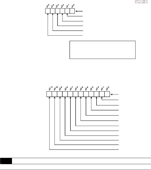
Chapter 4 Parameters|
Revision June 2008, 04EE, SW--PW V1.11/CTL V2.11 4-81
01011 0
Weights
Bit
0=N.O
1=N.C
MI1
MI2
MI3
MI4
MI5
MI6
The setting value
= bit5x2 +bit4x2 +bit2x2
542
= 1x2 +1x2 +1x2
542
=32+16+4
Setting 04.09
=52
NOTE:
2 =16384 2 =8192 2 =4096 2 =2048 2 =1024
2 =512 2 =256 2 =128 2 =64 2 =32
2 =16 2 =8 2 =4 2 =2 2 =1
14 13 12 11 10
98765
4321 0
When extension card is installed, the number of the multi-function input terminals will increase
according to the extension card. The maximum number of the multi-function input terminals is
shown as follows.
12345 0
0=N.O
1=N.C
MI1
MI2
MI3
MI4
MI5
MI6
Weights
Bit
7891011 6
MI7
MI8
MI9
MI10
MI11
MI12
This parameter is to delay the signals on digital input terminals. 1 unit is 2 msec, 2 units are 4
msec, etc. The delay time is to debounce noisy signals that could cause the digital terminals to
malfunction.
04.10 Digital Terminal Input Debouncing Time Unit: 2ms
Settings 1 to 20 Factory Setting: 1
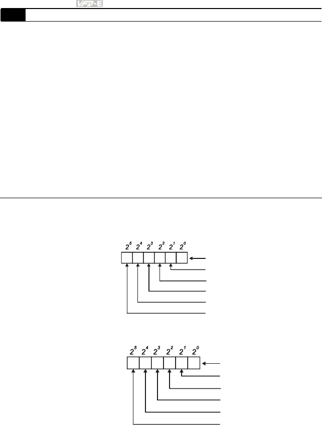
Chapter 4 Parameters|
4-82 Revision June 2008, 04EE, SW--PW V1.11/CTL V2.11
04.24 The Digital Input Used by PLC (NOT for VFD*E*C models)
Settings Read Only Factory setting: ##
Display Bit0=1: MI1 used by PLC
Bit1=1: MI2 used by PLC
Bit2=1: MI3 used by PLC
Bit3=1: MI4 used by PLC
Bit4=1: MI5 used by PLC
Bit5=1: MI6 used by PLC
Bit6=1: MI7 used by PLC
Bit7=1: MI8 used by PLC
Bit8=1: MI9 used by PLC
Bit9=1: MI10 used by PLC
Bit10=1: MI11 used by PLC
Bit11=1: MI12 used by PLC
For standard AC motor drive (without extension card), the equivalent 6-bit is used to display
the status (used or not used) of each digital input. The value for Pr.04.24 to display is the
result after converting 6-bit binary into decimal value.
12345 0
0=not used
1=used by PLC
MI1
MI2
MI3
MI4
MI5
MI6
Weights
Bit
For example: when Pr.04.24 is set to 52 (decimal) = 110100 (binary) that indicates MI3, MI5
and MI6 are used by PLC.
01011 0
Weights
Bit
0=OFF
1=ON
MI1
MI2
MI3
MI4
MI5
MI6
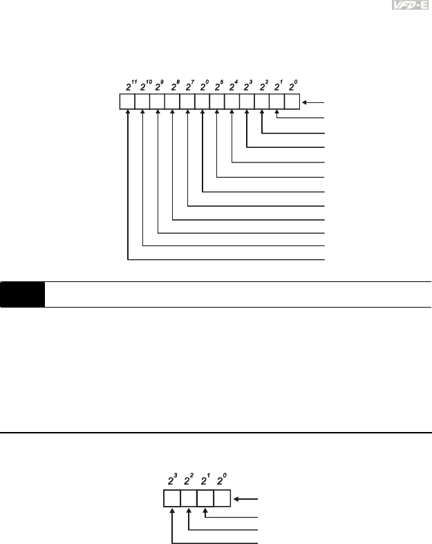
Chapter 4 Parameters|
Revision June 2008, 04EE, SW--PW V1.11/CTL V2.11 4-83
When extension card is installed, the number of the digital input terminals will increase
according to the extension card. The maximum number of the digital input terminals is shown
as follows.
12345 0 MI1
MI2
MI3
MI4
MI5
MI6
Weights
Bit
7891011 6
MI7
MI8
MI9
MI10
MI11
MI12
0=not used
1=Used by PLC
04.25 The Analog Input Used by PLC (NOT for VFD*E*C models)
Settings Read Only Factory setting: ##
Display Bit0=1: AVI used by PLC
Bit1=1: ACI/AVI2 used by PLC
Bit2=1: AI1 used by PLC
Bit3=1: AI2 used by PLC
The equivalent 2-bit is used to display the status(used or not used) of each analog input. The
value for Pr.04.25 to display is the result after converting 2-bit binary into decimal value.
10
Weights
Bit
0=not used
1=used by PLC
AVI
ACI/AVI2
13 2
AI1 (optional)
AI2 (optional)
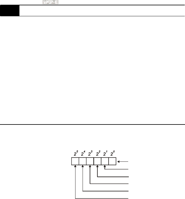
Chapter 4 Parameters|
4-84 Revision June 2008, 04EE, SW--PW V1.11/CTL V2.11
04.26 Display the Status of Multi-function Input Terminal
Settings Read Only Factory setting: ##
Display Bit0: MI1 Status
Bit1: MI2 Status
Bit2: MI3 Status
Bit3: MI4 Status
Bit4: MI5 Status
Bit5: MI6 Status
Bit6: MI7 Status
Bit7: MI8 Status
Bit8: MI9 Status
Bit9: MI10 Status
Bit10: MI11 Status
Bit11: MI12 Status
The multi-function input terminals are falling-edge triggered. For standard AC motor drive
(without extension card), there are MI1 to MI6 and Pr.04.26 will display 63 (111111) for no
action.
12345 0
0=Active
1=off
MI1
MI2
MI3
MI4
MI5
MI6
Weights
Bit
For Example:
If Pr.04.26 displays 52, it means MI1, MI2 and MI4 are active.
The display value 52= 32+16+4 =1 X 25+ 1X 24 + 1X 22 = bit 6 X 25+ bit 5 X 24 + bit 3 X 22
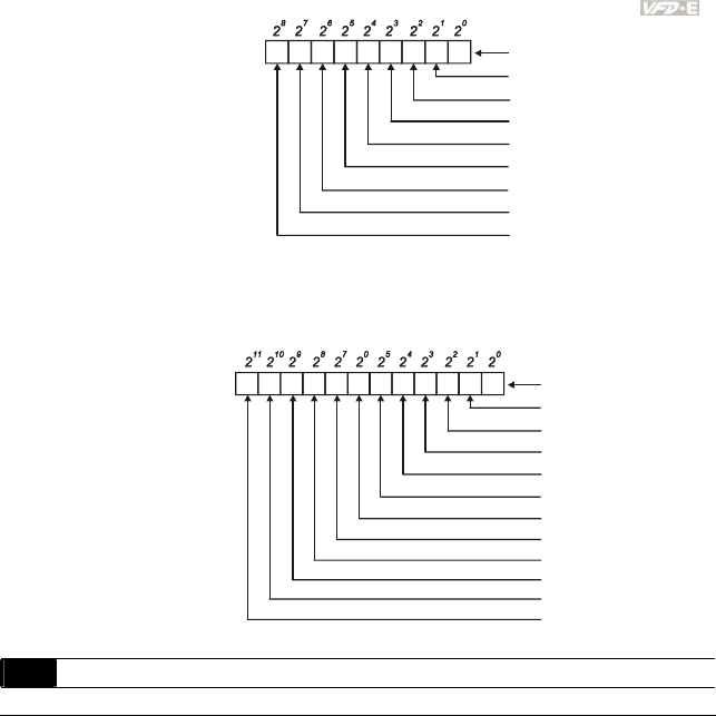
Chapter 4 Parameters|
Revision June 2008, 04EE, SW--PW V1.11/CTL V2.11 4-85
01011100 0
0=Active
1=Off
MI1
MI2
MI3
MI4
MI5
MI6
MI7
MI8
MI9
Weights
Bit
When extension card is installed, the number of the multi-function input terminals will increase
according to the extension card. The maximum number of the multi-function input terminals is
shown as follows.
12
3
4
50MI1
MI2
MI3
MI4
MI5
MI6
Weights
Bit
78
9
10
11 6
MI7
MI8
MI9
MI10
MI11
MI12
0=Active
1=Off
This parameter is used to select the terminals to be internal terminal or external terminal. You
can activate internal terminals by Pr.04.28. A terminal cannot be both internal terminal and
external terminal at the same time.
For standard AC motor drive (without extension card), the multi-function input terminals are
MI1 to MI6 as shown in the following.
04.27 Internal/External Multi-function Input Terminals Selection Unit: 1
Settings 0 to 4095 Factory Setting: 0
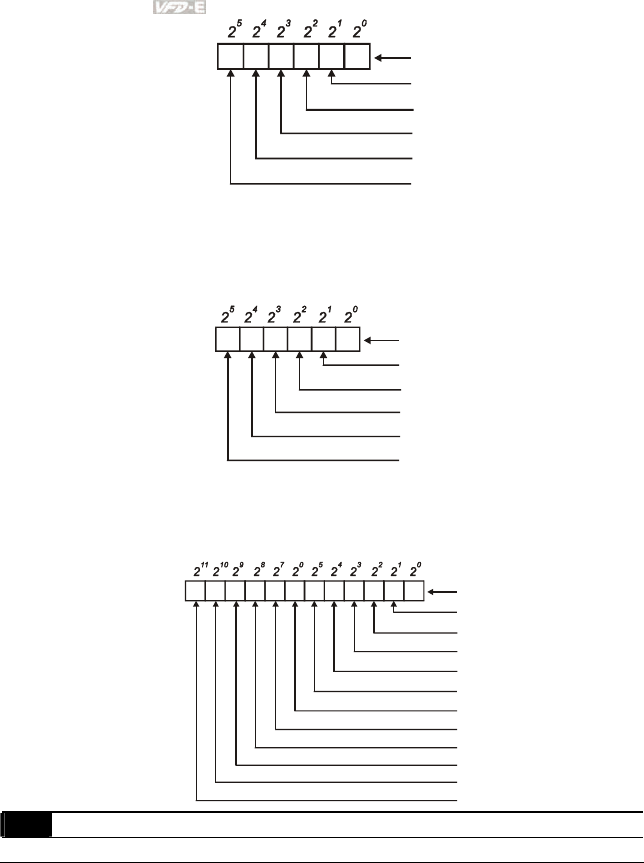
Chapter 4 Parameters|
4-86 Revision June 2008, 04EE, SW--PW V1.11/CTL V2.11
12345 0
0=external terminal
1=internal terminal
MI1
MI2
MI3
MI4
MI5
MI6
Weights
Bit
The Setting method is convert binary number to decimal number for input.
For example: if setting MI3, MI5, MI6 to be internal terminals and MI1, MI2, MI4 to be external
terminals. The setting value should be bit5X25+bit4X24+bit2X22= 1X25+1X24+1X22=
32+16+4=52 as shown in the following.
01011 0
Weights
Bit
0=external terminal
1=internal terminal
MI1
MI2
MI3
MI4
MI5
MI6
When extension card is installed, the number of the multi-function input terminals will increase
according to the extension card. The maximum number of the multi-function input terminals is
shown as follows.
12
3
4
50MI1
MI2
MI3
MI4
MI5
MI6
Weights
Bit
78
9
10
11 6
MI7
MI8
MI9
MI10
MI11
MI12
0=external terminal
1=internal terminal
This parameter is used to set the internal terminal action via keypad, communication or PLC.
04.28 Internal Terminal Status Unit: 1
Settings 0 to 4095 Factory Setting: 0
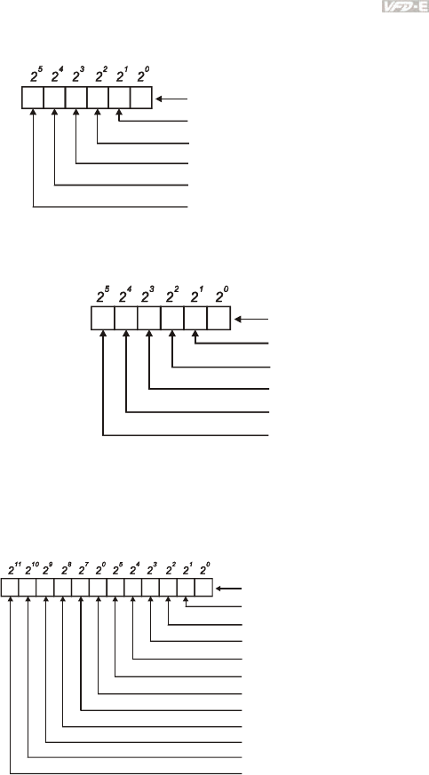
Chapter 4 Parameters|
Revision June 2008, 04EE, SW--PW V1.11/CTL V2.11 4-87
For standard AC motor drive (without extension card), the multi-function input terminals are
MI1 to MI6 as shown in the following.
12345 0
0=set internal terminal to be OFF
1= ONset internal terminal to be
MI1
MI2
MI3
MI4
MI5
MI6
Weights
Bit
For example, if setting MI3, MI5 and MI6 to be ON, Pr.04.28 should be set to
bit5X25+bit4X24+bit2X22= 1X25+1X24+1X22= 32+16+4=52 as shown in the following.
01011 0
Weights
Bit
0=OFF
1=ON
MI1
MI2
MI3
MI4
MI5
MI6
When extension card is installed, the number of the multi-function input terminals will increase
according to the extension card. The maximum number of the multi-function input terminals is
shown as follows.
12345 0 MI1
MI2
MI3
MI4
MI5
MI6
Weights
Bit
7891011 6
MI7
MI8
MI9
MI10
MI11
MI12
0=set internal terminal to be OFF
1=set internal terminal to be ON

Chapter 4 Parameters|
4-88 Revision June 2008, 04EE, SW--PW V1.11/CTL V2.11
Group 5: Multi-step Speeds Parameters
05.00 1st Step Speed Frequency Unit: 0.01
05.01 2nd Step Speed Frequency Unit: 0.01
05.02 3rd Step Speed Frequency Unit: 0.01
05.03 4th Step Speed Frequency Unit: 0.01
05.04 5th Step Speed Frequency Unit: 0.01
05.05 6th Step Speed Frequency Unit: 0.01
05.06 7th Step Speed Frequency Unit: 0.01
05.07 8th Step Speed Frequency Unit: 0.01
05.08 9th Step Speed Frequency Unit: 0.01
05.09 10th Step Speed Frequency Unit: 0.01
05.10 11th Step Speed Frequency Unit: 0.01
05.11 12th Step Speed Frequency Unit: 0.01
05.12 13th Step Speed Frequency Unit: 0.01
05.13 14th Step Speed Frequency Unit: 0.01
05.14 15th Step Speed Frequency Unit: 0.01
Settings 0.00 to 600.0Hz Factory Setting: 0.00
The Multi-function Input Terminals (refer to Pr.04.05 to 04.08) are used to select one of the AC
motor drive Multi-step speeds. The speeds (frequencies) are determined by Pr.05.00 to 05.14
as shown in the following.
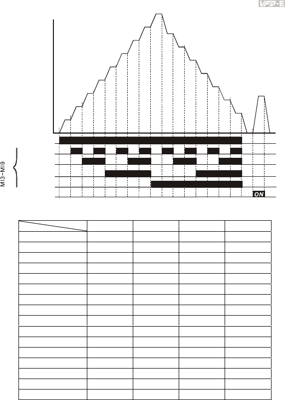
Chapter 4 Parameters|
Revision June 2008, 04EE, SW--PW V1.11/CTL V2.11 4-89
ON ON ON ON ON ON ON ON
ONONONON
ON
ON
ON
ON
05.00
05.01
05.02
05.03
05.04
05.05
05.06
05.07
05.08
05.09
05.10
05.11
05.12
05.13
05.14
01.15
OFF
OFF
OFF
OFF
OFF
123456789101112131415
Multi-function
terminals
04.05~04.08
Frequency
Master Speed
JOG Freq.
2nd speed
( 2)MI3 to MI6
1st speed
( to MI6 1)MI3
Jog Freq.
Multi-speed via External Terminals
Run/Stop
PU/external terminals
/communication
3rd speed
( 3)MI3 to MI6
4th speed
( 4)MI3 to MI6
MI6=4 MI5=3 MI4=2 MI3=1
Master frequency OFF OFF OFF OFF
1st speed OFF OFF OFF ON
2nd speed OFF OFF ON OFF
3rd speed OFF OFF ON ON
4th speed OFF ON OFF OFF
5th speed OFF ON OFF ON
6th speed OFF ON ON OFF
7th speed OFF ON ON ON
8th speed ON OFF OFF OFF
9th speed ON OFF OFF ON
10th speed ON OFF ON OFF
11th speed ON OFF ON ON
12th speed ON ON OFF OFF
13th speed ON ON OFF ON
14th speed ON ON ON OFF
15th speed ON ON ON ON
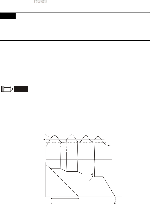
Chapter 4 Parameters|
4-90 Revision June 2008, 04EE, SW--PW V1.11/CTL V2.11
Group 6: Protection Parameters
06.00 Over-Voltage Stall Prevention Unit: 0.1
Settings 115V/230V series 330.0 to 410.0V Factory Setting: 390.0
460V series 660.0 to 820.0V Factory Setting: 780.0
0 Disable Over-voltage Stall Prevention (with brake unit or
brake resistor)
During deceleration, the DC bus voltage may exceed its Maximum Allowable Value due to
motor regeneration. When this function is enabled, the AC motor drive will not decelerate
further and keep the output frequency constant until the voltage drops below the preset value
again.
Over-Voltage Stall Prevention must be disabled (Pr.06.00=0) when a brake unit or brake
resistor is used.
NOTE
With moderate inertia load, over-voltage stall prevention will not occur and the real deceleration time
will be equal to the setting of deceleration time. The AC drive will automatically extend the
deceleration time with high inertia loads. If the deceleration time is critical for the application, a brake
resistor or brake unit should be used.
high voltage at DC side
over-voltage
detection level
output
frequency
time
Deceleration characteristic
when Over-Voltage Stall
Prevention enabled
Frequency Held
time
previous deceleration time
actual time to decelerate to stop when over-voltage
stall prevention is enabled
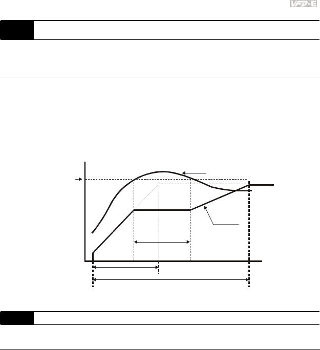
Chapter 4 Parameters|
Revision June 2008, 04EE, SW--PW V1.11/CTL V2.11 4-91
06.01 Over-Current Stall Prevention during Acceleration Unit: 1
Settings 20 to 250% Factory Setting: 170
0: disable
A setting of 100% is equal to the Rated Output Current of the drive.
During acceleration, the AC drive output current may increase abruptly and exceed the value
specified by Pr.06.01 due to rapid acceleration or excessive load on the motor. When this
function is enabled, the AC drive will stop accelerating and keep the output frequency constant
until the current drops below the maximum value.
06.01
Over-Current
Detection
Level
Output
Frequency
Over-Current Stall
prevention during
Acceleration,
frequency held
output current
time
setting
frequency
previous acceleration time
actual acceleration time when over-current stall
prevention is enabled
06.02 Over-current Stall Prevention during Operation Unit: 1
Settings 20 to 250% Factory Setting: 170
0: disable
If the output current exceeds the setting specified in Pr.06.02 when the drive is operating, the
drive will decrease its output frequency to prevent the motor stall. If the output current is lower
than the setting specified in Pr.06.02, the drive will accelerate again to catch up with the set
frequency command value.
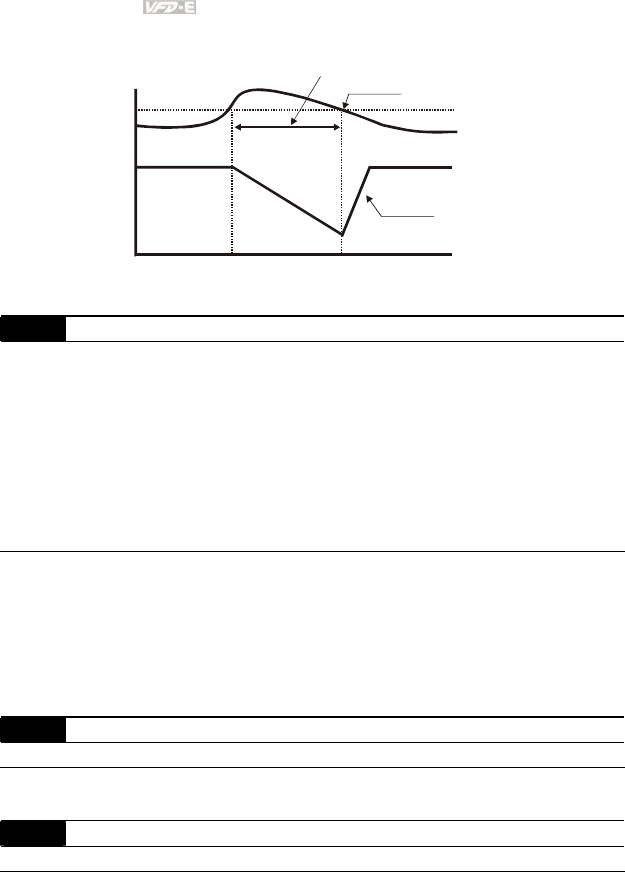
Chapter 4 Parameters|
4-92 Revision June 2008, 04EE, SW--PW V1.11/CTL V2.11
Over-Current
Detection
Level
06.02 Output Current
Output
Frequency
Over-Current Stall
Prevention during
Operation, output
frequency decrease
over-current stall prevention during operation
06.03 Over-Torque Detection Mode (OL2)
Factory Setting: 0
Settings 0 Over-Torque detection disabled.
1 Over-Torque detection enabled during constant speed operation.
After over-torque is detected, keep running until OL1 or OL occurs.
2 Over-Torque detection enabled during constant speed operation.
After over-torque is detected, stop running.
3 Over-Torque detection enabled during acceleration. After over-
torque is detected, keep running until OL1 or OL occurs.
4 Over-Torque detection enabled during acceleration. After over-
torque is detected, stop running.
This parameter determines the operation mode of the drive after the over-torque (OL2) is
detected via the following method: if the output current exceeds the over-torque detection level
(Pr.06.04) longer than the setting of Pr.06.05 Over-Torque Detection Time, the warning
message “OL2” is displayed. If a Multi-functional Output Terminal is set to over-torque
detection (Pr.03.00~03.01=04), the output is on. Please refer to Pr.03.00~03.01 for details.
06.04 Over-Torque Detection Level (OL2) Unit: 1
Settings 10 to 200% Factory Setting: 150
This setting is proportional to the Rated Output Current of the drive.
06.05 Over-Torque Detection Time (OL2) Unit: 0.1
Settings 0.1 to 60.0 sec Factory Setting: 0.1
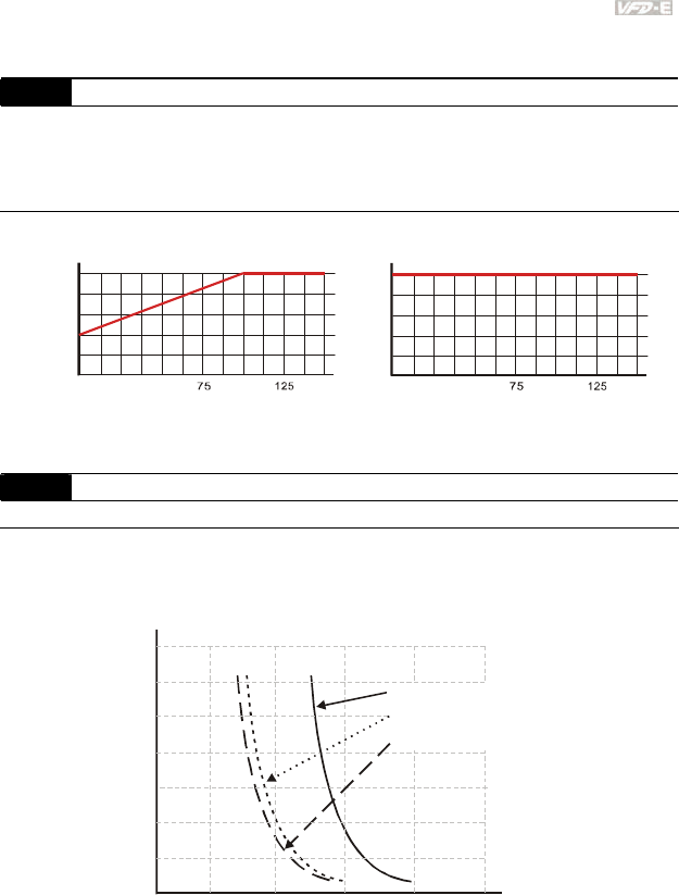
Chapter 4 Parameters|
Revision June 2008, 04EE, SW--PW V1.11/CTL V2.11 4-93
This parameter sets the time for how long over-torque must be detected before “OL2” is
displayed.
06.06 Electronic Thermal Overload Relay Selection (OL1)
Factory Setting: 2
Settings 0 Operate with a Standard Motor (self-cooled by fan)
1 Operate with a Special Motor (forced external cooling)
2 Operation disabled
This function is used to protect the motor from overloading or overheating.
40
20
60
80
100
25 50 100 150
rated frequency of the motor %
rated current of the motor%
Standard motor
(self-cooled by fan)
rated frequency of the motor %
rated current of the motor%
Special Motor
(forced external cooling)
25 50 100 150
40
20
60
80
100
06.07 Electronic Thermal Characteristic Unit: 1
Settings 30 to 600 sec Factory Setting: 60
The parameter determines the time required for activating the I2t electronic thermal protection
function. The graph below shows I2t curves for 150% output power for 1 minute.
350
50Hz or more
10Hz
5Hz
050100150 250200
300
250
200
150
100
50
Operation
time (seconds)
Load
factor (%)

Chapter 4 Parameters|
4-94 Revision June 2008, 04EE, SW--PW V1.11/CTL V2.11
06.08 Present Fault Record
06.09 Second Most Recent Fault Record
06.10 Third Most Recent Fault Record
06.11 Fourth Most Recent Fault Record
06.12 Fifth Most Recent Fault Record
Factory Setting: 0
Readings 0 No fault
1 Over-current (oc)
2 Over-voltage (ov)
3 IGBT Overheat (oH1)
4 Power Board Overheat (oH2)
5 Overload(oL)
6 Overload (oL1)
7 Motor Overload (oL2)
8 External Fault (EF)
9 Hardware protection failure (HPF)
10 Current exceeds 2 times rated current during accel.(ocA)
11 Current exceeds 2 times rated current during decel.(ocd)
12 Current exceeds 2 times rated current during steady state
operation (ocn)
13 Reserved
14 Phase-loss (PHL)
15 Reserved
16 Auto accel/decel failure (CFA)
17 Software/password protection (codE)
18 Power Board CPU WRITE Failure (cF1.0)
19 Power Board CPU READ Failure (cF2.0)
20 CC, OC Hardware protection failure (HPF1)
21 OV Hardware protection failure (HPF2)
22 GFF Hardware protection failure (HPF3)
23 OC Hardware protection failure (HPF4)
24 U-phase error (cF3.0)
25 V-phase error (cF3.1)
26 W-phase error (cF3.2)
27 DCBUS error (cF3.3)
28 IGBT Overheat (cF3.4)

Chapter 4 Parameters|
Revision June 2008, 04EE, SW--PW V1.11/CTL V2.11 4-95
29 Power Board Overheat (cF3.5)
30 Control Board CPU WRITE failure (cF1.1)
31 Contrsol Board CPU READ failure (cF2.1)
32 ACI signal error (AErr)
33 Reserved
34 Motor PTC overheat protection (PtC1)
35-39 Reserved
40 Communication time-out error of control board and power board
(CP10)
In Pr.06.08 to Pr.06.12 the five most recent faults that occurred, are stored. After removing the
cause of the fault, use the reset command to reset the drive.

Chapter 4 Parameters|
4-96 Revision June 2008, 04EE, SW--PW V1.11/CTL V2.11
Group 7: Motor Parameters
07.00 Motor Rated Current (Motor 0) Unit: 1
Settings 30% FLA to 120% FLA Factory Setting: FLA
Use the following formula to calculate the percentage value entered in this parameter:
(Motor Current / AC Drive Current) x 100%
with Motor Current=Motor rated current in A on type shield
AC Drive Current=Rated current of AC drive in A (see Pr.00.01)
Pr.07.00 and Pr.07.01 must be set if the drive is programmed to operate in Vector Control
mode (Pr.00.10 = 1). They also must be set if the "Electronic Thermal Overload Relay"
(Pr.06.06) or "Slip Compensation"(Pr.07-03) functions are selected.
Pr.07.00 must be greater than Pr.07.01.
07.01 Motor No-load Current (Motor 0) Unit: 1
Settings 0% FLA to 90% FLA Factory Setting: 0.4*FLA
The rated current of the AC drive is regarded as 100%. The setting of the Motor no-load
current will affect the slip compensation.
The setting value must be less than Pr.07.00 (Motor Rated Current).
07.02 Torque Compensation (Motor 0) Unit: 0.1
Settings 0.0 to 10.0 Factory Setting: 0.0
This parameter may be set so that the AC drive will increase its voltage output to obtain a
higher torque. Only to be used for V/f control mode.
Too high torque compensation can overheat the motor.
07.03 Slip Compensation (Used without PG) (Motor 0) Unit: 0.01
Settings 0.00 to 10.00 Factory Setting: 0.00
While driving an asynchronous motor, increasing the load on the AC motor drive will cause an
increase in slip and decrease in speed. This parameter may be used to compensate the slip by
increasing the output frequency. When the output current of the AC motor drive is bigger than
the motor no-load current (Pr.07.01), the AC drive will adjust its output frequency according to
this parameter.

Chapter 4 Parameters|
Revision June 2008, 04EE, SW--PW V1.11/CTL V2.11 4-97
07.04 Motor Parameters Auto Tuning Unit: 1
Factory Setting: 0
Settings 0 Disable
1 Auto Tuning R1 (motor doesn’t run)
2 Auto Tuning R1 + No-load Test (with running motor)
Start Auto Tuning by pressing RUN key after this parameter is set to 1 or 2.
When set to 1, it will only auto detect R1 value and Pr.07.01 must be input manually. When set
to 2, the AC motor drive should be unloaded and the values of Pr.07.01 and Pr.07.05 will be
set automatically.
The steps for AUTO-Tuning are:
1. Make sure that all the parameters are set to factory settings and the motor wiring is
correct.
2. Make sure the motor has no-load before executing auto-tuning and the shaft is not
connected to any belt or gear motor.
3. Fill in Pr.01.01, Pr.01.02, Pr.07.00, Pr.07.04 and Pr.07.06 with correct values.
4. After Pr.07.04 is set to 2, the AC motor drive will execute auto-tuning immediately after
receiving a ”RUN” command. (Note: The motor will run!). The total auto tune time will be
15 seconds + Pr.01.09 + Pr.01.10. Higher power drives need longer Accel/Decel time
(factory setting is recommended). After executing Auto-tune, Pr.07.04 is set to 0.
5. After executing, please check if there are values filled in Pr.07.01 and Pr.07.05. If not,
please press RUN key after setting Pr.07.04 again.
6. Then you can set Pr.00.10 to 1 and set other parameters according to your application
requirement.
NOTE
1. In vector control mode it is not recommended to have motors run in parallel.
2. It is not recommended to use vector control mode if motor rated power exceeds the rated power of
the AC motor drive.
07.05 Motor Line-to-line Resistance R1 (Motor 0) Unit: 1
Settings
0 to 65535 mΩ Factory Setting: 0

Chapter 4 Parameters|
4-98 Revision June 2008, 04EE, SW--PW V1.11/CTL V2.11
The motor auto tune procedure will set this parameter. The user may also set this parameter
without using Pr.07.04.
07.06 Motor Rated Slip (Motor 0) Unit: 0.01
Settings 0.00 to 20.00Hz Factory Setting: 3.00
Refer to the rated rpm and the number of poles on the nameplate of the motor and use the
following equation to calculate the rated slip.
Rated Slip (Hz) = Fbase (Pr.01.01 base frequency) – (rated rpm x motor pole 120)
07.07 Slip Compensation Limit Unit: 1
Settings 0 to 250% Factory Setting: 200
This parameter sets the upper limit of the compensation frequency (the percentage of
Pr.07.06).
Example: when Pr.07.06=5Hz and Pr.07.07=150%, the upper limit of the compensation
frequency is 7.5Hz. Therefore, for a 50Hz motor, the max. output is 57.5Hz.
07.08 Torque Compensation Time Constant Unit: 0.01
Settings 0.01 ~10.00 sec Factory Setting: 0.10
07.09 Slip Compensation Time Constant Unit: 0.01
Settings 0.05 ~10.00 sec Factory Setting: 0.20
Setting Pr.07.08 and Pr.07.09 changes the response time for the compensations.
Too long time constants give slow response; too short values can give unstable operation.
07.10 Accumulative Motor Operation Time (Min.) Unit: 1
Settings 0~1439 Factory Setting: 0
07.11 Accumulative Motor Operation Time (Day) Unit: 1
Settings 0 ~65535 Factory Setting: 0
Pr.07.10 and Pr.07.11 are used to record the motor operation time. They can be cleared by
setting to 0 and time is less than 1 minute is not recorded.
07.12 Motor PTC Overheat Protection Unit: 1
Factory Setting: 0
Settings 0 Disable
1 Enable
07.14 Motor PTC Overheat Protection Level Unit: 0.1
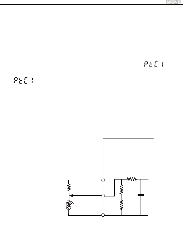
Chapter 4 Parameters|
Revision June 2008, 04EE, SW--PW V1.11/CTL V2.11 4-99
Settings 0.1~10.0V Factory Setting: 2.4
When the motor is running at low frequency for a long time, the cooling function of the motor
fan will be lower. To prevent overheating, it needs to have a Positive Temperature Coefficient
thermoistor on the motor and connect its output signal to the drive’s corresponding control
terminals.
When the source of first/second frequency command is set to AVI (02.00=1/02.09=1), it will
disable the function of motor PTC overheat protection (i.e. Pr.07.12 cannot be set to 1).
If temperature exceeds the setting level, motor will be coast to stop and is
displayed. When the temperature decreases below the level of (Pr.07.15-Pr.07.16) and
stops blinking, you can press RESET key to clear the fault.
Pr.07.14 (overheat protection level) must exceed Pr.07.15 (overheat warning level).
The PTC uses the AVI-input and is connected via resistor-divider as shown below.
1. The voltage between +10V to ACM: lies within 10.4V~11.2V.
2. The impedance for AVI is around 47kΩ.
3. Recommended value for resistor-divider R1 is 1~20kΩ.
4. Please contact your motor dealer for the curve of temperature and resistance value for
PTC.
A
VI
A
CM
+10V
PTC
VFD-E
47k
Ω
resistor-divider
R1
internal circuit
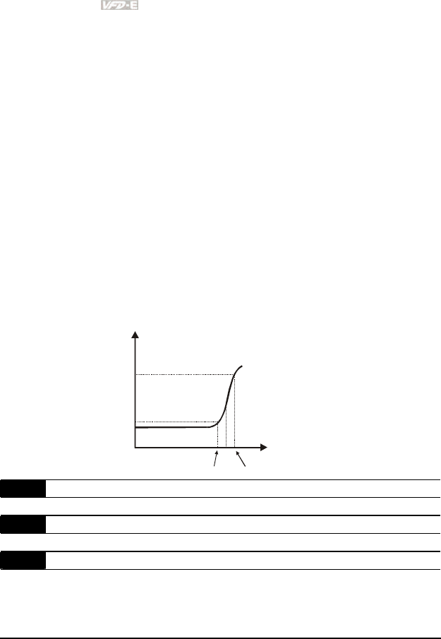
Chapter 4 Parameters|
4-100 Revision June 2008, 04EE, SW--PW V1.11/CTL V2.11
Refer to following calculation for protection level and warning level.
1. Protection level
Pr.07.14= V+10 * (RPTC1//47K) / [R1+( RPTC1//47K)]
2. Warning level
Pr.07.16= V+10 * (RPTC2//47K) / [R1+( RPTC2//47K)]
3. Definition:
V+10: voltage between +10V-ACM, Range 10.4~11.2VDC
RPTC1: motor PTC overheat protection level. Corresponding voltage level set in
Pr.07.14, RPTC2: motor PTC overheat warning level. Corresponding voltage level set
in Pr.07.15, 47kΩ: is AVI input impedance, R1: resistor-divider (recommended value:
1~20kΩ)
Take the standard PTC thermistor as example: if protection level is 1330Ω, the voltage
between +10V-ACM is 10.5V and resistor-divider R1 is 4.4kΩ. Refer to following calculation
for Pr.07.14 setting.
1330//47000=(1330*47000)/(1330+47000)=1293.4
10.5*1293.4/(4400+1293.4)=2.38(V) ≒2.4(V)
Therefore, Pr.07.14 should be set to 2.4.
550
1330
temperature ( )
℃
resistor value ( )
Ω
Tr
Tr-5
℃
Tr+5
℃
07.15 Motor PTC Overheat Warning Level Unit: 0.1
Settings 0.1~10.0V Factory Setting: 1.2
07.16 Motor PTC Overheat Reset Delta Level Unit: 0.1
Settings 0.1~5.0V Factory Setting: 0.6
07.17 Treatment of the motor PTC Overheat
Factory Setting: 0
Settings 0 Warn and RAMP to stop
1 Warn and COAST to stop
2 Warn and keep running

Chapter 4 Parameters|
Revision June 2008, 04EE, SW--PW V1.11/CTL V2.11 4-101
If temperature exceeds the motor PTC overheat warning level (Pr.07.15), the drive will act
according to Pr.07.17 and display . If the temperature decreases below the result
(Pr.07.15 minus Pr.07.16), the warning display will disappear.
07.13 Input Debouncing Time of the PTC Protection Unit: 2
Settings 0~9999 (is 0-19998ms) Factory Setting: 100
This parameter is to delay the signals on PTC analog input terminals. 1 unit is 2 msec, 2 units
are 4 msec, etc.
07.18 Motor Rated Current (Motor 1) Unit: 1
Settings 30% FLA to 120% FLA Factory Setting: FLA
07.19 Motor No-load Current (Motor 1) Unit: 1
Settings 0% FLA to 90% FLA Factory Setting: 0.4*FLA
07.20 Torque Compensation (Motor 1) Unit: 0.1
Settings 0.0 to 10.0 Factory Setting: 0.0
07.21 Slip Compensation (Used without PG) (Motor 1) Unit: 0.01
Settings 0.00 to 10.00 Factory Setting: 0.00
07.22 Motor Line-to-line Resistance R1 (Motor 1) Unit: 1
Settings
0 to 65535 mΩ Factory Setting: 0
07.23 Motor Rated Slip (Motor 1) Unit: 0.01
Settings 0.00 to 20.00Hz Factory Setting: 3.00
07.24 Motor Pole Number (Motor 1) Unit: 1
Settings 2 to 10 Factory Setting: 4
07.25 Motor Rated Current (Motor 2) Unit: 1
Settings 30% FLA to 120% FLA Factory Setting: FLA
07.26 Motor No-load Current (Motor 2) Unit: 1
Settings 0% FLA to 90% FLA Factory Setting: 0.4*FLA
07.27 Torque Compensation (Motor 2) Unit: 0.1
Settings 0.0 to 10.0 Factory Setting: 0.0
07.28 Slip Compensation (Used without PG) (Motor 2) Unit: 0.01
Settings 0.00 to 10.00 Factory Setting: 0.00
07.29 Motor Line-to-line Resistance R1 (Motor 2) Unit: 1
Settings
0 to 65535 mΩ Factory Setting: 0
07.30 Motor Rated Slip (Motor 2) Unit: 0.01
Settings 0.00 to 20.00Hz Factory Setting: 3.00

Chapter 4 Parameters|
4-102 Revision June 2008, 04EE, SW--PW V1.11/CTL V2.11
07.31 Motor Pole Number (Motor 2) Unit: 1
Settings 2 to 10 Factory Setting: 4
07.32 Motor Rated Current (Motor 3) Unit: 1
Settings 30% FLA to 120% FLA Factory Setting: FLA
07.33 Motor No-load Current (Motor 3) Unit: 1
Settings 0% FLA to 90% FLA Factory Setting: 0.4*FLA
07.34 Torque Compensation (Motor 3) Unit: 0.1
Settings 0.0 to 10.0 Factory Setting: 0.0
07.35 Slip Compensation (Used without PG) (Motor 3) Unit: 0.01
Settings 0.00 to 10.00 Factory Setting: 0.00
07.36 Motor Line-to-line Resistance R1 (Motor 3) Unit: 1
Settings
0 to 65535 mΩ Factory Setting: 0
07.37 Motor Rated Slip (Motor 3) Unit: 0.01
Settings 0.00 to 20.00Hz Factory Setting: 3.00
07.38 Motor Pole Number (Motor 3) Unit: 1
Settings 2 to 10 Factory Setting: 4
The motor 0 to motor 3 can be selected by setting the multi-function input terminals MI3~MI6
(Pr.04.05 to Pr.04.08) to 27 and 28.
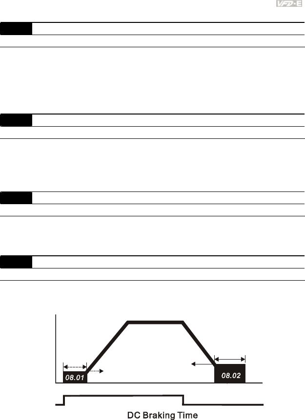
Chapter 4 Parameters|
Revision June 2008, 04EE, SW--PW V1.11/CTL V2.11 4-103
Group 8: Special Parameters
08.00 DC Brake Current Level Unit: 1
Settings 0 to 100% Factory Setting: 0
This parameter sets the level of DC Brake Current output to the motor during start-up and
stopping. When setting DC Brake Current, the Rated Current (Pr.00.01) is regarded as 100%.
It is recommended to start with a low DC Brake Current Level and then increase until proper
holding torque has been achieved.
08.01 DC Brake Time during Start-up Unit: 0.1
Settings 0.0 to 60.0 sec Factory Setting: 0.0
This parameter determines the duration of the DC Brake current after a RUN command. When
the time has elapsed, the AC motor drive will start accelerating from the Minimum Frequency
(Pr.01.05).
08.02 DC Brake Time during Stopping Unit: 0.1
Settings 0.0 to 60.0 sec Factory Setting: 0.0
This parameter determines the duration of the DC Brake current during stopping. If stopping
with DC Brake is desired, Pr.02.02 Stop Method must be set to 0 or 2 for Ramp to Stop.
08.03 Start-Point for DC Brake Unit: 0.01
Settings 0.00 to 600.0Hz Factory Setting: 0.00
This parameter determines the frequency when DC Brake will begin during deceleration.
Run/Stop
ON OFF
01.05 08.03
Output Frequency
Minimum Output
Frequency
Start-Point for
DC Braking
Time during
Stopping
DC Braking Time
during Stopping

Chapter 4 Parameters|
4-104 Revision June 2008, 04EE, SW--PW V1.11/CTL V2.11
DC Brake during Start-up is used for loads that may move before the AC drive starts, such as
fans and pumps. Under such circumstances, DC Brake can be used to hold the load in
position before setting it in motion.
DC Brake during stopping is used to shorten the stopping time and also to hold a stopped load
in position. For high inertia loads, a brake resistor for dynamic brake may also be needed for
fast decelerations.
08.04 Momentary Power Loss Operation Selection
Factory Setting: 0
Settings 0 Operation stops (coast to stop) after momentary power loss.
1 Operation continues after momentary power loss, speed search
starts with the Master Frequency reference value.
2 Operation continues after momentary power loss, speed search
starts with the minimum frequency.
This parameter determines the operation mode when the AC motor drive restarts from a
momentary power loss.
08.05 Maximum Allowable Power Loss Time Unit: 0.1
Settings 0.1 to 5.0 sec Factory Setting: 2.0
If the duration of a power loss is less than this parameter setting, the AC motor drive will
resume operation. If it exceeds the Maximum Allowable Power Loss Time, the AC motor drive
output is then turned off (coast stop).
The selected operation after power loss in Pr.08.04 is only executed when the maximum
allowable power loss time is ≤5 seconds and the AC motor drive displays “Lu”.
But if the AC motor drive is powered off due to overload, even if the maximum allowable power
loss time is ≤5 seconds, the operation mode as set in Pr.08.04 is not executed. In that case it
starts up normally.
08.06 Base Block Speed Search
Factory Setting: 1
Settings 0 Disable
1 Speed search starts with last frequency command
2 Speed search starts with minimum output frequency (Pr.01.05)
This parameter determines the AC motor drive restart method after External Base Block is
enabled.
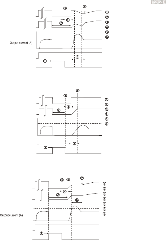
Chapter 4 Parameters|
Revision June 2008, 04EE, SW--PW V1.11/CTL V2.11 4-105
Output frequency
(H)
Output voltage(V)
08.08 Current Limit
for Speed SearchSpeed
FWD Run
Time
B.B.
Fig 1:B.B. Speed Search with Last Output Frequency Downward Timing Chart
(Speed Search Current Attains Speed Search Level)
A
Input B.B. signal
Stop output voltage
Disable B.B. signal
Waiting time 08.07
Speed Search
Synchronization speed detection
Time
B.B.
Fig 2: B.B. Speed Search with Last Output Frequency Downward Timing Chart
(Speed Search Current doesn't Attain Speed Search Level)
A
Input B.B. signal
Stop output voltage
Disable B.B. signal
Waiting time 08.07
Speed Search
Synchronization speed detection
Output frequency
( H)
08.08 Current Limit
for Speed SearchSpeed
FWD Run
Time
B.B.
Fig3: B.B. Speed Search with Minimum Output Frequency Upward Timing Chart
A
Input B.B. signal
Stop output voltage
Disable B.B. signal
Waiting time 08.07
Restart
Synchronization speed detection
Keep accelerating
A
Output frequency
(H)
06.01
Over current
stall prevention
during acceleration
FWD Run
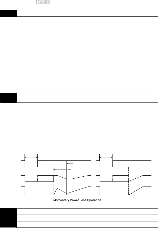
Chapter 4 Parameters|
4-106 Revision June 2008, 04EE, SW--PW V1.11/CTL V2.11
08.07 Baseblock Time for Speed Search (BB) Unit: 0.1
Settings 0.1 to 5.0 sec Factory Setting: 0.5
When momentary power loss is detected, the AC motor drive will block its output and then wait
for a specified period of time (determined by Pr.08.07, called Base-Block Time) before
resuming operation. This parameter should be set at a value to ensure that any residual
regeneration voltage from the motor on the output has disappeared before the drive is
activated again.
This parameter also determines the waiting time before resuming operation after External
Baseblock and Auto Restart after Fault (Pr.08.15).
When using a PG card with PG (encoder), speed search will begin at the actual PG (encoder)
feedback speed.
08.08 Current Limit for Speed Search Unit: 1
Settings 30 to 200% Factory Setting: 150
Following a momentary power loss, the AC motor drive will start its speed search operation
only if the output current is greater than the value set by Pr.08.08. When the output current is
less than the value of Pr.08.08, the AC motor drive output frequency is at “speed
synchronization point”. The drive will start to accelerate or decelerate back to the operating
frequency at which it was running prior to the power loss.
Output
Frequency
Output
Vol tage
08.06
08.05
08.04=1
08.06
08.05
08.04=2
Power
Input
Maximum Allowable
Power Loss Time
Baseblock Time
Speed Search
Speed
Synchronization
Detection
Maximum
Allowable Power
Baseblock Time
08.09 Skip Frequency 1 Upper Limit Unit: 0.01
08.10 Skip Frequency 1 Lower Limit Unit: 0.01
08.11 Skip Frequency 2 Upper Limit Unit: 0.01
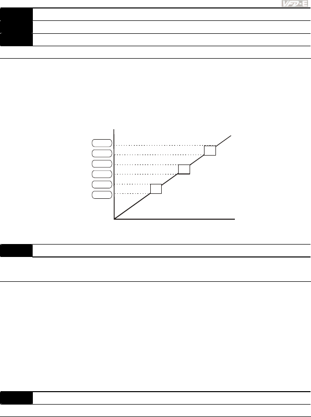
Chapter 4 Parameters|
Revision June 2008, 04EE, SW--PW V1.11/CTL V2.11 4-107
08.12 Skip Frequency 2 Lower Limit Unit: 0.01
08.13 Skip Frequency 3 Upper Limit Unit: 0.01
08.14 Skip Frequency 3 Lower Limit Unit: 0.01
Settings 0.00 to 600.0Hz Factory Setting: 0.00
These parameters set the Skip Frequencies. It will cause the AC motor drive never to remain
within these frequency ranges with continuous frequency output.
These six parameters should be set as follows Pr.08.09 ≥ Pr.08.10 ≥ Pr.08.11 ≥ Pr.08.12 ≥
Pr.08.13 ≥ Pr.08.14.
The frequency ranges may be overlapping.
0
08.09
08.10
08.11
08.12
08.13
08.14
setting frequency
internal frequency command
08.15 Auto Restart After Fault Unit: 1
Settings 0 to 10 Factory Setting: 0
0 Disable
Only after an over-current OC or over-voltage OV fault occurs, the AC motor drive can be
reset/restarted automatically up to 10 times.
Setting this parameter to 0 will disable automatic reset/restart operation after any fault has
occurred.
When enabled, the AC motor drive will restart with speed search, which starts at the frequency
before the fault. To set the waiting time before restart after a fault, please set Pr. 08.07 Base
Block Time for Speed Search.
08.16 Auto Reset Time at Restart after Fault Unit: 0.1
Settings 0.1 to 6000 sec Factory Setting: 60.0
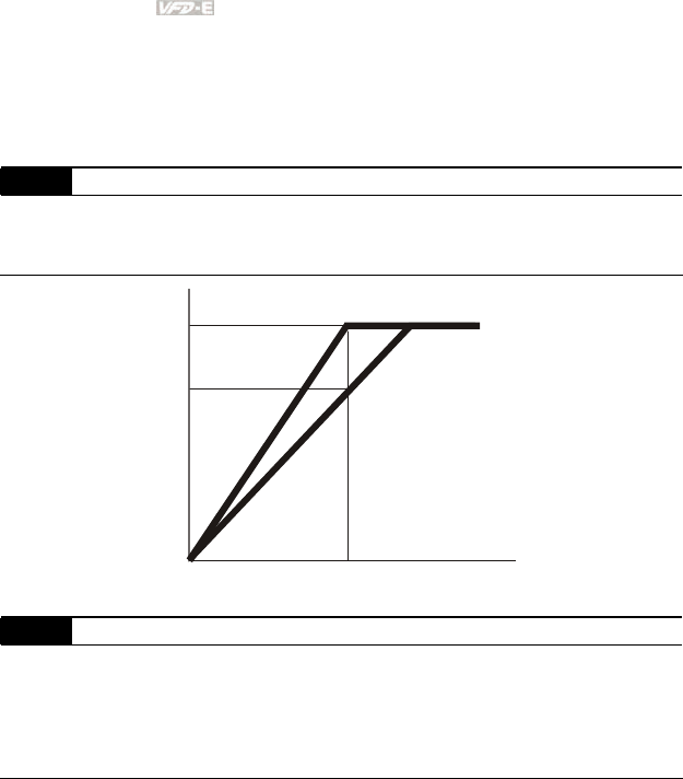
Chapter 4 Parameters|
4-108 Revision June 2008, 04EE, SW--PW V1.11/CTL V2.11
This parameter should be used in conjunction with Pr.08.15.
For example: If Pr.08.15 is set to 10 and Pr.08.16 is set to 600s (10 min), and if there is no
fault for over 600 seconds from the restart for the previous fault, the auto reset times for restart
after fault will be reset to 10.
08.17 Automatic Energy-saving
Factory Setting: 0
Settings 0 Energy-saving operation disabled
1 Energy-saving operation enabled
70%
100%
Output
Voltage
Output Frequency
During auto-energy saving
operation is the output
voltage lowered as much
as possible to keep the load.
The output voltage is maximally
lowered to 70% of the normal
output voltage
08.18 Automatic Voltage Regulation (AVR)
Factory Setting: 0
Settings 0 AVR function enabled
1 AVR function disabled
2 AVR function disabled for deceleration
3 AVR function disabled for stop
The rated voltage of the motor is usually 230V/200VAC 50Hz/60Hz and the input voltage of
the AC motor drive may vary between 180V to 264 VAC 50Hz/60Hz. Therefore, when the AC
motor drive is used without AVR function, the output voltage will be the same as the input
voltage. When the motor runs at voltages exceeding the rated voltage with 12% - 20%, its
lifetime will be shorter and it can be damaged due to higher temperature, failing insulation and
unstable torque output.

Chapter 4 Parameters|
Revision June 2008, 04EE, SW--PW V1.11/CTL V2.11 4-109
AVR function automatically regulates the AC motor drive output voltage to the Maximum
Output Voltage (Pr.01.02). For instance, if Pr.01.02 is set at 200 VAC and the input voltage is
at 200V to 264VAC, then the Maximum Output Voltage will automatically be reduced to a
maximum of 200VAC.
When the motor ramps to stop, the deceleration time is longer. When setting this parameter to
2 with auto acceleration/deceleration, the deceleration will be quicker.
08.19 Software Brake Level
(the Action Level of the Brake resistor)
Unit: 0.1
Settings 115/230V series: 370.0 to 430.0V Factory Setting: 380.0
460V series: 740.0 to 860.0V Factory Setting: 760.0
This parameter sets the DC-bus voltage at which the brake chopper is activated.
This parameter will be invalid for Frame A models (VFD002E11A/21A/23A,
VFD004E11A/21A/23A/43A, VFD007E21A/23A/43A and VFD022E23A/43A) without brake
chopper for which BUE brake unit must be used.
08.20 Compensation Coefficient for Motor Instability Unit: 0.1
Settings 0.0~5.0 Factory Setting: 0.0
The drift current will occur in a specific zone of the motor and it will make motor instable. By
using this parameter, it will improve this situation greatly.
The drift current zone of the high-power motors is usually in the low frequency area.
It is recommended to set to more than 2.0.
08.21 OOB Sampling Time Unit: 0.1
Settings 0.1 to 120.0 sec Factory Setting: 1.0
08.22 Number of OOB Sampling Times Unit: 1
Settings 0.00 to 32 Factory Setting: 20
08.23 OOB Average Sampling Angle
Settings Read-only Factory Setting: #.#
The OOB (Out Of Balance Detection) function can be used with PLC for washing machine.
When multi-function input terminal is enabled (MI=26), it will get Δθ value from the settings of
Pr.08.21 and Pr.08.22. PLC or the host controller will decide the motor speed by this t Δθ
value (Pr.08.23). When Δθ value is large, it means unbalanced load. At this moment, it needs
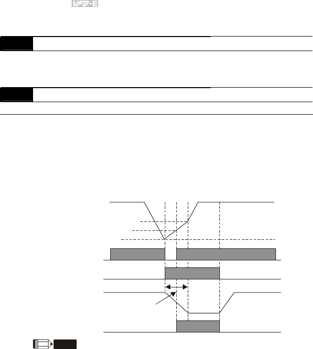
Chapter 4 Parameters|
4-110 Revision June 2008, 04EE, SW--PW V1.11/CTL V2.11
to lower the freqeuency command by PLC or the host controller. On the other hand, it can be
high-speed operation.
08.24 DEB Function
Factory Setting: 0
Settings 0 Disable
1 Enable
08.25 DEB Return Time Unit: 1
Settings 0~250 sec Factory Setting: 0
The DEB (Deceleration Energy Backup) function is the AC motor drive decelerates to stop
after momentary power loss. When the momentary power loss occurs, this function can be
used for the motor to decelerate to 0 speed with deceleration stop method. When the power is
on again, motor will run again after DEB return time. (for high-speed axis application)
Status 1: Insufficient power supply due to momentary power-loss/unstable power (due to low
voltage)/sudden heavy-load
07-14
NOTE
DC BUS voltage
it doesn't need
multi-function terminals
The level for DEB return time
(Lv=+30V+58V)
Lv level
Soft start relay at
power side
Output frequency
DEB return time
Pr.07-13 Decel. time selection for
momentary power loss
DEB function is activated
The level for soft start relay to be ON
(Lv+30)
When Pr.07-14 is set to 0, the AC motor drive will be stopped and won't re-start
at the power-on again.
Status 2: unexpected power off, such as momentary power loss
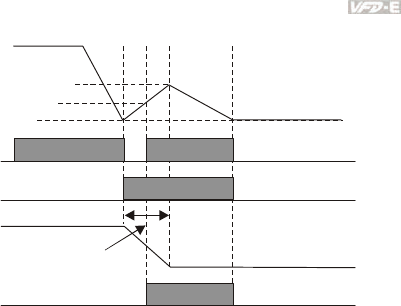
Chapter 4 Parameters|
Revision June 2008, 04EE, SW--PW V1.11/CTL V2.11 4-111
DC BUS voltage
The level for DEB return time
(Lv=+30V+58V)
Lv level
Soft start relay at
power side
Output frequency
DEB return time
Pr.07-13 Decel. time selection for
momentary power loss
DEB function is activated
The level for soft start relay to be ON
(Lv+30)
07-14

Chapter 4 Parameters|
4-112 Revision June 2008, 04EE, SW--PW V1.11/CTL V2.11
Group 9: Communication Parameters
There is a built-in RS-485 serial interface, marked RJ-45 near to the control terminals. The pins are
defined below:
RS-485 (NOT for VFD*E*C models)
Serial interface
1: Reserved 2: EV
5: SG+ 6: Reserved
7: Reserved 8: Reserved
3: GND
4: SG-
8
1
The pins definition for VFD*E*C models, please refer to chapter E.1.2.
Each VFD-E AC motor drive has a pre-assigned communication address specified by Pr.09.00. The
RS485 master then controls each AC motor drive according to its communication address.
09.00 Communication Address
Settings 1 to 254 Factory Setting: 1
If the AC motor drive is controlled by RS-485 serial communication, the communication
address for this drive must be set via this parameter. And the communication address for each
AC motor drive must be different and unique.
09.01 Transmission Speed
Factory Setting: 1
Settings 0 Baud rate 4800 bps (bits / second)
1 Baud rate 9600 bps
2 Baud rate 19200 bps
3 Baud rate 38400 bps
This parameter is used to set the transmission speed between the RS485 master (PLC, PC,
etc.) and AC motor drive.
09.02 Transmission Fault Treatment
Factory Setting: 3
Settings 0 Warn and keep operating
1 Warn and RAMP to stop
2 Warn and COAST to stop
3 No warning and keep operating
This parameter is set to how to react if transmission errors occur.
See list of error messages below (see section 3.6.)

Chapter 4 Parameters|
Revision June 2008, 04EE, SW--PW V1.11/CTL V2.11 4-113
09.03 Time-out Detection Unit: 0.1
Settings 0.0 to 120.0 sec Factory Setting: 0.0
0.0 Disable
If Pr.09.03 is not equal to 0.0, Pr.09.02=0~2, and there is no communication on the bus during
the Time Out detection period (set by Pr.09.03), “cE10” will be shown on the keypad.
09.04 Communication Protocol
Factory Setting: 0
Settings 0 Modbus ASCII mode, protocol <7,N,2>
1 Modbus ASCII mode, protocol <7,E,1>
2 Modbus ASCII mode, protocol <7,O,1>
3 Modbus RTU mode, protocol <8,N,2>
4 Modbus RTU mode, protocol <8,E,1>
5 Modbus RTU mode, protocol <8,O,1>
6 Modbus RTU mode, protocol <8,N,1>
7 Modbus RTU mode, protocol <8,E,2>
8 Modbus RTU mode, protocol <8,O,2>
9 Modbus ASCII mode, protocol <7,N,1>
10 Modbus ASCII mode, protocol <7,E,2>
11 Modbus ASCII mode, protocol <7,O,2>
1. Control by PC or PLC
A VFD-E can be set up to communicate in Modbus networks using one of the following
modes: ASCII (American Standard Code for Information Interchange) or RTU (Remote
Terminal Unit). Users can select the desired mode along with the serial port
communication protocol in Pr.09.04.
Code Description:
The CPU will be about 1 second delay when using communication reset. Therefore, there
is at least 1 second delay time in master station.
ASCII mode:
Each 8-bit data is the combination of two ASCII characters. For example, a 1-byte data:
64 Hex, shown as ‘64’ in ASCII, consists of ‘6’ (36Hex) and ‘4’ (34Hex).
Character ‘0’ ‘1’ ‘2’ ‘3’ ‘4’ ‘5’ ‘6’ ‘7’
ASCII code 30H 31H 32H 33H 34H 35H 36H 37H
Chapter 4 Parameters|
4-114 Revision June 2008, 04EE, SW--PW V1.11/CTL V2.11
Character ‘8’ ‘9’ ‘A’ ‘B’ ‘C’ ‘D’ ‘E’ ‘F’
ASCII code 38H 39H 41H 42H 43H 44H 45H 46H
RTU mode:
Each 8-bit data is the combination of two 4-bit hexadecimal characters. For example, 64
Hex.
2. Data Format
10-bit character frame (For ASCII):
( 7.N.2)
( 7.E.1)
Start
bit 0123456 Stop
bit
10-bit character frame
( 7.O.1)
Odd
parity
Start
bit 0123456 Stop
bit
10-bit character frame
Even
parity
Start
bit 0123456Stop
bit
7-bit character
10-bit character frame
Stop
bit
7-bit character
7-bit character
( 7.N.1)
( 7.E.2)
Start
bit 0123456 Stop
bit
11-bit character frame
( 7.O.2)
Odd
parity
Start
bit 0123456 Stop
bit
11-bit character frame
Even
parity
Start
bit 0123456Stop
bit
7-bit character
9-bit character frame
7-bit character
7-bit character
Stop
bit
Stop
bit
Chapter 4 Parameters|
Revision June 2008, 04EE, SW--PW V1.11/CTL V2.11 4-115
11-bit character frame (For RTU):
Start
bit 0123456 Stop
bit
Stop
bit
8-bit character
11-bit character frame
( 8.N.2 )
Start
bit 0123456Even
p
arity
Stop
bit
11-bit character frame
( 8.E .1 )
Start
bit 0123456Stop
bit
11-bit character frame
( 8.O.1 )
Odd
parity
7
7
7
8-bit character
8-bit character
Start
bit 0123456 Stop
bit
8-bit character
10-bit character frame
( 8.N.1 )
Start
bit 0123456 Even
p
arity
Stop
bit
12-bit character frame
( 8.E .2 )
Start
bit 0123456Stop
bit
12-bit character frame
( 8.O.2 )
Odd
parity
7
7
7
8-bit character
8-bit character
Stop
bit
Stop
bit
3. Communication Protocol
3.1 Communication Data Frame:
ASCII mode:
STX Start character ‘:’ (3AH)
Address Hi
Address Lo
Communication address:
8-bit address consists of 2 ASCII codes
Function Hi
Function Lo
Command code:
8-bit command consists of 2 ASCII codes
DATA (n-1)
to
DATA 0
Contents of data:
Nx8-bit data consist of 2n ASCII codes
n<=20, maximum of 40 ASCII codes

Chapter 4 Parameters|
4-116 Revision June 2008, 04EE, SW--PW V1.11/CTL V2.11
LRC CHK Hi
LRC CHK Lo
LRC check sum:
8-bit check sum consists of 2 ASCII codes
END Hi
END Lo
End characters:
END1= CR (0DH), END0= LF(0AH)
RTU mode:
START A silent interval of more than 10 ms
Address Communication address: 8-bit address
Function Command code: 8-bit command
DATA (n-1)
to
DATA 0
Contents of data:
n×8-bit data, n<=40 (20 x 16-bit data)
CRC CHK Low
CRC CHK High
CRC check sum:
16-bit check sum consists of 2 8-bit characters
END A silent interval of more than 10 ms
3.2 Address (Communication Address)
Valid communication addresses are in the range of 0 to 254. A communication address equal
to 0, means broadcast to all AC drives (AMD). In this case, the AMD will not reply any
message to the master device.
00H: broadcast to all AC drives
01H: AC drive of address 01
0FH: AC drive of address 15
10H: AC drive of address 16
:
FEH: AC drive of address 254
For example, communication to AMD with address 16 decimal (10H):
ASCII mode: Address=’1’,’0’ => ‘1’=31H, ‘0’=30H
RTU mode: Address=10H
3.3 Function (Function code) and DATA (data characters)
The format of data characters depends on the function code.
03H: read data from register
06H: write single register
08H: loop detection

Chapter 4 Parameters|
Revision June 2008, 04EE, SW--PW V1.11/CTL V2.11 4-117
10H: write multiple registers
The available function codes and examples for VFD-E are described as follows:
(1) 03H: multi read, read data from registers.
Example: reading continuous 2 data from register address 2102H, AMD address is 01H.
ASCII mode:
Command message: Response message:
STX ‘:’ STX ‘:’
‘0’ ‘0’
Address
‘1’
Address
‘1’
‘0’ ‘0’
Function
‘3’
Function
‘3’
‘2’ ‘0’
‘1’
Number of data
(Count by byte) ‘4’
‘0’ ‘1’
Starting data
address
‘2’ ‘7’
‘0’ ‘7’
‘0’
Content of starting
address
2102H
‘0’
‘0’ ‘0’
Number of data
(count by word)
‘2’ ‘0’
‘D’ ‘0’
LRC Check
‘7’
Content of address
2103H
‘0’
CR ‘7’
END
LF
LRC Check
‘1’
CR
END
LF
RTU mode:
Command message: Response message:
Address 01H Address 01H
Function 03H Function 03H
21H
Starting data
address 02H
Number of data
(count by byte) 04H

Chapter 4 Parameters|
4-118 Revision June 2008, 04EE, SW--PW V1.11/CTL V2.11
00H 17H Number of data
(count by word) 02H
Content of address
2102H 70H
CRC CHK Low 6FH 00H
CRC CHK High F7H
Content of address
2103H 00H
CRC CHK Low FEH
CRC CHK High 5CH
(2) 06H: single write, write single data to register.
Example: writing data 6000(1770H) to register 0100H. AMD address is 01H.
ASCII mode:
Command message: Response message:
STX ‘:’ STX ‘:’
‘0’ ‘0’
Address
‘1’
Address
‘1’
‘0’ ‘0’
Function
‘6’
Function
‘6’
‘0’ ‘0’
‘1’ ‘1’
‘0’ ‘0’
Data address
‘0’
Data address
‘0’
‘1’ ‘1’
‘7’ ‘7’
‘7’ ‘7’
Data content
‘0’
Data content
‘0’
‘7’ ‘7’
LRC Check
‘1’
LRC Check
‘1’
CR CR
END
LF
END
LF
RTU mode:
Command message: Response message:
Address 01H Address 01H

Chapter 4 Parameters|
Revision June 2008, 04EE, SW--PW V1.11/CTL V2.11 4-119
Function 08H Function 08H
00H 00H
Data address
00H
Data address
00H
17H 17H
Data content
70H
Data content
70H
CRC CHK Low EEH CRC CHK Low EEH
CRC CHK High 1FH CRC CHK High 1FH
(3) 08H: loop detection
This command is used to detect if the communication between master device (PC or PLC)
and AC motor drive is normal. The AC motor drive will send the received message to the
master device.
ASCII mode:
Command message: Response message:
STX ‘:’ STX ‘:’
‘0’ ‘0’
Address
‘1’
Address
‘1’
‘0’ ‘0’
Function
‘8’
Function
‘8’
‘0’ ‘0’
‘0’ ‘0’
‘0’ ‘0’
Data address
‘0’
Data address
‘0’
‘1’ ‘1’
‘7’ ‘7’
‘7’ ‘7’
Data content
‘0’
Data content
‘0’
‘7’ ‘7’
LRC Check
‘0’
LRC Check
‘0’
CR CR
END
LF
END
LF

Chapter 4 Parameters|
4-120 Revision June 2008, 04EE, SW--PW V1.11/CTL V2.11
RTU mode:
Command message: Response message:
Address 01H Address 01H
Function 08H Function 08H
00H 00H
Data address
00H
Data address
00H
17H 17H
Data content
70H
Data content
70H
CRC CHK Low EEH CRC CHK Low EEH
CRC CHK High 1FH CRC CHK High 1FH
(4) 10H: write multiple registers (write multiple data to registers)
Example: Set the multi-step speed,
Pr.05.00=50.00 (1388H), Pr.05.01=40.00 (0FA0H). AC drive address is 01H.
ASCII Mode:
Command message: Response message:
STX ‘:’ STX ‘:’
Address 1 ‘0’ Address 1 ‘0’
Address 0 ‘1’ Address 0 ‘1’
Function 1 ‘1’ Function 1 ‘1’
Function 0 ‘0’ Function 0 ‘0’
‘0’ ‘0’
‘5’ ‘5’
‘0’ ‘0’
Starting data
address
‘0’
Starting data
address
‘0’
‘0’ ‘0’
‘0’ ‘0’
‘0’ ‘0’
Number of data
(count by word)
‘2’
Number of data
(count by word)
‘2’
‘0’ ‘E’
Number of data
(count by byte) ‘4’ LRC Check ‘8’
‘1’ CR
‘3’ END LF
‘8’
The first data
content
‘8’
‘0’
‘F’
‘A’
The second data
content
‘0’
‘9’
LRC Check ‘A’
CR
END LF

Chapter 4 Parameters|
Revision June 2008, 04EE, SW--PW V1.11/CTL V2.11 4-121
RTU mode:
Command message: Response message:
Address 01H Address 01H
Function 10H Function 10H
05H 05H Starting data
address 00H
Starting data address
00H
00H’ 00H Number of data
(count by word) 02H
Number of data
(count by word) 02H
Number of data
(count by byte)
04 CRC Check Low 41H
13H CRC Check High 04H The first data
content 88H
0FH The second data
content A0H
CRC Check Low 4DH
CRC Check High D9H
3.4 Check sum
ASCII mode:
LRC (Longitudinal Redundancy Check) is calculated by summing up, module 256, the values
of the bytes from ADR1 to last data character then calculating the hexadecimal
representation of the 2’s-complement negation of the sum.
For example, reading 1 word from address 0401H of the AC drive with address 01H.
STX ‘:’
‘0’ Address 1
Address 0 ‘1’
‘0’ Function 1
Function 0 ‘3’
‘0’
‘4’
‘0’
Starting data address
‘1’
‘0’
‘0’
‘0’
Number of data
‘1’

Chapter 4 Parameters|
4-122 Revision June 2008, 04EE, SW--PW V1.11/CTL V2.11
‘F’ LRC Check 1
LRC Check 0 ‘6’
CR END 1
END 0 LF
01H+03H+04H+01H+00H+01H=0AH, the 2’s-complement negation of 0AH is F6H.
RTU mode:
Address 01H
Function 03H
21H Starting data address
02H
00H Number of data
(count by word) 02H
CRC CHK Low 6FH
CRC CHK High F7H
CRC (Cyclical Redundancy Check) is calculated by the following steps:
Step 1: Load a 16-bit register (called CRC register) with FFFFH.
Step 2: Exclusive OR the first 8-bit byte of the command message with the low order byte of
the 16-bit CRC register, putting the result in the CRC register.
Step 3: Examine the LSB of CRC register.
Step 4: If the LSB of CRC register is 0, shift the CRC register one bit to the right with MSB
zero filling, then repeat step 3. If the LSB of CRC register is 1, shift the CRC register one bit
to the right with MSB zero filling, Exclusive OR the CRC register with the polynomial value
A001H, then repeat step 3.
Step 5: Repeat step 3 and 4 until eight shifts have been performed. When this is done, a
complete 8-bit byte will have been processed.
Step 6: Repeat step 2 to 5 for the next 8-bit byte of the command message. Continue doing
this until all bytes have been processed. The final contents of the CRC register are the CRC
value. When transmitting the CRC value in the message, the upper and lower bytes of the
CRC value must be swapped, i.e. the lower order byte will be transmitted first.
The following is an example of CRC generation using C language. The function takes two
arguments:
Unsigned char* data Å a pointer to the message buffer
Unsigned char length Å the quantity of bytes in the message buffer
The function returns the CRC value as a type of unsigned integer.

Chapter 4 Parameters|
Revision June 2008, 04EE, SW--PW V1.11/CTL V2.11 4-123
Unsigned int crc_chk(unsigned char* data, unsigned char length){
int j;
unsigned int reg_crc=0xFFFF;
while(length--){
reg_crc ^= *data++;
for(j=0;j<8;j++){
if(reg_crc & 0x01){ /* LSB(b0)=1 */
reg_crc=(reg_crc>>1) ^ 0xA001;
}else{
reg_crc=reg_crc >>1;
}
}
}
return reg_crc;
}
3.5 Address list
The contents of available addresses are shown as below:
Content Address Function
AC drive
Parameters GGnnH
GG means parameter group, nn means parameter number,
for example, the address of Pr 04.01 is 0401H. Refer to
chapter 5 for the function of each parameter. When reading
parameter by command code 03H, only one parameter can
be read at one time.
Bit 0-1
00B: No function
01B: Stop
10B: Run
11B: Jog + Run
Bit 2-3 Reserved
Bit 4-5
00B: No function
01B: FWD
10B: REV
11B: Change direction
Bit 6-7 00B: Comm. forced 1st accel/decel
01B: Comm. forced 2nd accel/decel
Command
Write only
2000H
Bit 8-15 Reserved

Chapter 4 Parameters|
4-124 Revision June 2008, 04EE, SW--PW V1.11/CTL V2.11
Content Address Function
2001H Frequency command
Bit 0 1: EF (external fault) on
Bit 1 1: Reset
2002H
Bit 2-15 Reserved
Error code:
0: No error occurred
Status
monitor
Read only
2100H
1: Over-current (oc)
2: Over-voltage (ov)
3: IGBT Overheat (oH1)
4: Power Board Overheat (oH2)
5: Overload (oL)
6: Overload1 (oL1)
7: Overload2 (oL2)
8: External fault (EF)
9: Current exceeds 2 times rated current during accel (ocA)
10: Current exceeds 2 times rated current during decel (ocd)
Current exceeds 2 times rated current during decel (ocd)
11: Current exceeds 2 times rated current during steady state
operation (ocn)
12: Ground Fault (GFF)
13: Low voltage (Lv)
14: PHL (Phase-Loss)
2100H 15: Base Block
16: Auto accel/decel failure (cFA)
17: Software protection enabled (codE)
18: Power Board CPU WRITE failure (CF1.0)
19: Power Board CPU READ failure (CF2.0)
20: CC, OC Hardware protection failure (HPF1)
21: OV Hardware protection failure (HPF2)
22: GFF Hardware protection failure (HPF3)
23: OC Hardware protection failure (HPF4)

Chapter 4 Parameters|
Revision June 2008, 04EE, SW--PW V1.11/CTL V2.11 4-125
Content Address Function
24: U-phase error (cF3.0)
25: V-phase error (cF3.1)
26: W-phase error (cF3.2)
27: DCBUS error (cF3.3)
2100H 28: IGBT Overheat (cF3.4)
29: Power Board Overheat (cF3.5)
30: Control Board CPU WRITE failure (cF1.1)
31: Control Board CPU WRITE failure (cF2.1)
32: ACI signal error (AErr)
33: Reserved
34: Motor PTC overheat protection (PtC1)
Status of AC drive
00B: RUN LED is off, STOP LED is on (The AC
motor Drive stops)
01B: RUN LED blinks, STOP LED is on (When
AC motor drive decelerates to stop)
10B: RUN LED is on, STOP LED blinks (When
AC motor drive is standby)
Bit 0-1
11B: RUN LED is on, STOP LED is off (When AC
motor drive runs)
Bit 2 1: JOG command
Bit 3-4 00B: FWD LED is on, REV LED is off (When AC
motor drive runs forward)
01B: FWD LED is on, REV LED blinks (When AC
motor drive runs from reverse to forward)
10B: FWD LED blinks, REV LED is on (When AC
motor drive runs from forward to reverse)
11B: FWD LED is off, REV LED is on (When AC
motor drive runs reverse)
Bit 5-7 Reserved
Bit 8 1: Master frequency Controlled by communication
interface
2101H
Bit 9 1: Master frequency controlled by analog signal

Chapter 4 Parameters|
4-126 Revision June 2008, 04EE, SW--PW V1.11/CTL V2.11
Content Address Function
Bit 10 1: Operation command controlled by
communication interface
Bit 11-15 Reserved
2102H Frequency command (F)
2103H Output frequency (H)
2104H Output current (AXXX.X)
2105H Reserved
2106H Reserved
2107H Reserved
2108H DC-BUS Voltage (UXXX.X)
2109H Output voltage (EXXX.X)
210AH Display temperature of IGBT (°C)
2116H User defined (Low word)
2117H User defined (High word)
Note: 2116H is number display of Pr.00.04. High byte of 2117H is number of decimal places
of 2116H. Low byte of 2117H is ASCII code of alphabet display of Pr.00.04.
3.6 Exception response:
The AC motor drive is expected to return a normal response after receiving command
messages from the master device. The following depicts the conditions when no normal
response is replied to the master device.
The AC motor drive does not receive the messages due to a communication error; thus, the
AC motor drive has no response. The master device will eventually process a timeout
condition.
The AC motor drive receives the messages without a communication error, but cannot handle
them. An exception response will be returned to the master device and an error message
“CExx” will be displayed on the keypad of AC motor drive. The xx of “CExx” is a decimal code
equal to the exception code that is described below.
In the exception response, the most significant bit of the original command code is set to 1,
and an exception code which explains the condition that caused the exception is returned.
Example of an exception response of command code 06H and exception code 02H:
ASCII mode: RTU mode:

Chapter 4 Parameters|
Revision June 2008, 04EE, SW--PW V1.11/CTL V2.11 4-127
STX ‘:’ Address 01H
‘0’ Function 86H
Address Low
Address High ‘1’ Exception code 02H
‘8’ CRC CHK Low C3H
Function Low
Function High ‘6’ CRC CHK High A1H
‘0’
Exception code
‘2’
‘7’
LRC CHK Low
LRC CHK High ‘7’
CR
END 1
END 0 LF
The explanation of exception codes:
Exception
code Explanation
01
Illegal function code:
The function code received in the command message is not
available for the AC motor drive.
02
Illegal data address:
The data address received in the command message is not
available for the AC motor drive.
03
Illegal data value:
The data value received in the command message is not available
for the AC drive.
04 Slave device failure:
The AC motor drive is unable to perform the requested action.
10
Communication time-out:
If Pr.09.03 is not equal to 0.0, Pr.09.02=0~2, and there is no
communication on the bus during the Time Out detection period (set
by Pr.09.03), “cE10” will be shown on the keypad.
3.7 Communication program of PC:
The following is a simple example of how to write a communication program for Modbus
ASCII mode on a PC in C language.
#include<stdio.h>
#include<dos.h>

Chapter 4 Parameters|
4-128 Revision June 2008, 04EE, SW--PW V1.11/CTL V2.11
#include<conio.h>
#include<process.h>
#define PORT 0x03F8 /* the address of COM1 */
/* the address offset value relative to COM1 */
#define THR 0x0000
#define RDR 0x0000
#define BRDL 0x0000
#define IER 0x0001
#define BRDH 0x0001
#define LCR 0x0003
#define MCR 0x0004
#define LSR 0x0005
#define MSR 0x0006
unsigned char rdat[60];
/* read 2 data from address 2102H of AC drive with address 1 */
unsigned char tdat[60]={':','0','1','0','3','2','1','0',’2', '0','0','0','2','D','7','\r','\n'};
void main(){
int i;
outportb(PORT+MCR,0x08); /* interrupt enable */
outportb(PORT+IER,0x01); /* interrupt as data in */
outportb(PORT+LCR,(inportb(PORT+LCR) | 0x80));
/* the BRDL/BRDH can be access as LCR.b7==1 */
outportb(PORT+BRDL,12); /* set baudrate=9600, 12=115200/9600*/
outportb(PORT+BRDH,0x00);
outportb(PORT+LCR,0x06); /* set protocol, <7,N,2>=06H, <7,E,1>=1AH,
<7,O,1>=0AH, <8,N,2>=07H, <8,E,1>=1BH, <8,O,1>=0BH */
for(i=0;i<=16;i++){
while(!(inportb(PORT+LSR) & 0x20)); /* wait until THR empty */
outportb(PORT+THR,tdat[i]); /* send data to THR */ }
i=0;
while(!kbhit()){
if(inportb(PORT+LSR) & 0x01){ /* b0==1, read data ready */
rdat[i++]=inportb(PORT+RDR); /* read data form RDR */
} } }
09.05 Reserved

Chapter 4 Parameters|
Revision June 2008, 04EE, SW--PW V1.11/CTL V2.11 4-129
09.06 Reserved
09.07 Response Delay Time Unit: 2ms
Settings 0 ~ 200 (400msec) Factory Setting: 1
This parameter is the response delay time after AC drive receives communication command
as shown in the following. 1 unit = 2 msec.
RS485 BUS PC or PLC command
Handling time
of AC drive
Response Delay Time
Response Message of AC Drive
Max.: 6msec
Pr.09.07
09.08 Transmission Speed for USB Card
Factory Setting: 2
Settings 0
Baud rate 4800 bps
1 Baud rate 9600 bps
2 Baud rate 19200 bps
3 Baud rate 38400 bps
4 Baud rate 57600 bps
This parameter is used to set the transmission speed for USB card.
09.09 Communication Protocol for USB Card
Factory Setting: 1
Settings 0 Modbus ASCII mode, protocol <7,N,2>
1 Modbus ASCII mode, protocol <7,E,1>
2 Modbus ASCII mode, protocol <7,O,1>
3 Modbus RTU mode, protocol <8,N,2>
4 Modbus RTU mode, protocol <8,E,1>
5 Modbus RTU mode, protocol <8,O,1>
6 Modbus RTU mode, protocol <8,N,1>
7 Modbus RTU mode, protocol <8,E,2>
8 Modbus RTU mode, protocol <8,O,2>
9 Modbus ASCII mode, protocol <7,N,1>
10 Modbus ASCII mode, protocol <7,E,2>
11 Modbus ASCII mode, protocol <7,O,2>

Chapter 4 Parameters|
4-130 Revision June 2008, 04EE, SW--PW V1.11/CTL V2.11
09.10 Transmission Fault Treatment for USB Card
Factory Setting: 0
Settings 0 Warn and keep operating
1 Warn and RAMP to stop
2 Warn and COAST to stop
3 No warning and keep operating
This parameter is set to how to react when transmission errors occurs.

Chapter 4 Parameters|
Revision June 2008, 04EE, SW--PW V1.11/CTL V2.11 4-131
09.11 Time-out Detection for USB Card Unit: 0.1
Settings 0.0 to 120.0 sec Factory Setting: 0.0
0.0 Disable
09.12 COM port for PLC Communication (NOT for VFD*E*C models)
Factory Setting: 0
Settings 0
RS485
1 USB card

Chapter 4 Parameters|
4-132 Revision June 2008, 04EE, SW--PW V1.11/CTL V2.11
Group 10: PID Control
10.00 PID Set Point Selection
Factory Setting: 0
Settings 0 Disable
1 Digital keypad UP/DOWN keys
2 AVI 0 ~ +10VDC
3 ACI 4 ~ 20mA / AVI2 0 ~ +10VDC
4 PID set point (Pr.10.11)
10.01 Input Terminal for PID Feedback
Factory Setting: 0
Settings 0 Positive PID feedback from external terminal AVI (0 ~ +10VDC).
1 Negative PID feedback from external terminal AVI (0 ~ +10VDC).
2 Positive PID feedback from external terminal ACI (4 ~ 20mA)/ AVI2
(0 ~ +10VDC).
3 Negative PID feedback from external terminal ACI (4 ~ 20mA)/
AVI2 (0 ~ +10VDC).
Note that the measured variable (feedback) controls the output frequency (Hz). Select input
terminal accordingly. Make sure this parameter setting does not conflict with the setting for
Pr.10.00 (Master Frequency).
When Pr.10.00 is set to 2 or 3, the set point (Master Frequency) for PID control is obtained
from the AVI or ACI/AVI2 external terminal (0 to +10V or 4-20mA) or from multi-step speed.
When Pr.10.00 is set to 1, the set point is obtained from the keypad.
Negative feedback means: +target value – feedback
Positive feedback means: -target value + feedback.
10.02 Proportional Gain (P) Unit: 0. 1
Settings 0.0 to 10.0 Factory Setting: 1.0
This parameter specifies proportional control and associated gain (P). If the other two gains (I
and D) are set to zero, proportional control is the only one effective. With 10% deviation (error)
and P=1, the output will be P x10% x Master Frequency.

Chapter 4 Parameters|
Revision June 2008, 04EE, SW--PW V1.11/CTL V2.11 4-133
NOTE
The parameter can be set during operation for easy tuning.
10.03 Integral Time ( I ) Unit: 0.01
Settings 0.00 to 100.0 sec Factory Setting: 1.00
0.00 Disable
This parameter specifies integral control (continual sum of the deviation) and associated gain
(I). When the integral gain is set to 1 and the deviation is fixed, the output is equal to the input
(deviation) once the integral time setting is attained.
NOTE
The parameter can be set during operation for easy tuning.
10.04 Derivative Control (D) Unit: 0.01
Settings 0.00 to 1.00 sec Factory Setting: 0.00
This parameter specifies derivative control (rate of change of the input) and associated gain
(D). With this parameter set to 1, the PID output is equal to differential time x (present
deviation − previous deviation). It increases the response speed but it may cause over-
compensation.
NOTE
The parameter can be set during operation for easy tuning.
10.05 Upper Bound for Integral Control Unit: 1
Settings
0 to 100 % Factory Setting: 100
This parameter defines an upper bound or limit for the integral gain (I) and therefore limits the
Master Frequency.
The formula is: Integral upper bound = Maximum Output Frequency (Pr.01.00) x (Pr.10.05).
This parameter can limit the Maximum Output Frequency.
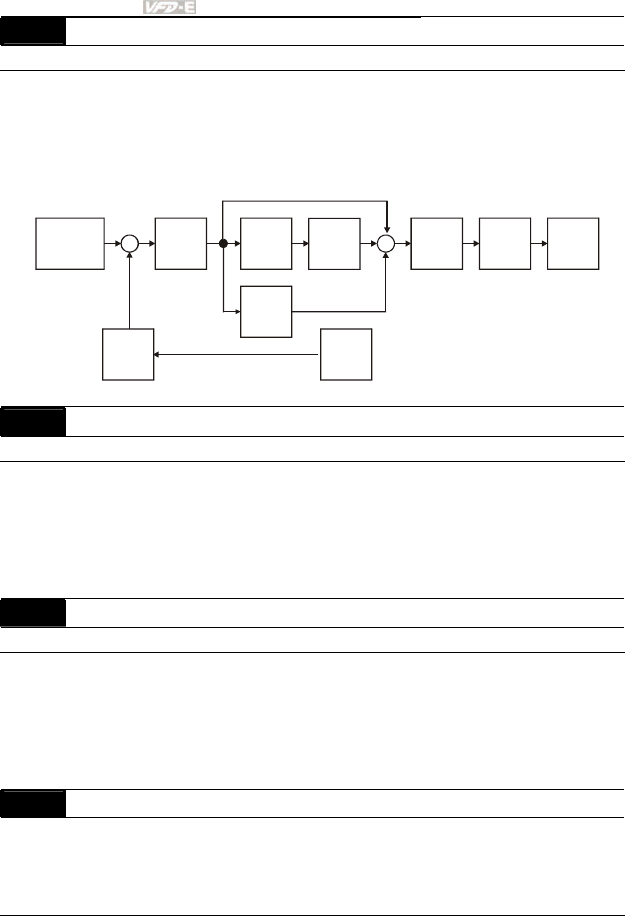
Chapter 4 Parameters|
4-134 Revision June 2008, 04EE, SW--PW V1.11/CTL V2.11
10.06 Primary Delay Filter Time Unit: 0.1
Settings 0.0 to 2.5 sec Factory Setting: 0.0
To avoid amplification of measurement noise in the controller output, a derivative digital filter is
inserted. This filter helps to dampen oscillations.
The complete PID diagram is in the following:
P
10.02
I
10.03
D
10.04
10.05
10.10
10.07 10.06
10.01
+
-
+
+
+
Setpoint
Input Freq.
Gain
PID
feedback
Integral
gain
limit
Output
Freq.
Limit
Digital
filter Freq.
Command
10.07 PID Output Frequency Limit Unit: 1
Settings 0 to 110 % Factory Setting: 100
This parameter defines the percentage of output frequency limit during the PID control. The
formula is Output Frequency Limit = Maximum Output Frequency (Pr.01.00) X Pr.10.07 %.
This parameter will limit the Maximum Output Frequency. An overall limit for the output
frequency can be set in Pr.01.07.
10.08 PID Feedback Signal Detection Time Unit: 0.1
Settings 0.0 to d 3600 sec Factory Setting: 60.0
This parameter defines the time during which the PID feedback must be abnormal before a
warning (see Pr.10.09) is given. It also can be modified according to the system feedback
signal time.
If this parameter is set to 0.0, the system would not detect any abnormality signal.
10.09 Treatment of the Erroneous Feedback Signals (for PID feedback error)
Factory Setting: 0
Settings 0 Warning and RAMP to stop
1 Warning and COAST to stop
2 Warning and keep operating

Chapter 4 Parameters|
Revision June 2008, 04EE, SW--PW V1.11/CTL V2.11 4-135
This function is only for ACI signal.
AC motor drive action when the feedback signals (analog PID feedback) are abnormal
according to Pr.10.16.
10.10 Gain Over the PID Detection Value Unit: 0.1
Settings
0.0 to 10.0 Factory Setting: 1.0
This function is only for ACI signal.
This is the gain adjustment over the feedback detection value. Refer to PID control block
diagram in Pr.10.06 for detail.
10.11 Source of PID Set point Unit: 0.01
Settings 0.00 to 600.0Hz Factory Setting: 0.00
This parameter is used in conjunction with Pr.10.00 set 4 to input a set point in Hz.
10.12 PID Offset Level Unit: 0.1
Settings 1.0 to 50.0% Factory Setting: 10.0
10.13 Detection Time of PID Offset Unit: 0.1
Settings 0.1 to 300.0 sec Factory Setting: 5.0
This parameter is used to set detection of the offset between set point and feedback.
When the offset is higher than the setting of Pr.10.12 for a time exceeding the setting of
Pr.10.13, the AC motor drive will output a signal when Pr.03.00 ~ Pr.03.01 is set to 16.
10.14 Sleep/Wake Up Detection Time Unit: 0.1
Settings 0.0 to 6550 sec Factory Setting: 0.0
10.15 Sleep Frequency Unit: 0.01
Settings 0.00 to 600.0 Hz Factory Setting: 0.00
10.16 Wakeup Frequency Unit: 0.01
Settings 0.00 to 600.0 Hz Factory Setting: 0.00
When the actual output frequency
≤
Pr.10.15 and the time exceeds the setting of Pr.10.14,
the AC motor drive will be in sleep mode.
When the actual frequency command > Pr.10.16 and the time exceeds the setting of Pr.10.14,
the AC motor drive will restart.
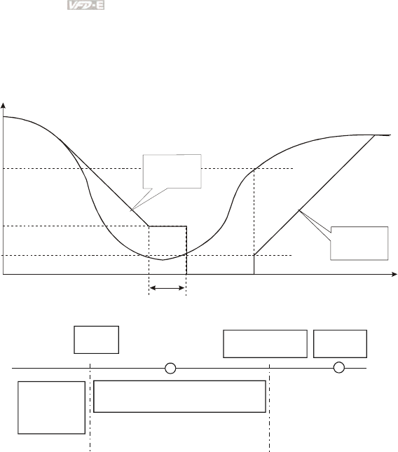
Chapter 4 Parameters|
4-136 Revision June 2008, 04EE, SW--PW V1.11/CTL V2.11
When the AC motor drive is in sleep mode, frequency command is still calculated by PID.
When frequency reaches wake up frequency, AC motor drive will accelerate from Pr.01.05
minimum frequency following the V/f curve.
The wake up frequency must be higher than sleep frequency.
10.16
10.15
01.05
10.14
Frequency
The limit of
decel. time
frequency calculated by PID
output
frequency
Time
The limit of
accel. time
Fmin
Fsleep
Fcmd=0
Fout = 0
lower bound
of frequency
Fmin<Fsleep< lower bound
of frequency
When output frequency
≤ sleep frequency and time > detection time, it will go in sleep mode.
When min. output frequency ≦ PID frequency ≦ lower bound of frequency and sleep function
is enabled (output frequency
≤
sleep frequency and time > detection time), frequency will be 0
(in sleep mode). If sleep function is disabled, frequency command = lower bound frequency.
When PID frequency < min. output frequency and sleep function is enabled (output frequency
≤ sleep frequency and time > detection time), output frequency =0 (in sleep mode).
If output frequency ≤ sleep frequency but time < detection time, frequency command = lower
frequency. If sleep function is disabled, output frequency =0.

Chapter 4 Parameters|
Revision June 2008, 04EE, SW--PW V1.11/CTL V2.11 4-137
10.17 Minimum PID Output Frequency Selection
Factory Setting: 0
Settings 0 By PID control
1 By Minimum output frequency (Pr.01.05)
This is the source selection of minimum output frequency when control is by PID.

Chapter 4 Parameters|
4-138 Revision June 2008, 04EE, SW--PW V1.11/CTL V2.11
Group 11: Multi-function Input/Output Parameters for Extension Card
Make sure that the extension card is installed on the AC motor drive correctly before using group 11
parameters. See Appendix B for details.
11.00 Multi-function Output Terminal MO2/RA2
11.01 Multi-function Output Terminal MO3/RA3
11.02 Multi-function Output Terminal MO4/RA4
11.03 Multi-function Output Terminal MO5/RA5
11.04 Multi-function Output Terminal MO6/RA6
11.05 Multi-function Output Terminal MO7/RA7
Settings 0 to 21 Factory Setting: 0
Settings Function Description
0 No Function
1 AC Drive Operational Active when the drive is ready or RUN command is “ON”.
2 Master Frequency
Attained
Active when the AC motor drive reaches the output
frequency setting.
3 Zero Speed Active when Command Frequency is lower than the
Minimum Output Frequency.
4 Over-Torque Detection
Active as long as over-torque is detected. (Refer to Pr.06.03
~ Pr.06.05)
5 Baseblock (B.B.)
Indication
Active when the output of the AC motor drive is shut off
during baseblock. Base block can be forced by Multi-
function input (setting 09).
6 Low-Voltage Indication Active when low voltage (Lv) is detected.
7 Operation Mode
Indication
Active when operation command is controlled by external
terminal.
8 Fault Indication Active when a fault occurs (oc, ov, oH, oL, oL1, EF, cF3,
HPF, ocA, ocd, ocn, GFF).

Chapter 4 Parameters|
Revision June 2008, 04EE, SW--PW V1.11/CTL V2.11 4-139
Settings Function Description
9 Desired Frequency
Attained Active when the desired frequency (Pr.03.02) is attained.
10 Terminal Count Value
Attained Active when the counter reaches Terminal Count Value.
11 Preliminary Count Value
Attained Active when the counter reaches Preliminary Count Value.
12 Over Voltage Stall
supervision
Active when the Over Voltage Stall function operating
13 Over Current Stall
supervision Active when the Over Current Stall function operating
14 Heat Sink Overheat
Warning
When heatsink overheats, it will signal to prevent OH turn
off the drive. When it is higher than 85oC (185oF), it will be
ON.
15 Over Voltage supervision Active when the DC-BUS voltage exceeds level
16 PID supervision Active when the PID function is operating
17 Forward command Active when the direction command is FWD
18 Reverse command Active when the direction command is REV
19 Zero Speed Output
Signal
Active unless there is an output frequency present at
terminals U/T1, V/T2, and W/T3.
20
Communication Warning
(FbE,Cexx, AoL2, AUE,
SAvE)
Active when there is a Communication Warning
21 Brake Control (Desired
Frequency Attained)
Active when output frequency ≥Pr.03.14. Deactivated when
output frequency ≤Pr.03.15 after STOP command.
11.06 Multi-function Input Terminal (MI7)
11.07 Multi-function Input Terminal (MI8)
11.08 Multi-function Input Terminal (MI9)
11.09 Multi-function Input Terminal (MI10)

Chapter 4 Parameters|
4-140 Revision June 2008, 04EE, SW--PW V1.11/CTL V2.11
11.10 Multi-function Input Terminal (MI11)
11.11 Multi-function Input Terminal (MI12)
Settings 0 to 23 Factory Setting: 0
Settings Function Description
0 No Function Any unused terminals should be programmed to 0 to insure they
have no effect on operation.
1 Multi-Step Speed
Command 1
2 Multi-Step Speed
Command 2
3 Multi-Step Speed
Command 3
4 Multi-Step Speed
Command 4
These four inputs select the multi-speed defined by Pr.05.00 to
Pr.05.14 as shown in the diagram at the end of the table in
Pr.04.08.
NOTE: Pr.05.00 to Pr.05.14 can also be used to control output
speed by programming the AC motor drive’s internal PLC
function. There are 17 step speed frequencies (including
Master Frequency and Jog Frequency) to select for
application.
5 External Reset
The External Reset has the same function as the Reset key on
the Digital keypad. After faults such as O.H., O.C. and O.V. are
cleared this input can be used to reset the drive.
6 Accel/Decel Inhibit
When the command is active, acceleration and deceleration is
stopped and the AC motor drive maintains a constant speed.
7
Accel/Decel Time
Selection
Command
Used to select the one of 2 Accel/Decel Times (Pr.01.09 to
Pr.01.12). See explanation at the end of this table.
8 Jog Operation
Control
Parameter value 08 programs one of the Multi-function Input
Terminals MI7 ∼ MI12 (Pr.11.06~Pr.11.11) for Jog control.
NOTE: Programming for Jog operation by 08 can only be
done while the motor is stopped. (Refer to parameter
Pr.01.13~Pr.01.15)

Chapter 4 Parameters|
Revision June 2008, 04EE, SW--PW V1.11/CTL V2.11 4-141
Settings Function Description
9
External Base
Block
(Refer to Pr.08.06)
Parameter value 09 programs a Multi-function Input Terminals for
external Base Block control.
NOTE: When a Base-Block signal is received, the AC motor
drive will block all output and the motor will free run. When
base block control is deactivated, the AC drive will start its
speed search function and synchronize with the motor
speed, and then accelerate to Master Frequency.
10 UP: Increase
Master Frequency
11 DOWN: Decrease
Master Frequency
Increase/decrease the Master Frequency each time an input is
received or continuously when the input stays active. When both
inputs are active at the same time, the Master Frequency
increase/decrease is halted. Please refer to Pr.02.07, 02.08. This
function is also called “motor potentiometer”.
12 Counter Trigger
Parameter value 12 programs one of the Multi-function Input
Terminals MI7 ∼ MI12 (Pr.11.06~Pr.11.11) to increment the AC
drive’s internal counter. When an input is received, the counter is
incremented by 1.
13 Counter Reset When active, the counter is reset and inhibited. To enable
counting the input should be OFF. Refer to Pr.03.05 and 03.06.
14 External Fault
Parameter value 14 programs one of the Multi-function Input
Terminals MI7 ∼ MI12 (Pr.11.06~Pr.11.11) to be External Fault
(E.F.) inputs.
15 PID function
disabled
When an input ON with this setting is ON, the PID function will be
disabled.
16 Output Shutoff Stop
AC motor drive will stop output and the motor free run if one of
these settings is enabled. If the status of terminal is changed, AC
motor drive will restart from 0Hz.
17 Parameter lock
enable
When this setting is enabled, all parameters will be locked and
write parameters is disabled.

Chapter 4 Parameters|
4-142 Revision June 2008, 04EE, SW--PW V1.11/CTL V2.11
Settings Function Description
18
Operation
Command
Selection (Pr.02.01
setting/external
terminals)
ON: Operation command via Ext. Terminals
OFF: Operation command via Pr.02.01 setting
Pr.02.01 is disabled if this parameter value 18 is set. See the
explanation below this table.
19
Operation
Command
Selection (Pr 02.01
setting/Digital
Keypad)
ON: Operation command via Digital Keypad
OFF: Operation command via Pr.02.01 setting
Pr.02.01 is disabled if this parameter value 19 is set. See the
explanation below this table.
20
Operation
Command
Selection (Pr 02.01
setting/
Communication)
ON: Operation command via Communication
OFF: Operation command via Pr.02.01 setting
Pr.02.01 is disabled if this parameter value 20 is set. See the
explanation below this table.
21 Forward/Reverse
This function has top priority to set the direction for running (If
“Pr.02.04=0”)
22
Source of second
frequency
command enabled
Used to select the first/second frequency command source. Refer
to Pr.02.00 and 02.09.
ON: 2nd Frequency command source
OFF: 1st Frequency command source
23 Run/Stop PLC
Program
ON: Run PLC Program
OFF: Stop PLC Program
When AC motor drive is in STOP mode and this function is
enabled, it will display PLC1 in the PLC page and execute PLC
program. When this function is disabled, it will display PLC0 in the
PLC page and stop executing PLC program. The motor will be
stopped by Pr.02.02.
When operation command source is external terminal, the keypad
cannot be used to change PLC status. And this function will be
invalid when AC Motor drive is in PLC2 status.

Chapter 4 Parameters|
Revision June 2008, 04EE, SW--PW V1.11/CTL V2.11 4-143
Settings Function Description
24
Download/Execute/
Monitor PLC
Program (PLC2)
When AC motor drive is in STOP mode and this function is
enabled, it will display PLC2 in the PLC page and you can
download/execute/monitor PLC. When this function is disabled, it
will display PLC0 in the PLC page and stop executing PLC
program. The motor will be stopped by Pr.02.02.
When operation command source is external terminal, the keypad
cannot be used to change PLC status. And this function will be
invalid when the AC Motor drive is in PLC1 status.
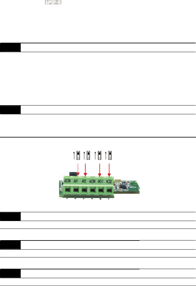
Chapter 4 Parameters|
4-144 Revision June 2008, 04EE, SW--PW V1.11/CTL V2.11
Group 12: Analog Input/Output Parameters for Extension Card
Make sure that the extension card is installed on the AC motor drive correctly before using group 12
parameters. See Appendix B for details.
12.00 AI1 Function Selection
Factory Setting: 0
Settings 0 Disabled
1 Source of the 1st frequency
2 Source of the 2nd frequency
3 PID Set Point (PID enable)
4 Positive PID feedback
5 Negative PID feedback
12.01 AI1 Analog Signal Mode
Factory Setting: 1
Settings 0 ACI2 analog current (0.0 ~ 20.0mA)
1 AVI3 analog voltage (0.0 ~ 10.0V)
Besides parameters settings, the voltage/current mode should be used with the switch.
AVI3
ACI2
AVI4
ACI3
AVO1
ACO1
AVO2
ACO2
12.02 Min. AVI3 Input Voltage Unit: 0.1
Settings 0.0 to 10.0V Factory Setting: 0.0
12.03 Min. AVI3 Scale Percentage Unit: 0.1
Settings 0.0 to 100.0% Factory Setting: 0.0
12.04 Max. AVI3 Input Voltage Unit: 0.1
Settings 0.0 to 10.0V Factory Setting: 10.0

Chapter 4 Parameters|
Revision June 2008, 04EE, SW--PW V1.11/CTL V2.11 4-145
12.05 Max. AVI3 Scale Percentage Unit: 0.1
Settings 0.0 to 100.0% Factory Setting: 100.0
12.06 Min. ACI2 Input Current Unit: 0.1
Settings 0.0 to 20.0mA Factory Setting: 4.0
12.07 Min. ACI2 Scale Percentage Unit: 0.1
Settings 0.0 to 100.0% Factory Setting: 0.0
12.08 Max. ACI2 Input Current Unit: 0.1
Settings 0.0 to 20.0mA Factory Setting: 20.0
12.09 Max. ACI2 Scale Percentage Unit: 0.1
Settings 0.0 to 100.0% Factory Setting: 100.0
12.10 AI2 Function Selection
Factory Setting: 0
Settings 0 Disabled
1 Source of the 1st frequency
2 Source of the 2nd frequency
3 PID Set Point (PID enable)
4 Positive PID feedback
5 Negative PID feedback
12.11 AI2 Analog Signal Mode
Factory Setting: 1
Settings 0 ACI3 analog current (0.0 ~ 20.0mA)
1 AVI4 analog voltage (0.0 ~ 10.0V)
Besides parameters settings, the voltage/current mode should be used with the switch.
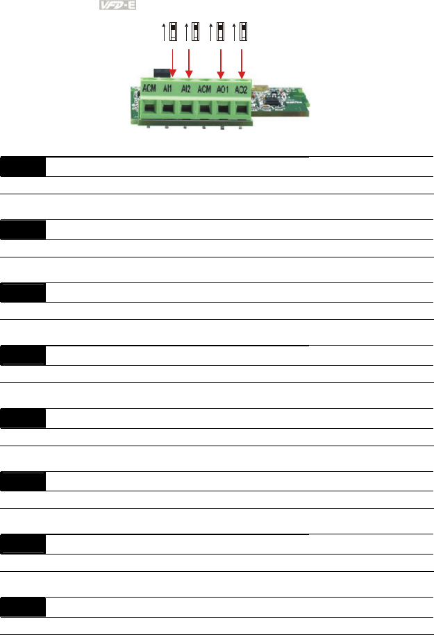
Chapter 4 Parameters|
4-146 Revision June 2008, 04EE, SW--PW V1.11/CTL V2.11
AVI3
ACI2
AVI4
ACI3
AVO1
ACO1
AVO2
ACO2
12.12 Min. AVI4 Input Voltage Unit: 0.1
Settings 0.0 to 10.0V Factory Setting: 0.0
12.13 Min. AVI4 Scale Percentage Unit: 0.1
Settings 0.0 to 100.0% Factory Setting: 0.0
12.14 Max. AVI4 Input Voltage Unit: 0.1
Settings 0.0 to 10.0V Factory Setting: 10.0
12.15 Max. AVI4 Scale Percentage Unit: 0.1
Settings 0.0 to 100.0% Factory Setting: 100.0
12.16 Min. ACI3 Input Current Unit: 0.1
Settings 0.0 to 20.0mA Factory Setting: 4.0
12.17 Min. ACI3 Scale Percentage Unit: 0.1
Settings 0.0 to 100.0% Factory Setting: 0.0
12.18 Max. ACI3 Input Current Unit: 0.1
Settings 0.0 to 20.0mA Factory Setting: 20.0
12.19 Max. ACI3 Scale Percentage Unit: 0.1
Settings 0.0 to 100.0% Factory Setting: 100.0
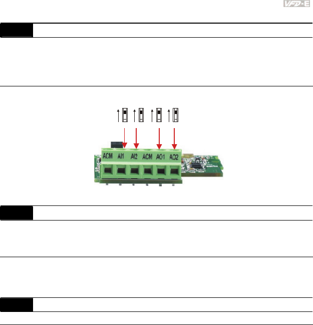
Chapter 4 Parameters|
Revision June 2008, 04EE, SW--PW V1.11/CTL V2.11 4-147
12.20 AO1 Terminal Analog Signal Mode
Factory Setting: 0
Settings 0 AVO1
1 ACO1 (analog current 0.0 to 20.0mA)
2 ACO1 (analog current 4.0 to 20.0mA)
Besides parameter setting, the voltage/current mode should be used with the switch.
AVI3
ACI2
AVI4
ACI3
AVO1
ACO1
AVO2
ACO2
12.21 AO1 Analog Output Signal
Factory Setting: 0
Settings 0 Analog Frequency
1 Analog Current (0 to 250% rated current)
This parameter is used to choose analog frequency (0-+10Vdc) or analog current (4-20mA) to
correspond to the AC motor drive’s output frequency or current.
12.22 AO1 Analog Output Gain Unit: 1
Settings 1 to 200% Factory Setting: 100
This parameter is used to set the analog output voltage range.
When Pr.12.21 is set to 0, analog output voltage corresponds to the AC motor drive’s output
frequency. When Pr.12.22 is set to 100, the max. output frequency (Pr.01.00) setting
corresponds to the AFM output (+10VDC or 20mA)
When Pr.12.21 is set to 1, analog output voltage corresponds to the AC motor drive’s output
current. When Pr.12.22 is set to 100, the 2.5 X rated current corresponds to the AFM output
(+10VDC or 20mA)
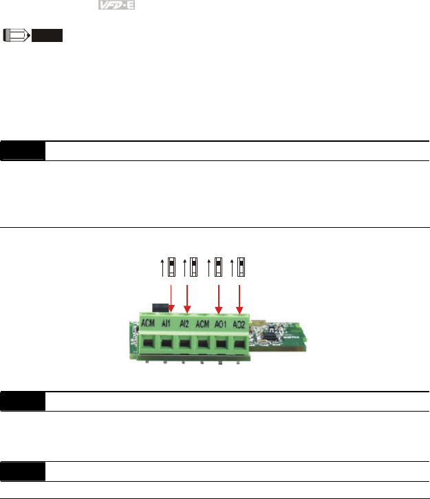
Chapter 4 Parameters|
4-148 Revision June 2008, 04EE, SW--PW V1.11/CTL V2.11
NOTE
If the scale of the voltmeter is less than 10V, refer to following formula to set Pr.12.22:
Pr.12.22 = [(full scale voltage)/10]*100%.
Example: When using voltmeter with full scale (5V), Pr.12.22 should be set to 5/10*100%=50%. If
Pr.12.21 is set to 0, the output voltage will correspond to the max. output frequency.
12.23 AO2Terminal Analog Signal Mode
Factory Setting: 0
Settings 0 AVO2
1 ACO2 (analog current 0.0 to 20.0mA)
2 ACO2 (analog current 4.0 to 20.0mA)
Besides parameter setting, the voltage/current mode should be used with the switch.
AVI3
ACI2
AVI4
ACI3
AVO1
ACO1
AVO2
ACO2
12.24 AO2 Analog Output Signal
Factory Setting: 0
Settings 0 Analog Frequency
1 Analog Current (0 to 250% rated current)
12.25 AO2 Analog Output Gain Unit: 1
Settings 1 to 200% Factory Setting: 100
Setting method for the AO2 is the same as the AO1.
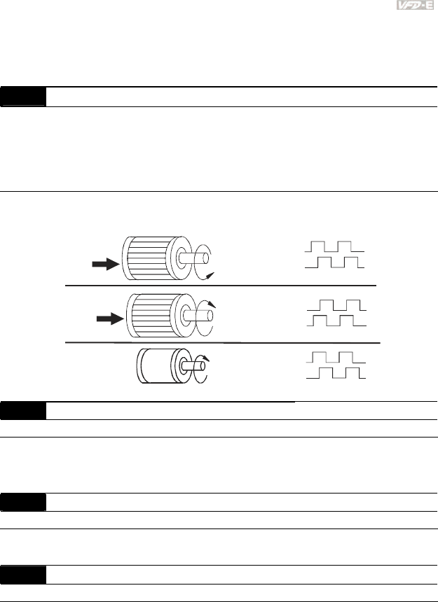
Chapter 4 Parameters|
Revision June 2008, 04EE, SW--PW V1.11/CTL V2.11 4-149
Group 13: PG function Parameters for Extension Card
Make sure that the extension card is installed on the AC motor drive correctly before using group 12
parameters. See Appendix B for details.
13.00 PG Input
Factory Setting: 0
Settings 0 Disable PG
1 Single phase
2 Forward/Counterclockwise rotation
3 Reverse/Clockwise rotation
The relationship between the motor rotation and PG input is illustrated below:
FWD CCW
REV CW
PULSE
GENERATOR
PG
13.00=2
13.00=3
A phase leads B phase
A phase
A phase
A phase
B phase
B phase
B phase
CW
B phase leads A phase
13.01 PG Pulse Range Unit: 1
Settings 1 to 20000 Factory Setting: 600
A Pulse Generator (PG) is used as a sensor that provides a feedback signal of the motor
speed. This parameter defines the number of pulses for each cycle of the PG control.
13.02 Motor Pole Number (Motor 0) Unit: 1
Settings 2 to 10 Factory Setting: 4
The pole number should be even (can’t be odd).
13.03 Proportional Gain (P) Unit: 0.01
Settings 0.0 to 10.0 Factory Setting: 1.0
This parameter specifies proportional control and associated gain (P), and is used for speed
control with PG feedback.
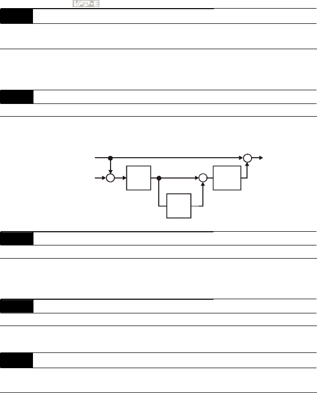
Chapter 4 Parameters|
4-150 Revision June 2008, 04EE, SW--PW V1.11/CTL V2.11
13.04 Integral Gain ( I ) Unit: 0.01
Settings 0.00 to 100.00 sec Factory Setting: 1.00
0.00 Disable
This parameter specifies integral control and associated gain (I), and is used for speed control
with PG feedback.
13.05 Speed Control Output Frequency Limit Unit: 0.01
Settings 0.00 to 100.00Hz Factory Setting: 10.00
This parameter limits the amount of correction by the PI control on the output frequency when
controlling speed via PG feedback. It can limit the maximum output frequency.
13.04
I
P
13.03 13.05
+
-+
+
+
Frequency
command
Speed
detection
Output
Frequency
Limit
output frequency
13.06 Speed Feedback Display Filter Unit: 1
Settings 0 to 9999 (*2ms) Factory Setting: 500
When Pr.0.04 is set to 14, its display will be updated regularly. This update time is set by
Pr.13.06.
13.09 Speed Feedback Filter Unit: 1
Settings 0 to 9999 (*2ms) Factory Setting: 16
This parameter is the filter time from the speed feedback to the PG card.
13.07 Time for Feedback Signal Fault Unit: 0.1
Settings 0.1 to 10.0 sec Factory Setting: 1.0
0.0 Disabled
This parameter defines the time during which the PID feedback must be abnormal before a
warning (see Pr.13.08) is given. It also can be modified according to the system feedback
signal time.
If this parameter is set to 0.0, the system would not detect any abnormality signal.

Chapter 4 Parameters|
Revision June 2008, 04EE, SW--PW V1.11/CTL V2.11 4-151
13.08 Treatment of the Feedback Signal Fault
Factory Setting: 1
Settings 0 Warn and RAMP to stop
1 Warn and COAST to stop
2 Warn and keep operating
AC motor drive action when the feedback signals (analog PID feedback or PG (encoder)
feedback) are abnormal.
13.10 Source of the High-speed Counter (NOT for VFD*E*C models)
Factory Setting: Read only
Settings 0 PG card
1 PLC

Chapter 4 Parameters|
4-152 Revision June 2008, 04EE, SW--PW V1.11/CTL V2.11
4.4 Different Parameters for VFD*E*C Models
Software version for VFD*E*C is V1.00 for power board and V2.00 for control board.
: The parameter can be set during operation.
Group 0 User Parameters
Parameter Explanation Settings Factory
Setting Customer
0: Parameter can be read/written
1: All parameters are read only
6: Clear PLC program (NOT for VFD*E*C
models)
9: All parameters are reset to factory settings
(50Hz, 230V/400V or 220V/380V depends on
Pr.00.12)
00.02 Parameter Reset
10: All parameters are reset to factory
settings (60Hz, 220V/440V)
0
0: Display the frequency command value
(Fxxx)
1: Display the actual output frequency (Hxxx)
2: Display the content of user-defined unit
(Uxxx)
3: Multifunction display, see Pr.00.04
4: FWD/REV command
00.03 Start-up Display
Selection
5: PLCx (PLC selections: PLC0/PLC1/PLC2)
(NOT for VFD*E*C models)
0
0: Display the content of user-defined unit
(Uxxx)
1: Display the counter value (c)
2: Display PLC D1043 value (C) (NOT for
VFD*E*C models)
3: Display DC-BUS voltage (u)
4: Display output voltage (E)
5: Display PID analog feedback signal value
(b) (%)
6: Output power factor angle (n)
00.04 Content of Multi-
function Display
7: Display output power (P)
0

Chapter 4 Parameters|
Revision June 2008, 04EE, SW--PW V1.11/CTL V2.11 4-153
Parameter Explanation Settings Factory
Setting Customer
8: Display the estimated value of torque as it
relates to current (t)
9: Display AVI (I) (V)
10: Display ACI / AVI2 (i) (mA/V)
11: Display the temperature of IGBT (h) (°C)
12: Display AVI3/ACI2 level (I.)
13: Display AVI4/ACI3 level (i.)
14: Display PG speed in RPM (G)
15: Display motor number (M)
Group 1 Basic Parameters
Parameter Explanation Settings Factory
Setting Customer
01.11 Accel Time 2 0.1 to 600.0 / 0.01 to 600.0 sec 1.0
01.12 Decel Time 2 0.1 to 600.0 / 0.01 to 600.0 sec 1.0
Group 2 Operation Method Parameters
Parameter Explanation Settings Factory
Setting Customer
02.00
Source of First
Master Frequency
Command
0: Digital keypad UP/DOWN keys or Multi-
function Inputs UP/DOWN. Last used
frequency saved.
1: 0 to +10V from AVI
2: 4 to 20mA from ACI or 0 to +10V from
AVI2
3: RS-485 (RJ-45)/USB communication
4: Digital keypad potentiometer
5: CANopen communication
5
0: Digital keypad
1: External terminals. Keypad STOP/RESET
enabled.
02.01 Source of First
Operation
Command
2: External terminals. Keypad STOP/RESET
disabled.
5

Chapter 4 Parameters|
4-154 Revision June 2008, 04EE, SW--PW V1.11/CTL V2.11
Parameter Explanation Settings Factory
Setting Customer
3: RS-485 (RJ-45)/USB communication.
Keypad STOP/RESET enabled.
4: RS-485 (RJ-45)/USB communication.
Keypad STOP/RESET disabled.
5: CANopen communication. Keypad
STOP/RESET disabled.
02.09
Source of Second
Frequency
Command
0: Digital keypad UP/DOWN keys or Multi-
function Inputs UP/DOWN. Last used
frequency saved.
1: 0 to +10V from AVI
2: 4 to 20mA from ACI or 0 to +10V from
AVI2
3: RS-485 (RJ-45)/USB communication
4: Digital keypad potentiometer
5: CANopen communication
0
02.16
Display the Master
Freq Command
Source
Read Only
Bit0=1: by First Freq Source (Pr.02.00)
Bit1=1: by Second Freq Source (Pr.02.09)
Bit2=1: by Multi-input function
Bit3=1: by PLC Freq command (NOT for
VFD*E*C models)
##
02.17
Display the
Operation
Command Source
Read Only
Bit0=1: by Digital Keypad
Bit1=1: by RS485 communication
Bit2=1: by External Terminal 2/3 wire mode
Bit3=1: by Multi-input function
Bit5=1: by CANopen communication
##
Group 3 Output Function Parameters
Parameter Explanation Settings Factory
Setting Customer
03.09 Reserved
03.10 Reserved
Group 4 Input Function Parameters
Parameter Explanation Settings Factory
Setting Customer
0: No function 1 04.05 Multi-function Input
Terminal (MI3)
1: Multi-Step speed command 1

Chapter 4 Parameters|
Revision June 2008, 04EE, SW--PW V1.11/CTL V2.11 4-155
Parameter Explanation Settings Factory
Setting Customer
2: Multi-Step speed command 2
3: Multi-Step speed command 3 2
4: Multi-Step speed command 4
04.06 Multi-function Input
Terminal (MI4)
5: External reset
6: Accel/Decel inhibit 3
7: Accel/Decel time selection command
04.07 Multi-function Input
Terminal (MI5)
8: Jog Operation
9: External base block 23
10: Up: Increment master frequency
04.08 Multi-function Input
Terminal (MI6)
11: Down: Decrement master frequency
12: Counter Trigger Signal
13: Counter reset
14: E.F. External Fault Input
15: PID function disabled
16: Output shutoff stop
17: Parameter lock enable
18: Operation command selection (external
terminals)
19: Operation command selection(keypad)
20: Operation command selection
(communication)
21: FWD/REV command
22: Source of second frequency command
23: Quick Stop (Only for VFD*E*C models)
24: Download/execute/monitor PLC Program
(PLC2) (NOT for VFD*E*C models)
25: Simple position function
26: OOB (Out of Balance Detection)
27: Motor selection (bit 0)
28: Motor selection (bit 1)
04.24 Reserved

Chapter 4 Parameters|
4-156 Revision June 2008, 04EE, SW--PW V1.11/CTL V2.11
Parameter Explanation Settings Factory
Setting Customer
04.25 Reserved
Group 7 Motor Parameters
Parameter Explanation Settings Factory
Setting Custome
r
07.08
Torque
Compensation Time
Constant
0.01 ~10.00 Sec 0.30
Group 9 Communication Parameters
Parameter Explanation Settings Factory
Setting Custome
r
09.12 Reserved
09.13
CANopen
Communication
Address
0: disable
1: 1 to 127 1
09.14 CANbus Baud Rate
0: 1M
1: 500K
2: 250K
3: 125K
4: 100K
5: 50K
0
09.15 Gain of CANbus
Frequency
0.00~2.00 1.00
09.16 CANbus Warning
bit 0 : CANopen Guarding Time out
bit 1 : CANopen Heartbeat Time out
bit 2 : CANopen SYNC Time out
bit 3 : CANopen SDO Time out
bit 4 : CANopen SDO buffer overflow
bit 5 : CANbus Off
bit 6 : Error protocol of CANopen
bit 7 : CANopen boot up fault
Read-
only
Group 11 Parameters for Extension Card

Chapter 4 Parameters|
Revision June 2008, 04EE, SW--PW V1.11/CTL V2.11 4-157
Parameter Explanation Settings Factory
Setting Customer
0: No function 0
1: Multi-Step speed command 1
11.06 Multi-function Input
Terminal (MI7)
2: Multi-Step speed command 2
3: Multi-Step speed command 3 0
4: Multi-Step speed command 4
11.07 Multi-function Input
Terminal (MI8)
5: External reset
6: Accel/Decel inhibit 0
7: Accel/Decel time selection command
11.08 Multi-function Input
Terminal (MI9)
8: Jog Operation
9: External base block 0
10: Up: Increment master frequency
11.09 Multi-function Input
Terminal (MI10)
11: Down: Decrement master frequency
12: Counter Trigger Signal 0
13: Counter reset
14: E.F. External Fault Input
11.10 Multi-function Input
Terminal (MI11)
15: PID function disabled
16: Output shutoff stop 0
17: Parameter lock enable
18: Operation command selection (external
terminals)
19: Operation command selection (keypad)
20: Operation command selection
(communication)
21: FWD/REV command
22: Source of second frequency command
23: Quick Stop (Only for VFD*E*C models)
24: Download/execute/monitor PLC Program
(PLC2) (NOT for VFD*E*C models)
25: Simple position function
11.11 Multi-function Input
Terminal (MI12)
26: OOB (Out of Balance Detection)

Chapter 4 Parameters|
4-158 Revision June 2008, 04EE, SW--PW V1.11/CTL V2.11
Parameter Explanation Settings Factory
Setting Customer
27: Motor selection (bit 0)
28: Motor selection (bit 1)
Group 13: PG function Parameters for Extension Card
Parameter Explanation Settings Factory
Setting Customer
13.10 Reserved
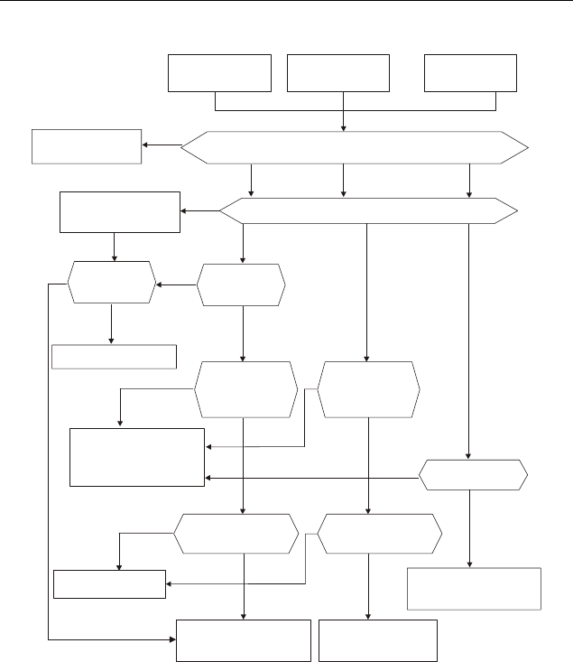
Revision June 2008, 04EE, SW--PW V1.11/CTL V2.11 5-1
Chapter 5 Troubleshooting
5.1 Over Current (OC)
ocA ocd OC
Over-current
during acceleration
Over-current
during deceleration Over current
Check if there is any
between the U, V, W and motor
short circuits and
grounding
Yes
No No No
No No No
Yes
Yes
Yes
Remove short circuit
or ground fault
Reduce the load or
increase the power
of AC motor drive
NoNo Reduce torque
compensation
Reduce torque
compensation
Suitable torque
compensation
No No
No
No
No
Yes Ye s
Yes
Yes
Yes
Maybe AC motor drive
has malfunction or error
due to noise. Please
contact DELTA.
Can acceleration
time be made longer?
Can deceleration
time be made longer?
Reduce load or increase
the power of AC motor
drive
Check braking
method. Please
contact DELTA
Reduce load or increase
the power of AC motor
drive
Has load changed
suddenly?
Check if
acceleration time
is too short by
load inertia.
Check if
deceleration time
is too short by
load inertia.
Increase accel/decel
time
Check if load is too large
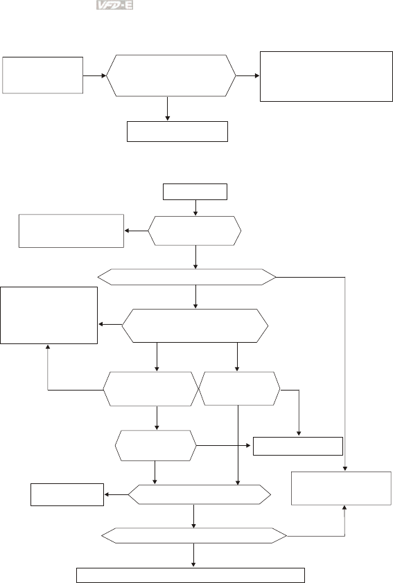
Chapter 5 Troubleshooting|
5-2 Revision June 2008, 04EE, SW--PW V1.11/CTL V2.11
5.2 Ground Fault
GFF
Ground fault
No
Yes
Is output circuit(cable or
motor) of AC motor drive
grounded?
Remove ground fault
Maybe AC motor drive has
malfunction or misoperation
due to noise. Please
contact DELTA.
5.3 Over Voltage (OV)
Over voltage
Ye s
No
Ye s
No
No
No
Is voltage within
specification
Reduce voltage to
be within spec.
Has over-voltage occurred without load
Maybe AC motor drive
has malfunction or
misoperation due to
noise. Please contact
DELTA.
Ye s Ye s
Yes
Yes
Yes
Yes
No
No
No
No
No
When OV occurs, check if the
voltage of DC BUS is greater
than protection value
Dose OV occur when
sudden acceleration
stops
Increase
deceleration
time
Increase setting time
Increase
acceleration
time
Reduce moment
of inertia Reduce moment of load inertia
Use brake unit or DC brake
Need to check control method. Please contact DELTA.
Need to consider using
brake unit or
DC brake
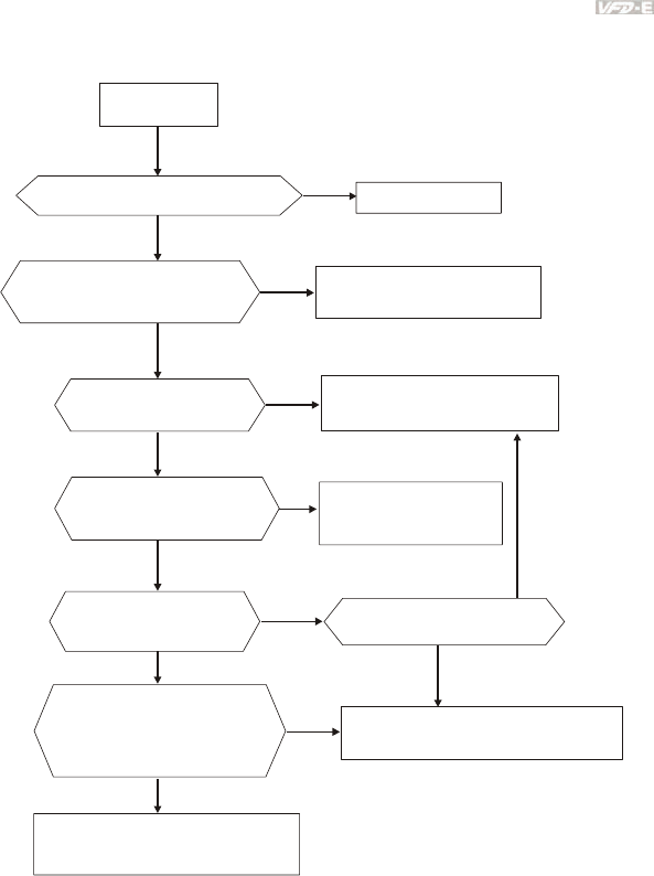
Chapter 5 Troubleshooting|
Revision June 2008, 04EE, SW--PW V1.11/CTL V2.11 5-3
5.4 Low Voltage (Lv)
Low voltage
Is input power correct? Or power cut,
including momentary power loss
Ye s
Yes
Yes
Ye s
Yes
Yes
No
No
No
No
No
No
No
Restart after reset
Check if there is any ma lfunction
component in
power supply circuit
or disconnection Change defective component
and check connection
Check if voltage is
within specification
Make necessary corrections,
such as change power supply
system for requirement
Check if there is heavy load
with high start current in the
same power system
Check if Lv occurs when
breaker and magnetic
contactor is ON
Suitable
transformer
power
capacity
Check if voltage between +/B1
and - is greater than
200VDC (for 115V/230V models)
400VDC (for 460V models)
Maybe AC motor drive has malfunction.
Please contact DELTA.
Control circuit has malfunction or
misoperation due to noise. Please
contact DELTA.
Ye s Using the different power
supply for this drive and
heavy load system
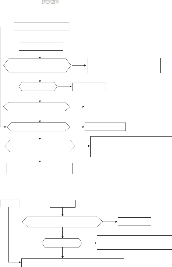
Chapter 5 Troubleshooting|
5-4 Revision June 2008, 04EE, SW--PW V1.11/CTL V2.11
5.5 Over Heat (OH)
AC motor drive overheats
Heat sink overheats
Check if temperature of heat sink
is greater than 90
O
C
No
No
No
No
Ye s
Yes
Yes
Ye s
Ye s
Reduce load
No Temperature detection malfunctions.
Please contact DELTA.
If cooling fan functions normally Change cooling fan
Check if cooling fan is jammed Remove obstruction
Check if surrounding temperature
is within specification
Adjust surrounding temperature
to specification
Maybe AC motor drive has malfunction or
misoperation due to noise. Please contact
DELTA.
Is load too large
5.6 Overload
OL1/ OL2
OL
Reduce load or increase the power of AC motor drive
Check for correct settings at
Pr. 06-06 and 06-07
Ye s
Yes
No
No Modify setting
Is load too large Maybe AC motor drive has malfunction
or misoperation due to noise.
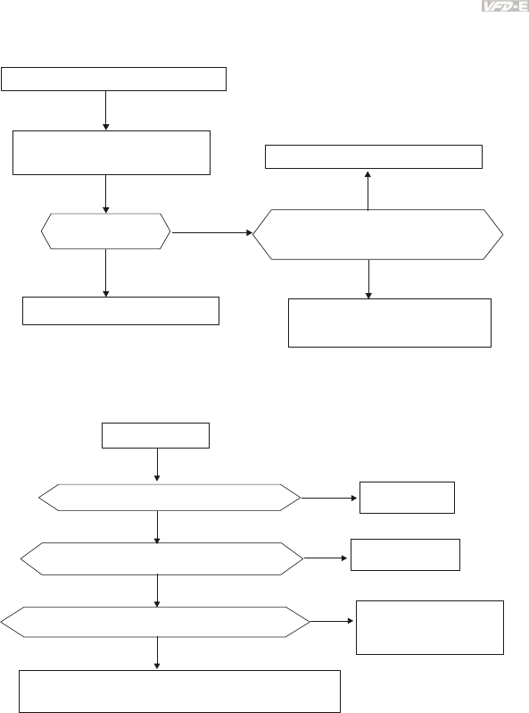
Chapter 5 Troubleshooting|
Revision June 2008, 04EE, SW--PW V1.11/CTL V2.11 5-5
5.7 Keypad Display is Abnormal
Abnormal display or no display
Cycle power to AC motor drive
No
Ye s
Ye s Ye s
No
Display normal?
AC motor drive works normally
Fix connector and eliminate noise
Check if all connectors are connect
correctly and no noise is present
AC motor drive has malfunction.
Please contact DELTA.
5.8 Phase Loss (PHL)
Phase loss
No
No
Yes
Yes
Check wiring at R, S and T terminals Correct wiring
Check if the screws of terminals are tightened No Tighten all screws
Yes Please check the wiring
and power system for
abnormal power
Maybe AC motor drive has malfunction or misoperation
due to noise. Please contact DELTA.
Check if the input voltage of R, S, T is unbalanced
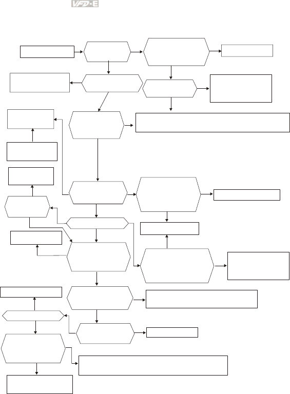
Chapter 5 Troubleshooting|
5-6 Revision June 2008, 04EE, SW--PW V1.11/CTL V2.11
5.9 Motor cannot Run
Motor cannot run
Check
KPE-LE02 for
normal display
No No
No
No
No
No
No
No No No No
No
No
No
Check if non-fuse
breaker and magnetic
contactor are ON
Yes Yes
Ye s
Ye s
Yes
Yes
Yes
Yes
Yes
Yes
Set them to ON
Reset after clearing
fault and then RUN Check if there is any
fault code displayed Check if input
voltage is normal
Check if any faults
occur, such as
Lv, PHL or
disconnection
Input "RUN"
command
by keypad
It can run when
no faults occur
Press RUN key to
check if it can run
Maybe AC motor drive has malfunction or mi soperation
due to noise. Please contact DELTA.
Press UP key to
set frequency
Yes
Modify frequency
setting
Check if input FWD
or REV command
Check if the wiring
of terminal FWD
and between
REV-DCM is correct
Yes
Change switch or relay
Set frequency or not
Press UP to
check if motor
can run
Correct connection
Check if the parameter
setting and wi ring of
analog signal and
multi-step speed
are correct
No
Motor has malfunction No Maybe AC motor drive has malfunction.
Please contact DELTA.
Check if there is any
output voltage from
terminals U, V and W
Check if motor
connection
is correct
No Connect correctly
Check if the setting
of torque
compensation
is correct
Increase the setting of
torque compensation
Motor is locked due to large load, please reduce load.
For example, if there is a brake, check if it is released.
If load is too large
if upper bound freq.
and setting freq. is
lower than the min.
output freq. Yes Change defective
potentiometer and
relay
Yes
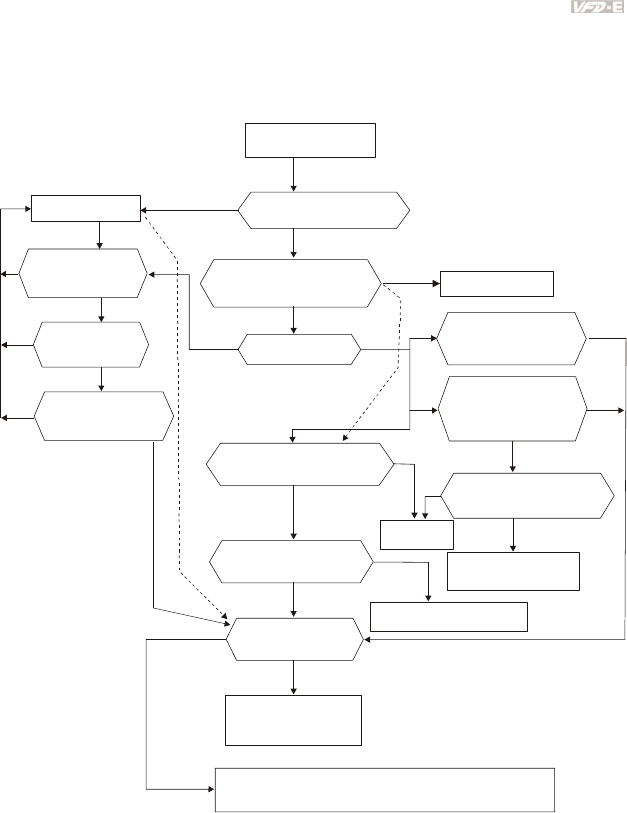
Chapter 5 Troubleshooting|
Revision June 2008, 04EE, SW--PW V1.11/CTL V2.11 5-7
5.10 Motor Speed cannot be Changed
For VFD*E*C models, no PLC function is supported. Please follow the dashed line to skip the PLC
parts.
Motor can run but
cannot change speed
Ye s
Yes
Yes
Ye s
Yes
Ye s
Ye s
Ye s
Ye s
Ye s
No
No
No
No
No
No
No
No
No
No
Check if the setting of the
max. frequency is too low
Check to see if frequency is
out of range (upper/lower)
boundaries
Modify the setting
Modify the setting
Ye s
No
Ye s
If the execution
time is too long
Ye s
If finished with
executing PLC
program
Check if the PLC
program is correct
If the PLC program
is executed
Press UP/DOWN key
to see if speed has
any change
If there is any change
of the signal that sets
frequency (0-10V and
4-20mA)
Check if the wiring between
MI1~MI6 to DCM is correct
Correct
wiring
Check if frequency for
each step is different
Check if the wiring of
external terminal is correct
Change frequencysetting
Check if accel./decel.
time is set correctly
Please set suitable
accel./decel. time by
load inertia
Maybe AC motor drive has malfunction or misoperation
due to noise. Please contact DELTA.
Change defective
potentiometer
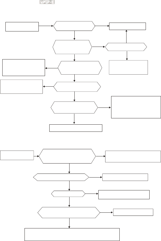
Chapter 5 Troubleshooting|
5-8 Revision June 2008, 04EE, SW--PW V1.11/CTL V2.11
5.11 Motor Stalls during Acceleration
Motor stalls during
acceleration
Check if acceleration
time is too short
Yes
Yes
Yes
Yes
No
No No
No
No
No
Increase setting time
Yes Use special motor?
Reduce load or
increase the capacity
of AC motor drive
Check if the inertia
of the motor and load
is too high
Check for low voltage
at input
Check if the load torque
is too high
Yes
Maybe AC motor drive has
malfunction or misoperation
due to noise. Please contact
DELTA
Increase torque compensation
Check if the torque
compensation is suitable
Thicken or shorten the
wiring between the
motor or AC motor drive
Reduce load or
increase the capacity
of AC motor drive
5.12 The Motor does not Run as Expected
Check Pr. 01-01 thru Pr. 01-06
and torque compensation
settings
No
Yes
Yes
Yes
Yes
No
No
No
Adjust Pr.01-01 to Pr.01-06
and lower torque compensation
Run in low speed continuously
Is load too large
Please use specific motor
Reduce load or increase the
capacity of AC motor drive
Check if output voltage of U, V, W
is balanced Motor has malfunction
Maybe AC motor drive has malfunction or misoperation
due to noise. Please contact DELTA.
Motor does not run
as expected

Chapter 5 Troubleshooting|
Revision June 2008, 04EE, SW--PW V1.11/CTL V2.11 5-9
5.13 Electromagnetic/Induction Noise
Many sources of noise surround AC motor drives and penetrate it by radiation or conduction. It may
cause malfunctioning of the control circuits and even damage the AC motor drive. Of course, there
are solutions to increase the noise tolerance of an AC motor drive. But this has its limits. Therefore,
solving it from the outside as follows will be the best.
1. Add surge suppressor on the relays and contacts to suppress switching surges.
2. Shorten the wiring length of the control circuit or serial communication and keep them
separated from the power circuit wiring.
3. Comply with the wiring regulations by using shielded wires and isolation amplifiers for
long length.
4. The grounding terminal should comply with the local regulations and be grounded
independently, i.e. not to have common ground with electric welding machines and other
power equipment.
5. Connect a noise filter at the mains input terminal of the AC motor drive to filter noise from
the power circuit.
In short, solutions for electromagnetic noise exist of “no product”(disconnect disturbing equipment),
“no spread”(limit emission for disturbing equipment) and “no receive”(enhance immunity).
5.14 Environmental Condition
Since the AC motor drive is an electronic device, you should comply with the environmental
conditions. Here are some remedial measures if necessary.
1. To prevent vibration, the use of anti-vibration dampers is the last choice. Vibrations must
be within the specification. Vibration causes mechanical stress and it should not occur
frequently, continuously or repeatedly to prevent damage to the AC motor drive.
2. Store the AC motor drive in a clean and dry location, free from corrosive fumes/dust to
prevent corrosion and poor contacts. Poor insulation in a humid location can cause short-
circuits. If necessary, install the AC motor drive in a dust-proof and painted enclosure and
in particular situations, use a completely sealed enclosure.
3. The ambient temperature should be within the specification. Too high or too low
temperature will affect the lifetime and reliability. For semiconductor components, damage
will occur once any specification is out of range. Therefore, it is necessary to periodically
check air quality and the cooling fan and provide extra cooling of necessary. In addition,
the microcomputer may not work in extremely low temperatures, making cabinet heating
necessary.
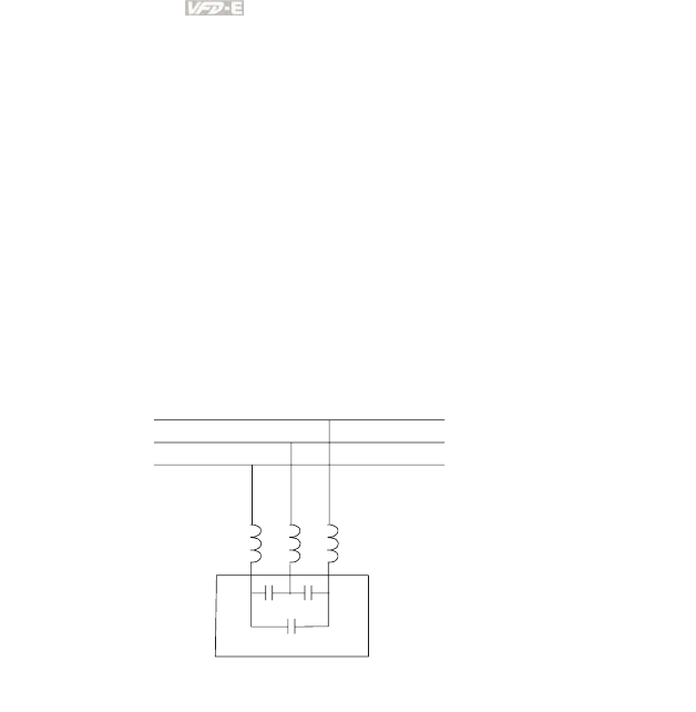
Chapter 5 Troubleshooting|
5-10 Revision June 2008, 04EE, SW--PW V1.11/CTL V2.11
4. Store within a relative humidity range of 0% to 90% and non-condensing environment.
Use an air conditioner and/or exsiccator.
5.15 Affecting Other Machines
An AC motor drive may affect the operation of other machines due to many reasons. Some solutions
are:
High Harmonics at Power Side
High harmonics at power side during running can be improved by:
1. Separate the power system: use a transformer for AC motor drive.
2. Use a reactor at the power input terminal of the AC motor drive.
3. If phase lead capacitors are used (never on the AC motor drive output!!), use serial
reactors to prevent damage to the capacitors damage from high harmonics.
serial reactor
phase lead capacitor
Motor Temperature Rises
When the motor is a standard induction motor with fan, the cooling will be bad at low speeds,
causing the motor to overheat. Besides, high harmonics at the output increases copper and
core losses. The following measures should be used depending on load and operation
range.
1. Use a motor with independent ventilation (forced external cooling) or increase the motor
rated power.
2. Use a special inverter duty motor.
3. Do NOT run at low speeds for long time.
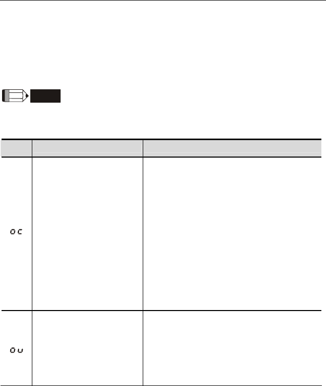
Revision June 2008, 04EE, SW--PW V1.11/CTL V2.11 6-1
Chapter 6 Fault Code Information and Maintenance
6.1 Fault Code Information
The AC motor drive has a comprehensive fault diagnostic system that includes several different
alarms and fault messages. Once a fault is detected, the corresponding protective functions will be
activated. The following faults are displayed as shown on the AC motor drive digital keypad display.
The five most recent faults can be read from the digital keypad or communication.
NOTE
Wait 5 seconds after a fault has been cleared before performing reset via keypad of input terminal.
6.1.1 Common Problems and Solutions
Fault
Name Fault Descriptions Corrective Actions
Over current
Abnormal increase in current.
1. Check if motor power corresponds with the
AC motor drive output power.
2. Check the wiring connections to U/T1, V/T2,
W/T3 for possible short circuits.
3. Check the wiring connections between the AC
motor drive and motor for possible short
circuits, also to ground.
4. Check for loose contacts between AC motor
drive and motor.
5. Increase the Acceleration Time.
6. Check for possible excessive loading
conditions at the motor.
7. If there are still any abnormal conditions when
operating the AC motor drive after a short-
circuit is removed and the other points above
are checked, it should be sent back to
manufacturer.
Over voltage
The DC bus voltage has
exceeded its maximum
allowable value.
1. Check if the input voltage falls within the
rated AC motor drive input voltage range.
2. Check for possible voltage transients.
3. DC-bus over-voltage may also be caused by
motor regeneration. Either increase the
Decel. Time or add an optional brake resistor
(and brake unit).
4. Check whether the required brake power is
within the specified limits.
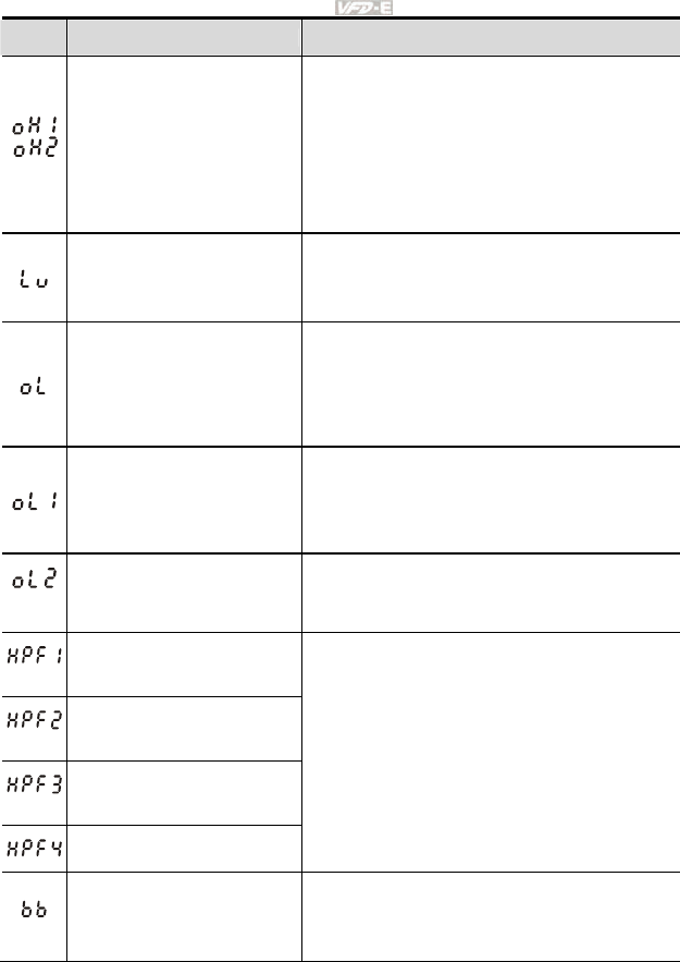
Chapter 6 Fault Code Information and Maintenance|
6-2 Revision June 2008, 04EE, SW--PW V1.11/CTL V2.11
Fault
Name Fault Descriptions Corrective Actions
Overheating
Heat sink temperature too high
1. Ensure that the ambient temperature falls
within the specified temperature range.
2. Make sure that the ventilation holes are not
obstructed.
3. Remove any foreign objects from the
heatsinks and check for possible dirty heat
sink fins.
4. Check the fan and clean it.
5. Provide enough spacing for adequate
ventilation. (See chapter 1)
Low voltage
The AC motor drive detects
that the DC bus voltage has
fallen below its minimum
value.
1. Check whether the input voltage falls within
the AC motor drive rated input voltage range.
2. Check for abnormal load in motor.
3. Check for correct wiring of input power to R-S-
T (for 3-phase models) without phase loss.
Overload
The AC motor drive detects
excessive drive output current.
NOTE: The AC motor drive
can withstand up to 150% of
the rated current for a
maximum of 60 seconds.
1. Check whether the motor is overloaded.
2. Reduce torque compensation setting in
Pr.07.02.
3. Use the next higher power AC motor drive
model.
Overload 1
Internal electronic overload trip
1. Check for possible motor overload.
2. Check electronic thermal overload setting.
3. Use a higher power motor.
4. Reduce the current level so that the drive
output current does not exceed the value set
by the Motor Rated Current Pr.07.00.
Overload 2
Motor overload.
1. Reduce the motor load.
2. Adjust the over-torque detection setting to an
appropriate setting (Pr.06.03 to Pr.06.05).
CC (current clamp)
OV hardware error
GFF hardware error
OC hardware error
Return to the factory.
External Base Block.
(Refer to Pr. 08.07)
1. When the external input terminal (B.B) is
active, the AC motor drive output will be turned
off.
2. Deactivate the external input terminal (B.B) to
operate the AC motor drive again.
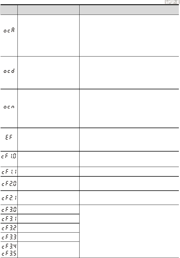
Chapter 6 Fault Code Information and Maintenance|
Revision June 2008, 04EE, SW--PW V1.11/CTL V2.11 6-3
Fault
Name Fault Descriptions Corrective Actions
Over-current during
acceleration
1. Short-circuit at motor output: Check for
possible poor insulation at the output lines.
2. Torque boost too high: Decrease the torque
compensation setting in Pr.07.02.
3. Acceleration Time too short: Increase the
Acceleration Time.
4. AC motor drive output power is too small:
Replace the AC motor drive with the next
higher power model.
Over-current during
deceleration
1. Short-circuit at motor output: Check for
possible poor insulation at the output line.
2. Deceleration Time too short: Increase the
Deceleration Time.
3. AC motor drive output power is too small:
Replace the AC motor drive with the next
higher power model.
Over-current during
constant speed operation
1. Short-circuit at motor output: Check for
possible poor insulation at the output line.
2. Sudden increase in motor loading: Check for
possible motor stall.
3. AC motor drive output power is too small:
Replace the AC motor drive with the next
higher power model.
External Fault
1. When multi-function input terminals (MI3-MI9)
are set to external fault, the AC motor drive
stops output U, V and W.
2. Give RESET command after fault has been
cleared.
Internal EEPROM can not be
programmed. Return to the factory.
Internal EEPROM can not be
programmed. Return to the factory.
Internal EEPROM can not be
read.
1. Press RESET key to set all parameters to
factory setting.
2. Return to the factory.
Internal EEPROM can not be
read.
1. Press RESET key to set all parameters to
factory setting.
2. Return to the factory.
U-phase error
V-phase error
W-phase error
OV or LV
Temperature sensor error
Return to the factory.
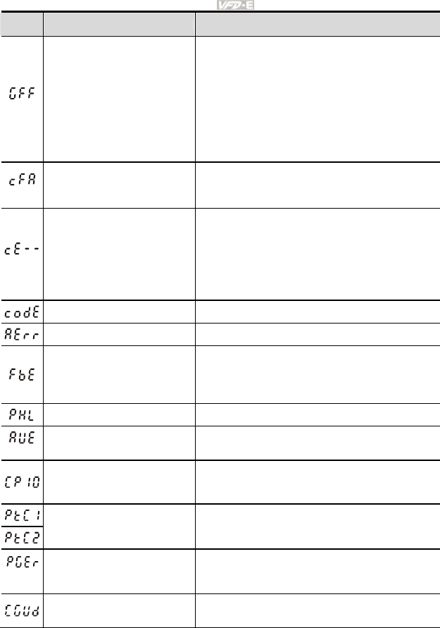
Chapter 6 Fault Code Information and Maintenance|
6-4 Revision June 2008, 04EE, SW--PW V1.11/CTL V2.11
Fault
Name Fault Descriptions Corrective Actions
Ground fault
When (one of) the output terminal(s) is grounded,
short circuit current is more than 50% of AC motor
drive rated current, the AC motor drive power
module may be damaged.
NOTE: The short circuit protection is provided
for AC motor drive protection, not for
protection of the user.
1. Check whether the IGBT power module is
damaged.
2. Check for possible poor insulation at the
output line.
Auto accel/decel failure
1. Check if the motor is suitable for operation by
AC motor drive.
2. Check if the regenerative energy is too large.
3. Load may have changed suddenly.
Communication Error
1. Check the RS485 connection between the AC
motor drive and RS485 master for loose wires
and wiring to correct pins.
2. Check if the communication protocol, address,
transmission speed, etc. are properly set.
3. Use the correct checksum calculation.
4. Please refer to group 9 in the chapter 5 for
detail information.
Software protection failure Return to the factory.
Analog signal error Check the wiring of ACI
PID feedback signal error
1. Check parameter settings (Pr.10.01) and
AVI/ACI wiring.
2. Check for possible fault between system
response time and the PID feedback signal
detection time (Pr.10.08)
Phase Loss Check input phase wiring for loose contacts.
Auto Tuning Error 1. Check cabling between drive and motor
2. Retry again
Communication time-out
error on the control board
or power board
1. Press RESET key to set all parameters to
factory setting.
2. Return to the factory.
Motor overheat protection 1. Check if the motor is overheat
2. Check Pr.07.12 to Pr.07.17 settings
PG signal error 1. Check the wiring of PG card
2. Try another PG card
CANopen Guarding Time out
(Only for VFDxxxExxC)
Connect to CAN bus again and reset CAN bus

Chapter 6 Fault Code Information and Maintenance|
Revision June 2008, 04EE, SW--PW V1.11/CTL V2.11 6-5
Fault
Name Fault Descriptions Corrective Actions
CANopen Heartbeat Time out
(Only for VFDxxxExxC)
Connect to CAN bus again and reset CAN bus
CANopen SYNC Time out
(Only for VFDxxxExxC)
Check if CANopen synchronous message is
abnormal
CANopen SDO Time out
(Only for VFDxxxExxC)
Check if command channels are full
CANopen SDO buffer
overflow(Only for
VFDxxxExxC)
1. Too short time between commands, please
check SDO message sent from the master
2. Reset CAN bus
CAN bus off(Only for
VFDxxxExxC)
1. Check if it connects to terminal resistor
2. Check if the signal is abnormal
3. Check if the master is connected
CAN Boot up fault(Only for
VFDxxxExxC)
1. Check if the master is connected
2. Reset CAN bus
Error communication protocol
of CANopen (Only for
VFDxxxExxC)
Check if the communication protocol is correct

Chapter 6 Fault Code Information and Maintenance|
6-6 Revision June 2008, 04EE, SW--PW V1.11/CTL V2.11
6.1.2 Reset
There are three methods to reset the AC motor drive after solving the fault:
1. Press key on keypad.
2. Set external terminal to “RESET” (set one of Pr.04.05~Pr.04.08 to 05) and then set to be
ON.
3. Send “RESET” command by communication.
NOTE
Make sure that RUN command or signal is OFF before executing RESET to prevent damage or
personal injury due to immediate operation.
6.2 Maintenance and Inspections
Modern AC motor drives are based on solid-state electronics technology. Preventive maintenance is
required to keep the AC motor drive in its optimal condition, and to ensure a long life. It is
recommended to have a qualified technician perform a check-up of the AC motor drive regularly.
Daily Inspection:
Basic check-up items to detect if there were any abnormalities during operation are:
1. Whether the motors are operating as expected.
2. Whether the installation environment is abnormal.
3. Whether the cooling system is operating as expected.
4. Whether any irregular vibration or sound occurred during operation.
5. Whether the motors are overheating during operation.
6. Always check the input voltage of the AC drive with a Voltmeter.
Periodic Inspection:
Before the check-up, always turn off the AC input power and remove the cover. Wait at least 10
minutes after all display lamps have gone out, and then confirm that the capacitors have fully
discharged by measuring the voltage between ~ . It should be less than 25VDC.

Chapter 6 Fault Code Information and Maintenance|
Revision June 2008, 04EE, SW--PW V1.11/CTL V2.11 6-7
DANGER!
1. Disconnect AC power before processing!
2. Only qualified personnel can install, wire and maintain AC motor drives. Please take off any
metal objects, such as watches and rings, before operation. And only insulated tools are
allowed.
3. Never reassemble internal components or wiring.
4. Prevent static electricity.
Periodical Maintenance
Ambient environment
Maintenance
Period
Check Items Methods and Criterion
Daily Half
Year
One
Year
Check the ambient temperature,
humidity, vibration and see if
there are any dust, gas, oil or
water drops
Visual inspection and measurement
with equipment with standard
specification
{
Check if there are any
dangerous objects in the
environment
Visual inspection {
Voltage
Maintenance
Period
Check Items Methods and Criterion
Daily Half
Year
One
Year
Check if the voltage of main
circuit and control circuit is
correct
Measure with multimeter with standard
specification {

Chapter 6 Fault Code Information and Maintenance|
6-8 Revision June 2008, 04EE, SW--PW V1.11/CTL V2.11
Keypad
Maintenance
Period
Check Items Methods and Criterion
Daily Half
Year
One
Year
Is the display clear for reading? Visual inspection {
Any missing characters? Visual inspection {
Mechanical parts
Maintenance
Period
Check Items Methods and Criterion
Daily Half
Year
One
Year
If there is any abnormal sound
or vibration Visual and aural inspection {
If there are any loose screws Tighten the screws {
If any part is deformed or
damaged Visual inspection {
If there is any color change by
overheating Visual inspection {
If there is any dust or dirt Visual inspection
{
Main circuit
Maintenance
Period
Check Items Methods and Criterion
Daily Half
Year
One
Year
If there are any loose or missing
screws Tighten or replace the screw {
If machine or insulator is
deformed, cracked, damaged or
with changed color change due
to overheating or ageing
Visual inspection
NOTE: Please ignore the color
change of copper plate
{
If there is any dust or dirt Visual inspection
{

Chapter 6 Fault Code Information and Maintenance|
Revision June 2008, 04EE, SW--PW V1.11/CTL V2.11 6-9
Terminals and wiring of main circuit
Maintenance
Period
Check Items Methods and Criterion
Daily Half
Year
One
Year
If the wiring shows change of
color change or deformation due
to overheat
Visual inspection {
If the insulation of wiring is
damaged or the color has
changed
Visual inspection {
If there is any damage Visual inspection {
DC capacity of main circuit
Maintenance
Period
Check Items Methods and Criterion
Daily Half
Year
One
Year
If there is any leakage of liquid,
change of color, cracks or
deformation
Visual inspection {
Measure static capacity when
required Static capacity ≥ initial value X 0.85 {
Resistor of main circuit
Maintenance
Period
Check Items Methods and Criterion
Daily Half
Year
One
Year
If there is any peculiar smell or
insulator cracks due to
overheating
Visual inspection, smell {
If there is any disconnection
Visual inspection or measure with
multimeter after removing wiring
between +/B1 ~ -
Resistor value should be within
±
10%
{

Chapter 6 Fault Code Information and Maintenance|
6-10 Revision June 2008, 04EE, SW--PW V1.11/CTL V2.11
Transformer and reactor of main circuit
Maintenance
Period
Check Items Methods and Criterion
Daily Half
Year
One
Year
If there is any abnormal vibration
or peculiar smell Visual, aural inspection and smell {
Magnetic contactor and relay of main circuit
Maintenance
Period
Check Items Methods and Criterion
Daily Half
Year
One
Year
If there are any loose screws Visual and aural inspection. Tighten
screw if necessary. {
If the contact works correctly Visual inspection {
Printed circuit board and connector of main circuit
Maintenance
Period
Check Items Methods and Criterion
Daily Half
Year
One
Year
If there are any loose screws and
connectors
Tighten the screws and press the
connectors firmly in place. {
If there is any peculiar smell and
color change Visual inspection and smell {
If there is any crack, damage,
deformation or corrosion Visual inspection {
If there is any leaked liquid or
deformation in capacitors Visual inspection {

Chapter 6 Fault Code Information and Maintenance|
Revision June 2008, 04EE, SW--PW V1.11/CTL V2.11 6-11
Cooling fan of cooling system
Maintenance
Period
Check Items Methods and Criterion
Daily Half
Year
One
Year
If there is any abnormal sound or
vibration
Visual, aural inspection and turn the
fan with hand (turn off the power
before operation) to see if it rotates
smoothly
{
If there is any loose screw Tighten the screw {
If there is any change of color due
to overheating Change fan {
Ventilation channel of cooling system
Maintenance
Period
Check Items Methods and Criterion
Daily Half
Year
One
Year
If there is any obstruction in the
heat sink, air intake or air outlet Visual inspection {

Revision June 2008, 04EE, SW--PW V1.11/CTL V2.11
Appendix A Specifications
There are 115V, 230V and 460V models in the VFD-E series. For 115V models, it is 1-phase
models. For 0.25 to 3HP of the 230V models, there are 1-phase/3-phase models. Refer to following
specifications for details.
Voltage Class 115V Class
Model Number VFD-XXXE 002 004 007
Max. Applicable Motor Output (kW) 0.2 0.4 0.75
Max. Applicable Motor Output (hp) 0.25 0.5 1.0
Rated Output Capacity (kVA) 0.6 1.0 1.6
Rated Output Current (A) 1.6 2.5 4.2
Maximum Output Voltage (V) 3-Phase Proportional to Twice the Input Voltage
Output Frequency (Hz) 0.1~600 Hz
Output Rating
Carrier Frequency (kHz) 1-15
Single-phase
Rated Input Current (A) 6 9 18
Rated Voltage/Frequency Single phase, 100-120V, 50/60Hz
Voltage Tolerance ±10%(90~132 V)
Input Rating
Frequency Tolerance ±5%(47~63 Hz)
Cooling Method Natural Cooling Fan Cooling
Weight (kg) 1.2 1.2 1.2
Voltage Class 230V Class
Model Number VFD-XXXE 002 004 007 015 022 037 055 075
Max. Applicable Motor Output (kW) 0.2 0.4 0.75 1.5 2.2 3.7 5.5 7.5
Max. Applicable Motor Output (hp) 0.25 0.5 1.0 2.0 3.0 5.0 7.5 10
Rated Output Capacity (kVA) 0.6 1.0 1.6 2.9 4.2 6.5 9.5 12.5
Rated Output Current (A) 1.6 2.5 4.2 7.5 11.0 17 25 33
Maximum Output Voltage (V) 3-Phase Proportional to Input Voltage
Output Frequency (Hz) 0.1~600 Hz
Output Rating
Carrier Frequency (kHz) 1-15
Single/3-phase 3-phase
Rated Input Current (A) 4.9/1.9 6.5/2.7 9.5/5.1 15.7/9 24/15 20.6 26 34
Rated Voltage/Frequency Single/3-phase
200-240 V, 50/60Hz
3-phase
200-240V, 50/60Hz
Voltage Tolerance ±10%(180~264 V)
Input Rating
Frequency Tolerance ±5%(47~63 Hz)
Cooling Method Natural Cooling Fan Cooling
Weight (kg) 1.1 1.1 1.1 *1.2/1.9 1.9 1.9 3.5 3.5
*NOTE: the weight for VFD015E23P is 1.2kg.
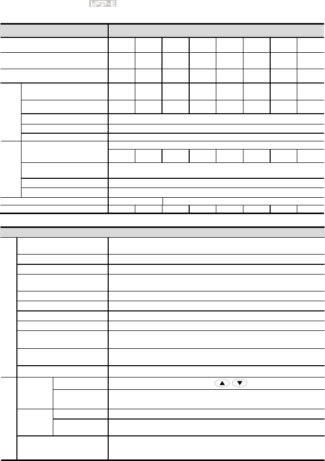
Appendix A Specifications|
A-2 Revision June 2008, 04EE, SW--PW V1.11/CTL V2.11
Voltage Class 460V Class
Model Number VFD-XXXE 004 007 015 022 037 055 075 110
Max. Applicable Motor Output (kW) 0.4 0.75 1.5 2.2 3.7 5.5 7.5 11
Max. Applicable Motor Output (hp) 0.5 1.0 2.0 3.0 5.0 7.5 10 15
Rated Output Capacity (kVA) 1.2 2.0 3.3 4.4 6.8 9.9 13.7 18.3
Rated Output Current (A) 1.5 2.5 4.2 5.5 8.2 13 18 24
Maximum Output Voltage (V) 3-Phase Proportional to Input Voltage
Output Frequency (Hz) 0.1~600 Hz
Output Rating
Carrier Frequency (kHz) 1-15
3-phase
Rated Input Current (A) 1.9 3.2 4.3 7.1 11.2 14 19 26
Rated Voltage/Frequency 3-phase, 380-480V, 50/60Hz
Voltage Tolerance
±
10%(342~528V)
Input Rating
Frequency Tolerance
±
5%(47~63Hz)
Cooling Method Natural Cooling Fan Cooling
Weight (kg) 1.2 1.2 1.2 1.9 1.9 4.2 4.2 4.2
General Specifications
Control System SPWM(Sinusoidal Pulse Width Modulation) control (V/f or sensorless vector
control)
Frequency Setting Resolution 0.01Hz
Output Frequency Resolution 0.01Hz
Torque Characteristics Including the auto-torque/auto-slip compensation; starting torque can be
150% at 3.0Hz
Overload Endurance 150% of rated current for 1 minute
Skip Frequency Three zones, setting range 0.1-600Hz
Accel/Decel Time 0.1 to 600 seconds (2 Independent settings for Accel/Decel time)
Stall Prevention Level Setting 20 to 250% of rated current
DC Brake Operation frequency 0.1-600.0Hz, output 0-100% rated current
Start time 0-60 seconds, stop time 0-60 seconds
Regenerated Brake Torque Approx. 20% (up to 125% possible with optional brake resistor or externally
mounted brake unit, 1-15hp (0.75-11kW) models have brake chopper built-in)
Control Characteristics
V/f Pattern 4-point adjustable V/f pattern
Keypad Setting by
Frequency
Setting External Signal Potentiometer-5kΩ/0.5W, 0 to +10VDC, 4 to 20mA, RS-485 interface; Multi-
function Inputs 3 to 9 (15 steps, Jog, up/down)
Keypad Set by RUN and STOP
Operation
Setting
Signal External Signal 2 wires/3 wires (MI1, MI2, MI3), JOG operation, RS-485 serial interface
(MODBUS), programmable logic controller
Operating Characteristics
Multi-function Input Signal
Multi-step selection 0 to 15, Jog, accel/decel inhibit, 2 accel/decel switches,
counter, external Base Block, ACI/AVI selections, driver reset, UP/DOWN
key settings, NPN/PNP input selection
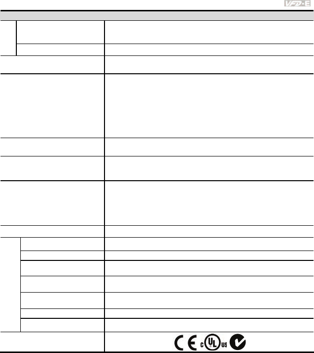
Appendix A Specifications|
Revision June 2008, 04EE, SW--PW V1.11/CTL V2.11 A-3
General Specifications
Multi-function Output Indication
AC drive operating, frequency attained, zero speed, Base Block, fault
indication, overheat alarm, emergency stop and status selections of input
terminals
Analog Output Signal Output frequency/current
Alarm Output Contact Contact will be On when drive malfunctions (1 Form C/change-over contact
and 1 open collector output) for standard type)
Operation Functions
Built-in PLC(NOT for CANopen models), AVR, accel/decel S-Curve, over-
voltage/over-current stall prevention, 5 fault records, reverse inhibition,
momentary power loss restart, DC brake, auto torque/slip compensation,
auto tuning, adjustable carrier frequency, output frequency limits, parameter
lock/reset, vector control, PID control, external counter, MODBUS
communication, abnormal reset, abnormal re-start, power-saving, fan control,
sleep/wake frequency, 1st/2nd frequency source selections, 1st/2nd
frequency source combination, NPN/PNP selection, parameters for motor 0
to motor 3, DEB and OOB (Out Of Balance Detection)(for washing machine)
Protection Functions Over voltage, over current, under voltage, external fault, overload, ground
fault, overheating, electronic thermal, IGBT short circuit, PTC
Display Keypad (optional)
6-key, 7-segment LED with 4-digit, 5 status LEDs, master frequency, output
frequency, output current, custom units, parameter values for setup and lock,
faults, RUN, STOP, RESET, FWD/REV, PLC
Built-in Brake Chopper
VFD002E11T/21T/23T, VFD004E11T/21T/23T/43T,
VFD007E21T/23T/43T, VFD015E23T/43T, VFD007E11A, VFD015E21A,
VFD022E21A/23A/43A, VFD037E23A/43A VFD007E11C, VFD015E21C,
VFD022E21C/23C/43C, VFD037E23C/43C, VFD055E23A/43A,
VFD075E23A/43A, VFD110E43A, VFD055E23C/43C, VFD075E23C/43C,
VFD110E43C
Built-in EMI Filter For 230V 1-phase and 460V 3-phase models.
Enclosure Rating IP20
Pollution Degree 2
Installation Location Altitude 1,000 m or lower, keep from corrosive gasses, liquid and dust
Ambient Temperature -10oC to 50oC (40oC for side-by-side mounting) Non-Condensing and not
frozen
Storage/ Transportation
Temperature -20 oC to 60 oC
Ambient Humidity Below 90% RH (non-condensing)
Environmental Conditions
Vibration 9.80665m/s2 (1G) less than 20Hz, 5.88m/s2 (0.6G) at 20 to 50Hz
Approvals

Appendix A Specifications|
A-4 Revision June 2008, 04EE, SW--PW V1.11/CTL V2.11
This page intentionally left blank

Revision June 2008, 04EE, SW--PW V1.11/CTL V2.11 B-1
Appendix B Accessories
B.1 All Brake Resistors & Brake Units Used in AC Motor Drives
Note: Please only use DELTA resistors and recommended values. Other resistors and values will
void Delta’s warranty. Please contact your nearest Delta representative for use of special resistors.
The brake unit should be at least 10 cm away from AC motor drive to avoid possible interference.
Refer to the “Brake unit Module User Manual” for further details.
Applicable
Motor
Voltage
hp kW
AC Drive Part No.
Full
Load
Torque
KG-M
Equivalent
Resistor Value
(recommended)
Brake Unit Part
No. and
Quantity
Brake Resistors
Part No. and
Quantity
Brake
Torque
10%ED
Min. Equivalent
Resistor Value
for each AC
Motor Drive
VFD002E11A/11C/11P 200W 250Ω BUE-20015 1 BR200W250 1 343 200Ω
0.25 0.2
VFD002E11T 0.110 200W 250Ω BR200W250 1 343 200Ω
VFD004E11A/11C/11P 200W 250Ω BUE-20015 1 BR200W250 1 170 100Ω
0.5 0.4
VFD004E11T 0.216 200W 250Ω BR200W250 1 170 100Ω
115V Series
1 0.75 VFD007E11A/11C/11P 0.427 200W 150Ω BR200W150 1 143 80Ω
VFD002E21A/21C/21P/23A
23C/23P
200W 250Ω BUE-20015 1 BR200W250 1 343 200Ω
0.25 0.2
VFD002E21T/23T
0.110
200W 250Ω BR200W250 1 343 200Ω
VFD004E21A/21C/21P/23A
/23C/23P
200W 250Ω BUE-20015 1 BR200W250 1 170 100Ω
0.5 0.4
VFD004E21T/23T
0.216
200W 250Ω
BR200W250 1 170 100Ω
VFD007E21A/21C/21P/23A
/23C/23P
200W 150Ω BUE-20015 1 BR200W150 1 143 80Ω
1 0.75
VFD007E21T/23T
0.427
200W 150Ω BR200W150 1 143 80Ω
VFD015E21A/21C 300W 85Ω BR300W100 1 107 40Ω
VFD015E23T 300W 85Ω BR300W100 1 107 80Ω
2 1.5
VFD015E23A/23C/23P
0.849
300W 85Ω BUE-20015 1 BR300W100 1 107 80Ω
3 2.2
VFD022E21A/21C/23A/23C 1.262 600W 50Ω BR300W100 2 143 40Ω
5 3.7
VFD037E23A/23C 2.080 600W 50Ω BR300W100 2 85 40Ω
7.5 5.5
VFD055E23A/23C 3.111 800W 37.5
Ω BR200W150 4 76 34Ω
230V Series
10 7.5
VFD075E23A/23C 4.148 1200W 25Ω BR300W100 4 85 24Ω
VFD004E43A/43C/43P 300W 400Ω BUE-40015 1 BR300W400 1 428 400Ω
0.5 0.4
VFD004E43T 0.216 300W 400Ω BR300W400 1 428 400Ω
VFD007E43A/43C/43P 300W 400Ω BUE-40015 1 BR300W400 1 214 200Ω
1 0.75
VFD007E43T 0.427 300W 400Ω BR300W400 1 214 200Ω
VFD015E43A/43C 400W 300Ω BUE-40015 1 BR200W150 2 143 160Ω
2 1.5
VFD015E43T 0.849 400W 300Ω BR200W150 2 143 160Ω
3 2.2
VFD022E43A/43C 1.262 600W 200Ω BR300W400 2 143 140Ω
5 3.7
VFD037E43A/43C 2.080 900W 133Ω BR300W400 3 129 96Ω
7.5 5.5
VFD055E43A/43C 3.111 1200W 100
Ω
BR300W400 4 115 96Ω
10 7.5
VFD075E43A/43C 4.148 1500W 80Ω BR300W400 5 107 69Ω
460V Series
15 11
VFD110E43A/43C 6.186 2100W 57Ω BR300W400 7 100 53Ω
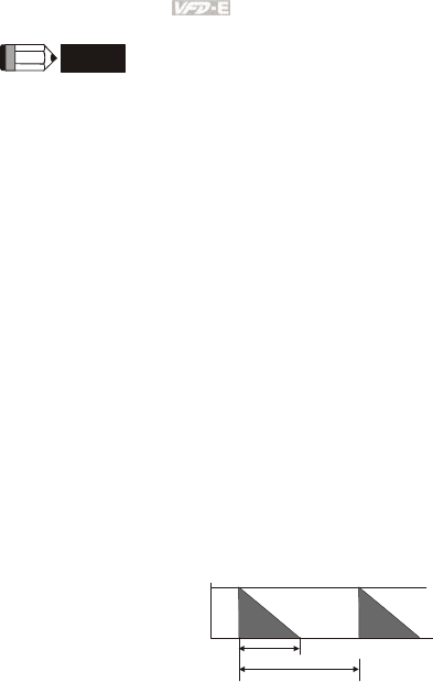
Appendix B Accessories|
B-2 Revision June 2008, 04EE, SW--PW V1.11/CTL V2.11
NOTE
1. Please select the brake unit and/or brake resistor according to the table. “-“ means no
Delta product. Please use the brake unit according to the Equivalent Resistor Value.
2. If damage to the drive or other equipment is due to the fact that the brake resistors and
the brake modules in use are not provided by Delta, the warranty will be void.
3. Take into consideration the safety of the environment when installing the brake resistors.
4. If the minimum resistance value is to be utilized, consult local dealers for the calculation of
the power in Watt.
5. Please select thermal relay trip contact to prevent resistor over load. Use the contact to
switch power off to the AC motor drive!
6. When using more than 2 brake units, equivalent resistor value of parallel brake unit can’t
be less than the value in the column “Minimum Equivalent Resistor Value for Each AC
Drive” (the right-most column in the table).
7. Please read the wiring information in the user manual of the brake unit thoroughly prior to
installation and operation.
8. Definition for Brake Usage ED%
Explanation: The definition of the barking usage ED(%) is for assurance of enough time
for the brake unit and brake resistor to dissipate away heat generated by braking. When
the brake resistor heats up, the resistance would increase with temperature, and brake
torque would decrease accordingly. Suggest cycle time is one minute
100%
T0
T1
Brake Time
Cycle Time
ED% = T1/T0x100(%)
9. For safety reasons, install a thermal overload relay between brake unit and brake resistor.
Together with the magnetic contactor (MC) in the mains supply circuit to the drive it offers
protection in case of any malfunctioning. The purpose of installing the thermal overload
relay is to protect the brake resistor against damage due to frequent brake or in case the
brake unit is continuously on due to unusual high input voltage. Under these
circumstances the thermal overload relay switches off the power to the drive. Never let
the thermal overload relay switch off only the brake resistor as this will cause serious
damage to the AC Motor Drive.
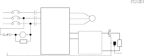
Appendix B Accessories|
Revision June 2008, 04EE, SW--PW V1.11/CTL V2.11 B-3
R/L1
S/L2
T/L3
NFB
MC
VFD Series
MOTOR
O.L.
U/T1
V/T2
W/T3
+P
-N
()
()
B1
B2
SA
R/L1
S/L2
T/L3
MC
IM
BR
O.L.
Thermal
Overload
Relay or
temperature
switch
Surge
Absorber
Thermal Overload
Relay
Brake
Resistor
Brake
Unit
+P
-N
()
()
Note1: When using the AC drive with DC reactor, please refer to wiring diagram in the AC drive
user manual for the wiring of terminal +(P) of Brake unit.
Note2: wire terminal -(N) to the neutral point of power system.
Do NOT
Temperature
Switch
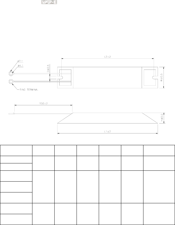
Appendix B Accessories|
B-4 Revision June 2008, 04EE, SW--PW V1.11/CTL V2.11
B.1.1 Dimensions and Weights for Brake Resistors
(Dimensions are in millimeter)
Order P/N: BR080W200, BR080W750, BR300W100, BR300W250, BR300W400, BR400W150,
BR400W040
Model no. L1 L2 H D W Max. Weight (g)
BR080W200
BR080W750 140 125 20 5.3 60 160
BR300W100
BR300W250
BR300W400
215 200 30 5.3 60 750
BR400W150
BR400W040
265 250 30 5.3 60 930
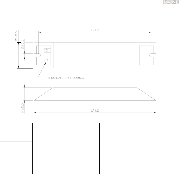
Appendix B Accessories|
Revision June 2008, 04EE, SW--PW V1.11/CTL V2.11 B-5
Order P/N: BR500W030, BR500W100, BR1KW020, BR1KW075
Model no. L1 L2 H D W Max. Weight (g)
BR500W030
BR500W100 335 320 30 5.3 60 1100
BR1KW020
BR1KW075
400 385 50 5.3 100 2800
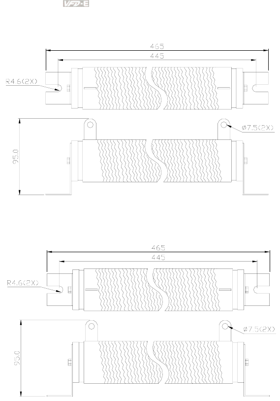
Appendix B Accessories|
B-6 Revision June 2008, 04EE, SW--PW V1.11/CTL V2.11
Order P/N: BR1K0W050
Order P/N: BR1K0W050, BR1K2W008, BR1K2W6P8, BR1K5W005, BR1K5W040
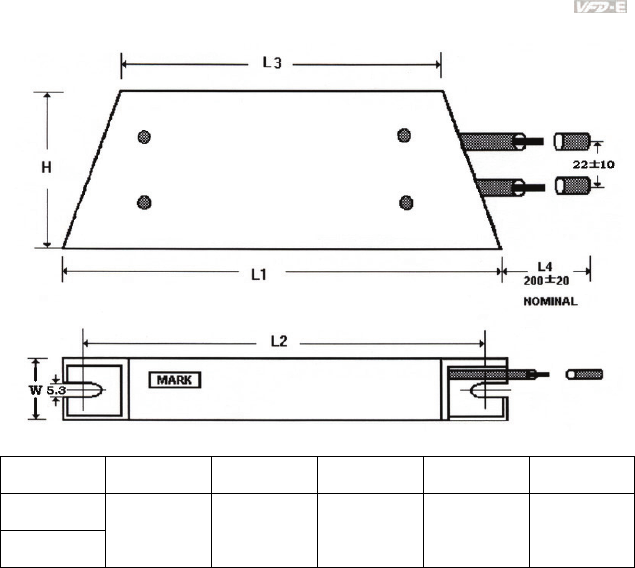
Appendix B Accessories|
Revision June 2008, 04EE, SW--PW V1.11/CTL V2.11 B-7
Order P/N: BR200W150, BR200W250
Model no. L1±2 L2±2 L3±2 W±1 H±1
BR200W150
BR200W250
165 150 110 30 60

Appendix B Accessories|
B-8 Revision June 2008, 04EE, SW--PW V1.11/CTL V2.11
B.2 No-fuse Circuit Breaker Chart
For 1-phase/3-phase drives, the current rating of the breaker shall be greater than 2 X (rated input
current).
1-phase 3-phase
Model
Recommended
no-fuse
breaker (A)
Model
Recommended
no-fuse
breaker (A)
VFD002E11A/11T/11C/
11P
15 VFD002E23A/23C/23T/
23P
5
VFD002E21A/21T/21C/
21P
10 VFD004E23A/23C/23T/
23P
5
VFD004E11A/11C/11T/
11P
20 VFD004E43A/43C/43T/
43P
5
VFD004E21A/21C/21T/
21P
15 VFD007E23A/23C/23T/
23P
10
VFD007E11A/11C 30 VFD007E43A/43C/43T/
43P
5
VFD007E21A/21C/21T/
21P
20 VFD015E23A/23C/23T/
23P
20
VFD015E21A/21C 30 VFD015E43A/43C/43T 10
VFD022E21A/21C 50 VFD022E23A/23C 30
VFD022E43A/43C 15
VFD037E23A/23C 40
VFD037E43A/43C 20
VFD055E23A/23C 50
VFD055E43A/43C 30
VFD075E23A/23C 60
VFD075E43A/43C 40
VFD110E43A/43C 50

Appendix B Accessories|
Revision June 2008, 04EE, SW--PW V1.11/CTL V2.11 B-9
B.3 Fuse Specification Chart
Smaller fuses than those shown in the table are permitted.
Line Fuse
Model I (A)
Input
I (A)
Output I (A) Bussmann P/N
VFD002E11A/11T/11C/
11P
6 1.6 15 JJN-15
VFD002E21A/21T/21C
/21P
4.9 1.6 10 JJN-10
VFD002E23A/23C/23T
/23P
1.9 1.6 5 JJN-6
VFD004E11A/11C/11T/
11P
9 2.5 20 JJN-20
VFD004E21A/21C/21T
/21P
6.5 2.5 15 JJN-15
VFD004E23A/23C/23T
/23P
2.7 2.5 5 JJN-6
VFD004E43A/43C/43T
/43P
1.9 1.5 5 JJS-6
VFD007E11A/11C 18 4.2 30 JJN-30
VFD007E21A/21C/21T
/21P
9.7 4.2 20 JJN-20
VFD007E23A/23C/23T
/23P
5.1 4.2 10 JJN-10
VFD007E43A/43C/43T
/43P
3.2 2.5 5 JJS-6
VFD015E21A/21C 15.7 7.5 30 JJN-30
VFD015E23A/23C/23T
/23P
9 7.5 20 JJN-20
VFD015E43A/43C/43T 4.3 4.2 10 JJS-10
VFD022E21A/21C 24 11 50 JJN-50
VFD022E23A/23C 15 11 30 JJN-30
VFD022E43A/43C 7.1 5.5 15 JJS-15
VFD037E23A/23C 20.6 17 40 JJN-40
VFD037E43A/43C 11.2 8.2 20 JJS-20
VFD055E23A/23C 26 25 50 JJN-50
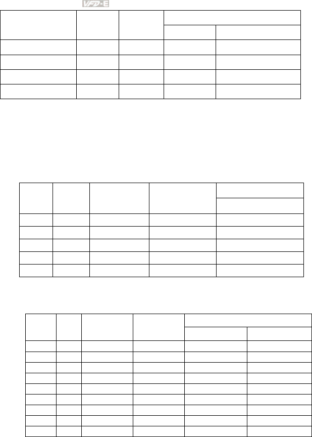
Appendix B Accessories|
B-10 Revision June 2008, 04EE, SW--PW V1.11/CTL V2.11
Line Fuse
Model I (A)
Input
I (A)
Output I (A) Bussmann P/N
VFD055E43A/43C 14 13 30 JJS-30
VFD075E23A/23C 34 33 60 JJN-60
VFD075E43A/43C 19 18 40 JJS-40
VFD110E43A/43C 26 24 50 JJS-50
B.4 AC Reactor
B.4.1 AC Input Reactor Recommended Value
230V, 50/60Hz, 1-Phase
Inductance (mH)
kW HP
Fundamental
Amps
Max. continuous
Amps 3~5% impedance
0.2 1/4 4 6 6.5
0.4 1/2 5 7.5 3
0.75 1 8 12 1.5
1.5 2 12 18 1.25
2.2 3 18 27 0.8
460V, 50/60Hz, 3-Phase
Inductance (mH)
kW HP
Fundamental
Amps
Max.
continuous
Amps 3% impedance 5% impedance
0.4 1/2 2 3 20 32
0.75 1 4 6 9 12
1.5 2 4 6 6.5 9
2.2 3 8 12 5 7.5
3.7 5 8 12 3 5
5.5 7.5 12 18 2.5 4.2
7.5 10 18 27 1.5 2.5
11 15 25 37.5 1.2 2
15 20 35 52.5 0.8 1.2

Appendix B Accessories|
Revision June 2008, 04EE, SW--PW V1.11/CTL V2.11 B-11
B.4.2 AC Output Reactor Recommended Value
115V/230V, 50/60Hz, 3-Phase
Inductance (mH)
kW HP
Fundamental
Amps
Max.
continuous
Amps 3% impedance 5% impedance
0.2 1/4 4 4 9 12
0.4 1/2 6 6 6.5 9
0.75 1 8 12 3 5
1.5 2 8 12 1.5 3
2.2 3 12 18 1.25 2.5
3.7 5 18 27 0.8 1.5
5.5 7.5 25 37.5 0.5 1.2
7.5 10 35 52.5 0.4 0.8
460V, 50/60Hz, 3-Phase
Inductance (mH)
kW HP
Fundamental
Amps
Max.
continuous
Amps 3% impedance 5% impedance
0.4 1/2 2 3 20 32
0.75 1 4 6 9 12
1.5 2 4 6 6.5 9
2.2 3 8 12 5 7.5
3.7 5 12 18 2.5 4.2
5.5 7.5 18 27 1.5 2.5
7.5 10 18 27 1.5 2.5
11 15 25 37.5 1.2 2
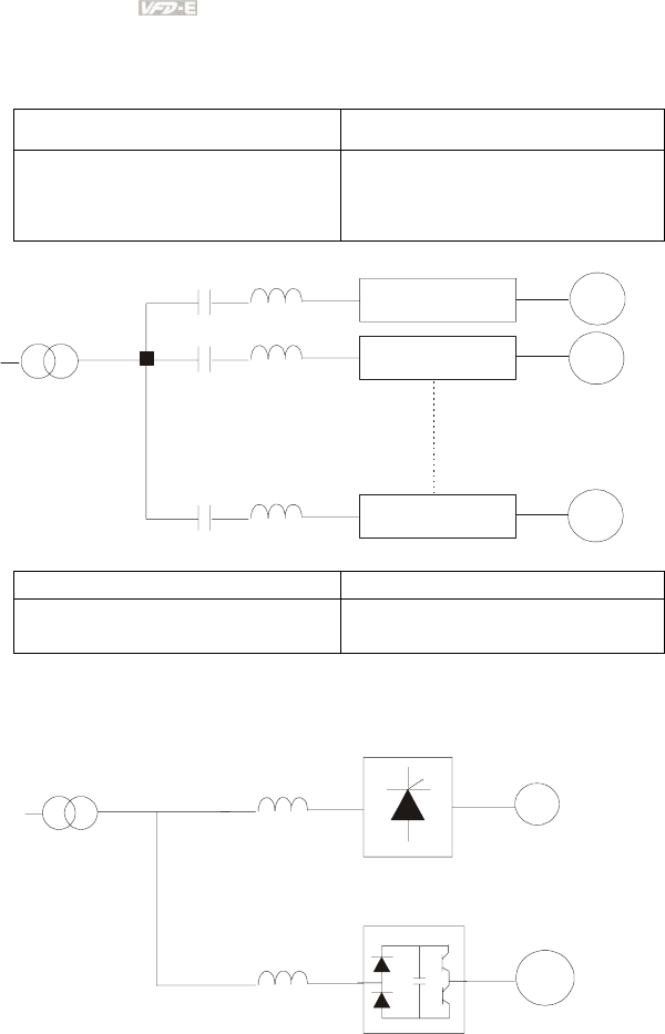
Appendix B Accessories|
B-12 Revision June 2008, 04EE, SW--PW V1.11/CTL V2.11
B.4.3 Applications
Connected in input circuit
Application 1 Question
When more than one AC motor drive is
connected to the same mains power, and one
of them is ON during operation.
When applying power to one of the AC motor
drive, the charge current of the capacitors
may cause voltage dip. The AC motor drive
may be damaged when over current occurs
during operation.
Correct wiring
M1
M2
Mn
reactor
AC motor drive
AC motor drive
AC motor drive
motor
motor
motor
Application 2 Question
Silicon rectifier and AC motor drive are
connected to the same power.
Switching spikes will be generated when the
silicon rectifier switches on/off. These spikes
may damage the mains circuit.
Correct wiring
DC
power reactor
reactor
AC motor drive
motor
Silicon Controlled Rectifier
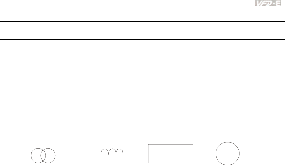
Appendix B Accessories|
Revision June 2008, 04EE, SW--PW V1.11/CTL V2.11 B-13
Application 3 Question
Used to improve the input power factor, to
reduce harmonics and provide protection from
AC line disturbances. (surges, switching
spikes, short interruptions, etc.). The AC line
reactor should be installed when the power
supply capacity is 500kVA or more and
exceeds 6 times the inverter capacity, or the
mains wiring distance
≤
10m.
When the mains power capacity is too large,
line impedance will be small and the charge
current will be too high. This may damage AC
motor drive due to higher rectifier
temperature.
Correct wiring
large-capacity
power reactor
small-capacity
AC motor drive
motor
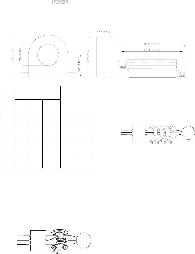
Appendix B Accessories|
B-14 Revision June 2008, 04EE, SW--PW V1.11/CTL V2.11
B.5 Zero Phase Reactor (RF220X00A)
Dimensions are in millimeter and (inch)
Recommended Wire
Size
Cable
type
(Note) AWG mm2 Nominal
(mm2)
Qty. Wiring
Method
≦10 ≦5.3 ≦5.5 1 Diagram
A
Single-
core
≦2 ≦33.6 ≦38 4 Diagram
B
≦12 ≦3.3 ≦3.5 1 Diagram
A
Three-
core ≦1 ≦42.4 ≦50 4 Diagram
B
Note: 600V Insulated unshielded Cable.
Power
Supply
Zero Phase Reactor
MOTOR
U/T1
V/T2
W/T3
R/L1
S/L2
T/L3
U/T1
V/T2
W/T3
R/L1
S/L2
T/L3
Power
Supply
Zero Phase Reactor
MOTOR
Note 1: The table above gives
approximate wire size for the zero phase
reactors but the selection is ultimately
governed by the type and diameter of
cable fitted i.e. the cable must fit through
the center hole of zero phase reactors.
Note 2: Only the phase conductors should
pass through, not the earth core or screen.
Note 3: When long motor output cables
are used an output zero phase reactor
may be required to reduce radiated
emissions from the cable.
Diagram B
Please put all wires through 4 cores in
series without winding.
Diagram A
Please wind each wire 4 times around the
core. The reactor must be put at inverter
output as close as possible.
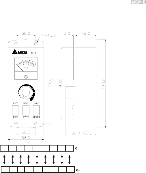
Appendix B Accessories|
Revision June 2008, 04EE, SW--PW V1.11/CTL V2.11 B-15
B.6 Remote Controller RC-01
Dimensions are in millimeter
AFM ACM +10VAVI DCM MI5 MI1 MI2 MI6
8654 16151413 11
RC-01Terminal block
(Wiring connections)
VFD-E I/O block
VFD-E Programming:
Pr.02.00 set to 2
Pr.02.01 set to 1 (external controls)
Pr.04.04 set to 1 (setting Run/Stop and Fwd/Rev controls)
Pr.04.07 (MI5) set to 5 (External reset)
Pr.04.08 (MI6) set to 8 (JOG operation)
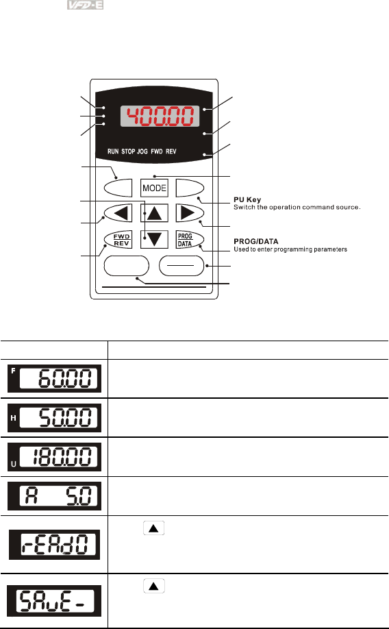
Appendix B Accessories|
B-16 Revision June 2008, 04EE, SW--PW V1.11/CTL V2.11
B.7 PU06
B.7.1 Description of the Digital Keypad VFD-PU06
U
F
H
VFD-PU06
JOG
RUN
RESET
STOP
LED Display
Indicates frequency, voltage, current, user
defined units, read, and save, etc.
Status Display
Display the driver's current status.
Model Number
STOP/RESET
Stops AC drive operation and reset t he drive
after fault occurred.
PU
EXT PU
Right key
Move the cursor to the right
RUN Key
Start AC drive operation.
Frequency Command
Status indicator
Output Frequency
Status indicator
User Defined Units
Status indicator
JOG
By pressing JOG key,
Jog frequency operation.
MODE
Change between different display mode.
Left Key
Move cursor to the left.
UP and DOWN Key
Set the parameter number
and changes the numerical
data, such as Master Frequency.
FWD/REV Key
Select FWD/REV operation.
B.7.2 Explanation of Display Message
Display Message Descriptions
The AC motor drive Master Frequency Command.
The Actual Operation Frequency present at terminals U, V, and W.
The custom unit (u)
The output current present at terminals U, V, and W.
Press to change the mode to READ. Press PROG/DATA for
about 2 sec or until it’s flashing, read the parameters of AC drive to the
digital keypad PU06. It can read 4 groups of parameters to PU06. (read
0 – read 3)
Press to change the mode to SAVE. Press PROG/DATA for
about 2 sec or until it’s flashing, then write the parameters from the
digital keypad PU06 to AC drive. If it has saved, it will show the type of
AC motor drive.
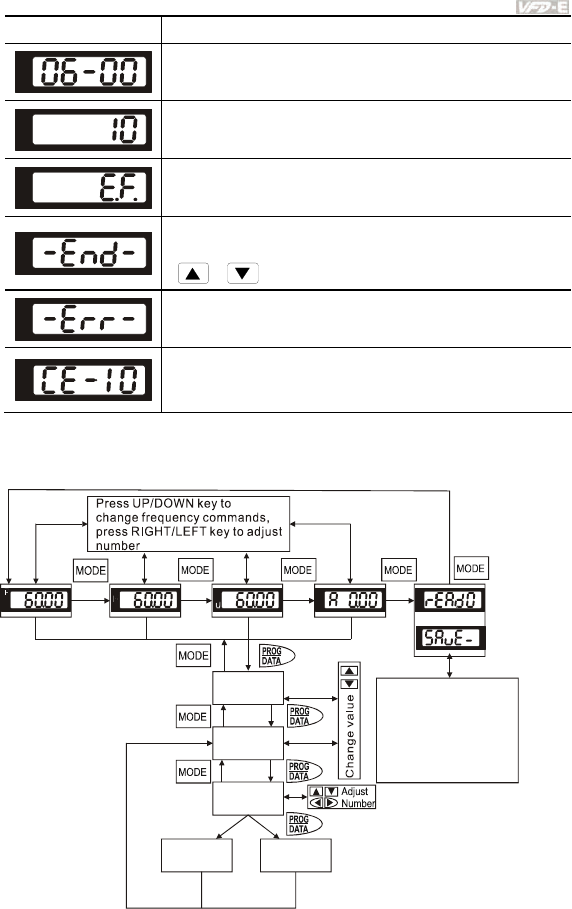
Appendix B Accessories|
Revision June 2008, 04EE, SW--PW V1.11/CTL V2.11 B-17
Display Message Descriptions
The specified parameter setting.
The actual value stored in the specified parameter.
External Fault
“End” displays for approximately 1 second if the entered input data have
been accepted. After a parameter value has been set, the new value is
automatically stored in memory. To modify an entry, use the
or keys.
“Err” displays if the input is invalid.
Communication Error. Please check the AC motor drive user manual
(Chapter 5, Group 9 Communication Parameter) for more details.
B.7.3 Operation Flow Chart
XX
XX-XX
XXXXX
-END-
VFD-PU06 Operation Flow Chart
Cannot
write in
-ERR-
Or
Succeed to
Write in
Press UP key to select
SAVE or READ.
Press PROG/DATA for
about 2 seconds or until
it is flashing, then save
parameters
or read parameters
.
from PU06 to
AC drive
from AC drive to PU06
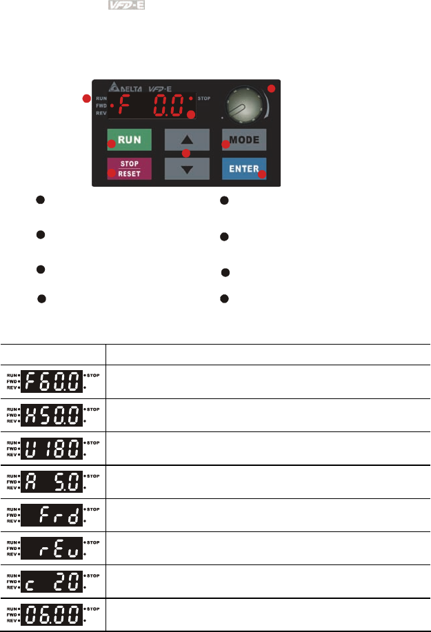
Appendix B Accessories|
B-18 Revision June 2008, 04EE, SW--PW V1.11/CTL V2.11
B.8 KPE-LE02
B.8.1 Description of the Digital Keypad KPE-LE02
LED Display
Indicates frequency, voltage, current, user
defined units and etc.
Status Display
Display the driver's current status.
STOP/RESET
Stops AC drive operation and reset the drive
after fault occurred.
RUN Key
Start AC drive operation.
MODE
Change between different display mode.
UP and DOWN Key
Set the parameter number and changes the
numerical data, such as Master Frequency.
Potentiometer
For master Frequency setting.
1
2
3
4
5
6
7
1
2
3
4
5
6
78
8
ENTER
Used to enter/modify programming
parameters
Display Message Descriptions
Displays the AC drive Master Frequency.
Displays the actual output frequency at terminals U/T1, V/T2, and W/T3.
User defined unit (where U = F x Pr.00.05)
Displays the output current at terminals U/T1, V/T2, and W/T3.
Displays the AC motor drive forward run status.
Displays the AC motor drive reverse run status.
The counter value (C).
Displays the selected parameter.
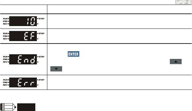
Appendix B Accessories|
Revision June 2008, 04EE, SW--PW V1.11/CTL V2.11 B-19
Display Message Descriptions
Displays the actual stored value of the selected parameter.
External Fault.
Display “End” for approximately 1 second if input has been accepted by
pressing key. After a parameter value has been set, the new value
is automatically stored in memory. To modify an entry, use the and
keys.
Display “Err”, if the input is invalid.
NOTE
When the setting exceeds 99.99 for those numbers with 2 decimals (i.e. unit is 0.01), it will only
display 1 decimal due to 4-digital display.
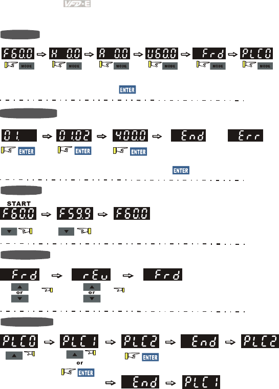
Appendix B Accessories|
B-20 Revision June 2008, 04EE, SW--PW V1.11/CTL V2.11
B.8.2 How to Operate the Digital Keypad
To s hift d ata
Setting direction
Setting PLC Mode
Setting Mode
Setting parameters
(When operation source is digital keypad)
enter PLC2 mode
enter PLC1 mode
START
GO START
NOTE: In the selection mode, press to set the parameters.
Success to
set parameter. Input data error
or
NOTE
:
In the parameter setting mode, you can press to return the selecting mode.
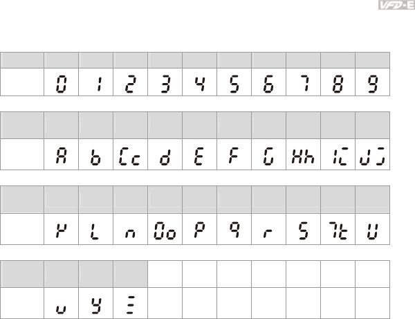
Appendix B Accessories|
Revision June 2008, 04EE, SW--PW V1.11/CTL V2.11 B-21
B.8.3 Reference Table for the 7-segment LED Display of the Digital
Keypad
Digit 0 1 2 3 4 5 6 7 8 9
LED
Display
English
alphabet A b Cc d E F G Hh Ii Jj
LED
Display
English
alphabet K L n Oo P q r S Tt U
LED
Display
English
alphabet v Y Z
LED
Display
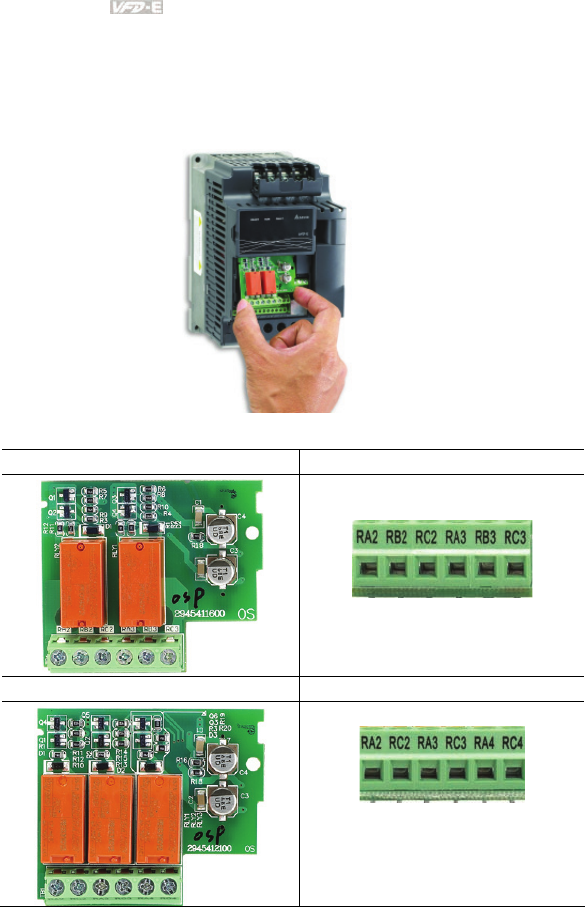
Appendix B Accessories|
B-22 Revision June 2008, 04EE, SW--PW V1.11/CTL V2.11
B.9 Extension Card
For details, please refer to the separate instruction shipped with these optional cards or download
from our website http://www.delta.com.tw/industrialautomation/.
Installation method
B.9.1 Relay Card
EME-R2CA Relay Output
EME-R3AA Relay Output
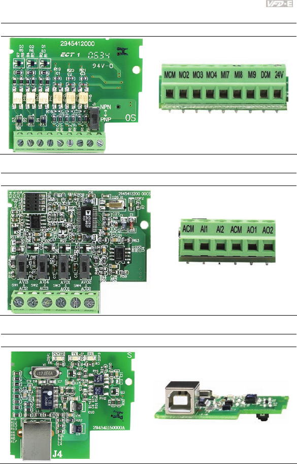
Appendix B Accessories|
Revision June 2008, 04EE, SW--PW V1.11/CTL V2.11 B-23
B.9.2 Digital I/O Card
EME-D33A
B.9.3 Analog I/O Card
EME-A22A
B.9.4 Communication Card
CME-USB01
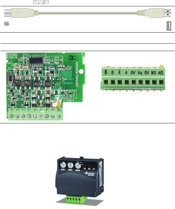
Appendix B Accessories|
B-24 Revision June 2008, 04EE, SW--PW V1.11/CTL V2.11
connect to extension card connect to PC
B.9.5 Speed Feedback Card
EME-PG01
B.10 Fieldbus Modules
B.10.1 DeviceNet Communication Module (CME-DN01)
B.10.1.1 Panel Appearance and Dimensions
1. For RS-485 connection to VFD-E 2. Communication port for connecting DeviceNet
network 3. Address selector 4. Baud rate selector 5. Three LED status indicators for monitor.
(Refer to the figure below)
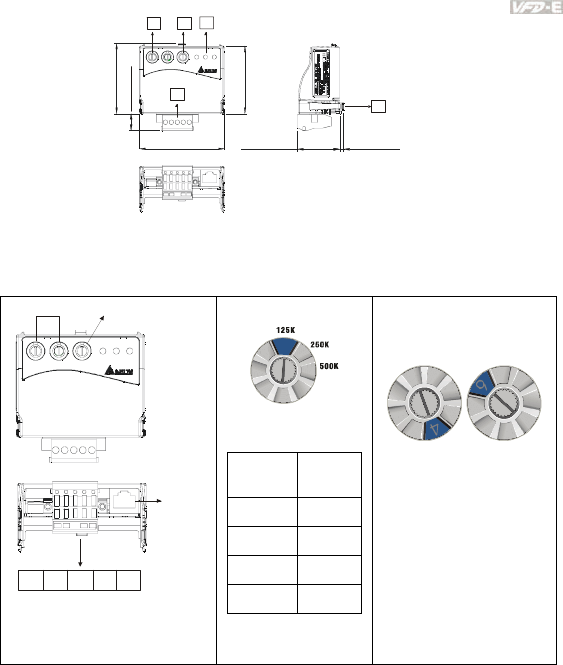
Appendix B Accessories|
Revision June 2008, 04EE, SW--PW V1.11/CTL V2.11 B-25
72.2 [2.84]
57.3 [2.26]
14.3 [0.57]
59.7 [2.35]
3.5 [0.14]35.8 [1.41]
CME-DN01
ADD1 ADD2
SP
500K
250K
125K
BAUD
MODNET
UNIT: mm(inch)
1
543
2
B.10.1.2 Wiring and Settings
Refer to following diagram for details.
CME-DN01
ADD1 ADD2
SP
500K
250K
125K
BAUD
MODNET
MAC address Date Rate
CAN-L
V+ Empty
Pin
CAN-H V-
1: Reser ved
2: EV
5: SG+
6: Reser ved
7: Reser ved
8: Reser ved
3: GND
4: SG-
Setting baud rate
BAUD
0
Switch
Value
Baud
Rate
0 125K
1 250K
2 500K
Other AUTO
Setting MAC addresses:
use decimal system.
ADD1 ADD2
B.10.1.3 Mounting Method
Step1 and step2 show how to mount this communication module onto VFD-E. The dimension
on the left hand side is for your reference.
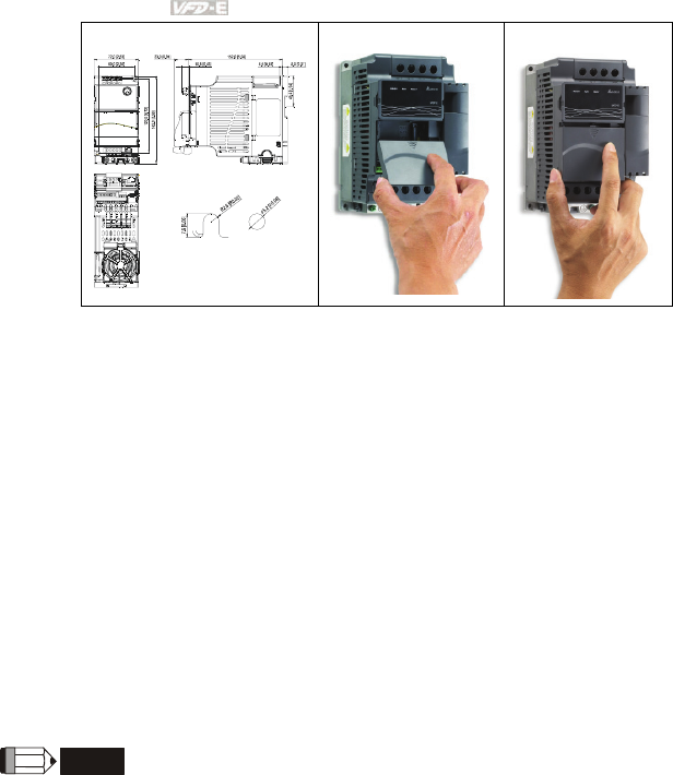
Appendix B Accessories|
B-26 Revision June 2008, 04EE, SW--PW V1.11/CTL V2.11
Dimensions
UNIT: mm(inch)
STEP 1
STEP 2
B.10.1.4 Power Supply
No external power is needed. Power is supplied via RS-485 port that is connected to VFD-E.
An 8 pins RJ-45 cable, which is packed together with this communication module, is used to
connect the RS-485 port between VFD-E and this communication module for power. This
communication module will perform the function once it is connected. Refer to the following
paragraph for LED indications.
B.10.1.5 LEDs Display
1. SP: Green LED means in normal condition, Red LED means abnormal condition.
2. Module: Green blinking LED means no I/O data transmission, Green steady LED means
I/O data transmission OK.
Red LED blinking or steady LED means module communication is abnormal.
3. Network: Green LED means DeviceNet communication is normal, Red LED means
abnormal
NOTE
Refer to user manual for detail information-- Chapter 5 Troubleshooting.
B.10.2 LonWorks Communication Module (CME-LW01)
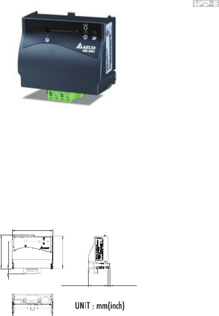
Appendix B Accessories|
Revision June 2008, 04EE, SW--PW V1.11/CTL V2.11 B-27
B.10.2.1 Introduction
Device CME-LW01 is used for communication interface between Modbus and LonTalk. CME-
LW01 needs be configured via LonWorks network tool first, so that it can perform the function
on LonWorks network. No need to set CME-LW01 address.
This manual provides instructions for the installation and setup for CME-LW01 that is used to
communicate with Delta VFD-E (firmware version of VFD-E should conform with CME-LW01
according to the table below) via LonWorks Network.
B.10.2.2 Dimensions
57.3[2.26]
72.2 [2.84]
59.7[2.35]
9.5[0.37]
3.5 [0.14]34.8 [1.37]
SP
CME-LW01
B.10.2.3 Specifications
Power supply: 16-30VDC, 750mW
Communication: Modbus in ASCII format, protocol: 9600, 7, N, 2
LonTalk: free topology with FTT-10A 78 Kbps.
LonTalk terminal: 4-pin terminals, wire gauge: 28-12 AWG, wire strip length: 7-8mm
RS-485 port: 8 pins with RJ-45
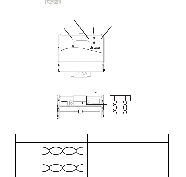
Appendix B Accessories|
B-28 Revision June 2008, 04EE, SW--PW V1.11/CTL V2.11
B.10.2.4 Wiring
SP
CME-LW01
Power LED SP LED
Service LED
Service Pin
1: Reserved
2: EV
3: GND
4: SG-
5: SG+
6: Reserved
7: Reserved
8: Reserved
LonTalk
1234
LonTalk
Terminal definition for LonTalk system
Terminal Symbol Function
1
2
3
4
These are twisted pair cables to connect
to LonTalk system. Terminals 1 and 2
should be used as one group, and the
same for terminals 3 and 4.
B.10.2.5 LED Indications
There are three LEDs in front panel of CME-LW01. If the communication is normal, power
LED, SP LED should be green (red LED means abnormal communication) and service LED
should be OFF. If LEDs display do not match, refer to user manual for details.
B.10.3 Profibus Communication Module (CME-PD01)
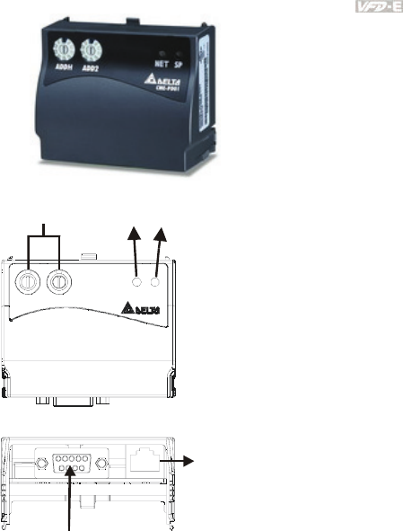
Appendix B Accessories|
Revision June 2008, 04EE, SW--PW V1.11/CTL V2.11 B-29
B.10.3.1 Panel Appearance
1: Reserved
2: EV
5: SG+
6: Reserved
7: Reserved
8: Reserved
3: GND
4: SG-
Profibus-DP
Interface (DB9)
RS-485 (RJ45)
ADDH ADDL SPNET
CME-PB01
SP LED
NET LEDAddress Switches
1. SP LED: Indicating the connection status between VFD-E and CME-PD01.
2. NET LED: Indicating the connection status between CME-PD01 and PROFIBUS-DP.
3. Address Switches: Setting the address of CME-PD01 on PROFIBUS- DP network.
4. RS-485 Interface (RJ45): Connecting to VFD-E, and supply power to CME-PD01.
5. PROFIBUS-DP Interface (DB9): 9-PIN connector that connects to PROFIBUS-DP
network.
6. Extended Socket: 4-PIN socket that connects to PROFIBUS-DP network.
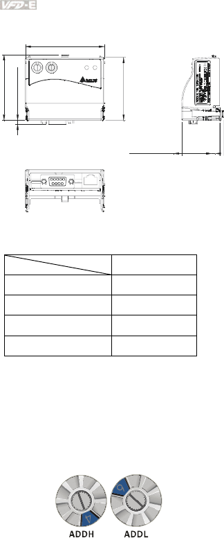
Appendix B Accessories|
B-30 Revision June 2008, 04EE, SW--PW V1.11/CTL V2.11
B.10.3.2 Dimensions
57.3 [2.26]
59.7 [2.35]
3.6 [0.14]
72.2 [2.84]
34.8 [1.37]
AD DH ADDL
SPNET
CME-PB01
UNIT: mm(inch)
B.10.3.3 Parameters Settings in VFD-E
VFD-E
Baud Rate 9600 Pr.09.01=1
RTU 8, N, 2 Pr.09.04=3
Freq. Source Pr.02.00=4
Command Source Pr.02.01=3
B.10.3.4 Power Supply
The power of CME-PD01 is supplied from VFD-E. Please connect VFD-E to CME-PD01 by
using 8 pins RJ-45 cable, which is packed together with CME-PD01. After connection is
completed, CME-PD01 is powered whenever power is applied to VFD-E.
B.10.3.5 PROFIBUS Address
CME-PD01 has two rotary switches for the user to select the PROFIBUS address. The set
value via 2 address switches, ADDH and ADDL, is in HEX format. ADDH sets the upper 4 bits,
and ADDL sets the lower 4 bits of the PROFIBUS address.
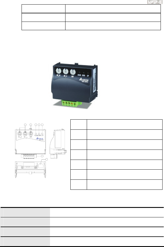
Appendix B Accessories|
Revision June 2008, 04EE, SW--PW V1.11/CTL V2.11 B-31
Address Meaning
1..0x7D Valid PROFIBUS address
0 or 0x7E..0xFE Invalid PROFIBUS address
B.10.4 CME-COP01 (CANopen)
CME-COP01 CANopen communication module is specifically for connecting to CANopen
communication module of Delta VFD-E AC motor drive.
B.10.4.1 Product Profile
c COM port
d CANopen connection port
e RUN indicator
f ERROR indicator
g SP (Scan Port) indicator
h Baud rate switch
1
2
76345
Unit: mm i Address switch
B.10.4.2 Specifications
CANopen Connection
Interface Pluggable connector (5.08mm)
Transmission method CAN
Transmission cable 2-wire twisted shielded cable
Electrical isolation 500V DC
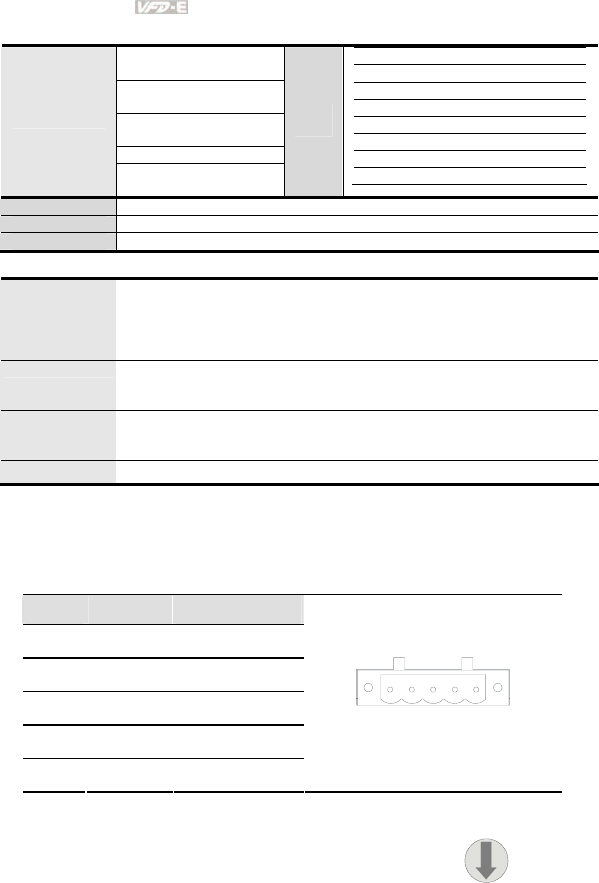
Appendix B Accessories|
B-32 Revision June 2008, 04EE, SW--PW V1.11/CTL V2.11
Communication
Process Data Objects
(PDO)
Service Data Object
(SDO)
Synchronization
(SYNC)
Emergency (EMCY)
Message type
Network Management
(NMT)
Baud
rate
10 Kbps
20 Kbps
50 Kbps
125 Kbps
250 Kbps
500 Kbps
800 Kbps
1 Mbps
Product code Delta VFD-E AC motor drive 22
Device type 402
Vendor ID 477
Environmental Specifications
Noise Immunity
ESD(IEC 61131-2, IEC 61000-4-2): 8KV Air Discharge
EFT(IEC 61131-2, IEC 61000-4-4): Power Line: 2KV, Digital I/O: 1KV,
Analog & Communication I/O: 1KV
Damped-Oscillatory Wave: Power Line: 1KV, Digital I/O: 1KV
RS(IEC 61131-2, IEC 61000-4-3): 26MHz ~ 1GHz, 10V/m
Environment
Operation: 0°C ~ 55°C (Temperature), 50 ~ 95% (Humidity), Pollution
degree 2;
Storage: -40°C ~ 70°C (Temperature), 5 ~ 95% (Humidity)
Vibration /
Shock
Resistance
Standard: IEC1131-2, IEC 68-2-6(TEST Fc/IEC1131-2 & IEC 68-2-27
(TEST Ea)
Certifications Standard: IEC 61131-2,UL508
B.10.4.3 Components
Pin Definition on CANopen Connection Port
To connect with CANopen, use the connector enclosed with CME-COP01 or any connectors
you can buy in the store for wiring.
Pin Signal Content
1 CAN_GND Ground / 0 V / V-
2 CAN_L Signal-
3 SHIELD Shield
4 CAN_H Signal+
5 - Reserved
1 2 3 4 5
Baud Rate Setting
Rotary switch (BR) sets up the communication speed on
CANopen network in hex. Setup range: 0 ~ 7 (8 ~F are
forbidden)
0
1
2
3
4
5
6
7
8
9
A
B
C
D
E
F
BR
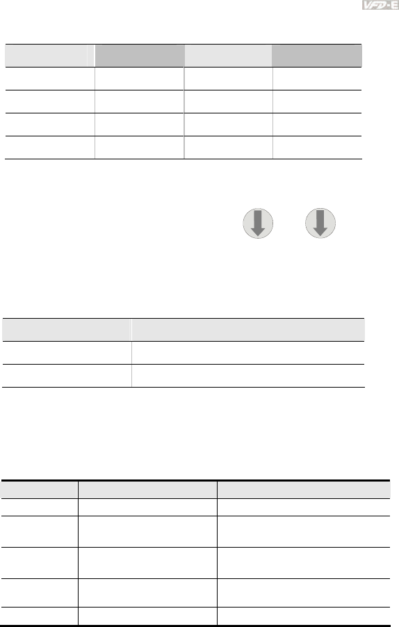
Appendix B Accessories|
Revision June 2008, 04EE, SW--PW V1.11/CTL V2.11 B-33
Example: If you need to set up the communication speed of CME-COP01 as 500K, simply
switch BR to “5”.
BR Value Baud rate BR Value Baud rate
0 10K 4 250K
1 20K 5 500K
2 50K 6 800K
3 125K 7 1M
MAC ID Setting
Rotary switches (ID_L and ID_H) set up the
Node-ID on CANopen network in hex. Setup
range: 00 ~ 7F (80 ~FF are forbidden)
0
1
2
3
4
5
6
7
8
9
A
B
C
D
E
F
0
1
2
3
4
5
6
7
8
9
A
B
C
D
E
F
ID_H ID_L
Example: If you need to set up the communication address of CME-COP01 as 26(1AH),
simply switch ID_H to “1” and ID_L to “A”.
Switch Setting Content
0 … 7F Valid CANopen MAC ID setting
Other Invalid CANopen MAC ID setting
B.10.4.4 LED Indicator Explanation & Troubleshooting
There are 3 LED indicators, RUN, ERROR and SP, on CME-COP01 to indicate the
communication status of CME-COP01.
RUN LED
LED Status State Indication
OFF No power No power on CME-COP01 card
Single Flash
(Green) STOPPED CME-COP01 is in STOPPED state
Blinking
(Green) PRE-OPERATIONAL CME-COP01 is in the PRE-
OPERATIONAL state
Green ON OPERATIONAL CME-COP01 is in the
OPERATIONAL state
Red ON Configuration error Node-ID or Baud rate setting error

Appendix B Accessories|
B-34 Revision June 2008, 04EE, SW--PW V1.11/CTL V2.11
ERROR LED
LED Status State Indication
OFF No error CME-COP01 is working condition
Single Flash
(Red) Warning limit reached
At least one of error counter of the
CANopen controller has reached or
exceeded the warning level (too many
error frames)
Double Flash
(Red) Error control event A guard event or heartbeat event has
occurred
Red ON Bus-off The CANopen controller is bus-off
SP LED
LED Status State Indication
OFF No Power No power on CME-COP01 card
LED Blinking
(Red) CRC check error Check your communication setting in
VFD-E drives (19200,<8,N,2>,RTU)
Red ON Connection failure/No
connection
1. Check the connection between
VFD-E drive and CME-COP01
card is correct
2. Re-wire the VFD-E connection and
ensure that the wire specification is
correct
LED Blinking
(Green)
CME-COP01 returns error
code
Check the PLC program, ensure the
index and sub-index is correct
Green ON Normal Communication is normal
LED Descriptions
State Description
LED ON Constantly on
LED OFF Constantly off
LED blinking Flash, on for 0.2s and off for 0.2s
LED single
flash On for 0.2s and off for 1s
LED double
flash On for 0.2s off for 0.2s, on for 0.2s and off for 1s
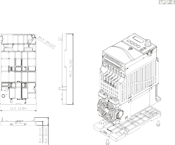
Appendix B Accessories|
Revision June 2008, 04EE, SW--PW V1.11/CTL V2.11 B-35
B.11 DIN Rail
B.11.1 MKE-DRA
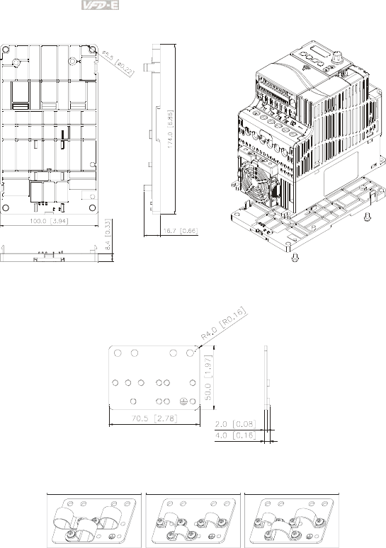
Appendix B Accessories|
B-36 Revision June 2008, 04EE, SW--PW V1.11/CTL V2.11
B.11.2 MKE-DRB
B.11.3 MKE-EP
EMC earthing plate for Shielding Cable
C CLAMP TWO HOLE STRAP
1 TWO HOLE STRAP
2
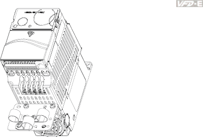
Appendix B Accessories|
Revision June 2008, 04EE, SW--PW V1.11/CTL V2.11 B-37

Appendix B Accessories|
B-38 Revision June 2008, 04EE, SW--PW V1.11/CTL V2.11
This page intentionally left blank

Revision June 2008, 04EE, SW--PW V1.11/CTL V2.11 C-1
Appendix C How to Select the Right AC Motor Drive
The choice of the right AC motor drive for the application is very important and has great influence
on its lifetime. If the capacity of AC motor drive is too large, it cannot offer complete protection to the
motor and motor maybe damaged. If the capacity of AC motor drive is too small, it cannot offer the
required performance and the AC motor drive maybe damaged due to overloading.
But by simply selecting the AC motor drive of the same capacity as the motor, user application
requirements cannot be met completely. Therefore, a designer should consider all the conditions,
including load type, load speed, load characteristic, operation method, rated output, rated speed,
power and the change of load capacity. The following table lists the factors you need to consider,
depending on your requirements.
Related Specification
Item Speed and
torque
characteristics
Time
ratings
Overload
capacity
Starting
torque
Load type
Friction load and weight
load
Liquid (viscous) load
Inertia load
Load with power
transmission
● ●
Load speed and
torque
characteristics
Constant torque
Constant output
Decreasing torque
Decreasing output
● ●
Load
characteristics
Constant load
Shock load
Repetitive load
High starting torque
Low starting torque
● ● ● ●
Continuous operation, Short-time operation
Long-time operation at medium/low speeds ● ●
Maximum output current (instantaneous)
Constant output current (continuous) ● ●
Maximum frequency, Base frequency ●
Power supply transformer capacity or
percentage impedance
Voltage fluctuations and unbalance
Number of phases, single phase protection
Frequency
● ●
Mechanical friction, losses in wiring ● ●
Duty cycle modification ●

Appendix C How to Select the Right AC Motor Drive|
C-2 Revision June 2008, 04EE, SW--PW V1.11/CTL V2.11
C.1 Capacity Formulas
1. When one AC motor drive operates one motor
The starting capacity should be less than 1.5x rated capacity of AC motor drive
The starting capacity=
)(_____5.1
375cos973
2
kVAdrivemotorACofcapacitythe
t
NGD
T
Nk
A
L×≤
⎟
⎟
⎠
⎞
⎜
⎜
⎝
⎛×+
××
×
ϕη
2. When one AC motor drive operates more than one motor
2.1 The starting capacity should be less than the rated capacity of AC motor drive
Acceleration time
≦60 seconds
The starting capacity=
()
[]
()
)(_____5.11
cos 111 kVAdrivemotorACofcapacitythek
n
n
Pknn
Nk
sCss
T
s
T×≤+=+
×
×
⎥
⎥
⎥
⎦
⎤
⎢
⎢
⎢
⎣
⎡
−−
ϕη
Acceleration time
≧60 seconds
The starting capacity=
()
[]
()
)(_____1
cos 111 kVAdrivemotorACofcapacitythek
n
n
Pknn
Nk
sCss
T
s
T≤+=+
×
×
⎥
⎥
⎥
⎦
⎤
⎢
⎢
⎢
⎣
⎡
−−
ϕη
2.2 The current should be less than the rated current of AC motor drive(A)
Acceleration time
≦60 seconds
)(______5.111 AdrivemotorACofcurrentratedthek
n
n
In SM
T
S
T×≤++ ⎥
⎦
⎤
⎢
⎣
⎡⎟
⎠
⎞
⎜
⎝
⎛−
Acceleration time
≧60 seconds
)(______11 AdrivemotorACofcurrentratedthek
n
n
In SM
T
S
T≤++ ⎥
⎦
⎤
⎢
⎣
⎡⎟
⎠
⎞
⎜
⎝
⎛−

Appendix C How to Select the Right AC Motor Drive|
Revision June 2008, 04EE, SW--PW V1.11/CTL V2.11 C-3
2.3 When it is running continuously
The requirement of load capacity should be less than the capacity of AC motor drive(kVA)
The requirement of load capacity=
)(_____
cos kVAdrivemotorACofcapacitythe
Pk M≤
×
×
ϕη
The motor capacity should be less than the capacity of AC motor drive
)(_____103 3kVAdrivemotorACofcapacitytheIVk MM ≤×××× −
The current should be less than the rated current of AC motor drive(A)
)(______ AdrivemotorACofcurrentratedtheIk M≤×
Symbol explanation
M
P
: Motor shaft output for load (kW)
η : Motor efficiency (normally, approx. 0.85)
ϕ
cos : Motor power factor (normally, approx. 0.75)
MV : Motor rated voltage(V)
M
I
: Motor rated current(A), for commercial power
k : Correction factor calculated from current distortion factor (1.05-1.1, depending on
PWM method)
1CP : Continuous motor capacity (kVA)
Sk : Starting current/rated current of motor
Tn : Number of motors in parallel
Sn : Number of simultaneously started motors
2
GD : Total inertia (GD2) calculated back to motor shaft (kg m2)
L
T
: Load torque
A
t
: Motor acceleration time
N : Motor speed

Appendix C How to Select the Right AC Motor Drive|
C-4 Revision June 2008, 04EE, SW--PW V1.11/CTL V2.11
C.2 General Precaution
Selection Note
1. When the AC Motor Drive is connected directly to a large-capacity power transformer
(600kVA or above) or when a phase lead capacitor is switched, excess peak currents
may occur in the power input circuit and the converter section may be damaged. To avoid
this, use an AC input reactor (optional) before AC Motor Drive mains input to reduce the
current and improve the input power efficiency.
2. When a special motor is used or more than one motor is driven in parallel with a single
AC Motor Drive, select the AC Motor Drive current ≥1.25x(Sum of the motor rated
currents).
3. The starting and accel./decel. characteristics of a motor are limited by the rated current
and the overload protection of the AC Motor Drive. Compared to running the motor D.O.L.
(Direct On-Line), a lower starting torque output with AC Motor Drive can be expected. If
higher starting torque is required (such as for elevators, mixers, tooling machines, etc.)
use an AC Motor Drive of higher capacity or increase the capacities for both the motor
and the AC Motor Drive.
4. When an error occurs on the drive, a protective circuit will be activated and the AC Motor
Drive output is turned off. Then the motor will coast to stop. For an emergency stop, an
external mechanical brake is needed to quickly stop the motor.
Parameter Settings Note
1. The AC Motor Drive can be driven at an output frequency up to 400Hz (less for some
models) with the digital keypad. Setting errors may create a dangerous situation. For
safety, the use of the upper limit frequency function is strongly recommended.
2. High DC brake operating voltages and long operation time (at low frequencies) may
cause overheating of the motor. In that case, forced external motor cooling is
recommended.
3. Motor accel./decel. time is determined by motor rated torque, load torque, and load inertia.
4. If the stall prevention function is activated, the accel./decel. time is automatically extended
to a length that the AC Motor Drive can handle. If the motor needs to decelerate within a
certain time with high load inertia that can’t be handled by the AC Motor Drive in the
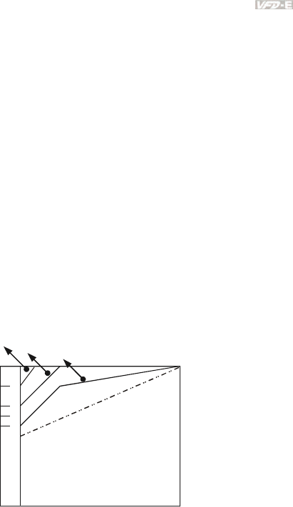
Appendix C How to Select the Right AC Motor Drive|
Revision June 2008, 04EE, SW--PW V1.11/CTL V2.11 C-5
required time, either use an external brake resistor and/or brake unit, depending on the
model, (to shorten deceleration time only) or increase the capacity for both the motor and
the AC Motor Drive.
C.3 How to Choose a Suitable Motor
Standard motor
When using the AC Motor Drive to operate a standard 3-phase induction motor, take the
following precautions:
1. The energy loss is greater than for an inverter duty motor.
2. Avoid running motor at low speed for a long time. Under this condition, the motor
temperature may rise above the motor rating due to limited airflow produced by the
motor’s fan. Consider external forced motor cooling.
3. When the standard motor operates at low speed for long time, the output load must be
decreased.
4. The load tolerance of a standard motor is as follows:
3 6 20 60
100
82
70
60
50
0
60%
40%
25%
torque(%)
continuous
Frequency (Hz)
Load duty-cycle
5. If 100% continuous torque is required at low speed, it may be necessary to use a special
inverter duty motor.
6. Motor dynamic balance and rotor endurance should be considered once the operating
speed exceeds the rated speed (60Hz) of a standard motor.

Appendix C How to Select the Right AC Motor Drive|
C-6 Revision June 2008, 04EE, SW--PW V1.11/CTL V2.11
7. Motor torque characteristics vary when an AC Motor Drive instead of commercial power
supply drives the motor. Check the load torque characteristics of the machine to be
connected.
8. Because of the high carrier frequency PWM control of the VFD series, pay attention to the
following motor vibration problems:
Resonant mechanical vibration: anti-vibration (damping) rubbers should be used to mount
equipment that runs at varying speed.
Motor imbalance: special care is required for operation at 50 or 60 Hz and higher
frequency.
To avoid resonances, use the Skip frequencies.
9. The motor fan will be very noisy when the motor speed exceeds 50 or 60Hz.
Special motors:
1. Pole-changing (Dahlander) motor:
The rated current is differs from that of a standard motor. Please check before operation
and select the capacity of the AC motor drive carefully. When changing the pole number
the motor needs to be stopped first. If over current occurs during operation or
regenerative voltage is too high, please let the motor free run to stop (coast).
2. Submersible motor:
The rated current is higher than that of a standard motor. Please check before operation
and choose the capacity of the AC motor drive carefully. With long motor cable between
AC motor drive and motor, available motor torque is reduced.
3. Explosion-proof (Ex) motor:
Needs to be installed in a safe place and the wiring should comply with the (Ex)
requirements. Delta AC Motor Drives are not suitable for (Ex) areas with special
precautions.
4. Gear reduction motor:
The lubricating method of reduction gearbox and speed range for continuous operation
will be different and depending on brand. The lubricating function for operating long time
at low speed and for high-speed operation needs to be considered carefully.
5. Synchronous motor:
The rated current and starting current are higher than for standard motors. Please check
before operation and choose the capacity of the AC motor drive carefully. When the AC
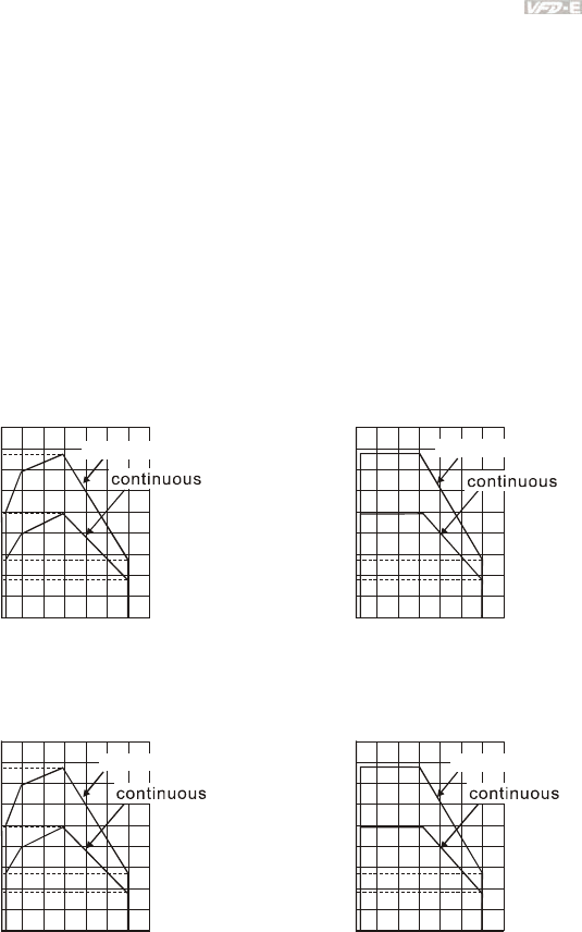
Appendix C How to Select the Right AC Motor Drive|
Revision June 2008, 04EE, SW--PW V1.11/CTL V2.11 C-7
motor drive operates more than one motor, please pay attention to starting and changing
the motor.
Power Transmission Mechanism
Pay attention to reduced lubrication when operating gear reduction motors, gearboxes, belts
and chains, etc. over longer periods at low speeds. At high speeds of 50/60Hz and above,
lifetime reducing noises and vibrations may occur.
Motor torque
The torque characteristics of a motor operated by an AC motor drive and commercial mains
power are different.
Below you’ll find the torque-speed characteristics of a standard motor (4-pole, 15kW):
AC motor drive Motor
180
155
140
100
80
55
38
0320 60 120
60 seconds
Base freq.: 60Hz
V/F for 220V/60Hz
180
155
100
55
38
0320 60 120
torque (%)
Frequency (Hz) Frequency (Hz)
60 seconds
60 seconds
torque (%)
Base freq.: 60Hz
V/F for 220V/60Hz
130
140
100
85
45
35
0320 50 120
180
150
100
45
35
050 120
68 80
torque (%)
torque (
%
)
60 seconds 60 seconds
Frequency (Hz)
Frequency (Hz)
320
Base freq.: 50Hz
V/F for 220V/50Hz
Base freq.: 50Hz
V/F for 220V/50Hz

Appendix C How to Select the Right AC Motor Drive|
C-8 Revision June 2008, 04EE, SW--PW V1.11/CTL V2.11
This page intentionally left blank.

Revision June 2008, 04EE, SW--PW V1.11/CTL V2.11 D-1
Appendix D How to Use PLC Function
※ This function is NOT for VFD*E*C models.
D.1 PLC Overview
D.1.1 Introduction
The PLC function built in the VFD-E provides following commands: WPLSoft, basic
commands and application commands. The operation methods are the same as Delta DVP-
PLC series.
D.1.2 Ladder Diagram Editor – WPLSoft
WPLSoft is a program editor of Delta DVP-PLC series and VFD-E series for WINDOWS.
Besides general PLC program planning and general WINDOWS editing functions, such as
cut, paste, copy, multi-windows, WPLSoft also provides various Chinese/English comment
editing and other special functions (e.g. register editing, settings, the data readout, the file
saving, and contacts monitor and set, etc.).
Following is the system requirement for WPLSoft:
Item System Requirement
Operation
System Windows 95/98/2000/NT/ME/XP
CPU Pentium 90 and above
Memory 16MB and above (32MB and above is recommended)
Hard Disk Capacity: 50MB and above
CD-ROM (for installing WPLSoft)
Monitor Resolution: 640×480, 16 colors and above,
It is recommended to set display setting of Windows to 800×600.
Mouse General mouse or the device compatible with Windows
Printer Printer with Windows driver
RS-232 port At least one of COM1 to COM8 can be connected to PLC
Applicable
Models All Delta DVP-PLC series and VFD-E series
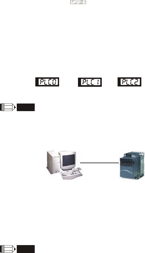
Appendix D How to Use PLC Function|
D-2 Revision June 2008, 04EE, SW--PW V1.11/CTL V2.11
D.2 Start-up
D.2.1 The Steps for PLC Execution
Please operate PLC function by the following five steps.
1. Switch the mode to PLC2 for program download/upload:
A. Go to “PLC0” page by pressing the MODE key
B. Change to “PLC2” by pressing the “UP” key and then press the “ENTER” key after
confirmation
C. If succeeded, “END” is displayed and back to “PLC2” after one or two seconds.
Disable Run PLC Read/write PLC program
into AC drives
NOTE
You don’t need to care about the PLC warning, such as PLod, PLSv and PldA, before downloading a
program to VFD-E.
2. Connection: Please connect RJ-45 of AC motor drive to computer via RS485-to-RS232
converter.
RS485
3. Run the program. The PLC status will always be PLC2, even if the AC motor drive is
switched off.
There are three ways to operate PLC:
A. In “PLC1” page: execute PLC program.
B. In “PLC2” page: execute/stop PLC program by using WPL software.
C. After setting multi-function input terminals (MI3 to MI9) to 23 (RUN/STOP PLC), it will
display “PLC1” for executing PLC when the terminal is ON. It will display “PLC0” to stop
PLC program when terminals are OFF.
NOTE
When external terminals are set to 23 and the terminal is ON, it cannot use keypad to change PLC
mode. Moreover, when it is PLC2, you cannot execute PLC program by external terminals.
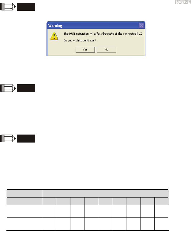
Appendix D How to Use PLC Function|
Revision June 2008, 04EE, SW--PW V1.11/CTL V2.11 D-3
NOTE
When power on after power off, the PLC status will be in “PLC1”.
4. When you are in “PLC2”, please remember to change to “PLC1” when finished to prevent
anyone modifying PLC program.
NOTE
When output/input terminals (MI1~MI9, Relay1~Relay 4, MO1~MO4) are used in PLC program, they
cannot be used in other places. For example, When Y0 in PLC program is activated, the
corresponding output terminals Relay (RA/RB/RC) will be used. At this moment, parameter 03.00
setting will be invalid. Because the terminal has been used by PLC.
NOTE
The PLC corresponding input points for MI1 to MI6 are X0 to X5. When extension card are added, the
extension input points will be numbered from X06 and output points will start from Y2 as shown in
chapter D.2.2.
D.2.2 Device Reference Table
Device X
ID 0 1 2 3 4 5 6 7 10
Terminals of AC
Drives MI1 MI2 MI3 MI4 MI5 MI6 -- -- --
3IN/3OUT Card
(EME-D33A) -- -- -- -- -- -- MI7 MI8 MI9
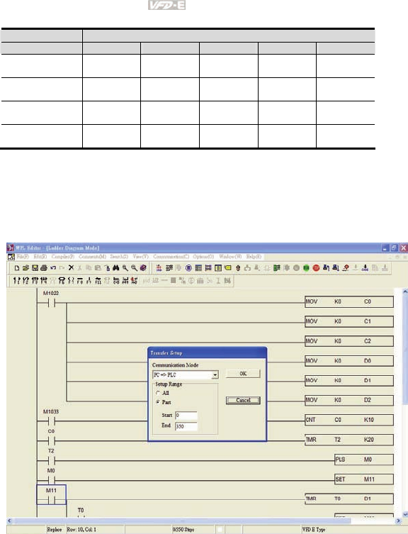
Appendix D How to Use PLC Function|
D-4 Revision June 2008, 04EE, SW--PW V1.11/CTL V2.11
Device Y
ID 0 1 2 3 4
Terminals of AC
Drives RY MO1 -- -- --
Relay Card-2C
(EME-DR2CA) -- --
RY2 RY3 --
Relay Card-3A
(EME-R3AA) -- --
RY2 RY3 RY4
3IN/3OUT Card
(EME-D33A) -- -- MO2 MO3 MO4
D.2.3 WPLSoft Installation
Download PLC program to AC drive: Refer to D.3 to D.7 for writing program and download
the editor (WPLSoft V2.09) at DELTA website
http://www.delta.com.tw/product/em/plc/plc_software.asp.
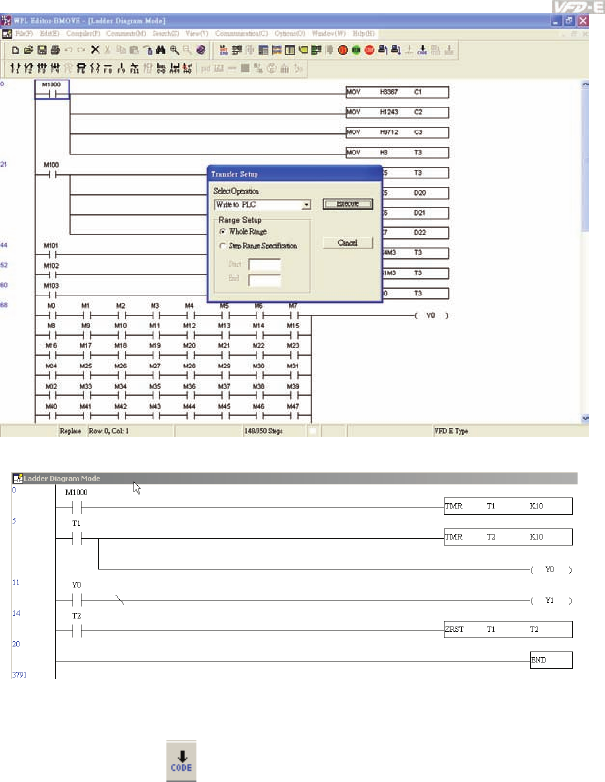
Appendix D How to Use PLC Function|
Revision June 2008, 04EE, SW--PW V1.11/CTL V2.11 D-5
D.2.4 Program Input
D.2.5 Program Download
Please do following steps for program download.
Step 1. Press button for compiler after inputting program in WPLSoft.
Step 2. After finishing compiler, choose the item “Write to PLC” in the communication items.
After finishing Step 2, the program will be downloaded from WPLSoft to the AC motor drive
by the communication format.
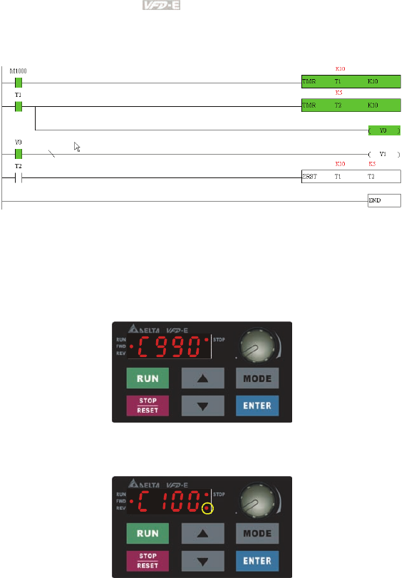
Appendix D How to Use PLC Function|
D-6 Revision June 2008, 04EE, SW--PW V1.11/CTL V2.11
D.2.6 Program Monitor
If you execute “start monitor” in the communication item during executing PLC, the ladder
diagram will be shown as follows.
D.2.7 The Limit of PLC
1. The protocol of PLC is 7,E,1
2. Make sure that the AC drive is stop and stop PLC before program upload/download.
3. The priority of commands WPR and FREQ is FREQ > WPR.
4. When setting P 00.04 to 2, the display will be the value in PLC register D1043.
A. 0 ~ 999 display:
B. 1000 ~ 9999 display: It will only display the first 3 digits. The LED at the
bottom-right corner will light to indicate 10 times of the display value. For
example, the actual value for the following figure is 100X10=1000.
C. 10000~65535 display: It will only display the first 3 digits. The LED at the
bottom-right corner and the single decimal point between the middle and the
right-most numbers will light to indicate 100 times of the display value. For
example, the actual value for the following figure is 100X100=10000.

Appendix D How to Use PLC Function|
Revision June 2008, 04EE, SW--PW V1.11/CTL V2.11 D-7
5. When it is changed to “PLC2”, RS-485 will be used by PLC.
6. When it is in PLC1 and PLC2 mode, the function to reset all parameters to factory setting
is disabled (i.e. Pr.00.02 can’t be set to 9 or 10).
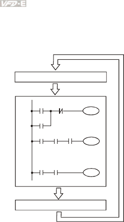
Appendix D How to Use PLC Function|
D-8 Revision June 2008, 04EE, SW--PW V1.11/CTL V2.11
D.3 Ladder Diagram
D.3.1 Program Scan Chart of the PLC Ladder Diagram
Calculate the result by ladder
diagram algorithm (it doesn’t
sent to the outer output point
but the inner equipment will
output immediately.)
Y0
X0 X1
Y0
Start
M100 X3
Y1
X10
:
:
X100 M505
Y126
End
Send the result to the output point
Read input state from outside
Execute in cycles
D.3.2 Introduction
Ladder diagram is a diagram language that applied on the automatic control and it is also a
diagram that made up of the symbols of electric control circuit. PLC procedures are finished
after ladder diagram editor edits the ladder diagram. It is easy to understand the control flow
that indicated with diagram and also accept by technical staff of electric control circuit. Many
basic symbols and motions of ladder diagram are the same as mechanical and electrical
equipments of traditional automatic power panel, such as button, switch, relay, timer,
counter and etc.
The kinds and amounts of PLC internal equipment will be different with brands. Although
internal equipment has the name of traditional electric control circuit, such as relay, coil and
contact. It doesn’t have the real components in it. In PLC, it just has a basic unit of internal
memory. If this bit is 1, it means the coil is ON and if this bit is 0, it means the coil is OFF.
You should read the corresponding value of that bit when using contact (Normally Open, NO
or contact a). Otherwise, you should read the opposite sate of corresponding value of that
bit when using contact (Normally Closed, NC or contact b). Many relays will need many bits,
such as 8-bits makes up a byte. 2 bytes can make up a word. 2 words makes up double
word. When using many relays to do calculation, such as add/subtraction or shift, you could

Appendix D How to Use PLC Function|
Revision June 2008, 04EE, SW--PW V1.11/CTL V2.11 D-9
use byte, word or double word. Furthermore, the two equipments, timer and counter, in PLC
not only have coil but also value of counting time and times.
In conclusion, each internal storage unit occupies fixed storage unit. When using these
equipments, the corresponding content will be read by bit, byte or word.
Basic introduction of the inner equipment of PLC:
Input relay Input relay is the basic storage unit of internal memory that corresponds to
external input point (it is the terminal that used to connect to external input switch
and receive external input signal). Input signal from external will decide it to
display 0 or 1. You couldn’t change the state of input relay by program design or
forced ON/OFF via WPLSoft. The contacts (contact a, b) can be used unlimitedly.
If there is no input signal, the corresponding input relay could be empty and can’t
be used with other functions.
Equipment indication method: X0, X1,…X7, X10, X11,…. The symbol of
equipment is X and the number uses octal.
Output relay Output relay is the basic storage unit of internal memory that corresponds to
external output point (it is used to connect to external load). It can be driven by
input relay contact, the contact of other internal equipment and itself contact. It
uses a normally open contact to connect to external load and other contacts can
be used unlimitedly as input contacts. It doesn’t have the corresponding output
relay, if need, it can be used as internal relay.
Equipment indication: Y0, Y1,…Y7, Y10, Y11,…. . The symbol of
equipment is Y and the number uses octal.
Internal relay The internal relay doesn’t connect directly to outside. It is an auxiliary relay in
PLC. Its function is the same as the auxiliary relay in electric control circuit. Each
auxiliary relay has the corresponding basic unit. It can be driven by the contact of
input relay, output relay or other internal equipment. Its contacts can be used
unlimitedly. Internal auxiliary relay can’t output directly, it should output with
output point.
Equipment indication: M0, M1,…, M4, M159. The symbol of equipment
is M and the number uses decimal number system.
Timer Timer is used to control time. There are coil, contact and timer storage. When coil
is ON, its contact will act (contact a is close, contact b is open) when attaining
desired time. The time value of timer is set by settings and each timer has its
regular period. User sets the timer value and each timer has its timing period.
Once the coil is OFF, the contact won’t act (contact a is open and contact b is
close) and the timer will be set to zero.
Equipment indication: T0, T1,…,T15. The symbol of equipment is T and
the number uses decimal system. The different number range
corresponds with the different timing period.
Counter Counter is used to count. It needs to set counter before using counter (i.e. the
pulse of counter). There are coil, contacts and storage unit of counter in counter.
When coil is from OFF to ON, that means input a pulse in counter and the counter
should add 1. There are 16-bit, 32-bit and high-speed counter for user to use.
Equipment indication: C0, C1,…,C7. The symbol of equipment is C and
the number uses decimal.
Data register PLC needs to handle data and operation when controlling each order, timer value
and counter value. The data register is used to store data or parameters. It stores
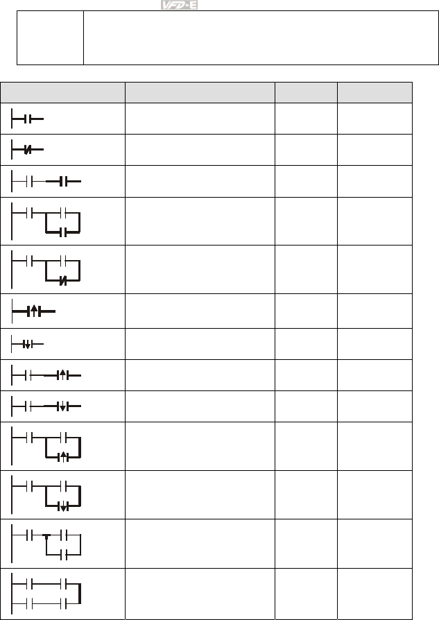
Appendix D How to Use PLC Function|
D-10 Revision June 2008, 04EE, SW--PW V1.11/CTL V2.11
16-bit binary number, i.e. a word, in each register. It uses two continuous number
of data register to store double words.
Equipment indication: D0, D1,…,D29. The symbol of equipment is D and
the number uses decimal.
The structure and explanation of ladder diagram:
Ladder Diagram Structure Explanation Command Equipment
Normally open, contact a LD X, Y, M, T, C
Normally closed, contact b LDI X, Y, M, T, C
Serial normally open AND X, Y, M, T, C
Parallel normally open OR X, Y, M, T, C
Parallel normally closed ORI X, Y, M, T, C
Rising-edge trigger switch LDP X, Y, M, T, C
Falling-edge trigger switch LDF X, Y, M, T, C
Rising-edge trigger in serial ANDP X, Y, M, T, C
Falling-edge trigger in serial ANDF X, Y, M, T, C
Rising-edge trigger in parallel ORP X, Y, M, T, C
Falling-edge trigger in parallel ORF X, Y, M, T, C
Block in serial ANB none
Block in parallel ORB none
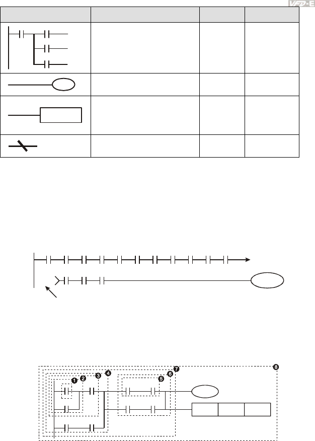
Appendix D How to Use PLC Function|
Revision June 2008, 04EE, SW--PW V1.11/CTL V2.11 D-11
Ladder Diagram Structure Explanation Command Equipment
Multiple output
MPS
MRD
MPP
none
Output command of coil drive OUT Y, M, S
Basic command, Application
command
Application
command
Please refer to
basic command
and application
command
Inverse logic INV none
D.3.3 The Edition of PLC Ladder Diagram
The program edited method is from left power line to right power line. (the right power line
will be omitted during the edited of WPLSoft.) After editing a row, go to editing the next row.
The maximum contacts in a row are 11 contacts. If you need more than 11 contacts, you
could have the new row and start with continuous line to continue more input devices. The
continuous number will be produced automatically and the same input point can be used
repeatedly. The drawing is shown as follows.
X0 X1 X2 X3 X4 X5
Y0
X11 X12 X13
X6 X7 X10 C0 C1
00000
00000
Row Number
The operation of ladder diagram is to scan from left upper corner to right lower corner. The
output handling, including the operation frame of coil and application command, at the most
right side in ladder diagram.
Take the following diagram for example; we analyze the process step by step. The number
at the right corner is the explanation order.
X0 X1 Y1 X4
M0
X3 M1
T0 M3
Y1
TMR T0 K10
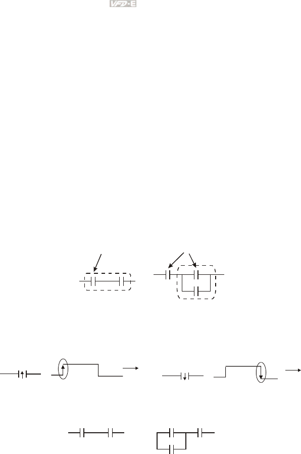
Appendix D How to Use PLC Function|
D-12 Revision June 2008, 04EE, SW--PW V1.11/CTL V2.11
The explanation of command order:
1 LD X0
2 OR M0
3 AND X1
4 LD X3
AND M1
ORB
5 LD Y1
AND X4
6 LD T0
AND M3
ORB
7 ANB
8 OUT Y1
TMR T0 K10
The detail explanation of basic structure of ladder diagram
1. LD (LDI) command: give the command LD or LDI in the start of a block.
AND Block OR Block
LD command LD command
The structures of command LDP and LDF are similar to the command LD. The difference is
that command LDP and LDF will act in the rising-edge or falling-edge when contact is ON as
shown in the following.
X0
OFF ON OFF
Time
Falling-edge
X0
OFF ON OFF
Time
Rising-edge
2. AND (ANI) command: single device connects to a device or a block in series.
AND comman
d
AND comman
d
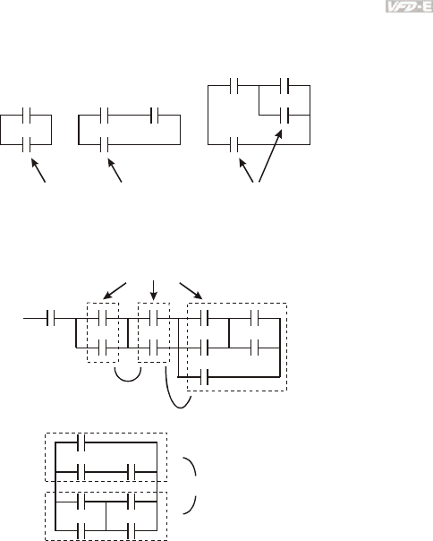
Appendix D How to Use PLC Function|
Revision June 2008, 04EE, SW--PW V1.11/CTL V2.11 D-13
The structures of ANDP and ANDF are the same but the action is in rising-edge or falling-
edge.
3. OR (ORI) command: single device connects to a device or a block.
OR command OR command OR command
The structures of ORP and ORF are the same but the action is in rising-edge or falling-edge.
4. ANB command: a block connects to a device or a block in series.
ANB command
5. ORB command: a block connects to a device or a block in parallel.
ORB command
If there are several blocks when operate ANB or ORB, they should be combined to blocks or
network from up to down or from left to right.
6. MPS, MRD, MPP commands: Divergent memory of multi-output. It can produce many
various outputs.
7. The command MPS is the start of divergent point. The divergent point means the
connection place between horizontal line and vertical line. We should determine to have
contact memory command or not according to the contacts status in the same vertical line.
Basically, each contact could have memory command but in some places of ladder
diagram conversion will be omitted due to the PLC operation convenience and capacity
limit. MPS command can be used for 8 continuous times and you can recognize this
command by the symbol “┬”.
8. MRD command is used to read memory of divergent point. Because the logical status is
the same in the same horizontal line, it needs to read the status of original contact to keep
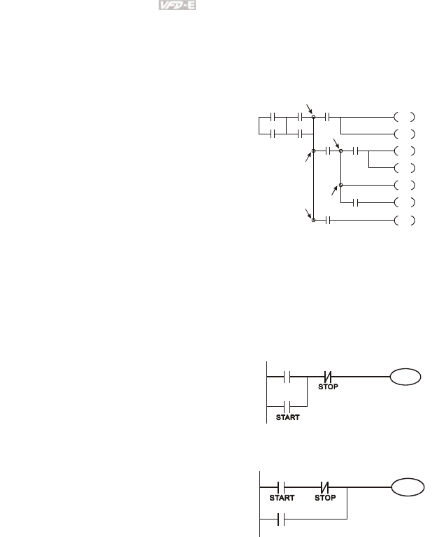
Appendix D How to Use PLC Function|
D-14 Revision June 2008, 04EE, SW--PW V1.11/CTL V2.11
on analyzing other ladder diagram. You can recognize the command MRD by the symbol
“├”.
9. MPP command is used to read the start status of the top level and pop it out from stack.
Because it is the last item of the horizontal line, it means the status of this horizontal line
is ending.
You can recognize this command by the symbol
“└”. Basically, that is all right to use the above
method to analyze but sometimes compiler will
omit the same outputs as shown at the right.
MPS
MRD
MPP
MPP
MPS
D.3.4 The Example for Designing Basic Program
Start, Stop and Latching
In the same occasions, it needs transient close button and transient open button to be start
and stop switch. Therefore, if you want to keep the action, you should design latching circuit.
There are several latching circuits in the following:
Example 1: the latching circuit for priority of stop
When start normally open contact X1=On, stop
normally contact X2=Off, and Y1=On are set at
the same time, if X2=On, the coil Y1 will stop
acting. Therefore, it calls priority of stop.
X2
Y1
X1
Y1
Example 2: the latching circuit for priority of start
When start normally open contact X1=On, stop
normally contact X2=Off and Y1=On (coil Y1 will
be active and latching) are valid at the same time, if
X2=On, coil Y1 will be active due to latched
contact. Therefore, it calls priority of start.
X2
Y1
X1
Y1
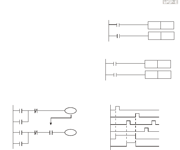
Appendix D How to Use PLC Function|
Revision June 2008, 04EE, SW--PW V1.11/CTL V2.11 D-15
Example 3: the latching circuit of SET and RST commands
SET Y1
RST Y1
X1
X2
Top priority of stop
The figure at the right side is latching circuit that made
up of RST and SET command.
It is top priority of stop when RST command is set
behind SET command. When executing PLC from up
to down, The coil Y1 is ON and coil Y1 will be OFF
when X1 and X2 act at the same time, therefore it calls
priority of stop.
It is top priority of start when SET command is set after
RST command. When X1 and X2 act at the same
time, Y1 is ON so it calls top priority of start.
SET
Y1
RST
Y1
X2
X1
Top priority of start
The common control circuit
Example 4: condition control
X3
Y1
X1
Y1
X4
Y2
X2
Y2
Y1
X1
X3
X2
X4
Y1
Y2
X1 and X3 can start/stop Y1 separately, X2 and X4 can start/stop Y2 separately and they are all
self latched circuit. Y1 is an element for Y2 to do AND function due to the normally open contact
connects to Y2 in series. Therefore, Y1 is the input of Y2 and Y2 is also the input of Y1.
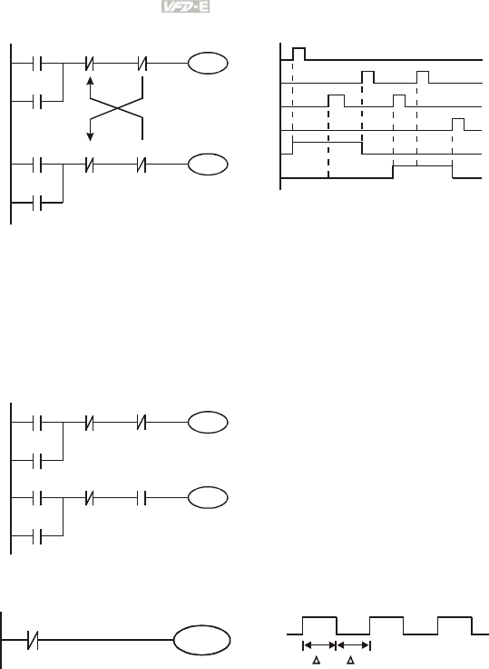
Appendix D How to Use PLC Function|
D-16 Revision June 2008, 04EE, SW--PW V1.11/CTL V2.11
Example 5: Interlock control
X3
Y1
X1
Y1
X4
Y2
X2
Y2
Y1
Y2
X1
X3
X2
X4
Y1
Y2
The figure above is the circuit of interlock control. Y1 and Y2 will act according to the start
contact X1 and X2. Y1 and Y2 will act not at the same time, once one of them acts and the
other won’t act. (This is called interlock.) Even if X1 and X2 are valid at the same time, Y1 and
Y2 won’t act at the same time due to up-to-down scan of ladder diagram. For this ladder
diagram, Y1 has higher priority than Y2.
Example 6: Sequential Control
X3
Y1
X1
Y1
X4
Y2
X2
Y2
Y1
Y2
If add normally close contact Y2 into Y1
circuit to be an input for Y1 to do AND
function. (as shown in the left side) Y1 is an
input of Y2 and Y2 can stop Y1 after acting.
In this way, Y1 and Y2 can execute in
sequential.
Example 7: Oscillating Circuit
The period of oscillating circuit is ΔT+ΔT
Y1
Y1
Y1
T T
The figure above is a very simple ladder step diagram. When starting to scan Y1 normally
close contact, Y1 normally close contact is close due to the coil Y1 is OFF. Then it will scan
Y1 and the coil Y1 will be ON and output 1. In the next scan period to scan normally close
contact Y1, Y1 normally close contact will be open due to Y1 is ON. Finally, coil Y1 will be
OFF. The result of repeated scan, coil Y will output the vibrating pulse with cycle timeΔ
T(On)+ΔT(Off).
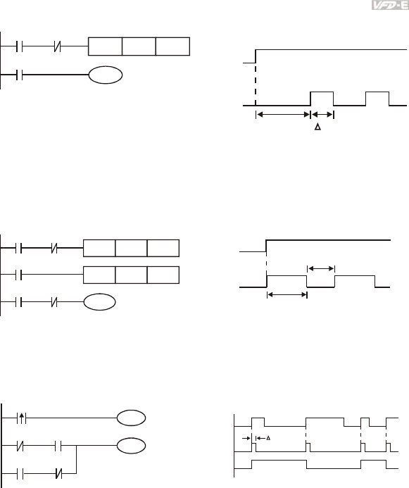
Appendix D How to Use PLC Function|
Revision June 2008, 04EE, SW--PW V1.11/CTL V2.11 D-17
The vibrating circuitry of cycle time ΔT(On)+ΔT(Off):
T0
X0
TMR
Y1
Y1
T0
Kn
Y1
TTn
X0
The figure above uses timer T0 to control coil Y1 to be ON. After Y1 is ON, timer T0 will be
closed at the next scan period and output Y1. The oscillating circuit will be shown as above. (n
is the setting of timer and it is decimal number. T is the base of timer. (clock period))
Example 8: Blinking Circuit
T2TMR Kn2
T1
X0
TMR
Y1
T2
T1
Kn1
X0 T1
Y1
T
n1
X0
Tn2
*
*
The figure above is common used oscillating circuit for indication light blinks or buzzer alarms. It
uses two timers to control On/OFF time of Y1 coil. If figure, n1 and n2 are timer setting of T1
and T2. T is the base of timer (clock period)
Example 9: Triggered Circuit
Y1
M0
X0
Y1
Y1
M0
M0
X0
M0
Y1
T
In figure above, the rising-edge differential command of X0 will make coil M0 to have a single
pulse of ΔT (a scan time). Y1 will be ON during this scan time. In the next scan time, coil M0
will be OFF, normally close M0 and normally close Y1 are all closed. However, coil Y1 will keep
on being ON and it will make coil Y1 to be OFF once a rising-edge comes after input X0 and coil
M0 is ON for a scan time. The timing chart is as shown above. This circuit usually executes
alternate two actions with an input. From above timing: when input X0 is a square wave of a
period T, output coil Y1 is square wave of a period 2T.
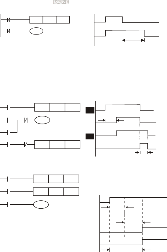
Appendix D How to Use PLC Function|
D-18 Revision June 2008, 04EE, SW--PW V1.11/CTL V2.11
Example 10: Delay Circuit
T10
X0
TMR
Y1
T10
K1000
TB = 0.1 sec
X0
Y1
100 seconds
When input X0 is ON, output coil Y1 will be ON at the same time due to the corresponding
normally close contact OFF makes timer T10 to be OFF. Output coil Y1 will be OFF after
delaying 100 seconds (K1000*0.1 seconds =100 seconds) once input X0 is OFF and T10 is
ON. Please refer to timing chart above.
Example 11: Output delay circuit, in the following example, the circuit is made up of two timers. No
matter input X0 is ON or OFF, output Y4 will be delay.
T5
T5
TMR
Y4
T6
X0
K50
Y4
T6
Y4
TMR
X0
K30
X0
T5
Y0
T6
5 seconds
3 seconds
Example12: Extend Timer Circuit
T12TMR Kn2
T11
X0
TMR
Y1
T11
Kn1
T12
In this circuit, the total delay time from input
X0 is close and output Y1 is ON= (n1+n2)* T.
where T is clock period.
X0
Y1
T11
T12
n1*
n2*
T
T
(n1+n2)* T

Appendix D How to Use PLC Function|
Revision June 2008, 04EE, SW--PW V1.11/CTL V2.11 D-19
D.4 PLC Devices
D.4.1 Summary of DVP-PLC Device Number
Items Specifications Remarks
Control Method Stored program, cyclic scan
system
I/O Processing Method Batch processing (when END
instruction is executed)
I/O refresh instruction is
available
Execution Speed Basic commands (minimum
0.24 us)
Application commands
(10 ~ hundreds us)
Program Language Instruction, Ladder Logic, SFC Including the Step
commands
Program Capacity 500 STEPS SRAM + Battery
Commands 45 commands
28 basic commands
17 application
commands
Input/Output Contact Input (X): 6, output (Y): 2
X External Input Relay X0~X17, 16 points,
octal number system
Correspond to external
input point
Y External Output Relay Y0~Y17, 16 points,
octal number system
Total is
32
points Correspond to external
output point
For general M0~M159, 160
points
M Auxiliary
For special M1000~M1031, 32
points
Total is
192
points
Contacts can switch to
On/Off in program
T Timer 100ms timer T0~T15, 16 points
Total is
16
points
When the timer
indicated by TMR
command attains the
setting, the T contact
with the same number
will be On.
16-bit count up for
general C0~C7, 8 points Total is
8 points
1-phase input
1-phase 2
inputs
Relay bit mode
C Counter
32-bit
count
up/down
high-
speed
counter 2-phase 2
inputs
C235, 1 point (need
to use with PG card)
Total is
1 point
When the counter
indicated by CNT
command attains the
setting, the C contact
with the same number
will be On.
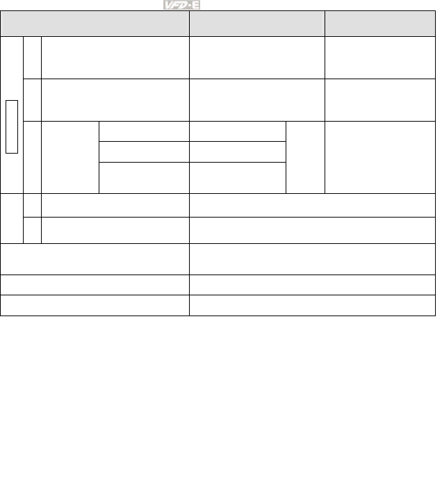
Appendix D How to Use PLC Function|
D-20 Revision June 2008, 04EE, SW--PW V1.11/CTL V2.11
Items Specifications Remarks
T Present value of timer T0~T15, 16 points
When timer attains, the
contact of timer will be
On.
C Present value of counter C0~C7, 8-bit counter, 8 points
When timer attains, the
contact of timer will be
On.
For latched D0~D9, 10 points
For general D10~D29, 20 points
Register WORD data
D Data
register
For special D1000~D1044, 45
points
Total is
75
points
It can be memory area
for storing data.
K Decimal K-32,768 ~ K32,767 (16-bit operation)
Constant
H Hexadecimal H0000 ~ HFFFF (16-bit operation)
Communication port (for read/write
program) RS485 (slave)
Analog input/output Built-in 2 analog inputs and 1 analog output
Function extension module (optional) Digital input/output card (A/D, D/A card)
D.4.2 Devices Functions
The Function of Input/output Contacts
The function of input contact X: input contact X reads input signal and enter PLC by
connecting with input equipment. It is unlimited usage times for A contact or B contact of
each input contact X in program. The On/Off of input contact X can be changed with the
On/Off of input equipment but can’t be changed by using peripheral equipment (WPLSoft).
The Function of Output Contact Y
The mission of output contact Y is to drive the load that connects to output contact Y by
sending On/Off signal. There are two kinds of output contact: one is relay and the other is
transistor. It is unlimited usage times for A or B contact of each output contact Y in program.
But there is number for output coil Y and it is recommended to use one time in program.
Otherwise, the output result will be decided by the circuit of last output Y with PLC program
scan method.
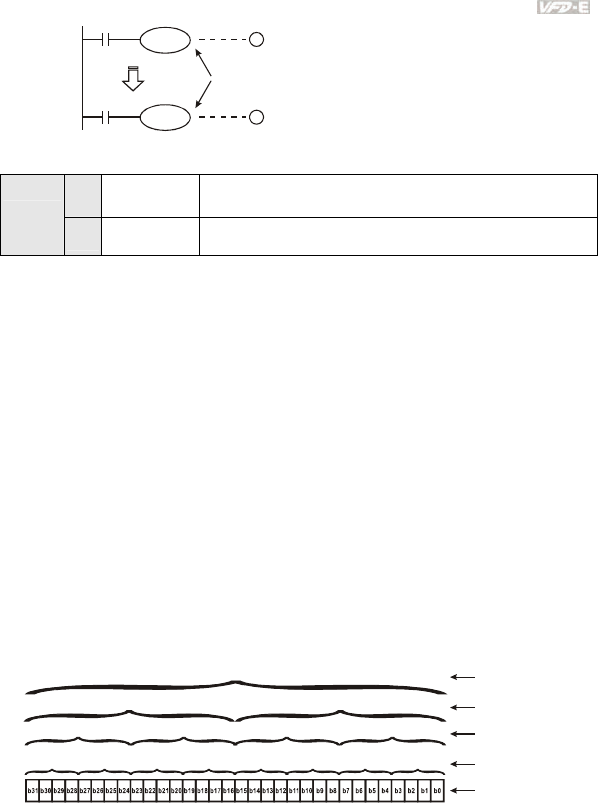
Appendix D How to Use PLC Function|
Revision June 2008, 04EE, SW--PW V1.11/CTL V2.11 D-21
X0
X10
Y0
Y0
1
2
Y0 is repeated
The output of Y0 will be decided by circuit
○
2, i.e. decided by On/Off of X10.
D.4.3 Value, Constant [K] / [H]
K Decimal K-32,768 ~ K32,767 (16-bit operation)
Constant
H Hexadecimal H0000 ~ HFFFF (16-bit operation)
There are five value types for DVP-PLC to use by the different control destination. The
following is the explanation of value types.
1. Binary Number (BIN)
It uses binary system for the PLC internal operation or storage. The relative information of
binary system is in the following.
Bit : Bit is the basic unit of binary system, the status are 1 or 0.
Nibble : It is made up of continuous 4 bits, such as b3~b0. It can be used to represent
number 0~9 of decimal or 0~F of hexadecimal.
Byte : It is made up of continuous 2 nibbles, i.e. 8 bits, b7~b0. It can used to represent
00~FF of hexadecimal system.
Word : It is made up of continuous 2 bytes, i.e. 16 bits, b15~b0. It can used to represent
0000~FFFF of hexadecimal system.
Double
Word
: It is made up of continuous 2 words, i.e. 32 bits, b31~b0. It can used to
represent 00000000~FFFFFFFF of hexadecimal system.
The relations among bit, nibble, byte, word, and double word of binary number are shown as
follows.
NB0NB1NB2NB3NB4NB5NB6NB7
BY3 BY2 BY1 BY0
W1
DW
W0
Double Word
Word
Byte
Nibble
Bit
2. Octal Number (OCT)
The numbers of external input and output terminal of DVP-PLC use octal number.
Example:
External input: X0~X7, X10~X17…(device number)

Appendix D How to Use PLC Function|
D-22 Revision June 2008, 04EE, SW--PW V1.11/CTL V2.11
External output: Y0~Y7, Y10~Y17…(device number)
3. Decimal Number (DEC)
The suitable time for decimal number to use in DVP-PLC system.
To be the setting value of timer T or counter C, such as TMR C0 K50. (K constant)
To be the device number of M, T, C and D. For example: M10, T30. (device number)
To be operand in application command, such as MOV K123 D0. (K constant)
4. BCD (Binary Code Decimal, BCD)
It shows a decimal number by a unit number or four bits so continuous 16 bits can use to
represent the four numbers of decimal number. BCD code is usually used to read the input
value of DIP switch or output value to 7-segment display to be display.
5. Hexadecimal Number (HEX)
The suitable time for hexadecimal number to use in DVP-PLC system.
To be operand in application command. For example: MOV H1A2B D0. (constant H)
Constant K:
In PLC, it is usually have K before constant to mean decimal number. For example, K100
means 100 in decimal number.
Exception:
The value that is made up of K and bit equipment X, Y, M, S will be bit, byte, word or
double word. For example, K2Y10, K4M100. K1 means a 4-bit data and K2~K4 can
be 8, 12 and 16-bit data separately.
Constant H:
In PLC, it is usually have H before constant to mean hexadecimal number. For example,
H100 means 100 in hexadecimal number.
D.4.4 The Function of Auxiliary Relay
There are output coil and A, B contacts in auxiliary relay M and output relay Y. It is unlimited
usage times in program. User can control loop by using auxiliary relay, but can’t drive
external load directly. There are two types divided by its characteristics.
1. Auxiliary relay for general : It will reset to Off when power loss during running. Its state will
be Off when power on after power loss.
2. Auxiliary relay for special : Each special auxiliary relay has its special function. Please
don’t use undefined auxiliary relay.
D.4.5 The Function of Timer
The unit of timer is 1ms, 10ms and 100ms. The count method is count up. The output coil
will be On when the present value of timer equals to the settings. The setting is K in decimal
number. Data register D can be also used as settings.
The real setting time of timer = unit of timer * settings

Appendix D How to Use PLC Function|
Revision June 2008, 04EE, SW--PW V1.11/CTL V2.11 D-23
D.4.6 The Features and Functions of Counter
Features:
Item 16 bits counters 32 bits counters
Type General General High speed
Count direction Count up Count up/down
Settings 0~32,767 -2,147,483,648~+2,147,483,647
Designate for
constant Constant K or data register D Constant K or data register D (2 for designated)
Present value
change
Counter will stop when
attaining settings
Counter will keep on counting when attaining
settings
Output contact
When count attains settings,
contact will be On and
latched.
When count up attains settings, contact will be On
and latched.
When count down attains settings, contact will
reset to Off.
Reset action The present value will reset to 0 when RST command is executed and contact
will reset to Off.
Present register 16 bits 32 bits
Contact action After scanning, act together. After scanning,
act together.
Act immediately when count
attains. It has no relation with
scan period.
Functions:
When pulse input signal of counter is from Off to On, the present value of counter equals to settings
and output coil is On. Settings are decimal system and data register D can also be used as settings.
16-bit counters C0~C7:
1. Setting range of 16-bit counter is K0~K32,767. (K0 is the same as K1. output contact will
be On immediately at the first count.
2. General counter will be clear when PLC is power loss. If counter is latched, it will
remember the value before power loss and keep on counting when power on after power
loss.
3. If using MOV command, WPLSoft to send a value, which is large than setting to C0,
register, at the next time that X1 is from Off to On, C0 counter contact will be On and
present value will be set to the same as settings.
4. The setting of counter can use constant K or register D (not includes special data register
D1000~D1044) to be indirect setting.
5. If using constant K to be setting, it can only be positive number but if setting is data
register D, it can be positive/negative number. The next number that counter counts up
from 32,767 is -32,768.
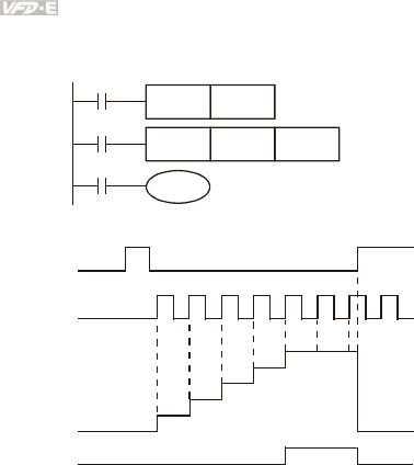
Appendix D How to Use PLC Function|
D-24 Revision June 2008, 04EE, SW--PW V1.11/CTL V2.11
Example:
LD X0
RST C0
LD X1
CNT C0 K5
LD C0
OUT Y0
C0
Y0
X1
C0 K5CNT
X0
C0RST
1. When X0=On, RST command is
executed, C0 reset to 0 and
output contact reset to Off.
2. When X1 is from Off to On,
counter will count up (add 1).
3. When counter C0 attains settings
K5, C0 contact is On and C0 =
setting =K5. C0 won’t accept X1
trigger signal and C0 remains
K5.
X0
X1
0
1
2
3
4
5
0
Contacts Y0, C0
C0
present
value
settings
32-bit high-speed addition/subtraction counter C235:
1. Setting range of 32-bit high-speed addition/subtraction counter is :
K-2,147,483,648~K2,147,483,647.
2. The settings can be positive / negative numbers by using constant K or data register D
(special data register D1000~D1044 is not included). If using data register D, the setting
will occupy two continuous data register.
The total band width of high-speed counter that VFD-E supports is up to 30kHz and 500kHz for pulse
input.
D.4.7 Register Types
There are two types of register which sorts by characters in the following:
1. General
register
: The data in register will be cleared to 0 when PLC switches from RUN
to STOP or power is off.
2. Special
register
: Each special register has the special definition and purpose. It is used
to save system status, error messages, monitor state.

Appendix D How to Use PLC Function|
Revision June 2008, 04EE, SW--PW V1.11/CTL V2.11 D-25
D.4.8 Special Auxiliary Relays
Special
M Function Read(R)/
Write(W)
M1000 Normally open contact (a contact). This contact is On when running and it is
On when the status is set to RUN. R
M1001 Normally closed contact (b contact). This contact is Off in running and it is Off
when the status is set to RUN. R
M1002 On only for 1 scan after RUN. Initial pulse is contact a. It will get positive
pulse in the RUN moment. Pulse width=scan period. R
M1003 Off only for 1 scan after RUN. Initial pulse is contact a. It will get negative
pulse in the RUN moment. Pulse width=scan period. R
M1004 Reserved --
M1005 Fault indication of the AC motor drives R
M1006 Output frequency is 0 R
M1007 The operation direction of AC motor drives (FWD: 0, REV: 1) R
M1008 Reserved --
M1009 Reserved --
M1010 Reserved --
M1011 10ms clock pulse, 5ms On/5ms Off R
M1012 100ms clock pulse, 50ms On / 50ms Off R
M1013 1s clock pulse, 0.5s On / 0.5s Off R
M1014 1min clock pulse, 30s On / 30s Off R
M1015 Frequency attained R
M1016 Parameter read/write error R
M1017 Succeed to write parameter R
M1018 Enable high-speed counter function (When M1028=On) R
M1019 Reserved R
M1020 Zero flag R
M1021 Borrow flag R
M1022 Carry flag R
M1023 Divisor is 0 R
M1024 Reserved --
M1025 RUN(ON) / STOP(OFF) the AC motor drive R/W

Appendix D How to Use PLC Function|
D-26 Revision June 2008, 04EE, SW--PW V1.11/CTL V2.11
Special
M Function Read(R)/
Write(W)
M1026 The operation direction of the AC motor drive (FWD: OFF, REV: ON) R/W
M1027 Reserved --
M1028 Enable(ON)/disable(OFF) high-speed counter function R/W
M1029 Clear the value of high-speed counter R/W
M1030 Decide to count up(OFF)/count down(ON) R/W
M1031 Reserved --
D.4.9 Special Registers
Special D Function Read(R)/ Write(W)
D1000 Reserved --
D1001 PLC firmware version R
D1002 Program capacity R
D1003 Checksum R
D1004-
D1009 Reserved --
D1010 Present scan time (Unit: 0.1ms) R
D1011 Minimum scan time (Unit: 0.1ms) R
D1012 Maximum scan time (Unit: 0.1ms) R
D1013-
D1019 Reserved --
D1020 Output frequency R
D1021 Output current R
D1022
The ID of the extension card:
02 USB Card
03 12-Bit A/D (2CH) 12-Bit D/A (2CH)
04 Relay Card-2C
05 Relay Card-3A
06 3IN/3OUT Card
07 PG Card
R
D1023-
D1024 Reserved --

Appendix D How to Use PLC Function|
Revision June 2008, 04EE, SW--PW V1.11/CTL V2.11 D-27
Special D Function Read(R)/ Write(W)
D1025 The present value of the high-speed counter C235 (low byte) R
D1026 The present value of the high-speed counter C235 (high byte) R
D1027 Frequency command of the PID control R
D1028 The value of AVI (analog voltage input) 0-10V corresponds to 0-
1023 R
D1029
The value of ACI (analog current input) 4-20mA corresponds to 0-
1023 or the value of AVI2 (analog voltage input) 0-10V
corresponds to 0-1023
R
D1030 The value of V.R digital keypad 0-10V corresponds to 0-1023 R
D1031-
D1035 Reserved --
D1036 PLC error code R
D1037-
D1039 Reserved --
D1040 Analog output value R/W
D1041-
D1042 Reserved --
D1043 User defined (when Pr.00.04 is set to 2, the register data will be
displayed as C xxx) R/W
D1044 High-speed counter mode R/W
D.4.10 Communication Addresses for Devices (only for PLC2 mode)
Device Range Type Address (Hex)
X 00–17 (octal) Bit 0400-040F
Y 00–17 (octal) Bit 0500-050F
T 00-15 Bit/word 0600-060F
M 000-159 Bit 0800-089F
M 1000-1031 Bit 0BE8-0C07
C 0-7 Bit/word 0E00-0E07
D 00-63 Word 1000-101D
D 1000-1044 Word 13E8-1414

Appendix D How to Use PLC Function|
D-28 Revision June 2008, 04EE, SW--PW V1.11/CTL V2.11
NOTE: when it is in PLC1 mode, the communication address will correspond to the parameter NOT
the device. For example, address 0400H will correspond to Pr.04.00 NOT X0.
D.4.11 Function Code (only for PLC2 mode)
Function Code Description Supported Devices
01 Read coil status Y, M, T, C
02 Read input status X, Y, M, T, C
03 Read one data T, C, D
05 Force changing one coil status Y, M, T, C
06 Write in one data T, C, D
0F Force changing multiple coil status Y, M, T, C
10 Write in multiple data T, C, D
D.5 Commands
D.5.1 Basic Commands
Commands Function Operands
LD Load contact A X, Y, M, T, C
LDI Load contact B X, Y, M, T, C
AND Series connection with A contact X, Y, M, T, C
ANI Series connection with B contact X, Y, M, T, C
OR Parallel connection with A contact X, Y, M, T, C
ORI Parallel connection with B contact X, Y, M, T, C
ANB Series connects the circuit block --
ORB Parallel connects the circuit block --
MPS Save the operation result --
MRD Read the operation result (the pointer not moving) --
MPP Read the result --
INV Inverter the result --

Appendix D How to Use PLC Function|
Revision June 2008, 04EE, SW--PW V1.11/CTL V2.11 D-29
D.5.2 Output Commands
Commands Function Operands
OUT Drive coil Y, M
SET Action latched (ON) Y, M
RST Clear the contacts or the registers Y, M, T, C, D
D.5.3 Timer and Counters
Commands Function Operands
TMR 16-bit timer T-K or T-D
CNT 16-bit counter C-K or C-D
D.5.4 Main Control Commands
Commands Function Operands
MC Connect the common series connection
contacts N0~N7
MCR Disconnect the common series connection
contacts N0~N7
D.5.5 Rising-edge/falling-edge Detection Commands of Contact
Commands Function Operands
LDP Rising-edge detection operation starts X, Y, M, T, C
LDF Falling-edge detection operation starts X, Y, M, T, C
ANDP Rising-edge detection series connection X, Y, M, T, C
ANDF Falling-edge detection series connection X, Y, M, T, C
ORP Rising-edge detection parallel connection X, Y, M, T, C
ORF Falling-edge detection parallel connection X, Y, M, T, C
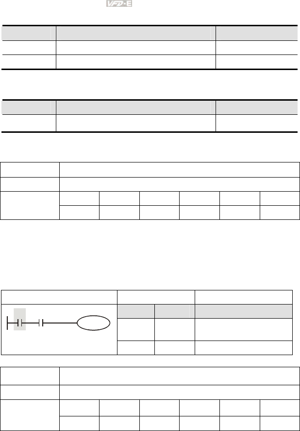
Appendix D How to Use PLC Function|
D-30 Revision June 2008, 04EE, SW--PW V1.11/CTL V2.11
D.5.6 Rising-edge/falling-edge Output Commands
Commands Function Operands
PLS Rising-edge output Y, M
PLF Falling-edge output Y, M
D.5.7 End Command
Command Function Operands
END Program end none
D.5.8 Explanation for the Commands
Mnemonic Function
LD Load A contact
X0~X17 Y0~Y17 M0~M159 T0~15 C0~C7 D0~D29
Operand
9 9 9 9 9 --
Explanations:
The LD command is used on the A contact that has its start from the left BUS or the A contact that is
the start of a contact circuit. Function of the command is to save present contents, and at the same
time, save the acquired contact status into the accumulative register.
Program Example:
Ladder diagram Command code Operation
LD X0 Load contact A of X0
AND X1 Connect to contact A of X1
in series
X0 X1
Y1
OUT Y1 Drive Y1 coil
Mnemonic Function
LDI Load B contact
X0~X17 Y0~Y17 M0~M159 T0~15 C0~C7 D0~D29
Operand
9 9 9 9 9 --
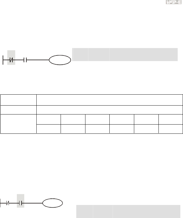
Appendix D How to Use PLC Function|
Revision June 2008, 04EE, SW--PW V1.11/CTL V2.11 D-31
Explanations:
The LDI command is used on the B contact that has its start from the left BUS or the B contact that is
the start of a contact circuit. Function of the command is to save present contents, and at the same
time, save the acquired contact status into the accumulative register.
Program Example:
Ladder diagram: Command code: Operation:
LDI X0 Load contact B of X0
AND X1 Connect to contact A of X1 in series
X0 X1
Y1
OUT Y1 Drive Y1 coil
Mnemonic Function
AND Series connection- A contact
X0~X17 Y0~Y17 M0~M159 T0~15 C0~C7 D0~D29
Operand
9 9 9 9 9 --
Explanations:
The AND command is used in the series connection of A contact. The function of the command is to
readout the status of present specific series connection contacts first, and then to perform the “AND”
calculation with the logic calculation result before the contacts, thereafter, saving the result into the
accumulative register.
Program Example:
Ladder diagram: Command code: Operation:
LDI X1 Load contact B of X1
AND X0 Connect to contact A of X0 in series
X0X1
Y1
OUT Y1 Drive Y1 coil
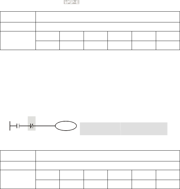
Appendix D How to Use PLC Function|
D-32 Revision June 2008, 04EE, SW--PW V1.11/CTL V2.11
Mnemonic Function
ANI Series connection- B contact
X0~X17 Y0~Y17 M0~M159 T0~15 C0~C7 D0~D29
Operand
9 9 9 9 9 --
Explanations:
The ANI command is used in the series connection of B contact. The function of the command is to
readout the status of present specific series connection contacts first, and then to perform the “AND”
calculation with the logic calculation result before the contacts, thereafter, saving the result into the
accumulative register.
Program Example:
Ladder diagram: Command code: Operation:
LD X1 Load contact A of X1
ANI X0 Connect to contact B of
X0 in series
X0X1
Y1
OUT Y1 Drive Y1 coil
Mnemonic Function
OR Parallel connection- A contact
X0~X17 Y0~Y17 M0~M159 T0~15 C0~C7 D0~D29
Operand
9 9 9 9 9 --
Explanations:
The OR command is used in the parallel connection of A contact. The function of the command is to
readout the status of present specific series connection contacts, and then to perform the “OR”
calculation with the logic calculation result before the contacts, thereafter, saving the result into the
accumulative register.
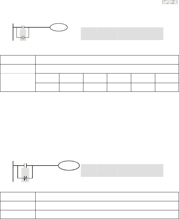
Appendix D How to Use PLC Function|
Revision June 2008, 04EE, SW--PW V1.11/CTL V2.11 D-33
Program Example:
Ladder diagram: Command code: Operation:
LD X0 Load contact A of X0
OR X1 Connect to contact A of
X1 in parallel
X0
X1
Y1
OUT Y1 Drive Y1 coil
Mnemonic Function
ORI Parallel connection- B contact
X0~X17 Y0~Y17 M0~M159 T0~15 C0~C7 D0~D29
Operand
9 9 9 9 9 --
Explanations:
The ORI command is used in the parallel connection of B contact. The function of the command is to
readout the status of present specific series connection contacts, and then to perform the “OR”
calculation with the logic calculation result before the contacts, thereafter, saving the result into the
accumulative register.
Program Example:
Ladder diagram: Command code: Operation:
LD X1 Load contact A of X0
ORI X1 Connect to contact B of
X1 in parallel
X0
X1
Y1
OUT Y1 Drive Y1 coil
Mnemonic Function
ANB Series connection (Multiple Circuits)
Operand None
Explanations:
To perform the “ANB” calculation between the previous reserved logic results and contents of the
accumulative register.
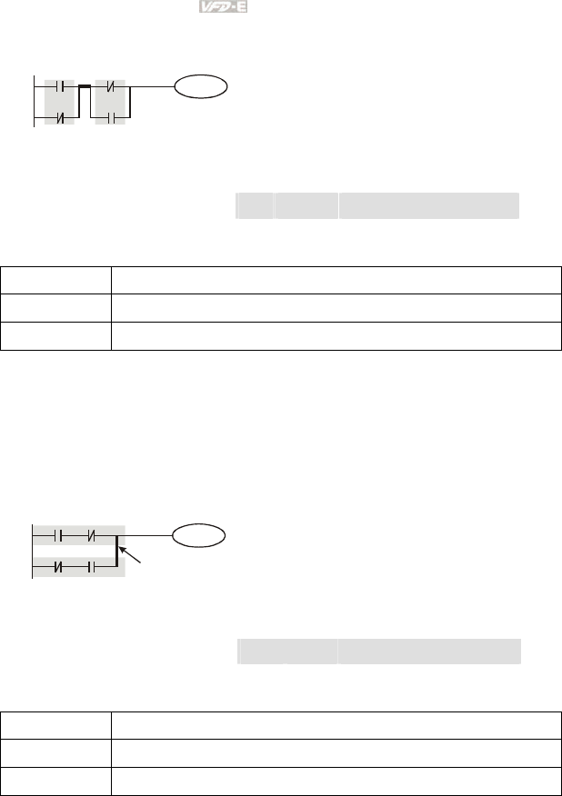
Appendix D How to Use PLC Function|
D-34 Revision June 2008, 04EE, SW--PW V1.11/CTL V2.11
Program Example:
Ladder diagram: Command code: Operation:
LD X0 Load contact A of X0
ORI X2 Connect to contact B of X2 in
parallel
LDI X1 Load contact B of X1
OR X3 Connect to contact A of X3 in
parallel
ANB Connect circuit block in series
X0
X2
Y1
X1
X3
ANB
Block A Block B
OUT Y1 Drive Y1 coil
Mnemonic Function
ORB Parallel connection (Multiple circuits)
Operand None
Explanations:
To perform the “OR” calculation between the previous reserved logic results and contents of the
accumulative register.
Program Example:
Ladder diagram: Command code: Operation:
LD X0 Load contact A of X0
ANI X1 Connect to contact B of X1 in
series
LDI X2 Load contact B of X2
AND X3 Connect to contact A of X3 in
series
ORB Connect circuit block in parallel
X0
X2
Y1
X1
X3
ORB
Block A
Block B
OUT Y1 Drive Y1 coil
Mnemonic Function
MPS Store the current result of the internal PLC operations
Operand None
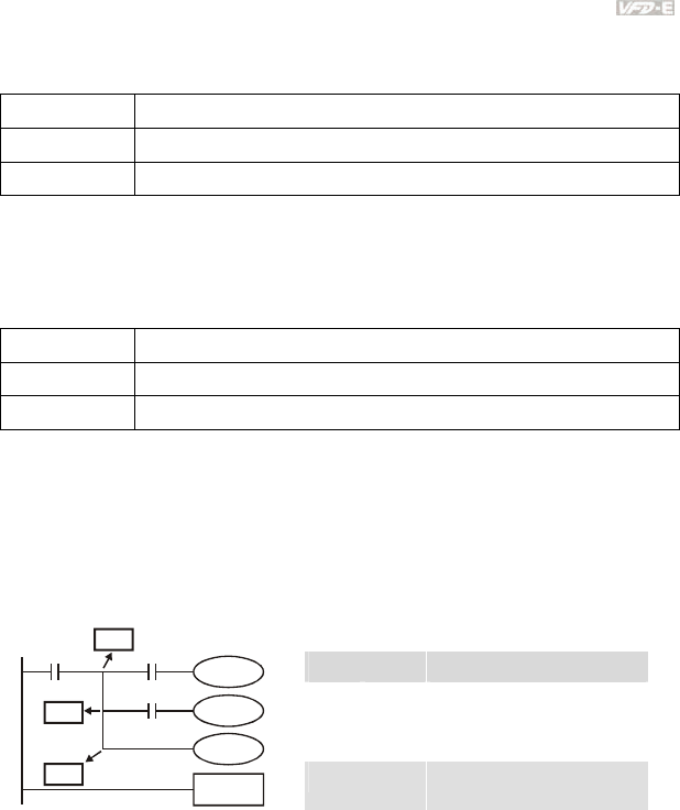
Appendix D How to Use PLC Function|
Revision June 2008, 04EE, SW--PW V1.11/CTL V2.11 D-35
Explanations:
To save contents of the accumulative register into the operation result. (the result operation pointer
pluses 1)
Mnemonic Function
MRD Reads the current result of the internal PLC operations
Operand None
Explanations:
Reading content of the operation result to the accumulative register. (the pointer of operation result
doesn’t move)
Mnemonic Function
MPP Reads the current result of the internal PLC operations
Operand None
Explanations:
Reading content of the operation result to the accumulative register. (the stack pointer will decrease
1)
Program Example:
Ladder diagram: Command code: Operation:
LD X0 Load contact A of X0
MPS Save in stack
AND X1 Connect to contact A of X1 in
series
OUT Y1 Drive Y1 coil
MRD Read from the stack (without
moving pointer)
AND X2 Connect to contact A of X2 in
series
OUT M0 Drive M0 coil
MPP Read from the stack
OUT Y2 Drive Y2 coil
X0
Y1
X1
M0
X2
Y2
END
MPP
MRD
MPS
END End program
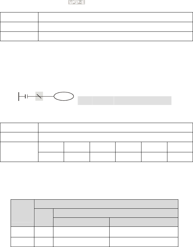
Appendix D How to Use PLC Function|
D-36 Revision June 2008, 04EE, SW--PW V1.11/CTL V2.11
Mnemonic Function
INV Inverting Operation
Operand None
Explanations:
Inverting the operation result and use the new data as an operation result.
Program Example:
Ladder diagram: Command code: Operation:
LD X0 Load A contact of X0
INV Inverting the operation result
X0
Y1
OUT Y1 Drive Y1 coil
Mnemonic Function
OUT Output coil
X0~X17 Y0~Y17 M0~M159 T0~15 C0~C7 D0~D29
Operand
-- 9 9 -- -- --
Explanations:
Output the logic calculation result before the OUT command to specific device.
Motion of coil contact
OUT command
Contact
Operation
result Coil
A contact (normally open) B contact (normally closed)
FALSE OFF Non-continuity Continuity
TRUE ON Continuity Non-continuity
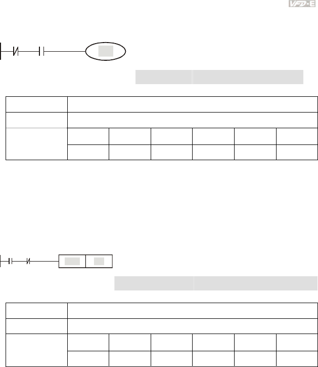
Appendix D How to Use PLC Function|
Revision June 2008, 04EE, SW--PW V1.11/CTL V2.11 D-37
Program Example:
Ladder diagram: Command code: Operation:
LDI X0 Load contact B of X0
AND X1 Connect to contact A of X1 in
series
X0 X1
Y1
OUT Y1 Drive Y1 coil
Mnemonic Function
SET Latch (ON)
X0~X17 Y0~Y17 M0~M159 T0~15 C0~C7 D0~D29
Operand
-- 9 9 -- -- --
Explanations:
When the SET command is driven, its specific device is set to be “ON,” which will keep “ON” whether
the SET command is still driven. You can use the RST command to set the device to “OFF”.
Program Example:
Ladder diagram: Command code: Operation:
LD X0 Load contact A of X0
ANI Y0 Connect to contact B of Y0 in series
X0 Y0
Y1
SET
SET Y1 Y1 latch (ON)
Mnemonic Function
RST Clear the contacts or the registers
X0~X17 Y0~Y17 M0~M159 T0~15 C0~C7 D0~D29
Operand
-- 9 9 9 9 --
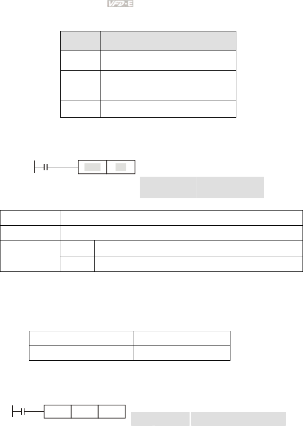
Appendix D How to Use PLC Function|
D-38 Revision June 2008, 04EE, SW--PW V1.11/CTL V2.11
Explanations:
When the RST command is driven, motion of its specific device is as follows:
Device Status
Y, M Coil and contact will be set to “OFF”.
T, C
Present values of the timer or counter
will be set to 0, and the coil and contact
will be set to “OFF.”
D The content value will be set to 0.
Program Example:
Ladder diagram: Command code: Operation:
LD X0 Load contact A of X0
X0
Y5
RST
RST Y5 Clear contact Y5
Mnemonic Function
TMR 16-bit timer
T-K T0~T15, K0~K32,767
Operand
T-D T0~T15, D0~D29
Explanations:
When TMR command is executed, the specific coil of timer is ON and timer will start to count. When
the setting value of timer is attained (counting value >= setting value), the contact will be as following:
NO(Normally Open) contact Open collector
NC(Normally Closed) contact Close collector
Program Example:
Ladder diagram: Command code: Operation:
LD X0 Load contact A of X0 T5 timer
X0
T5TMR K1000
TMR T5 K1000 Setting is K1000
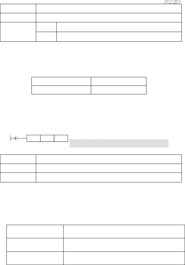
Appendix D How to Use PLC Function|
Revision June 2008, 04EE, SW--PW V1.11/CTL V2.11 D-39
Mnemonic Function
CNT 16-bit counter
C-K C0~C7, K0~K32,767
Operand
C-D C0~C7, D0~D29
Explanations:
1. When the CNT command is executed from OFFÆON, which means that the counter coil
is driven, and 1 should thus be added to the counter’s value; when the counter achieved
specific set value (value of counter = the setting value), motion of the contact is as follows:
NO(Normally Open) contact Continuity
NC(Normally Closed) contact Non-continuity
2. If there is counting pulse input after counting is attained, the contacts and the counting
values will be unchanged. To re-count or to conduct the CLEAR motion, please use the
RST command.
Program Example:
Ladder diagram: Command code: Operation:
LD X0 Load contact A of X0 C2 counter
X0
C20CNT K100
CNT C2 K100 Setting is K100
Mnemonic Function
MC / MCR Master control Start/Reset
Operand N0~N7
Explanations:
1. MC is the main-control start command. When the MC command is executed, the
execution of commands between MC and MCR will not be interrupted. When MC
command is OFF, the motion of the commands that between MC and MCR is described
as follows:
Timer The counting value is set back to zero, the coil and the contact
are both turned OFF
Accumulative timer The coil is OFF, and the timer value and the contact stay at their
present condition
Subroutine timer The counting value is back to zero. Both coil and contact are
turned OFF.
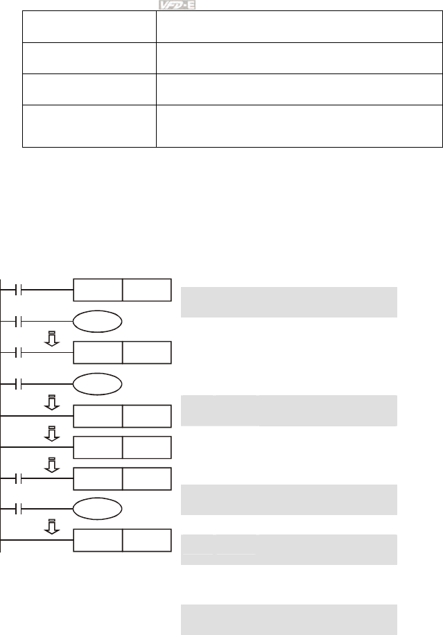
Appendix D How to Use PLC Function|
D-40 Revision June 2008, 04EE, SW--PW V1.11/CTL V2.11
Counter The coil is OFF, and the counting value and the contact stay at
their present condition
Coils driven up by the OUT
command All turned OFF
Devices driven up by the
SET and RST commands Stay at present condition
Application commands
All of them are not acted , but the nest loop FOR-NEXT
command will still be executed for times defined by users even
though the MC-MCR commands is OFF.
2. MCR is the main-control ending command that is placed at the end of the main-control
program and there should not be any contact commands prior to the MCR command.
3. Commands of the MC-MCR main-control program supports the nest program structure,
with 8 layers as its greatest. Please use the commands in order from N0~ N7, and refer to
the following:
Program Example:
Ladder diagram: Command code: Operation:
LD X0 Load A contact of X0
MC N0 Enable N0 common series
connection contact
LD X1 Load A contact of X1
OUT Y0 Drive Y0 coil
:
LD X2 Load A contact of X2
MC N1 Enable N1 common series
connection contact
LD X3 Load A contact of X3
OUT Y1 Drive Y1 coil
:
MCR N1 Disable N1 common series
connection contact
:
MCR N0 Disable N0 common series
connection contact
:
LD X10 Load A contact of X10
X0
Y0
MC N0
X1
X2
Y1
MC N1
X3
MCR N1
MCR N0
X10
MC N0
Y10
X11
MCR N0
MC N0 Enable N0 common series
connection contact
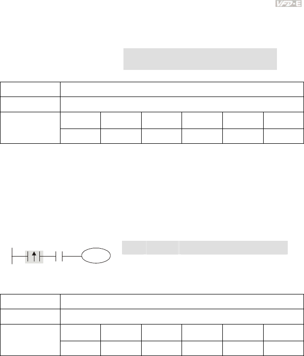
Appendix D How to Use PLC Function|
Revision June 2008, 04EE, SW--PW V1.11/CTL V2.11 D-41
LD X11 Load A contact of X11
OUT Y10 Drive Y10 coil
:
MCR N0 Disable N0 common series
connection contact
Mnemonic Function
LDP Rising-edge detection operation
X0~X17 Y0~Y17 M0~M159 T0~15 C0~C7 D0~D29
Operand
9 9 9 9 9 --
Explanations:
Usage of the LDP command is the same as the LD command, but the motion is different. It is used to
reserve present contents and at the same time, saving the detection status of the acquired contact
rising-edge into the accumulative register.
Program Example:
Ladder diagram: Command code: Operation:
LDP X0 Start X0 rising-edge detection
AND X1 Series connection A contact of X1
X1
Y1
X0
OUT Y1 Drive Y1 coil
Mnemonic Function
LDF Falling-edge detection operation
X0~X17 Y0~Y17 M0~M159 T0~15 C0~C7 D0~D29
Operand
9 9 9 9 9 --
Explanations:
Usage of the LDF command is the same as the LD command, but the motion is different. It is used to
reserve present contents and at the same time, saving the detection status of the acquired contact
falling-edge into the accumulative register.
Program Example:
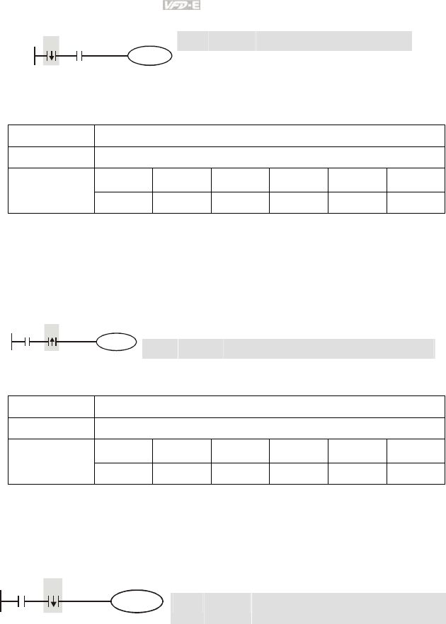
Appendix D How to Use PLC Function|
D-42 Revision June 2008, 04EE, SW--PW V1.11/CTL V2.11
Ladder diagram: Command code: Operation:
LDF X0 Start X0 falling-edge detection
AND X1 Series connection A contact of X1
X0 X1
Y1
OUT Y1 Drive Y1 coil
Mnemonic Function
ANDP Rising-edge series connection
X0~X17 Y0~Y17 M0~M159 T0~15 C0~C7 D0~D29
Operand
9 9 9 9 9 --
Explanations:
ANDP command is used in the series connection of the contacts’ rising-edge detection.
Program Example:
Ladder diagram: Command code: Operation:
LD X0 Load A contact of X0
ANDP X1 X1 rising-edge detection in series connection
X1X0
Y1
OUT Y1 Drive Y1 coil
Mnemonic Function
ANDF Falling-edge series connection
X0~X17 Y0~Y17 M0~M159 T0~15 C0~C7 D0~D29
Operand
9 9 9 9 9 --
Explanations:
ANDF command is used in the series connection of the contacts’ falling-edge detection.
Program Example:
Ladder diagram: Command code: Operation:
LD X0 Load A contact of X0
ANDF X1 X1 falling-edge detection in series
connection
X1X0
Y1
OUT Y1 Drive Y1 coil
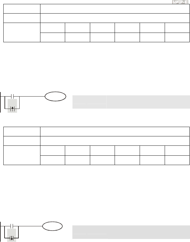
Appendix D How to Use PLC Function|
Revision June 2008, 04EE, SW--PW V1.11/CTL V2.11 D-43
Mnemonic Function
ORP Rising-edge parallel connection
X0~X17 Y0~Y17 M0~M159 T0~15 C0~C7 D0~D29
Operand
9 9 9 9 9 --
Explanations:
The ORP commands are used in the parallel connection of the contact’s rising-edge detection.
Program Example:
Ladder diagram: Command code: Operation:
LD X0 Load A contact of X0
ORP X1 X1 rising-edge detection in parallel
connection
X0
X1
Y1
OUT Y1 Drive Y1 coil
Mnemonic Function
ORF Falling-edge parallel connection
X0~X17 Y0~Y17 M0~M159 T0~15 C0~C7 D0~D29
Operand
9 9 9 9 9 --
Explanations:
The ORP commands are used in the parallel connection of the contact’s falling-edge detection.
Program Example:
Ladder diagram: Command code: Operation:
LD X0 Load A contact of X0
ORF X1 X1 falling-edge detection in parallel
connection
X0
X1
Y1
OUT Y1 Drive Y1 coil
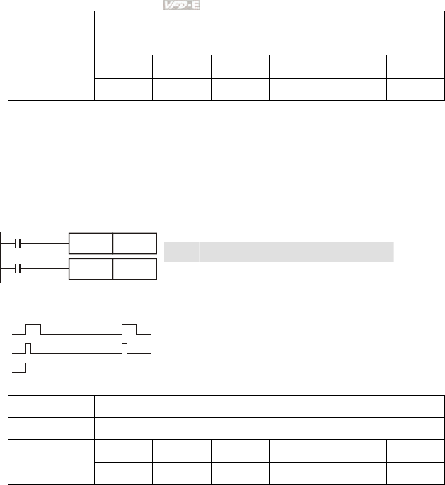
Appendix D How to Use PLC Function|
D-44 Revision June 2008, 04EE, SW--PW V1.11/CTL V2.11
Mnemonic Function
PLS Rising-edge output
X0~X17 Y0~Y17 M0~M159 T0~15 C0~C7 D0~D29
Operand
-- 9 9 -- -- --
Explanations:
When X0=OFF→ON (rising-edge trigger), PLS command will be executed and M0 will send the
pulse of one time which the length is a scan time.
Program Example:
Ladder diagram: Command code: Operation:
LD X0 Load A contact of X0
PLS M0 M0 rising-edge output
LD M0 Load the contact A of M0
X0
M0
PLS
M0
Y0SET
Timing Diagram:
X0
M0
Y0
a scan time
SET Y0 Y0 latched (ON)
Mnemonic Function
PLF Falling-edge output
X0~X17 Y0~Y17 M0~M159 T0~15 C0~C7 D0~D29
Operand
-- 9 9 -- -- --
Explanations:
When X0= ON→OFF (falling-edge trigger), PLF command will be executed and M0 will send the
pulse of one time which the length is the time for scan one time.
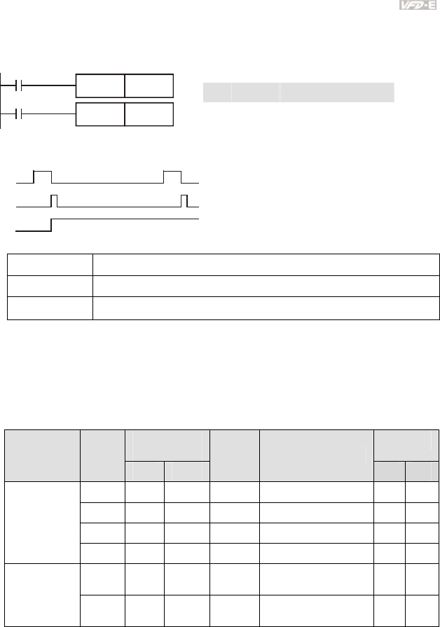
Appendix D How to Use PLC Function|
Revision June 2008, 04EE, SW--PW V1.11/CTL V2.11 D-45
Program Example:
Ladder diagram: Command code: Operation:
LD X0 Load A contact of X0
PLF M0 M0 falling-edge output
LD M0 Load the contact A of M0
X0
M0
PLF
M0
Y0SET
Timing Diagram:
a scan time
X0
M0
Y0
SET Y0 Y0 latched (ON)
Mnemonic Function
END Program End
Operand None
Explanations:
It needs to add the END command at the end of ladder diagram program or command program. PLC
will scan from address o to END command, after executing it will return to address 0 to scan again.
D.5.9 Description of the Application Commands
Mnemonic
Codes
Steps
API
16 bits 32 bits
P
Command Function
16-bit 32-bit
10 CMP -- Compare 7 --
11 ZCP -- Zone compare 9 --
12 MOV -- Data Move 5 --
Transmission
Comparison
15 BMOV -- Block move 7 --
20 ADD -- Perform the addition of
BIN data
7 --
Four
Fundamental
Operations of
Arithmetic 21 SUB -- Perform the subtraction
of BIN data
7 --
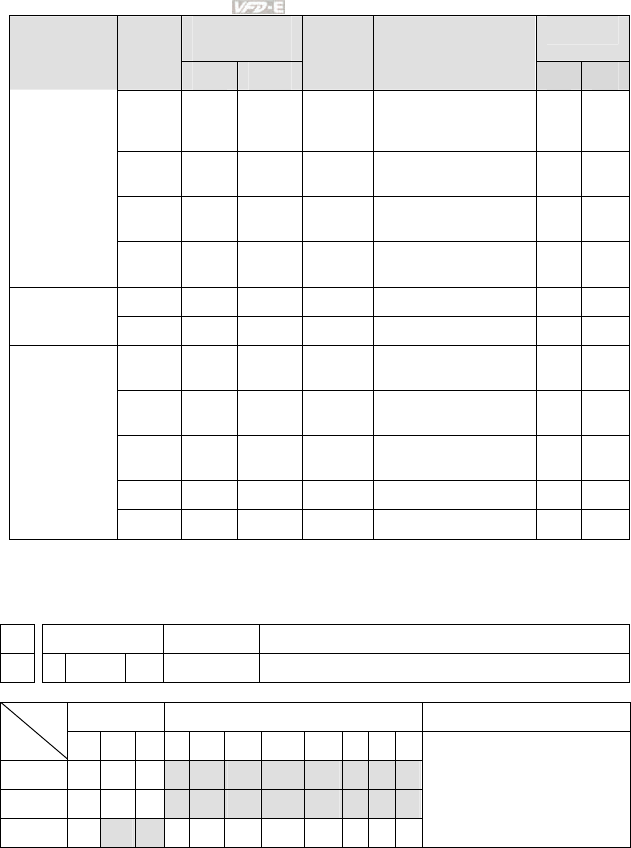
Appendix D How to Use PLC Function|
D-46 Revision June 2008, 04EE, SW--PW V1.11/CTL V2.11
Mnemonic
Codes
Steps
API
16 bits 32 bits
P
Command Function
16-bit 32-bit
22 MUL --
Perform the
multiplication of BIN
data
7 --
23 DIV -- Perform the division of
BIN data
7 --
24 INC -- Perform the addition of
1
3 --
25 DEC -- Perform the subtraction
of 1
3 --
30 ROR -- Rotate to the right 5 --
Rotation and
Displacement 31 ROL -- Rotate to the left 5 --
53 -- DHSCS X
High speed counter
enable
-- 13
139 FPID -- Control PID parameters
of inverter
5 --
140 FREQ -- Control frequency of
inverter
5 --
141 RPR -- Read the parameter 9 --
Special
command for
AC motor
drive
142 WPR -- Write the parameter 7 --
D.5.10 Explanation for the Application Commands
API Mnemonic Operands Function
10
CMP P S1, S2, D Compare
Bit Devices Word devices Program Steps Type
OP X Y M K H KnX KnY KnM T C D
S1 * * * * * * * *
S2 * * * * * * * *
D * *
CMP, CMPP: 7 steps
Operands:
S1: Comparison Value 1 S2: Comparison Value 2 D: Comparison result
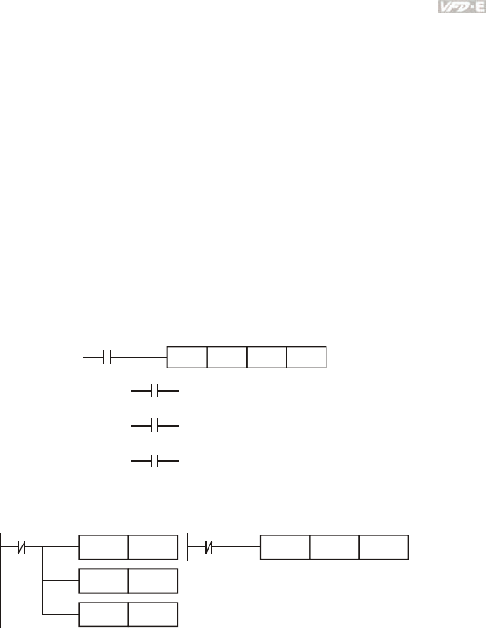
Appendix D How to Use PLC Function|
Revision June 2008, 04EE, SW--PW V1.11/CTL V2.11 D-47
Explanations:
1. Operand D occupies 3 consecutive devices.
2. See the specifications of each model for their range of use.
3. The contents in S1 and S2 are compared and the result will be stored in D.
4. The two comparison values are compared algebraically and the two values are signed
binary values. When b15 = 1 in 16-bit instruction, the comparison will regard the value as
negative binary values.
Program Example:
1. Designate device Y0, and operand D automatically occupies Y0, Y1, and Y2.
2. When X10 = On, CMP instruction will be executed and one of Y0, Y1, and Y2 will be On.
When X10 = Off, CMP instruction will not be executed and Y0, Y1, and Y2 remain their
status before X10 = Off.
3. If the user need to obtain a comparison result with ≥ ≤, and ≠, make a series parallel
connection between Y0 ~ Y2.
X10
Y0
Y1
Y2
CMP K10 D10 Y0
If K10>D10, Y0 = On
If K10=D10, Y1 = On
If K10<D10, Y2= On
4. To clear the comparison result, use RST or ZRST instruction.
X10
RST M0
RST
RST
M1
M2
X10
ZRST M0 M2

Appendix D How to Use PLC Function|
D-48 Revision June 2008, 04EE, SW--PW V1.11/CTL V2.11
API Mnemonic Operands Function
11
ZCP P S1, S2, S, D Zone Compare
Bit Devices Word devices Program Steps Type
OP X Y M K H KnX KnY KnM T C D
S1 * * * * * * * *
S2 * * * * * * * *
S * * * * * * * *
D * *
ZCP, ZCPP: 9 steps
Operands:
S1: Lower bound of zone comparison S2: Upper bound of zone comparison S: Comparison value
D: Comparison result
Explanations:
1. The content in S1 should be smaller than the content in S2.
2. Operand D occupies 3 consecutive devices.
3. See the specifications of each model for their range of use.
4. S is compared with its S1 S2 and the result is stored in D.
5. When S1 > S2, the instruction performs comparison by using S1 as the lower/upper
bound.
6. The two comparison values are compared algebraically and the two values are signed
binary values. When b15 = 1 in 16-bit instruction or b31 = 1 in 32-bit instruction, the
comparison will regard the value as negative binary values.
Program Example:
1. Designate device M0, and operand D automatically occupies M0, M1 and M2.
2. When X0 = On, ZCP instruction will be executed and one of M0, M1, and M2 will be On.
When X10 = Off, ZCP instruction will not be executed and M0, M1, and M2 remain their
status before X0 = Off.
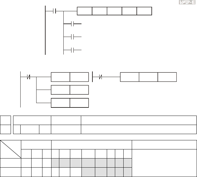
Appendix D How to Use PLC Function|
Revision June 2008, 04EE, SW--PW V1.11/CTL V2.11 D-49
X0
M0
M1
M2
ZCP
If C10 < K10, M0 = On
If K10 < C10 < K100, M1 = On
If C10 > K100, M2 = On
X0
K10 C10 M0K100
==
3. To clear the comparison result, use RST or ZRST instruction.
X0
RST M0
RST
RST
M1
M2
X
0
ZRST M0 M2
API Mnemonic Operands Function
12
MOV P S, D Move
Bit Devices Word devices Program Steps Type
OP X Y M K H KnX KnY KnM T C D
S * * * * * ** *
D * * ** *
MOV, MOVP: 5 steps
Operands:
S: Source of data D: Destination of data
Explanations:
1. See the specifications of each model for their range of use.
2. When this instruction is executed, the content of S will be moved directly to D. When this
instruction is not executed, the content of D remains unchanged.
Program Example:
MOV instruction has to be adopted in the moving of 16-bit data.
1. When X0 = Off, the content in D10 will remain unchanged. If X0 = On, the value K10 will
be moved to D10 data register.
2. When X1 = Off, the content in D10 will remain unchanged. If X1 = On, the present value
T0 will be moved to D10 data register.
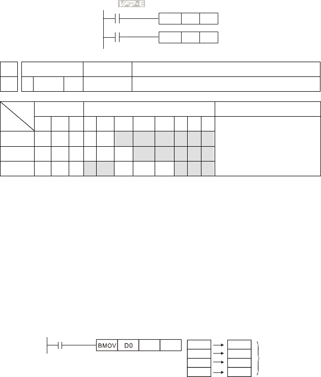
Appendix D How to Use PLC Function|
D-50 Revision June 2008, 04EE, SW--PW V1.11/CTL V2.11
X0
K10MOV D0
X1
T0MOV D10
API Mnemonic Operands Function
15
BMOV P S, D, n Block Move
Bit Devices Word devices Program Steps Type
OP X Y M K H KnX KnY KnM T C D
S ** * * * *
D * * * * *
n * * * * *
BMOV, BMOVP: 7 steps
Operands:
S: Start of source devices D: Start of destination devices n: Number of data to be moved
Explanations:
1. Range of n: 1 ~ 512
2. See the specifications of each model for their range of use.
3. The contents in n registers starting from the device designated by S will be moved to n
registers starting from the device designated by D. If n exceeds the actual number of
available source devices, only the devices that fall within the valid range will be used.
Program Example 1:
When X10 = On, the contents in registers D0 ~ D3 will be moved to the 4 registers D20 ~ D23.
X10
D20 K4 D0
D1
D2
D3
D20
D21
D22
D23
n=4
Program Example 2:
Assume the bit devices KnX, KnY, KnM and KnS are designated for moving, the number of digits of
S and D has to be the same, i.e. their n has to be the same.
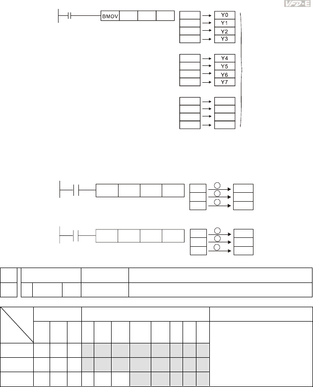
Appendix D How to Use PLC Function|
Revision June 2008, 04EE, SW--PW V1.11/CTL V2.11 D-51
M1000
D0 D20 K4 M0
M1
M2
M3
M4
M5
M6
M7
M8
M9
M10
n=3
M11
Y10
Y11
Y12
Y13
Program Example 3:
To avoid coincidence of the device numbers to be moved designated by the two operands and cause
confusion, please be aware of the arrangement on the designated device numbers.
When S > D, the BMOV command is processed in the order as 1→2→3
X10
D20
BMOV
D19 K3 D20
D21
D22
D19
D20
D21
1
2
3
When S < D, the BMOV command is processed in the order as 3→2→1
D10
D11
D12
D11
D12
D13
1
2
3
X1
1
D10
BMOV
D11 K3
API Mnemonic Operands Function
20
ADD P S
1, S2, D Addition
Bit Devices Word devices Program Steps Type
OP
X Y M K H KnX KnY KnM T C D
S1 * * * * * ** *
S2 * * * * * ** *
D * * ** *
ADD, ADDP: 7 steps
Operands:
S1: Summand S2: Addend D: Sum
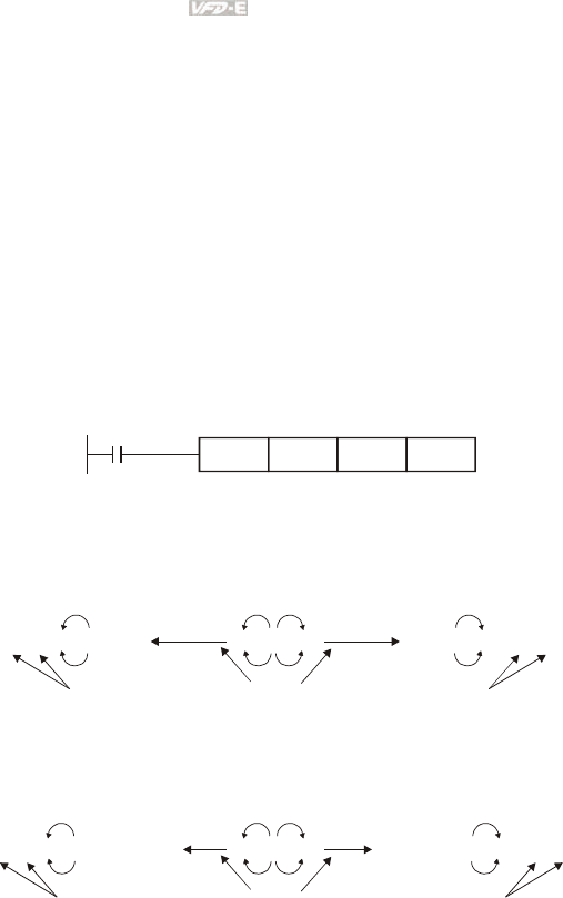
Appendix D How to Use PLC Function|
D-52 Revision June 2008, 04EE, SW--PW V1.11/CTL V2.11
Explanations:
1. See the specifications of each model for their range of use.
2. This instruction adds S1 and S2 in BIN format and store the result in D.
3. The highest bit is symbolic bit 0 (+) and 1 (-), which is suitable for algebraic addition, e.g.
3 + (-9) = -6.
4. Flag changes in binary addition
16-bit command:
A. If the operation result = 0, zero flag M1020 = On.
B. If the operation result < -32,768, borrow flag M1021 = On.
C. If the operation result > 32,767, carry flag M1022 = On.
Program Example 1:
16-bit command:
When X0 = On, the content in D0 will plus the content in D10 and the sum will be stored in D20.
X0
ADD D0 D10 D20
Remarks:
Flags and the positive/negative sign of the values:
-2, -1, 0 -32,768 -1, 0 1 32,767 0 1 2
-2, -1, 0 -2,147,483,648
-1, 0 1
2,147,483,647 0 1 2
16 bit: Zero flag Zero flag Zero flag
Borrow flag The highest bit
of the data
= 1 (negative)
32 bit: Zero flag Zero flag Zero flag
The highest bit
of the data
= 0 (positive)
Carry flag
Borrow flag Carry flag
The highest bit
of the data
= 1 (negative)
The highest bit
of the data
= 0 (positive)
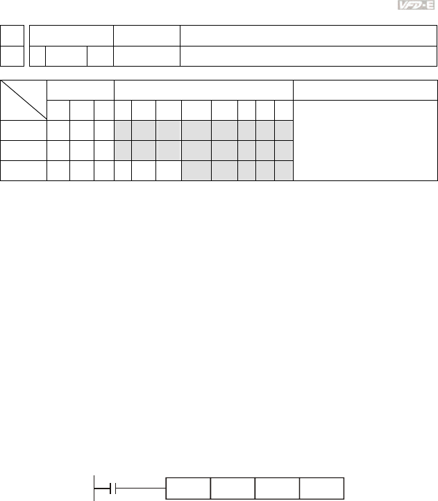
Appendix D How to Use PLC Function|
Revision June 2008, 04EE, SW--PW V1.11/CTL V2.11 D-53
API Mnemonic Operands Function
21
SUB P S
1, S2, D Subtraction
Bit Devices Word devices Program Steps Type
OP X Y M K H KnX KnY KnM T C D
S1 * * * * * ** *
S2 * * * * * ** *
D * * ** *
SUB, SUBP: 7 steps
DSUB, DSUBP: 13 steps
Operands:
S1: Minuend S2: Subtrahend D: Remainder
Explanations:
1. This instruction subtracts S1 and S2 in BIN format and stores the result in D.
2. The highest bit is symbolic bit 0 (+) and 1 (-), which is suitable for algebraic subtraction.
3. Flag changes in binary subtraction
In 16-bit instruction:
A. If the operation result = 0, zero flag M1020 = On.
B. If the operation result < -32,768, borrow flag M1021 = On.
C. If the operation result > 32,767, carry flag M1022 = On.
Program Example:
In 16-bit BIN subtraction:
When X0 = On, the content in D0 will minus the content in D10 and the remainder will be stored in
D20.
X0
SUB D0 D10 D20
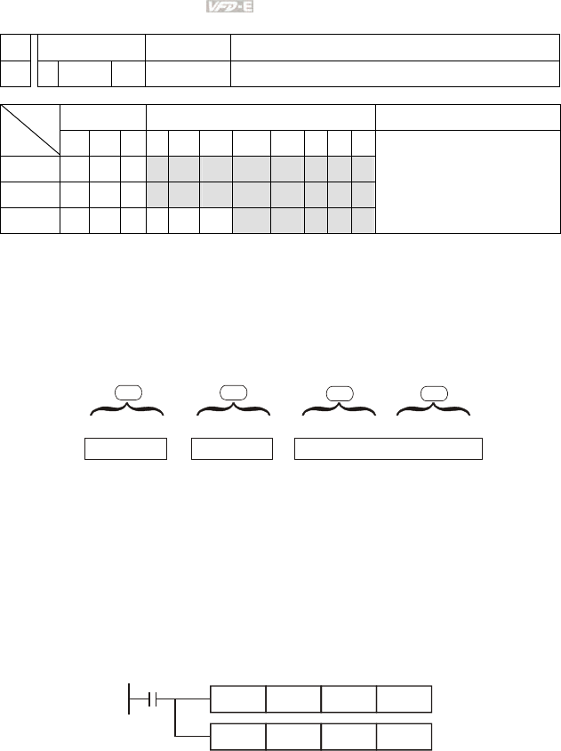
Appendix D How to Use PLC Function|
D-54 Revision June 2008, 04EE, SW--PW V1.11/CTL V2.11
API Mnemonic Operands Function
22
MUL P S1, S2, D Multiplication
Bit Devices Word devices Program Steps Type
OP X Y M K H KnX KnY KnM T C D
S1 * * * * * * * *
S2 * * * * * * * *
D * * * * *
MUL, DMULP: 7 steps
Operands:
S1: Multiplicand S2: Multiplicator D: Product
Explanations:
1. In 16-bit instruction, D occupies 2 consecutive devices.
2. This instruction multiplies S1 by S2 in BIN format and stores the result in D. Be careful
with the positive/negative signs of S1, S2 and D when doing 16-bit and 32-bit operations.
16-bit command:
S1 D
b15..........b0
X
b15..........b0
S2
=
b31..........b16b15..............b0
D+1
b15 is a symbol bit b15 is a symbol bit b31 is a symbol bit (b15 of D+1)
Symbol bit = 0 refers to a positive value.
Symbol bit = 1 refers to a negative value.
When D serves as a bit device, it can designate K1 ~ K4 and construct a 16-bit result, occupying
consecutive 2 groups of 16-bit data.
Program Example:
The 16-bit D0 is multiplied by the 16-bit D10 and brings forth a 32-bit product. The higher 16 bits are
stored in D21 and the lower 16-bit are stored in D20. On/Off of the most left bit indicates the
positive/negative status of the result value.
X0
MUL D0 D10 D20
MUL D0 D10 K8M0
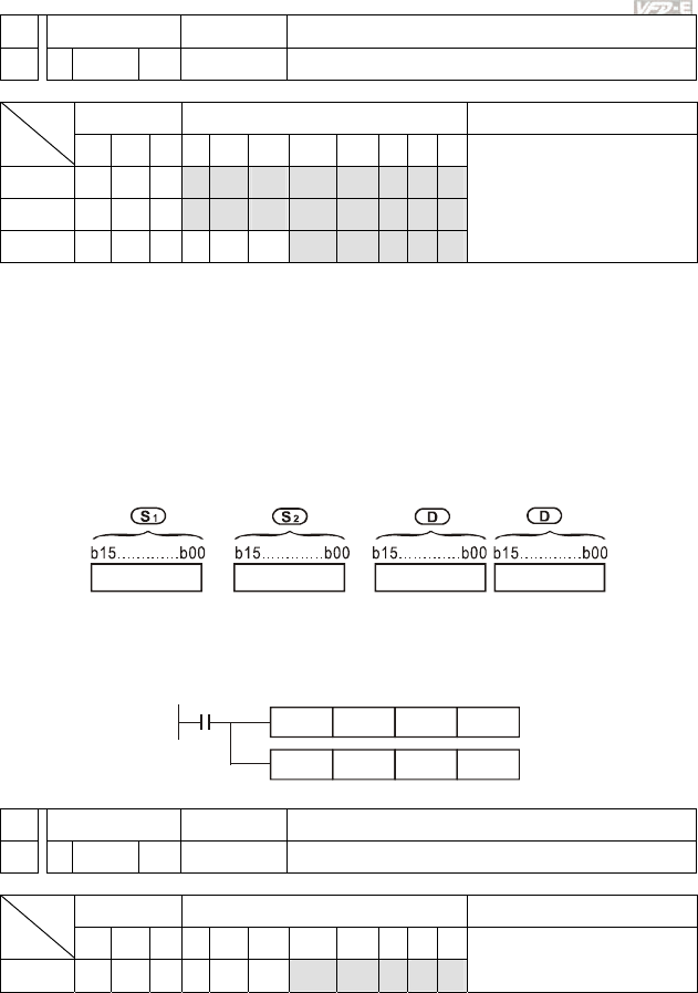
Appendix D How to Use PLC Function|
Revision June 2008, 04EE, SW--PW V1.11/CTL V2.11 D-55
API Mnemonic Operands Function
23
DIV P S1, S2, D Division
Bit Devices Word devices Program Steps Type
OP X Y M K H KnX KnY KnM T C D
S1 * * * * * ** *
S2 * * * * * ** *
D * * ** *
DIV, DIVP: 7 steps
Operands:
S1: Dividend S2: Divisor D: Quotient and remainder
Explanations:
1. In 16-bit instruction, D occupies 2 consecutive devices.
2. This instruction divides S1 and S2 in BIN format and stores the result in D. Be careful with
the positive/negative signs of S1, S2 and D when doing 16-bit and 32-bit operations.
16-bit instruction:
+1
=
/
Quotient Remainder
Program Example:
When X0 = On, D0 will be divided by D10 and the quotient will be stored in D20 and remainder in
D21. On/Off of the highest bit indicates the positive/negative status of the result value.
X0
DIV D0 D10 D20
D0 D10 K4Y0
DIV
API Mnemonic Operands Function
24
INC P D Increment
Bit Devices Word devices Program Steps Type
OP X Y M K H KnX KnY KnM T C D
D * * ** *
INC, INCP: 3 steps
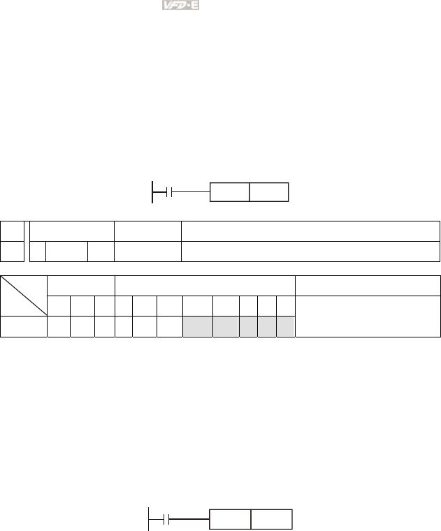
Appendix D How to Use PLC Function|
D-56 Revision June 2008, 04EE, SW--PW V1.11/CTL V2.11
Operands:
D: Destination device
Explanations:
1. If the instruction is not a pulse execution one, the content in the designated device D will
plus “1” in every scan period whenever the instruction is executed.
2. This instruction adopts pulse execution instructions (INCP).
3. In 16-bit operation, 32,767 pluses 1 and obtains -32,768. In 32-bit operation,
2,147,483,647 pluses 1 and obtains -2,147,483,648.
Program Example:
When X0 goes from Off to On, the content in D0 pluses 1 automatically.
X0
INCP D0
API Mnemonic Operands Function
25
DEC P D Decrement
Bit Devices Word devices Program Steps Type
OP X Y M K H KnX KnY KnM T C D
D * * * * *
DEC, DECP: 3 steps
Operands:
D: Destination
Explanations:
1. If the instruction is not a pulse execution one, the content in the designated device D will
minus “1” in every scan period whenever the instruction is executed.
2. This instruction adopts pulse execution instructions (DECP).
3. In 16-bit operation, -32,768 minuses 1 and obtains 32,767. In 32-bit operation, -
2,147,483,648 minuses 1 and obtains 2,147,483,647.
Program Example:
When X0 goes from Off to On, the content in D0 minuses 1 automatically.
X0
DECP D0
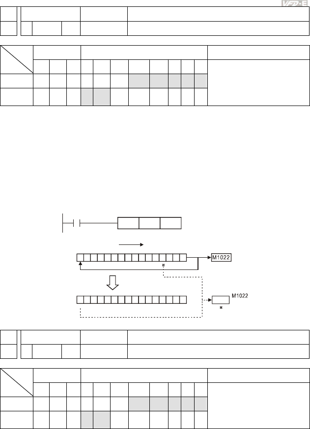
Appendix D How to Use PLC Function|
Revision June 2008, 04EE, SW--PW V1.11/CTL V2.11 D-57
API Mnemonic Operands Function
30
ROR P D, n Rotate to the Right
Bit Devices Word devices Program Steps Type
OP X Y M K H KnX KnY KnM T C D
D * * ** *
n
* *
ROR, RORP: 5 steps
Operands:
D: Device to be rotated n: Number of bits to be rotated in 1 rotation
Explanations:
1. This instruction rotates the device content designated by D to the right for n bits.
2. This instruction adopts pulse execution instructions (RORP).
Program Example:
When X0 goes from Off to On, the 16 bits (4 bits as a group) in D10 will rotate to the right, as shown
in the figure below. The bit marked with ※ will be sent to carry flag M1022.
011 10 101 0 0111 001
010111001111001 0 0
upper bit lower bit
upper bit lower bit
*
X0
RORP D10 K4
Rotate to the right
16 bits
Carry
flag
Carry
flag
After one rotation
to the right
D10
D10
API Mnemonic Operands Function
31
ROL P D, n Rotate to the Left
Bit Devices Word devices Program Steps Type
OP X Y M K H KnX KnY KnM T C D
D * * ** *
n
* *
ROL, ROLP: 5 steps
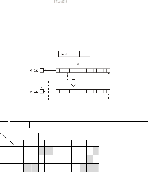
Appendix D How to Use PLC Function|
D-58 Revision June 2008, 04EE, SW--PW V1.11/CTL V2.11
Operands:
D: Device to be rotated n: Number of bits to be rotated in 1 rotation
Explanations:
1. This instruction rotates the device content designated by D to the left for n bits.
2. This instruction adopts pulse execution instructions (ROLP).
Program Example:
When X0 goes from Off to On, the 16 bits (4 bits as a group) in D10 will rotate to the left, as shown in
the figure below. The bit marked with ※ will be sent to carry flag M1022.
X0
D10 K4
111 11 100 0 0011 000
11000001100110111
16 bits
Rotate to the left
After one rotation
to the left
Carry
flag
Carry
flag
D10
D10
upper bit
upper bit lower bit
lower bit
D.5.11 Special Application Commands for the AC Motor Drive
API Mnemonic Operands Function
53
DHSCS S1, S2, D Compare (for high-speed counter)
Bit Devices Word devices Program Steps Type
OP X Y M K H KnX KnY KnM T C D
S1
* * *
S2
*
D
* *
* * *
DHSCS: 13 steps
Operands:
S1: Comparison Value S2: High-speed counter C235 D: Comparison result
Explanations:
1. It needs optional PG card to receive external input pulse.
2. To count automatically, please set the target value by using DHSCS command and set
M1028=On. The counter C235 will be ON when the count number = target value. If you
want to clear C235, please set M1029=ON.
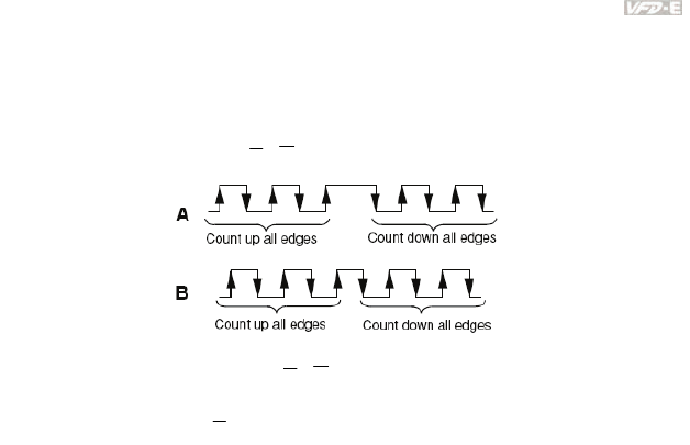
Appendix D How to Use PLC Function|
Revision June 2008, 04EE, SW--PW V1.11/CTL V2.11 D-59
3. Please use rising-edge/falling-edge command, such as LDP/LDF, for the contact
condition. Please notice that error may occur when using contact A/B for the contact
condition.
4. There are three input modes for high-speed counter in the following can be set by D1044.
A-B phase mode(4 times frequency )(D1044=0): user can input the A and B pulse for
counting. Make sure that
A
,
B
and GND are grounding.
Pulse + signal mode(D1044=1): user can count by pulse input or signal. A is for pulse and
B is for signal. Make sure that
A
,
B
and GND are grounding.
Pulse + flag mode(D1044=2): user can count by M1030. Only A is needed for this mode
and make sure that
A
, and GND are grounding.
Program Example:
1. Assume that when M100=ON, it is set to A-B phase mode. When M101=ON, it is set to
pulse+signal mode. When M102=ON, it is set to pulse+flag mode.
2. M1030 is used to set to count up (OFF) and count down (ON).
3. If M0 goes from OFF to ON, DHSCS command starts to execute the comparison of high-
speed counter. When C235 goes from H’2 to H’3 or from H’4 to H’3, M3 will be always be
ON.
4. If M1 goes from OFF to ON, DHSCS command starts to execute the comparison of high-
speed counter. When C235 goes from H’1004F to H’10050 or from H’10051 to H’10050,
M2 will be always be ON.
5. M1028: it is used to enable(ON)/disable(OFF) the high-speed counter function. M1029: it
is used to clear the high-speed counter. M1018: it is used to start high-speed counter
function. (when M1028 is ON).
6. D1025: the low word of high-speed counter C235. D1026: the high word of high-speed
counter C235.

Appendix D How to Use PLC Function|
D-60 Revision June 2008, 04EE, SW--PW V1.11/CTL V2.11
M100
MOV K0 D1044
K2 D1044
C235DHSCS
H3 M3
END
K1MOV
MOV
H10050 M2
D1044
C235DHSCS
M11
M10
M3
M2
M1
M0
M102
M101
M1000
M1030
M102
Y1
M1018
M1018
M1028
M1029
D1025 D0
D1
MOV
MOV D1026
API Mnemonic Operands Function
139
RPR P S1, S2 Read the AC motor drive’s parameters
Bit Devices Word devices Program Steps Type
OP X Y M K H KnX KnY KnM T C D
S1
* * *
S2
*
RPR, RPRP: 5 steps
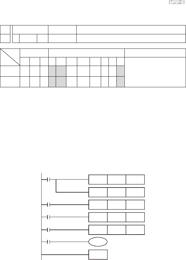
Appendix D How to Use PLC Function|
Revision June 2008, 04EE, SW--PW V1.11/CTL V2.11 D-61
Operands:
S1: Data address for reading S2: Register that saves the read data
API Mnemonic Operands Function
140
WPR P S1, S2 Write the AC motor drive’s parameters
Bit Devices Word devices Program Steps Type
OP X Y M K H KnX KnY KnM T C D
S1
* *
*
S2
* *
*
WPR, WPRP: 5 steps
Operands:
S1: Data address for writing S2: Register that saves the written data
Program Example:
1. Assume that it will write the data in address H2100 of the VFD-E into D0 and H2101 into
D1.
2. When M0=ON, it will write the data in D10 to the address H2001 of the VFD-E.
3. When M1=ON, it will write the data in H2 to the address H2000 of the VFD-E, i.e. start the
AC motor drive.
4. When M2=ON, it will write the data in H1 to the address H2000 of the VFD-E, i.e. stop the
AC motor drive.
5. When data is written successfully, M1017 will be ON.
END
M1000
RPR H2100 D0
RPR H2101 D1
WPR
WPRP
WPRP
D10
H2
H1 H2000
H2001
H2000
Y0
M1017
M1
M2
M0

Appendix D How to Use PLC Function|
D-62 Revision June 2008, 04EE, SW--PW V1.11/CTL V2.11
API Mnemonic Operands Function
141
FPID P S1, S2, S3, S4 PID control for the AC motor drive
Bit Devices Word devices Program Steps Type
OP X Y M K H KnX KnY KnM T C D
S1
* * *
S2
* * *
S3
* * *
S4
* * *
FPID, FPIDP: 9 steps
Operands:
S1: PID Set Point Selection(0-4), S2: Proportional gain P (0-100), S3: Integral Time I (0-10000), S4:
Derivative control D (0-100)
Explanation:
1. This command FPID can control the PID parameters of the AC motor drive directly,
including Pr.10.00 PID set point selection, Pr.10.02 Proportional gain (P), Pr.10.03
Integral time (I) and Pr.10.04 Derivative control (D)
Program Example:
1. Assume that when M0=ON, S1 is set to 0 (PID function is disabled), S2=0, S3=1 (unit:
0.01 seconds) and S4=1 (unit: 0.01 seconds).
2. Assume that when M1=ON, S1 is set to 0 (PID function is disabled), S2=1 (unit: 0.01),
S3=0 and S4=0.
3. Assume that when M2=ON, S1 is set to 1(frequency is inputted by digital keypad), S2=1
(unit: 0.01), S3=0 and S4=0.
4. D1027: frequency command controlled by PID.
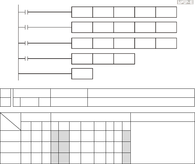
Appendix D How to Use PLC Function|
Revision June 2008, 04EE, SW--PW V1.11/CTL V2.11 D-63
END
H0
M2
M1
M0
M1000
H1
H0
H0
H1
H1
H1 H1
H0 H0
H0 H0
FPID
MOV D1027 D1
FPID
FPID
API Mnemonic Operands Function
142
FREQ P S1, S2, S3 Operation control of the AC motor drive
Bit Devices Word devices Program Steps Type
OP X Y M K H KnX KnY KnM T C D
S1
* *
*
S2
* *
*
S3
* *
*
FREQ, FREQP: 7 steps
Operands:
S1: frequency command, S2: acceleration time, S3: deceleration time
Explanation:
1. This command can control frequency command, acceleration time and deceleration time
of the AC motor drive. Please use M1025 to RUN(ON)/STOP(OFF) the AC motor drive
and use M1025 to control the operation direction: FWD(ON)/REV(OFF).
Program Example:
1. M1025: RUN(ON)/STOP(Off) the AC motor drive. M1026: operation direction of the AC
motor drive – FWD(OFF)/REV(ON). M1015: frequency is reached.
2. When M10=ON, setting frequency command of the AC motor drive to K300(3.00Hz) and
acceleration/deceleration time is 0.
3. When M11=ON, setting frequency command of the AC motor drive to K3000(30.00Hz),
acceleration time is 50 and deceleration time is 60.
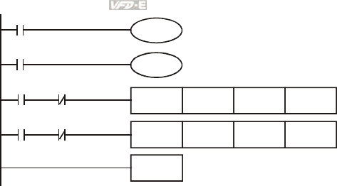
Appendix D How to Use PLC Function|
D-64 Revision June 2008, 04EE, SW--PW V1.11/CTL V2.11
END
M1000
M1025
M11
M1026
FREQP K300 K0 K0
FREQ K3000 K50 K60
M11M10
M10M11

Appendix D How to Use PLC Function|
Revision June 2008, 04EE, SW--PW V1.11/CTL V2.11 D-65
D.6 Error Code
Code ID Description Corrective Actions
PLod 20 Data write error
Check if the program is error and
download the program again
PLSv 21 Data write error when executing
Power on again and download the
program again
PLdA 22 Program upload error
1. Please upload again.
2. Return to the factory if it occurs
continuously
PLFn 23
Command error when download
program
Check if the program is error and
download program again
PLor 30
Program capacity exceeds
memory capacity
PLFF 31 Command error when executing
PLSn 32 Check sum error
PLEd 33
There is no “END” command in
the program
PLCr 34
The command MC is continuous
used more than nine times
Power on again and download program
again

Appendix D How to Use PLC Function|
D-66 Revision June 2008, 04EE, SW--PW V1.11/CTL V2.11
This page intentionally left blank

Revision June 2008, 04EE, SW--PW V1.11/CTL V2.11 E-1
Appendix E CANopen Function
The built-in CANopen function is a kind of remote control. Master can control the AC motor drive by
using CANopen protocol. CANopen is a CAN-based higher layer protocol. It provides standardized
communication objects, including real-time data (Process Data Objects, PDO), configuration data
(Service Data Objects, SDO), and special functions (Time Stamp, Sync message, and Emergency
message). And it also has network management data, including Boot-up message, NMT message,
and Error Control message. Refer to CiA website http://www.can-cia.org/ for details.
Delta CANopen supports functions:
Support CAN2.0A Protocol;
Support CANopen DS301 V4.02;
Support DSP-402 V2.0.
Delta CANopen supports services:
PDO (Process Data Objects): PDO1~ PDO2
SDO (Service Data Object):
Initiate SDO Download;
Initiate SDO Upload;
Abort SDO;
SDO message can be used to configure the slave node and access the Object Dictionary
in every node.
SOP (Special Object Protocol):
Support default COB-ID in Predefined Master/Slave Connection Set in DS301 V4.02;
Support SYNC service;
Support Emergency service.
NMT (Network Management):
Support NMT module control;
Support NMT Error control;
Support Boot-up.
Delta CANopen doesn’t support service:
Time Stamp service
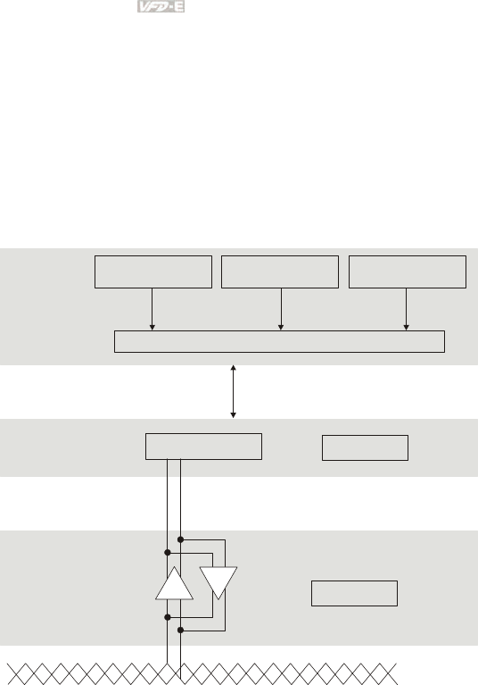
Appendix E CANopen Function |
E-2 Revision June 2008, 04EE, SW--PW V1.11/CTL V2.11
E.1 Overview
E.1.1 CANopen Protocol
CANopen is a CAN-based higher layer protocol, and was designed for motion-oriented
machine control networks, such as handling systems. Version 4 of CANopen (CiA DS301) is
standardized as EN50325-4. The CANopen specifications cover application layer and
communication profile (CiA DS301), as well as a framework for programmable devices (CiA
302), recommendations for cables and connectors (CiA 303-1) and SI units and prefix
representations (CiA 303-2).
Device Profile CiA
DSP-401
Device Profile CiA
DSP-404
Device Profile CiA
DSP-XXX
OSI Layer 7
Application Communication Profile CiA DS-301
CAN Controller CAN 2.0A
OSI Layer 2
Data Link Layer
ISO 11898
OSI Layer 1
Physical Layer
+-
+-
CAN bus
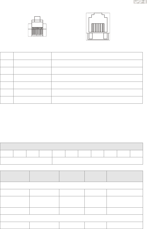
Appendix D How to Use PLC Function|
Revision June 2008, 04EE, SW--PW V1.11/CTL V2.11 E-3
E.1.2 RJ-45 Pin Definition
8~1 8~1
socket plug
PIN Signal Description
1 CAN_H CAN_H bus line (dominant high)
2 CAN_L CAN_L bus line (dominant low)
3 CAN_GND Ground / 0V /V-
4 SG+ 485 communication
5 SG- 485 communication
7 CAN_GND Ground / 0V /V-
E.1.3 Pre-Defined Connection Set
To reduce configuration effort for simple networks, CANopen define a mandatory default
identifier allocation scheme. The 11-bit identifier structure in predefined connection is set as
follows:
COB Identifier (CAN Identifier)
10 9 8 7 6 5 4 3 2 1 0
Function Code Node Number
Object Function Code Node Number COB-ID Object Dictionary
Index
Broadcast messages
NMT 0000 - 0 -
SYNC 0001 - 0x80 0x1005, 0x1006,
0x1007
TIME STAMP 0010 - 0x100 0x1012, 0x1013
Point-to-point messages
Emergency 0001 1-127 0x81-0xFF 0x1014, 0x1015

Appendix E CANopen Function |
E-4 Revision June 2008, 04EE, SW--PW V1.11/CTL V2.11
Object Function Code Node Number COB-ID Object Dictionary
Index
TPDO1 0011 1-127 0x181-0x1FF 0x1800
RPDO1 0100 1-127 0x201-0x27F 0x1400
TPDO2 0101 1-127 0x281-0x2FF 0x1801
RPDO2 0110 1-127 0x301-0x37F 0x1401
TPDO3 0111 1-127 0x381-0x3FF 0x1802
RPDO3 1000 1-127 0x401-0x47F 0x1402
TPDO4 1001 1-127 0x481-0x4FF 0x1803
RPDO4 1010 1-127 0x501-0x57F 0x1403
Default SDO (tx) 1011 1-127 0x581-0x5FF 0x1200
Default SDO (rx) 1100 1-127 0x601-0x67F 0x1200
NMT Error
Control
1110 1-127 0x701-0x77F 0x1016, 0x1017
E.1.4 CANopen Communication Protocol
It has services as follows:
NMT (Network Management Object)
SDO (Service Data Object)
PDO (Process Data Object)
EMCY (Emergency Object)
E.1.4.1 NMT (Network Management Object)
The Network Management (NMT) follows a Master/Slave structure for executing NMT
service. Only one NMT master is in a network, and other nodes are regarded as slaves. All
CANopen nodes have a present NMT state, and NMT master can control the state of the
slave nodes. The state diagram of a node are shown as follows:
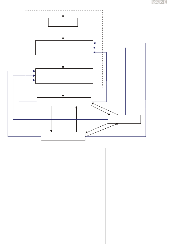
Appendix D How to Use PLC Function|
Revision June 2008, 04EE, SW--PW V1.11/CTL V2.11 E-5
Reset Communication
Initializing
Reset Application
Pre-Operation ABCD
Stopped AB
Operation ABCD
(1)
(15)
(16)
(2)F
(14)
(13)
(12)
(3) (4)
(11)
(10)
(9)
(7)
(5)
(6) (8)
(1) After power is applied, it is auto in initialization state
(2) Enter pre-operational state automatically
(3) (6) Start remote node
(4) (7) Enter pre-operational state
(5) (8) Stop remote node
(9) (10) (11) Reset node
(12) (13) (14) Reset communication
(15) Enter reset application state automatically
(16) Enter reset communication state automatically
A: NMT
B: Node Guard
C: SDO
D: Emergency
E: PDO
F: Boot-up
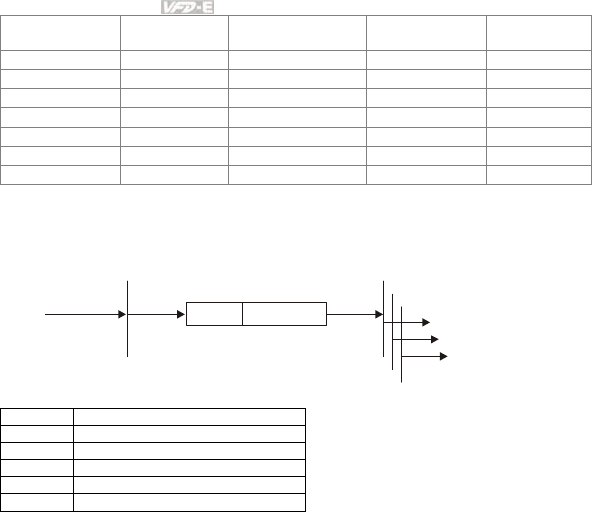
Appendix E CANopen Function |
E-6 Revision June 2008, 04EE, SW--PW V1.11/CTL V2.11
Initializing Pre-Operational Operational Stopped
PDO ○
SDO ○ ○
SYNC ○ ○
Time Stamp ○ ○
EMERG ○ ○
Boot-up ○
NMT ○ ○ ○
NMT Protocol is shown as follows:
NMT Master
Request
request
CS Node-ID
COB-ID=0
Start Remote Node NMT Slave(s)
Indication
byte 0 byte 1
Indication
Indication
Indication(s)
Cs
Value Definition
1 Start
2 Stop
128 Enter Pre-Operational
129 Reset Node
130 Reset Communication
E.1.4.2 SDO (Service Data Object)
SDO is used to access the Object Dictionary in every CANopen node by Client/Server model.
One SDO has two COB-ID (request SDO and response SDO) to upload or download data
between two nodes. No data limit for SDOs to transfer data. But it needs to transfer by
segment when data exceeds 4 bytes with an end signal in the last segment.
The Object Dictionary (OD) is a group of objects in CANopen node. Every node has an OD
in the system, and OD contains all parameters describing the device and its network
behavior. The access path of OD is the index and sub-index, each object has a unique index
in OD, and has sub-index if necessary.
The request and response frame structure of SDO communication is shown as follows:
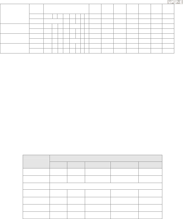
Appendix D How to Use PLC Function|
Revision June 2008, 04EE, SW--PW V1.11/CTL V2.11 E-7
Data 0 Data
1
Data
2
Data
3
Data
4
Data
5
Data
6
Data
7
7 6 5 4 3 2 1 0 Index Index Index Data Data Data Data
Type
command L H Sub LL LH HL HH
Client 0 0 1 - N E S Initiate Domain
Download Server 0 1 1 - - - - -
Client 0 1 0 - - - - - Initiate Domain
Upload Server 0 1 0 - N E S
Client 1 0 0 - - - - - Abort Domain
Transfer Server 1 0 0 - - - - -
N: Bytes not use
E: normal(0)/expedited(1)
S: size indicated
E.1.4.3 PDO (Process Data Object)
PDO communication can be described by the producer/consumer model. Each node of the
network will listen to the messages of the transmission node and distinguish if the message
has to be processed or not after receiving the message. PDO can be transmitted from one
device to one another device or to many other devices.
Every PDO has two PDO services: a TxPDO and a RxPDO. PDOs are transmitted in a non-
confirmed mode.
PDO Transmission type is defined in the PDO communication parameter index (1400h for
the 1st RxPDO or 1800h for the 1st TxPDO), and all transmission types are listed in the
following table:
PDO
Type Number Cyclic Acyclic Synchronous Asynchronous RTR only
0
○ ○
1-240 ○ ○
241-251 Reserved
252 ○ ○
253 ○ ○
254 ○
255 ○
Type number 1-240 indicates the number of SYNC message between two PDO
transmissions.
Type number 252 indicates the data is updated (but not sent) immediately after receiving
SYNC.
Type number 253 indicates the data is updated immediately after receiving RTR.
Type number 254: Delta CANopen doesn’t support this transmission format.
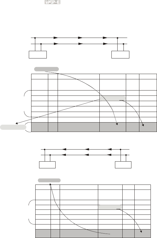
Appendix E CANopen Function |
E-8 Revision June 2008, 04EE, SW--PW V1.11/CTL V2.11
Type number 255 indicates the data is asynchronous transmission.
All PDO transmission data must be mapped to index via Object Dictionary.
Example:
Master transmits data to SlavePDO
PDO1
CAN(H)
CAN(L)
Master Slave
PDO1 data value Data 0, Data 1, Data 2, Data 3, Data 4, Data 5, Data 6, Data 7,
0x11, 0x22, 0x33, 0x44, 0x55, 0x66, 0x77, 0x88,
Index Sub Definition Valu e R/W Size
1. Mapped Object
0. Number
2. Mapped Object
3. Mapped Object
4. Mapped Object
0
1
2
3
4
0x1600
0x1600
0x1600
0x1600
0x1600
R/W
R/W
R/W
R/W
R/W
1
0
0
0
U8
U32
U32
U32
U32
0x6040 0. Control word0R/W U16
PDO1 Map
0x60400010
(2 Bytes)
0x60400010 0x2211
Slave returns message to Master
PDO1
CAN(H)
CAN(L)
Master Slave
PDO1 data value Data 0, Data 1, Data 2, Data 3, Data 4, Data 5, Data 6, Data 7,
0xF3, 0x00,
Index Sub Definition Value R/W Size
1. Mapped Object
0. Number
2. Mapped Object
3. Mapped Object
4. Mapped Object
0
1
2
3
4
0x1A00
0x1A00
0x1A00
0x1A00
0x1A00
R/W
R/W
R/W
R/W
R/W
1
0
0
0
U8
U32
U32
U32
U32
0x6041 Status Word0R/W U16
PDO1 Map
0x60410010
0xF3
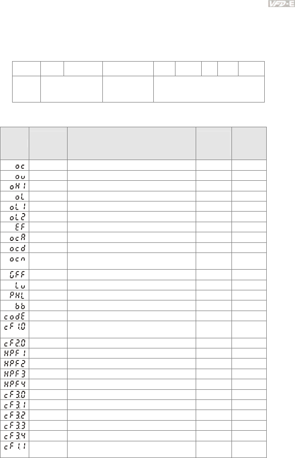
Appendix D How to Use PLC Function|
Revision June 2008, 04EE, SW--PW V1.11/CTL V2.11 E-9
E.1.4.4 EMCY (Emergency Object)
Emergency objects are triggered when hardware failure occurs for a warning interrupt. The
data format of a emergency object is a 8 bytes data as shown in the following:
Byte 0 1 2 3 4 5 6 7
Content Emergency Error
Code
Error register
(Object 1001H) Manufacturer specific Error Field
Definition of Emergency Object
Display
Controller
Error
Code
Description
CANopen
Error
Code
CANopen
Error
Register
(bit 0~7)
0001H Over current 7400H 1
0002H Over voltage 7400H 2
0003H Overheating 4310H 3
0005H Overload 2310H 1
0006H Overload 1 7120H 1
0007H Overload 2 2310H 1
0008H External Fault 9000H 7
0009H Over-current during acceleration 2310H 1
000AH Over-current during deceleration 2310H 1
000BH Over-current during constant speed
operation
2310H 1
000CH Ground fault 2240H 1
000DH Lower than standard voltage 3220h 2
000EH Phase Loss 3130h 7
000FH External Base Block 9000h 7
0011H Software protection failure 6320h 7
0013H Internal EEPROM can not be
programmed 5530h 7
0014H Internal EEPROM can not be read 5530h 7
0015H CC (current clamp) 5000h 7
0016H OV hardware error 5000h 2
0017H GFF hardware error 5000h 2
0018H OC hardware error 5000h 1
0019H U-phase error 2300h 1
001AH V-phase error 2300h 1
001BH W-phase error 2300h 1
001CH OV or LV 3210h 2
001DH Temperature sensor error 4310h 3
001FH Internal EEPROM can not be
programmed 5530h 7

Appendix E CANopen Function |
E-10 Revision June 2008, 04EE, SW--PW V1.11/CTL V2.11
Display
Controller
Error
Code
Description
CANopen
Error
Code
CANopen
Error
Register
(bit 0~7)
0020H Internal EEPROM can not be read 5530h 7
0021H Analog signal error FF00h 7
0023H Motor overheat protection 7120h 3
0024H PG signal error 7300h 7
0029H Communication time-out error on the
control board or power board 7500h 4
Definition of Index
Index Sub Definition Factory
Setting R/W Size Unit NOTE
0x1000 0 Abort connection
option code 0x00010192 RO U32
0x1001 0 Error register 0 RO U8
0x1005 0
COB-ID SYNC
message 0x80 RW U32
0x1006 0
Communication cycle
period 0 RW U32 us 500us~15000us
0x1008 0
Manufacturer device
name 0 RO U32
0x1009 0
Manufacturer
hardware version 0RO U32
0x100A 0
Manufacturer software
version 0 RO U32
0x100C 0 Guarding time 0 RW U16 ms 0x80 + node 1
0x100D 0 Guarding factor 0 RW U8
0x1014 0 COB-ID emergency 0x0000080
+Node-ID RO U32
0x1015 0 Inhibit time EMCY 0RW U16 100us It is set to be
multiple of 10.
0 Number 0x1 RO U8
0x1016 1 Consumer heartbeat
time 0x0 RW U32 1ms
Heartbeat time can
be used when
Guarding time is
invalid.
0x1017 0
Producer heartbeat
time 0x0 RW U16 1ms
Heartbeat time can
be used when
Guarding time is
invalid.
0 Number 0x3 RO U8
1 Vender ID 0x000001DD RO U32
2 Product code 0x00002600
+model RO U32
0x1018
3 Revision 0x00010000 RO U32
0 Server SDO
Parameter 2RO U8
0x1200
1 COB-ID Client ->
Server
0x0000600+
Node-ID RO U32

Appendix D How to Use PLC Function|
Revision June 2008, 04EE, SW--PW V1.11/CTL V2.11 E-11
Index Sub Definition Factory
Setting R/W Size Unit NOTE
2 COB-ID Client <-
Server
0x0000580+
Node-ID RO U32
0 Number 2 RO U8
1 COB-ID used by PDO 0x00000200
+Node-ID RW U32
00:Acyclic &
Synchronous
01~240:Cyclic &
Synchronous
0x1400
2 Transmission Type 5 RW U8
255: Asynchronous
0 Number 2 RO U8
1 COB-ID used by PDO 0x80000300
+Node-ID RW U32
00:Acyclic &
Synchronous
01~240:Cyclic &
Synchronous
0x1401
2 Transmission Type 5 RW U8
255: Asynchronous
0 Number 2 RW U8
1 1.Mapped Object 0x60400010 RW U32
2 2.Mapped Object 0x60420020 RW U32
3 3.Mapped Object 0 RW U32
0x1600
4 4.Mapped Object 0 RW U32
0 Number 0 RW U8
1 1.Mapped Object 0 RW U32
2 2.Mapped Object 0 RW U32
3 3.Mapped Object 0 RW U32
0x1601
4 4.Mapped Object 0 RW U32
0 Number 5 RO U8
1 COB-ID used by PDO 0x00000180
+Node-ID RW U32
00:Acyclic &
Synchrouous
01~240:Cyclic &
Synchrouous
253: Remote
function
2 Transmission Type 5 RW U8
255: Asynchronous
3 Inhibit time 0 RW U16 100us It is set to be
multiple of 10.
4 Reserved 3 RW U8 Reserved
0x1800
5 Event timer 0 RW U16 1ms
0 Number 5 RO U8
1 COB-ID used by PDO 0x80000280
+Node-ID RW U32
00:Acyclic &
Synchrouous
01~240:Cyclic &
Synchrouous
253: Remote
function
0x1801
2 Transmission Type 5 RW U8
255: Asynchronous

Appendix E CANopen Function |
E-12 Revision June 2008, 04EE, SW--PW V1.11/CTL V2.11
Index Sub Definition Factory
Setting R/W Size Unit NOTE
3 Inhibit time 0RW U16 100us It is set to be
multiple of 10.
4 Reserved 3 RW U8
5 Event timer 0 RW U16 1ms
0 Number 2 RW U8
1 1.Mapped Object 0x60410010 RW U32
2 2.Mapped Object 0x60430010 RW U32
3 3.Mapped Object 0 RW U32
0x1A00
4 4.Mapped Object 0 RW U32
0 Number 0 RW U8
1 1.Mapped Object 0 RW U32
2 2.Mapped Object 0 RW U32
3 3.Mapped Object 0 RW U32
0x1A01
4 4.Mapped Object 0 RW U32
Index Sub Definition Factory
Setting RW Size Unit Map NOTE
0: No action
2: Disable Voltage
0x6007 0
Abort connection
option code 2 RW S16 Yes
3: Quick stop
0x603F 0 Error code 0 RO U16 Yes
0x6040 0 Control word 0 RW U16 Yes
bit 0 ~ 3: switch status
bit 4: rfg enable
bit 5: rfg unlock
bit 6: rfg use ref
bit 7: Fault reset
0x6041 0 Status word 0 RO U16 Yes
Bit0 Ready to switch on
Bit1 Switched on
Bit2 Operation enabled
Bit3 Fault
Bit4 Voltage enabled
Bit5 Quick stop
Bit6 Switch on disabled
Bit7 Warning
Bit8
Bit9 Remote
Bit10 Target reached
Bit11 Internal limit active
Bit12 - 13
Bit14 - 15
0x6042 0 vl target velocity 0 RW S16 rpm Yes
0x6043 0
vl velocity
demand 0 RO S16 rpm Yes
0x604F 0
vl ramp function
time 10000 RW U32 1ms Yes
If Pr.01.19 is set to 0.1, the
unit must be 100ms and
can’t be set to 0.
0x6050 0 vl slow down time 10000 RW U32 1ms Yes
If Pr.01.19 is set to 0.1, the
unit must be 100ms and
can’t be set to 0.
0x6051 0 vl quick stop time 1000 RW U32 1ms Yes
If Pr.01.19 is set to 0.1, the
unit must be 100ms and
can’t be set to 0.

Appendix D How to Use PLC Function|
Revision June 2008, 04EE, SW--PW V1.11/CTL V2.11 E-13
Index Sub Definition Factory
Setting RW Size Unit Map NOTE
0 : disable drive function
1 :slow down on slow down
ramp
2: slow down on quick stop
ramp (2th decel. time)
5 slow down on slow down
ramp and stay in QUICK
STOP
0x605A 0
Quick stop option
code 2 RW S16 1ms Yes
6 slow down on quick stop
ramp and stay in QUICK
STOP
0x6060 0
Mode of
operation 2 RO U8 Yes Speed mode
0x6061 0
Mode of
operation display 2 RO U8 Yes
E.2 How to Control by CANopen
To control the AC motor drive by CANopen, please set parameters by the following steps:
Step 1. Operation source setting: set Pr.02.01 to 5 (CANopen communication. Keypad
STOP/RESET disabled.)
Step 2. Frequency source setting: set Pr.02.00 to 5 (CANopen communication)
Step 3. CANopen station setting: set Pr.09.13 (CANopen Communication Address 1-127)
Step 4. CANopen baud rate setting: set Pr.09.14 (CANBUS Baud Rate)
Step 5. Set multiple input function to quick stop when necessary: Set Pr.04.05 to 04.08 or Pr.11.06 to
11.11 to 23.
According to DSP-402 motion control rule, CANopen provides speed control mode. There are many
status can be switched during Start to Quick Stop. To get current status, please read “Status Word”.
Status is switched by the PDO index control word via external terminals.
Control word is a 16-byte in index 0x6040 and each bit has specific definition. The status bits are bit
4 to bit 6 as shown in the following:
Bit 4: ramp function enabled
Bit 5: ramp function disabled
Bit 6: rfg use reference
Appendix E CANopen Function |
E-14 Revision June 2008, 04EE, SW--PW V1.11/CTL V2.11
Following is the flow chart for status switch:
Start
Not Ready to Switch On
X0XX0000
Switch On Disable
X1XX0000
Ready to Switch On
X01X0001
Switch On
X01X0011
Operation Enable
X01X0111
0XXXX110
QStop=1
0XXXXX0X
or
0XXXX01X
QStop=0
0XXXX111 0XXXX110
0XXX1111 0XXX0110
0XXX1111
0XXXXX0X
0XXXX01X
or
0XXXXX0X
QStop=0
Quick Stop Active
X00X0111
0XXX1111
QStop=1
0XXXX01X
QStop=0
Fault Reaction Active
X0XX1111
Fault
X0XX1000
0XXXXX0X
or
Font=0
XXXXXXXX
Power
Disable
Fault
Power
Enable
