Delta Electronics Ac Motor Drive Vfd Ve Series Users Manual Preface
Delta-Ac-Motor-Drive-Vfd-Ve-Series-Users-Manual-244556 delta-ac-motor-drive-vfd-ve-series-users-manual-244556
VFD-VE Series to the manual 0c97e4d2-6f85-48f8-9896-570cfef49bdd
2015-01-24
: Delta-Electronics Delta-Electronics-Ac-Motor-Drive-Vfd-Ve-Series-Users-Manual-338661 delta-electronics-ac-motor-drive-vfd-ve-series-users-manual-338661 delta-electronics pdf
Open the PDF directly: View PDF ![]() .
.
Page Count: 291 [warning: Documents this large are best viewed by clicking the View PDF Link!]
- Preface
- Table of Contents
- Chapter 1 Introduction
- Chapter 2 Installation and Wiring
- Chapter 3 Digital Keypad Operation and Start Up
- Chapter 4 Parameters
- Chapter 5 Troubleshooting
- 5.1 Over Current (OC)
- 5.2 Ground Fault
- 5.3 Over Voltage (OV)
- 5.4 Low Voltage (Lv)
- 5.5 Over Heat (oH1, oH2, oH3)
- 5.6 Overload
- 5.7 Display of KPV-CE01 is Abnormal
- 5.8 Phase Loss (PHL)
- 5.9 Motor cannot Run
- 5.10 Motor Speed cannot be Changed
- 5.11 Motor Stalls during Acceleration
- 5.12 The Motor does not Run as Expected
- 5.13 Electromagnetic/Induction Noise
- 5.14 Environmental Condition
- 5.15 Affecting Other Machines
- Chapter 6 Fault Code Information and Maintenance
- Appendix A Specifications
- Appendix B Accessories
- B.1 All Brake Resistors & Brake Units Used in AC Motor Drives
- B.2 No-fuse Circuit Breaker Chart
- B.3 Fuse Specification Chart
- B.4 AC Reactor
- B.5 Zero Phase Reactor (RF220X00A)
- B.6 DC Choke Recommended Values
- B.7 Remote Controller RC-01
- B.8 PG Card (for Encoder)
- B.9 AMD-EMI Filter Cross Reference
- B.10 Multi-function I/O Extension Card
- Appendix C How to Select the Right AC Motor Drive


Preface
Thank you for choosing DELTA’s high-performance VFD-VE Series. The VFD-VE Series is
manufactured with high-quality components and materials and incorporates the latest
microprocessor technology available.
This manual is to be used for the installation, parameter setting, troubleshooting, and daily
maintenance of the AC motor drive. To guarantee safe operation of the equipment, read the following
safety guidelines before connecting power to the AC motor drive. Keep this operating manual at
hand and distribute to all users for reference.
To ensure the safety of operators and equipment, only qualified personnel familiar with AC motor
drive are to do installation, start-up and maintenance. Always read this manual thoroughly before
using VFD-VE series AC Motor Drive, especially the WARNING, DANGER and CAUTION notes.
Failure to comply may result in personal injury and equipment damage. If you have any questions,
please contact your dealer.
PLEASE READ PRIOR TO INSTALLATION FOR SAFETY.
DANGER!
1. AC input power must be disconnected before any wiring to the AC motor drive is made.
2. A charge may still remain in the DC-link capacitors with hazardous voltages, even if the power
has been turned off. To prevent personal injury, please ensure that power has turned off before
opening the AC motor drive and wait ten minutes for the capacitors to discharge to safe voltage
levels.
3. Never reassemble internal components or wiring.
4. The AC motor drive may be destroyed beyond repair if incorrect cables are connected to the
input/output terminals. Never connect the AC motor drive output terminals U/T1, V/T2, and
W/T3 directly to the AC mains circuit power supply.
5. Ground the VFD-VE using the ground terminal. The grounding method must comply with the
laws of the country where the AC motor drive is to be installed. Refer to the Basic Wiring
Diagram.
6. VFD-VE series is used only to control variable speed of 3-phase induction motors, NOT for 1-
phase motors or other purpose.
7. VFD-VE series shall NOT be used for life support equipment or any life safety situation.

WARNING!
1. DO NOT use Hi-pot test for internal components. The semi-conductor used in AC motor drive
easily damage by high-voltage.
2. There are highly sensitive MOS components on the printed circuit boards. These components
are especially sensitive to static electricity. To prevent damage to these components, do not
touch these components or the circuit boards with metal objects or your bare hands.
3. Only qualified persons are allowed to install, wire and maintain AC motor drives.
CAUTION!
1. Some parameters settings can cause the motor to run immediately after applying power.
2. DO NOT install the AC motor drive in a place subjected to high temperature, direct sunlight,
high humidity, excessive vibration, corrosive gases or liquids, or airborne dust or metallic
particles.
3. Only use AC motor drives within specification. Failure to comply may result in fire, explosion or
electric shock.
4. To prevent personal injury, please keep children and unqualified people away from the
equipment.
5. When the motor cable between AC motor drive and motor is too long, the layer insulation of the
motor may be damaged. Please use a frequency inverter duty motor or add an AC output
reactor to prevent damage to the motor. Refer to appendix B Reactor for details.
6. The rated voltage for AC motor drive must be ≤ 240V (≤ 480V for 460V models) and the mains
supply current capacity must be ≤ 5000A RMS (≤10000A RMS for the ≥ 40hp (30kW) models).

Table of Contents
Preface ............................................................................................................. i
Table of Contents .......................................................................................... iii
Chapter 1 Introduction ................................................................................ 1-1
1.1 Receiving and Inspection ................................................................... 1-2
1.1.1 Nameplate Information................................................................ 1-2
1.1.2 Model Explanation ...................................................................... 1-2
1.1.3 Series Number Explanation ........................................................ 1-3
1.1.4 Drive Frames and Appearances ................................................. 1-3
1.2 Preparation for Installation and Wiring ............................................... 1-4
1.2.1 Ambient Conditions..................................................................... 1-4
1.2.2 Remove Keypad ......................................................................... 1-6
1.2.3 Remove Front Cover................................................................... 1-7
1.2.4 Lifting .......................................................................................... 1-8
1.3 Dimensions......................................................................................... 1-9
Chapter 2 Installation and Wiring .............................................................. 2-1
2.1 Wiring ................................................................................................. 2-2
2.2 External Wiring ................................................................................... 2-4
2.3 Main Circuit ........................................................................................ 2-5
2.3.1 Main Circuit Connection.............................................................. 2-5
2.3.2 Main Circuit Terminals ................................................................ 2-9
2.4 Control Terminals .............................................................................2-10
Chapter 3 Digital Keypad Operation and Start Up ....................................3-1
3.1 Digital Keypad KPV-CE01 ..................................................................3-1
3.1.1 Description of the Digital Keypad KPV-CE01 .............................. 3-1
3.1.2 How to Operate the Digital Keypad KPV-CE01........................... 3-3
3.1.3 Dimension of the Digital Keypad ................................................. 3-5
3.1.4 Reference Table for the LCD Display of the Digital Keypad........ 3-5
3.1.5 Operation Method........................................................................ 3-6
3.2 Start-up...............................................................................................3-6
3.2.1 Preparations before Start-up ....................................................... 3-6
3.2.2 Trial Run......................................................................................3-8
Chapter 4 Parameters..................................................................................4-1
4.1 Summary of Parameter Settings.........................................................4-2
4.2 Version Differences ..........................................................................4-26
4.2.1 Version 2.02 .............................................................................. 4-26
4.2.2 Version 2.04 .............................................................................. 4-26
4.3 Description of Parameter Settings ....................................................4-38
Chapter 5 Troubleshooting .........................................................................5-1
5.1 Over Current (OC) ..............................................................................5-1
5.2 Ground Fault.......................................................................................5-2
5.3 Over Voltage (OV) ..............................................................................5-2
5.4 Low Voltage (Lv).................................................................................5-3
5.5 Over Heat (oH1, oH2, oH3) ................................................................5-4
5.6 Overload .............................................................................................5-4
5.7 Display of KPV-CE01 is Abnormal......................................................5-5
5.8 Phase Loss (PHL) .............................................................................. 5-5
5.9 Motor cannot Run............................................................................... 5-6
5.10 Motor Speed cannot be Changed..................................................... 5-7
5.11 Motor Stalls during Acceleration....................................................... 5-8
5.12 The Motor does not Run as Expected .............................................. 5-8
5.13 Electromagnetic/Induction Noise ...................................................... 5-9
5.14 Environmental Condition .................................................................. 5-9
5.15 Affecting Other Machines ............................................................... 5-10
Chapter 6 Fault Code Information and Maintenance................................ 6-1
6.1 Fault Code Information....................................................................... 6-1
6.1.1 Common Problems and Solutions............................................... 6-1
6.1.2 Reset .......................................................................................... 6-6
6.2 Maintenance and Inspections............................................................. 6-7
Appendix A Specifications ........................................................................ A-1
Appendix B Accessories ........................................................................... B-1
B.1 All Brake Resistors & Brake Units Used in AC Motor Drives..............B-1
B.1.1 Dimensions and Weights for Brake Resistors ............................ B-4
B.1.2 Specifications for Brake Unit ......................................................B-6
B.1.3 Dimensions for Brake Unit.......................................................... B-7
B.2 No-fuse Circuit Breaker Chart ............................................................B-9
B.3 Fuse Specification Chart ..................................................................B-10
B.4 AC Reactor ......................................................................................B-11
B.4.1 AC Input Reactor Recommended Value...................................B-11
B.4.2 AC Output Reactor Recommended Value................................ B-11
B.4.3 Applications for AC Reactor......................................................B-13
B.5 Zero Phase Reactor (RF220X00A) ................................................. B-15
B.6 DC Choke Recommended Values................................................... B-16
B.7 Remote Controller RC-01 ................................................................ B-17
B.8 PG Card (for Encoder) .................................................................... B-18
B.8.1 EMV-PG01X .............................................................................B-18
B.8.2 EMV-PG01O.............................................................................B-21
B.8.3 EMV-PG01L..............................................................................B-25
B.9 AMD-EMI Filter Cross Reference .................................................... B-29
B.9.1 Dimensions ...............................................................................B-33
B.10 Multi-function I/O Extension Card.................................................. B-40
B.10.1 Functions ................................................................................B-40
B.10.2 Dimensions .............................................................................B-42
B.10.3 Wiring......................................................................................B-42
Appendix C How to Select the Right AC Motor Drive.............................. C-1
C.1 Capacity Formulas ............................................................................ C-1
C.2 General Precaution ........................................................................... C-3
C.3 How to Choose a Suitable Motor....................................................... C-5

Revision August 2008, 03VE, SW V2.04 1-1
Chapter 1 Introduction
The AC motor drive should be kept in the shipping carton or crate before installation. In order to
retain the warranty coverage, the AC motor drive should be stored properly when it is not to be used
for an extended period of time. Storage conditions are:
CAUTION!
1. Store in a clean and dry location free from direct sunlight or corrosive fumes.
2. Store within an ambient temperature range of -10 °C to +40 °C.
3. Store within a relative humidity range of 0% to 90% and non-condensing environment.
4. Store within an air pressure range of 86 kPA to 106kPA.
5. DO NOT place on the ground directly. It should be stored properly. Moreover, if the surrounding
environment is humid, you should put exsiccator in the package.
6. DO NOT store in an area with rapid changes in temperature. It may cause condensation and
frost.
7. If the AC motor drive is stored for more than 3 months, the temperature should not be higher
than 30 °C. Storage longer than one year is not recommended, it could result in the degradation
of the electrolytic capacitors.
8. When the AC motor drive is not used for longer time after installation on building sites or places
with humidity and dust, it’s best to move the AC motor drive to an environment as stated above.
Chapter 1 Introduction|
1-2 Revision August 2008, 03VE, SW V2.04
1.1 Receiving and Inspection
This VFD-VE AC motor drive has gone through rigorous quality control tests at the factory before
shipment. After receiving the AC motor drive, please check for the following:
Check to make sure that the package includes an AC motor drive, the User Manual/Quick
Start and CD.
Inspect the unit to assure it was not damaged during shipment.
Make sure that the part number indicated on the nameplate corresponds with the part
number of your order.
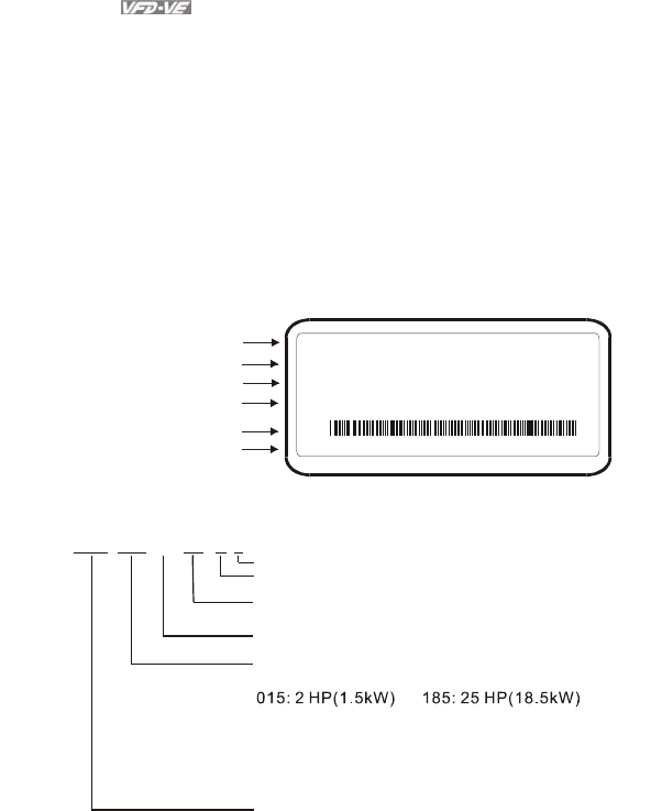
1.1.1 Nameplate Information
Example for 5HP/3.7kW 3-phase 230V AC motor drive
Serial Number & Bar Code
AC Drive Model
Input Spec.
Output Spec.
Output Frequency Range
Enclosure type
MODE : VFD037V23A-2
INPUT : 3PH 200-240V 50/60Hz 19.6A
OUTPUT : 3PH 0-240V 17A 6.5kVA 5HP
Freq. Range : 0.00~600.00Hz
ENCLOSURE: TYPE 1
037V23A2T6360001
1.1.2 Model Explanation
VFD A-
Version Type
23
Mains Input Voltage
23: Three phase230V 43: Three phase460V
V037
Applicable motor capacity
007: 1 HP(0.7kW) 150: 20HP(15kW)
022: 3 HP(2.2kW) 220: 30 HP(22kW)
037: 5 HP(3.7kW) 300: 40HP(30kW)
055: 7.5HP(5.5kW) 370: 50 HP(37kW)
075: 10 HP(7.5kW) 450: 60HP(45kW)
110: 15 HP(11kW) 550: 75HP(55kW)
750: 100HP(75kW)
Series Name ( ariable requency rive)
VF D
2VFD-VE Series
Vector Series
Chapter 1 Introduction|
Revision August 2008, 03VE, SW V2.04 1-3
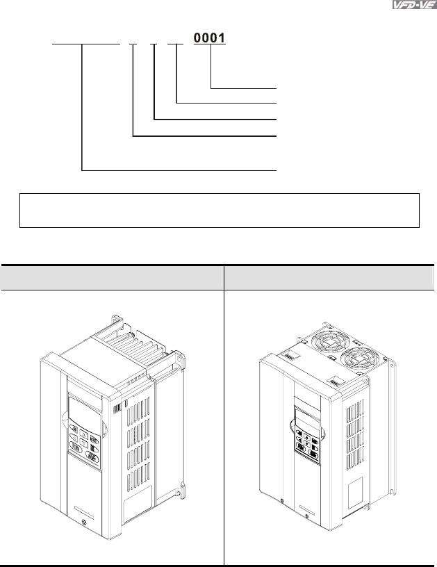
1.1.3 Series Number Explanation
367T037V23A2
Production number
Production year 2007
Production factory
Production week
(T: Taoyuan, W: Wujian)
Model
230V 3-phase 5HP(3.7kW)
If the nameplate information does not correspond to your purchase order or if there are
any problems, please contact your distributor.
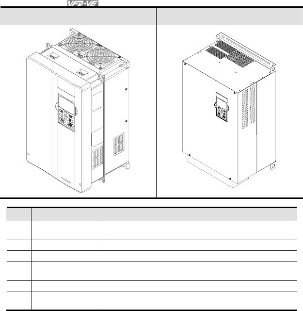
1.1.4 Drive Frames and Appearances
1-5HP/0.75-3.7kW (Frame B) 7.5-15HP/5.5-11kW (Frame C)
Chapter 1 Introduction|
1-4 Revision August 2008, 03VE, SW V2.04
15-30HP/11-22kW (Frame D) 40-100HP/30-75kW (Frame E)
Frame Power range Models
B (B1) 1-3hp (0.75-2.2kW) VFD007V23A/43A-2, VFD015V23A/43A-2,
VFD022V23A/43A-2
B (B2) 5hp (3.7kW) VFD037V23A/43A-2
C 7.5-15hp (5.5-11kW) VFD055V23A/43A-2, VFD075V23A/43A-2, VFD110V43B-2
D 15-30hp (11-22kW)
VFD110V23A/43A-2, VFD150V23A/43A-2,
VFD185V23A/43A-2, VFD220V23A/43A-2
E (E1) 40-60hp (30-45kW) VFD300V43A-2, VFD370V43A-2, VFD450V43A-2
E (E2) 40-100hp (30-75kW) VFD300V23A-2, VFD370V23A-2, VFD550V43C-2,
VFD750V43C-2
Please refer to Chapter 1.3 for exact dimensions.
1.2 Preparation for Installation and Wiring
1.2.1 Ambient Conditions
Install the AC motor drive in an environment with the following conditions:
Chapter 1 Introduction|
Revision August 2008, 03VE, SW V2.04 1-5
Air Temperature: -10 ~ +40°C (14 ~ 122°F)
Relative Humidity: <90%, no condensation allowed
Atmosphere
pressure: 86 ~ 106 kPa
Installation Site
Altitude: <1000m
Operation
Vibration: <20Hz: 9.80 m/s2 (1G) max
20 ~ 50Hz: 5.88 m/s2 (0.6G) max
Temperature: -20°C ~ +60°C (-4°F ~ 140°F)
Relative Humidity: <90%, no condensation allowed
Atmosphere
pressure: 86 ~ 106 kPa
Storage
Transportation
Vibration: <20Hz: 9.80 m/s2 (1G) max
20 ~ 50Hz: 5.88 m/s2 (0.6G) max
Pollution Degree 2: good for a factory type environment.
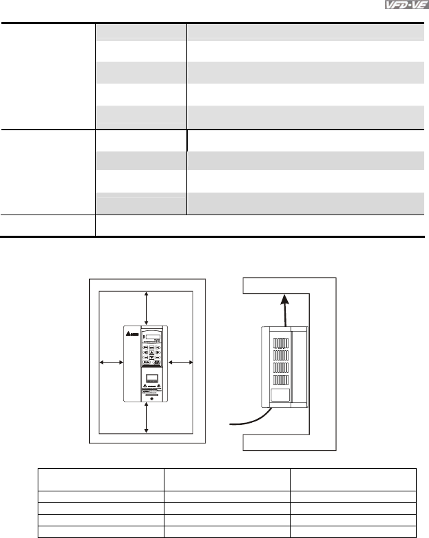
Minimum Mounting Clearances
H
DATA
PROG
REV
FWD
Air Flow
H
WW
HP W
mm (inch)
H
mm (inch)
1-5HP 50 (2) 150 (6)
7.5-20HP 75 (3) 175 (7)
25-75HP 75 (3) 200 (8)
100HP and above 75 (3) 250 (10)
Chapter 1 Introduction|
1-6 Revision August 2008, 03VE, SW V2.04
CAUTION!
1. Operating, storing or transporting the AC motor drive outside these conditions may cause
damage to the AC motor drive.
2. Failure to observe these precautions may void the warranty!
3. Mount the AC motor drive vertically on a flat vertical surface object by screws. Other directions
are not allowed.
4. The AC motor drive will generate heat during operation. Allow sufficient space around the unit
for heat dissipation.
5. The heat sink temperature may rise to 90°C when running. The material on which the AC motor
drive is mounted must be noncombustible and be able to withstand this high temperature.
6. When AC motor drive is installed in a confined space (e.g. cabinet), the surrounding
temperature must be within -10 ~ 40°C with good ventilation. DO NOT install the AC motor
drive in a space with bad ventilation.
7. When installing multiple AC more drives in the same cabinet, they should be adjacent in a row
with enough space in-between. When installing one AC motor drive below another one, use a
metal separation between the AC motor drives to prevent mutual heating.
8. Prevent fiber particles, scraps of paper, saw dust, metal particles, etc. from adhering to the
heatsink.
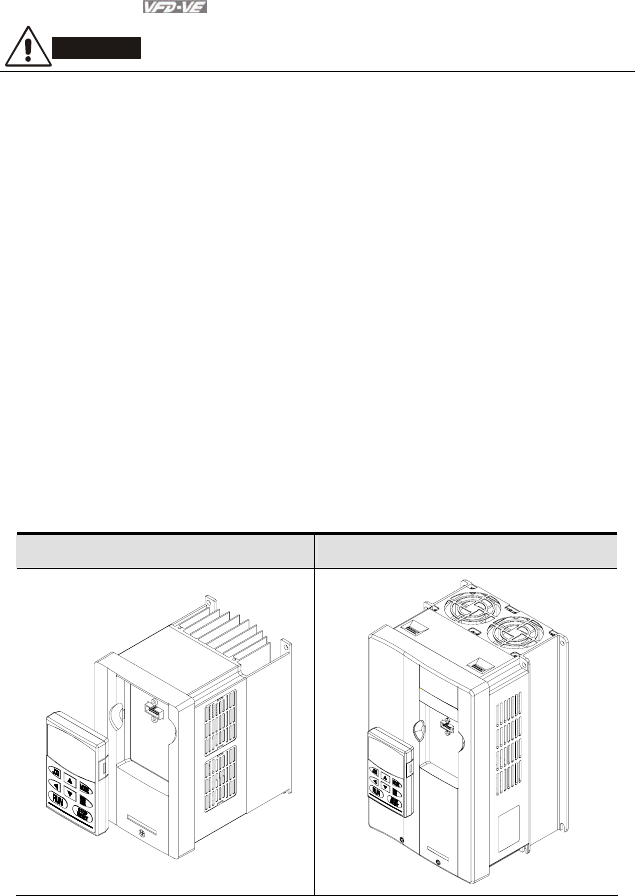
1.2.2 Remove Keypad
1-5HP/0.75-3.7kW (Frame B) 7.5-15HP/5.5-11kW (Frame C)
Chapter 1 Introduction|
Revision August 2008, 03VE, SW V2.04 1-7
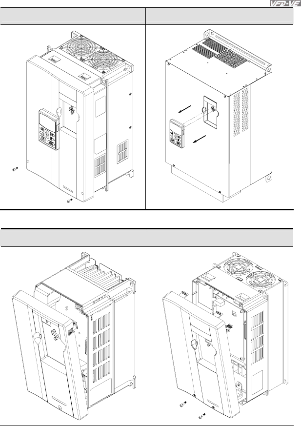
15-30HP/11-22kW (Frame D) 40-100HP/30-75kW (Frame E)
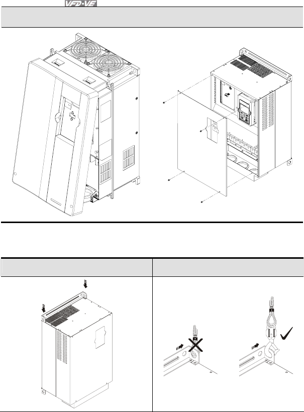
1.2.3 Remove Front Cover
1-5HP/0.75-3.7kW (Frame B) 7.5-15HP/5.5-11kW (Frame C)
Chapter 1 Introduction|
1-8 Revision August 2008, 03VE, SW V2.04
15-30HP/11-22kW (Frame D) 40-100HP/30-75kW (Frame E)
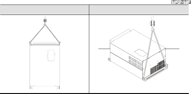
1.2.4 Lifting
Please carry only fully assembled AC motor drives as shown in the following.
For 40-100HP (Frame E and E1)
Step 1 Step 2
Chapter 1 Introduction|
Revision August 2008, 03VE, SW V2.04 1-9
Step 3 Step 4
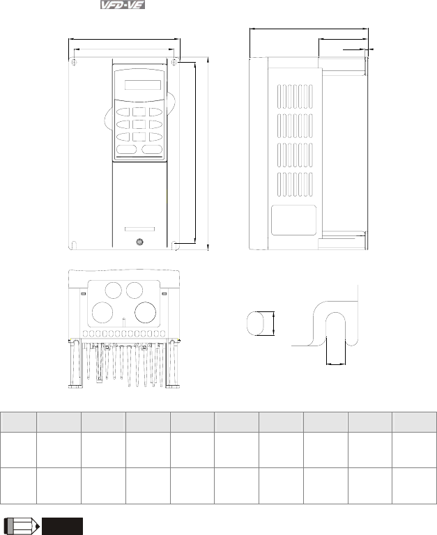
1.3 Dimensions
Chapter 1 Introduction|
1-10 Revision August 2008, 03VE, SW V2.04
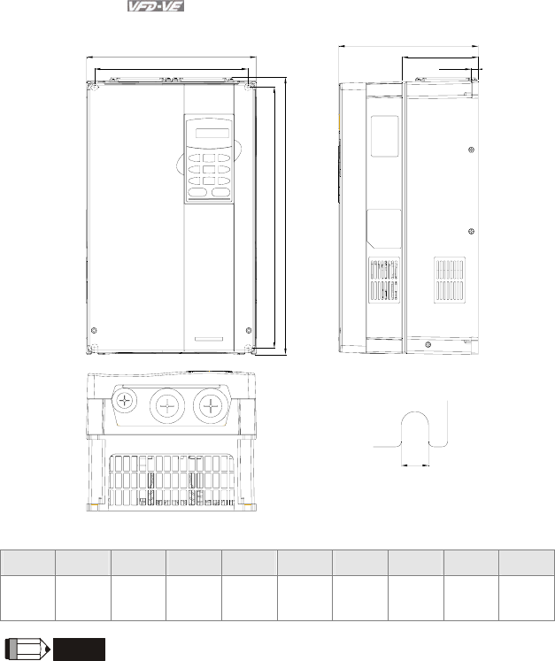
Frame B
H
W1
D
W
H1
D2
D1
S1
S2
Unit: mm[inch]
Frame W W1 H H1 D D1 D2 S1 S2
B1 150.0
[5.91]
135.0
[5.32]
260.0
[10.24]
244.3
[9.63]
160.2
[6.31]
67.0
[2.64]
4.0
[0.16]
8.0
[0.32]
6.5
[0.26]
B2 150.0
[5.91]
135.0
[5.32]
272.1
[10.72]
244.3
[9.63]
183.7
[7.24]
67.0
[2.64]
4.0
[0.16]
8.0
[0.32]
6.5
[0.26]
NOTE
Frame B1: VFD007V23A/43A-2, VFD015V23A/43A-2, VFD022V23A/43A-2
Frame B2: VFD037V23A/43A-2
Chapter 1 Introduction|
Revision August 2008, 03VE, SW V2.04 1-11
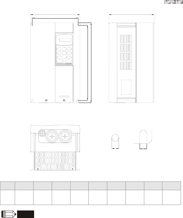
Frame C
H1
H
W
W1
D
S1 S2
Unit: mm[inch]
Frame W W1 H H1 D - - S1 S2
C 200.0
[7.88]
185.6
[7.31]
323.0
[12.73]
244.3
[9.63]
160.2
[6.31] - -
7.0
[0.28]
7.0
[0.28]
NOTE
Frame C: VFD055V23A/43A-2, VFD075V23A/43A-2, VFD110V43B-2
Chapter 1 Introduction|
1-12 Revision August 2008, 03VE, SW V2.04
Frame D
S1
W
W1
H
H1
D
D1
D2
Unit: mm[inch]
Frame W W1 H H1 D D1 D2 S1 -
D 250.0
[9.85]
226.0
[8.90]
408.2
[16.07]
384.0
[15.13]
205.4
[8.08]
110.0
[4.33]
10.0
[0.39]
10.0
[0.39] -
NOTE
Frame D: VFD110V23A/43A-2, VFD150V23A/43A-2, VFD185V23A/43A-2, VFD220V23A/43A-2
Chapter 1 Introduction|
Revision August 2008, 03VE, SW V2.04 1-13
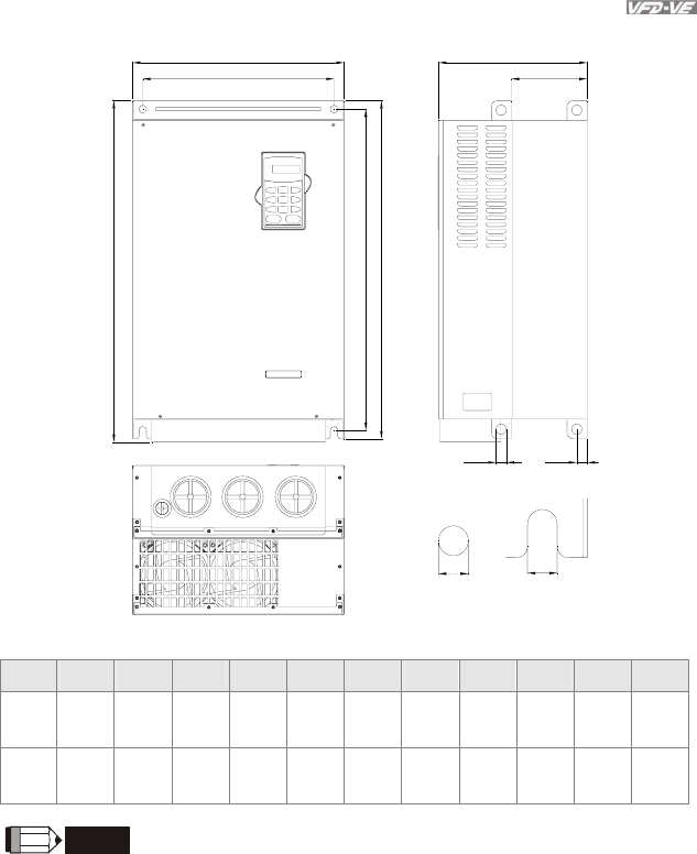
Frame E
W1
W D
H1
H2
S2
H
D1
S1
D2
S3
Unit: mm[inch]
Frame W W1 H H1 H2 D D1 D2 S1 S2 S3
E1 370.0
[14.57]
335.0
[13.19] - 589.0
[23.19]
560.0
[22.05]
260.0
[10.24]
132.5
[5.22]
18.0
[0.71]
13.0
[0.51]
13.0
[0.51]
18.0
[0.71]
E2 370.0
[14.57]
335.0
[13.19]
595.0
[23.43]
589.0
[23.19]
560.0
[22.05]
260.0
[10.24]
132.5
[5.22]
18.0
[0.71]
13.0
[0.51]
13.0
[0.51]
18.0
[0.71]
NOTE
Frame E1: VFD300V43A-2, VFD370V43A-2, VFD450V43A-2
Frame E2: VFD300V23A-2, VFD370V23A-2, VFD550V43C-2, VFD750V43C-2

Chapter 1 Introduction|
1-14 Revision August 2008, 03VE, SW V2.04
This page intentionally left blank

Revision August 2008, 03VE, SW V2.04 2-1
Chapter 2 Installation and Wiring
After removing the front cover (see chapter 1.2.3 for details), check if the power and control terminals
are clear. Be sure to observe the following precautions when wiring.
General Wiring Information
Applicable Codes
All VFD-VE series are Underwriters Laboratories, Inc. (UL) and Canadian Underwriters
Laboratories (cUL) listed, and therefore comply with the requirements of the National
Electrical Code (NEC) and the Canadian Electrical Code (CEC).
Installation intended to meet the UL and cUL requirements must follow the instructions
provided in “Wiring Notes” as a minimum standard. Follow all local codes that exceed UL
and cUL requirements. Refer to the technical data label affixed to the AC motor drive and
the motor nameplate for electrical data.
The "Line Fuse Specification" in Appendix B, lists the recommended fuse part number for
each VFD-VE Series part number. These fuses (or equivalent) must be used on all
installations where compliance with U.L. standards is a required.
CAUTION!
1. Make sure that power is only applied to the R/L1, S/L2, T/L3 terminals. Failure to comply may
result in damage to the equipment. The voltage and current should lie within the range as
indicated on the nameplate.
2. Check following items after finishing the wiring:
A. Are all connections correct?
B. No loose wires?
C. No short-circuits between terminals or to ground?
DANGER!
1. A charge may still remain in the DC bus capacitors with hazardous voltages even if the power
has been turned off. To prevent personal injury, please ensure that the power is turned off and
wait ten minutes for the capacitors to discharge to safe voltage levels before opening the AC
motor drive.
2. All the units must be grounded directly to a common ground terminal to prevent lightning strike
or electric shock.
3. Only qualified personnel familiar with AC motor drives is allowed to perform installation, wiring
and commissioning.
4. Make sure that the power is off before doing any wiring to prevent electric shock.
Chapter 2 Installation and Wiring|
2-2 Revision August 2008, 03VE, SW V2.04
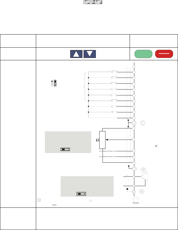
2.1 Wiring
Users must connect wires according to the circuit diagrams on the following pages. Do not plug a
modem or telephone line to the RS-485 communication port or permanent damage may result. The
pins 1 & 2 are the power supply for the optional copy keypad KPV-CE01 only and should not be used
for RS-485 communication.
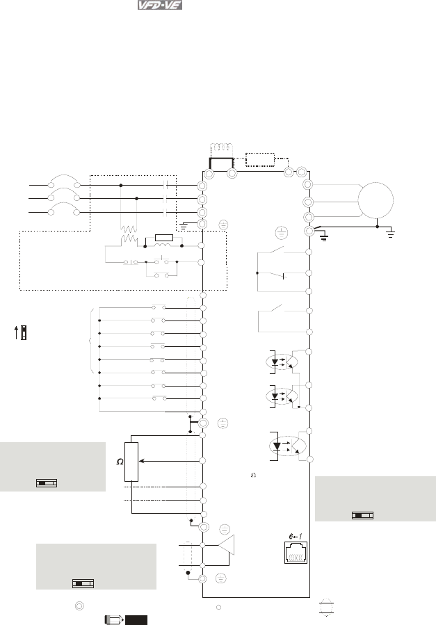
Figure 1 for models of VFD-VE Series (15 HP/11kW and below)
VFD007V23A/43A-2, VFD015V23A/43A-2, VFD022V23A/43A-2, VFD037V23A/43A-2,
VFD055V23A/43A-2, VFD075V23A/43A-2, VFD110V43B-2, VFD110V23A/43A-2
+2/B1
B2
Brake resistor
(optional)
+1
Jumper
DC choke
(optional)
Main circuit (power) terminals Control circuit terminals Shielded leads & Cable
Sw1
Sink
Source
Factory setting:
SINK Mode
Please refer to
Figure 3 for wiring
of SINK mode an d
SOURCEmode.
R(L1)
S(L2)
T(L3)
Fuse/NFB(No Fuse Breaker)
SA
OFF ON
MC
MC
RB
RC
Recommended Circuit
when power supply
is turned OFF by a
fault output.
R(L1)
S(L2)
T(L3)
E
AVI
ACI
AUI
ACM
+10V
5K
3
2
1
Power supply
+10V 20mA
Master Frequency
0 to 10V 47k
Analog Signal Common
E
U(T1)
V(T2)
W(T3)
IM
3~
RA
RB
RC
Motor
RS-485 serial communication
1: +EV
2: GND
3: SG-
4: SG+
5: NC
6: NC
E
DFM
DCM
Digital Frequency Output
Te r m i n al
factory setting: 1:1
Duty=50%, 10VDC
Digital Signal Com mon
Multi-function contact output 1
(relay)
factory setting: fault indication
MO1
MO2
MCM
Multi-function contact output 3
(photocoupler)
Multi-function
Photocoupler Output
Multi-function contact output 4
(photocoupler)
MRA
MRC
Multi-function contact output 2
(relay)
48VDC 50mA
factory setting:
indicates that it is running
DFM output signal selection
MI1
MI2
MI3
MI4
MI6
MI5
DCM
+24V
FWD/STOP
REV/STOP
Multi-step 1
Multi-step 2
Multi-step 3
Multi-step 4
No function
Digital Signal Common
Factory
setting
* Don't apply the mains voltage directly
to above terminals. E
No function
REV
FWD
ACI current/voltage selection
AFM
ACM
Analog Signal common
E
The brake resistor is built-in to model VFD110V43B.
NOTE
If the fault occurs, the
contact will be ON to turn
off the power and protect the power system.
-
OC TP
DFM Switch
Make sure that power is OFF
before changing the switch
setting.
4~20mA/0~10V
-10~+10V
0-20mA 0-10V
ACI Switch
Make sure that power is OFF
before changing the switch
setting.
0~10VDC/ 2mA
AFM analog output selection
Analog Multi-function Output Terminal
0-10V 0-20mA
AFM Switch
Make sure that power is OFF
before changing the switch
setting.
For communication,
it needs to use
VFD-USB01/IFD8500
to connect to PC.
Chapter 2 Installation and Wiring|
Revision August 2008, 03VE, SW V2.04 2-3
Main circuit (power) terminals Control circuit terminals Shielded leads & Cable
Sw1
Sink
Source
Factory setting:
SINK Mode
Please refer to
Figure 3 for wiring
of S INK mode and
SOURCEmode.
R(L1)
S(L2)
T(L3)
Fuse/NFB(No Fuse Breaker)
SA
OFF ON
MC
MC
RB
RC
Recommended Circuit
when power s upply
is turned OFF by a
fault output.
R(L1)
S(L2)
T(L3)
E
AVI
ACI
AUI
ACM
+10V
5K
3
2
1
Power supply
+10V 20m A
Master Frequency
0 to 10V 47k
Analog S ignal Common
E
U(T1)
V(T2)
W(T3)
IM
3~
RA
RB
RC
Motor
RS-485 serial communication
1: +EV
2: GND
3: SG-
4: SG+
5: NC
6: NC
E
DFM
DCM
Digital Frequency Output
Terminal
factory setting: 1:1
Duty=50%, 10VDC
Digital Signal Common
Multi-function contact output 1
(relay)
factory setting: fault indication
MO1
MO2
MCM
Multi-function contact output 3
(photocoupler)
Multi-function
Photocoupler Output
Multi-function contact output 4
(photocoupler)
MRA
MRC
Multi-function contact output 2
(relay)
48VDC 50mA
factory setting:
indicates that it is running
DFM output signal selection
MI1
MI2
MI3
MI4
MI6
MI5
DCM
+24V
FWD/STOP
REV/STOP
Multi-step 1
Multi-step 2
Multi-step 3
Multi-step 4
No function
Digital Signal Common
Factory
setting
* Don't apply the mains voltage directly
to above terminals. E
No function
REV
FWD
ACI current/voltage selection
AFM
ACM
Analog Signal common
E
The brake resistor is built-in to model VFD110V43B.
NOTE
If the fault occurs, the
contact will be ON to turn
off the power and protect the power system.
OC TP
DFM Switch
Make sure that power is OFF
before changing the switch
setting.
4~20mA/0~10V
-10~+10V
0-20mA 0-10V
ACI Switch
Make sure that power is OFF
before changing the switch
setting.
0~10VDC/2mA
AFM analog output selection
Analog Multi-function Output Terminal
0-10V 0-20mA
AFM Switch
Make sure that power is OFF
before changing the switch
setting.
For communication,
it needs to use
VFD-USB01/IFD8500
to connect to PC.
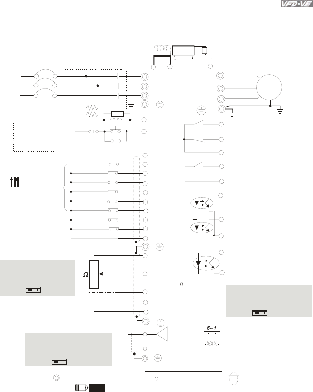
Figure 2 for models of VFD-VE Series (20HP/15kW and above)
VFD150V23A/43A-2, VFD185V23A/43A-2, VFD220V23A/43A-2, VFD300V43A-2, VFD370V43A-2,
VFD450V43A-2, VFD300V23A-2, VFD370V23A-2, VFD550V43C-2, VFD750V43C-2
Jumper
DC choke
(optional)
-(minus sign)
VFDB
+2
+1
brake unit
(optional)
brake resistor
(optional)
Chapter 2 Installation and Wiring|
2-4 Revision August 2008, 03VE, SW V2.04
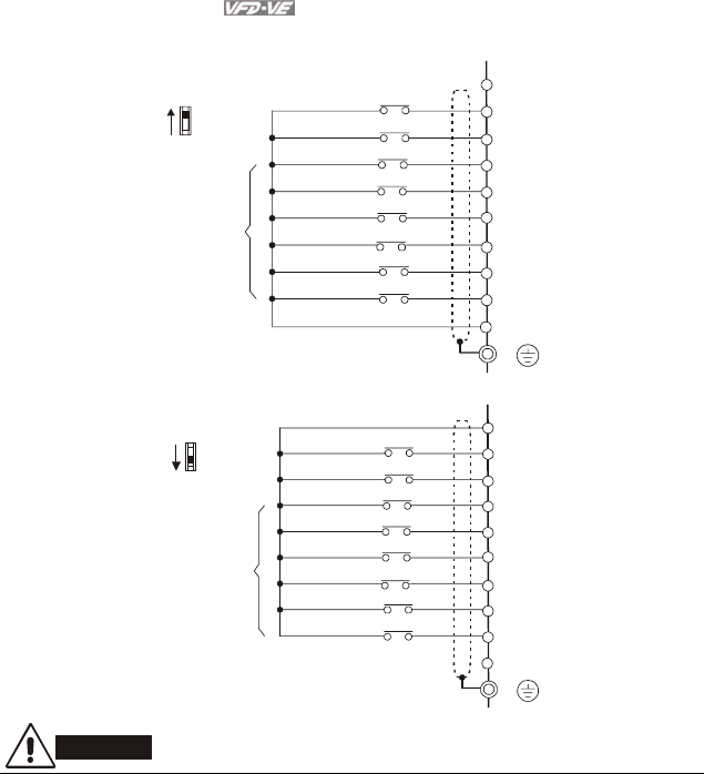
Figure 3 Wiring for SINK(NPN) mode and SOURCE(PNP) mode
*Don't apply the mains voltage directly
to above terminals.
FWD/STOP
REV/STOP
Multi-step1
Multi-step2
Multi-step3
Multi-step4
+24V
MI1
MI2
MI3
MI4
MI5
MI6
Factory
setting
SINK/NPN Mode
FWD
REV
No Function
No Function
Digital Signal Common
DCM
Sink
Source
SW1
E
*Don't apply the mains voltage directly
to above terminals.
FWD/STOP
REV/STOP
Multi-step1
Multi-step2
Multi-step3
Multi-step4
+24V
MI1
MI2
MI3
MI4
MI5
MI6
Factory
setting
SOURCE/PNP Mode
FWD
REV
No Function
No Function
DCM
E
Sink
Source
SW1
CAUTION!
1. The wiring of main circuit and control circuit should be separated to prevent erroneous actions.
2. Please use shield wire for the control wiring and not to expose the peeled-off net in front of the
terminal.
3. Please use the shield wire or tube for the power wiring and ground the two ends of the shield
wire or tube.
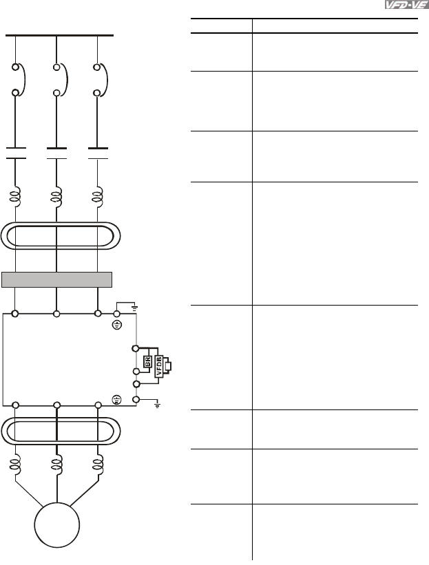
2.2 External Wiring
Chapter 2 Installation and Wiring|
Revision August 2008, 03VE, SW V2.04 2-5
Motor
Output AC
Line Reactor
Power Suppl
y
Magnetic
contactor
Input AC
Line Reactor
EMI Filter
R/L1 S/L2 T/L3
U/T1 V/T2 W/T3
+/B1
B2
Zero-phase
Reactor
Zero-phase
Reactor
FUSE/NFB
-
BR
E
Break resistor
(optional)
Break unit (optional)
Break resistor
(optional)
2.3 Main Circuit
2.3.1 Main Circuit Connection
Items Explanations
Power
supply
Please follow the specific power
supply requirements shown in
Appendix A.
Fuse/NFB
(Optional)
There may be an inrush current
during power up. Please check the
chart of Appendix B and select the
correct fuse with rated current. Use of
an NFB is optional.
Magnetic
contactor
(Optional)
Please do not use a Magnetic
contactor as the I/O switch of the AC
motor drive, as it will reduce the
operating life cycle of the AC drive.
Input AC
Line Reactor
(Optional)
Used to improve the input power
factor, to reduce harmonics and
provide protection from AC line
disturbances (surges, switching
spikes, short interruptions, etc.). AC
line reactor should be installed when
the power supply capacity is 500kVA
or more or advanced capacity is
activated .The wiring distance should
be ≤ 10m. Refer to appendix B for
details.
Zero-phase
Reactor
(Ferrite Core
Common
Choke)
(Optional)
Zero phase reactors are used to
reduce radio noise especially when
audio equipment is installed near the
inverter. Effective for noise reduction
on both the input and output sides.
Attenuation quality is good for a wide
range from AM band to 10MHz.
Appendix B specifies the zero phase
reactor. (RF220X00A)
EMI filter
(Optional)
To reduce electromagnetic
interference, please refer to Appendix
B for more details.
Brake
Resistor
(Optional)
Used to reduce the deceleration time
of the motor. Please refer to the chart
in Appendix B for specific Brake
Resistors.
Output AC
Line Reactor
(Optional)
Motor surge voltage amplitude
depends on motor cable length. For
applications with long motor cable
(>20m), it is necessary to install a
reactor at the inverter output side
Chapter 2 Installation and Wiring|
2-6 Revision August 2008, 03VE, SW V2.04
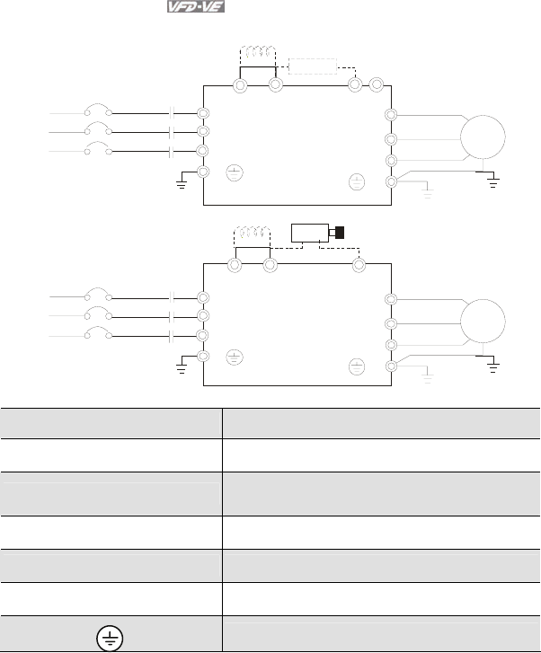
Figure 1 for the main terminals
R(L1)
S(L2)
T(L3)
R
S
T
U(T1)
V(T2)
W(T3)
IM
3~
MC
E
E
+1 +2/B1 B2
No-fuse breaker
( NFB)
Br ak e res istor(O pti ona l)
Motor
-
Figure 2 for the main terminals
R(L1)
S(L2)
T(L3)
R
S
T
U(T1)
V(T2)
W(T3)
IM
3~
MC
E
E
VFDB
+1 +2 -
No-fuse breaker
(NF B)
Br ak e res istor
(optional)
Motor
Terminal Symbol Explanation of Terminal Function
R/L1, S/L2, T/L3 AC line input terminals (1-phase/3-phase)
U/T1, V/T2, W/T3 AC drive output terminals for connecting 3-phase
induction motor
+1, +2 Connections for DC Choke (optional)
+2/B1, B2 Connections for Brake Resistor (optional)
+2~(-), +2/B1~(-) Connections for External Brake Unit (VFDB series)
Earth connection, please comply with local regulations.
Chapter 2 Installation and Wiring|
Revision August 2008, 03VE, SW V2.04 2-7
Mains power terminals (R/L1, S/L2, T/L3)
Connect these terminals (R/L1, S/L2, T/L3) via a no-fuse breaker or earth leakage
breaker to 3-phase AC power (some models to 1-phase AC power) for circuit protection. It
is unnecessary to consider phase-sequence.
It is recommended to add a magnetic contactor (MC) in the power input wiring to cut off
power quickly and reduce malfunction when activating the protection function of AC motor
drives. Both ends of the MC should have an R-C surge absorber.
Please make sure to fasten the screw of the main circuit terminals to prevent sparks
which is made by the loose screws due to vibration.
Please use voltage and current within the regulation shown in Appendix A.
When using leakage-current breaker to prevent leakage current,
Do NOT run/stop AC motor drives by turning the power ON/OFF. Run/stop AC motor
drives by RUN/STOP command via control terminals or keypad. If you still need to
run/stop AC drives by turning power ON/OFF, it is recommended to do so only ONCE per
hour.
Do NOT connect 3-phase models to a 1-phase power source.
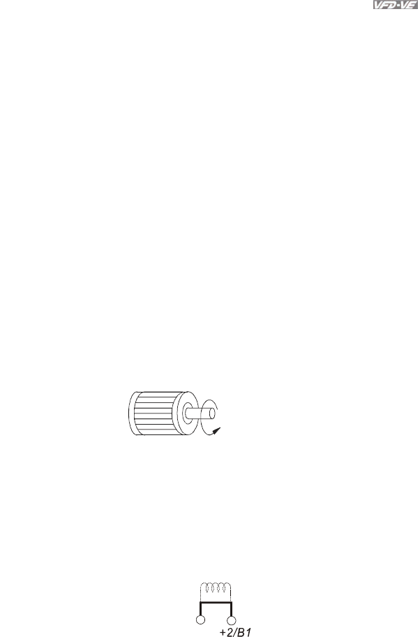
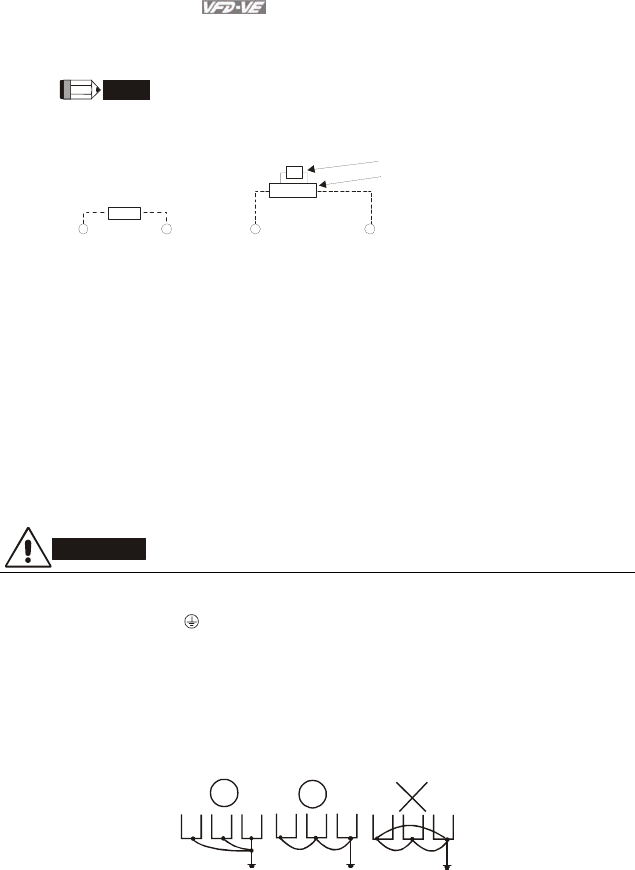
Output terminals for main circuit (U, V, W)
When the AC drive output terminals U/T1, V/T2, and W/T3 are connected to the motor
terminals U/T1, V/T2, and W/T3, respectively, the motor will rotate counterclockwise (as
viewed on the shaft end of the motor) when a forward operation command is received. To
permanently reverse the direction of motor rotation, switch over any of the two motor
leads.
Forward
running
DO NOT connect phase-compensation capacitors or surge absorbers at the output
terminals of AC motor drives.
With long motor cables, high capacitive switching current peaks can cause over-current,
high leakage current or lower current readout accuracy. To prevent this, the motor cable
should be less than 20m for 3.7kW models and below. And the cable should be less than
50m for 5.5kW models and above. For longer motor cables use an AC output reactor.
Use well-insulated motor, suitable for inverter operation.
Terminals [+1, +2] for connecting DC reactor
+1
Jumper
DC reactor
Chapter 2 Installation and Wiring|
2-8 Revision August 2008, 03VE, SW V2.04
To improve power factor and reduce harmonics connect a DC reactor between terminals
[+1, +2]. Please remove the jumper before connecting the DC reactor.
NOTE
Models of 15kW and above have a built-in DC reactor.
Terminals [+2/B1, B2] for connecting brake resistor and terminals [+1, +2/B1] for
connecting external brake unit
Brake unit(optional)
Refer to Appendix B for the use of
spec ial b raking resis tor/unit
+2/B
1
B2
BR
+2/B
1
-
VFDB
BR
Brake resistor(optional
)
Connect a brake resistor or brake unit in applications with frequent deceleration ramps,
short deceleration time, too low brake torque or requiring increased brake torque.
If the AC motor drive has a built-in brake chopper (all models of 11kW and below),
connect the external brake resistor to the terminals [+2/B1, B2].
Models of 15kW and above don’t have a built-in brake chopper. Please connect an
external optional brake unit (VFDB-series) and brake resistor. Refer to VFDB series user
manual for details.
Connect the terminals [+(P), -(N)] of the brake unit to the AC motor drive terminals
[+2(+2/B1), (-)]. The length of wiring should be less than 5m with twisted cable.
When not used, please leave the terminals [+2/B1, -] open.
WARNING!
1. Short-circuiting [B2] or [-] to [+2/B1] can damage the AC motor drive.
Grounding terminals ( )
Make sure that the leads are connected correctly and the AC drive is properly grounded.
(Ground resistance should not exceed 0.1Ω.)
Use ground leads that comply with local regulations and keep them as short as possible.
Multiple VFD-VE units can be installed in one location. All the units should be grounded
directly to a common ground terminal, as shown in the figure below. Ensure there are no
ground loops.
goodexcellent not allowed
Chapter 2 Installation and Wiring|
Revision August 2008, 03VE, SW V2.04 2-9
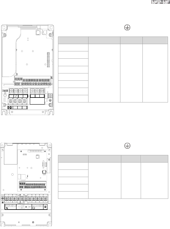
2.3.2 Main Circuit Terminals
Frame B
+1 +2 B1-B2U/T1 V/T2 W/T3
Screw Torque :
Wire Gauge :
18Kgf-cm
18~10AWG
R/L1 S/L2 T/L3
Main circuit terminals
R/L1, S/L2, T/L3, U/T1, V/T2, W/T3, , +1, +2/B1, -, B2
Models Wire Torque Wire Type
VFD007V23A-2
VFD007V43A-2
VFD015V23A-2
VFD015V43A-2
VFD022V23A-2
VFD022V43A-2
VFD037V23A-2
VFD037V43A-2
14-10 AWG
(2.1-5.3mm2)
18kgf-cm
(15.6in-lbf)
Stranded
copper only,
75oC
Frame C
POWER IM MOTOR3
Main circuit terminals
R/L1, S/L2, T/L3, U/T1, V/T2, W/T3, , +1, +2/B1, -, B2
Models Wire Torque Wire Type
VFD055V23A-2
VFD075V23A-2
VFD110V43B-2
VFD055V43A-2
VFD075V43A-2
12-8 AWG
(3.3-8.4mm2)
30kgf-cm
(26in-lbf)
Stranded
copper only,
75 oC
Chapter 2 Installation and Wiring|
2-10 Revision August 2008, 03VE, SW V2.04
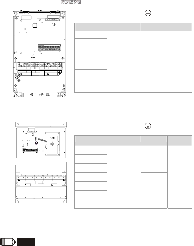
Frame D
3
V/T2 W/T3
R/L1
DC DC +
( ) ( )
-
POWER
S/L2 T/L3 -
+2+1
MOTOR
IM
Main circuit terminals
R/L1, S/L2, T/L3, U/T1, V/T2, W/T3, , +1, +2, -
Models Wire Torque Wire Type
VFD110V23A-2
VFD110V43A-2
VFD150V43A-2
VFD150V23A-2
VFD185V23A-2
VFD185V43A-2
VFD220V43A-2
VFD220V23A-2
8-2 AWG
(8.4-33.6mm2)
30kgf-cm
(26in-lbf)
Stranded
copper only,
75 oC
Frame E
W/T3S/L2R/L1 T/L3 +2+1 U/T1 V/T2
(173in-lbf)
Screw Torque:
200kgf-cm
POWER IM MOTOR
3
POWER
ALARM
CHARGE
Main circuit terminals
R/L1, S/L2, T/L3, U/T1, V/T2, W/T3, , +1, +2, -
Models Wire Torque Wire Type
VFD300V43A-2
VFD370V43A-2
VFD450V43A-2
57kgf-cm
(49in-lbf)
VFD300V23A-2
VFD370V23A-2
VFD550V43C-2
VFD750V43C-2
4-2 AWG
(21.2-33.6mm2)
200kgf-cm
(173in-lbf)
Stranded
copper
only, 75 oC
NOTE
# To connect 6 AWG (13.3 mm2) wires, use Recognized Ring Terminals
2.4 Control Terminals
Circuit diagram for digital inputs (SINK current 16mA.)
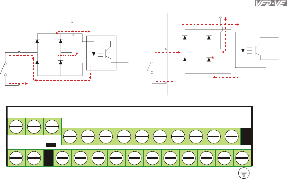
Chapter 2 Installation and Wiring|
Revision August 2008, 03VE, SW V2.04 2-11
+24
SINK Mode
multi-input
terminal
Internal CircuitDCM
+24V
Multi-Input
Ter mi nal
DCM
Internal Circuit
SOURCE Mode
+10V
MO1 MO2
MI3
MI4
MI5
MI6
DFM
+24V
DCM
ACM
AVI
ACI
AFM
MCM
RA
RB
RC
MRC
MRA
REV
MI2
FWD MI1
AUI
The Position of the Control Terminals
Chapter 2 Installation and Wiring|
2-12 Revision August 2008, 03VE, SW V2.04
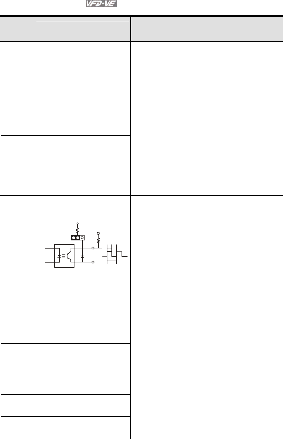
Terminal symbols and functions
Terminal
Symbol Terminal Function Factory Settings (SINK)
ON: Connect to DCM
FWD Forward-Stop Command ON: Run in FWD direction
OFF: Stop acc. to Stop Method
REV Reverse-Stop Command ON: Run in REV direction
OFF: Stop acc. to Stop Method
+24V DC Voltage Source +24VDC, 80mA, used for SOURCE mode.
MI1 Multi-function Input 1
MI2 Multi-function Input 2
MI3 Multi-function Input 3
MI4 Multi-function Input 4
MI5 Multi-function Input 5
MI6 Multi-function Input 6
Refer to Pr.02-01 to Pr.02-06 for programming
the Multi-function Inputs.
ON: the activation current is 6.5mA. OFF:
leakage current tolerance is 10μA.
DFM
Digital Frequency Meter
(Open Collector Output)
Max: 48V
50mA
DFM-DCM
100%
50%
J5
internal circuit
Pulse voltage output monitor signal,
proportional to output frequency
Duty-cycle: 50%
Ratio: Pr.02-18
Min. load: 4.7kΩ
Max. current: 50mA
Max. voltage: 48Vdc
Jumper: DFM jumper, factory
setting is OC
DCM Digital Signal Common Common for digital inputs and used for SINK
mode.
RA Multi-function Relay Output 1
(N.O.) a
RB Multi-function Relay Output 1
(N.C.) b
RC Multi-function Relay Common
MRA Multi-function Relay Output 2
(N.O.) a
MRC Multi-function Relay Common
Resistive Load:
5A(N.O.)/3A(N.C.) 240VAC
5A(N.O.)/3A(N.C.) 24VDC
Inductive Load:
1.5A(N.O.)/0.5A(N.C.) 240VAC
1.5A(N.O.)/0.5A(N.C.) 24VDC
To output monitor signal, including in operation,
frequency arrival, overload and etc.
Refer to Pr.02-11~02-12 for programming
Chapter 2 Installation and Wiring|
Revision August 2008, 03VE, SW V2.04 2-13
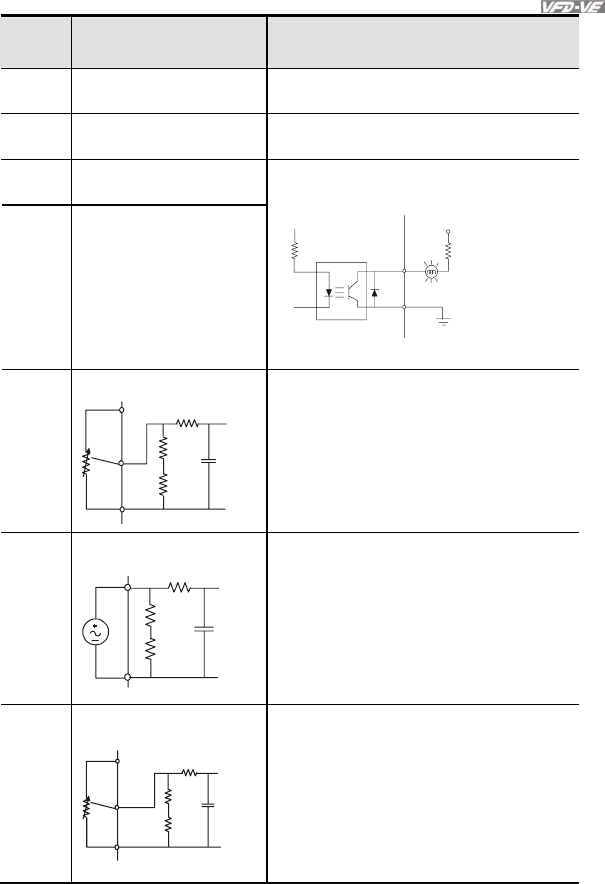
Terminal
Symbol Terminal Function Factory Settings (SINK)
ON: Connect to DCM
+10V Potentiometer Power Supply +10VDC 20mA (variable resistor 3-5kohm)
MCM Multi-function Output
Common (Photocoupler) Max. 48VDC 50mA
MO1 Multi-function Output 1
(Photocoupler)
MO2 Multi-function Output 2
(Photocoupler)
Maximum 48VDC, 50mA
Refer to Pr.02-13 to Pr.02-14 for programming
MO1~MO2-DCM
MO1~MO2
MCM
Internal Circuit
Max: 48Vdc
50mA
AVI
Analog voltage Input
ACM
AVI
+10V
internal circuit
AVI circuit
Impedance: 200kΩ
Resolution: 12 bits
Range: 0 ~ 10VDC = 0 ~ Max. Output
Frequency (Pr.01-00)
Set-up: Pr.03-00 ~ Pr.03-02
ACI
Analog current Input
ACM
ACI
internal circuit
ACI circuit
Impedance: 250Ω
Resolution: 12 bits
Range: 4 ~ 20mA/0~10V =
0 ~ Max. Output Frequency
(Pr.01-00)
Set-up: Pr.03-00 ~ Pr.03-02
Jumper: ACI jumper, factory setting is
4-20mA
AUI
Auxiliary analog voltage input
ACM
AUI
+10
~
-10V
internal circuit
AUI circuit
Impedance: 200kΩ
Resolution: 12 bits
Range: -10 ~ +10VDC =
0 ~ Max. Output Frequency
(Pr.01-00)
Set-up: Pr.03-00 ~ Pr.03-02
Chapter 2 Installation and Wiring|
2-14 Revision August 2008, 03VE, SW V2.04
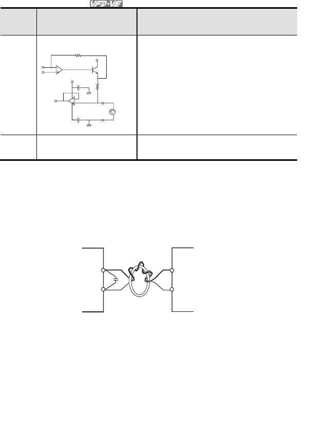
Terminal
Symbol Terminal Function Factory Settings (SINK)
ON: Connect to DCM
AFM
Analog output meter
A
FM
A
CM
0~20mA
Impedance: 18.5kΩ (voltage output)
1.1mΩ (current output)
Output current 20mA max
Resolution: max. frequency corresponds to
0-10V
Range: 0 ~ 10V/0 ~ 20mA
Function: Pr.03-18
Switch: AFM switch, factory setting is 0-
10V
ACM Analog control signal
(common) Common for AVI, ACI, AUI, AFM
*Control signal wiring size: 18 AWG (0.75 mm2) with shielded wire.
Analog input terminals (AVI, ACI, AUI, ACM)
Analog input signals are easily affected by external noise. Use shielded wiring and keep it
as short as possible (<20m) with proper grounding. If the noise is inductive, connecting
the shield to terminal ACM can bring improvement.
If the analog input signals are affected by noise from the AC motor drive, please connect
a capacitor and ferrite core as indicated in the following diagrams:
C
AVI/ACI/AUI
ACM
ferrite core
wind each wires 3 times or more around the core
Digital inputs (FWD, REV, MI1~MI6, DCM)
When using contacts or switches to control the digital inputs, please use high quality
components to avoid contact bounce.
Digital outputs (MO1, MO2, MCM)
Make sure to connect the digital outputs to the right polarity, see wiring diagrams.
When connecting a relay to the digital outputs, connect a surge absorber or fly-back diode
across the coil and check the polarity.
Chapter 2 Installation and Wiring|
Revision August 2008, 03VE, SW V2.04 2-15
General
Keep control wiring as far as possible from the power wiring and in separate conduits to
avoid interference. If necessary let them cross only at 90º angle.
The AC motor drive control wiring should be properly installed and not touch any live
power wiring or terminals.
NOTE
If a filter is required for reducing EMI (Electro Magnetic Interference), install it as close as
possible to AC drive. EMI can also be reduced by lowering the Carrier Frequency.
When using a GFCI (Ground Fault Circuit Interrupter), select a current sensor with
sensitivity of 200mA, and not less than 0.1-second detection time to avoid nuisance
tripping.
DANGER!
Damaged insulation of wiring may cause personal injury or damage to circuits/equipment if it comes
in contact with high voltage.
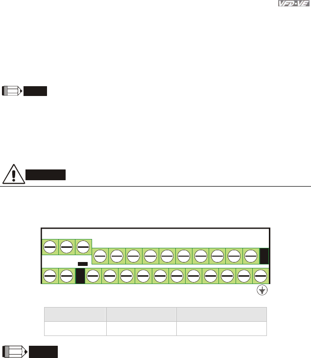
The specification for the control terminals
+10V
MO1 MO2
MI3
MI4
MI5
MI6
DFM
+24V
DCM
ACM
AVI
ACI
AFM
MCM
RA
RB
RC
MRC
MRA
REV
MI2
FWD MI1
AUI
The Position of the Control Terminals
Frame Torque Wire
B, C, D, E, E1 8 kgf-cm (6.9 in-lbf) 22-14 AWG (0.3-2.1mm2)
NOTE
Frame B: VFD007V23A/43A-2, VFD015V23A/43A-2, VFD022V23A/43A-2, VFD037V23A/43A-2;
Frame C: VFD055V23A/43A-2, VFD075V23A/43A-2, VFD110V43B-2,
Frame D: VFD110V23A/43A-2, VFD150V23A/43A-2, VFD185V23A/43A-2, VFD220V23A/43A-2
Frame E: VFD300V43A-2, VFD370V43A-2, VFD450V43A-2
Frame E1: VFD300V23A-2, VFD370V23A-2, VFD550V43C-2, VFD750V43C-2
Revision August 2008, 03VE, SW V2.04 3-1
Chapter 3 Digital Keypad Operation and Start Up
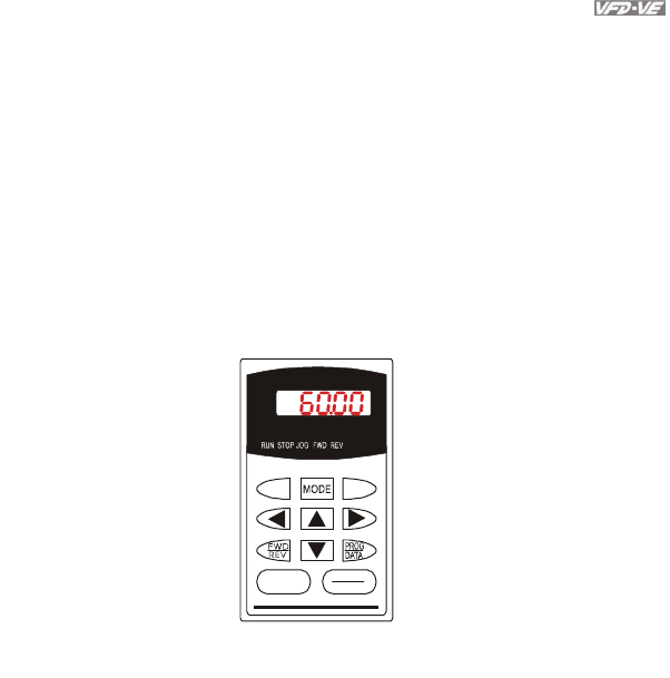
3.1 Digital Keypad KPV-CE01
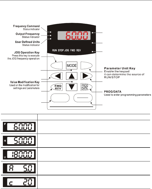
3.1.1 Description of the Digital Keypad KPV-CE01
U
F
H
KPV-CE01
JOG
RUN RESET
STOP
MODE Selection Key
Press this key to view different
operating values
LED Display
Display frequency, current, voltage
and error, etc.
Status Display
Display of driver status
Part Number
STOP/RESET
Left Key
moves cursor to the left
PU
EXTPU
Right Key
Moves the cursor right
FWD/REV Direction Key
RUN key
Display Message Descriptions
Displays the AC drive Master Frequency.
Displays the actual output frequency present at terminals U/T1, V/T2, and
W/T3.
User defined unit (where U = F x Pr.00-05)
Displays the output current present at terminals U/T1, V/T2, and W/T3.
The counter value (C).
Chapter 3 Digital Keypad Operation and Start Up|
3-2 Revision August 2008, 03VE, SW V2.04
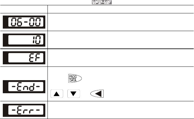
Display Message Descriptions
Displays the selected parameter.
Displays the actual stored value of the selected parameter.
External Fault.
Display “End” for approximately 1 second if input has been accepted by
pressing key. After a parameter value has been set, the new
value is automatically stored in memory. To modify an entry, use the
, and keys.
Display “Err”, if the input is invalid.

Chapter 3 Digital Keypad Operation and Start Up|
Revision August 2008, 03VE, SW V2.04 3-3
3.1.2 How to Operate the Digital Keypad KPV-CE01
START
U
F
H
U
F
H
U
F
H
U
F
H
U
F
H
U
F
H
U
F
H
U
F
H
U
F
H
U
F
H
MODE
MODE
MODEMODE
MODE
MODE
START
U
F
H
Selection mode
START
To shift cursor
To modify data
To set parameters
U
F
H
U
F
H
U
F
H
GO START
U
F
H
U
F
H
U
F
H
U
F
H
U
F
H
U
F
H
to set the parameters.
NOTE: In the selection mode, press
to return to the selection mode.
NOTE: In the parameter setting mode, you can press
move to previous display
U
F
H
U
F
H
U
F
H
U
F
H
U
F
H
START
U
F
H
U
F
H
U
F
H
parameter set successfully
parameter set error
MODE
To switch display mode
MODE MODE
Chapter 3 Digital Keypad Operation and Start Up|
3-4 Revision August 2008, 03VE, SW V2.04
U
F
HU
F
H
U
F
H
U
F
HU
F
H
U
F
HU
F
H
U
F
H
U
F
H
U
F
H
U
F
H
U
F
HU
F
H
U
F
HU
F
HU
F
H
U
F
HU
F
H
U
F
H
U
F
H
U
F
H
U
F
HU
F
H
U
F
HU
F
H
U
F
HU
F
H
U
F
HU
F
H
U
F
H
U
F
HU
F
H
U
F
H
U
F
HU
F
HU
F
H
U
F
HU
F
H
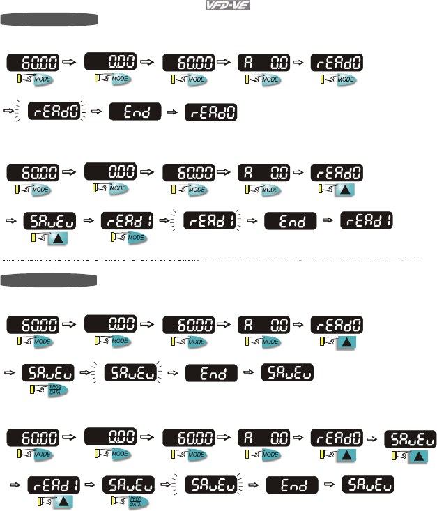
To copy parameters 1
Copy parameters from the AC Motor Drive to the KPV-CE01
about 2-3 seconds
start blinking It will display "End" to indicate that
the first parameter is saved, then
return to "rEAd0".
about 2-3 seconds
start blinking It will display "End" to indicate that
the second parameter is saved, then
return to "rEAd1".
To copy parameters 2
Copy parameters from to the KPV-CE01 the AC Motor Drive
about 2-3 seconds
about 2-3 seconds
start blinking
start blinking
It will display "End" to indicate that
the first parameter is saved, then
return to "SAvEv".
It will display "End" to indicate that
the second parameter is saved, then
return to "SAvEv".
Chapter 3 Digital Keypad Operation and Start Up|
Revision August 2008, 03VE, SW V2.04 3-5
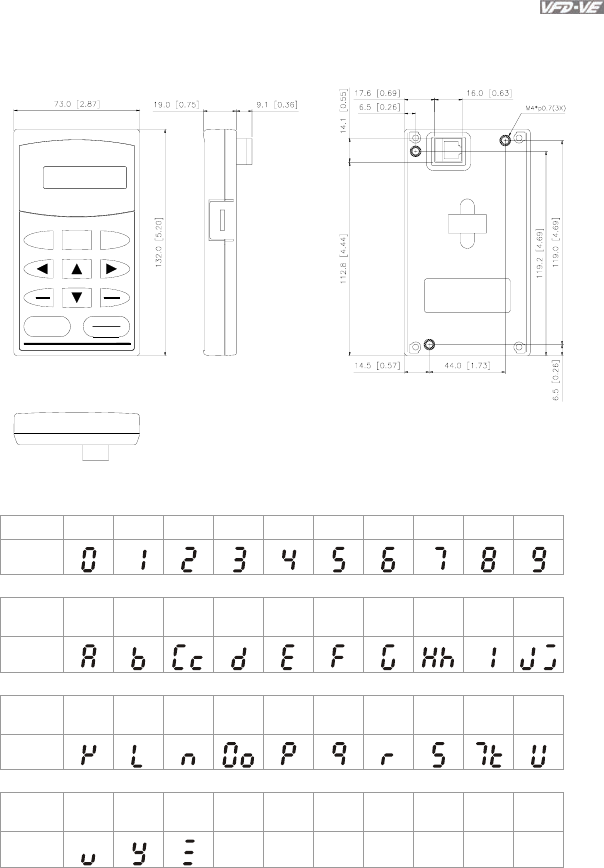
3.1.3 Dimension of the Digital Keypad
Unit: mm [inch]
MODE
REV
FWD
RUN
JOG
LABEL 1
PROG
DATA
RESET
STOP
PU
U
RUN STOPJOGFWD
KPV-CEO1
REVEXTPU
F
H
3.1.4 Reference Table for the LCD Display of the Digital Keypad
Digital 0 1 2 3 4 5 6 7 8 9
LCD
English
alphabet A b Cc d E F G Hh I Jj
LCD
English
alphabet K L n Oo P q r S Tt U
LCD
English
alphabet v Y Z
LCD
Chapter 3 Digital Keypad Operation and Start Up|
3-6 Revision August 2008, 03VE, SW V2.04
3.1.5 Operation Method
Refer to 3.1.2 How to operate the digital keypad KPV-CE01 and chapter 4 parameters for
setting. Please choose a suitable method depending on application and operation rule. The
operation is usually used as shown in the following table.
3.2 Start-up
3.2.1 Preparations before Start-up
Operation Method Frequency Source Operation Command
Source
KPV-CE01 keypad
RUN
RESET
STOP
Operate from
external signal
Sw1
Sink
Source
Factory setting:
SINK Mode
Please refer to
Figure 3 for wiring
of S INK mode and
SOURCEmode.
AVI
ACI
AUI
ACM
+10V
5K
3
2
1
Power supply
+10V 20mA
Master Frequency
0 to 10V 47k
Analog Signal Common
E
MI1
MI2
MI3
MI4
MI6
MI5
DCM
+24V
FWD/STOP
REV/STOP
Multi-step 1
Multi-step 2
Multi-step 3
Multi-step 4
No function
Digital Signal Common
Factory
setting
* Don't apply the mains voltage directly
to abov e t e rminals. E
No function
REV
FWD
ACI current/voltage selection
AFM
ACM
Analog Signal common
E
4~20mA/0~10V
-10~+ 10V
0-20mA 0-10V
ACI Switch
Make sure that power is OFF
before changing the switch
setting.
0~10VDC/2mA
AFM analog output selection
Analog Multi-function Output Terminal
0-10V 0-20mA
AFM Switch
Make sure that power is OFF
before changing the switch
setting.
Control circuit terminals Shielded leads & Cable
Main circuit (power) terminals
Operate from
communication
Please refer to the communication address 2000H and 2119H settings in the
communication address definition.
Chapter 3 Digital Keypad Operation and Start Up|
Revision August 2008, 03VE, SW V2.04 3-7
Carefully check the following items before proceeding.
Make sure that the wiring is correct. In particular, check that the output terminals U, V, W.
are NOT connected to power and that the drive is well grounded.
Verify that there are no short-circuits between terminals and from terminals to ground or
mains power.
Check for loose terminals, connectors or screws.
Verify that no other equipment is connected to the AC motor
Make sure that all switches are OFF before applying power to ensure that the AC motor
drive doesn’t start running and there is no abnormal operation after applying power.
Make sure that the front cover is well installed before applying power.
Do NOT operate the AC motor drive with humid hands.
The keypad shows briefly "Delta" and then should light up as follows (normal status with
no error)
U
F
H
KPV-CE01
JOG
RUN
RESET
STOP
PU
EXT P U
- If the drive has built-in fan (2hp/1.5kW and above) it should run. The factory setting
of Fan Control Pr.07-19=00 (Fan always on).
Chapter 3 Digital Keypad Operation and Start Up|
3-8 Revision August 2008, 03VE, SW V2.04
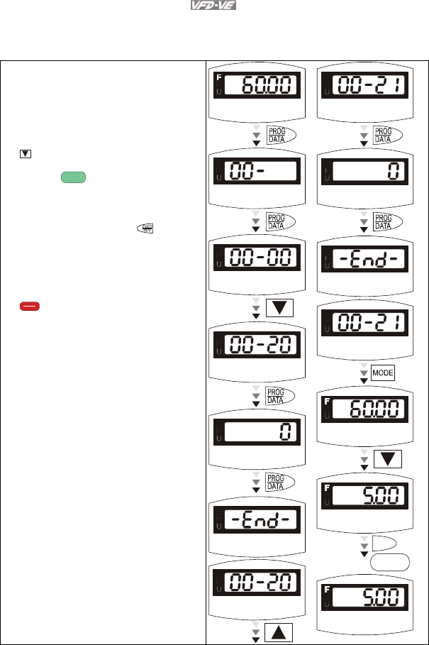
3.2.2 Trial Run
After finishing checking the items in “3.2.1 preparation before start-up”, you can perform a
trial run. The factory setting of operation source is from keypad (Pr.00-20=00).
1. After applying power, verify that LED “F”
is on and the display shows 60.00Hz.
2. Setting frequency to about 5Hz by using
key.
3. Pressing
RUN
key for forward running.
And if you want to change to reverse
running, you should press key. The
LED will display the status. And if you
want to decelerate to stop, please press
RESET
STOP
key.
4. Check following items:
Check if the motor direction of rotation
is correct.
Check if the motor runs steadily
without abnormal noise and vibration.
Check if acceleration and deceleration
are smooth.
If the results of trial run are normal, please
start formal run.
KPV-CE01
RUN
STOP
JOG
FWD
REV EXT PU
F
KPV-CE01
RUN
STOP
JOG
FWD
REV EXT PU
F
KPV-CE01
RUN
STOP
JOG
FWD
REV EXT PU
F
KPV-CE01
RUN
STOP
JOG
FWD
REV EXT PU
F
KPV-CE01
RUN
STOP
JOG
FWD
REV EXT PU
F
KPV-CE01
RUN
STOP
JOG
FWD
REV EXT PU
F
KPV-CE01
RUN
STOP
JOG
FWD
REV EXT PU
F
KPV-CE01
RUN
STOP
JOG
FWD
REV EXT PU
F
KPV-CE01
RUN
STOP
JOG
FWD
REV EXT PU
F
KPV-CE01
RUN
STOP
JOG
FWD
REV EXT PU
F
KPV-CE01
RUN
STOP
JOG
FWD
REV EXT PU
KPV-CE01
RUN
STOP
JOG
FWD
REV EXT PU
KPV-CE01
RUN
STOP
JOG
FWD
REV EXT PU
PU
RUN
KPV-CE01
RUN
STOP JOG
FWD
REV EXT
PU

Chapter 3 Digital Keypad Operation and Start Up|
Revision August 2008, 03VE, SW V2.04 3-9
NOTE
1. Please stop running immediately if any fault occurs and refer to troubleshooting for solving the
problem.
2. Please do NOT touch output terminals U, V, W when power is still applied to L1/R, L2/S, L3/T
even when the AC motor drive has stopped. The DC-link capacitors may still be charged to
hazardous voltage levels, even if the power has been turned off.
3. To avoid damage to components, do not touch them or the circuit boards with metal objects or
your bare hands.

Chapter 3 Digital Keypad Operation and Start Up|
3-10 Revision August 2008, 03VE, SW V2.04
This page intentionally left blank.

Revision August 2008, 03VE, SW V2.04 4-1
Chapter 4 Parameters
The VFD-VE parameters are divided into 12 groups by property for easy setting. In most applications,
the user can finish all parameter settings before start-up without the need for re-adjustment during
operation.
The 12 groups are as follows:
Group 0: System Parameters
Group 1: Basic Parameters
Group 2: Digital Input/Output Parameters
Group 3: Analog Input/Output Parameters
Group 4: Multi-Step Speed Parameters
Group 5: Motor Parameters
Group 6: Protection Parameters
Group 7: Special Parameters
Group 8: High-function PID Parameters
Group 9: Communication Parameters
Group 10: Speed Feedback Control Parameters
Group 11: Advanced Parameters
Chapter 4 Parameters|
4-2 Revision August 2008, 03VE, SW V2.04
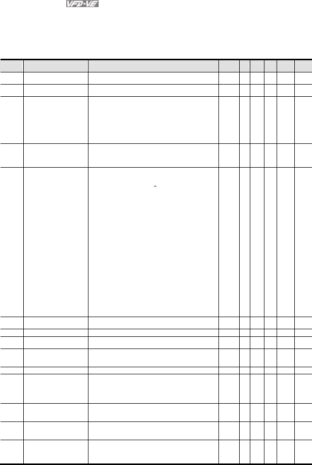
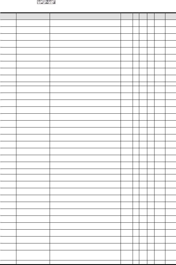
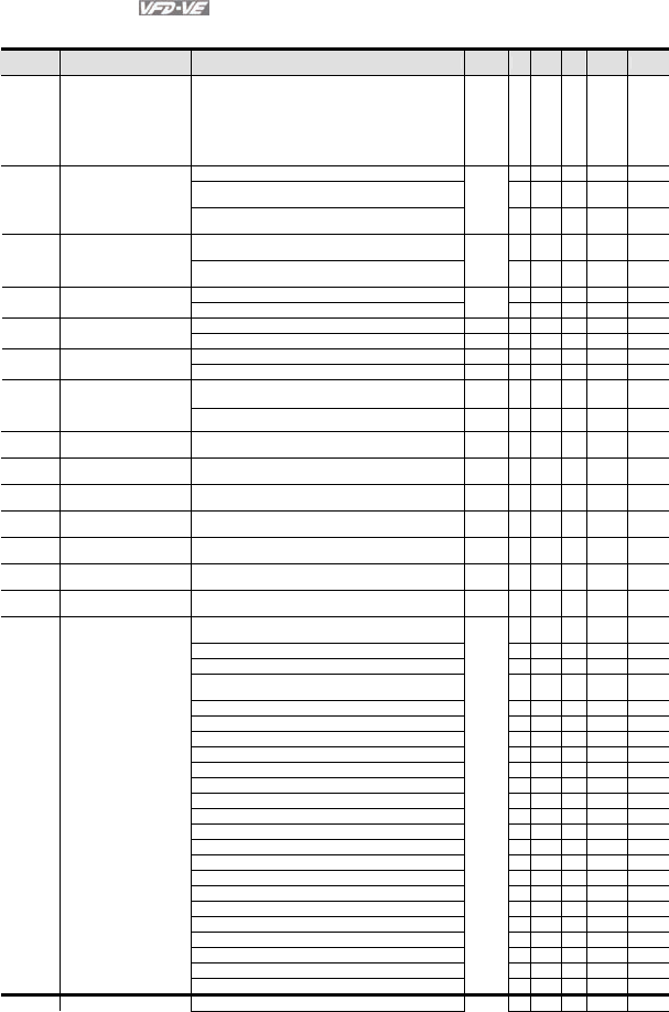
4.1 Summary of Parameter Settings
: The parameter can be set during operation.
Group 0 System Parameters
Pr. Explanation Settings Factory
Setting VF
VFPG
SVC
FOCPG
TQRPG
00-00 Identity Code of the AC
motor drive
Read-only 0 ○ ○ ○ ○ ○
00-01 Rated Current Display of
the AC motor drive
Read-only 0
○ ○ ○ ○ ○
00-02 Parameter Reset
0: No function
1: Read only
2: Enable group 11 parameters setting
8: Keypad lock
9: All parameters are reset to factory settings (50Hz,
220V/380V)
10: All parameters are reset to factory settings (60Hz,
220V/440V)
0 ○ ○ ○ ○ ○
00-03 Start-up Display Selection
0: Display the frequency command value (LED F)
1: Display the actual output frequency (LED H)
2: Multifunction display, see Pr.00-04 (LED U)
3: Display the output current (A)
0 ○ ○ ○ ○ ○
00-04 Content of Multi Function
Display
0: Display output current (A)
1: Display counter value (C)
2: Display output frequency (H)
3: Display DC-BUS voltage ( u)
4: Display output voltage (E)
5: Output power factor angle (n)
6: Display output power (kW)
7: Display actual motor speed (HU)
8: Display estimate output torque (kg-m)
9: Display PG position (G) (refer to Pr.10-00 and Pr.10-
01)
10: Display PID feedback
11: Display AVI (%)
12: Display ACI (%)
13: Display AUI (%)
14: Display the temperature of heat sink (°C)
15: Display the temperature of IGBT (°C)
16: The status of digital input (ON/OFF)
17: The status of digital output (ON/OFF)
18: Multi-step speed
19: The corresponding CPU pin status of digital input
20: The corresponding CPU pin status of digital output
21: Number of actual motor revolution (PG1 of PG card)
22: Pulse input frequency (PG2 of PG card)
23: Pulse input position (PG2 of PG card)
0 ○ ○ ○ ○ ○
00-05 User-Defined Coefficient K Digit 4: decimal point number (0 to 3)
Digit 0-3: 40 to 9999
0 ○ ○ ○ ○ ○
00-06 Software Version Read-only #.# ○ ○ ○ ○ ○
00-07 Password Input 1 to 9998 and 10000 to 65535
0 to 2: times of wrong password
0 ○ ○ ○ ○ ○
00-08 Password Set
1 to 9998 and 10000 to 65535
0: No password set or successful input in Pr.00-07
1: Password has been set
0 ○ ○ ○ ○ ○
00-09 Energy Saving Gain 10~1000 % 100% ○
00-10 Control Method
0: V/f Control
1: V/f Control + Encoder (VFPG)
2: Sensorless vector control (SVC)
3: FOC vector control + Encoder (FOCPG)
4: Torque control + Encoder (TQRPG)
0 ○ ○ ○ ○ ○
00-11 V/f Curve Selection
0: V/f curve determined by group 01
1: 1.5 power curve
2: Square curve
0 ○ ○
00-12 Constant/Variable Torque
Selection
0: Constant Torque (100%)
1: Variable Torque (125%)
0 ○ ○ ○ ○
00-13
Optimal
Acceleration/Deceleration
Setting
0: Linear accel./decel. I
1: Auto accel., linear decel.
2: Linear accel., auto decel.
3: Auto accel./decel.
0 ○ ○ ○ ○

Chapter 4 Parameters|
Revision August 2008, 03VE, SW V2.04 4-3
Pr. Explanation Settings Factory
Setting VF
VFPG
SVC
FOCPG
TQRPG
4: Stall prevention by auto accel./decel. (limited by 01-12
to 01-21)
00-14
Time Unit for
Acceleration/Deceleration
and S Curve
0: Unit: 0.01 second
1: Unit: 0.1 second
0 ○ ○ ○ ○
00-15 Reserved
00-16 Reserved
00-17 Carrier Frequency 1~15KHz 10
○ ○ ○ ○ ○
00-18 Auto Voltage Regulation
(AVR) Function
0: Enable AVR
1: Disable AVR
2: Disable AVR when deceleration stop
0 ○ ○ ○ ○ ○
00-19 Auto Energy-saving
Operation
0: Disable
1: Enable
0 ○ ○ ○ ○
00-20 Source of the Master
Frequency Command
0: Digital keypad (KPV-CE01)
1: RS-485 serial communication
2: External analog input (Pr. 03-00)
3: External UP/DOWN terminal
4: Pulse input without direction command (Pr.10-15
without direction)
5: Pulse input with direction command (Pr.10-15)
0 ○ ○ ○ ○
00-21 Source of the Operation
Command
0: Digital keypad (KPV-CE01)
1: External terminals. Keypad STOP disabled.
2: RS-485 serial communication (RJ-11). Keypad STOP
disabled.
0 ○ ○ ○ ○ ○
00-22 Stop Method 0: Ramp to stop
1: Coast to stop
0 ○ ○ ○ ○ ○
00-23 Reverse Operation
0: Enable reverse
1: Disable reverse
2: Disable forward
0 ○ ○ ○ ○ ○
Chapter 4 Parameters|
4-4 Revision August 2008, 03VE, SW V2.04
Group 1 Basic Parameters
Pr. Explanation Settings Factory
Setting VF
VFPG
SVC
FOCPG
TQRPG
01-00 Maximum Output
Frequency
50.00~600.00Hz 60.00/
50.00
○ ○ ○ ○ ○
01-01 1st Output Frequency
Setting 1
0.00~600.00Hz 60.00/
50.00
○ ○ ○ ○ ○
01-02 1st Output Voltage
Setting 1
230V: 0.1V~255.0V
460V: 0.1V~510.0V
220.0
440.0
○ ○ ○ ○ ○
01-03 2nd Output Frequency
Setting 1
0.00~600.00Hz 0.50 ○ ○
01-04 2nd Output Voltage
Setting 1
230V: 0.1V~255.0V
460V: 0.1V~510.0V
5.0
10.0
○ ○
01-05 3rd Output Frequency
Setting 1
0.00~600.00Hz 0.50 ○ ○
01-06 3rd Output Voltage
Setting 1
230V: 0.1V~255.0V
460V: 0.1V~510.0V
5.0
10.0
○ ○
01-07 4th Output Frequency
Setting 1
0.00~600.00Hz 0.00 ○ ○ ○ ○
01-08 4th Output Voltage
Setting 1
230V: 0.1V~255.0V
460V: 0.1V~510.0V
0.0
0.0
○ ○ ○
01-09 Start Frequency 0.00~600.00Hz 0.50 ○ ○ ○ ○
01-10 Output Frequency Upper
Limit 0.00~600.00Hz 600.00 ○ ○ ○ ○
01-11 Output Frequency Lower
Limit 0.00~600.00Hz 0.00 ○ ○ ○ ○
01-12 Accel Time 1 0.00~600.00 sec/0.00~6000.0 sec 10.00/
10.0
○ ○ ○ ○
01-13 Decel Time 1 0.00~600.00 sec/0.00~6000.0 sec 10.00/
10.0
○ ○ ○ ○
01-14 Accel Time 2 0.00~600.00 sec/0.00~6000.0 sec 10.00/
10.0
○ ○ ○ ○
01-15 Decel Time 2 0.00~600.00 sec/0.00~6000.0 sec 10.00/
10.0
○ ○ ○ ○
01-16 Accel Time 3 0.00~600.00 sec/0.00~6000.0 sec 10.00/
10.0
○ ○ ○ ○
01-17 Decel Time 3 0.00~600.00 sec/0.00~6000.0 sec 10.00/
10.0
○ ○ ○ ○
01-18 Accel Time 4 0.00~600.00 sec/0.00~6000.0 sec 10.00/
10.0
○ ○ ○ ○
01-19 Decel Time 4 0.00~600.00 sec/0.00~6000.0 sec 10.00/
10.0
○ ○ ○ ○
01-20 JOG Acceleration Time 0.00~600.00 sec/0.00~6000.0 sec 1.00/
1.0
○ ○ ○ ○
01-21 JOG Deceleration Time 0.00~600.00 sec/0.00~6000.0 sec 1.00/
1.0
○ ○ ○ ○
01-22 JOG Frequency 0.00~600.00Hz 6.00 ○ ○ ○ ○ ○
01-23 1st/4th Accel/decel
Frequency
0.00~600.00Hz 0.00 ○ ○ ○ ○
01-24 S-curve for Acceleration
Departure Time 1
0.00~25.00 sec/0.00~250.0 sec 0.2/0.0 ○ ○ ○ ○
01-25 S-curve for Acceleration
Arrival Time 2
0.00~25.00 sec /0.00~250.0 sec 0.2/0.0 ○ ○ ○ ○
01-26 S-curve for Deceleration
Departure Time 1
0.00~25.00 sec /0.00~250.0 sec 0.2/0.0 ○ ○ ○ ○
01-27 S-curve for Deceleration
Arrival Time 2
0.00~25.00 sec /0.00~250.0 sec 0.2/0.0 ○ ○ ○ ○
01-28 Skip Frequency 1 (upper
limit)
0.00~600.00Hz 0.00 ○ ○ ○ ○
01-29 Skip Frequency 1 (lower
limit)
0.00~600.00Hz 0.00 ○ ○ ○ ○
01-30 Skip Frequency 2 (upper
limit)
0.00~600.00Hz 0.00 ○ ○ ○ ○
01-31 Skip Frequency 2 (lower
limit)
0.00~600.00Hz 0.00 ○ ○ ○ ○
01-32 Skip Frequency 3 (upper
limit)
0.00~600.00Hz 0.00 ○ ○ ○ ○
01-33 Skip Frequency 3 (lower
limit)
0.00~600.00Hz 0.00 ○ ○ ○ ○
01-34 Mode Selection when
Frequency < Fmin
0: Output Waiting
1: Zero-speed operation
2: Fmin (4th output frequency setting)
0 ○ ○ ○ ○
01-35 1st Output Frequency 0.00~600.00Hz 60.00/ ○ ○ ○ ○ ○

Chapter 4 Parameters|
Revision August 2008, 03VE, SW V2.04 4-5
Pr. Explanation Settings Factory
Setting VF
VFPG
SVC
FOCPG
TQRPG
Setting 2 50.00
01-36 1st Output Voltage
Setting 2
230V: 0.1V~255.0V
460V: 0.1V~510.0V
220.0
440.0
○ ○ ○ ○ ○
01-37 2nd Output Frequency
Setting 2
0.00~600.00Hz 0.50 ○ ○
01-38 2nd Output Voltage
Setting 2
230V: 0.1V~255.0V
460V: 0.1V~510.0V
5.0/
10.0
○ ○
01-39 3rd Output Frequency
Setting 2
0.00~600.00Hz 0.50 ○ ○
01-40 3rd Output Voltage
Setting 2
230V: 0.1V~255.0V
460V: 0.1V~510.0V
5.0/
10.0
○ ○
01-41 4th Output Frequency
Setting 2
0.00~600.00Hz 0.00 ○ ○ ○ ○ ○
01-42 4th Output Voltage
Setting 2
230V: 0.1V~255.0V
460V: 0.1V~510.0V
0.0/
0.0
○ ○
Chapter 4 Parameters|
4-6 Revision August 2008, 03VE, SW V2.04
Group 2 Digital Input/Output Parameters
Pr. Explanation Settings Factory
Setting VF
VFPG
SVC
FOCPG
TQRPG
02-00 2-wire/3-wire Operation
Control
0: FWD/STOP, REV/STOP
1: FWD/STOP, REV/STOP (Line Start Lockout)
2: RUN/STOP, REV/FWD
3: RUN/STOP, REV/FWD (Line Start Lockout)
4: 3-wire (momentary push button)
5: 3-wire (momentary push button and Line Start
Lockout)
0 ○ ○ ○ ○ ○
0: no function ○ ○ ○ ○ ○
1: multi-step speed command 1/multi-step position
command 1
○ ○ ○ ○
02-01 Multi-Function Input
Command 1 (MI1)
(it is Stop terminal for 3-
wire operation) 2: multi-step speed command 2/ multi-step position
command 2
1
○ ○ ○ ○
3: multi-step speed command 3/ multi-step position
command 3
○ ○ ○ ○ 02-02
Multi-Function Input
Command 2 (MI2) 4: multi-step speed command 4/ multi-step position
command 4
2
○ ○ ○ ○
5: Reset ○ ○ ○ ○ ○
02-03 Multi-Function Input
Command 3 (MI3) 6: JOG command
3
○ ○ ○ ○
7: acceleration/deceleration speed inhibit 4 ○ ○ ○ ○
02-04 Multi-Function Input
Command 4 (MI4) 8: the 1st, 2nd acceleration/deceleration time selection ○ ○ ○ ○
9: the 3rd, 4th acceleration/deceleration time selection 0 ○ ○ ○ ○
02-05 Multi-Function Input
Command 5 (MI5) 10: EF input (07-36) ○ ○ ○ ○ ○
11: B.B. input 0 ○ ○ ○ ○ ○
02-06 Multi-Function Input
Command 6 (MI6)
(specific terminal for
TRG) 12: Output stop ○ ○ ○ ○ ○
02-23 Multi-Function Input
Command 7
13: cancel the setting of the optimal
acceleration/deceleration time
0 ○ ○ ○ ○
02-24 Multi-Function Input
Command 8 14: switch between drive settings 1 and 2 0 ○ ○ ○ ○
02-25 Multi-Function Input
Command 9 15: operation speed command form AVI 0 ○ ○ ○ ○
02-26 Multi-Function Input
Command 10 16: operation speed command form ACI 0 ○ ○ ○ ○
02-27 Multi-Function Input
Command 11 17: operation speed command form AUI 0 ○ ○ ○ ○
02-28 Multi-Function Input
Command 12 18: Emergency Stop (07-36) 0 ○ ○ ○ ○ ○
02-29 Multi-Function Input
Command 13 19: Digital Up command 0 ○ ○ ○ ○
02-30 Multi-Function Input
Command 14 20: Digital Down command 0 ○ ○ ○ ○
21: PID function disabled ○ ○ ○ ○
22: clear counter ○ ○ ○ ○ ○
23: input the counter value (multi-function input
command 6)
○ ○ ○ ○ ○
24: FWD JOG command ○ ○ ○ ○
25: REV JOG command ○ ○ ○ ○
26: TQC+PG/FOC+PG model selection
○ ○
27: ASR1/ASR2 selection ○ ○
28: Emergency stop (EF1) ○ ○ ○ ○ ○
29: Signal confirmation for Y-connection ○ ○ ○ ○
30: Signal confirmation for Δ−connection ○ ○ ○ ○
31: High torque bias (by Pr.07-29) ○ ○ ○ ○ ○
32: Middle torque bias (by Pr.07-30) ○ ○ ○ ○ ○
33: Low torque bias (by Pr.07-31) ○ ○ ○ ○ ○
34: Enable multi-step position control ○ ○
35: Enable position control ○ ○
36: Enable position learning function (valid at stop) ○ ○
37: Enable pulse position input command ○ ○
38: Disable write EEPROM function ○ ○ ○ ○ ○
39: Torque command direction
○
40: Force stop ○ ○ ○ ○ ○
41: Serial position clock
○
42: Serial position input
○
43: Analog input resolution selection ○
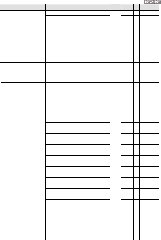
Chapter 4 Parameters|
Revision August 2008, 03VE, SW V2.04 4-7
Pr. Explanation Settings Factory
Setting VF
VFPG
SVC
FOCPG
TQRPG
44: Reset initial reel diameter ○ ○ ○ ○ ○
45: Reset initial reel diameter 0 ○ ○ ○ ○ ○
46: Reset initial reel diameter 1 ○ ○ ○ ○ ○
47: Reset PID control integration of tension ○ ○ ○ ○ ○
48: Mechanical gear ratio switch ○ ○ ○
49: Reserved
50: Reserved
02-07 UP/DOWN Key Mode 0: up/down by the accel/decel time
1: up/down constant speed (Pr.02-08)
0 ○ ○ ○ ○
02-08
The
A
cceleration/Deceleration
Speed of the UP/DOWN
Key with Constant Speed
0.01 ~ 1.00Hz/ms 0.01 ○ ○ ○ ○
02-09 Digital Input Response
Time
0.001~ 30.000 sec 0.005 ○ ○ ○ ○ ○
02-10 Digital Input Operation
Direction
0 ~ 65535 0 ○ ○ ○ ○ ○
0: No function 11 ○ ○ ○ ○ ○
02-11
Multi-function Output 1
RA, RB, RC(Relay1) 1: Operation indication ○ ○ ○ ○ ○
2: Operation speed attained 1 ○ ○ ○ ○ ○
02-12
Multi-function Output 2
MRA, MRC (Relay2) 3: Desired frequency attained 1 (Pr.02-19) ○ ○ ○ ○ ○
4: Desired frequency attained 2 (Pr.02-21) 0 ○ ○ ○ ○
5: Zero speed (frequency command) ○ ○ ○ ○
02-13
Multi-function Output 3
(MO1)
6: Zero speed with stop (frequency command) ○ ○ ○ ○
7: Over torque (OT1) (Pr.06-06~06-08) ○ ○ ○ ○ ○
8: Over torque (OT2) (Pr.06-09~06-11) ○ ○ ○ ○ ○
9: Drive ready 0 ○ ○ ○ ○ ○
02-14 Multi-function Output 4
(MO2) 10: User-defined Low-voltage Detection ○ ○ ○ ○ ○
11: Malfunction indication
○ ○ ○ ○ ○
12: Mechanical brake release (Pr.02-31) ○ ○ ○ ○ ○
02-35 Multi-function Output 5
(MO3) 13: Overheat ○ ○ ○ ○ ○
14: Software brake signal ○ ○ ○ ○ ○
15: PID feedback error ○ ○ ○ ○ ○
02-36 Multi-function Output 6
(MO4) 16: Slip error (oSL) ○ ○ ○ ○
17: Terminal count value attained (Pr.02-16) ○ ○ ○ ○ ○
18: Preliminary count value attained (Pr.02-17) ○ ○ ○ ○ ○
02-37 Multi-function Output 7
(MO5) 19: Baseblock (B.B.) Indication ○ ○ ○ ○ ○
20: Warning output
○ ○ ○ ○ ○
21: Over voltage warning ○ ○ ○ ○ ○
02-38 Multi-function Output 8
(MO6) 22: Over-current stall prevention warning ○ ○ ○ ○ ○
23: Over-voltage stall prevention warning ○ ○ ○
24: Operation mode indication ○ ○ ○ ○ ○
02-39 Multi-function Output 9
(MO7) 25: Forward command ○ ○ ○ ○
26: Reverse command ○ ○ ○ ○
27: Output when current >= Pr.02-32 ○ ○ ○ ○ ○
02-40 Multi-function Output 10
(MO8) 28: Output when current < Pr.02-32 ○ ○ ○ ○ ○
29: Output when frequency >= Pr.02-33 ○ ○ ○ ○ ○
30: Output when frequency < Pr.02-33 ○ ○ ○ ○ ○
02-41 Multi-function Output 11
(MO9) 31: Y-connection for the motor coil ○ ○ ○ ○
32: Δ connection for the motor coil ○ ○ ○ ○
33: Zero speed (actual output frequency) ○ ○ ○ ○
02-42 Multi-function Output 12
(MOA) 34: Zero speed with Stop (actual output frequency) ○ ○ ○ ○
35: Error output selection 1 (Pr.06-23) ○ ○ ○ ○ ○
36: Error output selection 2 (Pr.06-24) ○ ○ ○ ○ ○
37: Error output selection 3 (Pr.06-25) ○ ○ ○ ○ ○
38: Error output selection 4 (Pr.06-26) ○ ○ ○ ○ ○
39: Position attained (Pr.10-19) ○
40: Speed attained (including zero speed) ○ ○ ○ ○
41: Multi-position attained
○
42: Crane function ○ ○ ○ ○
43: Motor zero-speed output (Pr.02-43) ○ ○ ○ ○
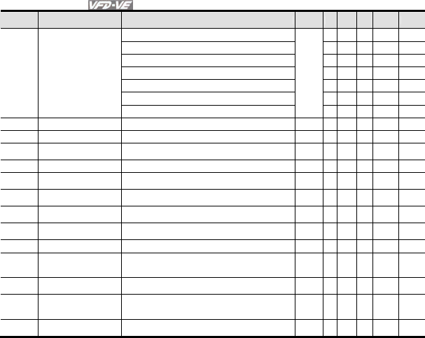
Chapter 4 Parameters|
4-8 Revision August 2008, 03VE, SW V2.04
Pr. Explanation Settings Factory
Setting VF
VFPG
SVC
FOCPG
TQRPG
44: Max. reel diameter attained ○ ○ ○ ○ ○
45: Empty reel diameter attained ○ ○ ○ ○ ○
46: Broken belt detection ○ ○ ○ ○ ○
47: Break release at stop ○ ○ ○ ○
48: Error PID feedback of tension ○ ○ ○ ○ ○
49: Reserved
50: Reserved
02-15 Multi-output Direction 0 ~ 65535 0 ○ ○ ○ ○ ○
02-16 Terminal Count Value 0 ~ 65535 0 ○ ○ ○ ○ ○
02-17 Preliminary Counter
Value 0 ~ 65535 0 ○ ○ ○ ○ ○
02-18 Digital Output Gain 1 ~ 40 1 ○ ○ ○ ○ ○
02-19 Desired Frequency
Attained 1 0.00 ~ 600.00Hz 60.00/
50.00
○ ○ ○ ○
02-20 The Width of the Desired
Frequency Attained 1 0.00 ~ 600.00Hz 2.00 ○ ○ ○ ○
02-21 Desired Frequency
Attained 2 0.00 ~ 600.00Hz 60.00/
50.00
○ ○ ○ ○
02-22 The Width of the Desired
Frequency Attained 2 0.00 ~ 600.00Hz 2.00 ○ ○ ○ ○
02-31 Brake Delay Time 0.000~65.000 Sec 0.000 ○ ○ ○ ○ ○
02-32 Output Current Level
Setting for External
Terminals
0~100%
0 ○ ○ ○ ○ ○
02-33 Output Boundary for
External Terminals 0.00~+-60.00Hz (it is motor speed when using PG) 0.00 ○ ○ ○ ○ ○
02-34 External Operation
Control Selection after
Reset
0: Disable
1: Drive runs if run command exists after reset
0 ○ ○ ○
02-43 Zero-speed Level of
Motor 0~65535 rpm 0 ○ ○ ○ ○ ○
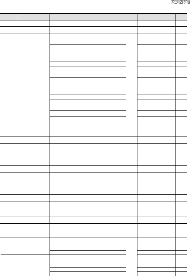
Chapter 4 Parameters|
Revision August 2008, 03VE, SW V2.04 4-9
Group 3 Analog Input/Output Parameters
Pr. Explanation Settings Factory
Setting VF VFPG
SVC
FOCPG
TQRPG
03-00 Analog Input 1 (AVI) 0: No function 1 ○ ○ ○ ○ ○
03-01 Analog Input 2 (ACI) 1: Frequency command (torque limit under TQR control
mode)
0 ○ ○ ○ ○ ○
03-02 Analog Input 3 (AUI) 2: torque command (torque limit under speed mode) 0 ○
3: Torque compensation command ○ ○ ○ ○ ○
4: PID target value (refer to group 8) ○ ○ ○ ○
5: PID feedback signal (refer to group 8) ○ ○ ○ ○
6: P.T.C. thermistor input value ○ ○ ○ ○ ○
7: Positive torque limit ○
8: Negative torque limit ○
9: Regenerative torque limit ○
10: Positive/negative torque limit ○
11: PID feedback signal of tension ○ ○ ○ ○ ○
12: Line speed ○ ○ ○ ○ ○
13: Reel diameter ○ ○ ○ ○ ○
14: PID target value of tension (tension closed-loop) ○ ○ ○ ○ ○
15: Tension setting (tension open-loop) ○
16: Zero-speed tension ○
17: Tension taper ○
03-03 Analog Input Bias 1
(AVI) -100.0~100.0% 0 ○ ○ ○ ○ ○
03-04 Analog Input Bias 2
(ACI) -100.0~100.0% 0 ○ ○ ○ ○ ○
03-05 Analog Input Bias 3
(AUI) -100.0~100.0% 0 ○ ○ ○ ○ ○
03-06 Positive/negative Bias
Mode (AVI)
0 ○ ○ ○ ○ ○
03-07 Positive/negative Bias
Mode (ACI)
0 ○ ○ ○ ○ ○
03-08 Positive/negative Bias
Mode (AUI)
0: Zero bias
1: Lower than bias=bias
2: Greater than bias=bias
3: The absolute value of the bias voltage while serving
as the center
4: Serve bias as the center
0 ○ ○ ○ ○ ○
03-09 Analog Input Gain 1
(AVI) -500.0~500.0% 100.0 ○ ○ ○ ○ ○
03-10 Analog Input Gain 2
(ACI ) -500.0~500.0% 100.0 ○ ○ ○ ○ ○
03-11 Analog Input Gain 3
(AUI) -500.0~500.0% 100.0 ○ ○ ○ ○ ○
03-12 ACI/AVI2 Selection 0: ACI
1: AVI 2
0 ○ ○ ○ ○ ○
03-13 Analog Input Delay
Time (AVI) 0.00~2.00 sec 0.01 ○ ○ ○ ○ ○
03-14 Analog Input Delay
Time (ACI) 0.00~2.00 sec 0.01 ○ ○ ○ ○ ○
03-15 Analog Input Delay
Time (AUI) 0.00~2.00 sec 0.01 ○ ○ ○ ○ ○
03-16 Addition Function of
the Analog Input
0: Disable (AVI, ACI, AUI)
1: Enable
○ ○ ○ ○ ○
03-17 Loss of the ACI Signal 0: Disable
1: Continue operation at the last frequency
2: Decelerate to stop
3: Stop immediately and display E.F.
0 ○ ○ ○ ○ ○
0: Output frequency (Hz) 0 ○ ○ ○ ○ ○
03-18 Analog Output
Selection 1 1: Frequency command (Hz) ○ ○ ○ ○ ○
2: Motor speed (Hz) ○ ○ ○ ○ ○
03-21 Analog Output
Selection 2 3: Output current (rms) ○ ○ ○ ○ ○
4: Output voltage ○ ○ ○ ○ ○
03-24 Analog Output
Selection 3 5: DC Bus Voltage ○ ○ ○ ○ ○
6: Power factor ○ ○ ○ ○ ○
7: Power ○ ○ ○ ○ ○
8: Output torque ○ ○ ○ ○ ○
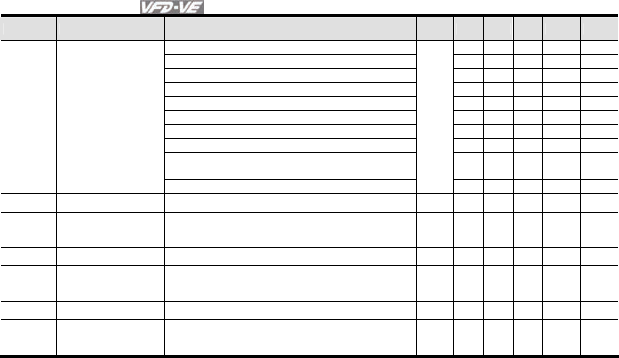
Chapter 4 Parameters|
4-10 Revision August 2008, 03VE, SW V2.04
Pr. Explanation Settings Factory
Setting VF VFPG
SVC
FOCPG
TQRPG
9: AVI ○ ○ ○ ○ ○
10: ACI ○ ○ ○ ○ ○
11: AUI ○ ○ ○ ○ ○
12: q-axis current ○ ○ ○ ○ ○
13: q-axis feedback value ○ ○ ○ ○ ○
14: d-axis current ○ ○ ○ ○ ○
15: d-axis feedback value ○ ○ ○ ○ ○
16: q-axis voltage ○ ○ ○ ○ ○
17: d-axis voltage ○ ○ ○ ○ ○
18: Torque command ○ ○ ○ ○ ○
19: Pulse frequency command ○ ○ ○ ○ ○
03-19 Analog Output Gain 1 0~200.0% 100.0 ○ ○ ○ ○ ○
03-20 Analog Output Value
in REV Direction 1
0: Absolute value in REV direction
1: Output 0V in REV direction
2: Enable output voltage in REV direction
0 ○ ○ ○ ○ ○
03-22 Analog Output Gain 2 0~200.0% 100.0 ○ ○ ○ ○ ○
03-23 Analog Output Value
in REV Direction 2
0: Absolute value in REV direction
1: Output 0V in REV direction
2: Enable output voltage in REV direction
0 ○ ○ ○ ○ ○
03-25 Analog Output Gain 3 0~200.0% 100.0 ○ ○ ○ ○ ○
03-26 Analog Output Value
in REV Direction 3
0: Absolute value in REV direction
1: Output 0V in REV direction
2: Enable output voltage in REV direction
0 ○ ○ ○ ○ ○
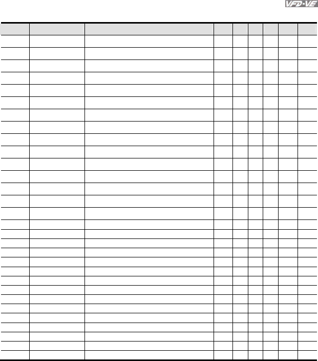
Chapter 4 Parameters|
Revision August 2008, 03VE, SW V2.04 4-11
Group 4 Multi-Step Speed Parameters
Pr. Explanation Settings Factory
Setting VF VFPG
SVC
FOCPG
TQRPG
04-00 1st Step Speed
Frequency
0.00~600.00Hz 0.00 ○ ○ ○ ○
04-01 2nd Step Speed
Frequency
0.00~600.00Hz 0.00 ○ ○ ○ ○
04-02 3rd Step Speed
Frequency
0.00~600.00Hz 0.00 ○ ○ ○ ○
04-03 4th Step Speed
Frequency
0.00~600.00Hz 0.00 ○ ○ ○ ○
04-04 5th Step Speed
Frequency
0.00~600.00Hz 0.00 ○ ○ ○ ○
04-05 6th Step Speed
Frequency 0.00~600.00Hz 0.00 ○ ○ ○ ○
04-06 7th Step Speed
Frequency 0.00~600.00Hz 0.00 ○ ○ ○ ○
04-07 8th Step Speed
Frequency 0.00~600.00Hz 0.00 ○ ○ ○ ○
04-08 9th Step Speed
Frequency 0.00~600.00Hz 0.00 ○ ○ ○ ○
04-09 10th Step Speed
Frequency 0.00~600.00Hz 0.00 ○ ○ ○ ○
04-10 11th Step Speed
Frequency 0.00~600.00Hz 0.00 ○ ○ ○ ○
04-11 12th Step Speed
Frequency 0.00~600.00Hz 0.00 ○ ○ ○ ○
04-12 13th Step Speed
Frequency 0.00~600.00Hz 0.00 ○ ○ ○ ○
04-13 14th Step Speed
Frequency 0.00~600.00Hz 0.00 ○ ○ ○ ○
04-14 15th Step Speed
Frequency 0.00~600.00Hz 0.00 ○ ○ ○ ○
04-15 Multi-position 1 0~65535 0 ○ ○
04-16 Multi-position 2 0~65535 0 ○ ○
04-17 Multi-position 3 0~65535 0 ○ ○
04-18 Multi-position 4 0~65535 0 ○ ○
04-19 Multi-position 5 0~65535 0 ○ ○
04-20 Multi-position 6 0~65535 0 ○ ○
04-21 Multi-position 7 0~65535 0 ○ ○
04-22 Multi-position 8 0~65535 0 ○ ○
04-23 Multi-position 9 0~65535 0 ○ ○
04-24 Multi-position 10 0~65535 0 ○ ○
04-25 Multi-position 11 0~65535 0 ○ ○
04-26 Multi-position 12 0~65535 0 ○ ○
04-27 Multi-position 13 0~65535 0 ○ ○
04-28 Multi-position 14 0~65535 0 ○ ○
04-29 Multi-position 15 0~65535 0 ○ ○
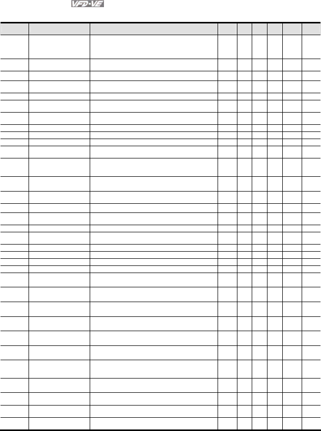
Chapter 4 Parameters|
4-12 Revision August 2008, 03VE, SW V2.04
Group 5 Motor Parameters
Pr. Explanation Settings Factory
Setting VF VFPG
SVC
FOCPG
TQRPG
05-00 Motor Auto Tuning 0: No function
1: Rolling test
2: Static Test
3: Reserved
0
○ ○ ○
05-01 Full-load Current of
Motor 1
40-100% #.## ○ ○ ○ ○ ○
05-02 Rated power of Motor 1 0~655.35 #.## ○ ○ ○
05-03 Rated speed of Motor 1
(rpm)
0~65535
1710 (60Hz, 4 poles), 1410 (50Hz, 4 poles)
1710 ○ ○ ○ ○
05-04 Number of Motor Poles 1 2~20 4 ○ ○ ○ ○ ○
05-05 No-load Current of Motor
1
0-factory setting of Pr.05-01 #.## ○ ○ ○ ○
05-06 Rotor Resistance R1 of
Motor 1
0~65.535Ω #.###
○ ○ ○
05-07 Rr of Motor 1 0~65.535Ω #.###
○ ○ ○
05-08 Lm of Motor 1 0~6553.5mH #.# ○ ○ ○
05-09 Lx of Motor 1 0~6553.5mH #.# ○ ○ ○
05-10 Motor 1/Motor 2
Selection
1: Motor 1
2: Motor 2
1 ○ ○ ○ ○ ○
05-11 Frequency for Y-
connection/
Δ−connection Switch
0.00~600.00Hz 60.00 ○ ○ ○ ○
05-12 Y-connection
/Δ−connection Switch
0: Disable
1: Enable
0 ○ ○ ○ ○
05-13 Full-load Current of
Motor 2
40-100% #.## ○ ○ ○ ○ ○
05-14 Rated Power of Motor 2 0~655.35 #.## ○ ○ ○
05-15 Rated Speed of Motor 2
(rpm)
0~65535 1710
○ ○ ○ ○
05-16 Number of Motor Poles 2 2~20 4 ○ ○ ○ ○ ○
05-17 No-load Current of Motor
2
0- factory setting of Pr.05-01 #.## ○ ○ ○ ○
05-18 Rs of Motor 2 0~65.535Ω #.###
○ ○ ○
05-19 Rr of Motor 2 0~65.535Ω #.###
○ ○ ○
05-20 Lm of Motor 2 0~6553.5mH #.# ○ ○ ○
05-21 Lx of Motor 2 0~6553.5mH #.# ○ ○ ○
05-22 Torque Compensation
Time Constant
0.001~10.000sec 0.020 ○ ○ ○
05-23 Slip Compensation Time
Constant
0.001~10.000sec 0.100
○ ○
05-24 Torque Compensation
Gain
0~10 0
○ ○
05-25 Slip Compensation Gain 0.00~10.00 0.00 ○ ○
05-26 Slip Deviation Level 0~1000% (0: disable) 0 ○ ○ ○
05-27 Detection Time of Slip
Deviation
0.0~10.0 sec 1.0 ○ ○ ○
05-28 Over Slip Treatment
0: Warn and keep operation
1: Warn and ramp to stop
2: Warn and coast to stop
0
○ ○ ○
05-29 Hunting Gain 0~10000 (0: disable) 2000 ○ ○ ○
05-30 Delay Time for Y-
connection/Δ −connection
0~60.000 sec 0.200 ○ ○ ○ ○
05-31 Accumulative Motor
Operation Time (Min.)
00~1439 0
○ ○ ○ ○ ○
05-32 Accumulative Motor
Operation Time (day)
00~65535 0
○ ○ ○ ○ ○
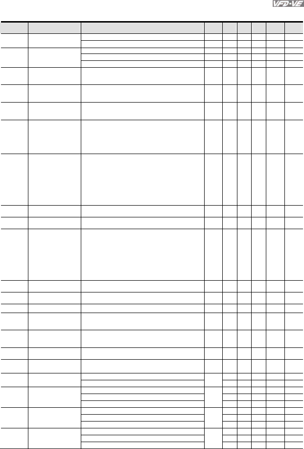
Chapter 4 Parameters|
Revision August 2008, 03VE, SW V2.04 4-13
Group 6 Protection Parameters
Pr. Explanation Settings
F
actory
Setting VF VFPG
SVC
FOCPG
TQRPG
160.0~220.0Vdc 180.0 ○ ○ ○ ○ ○
06-00 Low Voltage Level
320.0~440.0Vdc 360.0 ○ ○ ○ ○ ○
0.0: Disable
350.0~450.0Vdc 380.0 ○ ○ ○ ○ ○
06-01 Over-voltage Stall
Prevention
700.0~900.0Vdc 760.0 ○ ○ ○ ○ ○
06-02 Phase-loss Protection 0: Warn and keep operation
1: Warn and ramp to stop
2: Warn and coast to stop
0 ○ ○ ○ ○ ○
06-03 Over-current Stall
Prevention during
Acceleration
00~250% 170 ○ ○ ○
06-04 Over-current Stall
Prevention during
Operation
00~250% 170 ○ ○ ○
06-05 Accel./Decel. Time
Selection of Stall
Prevention at constant
speed
0: by current accel/decel time
1: by the 1st accel/decel time
2: by the 2nd accel/decel time
3: by the 3rd accel/decel time
4: by the 4th accel/decel time
5: by auto accel/decel time
0 ○ ○ ○
06-06 Over-torque Detection
Selection (OT1)
0: disable
1: over-torque detection during constant speed
operation, continue to operate after detection
2: over-torque detection during constant speed
operation, stop operation after detection
3: over-torque detection during operation, continue to
operate after detection
4: over-torque detection during operation, stop
operation after detection
0 ○ ○ ○ ○ ○
06-07 Over-torque Detection
Level (OT1)
10~250% 150 ○ ○ ○ ○ ○
06-08 Over-torque Detection
Time (OT1)
0.0~60.0 sec 0.1 ○ ○ ○ ○ ○
06-09 Over-torque Detection
Selection (OT2)
0: disable
1: over-torque detection during constant speed
operation, continue to operate after detection
2: over-torque detection during constant speed
operation, stop operation after detection
3: over-torque detection during operation, continue to
operate after detection
4: over-torque detection during operation, stop
operation after detection
0 ○ ○ ○ ○ ○
06-10 Over-torque Detection
Level (OT2)
10~250% 150 ○ ○ ○ ○ ○
06-11 Over-torque Detection
Time (OT2)
0.0~60.0 sec 0.1 ○ ○ ○ ○ ○
06-12 Current Limit 0~250% 150 ○ ○
06-13 Electronic Thermal
Relay Selection (Motor
1)
0: Inverter motor
1: Standard motor
2: Disable
2 ○ ○ ○ ○ ○
06-14 Electronic Thermal
Characteristic for
Motor 1
30.0~600.0 sec 60.0 ○ ○ ○ ○ ○
06-15 Heat Sink Over-heat
(OH) Warning
0.0~110.0 °C 85.0 ○ ○ ○ ○ ○
06-16 Stall Prevention Limit
Level
0~100% (refer to Pr.06-03, Pr.06-04) 50 ○ ○ ○
06-17 Present Fault Record 0: No fault 0 ○ ○ ○ ○ ○
1: Over-current during acceleration (ocA) ○ ○ ○ ○ ○
2: Over-current during deceleration (ocd) 0 ○ ○ ○ ○ ○
06-18 Second Most Recent
Fault Record 3: Over-current during constant speed (ocn) ○ ○ ○ ○ ○
4: Ground fault (GFF) ○ ○ ○ ○ ○
5: IGBT short-circuit (occ) 0 ○ ○ ○ ○ ○
06-19 Third Most Recent
Fault Record 6: Over-curent at stop (ocS) ○ ○ ○ ○ ○
7: Over-voltage during acceleration (ovA) ○ ○ ○ ○ ○
8: Over-voltage during deceleration (ovd) 0 ○ ○ ○ ○ ○
06-20 Fourth Most Recent
Fault Record 9: Over-voltage during constant speed (ovn) ○ ○ ○ ○ ○
10: Over-voltage at stop (ovS) ○ ○ ○ ○ ○

Chapter 4 Parameters|
4-14 Revision August 2008, 03VE, SW V2.04
Pr. Explanation Settings
F
actory
Setting VF VFPG
SVC
FOCPG
TQRPG
11: Low-voltage during acceleration (LvA) ○ ○ ○ ○ ○
12: Low-voltage during deceleration (Lvd) ○ ○ ○ ○ ○
06-21 Fifth Most Recent
Fault Record 13: Low-voltage during constant speed (Lvn) ○ ○ ○ ○ ○
14: Low-voltage at stop (LvS) 0 ○ ○ ○ ○ ○
15: Phase loss (PHL) ○ ○ ○ ○ ○
16: IGBT heat sink over-heat (oH1) ○ ○ ○ ○ ○
17: Heat sink over-heat (oH2)(for 40HP above) 0 ○ ○ ○ ○ ○
06-22 Sixth Most Recent
Fault Record 18: TH1 open loop error (tH1o) ○ ○ ○ ○ ○
19: TH2 open loop error (tH2o) ○ ○ ○ ○ ○
20: Fan error signal output ○ ○ ○ ○ ○
21: over-load (oL) (150% 1Min) ○ ○ ○ ○ ○
22: Motor 1 over-load (EoL1) ○ ○ ○ ○ ○
23: Motor 2 over-load (EoL2) ○ ○ ○ ○ ○
24: Motor PTC overheat (oH3) ○ ○ ○ ○ ○
25: Fuse error (FuSE) ○ ○ ○ ○ ○
26: over-torque 1 (ot1) ○ ○ ○ ○ ○
27: over-torque 1 (ot2) ○ ○ ○ ○ ○
28: Reserved
29: Reserved
30: Memory write-in error (cF1) ○ ○ ○ ○ ○
31: Memory read-out error (cF2) ○ ○ ○ ○ ○
32: Isum current detection error (cd0) ○ ○ ○ ○ ○
33: U-phase current detection error (cd1) ○ ○ ○ ○ ○
34: V-phase current detection error (cd2) ○ ○ ○ ○ ○
35: W-phase current detection error (cd3) ○ ○ ○ ○ ○
36: Clamp current detection error (Hd0) ○ ○ ○ ○ ○
37: Over-current detection error (Hd1) ○ ○ ○ ○ ○
38: Over-voltage detection error (Hd2) ○ ○ ○ ○ ○
39: Ground current detection error (Hd3) ○ ○ ○ ○ ○
40: Auto tuning error (AuE) ○ ○ ○
41: PID feedback loss (AFE) ○ ○ ○ ○ ○
42: PG feedback error (PGF1) ○ ○ ○
43: PG feedback loss (PGF2) ○ ○ ○
44: PG feedback stall (PGF3) ○ ○
45: PG slip error (PGF4) ○ ○
46: PG ref input error (PGr1) ○ ○ ○ ○ ○
47: PG ref loss (PGr2) ○ ○ ○ ○ ○
48: Analog current input loss (ACE) ○ ○ ○ ○ ○
49: External fault input (EF) ○ ○ ○ ○ ○
50: Emergency stop (EF1) ○ ○ ○ ○ ○
51: External Base Block (B.B.) ○ ○ ○ ○ ○
52: Password error (PcodE) ○ ○ ○ ○ ○
53: Reserved
54: Communication error (cE1) ○ ○ ○ ○ ○
55: Communication error (cE2) ○ ○ ○ ○ ○
56: Communication error (cE3) ○ ○ ○ ○ ○
57: Communication error (cE4) ○ ○ ○ ○ ○
58: Communication Time-out (cE10) ○ ○ ○ ○ ○
59: PU time-out (cP10) ○ ○ ○ ○ ○
60: Brake transistor error (bF) ○ ○ ○ ○ ○
61: Y-connection/Δ-connection switch error (ydc) ○ ○ ○ ○
62: Decel. Energy Backup Error (dEb) ○ ○ ○ ○ ○
63: Slip error (oSL) ○ ○ ○ ○
64: Broken belt error (bEb) ○ ○ ○ ○ ○
65: Error PID feedback signal of tension (tdEv) ○ ○ ○ ○ ○
06-23 Fault Output Option 1 0~65535 (refer to bit table for fault code) 0 ○ ○ ○ ○ ○
06-24 Fault Output Option 2 0~65535 (refer to bit table for fault code) 0 ○ ○ ○ ○ ○
06-25 Fault Output Option 3 0~65535 (refer to bit table for fault code) 0 ○ ○ ○ ○ ○
06-26 Fault Output Option 4 0~65535 (refer to bit table for fault code) 0 ○ ○ ○ ○ ○
06-27 Electronic Thermal
Relay Selection (Motor
2)
0: Inverter motor
1: Standard motor
2: Disable
2 ○ ○ ○ ○ ○

Chapter 4 Parameters|
Revision August 2008, 03VE, SW V2.04 4-15
Pr. Explanation Settings
F
actory
Setting VF VFPG
SVC
FOCPG
TQRPG
06-28 Electronic Thermal
Characteristic for
Motor 2
30.0~600.0 sec 60.0 ○ ○ ○ ○ ○
06-29 PTC (Positive
Temperature
Coefficient) Detection
Selection
0: Warn and keep operation
1: Warn and ramp to stop
2: Warn and coast to stop
0 ○ ○ ○ ○ ○
06-30 PTC Level 0.0~100.0% 50.0 ○ ○ ○ ○ ○
06-31 Filter Time for PTC
Detection
0.00~10.00sec 0.20 ○ ○ ○ ○ ○
06-32 Output Frequency for
Malfunction
0.00~655.35 Hz 0.00 ○ ○ ○ ○ ○
06-33 Output AC Voltage for
Malfunction
0.0~6553.5 V 0.0 ○ ○ ○ ○ ○
06-34 DC Voltage for
Malfunction
0.0~6553.5 V 0.0 ○ ○ ○ ○ ○
06-35 Current Value for
Malfunction
0.00~655.35 Amp 0.00 ○ ○ ○ ○ ○
06-36 IGBT Temperature for
Malfunction
0.0~6553.5 °C 0.0 ○ ○ ○ ○ ○
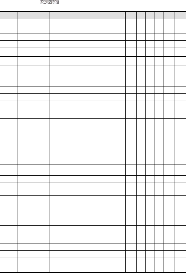
Chapter 4 Parameters|
4-16 Revision August 2008, 03VE, SW V2.04
Group 7 Special Parameters
Pr. Explanation Settings Factory
Setting VF VFPG
SVC
FOCPG
TQRPG
07-00 Software Brake Level 230V: 350.0~450.0Vdc
460V: 700.0~900.0Vdc
380.0
760.0
○ ○ ○ ○ ○
07-01 DC Brake Current
Level
0~100% 0
○ ○
07-02 DC Brake Time during
Start-up
0.0~60.0 sec 0.0 ○ ○
07-03 DC Brake Time during
Stopping
0.0~60.0 sec 0.0 ○ ○
07-04 Start-point for DC
Brake
0.00~600.00Hz 0.00
○ ○ ○
07-05 DC Brake Voltage
Gain
1~500 50
○ ○ ○
07-06 Momentary Power
Loss Operation
Selection
0: Operation stop after momentary power loss
1: Operation continues after momentary power loss,
speed search starts with the Master Frequency
reference value
2: Operation continues after momentary power loss,
speed search starts with the minimum frequency
0 ○ ○ ○ ○ ○
07-07 Maximum Allowable
Power Loss Time
0.1~5.0 sec 2.0 ○ ○ ○ ○ ○
07-08 B.B. Time for Speed
Search
0.1~5.0 sec 0.5 ○ ○ ○ ○ ○
07-09 Current Limit for
Speed Search
20~200% 150
○ ○ ○ ○ ○
07-10 Base-block Speed
Search
0: Stop operation
1: Speed search starts with last frequency command
2: Speed search starts with minimum output frequency
0 ○ ○ ○ ○ ○
07-11 Auto Restart after
Fault
0~10 0
○ ○ ○ ○ ○
07-12 Speed Search during
Start-up
0: Disable
1: Speed search from maximum frequency
2: Speed search from start-up frequency
3: Speed search from minimum frequency
0 ○ ○ ○ ○
07-13 Decel. Time Selection
for Momentary Power
Loss
0: Disable
1: 1st decel. time
2: 2nd decel. time
3: 3rd decel. time
4: 4th decel. time
5: Current decel. time
6: Auto decel. Time
0 ○ ○ ○ ○ ○
07-14 DEB Return Time 0.0~25.0 sec 0.0 ○ ○ ○ ○
07-15 Dwell Time at Accel. 0.00~600.00sec 0.00 ○ ○ ○ ○
07-16 Dwell Frequency at
Accel.
0.00~600.00Hz 0.00
○ ○ ○ ○
07-17 Dwell Time at Decel. 0.00~600.00sec 0.00 ○ ○ ○ ○
07-18 Dwell Frequency at
Decel.
0.00~600.00Hz 0.00
○ ○ ○ ○
07-19 Fan Control 0: Fan always ON
1: 1 minute after AC motor drive stops, fan will be OFF
2: AC motor drive runs and fan ON, AC motor drive
stops and fan OFF
3: Fan ON to run when preliminary heat sink
temperature attained
4: Fan always OFF
0 ○ ○ ○ ○ ○
07-20 Torque Command -100.0~100.0% (Pr. 07-22 setting=100%) 0.0 ○
07-21 Torque Command
Source
0: Digital keypad
1: RS485 serial communication (RJ-11)
2: Analog signal (Pr.03-00)
0 ○
07-22 Maximum Torque
Command
0~500% 100
○
07-23 Filter Time of Torque
Command
0.000~1.000 sec 0.000 ○
07-24 Speed Limit Selection 0: By Pr.07-25 and Pr.07-26
1: Frequency command source (Pr.00-20)
0 ○
07-25 Torque Mode +Speed
Limit
0~120% 10
○
07-26 Torque Mode-Speed
Limit
0~120% 10
○

Chapter 4 Parameters|
Revision August 2008, 03VE, SW V2.04 4-17
Pr. Explanation Settings Factory
Setting VF VFPG
SVC
FOCPG
TQRPG
07-27 Source of Torque
Offset
0: Disable
1: Analog input (Pr.03-00)
2: Torque offset setting
3: Control by external terminal (by Pr.07-29 to Pr.07-
31)
0
○ ○ ○
07-28 Torque Offset Setting 0.0~100.0% 0.0 ○ ○ ○
07-29 High Torque Offset 0.0~100.0% 30.0 ○ ○ ○
07-30 Middle Torque Offset 0.0~100.0% 20.0 ○ ○ ○
07-31 Low Torque Offset 0.0~100.0% 10.0 ○ ○ ○
07-32 Forward Motor Torque
Limit
0~500% 200
○ ○
07-33 Forward Regenerative
Torque Limit
0~500% 200
○ ○
07-34 Reverse Motor Torque
Limit
0~500% 200
○ ○
07-35 Reverse Regenerative
Torque Limit
0~500% 200
○ ○
07-36 Emergency Stop (EF)
& Forced Stop
Selection
0: Coast stop
1: By deceleration Time 1
2: By deceleration Time 2
3: By deceleration Time 3
4: By deceleration Time 4
5: System Deceleration
6: Automatic Deceleration
0 ○ ○ ○ ○ ○
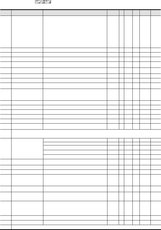
Chapter 4 Parameters|
4-18 Revision August 2008, 03VE, SW V2.04
Group 8 High-function PID Parameters
Pr. Explanation Settings Factory
Setting VF
VFPG
SVC
FOCPG
TQRPG
08-00 Input Terminal for PID
Feedback
0: No function
1: Negative PID feedback from external terminal AVI
(Pr.03-00)
2: Negative PID feedback from PG card (Pr.10-15, skip
direction)
3: Negative PID feedback from PG card (Pr.10-15)
4: Positive PID feedback from external terminal AVI
(Pr.03-00)
5: Positive PID feedback from PG card (Pr.10-15, skip
direction)
6: Positive PID feedback from PG card (Pr.10-15)
0 ○
○ ○
○
08-01 Proportional Gain (P) 0.0~500.0% 80.0 ○
○ ○
○
08-02 Integral Gain (I) 0.00~100.00 sec 1.00 ○
○ ○
○
08-03 Derivative Control (D) 0.00~1.00 sec 0.00 ○
○ ○
○
08-04 Upper limit for Integral
Control 0.0~100.0% 100.0
○
○ ○
○
08-05 PID Output Frequency
Limit 0.0~110.0% 100.0
○
○ ○
○
08-06 PID Offset -100.0~+100.0% 0.0 ○
○ ○
○
08-07 PID Delay Time 0.0~2.5 sec 0.0 ○
○ ○
○
08-08 Feedback Signal Detection
Time 0.0~3600.0 sec 0.0 ○
○ ○
○
08-09 Feedback Fault Treatment
0: Warn and keep operating
1: Warn and ramp to stop
2: Warn and coast to stop
3: Warn and keep at last frequency
0 ○
○ ○
○
08-10 Sleep Frequency 0.00~600.00Hz 0.00 ○
○ ○
○
08-11 Wake-up Frequency 0.00~600.00Hz 0.00 ○
○ ○
○
08-12 Sleep Time 0.0~6000.0 sec 0.0 ○
○ ○
○
08-13 PID Deviation Level 1.0~50.0% 10.0 ○
○ ○
○
08-14 PID Deviation Time 0.1~300.0 sec 5.0 ○
○ ○
○
08-15 Filter Time for PID
Feedback 0.1~300.0 sec 5.0 ○
○ ○
○
08-16
|
08-20
Reserved
0: Disable 0 ○ ○ ○ ○
08-21 Tension Control Selection
1: Closed-loop, speed mode ○ ○ ○ ○
2: Line speed, speed mode ○ ○ ○ ○
3: Reserved
4: Open-loop, torque mode ○
08-22 Wind Mode 0: Rewind
1: Unwind
0 ○ ○ ○ ○ ○
08-23 Mechanical Gear Ratio A 1-65535 100 ○ ○ ○ ○ ○
08-24 Mechanical Gear Ratio B 1-65535 100 ○ ○ ○ ○ ○
08-25 Source of the Tension
Command/Line Speed
0: Parameter setting (Pr.08-26)
1: RS-485 communication setting (Pr.08-26)
2: Analog input (Pr. 03-00~03-02 is set to 14 PID target
value of tension, 03-00~03-02 is set to 12 line speed)
0 ○ ○ ○ ○ ○
08-26 PID Target Value of
Tension/Line Speed
0.0~100.0% 50.0
○ ○ ○ ○ ○
08-27 Source of Tension/Line
Speed PID Feedback
0: Analog input (Pr. 03-00~03-02 is set to 11 PID
feedback of tension)
1: Pulse input (Pr.08-40)
0 ○ ○ ○ ○ ○
08-28 Auto-tuning Tension PID 0: Disable
1: Reel diameter (08-29~08-31corresponds to 08-44,
08-32~08-34 corresponds to 08-43)
2: Frequency (08-29~08-31 corresponds to 01-07, 08-
32~08-34 corresponds to 01-00)
○ ○ ○ ○ ○
08-29 Tension PID P1 0.0~1000.0 50.0 ○ ○ ○ ○ ○
08-30 Tension PID I1 0.00~500.00 sec 1.00 ○ ○ ○ ○ ○
08-31 Reserved

Chapter 4 Parameters|
Revision August 2008, 03VE, SW V2.04 4-19
Pr. Explanation Settings Factory
Setting VF
VFPG
SVC
FOCPG
TQRPG
08-32 Tension PID P2 0.0~1000.0 50.0 ○ ○ ○ ○ ○
08-33 Tension PID I2 0.00~500.00 sec 1.00 ○ ○ ○ ○ ○
08-34 Reserved
08-35 PID/Line Speed Output
Status
0: Positive output
1: Negative output
0 ○ ○ ○ ○ ○
08-36 Tension/Line Speed PID
Output Limit
0~100.00% (according to Pr,01-00) 20.00 ○ ○ ○ ○ ○
08-37 Source of Line Speed
Input Command
0: Disable
1: Analog input (Pr. 03-00~03-02 is set to 12 line speed)
2: RS-485 communication setting (Pr.08-41)
3: Pulse input (Pr.08-40)
4: DFM-DCM pulse input (Pr.02-18)
0 ○ ○ ○ ○ ○
08-38 Max. Line Speed 0.0~3000.0m/min 1000.0 ○ ○ ○ ○ ○
08-39 Min. Line Speed 0.0~3000.0m/min 0.0 ○ ○ ○ ○ ○
08-40 Pulse Number for Each
Meter
0.0~6000.0 0.0
○ ○ ○ ○ ○
08-41 Current Line Speed 0.0~3000.0m/min 0.0 ○ ○ ○ ○ ○
08-42 Source of Reel Diameter 0: Calculated by line speed
1: Calculated by integrating thickness (encoder is on
reel shaft)(Pr.08-49~51, Pr.10-15)
2: Calculated by integrating thickness (encoder is on
motor)(Pr.08-23~08-24, 08-50~08-51, 10-00~10-01)
3: Calculated by analog input (Pr.03-00~03-02 is set to
13)
0 ○ ○ ○ ○ ○
08-43 Max. Reel Diameter 1.0~6000.0mm 6000.0 ○ ○ ○ ○ ○
08-44 Empty Reel Diameter 1.0~6000.0mm 1.0 ○ ○ ○ ○ ○
08-45 Source of Initial Reel
Diameter
0: RS-485 communication setting (Pr.08-46)
1: Analog input (Pr.03-00-Pr.03-02 is set to 13)
0 ○ ○ ○ ○ ○
08-46 Initial Reel Diameter 1.0~6000.0mm 1.0 ○ ○ ○ ○ ○
08-47 Initial Reel Diameter 1 1.0~6000.0mm 1.0 ○ ○ ○ ○ ○
08-48 Initial Reel Diameter 2 1.0~6000.0mm 1.0 ○ ○ ○ ○ ○
08-49 Number of Pulse per
Revolution
1~10000ppr 1
○ ○ ○ ○ ○
08-50 Coil Number for Each
Layer
0.001~60.000mm 1.000
○ ○ ○ ○ ○
08-51 Material Thickness 0.001~60.000mm 1.000 ○ ○ ○ ○ ○
08-52 Filter Time of Reel
Diameter
0.00 to 100.00 seconds 1.00 ○ ○ ○ ○ ○
08-53 Auto Compensation of
Reel Diameter
0: Disable
1: Enable
1.00 ○ ○ ○ ○ ○
08-54 Current Reel Diameter 1.0~6000.0mm 1.0 ○ ○ ○ ○ ○
08-55 Smart Start 0: Disable
1: Enable
2: In unwind mode, rewind in reverse direction
1 ○ ○ ○ ○ ○
08-56 Switch Level for Smart
Start and PID function
0.0~100.0% (according to Pr.08-26) 15.0 ○ ○ ○ ○ ○
08-57 Frequency for Smart Start 0.00~600.00Hz 2.00 ○ ○ ○ ○ ○
08-58 Accel. Time for Smart Start 0.01~600.00 seconds 3.00 ○ ○ ○ ○
08-59 Broken Belt Detection 0: Disable
1: Enable
0 ○ ○ ○ ○
08-60 Min. Line Speed of Broken
Belt Detection
0.0~3000.0m/min 0.0
○ ○ ○ ○
08-61 Allowance Error of Line
Speed of Broken Belt
Detection
1.0~6000.0mm 100.0
○ ○ ○ ○
08-62 Detection Time of Broken
Belt
0.00~100.00 sec 1.00 ○ ○ ○ ○
08-63 Allowance Error Level of
Tension/Line Speed PID
Feedback
0~100% 100
○ ○ ○ ○
08-64 Allowance Error Detection
Time of Tension PID
Feedback
0.0~10.0 sec 0.5 ○ ○ ○ ○
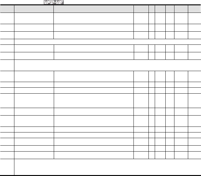
Chapter 4 Parameters|
4-20 Revision August 2008, 03VE, SW V2.04
Pr. Explanation Settings Factory
Setting VF
VFPG
SVC
FOCPG
TQRPG
08-65 Error Treatment of Tension
PID Feedback
0: Warn and keep operation
1: Warn and coast to stop
2: Warn and ramp to stop
0 ○ ○ ○ ○
08-66 Upper Limit of Tension PID
Feedback
0.0~100.0% 100.0
○ ○ ○ ○ ○
08-67 Lower Limit of Tension PID
Feedback
0.0~100.0% 0.0
○ ○ ○ ○ ○
08-68 Reserved
08-69 DFM Selection 0: Output frequency
1: Frequency command
0 ○ ○ ○ ○ ○
08-70 Low-pass Filter Time of
Line Speed
0.00~100.00 sec 0.00 ○ ○ ○ ○ ○
08-71
|
08-75
Reserved
08-76 Source of Tension Setting
0: Communication RS-485 (Pr.08-78)
1: Analog input (Pr. 03-00~03-02 is set to 15 tension
setting) (Pr.08-78)
0
○
08-77 Max. Tension 0~30000 N 0 ○
08-78 Tension Setting 0~30000 N 0 ○
08-79 Source of Zero-speed
Tension Setting
0: Disable
1: Communication RS-485 (Pr.08-80)
2: Analog input (Pr. 03-00~03-02 is set to 16 zero-
speed tension) (Pr.08-80)
0
○
08-80 Setting of Zero-speed
Tension
0~30000 N 0 ○
08-81 Source of Tension Taper 0: Communication RS-485 (Pr.08-82)
1: Analog input (Pr. 03-00~03-02 is set to 17 tension
taper)(Pr.08-82)
0
○
08-82 Tension Taper 0~100% 0 ○
08-83 Friction Compensation 0.0~100.0% 0.0 ○
08-84 Compensation Coefficient
of Material Inertial
0~30000 0
○
08-85 Torque Feedforward Gain 0.0~100.0% 50.0 ○
08-86 Low Pass Filter Time of
Torque Feedforward
0.00~100.00 5.00
○
08-87
|
08-99
Reserved

Chapter 4 Parameters|
Revision August 2008, 03VE, SW V2.04 4-21
Group 9 Communication Parameters
Pr. Explanation Settings Factory
Setting VF VFPG
SVC
FOCPG
TQRPG
09-00 Communication
Address
1~254 1
○ ○ ○ ○ ○
09-01 COM1 Transmission
Speed
4.8~115.2Kbps 9.6
○ ○ ○ ○ ○
09-02 COM1 Transmission
Fault Treatment
0: Warn and keep operation
1: Warn and ramp to stop
2: Warn and coast to stop
3: No warning and keep operation
3 ○ ○ ○ ○ ○
09-03 COM1 Time-out
Detection
0.0~100.0 sec 0.0 ○ ○ ○ ○ ○
09-04 COM1 Communication
Protocol
0: 7N1 (ASCII)
1: 7N2 (ASCII)
2: 7E1 (ASCII)
3: 7O1 (ASCII)
4: 7E2 (ASCII)
5: 7O2 (ASCII)
6: 8N1 (ASCII)
7: 8N2 (ASCII)
8: 8E1 (ASCII)
9: 8O1 (ASCII)
10: 8E2 (ASCII)
11: 8O2 (ASCII)
12: 8N1 (RTU)
13: 8N2 (RTU)
14: 8E1 (RTU)
15: 8O1 (RTU)
16: 8E2 (RTU)
17: 8O2 (RTU)
1 ○ ○ ○ ○ ○
09-05 COM2 Transmission
Speed (Keypad)
4.8~115.2Kbps 9.6
○ ○ ○ ○ ○
09-06 COM2 Transmission
Fault Treatment
(Keypad)
0: Warn and keep operation
1: Warn and ramp to stop
2: Warn and coast to stop
3: No warning and keep operation
3 ○ ○ ○ ○ ○
09-07 COM2 Time-out
Detection (Keypad)
0.0~100.0 sec 0.0 ○ ○ ○ ○ ○
09-08 COM2 Communication
Protocol (Keypad)
0: 7N1 (ASCII)
1: 7N2 (ASCII)
2: 7E1 (ASCII)
3: 7O1 (ASCII)
4: 7E2 (ASCII)
5: 7O2 (ASCII)
6: 8N1 (ASCII)
7: 8N2 (ASCII)
8: 8E1 (ASCII)
9: 8O1 (ASCII)
10: 8E2 (ASCII)
11: 8O2 (ASCII)
12: 8N1 (RTU)
13: 8N2 (RTU)
14: 8E1 (RTU)
15: 8O1 (RTU)
16: 8E2 (RTU)
17: 8O2 (RTU)
13 ○ ○ ○ ○ ○
09-09 Response Delay Time 0.0~200.0ms 2.0 ○ ○ ○ ○ ○
09-10 Transmission Master
Frequency
0.00~600.00Hz 60.00 ○ ○ ○ ○
09-11 Block Transfer 1 0~65535 0 ○ ○ ○ ○ ○
09-12 Block Transfer 2 0~65535 0 ○ ○ ○ ○ ○
09-13 Block Transfer 3 0~65535 0 ○ ○ ○ ○ ○
09-14 Block Transfer 4 0~65535 0 ○ ○ ○ ○ ○
09-15 Block Transfer 5 0~65535 0 ○ ○ ○ ○ ○
09-16 Block Transfer 6 0~65535 0 ○ ○ ○ ○ ○
09-17 Block Transfer 7 0~65535 0 ○ ○ ○ ○ ○
09-18 Block Transfer 8 0~65535 0 ○ ○ ○ ○ ○
09-19 Block Transfer 9 0~65535 0 ○ ○ ○ ○ ○

Chapter 4 Parameters|
4-22 Revision August 2008, 03VE, SW V2.04
Pr. Explanation Settings Factory
Setting VF VFPG
SVC
FOCPG
TQRPG
09-20 Block Transfer 10 0~65535 0 ○ ○ ○ ○ ○
09-21 Multi-function Output
Status
0~65535 Read-
only
○ ○ ○ ○ ○
09-22 AFM2 Status 0~4095 Read-
only
○ ○ ○ ○ ○
09-23 AFM3 Status 0~4095 Read-
only
○ ○ ○ ○ ○

Chapter 4 Parameters|
Revision August 2008, 03VE, SW V2.04 4-23
Group 10 Speed Feedback Control Parameters
Pr. Explanation Settings Factory
Setting VF VFPG
SVC
FOCPG
TQRPG
10-00 Encoder Pulse 1~20000 600 ○ ○ ○
10-01 Encoder Input Type
Setting
0: Disable
1: Phase A leads in a forward run command and phase
B leads in a reverse run command
2: Phase B leads in a forward run command and phase
A leads in a reverse run command
3: Phase A is a pulse input and phase B is a direction
input. (low input=reverse direction, high input=forward
direction)
4: Phase A is a pulse input and phase B is a direction
input. (low input=forward direction, high input=reverse
direction)
5: Single-phase input
0
○ ○ ○
10-02 PG Feedback Fault
Treatment
0: Warn and keep operation
1: Warn and ramp to stop
2: Warn and coast to stop
2
○ ○ ○
10-03 Detection Time for PG
Feedback Fault
0.00~10.0 sec 1.0 ○ ○ ○
10-04 ASR (Auto Speed
Regulation) Control
( P) 1
0~40 10
○ ○
10-05 ASR (Auto Speed
Regulation) Control (I)
1
0.000~10.000 sec 0.100 ○ ○
10-06 ASR (Auto Speed
Regulation) Control
( P) 2
0~40 10
○ ○
10-07 ASR (Auto Speed
Regulation) Control (I)
2
0.000~10.000 sec 0.100 ○ ○
10-08 ASR 1/ASR2 Switch
Frequency
5.00~600.00Hz 7.00
○ ○
10-09 ASR Primary Low
Pass Filter Gain
0.000~0.350 sec 0.008 ○
10-10 PG Stall Level 0~120% (0: disable) 115 ○ ○
10-11 PG Stall Detection
Time
0.0~2.0 sec 0.1 ○ ○
10-12 PG Slip Range 0~50% (0: disable) 50 ○ ○
10-13 PG Slip Detection
Time
0.0~10.0 sec 0.5 ○ ○
10-14 PG Stall and Slip Error
Treatment
0: Warn and keep operation
1: Warn and ramp to stop
2: Warn and coast to stop
2
○ ○
10-15 Pulse Input Type
Setting
0: Disable
1: Phase A leads in a forward run command and phase
B leads in a reverse run command
2: Phase B leads in a forward run command and phase
A leads in a reverse run command
3: Phase A is a pulse input and phase B is a direction
input. (low input=reverse direction, high input=forward
direction)
4: Phase A is a pulse input and phase B is a direction
input. (low input=forward direction, high input=reverse
direction)
0 ○ ○ ○ ○ ○
10-16 Output Setting for
Frequency Division
(denominator)
1~255 1
○ ○ ○
10-17 PG Electrical Gear A
(Channel 1 of PG
card)
1~5000 100
○ ○
10-18 PG Electrical Gear B
(Channel 2 of PG
card)
1~5000 100
○ ○
10-19 PG Position Control
Point (Home)
0~20000 0
○ ○
10-20 Range for PG Position
Attained (Home range)
0~20000 10
○ ○

Chapter 4 Parameters|
4-24 Revision August 2008, 03VE, SW V2.04
Pr. Explanation Settings Factory
Setting VF VFPG
SVC
FOCPG
TQRPG
10-21 P Gain of Zero Speed 0~40 10
○ ○
10-22 I Gain of Zero Speed 0.000~10.000 sec 0.100 ○ ○ ○ ○
10-23 Feed Forward Gain of
APR
0~100 30
○ ○
10-24 Decelerate Time of
Position
0.00~600.00 sec/00~6000.0 sec 3.00
3.0
○ ○
10-25 Max. Frequency for
Resolution Switch
50.00~600.00Hz 50.00
○ ○ ○ ○ ○
10-26 Reserved
10-27 PG Mechanical Gear
A1
1~65535 100
○ ○ ○
10-28 PG Mechanical Gear
B1
1~65535 100
○ ○ ○
10-29 PG Mechanical Gear
A2
1~65535 100
○ ○ ○
10-30 PG Mechanical Gear
B2
1~65535 100
○ ○ ○

Chapter 4 Parameters|
Revision August 2008, 03VE, SW V2.04 4-25
Group 11 Advanced Parameters
Pr. Explanation Settings Factory
Setting VF VFPG
SVC
FOCPG
TQRPG
11-00 System Control
bit 0: ASR Auto tuning
bit 1: Inertia estimate (only for FOCPG mode)
bit 2: Zero Servo
bit 3: Reserved
bit 4: Enable gain adjustment of position loop KP
0
○
11-01 Per Unit of System
Inertia
1~65535 (256=1PU) 400 ○ ○
11-02 Low-speed Bandwidth 0~40Hz 10
○ ○ ○
11-03 High-speed Bandwidth 0~40Hz 10
○ ○ ○
11-04 PDFF Gain Value 0~200% 30
○
11-05
Gain Value of Flux
Weakening Curve for
Motor 1
0~200% 90
○ ○
11-06
Gain Value of Flux
Weakening Curve for
Motor 2
0~200% 90
○ ○
11-07 Detection Time for
Phase-loss
0.01~600.00 sec 0.20 ○ ○ ○ ○ ○
11-08 Reserved
11-09 Level of Phase-loss 0.0~320.0 60.0 ○ ○ ○ ○ ○
11-10 Speed Feed Forward
Gain
0~100% 0
○
11-11 Zero-speed Bandwidth 0~40Hz 10
○ ○ ○
11-12 Speed Response of
Flux Weakening Area
0: Disable
0~150%
65 ○
11-13 Notch Filter Depth 0~20db 0
○
11-14 Notch Filter Frequency 0.00~200.00 0.00
○
11-15 Gain Value of Slip
Compensation 0.00~1.00 1.00 ○
11-16 Low-pass Filter Time
of Keypad Display 0.001~65.535sec 0.100 ○ ○ ○ ○ ○
11-17 Low-pass Filter Time
of PG2 Pulse Input 0.000~65.535sec 0.100 ○ ○ ○ ○
11-18 APR Gain 0.00~40.00 10.00 ○
11-19 APR Curve Time 0.00~655.35 sec 3.00 ○
11-20
|
11-28
Reserved
11-29
Accumulative
Operation Time of
Phase-loss
0~65535 (hour) 0 ○ ○ ○ ○ ○
11-30
|
11-40
Reserved
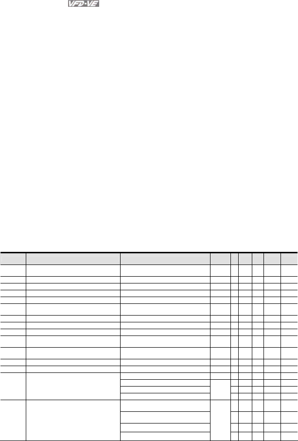
Chapter 4 Parameters|
4-26 Revision August 2008, 03VE, SW V2.04
4.2 Version Differences
4.2.1 Version 2.02
New or update parameter groups are:
Group 2: Digital Input/Output Parameters
Group 3: Analog Input/Output Parameters
Group 6: Protection Parameters
Group 8: High-function PID Parameters
Group 10: Speed Feedback Control Parameters
4.2.2 Version 2.04
New or update parameter groups are:
Group 0 System Parameters
Group 2: Digital Input/Output Parameters
Group 3: Analog Input/Output Parameters
Group 5: Motor Parameters
Group 6: Protection Parameters
Group 8: High-function PID Parameters
Group 10: Speed Feedback Control Parameters
Version 2.02
Group 2 Digital Input/Output Parameters
New settings are marked in bold. In version 2.02, the parameters are from Pr.02-00 to Pr.02-34.
Pr. Explanation Settings Factory
Setting VF
VFPG
SVC
FOCPG
TQRPG
02-01 Multi-Function Input Command 1 (MI1)
(it is Stop terminal for 3-wire operation) 27: ASR1/ASR2 selection ○ ○
02-02 Multi-Function Input Command 2 (MI2) 28: Emergency stop (EF1) ○ ○ ○ ○ ○
02-03 Multi-Function Input Command 3 (MI3) 29: Signal confirmation for Y-connection ○ ○ ○ ○
02-04 Multi-Function Input Command 4 (MI4) 30: Signal confirmation for Δ−connection ○ ○ ○ ○
02-05 Multi-Function Input Command 5 (MI5) 31: High torque bias (by Pr.07-29) ○ ○ ○ ○ ○
02-06 Multi-Function Input Command 6 (MI6)
(specific terminal for TRG) 32: Middle torque bias (by Pr.07-30) ○ ○ ○ ○ ○
02-23 Multi-Function Input Command 7 33: Low torque bias (by Pr.07-31) ○ ○ ○ ○ ○
02-24 Multi-Function Input Command 8 34: Enable multi-step position control ○ ○
02-25 Multi-Function Input Command 9 35: Enable position control ○ ○
02-26 Multi-Function Input Command 10 36: Enable position learning function
(valid at stop)
○ ○
02-27 Multi-Function Input Command 11 37: Enable pulse position input
command
○ ○
02-28 Multi-Function Input Command 12 38: Disable write EEPROM function ○ ○ ○ ○ ○
02-29 Multi-Function Input Command 13 39: Torque command direction
○
02-30 Multi-Function Input Command 14 40: Force stop ○ ○ ○ ○ ○
41: Serial position clock
○
42: Serial position input
○
43: Analog input resolution selection
○
02-11 Multi-function Output 1 RA, RB,
RC(Relay1)
29: Output when frequency >= Pr.02-33 ○ ○ ○ ○ ○
02-12 Multi-function Output 2
MRA, MRC (Relay2)
30: Output when frequency < Pr.02-33 ○ ○ ○ ○ ○
02-13 Multi-function Output 3 (MO1) 31: Y-connection for the motor coil ○ ○ ○ ○
02-14 Multi-function Output 4 (MO2) 32: Δ connection for the motor coil ○ ○ ○ ○
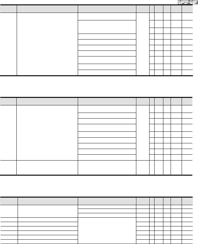
Chapter 4 Parameters|
Revision August 2008, 03VE, SW V2.04 4-27
Pr. Explanation Settings Factory
Setting VF
VFPG
SVC
FOCPG
TQRPG
02-35 Multi-function Output 5 (MO3) 33: Zero speed (actual output
frequency)
○ ○ ○ ○
02-36 Multi-function Output 6 (MO4) 34: Zero speed with Stop (actual output
frequency)
○ ○ ○ ○
02-37 Multi-function Output 7 (MO5) 35: Error output selection 1 (Pr.06-23) ○ ○ ○ ○ ○
02-38 Multi-function Output 8 (MO6) 36: Error output selection 2 (Pr.06-24) ○ ○ ○ ○ ○
02-39 Multi-function Output 9 (MO7) 37: Error output selection 3 (Pr.06-25) ○ ○ ○ ○ ○
02-40 Multi-function Output 10 (MO8) 38: Error output selection 4 (Pr.06-26) ○ ○ ○ ○ ○
02-41 Multi-function Output 11 (MO9) 39: Position attained (Pr.10-19) ○
02-42 Multi-function Output 12 (MOA) 40: Speed attained (including zero
speed)
○ ○ ○ ○
41: Multi-position attained
○
42: Crane function ○ ○ ○ ○
Group 3 Analog Input/Output Parameters
In version 2.02, the parameters are from Pr.03-00 to Pr.03-20. The settings for Pr.03-00 to
Pr.03-02 are from 0 to 10
Pr. Explanation Settings Factory
Setting VF
VFPG
SVC
FOCPG
TQRPG
03-00 Analog Input 1 (AVI) 2: torque command (torque limit under
speed mode)
0
○
3: Torque compensation command ○ ○ ○ ○ ○
03-01 Analog Input 2 (ACI) 4: PID target value (refer to group 8) ○ ○ ○ ○
5: PID feedback signal (refer to group
8)
○ ○ ○ ○
03-02 Analog Input 3 (AUI) 6: P.T.C. thermistor input value ○ ○ ○ ○ ○
7: Positive torque limit ○
8: Negative torque limit ○
9: Regenerative torque limit ○
10: Positive/negative torque limit ○
03-20 Analog Output Value in REV Direction 0: Absolute value in REV direction
1: Output 0V in REV direction
2: Enable output voltage in REV
direction
0 ○ ○ ○ ○ ○
Group 6 Protection Parameters
In version 2.02, the parameters are from Pr.06-00 to Pr.06-31. The settings of Pr.06-01 are
shown as follows. The settings for Pr.06-17 to Pr.06-22 are from 0 to 62.
Pr. Explanation Settings Factory
Setting VF
VFPG
SVC
FOCPG
TQRPG
0.0: Disable
350.0~450.0Vdc 380.0 ○ ○ ○ ○ ○
06-01 Over-voltage Stall Prevention
700.0~900.0Vdc 760.0 ○ ○ ○ ○ ○
06-17 Present Fault Record 0 ○ ○ ○ ○ ○
06-18 Second Most Recent Fault Record 0 ○ ○ ○ ○ ○
06-19 Third Most Recent Fault Record 0 ○ ○ ○ ○ ○
06-20 Fourth Most Recent Fault Record 0 ○ ○ ○ ○ ○
06-21 Fifth Most Recent Fault Record 0 ○ ○ ○ ○ ○
06-22 Sixth Most Recent Fault Record
0: No fault
1: Over-current during acceleration
(ocA)
2: Over-current during deceleration
(ocd)
3: Over-current during constant speed
(ocn) 0 ○ ○ ○ ○ ○
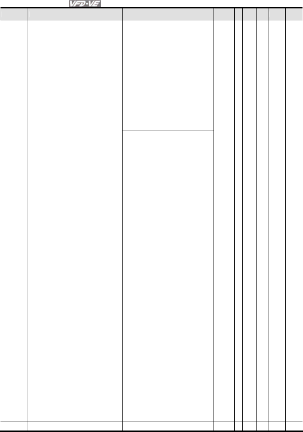
Chapter 4 Parameters|
4-28 Revision August 2008, 03VE, SW V2.04
Pr. Explanation Settings Factory
Setting VF
VFPG
SVC
FOCPG
TQRPG
4: Ground fault (GFF)
5: IGBT short-circuit (occ)
6: Over-curent at stop (ocS)
7: Over-voltage during acceleration
(ovA)
8: Over-voltage during deceleration
(ovd)
9: Over-voltage during constant speed
(ovn)
10: Over-voltage at stop (ovS)
11: Low-voltage during acceleration
(LvA)
12: Low-voltage during deceleration
(Lvd)
13: Low-voltage during constant speed
(Lvn)
14: Low-voltage at stop (LvS)
15: Phase loss (PHL)
16: IGBT heat sink over-heat (oH1)
17: Heat sink over-heat (oH2)(for 40HP
above)
18: TH1 open loop error (tH1o)
19: TH2 open loop error (tH2o)
20: Fan error signal output
21: over-load (oL) (150% 1Min)
22: Motor 1 over-load (EoL1)
23: Motor 2 over-load (EoL2)
24: Motor PTC overheat (oH3)
25: Fuse error (FuSE)
26: over-torque 1 (ot1)
27: over-torque 1 (ot2)
28: Insufficient torque 1
29: Insufficient torque 2
30: Memory write-in error (cF1)
31: Memory read-out error (cF2)
32: Isum current detection error (cd0)
33: U-phase current detection error
(cd1)
34: V-phase current detection error
(cd2)
35: W-phase current detection error
(cd3)
36: Clamp current detection error (Hd0)
37: Over-current detection error (Hd1)
38: Over-voltage detection error (Hd2)
39: Ground current detection error (Hd3)
40: Auto tuning error (AuE)
41: PID feedback loss (AFE)
42: PG feedback error (PGF1)
43: PG feedback loss (PGF2)
44: PG feedback stall (PGF3)
45: PG slip error (PGF4)
46: PG ref input error (PGr1)
47: PG ref loss (PGr2)
48: Analog current input loss (ACE)
49: External fault input (EF)
50: Emergency stop (EF1)
51: External Base Block (B.B.)
52: Password error (PcodE)
53: Software error (ccodE)
54: Communication error (cE1)
55: Communication error (cE2)
56: Communication error (cE3)
57: Communication error (cE4)
58: Communication Time-out (cE10)
59: PU time-out (cP10)
60: Brake transistor error (bF)
61: Y-connection/Δ-connection switch
error (ydc)
62: Decel. Energy Backup Error (dEb)
06-31 Filter Time for PTC Detection 0.00~10.00sec 0.20 ○ ○ ○ ○ ○
Group 8 High-function PID Parameters
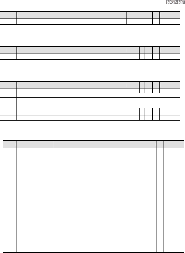
Chapter 4 Parameters|
Revision August 2008, 03VE, SW V2.04 4-29
In version 2.02, the parameters are from Pr.08-00 to Pr.08-15.
Pr. Explanation Settings Factory
Setting VF
VFPG
SVC
FOCPG
TQRPG
08-15 Filter Time for PID Feedback 0.1~300.0 sec 5.0 ○ ○ ○ ○
Group 10 Speed Feedback Control Parameters
In version 2.02, the parameters are from Pr.10-00 to Pr.10-28.
Pr. Explanation Settings Factory
Setting VF
VFPG
SVC
FOCPG
TQRPG
10-28 PG Mechanical Gear B1 1~5000 100
○
○ ○
Group 11 Advanced Parameters
In version 2.02, the parameters are from Pr.11-00 to Pr.11-30.
Pr. Explanation Settings Factory
Setting VF
VFPG
SVC
FOCPG
TQRPG
11-09 Level of Phase-loss 0.0~320.0 60.0 ○ ○ ○ ○ ○
11-10 Reserved
11-18
|
11-28
Reserved
11-29 Accumulative Operation Time of Phase-
loss 0~65535 (hour) 0 ○ ○ ○ ○ ○
11-30 APR Curve Time 0.00~655.35 sec 3.00 ○
Version 2.04
Group 0 System Parameters
Pr. Explanation Settings Factory
Setting VF
VFPG
SVC
FOCPG
TQRPG
00-03 Start-up Display Selection
0: Display the frequency command value (LED F)
1: Display the actual output frequency (LED H)
2: Multifunction display, see Pr.00-04 (LED U)
3: Display the output current (A)
0 ○ ○ ○ ○ ○
00-04 Content of Multi Function
Display
0: Display output current (A)
1: Display counter value (C)
2: Display output frequency (H)
3: Display DC-BUS voltage ( u)
4: Display output voltage (E)
5: Output power factor angle (n)
6: Display output power (kW)
7: Display actual motor speed (HU)
8: Display estimate output torque (kg-m)
9: Display PG position (G) (refer to Pr.10-00 and Pr.10-
01)
10: Display PID feedback
11: Display AVI (%)
12: Display ACI (%)
13: Display AUI (%)
14: Display the temperature of heat sink (°C)
15: Display the temperature of IGBT (°C)
16: The status of digital input (ON/OFF)
17: The status of digital output (ON/OFF)
18: Multi-step speed
19: The corresponding CPU pin status of digital input
20: The corresponding CPU pin status of digital output
21: Number of actual motor revolution (PG1 of PG
card)
22: Pulse input frequency (PG2 of PG card)
23: Pulse input position (PG2 of PG card)
0 ○ ○ ○ ○ ○
Group 2 Digital Input/Output Parameters
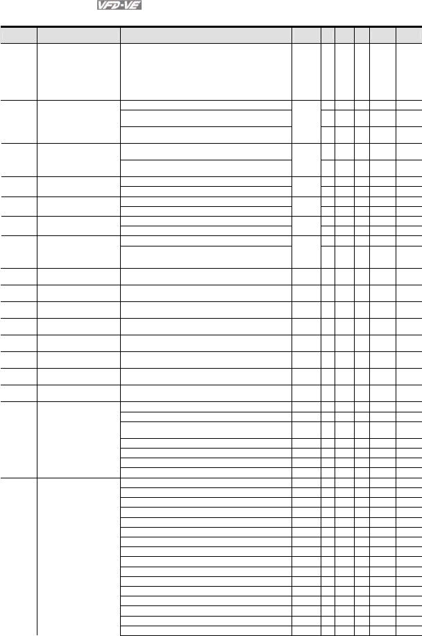
Chapter 4 Parameters|
4-30 Revision August 2008, 03VE, SW V2.04
New settings 44~50 for Pr.02-00~Pr.02-06 and new parameter 02-43.
Pr. Explanation Settings Factory
Setting VF
VFPG
SVC
FOCPG
TQRPG
02-00 2-wire/3-wire Operation
Control
0: FWD/STOP, REV/STOP
1: FWD/STOP, REV/STOP (Line Start Lockout)
2: RUN/STOP, REV/FWD
3: RUN/STOP, REV/FWD (Line Start Lockout)
4: 3-wire (momentary push button)
5: 3-wire (momentary push button and Line Start
Lockout)
0 ○ ○ ○ ○ ○
0: no function ○ ○ ○ ○ ○
1: multi-step speed command 1/multi-step position
command 1
○ ○ ○ ○
02-01 Multi-Function Input
Command 1 (MI1)
(it is Stop terminal for 3-
wire operation) 2: multi-step speed command 2/ multi-step position
command 2
1
○ ○ ○ ○
3: multi-step speed command 3/ multi-step position
command 3
○ ○ ○ ○
02-02
Multi-Function Input
Command 2 (MI2) 4: multi-step speed command 4/ multi-step position
command 4
2
○ ○ ○ ○
5: Reset ○ ○ ○ ○ ○
02-03 Multi-Function Input
Command 3 (MI3) 6: JOG command
3
○ ○ ○ ○
7: acceleration/deceleration speed inhibit 4 ○ ○ ○ ○
02-04 Multi-Function Input
Command 4 (MI4) 8: the 1st, 2nd acceleration/deceleration time selection ○ ○ ○ ○
9: the 3rd, 4th acceleration/deceleration time selection 0 ○ ○ ○ ○
02-05 Multi-Function Input
Command 5 (MI5) 10: EF input (07-36) ○ ○ ○ ○ ○
11: B.B. input 0 ○ ○ ○ ○ ○
02-06 Multi-Function Input
Command 6 (MI6)
(specific terminal for
TRG)
12: Output stop
○ ○ ○ ○ ○
02-23 Multi-Function Input
Command 7
13: cancel the setting of the optimal
acceleration/deceleration time
0 ○ ○ ○ ○
02-24 Multi-Function Input
Command 8 14: switch between drive settings 1 and 2 0 ○ ○ ○ ○
02-25 Multi-Function Input
Command 9 15: operation speed command form AVI 0 ○ ○ ○ ○
02-26 Multi-Function Input
Command 10 16: operation speed command form ACI 0 ○ ○ ○ ○
02-27 Multi-Function Input
Command 11 17: operation speed command form AUI 0 ○ ○ ○ ○
02-28 Multi-Function Input
Command 12 18: Emergency Stop (07-36) 0 ○ ○ ○ ○ ○
02-29 Multi-Function Input
Command 13 19: Digital Up command 0 ○ ○ ○ ○
02-30 Multi-Function Input
Command 14 20: Digital Down command 0 ○ ○ ○ ○
21: PID function disabled ○ ○ ○ ○
22: clear counter ○ ○ ○ ○ ○
23: input the counter value (multi-function input
command 6)
○ ○ ○ ○ ○
24: FWD JOG command ○ ○ ○ ○
25: REV JOG command ○ ○ ○ ○
26: TQC+PG/FOC+PG model selection ○ ○
27: ASR1/ASR2 selection ○ ○
28: Emergency stop (EF1) ○ ○ ○ ○ ○
29: Signal confirmation for Y-connection ○ ○ ○ ○
30: Signal confirmation for Δ−connection ○ ○ ○ ○
31: High torque bias (by Pr.07-29) ○ ○ ○ ○ ○
32: Middle torque bias (by Pr.07-30) ○ ○ ○ ○ ○
33: Low torque bias (by Pr.07-31) ○ ○ ○ ○ ○
34: Enable multi-step position control ○ ○
35: Enable position control ○ ○
36: Enable position learning function (valid at stop) ○ ○
37: Enable pulse position input command ○ ○
38: Disable write EEPROM function ○ ○ ○ ○ ○
39: Torque command direction
○
40: Force stop ○ ○ ○ ○ ○
41: Serial position clock ○
42: Serial position input ○
43: Analog input resolution selection ○

Chapter 4 Parameters|
Revision August 2008, 03VE, SW V2.04 4-31
Pr. Explanation Settings Factory
Setting VF
VFPG
SVC
FOCPG
TQRPG
44: Reset initial reel diameter ○ ○ ○ ○ ○
45: Reset initial reel diameter 0 ○ ○ ○ ○ ○
46: Reset initial reel diameter 1 ○ ○ ○ ○ ○
47: Reset PID control integration of tension ○ ○ ○ ○ ○
48: Mechanical gear ratio switch ○ ○ ○
49: Reserved
50: Reserved
0: No function 11 ○ ○ ○ ○ ○
02-11
Multi-function Output 1
RA, RB, RC(Relay1) 1: Operation indication ○ ○ ○ ○ ○
2: Operation speed attained 1 ○ ○ ○ ○ ○
02-12
Multi-function Output 2
MRA, MRC (Relay2) 3: Desired frequency attained 1 (Pr.02-19) ○ ○ ○ ○ ○
4: Desired frequency attained 2 (Pr.02-21) 0 ○ ○ ○ ○
5: Zero speed (frequency command) 0 ○ ○ ○ ○
02-13
Multi-function Output 3
(MO1)
6: Zero speed with stop (frequency command) ○ ○ ○ ○
7: Over torque (OT1) (Pr.06-06~06-08) ○ ○ ○ ○ ○
8: Over torque (OT2) (Pr.06-09~06-11) ○ ○ ○ ○ ○
9: Drive ready 0 ○ ○ ○ ○ ○
02-14 Multi-function Output 4
(MO2) 10: User-defined Low-voltage Detection ○ ○ ○ ○ ○
11: Malfunction indication
○ ○ ○ ○ ○
12: Mechanical brake release (Pr.02-31) ○ ○ ○ ○ ○
02-35 Multi-function Output 5
(MO3) 13: Overheat ○ ○ ○ ○ ○
14: Software brake signal ○ ○ ○ ○ ○
15: PID feedback error ○ ○ ○ ○ ○
02-36 Multi-function Output 6
(MO4) 16: Slip error (oSL) ○ ○ ○ ○
17: Terminal count value attained (Pr.02-16) ○ ○ ○ ○ ○
18: Preliminary count value attained (Pr.02-17) ○ ○ ○ ○ ○
02-37 Multi-function Output 7
(MO5) 19: Baseblock (B.B.) Indication ○ ○ ○ ○ ○
20: Warning output ○ ○ ○ ○ ○
21: Over voltage warning ○ ○ ○ ○ ○
02-38 Multi-function Output 8
(MO6) 22: Over-current stall prevention warning ○ ○ ○ ○ ○
23: Over-voltage stall prevention warning ○ ○ ○
24: Operation mode indication ○ ○ ○ ○ ○
02-39 Multi-function Output 9
(MO7) 25: Forward command ○ ○ ○ ○
26: Reverse command ○ ○ ○ ○
27: Output when current >= Pr.02-32 ○ ○ ○ ○ ○
02-40 Multi-function Output
10 (MO8) 28: Output when current < Pr.02-32 ○ ○ ○ ○ ○
29: Output when frequency >= Pr.02-33 ○ ○ ○ ○ ○
30: Output when frequency < Pr.02-33 ○ ○ ○ ○ ○
02-41 Multi-function Output
11 (MO9) 31: Y-connection for the motor coil ○ ○ ○ ○
32: Δ connection for the motor coil ○ ○ ○ ○
33: Zero speed (actual output frequency) ○ ○ ○ ○
02-42 Multi-function Output
12 (MOA) 34: Zero speed with Stop (actual output frequency) ○ ○ ○ ○
35: Error output selection 1 (Pr.06-23) ○ ○ ○ ○ ○
36: Error output selection 2 (Pr.06-24) ○ ○ ○ ○ ○
37: Error output selection 3 (Pr.06-25) ○ ○ ○ ○ ○
38: Error output selection 4 (Pr.06-26) ○ ○ ○ ○ ○
39: Position attained (Pr.10-19) ○
40: Speed attained (including zero speed) ○ ○ ○ ○
41: Multi-position attained ○
42: Crane function ○ ○ ○ ○
43: Motor zero-speed output (Pr.02-43) ○○ ○ ○
44: Max. reel diameter attained ○ ○ ○ ○ ○
45: Empty reel diameter attained ○ ○ ○ ○ ○
46: Broken belt detection ○ ○ ○ ○ ○
47: Break release at stop ○ ○ ○ ○
48: Error PID feedback of tension ○ ○ ○ ○ ○
49: Reserved
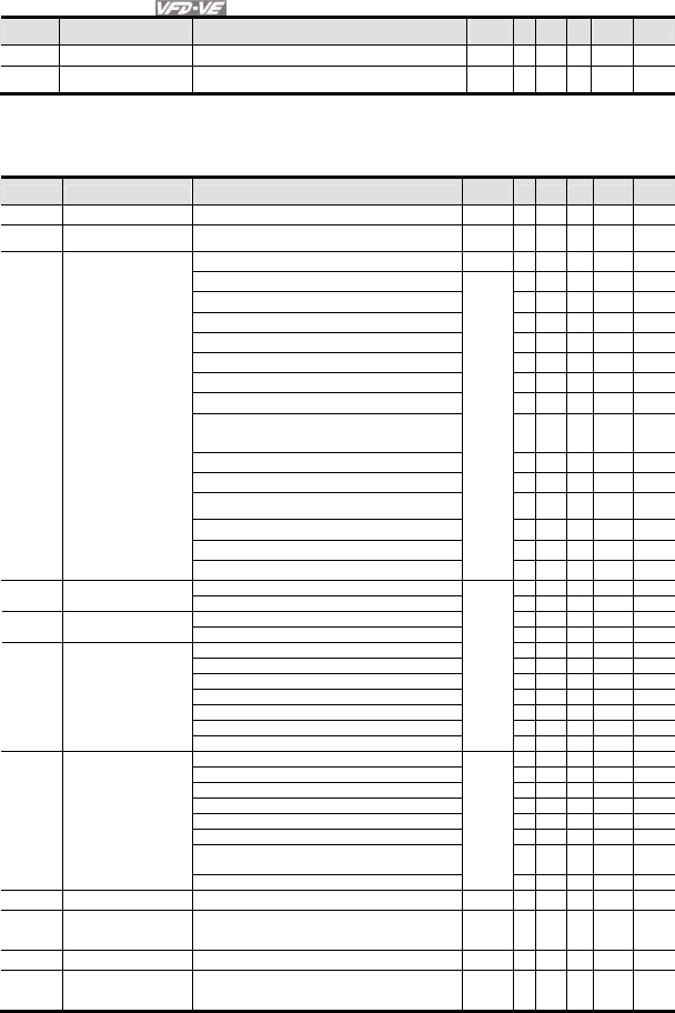
Chapter 4 Parameters|
4-32 Revision August 2008, 03VE, SW V2.04
Pr. Explanation Settings Factory
Setting VF
VFPG
SVC
FOCPG
TQRPG
50: Reserved
02-43 Zero-speed Level of
Motor 0~65535 rpm 0 ○ ○ ○ ○ ○
Group 3 Analog Input/Output Parameters
New settings 11~16 for Pr.03-00~Pr.03-02 and new parameters 03-21~03-26.
Pr. Explanation Settings Factory
Setting VF
VFPG
SVC
FOCPG
TQRPG
03-00 Analog Input 1 (AVI) 0: No function 1 ○ ○ ○ ○ ○
03-01 Analog Input 2 (ACI) 1: Frequency command (torque limit under TQR
control mode)
0 ○ ○ ○ ○ ○
03-02 Analog Input 3 (AUI) 2: torque command (torque limit under speed mode) 0 ○
3: Torque compensation command ○ ○ ○ ○ ○
4: PID target value (refer to group 8) ○ ○ ○ ○
5: PID feedback signal (refer to group 8) ○ ○ ○ ○
6: P.T.C. thermistor input value ○ ○ ○ ○ ○
7: Positive torque limit ○
8: Negative torque limit ○
9: Regenerative torque limit ○
10: Positive/negative torque limit ○
11: PID feedback signal of tension ○ ○ ○ ○ ○
12: Line speed ○ ○ ○ ○ ○
13: Reel diameter ○ ○ ○ ○ ○
14: PID target value of tension (tension closed-
loop)
○ ○ ○ ○ ○
15: Tension setting (tension open-loop)
○
16: Zero-speed tension
○
17: Tension taper
○
0: Output frequency (Hz) 0 ○ ○ ○ ○ ○
03-18 Analog Output Selection
1: Frequency command (Hz) ○ ○ ○ ○ ○
2: Motor speed (Hz) ○ ○ ○ ○ ○
03-21 Analog Output
Selection 2 3: Output current (rms) ○ ○ ○ ○ ○
4: Output voltage ○ ○ ○ ○ ○
03-24 Analog Output
Selection 3 5: DC Bus Voltage ○ ○ ○ ○ ○
6: Power factor ○ ○ ○ ○ ○
7: Power ○ ○ ○ ○ ○
8: Output torque ○ ○ ○ ○ ○
9: AVI ○ ○ ○ ○ ○
10: ACI ○ ○ ○ ○ ○
11: AUI ○ ○ ○ ○ ○
12: q-axis current ○ ○ ○ ○ ○
13: q-axis feedback value ○ ○ ○ ○ ○
14: d-axis current ○ ○ ○ ○ ○
15: d-axis feedback value ○ ○ ○ ○ ○
16: q-axis voltage ○ ○ ○ ○ ○
17: d-axis voltage ○ ○ ○ ○ ○
18: Torque command ○ ○ ○ ○ ○
19: Pulse frequency command ○ ○ ○ ○ ○
03-22 Analog Output Gain 2 0~200.0% 100.0 ○ ○ ○ ○ ○
03-23 Analog Output Value in
REV Direction 2
0: Absolute value in REV direction
1: Output 0V in REV direction
2: Enable output voltage in REV direction
0 ○ ○ ○ ○ ○
03-25 Analog Output Gain 3 0~200.0% 100.0 ○ ○ ○ ○ ○
03-26 Analog Output Value in
REV Direction 3
0: Absolute value in REV direction
1: Output 0V in REV direction
2: Enable output voltage in REV direction
0 ○ ○ ○ ○ ○
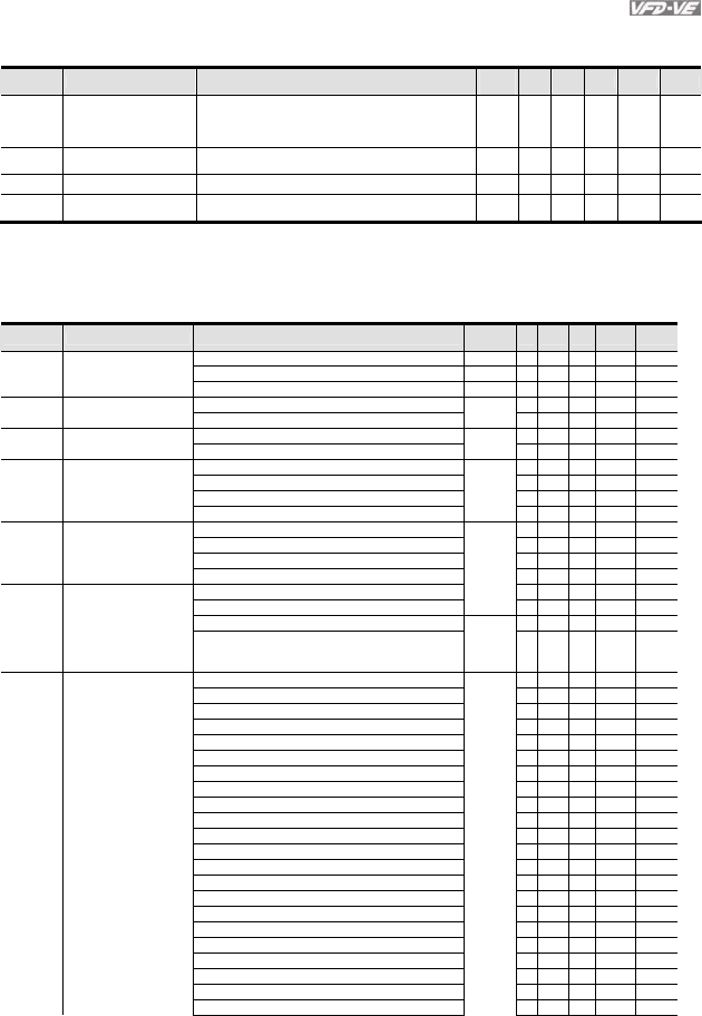
Chapter 4 Parameters|
Revision August 2008, 03VE, SW V2.04 4-33
Group 5 Motor Parameters
Pr. Explanation Settings Factory
Setting VF VFPG
SVC
FOCPG
TQRPG
05-00 Motor Auto Tuning 0: No function
1: Rolling test
2: Static Test
3: Reserved
0
○ ○ ○
05-01 Full-load Current of
Motor 1
40-100% #.## ○ ○ ○ ○ ○
05-02 Rated power of Motor 1 0~655.35 #.## ○ ○ ○
05-03 Rated speed of Motor 1
(rpm)
0~65535
1710 (60Hz, 4 poles), 1410 (50Hz, 4 poles)
1710 ○ ○ ○ ○
Group 6 Protection Parameters
New setting 0 for Pr.06-01, new settings 64~65 for Pr.06-17~Pr.06-22 and new parameters 06-
32~06-36.
Pr. Explanation Settings Factory
Setting VF
VFPG
SVC
FOCPG
TQRPG
0.0: Disable
350.0~450.0Vdc 380.0 ○ ○ ○ ○ ○
06-01 Over-voltage Stall
Prevention
700.0~900.0Vdc 760.0 ○ ○ ○ ○ ○
06-17 Present Fault Record 0: No fault 0 ○ ○ ○ ○ ○
1: Over-current during acceleration (ocA) ○ ○ ○ ○ ○
2: Over-current during deceleration (ocd) 0 ○ ○ ○ ○ ○
06-18 Second Most Recent
Fault Record 3: Over-current during constant speed (ocn) ○ ○ ○ ○ ○
4: Ground fault (GFF) ○ ○ ○ ○ ○
5: IGBT short-circuit (occ) 0 ○ ○ ○ ○ ○
06-19 Third Most Recent Fault
Record 6: Over-curent at stop (ocS) ○ ○ ○ ○ ○
7: Over-voltage during acceleration (ovA) ○ ○ ○ ○ ○
8: Over-voltage during deceleration (ovd) 0 ○ ○ ○ ○ ○
06-20 Fourth Most Recent
Fault Record 9: Over-voltage during constant speed (ovn) ○ ○ ○ ○ ○
10: Over-voltage at stop (ovS) ○ ○ ○ ○ ○
11: Low-voltage during acceleration (LvA) ○ ○ ○ ○ ○
12: Low-voltage during deceleration (Lvd) ○ ○ ○ ○ ○
06-21 Fifth Most Recent Fault
Record 13: Low-voltage during constant speed (Lvn) ○ ○ ○ ○ ○
14: Low-voltage at stop (LvS) 0 ○ ○ ○ ○ ○
15: Phase loss (PHL) ○ ○ ○ ○ ○
16: IGBT heat sink over-heat (oH1)
○ ○ ○ ○ ○
17: Heat sink over-heat (oH2)(for 40HP above) 0 ○ ○ ○ ○ ○
06-22 Sixth Most Recent Fault
Record 18: TH1 open loop error (tH1o) ○ ○ ○ ○ ○
19: TH2 open loop error (tH2o) ○ ○ ○ ○ ○
20: Fan error signal output ○ ○ ○ ○ ○
21: over-load (oL) (150% 1Min) ○ ○ ○ ○ ○
22: Motor 1 over-load (EoL1) ○ ○ ○ ○ ○
23: Motor 2 over-load (EoL2) ○ ○ ○ ○ ○
24: Motor PTC overheat (oH3) ○ ○ ○ ○ ○
25: Fuse error (FuSE) ○ ○ ○ ○ ○
26: over-torque 1 (ot1) ○ ○ ○ ○ ○
27: over-torque 1 (ot2) ○ ○ ○ ○ ○
28: Reserved ○ ○ ○ ○ ○
29: Reserved
○ ○ ○ ○ ○
30: Memory write-in error (cF1) ○ ○ ○ ○ ○
31: Memory read-out error (cF2) ○ ○ ○ ○ ○
32: Isum current detection error (cd0) ○ ○ ○ ○ ○
33: U-phase current detection error (cd1) ○ ○ ○ ○ ○
34: V-phase current detection error (cd2) ○ ○ ○ ○ ○
35: W-phase current detection error (cd3) ○ ○ ○ ○ ○
36: Clamp current detection error (Hd0) ○ ○ ○ ○ ○
37: Over-current detection error (Hd1) ○ ○ ○ ○ ○
38: Over-voltage detection error (Hd2) ○ ○ ○ ○ ○
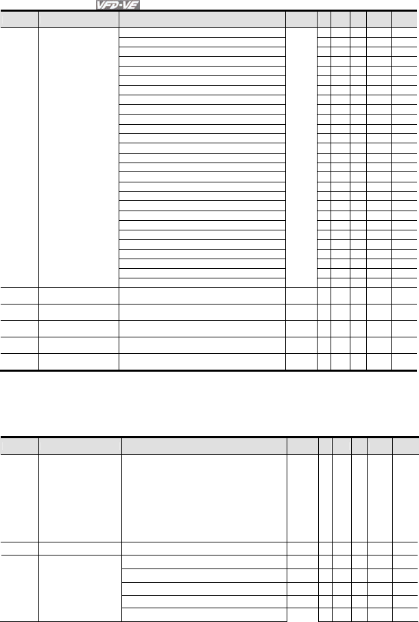
Chapter 4 Parameters|
4-34 Revision August 2008, 03VE, SW V2.04
Pr. Explanation Settings Factory
Setting VF
VFPG
SVC
FOCPG
TQRPG
39: Ground current detection error (Hd3) ○ ○ ○ ○ ○
40: Auto tuning error (AuE) ○ ○ ○
41: PID feedback loss (AFE) ○ ○ ○ ○ ○
42: PG feedback error (PGF1) ○ ○ ○
43: PG feedback loss (PGF2) ○ ○ ○
44: PG feedback stall (PGF3) ○ ○
45: PG slip error (PGF4) ○ ○
46: PG ref input error (PGr1) ○ ○ ○ ○ ○
47: PG ref loss (PGr2) ○ ○ ○ ○ ○
48: Analog current input loss (ACE) ○ ○ ○ ○ ○
49: External fault input (EF) ○ ○ ○ ○ ○
50: Emergency stop (EF1) ○ ○ ○ ○ ○
51: External Base Block (B.B.) ○ ○ ○ ○ ○
52: Password error (PcodE) ○ ○ ○ ○ ○
53: Reserved
○ ○ ○ ○ ○
54: Communication error (cE1) ○ ○ ○ ○ ○
55: Communication error (cE2) ○ ○ ○ ○ ○
56: Communication error (cE3) ○ ○ ○ ○ ○
57: Communication error (cE4) ○ ○ ○ ○ ○
58: Communication Time-out (cE10) ○ ○ ○ ○ ○
59: PU time-out (cP10) ○ ○ ○ ○ ○
60: Brake transistor error (bF) ○ ○ ○ ○ ○
61: Y-connection/Δ-connection switch error (ydc) ○ ○ ○ ○
62: Decel. Energy Backup Error (dEb) ○ ○ ○ ○ ○
63: Slip error (oSL) ○ ○ ○ ○
64: Broken belt error (bEb) ○ ○ ○ ○ ○
65: Error PID feedback signal of tension (tdEv) ○ ○ ○ ○ ○
06-32 Output Frequency for
Malfunction
0.00~655.35 Hz 0.00 ○ ○ ○ ○ ○
06-33 Output AC Voltage for
Malfunction
0.0~6553.5 V 0.0 ○ ○ ○ ○ ○
06-34 DC Voltage for
Malfunction
0.0~6553.5 V 0.0 ○ ○ ○ ○ ○
06-35 Current Value for
Malfunction
0.00~655.35 Amp 0.00 ○ ○ ○ ○ ○
06-36 IGBT Temperature for
Malfunction
0.0~6553.5 °C 0.0 ○ ○ ○ ○ ○
Group 8 High-function PID Parameters
New parameters 08-21~08-99
Pr. Explanation Settings Factory
Setting VF
VFPG
SVC
FOCPG
TQRPG
08-00 Input Terminal for PID
Feedback
0: No function
1: Negative PID feedback from external terminal AVI
(Pr.03-00)
2: Negative PID feedback from PG card (Pr.10-15,
skip direction)
3: Negative PID feedback from PG card (Pr.10-15)
4: Positive PID feedback from external terminal AVI
(Pr.03-00)
5: Positive PID feedback from PG card (Pr.10-15,
skip direction)
6: Positive PID feedback from PG card (Pr.10-15)
0 ○ ○ ○ ○
08-01 Proportional Gain (P) 0.0~500.0% 80.0 ○ ○ ○ ○
0: Disable 0 ○ ○ ○ ○
08-21 Tension Control
Selection 1: Closed-loop, speed mode ○ ○ ○ ○
2: Line speed, speed mode ○ ○ ○ ○
3: Reserved
4: Open-loop, torque mode
○

Chapter 4 Parameters|
Revision August 2008, 03VE, SW V2.04 4-35
Pr. Explanation Settings Factory
Setting VF
VFPG
SVC
FOCPG
TQRPG
08-22 Wind Mode 0: Rewind
1: Unwind 0 ○ ○ ○ ○ ○
08-23 Mechanical Gear Ratio
A
1-65535 100 ○ ○ ○ ○ ○
08-24 Mechanical Gear Ratio
B
1-65535 100 ○ ○ ○ ○ ○
08-25 Source of the Tension
Command/Line Speed
0: Parameter setting (Pr.08-26)
1: RS-485 communication setting (Pr.08-26)
2: Analog input (Pr. 03-00~03-02 is set to 14 PID
target value of tension, 03-00~03-02 is set to 12
line speed)
0 ○ ○ ○ ○ ○
08-26 PID Target Value of
Tension/Line Speed
0.0~100.0% 50.0 ○ ○ ○ ○ ○
08-27 Source of Tension/Line
Speed PID Feedback
0: Analog input (Pr. 03-00~03-02 is set to 11 PID
feedback of tension)
1: Pulse input (Pr.08-40)
0 ○ ○ ○ ○ ○
08-28 Auto-tuning Tension
PID
0: Disable
1: Reel diameter (08-29~08-31corresponds to 08-
44, 08-32~08-34 corresponds to 08-43)
2: Frequency (08-29~08-31 corresponds to 01-07,
08-32~08-34 corresponds to 01-00)
○ ○ ○ ○ ○
08-29 Tension PID P1 0.0~1000.0 50.0 ○ ○ ○ ○ ○
08-30 Tension PID I1 0.00~500.00 sec 1.00 ○ ○ ○ ○ ○
08-31 Reserved
08-32 Tension PID P2 0.0~1000.0 50.0 ○ ○ ○ ○ ○
08-33 Tension PID I2 0.00~500.00 sec 1.00 ○ ○ ○ ○ ○
08-34 Reserved
08-35 PID/Line Speed Output
Status
0: Positive output
1: Negative output
0 ○ ○ ○ ○ ○
08-36 Tension/Line Speed PID
Output Limit
0~100.00% (according to Pr,01-00) 20.00 ○ ○ ○ ○ ○
08-37 Source of Line Speed
Input Command
0: Disable
1: Analog input (Pr. 03-00~03-02 is set to 12 line
speed)
2: RS-485 communication setting (Pr.08-41)
3: Pulse input (Pr.08-40)
4: DFM-DCM pulse input (Pr.02-18)
0 ○ ○ ○ ○ ○
08-38 Max. Line Speed 0.0~3000.0m/min 1000.0 ○ ○ ○ ○ ○
08-39 Min. Line Speed 0.0~3000.0m/min 0.0 ○ ○ ○ ○ ○
08-40 Pulse Number for Each
Meter
0.0~6000.0 0.0
○ ○ ○ ○ ○
08-41 Current Line Speed 0.0~3000.0m/min
0.0 ○ ○ ○ ○ ○
08-42 Source of Reel
Diameter
0: Calculated by line speed
1: Calculated by integrating thickness (encoder
is on reel shaft)(Pr.08-49~51, Pr.10-15)
2: Calculated by integrating thickness (encoder
is on motor)(Pr.08-23~08-24, 08-50~08-51, 10-
00~10-01)
3: Calculated by analog input (Pr.03-00~03-02 is
set to 13)
0 ○ ○ ○ ○ ○
08-43 Max. Reel Diameter 1.0~6000.0mm 6000.0 ○ ○ ○ ○ ○
08-44 Empty Reel Diameter 1.0~6000.0mm 1.0 ○ ○ ○ ○ ○
08-45 Source of Initial Reel
Diameter
0: RS-485 communication setting (Pr.08-46)
1: Analog input (Pr.03-00-Pr.03-02 is set to 13)
0 ○ ○ ○ ○ ○
08-46 Initial Reel Diameter 1.0~6000.0mm 1.0 ○ ○ ○ ○ ○
08-47 Initial Reel Diameter 1 1.0~6000.0mm 1.0 ○ ○ ○ ○ ○
08-48 Initial Reel Diameter 2 1.0~6000.0mm 1.0 ○ ○ ○ ○ ○
08-49 Number of Pulse per
Revolution
1~10000ppr 1
○ ○ ○ ○ ○
08-50 Coil Number for Each
Layer
0.001~60.000mm 1.000 ○ ○ ○ ○ ○
08-51 Material Thickness 0.001~60.000mm 1.000 ○ ○ ○ ○ ○
08-52 Filter Time of Reel
Diameter
0.00 to 100.00 seconds 1.00 ○ ○ ○ ○ ○
08-53 Auto Compensation of 0: Disable 1.00 ○ ○ ○ ○ ○
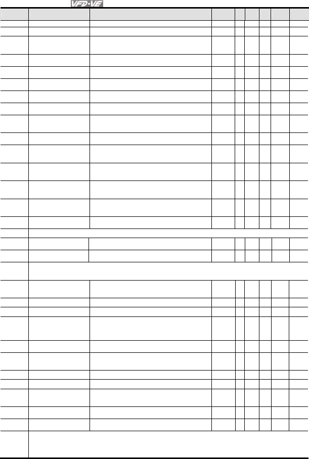
Chapter 4 Parameters|
4-36 Revision August 2008, 03VE, SW V2.04
Pr. Explanation Settings Factory
Setting VF
VFPG
SVC
FOCPG
TQRPG
Reel Diameter 1: Enable
08-54 Current Reel Diameter 1.0~6000.0mm 1.0 ○ ○ ○ ○ ○
08-55 Smart Start 0: Disable
1: Enable
2: In unwind mode, rewind in reverse direction
1 ○ ○ ○ ○ ○
08-56 Switch Level for Smart
Start and PID function
0.0~100.0% (according to Pr.08-26) 15.0 ○ ○ ○ ○ ○
08-57 Frequency for Smart
Start
0.00~600.00Hz 2.00
○ ○ ○ ○ ○
08-58 Accel. Time for Smart
Start
0.01~600.00 seconds 3.00 ○ ○ ○ ○
08-59 Broken Belt Detection 0: Disable
1: Enable
0 ○ ○ ○ ○
08-60 Min. Line Speed of
Broken Belt Detection
0.0~3000.0m/min 0.0
○ ○ ○ ○
08-61 Allowance Error of Line
Speed of Broken Belt
Detection
1.0~6000.0mm 100.0
○ ○ ○ ○
08-62 Detection Time of
Broken Belt
0.00~100.00 sec 1.00 ○ ○ ○ ○
08-63 Allowance Error Level
of Tension/Line Speed
PID Feedback
0~100% 100
○ ○ ○ ○
08-64 Allowance Error
Detection Time of
Tension PID Feedback
0.0~10.0 sec 0.5 ○ ○ ○ ○
08-65 Error Treatment of
Tension PID Feedback
0: Warn and keep operation
1: Warn and coast to stop
2: Warn and ramp to stop
0 ○ ○ ○ ○
08-66 Upper Limit of Tension
PID Feedback
0.0~100.0% 100.0
○ ○ ○ ○ ○
08-67 Lower Limit of Tension
PID Feedback
0.0~100.0% 0.0
○ ○ ○ ○ ○
08-68 Reserved
08-69 DFM Selection 0: Output frequency
1: Frequency command
0 ○ ○ ○ ○ ○
08-70 Low-pass Filter Time of
Line Speed
0.00~100.00 sec 0.00 ○ ○ ○ ○ ○
08-71
|
08-75
Reserved
08-76 Source of Tension
Setting
0: Communication RS-485 (Pr.08-78)
1: Analog input (Pr. 03-00~03-02 is set to 15
tension setting) (Pr.08-78)
0
○
08-77 Max. Tension 0~30000 N 0 ○
08-78 Tension Setting 0~30000 N 0 ○
08-79 Source of Zero-speed
Tension Setting
0: Disable
1: Communication RS-485 (Pr.08-80)
2: Analog input (Pr. 03-00~03-02 is set to 16 zero-
speed tension) (Pr.08-80)
0
○
08-80 Setting of Zero-speed
Tension
0~30000 N 0 ○
08-81 Source of Tension
Taper
0: Communication RS-485 (Pr.08-82)
1: Analog input (Pr. 03-00~03-02 is set to 17
tension taper)(Pr.08-82)
0
○
08-82 Tension Taper 0~100% 0 ○
08-83 Friction Compensation 0.0~100.0% 0.0 ○
08-84 Compensation
Coefficient of Material
Inertial
0~30000 0
○
08-85 Torque Feed Forward
Gain
0.0~100.0% 50.0
○
08-86 Low Pass Filter Time of
Torque Feed Forward
0.00~100.00 5.00
○
08-87
|
08-99
Reserved
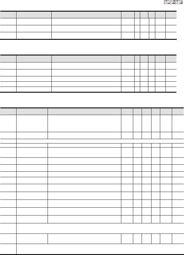
Chapter 4 Parameters|
Revision August 2008, 03VE, SW V2.04 4-37
Group 9 Communication Parameters
Pr. Explanation Settings Factory
Setting VF
VFPG
SVC
FOCPG
TQRPG
09-21 Multi-function Output
Status
0~65535 Read-
only
○ ○ ○ ○ ○
09-22 AFM2 Status 0~4095 Read-
only
○ ○ ○ ○ ○
09-23 AFM3 Status 0~4095 Read-
only
○ ○ ○ ○ ○
Group 10 Speed Feedback Control Parameters
New parameters 10-29~10-30
Pr. Explanation Settings Factory
Setting VF
VFPG
SVC
FOCPG
TQRPG
10-04 ASR (Auto Speed
Regulation) Control ( P) 1
0~40 10
○ ○
10-06 ASR (Auto Speed
Regulation) Control ( P) 2
0~40 10
○ ○
10-21 P Gain of Zero Speed 0~40 10
○ ○
10-29 PG Mechanical Gear A2 1~5000 100 ○ ○ ○
10-30 PG Mechanical Gear B2 1~5000 100 ○ ○ ○
Group 11 Advanced Parameters
Updated parameters 11-00 and 11-09~11-10 and new parameters 11-18~11-40.
Pr. Explanation Settings Factory
Setting VF VFPG SVC FOCPG TQRPG
11-00 System Control
bit 0: ASR Auto tuning
bit 1: Inertia estimate
bit 2: Zero Servo
bit 3: Reserved
bit 4: Enable gain adjustment of position loop KP
0
○
11-07 Detection Time for
Phase-loss
0.01~600.00 sec 0.20 ○ ○ ○ ○ ○
11-08 Reserved
11-09 Level of Phase-loss 0.0~320.0 60.0 ○ ○ ○ ○ ○
11-10
Speed Feed Forward
Gain
0~100% 0
○
11-11 Zero-speed
Bandwidth
0~40Hz 10
○ ○ ○
11-12 Speed Response of
Flux Weakening Area
0: Disable
0~150%
65 ○
11-13 Notch Filter Depth 0~20db 0
○
11-14 Notch Filter
Frequency
0.00~200.00 0.00
○
11-15 Gain Value of Slip
Compensation 0.00~1.00 1.00 ○
11-16 Low-pass Filter Time
of Keypad Display 0.001~65.535sec 0.100 ○ ○ ○ ○ ○
11-17 Low-pass Filter Time
of PG2 Pulse Input 0.000~65.535sec 0.100 ○ ○ ○ ○
11-18 APR Gain 0.00~40.00 10.00 ○
11-19 APR Curve Time 0.00~655.35 sec 3.00 ○
11-20
|
11-28
Reserved
11-29
Accumulative
Operation Time of
Phase-loss
0~65535 (hour) 0 ○ ○ ○ ○ ○
11-30
|
11-40
Reserved
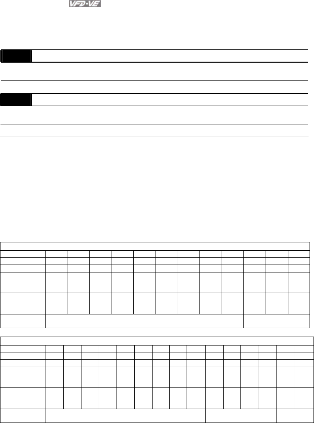
Chapter 4 Parameters|
4-38 Revision August 2008, 03VE, SW V2.04
4.3 Description of Parameter Settings
Group 0 User Parameters : This parameter can be set during operation.
00-00 Identity Code of the AC Motor Drive
Control
mode VF VFPG SVC FOCPG TQRPG Factory setting: ##
Settings Read Only
00-01 Rated Current Display of the AC Motor Drive
Control
mode VF VFPG SVC FOCPG TQRPG Factory setting: ##
Settings Read Only
Pr. 00-00 displays the identity code of the AC motor drive. The capacity, rated current, rated
voltage and the max. carrier frequency relate to the identity code. Users can use the following
table to check how the rated current, rated voltage and max. carrier frequency of the AC motor
drive correspond to the identity code.
Pr.00-01 displays the rated current of the AC motor drive. By reading this parameter the user
can check if the AC motor drive is correct.
The factory setting is rated current for the constant torque and can be set in Pr.00-12.
230V Series
kW 0.75 1.5 2.2 3.7 5.5 7.5 11 15 18.5 22 30 37
HP 1.0 2.0 3.0 5.0 7.5 10 15 20 25 30 40 50
Pr.00-00 4 6 8 10 12 14 16 18 20 22 24 26
Rated Current
for Constant
Torque (A)
5 7.5 11 17 25 33 49 65 75 90 120 146
Rated Current
for Variable
Torque (A)
6.3 9.4 13.8 21.3 31.3 41.3 61.3 81.3 93.8 113 150 183
Max. Carrier
Frequency 15kHz 9kHz
460V Series
kW 0.75 1.5 2.2 3.7 5.5 7.5 11 15 18.5 22 30 37 45 55 75
HP 1.0 2.0 3.0 5.0 7.5 10 15 20 25 30 40 50 60 75 100
Pr.00-00 5 7 9 11 13 15 17 19 21 23 25 27 29 31 33
Rated Current
for Constant
Torque (A)
3 4.2 6 8.5 13 18 24 32 38 45 60 73 91 110 150
Rated Current
for Variable
Torque (A)
3.8 5.3 7.5 10.6 16.3 22.5 30 40 47.5 56.3 75 91.3 113.8
138 188
Max. Carrier
Frequency 15kHz 9kHz 6kHz

Chapter 4 Parameters|
Revision August 2008, 03VE, SW V2.04 4-39
00-02 Parameter Reset
Control
mode VF VFPG SVC FOCPG TQRPG Factory setting: 0
Settings 0 No Function
1 Read Only
2 Enable Group 11 Parameters Setting
8 Keypad Lock
9 All parameters are reset to factory settings (50Hz, 220V/380V)
10 All parameters are reset to factory settings (60Hz, 220V/440V)
When it is set to 1, all parameters are read only except Pr.00-00~00-07 and it can be used
with password setting for password protection.
This parameter allows the user to reset all parameters to the factory settings except the fault
records (Pr.06-17 ~ Pr.06-22).
50Hz: Pr.01-01 is set to 50Hz and Pr.01-02 is set to 230V or 400V.
60Hz: Pr.01-01 is set to 60Hz and Pr.01-02 is set to 230Vor 460V.
When Pr.00-02=08, the KPV-CE01 keypad is locked and only Pr.00-02 can be set. To unlock
the keypad, set Pr.00-02=00.
When Pr.00-02 is set to 1 or 8, Pr.00-02 setting should be set to 0 before setting to other
setting.
After setting Pr.00-02 to 2, it can display group 11 to re-connect the keypad after disconnection
or re-power on after the power off.
00-03 Start-up Display Selection
Control
mode VF VFPG SVC FOCPG TQRPG Factory setting: 0
Settings 0 Display the frequency command value. (LED F)
1 Display the actual output frequency (LED H)
2 Multifunction display, see Pr.00-04 (LED U)
3 Display the output current (A)
This parameter determines the start-up display page after power is applied to the drive.
00-04 Content of Multi-Function function Display
Control
mode VF VFPG SVC FOCPG TQRPG Factory setting: 0
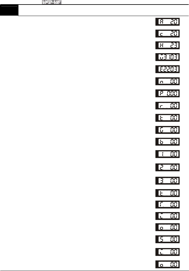
Chapter 4 Parameters|
4-40 Revision August 2008, 03VE, SW V2.04
00-04 Content of Multi-Function function Display
Settings 0 Display the output current in A supplied to the motor
U
1
Display the counter value which counts the number of
pulses on TRG terminal
U
2 Display actual output frequency (H)
U
3
Display the actual DC BUS voltage in VDC of the AC
motor drive
U
4
Display the output voltage in VAC of terminals U, V, W
to the motor.
U
5
Display the power factor angle in º of terminals U, V, W
to the motor.
U
6
Display the output power in kW of terminals U, V and W
to the motor.
U
7
Display the actual motor speed in rpm (enabled when
using with PG card).
U
8
Display the estimated value of torque in Nm as it relates
to current.
U
9
Display PG position. When Pr.10-01 is set to 1 or 2, it
means that motor angle is 0~4XPr.10-00.
U
10 Display analog feedback signal value in %.
U
11
Display the signal of AVI analog input terminal in %.
Range 0~10V corresponds to 0~100%. (1.)
U
12
Display the signal of ACI analog input terminal in %.
Range 4~20mA/0~10V corresponds to 0~100%. (2.)
U
13
Display the signal of AUI analog input terminal in %.
Range -10V~10V corresponds to 0~100%. (3.)
U
14
Display the temperature of heat sink in °C.
U
15
Display the temperature of IGBT in °C.
U
16 Display digital input status ON/OFF (i)
U
17 Display digital output status ON/OFF (o)
U
18 Display multi-step speed
U
19 The corresponding CPU pin status of digital input (i.)
U
20 The corresponding CPU pin status of digital output (o.)
U
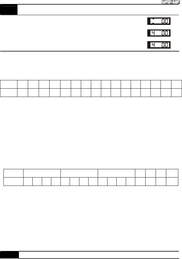
Chapter 4 Parameters|
Revision August 2008, 03VE, SW V2.04 4-41
00-04 Content of Multi-Function function Display
21 Number of actual motor revolution (PG1 of PG card) (Z)
U
22 Pulse input frequency (PG2 of PG card) (4)
U
23 Pulse input position (PG2 of PG card) (4.)
U
This parameter sets the display when Pr. 00-03 is set to 2.
It is used to display the content when LED U is ON. It is helpful for getting the AC motor drive’s
status by this parameter.
Terminal MI14 MI13 MI12 MI11 MI10 MI9 MI8 MI7 MI6 MI5 MI4 MI3 MI2 MI1 REV FWD
Status 0 0 0 0 0 00010 00011 0
0: OFF, 1: ON
MI1: Pr.02-01 is set to 1 (multi-step speed command 1/multi-step position command 1)
MI6: Pr.02-06 is set to 8 (the 1st, 2nd acceleration/deceleration time selection)
If REV, MI1 and MI6 are ON, the value is 0000 0000 1000 01102 in binary and 0086H in HEX.
At the meanwhile, if Pr.00-04 is set to “16” or “19”, it will display “0086” with LED U is ON on
the keypad KPV-CE01. The setting 16 is the status of digital input and the setting 19 is the
corresponding CPU pin status of digital input. User can set to 16 to monitor digital input status
and then set to 19 to check if the wire is normal.
Terminal Reserved Reserved Reserved MO2 MO1 RA MRA
Status 0 0 0 0000010 0 0 0 1 1 0
MRA: Pr.02-11 is set to 9 (Drive ready).
After applying the power to the AC motor drive, if there is no other abnormal status, the
contact will be ON. At the meanwhile, if Pr.00-04 is set to 17 or 20, it will display 0001 with
LED U is ON on the keypad. The setting 17 is the status of digital output and the setting 20 is
the corresponding CPU pin status of digital output. User can set 17 to monitor the digital
output status and then set to 20 to check if the wire if normal.
00-05 User Defined Coefficient K
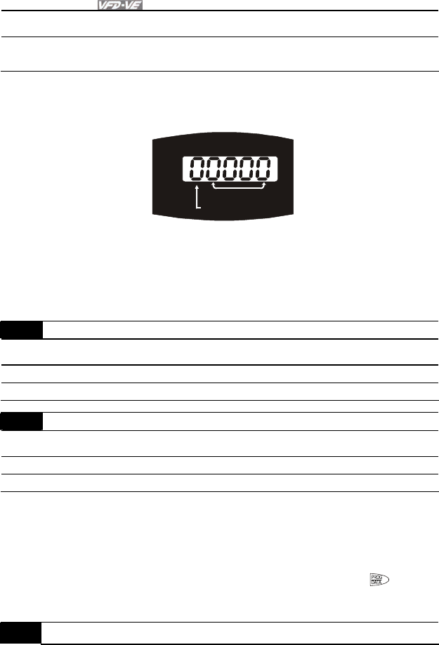
Chapter 4 Parameters|
4-42 Revision August 2008, 03VE, SW V2.04
Control
mode VF VFPG SVC FOCPG TQRPG Factory setting: 0
Settings Digit 4: decimal point number (0 to 3)
Digit 0-3: 40 to 9999
It is used digital setting method
Digital 4: decimal point number (0: no decimal point, 1: 1 decimal point and so on.)
Digit 0-3: 40 to 9999 (the corresponding value for the max. frequency).
U
F
H
01234
decimal point number
corresponding value
Digital
For example, if use uses rpm to display the motor speed and the corresponding value to the 4-
pole motor 60Hz is 1800. This parameter can be set to 01800 to indicate that the
corresponding value for 60Hz is 1800rpm. If the unit is rps, it can be set 10300 to indicate the
corresponding value for 60Hz is 30.0 (a decimal point).
00-06 Software Version
Control
mode VF VFPG SVC FOCPG TQRPG Factory setting: Read Only
Settings Read Only
Display #.##
00-07 Password Input Unit: 1
Control
mode VF VFPG SVC FOCPG TQRPG Factory setting: 00
Settings 1 to 9998 and 10000 to 65535
Display 00~02 (times of wrong password)
The function of this parameter is to input the password that is set in Pr.00-08. Input the correct
password here to enable changing parameters. You are limited to a maximum of 3 attempts.
After 3 consecutive failed attempts, a blinking “PcodE” will show up to force the user to restart
the AC motor drive in order to try again to input the correct password.
When forgetting password, you can decode by setting 9999 and press button twice.
Please note that all the settings will be set to factory setting.
00-08 Password Set Unit: 1
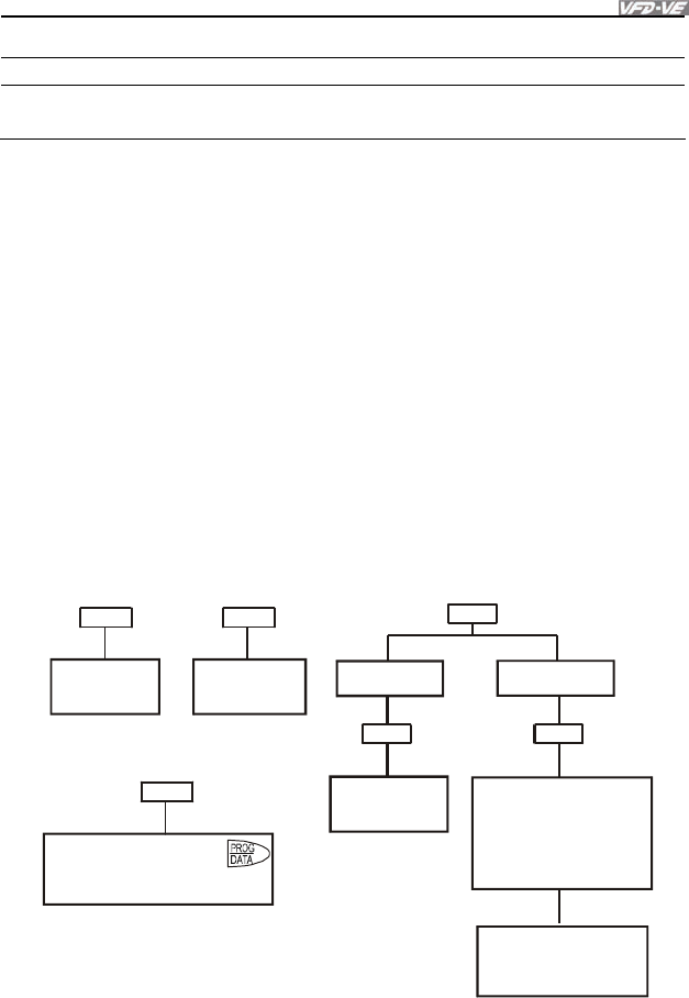
Chapter 4 Parameters|
Revision August 2008, 03VE, SW V2.04 4-43
Control
mode VF VFPG SVC FOCPG TQRPG Factory setting: 00
Settings 1 to 9998 and 10000 to 65535
Display 00 No password set or successful input in Pr. 00-07
01 Password has been set
To set a password to protect your parameter settings.
If the display shows 00, no password is set or password has been correctly entered in Pr.00-
07. All parameters can then be changed, including Pr.00-08.
The first time you can set a password directly. After successful setting of password the display
will show 01.
Be sure to record the password for later use.
To cancel the parameter lock, set the parameter to 00 after inputting correct password into Pr.
00-07.
The password consists of min. 2 digits and max. 5 digits.
How to make the password valid again after decoding by Pr.00-07:
Method 1: Re-input original password into Pr.00-08 (Or you can enter a new password if you
want to use a changed or new one).
Method 2: After rebooting, password function will be recovered.
Password Decode Flow Chart
00-0800-08
00-07
Password Setting Decoding Flow Chart
Forgetting Passwrod
After entering 9999, press
twice to decode. The parameter
setting will be set to factory setting.
3 chances to enter the correct
password.
1st time displays "01" if
password is incorrect.
2nd time displays "02", if
password is incorrect.
3rd time displays "P code"
(blinking)
If the password was entered
incorrectly after three tries,
the keypad will be locked.
Turn the power OFF/ON to
re-enter the password.
Incorrect Password
END
00-07
00-07
Displays 00 when
entering correct
password into
Pr.00-07.
Correct Password
END
00-08
Displays 00 when
entering correct
password into
Pr.00-07.
Displays 01 when
entering correct
password into
Pr.00-08.

Chapter 4 Parameters|
4-44 Revision August 2008, 03VE, SW V2.04
00-09 Energy Saving Gain Unit: 1
Control
mode FOCPG
Factory setting: 100%
Settings 10~1000 %
When Pr.00-19 is set to1, this parameter can be used for energy saving. The setting should be
decreased when the energy saving is not well. When the motor is vibrated, the setting should
be increased.
00-10 Control Method
Control
mode VF VFPG SVC FOCPG TQRPG Factory setting: 0
Settings 0 V/f control
1 V/f + Encoder (VFPG)
2 Sensorless vector control (SVC)
3 FOC vector control + Encoder (FOCPG)
4 Torque control + Encoder (TQRPG)
This parameter determines the control method of the AC motor drive:
Setting 0: user can design V/f ratio by requirement and control multiple motors simultaneously.
Setting 1: User can use PG card with Encoder to do close-loop speed control.
Setting 2: To have optimal control characteristic by auto-tuning.
Setting 3: To increase torque and control speed precisely. (1:1000)
Setting 4: To increase accuracy for torque control.
00-11 V/f Curve Selection
Control
mode VF VFPG
Factory setting: 0
Settings 0 V/f curve determined by group 01
1 1.5 power curve
2 Square curve
When it is set to 0, the V/f curve setting for the motor 1 is according to Pr.01-01~Pr.01-08 and
Pr. 01-35~01-42 are for the motor 2.
When setting to 1 or 2, the settings of the 2nd voltage/frequency and the 3rd voltage/frequency
are invalid.
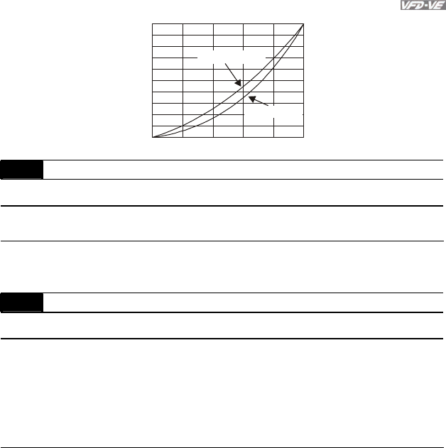
Chapter 4 Parameters|
Revision August 2008, 03VE, SW V2.04 4-45
020 40 60 80 100
100
90
80
70
60
50
40
30
20
10
01-02 voltage%
01-01 Frequency%
1.5 Power curve
Square curve
00-12 Constant/Variable Torque Selection
Control
mode VF VFPG SVC FOCPG Factory setting: 0
Settings 0 Constant Torque (100%)
1 Variable Torque (125%)
When “1” is selected, the oL level is 125% of rated drive current. All other overload ratings will
not change, example: 150% of rated drive current for 60 seconds.
00-13 Optimal Acceleration/Deceleration Setting
Control
mode VF VFPG SVC FOCPG Factory setting: 0
Settings 0 Linear accel./decel. I
1 Auto accel., linear decel.
2 Linear accel., auto decel.
3 Auto accel./decel. I
4 Stall prevention by auto accel./decel. (limited by 01-12 to 01-21)
It can decrease the drive’s vibration during load starts and stops by setting this parameter.
Also it will speed up to the setting frequency with the fastest and smoothest start-up current
when it detects small torque. At deceleration, it will auto stop the drive with the fastest and the
smoothest deceleration time when the regenerated voltage of the load is detected.
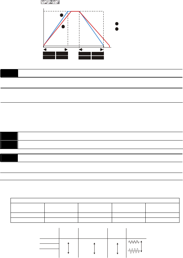
Chapter 4 Parameters|
4-46 Revision August 2008, 03VE, SW V2.04
When Pr.00-13 is set to 0.
1
2
01-00
01-12 01-14
01-16 01-18
01-13 01-15
01-17 01-19
01-05
1
2
Frequency
Max.
Frequency
Min.
Frequency
accel. time Time
decel. time
Accel./Decel. Time
When Pr.00-13 is set to 3.
00-14 Time Unit for Acceleration/Deceleration and S Curve
Control
mode VF VFPG SVC FOCPG Factory setting: 0
Settings 0 Unit: 0.01 second
1 Unit: 0.1 second
This parameter determines the time unit for the Acceleration/Deceleration setting. Refer to
Pr.01-12 ~ Pr.01-19 (accel./decel. Time 1 to 4), Pr. 01-20~Pr.01-21 (JOG accel./decel. Time)
and Pr. 01-24~Pr.01-27 (S curve accel./decel. Time).
00-15 Reserved
00-16 Reserved
00-17 Carrier Frequency Unit: 1
Control
mode VF VFPG SVC FOCPG TQRPG Factory setting: 10
Settings 1~15kHz
This parameter determinates the PWM carrier frequency of the AC motor drive.
230V/460V Series
Models 1-5HP
0.75-3.7kW
7.5-25HP
5.5-18.5kW
30-60HP
22-45kW
75-100HP
55-75Kw
Setting Range 01~15kHz 01~15kHz 01~09kHz 01~06kHz
Factory Setting 10kHz 9kHz 6kHz 6kHz
1kHz
8kHz
15kHz
Carrier
Frequency
Acoustic
Noise
Electromagnetic
Noise or Leakage
Current
Heat
Dissipation
Current
Wave
Significant
Minimal
Minimal Minimal
Significant Significant

Chapter 4 Parameters|
Revision August 2008, 03VE, SW V2.04 4-47
From the table, we see that the PWM carrier frequency has a significant influence on the
electromagnetic noise, AC motor drive heat dissipation, and motor acoustic noise.
00-18 Auto Voltage Regulation (AVR) Function
Control
mode VF VFPG SVC FOCPG TQRPG Factory setting: 0
Settings 0 Enable AVR
1 Disable AVR
2 Disable AVR when deceleration stop
It is used to select the AVR mode. AVR is used to regulate the output voltage to the motor. For
example, if V/f curve is set to AC200V/50Hz and the input voltage is from 200 to 264VAC, the
output voltage won’t excess AC200V/50Hz. If the input voltage is from 180 to 200V, the output
voltage to the motor and the input voltage will be in direct proportion.
When setting Pr.00-18 to 1 during ramp to stop and used with auto accel./decel. function, the
acceleration will be smoother and faster.
00-19 Auto Energy-saving Operation
Control
mode VF VFPG SVC FOCPG Factory setting: 0
Settings 0 Disable
1 Enable
When the Auto Energy-saving function is enabled, the drive will operate with full voltage during
acceleration and deceleration. At constant speed, the AC drive will calculate the optimal output
voltage value for the load. It is possible for the output voltage to be 25% below Maximum
Output Voltage during auto energy-saving operation. This function should not be used with
variable loads or continuous rated output loads.
When output frequency is constant, i.e. constant operation, the output voltage will be auto
decreased with load reduction. To make the AC motor drive runs under the energy-saving with
the minimum value of the product of voltage and current.
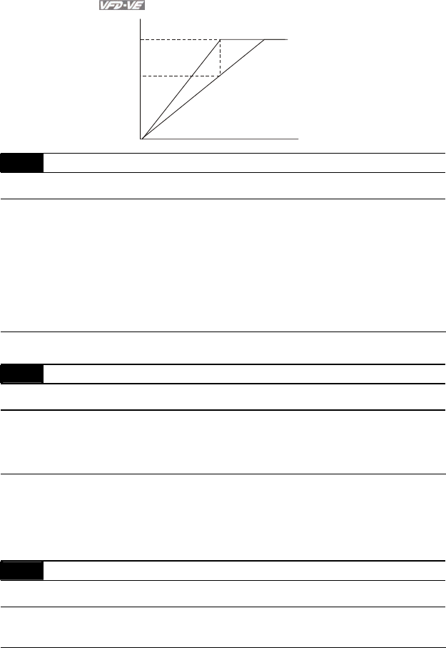
Chapter 4 Parameters|
4-48 Revision August 2008, 03VE, SW V2.04
75%
100%
Output Voltage
The maximum output voltage
reduction is 25%.
Auto Energy-saving Operation
Frequency
00-20 Source of the Master Frequency Command
Control
mode VF VFPG SVC FOCPG Factory setting: 0
Settings 0 Digital keypad (KPV-CE01)
1
RS-485 serial communication
2
External analog input (Pr. 03-00)
3
External UP/DOWN terminal
4
Pulse input without direction command (Pr.10-15 without direction)
5
Pulse input with direction command (Pr.10-15)
This parameter determines the drive’s master frequency source.
00-21 Source of the Operation Command
Control
mode VF VFPG SVC FOCPG TQRPG Factory setting: 0
Settings 0 Digital keypad (KPV-CE01)
1
External terminals. Keypad STOP disabled.
2
RS-485 serial communication (RJ-11). Keypad STOP disabled.
When Pr.00-21 is set to 1, it also needs to set Pr.00-20 and Pr.00-21 to 0. After pressing PU
key to make LED PU to be light, RUN, JOG and STOP key are valid now.
00-22 Stop Method
Control
mode VF VFPG SVC FOCPG TQRPG Factory setting: 0
Settings 0 Ramp to stop
1
Coast to stop
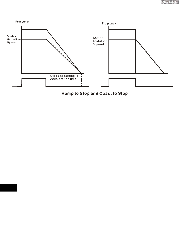
Chapter 4 Parameters|
Revision August 2008, 03VE, SW V2.04 4-49
The parameter determines how the motor is stopped when the AC motor drive receives a valid
stop command.
Operation
Command
Operation
Command
Time
Time Free running
to stop
Output
Frequency
RUN STOP RUN STOP
Output
Frequency
Ramp to stop: the AC motor drive decelerates from the maximum output frequency (Pr. 01-
00) to minimum output frequency (Pr. 01-09) according to the deceleration time and then
stop.
Coast to stop: the AC motor drive stops the output instantly upon a STOP command and
the motor free runs until it comes to a complete standstill.
(1) It is recommended to use “ramp to stop” for safely of personnel or to prevent material
from being wasted in applications where the motor has to stop after the drive is stopped.
The deceleration time has to be set accordingly.
(2) If the motor free running is allowed or the load inertia is large, it is recommended to
select “coast to stop”. For example, blowers, punching machines and pumps.
The stop method of the torque control is also set by Pr.00-22.
00-23 Reverse Operation
Control
mode VF VFPG SVC FOCPG TQRPG Factory setting: 0
Settings 0 Enable reverse
1
Disable reverse
2
Disable forward
This parameter enables the AC motor drives to run in the Reverse Direction. It may be used to
prevent a motor from running in a direction that would consequently injure humans or damage
the equipment.

Chapter 4 Parameters|
4-50 Revision August 2008, 03VE, SW V2.04
Group 1 Basic Parameters
01-00 Maximum Output Frequency Unit: 0.01
Control
mode VF VFPG SVC FOCPG TQRPG Factory setting: 60.00/50.00
Settings 50.0 to 600.00Hz
This parameter determines the AC motor drive’s Maximum Output Frequency. All the AC
motor drive frequency command sources (analog inputs 0 to +10V, 4 to 20mA and -10V to
+10V) are scaled to correspond to the output frequency range.
01-01 1st Output Frequency Setting 1
01-35 1st Output Frequency Setting 2 Unit: 0.01
Control
mode VF VFPG SVC FOCPG TQRPG Factory setting: 60.00/50.00
Settings 0.00~600.00Hz
These are for the base frequency and motor rated frequency.
This value should be set according to the rated frequency of the motor as indicated on the
motor nameplate. If the motor is 60Hz, the setting should be 60Hz. If the motor is 50Hz, it
should be set to 50Hz.
Pr.01-35 is used for the application occasion that uses double base motor.
01-02 1st Output Voltage Setting 1
01-36 1st Output Voltage Setting 2 Unit: 0.1
Control
mode VF VFPG SVC FOCPG TQRPG
Settings 230V series 0.1 to 255.0V Factory Setting: 220.0
460V series 0.1 to 510.0V Factory Setting: 440.0
These are for the base frequency and motor rated frequency.
This value should be set according to the rated voltage of the motor as indicated on the motor
nameplate. If the motor is 220V, the setting should be 220.0. If the motor is 200V, it should be
set to 200.0.
There are many motor types in the market and the power system for each country is also
difference. The economic and convenience method to solve this problem is to install the AC
motor drive. There is no problem to use with the different voltage and frequency and also can
amplify the original characteristic and life of the motor.
01-03 2nd Output Frequency Setting 1 Unit: 0.01

Chapter 4 Parameters|
Revision August 2008, 03VE, SW V2.04 4-51
Control
mode VF VFPG SVC
Factory setting: 0.50
Settings 0.00~600.00Hz
01-04 2nd Output Voltage Setting 1 Unit: 0.1
Control
mode VF VFPG SVC
Settings 230V series 0.1 to 255.0V Factory Setting: 5.0
460V series 0.1 to 510.0V Factory Setting: 10.0
01-37 2nd Output Frequency Setting 2 Unit: 0.01
Control
mode VF VFPG SVC
Factory setting: 0.50
Settings 0.00~600.00Hz
01-38 2nd Output Voltage Setting 2 Unit: 0.1
Control
mode VF VFPG SVC
Settings 230V series 0.1 to 255.0V Factory Setting: 5.0
460V series 0.1 to 510.0V Factory Setting: 10.0
01-05 3rd Output Frequency Setting 1 Unit: 0.01
Control
mode VF VFPG SVC
Factory Setting: 0.50
Settings 0.00~600.00Hz
01-06 3rd Output Voltage Setting 1 Unit: 0.1
Control
mode VF VFPG SVC
Settings 230V series 0.1 to 255.0V Factory Setting: 5.0
460V series 0.1 to 510.0V Factory Setting: 10.0
01-39 3rd Output Frequency Setting 2 Unit: 0.01
Control
mode VF VFPG SVC
Factory Setting: 0.50
Settings 0.00~600.00Hz
01-40 3rd Output Voltage Setting 2 Unit: 0.1
Control
mode VF VFPG SVC
Settings 230V series 0.1 to 255.0V Factory Setting: 5.0
460V series 0.1 to 510.0V Factory Setting: 10.0
01-07 4th Output Frequency Setting 1 Unit: 0.01
Control
mode VF VFPG SVC FOCPG Factory Setting: 0.00
Settings 0.00~600.00Hz
01-08 4th Output Voltage Setting 1 Unit: 0.1

Chapter 4 Parameters|
4-52 Revision August 2008, 03VE, SW V2.04
Control
mode VF VFPG SVC
Settings 230V series 0.1 to 255.0V Factory Setting: 0.0
460V series 0.1 to 510.0V Factory Setting: 0.0
01-41 4th Output Frequency Setting 2 Unit: 0.01
Control
mode VF VFPG SVC FOCPG TQRPG Factory Setting: 0.00
Settings 0.00~600.00Hz
01-42 4th Output Voltage Setting 2 Unit: 0.1
Control
mode VF VFPG SVC
Settings 230V series 0.1 to 255.0V Factory Setting: 0.0
460V series 0.1 to 510.0V Factory Setting: 0.0
V/f curve setting is usually set by the motor’s allowable loading characteristics. Pay special
attention to the motor’s heat dissipation, dynamic balance, and bearing lubricity, if the loading
characteristics exceed the loading limit of the motor.
For the V/f curve setting, it should be Pr.01-01≥ Pr.01-03≥ Pr.01-05≥ Pr.01-07. There is no
limit for the voltage setting, but a high voltage at the low frequency may cause motor damage,
overheat, stall prevention or over-current protection. Therefore, please use the low voltage at
the low frequency to prevent motor damage.
Pr.01-35 to Pr.01-42 is the V/f curve for the motor 2. When multi-function input terminals Pr.02-
01 to Pr.02-14 is set to 14 and enabled or switch to the Δ-connection, the AC motor drive will
act as the 2nd V/f curve.
01-09 Start Frequency Unit: 0.01
Control
mode VF VFPG SVC FOCPG Factory Setting: 0.50
Settings 0.00~600.00Hz
When start frequency is higher than the min. output frequency, drives’ output will be from start
frequency to the setting frequency. Please refer to the following diagram for details.
Fcmd=frequency command,
Fstart=start frequency (Pr.01-09),
fstart=actual start frequency of drive,
Fmin=4th output frequency setting (Pr.01-07/Pr.01-41),
Flow=output frequency lower limit (Pr.01-11)
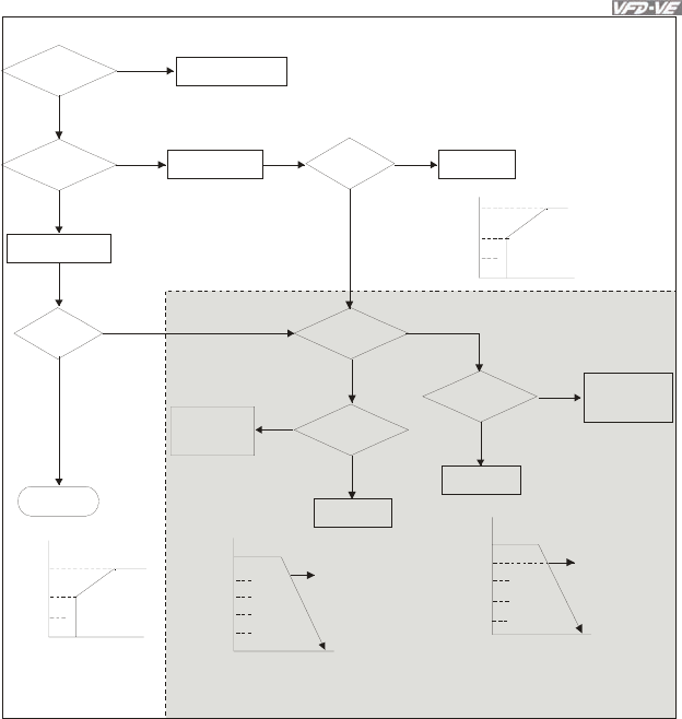
Chapter 4 Parameters|
Revision August 2008, 03VE, SW V2.04 4-53
Fcmd>Fmin
Fstart>Fmin
NO
YES
YES
fstart=Fstart
NO fstart=Fmin
Flow=0
Flow=0 YES H=Fcmd
YES
H=Fcmd
NO Fcmd>Flow
YES
Fcmd>Fmin
YES
H=Fcmd
NO
NO
Fcmd<Fmin
NO
H=Flow
YES
NO
Fcmd
Fmin
Fstart
Fcmd
Fmin
Fstart
Fcmd1>Flow&
Fcmd1>Fmin
Fmin
Flow
Fcmd2>Flow&
Fcmd2<Fmin
Flow>Fcmd1
>Fmin
Fmin
Flow
Fmin>Fcmd2
60Hz 60Hz
Hz
Time
Hz
Time
Time
Time
Hz
Hz
Fcmd1
Fcmd2
H=Flow
Fcmd1
Fcmd2
H=Fcmd1
by Pr.0 1- 34
by
Pr.01-34
by
Pr.01-34
by Pr.01-34
by Pr.01-34
operation after
start-up
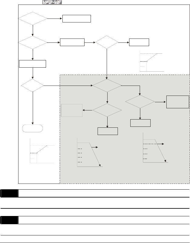
Chapter 4 Parameters|
4-54 Revision August 2008, 03VE, SW V2.04
Fcmd>Fmin
Fstart>Fmin
NO
YES
YES
fstart=Fstart
NO
fstart=Fmin
Flow=0
Flow=0
YES
H=Fcmd
YES
H=Fcmd
NO
Fcmd>Flow
YES
Fcmd>Fmin
YES
H=Fcmd
NO
NO
Fcmd<Fmin
NO
H=Flow
YES
NO
Fcmd
Fmin
Fstart
Fcmd
Fmin
Fstart
Fcmd1>Flow &
Fcmd1>Fmin
Fmin
Flow
Fcmd2>Flow &
Fcmd2<Fmin
Flow>Fcmd1
>Fmin
Fmin
Flow
Fmin>Fcmd2
60Hz 60Hz
Hz
Time
Hz
Time
Time
Time
Hz
Hz
Fcmd1
Fcmd2
H=Flow
Fcmd1
Fcmd2
H=Fcmd1
by Pr.01- 34
by
Pr.01-34
by
Pr.01-34
by Pr.01-34
by Pr.01-34
operation after
start-up
01-10 Output Frequency Upper Limit Unit: 0.01
Control
mode VF VFPG SVC FOCPG Factory Setting: 600.00
Settings 0.00~600.00Hz
01-11 Output Frequency Lower Limit Unit: 0.01
Control
mode VF VFPG SVC FOCPG Factory Setting: 0.00
Settings 0.00~600.00Hz
The upper/lower output frequency setting is used to limit the actual output frequency. If the
frequency setting is higher than the upper limit, it will run with the upper limit frequency. If
output frequency lower than output frequency lower limit and frequency setting is higher than
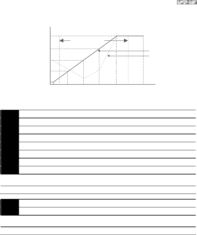
Chapter 4 Parameters|
Revision August 2008, 03VE, SW V2.04 4-55
min. frequency, it will run with lower limit frequency. The upper limit frequency should be set to
be higher than the lower limit frequency.
01-05 01-03 01-01
01-06
01-04
01-02
01-0001-07
01-08 01-09
01-11 01-10
1st Output
Voltage Setting 1
Output Frequency
Lower Limit
Frequency output
ranges limitation
Regular V/f Curve
Special V/f Curve
Voltage
4th Freq.
Start Freq.
3rd Freq.2nd Freq. 1st Freq. Maximum Output
Frequency
V
/f Curve
2nd Output
Voltage Setting 1
3rd Output
Voltage Setting 1
4th Output
Voltage Setting 1
Output Frequency
Upper Limit
Frequency
01-12 Accel. Time 1 Unit: 0.1/0.01
01-13 Decel. Time 1 Unit: 0.1/0.01
01-14 Accel. Time 2 Unit: 0.1/0.01
01-15 Decel. Time 2 Unit: 0.1/0.01
01-16 Accel. Time 3 Unit: 0.1/0.01
01-17 Decel. Time 3 Unit: 0.1/0.01
01-18 Accel. Time 4 Unit: 0.1/0.01
01-19 Decel. Time 4 Unit: 0.1/0.01
Control
mode VF VFPG SVC FOCPG Factory Setting: 10.00/10.0
Settings 0.00~600.00 sec/0.00~6000.0 sec
01-20 JOG Acceleration Time Unit: 0.1/0.01
01-21 JOG Deceleration Time Unit: 0.1/0.01
Control
mode VF VFPG SVC FOCPG Factory Setting: 1.00/1.0
Settings 0.00~600.00 sec/0.00~6000.0 sec
The Acceleration Time is used to determine the time required for the AC motor drive to ramp
from 0Hz to Maximum Output Frequency (Pr.01-00).
The Deceleration Time is used to determine the time require for the AC motor drive to
decelerate from the Maximum Output Frequency (Pr.01-00) down to 0Hz.
The Acceleration/Deceleration Time is invalid when using Pr.00-13 Optimal
Acceleration/Deceleration Setting.

Chapter 4 Parameters|
4-56 Revision August 2008, 03VE, SW V2.04
The Acceleration/Deceleration Time 1, 2, 3, 4 are selected according to the Multi-function Input
Terminals settings. See Pr.02-01 to Pr.02-30 for details.
When enabling torque limit and stall prevention function, actual accel./decel. time will longer
than the above action time.
01-00
01-13,15,17,19,21
01-12,14,16,18,20
Frequency
Time
Max. Output
Frequency
Frequency
Setting
accel. time decel. time
Accel./Decel. Time
01-22 JOG Frequency Unit: 0.01
Control
mode VF VFPG SVC FOCPG TQRPG Factory Setting: 6.00
Settings 0.00~600.00Hz
Both external terminal JOG and key “JOG” on the keypad can be used. When the jog
command is ON, the AC motor drive will accelerate from 0Hz to jog frequency (Pr.01-22).
When the jog command is OFF, the AC motor drive will decelerate from Jog Frequency to zero.
The used Accel./Decel. time is set by the Jog Accel./Decel. time (Pr.01-20, Pr.01-21).
01-23 1st/4th Accel./decel. Frequency Unit: 0.01
Control
mode VF VFPG SVC FOCPG Factory Setting: 0.00
Settings 0.00~600.00Hz
This parameter selects the frequency point for transition from acceleration/deceleration time 1
to acceleration/deceleration time 4.
The transition from acceleration/deceleration time 1 to acceleration/deceleration time 4, may
also be enabled by the external terminals (Pr. 02-01 to 02-08). The external terminal has
priority over Pr. 01-23.
01-24 S-curve for Acceleration Departure Time 1 Unit: 0.1/0.01
01-25 S-curve for Acceleration Arrival Time 2 Unit: 0.1/0.01
01-26 S-curve for Deceleration Departure Time 1 Unit: 0.1/0.01
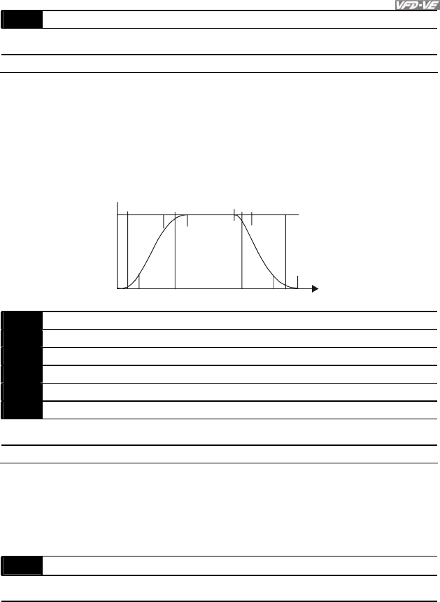
Chapter 4 Parameters|
Revision August 2008, 03VE, SW V2.04 4-57
01-27 S-curve for Deceleration Arrival Time 2 Unit: 0.1/0.01
Control
mode VF VFPG SVC FOCPG Factory Setting: 0.2/0.0
Settings 0.00~25.00 sec /0.00~250.0 sec
It is used to give the smoothest transition between speed changes. The accel./decel. curve
can adjust the S-curve of the accel./decel. When it is enabled, the drive will have different
accel./decel. curve by the accel./decel. time.
The S-curve function is disabled when Pr.00-13 is set to 0.
The Actual Accel. Time = selected accel. Time + (Pr.01-24 + Pr.01-25)/2
The Actual Decel. Time = selected decel. Time + (Pr.01-26 + Pr.01-27)/2
01-24
01-25 01-26
01-27
Frequency
Time
01-28 Skip Frequency 1 (upper limit) Unit: 0.01
01-29 Skip Frequency 1 (lower limit) Unit: 0.01
01-30 Skip Frequency 2 (upper limit) Unit: 0.01
01-31 Skip Frequency 2 (lower limit) Unit: 0.01
01-32 Skip Frequency 3 (upper limit) Unit: 0.01
01-33 Skip Frequency 3 (lower limit) Unit: 0.01
Control
mode VF VFPG SVC FOCPG Factory Setting: 0.00
Settings 0.00~600.00Hz
These parameters are used to set the skip frequency of the AC drive. The skip frequencies are
useful when a motor has vibration at a specific frequency bandwidth. By skipping this
frequency, the vibration will be avoided.
01-34 Mode Selection when Frequency< Fmin
Control
mode VF VFPG SVC FOCPG Factory Setting: 0
Settings 0 Output Waiting
1
Zero-speed operation
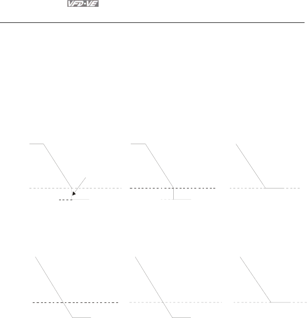
Chapter 4 Parameters|
4-58 Revision August 2008, 03VE, SW V2.04
2
Fmin (4th output frequency setting)
When the frequency is less than Fmin (Pr.01-07 or Pr.01-41), it will operate by this parameter.
When it is set to 0, the AC motor drive will be in waiting mode without voltage output from
terminals U/V/W.
When setting 1, it will execute DC brake by Vmin(Pr.01-08 and Pr.01-42) in V/f, VFPG and
SVC modes.
When it is set to 2, the AC motor drive will run by Fmin (Pr.01-07, Pr.01-41) and Vmin (Pr.01-
08, Pr.01-42) in V/f, VFPG, SVC and FOCPG modes.
In V/f, VFPG and SVC modes
fmin
01-07
fout
0Hz
01-34=0 01-34=2
01-34=1
0Hz
stop output
0Hz operation
(DC brake)
stop waiting for output
In FOCPG mode, when Pr.01-34 is set to 2, it will act according Pr.01-34 setting.
fmin
01-07
fout
01-34=0 01-34=2
01-34=1
frequency command frequency command
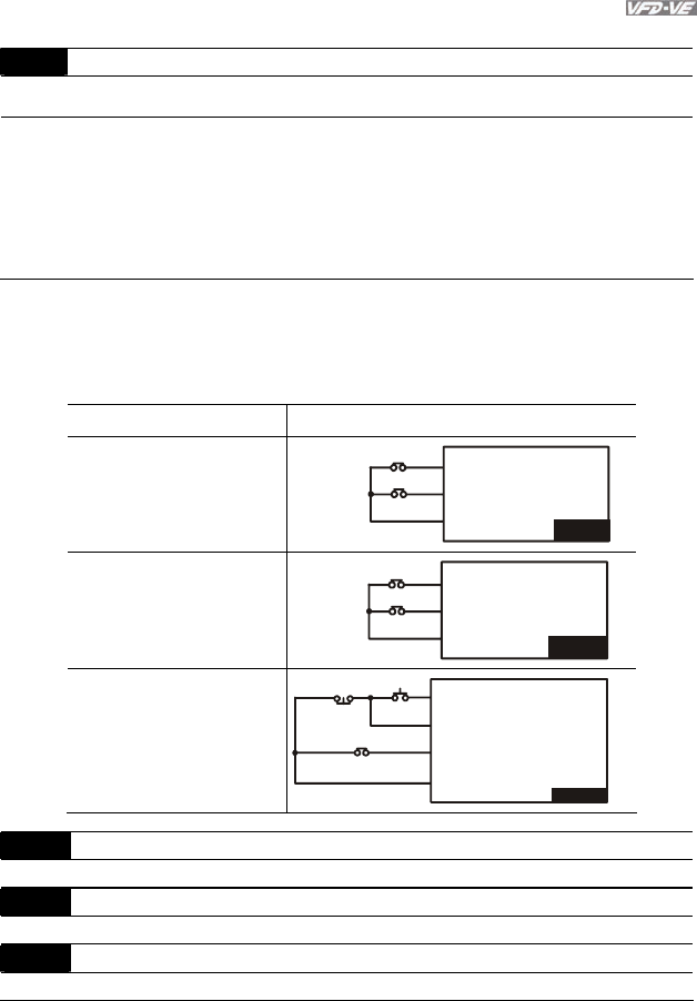
Chapter 4 Parameters|
Revision August 2008, 03VE, SW V2.04 4-59
Group 2 Digital Input/Output Parameters
02-00 2-wire/3-wire Operation Control
Control
mode VF VFPG SVC FOCPG TQRPG Factory setting: 0
Settings 0 FWD/STOP, REV/STOP
1 FWD/STOP, REV/STOP (Line Start Lockout)
2 RUN/STOP, REV/FWD
3 RUN/STOP, REV/FWD (Line Start Lockout)
4 3-wire (momentary push button)
5 3-wire (momentary push button and Line Start Lockout)
Three of the six methods include a “Line Start Lockout” feature. When line start lockout is
enabled, the drive will not run once applying the power. The Line Start Lockout feature doesn’t
guarantee the motor will never start under this condition. It is possible the motor may be set in
motion by a malfunctioning switch.
02-00 Control Circuits of the External Terminal
0, 1
2-wire operation control (1)
FWD/STOP
REV/STOP
FWD:("OPEN":STOP)
("CLOSE":FWD)
REV:("OPEN": STOP)
("CLOSE": REV)
V
FD-VE
DCM
FWD/STOP
REV/STOP
2, 3
2-wire operation control (2)
RUN/STOP
REV/FWD
FWD:("OPEN":STOP)
("CLOSE":RUN)
REV:("OPEN": FWD)
("CLOSE": REV)
V
FD-VE
DCM
RUN/STOP
FWD/REV
4, 5
3-wire operation control
FWD "CLOSE":RUN
MI1 "OPEN":STOP
REV/FWD "OPEN": FWD
"CLOSE": REV
V
FD-VE
DCM
STOP
REV/FWD
RUN
02-01 Multi-Function Input Command 1 (MI1)
Factory Setting: 1
02-02 Multi-Function Input Command 2 (MI2)
Factory Setting: 2
02-03 Multi-Function Input Command 3 (MI3)
Factory Setting: 3
Chapter 4 Parameters|
4-60 Revision August 2008, 03VE, SW V2.04
02-04 Multi-Function Input Command 4 (MI4)
Factory Setting: 4
02-05 Multi-Function Input Command 5 (MI5)
Factory Setting: 0
02-06 Multi-Function Input Command 6 (MI6)
Factory Setting: 0
02-23 Multi-Function Input Command 7 (MI7)
Factory Setting: 0
02-24 Multi-Function Input Command 8 (MI8)
Factory Setting: 0
02-25 Multi-Function Input Command 9 (MI9)
Factory Setting: 0
02-26 Multi-Function Input Command 10 (MIA)
Factory Setting: 0
02-27 Multi-Function Input Command 11 (MIB)
Factory Setting: 0
02-28 Multi-Function Input Command 12
Factory Setting: 0
02-29 Multi-Function Input Command 13
Factory Setting: 0
02-30 Multi-Function Input Command 14
Factory Setting: 0
Settings 0-50
Control Mode
Settings VF VFPG SVC FOCPG TQRPG
0: no function ○ ○ ○ ○ ○
1: multi-step speed command 1/multi-step position
command 1
○ ○ ○ ○
2: multi-step speed command 2/ multi-step position
command 2
○ ○ ○ ○
3: multi-step speed command 3/ multi-step position
command 3
○ ○ ○ ○
4: multi-step speed command 4/ multi-step position
command 4
○ ○ ○ ○
5: Reset ○ ○ ○ ○ ○
6: JOG command ○ ○ ○ ○
7: acceleration/deceleration speed inhibit ○ ○ ○ ○
8: the 1st, 2nd acceleration/deceleration time selection ○ ○ ○ ○
9: the 3rd, 4th acceleration/deceleration time selection ○ ○ ○ ○
10: EF input (07-36) ○ ○ ○ ○ ○
11: B.B. input ○ ○ ○ ○ ○
12: Output stop ○ ○ ○ ○ ○

Chapter 4 Parameters|
Revision August 2008, 03VE, SW V2.04 4-61
Control Mode
Settings VF VFPG SVC FOCPG TQRPG
13: cancel the setting of the optimal
acceleration/deceleration time
○ ○ ○ ○
14: switch between drive settings 1 and 2 ○ ○ ○ ○
15: operation speed command form AVI ○ ○ ○ ○
16: operation speed command form ACI ○ ○ ○ ○
17: operation speed command form AUI ○ ○ ○ ○
18: Emergency Stop (07-36) ○ ○ ○ ○ ○
19: Digital Up command ○ ○ ○ ○
20: Digital Down command ○ ○ ○ ○
21: PID function disabled ○ ○ ○ ○
22: clear counter ○ ○ ○ ○ ○
23: input the counter value (multi-function input command
6)
○ ○ ○ ○ ○
24: FWD JOG command ○ ○ ○ ○
25: REV JOG command ○ ○ ○ ○
26: TQC+PG/FOC+PG model selection ○ ○ ○ ○ ○
27: ASR1/ASR2 selection ○ ○ ○ ○
28: Emergency stop (EF1) ○ ○ ○ ○ ○
29: Signal confirmation for Y-connection ○ ○ ○ ○
30: Signal confirmation for connection ○ ○ ○ ○
31: High torque bias (by Pr.07-29) ○ ○ ○ ○ ○
32: Middle torque bias (by Pr.07-30) ○ ○ ○ ○ ○
33: Low torque bias (by Pr.07-31) ○ ○ ○ ○ ○
34: Enable multi-step position control ○ ○
35: Enable position control ○ ○ ○ ○
36: Enable position learning function (valid at stop) ○ ○
37: Enable pulse position input command ○ ○ ○ ○
38: Disable write EEPROM function ○ ○ ○ ○ ○
39: Torque command direction
○
40: Force stop ○ ○ ○ ○ ○
41: Serial position clock
○
42: Serial position input
○
43: Analog input resolution selection ○
44: Reset initial reel diameter ○ ○ ○ ○ ○
45: Reset initial reel diameter 0 ○ ○ ○ ○ ○
46: Reset initial reel diameter 1 ○ ○ ○ ○ ○
47: Reset PID control integration of tension ○ ○ ○ ○ ○
48: Mechanical Gear Ratio Switch ○ ○ ○
49: Reserved
50: Reserved
This parameter selects the functions for each multi-function terminal.
The terminals of Pr.02-23~Pr.02-27 are virtual and set as MI7~MIB when using with optional
card EMV-APP01
If Pr.02-00 is set to 3-wire operation control. Terminal MI1 is needed for the 3rd wire position.
Therefore, MI1 is not allowed for any other operation.
Multi-function input commands 7-14 are the extension terminals of Pr.02-01 to Pr.02-06. There
are 14 terminals but the terminals 7-14 are virtual terminals and you can set the status of bit 8-
15 of Pr.02-10 to ON or OFF by KPV-CE01 or communication.

Chapter 4 Parameters|
4-62 Revision August 2008, 03VE, SW V2.04
Settings Functions Descriptions
0 No Function
1
Multi-step speed
command 1/multi-step
position command 1
2
Multi-step speed
command 2/ multi-step
position command 2
3
Multi-step speed
command 3/ multi-step
position command 3
4
Multi-step speed
command 4/ multi-step
position command 4
15 step speeds could be conducted through the digital
statuses of the 4 terminals, and 17 in total if the master speed
and JOG are included. (Refer to Pr. 04-00~04-29)
5 Reset After the error of the drive is eliminated, use this terminal to
reset the drive.
6 JOG Command JOG operation
7 Acceleration/deceleration
Speed Inhibit
When this function is enabled, acceleration and deceleration
is stopped and the AC motor drive start to accel./decel. from
the inhibit point.
8
The 1st, 2nd acceleration
or deceleration time
selection
9
The 3rd, 4th acceleration
or deceleration time
selection
The acceleration/deceleration time of the drive could be
selected from this function or the digital statuses of the
terminals; there are 4 acceleration/deceleration speeds in
total for selection.
10 EF Input External fault input terminal
11 B.B. Input
If the ON/OFF function of the terminal is pre-determined,
output of the drive will be cut off immediately, and the motor
will then be of the B.B. status. And once the ON/OFF function
is restored, the drive will then trace from the bottom upward to
catch up with its mutual rotation speed with the same
frequency before B.B., then speed up to the pre-set
frequency. Even if the motor is of a complete stop after B.B.,
as long as the ON/OFF status is restored, the speed-tracing
function could still be operated.
12 Output Stop
If the ON/OFF function of the terminal is pre-determined,
output of the drive will be cut off immediately, and the motor
will then be free run. And once the ON/OFF function is
restored, the drive will accelerate to the setting frequency.
13 Cancel the setting of the Before using this function, Pr.00-13 should be set to

Chapter 4 Parameters|
Revision August 2008, 03VE, SW V2.04 4-63
Settings Functions Descriptions
optimal accel./decel. time 01/02/03/04 first. When this function is enabled, OFF is for
auto mode and ON is for linear accel./decel.
14 Switch between drive
settings 1 and 2
When this function is enabled, the drive will start to use motor
2 parameters.
15 Operation speed
command form AVI
When this function is enabled, the source of the frequency will
force to be AVI.
16 Operation speed
command form ACI
When this function is enabled, the source of the frequency will
force to be ACI.
17 Operation speed
command form AUI
When this function is enabled, the source of the frequency will
force to be AUI.
18 Emergency Stop (07-36) When this function is enabled, the drive will ramp to stop by
Pr.07-36 setting.
19 Digital Up command
20 Digital Down command
When this function is enabled, the frequency will be increased
and decreased. If this function keeps ON, the frequency will
be increased/decreased by Pr.02-07/Pr.02-08. This function is
the same as the ▲▼ key on the keypad.
21 PID function disabled When this function is ON, the PID function is disabled.
22 Clear counter
When this function is enabled, it will clear current counter
value and display “0”. Only when this function is disabled, it
will keep counting upward.
23
Input the counter value
(multi-function input
command 6)
When this function is enabled, the counter value will increase
1.
24 FWD JOG command When this function is enabled, the drive will execute forward
Jog command.
25 REV JOG command When this function is enabled, the drive will execute reverse
Jog command.
26 TQC+PG/FOC+PG
model selection
OFF: FOC+PG speed control mode.
ON: TQR+PG torque control mode.
27 ASR1/ASR2 selection ON: speed will be adjusted by ASR 2 setting.
OFF: speed will be adjusted by ASR 1 setting.
28 Emergency stop (EF1) When it is ON, the drive will execute emergency stop. (it will
have fault code record)
29 Signal confirmation for Y-
connection When it is ON, the drive will operate by 1st V/f.
30 Signal confirmation for
Δ−connection When it is ON, the drive will operate by 2nd V/f.
31 High torque bias (by
Pr.07-29) The high torque bias is according to the Pr.07-29 setting.
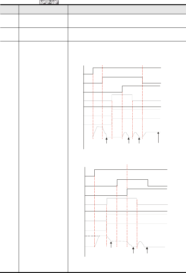
Chapter 4 Parameters|
4-64 Revision August 2008, 03VE, SW V2.04
Settings Functions Descriptions
32 Middle torque bias (by
Pr.07-30) The middle torque bias is according to the Pr.07-30 setting.
33 Low torque bias (by
Pr.07-31) The low torque bias is according to the Pr.07-31 setting.
34 Enable multi-step
position control
When this function is enabled, the corresponding 15-step
speed for the multi-function inputs 1-4 will be 15 positions.
(Refer to Pr.04-15 to Pr.04-29)
Run
1
0
1
1
1
0
1
1
0
0
1
1
0
0
1
1
04-27 04-26 04-11
MI=d35
MI=d34
MI=d1
MI=d2
MI=d3
MI=d4
speed mode speed mode
position mode
10-19
position
(Home)
multi-
position
1
3
multi-
position
12
12th step
speed
frequency
MI=4
Run
1
0
1
1
1
0
1
1
1
0
1
1
0
0
1
1
主速
04-12
04-27 04-26
MI=d34
MI=d35
MI=d1
MI=d2
MI=d3
speed mode position mode
13th step
speed
frequency
multi-
position
13
multi-
position
12
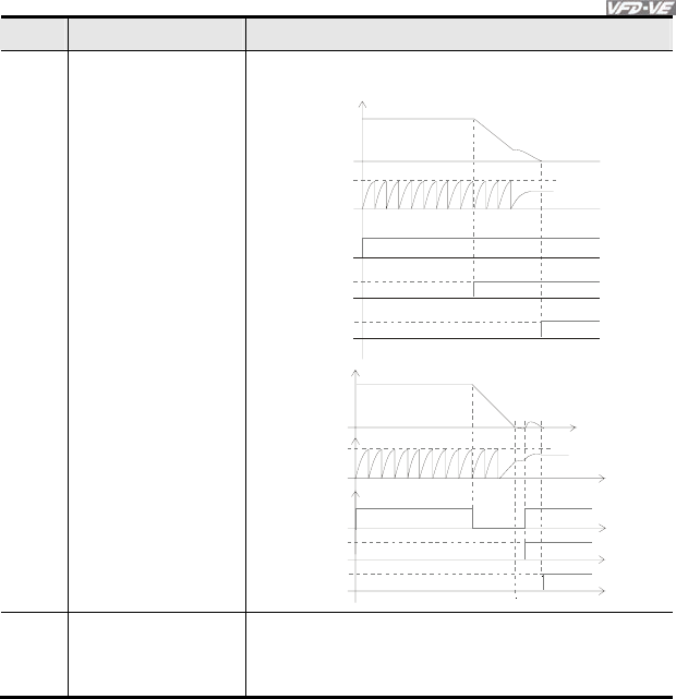
Chapter 4 Parameters|
Revision August 2008, 03VE, SW V2.04 4-65
Settings Functions Descriptions
35 Enable position control
When this function is enabled, the AC motor drive will start to
execute position control.
10-00
10-01
RUN
MI=d35
MO=d39
10-19
PG
Feedback
Motor
Frequency
Time
10-00
10-01
RUN
MI=d35
MO=d39
10-19
RUN RUN
Motor
frequency
PG
feedback
Time
36 Enable position learning
function (valid at stop)
When this function is enabled, it will select the corresponding
multi-position by the ON/OFF status of multi-function inputs 1-
4 and written the current motor position into the corresponding
multi-position.
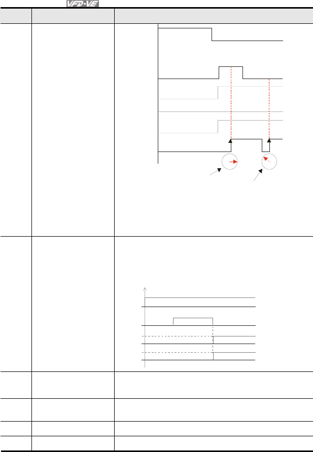
Chapter 4 Parameters|
4-66 Revision August 2008, 03VE, SW V2.04
Settings Functions Descriptions
MI=d1
Run/Stop
1
1
1010 =10
2
corresponds to
Pr.04-24
11
00
000
11 1
1011 =11
2
corresponds
to Pr.04-25
MI=d2
MI=d3
MI=d4
MI=d36
The motor position
is from encoder feedback
and written into the
corresponding multi-
position of ON/OFF
status of MI1 to MI4
( Pr.04-25)
The motor position
is from encoder feedback
and written into the
corresponding multi-
position of ON/OFF
status of MI1 to MI4
( Pr.04-24)
37 Enable pulse position
input command
When this function is enabled, the pulse of PG card will
change from speed command to position command. It is
recommended to set Pr.10-23 to 0.
Example: When it is controlled by pulse (Pr.00-20 is set to 5),
please refer to the following diagram for returning home.
RUN
MI=d35
MO=d5
MI=d37 Time
38 Disable write EEPROM
function When this function is enabled, you can’t write into EEPROM.
39 Torque command
direction
When the torque command source is AVI or ACI, it can
change torque direction by enabling this function.
40 Force stop When this function is enabled, the drive will free run to stop.
41 Serial position clock The position method of the main shaft:
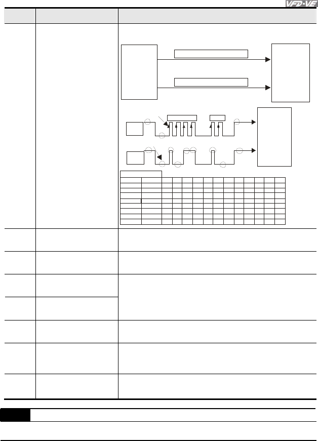
Chapter 4 Parameters|
Revision August 2008, 03VE, SW V2.04 4-67
Settings Functions Descriptions
42 Serial position input
When using setting 41 and setting 42, it needs to use with 2
input terminals for multi-position control.
CNC
DO SPI Positi on Command Clock DI
DO SPI Positi on Command Data DI
Con tro ller
(PLC) main
shaft
VFD -VE
PG position
co ntrol point
Pr.10-19
OSS
Clock
OSS
Dat a
1 2 3 4 11 12
b0
b11
Encoder b1b2b3b4b5b6b7b8b9
b1 0
36 0
18 0
90
45
13 7
30 8
40 96
40 95
20 48
10 24
51 2
15 58
35 04
36 87
0
1
00000000000
11111111111
000000000001
0000000000
1000000000
1000010110
1
1
0
0
0
0
011011000011
100110011111
PG position
co n tr ol poi nt
Pr.10 -19
main shaft
VFD-VE
transmission start
Rea dy for t ra nsmi s s i on
test example
angle
43 Analog input resolution
selection Refer to Pr.10-25.
44 Reset initial reel
diameter When this function is enabled, the initial reel diameter is reset.
45 Reset initial reel
diameter 0
46 Reset initial reel
diameter 1
When this function is enabled, Pr.08-46~08-48 is valid.
47 Reset PID control
integration of tension
When this function is enabled, the PID control integration of
tension is reset.
48 Mechanical Gear Ratio
Switch
When this functioni is enabled, the mechanical gear ratio
switch will be the second group A2/B2 (refer to Pr.10-29 and
Pr.10-30).
49
|
50
Reserved
02-07 UP/DOWN Key Mode
Control
mode VF VFPG SVC FOCPG Factory setting: 0
Settings 0 Up/down by the accel/decel time
1 Up/down constant speed (Pr.02-08)

Chapter 4 Parameters|
4-68 Revision August 2008, 03VE, SW V2.04
02-08 The Acceleration/Deceleration Speed of the UP/DOWN Key
with Constant Speed Unit: 0.01
Control
mode VF VFPG SVC FOCPG Factory setting: 0.01
Settings 0.01 ~ 1.00Hz/ms
These settings are used when multi-function input terminals are set to 19/20.
02-09 Digital Input Response Time Unit: 0.001
Control
mode VF VFPG SVC FOCPG TQRPG Factory setting: 0.005
Settings 0.001~ 30.000 sec
This parameter is used for digital input terminal signal delay and confirmation. The delay time
is confirmation time to prevent some uncertain interferences that would result in error (except
for the counter input) in the input of the digital terminals (FWD, REV and MI1~6). Under this
condition, confirmation for this parameter could be improved effectively, but the response time
will be somewhat delayed.
02-10 Digital Input Operation Direction Unit: 1
Control
mode VF VFPG SVC FOCPG TQRPG Factory setting: 0
Settings 0 ~ 65535
This parameter is used to set the input signal level and it won’t be affected by the
SINK/SOURCE status.
Bit0 is for FWD terminal, bit1 is for REV terminal and bit2 to bit15 is for MI1 to MI14.
User can change terminal status by communicating.
For example, MI1 is set to 1 (multi-step speed command 1), MI2 is set to 2 (multi-step speed
command 2). Then the forward + 2nd step speed command=1001(binary)=9 (Decimal). Only
need to set Pr.02-10=9 by communication and it can forward with 2nd step speed. It doesn’t
need to wire any multi-function terminal.
bit15 bit14 bit13 bit12 bit11 bit10 bit9 bit8 bit7 bit6 bit5 bit4 bit3 bit2 bit1 bit0
MI14 MI13 MI12 MI11 MI10 MI9 MI8 MI7 MI6 MI5 MI4 MI3 MI2 MI1 REV FWD
02-11 Multi-function Output 1 RA, RB, RC (Relay1)
Factory Setting: 11
02-12 Multi-function Output 2 MRA, MRC (Relay2)
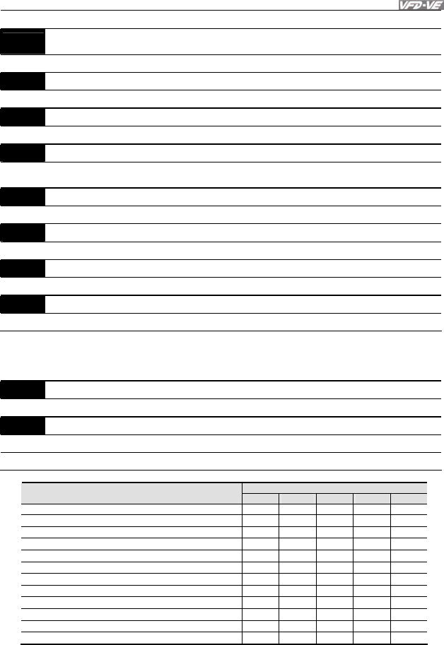
Chapter 4 Parameters|
Revision August 2008, 03VE, SW V2.04 4-69
Factory Setting: 1
02-13 Multi-function Output 3 (MO1)
Factory Setting: 0
02-14 Multi-function Output 4 (MO2)
Factory Setting: 0
02-35 Multi-function Output 5 (MO3) (need to use with EMV-APP01)
Factory Setting: 0
02-36 Multi-function Output 5 6 (MO4) (need to use with EMV-APP01)
Factory Setting: 0
02-37 Multi-function Output 5 7 (MO3MO5) (need to use with EMV-APP01)
Factory Setting: 0
02-38 Multi-function Output 8 (MO6) (need to use with EMV-APP01)
Factory Setting: 0
02-39 Multi-function Output 9 (MO7) (need to use with EMV-APP01)
Factory Setting: 0
02-40 Multi-function Output 10 (MO8) (need to use with EMV-APP01)
Factory Setting: 0
02-41 Multi-function Output 11 (MO9) (need to use with EMV-APP01)
Factory Setting: 0
02-42 Multi-function Output 12 (MOA) (need to use with EMV-APP01)
Factory Setting: 0
Settings 0-50
Control Mode
Settings VF VFPG SVC FOCPG TQRPG
0: No function
1: Operation indication ○ ○ ○ ○ ○
2: Operation speed attained ○ ○ ○ ○ ○
3: Desired frequency attained 1 (Pr.02-19) ○ ○ ○ ○ ○
4: Desired frequency attained 2 (Pr.02-21) ○ ○ ○ ○
5: Zero speed (frequency command) ○ ○ ○ ○
6: Zero speed with stop (frequency command) ○ ○ ○ ○
7: Over torque (OT1) (Pr.06-06~06-08) ○ ○ ○ ○ ○
8: Over torque (OT2) (Pr.06-09~06-11) ○ ○ ○ ○ ○
9: Drive ready ○ ○ ○ ○ ○
10: User-defined Low-voltage Detection ○ ○ ○ ○ ○
11: Malfunction indication ○ ○ ○ ○ ○
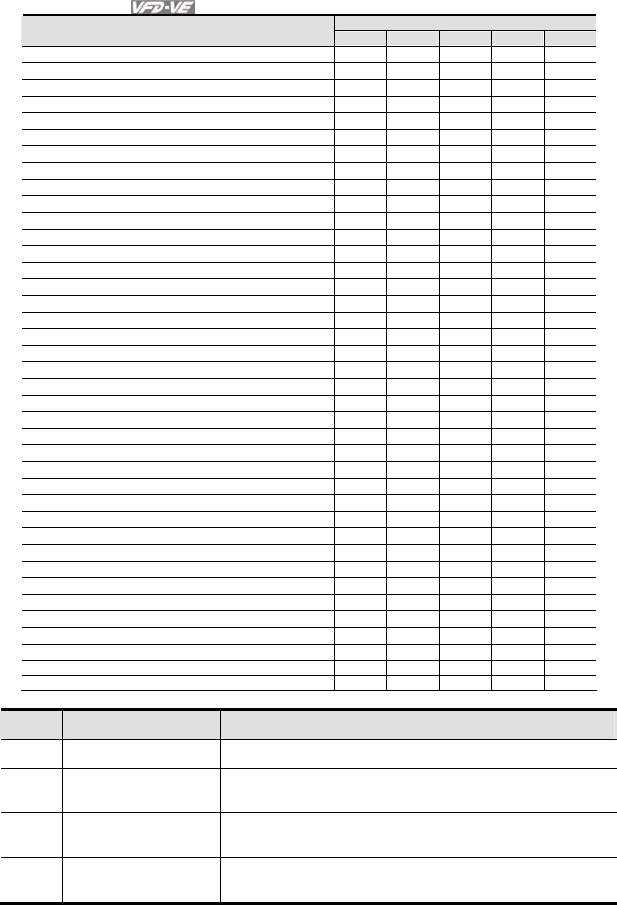
Chapter 4 Parameters|
4-70 Revision August 2008, 03VE, SW V2.04
Control Mode
Settings VF VFPG SVC FOCPG TQRPG
12: Mechanical brake release (Pr.02-31) ○ ○ ○ ○ ○
13: Overheat ○ ○ ○ ○ ○
14: Software brake signal ○ ○ ○ ○ ○
15: PID feedback error ○ ○ ○ ○ ○
16: Slip error (oSL) ○ ○ ○ ○
17: Terminal count value attained (Pr.02-16) ○ ○ ○ ○ ○
18: Preliminary count value attained (Pr.02-17) ○ ○ ○ ○ ○
19: Baseblock (B.B.) Indication ○ ○ ○ ○ ○
20: Warning output ○ ○ ○ ○ ○
21: Over voltage warning ○ ○ ○ ○ ○
22: Over-current stall prevention warning ○ ○ ○
23: Over-voltage stall prevention warning ○ ○ ○ ○ ○
24: Operation mode indication ○ ○ ○ ○ ○
25: Forward command ○ ○ ○ ○ ○
26: Reverse command ○ ○ ○ ○ ○
27: Output when current >= Pr.02-32 ○ ○ ○ ○ ○
28: Output when current < Pr.02-32 ○ ○ ○ ○ ○
29: Output when frequency >= Pr.02-33 ○ ○ ○ ○ ○
30: Output when frequency < Pr.02-33 ○ ○ ○ ○ ○
31: Y-connection for the motor coil ○ ○ ○ ○
32: Δ connection for the motor coil ○ ○ ○ ○
33: Zero speed (actual output frequency) ○ ○ ○ ○
34: Zero speed with Stop (actual output frequency) ○ ○ ○ ○
35: Error output selection 1 (Pr.06-23) ○ ○ ○ ○ ○
36: Error output selection 2 (Pr.06-24) ○ ○ ○ ○ ○
37: Error output selection 3 (Pr.06-25) ○ ○ ○ ○ ○
38: Error output selection 4 (Pr.06-26) ○ ○ ○ ○ ○
39: Position attained (Pr.10-19) ○
40: Speed attained (including zero speed) ○ ○ ○ ○
41: Multi-position attained
○
42: Crane function ○ ○ ○ ○
43: Motor zero-speed output (Pr.02-43) ○ ○ ○ ○
44: Max. reel diameter attained ○ ○ ○ ○ ○
45: Empty reel diameter attained ○ ○ ○ ○ ○
46: Broken belt detection ○ ○ ○ ○ ○
47: Break release at stop ○ ○ ○ ○ ○
48: Error PID feedback of tension ○ ○ ○ ○ ○
49: Reserved
50: Reserved
Settings Functions Descriptions
0 No Function
1 Operation Indication Active when the drive is not at STOP.
2 Master Frequency
Attained
Active when the AC motor drive reaches the output frequency
setting.
3 Desired Frequency
Attained 1 (Pr.02-19) Active when the desired frequency (Pr.02-19) is attained.

Chapter 4 Parameters|
Revision August 2008, 03VE, SW V2.04 4-71
Settings Functions Descriptions
4 Desired Frequency
Attained 2 (Pr.02-21) Active when the desired frequency (Pr.02-21) is attained.
5 Zero Speed (frequency
command)
Active when frequency command =0. (the drive should be at
RUN mode)
6 Zero Speed with Stop
(frequency command) Active when frequency command =0 or stop.
7 Over Torque (OT1)
(Pr.06-06~06-08)
Active when detecting over-torque. Refer to Pr.06-06 (over-
torque detection selection-OT1), Pr.06-07 (over-torque
detection level-OT1) and Pr.06-08 (over-torque detection time-
OT1).
8 Over Torque (OT2)
(Pr.06-09~06-11)
Active when detecting over-torque. Refer to Pr.06-09 (over-
torque detection selection-OT2), Pr.06-10 (over-torque
detection level-OT2) and Pr.06-11 (over-torque detection time-
OT2).
9 Drive Ready Active when the drive is ON and no abnormality detected.
10 User-defined Low-
voltage Detection
Active when the DC Bus voltage is too low. (refer to Pr.06-00
low voltage level)
11 Malfunction Indication Active when fault occurs (except Lv stop).
12 Mechanical Brake
Release (Pr.02-31)
When drive runs after Pr.02-31, it will be ON. This function
should be used with DC brake and it is recommended to use
contact ”b”(N.C).
13 Overheat Active when IGBT or heat sink overheats to prevent OH turn
off the drive. (refer to Pr.06-05)
14 Software Brake Signal
This function is used in conjunction with a VFDB Brake Unit.
The output will be activated when the drive needs help braking
the load. A smooth deceleration is achieved by using this
function. (refer to Pr.07-00)
15 PID Feedback Error Active when the feedback signal is abnormal.
16 Slip Error (oSL) Active when the slip error is detected.
17 Terminal Count Value
Attained
Active when the counter reaches Terminal Counter Value
(Pr.02-16).
18 Preliminary Counter
Value Attained
Active when the counter reaches Preliminary Counter Value
(Pr.02-17).
19 Baseblock (B.B.)
Indication
Active when the output of the AC motor drive is shut off during
baseblock.
20 Warning Output Active when the warning is detected.

Chapter 4 Parameters|
4-72 Revision August 2008, 03VE, SW V2.04
Settings Functions Descriptions
21 Over-voltage Warning Active when the over-voltage is detected.
22 Over-current Stall
Prevention Warning Active when the over-current stall prevention is detected.
23 Over-voltage Stall
prevention Warning Active when the over-voltage stall prevention is detected.
24 Operation Mode
Indication
Active when the operation command is controlled by external
terminal.
25 Forward Command Active when the operation direction is forward.
26 Reverse Command Active when the operation direction is reverse.
27 Output when Current >=
Pr.02-32 Active when current is >= Pr.02-32.
28 Output when Current <
Pr.02-32 Active when current is < Pr.02-32.
29 Output when frequency
>= Pr.02-33 Active when frequency is >= Pr.02-33.
30 Output when Frequency
< Pr.02-33 Active when frequency is < Pr.02-33.
31 Y-connection for the
Motor Coil
Active when PR.05-12 is less than PR.05-11 and time is more
than Pr.05-30.
32 Δ-connection for the
Motor Coil
Active when PR.05-12 is higher than PR.05-11 and time is
more than Pr.05-30.
33 Zero Speed (actual
output frequency)
Active when the actual output frequency is 0. (the drive should
be at RUN mode)
34
Zero Speed with Stop
(actual output
frequency)
Active when the actual output frequency is 0 or Stop.
35 Error Output Selection 1
(Pr.06-23) Active when Pr.06-23 is ON.
36 Error Output Selection 2
(Pr.06-24) Active when Pr.06-24 is ON.
37 Error Output Selection 3
(Pr.06-25) Active when Pr.06-25 is ON.
38 Error Output Selection 4
(Pr.06-26) Active when Pr.06-26 is ON.
39 Position Attained
(Pr.10-19) Active when the PG position control point reaches Pr.10-19.
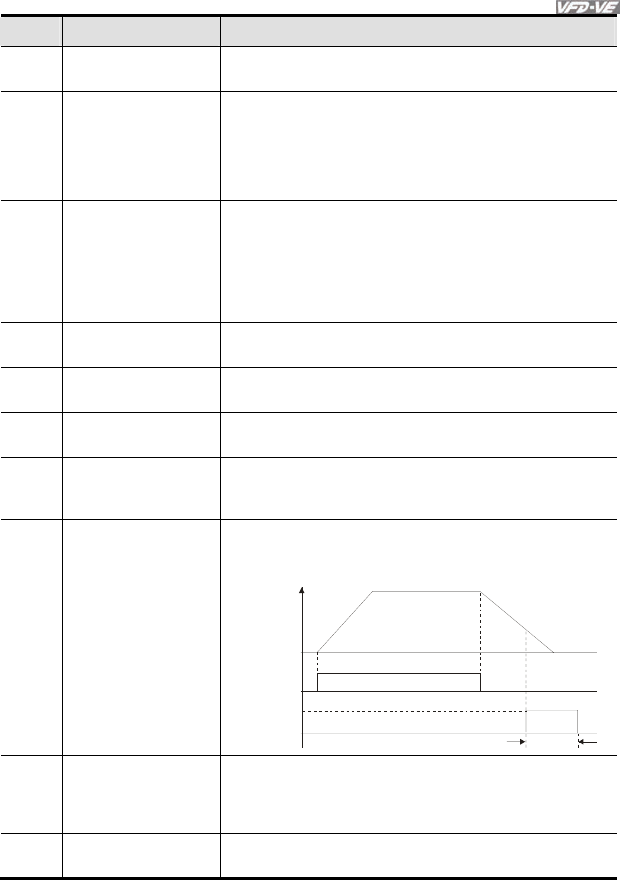
Chapter 4 Parameters|
Revision August 2008, 03VE, SW V2.04 4-73
Settings Functions Descriptions
40 Speed Attained
(including zero speed)
Active when the output frequency reaches frequency setting or
stop.
41 Multi-position Attained
User can set any three multi-function input terminals to 41. The
current position action status of these three terminals will be
outputted. Example: if setting Pr.02-11, Pr.02-12 and Pr.02-13
to 41 and only the multi-position of the second point has been
done. Therefore, current status are RA (OFF), MRA (ON) and
MO1 (OFF). In this way, their status is 010.
42 Crane Function
This function should be used with Pr.02-31, Pr.02-32 and
Pr.02-33.
Active when setting Pr.07-16=Pr.02-33 and Fcmd > Pr.02-33
and output current > Pr.02-32 and Time > Pr.02-31.
The example of the crane application is in the following for
your reference.
43 Motor Zero-speed
Output (Pr.02-43) Active when motor actual speed is less than Pr.02-43.
44 Max. Reel Diameter
Attained Active when the reel diameter is equal to Pr.08-43.
45 Empty Reel Diameter
Attained Active when the reel diameter is equal to Pr.08-44.
46 Broken Belt Detection
The broken belt occurs when 1. line speed is higher than
Pr.08-61, 2. the error of reel diameter exceeds Pr.08-61, 3.
detection time exceeds Pr.08-62
47 Break Release at Stop
When drive stops, the corresponding multi-function terminal
will be ON if the frequency is less than Pr.02-33. After it is ON,
it will be OFF when brake delay time exceeds Pr.02-31.
02-31
RUN RUN
Frequenc
y
command
Multi-function
output MO=47
Frequency
command <02-33
48 Error PID Feedback of
Tension
When the error between PID target value and PID feedback
exceeds Pr.08-63 and allowance error detection time of
tension PID feedback exceeds Pr.08-64, please refer to Pr. 08-
64 for error treatment of tension PID feedback.
49 Reserved

Chapter 4 Parameters|
4-74 Revision August 2008, 03VE, SW V2.04
Settings Functions Descriptions
50 Reserved
Example of crane function
02-31
02-31
Frequenc
y
command
Freq. command>02-31
& output current >02-32
Freq. command<02-33
or output current <02-32
multi-function output
MO=42 (Active when
Fcom>=02-33, output
current>02-32 and time
>02-31)
It is recommended to be used with Dwell function (Pr.07-15 to Pr.07-18) as shown in the following:
Mechanical breaker
Multi-functioni output
MO= 42
( Activate when
Fcmd >= 02-33
output current > 02-32
Time > 02-31)
07-16 Dwell
Freq.
at Accel.
07-15
Dwell Time at Accel.
Output Freq.
02-31
Brake Delay Time
Set 07-16=02-33and
output current >02-32
07-17
Dwell Time atDecel.
Set 07-18=02-33 and
output current <02-32
07-18 Dwell Freq.
at Decel.
02-31
Brake Delay Time
Crane function will be activated when
setting 07-16=02-33 and Fcmd>02-33
and output current>02-32 and
Time > 02-31
02-15 Multi-output Direction Unit:1
Control
mode VF VFPG SVC FOCPG TQRPG Factory setting: 0
Settings 0 ~ 65535
This parameter is set via bit setting. If a bit is 1, the corresponding output acts in the opposite
way.
Example:
If Pr02-11=1 and Pr02-15=0, Relay 1 RA-RC is closed when the drive runs and is open when
the drive is stopped.
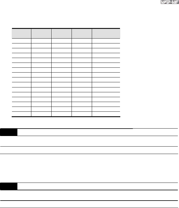
Chapter 4 Parameters|
Revision August 2008, 03VE, SW V2.04 4-75
If Pr02-11=1 and Pr02-15=1, Relay 1 RA-RC is open when the drive runs and is closed when
the drive is stopped.
Bit setting
bit3
MO2
bit2
MO1
bit1
RA
bit0
MRA Pr02-15
0 0 0 0 0
0 0 0 1 1
0 0 1 0 2
0 0 1 1 3
0 1 0 0 4
0 1 0 1 5
0 1 1 0 6
0 1 1 1 7
1 0 0 0 8
1 0 0 1 9
1 0 1 0 10
1 0 1 1 11
1 1 0 0 12
1 1 0 1 13
1 1 1 0 14
1 1 1 1 15
02-16 Terminal Count Value Unit:1
Control
mode VF VFPG SVC FOCPG TQRPG Factory setting: 0
Settings 0 ~ 65535
The counter trigger can be set by the multi-function terminal MI6 (set Pr.02-06 to 23). Upon
completion of counting, the specified output terminal will be activated (Pr.02-11 to Pr.02-14 is
set to 17).
02-17 Preliminary Count Value Unit:1
Control
mode VF VFPG SVC FOCPG TQRPG Factory setting: 0
Settings 0 ~ 65535
When the counter value reaches this value, the corresponding multi-function output terminal
will be activated, provided one of Pr. 02-11 to 02-14 set to 18 (Preliminary Count Value
Setting). This parameter can be used for the end of the counting to make the drive runs from
the low speed to stop.
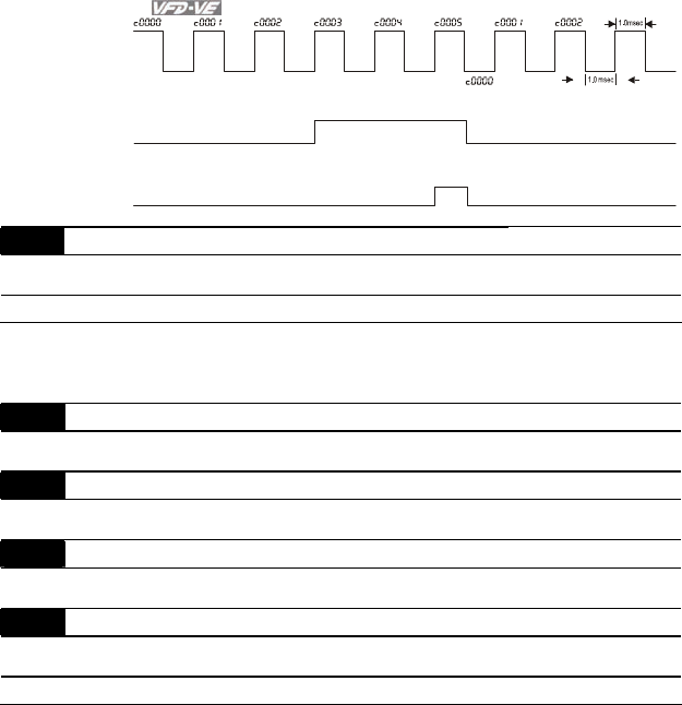
Chapter 4 Parameters|
4-76 Revision August 2008, 03VE, SW V2.04
TRG
[00-04=01]
02-13=18
02-14=17 02-16=5
02-17=3
[02-06=23]
Display value
Counter Trigger
(output signal)
Preliminary Counter Value
(Pr.02-11 ~Pr.02-14)
Terminal Counter Value
The width of trigger signal
02-18 Digital Output Gain Unit:1
Control
mode VF VFPG SVC FOCPG TQRPG Factory setting: 1
Settings 1 ~ 40
It is used to set the signal for the digital output terminals (DFM-DCM) and digital frequency
output (pulse X work period=50%). Output pulse per second = output frequency X Pr.02-18.
02-19 Desired Frequency Attained 1 Unit: 0.01
Control
mode VF VFPG SVC FOCPG Factory setting: 60.00/50.00
02-20 The Width of the Desired Frequency Attained 1 Unit: 0.01
Control
mode VF VFPG SVC FOCPG Factory setting: 2.00
02-21 Desired Frequency Attained 2 Unit: 0.01
Control
mode VF VFPG SVC FOCPG Factory setting: 60.00/50.00
02-22 The Width of the Desired Frequency Attained 2 Unit: 0.01
Control
mode VF VFPG SVC FOCPG Factory setting: 2.00
Settings 0.00 ~ 600.00Hz
Once output frequency reaches desired frequency and the corresponding multi-function output
terminal is set to 3 or 4 (Pr.02-11~Pr.02-14), this multi-function output terminal will be ON.
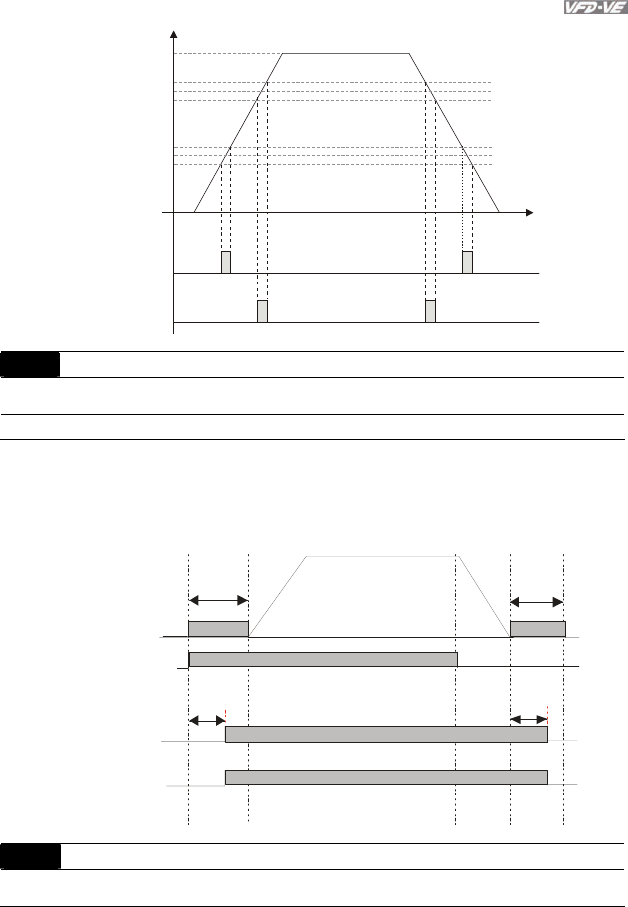
Chapter 4 Parameters|
Revision August 2008, 03VE, SW V2.04 4-77
02-11~14=3
02-11~14=4
Fcmd=60Hz
02-19=10Hz
02-20=2Hz
02-21=40Hz
02-22=2Hz
H
38Hz
40Hz
42Hz
10Hz
12Hz
8Hz
T
02-31 Brake Delay Time Unit:0.001
Control
mode VF VFPG SVC FOCPG TQRPG Factory setting: 0.000
Settings 0.000~65.000 Sec
When the AC motor drive runs after Pr.02-31 delay time, the corresponding multi-function
output terminal (12: mechanical brake release) will be ON. This function should be used with
DC brake.
Moto r sp ee d/
Output frequenc y DC br ake DC br ake
07 -0 2
DC br ake
time during
star t-up
07 -0
3
DC br ake
time during
st op pi ng
Mul ti- f unc ti on o utpu t
(me cha ni cal b rake re le ase )
Pr. 02 -11 to 0 2-1 4=12
Mec han i cal br ake
02 -3 1 b rake d el ay ti me
bounce time of mechanical brake
RUN/STOP
ON STOP
br ake d re lease br ake d
02-32 Output Current Level Setting for External Terminals Unit:1
Control
mode VF VFPG SVC FOCPG TQRPG Factory setting: 0

Chapter 4 Parameters|
4-78 Revision August 2008, 03VE, SW V2.04
Settings 0~100%
When output current is higher than Pr.02-32, it will activate multi-function output terminal
(Pr.02-11 to Pr.02-14 is set to 27).
When output current is lower than Pr.02-32, it will activate multi-function output terminal
(Pr.02-11 to Pr.02-14 is set to 28).
02-33 Output Boundary for External Terminals Unit:0.01
Control
mode VF VFPG SVC FOCPG TQRPG Factory setting: 0.00
Settings 0.00~+-60.00Hz
When output frequency is higher than Pr.02-33, it will activate the multi-function terminal
(Pr.02-11 to Pr.02-14 is set to 29).
When output frequency is lower than Pr.02-33, it will activate the multi-function terminal
(Pr.02-11 to Pr.02-14 is set to 30).
02-34 External Operation Control Selection after Reset Unit:1
Control
mode VF VFPG SVC
Factory setting: 0
Settings 0: Disable
1: Drive runs if run command exists after reset
After clearing fault once a fault is detected and the external terminal for RUN keeps ON, the
drive can run after pressing RESET key.
02-43 Zero-speed Level of Motor Unit: 1
Control
mode VF VFPG SVC FOCPG TQRPG Factory setting: 0
Settings 0~65535rpm
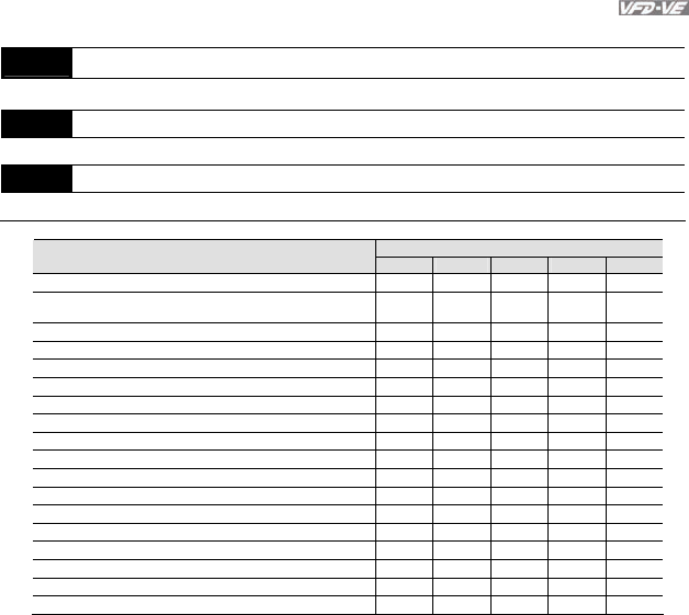
Chapter 4 Parameters|
Revision August 2008, 03VE, SW V2.04 4-79
Group 3 Analog Input/Output Parameters
03-00 Analog Input 1 (AVI)
Factory Setting: 1
03-01 Analog Input 2 (ACI)
Factory Setting: 0
03-02 Analog Input 3 (AUI)
Factory Setting: 0
Control Mode
Settings VF VFPG SVC FOCPG TQRPG
0: No function ○ ○ ○ ○ ○
1: Frequency command (torque limit under TQR control
mode)
○ ○ ○ ○ ○
2: torque command (torque limit under speed mode)
○
3: Torque compensation command ○ ○ ○ ○ ○
4: PID target value (refer to group 8) ○ ○ ○ ○
5: PID feedback signal (refer to group 8) ○ ○ ○ ○
6: P.T.C. thermistor input value ○ ○ ○ ○ ○
7: Positive torque limit
○
8: Negative torque limit
○
9: Regenerative torque limit
○
10: Positive/negative torque limit
○
11: PID feedback signal of tension ○ ○ ○ ○ ○
12: Line speed ○ ○ ○ ○ ○
13: Reel diameter ○ ○ ○ ○ ○
14: PID target value of tension (tension closed-loop) ○ ○ ○ ○ ○
15: Tension setting (tension open-loop)
○
16: Zero-speed tension
○
17: Tension taper
○
When it is frequency command or TQR speed limit, the corresponding value for 0~±
10V/4~20mA is 0 – max. output frequency(Pr.01-00)
When it is torque command or torque limit, the corresponding value for 0~±10V/4~20mA is 0 –
max. output torque (Pr.07-22).
When it is torque compensation, the corresponding value for 0~±10V/4~20mA is 0 – rated
torque.
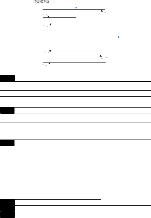
Chapter 4 Parameters|
4-80 Revision August 2008, 03VE, SW V2.04
Positive torque
Reverse
03-00~02=7
Positive torque limit
03-00~02=8
Negative torque limit
03-00~02=9
Regenerative
torque limit
03-00~02=10
Positive/negative torque limit
Negative Torque
Forward
03-00~02=10
Positive/negative torque limit 03-00~02=9
Regenerative
torque limit
03-03 Analog Input Bias 1 (AVI) Unit: 0.1
Control
mode VF VFPG SVC FOCPG TQRPG Factory setting: 0
Settings -100.0~100.0%
It is used to set the corresponding AVI voltage of the external analog input 0.
03-04 Analog Input Bias 1 (ACI) Unit: 0.1
Control
mode VF VFPG SVC FOCPG TQRPG Factory setting: 0
Settings -100.0~100.0%
It is used to set the corresponding ACI voltage of the external analog input 0.
03-05 Analog Input Bias 1 (AUI) Unit: 0.1
Control
mode VF VFPG SVC FOCPG TQRPG Factory setting: 0
Settings -100.0~100.0%
It is used to set the corresponding AUI voltage of the external analog input 0.
03-06 Positive/negative Bias Mode (AVI)
03-07 Positive/negative Bias Mode (ACI)
03-08 Positive/negative Bias Mode (AUI)
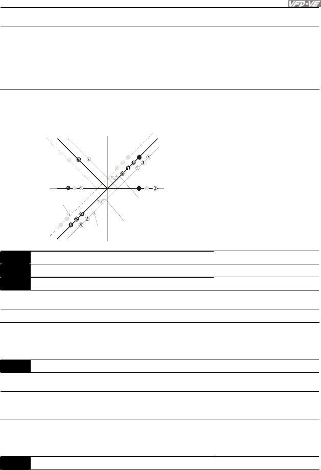
Chapter 4 Parameters|
Revision August 2008, 03VE, SW V2.04 4-81
Control
mode VF VFPG SVC FOCPG TQRPG Factory setting: 0
Settings 0 Zero bias
1 Lower than bias=bias
2 Greater than bias=bias
3 The absolute value of the bias voltage while serving as the center
4 Serve bias as the center
In a noisy environment, it is advantageous to use negative bias to provide a noise margin. It is
recommended NOT to use less than 1V to set the operation frequency.
10V5123 4-1-2-3-4-5-1 0 V 6 7 8 9
03-00
to
03-02
-6-7-8
-9
0
1
2
3
44
2
2
4
2
03-09~03-11 gain is positive
4
Zero bias
Lower than bias =bias
Greater than bias=bias
The absolute value of the bias voltage
while s erving as the center
Serve bias as the center
bias
bias
Positive bias
Negative bias
03-09 Analog Input Gain 1 (AVI) Unit: 1
03-10 Analog Input Gain 1 (ACI) Unit: 1
03-11 Analog Input Gain 1 (AUI) Unit: 1
Control
mode VF VFPG SVC FOCPG TQRPG Factory setting: 100.0
Settings -500.0~500.0%
Parameters 03-03 to 03-11 are used when the source of frequency command is the analog
voltage/current signal.
03-12 ACI/AVI2 Selection
Control
mode VF VFPG SVC FOCPG TQRPG Factory setting: 0
Settings 0 ACI
1 AVI 2
There are two AVI analog inputs can be used when this parameter is set to 1 and the SW2 on
the control board is set to AVI2. At this moment, ACI is for voltage input.
03-13 Analog Input Delay Time (AVI) Unit: 0.01
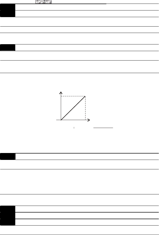
Chapter 4 Parameters|
4-82 Revision August 2008, 03VE, SW V2.04
03-14 Analog Input Delay Time (ACI) Unit: 0.01
03-15 Analog Input Delay Time (AUI) Unit: 0.01
Control
mode VF VFPG SVC FOCPG TQRPG Factory setting: 0.01
Settings 0.00 to 2.00 sec
These input delays can be used to filter noisy analog signal.
03-16 Addition Function of the Analog Input
Control
mode VF VFPG SVC FOCPG TQRPG Factory setting: 0
Settings 0 Disable (AVI, ACI, AUI)
1 Enable
When Pr.03-16 is set to 0 and the analog input setting is the same, the priority for AVI, ACI
and AUI are AVI>ACI>AUI.
Fcommand=[(ay bias)*gain]* Fmax(01-00)
10V or 16mA
ay : 10 or 16mA
bias : Pr.03-03,Pr. 03-04, Pr.03-05
gain : Pr.03-09, Pr.03-10, Pr.03-11
Frequency
Voltage
Fcommand: the corresponding
frequency for 10V or 20mA
03-17 Loss of the ACI Signal
Control
mode VF VFPG SVC FOCPG TQRPG Factory setting: 0
Settings 0 Disable
1 Continue operation at the last frequency
2 Decelerate to stop
3 Stop immediately and display E.F.
This parameter determines the behavior when ACI is lost.
03-18 Analog Output Selection 1 Unit: 1
03-21 Analog Output Selection 2 (need to be used with EMV-APP01) Unit: 1
03-24 Analog Output Selection 3 (need to be used with EMV-APP01) Unit: 1
Control
mode VF VFPG SVC FOCPG TQRPG Factory setting: 0

Chapter 4 Parameters|
Revision August 2008, 03VE, SW V2.04 4-83
Settings 0 to 19
Settings Functions Descriptions
0 Output frequency (Hz) Max. frequency Pr.01-00 is regarded as 100%.
1 Frequency command
(Hz) Max. frequency Pr.01-00 is regarded as 100%.
2 Motor speed (Hz) 600Hz is regarded as 100%
3 Output current (rms) 2.5 X rated current is regarded as 100%
4 Output voltage 2 X rated voltage is regarded as 100%
5 DC Bus Voltage 450V (900V)=100%
6 Power factor -1.000~1.000=100%
7 Power Rated power is regarded as 100%
8 Output torque Full-load torque is regarded as 100%
9 AVI 0~10V=0~100%
10 ACI 0~20mA=0~100%
11 AUI -10~10V=0~100%
12 q-axis current (2.5 X rated current) is regarded as 100%
13 q-axis feedback value (2.5 X rated current) is regarded as 100%
14 d-axis current (2.5 X rated current) is regarded as 100%
15 d-axis feedback value (2.5 X rated current) is regarded as 100%
16 q-axis voltage 250V (500V) =100%
17 d-axis voltage 250V (500V) =100%
18 Torque command Rated torque is regarded as 100%
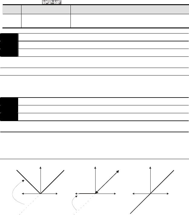
Chapter 4 Parameters|
4-84 Revision August 2008, 03VE, SW V2.04
Settings Functions Descriptions
19 Pulse frequency
command Max. frequency Pr.01-00 is regarded as 100%.
03-19 Analog Output Gain 1 Unit: 0.1
03-22 Analog Output Gain 2 (need to be used with EMV-APP01) Unit: 0.1
03-25 Analog Output Gain 3 (need to be used with EMV-APP01) Unit: 0.1
Control
mode VF VFPG SVC FOCPG TQRPG Factory setting: 100.0
Settings 0 to 200.0%
It is used to adjust the analog voltage level that terminal AFM outputs.
This parameter is set the corresponding voltage of the analog output 0.
03-20 Analog Output Value in REV Direction 1
03-23 Analog Output Value in REV Direction 2
03-26 Analog Output Value in REV Direction 3
Control
mode VF VFPG SVC FOCPG TQRPG Factory setting: 0
Settings 0 Absolute value in REV direction
1 Output 0V in REV direction
2 Enable output voltage in REV direction
03-18
03-21
03-24
03-20=0
03-23=0
03-26=0
03-20=1
03-23=1
03-26=1
10V(20mA
)
03-20=2
03-23=2
03-26=2
5V
(12mA)
10V(20mA
)
0V
(0mA)
10V(20mA
)
0V
(0mA)
Frequency Frequency
Selections for the analog output direction

Chapter 4 Parameters|
Revision August 2008, 03VE, SW V2.04 4-85
Group 4 Multi-Step Speed Parameters
04-00 1st Step Speed Frequency Unit: 0.01
04-01 2nd Step Speed Frequency Unit: 0.01
04-02 3rd Step Speed Frequency Unit: 0.01
04-03 4th Step Speed Frequency Unit: 0.01
04-04 5th Step Speed Frequency Unit: 0.01
04-05 6th Step Speed Frequency Unit: 0.01
04-06 7th Step Speed Frequency Unit: 0.01
04-07 8th Step Speed Frequency Unit: 0.01
04-08 9th Step Speed Frequency Unit: 0.01
04-09 10th Step Speed Frequency Unit: 0.01
04-10 11th Step Speed Frequency Unit: 0.01
04-11 12th Step Speed Frequency Unit: 0.01
04-12 13th Step Speed Frequency Unit: 0.01
04-13 14th Step Speed Frequency Unit: 0.01
04-14 15th Step Speed Frequency Unit: 0.01
Control
mode VF VFPG SVC FOCPG Factory setting: 0.00
Settings 0.00 to 600.00 Hz
04-15 Multi-position 1 Unit: 1
04-16 Multi-position 2 Unit: 1
04-17 Multi-position 3 Unit: 1
04-18 Multi-position 4 Unit: 1
04-19 Multi-position 5 Unit: 1
04-20 Multi-position 6 Unit: 1
04-21 Multi-position 7 Unit: 1
04-22 Multi-position 8 Unit: 1
04-23 Multi-position 9 Unit: 1
04-24 Multi-position 10 Unit: 1
04-25 Multi-position 11 Unit: 1
04-26 Multi-position 12 Unit: 1
04-27 Multi-position 13 Unit: 1
04-28 Multi-position 14 Unit: 1
04-29 Multi-position 15 Unit: 1
Control
mode VFPG FOCPG
Factory setting: 0
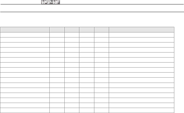
Chapter 4 Parameters|
4-86 Revision August 2008, 03VE, SW V2.04
Settings 0 to 65535
Please refer to the explanation of Pr.02-00 to Pr.02-06.
MI4 MI3 MI2 MI1
Pr.10-19 setting 0 0 0 0 Master frequency
04-15 multi-position 1 0 0 0 1 04-00 1st step speed frequency
04-16 multi-position2 0 0 1 0 04-01 2nd step speed frequency
04-17 multi-position 3 0 0 1 1 04-02 3rd step speed frequency
04-18 multi-position 4 0 1 0 0 04-03 4th step speed frequency
04-19 multi-position 5 0 1 0 1 04-04 5th step speed frequency
04-20 multi-position 6 0 1 1 0 04-05 6th step speed frequency
04-21 multi-position 7 0 1 1 1 04-06 7th step speed frequency
04-22 multi-position 8 1 0 0 0 04-07 8th step speed frequency
04-23 multi-position 9 1 0 0 1 04-08 9th step speed frequency
04-24 multi-position 10 1 0 1 0 04-09 10th step speed frequency
04-25 multi-position 11 1 0 1 1 04-10 11th step speed frequency
04-26 multi-position 12 1 1 0 0 04-11 12th step speed frequency
04-27 multi-position 13 1 1 0 1 04-12 13th step speed frequency
04-28 multi-position 14 1 1 1 0 04-13 14th step speed frequency
04-29 multi-position 15 1 1 1 1 04-14 15th step speed frequency

Chapter 4 Parameters|
Revision August 2008, 03VE, SW V2.04 4-87
Group 5 Motor Parameters
05-00 Motor Auto Tuning
Control
mode SVC FOCPG TQRPG
Factory setting: 0
Settings 0 No function
1 Rolling test
2 Static Test
3 Reserved
Starting auto tuning by pressing RUN key and it will write the measure value into Pr.05-05 to
Pr.05-09 for motor 1 and Pr.05-17 to Pr.05-21 for motor 2.
The steps to AUTO-Tuning are: (when setting to 1)
1. Make sure that all the parameters are set to factory settings and the motor wiring is
correct.
2. Make sure the motor has no-load before executing auto-tuning and the shaft is not
connected to any belt or gear motor. It is recommended to set to 2 or 3 if the motor can’t
separate from the load.
3. Motor 1: fill in Pr.01-02, Pr.01-01, Pr.05-01, Pr.05-02, Pr.05-03 and Pr.05-04 with correct
values. Refer to motor capacity to set accel./decel. time.
Motor 2: fill in Pr.01-36, Pr.01-35, Pr.05-13, Pr.05-14, Pr.05-15 and Pr.05-16 with correct
values. Refer to motor capacity to set accel./decel. time.
4. When Pr.05-00 is set to 1, the AC motor drive will execute auto-tuning immediately after
receiving a “RUN” command. (NOTE: the motor will run!)
5. After executing, please check if there are values filled in Pr.05-05 to Pr.05-09 for motor 1
and Pr.05-17 to Pr.05-21 for motor 2.
If Pr.05-00 is set to 2, it needs to input Pr.05-05 for motor 1/Pr.05-17 for motor 2.
NOTE
1. In torque/vector control mode, it is not recommended to have motors run in parallel.
2. It is not recommended to use torque/vector control mode if motor rated power exceeds the
rated power of the AC motor drive.
3. When tuning 2 motors, it needs to set multi-function input terminals or change Pr.05-10 for
motor 1/motor 2 selection.
4. The no-load current is usually 20~50% X rated current.
5. The rated speed can’t be larger or equal to 120f/p.

Chapter 4 Parameters|
4-88 Revision August 2008, 03VE, SW V2.04
05-01 Full-load Current of Motor 1
Control
mode VF VFPG SVC FOCPG TQRPG Factory setting: #.##
Settings 40 to 100%
This value should be set according to the rated frequency of the motor as indicated on the
motor nameplate. The factory setting is 90% X rated current.
Example: The rated current for 7.5HP (5.5kW) is 25 and factory setting is 22.5A. The range for
setting will be 10~30A.(25*40%=10 and 25*120%=30)
05-02 Rated Power of Motor 1 Unit: 0.01
Control
mode SVC FOCPG TQRPG
Factory setting: #.##
Settings 0 to 655.35 kW
It is used to set rated power of the motor 1. The factory setting is the power of the drive.
05-03 Rated Speed of Motor 1 (rpm) Unit: 1
Control
mode VFPG SVC FOCPG TQRPG Factory setting: 1710 (60Hz, 4 poles)
1410 (50Hz, 4 poles)
Settings 0 to 65535
It is used to set the rated speed of the motor and need to set according to the value indicated
on the motor nameplate.
05-04 Number of Motor Poles 1
Control
mode VF VFPG SVC FOCPG TQRPG Factory setting: 4
Settings 2 to 20
It is used to set the number of motor poles (must be an even number).
05-05 No-load Current of Motor 1 Unit: Amp
Control
mode VFPG SVC FOCPG TQRPG Factory setting: #.##
Settings 0 to factory setting of Pr.05-01
The factory setting is 40% X rated current.

Chapter 4 Parameters|
Revision August 2008, 03VE, SW V2.04 4-89
05-06 Rotor Resistance R1 of Motor 1 Unit: 0.001
05-07 Rr of Motor 1 Unit: 0.001
Control
mode SVC FOCPG TQRPG
Factory setting: #.###
Settings
0~65.535Ω
05-08 Lm of Motor 1 Unit: 0.1
05-09 Lx of Motor 1 Unit: 0.1
Control
mode SVC FOCPG TQRPG
Factory setting: #.#
Settings 0~6553.5mH
05-10 Motor 1/Motor 2 Selection
Control
mode VF VFPG SVC FOCPG TQRPG Factory setting: 1
Settings 1 Motor 1
2 Motor 2
It is used to set the motor that driven by the AC motor drive.
05-11 Frequency for Y-connection/ Δ−connection Switch Unit: 0.01
Control
mode VF VFPG SVC FOCPG TQRPG Factory setting: 60.00
Settings 0.00 to 600.00Hz
05-12 Y-connection /Δ−connection Switch
Control
mode VF VFPG SVC FOCPG TQRPG Factory setting: 0
Settings 0 Disable
1 Enable
05-30 Delay Time for Y-connection/Δ −connection Unit: 0.001
Control
mode VF VFPG SVC FOCPG Factory setting: 0.200
Settings 0 to 60.000
Pr.05-12 is used to enable/disable Y-connection/ Δ−connection Switch.
When Pr.05-12 is set to 1, the drive will select by Pr.05-11 setting and current motor frequency
to switch motor to Y-connection or Δ−connection. AT the same time, it will also affect motor
parameters (Pr.05-01 to 05-10/Pr.05-13 to Pr.05-21).
Pr.05-30 is used to set the switch delay time of Y-connection/Δ −connection.
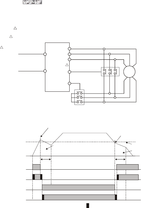
Chapter 4 Parameters|
4-90 Revision August 2008, 03VE, SW V2.04
When output frequency reaches Y-connection/Δ −connection switch frequency, drive will delay
by Pr.05-30 before multi-function output terminals are active.
Y- connection switch: can be used for wide range motor
Y connection for low speed: higher torque can be used for rigid tapping
U
V
W
MI1
MI2 RA
MRA
Pr.02-01~06=30
Pr.02-01~06=29 Pr.02-11~14=32
Pr.02-11~14=31
IM
UVW
XY Z
connection for high speed: higher torque can be used for high-speed drilling
connection is finished
Y-connection is finished connection control
Y connection control
Y-connection
confirmation input
Pr.05-11
Y- switch
frequency
△
Y-connection output
Y-conenction
confirmation input
△
-connection output
Pr.02-11~14=32
△
-connection
confirmation input
Pr.02-11~14=30
ON ON
Pr.02-11~14=31
ON
Pr.02-11~14=29
ON
ON
ON
If switch point is 60Hz,
the accel. switch point is 62Hz
Motor speed/
frequency
Bandwidth is 2Hz
:
mechanical bounce time
Decel. switch point is 58Hz
In this area, motor is in free
run status. AC motor drive
stops outputting. Motor speed will
decrease
by load inertia.
Pr. 05-30 Delay Time for Y-connection
/D -connection(Min. is 0.2 seconds)
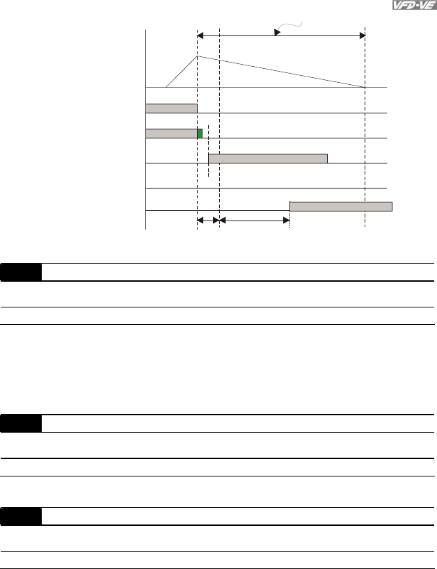
Chapter 4 Parameters|
Revision August 2008, 03VE, SW V2.04 4-91
Y-connection output
Pr.02-11~14=31
Y-connection
confirmation input
Pr.02-01~06=29
△
-connection output
Pr.02-11~14=32
△
-connection
confirmation input
Pr.02-01~06=30
ON
ON
ON
ON
2 seconds
Y- s wi t ch e rro r
frequency
△
free run status
output
frequency
delay time
Pr.05-30
05-13 Full-load Current of Motor 2 Unit: 1%
Control
mode VF VFPG SVC FOCPG TQRPG Factory setting: #.##
Settings 40 to 100%
This value should be set according to the rated frequency of the motor as indicated on the
motor nameplate. The factory setting is 90% X rated current.
Example: The rated current for 7.5HP (5.5kW) is 25 and factory setting is 22.5A. The range for
setting will be 10~30A.(25*40%=10 and 25*120%=30)
05-14 Rated Power of Motor 2 Unit: 0.01
Control
mode SVC FOCPG TQRPG
Factory setting: #.##
Settings 0 to 655.35
It is used to set rated power of the motor 2. The factory setting is the power of the drive.
05-15 Rated Speed of Motor 2 (rpm) Unit: 1
Control
mode VFPG SVC FOCPG TQRPG Factory setting: 1710
Settings 0 to 65535
It is used to set the rated speed of the motor and need to set according to the value indicated
on the motor nameplate.

Chapter 4 Parameters|
4-92 Revision August 2008, 03VE, SW V2.04
05-16 Number of Motor Poles 2
Control
mode VF VFPG SVC FOCPG TQRPG Factory setting: 4
Settings 2 to 20
It is used to set the number of motor poles (must be an even number).
05-17 No-load Current of Motor 2 Unit: Amp
Control
mode VFPG SVC FOCPG TQRPG Factory setting: #.##
Settings 0 to factory setting of Pr.05-01
The factory setting is 40% X rated current.
05-18 Rotor Resistance R1 of Motor 2 Unit: 0.001
05-19 Rr of Motor 2 Unit: 0.001
Control
mode SVC FOCPG TQRPG
Factory setting: #.###
Settings
0~65.535Ω
05-20 Lm of Motor 2 Unit: 0.1
05-21 Lx of Motor 2 Unit: 0.1
Control
mode SVC FOCPG TQRPG
Factory setting: #.#
Settings 0~6553.5mH
It will have different setting by the rated current.
05-22 Torque Compensation Time Constant Unit: 0.001
Control
mode VF VFPG SVC
Factory setting: 0.020
Settings 0.001 to 10.000 sec
05-23 Slip Compensation Time Constant Unit: 0.001
Control
mode VFPG SVC
Factory setting: 0.100
Settings 0.001 to 10.000 sec
Setting Pr.05-22 and Pr.05-23 change the response time for the compensation.
When Pr.05-22 and Pr.05-23 are set to 10.00 seconds, its response time for the compensation
will be the longest. But if the settings are too short, unstable system may occur.

Chapter 4 Parameters|
Revision August 2008, 03VE, SW V2.04 4-93
05-24 Torque Compensation Gain Unit: 1
Control
mode VF VFPG
Factory setting: 0
Settings 0 to10
This parameter may be set so that the AC motor drive will increase its voltage output to obtain
a higher torque. Only to be used for SVC control mode.
Too high torque compensation can overheat the motor.
05-25 Slip Compensation Gain Unit: 0.01
Control
mode VF SVC
Factory setting: 0.00
Settings 0.00 to10.00
When the asynchronous motor is driven by the drive, the load and slip will be increased. This
parameter can be used to correct frequency and lower the slip to make the motor can run near
the synchronous speed under rated current. When the output current is larger than the motor
no-load current, the drive will compensate the frequency by Pr.05-25 setting. If the actual
speed is slower than expectation, please increase the setting and vice versa.
It is only valid in SVC/VF mode.
The factory settings are:
A. In SVC mode, the factory setting is 1.00.
B. In VF mode, the factory setting is 0.00.
05-26 Slip Deviation Level Unit: 1
Control
mode VFPG SVC FOCPG
Factory setting: 0
Settings 0 to 1000% (0: disable)
05-27 Detection time of Slip Deviation Unit: 0.1
Control
mode VFPG SVC FOCPG
Factory setting: 1.0
Settings 0.0 to 10.0 sec
05-28 Over Slip Treatment
Control
mode VFPG SVC FOCPG
Factory setting: 0
Settings 0 Warn and keep operation
1 Warn and ramp to stop
2 Warn and coast to stop

Chapter 4 Parameters|
4-94 Revision August 2008, 03VE, SW V2.04
Pr.05-26 to Pr.05-28 are used to set allowable slip level/time and over slip treatment when the
drive is running.
05-29 Hunting Gain Unit: 1
Control
mode VF VFPG SVC
Factory setting: 2000
Settings 0 to 10000 (0: disable)
The motor will have current wave motion in some specific area. It can improve this situation by
setting this parameter. (When it is high frequency or run with PG, Pr.05-29 can be set to 0.
when the current wave motion happens in the low frequency, please increase Pr.05-29.)
05-31 Accumulative Motor Operation Time (Min.) Unit: 1
Control
mode VF VFPG SVC FOCPG TQRPG Factory setting: 00
Settings 00 to1439
05-32 Accumulative Motor Operation Time (Day) Unit: 1
Control
mode VF VFPG SVC FOCPG TQRPG Factory setting: 00
Settings 00 to 65535
Pr. 05-31 and Pr.05-32 are used to record the motor operation time. They can be cleared by
setting to 00 and time won’t be recorded when it is less than 60 seconds.
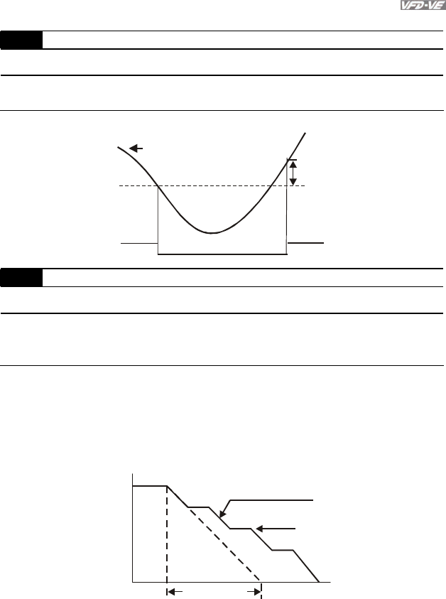
Chapter 4 Parameters|
Revision August 2008, 03VE, SW V2.04 4-95
Group 6 Protection Parameters
06-00 Low Voltage Level Unit: 0.1
Control
mode VF VFPG SVC FOCPG TQRPG
Settings 230V series 160.0~220.0Vdc Factory Setting: 180.0
460V series 320.0~440.0Vdc Factory Setting: 360.0
It is used to set the Lv level.
LV
Pr. 06-00
30V(60V)
input voltage
06-01 Over-Voltage Stall Prevention Unit: 0.1
Control
mode VF VFPG SVC FOCPG TQRPG
Settings 230V series 350.0~450.0Vdc Factory Setting: 380.0
460V series 700.0~900.0Vdc Factory Setting: 760.0
0.0: disable (when brake resistor used)
During deceleration, the DC bus voltage may exceed its Maximum Allowable Value due to
motor regeneration. When this function is enabled, the AC motor drive will not decelerate
further and keep the output frequency constant until the voltage drops below the preset value
again.
output
frequency
Deceleration characteristic
when Over-Voltage Stall
Prevention enabled
Frequency Held
time
previous
deceleration time
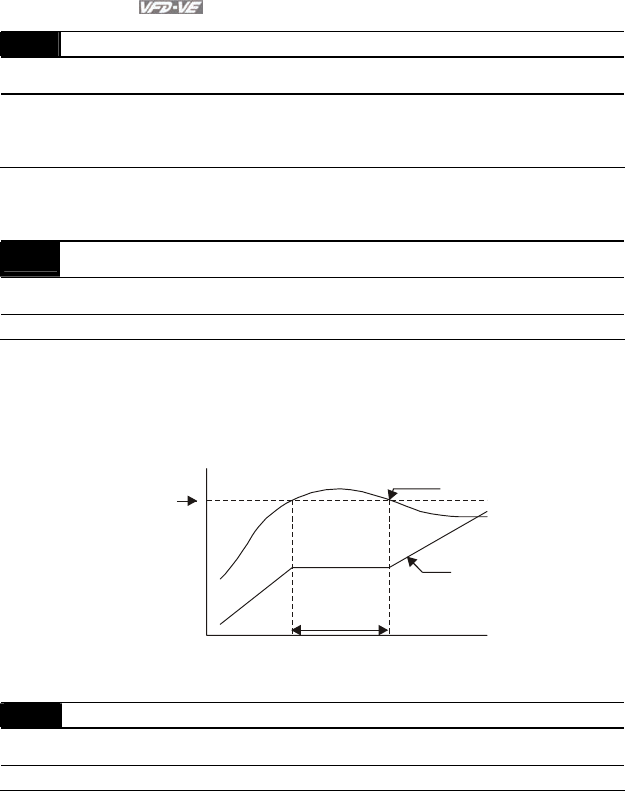
Chapter 4 Parameters|
4-96 Revision August 2008, 03VE, SW V2.04
06-02 Phase-loss Protection
Control
mode VF VFPG SVC FOCPG TQRPG Factory Setting: 0
Settings 0 Warn and keep operation
1 Warn and ramp to stop
2 Warn and coast to stop
It is used to set the phase-loss treatment. The phase-loss will effect driver’s control
characteristic and life.
06-03 Over-Current Stall Prevention during Acceleration Unit: 1
Control
mode VF VFPG SVC
Factory Setting: 170
Settings 00~250%
During acceleration, the AC drive output current may increase abruptly and exceed the value
specified by Pr.06-03 due to rapid acceleration or excessive load on the motor. When this
function is enabled, the AC drive will stop accelerating and keep the output frequency constant
until the current drops below the maximum value.
06-03
Over-Current
Detection
Level
Output
Frequency
Over-Current Stall
prevention during
Acceleration,
frequency held
time
actual acceleration time when over-current stall
prevention is enabled
current
06-04 Over-current Stall Prevention during Operation Unit: 1
Control
mode VF VFPG SVC
Factory Setting: 170
Settings 00 to 250%
If the output current exceeds the setting specified in Pr.06-04 when the drive is operating, the
drive will decrease its output frequency to prevent the motor stall. If the output current is lower
than the setting specified in Pr.06-04, the drive will accelerate again to catch up with the set
frequency command value.
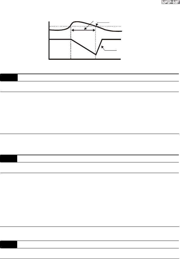
Chapter 4 Parameters|
Revision August 2008, 03VE, SW V2.04 4-97
Over-Current
Detection Level
06-04 Output Current
Output
Frequency
Over-Current Stall
Prevention during
Operation, output
frequency decrease
over-current stall prevention during operation
Time
06-05 Accel./Decel. Time Selection of Stall Prevention at Constant Speed
Control
mode VF VFPG SVC
Factory Setting: 0
Settings 0 by current accel/decel. time
1 by the 1st accel/decel. time
2 by the 2nd accel/decel. time
3 by the 3rd accel/decel. time
4 by the 4th accel/decel. time
5 by auto accel/decel. time
It is used to set the accel./decel. Time selection when stall prevention occurs at constant
speed.
06-06 Over-torque Detection Selection (OT1)
Control
mode VF VFPG SVC FOCPG TQRPG Factory Setting: 0
Settings 0 Over-Torque detection disabled.
1 Over-torque detection during constant speed operation, continue to
operate after detection
2 Over-torque detection during constant speed operation, stop
operation after detection
3 Over-torque detection during operation, continue to operate after
detection
4 Over-torque detection during operation, stop operation after
detection
06-07 Over-torque Detection Level (OT1) Unit: 1
Control
mode VF VFPG SVC FOCPG TQRPG Factory Setting: 150
Chapter 4 Parameters|
4-98 Revision August 2008, 03VE, SW V2.04
Settings 10 to 250%
06-08 Over-torque Detection Time (OT1) Unit: 0.1
Control
mode VF VFPG SVC FOCPG TQRPG Factory Setting: 0.1
Settings 0.0 to 60.0 sec
06-09 Over-torque Detection Selection (OT2)
Control
mode VF VFPG SVC FOCPG TQRPG Factory Setting: 0
Settings 0 Over-Torque detection disabled.
1 Over-torque detection during constant speed operation, continue to
operate after detection
2 Over-torque detection during constant speed operation, stop
operation after detection
3 Over-torque detection during operation, continue to operate after
detection
4 Over-torque detection during operation, stop operation after
detection
06-10 Over-torque Detection Level (OT2) Unit: 1
Control
mode VF VFPG SVC FOCPG TQRPG Factory Setting: 150
Settings 10 to 250%
06-11 Over-torque Detection Time (OT2) Unit: 0.1
Control
mode VF VFPG SVC FOCPG TQRPG Factory Setting: 0.1
Settings 0.0 to 60.0 sec
Pr.06-06 and Pr.06-09 determine the operation mode of the drive after the over-torque is
detected via the following method: if the output current exceeds the over-torque detection level
(Pr.06-19) and also exceeds the Pr.06-08 Over-Torque Detection Time, the fault code
“OT1/OT2” is displayed. If a Multi-Functional Output Terminal is to over-torque detection, the
output is on. Please refer to Pr.02-11~02-14 for details.
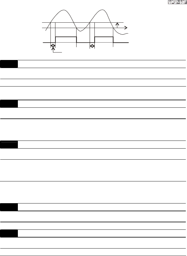
Chapter 4 Parameters|
Revision August 2008, 03VE, SW V2.04 4-99
5%
Pr.06-07,
Pr.06-10
Pr.06-08, 06-11
current
06-12 Current Limit Unit: 1
Control
mode FOCPG TQRPG
Factory Setting: 150
Settings 0 to 250%
It is used to set the current limit.
06-13 Electronic Thermal Relay Selection (Motor 1)
Control
mode VF VFPG SVC FOCPG TQRPG Factory Setting: 2
Settings 0 Operate with a Inverter Motor (forced external cooling)
1 Operate with a Standard Motor (self-cooled by fan)
2 Disabled
06-27 Electronic Thermal Relay Selection (Motor 2)
Control
mode VF VFPG SVC FOCPG TQRPG Factory Setting: 2
Settings 0 Operate with a Inverter Motor (forced external cooling)
1 Operate with a Standard Motor (self-cooled by fan)
2 Disabled
It is used to prevent self-cooled motor overheats under low speed. User can use electrical
thermal relay to limit driver’s output power.
06-14 Electronic Thermal Characteristic for Motor 1 Unit: 0.1
Control
mode VF VFPG SVC FOCPG TQRPG Factory Setting: 60.0
Settings 30.0 to 600.0 sec
06-28 Electronic Thermal Characteristic for Motor 2 Unit: 0.1
Control
mode VF VFPG SVC FOCPG TQRPG Factory Setting: 60.0
Settings 30.0 to 600.0 sec
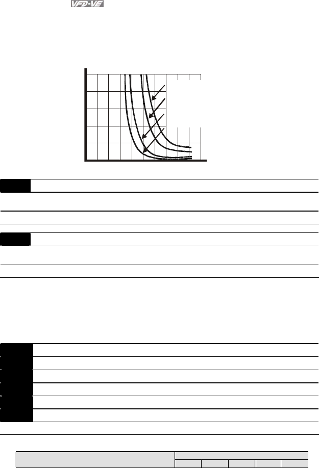
Chapter 4 Parameters|
4-100 Revision August 2008, 03VE, SW V2.04
The parameter is set by the output frequency, current and operation time of the drive for
activating the I2t electronic thermal protection function. The function will be activated for the
150% * setting current for the setting of Pr.06-14/Pr.06-28.
1
2
3
4
5
0 20 40 60 80100120140160180200
Operation
time(min)
Load
factor (%)
60Hz or more
50Hz
10Hz
5Hz
06-15 Heat Sink Over-heat (OH) Warning Unit: 0.1
Control
mode VF VFPG SVC FOCPG TQRPG Factory Setting: 85.0
Settings 0.0 to 110.0
oC
06-16 Stall Prevention Limit Level Unit: 1
Control
mode VF VFPG SVC
Factory Setting: 50
Settings 0 to 100% (refer to Pr.06-03, Pr.06-04)
When operation frequency is larger than Pr.01-01, Pr06-03=150%, Pr. 06-04=100% and Pr.
06-28=80%:
Stall Prevention Level during acceleration = 06-03x06-28=150x80%=120%.
Stall Prevention Level at constant speed= 06-03x06-28=100x80%=80%.
06-17 Present Fault Record
06-18 Second Most Recent Fault Record
06-19 Third Most Recent Fault Record
06-20 Fourth Recent Fault Record
06-21 Fifth Most Recent Fault Record
06-22 Sixth Most Recent Fault Record
Settings 0 to 65 Factory Setting: 0
Control Mode
Settings VF VFPG SVC FOCPG TQRPG

Chapter 4 Parameters|
Revision August 2008, 03VE, SW V2.04 4-101
Control Mode
Settings VF VFPG SVC FOCPG TQRPG
0: No fault ○ ○ ○ ○ ○
1: Over-current during acceleration (ocA) ○ ○ ○ ○ ○
2: Over-current during deceleration (ocd) ○ ○ ○ ○ ○
3: Over-current during constant speed (ocn) ○ ○ ○ ○ ○
4: Ground fault (GFF) ○ ○ ○ ○ ○
5: IGBT short-circuit (occ) ○ ○ ○ ○ ○
6: Over-curent at stop (ocS) ○ ○ ○ ○ ○
7: Over-voltage during acceleration (ovA) ○ ○ ○ ○ ○
8: Over-voltage during deceleration (ovd) ○ ○ ○ ○ ○
9: Over-voltage during constant speed (ovn) ○ ○ ○ ○ ○
10: Over-voltage at stop (ovS) ○ ○ ○ ○ ○
11: Low-voltage during acceleration (LvA) ○ ○ ○ ○ ○
12: Low-voltage during deceleration (Lvd) ○ ○ ○ ○ ○
13: Low-voltage during constant speed (Lvn) ○ ○ ○ ○ ○
14: Low-voltage at stop (LvS) ○ ○ ○ ○ ○
15: Phase loss (PHL) ○ ○ ○ ○ ○
16: IGBT heat sink over-heat (oH1) ○ ○ ○ ○ ○
17: Heat sink over-heat (oH2)(for 40HP above) ○ ○ ○ ○ ○
18: TH1 open loop error (tH1o) ○ ○ ○ ○ ○
19: TH2 open loop error (tH2o) ○ ○ ○ ○ ○
20: Fan error signal output ○ ○ ○ ○ ○
21: over-load (oL) (150% 1Min) ○ ○ ○ ○ ○
22: Motor 1 over-load (EoL1) ○ ○ ○ ○ ○
23: Motor 2 over-load (EoL2) ○ ○ ○ ○ ○
24: Motor PTC overheat (oH3) ○ ○ ○ ○ ○
25: Fuse error (FuSE) ○ ○ ○ ○ ○
26: over-torque 1 (ot1) ○ ○ ○ ○ ○
27: over-torque 1 (ot2) ○ ○ ○ ○ ○
28: Reserved
29: Reserved
30: Memory write-in error (cF1) ○ ○ ○ ○ ○
31: Memory read-out error (cF2) ○ ○ ○ ○ ○
32: Isum current detection error (cd0) ○ ○ ○ ○ ○
33: U-phase current detection error (cd1) ○ ○ ○ ○ ○
34: V-phase current detection error (cd2) ○ ○ ○ ○ ○
35: W-phase current detection error (cd3) ○ ○ ○ ○ ○
36: Clamp current detection error (Hd0) ○ ○ ○ ○ ○
37: Over-current detection error (Hd1) ○ ○ ○ ○ ○
38: Over-voltage detection error (Hd2) ○ ○ ○ ○ ○
39: Ground current detection error (Hd3) ○ ○ ○ ○ ○
40: Auto tuning error (AuE) ○ ○ ○
41: PID feedback loss (AFE) ○ ○ ○ ○ ○
42: PG feedback error (PGF1) ○ ○ ○
43: PG feedback loss (PGF2) ○ ○ ○
44: PG feedback stall (PGF3) ○ ○
45: PG slip error (PGF4) ○ ○
46: PG ref input error (PGr1) ○ ○ ○ ○ ○
47: PG ref loss (PGr2) ○ ○ ○ ○ ○
48: Analog current input loss (ACE) ○ ○ ○ ○ ○
49: External fault input (EF) ○ ○ ○ ○ ○
50: Emergency stop (EF1) ○ ○ ○ ○ ○
51: External Base Block (B.B.) ○ ○ ○ ○ ○
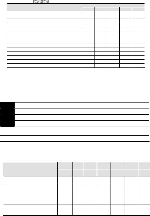
Chapter 4 Parameters|
4-102 Revision August 2008, 03VE, SW V2.04
Control Mode
Settings VF VFPG SVC FOCPG TQRPG
52: Password error (PcodE) ○ ○ ○ ○ ○
53: Reserved
54: Communication error (cE1) ○ ○ ○ ○ ○
55: Communication error (cE2) ○ ○ ○ ○ ○
56: Communication error (cE3) ○ ○ ○ ○ ○
57: Communication error (cE4) ○ ○ ○ ○ ○
58: Communication Time-out (cE10) ○ ○ ○ ○ ○
59: PU time-out (cP10) ○ ○ ○ ○ ○
60: Brake transistor error (bF) ○ ○ ○ ○ ○
61: Y-connection/Δ-connection switch error (ydc) ○ ○ ○ ○
62: Decel. Energy Backup Error (dEb) ○ ○ ○ ○ ○
63: Slip error (oSL) ○ ○ ○ ○
64: Broken belt error (bEb) ○ ○ ○ ○ ○
65: Error PID feedback signal of tension (tdEv) ○ ○ ○ ○ ○
It will record when the fault occurs and force stopping. For the Lv, it will record when it is
operation, or it will warn without record.
Setting 62: when DEB function is enabled, the drive will execute DEB and record to the Pr.06-
17 to Pr.06-22 simultaneously.
06-23 Fault Output Option 1 Unit: 1
06-24 Fault Output Option 2 Unit: 1
06-25 Fault Output Option 3 Unit: 1
06-26 Fault Output Option 4 Unit: 1
Control
mode VF VFPG SVC FOCPG TQRPG Factory Setting: 0
Settings 0 to 65535 sec (refer to bit table for fault code)
These parameters can be used with multi-function output (set Pr.02-11 to Pr.02-14 to 35-38)
for the specific requirement. When the fault occurs, the corresponding terminals will be
activated (It needs to convert binary value to decimal value to fill in Pr.06-23 to Pr.06-26).
Bit0 Bit1 Bit2 Bit3 Bit4 Bit5 Bit6
Fault code
current Volt. OL SYS FBK EXI CE
0: No fault
1: Over-current during acceleration
(ocA)
●
2: Over-current during deceleration
(ocd)
●
3: Over-current during constant
speed (ocn)
●

Chapter 4 Parameters|
Revision August 2008, 03VE, SW V2.04 4-103
Bit0 Bit1 Bit2 Bit3 Bit4 Bit5 Bit6
Fault code
current Volt. OL SYS FBK EXI CE
4: Ground fault (GFF)
●
5: IGBT short-circuit (occ) ●
6: Over-curent at stop (ocS) ●
7: Over-voltage during acceleration
(ovA)
●
8: Over-voltage during deceleration
(ovd)
●
9: Over-voltage during constant
speed (ovn)
●
10: Over-voltage at stop (ovS) ●
11: Low-voltage during
acceleration (LvA)
●
12: Low-voltage during
deceleration (Lvd)
●
13: Low-voltage during constant
speed (Lvn)
●
14: Low-voltage at stop (LvS) ●
15: Phase loss (PHL)
●
16: IGBT heat sink over-heat (oH1)
●
17: Heat sink over-heat (oH2)(for
40HP above)
●
18: TH1 open loop error (tH1o)
●
19: TH2 open loop error (tH2o)
●
20: Fan error signal output
●
21: over-load (oL) (150% 1Min)
●
22: Motor 1 over-load (EoL1)
●
23: Motor 2 over-load (EoL2)
●
24: Motor PTC overheat (oH3)
●
25: Fuse error (FuSE)
●
26: over-torque 1 (ot1)
●

Chapter 4 Parameters|
4-104 Revision August 2008, 03VE, SW V2.04
Bit0 Bit1 Bit2 Bit3 Bit4 Bit5 Bit6
Fault code
current Volt. OL SYS FBK EXI CE
27: over-torque 1 (ot2)
●
28: Reserved
29: Reserved
30: Memory write-in error (cF1)
●
31: Memory read-out error (cF2)
●
32: Isum current detection error
(cd0)
●
33: U-phase current detection error
(cd1)
●
34: V-phase current detection error
(cd2)
●
35: W-phase current detection
error (cd3)
●
36: Clamp current detection error
(Hd0)
●
37: Over-current detection error
(Hd1)
●
38: Over-voltage detection error
(Hd2)
●
39: Ground current detection error
(Hd3)
●
40: Auto tuning error (AuE)
●
41: PID feedback loss (AFE)
●
42: PG feedback error (PGF1)
●
43: PG feedback loss (PGF2)
●
44: PG feedback stall (PGF3)
●
45: PG slip error (PGF4)
●
46: PG ref input error (PGr1)
●
47: PG ref loss (PGr2)
●
48: Analog current input loss
(ACE)
●
49: External fault input (EF)
●

Chapter 4 Parameters|
Revision August 2008, 03VE, SW V2.04 4-105
Bit0 Bit1 Bit2 Bit3 Bit4 Bit5 Bit6
Fault code
current Volt. OL SYS FBK EXI CE
50: Emergency stop (EF1)
●
51: External Base Block (B.B.)
●
52: Password error (PcodE)
●
53: Reserved
54: Communication error (cE1)
●
55: Communication error (cE2)
●
56: Communication error (cE3)
●
57: Communication error (cE4)
●
58: Communication Time-out
(cE10)
●
59: PU time-out (cP10)
●
60: Brake transistor error (bF)
●
61: Y-connection/Δ-connection
switch error (ydc)
●
62: Decel. Energy Backup Error
(dEb)
●
63: Slip error (oSL)
●
64: Broken belt error (bEb)
●
65: Error PID feedback signal of
tension (tdEv)
●
06-29 PTC (Positive Temperature Coefficient) Detection Selection
Control
mode VF VFPG SVC FOCPG TQRPG Factory Setting: 0
Settings 0 Warn and keep operating
1 Warn and ramp to stop
2 Warn and coast to stop
It is used to set the treatment after detecting PTC.
06-30 PTC Level Unit: 0.1
Control
mode VF VFPG SVC FOCPG TQRPG Factory Setting: 50.0

Chapter 4 Parameters|
4-106 Revision August 2008, 03VE, SW V2.04
Settings 0.0 to 100.0%
It is used to set the PTC level, and the corresponding value for 100% is max. analog input
value.
06-31 Filter Time for PTC Detection Unit: 0.01
Control
mode VF VFPG SVC FOCPG TQRPG Factory Setting: 0.20
Settings 0.00 to 10.00 sec
06-32 Output Frequency for Malfunction Unit: 0.01
Control
mode VF VFPG SVC FOCPG TQRPG Factory Setting: 0.00
Settings 0.00 to 655.35 Hz
06-33 Output AC Voltage for Malfunction Unit: 0.1
Control
mode VF VFPG SVC FOCPG TQRPG Factory Setting: 0.0
Settings 0.0~6553.5 V
06-34 DC Voltage for Malfunction Unit: 0.1
Control
mode VF VFPG SVC FOCPG TQRPG Factory Setting: 0.0
Settings 0.0~6553.5 V
06-35 Current Value for Malfunction Unit: 0.01
Control
mode VF VFPG SVC FOCPG TQRPG Factory Setting: 0.00
Settings 0.00~655.35 Amp
06-36 IGBT Temperature for Malfunction Unit: 0.1
Control
mode VF VFPG SVC FOCPG TQRPG Factory Setting: 0.0
Settings 0.0~6553.5 °C

Chapter 4 Parameters|
Revision August 2008, 03VE, SW V2.04 4-107
Group 7 Special Parameters
07-00 Software Brake Level Unit: 0.1
Control
mode VF VFPG SVC FOCPG TQRPG
Settings 230V series 350.0~450.0Vdc Factory Setting: 380.0
460V series 700.0~900.0Vdc Factory Setting: 760.0
This parameter sets the DC-bus voltage at which the brake chopper is activated.
07-01 DC Brake Current Level Unit: 1
Control
mode VF VFPG SVC FOCPG TQRPG Factory Setting: 0
Settings 0 to 100%
This parameter sets the level of DC Brake Current output to the motor during start-up and
stopping. When setting DC Brake Current, the Rated Current (Pr.00-01) is regarded as 100%.
It is recommended to start with a low DC Brake Current Level and then increase until proper
holding torque has been attained.
When it is in FOCPG/TQRPG mode, it can enable DC brake function by setting to any value.
07-02 DC Brake Time during Start-up Unit: 0.1
Control
mode VF VFPG SVC FOCPG TQRPG Factory Setting: 0.0
Settings 0.0 to 60.0 sec
This parameter determines the duration of the DC Brake current after a RUN command. When
the time has elapsed, the AC motor drive will start accelerating from the Minimum Frequency
(Pr.01-05).
07-03 DC Brake Time during Stopping Unit: 0.01
Control
mode VF VFPG SVC FOCPG TQRPG Factory Setting: 0.00
Settings 0.00 to 60.00 sec
This parameter determines the duration of the DC Brake current during stopping.
07-04 Start-Point for DC Brake Unit: 0.01
Control
mode VF VFPG SVC TQRPG Factory Setting: 0.00
Settings 0.00 to 600.00Hz
This parameter determines the frequency when DC Brake will begin during deceleration.
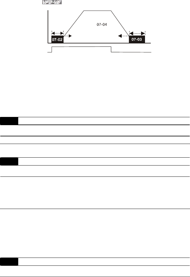
Chapter 4 Parameters|
4-108 Revision August 2008, 03VE, SW V2.04
ON OFF
01-09
Output frequency
Run/Stop Time
DC Braking Time
DC Braking Time
during Stopping
Minimum
output
frequency
Start-point for
DC braking
time during
stopping
DC Brake during Start-up is used for loads that may move before the AC drive starts, such as
fans and pumps. Under such circumstances, DC Brake can be used to hold the load in
position before setting it in motion.
DC Brake during stopping is used to shorten the stopping time and also to hold a stopped load
in position. For high inertia loads, a dynamic brake resistor may also be needed for fast
decelerations.
07-05 DC Brake Proportional Gain Unit: 1
Control
mode VF VFPG SVC
Factory Setting: 50
Settings 1 to 500Hz
It is used to set the output voltage gain when DC brake.
07-06 Momentary Power Loss Operation Selection
Control
mode VF VFPG SVC FOCPG TQRPG Factory Setting: 0
Settings 0 Operation stops after momentary power loss.
1 Operation continues after momentary power loss, speed search
starts with the Master Frequency reference value.
2 Operation continues after momentary power loss, speed search
starts with the minimum frequency.
This parameter determines the operation mode when the AC motor drive restarts from a
momentary power loss.
In PG control mode, the AC motor drive will execute the speed search function automatically
by the PG speed when this setting isn’t set to 0.
07-07 Maximum Allowable Power Loss Time Unit: 0.1
Control
mode VF VFPG SVC FOCPG TQRPG Factory Setting: 2.0
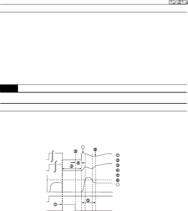
Chapter 4 Parameters|
Revision August 2008, 03VE, SW V2.04 4-109
Settings 0.1 to 5.0 sec
If the duration of a power loss is less than this parameter setting, the AC motor drive will
resume operation. If it exceeds the Maximum Allowable Power Loss Time, the AC motor drive
output is then turned off (coast stop).
The selected operation after power loss in Pr.07-06 is only executed when the maximum
allowable power loss time is ≤5 seconds and the AC motor drive displays “Lu”.
But if the AC motor drive is powered off due to overload, even if the maximum allowable power
loss time is ≤5 seconds, the operation mode as set in Pr.07-06 is not executed. In that case it
starts up normally.
07-08 Baseblock Time for Speed Search (BB) Unit: 0.1
Control
mode VF VFPG SVC FOCPG TQRPG Factory Setting: 0.5
Settings 0.1 to 5.0 sec
When momentary power loss is detected, the AC drive will block its output and then wait for a
specified period of time (determined by Pr.07-08, called Base-Block Time) before resuming
operation. This parameter should be set at a value to ensure that any residual regeneration
voltage from the motor on the output has disappeared before the drive is activated again.
B.B.
A
Output frequency(H)
Output voltage(V)
Output current
07-09
Current Limit for
Speed Search
FWD Run
Time
B.B. Search with last output frequency downward timing chart
Input B.B. signal
Stop output voltage
Disable B.B. signal
Waiting time Pr.07-08
Speed search
Synchronization speed detection
7
7
Frequency command before B.B.
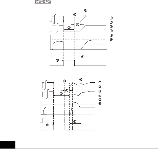
Chapter 4 Parameters|
4-110 Revision August 2008, 03VE, SW V2.04
Time
B.B.
output current A
Input B.B. signal
Stop output voltage
Disable B.B. signal
Waiting time 08.07
Speed Search
Synchronization speed detection
Output frequency
( H)
07-09 Current Limit
for Speed Search Speed
FWD Run
B.B. Search with minimum output frequency upward timing chart
Output voltage
( V)
B.B. Search with minimum output frequency upward timing chart
Output frequency(H)
Output voltage(V)
Output current
06-03
Over-Current Stall
Prevention
during Accel.
FWD Run
Time
Input B.B. signal
Stop voltage output
Disable B.B. signal
Waiting time Pr.07-08
Speed search
Synchronization speed detection
B.B.
A
07-09 Current Limit for Speed Search Unit: 1
Control
mode VF VFPG SVC FOCPG TQRPG Factory Setting: 150
Settings 20 to 200%
Following a momentary power loss, the AC motor drive will start its speed search operation
only if the output current is greater than the value set by Pr.8-07. When the output current is
less than the value of Pr.8-07, the AC motor drive output frequency is at “speed
synchronization point”. The drive will start to accelerate or decelerate back to the operating
frequency at which it was running prior to the power loss.
When executing speed search, the V/f curve is operated by group 1 setting. The maximum
current for the optimum accel./decel. and start speed search is set by Pr.07-09.

Chapter 4 Parameters|
Revision August 2008, 03VE, SW V2.04 4-111
07-10 Base Block Speed Search
Control
mode VF VFPG SVC FOCPG TQRPG Factory Setting: 0
Settings 0 Stop operation
1 Speed search starts with last frequency command
2 Speed search starts with minimum output frequency
This parameter determines the AC motor drive restart method after External Base Block is
enabled.
In PG control mode, the AC motor drive will execute the speed search function automatically
by the PG speed when this setting isn’t set to 0.
07-11 Auto Restart After Fault Unit: 1
Control
mode VF VFPG SVC FOCPG TQRPG Factory Setting: 0
Settings 0 to 10
Only after an over-current OC or over-voltage OV fault occurs, the AC motor drive can be
reset/restarted automatically up to 10 times.
Setting this parameter to 0 will disable the reset/restart operation after any fault has occurred.
When enabled, the AC motor drive will restart with speed search, which starts at the frequency
before the fault. To set the waiting time before restart after a fault, please set Pr. 07-08 Base
Block Time for Speed Search.
07-12 Speed Search during Start-up
Control
mode VF VFPG SVC FOCPG TQRPG Factory Setting: 0
Settings 0 Disable
1 Speed search from maximum frequency
2 Speed search from start-up frequency
3 Speed search from minimum frequency
This parameter is used for starting and stopping a motor with high inertia. A motor with high
inertia will take a long time to stop completely. By setting this parameter, the user does not
need to wait for the motor to come to a complete stop before restarting the AC motor drive. If a
PG card and encoder is used on the drive and motor, then the speed search will start from the
speed that is detected by the encoder and accelerate quickly to the commanded frequency.
The output current is set by the Pr.07-09.

Chapter 4 Parameters|
4-112 Revision August 2008, 03VE, SW V2.04
In PG control mode, the AC motor drive will execute the speed search function automatically
by the PG speed when this setting isn’t set to 0.
07-13 Decel. Time Selection for Momentary Power Loss (DEB function)
Control
mode VF VFPG SVC FOCPG TQRPG Factory Setting: 0
Settings 0 Disable
1 1st decel. time
2 2nd decel. time
3 3rd decel. time
4 4th decel. time
5 Current decel. time
6 Auto decel. time
This parameter is used for the decel. time selection for momentary power loss.
07-14 DEB Return Time Unit: 0.1
Control
mode VF VFPG SVC FOCPG Factory Setting: 0.0
Settings 0.0 to 25.0 sec
The DEB (Deceleration Energy Backup) function is the AC motor drive decelerates to stop
after momentary power loss. When the momentary power loss occurs, this function can be
used for the motor to decelerate to 0 speed with deceleration stop method. When the power is
on again, motor will run again after DEB return time.
Status 1: Insufficient power supply due to momentary power-loss/unstable power (due to low
voltage)/sudden heavy-load
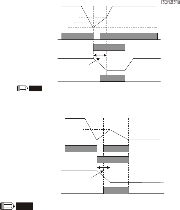
Chapter 4 Parameters|
Revision August 2008, 03VE, SW V2.04 4-113
07-14
NOTE
DC BUS voltage
it doesn't need
multi-function terminals
The level for DEB return time
(Lv=+30V+58V)
Lv level
Soft start relay at
power side
Output frequency
DEB return time
Pr.07-13 Decel. time selection for
momentary power loss
DEB function is activated
The level for soft start relay to be ON
(Lv+30)
When Pr.07-14 is set to 0, the AC motor drive will be stopped and wo n't re-start
at the power-on again.
Status 2: unexpected power off, such as momentary power loss
DC BUS voltage
The level for DEB return time
(Lv=+30V+58V)
Lv level
Soft start relay at
power side
Output frequency
DEB return time
Pr.07-13 Decel. time selection for
momentary power loss
DEB function is activated
The level for soft start relay to be ON
(Lv+30)
07-14
NOTE
For example, in textile machinery, you will hope that all the machines can be decelerated to stop to
prevent broken stitching when power loss. In this case, the host controller will send a message to the
AC motor drive to use DEB function with deceleration time via EF.
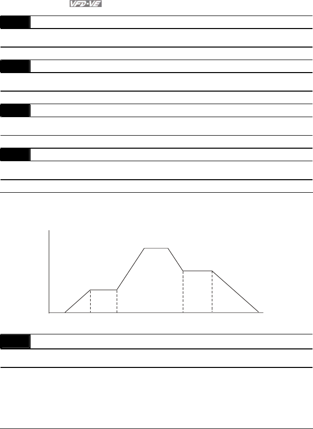
Chapter 4 Parameters|
4-114 Revision August 2008, 03VE, SW V2.04
07-15 Dwell Time at Accel. Unit: 0.01
Control
mode VF VFPG SVC FOCPG Factory Setting: 0.00
Settings 0.00 to 600.00 sec
07-16 Dwell Frequency at Accel. Unit: 0.01
Control
mode VF VFPG SVC FOCPG Factory Setting: 0.00
Settings 0.00 to 600.00 Hz
07-17 Dwell Time at Decel. Unit: 0.01
Control
mode VF VFPG SVC FOCPG Factory Setting: 0.00
Settings 0.00 to 600.00 sec
07-18 Dwell Frequency at Decel. Unit: 0.01
Control
mode VF VFPG SVC FOCPG Factory Setting: 0.00
Settings 0.00 to 600.00 Hz
In the heavy load situation, Dwell can make stable output frequency temporarily.
Pr.07-15 to Pr.07-18 is for heavy load to prevent OV or OC occurs.
Frequency
Time
Dwell at accel./decel.
07-16
Dwell
Frequency
at Accel. 07-15
Dwell Time
at Accel.
07-17
Dwell Time
at Decel.
07-18
Dwell
Frequency
at Decel.
07-19 Fan Control
Control
mode VF VFPG SVC FOCPG TQRPG Factory Setting: 0
Settings 0 Fan always ON
1 1 minute after AC motor drive stops, fan will be OFF
2 AC motor drive runs and fan ON, AC motor drive stops and fan OFF
3 Fan ON to run when preliminary heat sink temperature attained
4 Fan always OFF
This parameter is used for the fan control.

Chapter 4 Parameters|
Revision August 2008, 03VE, SW V2.04 4-115
07-20 Torque Command Unit: 0.1
Control
mode TQRPG
Factory Setting: 0.0
Settings -100.0 to 100.0%
(Pr. 07-22 setting=100%)
This parameter is torque command. When Pr.07-22 is 250% and Pr.07-20 is 100%, the actual
torque command = 250%X100% X motor rated torque.
07-21 Torque Command Source
Control
mode TQRPG
Factory Setting: 0
Settings 0 Digital keypad
1 RS485 serial communication (RJ-11)
2 Analog signal (Pr.03-00)
This parameter is torque command source and the torque command is in Pr.07-20.
07-22 Maximum Torque Command Unit: 1
Control
mode TQRPG
Factory Setting: 100
Settings 0 to 500%
This parameter is for the max. torque command (motor rated torque is 100%).
07-23 Filter Time of Torque Command Unit: 0.001
Control
mode TQRPG
Factory Setting: 0.000
Settings 0.000 to 1.000 sec
When the setting is too long, the control will be stable but the control response will be delay.
When the setting is too short, the response will be quickly but the control maybe unstable.
User can adjust the setting by the control and response situation.
07-24 Speed Limit Selection
Control
mode TQRPG
Factory Setting: 0
Settings 0 By Pr.07-25 and Pr.07-26
1 Frequency command source (Pr.00-20)
Chapter 4 Parameters|
4-116 Revision August 2008, 03VE, SW V2.04
07-26 00-20 07-25
00-20
07-26 07-25
07-24=1 07-24=1
torque torque torque
frequency frequency frequency
Pr.07-24=0
Running/opposite running
direction are
limited by Pr.07-25
and Pr.07-26.
When it is forward running,
running direction is limited
by Pr.00-20
opposite running direction
is limited by Pr.07-26.
When it is reverse running,
running direction is limited
by Pr.07-25
opposite running direction
is limited by Pr.00-20.
07-25 Torque Mode +Speed Limit Unit: 1
07-26 Torque Mode-Speed Limit Unit: 1
Control
mode TQRPG
Factory Setting: 10
Settings 0 to 120%
These parameters are used in the torque mode to limit the running direction and opposite
direction. (Pr.01-00 max. output frequency=100%)
07-27 Source of Torque Offset
Control
mode SVC FOCPG TQRPG
Factory Setting: 0
Settings 0 Disable
1 Analog input (Pr.03-00)
2 Torque offset setting
3 Control by external terminal (by Pr.07-29 to Pr.07-31)
This parameter is the source of torque offset.
When it is set to 3, the source of torque offset will decide to Pr.07-29, Pr.07-30 and Pr.07-31
by the multi-function input terminals setting (31, 32 or 33).
02-01~02-06 is set to 31 02-01~02-06 is set to 32 02-01~02-06 is set to 33 Torque offset
OFF OFF OFF None
OFF OFF ON 07-33
OFF ON OFF 07-32
OFF ON ON 07-33+07-32
ON OFF OFF 07-31
ON OFF ON 07-31+07-33
ON ON OFF 07-31+07-32
ON ON ON 07-31+07-32+07-33

Chapter 4 Parameters|
Revision August 2008, 03VE, SW V2.04 4-117
07-28 Torque Offset Setting Unit: 0.1
Control
mode SVC FOCPG TQRPG
Factory Setting: 0.0
Settings 0.0 to 100.0%
This parameter is torque offset. The motor rated torque is 100%.
07-29 High Torque Offset Unit: 0.1
Control
mode SVC FOCPG TQRPG
Factory Setting: 30.0
Settings 0.0 to 100.0%
07-30 Middle Torque Offset Unit: 0.1
Control
mode SVC FOCPG TQRPG
Factory Setting: 20.0
Settings 0.0 to 100.0%
07-31 Low Torque Offset Unit: 0.1
Control
mode SVC FOCPG TQRPG
Factory Setting: 10.0
Settings 0.0 to 100.0%
When it is set to 3, the source of torque offset will decide to Pr.07-29, Pr.07-30 and Pr.07-31
by the multi-function input terminals setting (31, 32 or 33). The motor rated torque is 100%.
07-32 Forward Motor Torque Limit Unit: 1
07-33 Forward Regenerative Torque Limit Unit: 1
07-34 Reverse Motor Torque Limit Unit: 1
07-35 Reverse Regenerative Torque Limit Unit: 1
Control
mode FOCPG TQRPG
Factory Setting: 200
Settings 0 to 500%
The motor rated torque is 100%. The settings for Pr.07-32 to Pr.07-35 will compare with Pr.03-
00=7, 8, 9, 10. The minimum of the comparison result will be torque limit as shown in the
following figure.
According to the formula of motor rated torque:
)/(
)(
).( sradW
P
MNT
ω
=, where P(ω) is Pr.05-
02 and W(rad/s) is Pr.05-03. srad
RPM /
260 =
×
π
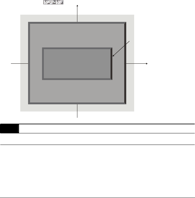
Chapter 4 Parameters|
4-118 Revision August 2008, 03VE, SW V2.04
Positive
torque
Negative
torque
speed
06-12 current limit 06-12 current limit
06-12 current limit 06-12 current limit
Reverse motor mode Forward motor mode
Forward motor mode
Reverse motor mode
The level of torque limit will be
the min. value of following three values
1. torque limit of Pr.07-32 to Pr.07-35
2. Torque limit of external analog terminals
(AVI, ACI and AUI)
3. Pr.06-12 current limit
External analog terminals
Pr.03-00~02
7: positive torque limit
10: positive/negative torque limit
9: regenerative torque limit
External analog terminals
Pr.03-00~02
7: positive torque limit
10: positive/negative torque limit
External analog terminals
Pr.03-00~03-02
8: negative torque limit
10: positive/negative torque limit
External analog terminals
Pr.03-00~03-02
8: negative torque limit
10: positive/negative torque limit
Pr.07-35
Reverse regenerative
torque limit
Pr.07-32
Forward motor
torque limit
Pr.07-33
Forward regenerative
torque limit
Pr.07-34
Reverse motor
torque limit
Quadrant I
Quadrant II
Quadrant III Quadrant IV
speed
07-36 Emergency Stop (EF) & Forced Stop Selection
Control
mode VF VFPG SVC FOCPG TQRPG Factory Setting: 0
Settings 0 Coast stop
1 By deceleration Time 1
2 By deceleration Time 2
3 By deceleration Time 3
4 By deceleration Time 4
5 System Deceleration
6 Automatic Deceleration
When the multi-function input terminal is set to 10 or 18 and it is ON, the AC motor drive will be
operated by Pr.07-36.

Chapter 4 Parameters|
Revision August 2008, 03VE, SW V2.04 4-119
Group 8 High-function PID Parameters
08-00 Input Terminal for PID Feedback
Control
mode VF VFPG SVC FOCPG Factory Setting: 0
Settings 0 No function
1 Negative PID feedback from external terminal AVI (Pr.03-00)
2 Negative PID feedback from PG card (Pr.10-15, skip direction)
3 Negative PID feedback from PG card (Pr.10-15)
4 Positive PID feedback from external terminal AVI (Pr.03-00)
5 Positive PID feedback from PG card (Pr.10-15, skip direction)
6 Positive PID feedback from PG card (Pr.10-15)
Negative feedback means: +target value – feedback. It is used for the detection value will be
increased by increasing the output frequency.
Positive feedback means: -target value + feedback. It is used for the detection value will be
decreased by increasing the output frequency.
08-01 Proportional Gain (P) Unit: 0.1
Control
mode VF VFPG SVC FOCPG Factory Setting: 80.0
Settings 0.0 to 500.0%
This parameter determinates the gain of the feedback loop. If the gain is large, the response
will be strong and immediate (if the gain is too large, vibration may occur). If the gain is small,
the response will weak and slow.
08-02 Integral Gain (I) Unit: 0.01
Control
mode VF VFPG SVC FOCPG Factory Setting: 1.00
Settings 0.00 to 100.00 sec
This parameter determines the speed of response for the PID feedback loop. If the integral
time is long, the response will be slow. If the integral time is short, the response will be quick.
Be careful not to set(I) too small, since a rapid response may cause oscillation in the PID loop.
If the integral time is set as 0.00, Pr.08-02 will be disabled.

Chapter 4 Parameters|
4-120 Revision August 2008, 03VE, SW V2.04
08-03 Derivative Control (D) Unit: 0.01
Control
mode VF VFPG SVC FOCPG Factory Setting: 0.00
Settings 0.00 to 1.00 sec
This parameter determines the damping effect for the PID feedback loop. If the differential time
is long, any oscillation will quickly subside. If the differential time is short, the oscillation will
subside slowly.
08-04 Upper limit for Integral Control Unit: 0.1
Control
mode VF VFPG SVC FOCPG Factory Setting: 100.0
Settings 0.0 to 100.0%
This parameter defines an upper bound or limit for the integral gain (I) and therefore limits the
Master Frequency.
The formula is: Integral upper bound = Maximum Output Frequency (Pr.01-00) x (Pr.08-04).
08-05 PID Output Frequency Limit Unit: 0.1
Control
mode VF VFPG SVC FOCPG Factory Setting: 100.0
Settings 0.0 to 110.0%
This parameter defines the percentage of output frequency limit during the PID control. The
formula is Output Frequency Limit = Maximum Output Frequency (Pr.01-00) X Pr.08-05 %.
This parameter will limit the Maximum Output Frequency.
08-06 PID Offset Unit: 0.1
Control
mode VF VFPG SVC FOCPG Factory Setting: 0.0
Settings -100.0 to 100.0%
08-07 PID Delay Time Unit: 0.1
Control
mode VF VFPG SVC FOCPG Factory Setting: 0.0
Settings 0.0 to 2.5 sec
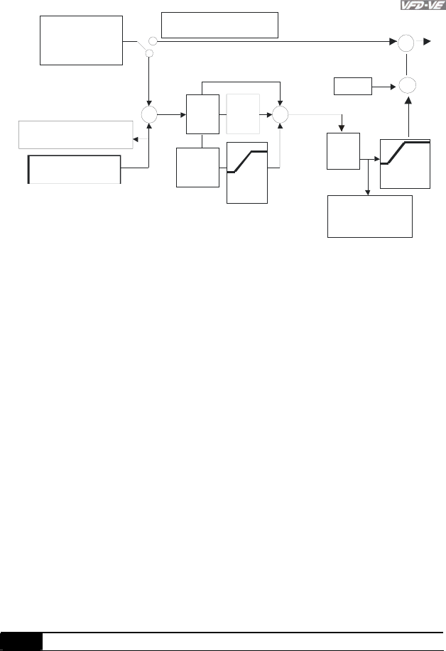
Chapter 4 Parameters|
Revision August 2008, 03VE, SW V2.04 4-121
Inp ut Selection
of the PID Fee dback
PID Cancelled
PID Freq.
out put
command
limit
Treatme nt o f t he
Feedback Signal Fau lt
Int egral Time
Proportion
ga in
00-14=10 display o f t he
PID feed back
Differential
Time
00- 20:KPV-C E0 1/
RS485
03-00~0 2:
UP/D own
ke y PG
08-00=0
or 02-01~06=21(pid off)
08-00:AVI/ACI
AUI /PG
P
08-01
D
08-03
I
08-02 08-04
08-07
If Hz>08 -05
time over0 8-08
=>08-09
08-05
Output
+
-+
+
Inp ut Selection of the
PID Targe ted Value
1
2
08-06
PID offset
Display of th e PID fee dback
uppe r limit
for
Int egral
PID
Delay
Time
+
PI Control: controlled by the P action only, and thus, the deviation cannot be eliminated
entirely. To eliminate residual deviations, the P + I control will generally be utilized. And when
the PI control is utilized, it could eliminate the deviation incurred by the targeted value changes
and the constant external interferences. However, if the I action is excessively powerful, it will
delay the responding toward the swift variation. The P action could be used solely on the
loading system that possesses the integral components.
PD Control: when deviation occurred, the system will immediately generate some operation
load that is greater than the load generated single handedly by the D action to restrain the
increment of the deviation. If the deviation is small, the effectiveness of the P action will be
decreasing as well. The control objects include occasions with integral component loads,
which are controlled by the P action only, and sometimes, if the integral component is
functioning, the whole system will be vibrating. On such occasions, in order to make the P
action’s vibration subsiding and the system stabilizing, the PD control could be utilized. In
other words, this control is good for use with loadings with no brake functions over the
processes.
PID Control: Utilize the I action to eliminate the deviation and the D action to restrain the
vibration, thereafter, combine with the P action to construct the PID control. Use of the PID
method could obtain a control process with no deviations, high accuracies and a stable system.
08-08 Feedback Signal Detection Time Unit: 0.1

Chapter 4 Parameters|
4-122 Revision August 2008, 03VE, SW V2.04
Control
mode VF VFPG SVC FOCPG Factory Setting: 0.0
Settings 0.0 to 3600.0 sec
This parameter defines the time during which the PID feedback must be abnormal before a
warning is given. It also can be modified according to the system feedback signal time.
If this parameter is set to 0.0, the system would not detect any abnormality signal.
08-09 Feedback Fault Treatment
Control
mode VF VFPG SVC FOCPG Factory Setting: 0
Settings 0 Warn and keep operating
1 Warn and RAMP to stop
2 Warn and COAST to stop
3 Warn and keep at last frequency
AC motor drive acts when the feedback signals (analog PID feedback or PG (encoder)
feedback) are abnormal.
08-10 Sleep Frequency Unit: 0.01
Control
mode VF VFPG SVC FOCPG Factory Setting: 0.00
Settings 0.00 to 600.00Hz
08-11 Wake-up Frequency Unit: 0.01
Control
mode VF VFPG SVC FOCPG Factory Setting: 0.00
Settings 0.00 to 600.00Hz
08-12 Sleep Time Unit: 0.1
Control
mode VF VFPG SVC FOCPG Factory Setting: 0.0
Settings 0.0 to 6000.0sec
These parameters determine sleep functions of the AC drive. If the command frequency falls
below the sleep frequency, for the specified time in Pr. 08-12, then the drive will shut off the
output and wait until the command frequency rises above Pr. 08-11. Please see the below
diagram.
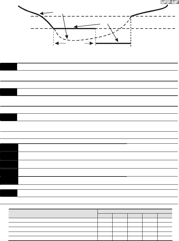
Chapter 4 Parameters|
Revision August 2008, 03VE, SW V2.04 4-123
08-11
08-10
08-12
0Hz
Sleep Function
Frequency command
actual output frequency
sleep time
Wake-up frequency
Sleep frequency
08-13 PID Deviation Level Unit: 0.1
Control
mode VF VFPG SVC FOCPG Factory Setting: 10.0
Settings 1.0 to 50.0%
08-14 PID Deviation Time Unit: 0.1
Control
mode VF VFPG SVC FOCPG Factory Setting: 5.0
Settings 0.1 to 300.0 sec
08-15 Filter Time for PID Feedback Unit: 0.1
Control
mode VF VFPG SVC FOCPG Factory Setting: 5.0
Settings 0.1 to 300.0 sec
08-16 Reserved
08-17 Reserved
08-18 Reserved
08-19 Reserved
08-20 Reserved
08-21 Tension Control Selection
Settings 0 to 4 Factory Setting: 0
Control Mode
Settings VF VFPG SVC FOCPG TQRPG
0: Disable
1: Closed-loop, speed mode ○ ○ ○ ○
2: Line speed, speed mode ○ ○ ○ ○
3: Reserved
4: Open-loop, torque mode
○
Closed-loop, speed mode
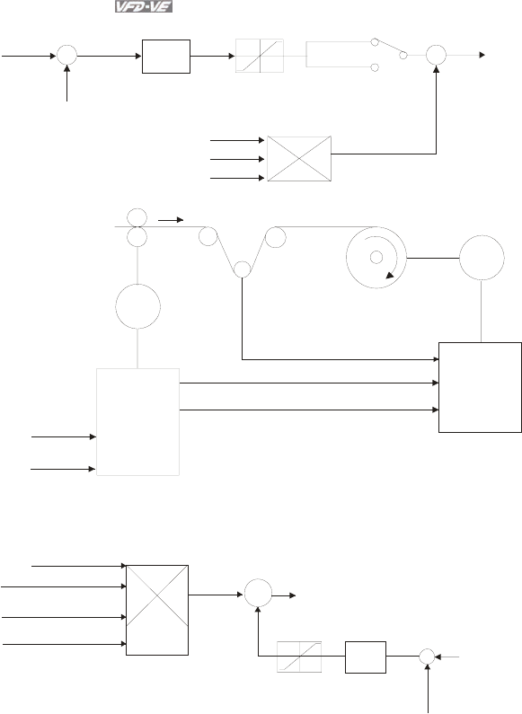
Chapter 4 Parameters|
4-124 Revision August 2008, 03VE, SW V2.04
+-
08-25
&
08-26
08-27
PI
08-29 & 08-30
08-32 & 08-33
Limit
+
+
PID output frequency
08-35=0 *1
08-35=1 *-1
08-23 & 08-24
mechanical gear ratio
output
frequency
master frequency
reel diameter
line speed
Motor
Motor
AFM or DFM
AI
FWD orREV
MO=d1
AI
AI or PG2
FWD
Drive 1
Drive 2
frequency
setting
operation
command
tension feed back
line speed in p ut
operation command
Line speed, speed mode
08-27=1
+
+
08-36
PI
08-29~08-30
08-32~08-33
+
-
08-23 or 08-24
mechanical gear ratio A/B
08-42 reel diameter
08-25=2,
08-26
line speed
command
line speed
feedback
master
frequency
frequency command
08-27=1
line speed feedback
08-25=2, 08-26
line speed
command
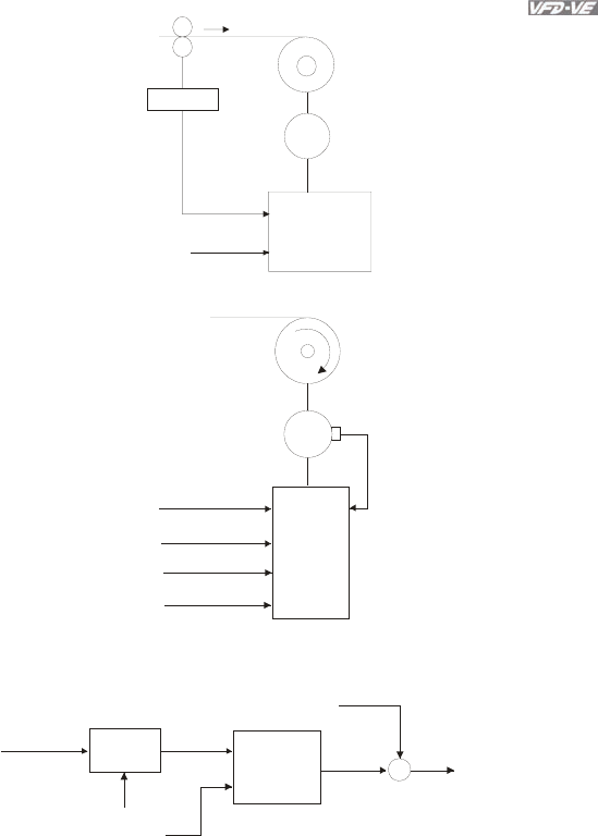
Chapter 4 Parameters|
Revision August 2008, 03VE, SW V2.04 4-125
Motor
Encoder
PG2
drive
line speed
feedback
line speed
command AI or
communication
Open-loop, torque mode
Motor
AI or PG2
FWD
MI=d39
AI PG1
tension
command
operation
command
torque command
direction
driv
e
line speed
input
(not indispensable)
08-76/08-79 08-81 ++
08-42
08-42
tension
setting
reel diameter
reel diamete
r
tension
taper torque
calculation
torque
value
torque
compensation
08-83~08-86
torque
command
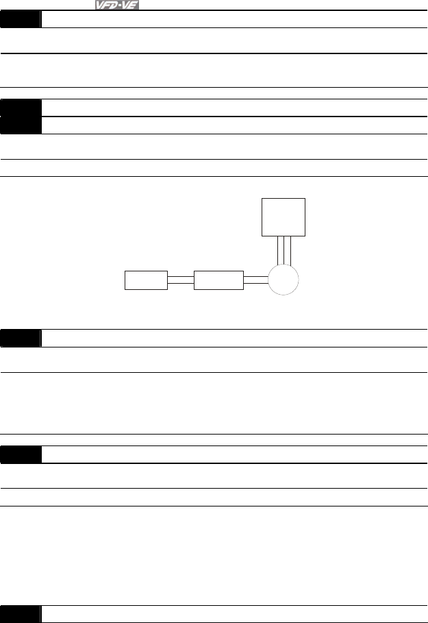
Chapter 4 Parameters|
4-126 Revision August 2008, 03VE, SW V2.04
08-22 Wind Mode
Control
mode VF VFPG SVC FOCPG TQRPG Factory Setting: 0
Settings 0 Rewind
1 Unwind
08-23 Mechanical Gear Ratio A Unit: 1
08-24 Mechanical Gear Ratio B Unit: 1
Control
mode VF VFPG SVC FOCPG TQRPG Factory Setting: 100
Settings 1 to 65535
1:10
10:1
Application without Encode
r
Driver
Motor
mechanical
gear ratio A
Load Gear ratio
mechanical
gear ratio B
08-25 Source of the Tension Command/Line Speed
Control
mode VF VFPG SVC FOCPG TQRPG Factory Setting: 0
Settings 0 Parameter setting (Pr.08-26)
1 RS-485 communication setting (Pr.08-26)
2 Analog input (Pr. 03-00~03-02 is set to 14 PID target value of
tension, 03-00~03-02 is set to 12 line speed)
08-26 PID Target Value of Tension/Line Speed Unit: 0.1
Control
mode VF VFPG SVC FOCPG TQRPG Factory Setting: 50.0
Settings 0.0 to 100.0%
The setting range is from 0.0 to 100.0%. In tension mode, when Pr.08-21 is set to 1 (Closed-
loop, speed mode), the corresponding value for 100% of dancer is 10V.
In tension mode, when Pr.08-21 is set to 2 (Line speed, speed mode), the corresponding value
for 100% of line speed is max. line speed (Pr.08-38).
08-27 Source of Tension/Line Speed PID Feedback

Chapter 4 Parameters|
Revision August 2008, 03VE, SW V2.04 4-127
Control
mode VF VFPG SVC FOCPG TQRPG Factory Setting: 0
Settings 0 Analog input (Pr. 03-00~03-02 is set to 11 PID feedback of tension)
1 Pulse input (Pr.08-40)
08-28 Auto-tuning Tension PID
Control
mode VF VFPG SVC FOCPG TQRPG Factory Setting: 0
Settings 0 Disable
1 Reel diameter (08-29~08-31corresponds to 08-44, 08-32~08-34
corresponds to 08-43)
2 Frequency (08-29~08-31 corresponds to 01-07, 08-32~08-34
corresponds to 01-00)
When Pr.08-28 is set to 1:
08-29
08-30
P.I . D
0
08-32
08-33
08-44 08-43
Dmax
Dmin
reel
diameter
When Pr.08-28 is set to 2:
Fmax
Fmin
08-29
08-30
P.I.D
0
08-32
08-33
01-0
7
01-00
output
frequency
08-29 Tension PID P1 Unit: 0.1

Chapter 4 Parameters|
4-128 Revision August 2008, 03VE, SW V2.04
Control
mode VF VFPG SVC FOCPG TQRPG Factory Setting: 50.0
Settings 0.0 to 1000.0
08-30 Tension PID I1 Unit: 0.01
Control
mode VF VFPG SVC FOCPG TQRPG Factory Setting: 1.00
Settings 0.00 to 500.00 sec
08-31 Reserved
08-32 Tension PID P2 Unit: 0.1
Control
mode VF VFPG SVC FOCPG TQRPG Factory Setting: 50.0
Settings 0.0 to 1000.0
08-33 Tension PID I2 Unit: 0.01
Control
mode VF VFPG SVC FOCPG TQRPG Factory Setting: 1.00
Settings 0.00 to 500.00 sec
08-34 Reserved
08-35 PID Output Status
Control
mode VF VFPG SVC FOCPG TQRPG Factory Setting: 0
Settings 0 Positive output
1 Negative output
08-36 Tension/Line Speed PID Output Limit Unit: 0.01
Control
mode VF VFPG SVC FOCPG TQRPG Factory Setting: 20.00
Settings 0 to 100.00% (according to Pr.01-00)
08-37 Source of Line Speed Input Command
Control
mode VF VFPG SVC FOCPG TQRPG Factory Setting: 0
Settings 0 Disable
1 Analog input (Pr. 03-00~03-02 is set to 12 line speed)
2 RS-485 communication setting (Pr.08-41)
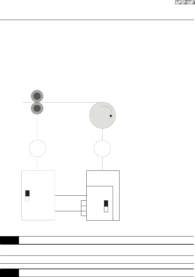
Chapter 4 Parameters|
Revision August 2008, 03VE, SW V2.04 4-129
3 Pulse input (Pr.08-40)
4 DFM-DCM pulse input (Pr.02-18)
When it is set to 1, 3 or 4, the current line speed will be saved into Pr.08-41 via analog and
pulse command. When it is set to 2, it can change the setting of Pr.08-41 (current line speed)
via communication.
When it is set to 3 or 4, pulse signal needs to be connected to PG2 of the PG card and then
set the PG type by Pr.10-15.
When it is set to 3, it needs to use with Pr.08-40.
When it is set to 4, Pr.02-18 setting needs to be set to the DFM output value of previous driver
as shown in the following before setting Pr.08-38.
TP
DFM
DFM
(02-18)
DCM
TP
AB2
A2
/A2
B2
/B2
DCM
PG 2
tractor
motor motor
Driver 1 Driver 2
the setting of Pr,02-18 of motor 2
= the setting of Pr.02-18 of motor 1
Pr.10-15 of motor 2
should be set to 3 or 4
Wind
08-38 Max. Line Speed Unit: 0.1
Control
mode VF VFPG SVC FOCPG TQRPG Factory Setting: 1000.0
Settings 0.0 to 3000.0 m/min
08-39 Min. Line Speed Unit: 0.1

Chapter 4 Parameters|
4-130 Revision August 2008, 03VE, SW V2.04
Control
mode VF VFPG SVC FOCPG TQRPG Factory Setting: 0.0
Settings 0.0 to 3000.0 m/min
08-40 Pulse Number for Each Meter Unit: 0.1
Control
mode VF VFPG SVC FOCPG TQRPG Factory Setting: 0.0
Settings 0.0 to 6000.0
08-41 Current Line Speed Unit: 0.1
Control
mode VF VFPG SVC FOCPG TQRPG Factory Setting: 0.0
Settings 0.0 to 3000.0 m/min
When Pr.08-37 is set to 1, 3, or 4, the current line speed will be saved into Pr.08-41 via analog
and pulse command. At this time, Pr.08-41 will be read only.
When Pr.08-37 is set to 2, the setting of Pr.08-41(current line speed) can be changed by
communication.
08-42 Source of Reel Diameter
Control
mode VF VFPG SVC FOCPG TQRPG Factory Setting: 0
Settings 0 Calculated by line speed
1 Calculated by integrating thickness (encoder is on reel shaft)(Pr.08-
49~51, Pr.10-15)
2 Calculated by integrating thickness (encoder is on motor)(Pr.08-
23~08-24, 08-50~08-51, 10-00~10-01)
3 Calculated by analog input (Pr.03-00~03-02 is set to 13)
When it is set to 1 or 2, it needs to be used with PG card.
When it is set to 1, the reel diameter can be got from the encoder on the reel shaft. At this time,
the pulse signal needs to be connected to the PG2 of PG card and get the reel diameter from
the settings of Pr.10-15, Pr.08-49, Pr.08-50 and Pr.08-51.
When it is set to 2, the reel diameter can be calculated from the motor encoder and gear ratio.
At this time, the pulse signal should be connected to the PG1 of the PG card and get the reel
diameter from the settings of Pr.08-23, Pr.08-24, Pr.10-01, Pr.10-00, Pr.08-50 and Pr.08-51.
When it is set to 3, the reel diameter can be calculated by analog input (Pr.03-00~03-02 is set
to 13) and the corresponding value of 10V is Pr.08-43.
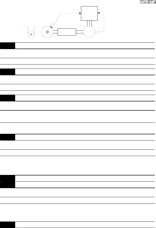
Chapter 4 Parameters|
Revision August 2008, 03VE, SW V2.04 4-131
the path when
Pr.08- 42 is set to 1
Driver
th e pa th when
Pr.08- 42 is set to 2
gear ratio Motor
Encoder
proximity
switch/
encoder
08-43 Max. Reel Diameter Unit: 0.1
Control
mode VF VFPG SVC FOCPG TQRPG Factory Setting: 6000.0
Settings 1.0 to 6000.0mm
08-44 Empty Reel Diameter Unit: 0.1
Control
mode VF VFPG SVC FOCPG TQRPG Factory Setting: 1.0
Settings 1 to 6000.0mm
08-45 Source of Reel Diameter
Control
mode VF VFPG SVC FOCPG TQRPG Factory Setting: 0
Settings 0 RS-485 communication setting (Pr.08-46)
1 Analog input (Pr.03-00-Pr.03-02 is set to 13)
When it is set to 1, the corresponding value of 10V is Pr.08-43.
08-46 Initial Reel Diameter Unit: 0.1
Control
mode VF VFPG SVC FOCPG TQRPG Factory Setting: 1.0
Settings 1.0 to 6000.0mm
When Pr.08-45 is set to 1, Pr.08-46 will be read-only.
08-47 Initial Reel Diameter 1 Unit: 0.1
08-48 Initial Reel Diameter 2 Unit: 0.1
Control
mode VF VFPG SVC FOCPG TQRPG Factory Setting: 1.0
Settings 1.0 to 6000.0mm
Pr.08-46 needs to be used by setting 44~46 to Pr.02-01~02-06, Pr.02-23~Pr.02-30.
When you need to have many types of reel diameter, please set Pr.08-46 to 0.
08-49 Number of Pulse Per Revolution Unit: 1

Chapter 4 Parameters|
4-132 Revision August 2008, 03VE, SW V2.04
Control
mode VF VFPG SVC FOCPG TQRPG Factory Setting: 1
Settings 1 to 10000ppr
08-50 Coil Number for Each Layer Unit: 1
Control
mode VF VFPG SVC FOCPG TQRPG Factory Setting: 1
Settings 1 to 10000
08-51 Material Thickness Unit: 0.001
Control
mode VF VFPG SVC FOCPG TQRPG Factory Setting: 1.000
Settings 0.001 to 60.000mm
08-52 Filter Time of Reel Diameter Unit: 0.01
Control
mode VF VFPG SVC FOCPG TQRPG Factory Setting: 1.00
Settings 0.00 to 100.00 sec
This parameter can be used to improve unstable of the source of reel diameter(Pr.08-42).
08-53 Auto Compensation of Reel Diameter
Control
mode VF VFPG SVC FOCPG TQRPG Factory Setting: 0
Settings 0 Disable
1 Enable
08-54 Current Reel Diameter Unit: 0.1
Control
mode VF VFPG SVC FOCPG TQRPG Factory Setting: 1.0
Settings 1.0 to 6000.0 mm
When the AC motor drive is not at STOP, this parameter is read-only.
08-55 Smart Start
Control
mode VF VFPG SVC FOCPG TQRPG Factory Setting: 0
Settings 0 Disable
1 Enable
2 In unwind mode, rewind in reverse direction
08-56 Switch Level for Smart Start and PID Function Unit: 1
Control
mode VF VFPG SVC FOCPG TQRPG Factory Setting: 15.0

Chapter 4 Parameters|
Revision August 2008, 03VE, SW V2.04 4-133
Settings 0.0~100.0% (according to Pr.08-26)
08-57 Frequency for Smart Start Unit: 1
Control
mode VF VFPG SVC FOCPG TQRPG Factory Setting: 2.00
Settings 0.00~600.00Hz
08-58 Accel. Time for Smart Start Unit: 0.01
Control
mode VF VFPG SVC FOCPG Factory Setting: 3.00
Settings 0.01~600.00 sec
When the speeds of wider/unwinder and tractor can’t match at start-up, the situation can be
improved by setting Pr.08-57 and Pr.08-58.
08-59 Broken Belt Detection
Control
mode VF VFPG SVC FOCPG Factory Setting: 0
Settings 0 Disable
1 Enable
08-60 Min. Line Speed of Broken Belt Detection Unit: 0.1
Control
mode VF VFPG SVC FOCPG Factory Setting: 0.0
Settings 0.0~3000.0 m/min
08-61 Allowance Error of Line Speed of Broken Belt Detection Unit: 0.1
Control
mode VF VFPG SVC FOCPG Factory Setting: 100.0
Settings 1.0~6000.0 mm
08-62 Detection Time of Broken Belt Unit: 0.1
Control
mode VF VFPG SVC FOCPG Factory Setting: 1.00
Settings 0.00~100.00 sec
When the broken belt detection is enabled, line speed is higher then Pr.08-61, allowance error
of line speed of broken belt detection exceeds Pr.08-61 and detection time of broken belt
exceeds Pr.08-62, the broken belt occurs.
08-63 Allowance Error Level of Tension/Line Speed PID Feedback Unit: 1

Chapter 4 Parameters|
4-134 Revision August 2008, 03VE, SW V2.04
Control
mode VF VFPG SVC FOCPG Factory Setting: 100
Settings 0~100%
The corresponding value for the 100% of dancer is 10V.
08-64 Allowance Error Detection Time of Tension PID Feedback Unit: 0.1
Control
mode VF VFPG SVC FOCPG Factory Setting: 0.5
Settings 0.0~10.0 sec
08-65 Error Treatment of Tension PID Feedback
Control
mode VF VFPG SVC FOCPG Factory Setting: 0
Settings 0 Warn and keep operation
1 Warn and coast to stop
2 Warn and ramp to stop
When the error of tension PID target value and tension PID feedback exceeds Pr.08-63 and
the allowance error detection time of tension PID exceeds Pr.08-64, tension PID feedback
error occurs. Refer to Pr.08-65 for error treatment of tension PID feedback.
08-66 Upper Limit of Tension PID Feedback Unit: 0.1
Control
mode VF VFPG SVC FOCPG TQRPG Factory Setting: 100.0
Settings 0.0~100.0%
08-67 Lower Limit of Tension PID Feedback Unit: 0.1
Control
mode VF VFPG SVC FOCPG TQRPG Factory Setting: 0.0
Settings 0.0~100.0%
08-68 Reserved
08-69 DFM Selection
Control
mode VF VFPG SVC FOCPG TQRPG Factory Setting: 0
Settings 0 Output frequency
1 Frequency command
08-70 Low-pass Filter Time of Line Speed Unit: 0.01
Control
mode VF VFPG SVC FOCPG TQRPG Factory Setting: 0.00

Chapter 4 Parameters|
Revision August 2008, 03VE, SW V2.04 4-135
Settings 0.00~100.00 sec
08-71
|
08-75
Reserved
08-76 Source of Tension Setting
Control
mode TQRPG
Factory Setting: 0
Settings 0 Communication RS-485 (Pr.08-78)
1 Analog input (Pr. 03-00~03-02 is set to 15 tension setting) (Pr.08-78)
08-77 Max. Tension Unit: 1
Control
mode TQRPG
Factory Setting: 0
Settings 0 ~30000 N
08-78 Tension Setting Unit: 1
Control
mode TQRPG
Factory Setting: 0
Settings 0 ~30000 N
08-79 Source of Zero-speed Tension Setting
Control
mode TQRPG
Factory Setting: 0
Settings 0 Disable
1 Communication RS-485 (Pr.08-80)
2 Analog input (Pr. 03-00~03-02 is set to 16 zero-speed tension)
(Pr.08-80)
08-80 Setting of Zero-speed Tension Unit: 1
Control
mode TQRPG
Factory Setting: 0
Settings 0 ~30000 N
08-81 Source of Tension Taper
Control
mode TQRPG
Factory Setting: 0
Settings 0 Communication RS-485 (Pr.08-82)
1 Analog input (Pr. 03-00~03-02 is set to 17 tension taper) (Pr.08-82)
08-82 Tension Taper Unit: 1

Chapter 4 Parameters|
4-136 Revision August 2008, 03VE, SW V2.04
Control
mode TQRPG
Factory Setting: 0
Settings 0~100%
08-83 Friction Compensation Unit: 1
Control
mode TQRPG
Factory Setting: 0.0
Settings 0.0~100.0%
08-84 Compensation Coefficient of Material Inertial Unit: 1
Control
mode TQRPG
Factory Setting: 0
Settings 0~30000
08-85 Torque Feed Forward Gain Unit: 0.1
Control
mode TQRPG
Factory Setting: 50.0
Settings 0.0~100.0%
08-86 Low Pass Filter Time of Torque Feed Forward Unit: 0.01
Control
mode TQRPG
Factory Setting: 5.00
Settings 0.00~100.00
08-87
|
08-99
Reserved
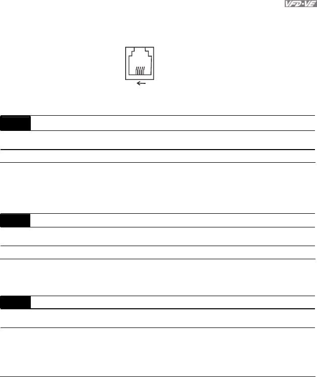
Chapter 4 Parameters|
Revision August 2008, 03VE, SW V2.04 4-137
Group 9: Communication Parameters
There is a built-in RS-485 serial interface, marked RJ-11 near to the control terminals. The pins are
defined below:
61
1: EV
2: GND
3: SG-
4: SG+
5: Reserved
6: Reserved
Each VFD-VE AC drive has a pre-assigned communication address specified by Pr.09-00. The
RS485 master then controls each AC motor drive according to its communication address.
09-00 Communication Address
Control
mode VF VFPG SVC FOCPG TQRPG Factory Setting: 1
Settings 1 to 254
If the AC motor drive is controlled by RS-485 serial communication, the communication
address for this drive must be set via this parameter. And the communication address for each
AC motor drive must be different and unique.
09-01 COM1 Transmission Speed
Control
mode VF VFPG SVC FOCPG TQRPG Factory Setting: 9.6
Settings 4.8 to 115.2kbps
This parameter is used to set the transmission speed between the RS485 master (PLC, PC,
etc.) and AC motor drive.
09-02 COM1 Transmission Fault Treatment
Control
mode VF VFPG SVC FOCPG TQRPG Factory Setting: 3
Settings 0 Warn and keep operating
1 Warn and RAMP to stop
2 Warn and COAST to stop
3 No warning and keep operating
This parameter is set to how to react if transmission errors occur.

Chapter 4 Parameters|
4-138 Revision August 2008, 03VE, SW V2.04
09-03 COM1 Time-out Detection Unit: 0.1
Control
mode VF VFPG SVC FOCPG TQRPG Factory Setting: 0.0
Settings 0.0 ~ 100.0 sec (0.0 disable)
If Pr.09-03 is not set to 0.0, Pr.09-02=0~2, and there is no communication on the bus during
the Time Out detection period (set by Pr.09-03), “cE10” will be shown on the keypad.
09-04 COM1 Communication Protocol
Control
mode VF VFPG SVC FOCPG TQRPG Factory Setting: 1
Settings 0 Modbus ASCII mode, protocol <7,N,1>
1 Modbus ASCII mode, protocol <7,N,2>
2 Modbus ASCII mode, protocol <7,E,1>
3 Modbus ASCII mode, protocol <7,O,1>
4 Modbus ASCII mode, protocol <7,E,2>
5 Modbus ASCII mode, protocol <7,O,2>
6 Modbus ASCII mode, protocol <8,N,1>
7 Modbus ASCII mode, protocol <8,N,2>
8 Modbus ASCII mode, protocol <8,E,1>
9 Modbus ASCII mode, protocol <8,O,1>
10 Modbus ASCII mode, protocol <8,E,2>
11 Modbus ASCII mode, protocol <8,O,2>
12 Modbus RTU mode, protocol <8,N,1>
13 Modbus RTU mode, protocol <8,N,2>
14 Modbus RTU mode, protocol <8,E,1>
15 Modbus RTU mode, protocol <8,O,1>
16 Modbus RTU mode, protocol <8,E,2>
17 Modbus RTU mode, protocol <8,O,2>
1. Control by PC or PLC
A VFD-VE can be set up to communicate on Modbus networks using one of the following modes:
ASCII (American Standard Code for Information Interchange) or RTU (Remote Terminal Unit).
Users can select the desired mode along with the serial port communication protocol in Pr.09-04.
Code Description:
ASCII mode:
Each 8-bit data is the combination of two ASCII characters. For example, a 1-byte data:
64 Hex, shown as ‘64’ in ASCII, consists of ‘6’ (36Hex) and ‘4’ (34Hex).
Character ‘0’ ‘1’ ‘2’ ‘3’ ‘4’ ‘5’ ‘6’ ‘7’
ASCII code 30H 31H 32H 33H 34H 35H 36H 37H
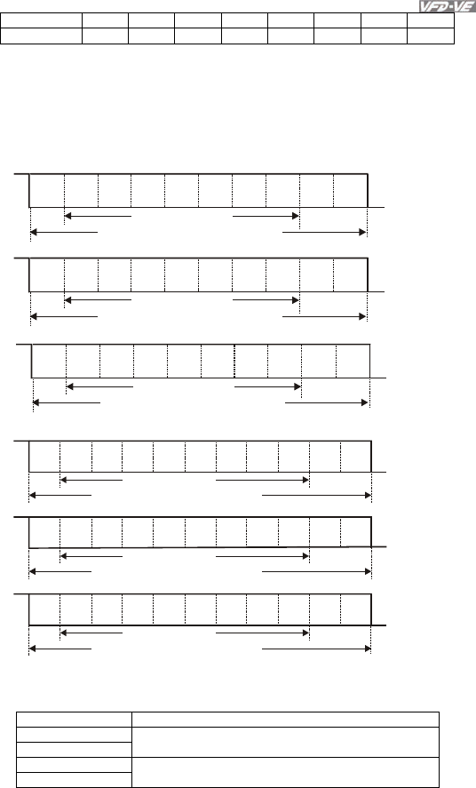
Chapter 4 Parameters|
Revision August 2008, 03VE, SW V2.04 4-139
Character ‘8’ ‘9’ ‘A’ ‘B’ ‘C’ ‘D’ ‘E’ ‘F’
ASCII code 38H 39H 41H 42H 43H 44H 45H 46H
RTU mode:
Each 8-bit data is the combination of two 4-bit hexadecimal characters. For example, 64
Hex.
2. Data Format
10-bit character frame (For ASCII):
( 7.N.2)
( 7.E.1)
Start
bit 0123456 Stop
bit
10-bit character frame
( 7.O.1)
Odd
parity
Start
bit 0123456 Stop
bit
10-bit character frame
Even
parity
Start
bit 0123456Stop
bit
7-bit character
10-bit character frame
Stop
bit
7-bit character
7-bit character
11-bit character frame (For RTU):
Start
bit 0123456 Stop
bit
Stop
bit
8-bit character
11-bit character frame
( 8.N.2 )
Start
bit 0123456Even
parity
Stop
bit
11-bit character frame
( 8.E.1 )
Start
bit 0123456Stop
bit
11-bit character frame
( 8.O.1 )
Odd
parity
7
7
7
8-bit character
8-bit character
3. Communication Protocol
3.1 Communication Data Frame:
ASCII mode:
STX Start character ‘:’ (3AH)
Address Hi
Address Lo
Communication address:
8-bit address consists of 2 ASCII codes
Function Hi
Function Lo
Command code:
8-bit command consists of 2 ASCII codes
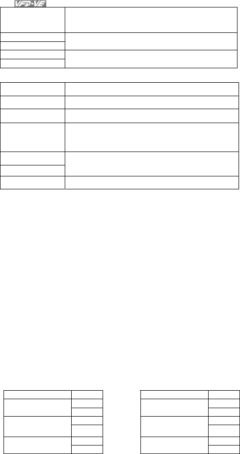
Chapter 4 Parameters|
4-140 Revision August 2008, 03VE, SW V2.04
DATA (n-1)
to
DATA 0
Contents of data:
Nx8-bit data consist of 2n ASCII codes
n<=16, maximum of 32 ASCII codes
LRC CHK Hi
LRC CHK Lo
LRC check sum:
8-bit check sum consists of 2 ASCII codes
END Hi
END Lo
End characters:
END1= CR (0DH), END0= LF(0AH)
RTU mode:
START A silent interval of more than 10 ms
Address Communication address: 8-bit address
Function Command code: 8-bit command
DATA (n-1)
to
DATA 0
Contents of data:
n×8-bit data, n<=16
CRC CHK Low
CRC CHK High
CRC check sum:
16-bit check sum consists of 2 8-bit characters
END A silent interval of more than 10 ms
3.2 Address (Communication Address)
Valid communication addresses are in the range of 0 to 254. A communication address equal to 0,
means broadcast to all AC drives (AMD). In this case, the AMD will not reply any message to the
master device.
00H: broadcast to all AC drives
01H: AC drive of address 01
0FH: AC drive of address 15
10H: AC drive of address 16
:
FEH: AC drive of address 254
For example, communication to AMD with address 16 decimal (10H):
ASCII mode: Address=’1’,’0’ => ‘1’=31H, ‘0’=30H
RTU mode: Address=10H
3.3 Function (Function code) and DATA (data characters)
The format of data characters depends on the function code.
03H: read data from register
06H: write single register
08H: loop detection
10H: write multiple registers
The available function codes and examples for VFD-VE are described as follows:
(1) 03H: multi read, read data from registers.
Example: reading continuous 2 data from register address 2102H, AMD address is 01H.
ASCII mode:
Command message: Response message:
STX ‘:’ STX ‘:’
‘0’ ‘0’
Address ‘1’ Address ‘1’
‘0’ ‘0’
Function ‘3’ Function ‘3’
‘2’ ‘0’ Starting data
address ‘1’
Number of data
(Count by byte) ‘4’

Chapter 4 Parameters|
Revision August 2008, 03VE, SW V2.04 4-141
Command message: Response message:
‘0’ ‘1’
‘2’ ‘7’
‘0’ ‘7’
‘0’
Content of starting
address
2102H ‘0’
‘0’ ‘0’
Number of data
(count by word)
‘2’ ‘0’
‘D’ ‘0’
LRC Check ‘7’
Content of address
2103H
‘0’
CR ‘7’
END LF LRC Check ‘1’
CR
END LF
RTU mode:
Command message: Response message:
Address 01H Address 01H
Function 03H Function 03H
21H Starting data
address 02H
Number of data
(count by byte) 04H
00H 17H Number of data
(count by word) 02H
Content of address
2102H 70H
CRC CHK Low 6FH 00H
CRC CHK High F7H
Content of address
2103H 00H
CRC CHK Low FEH
CRC CHK High 5CH
(2) 06H: single write, write single data to register.
Example: writing data 6000(1770H) to register 0100H. AMD address is 01H.
ASCII mode:
Command message: Response message:
STX ‘:’ STX ‘:’
‘0’ ‘0’
Address ‘1’ Address ‘1’
‘0’ ‘0’
Function ‘6’ Function ‘6’
‘0’ ‘0’
‘1’ ‘1’
‘0’ ‘0’
Data address
‘0’
Data address
‘0’
‘1’ ‘1’
‘7’ ‘7’
‘7’ ‘7’
Data content
‘0’
Data content
‘0’
‘7’ ‘7’
LRC Check ‘1’ LRC Check ‘1’
CR CR
END LF END LF
RTU mode:
Command message: Response message:
Address 01H Address 01H
Function 06H Function 06H
Data address 01H Data address 01H
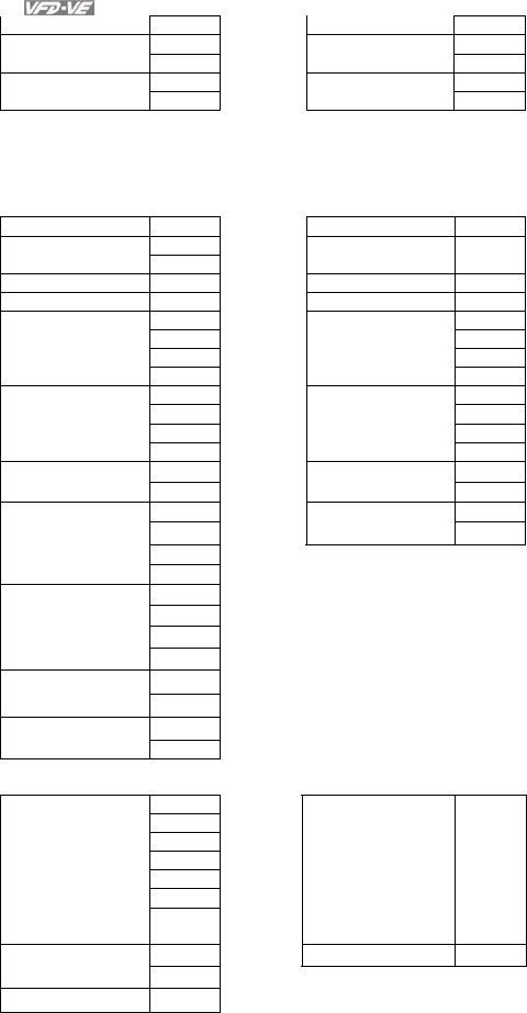
Chapter 4 Parameters|
4-142 Revision August 2008, 03VE, SW V2.04
00H 00H
17H 17H
Data content 70H Data content 70H
CRC CHK Low 86H CRC CHK Low 86H
CRC CHK High 22H CRC CHK High 22H
(3) 10H: write multiple registers (write multiple data to registers)
Example: Set the multi-step speed,
Pr.05-00=50.00 (1388H), Pr.05-01=40.00 (0FA0H). AC drive address is 01H.
ASCII Mode:
Command message: Response message:
STX ‘:’ STX ‘:’
Address 1 ‘0’ Address 1 ‘0’
Address 0 ‘1’ Address 0 ‘1’
Function 1 ‘1’ Function 1 ‘1’
Function 0 ‘0’ Function 0 ‘0’
‘0’ ‘0’
‘5’ ‘5’
‘0’ ‘0’
Starting data
address
‘0’
Starting data
address
‘0’
‘0’ ‘0’
‘0’ ‘0’
‘0’ ‘0’
Number of data
(count by word)
‘2’
Number of data
(count by word)
‘2’
‘0’ ‘E’
Number of data
(count by byte) ‘4’ LRC Check ‘8’
‘1’ CR
‘3’ END LF
‘8’
The first data
content
‘8’
‘0’
‘F’
‘A’
The second data
content
‘0’
‘9’
LRC Check ‘A’
CR
END LF
RTU mode:
Command message: Response message:
Address 01H Address 01H
Function 10H Function 10H
05H 05H Starting data
address 00H
Starting data address
00H
00H’ 00H Number of data
(count by word) 02H
Number of data
(count by word) 02H
Number of data
(count by byte)
04 CRC Check Low 41H
13H CRC Check High 04H
The first data
content 88H
The second data 0FH
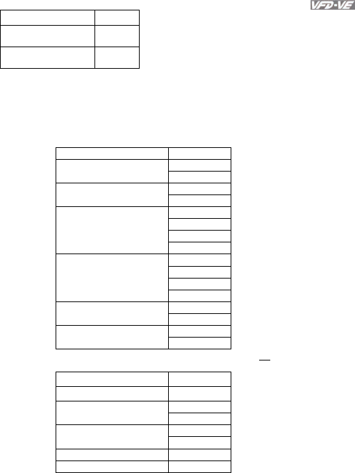
Chapter 4 Parameters|
Revision August 2008, 03VE, SW V2.04 4-143
content A0H
CRC Check Low ‘9’
CRC Check High ‘A’
3.4 Check sum
ASCII mode:
LRC (Longitudinal Redundancy Check) is calculated by summing up, module 256, the values of the
bytes from ADR1 to last data character then calculating the hexadecimal representation of the 2’s-
complement negation of the sum.
For example, reading 1 word from address 0401H of the AC drive with address 01H.
STX ‘:’
‘0’ Address 1
Address 0 ‘1’
‘0’ Function 1
Function 0 ‘3’
‘0’
‘4’
‘0’
Starting data address
‘1’
‘0’
‘0’
‘0’
Number of data
‘1’
‘F’ LRC Check 1
LRC Check 0 ‘6’
CR END 1
END 0 LF
01H+03H+04H+01H+00H+01H=0AH, the 2’s-complement negation of 0AH is F6H.
RTU mode:
Address 01H
Function 03H
21H Starting data address
02H
00H Number of data
(count by word) 02H
CRC CHK Low 6FH
CRC CHK High F7H
CRC (Cyclical Redundancy Check) is calculated by the following steps:
Step 1: Load a 16-bit register (called CRC register) with FFFFH.
Step 2: Exclusive OR the first 8-bit byte of the command message with the low order byte of the 16-
bit CRC register, putting the result in the CRC register.
Step 3: Examine the LSB of CRC register.
Step 4: If the LSB of CRC register is 0, shift the CRC register one bit to the right with MSB zero
filling, then repeat step 3. If the LSB of CRC register is 1, shift the CRC register one bit to the right
with MSB zero filling, Exclusive OR the CRC register with the polynomial value A001H, then repeat
step 3.
Step 5: Repeat step 3 and 4 until eight shifts have been performed. When this is done, a complete
8-bit byte will have been processed.
Step 6: Repeat step 2 to 5 for the next 8-bit byte of the command message. Continue doing this until
all bytes have been processed. The final contents of the CRC register are the CRC value. When
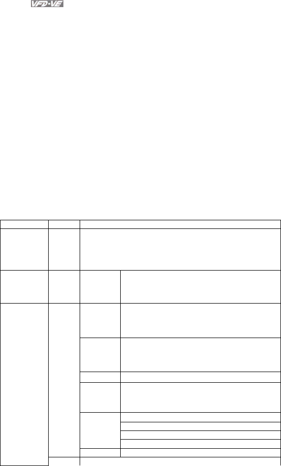
Chapter 4 Parameters|
4-144 Revision August 2008, 03VE, SW V2.04
transmitting the CRC value in the message, the upper and lower bytes of the CRC value must be
swapped, i.e. the lower order byte will be transmitted first.
The following is an example of CRC generation using C language. The function takes two arguments:
Unsigned char* data Å a pointer to the message buffer
Unsigned char length Å the quantity of bytes in the message buffer
The function returns the CRC value as a type of unsigned integer.
Unsigned int crc_chk(unsigned char* data, unsigned char length){
int j;
unsigned int reg_crc=0xFFFF;
while(length--){
reg_crc ^= *data++;
for(j=0;j<8;j++){
if(reg_crc & 0x01){ /* LSB(b0)=1 */
reg_crc=(reg_crc>>1) ^ 0xA001;
}else{
reg_crc=reg_crc >>1;
}
}
}
return reg_crc;
}
3.5 Address list
The contents of available addresses are shown as below:
Content Address Function
AC drive
Parameters GGnnH
GG means parameter group, nn means parameter number,
for example, the address of Pr 4-01 is 0401H. Referencing to
chapter 5 for the function of each parameter. When reading
parameter by command code 03H, only one parameter can
be read at one time.
Command
Write only 2000H Bit 0-3
0: No function
1: Stop
2: Run
3: Jog + Run
Bit 4-5
00B: No function
01B: FWD
10B: REV
11B: Change direction
Bit 6-7
00B: 1st accel/decel
01B: 2nd accel/decel
10B: 3rd accel/decel
11B: 4th accel/decel
Bit 8-11 Represented 16 step speeds.
Bit 12
0: No comm. multi step speed or accel/decel
time
1: Comm. multi step speed or accel/decel time
Command
Write only
00B: No function
01B: operated by digital keypad
02B: operated by Pr.00-21 setting
Bit 13~14
03B: change operation source
2000H
Bit 15 Reserved
2001H Frequency command

Chapter 4 Parameters|
Revision August 2008, 03VE, SW V2.04 4-145
Content Address Function
Bit 0 1: EF (external fault) on
Bit 1 1: Reset
Bit 2 1: B.B. ON
2002H
Bit 3-15 Reserved
2100H Error code: refer to Pr.06-17 to Pr.06-22
Bit 0 1: FWD command
Bit 1 1: Operation status
Bit 2 1: Jog command
Status
monitor
Read only 2119H
Bit 3 1: REV command
Bit 4 1: REV command
Bit 8 1: Master frequency Controlled by communication
interface
Bit 9 1: Master frequency controlled by analog signal
Bit 10 1: Operation command controlled by
communication interface
Bit 11 1: Parameters have been locked
Bit 12 1: enable to copy parameter from keypad
Bit 13-15 Reserved
2102H Frequency command (F)
2103H Output frequency (H)
2104H Output current (AXXX.X)
2105H DC-BUS Voltage (UXXX.X)
2106H Output voltage (EXXX.X)
2107H Current step number of Multi-Step Speed Operation
2109H Counter value
2116H Multi-function display (Pr.00-04)
211AH Setting frequency (F)
211BH Max. setting frequency
211CH Max. output frequency
2200H Feedback Signal (XXX.XX %)
2203H AVI analog input (XXX.XX %)
2204H ACI analog input (XXX.XX %)
2205H AUI analog input (XXX.XX %)
2206H Display temperature of IGBT (oC)
2207H Display temperature of heatsink (oC)
3.6 Exception response:
The AC motor drive is expected to return a normal response after receiving command messages
from the master device. The following depicts the conditions when no normal response is replied to
the master device.
The AC motor drive does not receive the messages due to a communication error; thus, the AC
motor drive has no response. The master device will eventually process a timeout condition.
The AC motor drive receives the messages without a communication error, but cannot handle them.
An exception response will be returned to the master device and an error message “CExx” will be
displayed on the keypad of AC motor drive. The xx of “CExx” is a decimal code equal to the
exception code that is described below.
In the exception response, the most significant bit of the original command code is set to 1, and an
exception code which explains the condition that caused the exception is returned.
Example of an exception response of command code 06H and exception code 02H:
ASCII mode: RTU mode:
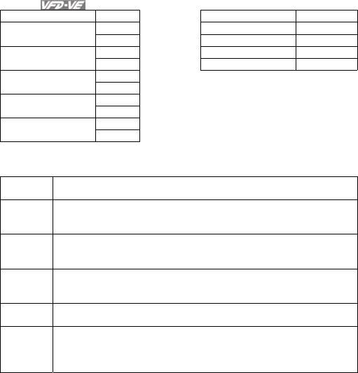
Chapter 4 Parameters|
4-146 Revision August 2008, 03VE, SW V2.04
STX ‘:’ Address 01H
‘0’ Function 86H Address Low
Address High ‘1’ Exception code 02H
‘8’ CRC CHK Low C3H Function Low
Function High ‘6’ CRC CHK High A1H
‘0’
Exception code ‘2’
‘7’ LRC CHK Low
LRC CHK High ‘7’
CR END 1
END 0 LF
The explanation of exception codes:
Exception
code Explanation
01
Illegal function code:
The function code received in the command message is not
available for the AC motor drive.
02
Illegal data address:
The data address received in the command message is not
available for the AC motor drive.
03
Illegal data value:
The data value received in the command message is not available
for the AC drive.
04 Slave device failure:
The AC motor drive is unable to perform the requested action.
10
Communication time-out:
If Pr.09-03 is not equal to 0.0, Pr.09-02=0~2, and there is no
communication on the bus during the Time Out detection period (set
by Pr.09-03), “cE10” will be shown on the keypad.
3.7 Communication program of PC:
The following is a simple example of how to write a communication program for Modbus ASCII mode
on a PC by C language.
#include<stdio.h>
#include<dos.h>
#include<conio.h>
#include<process.h>
#define PORT 0x03F8 /* the address of COM1 */
/* the address offset value relative to COM1 */
#define THR 0x0000
#define RDR 0x0000
#define BRDL 0x0000
#define IER 0x0001
#define BRDH 0x0001
#define LCR 0x0003
#define MCR 0x0004
#define LSR 0x0005
#define MSR 0x0006
unsigned char rdat[60];
/* read 2 data from address 2102H of AC drive with address 1 */
unsigned char tdat[60]={':','0','1','0','3','2','1','0',’2', '0','0','0','2','D','7','\r','\n'};
void main(){
int i;

Chapter 4 Parameters|
Revision August 2008, 03VE, SW V2.04 4-147
outportb(PORT+MCR,0x08); /* interrupt enable */
outportb(PORT+IER,0x01); /* interrupt as data in */
outportb(PORT+LCR,(inportb(PORT+LCR) | 0x80));
/* the BRDL/BRDH can be access as LCR.b7==1 */
outportb(PORT+BRDL,12); /* set baudrate=9600, 12=115200/9600*/
outportb(PORT+BRDH,0x00);
outportb(PORT+LCR,0x06); /* set protocol, <7,N,2>=06H, <7,E,1>=1AH, <7,O,1>=0AH,
<8,N,2>=07H, <8,E,1>=1BH, <8,O,1>=0BH */
for(i=0;i<=16;i++){
while(!(inportb(PORT+LSR) & 0x20)); /* wait until THR empty */
outportb(PORT+THR,tdat[i]); /* send data to THR */ }
i=0;
while(!kbhit()){
if(inportb(PORT+LSR) & 0x01){ /* b0==1, read data ready */
rdat[i++]=inportb(PORT+RDR); /* read data form RDR */
} } }
09-05 COM2 Transmission Speed (Keypad) Unit: 0.1
Control
mode VF VFPG SVC FOCPG TQRPG Factory Setting: 9.6
Settings 4.8 to 115.2kbps
This parameter is used to set the transmission speed between the RS485 master (PLC, PC,
etc.) and AC motor drive.
09-06 COM2 Transmission Fault Treatment (Keypad)
Control
mode VF VFPG SVC FOCPG TQRPG Factory Setting: 3
Settings 0 Warn and keep operating
1 Warn and RAMP to stop
2 Warn and COAST to stop
3 No warning and keep operating
This parameter is set to how to react if transmission errors occur.
09-07 COM2 Time-out Detection (Keypad) Unit: 0.1
Control
mode VF VFPG SVC FOCPG TQRPG Factory Setting: 0.0
Settings 0.0 ~ 100.0 sec
If Pr.09-03 is not equal to 0.0, Pr.09-02=0~2, and there is no communication on the bus during
the Time Out detection period (set by Pr.09-03), “cE10” will be shown on the keypad.
09-08 COM2 Communication Protocol (Keypad)
Control
mode VF VFPG SVC FOCPG TQRPG Factory Setting: 13
Settings 0 Modbus ASCII mode, protocol <7,N,1>
1 Modbus ASCII mode, protocol <7,N,2>
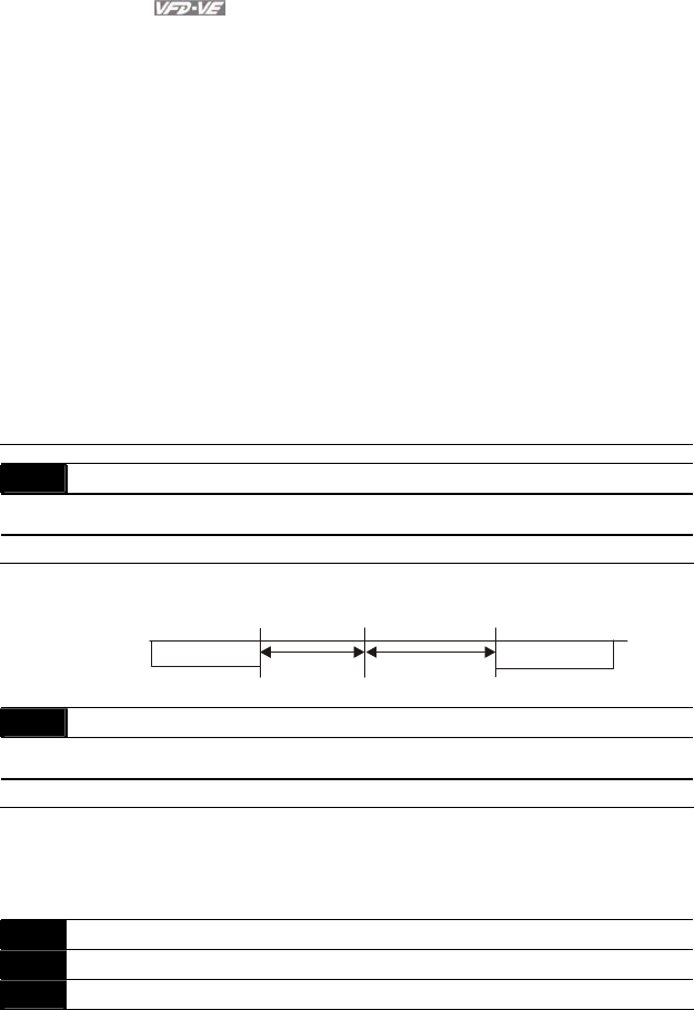
Chapter 4 Parameters|
4-148 Revision August 2008, 03VE, SW V2.04
2 Modbus ASCII mode, protocol <7,E,1>
3 Modbus ASCII mode, protocol <7,O,1>
4 Modbus ASCII mode, protocol <7,E,2>
5 Modbus ASCII mode, protocol <7,O,2>
6 Modbus ASCII mode, protocol <8,N,1>
7 Modbus ASCII mode, protocol <8,N,2>
8 Modbus ASCII mode, protocol <8,E,1>
9 Modbus ASCII mode, protocol <8,O,1>
10 Modbus ASCII mode, protocol <8,E,2>
11 Modbus ASCII mode, protocol <8,O,2>
12 Modbus RTU mode, protocol <8,N,1>
13 Modbus RTU mode, protocol <8,N,2>
14 Modbus RTU mode, protocol <8,E,1>
15 Modbus RTU mode, protocol <8,O,1>
16 Modbus RTU mode, protocol <8,E,2>
17 Modbus RTU mode, protocol <8,O,2>
09-09 Response Delay Time Unit: 0.1
Control
mode VF VFPG SVC FOCPG TQRPG Factory Setting: 2.0
Settings 0.0 ~ 200.0 msec
This parameter is the response delay time after AC drive receives communication command
as shown in the following.
PC or PLC command
Handling time
of the AC drive Response Delay Time
Pr.09-09
Response Message
of the AC Drive
RS-485 BUS
09-10 Transmission Master Frequency Unit: 0.01
Control
mode VF VFPG SVC FOCPG TQRPG Factory Setting: 60.00
Settings 0.00 ~ 600.00 Hz
When Pr.00-20 is set to 1 (RS485 communication). The AC motor drive will save the last
frequency command into Pr.09-10 when abnormal turn-off or momentary power loss. After re-
power on, it will with the frequency set in Pr.09-10 if there is no new frequency command.
09-11 Block Transfer 1 Unit: 1
09-12 Block Transfer 2 Unit: 1
09-13 Block Transfer 3 Unit: 1
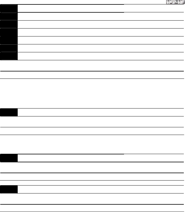
Chapter 4 Parameters|
Revision August 2008, 03VE, SW V2.04 4-149
09-14 Block Transfer 4 Unit: 1
09-15 Block Transfer 5 Unit: 1
09-16 Block Transfer 6 Unit: 1
09-17 Block Transfer 7 Unit: 1
09-18 Block Transfer 8 Unit: 1
09-19 Block Transfer 9 Unit: 1
09-20 Block Transfer 10 Unit: 1
Control
mode VF VFPG SVC FOCPG TQRPG Factory Setting: 0
Settings 0 to 65535
There is a group of block transfer parameter available in the AC motor drive (Pr.09-11 to
Pr.09-20). User can use them (Pr.09-11 to Pr.09-20) to save those parameters that you want
to read.
09-21 Multi-function Output Status
Control
mode VF VFPG SVC FOCPG TQRPG Factory Setting: Read-only
Settings 0 to 65535
09-22 AFM2 Status
Control
mode VF VFPG SVC FOCPG TQRPG Factory Setting: Read-only
Settings 0 to 4095
09-23 AFM3 Status
Control
mode VF VFPG SVC FOCPG TQRPG Factory Setting: Read-only
Settings 0 to 4095
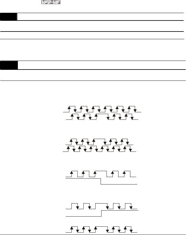
Chapter 4 Parameters|
4-150 Revision August 2008, 03VE, SW V2.04
Group 10 PID Control
10-00 Encoder Pulse Unit: 1
Control
mode VFPG FOCPG TQRPG
Factory Setting: 600
Settings 1 to 20000 (Max=20000 for 2-pole motor)
A Pulse Generator (PG) or encoder is used as a sensor that provides a feedback signal of the
motor speed. This parameter defines the number of pulses for each cycle of the PG control.
10-01 Encoder Input Type Setting
Control
mode VFPG FOCPG TQRPG
Factory Setting: 0
Settings 0 Disable
1
Phase A leads in a forward run command and phase B leads in a
reverse run command
A
B
FWD REV
2
Phase B leads in a forward run command and phase A leads in a
reverse run command
A
B
FWD REV
3
Phase A is a pulse input and phase B is a direction input. (low
input=reverse direction, high input=forward direction)
A
B
FWD REV
4
Phase A is a pulse input and phase B is a direction input. (low
input=forward direction, high input=reverse direction)
A
B
FWD REV
5
Single-phase input
A
It is helpful for the stable control by inputting correct pulse type.

Chapter 4 Parameters|
Revision August 2008, 03VE, SW V2.04 4-151
10-02 PG Feedback Fault Treatment
Control
mode VFPG FOCPG TQRPG
Factory Setting: 2
Settings 0 Warn and keep operating
1 Warn and RAMP to stop
2 Warn and COAST to stop
10-03 Detection Time for PG Feedback Fault Unit: 0.01
Control
mode VFPG FOCPG TQRPG
Factory Setting: 1.00
Settings 0.00 to 10.00 sec
When PG loss, encoder signal error, pulse signal setting error or signal error, if time exceeds
the detection time for PG feedback fault (Pr.10-03), the PG signal error will occur. Refer to the
Pr.10-02 for PG feedback fault treatment.
10-04 ASR (Auto Speed Regulation) control (P) 1 Unit: 0.1
Control
mode VFPG FOCPG
Factory Setting: 10
Settings 0 to 40 Hz
10-05 ASR (Auto Speed Regulation) control (I) 1 Unit: 0.001
Control
mode VFPG FOCPG
Factory Setting: 0.100
Settings 0.000 to 10.000 sec
10-06 ASR (Auto Speed Regulation) control (P) 2 Unit: 0.1
Control
mode VFPG FOCPG
Factory Setting: 10
Settings 0 to 40Hz
10-07 ASR (Auto Speed Regulation) control (I) 2 Unit: 0.001
Control
mode VFPG FOCPG
Factory Setting: 0.100
Settings 0.000 to 10.000 sec
10-08 ASR 1/ASR2 Switch Frequency Unit: 0.01
Control
mode VFPG FOCPG
Factory Setting: 7.00
Settings 5.00 o 600.00Hz
ASR P determines Proportional control and associated gain (P). ASR I determines integral
control and associated gain (I).
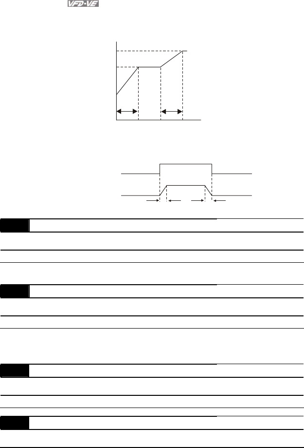
Chapter 4 Parameters|
4-152 Revision August 2008, 03VE, SW V2.04
When integral time is set to 0, it is disabled. Pr.10-08 defines the switch frequency for the
ASR1 (Pr.10-04, Pr.10-05) and ASR2 (Pr.10-06, Pr.10-07).
10-08
10-04
10-05
10-06
10-07
Hz
PI
10-21
10-22
0H
z
5Hz 5Hz
When using multi-function input terminals to switch ASR1/ASR2, the diagram will be shown as
follows.
ON
OFF
ASR 1
0.1 sec
OFF
0.1 sec
ASR 1
ASR 2
Setting multi-function input terminal to 27
(ASR1/ASR2 switch)
10-09 ASR Primary Low Pass Filter Gain Unit: 0.001
Control
mode FOCPG
Factory Setting: 0.008
Settings 0.000 to 0.350 sec
It defines the filter time of the ASR command.
10-10 PG Stall Level Unit: 1
Control
mode VFPG FOCPG
Factory Setting: 115
Settings 0 to 120% (0: disable)
This parameter determines the maximum PG feedback signal allowed before a fault occurs.
(max. output frequency Pr.01-00 =100%)
10-11 PG Stall Detection Time Unit: 0.1
Control
mode VFPG FOCPG
Factory Setting: 0.1
Settings 0.0 to 2.0 sec
10-12 PG Slip Range Unit: 1
Control
mode VFPG FOCPG
Factory Setting: 50
Chapter 4 Parameters|
Revision August 2008, 03VE, SW V2.04 4-153
Settings 0 to 50% (0: disable)
10-13 PG Slip Detection Time Unit: 0.1
Control
mode VFPG FOCPG
Factory Setting: 0.5
Settings 0.0 to 10.0 sec
10-14 PG Stall and Slip Error Treatment
Control
mode VFPG FOCPG
Factory Setting: 2
Settings 0 Warn and keep operating
1 Warn and RAMP to stop
2 Warn and COAST to stop
When the value of (rotation speed – motor frequency) exceeds Pr.10-12 setting, detection time
exceeds Pr.10-13 or motor frequency exceeds Pr.10-10 setting, it will start to accumulate time.
If detection time exceeds Pr.10-11, the PG feedback signal error will occur. Refer to Pr.10-14
PG stall and slip error treatment.
10-15 Pulse Input Type Setting
Control
mode VF VFPG SVC FOCPG TQRPG Factory Setting: 0
Settings 0 Disable
1
Phase A leads in a forward run command and phase B leads in a
reverse run command
A
B
FWD REV
2
Phase B leads in a forward run command and phase A leads in a
reverse run command
A
B
FWD REV
3
Phase A is a pulse input and phase B is a direction input. (low
input=reverse direction, high input=forward direction)
A
B
FWD REV
Chapter 4 Parameters|
4-154 Revision August 2008, 03VE, SW V2.04
4
Phase A is a pulse input and phase B is a direction input. (low
input=forward direction, high input=reverse direction)
A
B
FWD REV
10-16 Output Setting for Frequency Division (denominator) Unit: 1
Control
mode VFPG FOCPG TQRPG
Factory Setting: 1
Settings 1 to 255
This parameter is used to set the denominator for frequency division. For example, when it is
set to 2 with feedback 1024ppr, PG output will be 1024/2=512ppr.
10-17 PG Electrical Gear A (Channel 1 of PG card) Unit: 1
Control
mode VFPG FOCPG
Factory Setting: 100
Settings 1 to 5000
10-18 PG Electrical Gear B (Channel 2 of PG card) Unit: 1
Control
mode VFPG FOCPG
Factory Setting: 100
Settings 1 to 5000
Rotation speed = pulse frequency/encoder pulse (Pr.10-00) * PG Electrical Gear A / PG
Electrical Gear B.
10-19 PG Position Control Point (Home) Unit: 1
Control
mode VFPG FOCPG
Factory Setting: 0
Settings 0 to 20000
This parameter determines the home position in the position control.

Chapter 4 Parameters|
Revision August 2008, 03VE, SW V2.04 4-155
10-20 Range for PG Position Attained (Home range) Unit: 1
Control
mode VFPG FOCPG
Factory Setting: 10
Settings 0 to 20000
This parameter determines the Home position attained in the position control mode.
10-21 P Gain of Zero Speed Unit: 1
Control
mode VFPG FOCPG
Factory Setting: 10
Settings 0 to 40Hz
10-22 I Gain of Zero Speed Unit: 0.001
Control
mode VFPG FOCPG
Factory Setting: 0.100
Settings 0.000 to 10.000 sec
This parameter determines zero speed command gain in speed control.
10-23 Feed Forward Gain of APR Unit: 1
Control
mode VFPG FOCPG
Factory Setting: 30
Settings 0 to 100
10-24 Decelerate Time of Position Unit: 0.01/0.1
Control
mode VFPG FOCPG
Factory Setting: 3.00/3.0
Settings 0.00 to 600.00 sec/0.0 to 6000.0 sec
10-25 Max. Frequency for Resolution Switch Unit: 0.01
Control
mode VF VFPG SVC FOCPG TQRPG Factory Setting: 50.00
Settings 50.00 to 600.00Hz
This function is used to enhance the function of unstable speed/position due to insufficient
resolution of analog simulation value. It needs to use with external input terminals (one of
Pr.02-01 to Pr.02-06/Pr.02-23 to Pr.02-30 should be set to 43).
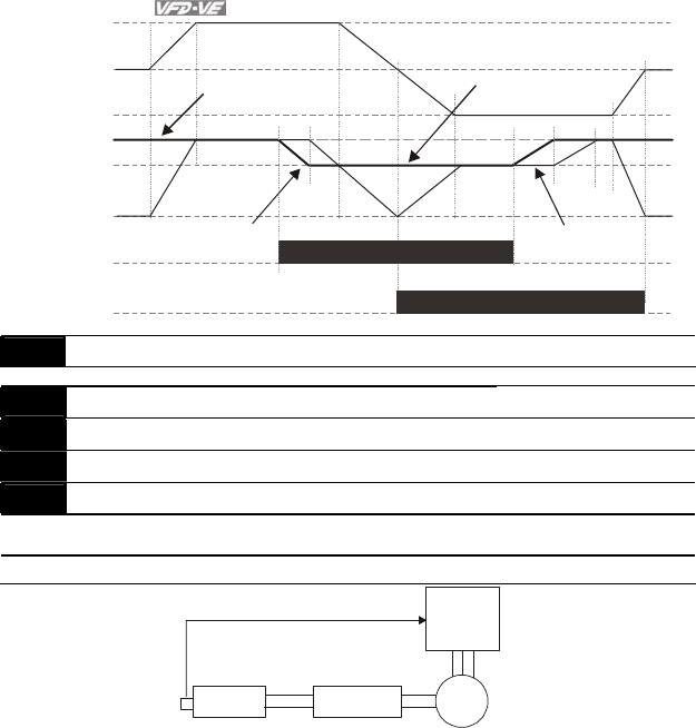
Chapter 4 Parameters|
4-156 Revision August 2008, 03VE, SW V2.04
AUI +10V
AUI 0V
AUI -10V
0Hz
Max. output frequency
Pr.01-00
Resolution switch frequency
Pr.10-25
Forward running
Reverse running
Output
frequency
Resolution switch
Pr.02-11~02-14=43
Max. waiting time for
frequency switch Max. waiting time for
frequency switch
10-26 Reserved
10-27 PG Mechanical Gear A1 Unit: 1
10-28 PG Mechanical Gear B1 Unit: 1
10-29 PG Mechanical Gear A2 Unit: 1
10-30 PG Mechanical Gear B2 Unit: 1
Control
mode VFPG FOCPG TQRPG
Factory Setting: 100
Settings 1 to 65535
1:10
10:1
Driver
Motor
Gear ratio B1/B2
Gear ratio
Load
Gear ratio A1/A2
Encoder is used
at load side
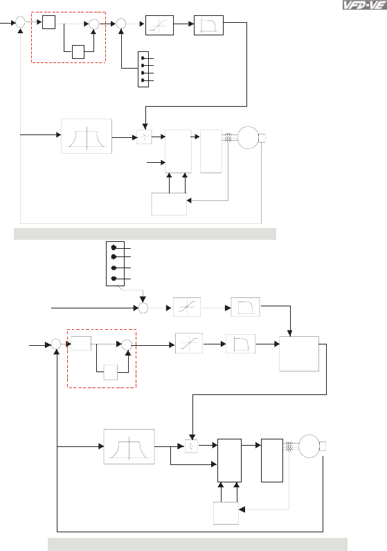
Chapter 4 Parameters|
Revision August 2008, 03VE, SW V2.04 4-157
P
I
IGBT
&
PWM
M
07-27
TQ B i as
10-09
01-01
01-02
05-01~09
10-00
10-01
00-20
+
-
+
+
+
+
current
limit
current
measure
actual frequency
current feedback
torque limit
no offset
by analog input (Pr.03-00)
torque offset setting
controlled by external terminals (Pr.07-29 to Pr.07-31)
flux weakening curve
Control Diagram for the Vector + Torque
10-04
10-06
10-21
and
10-05
10-07
10-22
07-32~07-35
10-04
10-06
10-21
10-05
10-07
10-22
and
P
I
10-09
IGBT
&
PWM
M
01-01
01-02
05-01~09
10-00
10-01
+
-
+
+
+
+
06-12 07-23
+
no offset
by analog input (Pr.03-00)
to rq ue of f set settin g
c ontr ol le d b y e xt ern al te rmi na ls ( Pr.0 7- 29 to Pr.0 7-3 1)
tor que co mman d
07 -2 1
07 -24 o r 00-2 0
sp eed l imi t or com mand
tor que l imi t
07 -3 2~ 07- 35
ac tu al f re qu enc y
Con trol Di ag ram fo r the To rqu e + Encode r
sp eed to rqu e
mode switch
Cu rre nt fe edb ac k
Cu rre nt
contr ol
Cur ren t
mea sur e
flux weakening curve

Chapter 4 Parameters|
4-158 Revision August 2008, 03VE, SW V2.04
RUN STOP
ON OFF
OFF ON
03-00~03=2
(AVI/AUI/ACI
is torque command)
RUN/STOP
multi-function input
te rminal is set to 2 6
(torque/speed mode switch)
Control mode
speed
command
speed
command
speed limit speed limit
torque
limit torque
limit
to rque
command
to rque
command
speed
command
speed
control
speed
control
to rque
command
to rque
command
speed control
(decelerate to stop)
Torque Control/Speed Contr ol Switch Timing
(00-10=3/4, multi-function input terminal is set to 26)
03-00~03=1
(AVI/AUI/ACI is
frequency command)
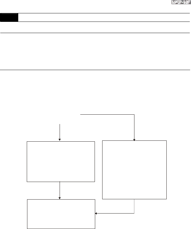
Chapter 4 Parameters|
Revision August 2008, 03VE, SW V2.04 4-159
Group 11 Advanced Parameters
11-00 System Control
Control
mode FOCPG
Factory Setting: 0
Settings Bit 0 ASR Auto tuning
Bit 1 Inertia estimate (only in FOCPG mode)
Bit 2 Zero Servo
Bit 3 Reserved
Bit 4 Enable gain adjustment of position loop KP
Bit 0=1: system will generate an ASR setting and Pr. 10-04~10-07, 10-21~10-22 will be invalid.
Bit 1=1: Inertia estimate function is enabled.
Bit 2=1: when frequency command is less than Fmin (Pr.01-07), it will use zero servo function.
YES
NO
Estimate Jm value
Setting auto gain adjustment
Pr.11-00=1
Adjust Pr.11-02, 11-03 and 11-11
separately by speed response
Adjust by requirement
Pr.11-04 (PDFF function)
Adjust by requirement
Pr.10-08
(ASR1/ASR2 switch frequency)
Adjust by requirement
Pr.07-32~35 (torque limit)
Adjust gain value by manual
Pr.11-00=0 (factory setting)
Adjust Pr.10-04, 10-05, 10-06,
10-07, 10-21 and 10-22
separatelyby speed response
Adjust by requirement
Pr.10-09 (for general,
no need to adjust)
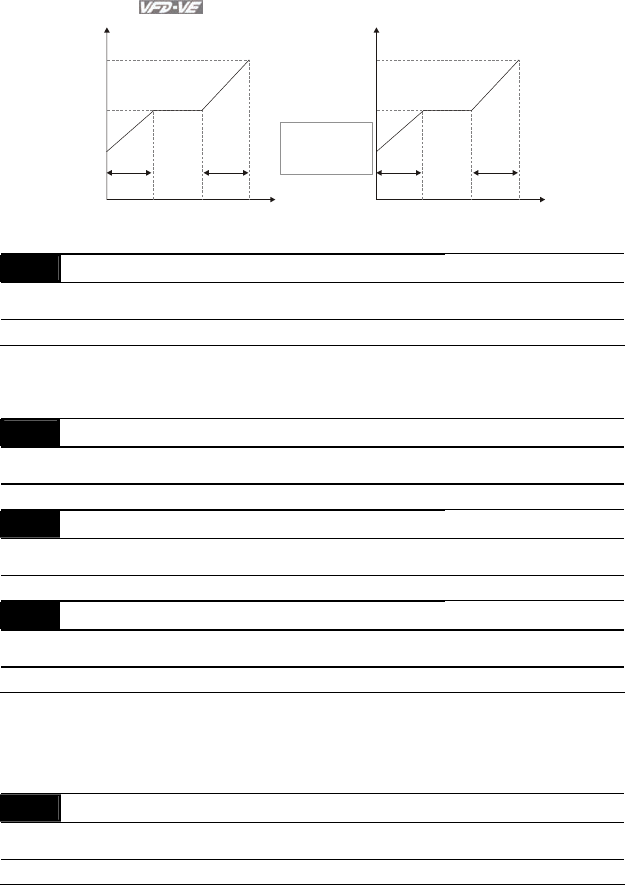
Chapter 4 Parameters|
4-160 Revision August 2008, 03VE, SW V2.04
PI
Hz
10-06
10-07
10-04
10-05
10-21
10-22
0Hz 10-08
5Hz 5Hz
PI
Hz
11-03
11-02
0Hz 10-08
5Hz 5Hz
PI adjustment-manual gain PI adjustment-auto gain
1. Pr. 11-01 value
2. set Pr.11-00 to 1
Pr.11-11
use to adjust the
strength of zero-
servo lock
11-01 Per Unit of System Inertia Unit: 1
Control
mode FOCPG
Factory Setting: 400
Settings 1 to 65535 (256=1PU)
To get the system inertia from Pr.11-01, user needs to set Pr.11-00 to 2 and execute
continuous forward/reverse running.
11-02 Low-speed Bandwidth Unit: 1
Control
mode FOCPG
Factory Setting: 10
Settings 0 to 40Hz
11-03 High-speed Bandwidth Unit: 1
Control
mode FOCPG
Factory Setting: 10
Settings 0 to 40Hz
11-11 Zero-speed Bandwidth Unit: 1
Control
mode VFPG FOCPG TQRPG
Factory Setting: 10
Settings 0 to 40Hz
After estimating inertia and set Pr.11-00 to 1 (auto tuning), user can adjust parameters Pr.11-
02, 11-03 and 11-11 separately by speed response. The larger number you set, the faster
response you will get. Pr.10-08 is the switch frequency for low-speed/high-speed bandwidth.
11-04 PDFF Gain Value Unit: 1
Control
mode FOCPG
Factory Setting: 30
Settings 0 to 200%

Chapter 4 Parameters|
Revision August 2008, 03VE, SW V2.04 4-161
After finishing estimating and set Pr.11-00=1 (auto tuning), using Pr.11-04 to reduce overshoot.
Please adjust PDFF gain value by actual situation.
Besides traditional PI control, it also provides PDFF function to reduce overshoot for speed
control.
1. Get Pr.11-01 value
2. Set Pr.11-00 to 1
3. Adjust Pr.11-04 (the larger number is set and the suppressed overshoot function will be
better. But it needs to be used by the actual condition)
PI PDFF
It is recommended to disable
this function (Pr.11-04=0) for
Y/ connection switch and
ASR1/ASR2 switch application.
11-05 Gain Value of Flux Weakening Curve for Motor 1 Unit: 1
Control
mode FOCPG
Factory Setting: 90
Settings 0 to 200%
It is used to adjust the output voltage of flux weakening curve.
For the spindle application, the adjustment method is
1. It is used to adjust the output voltage when exceeding rated frequency.
2. Monitor the output voltage
3. Adjust Pr.11-05 (motor 1) or Pr.11-06 (motor 2) setting to make the output voltage reach
motor rated voltage.
4. The larger number it is set, the larger output voltage you will get.
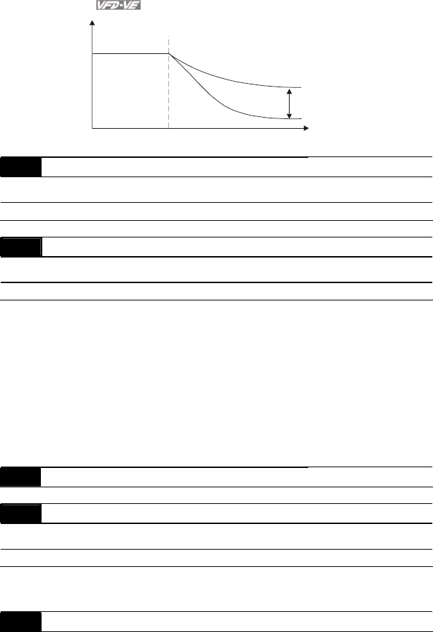
Chapter 4 Parameters|
4-162 Revision August 2008, 03VE, SW V2.04
Hz
N-m
Fbase
11-05/11 -06
Flux Weakening Curve
11-06 Gain Value of Flux Weakening Curve for Motor 2 Unit: 1
Control
mode FOCPG
Factory Setting: 90
Settings 0 to 200%
11-07 Detection Time for Phase-loss Unit: 0.01
Control
mode VF VFPG SVC FOCPG TQRPG Factory Setting: 0.20
Settings 0.01 to 600.00 sec
When the phase-loss occurs and exceeds this detection time, the fault code “PHL” will be
displayed. The AC motor drive will record the operation time during phase-loss.
When phase-loss occurs and Pr.11-07 is set to 0, it won’t display PHL and won’t execute
Pr.06-02.
When user sets this parameter to 0 or not factory setting, we won’t promise that all
characteristics will be the same as the 3-phase input.
If it is set to 0 or a larger number, it will short the life of rectifier and capacitors in the AC motor
drive.
11-08 Reserved
11-09 Level of Phase-loss Unit: 0.1
Control
mode VF VFPG SVC FOCPG TQRPG Factory Setting: 60.0
Settings 0.0 to 320.0
11-10 Speed Feed Forward Gain Unit: 1

Chapter 4 Parameters|
Revision August 2008, 03VE, SW V2.04 4-163
Control
mode FOCPG
Factory Setting: 0
Settings 0 to 100%
11-12 Speed Response of Flux Weakening Area Unit: 1
Control
mode FOCPG
Factory Setting: 65
Settings 0 to 150% (0: disable)
It is used to control the response speed for the flux weakening area. The larger number you
set, the faster response you will get.
11-13 Notch Filter Depth Unit: 1
Control
mode FOCPG
Factory Setting: 0
Settings 0 to 20 db
11-14 Notch Filter Frequency Unit: 0.01
Control
mode FOCPG
Factory Setting: 0.00
Settings 0.00 to 200.00
This parameter is used to set resonance frequency of mechanical system. It can be used to
suppress the resonance of mechanical system.
The larger number you set Pr.11-13, the better suppression resonance function you will get.
The notch filter frequency is the resonance of mechanical frequency.
11-15 Gain Value of Slip Compensation Unit: 0.01
Control
mode SVC
Factory Setting: 1.00
Settings 0.00 to 1.00
It is only valid in SVC mode.
When the AC motor drive drives the asynchronous motor, slip will increase when the load is
added. This parameter can be used to change frequency, lower slip and make the motor be
synchronous when running under rated current. When the output current is higher than no-load
current, the AC motor drive will adjust frequency by this parameter. If the actual speed is
slower than expected, please increase the setting or decrease the setting.
11-16 Low-pass Filter Time of Keypad Display Unit: 0.001
Control
mode VF VFPG SVC FOCPG TQRPG Factory Setting: 0.100

Chapter 4 Parameters|
4-164 Revision August 2008, 03VE, SW V2.04
Settings 0.001 to 65.535 Sec
It is used to lower the blinking frequency of LCD display.
11-17 Low-pass Filter Time of PG2 Pulse Input Unit: 0.001
Control
mode VF VFPG SVC FOCPG Factory Setting: 0.100
Settings 0.000 to 65.535 Sec
11-18 APR Gain Unit: 0.01
Control
mode FOCPG
Factory Setting: 10.00
Settings 0.00 to 40.00
11-19 APR Curve Time Unit: 0.01
Control
mode FOCPG
Factory Setting: 3.00
Settings 0.00 to 655.35 sec
11-20
|
11-28
Reserved
11-29 Accumulative Operation Time of Phase-loss Unit: 1
Control
mode VF VFPG SVC FOCPG TQRPG Factory Setting: 0
Settings 0 to 65535 (hour)
11-30
|
11-40
Reserved

Chapter 4 Parameters|
Revision August 2008, 03VE, SW V2.04 4-165
This page intentionally left blank
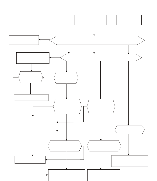
Revision August 2008, 03VE, SW V2.04 5-1
Chapter 5 Troubleshooting
5.1 Over Current (OC)
ocA ocd OC
Over-current
during acceleration
Over-current
during acceleration Over current
Check if there is any
between the U, V, W and motor
short circuits and
grounding
Yes
No No No
No No No
Yes
Yes
Yes
Remove short circuit
or ground fault
Reduce the load or
increase the power
of AC motor drive
NoNo Reduce torque
compensation
Reduce torque
compensation
Suitable torque
compensation
No No
No
No
No
Yes Ye s
Yes
Yes
Yes
Maybe AC motor drive
has malfunction or error
due to noise. Please
contact DELTA.
Can acceleration
time be made longer?
Can deceleration
time be made longer?
Reduce load or increase
the power of AC motor
drive
Check braking
method. Please
contact DELTA
Reduce load or increase
the power of AC motor
drive
Is load changed
suddenly?
Check if
acceleration time
is too short by
load inertia.
Check if
deceleration time
is too short by
load inertia.
Increase accel/decel
time
If load is too large
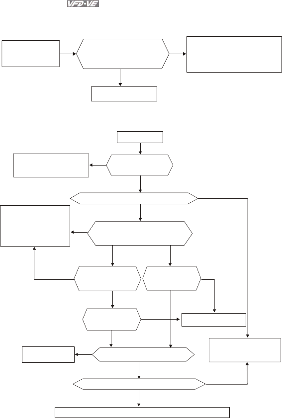
Chapter 5 Troubleshooting|
5-2 Revision August 2008, 03VE, SW V2.04
5.2 Ground Fault
GFF
Ground fault
No
Yes
If output circuit(cable or
motor) of AC motor drive
is grounded?
Remove grounding
Maybe AC motor drive has
malfunction or misoperation
due to noise. Please
contact DELTA.
5.3 Over Voltage (OV)
Over voltage
Ye s
No
Ye s
No
No
No
If voltage is within
specification
Reduce voltage to
be within spec.
If over-voltage is occurred without load
Maybe AC motor drive
has malfunction or
misoperation due to
noise. Please contact
DELTA.
Ye s Yes
Yes
Yes
Yes
Yes
No
No
No
No
No
When OV occurs, check if the
voltage of DC BUS is greater
than protection value
If OV occurs when
sudden acceleration
stops
Increase
deceleration
time
Increase setting time
Increase
acceleration
time
Reduce moment
of inertia Reduce moment of load inertia
Use brake unit or DC brake
Need to check control method. Please contact DELTA.
Need to considerate to
use brake unit and
DC brake
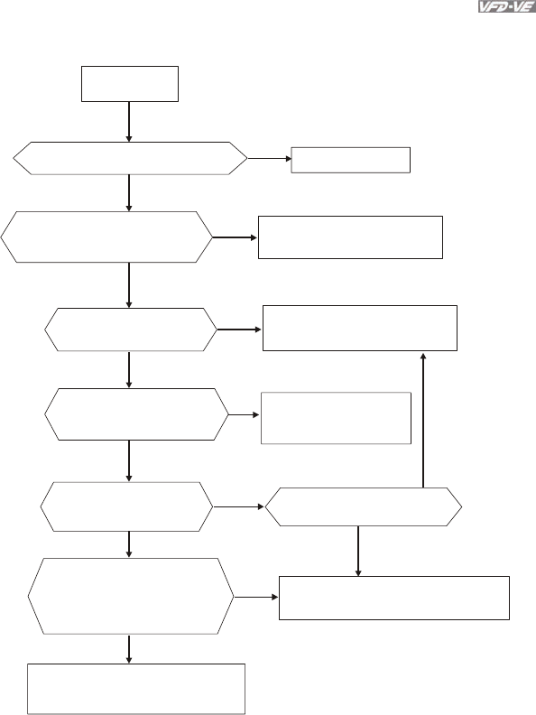
Chapter 5 Troubleshooting|
Revision August 2008, 03VE, SW V2.04 5-3
5.4 Low Voltage (Lv)
Low voltage
Power cut, including momentary
power loss
Ye s
Yes
Yes
Ye s
Yes
Yes
No
No
No
No
No
No
No
Restart after reset
Check if there is any ma lfunction
component in
power supply circuit
or disconnection Change defective component
and check connection
Check if voltage is
within specification
Change power supply
system for requirement
Check if there is heavy load
with high start current in the
same power system
Check if Lv occurs when
breaker and magnetic
contactor is ON
Suitable
transformer
power
capacity
Check if voltage between +1/+2
and - is greater than Pr.06-00 Maybe AC motor drive has malfunction.
Please contact DELTA.
Control circuit has malfunction or
misoperation due to noise. Please
contact DELTA.
Ye s Using the different power
supply for this drive and
heavy load system
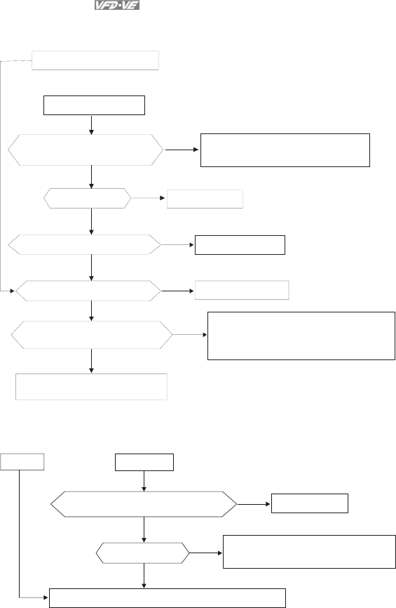
Chapter 5 Troubleshooting|
5-4 Revision August 2008, 03VE, SW V2.04
5.5 Over Heat (oH1, oH2, oH3)
AC motor drive overheats
Heat sink overheats
Check if temperature of heat sink
is larger than 90
O
C
No
No
No
Yes
Yes
Yes
Yes
Yes
No
Reduce load
No Temperature detection malfunctions.
Please contact DELTA.
If cooling fan functions normally Change cooling fan
Check if cooling fan is jammed Remove obstruction
Check if surrounding temperature
is withi n specification
Adjust surrounding temperature
to specification
Maybe AC motor drive has malfunction or
misoperation due to noise. Please contact
DELTA.
If load is too large
5.6 Overload
OL1/ OL2
OL
Reduce load or increase the power of AC motor drive
Check if the setting of electronic
thermal relay is suitable
Ye s
Yes
No
No Modify setting
If load is too large Maybe AC motor drive has malfunction
or misoperation due to noise.
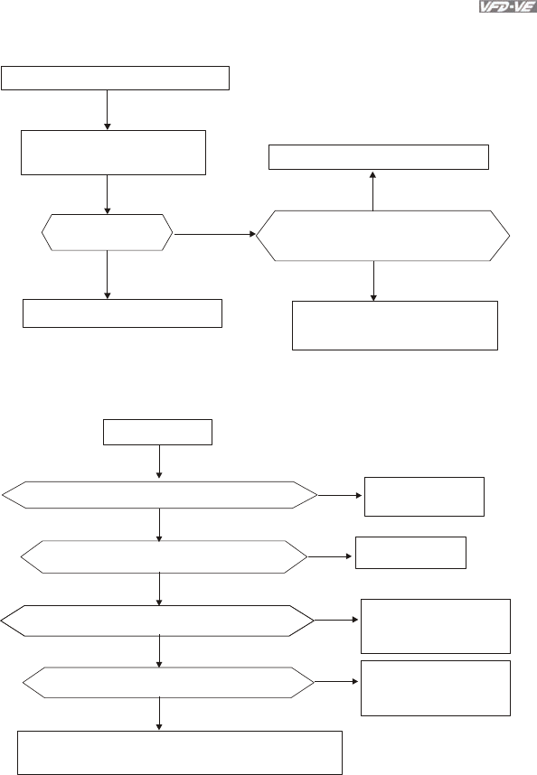
Chapter 5 Troubleshooting|
Revision August 2008, 03VE, SW V2.04 5-5
5.7 Display of KPV-CE01 is Abnormal
Abnormal display or no display
Turn the power off and power
on again after display is off
No
Ye s
Ye s Ye s
No
Display normal?
AC motor drive works normally
Fix connector and eliminate noise
Check if all connectors are connected
well and if there is no noise
AC motor drive has malfunction.
Please contact DELTA.
5.8 Phase Loss (PHL)
Phase loss
No
Yes
Check if the wiring of terminals R, S and T is OK Connect all three
phase well
Check if the screws of terminals are tightened No Tighten all screws
Maybe AC motor drive has malfunction or misoperation
due to noise. Please contact DELTA.
No
Yes
Yes Please check the wiring
and power system for
abnormal power
Check if the input voltage of R, S, T is unbalanced
Yes
Yes Please check the wiring
and power system for
abnormal power
Check if the input voltage of R, S, T is unbalanced
No
Yes Please check the fuse
at AC side
Check if it is 40hp and above
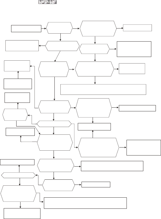
Chapter 5 Troubleshooting|
5-6 Revision August 2008, 03VE, SW V2.04
5.9 Motor cannot Run
Motor cannot run
Check if CE01
displays
normally
No No
No
No
No No
No
No
No No No No
No
No
No
Check if non-fuse
breaker and magnetic
contactor are ON
Yes Ye s
Ye s
Ye s
Yes
Yes
Yes
Yes
Ye s
Yes
Yes
Set them to ON
Reset after clearing
fault and then RUN Check if there is any
fault code displayed Check if input
voltage is normal
Check if any faults
occur, such as
Lv, PHL or
disconnection
Input "RUN"
command
by keypad
It ca n run when
no faults occur If jumper or DC
reactor is connected
between +1 and +2/B1
Use jumper
or DC reactor
Press RUN key to
check if it can run Maybe AC motor drive has malfunction or misoperation
due to noise. Please contact DELTA.
Press UP key to
set frequency
Yes
Modify frequency
setting
Check if input FWD
or REV command
Check if the wiring
of terminal FWD
and between
REV-DCM is correct
Yes
Change switch or relay
Set frequency or not
Press UP to
check if motor
can run
Correct connection
Check if the parameter
setting and wiring of
analog signal and
multi-step speed
are correct
No
Motor has malfunction No Maybe AC motor drive has malfunction.
Please contact DELTA.
Check if there is any
output voltage from
terminals U, V and W
Check if motor
connection
is correct
No Connect correctly
Check if the setting
of torque
compensation
is correct
Increase the setting of
torque compensation
Motor is locked due to large load, please reduce load.
For example, if there is a brake, check if it is released.
If load is too large
if upper bound freq.
and setting freq. is
lower than the min.
output freq. Ye s Change defective
potentiometer and
relay
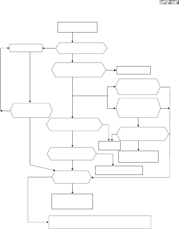
Chapter 5 Troubleshooting|
Revision August 2008, 03VE, SW V2.04 5-7
5.10 Motor Speed cannot be Changed
Motor can run but
cannot change speed
Ye s
Yes
Ye s
Ye s
Yes
Ye s
Yes
Ye s
No
No
No
No
No
No
No
No
No
Check if the setting of the
max. frequency is too low
If the setting of frequency
is out of range(upper/lower)
bound
Modify the setting
Modify the setting
Yes
If the setting of
Pr.04-00 to Pr.04-14
are the same
Press UP/DOWN key
to see if speed has
any change
If there is any change
of the signal that sets
frequency (0-10V and
4-20mA)
Check if the wiring between
M1~M6 to DCM is correct
Connect
correctly
Check if frequency for
each step is different
Check if the wiring of
external terminal is correct
Change frequency setting
If accel./decel. time
is very long
Please set suitable
accel./decel. time by
load inertia
Maybe AC motor drive has malfunction or misoperation
due to noise. Please contact DELTA.
Change defective
potentiometer
No
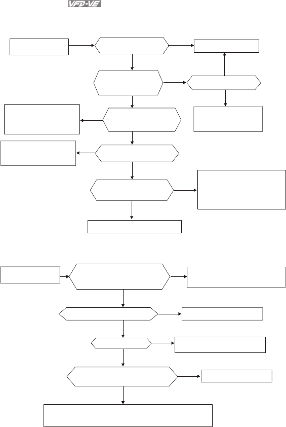
Chapter 5 Troubleshooting|
5-8 Revision August 2008, 03VE, SW V2.04
5.11 Motor Stalls during Acceleration
Motor stalls during
acceleration
Check if acceleration
time is too short
Yes
Yes
Yes
Yes
No
No No
No
No
No
Increase setting time
Yes Use special motor?
Reduce load or
increase the capacity
of AC motor drive
Check if the inertia
of motor and load
are very high
Check if the voltage of
terminal is lower than
before
Check if the load torque
is too high
Yes
Maybe AC motor drive has
malfunction or misoperation
due to noise. Please contact
DELTA
Increase torque compensation
Check if the torque
compensation is suitable
Thicken or shorten the
wiring between the
motor or AC motor drive
Reduce load or
increase the capacity
of AC motor drive
5.12 The Motor does not Run as Expected
Check if V/f characteristic
and torque compensation
is suitable
No
Yes
Yes
Yes
Yes
No
No
No
Adjust
and lower torque compensation
V/f characteristic
Run in low speed continuously
If load is too large
Please use specific motor
Reduce load or increase the
capacity of AC motor drive
Check if output voltage of U, V W
is balanced Motor has malfunction
Maybe AC motor drive has malfunction or misoperation
due to noise. Please contact DELTA.
Motor does not run
as expected

Chapter 5 Troubleshooting|
Revision August 2008, 03VE, SW V2.04 5-9
5.13 Electromagnetic/Induction Noise
There are many noises surround the AC motor drives and invade it by radiation or power circuit. It
may cause the misoperation of control circuit and even damage the AC motor drive. Of course, that
is a solution to increase the noise tolerance of AC motor drive. But it is not the best one due to the
limit. Therefore, solve it from the outside as following will be the best.
1. Add surge killer on the relay or contact to suppress switching surge between ON/OFF.
2. Shorten the wiring length of the control circuit or serial circuit and separate from the main
circuit wiring.
3. Comply with the wiring regulation for those shielded wire and use isolation amplifier for
long wire.
4. The grounding terminal should comply with the local regulation and ground independently,
i.e. not to have common ground with electric welding machine and power equipment.
5. Connect a noise filter at the input terminal of the AC motor drive to prevent noise from
power circuit.
In a word, three-level solutions for electromagnetic noise are “no product”, “no spread” and
“no receive”.
5.14 Environmental Condition
Since AC motor drive is an electronic device, you should comply with the environmental condition
stated in the appendix A. Following are the remedial measures for necessary.
1. To prevent vibration, anti-vibration spacer is the last choice. The vibration tolerance must
be within the specification. The vibration effect is equal to the mechanical stress and it
cannot occur frequently, continuously or repeatedly to prevent damaging AC motor drive.
2. Store in a clean and dry location free from corrosive fumes/dust to prevent rustiness, poor
contact. It also may cause short by low insulation in a humid location. The solution is to
use both paint and dust-proof. For particular occasion, use the enclosure with whole-seal
structure.
3. The surrounding temperature should be within the specification. Too high or low
temperature will affect the lifetime and reliability. For semiconductor components, damage
will occur once any specification is out of range. Therefore, it is necessary to clean and
periodical check for the air cleaner and cooling fan besides having cooler and sunshade.
In additional, the microcomputer may not work in extreme low temperature and needs to
have heater.
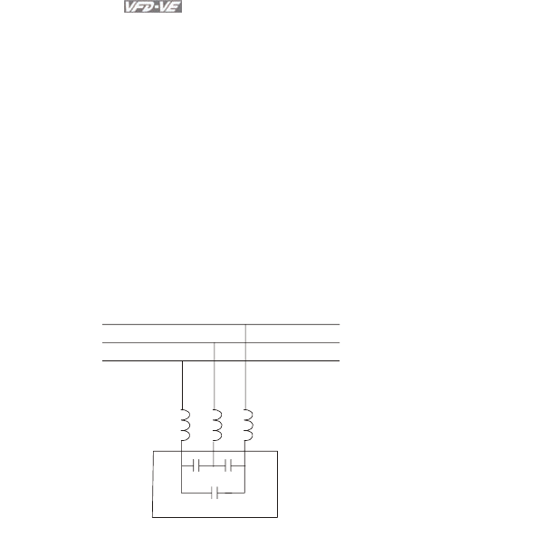
Chapter 5 Troubleshooting|
5-10 Revision August 2008, 03VE, SW V2.04
4. Store within a relative humidity range of 0% to 90% and non-condensing environment. Do
not turn off the air conditioner and have exsiccator for it.
5.15 Affecting Other Machines
AC motor drive may affect the operation of other machine due to many reasons. The solutions are as
follows.
High Harmonic at Power Side
If there is high harmonic at power side during running, the improved methods are:
1. Separate power system: use transformer for AC motor drive.
2. Use reactor at the power input terminal of AC motor drive or decrease high harmonic by
multiple circuit.
3. If there is phase lead capacitor, it should use serial reactor to prevent capacitor damage
from high harmonic.
serial reactor
phase lead capacitor
Motor Temperature Rises
When the motor is induction motor with ventilation-cooling-type used in variety speed
operation, bad cooling will happen in the low speed. Therefore, it may overheat. Besides,
high harmonic is in output waveform to increase copper loss and iron loss. Following
measures should be used by load situation and operation range when necessary.
1. Use the motor with independent power ventilation or increase the horsepower.
2. Use inverter duty motor.
3. Do NOT run in the low speed
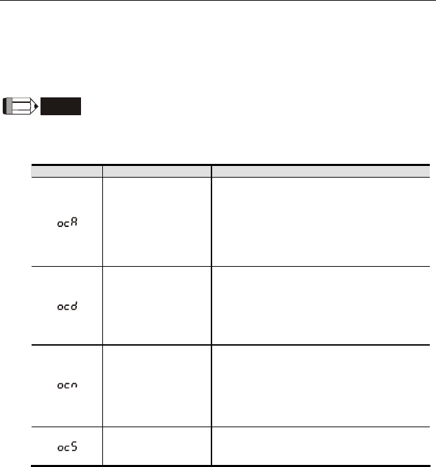
Revision August 2008, 03VE, SW V2.04 6-1
Chapter 6 Fault Code Information and Maintenance
6.1 Fault Code Information
The AC motor drive has a comprehensive fault diagnostic system that includes several different
alarms and fault messages. Once a fault is detected, the corresponding protective functions will be
activated. The following faults are displayed as shown on the AC motor drive digital keypad display.
The six most recent faults can be read from the digital keypad or communication.
NOTE
Wait 5 seconds after a fault has been cleared before performing reset via keypad of input terminal.
6.1.1 Common Problems and Solutions
Fault Name Fault Descriptions Corrective Actions
Over-current during
acceleration
(Output current
exceeds triple rated
current during
acceleration.)
1. Short-circuit at motor output: Check for
possible poor insulation at the output
lines.
2. Acceleration Time too short: Increase the
Acceleration Time.
3. AC motor drive output power is too small:
Replace the AC motor drive with the next
higher power model.
Over-current during
deceleration
(Output current
exceeds triple rated
current during
deceleration.)
1. Short-circuit at motor output: Check for
possible poor insulation at the output line.
2. Deceleration Time too short: Increase the
Deceleration Time.
3. AC motor drive output power is too small:
Replace the AC motor drive with the next
higher power model.
Over-current during
steady state
operation
(Output current
exceeds triple rated
current during
constant speed.)
1. Short-circuit at motor output: Check for
possible poor insulation at the output line.
2. Sudden increase in motor loading: Check
for possible motor stall.
3. AC motor drive output power is too small:
Replace the AC motor drive with the next
higher power model.
Hardware failure in
current detection Return to the factory

Chapter 6 Fault Code Information and Maintenance|
6-2 Revision August 2008, 03VE, SW V2.04
Fault Name Fault Descriptions Corrective Actions
Ground fault
When (one of) the output terminal(s) is
grounded, short circuit current is more than
50% of AC motor drive rated current, the AC
motor drive power module may be damaged.
NOTE: The short circuit protection is
provided for AC motor drive protection,
not for protection of the user.
1. Check the wiring connections between the
AC motor drive and motor for possible
short circuits, also to ground.
2. Check whether the IGBT power module is
damaged.
3. Check for possible poor insulation at the
output line.
Short-circuit is
detected between
upper bridge and
lower bridge of the
IGBT module
Return to the factory
DC BUS over-voltage
during acceleration
(230V: DC 450V;
460V: DC 900V)
DC BUS over-voltage
during deceleration
(230V: DC 450V;
460V: DC 900V)
DC BUS over-voltage
in constant speed
(230V: DC 450V;
460V: DC 900V)
1. Check if the input voltage falls within the
rated AC motor drive input voltage range.
2. Check for possible voltage transients.
3. If DC BUS over-voltage due to
regenerative voltage, please increase the
Deceleration Time or add an optional
brake resistor.
Hardware failure in
voltage detection
Check if input voltage is within specification
range and monitor if there is surge voltage.
DC BUS voltage is
less than Pr.06-00
during acceleration
DC BUS voltage is
less than Pr.06-00
during deceleration
DC BUS voltage is
less than Pr.06-00 in
constant speed
DC BUS voltage is
less than Pr.06-00 at
stop
1. Check if the input voltage is normal
2. Check for possible sudden load
Phase Loss
Check Power Source Input if all 3 input phases
are connected without loose contacts.
For models 40hp and above, please check if
the fuse for the AC input circuit is blown.
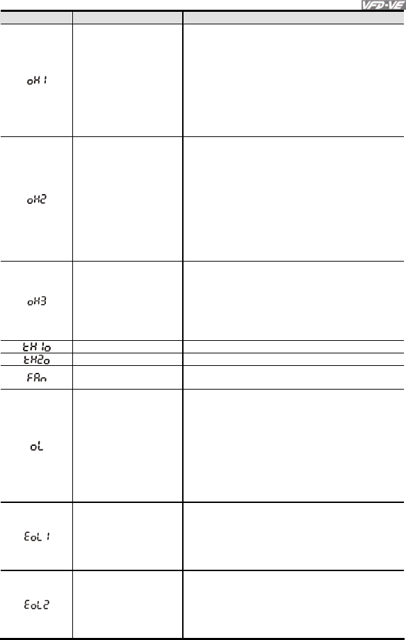
Chapter 6 Fault Code Information and Maintenance|
Revision August 2008, 03VE, SW V2.04 6-3
Fault Name Fault Descriptions Corrective Actions
IGBT overheating
IGBT temperature
exceeds protection
level
1 to15HP: 90 oC
20 to 100HP: 100 oC
1. Ensure that the ambient temperature falls
within the specified temperature range.
2. Make sure that the ventilation holes are
not obstructed.
3. Remove any foreign objects from the
heatsinks and check for possible dirty
heat sink fins.
4. Check the fan and clean it.
5. Provide enough spacing for adequate
ventilation.
Heatsink
overheating
Heat sink
temperature exceeds
90oC
1. Ensure that the ambient temperature
falls within the specified temperature
range.
2. Make sure that the ventilation holes are
not obstructed.
3. Remove any foreign objects from the
heatsinks and check for possible dirty
heat sink fins.
4. Check the fan and clean it.
5. Provide enough spacing for adequate
ventilation.
Motor overheating
The AC motor drive
detects that the
internal temperature
exceeds Pr.06-30
(PTC level)
1. Make sure that the motor is not
obstructed.
2. Ensure that the ambient temperature
falls within the specified temperature
range.
3. Take the next higher power AC motor
drive model.
OH1 hardware failure Return to the factory
OH2 hardware failure Return to the factory
Fan failure 1. Make sure that the fan is not obstructed.
2. Return to the factory
Overload
The AC motor drive
detects excessive
drive output current.
NOTE: The AC motor
drive can withstand
up to 150% of the
rated current for a
maximum of 60
seconds.
1. Check whether the motor is overloaded.
2. Take the next higher power AC motor
drive model.
Motor 1 overload
1. Check whether the motor 1 is
overloaded.
2. Check whether the rated current of motor
1 (Pr.05-01) is suitable
3. Take the next higher power AC motor
drive model.
Motor 2 overload
1. Check whether the motor 2 is
overloaded.
2. Check whether the rated current of motor
2 (Pr.05-13) is suitable
3. Take the next higher power AC motor
drive model.
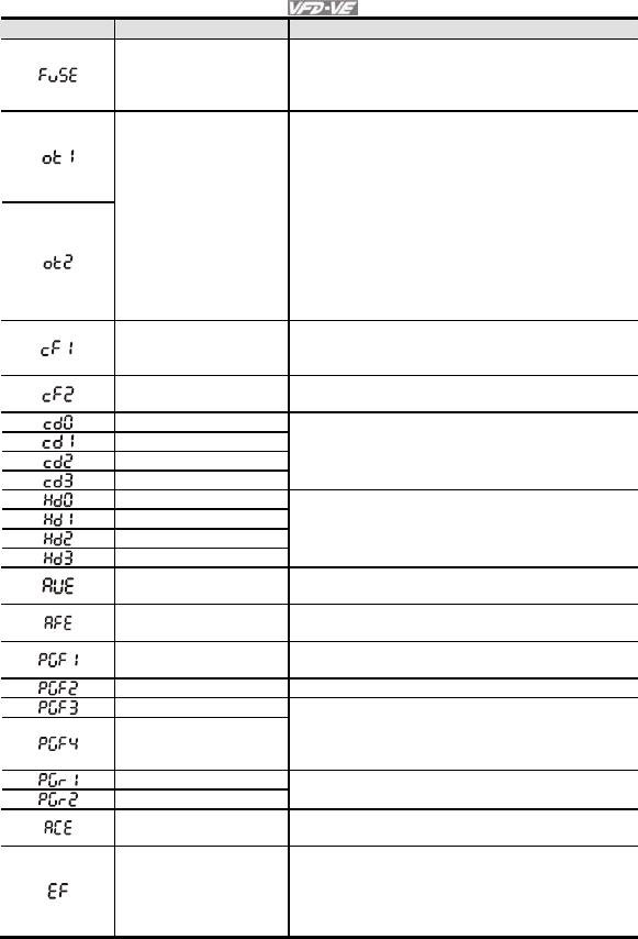
Chapter 6 Fault Code Information and Maintenance|
6-4 Revision August 2008, 03VE, SW V2.04
Fault Name Fault Descriptions Corrective Actions
Broken fuse
The fuse at DC side
is broken for 30hp
and below
1. Check whether the fuse of the transistor
module is functioning well
2. Check whether the loading side is short-
circuit
Electronic Thermal
Relay 1/2 Protection
These two fault codes
will be displayed
when output current
exceeds the level of
over-torque detection
(Pr.06-08 or Pr.06-
11) and it is set 2 or 4
in Pr.06-06 or Pr.06-
09.
1. Check whether the motor is overloaded.
2. Check whether motor rated current
setting (Pr.05-01) is suitable
3. Check electronic thermal relay function
4. Take the next higher power AC motor
drive model.
Internal EEPROM
can not be
programmed.
1. Press “RESET” key to the factory setting
2. Return to the factory.
Internal EEPROM
can not be read.
1. Press “RESET” key to the factory setting
2. Return to the factory.
Isum error
U-phase error
V-phase error
W-phase error
Re-power on to try it. If fault code is still
displayed on the keypad please return to the
factory
CC (current clamp)
OC hardware error
OV hardware error
GFF hardware error
Re-power on to try it. If fault code is still
displayed on the keypad please return to the
factory
Auto tuning error 1. Check cabling between drive and motor
2. Retry again
PID loss (ACI) 1. Check the wiring of the PID feedback
2. Check the PID parameters settings
PG feedback error Check if Pr.10-01 is set to 0 when it is PG
feedback control
PG feedback loss Check the wiring of the PG feedback
PG feedback stall
PG slip error
1. Check the wiring of the PG feedback
2. Check if the setting of PI gain and
deceleration is suitable
3. Return to the factory
Pulse input error
Pulse input loss
1. Check the pulse wiring
2. Return to the factory
ACI loss 1. Check the ACI wiring
2. Check if the ACI signal is less than 4mA
External Fault
1. Input EF (N.O.) on external terminal is
closed to GND. Output U, V, W will be
turned off.
2. Give RESET command after fault has
been cleared.
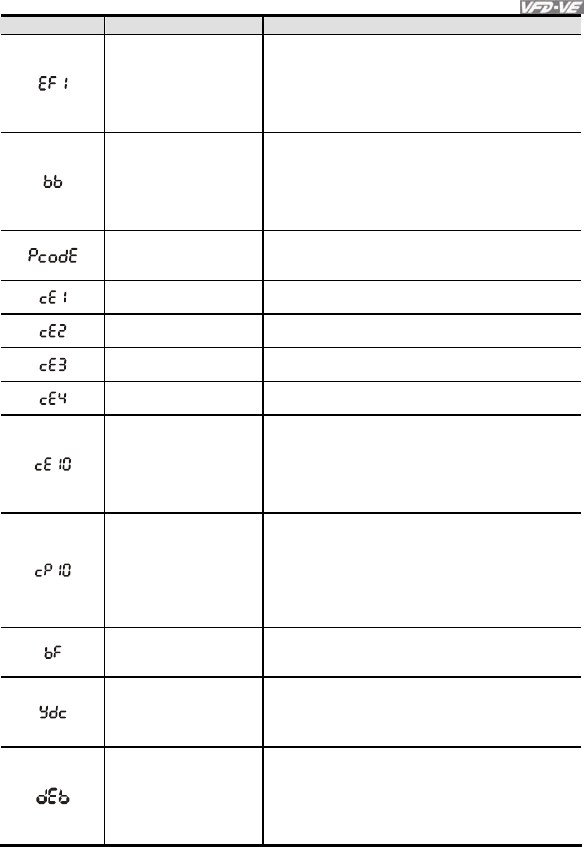
Chapter 6 Fault Code Information and Maintenance|
Revision August 2008, 03VE, SW V2.04 6-5
Fault Name Fault Descriptions Corrective Actions
Emergency stop
1. When the multi-function input terminals
MI1 to MI6 are set to emergency stop,
the AC motor drive stops output U, V, W
and the motor coasts to stop.
2. Press RESET after fault has been
cleared.
External Base Block
1. When the external input terminal (B.B) is
active, the AC motor drive output will be
turned off.
2. Deactivate the external input terminal
(B.B) to operate the AC motor drive
again.
Password is locked.
Keypad will be locked. Turn the power ON
after power OFF to re-enter the correct
password. See Pr.00-07 and 00-08.
Illegal function code Check if the function code is correct (function
code must be 03, 06, 10, 63)
Illegal data address
(00H to 254H) Check if the communication address is correct
Illegal data value Check if the data value exceeds max./min.
value
Data is written to
read-only address Check if the communication address is correct
Communication
time-out
COM1: exceeds
Pr.09-03 setting,
COM2: exceeds
Pr.09-07 setting
Check if the wiring for the communication is
correct
Keypad (KPV-CE01)
communication
time-out
COM1: exceeds
Pr.09-03 setting,
COM2: exceeds
Pr.09-07 setting
1. Check if the wiring for the
communication is correct
2. Check if there is any wrong with the
keypad
Brake resistor fault
If the fault code is still displayed on the keypad
after pressing “RESET” key, please return to
the factory.
Y-connection/Δ-
connection switch
error
1. Check the wiring of the Y-connection/Δ-
connection
2. Check the parameters settings
When Pr.07-13 is not
set to 0 and
momentary power off
or power cut, it will
display dEb during
accel./decel. stop.
1. Set Pr.07-13 to 0
2. Check if input power is stable
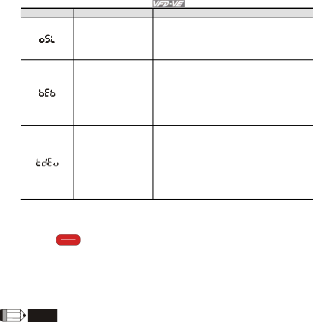
Chapter 6 Fault Code Information and Maintenance|
6-6 Revision August 2008, 03VE, SW V2.04
Fault Name Fault Descriptions Corrective Actions
It will be displayed
when slip exceeds
Pr.05-26 setting and
time exceeds Pr.05-
27 setting.
1. Check if motor parameter is correct (please
decrease the load if overload
2. Check the settings of Pr.05-26 and Pr.05-
27
It will be displayed
when broken belt
detection function is
enabled(Pr.08-59),
allowance error is
higher than Pr.08-61
and detection time
exceeds Pr.08-62.
1. Check if the belt is broken
2. Check the settings of Pr.08-60, Pr.08-62
and Pr.08-63
It will be displayed
when the allowance
error of tension PID
feedback exceeds
Pr.08-63 setting and
allowance error
detection time
exceeds Pr.08-64
setting.
1. Check if the PID feedback is correct
2. Check if the material is broken
3. Check the settings of Pr.08-63 and Pr.08-
64
6.1.2 Reset
There are three methods to reset the AC motor drive after solving the fault:
1. Press
RESET
STOP
key on KPV-CE01.
2. Set external terminal to “RESET” (set one of Pr.02-01~Pr.02-06/ Pr.02-23~Pr.02-30 to 5)
and then set to be ON.
3. Send “RESET” command by communication.
NOTE
Make sure that RUN command or signal is OFF before executing RESET to prevent damage or
personal injury due to immediate operation.

Chapter 6 Fault Code Information and Maintenance|
Revision August 2008, 03VE, SW V2.04 6-7
6.2 Maintenance and Inspections
Modern AC motor drives are based on solid state electronics technology. Preventive maintenance is
required to operate this AC motor drive in its optimal condition, and to ensure a long life. It is
recommended to have a check-up of the AC motor drive performed by a qualified technician.
Daily Inspection:
Basic check-up items to detect if there were any abnormalities during operation are:
1. Whether the motors are operating as expected.
2. Whether the installation environment is abnormal.
3. Whether the cooling system is operating as expected.
4. Whether any irregular vibration or sound occurred during operation.
5. Whether the motors are overheating during operation.
6. Always check the input voltage of the AC drive with a Voltmeter.
Periodic Inspection:
Before the check-up, always turn off the AC input power and remove the cover. Wait at least 10
minutes after all display lamps have gone out, and then confirm that the capacitors have fully
discharged by measuring the voltage between +1/+2 and -. The voltage between +1/+2 and-should
be less than 25VDC.
DANGER!
1. Disconnect AC power before processing!
2. Only qualified personnel can install, wire and maintain AC motor drives. Please take off any
metal objects, such as watches and rings, before operation. And only insulated tools are
allowed.
3. Never reassemble internal components or wiring.
4. Prevent static electricity.

Chapter 6 Fault Code Information and Maintenance|
6-8 Revision August 2008, 03VE, SW V2.04
Periodical Maintenance
Ambient environment
Maintenance
Period
Check Items Methods and Criterion
Daily Half
Year
One
Year
Check the ambient temperature,
humidity, vibration and see if
there are any dust, gas, oil or
water drops
Visual inspection and measurement
with equipment with standard
specification
{
If there are any dangerous
objects Visual inspection {
Voltage
Maintenance
Period
Check Items Methods and Criterion
Daily Half
Year
One
Year
Check if the voltage of main
circuit and control circuit is
correct
Measure with multimeter with standard
specification {
Keypad
Maintenance
Period
Check Items Methods and Criterion
Daily Half
Year
One
Year
Is the display clear for reading Visual inspection {
Any missing characters Visual inspection {
Mechanical parts
Maintenance
Period
Check Items Methods and Criterion
Daily Half
Year
One
Year
If there is any abnormal sound
or vibration Visual and aural inspection {
If there are any loose screws Tighten the screws {
If any part is deformed or
damaged Visual inspection {

Chapter 6 Fault Code Information and Maintenance|
Revision August 2008, 03VE, SW V2.04 6-9
Maintenance
Period
Check Items Methods and Criterion
Daily Half
Year
One
Year
If there is any color change by
overheating Visual inspection {
If there is any dust or dirt Visual inspection
{
Main circuit
Maintenance
Period
Check Items Methods and Criterion
Daily Half
Year
One
Year
If there are any loose or missing
screws Tighten or replace the screw {
If machine or insulator is
deformed, cracked, damaged or
with color change due to
overheating or ageing
Visual inspection
NOTE: Please ignore the color
change of copper plate
{
If there is any dust or dirt Visual inspection
{
Terminals and wiring of main circuit
Maintenance
Period
Check Items Methods and Criterion
Daily Half
Year
One
Year
If the terminal or the plate is
color change or deformation due
to overheat
Visual inspection {
If the insulator of wiring is
damaged or color change Visual inspection {
If there is any damage Visual inspection {

Chapter 6 Fault Code Information and Maintenance|
6-10 Revision August 2008, 03VE, SW V2.04
DC capacity of main circuit
Maintenance
Period
Check Items Methods and Criterion
Daily Half
Year
One
Year
If there is any leak of liquid,
color change, crack or
deformation
Visual inspection {
Measure static capacity when
required Static capacity ≥ initial value X 0.85 {
Resistor of main circuit
Maintenance
Period
Check Items Methods and Criterion
Daily Half
Year
One
Year
If there is any peculiar smell or
insulator cracks due to overheat Visual inspection, smell {
If there is any disconnection
Visual inspection or measure with
multimeter after removing wiring
between +1/+2 ~ -
Resistor value should be within
±
10%
{
Transformer and reactor of main circuit
Maintenance
Period
Check Items Methods and Criterion
Daily Half
Year
One
Year
If there is any abnormal vibration
or peculiar smell Visual, aural inspection and smell {
Magnetic contactor and relay of main circuit
Maintenance
Period
Check Items Methods and Criterion
Daily Half
Year
One
Year
If there are any loose screws Visual and aural inspection {
If the contact works correctly Visual inspection {

Chapter 6 Fault Code Information and Maintenance|
Revision August 2008, 03VE, SW V2.04 6-11
Printed circuit board and connector of main circuit
Maintenance
Period
Check Items Methods and Criterion
Daily Half
Year
One
Year
If there are any loose screws and
connectors
Tighten the screws and press the
connectors firmly in place. {
If there is any peculiar smell and
color change Visual inspection {
If there is any crack, damage,
deformation or corrosion Visual inspection {
If there is any liquid is leaked or
deformation in capacity Visual inspection {
Cooling fan of cooling system
Maintenance
Period
Check Items Methods and Criterion
Daily Half
Year
One
Year
If there is any abnormal sound or
vibration
Visual, aural inspection and turn the
fan with hand (turn off the power
before operation) to see if it rotates
smoothly
{
If there is any loose screw Tighten the screw {
If there is any color change due to
overheat Change fan {
Ventilation channel of cooling system
Maintenance
Period
Check Items Methods and Criterion
Daily Half
Year
One
Year
If there is any obstruction in the
heat sink, air intake or air outlet Visual inspection {

Chapter 6 Fault Code Information and Maintenance|
6-12 Revision August 2008, 03VE, SW V2.04
This page intentionally left blank
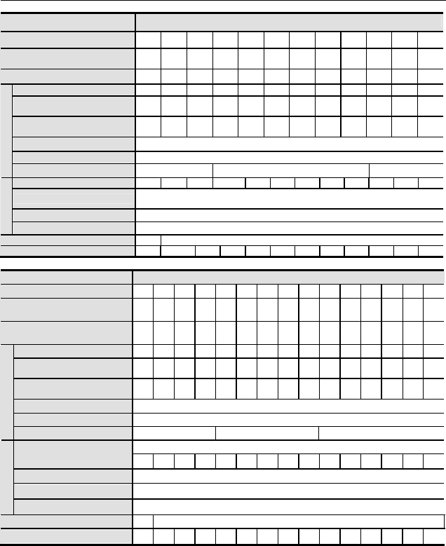
Revision August 2008, 03VE, SW V2.04
A-1
Appendix A Specifications
Voltage Class 230V Class
Model Number VFD-XXXV 007 015 022 037 055 075 110 150 185 220 300 370
Max. Applicable Motor Output
(kW) 0.75 1.5 2.2 3.7 5.5 7.5 11 15 18.5 22 30 37
Max. Applicable Motor Output (hp) 1.0 2.0 3.0 5.0 7.5 10 15 20 25 30 40 50
Rated Output Capacity (kVA) 1.9 2.7 4.2 6.5 9.5 13 19 25 29 34 46 55
Rated Output Current for
Constant Torque (A) 5.0 7.5 11 17 25 33 49 65 75 90 120 146
Rated Output Current for
Variable Torque (A) 6.25 9.4 13 21 31 41 61 81 93 112 150 182
Maximum Output Voltage (V) 3-Phase Proportional to Input Voltage
Output Frequency (Hz) 0.00~600.00 Hz
Output Rating
Carrier Frequency (kHz) 15 9 6
Rated Input Current (A) 6.4 9.9 15 21 25 33 52 63 68 79 106 126
Rated Voltage/Frequency 3-phase
200-240V, 50/60Hz
Voltage Tolerance ±10%(180~264 V)
Input Rating
Frequency Tolerance ±5%(47~63 Hz)
Cooling Method Natural Fan Cooled
Weight (kg) 2.7 3.2 4.5 6.8 8 10 13 13 13 13 36 36
Voltage Class 460V Class
Model Number VFD-XXXV 007 015 022 037 055 075 110 150 185 220 300 370 450 550 750
Max. Applicable Motor Output
(kW) 0.75 1.5 2.2 3.7 5.5 7.5 11 15 18.5 22 30 37 45 55 75
Max. Applicable Motor Output
(hp) 1.0 2.0 3.0 5.0 7.5 10 15 20 25 30 40 50 60 75 100
Rated Output Capacity (kVA) 2.3 3.2 4.2 6.3 9.9 14 18 24 29 34 46 56 69 80 100
Rated Output Current for
Constant Torque (A) 3.0 4.2 6.0 8.5 13 18 24 32 38 45 60 73 91 110 150
Rated Output Current for
Variable Torque (A) 3.8 5.3 7.5 10 16 22 30 40 47 56 75 91 113 138 188
Maximum Output Voltage (V) 3-phase Proportional to Input Voltage
Output Frequency (Hz) 0.00~600.00 Hz
Output Rating
Carrier Frequency (kHz) 15 9 6
3-phase 380~480V
Rated Input Current (A) 4.0 5.8 7.4 9.9 12 17 25 27 35 42 56 67 87 101 122
Rated Voltage 3-phase 380 to 480 V
Voltage Tolerance
±
10%(342~528 V)
Input Rating
Frequency Tolerance
±
5%(47~63 Hz)
Cooling Method Natural Fan Cooled
Weight (kg) 2.7 3.2 4.5 6.8 8 10 13 13 13 13 36 36 36 50 50
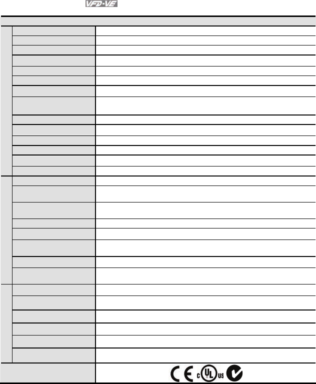
Appendix A Specifications|
A-2 Revision August 2008, 03VE, SW V2.04
General Specifications
Control System 1 V/f curve; 2 V/f+PG; 3 SVC; 4 FOC+PG; 5 TQR+PG
Start Torque Starting torque is 150% at 0.5Hz and 0Hz with FOC + PG control mode
Speed Control Range 1:100 Sensorless vector (up to 1:1000 when using PG card)
Speed Control Resolution
±
0.5% Sensorless vector (up to ±0.02% when using PG card)
Speed Response Ability 5Hz (up to 30Hz for vector control)
Max. Output Frequency 0.00 to 600.00Hz
Output Frequency Accuracy Digital command
±
0.005%, analog command
±
0.5%
Frequency Setting
Resolution
Digital command
±
0.01Hz, analog command: 1/4096(12-bit) of the max. output
frequency
Torque Limit Max. is 200% torque current
Torque Accuracy ±5%
Accel/Decel Time 0.00 to 600.00/0.0 to 6000.0 seconds
V/f Curve Adjustable V/f curve using 4 independent points and square curve
Frequency Setting Signal
±
10V, 4~20mA, pulse input
Control Characteristics
Brake Torque About 20%
Motor Protection Electronic thermal relay protection
Over-current Protection The current forces 220% of the over-current protection and 300% of the rated
current
Ground Leakage Current
Protection Higher than 50% X rated current
Overload Ability Constant torque: 150% for 60 seconds, variable torque: 200% for 3 seconds
Over-voltage Protection Over-voltage level: Vdc > 400/800V; low-voltage level: Vdc < 200/400V
Over-voltage Protection for
the Input Power Varistor (MOV)
Over-temperature Protection Built-in temperature sensor
Protection Characteristics
Compensation for the
Momentory Power Loss Up to 5 seconds for parameter setting
Protection Level NEMA 1/IP21
Operation Temperature -10oC to 40oC
Storage Temperature -20 oC to 60 oC
Ambient Humidity Below 90% RH (non-condensing)
Vibration 9.80665m/s2 (1G) less than 20Hz, 5.88m/s2 (0.6G) at 20 to 50Hz
Environmental Conditions
Installation Location Altitude 1,000 m or lower, keep from corrosive gasses, liquid and dust
Approvals
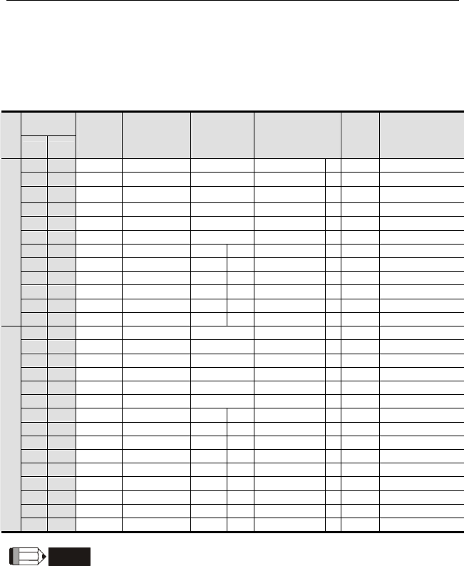
Revision August 2008, 03VE, SW V2.04 B-1
Appendix B Accessories
B.1 All Brake Resistors & Brake Units Used in AC Motor Drives
Note: Please only use DELTA resistors and recommended values. Other resistors and values will
void Delta’s warranty. Please contact your nearest Delta representative for use of special resistors.
For instance, in 460V series, 100hp/75kW, the AC motor drive needs 2 brake units with total of 16
brake resistors, so each brake unit uses 8 brake resistors. The brake unit should be at least 10 cm
away from AC motor drive to avoid possible interference. Refer to the “Brake Unit Module User
Manual” for further details.
Applicable
Motor
Voltage
hp kW
Full Load
Torque
Nm
Resistor value
spec for each
AC Motor
Drive
Brake Unit
Model VFDB
No. of Units
Used
Brake Resistors
Model and No. of
Units Used
Brake
Torque
10%ED
Min. Equivalent
Resistor Value for
each AC Motor
Drive
1 0.75 0.427 80W 200Ω BR080W200 1 125 82Ω
2 1.5 0.849 300W 100Ω BR300W100 1 125 82Ω
3 2.2 1.262 300W 100Ω BR300W100 1 125 82Ω
5 3.7 2.080 400W 40Ω BR400W040 1 125 33Ω
7.5 5.5 3.111 500W 30Ω BR500W030 1 125 30Ω
10 7.5 4.148 1000W 20Ω BR1K0W020 1 125 20Ω
15 11 6.186
2400W 13.6Ω2015 1 BR1K2W6P8 2 125 13.6Ω
20 15 8.248
3000W 10Ω2015 1 BR1K5W005 2 125 10Ω
25 18.5 10.281 4800W 8Ω2022 1 BR1K2W008 4 125 8Ω
30 22 12.338
4800W 6.8Ω2022 1 BR1K2W6P8 4 125 6.8Ω
40 30 16.497 6000W 5Ω2015 2 BR1K5W005 4 125 5Ω
230V Series
50 37 20.6 9600W 4Ω2015 2 BR1K2W008 8 125 4Ω
1 0.75 0.427 80W 750Ω BR080W750 1 125 160Ω
2 1.5 0.849 300W 400Ω BR300W400 1 125 160Ω
3 2.2 1.262 300W 250Ω BR300W250 1 125 160Ω
5 3.7 2.080 400W 150Ω BR400W150 1 125 130Ω
7.5 5.5 3.111 500W 100Ω BR500W100 1 125 91Ω
10 7.5 4.148 1000W 75Ω BR1K0W075 1 125 62Ω
15 11 6.186
1000W 50Ω4030 1 BR1K0W050 1 125 39Ω
20 15 8.248
1500W 40Ω4030 1 BR1K5W040 1 125 40Ω
25 18.5 10.281 4800W 32Ω4030 1 BR1K2W008 4 125 32Ω
30 22 12.338
4800W 27.2Ω4030 1 BR1K2W6P8 4 125 27.2Ω
40 30 16.497
6000W 20Ω4030 1 BR1K5W005 4 125 20Ω
50 37 20.6
9600W 16Ω4045 1 BR1K2W008 8 125 16Ω
60 45 24.745
9600W 13.6Ω4045 1 BR1K2W6P8 8 125 13.6Ω
75 55 31.11
12000W 10Ω4030 2 BR1K5W005 8 125 10Ω
460V Series
100 75 42.7
19200W 6.8Ω4045 2 BR1K2W6P8 16 125 6.8Ω
NOTE

Appendix B Accessories|
B-2 Revision August 2008, 03VE, SW V2.04
1. Please select the factory setting resistance value (Watt) and the duty-cycle value (ED%).
2. If damage to the drive or other equipment are due to the fact that the brake resistors and the
brake modules in use are not provided by Delta, the warranty will be void.
3. Take into consideration the safety of the environment when installing the brake resistors.
4. If the minimum resistance value is to be utilized, consult local dealers for the calculation of the
Watt figures.
5. Please select thermal relay trip contact to prevent resistor over load. Use the contact to switch
power off to the AC motor drive!
6. When using more than 2 brake units, equivalent resistor value of parallel brake unit can’t be
less than the value in the column “Minimum Equivalent Resistor Value for Each AC Drive” (the
right-most column in the table). An example of 575V 100HP, the min. equivalent resistor value
for each AC motor drive is 12.5Ω with 2 brake units connection. Therefore, the equivalent
resistor value for each brake unit should be 25Ω.
7. Please read the wiring information in the user manual of brake unit thoroughly prior to taking
into operation.
8. Definition for Brake Usage ED%
Explanation: The definition of the barke usage ED(%) is for assurance of enough time for the
brake unit and brake resistor to dissipate away heat generated by braking. When the brake
resistor heats up, the resistance would increase with temperature, and brake torque would
decrease accordingly. Suggested cycle time is one minute
100%
T0
T1
Brake Time
Cycle Time
ED% = T1/T0x100(%)
9. For safety consideration, install an overload relay between the brake unit and the brake resistor.
In conjunction with the magnetic contactor (MC) prior to the drive, it can perform complete
protection against abnormality. The purpose of installing the thermal overload relay is to protect
the brake resistor from damage due to frequent brake, or due to brake unit keeping operating
resulted from unusual high input voltage. Under such circumstance, just turn off the power to
prevent damaging the brake resistor.
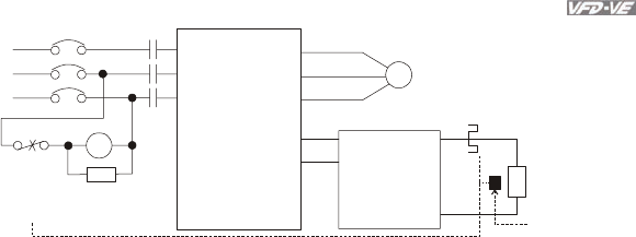
Appendix B Accessories|
Revision August 2008, 03VE, SW V2.04 B-3
R/L1
S/L2
T/L3
NFB
MC
VFD Series
MOTOR
O.L.
U/T1
V/T2
W/T3
+P
-N
()
()
B1
B2
SA
R/L1
S/L2
T/L3
MC
IM
BR
O.L.
Thermal
Overload
Relay or
temperature
switch
Surge
Absorber
Thermal Overload
Relay
Brake
Resistor
Brake
Unit
+P
-N
()
()
Note1: When using the AC drive with DC reactor, please refer to wiring diagram in the AC drive
user manual for the wiring of terminal +(P) of Brake unit.
Note2: wire terminal -(N) to the neutral point of power system.
Do NOT
Temperature
Switch
10. For model VFD110V43B, the brake unit is built-in. To increase the brake function, it can add
optional brake unit.
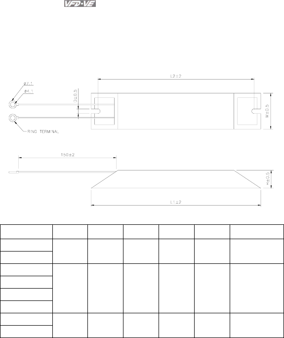
Appendix B Accessories|
B-4 Revision August 2008, 03VE, SW V2.04
B.1.1 Dimensions and Weights for Brake Resistors
(Dimensions are in millimeter)
Order P/N: BR080W200, BR080W750, BR300W070, BR300W100, BR300W250, BR300W400,
BR400W150, BR400W040
Model no. L1 L2 H D W Max. Weight (g)
BR080W200
BR080W750 140 125 20 5.3 60 160
BR300W070
BR300W100
BR300W250
BR300W400
215 200 30 5.3 60 750
BR400W150
BR400W040 265 250 30 5.3 60 930
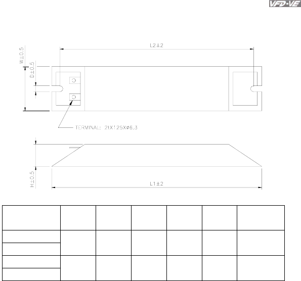
Appendix B Accessories|
Revision August 2008, 03VE, SW V2.04 B-5
Order P/N: BR500W030, BR500W100, BR1KW020, BR1KW075
Model no. L1 L2 H D W Max. Weight
(g)
BR500W030
BR500W100 335 320 30 5.3 60 1100
BR1KW020
BR1KW075 400 385 50 5.3 100 2800
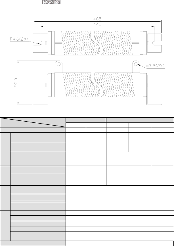
Appendix B Accessories|
B-6 Revision August 2008, 03VE, SW V2.04
Order P/N: BR1K0W050, BR1K2W008, BR1K2W6P8, BR1K5W005, BR1K5W040
B.1.2 Specifications for Brake Unit
230V Series 460V Series
2015 2022 4030 4045 4132
Max. Motor Power (kW) 15 22 30 45 132
Max. Peak Discharge Current
(A) 10%ED 40 60 40 60 240
Continuous Discharge Current
(A) 15 20 15 18 75
Output Rating
Brake Start-up Voltage (DC) 330/345/360/380/400/
415±3V
660/690/720/760/800/83
0±6V
618/642/66
7/690/725/
750±6V
Input
Rating
DC Voltage 200~400VDC 400~800VDC
Heat Sink Overheat Temperature over +95°C (203 oF)
Alarm Output Relay contact 5A 120VAC/28VDC (RA, RB, RC)
Protection
Power Charge Display Blackout until bus (+~-) voltage is below 50VDC
Installation Location Indoor (no corrosive gases, metallic dust)
Operating Temperature -10°C ∼ +50°C (14oF to 122oF)
Storage Temperature -20°C ∼ +60°C (-4oF to 140oF)
Humidity 90% Non-condensing
Environment
Vibration 9.8m/s2 (1G) under 20Hz
2m/s2 (0.2G) at 20~50Hz
Wall-mounted Enclosed Type IP50 IP10
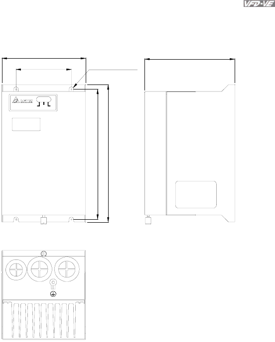
Appendix B Accessories|
Revision August 2008, 03VE, SW V2.04 B-7
B.1.3 Dimensions for Brake Unit
(Dimensions are in millimeter[inch])
Figure 1: VFDB2015, VFDB2022, VFDB4030, VFDB4045
80.0 [3.15]
121.0 [4.76]
189.5 [7.46]
200.0 [7.87]
130.0 [5.12]
R3.3 [R0.13]
ACT.
YELLOW
CHARGE
GREEN
ERR.
RED
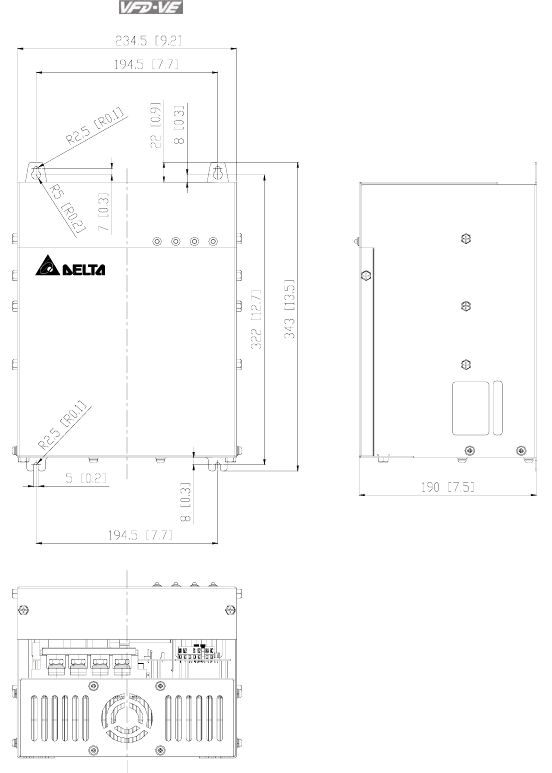
Appendix B Accessories|
B-8 Revision August 2008, 03VE, SW V2.04
Figure 2: VFDB4132
VFDB4132
CHARGE ACT OC OH
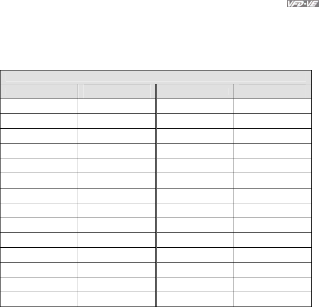
Appendix B Accessories|
Revision August 2008, 03VE, SW V2.04 B-9
B.2 No-fuse Circuit Breaker Chart
For 3-phase drives, the current rating of the breaker shall be within 2-4 times maximum input current
rating.
(Refer to Appendix A for rated input current)
3-phase
Model Recommended no-fuse
breaker (A) Model Recommended no-fuse
breaker (A)
VFD007V23A-2 10 VFD110V43B-2 50
VFD007V43A-2 5 VFD150V23A-2 125
VFD015V23A-2 15 VFD150V43A-2 60
VFD015V43A-2 10 VFD185V23A-2 150
VFD022V23A-2 30 VFD185V43A-2 75
VFD022V43A-2 15 VFD220V23A-2 175
VFD037V23A-2 40 VFD220V43A-2 100
VFD037V43A-2 20 VFD300V23A-2 225
VFD055V23A-2 50 VFD300V43A-2 125
VFD055V43A-2 30 VFD370V23A-2 250
VFD075V23A-2 60 VFD370V43A-2 150
VFD075V43A-2 40 VFD450V43A-2 175
VFD110V23A-2 100 VFD550V43C-2 250
VFD110V43A-2 50 VFD750V43C-2 300

Appendix B Accessories|
B-10 Revision August 2008, 03VE, SW V2.04
B.3 Fuse Specification Chart
Smaller fuses than those shown in the table are permitted.
Line Fuse
Model I (A)
Input
I (A)
Output I (A) Bussmann P/N
VFD007V23A-2 5.7 5.0 10 JJN-10
VFD007V43A-2 3.2 2.7 5 JJN-6
VFD015V23A-2 7.6 7.0 15 JJN-15
VFD015V43A-2 4.3 4.2 10 JJN-10
VFD022V23A-2 15.5 11 30 JJN-30
VFD022V43A-2 5.9 5.5 15 JJN-15
VFD037V23A-2 20.6 17 40 JJN-40
VFD037V43A-2 11.2 8.5 20 JJN-20
VFD055V23A-2 26 25 50 JJN-50
VFD055V43A-2 14 13 30 JJN-30
VFD075V23A-2 34 33 60 JJN-60
VFD075V43A-2 19 18 40 JJN-40
VFD110V23A-2 50 49 100 JJN-100
VFD110V43A-2 25 24 50 JJN-50
VFD110V43B-2 25 24 50 JJN-50
VFD150V23A-2 60 65 125 JJN-125
VFD150V43A-2 32 32 60 JJN-60
VFD185V23A-2 75 75 150 JJN-150
VFD185V43A-2 39 38 75 JJN-70
VFD220V23A-2 90 90 175 JJN-175
VFD220V43A-2 49 45 100 JJN-100
VFD300V23A-2 110 120 225 JJN-225
VFD300V43A-2 60 60 125 JJN-125
VFD370V23A-2 142 145 250 JJN-250
VFD370V43A-2 63 73 150 JJN-150
VFD450V43A-2 90 91 175 JJN-175
VFD550V43C-2 130 110 250 JJN-250
VFD750V43C-2 160 150 300 JJN-300
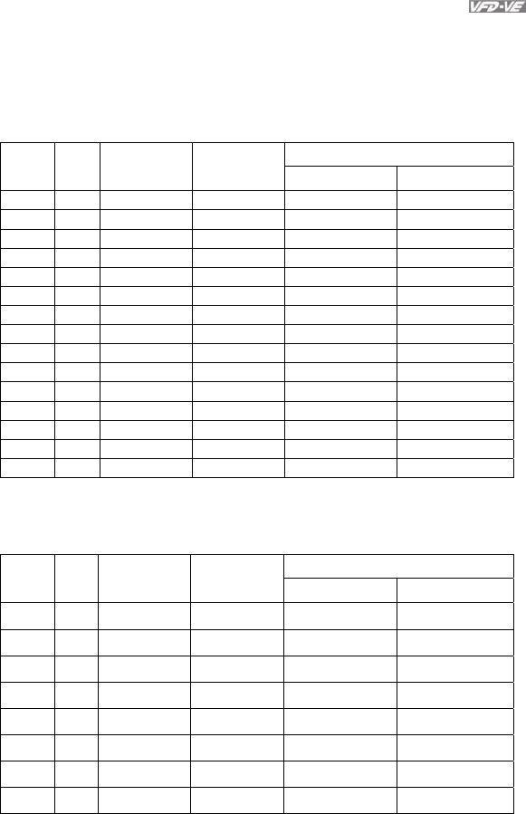
Appendix B Accessories|
Revision August 2008, 03VE, SW V2.04 B-11
B.4 AC Reactor
B.4.1 AC Input Reactor Recommended Value
460V, 50/60Hz, 3-Phase
Inductance (mH)
kW HP
Fundamental
Amps
Max.
continuous
Amps 3% impedance 5% impedance
0.75 1 4 6 9 12
1.5 2 4 6 6.5 9
2.2 3 8 12 5 7.5
3.7 5 8 12 3 5
5.5 7.5 12 18 2.5 4.2
7.5 10 18 27 1.5 2.5
11 15 25 37.5 1.2 2
15 20 35 52.5 0.8 1.2
18.5 25 35 52.5 0.8 1.2
22 30 45 67.5 0.7 1.2
30 40 55 82.5 0.5 0.85
37 50 80 120 0.4 0.7
45 60 80 120 0.4 0.7
55 75 100 150 0.3 0.45
75 100 130 195 0.2 0.3
B.4.2 AC Output Reactor Recommended Value
230V, 50/60Hz, 3-Phase
Inductance (mH)
kW HP
Fundamental
Amps
Max.
continuous
Amps 3% impedance 5% impedance
0.75 1 8 12 3 5
1.5 2 8 12 1.5 3
2.2 3 12 18 1.25 2.5
3.7 5 18 27 0.8 1.5
5.5 7.5 25 37.5 0.5 1.2
7.5 10 35 52.5 0.4 0.8
11 15 55 82.5 0.25 0.5
15 20 80 120 0.2 0.4
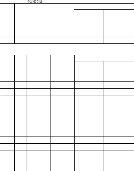
Appendix B Accessories|
B-12 Revision August 2008, 03VE, SW V2.04
Inductance (mH)
kW HP
Fundamental
Amps
Max.
continuous
Amps 3% impedance 5% impedance
18.5 25 80 120 0.2 0.4
22 30 100 150 0.15 0.3
30 40 130 195 0.1 0.2
37 50 160 240 0.075 0.15
460V, 50/60Hz, 3-Phase
Inductance (mH)
kW HP
Fundamental
Amps
Max.
continuous
Amps 3% impedance 5% impedance
0.75 1 4 6 9 12
1.5 2 4 6 6.5 9
2.2 3 8 12 5 7.5
3.7 5 12 18 2.5 4.2
5.5 7.5 18 27 1.5 2.5
7.5 10 18 27 1.5 2.5
11 15 25 37.5 1.2 2
15 20 35 52.5 0.8 1.2
18.5 25 45 67.5 0.7 1.2
22 30 45 67.5 0.7 1.2
30 40 80 120 0.4 0.7
37 50 80 120 0.4 0.7
45 60 100 150 0.3 0.45
55 75 130 195 0.2 0.3
75 100 160 240 0.15 0.23

Appendix B Accessories|
Revision August 2008, 03VE, SW V2.04 B-13
B.4.3 Applications for AC Reactor
Connected in input circuit
Application 1 Question
When more than one AC motor drive is
connected to the same power, one of them is
ON during operation.
When applying to one of the AC motor drive,
the charge current of capacity may cause
voltage ripple. The AC motor drive may
damage when over current occurs during
operation.
Correct wiring
M1
M2
Mn
reactor
AC motor drive
AC motor drive
AC motor drive
motor
motor
motor
Application 2 Question
Silicon rectifier and AC motor drive is
connected to the same power.
Surges will be generated at the instant of
silicon rectifier switching on/off. These surges
may damage the mains circuit.
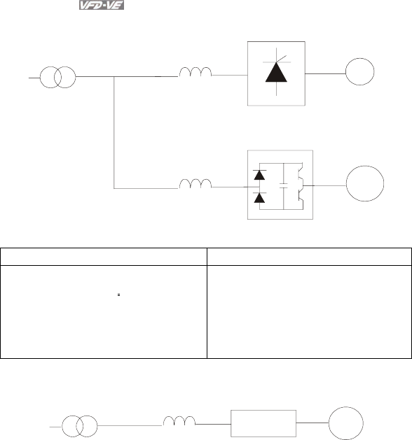
Appendix B Accessories|
B-14 Revision August 2008, 03VE, SW V2.04
Correct wiring
DC
power reactor
reactor
AC motor drive
motor
silicon rectifier
Application 3 Question
Used to improve the input power factor, to
reduce harmonics and provide protection
from AC line disturbances. (surges, switching
spikes, short interruptions, etc.). AC line
reactor should be installed when the power
supply capacity is 500kVA or more and
exceeds 6 times the inverter capacity, or the
mains wiring distance ≤10m.
When power capacity is too large, line
impedance will be small and the charge
current will be too large. That may damage
AC motor drive due to higher rectifier
temperature.
Correct wiring
large-capacity
power reactor
small-capacity
AC motor drive
motor
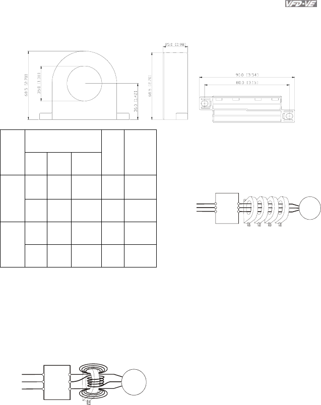
Appendix B Accessories|
Revision August 2008, 03VE, SW V2.04 B-15
B.5 Zero Phase Reactor (RF220X00A)
Recommended Wire
Size
Cable
type
(Note) AWG mm2 Nominal
(mm2)
Qty. Wiring
Method
≦10 ≦5.3 ≦5.5 1 Diagram
A
Single-
core
≦2 ≦33.6 ≦38 4 Diagram
B
≦12 ≦3.3 ≦3.5 1 Diagram
A
Three-
core
≦1 ≦42.4 ≦50 4 Diagram
B
Note: 600V Insulated unshielded Cable.
Power
Supply
Zero Phase Reactor
MOTOR
U/T1
V/T2
W/T3
R/L1
S/L2
T/L3
U/T1
V/T2
W/T3
R/L1
S/L2
T/L3
Power
Supply
Zero Phase Reactor
MOTOR
Note 1: The table above gives approximate
wire size for the zero phase reactors but the
selection is ultimately governed by the type
and diameter of cable fitted i.e. the cable
must fit through the center hole of zero
phase reactors.
Note 2: Only the phase conductors should
pass through, not the earth core or screen.
Note 3: When long motor output cables are
used an output zero phase reactor may be
required to reduce radiated emissions from
the cable.
Diagram B
Please put all wires through 4 cores in
series without winding.
Diagram A
Please wind each wire 4 times around the
core. The reactor must be put at inverter
output as close as possible.
Dimensions are in millimeter and (inch)
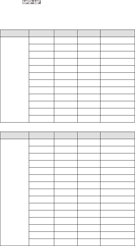
Appendix B Accessories|
B-16 Revision August 2008, 03VE, SW V2.04
B.6 DC Choke Recommended Values
230V DC Choke
Input voltage kW HP DC Amps Inductance (mh)
0.75 1 9 7.50
1.5 2 12 4.00
2.2 3 18 2.75
3.7 5 25 1.75
5.5 7.5 32 0.85
7.5 10 40 0.75
11 15 62 Built-in
15 20 92 Built-in
18.5 25 110 Built-in
22 30 125 Built-in
30 40 -- Built-in
230Vac
50/60Hz
3-Phase
37 50 -- Built-in
460V DC Choke
Input voltage kW HP DC Amps Inductance (mh)
0.75 1 4 25.00
1.5 2 9 11.50
2.2 3 9 11.50
3.7 5 12 6.00
5.5 7.5 18 3.75
7.5 10 25 4.00
11 15 32 Built-in
15 20 50 Built-in
18.5 25 62 Built-in
22 30 80 Built-in
30 40 92 Built-in
37 50 110 Built-in
45 60 125 Built-in
55 75 200 Built-in
460Vac
50/60Hz
3-Phase
75 100 240 Built-in
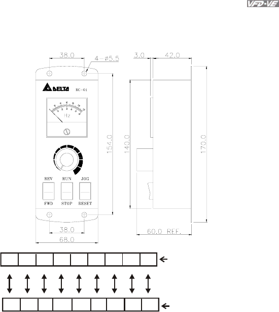
Appendix B Accessories|
Revision August 2008, 03VE, SW V2.04 B-17
B.7 Remote Controller RC-01
Dimensions are in millimeter
AFM ACM +10V
AVI DCM MI5 FWD REV JOG
8654 16151413 11
RC-01 terminal block
Wiring connections
VFD-VE
I/O Block
VFD-VE Programming:
Pr.00-20 set to 2
Pr.00-21 set to 1 (external controls)
Pr.02-00 set to 1 (setting Run/Stop and Fwd/Rev controls)
Pr.02-05 (MI5) set to 5 (External reset)
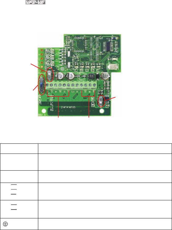
Appendix B Accessories|
B-18 Revision August 2008, 03VE, SW V2.04
B.8 PG Card (for Encoder)
B.8.1 EMV-PG01X
AB2:
PG2 signal
mode switch
ABZ1:
PG1 signal
mode switch
PG1
Pulse feedback
PG2
Pulse input
PS1:
5/12V switch
1. Terminals descriptions
Terminal Symbols Descriptions
VP Power source of EMV-PG01X (use PS1 to switch 12V/5V)
Output Voltage: +5V/+12V±5% 200mA
DCM Power source and input signal common
A1,
B1,
Z1,
A1
B1
Z1
Input signal. Input type is selected by ABZ1. It can be 1-phase or 2-
phase input. Maximum 300kP/sec
A2,
B2,
A2
B2
Input signal. Input type is selected by AB2. It can be 1-phase or 2-
phase input. Maximum 300kP/sec
Grounding
2. Wiring Notes
a. Please use a shielded cable to prevent interference. Do not run control wires
parallel to any high voltage AC power line (200 V and above).
b. Recommended wire size 0.21 to 0.81mm2 (AWG24 to AWG18).
3. Wire length (wire length and signal frequency are in inverse proportion)
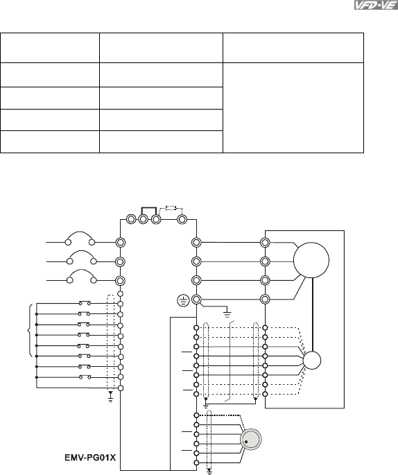
Appendix B Accessories|
Revision August 2008, 03VE, SW V2.04 B-19
Types of Pulse
Generators Maximum Wire Length Wire Gauge
Output Voltage 50m
Open Collector 50m
Line Driver 300m
Complementary 70m
1.25mm2 (AWG16) or above
4. Basic Wiring Diagram
wiring 1
R/L1
S/L2
T/L3
NFB
R
S
T
+1 +2/B1 B2
U/T1
V/T2
W/T3
M
3~
-U
W
V
VP
DCM
A1
A1
B1
B1
Z1
Z1
PG
VP
DCM
A2
A2
B2
B2
10-17
10-18
jumper
Braking resistor (optional)
Motor
Non-fuse breaker
MI1
MI2
MI3
MI4
MI6
MI5
DCM
+24V
FWD/STOP
REV/STOP
Multi-step 1
Multi-step 2
Multi-step 3
Multi-step 4
No function
Digital Signal Common
Factory
setting
No function
REV
FWD
manual pulse generator
(MPG)
incremental encoder
Line driverLine driver
Line driver

Appendix B Accessories|
B-20 Revision August 2008, 03VE, SW V2.04
wiring 2
R/L1
S/L2
T/L3
NFB
R
S
T
+1 +2/B1 B2
U/T1
V/T2
W/T3
M
3~
-U
W
V
VP
DCM
A1
A1
B1
B1
Z1
Z1
PG
jumper Braking resistor (optional)
Motor
Non-fuse breaker
MI1
MI2
MI3
MI4
MI6
MI5
DCM
+24V
FWD/STOP
REV/STOP
Multi-step 1
Multi-step 2
Multi-step 3
Multi-step 4
No function
Digital Signal Common
Factory
setting
No function
REV
FWD
incremental encoder
Line driverLine driver
phase difference is 90
o
5. Types of Pulse Generators (Encoders)
ABZ1+ PS1 AB2+PS1
Types of Pulse Generators
5V 12V 5V 12V
VOLTAGE
O/P
0V
VCC
OC
5V
TP
12V
OC
5V
TP
12V
OC
5V
TP
12V
OC
5V
TP
12V
Open collector
O/P
0V
VCC
OC
5V
TP
12V
OC
5V
TP
12V
OC
5V
TP
12V
OC
5V
TP
12V
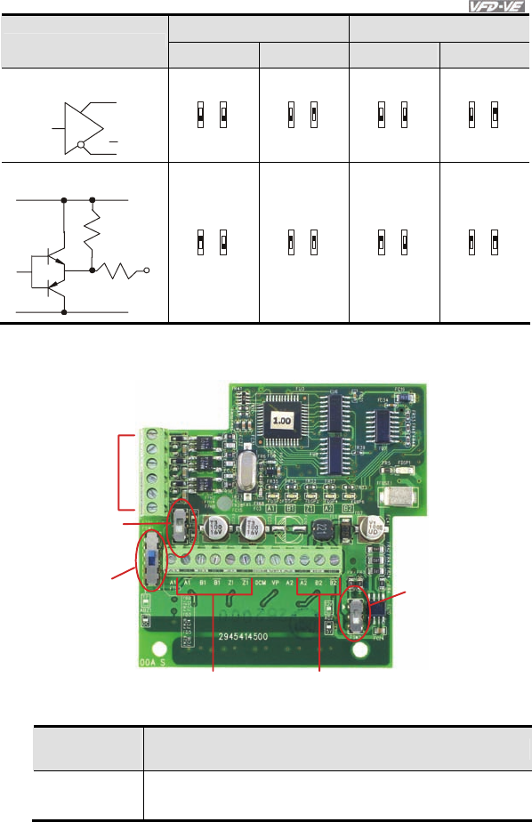
Appendix B Accessories|
Revision August 2008, 03VE, SW V2.04 B-21
ABZ1+ PS1 AB2+PS1
Types of Pulse Generators
5V 12V 5V 12V
Line driver
Q
Q
OC
5V
TP
12V
OC
5V
TP
12V
OC
5V
TP
12V
OC
5V
TP
12V
Complementary
O/P
0V
VCC
OC
5V
TP
12V
OC
5V
TP
12V
OC
5V
TP
12V
OC
5V
TP
12V
B.8.2 EMV-PG01O
PG OUT
Pulse output
AB2: PG2 signal
mode switch
ABZ1: PG1 signal
mode switch
PG1
Pulse feedback
PG2
Pulse input
PS1:
5/12V switch
1. Terminals descriptions
Terminal
Symbols Descriptions
VP Power source of EMV-PG01O (use PS1 to switch 12V/5V)
Output Voltage: +5V/+12V±5% 200mA

Appendix B Accessories|
B-22 Revision August 2008, 03VE, SW V2.04
Terminal
Symbols Descriptions
DCM Power source and input signal common
A1,
B1,
Z1,
A1
B1
Z1
Input signal from encoder. Input type is selected by ABZ1. It can be
1-phase or 2-phase input. Maximum 300kP/sec
A2,
B2,
A2
B2
Input signal from encoder. Input type is selected by AB2. It can be 1-
phase or 2-phase input. Maximum 300kP/sec
A/O, B/O, Z/O Output signal. It has division frequency function (Pr.10-16), open
collector: max. output DC20V 50mA
Grounding
2. Wiring Notes
a. Please use a shielded cable to prevent interference. Do not run control wires
parallel to any high voltage AC power line (200 V and above).
b. Recommended wire size 0.21 to 0.81mm2 (AWG24 to AWG18).
3. Wire length: (wire length and signal frequency are in inverse proportion)
Types of Pulse
Generators Maximum Wire Length Wire Gauge
Output Voltage 50m
Open Collector 50m
Line Driver 300m
Complementary 70m
1.25mm2 (AWG16) or above
4. Basic Wiring Diagram
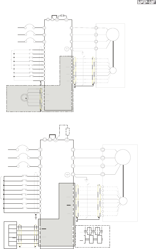
Appendix B Accessories|
Revision August 2008, 03VE, SW V2.04 B-23
wiring 1
R/L 1
S/L2
T/L3
NFB
R
S
T
+1 +2/B1 B2
U/T1
V/T2
W/T3
M
3~
-U
W
V
VP
DC M
A1
A1
B1
B1
Z1
Z1
PG
j
umpe r
Bra ke re sist o r (o ptio na l)
Motor
No -fuse bre ake r
MI1
MI2
MI3
MI4
MI6
MI5
DCM
+24V
FWD/STOP
REV/STOP
Mul ti-step 1
Multi-step 2
Multi-step 3
Mul ti-step 4
No function
Digital Signal Common
Factory
setting
No function
REV
FWD
incremental encoder
Li ne driverLi ne driver
manual pulse generator
(MPG) VP
DC M
A2
A2
B2
B2
10-17
10-18
VP
DC M
A/O
B/O
Z/O
Li ne driver
EMV-PG01O
wiring 2
R/L 1
S/L2
T/L3
NFB
R
S
T
+1 +2/B1 B2
U/T1
V/T2
W/T3
M
3~
-U
W
V
VP
DC M
A1
A1
B1
B1
Z1
Z1
PG
jumper Bra ke re sisto r (o ptio na l)
Motor
No -fuse bre ake r
MI1
MI2
MI3
MI4
MI6
MI5
DCM
+24V
FWD/STOP
REV/STOP
Mul ti-step 1
Mul ti-step 2
Multi-step 3
Mul ti-step 4
No function
Digital Signal Common
Factory
setting
No function
REV
FWD
incremental encoder
Li ne driverLine driver
Y0
Y0
Y1
Y1
DC M
A2
A2
B2
B2
EH -P LC
Y0
Y0
Y1
Y1
CO M
phase difference is 90
o
VP
DC M
A/O
B/O
Z/O
EMV-PG01O
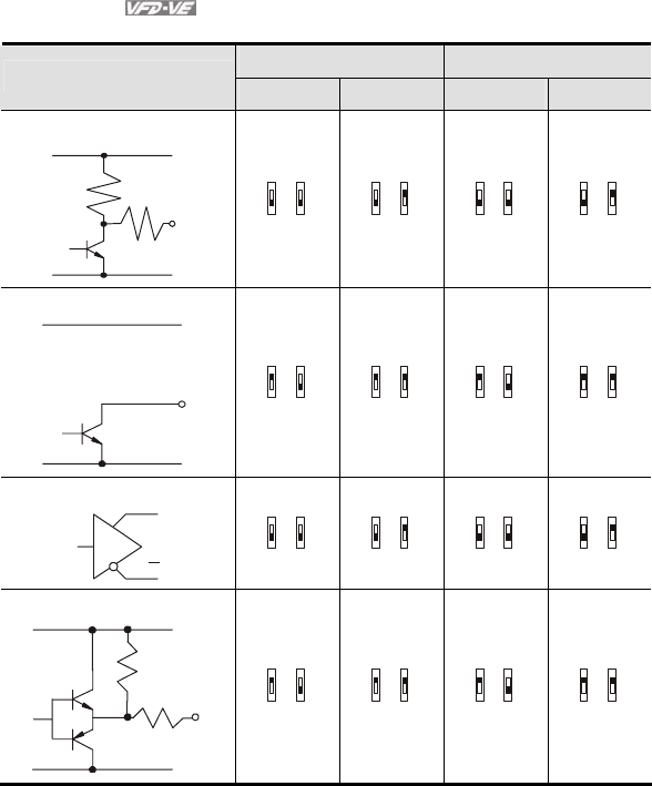
Appendix B Accessories|
B-24 Revision August 2008, 03VE, SW V2.04
5. Types of Pulse Generators (Encoders)
ABZ1+PS1 AB2+PS1
Types of Pulse Generators
5V 12V 5V 12V
VOLTAGE
O/P
0V
VCC
OC
5V
TP
12V
OC
5V
TP
12V
OC
5V
TP
12V
OC
5V
TP
12V
Open collector
O/P
0V
VCC
OC
5V
TP
12V
OC
5V
TP
12V
OC
5V
TP
12V
OC
5V
TP
12V
Line driver
Q
Q
OC
5V
TP
12V
OC
5V
TP
12V
OC
5V
TP
12V
OC
5V
TP
12V
Complementary
O/P
0V
VCC
OC
5V
TP
12V
OC
5V
TP
12V
OC
5V
TP
12V
OC
5V
TP
12V
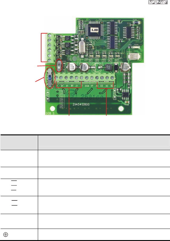
Appendix B Accessories|
Revision August 2008, 03VE, SW V2.04 B-25
B.8.3 EMV-PG01L
PG OUT
pulse output
AB2: PG2 signal
mode switch
ABZ1: PG1 signal
mode switch
PG1
pulse feedback
PG2
pulse input
1. Terminals descriptions
Terminal
Symbols Descriptions
VP Power source of EMV-PG01L
Output Voltage: +5V±5% 200mA
DCM Power source and input signal common
A1,
B1,
Z1,
A1
B1
Z1
Input signal. Input type is selected by ABZ1. It can be 1-phase or 2-
phase input. Maximum 300kP/sec
A2,
B2,
A2
B2
Input signal. Input type is selected by AB2. It can be 1-phase or 2-
phase input. Maximum 300kP/sec
A/O, B/O, Z/O Output signal. It has division frequency function (Pr.10-16), Line
driver: max. output DC5V 50mA
Grounding
2. Wiring Notes
a. Please use a shielded cable to prevent interference. Do not run control wires
parallel to any high voltage AC power line (200 V and above).
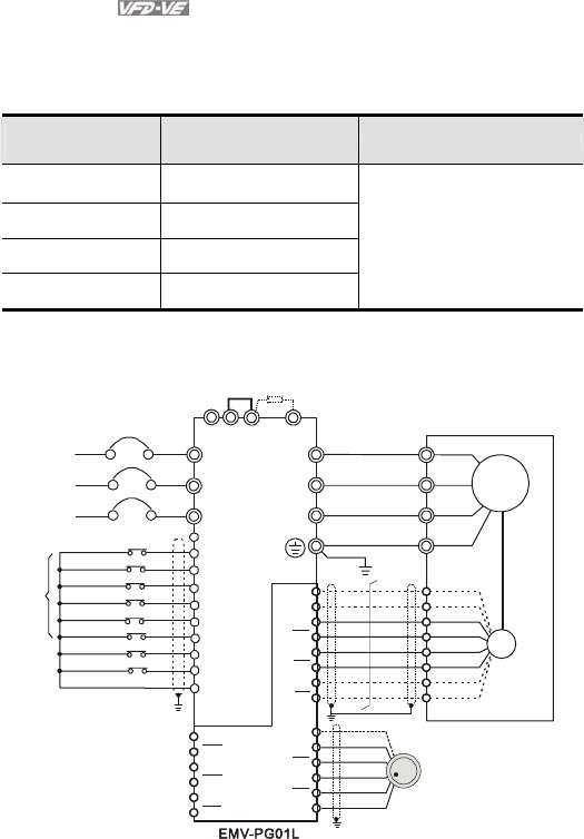
Appendix B Accessories|
B-26 Revision August 2008, 03VE, SW V2.04
b. Recommended wire size 0.21 to 0.81mm2 (AWG24 to AWG18).
3. Wire length: (wire length and signal frequency are in inverse proportion)
Types of Pulse
Generators Maximum Wire Length Wire Gauge
Output Voltage 50m
Open Collector 50m
Line Driver 300m
Complementary 70m
1.25mm2 (AWG16) or above
4. Basic Wiring Diagram
wiring 1
R/L1
S/L2
T/L3
NFB
R
S
T
+1 +2/B1 B2
U/T1
V/T2
W/T3
M
3~
-U
W
V
VP
DCM
A1
A1
B1
B1
Z1
Z1
PG
VP
DCM
A2
A2
B2
B2
10-17
10-18
jumper
Braking resistor (optional)
Motor
Non-fuse breaker
MI1
MI2
MI3
MI4
MI6
MI5
DCM
+24V
FWD/STOP
REV/STOP
Multi-step 1
Multi-step 2
Multi-step 3
Multi-step 4
No function
Digital Signal Common
Factory
setting
No function
REV
FWD
manual pulse generator
(MPG)
incremental encoder
Line driverLine driver
Line driver
AO
AO
BO
BO
ZO
ZO
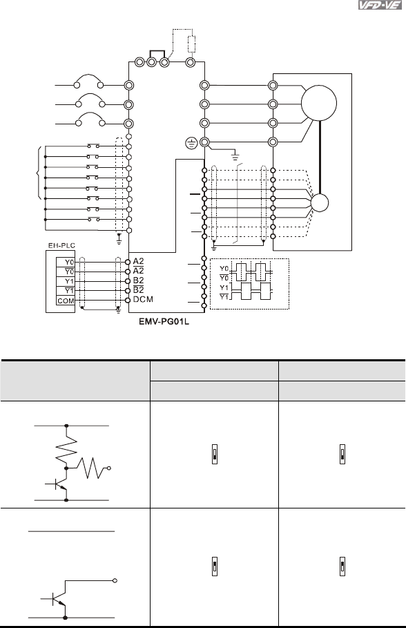
Appendix B Accessories|
Revision August 2008, 03VE, SW V2.04 B-27
wiring 2
R/L1
S/L2
T/L3
NFB
R
S
T
+1 +2/B1 B2
U/T1
V/T2
W/T3
M
3~
-U
W
V
VP
DCM
A1
A1
B1
B1
Z1
Z1
PG
jumper Braking resistor (optional)
Motor
Non-fuse breaker
MI1
MI2
MI3
MI4
MI6
MI5
DCM
+24V
FWD/STOP
REV/STOP
Multi-step 1
Multi-step 2
Multi-step 3
Multi-step 4
No function
Digital Signal Common
Factory
setting
No function
REV
FWD
incremental encoder
Line driverLine driver
phase difference is 90
o
AO
AO
BO
BO
ZO
ZO
5. Types of Pulse Generators (Encoders)
ABZ1 AB2
Types of Pulse Generators
5V 5V
VOLTAGE
O/P
0V
VCC
OC
TP
OC
TP
Open collector
O/P
0V
VCC
OC
TP
OC
TP
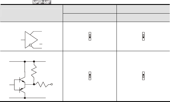
Appendix B Accessories|
B-28 Revision August 2008, 03VE, SW V2.04
ABZ1 AB2
Types of Pulse Generators
5V 5V
Line driver
Q
Q
OC
TP
OC
TP
Complementary
O/P
0V
VCC
OC
TP
OC
TP

Appendix B Accessories|
Revision August 2008, 03VE, SW V2.04 B-29
B.9 AMD-EMI Filter Cross Reference
AC Drives Model Number FootPrint
VFD007V43A-2, VFD015V43A-2, VFD022V43A-2 RF022B43AA Y
VFD037V43A-2 RF037B43BA Y
VFD055V43A-2, VFD075V43A-2, VFD110V43A-2,
VFD110V43B-2 RF110B43CA Y
VFD007V23A-2, VFD015V23A-2 10TDT1W4C N
VFD022V23A-2, VFD037V23A-2 26TDT1W4C N
VFD055V23A-2, VFD075V23A-2, VFD150V43A-2,
VFD185V43A-2 50TDS4W4C N
VFD110V23A-2, VFD150V23A-2, VFD220V43A-2,
VFD300V43A-2, VFD370V43A-2 100TDS84C N
VFD550V43A-2, VFD750V43A-2, VFD550V43C-2,
VFD750V43C-2 200TDDS84C N
VFD185V23A-2, VFD220V23A-2, VFD300V23A-2,
VFD450V43A-2 150TDS84C N
VFD370V23A-2 180TDS84C N
Installation
All electrical equipment, including AC motor drives, will generate high-frequency/low-frequency noise
and will interfere with peripheral equipment by radiation or conduction when in operation. By using an
EMI filter with correct installation, much interference can be eliminated. It is recommended to use
DELTA EMI filter to have the best interference elimination performance.
We assure that it can comply with following rules when AC motor drive and EMI filter are installed
and wired according to user manual:
EN61000-6-4
EN61800-3: 1996 + A11: 2000
EN55011 (1991) Class A Group 1 (1st Environment, restricted distribution)
General precaution
1. EMI filter and AC motor drive should be installed on the same metal plate.
2. Please install AC motor drive on footprint EMI filter or install EMI filter as close as possible to
the AC motor drive.
3. Please wire as short as possible.
4. Metal plate should be grounded.
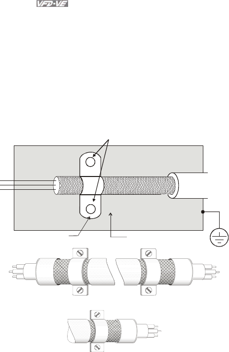
Appendix B Accessories|
B-30 Revision August 2008, 03VE, SW V2.04
5. The cover of EMI filter and AC motor drive or grounding should be fixed on the metal plate and
the contact area should be as large as possible.
Choose suitable motor cable and precautions
Improper installation and choice of motor cable will affect the performance of EMI filter. Be sure to
observe the following precautions when selecting motor cable.
1. Use the cable with shielding (double shielding is the best).
2. The shielding on both ends of the motor cable should be grounded with the minimum length
and maximum contact area.
3. Remove any paint on metal saddle for good ground contact with the plate and shielding.
Remove any paint on metal saddle for good ground contact with
the plate and shielding.
saddle the plate with grounding
Saddle on both ends
Saddle on one end
Appendix B Accessories|
Revision August 2008, 03VE, SW V2.04 B-31
The length of motor cable
When motor is driven by an AC motor drive of PWM type, the motor terminals will experience surge
voltages easily due to components conversion of AC motor drive and cable capacitance. When the
motor cable is very long (especially for the 460V series), surge voltages may reduce insulation
quality. To prevent this situation, please follow the rules below:
Use a motor with enhanced insulation.
Connect an output reactor (optional) to the output terminals of the AC motor drive
The length of the cable between AC motor drive and motor should be as short as possible
(10 to 20 m or less)
For models 7.5hp/5.5kW and above:
Insulation level of motor 1000V 1300V 1600V
460VAC input voltage 66 ft (20m) 328 ft (100m) 1312 ft (400m)
230VAC input voltage 1312 ft (400m) 1312 ft (400m) 1312 ft (400m)
For models 5hp/3.7kW and less:
Insulation level of motor 1000V 1300V 1600V
460VAC input voltage 66 ft (20m) 165 ft (50m) 165 ft (50m)
230VAC input voltage 328 ft (100m) 328 ft (100m) 328 ft (100m)
NOTE
When a thermal O/L relay protected by motor is used between AC motor drive and motor, it may
malfunction (especially for 460V series), even if the length of motor cable is only 165 ft (50m) or less.
To prevent it, please use AC reactor and/or lower the carrier frequency (Pr. 00-17 PWM carrier
frequency).
NOTE
Never connect phase lead capacitors or surge absorbers to the output terminals of the AC motor
drive.

Appendix B Accessories|
B-32 Revision August 2008, 03VE, SW V2.04
If the length is too long, the stray capacitance between cables will increase and may
cause leakage current. It will activate the protection of over current, increase leakage
current or not insure the correction of current display. The worst case is that AC motor
drive may damage.
If more than one motor is connected to the AC motor drive, the total wiring length is the
sum of the wiring length from AC motor drive to each motor.
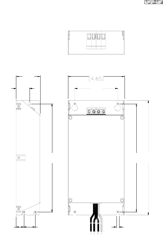
Appendix B Accessories|
Revision August 2008, 03VE, SW V2.04 B-33
B.9.1 Dimensions
Dimensions are in millimeter and (inch)
Order P/N: RF015B21AA / RF022B43AA
239
(9.4)
118
90
(3.54)
28
(1.1)
50
(1.97)
226
(8.9)
5.5
(3.37)
226
(8.9)
16
(0.63)
24
(0.94)
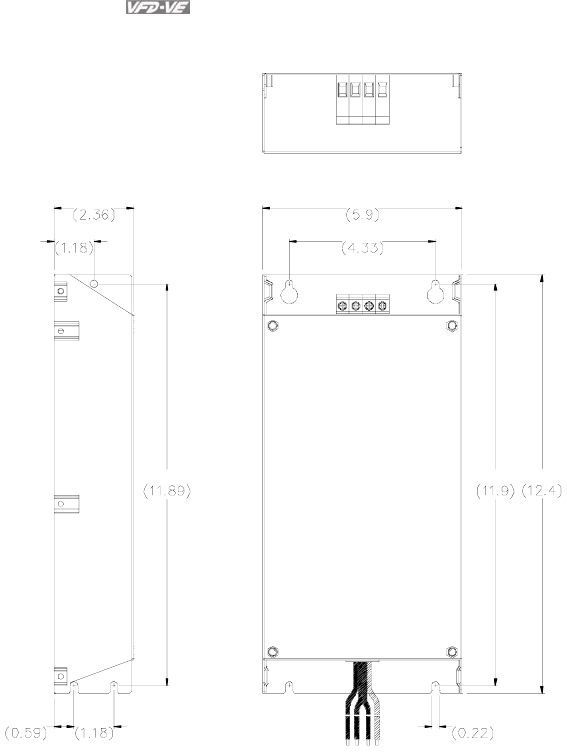
Appendix B Accessories|
B-34 Revision August 2008, 03VE, SW V2.04
Order P/N: RF022B21BA / RF037B43BA
302
110
150
315
5.5
30
60
302
15 30
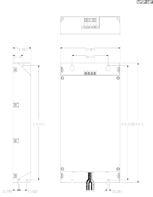
Appendix B Accessories|
Revision August 2008, 03VE, SW V2.04 B-35
Order P/N: RF110B43CA
60
33
200
120
398382
2620
382
7.0
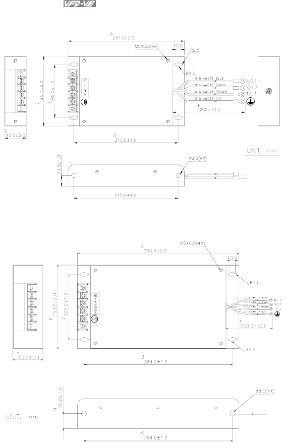
Appendix B Accessories|
B-36 Revision August 2008, 03VE, SW V2.04
Order P/N: 10TDT1W4C
Order P/N: 26TDT1W4C
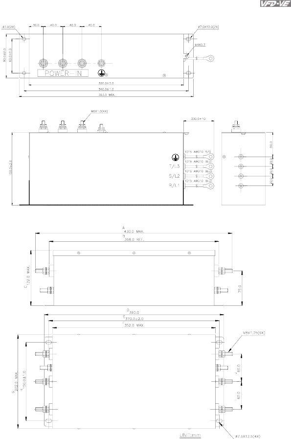
Appendix B Accessories|
Revision August 2008, 03VE, SW V2.04 B-37
Order P/N: 50TDS4W4C
Order P/N: 100TDS84C
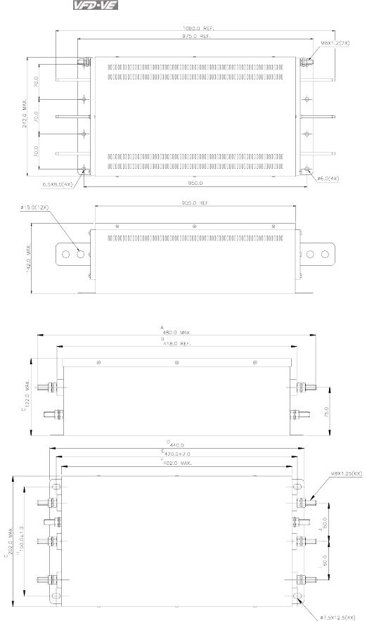
Appendix B Accessories|
B-38 Revision August 2008, 03VE, SW V2.04
Order P/N: 200TDDS84C
Order P/N: 150TDS84C
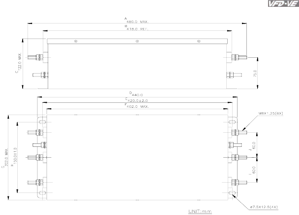
Appendix B Accessories|
Revision August 2008, 03VE, SW V2.04 B-39
Order P/N: 180TDS84C
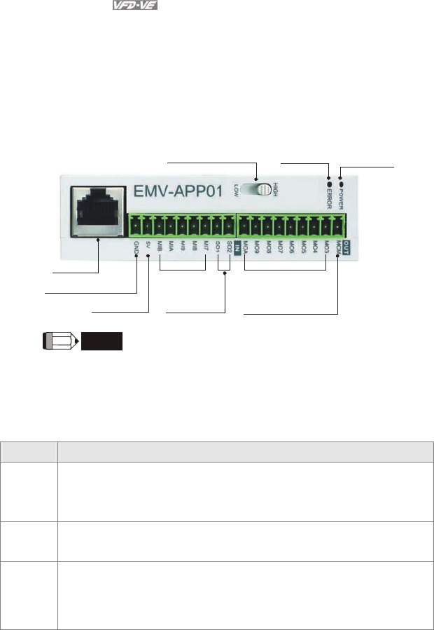
Appendix B Accessories|
B-40 Revision August 2008, 03VE, SW V2.04
B.10 Multi-function I/O Extension Card
B.10.1 Functions
EMV-APP01 optional multi-function I/O extension card is exclusively designed for VFD-VE
series and used with firmware version 2.04 and above. It communicates with the AC motor
drive by RS-485 communication port (COM1). To make sure that the communication is
normal, it needs to set the COM1 communication protocol to RTU mode (8, N, 1), i.e. set
Pr.09-04 to 12 no matter what the baud rate switch is set.
RS485 port
High/Low baud rate switch
Communication
indicator Power indicator
Analog signal common
Output power
Multi-function
input terminals
Analog output
terminals
Multi-function
output terminals
Multi-function
output common terminal
NOTE
Please operate by the following steps for switching the high/low baud rate,
1. make sure that RS-485 cable is disconnected before operation
2. switch the high/low baud rate
3. set Pr.09-01 to the corresponding baud rate to finish setting
If the RS-485 cable is connected before changing the high/low baud rate, the
communication function will still be invalid even if the communication baud rate (Pr.09-01) is
changed to the corresponding baud rate and the ERROR indicator is normal.
Terminals Description
POWER Power indicator. It will be ON when EMV-APP01 connects to the AC motor drive
correctly.
ERROR ERROR indicator. It will be ON when EMV-APP01 can communicate with the AC
motor drive or it will blink.
HIGH/LOW
Baud rate switch for extension card:
HIGH: set the baud rate to 115200
LOW: set the baud rate to 9600
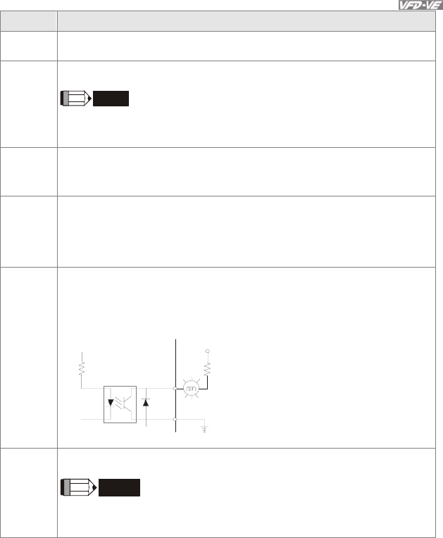
Appendix B Accessories|
Revision August 2008, 03VE, SW V2.04 B-41
Terminals Description
5V Output power 500mA Max
GND Analog signal common terminal
NOTE
This GND terminal is only used for 5V terminal on EMV-APP01. Please do NOT
confuse with DCM terminal.
SO1-MCM
SO2-MCM
Multi-function analog voltage output terminal 0~10.0V (output current: 2mA Max.)
Analog output is set by Pr.03-21 and Pr.03-24.
MI7~MIB Multi-function input terminals
Please refer to Pr.02-23 to Pr.02-27 for MI7-GND~MIB-GND function selection. Take
terminals MI7-GND for example, ON: the activation current is 6.5mA and OFF:
leakage current tolerance is 10μA.
MO3~MOA Multi-function output terminals (photocoupler)
The AC motor drive outputs each monitor signal, such as during operation, frequency
attained and overload, by transistor with open collector. Please refer to Pr.03-35 to
Pr.03-42 for details.
MO3~MOA-MCM
MO3
~
MOA
MCM
Max: 48Vdc/50mA
internal c ircuit
MCM Multi-function output common terminal. Max: 48Vdc/50mA
NOTE
This MCM terminal is only used with MO3~MOA on EMV-APP01. Please do NOT
confuse with terminal MCM.
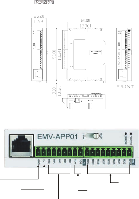
Appendix B Accessories|
B-42 Revision August 2008, 03VE, SW V2.04
B.10.2 Dimensions
B.10.3 Wiring
Analog signal common
Output power
refer to Pr.02-23 to Pr.02-27
refer to Pr.03-21 to Pr.03-24
refer to Pr.02-35 to Pr.02-42
When wiring, please refer to the multi-function input/output function in parameters group 02
and group 03 of chapter 4 parameters to set by your applications.

Appendix B Accessories|
Revision August 2008, 03VE, SW V2.04 B-43
This page intentionally left blank

Revision August 2008, 03VE, SW V2.04 C-1
Appendix C How to Select the Right AC Motor Drive
The choice of the right AC motor drive for the application is very important and has great influence
on its lifetime. If the capacity of AC motor drive is too large, it cannot offer complete protection to the
motor and motor maybe damaged. If the capacity of AC motor drive is too small, it cannot offer the
required performance and the AC motor drive maybe damaged due to overloading.
But by simply selecting the AC motor drive of the same capacity as the motor, user application
requirements cannot be met completely. Therefore, a designer should consider all the conditions,
including load type, load speed, load characteristic, operation method, rated output, rated speed,
power and the change of load capacity. The following table lists the factors you need to consider,
depending on your requirements.
Related Specification
Item Speed and
torque
characteristics
Time
ratings
Overload
capacity
Starting
torque
Load type
Friction load and weight
load
Liquid (viscous) load
Inertia load
Load with power
transmission
● ●
Load speed and
torque
characteristics
Constant torque
Constant output
Decreasing torque
Decreasing output
● ●
Load
characteristics
Constant load
Shock load
Repetitive load
High starting torque
Low starting torque
● ● ● ●
Continuous operation, Short-time operation
Long-time operation at medium/low speeds ● ●
Maximum output current (instantaneous)
Constant output current (continuous) ● ●
Maximum frequency, Base frequency ●
Power supply transformer capacity or
percentage impedance
Voltage fluctuations and unbalance
Number of phases, single phase protection
Frequency
● ●
Mechanical friction, losses in wiring ● ●
Duty cycle modification ●
C.1 Capacity Formulas

Appendix C How to Select the Right AC Motor Drive|
C-2 Revision August 2008, 03VE, SW V2.04
1. When one AC motor drive operates one motor
The starting capacity should be less than 1.5x rated capacity of AC motor drive
The starting capacity=
)(_____5.1
375cos973
2
kVAdrivemotorACofcapacitythe
t
NGD
T
Nk
A
L×≤
⎟
⎟
⎠
⎞
⎜
⎜
⎝
⎛×+
××
×
ϕη
2. When one AC motor drive operates more than one motor
2.1 The starting capacity should be less than the rated capacity of AC motor drive
Acceleration time
≦
60 seconds
The starting capacity=
()
[]
()
)(_____5.11
cos 111 kVAdrivemotorACofcapacitythek
n
n
Pknn
Nk
sCss
T
s
T×≤+=+
×
×
⎥
⎥
⎥
⎦
⎤
⎢
⎢
⎢
⎣
⎡
−−
ϕη
Acceleration time
≧
60 seconds
The starting capacity=
()
[]
()
)(_____1
cos 111 kVAdrivemotorACofcapacitythek
n
n
Pknn
Nk
sCss
T
s
T≤+=+
×
×
⎥
⎥
⎥
⎦
⎤
⎢
⎢
⎢
⎣
⎡
−−
ϕη
2.2 The current should be less than the rated current of AC motor drive(A)
Acceleration time
≦
60 seconds
)(______5.111 AdrivemotorACofcurrentratedthek
n
n
In SM
T
S
T×≤++ ⎥
⎦
⎤
⎢
⎣
⎡⎟
⎠
⎞
⎜
⎝
⎛−
Acceleration time
≧
60 seconds
)(______11 AdrivemotorACofcurrentratedthek
n
n
In SM
T
S
T≤++ ⎥
⎦
⎤
⎢
⎣
⎡⎟
⎠
⎞
⎜
⎝
⎛−

Appendix C How to Select the Right AC Motor Drive|
Revision August 2008, 03VE, SW V2.04 C-3
2.3 When it is running continuously
The
requirement of load capacity should be less than the capacity of AC
motor drive(kVA)
The requirement of load capacity=
)(_____
cos kVAdrivemotorACofcapacitythe
Pk M≤
×
×
ϕη
The motor capacity should be less than the capacity of AC motor drive
)(_____103 3kVAdrivemotorACofcapacitytheIVk MM ≤×××× −
The current should be less than the rated current of AC motor drive(A)
)(______ AdrivemotorACofcurrentratedtheIk M≤×
Symbol explanation
M
P
: Motor shaft output for load (kW)
η : Motor efficiency (normally, approx. 0.85)
ϕ
cos : Motor power factor (normally, approx. 0.75)
MV : Motor rated voltage(V)
M
I
: Motor rated current(A), for commercial power
k : Correction factor calculated from current distortion factor (1.05-1.1, depending on
PWM method)
1CP : Continuous motor capacity (kVA)
Sk : Starting current/rated current of motor
Tn : Number of motors in parallel
Sn : Number of simultaneously started motors
2
GD : Total inertia (GD2) calculated back to motor shaft (kg m2)
L
T
: Load torque
A
t
: Motor acceleration time
N : Motor speed
C.2 General Precaution

Appendix C How to Select the Right AC Motor Drive|
C-4 Revision August 2008, 03VE, SW V2.04
Selection Note
1. When the AC Motor Drive is connected directly to a large-capacity power transformer
(600kVA or above) or when a phase lead capacitor is switched, excess peak currents
may occur in the power input circuit and the converter section may be damaged. To avoid
this, use an AC input reactor (optional) before AC Motor Drive mains input to reduce the
current and improve the input power efficiency.
2. When a special motor is used or more than one motor is driven in parallel with a single
AC Motor Drive, select the AC Motor Drive current ≥1.25x(Sum of the motor rated
currents).
3. The starting and accel./decel. characteristics of a motor are limited by the rated current
and the overload protection of the AC Motor Drive. Compared to running the motor D.O.L.
(Direct On-Line), a lower starting torque output with AC Motor Drive can be expected. If
higher starting torque is required (such as for elevators, mixers, tooling machines, etc.)
use an AC Motor Drive of higher capacity or increase the capacities for both the motor
and the AC Motor Drive.
4. When an error occurs on the drive, a protective circuit will be activated and the AC Motor
Drive output is turned off. Then the motor will coast to stop. For an emergency stop, an
external mechanical brake is needed to quickly stop the motor.
Parameter Settings Note
1. The AC Motor Drive can be driven at an output frequency up to 400Hz (less for some
models) with the digital keypad. Setting errors may create a dangerous situation. For
safety, the use of the upper limit frequency function is strongly recommended.
2. High DC brake operating voltages and long operation time (at low frequencies) may
cause overheating of the motor. In that case, forced external motor cooling is
recommended.
3. Motor accel./decel. time is determined by motor rated torque, load torque, and load inertia.
4. If the stall prevention function is activated, the accel./decel. time is automatically extended
to a length that the AC Motor Drive can handle. If the motor needs to decelerate within a
certain time with high load inertia that can’t be handled by the AC Motor Drive in the
required time, either use an external brake resistor and/or brake unit, depending on the
model, (to shorten deceleration time only) or increase the capacity for both the motor and
the AC Motor Drive.
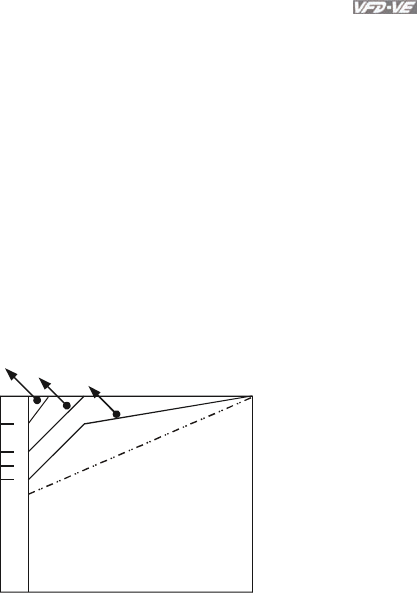
Appendix C How to Select the Right AC Motor Drive|
Revision August 2008, 03VE, SW V2.04 C-5
C.3 How to Choose a Suitable Motor
Standard motor
When using the AC Motor Drive to operate a standard 3-phase induction motor, take the
following precautions:
1. The energy loss is greater than for an inverter duty motor.
2. Avoid running motor at low speed for a long time. Under this condition, the motor
temperature may rise above the motor rating due to limited airflow produced by the
motor’s fan. Consider external forced motor cooling.
3. When the standard motor operates at low speed for long time, the output load must be
decreased.
4. The load tolerance of a standard motor is as follows:
3 6 20 60
100
82
70
60
50
0
60%
40%
25%
torque(%)
continuous
Frequency (Hz)
Load duty-cycle
5. If 100% continuous torque is required at low speed, it may be necessary to use a special
inverter duty motor.
6. Motor dynamic balance and rotor endurance should be considered once the operating
speed exceeds the rated speed (60Hz) of a standard motor.
7. Motor torque characteristics vary when an AC Motor Drive instead of commercial power
supply drives the motor. Check the load torque characteristics of the machine to be
connected.
8. Because of the high carrier frequency PWM control of the VFD series, pay attention to the
following motor vibration problems:

Appendix C How to Select the Right AC Motor Drive|
C-6 Revision August 2008, 03VE, SW V2.04
Resonant mechanical vibration: anti-vibration (damping) rubbers should be
used to mount equipment that runs at varying speed.
Motor imbalance: special care is required for operation at 50 or 60 Hz and
higher frequency.
To avoid resonances, use the Skip frequencies.
9. The motor fan will be very noisy when the motor speed exceeds 50 or 60Hz.
Special motors:
1. Pole-changing (Dahlander) motor:
The rated current is differs from that of a standard motor. Please check before operation
and select the capacity of the AC motor drive carefully. When changing the pole number
the motor needs to be stopped first. If over current occurs during operation or
regenerative voltage is too high, please let the motor free run to stop (coast).
2. Submersible motor:
The rated current is higher than that of a standard motor. Please check before operation
and choose the capacity of the AC motor drive carefully. With long motor cable between
AC motor drive and motor, available motor torque is reduced.
3. Explosion-proof (Ex) motor:
Needs to be installed in a safe place and the wiring should comply with the (Ex)
requirements. Delta AC Motor Drives are not suitable for (Ex) areas with special
precautions.
4. Gear reduction motor:
The lubricating method of reduction gearbox and speed range for continuous operation
will be different and depending on brand. The lubricating function for operating long time
at low speed and for high-speed operation needs to be considered carefully.
5. Synchronous motor:
The rated current and starting current are higher than for standard motors. Please check
before operation and choose the capacity of the AC motor drive carefully. When the AC
motor drive operates more than one motor, please pay attention to starting and changing
the motor.
Power Transmission Mechanism
Pay attention to reduced lubrication when operating gear reduction motors, gearboxes, belts
and chains, etc. over longer periods at low speeds. At high speeds of 50/60Hz and above,
lifetime reducing noises and vibrations may occur.
Motor torque
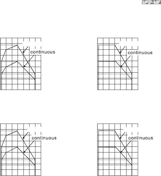
Appendix C How to Select the Right AC Motor Drive|
Revision August 2008, 03VE, SW V2.04 C-7
The torque characteristics of a motor operated by an AC motor drive and commercial mains
power are different.
Below you’ll find the torque-speed characteristics of a standard motor (4-pole, 15kW):
AC motor drive Motor
180
155
140
100
80
55
38
0320 60 120
60 seconds
Base freq.: 60Hz
V/F for 220V/60Hz
180
155
100
55
38
0320 60 120
torque (%)
Frequency (Hz) Frequency (Hz)
60 seconds
60 seconds
torque (%)
Base freq.: 60Hz
V/F for 220V/60Hz
130
140
100
85
45
35
0320 50 120
180
150
100
45
35
050 120
68 80
torque (%)
torque (
%
)
60 seconds 60 seconds
Frequency (Hz)
Frequency (Hz)
320
Base freq.: 50Hz
V/F for 220V/50Hz
Base freq.: 50Hz
V/F for 220V/50Hz

Appendix C How to Select the Right AC Motor Drive|
C-8 Revision August 2008, 03VE, SW V2.04
This page intentionally left blank.
