Delta Electronics WAP551 Wireless AP with PoE User Manual WAP 551 561 QSG
Delta Networks, Inc. Wireless AP with PoE WAP 551 561 QSG
Contents
- 1. User Manual
- 2. User Manual.pdf
User Manual
Quick Start Guide
DRAFT -- CISCO CONFIDENTIAL
Cisco Small Business
WAP551 Single-Radio 450Mbps 802.11n
Access Point with PoE
and
WAP561 Dual-Radio 450Mbps 802.11n Access
Point with PoE
Versión en Español para México en el CD
Version en français sur CD
Versione italiana sul CD
Deutsch Version auf CD

2 Cisco Small Business WAP551 and WAP561 Wireless-N Access Point with PoE
DRAFT -- CISCO CONFIDENTIAL
Welcome
Thank you for choosing the Cisco Small Business WAP551 or WAP561
Wireless Access Point. The Cisco WAP551 is a single-radio, selectable-
band, 450Mbps data rate 802.11n access point, and the Cisco WAP561 is
a dual-radio variant of the Cisco WAP551.
This guide is designed to familiarize you with the general layout of the
access point, describe how to deploy the device in your network, and
describe how to configure the device. Your access point has more features
and functionality than what is described in this guide. For additional
information, see the Administration Guide. A link to the Administration
Guide is found in “Where to Go From Here” on page 11.
Package Contents
•Wireless Access Point
•Mounting kit
•This Quick Start Guide
•Product CD
•Ethernet Cable
Before You Begin
Before you begin the installation, make sure that you have the following
equipment and services:
•A computer with Browser support for:
– Internet Explorer v7.0 or later
– Chrome v5.0 or later
– Firefox v3.0 or later
–Safari v3.0 or later
•Tools for installing the hardware
•One or more Ethernet network switches
•Uninterruptible Power Supply (UPS) to provide backup power to
essential devices
1

Cisco Small Business WAP551 and WAP561 Wireless-N Access Point with PoE 3
DRAFT -- CISCO CONFIDENTIAL
Cisco WAP551 and WAP561 Wireless-N
Access Point Features
Front Panel
The front panel of the devices consists of three lights: Power, WLAN, and
LAN. For full descriptions of the colors of the lights and their indications,
see “Verifying the Hardware Installation”. A Kensington lock slot is found
under the lights.
Back Panel
The back panel of the devices consists of:
•Power Button—Use this button to turn the power on and off. It is not
applicable when using PoE.
•Power Jack—Use this jack if you are not using PoE.
•Kensington Lock Slot—Use to attach a cable and lock to the device.
•Reset—See “Rebooting the Devices or Returning them to their
Factory Default Settings” for information on the Reset button.
•RJ-45 Ethernet Port—Use this auto-sensing, Gigabit Ethernet (802.3)
port to connect to network devices, such as computers, routers, or
switches. Cisco strongly recommends using Cat5 or better cable for
Gigabit connectivity. You may use the Ethernet port to power your
device using PoE.
Default Settings
If you are using a Cisco Small Business RV Series router, the default range
for the DHCP assigned address is from 192.168.1.100 to 192.168.1.254. Any
device connecting to the same LAN will be assigned an IP address in this
range.
Parameter Default Value
Username cisco
Password cisco
LAN IP Address DHCP address assigned
by server
Fallback LAN IP 192.168.1.245
Subnetwork Mask 255.255.255.0
2
4 Cisco Small Business WAP551 and WAP561 Wireless-N Access Point with PoE
DRAFT -- CISCO CONFIDENTIAL
Mounting the Cisco WAP551 and WAP561
Wireless-N Access Points
You can place your access point on a desktop, or mount it on a wall or
ceiling.
Placement Tips
• Ambient Temperature—To prevent the access point from overheating,
do not operate it in an area that exceeds an ambient temperature of
104°F (40°C).
•Air Flow—Both side panels have vents which must be unobstructed to
prevent overheating.
• Mechanical Loading—The device should be level, stable, and secure
to prevent it from sliding or shifting out of position.
Wall and Ceiling Mounting
The Cisco WAP551 and WAP561 can be wall or ceiling-mounted.
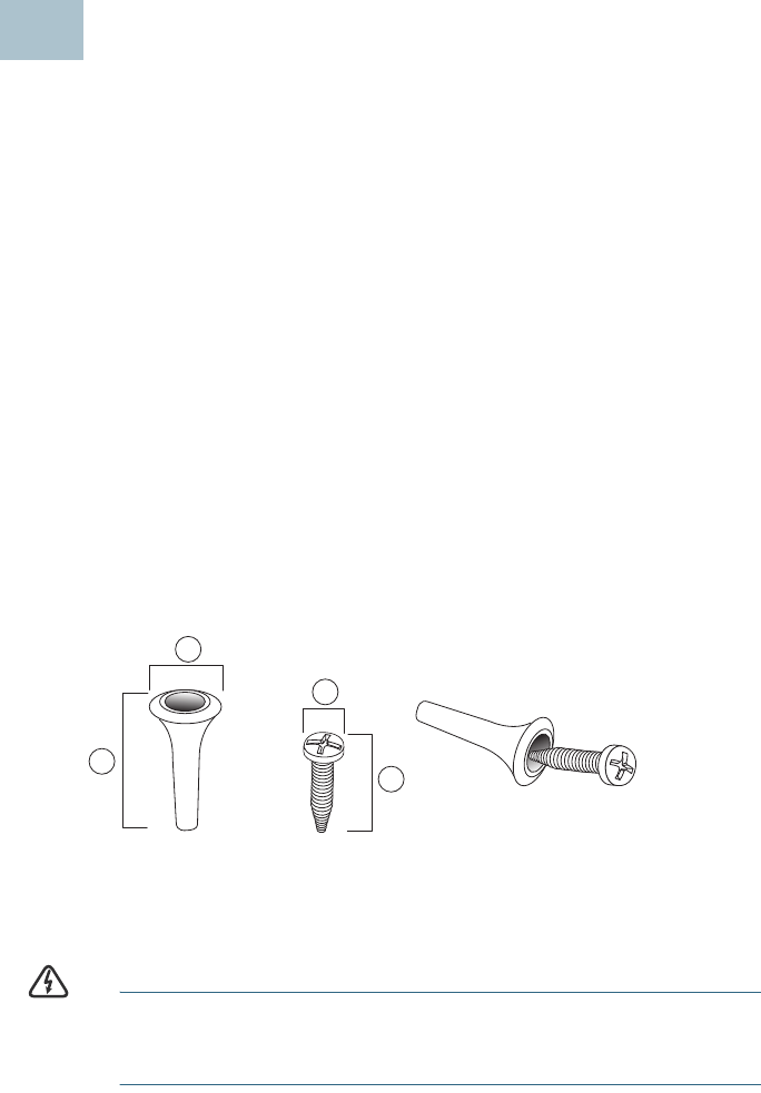
There is a mounting kit packed with your device. The kit is designed to
install your device to the wall or the ceiling. The dimensions for the mount
kit screws are as follows:
WARNING Insecure mounting might damage the device or cause injury.
Cisco is not responsible for damages incurred by insecure wall
or ceiling mounting.
17.8 to 8.3 mm/
.31 to .33 in
221.8 to 22.3 mm/
.86 to .88 in
35.5 to 6.0 mm/
.22 to .24 in
417.5 to 18.2mm/
.69 to .72 in
3
1
2
4
3
196243

Cisco Small Business WAP551 and WAP561 Wireless-N Access Point with PoE 5
DRAFT -- CISCO CONFIDENTIAL
To mount the WAP device to a wall or ceiling:
STEP 1Determine where you want to mount the device. Verify that the
surface is smooth, flat, dry, and sturdy.
STEP 2Drill two pilot holes into the surface x.xx inches (xx mm) apart for
your Cisco WAP device.
STEP 3Insert a screw into each hole, leaving a gap between the surface
and the base of the screw head.
STEP 4Place the upper slots of the bracket over the screws, adjust the
screws accordingly, and slide the bracket down until the screws fit
snugly into the slots.
STEP 5Using the bracket as a template, drill two more holes for the lower
screws.
STEP 6Insert a screw into each lower hole.
STEP 7Slide the WAP device into the bracket, placing the cables or cords
through the break-out tab found in the back of the bracket.
Connecting the Cisco WAP551 and
WAP561 Wireless-N Access Points
These instructions assume that your will be using PoE to power your WAP
device. If PoE is not provided, power adaptors are sold separately; see
Where to Go From Here, page 11. To connect the device to the network:
STEP 1Connect the Ethernet cable to the Ethernet port of a switch or a
router.
STEP 2Connect the other end of the network Ethernet cable to the
Ethernet port of the wireless access point.
After installation, all lights should be active. Refer to Verifying the
Hardware Installation, page 6 for details about the different lights on each
switch.
4

6 Cisco Small Business WAP551 and WAP561 Wireless-N Access Point with PoE
DRAFT -- CISCO CONFIDENTIAL
Verifying the Hardware Installation
To verify the hardware installation, complete the following tasks:
•Check the cable connections.
•Check the state of the indicator lights.
NOTE If you need help resolving a problem, visit the Cisco Small Business
Support Community at www.cisco.com/go/smallbizsupport.
Label Activity Description
Power Off Power is off.
Solid Green Power is on. Normal operation.
Flashing Green Booting or firmware ppgrade.
Solid Red Booting or firmware upgrade failed.
WLAN Off Wireless is disabled, for both 2.4 GHz and
5GHz wireless networks
Solid Green Wireless 2.4 GHz band is enabled.
Solid Amber Wireless 5 GHz band is enabled.
Solid Blue Concurrent wireless modes are enabled.
WAP561 only.
Flashing Transmitting or receiving data.
Flashing Fast (2x
Flashing rate)
Wi-Fi Protected Setup (WPS) is synchronizing.
LAN Off No Ethernet link.
Solid Green GE Ethernet link is active.
Solid Amber FE Ethernet link is active.
Flashing Transmitting or receiving data.
5

Cisco Small Business WAP551 and WAP561 Wireless-N Access Point with PoE 7
DRAFT -- CISCO CONFIDENTIAL
Getting Started with the Configuration
To configure the wireless access points, follow these steps to access the
Wizard and then the web-based configuration utility from your computer.
STEP 1Connect the wireless access point to the same network (IP subnet)
as your computer. The factory default IP address configuration of
the access points is DHCP. Make sure your DHCP server is running
and can be reached.
See “Incorrect IP Address” on page 9 for troubleshooting
information, or if you do not have a DHCP server.
STEP 2Locate the IP address of the wireless access point.
a. The wireless access points can be accessed and managed by
Cisco Small Business network tools and services including the
Cisco FindIT Network Discovery Utility that enables you to
automatically discover all supported Cisco Small Business
devices in the same local network segment as your computer.
You can get a snapshot view of each device or launch the
product configuration utility to view and configure the settings.
For more information, see www.cisco.com/go/findit.
b. The wireless access points are Bonjour-enabled and
automatically broadcast their services and listen for services
being advertised by other Bonjour-enabled devices. If you
have a Bonjour-enabled browser, such as Microsoft Internet
Explorer with a Bonjour plug-in, or the Apple Mac Safari
browser, you can find the wireless access point on your local
network without knowing its IP address.
You can download the complete Bonjour for Internet Explorer
browser from Apple’s Web site by visiting
http://www.apple.com/bonjour/.
c. Locate the IP address assigned by your DHCP server by
accessing your router/DHCP Server; see your DHCP server
instructions for information.
STEP 3Launch a web browser, such as Internet Explorer or Mozilla Firefox.
STEP 4In the Address field enter the default DHCP address and press the
Enter key.
STEP 5Enter the default user name of cisco and password of cisco in the
User Name and Password fields.
STEP 6Click Login. The Wireless Access Point Setup Wizard appears.
6

8 Cisco Small Business WAP551 and WAP561 Wireless-N Access Point with PoE
DRAFT -- CISCO CONFIDENTIAL
STEP 7Follow the Setup Wizard instructions to finish the WAP device
installation. For more advanced configurations, see the
Administration Guide. A link to the Administration Guide is found in
“Where to Go From Here” on page 11.
Congratulations, you can now start using your wireless access point.
Suggested Next Steps
In case of an error while installing, try the following troubleshooting
procedures:
Troubleshooting
If you cannot display the configuration utility, you can test the ability of the
computer to communicate with the device by using ping. To use ping on a
computer running Windows:
STEP 1Verify that the Cisco WAP551 or WAP561 is powered on and the
lights indicate the appropriate links.
STEP 2Locate the device’s IP address. While there are different ways to
locate your device’s IP address, this procedure uses Cisco FindIT.
d. If you have previously downloaded Cisco FindIT, open Mozilla
Firefox and launch Cisco FindIT. For more information on
downloading Cisco FindIT, see www.cisco.com/go/findit.
e. In the Cisco FindIT display, place your mouse over the device’s
name. The device IP address is displayed along with other
device information.
STEP 3Open a command window by using Start > Run and enter cmd.
STEP 4At the Command window prompt enter ping and the device IP
address. In this example, we pinged 192.0.2.10.
If successful, you should get a reply similar to the following:
Pinging 192.0.2.10 with 32 bytes of data:
Reply from 192.0.2.10: bytes=32 time<1ms TTL=128
If it fails, you should get a reply similar to the following:
Pinging 192.0.2.10 with 32 bytes of data:
Request timed out.
7
Cisco Small Business WAP551 and WAP561 Wireless-N Access Point with PoE 9
DRAFT -- CISCO CONFIDENTIAL
Possible Cause of Failure
No Power
•Power up the switch and your computer if they are turned off.
•If your access point is using PoE, make sure your PoE switch is powered
on and the lights indicate that you have a link. See “Verifying the
Hardware Installation” on page 6.
•Verify that the power button is on; only applicable if you are not using
PoE.
•Verify that the devices on your network are not plugged into a
switchable outlet.
Bad Ethernet Connection
•Check the state of the indicator lights. See “Verifying the Hardware
Installation” on page 6.
•Check the connectors of the Ethernet cable to ensure they are firmly
plugged into the switch and your computer.
•Verify the connected switch has auto-negotiation enabled. The access
point and the switch need the same negotiation parameters set.
Bad Image
After a new firmware installation, if the Power light is flashing quickly,
contact system support; see “Where to Go From Here” on page 11.
Incorrect IP Address
The most likely cause of connectivity failure is an incorrect IP address. The
Web browser may be pointed to the wrong IP address, or your computer
may be configured with an IP address that is not in the same subnet as the
device.
Because the factory default IP address configuration is DHCP, make sure
that your DHCP server is running and can be reached. You may need to
disconnect and reconnect the devices for them to discover their new IP
addresses from the DHCP server. You can then query the DHCP server for
the new IP address. See Step 2 of “Getting Started with the
Configuration” on page 7 for more information on how to find the DHCP
address.
If the wireless access points do not receive a DHCP response (there is no
DHCP server on your network) after 60 seconds, the access points will
fallback to the following default static IP address: 192.168.1.245 and a
default mask of 255.255.255.0. To reach that IP address, be sure that your
computer is on the 192.168.1.xxx network.

10 Cisco Small Business WAP551 and WAP561 Wireless-N Access Point with PoE
DRAFT -- CISCO CONFIDENTIAL
Rebooting the Devices or Returning them
to their Factory Default Settings
To reboot your device:
•If your device uses a power adaptor, use the Power button to reboot
your device. The Power button only functions when the device uses a
power adaptor.
•Unplug your Ethernet connection for three seconds and plug it back in.
• If your devices uses PoE, with the power on, press the Reset button with
a bent paperclip for less than three seconds, or until the lights go off.
– When all the lights go off, release the Reset button.
– Release the Reset button as soon as the lights go off, or you will
restore the device to factory default settings and lose your
configurations.
To reset the device to factory default settings:
•To restore the device to the factory default settings, with the power on,
press-and-hold the Reset button with a bent paperclip for more than 10
seconds.
– All of the lights will go off.
– Release the Reset button when power light turns on.
8

Cisco Small Business WAP551 and WAP561 Wireless-N Access Point with PoE 11
DRAFT -- CISCO CONFIDENTIAL
Where to Go From Here
Support
Cisco Small Business
Support Community
www.cisco.com/go/smallbizsupport
Cisco Small Business
Support and Resources
www.cisco.com/go/smallbizhelp
Phone Support Contacts www.cisco.com/en/US/support/
tsd_cisco_small_business
_support_center_contacts.html
Cisco Small Business
Firmware Downloads
www.cisco.com/go/smallbizfirmware
Select a link to download firmware for Cisco
Small Business Products. No login is
required.
Downloads for all other Cisco Small Business
products, including Network Storage
Systems, are available in the Download area
on Cisco.com at www.cisco.com/go/
software (registration/login required).
Cisco Small Business
Open Source Requests
www.cisco.com/go/
smallbiz_opensource_request
Product Documentation
Cisco Small Business
WAP551 and WAP561
Administration Guide
www.cisco.com/go/500_wap_resources
Cisco Small Business
Power Adaptors
Go to www.cisco.com/go/wap_accessories
and select the Resources tab. Scroll down to
Technical Documentation.
Cisco Small Business
Cisco Partner Central
for Small Business
(Partner Login Required)
www.cisco.com/web/partners/sell/smb
Cisco Small Business
Home
www.cisco.com/smb
9

Americas Headquarters
Cisco Systems, Inc.
170 West Tasman Drive
San Jose, CA 95134-1706
USA
www.cisco.com
Small Business Support, Global: www.cisco.com/go/sbsc
Cisco and the Cisco logo are trademarks or registered trademarks of Cisco and/or its affiliates
in the U.S. and other countries. To view a list of Ciscotrademarks, go to this URL:
www.cisco.com/go/trademarks. Third-party trademarks mentioned are the property of their
respective owners. The use of the word partner does not imply a partnership relationship
between Cisco and any other company. (1110R)
© 2012 Cisco Systems, Inc. All rights reserved.
78-20584-01
Cisco Small Business WAP551 and WAP561 Wireless-N Access Point with PoE 13
DRAFT -- CISCO CONFIDENTIAL
Federal Communication Commission Interference Statement
This device complies with Part 15 of the FCC Rules. Operation is subject to
the following two conditions: (1) This device may not cause harmful
interference, and (2) this device must accept any interference received,
including interference that may cause undesired operation.
This equipment has been tested and found to comply with the limits for a
Class B digital device, pursuant to Part 15 of the FCC Rules. These limits
are designed to provide reasonable protection against harmful interference in a
residential installation. This equipment generates, uses and can radiate radio
frequency energy and, if not installed and used in accordance with the
instructions, may cause harmful interference to radio communications.
However, there is no guarantee that interference will not occur in a particular
installation. If this equipment does cause harmful interference to radio or
television reception, which can be determined by turning the equipment off
and on, the user is encouraged to try to correct the interference by one of the
following measures:
- Reorient or relocate the receiving antenna.
- Increase the separation between the equipment and receiver.
- Connect the equipment into an outlet on a circuit different from that
to which the receiver is connected.
- Consult the dealer or an experienced radio/TV technician for help.
FCC Caution: Any changes or modifications not expressly approved by the
party responsible for compliance could void the user's authority to operate this
equipment.
This transmitter must not be co-located or operating in conjunction with any
other antenna or transmitter.
Operations in the 5.15-5.25GHz band are restricted to indoor usage only.
FOR MOBILE DEVICE USAGE (>20cm/low power)
Radiation Exposure Statement:
This equipment complies with FCC radiation exposure limits set forth for an
uncontrolled environment. This equipment should be installed and operated
with minimum distance 20cm between the radiator & your body.
FOR COUNTRY CODE SELECTION USAGE (WLAN DEVICES)
Note: The country code selection is for non-US model only and is not
available to all US model. Per FCC regulation, all WiFi product marketed in
US must fixed to US operation channels only.
Industry Canada statement:
This device complies with RSS-210 of the Industry Canada Rules. Operation is
subject to the following two conditions: (1) This device may not cause harmful
interference, and (2) this device must accept any interference received, including
interference that may cause undesired operation.
Ce dispositif est conforme à la norme CNR-210 d'Industrie Canada applicable aux
appareils radio exempts de licence. Son fonctionnement est sujet aux deux conditions
suivantes: (1) le dispositif ne doit pas produire de brouillage préjudiciable, et (2) ce
dispositif doit accepter tout brouillage reçu, y compris un brouillage susceptible de
provoquer un fonctionnement indésirable.
Caution :
(i) the device for operation in the band 5150-5250 MHz is only for indoor use to
reduce the potential for harmful interference to co-channel mobile satellite systems;
(ii) high-power radars are allocated as primary users (i.e. priority users) of the bands
5250-5350 MHz and 5650-5850 MHz and that these radars could cause interference
and/or damage to LE-LAN devices.
Avertissement:
(i) les dispositifs fonctionnant dans la bande 5 150-5 250 MHz sont réservés
uniquement pour une utilisation à l’intérieur afin de réduire les risques de
brouillage préjudiciable aux systèmes de satellites mobiles utilisant les mêmes
canaux;
(ii) De plus, les utilisateurs devraient aussi être avisés que les utilisateurs de radars de
haute puissance sont désignés utilisateurs principaux (c.-à-d., qu’ils ont la priorité)
pour les bandes 5 250-5 350 MHz et 5 650-5 850 MHz et que ces radars pourraient
causer du brouillage et/ou des dommages aux dispositifs LAN-EL.
FOR MOBILE DEVICE USAGE (>20cm/low power)
Radiation Exposure Statement:
This equipment complies with IC radiation exposure limits set forth for an
uncontrolled environment. This equipment should be installed and operated with
minimum distance 20cm between the radiator & your body.
Déclaration d'exposition aux radiations:
Cet équipement est conforme aux limites d'exposition aux rayonnements IC établies
pour un environnement non contrôlé. Cet équipement doit être installé et utilisé avec
un minimum de 20 cm de distance entre la source de rayonnement et votre corps.