Delta Systems 2023-001 Remote Control User Manual P5593100AV indd
Delta Systems INC. Remote Control P5593100AV indd
Contents
- 1. Manual
- 2. Manual addition
Manual
1
OPERATING INSTRUCTIONS RC30 & RC23
Please read and save these instructions. Read carefully before attempting to assemble, install, operate or maintain the product de-
scribed. Protect yourself and others by observing all safety information. Failure to comply with these instructions could result in
personal injury and/or property damage. Retain instructions for future reference
fi
Quality Winches Since 1956
General Safety Information
Throughout this manual potential safety hazards will be noted with the following terms. Please read and understand
these terms before operating the product.
Danger means a hazard
that will cause death or se-
rious injury if the warning
is ignored.
Caution means a hazard that
may cause minor or moder-
ate injury if the warning is
ignored. It also may mean a
hazard that will only cause
damage to property
Warning means a hazard
that could cause death or
serious injury if the warning
is ignored.
P5593100AV
07/04
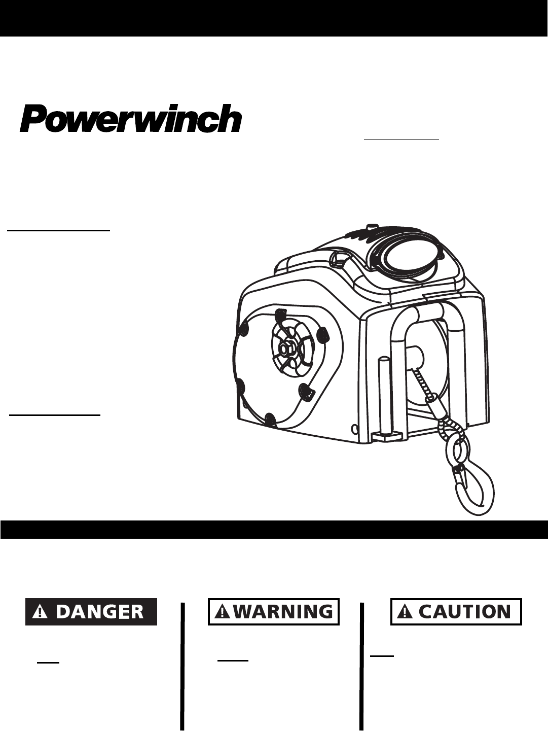
“RF” REMOTE CONTROLLED
TRAILER WINCHES
WITH SPOTLIGHT
BOAT TRAILER WINCH
MODELS
RC30 (P77950)
& RC23 (P55750)
DESCRIPTION:
Trailer winches are used for launching
and unloading boats. These winches
feature power-in/free-wheel out ca-
pabilities. These winches operate by
means of a wireless remote system
within a radius of 25 feet around the
center of the winch. These winches
also come equipped with a 12-volt
spotlight to help improve visibility
while operating in hours of darkness.
UNPACKING:
When unpacking, inspect carefully for
any damage that may have occured
during transit. Make sure that any
loose fi ttings, bolts, etc., are tightened
before putting unit into service.
2
OPERATING INSTRUCTIONS RC30 & RC23
General Safety Information (continued)
The following safety precautions must be followed at all times
NOTE: Note means any additional
information pertaining to the product or its
proper usage.
The following safety precautions must be
followed at all times:
1. Read all manuals included with this
product carefully. Be thoroughly
familiar with the controls and the
proper use of the equipment. Only
persons well acquainted with these
rules of safe operation should be
allowed to use the winch.
Always unplug the
wiring harness to
prevent accidental starting before attempting
to install, service, relocate or perform
any maintenance.
2. Never use the winch to lift or move
people or animals.
3. Stand away from the winch when in
use and keep children away from
winch area at all times.
Always stand clear
of the area behind
and between the load or anchor point and
the winch. Serious injury could occur, if
the cable breaks.
4. Always keep hands clear of cable
spool (drum area).
5. Do not wear loose fi tting clothing,
scarves, or neck ties. Loose clothing
may become caught in moving parts
and result in serious personal injury.
6. Never use the winch for overhead
lifting.
7. Always wire the winch with circuit
breakers. Failure to use the breakers
could cause overheating thus creating
a potential fi re hazard or motor
damage.
The cable fasteners
on this or any winch
are not designed to hold rated loads.
Always leave a minimum of fi ve wraps of
cable on the drum at the bottom layer to
achieve a rated load.
8. Inspect the entire cable for weak or
worn condition or kinking (short tight
twist or curl) before each use.
9. When replacing the cable, always use
a Powerwinch cable with the same
winch rating and cable strength.
10. Never substitute rope for cable.
Possible injury could occur.
11. Do not attempt to pull a load greater
than the rated load of the winch.
12. Do not use the winch to hold or
support the load once a job is
complete or to permanently secure the
load. Damage could occur to the
winch or the load.
13. Never wrap the winch cable around
the load. Use an Ecostrap™ or chain
to prevent the cable from kinking or
fraying.
After using the
winch, always
disconnect the power cord from the socket
to avoid moisture collection in the socket
and prevent the possibility of short
circuiting.
15. Always block the vehicle wheels to
help prevent the vehicle from rolling when
pulling a load with the winch.
16. Do not operate the winch under the
infl uence of drugs, alcohol, or other
medication.
Secure the boat to
the trailer after
winching the boat onto the trailer or
personal injury could occur.

3
OPERATING INSTRUCTIONS RC30 & RC23
Specifi cations
Various load conditions will affect winch performance. The line pull required for a specifi c application de-
pends on the weight of the load, condition of the trailer rollers, and the degree of the loading ramp incline.
The chart below is based on a single line pull and is a guideline to aid in calculating pulling requirements.
NOTE: The noise level of this winch in operation is below 98db (A).
CHART #1 - Approximate Rolling Load Capacities. (Values are in pounds)
CHART #2 - Winch and Boat Capacities
% Incline Level Surface 5% 10% 20% 30% 50% 70% 100%
Deg Incline 0 DEG 3 DEG 6 DEG 11 DEG 17 DEG 26 DEG 35 DEG 45 DEG
RC23 24000 13340 10040 6800 5220 3720 3060 2580
RC30 40000 23345 17570 11900 9135 6510 5355 4515
- A 10% incline (or 6 deg) is 1 foot rise in 10 feet.
- To convert from pounds to kilos divide by 2.2
- Capacity can be increased (almost doubled) by using a pulley block.
Model Single Line
Capacity
Double Line Pull Approximate*
Boat Weight
Approximate*
Boat Size
RC23 2400 lbs 4300 lbs 7500 lbs 17-23 ft
RC30 4000 lbs 7500 lbs 11500 lbs 23-30 ft
* Boat size and weight is approximate and varies depending on boat type. When calculating boat weight be
sure to use fully loaded weight- including boat, motor, fuel, water, gear etc.
Model Line Speed
@ Capacity
(FPM)
Gear
Ratio
Voltage
(Volts)
Circuit
Breaker
(Amps)
Unit
Weight
(lbs)
Depth Height Width
RC23 14 225:01:00 12 60 X XX XXX XXXX
RC30 8 450:01:00 12 60 X XX XXX XXXX
CHART #3 - Winch Specifi cations
4
OPERATING INSTRUCTIONS RC30 & RC23
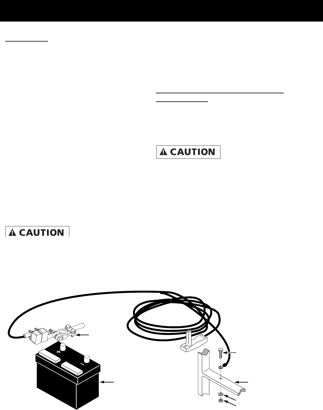
Battery
Terminal*
5/16" Bolt*
5/16"Lock Washer
And Nut*
12 Volt Car
Or Truck Battery Vehicle
Frame
* NOT SUPPLIED
Winch Installation
MOUNTING
The winch can be mounted on the trailer
in the same position and location as an
existing hand winch. After removing the
hand winch, bolt the Powerwinch unit
using a minimum of (2) 3/8” Grade 5
machine bolts and lock nuts. The
Powerwinch Quick Mount Kit
(P7700000AJ) is available from the
dealer.
The cable hook on the winch and the bow
eye on the boat should be at the same
height when the boat is in the fully loaded
position on the trailer. If the bow eye is
too high, extra pull is required of the winch
and extra stress is exerted on the boat’s
stern and bow eye.
To achieve equal height of the winch and
boat, raise or lower the winch stand. In
most cases, the trailer manufacturer will
have an adapter available for use with a
winch.
A minimum of 12
inch clearance is
required between the winch and the bow
eye to prevent the cable hook from being
drawn into the winch drum when the boat
is in the fully loaded position on the trailer.
If necessary, extend the bow stop to
obtain the clearance.
When using a double line pull (using a pulley block),
install an appropriate eye bolt on the winch stand as
close as possible to the base of the winch. If a Quick
Mount Kit is used, make sure the winch is in the
forward position before
installing the eye bolt.
PERMANENT WIRING FOR MODELS
RC23 and RC30
To permanently wire the winch, refer to Figure 1 fol-
low the outlined procedures.
1. Attach the circuit breaker to the positive (+) bat-
tery post or to the positive (+) battery side of the
starter solenoid (See Figure 1).
Never attach the
circuit breaker to the
battery ground terminal.
2. Run the wire under the vehicle to the
battery, attaching at suitable intervals to the vehicle
frame. Use nylon wire ties (not supplied) to secure
the wire to the vehicle frame about every 18 inches.
If no wire ties are available use electrician’s tape.
Avoid sharp edges or places where the wire might
rub.
3. Attach the ground wire (black) to the vehicle
frame using a 5/16” bolt and lock nut. Before attach-
ing the wire, clean the metal with a wire brush, steel
wool, or sandpaper.
4. Remove the knock out plug in the spare tire well
and draw the excess wire up into the vehicle.
Figure 1 - Permanent Wiring Hookup for Models RC23 & RC30

5
OPERATING INSTRUCTIONS RC30 &RC23
Transmitter Instructions
The Powerwinch RC30 and RC23 winches are equipped to operate with a radio
frequency remote transmitter and receiver module (located inside of winch cover).
Every transmitter and reciver module must be programmed by the operator to
communicate with one another before the initial use of the winch. Please refer to the
instructions below so that proper communication between the transmitter and receiver
module can be established.
TRANSMITTER FUNCTIONS
1. Place the transmitter in the palm of the hand. The button to the lower left is the power ON/OFF switch.
Press this button and the red LED will light indicating that the transmitter is powered up and ready for use.
The transmitter must be turned off after every use to preserve battery life.
2. The button in the upper right corner is the button that will be used to activate the Powerwinch. The
button to the upper left will not be used at this time.
If this is the your fi rst time using the Powerwinch please go to( Learning Your Transmitter ).
3. After the transmitter is learned to your Powerwinch just press the ON/OFF button to energize your
transmitter and then press the button to the upper right and your winch will start running.
Use extreme caution when using this system.
4. The transmitter is a electronic device so keep as dry as possible.
5. If the LED fails to light or the range of the transmitter has decreased change the battery in your
transmitter. It takes a A23 12 volt battery available at many stores.
Learning Your Transmitter
In the rear of your Powerwinch RC23/RC30 winch you will fi nd a black oval housing with two red switches
(This is the Manual Overide/Learn Switch, See Figure 3). The red button closest to the wires is the learn
button and the button farthest from the wires is the manual override switch that allows you to operate the
Powerwinch without the use of the transmitter.
Before learning the transmitter make sure the clutch is fully disengaged on the Powerwinch head.
1. Make sure that the winch is wired to a 12-volt battery as described earlier.
2. To learn the transmitter, fi rst turn power on to the transmitter the red LED will light.
3. Press and hold the learn button (closest to the wires) for 2 seconds.
4. Now press the right hand button on the transmitter and hold for 1 second. Release the button and press it
again and hold for one second.
5. Release, your Powerwinch transmitter is now learned to your receiver. Pressing the button should
activate the Powerwinch head.

6
OPERATING INSTRUCTIONS RC30 & RC23
In case you would ever lose your transmitter and have to obtain another from Powerwinch Inc, you can
remove all transmitters by pressing and holding the learn button for 25 seconds with the Powerwinch head
powered up. Of course you would have to repeat the learn process for a new transmitter.
This Device complies With The FCC Part15. Operation is subject to the following two conditions.
(1) This device may not cause harmful interference.
(2) This device must accept any interference received, including interference that may cause undesired
operation.
Section 15.105 Information to the user
Note: This equipment has been tested and found to comply with the limits for a Class B digital device,
pursuant to Part 15 of the FCC Rules. These limits are designed to provide reasonable protection against
harmful interference in a residential installation. This equipment generates, uses and can radiate radio
frequency energy and, if not installed and used in accordance with the instructions, may cause harmful
interference to radio communications. However, there is no guarantee that interference will not occur in a
particular installation. If this equipment does cause harmful interference to radio or television reception,
which can be determined by turning the equipment off and on, the user is encouraged to try to correct the
interference by one or more of the following measures:
__Reorient or relocate the receiving antenna.
-- Increase the separation between the equipment and receiver.
-- Connect the equipment into an outlet on a circuit different from that to which the receiver is connected.
-- Consult the dealer or an experienced radio/TV technician for help.
Figure 2 - Transmitter Key Fob
Transmitter Functions
7
OPERATING INSTRUCTIONS RC30 & RC23
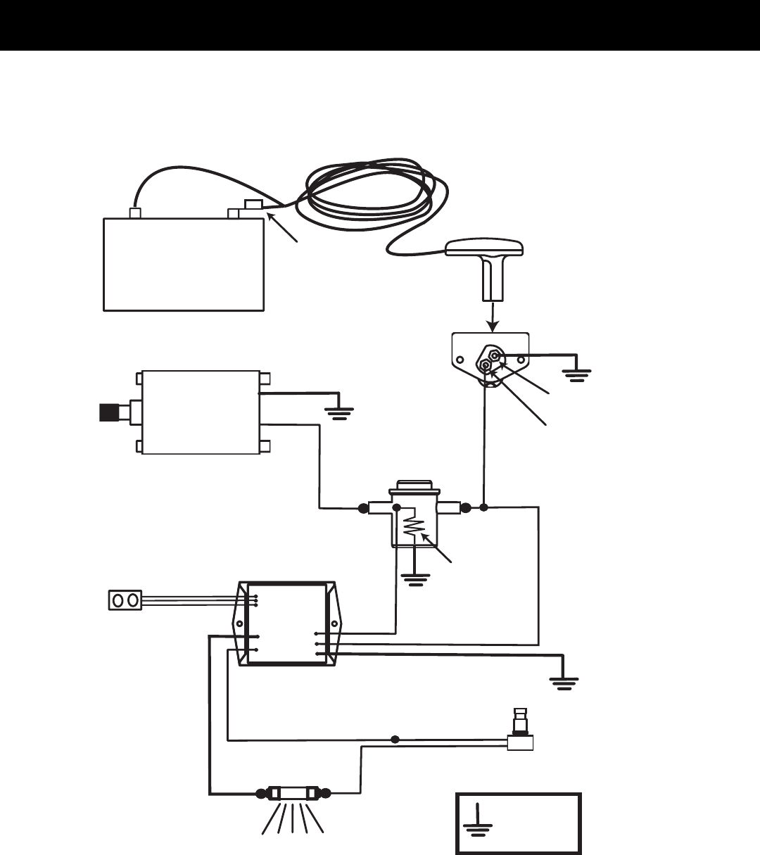
12-VOLT BATTERY
+
-
SOLENOID
POWER SOCKET
(REAR VIEW)
SWITCH
RECEIVER
MODULE
LIGHT BULB
12-VOLT MOTOR
INTERNAL
COIL
GOLD
TERMINAL
SILVER
TERMINAL
RED WIRE
BLACK WIRE
RED WITH WHITE STRIPE WIRE
(POSITIVE TO LIGHT BULB)
BLACK WIRE
RED WIRE
BLUE
WIRE
BLACK WIRE
SWITCH LEAD
BLACK WIRE
SWITCH LEAD
MANUAL
OVERIDE/LEARN
SWITCH
GREEN WIRE
(NEGATIVE TO LIGHT BULB)
DENOTES
GROUNDED TO
WINCH FRAME
(4 PLACES)
WIRING
HARNESS MALE PLUG
(INSERT INTO
FRONT OF POWER
SOCKET)
CIRCUIT
BREAKER
Figure 3 - Internal Wiring Diagram of RC30 &RC23 Winches

8
OPERATING INSTRUCTIONS RC30 &RC23
RC30 &RC23 Winch Troubleshooting
Limited Warranty
A. This Limited Warranty is given by the Powerwinch Division of the Scott Fetzer Company (the “Company”) to the original purchaser (the “Purchaser”) of a Power-
winch Product (the “Product”) specifi ed in this manual. This Limited Warranty is not transferable to any other party.
B. Responsibilities of the Company under this Limited Warranty:
1. Repair or replace (at the discretion of the Company) any part or parts of the Product found by the Company to be defective within a one (1) year period
from the date of purchase.
2. The Company will pay the transportation charge for shipment back to the Purchaser of any Product received for legitimate Warranty repair.
C. Responsibilities of the Purchaser under this Limited Warranty:
1. Purchaser will have to show dated proof of purchase to qualify for service under the provisions of the Limited Warranty.
2. Promptly notify the Seller or the Company of any claim hereunder.
3. At the Option of the Company, return the Product to the Company for inspection. Authorization must be given prior to any Product return. Call the
Company at (513)-539-7215 or write the Company at 301 Lawton Ave., Monroe, OH 45050 for authorization and complete instructions on how to return the Product
directly to the Company.
4. Use reasonable care in maintenance, operation, use and storage of the Product in accordance with the instructions contained in the Owner’s Manual.
5. Have Warranty work performed by a representative approved by the Company.
6. Except as noted in B.2., transportation charges are the responsibility of the Purchaser.
D. This Limited Warranty covers:
1. Defects in workmanship or materials.
2. Any part or parts of the Product sold or manufactured by the Company.
E. This Limited Warranty does not cover:
1. Any failure that results from improper installation of the Product.
2. Any failure that results from accident, Purchaser’s abuse, neglect, modifi cation, improper maintenance, or failure to operate and use the Product in ac-
cordance with the instructions provided in the Owner’s Manual supplied with the Product.
F. There is no other express warranty. Implied warranties, including those of merchantability and fi tness for a particular purpose, are limited to one (1) year from date of
purchase. This is the exclusive remedy and any liability for any and all incidental or consequential damages or expenses whatsoever is excluded.
Some states do not allow limitations on how long an implied warranty lasts, or do not allow exclusion or limitation of incidental or consequential damages, the above
limitations may not apply to you. This Limited Warranty gives you specifi c legal rights, and you may also have other rights which vary from state to state.

9
fi
Powerwinch RC23
Part Number P55750
Powerwinch, 301 Lawton Ave, Monroe, OH 45050 (513) 539-7215
For Replacement Parts Please Call
(800) 243-3097

10
fi
For Replacement Parts Please Call
(800) 243-3097
Powerwinch RC30
Part Number P55950