Delta Systems 2033500 KEY CAPTAIN REMOTE LAUNCHING SYSTEM-RECEIVER User Manual Catalog mailing
Delta Systems INC. KEY CAPTAIN REMOTE LAUNCHING SYSTEM-RECEIVER Catalog mailing
UserManual.wiki
>
Delta Systems
>
2033500 User Manual
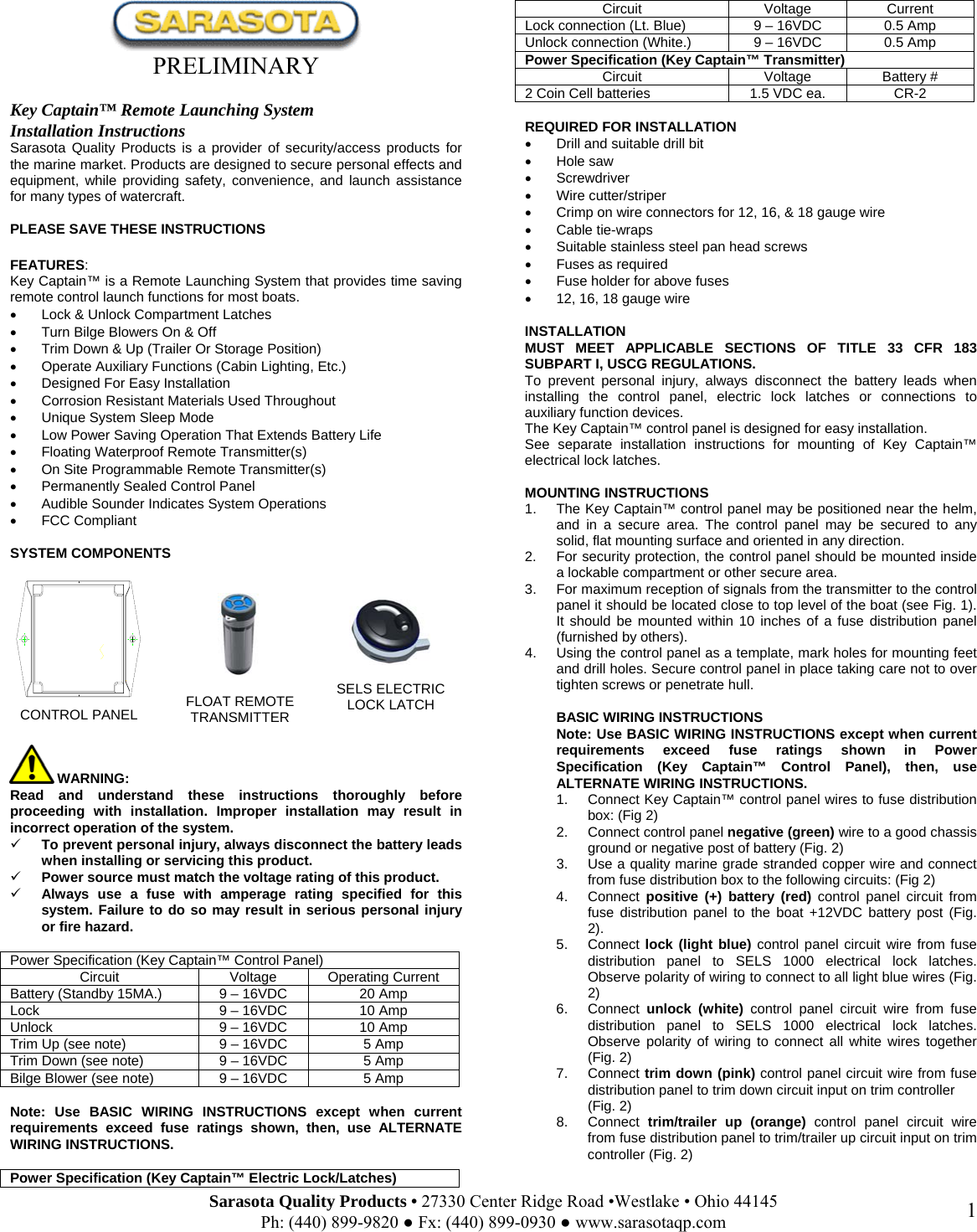
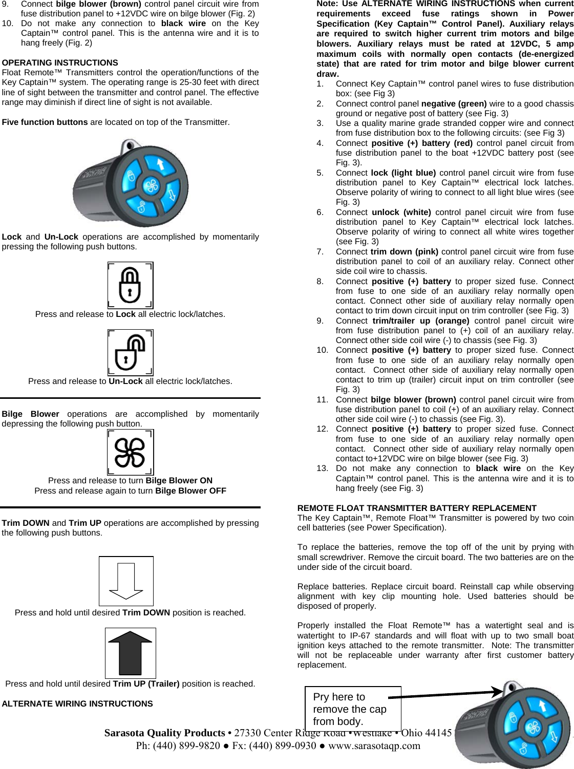
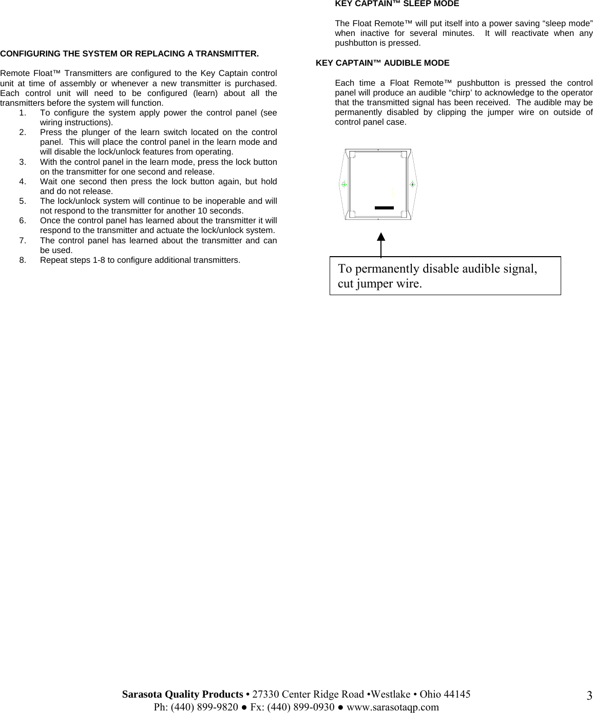
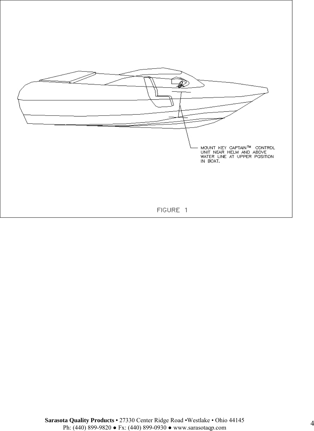
USERS MANUAL
Navigation menu
Upload a User Manual
Namespaces
Wiki Guide
HTML
PDF
Info
Views
User Manual
Discussion / Help
Navigation