Delta Systems 2051010 433.92 MHz Remote Control Transmitter User Manual ABS 50870 Cycl HP 8 04 REPAG
Delta Systems INC. 433.92 MHz Remote Control Transmitter ABS 50870 Cycl HP 8 04 REPAG
Users Manual
60233
233SL Remote Control
Dual Beam Searchlight
233SL Remote Control
Dual Beam Searchlight
233SL Remote Control
Dual Beam Searchlight
233SL Remote Control
Dual Beam Searchlight
233SL Remote Control
Dual Beam Searchlight
233SL Remote Control
Dual Beam Searchlight
233SL
Remote Control
Dual Beam
Searchlight
Dual Beam Wireless
Remote Control
Searchlight
Part Number Voltage AMPS WAT
60233-0012 12 VDC TBD TBD
60233-0024 24 VDC TBD TBD
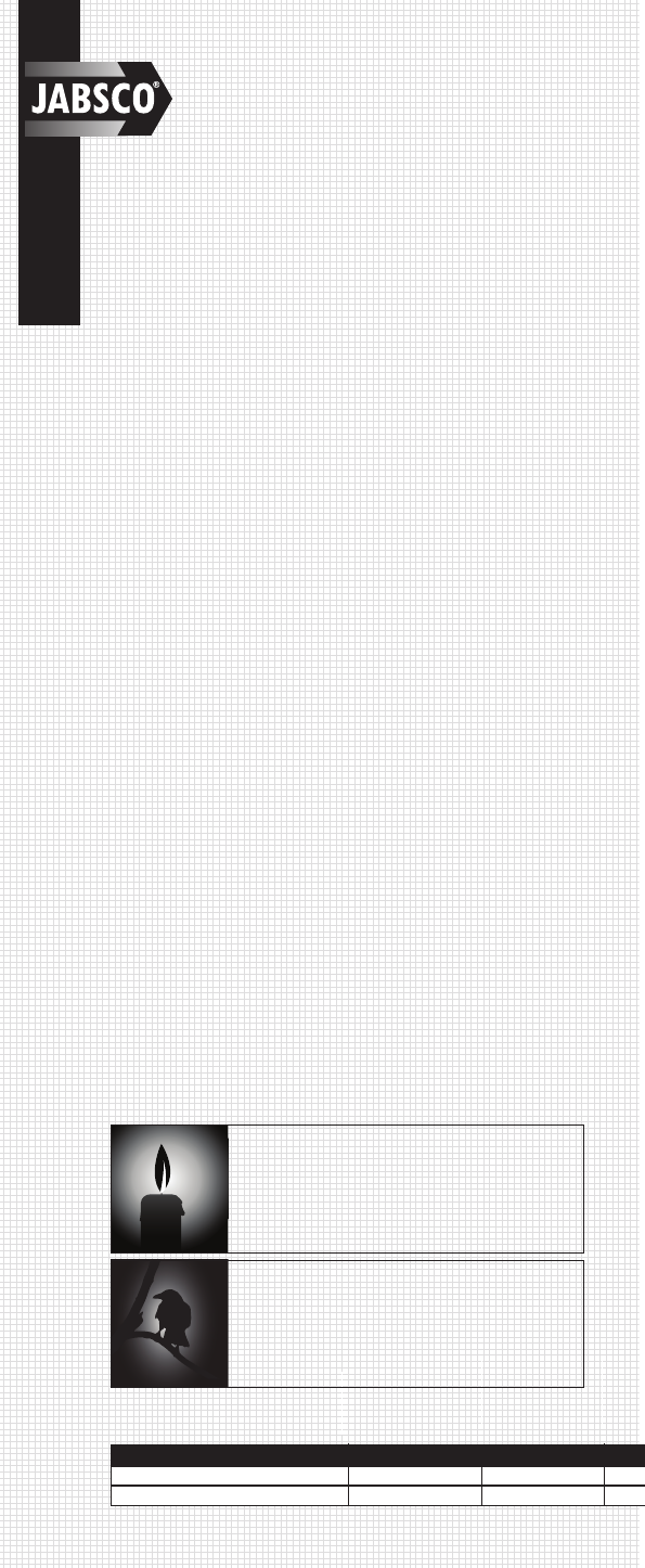
CandlePower
The first standard for the measurement of light consisted of
a spermaceti candle of standard dimensions burning at a
certain rate, giving off light in one direction. This was known
as a standard candle, and it's light from any one direction
was said to have an intensity of one candlepower. This is
also know as one candela. A candle emits one candlepow-
LUX
LUX is a unit of measurement of the intensity of light. It is
equal to the illumination of a surface one meter away from a
single candle. The International System unit of illumination,
equal to one lumen per square meter.
• Powerful dual beam halogen bulb configuration giving
225,000 candlepower
• Patent protected focus mechanism giving true
Spot/Flood capability
• Wireless searchlight control system allowing up to
4 easy to install control stations
• Infinite motion capabilities due to 8 way touch pad
directional control
• Rugged anodized & painted aluminum housing for
total corrosion resistance
• Continuous rotation capabilities while eliminating
slip ring corrosion
• 70° vertical capabilities using rugged delrin components
and heavy duty gear motor
• Patent protected sweep feature giving accurate
and constant +/- 20 degree from starting location
• Fast and Slow capabilities for accurate marker
identification and fine tune
• Patent protected easy to install bayonet base with
security locking mechanism.
APPLICATION
A marine searchlight has to be capable of performing a range of
tasks from locating buoys to illuminating a narrow channel and
occasionally, searching for a man overboard. The features of the
233SL have been designed to offer the best combination of
beam spread (width) and intensity (length), for both shorter and
longer range work giving the user total flexibility when tackling
any of the above applications.
This product can also be used on medium to larger motor homes
for illuminating driveways to campsites, road signs and as a back
up light.
PERFORMANCE DATA
Jabsco quotes performance data in two ways: Candle power &
Lux. Candle power is a useful guide to actual light produced
but does not measure the efficiency of the reflector design to
project that light at the target. The most relevant comparison
guide is LUX, which is the measurement of actual light avail-
able at a given distance. In order to be able to distinguish a
reasonable level of detail, a level of one lux is generally con-
sidered to be necessary
SPECIFICATIONS
TTS Bulb Configuration Weight Standard Carton
Spot / Flood TBD 1
Spot / Flood TBD 1
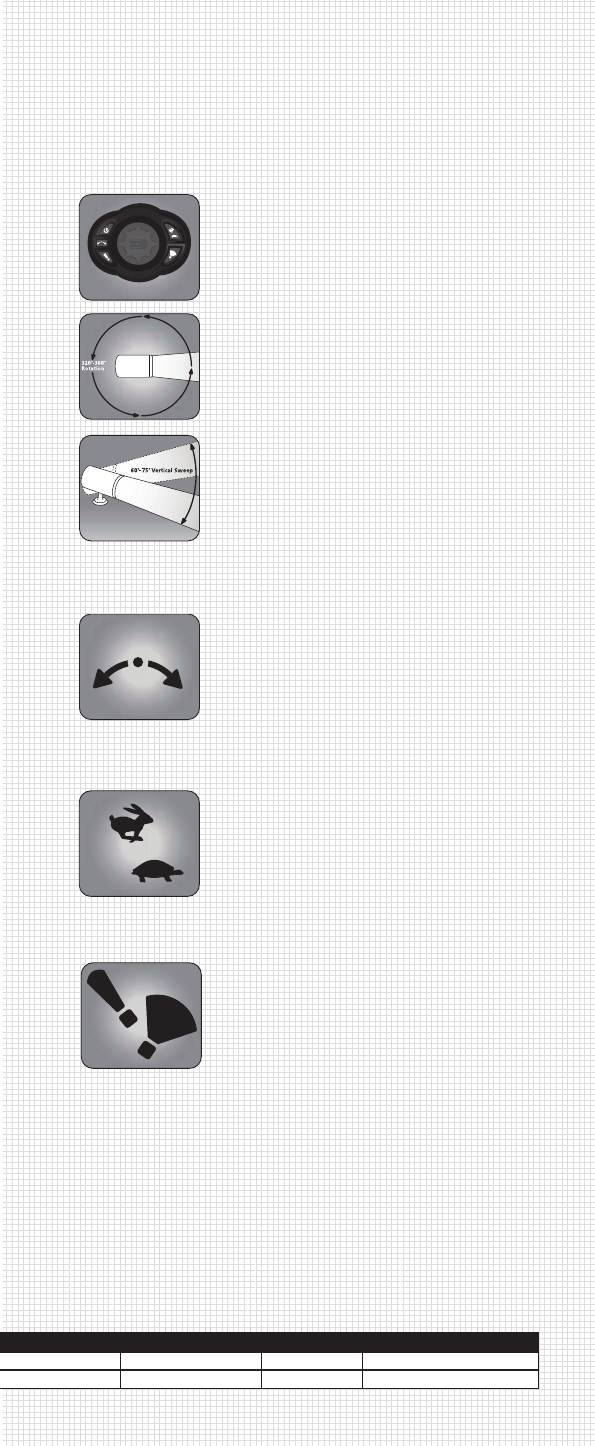
SEARCHLIGHT FUNCTION AND OPERATION
The advantage of the Remote Control is that it allows you to direct
the light in the best location for maximum effectiveness. They are an
increasingly popular addition on power boats, help. Secondary
remote control kits can be bought for most models which allow con-
trol from either the flybridge or main helm.
Horizontal Range
The horizontal range for this light is a con-
tinuous 360 degrees. There is no hard stop
on this light.
Vertical Range
The vertical range for this light is 70
degrees. This means you have 35 degrees
from the horizontal in both the up and down
ward motion of the light.
Auto Sweep
With the light on in either fast or slow mode,
pushing this button will continuously sweep
the light 10 degrees each side of the initial
target spot. If the light was in fast mode
when hitting the sweep button the light will
automatically place the unit into slow mode.
Simply press the auto sweep button again
to finish the cycle. The light will return to its
initial starting point and the directional con-
trols will become available for use again.
Speed
The 233SL has the option to run the light in
all motion axis’s in FAST or SLOW mode.
For fast simply hit the Hare button, and for
slow hit the Tortoise Button.
Spot / Flood
The spot and flood buttons allow you to
change the beam configuration from a spot
to a flood, and allow you to choose any
beam configuration you desire between
these two extreme limits. Simply hold one of
the buttons down until you reach your
desired beam configuration. For full spot
simply hold the spot button down until it
comes to a hard stop. Likewise for flood.
8 Way Controller
The 8 way controller allows for easier and
faster location of an object due to the
ability to move this light in any of the
diagonals.
INSTALLATION & SET UP INSTRUCTIONS
The installation instructions will take you through 3 stages of instal-
lation and set up. These stages will be as follows
1: Mounting the light
2: Mounting the contoller
3: Learning the controller to the light
Further information is included on page 3 of this data booklet on the
controller features and the process required to install additional
control stations to this light.

1. MOUNTING THE STAINLESS STEEL BAYONET
MOUNTING BRACKET AND DECK SEAL
a. Select a location that will allow for clear beam
projection. Searchlight base should be mounted on
level, flat surface.
b. The mounting template should be used to locate the
stainless steel bayonet mounting plate and deck seal
supplied. An xx hole for the 12v supply needs to be
drilled in the location also highlighted on the
mounting template. 4 3/16" mounting holes also need
to be drilled for fixing the light to the deck. It is
recommended that stainless steel mounting bolts be
used with lock washers.
c. Mount light so that the Jabsco name on the base is
facing to the rear.
d. Fasten light in place with XX (XX) #10 x 1" screws
provided or applicable screws for your particular
application.
2. MOUNTING THE SEARCHLIGHT
a. Feed the power cables through the central holes in
the bayonet base deck seal. If possible have
someone snake the wires from the inside of the boat
to minimize the amount of cable between the light
and the bayonet base fitting.
b. Place the light on the bayonet base fitting with the
security locking grub screw located at 5 o’clock.
Rotate the light into the bayonet base fitting while
applying reasonable pressure until the security
locking grub screw is at 6 o’clock
c. Using the security locking grub screw key. Lock the
light in place by rotating the security locking grub screw.
3. MOUNTING THE CONTROLLER
a. Select a location, which will allow for fit and
convenient operation of control.
b. Drill one hole (see Panel Cutout Template enclosed)
for running the power supply cables through
c. Run power cables through hole drill, if possible
have someone snake the wires from the inside of the
boat to minimize the amount of cable between the
controller and the mounting surface.
d. Fasten control using the installation kit included
Please note that if this unit is being used to upgrade an exist-
ing searchlight, Jabsco has available to its customers a retro
fit kit that will allow the controller to be seated in a mounting
bracket designed to cover existing holes from previous instal-
lations. This kit number is xxxxx-xxxx.
3: LEARNING MODE PROCEDURE
Note: The controller included with this product was initialized
at the factory to talk with the searchlight it was supplied with.
It is not necessary to conduct this procedure unless adding or
replacing a controller.
a. Disconnect battery power to the receiver.
b. Press and hold the “on/off” button on the controller
while reconnecting power to the searchlight. The
searchlight will turn “on” within (2) seconds.
c. Code synchronization is then complete.
LEARNING ADDITIONAL CONTROLLERSTO THE UNIT
The Jabsco 233SL can support up to (4) separate controllers.
Each time a controller is added to the system or is replaced;
all controllers require re-initialization using the above proce-
dure. Power to the searchlight must be disconnected then
reconnected while pressing the controllers “on/off” button for
each controller added in turn.
ELECTRICAL INSTALLATION
It is suggested that the Searchlight and controller (s) be wired
together in an independent circuit. Consult the wiring diagram
for connections
Although Internal Fuses are present it is suggested that exter-
nal fuses be installed on both the searchlight & the controller
(s) Consult the Wiring Table for fuse and wire size.
CLEANING OF EXTERIOR SURFACES
Recommendation for cleaning exterior surfaces is a solution
of warm water and a mild detergent soap
BULB REPLACEMENT
Bulb replacement kit included 2 x H7 halogen bulbs and a
replacement decal
a. Disconnect all power to the searchlight and controllers
before starting bulb replacement process
b. Using a small watchman’s screwdriver carefully lever
the decal holder plate at the rear of the searchlight.
Exposing the 2 locking nuts.
c. Loosen the lock nuts being careful to support the front
bezel ring of the searchlight. Note – the internal
chassis is connected to the bezel and glass and is all
pulled in from the rear, loosening thee nuts will allow
the internal chassis to be pulled out from the front.
d. Once the nuts have been removed (and stored safely)
the chassis is able to be pulled from the front. The
chassis will need to be twisted to an angle of
10 degrees or so with the left side moving upwards (if
you are looking from the front) this is to allow the
rotational gear mechanism to separate.
e. Once the chassis has been removed from the housing
the H& connectors on the rear of the bulbs can be
removed.
f. The bulb holder springs can be opened and the bulbs
can be removed.
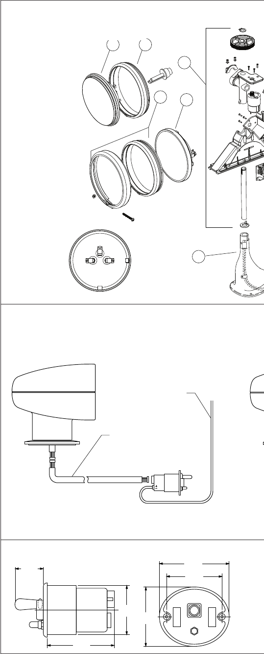
Key Description Part Number
1 Upper Housing 60016-1000
2 Lower Housing 60017-1000
3 Base with Gasket 60088-1000
4 Lens with Gasket 60015-1000
5 Bulb (2 Req'd) 18753-0336
6 Bulb Housing 60018-1000
7 Cable Assembly 60063-1000
8 Motor Kit Vertical (Upper) 18753-0458
9 Motor Kit Horizontal (Lower) 18753-0350
10 Drive Arm/Gear 18753-0457
11 Bulb Clip Kit 18753-0459
12 Screws 18753-0471
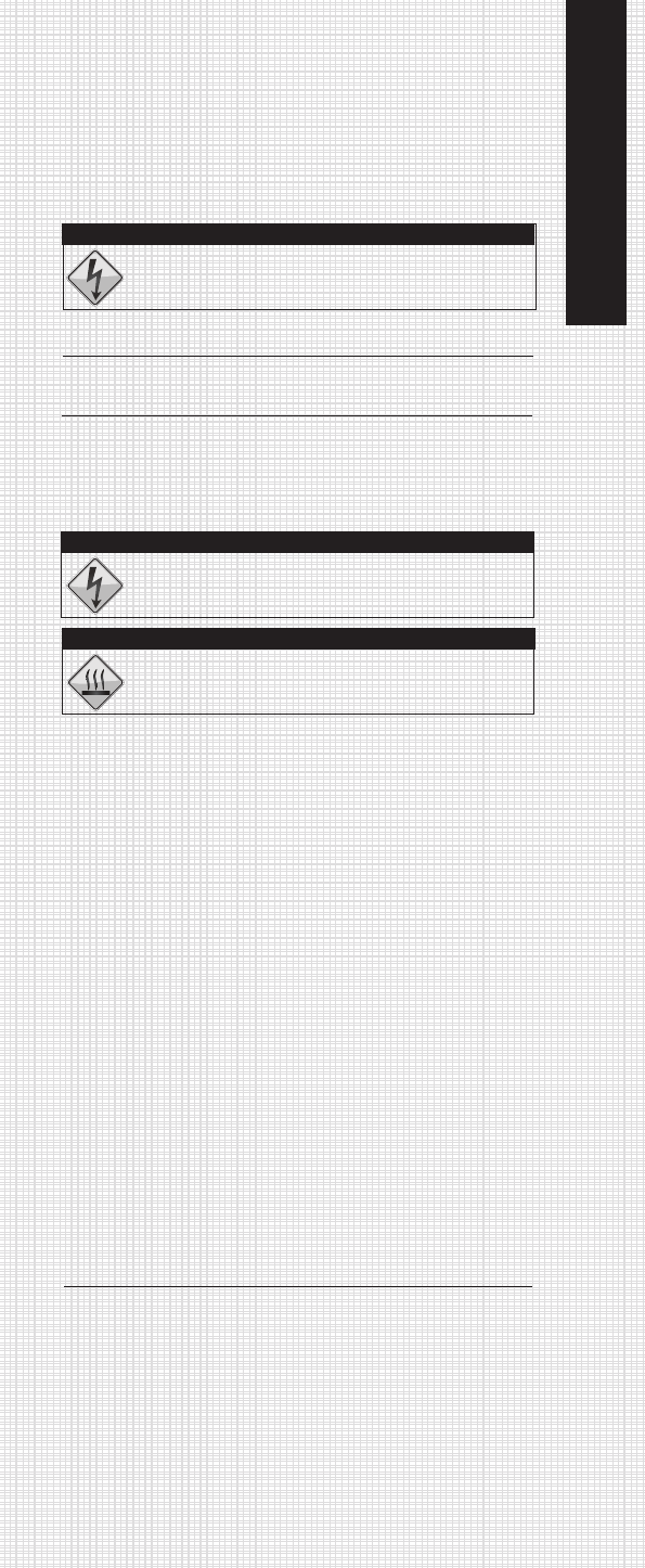
Do not use cleaners that contain esters, halo-
genated solvents, aromatic solvents, ketones and
strong acids or bases.
CAUTION!
Disconnect power from the system before working on
the unit to avoid personal injury, damage to the
surrounding environment and/or damage to the unit.
DANGER! - REDUCETHE RISK OF ELECTRIC SHOCK
Burn hazard. Do not touch lens when light is “on”.
CAUTION! - BURN HAZARD
WIRING TABLE
AMP FUSE WIRE SIZE PER FEET OF RUN*
VOLTAGE DRAW SIZE 0”-10” 10”-15” 15”-25”25”-40” 40”-60”
12 Vdc 16 20 #16 (1.5) #14 (2.5) #14 (2.5) #12 (4) #6 (16)
24Vdc 8 15 #18 (1) #16 (1.5) #16(1.5) #14 (2.5) #10 (6)
* Length of run is total length of the circuit from the power source to product and back to ground. Wiresizes
listed are AWG gauge and metric millimeters.
PART LIST
Wiring Diagram,
Single Control
W
12 VOLT POWER
INPUT LEADS SUPPLIED
BY CUSTOMER (16 GA.)
15' CONTROL CABLE INCLUDED
FOR ADDITIONAL CABLES
SEE CABLE LISTING
CONTROL
SECONDARY CONTROL
KIT
1
8
7
3
5
4
REMOTE CONTROL
MOUNTING DIMENSIONS
1-1/2"
(38mm)
3-1/2"
(89mm)
2-5/8"
(67mm) 3-1/8"
(79mm)
3-3/4"
(95mm)
3-5/16"
(84mm)
Exploded View
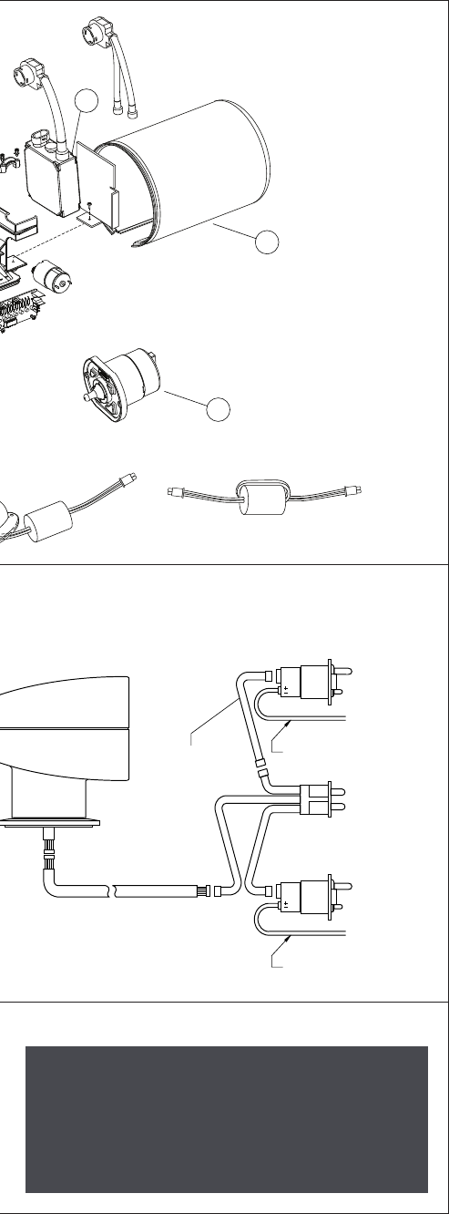
Wiring Diagram,
Optional Secondary Remote Control
12 VOLT POWER
INPUT LEADS SUPPLIED
BY CUSTOMER (16 GA.)
12 VOLT POWER
INPUT LEADS SUPPLIED
BY CUSTOMER (16 GA.)
MAIN CONTROL
STATION SELECTOR
PANEL
SECONDARY
CONTROL
CABLE MUST BE
ACQUIRED
SEPARATELY
(SEE CABLE
LISTING)
CONDARY CONTROL
NO. 43670-0004
2
9
8
Wiring Diagram
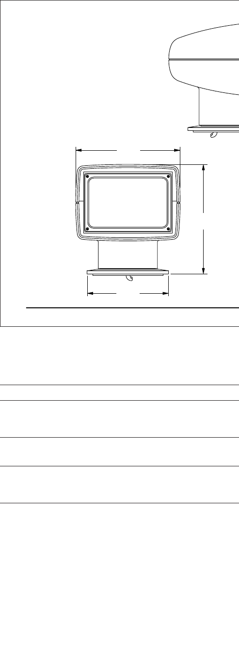
DIMENSIONAL DRAWING
8-1/2"
(216MM)
8-15/16"
(227mm)
6-5/8"
(168mm)
TROUBLESHOOTING
All lights are thoroughly inspected before shipping and are warranted to ope
AND WIRE HARNESS CONNECTIONS BEFORE PROCEEDING WITH THI
PROBLEM
Control lever works in reverse in all directions.
Light moves in only three of the possible four directions.
Dim light (low voltage)
Bulb operates - no light movement
or
Light moves - bulb does not operate.
FCC REGULATIONS
This device complies with part 15 of the FCC Rules. Operation
is subject to the following two conditions: (1) This device may not
cause harmful interference. (2) This device must accept any
interference received, including interference that may cause
undesired operation. Note: The manufacturer is not responsible for
any radio or TV interference cuased by unauthorized modifications
to the equipment. Such modifications could void the user's authority
to operate the equipment.
Note: This equipment has been tested and found to comply with the
limits for a Class B digital device, pursuant to Part 15 of the FCC Rules.
These limits are designed to provide reasonable protection against
harmful interference in a residential installation. This equipment gen-
erates, uses and can radiate radio frequencey energy and, if not
installed and used in accordance with the instructions, may cause
harmful interference to radio communications. However, there is no
guarantee that interference will not occur in a particular
Dimensional Drawings
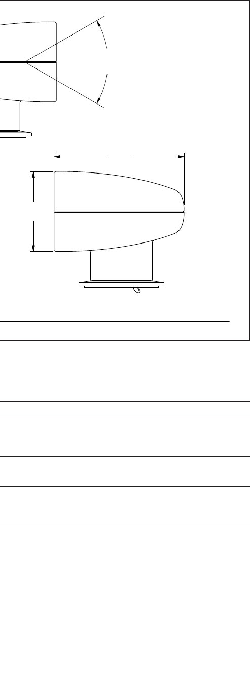
60°
VERTICAL
SWEEP
10-1/8"
(257mm)
6-1/4"
(159mm)
rate within specifications. If light does not operate correctly,
CHECK FUSES,
S TROUBLESHOOTING.
SOLUTION
See wiring instructions.
A. Check connectors.
B. Replace control.
C. If problem persists, return light & control for service.
A. Check voltage at power source.
B. Refer to cable listing for proper wire gage and length.
A. Check fuses on front of control.
B. Check bulb.
installation. If this equipment does causes harmful interference to radio
or television reception, which can be determined by turning the equip-
ment off and on, the user is encouraged to try to correct the interfer-
ence by one or more of the following measures:
1. Reorient or relocate the receiving antenna.
2. Increase the separation between the equipment and receiver.
3. Connect the equipment into an outlet on a circuit different from
that to which the receiver is connected.
4. Consult the dealer or an experienced radio/TV technician for
help.
ITT declares that this device is in compliance with the essential require-
ments and adheres to relevant provisions of Directive 1999/5/EC

Jabsco,
1 Kondelin Road, Cape Ann Industrial Park, Gloucester, MA 01930 USA
Tel: +1 978 281 0440 Fax: +1 978 283 2619
Jabsco,
Bingley Road, Hoddesdon, Hertfordshire EN11 0BU UK
Tel: +44 (0) 1992 450 145 Fax: +44 (0) 1992 467 132
NHK Jabsco Co Ltd,
3-21-10, Shin-Yokohama, Kohoku-ku, Yokohama 222 JAPAN
Tel: +81 (0) 45 475 8906 Fax: +81 (0) 45 475 8908
Jabsco GmbH,
Oststraße 28, 22844 Norderstedt GERMANY
Tel: +49 (0) 40 53 53 73 0 Fax: +49 (0) 40 53 53 73 11
Jabsco Marine Italia S.r.l.,
Via Tommaseo, 6, 20059 Vimercate, Milano ITALY
Tel: +39 039 6852323 Fax: +39 039 666307
Warranty: All products of the company are sold and all services of the company are offered subject to
the company’s warranty and terms and conditions of sale, copies of which will be furnished upon request
© Copyright 2008 ITT Corporation 43000-XXXX rev A 6/08
Discover Jabsco at www.jabsco.com