Delta Tau Geo Brick Lv Users Manual User
2015-07-14
: Delta-Tau Delta-Tau-Geo-Brick-Lv-Users-Manual-773830 delta-tau-geo-brick-lv-users-manual-773830 delta-tau pdf
Open the PDF directly: View PDF ![]() .
.
Page Count: 271 [warning: Documents this large are best viewed by clicking the View PDF Link!]
- Introduction
- Specifications
- Receiving, Unpacking, and Mounting
- PinOuts and Software Setup
- TB1: 24VDC Logic Input
- TB3: Safe Torque Off (STO)
- J1: DC Bus Input
- J4: Limits, Flags, EQU [Axis 1- 4]
- J5: Limits, Flags, EQU [Axis 5- 8]
- J6: General Purpose Inputs and Outputs
- J7: General Purpose Inputs and Outputs (Additional)
- J8: PWM Amplifier Interface
- J9: Handwheel and Analog I/O
- X1-X8: Encoder Feedback, Digital A Quad B
- X1-X8: Encoder Feedback, Sinusoidal
- X1-X8: Encoder Feedback, Resolver
- X1-X8: Encoder Feedback, HiperFace
- X1-X8: Encoder Feedback, SSI
- X1-X8: Encoder Feedback, EnDat 2.1/2.2
- X1-X8: Encoder Feedback, BiSS C/B
- Setting up SSI | EnDat | BiSS
- X1-X8: Encoder Feedback, Yaskawa Sigma II & III
- Global Control Registers
- Channel Control Registers
- Yaskawa Feedback Channel Control Power-On Example PLC (Motors 1-8)
- Yaskawa Data Registers
- Yaskawa Sigma II 16-Bit Absolute Encoder
- Yaskawa Sigma II 17-Bit Absolute Encoder
- Yaskawa Sigma III 20-Bit Absolute Encoder
- Yaskawa Sigma II 13-Bit Incremental Encoder
- Yaskawa Sigma II 17-Bit Incremental Encoder
- Yaskawa Incremental Encoder Alarm Codes
- Homing with Yaskawa Incremental Encoders
- X9-X10: Analog Inputs/Outputs
- X11-X12: Analog Inputs/Outputs
- X13: USB 2.0 Connector
- X14: RJ45, Ethernet Connector
- X15: Watchdog & ABORT (TB2)
- RS232: Serial Communication Port
- AMP1-AMP8: Motor Wiring
- +5V ENC PWR (Alternate Encoder Power)
- Motor Type & Protection Power-On PLCs
- Motor Setup
- Motor Setup Flow Chart
- Dominant Clock Settings
- Stepper Motor Setup -- Direct Micro-Stepping
- Before you start
- Encoder Conversion Table Setup
- Position, Velocity Pointers: Ixx03, Ixx04
- Motor Activation, Commutation Enable: Ixx00, Ixx01
- Command Output Address: Ixx02
- Current Feedback, ADC Mask, Commutation angle: Ixx82, Ixx84, Ixx72
- Flag Address, Mode Control: Ixx25, Ixx24
- Commutation Address, Cycle size: Ixx83, Ixx70, Ixx71
- Maximum Achievable Motor Speed, Output Command Limit: Ixx69
- PWM Scale Factor: Ixx66
- I2T Protection, Magnetization Current: Ixx57, Ixx58, Ixx69, Ixx77
- Phasing, Power-On Mode: Ixx80, Ixx73, Ixx74, Ixx81, Ixx91
- Position-Loop PID Gains: Ixx30…Ixx39
- Current-Loop Gains: Ixx61, Ixx62, Ixx76
- Number of Counts per Revolution (Stepper Motors)
- Brushless Motor Setup
- Before you start
- Flag Control, Commutation Angle, Current Mask: Ixx24, Ixx72, Ixx84
- PWM Scale Factor: Ixx66
- Current Feedback Address: Ixx82
- Commutation Position Address, Commutation Enable: Ixx83, Ixx01
- I2T Protection: Ixx57, Ixx58, Ixx69
- Commutation Cycle Size: Ixx70, Ixx71
- ADC Offsets: Ixx29, Ixx79
- Current-Loop Gains: Ixx61, Ixx62, Ixx76
- Motor Phasing, Power-On Mode: Ixx73, Ixx74, Ixx80, Ixx81, Ixx91
- Open-Loop Test, Encoder Decode: I7mn0
- Position-Loop PID Gains: Ixx30…Ixx39
- DC Brush Motor Software Setup
- Before you start
- Phasing Search Error Bit, Current-Loop Integrator Output (Ixx96)
- Flags, Commutation, Phase Angle, ADC Mask: Ixx24, Ixx01, Ixx72, Ixx84
- PWM Scale Factor: Ixx66
- Current Feedback Address: Ixx82
- Commutation Cycle Size: Ixx70, Ixx71
- I2T Protection, Magnetization Current: Ixx57, Ixx58, Ixx69, Ixx77
- ADC Offsets: Ixx29, Ixx79
- Current-Loop Gains, Open-Loop/Enc. Decode: Ixx61, Ixx62, Ixx76, I7mn0
- Position-Loop PID Gains: Ixx30…Ixx39
- MACRO Connectivity
- Introduction to MACRO
- MACRO Configuration Examples
- Configuration Example 1: Brick – Brick (Servo Motors)
- Configuration Example 2: Brick – Brick (Stepper Motors)
- Configuration Example 3: Brick – Geo MACRO Drive
- Brick – Brick MACRO I/O Data Transfer
- MACRO Limits, Flags and Homing
- Absolute Position Reporting Over MACRO
- MACRO Configuration Power-Up Sequence
- Troubleshooting
- Appendix A
- Appendix B
- Control Board Jumpers (For Internal Use)
- E6 – E9: AENA/GPIO Selection Jumper
- E10 – E12: Power-Up/Reset Load Source
- E13: Firmware Reload Enable (BOOT SW)
- E14: Watchdog Disable Jumper
- E25-28: Select Encoder Index input or AENA output (channels 1-4)
- E35-38: Select Encoder Index input or AENA output (channels 5-8)
- E40: USB/Ethernet Communication Firmware Load Enable
- Control Board Jumpers (For Internal Use)
- Appendix C
- Appendix D
Single Source Machine Control ……………………………………………..…...………………. Power // Flexibility // Ease of Use
21314 Lassen St. Chatsworth, CA 91311 // Tel. (818) 998-2095 Fax. (818) 998-7807 // www.deltatau.com
^2 Geo Brick LV
^3 Low Voltage Programmable Servo Amplifier
^4 5XX-603814-XUXX
^5 February 14, 2015
^1 USER MANUAL
DELTA TAU
Data Systems, Inc.
NEW IDEAS IN MOTION …

Geo Brick LV User Manual
Copyright Information
© 2015 Delta Tau Data Systems, Inc. All rights reserved.
This document is furnished for the customers of Delta Tau Data Systems, Inc. Other uses are
unauthorized without written permission of Delta Tau Data Systems, Inc. Information contained in this
manual may be updated from time-to-time due to product improvements, etc., and may not conform in
every respect to former issues.
To report errors or inconsistencies, call or email:
Delta Tau Data Systems, Inc. Technical Support
Phone: (818) 717-5656
Fax: (818) 998-7807
Email: support@deltatau.com
Website: http://www.deltatau.com
Operating Conditions
All Delta Tau Data Systems, Inc. motion controller, accessory, and amplifier products contain static
sensitive components that can be damaged by incorrect handling. When installing or handling Delta Tau
Data Systems, Inc. products, avoid contact with highly insulated materials. Only qualified personnel
should be allowed to handle this equipment.
In the case of industrial applications, we expect our products to be protected from hazardous or
conductive materials and/or environments that could cause harm to the controller by damaging
components or causing electrical shorts. When our products are used in an industrial environment, install
them into an industrial electrical cabinet to protect them from excessive or corrosive moisture, abnormal
ambient temperatures, and conductive materials. If Delta Tau Data Systems, Inc. products are directly
exposed to hazardous or conductive materials and/or environments, we cannot guarantee their operation.
Geo Brick LV User Manual
Safety Instructions
Qualified personnel must transport, assemble, install, and maintain this equipment. Properly qualified
personnel are persons who are familiar with the transport, assembly, installation, and operation of
equipment. The qualified personnel must know and observe the following standards and regulations:
IEC364resp.CENELEC HD 384 or DIN VDE 0100
IEC report 664 or DIN VDE 0110
National regulations for safety and accident prevention or VBG 4
Incorrect handling of products can result in injury and damage to persons and machinery. Strictly adhere
to the installation instructions. Electrical safety is provided through a low-resistance earth connection. It
is vital to ensure that all system components are connected to earth ground.
This product contains components that are sensitive to static electricity and can be damaged by incorrect
handling. Avoid contact with high insulating materials (artificial fabrics, plastic film, etc.). Place the
product on a conductive surface. Discharge any possible static electricity build-up by touching an
unpainted, metal, grounded surface before touching the equipment.
Keep all covers and cabinet doors shut during operation. Be aware that during operation, the product has
electrically charged components and hot surfaces. Control and power cables can carry a high voltage,
even when the motor is not rotating. Never disconnect or connect the product while the power source is
energized to avoid electric arcing.
WARNING
A Warning identifies hazards that could result in personal injury
or death. It precedes the discussion of interest.
!
Caution
A Caution identifies hazards that could result in equipment damage. It
precedes the discussion of interest.
Note
A Note identifies information critical to the user’s understanding or
use of the equipment. It follows the discussion of interest.
Geo Brick LV User Manual
MANUAL REVISION HISTORY
REV
DESCRIPTION
DATE
CHANGE
APPROVED
9
CONTROL BOARD PINOUTS AND SETUP
STROBE WORD PLCS, ADC STATUS BITS
MOTOR SETUP SECTION
TROUBLESHOOTING SECTION
10/11/11
R.N
R.N
10
UPDATED +5V ENC PWR SECTION
10/13/11
R.N
R.N
11
CORRECTED IXX30 FOR PFM
11/01/11
M.Y
M.Y
12
GENERAL UPDATES
04/15/12
R.N
R.N
13
CORRECTIONS AND UPDATES
12/11/12
R.N
R.N
14
- UPDATED PART NUMBER TREE
- ADDED POWER ON/OFF SEQUENCE
- UPDATED LOGIC POWER INPUT SECTION
- ADDED STO INFORMATION
- UPDATED X9-X12 SECTION
- UPDATED MACRO CONNECTIVITY SECTION
- ADDED SERIAL N0 AND BOARD IDENTIFICATION
- CORRECTED IXX81 TABLE IN HALLS
- GENERAL FORMATTING, CORRECTIONS, AND UPDATES
12/14/12
R.N
R.N
15
RE-ADDED PLC DISABLING AND MOTOR KILL IN INITILIAZATION PLC
03/20/13
R.N
R.N
16
MISCELLANEOUS CORRECTIONS.
02/24/14
R.N
R.N
17
- CORRECTED ENCODER LOSS FOR SINUSOIDAL ENCODERS
- UPDATED GP IO, LIMITS EQU SECTIONS
- CORRECTED HALLS SCALE FACTOR
- GENERAL FORMATTING AND UPDATES
02/04/15
R.N
R.N
Note
Older revision correction notes have been removed for obsolescence
and clarity.


Geo Brick LV User Manual
Table of Contents vi
Table of Contents
INTRODUCTION ................................................................................................................... 11
Documentation ..........................................................................................................................11
Downloadable Turbo PMAC Script ............................................................................................12
SPECIFICATIONS ................................................................................................................. 13
Part Number .............................................................................................................................13
Geo Brick LV Options................................................................................................................15
Environmental Specifications ....................................................................................................16
Electrical Specifications ............................................................................................................17
RECEIVING, UNPACKING, AND MOUNTING ................................................................ 19
Use of Equipment .....................................................................................................................19
Mounting ...................................................................................................................................20
Connector Locations .................................................................................................................21
CAD Drawing ............................................................................................................................22
PINOUTS AND SOFTWARE SETUP ................................................................................... 23
TB1: 24VDC Logic Input ...........................................................................................................23
TB3: Safe Torque Off (STO) .....................................................................................................24
Dynamic Braking ............................................................................................................................. 24
Disabling the STO ............................................................................................................................ 25
Wiring and Using the STO ................................................................................................................ 25
J1: DC Bus Input .......................................................................................................................26
Power On/Off Sequence .................................................................................................................... 27
J4: Limits, Flags, EQU [Axis 1- 4] ..............................................................................................28
J5: Limits, Flags, EQU [Axis 5- 8] ..............................................................................................29
Wiring the Limits and Flags ............................................................................................................. 30
Limits and Flags [Axis 1- 4] Suggested M-Variables ........................................................................ 31
Limits and Flags [Axis 5- 8] Suggested M-Variables ........................................................................ 31
J6: General Purpose Inputs and Outputs ..................................................................................32
J7: General Purpose Inputs and Outputs (Additional)................................................................33
About the Digital Inputs and Outputs ................................................................................................ 34
Wiring the Digital Inputs and Outputs .............................................................................................. 35
General Purpose I/Os (J6) Suggested M-Variables ........................................................................... 36
General Purpose I/Os Additional (J7) Suggested M-Variables .......................................................... 36
J8: PWM Amplifier Interface ......................................................................................................37
J9: Handwheel and Analog I/O ..................................................................................................38
Setting up the Analog Inputs (J9) ...................................................................................................... 39
Setting up the Analog Output (J9) ..................................................................................................... 41
Setting up Pulse and Direction Output PFM (J9) .............................................................................. 43
Setting up the Handwheel Port (J9) .................................................................................................. 45
X1-X8: Encoder Feedback, Digital A Quad B ............................................................................46
Setting up Quadrature Encoders ....................................................................................................... 48

Geo Brick LV User Manual
Table of Contents vii
Encoder Count Error (Mxx18) .......................................................................................................... 48
Encoder Loss Detection, Quadrature ................................................................................................ 49
Step and Direction PFM Output (To External Stepper Amplifier) ...................................................... 51
X1-X8: Encoder Feedback, Sinusoidal ......................................................................................56
Setting up Sinusoidal Encoders ......................................................................................................... 57
Counts per User Units ...................................................................................................................... 58
Encoder Count Error (Mxx18) .......................................................................................................... 59
Encoder Loss Detection, Sinusoidal .................................................................................................. 60
X1-X8: Encoder Feedback, Resolver ........................................................................................61
Setting up Resolvers ......................................................................................................................... 61
Resolver Excitation Magnitude ......................................................................................................... 62
Resolver Excitation Frequency ......................................................................................................... 62
X1-X8: Encoder Feedback, HiperFace ......................................................................................67
Setting up HiperFace On-Going Position.......................................................................................... 68
Setting up HiperFace Absolute Power-On Position ........................................................................... 70
Setting up HiperFace Encoders Example .......................................................................................... 74
Encoder Count Error (Mxx18) .......................................................................................................... 79
Encoder Loss Detection, Sinusoidal .................................................................................................. 80
X1-X8: Encoder Feedback, SSI ................................................................................................82
Configuring SSI ................................................................................................................................ 82
SSI Control Registers Setup Example ................................................................................................ 86
X1-X8: Encoder Feedback, EnDat 2.1/2.2 .................................................................................88
Configuring EnDat ........................................................................................................................... 88
EnDat Control Registers Setup Example ........................................................................................... 92
X1-X8: Encoder Feedback, BiSS C/B .......................................................................................94
Configuring BiSS .............................................................................................................................. 94
BiSS Control Registers Setup Example.............................................................................................. 98
Setting up SSI | EnDat | BiSS.................................................................................................. 100
Setup Summary ............................................................................................................................... 101
Technique 1 Example ..................................................................................................................... 103
Technique 2 Example ..................................................................................................................... 106
Technique 3 Example ..................................................................................................................... 111
X1-X8: Encoder Feedback, Yaskawa Sigma II & III ................................................................ 116
Yaskawa Sigma II 16-Bit Absolute Encoder .................................................................................... 121
Yaskawa Sigma II 17-Bit Absolute Encoder .................................................................................... 124
Yaskawa Sigma III 20-Bit Absolute Encoder ................................................................................... 127
Yaskawa Sigma II 13-Bit Incremental Encoder ............................................................................... 130
Yaskawa Sigma II 17-Bit Incremental Encoder ............................................................................... 132
Yaskawa Incremental Encoder Alarm Codes ................................................................................... 134
Homing with Yaskawa Incremental Encoders ................................................................................. 135
X9-X10: Analog Inputs/Outputs ............................................................................................... 136
X11-X12: Analog Inputs/Outputs ............................................................................................. 136
Setting up the Analog (ADC) Inputs ................................................................................................ 137
Setting up the Analog (DAC) Outputs ............................................................................................. 138
Setting up the General Purpose Relay, Brake .................................................................................. 140
Setting up the External Amplifier Fault Input .................................................................................. 142

Geo Brick LV User Manual
Table of Contents viii
X13: USB 2.0 Connector ......................................................................................................... 143
X14: RJ45, Ethernet Connector .............................................................................................. 143
X15: Watchdog & ABORT (TB2) ............................................................................................. 144
Wiring the Abort Input .................................................................................................................... 144
Wiring the Watchdog Output .......................................................................................................... 145
RS232: Serial Communication Port ......................................................................................... 146
AMP1-AMP8: Motor Wiring ..................................................................................................... 147
Stepped Motor Wiring .................................................................................................................... 148
Brushless (Servo) Motor wiring ...................................................................................................... 148
Brush Motor Wiring ....................................................................................................................... 148
+5V ENC PWR (Alternate Encoder Power) ............................................................................. 149
Wiring the Alternate (+5V) Encoder Power .................................................................................... 150
Functionality, Safety Measures ....................................................................................................... 151
MOTOR TYPE & PROTECTION POWER-ON PLCS ..................................................... 152
Stepper Motor Power-On PLC Sample.................................................................................... 153
Servo (brushless/brush) Motor Power-On PLC Sample .......................................................... 154
Hybrid Motor Power-On PLC Sample ...................................................................................... 155
MOTOR SETUP ................................................................................................................... 156
Motor Setup Flow Chart .......................................................................................................... 156
Dominant Clock Settings ......................................................................................................... 157
Stepper Motor Setup -- Direct Micro-Stepping ......................................................................... 158
Before you start .............................................................................................................................. 158
Encoder Conversion Table Setup .................................................................................................... 158
Position, Velocity Pointers: Ixx03, Ixx04 ........................................................................................ 159
Motor Activation, Commutation Enable: Ixx00, Ixx01 ..................................................................... 159
Command Output Address: Ixx02 ................................................................................................... 159
Current Feedback, ADC Mask, Commutation angle: Ixx82, Ixx84, Ixx72 ........................................ 160
Flag Address, Mode Control: Ixx25, Ixx24...................................................................................... 160
Commutation Address, Cycle size: Ixx83, Ixx70, Ixx71 .................................................................... 160
Maximum Achievable Motor Speed, Output Command Limit: Ixx69 ................................................ 161
PWM Scale Factor: Ixx66............................................................................................................... 162
I2T Protection, Magnetization Current: Ixx57, Ixx58, Ixx69, Ixx77 ................................................. 163
Phasing, Power-On Mode: Ixx80, Ixx73, Ixx74, Ixx81, Ixx91 .......................................................... 164
Position-Loop PID Gains: Ixx30…Ixx39 ......................................................................................... 164
Current-Loop Gains: Ixx61, Ixx62, Ixx76 ........................................................................................ 165
Number of Counts per Revolution (Stepper Motors) ........................................................................ 165
Brushless Motor Setup ............................................................................................................ 166
Before you start .............................................................................................................................. 166
Flag Control, Commutation Angle, Current Mask: Ixx24, Ixx72, Ixx84 ........................................... 166
PWM Scale Factor: Ixx66............................................................................................................... 166
Current Feedback Address: Ixx82 ................................................................................................... 166
Commutation Position Address, Commutation Enable: Ixx83, Ixx01 ............................................... 167
I2T Protection: Ixx57, Ixx58, Ixx69 ................................................................................................. 169
Commutation Cycle Size: Ixx70, Ixx71 ............................................................................................ 170

Geo Brick LV User Manual
Table of Contents ix
ADC Offsets: Ixx29, Ixx79 .............................................................................................................. 171
Current-Loop Gains: Ixx61, Ixx62, Ixx76 ........................................................................................ 172
Motor Phasing, Power-On Mode: Ixx73, Ixx74, Ixx80, Ixx81, Ixx91 ................................................ 173
Open-Loop Test, Encoder Decode: I7mn0 ...................................................................................... 193
Position-Loop PID Gains: Ixx30…Ixx39 ......................................................................................... 195
DC Brush Motor Software Setup ............................................................................................. 196
Before you start .............................................................................................................................. 196
Phasing Search Error Bit, Current-Loop Integrator Output (Ixx96) ................................................ 196
Flags, Commutation, Phase Angle, ADC Mask: Ixx24, Ixx01, Ixx72, Ixx84 ..................................... 197
PWM Scale Factor: Ixx66............................................................................................................... 197
Current Feedback Address: Ixx82 ................................................................................................... 197
Commutation Cycle Size: Ixx70, Ixx71 ............................................................................................ 198
I2T Protection, Magnetization Current: Ixx57, Ixx58, Ixx69, Ixx77 ................................................. 198
ADC Offsets: Ixx29, Ixx79 .............................................................................................................. 199
Current-Loop Gains, Open-Loop/Enc. Decode: Ixx61, Ixx62, Ixx76, I7mn0 .................................... 199
Position-Loop PID Gains: Ixx30…Ixx39 ......................................................................................... 200
MACRO CONNECTIVITY ................................................................................................. 201
Introduction to MACRO ........................................................................................................... 201
MACRO Configuration Examples ............................................................................................ 202
Review: MACRO Nodes and Addressing ......................................................................................... 203
Review: MACRO Auxiliary Commands ........................................................................................... 204
Configuration Example 1: Brick – Brick (Servo Motors) ........................................................... 205
Setting up the Slave in Torque Mode ............................................................................................... 206
Setting up the Master in Torque Mode ............................................................................................ 209
Setting up the Slave in PWM Mode ................................................................................................. 212
Setting up the Master in PWM Mode............................................................................................... 213
Configuration Example 2: Brick – Brick (Stepper Motors) ........................................................ 219
Setting up the Slave in Torque Mode for Steppers ........................................................................... 219
Setting up the Master in Torque Mode for Steppers ......................................................................... 224
Configuration Example 3: Brick – Geo MACRO Drive ............................................................. 227
Brick – Brick MACRO I/O Data Transfer.................................................................................. 235
Transferring the Digital (Discrete) Input and Outputs .................................................................... 236
Transferring The X9-X12 Analog Inputs/Outputs ............................................................................ 241
Transferring The J9 Analog Inputs ................................................................................................. 243
MACRO Limits, Flags and Homing .......................................................................................... 244
Limits and Flags ............................................................................................................................. 244
Homing from Master ...................................................................................................................... 244
Homing from Slave ......................................................................................................................... 244
MACRO Suggested M-Variables ..................................................................................................... 245
Absolute Position Reporting Over MACRO ............................................................................. 247
MACRO Configuration Power-Up Sequence ........................................................................... 248
TROUBLESHOOTING ........................................................................................................ 249
Serial Number and Board Revisions Identification ................................................................... 249
D1: Error Codes ...................................................................................................................... 250

Geo Brick LV User Manual
Table of Contents x
Strobe Word and Axes Data Structures................................................................................... 251
Strobe Word Structure .................................................................................................................... 251
ADC A Status Word ........................................................................................................................ 252
ADC B Status Word ........................................................................................................................ 252
LED Status .............................................................................................................................. 253
Boot Switch SW (Firmware Reload) – Write-Protect Disable ................................................... 254
Reloading PMAC firmware............................................................................................................. 255
Changing IP Address, Gateway IP, Or Gateway Mask .................................................................... 257
Enabling ModBus ........................................................................................................................... 258
Reloading Boot And Communication Firmware .............................................................................. 259
Reset Switch SW (Factory Reset) ........................................................................................... 260
Error 18 (Erro18) ..................................................................................................................... 261
Watchdog Timer Trip............................................................................................................... 262
APPENDIX A ........................................................................................................................ 263
D-Sub Connector Spacing Specifications ................................................................................ 263
APPENDIX B ........................................................................................................................ 264
Control Board Jumpers (For Internal Use) ............................................................................... 264
APPENDIX C ........................................................................................................................ 266
Schematic Samples ................................................................................................................ 266
APPENDIX D ........................................................................................................................ 269
Absolute Serial Encoders Limitation with Turbo PMAC ........................................................... 269

Geo Brick LV User Manual
Introduction 11
INTRODUCTION
The Geo Brick LV (Low Voltage) combines the intelligence and capability of the Turbo PMAC2 motion
controller with advanced MOSFET technology, resulting in a compact, smart 4-, or 8-axis servo drive
package.
The flexibility of the Turbo PMAC2 enables the Geo Brick LV to drive stepper, brush, or brushless
motors with unsurpassed pure digital DSP performance. The absence of analog signals – required for
typical motion controller/drive interfacing – enables higher gains, better overall performance and tighter
integration, while significantly driving down costs and setup time.
The Geo Brick LV’s embedded 32-axis Turbo PMAC2 motion controller is programmable for virtually
any kind of motion control application. The built-in software PLCs allow for complete machine logic
control.
The Geo Brick LV supports the following types of motors:
Three-Phase AC/DC Brushless, synchronous rotary/linear
DC Brush
2-Phase Stepper
Note
The Geo Brick LV can also provide pulse and direction PFM output(s)
to third-party stepper amplifiers.
Documentation
In conjunction with this user manual, the Turbo Software Reference Manual and Turbo PMAC User
Manual are essential for proper use, motor setup, and configuration of the Geo Brick LV. It is highly
recommended to refer to the latest revision of the manuals found on Delta Tau’s website, under
Support>documentation>Manuals: Delta Tau Manuals
Geo Brick LV User Manual
Introduction 12
Downloadable Turbo PMAC Script
!
Caution
Some code examples require the user to input specific information
pertaining to their system hardware. When user information is
required, a commentary ending with –User Input is inserted.
This manual contains downloadable code samples in Turbo PMAC script. These examples can be copied
and pasted into the editor area in the Pewin32pro2. Care must be taken when using pre-configured Turbo
PMAC code, some information may need to be updated to match hardware and system specific
configurations. Downloadable Turbo PMAC Scripts are enclosed in the following format:
// TURBO PMAC SCRIPT EXAMPLE
P1=0 ; Set P1=0 at download
Open PLC 1 Clear ; Open PLC Buffer 1, clear contents
CMDP"Geo Brick LV Manual Test PLC" ; Send unsolicited response to host port
P1=P1+1 ; Counter using variable P1
Disable PLC 1 ; Disable plc 1
Close ; Close open buffer
!
Caution
All PLC examples are stated in PLC number 1. It is the user’s
responsibility to arrange their application PLCs’ properly and handle
power-on sequencing for various tasks.
It is the user’s responsibility to use the PLC examples presented in this manual properly. That is,
incorporating the statement code in the application configuration, and handling tasks in a sequential
manner. For example, with serial absolute encoders, setting up the global control registers should be
executed before trying to read absolute position, and absolute phase referencing. Furthermore, other PLC
programs (which would be trying to move motors) should be disabled until these functions are executed.
!
Caution
Often times, downloadable example codes use suggested M-variables,
it is the user’s responsibility to make sure they are downloaded, or
perform necessary changes to use the intended registers.
Geo Brick LV User Manual
Specifications 13
SPECIFICATIONS
Part Number
BD 0 0000C4
-- - 04 00000
** ** ** **
G
CPU Options – GBDA-BB-CDD-EFGHHHI0
Turbo PMAC 2 Processor
C0: 80Mhz, 8Kx24 Internal, 256Kx24SRAM, 1MB Flash (Default)
C3: 80Mhz, 8Kx24 Internal, 1Mx24SRAM, 4MB Flash
F3: 240Mhz, 192Kx24 Internal, 1Mx24SRAM, 4MB Flash
0: No options (Default)
2: Four GPIO Relays (On connectors X9-X12)
3: Two Analog In, two analog Out (On conn. X11-X12) & 4 GPIO Relays (On connectors X9-X12)
4: Four Analog In, four analog Out (On conn. X9-X12) & 4 GPIO Relays (On connectors X9-X12)
5: Two Analog In, two analog Out (On conn. X11-X12) & 2 AENA Relays for Chan. 3&4
(On conn. X11-X12) and 2 GPIO Relays (On conn. X9-X10)
6: Four Analog In, four analog Out (Connectors X9-X12) with 2 AENA Relays for Chan. 3&4
(On conn. X11-X12) and 2 GPIO Relays (On conn. X9-X10)
9: Two AENA Relays for Chan.3&4 (Conn.X11-X12) and 2 GPIO Relays (On conn.X9-X10)
4 axes
00 / 05
02 / 07
Note: Analog outputs are 12-bit filtered PWM and Analog Inputs are 16-bit.
Analog I/O Options GBDA-BB-CDD-EFGHHHI0
4 axes
P3 / P8
0: No options (Default)
2: Four GPIO Relays (On connectors X9-X12)
7: Two Analog In, 2 analog Out (Conn.X9-X10) & 4 GPIO Relays (On connectors X9-X12)
8: Two Analog In, 2 analog Out (Conn.X9-X10) & 2 AENA Relays for Chan. 3&4 (On conn. X11-X12)
and 2 GPIO Relays (On connectors X9-X10)
9: Two AENA Relays for Chan.3&4 (Conn.X11-X12) and 2 GPIO Relays (On conn.X9-X10)
8 axes
42 / 47
ABCDEFGHI
AB
C
D
E
F
Axes GBDA-BB-CDD-EFGHHHI0
4 : Four Axes (Default)
8 : Eight Axes
Axes 1 to 4 Options GBDA-BB-CDD-EFGHHHI0
1: 0.25A / 0.75A - 4 Phase (Servo / Stepper outputs)
2: 1A / 3A - 4 Phase (Servo / Stepper outputs)
4: 5A /15A - 4 Phase (Servo / Stepper outputs)
Four primary encoder inputs. No secondary encoders, 4-axis system
Four secondary encoders for a total of 8 encoder inputs
PWM amplifier Interface for channel 7 with encoders for axes 5 to 8 ( 4 secondary encoders)
(Call factory if PWM on Channel 8 is needed)
4
axes
Example:
For 5V flag inputs then specify it at the “Channel 5 to 8 Encoder/Flag Options”
“07" Four secondary encoder inputs (total of 8 encoder inputs), 5V Flag inputs - i.e. GBDx-xx-407-xxxxxxx
If the above Number of Amplifier Axes are selected, then only the corresponding Axes Options are available.
12-24V 5V Flags
00 05
02
P3 07
P8
8
axes 42 27
5A /15A - 4 Phase Servo / Stepper output, with encoders and Flags for every axis.
Digital I/O Option GBDA-BB-CDD-EFGHHHI0
0: 16 IN / 8 OUT (Default)
1: Expanded digital I/O, additional 16 inputs and 8 outputs (Total of 32 IN / 16 OUT)
Outputs rated: 0.5A@12-24VDC
0: No Analog Options available, for this configurations
To receive Analog Inputs for these configurations, you must order GBD-ABB-CDD-EFGHHHI0
MUXED ADC Option in “MACRO and Special Feedback Options”
2: Four GPIO Relays (On connectors X9-X12)
9: Four AENA Relays for Chan.3&4 (On conn.X11-X12) and Chan.5&6 (On conn.X9-X10)
Axes 5 to 8 Options GBDA-BB-CDD-EFGHHHI0
12
22 17
47
0.25A/ 0.75A - 4 Phase Servo / Stepper output, with encoders and Flags for every axis.
1A / 3A - 4 Phase Servo / Stepper output, with encoders and Flags for every axis.

Geo Brick LV User Manual
Specifications 14
MACRO and Special Feedback Options
MACRO Ring Interface and
8 Single or 4 Differential channel 12-bit 10v range MUXED ADC
GBDA-BB-CDD-EFGHHHI0
0: No MACRO or ADC
1: RJ45 MACRO
2: Fiber Optic MACRO
3: MUXED ADC
4: RJ45 MACRO and MUXED ADC
5: Fiber Optic MACRO and MUXED ADC
I
Special Feedback Number and Type of Channels
GBDA-BB-CDD-EFGHHHI0
000: No Special Feedback Channels
4A0: 4 Sinusoidal Encoder Feedback Channels
4B0: 4 Resolver Feedback Channels
4C1: 4 Serial Encoder Feedback Channels (SSI Protocol)
4C2: 4 Serial Encoder Feedback Channels (Yaskawa Sigma II & III Protocol)
4C3: 4 Serial Encoder Feedback Channels (EnDat 2.2 Protocol)
4C6: 4 Serial Encoder Feedback Channels (BISS-B & C Protocol)
4C7: 4 Serial Encoder Feedback Channels (Tamagawa Protocol)
4C8: 4 Serial Encoder Feedback Channels (Panasonic Protocol)
4D1: 4 Sinusoidal Encoder and Serial Enc. (SSI Protocol)
4D2: 4 Sinusoidal Encoder and Serial Enc. (Yaskawa Sigma II & III & V Protocol)
4D3: 4 Sinusoidal Encoder and Serial Enc. (EnDat 2.1 / 2.2 Protocol)
4D4: 4 Sinusoidal Encoder and Serial Enc. (HiperFace Protocol)
4D6: 4 Sinusoidal Encoder and Serial Enc. (BISS-B & C Protocol)
4D7: 4 Sinusoidal Encoder and Serial Enc. (Tamagawa Protocol)
4D8: 4 Sinusoidal Encoder and Serial Enc. (Panasonic Protocol)
4E1: 4 Resolver Feedback Channels and Serial Enc. (SSI Protocol)
4E2: 4 Resolver Feedback Ch. and Serial Enc. (Yaskawa Sigma II & III & V Prot.)
4E3: 4 Resolver Feedback Channels and Serial Enc. (EnDat 2.2 Protocol)
4E6: 4 Resolver Feedback Channels and Serial Enc. (BISS-B & C Protocol)
4E7: 4 Resolver Feedback Channels and Serial Enc. (Tamagawa Protocol)
4E8: 4 Resolver Feedback Channels and Serial Enc. (Panasonic Protocol)
8A0: 8 Sinusoidal Encoder Feedback Channels
8B0: 8 Resolver Feedback Channels
8C1: 8 Serial Encoder Feedback Channels (SSI Protocol)
8C2: 8 Serial Encoder Feedback Channels (Yaskawa Sigma II & III & V Protocol)
8C3: 8 Serial Encoder Feedback Channels (EnDat 2.2 Protocol)
8C6: 8 Serial Encoder Feedback Channels (BISS-B & C Protocol)
8C7: 8 Serial Encoder Feedback Channels (Tamagawa Protocol)
8C8: 8 Serial Encoder Feedback Channels (Panasonic Protocol)
8D1: 8 Sinusoidal Encoder and Serial Enc. (SSI Protocol)
8D2: 8 Sinusoidal Encoder and Serial Enc. (Yaskawa Sigma II & III & V Protocol)
8D3: 8 Sinusoidal Encoder and Serial Enc. (EnDat 2.1 / 2.2 Protocol)
8D4: 8 Sinusoidal Encoder and Serial Enc. (HiperFace Protocol)
8D6: 8 Sinusoidal Encoder and Serial Enc. (BISS-B & C Protocol)
8D7: 8 Sinusoidal Encoder and Serial Enc. (Tamagawa Protocol)
8D8: 8 Sinusoidal Encoder and Serial Enc. (Panasonic Protocol)
8E1: 8 Resolver Feedback Channels and Serial Enc. (SSI Protocol)
8E2: 8 Resolver Feedback Ch. and Serial Enc. (Yaskawa Sigma II & III & V Prot.)
8E3: 8 Resolver Feedback Channels and Serial Enc. (EnDat 2.2 Protocol)
8E6: 8 Resolver Feedback Channels and Serial Enc. (BISS-B & C Protocol)
8E7: 8 Resolver Feedback Channels and Serial Enc. (Tamagawa Protocol)
8E8: 8 Resolver Feedback Channels and Serial Enc. (Panasonic Protocol)
H
Note: If any of the “H” or “I” digits (GBDA-BB-CDD-EFGHHHI0) are ordered, you will also receive RS-232 comms port, 1
channel "handwheel" port.

Geo Brick LV User Manual
Specifications 15
Geo Brick LV Options
CPU Options
C0: 80MHz Turbo PMAC2 CPU (standard)
8Kx24 internal memory, 256Kx24 SRAM, 1MB flash memory
C3: 80MHz Turbo PMAC2 CPU
8Kx24 internal memory, 1Mx24 SRAM, 4MB flash memory
F3: 240MHz Turbo PMAC2 CPU
192Kx24 internal memory, 1Mx24 SRAM, 4MB flash memory
Encoder Feedback Type
Digital Quadrature
Sinusoidal
HiperFace
Resolver
SSI
EnDat 2.1 / 2.2
Yaskawa Sigma II / III
BiSS B / C
Panasonic
Tamagawa
Note
Regardless of the encoder feedback option(s) fitted, digital quadrature
encoders can always be utilized. However, Hall sensors cannot be
used with a channel which has been programmed for serial clocking.
Axes Power
0.25A RMS continuous, 0.75 A RMS peak
1 A RMS continuous, 3 A RMS peak
5 A RMS continuous, 15 A RMS peak
Encoder Input
Up to eight encoder inputs, and one handwheel quadrature input
Additional encoder inputs can be obtained through MACRO connectivity
Digital Inputs/Outputs
Up to 32 inputs and 16 outputs (Sinking or Sourcing)
Additional digital I/Os can be obtained through Fieldbus connectivity
Analog Inputs, DAC Outputs, Brakes, and Relays
Up to 4 x 16-bit analog inputs, 8 x 12-bit analog inputs, 4 x brake/ relay outputs , and 5 x 12-bit
filtered PWM (±10V) outputs
Communication
USB 2.0, Ethernet 100 Base T, RS232, DPRAM (required for NC software/applications)
Fieldbus Connectivity
MACRO
ModBus

Geo Brick LV User Manual
Specifications 16
Environmental Specifications
Specification
Description
Range
Ambient operating Temperature
EN50178 Class 3K3 – IEC721-3-3
Minimum operating temperature
0°C (32°F)
Maximum operating temperature
45°C (113°F)
Storage Temperature Range
EN 50178 Class 1K4 – IEC721-3-1/2
Minimum Storage temperature
-25°C (-13°F)
Maximum Storage temperature
70°C (158°F)
Humidity Characteristics w/
no condensation and no formation of ice
IEC721-3-3
Minimum Relative Humidity
5% HU
Maximum Relative Humidity
up to 35°C (95°F)
95% HU
Maximum Relative Humidity
from 35°C up to 50°C (122°F)
85% HU
De-rating for Altitude
0~1000m (0~3300ft)
No de-rating
1000 ~3000m (3300~9840ft)
-0.01%/m
3000 ~4000m (9840~13000ft)
-0.02%/m
Environment
ISA 71-04
Degree 2 environments
Atmospheric Pressure
EN50178 class 2K3
70 KPa to 106 KPa
Shock
Unspecified
Vibration
Unspecified
Air Flow Clearances
3" (76.2mm) above and below unit for air flow
Cooling
Natural convection and external fan
Standard IP Protection
IP20
IP 55 can be evaluated for custom applications
Geo Brick LV User Manual
Specifications 17
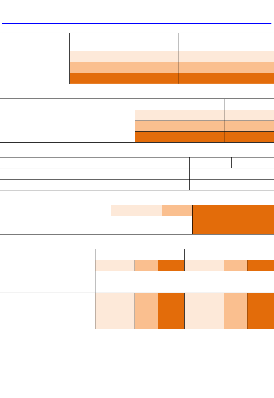
Electrical Specifications
Current Output
Nominal Current Per Axis
[Amps RMS]
Peak Current Per Axis
[Amps RMS] @ 1 sec
Possible
Configurations
0.25 A
0.75 A
1 A
3 A
5 A
15 A
Max ADC
Axis Current Rating
Max ADC
Full Range ADC Current Reading
( I2T Settings)
0.25A / 0.75A
1.6925 A
1A / 3A
6.770 A
5A / 15A
33.85 A
Logic Power Supply Requirements
4-Axis
8-Axis
Input Voltage [VDC]
24VDC ±5%
Continuous Current Input [amps RMS]
4 A
PWM Frequency Range [KHz]
0.25A/0.75A
1A/3A
5A/15A
< 100 KHz
(40KHz recommended)
< 30 KHz
(20KHz recommended)
Bus Power Supply Requirements
4-Axis
8-Axis
Axes Configuration
0.25A/0.75A
1A/3A
5A/15A
0.25A/0.75A
1A/3A
5A/15A
Nominal Voltage [VDC]
12 – 60 VDC
Maximum Voltage [VDC]
80 VDC
Continuous Current
[Amps RMS]
1
4
12.5
2
8
25
Peak Current
[Amps RMS] @ 1 sec
3
12
25
6
24
50
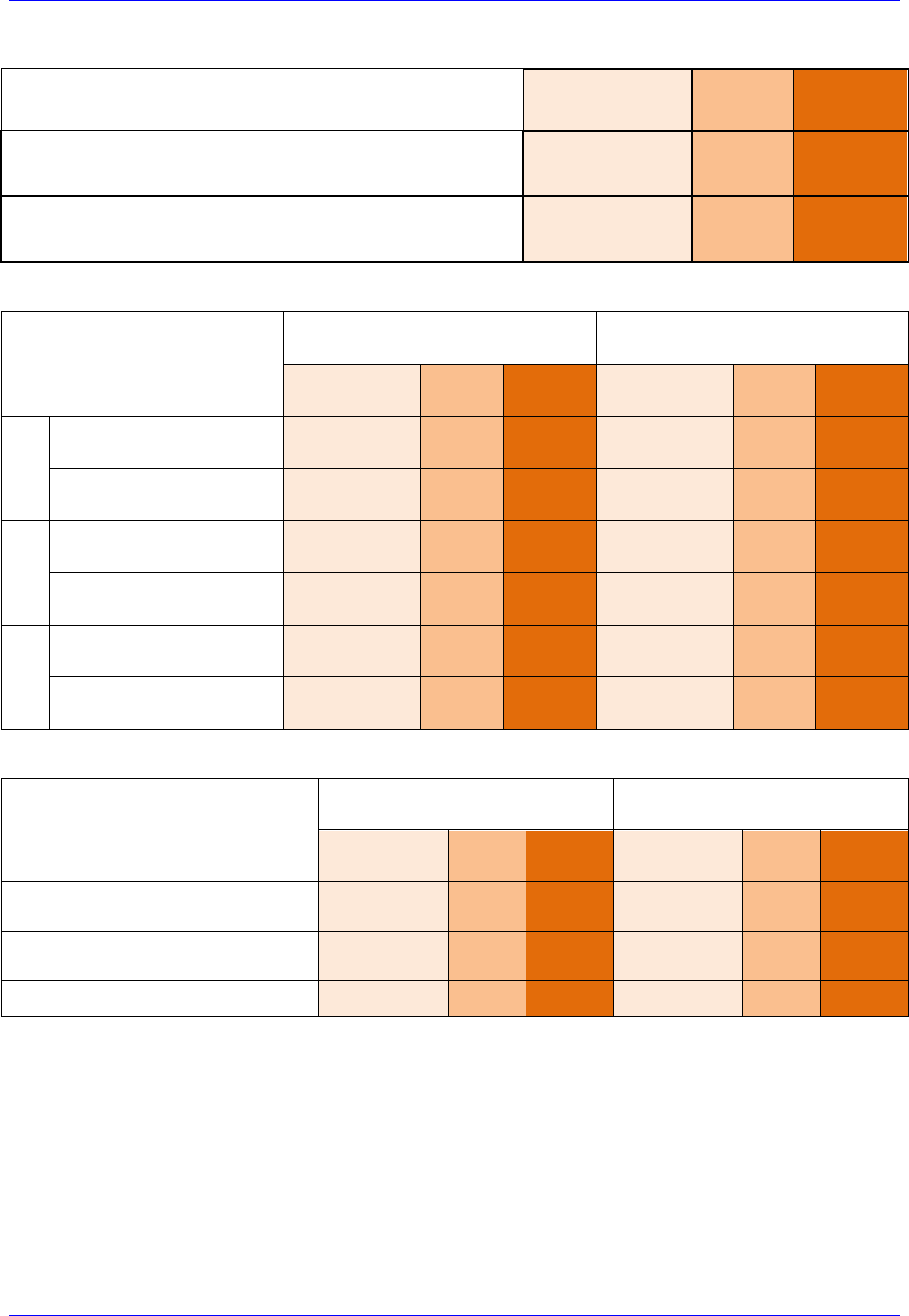
Geo Brick LV User Manual
Specifications 18
Bus Line Recommended Slow-Acting Fuse
(24 - 48 VDC @ recommended frequency)
0.25A/0.75A
1A/3A
5A/15A
4-Axis
2.5A
8A
25A
8-Axis
5A
15A
25A
Power Dissipation Per Axis
[watts]
24 VDC
48 VDC
0.25A/0.75A
1A/3A
5A/15A
0.25A/0.75A
1A/3A
5A/15A
20 KHz
Max. Output Power –
Nominal current
1.6W
3.1W
12.8 W
1.8W
3.8W
16.4 W
Max. Sinusoidal Output
7.5W
29.5W
147 W
15W
59W
294 W
40 KHz
Max. Output Power –
Nominal current
2.9W
4.9W
-
3.3W
6.3W
-
Max. Sinusoidal Output
7.5W
29.5W
-
15W
59W
-
100 KHz
Max. Output Power –
Nominal current
6.9W
10.5W
-
7.8W
14.1W
-
Max. Sinusoidal Output
7.5W
29.5W
-
15W
59W
-
Axis Efficiency [%]
24 VDC
48 VDC
0.25A/0.75A
1A/3A
5A/15A
0.25A/0.75A
1A/3A
5A/15A
Max. Output Power –
Nominal current – 20 KHz
82%
90.5%
92%
89%
94%
95%
Max. Output Power –
Nominal current – 40 KHz
72%
85.5%
-
82%
90%
-
Max. Sinusoidal Output – 100 KHz
52%
74%
-
66%
81%
-

Geo Brick LV User Manual
Receiving, Unpacking, and Mounting 19
RECEIVING, UNPACKING, AND MOUNTING
Delta Tau products are thoroughly tested at the factory and carefully packaged for shipment. When the
Geo Brick LV is received, there are several things to be done immediately:
Observe the condition of the shipping container and report any damage immediately to the
commercial carrier that delivered the drive.
Remove the drive from the shipping container and remove all packing materials. Check all shipping
material for connector kits, documentation, or other small pieces of equipment. Be aware that some
connector kits and other equipment pieces may be quite small and can be accidentally discarded if
care is not used when unpacking the equipment. The container and packing materials may be retained
for future shipment.
Verify that the part number of the drive received is the same as the part number listed on the purchase
order.
Inspect the drive for external physical damage that may have been sustained during shipment and
report any damage immediately to the commercial carrier that delivered the drive.
Electronic components in this product are design-hardened to reduce static sensitivity. However, use
proper procedures when handling the equipment.
If the Geo Brick LV is to be stored for several weeks before use, be sure that it is stored in a location
that conforms to published storage humidity and temperature specifications.
Use of Equipment
The following restrictions will ensure the proper use of the Geo Brick LV:
The components built into electrical equipment or machines can be used only as integral components
of such equipment.
The Geo Brick LV must not be operated on power supply networks without a ground or with an
asymmetrical ground.
If the Geo Brick LV is used in residential areas, or in business or commercial premises, implement
additional filtering measures.
The Geo Brick LV may be operated only in a closed switchgear cabinet, taking into account the
ambient conditions defined in the environmental specifications.

Geo Brick LV User Manual
Receiving, Unpacking, and Mounting 20
Mounting
The location of the Geo Brick LV is important. Installation should be in an area that is protected from
direct sunlight, corrosives, harmful gases or liquids, dust, metallic particles, and other contaminants.
Exposure to these can reduce the operating life and degrade performance of the drive.
Several other factors should be carefully evaluated when selecting a location for installation:
For effective cooling and maintenance, the Geo Brick LV should be mounted on a smooth, non-
flammable vertical surface.
At least 76 mm (3 inches) top and bottom clearance must be provided for air flow. At least 10
mm (0.4 inches) clearance is required between units (each side).
Temperature, humidity and Vibration specifications should also be taken in account.
!
Caution
Unit must be installed in an enclosure that meets the environmental IP
rating of the end product (ventilation or cooling may be necessary to
prevent enclosure ambient from exceeding 45° C [113° F]).
The Geo Brick LV can be mounted with a traditional 3-hole panel mount, two U shape/notches on the
bottom and one pear shaped hole on top.
If multiple Geo Brick LVs are used, they can be mounted side-by-side, leaving at least a 122 mm
clearance between drives. This means a 122 mm center-to-center distance (0.4 inches). It is extremely
important that the airflow is not obstructed by the placement of conduit tracks or other devices in the
enclosure.
If the drive is mounted to a back panel, the back panel should be unpainted and electrically conductive to
allow for reduced electrical noise interference. The back panel should be machined to accept the
mounting bolt pattern of the drive.
The Geo Brick LV can be mounted to the back panel using three M4 screws and internal-tooth lock
washers. It is important that the teeth break through any anodization on the drive’s mounting gears to
provide a good electrically conductive path in as many places as possible. Mount the drive on the back
panel so there is airflow at both the top and bottom areas of the drive (at least three inches).
Geo Brick LV User Manual
Receiving, Unpacking, and Mounting 21
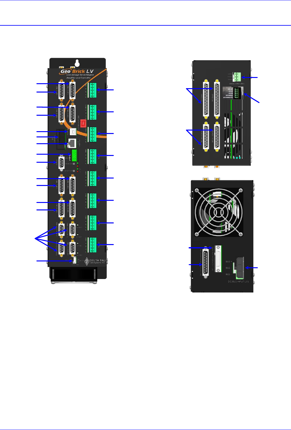
Connector Locations
Bottom View
AC/DC
Bus Power
Input
PWM Interface
Analog I/O
Handwheel
General
Purpose I/O
Limits
& Flags
24VDC
Logic Power
Top View
Front View
AMP 1
AMP 2
AMP 5
AMP 6
AMP 3
Alt. Enc. Pwr
Encoder #4
Encoder #3
Encoder #2
Encoder #1
USB
Ethernet
MACRO
Abort & WD
RS232
Analog I/O
AMP 4
Encoder #5
Encoder #6
Encoder #7
Encoder #8
AMP 7
AMP 8
STO
Safe Torque
Off
Geo Brick LV User Manual
Receiving, Unpacking, and Mounting 22
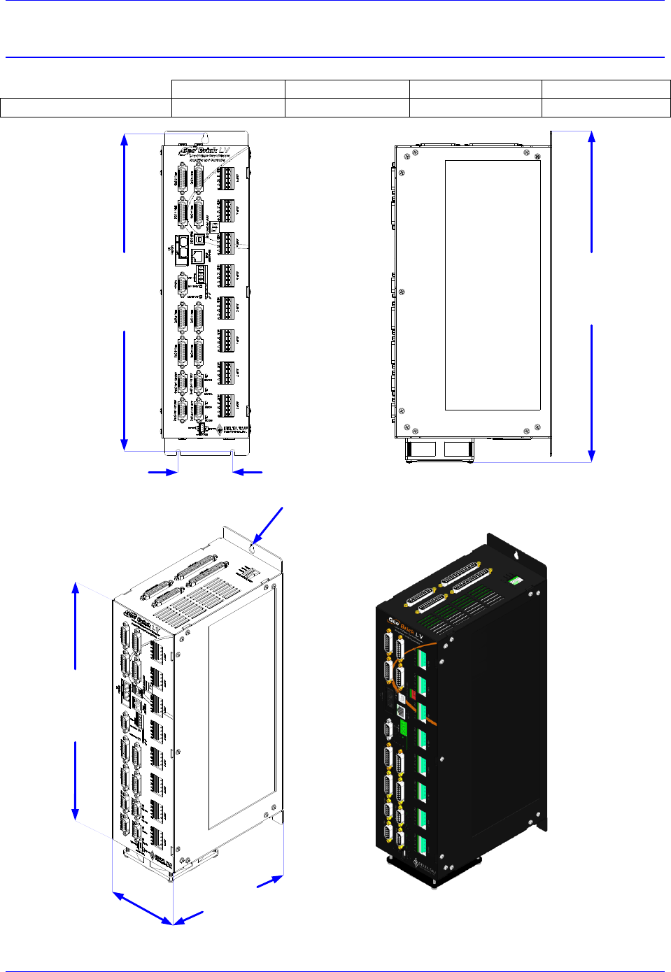
CAD Drawing
GBD4-xx-xxx-xxx-xxxxxx and GBD8-xx-xxx-xxx-xxxxxx
Width
Depth
Height
Weight
Case Dimensions
4’’(101.6mm)
7.2’’(182.88mm)
15.4’’(391.16mm)
9.6 lbs (4.4Kg)
13.50"
(342.90 mm)
4.00"
(101.60 mm)
7.20"
(182.88 mm)
3 x M4
15.40"
(391.16 mm)
2.50"
(63.50 mm)
14.62"
(371.35 mm)
Geo Brick LV User Manual
PinOuts and Software Setup 23
PINOUTS AND SOFTWARE SETUP
WARNING
Installation of electrical control equipment is subject to many
regulations including national, state, local, and industry guidelines
and rules. General recommendations can be stated but it is
important that the installation be carried out in accordance with
all regulations pertaining to the installation.
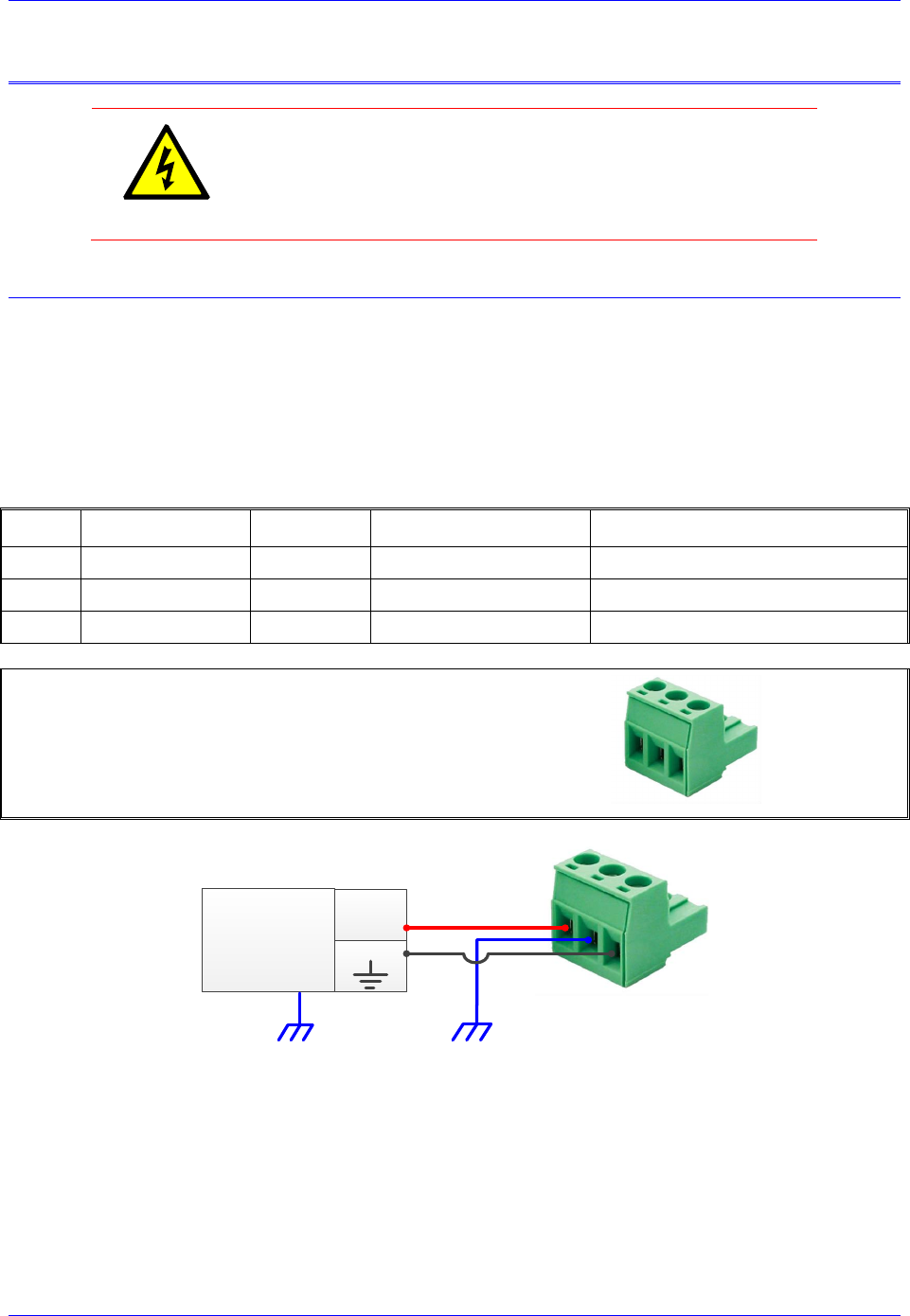
TB1: 24VDC Logic Input
This 3-pin Phoenix Terminal Block is used to bring in the 24-Volt DC supply to power up the logic
portion of the Geo Brick LV. This power can remain on regardless of the main DC bus power, allowing
the signal electronics to be active while the main motor power control may be passive.
The 24Volts power supply must be capable of providing 2~4Amps per Geo Brick LV. If multiple drives
are sharing the same 24-Volt power supply, it is highly recommended to wire each drive back to the
power supply terminals separately.
This connection can be made using a 22 AWG wire directly from a protected power supply.
Pin #
Symbol
Function
Description
Notes
1
+24VDC
Input
Logic power input +
+16~32VDC
2
CHGND
Ground
Chassis ground
Connect to Protection Earth
3
+24VDC RET
Common
Logic power return -
Connect to Power Supply Return
Phoenix Contact mating connector part# 1735879
Delta Tau mating connector part# 016-090A03-08P
123
24 VDC
Power Supply
+24VDC
COM
Geo Brick LV User Manual
PinOuts and Software Setup 24
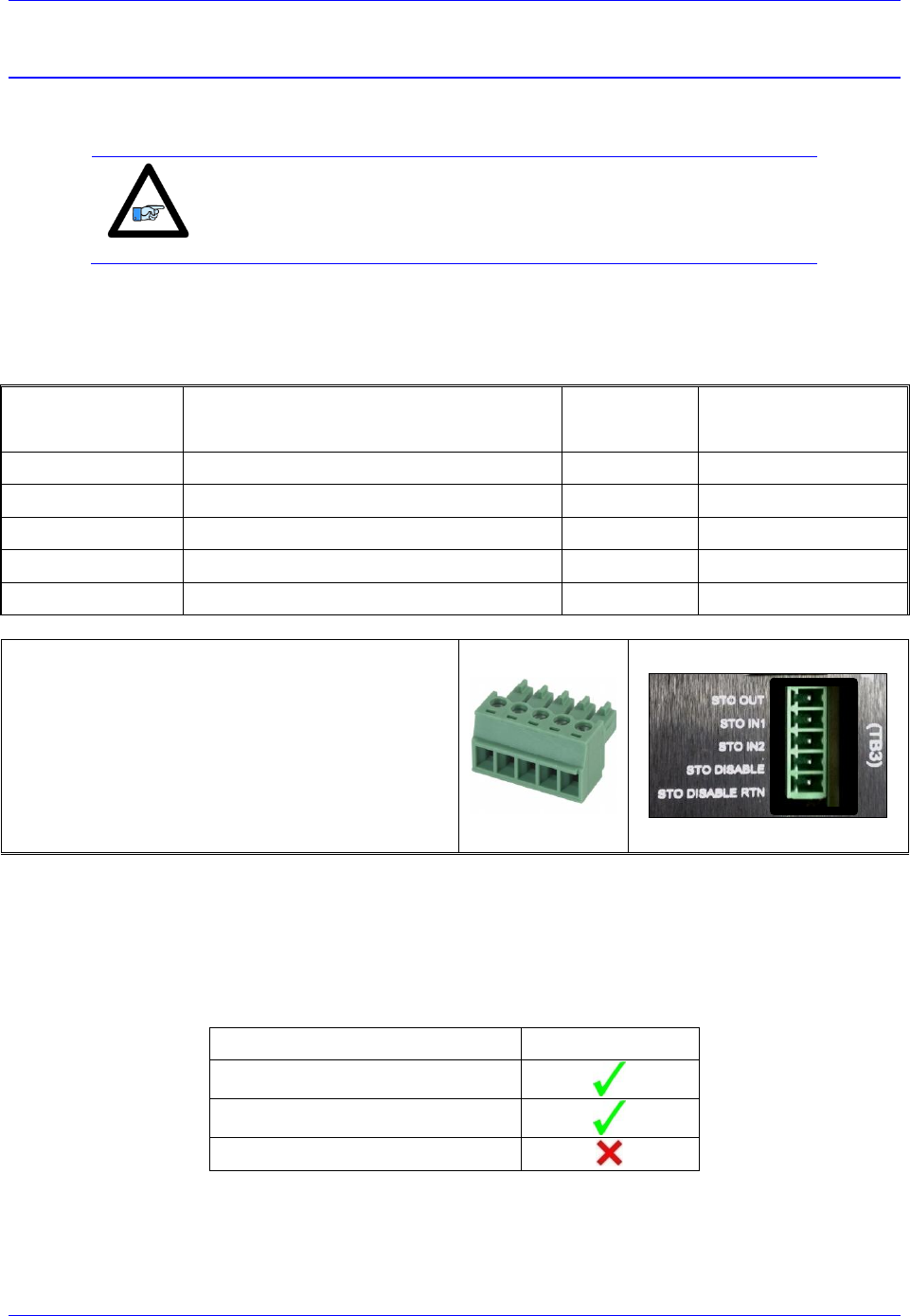
TB3: Safe Torque Off (STO)
This 5-pin Phoenix Terminal Block connector is used to wire the Safe Torque Off (STO) safety function
or alternately disabling it.
Note
The STO feature (and connector) was introduced into the Geo Brick
LV in October of 2012. It will be installed on all new shipments and
certain RMAs.
The STO allows the complete “hardware” disconnection of the power amplifiers from the motors. This
mechanism prevents unintentional “movement of” or torque output to the motors in accordance with
IEC/EN safety standards.
Pin #
Symbol
Function
Description
1
STO OUT
Output
STO Output
2
STO IN 1
Input
STO Input #1
3
STO IN 2
Input
STO Input #2
4
STO DISABLE
-
STO disable
5
STO DISABLE RTN
-
STO disable return
Phoenix Contact Mating Connector Part #: 1850699
Delta Tau mating connector part #
1
2
3
4
5
1 2 3 4 5
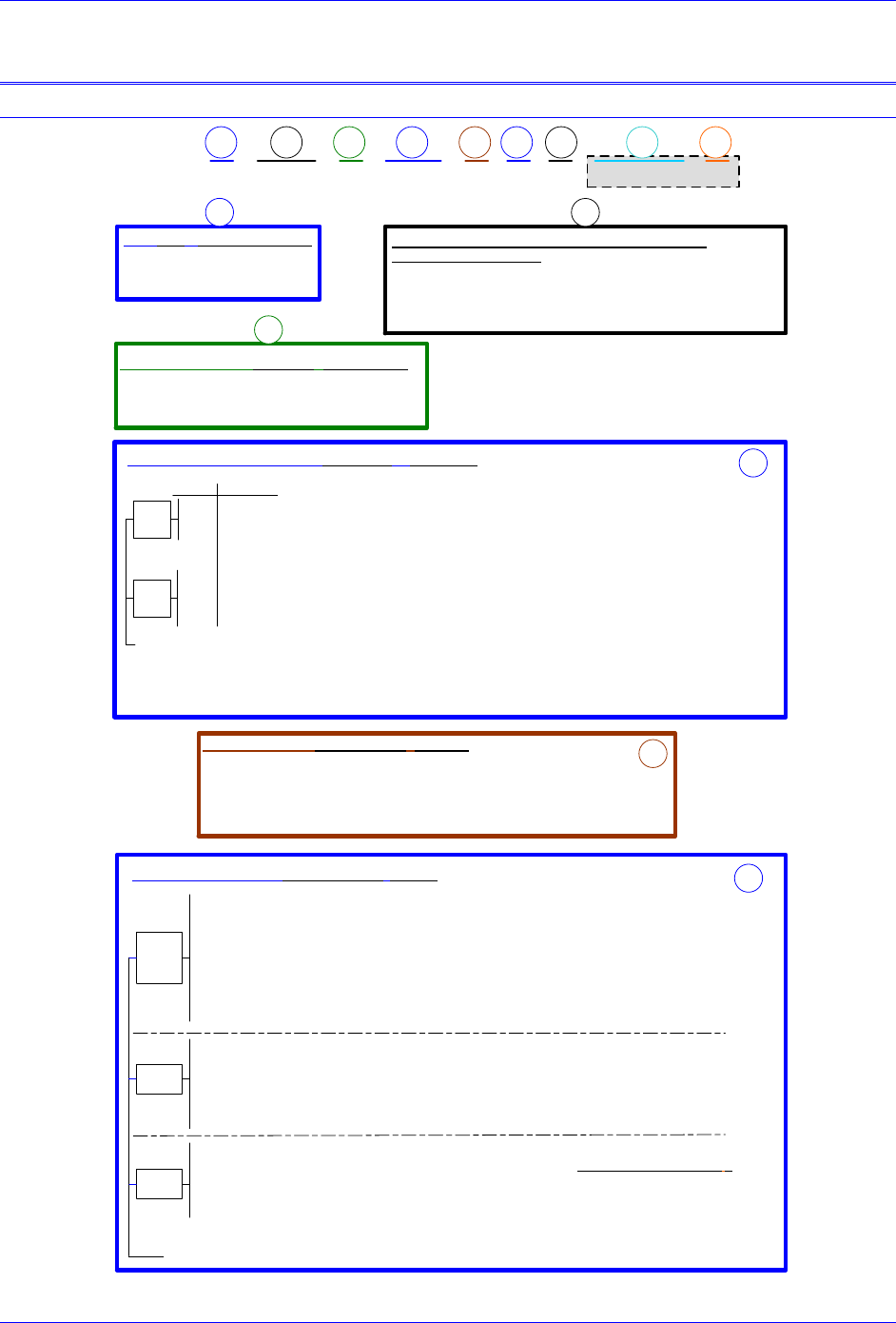
Dynamic Braking
Traditionally, and before the introduction of the STO, when an axis is killed the motor leads are shorted
internally (inside the Geo Brick LV) causing “dynamic braking”, which stops the motor from coasting
freely. The STO feature alters slightly how the dynamic braking is applied. The following table
summarizes the various conditions of dynamic braking when an axis is killed:
Safe Torque Off (STO)
Dynamic Braking
Disabled (not wired)
Enabled (wired) but Not Triggered
Enabled (wired) and Triggered
Geo Brick LV User Manual
PinOuts and Software Setup 25
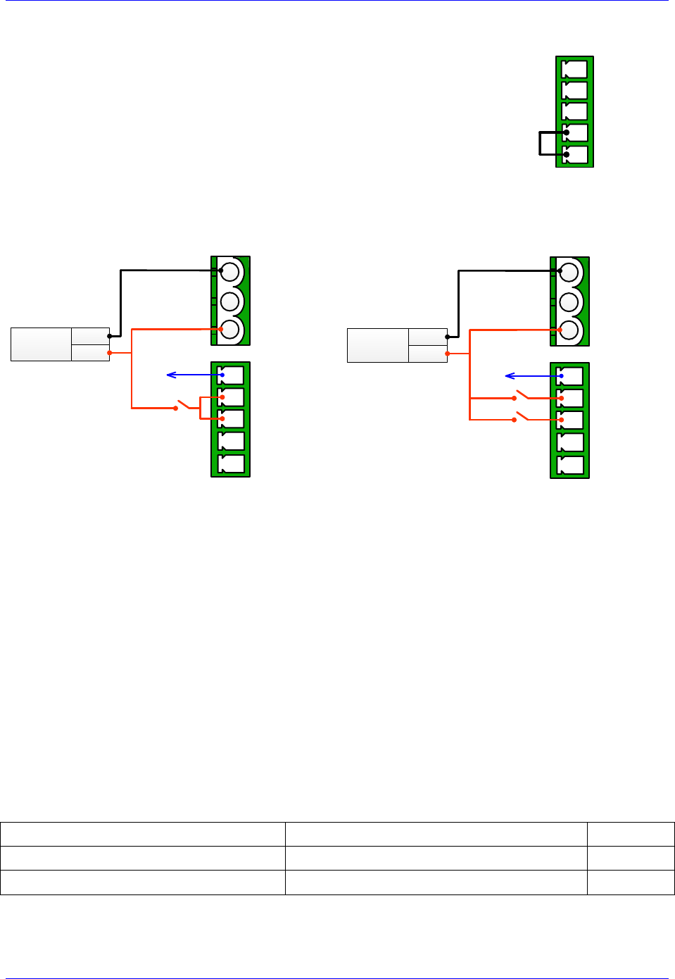
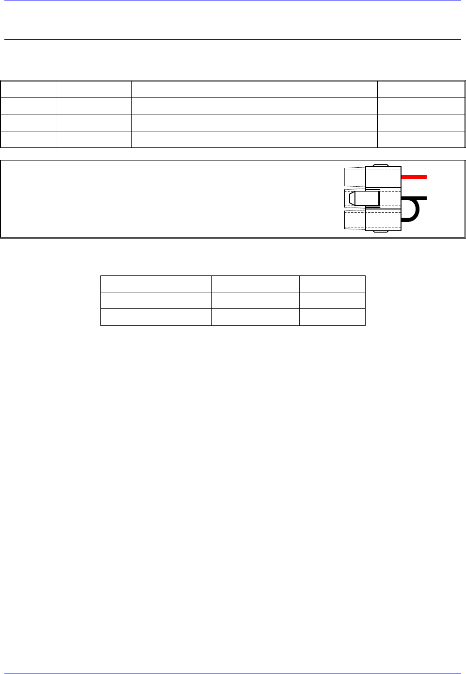
Disabling the STO
Disabling the STO maintains full backward compatibility with existing systems,
pre-STO installations. This can be simply done by tying STO disable (pin #4) to
STO Disable RTN (pin #5).
Pins 1, 2 and 3 have no practical use in this mode, and should be left floating.
STO Out
TB3
STO IN 1
STO IN 2
STO DISABLE
STO DISABLE RTN
5
4
3
2
1
Wiring and Using the STO
Single STO Trigger
Dual STO Trigger(s)
STO Out
TB3
STO IN 1
STO IN 2
STO DISABLE
STO DISABLE RTN
5
4
3
2
1
24 VDC
Power Supply
COM
+24 VDC
N.C
Input to Brick/Logic
2
3
1+ 24VDC
CHGND
+24VRET
TB1
STO Out
TB3
STO IN 1
STO IN 2
STO DISABLE
STO DISABLE RTN
5
4
3
2
1
24 VDC
Power Supply
COM
+24 VDC
N.C
Input to Brick/Logic
2
3
1+ 24VDC
CHGND
+24VRET
TB1
In normal mode operation, the STO relay(s) must be normally closed. +24VDC must be applied to
both STO inputs (pins #2, #3) to allow power to the motors.
The STO is triggered, and power is disconnected from the motors, if the +24V is disconnected from
either STO inputs (pins #2, #3).
The STO Out (pin #1) is a voltage status output rated to 24 VDC ±10% at a max of 125mA. It
reflects the status of the STO function:
(24 V) in normal mode operation (+24VDC connected to both STO inputs)
( 0 V) in triggered mode (+24VDC disconnected from either STO inputs)
Certain safety standards require dual protection, thus mandating the use of two STO input triggers.
The STO relay(s) can be wired in series with the E-Stop circuitry which typically disconnects the
main bus power from the system.
Summary of operation and status:
+24 VDC
STO State
STO Out
Applied to both STO Inputs
Not Triggered (normal mode operation)
24V
Disconnected from either STO inputs
Triggered
0V
Geo Brick LV User Manual
PinOuts and Software Setup 26
J1: DC Bus Input
This 3-pin connector is used to bring in the main DC bus (motor) power. The mating connecter is a Molex
male 10.00mm (.393") Pitch Mini-Fit Sr.™ Receptacle Housing, Single Row, 3 Circuits.
Pin #
Symbol
Function
Description
Notes
1
BUS+
Input
Bus power input Bus+
+12~60VDC
2
BUS-
Common
Bus power return Bus-
Return Line
3
BUS-
Common
Bus power return Bus-
Return Line
Molex mating connector part# 0428160312
Delta Tau mating connector part # 016-090003-049
BUS+
BUS-
This connection can be made using the following wire gauge and fusing:
Model
Fuse (FRN/LPN)
Wire Gauge
4-Axis (GBD4-xx-xxx)
15 A
12 AWG
8-Axis (GBD8-xx-xxx)
25 A
10 AWG

Geo Brick LV User Manual
PinOuts and Software Setup 27
Power On/Off Sequence
!
Caution
The main bus power should NEVER be brought into the Geo Brick
LV if the 24V logic power is NOT applied.
!
Caution
Make sure that no motor commands (e.g. phasing, jogging, open loop)
are being executed by the controller (PMAC) at the time of applying
main bus power.
Powering up a Geo Brick LV must obey the following procedure:
1. Apply 24V logic power
2. Wait a minimum of ~ 2 seconds
3. Apply main bus power
!
Caution
When the main DC bus motor power is disconnected, a Kill command
should be sent to all motors (e.g. via logic PLC or HMI).
Powering down a Geo Brick LV must obey the following procedure:
1. Disconnect main bus power
2. Wait a minimum of ~ 1 second
3. Disconnect 24V logic power
!
Caution
The loss of DC bus motor power in the Geo Brick LV is not an
amplifier fault condition.
The loss of DC bus motor power in the Geo Brick LV is not an amplifier fault condition. Killing all
motors upon disconnecting bus power is highly recommended.
In this scenario, if the controller is programmed to persistently enable a motor (bad practice), it will not
know that the bus has been disconnected (no amplifier fault). Therefore, as soon as the DC bus is re-
applied, it will try to enable which results in an in-rush current (hardware damage) and unexpected –
dangerous – motor move.
Geo Brick LV User Manual
PinOuts and Software Setup 28
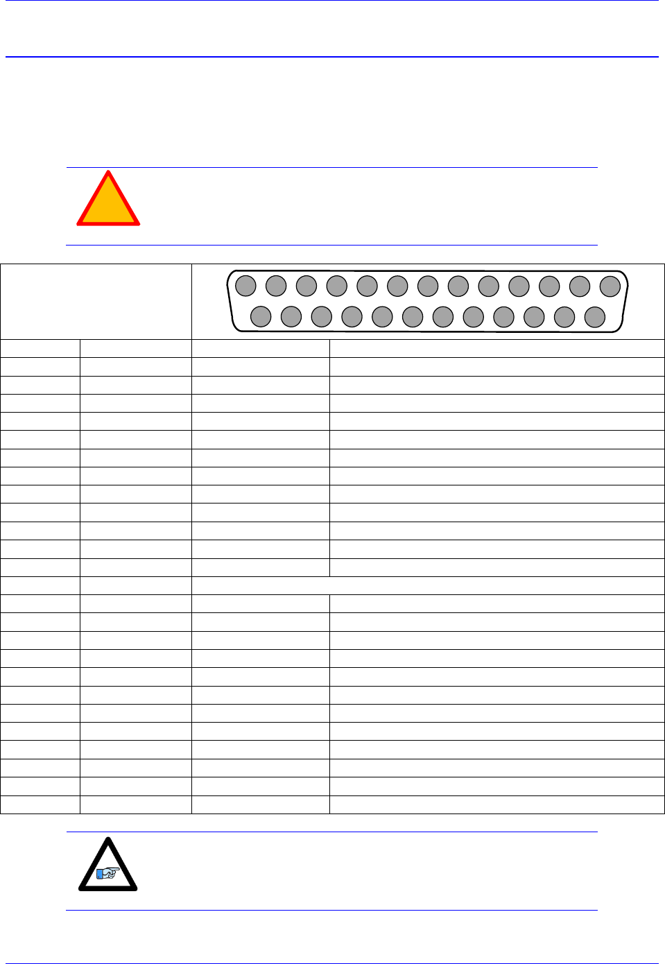
J4: Limits, Flags, EQU [Axis 1- 4]
J4 is used to wire axis/channels 1 through 4 over travel limit switches, home and user flags, and EQU
output. The limits and flags can be ordered either 5V or 12-24V. The EQU output is always 5V. Per
axis/channel, there are 2 limit inputs, 2 flag inputs, and 1 EQU output:
- Positive limit. Negative limit
- Home flag. User flag
- EQU
!
Caution
To avoid machine/equipment damage and before applying power or
connecting any of the flags; make sure that your electrical
design/wiring is in accordance with the Geo Brick LV’s part number
option for 5- or 24-volt connection
J4: D-sub DB-25F
Mating: D-sub DB-25M
1
2
3
4
5
6
7
8
9
10
11
12
13
14
15
16
17
18
19
20
21
22
23
24
25
Pin #
Symbol
Function
Description
1
USER1
Input
User Flag 1
2
MLIM1
Input
Negative Limit 1
3
FL_RT1
Input
Flag Return 1
4
USER2
Input
User Flag 2
5
MLIM2
Input
Negative Limit 2
6
FL_RT2
Input
Flag Return 2
7
USER3
Input
User Flag 3
8
MLIM3
Input
Negative Limit 3
9
FL_RT3
Input
Flag Return 3
10
USER4
Input
User Flag 4
11
MLIM4
Input
Negative Limit 4
12
FL_RT4
Input
Flag Return 4
13
GND
Common
14
PLIM1
Input
Positive Limit 1
15
HOME1
Input
Home Flag 1
16
EQU1
Output
Compare Output, EQU 1 TTL (5V) level
17
PLIM2
Input
Positive Limit 2
18
HOME2
Input
Home Flag 2
19
EQU2
Output
Compare Output, EQU 2 TTL (5V) level
20
PLIM3
Input
Positive Limit 3
21
HOME3
Input
Home Flag 3
22
EQU3
Output
Compare Output, EQU 3 TTL (5V) level
23
PLIM4
Input
Positive Limit 4
24
HOME4
Input
Home Flag 4
25
EQU4
Output
Compare Output, EQU 4 TTL (5V) level
Note
For 5V flags (internal use): Install RP39, RP43, RP47 and RP51.
1Kohm Sip, 8-pin, four independent Resistors.
For 12-24Vflags: Empty bank (Default).

Geo Brick LV User Manual
PinOuts and Software Setup 29
J5: Limits, Flags, EQU [Axis 5- 8]
J5 is used to wire axis/channels 5 through 8 over travel limit switches, home, user flags, and EQU output.
The limits and flags can be ordered either 5V or 12-24V. The EQU output is always 5V. Per axis/channel,
there are 2 limit inputs, 2 flag inputs, and 1 EQU output:
- Positive limit. Negative limit
- Home flag. User flag
- EQU
!
Caution
To avoid machine/equipment damage and before applying power or
connecting any of the flags; make sure that your electrical
design/wiring is in accordance with the Geo Brick LV’s part number
option (5- or 24-volts)
J5: D-sub DB-25F
Mating: D-sub DB-25M
1
2
3
4
5
6
7
8
9
10
11
12
13
14
15
16
17
18
19
20
21
22
23
24
25
Pin #
Symbol
Function
Description
1
USER5
Input
User Flag 5
2
MLIM5
Input
Negative Limit 5
3
FL_RT5
Input
Flag Return 5
4
USER6
Input
User Flag 6
5
MLIM6
Input
Negative Limit 6
6
FL_RT6
Input
Flag Return 6
7
USER7
Input
User Flag 7
8
MLIM7
Input
Negative Limit 7
9
FL_RT7
Input
Flag Return 7
10
USER8
Input
User Flag 8
11
MLIM8
Input
Negative Limit 8
12
FL_RT8
Input
Flag Return 8
13
GND
Common
14
PLIM5
Input
Positive Limit 5
15
HOME5
Input
Home Flag 5
16
BEQU5
Output
Compare Output EQU 5, TTL (5V) level
17
PLIM6
Input
Positive Limit 6
18
HOME6
Input
Home Flag 6
19
BEQU6
Output
Compare Output EQU 6, TTL (5V) level
20
PLIM7
Input
Positive Limit 7
21
HOME7
Input
Home Flag 7
22
BEQU7
Output
Compare Output EQU 7, TTL (5V) level
23
PLIM8
Input
Positive Limit 8
24
HOME8
Input
Home Flag 8
25
BEQU8
Output
Compare Output EQU 8, TTL (5V) level
Note
For Delta Tau’s internal use:
For 5V flags: Install RP89, RP93, RP97 and RP101
1Kohm Sip, 8-pin, four independent Resistors.
For 12-24Vflags: Empty bank (Default).
Geo Brick LV User Manual
PinOuts and Software Setup 30
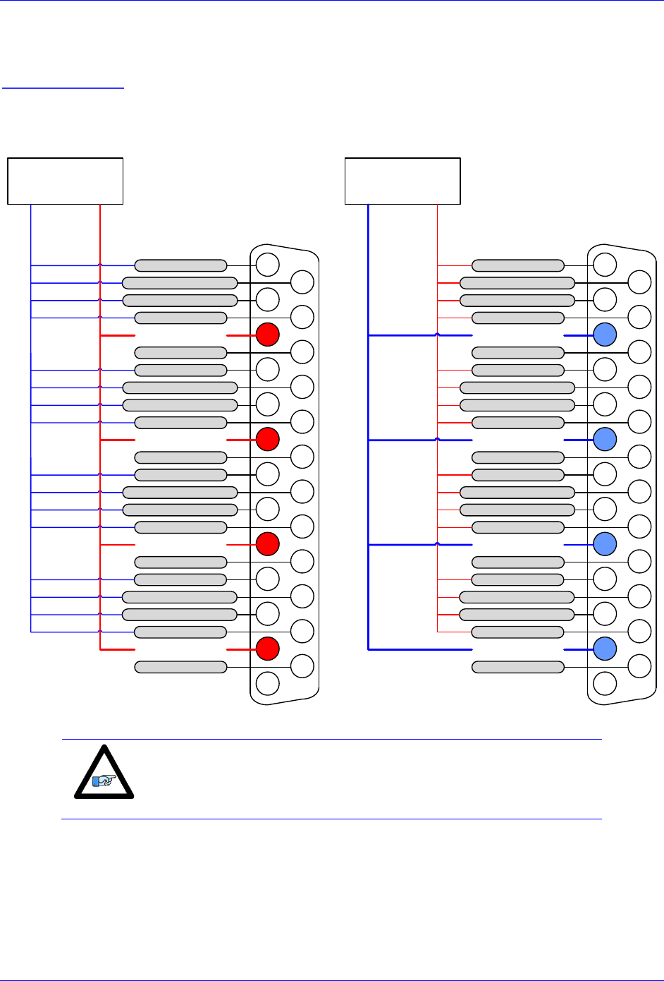
Wiring the Limits and Flags
The Geo Brick allows the use of sinking or sourcing limits and flags. The opto-isolator IC used is a
PS2705-4NEC-ND quad phototransistor output type. This IC allows the current to flow from return to
flag or from flag to return. Sinking into or sourcing out of the Geo Brick LV:
Sourcing Limits And Flags
Sinking Limits And Flags
12345678910111213
141516171819202122232425
5 or 24 VDC
Power supply
USER 1/5
NC POS. LIMIT 1/5
NC NEG. LIMIT 1/5
HOME 1/5
USER 2/6
NC POS. LIMIT 2/6
NC NEG. LIMIT 2/6
HOME 2/6
USER 3/7
NC POS. LIMIT 3/7
NC NEG. LIMIT 3/7
HOME 3/7
USER 4/8
NC POS. LIMIT 4/8
NC NEG. LIMIT 4/8
HOME 4/8
EQU 1/5
EQU 2/6
EQU 3/7
EQU 4/8
COM
+5VDC /
+24VDC
FLAG RETURN 1/5
FLAG RETURN 2/6
FLAG RETURN 3/7
FLAG RETURN 4/8
Note
Per channel, the flags can be either sinking or sourcing depending on
the flag return wiring. The over travel limits must be normally closed
switches. They can be disabled (Ixx24) but they are not software
configurable.

Geo Brick LV User Manual
PinOuts and Software Setup 31
Limits and Flags [Axis 1- 4] Suggested M-Variables
M115->X:$078000,19 ; User 1 flag input status
M116->X:$078000,9 ; EQU1, ENC1 compare output value
M120->X:$078000,16 ; Home flag 1 input status
M121->X:$078000,17 ; Positive Limit 1 flag input status
M122->X:$078000,18 ; Negative Limit 1 flag input status
M215->X:$078008,19 ; User 2 flag input status
M216->X:$078008,9 ; EQU2, ENC2 compare output value
M220->X:$078008,16 ; Home flag 2 input status
M221->X:$078008,17 ; Positive Limit 2 flag input status
M222->X:$078008,18 ; Negative Limit 2 flag input status
M315->X:$078010,19 ; User 3 flag input status
M316->X:$078010,9 ; EQU3, ENC3 compare output value
M320->X:$078010,16 ; Home flag 3 input status
M321->X:$078010,17 ; Positive Limit 3 flag input status
M322->X:$078010,18 ; Negative Limit 3 flag input status
M415->X:$078018,19 ; User 4 flag input status
M416->X:$078018,9 ; EQU4, ENC4 compare output value
M420->X:$078018,16 ; Home flag 4 input status
M421->X:$078018,17 ; Positive Limit 4 flag input status
M422->X:$078018,18 ; Negative Limit 4 flag input status
Limits and Flags [Axis 5- 8] Suggested M-Variables
M515->X:$078100,19 ; User 5 flag input status
M516->X:$078100,9 ; EQU5, ENC5 compare output value
M520->X:$078100,16 ; Home flag 5 input status
M521->X:$078100,17 ; Positive Limit 5 flag input status
M522->X:$078100,18 ; Negative Limit 5 flag input status
M615->X:$078108,19 ; User 6 flag input status
M616->X:$078108,9 ; EQU6, ENC6 compare output value
M620->X:$078108,16 ; Home flag 6 input status
M621->X:$078108,17 ; Positive Limit 6 flag input status
M622->X:$078108,18 ; Negative Limit 6 flag input status
M715->X:$078110,19 ; User 7 flag input status
M716->X:$078110,9 ; EQU7, ENC7 compare output value
M720->X:$078110,16 ; Home flag 7 input status
M721->X:$078110,17 ; Positive Limit 7 flag input status
M722->X:$078110,18 ; Negative Limit 7 flag input status
M815->X:$078118,19 ; User 8 flag input status
M816->X:$078118,9 ; EQU8, ENC4 compare output value
M820->X:$078118,16 ; Home flag 8 input status
M821->X:$078118,17 ; Positive Limit 8 flag input status
M822->X:$078118,18 ; Negative Limit 8 flag input status

Geo Brick LV User Manual
PinOuts and Software Setup 32
J6: General Purpose Inputs and Outputs
J6 is used to wire general purpose digital inputs/outputs to the Geo Brick LV.
J6: D-sub DC-37F
Mating: D-sub DC-37M
12345678910111213
202122232425262728293031
141516171819
323334353637
Pin #
Symbol
Function
Description
1
GPI1
Input
Input 1
2
GPI3
Input
Input 3
3
GPI5
Input
Input 5
4
GPI7
Input
Input 7
5
GPI9
Input
Input 9
6
GPI11
Input
Input 11
7
GPI13
Input
Input 13
8
GPI15
Input
Input 15
9
IN_COM1-8
Common 01-08
Input 01 to 08 Common
10
OUT-RET
Input
Outputs Return
11
OUT_COM
Input
Outputs Common
12
GP01-
Output
Sourcing Output 1
13
GP02-
Output
Sourcing Output 2
14
GP03-
Output
Sourcing Output 3
15
GP04-
Output
Sourcing Output 4
16
GP05-
Output
Sourcing Output 5
17
GP06-
Output
Sourcing Output 6
18
GP07-
Output
Sourcing Output 7
19
GP08-
Output
Sourcing Output 8
20
GPI2
Input
Input 2
21
GPI4
Input
Input 4
22
GPI6
Input
Input 6
23
GPI8
Input
Input 8
24
GPI10
Input
Input 10
25
GPI12
Input
Input 12
26
GPI14
Input
Input 14
27
GPI16
Input
Input 16
28
IN_COM9-16
Common 09-16
Input 09 to 16 Common
29
OUT_COM
Input
Outputs Common
30
GP01+
Output
Sinking Output 1
31
GP02+
Output
Sinking Output 2
32
GP03+
Output
Sinking Output 3
33
GP04+
Output
Sinking Output 4
34
GP05+
Output
Sinking Output 5
35
GP06+
Output
Sinking Output 6
36
GP07+
Output
Sinking Output 7
37
GP08+
Output
Sinking Output 8

Geo Brick LV User Manual
PinOuts and Software Setup 33
J7: General Purpose Inputs and Outputs (Additional)
J7 is used to wire the additional (optional) general purpose digital Inputs/Outputs to the Geo Brick.
J7: D-sub DC-37F
Mating: D-sub DC-37M
12345678910111213
202122232425262728293031
141516171819
323334353637
Pin #
Symbol
Function
Description
1
GPI17
Input
Input 17
2
GPI19
Input
Input 19
3
GPI21
Input
Input 21
4
GPI23
Input
Input 23
5
GPI25
Input
Input 25
6
GPI27
Input
Input 27
7
GPI29
Input
Input 29
8
GPI31
Input
Input 31
9
IN_COM 17-24
Common 17-24
Input 17 to 24 Common
10
OUT-RET
Input
Outputs Return
11
OUT_COM
Input
Outputs Common
12
GPO9-
Output
Sourcing Output 9
13
GPO10-
Output
Sourcing Output 10
14
GPO11-
Output
Sourcing Output 11
15
GPO12-
Output
Sourcing Output 12
16
GPO13-
Output
Sourcing Output 13
17
GPO14-
Output
Sourcing Output 14
18
GPO15-
Output
Sourcing Output 15
19
GPO16-
Output
Sourcing Output 16
20
GPI18
Input
Input 18
21
GPI20
Input
Input 20
22
GPI22
Input
Input 22
23
GPI24
Input
Input 24
24
GPI26
Input
Input 26
25
GPI28
Input
Input 28
26
GPI30
Input
Input 30
27
GPI32
Input
Input 32
28
IN_COM_25-32
Common 25-32
Input 25 to 32 Common
29
OUT_COM
Input
Outputs Common
30
GPO9+
Output
Sinking Output 9
31
GPO10+
Output
Sinking Output 10
32
GPO11+
Output
Sinking Output 11
33
GPO12+
Output
Sinking Output 12
34
GPO13+
Output
Sinking Output 13
35
GPO14+
Output
Sinking Output 14
36
GPO15+
Output
Sinking Output 15
37
GPO16+
Output
Sinking Output 16

Geo Brick LV User Manual
PinOuts and Software Setup 34
About the Digital Inputs and Outputs
All general purpose inputs and outputs are optically isolated. They operate in the 12–24 VDC range, and
can be wired to be either sinking or sourcing.
Inputs
The inputs use the PS2505L-1NEC photocoupler.
For sourcing inputs, connect the input common pin(s) to the 12–24V line of the power supply. The input
devices are then connected to the common ground line of the power supply at one end, and individual
input pins at the other.
For sinking inputs, connect the input common pin(s) to the common ground line of the power supply. The
input devices are then connected to the 12–24V line of the power supply at one end, and individual input
pins at the other.
Note
The inputs can be wired either sourcing or sinking in sets of eight,
with each set possessing its own common.
Outputs
The outputs, in the older models of the Geo Brick LV, use the PS2501L-1NEC photocoupler. They are
rated to a maximum current of 500 mA, and are overload protected.
The outputs, in the newer models of the Geo Brick LV (control board 603793-10A and later), use the
PS2701-1NEC photocoupler. They are protected with a ZXMS6006DG; an enhancement mode
MOSFET - diode incorporated. The protection involves over-voltage, over-current, I2T and short circuit.
For sourcing outputs, connect the common collector (pin #29) to the 12–24V line of the power supply.
The output devices are then connected to the common ground line of the power supply at one end, and
individual sourcing output pins at the other.
For sinking outputs, connect the common emitter (pin #11) to the common ground line of the power
supply. The output devices are then connected to the 12–24V line of the power supply at one end, and
individual sinking output pins at the other.
Note
Do not mix topologies for outputs. They are all either sinking or
sourcing. If the common emitter is used, the common collector should
not be connected and vice versa.
Note
Newer models of the Geo Brick LV were introduced in October of
2012 and can be recognized by the 5-pin terminal block STO
connector which was not available previously.
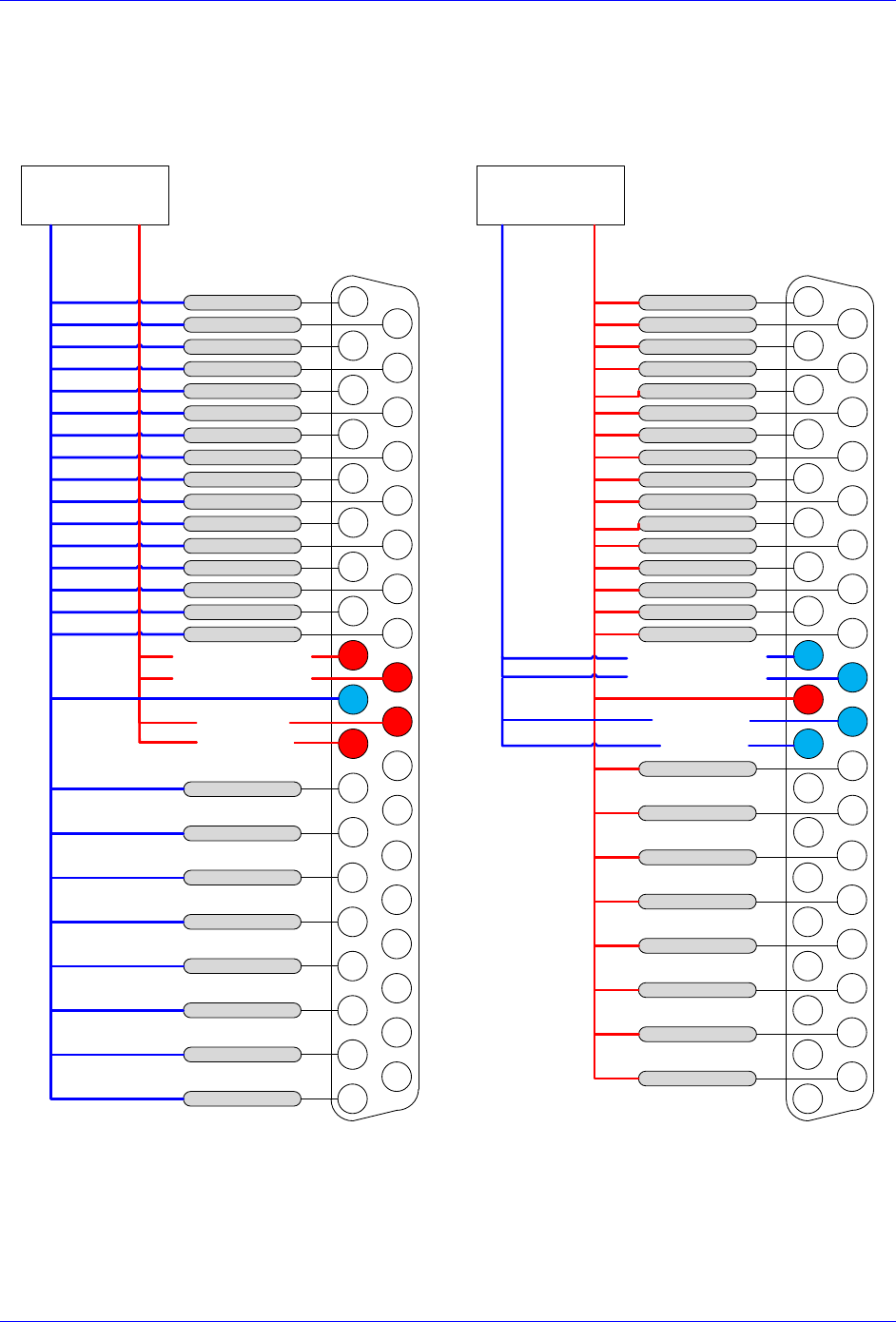
Geo Brick LV User Manual
PinOuts and Software Setup 35
Wiring the Digital Inputs and Outputs
The inputs and outputs can be wired to be either sourcing out of or sinking into the Geo Brick LV:
Sourcing Inputs / Outputs
Sinking Inputs / Outputs
12345678910111213
202122232425262728293031
12 - 24 VDC
Power supply
INPUT 1 / 17
INPUT 2 / 18
INPUT 3 / 19
INPUT 4 / 20
INPUT 7 / 23
INPUT 8 / 24
INPUT 9 / 25
INPUT 10 / 26
INPUT 13 / 29
INPUT 14 / 30
INPUT 15 / 31
INPUT 16 / 32
INPUT 6 / 22
INPUT 12 / 28
OUTPUT 1 / 9
COM
+12VDC /
+24VDC
141516171819
323334353637
COM. COLLECT
INPUT 5 / 21
INPUT 11 / 27
OUTPUT 2 / 10
OUTPUT 3 / 11
OUTPUT 4 / 12
OUTPUT 5 / 13
OUTPUT 6 / 14
OUTPUT 7 / 15
OUTPUT 8 / 16
IN COM 09-16 / 25-32
IN COM 01-08 / 17-24
COM. COLLECT
12345678910111213
202122232425262728293031
12 - 24 VDC
Power supply
INPUT 1 / 17
INPUT 2 / 18
INPUT 3 / 19
INPUT 4 / 20
INPUT 7 / 23
INPUT 8 / 24
INPUT 9 / 25
INPUT 10 / 26
INPUT 13 / 29
INPUT 14 / 30
INPUT 15 / 31
INPUT 16 / 32
INPUT 6 / 22
INPUT 12 / 28
OUTPUT 1 / 9
COM
+12VDC /
+24VDC
141516171819
323334353637
COM. EMIT
INPUT 5 / 21
INPUT 11 / 27
OUTPUT 2 / 10
OUTPUT 3 / 11
OUTPUT 4 / 12
OUTPUT 5 / 13
OUTPUT 6 / 14
OUTPUT 7 / 15
OUTPUT 8 / 16
IN COM 09-16 / 25-32
IN COM 01-08 / 17-24
COM. EMIT

Geo Brick LV User Manual
PinOuts and Software Setup 36
General Purpose I/Os (J6) Suggested M-Variables
// Inputs:
M1->Y:$78800,0,1 ; Input 01 J6 Pin#1
M2->Y:$78800,1,1 ; Input 02 J6 Pin#20
M3->Y:$78800,2,1 ; Input 03 J6 Pin#2
M4->Y:$78800,3,1 ; Input 04 J6 Pin#21
M5->Y:$78800,4,1 ; Input 05 J6 Pin#3
M6->Y:$78800,5,1 ; Input 06 J6 Pin#22
M7->Y:$78800,6,1 ; Input 07 J6 Pin#4
M8->Y:$78800,7,1 ; Input 08 J6 Pin#23
M9->Y:$78801,0,1 ; Input 09 J6 Pin#5
M10->Y:$78801,1,1 ; Input 10 J6 Pin#24
M11->Y:$78801,2,1 ; Input 11 J6 Pin#6
M12->Y:$78801,3,1 ; Input 12 J6 Pin#25
M13->Y:$78801,4,1 ; Input 13 J6 Pin#7
M14->Y:$78801,5,1 ; Input 14 J6 Pin#26
M15->Y:$78801,6,1 ; Input 15 J6 Pin#8
M16->Y:$78801,7,1 ; Input 16 J6 Pin#27
//Outputs: Output# Sourcing Sinking
M33->Y:$078802,0,1 ; Output 1 J6 Pin#12 Pin#30
M34->Y:$078802,1,1 ; Output 2 J6 Pin#13 Pin#31
M35->Y:$078802,2,1 ; Output 3 J6 Pin#14 Pin#32
M36->Y:$078802,3,1 ; Output 4 J6 Pin#15 Pin#33
M37->Y:$078802,4,1 ; Output 5 J6 Pin#16 Pin#34
M38->Y:$078802,5,1 ; Output 6 J6 Pin#17 Pin#35
M39->Y:$078802,6,1 ; Output 7 J6 Pin#18 Pin#36
M40->Y:$078802,7,1 ; Output 8 J6 Pin#19 Pin#37
General Purpose I/Os Additional (J7) Suggested M-Variables
// Inputs:
M17->Y:$78803,0,1 ; Input 17 J7 Pin#1
M18->Y:$78803,1,1 ; Input 18 J7 Pin#20
M19->Y:$78803,2,1 ; Input 19 J7 Pint#2
M20->Y:$78803,3,1 ; Input 20 J7 Pin#21
M21->Y:$78803,4,1 ; Input 21 J7 Pin#3
M22->Y:$78803,5,1 ; Input 22 J7 Pin#22
M23->Y:$78803,6,1 ; Input 23 J7 Pin#4
M24->Y:$78803,7,1 ; Input 24 J7 Pin#23
M25->Y:$78804,0,1 ; Input 25 J7 Pin#5
M26->Y:$78804,1,1 ; Input 26 J7 Pin#24
M27->Y:$78804,2,1 ; Input 27 J7 Pin#6
M28->Y:$78804,3,1 ; Input 28 J7 Pin#25
M29->Y:$78804,4,1 ; Input 29 J7 Pin#7
M30->Y:$78804,5,1 ; Input 30 J7 Pin#26
M31->Y:$78804,6,1 ; Input 31 J7 Pin#8
M32->Y:$78804,7,1 ; Input 32 J7 Pin#27
//Outputs: Output# Sourcing Sinking
M41->Y:$078805,0,1 ; Output 09 J7 Pin#12 Pin#30
M42->Y:$078805,1,1 ; Output 10 J7 Pin#13 Pin#31
M43->Y:$078805,2,1 ; Output 11 J7 Pin#14 Pin#32
M44->Y:$078805,3,1 ; Output 12 J7 Pin#15 Pin#33
M45->Y:$078805,4,1 ; Output 13 J7 Pin#16 Pin#34
M46->Y:$078805,5,1 ; Output 14 J7 Pin#17 Pin#35
M47->Y:$078805,6,1 ; Output 15 J7 Pin#18 Pin#36
M48->Y:$078805,7,1 ; Output 16 J7 Pin#19 Pin#37

Geo Brick LV User Manual
PinOuts and Software Setup 37
J8: PWM Amplifier Interface
J8 is used to connect to third party PWM amplifiers. This is a limited option, contact technical support for
setup details.

Geo Brick LV User Manual
PinOuts and Software Setup 38
J9: Handwheel and Analog I/O
J9 is used to wire the additional analog inputs, handwheel encoder, analog output, and PFM output.
J9: D-sub DB-25F
Mating: D-sub DB-25M
1
2
3
4
5
6
7
8
9
10
11
12
13
14
15
16
17
18
19
20
21
22
23
24
25
Pin #
Symbol
Function
Notes
1
AIN1
Input
Analog Input #1
2
AIN3
Input
Analog Input #3
3
AIN5
Input
Analog Input #5
4
AIN7
Input
Analog Input #7
5
+12V
Output
For troubleshooting (no practical use)
6
GND
Common
Common Ground
7
ANAOUT-
Output
Analog Output -
8
PULSE-
Output
Pulse Output -
9
DIR-
Output
Direction Output -
10
HWA+
Input
Handwheel Quadrature A
11
HWB+
Input
Handwheel Quadrature B
12
HWC+
Input
Handwheel Quadrature C
13
+5V
Output
For troubleshooting (no practical use)
14
AIN2
Input
Analog Input #2
15
AIN4
Input
Analog Input #4
16
AIN6
Input
Analog Input #6
17
AIN8
Input
Analog Input #8
18
-12V
Output
For troubleshooting (no practical use)
19
ANAOUT+
Output
Analog Output +
20
PULSE+
Output
Pulse Output +
21
DIR+
Output
Direction Output +
22
GND
Common
Common Ground
23
HWA-
Input
Handwheel Quadrature A/
24
HWB-
Input
Handwheel Quadrature B/
25
HWC-
Input
Handwheel Quadrature C/
Note
Analog Inputs at Y:$784B0 using PMAC option12.
Analog Output at Y:$78412,8,16,S using Supp. Ch1* Output A.
Pulse and Direction at Y:$7841C,8,16,S using Supp. Ch2* Output C.
Handwheel Input at Y:$78410 using Supp. Ch1* Handwheel.
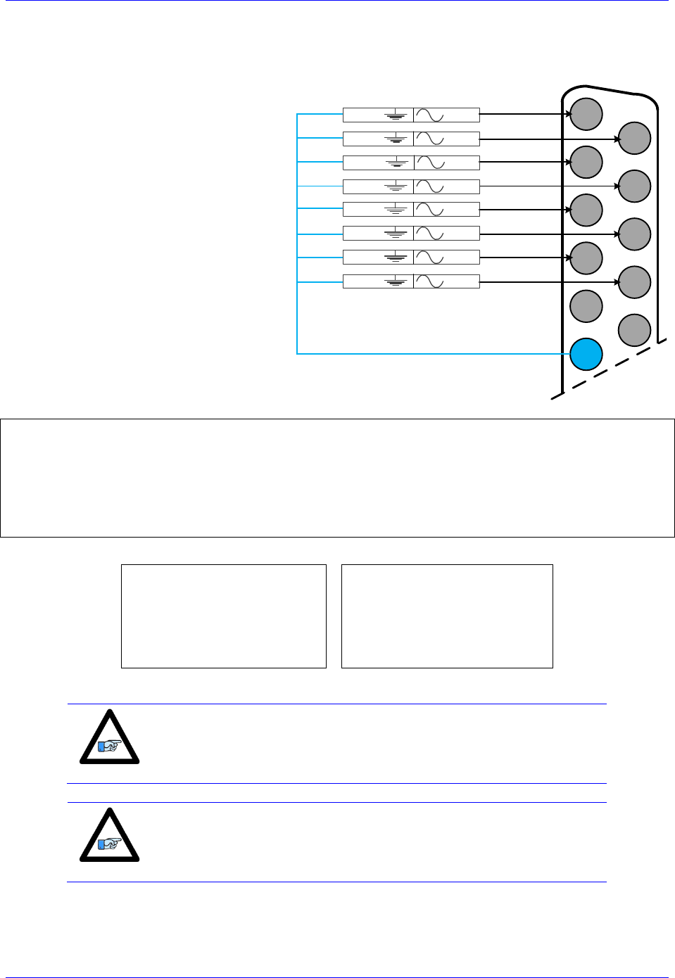
Geo Brick LV User Manual
PinOuts and Software Setup 39
Setting up the Analog Inputs (J9)
J9 port provides eight multiplexed 12-bit
single-ended analog inputs using the
traditional PMAC Option 12.
These analog inputs can be used either in
unipolar mode in the 0V to +10V range, or
bipolar mode in the -10V to +10V range.
Each input has a 470Ω input resistor in-
line, and a 0.01 μF resistor to ground
ensuing a 4.7 μsec time constant per input
line.
±10VDC
Input Signals
12345678910111213
141516171819202122232425
ADC3
ADC1AGND
ADC2AGND
AGND
ADC4AGND
ADC5AGND
ADC6AGND
ADC7AGND
ADC8AGND
I5060=8 ; Copy 8 ADC pairs
I5061=$000340 ; ADC1 is referenced to $078800+$000340= $78B40
I5062=$000340 ; ADC2 is referenced to $078800+$000340= $78B40
I5063=$000340 ; ADC3 is referenced to $078800+$000340= $78B40
I5064=$000340 ; ADC4 is referenced to $078800+$000340= $78B40
I5065=$000340 ; ADC5 is referenced to $078800+$000340= $78B40
I5066=$000340 ; ADC6 is referenced to $078800+$000340= $78B40
I5067=$000340 ; ADC7 is referenced to $078800+$000340= $78B40
I5068=$000340 ; ADC8 is referenced to $078800+$000340= $78B40
Bipolar Mode
Unipolar Mode
I5081=$000008 ; ADC1 Bipolar
I5082=$000009 ; ADC2 Bipolar
I5083=$00000A ; ADC3 Bipolar
I5084=$00000B ; ADC4 Bipolar
I5085=$00000C ; ADC5 Bipolar
I5086=$00000D ; ADC6 Bipolar
I5087=$00000E ; ADC7 Bipolar
I5088=$00000F ; ADC8 Bipolar
I5081=$000000 ; ADC1 Unipolar
I5082=$000001 ; ADC2 Unipolar
I5083=$000002 ; ADC3 Unipolar
I5084=$000003 ; ADC4 Unipolar
I5085=$000004 ; ADC5 Unipolar
I5086=$000005 ; ADC6 Unipolar
I5087=$000006 ; ADC7 Unipolar
I5088=$000007 ; ADC8 Unipolar
Note
A SAVE and a reset ($$$) is required to initialize this function
properly after download.
Note
In Unipolar mode, the ADCs can measure up to 12V since the op-
amps are powered with 12VDC.

Geo Brick LV User Manual
PinOuts and Software Setup 40
J9 Analog Inputs Suggested M-Variables
Bipolar Mode (Signed)
Unipolar Mode (Unsigned)
M6991->Y:$003400,12,12,S ; ADC1
M6992->Y:$003402,12,12,S ; ADC2
M6993->Y:$003404,12,12,S ; ADC3
M6994->Y:$003406,12,12,S ; ADC4
M6995->Y:$003408,12,12,S ; ADC5
M6996->Y:$00340A,12,12,S ; ADC6
M6997->Y:$00340C,12,12,S ; ADC7
M6998->Y:$00340E,12,12,S ; ADC8
M6991->Y:$003400,12,12,U ; ADC1
M6992->Y:$003402,12,12,U ; ADC2
M6993->Y:$003404,12,12,U ; ADC3
M6994->Y:$003406,12,12,U ; ADC4
M6995->Y:$003408,12,12,U ; ADC5
M6996->Y:$00340A,12,12,U ; ADC6
M6997->Y:$00340C,12,12,U ; ADC7
M6998->Y:$00340E,12,12,U ; ADC8
Testing The J9 Analog Inputs
Input Voltage
Software Counts
Bipolar
-10
-2048
-5
-1024
Unipolar
0
0
+10
+2048
+5
+1024
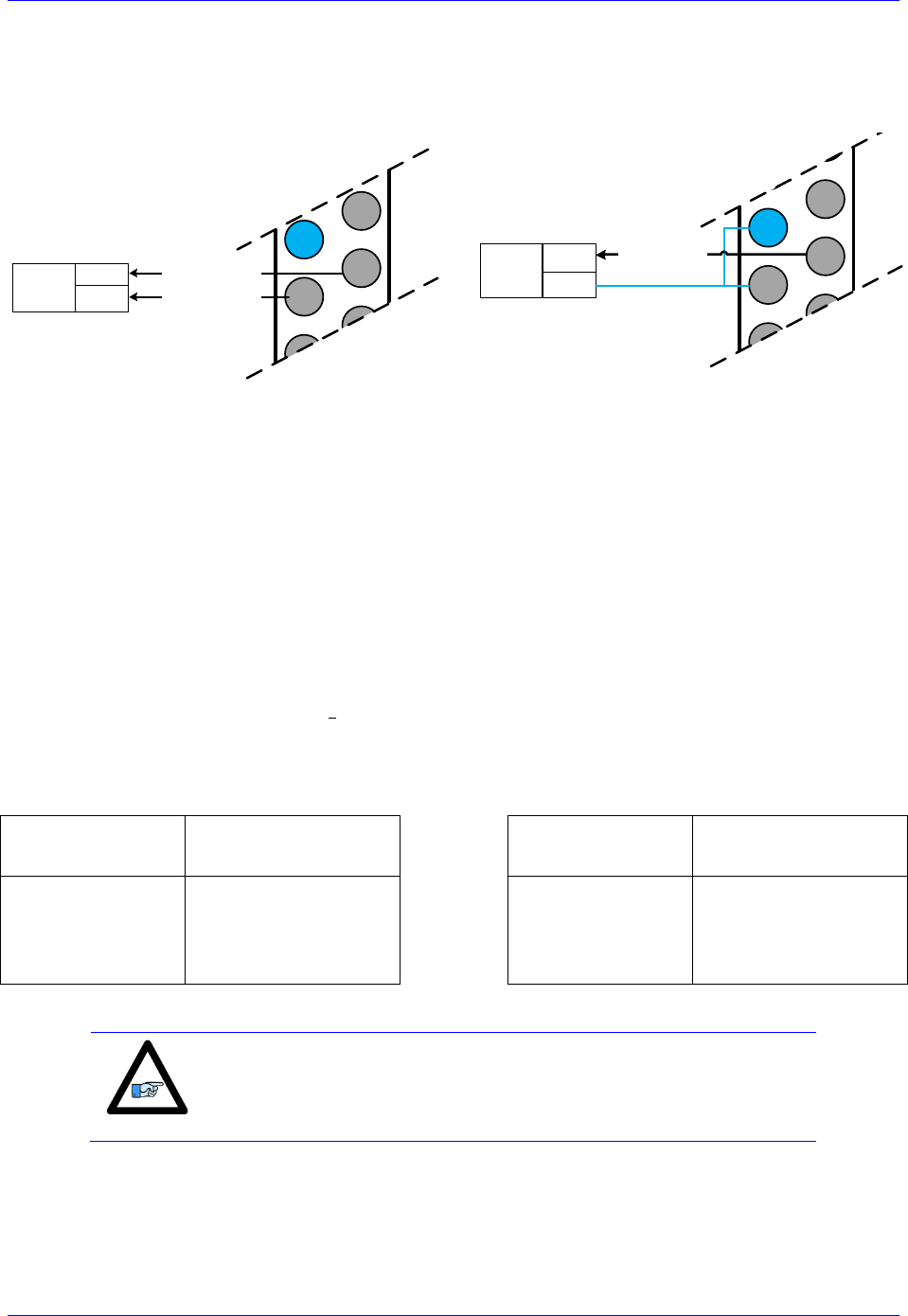
Geo Brick LV User Manual
PinOuts and Software Setup 41
Setting up the Analog Output (J9)
Differential Output
Single-Ended Output
12345678910111213
141516171819202122232425
Analog
Device DAC-
DAC+ DAC Output
±10VDC
12345678910111213
141516171819202122232425
DAC Output
±10VDC
Analog
Device
DAC
COM
The analog output out of J9 is a (12-bit) filtered PWM signal, therefore a PWM frequency in the range of
30-40 KHz and a PWM deadtime of zero are suggested for a good quality analog output signal (minimum
ripple). A fully populated Brick can have one of three gates generating the clocks:
Servo IC 0
Servo IC 1
MACRO IC 0
I19 specifies which gate is the clock source master. I19 is equal to 7007 by default indicating that Servo
IC 0 is the master gate. However, the analog output on J9 is generated from MACRO IC 0.
The relationship between the PWM clock frequency of the clock-receiving gate and the clock-generating
gate should always be respected in such a way that:
Where n is an integer
Example:
With Servo IC 0 sourcing the clock at its’ recommended settings (20 KHz PWM), the following are
suggested MACRO IC 0 clock settings which would provide a good analog output signal:
Servo IC 0
Clock Settings
Resulting
Frequencies KHz
MACRO IC 0
Clock Settings
Resulting
Frequencies KHz
I7000=1473
I7001=0
I7002=7
I10=1677653
PWM
PHASE
SERVO
20
40
5
I6800=735
I6801=3
I6802=3
I6804=0
PWM
PHASE
SERVO
PWMDeadtime
40
20
5
0
Note that n=2 in this case
Note
These MACRO IC0 Clock settings are optimized for a good Analog
Output signal. If the Brick is a MACRO Ring Controller then the
analog output signal quality is compromised with a much lower PWM
frequency, or should not be used at all.
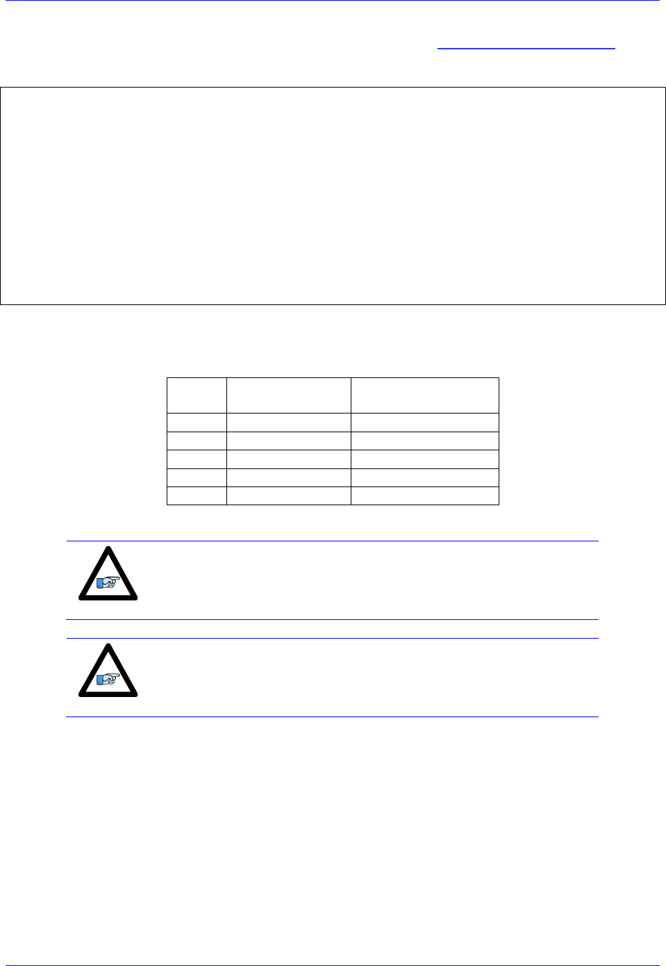
Geo Brick LV User Manual
PinOuts and Software Setup 42
For Help with clock calculations, download the Delta Tau Calculator: DT Calculator Forum Link
J9 Analog Output Suggested M-Variable
// I/O 10 & 11 Mode (PWM)
M7051->Y:$78404,10,1
M7052->Y:$78404,11,1
M7051=0 ; =0 PWM, =1 PFM
M7052=0 ; =0 PWM, =1 PFM
// Analog Output M-variable
M7050->Y:$78412,8,16,S
// These I/O nodes have to be setup once on power-up.
// power-up PLC Example
Open PLC 1 clear
I6612=100*8388608/I10 While(I6612>0) Endw
M7051=0 ; PWM mode
M7052=0 ; PWM mode
Disable PLC 1
Close
Testing the J9 Analog Output
With I6800=735, writing directly to the assigned M-variable (i.e. M7050) should produce the following:
M7050
Single-Ended:
Gnd Output+
Differential:
Output+ Output-
-735
-10V
-20V
-368
-5V
-10V
0
0V
0V
368
+5V
+10V
735
+10V
+20V
Note
Writing values greater than I6800 (i.e. 735) in M7050 will saturate the
output to 10, or 20 volts in single-ended or differential mode
respectively
Note
MACRO connectivity provides more analog output options, e.g. ACC-
24M2A.
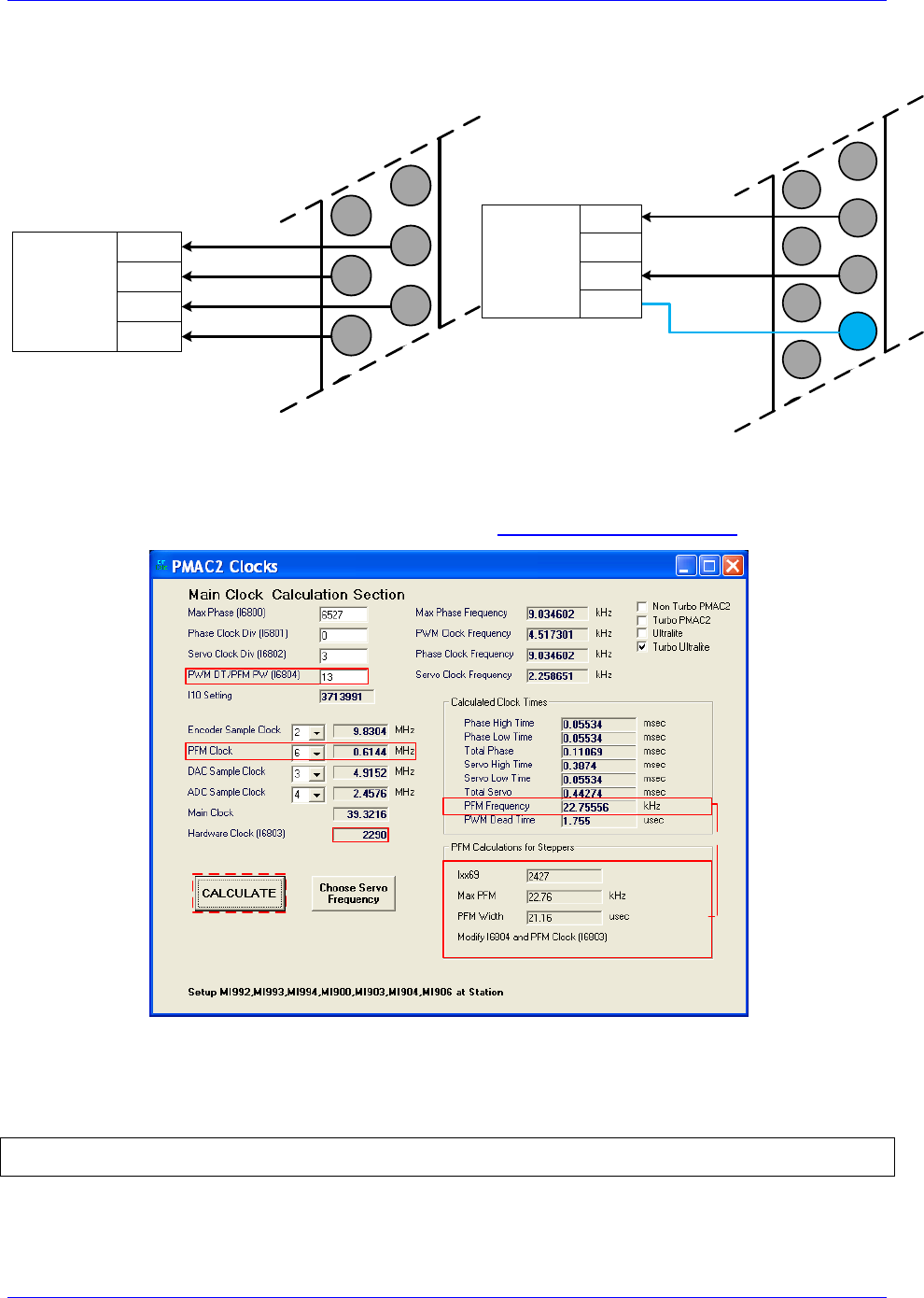
Geo Brick LV User Manual
PinOuts and Software Setup 43
Setting up Pulse and Direction Output PFM (J9)
Differential Pulse And Direction
Single Ended Pulse And Direction
12345678910111213
141516171819202122232425
PULSE
FREQUENCY
DEVICE/
AMPLIFIER
PULSE+
PULSE-
DIR+
DIR-
12345678910111213
141516171819202122232425
PULSE
FREQUENCY
DEVICE/
AMPLIFIER
PULSE+
DIR+
COM
Using the Delta Tau Calculator or referring to the Turbo Software Reference Manual, the desired
maximum PFM Frequency and pulse width can be chosen. DT Calculator Forum Link
Step1
Step2
Results
Step 1: Choose Max PFM clock by changing the PFM clock divider. Click on calculate to see results.
Step 2: Choose PFM Pulse width by changing I6804. Click on calculate to see results.
For a PFM clock range 0-20 KHz, and a pulse width of ~20 μsec:
I6803=2290 ; PFM Clock divider equal to 6
I6804=13 ; PFM Pulse Width Control equal to 13

Geo Brick LV User Manual
PinOuts and Software Setup 44
The output frequency control Ixx69 specifies the maximum command output value that corresponds to the
maximum PFM Frequency.
I6826=3 ; MACRO IC Channel2 Output Mode Select. C PFM
M8000->Y:$7841C,8,16,S ; Supplementary Channel 2* Output C Command Value
; Min=0, Max= Calculated Ixx69
M8001->X:$7841D,21 ; Invert C Output Control. 0=no inversion, 1=invert
Testing the J9 PFM Output
Writing, directly to the suggested M-variable (i.e. M8000), values proportional to the calculated Ixx69,
produces the following corresponding frequencies:
M8000
PFM [KHz]
0
0
1213
11
2427
22
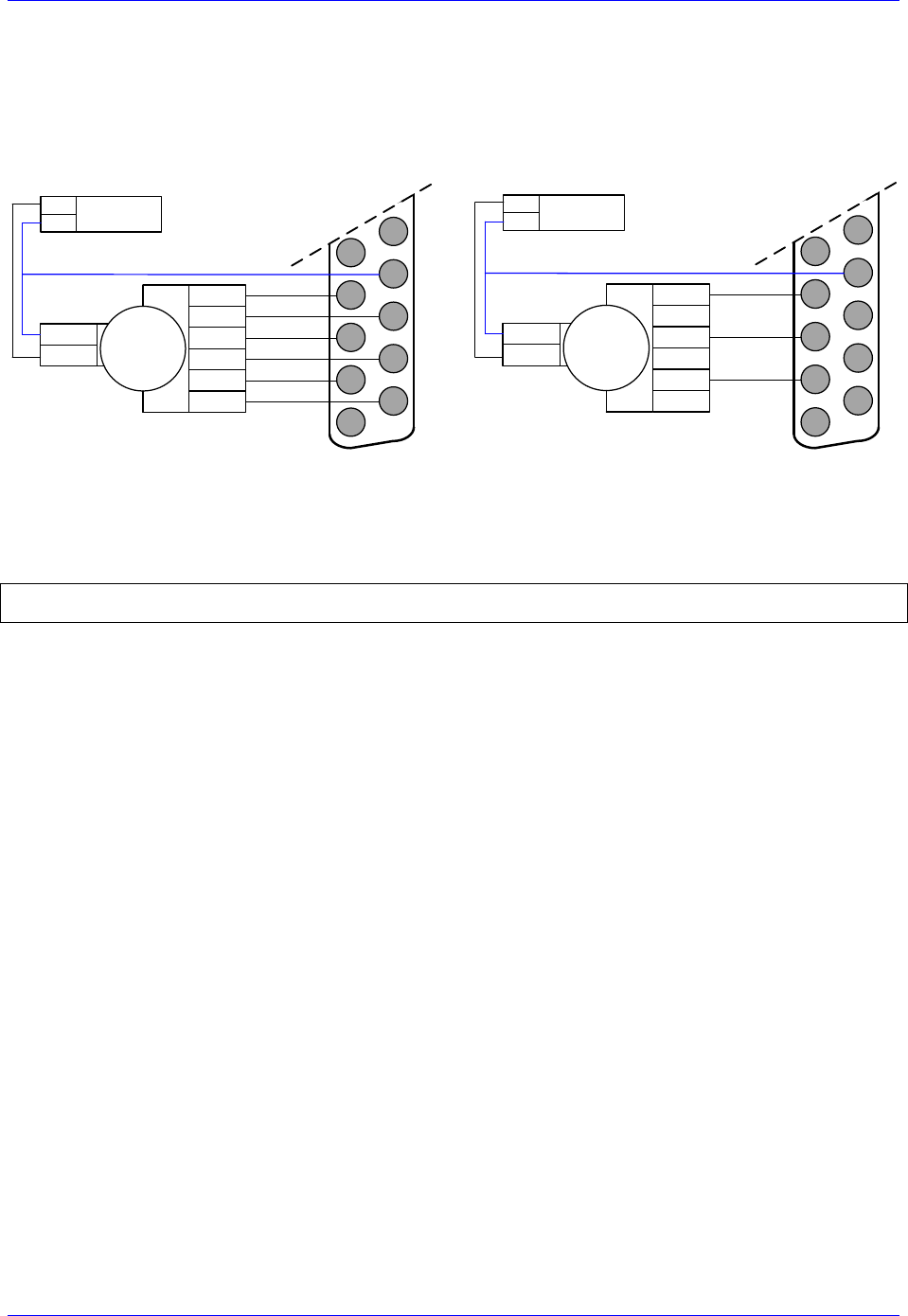
Geo Brick LV User Manual
PinOuts and Software Setup 45
Setting up the Handwheel Port (J9)
A quadrature encoder type device is normally brought into the handwheel port; it can be wired and used
in either single-ended or differential mode. The encoder power is not provided for this device, it must be
brought in externally.
Differential Handwheel
Single ended Handwheel
12345678910111213
141516171819202122232425
Quadrature
Encoder
CHA+
CHA-
+5V PWR
GND CHB+
CHB-
CHC+
CHC-
External +5V
Power Supply
+5V
COM
12345678910111213
141516171819202122232425
Quadrature
Encoder
CHA+
+5V PWR
GND CHB+
CHC+
External +5V
Power Supply
+5V
COM
The encoder data can be brought into the Encoder Conversion Table allowing direct access with an M-
variable or used as a master position (Ixx05) for a specific motor.
Example:
I8000=$78410 ; ECT Entry 1: 1/T extension of location $78410
M8000->X:$3501,0,24,S ; ECT 1st entry result

Geo Brick LV User Manual
PinOuts and Software Setup 46
X1-X8: Encoder Feedback, Digital A Quad B
X1-X8: D-sub DA-15F
Mating: D-sub DA-15M
2
3
4
5
6
7
8
9
10
11
12
13
14
15
1
Pin#
Symbol
Function
Description
1
CHA+
Input
Encoder A+
2
CHB+
Input
Encoder B+
3
CHC+ / AENA+
Input
Encoder Index+ / Stepper amp enable +
4
ENCPWR
Output
Encoder Power 5V
5
CHU+ / DIR+
In/Out
Halls U+ / Direction Output + for Stepper
6
CHW+/ PUL+
In/Out
Halls W+ / Pulse Output + for Stepper
7
2.5V
Output
2.5V Reference power
8
Stepper Enable
Input
Tie to pin#4 (5V) to enable PFM output
9
CHA-
Input
Encoder A-
10
CHB-
Input
Encoder B-
11
CHC- / AENA-
Input
Encoder Index- / Stepper amp enable -
12
GND
Common
Common ground
13
CHV+ / DIR-
In/Out
Halls V+ / Direction Output- for Stepper
14
CHT+ / PUL-
In/Out
Halls T+ / Pulse Output- for Stepper
15
-
-
Unused
Note
Use an encoder cable with high quality shield. Connect the shield to
connector shell, and use ferrite core in noise sensitive environments.
The standard encoder inputs on the Geo Brick LV are designed for differential quadrature type signals.
Quadrature encoders provide two digital signals to determine the position of the motor. Each nominally
with 50% duty cycle, and nominally 1/4 cycle apart. This format provides four distinct states per cycle of
the signal, or per line of the encoder. The phase difference of the two signals permits the decoding
electronics to discern the direction of travel, which would not be possible with a single signal.
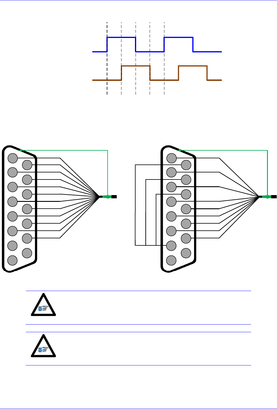
Geo Brick LV User Manual
PinOuts and Software Setup 47
Channel A
Channel B
Typically, these signals are 5V TTL/CMOS level whether they are single-ended or differential.
Differential signals can enhance noise immunity by providing common mode noise rejection. Modern
design standards virtually mandate their use in industrial systems.
Differential Quadrature Encoder Wiring
Single-Ended Quadrature Encoder Wiring
2
3
4
5
6
7
8
9
10
11
12
13
14
15
1
A+
A-
B-
B+
C+
C-
+ 5VDC
GND
Encoder shield (solder to shell)
U+
V+
W+
T+
Differential Quadrature Encoder
with hall sensors (optional)
2
3
4
5
6
7
8
9
10
11
12
13
14
15
1
A+
B+
C+
+ 5VDC
GND
Encoder shield (solder to shell)
U+
V+
W+
T+
Single-Ended Quadrature Encoder
with hall sensors (optional)
Note
For single-ended encoders, tie the negative pins to power reference
(Pin#7). Alternately, some open collector single ended encoders may
require tying the negative pins to ground in series with a 1-2 KOhm
resistors.
Note
Some motor manufacturers bundle the hall sensors with the motor-
lead cable. The hall sensors must be brought into this connector for
setup simplicity.

Geo Brick LV User Manual
PinOuts and Software Setup 48
Setting up Quadrature Encoders
Digital Quadrature Encoders use the 1/T incremental entry in the encoder conversion table. Position and
velocity pointers should, by default, be valid and in most cases no software setup is required, activating
(Ixx00=1) the corresponding channel is sufficient to see encoder counts in the position window when the
motor/encoder shaft is moved by hand.
I100,8,100=1 ; Channels 1-8 activated
Encoder Count Error (Mxx18)
The Geo Brick LV has an encoder count error detection feature. If both the A and B channels of the
quadrature encoder change state at the decode circuitry (post-filter) in the same hardware sampling clock
(SCLK) cycle, an unrecoverable error to the counter value will result (lost counts). Suggested M-Variable
Mxx18 for this channel is then set and latched to 1 (until reset or cleared). The three most common root
causes of this error:
Real encoder hardware problem
Trying to move the encoder (motor) faster than it’s specification
Using an extremely high resolution/speed encoder. This may require increasing the SCLK
The default sampling clock in the Geo Brick LV is ~ 10MHz, which is acceptable for virtually all
applications. A setting of I7m03 of 2257 (from default of 2258) sets the sampling clock SCLK at about
~20MHz. It can be increased to up to ~40 MHz.
Note
No automatic action is taken by the Geo Brick LV if the encoder count
error bit is set.
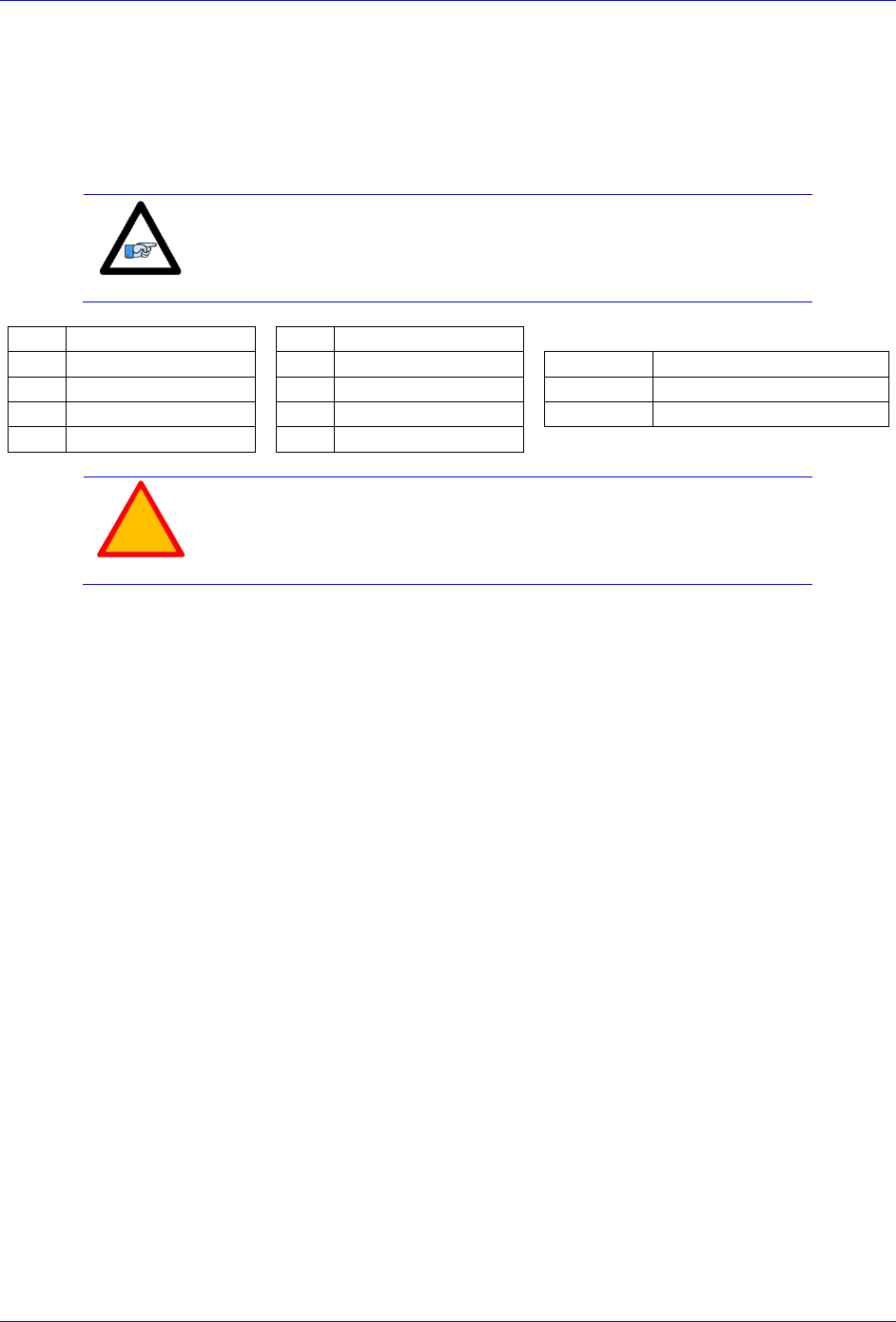
Geo Brick LV User Manual
PinOuts and Software Setup 49
Encoder Loss Detection, Quadrature
Designed for use with differential line-driver outputs (encoders), the encoder loss circuitry monitors each
quadrature input pair with an exclusive-or XOR gate. In normal operation mode, the two quadrature
inputs should be in opposite logical states – that is one high and one low – yielding a true output from the
XOR gate.
Note
Single-Ended Quadrature Encoders are not supported for encoder loss.
Ch#
Address/Definition
Ch#
Address/Definition
1
Y:$78807,0,1
5
Y:$78807,4,1
Status Bit
Definition
2
Y:$78807,1,1
6
Y:$78807,5,1
=0
Encoder lost, Fault
3
Y:$78807,2,1
7
Y:$78807,6,1
=1
Encoder present, no Fault
4
Y:$78807,3,1
8
Y:$78807,7,1
!
Caution
Appropriate action (user-written plc) needs to be implemented when
an encoder loss is encountered. To avoid a runaway, an immediate
Kill of the motor/encoder in question is strongly advised.
No automatic firmware (Geo Brick) action is taken upon detection of encoder(s) loss; it is the user’s
responsibility to perform the necessary action to make the application safe under these conditions, see
example PLC below. Killing the motor/encoder in question is the safest action possible, and strongly
recommended to avoid a runaway, and machine damage. Also, the user should decide the action to be
taken (if any) for the other motors in the system. The Encoder Loss Status bit is a low true logic. It is set
to 1 under normal conditions, and set to 0 when a fault (encoder loss) is encountered.

Geo Brick LV User Manual
PinOuts and Software Setup 50
Encoder Loss Example PLC:
A 4-axis Geo Brick is setup to kill all motors upon the detection of one or more encoder loss. In addition,
it does not allow enabling any of the motors when an encoder loss condition has been encountered:
#define Mtr1AmpEna M139 ; Motor#1 Amplifier Enable Status Bit
Mtr1AmpEna->X:$B0,19 ; Suggested M-Variable
#define Mtr2AmpEna M239 ; Motor#2 Amplifier Enable Status Bit
Mtr2AmpEna->X:$130,19 ; Suggested M-Variable
#define Mtr3AmpEna M339 ; Motor#3 Amplifier Enable Status Bit
Mtr3AmpEna->X:$1B0,19 ; Suggested M-Variable
#define Mtr4AmpEna M439 ; Motor#4 Amplifier Enable Status Bit
Mtr4AmpEna->X:$230,19 ; Suggested M-Variable
#define Mtr1EncLoss M180 ; Motor#1 Encoder Loss Status Bit
Mtr1EncLoss->Y:$078807,0,1 ;
#define Mtr2EncLoss M280 ; Motor#2 Encoder Loss Status Bit
Mtr2EncLoss->Y:$078807,1,1 ;
#define Mtr3EncLoss M380 ; Motor#3 Encoder Loss Status Bit
Mtr3EncLoss->Y:$078807,2,1 ;
#define Mtr4EncLoss M480 ; Motor#4 Encoder Loss Status Bit
Mtr4EncLoss->Y:$078807,3,1 ;
#define SysEncLoss P1080 ; System Global Encoder Loss Status (user defined)
SysEncLoss=0 ; Save and Set to 0 at download, normal operation
; =1 System Encoder Loss Occurred
OPEN PLC 1 CLEAR
If (SysEncLoss=0) ; No Loss yet, normal mode
If (Mtr1EncLoss=0 or Mtr2EncLoss=0 or Mtr4EncLoss=0 or Mtr4EncLoss=0)
CMD^K ; One or more Encoder Loss(es) detected, kill all motors
SysEncLoss=1 ; Set Global Encoder Loss Status to Fault
EndIf
EndIF
If (SysEncLoss=1) ; Global Encoder Loss Status At Fault?
If (Mtr1AmpEna=1 or Mtr2AmpEna=1 or Mtr4AmpEna=1 or Mtr4AmpEna=1) ; Trying to Enable Motors?
CMD^K ; Do not allow Enabling Motors, Kill all
EndIF
EndIF
CLOSE
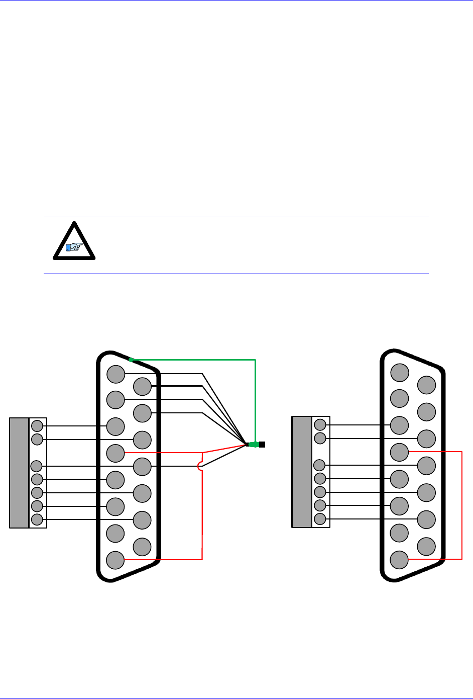
Geo Brick LV User Manual
PinOuts and Software Setup 51
Step and Direction PFM Output (To External Stepper Amplifier)
The Geo Brick LV has the capability of generating step and direction (Pulse Frequency Modulation)
output signals to external stepper amplifiers. These signals are accessible at the encoder connectors. The
step and direction outputs are RS422 compatible and could be connected in either differential or single-
ended configuration for 5V (input signal) amplifiers.
Tying pin #8 to pin #4 (+5V) enables the PFM signal output.
Digital A quad B encoders can still be used alongside PFM output, but hall sensors can NOT be brought
into this connector, they conflict with the PFM circuitry.
The PFM amplifier enable output signal is not available by default. Jumpers E25, E26, E27, and E28
should be installed to activate the amp enable functions of channels 1 through 4 respectively. Similarly
jumpers E35, E36, E37, and E38 should be installed to activate the amp enable functions of channels 5
through 8 respectively.
Note
We strongly recommend requesting that these jumpers be installed
upon shipping to avoid opening the unit and losing warranty.
The index channel (C-channel) can NOT be wired into this connector when the amplifier enable output
signal is configured.
PFM output
with encoder feedback
PFM output without
encoder feedback
2
3
4
5
6
7
8
9
10
11
12
13
14
15
1
A+
A-
B-
B+
+ 5VDC
GND
Encoder shield (solder to shell)
DIR+
DIR-
PULSE+
PULSE-
AENA+
AENA-
PFM enable
External Stepper
Amplifier
AENA-
AENA+
DIR+
DIR-
PUL+
PUL-
GND DIGITAL GND
2
3
4
5
6
7
8
9
10
11
12
13
14
15
1
DIR+
DIR-
PULSE+
PULSE-
AENA+
AENA-
PFM enable
External Stepper
Amplifier
AENA-
AENA+
DIR+
DIR-
PUL+
PUL-
GND DIGITAL GND
+5V
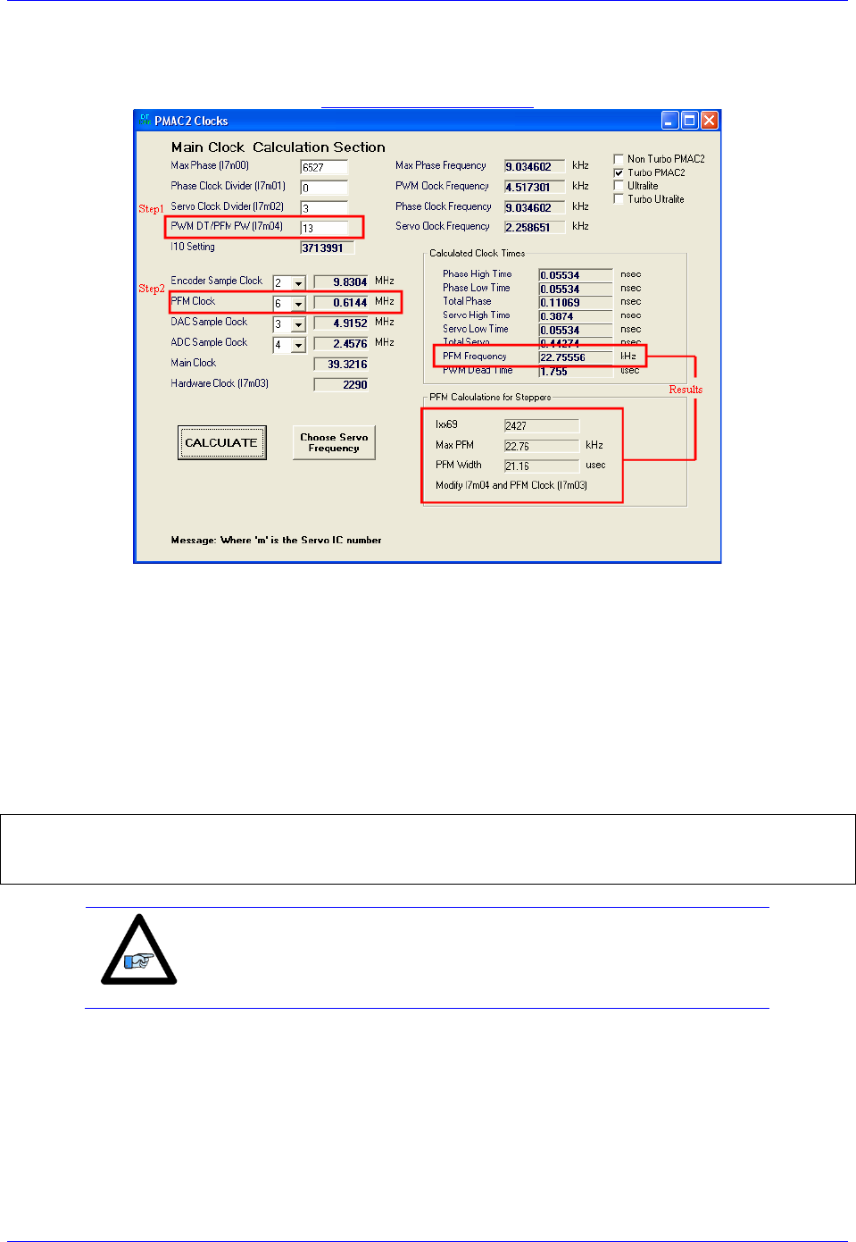
Geo Brick LV User Manual
PinOuts and Software Setup 52
The stepper drive specifications dictate the choice of the maximum PFM clock frequency, and pulse
width. DT Calculator Forum Link
Step 1: Choose Max PFM clock by changing the PFM clock divider. Click on calculate to see results.
Step 2: Choose PFM Pulse width by changing I7m04. Click on calculate to see results.
The output frequency control Ixx69 specifies the maximum command output value which corresponds to
the maximum PFM Frequency.
Example: Channels 5-8 are driving 4 stepper drives-motors, and require a PFM clock range of 0-20 KHz
and a pulse width of ~20 μsec.
PFM Clock Settings Example
// Channels 5-8 PFM Clock Settings
I7103=2290 ; Servo IC 1 PFM Clock divider equal to 6
I7104=13 ; Servo IC 1 PFM Pulse Width Control equal to 13
I569,4,100=2427 ; Output Command Limit
Note
The following example assumes that there is no encoder attached to
the motor, and the feedback is internally generated.

Geo Brick LV User Manual
PinOuts and Software Setup 53
Ch. 5-8 PFM Setup Example
// Encoder Conversion Table, for channels 5-8
I8004=$C78100 ; Entry 5 incremental encoder, no extension
I8005=$C78108 ; Entry 6 incremental encoder, no extension
I8006=$C78110 ; Entry 7 incremental encoder, no extension
I8007=$C78118 ; Entry 8 incremental encoder, no extension
// Channels 5-8 Output Mode Select, Encoder/Decode
I7116,4,10=3 ; Servo IC 1, Channels 5-8 Output Mode Select to PFM
I7110,4,10=8 ; Servo IC 1, Channels 5-8 Encoder Decode, Internal Pulse and Direction
// Channels 5-8 Command Output Register
I502=$78104 ; Channel 5, PFM
I602=$7810C ; Channel 6, PFM
I702=$78114 ; Channel 7, PFM
I802=$7811C ; Channel 8, PFM
In PFM mode, it is possible to:
Write directly to the PFM output register using the suggested M-Variable definition (Mxx07)
The corresponding channel has to be deactivated in this mode (Ixx00=0)
Issue open loop commands to a channel/motor, e.g.:#5O5
The corresponding channel has to be activated in this mode (Ixx00=1)
Issue closed loop commands to a channel/motor, e.g.: #5J=1000
The corresponding channel has to be activated (Ixx00=1) and the position loop PID gains have to
be implemented.
Writing directly to the PFM register
// Channels 5-8 Suggested M-Variables, PFM command output
M507->Y:$78104,8,16,S ; Channel 5, Min=0, Max= Calculated I569
M607->Y:$7810C,8,16,S ; Channel 6, Min=0, Max= Calculated I669
M707->Y:$78114,8,16,S ; Channel 7, Min=0, Max= Calculated I769
M807->Y:$7811C,8,16,S ; Channel 8, Min=0, Max= Calculated I869
Writing directly to the suggested M-variable(s) values proportional to
Ixx69 produces corresponding frequencies:
Suggested
M-
Variable
Output
Frequency
PFM [KHz]
0
0
1213
11
2427
22
Issuing Open-Loop Commands
Activating the motor channel should be sufficient at this point to allow open loop commands. Note that an
open loop command of zero magnitude (#nO0) will result in a zero frequency output, and an open loop
command of 100 (#nO100) will result in the maximum calculated frequency output.
I500,4,100=1 ; Channels 5-8 active
Going back to the setup example, these are some open loop commands
resulting frequencies:
Open
Loop
Command
Output
Frequency
PFM [KHz]
0
0
50
11
100
22
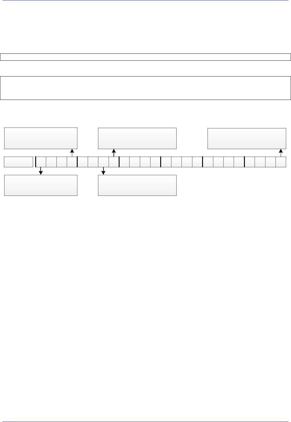
Geo Brick LV User Manual
PinOuts and Software Setup 54
Issuing Closed-Loop Commands
Issuing closed-loop commands requires activating the channel, setting the flag control, assigning the
position and velocity pointers, and implementing PID gains.
Activating channels, Ixx00
I500,4,100=1 ; Channels 5-8 active
Assigning position and velocity pointers, Ixx03 and Ixx04
I503=$3505 I504=$3505 ; Channel 5 position and velocity pointers
I603=$3506 I604=$3506 ; Channel 6 position and velocity pointers
I703=$3507 I704=$3507 ; Channel 7 position and velocity pointers
I803=$3508 I804=$3508 ; Channel 8 position and velocity pointers
Flag Control, Ixx24
The following diagram showcases important bit settings pertaining to flags, and amplifier information:
23 22 21 20 19 18 17 16 15 14 13 12 11 10 9 8 7 6 5 4 3 2 1 0
Amplifier Enable Use Bit
= 0 Use amp enable output
= 1 Don’t use amp enable
Amplifier Fault Use Bit
= 0 Enable amp fault input
= 1 Disable amp fault input
Overtravel Limit Use Bit
= 0 Enable hardware over-travel limits
= 1 Disable hardware over-travel limits
Amplifier Fault Polarity Bit
= 0 For low true amp
= 1 For high true amp
Bit #:
Flag Register Type
Always =1 for Brick Controller
(Turbo PMAC)
Example:
Setting Ixx24 for a low true amplifier, disabling the over-travel limits and amplifier fault input yields
$120001.

Geo Brick LV User Manual
PinOuts and Software Setup 55
Implementing PID gains, Ixx30…Ixx35
In PFM mode, the PID Gains can be determined using the following empirical equations:
[MHz]CLock PFMIxx08
660000
Ixx30
// Channels 5-8 PID Gains (with default clock settings):
I530,4,100=11190 ; Motors 5-8 Proportional Gain
I531,4,100=0 ; Motors 5-8 Derivative Gain
I532,4,100=15038 ; Motors 5-8 Velocity FeedForward Gain
I533,4,100=0 ; Motors 5-8 Integral Gain
I534,4,100=0 ; Motors 5-8 Integral Mode
I535,4,100=0 ; Motors 5-8 Acceleration FeedForward Gain
Note
At this point of the setup, the drive-motor(s) is ready to accept Jog
commands.
0 Ixx31
[KHz] Freq. Servo 6660 Ixx32
0..Ixx353Ixx3

Geo Brick LV User Manual
PinOuts and Software Setup 56
X1-X8: Encoder Feedback, Sinusoidal
X1-X8: D-sub DA-15F
Mating: D-sub DA-15M
2
3
4
5
6
7
8
9
10
11
12
13
14
15
1
Pin #
Symbol
Function
Notes
1
Sin+
Input
Sine+
2
Cos+
Input
Cosine+
3
CHC+
Input
Index+
4
EncPwr
Output
Encoder Power 5 Volts
5
CHU+
In/Out
U Hall
6
CHW+
In/Out
W Hall
7
2.5 Volts
Output
Reference Power 2.5 volts
8
Unused
9
Sin-
Input
Sine-
10
Cos-
Input
Cosine-
11
CHC-
Input
Index-
12
GND
Common
Common Ground
13
CHV+
In/Out
V Hall
14
CHT+
In/Out
T Hall
15
Unused
This option allows the Geo Brick LV to interface directly to up to eight sinusoidal feedback devices. The
high resolution interpolator circuitry accepts inputs from sinusoidal or quasi-sinusoidal encoders (1-Volt
peak to peak) and provides encoder position data. It creates 4,096 steps per sine-wave cycle.
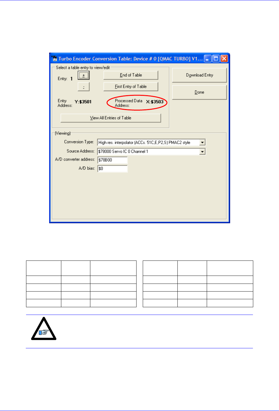
Geo Brick LV User Manual
PinOuts and Software Setup 57
Setting up Sinusoidal Encoders
The Sinusoidal position feedback is set up through the Encoder Conversion Table (ECT) as a high
resolution interpolation entry.
Encoder Conversion Table Setup Example, Channel 1
1. Conversion Type: High res. interpolator, PMAC2 Style
2. Enter Source Address (see table below)
3. Enter A/D Converter Address (see table below)
4. A/D Bias: always zero
Channel #
Source
Address
A/D converter
Address
Channel #
Source
Address
A/D converter
Address
1
$78000
$78B00
5
$78100
$78B08
2
$78008
$78B02
6
$78108
$78B0A
3
$78010
$78B04
7
$78110
$78B0C
4
$78018
$78B06
8
$78118
$78B0E
Note
Results are found in the processed data address, which the position
and velocity feedback pointers (Ixx03, Ixx04) are usually assigned to.

Geo Brick LV User Manual
PinOuts and Software Setup 58
The equivalent Turbo PMAC script code for 8-channel entries
// Channel 1
I8000=$FF8000 ; High resolution interpolator
I8001=$078B00 ; A/D converter address
I8002=$000000 ; Bias Term and Entry result
// Channel 2
I8003=$FF8008 ; High resolution interpolator
I8004=$078B02 ; A/D converter address
I8005=$000000 ; Bias Term and Entry result
// Channel 3
I8006=$FF8010 ; High resolution interpolator
I8007=$078B04 ; A/D converter address
I8008=$000000 ; Bias Term and Entry result
// Channel 4
I8009=$FF8018 ; High resolution interpolator
I8010=$078B06 ; A/D converter address
I8011=$000000 ; Bias Term and Entry result
// Channel 5
I8012=$FF8100 ; High resolution interpolator
I8013=$078B08 ; A/D converter address
I8014=$000000 ; Bias Term and Entry result
// Channel 6
I8015=$FF8108 ; High resolution interpolator
I8016=$078B0A ; A/D converter address
I8017=$000000 ; Bias Term and Entry result
// Channel 7
I8018=$FF8110 ; High resolution interpolator
I8019=$078B0C ; A/D converter address
I8020=$000000 ; Bias Term and Entry result
// Channel 8
I8021=$FF8118 ; High resolution interpolator
I8022=$078B0E ; A/D converter address
I8023=$000000 ; Bias Term and Entry result
Position and Velocity feedback pointers should now be set to the corresponding ECT result:
I103=$3503 I104=$3503
I203=$3506 I204=$3506
I303=$3509 I304=$3509
I403=$350C I404=$350C
I503=$350F I504=$350F
I603=$3512 I604=$3512
I703=$3515 I704=$3515
I803=$3518 I804=$3518
Note
At this point of the setup, you should be able to move the
motor/encoder shaft by hand and see ‘motor’ counts in the position
window.
Counts per User Units
With the interpolation of x 4096 in Turbo PMAC, there are 128 (4096/32) motor counts per sine/cosine
cycles. Motor counts can be monitored in the motor position window upon moving the motor by hand.
Examples:
A 1024 Sine/Cosine periods per revolution of a rotary encoder produces 1024 x 128 = 131,072 cts/rev.
A 20 μm linear encoder resolution produces 128/0.02 = 6400 cts/mm.

Geo Brick LV User Manual
PinOuts and Software Setup 59
Encoder Count Error (Mxx18)
The Geo Brick LV has an encoder count error detection feature. If both the A and B channels of the
quadrature encoder change state at the decode circuitry (post-filter) in the same hardware sampling clock
(SCLK) cycle, an unrecoverable error to the counter value will result (lost counts). Suggested M-Variable
Mxx18 for this channel is then set and latched to 1 (until reset or cleared). The three most common root
causes of this error:
Real encoder hardware problem
Trying to move the encoder (motor) faster than it’s specification
Using an extremely high resolution/speed encoder. This may require increasing the SCLK
The default sampling clock in the Geo Brick LV is ~ 10MHz, which is acceptable for virtually all
applications. A setting of I7m03 of 2257 (from default of 2258) sets the sampling clock SCLK at about
~20MHz. It can be increased to up to ~40 MHz.
Note
No automatic action is taken by the Geo Brick LV if the encoder count
error bit is set.
Geo Brick LV User Manual
PinOuts and Software Setup 60
Encoder Loss Detection, Sinusoidal
Encoder loss detection with Sinusoidal encoders can be performed using the encoder conversion table.
The ECT can be set up to compute the sum of the squares of the sine and cosine terms (including user
introduced biases). Using channel #1, the encoder conversion table (5-line entry) for computing the sum
of the squares would look like:
I8024 = $F78B00 ; Diagnostic entry for sinusoidal encoder(s)
I8025 = $100000 ; Bit 0 is 0 to compute sum of the squares
I8026 = $0 ; Active Sine/Cosine Bias Corrections
I8027 = $0 ;
I8028 = $0 ; Sum of the squares result
The result (@ $351D for example) corresponds to:
(SineADC + SineBias)2 + (CosineADC + CosineBias)2
This term can be monitored to check for loss of the encoder. If the inputs are no longer driven externally,
for example because the cable has come undone, the positive and negative input pair to the ADC will pull
to substantially the same voltage, and the output of the ADC will be a very small number, resulting in a
small magnitude of the sum of squares in at least part of the cycle. (If both signals cease to be driven
externally, the sum of squares will be small over the entire cycle). The high four bits (bits 20 – 23) of the
sum-of-squares result can be monitored, and if the four-bit value goes to 0, it can be concluded that the
encoder has been “lost”, and the motor should be “killed”.
The 4-bit value can be obtained as follows:
#define Mtr1EncLoss M180 ; Motor#1 Encoder Loss Status
Mtr1EncLoss->X:$351D,20,4 ; Upper 4 bits of the sum of the squares
!
Caution
Appropriate action (user-written plc) needs to be implemented when
an encoder loss is encountered. To avoid a runaway, an immediate
Kill of the motor/encoder in question is strongly advised.
No automatic firmware (Geo Brick) action is taken upon detection of encoder(s) loss; it is the user’s
responsibility to perform the necessary action to make the application safe under these conditions. Killing
the motor/encoder in question is the safest action possible, and strongly recommended to avoid a
runaway, and machine damage. Also, the user should decide the action to be taken (if any) for the other
motors in the system.

Geo Brick LV User Manual
PinOuts and Software Setup 61
X1-X8: Encoder Feedback, Resolver
X1-X8: D-sub DA-15F
Mating: D-sub DA-15M
2
3
4
5
6
7
8
9
10
11
12
13
14
15
1
Pin #
Symbol
Function
Notes
1
Sin+
Input
Sine+
2
Cos+
Input
Cosine+
3
CHC+
Input
Index+
4
EncPwr
Output
Encoder Power 5 Volts
5
Unused
6
Unused
7
2.5 Volts
Output
Reference Power 2.5 volts
8
Unused
9
Sin-
Input
Sine-
10
Cos-
Input
Cosine-
11
CHC-
Input
Index-
12
GND
Common
Common Ground
13
Unused
14
Unused
15
ResOut
Output
Resolver Excitation Output
This option allows the Brick to connect to up to eight Resolver feedback devices.
Setting up Resolvers
The Resolver data sampling is done at phase rate, and processed in the encoder conversion table. The
commutation (occurring at phase rate) position is retrieved from the Encoder Conversion Table which is
normally read at Servo rate. Thus, the Servo and Phase cycles have to be at the same rate.
Note
Use an encoder cable with high quality shield. Connect the
shield to chassis ground, and use ferrite core in noise sensitive
environment if deemed necessary.
It is essential to set the Servo clock the same as the Phase
Clock in Resolver applications. This will greatly reduce noise.
The Servo Cycle Extension Period (Ixx60) can be used to
lower the CPU load and avoid quantization errors through the
PID loop at high Servo rates.
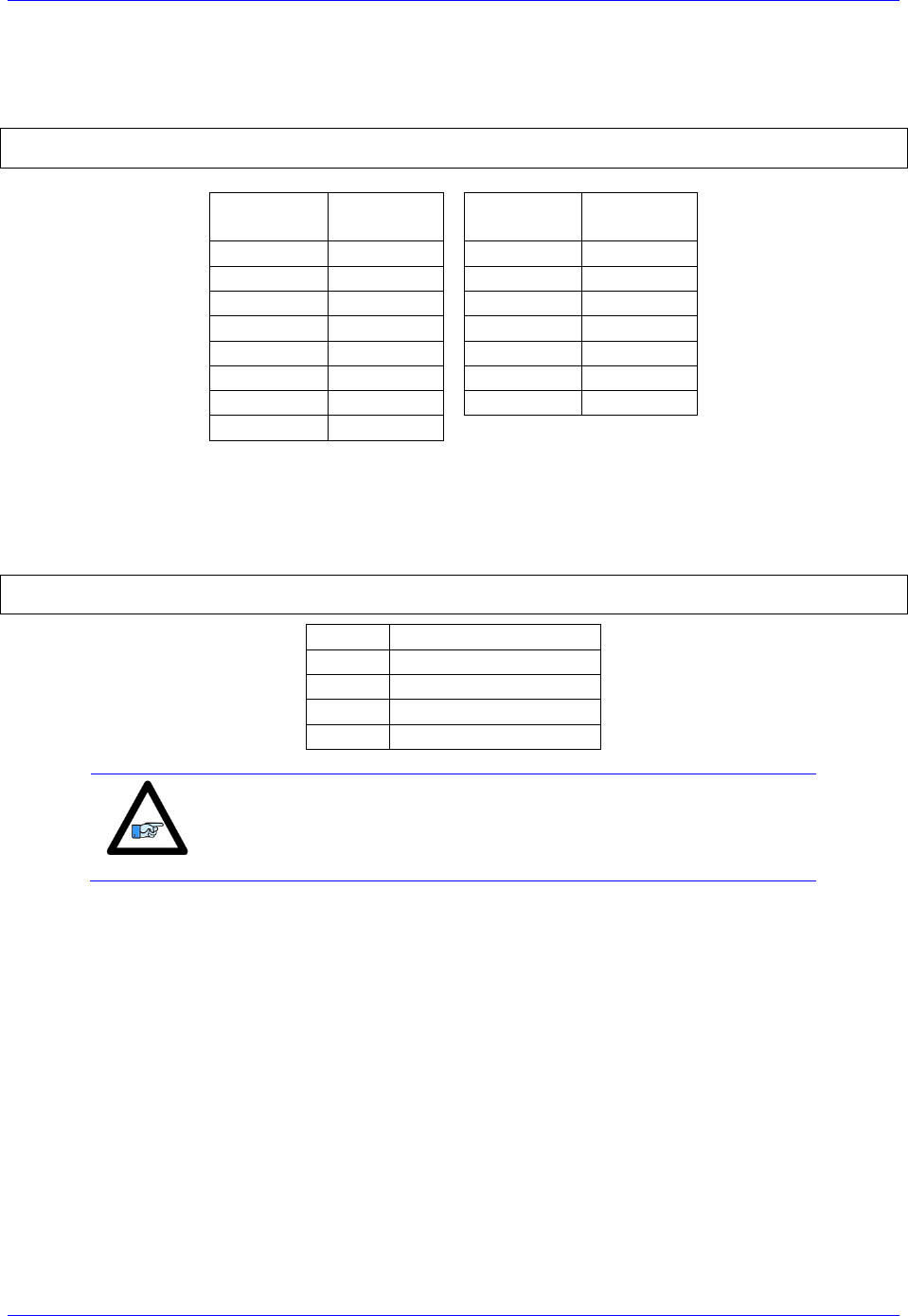
Geo Brick LV User Manual
PinOuts and Software Setup 62
Resolver Excitation Magnitude
Revolvers’ excitation magnitude is a global setting used for all available Resolver channels. It has 15
possible settings:
#define ResExcMag M8000 ; Resolver Excitation Magnitude MACRO definition
ResExcMag->Y:$78B11,0,4 ; Resolver Excitation Magnitude register
Excitation
Magnitude
Peak-Peak
[Volts]
Excitation
Magnitude
Peak-Peak
[Volts]
1
1.6
9
8.5
2
2.5
10
9.5
3
3.3
11
10.4
4
4.2
12
11.3
5
5.0
13
12
6
6.0
14
13
7
6.9
15
14
8
7.7
Resolver Excitation Frequency
The Resolvers’ excitation frequency is divided from the Phase clock and is setup to be the same as but not
greater than the Resolvers’ excitation frequency specification. The Resolver excitation frequency is a
global setting used for all available Resolver channels, it has 4 possible settings:
#define ResExcFreq M8001 ; Resolver Excitation Frequency MACRO definition
ResExcFreq->Y:$78B13,0,4 ; Resolver Excitation Frequency register
Setting
Excitation Frequency
0
Phase Clock/1
1
Phase Clock/2
2
Phase Clock/4
3
Phase Clock/6
Note
The Resolver Excitation Magnitude and Frequency need to be
executed once on power-up.
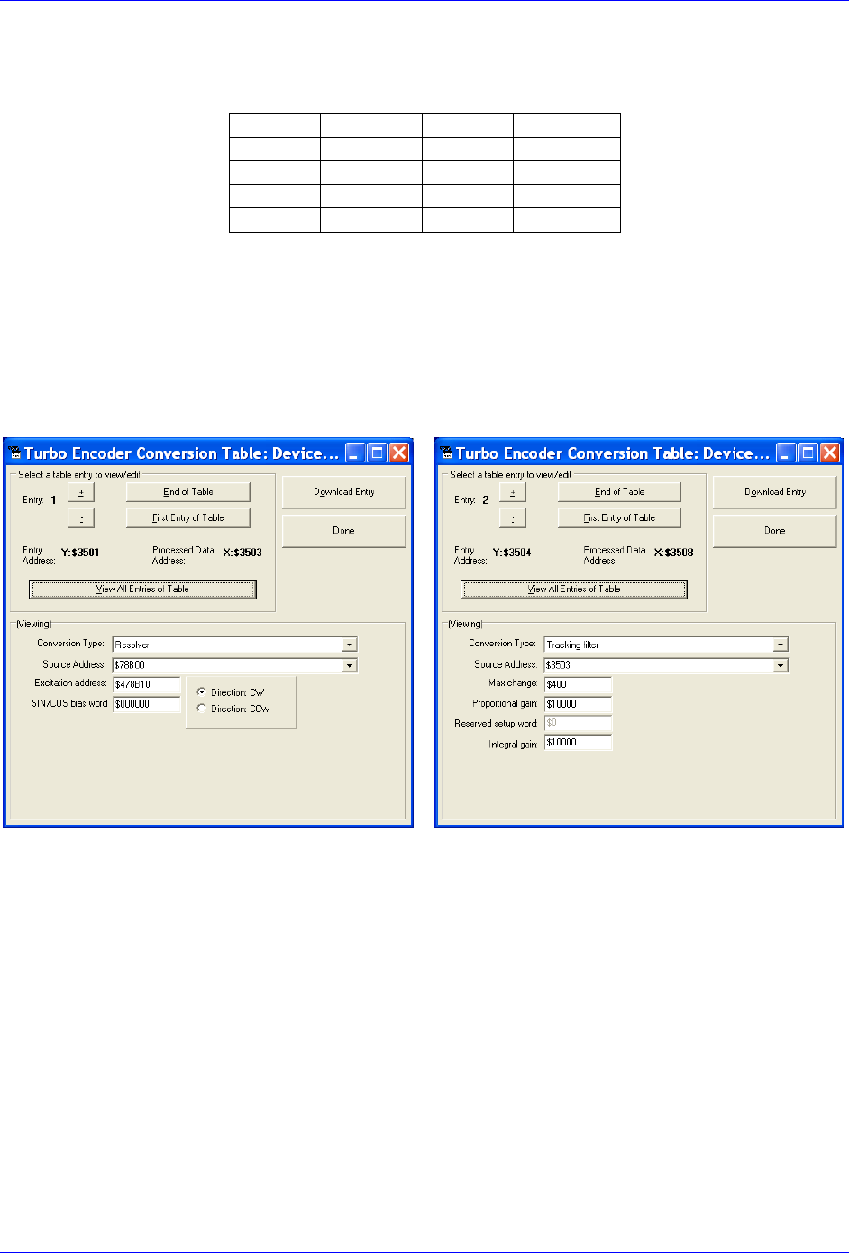
Geo Brick LV User Manual
PinOuts and Software Setup 63
Resolver Data Registers
The Resolver raw data is found in the Resolver Data registers
Channel
Register
Channel
Register
1
Y:$78B00
5
Y:$78B08
2
Y:$78B02
6
Y:$78B0A
3
Y:$78B04
7
Y:$78B0C
4
Y:$78B06
8
Y:$78B0E
Encoder Conversion Table Processing
A dedicated 3-line Encoder Conversion Table entry is used for Resolver feedback.
Due to the noisy nature of Resolvers, implementing a tracking filter to the result is highly recommended.
The Pewin32Pro2 software provides with an automatic encoder conversion table utility that can be used
to implement both the Resolver entry and Tracking Filter. Under Configure>Encoder Conversion Table:
Channel 1 Resolver Setup Example
Resolver Entry
Tracking Filter
Steps:
1. Choose Resolver from Conversion
Type pull-down menu.
2. Enter Source Address. See Resolver Data
Registers table above.
3. Enter Excitation Address
$4 Source address+$10
4. Download Entry.
5. Record Processed Data Address
$3503 for channel 1.
6. Move up to the next Entry
7. Choose Tracking from Conversion Type
pull-down menu.
8. Enter Source address. This is the result
recorded in step5.
9. Download Entry
10. Record Processed Data Address. This is the
source for position Ixx03 and velocity
Ixx04 feedback pointers.

Geo Brick LV User Manual
PinOuts and Software Setup 64
Calculating the Tracking Filter Gains
The tracking filter gains are system dependent, and need to be fine-tuned. This can be done by gathering
and plotting filtered versus unfiltered data while moving the motor shaft manually. Best case scenario is
super-imposing the filtered data on top of the unfiltered with minimum ripple and overshoot.
The empirical equations for the filter’s proportional and integral gains (usually acceptable most
applications) present a good starting point: Ff: Filter Frequency (Hz)
Sf: Servo Frequency (Hz)
Motors 1-8 Resolver Encoder Conversion Table Setup Example
// Channel 1
I8000= $F78B00 ; Resolver Counter Clockwise
I8001= $478B10 ; Excitation address
I8002= $000000 ; SIN/COS Bias word
I8003=$D83503 ; Tracking filter from conversion location $3503
I8004=$400 ; Maximum change in counts/cycle
I8005=$80000 ; Proportional gain
I8006=$0 ; Reserved setup word
I8007=$1 ; Integral gain
// Channel 2
I8008=$F78B02 ; Resolver Counter Clockwise
I8009=$478B10 ; Excitation address
I8010=$000000 ; SIN/COS Bias word
I8011=$D8350B ; Tracking filter from conversion location $350B
I8012=$400 ; Maximum change in counts/cycle
I8013=$80000 ; Proportional gain
I8014=$0 ; Reserved setup word
I8015=$1 ; Integral gain
// Channel 3
I8016=$F78B04 ; Resolver Counter Clockwise
I8017=$478B10 ; Excitation address
I8018=$000000 ; SIN/COS Bias word
I8019=$D83513 ; Tracking filter from conversion location $3513
I8020=$400 ; Maximum change in counts/cycle
I8021=$80000 ; Proportional gain
I8022=$0 ; Reserved setup word
I8023=$1 ; Integral gain
// Channel 4
I8024=$F78B06 ; Resolver Counter Clockwise
I8025=$478B10 ; Excitation address
I8026=$000000 ; SIN/COS Bias word
I8027=$D8351B ; Tracking filter from conversion location $351B
I8028=$400 ; Maximum change in counts/cycle
I8029=$80000 ; Proportional gain
I8030=$0 ; Reserved setup word
I8031=$1 ; Integral gain
// Channel 5
I8032=$F78B08 ; Resolver Counter Clockwise
I8033=$478B10 ; Excitation address
I8034=$000000 ; SIN/COS Bias word
I8035=$D83523 ; Tracking filter from conversion location $3523
I8036=$400 ; Maximum change in counts/cycle
I8037=$80000 ; Proportional gain
I8038=$0 ; Reserved setup word
I8039=$1 ; Integral gain
// Channel 6
I8040=$F78B0A ; Resolver Counter Clockwise
I8041=$478B10 ; Excitation address
Geo Brick LV User Manual
PinOuts and Software Setup 65
I8042=$000000 ; SIN/COS Bias word
I8043=$D8352B ; Tracking filter from conversion location $352B
I8044=$400 ; Maximum change in counts/cycle
I8045=$80000 ; Proportional gain
I8046=$0 ; Reserved setup word
I8047=$1 ; Integral gain
// Channel 7
I8048=$F78B0C ; Resolver Counter Clockwise
I8049=$478B10 ; Excitation address
I8050=$000000 ; SIN/COS Bias word
I8051=$D83533 ; Tracking filter from conversion location $3533
I8052=$400 ; Maximum change in counts/cycle
I8053=$80000 ; Proportional gain
I8054=$0 ; Reserved setup word
I8055=$1 ; Integral gain
// Channel 8
I8056=$F78B0E ; Resolver Counter Clockwise
I8057=$478B10 ; Excitation address
I8058=$000000 ; SIN/COS Bias word
I8059=$D8353B ; Tracking filter from conversion location $353B
I8060=$400 ; Maximum change in counts/cycle
I8061=$80000 ; Proportional gain
I8062=$0 ; Reserved setup word
I8063=$1 ; Integral gain
// End Of Table
I8064=$000000 ; End Of Table
Position, Velocity Feedback Pointers
I103=$3508 I104=$3508
I203=$3510 I204=$3510
I303=$3518 I304=$3518
I403=$3520 I404=$3520
I503=$3528 I504=$3528
I603=$3530 I604=$3530
I703=$3538 I704=$3538
I803=$3540 I804=$3540
Note
At this point of the setup process, you should be able to move the
motor/encoder shaft by hand and see encoder counts in the position
window.

Geo Brick LV User Manual
PinOuts and Software Setup 66
Resolver Power-On PLC Example
Setting up a resolver with 10V excitation magnitude and 10 KHz excitation frequency:
// Clock Settings: 10KHz Phase & Servo
I7100=5895 ; Servo IC1
I7101=0
I7102=0
I6800=5895 ; MACRO IC0
I6801=0
I6802=0
I7000=5895 ; Servo IC0
I7001=0
I7002=0
I10=838613 ; Servo Time Interrupt
#define ResExcMag M8000 ; Excitation Magnitude
#define ResExcFreq M8001 ; Excitation Frequency
ResExcMag->Y:$78B11,0,4 ; Excitation Magnitude register
ResExcFreq->Y:$78B13,0,4 ; Excitation Frequency register
ResExcMag=11 ;~10 Volts –User Input
ResExcFreq=0 ; = Phase Clock/1 =10 KHz –User Input
// PLC to establish Resolver Magnitude & Frequency on power-up
Open plc 1 clear
ResExcMag=11
ResExcFreq=0
Disable plc 1
Close

Geo Brick LV User Manual
PinOuts and Software Setup 67
X1-X8: Encoder Feedback, HiperFace
!
Caution
The majority of HiperFace devices requires 7-12VDC power. This has
to be supplied externally and NOT wired into the brick unit. Pins#4
and #12 are unused in this case, leave floating.
X1-X8: D-sub DA-15F
Mating: D-Sub DA-15M
2
3
4
5
6
7
8
9
10
11
12
13
14
15
1
Pin #
Symbol
Function
Notes
1
Sin+
Input
Sine+ signal input
2
Cos+
Input
Cosine+ signal input
3
Unused
4
EncPwr
Output
+5V encoder power
5
RS485-
Input
Data- Packet
6
Unused
7
Unused
8
Unused
9
SIN-
Sine- signal input
10
COS-
Cosine- signal input
11
Unused
12
GND
Common
Common ground
13
Unused
14
RS485+
Input
Data+ Packet
15
Unused
This option allows the Brick to connect to up to eight HiperFace type feedback devices.
The HiperFace on-going position (sinusoidal data) is processed by the x 4096 interpolator. The encoder
conversion table is setup as a high resolution interpolator 3-line entry similarly to setting up a sinusoidal
encoder. The absolute power-on position (serial data) is computed directly from the raw HiperFace serial
data registers. Subsequently, a power-on phase referencing routine can be implemented.

Geo Brick LV User Manual
PinOuts and Software Setup 68
Setting up HiperFace On-Going Position
The HiperFace on-going position is set up through the Encoder Conversion Table as a high resolution
interpolation entry
Encoder Conversion Table Setup Example, Channel 1
1. Conversion Type: High res. interpolator, PMAC2 Style
2. Enter Source Address (see table below)
3. Enter A/D Converter Address (see table below)
4. A/D Bias: typically =0
Channel #
Source
Address
A/D converter
Address
Channel #
Source
Address
A/D converter
Address
1
$78000
$78B00
5
$78100
$78B08
2
$78008
$78B02
6
$78108
$78B0A
3
$78010
$78B04
7
$78110
$78B0C
4
$78018
$78B06
8
$78118
$78B0E
Note
Results are found in the processed data address, which the position
and velocity feedback pointers (Ixx03, Ixx04) are usually pointed to.

Geo Brick LV User Manual
PinOuts and Software Setup 69
And the equivalent Turbo PMAC code for setting up all 8 channels:
// Channel 1
I8000=$FF8000 ; High resolution interpolator entry, $78000
I8001=$078B00 ; A/D converter address, $78B00
I8002=$000000 ; Bias Term and Entry result at $3503
// Channel 2
I8003=$FF8008 ; High resolution interpolator entry, $78008
I8004=$078B02 ; A/D converter address, $78B02
I8005=$000000 ; Bias Term and Entry result at $3506
// Channel 3
I8006=$FF8010 ; High resolution interpolator entry, $78010
I8007=$078B04 ; A/D converter address, $78B04
I8008=$000000 ; Bias Term and Entry result at $3509
// Channel 4
I8009=$FF8018 ; High resolution interpolator entry, $78018
I8010=$078B06 ; A/D converter address, $78B06
I8011=$000000 ; Bias Term and Entry result at $350C
// Channel 5
I8012=$FF8100 ; High resolution interpolator entry, $78100
I8013=$078B08 ; A/D converter address, $78B08
I8014=$000000 ; Bias Term and Entry result at $350F
// Channel 6
I8015=$FF8108 ; High resolution interpolator entry, $78108
I8016=$078B0A ; A/D converter address, $78B0A
I8017=$000000 ; Bias Term and Entry result at $3512
// Channel 7
I8018=$FF8110 ; High resolution interpolator entry, $78110
I8019=$078B0C ; A/D converter address, $78B0C
I8020=$000000 ; Bias Term and Entry result at $3515
// Channel 8
I8021=$FF8118 ; High resolution interpolator entry, $78118
I8022=$078B0E ; A/D converter address, $78B0E
I8023=$000000 ; Bias Term and Entry result at $3518
Now, the position and velocity pointers are assigned to the corresponding processed data register:
I103=$3503 I104=$3503 ; Motor #1 Position and Velocity feedback address
I203=$3506 I204=$3506 ; Motor #2 Position and Velocity feedback address
I303=$3509 I304=$3509 ; Motor #3 Position and Velocity feedback address
I403=$350C I404=$350C ; Motor #4 Position and Velocity feedback address
I503=$350F I504=$350F ; Motor #5 Position and Velocity feedback address
I603=$3512 I604=$3512 ; Motor #6 Position and Velocity feedback address
I703=$3515 I704=$3515 ; Motor #7 Position and Velocity feedback address
I803=$3518 I804=$3518 ; Motor #8 Position and Velocity feedback address
Channel Activation
I100,8,100=1 ; Motors 1-8 activated
Note
At this point of the setup process, you should be able to move the
motor/encoder shaft by hand and see encoder counts in the position
window.
Counts Per Revolution:
With the interpolation of x 4096 in Turbo PMAC, there are 128 (4096/32) motor counts per sine/cosine
cycles. Motor counts can be monitored in the motor position window upon moving the motor by hand.
Examples:
A 1024 Sine/Cosine periods per revolution rotary encoder produces 1024 x 128 = 131,072 cts/rev.
A 20 μm resolution linear encoder produces 128/0.02 = 6400 cts/mm.

Geo Brick LV User Manual
PinOuts and Software Setup 70
Setting up HiperFace Absolute Power-On Position
Setting up the absolute position read with HiperFace requires the programming of two essential control
registers:
Global Control Registers
Channel Control Registers
The resulting data is found in:
HiperFace Data Registers
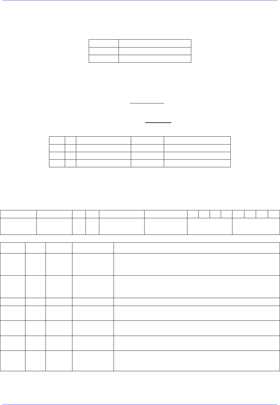
Geo Brick LV User Manual
PinOuts and Software Setup 71
Global Control Registers
X:$78BnF (default value: $812004) where n=2 for axes 1-4
n=3 for axes 5-8
Global Control Register
Axes 1-4
X:$78B2F
Axes 5-8
X:$78B3F
The Global Control register is used to program the serial encoder interface clock frequency SER_Clock
and configure the serial encoder interface trigger clock. SER_Clock is generated from a two-stage divider
clocked at 100 MHz as follows:
M
N
SER_Clock [KHz]
Baud Rate
Global Register Setting
129
2
192.30
9600
$812004
129
3
96.15
4800
$813004
129
1
394.61
19200
$812004
Default Settings: M=129, N=2
There are two external trigger sources; phase and servo. Bits [9:8] in the Global Control register are used
to select the source and active edge to use as the internal serial encoder trigger. The internal trigger is
used by all four channels to initiate communication with the encoder. To compensate for external system
delays, this trigger has a programmable 4-bit delay setting in 20 μsec increments.
23--16
15--12
11
10
9
8
7
6
5
4
3
2
1
0
M_Divisor
N_Divisor
Trigger Clock
Trigger Edge
Trigger Delay
Protocol Code
Bit
Type
Default
Name
Description
[23:16]
R/W
0x81
M_Divisor
Intermediate clock frequency for SER_Clock. The
intermediate clock is generated from a (M+1) divider clocked
at 100 MHz.
[15:12]
R/W
0x2
N_Divisor
Final clock frequency for SER_Clock. The final clock is
generated from a
N
2
divider clocked by the intermediate
clock.
[11:10]
R
00
Reserved
Reserved and always reads zero.
[09]
R/W
0
TriggerClock
Trigger clock select
= 0 Phase Clock
= 1 Servo Clock
[08]
R/W
0
TriggerEdge
Active clock edge select
= 0 Rising edge
= 1 Falling edge
[07:04]
R/W
0x0
TriggerDelay
Trigger delay program relative to the active edge of the
trigger clock. Units are in increments of 20 usec.
[03:00]
R
0x4
ProtocolCode
This read-only bit field is used to read the serial encoder interface
protocol supported by the FPGA. A value of $4 defines this
protocol as HiperFace.

Geo Brick LV User Manual
PinOuts and Software Setup 72
Channel Control Registers
X:$78Bn0, X:$78Bn4, X:$78Bn8, X:$78BnC where: n=2 for axes 1-4
n=3 for axes 5-8
Channel 1
X:$78B20
Channel 5
X:$78B30
Channel 2
X:$78B24
Channel 6
X:$78B34
Channel 3
X:$78B28
Channel 7
X:$78B38
Channel 4
X:$78B2C
Channel 8
X:$78B3C
Each channel has its own Serial Encoder Command Control Register defining functionality parameters.
Parameters such as setting the number of position bits in the serial bit stream, enabling/disabling channels
through the SENC_MODE (when this bit is cleared, the serial encoder pins of that channel are tri-stated),
enabling/disabling communication with the encoder using the trigger control bit. An 8-bit mode command
is required for encoder communication. Currently, three HiperFace commands are supported; read
encoder position ($42), read encoder status ($50) and Reset encoder($53).
[23:16]
[15:14]
13
12
11
10
[9:8]
[7:0]
Command
Code
Trigger
Mode
Trigger
Enable
Rxdataready
SencMode
Encoder
Address
Bit
Type
Default
Name
Description
[23:16]
W
0x42
Command
Code
$42 – Read Encoder Position
$50 – Read Encoder Status
$53 – Reset Encoder
[15:14]
0
Reserved
Reserved and always reads zero.
[13]
R/W
0
Trigger Mode
Trigger Mode to initiate communication:
0= continuous trigger
1= one-shot trigger - for HiperFace
All triggers occur at the defined Phase/Servo clock edge and
delay setting. Due to HiperFace protocol speed limitation,
only one-shot trigger mode is used.
[12]
R/W
1
Trigger Enable
0= disabled
1= enabled
This bit must be set for either trigger mode. If the Trigger
Mode bit is set for one-shot mode, the hardware will
automatically clear this bit after the trigger occurs.
[11]
0
Reserved
Reserved and always reads zero.
[10]
R
0
RxData Ready
This read-only bit provides the received data status. It is low
while the interface logic is communicating (busy) with the
serial encoder. It is high when all the data has been received
and processed.
W
1
SENC_MODE
This write-only bit is used to enable the output drivers for
the SENC_SDO, SENC_CLK, SENC_ENA pins for each
respective channel.
[09:08]
0x00
Reserved
Reserved and always reads zero.
[07:00]
R/W
0xFF
Encoder
address
This bit field is normally used to define the encoder address
transmitted with each command. Delta Tau does not support
multiple encoders per channel; a value of $FF sends a
general broadcast.

Geo Brick LV User Manual
PinOuts and Software Setup 73
HiperFace Data Registers
The HiperFace absolute power-on data is conveyed into 4 memory locations; Serial Encoder Data A, B,
C, and D.
The Serial Encoder Data A register holds the 24 bits of the encoder position data. If the data exceeds the
24 available bits in this register, the upper overflow bits are LSB justified and readable in the Serial
Encoder Data B, which also holds status and error bits. Serial Encoder Data C, and D registers are
reserved and always read zero.
HiperFace Data B
HiperFace Data A
23
22
21
20
[19:16]
[07:0]
[23:0]
TimeOut
Error
CheckSum
Error
Parity
Error
Error
Bit
Position Data [31:24]
Position Data [23:0]
HiperFace Serial Data A
HiperFace Serial Data B
Channel 1
Y:$78B20
Y:$78B21
Channel 2
Y:$78B24
Y:$78B25
Channel 3
Y:$78B28
Y:$78B29
Channel 4
Y:$78B2C
Y:$78B2D
Channel 5
Y:$78B30
Y:$78B31
Channel 6
Y:$78B34
Y:$78B35
Channel 7
Y:$78B38
Y:$78B39
Channel 8
Y:$78B3C
Y:$78B3D
Data Registers C and D are listed here for future use and documentation purposes only. They do not
pertain to the HiperFace setup and always read zero.
HiperFace Serial Data C
HiperFace Serial Data D
Channel 1
Y:$78B22
Y:$78B23
Channel 2
Y:$78B26
Y:$78B27
Channel 3
Y:$78B2A
Y:$78B28
Channel 4
Y:$78B2E
Y:$78B2F
Channel 5
Y:$78B32
Y:$78B33
Channel 6
Y:$78B36
Y:$78B37
Channel 7
Y:$78B3A
Y:$78B38
Channel 8
Y:$78B3E
Y:$78B3F
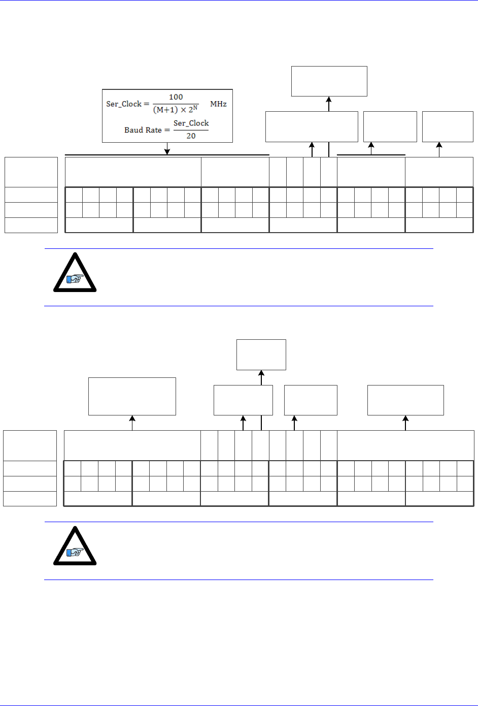
Geo Brick LV User Manual
PinOuts and Software Setup 74
Setting up HiperFace Encoders Example
An 8-axis Geo Brick LV is connected to eight HiperFace encoders, serial data is programmed to 9600
(M=129, N=2) baud rate for all eight channels:
M Divisor
Bit #:
Description:
Binary:
23 22 21 20 19 18 17 16 15 14 13 12 11 10 9 8 7 6 5 4 3 2 1 0
N Divisor Trigger Delay Protocol
=0 Rising Edge
=1 Falling Edge
Typically =0
=0 Trigger on Phase
=1 Trigger on Servo
$4 for
HiperFace
0 0
Hex ($):
100000010010000000000100
812004
clock
Edge
Note
The only user configurable HiperFace Global Control field is the baud
rate (M and N divisors).
The channel control registers are programmed to read position ($42):
Bit #:
Description:
Binary:
23 22 21 20 19 18 17 16 15 14 13 12 11 10 9 8 7 6 5 4 3 2 1 0
Encoder Address
Hex ($):
010000100011010011111111
423 4 F F
Command code 0 0
Trigger
Mode
Trigger
Enable
0
Senc
Mode
0 0
= $42 Read position
= $50 Encoder Status
= $53 Reset Encoder
=0 Continuous
=1 One shot
=0 Disabled
=1 Enabled
=0 Disabled
=1 Enabled
Always $FF for
General Broadcast
Note
The only user configurable HiperFace Channel Control field is
the command code: $42 to read position
$50 to read encoder status
$53 to reset encoder

Geo Brick LV User Manual
PinOuts and Software Setup 75
The Global and Channel Control registers have to be initialized on power-up. Following, is an example
PLC showing the initialization of all eight channels:
//=========================== NOTES ABOUT THIS PLC EXAMPLE ================================//
// This PLC example utilizes: - M5990 through M5999
// - Coordinate system 1 Timer 1
// Make sure that current and/or future configurations do not create conflicts with
// these parameters.
//=========================================================================================//
M5990..5999->* ; Self-referenced M-Variables
M5990..5999=0 ; Reset at download
//========================= GLOBAL CONTROL REGISTERS ======================================//
#define HFGlobalCtrl1_4 M5990 ; Channels 1-4 HiperFace global control register
#define HFGlobalCtrl5_8 M5991 ; Channels 5-8 HiperFace global control register
HFGlobalCtrl1_4->X:$78B2F,0,24,U ; Channels 1-4 HiperFace global control register address
HFGlobalCtrl5_8->X:$78B3F,0,24,U ; Channels 5-8 HiperFace global control register address
//======================== CHANNEL CONTROL REGISTERS ======================================//
#define Ch1HFCtrl M5992 ; Channel 1 HiperFace control register
#define Ch2HFCtrl M5993 ; Channel 2 HiperFace control register
#define Ch3HFCtrl M5994 ; Channel 3 HiperFace control register
#define Ch4HFCtrl M5995 ; Channel 4 HiperFace control register
#define Ch5HFCtrl M5996 ; Channel 5 HiperFace control register
#define Ch6HFCtrl M5997 ; Channel 6 HiperFace control register
#define Ch7HFCtrl M5998 ; Channel 7 HiperFace control register
#define Ch8HFCtrl M5999 ; Channel 8 HiperFace control register
Ch1HFCtrl->X:$78B20,0,24,U ; Channel 1 HiperFace control register Address
Ch2HFCtrl->X:$78B24,0,24,U ; Channel 2 HiperFace control register Address
Ch3HFCtrl->X:$78B28,0,24,U ; Channel 3 HiperFace control register Address
Ch4HFCtrl->X:$78B2C,0,24,U ; Channel 4 HiperFace control register Address
Ch5HFCtrl->X:$78B30,0,24,U ; Channel 5 HiperFace control register Address
Ch6HFCtrl->X:$78B34,0,24,U ; Channel 6 HiperFace control register Address
Ch7HFCtrl->X:$78B38,0,24,U ; Channel 7 HiperFace control register Address
Ch8HFCtrl->X:$78B3C,0,24,U ; Channel 8 HiperFace control register Address
//========= POWER-ON PLC EXAMPLE, GLOBAL & CHANNEL CONTROL REGISTERS ======================//
Open PLC 1 Clear
HFGlobalCtrl1_4=$812004 ; Channels 1-4 HiperFace, 9600 baud rate (M=129 N=2) –User Input
HFGlobalCtrl5_8=$812004 ; Channels 5-8 HiperFace, 9600 baud rate (M=129 N=2) –User Input
Ch1HFCtrl=$4234FF ; Channel 1 HiperFace control register (read position) –User Input
Ch2HFCtrl=$4234FF ; Channel 2 HiperFace control register (read position) –User Input
Ch3HFCtrl=$4234FF ; Channel 3 HiperFace control register (read position) –User Input
Ch4HFCtrl=$4234FF ; Channel 4 HiperFace control register (read position) –User Input
Ch5HFCtrl=$4234FF ; Channel 5 HiperFace control register (read position) –User Input
Ch6HFCtrl=$4234FF ; Channel 6 HiperFace control register (read position) –User Input
Ch7HFCtrl=$4234FF ; Channel 7 HiperFace control register (read position) –User Input
Ch8HFCtrl=$4234FF ; Channel 8 HiperFace control register (read position) –User Input
I5111=500*8388608/I10 while(I5111>0) endw ; ½ sec delay
Dis plc 1 ; Execute once on power-up or reset
Close
//=========================================================================================//
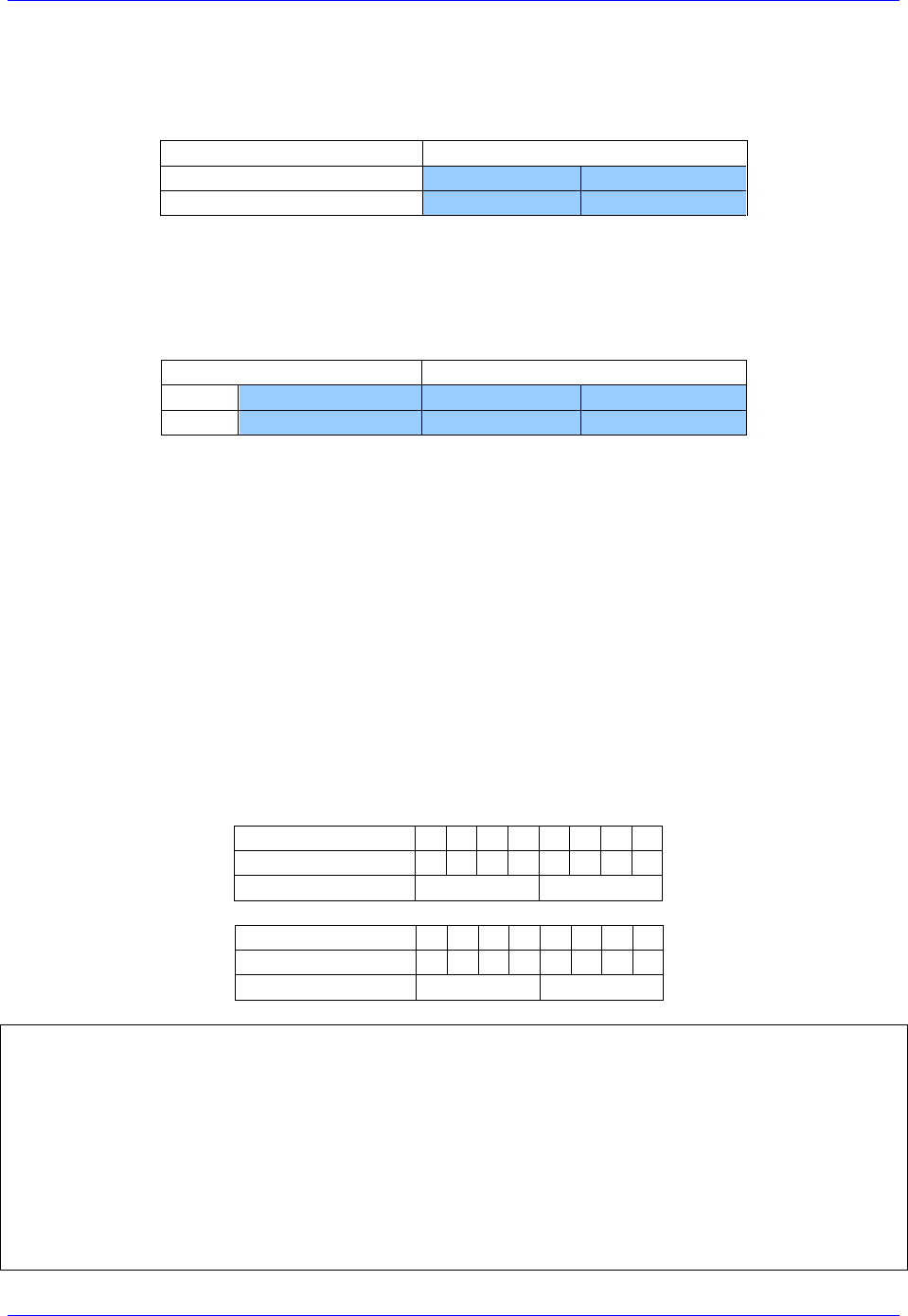
Geo Brick LV User Manual
PinOuts and Software Setup 76
Channels 1 through 4 are driving HiperFace encoders with 12-bit (4096) single-turn resolution and 12-
bit (4096) multi-turn resolution for a total number of data bits of 24 (12+12). The entire data stream is
held in the HiperFace serial data A register:
HiperFace Data A Register
HiperFace Data A Register
[23:0]
[23:0]
[11:0]
Multi-Turn Data
Single-Turn Data
Channels 5 through 8 are driving HiperFace encoders with 16-bit (65536) single-turn resolution and 12-
bit (4096) multi-turn resolution for a total number of data bits of 28 (16+12). The HiperFace serial Data
A register holds the 16-bit single-turn data and the first 8 bits of multi-turn data. The Hiperface serial
Data B register holds the 4 bits overflow of multi-turn data:
HiperFace Data B Register
HiperFace Data A Register
[23:4]
[3:0]
[23:15]
[15:0]
Multi-Turn Data1
Multi-Turn Data
Single-Turn Data
The automatic absolute position read in PMAC, using Ixx10 and Ixx95, expects the data to be left shifted
(5-bits) in the Encoder Conversion Table. Reading raw data and constructing position directly out of the
serial encoder registers requires a custom procedure.
The following example PLC reads and constructs the absolute position for channels 1 through 8. It is pre-
configured for the user to input their encoder information, and specify which channels are being used.
Using the Absolute Position Read Example PLC
Under User Input section:
1. Enter single turn (ChxSTRes) and multi turn (ChxMTRes) resolutions in bits for each encoder.
For strictly absolute single turn encoders, multi turn resolution is set to zero.
2. In ChAbsSel, specify which channels are desired to perform an absolute position read. This value
is in hexadecimal. A value of 1 specifies that this channel is connected, 0 specifies that it is not
connected and should not perform and absolute read. Examples:
Reading Absolute
Position, channels
1 through 4
Channel#
8
7
6
5
4
3
2
1
ChAbsSel (Binary)
0
0
0
0
1
1
1
1
=> ChAbsSel=$0F
ChAbsSel (Hex)
0
F
Reading Absolute
Position, channels
1,3,5,7
Channel#
8
7
6
5
4
3
2
1
ChAbsSel (Binary)
0
1
0
1
0
1
0
1
=> ChAbsSel=$55
ChAbsSel (Hex)
5
5
//=========================== NOTES ABOUT THIS PLC EXAMPLE ================================//
// This PLC example utilizes: - M6000 through M6035
// - P7000 through P7032
// Make sure that current and/or future configurations do not create conflicts with
// these parameters.
//=========================================================================================//
M6000..6035->* ; Self-referenced M-Variables
M6000..6035=0 ; Reset M-Variables at download
P7000..7032=0 ; Reset P-Variables at download
//==================================== USER INPUT =========================================//
#define Ch1STRes P7000 #define Ch1MTRes P7001
#define Ch2STRes P7002 #define Ch2MTRes P7003
#define Ch3STRes P7004 #define Ch3MTRes P7005

Geo Brick LV User Manual
PinOuts and Software Setup 77
#define Ch4STRes P7006 #define Ch4MTRes P7007
#define Ch5STRes P7008 #define Ch5MTRes P7009
#define Ch6STRes P7010 #define Ch6MTRes P7011
#define Ch7STRes P7012 #define Ch7MTRes P7013
#define Ch8STRes P7014 #define Ch8MTRes P7015
Ch1STRes=12 Ch1MTRes=12 ; Ch1 Multi Turn and Single Turn Resolutions --User Input
Ch2STRes=12 Ch2MTRes=12 ; Ch2 Multi Turn and Single Turn Resolutions --User Input
Ch3STRes=12 Ch3MTRes=12 ; Ch3 Multi Turn and Single Turn Resolutions --User Input
Ch4STRes=12 Ch4MTRes=12 ; Ch4 Multi Turn and Single Turn Resolutions --User Input
Ch5STRes=16 Ch5MTRes=12 ; Ch5 Multi Turn and Single Turn Resolutions --User Input
Ch6STRes=16 Ch6MTRes=12 ; Ch6 Multi Turn and Single Turn Resolutions --User Input
Ch7STRes=16 Ch7MTRes=12 ; Ch7 Multi Turn and Single Turn Resolutions --User Input
Ch8STRes=16 Ch8MTRes=12 ; Ch8 Multi Turn and Single Turn Resolutions --User Input
#define ChAbsSel P7016 ; Select Channels using absolute read (in Hexadecimal)
ChAbsSel=$FF ; Channels selected for absolute position read –User Input
//=============================== DEFINITIONS & SUBSTITUTIONS =============================//
#define SerialRegA M6000 ; HiperFace Serial Data Register A
#define SerialRegB M6001 ; HiperFace Serial Data Register B
#define Two2STDec M6002 ; 2^STRes in decimal, for shifting operations
#define Two2STHex M6003 ; 2^STRes in Hexadecimal, for bitwise operations
#define Two2MTDec M6004 ; 2^MTRes in decimal, for shifting operations
#define Two2MTHex M6005 ; 2^MTRes in Hexadecimal, for bitwise operations
#define MTTemp1 M6006 ; Multi Turn Data temporary holding register 1
#define MTTemp2 M6007 ; Multi Turn Data temporary holding register 2
#define STTemp1 M6008 ; Single Turn Data temporary holding register 1
#define STTemp2 M6009 ; Single Turn Data temporary holding register 2
#define ChNoHex M6010 ; Channel Number in Hex
#define ChAbsCalc M6011 ; Abs. calc. flag (=1 true do read, =0 false do not do read)
#define LowerSTBits P7017 ; Lower Single Turn Bits, RegA
#define UpperSTBits P7018 ; Upper Single Turn Bits, RegB (where applicable)
#define LowerMTBits P7019 ; Lower Multi Turn Bits, RegA (where applicable)
#define UpperMTBits P7020 ; Upper Multi Turn Bits, RegB (where applicable)
#define STData P7021 ; Single Turn Data Word
#define MTData P7022 ; Multi Turn Data Word
#define NegTh P7023 ; Negative Threshold
#define Temp1 P7024 ; General Temporary holding register 1
#define Temp2 P7025 ; General Temporary holding register 2
#define SerialBase P7026 ; Indirect addressing index for serial registers, 6020
#define ChBase P7027 ; Indirect addressing index for channel No, 162
#define ChNo P7028 ; Current Channel Number
#define ResBase P7029 ; Indirect Addressing index for resolution input, 6000
#define STRes P7030 ; Single Turn Resolution of currently addressed channel
#define MTRes P7031 ; Multi Turn Resoltuion of currently addressed channel
#define PsfBase P7032 ; Indirect addressing for position scale factor Ixx08, 108
// HiperFace Serial Data Registers A and B
M6020->Y:$78B20,0,24,U M6021->Y:$78B21,0,24,U ; Channel 1
M6022->Y:$78B24,0,24,U M6023->Y:$78B25,0,24,U ; Channel 2
M6024->Y:$78B28,0,24,U M6025->Y:$78B29,0,24,U ; Channel 3
M6026->Y:$78B2C,0,24,U M6027->Y:$78B2D,0,24,U ; Channel 4
M6028->Y:$78B30,0,24,U M6029->Y:$78B31,0,24,U ; Channel 5
M6030->Y:$78B34,0,24,U M6031->Y:$78B35,0,24,U ; Channel 6
M6032->Y:$78B38,0,24,U M6033->Y:$78B39,0,24,U ; Channel 7
M6034->Y:$78B3C,0,24,U M6035->Y:$78B3D,0,24,U ; Channel 8
//===================================== PLC SCRIPT ========================================//
Open PLC 1 Clear
ChNo=0
While(ChNo!>7) ; Loop for 8 Channels
ChNo=ChNo+1
ChNoHex=exp((ChNo-1)*ln(2))
ChAbsCalc=(ChAbsSel&ChNoHex)/ChNoHex
If (ChAbsCalc!=0) ; Absolute read on this channel?
SerialBase=6020+(ChNo-1)*2
SerialRegA=M(SerialBase)
SerialRegB=M(SerialBase+1)
ResBase=7000+(ChNo-1)*2
STRes=P(ResBase)
MTRes=P(ResBase+1)

Geo Brick LV User Manual
PinOuts and Software Setup 78
STData=0
MTData=0
If (STRes!>24) ; Single Turn Res<=24
//===========SINGLE TURN DATA===========//
Two2STDec=exp(STRes*ln(2))
Two2STHex=Two2STDec-1
STData=SerialRegA&Two2STHex
//===========MULTI TURN DATA============//
Two2MTDec=exp(MTRes*ln(2))
Two2MTHex=Two2MTDec-1
If (MTRes=0)
LowerMTBits=0
UpperMTBits=0
Two2MTDec=0
Two2MTHex=0
MTData=0
Else
LowerMTBits=24-STRes
STTemp1=exp(LowerMTBits*ln(2))
STTemp2=0
UpperMTBits=MTRes-LowerMTBits
MTTemp1=exp(LowerMTBits*ln(2))
MTTemp2=exp(UpperMTBits*ln(2))
Temp1=(SerialRegA/Two2STDec)&(MTTemp1-1)
Temp2=SerialRegB&(MTTemp2-1)
MTData=Temp2*STTemp1+Temp1
EndIf
Else ; Single Turn Res>24
//===========SINGLE TURN DATA===========//
LowerSTBits=24
UpperSTBits=STRes-24
STTemp1=exp(UpperSTBits*ln(2))
STTemp2=STTemp1-1
Two2STDec=16777216*STTemp1
Two2STHex=Two2STDec-1
STData=(SerialRegB&STTemp2)*16777216+SerialRegA
//===========MULTI TURN DATA============//
If (MTRes=0)
LowerMTBits=0
UpperMTBits=0
Two2MTDec=0
Two2MTHex=0
MTData=0
Else
Two2MTDec=exp(MTRes*ln(2))
Two2MTHex=Two2MTDec-1
LowerMTBits=0
UpperMTBits=MTRes
MTTemp1=exp(UpperMTBits*ln(2))
MTTemp2=MTTemp1-1
MTData=(SerialRegB/STTemp1)&MTTemp2
EndIf
EndIf
//======ASSEMBLING ACTUAL POSITION======//
ChBase=162+(ChNo-1)*100
PsfBase=108+(ChNo-1)*100
NegTh=Two2MTDec/2
If (MTData!>NegTh)
M(ChBase)=(MTData*Two2STDec+STData)*32*I(PsfBase)
Else
M(ChBase)=-(((Two2MTHex-MTData)*Two2STDec)+(Two2STDec-STData))*32*I(PsfBase)
EndIf
EndIf
EndW
ChNo=0
Dis plc 1
Close

Geo Brick LV User Manual
PinOuts and Software Setup 79
Encoder Count Error (Mxx18)
The Geo Brick LV has an encoder count error detection feature. If both the A and B channels of the
quadrature encoder change state at the decode circuitry (post-filter) in the same hardware sampling clock
(SCLK) cycle, an unrecoverable error to the counter value will result (lost counts). Suggested M-Variable
Mxx18 for this channel is then set and latched to 1 (until reset or cleared). The three most common root
causes of this error:
Real encoder hardware problem
Trying to move the encoder (motor) faster than it’s specification
Using an extremely high resolution/speed encoder. This may require increasing the SCLK
The default sampling clock in the Geo Brick LV is ~ 10MHz, which is acceptable for virtually all
applications. A setting of I7m03 of 2257 (from default of 2258) sets the sampling clock SCLK at about
~20MHz. It can be increased to up to ~40 MHz.
Note
No automatic action is taken by the Geo Brick LV if the encoder count
error bit is set.

Geo Brick LV User Manual
PinOuts and Software Setup 80
Encoder Loss Detection, Sinusoidal
Encoder loss detection with Sinusoidal encoders can be performed using the encoder conversion table.
The ECT can be set up to compute the sum of the squares of the sine and cosine terms (including user
introduced biases). Using channel #1, the encoder conversion table (5-line entry) for computing the sum
of the squares would look like:
I8024 = $F78B00 ; Diagnostic entry for sinusoidal encoder(s)
I8025 = $100000 ; Bit 0 is 0 to compute sum of the squares
I8026 = $0 ; Active Sine/Cosine Bias Corrections
I8027 = $0 ;
I8028 = $0 ; Sum of the squares result
The result (@ $351D for example) corresponds to:
(SineADC + SineBias)2 + (CosineADC + CosineBias)2
This term can be monitored to check for loss of the encoder. If the inputs are no longer driven externally,
for example because the cable has come undone, the positive and negative input pair to the ADC will pull
to substantially the same voltage, and the output of the ADC will be a very small number, resulting in a
small magnitude of the sum of squares in at least part of the cycle. (If both signals cease to be driven
externally, the sum of squares will be small over the entire cycle). The high four bits (bits 20 – 23) of the
sum-of-squares result can be monitored, and if the four-bit value goes to 0, it can be concluded that the
encoder has been “lost”, and the motor should be “killed”.
The 4-bit value can be obtained as follows:
#define Mtr1EncLoss M180 ; Motor#1 Encoder Loss Status
Mtr1EncLoss->X:$351D,20,4 ; Upper 4 bits of the sum of the squares
!
Caution
Appropriate action (user-written plc) needs to be implemented when
an encoder loss is encountered. To avoid a runaway, an immediate
Kill of the motor/encoder in question is strongly advised.
No automatic firmware (Geo Brick) action is taken upon detection of encoder(s) loss; it is the user’s
responsibility to perform the necessary action to make the application safe under these conditions. Killing
the motor/encoder in question is the safest action possible, and strongly recommended to avoid a
runaway, and machine damage. Also, the user should decide the action to be taken (if any) for the other
motors in the system.

Geo Brick LV User Manual
PinOuts and Software Setup 81
Encoder Loss Example PLC:
A 4-axis Geo Brick is setup to kill all motors upon detection of one or more encoder loss. In addition, it
does not allow enabling any of the motors when an encoder is in a loss condition:
#define Mtr1AmpEna M139 ; Motor#1 Amplifier Enable Status Bit
Mtr1AmpEna->X:$B0,19 ; Suggested M-Variable
#define Mtr2AmpEna M239 ; Motor#2 Amplifier Enable Status Bit
Mtr2AmpEna->X:$130,19 ; Suggested M-Variable
#define Mtr3AmpEna M339 ; Motor#3 Amplifier Enable Status Bit
Mtr3AmpEna->X:$1B0,19 ; Suggested M-Variable
#define Mtr4AmpEna M439 ; Motor#4 Amplifier Enable Status Bit
Mtr4AmpEna->X:$230,19 ; Suggested M-Variable
#define Mtr1EncLoss M180 ; Motor#1 Encoder Loss Status Bit
Mtr1EncLoss->Y:$078807,0,1 ;
#define Mtr2EncLoss M280 ; Motor#2 Encoder Loss Status Bit
Mtr2EncLoss->Y:$078807,1,1 ;
#define Mtr3EncLoss M380 ; Motor#3 Encoder Loss Status Bit
Mtr3EncLoss->Y:$078807,2,1 ;
#define Mtr4EncLoss M480 ; Motor#4 Encoder Loss Status Bit
Mtr4EncLoss->Y:$078807,3,1 ;
#define SysEncLoss P5989 ; System Global Encoder Loss Status (user defined)
SysEncLoss=0 ; Save and Set to 0 at download, normal operation
; =1 System Encoder Loss Occurred
OPEN PLC 1 CLEAR
If (SysEncLoss=0) ; No Loss yet, normal mode
If (Mtr1EncLoss=0 or Mtr2EncLoss=0 or Mtr4EncLoss=0 or Mtr4EncLoss=0)
CMD^K ; One or more Encoder Loss(es) detected, kill all motors
SysEncLoss=1 ; Set Global Encoder Loss Status to Fault
EndIf
EndIF
If (SysEncLoss=1) ; Global Encoder Loss Status At Fault?
If (Mtr1AmpEna=1 or Mtr2AmpEna=1 or Mtr4AmpEna=1 or Mtr4AmpEna=1) ; Trying to Enable Motors?
CMD^K ; Do not allow Enabling Motors, Kill all
EndIF
EndIF
CLOSE

Geo Brick LV User Manual
PinOuts and Software Setup 82
X1-X8: Encoder Feedback, SSI
X1-X8: D-sub DA-15F
Mating: D-sub DA-15M
2
3
4
5
6
7
8
9
10
11
12
13
14
15
1
Pin #
Symbol
Function
Notes
1
Unused
2
Unused
3
Unused
4
EncPwr
Output
Encoder Power 5 Volts only
5
Data-
Input
Data- packet
6
Clock-
Output
Serial Encoder Clock-
7
Unused
8
Unused
9
Unused
10
Unused
11
Unused
12
GND
Common
Common Ground
13
Clock+
Output
Serial Encoder Clock+
14
Data+
Input
Data+ Packet
15
Unused
Note
Some SSI devices require 24V power which has to be brought in
externally. Pins #4, and #12 are unused in this case, leave floating.
Hardware capture is not available with Serial Data encoders
Configuring SSI
Configuring the SSI protocol requires the programming of two essential control registers:
Global Control Registers
Channel Control Registers
The resulting data is found in:
SSI Data Registers
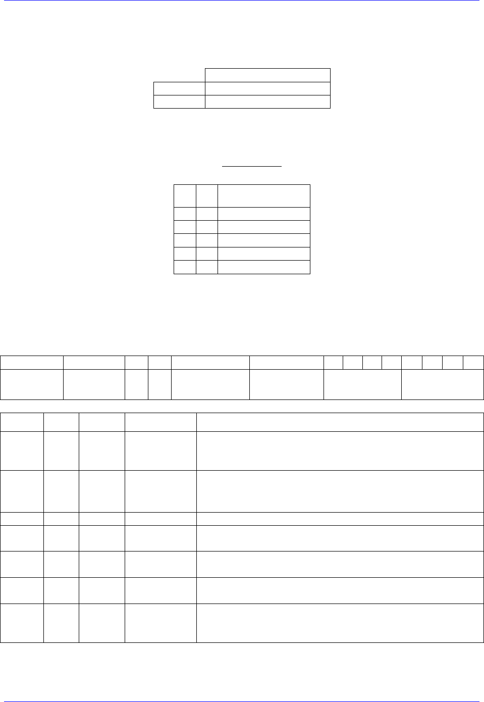
Geo Brick LV User Manual
PinOuts and Software Setup 83
Global Control Registers
X:$78BnF (Default value: $630002) where: n=2 for axes 1-4
n=3 for axes 5-8
Global Control Register
Axes 1-4
X:$78B2F
Axes 5-8
X:$78B3F
The Global Control register is used to program the serial encoder interface clock frequency SER_Clock
and configure the serial encoder interface trigger clock. SER_Clock is generated from a two-stage divider
clocked at 100 MHz:
M
N
Clock Frequency
49
0
2.0 MHz
99
0
1.0 MHz
99
1
500.0 KHz
99
2
250.0 KHz
…
…
Default Settings: M=99, N=0 => 1 MHz transfer rates
There are two external trigger sources; phase and servo. Bits [9:8] in the Global Control register are used
to select the source and active edge to use as the internal serial encoder trigger. The internal trigger is
used by all four channels to initiate communication with the encoder. To compensate for external system
delays, this trigger has a programmable 4-bit delay setting in 20 μsec increments.
23--16
15--12
11
10
9
8
7
6
5
4
3
2
1
0
M_Divisor
N_Divisor
Trigger Clock
Trigger Edge
Trigger Delay
Protocol Code
Bit
Type
Default
Name
Description
[23:16]
R/W
0x63
M_Divisor
Intermediate clock frequency for SER_Clock. The
intermediate clock is generated from a (M+1) divider clocked
at 100 MHz.
[15:12]
R/W
0x0
N_Divisor
Final clock frequency for SER_Clock. The final clock is
generated from a
N
2
divider clocked by the intermediate
clock.
[11:10]
R
00
Reserved
Reserved and always reads zero.
[09]
R/W
0
TriggerClock
Trigger clock select:
=0, trigger on Phase Clock
=1, trigger on Servo Clock
[08]
R/W
0
TriggerEdge
Active clock edge select:
=0, select rising edge
=1, select falling edge
[07:04]
R/W
0x0
TriggerDelay
Trigger delay program relative to the active edge of the
trigger clock. Units are in increments of 20 usec.
[03:00]
R
0x2
ProtocolCode
This read-only bit field is used to read the serial encoder
interface protocol supported by the FPGA. A value of $2
defines this as SSI protocol.

Geo Brick LV User Manual
PinOuts and Software Setup 84
Channel Control Registers
X:$78Bn0, X:$78Bn4, X:$78Bn8, X:$78BnC where: n=2 for axes 1-4
n=3 for axes 5-8
Channel 1
X:$78B20
Channel 5
X:$78B30
Channel 2
X:$78B24
Channel 6
X:$78B34
Channel 3
X:$78B28
Channel 7
X:$78B38
Channel 4
X:$78B2C
Channel 8
X:$78B3C
Each channel has its own Serial Encoder Command Control Register defining functionality parameters.
Parameters such as setting the number of position bits in the serial bit stream, enabling/disabling channels
through the SENC_MODE (when this bit is cleared, the serial encoder pins of that channel are tri-stated),
enabling/disabling communication with the encoder using the trigger control bit.
[23:16]
15
14
13
12
11
10
[9:6]
[5:0]
Parity
Type
Trigger
Mode
Trigger
Enable
GtoB
Rx data ready
/Senc Mode
PositionBits/
Resolution
Bit
Type
Default
Name
Description
[23:16]
R
0x00
Reserved
Reserved and always reads zero.
[15:14]
R/W
0x00
Parity Type
Parity Type of the received data:
00=None 10=Even
01=Odd 11=Reserved
[13]
R/W
0
Trigger Mode
Trigger Mode to initiate communication:
0= continuous trigger
1= one-shot trigger
All triggers occur at the defined Phase/Servo clock edge and
delay setting.
[12]
R/W
0
Trigger Enable
0= disabled
1= enabled
This bit must be set for either trigger mode. If the Trigger
Mode bit is set for one-shot mode, the hardware will
automatically clear this bit after the trigger occurs.
[11]
R/W
0
Convert G to
B
Gray code to Binary conversion: 0=Binary
1=Gray
[10]
R
0
RxData Ready
This read-only bit provides the received data status. It is low
while the interface logic is communicating (busy) with the
serial encoder. It is high when all the data has been received
and processed.
W
0
SENC_MODE
This write-only bit is used to enable the output drivers for
the SENC_SDO, SENC_CLK, SENC_ENA pins for each
respective channel.
[09:06]
R
0x0
Reserved
Reserved and always reads zero.
[05:00]
W
0x00
Position Bits
This bit field is used to define the number of position data
bits or encoder resolution:
Range is 12 – 32 (001100 –100000)

Geo Brick LV User Manual
PinOuts and Software Setup 85
SSI Data Registers
The SSI data is conveyed into 4 memory locations; Serial Encoder Data A, B, C, and D.
The Serial Encoder Data A register holds the 24 bits of the encoder position data. If the data exceeds the
24 available bits in this register, the upper overflow bits are LSB justified and readable in the Serial
Encoder Data B, which also holds the parity error flag.
Serial Encoder Data C, and D registers are reserved and always read zero.
Serial Encoder Data B
Serial Encoder Data A
23
[22:08]
[07:0]
[23:0]
Parity Err
Position Data [31:24]
Position Data [23:0]
SSI Encoder Data A
SSI Encoder Data B
Channel 1
Y:$78B20
Y:$78B21
Channel 2
Y:$78B24
Y:$78B25
Channel 3
Y:$78B28
Y:$78B29
Channel 4
Y:$78B2C
Y:$78B2D
Channel 5
Y:$78B30
Y:$78B31
Channel 6
Y:$78B34
Y:$78B35
Channel 7
Y:$78B38
Y:$78B39
Channel 8
Y:$78B3C
Y:$78B3D
Data Registers C and D are listed here for future use and documentation purposes only. They do not
pertain to the SSI setup and always read zero.
SSI Encoder Data C
SSI Encoder Data D
Channel 1
Y:$78B22
Y:$78B23
Channel 2
Y:$78B26
Y:$78B27
Channel 3
Y:$78B2A
Y:$78B28
Channel 4
Y:$78B2E
Y:$78B2F
Channel 5
Y:$78B32
Y:$78B33
Channel 6
Y:$78B36
Y:$78B37
Channel 7
Y:$78B3A
Y:$78B38
Channel 8
Y:$78B3E
Y:$78B3F
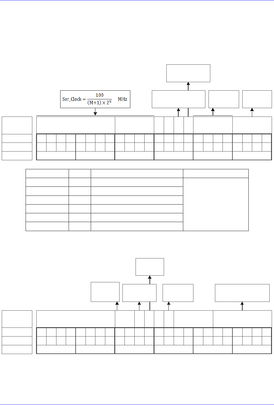
Geo Brick LV User Manual
PinOuts and Software Setup 86
SSI Control Registers Setup Example
Channel 1 is driving a 25-bit (13-bit Singleturn, 12-bit Multiturn) SSI encoder. The encoder outputs
binary data with no parity, and requires a 1 MHz serial clock.
Global Control Register
The Global Control register is a 24-bit hexadecimal word which is set up as follows:
M Divisor
Bit #:
Description:
Binary:
23 22 21 20 19 18 17 16 15 14 13 12 11 10 9 8 7 6 5 4 3 2 1 0
N Divisor Trigger Delay Protocol
=0 Rising Edge
=1 Falling Edge
Typically =0
=0 Trigger on Phase
=1 Trigger on Servo
$2 for
SSI
0 0
Hex ($):
011000110000000000000010
630002
clock
Edge
Field
Value
Notes
Global Control Word
M divisor
=99
Hex 0x63
$630002
N divisor
=0
Hex 0x0
Trigger clock
=0
Trigger on Phase (recommended)
Trigger Edge
=0
Rising edge (recommended)
Trigger Delay
=0
No delay (typical)
Protocol Code
=2
Hex 0x2, SSI protocol
Channel Control Register
The Channel Control register is a 24-bit hexadecimal word which is set up as follows:
Bit #:
Description:
Binary:
23 22 21 20 19 18 17 16 15 14 13 12 11 10 9 8 7 6 5 4 3 2 1 0
Bit Length
Hex ($):
000000000001010000011001
001419
Reserved
(always 0)
Trigger
Mode
Trigger
Enable
0
Senc
Mode
Reserved
(always 0)
=0 Continuous
=1 One shot
=0 Disabled
=1 Enabled
=0 Disabled
=1 Enabled
Encoder Resolution
(ST+MT)
Parity
Type
=00 None
=01 Odd
=10 Even

Geo Brick LV User Manual
PinOuts and Software Setup 87
Field
Value
Notes
Channel Control Word
Parity Type
=0
Hex 0x00
$001419
Trigger Mode
=0
Continuous trigger (typical)
Trigger Enable
=1
Enable
Gray / Binary
=0
Binary
Data Ready / Senc Mode
=1
Enable serial driver
Protocol Bits
=25
Hex 0x19
Control Registers Power-On PLC
The global and channel control words have to be executed once on power-up:
//=========================== NOTES ABOUT THIS PLC EXAMPLE ================================//
// This PLC example utilizes: - M5990 through M5991
// - Coordinate system 1 Timer 1
// Make sure that current and/or future configurations do not create conflicts with
// these parameters.
//=========================================================================================//
M5990..5991->* ; Self-referenced M-Variables
M5990..5991=0 ; Reset at download
//========================= GLOBAL CONTROL REGISTERS ======================================//
#define SSIGlobalCtrl1_4 M5990 ; Channels 1-4 SSI global control register
SSIGlobalCtrl1_4->X:$78B2F,0,24,U ; Channels 1-4 SSI global control register address
//======================== CHANNEL CONTROL REGISTERS ======================================//
#define Ch1SSICtrl M5991 ; Channel 1 SSI control register
Ch1SSICtrl->X:$78B20,0,24,U ; Channel 1 SSI control register Address
//========= POWER-ON PLC EXAMPLE, GLOBAL & CHANNEL CONTROL REGISTERS ======================//
Open PLC 1 Clear
SSIGlobalCtrl1_4=$630002 ; Trigger at Phase, 1 MHz serial Clock (M=99, N=0)–User Input
Ch1SSICtrl=$001419 ; Channel 1 SSI control register –User Input
I5111=500*8388608/I10 while(I5111>0) endw ; ½ sec delay
Dis plc 1 ; Execute once on power-up or reset
Close
//=========================================================================================//

Geo Brick LV User Manual
PinOuts and Software Setup 88
X1-X8: Encoder Feedback, EnDat 2.1/2.2
X1-X8: D-sub DA-15F
Mating: D-Sub DA-15M
2
3
4
5
6
7
8
9
10
11
12
13
14
15
1
Pin #
Symbol
Function
Notes
1
Unused
2
Unused
3
Unused
4
EncPwr
Output
Encoder Power 5 Volts
5
Data-
Input
Data- packet
6
Clock-
Output
Serial Encoder Clock-
7
Unused
8
Unused
9
Unused
10
Unused
11
Unused
12
GND
Common
Common Ground
13
Clock+
Output
Serial Encoder Clock+
14
Data+
Input
Data+ Packet
15
Unused
Note
Some EnDat devices require 24V power which has to be brought
in externally. Pins 4, and 12 are unused in this case, leave floating.
Hardware capture is not available with Serial encoders
Configuring EnDat
Configuring the EnDat protocol requires the programming of two essential control registers:
Global Control Registers
Channel Control Registers
The resulting data is found in:
EnDat Data Registers
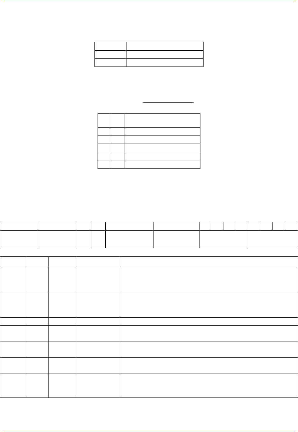
Geo Brick LV User Manual
PinOuts and Software Setup 89
Global Control Registers
X:$78BnF (default value: $002003) where n=2 for axes 1-4
n=3 for axes 5-8
Global Control Register
Axes 1-4
X:$78B2F
Axes 5-8
X:$78B3F
The Global Control register is used to program the serial encoder interface clock frequency. SENC_CLK
is the serial data clock transmitted from the Brick to the encoder. It is used by the encoder to clock in data
transmitted from the Brick, and clock out data from the encoder:
M
N
Serial Clock Frequency
0
0
4.0 MHz
0
2
1.0 MHz
0
3
500 KHz
0
4
250 KHz
…
…
…
Default Settings M=0, N=2 => 1 MHz transfer rate
There are two external trigger sources; phase and servo. Bits [9:8] in the Global Control register are used
to select the source and active edge to use as the internal serial encoder trigger. The internal trigger is
used by all four channels to initiate communication with the encoder. To compensate for external system
delays, this trigger has a programmable 4-bit delay setting in 20 μsec increments.
23--16
15--12
11
10
9
8
7
6
5
4
3
2
1
0
M_Divisor
N_Divisor
Trigger Clock
Trigger Edge
Trigger Delay
Protocol Code
Bit
Type
Default
Name
Description
[23:16]
R/W
0x00
M_Divisor
Intermediate clock frequency for SER_Clock. The
intermediate clock is generated from a (M+1) divider clocked
at 100 MHz.
[15:12]
R/W
0x2
N_Divisor
Final clock frequency for SER_Clock. The final clock is
generated from a
N
2
divider clocked by the intermediate
clock.
[11:10]
R
00
Reserved
Reserved and always reads zero.
[09]
R/W
0
TriggerClock
Trigger clock select: 0= PhaseClock
1= ServoClock
[08]
R/W
0
TriggerEdge
Active clock edge select: 0= rising edge
1= falling edge
[07:04]
R/W
0x0
TriggerDelay
Trigger delay program relative to the active edge of the
trigger clock. Units are in increments of 20 usec.
[03:00]
R
0x3
ProtocolCode
This read-only bit field is used to read the serial encoder
interface protocol supported by the FPGA. A value of 0x3
defines this protocol as EnDat.

Geo Brick LV User Manual
PinOuts and Software Setup 90
Channel Control Registers
X:$78Bn0, X:$78Bn4, X:$78Bn8, X:$78BnC where: n=2 for axes 1-4
n=3 for axes 5-8
Channel 1
X:$78B20
Channel 5
X:$78B30
Channel 2
X:$78B24
Channel 6
X:$78B34
Channel 3
X:$78B28
Channel 7
X:$78B38
Channel 4
X:$78B2C
Channel 8
X:$78B3C
Each channel has its own Serial Encoder Command Control Register defining functionality parameters.
Parameters such as setting the number of position bits in the serial bit stream, enabling/disabling channels
through the SENC_MODE (when this bit is cleared, the serial encoder pins of that channel are tri-stated),
enabling/disabling communication with the encoder using the trigger control bit.
23
22
[21:16]
15
14
13
12
11
10
[9:6]
[5:0]
Command
Code
Trigger
Mode
Trigger
Enable
Rxdata ready
/Senc Mode
PositionBits/
Resolution
Bit
Type
Default
Name
Description
[23:22]
R
0x000
Reserved
Reserved and always reads zero.
[21:16]
R
0x00
Command
Code
($38) 111000 – Encoder to Send Position (EnDat2.2 only)
($15) 010101 – Encoder to Receive Reset (EnDat2.2 only)
($07) 000111 – Encoder to Send Position (EnDat 2.1 & 2.2)
($2A)101010 – Encoder to Receive Reset (EnDat 2.1 & 2.2)
[15:14]
R
00
Reserved
Reserved and always reads zero.
[13]
R/W
0
Trigger Mode
Trigger Mode: 0= continuous trigger
1= one-shot trigger
All triggers occur at the defined Phase/Servo clock edge and
delay setting. See Global Control register for these
settings.
[12]
R/W
0
Trigger Enable
Enable trigger: 0= disabled
1= enabled
This bit must be set for either trigger mode. If the Trigger
Mode bit is set for one-shot mode, the hardware will
automatically clear this bit after the trigger occurs.
[11]
R/W
0
Reserved
Reserved and always reads zero.
[10]
R
0
RxData Ready
This read-only bit provides the received data status. It is low
while the interface logic is communicating (busy) with the
serial encoder. It is high when all the data has been received
and processed.
W
0
SENC_MODE
This write-only bit is used to enable the output drivers for
the SENC_SDO, SENC_CLK, SENC_ENA pins for each
respective channel.
[09:06]
R
0x0
Reserved
Reserved and always reads zero.
[05:00]
W
0x00
Position Bits
This bit field is used to define the number of position data
bits or encoder resolution:
Range is 12 – 40 (001100 –101000)

Geo Brick LV User Manual
PinOuts and Software Setup 91
EnDat Data Registers
The EnDat data is conveyed into 4 memory locations; EnDat Data A, B, C, and D.
The EnDat Data A register holds the 24 bits of the encoder position data. If the data exceeds the 24
available bits in this register, the upper overflow bits are LSB justified and readable in the EnDat Data B
register, which also holds error flags. The error bit flag is always returned by the encoder, except for a
Reset command. The CRC error bit is set if the return data fails the CRC verification. The timeout error
flag is set if the SEIGATE3 does not receive a response from the encoder.
EnDat Data C, and D registers are reserved and always read zero.
EnDat Data B
EnDat Data A
23
22
21
[20:16]
[15:0]
[23:0]
TimeOut Err
CRC Err
Err flag
Position Data [39:24]
Position Data [23:0]
EnDat Data A
EnDat Data B
Channel 1
Y:$78B20
Y:$78B21
Channel 2
Y:$78B24
Y:$78B25
Channel 3
Y:$78B28
Y:$78B29
Channel 4
Y:$78B2C
Y:$78B2D
Channel 5
Y:$78B30
Y:$78B31
Channel 6
Y:$78B34
Y:$78B35
Channel 7
Y:$78B38
Y:$78B39
Channel 8
Y:$78B3C
Y:$78B3D
EnDat Registers C and D are listed here for future use and documentation purposes only. They do not
pertain to the EnDat setup and always read zero.
EnDat Data C
EnDat Data D
Channel 1
Y:$78B22
Y:$78B23
Channel 2
Y:$78B26
Y:$78B27
Channel 3
Y:$78B2A
Y:$78B28
Channel 4
Y:$78B2E
Y:$78B2F
Channel 5
Y:$78B32
Y:$78B33
Channel 6
Y:$78B36
Y:$78B37
Channel 7
Y:$78B3A
Y:$78B38
Channel 8
Y:$78B3E
Y:$78B3F
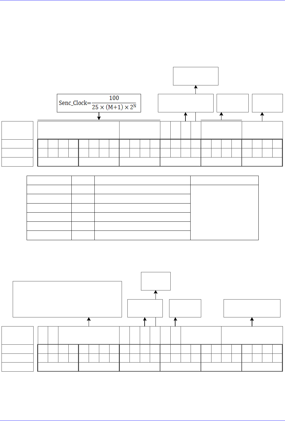
Geo Brick LV User Manual
PinOuts and Software Setup 92
EnDat Control Registers Setup Example
Channel 1 is driving a 37-bit (25-bit Singleturn, 12-bit Multiturn) EnDat 2.2 encoder. The encoder
requires a 4 MHz serial clock.
Global Control Register
The Global Control register is a 24-bit hexadecimal word which is set up as follows:
M Divisor
Bit #:
Description:
Binary:
23 22 21 20 19 18 17 16 15 14 13 12 11 10 9 8 7 6 5 4 3 2 1 0
N Divisor Trigger Delay Protocol
=0 Rising Edge
=1 Falling Edge
Typically =0
=0 Trigger on Phase
=1 Trigger on Servo
$3 for
EnDat
0 0
Hex ($):
000000000000000000000011
000003
clock
Edge
Field
Value
Notes
Global Control Word
M divisor
=0
Hex 0x00
$000003
N divisor
=0
Hex 0x0
Trigger clock
=0
Trigger on Phase (recommended)
Trigger Edge
=0
Rising edge (recommended)
Trigger Delay
=0
No delay (typical)
Protocol Code
=3
Hex 0x3, EnDat
Channel Control Register
The Channel Control register is a 24-bit hexadecimal word which is set up as follows:
Bit #:
Description:
Binary:
23 22 21 20 19 18 17 16 15 14 13 12 11 10 9 8 7 6 5 4 3 2 1 0
Bit Length
(Resolution)
Hex ($):
001110000001010000100101
381425
Command Code
Trigger
Mode
Trigger
Enable
0
Senc
Mode
Reserved
(always 0)
=0 Continuous
=1 One shot
=0 Disabled
=1 Enabled
=0 Disabled
=1 Enabled
Encoder Resolution
(ST+MT)
0 0 0 0
=111000 ($38) Send Position (EnDat 2.2 only)
=010101 ($15) Reset (EnDat 2.2 only)
=000111 ($07) Send Position (EnDat 2.1 / 2.2)
=101010 ($2A) Reset (EnDat 2.1 / 2.2)

Geo Brick LV User Manual
PinOuts and Software Setup 93
Field
Value
Notes
Channel Control Word
Command code
=$38
Hex 0x38 for EnDat 2.2 only
$381425
Trigger Mode
=0
Continuous trigger (typical)
Trigger Enable
=1
Enable
Data Ready / Senc Mode
=1
Enable serial driver
Protocol Bits
=37
Hex 0x25
Control Registers Power-On PLC
The Global and Channel Control words have to be executed once on power-up
//=========================== NOTES ABOUT THIS PLC EXAMPLE ================================//
// This PLC example utilizes: - M5990 through M5991
// - Coordinate system 1 Timer 1
// Make sure that current and/or future configurations do not create conflicts with
// these parameters.
//=========================================================================================//
M5990..5991->* ; Self-referenced M-Variables
M5990..5991=0 ; Reset at download
//========================= GLOBAL CONTROL REGISTERS ======================================//
#define EnDatGlobalCtrl1_4 M5990 ; Channels 1-4 EnDat global control register
EnDatGlobalCtrl1_4->X:$78B2F,0,24,U ; Channels 1-4 EnDat global control register address
//======================== CHANNEL CONTROL REGISTERS ======================================//
#define Ch1EnDatCtrl M5991 ; Channel 1 EnDat control register
Ch1EnDatCtrl->X:$78B20,0,24,U ; Channel 1 EnDat control register Address
//========= POWER-ON PLC EXAMPLE, GLOBAL & CHANNEL CONTROL REGISTERS ======================//
Open PLC 1 Clear
EnDatGlobalCtrl1_4=$3 ; Trigger at Phase, 4MHz serial Clock –User Input
Ch1EnDatCtrl=$381425 ; Channel 1 EnDat control register –User Input
I5111=500*8388608/I10 while(I5111>0) endw ; ½ sec delay
Dis plc 1 ; Execute once on power-up or reset
Close
//=========================================================================================//
Note
Some EnDat2.2 Encoders do not support additional information with
the $38 (111000) command code. Try using $07 (000111) command
code if you cannot see data in the Serial Data Register A, or in the
position window (after setting up the Encoder Conversion Table).

Geo Brick LV User Manual
PinOuts and Software Setup 94
X1-X8: Encoder Feedback, BiSS C/B
X1-X8: D-sub DA-15F
Mating: D-Sub DA-15M
2
3
4
5
6
7
8
9
10
11
12
13
14
15
1
Pin #
Symbol
Function
Notes
1
Unused
2
Unused
3
Unused
4
EncPwr
Output
Encoder Power 5 Volts
5
Data-
Input/Output
Data- packet, SLO-
6
Clock-
Output
Serial Encoder Clock-, MO-
7
Unused
8
Unused
9
Unused
10
Unused
11
Unused
12
GND
Common
Common Ground
13
Clock+
Output
Serial Encoder Clock+ , MO+
14
Data+
Input/Output
Data+ Packet, SLO+
15
Unused
Note
Some BiSS devices require 24V power which has to be brought in
externally. Pins 4, and 12 are unused in this case, leave floating.
Hardware capture is not available with Serial encoders
Configuring BiSS
Configuring the BiSS protocol requires the programming of two essential control registers:
Global Control Registers
Channel Control Registers
The resulting data is found in:
BiSS-C/BiSS-B Data Registers
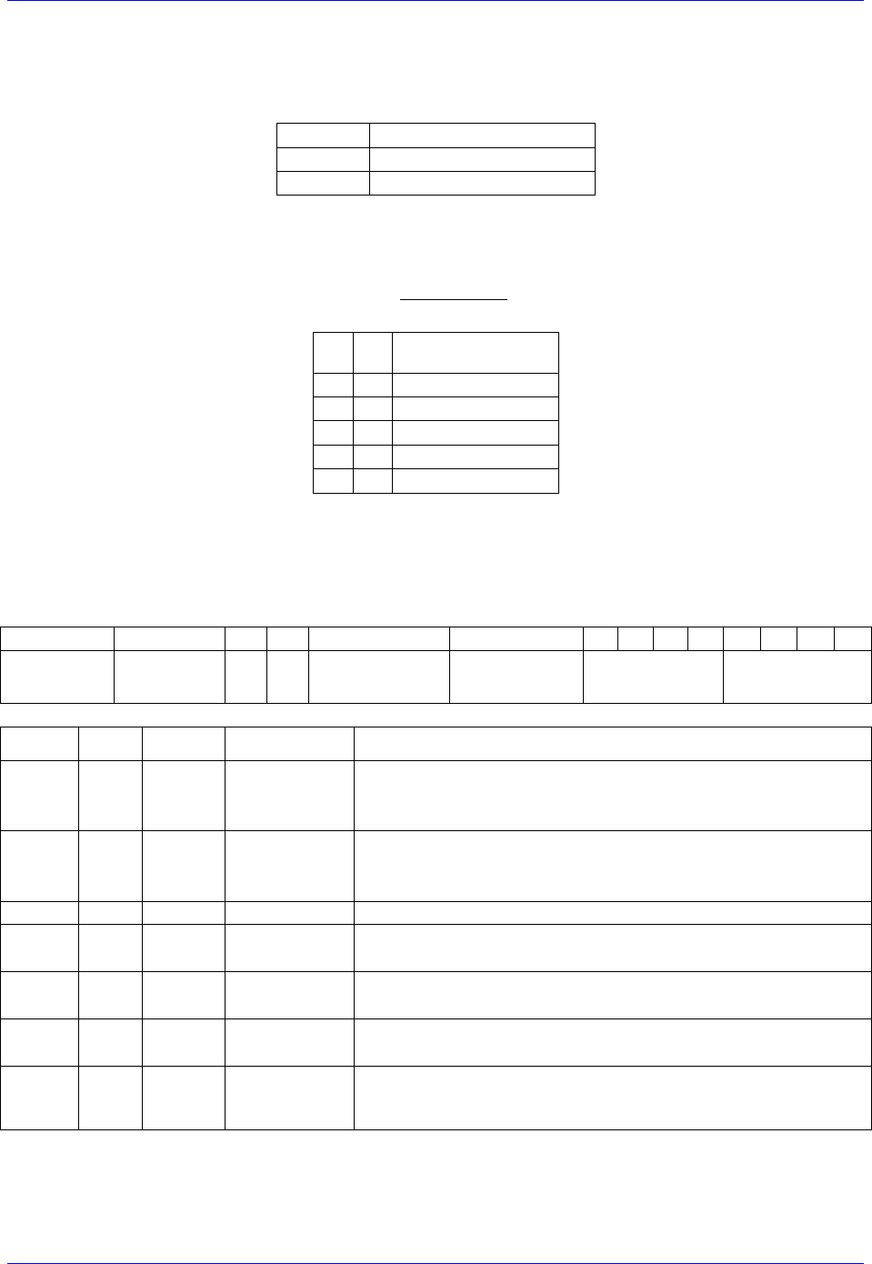
Geo Brick LV User Manual
PinOuts and Software Setup 95
Global Control Registers
X:$78BnF (default value: $18000B) where n=2 for axes 1-4
n=3 for axes 5-8
Global Control Register
Axes 1-4
X:$78B2F
Axes 5-8
X:$78B3F
The Global Control register is used to program the serial encoder interface clock frequency SER_Clock
and configure the serial encoder interface trigger clock. SER_Clock is generated from a two-stage divider
clocked at 100 MHz as follows:
M
N
Clock Frequency
49
0
2.0 MHz
99
0
1.0 MHz
99
1
500.0 KHz
99
2
250.0 KHz
…
…
Default Settings: M=24, N=0 => 4 MHz transfer rates
There are two external trigger sources; phase and servo. Bits [9:8] in the Global Control register are used
to select the source and active edge to use as the internal serial encoder trigger. The internal trigger is
used by all four channels to initiate communication with the encoder. To compensate for external system
delays, this trigger has a programmable 4-bit delay setting in 20 μsec increments.
23--16
15--12
11
10
9
8
7
6
5
4
3
2
1
0
M_Divisor
N_Divisor
Trigger Clock
Trigger Edge
Trigger Delay
Protocol Code
Bit
Type
Default
Name
Description
[23:16]
R/W
0x18
M_Divisor
Intermediate clock frequency for SER_Clock. The
intermediate clock is generated from a (M+1) divider clocked
at 100 MHz.
[15:12]
R/W
0x0
N_Divisor
Final clock frequency for SER_Clock. The final clock is
generated from a
N
2
divider clocked by the intermediate
clock.
[11:10]
R
00
Reserved
Reserved and always reads zero.
[09]
R/W
0
TriggerClock
Trigger clock select: 0= PhaseClock
1= ServoClock
[08]
R/W
0
TriggerEdge
Active clock edge select: 0= rising edge
1= falling edge
[07:04]
R/W
0x0
TriggerDelay
Trigger delay program relative to the active edge of the
trigger clock. Units are in increments of 20 usec.
[03:00]
R
0xB
ProtocolCode
This read-only bit field is used to read the serial encoder interface
protocol supported by the FPGA. A value of $B defines this
protocol as BiSS.

Geo Brick LV User Manual
PinOuts and Software Setup 96
Channel Control Registers
X:$78Bn0, X:$78Bn4, X:$78Bn8, X:$78BnC where: n=2 for axes 1-4
n=3 for axes 5-8
Channel 1
X:$78B20
Channel 5
X:$78B30
Channel 2
X:$78B24
Channel 6
X:$78B34
Channel 3
X:$78B28
Channel 7
X:$78B38
Channel 4
X:$78B2C
Channel 8
X:$78B3C
Each channel has its own Serial Encoder Command Control Register defining functionality parameters.
Parameters such as setting the number of position bits in the serial bit stream, enabling/disabling channels
through the SENC_MODE (when this bit is cleared, the serial encoder pins of that channel are tri-stated),
enabling/disabling communication with the encoder using the trigger control bit.
[23:16]
15
14
13
12
11
10
9
[8:6]
[5:0]
CRC
Mask
=0 BiSS-C
=1 BiSS-B
MCD
Trigger
Mode
Trigger
Enable
Rxdataready
SencMode
Status
Bits
PositionBits/
Resolution
Bit
Type
Default
Name
Description
[23:16]
R/W
0x21
CRC_Mask
This bit field is used to define the CRC polynomial used for the
position and status data. The 8-bit mask is to define any 4-bit to 8-
bit CRC polynomial. The mask bits M[7:0] represent the
coefficients [8:1], respectively, in the polynomial: M7x8 +M6x7 +
M5x6 + M4x5 + M3x4 + M2x3 + M1x2 + M0x1 + 1. The coefficient for
x0 is always 1 and therefore not included in the mask. An all zero
mask indicates no CRC bits in the encoder data. Most common
setting:
($21) 00100001 = x6 + x1 + 1 (typical for Renishaw)
($09) 00001001 = x4 + x1 + 1
[15]
R/W
0
BiSS B/C
This bit is used to select the BiSS protocol mode
(=0 BiSS-C, =1 BiSS-B)
[14]
R/W
0
MCD
This bit is used to enable support for the optional MCD bit
in BiSS-B mode. Setting this bit has no effect if the BiSS-B
mode is not selected.
[13]
R/W
0
Trigger Mode
Trigger Mode to initiate communication:
0= continuous trigger
1= one-shot trigger
All triggers occur at the defined Phase/Servo clock edge and
delay setting.
[12]
R/W
0
Trigger
Enable
0= disabled
1= enabled
This bit must be set for either trigger mode. If the Trigger
Mode bit is set for one-shot mode, the hardware will
automatically clear this bit after the trigger occurs.
[11]
0
Reserved
Reserved and always reads zero.
[10]
R
0
RxData Ready
This read-only bit provides the received data status. It is low
while the interface logic is communicating (busy) with the
serial encoder. It is high when all the data has been received
and processed.
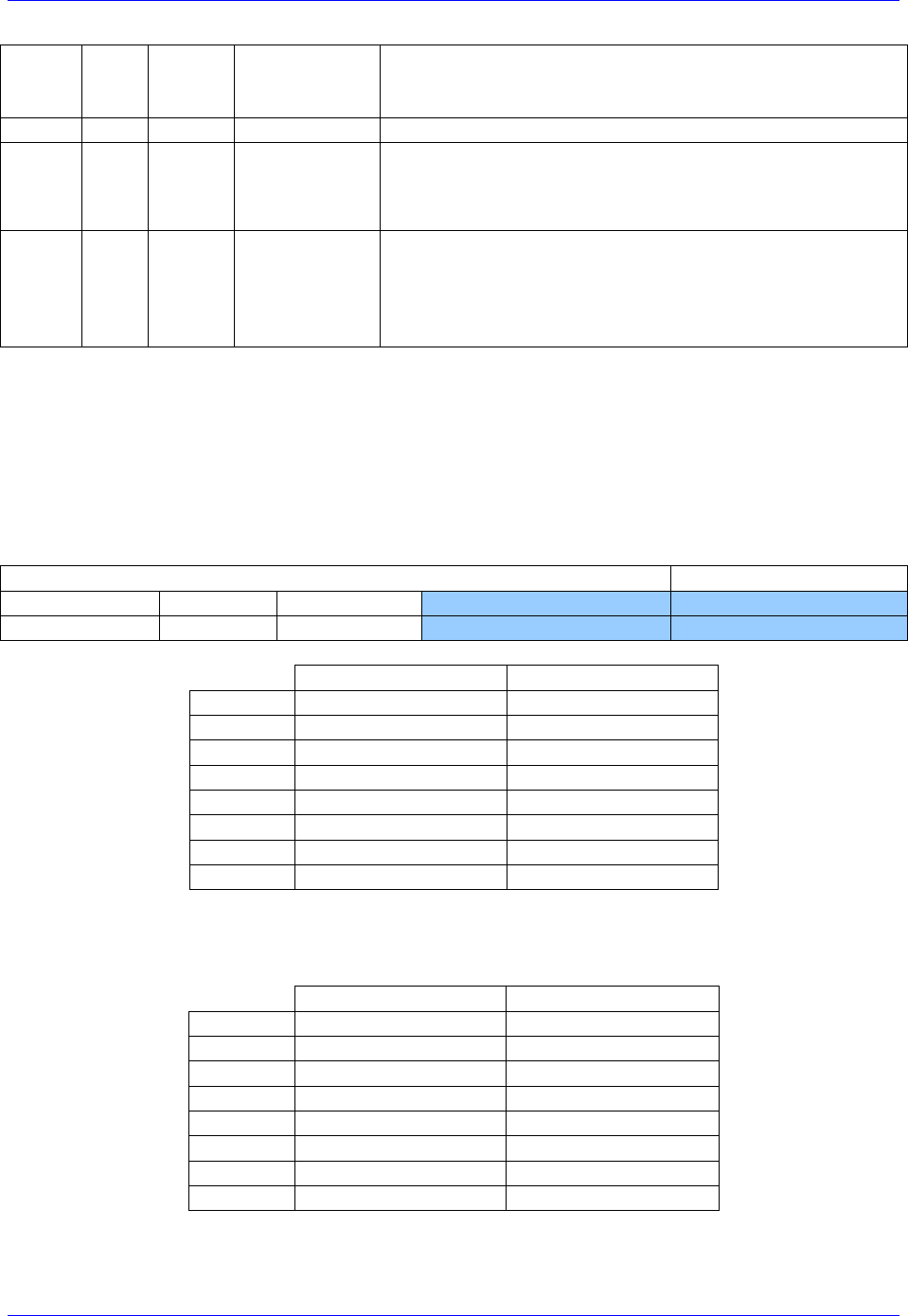
Geo Brick LV User Manual
PinOuts and Software Setup 97
W
0
SENC_MODE
This write-only bit is used to enable the output drivers for
the SENC_SDO, SENC_CLK, SENC_ENA pins for each
respective channel.
[09]
0x0
Reserved
Reserved and always reads zero.
[08:06]
R/W
000
Status
Bits
This bit field is used to define the number of status bits in the
encoder data. The valid range of settings is 0 – 6 (000 – 110). The
status bits are assumed to always follow after the position data and
before the CRC.
[05:00]
W
0x00
Position Bits
This bit field is used to define the number of position data
bits or encoder resolution:
Range is 12 – 40 (001100 –101000)
The position bits are assumed to be in binary MSB-first format:
$12 for 18-bit | $1A for 26-bit | $20 for 32-bit
BiSS Data Registers
The BiSS data is conveyed into 4 memory locations; Serial Encoder Data A, B, C, and D.
The Serial Encoder Data A register holds the 24 bits of the encoder position data. If the data exceeds the
24 available bits in this register, the upper overflow bits are LSB justified and readable in the Serial
Encoder Data B, which also holds status and error bits. Serial Encoder Data C, and D registers are
reserved and always read zero.
BiSS Data B
BiSS Data A
23
22
[21:16]
[15:0]
[23:0]
TimeOut Err
CRC Err
Status Data
Position Data [39:24]
Position Data [23:0]
BiSS Encoder Data A
BiSS Encoder Data B
Channel 1
Y:$78B20
Y:$78B21
Channel 2
Y:$78B24
Y:$78B25
Channel 3
Y:$78B28
Y:$78B29
Channel 4
Y:$78B2C
Y:$78B2D
Channel 5
Y:$78B30
Y:$78B31
Channel 6
Y:$78B34
Y:$78B35
Channel 7
Y:$78B38
Y:$78B39
Channel 8
Y:$78B3C
Y:$78B3D
Data Registers C and D are listed here for future use and documentation purposes only. They do not
pertain to the BiSS setup and always read zero.
BiSS Encoder Data C
BiSS Encoder Data D
Channel 1
Y:$78B22
Y:$78B23
Channel 2
Y:$78B26
Y:$78B27
Channel 3
Y:$78B2A
Y:$78B28
Channel 4
Y:$78B2E
Y:$78B2F
Channel 5
Y:$78B32
Y:$78B33
Channel 6
Y:$78B36
Y:$78B37
Channel 7
Y:$78B3A
Y:$78B38
Channel 8
Y:$78B3E
Y:$78B3F
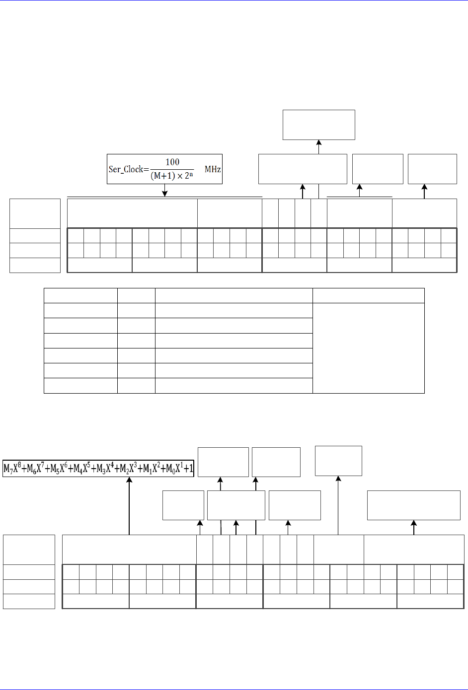
Geo Brick LV User Manual
PinOuts and Software Setup 98
BiSS Control Registers Setup Example
Channel 1 is driving an 18-bit Renishaw resolute BiSS-C encoder. The encoder requires a 1 MHz serial
clock, and has 2 status bits.
Global Control Register
The Global Control register is a 24-bit hexadecimal word which is set up as follows:
M Divisor
Bit #:
Description:
Binary:
23 22 21 20 19 18 17 16 15 14 13 12 11 10 9 8 7 6 5 4 3 2 1 0
N Divisor Trigger Delay Protocol
=0 Rising Edge
=1 Falling Edge
Typically =0
=0 Trigger on Phase
=1 Trigger on Servo
$B for
BiSS
0 0
Hex:
011000100000000000001011
63000B
clock
Edge
Field
Value
Notes
Global Control Word
M divisor
=99
Hex 0x63
$63000B
N divisor
=0
Hex 0x0
Trigger clock
=0
Trigger on Phase (recommended)
Trigger Edge
=0
Rising edge (recommended)
Trigger Delay
=0
No delay (typical)
Protocol Code
=11
Hex 0xB, BiSS protocol
Channel Control Register
The Channel Control register is a 24-bit hexadecimal word set up as follows:
Bit #:
Description:
Binary:
23 22 21 20 19 18 17 16 15 14 13 12 11 10 9 8 7 6 5 4 3 2 1 0
Bit Length
(Resolution)
Hex ($):
001000010001010010010010
211492
CRC Mask
Trigger
Mode
Trigger
Enable
0
Senc
Mode
=0 Continuous
=1 One shot
=0 Disabled
=1 Enabled
=0 Disabled
=1 Enabled
Encoder Resolution
(ST+MT)
BiSS
Type
=0 BiSS-C
=1 BiSS-B
MCD
0 Status
MCD
(BiSS-B only)
Number Of
Status Bits

Geo Brick LV User Manual
PinOuts and Software Setup 99
Field
Value
Notes
Channel Control Word
CRC Mask
=33
Hex 0x21 typical for Renishaw
$211492
BiSS Type
=0
for BiSS-C
Trigger Mode
=0
Continuous trigger (typical)
Trigger Enable
=1
Enable
Data Ready / Senc Mode
=1
Enable serial driver
Status Bits
=2
Binary 010
Protocol Bits
=18
Binary 010010
Control Registers Power-On PLC
The Global and Channel Control words have to be executed once on power-up
//=========================== NOTES ABOUT THIS PLC EXAMPLE ================================//
// This PLC example utilizes: - M5990 through M5991
// - Coordinate system 1 Timer 1
// Make sure that current and/or future configurations do not create conflicts with
// these parameters.
//=========================================================================================//
M5990..5991->* ; Self-referenced M-Variables
M5990..5991=0 ; Reset at download
//========================= GLOBAL CONTROL REGISTERS ======================================//
#define SSIGlobalCtrl1_4 M5990 ; Channels 1-4 BiSS global control register
SSIGlobalCtrl1_4->X:$78B2F,0,24,U ; Channels 1-4 BiSS global control register address
//======================== CHANNEL CONTROL REGISTERS ======================================//
#define Ch1SSICtrl M5991 ; Channel 1 BiSS control register
Ch1SSICtrl->X:$78B20,0,24,U ; Channel 1 BiSS control register Address
//========= POWER-ON PLC EXAMPLE, GLOBAL & CHANNEL CONTROL REGISTERS ======================//
Open PLC 1 Clear
SSIGlobalCtrl1_4=$63000B ; Trigger at Phase, 1 MHz serial Clock (M=99, N=0) –User Input
Ch1SSICtrl=$211492 ; Channel 1, BiSS-C protocol, 18-bit resolution –User Input
I5111=500*8388608/I10 while(I5111>0) endw ; ½ sec delay
Dis plc 1 ; Execute once on power-up or reset
Close
//=========================================================================================//
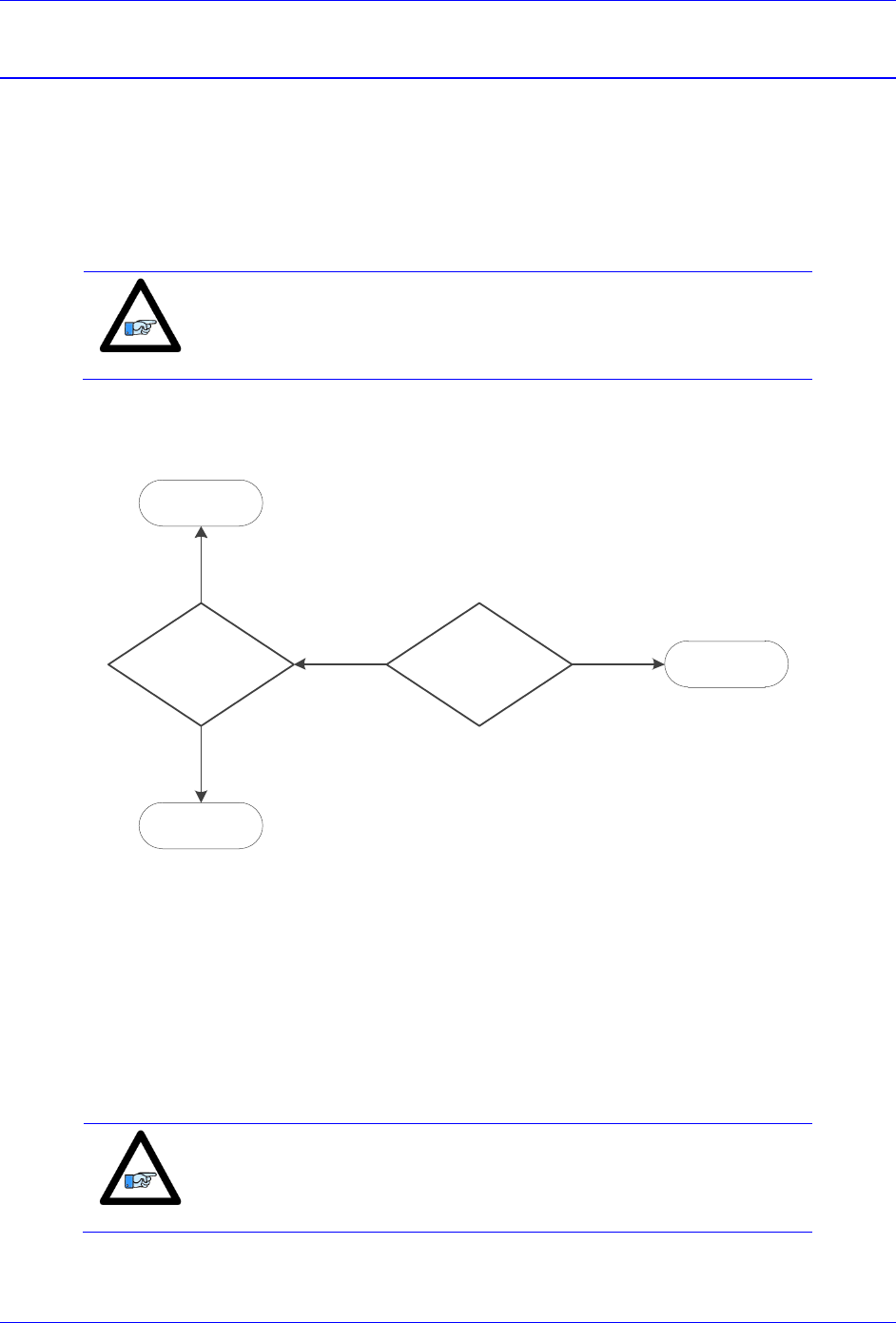
Geo Brick LV User Manual
PinOuts and Software Setup 100
Setting up SSI | EnDat | BiSS
In Turbo PMAC (i.e. Brick family), the absolute serial encoder data is brought in as an unfiltered parallel
Y-word into the Encoder Conversion Table (ECT) where it is processed for the PMAC to use for on-
going position in the motor servo-loop, power-on absolute position, and (power-on/on-going) phase
referencing. In general, encoder data is left-shifted 5 bits in the ECT to provide fractional data. This
process can cause saturation of certain registers with higher resolution absolute serial encoders, thus for
this type of encoders, it is recommended to process the data as unshifted. Moreover, special
considerations need to be taken in setting up commutation (for commutated motors, e.g. brushless).
Note
Details about registers’ overflow and examples can be found in the
appendix section.
The following flowchart summarizes the recommended method to use, regardless of the Multiturn (MT)
data specification. It is only dependent on the Singleturn (ST) resolution (for rotary encoders) or protocol
resolution (for linear scales).
ST
Encoder Resolution
≥ 24 bits
NO YES
ST
Encoder Resolution
≥ 19 bits
NO
YES
Technique 2
Technique 1
Technique 3
Start Here
Technique 1
This technique places the Least Significant Bit (LSB) of the serial data in bit 5 of the result register
providing the 5 bits of “non-existent” fraction.
Technique 2
This technique places the LSB of the serial data in bit 0 of the result register, creating no fractional bits. It
requires a dedicated Encoder Conversion Table (ECT) entry for commutation.
Technique 3
This technique processes the data for position similarly to Technique 1, but it requires a dedicated ECT
entry for commutation.
Note
Some applications may require deviating from the suggested setup
methods (e.g. extremely high resolution and speed requirements).
Contact Delta Tau for assistance with these special cases.
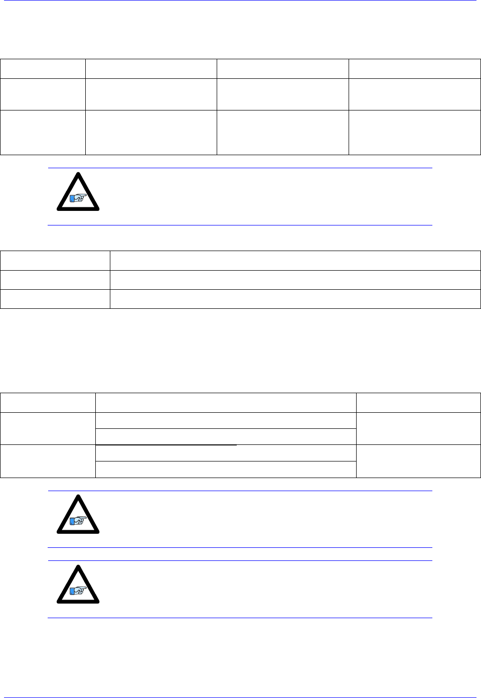
Geo Brick LV User Manual
PinOuts and Software Setup 101
Setup Summary
Encoder Conversion Table Processing:
Process
Technique 1
Technique 2
Technique 3
ECT for
Position
From serial register A,
5-bit shift
From serial register A,
no shift
From serial register A,
5-bit shift
ECT for
Commutation
N/A
From serial register A,
18 bits, no shift,
Offset=ST-18
From serial register A,
18 bits, no shift,
Offset=ST-18
Note
ST is the Singleturn resolution (in bits) for rotary encoders. Similarly,
this would be the protocol resolution (in bits) for linear scales.
The position and velocity pointers are then assigned to the “ECT for position” result:
Parameter
Technique 1/2/3
Position (Ixx03)
@ ECT position result
Velocity (Ixx04)
@ ECT position result (typically, with single source feedback)
Commutation Source and Type (for commutated motors, e.g. brushless)
With technique 1, if the Singleturn + Multiturn data bits fulfill 24 bits and are contiguous, then serial data
register A can be used as the commutation source. Otherwise, the resulting register from the ECT for
position is used for commutation (requires special settings for the commutation cycle size).
With techniques 2 and 3, the feedback source for commutation should come from its dedicated ECT.
Parameter
Technique 1
Technique 2/3
Commutation
Source (Ixx83)
@ serial data register A
if ST+MT ≥ 24 bits
@ commutation
ECT result
@ ECT position result
if ST+MT < 24 bits
Commutation
Type (Ixx01)
= 3 (from Y register)
if ST+MT ≥ 24 bits
=1 (from X register)
= 1 (from X register)
if ST+MT < 24 bits
Note
Special considerations should be made if the Singleturn (ST) and
Multiturn (MT) data bits are NOT contiguous (in consecutive fields).
Contact Delta Tau for assistance with these special cases.
Note
Multiturn MT is equal to zero for encoders which do not possess
Multiturn data bits.

Geo Brick LV User Manual
PinOuts and Software Setup 102
Resolution Scale Factor (SF)
Parameter
Encoder Type
Technique 1/3
Technique 2
Resolution
Scale Factor SF
Rotary
[counts/rev]
= 2ST
= 2ST-5 = 2ST/32
Linear
[counts/user units]
= 1/RES
= 1/(32*RES)
Where ST: is the rotary encoder Singleturn resolution in bits
RES: is the linear scale resolution, in user units (e.g. mm)
Commutation Cycle Size
Parameter
Motor/Encoder
Technique 1
Technique 2/3
Ixx70
Rotary
= Number of pole pairs
Linear
= 1
Ixx71
Rotary
= SF= 2ST
if Ixx01=3
= 218
= 262144
= 32 * SF= 32 * 2ST
if Ixx01=1
Linear
= ECL * SF= ECL/RES
if Ixx01=3
= ECL * SF / 2Offset
= ECL/(RES*2Offset)
= 32 * ECL * SF
= 32 * (ECL/RES)
if Ixx01=1
Where ST: is the rotary encoder Singleturn resolution in bits
RES: is the linear scale resolution, in user units (e.g. mm)
ECL: is the electrical cycle length of the linear motor, same units as RES (e.g. mm)
Offset: is the ECT commutation Offset, it is (=ST-18 for rotary, or =RES-18 for linear)
SF: is the encoder resolution scale factor (calculated previously)
Position and Velocity Scale Factors, Position Error Limit
With technique 2, and technique 3 (with encoder resolutions greater than 20 bits), it is recommended to
set the position and velocity scale factors to equal 1 and widen the position error limit. Otherwise, default
values should be ok for all other cases. This alleviates register saturation(s), allows for higher commanded
speed settings and easier PID (position-loop) tuning.
Parameter(s)
Technique 1
Technique 2
Technique 3
Ixx08, Ixx09
= 96
= 1
= 96
= 1
for ST < 20
for ST ≥ 20
Ixx67
Default
= 8388607
= Default
= 8388607
for ST < 20
for ST ≥ 20
Absolute Power-On Position and Phasing
Process
Technique 1
Technique 2
Technique 3
Absolute Position Read
From serial register A,
automatic settings
From serial register A,
scaling required
From serial register A,
automatic settings
Absolute Phasing
Automatic settings,
depending on ST+MT
From ECT for Comm.,
automatic settings
From ECT for Comm.,
automatic settings
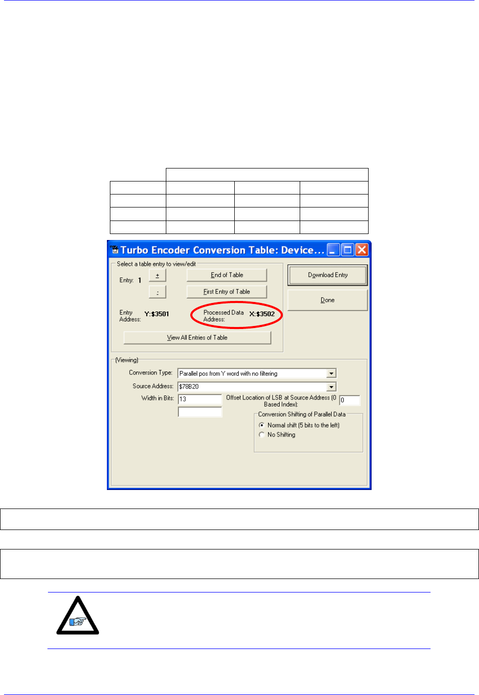
Geo Brick LV User Manual
PinOuts and Software Setup 103
Technique 1 Example
Channel 1 is driving a 25-bit (13-bit Singleturn, 12-bit Multiturn) rotary serial encoder, or a linear scale
with similar protocol resolution (13 bits, 1 micron).
Encoder Conversion Table - for Position (Technique 1)
Conversion Type: Parallel pos from Y word with no filtering
Width in Bits: Singleturn/absolute resolution in bits (e.g. 13 bits)
Offset Location of LSB: leave at zero
Normal Shift (5 bits to the left)
Source Address: serial data register A (see table below)
Remember to click on Download Entry for the changes to take effect.
Source Address ( Serial Data Register A)
Channel 1
Y:$78B20
Channel 5
Y:$78B30
Channel 2
Y:$78B24
Channel 6
Y:$78B34
Channel 3
Y:$78B28
Channel 7
Y:$78B38
Channel 4
Y:$78B2C
Channel 8
Y:$78B3C
This is a 2-line ECT entry, its equivalent script code:
I8000=$278B20 ; Unfiltered parallel pos of location Y:$78B20
I8001=$00D000 ; Width and Offset. Processed result at $3502
Typically, the position and velocity pointers are set to the processed data address (e.g. $3502):
I100=1 ; Mtr#1 Active. Remember to activate the channel to see feedback
I103=$3502 ; Mtr#1 position loop feedback address
I104=$3502 ; Mtr#1 velocity loop feedback address
Note
At this point, you should be able to move the motor/encoder shaft by
hand and see ‘motor’ counts in the position window.
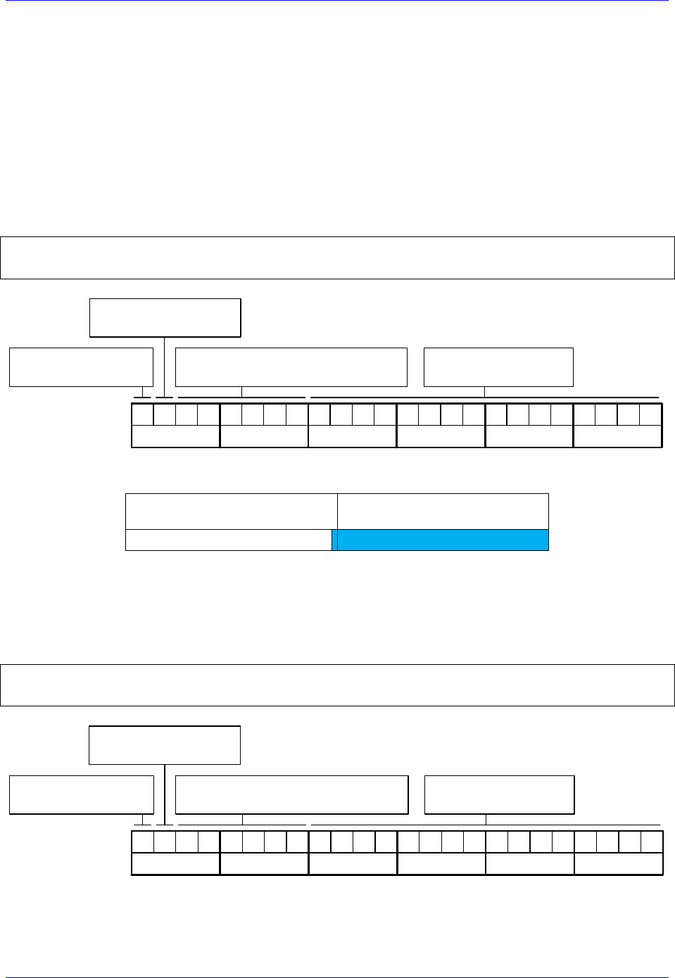
Geo Brick LV User Manual
PinOuts and Software Setup 104
Counts per User Units (Technique 1)
With technique 1, the user should expect to see 2ST counts per revolution for rotary encoders, and
1/Resolution counts per user unit for linear scales in the motor position window.
Examples: 25-bit rotary encoder (13-bit Singleturn): 213= 8,192 cts/rev
1-micron linear scale: 1/0.001= 1,000 cts/mm
Absolute Power-On Position Read (Technique 1)
With Technique 1, the absolute power-on read can be performed using PMAC’s automatic settings
(Ixx80, Ixx10 and Ixx95).
Example 1: Channel 1 driving a 25-bit (13-bit single turn, 12-bit multi-turn) rotary serial encoder:
I180=2 ; Absolute power-on read enabled
I110=$78B20 ; Absolute power-on position address (ch1 serial data register A)
I195=$990000 ; Parallel Read, 25 bits, Signed, from Y-Register –User Input
Bit 23: =1 Signed
=0 Unsigned
10011001
Bit 22: =1 X-Register
=0 Y-Register
Bits16-21: Number of Bits to read
(Resolution 25 bits or 011001 )
Ixx95 Binary:
Hex($): 9 9
00000000
0 0
00000000
0 0
Bits 0-15: reserved
(always 0)
In this mode, PMAC reads and reports 25 bits from the consecutive serial data registers:
Serial Register A
(Ch1 Y:$78B20)
Serial Register B
(Ch1 Y:$78B21)
25 bits
02347
With the setting of Ixx80=2, the actual position is reported automatically on Power-up. Otherwise, a #1$*
command is necessary to read and report the absolute position.
Example 2: Channel 1 driving an 18-bit (18-bit Singleturn, No Multiturn) absolute rotary serial encoder,
or a similar protocol resolution (18 bits) linear scale:
I180=2 ; Absolute power-on read enabled
I110=$78B20 ; Absolute power-on position address (ch1 serial data register A)
I195=$120000 ; Parallel Read, 18 bits, Unsigned, from Y-Register –User Input
Bit 23: =1 Signed
=0 Unsigned
00010010
Bit 22: =1 X-Register
=0 Y-Register
Bits16-21: Number of Bits to read
(Resolution 18 bits or 010010 )
Ixx95 Binary:
Hex($): 1 2
00000000
0 0
00000000
0 0
Bits 0-15: reserved
(always 0)
Geo Brick LV User Manual
PinOuts and Software Setup 105
In this mode, PMAC reads and reports 18 bits from the first serial data register:
Serial Data Register A
(Ch1 Y:$78B20)
Serial Data Register B
(Ch1 Y:$78B21)
18 bits
02347
With this setting of Ixx80=2, the actual position is reported automatically on Power-up. Otherwise, a
#1$* command is necessary to read and report the absolute position.
Note
With absolute serial encoders (no multi-turn data), the power-on
position format is set up for unsigned operation.
Note
The upper two fields in Ixx95 are the only relevant ones. Bits 0
through 15 are reserved and should always be set to 0.
Note
Some serial encoders use an external (not from the Brick) source for
power. Make sure that this power is applied prior to performing an
absolute read on power-up.
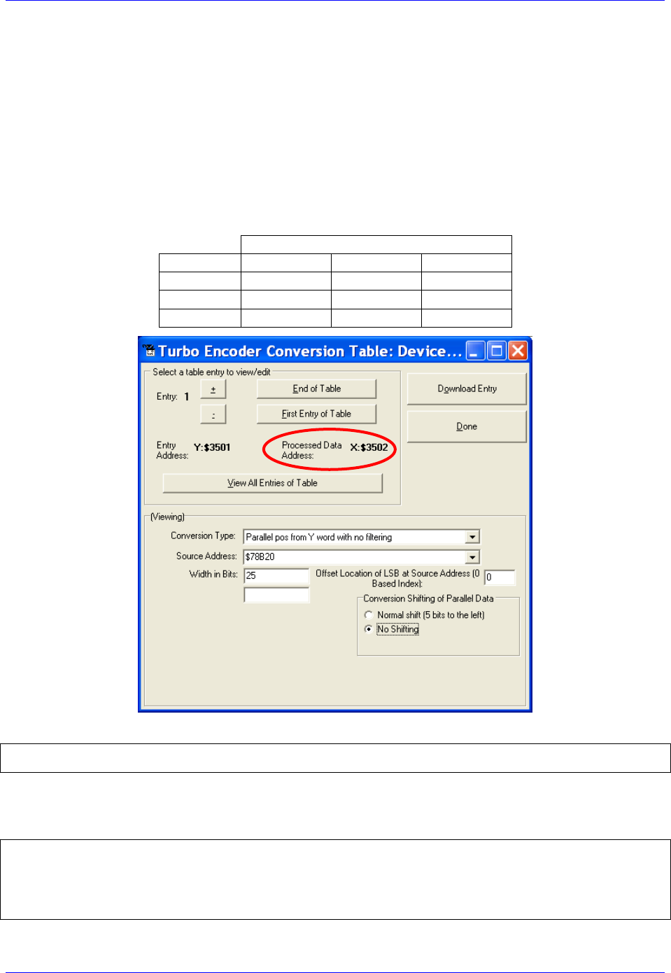
Geo Brick LV User Manual
PinOuts and Software Setup 106
Technique 2 Example
Channel 1 is driving a 37-bit (25-bit Singleturn, 12-bit Multiturn) rotary serial encoder, or a linear scale
with similar protocol resolution (25 bits, 10 nanometer).
Encoder Conversion Table – for Position (Technique 2)
Conversion Type: Parallel pos from Y word with no filtering
Width in Bits: Singleturn/absolute resolution in bits (e.g. 25 bits)
Offset Location of LSB: leave at zero
No shifting
Source Address: serial data register A (see table below)
Remember to click on Download Entry for the changes to take effect.
Source Address (serial data register A)
Channel 1
Y:$78B20
Channel 5
Y:$78B30
Channel 2
Y:$78B24
Channel 6
Y:$78B34
Channel 3
Y:$78B28
Channel 7
Y:$78B38
Channel 4
Y:$78B2C
Channel 8
Y:$78B3C
This is a 2-line ECT entry, its equivalent script code:
I8000=$2F8B20 ; Unfiltered parallel pos of location Y:$78B20
I8001=$19000 ; Width and Offset. Processed result at $3502
Typically, the position and velocity pointers are set to the processed data address (e.g. $3502). Also, with
technique 2, it is recommended to set the position and velocity scale factors to 1 and the position error
limit to its maximum value:
I100=1 ; Mtr#1 Active. Remember to activate the channel to see feedback
I103=$3502 ; Mtr#1 position loop feedback address
I104=$3502 ; Mtr#1 velocity loop feedback address
I108=1 ; Mtr#1 position-loop scale factor
I109=1 ; Mtr#1 velocity-loop scale factor
I167=8388607 ; Mtr#1 Position Error Limit

Geo Brick LV User Manual
PinOuts and Software Setup 107
Note
At this point, you should be able to move the motor/encoder shaft by
hand and see ‘motor’ counts in the position window
Counts per User Units (Technique 2)
With technique 2, the user should expect to see 2ST-5= 2ST/32 counts per revolution for rotary encoders,
and 1/(32*Resolution) counts per user unit for linear scales in the motor position window.
Examples: 37-bit rotary encoder (25-bit Singleturn): 225/32= 1,048,576 cts/rev
10-nanometer linear scale: 1/(32*0.000010)= 3,125 cts/mm
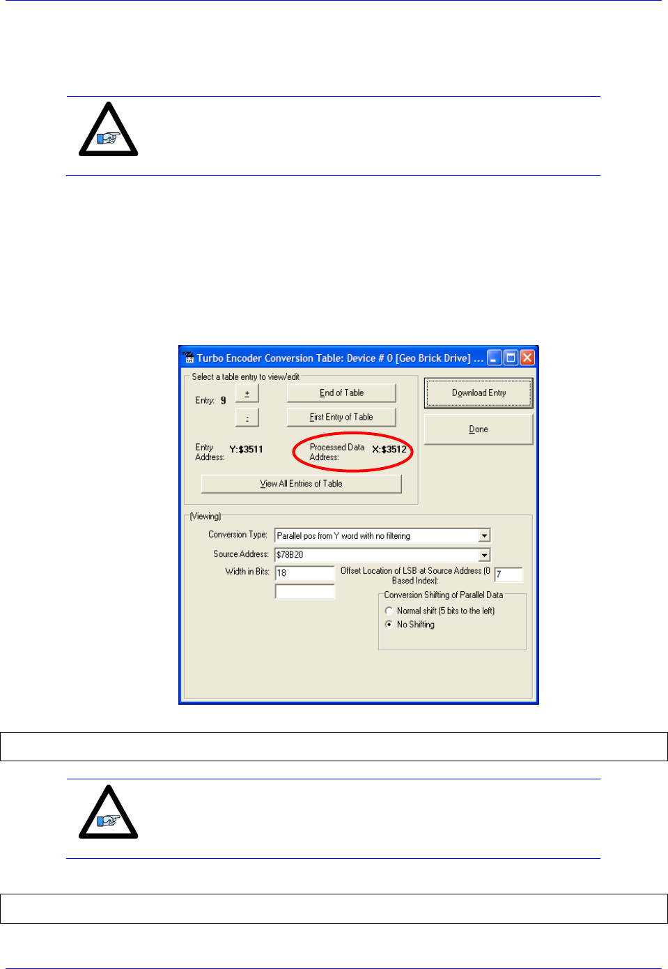
Geo Brick LV User Manual
PinOuts and Software Setup 108
Encoder Conversion Table - for Commutation (Technique 2)
Commutation with Turbo PMAC does not require high resolution data. With Technique 2, it is
recommended to fix it at 18 bits. This will also eliminate quantization noise.
Note
It is recommended to insert the commutation ECT entries after all of
the position ECT entries have been configured.
Assuming that eight encoders have been configured for position, the first ECT for commutation for the
first motor would be at entry number nine:
Conversion Type: Parallel pos from Y word with no filtering
Width in Bits: 18
Offset Location of LSB: = Singleturn/protocol bits – 18 (e.g. 25-18=7)
No shifting
Source Address: serial data register A (same as position ECT for this motor)
Remember to click on Download Entry for the changes to take effect.
This is a 2-line ECT entry, its equivalent script code:
I8016=$2F8B20 ; Unfiltered parallel pos of location Y:$78B20 –User Input
I8017=$12007 ; Width and Offset. Processed result at X:$3512 –User Input
Note
Record the processed data address (e.g. $3512). This is where the
commutation position address Ixx83 will be pointing to. Also, this will
be used in setting up the power-on phasing routine.
The commutation enable, and position address would then be:
I101=1 ; Mtr#1 Commutation enable, from X Register
I183=$3512 ; Mtr#1 Commutation Position Address –User Input
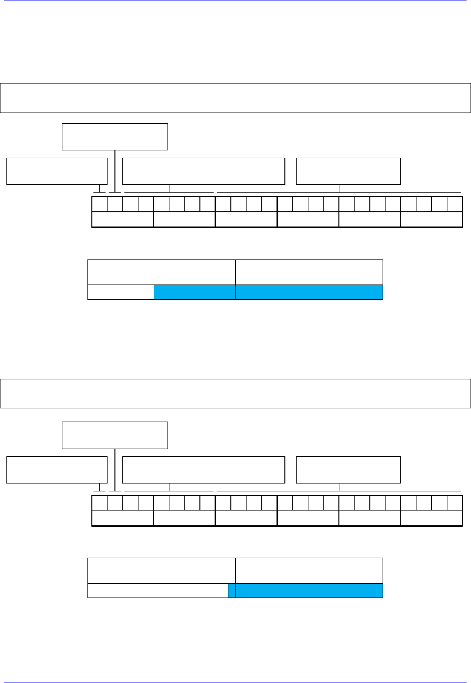
Geo Brick LV User Manual
PinOuts and Software Setup 109
Absolute Power-On Position Read (Technique 2)
With technique 2, the absolute power-on position can be read directly from the serial data registers. But,
proper scaling (5-bit right shift, in a PLC) is required to conform to the unshifted on-going position.
Example 1: Channel 1 driving a 37-bit (25-bit single turn, 12-bit multi-turn) rotary serial encoder:
I180=0 ; Absolute power-on read disabled
I110=$78B20 ; Absolute power-on position address (ch1 serial data register A)
I195=$A50000 ; Parallel Read, 37 bits, Signed, from Y-Register –User Input
Bit 23: =1 Signed
=0 Unsigned
10100101
Bit 22: =1 X-Register
=0 Y-Register
Bits16-21: Number of Bits to read
(Resolution 37 bits or 100101 )
Ixx95 Binary:
Hex($): A 5
00000000
0 0
00000000
0 0
Bits 0-15: reserved
(always 0)
In this mode, PMAC reads 37 bits from the consecutive serial data registers:
Serial Register A
(Ch1 Y:$78B20)
Serial Register B
(Ch1 Y:$78B21)
37 bits
02347
With the setting of Ixx80=0, the actual position is not reported automatically on power-up. It will be
reported after scaling (i.e. in PLC, below).
Example 2: Channel 1 driving a 25-bit (25-bit Singleturn, No Multiturn) absolute rotary serial encoder,
or a similar protocol resolution (25 bits) linear scale:
I180=0 ; Absolute power-on read disabled
I110=$78B20 ; Absolute power-on position address (ch1 serial data register A)
I195=$190000 ; Parallel Read, 25 bits, Unsigned, from Y-Register –User Input
Bit 23: =1 Signed
=0 Unsigned
00011001
Bit 22: =1 X-Register
=0 Y-Register
Bits16-21: Number of Bits to read
(Resolution 25 bits or 011001 )
Ixx95 Binary:
Hex($): 1 9
00000000
0 0
00000000
0 0
Bits 0-15: reserved
(always 0)
In this mode, PMAC reads 25 bits from the first serial data register:
Serial Data Register A
(Ch1 Y:$78B20)
Serial Data Register B
(Ch1 Y:$78B21)
25 bits
02347
With the setting of Ixx80=0, the actual position is not reported automatically on power-up. It will be
reported after scaling (i.e. in PLC, below).

Geo Brick LV User Manual
PinOuts and Software Setup 110
Note
With absolute serial encoders (no multi-turn data), the power-on
position format is set up for unsigned operation.
Note
The upper two fields in Ixx95 are the only relevant ones. Bits 0
through 15 are reserved and should always be set to 0.
Power-On Position scaling PLC example (for technique 2)
M162->D:$00008B ; #1 Actual position (Suggested M-Variable)
Open PLC 1 clear
I5111=100*8388608/I10 while(I5111>0) endw ; 100 msec delay
CMD“#1K“ ; Make sure motor(s) killed
I5111=100*8388608/I10 while(I5111>0) endw ; 100 msec delay
CMD“#1$*“ ; Read un-scaled absolute position
I5111=100*8388608/I10 while(I5111>0) endw ; 100 msec delay
M162=M162/32 ; Scale absolute position (shift right 5 bits)
I5111=100*8388608/I10 while(I5111>0) endw ; 100 msec delay
Dis PLC 1 ; Run once on power-up or reset
Close
Note
Some serial encoders use an external (not from the Brick) source for
power. Make sure that this power is applied prior to performing an
absolute read on power-up.
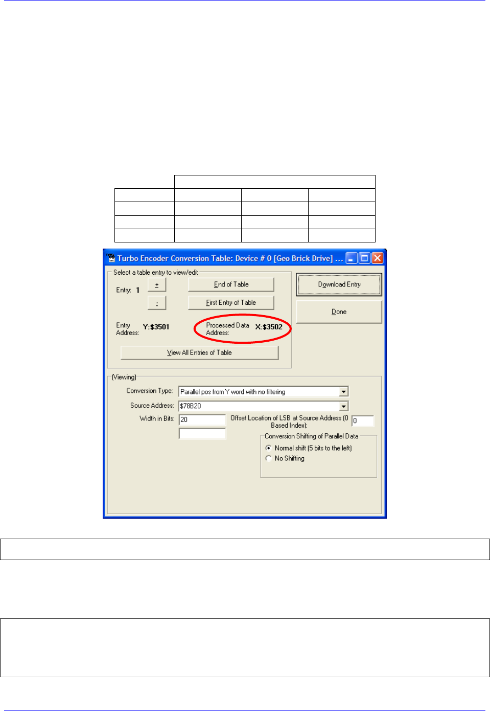
Geo Brick LV User Manual
PinOuts and Software Setup 111
Technique 3 Example
Channel 1 is driving a 32-bit (20-bit Singleturn, 12-bit Multiturn) rotary serial encoder, or a linear scale
with similar protocol resolution (20 bits, 0.1 micron).
Encoder Conversion Table - for Position (Technique 3)
Conversion Type: Parallel pos from Y word with no filtering
Width in Bits: Singleturn/absolute resolution in bits (e.g. 20 bits)
Offset Location of LSB: leave at zero
Normal Shift (5 bits to the left)
Source Address : serial data register A (see table below)
Remember to click on Download Entry for the changes to take effect.
Source Address ( serial data register A)
Channel 1
Y:$78B20
Channel 5
Y:$78B30
Channel 2
Y:$78B24
Channel 6
Y:$78B34
Channel 3
Y:$78B28
Channel 7
Y:$78B38
Channel 4
Y:$78B2C
Channel 8
Y:$78B3C
This is a 2-line ECT entry, its equivalent script code:
I8000=$278B20 ; Unfiltered parallel pos of location Y:$78B20
I8001=$014000 ; Width and Offset. Processed result at $3502
Typically, the position and velocity pointers are set to the processed data address (e.g. $3502). With
Singleturn or linear resolutions less than 20 bits, the position/velocity scale factors, and position error
limit can be left at default values. But with resolutions of 20 bits or greater, it is recommended to set the
scale factors to 1 and the position error limit to its maximum value:
I100=1 ; Mtr#1 Active. Remember to activate the channel to see feedback
I103=$3502 ; Mtr#1 position loop feedback address
I104=$3502 ; Mtr#1 velocity loop feedback address
I108=1 ; Mtr#1 position-loop scale factor
I109=1 ; Mtr#1 velocity-loop scale factor
I167=8388607 ; Mtr#1 Position Error Limit

Geo Brick LV User Manual
PinOuts and Software Setup 112
Note
At this point, you should be able to move the motor/encoder shaft by
hand and see ‘motor’ counts in the position window.
Counts per User Units (Technique 3)
With technique 3, the user should expect to see 2ST counts per revolution for rotary encoders, and
1/Resolution counts per user unit for linear scales in the motor position window.
Examples: 32-bit rotary encoder (20-bit Singleturn): 220= 1,048,576 cts/rev
0.1-micron linear scale: 1/0.0001= 10,000 cts/mm
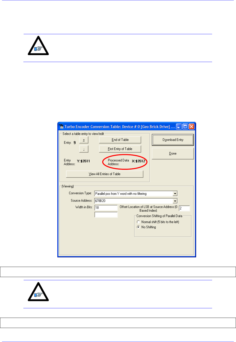
Geo Brick LV User Manual
PinOuts and Software Setup 113
Encoder Conversion Table - for Commutation (Technique 3)
Commutation with Turbo PMAC does not require high resolution data. With Technique 3, it is
recommended to fix it at 18 bits. This will also eliminate quantization noise.
Note
It is recommended to insert the commutation ECT entries after all of
the position ECT entries have been configured.
Assuming that eight encoders have been configured for position, the first ECT for commutation for the
first motor would be at entry number nine:
Conversion Type: Parallel pos from Y word with no filtering
Width in Bits: 18
Offset Location of LSB = Singleturn/protocol bits – 18 (e.g. 20-18=2)
No shifting
Source Address: Serial data register A (same as position ECT for this motor)
Remember to click on Download Entry for the changes to take effect.
This is a 2-line ECT entry, its equivalent script code:
I8016=$2F8B20 ; Unfiltered parallel pos of location Y:$78B20 –User Input
I8017=$12002 ; Width and Offset. Processed result at X:$3512 –User Input
Note
Record the processed data address (e.g. $3512). This is where the
commutation position address Ixx83 will be pointing to. Also, this will
be used in setting up the power-on phasing routine.
The commutation enable, and position address would then be:
I101=1 ; Mtr#1 Commutation enable, from X Register
I183=$3512 ; Mtr#1 Commutation Position Address –User Input
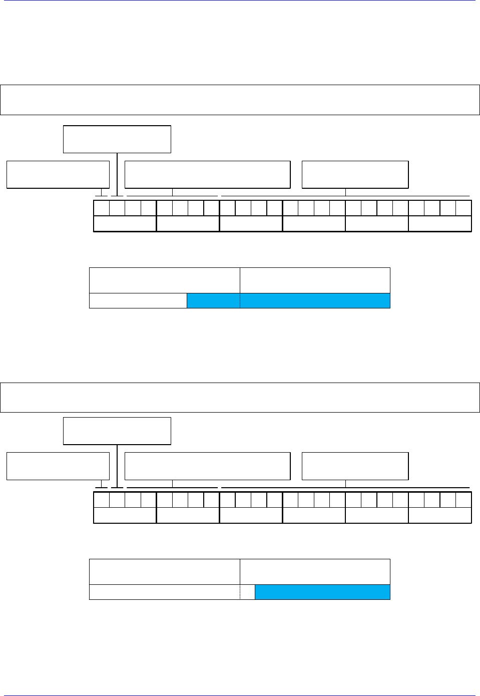
Geo Brick LV User Manual
PinOuts and Software Setup 114
Absolute Power-On Position Read (Technique 3)
With Technique 3, the absolute power-on read can be performed using PMAC’s automatic settings
(Ixx80, Ixx10 and Ixx95).
Example 1: Channel 1 driving a 32-bit (20-bit single turn, 12-bit multi-turn) rotary serial encoder:
I180=2 ; Absolute power-on read enabled
I110=$78B20 ; Absolute power-on position address (ch1 serial data register A)
I195=$A00000 ; Parallel Read, 32 bits, Signed, from Y-Register –User Input
Bit 23: =1 Signed
=0 Unsigned
10100000
Bit 22: =1 X-Register
=0 Y-Register
Bits16-21: Number of Bits to read
(Resolution 32 bits or 100000 )
Ixx95 Binary:
Hex($): A 0
00000000
0 0
00000000
0 0
Bits 0-15: reserved
(always 0)
In this mode, PMAC reads and reports 32 bits from the consecutive serial data registers:
Serial Data Register A
(Ch1 Y:$78B20)
Serial Data Register B
(Ch1 Y:$78B21)
32 bits
02347
With the setting of Ixx80=2, the actual position is reported automatically on Power-up. Otherwise, a #1$*
command is necessary to read and report the absolute position.
Example 2: Channel 1 driving a 20-bit (20-bit Singleturn, No Multiturn) absolute rotary serial encoder,
or a similar protocol resolution (20 bits) linear scale:
I180=2 ; Absolute power-on read enabled
I110=$78B20 ; Absolute power-on position address (ch1 serial data register A)
I195=$140000 ; Parallel Read, 20 bits, Unsigned, from Y-Register –User Input
Bit 23: =1 Signed
=0 Unsigned
00010100
Bit 22: =1 X-Register
=0 Y-Register
Bits16-21: Number of Bits to read
(Resolution 20 bits or 010100 )
Ixx95 Binary:
Hex($): 1 4
00000000
0 0
00000000
0 0
Bits 0-15: reserved
(always 0)
In this mode, PMAC reads and reports 20 bits from the first serial data register:
Serial Data Register A
(Ch1 Y:$78B20)
Serial Data Register B
(Ch1 Y:$78B21)
20 bits
02347
With the setting of Ixx80=2, the actual position is reported automatically on Power-up. Otherwise, a #1$*
command is necessary to read and report the absolute position.

Geo Brick LV User Manual
PinOuts and Software Setup 115
Note
With absolute serial encoders (no multi-turn data), the power-on
position format is set up for unsigned operation.
Note
The upper two fields in Ixx95 are the only relevant ones. Bits 0
through 15 are reserved and should always be set to 0.
Note
Some serial encoders use an external (not from the Brick) source for
power. Make sure that this power is applied prior to performing an
absolute read on power-up.
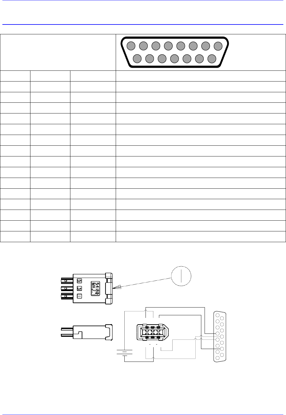
Geo Brick LV User Manual
PinOuts and Software Setup 116
X1-X8: Encoder Feedback, Yaskawa Sigma II & III
X1-X8: D-sub DA-15F
Mating: D-sub DA-15M
2
3
4
5
6
7
8
9
10
11
12
13
14
15
1
Pin #
Symbol
Function
Notes
1
2
3
4
EncPwr
Output
Encoder Power 5 Volts
5
SDI
Input
Serial Data In
6
7
8
9
10
11
12
GND
Common
Common Ground
13
14
SDO
Output
Serial Data Out
15
If you prefer to keep the original Molex connector on the Yaskawa encoder cable, the following converter
can be used to attach to the Brick D-sub DA-15F:
135
246
12345678
9101112131415
Yaskawa Encoder Cable has FEMALE Connector by defalut
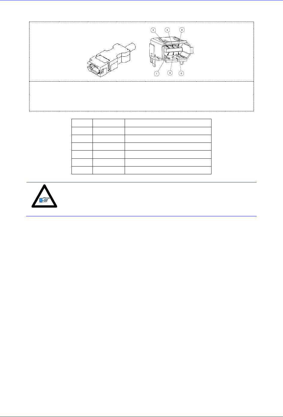
Geo Brick LV User Manual
PinOuts and Software Setup 117
Molex 2.00 mm (.079") Pitch Serial I/O Connector, Receptacle Kit, Wire-to-Wire.
Part Number: 0542800609
Pin #
Function
Wire Color code
1
+5VDC
RED
2
GND
BLACK
3
BAT+
Orange
4
BAT-
Orange/Black (Orange/White)
5
SDO
Blue
6
SDI
Blue/Black (Blue/White)
Note
All Yaskawa Sigma II & Sigma III protocols, whether incremental or
absolute and regardless of the resolution, are supported.
This option allows the Brick to connect to up to eight Yaskawa devices. Setting up the Yaskawa Sigma
interface correctly requires the programming of two essential control registers:
Global Control Registers
Channel Control Registers
The resulting data is found in:
Yaskawa Data Registers
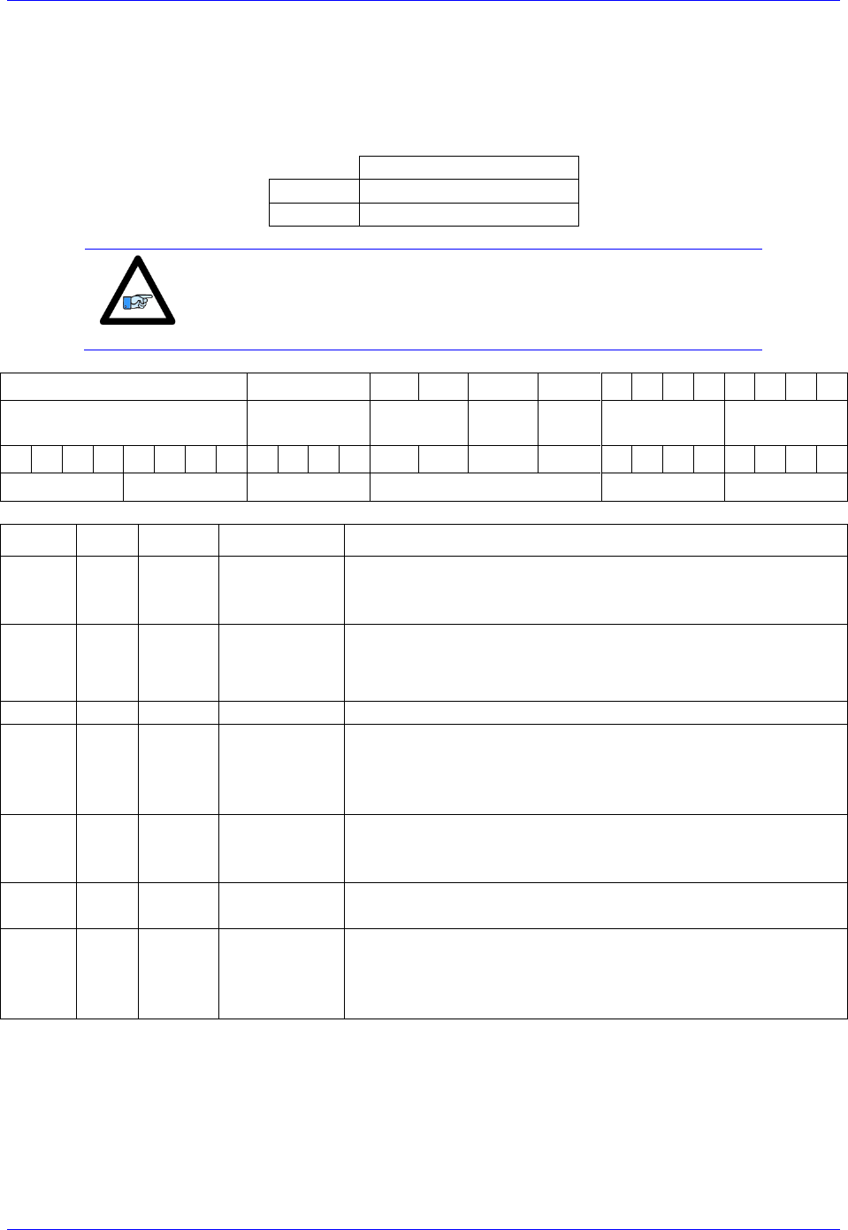
Geo Brick LV User Manual
PinOuts and Software Setup 118
Global Control Registers
X:$78BnF (default value: $002003) where n=2 for axes 1-4
n=3 for axes 5-8
Global Control Register
Axes 1-4
X:$78B2F
Axes 5-8
X:$78B3F
Note
With the Yaskawa option, the Global Control Register is pre-set and
need not be changed.
[23-16]
[15-12]
11
10
9
8
7
6
5
4
3
2
1
0
M Divisor
N Divisor
Reserved
Trig.
Clock
Trig.
Edge
Trigger
Delay
Protocol
Code
0
0
0
0
0
0
0
0
0
0
0
0
0
0
0
0
0
0
0
0
0
1
1
0
0
0
0
0
0
6
Bit
Type
Default
Name
Description
[23:16]
R/W
0x00
M_Divisor
Intermediate clock frequency for SER_Clock. The
intermediate clock is generated from a (M+1) divider clocked
at 100 MHz.
[15:12]
R/W
0x0
N_Divisor
Final clock frequency for SER_Clock. The final clock is
generated from a
N
2
divider clocked by the intermediate
clock.
[11:10]
R
00
Reserved
Reserved and always reads zero.
[09]
R/W
0
TriggerClock
Trigger clock select for initiating serial encoder
communications:
0= PhaseClock
1= ServoClock
[08]
R/W
0
TriggerEdge
Active clock edge select for the trigger clock:
0= rising edge
1= falling edge
[07:04]
R/W
0x0
TriggerDelay
Trigger delay program relative to the active edge of the
trigger clock. Units are in increments of 20 usec.
[03:00]
R
ProtocolCode
This read-only bit field is used to read the serial interface
protocol supported by the FPGA.
A value of $5 defines this protocol as Yaskawa Sigma I.
A value of $6 defines this protocol as Yaskawa Sigma II.

Geo Brick LV User Manual
PinOuts and Software Setup 119
Channel Control Registers
X:$78Bn0, X:$78Bn4, X:$78Bn8, X:$78BnC where: n=2 for axes 1-4
n=3 for axes 5-8
Channel 1
X:$78B20
Channel 5
X:$78B20
Channel 2
X:$78B24
Channel 6
X:$78B34
Channel 3
X:$78B28
Channel 7
X:$78B38
Channel 4
X:$78B2C
Channel 8
X:$78B3C
Bits 10, 12, and 13 are the only fields to be configured in the Channel Control Registers with the
Yaskawa option. The rest is protocol information. This has to be done in a startup PLC to execute once on
power up.
[23:14]
13
12
11
10
[9:0]
Reserved
Trig.
Mode
Trig.
Enable
RxData Ready/
SENC
Reserved
Bit
Type
Default
Name
Description
[23:14]
R
0x000
Reserved
Reserved and always reads zero.
[13]
R/W
0
Trigger Mode
Trigger Mode to initiate communication:
0= continuous trigger
1= one-shot trigger
All triggers occur at the defined Phase/Servo clock edge and
delay setting. See Global Control register for these settings.
[12]
R/W
0
Trigger
Enable
Enable trigger for serial encoder communications:
0= disabled
1= enabled
This bit must be set for either trigger mode. If the Trigger
Mode bit is set for one-shot mode, the hardware will
automatically clear this bit after the trigger occurs.
[11]
R/W
0
Reserved
Reserved and always reads zero.
[10]
R
0
RxData Ready
This read-only bit provides the received data status. It is low
while the interface logic is communicating (busy) with the
serial encoder. It is high when all the data has been received
and processed.
W
0
SENC_MODE
This write-only bit is used to enable the output drivers for
the SENC_SDO, SENC_CLK, SENC_ENA pins for each
respective channel. It also directly drives the respective
SENC_MODE pin for each channel.
[09:00]
R
0x0
Reserved
Reserved and always reads zero.

Geo Brick LV User Manual
PinOuts and Software Setup 120
Yaskawa Feedback Channel Control Power-On Example PLC (Motors 1-8)
This code statement can be added to your existing initialization PLC.
End Gat
Del Gat
Close
Open PLC 1 clear
CMD"WX:$78B20,$1400"
CMD"WX:$78B24,$1400"
CMD"WX:$78B28,$1400"
CMD"WX:$78B2C,$1400"
CMD"WX:$78B30,$1400"
CMD"WX:$78B34,$1400"
CMD"WX:$78B38,$1400"
CMD"WX:$78B3C,$1400"
Disable plc 1
Close
Yaskawa Data Registers
Yaskawa Data Registers
Channel 1
Y:$78B20
Channel 5
Y:$78B20
Channel 2
Y:$78B24
Channel 6
Y:$78B34
Channel 3
Y:$78B28
Channel 7
Y:$78B38
Channel 4
Y:$78B2C
Channel 8
Y:$78B3C
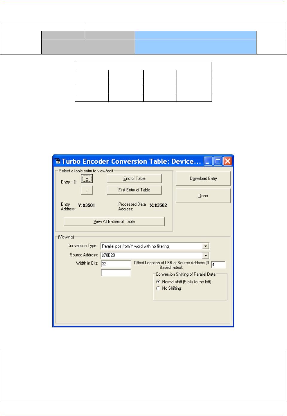
Geo Brick LV User Manual
PinOuts and Software Setup 121
Yaskawa Sigma II 16-Bit Absolute Encoder
Y:$78B21
Y:$78B20
[23-12]
[11-0]
[23-20]
[19-4]
[3:0]
Multi-Turn Position
(16-bits)
Absolute Single Turn Data
(16-bits)
Yaskawa Data Registers
Channel 1
Y:$78B20
Channel 5
Y:$78B30
Channel 2
Y:$78B24
Channel 6
Y:$78B34
Channel 3
Y:$78B28
Channel 7
Y:$78B38
Channel 4
Y:$78B2C
Channel 8
Y:$78B3C
The on-going servo and commutation position data is setup using a 2-line Entry in the Encoder
Conversion Table. The first line represents a Parallel Y-Word with no filtering ($2) from the
corresponding Yaskawa data register/channel. The second line represents the width of the data to be read
and bit location of the LSB of the data in the source word.
Channel 1, Yaskawa Sigma II 16-bit Absolute Encoder Setup Example
Encoder Conversion Table Setup (Motors 1-8)
The ECT automatic entry is equivalent to:
I8000=$278B20 ; Entry 1 Unfiltered parallel pos of location Y:$78B20
I8001=$020004 ; Width and Bias, total of 32-bits LSB starting at bit#4
I8002=$278B24 ; Entry 2 Unfiltered parallel pos of location Y:$78B24
I8003=$020004 ; Width and Bias, total of 32-bits LSB starting at bit#4
I8004=$278B28 ; Entry 3 Unfiltered parallel pos of location Y:$78B28
I8005=$020004 ; Width and Bias, total of 32-bits LSB starting at bit#4
I8006=$278B2C ; Entry 4 Unfiltered parallel pos of location Y:$78B2C

Geo Brick LV User Manual
PinOuts and Software Setup 122
I8007=$020004 ; Width and Bias, total of 32-bits LSB starting at bit#4
I8008=$278B30 ; Entry 5 Unfiltered parallel pos of location Y:$78B30
I8009=$020004 ; Width and Bias, total of 32-bits LSB starting at bit#4
I8010=$278B34 ; Entry 6 Unfiltered parallel pos of location Y:$78B34
I8011=$020004 ; Width and Bias, total of 32-bits LSB starting at bit#4
I8012=$278B38 ; Entry 7 Unfiltered parallel pos of location Y:$78B38
I8013=$020004 ; Width and Bias, total of 32-bits LSB starting at bit#4
I8014=$278B3C ; Entry 8 Unfiltered parallel pos of location Y:$78B3C
I8015=$020004 ; Width and Bias, total of 32-bits LSB starting at bit#4
Position (Ixx03) and Velocity (Ixx04) Pointers
I103=$3502 ; Motor 1 Position feedback address, ECT processed data
I104=$3502 ; Motor 1 Velocity feedback address, ECT processed data
I203=$3504 ; Motor 2 Position feedback address, ECT processed data
I204=$3504 ; Motor 2 Velocity feedback address, ECT processed data
I303=$3506 ; Motor 3 Position feedback address, ECT processed data
I304=$3506 ; Motor 3 Velocity feedback address, ECT processed data
I403=$3508 ; Motor 4 Position feedback address, ECT processed data
I404=$3508 ; Motor 4 Velocity feedback address, ECT processed data
I503=$350A ; Motor 5 Position feedback address, ECT processed data
I504=$350A ; Motor 5 Velocity feedback address, ECT processed data
I603=$350C ; Motor 6 Position feedback address, ECT processed data
I604=$350C ; Motor 6 Velocity feedback address, ECT processed data
I703=$350E ; Motor 7 Position feedback address, ECT processed data
I704=$350E ; Motor 7 Velocity feedback address, ECT processed data
I803=$3510 ; Motor 8 Position feedback address, ECT processed data
I804=$3510 ; Motor 8 Velocity feedback address, ECT processed data
Motor Activation
I100,8,100=1 ; Motors 1-8 Activated
Note
At this point of the setup process, you should be able to move the
motor/encoder shaft by hand and see encoder counts in the position
window.

Geo Brick LV User Manual
PinOuts and Software Setup 123
Absolute Power-On Position Read (Yaskawa 16-bit)
Channel 1 example PLC, 16-bit Absolute Sigma II Encoder
End Gat
Del Gat
Close
#define STD0_15 M7000 ; Single-turn Data 0-15 (16-bits)
#define MTD0_3 M7001 ; Multi-Turn Data 0-3 (4-bits)
#define MTD4_15 M7002 ; Multi-Turn Data 4-15 (12-bits)
#define MTD0_15 M7003 ; Multi-Turn Data 0-15 (16-bits)
STD0_15->Y:$78B20,4,16
MTD0_3->Y:$78B20,20,4
MTD4_15->Y:$78B21,0,12
MTD0_15->*
#define Mtr1ActPos M162
Mtr1ActPos->D:$00008B ; #1 Actual position (1/[Ixx08*32] cts)
Open plc 1 clear
MTD0_15 = MTD4_15 * $10 + MTD0_3
If (MTD0_15>$7FFF)
MTD0_15 = (MTD0_15^$FFFF + 1)*-1
If (STD0_15 !=0)
STD0_15 = (STD0_15^$FFFF + 1)*-1
Endif
Endif
Mtr1ActPos = ((MTD0_15 * $10000)+ STD0_15) * I108 * 32
disable plc 1
close
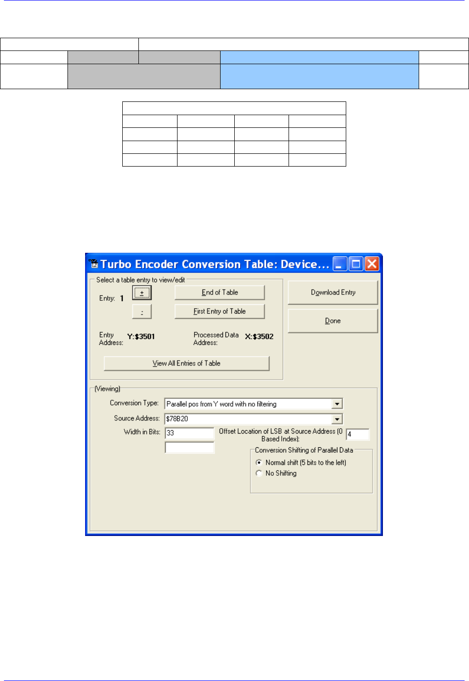
Geo Brick LV User Manual
PinOuts and Software Setup 124
Yaskawa Sigma II 17-Bit Absolute Encoder
Y:$78B21
Y:$78B20
[23-13]
[12-0]
[23-21]
[20-4]
[3:0]
Multi-Turn Position
(16-bits)
Absolute Single Turn Data
(17-bits)
Yaskawa Data Registers
Channel 1
Y:$78B20
Channel 5
Y:$78B30
Channel 2
Y:$78B24
Channel 6
Y:$78B34
Channel 3
Y:$78B28
Channel 7
Y:$78B38
Channel 4
Y:$78B2C
Channel 8
Y:$78B3C
The on-going servo and commutation position data is setup using a 2-line Entry in the Encoder
Conversion Table. The first line represents a Parallel Y-Word with no filtering ($2) from the
corresponding Yaskawa data register/channel. The second line represents the width of the data to be read
and bit location of the LSB of the data in the source word.
Channel 1, Yaskawa Sigma II 17-bit Absolute Encoder Setup Example

Geo Brick LV User Manual
PinOuts and Software Setup 125
Encoder Conversion Table Setup (Motors 1-8)
The ECT automatic entry is equivalent to:
I8000=$278B20 ; Entry 1 Unfiltered parallel pos of location Y:$78B20
I8001=$021004 ; Width and Bias, total of 33-bits LSB starting at bit#4
I8002=$278B24 ; Entry 2 Unfiltered parallel pos of location Y:$78B24
I8003=$021004 ; Width and Bias, total of 33-bits LSB starting at bit#4
I8004=$278B28 ; Entry 3 Unfiltered parallel pos of location Y:$78B28
I8005=$021004 ; Width and Bias, total of 33-bits LSB starting at bit#4
I8006=$278B2C ; Entry 4 Unfiltered parallel pos of location Y:$78B2C
I8007=$021004 ; Width and Bias, total of 33-bits LSB starting at bit#4
I8008=$278B30 ; Entry 5 Unfiltered parallel pos of location Y:$78B30
I8009=$021004 ; Width and Bias, total of 33-bits LSB starting at bit#4
I8010=$278B34 ; Entry 6 Unfiltered parallel pos of location Y:$78B34
I8011=$021004 ; Width and Bias, total of 33-bits LSB starting at bit#4
I8012=$278B38 ; Entry 7 Unfiltered parallel pos of location Y:$78B38
I8013=$021004 ; Width and Bias, total of 33-bits LSB starting at bit#4
I8014=$278B3C ; Entry 8 Unfiltered parallel pos of location Y:$78B3C
I8015=$021004 ; Width and Bias, total of 33-bits LSB starting at bit#4
Position (Ixx03) and Velocity (Ixx04) Pointers
I103=$3502 ; Motor 1 Position feedback address, ECT processed data
I104=$3502 ; Motor 1 Velocity feedback address, ECT processed data
I203=$3504 ; Motor 2 Position feedback address, ECT processed data
I204=$3504 ; Motor 2 Velocity feedback address, ECT processed data
I303=$3506 ; Motor 3 Position feedback address, ECT processed data
I304=$3506 ; Motor 3 Velocity feedback address, ECT processed data
I403=$3508 ; Motor 4 Position feedback address, ECT processed data
I404=$3508 ; Motor 4 Velocity feedback address, ECT processed data
I503=$350A ; Motor 5 Position feedback address, ECT processed data
I504=$350A ; Motor 5 Velocity feedback address, ECT processed data
I603=$350C ; Motor 6 Position feedback address, ECT processed data
I604=$350C ; Motor 6 Velocity feedback address, ECT processed data
I703=$350E ; Motor 7 Position feedback address, ECT processed data
I704=$350E ; Motor 7 Velocity feedback address, ECT processed data
I803=$3510 ; Motor 8 Position feedback address, ECT processed data
I804=$3510 ; Motor 8 Velocity feedback address, ECT processed data
Motor Activation
I100,8,100=1 ; Motors 1-8 Activated
Note
At this point of the setup process, you should be able to move the
motor/encoder shaft by hand and see encoder counts in the position
window.

Geo Brick LV User Manual
PinOuts and Software Setup 126
Absolute Power-On Position Read (Yaskawa 17-bit)
Channel 1 example PLC, 17-bit Absolute Sigma II Encoder
End Gat
Del Gat
Close
#define FirstWord M7000 ; Yaskawa Data Register1, 1st word
#define SecondWord M7001 ; Yaskawa Data Register1, 2nd word
#define STD0_16 M7002 ; Single-Turn Data 0-16 (17-bits)
#define MTD0_15 M7003 ; Multi-Turn Data 0-15 (16-bits)
FirstWord->Y:$78B20,0,24
SecondWord->Y:$78B21,0,4
STD0_16->*
MTD0_15->*
#define Mtr1ActPos M162
Mtr1ActPos->D:$00008B ; #1 Actual position (1/[Ixx08*32] cts)
open plc 1 clear
MTD0_15 = (SecondWord & $1FFF) * $8 + int (FirstWord / 2097152)
STD0_16 = int ((FirstWord & $1FFFF0) / 16)
If (MTD0_15>$7FFF)
MTD0_15 = (MTD0_15^$FFFF + 1)*-1
If (STD0_16 !=0)
STD0_16 = (STD0_16^$1FFFF + 1)*-1
Endif
Endif
Mtr1ActPos = ((MTD0_15 * $20000)+ STD0_16) * I108 * 32
disable plc 1
close

Geo Brick LV User Manual
PinOuts and Software Setup 127
Yaskawa Sigma III 20-Bit Absolute Encoder
Y:$78B21
Y:$78B20
[23-16]
[15-0]
[23-4]
[3:0]
Multi-Turn Position
(16-bits)
Absolute Single Turn Data
(20-bits)
Yaskawa Data Registers
Channel 1
Y:$78B20
Channel 5
Y:$78B30
Channel 2
Y:$78B24
Channel 6
Y:$78B34
Channel 3
Y:$78B28
Channel 7
Y:$78B38
Channel 4
Y:$78B2C
Channel 8
Y:$78B3C
The on-going servo and commutation position data is setup using a 2-line Entry in the Encoder
Conversion Table. The first line represents a Parallel Y-Word with no filtering ($2) from the
corresponding Yaskawa data register/channel. The second line represents the width of the data to be read
and bit location of the LSB of the data in the source word.
Channel 1, Yaskawa Sigma III 20-bit Absolute Encoder Setup Example

Geo Brick LV User Manual
PinOuts and Software Setup 128
Encoder Conversion Table Setup (Motors 1-8)
The ECT automatic entry is equivalent to:
I8000=$278B20 ; Entry 1 Unfiltered parallel pos of location Y:$78B20
I8001=$024004 ; Width and Bias, total of 36-bits LSB starting at bit#4
I8002=$278B24 ; Entry 2 Unfiltered parallel pos of location Y:$78B24
I8003=$024004 ; Width and Bias, total of 36-bits LSB starting at bit#4
I8004=$278B28 ; Entry 3 Unfiltered parallel pos of location Y:$78B28
I8005=$024004 ; Width and Bias, total of 36-bits LSB starting at bit#4
I8006=$278B2C ; Entry 4 Unfiltered parallel pos of location Y:$78B2C
I8007=$024004 ; Width and Bias, total of 36-bits LSB starting at bit#4
I8008=$278B30 ; Entry 5 Unfiltered parallel pos of location Y:$78B30
I8009=$024004 ; Width and Bias, total of 36-bits LSB starting at bit#4
I8010=$278B34 ; Entry 6 Unfiltered parallel pos of location Y:$78B34
I8011=$024004 ; Width and Bias, total of 36-bits LSB starting at bit#4
I8012=$278B38 ; Entry 7 Unfiltered parallel pos of location Y:$78B38
I8013=$024004 ; Width and Bias, total of 36-bits LSB starting at bit#4
I8014=$278B3C ; Entry 8 Unfiltered parallel pos of location Y:$78B3C
I8015=$024004 ; Width and Bias, total of 36-bits LSB starting at bit#4
Position (Ixx03) and Velocity (Ixx04) Pointers
I103=$3502 ; Motor 1 Position feedback address, ECT processed data
I104=$3502 ; Motor 1 Velocity feedback address, ECT processed data
I203=$3504 ; Motor 2 Position feedback address, ECT processed data
I204=$3504 ; Motor 2 Velocity feedback address, ECT processed data
I303=$3506 ; Motor 3 Position feedback address, ECT processed data
I304=$3506 ; Motor 3 Velocity feedback address, ECT processed data
I403=$3508 ; Motor 4 Position feedback address, ECT processed data
I404=$3508 ; Motor 4 Velocity feedback address, ECT processed data
I503=$350A ; Motor 5 Position feedback address, ECT processed data
I504=$350A ; Motor 5 Velocity feedback address, ECT processed data
I603=$350C ; Motor 6 Position feedback address, ECT processed data
I604=$350C ; Motor 6 Velocity feedback address, ECT processed data
I703=$350E ; Motor 7 Position feedback address, ECT processed data
I704=$350E ; Motor 7 Velocity feedback address, ECT processed data
I803=$3510 ; Motor 8 Position feedback address, ECT processed data
I804=$3510 ; Motor 8 Velocity feedback address, ECT processed data
Motor Activation
I100,8,100=1 ; Motors 1-8 Activated
Note
At this point of the setup process, you should be able to move the
motor/encoder shaft by hand and see encoder counts in the position
window.

Geo Brick LV User Manual
PinOuts and Software Setup 129
Absolute Power-On Position Read (Yaskawa 20-bit)
Channel 1 example PLC, 20-bit Absolute Sigma III Encoder
End Gat
Del Gat
Close
#define FirstWord M1000 ; Yaskawa Data Register1, 1st word
#define SecondWord M1001 ; Yaskawa Data Register1, 2nd word
#define STD0_19 M1002 ; Single-Turn Data 0-19 (20-bits)
#define MTD0_15 M1003 ; Multi-Turn Data 0-15 (16-bits)
FirstWord->Y:$78B20,0,24
SecondWord->Y:$78B21,0,4
STD0_19->*
MTD0_15->*
#define Mtr1ActPos M162
Mtr1ActPos->D:$00008B ; #1 Actual position (1/[Ixx08*32] cts)
open plc 1 clear
MTD0_15 = (SecondWord & $FFFF)
STD0_19 = int ((FirstWord & $FFFFF0) / 16)
If (MTD0_15>$7FFF)
MTD0_15 = (MTD0_15^$FFFF + 1)*-1
If (STD0_19 !=0)
STD0_19 = (STD0_19^$FFFFF + 1)*-1
Endif
Endif
Mtr1ActPos = ((MTD0_15 * $100000)+ STD0_19) * I108 * 32
disable plc 1
close

Geo Brick LV User Manual
PinOuts and Software Setup 130
Yaskawa Sigma II 13-Bit Incremental Encoder
Y:$78B21
Y:$78B20
[23-11]
[10-0]
23
[22-11]
[10:4]
3
2
1
0
Incremental Compensation
(11-bits)
Incremental Position in
Single Turn
(13-bits)
U
V
W
Z
Yaskawa Data Registers
Channel 1
Y:$78B20
Channel 5
Y:$78B30
Channel 2
Y:$78B24
Channel 6
Y:$78B34
Channel 3
Y:$78B28
Channel 7
Y:$78B38
Channel 4
Y:$78B2C
Channel 8
Y:$78B3C
The on-going servo and commutation position data is setup using a 2-line Entry in the Encoder
Conversion Table. The first line represents a Parallel Y-Word with no filtering ($2) from the
corresponding Yaskawa data register/channel. The second line represents the width of the data to be read
and bit location of the LSB of the data in the source word.
Channel 1, Yaskawa Sigma II 13-bit Incremental Encoder Setup Example

Geo Brick LV User Manual
PinOuts and Software Setup 131
Encoder Conversion Table Setup (Motors 1-8)
The ECT automatic entry is equivalent to:
I8000=$278B20 ; Entry 1 Unfiltered parallel pos of location Y:$78B20
I8001=$00D006 ; Width and Bias, total of 13-bits LSB starting at bit#6
I8002=$278B24 ; Entry 2 Unfiltered parallel pos of location Y:$78B24
I8003=$00D006 ; Width and Bias, total of 13-bits LSB starting at bit#6
I8004=$278B28 ; Entry 3 Unfiltered parallel pos of location Y:$78B28
I8005=$00D006 ; Width and Bias, total of 13-bits LSB starting at bit#6
I8006=$278B2C ; Entry 4 Unfiltered parallel pos of location Y:$78B2C
I8007=$00D006 ; Width and Bias, total of 13-bits LSB starting at bit#6
I8008=$278B30 ; Entry 5 Unfiltered parallel pos of location Y:$78B30
I8009=$00D006 ; Width and Bias, total of 13-bits LSB starting at bit#6
I8010=$278B34 ; Entry 6 Unfiltered parallel pos of location Y:$78B34
I8011=$00D006 ; Width and Bias, total of 13-bits LSB starting at bit#6
I8012=$278B38 ; Entry 7 Unfiltered parallel pos of location Y:$78B38
I8013=$00D006 ; Width and Bias, total of 13-bits LSB starting at bit#6
I8014=$278B3C ; Entry 8 Unfiltered parallel pos of location Y:$78B3C
I8015=$00D006 ; Width and Bias, total of 13-bits LSB starting at bit#6
Position (Ixx03) and Velocity (Ixx04) Pointers
I103=$3502 ; Motor 1 Position feedback address, ECT processed data
I104=$3502 ; Motor 1 Velocity feedback address, ECT processed data
I203=$3504 ; Motor 2 Position feedback address, ECT processed data
I204=$3504 ; Motor 2 Velocity feedback address, ECT processed data
I303=$3506 ; Motor 3 Position feedback address, ECT processed data
I304=$3506 ; Motor 3 Velocity feedback address, ECT processed data
I403=$3508 ; Motor 4 Position feedback address, ECT processed data
I404=$3508 ; Motor 4 Velocity feedback address, ECT processed data
I503=$350A ; Motor 5 Position feedback address, ECT processed data
I504=$350A ; Motor 5 Velocity feedback address, ECT processed data
I603=$350C ; Motor 6 Position feedback address, ECT processed data
I604=$350C ; Motor 6 Velocity feedback address, ECT processed data
I703=$350E ; Motor 7 Position feedback address, ECT processed data
I704=$350E ; Motor 7 Velocity feedback address, ECT processed data
I803=$3510 ; Motor 8 Position feedback address, ECT processed data
I804=$3510 ; Motor 8 Velocity feedback address, ECT processed data
Motor Activation
I100,8,100=1 ; Motors 1-8 Activated
Note
At this point of the setup process, you should be able to move the
motor/encoder shaft by hand and see encoder counts in the position
window.
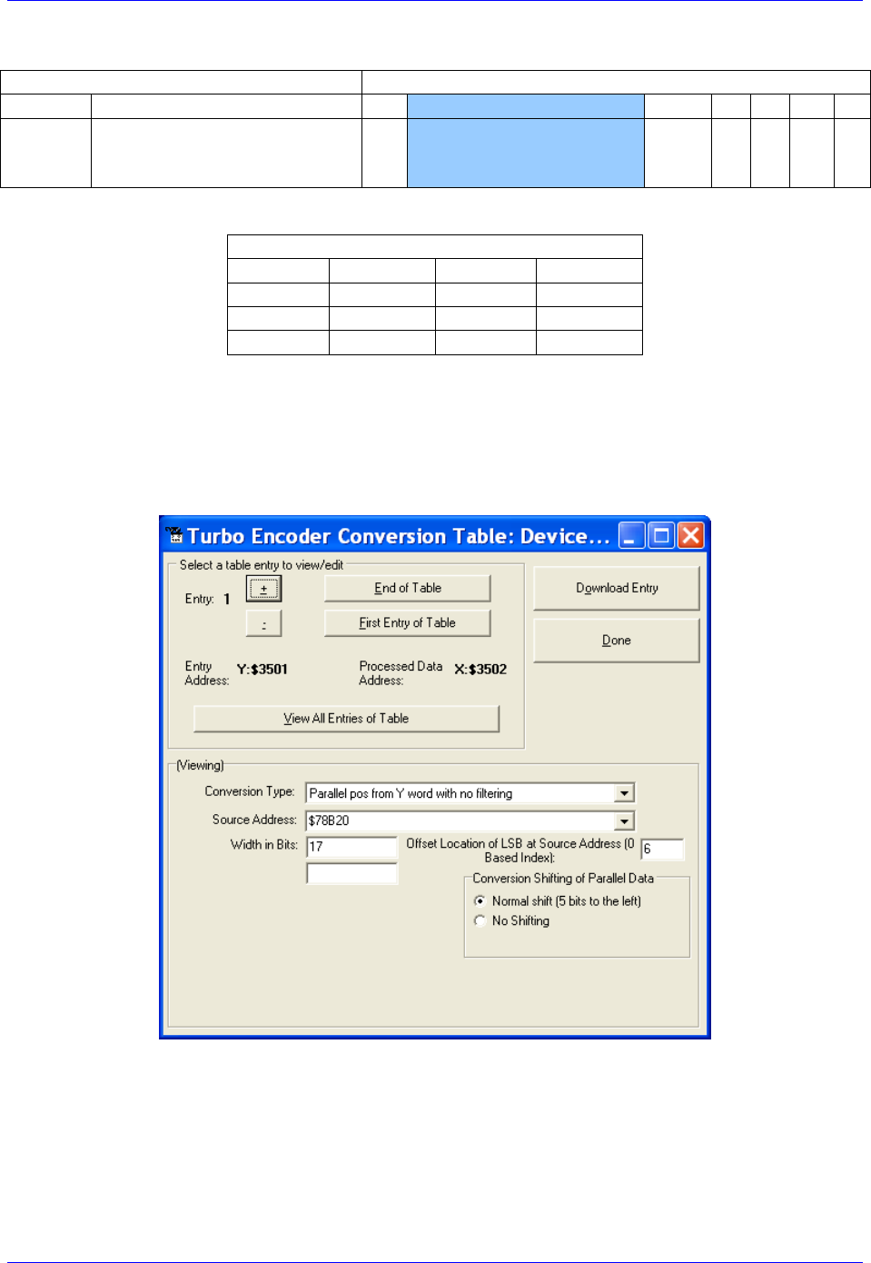
Geo Brick LV User Manual
PinOuts and Software Setup 132
Yaskawa Sigma II 17-Bit Incremental Encoder
Y:$78B21
Y:$78B20
[23-11]
[10-0]
23
[22-6]
[5:4]
3
2
1
0
Incremental Compensation
(11-bits)
Incremental Position in
Single Turn
(17-bits)
U
V
W
Z
Yaskawa Data Registers
Channel 1
Y:$78B20
Channel 5
Y:$78B30
Channel 2
Y:$78B24
Channel 6
Y:$78B34
Channel 3
Y:$78B28
Channel 7
Y:$78B38
Channel 4
Y:$78B2C
Channel 8
Y:$78B3C
The on-going servo and commutation position data is setup using a 2-line Entry in the Encoder
Conversion Table. The first line represents a Parallel Y-Word with no filtering ($2) from the
corresponding Yaskawa data register/channel. The second line represents the width of the data to be read
and bit location of the LSB of the data in the source word.
Channel 1, Yaskawa Sigma II 17-bit Incremental Encoder Setup Example

Geo Brick LV User Manual
PinOuts and Software Setup 133
Encoder Conversion Table Setup (Motors 1-8)
The ECT automatic entry is equivalent to:
I8000=$278B20 ; Entry 1 Unfiltered parallel pos of location Y:$78B20
I8001=$011006 ; Width and Bias, total of 17-bits LSB starting at bit#6
I8002=$278B24 ; Entry 2 Unfiltered parallel pos of location Y:$78B24
I8003=$011006 ; Width and Bias, total of 17-bits LSB starting at bit#6
I8004=$278B28 ; Entry 3 Unfiltered parallel pos of location Y:$78B28
I8005=$011006 ; Width and Bias, total of 17-bits LSB starting at bit#6
I8006=$278B2C ; Entry 4 Unfiltered parallel pos of location Y:$78B2C
I8007=$011006 ; Width and Bias, total of 17-bits LSB starting at bit#6
I8008=$278B30 ; Entry 5 Unfiltered parallel pos of location Y:$78B30
I8009=$011006 ; Width and Bias, total of 17-bits LSB starting at bit#6
I8010=$278B34 ; Entry 6 Unfiltered parallel pos of location Y:$78B34
I8011=$011006 ; Width and Bias, total of 17-bits LSB starting at bit#6
I8012=$278B38 ; Entry 7 Unfiltered parallel pos of location Y:$78B38
I8013=$011006 ; Width and Bias, total of 17-bits LSB starting at bit#6
I8014=$278B3C ; Entry 8 Unfiltered parallel pos of location Y:$78B3C
I8015=$011006 ; Width and Bias, total of 17-bits LSB starting at bit#6
Position (Ixx03) and Velocity (Ixx04) Pointers
I103=$3502 ; Motor 1 Position feedback address, ECT processed data
I104=$3502 ; Motor 1 Velocity feedback address, ECT processed data
I203=$3504 ; Motor 2 Position feedback address, ECT processed data
I204=$3504 ; Motor 2 Velocity feedback address, ECT processed data
I303=$3506 ; Motor 3 Position feedback address, ECT processed data
I304=$3506 ; Motor 3 Velocity feedback address, ECT processed data
I403=$3508 ; Motor 4 Position feedback address, ECT processed data
I404=$3508 ; Motor 4 Velocity feedback address, ECT processed data
I503=$350A ; Motor 5 Position feedback address, ECT processed data
I504=$350A ; Motor 5 Velocity feedback address, ECT processed data
I603=$350C ; Motor 6 Position feedback address, ECT processed data
I604=$350C ; Motor 6 Velocity feedback address, ECT processed data
I703=$350E ; Motor 7 Position feedback address, ECT processed data
I704=$350E ; Motor 7 Velocity feedback address, ECT processed data
I803=$3510 ; Motor 8 Position feedback address, ECT processed data
I804=$3510 ; Motor 8 Velocity feedback address, ECT processed data
Motor Activation
I100,8,100=1 ; Motors 1-8 Activated
Note
At this point of the setup process, you should be able to move the
motor/encoder shaft by hand and see encoder counts in the position
window.

Geo Brick LV User Manual
PinOuts and Software Setup 134
Yaskawa Incremental Encoder Alarm Codes
Yaskawa Incremental encoder Alarm Registers
Channel 1
Y:$78B22,8,8
Channel 5
Y:$78B32,8,8
Channel 2
Y:$78B26,8,8
Channel 6
Y:$78B36,8,8
Channel 3
Y:$78B2A,8,8
Channel 7
Y:$78B3A,8,8
Channel 4
Y:$78B2E,8,8
Channel 8
Y:$78B3E,8,8
Bit#
Error Name
Type
Alarm
Type
Clear
Action
Notes
8
Fixed at “1”
-
-
-
9
Encoder Error
Alarm
Session
Flag
Power
cycle
Encoder Error
10
Fixed at “0”
-
-
-
11
Position Error
Alarm
Session
Flag
Power
cycle
Possible error in position or Hall
sensor
12
Fixed at “0”
-
-
-
13
Fixed at “0”
-
-
-
14
Origin not passed
flag
Warning
-
-
The origin has not been passed in this
session yet
15
Fixed at “0”
Set at zero

Geo Brick LV User Manual
PinOuts and Software Setup 135
Homing with Yaskawa Incremental Encoders
Hardware capture is not available with serial data encoders, software capture (Ixx97=1) is required.
Setting Ixx97 to 1 tells Turbo PMAC to use the register whose address is specified by Ixx03 for the
trigger position. The disadvantage is that the software capture can have up to 1 background cycle delay
(typically 2-3 msec), which limits the accuracy of the capture. To alleviate homing inaccuracies with
serial encoders, it is recommended to perform home search moves at low speeds.
Homing to a flag (i.e. Home, Overtravel Limit, and User) is done using the traditional capture parameters
I7mn2, and I7mn3. Remember to (temporarily) disable the end of travel limit use (bit#17 of Ixx24) when
homing to one of the hardware limit flags, and re-enabling it when homing is finished. Example:
Homing channel 1 to the negative limit (high true)
I124=I124|$20001 ; Flag Mode, Disable hardware over travel limits
I197=1 ; channel 1 position capture, software
I7012=2 ; Channel 1 capture control, capture on flag high
I7012=2 ; Channel 1 capture flag select, minus or negative end limit
Homing to the index pulse, normally performed after referencing to a hardware flag, is an internal
function of the Yaskawa encoder. Bit 14 of the alarm code indicates whether the index has been detected
since last power-up. The motor should be jogged until bit 14 is low, the encoder will then place the
“incremental compensation” value in the lower 11 bits of the second data word. Subtracting the
“incremental compensation” from the “incremental position” results into the true position of the index.
Motor 1 index detection example plc:
#define FirstWord M7025
#define SecondWord M7026
#define OriginNotPassed M7027
FirstWord->Y:$78B20,0,24
SecondWord->Y:$78B21,0,24
OriginNotPassed->Y:$78B22,14
#define Mtr1ActPos M162 ; Suggested M-Variable Definition, Motor 1 Actual Position
Mtr1ActPos->D:$00008B ; #1 Actual position (1/[Ixx08*32] cts)
open plc 1 clear
if (OriginNotPassed = 1)
cmd "#1j+" ; Jog in positive direction looking for index
while (OriginNotPassed = 1); wait until index is detected
endwhile
cmd "#1k" ; Kill Motor
endif
while (SecondWord & $8FF = 0) ; Incremental Compensation takes up to 2 msec to execute
endwhile
Mtr1ActPos = int (((FirstWord & $8FFFC0) / $40)-((SecondWord & $8FF) * $40))* I108 * 32
disable plc 1
close
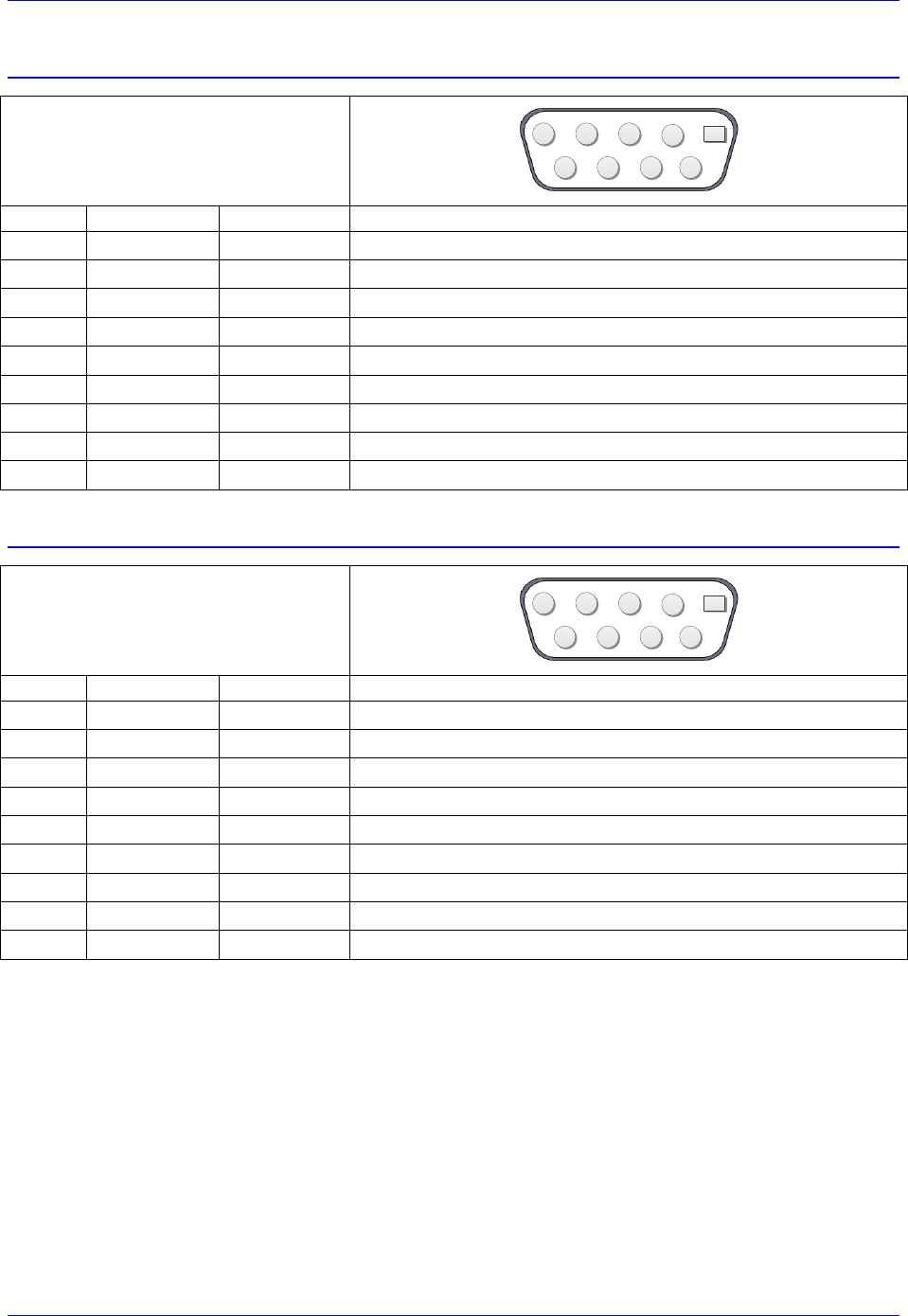
Geo Brick LV User Manual
PinOuts and Software Setup 136
X9-X10: Analog Inputs/Outputs
X9-X10: D-Sub DE-9F
Mating: D-Sub DE-9M
2
345
9 8 7 6
1
Pin #
Symbol
Function
Notes
1
AGND
Ground
Analog Ground
2
ADC+
Input
16-bit Analog Input, channel 5/6+
3
DAC+
Output
12-bit filtered PWM analog output, channel 5/6+
4
BR-NC
Output
Brake 5-6 / Relay Normally Closed
5
AMPFLT
Input
Amplifier fault Input 5/6
6
ADC-
Input
16-bit Analog Input, channel 5/6-
7
DAC-
Output
12-bit filtered PWM analog output, channel 5/6-
8
BRCOM
Common
Brake 5-6 / Relay Common
9
BR-NO
Output
Brake 5-6 / Relay Normally Open
X11-X12: Analog Inputs/Outputs
X11-X12: D-Sub DE-9F
Mating: D-Sub DE-9M
2
345
9 8 7 6
1
Pin #
Symbol
Function
Notes
1
AGND
Ground
Analog Ground
2
ADC+
Input
16-bit Analog Input, channel 7/8+
3
DAC+
Output
12-bit filtered PWM analog output, channel 7/8+
4
BR-NC
Output
Brake 3-4 / Relay Normally Closed
5
AMPFLT
Input
Amplifier fault Input 7/8
6
ADC-
Input
16-bit Analog Input, channel 7/8-
7
DAC-
Output
12-bit filtered PWM analog output, channel 7/8-
8
BRCOM
Common
Brake 3-4/ Relay Common
9
BR-NO
Output
Brake 3-4 / Relay Normally Open
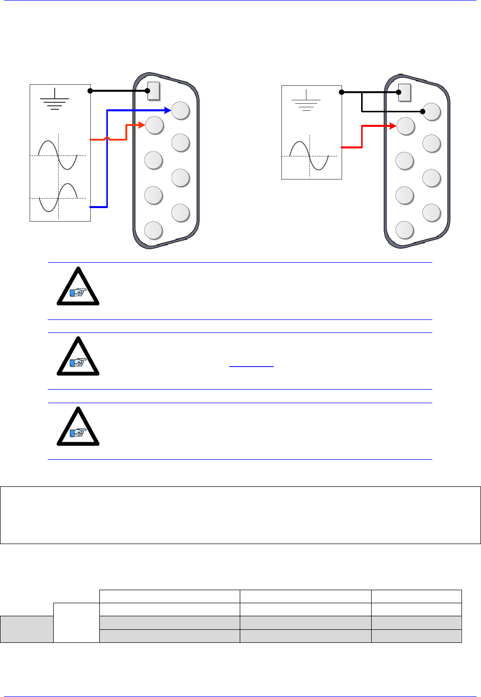
Geo Brick LV User Manual
PinOuts and Software Setup 137
Setting up the Analog (ADC) Inputs
Differential Analog Input Signal
Single Ended Analog Input Signal
2
345
9 8 7 6
1
ADC+
ADC-
AGND
±10VDC
Input Signal
2
345
9 8 7 6
1
ADC+
AGND
±10VDC
Input Signal
Note
For single-ended connections, tie the negative ADC pin to ground.
Note
The analog inputs use the ADS8321 Converter device
Note
Full (16-bit) resolution is available for bipolar signals only. Half of the
range of the full resolution is used for unipolar (0-5V or 0-10V)
signals.
Analog Inputs Suggested M-Variables
I7106=$1FFFFF ; Servo IC 1 ADC Strobe Word
M505->Y:$078105,8,16,S ; ADC Input reading (ADC5A), connector X9
M605->Y:$07810D,8,16,S ; ADC Input reading (ADC6A), connector X10
M705->Y:$078115,8,16,S ; ADC Input reading (ADC7A), connector X11
M805->Y:$07811D,8,16,S ; ADC Input reading (ADC8A), connector X12
Testing the Analog Inputs
The software counts range (reading) is -216/2 to 216/2, so that:
Single-Ended Signal [VDC]
Differential Signal [VDC]
Software Counts
Bipolar
-10
-5
-32768
Unipolar
0
0
0
10
5
+32768
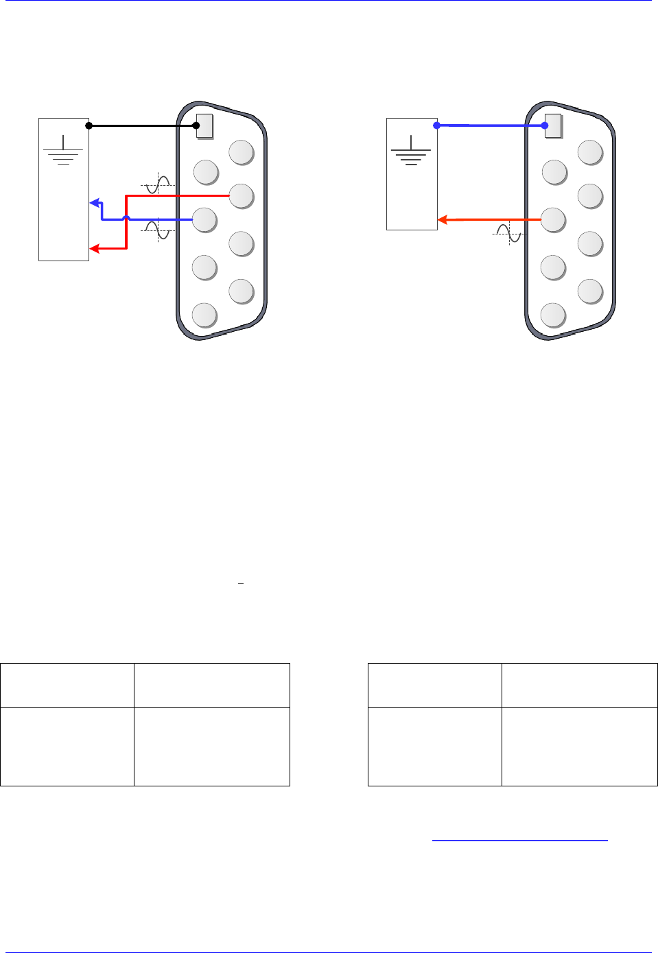
Geo Brick LV User Manual
PinOuts and Software Setup 138
Setting up the Analog (DAC) Outputs
Differential DAC Output Signal
Single Ended DAC Output Signal
2
345
9 8 7 6
1
AGND
Analog
Device
DAC+
DAC-
2
345
9 8 7 6
1
AGND
Analog
Device
DAC+
The analog outputs on X9 through X12 are (12-bit) filtered PWM signals, therefore a PWM frequency in
the range of 30-40 KHz and a PWM deadtime of zero are suggested for a good quality analog output
signal (minimized ripple). A fully populated Brick can have one of three gates generating the clocks:
Servo IC 0 (I7000’s)
Servo IC 1 (I7100’s)
MACRO IC 0 (I6800’s)
I19 specifies which gate is the clock source master. I19 is equal to 7007 by default indicating that Servo
IC 0 is the master gate. However, the analog outputs on X9 through X12 are generated out of Servo IC1.
The relationship between the PWM clock frequency of Servo IC 1 (recipient) and the master gate
(generator), typically Servo IC 0, should always be respected in such a way that:
Where n is an integer
Example:
With Servo IC 0 sourcing the clock at its’ recommended settings (20 KHz PWM), the following are
suggested MACRO IC 0 clock settings which would provide a good analog output signal:
Servo IC 0
Clock Settings
Resulting
Frequencies KHz
Servo IC 1
Clock Settings
Resulting
Frequencies KHz
I7000=1473
I7001=0
I7002=7
I10=1677653
PWM
PHASE
SERVO
20
40
5
I7100=735
I7101=3
I7102=3
I7104=0
PWM
PHASE
SERVO
PWMDeadtime
40
20
5
0
Note that n=2 in this case
For Help with clock calculations, download the Delta Tau Calculator: DT Calculator Forum Link
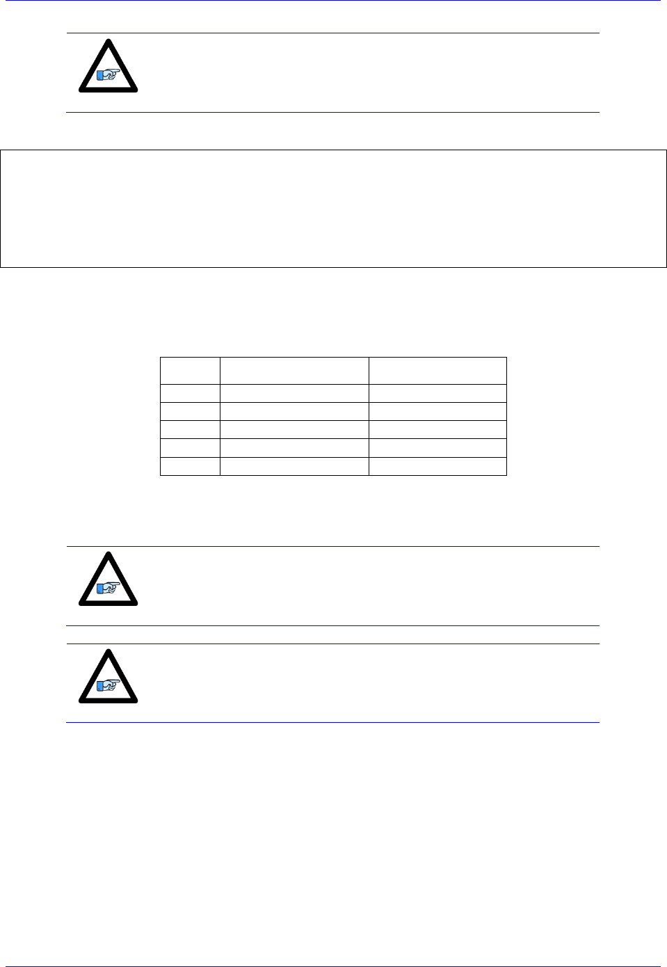
Geo Brick LV User Manual
PinOuts and Software Setup 139
Note
These Servo IC 1 clock settings are optimized for a good quality
analog output signal. If any one of axes 5-8 is used for direct PWM
control then the analog output signal quality should be compromised
with a much lower PWM frequency, or not used at all.
Analog Outputs Suggested M-Variables:
// De-activate Motors 5-8 to write directly to the analog outputs
I500,4,100=0 ; De-activate channels 5-8 to use direct write
I569,4,100=816 ; Set Output Limit --User Input
// Analog Outputs:
M502->Y:$078102,8,16,S ; Analog DAC Output (DAC5), Connector X9
M602->Y:$07810A,8,16,S ; Analog DAC Output (DAC6), Connector X10
M702->Y:$078112,8,16,S ; Analog DAC Output (DAC7), Connector X11
M802->Y:$07811A,8,16,S ; Analog DAC Output (DAC8), Connector X12
Testing the Analog Outputs
With the setting of I7100=735 (per the above example), writing directly to the assigned M-variable (i.e.
Mxx02) should produce the following voltage output:
Mxx02
Single Ended [VDC]
Differential [VDC]
-735
-10
-20
-368
-5
-10
0
0
0
368
+5
+10
735
+10
+20
The output voltage is measured between AGND and DAC+ for single-ended operation and between
DAC- and DAC+ for differential operation.
Note
Writing values greater than I7100 (i.e. 735) in Mx02 will saturate the
output to 10, or 20 volts in single-ended or differential mode
respectively.
Note
MACRO connectivity provides more analog output options, e.g. ACC-
24M2A.

Geo Brick LV User Manual
PinOuts and Software Setup 140
Setting up the General Purpose Relay, Brake
This option provides either a general purpose relay (which can be toggled in software) OR a dedicated
brake relay output tied to its’ corresponding channel amplifier-enable line. This option is built to order
and is jumper configurable at the factory (E6, E7, E8 and E9).
The brake relay is commonly used in synchronizing (in hardware) external events such as automatically
releasing a motor brake upon enabling it (i.e. vertical axis). In this mode, the general purpose relay has no
use, and the related registers (suggested M-variables) are meaningless.
!
Caution
This option utilizes the Omron G6S-2F relay, which is rated to up to
220VAC. However, it is advised to use an external relay for AC
operations, and limit the usage for this connection to up to 30VDC at
2 amperes.
The brake output can be either:
High true using the normally open contact (pin #9)
Low true using the normally closed contact (pin #4)
Also, it can be either sourcing or sinking depending on the wiring scheme.
The following table summarizes the logic of operation:
Operation
Command From
Geo Brick LV
Contact between pins
#8 and #9
Contact between pins
#8 and #4
Brake
Amp. disabled (killed)
Open
Closed
Amp. Enabled (open/closed loop)
Closed
Open
GP Relay
M-variable = 0
Open
Closed
M-variable = 1
Closed
Open
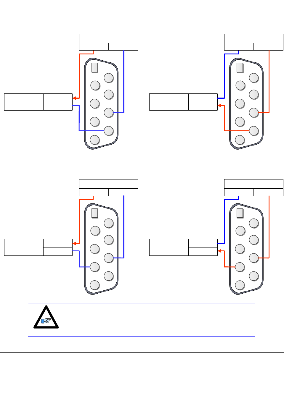
Geo Brick LV User Manual
PinOuts and Software Setup 141
High True Brake Output
Sourcing
Sinking
BRAKE
2
345
9 8 7 6
1
Logic device /
Brake BRAKE RET
DC Power Supply
12-24VDC COM
BRAKE RET
2
345
9 8 7 6
1
Logic device /
Brake BRAKE
DC Power Supply
COM 12-24V
Low True Brake Output
Sourcing
Sinking
BRAKE
2
345
9 8 7 6
1
Logic device /
Brake BRAKE RET
DC Power Supply
12-24VDC COM
BRAKE RET
2
345
9 8 7 6
1
Logic device /
Brake BRAKE
DC Power Supply
COM 12-24V
Note
The brake relays on X9, X10, X11, and X12 are tied to the amplifier
enable signals of axes 5, 6, 3, and 4 respectively.
General Purpose Relay Suggested M-Variables
// General purpose relay Outputs:
M5014->Y:$078800,8,1 ; General purpose relay output, X9
M6014->Y:$078801,8,1 ; General purpose relay output, X10
M7014->Y:$78803,8,1 ; General purpose relay output, X11
M8014->Y:$78804,8,1 ; General purpose relay output, X12
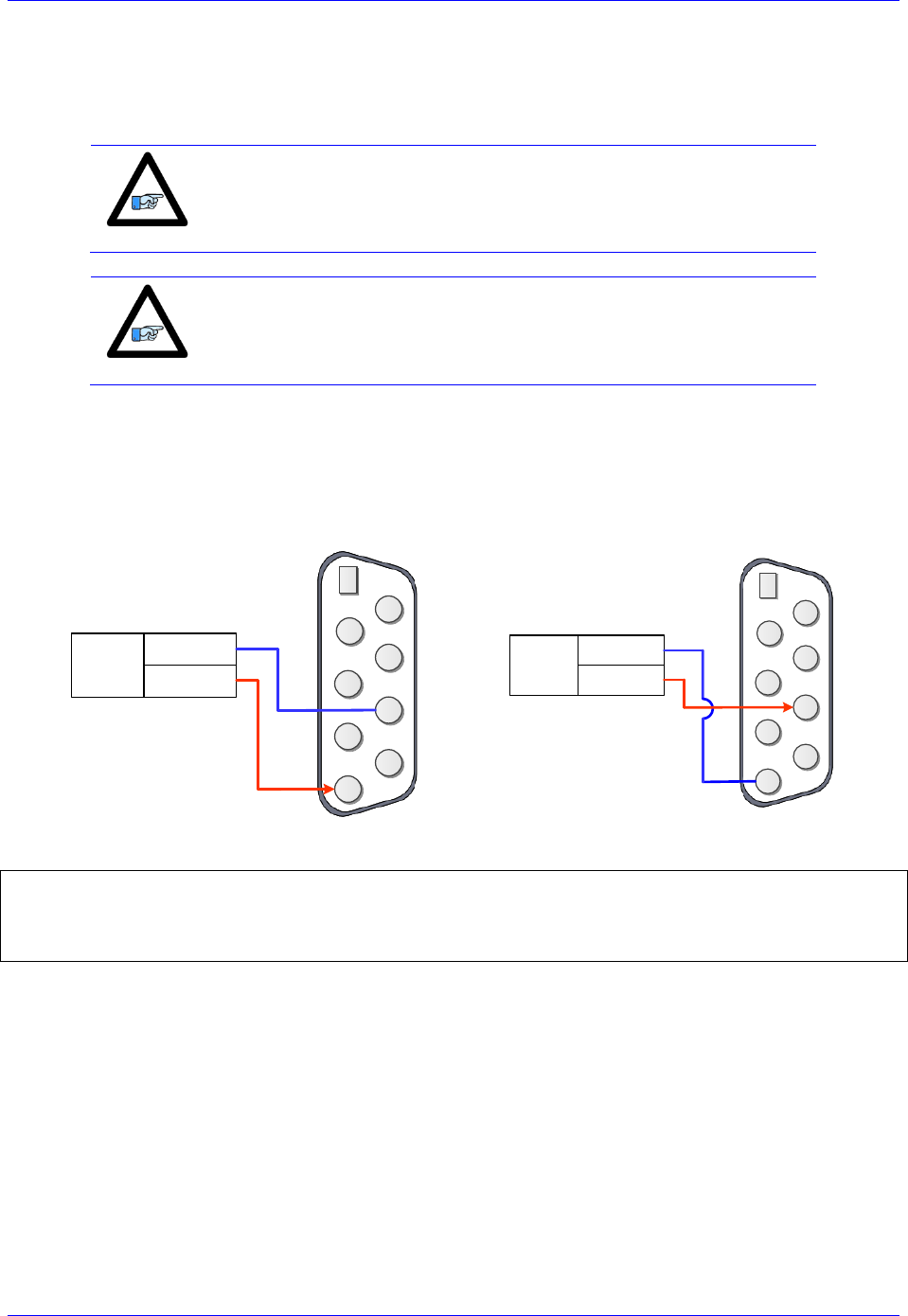
Geo Brick LV User Manual
PinOuts and Software Setup 142
Setting up the External Amplifier Fault Input
The amplifier fault signal is a bidirectional single-ended input. Its’ minus end is tied internally to the
brake/relay common (pin #8) which dictates how the amplifier fault input should be connected.
Note
If the amplifier fault signal is not used, it can be treated and used as a
general purpose +12~24V input by setting bit 20 of Ixx24 to 1.
Note
The amplifier fault signal polarity can be changed in software with bit
23 of Ixx24; =1 for High True, =0 for Low True.
If the brake/relay option is in use (otherwise, whichever scheme desirable):
If pin#8 is wired to common ground, then use the sourcing scheme
If pin#8 is wired to 24V, then use the sinking scheme
Sourcing
Sinking
AFAULT RET
2
345
9 8 7 6
1
External
Amplifier AFAULT
12-24V
AFAULT RET
2
345
9 8 7 6
1
External
Amplifier AFAULT
12-24V
External Amplifier Fault Input, Suggested M-Variables:
// External Amplifier Fault Inputs:
M523->X:$078100,15,1 ; Amp. Fault Input (CH5), Connector X9
M623->X:$078108,15,1 ; Amp. Fault Input (CH6), Connector X10
M723->X:$078110,15,1 ; Amp. Fault Input (Ch7), Connector X11
M823->X:$078118,15,1 ; Amp. Fault Input (Ch8), Connector X12
This feature is commonly used when an amplifier is commanded through the DAC outputs on X9-X12,
and the need of a fault input signal is required to run the operation safely (i.e. kill in the occurrence of an
amplifier fault).
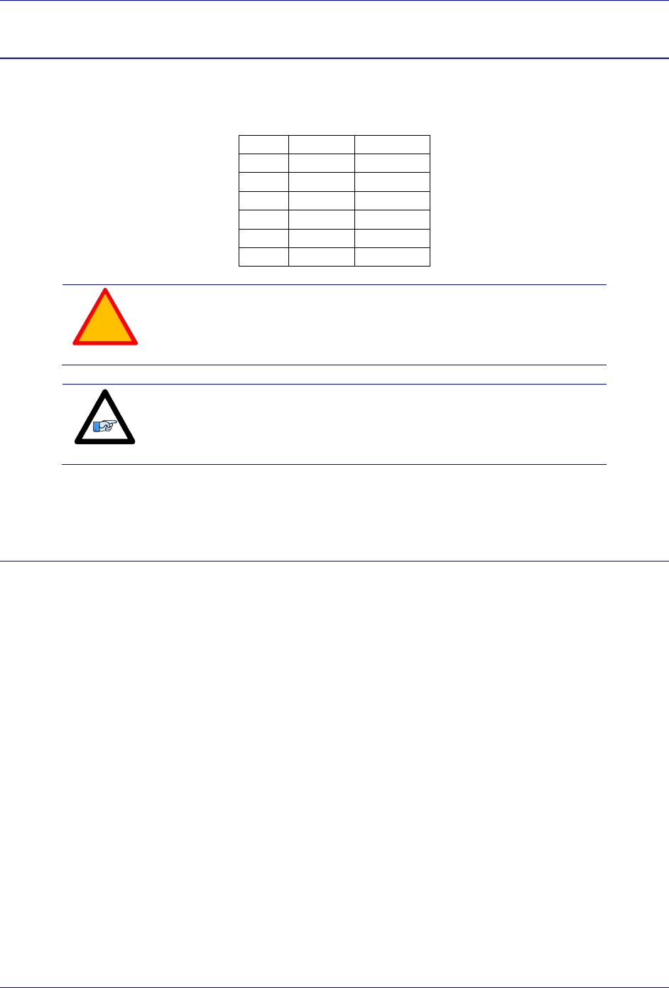
Geo Brick LV User Manual
PinOuts and Software Setup 143
X13: USB 2.0 Connector
This connector is used to establish USB (A-B type cable) communication between the host PC and the
Geo Brick LV. This type of USB cable can be purchased at any local electronics or computer store. It
may be ordered from Delta Tau as well.
Pin #
Symbol
Function
1
VCC
N.C.
2
D-
Data-
3
D+
Data+
4
Gnd
GND
5
Shell
Shield
6
Shell
Shield
!
Caution
The electrical ground plane of the host PC connected through USB
must be at the same level as the Geo Brick LV. Ground loops may
result in ESD shocks causing the damage of the communication
processor on the Geo Brick LV.
Note
Use a shielded USB (category 6 or 7) cable. In noise sensitive
environment, install ferrite cores at both Geo Brick and PC side.
If the electrical ground planes of the host PC and the Geo Brick LV are not at the same level (e.g. laptop
on battery) then the use of an industrial USB hub is highly advised.
X14: RJ45, Ethernet Connector
This connector is used to establish communication over Ethernet between the PC and the Geo Brick LV.
A crossover cable is required if you are going directly to the Geo Brick LV from the PC Ethernet card,
and not through a hub.
Delta Tau strongly recommends the use of RJ45 CAT5e or better shielded cable. Newer network cards
have the Auto-MDIX feature that eliminates the need for crossover cabling by performing an internal
crossover when a straight cable is detected during the auto-negotiation process. For older network cards,
one end of the link must perform media dependent interface (MDI) crossover (MDIX), so that the
transmitter on one end of the data link is connected to the receiver on the other end of the data link (a
crossover/patch cable is typically used). If an RJ45 hub is used, then a regular straight cable must be
implemented. Maximum length for Ethernet cable should not exceed 100m (330ft).
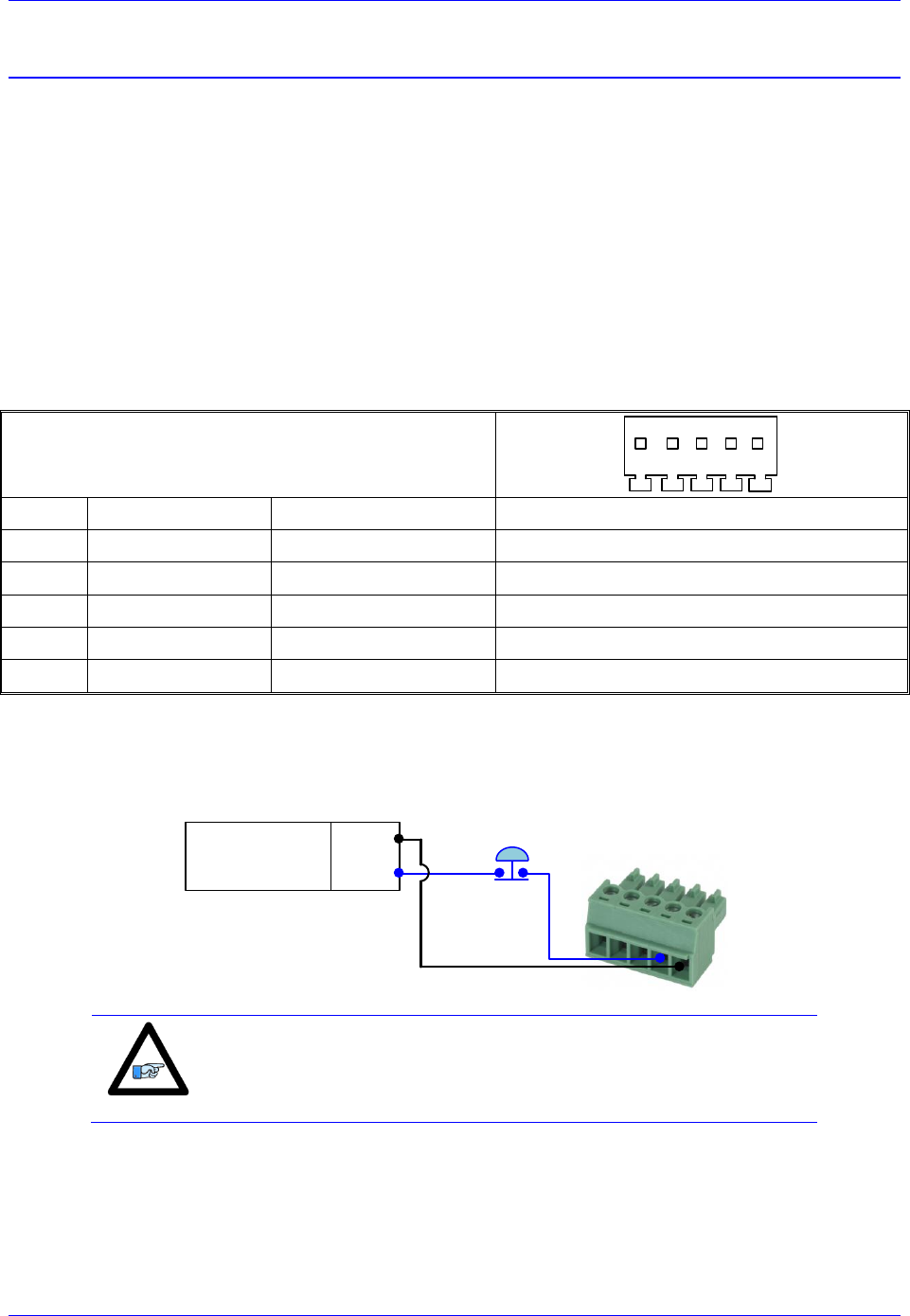
Geo Brick LV User Manual
PinOuts and Software Setup 144
X15: Watchdog & ABORT (TB2)
X15 has two essential functions:
A 24VDC Abort Input (mandatory for normal operation) which can be used in various
applications to halt motion when necessary (i.e. opening machine door, replacing tool).
A watchdog relay output allowing the user to bring the machine to a stop in a safe manner in the
occurrence of a watchdog.
These functions are disabled on Geo Brick LV with Turbo PMAC firmware version 1.946 or earlier.
Geo Brick LV with Turbo PMAC firmware version 1.947 or later allows the enabling (using software
parameter I35) of the watchdog and abort functions:
I35=0 Disables the watchdog and abort hardware functions (default setting)
I35=1 Enables the watchdog and abort hardware functions
X15: Phoenix 5-pin TB Female
Mating: Phoenix 5-pin TB Male
1 2 3 4 5
TB-5: 016-PL0F05-38P
Pin #
Symbol
Function
Notes
1
ABORT-
Input
ABORT Return
2
ABORT+
Input
ABORT Input 24VDC
3
WD N.O.
Output
Watchdog (normally open contact)
4
WD N.C.
Output
Watchdog (normally closed contact)
5
WD COM
Common
Watchdog common
Wiring the Abort Input
If an Abort input button is used, it must be a normally closed switch.
1
2
3
4
5
24VDC
Power Supply
COM
24VDC
Abort Input
Switch (optional)
Note
Killed axes are not affected by the triggering of the abort. They do not
get enabled (unlike the software abort command).
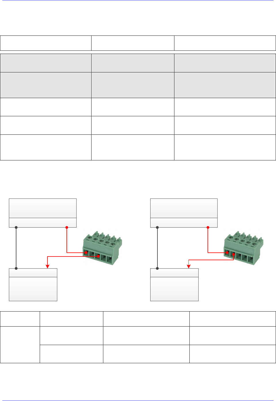
Geo Brick LV User Manual
PinOuts and Software Setup 145
The hardware Abort input functionality differs slightly from the software global Abort (^A) command.
The following table summarizes the differences:
Motor(s) Status
Before Abort Action
Software Global Abort
^A Action
Hardware Abort Trigger
Action (Removing 24VDC)
Killed
(Open-Loop mode)
Closes the position-loop on
all active (Ixx0=1) motors
No Action is taken.
Motors remain killed
Amplifier Enabled
(i.e. #1o0, Open-Loop mode)
Closes the position-loop
on all active (Ixx0=1) motors
Closes the position-loop on all
‘amplifier enabled’ motors only.
Killed motors are not affected
Servo-ing – in position
(Closed-Loop mode)
Motor(s) remain in
closed-loop at velocity zero
Motor(s) remain in closed-loop
at velocity zero
Servo-ing – Jogging
(Closed-Loop mode)
Motor(s) decelerate to zero
velocity at Ixx15 rate
Motor(s) decelerate to zero
velocity at Ixx15 rate
Servo-ing – Running Program(s)
(Closed-Loop mode)
Aborts motion program(s)
and decelerate to zero
velocity at Ixx15 rate
Aborts motion program(s) and
decelerate to zero velocity
at Ixx15 rate
Wiring the Watchdog Output
Watchdog Output,
Normally Open
Watchdog Output,
Normally Closed
1
2
3
4
5
24 VDC
Power Supply
COM 24VDC
Logic device
(safe shutdown)
COM 24VDC
1
2
3
4
5
24 VDC
Power Supply
COM 24VDC
Logic device
(safe shutdown)
COM 24VDC
Operation
Mode
Connection between pins
#5 and #3
Connection between pins
#5 and #4
Watchdog
Not triggered
(normal operation)
Open
Closed
Triggered
(Faulty operation)
Closed
Open
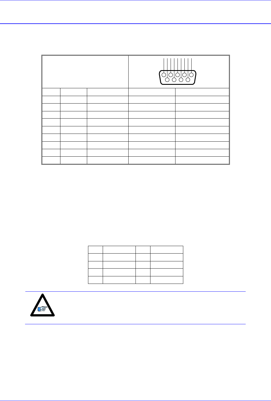
Geo Brick LV User Manual
PinOuts and Software Setup 146
RS232: Serial Communication Port
An optional serial RS-232 communication port is available on the Geo Brick LVs. This port can be used
as a primary communication mean or employed as a secondary port that allows simultaneous
communication.
RS-232: D-Sub DE-9F
Mating: D-Sub DE-9M
12345
6789
N.C.
DTR
TXD
CTS
RXD
RTS
DSR
N.C.
GND
Pin#
Symbol
Function
Description
Notes
1
N.C.
NC
2
TXD
Output
Receive data
Host transmit Data
3
RXD
Input
Send data
Host receive Data
4
DSR
Bi-directional
Data set ready
Tied to “DTR”
5
GND
Common
Common GND
6
DTR
Bi-directional
Data term ready
Tied to “DSR”
7
CTS
Input
Clear to send
Host ready bit
8
RTS
Output
Req. to send
PMAC ready bit
9
N.C
NC
The baud rate for the RS-232 serial port is set by variable I54. At power-up reset, The Geo Brick LV sets
the active baud based on the setting of I54 and the CPU speed I52. Note that the baud rate frequency is
divided down from the CPU’s operational frequency. The factory default baud rate is 38400. This baud
rate will be selected automatically on re-initialization of the Geo Brick LV, either in hardware using the
re-initialization (RESET SW) button or in software using the $$$*** command.
To change the baud rate setting on the Geo Brick LV, set I54 to the corresponding value of desired
frequency. Issue a SAVE and recycle power on the unit. For odd baud rate settings, refer to the Turbo
Software Reference Manual.
I54
Baud Rate
I54
Baud Rate
8
9600
12
38,400
9
14,400
13
57,600
10
19,200
14
76,800
11
28,800
15
115,200
Note
I54=12 (38400 baud) is the factory default setting
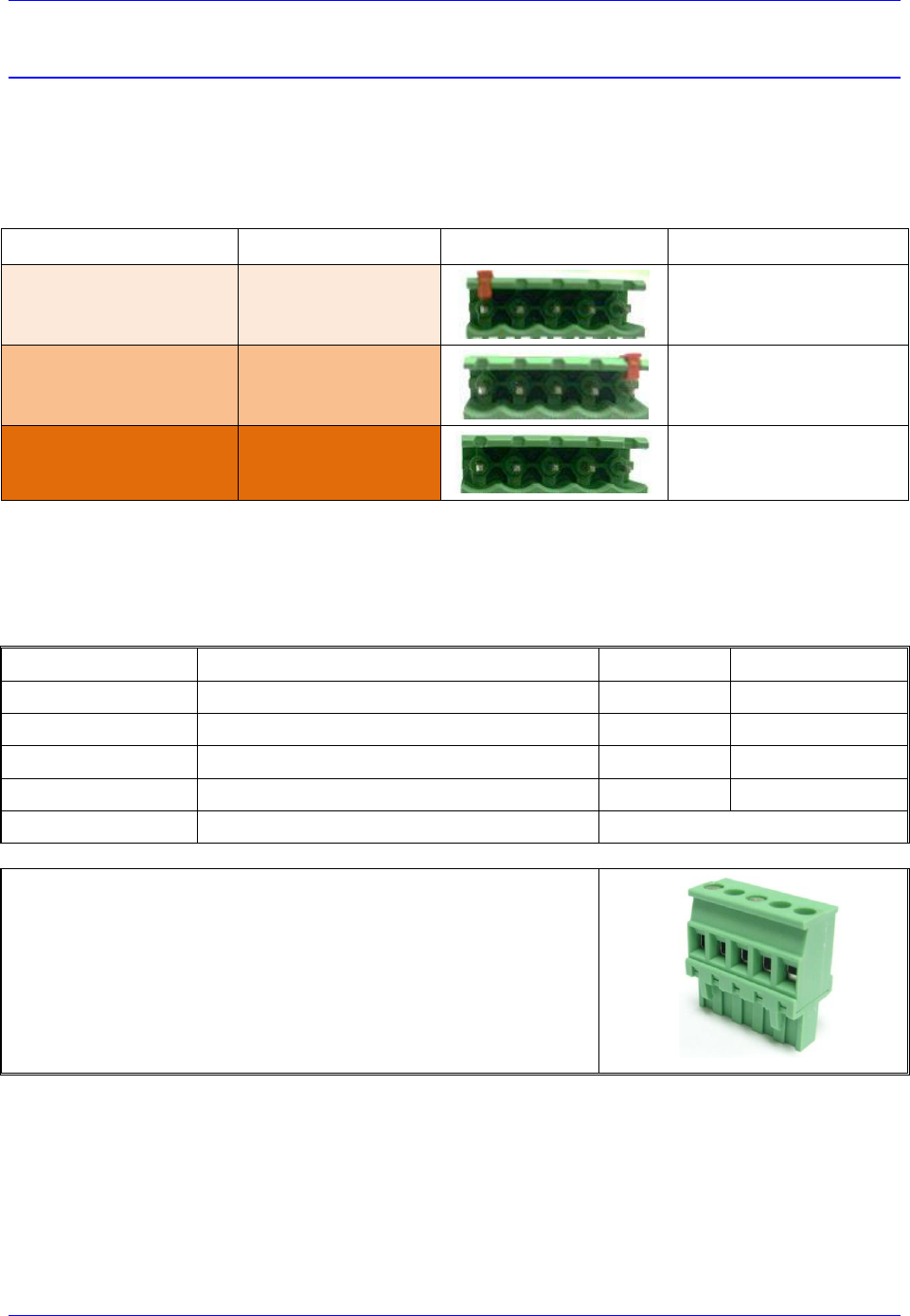
Geo Brick LV User Manual
PinOuts and Software Setup 147
AMP1-AMP8: Motor Wiring
These connections are used to wire the amplifier-motor output:
Traditionally, the Geo Brick LV offered a power rating of 5A continuous RMS, 15A peak RMS. In
October 2012, two additional power ratings were added to the Geo Brick LV offering a total of three
possible power configurations (per set of 4 axes each):
Nominal RMS Current
Peak RMS Current
Connector
Notes
0.25 A
0.75 A
Left hand side indicator
1 A
3 A
Right hand side indicator
5 A
15 A
No indicator
For Stepper motors, use U and W at one coil, V and X at the other coil.
For DC brushless motors (servo) use U, V and W. Leave X floating.
For DC Brush motors, use U and W. Leave V and X floating.
Pin#
Symbol
Function
Description
1
Phase 1
U
Output
Motor Output
2
Phase 2
V
Output
Motor Output
3
Phase 3
W
Output
Motor Output
4
Phase 4
X
Output
Motor Output
5
GND
Common
Mating Connector 5-pin Phoenix Terminal Block:
Phoenix Contact mating connector part # 1792278
Delta Tau mating connector part # 016-090A05-08P
1
2
3
4
5
U
V
W
X
GND
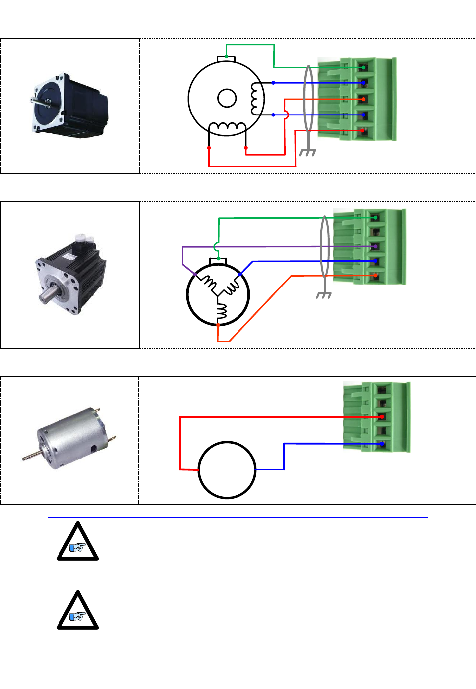
Geo Brick LV User Manual
PinOuts and Software Setup 148
Stepped Motor Wiring
1
4
5
2
3
Shield
U
X
GND
V
W
Brushless (Servo) Motor wiring
1
4
5
2
3
Shield
U
X
GND
V
W
Brush Motor Wiring
M
1
4
5
2
3
U
X
GND
V
W
Note
The motor’s frame drain wire and the motor cable shield should be
tied together to minimize noise disturbances.
Note
Color code may differ from one motor manufacturer to another.
Review the motor documentation carefully before making this
connection.
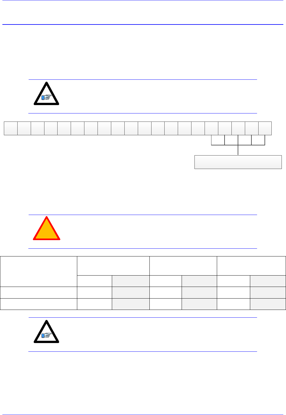
Geo Brick LV User Manual
PinOuts and Software Setup 149
+5V ENC PWR (Alternate Encoder Power)
Typically, feedback devices are powered up through the X1-X8 connectors on the Geo Brick LV using
the internal +5VDC power supply. In some cases, feedback devices consume power excessively and risk
of surpassing the internal power supply limitation.
This connector provides an alternate mean to power-up the feedback devices (+5V only) if the total
encoder budget exceeds the specified thresholds.
Note
Encoders requiring greater than +5VDC power must be supplied
externally, and NOT through the X1-X8 connectors NOR through this
connector.
G B D x - x x - x x x - x x x xxxxx
Add-in Board Options
The add-in board (any non-zero digit in the highlighted part number field) for MACRO and special
feedback requires an additional ~ 0.5A (+5V power). This alters the total power available for encoders.
The newer models of the Geo Brick LV have a beefier power supply and can handle more (+5V) power
drain. The following tables summarize the +5V power available for encoder devices (X1-X8):
!
Caution
The maximum current draw out of a single encoder channel must not
exceed 750 mA.
Geo Brick LV Model
Total Encoder Power
Available [Amps]
Power Per Encoder
(4 x channels) [mA]
Power Per Encoder
( 8 x channels) [mA]
Older
Newer
Older
Newer
Older
Newer
Without Add-in Board
1.5
2
375
500
188
250
With Add-in Board
1
1.5
250
375
125
188
Note
The newer models of the Geo Brick LV were introduced in October of
2012 and can be recognized by the 5-pin terminal block STO
connector which was not previously available.
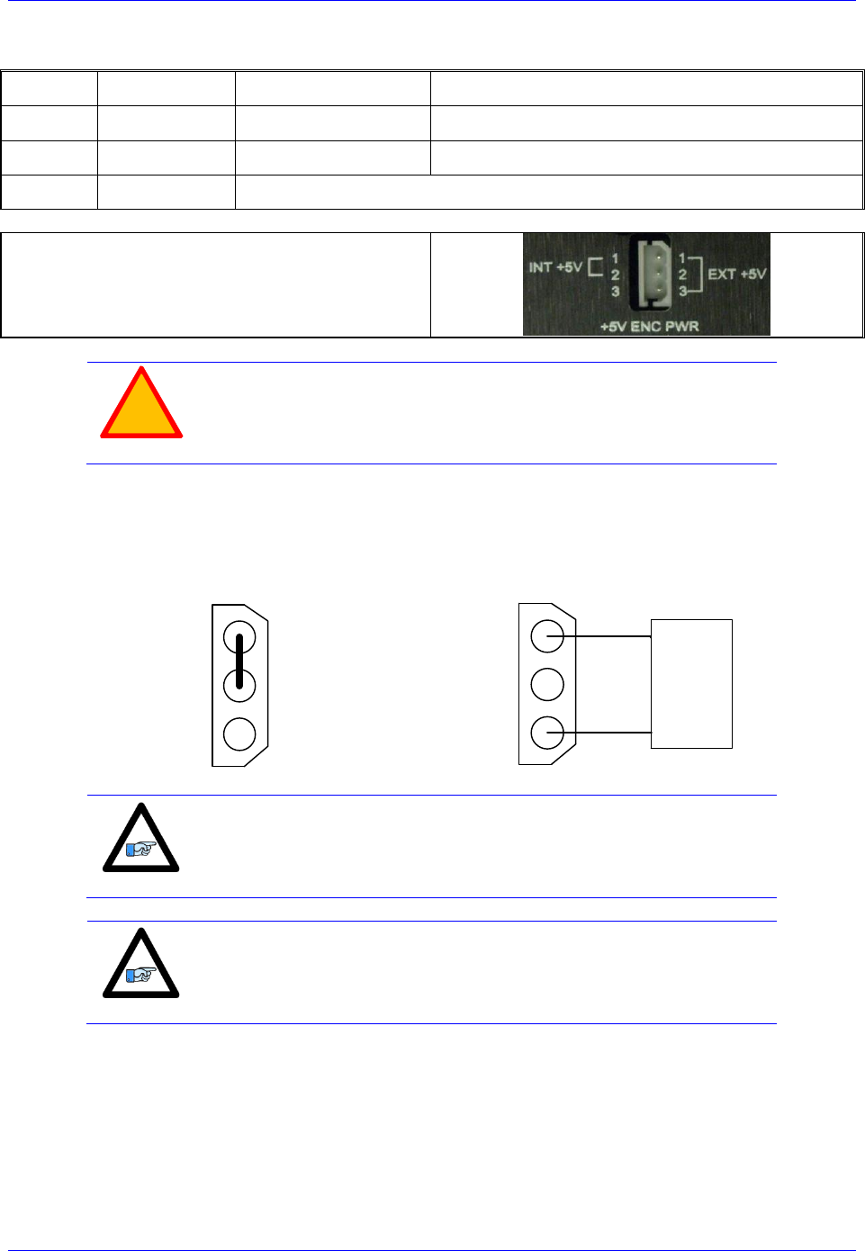
Geo Brick LV User Manual
PinOuts and Software Setup 150
Wiring the Alternate (+5V) Encoder Power
Pin#
Symbol
Description
Note
1
5VEXT
Input
5V from external power supply
2
5VINT
Output
Tie to pin#1 to use internal power supply
3
GND
Common
Mating Connector:
Adam-Tech part number 25CH-E-03
Pins part number 25CTE-R
Crimping tool: Molex EDP #11-01-0208
!
Caution
Only two of the three available pins should be used at one time. Do
not daisy-chain the internal 5V power supply with an external one.
By default, pins 1-2 are tied together to use the internal power supply. To wire an external power supply,
remove the jumper tying pins 1-2 and connect the external +5V to pin #1, and ground/common to pin#3:
Internal Power Supply
Wiring (Default)
External Power Supply
Wiring
1
2
3
1
2
3
+5V
Gnd
External
Power
Supply
Note
A jumper tying pins 1 and 2 is the default configuration. This is the
configuration with which the Geo Brick LV is shipped to a customer.
Note
The controller (PMAC) 5V logic is independent of this scheme, so if
no encoder power is provided the PMAC will remain powered-up
(provided the standard 24 volts is brought in).

Geo Brick LV User Manual
PinOuts and Software Setup 151
Functionality, Safety Measures
There are a couple of safety and functionality measures to take into account when an external encoder
power supply is utilized:
Power sequence: encoders versus controller/drive
It is highly recommended to power up the encoders before applying power to the Geo Brick LV
Encoder Power Loss (i.e. power supply failure, loose wire/connector)
The Geo Brick LV, with certain feedback devices, can be setup to read absolute position or perform
phasing on power-up (either automatic firmware functions, or user PLCs). If the encoder power is not
available, these functions will not be performed properly. Moreover, trying to close the loop on a motor
without encoder feedback can be dangerous.
!
Caution
Make sure that the encoders are powered-up before executing any
motor/motion commands.
Losing encoder power can lead to dangerous runaway conditions, setting the fatal following error limit
and I2T protection in PMAC is highly advised.
!
Caution
Make sure that the fatal following error limit and I2T protection are
configured properly in PMAC.
With Commutated motors (i.e. DC brushless), a loss of encoder generally breaks the commutation cycle
causing a fatal following error or I2T fault either in PMAC or Amplifier side. However, with non-
commutated motors (i.e. DC brush), losing encoder signal can more likely cause dangerous runway
conditions.
Note
Setting up encoder loss detection for quadrature and sinusoidal
encoders is highly recommended. Serial Encoders normally provide
with a flag or timeout error bit that can be used for that function.

Geo Brick LV User Manual
Motor Type & Protection Power-On PLCs 152
MOTOR TYPE & PROTECTION POWER-ON PLCS
The Geo Brick LV is capable of driving stepper and/or servo (brush/brushless) motors without any
hardware changes. The amplifier firmware requires declaring the motor type (per channel) on power up in
a power-on PLC. This PLC also executes the following functions:
Set motor type (stepper or servo)
Clear amplifier fault(s), per channel
Enable Strobe Word write protection
Note
The sample PLCs below are common 8-axis configurations. For 4-axis
configurations, simply delete the settings of axis 5 through 8.
These functions are established by sending commands to the amplifier processor from the PMAC through
the ADC Strobe Word (see Strobe Word data structure section).

Geo Brick LV User Manual
Motor Type & Protection Power-On PLCs 153
Stepper Motor Power-On PLC Sample
The following PLC sets up an 8-axis Geo Brick LV to drive 8 stepper motors:
Open PLC 1 Clear
// Disable all other PLCs, and kill motors
DIS PLC 0
DIS PLCC 0..31
DIS PLC 2..31
CMD^K
// Axis 1 Settings
CMD"WX:$78014,$F8CDFE" ; Select axis # and set motor mode (Stepper)
I5111 = 50 * 8388608/I10 While(I5111 > 0)EndW
CMD"WX:$78014,$F84DFE" ; Clear error(s) on selected axis in stepper mode
I5111 = 50 * 8388608/I10 While(I5111 > 0)EndW
CMD"WX:$78014,$F00DFE" ; Save and write protect channel from strobe word changes
I5111 = 50 * 8388608/I10 While(I5111 > 0)EndW
// Axis 2 Settings
CMD"WX:$78014,$F9CDFE" ; Select axis # and set motor mode (Stepper)
I5111 = 50 * 8388608/I10 While(I5111 > 0)EndW
CMD"WX:$78014,$F94DFE" ; Clear error(s) on selected axis in stepper mode
I5111 = 50 * 8388608/I10 While(I5111 > 0)EndW
CMD"WX:$78014,$F10DFE" ; Save and write protect channel from strobe word changes
I5111 = 50 * 8388608/I10 While(I5111 > 0)EndW
// Axis 3 Settings
CMD"WX:$78014,$FACDFE" ; Select axis # and set motor mode (Stepper)
I5111 = 50 * 8388608/I10 While(I5111 > 0)EndW
CMD"WX:$78014,$FA4DFE" ; Clear error(s) on selected axis in stepper mode
I5111 = 50 * 8388608/I10 While(I5111 > 0)EndW
CMD"WX:$78014,$F20DFE" ; Save and write protect channel from strobe word changes
I5111 = 50 * 8388608/I10 While(I5111 > 0)EndW
// Axis 4 Settings
CMD"WX:$78014,$FBCDFE" ; Select axis # and set motor mode (Stepper)
I5111 = 50 * 8388608/I10 While(I5111 > 0)EndW
CMD"WX:$78014,$FB4DFE" ; Clear error(s) on selected axis in stepper mode
I5111 = 50 * 8388608/I10 While(I5111 > 0)EndW
CMD"WX:$78014,$F30DFE" ; Save and write protect channel from strobe word changes
I5111 = 50 * 8388608/I10 While(I5111 > 0)EndW
// Axis 5 Settings
CMD"WX:$78114,$F8CDFE" ; Select axis # and set motor mode (Stepper)
I5111 = 50 * 8388608/I10 While(I5111 > 0)EndW
CMD"WX:$78114,$F84DFE" ; Clear error(s) on selected axis in stepper mode
I5111 = 50 * 8388608/I10 While(I5111 > 0)EndW
CMD"WX:$78114,$F00DFE" ; Save and write protect channel from strobe word changes
I5111 = 50 * 8388608/I10 While(I5111 > 0)EndW
// Axis 6 Settings
CMD"WX:$78114,$F9CDFE" ; Select axis # and set motor mode (Stepper)
I5111 = 50 * 8388608/I10 While(I5111 > 0)EndW
CMD"WX:$78114,$F94DFE" ; Clear error(s) on selected axis in stepper mode
I5111 = 50 * 8388608/I10 While(I5111 > 0)EndW
CMD"WX:$78114,$F10DFE" ; Save and write protect channel from strobe word changes
I5111 = 50 * 8388608/I10 While(I5111 > 0)EndW
// Axis 7 Settings
CMD"WX:$78114,$FACDFE" ; Select axis # and set motor mode (Stepper)
I5111 = 50 * 8388608/I10 While(I5111 > 0)EndW
CMD"WX:$78114,$FA4DFE" ; Clear error(s) on selected axis in stepper mode
I5111 = 50 * 8388608/I10 While(I5111 > 0)EndW
CMD"WX:$78114,$F20DFE" ; Save and write protect channel from strobe word changes
I5111 = 50 * 8388608/I10 While(I5111 > 0)EndW
// Axis 8 Settings
CMD"WX:$78114,$FBCDFE" ; Select axis # and set motor mode (Stepper)
I5111 = 50 * 8388608/I10 While(I5111 > 0)EndW
CMD"WX:$78114,$FB4DFE" ; Clear error(s) on selected axis in stepper mode
I5111 = 50 * 8388608/I10 While(I5111 > 0)EndW
CMD"WX:$78114,$F30DFE" ; Save and write protect channel from strobe word changes
I5111 = 50 * 8388608/I10 While(I5111 > 0)EndW
Dis PLC 1
Close

Geo Brick LV User Manual
Motor Type & Protection Power-On PLCs 154
Servo (brushless/brush) Motor Power-On PLC Sample
The following PLC sets up an 8-axis Geo Brick LV to drive 8 brush or brushless motors:
Open plc 1 clear
// Disable all other PLCs, and kill motors
DIS PLC 0
DIS PLCC 0..31
DIS PLC 2..31
CMD^K
// Axis 1 Settings
CMD"WX:$78014,$F8CCFE" ; Select axis # and set motor mode (Servo)
I5111 = 50 * 8388608/I10 While(I5111 > 0)EndW
CMD"WX:$78014,$F84CFE" ; Clear error(s) on selected axis in Servo mode
I5111 = 50 * 8388608/I10 While(I5111 > 0)EndW
CMD"WX:$78014,$F00CFE" ; Save and write protect channel from strobe word changes
I5111 = 50 * 8388608/I10 While(I5111 > 0)EndW
// Axis 2 Settings
CMD"WX:$78014,$F9CCFE" ; Select axis # and set motor mode (Servo)
I5111 = 50 * 8388608/I10 While(I5111 > 0)EndW
CMD"WX:$78014,$F94CFE" ; Clear error(s) on selected axis in Servo mode
I5111 = 50 * 8388608/I10 While(I5111 > 0)EndW
CMD"WX:$78014,$F10CFE" ; Save and write protect channel from strobe word changes
I5111 = 50 * 8388608/I10 While(I5111 > 0)EndW
// Axis 3 Settings
CMD"WX:$78014,$FACCFE" ; Select axis # and set motor mode (Servo)
I5111 = 50 * 8388608/I10 While(I5111 > 0)EndW
CMD"WX:$78014,$FA4CFE" ; Clear error(s) on selected axis in Servo mode
I5111 = 50 * 8388608/I10 While(I5111 > 0)EndW
CMD"WX:$78014,$F20CFE" ; Save and write protect channel from strobe word changes
I5111 = 50 * 8388608/I10 While(I5111 > 0)EndW
// Axis 4 Settings
CMD"WX:$78014,$FBCCFE" ; Select axis # and set motor mode (Servo)
I5111 = 50 * 8388608/I10 While(I5111 > 0)EndW
CMD"WX:$78014,$FB4CFE" ; Clear error(s) on selected axis in Servo mode
I5111 = 50 * 8388608/I10 While(I5111 > 0)EndW
CMD"WX:$78014,$F30CFE" ; Save and write protect channel from strobe word changes
I5111 = 50 * 8388608/I10 While(I5111 > 0)EndW
// Axis 5 Settings
CMD"WX:$78114,$F8CCFE" ; Select axis # and set motor mode (Servo)
I5111 = 50 * 8388608/I10 While(I5111 > 0)EndW
CMD"WX:$78114,$F84CFE" ; Clear error(s) on selected axis in Servo mode
I5111 = 50 * 8388608/I10 While(I5111 > 0)EndW
CMD"WX:$78114,$F00CFE" ; Save and write protect channel from strobe word changes
I5111 = 50 * 8388608/I10 While(I5111 > 0)EndW
// Axis 6 Settings
CMD"WX:$78114,$F9CCFE" ; Select axis # and set motor mode (Servo)
I5111 = 50 * 8388608/I10 While(I5111 > 0)EndW
CMD"WX:$78114,$F94CFE" ; Clear error(s) on selected axis in Servo mode
I5111 = 50 * 8388608/I10 While(I5111 > 0)EndW
CMD"WX:$78114,$F10CFE" ; Save and write protect channel from strobe word changes
I5111 = 50 * 8388608/I10 While(I5111 > 0)EndW
// Axis 7 Settings
CMD"WX:$78114,$FACCFE" ; Select axis # and set motor mode (Servo)
I5111 = 50 * 8388608/I10 While(I5111 > 0)EndW
CMD"WX:$78114,$FA4CFE" ; Clear error(s) on selected axis in Servo mode
I5111 = 50 * 8388608/I10 While(I5111 > 0)EndW
CMD"WX:$78114,$F20CFE" ; Save and write protect channel from strobe word changes
I5111 = 50 * 8388608/I10 While(I5111 > 0)EndW
// Axis 8 Settings
CMD"WX:$78114,$FBCCFE" ; Select axis # and set motor mode (Servo)
I5111 = 50 * 8388608/I10 While(I5111 > 0)EndW
CMD"WX:$78114,$FB4CFE" ; Clear error(s) on selected axis in Servo mode
I5111 = 50 * 8388608/I10 While(I5111 > 0)EndW
CMD"WX:$78114,$F30CFE" ; Save and write protect channel from strobe word changes
I5111 = 50 * 8388608/I10 While(I5111 > 0)EndW
Dis PLC 1
Close

Geo Brick LV User Manual
Motor Type & Protection Power-On PLCs 155
Hybrid Motor Power-On PLC Sample
Note
It is possible to mix and match motor types per channel.
The following PLC sets up a 4-axis Geo Brick LV to drive stepper motors on channels 1, 2 and servo
motors on channels 3, 4:
Open plc 1 clear
// Disable all other PLCs, and kill motors
DIS PLC 0
DIS PLCC 0..31
DIS PLC 2..31
CMD^K
// Axis 1 Settings
CMD"WX:$78014,$F8CDFE" ; Select axis # and set motor mode (Stepper)
I5111 = 50 * 8388608/I10 While(I5111 > 0)EndW
CMD"WX:$78014,$F84DFE" ; Clear error(s) on selected axis in stepper mode
I5111 = 50 * 8388608/I10 While(I5111 > 0)EndW
CMD"WX:$78014,$F00DFE" ; Save and write protect channel from strobe word changes
I5111 = 50 * 8388608/I10 While(I5111 > 0)EndW
// Axis 2 Settings
CMD"WX:$78014,$F9CDFE" ; Select axis # and set motor mode (Stepper)
I5111 = 50 * 8388608/I10 While(I5111 > 0)EndW
CMD"WX:$78014,$F94DFE" ; Clear error(s) on selected axis in stepper mode
I5111 = 50 * 8388608/I10 While(I5111 > 0)EndW
CMD"WX:$78014,$F10DFE" ; Save and write protect channel from strobe word changes
I5111 = 50 * 8388608/I10 While(I5111 > 0)EndW
// Axis 3 Settings
CMD"WX:$78014,$FACCFE" ; Select axis # and set motor mode (Servo)
I5111 = 50 * 8388608/I10 While(I5111 > 0)EndW
CMD"WX:$78014,$FA4CFE" ; Clear error(s) on selected axis in Servo mode
I5111 = 50 * 8388608/I10 While(I5111 > 0)EndW
CMD"WX:$78014,$F20CFE" ; Save and write protect channel from strobe word changes
I5111 = 50 * 8388608/I10 While(I5111 > 0)EndW
// Axis 4 Settings
CMD"WX:$78014,$FBCCFE" ; Select axis # and set motor mode (Servo)
I5111 = 50 * 8388608/I10 While(I5111 > 0)EndW
CMD"WX:$78014,$FB4CFE" ; Clear error(s) on selected axis in Servo mode
I5111 = 50 * 8388608/I10 While(I5111 > 0)EndW
CMD"WX:$78014,$F30CFE" ; Save and write protect channel from strobe word changes
I5111 = 50 * 8388608/I10 While(I5111 > 0)EndW
Dis PLC 1
Close
Note
With firmware version 1.947 or later, it is possible to write to the
strobe word using the corresponding Servo IC parameter I7m06
instead of using the online command syntax CMD" " with WX (write
to X register) format.
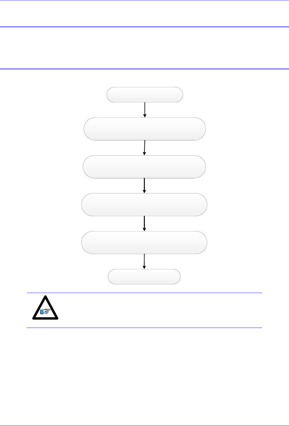
Geo Brick LV User Manual
Motor Setup 156
MOTOR SETUP
This section discusses manual (step by step) motor setup guidelines for stepper or servo motors. This
motor setup segment should be the last of a few necessary steps to properly configure a motor with Geo
Brick LV.
Motor Setup Flow Chart
The following chart summarizes the steps to implement for setting up a motor properly with the Geo
Brick LV:
Factory Default Reset $$$***, Save, $$$
(recommended)
Encoder Software Setup. Verify Feedback.
(Not applicable for steppers)
Dominant Clock Settings
Motor Software Setup
Motor Type And Protection
(Power-On PLC)
Encoder / Motor wiring
Note
The following (Motor Setup) section assumes that feedback devices (if
applicable) have been setup properly, and that moving the
motor/encoder shaft by hand shows correct data in the position
window.

Geo Brick LV User Manual
Motor Setup 157
Dominant Clock Settings
The choice of clock settings usually relies on system requirements, and type of application.
Calculating Minimum PWM Frequency
The minimum PWM frequency of a system is based on the time constant of the motor. In general, the
lower the time constant, the higher the PWM frequency should be. The motor time constant is calculated
dividing the motor inductance by the resistance (phase-phase). The minimum PWM Frequency is then
determined using the following relationship:
Ohms
R
H
L
sec
sec
2
20
)(
2
20
HzPWM
PWM
Example: A motor with an inductance of 2.80 mH, resistance of 14 (phase-phase) yields a time
constant of 200 sec. Therefore, the minimum PWM Frequency is about ~15.9KHz.
Recommended clock Frequencies
The most commonly used and recommended clock settings for the Geo Brick LV are 20 KHz PWM, 10
KHz Phase, and 5 KHz Servo.
I6800=1473 ; Macro IC0 Max Phase/PWM Frequency Control
I6801=3 ; Macro IC0 Phase Clock Frequency Control
I6802=1 ; Macro IC0 Servo Clock Frequency Control
I7100=1473 ; Servo IC1 Max Phase/PWM Frequency Control
I7101=3 ; Servo IC1 Phase Clock Frequency Control
I7102=1 ; Servo IC1 Servo Clock Frequency Control
I7000=1473 ; Servo IC0 Max Phase/PWM Frequency Control
I7001=3 ; Servo IC0 Phase Clock Frequency Control
I7002=1 ; Servo IC0 Servo Clock Frequency Control
I10=1677653 ; Servo Interrupt Time
Note that downloading parameters to a non-existent Servo or Macro IC is usually neglected by PMAC but
it is not a good practice for documentation and future configuration downloads. Use/download only the
parameters pertaining to the IC’s present on your unit:
Condition
Use/Download
Description
I4900=$1 and I4902=$0
I7000s
Servo IC 0 present
I4900=$3 and I4902=$0
I7100s and I7000s
Servo ICs 0, and 1 present
I4900=$1 and I4902=$1
I6800s and I7000s
Servo IC 0 and Macro IC 0 present
I4900=$3 and I4902=$1
I6800s, I7100s and I7000s
Servo ICs 0, 1 and Macro IC 0 present
Clock Calculations
The following clock calculations are used in selected downloadable scripts in subsequent section(s). Thus,
it is highly recommended to adjoin them to your downloadable file:
I15=0 ; Trigonometric calculation in degrees
#define MaxPhaseFreq P8000 ; Max Phase Clock [KHz]
#define PWMClk P8001 ; PWM Clock [KHz]
#define PhaseClk P8002 ; Phase Clock [KHz]
#define ServoClk P8003 ; Servo Clock [KHz]
MaxPhaseFreq=117964.8/(2*I7000+3)
PWMClk=117964.8/(4*I7000+6)
PhaseClk=MaxPhaseFreq/(I7001+1)
ServoClk=PhaseClk/(I7002+1)
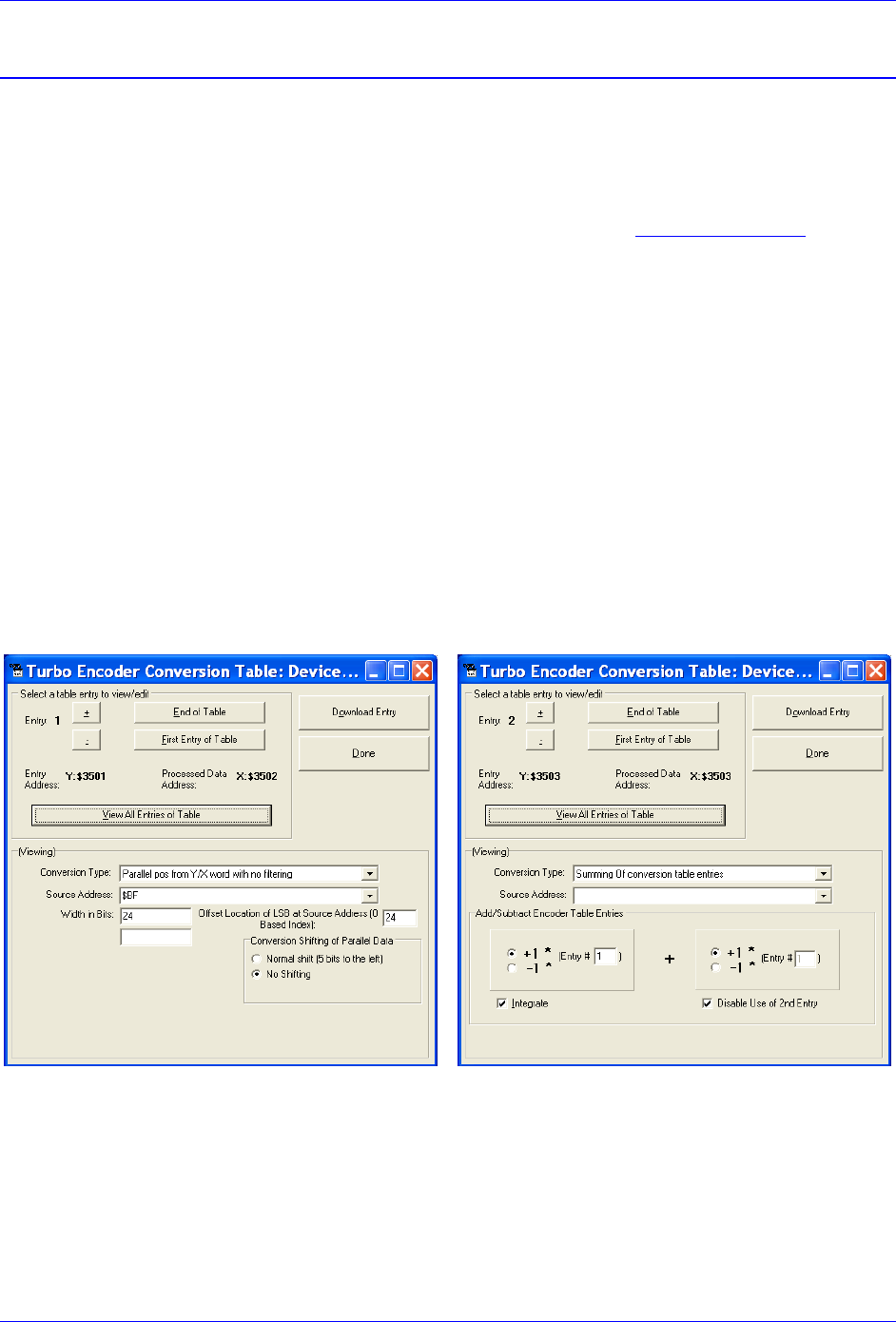
Geo Brick LV User Manual
Motor Setup 158
Stepper Motor Setup -- Direct Micro-Stepping
Before you start
Remember to create/edit the motor type and protection power-on PLC.
Parameters with Comments ending with -User Input require the user to enter information
pertaining to their system/hardware.
Downloading and using the suggested M-variables is highly recommended.
Detailed description of motor setup parameters can be found in the Turbo SRM Manual
The traditional direct-microstepping technique controlled with sinusoidal outputs from the Turbo PMAC
is not appropriate for motors controlled with direct-PWM outputs such as in Geo Brick LV Drives. A new
technique permits direct microstepping along with direct-PWM motor control.
This technique creates a simulated position sensor and feedback loop by numerically integrating the
(velocity) command output from the servo loop. This integration requires two entries in the encoder
conversion table. The resulting simulated position value can be used for both motor phase commutation
and servo-loop feedback. Alternately, a load encoder could be used for position-loop feedback while this
simulated value is used for commutation.
Encoder Conversion Table Setup
The first entry in the encoder conversion table (ECT) for each stepper motor must read the servo-loop
output like an absolute encoder. This is done with a “parallel-read” entry of a Y/X double register (the
data is in X), unshifted and unfiltered; specifying the use of 24 bits of the 48-bit Y/X register, starting 24
bits from the low end. This is effectively like reading a 24-bit DAC register.
The second entry in the ECT for each stepper motor integrates the result of the first entry.

Geo Brick LV User Manual
Motor Setup 159
Motor (Quadrature/Torque) command value Registers
Motor#
Address (X-memory)
Motor#
Address (X-memory)
1
$0000BF
5
$0002BF
2
$00013F
6
$00033F
3
$0001BF
7
$0003BF
4
$00023F
8
$00043F
Motors 1-8 Stepper Setup Encoder Conversion Table
I8000=$6800BF ; Parallel read of Y/X:$BF
I8001=$18018 ; Use 24 bits starting at X bit 0
I8002=$EC0001 ; Integrate result from I8001
I8003=$68013F ; Parallel read of Y/X:$13F
I8004=$18018 ; Use 24 bits starting at X bit 0
I8005=$EC0004 ; Integrate result from I8004
I8006=$6801BF ; Parallel read of Y/X:$1BF
I8007=$18018 ; Use 24 bits starting at X bit 0
I8008=$EC0007 ; Integrate result from I8007
I8009=$68023F ; Parallel read of Y/X:$23F
I8010=$18018 ; Use 24 bits starting at X bit 0
I8011=$EC000A ; Integrate result from I8010
I8012=$6802BF ; Parallel read of Y/X:$2BF
I8013=$18018 ; Use 24 bits starting at X bit 0
I8014=$EC000D ; Integrate result from I8013
I8015=$68033F ; Parallel read of Y/X:$33F
I8016=$18018 ; Use 24 bits starting at X bit 0
I8017=$EC0010 ; Integrate result from I8016
I8018=$6803BF ; Parallel read of Y/X:$3BF
I8019=$18018 ; Use 24 bits starting at X bit 0
I8020=$EC0013 ; Integrate result from I8019
I8021=$68043F ; Parallel read of Y/X:$43F
I8022=$18018 ; Use 24 bits starting at X bit 0
I8023=$EC0016 ; Integrate result from I8022
Position, Velocity Pointers: Ixx03, Ixx04
The position and velocity pointers (no external encoder used) will be set to the integration result:
I103=$3503 I104=$3503 ; Motor 1 position and velocity feedback
I203=$3506 I204=$3506 ; Motor 2 position and velocity feedback
I303=$3509 I304=$3509 ; Motor 3 position and velocity feedback
I403=$350C I404=$350C ; Motor 4 position and velocity feedback
I503=$350F I504=$350F ; Motor 5 position and velocity feedback
I603=$3512 I604=$3512 ; Motor 6 position and velocity feedback
I703=$3515 I704=$3515 ; Motor 7 position and velocity feedback
I803=$3518 I804=$3518 ; Motor 8 position and velocity feedback
Motor Activation, Commutation Enable: Ixx00, Ixx01
I100,8,100=1 ; Motors 1-8 active
I101,8,100=1 ; Motors 1-8 Commutation Enabled (from X-register)
Command Output Address: Ixx02
I102=$078002 ; Motor 1 Output Address
I202=$07800A ; Motor 2 Output Address
I302=$078012 ; Motor 3 Output Address
I402=$07801A ; Motor 4 Output Address
I502=$078102 ; Motor 5 Output Address
I602=$07810A ; Motor 6 Output Address
I702=$078112 ; Motor 7 Output Address
I802=$07811A ; Motor 8 Output Address

Geo Brick LV User Manual
Motor Setup 160
Current Feedback, ADC Mask, Commutation angle: Ixx82, Ixx84, Ixx72
I182=$078006 ; Motor 1 Current Feedback Address
I282=$07800E ; Motor 2 Current Feedback Address
I382=$078016 ; Motor 3 Current Feedback Address
I482=$07801E ; Motor 4 Current Feedback Address
I582=$078106 ; Motor 5 Current Feedback Address
I682=$07810E ; Motor 6 Current Feedback Address
I782=$078116 ; Motor 7 Current Feedback Address
I882=$07811E ; Motor 8 Current Feedback Address
I184,8,100=$FFFC00 ; Motors 1-8 Current Loop Feedback Mask, 14-bit (Geo Brick LV Specific)
I172,8,100=512 ; Commutation Phase Angle.2-Phase opposite voltage & current sign
; (Geo Brick LV Specific)
Flag Address, Mode Control: Ixx25, Ixx24
I125=$078000 ; Motor 1 Flag Address
I225=$078008 ; Motor 2 Flag Address
I325=$078010 ; Motor 3 Flag Address
I425=$078018 ; Motor 4 Flag Address
I525=$078100 ; Motor 5 Flag Address
I625=$078108 ; Motor 6 Flag Address
I725=$078110 ; Motor 7 Flag Address
I825=$078118 ; Motor 8 Flag Address
I124=$800401 ; Motor 1 Flag Control. High True Amp Fault, disable 3rd Harmonic
I224=$800401 ; Motor 2 Flag Control. High True Amp Fault, disable 3rd Harmonic
I324=$800401 ; Motor 3 Flag Control. High True Amp Fault, disable 3rd Harmonic
I424=$800401 ; Motor 4 Flag Control. High True Amp Fault, disable 3rd Harmonic
I524=$800401 ; Motor 5 Flag Control. High True Amp Fault, disable 3rd Harmonic
I624=$800401 ; Motor 6 Flag Control. High True Amp Fault, disable 3rd Harmonic
I724=$800401 ; Motor 7 Flag Control. High True Amp Fault, disable 3rd Harmonic
I824=$800401 ; Motor 8 Flag Control. High True Amp Fault, disable 3rd Harmonic
Commutation Address, Cycle size: Ixx83, Ixx70, Ixx71
I183=$3503 ; Motor 1 on-going Commutation Address (ECT Integration Result)
I283=$3506 ; Motor 2 on-going Commutation Address (ECT Integration Result)
I383=$3509 ; Motor 3 on-going Commutation Address (ECT Integration Result)
I483=$350C ; Motor 4 on-going Commutation Address (ECT Integration Result)
I583=$350F ; Motor 5 on-going Commutation Address (ECT Integration Result)
I683=$3512 ; Motor 6 on-going Commutation Address (ECT Integration Result)
I783=$3515 ; Motor 7 on-going Commutation Address (ECT Integration Result)
I883=$3518 ; Motor 8 on-going Commutation Address (ECT Integration Result)
I170,8,100=1 ; Motors 1-8 Single cycle size
I171,8,100=65536 ; Microsteps per Ixx70 commutation cycles

Geo Brick LV User Manual
Motor Setup 161
Maximum Achievable Motor Speed, Output Command Limit: Ixx69
In Micro-Stepping, the maximum achievable speed is proportional to the Servo clock and Motor Step
angle. A faster Servo Clock results in higher achievable motor speeds.
To ensure the safety of the application and reliability of the micro-stepping technique, the smaller value
between the Theoratical and the Calculated output command limit Ixx69 must be chosen.
Theoratical Ixx69
Sine Table: 2048
Electrical Length = 2048*32 (5-bit shift) = 65536
Max Electrical Length per Servo Cycle = Electrical Length/6 = 10922.66667
Micro-Stepping Theoratical Ixx69 = Max Electrical Length per Servo Cycle/256 = 42.6667
Calculated Ixx69
Servo Clock (KHz): 8
Stepper Angle: 1.8°
Motor Speed (rpm): 1500
Electrical Cycles per Revolution = 360 / (4*Stepper Angle)
Maximum-Achievable Motor Speed (RPM) =
(Servo Clock*1000) / (Electrical Cycles per Revolution*6)*60
Calculated Ixx69 =
Max Motor Speed* Electrical Cycles per Revolution/ 60 * 2048/6/(Servo Clock *1000)
#define ServoClk P8003 ; [KHz] Computed in Dominant Clock Settings Section
#define StepAngle 1.8 ; Step Angle [Degrees] –User Input
#define MotorSpeed 1500 ; Motor Speed Spec [RPM] –User Input
#define ElecCyclePerRev P7004 ; Electrical Cycle Per Revolution
ElecCyclePerRev=360/(4* StepAngle)
#define MaxMtrSpeed P7005 ; This is the maximum achievable motor speed
MaxMtrSpeed=( ServoClk*1000)/( ElecCyclePerRev*6)*60
#define CalculatedIxx69 P7006 ; Calculated Ixx69
CalculatedIxx69= MotorSpeed*ElecCyclePerRev/60*2048/6/(ServoClk*1000)
Setting up 1.8° Step Motors specified at 1500 rpm and a Servo Clock of 8 KHz results in a maximum
achievable speed (P7001) of 1600 rpm and a calculated Ixx69 (P7002) of 53.3334.
Theoratial Ixx69 < Calculated Ixx69 => I169,8,100= Theoratial Ixx69
I169,8,100=42.667 ; Motors 1 thru 8 Output Command Limit

Geo Brick LV User Manual
Motor Setup 162
PWM Scale Factor: Ixx66
If Motor Rated Voltage > Bus Voltage:
I166=0.95 * I7000 ; Motor #1 PWM Scale Factor, typical setting
I266=I166 I366=I166 I466=I166 ; Assuming same motor(s) as motor #1
I566=I166 I666=I166 I766=I166 I866=I166 ; Assuming same motor(s) as motor #1
If Bus Voltage > Motor Rated Voltage:
Ixx66 acts as a voltage limiter. In order to obtain full voltage output it is set to about 10% over PWM
count divided by DC Bus/Motor voltage ratio:
#define DCBusInput 60 ; DC Bus Voltage -User Input
#define Mtr1Voltage 24 ; Motor 1 Rated Voltage [VDC]-User Input
#define Mtr2Voltage 24 ; Motor 2 Rated Voltage [VDC]-User Input
#define Mtr3Voltage 24 ; Motor 3 Rated Voltage [VDC]-User Input
#define Mtr4Voltage 24 ; Motor 4 Rated Voltage [VDC]-User Input
#define Mtr5Voltage 24 ; Motor 5 Rated Voltage [VDC]-User Input
#define Mtr6Voltage 24 ; Motor 6 Rated Voltage [VDC]-User Input
#define Mtr7Voltage 24 ; Motor 7 Rated Voltage [VDC]-User Input
#define Mtr8Voltage 24 ; Motor 8 Rated Voltage [VDC]-User Input
I166=I7000*Mtr1Voltage/DCBusInput ; Motor 1 PWM Scale Factor ( Geo Brick LV Specific)
I266=I7000*Mtr2Voltage/DCBusInput ; Motor 2 PWM Scale Factor ( Geo Brick LV Specific)
I366=I7000*Mtr3Voltage/DCBusInput ; Motor 3 PWM Scale Factor ( Geo Brick LV Specific)
I466=I7000*Mtr4Voltage/DCBusInput ; Motor 4 PWM Scale Factor ( Geo Brick LV Specific)
I566=I7000*Mtr5Voltage/DCBusInput ; Motor 5 PWM Scale Factor ( Geo Brick LV Specific)
I666=I7000*Mtr6Voltage/DCBusInput ; Motor 6 PWM Scale Factor ( Geo Brick LV Specific)
I766=I7000*Mtr7Voltage/DCBusInput ; Motor 7 PWM Scale Factor ( Geo Brick LV Specific)
I866=I7000*Mtr8Voltage/DCBusInput ; Motor 8 PWM Scale Factor ( Geo Brick LV Specific)

Geo Brick LV User Manual
Motor Setup 163
I2T Protection, Magnetization Current: Ixx57, Ixx58, Ixx69, Ixx77
The lower values (tighter specifications) of the Continuous/Instantaneous current ratings between the Geo
Brick LV and motor are chosen to setup I2T protection.
If the peak current limit chosen is that of the Geo Brick LV (e.g. 15 Amps) then the time allowed at peak
current is set to 1 seconds.
If the peak current limit chosen is that of the Motor, check the motor specifications for time allowed at
peak current.
Examples:
For setting up I2T on a Geo Brick LV driving a 3A/9A motor, 3 amps continuous and 9 amps
instantaneous will be used as current limits. And time allowed at peak is that of the motor.
For setting up I2T on a Geo Brick LV driving a 4A/16A motor, 4 amps continuous and 15 amps
instantaneous will be used as current limits. And time allowed at peak is 1 seconds.
The rule of thumb for Stepper magnetization current is Ixx77 = Ixx57/√2
Motors 1 thru 8 have 5-amp continuous, 15-amp peak current limits. With a servo clock of 8 KHz, I2T
protection and magnetization current would be set to:
I15=0 ; Trigonometric calculation in degrees
#define ContCurrent 5 ; Continuous Current Limit [Amps] –User Input
#define PeakCurrent 15 ; Instantaneous Current Limit [Amps] –User Input
#define MaxADC 33.85 ; Brick LV full range ADC reading (see electrical specifications)
#define ServoClk P8003 ; [KHz] Computed in Dominant Clock Settings Section
#define I2TOnTime 1 ; Time allowed at peak Current [sec]
#define VoltOutLimit P7007 ; This is Ixx69 normally used in direct digital PWM
I157=INT(32767*(ContCurrent*1.414/MaxADC)*cos(30))
I177=I157/SQRT(2)
VoltOutLimit=INT(32767*(PeakCurrent*1.414/MaxADC)*cos(30))
I158=INT((VoltOutLimit*VoltOutLimit-I157*I157)*ServoClk*1000*I2TOnTime/(32767*32767))
I257=I157 I277=I177 I258=I158
I357=I157 I377=I177 I358=I158
I457=I157 I477=I177 I458=I158
I557=I157 I577=I177 I558=I158
I657=I157 I677=I177 I658=I158
I757=I157 I777=I177 I758=I158
I857=I157 I877=I177 I858=I158
Note
This software I2T is designed to primarily protect the motor. The Geo
Brick LV’s hardware built-in I2T protects the amplifier and presents
an added layer of system safety.

Geo Brick LV User Manual
Motor Setup 164
Phasing, Power-On Mode: Ixx80, Ixx73, Ixx74, Ixx81, Ixx91
I180=0 I173=0 I174=0 ;
I280=0 I273=0 I274=0 ;
I380=0 I373=0 I374=0 ;
I480=0 I473=0 I474=0 ;
I580=0 I573=0 I574=0 ;
I680=0 I673=0 I674=0 ;
I780=0 I773=0 I774=0 ;
I880=0 I873=0 I874=0 ;
I181=$3503 ; Motor 1 Power-On Commutation, Integrated Output #1
I281=$3506 ; Motor 2 Power-On Commutation, Integrated Output #2
I381=$3509 ; Motor 3 Power-On Commutation, Integrated Output #3
I481=$350C ; Motor 4 Power-On Commutation, Integrated Output #4
I581=$350F ; Motor 5 Power-On Commutation, Integrated Output #5
I681=$3512 ; Motor 6 Power-On Commutation, Integrated Output #6
I781=$3515 ; Motor 7 Power-On Commutation, Integrated Output #7
I881=$3518 ; Motor 8 Power-On Commutation, Integrated Output #8
I191,8,100=$500000 ; Mtrs 1-8 Pwr-on Pos. format Read 16 (11+5) bits of X register Ixx81
Position-Loop PID Gains: Ixx30…Ixx39
I130,8,100=1024 ;
I131,8,100=0 ;
I132,8,100=85 ;
I133,8,100=1024 ;
I134,8,100=1 ;
I135,8,100=0 ;
I136,8,100=0 ;
I137,8,100=0 ;
I138,8,100=0 ;
I139,8,100=0 ;
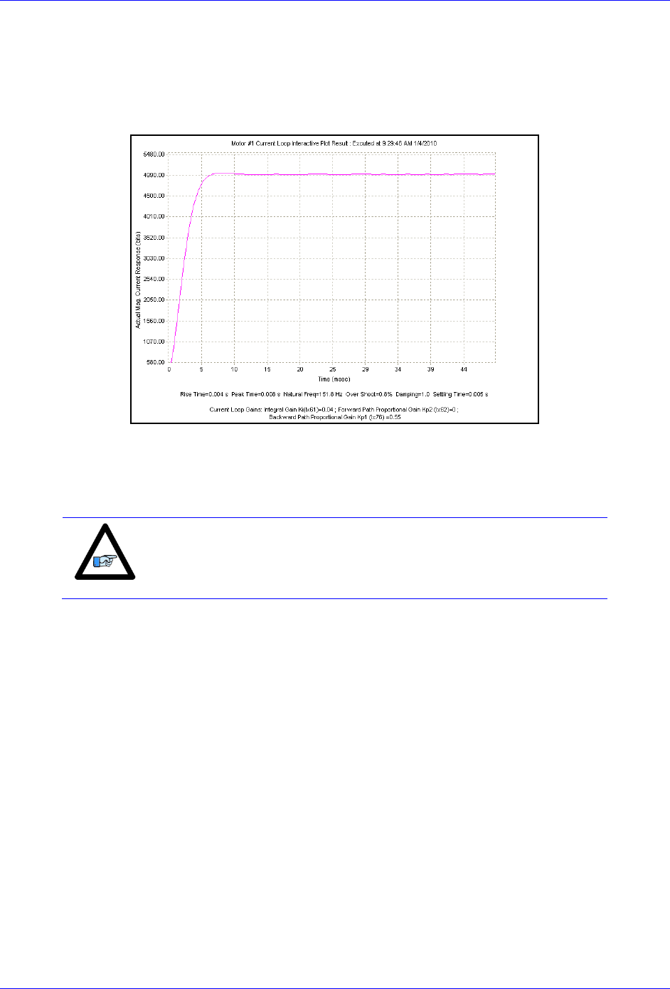
Geo Brick LV User Manual
Motor Setup 165
Current-Loop Gains: Ixx61, Ixx62, Ixx76
The current-loop tuning can be performed as in any Turbo PMAC digital current loop setup. The
PMACTuningPro2 automatic or interactive utility can be used to fine-tune the current loop gains.
Ixx61=0.005, Ixx62=0, and Ixx76=0.05 is a good/safe starting point for interactive current-loop tuning.
Typically, an acceptable current-loop step response would look like the following:
Number of Counts per Revolution (Stepper Motors)
With a count equal to a micro-step, and 512 micro-steps per 1.8-degree full step (2048 per cycle), you
should expect to see 360*512/1.8= 102,400 counts per revolution of the motor.
Note
Some stepper motors have unconventional specifications making top
speeds unattainable with the basic micro-stepping technique.
Adjusting the direct current on the fly might be necessary (i.e. using
open servo).

Geo Brick LV User Manual
Motor Setup 166
Brushless Motor Setup
Before you start
Remember to create/edit the motor type and protection power-on PLC
At this point of the setup it is assumed that the encoder has been wired and configured correctly
in the Encoder Feedback section. And that moving the motor/encoder shaft by hand shows
encoder counts in the position window.
Parameters with Comments ending with -User Input require the user to enter information
pertaining to their system/hardware.
Downloading and using the suggested M-variables is highly recommended.
Detailed description of motor setup parameters can be found in the Turbo SRM
Flag Control, Commutation Angle, Current Mask: Ixx24, Ixx72, Ixx84
I124,8,100=$800001 ; Motors 1-8 Flag control, High true amp fault (Geo Brick LV specific)
I172,8,100=683 ; Motors 1-8 Commutation phase angle (Geo Brick LV specific)
I184,8,100=$FFFC00 ; Motors 1-8 Current-Loop Feedback Mask Word (Geo Brick LV specific)
PWM Scale Factor: Ixx66
If Motor Rated Voltage > Bus Voltage:
I166=0.95 * I7000 ; Motor #1 PWM Scale Factor, typical setting
I266=I166 I366=I166 I466=I166 ; Assuming same motor(s) as motor #1
I566=I166 I666=I166 I766=I166 I866=I166 ; Assuming same motor(s) as motor #1
If Bus Voltage > Motor Rated Voltage:
Ixx66 acts as a voltage limiter. In order to obtain full voltage output it is set to the PWM count divided by
DC Bus/Motor voltage ratio:
#define DCBusInput 60 ; DC Bus Voltage -User Input
#define Mtr1Voltage 24 ; Motor 1 Rated Voltage [VDC]-User Input
#define Mtr2Voltage 24 ; Motor 2 Rated Voltage [VDC]-User Input
#define Mtr3Voltage 24 ; Motor 3 Rated Voltage [VDC]-User Input
#define Mtr4Voltage 24 ; Motor 4 Rated Voltage [VDC]-User Input
#define Mtr5Voltage 24 ; Motor 5 Rated Voltage [VDC]-User Input
#define Mtr6Voltage 24 ; Motor 6 Rated Voltage [VDC]-User Input
#define Mtr7Voltage 24 ; Motor 7 Rated Voltage [VDC]-User Input
#define Mtr8Voltage 24 ; Motor 8 Rated Voltage [VDC]-User Input
I166=I7000*Mtr1Voltage/DCBusInput ; Motor 1 PWM Scale Factor
I266=I7000*Mtr2Voltage/DCBusInput ; Motor 2 PWM Scale Factor
I366=I7000*Mtr3Voltage/DCBusInput ; Motor 3 PWM Scale Factor
I466=I7000*Mtr4Voltage/DCBusInput ; Motor 4 PWM Scale Factor
I566=I7000*Mtr5Voltage/DCBusInput ; Motor 5 PWM Scale Factor
I666=I7000*Mtr6Voltage/DCBusInput ; Motor 6 PWM Scale Factor
I766=I7000*Mtr7Voltage/DCBusInput ; Motor 7 PWM Scale Factor
I866=I7000*Mtr8Voltage/DCBusInput ; Motor 8 PWM Scale Factor
Current Feedback Address: Ixx82
I182=$078006 ; Motor 1 Current Feedback Address
I282=$07800E ; Motor 2 Current Feedback Address
I382=$078016 ; Motor 3 Current Feedback Address
I482=$07801E ; Motor 4 Current Feedback Address
I582=$078106 ; Motor 5 Current Feedback Address
I682=$07810E ; Motor 6 Current Feedback Address
I782=$078116 ; Motor 7 Current Feedback Address
I882=$07811E ; Motor 8 Current Feedback Address

Geo Brick LV User Manual
Motor Setup 167
Commutation Position Address, Commutation Enable: Ixx83, Ixx01
Quadrature / Sinusoidal / HiperFace
For these types of feedback devices, it is recommended to use the quadrature data for commutation. And
Ixx01 should be equal to 1, indicating commutation from an X-register:
I183=$078001 ; Motor 1 Commutation source address
I283=$078009 ; Motor 2 Commutation source address
I383=$078011 ; Motor 3 Commutation source address
I483=$078019 ; Motor 4 Commutation source address
I583=$078101 ; Motor 5 Commutation source address
I683=$078109 ; Motor 6 Commutation source address
I783=$078111 ; Motor 7 Commutation source address
I883=$078119 ; Motor 8 Commutation source address
I101,8,100=1 ; Motors 1-8 Commutation Enabled, from X-register
SSI / EnDat / BiSS
Technique 1
PMAC expects the commutation data to be left most shifted. With technique 1, this is satisfied if the
encoder data fulfills or exceeds 24 bits. But if the data length is less than 24 bits then it is recommended,
for simplicity, to use the processed encoder conversion table result. Ixx01 is then set up correspondingly
for either a Y- or X- register.
If the Singleturn + Multiturn data fulfills 24 bits; ST+MT ≥ 24 bits:
I183=$78B20 ; Motor 1 Commutation source address
I283=$78B24 ; Motor 2 Commutation source address
I383=$78B28 ; Motor 3 Commutation source address
I483=$78B2C ; Motor 4 Commutation source address
I583=$78B30 ; Motor 5 Commutation source address
I683=$78B34 ; Motor 6 Commutation source address
I783=$78B38 ; Motor 7 Commutation source address
I883=$78B3C ; Motor 8 Commutation source address
I101,8,100=3 ; Motors 1-8 Commutation Enabled, from Y-register
If the Singleturn + Multiturn data does not fulfill 24 bits; ST+MT < 24 bits:
I183=I104 ; Motor 1 Commutation source address
I283=I204 ; Motor 2 Commutation source address
I383=I304 ; Motor 3 Commutation source address
I483=I404 ; Motor 4 Commutation source address
I583=I504 ; Motor 5 Commutation source address
I683=I604 ; Motor 6 Commutation source address
I783=I704 ; Motor 7 Commutation source address
I883=I804 ; Motor 8 Commutation source address
I101,8,100=1 ; Motors 1-8 Commutation Enabled, from X-register
Technique 2/3
With techniques 2 and 3, the commutation-dedicated encoder conversion table (see feedback setup
section) result is the commutation source. And Ixx01 should be equal to 1 indicating an X-register:
// These addresses can differ depending on the encoder conversion table management
I183=$3512 ; Motor 1 Commutation source address -User Input
I283=$3514 ; Motor 2 Commutation source address -User Input
I383=$3516 ; Motor 3 Commutation source address -User Input
I483=$3518 ; Motor 4 Commutation source address -User Input
I583=$351A ; Motor 5 Commutation source address -User Input
I683=$351C ; Motor 6 Commutation source address -User Input
I783=$351E ; Motor 7 Commutation source address -User Input
I883=$3520 ; Motor 8 Commutation source address -User Input
I101,8,100=1 ; Motors 1-8 Commutation Enabled, from X-register

Geo Brick LV User Manual
Motor Setup 168
Resolver
With resolvers, it is recommended to use the unfiltered data processed in the Encoder Conversion Table:
// these addresses can differ depending on the encoder conversion table management
I183=$3503 ; Motor 1 On-going Commutation Position Address
I283=$350B ; Motor 2 On-going Commutation Position Address
I383=$3513 ; Motor 3 On-going Commutation Position Address
I483=$351B ; Motor 4 On-going Commutation Position Address
I583=$3523 ; Motor 5 On-going Commutation Position Address
I683=$352B ; Motor 6 On-going Commutation Position Address
I783=$3533 ; Motor 7 On-going Commutation Position Address
I883=$353B ; Motor 8 On-going Commutation Position Address
I101,8,100=1 ; Motors 1-8 Commutation Enabled, from X-register
Yaskawa
With Yaskawa feedback devices, it is recommended to use the processed data in the Encoder Conversion
Table (same as position):
I183=I104 ; Motor 1 On-going Commutation Position Address
I283=I204 ; Motor 2 On-going Commutation Position Address
I383=I304 ; Motor 3 On-going Commutation Position Address
I483=I404 ; Motor 4 On-going Commutation Position Address
I583=I504 ; Motor 5 On-going Commutation Position Address
I683=I604 ; Motor 6 On-going Commutation Position Address
I783=I704 ; Motor 7 On-going Commutation Position Address
I883=I804 ; Motor 8 On-going Commutation Position Address
I101,8,100=1 ; Motors 1-8 Commutation Enabled, from X-register

Geo Brick LV User Manual
Motor Setup 169
I2T Protection: Ixx57, Ixx58, Ixx69
The lower values (tighter specifications) of the Continuous/Instantaneous current ratings between the Geo
Brick LV and motor are chosen to setup I2T protection.
If the peak current limit chosen is that of the Geo Brick LV (e.g. 15 Amps) then the time allowed at peak
current is set to 1 seconds.
If the peak current limit chosen is that of the Motor, check the motor specifications for time allowed at
peak current.
Examples:
For setting up I2T on a Geo Brick LV driving a 3A/9A motor, 3 amps continuous and 9 amps
instantaneous will be used as current limits. And time allowed at peak is that of the motor.
For setting up I2T on a Geo Brick LV driving a 4A/16A motor, 4 amps continuous and 15 amps
instantaneous will be used as current limits. And time allowed at peak is 1 seconds.
Motors 1 thru 8 have 5-amp continuous, 15-amp peak current limits.
#define ServoClk P8003 ; [KHz] Computed in Dominant Clock Settings Section
#define ContCurrent 5 ; Continuous Current Limit [Amps] –User Input
#define PeakCurrent 15 ; Instantaneous Current Limit [Amps] –User Input
#define MaxADC 33.85 ; Brick LV full range ADC reading (see electrical specifications)
#define I2TOnTime 1 ; Time allowed at peak Current [sec]
I157=INT(32767*(ContCurrent*1.414/MaxADC)*cos(30))
I169=INT(32767*(PeakCurrent*1.414/MaxADC)*cos(30))
I158=INT((I169*I169-I157*I157)*ServoClk*1000*I2TOnTime/(32767*32767))
I257=I157 I258=I158 I269=I169
I357=I157 I358=I158 I369=I169
I457=I157 I458=I158 I469=I169
I557=I157 I558=I158 I569=I169
I657=I157 I658=I158 I669=I169
I757=I157 I758=I158 I769=I169
I857=I157 I858=I158 I869=I169
Note
This software I2T is designed to primarily protect the motor. The Geo
Brick LV’s hardware built-in I2T protects the amplifier and presents
an added layer of system safety.

Geo Brick LV User Manual
Motor Setup 170
Commutation Cycle Size: Ixx70, Ixx71
The ratio of Ixx70/Ixx71 represents the number of encoder counts per electrical cycle. These parameters
are typically set up with respect to the motor, encoder type, resolution, and processing method:
For a rotary motor: the number of commutation cycles Ixx70 should be equal to the number of pole
pairs: Ixx70= {Number of pole pairs}. The commutation cycle size Ixx71, is equal to the electrical cycle
length or pole-pair pitch in units of encoder counts:
Feedback Type
Motor Scale Factor (SF)
[counts/rev]
Ixx71
Quadrature
SF= Lines x 4
= SF
Sinusoidal / HiperFace
SF= Sine/Cosine cycles per rev * 128
= SF/32
Resolver
SF= 4096
= SF*32= 131072
SSI / EnDat / BiSS
Technique 1
SF= 2ST
= SF= 2ST
If Ixx01= 3
= 32*SF= 32*2ST
If Ixx01= 1
SSI / EnDat / BiSS
Technique 2
SF= 2ST-5 = 2ST /32
= 218= 262144
SSI / EnDat / BiSS
Technique 3
SF= 2ST
Yaskawa Sigma II
SF= 2ST
= 32*SF= 32*2ST
Where ST: is the rotary encoder Singleturn resolution in bits
For a linear motor: the number of commutation cycles Ixx70 is typically equal to 1: Ixx70=1. The
commutation cycle size Ixx71, is equal to the Electrical Cycle Length (ECL) or pole-pair pitch in units of
encoder counts:
Feedback Type
Motor Scale Factor (SF)
[counts/mm]
Ixx71
Quadrature
SF= (1/RESmm)*4
= SF*ECLmm= ECLmm / RESmm
Sinusoidal / HiperFace
SF= 128/RESmm
= SF*ECLmm/32= 4* ECLmm / RESmm
SSI / EnDat / BiSS
Technique 1
SF= 1/RESmm
= ECLmm * SF= ECLmm / RESmm
If Ixx01= 3
= 32* ECLmm*SF
= 32* ECLmm/ RESmm
If Ixx01= 1
SSI / EnDat / BiSS
Technique 2
SF= 1/(32*RESmm)
= ECLmm*SF/2Offset
= ECLmm/(RESmm*2Offset)
SSI / EnDat / BiSS
Technique 3
SF= 1/RESmm
Yaskawa Sigma II
SF= 1/RESmm
= 32* ECLmm*SF = 32* ECLmm/ RESmm
Where RES: is the linear scale resolution in user units (e.g. mm)
ECL: is the electrical cycle length of the linear motor in the same units as RES (e.g. mm)
Offset: is the ECT commutation offset; = linear encoder protocol bit length - 18

Geo Brick LV User Manual
Motor Setup 171
Note
The Singleturn (ST) data bits for rotary encoders, as well as the serial
protocol bit-length for linear scales can be found in the encoder
manufacturer’s spec sheet.
Note
The Electrical Cycle Length (ECL) or pole-pair pitch (in user units)
can be found in the motor manufacturer’s spec sheet.
Ixx71 Saturation
High resolution encoders could saturate the Ixx71 register, which is a signed 24-bit register. Thus, the
maximum value writeable to it is 2^24-1signbit= 16,777,215.
But remember, the ratio of Ixx71/Ixx70 is what really matters. Dividing Ixx70 and Ixx71 by a common
integer divisor could alleviate settings which are out of range.
Example: For an 8-pole brushless rotary motor, with a high resolution encoder (producing 33,554,432
counts/revolution), Ixx70 and Ixx71 are usually set to 4 (pole pairs), and 33554432 respectively. These
settings are not acceptable since Ixx71 exceeds the maximum permissible value in its 24-bit register,
dividing both Ixx70 and Ixx71 by 4 results in acceptable settings:
Ixx70= 4/4= 1
Ixx71= 33554432/4= 8388608
ADC Offsets: Ixx29, Ixx79
The ADC offsets importance may vary from one system to another, depending on the motor(s) type and
application requirements. They can be left at default of zero especially if a motor setup is to be
reproduced on multiple machines by copying the configuration file of the first time integration. However,
they should ultimately be set to minimize measurement offsets from the A and B-phase current feedback
circuits, respectively (read in Suggested M-variables Mxx05, Mxx06).
ADC offsets compensation can be done using the following procedure (starting from a killed motor).
This can be implemented in a one-time test PLC:
1. Record the current loop tuning gains: Ixx61, Ixx62, and Ixx76. Then set them to zero, these will
be restored at the end of the test.
2. Issue a #no0 (zero open loop output)
3. Sample ADC phases A, and B. Using suggested M-Variables Mxx05 and Mxx06 respectively.
E.g. store snapshots in two separate arrays of P-Variables.
4. Average readings over the number of sampled points.
5. Write the opposite value of the averaged ADCA readings in Ixx29
Write the opposite value of the averaged ADCB readings in Ixx79
6. Issue a #nK (Kill motor)
7. Restore the original current loop gains.
Note
Geo Brick LVs dating 10/1/2012 and later perform automatic ADC
offset compensation. Leave Ixx29 and Ixx79 at zero.
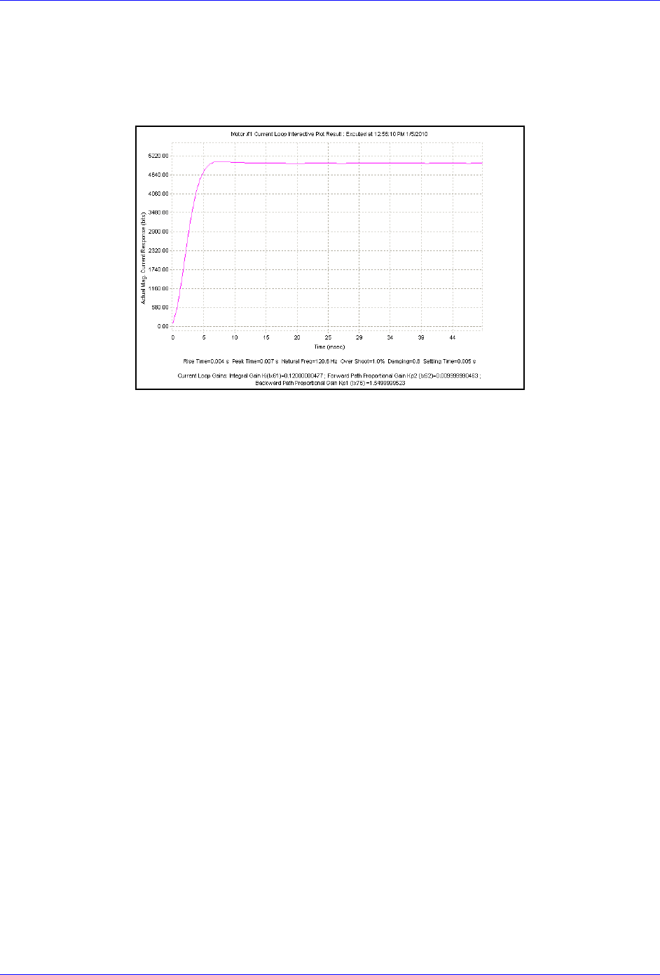
Geo Brick LV User Manual
Motor Setup 172
Current-Loop Gains: Ixx61, Ixx62, Ixx76
The current-loop tuning is done as in any Turbo PMAC digital current loop setup. The PMACTuningPro2
automatic or interactive utility can be used to fine-tune the Current-Loop.
An acceptable Current-Loop step response would look like:
Geo Brick LV User Manual
Motor Setup 173
Motor Phasing, Power-On Mode: Ixx73, Ixx74, Ixx80, Ixx81, Ixx91
The Geo Brick LV supports a variety of phasing procedures for commutated (brushless) motors. This
section discusses the following phasing methods:
Manual | Custom Phasing
2-Guess Phasing Method
Stepper Phasing Method
Hall Effect Phasing: Digital quadrature encoders
Hall Effect Phasing: Yaskawa Incremental encoders
Absolute Power-On Phasing: HiperFace
Absolute Power-On Phasing: EnDat | SSI | BiSS
Absolute Power-On Phasing: Yaskawa absolute encoders
WARNING
An unreliable phasing search method can lead to a runaway
condition. Test the phasing search method carefully to make sure
it works properly under all conceivable conditions, and various
locations of the travel. Make sure the Ixx11 fatal following error
limit is active and as tight as possible so the motor will be killed
quickly in the event of a serious phasing search error.
Note
In general, it is NOT recommended to execute any phasing search
move on power up using Turbo PMAC’s automatic setting (Ixx80).
Motor phasing should be inserted in a power-on plc before which it is
ensured that the bus power has been applied.

Geo Brick LV User Manual
Motor Setup 174
Manual | Custom Phasing
Manual phasing can be used with virtually any type of feedback. It is ideal for:
Quick Phasing
Troubleshooting phasing difficulties
Finding a “good” phase finding output value to use in the 2-guess or stepper phasing
Manual phasing consists of locking the motor tightly onto one of its phases, then zeroing the phase
position register (suggested M-Variable Mxx71). When implemented properly (locking the motor tightly
to a phase), it is considered to be one of the finest phasing methods.
The following is the most common manual phasing procedure:
a. Record the values of Ixx29, and Ixx79. These will be restored at the end of test.
b. Set Ixx29=0, and write a positive value in Ixx79
Ixx79=500 is a good starting point for most motors.
c. Issue #nO0 where n is the motor number
d. Increase (for larger motors) or decrease (for smaller motors) Ixx79 as necessary until the motor
is locked tightly onto one of its phases.
e. Wait for the motor to settle. In some instances, it oscillates around the phase for an extended
period of time. Some motors are small enough that you could safely stabilize by hand.
f. Zero the phase position register , suggested M-variable Mxx71=0
g. Issue a #nK to kill the motor
h. Restore Ixx29, and Ixx79 to their original values
i. Clear the phasing search error bit, Suggested M-Variable Mxx48=0
j. The motor is now phased. It is ready for open loop or closed loop commands (if the position loop
is tuned).
The aforementioned procedure can be done online from the terminal window, or implemented in a PLC
for convenience.
Manual Phasing Example 1:
#define Mtr1PhasePos M171 ; Motor 1 Phase Position Register, Suggested M-Variable
Mtr1PhasePos->X:$B4,0,24,S
#define Mtr1PhaseErrBit M148 ; Motor 1 Phasing Search Error Bit, Suggested M-Variable
Mtr1PhaseErrBit->Y:$C0,8
Open plc 1 clear
I5111=500*8388608/I10 while(I5111>0) Endw
P129=I129 P179=I179 ; Store Ixx29, and Ixx79
I129=0 I179=1000 ; Set Ixx29=0 and Ixx79 to positive value (adjustable)
I5111=100*8388608/I10 while(I5111>0) Endw ; 100 msec delay
CMD"#1o0" ; Issue 0% open loop command output
I5111=3000*8388608/I10 while(I5111>0) Endw ; 3 seconds delay to allow motor to settle
Mtr1PhasePos=0 ; Set phase register to zero
I5111=500*8388608/I10 while(I5111>0) Endw ; 1/2 second delay
CMD"#1K" ; Kill Motor
I5111=100*8388608/I10 while (I5111>0) Endw ; 100 msec delay
I129=P129 I179=P179 ; Restore Ixx29 and Ixx79 to original values
Mtr1PhaseErrBit=0 ; Clear Phasing search error bit
I5111=500*8388608/I10 while (I5111>0) Endw ; 1/2 second delay
Dis plc 1 ; Execute PLC once
Close

Geo Brick LV User Manual
Motor Setup 175
Alternately, a more refined manual phasing method can be implemented. Knowing a good value which
would lock the motors onto a phase (using the above procedure), the following example locks (in small
incremental steps) the motor onto one phase then steps it back into the other phase:
Manual Phasing Example 2:
#define Mtr1PhasePos M171 ; Motor 1 Phase Position Register, Suggested M-Variable
Mtr1PhasePos->X:$B4,0,24,S
#define Mtr1PhaseErrBit M148 ; Motor 1 Phasing Search Error Bit, Suggested M-Variable
Mtr1PhaseErrBit->Y:$C0,8
Open plc 1 clear
I5111=100*8388608/I10 while(I5111>0) Endw ; Delay
P129=I129 P179=I179 ; Store Ixx29, and Ixx79
I129=0 I179=0 ; Set ADC offsets to zero
I5111=100*8388608/I10 while(I5111>0) Endw ; Delay
CMD"#1o0" ; Issue #nO0
I5111=100*8388608/I10 while(I5111>0) Endw ; Delay
while (I129!>1500) ; Force motor to Phase A
I129=I129+10 I179=0 ; by pushing current incrementally
I5111=100*8388608/I10 while(I5111>0) Endw ; Delay
Endw
while (200 < ABS(M166))endw ; Wait for motor to settle
I5111=1000*8388608/I10 while(I5111>0) Endw ; Delay
while (I179!>1500) ; Force motor to Phase B
I179=I179+10 I129=I129-10 ; by pushing current incrementally
I5111=100*8388608/I10 while(I5111>0) Endw ; Delay
Endw
while (200 < ABS(M166))endw ; Wait for motor to settle
I5111=1000*8388608/I10 while(I5111>0) Endw ; Delay
Mtr1PhasePos=0 ; Set phase position register to zero
I5111=250*8388608/I10 while(I5111>0) Endw ; 1/2 second delay
CMD"#1K" ; Kill Motor
I5111=100*8388608/I10 while (I5111>0) Endw ; Delay
I129=P129 I179=P179 ; Restore Ixx29 and Ixx79 to original values
Mtr1PhaseErrBit=0 ; Clear Phasing search error bit
I5111=500*8388608/I10 while (I5111>0) Endw ; Delay
Dis plc 1 ; Run PLC once
Close

Geo Brick LV User Manual
Motor Setup 176
2-Guess Phasing Method
The 2-guess is a rough phasing method for motors with relatively small loads. It is not ideal for high
torque requirements. It can be used with any type of feedback. Example of typical settings:
Ixx73=1200 ; Phase finding output value (adjustable) in units of 16-bit DAC
Ixx74=12 ; Units of servo cycles (adjustable)
Ixx80=4 ; 2-guess method, no absolute position read, no power-on phasing
Stepper Phasing Method
The stepper is a finer phasing method than the 2-guess. It is generally used for motors with significant
loads and higher torque demands. It can be used with any type of feedback. Example of typical settings:
Ixx73=1200 ; Phase finding output value (adjustable) in units of 16-bit DAC
Ixx74=80 ; Units of Servo Cycles * 256 (adjustable)
Ixx80=6 ; Stepper method, no absolute position read, no power-on phasing
Note
The 2-guess or stepper method(s) phase the motor upon issuing a #n$.
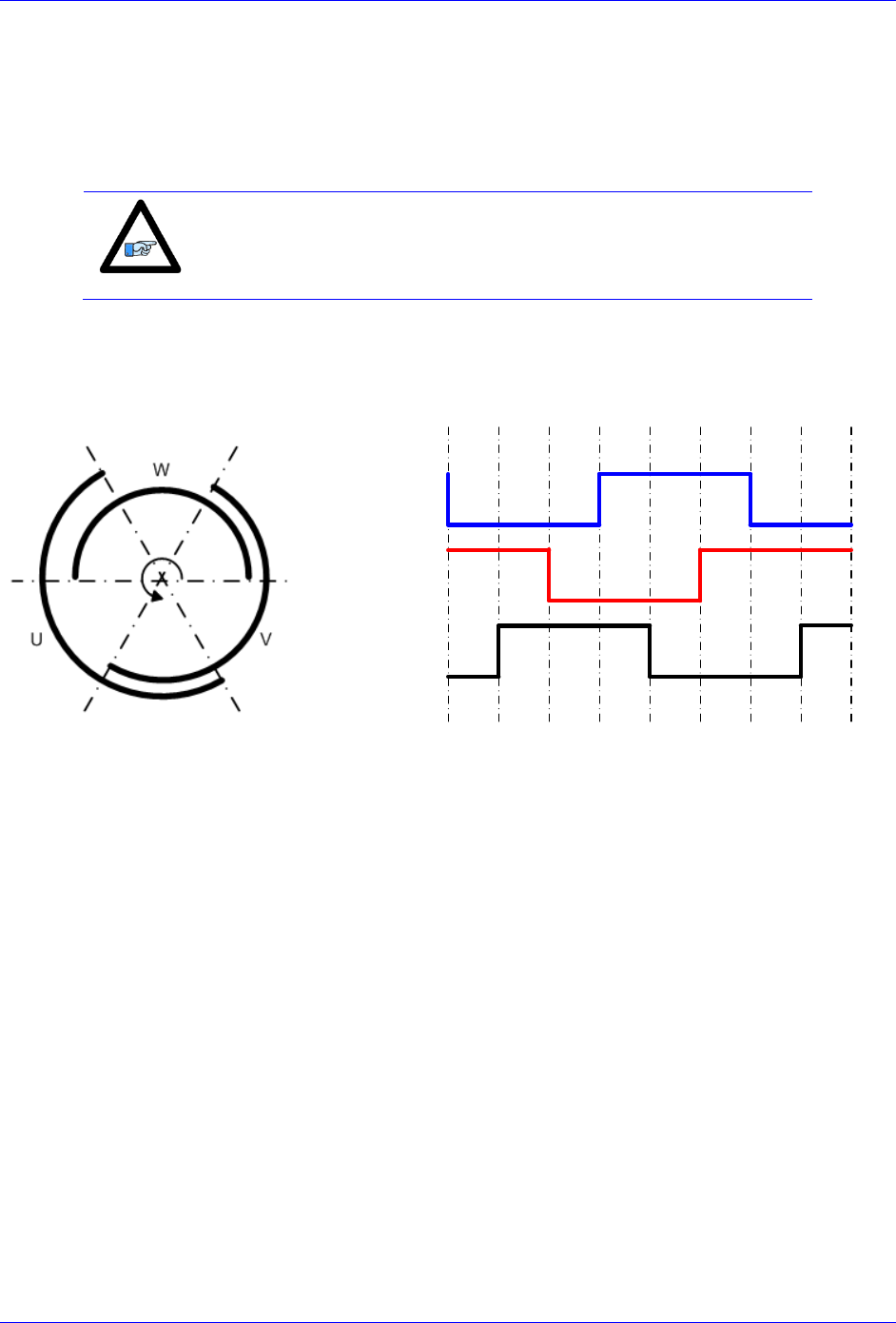
Geo Brick LV User Manual
Motor Setup 177
Hall Effect Phasing: Digital quadrature encoders
Digital hall sensors can be used for rough phasing on power-up without the need for a phasing search
operation such as the manual, 2-guess, or stepper phasing methods. It provides absolute information about
where the motor is positioned with respect to its commutation cycle. It is highly desirable due to the fact
that it allows phasing the motor without any movement.
Note
Inherently, digital hall sensors have an error of about ±30°, resulting
in a torque loss of about 15%. It needs to be corrected (fine phasing)
for top operation.
The Geo Brick LV supports the conventional 120° spacing hall sensors’ type, each nominally with 50%
duty cycle, and nominally 1/3 cycle apart. The Geo Brick LV has no automatic hardware or software
features to work with 60° spacing. The 120° spacing format provides six distinct states per cycle:
-60° 0° 60° 120° 180° -120° -60° 0° 60°
Channel W
Channel V
Channel U
Follow these steps to implement hall sensor phasing:
1. Start with Ixx81=0, and Ixx91=0, which eventually are the parameters to be configured
2. Phase the motor manually or using the 2-guess/stepper method.
3. Jog the motor slowly (with rough PID gains), or move in open loop/by hand in the positive direction of
the encoder while plotting Halls UVW (Mxx28) versus Phase Position (Mxx71).
4. Set up the detailed plot, scaling and processing for Halls UVW and Phase Position
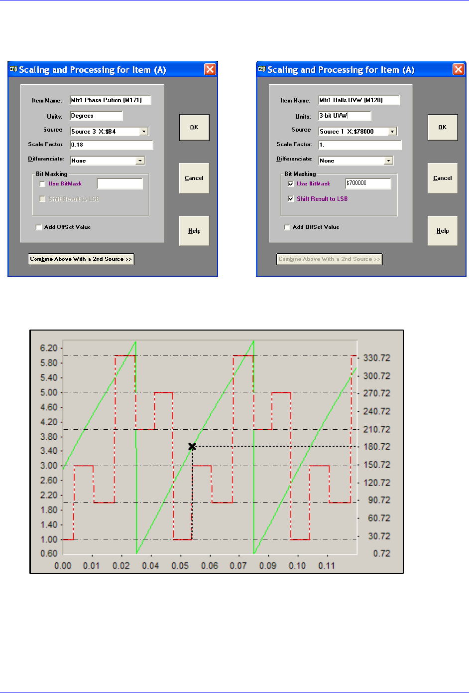
Geo Brick LV User Manual
Motor Setup 178
Plotting the phase position (Mxx71)
The scale factor is used to scale the phase position
to 0 - 360°. It is = 360 / Ixx71
Plotting the hall sensors (Mxx28)
$700000 Masking enables reading W, V, and U
in bits 20, 21, and 22 respectively
5. Gathering, and plotting data for a short positive travel of the motor should look like:
Motor #1: Hall Sensors Vs. Phase Position
Time (sec)
Hall Sensors UVW Mxx28
Phase Position Mxx71 (degrees)
State 1
State 2
State 3
State 4
State 5
State 6
Primarily, we are interested in two occurrences on the plot; the transition of the halls data between
states 1 & 3, and the point of intersection of Mxx28 and Mxx71 at this transition. This represents the
Hall Effect Zero (HEZ).
Geo Brick LV User Manual
Motor Setup 179
With positive movement of the motor, if the halls state transition is from 1 to 3 (as seen in
the example plot) then use the following set of equations:
I181=$78000 ; Channel 1 power-on phase address (see table below)
#define HallsTrans1_3 M7025 ; Standard direction, 1 to 3
#define Mtr1HEZ P7025 ; Hall effect zero
#define Mtr1HEZTemp P7026 ; Intermediate calculation
HallsTrans1_3->* ;
HallsTrans1_3=$800000 ; Bit #22=0 for standard transition
Mtr1HEZ=180 ; Degrees – User Input
Mtr1HEZTemp = INT(((Mtr1HEZ%360)/360)*64) ; Processing hall effect zero
I191=(Mtr1HEZTemp*65536)+HallsTrans1_3 ; Shift 16 bits left and set transition bit
With positive movement of the motor, if the halls state transition is from 3 to 1 then use
the following set of equations:
I181=$78000 ; Channel 1 power-on phase address (see table below)
#define HallsTrans3_1 M7025 ; Reversed direction, 3 to 1
#define Mtr1HEZ P7025 ; Hall effect zero
#define Mtr1HEZTemp P7026 ; Intermediate calculation
HallsTrans3_1->* ;
HallsTrans3_1=$C00000 ; Bit #22=1 for reversed transition
Mtr1HEZ=180 ; Degrees – User Input
Mtr1HEZTemp = INT(((Mtr1HEZ%360)/360)*64) ; Processing hall effect zero
I191=(Mtr1HEZTemp*65536)+HallsTrans3_1 ; Shift 16 bits left and set transition bit
Note
The only user input in the above set of equations is the Hall Effect
Zero angle, derived from the plot.
Power-On Phase Position Address
Ixx81 For Hall Sensors
Channel 1
$78000
Channel 5
$78100
Channel 2
$78008
Channel 6
$78108
Channel 3
$78010
Channel 7
$78110
Channel 4
$78018
Channel 8
$78118
Alternatively, the above procedure can be performed using the Halls Automatic Utility software available
on our forum.
Note
The automatic software utility requires jogging the motor; make sure
the motor is phased (custom, 2-guess, or stepper method) and that the
position-loop tuning is acceptable for closed loop movement.

Geo Brick LV User Manual
Motor Setup 180
Fine Phasing
Correcting for hall sensors’ error (torque loss) can be implemented using the following procedure
(performed once per installation):
1. Phase the motor manually (as tight as possible). See manual phasing section.
2. Home motor to machine zero location (e.g. most commonly using flag and C-index), with or
without home offset, similarly to how the motor would home after the machine has been
commissioned.
3. Record the phase position Mxx71 at the home location
The above procedure reveals the optimum phase position at home or zero location of the motor.
Subsequently, the motor is “roughly phased” on power up using hall sensors. And the phase position
Mxx71 is then corrected (overwritten) after the motor is homed (to known location). This is usually done
in a PLC routine.
Example:
Channel 1 is driving a motor with home capture done using home flag and index pulse (high true). The
recorded phase position from the manual phasing reference test was found to be 330. It is stored (saved)
in a user defined variable.
I7012=3 ; Motor 1 Capture Control, Index high and Flag high
I7013=0 ; Motor 1 Capture Control flag select, Home Flag
#define Mtr1DesVelZero M133 ; Motor 1 Desired-velocity-zero bit, Suggested M-Variable
Mtr1DesVelZero->X:$0000B0,13,1 ;
#define Mtr1InPosBit M140 ; Motor 1 Background in-position bit, Suggested M-Variable
Mtr1InPosBit->Y:$0000C0,0,1 ;
#define Mtr1PhasePos M171 ; Motor 1 Phase Position Register, Suggested M-Variable
Mtr1PhasePos->X:$B4,0,24,S ;
#define Mtr1RecPhasePos P7027 ; Recorded Phase Position (Manual phasing reference test)
Mtr1RecPhasePos=330 ; -- User Input
Open plc 1 clear
I5111=500*8388608/I10 while(I5111>0)Endw ; 1/2 sec delay
CMD"#1$" ; Phase motor, using Hall Effect Sensors
I5111=50*8388608/I10 while(I5111>0)Endw ; 50 msec Delay
While(Mtr1DesVelZero=0 or Mtr1InPosBit=0) Endw ; Wait until motor settles, and in position
CMD"#1hm" ; Issue a home command
I5111=50*8388608/I10 while(I5111>0)Endw ; 50 msec Delay
While(Mtr1DesVelZero=0 or Mtr1InPosBit=0)Endw ; Wait until motor settles, and in position
Mtr1PhasePos =Mtr1RecPhasePos ; Adjust Phase Position
I5111=500*8388608/I10 while(I5111>0)Endw ; 1/2 sec delay
CMD"#1K" ; Kill Motor (Optional)
Disable plc 1 ; Execute once
Close

Geo Brick LV User Manual
Motor Setup 181
Hall Effect Phasing: Yaskawa Incremental encoders
Hall-effect sensors can be used for rough phasing on power-up without the need for a phasing search
move. This initial phasing provides reasonable torque. With a hall sensors’ error of about ±30° resulting a
loss in torque of about 15%, it will need to be corrected for top operation.
Hall-effect sensors usually map out 6 zones of 60° electrical each. In terms of Turbo PMAC’s
commutation cycle, the boundaries should be at 180°, -120°, -60°, 0°, 60°, and 120°.
Zone
Definitions
Zone
Definitions
1
#define Phase30Deg 1
#define Phase90Deg 5
#define Phase150Deg 4
#define Phase210Deg 6
#define Phase270Deg 2
#define Phase330Deg 3
4
#define Phase30Deg 4
#define Phase90Deg 6
#define Phase150Deg 2
#define Phase210Deg 3
#define Phase270Deg 1
#define Phase330Deg 5
2
#define Phase30Deg 2
#define Phase90Deg 3
#define Phase150Deg 1
#define Phase210Deg 5
#define Phase270Deg 4
#define Phase330Deg 6
5
#define Phase30Deg 5
#define Phase90Deg 4
#define Phase150Deg 6
#define Phase210Deg 2
#define Phase270Deg 3
#define Phase330Deg 1
3
#define Phase30Deg 3
#define Phase90Deg 1
#define Phase150Deg 5
#define Phase210Deg 4
#define Phase270Deg 6
#define Phase330Deg 2
6
#define Phase30Deg 6
#define Phase90Deg 2
#define Phase150Deg 3
#define Phase210Deg 1
#define Phase270Deg 5
#define Phase330Deg 4
In order to decide which set of definitions to use for a motor, a one-time test needs to be done. It consists
of forcing/locking the motor to a phase with a current offset and reading the state output of the hall
sensors.
Record the values of Ixx29, and Ixx79 to restore them at the end of test
Set Ixx29=0, write a positive value to Ixx79 and issue a #nO0. 500 is a reasonable value for
Ixx79 to start with. Increment as necessary to force the motor to tightly lock onto a phase.
Record the Yaskawa Incremental Sensors Data. The result is an integer number between 1 and 6
(a value of 0 or 7 is not valid) representing the zone of which definitions to be used in the
subsequent PLC. Remember, Turbo PMAC allows only nibble based register definitions, so in
order to read bits 1 thru 3, a 1-bit right shift or division by 2 is necessary:

Geo Brick LV User Manual
Motor Setup 182
#define Ch1YasIncBits0_3 M127 ; Channel 1 Yaskawa Inc. Data (first 4 bits)
#define Ch2YasIncBits0_3 M227 ; Channel 2 Yaskawa Inc. Data (first 4 bits)
#define Ch3YasIncBits0_3 M327 ; Channel 3 Yaskawa Inc. Data (first 4 bits)
#define Ch4YasIncBits0_3 M427 ; Channel 4 Yaskawa Inc. Data (first 4 bits)
#define Ch5YasIncBits0_3 M527 ; Channel 5 Yaskawa Inc. Data (first 4 bits)
#define Ch6YasIncBits0_3 M627 ; Channel 6 Yaskawa Inc. Data (first 4 bits)
#define Ch7YasIncBits0_3 M727 ; Channel 7 Yaskawa Inc. Data (first 4 bits)
#define Ch8YasIncBits0_3 M827 ; Channel 8 Yaskawa Inc. Data (first 4 bits)
Ch1YasIncBits0_3->Y:$78B20,0,4
Ch2YasIncBits0_3->Y:$78B24,0,4
Ch3YasIncBits0_3->Y:$78B28,0,4
Ch4YasIncBits0_3->Y:$78B2C,0,4
Ch5YasIncBits0_3->Y:$78B30,0,4
Ch6YasIncBits0_3->Y:$78B34,0,4
Ch7YasIncBits0_3->Y:$78B38,0,4
Ch8YasIncBits0_3->Y:$78B3C,0,4
#define Ch1YasIncHalls M128
#define Ch2YasIncHalls M228
#define Ch3YasIncHalls M328
#define Ch4YasIncHalls M428
#define Ch5YasIncHalls M528
#define Ch6YasIncHalls M628
#define Ch7YasIncHalls M128
#define Ch8YasIncHalls M828
M128,8,100->*
Ch1YasIncHalls=Ch1YasIncBits0_3/2 ; Channel 1 Yaskawa Inc. Hall Sensors Data
Ch2YasIncHalls=Ch2YasIncBits0_3/2 ; Channel 2 Yaskawa Inc. Hall Sensors Data
Ch3YasIncHalls=Ch3YasIncBits0_3/2 ; Channel 3 Yaskawa Inc. Hall Sensors Data
Ch4YasIncHalls=Ch4YasIncBits0_3/2 ; Channel 4 Yaskawa Inc. Hall Sensors Data
Ch5YasIncHalls=Ch5YasIncBits0_3/2 ; Channel 5 Yaskawa Inc. Hall Sensors Data
Ch6YasIncHalls=Ch6YasIncBits0_3/2 ; Channel 6 Yaskawa Inc. Hall Sensors Data
Ch7YasIncHalls=Ch7YasIncBits0_3/2 ; Channel 7 Yaskawa Inc. Hall Sensors Data
Ch8YasIncHalls=Ch8YasIncBits0_3/2 ; Channel 8 Yaskawa Inc. Hall Sensors Data
Restore Ixx29, and Ixx79 to their original values

Geo Brick LV User Manual
Motor Setup 183
Example:
Channel 1 is driving a Yaskawa Incremental Encoder, with the test procedure above resulting in zone-1
definitions. Halls power-on phasing can be done in a PLC as follows:
#define Ch1IncData M7030
#define Ch1Halls M7031
Ch1IncData->Y:$78B20,0,24
Ch1Halls->*
#define Mtr1PhasePos M171 ; Suggested M-Variable definition
#define Mtr1PhaseSrchErr M148 ; Suggested M-Variable definition
Mtr1PhasePos->X:$0000B4,24,S ; #1 Present phase position (counts *Ixx70)
Mtr1PhaseSrchErr->Y:$0000C0,8,1 ; #1 Phasing error fault bit
// Zone-1 Definitions –User Input
#define Phase30Deg 1
#define Phase90Deg 5
#define Phase150Deg 4
#define Phase210Deg 6
#define Phase270Deg 2
#define Phase330Deg 3
Open plc 1 clear
Ch1Halls = int ((Ch1IncData & $E) / 2);
If (Ch1Halls = Phase30Deg)
Mtr1PhasePos = I171 * 30 / 360;
Endif
If (Ch1Halls = Phase90Deg)
Mtr1PhasePos = I171 * 90 / 360;
Endif
If (Ch1Halls = Phase150Deg)
Mtr1PhasePos = I171 * 150 / 360;
Endif
If (Ch1Halls = Phase210Deg)
Mtr1PhasePos = I171 * 210 / 360;
Endif
If (Ch1Halls = Phase270Deg)
Mtr1PhasePos = I171 * 270 / 360;
Endif
If (Ch1Halls = Phase330Deg)
Mtr1PhasePos = I171 * 330 / 360;
Endif
Mtr1PhaseSrchErr = 0;
disable plc 1
close
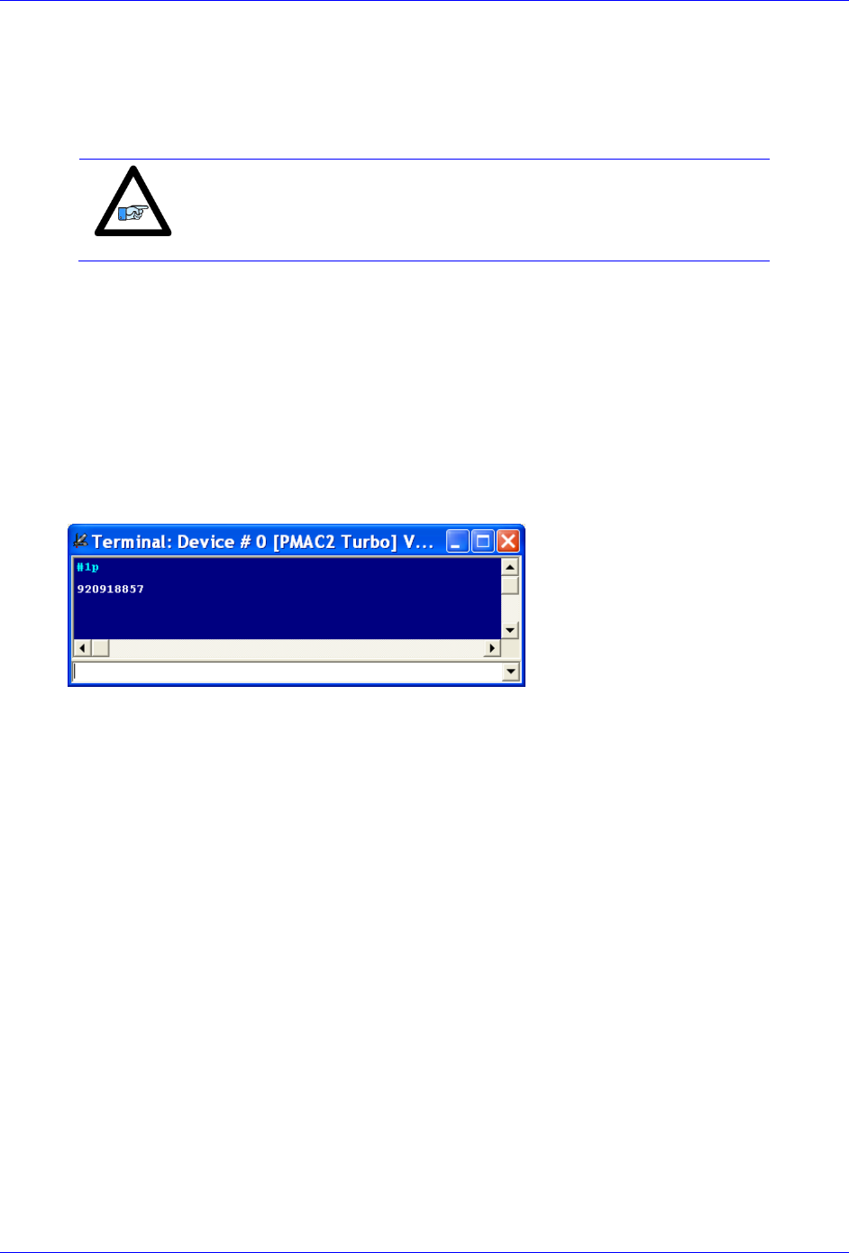
Geo Brick LV User Manual
Motor Setup 184
Absolute Power-On Phasing: HiperFace
With HiperFace, the absolute serial data can be used to establish a phase reference position on power-up
without moving the motor. A custom PLC is suggested for reading the absolute power-on position
directly from the raw serial HiperFace data registers.
Note
Prior to implementing a power-on phasing routine, the user should
verify that the motor can be phased manually, be able to execute open-
loop moves successfully (output and encoder direction matching), and
possibly perform jog commands (requires PID tuning).
A one-time simple test (per installation) is performed, preferably on an unloaded motor, to find the motor
phase position offset:
a. Execute the power-position read PLC to ensure that the actual position is correct and up to date
b. Record the values of Ixx29, and Ixx79 to restore them at the end of test (if applicable)
c. Set Ixx29=0, and write a positive value to Ixx79 then issue a #nO0 (where n is the motor
number). 500 is a conservative value for Ixx79 to start with. Adjust appropriately (most likely to
increase) to force the motor to lock tightly onto a phase
d. Wait for the motor to settle
e. Record the absolute position from the position window or issue a #nP to return the motor
position in the terminal window
f. Issue a #nK to kill the motor
g. Restore Ixx29, and Ixx79 to their original values (if applicable)
h. Enter the recorded value in the corresponding motor/channel definition in the example plc below
The following example PLC computes and corrects for the phase position register (Mxx71) for channels 1
through 8. It is pre-configured for the user to input their encoder/motor information, also to specify which
channels are to perform an absolute power-on phasing.
Using the Absolute Power-On Phasing Example PLC
Under the User Input section:
1. In MtrxSF, enter the motor scale factor.
For rotary encoders, this is the number of counts per revolution = 2Single-Turn Resolution
For Linear encoders, this is the number of counts per user units (i.e. mm) = 1/Encoder Resolution
2. In MtrxPhaseTest, enter the position value recorded in the manual phasing test described above.
3. In ChPhaseSel, specify which channels are desired to perform an absolute power-on phasing.
This value is in hexadecimal. A value of 1 in the corresponding field specifies that this channel is
connected, 0 specifies that it is not connected and should not perform phasing. Examples:

Geo Brick LV User Manual
Motor Setup 185
Absolute Power-On
Phasing, channels
1 through 4
Channel#
8
7
6
5
4
3
2
1
ChPhaseSel (Binary)
0
0
0
0
1
1
1
1
=> ChPhaseSel =$0F
ChPhaseSel (Hex)
0
F
Absolute Power-On
Phasing, channels
1,3,5,7
Channel#
8
7
6
5
4
3
2
1
ChPhaseSel (Binary)
0
1
0
1
0
1
0
1
=> ChPhaseSel =$55
ChPhaseSel (Hex)
5
5
//=========================== NOTES ABOUT THIS PLC EXAMPLE ================================//
// This PLC example utilizes: - P7050 through P7079
// - Suggested M-Variables (make sure they are downloaded)
// Make sure that current and/or future configurations do not create conflicts with
// these parameters.
//=========================================================================================//
P7050..7079=0 ; Reset P-Variables at download
//==================================== USER INPUT =========================================//
#define Mtr1SF P7050 #define Mtr5SF P7054 ; Motors scale factor
#define Mtr2SF P7051 #define Mtr6SF P7055 ; cts/rev for rotary encoders
#define Mtr3SF P7052 #define Mtr7SF P7056 ; cts/user units (i.e. mm, inches) for linear
#define Mtr4SF P7053 #define Mtr8SF P7057 ;
Mtr1SF=0 Mtr5SF=0 ; --User Input
Mtr2SF=0 Mtr6SF=0 ; --User Input
Mtr3SF=0 Mtr7SF=0 ; --User Input
Mtr4SF=0 Mtr8SF=0 ; --User Input
#define Mtr1PhaseTest P7058 #define Mtr5PhaseTest P7062 ; Phase force test values
#define Mtr2PhaseTest P7059 #define Mtr6PhaseTest P7063 ;
#define Mtr3PhaseTest P7060 #define Mtr7PhaseTest P7064 ;
#define Mtr4PhaseTest P7061 #define Mtr8PhaseTest P7065 ;
Mtr1PhaseTest=0 Mtr5PhaseTest=0 ; --User Input
Mtr2PhaseTest=0 Mtr6PhaseTest=0 ; --User Input
Mtr3PhaseTest=0 Mtr7PhaseTest=0 ; --User Input
Mtr4PhaseTest=0 Mtr8PhaseTest=0 ; --User Input
#define ChPhaseSel P7066 ; Select channels to perform power-on phasing (in Hexadecimal)
ChPhaseSel=$0 ; Channels selected for power-on phasing --User Input
//=============================== DEFINITIONS & SUBSTITUTIONS =============================//
#define ChNo P7067 ; Present addressed channel
#define PhaseOffset P7068 ; Holding register for computing phase position offset
#define ActPos P7069 ; Indirect addressing index for actual position, 162
#define PresPhasePos P7070 ; Holding register for computing present phase position
#define Ixx70 P7071 ; Indirect addresssing index for No of commutation cycles, 170
#define Ixx71 P7072 ; Indirect addresssing index for commutation cycle size, 171
#define Mxx71 P7073 ; Indirect addresssing index for phase position register, 171
#define PhaseErrBit P7074 ; Indirect addresssing index for phasing search error bit, 148
#define PhaseTest P7075 ; Indirect addresssing index for force phase test values, 7058
#define MtrSF P7076 ; Indirect addresssing index for motor scale factor, 7050
#define ChNoHex P7077 ; Channel number in hex
#define Ixx08 P7078 ; Indirect addresssing index for position scale factor, 108
#define ChPhaseTrue P7079 ; Present channel power-on phasing flag, =1 true =0 false
//=================================== PLC SCRIPT CODE =====================================//
Open plc 1 clear
ChNo=0 ; Reset channel number
While(ChNo!>7) ; Loop for 8 channels
ChNo=ChNo+1
ChNoHex=exp((ChNo-1)*ln(2))
ChPhaseTrue=(ChPhaseSel&ChNoHex)/ChNoHex
If (ChPhaseTrue!=0) ; Absolute read on this channel?
MtrSF=7050+(ChNo-1)*1
PhaseTest=7058+(ChNo-1)*1
Ixx70=170+(ChNo-1)*100
Ixx71=171+(ChNo-1)*100
ActPos=162+(ChNo-1)*100

Geo Brick LV User Manual
Motor Setup 186
Ixx08=108+(ChNo-1)*100
Mxx71=171+(ChNo-1)*100
PhaseErrBit=148+(ChNo-1)*100
I5111= 100*8388608/I10 while(I5111>0) endw
// Compute position offset from user force phase test input
PhaseOffset=P(PhaseTest)%P(MtrSF)
PhaseOffset=PhaseOffset*I(Ixx70)
PhaseOffset=PhaseOffset%I(Ixx71)
I5111= 100*8388608/I10 while(I5111>0) endw
// Compute present phase position
PresPhasePos=M(ActPos)/(I(Ixx08)*32)
PresPhasePos=PresPhasePos%P(MtrSF)
PresPhasePos=PresPhasePos*I(Ixx70)
PresPhasePos=PresPhasePos%I(Ixx71)
I5111= 100*8388608/I10 while(I5111>0) endw
// Correct for Mxx71 to apply power-on phasing, and clear phase error search bit
M(Mxx71)=(PresPhasePos-PhaseOffset)%I(Ixx71)
M(PhaseErrBit)=0
I5111= 100*8388608/I10 while(I5111>0) endw
EndIf
Endw
Dis plc 1
close
//=========================================================================================//
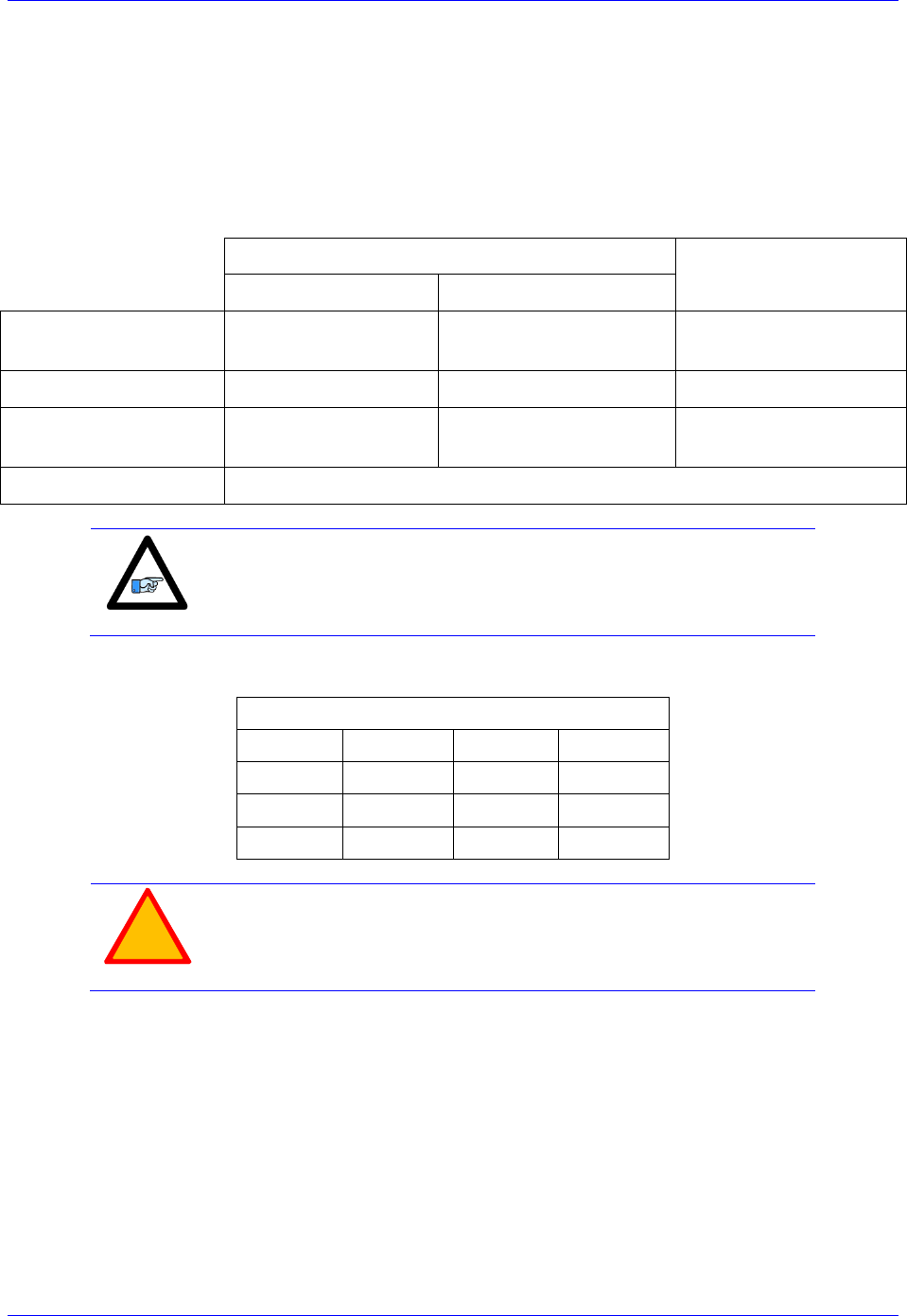
Geo Brick LV User Manual
Motor Setup 187
Absolute Power-On Phasing: EnDat | SSI | BiSS
With absolute serial encoders, the absolute serial data can be used to establish a phase reference position
on power-up without moving the motor or executing a phase search move.
The automatic setup of power-on phasing with PMAC is established through finding the motor’s phase
offset (a one-time test per installation) and storing the result (scaled properly) in the phase position offset
register (Ixx75). It also requires specifying the power-on phase source (Ixx81), and format (Ixx91).
The following, is a summary of the settings with the various proposed setup techniques:
Technique 1
Technique 2/3
(Ixx01=1)
For Ixx01= 3
For Ixx01= 1
PhaseOffset
(found experimentally)
Read from
Serial data register A
Read from
Position ECT result
Read from
Commutation ECT result
Ixx81
= Serial data register A
= Ixx83 (Pos. ECT result)
= Comm. ECT result
Ixx91
= Unsigned, Y-register
ST bits
= Unsigned, X-register,
(ST + 5bit shift) bits
= Unsigned, X-register,
18 bits
Ixx75
= ( - PhaseOffset * Ixx70 ) % Ixx71
Note
The automatic power-on phasing routine (Ixx75, Ixx81, and Ixx91)
expects the least significant bit of the data to be right most shifted (at
bit 0).
Remember that the serial data register A address for each of the channels is:
Serial Data Register A
Channel 1
Y:$78B20
Channel 5
Y:$78B30
Channel 2
Y:$78B24
Channel 6
Y:$78B34
Channel 3
Y:$78B28
Channel 7
Y:$78B38
Channel 4
Y:$78B2C
Channel 8
Y:$78B3C
!
Caution
Prior to implementing an absolute power-on phasing routine, make
sure that the motor can be phased manually, and that open-loop and/or
closed-loop moves (require PID tuning) can be performed
successfully.
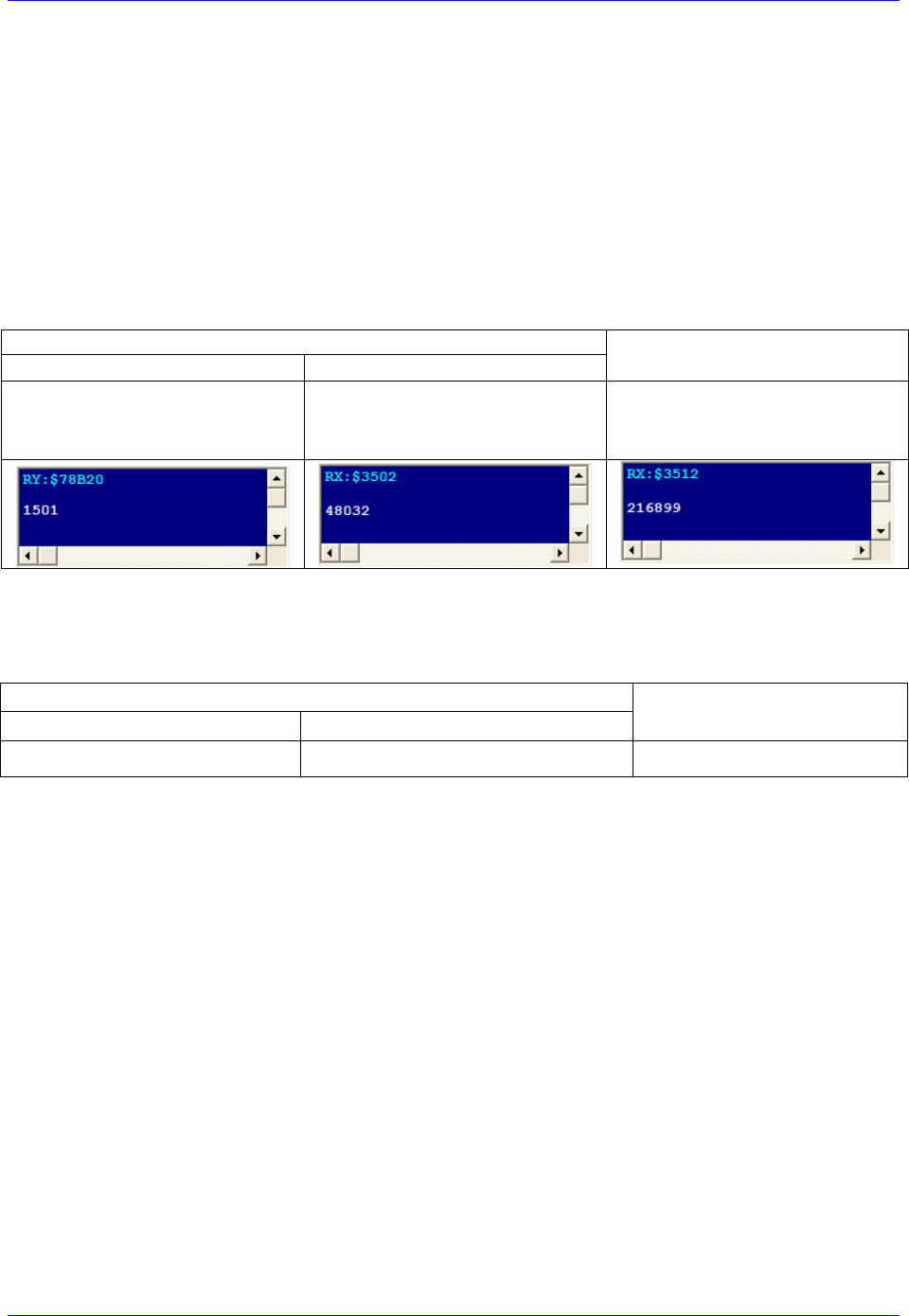
Geo Brick LV User Manual
Motor Setup 188
Finding the Phase Offset
The phase offset is found experimentally by performing a one-time phase force test on an
uncoupled/unloaded (preferably) motor:
1. Read/update the absolute position (must be read correctly for the phasing to work).
Issue a #n$* command, or enable the corresponding absolute position read PLC.
2. Record Ixx29, and Ixx79 (if non zero).These should be restored at the end of the test
3. Set Ixx29=0, and write a positive value to Ixx79 (500 is a good starting value).
4. Issue a #nO0 to send a zero open loop output.
5. Increase Ixx79 until the motor is tightly locked onto a phase.
6. Make sure the motor is settled and stationary (locked onto a phase)
7. Record the following value (this is the motor’s phase offset):
Technique 1
Technique 2/3
For Ixx01=3
For Ixx01=1
Query the motor’s corresponding
serial data register A
e.g. RY:$78B20
Query the motor’s corresponding
position ECT result
e.g.: RX:$3502
Query the motor’s corresponding
commutation ECT result
e.g.: RX:$3512
8. Issue a #nK to kill the motor
9. Restore Ixx29, and Ixx79 to their original values
Setting up Ixx81, the power-on phase position address:
Technique 1
Technique 2/3
(Ixx01=1)
For Ixx01= 3
For Ixx01= 1
= Serial data register A
= Ixx83 (Pos. ECT result)
= Comm. ECT result
Technique 1:
If Ixx01= 3; Ixx81 is equal to the motor’s corresponding serial data register A. (e.g.: I181=$78B20).
If Ixx01=1; Ixx81 is equal to the motor’s corresponding position ECT result. (e.g.: I181=$3502).
Technique 2/3:
Ixx81 is equal to the motor’s corresponding commutation ECT result. (e.g.: I181=$3512).
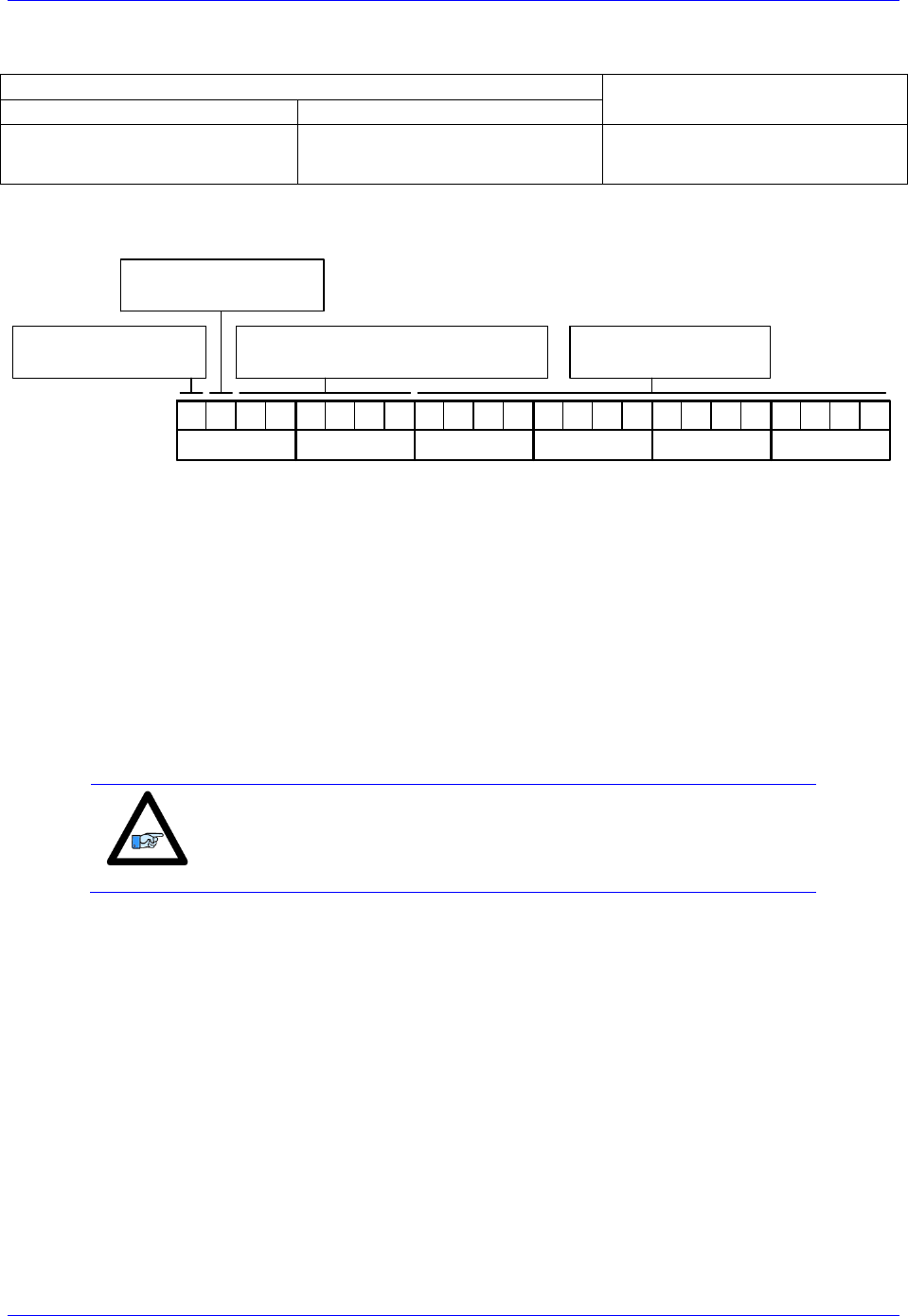
Geo Brick LV User Manual
Motor Setup 189
Setting up Ixx91, the power-on phase position format:
Technique 1
Technique 2/3
(Ixx01=1)
For Ixx01= 3
For Ixx01= 1
= Unsigned, Y-register
ST bits
= Unsigned, X-register,
(ST + 5bit-shift) bits
= Unsigned, X-register,
18 bits
The following diagram displays how Ixx91 is set up:
Bit 23: =1 Signed
=0 Unsigned
00000000
Bit 22: =1 X-Register
=0 Y-Register
Bits16-21: Number of Bits to read
Ixx91 Binary:
Hex($): 0 0
00000000
0 0
00000000
0 0
Bits 0-15: reserved
(always 0)
Technique 1:
If Ixx01=3; Ixx91 is set up for unsigned, Y-register, Singleturn bits.
For example: A 30-bit (18-bit Singleturn, 12-bit Multiturn) rotary encoder would yield Ixx91= $120000.
If Ixx01=1; Ixx91 is set up for unsigned, X-register, (Singleturn +5) bits.
For example: A 20-bit (20-bit Singleturn, 0-bit Multiturn) rotary encoder, or linear scale with similar
protocol resolution (20 bits) would yield Ixx91= $590000.
Technique 2/3:
Since the commutation is limited to 18 bits, and processed separately in the encoder conversion table,
Ixx91 is always= $520000 (unsigned, X-register, 18 bits).
Note
Ixx91 is a 24-bit hexadecimal word. The upper most two digits are the
only relevant ones. The lower 16 bits are reserved and should always
be left at zero.

Geo Brick LV User Manual
Motor Setup 190
Setting up Ixx75, the phase position offset
The Phase position offset is set up using the following equation:
Where: PhaseOffset is the recorded value (found earlier) from the phase force test.
In this mode, and upon issuing a #n$ command, PMAC will compute the correct phase position then close
the loop on the motor (motor must be tuned to hold position).
!
Caution
It is imperative that the absolute position read is performed
successfully prior to issuing a phase command.
If closing the position loop is not desired with the #n$ command then it is advised to create a simple PLC,
in which the current and PID loop gains are set to zero prior to issuing #n$ then restored (and motor
killed) after the phase position has been set, e.g.:
Open PLC 1 Clear
// Make sure that the absolute position is read and reported prior to this script code
I5111=100*8388608/I10 While(I5111>0) Endw ; 100 msec delay
CMD"#1K" ; Make sure motor is killed
I5111=100*8388608/I10 While(I5111>0) Endw ; 100 msec delay
CMD"I130..139=0" ; Zero PID loop gains
I161=0 I162=0 I176=0 ; Zero Current loop gains
I5111=100*8388608/I10 While(I5111>0) Endw ; 100 msec delay
CMD"#1$" ; Phase command
I5111=500*8388608/I10 While(I5111>0) Endw ; 500 msec delay
CMD"#1K" ; Kill Motor
I5111=500*8388608/I10 While(I5111>0) Endw ; 500 msec delay
// Here: ok to restore PID and current loop gains
// I130=X I131=X I132=X I133=X I134=X I135=X I136=X I137=X I138=X I139=X
// I161=X I162=X I176=X
I5111=100*8388608/I10 While(I5111>0) Endw ; 100 msec delay
Dis PLC 1
Close

Geo Brick LV User Manual
Motor Setup 191
Absolute Power-On Phasing: Yaskawa absolute encoders
With absolute encoders, the single turn data is used to find an absolute phase position offset per electrical
cycle thus an absolute phase reference position.
Note
Prior to implementing a power-on phasing routine you should try and
be able to phase the motor manually, successfully execute open-loop
moves (output and encoder direction matching), and jog commands
(require PID tuning). Remember to increase the fatal following error
limit with high resolution encoders when executing closed-loop moves
The U-phase in the Yaskawa motor/encoder assemblies is usually aligned with the index pulse, which
should result in the same motor phase offset per one revolution for each encoder type (i.e. 16, 17, or 20-
bit).
Yaskawa Absolute Encoders Single-Turn Data
16-bit
17-bit
20-bit
#define Mtr1STD4_15 M180
#define Mtr2STD4_15 M280
#define Mtr3STD4_15 M380
#define Mtr4STD4_15 M480
#define Mtr5STD4_15 M580
#define Mtr6STD4_15 M680
#define Mtr7STD4_15 M780
#define Mtr8STD4_15 M880
Mtr1STD4_15->Y:$278B20,4,16
Mtr2STD4_15->Y:$278B24,4,16
Mtr3STD4_15->Y:$278B28,4,16
Mtr4STD4_15->Y:$278B2C,4,16
Mtr5STD4_15->Y:$278B20,4,16
Mtr6STD4_15->Y:$278B34,4,16
Mtr7STD4_15->Y:$278B38,4,16
Mtr8STD4_15->Y:$278B3C,4,16
#define Mtr1STD0_23 M180
#define Mtr2STD0_23 M280
#define Mtr3STD0_23 M380
#define Mtr4STD0_23 M480
#define Mtr5STD0_23 M580
#define Mtr6STD0_23 M680
#define Mtr7STD0_23 M780
#define Mtr8STD0_23 M880
Mtr1STD0_23->Y:$278B20,0,24
Mtr2STD0_23->Y:$278B24,0,24
Mtr3STD0_23->Y:$278B28,0,24
Mtr4STD0_23->Y:$278B2C,0,24
Mtr5STD0_23->Y:$278B20,0,24
Mtr6STD0_23->Y:$278B34,0,24
Mtr7STD0_23->Y:$278B38,0,24
Mtr8STD0_23->Y:$278B3C,0,24
#define Mtr1STD4_23 M180
#define Mtr2STD4_23 M280
#define Mtr3STD4_23 M380
#define Mtr4STD4_23 M480
#define Mtr5STD4_23 M580
#define Mtr6STD4_23 M680
#define Mtr7STD4_23 M780
#define Mtr8STD4_23 M880
Mtr1STD4_23->Y:$278B20,4,20
Mtr2STD4_23->Y:$278B24,4,20
Mtr3STD4_23->Y:$278B28,4,20
Mtr4STD4_23->Y:$278B2C,4,20
Mtr5STD4_23->Y:$278B20,4,20
Mtr6STD4_23->Y:$278B34,4,20
Mtr7STD4_23->Y:$278B38,4,20
Mtr8STD4_23->Y:$278B3C,4,20
A one-time simple test (per installation) is performed on an unloaded motor to find the motor phase
position offset:
Enable the Absolute position read PLC. Previously created in the feedback section.
Record the values of Ixx29, and Ixx79 to restore them at the end of test.
Set Ixx29=0, and write a positive value to Ixx79 then issue a #nO0. 500 is a reasonably
conservative value for Ixx79 to start with. Adjust appropriately (most likely increase) to force the
motor (unloaded) to lock tightly onto a phase.
Record the Single-Turn Data value (defined in the table above) and store in the user defined
motor phase offset.
Issue a #nK to kill the motor
Restore Ixx29, and Ixx79 to their original values
Yaskawa Absolute Encoders Motor Phase Offset (found from above test procedure)
16-bit
17-bit
20-bit
#define PhaseOffset_16Bit P184
PhaseOffset_16Bit=5461
#define PhaseOffset_17Bit P184
PhaseOffset_17Bit=10922
#define PhaseOffset_20Bit P184
PhaseOffset_20Bit=30000
Note
Appropriate masking is required with 17-bit encoders to process the
data correctly.

Geo Brick LV User Manual
Motor Setup 192
Absolute Power-On Phasing Example PLCs (Yaskawa):
With the motor phase position offset established, the phase position register can now be modified on
power-up to compensate for the calculated offset. This allows the user to issue jog commands or close the
loop and run a motion program on power-up or reset.
Channel 1 driving a 16-bit Yaskawa absolute encoder
#define Mtr1PhasePos M171 ; Suggested M-Variables
Mtr1PhasePos->X:$B4,24,S
#define Mtr1PhaseErr M148 ; Suggested M-Variables
Mtr1PhaseErr->Y:$C0,8
#define Mtr1CommSize I171 ;
#define Mtr1CommCycles I170 ;
#define Mtr1CommRatio P170 ; Motor 1 commutation cycle size (Ixx71/Ixx70 counts)
Mtr1CommRatio=Mtr1CommSize/Mtr1CommCycles
Open plc 1 clear
Mtr1PhasePos = ((Mtr1STD4_15 % Mtr1CommRatio) - PhaseOffset_16Bit) * 32 * Mtr1CommCycles
Mtr1PhaseErr = 0
Disable plc 1
Close
Channel 1 driving a 17-bit Yaskawa absolute encoder
#define Mtr1PhasePos M171 ; Suggested M-Variables
Mtr1PhasePos->X:$B4,24,S
#define Mtr1PhaseErr M148 ; Suggested M-Variables
Mtr1PhaseErr->Y:$C0,8
#define Mtr1CommSize I171
#define Mtr1CommCycles I170
#define Mtr1CommRatio P170 ; Motor 1 commutation cycle size (Ixx71/Ixx70 counts)
Mtr1CommRatio=Mtr1CommSize/Mtr1CommCycles
Open plc 1 clear
Mtr1PhasePos = ((Int((Mtr1STD0_23&$1FFFF0)/$F) % Mtr1CommRatio) - PhaseOffset_17Bit) * 32 *
Mtr1CommCycles
Mtr1PhaseErr = 0
Disable plc 1
Close
Channel 1 driving a 20-bit Yaskawa absolute encoder
#define Mtr1PhasePos M171 ; Suggested M-Variables
Mtr1PhasePos->X:$B4,24,S
#define Mtr1PhaseErr M148 ; Suggested M-Variables
Mtr1PhaseErr->Y:$C0,8
#define Mtr1CommSize I171
#define Mtr1CommCycles I170
#define Mtr1CommRatio P170 ; Motor 1 commutation cycle size (Ixx71/Ixx70 counts)
Mtr1CommRatio=Mtr1CommSize/Mtr1CommCycles
#define TwoToThe20th 1048576
Open plc 1 clear
If (Mtr1STD4_23 !< PhaseOffset_20Bit)
Mtr1PhasePos = (Mtr1STD4_23 - PhaseOffset_20Bit) * 32
Else
Mtr1PhasePos = (TwoToThe20th - PhaseOffset_20Bit + Mtr1STD4_23) * 32
EndIf
Mtr1PhaseErr = 0;
Disable plc 1
Close
Note
It is highly recommended to try the sequence in this PLC manually at
first (using the terminal window). In some cases, the Motor Phase
Position Offset has to be added instead of subtracted depending on the
direction of the encoder mounting/decoding. The Geo Brick LV has
no control on the direction of the serial encoder data
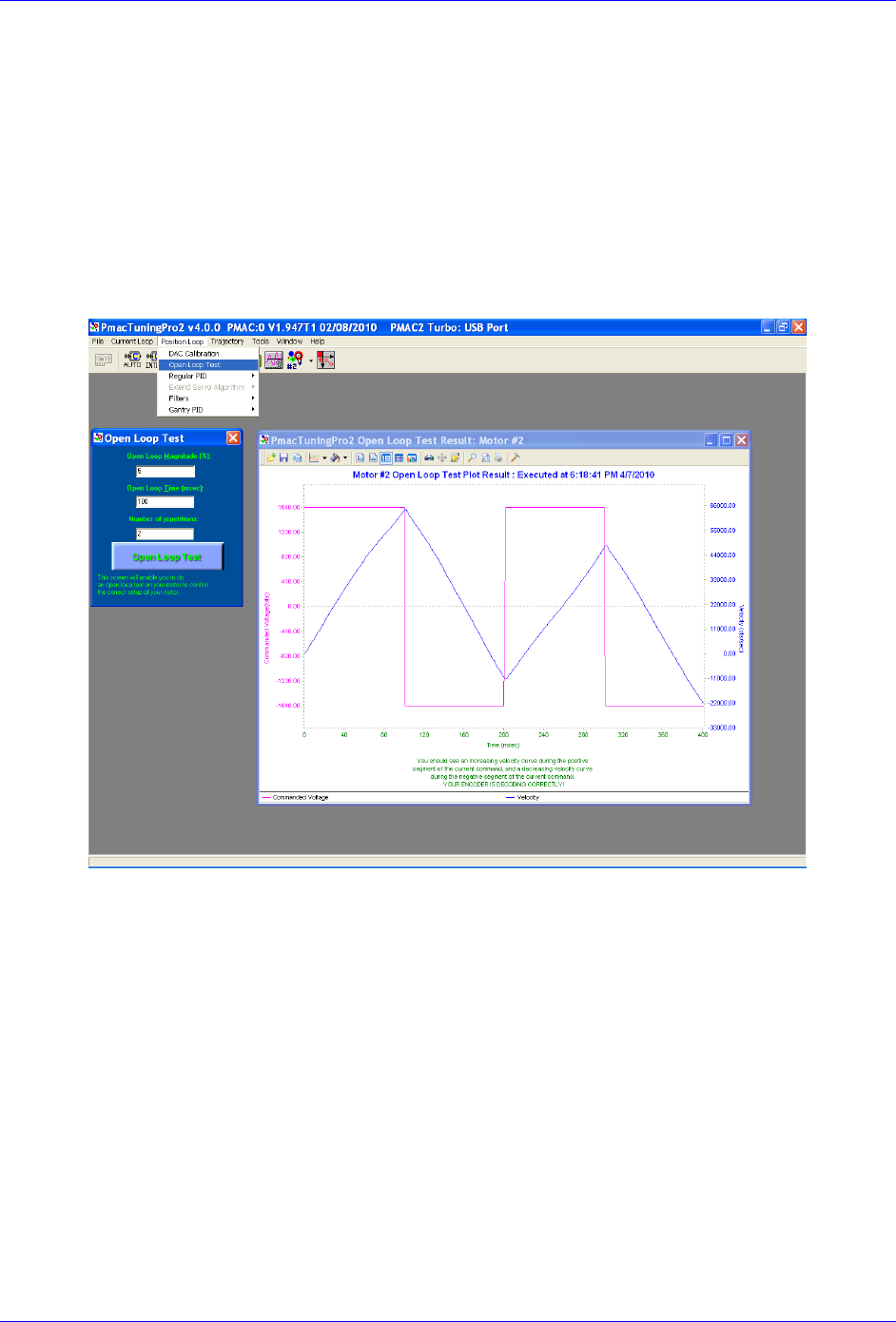
Geo Brick LV User Manual
Motor Setup 193
Open-Loop Test, Encoder Decode: I7mn0
Having phased the motor successfully, it is now possible to execute an open loop test. The open-loop test
is critical to verify that the direction sense of the encoder is the same as the command output.
A positive command should create a velocity and position counting in the positive direction; a negative
command should create a velocity and position counting in the negative direction. The open-loop test can
be done manually from the terminal window (e.g. #1O5) while gathering position, velocity data, or by
simply monitoring the direction of the velocity in the position window. The PMACTuningPro2 Software
provides an automatic open loop utility, which is convenient to use.
A successful open-loop test should look like the following:
The open loop magnitude (output) is adjustable, start off with 1 - 2 percent command output and
increment gradually until you see a satisfactory result.
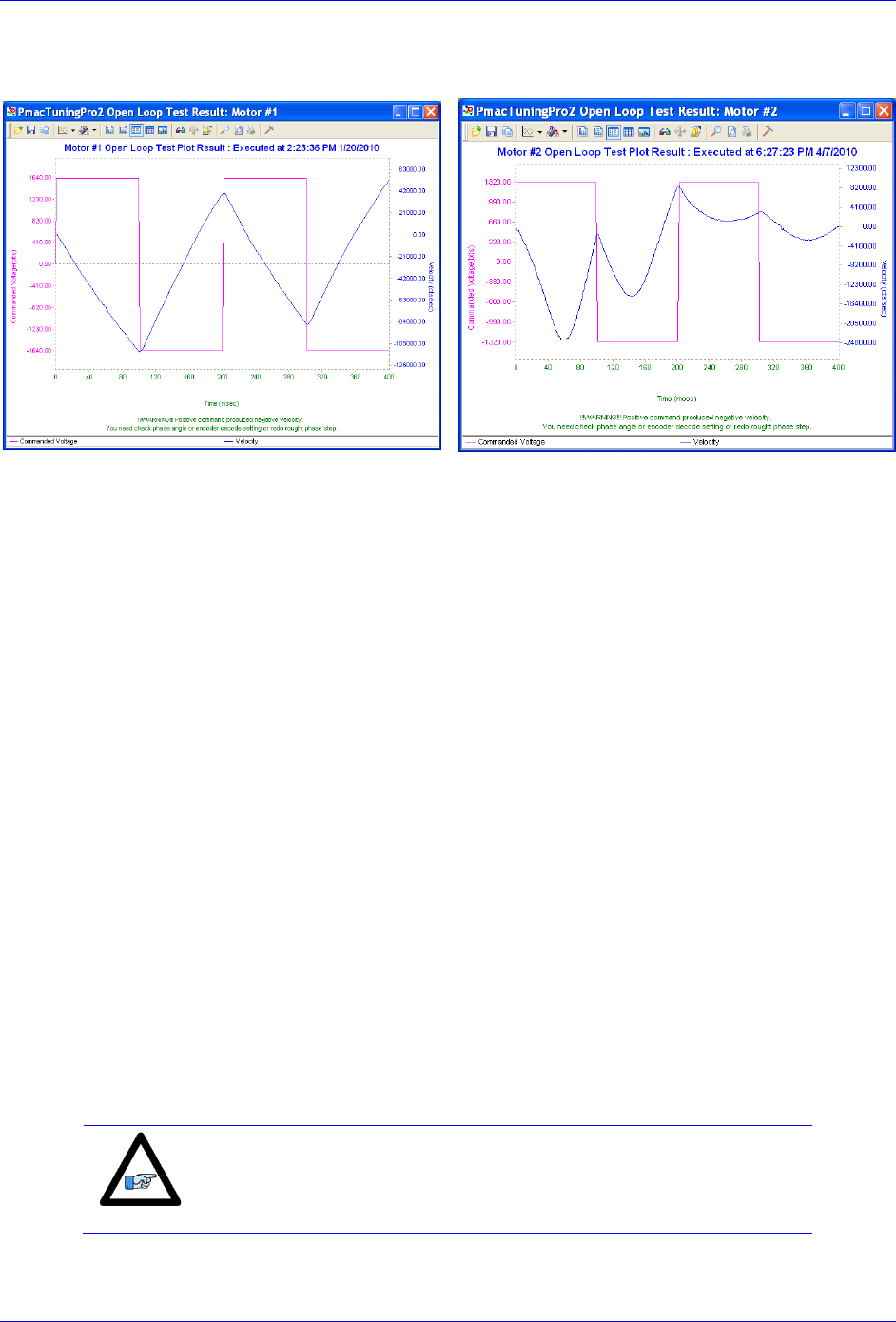
Geo Brick LV User Manual
Motor Setup 194
A failed open-loop test would either move the motor in the opposite direction of the command or lock it
onto a phase, one the following plots may apply:
General recommendation for troubleshooting unsuccessful open loop tests:
1. Re-phase motor and try again
2. An inverted saw tooth response, most times, indicate that the direction sense of the encoder is
opposite to that of the command output.
With Quadrature | Sinusoidal | HiperFace encoders:
Change I7mn0 to 3 from 7 (default) or vice-versa.
Make sure Ixx70 and Ixx71 are correct.
HiperFace sends absolute encoder data on power-up. If the on-going position direction is
reversed, one needs to make sure that the absolute data sent on power-up agrees with the new
direction of the encoder.
With Resolvers:
Change the direction from clock wise to counter clock wise in the first encoder conversion table
entry (see resolver feedback setup section).
With Absolute Serial Encoders (EnDat, SSI, BiSS, Yaskawa):
The Geo Brick LV has no control on the direction sense of the serial data stream. There are no
software parameters that allow this change. Normally, the direction sense is set by jumpers or
software at the encoder side. In this scenario, the commutation direction has to be reversed to
match the encoder sense. This is usually done by swapping any two of the motor leads and re-
phasing.
3. If the motor locks in position (with an open loop command i.e.#nO5 ) like a stepper motor, then
the phasing has failed, and most times this indicates that the commutation cycle size is setup
wrong (check Ixx70, Ixx71). Also it could indicate that the encoder sense is reversed.
Note
Halls Phasing (where applicable) needs to be re-configured if the
motor direction is reversed.
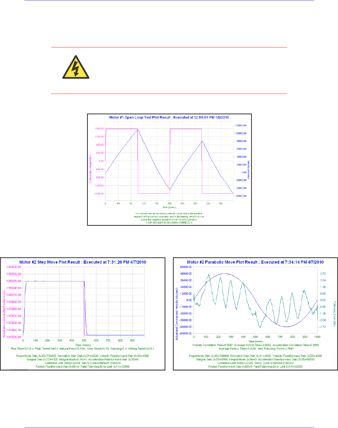
Geo Brick LV User Manual
Motor Setup 195
Position-Loop PID Gains: Ixx30…Ixx39
The position-loop tuning is done as in any Turbo PMAC PID-Loop setup. The PMACTuningPro2
automatic or interactive utility can be used for fine tuning.
WARNING
Remember to perform an Open Loop Test after phasing and
before trying to close the loop on the motor to make sure that the
encoder decode (I7mn0) is correct. A positive open loop
command should result in positive direction (of the encoder)
motion and vice-versa.
Good Open Loop Test
Acceptable Step and Parabolic position responses should look like the following:
Position Step Response
Position Parabolic Response

Geo Brick LV User Manual
Motor Setup 196
DC Brush Motor Software Setup
Before you start
Remember to create/edit the motor type and protection power-on PLC
At this point of the setup it is assumed that the encoder has been wired and configured correctly
in the Encoder Feedback section. And that moving the motor/encoder shaft by hand shows
encoder counts in the position window.
Parameters with Comments ending with -User Input require the user to enter information
pertaining to their system/hardware.
Downloading and using the suggested M-variables is highly recommended.
Detailed description of motor setup parameters can be found in the Turbo SRM Link
Phasing Search Error Bit, Current-Loop Integrator Output (Ixx96)
On power-up, the phasing search error bit has to be cleared to allow motor move commands to DC Brush
motors. The current-loop integrator output should not be allowed to build up over time. The motor (non-
existent) direct current-loop output should be zero-ed periodically. This is equivalent, but more efficient
than setting Ixx96 to 1.
M148->Y:$C0,8,1 ; Motor 1 Phasing error fault bit
M248->Y:$140,8,1 ; Motor 2 Phasing error fault bit
M348->Y:$1C0,8,1 ; Motor 3 Phasing error fault bit
M448->Y:$240,8,1 ; Motor 4 Phasing error fault bit
M548->Y:$2C0,8,1 ; Motor 5 Phasing error fault bit
M648->Y:$340,8,1 ; Motor 6 Phasing error fault bit
M748->Y:$3C0,8,1 ; Motor 7 Phasing error fault bit
M848->Y:$440,8,1 ; Motor 8 Phasing error fault bit
M129->Y:$BC,0,24,U ; Motor 1 Direct Current-Loop Integrator Output
M229->Y:$13C,0,24,U ; Motor 2 Direct Current-Loop Integrator Output
M329->Y:$1BC,0,24,U ; Motor 3 Direct Current-Loop Integrator Output
M429->Y:$23C,0,24,U ; Motor 4 Direct Current-Loop Integrator Output
M529->Y:$2BC,0,24,U ; Motor 5 Direct Current-Loop Integrator Output
M629->Y:$33C,0,24,U ; Motor 6 Direct Current-Loop Integrator Output
M729->Y:$3BC,0,24,U ; Motor 7 Direct Current-Loop Integrator Output
M829->Y:$43C,0,24,U ; Motor 8 Direct Current-Loop Integrator Output
I196,8,100=1 ; Turbo PMAC PWM control for Brush motor.
; This will ensure zero direct current loop output tuning
Open plc 1 clear
If (M148=1)
CMD"M148,8,100=0" ; Clear Phasing Error Bit
EndIF
M129=0 M229=0 M329=0 M429=0 ; Axis1-4 Zero Current-Loop Integrator Output
M529=0 M629=0 M729=0 M829=0 ; Axis5-8 Zero Current-Loop Integrator Output
Close ; For Brush Motor Control, PLC has to be executing periodically
Note
Remember to configure the Tuning software to allow this PLC to run
while performing position loop tuning.

Geo Brick LV User Manual
Motor Setup 197
Flags, Commutation, Phase Angle, ADC Mask: Ixx24, Ixx01, Ixx72, Ixx84
I124,8,100=$800001 ; Motors 1-8 Flag control, High true amp fault (Geo Brick LV specific)
I101,8,100=1 ; Motors 1-8 Commutation enabled
I172,8,100=512 ; Motors 1-8 Commutation phase angle (Geo Brick LV specific)
I184,8,100=$FFFC00 ; Motors 1-8 Current-Loop Feedback Mask Word (Geo Brick LV specific)
PWM Scale Factor: Ixx66
If Motor Rated Voltage > Bus Voltage:
I166=0.95 * I7000 ; Motor #1 PWM Scale Factor, typical setting
I266=I166 I366=I166 I466=I166 ; Assuming same motor(s) as motor #1
I566=I166 I666=I166 I766=I166 I866=I166 ; Assuming same motor(s) as motor #1
If Bus Voltage > Motor Rated Voltage:
Ixx66 acts as a voltage limiter. In order to obtain full voltage output it is set to about 10% over PWM
count divided by DC Bus/Motor voltage ratio:
#define DCBusInput 60 ; DC Bus Voltage -User Input
#define Mtr1Voltage 24 ; Motor 1 Rated Voltage [VDC]-User Input
#define Mtr2Voltage 24 ; Motor 2 Rated Voltage [VDC]-User Input
#define Mtr3Voltage 24 ; Motor 3 Rated Voltage [VDC]-User Input
#define Mtr4Voltage 24 ; Motor 4 Rated Voltage [VDC]-User Input
#define Mtr5Voltage 24 ; Motor 5 Rated Voltage [VDC]-User Input
#define Mtr6Voltage 24 ; Motor 6 Rated Voltage [VDC]-User Input
#define Mtr7Voltage 24 ; Motor 7 Rated Voltage [VDC]-User Input
#define Mtr8Voltage 24 ; Motor 8 Rated Voltage [VDC]-User Input
I166=I7000*Mtr1Voltage/DCBusInput ; Motor 1 PWM Scale Factor
I266=I7000*Mtr2Voltage/DCBusInput ; Motor 2 PWM Scale Factor
I366=I7000*Mtr3Voltage/DCBusInput ; Motor 3 PWM Scale Factor
I466=I7000*Mtr4Voltage/DCBusInput ; Motor 4 PWM Scale Factor
I566=I7000*Mtr5Voltage/DCBusInput ; Motor 5 PWM Scale Factor
I666=I7000*Mtr6Voltage/DCBusInput ; Motor 6 PWM Scale Factor
I766=I7000*Mtr7Voltage/DCBusInput ; Motor 7 PWM Scale Factor
I866=I7000*Mtr8Voltage/DCBusInput ; Motor 8 PWM Scale Factor
Current Feedback Address: Ixx82
I182=$078006 ; Motor 1 Current Feedback Address
I282=$07800E ; Motor 2 Current Feedback Address
I382=$078016 ; Motor 3 Current Feedback Address
I482=$07801E ; Motor 4 Current Feedback Address
I582=$078106 ; Motor 5 Current Feedback Address
I682=$07810E ; Motor 6 Current Feedback Address
I782=$078116 ; Motor 7 Current Feedback Address
I882=$07811E ; Motor 8 Current Feedback Address

Geo Brick LV User Manual
Motor Setup 198
Commutation Cycle Size: Ixx70, Ixx71
Set to zero with DC brush motors, commutation is done mechanically.
I170=0 I171=0 ; Motor 1 size and number of commutation cycles
I270=0 I271=0 ; Motor 2 size and number of commutation cycles
I370=0 I371=0 ; Motor 3 size and number of commutation cycles
I470=0 I471=0 ; Motor 4 size and number of commutation cycles
I570=0 I571=0 ; Motor 5 size and number of commutation cycles
I670=0 I671=0 ; Motor 6 size and number of commutation cycles
I770=0 I771=0 ; Motor 7 size and number of commutation cycles
I870=0 I871=0 ; Motor 8 size and number of commutation cycles
I2T Protection, Magnetization Current: Ixx57, Ixx58, Ixx69, Ixx77
The lower values (tighter specifications) of the Continuous/Instantaneous current ratings between the Geo
Brick LV and motor are chosen to setup I2T protection.
If the peak current limit chosen is that of the Geo Brick LV (e.g. 15 Amps) then the time allowed at peak
current is set to 1 seconds.
If the peak current limit chosen is that of the Motor, check the motor specifications for time allowed at
peak current.
Examples:
For setting up I2T on a Geo Brick LV driving a 3A/9A motor, 3 amps continuous and 9 amps
instantaneous will be used as current limits. And time allowed at peak is that of the motor.
For setting up I2T on a Geo Brick LV driving a 4A/16A motor, 4 amps continuous and 15 amps
instantaneous will be used as current limits. And time allowed at peak is 1 seconds.
Motors 1 thru 8 have 5-amp continuous, 15-amp peak current limits.
#define ServoClk P8003 ; [KHz] Computed in Dominant Clock Settings Section
#define ContCurrent 5 ; Continuous Current Limit [Amps] –User Input
#define PeakCurrent 15 ; Instantaneous Current Limit [Amps] –User Input
#define MaxADC 33.85 ; Brick LV full range ADC reading (see electrical specifications)
#define I2TOnTime 1 ; Time allowed at peak Current [sec]
I157=INT(32767*(ContCurrent*1.414/MaxADC)*cos(30))
I169=INT(32767*(PeakCurrent*1.414/MaxADC)*cos(30))
I158=INT((I169*I169-I157*I157)*ServoClk*1000*I2TOnTime/(32767*32767))
I257=I157 I258=I158 I269=I169
I357=I157 I358=I158 I369=I169
I457=I157 I458=I158 I469=I169
I557=I157 I558=I158 I569=I169
I657=I157 I658=I158 I669=I169
I757=I157 I758=I158 I769=I169
I857=I157 I858=I158 I869=I169
Note
This software I2T is designed to primarily protect the motor. The Geo
Brick LV’s hardware built-in I2T protects the amplifier and presents
an added layer of system safety.
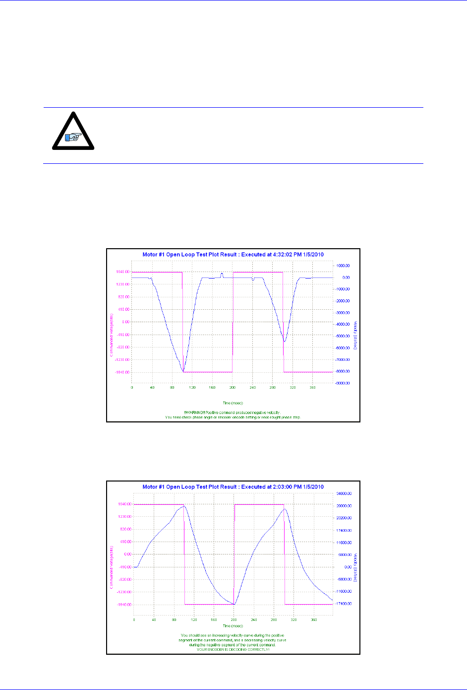
Geo Brick LV User Manual
Motor Setup 199
ADC Offsets: Ixx29, Ixx79
The ADC offsets importance may vary from one system to another, depending on the motor(s) type and
application requirements. They can be left at default of zero especially if a motor setup is to be
reproduced on multiple machines by copying the configuration file of the first time integration. However,
they should ultimately be set to minimize measurement offsets from the A and B-phase current feedback
circuits, respectively (read in Suggested M-variables Mxx05, Mxx06).
Note
Geo Brick LVs dating 10/1/2012 and later perform automatic ADC
offset compensation. Leave Ixx29 and Ixx79 at zero.
Current-Loop Gains, Open-Loop/Enc. Decode: Ixx61, Ixx62, Ixx76, I7mn0
Tuning (fine) the current loop with DC brush motors is neither critical nor required. Set Ixx61 to a
conservative value (i.e. 0.001) and perform an open-loop test. Essentially a positive open loop command
should result in position direction (of the encoder) motion and vice-versa:
Reversed Encoder Decode. I7mn0 needs adjustment
Once the Encoder Decode is verified, increment Ixx61 gradually and redo the Open-Loop test until a solid
saw tooth response is observed. Note that further increasing Ixx61 will not improve the performance.
Correct Encoder Decode - Acceptable Open-Loop Response
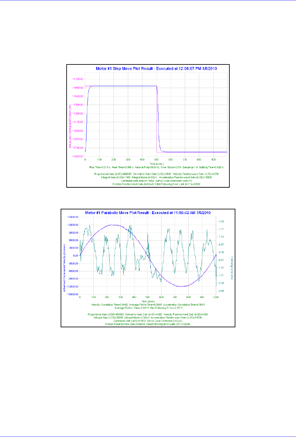
Geo Brick LV User Manual
Motor Setup 200
Position-Loop PID Gains: Ixx30…Ixx39
The position-loop tuning is done as in any Turbo PMAC PID-Loop setup. The PMACTuningPro2
automatic or interactive utility can be used to fine-tune the PID-Loop. Acceptable Step and Parabolic
position responses would look like:
Position Step Move
Position Parabolic Move
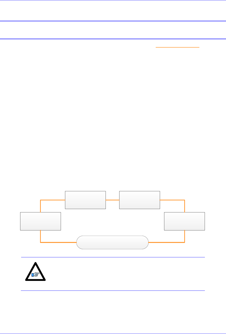
Geo Brick LV User Manual
MACRO Connectivity 201
MACRO CONNECTIVITY
Introduction to MACRO
MACRO Ring for Distributed Motion Control - www.macro.org -
MACRO stands for Motion and Control Ring Optical. It is a high bandwidth non-proprietary digital
interface industrialized by Delta Tau Data Systems for distributed multi-axis systems.
MACRO can be connected using either fiber optic or twisted copper pair RJ45 cables. The RJ45
electrical interface can extend to up to 30 meters (or about 100 feet), and the fiber optic interface can
extend to up to 3 kilometers (or about 2 miles). The following are some of the many advantages
which MACRO offers:
Noise Immunity: MACRO transfers data using light rather than electricity which renders it
immune to electromagnetic noise and capacitive coupling.
Wiring Simplicity: Single-plug connection between controllers, amplifiers, and I/O modules
minimizing wiring complexity in large systems.
High Speed: data transfer rate at 125 Megabits per second, and servo update rates as high as
65 KHz.
Centralized, Synchronized Control: No software intervention is required on the MACRO
stations. One or multiple rings can be controlled, synchronized, and accessed using a single
ring controller.
The following diagram depicts the general formation of a simple MACRO ring.
Ring Controller
Station # n
(Motors, I/Os)
Station # …
(Motors, I/Os)
Station # 2
(Motors, I/Os)
Station # 1
(Motors, I/Os)
Note
It is possible to have multiple/redundant rings and master/controllers
in one system. For simplicity, we will limit the discussion in the
following section(s) to the basic setting parameters of a single
MACRO ring and controller. Also, we will address the stations as
slaves and the ring controller as master.

Geo Brick LV User Manual
MACRO Connectivity 202
MACRO Configuration Examples
The Geo Brick LV with its’ MACRO interface supports a wide variety of MACRO ring formations. The
following common MACRO configurations are described in detail:
Configuration
Example
MACRO Ring Controller
(Master)
MACRO Ring
Slave(s)
Configuration
Type
1
Geo Brick LV
Geo Brick LV
(DC Brush/Brushless motors)
MACRO Auxiliary
2
Geo Brick LV
Geo Brick LV
(Stepper motors)
MACRO Auxiliary
3
Geo Brick LV
Geo MACRO Drive
MACRO Slave
Notice that the Geo Brick LV can be either a Master or a Slave in a MACRO Ring.
Whenever the Geo Brick LV is a slave, the MACRO configuration is called MACRO auxiliary. This is a
designation which was implemented in the firmware for the Brick family of controllers.
If the Geo Brick LV is a master and the station(s) consist of traditional MACRO hardware (e.g. Geo
MACRO Drive, ACC-65M etc.) then the MACRO configuration is called MACRO Slave. This is the
typical designation which supports the majority of MACRO compatible amplifiers and peripherals.
Note
The Geo Brick LV MACRO option is populated with 1 MACRO IC,
which consists of 8 servo nodes (motors/encoders) and 6 I/O nodes
(432 I/O points)
Note
Configuring a MACRO Auxiliary ring requires communicating (via
USB, Ethernet, or serial) separately to both the master and slave.
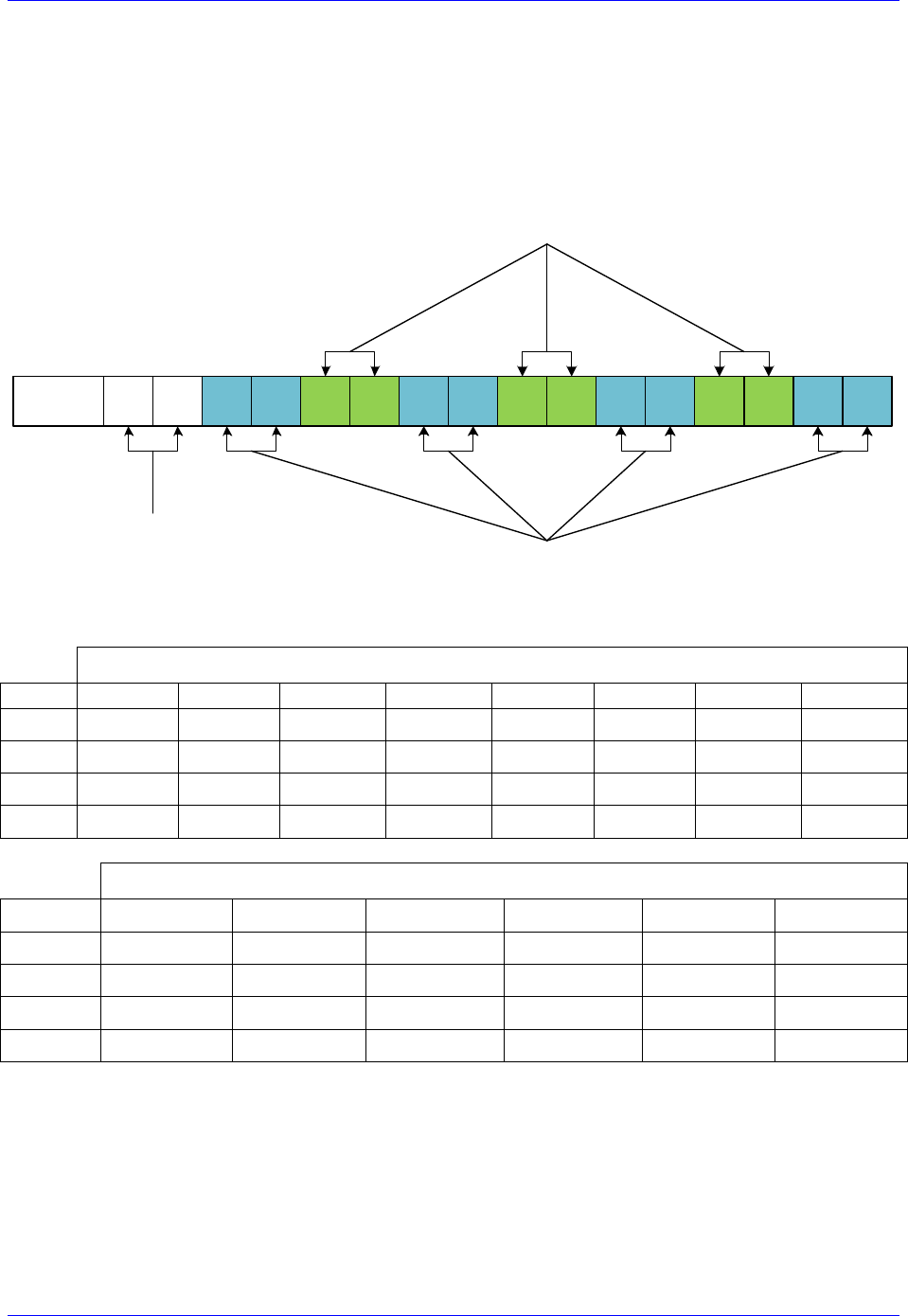
Geo Brick LV User Manual
MACRO Connectivity 203
Review: MACRO Nodes and Addressing
Each MACRO IC consists of 16 nodes: 2 auxiliary, 8 servo and 6 I/O nodes:
Auxiliary nodes are reserved for master/slave setting and internal firmware use
Servo nodes are used for motor control carrying feedback, commands, and flag information
I/O nodes are user configurable typically used in transferring general purpose data
15 14 13 12 11 10 9 8 7 6 5 4 3 2 1 0Node
Auxiliary
Nodes
I/ O Nodes
Servo Nodes
Each I/O node consists of 4 registers; 1 x 24-bit and 3 x16-bit registers (upper):
Geo Brick LV MACRO IC #0 Servo Node Registers
Node
0
1
4
5
8
9
12
13
24-bit
Y:$78420
Y:$78424
Y:$78428
Y:$7842C
Y:$78430
Y:$78434
Y:$78438
Y:$7843C
16-bit
Y:$78421
Y:$78425
Y:$78429
Y:$7842D
Y:$78431
Y:$78435
Y:$78439
Y:$7843D
16-bit
Y:$78422
Y:$78426
Y:$7842A
Y:$7842E
Y:$78432
Y:$78436
Y:$7843A
Y:$7843E
16-bit
Y:$78423
Y:$78427
Y:$7842B
Y:$7842F
Y:$78433
Y:$78437
Y:$7843B
Y:$7843F
Geo Brick LV MACRO IC #0 I/O Node Registers
Node
2
3
6
7
10
11
24-bit
X:$78420
X:$78424
X:$78428
X:$7842C
X:$78430
X:$78434
16-bit
X:$78421
X:$78425
X:$78429
X:$7842D
X:$78431
X:$78435
16-bit
X:$78422
X:$78426
X:$7842A
X:$7842E
X:$78432
X:$78436
16-bit
X:$78423
X:$78427
X:$7842B
X:$7842F
X:$78433
X:$78437

Geo Brick LV User Manual
MACRO Connectivity 204
Review: MACRO Auxiliary Commands
In MACRO Auxiliary mode (Brick - Brick), master and slave data exchange (i.e. reads, writes) can be
done using Macro Auxiliary MX commands.
For simplicity, the following examples describe syntax commands intended to communicate with a slave
unit associated with node 0. But ultimately, these commands can be used with any enabled node on the
addressed slave.
Note
MACRO auxiliary commands are only valid from the master side.
Online Commands:
Syntax
Example
Description
MX{anynode},{slave variable}
MX0,P1
Read and report slave variable P1
MX{anynode},{slave variable}={constant}
MX0,P1=1
Write a 1 to slave variable P1
Program “Buffer” Commands:
Syntax
Example
Description
MXR{anynode},{slave variable},{master variable}
MXR0,P2,P1
Copy slave P2 into master P1
MXW{anynode},{slave variable},{master variable}
MXW0,P2,P1
Copy master P1 into slave P2
Where:
{anynode} is a constant (0 to 63) representing the number of any node activated on the slave.
{slave variable} is the name of the variable at the slave side. It can be I, P, Q, or M-variable with a
number from 0 to 8191.
{master variable} is the name of the variable at the master side. It can be I, P, Q, or M-variable with a
number from 0 to 4095 (firmware limited).

Geo Brick LV User Manual
MACRO Connectivity 205
Configuration Example 1: Brick – Brick (Servo Motors)
MACRO Ring Master
MACRO Ring Slave
Driving Brush/Brushless Motors
This configuration supports two control modes:
Torque Mode: Most commonly used and highly recommended due to setup simplicity and
computational load sharing between Master and Slave.
In this mode, the Master closes strictly the position loop and sends torque commands to the Slave.
The Slave closes the current loop and handles the commutation of the motor.
PWM Mode: Useful when centralized commutation and tuning (current & PID) are desirable.
However, if the application involves Kinematics and/or high computation frequency, Torque
Mode is advised.
In this mode, the Master bypasses the Slave control functions. The Master handles the
commutation, it closes both the current and position loops, and sends PWM commands directly to
the Slaves’ power amplifier block.

Geo Brick LV User Manual
MACRO Connectivity 206
Setting up the Slave in Torque Mode
1. Establish communication to Slave unit using USB, Ethernet, or Serial.
2. Consider starting from factory default settings.
This can be done by issuing a $$$*** followed by a Save, and a $$$.
3. Consider downloading the suggested M-Variables in the Pewin32Pro2 software.
4. Set up motors per the motor setup section described in this manual.
I2T settings (Ixx57, and Ixx58) should be set for these motors on the master side.
Is it ok to have them enabled temporarily while configuring the motors locally, but ultimately in
normal mode operation (MACRO master-slave), I2T settings should be configured on the master side
and set to zero (Ixx57 = 0, Ixx58 = 0) on the slave side. Ixx69 may remain as computed.
Note
In normal operation of MACRO master-slave, I2T settings (Ixx57 and
Ixx58) should be configured on the master side and set to zero on the
slave side.
5. Clock settings considerations
The MACRO ring is synchronized at phase rate. Keep in mind that the phase clock frequency must
be the same on both the master and the slave.
The MACRO IC must be sourcing the clock (parameter I19). A Save followed by a $$$ are
required whenever I19 is changed.
It is advised to have both the MACRO and servo ICs set at the same phase frequency.
I19 = 6807 ; Clock source, MACRO IC 0
I6800 = I7000 ; Macro IC 0 MaxPhase/PWM Frequency Control
I6801 = I7001 ; Macro IC 0 Phase Clock Frequency Control
I6802 = I7002 ; Macro IC 0 Servo Clock Frequency Control
6. Make sure that the motors are fully operational and can be controlled in closed loop (e.g. jog
commands). Position PID tuning is not critical at this point. Fine tuning of the slave motors should be
eventually performed from the master side.
7. Kill all motors

Geo Brick LV User Manual
MACRO Connectivity 207
8. MACRO ring settings
I80, I81 and I82 enable the ring error check function.
I85 specifies a station number which the slave unit is assigned to (e.g. multiple slave stations).
I6840 specifies whether this is a master or a slave.
I6841 specifies which MACRO nodes are enabled. Note, that it is not advised to enable nodes
which will not be used.
I85=1 ; Station number #1 (if multiple slaves) – User Input
I6840=$4080 ; Macro IC0 Ring Configuration/Status, typical slave setting
I6841=$0FF333 ; Macro IC0 Node Activate Ctrl (Servo nodes 0, 1, 4, 5, 8, 9, 12, 13) – User Input
#define RingCheckPeriod 20 ; Suggested Ring Check Period [msec]
#define FatalPackErr 15 ; Suggested Fatal Packet Error Percentage [%]
I80=INT(RingCheckPeriod *8388608/I10/(I8+1)+1) ; Macro Ring Check Period [Servo Cycles]
I81=INT(I80* FatalPackErr /100+1) ; Macro Maximum Ring Error Count
I82=I80-I81*4 ; Macro Minimum Sync Packet Count
9. Flag Control Ixx24, disable over-travel limits on slave side (enable on master side)
I124,8,100=$820001 ; Disable over-travel limits channels 1-8
10. MACRO slave command address
Ixx44 specifies the MACRO command address and mode for slave motors.
I144=$178423 ; Macro IC0 Node 0 Command Address. Torque Mode
I244=$178427 ; Macro IC0 Node 1 Command Address. Torque Mode
I344=$17842B ; Macro IC0 Node 4 Command Address. Torque Mode
I444=$17842F ; Macro IC0 Node 5 Command Address. Torque Mode
I544=$178433 ; Macro IC0 Node 8 Command Address. Torque Mode
I644=$178437 ; Macro IC0 Node 9 Command Address. Torque Mode
I744=$17843B ; Macro IC0 Node 12 Command Address. Torque Mode
I844=$17843F ; Macro IC0 Node 13 Command Address. Torque Mode
Setting Ixx44 to the MACRO command register hands control of the motors to the master. To allow
motor commands from the slave again, Ixx44 needs to be set back to default of zero.
Note
Ixx44 must be set for at least one channel to allow MACRO auxiliary
mode communication, thus enabling MX commands.
11. Issue a Save followed by a reset $$$ to maintain changes.

Geo Brick LV User Manual
MACRO Connectivity 208
The slave motors should be phased (if commutated) before setting Ixx44. This can be done through a
handshaking PLC and using MACRO auxiliary MX commands to trigger the phase routine.
Slave Handshaking PLC Example: Phase then kill Motor#1
M133->X:$0000B0,13,1 ; Mtr1 Desired Velocity bit
M140->Y:$0000C0,0,1 ; Mtr1 In-position bit
P8000=0 ; Handshaking flag
Open PLC 1 Clear
IF (P8000 = 1)
CMD"#1K"
I5111= 250 *8388608/I10 While(I5111>0) EndW
I144=0 ; Turn Auxiliary Control off
I5111= 250 *8388608/I10 While(I5111>0) EndW
CMD"#1$"
I5111= 250 *8388608/I10 While(I5111>0) EndW
While (M133 = 0 OR M140 = 0) EndW
CMD"#1K"
I5111= 250 *8388608/I10 While(I5111>0) EndW
I144=$178423 ; Turn Auxiliary Control on
I5111= 250 *8388608/I10 While(I5111>0) EndW
P8000 = 0
EndIf
Close
Issuing MX0,P8000=1 from the master will then initiate the phasing routine.
Note about Slave Motors’ I2T
I2T setting parameters, Ixx69, Ixx57 and Ixx58, should be configured properly, for complete protection,
when the motor is controlled locally.
I2T setting parameters, Ixx57 and Ixx58, should be set to zero on the slave side when it is in auxiliary
mode, and configured for the corresponding channel over MACRO (on the master side).
As a rule of thumb, and for a given channel:
If Ixx44
Slave
Master
= 0
Ixx57 as computed
Ixx58 as computed
Ixx69 as computed
Ixx57 as computed
Ixx58 as computed
Ixx69 as computed
!= 0
Ixx57 = 0
Ixx58 = 0
Ixx69 as computed
On the master side, the computed values from the slave can be copied into the corresponding motor
MACRO channel.

Geo Brick LV User Manual
MACRO Connectivity 209
Setting up the Master in Torque Mode
1. Establish communication to the master using USB, Ethernet, or Serial.
2. Consider starting from factory default settings.
This can be done by issuing a $$$*** followed by a Save, and a reset $$$.
3. Consider downloading the suggested M-Variables in the Pewin32Pro2 software.
4. The master’s motors can now be set up as described in the motor setup section of this manual.
Typically, these are motors #1 through #4 (or #8).
5. Clock settings considerations
The MACRO ring is synchronized at phase rate. The phase clock frequency must be the same on
the master and each of the slaves.
It is advised that the MACRO and servo ICs be set to the same phase frequency.
I6800 = I7000 ; Macro IC0 MaxPhase/PWM Frequency Control
I6801 = I7001 ; Macro IC0 Phase Clock Frequency Control
I6802 = I7002 ; Macro IC0 Servo Clock Frequency Control
6. MACRO ring settings
I80, I81 and I82 enable the ring error check function.
I6840 specifies whether this is a master or a slave.
I6841 specifies which MACRO nodes are enabled. Note, that it is not advised to enable nodes
which will not be used.
I6840=$4030 ; Macro IC0 Ring Configuration/Status, typical master IC setting
I6841=$0FF333 ; Macro IC0 Node Activate Ctrl (Servo nodes 0, 1, 4, 5, 8, 9, 12, 13) – User Input
I78=32 ; Macro Type 1 Master/Slave Communications Timeout
I70=$3333 ; Macro IC 0 Node Auxiliary Register Enable (for 8 macro motors)
I71=0 ; Type 0 MX Mode
#define RingCheckPeriod 20 ; Suggested Ring Check Period [msec]
#define FatalPackErr 15 ; Suggested Fatal Packet Error Percentage [%]
I80=INT(RingCheckPeriod *8388608/I10/(I8+1)+1) ; Macro Ring Check Period [Servo Cycles]
I81=INT(I80* FatalPackErr /100+1) ; Macro Maximum Ring Error Count
I82=I80-I81*4 ; Macro Minimum Sync Packet Count
7. Issue a Save, followed by a reset ($$$) to maintain changes.
8. Activating MACRO motors, Flag Control
The master Geo Brick LV can be fitted with 1 or 2 servo ICs to service local channels (4 or 8). The
next available channel will be the first macro/slave motor. This allows taking advantage of some of
the default MACRO settings set by the firmware upon detecting a MACRO IC.
If I4900 = $1, then only Servo IC 0 is present, and the first macro motor is #5
I500,8,100=1 ; Activate channels 5-12
I524,8,100=$840001 ; Channels 5-12 flag control ($860001 to disable limits)
If I4900 = $3, then Servo ICs 0 and 1 are present, and the first macro motor is #9
I900,8,100=1 ; Activate channels 9-16
I924,8,100=$840001 ; Channels 9-16 flag control ($860001 to disable limits)

Geo Brick LV User Manual
MACRO Connectivity 210
9. Position And Velocity Pointers
If all local motors have digital quadrature encoders (or 1-line ECT entries), and no other entries are
used in the Encoder Conversion Table then the position (Ixx03) and Velocity (Ixx04) pointers of the
MACRO motors are valid by default (set by firmware) and need not be changed:
MACRO
motor
Motor #
Ixx03, Ixx04
MACRO
motor
Motor #
Ixx03, Ixx04
1st
5 or 9
$350A
5th
9 or 13
$3512
2nd
6 or 10
$350C
6th
10 or 14
$3514
3rd
7 or 11
$350E
7th
11 or 15
$3516
4th
8 or 12
$3510
8th
12 or 16
$3518
However, if the Encoder Conversion Table has been modified then the MACRO motors/nodes entries
need to be configured properly. This can be done using the Encoder Conversion Table utility in the
PewinPro2 under Configure>Encoder Conversion Table:
a. Click on End of Table to access the next available entry
b. Conversion Type: Parallel position from Y word with no filtering
c. No Shifting
d. Width in Bits: 24
e. Source Address: Servo node Address (See table below)
f. Record the processed data address.
This is where the position and velocity pointers will be set to for a specific node/motor number.
E.g. I903,2=$351A
g. Repeat steps for additional motors/servo nodes
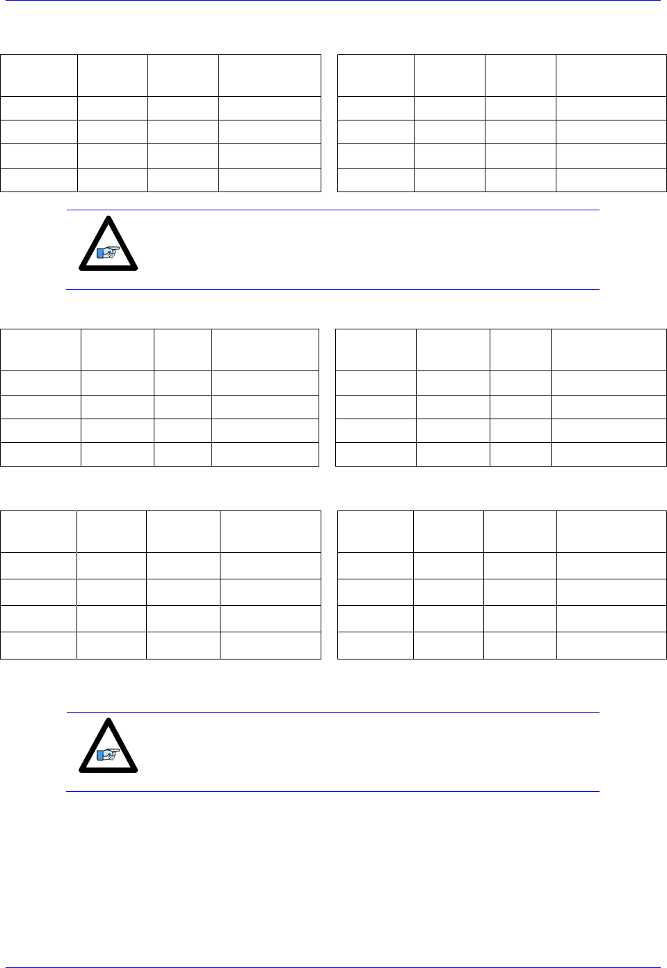
Geo Brick LV User Manual
MACRO Connectivity 211
Servo Node Addresses
MACRO
motor
Motor #
Address
Register
MACRO
motor
Motor #
Address
Register
1st
5 or 9
$78420
Servo Node 0
5th
9 or 13
$78430
Servo Node 8
2nd
6 or 10
$78424
Servo Node 1
6th
10 or 14
$78434
Servo Node 9
3rd
7 or 11
$78428
Servo Node 4
7th
11 or 15
$78438
Servo Node 12
4th
8 or 12
$7842C
Servo Node 5
8th
12 or 16
$7843C
Servo Node 13
Note
At this point of the setup, you should be able to move the
motor/encoder shaft by hand and see encoder counts in the position
window
10. The flag address Ixx25 is initiated by default in the firmware.
MACRO
motor
Motor #
Ixx25
Register
MACRO
motor
Motor #
Ixx25
Register
1st
5 or 9
$3440
Servo Node 0
5th
9 or 13
$3448
Servo Node 8
2nd
6 or 10
$3441
Servo Node 1
6th
10 or 14
$3449
Servo Node 9
3rd
7 or 11
$3444
Servo Node 4
7th
11 or 15
$344C
Servo Node 12
4th
8 or 12
$3445
Servo Node 5
8th
12 or 16
$344D
Servo Node 13
11. The motor command output address Ixx02 is initiated by default in the firmware
MACRO
motor
Motor #
Ixx02
Register
MACRO
motor
Motor #
Ixx02
Register
1st
5 or 9
$078420
Servo Node 0
5th
9 or 13
$078430
Servo Node 8
2nd
6 or 10
$078424
Servo Node 1
6th
10 or 14
$078434
Servo Node 9
3rd
7 or 11
$078428
Servo Node 4
7th
11 or 15
$078438
Servo Node 12
4th
8 or 12
$07842C
Servo Node 5
8th
12 or 16
$07843C
Servo Node 13
12. Make sure that the slave motors are phased (e.g. MX0,P8000=1 to initiate the slave phasing routine).
Note
It is probably wise at this point, and before trying to close the loop, to
perform some open loop commands/test (e.g. #nO0). This will ensure
the capability of enabling the slave amplifier(s).
13. Tuning the PID-Loop
The PID gains saved on the slave initially can be a good starting point. Otherwise, tuning (from the
master) can be carried out in the traditional manner - see motor setup section in this manual - there are no
special instructions for tuning the MACRO/slave motors.

Geo Brick LV User Manual
MACRO Connectivity 212
Setting up the Slave in PWM Mode
1. Establish communication to the slave using USB, Ethernet, or Serial.
2. Consider starting from factory default settings.
This can be done by issuing a $$$*** followed by a Save, and a reset $$$.
3. Consider downloading the suggested M-Variables in the Pewin32Pro2 software.
4. Clock settings considerations
The MACRO ring is synchronized at phase rate. Keep in mind that the phase clock frequency must
be the same on both the master and the slave.
The MACRO IC must be sourcing the clock (parameter I19). A Save followed by a $$$ are
required whenever I19 is changed.
It is advised to have both the MACRO and servo ICs set at the same phase frequency.
I19 = 6807 ; Clock source, MACRO IC 0
I6800 = I7000 ; Macro IC 0 MaxPhase/PWM Frequency Control
I6801 = I7001 ; Macro IC 0 Phase Clock Frequency Control
I6802 = I7002 ; Macro IC 0 Servo Clock Frequency Control
5. MACRO ring settings
I80, I81 and I82 enable the ring error check function.
I85 specifies a station number which the slave unit is assigned to (e.g. multiple slave stations).
I6840 specifies whether this is a master or a slave.
I6841 specifies which MACRO nodes are enabled. Note, that it is not advised to enable nodes
which will not be used.
Ixx44 specifies the MACRO command address and mode for slave motors.
I85=1 ; Station number #1 (if multiple slaves) – User Input
I6840=$4080 ; Macro IC 0 Ring Configuration/Status
I6841=$0FF333 ; Macro IC 0 Node Activate Ctrl (servo nodes 0, 1, 4, 5, 8, 9, 12, and 13)
I124,8,100=$820001 ; Flag mode control, disable limits on slave (enable on master)
#define RingCheckPeriod 20 ; Suggested Ring Check Period [msec]
#define FatalPackErr 15 ; Suggested Fatal Packet Error Percentage [%]
I80=INT(RingCheckPeriod *8388608/I10/(I8+1)+1) ; Macro Ring Check Period [Servo Cycles]
I81=INT(I80* FatalPackErr /100+1) ; Macro Maximum Ring Error Count
I82=I80-I81*4 ; Macro Minimum Sync Packet Count
I144=$078423 ; MacroIC0 Node 0 Command Address. PWM Mode
I244=$078427 ; MacroIC0 Node 1 Command Address. PWM Mode
I344=$07842B ; MacroIC0 Node 4 Command Address. PWM Mode
I444=$07842F ; MacroIC0 Node 5 Command Address. PWM Mode
I544=$078433 ; MacroIC0 Node 8 Command Address. PWM Mode
I644=$078437 ; MacroIC0 Node 9 Command Address. PWM Mode
I744=$07843B ; MacroIC0 Node12 Command Address. PWM Mode
I844=$07843F ; MacroIC0 Node13 Command Address. PWM Mode
6. Issue a Save followed by a $$$ to maintain changes.

Geo Brick LV User Manual
MACRO Connectivity 213
Setting up the Master in PWM Mode
1. Establish communication to the Geo Brick LV using USB, Ethernet, or Serial.
2. Consider starting from factory default settings.
This can be done by issuing a $$$*** followed by a Save, and a reset ($$$).
3. Consider downloading the suggested M-Variables in the Pewin32Pro2 software.
4. The master’s motors can now be set up as described in the motor setup section of this manual. These
are motors #1 through #8 (or #4 if it is a 4-axis Geo Brick LV).
5. Clock settings considerations
The MACRO ring is synchronized at phase rate. The phase clock frequency must be the same on
the master and each of the slaves (Geo MACRO Drives).
It is also advised that the MACRO and servo ICs be set to the same phase frequency.
I6800 = I7000 ; Macro IC0 MaxPhase/PWM Frequency Control
I6801 = I7001 ; Macro IC0 Phase Clock Frequency Control
I6802 = I7002 ; Macro IC0 Servo Clock Frequency Control
Note
It is not necessary for the master to have the MACRO IC sourcing the
clock. But if it is desired, I19 can be simply set to 6807 followed by a
save and a reset ($$$).
6. MACRO ring settings
I80, I81 and I82 enable the ring error check function.
I6840 specifies whether this is a master or a slave.
I6841 specifies which MACRO nodes are enabled. Note, that it is not advised to enable nodes
which will not be used.
I6840=$4030 ; Macro IC 0 Ring Configuration/Status
I6841=$0FF333 ; Macro IC 0 Node Activate Ctrl 8-axis (servo nodes 0, 1, 4, 5, 8, 9, 12, 13)
I78=32 ; Macro Type 1 Master/Slave Communications Timeout
I70=$3333 ; Macro IC 0 Node Auxiliary Register Enable (for 8 Ring motors)
I71=0 ; Type 0 MX Mode
#define RingCheckPeriod 20 ; Suggested Ring Check Period [msec]
#define FatalPackErr 15 ; Suggested Fatal Packet Error Percentage [%]
I80=INT(RingCheckPeriod *8388608/I10/(I8+1)+1) ; Macro Ring Check Period [Servo Cycles]
I81=INT(I80* FatalPackErr /100+1) ; Macro Maximum Ring Error Count
I82=I80-I81*4 ; Macro Minimum Sync Packet Count
7. Issue a Save, followed by a reset ($$$) to maintain changes.

Geo Brick LV User Manual
MACRO Connectivity 214
8. Activating MACRO motors, Flag Control
The master Geo Brick LV can be fitted with 1 or 2 servo ICs to service local channels (4 or 8). The
next available channel will be the first macro/slave motor. This allows taking advantage of some of
the default MACRO settings set by the firmware upon detecting a MACRO IC.
If I4900 = $1, then only Servo IC 0 is present, and the first macro motor is #5
I500,8,100=1 ; Activate channels 5-12
I524,8,100=$840001 ; Channels 5-12 flag control ($860001 to disable limits)
If I4900 = $3, then Servo ICs 0 and 1 are present, and the first macro motor is #9
I900,8,100=1 ; Activate channels 9-18
I924,8,100=$840001 ; Channels 9-18 flag control ($860001 to disable limits)
9. Position And Velocity Pointers
If all local motors have digital quadrature encoders (1-line ECT entries), and no other entries are used
in the Encoder Conversion Table then the position (Ixx03) and Velocity (Ixx04) pointers of the
MACRO motors are valid by default (set by firmware) and need not be changed:
MACRO
motor
Motor #
Ixx03, Ixx04
MACRO
motor
Motor #
Ixx03, Ixx04
1st
5 or 9
$350A
5th
9 or 13
$3512
2nd
6 or 10
$350C
6th
10 or 14
$3514
3rd
7 or 11
$350E
7th
11 or 15
$3516
4th
8 or 12
$3510
8th
12 or 16
$3518
However, if the Encoder Conversion Table has been modified then the MACRO motors/nodes entries
need to be configured properly. This can be done using the Encoder Conversion Table utility in the
PewinPro2 under Configure>Encoder Conversion Table:
a. Click on End of Table to access the next available entry
b. Conversion Type: Parallel position from Y word with no filtering
c. No Shifting
d. Width in Bits: 24
e. Source Address: Servo node Address (See table below)
f. Record the processed data address.
This is where the position and velocity pointers will be set to for a specific node/motor number.
E.g. I903,2=$351A
g. Repeat steps for additional motors/servo nodes
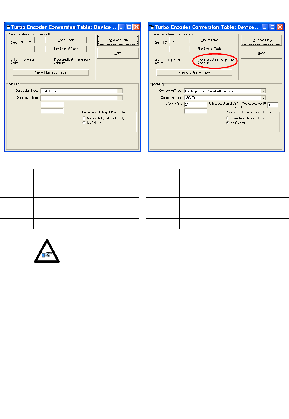
Geo Brick LV User Manual
MACRO Connectivity 215
Servo Node Addresses
MACRO
motor
Motor #
Address
Register
MACRO
motor
Motor #
Address
Register
1st
5 or 9
$78420
Servo Node 0
5th
9 or 13
$78430
Servo Node 8
2nd
6 or 10
$78424
Servo Node 1
6th
10 or 14
$78434
Servo Node 9
3rd
7 or 11
$78428
Servo Node 4
7th
11 or 15
$78438
Servo Node 12
4th
8 or 12
$7842C
Servo Node 5
8th
12 or 16
$7843C
Servo Node 13
Note
At this point of the setup, you should be able to move the
motor/encoder shaft by hand and see encoder counts in the position
window

Geo Brick LV User Manual
MACRO Connectivity 216
10. The flag address Ixx25 for MACRO motors is initiated by default in the firmware.
MACRO
motor
Motor #
Ixx25
Register
MACRO
motor
Motor #
Ixx25
Register
1st
5 or 9
$3440
Servo Node 0
5th
9 or 13
$3448
Servo Node 8
2nd
6 or 10
$3441
Servo Node 1
6th
10 or 14
$3449
Servo Node 9
3rd
7 or 11
$3444
Servo Node 4
7th
11 or 15
$344C
Servo Node 12
4th
8 or 12
$3445
Servo Node 5
8th
12 or 16
$344D
Servo Node 13
11. The motor command output address Ixx02 is initiated by default in the firmware
MACRO
motor
Motor #
Ixx02
Register
MACRO
motor
Motor #
Ixx02
Register
1st
5 or 9
$078420
Servo Node 0
5th
9 or 13
$078430
Servo Node 8
2nd
6 or 10
$078424
Servo Node 1
6th
10 or 14
$078434
Servo Node 9
3rd
7 or 11
$078428
Servo Node 4
7th
11 or 15
$078438
Servo Node 12
4th
8 or 12
$07842C
Servo Node 5
8th
12 or 16
$07843C
Servo Node 13
12. The Flag Control Ixx24 is typically set to $840001 ($860001 to disable hardware over-travel limits).
13. The commutation position address Ixx83 is initiated by default in the firmware.
MACRO
motor
Motor #
Ixx83
Register
MACRO
motor
Motor #
Ixx83
Register
1st
5 or 9
$078420
Servo Node 0
5th
9 or 13
$078430
Servo Node 8
2nd
6 or 10
$078424
Servo Node 1
6th
10 or 14
$078434
Servo Node 9
3rd
7 or 11
$078428
Servo Node 4
7th
11 or 15
$078438
Servo Node 12
4th
8 or 12
$07842C
Servo Node 5
8th
12 or 16
$07843C
Servo Node 13
14. The commutation enable Ixx01 should be set to 3, indicating that commutation is performed from Y-
registers (specified in Ixx83).
15. The current loop feedback address Ixx82 should be set per the following table:
MACRO
motor
Motor #
Ixx82
Register
MACRO
motor
Motor #
Ixx82
Register
1st
5 or 9
$078422
Servo Node 0
5th
9 or 13
$078432
Servo Node 8
2nd
6 or 10
$078426
Servo Node 1
6th
10 or 14
$078436
Servo Node 9
3rd
7 or 11
$07842A
Servo Node 4
7th
11 or 15
$07843A
Servo Node 12
4th
8 or 12
$07842E
Servo Node 5
8th
12 or 16
$07843E
Servo Node 13
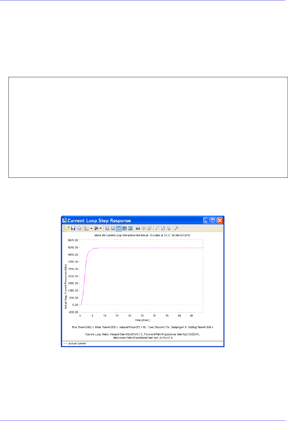
Geo Brick LV User Manual
MACRO Connectivity 217
16. The current feedback mask Ixx84 should be set to $FFFC00.
17. Commutation Cycle Size
Ixx70 = {Number of pair poles}
Ixx71 = {Number of counts per revolution * 32}
18. I2T Settings (example for motor #9):
I15=0 ; Trigonometric calculation in degrees
#define MaxPhaseFreq P8000 ; Max Phase Clock [KHz]
#define PWMClk P8001 ; PWM Clock [KHz]
#define PhaseClk P8002 ; Phase Clock [KHz]
#define ServoClk P8003 ; Servo Clock [KHz]
MaxPhaseFreq=117964.8/(2*I6800+3)
PWMClk=117964.8/(4*I6800+6)
PhaseClk=MaxPhaseFreq/(I6801+1)
ServoClk=PhaseClk/(I6802+1)
#define Mtr9ContCurrent 3 ; Continuous Current Limit [Amps] –User Input
#define Mtr9PeakCurrent 9 ; Instantaneous Current Limit [Amps] –User Input
#define MaxADC 33.85 ; See slave electrical specifications –User Input
#define Mtr9I2TOnTime 1 ; Time allowed at peak Current [sec]
I957=INT(32767*(Mtr9ContCurrent*1.414/MaxADC)*cos(30))
I969=INT(32767*(Mtr9PeakCurrent*1.414/MaxADC)*cos(30))
I958=INT((I969*I969-I957*I957)*ServoClk*1000*Mtr9I2TOnTime/(32767*32767))
19. Current-Loop Tuning (Ixx61, Ixx62, Ixx76)
Current loop tuning is performed in the same manner as it would be for any digitally commuted
amplifier. A satisfactory current loop response (PmacTuningPro2 screen shot) would look like:

Geo Brick LV User Manual
MACRO Connectivity 218
20. Motor Phasing, Open-Loop Test
Motor phasing is performed in the same manner as it would be for any digitally commutated motor.
The following is a satisfactory open loop test:
An erratic or inverted saw tooth response is typically (with quadrature, or sinusoidal encoders) an
indication of reversed encoder direction –with respect to the output command- The encoder decode
parameter can then be changed from 7 to 3 or vice versa. Phasing has to be performed again after this
parameter has been changed.
21. Tuning the Position-Loop
Tuning the position loop PID gains can be carried out in the traditional manner - see motor setup
section in this manual - there are no special instructions for tuning MACRO motors.
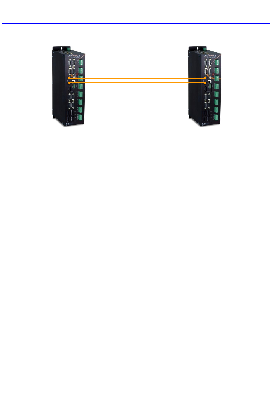
Geo Brick LV User Manual
MACRO Connectivity 219
Configuration Example 2: Brick – Brick (Stepper Motors)
MACRO Ring Master
MACRO Ring Slave
Driving Stepper Motors
Setting up the Slave in Torque Mode for Steppers
1. Establish communication to Slave unit using USB, Ethernet, or Serial.
2. Consider starting from factory default settings.
This can be done by issuing a $$$*** followed by a Save, and a $$$.
3. Consider downloading the suggested M-Variables in the Pewin32Pro2 software.
4. Set up motors per the motor setup section described in this manual.
5. Clock settings considerations
The MACRO ring is synchronized at phase rate. Keep in mind that the phase clock frequency must
be the same on both the master and the slave.
The MACRO IC must be sourcing the clock (parameter I19). A Save followed by a $$$ are
required whenever I19 is changed.
It is advised to have both the MACRO and servo ICs set at the same phase frequency.
I19 = 6807 ; Clock source, MACRO IC 0
I6800 = I7000 ; Macro IC 0 MaxPhase/PWM Frequency Control
I6801 = I7001 ; Macro IC 0 Phase Clock Frequency Control
I6802 = I7002 ; Macro IC 0 Servo Clock Frequency Control
6. Make sure that the motors are fully operational and can be controlled in closed loop (e.g. jog
commands). Position PID tuning is not critical at this point. Fine tuning of the slave motors should be
eventually performed from the master side.
7. Kill all motors

Geo Brick LV User Manual
MACRO Connectivity 220
8. MACRO ring settings
I80, I81 and I82 enable the ring error check function.
I85 specifies a station number which the slave unit is assigned to (e.g. multiple slave stations).
I6840 specifies whether this is a master or a slave.
I6841 specifies which MACRO nodes are enabled. Note, that it is not advised to enable nodes
which will not be used.
I85=1 ; Station number #1 (if multiple slaves) – User Input
I6840=$4080 ; Macro IC0 Ring Configuration/Status, typical slave setting
I6841=$0FF333 ; Macro IC0 Node Activate Ctrl (Servo nodes 0, 1, 4, 5, 8, 9, 12, 13) – User Input
#define RingCheckPeriod 20 ; Suggested Ring Check Period [msec]
#define FatalPackErr 15 ; Suggested Fatal Packet Error Percentage [%]
I80=INT(RingCheckPeriod *8388608/I10/(I8+1)+1) ; Macro Ring Check Period [Servo Cycles]
I81=INT(I80* FatalPackErr /100+1) ; Macro Maximum Ring Error Count
I82=I80-I81*4 ; Macro Minimum Sync Packet Count
9. MACRO slave command address
Ixx44 specifies the MACRO command address and mode for slave motors.
I144=$178423 ; Macro IC0 Node 0 Command Address. Torque Mode
I244=$178427 ; Macro IC0 Node 1 Command Address. Torque Mode
I344=$17842B ; Macro IC0 Node 4 Command Address. Torque Mode
I444=$17842F ; Macro IC0 Node 5 Command Address. Torque Mode
I544=$178433 ; Macro IC0 Node 8 Command Address. Torque Mode
I644=$178437 ; Macro IC0 Node 9 Command Address. Torque Mode
I744=$17843B ; Macro IC0 Node 12 Command Address. Torque Mode
I844=$17843F ; Macro IC0 Node 13 Command Address. Torque Mode
Setting Ixx44 to the MACRO command register hands control of the motors to the master. To allow
motor commands from the slave again, Ixx44 needs to be set back to default of zero.
Note
Ixx44 must be set for at least one channel to allow MACRO auxiliary
mode communication, thus enabling MX commands.
10. Issue a Save followed by a reset $$$ to maintain changes.
11. With Direct Micro-Stepping, the servo-loop command output is integrated in the Encoder Conversion
Table to create a simulated sensor position, so in order to convey the command output from the
Master the Encoder Conversion Table must be modified for MACRO support. Register 0 of each
respective node carries the command output, it will replace the source address of the local servo
command output (see stepper motor setup section in this manual):
Note
Instead of replacing the current ECT entries with the MACRO support
ECT entries, they can be added on. This way, a PLC program can be
implemented to allow toggling motor control between local (Slave)
and MACRO (Master).

Geo Brick LV User Manual
MACRO Connectivity 221
Encoder Conversion Table Source Address
Motor #
Local
MACRO
Motor #
Local
MACRO
1
$0000BF
$78420
5
$0002BF
$78430
2
$00013F
$78424
6
$00033F
$78434
3
$0001BF
$78428
7
$0003BF
$78438
4
$00023F
$7842C
8
$00043F
$7843C
We will keep the encoder conversion table entries for local control, and add entries for control over
MACRO. These settings would look like:
For local control (to command motor from Slave)
Results
Position, Velocity,
Commutation
Pointers
I8000=$6800BF ; Parallel read of Y/X:$BF
I8001=$018018 ; 24 bits starting at X bit0
I8002=$EC0001 ; Integrate result from I8001
I8003=$68013F ; Parallel read of Y/X:$13F
I8004=$018018 ; 24 bits starting at X bit0
I8005=$EC0004 ; Integrate result from I8004
I8006=$6801BF ; Parallel read of Y/X:$1BF
I8007=$018018 ; 24 bits starting at X bit0
I8008=$EC0007 ; Integrate result from I8007
I8009=$68023F ; Parallel read of Y/X:$23F
I8010=$018018 ; 24 bits starting at X bit0
I8011=$EC000A ; Integrate result from I8010
I8012=$6802BF ; Parallel read of Y/X:$2BF
I8013=$018018 ; 24 bits starting at X bit0
I8014=$EC000D ; Integrate result from I8013
I8015=$68033F ; Parallel read of Y/X:$33F
I8016=$018018 ; 24 bits starting at X bit0
I8017=$EC0010 ; Integrate result from I8016
I8018=$6803BF ; Parallel read of Y/X:$3BF
I8019=$018018 ; 24 bits starting at X bit0
I8020=$EC0013 ; Integrate result from I8019
I8021=$68043F ; Parallel read of Y/X:$43F
I8022=$018018 ; 24 bits starting at X bit0
I8023=$EC0016 ; Integrate result from I8022
$3501
$3502
$3503
$3504
$3505
$3506
$3507
$3508
$3509
$350A
$350B
$350C
$350D
$350E
$350F
$3510
$3511
$3512
$3513
$3514
$3515
$3516
$3517
$3518
I103=$3503
I104=I103
I183=I103
I203=$3506
I204=I203
I283=I203
I303=$3509
I304=I303
I383=I303
I403=$350C
I404=I403
I483=I403
I503=$350F
I504=I503
I583=I503
I603=$3512
I604=I603
I683=I603
I703=$3515
I704=I703
I783=I703
I803=$3518
I804=I803
I883=I803
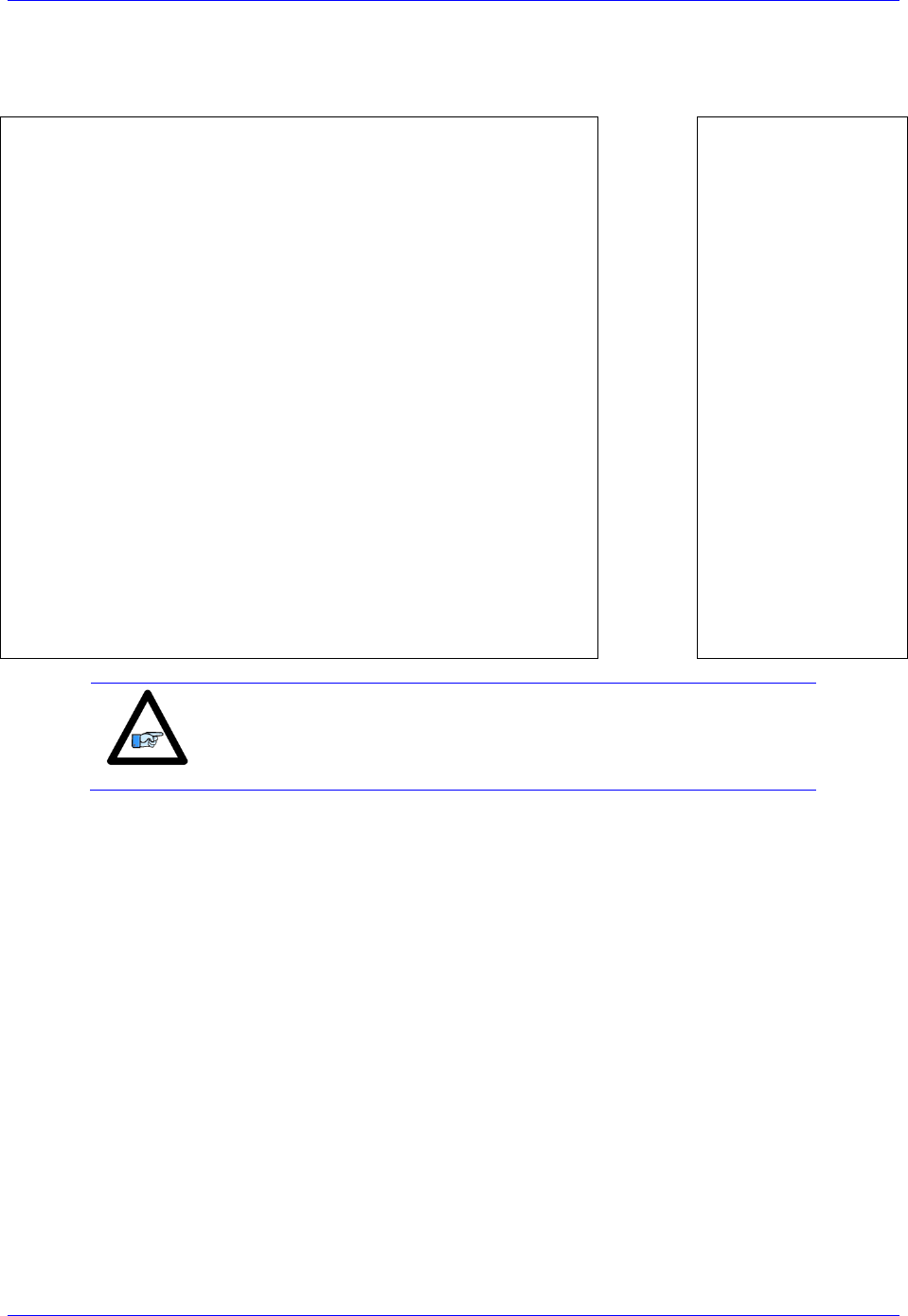
Geo Brick LV User Manual
MACRO Connectivity 222
For MACRO control (to command motor from Master)
Results
Position, Velocity,
Commutation
Pointers
I8024=$6F8420 ; Parallel read of Y/X:$78420
I8025=$018000 ; 24 bits starting at Y bit0
I8026=$EC0019 ; Integrate result from I8025
I8027=$6F8424 ; Parallel read of Y/X:$78424
I8028=$018000 ; 24 bits starting at Y bit0
I8029=$EC001C ; Integrate result from I8028
I8030=$6F8428 ; Parallel read of Y/X:$78428
I8031=$018000 ; 24 bits starting at Y bit0
I8032=$EC001F ; Integrate result from I8031
I8033=$6F842C ; Parallel read of Y/X:$7842C
I8034=$018000 ; 24 bits starting at Y bit0
I8035=$EC0022 ; Integrate result from I8030
I8036=$6F8430 ; Parallel read of Y/X:$78430
I8037=$018000 ; 24 bits starting at Y bit0
I8038=$EC0025 ; Integrate result from I8037
I8039=$6F8434 ; Parallel read of Y/X:$78434
I8040=$018000 ; 24 bits starting at Y bit0
I8041=$EC0028 ; Integrate result from I8040
I8042=$6F8438 ; Parallel read of Y/X:$78438
I8043=$018000 ; 24 bits starting at Y bit0
I8044=$EC002B ; Integrate result from I8043
I8045=$6F843C ; Parallel read of Y/X:$7843C
I8046=$018000 ; 24 bits starting at Y bit0
I8047=$EC002E ; Integrate result from I8046
$3519
$351A
$351B
$351C
$351D
$351E
$351F
$3520
$3521
$3522
$3523
$3524
$3525
$3526
$3527
$3528
$3529
$352A
$352B
$352C
$352D
$352E
$352F
$3530
I103=$351B
I104=I103
I183=I103
I203=$351E
I204=I203
I283=I203
I303=$3521
I304=I303
I383=I303
I403=$3524
I404=I403
I483=I403
I503=$3527
I504=I503
I583=I503
I603=$352A
I604=I603
I683=I603
I703=$352D
I704=I703
I783=I703
I803=$3530
I804=I803
I883=I803
Note
For Micro-Stepping, the parallel read and integration ECTs combine
to a 3-line entry. The processed data (result) lies in the 3rd line.
12. Issue a Save followed by a $$$ to maintain changes.

Geo Brick LV User Manual
MACRO Connectivity 223
The motors attached to the slave(s) have to be phased locally before allowing the Master to take over their
control. This can be done using Macro auxiliary MX commands from the master and creating a
handshaking flag to trigger local phasing followed by a kill on the slave side.
Slave Handshaking PLC Example: Phase then kill Motor #1
P8000=0 ; Handshaking flag
Open PLC 1 Clear
IF (P8000 = 1)
CMD"#1K"
I5111= 250 *8388608/I10 While(I5111>0) EndW
I144=0 ; Turn Auxiliary Control off
I103=$3503 ; Set position pointer to local control ECT
I104=$3503 ; Set velocity pointer to local control ECT
I183=$3503 ; Set commutation pointer to local control ECT
I5111= 250 *8388608/I10 While(I5111>0) EndW
CMD"#1$"
I5111= 500 *8388608/I10 While(I5111>0) EndW
CMD"#1K"
I5111= 250 *8388608/I10 While(I5111>0) EndW
I144=$178423 ; Turn Auxiliary Control on
I103=$351B ; Set position pointer to MACRO control ECT
I104=I103 ; Set velocity pointer to MACRO control ECT
I183=I103 ; Set commutation pointer to MACRO control ECT
I5111= 250 *8388608/I10 While(I5111>0) EndW
P8000 = 0
EndIf
Close
Note
Issuing MX0, P8000=1 from the Master will allow the execution of
this code on the slave.

Geo Brick LV User Manual
MACRO Connectivity 224
Setting up the Master in Torque Mode for Steppers
1. Establish communication to the master using USB, Ethernet, or Serial.
2. Consider starting from factory default settings.
This can be done by issuing a $$$*** followed by a Save, and a reset $$$.
3. Consider downloading the suggested M-Variables in the Pewin32Pro2 software.
4. The master’s motors can now be set up as described in the motor setup section of this manual.
Typically, these are motors #1 through #4 (or #8).
5. Clock settings considerations
The MACRO ring is synchronized at phase rate. The phase clock frequency must be the same on
the master and each of the slaves.
It is advised that the MACRO and servo ICs be set to the same phase frequency.
I6800 = I7000 ; Macro IC0 MaxPhase/PWM Frequency Control
I6801 = I7001 ; Macro IC0 Phase Clock Frequency Control
I6802 = I7002 ; Macro IC0 Servo Clock Frequency Control
6. MACRO ring settings
I80, I81 and I82 enable the ring error check function.
I6840 specifies whether this is a master or a slave.
I6841 specifies which MACRO nodes are enabled. Note, that it is not advised to enable nodes
which will not be used.
I6840=$4030 ; Macro IC0 Ring Configuration/Status, typical master IC setting
I6841=$0FF333 ; Macro IC0 Node Activate Ctrl (Servo nodes 0, 1, 4, 5, 8, 9, 12, 13) – User Input
I78=32 ; Macro Type 1 Master/Slave Communications Timeout
I70=$3333 ; Macro IC 0 Node Auxiliary Register Enable (for 8 macro motors)
I71=0 ; Type 0 MX Mode
#define RingCheckPeriod 20 ; Suggested Ring Check Period [msec]
#define FatalPackErr 15 ; Suggested Fatal Packet Error Percentage [%]
I80=INT(RingCheckPeriod *8388608/I10/(I8+1)+1) ; Macro Ring Check Period [Servo Cycles]
I81=INT(I80* FatalPackErr /100+1) ; Macro Maximum Ring Error Count
I82=I80-I81*4 ; Macro Minimum Sync Packet Count
7. Issue a Save, followed by a reset ($$$) to maintain changes.
8. Activating MACRO motors, Flag Control (Ixx00, Ixx24)
The master Geo Brick LV can be fitted with 1 or 2 servo ICs to service local channels (4 or 8). The
next available channel will be the first macro/slave motor. This allows taking advantage of some of
the default MACRO settings set by the firmware upon detecting a MACRO IC.
If I4900 = $1, then only Servo IC 0 is present, and the first macro motor is #5
I500,8,100=1 ; Activate channels 5-12
I524,8,100=$840001 ; Channels 5-12 flag control
If I4900 = $3, then Servo ICs 0 and 1 are present, and the first macro motor is #9
I900,8,100=1 ; Activate channels 9-16
I924,8,100=$840001 ; Channels 9-16 flag control
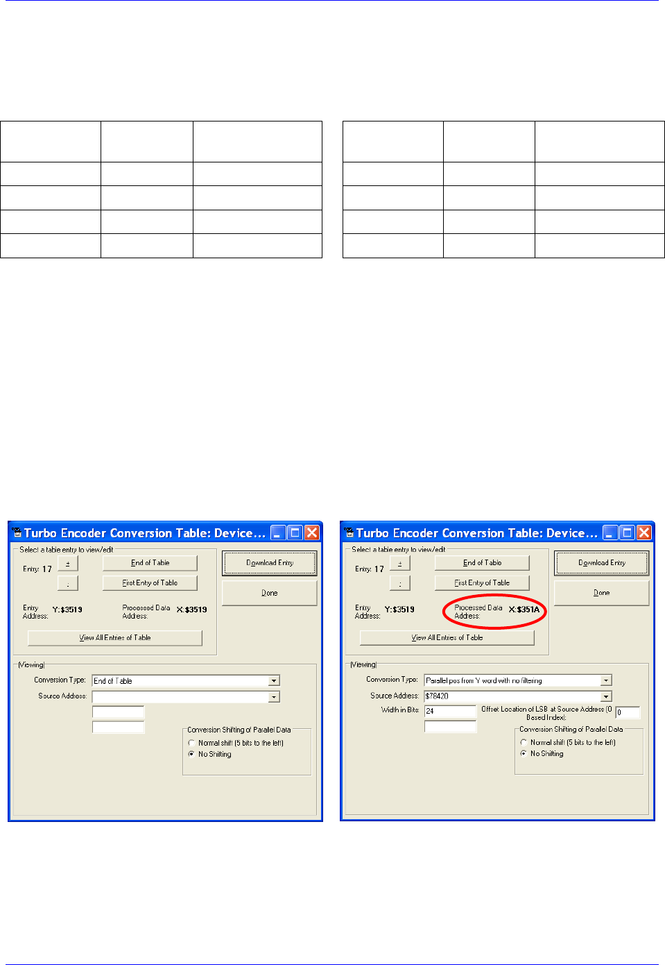
Geo Brick LV User Manual
MACRO Connectivity 225
9. Position And Velocity Pointers (Ixx03, Ixx04)
If all local motors have digital quadrature encoders (or 1-line ECT entries), and no other entries are
used in the Encoder Conversion Table then the position (Ixx03) and Velocity (Ixx04) pointers of the
MACRO motors are valid by default (set by firmware) and need not be changed:
MACRO
motor
Motor #
Ixx03, Ixx04
MACRO
motor
Motor #
Ixx03, Ixx04
1st
5 or 9
$350A
5th
9 or 13
$3512
2nd
6 or 10
$350C
6th
10 or 14
$3514
3rd
7 or 11
$350E
7th
11 or 15
$3516
4th
8 or 12
$3510
8th
12 or 16
$3518
However, if the Encoder Conversion Table has been modified then the MACRO motors/nodes entries
need to be configured properly. This can be done using the Encoder Conversion Table utility in the
PewinPro2 under Configure>Encoder Conversion Table:
4. Click on End of Table to access the next available entry
5. Conversion Type: Parallel position from Y word with no filtering
6. No Shifting
7. Width in Bits: 24
8. Source Address: Servo node Address (See table below)
9. Record the processed data address.
This is where the position and velocity pointers will be set to for a specific node/motor number.
E.g. I903,2=$351A
10. Repeat steps for additional motors/servo nodes

Geo Brick LV User Manual
MACRO Connectivity 226
Servo Node Addresses
MACRO
motor
Motor #
Address
Register
MACRO
motor
Motor #
Address
Register
1st
5 or 9
$78420
Servo Node 0
5th
9 or 13
$78430
Servo Node 8
2nd
6 or 10
$78424
Servo Node 1
6th
10 or 14
$78434
Servo Node 9
3rd
7 or 11
$78428
Servo Node 4
7th
11 or 15
$78438
Servo Node 12
4th
8 or 12
$7842C
Servo Node 5
8th
12 or 16
$7843C
Servo Node 13
10. The flag address Ixx25 is initiated by default in the firmware:
MACRO
motor
Motor #
Ixx25
Register
MACRO
motor
Motor #
Ixx25
Register
1st
5 or 9
$3440
Servo Node 0
5th
9 or 13
$3448
Servo Node 8
2nd
6 or 10
$3441
Servo Node 1
6th
10 or 14
$3449
Servo Node 9
3rd
7 or 11
$3444
Servo Node 4
7th
11 or 15
$344C
Servo Node 12
4th
8 or 12
$3445
Servo Node 5
8th
12 or 16
$344D
Servo Node 13
11. The motor command output address Ixx02 is initiated by default in the firmware:
MACRO
motor
Motor #
Ixx02
Register
MACRO
motor
Motor #
Ixx02
Register
1st
5 or 9
$078420
Servo Node 0
5th
9 or 13
$078430
Servo Node 8
2nd
6 or 10
$078424
Servo Node 1
6th
10 or 14
$078434
Servo Node 9
3rd
7 or 11
$078428
Servo Node 4
7th
11 or 15
$078438
Servo Node 12
4th
8 or 12
$07842C
Servo Node 5
8th
12 or 16
$07843C
Servo Node 13
12. Tuning the PID-Loop
With stepper motors, these are computed empirically, and can be set to the following:
Ixx30=1024
Ixx31=0
Ixx32=85
Ixx33=1024
Ixx34=1
13. Issue a SAVE followed by a $$$ to maintain changes
The motor setup is now finished and both Master and Slave units are in post-reset mode (power-up),
therefore local and Macro motors need to be phased.
Motors attached directly to the master are initialized and phased in the traditional manner. Motors
attached to the slave are initialized by executing the handshaking PLC (e.g. issuing MX0, P8000=1).
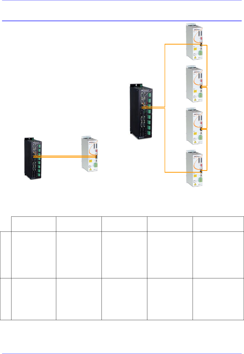
Geo Brick LV User Manual
MACRO Connectivity 227
Configuration Example 3: Brick – Geo MACRO Drive
This configuration example discusses the necessary
steps for setting up a MACRO ring with an 8-axis
Geo Brick LV as a master and up to 4 x dual axes
Geo MACRO drives as slaves.
For simplicity, we will cover guidelines for setting
up one Geo MACRO drive in detail. The others
can be configured similarly.
For non-MACRO experienced users, it may be
practical to configure one Geo MACRO drive at a
time (as shown below). That is by connecting it to
the Geo Brick LV via two fiber optic cables while
leaving the other drives outside of the ring.
Geo Brick LV
(Master)
Geo MACRO Drive
(Slave #4)
Geo MACRO Drive
(Slave #3)
Geo MACRO Drive
(Slave #2)
Geo MACRO Drive
(Slave #1)
out
in
Geo Brick LV
(Master)
Geo MACRO Drive
(Slave)
The following table summarizes the basic clock (Geo Brick LV recommended) and MACRO settings for
the ring in the diagram above. MS commands are allowed once the clocks are synchronized and nodes are
enabled properly on the master and each of the slaves. The slaves’ settings can be implemented via
MACRO ASCII communication.
Master
Slave #1
(Servo nodes 0,1)
Slave #2
(Servo nodes 4,5)
Slave #3
(Servo nodes 8,9)
Slave #4
(Servo nodes 12,13)
Clock Settings
I6800=1473
I6801=3
I6802=1
I7100=1473
I7101=3
I7102=1
I7000=1473
I7001=3
I7002=1
I10=1677653
MS0,I992=1473
MS0,I997=3
MS4,I992=1473
MS4,I997=3
MS8,I992=1473
MS8,I997=3
MS12,I992=1473
MS12,I997=3
MACRO Settings
I6840=$4030
I6841=$0FF333
I78=32
I70=$3333
I71=$3333
I80=101
I81=3
I82=30
MS0,I995=$4080
MS0,I996=$F4003
MS0,I11=1
MS0,I8=202
MS0,I9=18
MS0,I10=120
MS4,I995=$4080
MS4,I996=$F4030
MS4,I11=2
MS4,I8=202
MS4,I9=18
MS4,I10=120
MS8,I995=$4080
MS8,I996=$F4300
MS8,I11=3
MS8,I8=202
MS8,I9=18
MS8,I10=120
MS12,I995=$4080
MS12,I996=$F7000
MS12,I11=4
MS12,I8=202
MS12,I9=18
MS12,I10=120
Geo Brick LV User Manual
MACRO Connectivity 228
The following steps are guidelines for setting up one Geo Macro Drive slave:
1. Establish communication to the Geo Brick LV using USB, Ethernet, or Serial.
2. Consider starting from factory default settings.
This can be done by issuing a $$$*** followed by a Save, and a reset ($$$).
3. Consider downloading the suggested M-Variables in the Pewin32Pro2 software.
4. The master’s motors can now be set up as described in the motor setup section of this manual. These
are motors #1 through #8 (or #4 if it is a 4-axis Geo Brick LV).
5. Clock settings considerations
The MACRO ring is synchronized at phase rate. The phase clock frequency must be the same on
the master and each of the slaves (Geo MACRO Drives).
It is also advised that the MACRO and servo ICs be set to the same phase frequency.
I6800 = I7000 ; Macro IC0 MaxPhase/PWM Frequency Control
I6801 = I7001 ; Macro IC0 Phase Clock Frequency Control
I6802 = I7002 ; Macro IC0 Servo Clock Frequency Control
Note
It is not necessary for the master to have the MACRO IC sourcing the
clock. But if it is desired, I19 can be simply set to 6807 followed by a
Save and a reset $$$.
6. MACRO ring settings
I80, I81 and I82 enable the ring error check function.
I6840 specifies whether this is a master or a slave.
I6841 specifies which MACRO nodes are enabled. Note, that it is not advised to enable nodes
which will not be used.
I6840=$4030 ; Macro IC0 Ring Configuration/Status, typical master IC setting
I6841=$0FC003 ; Macro IC0 Node Activate Ctrl (Servo nodes 0, 1) – User Input
I78=32 ; Macro Type 1 Master/Slave Communications Timeout
I70=$3 ; Macro IC 0 Node Auxiliary Register Enable (for 2 macro motors)
I71=$3 ; Type 1 MX Mode
#define RingCheckPeriod 20 ; Suggested Ring Check Period [msec]
#define FatalPackErr 15 ; Suggested Fatal Packet Error Percentage [%]
I80=INT(RingCheckPeriod *8388608/I10/(I8+1)+1) ; Macro Ring Check Period [Servo Cycles]
I81=INT(I80* FatalPackErr /100+1) ; Macro Maximum Ring Error Count
I82=I80-I81*4 ; Macro Minimum Sync Packet Count
7. Issue a Save, followed by a reset $$$ to maintain changes.

Geo Brick LV User Manual
MACRO Connectivity 229
8. If the Geo MACRO Drive has been configured prior to this setup, then it may have been assigned a
station number and/or may have some enabled nodes. You would need to know what the station
number is in order to perform ASCII communication, or which nodes are enabled in order to issue
MS commands.
The following commands can then be issued to reset the Geo MACRO Drive(s) back to its factory
default settings:
MS$$$***15 will broadcast a global reset to stations associated with all enabled nodes
MSSAV15 will broadcast a Save to stations associated with all enabled nodes
MS$$$15 will broadcast a reset ($$$) to stations associated with all enabled nodes
9. Assuming that the Geo MACRO Drive(s) is or has been reset to factory default settings, we will now
try to establish MACRO ASCII communication by issuing:
MACSTA255
This command will establish MACRO ASCII (direct) communication with the first unassigned Geo
MACRO Drive (if more than one is in the ring) starting from the OUT/Transmit fiber or RJ45 out of
the Geo Brick LV.
10. When in ASCII mode, download from the editor or issue the following commands in the terminal
window:
I995 = $4080 ; MACRO IC ring configuration, typical slave setting
I996 = $0F4003 ; Node activation (servo nodes 0, 1) –User Input
11. Issue a Control^T in the terminal window to exit ASCII mode communication
Master Slave (MS) commands should now be available for nodes 0 and 1 (per this example).
12. Clock Settings
The phase frequency should be set the same as the master’s. Set the following:
MS0, I992 = Value of I7000 (or I6800) ; Max Phase Clock
MS0, I997 = Value of I7001 (or I6801) ; Phase Clock Divider
13. Ring Check Error
Enabling the ring check error function on the Geo MACRO drive requires computing and setting the
following parameters:
MS0,I8 -> I80*(I6802+1)
MS0,I9 -> I81*(I6802+1)*(I8+1)
MS0,I10 -> I82*(I6802+1)*(I8+1)
Where I8, I80, I81, I82, and I6802 are masters’ parameters.
14. Station Number
The station number is used for ASCII communication.
MS0, I11 = 1 ; Assign Station Number #1 –User Input
15. Issue MSSAV0 followed by MS$$$0 to maintain changes on the Geo MACRO Drive.

Geo Brick LV User Manual
MACRO Connectivity 230
16. Activating MACRO Motors
Variable I4900 reports how many servo ICs is the Geo Brick LV populated with. Knowing that each
Servo IC services 4 axes, querying I4900 will reveal how many local channels are occupied and thus
the number of the 1st available motor on the Macro Ring:
If I4900=
Servo ICs present
Local
Motors
First Motor#
On The Ring
Activation
2-axis Slave
$1
IC0 only (4-axis)
1 - 4
5
I500,2,100=1
$3
IC0, and IC1(8-axis)
1 – 8
9
I900,2,100=1
17. Position, Velocity pointers
If all local motors have digital quadrature encoders (1-line ECT entries), and no other entries are used
in the Encoder Conversion Table then the position (Ixx03) and Velocity (Ixx04) pointers of the
MACRO motors are valid by default (set by firmware) and need not be changed:
MACRO
motor
Motor #
Ixx03, Ixx04
MACRO
motor
Motor #
Ixx03, Ixx04
1st
5 or 9
$350A
5th
9 or 13
$3512
2nd
6 or 10
$350C
6th
10 or 14
$3514
3rd
7 or 11
$350E
7th
11 or 15
$3516
4th
8 or 12
$3510
8th
12 or 16
$3518
However, if the Encoder Conversion Table has been modified then the MACRO motors/nodes entries
need to be configured properly. This can be done using the Encoder Conversion Table utility in the
PewinPro2 under Configure>Encoder Conversion Table:
a. Click on End of Table to access the next available entry
b. Conversion Type: Parallel position from Y word with no filtering
c. No Shifting
d. Width in Bits: 24
e. Source Address: Servo node Address (See table below)
f. Record the processed data address.
This is where the position and velocity pointers will be set to for a specific node/motor number.
E.g. I903,2=$351A
g. Repeat steps for additional motors/servo nodes
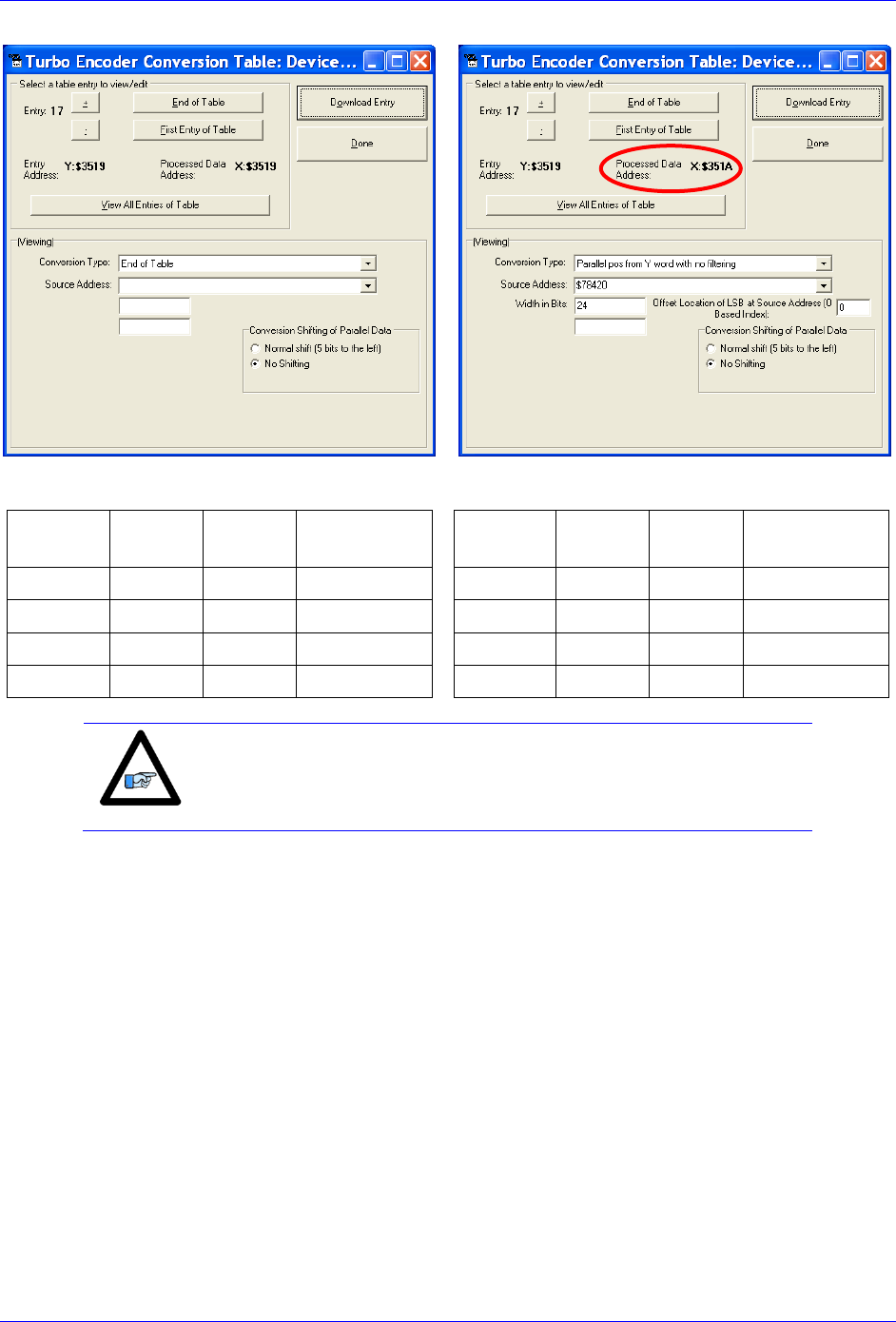
Geo Brick LV User Manual
MACRO Connectivity 231
Servo Node Addresses
MACRO
motor
Motor #
Address
Register
MACRO
motor
Motor #
Address
Register
1st
5 or 9
$78420
Servo Node 0
5th
9 or 13
$78430
Servo Node 8
2nd
6 or 10
$78424
Servo Node 1
6th
10 or 14
$78434
Servo Node 9
3rd
7 or 11
$78428
Servo Node 4
7th
11 or 15
$78438
Servo Node 12
4th
8 or 12
$7842C
Servo Node 5
8th
12 or 16
$7843C
Servo Node 13
Note
At this point of the setup, you should be able to move the
motor/encoder shaft by hand and see encoder counts in the position
window

Geo Brick LV User Manual
MACRO Connectivity 232
18. Typical MACRO motor settings
The motor command output address Ixx02 is initiated by default in the firmware
MACRO
motor
Motor #
Ixx02
Register
MACRO
motor
Motor #
Ixx02
Register
1st
5 or 9
$078420
Servo Node 0
5th
9 or 13
$078430
Servo Node 8
2nd
6 or 10
$078424
Servo Node 1
6th
10 or 14
$078434
Servo Node 9
3rd
7 or 11
$078428
Servo Node 4
7th
11 or 15
$078438
Servo Node 12
4th
8 or 12
$07842C
Servo Node 5
8th
12 or 16
$07843C
Servo Node 13
The flag address Ixx25 is initiated by default in the firmware.
MACRO
motor
Motor #
Ixx25
Register
MACRO
motor
Motor #
Ixx25
Register
1st
5 or 9
$3440
Servo Node 0
5th
9 or 13
$3448
Servo Node 8
2nd
6 or 10
$3441
Servo Node 1
6th
10 or 14
$3449
Servo Node 9
3rd
7 or 11
$3444
Servo Node 4
7th
11 or 15
$344C
Servo Node 12
4th
8 or 12
$3445
Servo Node 5
8th
12 or 16
$344D
Servo Node 13
The Flag Control Ixx24 is typically set to $40001 ($60001 to disable hardware over-travel limits).
The commutation position addresses Ixx83 is initiated by default in the firmware.
MACRO
motor
Motor #
Ixx83
Register
MACRO
motor
Motor #
Ixx83
Register
1st
5 or 9
$078420
Servo Node 0
5th
9 or 13
$078430
Servo Node 8
2nd
6 or 10
$078424
Servo Node 1
6th
10 or 14
$078434
Servo Node 9
3rd
7 or 11
$078428
Servo Node 4
7th
11 or 15
$078438
Servo Node 12
4th
8 or 12
$07842C
Servo Node 5
8th
12 or 16
$07843C
Servo Node 13
The commutation enable Ixx01 should be set to 3, indicating that commutation is performed from
Y registers (specified in Ixx83).
The PWM Scale Factor Ixx66 is set up as follows:
If Motor Voltage > Bus Voltage: Ixx66 = 1.1 * 16384
If Motor Voltage < Bus Voltage: Ixx66 = 1.1 * 16384 * MtrVolt / BusVolt
The commutation angle Ixx72 should be set to 1365.
The current feedback mask Ixx84 should be set to $FFF000.
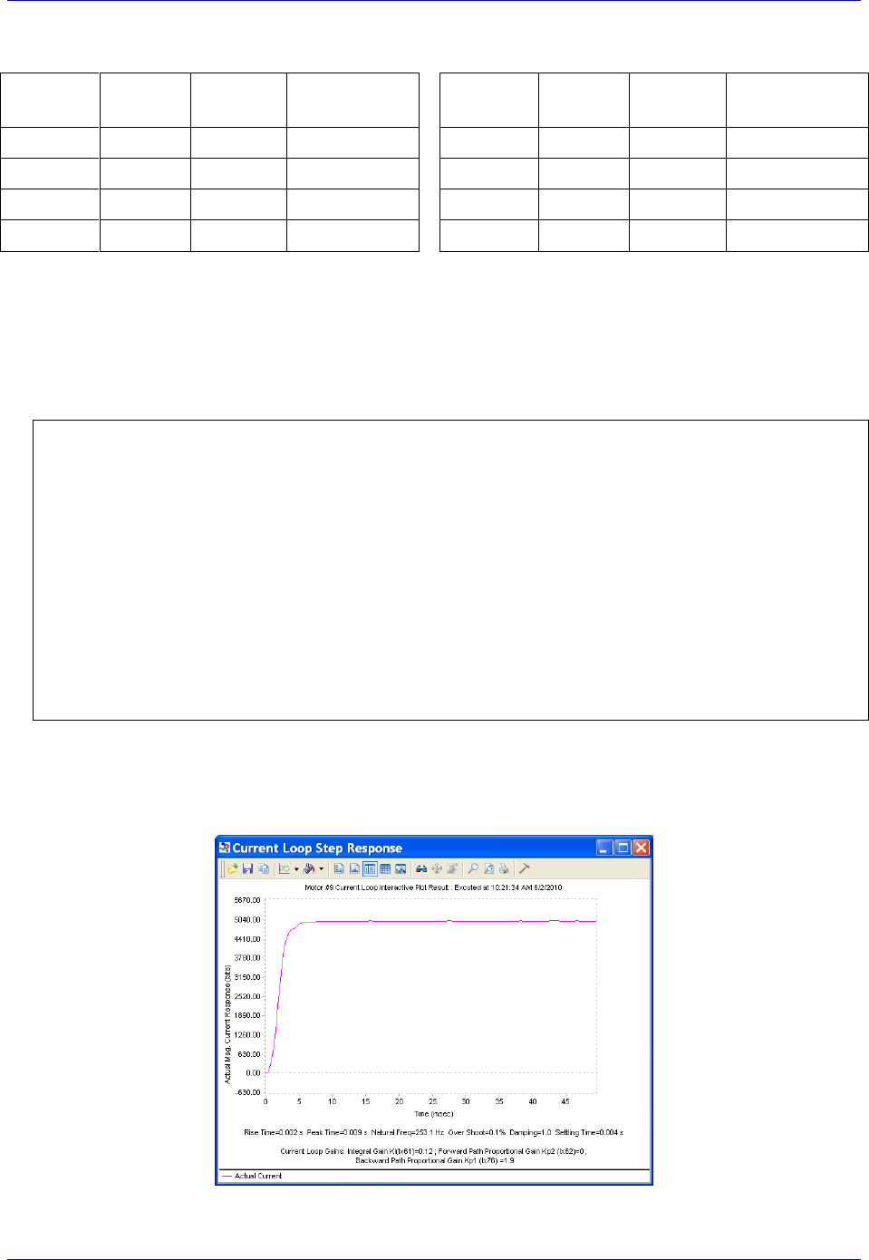
Geo Brick LV User Manual
MACRO Connectivity 233
The current loop feedback address Ixx82 should be set per the following table:
MACRO
motor
Motor #
Ixx82
Register
MACRO
motor
Motor #
Ixx82
Register
1st
5 or 9
$078422
Servo Node 0
5th
9 or 13
$078432
Servo Node 8
2nd
6 or 10
$078426
Servo Node 1
6th
10 or 14
$078436
Servo Node 9
3rd
7 or 11
$07842A
Servo Node 4
7th
11 or 15
$07843A
Servo Node 12
4th
8 or 12
$07842E
Servo Node 5
8th
12 or 16
$07843E
Servo Node 13
Commutation Cycle Size
Ixx70 = {Number of pair poles}
Ixx71 = {Number of counts per revolution * 32}
I2T Settings (example for motor #9):
I15=0 ; Trigonometric calculation in degrees
#define MaxPhaseFreq P8000 ; Max Phase Clock [KHz]
#define PWMClk P8001 ; PWM Clock [KHz]
#define PhaseClk P8002 ; Phase Clock [KHz]
#define ServoClk P8003 ; Servo Clock [KHz]
MaxPhaseFreq=117964.8/(2*I6800+3)
PWMClk=117964.8/(4*I6800+6)
PhaseClk=MaxPhaseFreq/(I6801+1)
ServoClk=PhaseClk/(I6802+1)
#define Mtr9ContCurrent 3 ; Continuous Current Limit [Amps] –User Input
#define Mtr9PeakCurrent 9 ; Instantaneous Current Limit [Amps] –User Input
#define MaxADC 16.3 ; See Geo MACRO electrical specifications –User Input
#define Mtr9I2TOnTime 2 ; Time allowed at peak Current [sec]
I957=INT(32767*(Mtr9ContCurrent*1.414/MaxADC)*cos(30))
I969=INT(32767*(Mtr9PeakCurrent*1.414/MaxADC)*cos(30))
I958=INT((I969*I969-I957*I957)*ServoClk*1000*Mtr9I2TOnTime/(32767*32767))
19. Current-Loop Tuning (Ixx61, Ixx62, Ixx76)
Current loop tuning is performed in the same manner as it would be for any digitally commuted
amplifier. A satisfactory current loop response (PmacTuningPro2 screen shot) would look like:
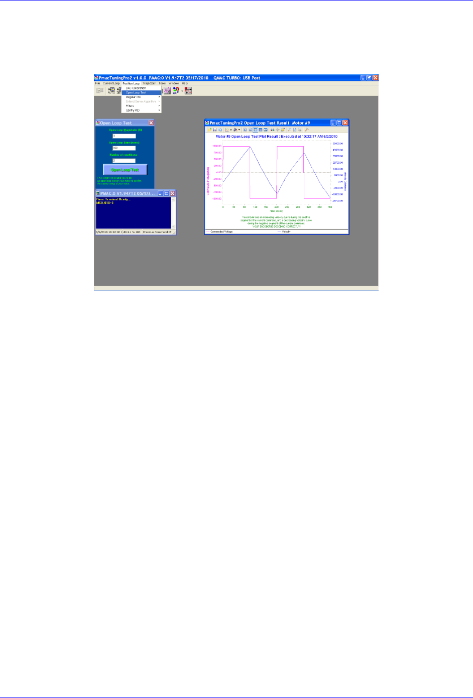
Geo Brick LV User Manual
MACRO Connectivity 234
20. Motor Phasing, Open-Loop Test
Motor phasing is performed in the same manner as it would be for any digitally commutated motor.
The following is a satisfactory open loop test:
An erratic or inverted saw tooth response is typically (with quadrature, or sinusoidal encoders) an
indication of reversed encoder direction –with respect to the output command- The encoder decode
parameter MS{node},I910 can then be changed from 7 to 3 or vice versa. Phasing has to be
performed again after this parameter has been changed.
21. Tuning the Position-Loop
Tuning the position loop PID gains can be carried on in the traditional manner - see motor setup
section in this manual- there are no special instructions for tuning MACRO motors.

Geo Brick LV User Manual
MACRO Connectivity 235
Brick – Brick MACRO I/O Data Transfer
This section describes the handling of inputs and outputs data transfer over the MACRO ring. That is
transferring I/O data from the Brick slave to the Brick master.
A Geo Brick LV, used as a MACRO slave, can be populated with up to:
32 digital inputs / 16 digital outputs (connectors J6, J7)
4 x 12-bit filtered PWM DAC outputs (connectors X9, X10, X11, X 12)
4 x 16-bit analog inputs (connectors X9, X10, X11, X 12)
8 x 12-bit analog inputs (connector J9)
There is a variety of ways to transfer I/O data over MACRO:
Using I/O nodes.
This method consists of assembling the data in a PLC code at the slave side, and conveying it
over to MACRO I/O nodes. These I/O nodes are then extracted in a PLC code on the master side
and placed into open memory registers. This technique is suitable for digital inputs and outputs.
Using servo nodes
This method is primarily used for the X9-X12 analog inputs and outputs which, in some
applications, may require being processed at servo or phase rate (e.g. servo feedback, cascaded
loop or output to a spindle drive). This is the fastest transfer method possible. Note that in this
mode, axes 5-8 on the slave cannot be configured to drive motors. The corresponding servo nodes
will be occupied.
Using MACRO Auxiliary MX reads and writes in a background PLC
This method is ideal for transferring a large amount of data without much coding and complexity.
It is suitable for monitoring and toggling inputs and outputs. But it is not deterministic (relies on
background PLCs, and phase cycle delays with MX commands) or as fast as other methods.
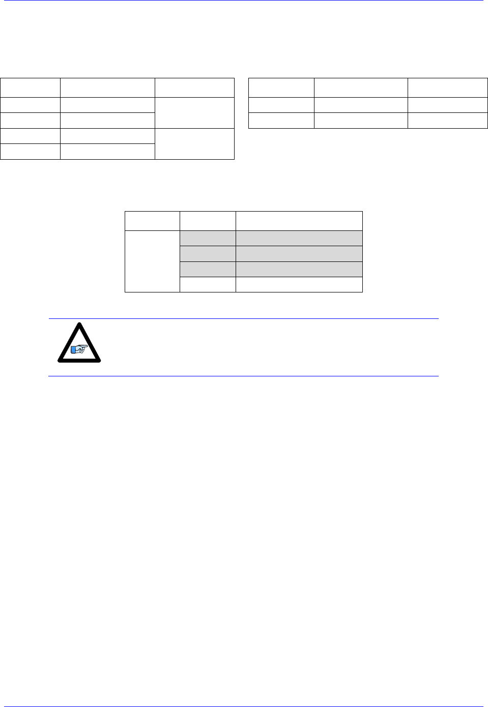
Geo Brick LV User Manual
MACRO Connectivity 236
Transferring the Digital (Discrete) Input and Outputs
A Geo Brick LV can be populated with up to 32 digital inputs and 16 digital outputs (connectors J6 and
J7) for a total of 48 I/O points (bits) mapped as follows:
Inputs
Address
Connector
Outputs
Address
Connector
1st byte
Y:$78800,0,8
J6
1st byte
Y:$78802,0,8
J6
2nd byte
Y:$78801,0,8
2nd byte
Y:$78805,0,8
J7
3rd Byte
Y:$78803,0,8
J7
4th Byte
Y:$78804,0,8
For the digital inputs and outputs, we will use the I/O node data transfer method. MACRO I/O node 2 will
be used to carry all 48 points of data:
I/O Node
Address
Register-Description
2
X:$78420
24-bit register
X:$78421
1st 16-bit register (Upper)
X:$78422
2nd16-bit register (Upper)
X:$78423
3rd 16-bit register (Upper)
Note
Some Geo Brick LVs may not be fully populated with all the
inputs/outputs bytes shown above. The non-existent bytes can be
simply deleted from the example codes below.
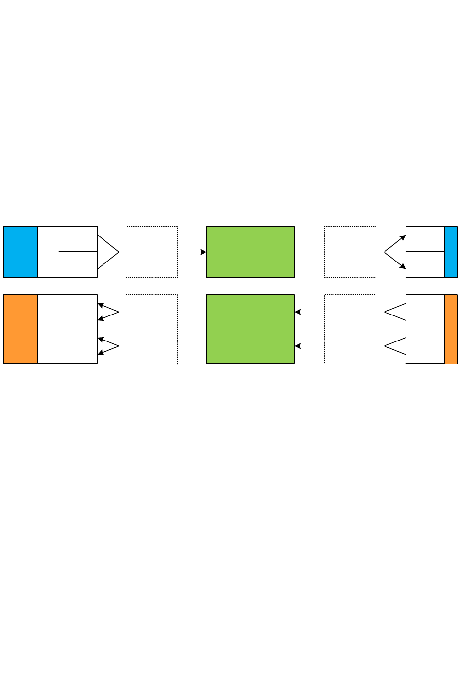
Geo Brick LV User Manual
MACRO Connectivity 237
The proposed transfer mechanism establishes the reading of inputs and writing to outputs through bitwise
assignments (single-bit definitions) from the master side.
Outputs: At the master side, the user would write the desired outputs’ state (using the bitwise definitions)
to pre-defined open memory registers which are copied, using a PLC code, into the 24-bit register of
MACRO I/O node 2. At the Slave side, this MACRO I/O node register is copied, using a PLC code, into
the local outputs’ registers which will reflect the user’s outputs’ desired state.
Inputs: At the slave side, the machine’s inputs’ state is copied into first 2 x 16-bit registers of MACRO
I/O node 2. At the master side, these MACRO I/O node registers are copied, using a PLC code, into pre-
defined open memory registers (bitwise definitions) where the user can monitor the machine’s inputs’
state.
The following diagram summarizes the abovementioned transfer technique:
MACRO I/O Node 2
24-bit register
1st 16-bit register
(upper 16 bits)
2nd 16-bit register
(upper 16 bits)
Brick SlaveBrick Master
1st Byte
2nd Byte
OUTPUTS
User Write
1st Byte
2nd Byte
3rd Byte
INPUTS
User Read
4th Byte
1st Byte
2nd Byte
3rd Byte
4th Byte
Master
PLC Operations
Slave
PLC Operations
Outputs Inputs
Open
Memory
Open Memory
Copy
Outputs to
IO node
Write
Inputs to
Master
Write
outputs to
Slave
Copy
Inputs to
IO node
1st Byte
2nd Byte

Geo Brick LV User Manual
MACRO Connectivity 238
Slave Digital I/Os Transfer Example
I6841=I6841|$000004 ; Make sure that I/O node 2 is active
// Digital Outputs
#define OutByte1 M7000 ; 1st Byte of Outputs J6
#define OutByte2 M7001 ; 2nd Byte of Outputs J7
OutByte1->Y:$078802,0,8,U
OutByte2->Y:$078805,0,8,U
// Digital Inputs
#define InByte1 M7003 ; 1st Byte of Inputs
#define InByte2 M7004 ; 2nd Byte of Inputs
#define InByte3 M7005 ; 3rd Byte of Inputs
#define InByte4 M7006 ; 4th Byte of Inputs
InByte1->Y:$078800,0,8,U
InByte2->Y:$078801,0,8,U
InByte3->Y:$078803,0,8,U
InByte4->Y:$078804,0,8,U
// Digital Inputs/Outputs Latch Registers
M7009..7013->*
M7009..7013=0
#define LatchOut M7009
#define LatchIn1 M7010
#define LatchIn2 M7011
#define LatchIn3 M7012
#define LatchIn4 M7013
// MACRO I/O Node Registers
#define N2Twenty4 M7016 ; 24-bit register, node 2
#define N2First16 M7017 ; 1st 16-bit register, node 2
#define N2Second16 M7018 ; 2nd 16-bit register, node 2
N2Twenty4->X:$78420,0,24,U
N2First16->X:$78421,8,16,U
N2Second16->X:$78422,8,16,U
// Digital I/O Data Transfer PLC
Open plc 1 clear
If (LatchOut!=N2Twenty4) ; Change in state?
LatchOut=N2Twenty4 ; Latch data
OutByte1= LatchOut&$0000FF ; Update Outputs 1-8, J6
OutByte2=(LatchOut&$00FF00)/256 ; Update Outputs 9-15, J7
EndIf
If (LatchIn1!=InByte1 Or LatchIn2!=InByte2 Or LatchIn3!=InByte3 Or LatchIn4!=InByte4)
LatchIn1=InByte1 ; Latch data
LatchIn2=InByte2 ; Latch data
LatchIn3=InByte3 ; Latch data
LatchIn4=InByte4 ; Latch data
N2First16= LatchIn1+LatchIn2*256 ; Assemble Input bytes 1-2 in 1st 16-bit register node 2
N2Second16=LatchIn3+LatchIn4*256 ; Assemble Input bytes 3-4 in 2nd 16-bit register node 2
EndIf
Close

Geo Brick LV User Manual
MACRO Connectivity 239
Master Digital I/Os Transfer Example
I6841=I6841|$000004 ; Make sure that I/O node 2 is active
// Open Memory Registers
#define OpenReg16Y M7000 ; Open memory register 16, Y-word
#define OpenReg16X M7001 ; Open memory register 16, X-word
#define OpenReg15Y M7002 ; Open memory register 15, Y-word
OpenReg16Y->Y:$10FF,0,24,U ; Holding 24 digital Outputs
OpenReg16X->X:$10FF,8,16,U ; Holding 1st 16-bit digital Inputs
OpenReg15Y->Y:$10FE,8,16,U ; Holding 2nd 16-bit digital Inputs
M7000..7002=0 ; Initialization
// Latching Words
M7004..7006->* ; Self referenced
M7004..7006=0 ; Initialization
#define LatchOut M7004 ; Digital Outputs Latch
#define LatchIn1 M7005 ; Digital Inputs Latch 1
#define LatchIn2 M7006 ; Digital Inputs Latch 2
// MACRO I/O Node Registers
#define N2Twenty4 M7008 ; Node 2, 24-bit register
#define N2First16 M7009 ; Node 2, 1st 16-bit register
#define N2Second16 M7010 ; Node 2, 2nd 16-bit register
N2Twenty4->X:$78420,0,24,U
N2First16->X:$78421,8,16,U
N2Second16->X:$78422,8,16,U
// Digital I/O Data Transfer PLC
Open plc 1 clear
If (LatchOut!=OpenReg16Y) ; Output Open Register Changed?
LatchOut=OpenReg16Y ; Latch data
N2Twenty4=LatchOut ; Update Output Word
EndIf
If (LatchIn1!=N2First16) ; Input Node word changed?
LatchIn1=N2First16 ; Latch data
OpenReg16X=LatchIn1 ; Update Input Open Register word
EndIf
If (LatchIn2!=N2Second16) ; Input Node word changed?
LatchIn2=N2Second16 ; Latch data
OpenReg15Y=LatchIn2 ; Update Input Open Register word
EndIf
Close

Geo Brick LV User Manual
MACRO Connectivity 240
Bitwise Assignments (downloaded onto the master)
// J6 Outputs
#define Output1 M7101
#define Output2 M7102
#define Output3 M7103
#define Output4 M7104
#define Output5 M7105
#define Output6 M7106
#define Output7 M7107
#define Output8 M7108
Output1->Y:$10FF,0,1 ; Output 1
Output2->Y:$10FF,1,1 ; Output 2
Output3->Y:$10FF,2,1 ; Output 3
Output4->Y:$10FF,3,1 ; Output 4
Output5->Y:$10FF,4,1 ; Output 5
Output6->Y:$10FF,5,1 ; Output 6
Output7->Y:$10FF,6,1 ; Output 7
Output8->Y:$10FF,7,1 ; Output 8
// J6 Inputs
#define Input1 M7131
#define Input2 M7132
#define Input3 M7133
#define Input4 M7134
#define Input5 M7135
#define Input6 M7136
#define Input7 M7137
#define Input8 M7138
#define Input9 M7139
#define Input10 M7140
#define Input11 M7141
#define Input12 M7142
#define Input13 M7143
#define Input14 M7144
#define Input15 M7145
#define Input16 M7146
Input1->X:$10FF,8,1 ; Input 1
Input2->X:$10FF,9,1 ; Input 2
Input3->X:$10FF,10,1 ; Input 3
Input4->X:$10FF,11,1 ; Input 4
Input5->X:$10FF,12,1 ; Input 5
Input6->X:$10FF,13,1 ; Input 6
Input7->X:$10FF,14,1 ; Input 7
Input8->X:$10FF,15,1 ; Input 8
Input9->X:$10FF,16,1 ; Input 9
Input10->X:$10FF,17,1 ; Input 10
Input11->X:$10FF,18,1 ; Input 11
Input12->X:$10FF,19,1 ; Input 12
Input13->X:$10FF,20,1 ; Input 13
Input14->X:$10FF,21,1 ; Input 14
Input15->X:$10FF,22,1 ; Input 15
Input16->X:$10FF,23,1 ; Input 16
// J7 Outputs
#define Output9 M7109
#define Output10 M7110
#define Output11 M7111
#define Output12 M7112
#define Output13 M7113
#define Output14 M7114
#define Output15 M7115
#define Output16 M7116
Output9 ->Y:$10FF,8,1 ; Output 9
Output10->Y:$10FF,9,1 ; Output 10
Output11->Y:$10FF,10,1 ; Output 11
Output12->Y:$10FF,11,1 ; Output 12
Output13->Y:$10FF,12,1 ; Output 13
Output14->Y:$10FF,13,1 ; Output 14
Output15->Y:$10FF,14,1 ; Output 15
Output16->Y:$10FF,15,1 ; Output 16
// J7 Inputs
#define Input17 M7147
#define Input18 M7148
#define Input19 M7149
#define Input20 M7150
#define Input21 M7151
#define Input22 M7152
#define Input23 M7153
#define Input24 M7154
#define Input25 M7155
#define Input26 M7156
#define Input27 M7157
#define Input28 M7158
#define Input29 M7159
#define Input30 M7160
#define Input31 M7161
#define Input32 M7162
Input17->Y:$10FE,8,1 ; Input 17
Input18->Y:$10FE,9,1 ; Input 18
Input19->Y:$10FE,10,1 ; Input 19
Input20->Y:$10FE,11,1 ; Input 20
Input21->Y:$10FE,12,1 ; Input 21
Input22->Y:$10FE,13,1 ; Input 22
Input23->Y:$10FE,14,1 ; Input 23
Input24->Y:$10FE,15,1 ; Input 24
Input25->Y:$10FE,16,1 ; Input 25
Input26->Y:$10FE,17,1 ; Input 26
Input27->Y:$10FE,18,1 ; Input 27
Input28->Y:$10FE,19,1 ; Input 28
Input29->Y:$10FE,20,1 ; Input 29
Input30->Y:$10FE,21,1 ; Input 30
Input31->Y:$10FE,22,1 ; Input 31
Input32->Y:$10FE,23,1 ; Input 32
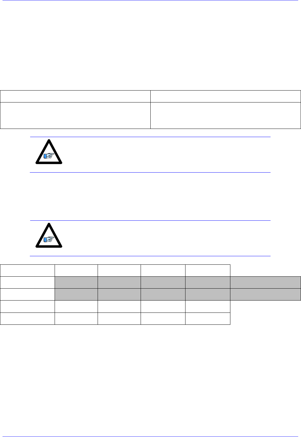
Geo Brick LV User Manual
MACRO Connectivity 241
Transferring The X9-X12 Analog Inputs/Outputs
A Geo Brick LV MACRO slave can be populated with up to:
4 x 16-bit analog inputs (connectors X9 through X12)
4 x 12-bit filtered PWM ±10V analog outputs (connectors X9 through X12)
These inputs and outputs are typically mapped using suggested or pre-defined M-Variables at the
following addresses:
Analog Inputs, connectors X9-X12
Analog Outputs, connectors X9-X12
M505->Y:$078105,8,16,S ; ADC Input 1
M605->Y:$07810D,8,16,S ; ADC Input 2
M705->Y:$078115,8,16,S ; ADC Input 3
M805->Y:$07811D,8,16,S ; ADC Input 4
M502->Y:$078102,8,16,S ; Analog DAC 1
M602->Y:$07810A,8,16,S ; Analog DAC 2
M702->Y:$078112,8,16,S ; Analog DAC 3
M802->Y:$07811A,8,16,S ; Analog DAC 4
Note
Some Geo Brick LVs may not be fully populated with all the analog
inputs and outputs. The non-existent ones can be simply deleted from
the example codes.
We will use the Servo Node method to transfer the X9-X12 analog data. Servo nodes 8, 9, 12, and 13 will
carry the analog output data in the 24-bit register, and the analog input data in the first 16-bit register.
The auxiliary mode Ixx44 is set to PWM mode to allow automatic transferring of ADCs.
Note
This method cannot be used if servo nodes 8, 9, 12, and 13 are already
in use, or if motors 5-8 on the slave are configured.
Servo Node
8
9
12
13
24-bit
Y:$78430
Y:$78434
Y:$78438
Y:$7843C
DAC Output Data
16-bit
Y:$78431
Y:$78435
Y:$78439
Y:$7843D
ADC Input Data
16-bit
Y:$78432
Y:$78436
Y:$7843A
Y:$7843E
16-bit
Y:$78433
Y:$78437
Y:$7843B
Y:$7843F

Geo Brick LV User Manual
MACRO Connectivity 242
Slave Settings
I6841=I6841|$3300 ; Enable servo nodes 8,9,12,13
I544=$078433 ; MacroIC0 Node 8 Command Address. PWM Mode For ADC Transfer
I644=$078437 ; MacroIC0 Node 9 Command Address. PWM Mode For ADC Transfer
I744=$07843B ; MacroIC0 Node12 Command Address. PWM Mode For ADC Transfer
I844=$07843F ; MacroIC0 Node13 Command Address. PWM Mode For ADC Transfer
I500,4,100=0 ; De-activate channels to allow direct DAC writes
Master Settings
I6841=I6841|$3300 ; Enable servo nodes 8,9,12,13
M1302->Y:$78430,8,16,S ; Analog DAC 1
M1402->Y:$78434,8,16,S ; Analog DAC 2
M1502->Y:$78438,8,16,S ; Analog DAC 3
M1602->Y:$7843C,8,16,S ; Analog DAC 4
M1305->Y:$78431,8,16,S ; Analog ADC 1
M1405->Y:$78435,8,16,S ; Analog ADC 1
M1505->Y:$78439,8,16,S ; Analog ADC 1
M1605->Y:$7843D,8,16,S ; Analog ADC 1
At the master side:
The analog DAC (filtered PWM) outputs can now be written to using Mxx02 variables.
The analog ADC inputs can now be read using Mxx05 variables.
Note
This setup example assumes that the DAC (filtered PWM) outputs at
the slave side have been set up properly. See X9-X12 connector setup
section.

Geo Brick LV User Manual
MACRO Connectivity 243
Transferring The J9 Analog Inputs
A Geo Brick LV MACRO slave with option 12 offers 8 x 12-bit analog inputs on connector J9.
These inputs and outputs are typically mapped using suggested or pre-defined M-Variables at the
following addresses:
Analog Inputs, connector J9
M6991->Y:$003400,12,12,S ; ADC1 Bipolar
M6992->Y:$003402,12,12,S ; ADC2 Bipolar
M6993->Y:$003404,12,12,S ; ADC3 Bipolar
M6994->Y:$003406,12,12,S ; ADC4 Bipolar
M6995->Y:$003408,12,12,S ; ADC5 Bipolar
M6996->Y:$00340A,12,12,S ; ADC6 Bipolar
M6997->Y:$00340C,12,12,S ; ADC7 Bipolar
M6998->Y:$00340E,12,12,S ; ADC8 Bipolar
M6991->Y:$003400,12,12,U ; ADC1 Unipolar
M6992->Y:$003402,12,12,U ; ADC2 Unipolar
M6993->Y:$003404,12,12,U ; ADC3 Unipolar
M6994->Y:$003406,12,12,U ; ADC4 Unipolar
M6995->Y:$003408,12,12,U ; ADC5 Unipolar
M6996->Y:$00340A,12,12,U ; ADC6 Unipolar
M6997->Y:$00340C,12,12,U ; ADC7 Unipolar
M6998->Y:$00340E,12,12,U ; ADC8 Unipolar
We will use the MACRO auxiliary MX read commands to transfer the J9 analog inputs. This is done in a
background PLC which copies M6991-M6998 from the slave into eight consecutive self-referenced
Mxx05 variables at the master.
Master Settings
M1705,8,100->*
Open PLC 1 Clear
// Analog Inputs (J9)
MXR0,M6991,M1705 ; J9 Analog Input 1
MXR0,M6992,M1805 ; J9 Analog Input 2
MXR0,M6993,M1905 ; J9 Analog Input 3
MXR0,M6994,M2005 ; J9 Analog Input 4
MXR0,M6995,M2105 ; J9 Analog Input 5
MXR0,M6996,M2205 ; J9 Analog Input 6
MXR0,M6997,M2305 ; J9 Analog Input 7
MXR0,M6998,M2405 ; J9 Analog Input 8
I5111=1*8388608/I10 while(I5111>0) Endw ; 1 msec delay
close
At the slave side, the J9 analog ADC inputs can now be read using these Mxx05 variables.
Note
This setup example assumes that the J9 ADC inputs have been set up
properly at the slave side. See J9 connector setup section.
Geo Brick LV User Manual
MACRO Connectivity 244
MACRO Limits, Flags and Homing
Limits and Flags
MACRO Motors’ Limits and Flags are automatically copied by the Firmware. They can be accessed from
the Ring Controller using the MACRO Suggested M-Variables.
Note
In a Brick – Brick MACRO configuration, the over-travel limits
should be disabled on the slave side (Ixx24=Ixx24|$20001). They are
only enabled on the master side.
Homing from Master
If it is desired to home from the master (centralized control) then the position capture should be set to
software capture with Ixx97 = 1.
In this mode, the slave’s Servo IC m Channel n capture control (I7mn2) and flag select control (I7mn3)
have to be configured. This can be achieved from the master side using MX commands:
In a two 8-axis Brick Macro ring, configure Motor #9 to home to User Flag High. Motor #9 corresponds
to Motor#1 on the Slave Station or Servo IC 0 channel 1:
MX0, I7012= 2 ; Servo IC 0 Channel 1Capture Control (flag high)
MX0, I7013= 3 ; Servo IC 0 Channel 1Capture Flag Select Control (user flag)
In a two 8-axis Brick Macro ring, configure Motor #14 to home to User Flag High. Motor #14
corresponds to Motor#6 on the Slave Station or Servo IC 1 channel 2:
MX0, I7122= 2 ; Servo IC 1 Channel 2 Capture Control (flag high)
MX0, I7123= 3 ; Servo IC 1 Channel 2 Capture Flag Select Control (user flag)
Note
In this mode, issuing a #nHome from the Master will initiate the home
move search for the corresponding motor #n
Homing from Slave
If the full accuracy of the position capture is desired, then the MACRO motor’s homing routine can be
pre-programmed on the slave in a PLC routine and triggered upon demand with a handshaking flag using
MX commands.
Note
Software capture with Ixx97 introduces up to 1 background cycle
delay which limits the accuracy of the capture.
In this mode, the slave’s Servo IC m Channel n capture control (I7mn2) and flag select control (I7mn3)
have to be configured.

Geo Brick LV User Manual
MACRO Connectivity 245
MACRO Suggested M-Variables
// Macro IC 0 Node 0 Flag Registers
M150->X:$003440,0,24 ; Macro IC 0 Node 0 flag status
M151->Y:$003440,0,24 ; Macro IC 0 Node 0 flag command
M153->X:$003440,20,4 ; Macro IC 0 Node 0 TUVW flags
M154->Y:$003440,14,1 ; Macro IC 0 Node 0 amplifier enable
M155->X:$003440,15,1 ; Macro IC 0 Node 0 node/amplifier
M156->X:$003440,16,1 ; Macro IC 0 Node 0 home flag
M157->X:$003440,17,1 ; Macro IC 0 Node 0 positive limit
M158->X:$003440,18,1 ; Macro IC 0 Node 0 negative limit
M159->X:$003440,19,1 ; Macro IC 0 Node 0 user flag
// Macro IC 0 Node 1 Flag Registers
M250->X:$003441,0,24 ; Macro IC 0 Node 1 flag status register
M251->Y:$003441,0,24 ; Macro IC 0 Node 1 flag command register
M253->X:$003441,20,4 ; Macro IC 0 Node 1 TUVW flags
M254->Y:$003441,14,1 ; Macro IC 0 Node 1 amplifier enable flag
M255->X:$003441,15,1 ; Macro IC 0 Node 1 node/amplifier fault flag
M256->X:$003441,16,1 ; Macro IC 0 Node 1 home flag
M257->X:$003441,17,1 ; Macro IC 0 Node 1 positive limit flag
M258->X:$003441,18,1 ; Macro IC 0 Node 1 negative limit flag
M259->X:$003441,19,1 ; Macro IC 0 Node 1 user flag
// Macro IC 0 Node 4 Flag Registers
M350->X:$003444,0,24 ; Macro IC 0 Node 4 flag status register
M351->Y:$003444,0,24 ; Macro IC 0 Node 4 flag command register
M353->X:$003444,20,4 ; Macro IC 0 Node 4 TUVW flags
M354->Y:$003444,14,1 ; Macro IC 0 Node 4 amplifier enable flag
M355->X:$003444,15,1 ; Macro IC 0 Node 4 node/amplifier fault flag
M356->X:$003444,16,1 ; Macro IC 0 Node 4 home flag
M357->X:$003444,17,1 ; Macro IC 0 Node 4 positive limit flag
M358->X:$003444,18,1 ; Macro IC 0 Node 4 negative limit flag
M359->X:$003444,19,1 ; Macro IC 0 Node 4 user flag
// Macro IC 0 Node 5 Flag Registers
M450->X:$003445,0,24 ; Macro IC 0 Node 5 flag status register
M451->Y:$003445,0,24 ; Macro IC 0 Node 5 flag command register
M453->X:$003445,20,4 ; Macro IC 0 Node 5 TUVW flags
M454->Y:$003445,14,1 ; Macro IC 0 Node 5 amplifier enable flag
M455->X:$003445,15,1 ; Macro IC 0 Node 5 node/amplifier fault flag
M456->X:$003445,16,1 ; Macro IC 0 Node 5 home flag
M457->X:$003445,17,1 ; Macro IC 0 Node 5 positive limit flag
M458->X:$003445,18,1 ; Macro IC 0 Node 5 negative limit flag
M459->X:$003445,19,1 ; Macro IC 0 Node 5 user flag
// Macro IC 0 Node 8 Flag Registers
M550->X:$003448,0,24 ; Macro IC 0 Node 8 flag status register
M551->Y:$003448,0,24 ; Macro IC 0 Node 8 flag command register
M553->X:$003448,20,4 ; Macro IC 0 Node 8 TUVW flags
M554->Y:$003448,14,1 ; Macro IC 0 Node 8 amplifier enable flag
M555->X:$003448,15,1 ; Macro IC 0 Node 8 node/amplifier fault flag
M556->X:$003448,16,1 ; Macro IC 0 Node 8 home flag
M557->X:$003448,17,1 ; Macro IC 0 Node 8 positive limit flag
M558->X:$003448,18,1 ; Macro IC 0 Node 8 negative limit flag
M559->X:$003448,19,1 ; Macro IC 0 Node 8 user flag

Geo Brick LV User Manual
MACRO Connectivity 246
// Macro IC 0 Node 9 Flag Registers
M650->X:$003449,0,24 ; Macro IC 0 Node 9 flag status register
M651->Y:$003449,0,24 ; Macro IC 0 Node 9 flag command register
M653->X:$003449,20,4 ; Macro IC 0 Node 9 TUVW flags
M654->Y:$003449,14,1 ; Macro IC 0 Node 9 amplifier enable flag
M655->X:$003449,15,1 ; Macro IC 0 Node 9 node/amplifier fault flag
M656->X:$003449,16,1 ; Macro IC 0 Node 9 home flag
M657->X:$003449,17,1 ; Macro IC 0 Node 9 positive limit flag
M658->X:$003449,18,1 ; Macro IC 0 Node 9 negative limit flag
M659->X:$003449,19,1 ; Macro IC 0 Node 9 user flag
// Macro IC 0 Node 12 Flag Registers
M750->X:$00344C,0,24 ; Macro IC 0 Node 12 flag status register
M751->Y:$00344C,0,24 ; Macro IC 0 Node 12 flag command register
M753->X:$00344C,20,4 ; Macro IC 0 Node 12 TUVW flags
M754->Y:$00344C,14,1 ; Macro IC 0 Node 12 amplifier enable flag
M755->X:$00344C,15,1 ; Macro IC 0 Node 12 node/amplifier fault flag
M756->X:$00344C,16,1 ; Macro IC 0 Node 12 home flag
M757->X:$00344C,17,1 ; Macro IC 0 Node 12 positive limit flag
M758->X:$00344C,18,1 ; Macro IC 0 Node 12 negative limit flag
M759->X:$00344C,19,1 ; Macro IC 0 Node 12 user flag
// Macro IC 0 Node 13 Flag Registers
M850->X:$00344D,0,24 ; Macro IC 0 Node 13 flag status register
M851->Y:$00344D,0,24 ; Macro IC 0 Node 13 flag command register
M853->X:$00344D,20,4 ; Macro IC 0 Node 13 TUVW flags
M854->Y:$00344D,14,1 ; Macro IC 0 Node 13 amplifier enable flag
M855->X:$00344D,15,1 ; Macro IC 0 Node 13 node/amplifier fault flag
M856->X:$00344D,16,1 ; Macro IC 0 Node 13 home flag
M857->X:$00344D,17,1 ; Macro IC 0 Node 13 positive limit flag
M858->X:$00344D,18,1 ; Macro IC 0 Node 13 negative limit flag
M859->X:$00344D,19,1 ; Macro IC 0 Node 13 user flag

Geo Brick LV User Manual
MACRO Connectivity 247
Absolute Position Reporting Over MACRO
!
Caution
Writing to the motor actual position (Mxx62) should only be done
when the motor is killed.
The Geo Brick LV supports a wide variety of absolute encoders. When used as a MACRO slave, the
simplest way to report the absolute position to the master (ring controller) is to use the MACRO auxiliary
communication (read/write).
Example: Retrieving motor #9’s absolute position from motor #1 on a slave Brick yields the online
command (using suggested M-Variables Mxx62): MXR0,M162,M962 which could be ultimately
inserted in the initialization PLC.

Geo Brick LV User Manual
MACRO Connectivity 248
MACRO Configuration Power-Up Sequence
Typically, in a MACRO master-slave configuration, it is desirable to power up the slave first and then the
master. This ensures proper establishment of MACRO communication. If this is not desirable or possible,
the following procedure should ensure that MACRO communication is properly initiated. But either way,
clearing MACRO ring faults is always recommended on power up in the following order:
1. Power up slave (logic power).
2. Issue a local clear fault command – in an initialization PLC.
CMD"CLRF"
3. Power-up master (logic power).
4. Insert a 1 second delay in an initialization PLC
This allows the slave to clear its own fault locally first.
5. Issue a local clear fault command – in the initialization PLC.
CMD"CLRF"
6. Insert a 250 millisecond delay
7. Broadcast a MACRO clear fault command – in the same PLC
CMD"MSCLRF15"
8. Insert a 250 millisecond delay
!
Caution
Make sure that the PLC logic is latched properly (scan initialization
PLCs once), sending CLRF and MSCLRF commands repeatedly locks
up MACRO communication.
Geo Brick LV User Manual
Troubleshooting 249
TROUBLESHOOTING
Serial Number and Board Revisions Identification
The following Serial Number Page provides the users with information about their Geo Brick LV
without having to open the enclosure by simply inserting the serial number and pressing the enter key:
This page will display:
Description and part number of the top assembly (Brick Drive LV)
Part numbers and revision numbers of the sub-assembly boards
Top assembly original ship date
Top assembly last ship date (e.g. if it has ever been back for repair)
Note
This page is strictly for identification purposes. Some information
may not be meaningful to the user and pertains to Delta Tau’s internal
use only.
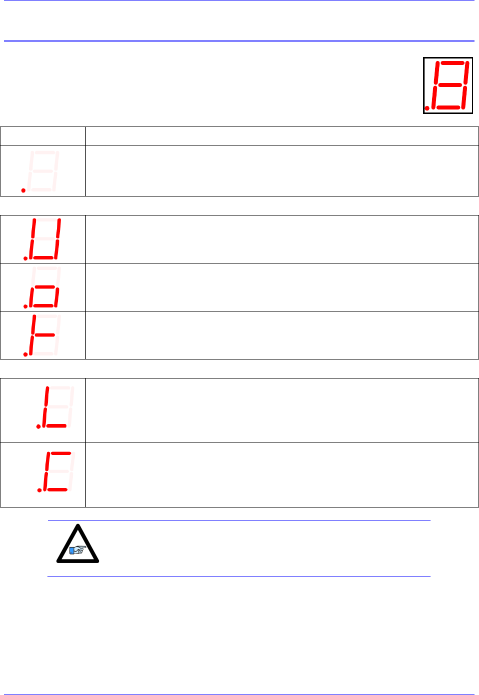
Geo Brick LV User Manual
Troubleshooting 250
D1: Error Codes
The Geo Brick LV utilizes a scrolling single-digit 7-segment display to exhibit amplifier
faults. In normal operation mode (logic and DC bus power applied), the Geo Brick LV will
display a solid dot indicating that the software and hardware are running normally.
DISPLAY
DESCRIPTION
Solid Dot:
Normal mode operation. No fault (s)
GLOBAL FAULTS
Under Voltage:
Indicates that the bus voltage is not present or less than 12Volts
Over Voltage:
Indicates that the bus voltage has exceeded 85Volts
Over Temperature:
Indicates that the (internal) electronics have exceeded 65°C
AXIS n FAULT (n = 1 through 8)
n
Axis n Over load:
Indicates that channel n ‘s current rating (0.75A / 3A / 15A) has been exceeded
n
Axis n Over Current:
Indicates that channel n ‘s peak current has exceeded the permissible limit (20 A)
Note
In order to reset (clear) the amplifier faults through software, the
power-on PLC (which specifies the motor types, clears error bits, and
activates the strobe word write-protect) must be enabled.
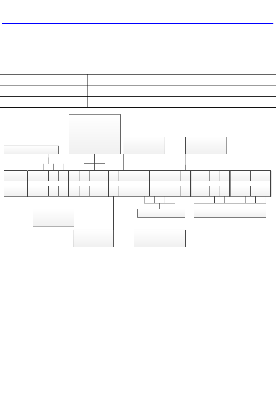
Geo Brick LV User Manual
Troubleshooting 251
Strobe Word and Axes Data Structures
The amplifier processor in the Geo Brick LV conveys data and certain status bits to the PMAC user. This
information, pertaining to a specific channel, is sent over using the ADC registers of each channel.
Strobe Word Structure
These functions are established by sending commands to the amplifier processor from the PMAC using
the ADC Strobe Word:
PMAC Variable
Description
Address
I7006
Axis 1-4 ADC Strobe Word
X:$78014
I7106
Axis 5-8 ADC Strobe Word
X:$78114
01234567891011121314151617181920212223
011111111011001000011111
Always $FE
=0 Servo
=1 Stepper
See decription
=0 I2T fault
=1 I2T Warning
=0 Protect
=1 Write
=0 No Reset
=1 Reset
=000 ($0) Axis 1
=001 ($1) Axis 2
=010 ($2) Axis 3
=011 ($3) Axis 4
=0 Save
=1 Write
Address Axis $F
Bit #
Value
About bits [12:9]:
Before 8/18/2009
These bits are used to set the I2T limit of the axis.
8/18/2009 – 10/1/2012
These bits have no significance. I2T is set automatically in the firmware.
After 10/1/2012
Bits [11:10] are command bits for displaying either firmware version or current option in ADC B.
If bits [11:10] = 11 then ADC B bits [9:6] display the amplifier firmware version.
If bits [11:10] = 00 then ADC B bits [7:6] display the axis current option.
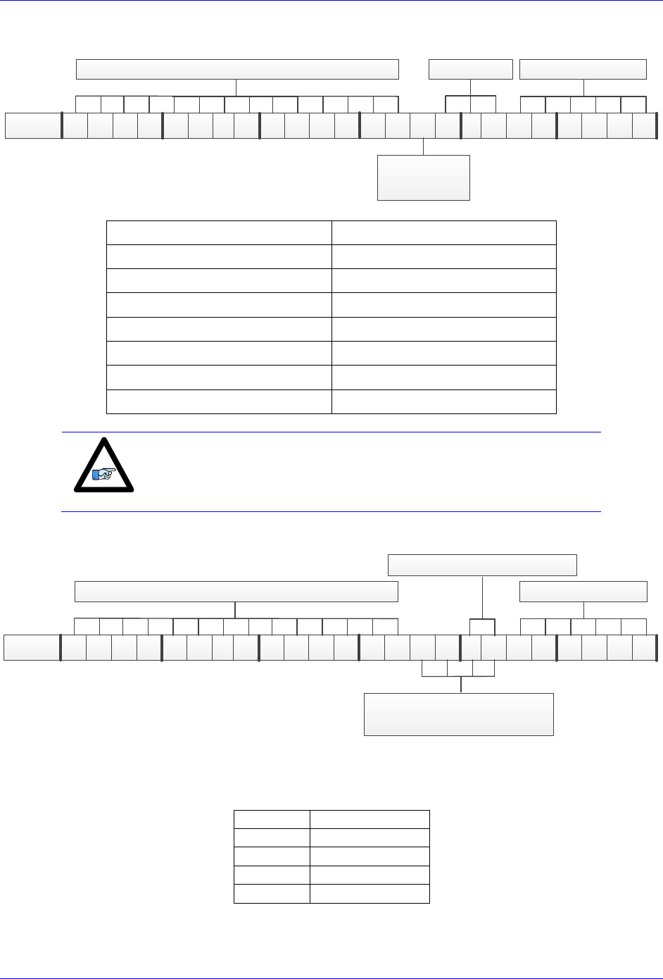
Geo Brick LV User Manual
Troubleshooting 252
ADC A Status Word
01234567891011121314151617181920212223Bit #
Status Bits Reserved
=0 Servo
=1 Stepper
ADC A Current Value
Bits [8:6] (hex)
Error Code
000 ($0)
No error, Not ready
001 ($1)
No error, Ready
010 ($2)
Bus Under-Voltage Warning
011 ($3)
Over-Temperature ( > 70°C)
100 ($4)
Over Voltage ( > 85 VDC)
101 ($5)
I2T Warning/Fault
110 ($6)
Over-Current Fault
Note
These status bits can be useful for custom-written graphic user
interface allowing the display of faults to the operator.
ADC B Status Word
01234567891011121314151617181920212223Bit #
ReservedADC B Current Value
Amplifier Firmware
Version Code
Axis Current Option
If bits [11:10] of the Strobe Word are = 11 then ADC B bits [9:6] display the amplifier firmware version.
If bits [11:10] of the Strobe Word are = 00 then ADC B bits [7:6] display the axis current option:
Bits [7:6]
Current Option
00
5A / 15A
01
1A / 3A
10
-
11
0.25A / 0.75A
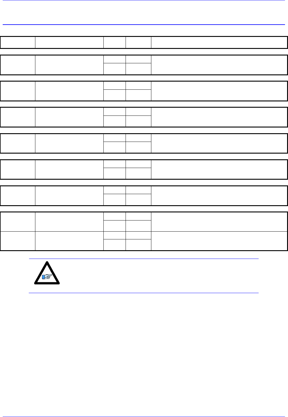
Geo Brick LV User Manual
Troubleshooting 253
LED Status
Symbol
Function(s)
State
Light
Description
RLY X9
Axis#5 Status
Brake/Relay#5 Status
On
Green
Green when Axis#5 Enabled or
Brake/Relay#5 output is true
Off
Unlit
RLY X10
Axis#6 Status
Brake/Relay#6 Status
On
Green
Green when Axis#6 Enabled or
Brake/Relay#6 output is true
Off
Unlit
RLY X11
Axis#3 Status
Brake/Relay#3 Status
On
Green
Green when Axis#3 Enabled or
Brake/Relay#3 output is true
Off
Unlit
RLY X12
Axis#4 Status
Brake/Relay#4 Status
On
Green
Green when Axis#4 Enabled or
Brake/Relay#4 output is true
Off
Unlit
+5V
+5V Logic Power
On
Green
Green indicates good +5V controller power.
Normal mode operation.
Off
Unlit
WD
Watchdog
On
Red
Red when watchdog has tripped.
Unlit is normal mode operation.
Off
Unlit
Active
Abort Status
On
Red
Red when +24V is disconnected
(ABORT is true)
Off
Unlit
Inactive
Abort Status
On
Green
Green when +24V is applied
(ABORT is not true, Normal mode operation)
Off
Unlit
Note
The abort functionality is only available with Turbo PMAC firmware
1.947 or newer, and with I35=1.
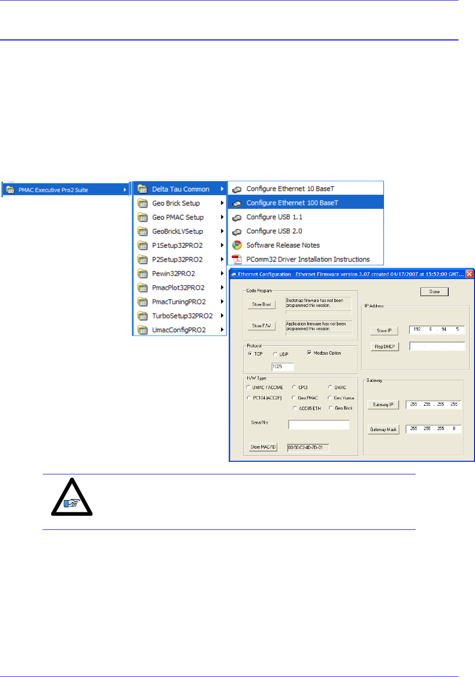
Geo Brick LV User Manual
Troubleshooting 254
Boot Switch SW (Firmware Reload) – Write-Protect Disable
This momentary button switch has two essential functions:
1. Putting the Geo Brick LV in Boostrap Mode for reloading PMAC firmware.
2. Disabling the USB/Ethernet communication write-protection for
Changing IP address, Gateway IP or MASK
Enabling ModBus
Reloading communication boot and firmware
These functions are accessible through the Configure Ethernet 100 BaseT utility found in the
Windows Start menu under PMAC Executive Pro2 Suite > Delta Tau Common > Configure
Ethernet 100 BaseT:
Note
This utility only works with USB communication.
The Pewin32Pro2 or any other software communicating to the
Brick must be closed before launching this utility.
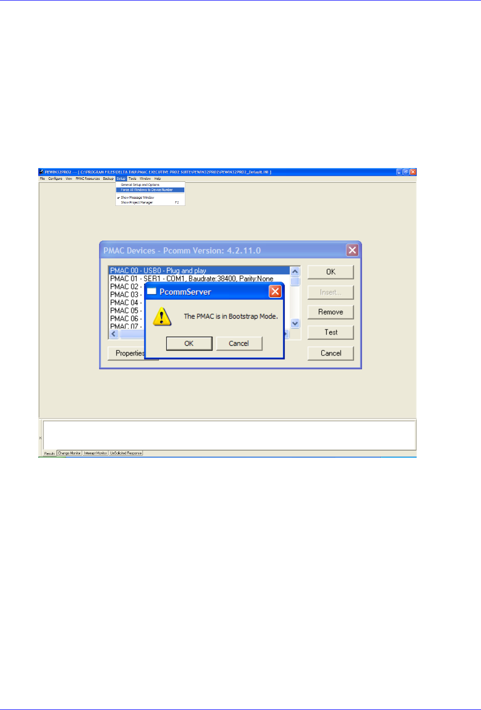
Geo Brick LV User Manual
Troubleshooting 255
Reloading PMAC firmware
The following steps ensure proper firmware reload/upgrade.
Step1: Power up the unit while holding the BOOT SW switch down.
Step2: Release the BOOT SW switch approximately 2-3 seconds after power-up.
Step3: Launch the Pewin32Pro2.
Run the PMAC Devices window under Setup > Force All Windows To Device Number.
Click Test for the corresponding communication method.
Click ok for message “The PMAC is in Boostrap Mode”
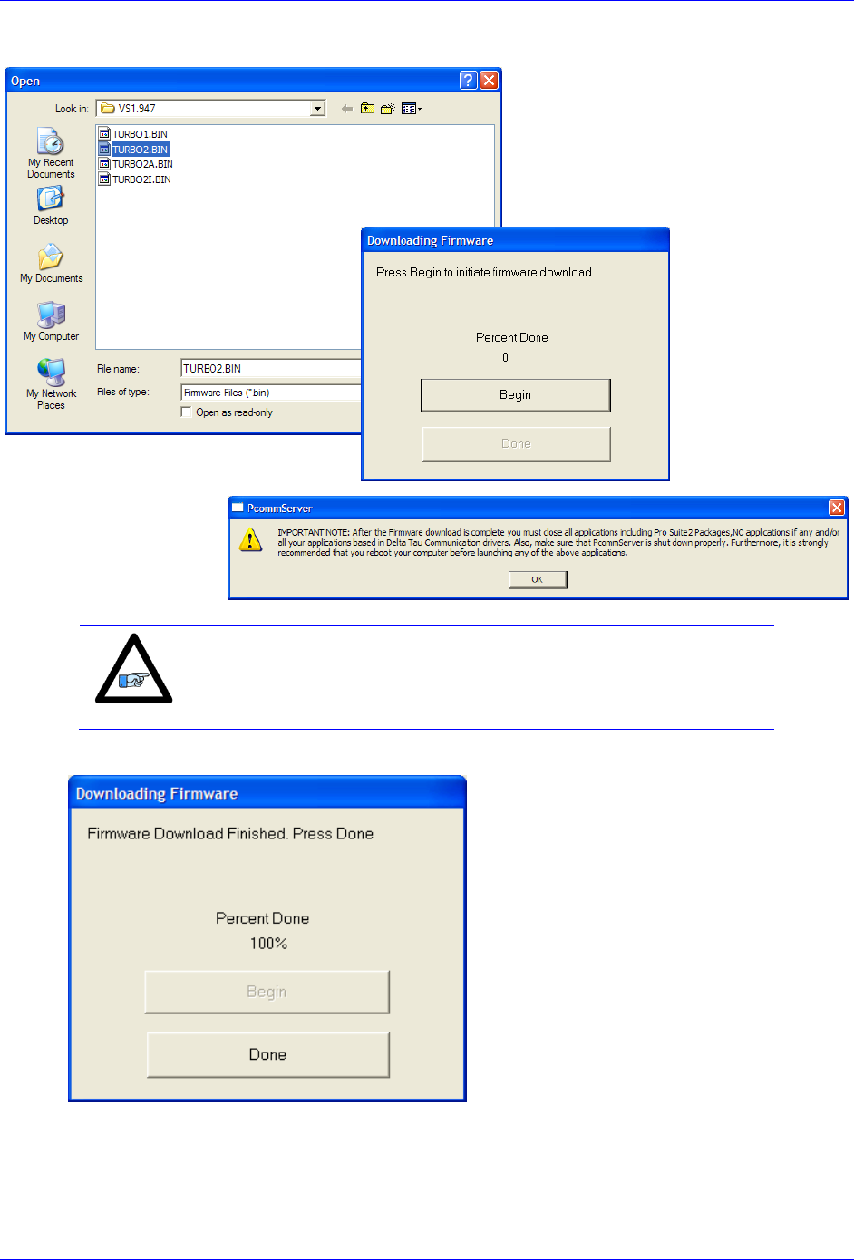
Geo Brick LV User Manual
Troubleshooting 256
Step4: The download utility will prompt for a .BIN file. MAKE SURE you open the correct file.
Note
Regardless of the version number, The PMAC firmware file for Geo
Brick LV MUST ALWAYS be TURBO2.BIN
Step4: Wait until download is finished, and click done.
Step5: Close all PMAC applications (i.e. Pewin32Pro2), and recycle power.
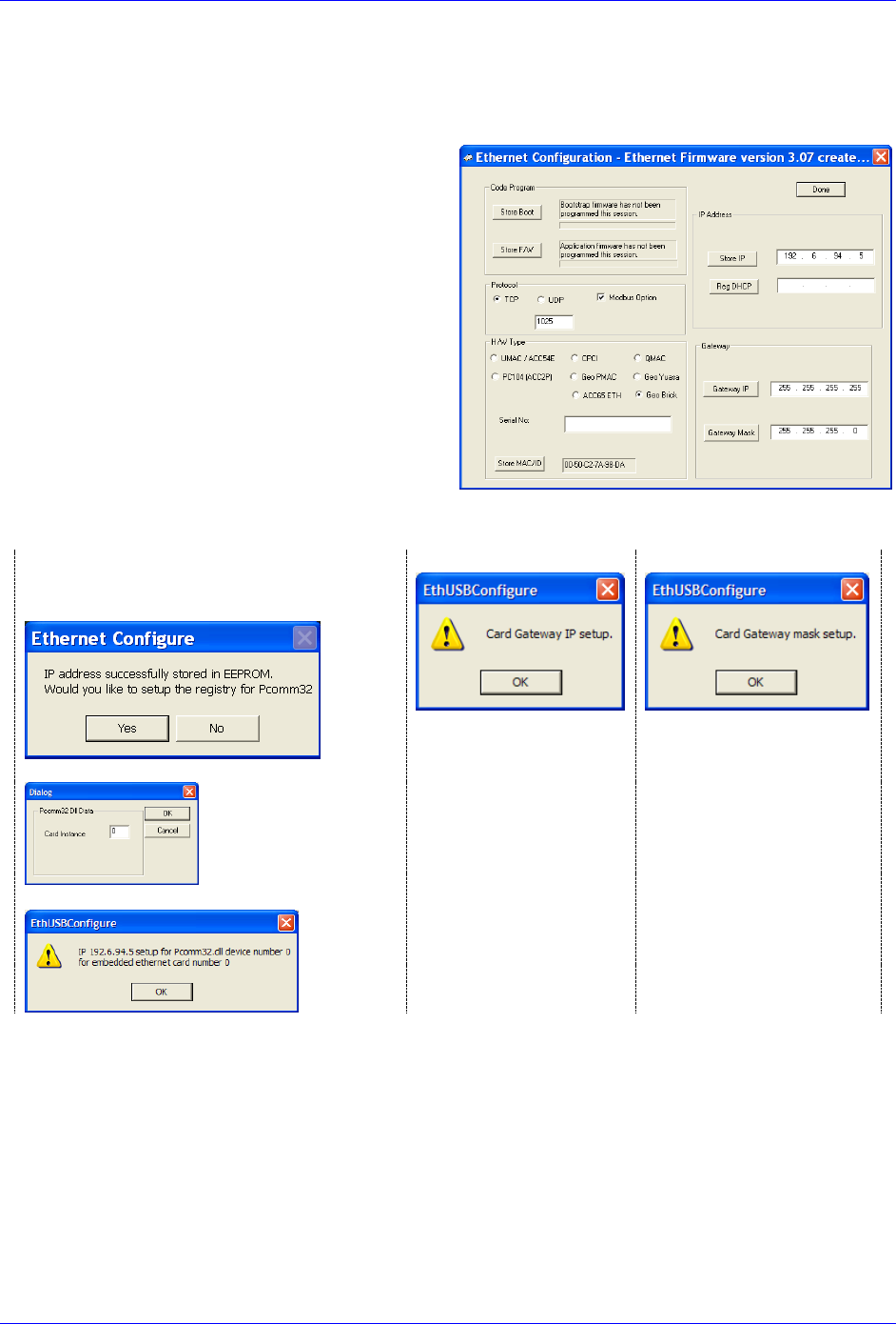
Geo Brick LV User Manual
Troubleshooting 257
Changing IP Address, Gateway IP, Or Gateway Mask
In order to change any of these addresses, the BOOT SW switch has to be held down prior to pressing the
corresponding Store button. The following steps ensure proper configuration:
Step1: Change the desired address field
Step2: Hold the BOOT SW switch down
Step3: Press on the corresponding Store button
Store IP for changing IP address
Gateway IP for changing Gateway IP
Gateway Mask for changing Gateway
Mask
Step4: Release the BOOT SW switch after the corresponding confirmation message is received:
For changing the IP address, follow
through the subsequent messages for setting
up windows registry for Pcomm32.
Gateway IP
Gateway Mask
Step5: Click on Done, and recycle logic power (24V) on the Brick
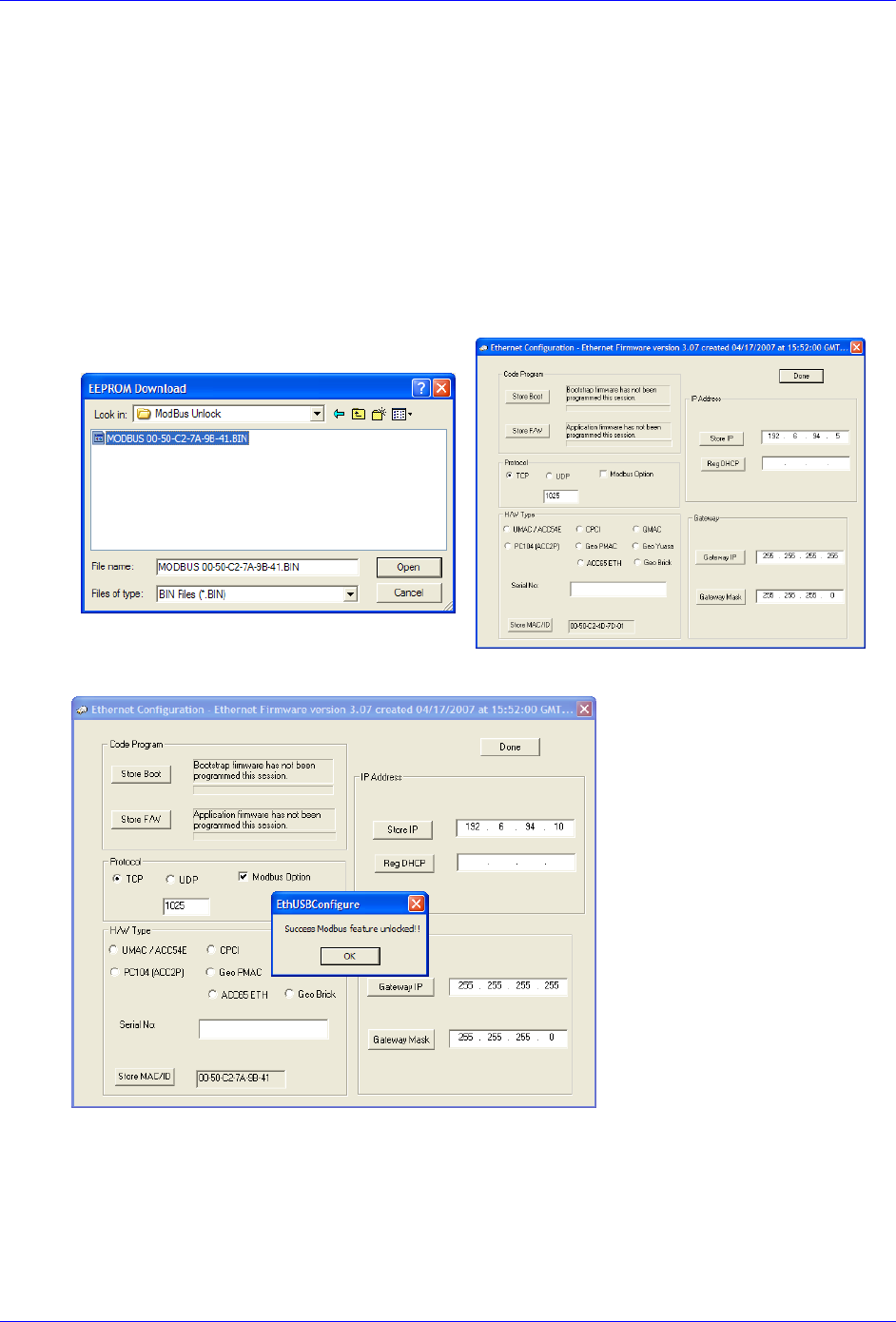
Geo Brick LV User Manual
Troubleshooting 258
Enabling ModBus
A Brick unit ordered initially with the ModBus option is normally enabled by factory.
However, ModBus is a field upgradeable option. The user needs to provide Delta Tau (or their local
distributor) with the MAC ID of the Brick unit. This is found in the lower left hand side of the Ethernet
100 Base T utility. Upon purchase of the ModBus Option, a .BIN file is obtained from Delta Tau for this
purpose. Installing this feature successfully requires the following procedure:
Step1: Hold the BOOT SW switch button down
Step2: Click on ModBus Option. The utility will prompt for the .bin file.
MAKE SURE you open the correct file.
Step3: Release the BOOT SW switch button after the ModBus unlocked message is generated.
Step4: Click on Done, and recycle logic power (24V) on the Brick
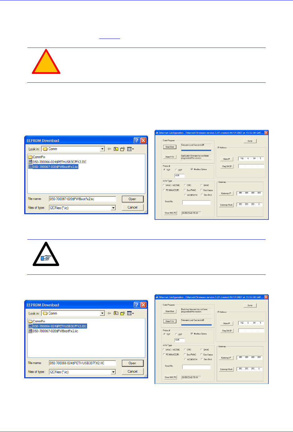
Geo Brick LV User Manual
Troubleshooting 259
Reloading Boot And Communication Firmware
The boot and firmware .IIC files are required for this procedure. They are normally obtained directly from
Delta Tau, or downloaded from the Forums. The following steps ensure proper configuration:
!
Caution
Downloading the wrong boot or communication files will severely
corrupt the functionality of the communication processor.
Step1: Hold the BOOT SW switch down
Step2: Click on Store Boot
Step3: The utility will prompt for the boot file. MAKE SURE you open the correct .IIC file (ending with
BootFx2.iic) and wait for “firmware load successful” message
Step4: Click on Store F/W
Note
The BOOT SW switch button can be released temporarily (between
file downloads). But it MUST to be held down the entire time the boot
or firmware files are being written.
Step5: The utility will prompt for the Firmware file. MAKE SURE you open the correct .IIC file (ending
with ETHUSB307FX2.iic) and wait for “firmware load successful” message
Step6: Release the BOOT SW switch. Click Done, and recycle logic power (24V) on the Brick.

Geo Brick LV User Manual
Troubleshooting 260
Reset Switch SW (Factory Reset)
This momentary switch button is used to reset the Geo Brick LV back to factory default settings, global
reset.
!
Caution
Issuing a SAVE after power up (with the reset switch held down) will
permanently erase any user configured parameters.
Reset SW instructions: Power down the unit then power back up while holding the Reset SW switch
down. Release the Reset SW once the unit is powered up. The factory default parameters are now restored
from the firmware EEPROM into the active memory. Issue a SAVE and a $$$ to maintain the factory
default settings.
Note
For traditional PMAC users, this switch is the equivalent of Jumper
E51 on PC-based or standalone boards.
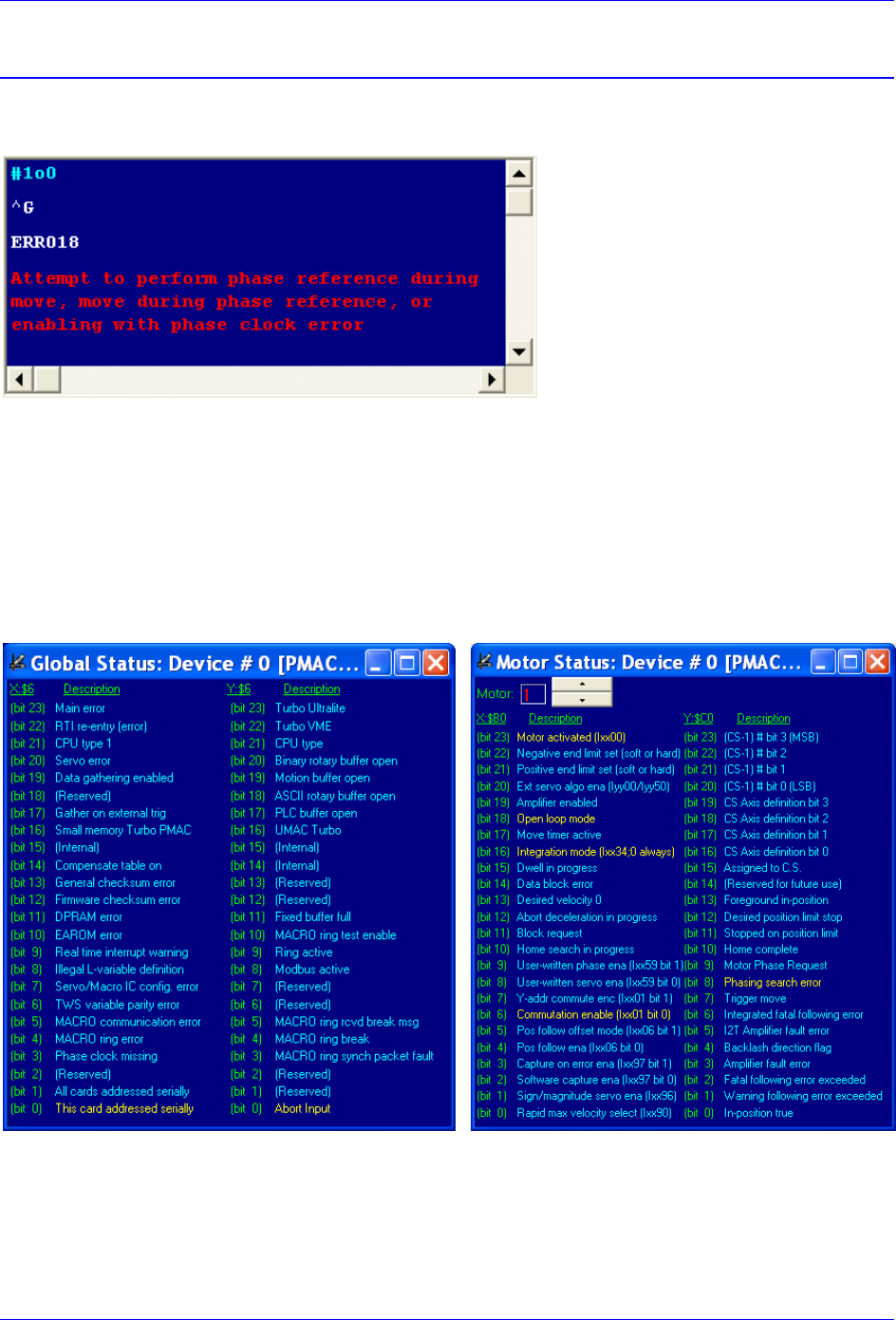
Geo Brick LV User Manual
Troubleshooting 261
Error 18 (Erro18)
Error 18 “Attempt to perform phase reference during move, move during phase reference, or enabling
with phase clock error” is highlighted in red in the terminal window:
This error occurs if any of the following is true:
The addressed motor is not phased.
In this mode, the phasing search error bit is highlighted in the Motor Status window.
No Phase Clock (internal).
In this mode, the Phase Clock Missing bit is highlighted in the Global Status window.
+24V Abort not applied (firmware 1.947 or later, and I35=1).
In this mode, the Abort Input bit is highlighted in the Global Status window.

Geo Brick LV User Manual
Troubleshooting 262
Watchdog Timer Trip
The watchdog timer trigger in the Geo Brick LV illuminates the red WD LED and interrupts
communication. It occurs if any of the following is true:
PMAC CPU over-clocked
In this mode, the CPU signals that is has been overloaded with computation and cannot
accomplish tasks in a timely manner. i.e. bad programming such as an infinite loop, or too much
computation (Kinematics) requiring faster CPU option.
Wrong clock settings
In this mode, the user has downloaded or written bad values to clock setting parameters.
Hardware +5V failure (internal)
In this mode, the internal 5V logic circuitry has failed. Check 5V Led Status.
Downloading wrong configuration file (I4900).
In this mode, the user has reloaded a bad configuration file.
For example, a configuration file uploaded from a 4-axis Geo Brick LV (Servo IC 1 parameters
set to zero) and restored into an 8-axis unit, thus writing zero to the second Servo IC clock
parameters will cause a watchdog. Commenting out variables I7100…7106 (or forcing them to
hold the same values as I7000…I7106) eliminates the watchdog problem.
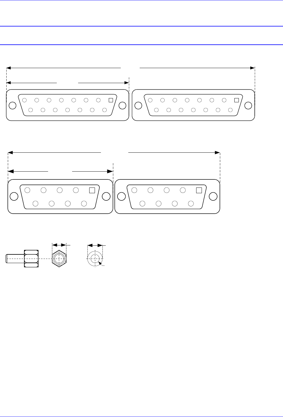
Geo Brick LV User Manual
Appendix A 263
APPENDIX A
D-Sub Connector Spacing Specifications
X1-X8: DA-15 Connectors for encoder feedback
2345
9101112
67
1314
8
15
12345
9101112
67
1314
8
15
1
1.541±.015
3.115±.05
X9-12: DE-9 Connectors for Analog I/O
2345
6789
1 2345
6789
1
1.213+.015
2.45±.05
Screw Lock Size for all D-sub connectors
.18
7
#4-40 FEMALE SCREWLOCK
QTY 2 per connector
Steel, Zinc Plated
.126
DIA
.235
DIA
LOCKWASHER
QTY 2 per connector
Clear Chromate
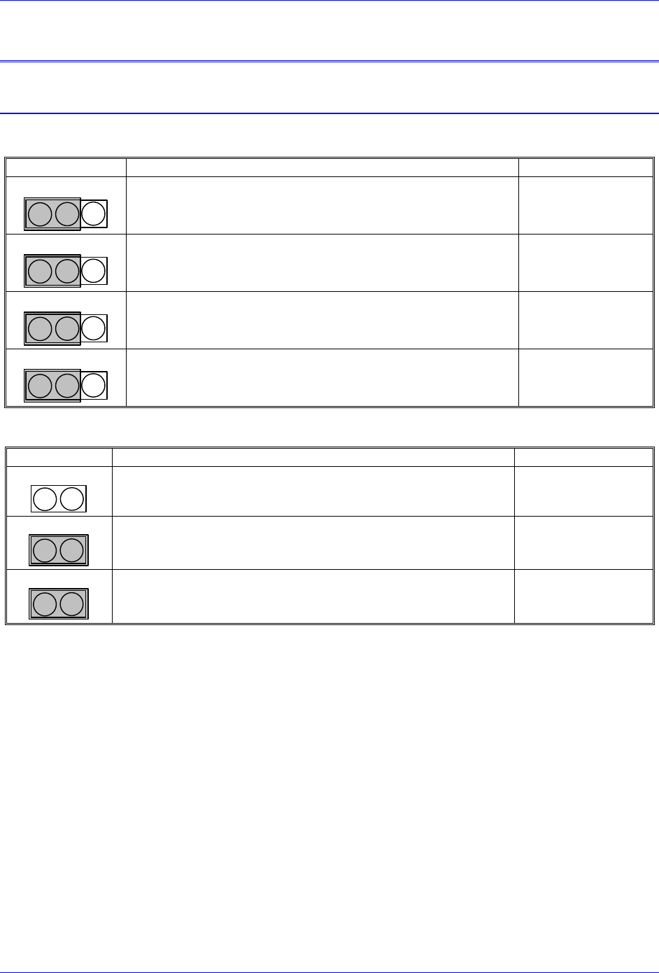
Geo Brick LV User Manual
Appendix B 264
APPENDIX B
Control Board Jumpers (For Internal Use)
E6 – E9: AENA/GPIO Selection Jumper
E-Point
Description
Default
E6
3
2
1
Jump pins 1 to 2 for GPIO1 on X9
Jump Pins 2 to 3 for AENA5 on X9
See Part Number
E7
3
2
1
Jump pins 1 to 2 for GPIO2 on X10
Jump Pins 2 to 3 for AENA6 on X10
See Part Number
E8
3
2
1
Jump pins 1 to 2 for GPIO3 on X11
Jump Pins 2 to 3 for AENA3 on X11
See Part Number
E9
3
2
1
Jump pins 1 to 2 for GPIO4 on X12
Jump Pins 2 to 3 for AENA4 on X12
See Part Number
E10 – E12: Power-Up/Reset Load Source
E-Point
Description
Default
E10
2
1
E10 removed to load active memory from Flash IC on power-up
No Jumper
E11
2
1
Jump1-2 for normal mode operation
Installed
E12
2
1
Jump1-2 for normal mode operation
Installed
Geo Brick LV User Manual
Appendix B 265
E13: Firmware Reload Enable (BOOT SW)
E-Point
Description
Default
E13
2
1
Install E13 to reload firmware through the communications port.
Remove jumper for normal operations.
No Jumper
E14: Watchdog Disable Jumper
E-Point
Description
Default
E14
2
1
Jump 1 to 2 to disable Watchdog timer (for test purposes only, can
be hazardous). Remove jumper to enable Watchdog timer.
No Jumper
E25-28: Select Encoder Index input or AENA output (channels 1-4)
E-Point
Description
Default
E25
2
1
No Jumper for TTL Level input for Ch1 Index signal (C)
Jumper 1-2 to output AENA1 at Ch1 encoder connector
No Jumper
E26
2
1
No Jumper for TTL Level input for Ch2 Index signal (C)
Jumper 1-2 to output AENA2 at Ch2 encoder connector
No Jumper
E27
2
1
No Jumper for TTL Level input for Ch3 Index signal (C)
Jumper 1-2 to output AENA3 at Ch3 encoder connector
No Jumper
E28
2
1
No Jumper for TTL Level input for Ch4 Index signal (C)
Jumper 1-2 to output AENA4 at Ch4 encoder connector
No Jumper
E35-38: Select Encoder Index input or AENA output (channels 5-8)
E-Point
Description
Default
E35
2
1
No Jumper for TTL Level input for Ch5 Index signal (C)
Jumper 1-2 to output AENA5 at Ch5 encoder connector
No Jumper
E36
2
1
No Jumper for TTL Level input for Ch6 Index signal (C)
Jumper 1-2 to output AENA6 at Ch6 encoder connector
No Jumper
E37
2
1
No Jumper for TTL Level input for Ch7 Index signal (C)
Jumper 1-2 to output AENA7 at Ch7 encoder connector
No Jumper
E38
2
1
No Jumper for TTL Level input for Ch8 Index signal (C)
Jumper 1-2 to output AENA8 at Ch8 encoder connector
No Jumper
E40: USB/Ethernet Communication Firmware Load Enable
E-Point
Description
Default
E40
2
1
Remove Jumper to reload communication firmware
Installed
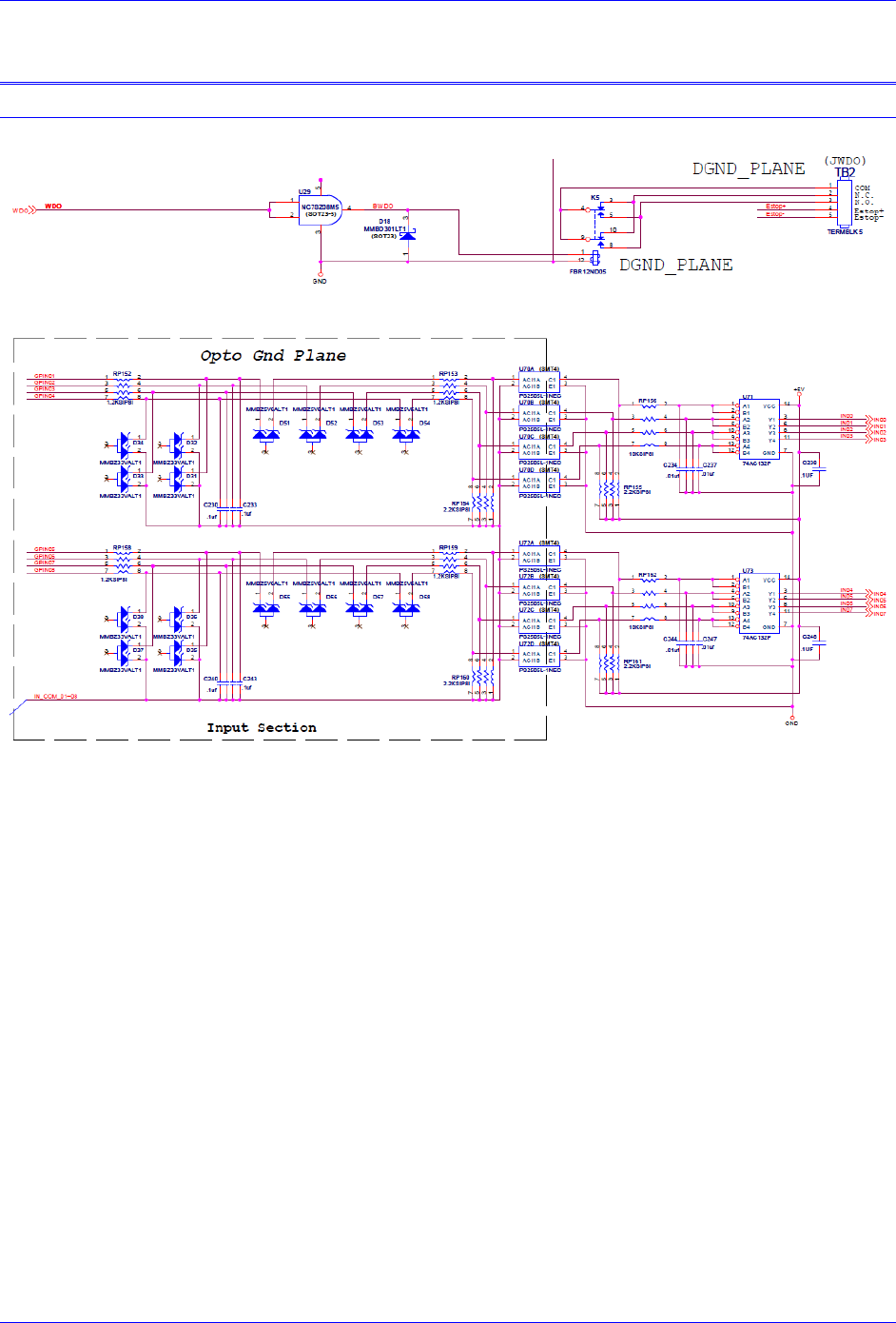
Geo Brick LV User Manual
Appendix C 266
APPENDIX C
Schematic Samples
Watchdog: X15
Inputs: J6 & J7
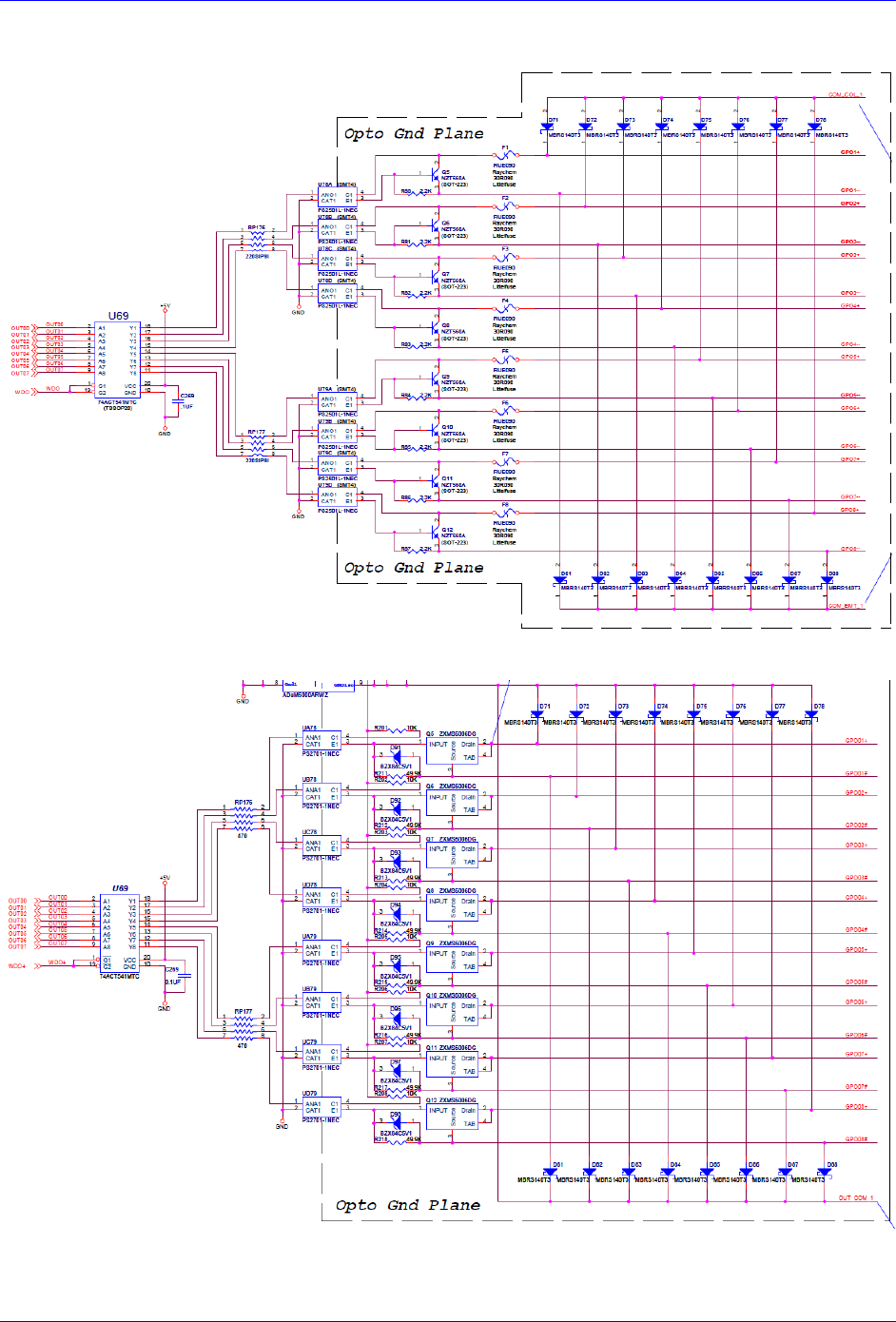
Geo Brick LV User Manual
Appendix C 267
Outputs: J6 & J7 (603793 – 109 and earlier)
Outputs: J6 & J7 (603793 – 10A and later)
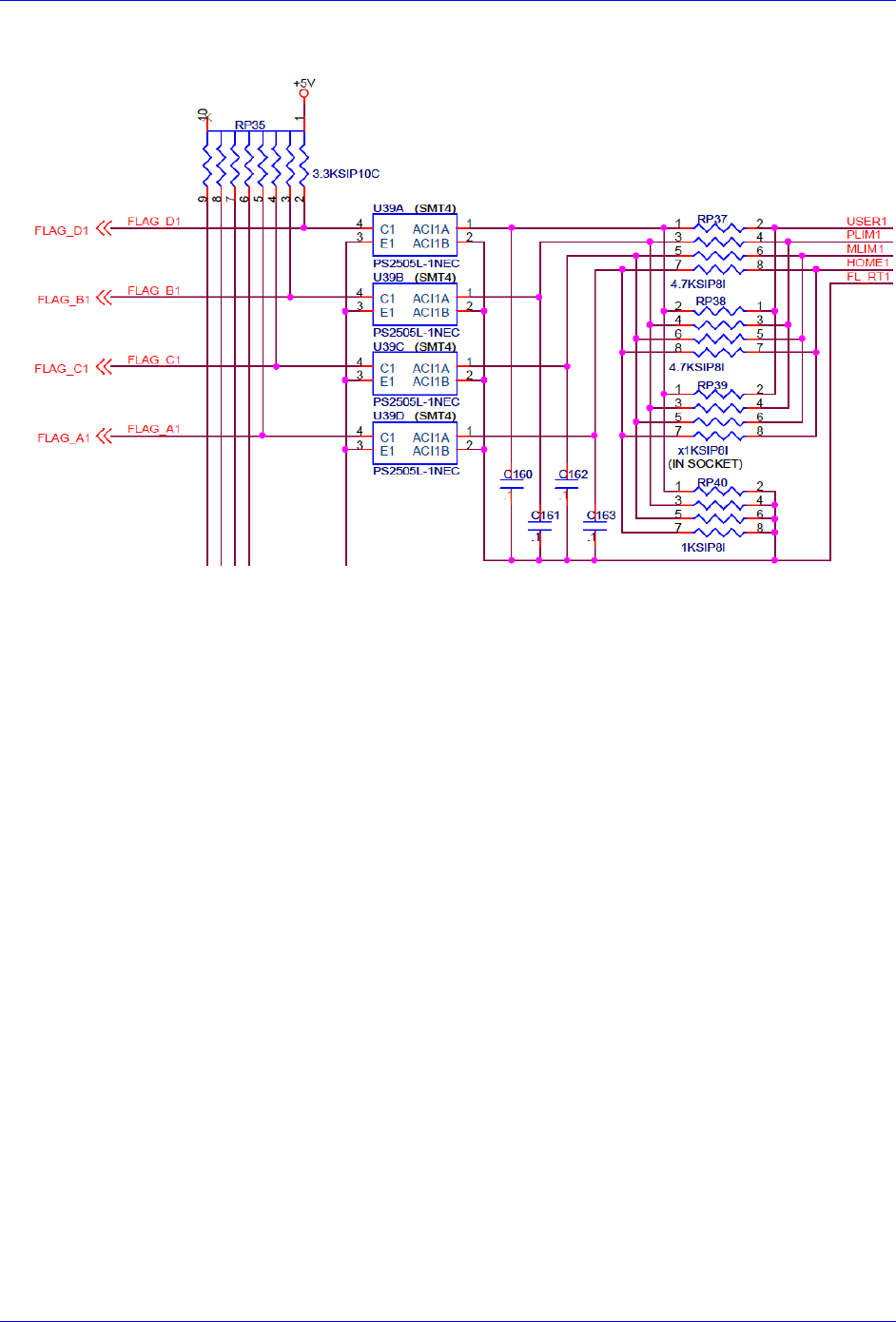
Geo Brick LV User Manual
Appendix C 268
Limits & Flags: J4
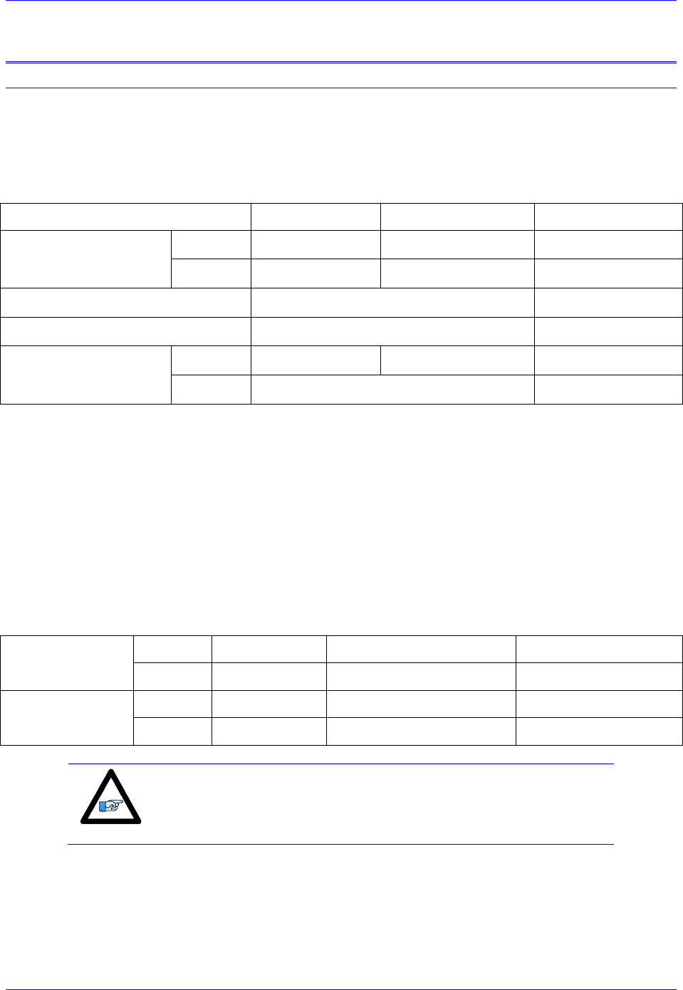
Geo Brick LV User Manual
Appendix D 269
APPENDIX D
Absolute Serial Encoders Limitation with Turbo PMAC
The following is a summary of certain limitations which could be encountered with higher resolution
absolute serial encoders, and a description of related registers with respect to the proposed setup
techniques. Note that techniques 1 and 3 are processed in the Encoder Conversion Table (ECT) using the
standard 5-bit shift, whereas technique 2 is processed with no shift.
Quick Comparison
Parameter/Description
Technique 1/3
Technique 2
Units
Resolution
Scale Factor (SF)
Rotary
SF =2ST
SF =2ST-5
counts/revolution
Linear
SF =1/RES
SF =1/(32*RES)
counts/user unit
Maximum open-loop velocity
218*ServoClk
counts/msec
Maximum closed-loop velocity
223*3/(Ixx08*32)
counts/msec
Maximum travel
before rollover
Rotary
247/SF =247-ST
247/SF =247-(ST-5)
revolutions
Linear
247/SF
user units
Where ST: is the rotary encoder Singleturn resolution in bits
RES: is the linear encoder resolution in user units (e.g. mm)
ServoClk: is the PMAC servo update rate in KHz
Ixx08: is Motor xx’s position scale factor
Resolution Scale Factor (SF)
Turbo PMAC expects the motor count Least Significant Bit LSB to be left-shifted (5 bits), per techniques
1 or 3. The only difference then with technique 2, when unshifted, is that the motor position loop will
now consider 1 LSB of the source to be 1/32 of a motor count, instead of 1.
Example: Take a 37-bit absolute serial rotary encoder (25-bit single turn, 12-bit multi-turn) and its
equivalent linear scale (e.g.10 nm resolution):
Technique 1/3
(5-bit shift)
Rotary
2ST
225= 33,554,432
counts/revolution
Linear
1/RES
1/0.00001= 100,000
counts/mm
Technique 2
(no shift)
Rotary
2ST-5
220= 1,048,576
counts/revolution
Linear
1/(32*RES)
1/32*0.00001= 3,125
counts/mm
Note
Regardless of the processing technique, the servo algorithm utilizes
“internally” the entire data bits stream (i.e. 25 bits) for its calculation.
The performance is not compromised.
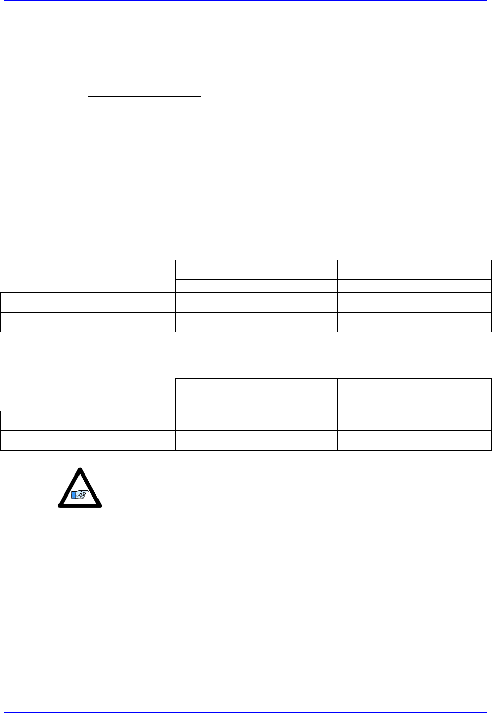
Geo Brick LV User Manual
Appendix D 270
Maximum “Actual” Open-Loop Velocity
In open-loop mode, the actual velocity register is limited by the Encoder Conversion Table to 24 bits.
Furthermore, it requires two samples (servo cycles) to compute the velocity. Therefore, the maximum
value which the actual velocity register can withhold is:
When performing an open-loop move/test with higher resolution serial encoders, care must be taken not
to exceed this threshold. You will see saturation plateau lines in the position data if it is plotted during the
move. At this point, re-establishing an absolute position read (using custom plc, or automatic settings) is
necessary to avoid fatal following errors in closed loop and or to be able to perform proper motor phasing.
Example: Take a 37-bit absolute serial rotary encoder (25-bit single turn, 12-bit multi-turn) and its
equivalent linear scale (e.g.10 nm resolution), and compare for two different clock settings:
With the default servo clock of 2.258 KHz, the maximum actual open-loop velocity is
MaxActVel=218*2.258= 591,921 [counts/msec] yielding:
Rotary [rpm]
Linear [mm/sec]
=MaxActVel*60000/SF
=MaxActVel*1000/SF
Technique 1/3 (5-bit shift)
1,058
5,919
Technique 2 (no shift)
33,870
189,414
With a servo clock setting of 4.500 KHz, the maximum actual open-loop velocity is
MaxActVel=218*4.500= 1,179,648 [counts/msec] yielding:
Rotary [rpm]
Linear [mm/sec]
=MaxActVel*60000/SF
=MaxActVel*1000/SF
Technique 1/3 (5-bit shift)
2,109
11,796
Technique 2 (no shift)
67,500
377,487
Note
The maximum actual velocity attainable is directly proportional to the
servo clock frequency. The faster the servo update, the higher is the
actual velocity threshold.
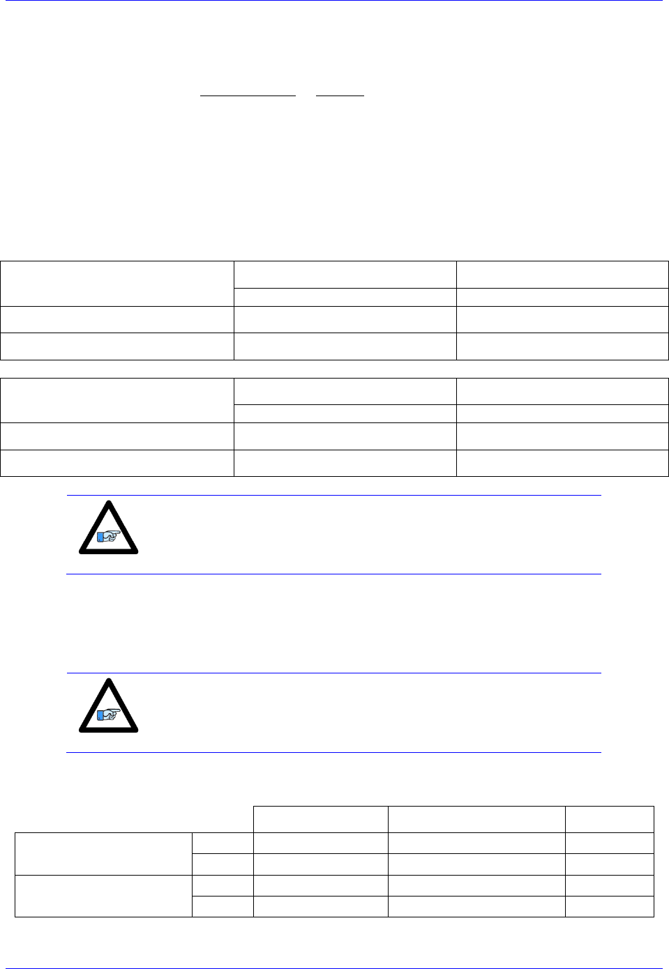
Geo Brick LV User Manual
Appendix D 271
Maximum “Commanded” Closed-Loop Velocity
In closed-loop mode, the commanded (desired) velocity register is limited to:
In terms of motor counts per millisecond, the maximum commanded velocity will be the same with or
without shifting but since the number of counts per revolution “unshifted” is 32 times less, then the
maximum programmable velocity is 32 times greater.
Example: Take a 37-bit absolute serial rotary encoder (25-bit Singleturn, 12-bit Multiturn) and its
equivalent linear scale (e.g.10 nm resolution). The maximum ‘commanded” closed-loop velocity (Ixx16,
Ixx22) setting programmable in Turbo PMAC is: 786,432 [counts/msec] with Ixx08=1
8,192 [counts/msec] with Ixx08=96
With Ixx08=1
Rotary [rpm]
Linear [mm/sec]
=MaxCmdVel*60000/SF
=MaxCmdVel*1000/SF
Technique 1/3 (5-bit Shift)
1,406
7,864
Technique 2 (no Shift)
45,000
251,658
With Ixx08=96
Rotary [rpm]
Linear [mm/sec]
=MaxCmdVel*60000/SF
=MaxCmdVel*1000/SF
Technique 1/3 (5-bit Shift)
14.645
81.916
Technique 2 (no Shift)
468.667
2621.334
Note
Notice the lower programmable closed-loop velocity settings with
techniques 1 and 3 (5-bit shift), associated with the default position
scale factor Ixx08 of 96.
Maximum Motor Travel
In Jog mode, the rollover is handled gracefully by PMAC and jogging can be virtually performed forever.
However, this can be problematic when running a motion program indefinitely in incremental mode
where the 48-bit fixed motor register can roll over much sooner than the 48-bit floating axis register.
Note
Absolute Serial Encoders with limited multi-turn range normally do
roll over way before the motor position register in Turbo PMAC does
(i.e. 12-bit multi-turn is 2048 revolutions in each direction)
Example: Take a 37-bit absolute serial rotary encoder (25-bit single turn, 12-bit multi-turn) and its
equivalent linear scale (e.g.10 nm resolution):
Total Travel Span
In each direction = Span/2
Units
Technique 1/3 (5-bit shift)
Rotary
247-25 = 4,194,304
2,097,152
revolutions
Linear
247/SF
1,407,374,883
mm
Technique 2 (no shift)
Rotary
247-20= 134,217,728
67,108,864
revolutions
Linear
247/SF
45,035,996,274
mm
