Delta MCS 1800 3000 COVER User Manual To The Bf34cb5c F204 4c09 9e42 Be3d63ebacff
User Manual: Delta MCS-1800 to the manual
Open the PDF directly: View PDF ![]() .
.
Page Count: 57
www.deltaww.com
DELTA MCS-1800 Power Shelf
Installation, Operation and
Maintenance Manual

Delta MCS 1800 3U
Power Shelf
Installation, Operations and
Maintenance Manual
DELTA ELECTRONICS, INC.

DELTA MCS 1800 3U Power Shelf
Installation, Operations and
Maintenance Manual
INDEX i
T
T
Ta
a
ab
b
bl
l
le
e
e
o
o
of
f
f
C
C
Co
o
on
n
nt
t
te
e
en
n
nt
t
ts
s
s
1. General ---------------------------------------------- 1-1
1.1 Using This Manual ---------------------------------------------- 1-1
1.2 Safety Notice ---------------------------------------------- 1-1
2. Product Description ---------------------------------------------- 2-1
2.1 Product Description ---------------------------------------------- 2-1
2.2 Product Main Features ---------------------------------------------- 2-1
2.3 System Specifications ---------------------------------------------- 2-1
3. Power Supply Unit (PSU) ---------------------------------------------- 3-1
3.1 Description ---------------------------------------------- 3-1
3.2 Specifications ---------------------------------------------- 3-1
3.3 Operation and Adjustment ---------------------------------------------- 3-4
3.4 System Alarm ---------------------------------------------- 3-5
3.5 PSU Block Diagram ---------------------------------------------- 3-5
3.6 PSU Operating Principle ---------------------------------------------- 3-5
4. Alarm Control Unit ---------------------------------------------- 4-1
4.1 Description ---------------------------------------------- 4-1
4.2 Specifications ---------------------------------------------- 4-1
4.3 Alarm Control Unit Block Diagram ---------------------------------------------- 4-4
4.4 Settings and Control ---------------------------------------------- 4-4
5. DC Distribution ---------------------------------------------- 5-1
5.1 DC Cabling ---------------------------------------------- 5-1
5.2 Low Voltage Battery Disconnect (System
equipped with PDU) ---------------------------------------------- 5-1
5.3 Battery Connections (System equipped with
PDU) ---------------------------------------------- 5-1
5.4 Battery Temperature Probe Connection (System
equipped with PDU) ---------------------------------------------- 5-1
6. Installation ---------------------------------------------- 6-1
6.1 Preliminary Inspection ---------------------------------------------- 6-1
6.2 System Mounting ---------------------------------------------- 6-1
6.3 Module Installation ---------------------------------------------- 6-1
6.4 Shelf Wiring ---------------------------------------------- 6-1
6.5 AC Input Connections ---------------------------------------------- 6-1

DELTA MCS 1800 3U Power Shelf
Installation, Operations and
Maintenance Manual
INDEX ii
T
T
Ta
a
ab
b
bl
l
le
e
e
o
o
of
f
f
C
C
Co
o
on
n
nt
t
te
e
en
n
nt
t
ts
s
s
6.6 Battery String Connections (System equipped
with PDU) ---------------------------------------------- 6-1
6.7 Temperature and Alarm Connections ---------------------------------------------- 6-2
6.8 EXT. Breaker trip signal I/P Connector Wiring ---------------------------------------------- 6-2
6.9 AC High Voltage Aux. Relay Output Wiring ---------------------------------------------- 6-2
7. System Start –Up Procedure ---------------------------------------------- 7-1
7.1 Initial Start-Up Preparation ---------------------------------------------- 7-1
7.3 Basic Functional Verification 7.2 No Load
Start-Up ---------------------------------------------- 7-1
7.4 DC Load Connections ---------------------------------------------- 7-1
7.5 System Functionality Check ---------------------------------------------- 7-1
7.6 System Operation ---------------------------------------------- 7-1
8. System Alarms and Troubleshooting ---------------------------------------------- 8-1
8.1 AC Fail Voltage Alarm Description ---------------------------------------------- 8-1
8.2 High Voltage Shutdown Alarm ---------------------------------------------- 8-1
8.3 High Voltage Alarm Description ---------------------------------------------- 8-1
8.4 Low Voltage Alarm ---------------------------------------------- 8-2
8.5 Low Voltage Disconnect Alarm (System
equipped with PDU) ---------------------------------------------- 8-2
8.6 Fuse Fail Alarm (System equipped with PDU) ---------------------------------------------- 8-2
8.7 Alarm Unit Fail ---------------------------------------------- 8-3
8.8 Rectifier Fail Alarm ---------------------------------------------- 8-3
9. Maintenance ---------------------------------------------- 9-1
9.1 Cleaning and Maintenance ---------------------------------------------- 9-1
9.2 Removing and Replacing a Rectifier Unit ---------------------------------------------- 9-1
10. Acronyms and Abbreviations ---------------------------------------------- 10-1 ~3
ATTACHMENT

DELTA MCS-1800 3U Power Shelf
Installation, Operations and
Maintenance Manual
1-1
1 General
1.1 Using This Manual
This manual contains specifications and instructions to properly install and maintain the power supply system.
Component specifications and drawings are also included.
This manual contains information related to the operation and maintenance of the Alarm Control Unit (ALU),
the –48V/+24V Power Supply Unit (PSU), and the Distribution Module. Additional information is provided
on system status and alarms, troubleshooting, and system maintenance. Appendix figures of this manual
contains drawings, simple block diagram for different functional blocks and systems schematic.
Step-by-step procedures required for the installation and turn-up are detailed. All equipment parameter
setting, adjustments, and confirmation, as well as system monitoring, operations, and maintenance procedures,
are included.
Warnings are printed in bold, italic lettering. They alert the installation or maintenance craftsperson of a
potential hazard to either the equipment or the craftsperson if the warning is not followed.
1.2 Safety Notice
Delta Energy Systems is not liable for any hazards incurred by not following proper safety procedures.
Installation, operation, and maintenance personnel should always follow these safety rules:
1. Before installing the system, verify the AC input voltage and frequency, the AC breaker rating and type,
and other environmental conditions as noted in the specifications.
2. The system has passed stringent system testing prior to shipment. To avoid electrical shock. The
rectifier system requires a single ground point permanently connected to earth ground.
3. An AC breaker must provide adequate isolation between the system input and commercial AC main.
4. The environment should be dust free and controlled by an AC system. The area must be free of any
flammable vapors or fluids.
5. To avoid electrical hazard, the covers must not be removed on any component, including the ALU and
the rectifier.
6. Circuit breakers or fuses must be replaced with approved replacement circuit breakers meeting the
original design specification.
7. All connections must be made per the latest issue of the applicable national and local codes.

DELTA MCS-1800 3U Power Shelf
Installation, Operations and
Maintenance Manual
2-1
2 Product Description
2.1 Product Description
This power Shelf consists of modular rectifiers, an Alarm Control Unit (ALU), and a DC distribution
module. Up to four rectifiers and an alarm unit can be equipped on a shelf containing an integrated distribution
module. The rectifiers can operate from a universal range of AC line voltages. The High Line (HL)
operations are defined at an AC line input range of 165VAC~ 264VAC. The Low Line (LL) operations are
defined at an AC line input range of 90 VAC-130 VAC.
The system is controlled and monitored by the ALU. System level rectifier voltage settings, system
status, and alarms are displayed on the ALU. The system float voltage, equalize voltage, and alarm thresholds
are set from RMS. The ALU also provides automatic derating of the output power over the whole operating
line voltages. Figure 1 shows different functional blocks of the system.
2.2 Product Main Features
The Power Shelf has the following main features:
-48 VDC/120 Amps, or +24VDC/200Amps, N+1 redundancy
Modular design for scalable, cost effective expansion
Front access for simple installation and maintenance
High power density
Active Power Factor Correction (>. 99PFC)
High efficiency
Temperature compensated float voltage control
Alarm Control Unit
Low Voltage Battery Disconnect (LVBD) (System equipped with PDU)
Remote Monitoring and control
2.3 System Specifications
The system specifications are provided in the following sections.
2.3.1 -48V Standard Power Shelf Configuration(MODUL NAME: ES48/120-JAAxx)
(1) AC Input: 175VAC ~ 275VAC, 48Amps. Max
(2) System Capacity: 120Amps. Max.
(3) Rectifier: -48V/30A×1~4
(4) Control and Supervisory Unit
Figure 1 shows a front view of shelf.
DELTA MCS-1800 3U Power Shelf
Installation, Operations and
Maintenance Manual
2-2
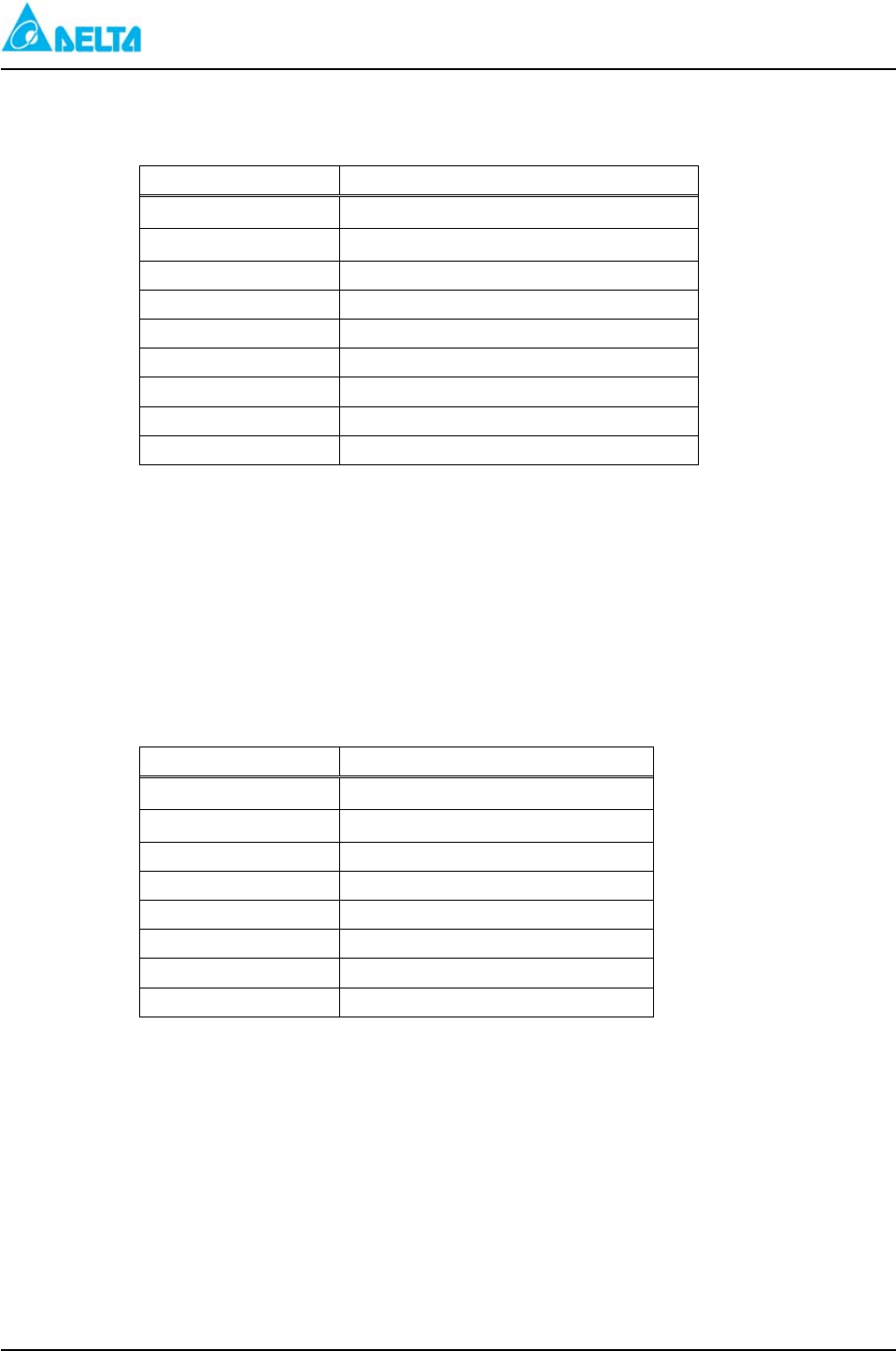
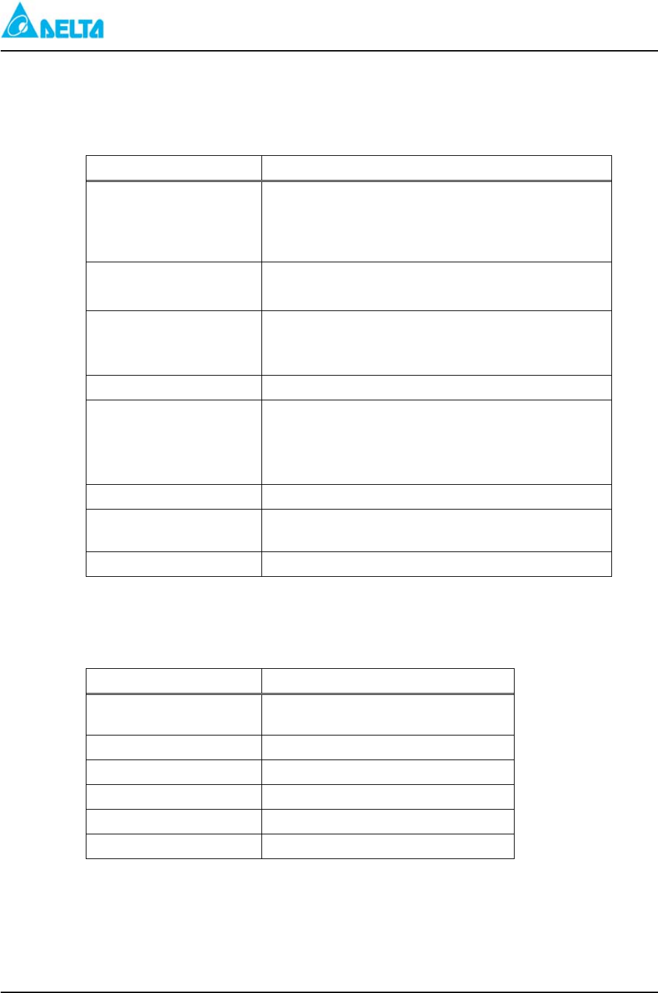
Environmental Data
System Environmental Data
Specification Value
Operating temperature 0℃ to +50℃
Storage temperature -40℃ to +70℃
Humidity 0% to 95% RH
Altitude -300 ft. to 10,000 ft.
Weight Approximately 48 lbs.
EMI/FRI FCC Part 15, Class B and CISPR 22, Class B
Lightning/surge ANSI/IEEE C62.41-1, and IEC 1000-4-5
Seismic Bellcore GR-63-CORE, Zone 4
Safety CUL and UL Listed and Marked
2.3.2 +24V Standard Power Shelf Configuration(MODUL NAME: ES24/200-JAAxx)
(1) AC Input: 175VAC ~ 275VAC, 48Amps. Max
(2) System Capacity: 200Amps. Max.
(3) Rectifier: +24V/50A×1~4
(4) Control and Supervisory
Figure 1 shows a front view of shelf.
Environmental Data
System Environmental Data
Specification Value
Operating temperature 0℃ to +50℃
Storage temperature -40℃ to +70℃
Humidity 0% to 95% RH
Altitude -300 ft. to 10,000 ft.
Weight Approximately 48 lbs.
Lightning/surge ANSI/IEEE C62.41-1, and IEC 1000-4-5
Seismic Bellcore GR-63-CORE, Zone 4
Safety CUL and UL Listed and Marked
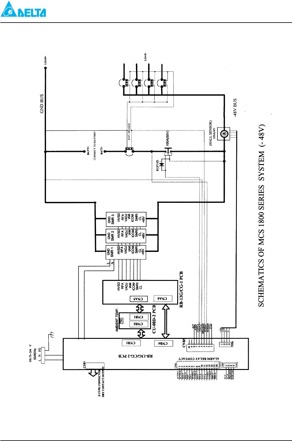
2.3.3 -48V System with Power Distribution and Rectifiers(MODUL NAME: ES48/90-JBAxx)
(1) AC Input: 175VAC ~ 275VAC, 36Amps. Max
(2) System Capacity: 90Amps. Max.
(3) Rectifier: -48V/30A×1~3
(4) Control and Supervisory
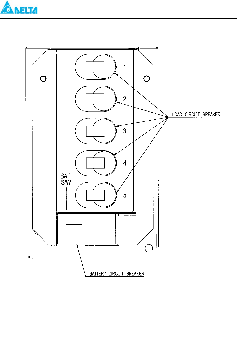
(5) Load Distribution: 30A Breaker×5 @ Single Pole
(6) Low Voltage Disconnect Switch: 100A×1 @ Single Pole at Battery Side
(7) Battery Breaker: 100A×1
(8) AC Breaker
DELTA MCS-1800 3U Power Shelf
Installation, Operations and
Maintenance Manual
2-3
Figure 1-1 shows a front view of shelf.
Environmental Data
System Environmental Data
Specification Value
Operating temperature 0℃ to +50℃
Storage temperature -40℃ to +70℃
Humidity 0% to 95% RH
Altitude -300 ft. to 10,000 ft.
Weight Approximately 48 lbs.
Lightning/surge ANSI/IEEE C62.41-1, and IEC 1000-4-5
Seismic Bellcore GR-63-CORE, Zone 4
2.3.4 -48V System with Power Distribution and Rectifiers(MODUL NAME: ES48/90-JFAxx)
(1) AC Input: 175VAC ~ 275VAC, 36Amps. Max
(2) System Capacity: 90Amps. Max.
(3) Rectifier: -48V/30A×1~3
(4) Control and Supervisory
(5) Load Distribution: 100A Breaker×4 @ Single Pole
(6) Low Voltage Disconnect Switch: 100A×1 @ Single Pole at Battery Side
Figure 1-1 shows a front view of shelf.
Environmental Data
System Environmental Data
Specification Value
Operating temperature 0℃ to +50℃
Storage temperature -40℃ to +70℃
Humidity 0% to 95% RH
Altitude -300 ft. to 10,000 ft.
Weight Approximately 48 lbs.
EMI/FRI FCC Part 15, Class B and CISPR 22, Class B
Lightning/surge ANSI/IEEE C62.41-1, and IEC 1000-4-5
Seismic Bellcore GR-63-CORE, Zone 4
Safety CUL and UL Listed and Marked
2.4 Electrical Data
The system electrical data is provided in the following tables.
2.4.1 Input
DELTA MCS-1800 3U Power Shelf
Installation, Operations and
Maintenance Manual
2-4
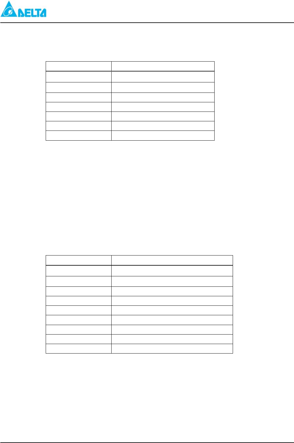
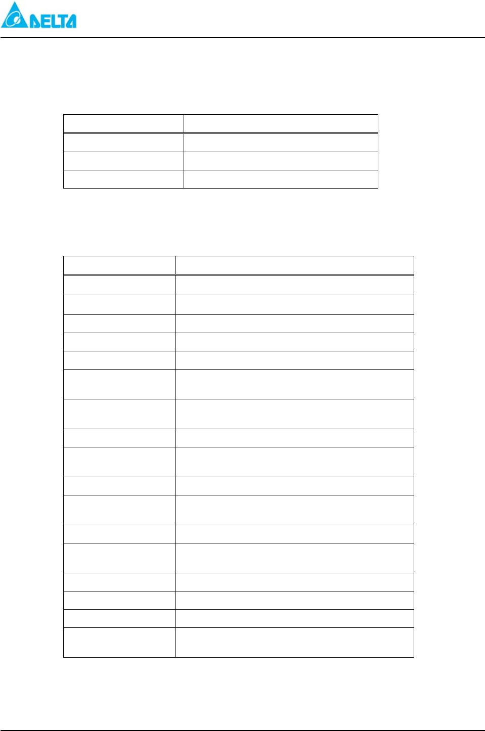
Table 1 displays the system input specifications.
Table 1 System Input Specifications
Specification Value
Nominal range 175 ~ 275VAC
Operational range
90 ~ 275VAC Full Load
150V ~ 175Vac de-rating to 80% Load
90V ~ 150Vac de-rating to 50% Load
50℃ ~ 65℃ de-rating 1500W
Frequency 45 ~ 65Hz
Power Factor >0.99 @ 220VAC, Full Load
THD <5% @ 220VAC, Full Load
Efficiency >90% @ 220VAC, Full Load
2.4.2 Output
Table 2 displays the system output specifications.
Table 2 System Output Specifications
Specification Value
DC Volts 38~60 VDC (-48V Version)
20~30 VDC (+24V Version)
Load regulation <1%
Line regulation <0.2%
Current Limit 110%
Current share <5%
Noise:
Audio band
Wide band
Acoustic
<2mv
<10 mVrms
<55 dBA
2.4.3 Status/Alarm Indicators
The Power Shelf has the following status/alarm indicators:
Load Current
AC ON
Rectifier Fail Alarm (RFA)
Current Limit (CL)
Float/Equalize (FL/EQU)
Major Alarm (MAJ)
Minor Alarm (MIN)
High Voltage Alarm (HV)
High Voltage Shutdown (HVSD)
Low Voltage Alarm (LV)
Low Voltage Disconnect Open (LVDS OPEN)
Fuse Blown (FUSE ALM)
AC Fail (AC FAIL)

DELTA MCS-1800 3U Power Shelf
Installation, Operations and
Maintenance Manual
2-5
2.4.4 Mechanical Data
Dimension Value
Height 5.2 in. (132mm)
Depth 10.35 in. (263mm)
Width 3.3 in. (83.6mm)
DELTA MCS-1800 3U Power Sh
elf
Installation, Operations and
Maintenance Manual
3-1
3 Power Supply Unit (PSU)
3.1 Description
This rectifier units are rated at full load when operated from high line. For Low operation, the output is
derated to half load. This derating is automatically activated from the Alarm Control Unit (ALU). However,
the rectifier can operate on a stand-alone basis, if this ALU is removed or nonfunctional.
Warning: In the absence of the ALU, the automatic derating of the rectifiers at Low Line is not effective.
Exceeding the 50% load limit at Low Line may damage the rectifiers.
The modular design provides the flexibility to configure and expand the system as the load demand
increases. Each rectifier unit is swappable with front access for ease of maintenance without system shutdown,
providing uninterrupted service.
The rectifier unit has an active power factor correction of greater than 0.99 for maximum AC utilization.
Each module is equipped with an AC switch located at the front of the module. Figure 3 shows a front view of
PSU.
Note: The equipment is only for installation in a Restricted Access Location.
The equipment is used on a stationary equipment/unit only.
3.2 Specifications
Detailed rectifier specifications are provided in the following sections.
3.2.1 Electrical
Detailed electrical specifications for the rectifier are provided in this section.
3.2.1.1 Input
Table 6 displays the rectifier input specifications.
Table 6 Rectifier Input Specifications
Specification Value
Input Voltage 90VAC to 275VAC, Single Phase, (during 176 to 150VAC
derated to 80% Load, during 150 to 90VAC derated to 50% Load)
Input Current 12 Amps at 176 VAC, Full Load
Line Frequency 45 to 65 Hz
Power Factor >0.99, at 220 VAC Input, Full Load
THD <5%, at 220 VAC Input, Full Load
Efficiency >90%, Full Load (-48V Version)
>88%, Full Load (+24V Version)
Inrush Current <12 Amps (peak), 220 VAC, Full Load, Cold Start
Start Time Delay
(Walk-In) 3 to 10 seconds
Protection Fuse
DELTA MCS-1800 3U Power Sh
elf
Installation, Operations and
Maintenance Manual
3-2
3.2.1.2 Output
Table 7 displays the rectifier output specifications.
Table 7 Rectifier Output Specifications
Specification Value
DC Output Voltage
40 to 60VDC [factory preset at –54.3VDC, 30Amps (HL) /
15Amps (LL)] –48V Version
20 to 30VDC [factory preset at 27.2VDC, 50Amps (HL) /
25Amps (LL)] +24V Version
Output Power 1800W Maximum (-48V Version)
1500W Maximum (+24V Version)
Regulation:
Load
Line
<1% (Load 0 to 100%)
<0.1%
Current Limit 110% Max. of Rated Output Current
Noise:
Audio Band
Wide Band
Acoustic
<2mV
<20 mVrms (10 KHz to 100 MHz)
<55 dBA @ 1M
Current Sharing <5% of Rated Output Current
Dynamic Response 10% to 90% Load Change Overshoot ≤5% Rated Output
Voltage Recovery Time <1 ms to ≤1% Rated Output Voltage
Protection Fuse
3.2.1.3 Protection
Table 8 displays the protection specifications.
Table 8 Protection Specifications
Condition Response
High Output Voltage (Exceeds
Preset Value) Automatic Shutdown and Latch
Over Current/Output Short Automatic Shutdown and Recovery
Over Temperature Automatic Shutdown and Recovery
Brownout No Damage
AC Input Voltage High Automatic Shutdown and Recovery
AC Input Voltage Low Automatic Shutdown and Recovery
DELTA MCS-1800 3U Power Sh
elf
Installation, Operations and
Maintenance Manual
3-3
3.2.1.4 Adjustments
Table 9 displays the adjustments.
Table 9 Adjustments
Adjustment Description
Test Points (I+,I-) Current
Float Voltage (FLO) Variable Resistor or Setting on ALU
Current Limit (CL) Variable Resistor or Setting on ALU
3.2.2 Environmental
Table 10 displays the environmental specifications.
Table 10 Environmental Specifications
Specification Value
Operating temperature 32 to +122℉ (0℃ to +50℃) OPTION
Storage temperature -40 to +185℉ (-40℃ to +85℃)
Humidity 0% to 95% Relative Humidity No condensing
Altitude -5.2”/132mm
Weight 3.3 Kg (7.26 lbs.)
EMI/FRI suppression Conforms to EN 55022, BS 6527 FCC Part 15 Subpart J,
and CISPR 22 Class A
Current harmonic Conforms to EN 61000-3-2/A12, EN 60555-2, IEC
1000-3-2 Class A
Voltage fluctuation Conforms to EN 61000-3-3M, EN 60555-3
Electrostatic discharge Conforms to EN 61000-4-2, IEC 1000-4-2, IEC 801-2
Level 4
Radiated susceptibility Conforms to IEC 1000-4-3, IEC 801-3 Level 3
Electrical fast transients Conforms to EN 61000-4-4, IEC 1000-4-4, IEC 801-4
Level 4
Conducted susceptibility Conforms to IEC 1000-4-6 Level 3
Lightning/surge Conforms to ANS/IEEE C62.41.-1, 1991 B3, IEC
1000-4-5 Level Special (6KV)
Safety Meets IEC 950, EN60950, UL/CUL/CE Approval
MTBF >150 K hours
Cooling Fan cooling
Heat dissipation 682 BTU/hour max. per module (-48V Version)
698 BTU/hour max. per module (+24V Version)
DELTA MCS-1800 3U Power Sh
elf
Installation, Operations and
Maintenance Manual
3-4
3.2.3 Status/Alarm Indicators
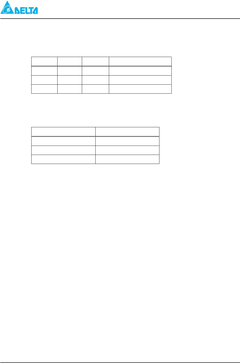
Table 11 displays the status alarm indicators
Table 11 Status Alarm Indicators
Indicator Color Function Description
LED Amber CL Current Limit
LED Green AC AC ON
LED Red RFA Rectifier Failure Alarm
3.2.4 Mechanical Data
Table 12 displays the rectifier mechanical data.
Table 12 Rectifier Mechanical Data
3.3 Operation and Adjustment
All operating adjustments are made at the front panel of each rectifier. The following components are
located on each rectifier panel:
1. Float voltage adjustment
2. Current limit adjustment
3. Current test points
4. Alarm indicators
Figure 3 shows different indicators and adjustment points on this unit.
Rectifier adjustments must be done sequentially from the first through the fourth rectifier with AC applied.
All adjustments must be made with no load, and the batteries disconnected to ensure adjustment accuracy.
3.3.1 Start-Up
To start up the system, perform the following steps:
1. Aproximately 3 to 8 seconds after the AC applied, the RFA LED extinguishes.
3.3.2 Float Voltage Adjustment
Verify the required float voltage setting per battery manufacturer specification. If the factory setting differs
from the battery manufacturer recommended setting, the ALU float voltage parameter and each rectifier’s
float voltage must be adjusted to the new setting. A digital multimeter and a small screwdriver are required
to perform this procedure. Located the float voltage access point (FL) at the front of the rectifier.
To adjust the float voltage, perform the following steps:
1. Remove the ALU.
Dimension Value
Height 5.2 in. (132mm)
Depth 10.35 in. (263mm)
Width 3.3 in. (83.6mm)

DELTA MCS-1800 3U Power Sh
elf
Installation, Operations and
Maintenance Manual
3-5
2. Place the digital multimeter probe in the V+ and V- output voltage connecter.
3. Adjust the float voltage by using a screwdriver to turn the FL point to the voltage value as shown on
the meter. The tolerance error should not exceed 0.02V.
Notes:
1. Turning the variable resistor adjustment point clockwise increases the value, and counterclockwise
2. Refer to Figure 3 (rectifier front view) for the location of V+, V- and FL point.
3. When the setting is completed, temperature and voltage compensation must be reset to the default
value.
3.3.3 Current Limit Setting
Warning: Current limit setting is not intended to be adjusted in the field. Users should only use it for
their reference.
Current limit adjustment is made by turning the CL variable resistor with the digital multimeter probes
in the I+, I- test points. This current limit is set at the factory. The factory setting is always the
maximum value of 110%. For a 48V/30 Amp rectifier, the computation for the current limit is
1.1×30=33 Amps.
The following adjustment procedure is for reference only:
1. At the rectifier, place the digital multimeter probes in the I+, I- test points.
2. Place a small screwdriver in the CL adjustment point.
3. Turn the variable resistor counterclockwise to increase the value. Turn the variable resistor
clockwise to decrease the current limit value.
3.4 System Alarm
During an alarm condition, the faulty rectifier illuminates its RFA light on the front panel. The rectifier
fail alarm signal is sent to the ALU, which processes the alarm, closes the RFA alarm contacts, and lights the
alarm LEDs.
3.5 PSU Block Diagram
Refer to Figure 5.
3.6 PSU Operating Principle
After applying the incoming line voltage to the rectifier, current is applied to the EMI filter and circulates
through protection components such as the AC circuit breaker and the fuse. The major functions of the
protection devices are to prevent the rectifier from being damaged by surge voltage, to efficiently reduce the
noise of differential mode and common mode, to eliminate the high frequency noise from input current, and to
prevent noise reverse to the source circuit.
The AC input voltage is rectified and converted to a 400VDC bus through a PFC boost stage. This PFC
stage maintains the Power Factor at >.99 and the Total Harmonic Distortion (THD) at <5%.
The 400 VDC bus voltages is modulated at a frequency higher than 100KHz and stepped down through a
transformer. Output of this transformer is rectified and filtered to provide the output DC voltage.
DELTA MCS-1800 3U Power Shelf
Installation, Operations and
Maintenance Manual
4-1
4 Alarm Control Unit
4.1 Description
The Alarm Control Unit (ALU) with RS232 & LAN interface and remote monitoring function provides
output alarms, alarm threshold adjustments, float and equalize voltage adjustments, temperature compensation
voltage settings, low voltage disconnect voltage threshold settings, an equalize charge timer, and system alarm
LEDs. In addition, the ALU automatically derates the system output current according to the following table:
Figure 2 shows a front view of Alarm control unit.
Table 13 Voltage Ranges
Input Voltage Range Output
90-150 VAC 50%
150-175 VAC 80%
176-275 VAC 100%
The module is hot swappable.
4.2 Specifications
4.2.1 Input Characteristics
Table 14 displays the input characteristics.
Table 14 Input Characteristics
Characteristic Value
Input Voltage Range 40V to 59.5V for 48V system
20V to 30V for 24V system
Input Current <0.5 Amps
4.2.2 Push Buttons
This alarm unit has 3 push buttons on the front panel. These push buttons are used to control the
alarm unit. Following are possible functions these buttons will act:
Control
- FL/EQU
- HVSD RST
- SMR RST
- Voltage/Current Display
DELTA MCS-1800 3U Power Shelf
Installation, Operations and
Maintenance Manual
4-2
Settings Description
FL/EQU
- Function
- This button is used to manually select SMR into float or equalize state.
HVSD RST
- Function
- When SMRs shut down resulting from DC high voltage. This button is
used to reset alarm state.
SMR RST
- Function
System will detect RFA warning when SMRs are vacant or turned off.
However, if the button is pushed at this time, the system will stop
sending the warning.
Voltage/Current
- Function
This button is used to change the voltage or current of LED display.
Notice: When SMR turn off , the system will detect RFA warning in ES48/90-JFAxx.
When SMR vacant , the system will detect RFA warning in other system.
4.2.3 Indicators
Table 15 displays the ALU indicators.
Table 15 ALU Indicators
Indicator Color Function Description
LED1 Green FL System Float State
LED2 Yellow EQU System Equalize State
LED3 Red HV DC High Voltage Alarm-Minor
LED4 Red LV DC Low Voltage Alarm-Minor
LED5 Yellow MIN System Minor Alarm
LED6 Red MAJ System Major Alarm
LED7 Red HVSD High Voltage Shutdown (DC)
LED8 Red AC FAIL Loss of AC Input
LED9 Red FUSE ALM DC Output or Breaker SW. Trip
LED10 Red LVDS OPEN Low Voltage Disconnect Open
4.2.4 Relay Output
Table 16 displays the relay output.(Please refer to Figure 5)
Table 16 Relay Output
Relay Function Description Relay Function Description
Relay1 ACF AC Failure Relay5 LV DC Low Voltage
Alarm-Minor
Relay2 MAJ Major Alarm Relay6 LVD Low Voltage Disconnect
Open
Relay3 HVSD High Voltage Shutdown Relay7 FA Breaker Trip
Alarm
Relay4 HV DC High Voltage
Alarm-Minor Relay8 MIN Minor Alarm
DELTA MCS-1800 3U Power Shelf
Installation, Operations and
Maintenance Manual
4-3
4.2.5 ALU Alarm Signal Descriptions
MAJ: Major Alarm
(1) 2 or above rectifiers fail.
(2) Temperature sensor disconnects.
(3) AC Low Voltage Alarm.
(4) AC High Voltage Alarm.
(5) LVDS Trip Alarm. (System equipped with PDU)
(6) Battery or Ambient over temperature. (System equipped with PDU)
(7) HVSD Alarm.
(8) Breaker Trip Alarm.
MIN: Minor Alarm
(1) One rectifier fail.
(2) Current Limit Alarm.
(3) DC High Voltage Alarm.
(4) DC Low Voltage Alarm.
HV: The alarm condition exists when the DC output voltage is higher than the parameter setting.
LV: The alarm condition exists when the DC output voltage is lower than the parameter setting.
AC Fail: The alarm condition exists when the AC voltage is absent.
LVDS: The alarm condition exists when the DC output voltage is lower than the threshold voltage.
(System equipped with PDU)
Fuse Fail: The alarm condition exists when the battery switch trip off or the DC Load output switch trip off.
4.2.6 Physical
Table 18 displays the ALU mechanical data.
Table 18 ALU Mechanical Data
Dimension Value
Height 5.2 in. (132mm)
Depth 9.9 in. (251.3mm)
Width 1.9 in. (46.2mm)
DELTA MCS-1800 3U Power Shelf
Installation, Operations and
Maintenance Manual
4-4
4.2.7 Environmental
Table 19 displays the environmental specifications.
Table 19 Environmental Specifications
Specification Value
Operating temperature 32℉ to +122℉ (0℃ to +50℃)
Storage temperature -40℉ to +185℉ (-40℃ to +85℃)
Humidity 0% to 95% Relative Humidity No condensing
Altitude -500 to 10,000 ft.
Weight 2.64 lbs. (1.2Kg)
ESD IEC 1000-4-2 (Contact 4KV Air 8KV)
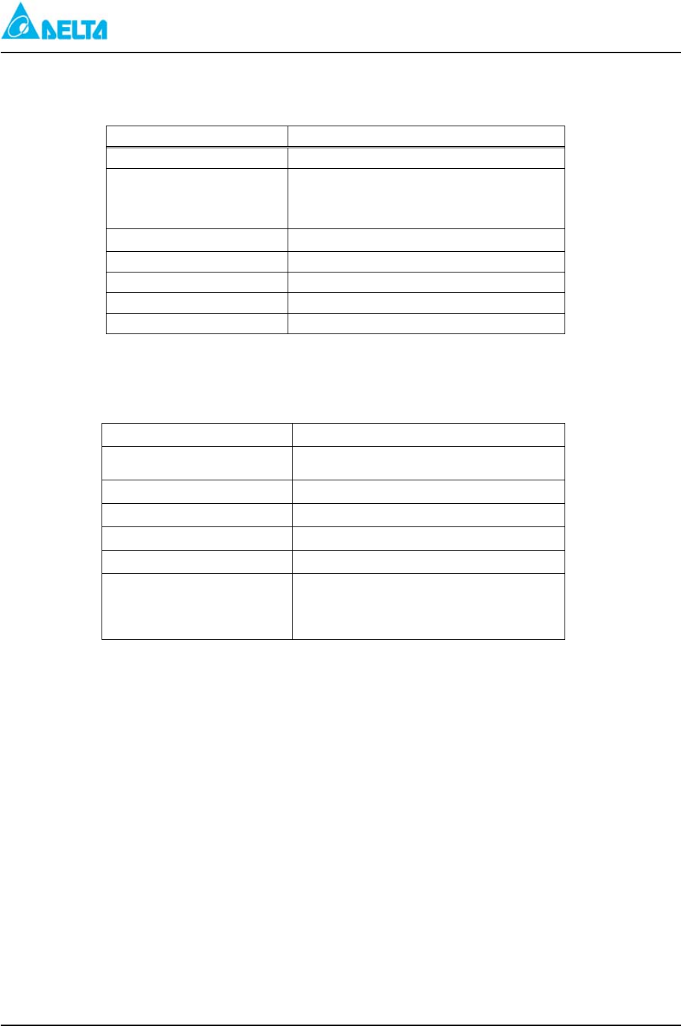
4.2.8 Remote monitoring and control
The ALU provide the flowing remote monitoring methods.
1. Use RS232 Interface.
2. Use Internet Web server function (RJ45)-(Optional)
4.2.10 Parameter Modify
Enter the Remote monitoring software or use the internet Brower to modify the parameter.
4.3 Alarm Control Unit Block Diagram
Refer to Figure 7.
4.4. Settings and Control
Settings:
Settings Description Comment
DC High Voltage Shutdown
Function
Default
Recovery
Steps
- High voltage shutdown threshold adjustment
- 58.5VDC (-48V System)
- 29.5VDC (+24V System)
- 57.5VDC (-48V System)
- 28.5VDC (+24V System)
- 0.1VDC
DC High Voltage Alarm
Function
Default
Recovery
Steps
- High voltage alarm threshold adjustment
- 57.5VDC (-48V System)
- 29VDC (+24V System)
- 56.5VDC (-48V System)
- 28VDC (+24V System)
- 0.1VDC
DC Low Voltage Alarm
Function
Default
Recovery
- Low voltage alarm threshold adjustment
- 44.0VDC (-48V System)
- 23VDC (+24V System)
- 45.0VDC (-48V System)
- 24VDC (+24V System)
DELTA MCS-1800 3U Power Shelf
Installation, Operations and
Maintenance Manual
4-5
Settings Description Comment
Steps - 0.1VDC
AC High Voltage Alarm
Function
Default
Recovery
Steps
- AC high voltage alarm threshold adjustment
- 264V
- 261V
- 1V
AC Low Voltage Alarm
Function
Default
Recovery
Steps
- AC Low voltage alarm threshold adjustment
- 176V
- 179V
- 1V
Temperature Alarm
Function
Default
Steps
- Battery Temperature alarm
- 104℉ (40℃)
- 1℃
Site ID
Function
Setting
- Set identification number for this site
- 4 digits and number range is 0-9
Floating / Equalize charging
voltage
Function
- Float / Equalize charging voltage
Default - Float
- 54.3VDC (-48V System)
- 27.2VDC (+24V System)
- EQUALIZE
- 56.4VDC (-48V System)
- 28.2VDC (+24V System)
Steps - 0.1V
LVDS Trip Voltage
Function
- Sets LVDS trip voltage
Default - 42VDC (-48V System)
- 22VDC (+24V System)
Recovery - When one rectifier work normally and not in the
CL Mode
Steps - 0.1V
Compensation On/Off
Function
- Enable / Disable Temperature Compensation
feature
Setting
Default
- ON/OFF
- On
Compensation Volt. Range
Function
Default
Steps
- To set Temperature Compensation Voltage
- -1.3VDC~+1.3VDC (-48V System)
- -0.7VDC~+0.7VDC (+24V System)
- 0.1V
Equalize Duration Time
Function
- To set the duration of equalizes charging after
AC recovery. This setting is active when battery
deeply discharge resulting from AC fail.
Default
Steps
- 1-10 hours
- 1 hour
Mains Recovery Charging
Current Limited
- When mains recovery to avoid the charging
current too large, CSU will limit the charging
current.
- [ (IL+ Max. Cap.) / Parameter] / available SMR
DELTA MCS-1800 3U Power Shelf
Installation, Operations and
Maintenance Manual
4-6
Settings Description Comment
Function
Battery Max. Capacity
Default
Range
Parameter
Default
Range
- 74AH
- 1~2500 AH
- 4
- 1~20
Temperature Shut Down
Function
Default
Recovery
- High Temperature Shutdown
- 149℉
- 122℉
Control:
Settings Description Comment
Remote SMR On/Off
- Function
- Remote SMR on/off capability exists through the
CSU control.
- Description - CSU automatically shuts down SMR in case of
DC high voltage.
- Users can manually shut down SMR from
Remote Management System.
SMR Shutdown
(1-3)
Floating / Equalize control
- Function
- SMR floating/equalize status can be set through
the CSU control.
- Description
- CSU automatically transfer SMR to floating
mode in case of mains recover after deep
discharge resulted from blackout/battery test
- Users can manually set SMR to floating or
equalize from CSU.
HVSD Recovery
- Function
- When system HVSD alarm recovery and system
voltage reduce to normal, this function is used to
reset the HVSD alarm

DELTA MCS-1800 3U Power Shelf
Installation, Operations and
Maintenance Manual
5-1
5 DC Distribution
5.1 DC Cabling
You can find DC output which marked Load + and Load – behind the shelf of the left hand side.
5.2 Low Voltage Battery Disconnect (System equipped with PDU)
The low voltage disconnect contactor is installed in front of the battery connection bus. Battery and system
bus are connected in parallel. When LVDS opens, it disconnects the batteries from the system bus.
5.3 Battery Connections (System equipped with PDU)
The battery connections which are behind the distribution module should be made through the breaker.
BAT + for battery positive and BAT – for battery negative.
5.4 Battery Temperature Probe Connection (System equipped with PDU)
The battery temperature probe senses the battery temperature and sends the signal back to the ALU. The
temperature is used to determine the temperature compensation voltage. A temperature sensor is included
with each Power Shelf. To connect the temperature sensor, perform the following steps:
1. Connect the sensor to the connector labeled TB located behind the shelf.
2. Attach the copper lug sensor to the center position.

DELTA MCS-180 3U 0 Power Shelf
Installation, Operations and
Maintenance Manual
6-1
6 Installation
6.1 Preliminary Inspection
Prior to removing the system from the crate, note any damage to the carton. Remove the system from the
packaging and inspect the shelf and components for any dents or damage. If any damage is noted, contact
the carrier immediately.
6.2 System Mounting
The power system is typically shipped with the shelf in one carton and rectifiers in individual cartons. The
shelf typically is shipped with the ALU and the distribution module. The module can be mounted in a
19”relay rack provided by the customer.
This system allows the relay rack to be installed as close to a rear wall as is necessary for the installation.
The front of the system should be clear of all obstruction and allow room for proper ventilation, installation,
and maintenance.
6.3 Module Installation
In order to reduce the weight of the system, all power modules can be removed from the shelf when mounting
the shelf onto a rack.
1) Ensure that the AC power is isolation.
2) Loosen the fixed thumbscrew on the rectifier and pull the rectifier out.
3) Loosen the fixed thumbscrew on the ALU panel and pull the ALU out.
4) Reverse the procedure, to install the rectifier and ALU.
6.4 Shelf Wiring
The shelf comes fully assembled and is equipped with the ALU and the distribution module. All internal
connections are made at the factory. No internal, shelf, or module wiring is required.
6.5 AC Input Connections
The power system is equipped with one power terminal located at the center rear of the shelf.
Warning: 1. AC power wire cannot less than AWG 10 and failure to use the appropriate power wire
causes safety hazards.
2. Each shelf requires a properly grounded AC input feeds supplied by Delta.
3. The system operates at AC voltages that can produce fatal electrical shock. Installation
and maintenance personnel must observe all safety precautions.
4. Confirm the operating voltage and proper grounding of the incoming line before
proceeding.
6.6 Battery String Connections (System equipped with PDU)
Warning: 1. Verify the polarity of the battery leads prior to connecting the battery cables to the system.
Failure to connect the battery cables correctly to the system can cause damage to batteries
and the system.
DELTA MCS-180 3U 0 Power Shelf
Installation, Operations and
Maintenance Manual
6-2
2. While connecting the battery cables inside the distribution module, make sure the system
is completely disenergized (that is, the AC lines are turned off and the battery cables are
disconnected at the battery end).
3. The system voltage (rectifier output voltage) is –48VDC. Connect the positive battery
cable(s) to the BATT + and connect the negative battery cable(s) to the BATT -.
6.7 Temperature and Alarm Connections
6.7.1 Battery Temperature Sensors
One (1) battery sensor cable is provided with each system. The connection method please refers to
section 5.4.
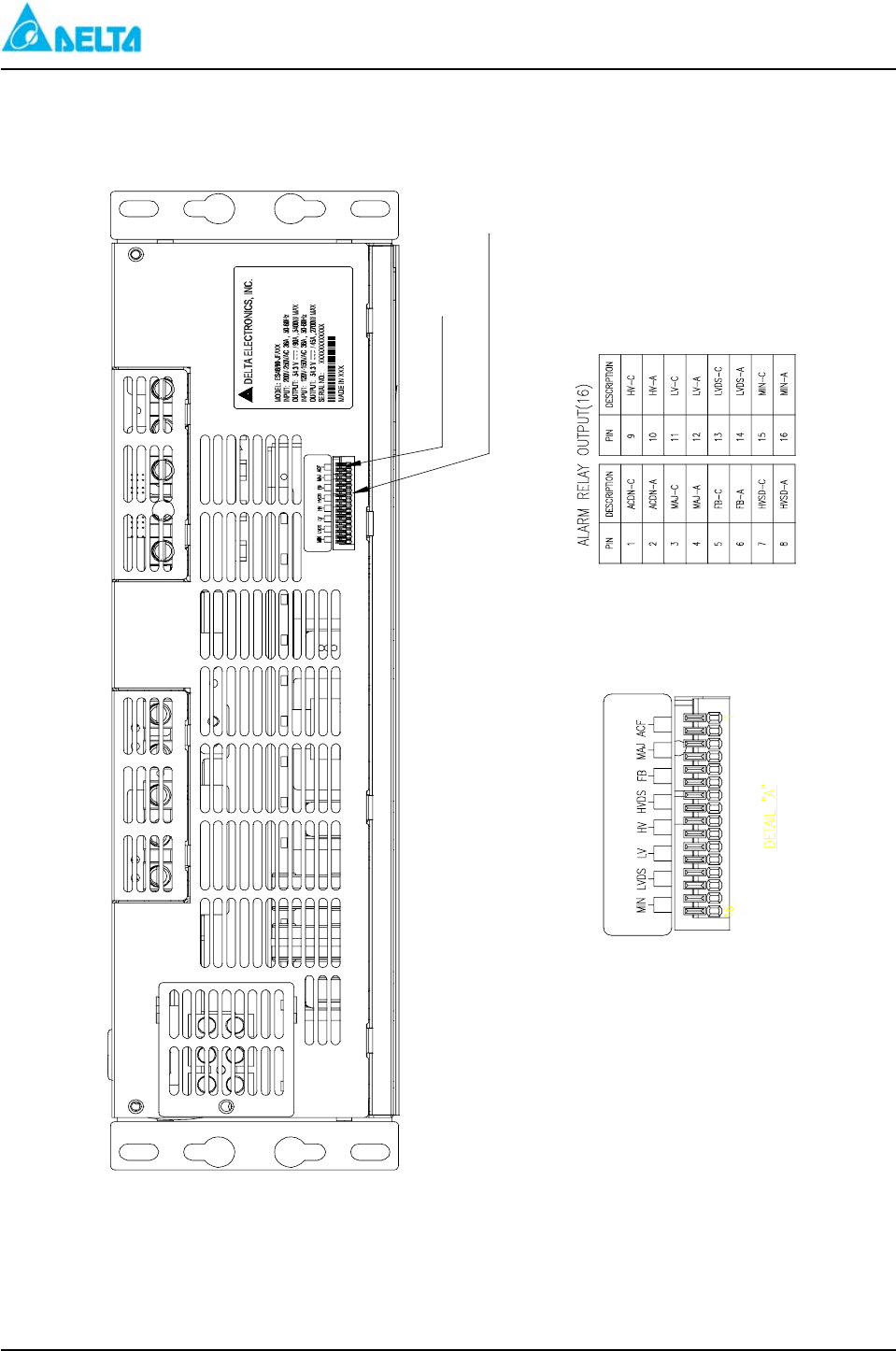
6.7.2 External Alarm Connections
1. Table 21 Alarm Terminal Block Pin Assignments
Alarm Description
ACF AC Fail
MAJ Major
HVSD High Voltage Shutdown
HV High Voltage Alarm
LV Low Voltage Alarm
LVD Low Voltage Disconnect
FA Fuse Alarm
MIN Minor
2. Each alarm connection is provided with a normally close relay contact. This contact is capable of
carrying 0.5 Amp DC at 30VDC on a continuous basis.
3. Warning: All external circuits connected to these alarm relay terminals must be secondary and
properly isolated from the incoming line.
6.8 Connect the PDU signal cables to the rear of the shelf which are mark “EXT. Breaker trip
signal I/P” connector.
The “FUSE ALM” LED on the front panel of ALU will light up when the breaker open.
6.9 AC High Voltage Aux. Relay output wiring
The connection point of “AC High Voltage Trigger Relay” which is on the rear of shelf will close when the
AC input voltage is higher than the setting value normally it’s open.

DELTA MCS-1800 3U Power Shelf
Installation, Operations and
Maintenance Manual
7-1
7 System Start-Up Procedure
7.1 Initial Start-Up Preparation
1. Verify all connections prior to starting this section.
2. Confirm the operating voltage before proceeding.
3. Ensure that the AC line is properly grounded.
4. Ensure the battery DC circuit breaker is switched to the “OFF” position
5. Ensure the PSU breaker is switched to the “OFF” position.
7.2 No Load Start-Up
The system can be started up without a load. To start up the system, perform the following steps:
1. Switch all DC distribution circuit breakers to the “OFF” position and/or remove all the fuses. If there is
the PDU in the system.
2. Verify that the battery is not connected to the system battery bus or ensure the battery switch in the “OFF”
position.
3. Check the ALU for alarm and status conditions.
7.3 Basic Functional Verification
After system start-up, basic functional verification should proceed as follows:
1. Check the ALU status and alarm LEDs.
2. Compare the rectifier DC voltage readings at the ALU with the output voltage of each rectifier by using
digital multimeter (measure at the V+ and V– points located on the front of each rectifier).
3. The “FUSE ALM” LED on the panel light because the battery breaker is switched to “OFF”.
7.4 DC Load Connections
1. Connect the positive load wires to the Load +.
2. Connect the negative load cable to the Load -.
Please refer to section 5 DC Distribution.
7.5 System Functionality Check
Control and supervisory functional testing can be performed at the ALU after the basic functional testing
is completed and the DC load is connected.
7.5.1 System Status and Alarms
Check the status of the equipment by viewing the ALU alarm and status LEDs.
7.6 System Operation
Upon completion of the system functional testing, the system is operational.

DELTA MCS-1800 3U Power Shelf
Installation, Operations and
Maintenance Manual
8-1
8 System Alarms and Troubleshooting
8.1 AC Fail Voltage Alarm Description
8.1.1 Description
If the ALU detects an input AC voltage below 50 VAC, the ALU sends an AC Fail alarm signal and
activates the dry contact. The AC Fail LED on the ALU panel lights up. When AC voltage is restored to the
nominal input voltage, the ALU extinguishes the AC Fail LED, and returns the contact to the normally closed
position.
8.1.2 Troubleshooting
The AC Fail alarm is normally caused by a commercial AC interruption due to a storm or maintenance.
If commercial AC is detected at the AC panel, check the rectifier input breakers in the AC panel for a tripped or
failed breaker.
Warning: The ALU senses the AC line through the AC Input terminal. If this connection is missing, the
system generates an AC Fail alarm.
8.2 High Voltage Shutdown Alarm
8.2.1 Description
When the ALU detects the output DC voltage exceeding the HVSD threshold setting, the ALU sends an
HVSD alarm signal and activates the dry contact. The ALU lights the HVSD LED located on the ALU panel
and shuts down each rectifier. At this point, the system is running on reserve batteries. When the DC voltage
falls below the HVSD threshold voltage, and push the HVSD RST Button, then the system recovers. The ALU
extinguishes the HVSD LED, returns the rectifiers to service, and closes the normally closed set of contacts.
8.2.2 Troubleshooting
High voltage shutdown occurs when the output voltage exceeds the HVSD threshold. This can be caused
by a rectifier failure, the system equalize voltage exceeding the HVSD threshold, or temperature compensation
exceeding the HVSD threshold setting.
1. Restart the rectifiers by resetting the HVSD RST button located on the ALU.
2. Verify the output voltage of each rectifier in both float and equalize.
3. Verify that the equalize voltage setting does not exceed the HVSD threshold setting.
4. Verify the temperature compensation voltage setting. Ensure that Temp Comp does not exceed the
HVSD threshold setting when operating in cold temperatures.
8.3 High Voltage Alarm Description
8.3.1 Description
The High Voltage alarm (HV) is a minor alarm activated when the DC output voltage exceeds the HV
threshold setting. When the system voltage exceeds the HV setting value, the ALU sends the HV alarm signal,
lights the HV LED located on the ALU panel, and activates the HV alarm contact. The rectifiers remain on
line during this minor alarm condition. When the system voltage decreases below the threshold setting, the
ALU extinguishes the HV LED and deactivates the HV alarm contact.

DELTA MCS-1800 3U Power Shelf
Installation, Operations and
Maintenance Manual
8-2
8.3.2 Troubleshooting
The HV alarm is usually caused when the equalize voltage exceeds the HV threshold setting. Another
probable cause that the temperature compensation voltage exceeds the HV threshold during cold temperature
operation. During this alarm condition, the system continues to operate.
8.4 Low Voltage Alarm
8.4.1 Description
The Low Voltage alarm (LV) is a minor alarm activated when the DC output voltage decreases below the
LV threshold setting. When the system voltage decreases below the LV LED located on the ALU panel, and
activates the LV alarm contact. The rectifiers remain on line during this minor alarm condition. When the
system voltage increases above the threshold setting, the ALU extinguishes the LV LED and deactivates the LV
alarm contact.
8.4.2 Troubleshooting
The LV alarm condition occurs during a brownout condition or prior to a complete AC Fail condition
caused by commercial AC problem conditions.
Another probable cause is that the temperature compensation voltage decreases the float voltage below the
LV threshold during hot temperature operation. During this alarm condition, the system continues to operate.
8.5 Low Voltage Disconnect Alarm (System equipped with PDU)
8.5.1 Description
During an AC Fail condition, the rectifiers are shut down and the reserve batteries begin to discharge.
When the battery cells discharge below the LVD setting, the ALU lights the LVD LED on the ALU panel,
activates the LVDS OPEN alarm contact, and opens the LVDS contactor. When the AC recovers, the LVBD
recovers automatically. The ALU extinguishes the LVD LED and resets the normally closed set of alarm
contacts.
8.5.2 Troubleshooting
If the battery disconnect switch remains open after voltage is restored to the rectifiers, one of the following
is occurring:
1. The ALU may be faulty. Swap out the ALU with a spare and verify voltage settings.
2. The LVBD coil windings may be open. With a digital multimeter, check the LVBD coil windings.
8.6 Fuse/Circuit Breaker Fail Alarm (System equipped with PDU)
8.6.1 Description
If the DC load output fuse opens or battery switch trip off, the ALU sends the alarm condition, lights the
LED on the ALU panel, and activates the Fuse Fail alarm.
8.6.2 Troubleshooting
To troubleshoot the fuse/circuit breaker fail alarm condition, perform the following steps:
1. Verify that the fuse/circuit breaker is the proper size (use 80% derating guide).
2. Verify that the external fault that might cause fuse/circuit breaker tripping is removed.
3. Replace the blown fuse with a fuse with the same rating or of the corrected value. In case of a circuit

DELTA MCS-1800 3U Power Shelf
Installation, Operations and
Maintenance Manual
8-3
breaker, turn it on. If necessary replace with the correct size fuse.
If the fuse/circuit breaker continues to trip, perform the following steps:
1. Check the DC branch load to ensure tat the fuse/ circuit breaker is the correct size.
2. If the branch load exceeds the fuse/circuit breaker rating, the device must be changed to a higher rating.
3. Install a fuse/circuit breaker with a higher rating.
Warning: Ensure that the device rating does not exceed the branch load wire capacity. If the device
rating is higher than the branch load wire rating, the branch load wire must be changed to a
larger wire. Failure to protect the branch load wire may result in overheating and fire.
8.7 Alarm Unit Fail
8.7.1 Description
During an ALU fail condition, the ALU fail and status LEDs are extinguished, and all alarm contacts open.
During an ALU failure, the rectifiers status changes from equalize to float or remains in the float condition.
The LVBD does not open during an ALU failure.
8.7.2 Troubleshooting
To troubleshoot the ALU fail condition, perform the following steps:
1. Check the input fuse located on the rear of the ALU. Replace if blown.
2. Check the DC input connectors for proper connections.
3. Replace with a spare and send the faulty unit to Delta for repair.
8.8 Rectifier Fail Alarm
(1) If one rectifier fails, the MIN contacts open, and the MIN LED on the ALU lights. When two rectifiers
fail, the MAJ alarm contact is opened, and the MAJ LED lights.
Warning: Do not open the rectifier unit. There are no serviceable parts.
(2) If you want to ignore the MAJ or MIN alarm when you pull out the rectifiers from the slots, just please
press the SMR RST button on the ALU.
(3) If you insert the above rectifier back to the slot, then pull out after the “FL” LED on the SMR panel light
up. The system will alarm in the “MIN” mode.
That means if we repeat to pull out and insert in and pull out the rectifier, the condition described in item
(2) will be cleared.

DELTA MCS-1800 3U Power Shelf
Installation, Operations and
Maintenance Manual
9-1
9 Maintenance
9.1 Cleaning and Maintenance
9.1.1 General
Special maintenance is not necessary for this system, unless the system is being operated in a severely
harsh environment (dusty environment). The front panels and the cover of the DC distribution cabinet were
treated with a special coating. Do not use organic cleanser or volatile solvent because corrosion damage
may occur. For periodic cleaning, brush the dust from the cover and panel. If necessary, use a gentle
cleanser or a lightly dampened lint free cloth to remove any dirt or smudges.
9.1.2 Periodic Maintenance
Periodic maintenance is not required for normal operation. If necessary, wipe dust from the front of
the power system using a lint free, soft cloth and gently wipe the front of the distribution module, the ALU,
and the rectifiers. If necessary, use a gentle detergent to clean.
Warning: Do not use a spray cleanser to clean the equipment. Using a spray cleanser directly on the
equipment can result in serious equipment damage.
9.2 Removing and Replacing a Rectifier Unit
9.2.1 Removing a Rectifier
Warning: Do not touch the DC output bus when pulling out the PSU module.
To remove a rectifier, perform the following steps.
1. Switch off PSU module.
2. Loosen the captive retaining screws located on the bottom of the front panel.
3. Pull out the rectifier unit slowly from the shelf.
9.2.2 Replacing a Rectifier
To replace a rectifier, perform the following steps:
1. Make sure the breaker on the front panel of PSU is switched off.
2. Install the rectifier unit carefully. Place the rectifier on the shelf, ensuring that the rails are on the
track.
Warning: Do not force the module into the slot. If does not slide in and connect easily, remove and reset
the unit.
3. Lock the rectifier into position by screwing in the captive retaining screws located at the bottom of
the rectifier.
4. Switch on the PSU and check the AC ON LED lights on the front of the PSU on the front of the
rectifier. AC ON LED lights.

Delta MCS-1800 3U Power Shelf
Installation, Operations and
Maintenance Manual
10-1
10 Acronyms and Abbreviations
--- A ---
ALU Alarm Control Unit
Amp Ampere
ANSI American National Standards Institute
--- B ---
BS British Standard
BTU British Thermal Unit
--- C ---
C Centigrade
CB Circuit Breaker
CE European Community
CISPR International Special Committee on Radio Interference
CL Current Limit
CUL Canadian Underwriters Laboratory
--- D ---
--- E ---
EMI Electro-Magnetic Interference
ESD Electrostatic Discharge
--- F ---
F Fahrenheit
FCC Federal Communications Commission
Ft. Foot
--- G ---
GND Ground
--- H ---
HL High Line
HV High Voltage
HVSD High Voltage Shutdown
Hz Hertz
--- I ---
IEC International Electronics Commission
IEEE Institute of Electrical and Electronics Engineers
In. Inch
--- J ---
--- K ---
Kg. Kilogram
KHz Kilohertz

Delta MCS-1800 3U Power Shelf
Installation, Operations and
Maintenance Manual
10-2
KHz Kilohertz
KV Kilovolt
KW Kilowatt
--- L ---
Lb. Pound
LED Light-Emitting Diode
LL Low Line
LV Low Voltage
LVD Low Voltage Disconnect
LVBD Low Voltage Battery Disconnect
LVDS Low Voltage Disconnect Switch
--- M ---
M Meter
Max. Maximum
MHz Megahertz
Mm Millimeter
Ms Millisecond
MTBF Mean Time Between Failure
MV Millivolt
mVrms Millivolt root root mean square
--- N ---
NEMA National Electrical Manufacturers Association
No. Number
--- O ---
--- P ---
PF Power Factor
PFC Power Factor Correction
PSU Power Supply Unit
--- Q ---
Qty. Quantity
--- R ---
RFA Rectifier Failure Alarm
RFI Radio Frequency Interference
RH Relative Humidity
RMA Return Material Authorization
--- S ---
--- T ---

Delta MCS-1800 3U Power Shelf
Installation, Operations and
Maintenance Manual
10-3
TB Terminal Block
THD Total Harmonic Distortion
--- U ---
UL Underwriters Laboratory
--- V ---
V Volt
VAC Vo lts AC
VDC Volts DC
--- W ---
W Watt
--- X ---
--- Y ---
--- Z ---

Delta MCS 1800 3U
Power Shelf
ATTACHMENT
DELTA ELECTRONICS, INC.
DELTA MCS 1800 3U Power Shelf
Installation, Operations and
Maintenance Manual
REV: 00 A-1
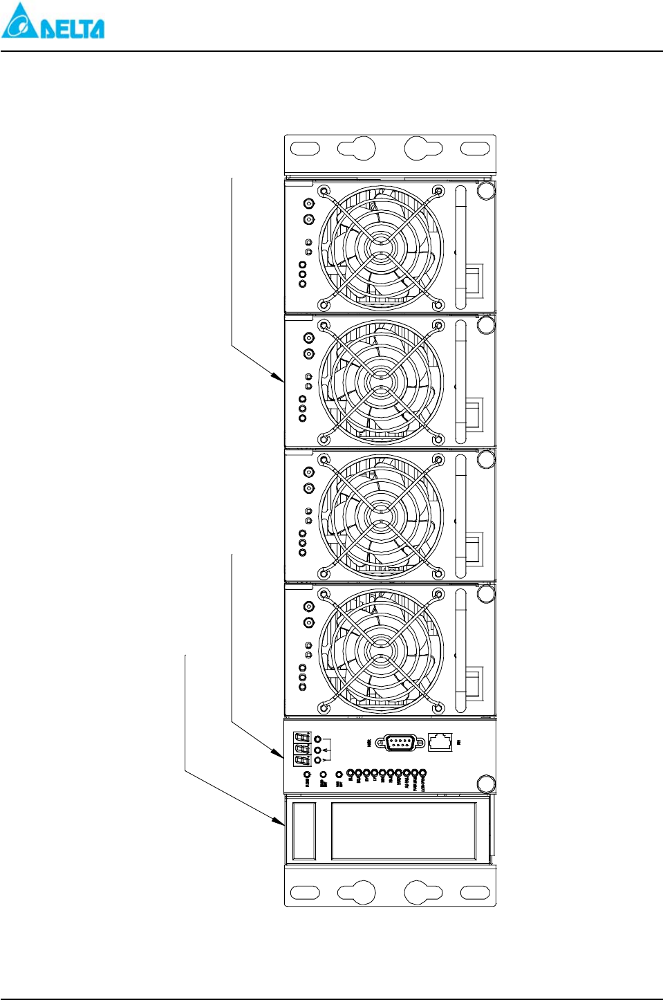
Figure 1: ES 48/120-JAAxx、ES 24/200-JAAxx (-48V/+24VPower Shelf)
Power Shelf
RFA
Alarm Control Unit
AC
ON
CL
AC ON
Power Supply Unit
ON
OFF
AC
OFF
OFF
AC
ON
ON
I-
CL FLO
I+
RFA
CL
AC ON
I-
CL FLO
CL
I+
RFA
AC ON
CL
I+
I-
FLO
AC
OFF
FLO
CL
CL RFA
AC ON
I+
I-
DELTA MCS 1800 3U Power Shelf
Installation, Operations and
Maintenance Manual
REV: 00 A-2
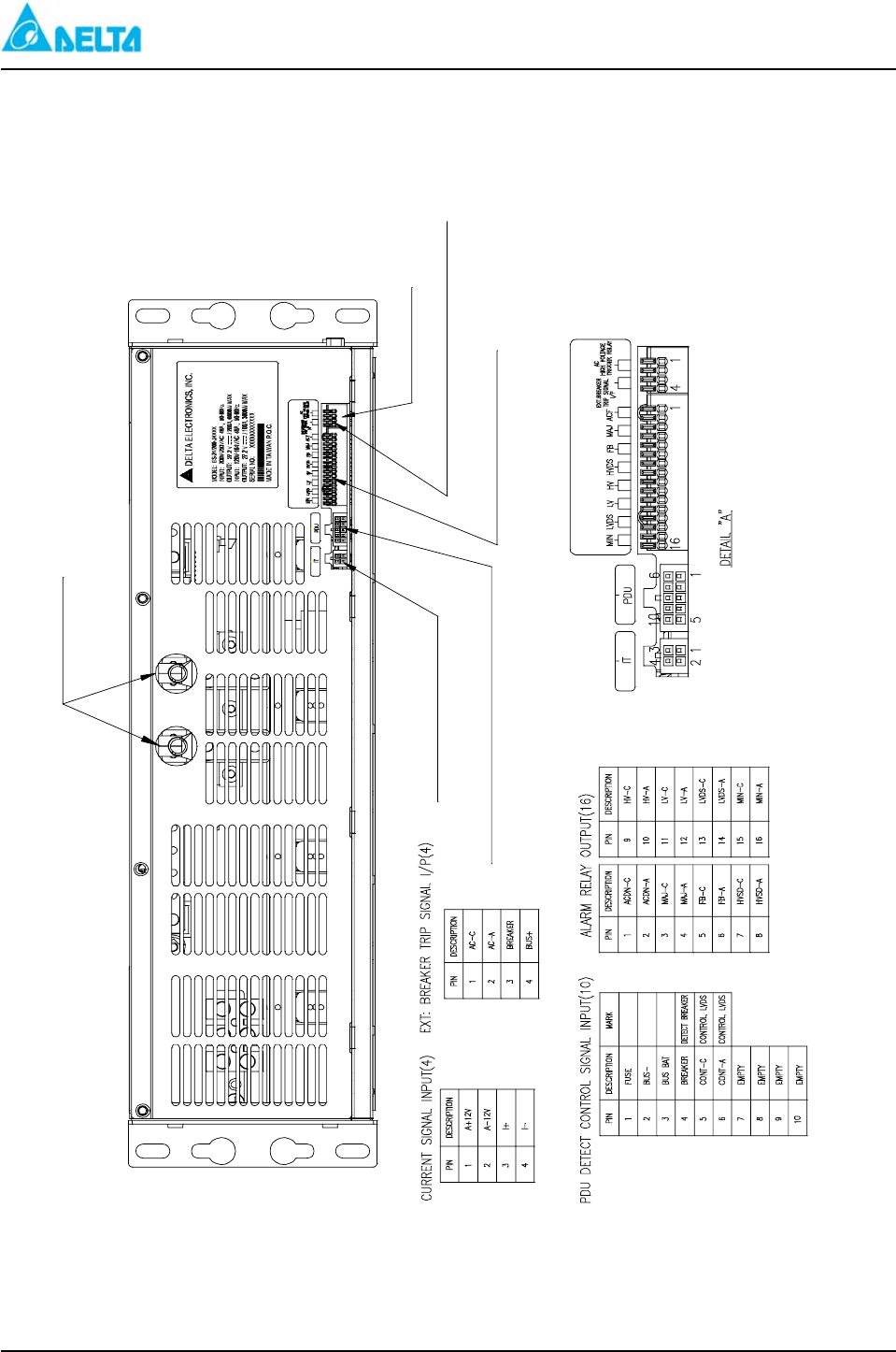
Figure 1-1: ES 48/120-JAAxx 、ES 24/200-JAAxx (DC Output Lug
Distribution)
DETAIL "A"
EXT: Breaker Trip Signal I/P
Alarm Relay Output
PDU Detect Control Signal Input
Current Signal Input
交換式電源供應器
台達電子工業股份有限公司
DC Output

DELTA MCS 1800 3U Power Shelf
Installation, Operations and
Maintenance Manual
REV: 00 A-3
Figure 1-2: ES 48/120-JAAxx 、ES 24/200-JAAxx (Signal connection
Connectors for External Distribution Unit )
DELTA MCS 1800 3U Power Shelf
Installation, Operations and
Maintenance Manual
REV: 00 A-4
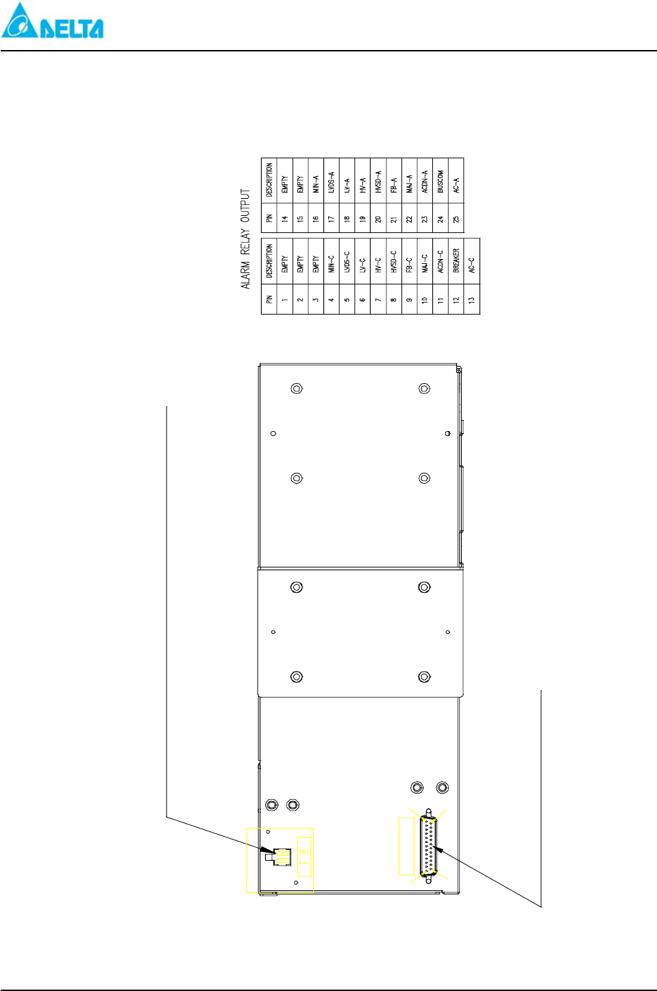
Figure 1-3: ES 48/120-JAAxx、ES 24/200-JAAxx (Battery Temperature
and Alarm Relay Output Connectors)
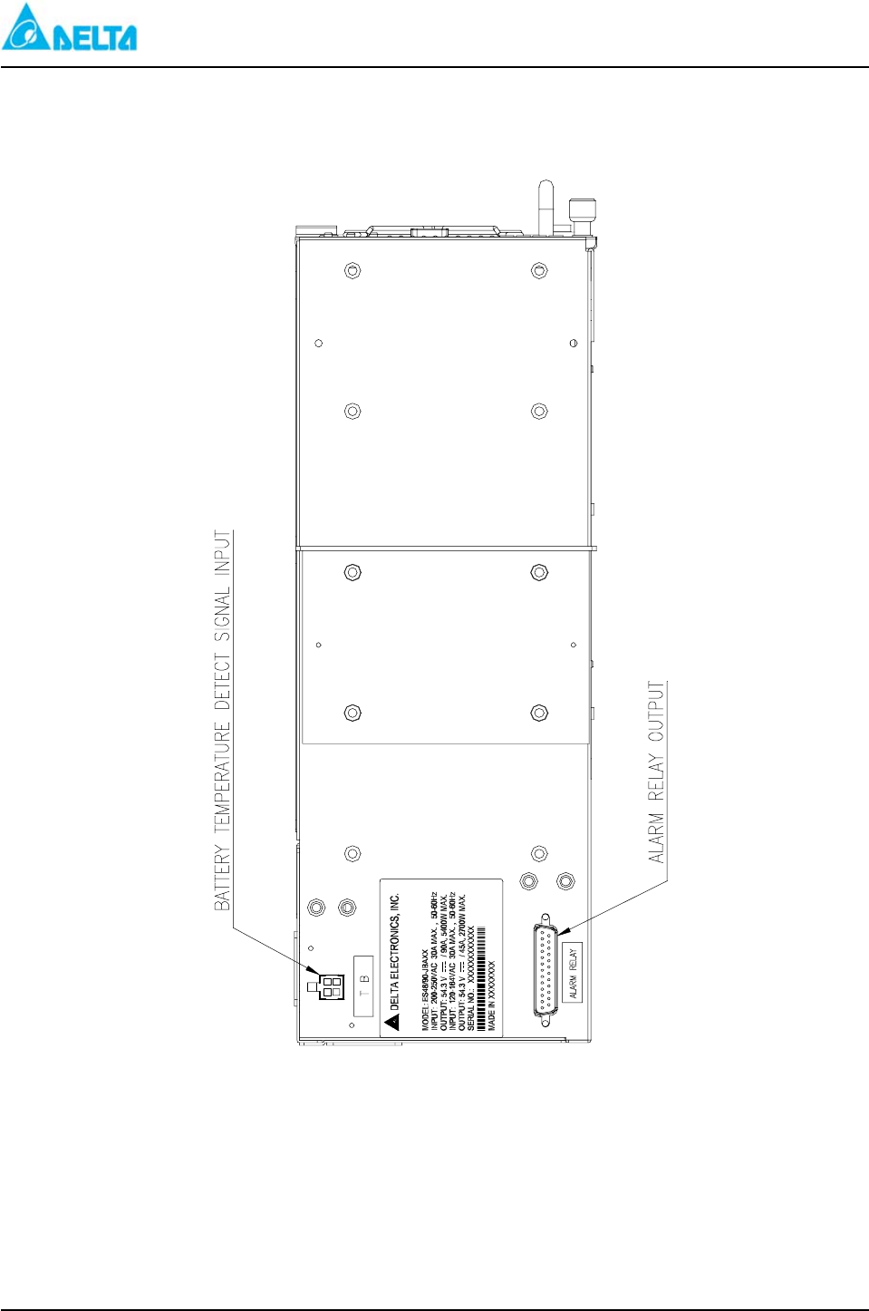
BATTERY TEMPERATURE DETECT SIGNAL INPUT
ALARM RELAY OUTPUT
14
25
ALARM RELAY
13 1
DELTA MCS 1800 3U Power Shelf
Installation, Operations and
Maintenance Manual
REV: 00 A-5
Figure 1-4: ES 48/120-JAAxx (Shelf Wiring MCS 1800 Series Shelf)
DELTA MCS 1800 3U Power Shelf
Installation, Operations and
Maintenance Manual
REV: 00 A-6
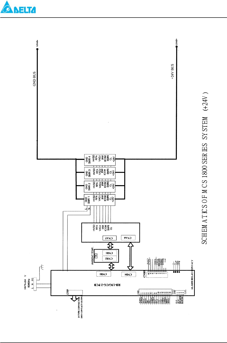
Figure 1-5: ES 24/200-JAAxx (Shelf Wiring Diagram)
DELTA MCS 1800 3U Power Shelf
Installation, Operations and
Maintenance Manual
REV: 00 A-7
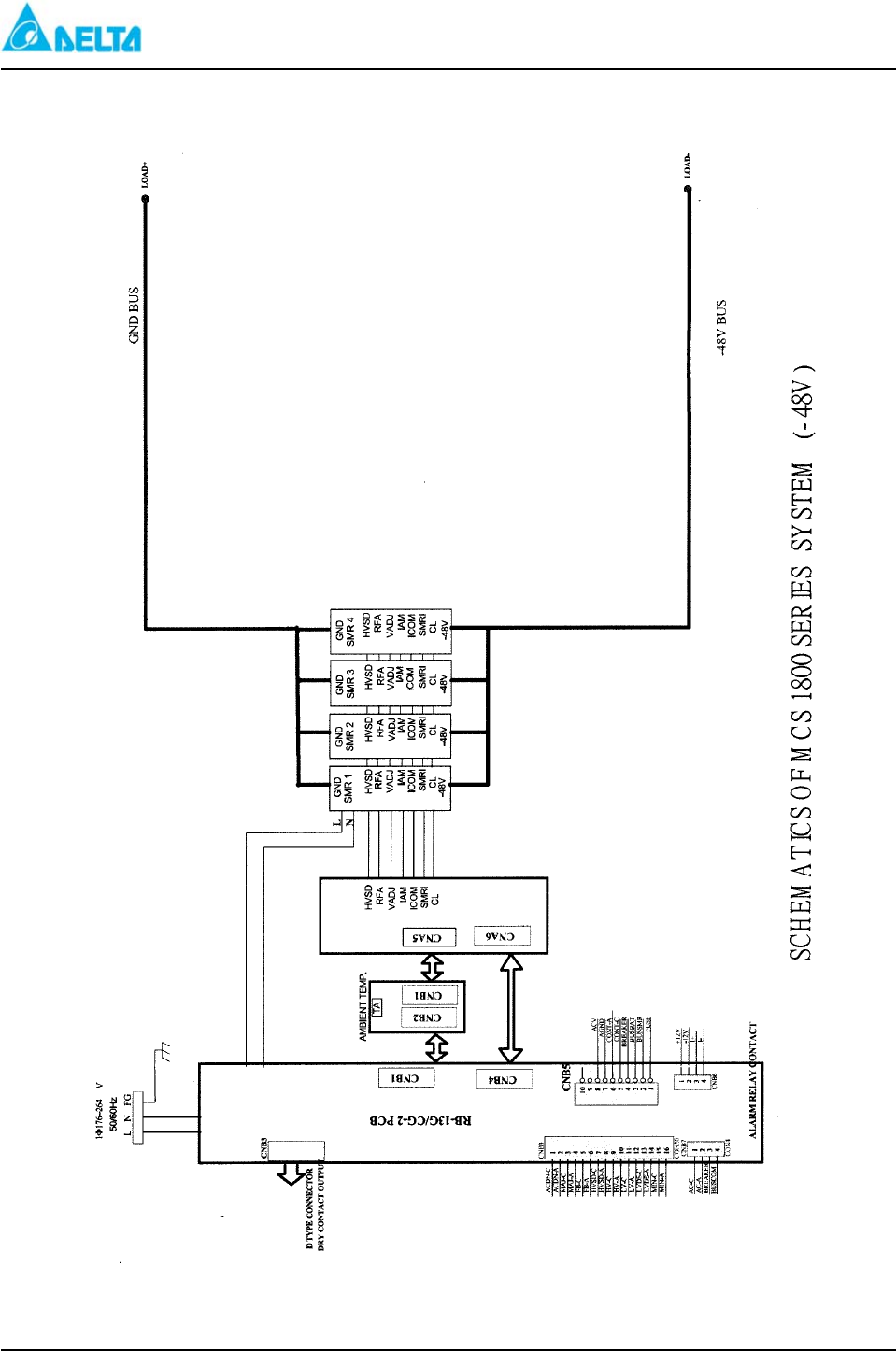
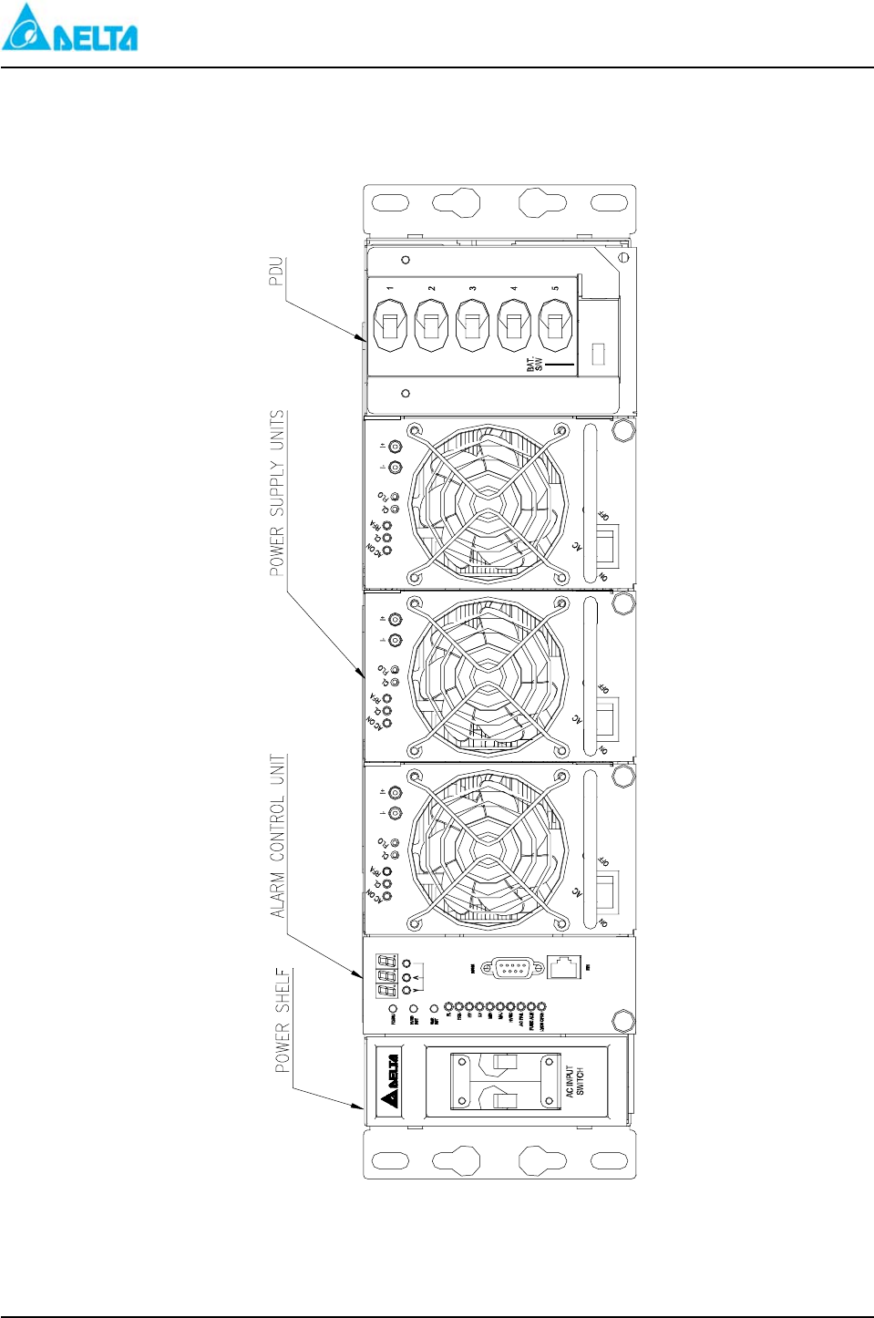
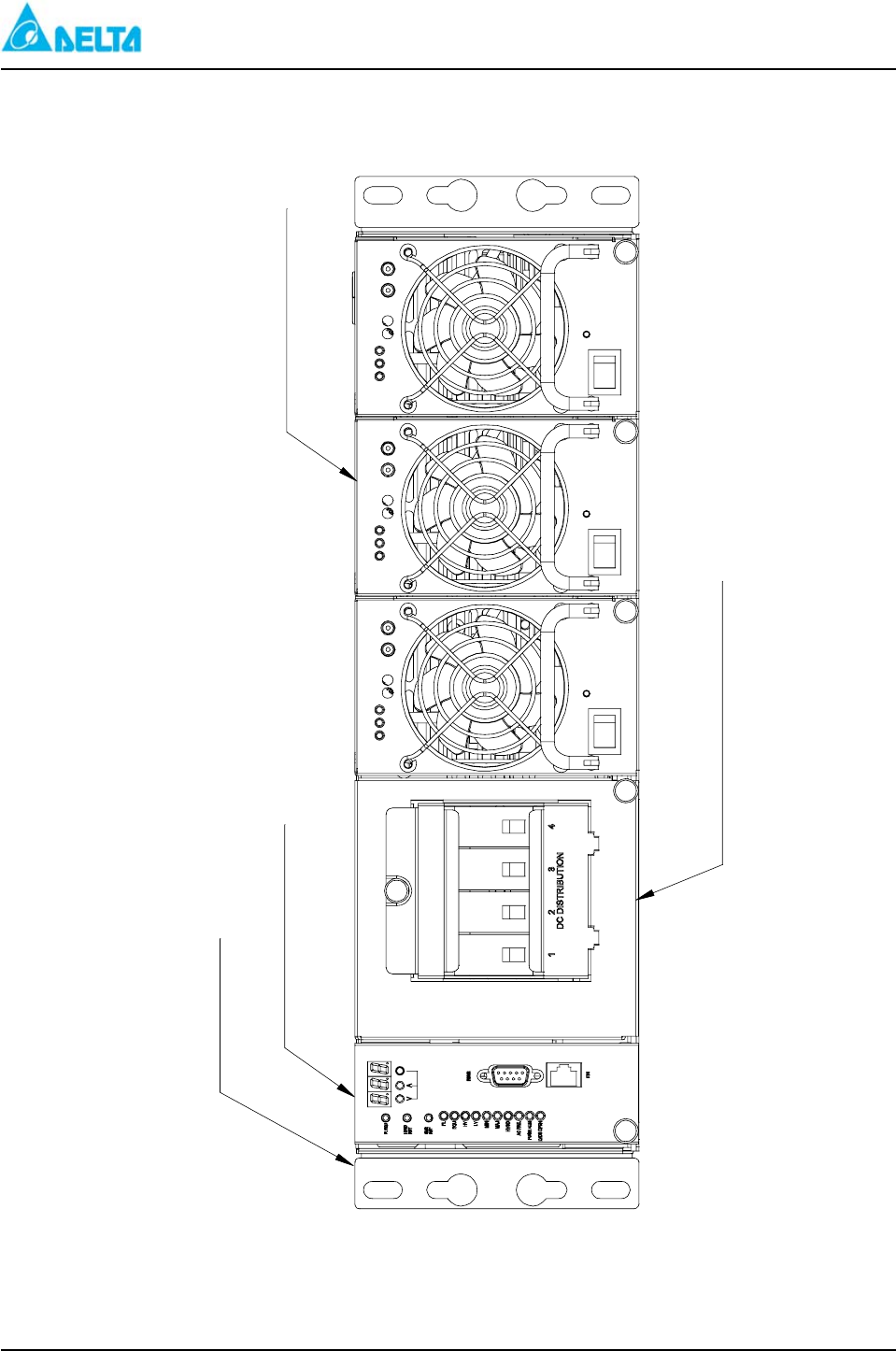
Figure 2: ES 48/90-JBAxx (-48V Power Shelf With PDU)
DELTA MCS 1800 3U Power Shelf
Installation, Operations and
Maintenance Manual
REV: 00 A-8
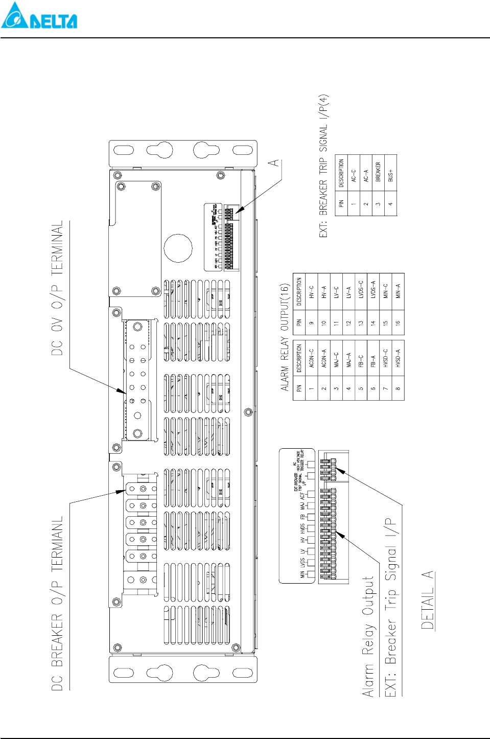
Figure 2-1: ES 48/90-JBAxx (DC Output Lug Distribution)
DELTA MCS 1800 3U Power Shelf
Installation, Operations and
Maintenance Manual
REV: 00 A-9
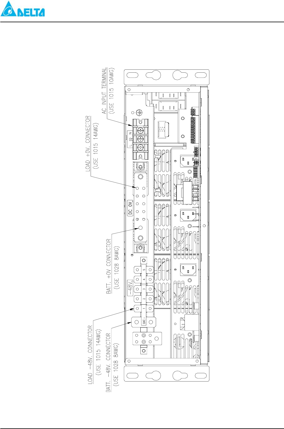
Figure 2-2: ES 48/90-JBAxx (Load Cable and Battery String
Connection Terminals)
DELTA MCS 1800 3U Power Shelf
Installation, Operations and
Maintenance Manual
REV: 00 A-10
Figure 2-3: ES 48/90-JBAxx (Battery Temperature and Alarm Relay
Output Connectors)
台達電子工業股份有限公司
交換式電源供應器
DELTA MCS 1800 3U Power Shelf
Installation, Operations and
Maintenance Manual
REV: 00 A-11
Figure 2-4: ES 48/90-JBAxx (Battery and Load Breaker Distribution)
DELTA MCS 1800 3U Power Shelf
Installation, Operations and
Maintenance Manual
REV: 00 A-12
Figure 2-5: ES 48/90-JBAxx (Shelf Wiring MCS 1800 Series Shelf)
DELTA MCS 1800 3U Power Shelf
Installation, Operations and
Maintenance Manual
REV: 00 A-13
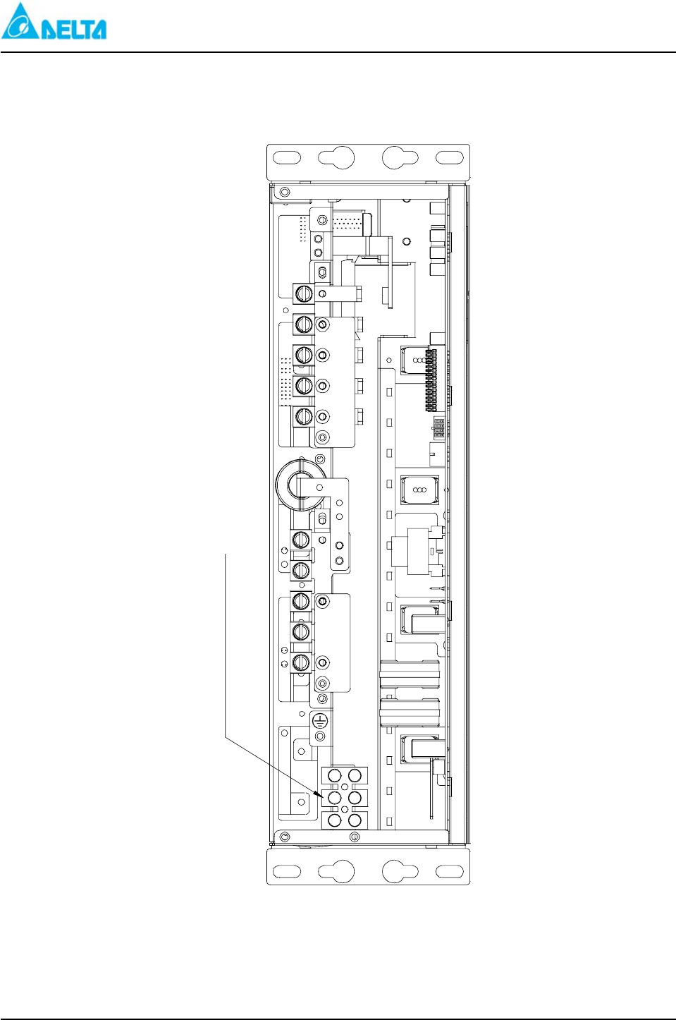
Figure 3: ES 48/90-JFAxx (-48V Power Shelf With PDU)
RFA
CLFLO
I-
I+
AC ON
CL
I-
CLFLO
I+
RFA
AC ON
CL
I-
FLO
CL
I+
RFA
AC ON
CL
OFF
AC
ON
OFF
AC
ON
OFF
AC
ON
Alarm Control Unit
Power Shelf
Power Supply Unit
Power Distribution Unit
DELTA MCS 1800 3U Power Shelf
Installation, Operations and
Maintenance Manual
REV: 00 A-14
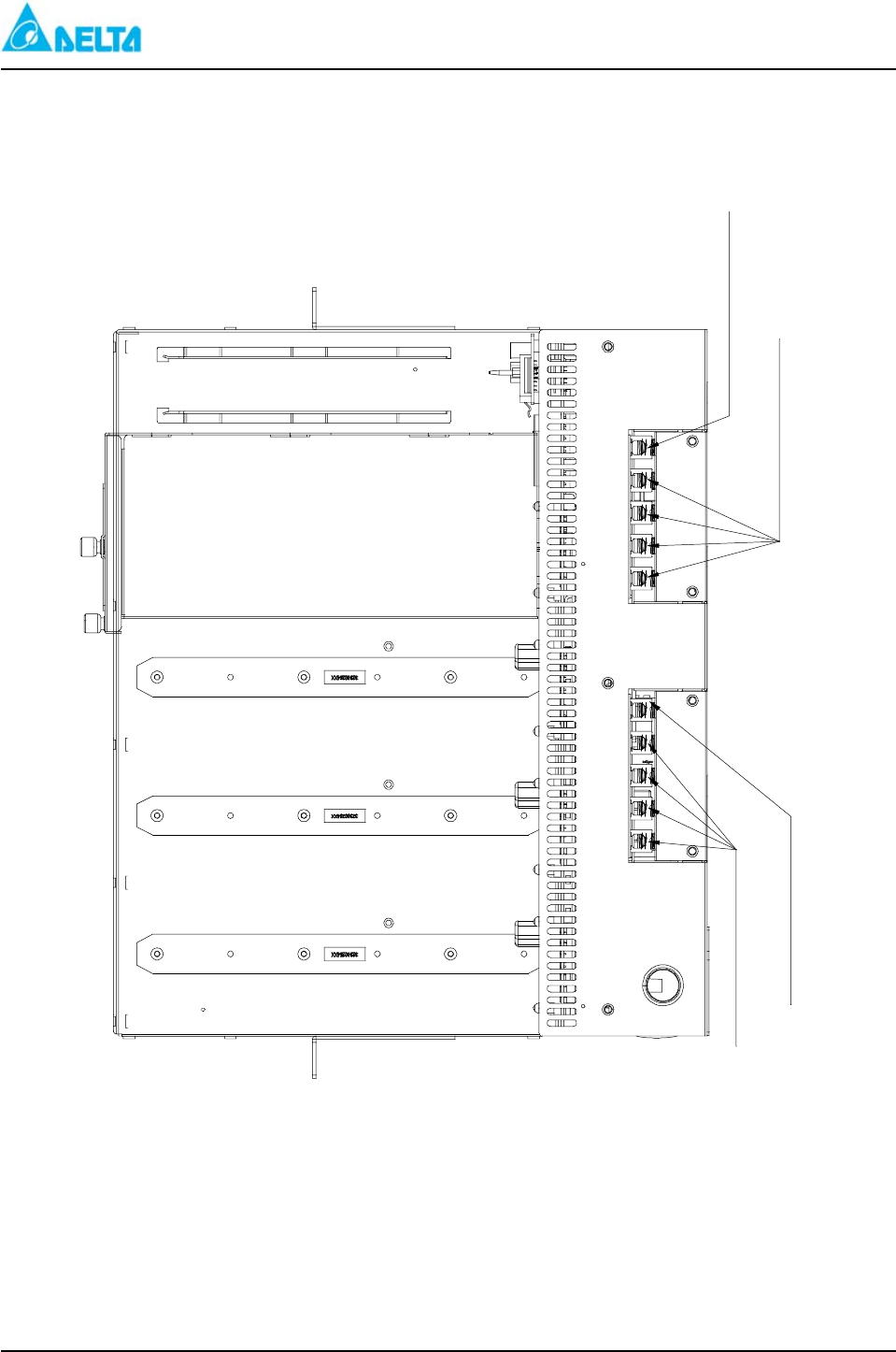
Figure 3-1: ES 48/90-JFAxx (Alarm Relay Output connectors)
台達電子工業股份有限公司
交換式電源供應器
Alarm Relay Output
DETAIL "A"
DELTA MCS 1800 3U Power Shelf
Installation, Operations and
Maintenance Manual
REV: 00 A-15
Figure 3-2: ES 48/90-JFAxx (AC Input Connector)
AC INPUT TERMINAL
(USE 1015 6AWG~10AWG)
DELTA MCS 1800 3U Power Shelf
Installation, Operations and
Maintenance Manual
REV: 00 A-16
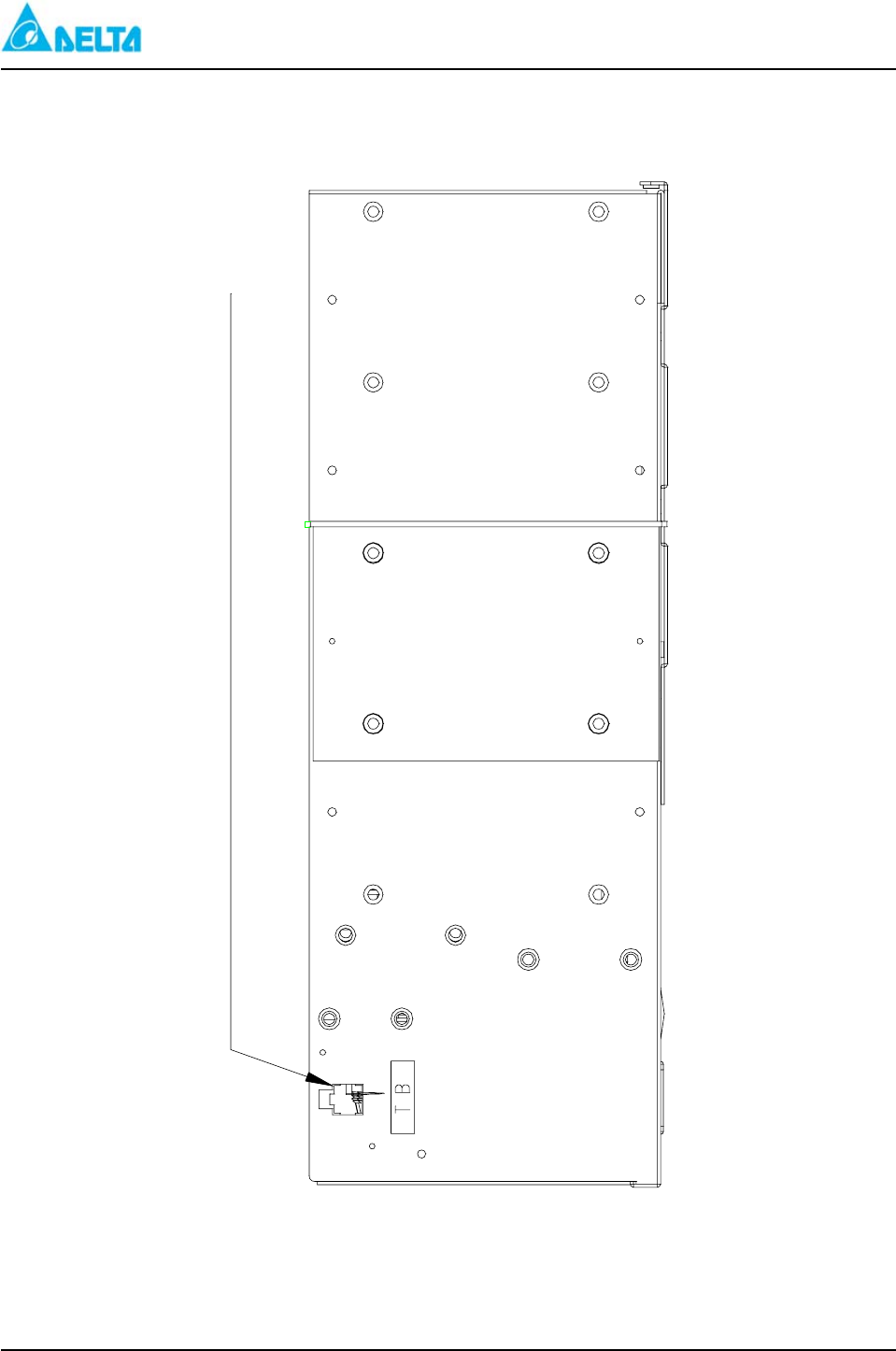
Figure 3-3: ES 48/90-JFAxx (Battery Temperature)
BATTERY TEMPERATURE DETECT SIGNAL INPUT
DELTA MCS 1800 3U Power Shelf
Installation, Operations and
Maintenance Manual
REV: 00 A-17
Figure 3-4 ES 48/90-JFAxx (DC Output Lug Distribution)
LOAD -48V TERMINAL
(USE 1015 4AWG~8AWG)
BATT+0V TERMINAL
(USE 1015 4AWG~8AWG)
LOAD +0V TERMINAL (USE 1015 4AWG~8AWG)
BATT. -48V TERMINAL
(USE 1015 4AWG~8AWG)
DELTA MCS 1800 3U Power Shelf
Installation, Operations and
Maintenance Manual
REV: 00 A-18
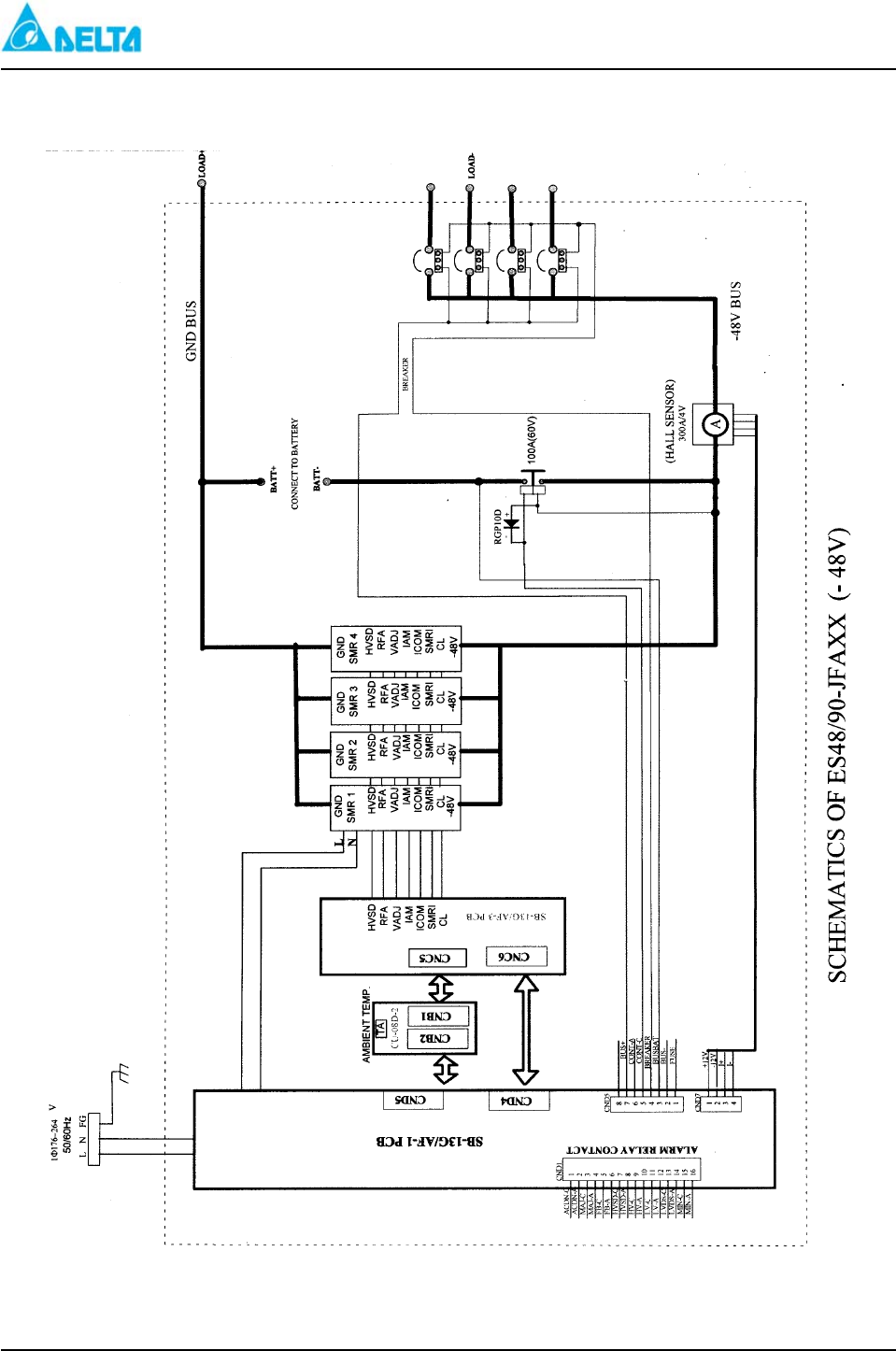
Figure 3-5: ES 48/90-JFAxx (Shelf Wiring MCS 1800 Series Shelf)
DELTA MCS 1800 3U Power Shelf
Installation, Operations and
Maintenance Manual
REV: 00 A-20
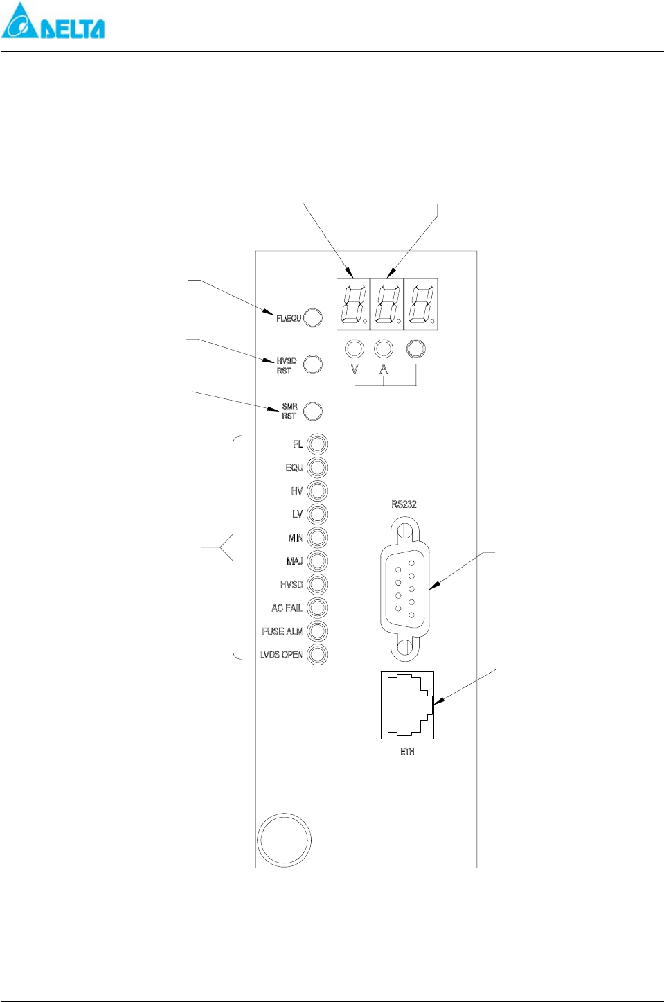
Figure 4: Alarm Control Unit
System Voltage
Measurment System Current
Measurement
Manual Float/
Equalizing Button
High Voltage Shut
Down Reset
SMR RFA
Warning Reset
Alarm/Status
Indicator LEDS RS232 Interface
LAN Interface
DELTA MCS 1800 3U Power Shelf
Installation, Operations and
Maintenance Manual
REV: 00 A-21
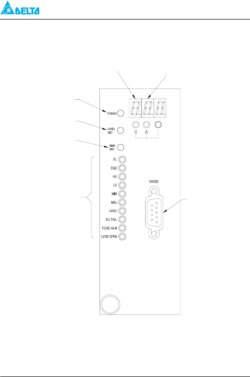
Figure 4-1: Alarm Control Unit
System Voltage
Measurment System Current
Measurement
Manual Float/
Equalizing Button
High Voltage Shut
Down Reset
SMR RFA
Warning Reset
Alarm/Status
Indicator LEDS RS232 Interface
DELTA MCS 1800 3U Power Shelf
Installation, Operations and
Maintenance Manual
REV: 00 A-22
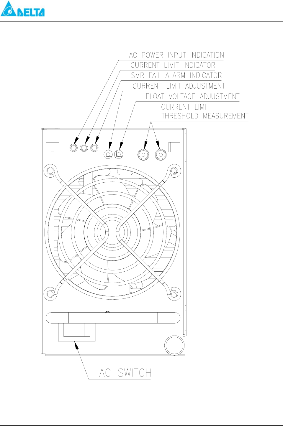
Figure 5: Power Supply Unit
DELTA MCS 1800 3U Power Shelf
Installation, Operations and
Maintenance Manual
REV: 00 A-23
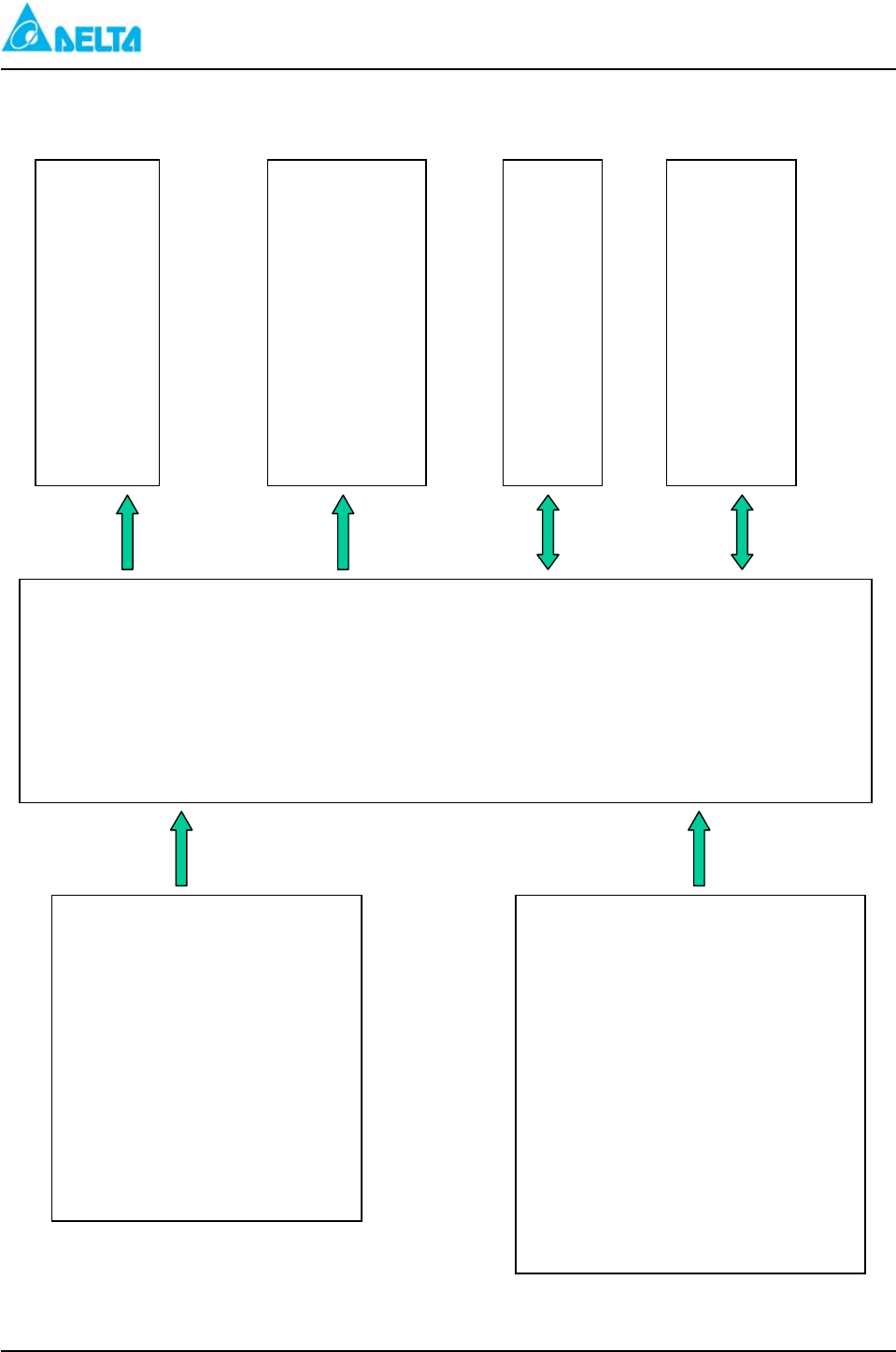
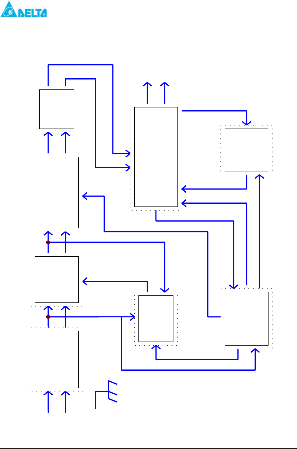
Figure 6: ALU Block Diagram
SMR Fail Alarm Detection
SMR Current Limit
Detection
Temp. Sensor Lock Off
Breaker or Fuse Fail
FL/EQU Exchange Signal
SMR Fail Reset
HVSD Alarm Reset
SMR Current (1-5)
Load Current (1)
Batt. Temperature
DC Voltage
AC voltage
Current
Alarm Output Relay
and LED Indicator
LVDS Contact Control
Current Limit Signal
Voltage Output
EEPROM
RS232 Communication
WEB Communication
A/D
D/I
USART
SSP
PWM
D/O
DELTA MCS 1800 3U Power Shelf
Installation, Operations and
Maintenance Manual
REV: 00 A-24
Figure 7: SMR Block Diagram
Input Fuse
Inrush C.K.T.
EMI Filter
I/P Bridge
PFC Boost
Converter
PFC
Controller
Full
Bid
Phase
Shift
DC/DC
C
Output
Rectifier
Aux. Power
&
Driver C.K.T.
Fan.
Connector
C.K.T.
DC/DC Output
Controller & Fuse
Protection Filter
L
N
FG
Vo +
Vo -

P/N: MCS-1800 Power Shelf
TAIPEI OFFICE
186 RUEY KUANG ROAD, NEIHU
TAIPEI 114, TAIWAN, R.O.C.
TEL : 886-2-87972088
FAX : 886-2-87972120
CHUNGLI PLANT
3 TUNG YUAN ROAD,
CHUNGLI INDUSTRIAL ZONE,
CHUNGLI, TAOYUAN HSIEN 320, TAIWAN, R.O.C.
TEL. 886-3-4526107
FAX. 886-3-4527314
