Delta TM 105312 Installation Manual Jan 07 User To The D973d0b2 5d22 44c0 9056 4b4383f5e92a
User Manual: Delta TM-105312 to the manual
Open the PDF directly: View PDF ![]() .
.
Page Count: 21
Revised 1-8-2007
Delta Cooling Towers, Inc.
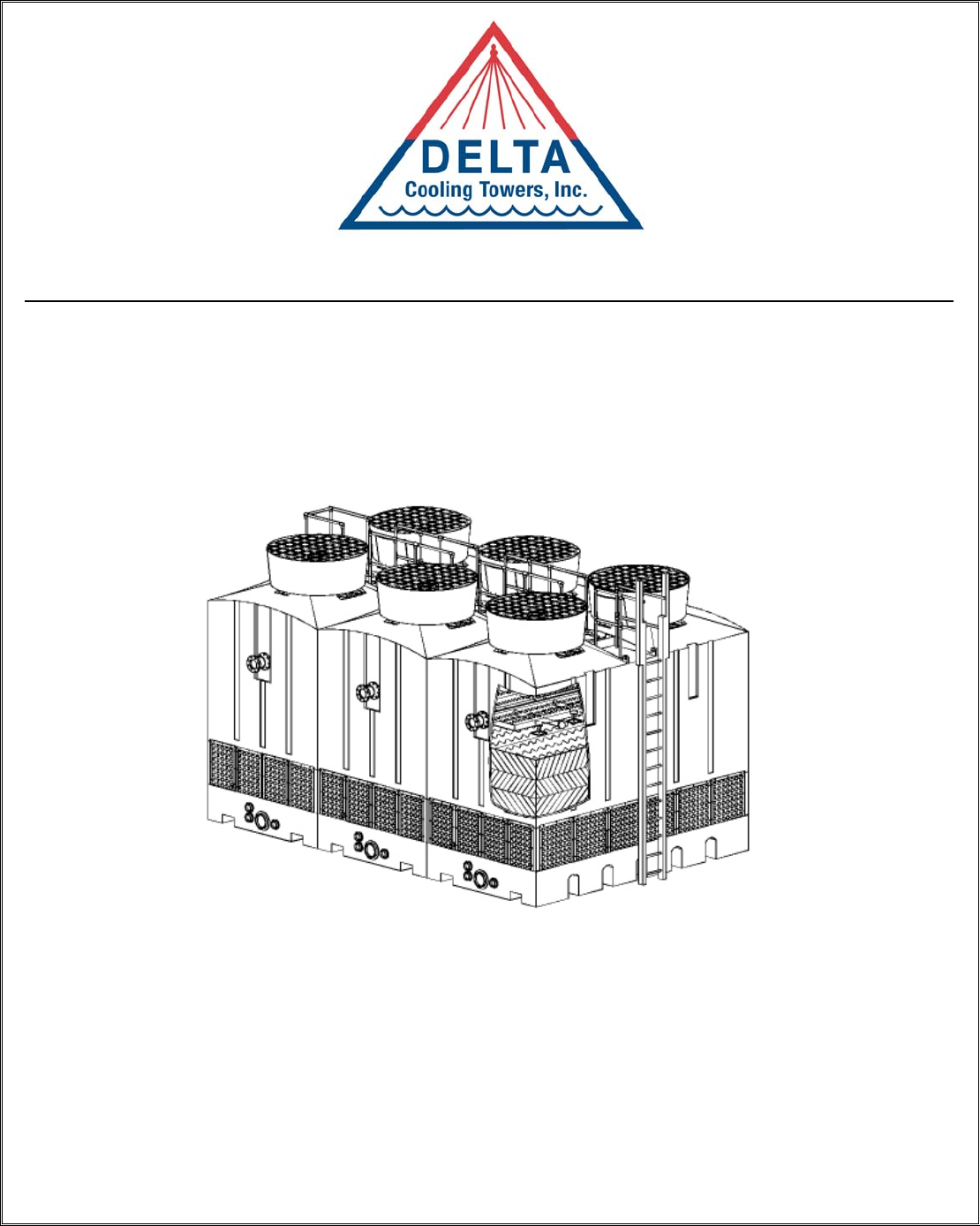
TM Series
Cooling Tower
Installation, Operation & Maintenance
Manual
Revised 1-8-2007 1
Table of Contents
Delta Cooling Towers Principle of Cooling Towers………………..……………. 2
Cooling Tower Terms and Definitions…………………… 2
Water Treatment……..………………………….……….. 3
General Information Safety………………..………………………………….… 3
Approximate Weights………………..…………………… 4
Dimensions & Other Physical Data……..………...……… 4
Handling & Installation On-Site Inspection………………..………..…….….……. 5
Off Loading……..……………..………………………….. 5
Anchoring……..……….…………………………..……… 8
Electrical Wiring of Fan Motor & Accessories……..…….. 8
Location, Piping & Connections……..…….……….…….. 8
PVC Solvent Cementing Instructions………………...…… 10
Operation and Maintenance Safety in Operation of the Fan..…..………..…….….……. 11
Water Distribution System……..…………………………. 11
Fan & Mechanical Drive System….………………..…...… 12
Start-up Instructions………………………………..…….. 12
Water Level in Tower Sump…..……..…….……….…….. 13
Cold Weather Operation…………...………………...…… 14
Trouble-Shooting Guide.…………...……………….….… 16
Motor Trouble-Shooting Guide…………...………....…… 18
Other Information Cooling Tower Optional Accessories..…..…...….….……. 19
Recommended Replacement Parts……..…………………. 19
Preventative Maintenance Checklist….……………….….. 20
Important: Delta’s cooling towers have been designed to provide trouble-free service over an extended period of time. To obtain
the design performance, it is necessary that the cooling tower be installed, operated and maintained as prescribed in
these instructions.
Only persons possessing the skill and experience described herein should attempt to install this equipment. Prior to
installation, these instructions should be read carefully by the person who is to install the cooling tower to be
certain that its installation, operation and maintenance are thoroughly understood.
Questions regarding the installation, operation or maintenance of this equipment should be directed to Delta Cooling
Towers, Inc., Rockaway, New Jersey, (Telephone: 973/586-2201).
Step-by-step instructions contained in this brochure are based on normal installation conditions only. Abnormal or
unusual combinations of field conditions should be brought to the attention of Delta Cooling Towers or its
representative prior to installation of the equipment. The information contained herein is subject to change without
notice in the interest of product improvement.

Revised 1-8-2007 2
Delta Cooling Towers
Principle of Cooling Towers
All Cooling Towers operate on the principle of removing heat from water by evaporating a small portion of the
water that is recirculated through the unit.
The heat that is removed is called the latent heat of vaporization.
Each one pound of water that is evaporated removes approximately 1,000 BTU's in the form of latent heat.
Cooling Tower Terms and Definitions
BTU - A BTU is the heat energy required to raise the temperature of one pound of water one degree Fahrenheit
in the range from 32° F. to 212° F.
Cooling Range - The difference in temperature between the hot water entering the tower and the cold water
leaving the tower is the cooling range.
Approach - The difference between the temperature of the cold water leaving the tower and the wet-bulb
temperature of the air is known as the approach. Establishment of the approach fixes the operating temperature
of the tower and is a most important parameter in determining both tower size and cost.
Drift - The water entrained in the air flow and discharged to the atmosphere. Drift loss does not include water
lost by evaporation. Proper tower design and operation can minimize drift loss.
Heat Load - The amount of heat to be removed from the circulating water within the tower. Heat load is equal to
water circulation rate (gpm) times the cooling range times 500 and is expressed in BTU/hr. Heat load is also an
important parameter in determining tower size and cost.
Ton - An evaporative cooling ton is 15,000 BTU's per hour.
Wet-Bulb Temperature - The lowest temperature that water theoretically can reach by evaporation. Wet-Bulb
Temperature is an extremely important parameter in tower selection and design and should be measured by a
psychrometer.
Pumping Head - The pressure required to pump the water from the tower basin, through the entire system and
return to the top of the tower.
Make-Up - The amount of water required to replace normal losses caused by bleed-off, drift, and evaporation.
Bleed Off (Blowdown) - The circulating water in the tower which is discharged to waste to help keep the
dissolved solids concentration of the water below a maximum allowable limit. As a result of evaporation,
dissolved solids concentration will continually increase unless reduced by bleed off.

Revised 1-8-2007 3
Water Treatment
• The Delta Cooling Towers are manufactured from corrosion-resistant plastics which are resistant to water
treatment chemicals including common fungicides and bactericides.
• Follow appropriate water treatment practices as required and take frequent sample tests to avoid possible
water contamination. We also recommend water treatment maintenance as a measure of protection of the
environment in the vicinity of any cooling tower or other equipment open to atmosphere.
• To determine the appropriate water treatment practices for your particular application, it is suggested that
you contact a water treatment firm for their recommendation. A list of water treatment firms is available for
your reference. It is not necessarily complete nor do we recommend a specific firm. The list will be mailed to
you on request or consult your local yellow pages.
• Bleed-off is also important to water quality. Evaporation of the recirculated water does not remove the
dissolved solids that are present in the water. Without bleed-off, the continual buildup of these solids will
impair the proper functioning of the piping and other equipment in the system.
• A bleed line can be connected in any part of the system for routing to the sewer. Normally, it is most
desirable to make this connection in the hot water line at the cooling tower. A petcock type valve, installed in
the bleed line is recommended. Normally, bleed-off of 1% to 2% of the recirculation water flow is
satisfactory. The required amount of bleed-off water must be substituted with properly controlled amounts of
make-up water.
General Information
Safety
When handling, lifting, installing or operating the cooling tower, always employ safe work procedures,
according to best practices of the trade and according to applicable construction, electrical and safety standards,
regulations and codes.
Follow all safety practices described in these instructions.
Revised 1-8-2007 4
Approximate Weights
The TM Series cooling towers are manufactured in three basic sections; a polyethylene tower body, a
polyethylene sump, and a fan assembly section. The tower body ships with the fan assemblies installed.
The tower sump ships as a separate piece.
Approximate Weights (lbs.)
Overall
Dimensions
(inches)
Model Group Shipping
Body Sump
Operating L x W x H
TM-105312 – TM-115412
4,850
1,660
11,800
198” x 102” x 186”
TM-205312 – TM-215412
(2) 4,850
(2) 1,660
23,600
198” x 204” x 186”
TM-305312 – TM-315412
(3) 4,850
(3) 1,760
35,400
198” x 306” x 198”
TM-405312 – TM-415412
(4) 4,850
(4) 1,760
47,200
198” x 408” x 198”
TM-505312 – TM-510412
(5) 4,850
(5) 1,760
59,000
198” x 510” x 198”
TM-605312 – TM-610412
(6) 4,850
(6) 1,760
70,800
198” x 612” x 198”
Dimensions and Other Physical Data
For cooling tower dimensions, design for foundations, assembly and layout, refer to the following
drawings which are a part of these instructions:
Model Group Title Drawing No.
TM-105312 – TM-115412 1 Cell DT-D-87-901
2 Cell (5 - 7.5 HP) DT-D-87-902
TM-205312 – TM-215412
2 Cell (10 – 15 HP) DT-D-87-903
TM-305312 – TM-315412 3 Cell
DT-D-87-904-1
DT-D-87-904-2
TM-405312 – TM-415412 4 Cell DT-D-87-905-1
DT-D-87-905-2
TM-505312 – TM-510412 5 Cell DT-D-87-906-1
DT-D-87-906-2
TM-605312 – TM-610412 6 Cell DT-D-87-907-1
DT-D-87-907-1
Revised 1-8-2007 5
Handling and Installation of Your TM Series Cooling Tower
On -Site Inspection
Upon arrival at the job site, carefully inspect the shipment for any damage. If shipping damage has occurred,
notify the driver or the carrier immediately and make a notation of the damage on the shipping bill of lading.
Check that all items listed B/L have been received.
Offloading
The TM Series cooling towers are normally delivered to the site on a 30 inch high drop deck trailer. Both the
tower body assembly and sump assembly are strapped down to the truck bed. The sump assembly should be
unloaded first.
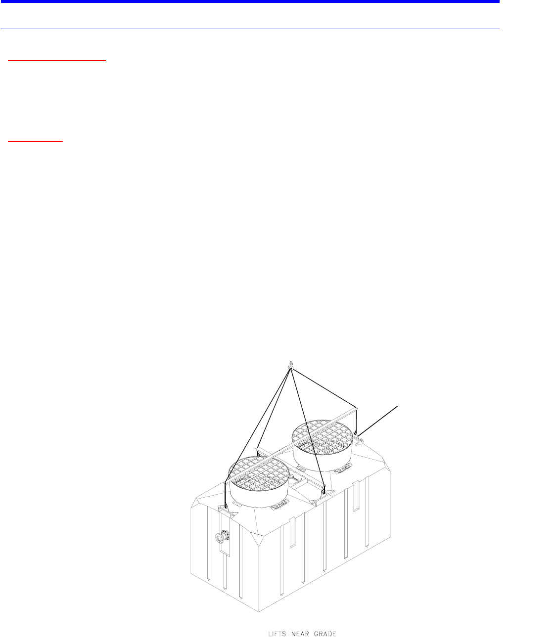
Lifting with crane:
• Use fabric slings of sufficient strength for better load distribution and protection of the plastic tower
body.
• Wrap slings underneath tower sump assembly to lift and set into place.
• Lift tower body by attaching slings, kept separate by spreader bars, to the four lifting bars as shown
below.
• Spreader bars must be used to lift vertically on the lifting bar. Above the spreader bars use adequate
length straps specifically designed for vertical lifting in order to maintain an angle of 60° or less between
slings.
Liftin
g
Bar
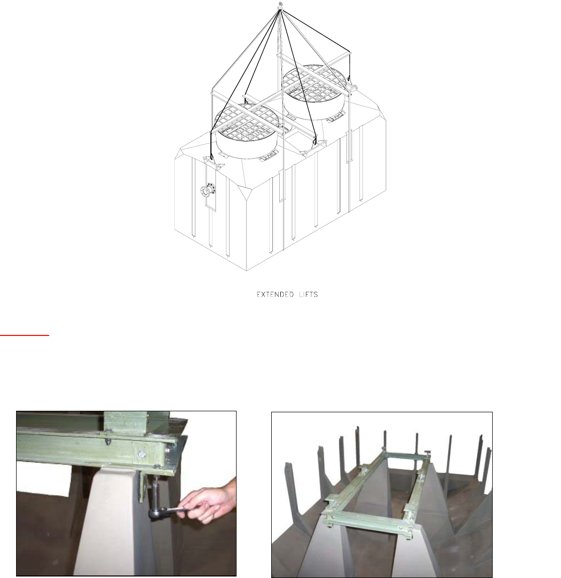
Revised 1-8-2007 6
Store tower assembly as shipped until the time of installation, in a secure, level and debris free location at the job
site.
CAUTION: For extended lifts, use duplicate rigging, fabric slings around body as shown, as an additional
safety precaution.
Installing
The cooling tower should be assembled in place on the previously prepared foundation.
• After re-checking the rigging, lift the sump section of each cell and secure properly to the foundation.
• Attach the fiberglass sump box to the center support post using the hardware provided as shown.
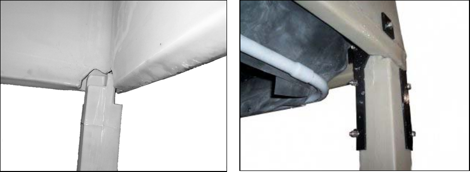
Revised 1-8-2007 7
• The body section should then be lifted and carefully position to align the support post of the sump
with the corresponding groove of the tower body. Note that the four corner posts are slightly higher
than other post to ease installation alignment.
• Set one end of the tower body onto the corner post at one end of the sump first. This can be
accomplished by use of a rope tether attached to the lifting bar at one end of the housing. Continue
setting and aligning support post along the sides of the tower moving from one end to the other. This
step may require a couple installers to align multiple posts simultaneously. You may use a rubber mallet
or blocking wood to aid aligning post.
IMPORTANT: Make sure that all posts are correctly seated into the pocket of the tower body.
• For single cell units, the four corner sump posts should then be secured to the main housing with the
provided stainless steel angle brackets and hardware. On Multi-cell towers, the outermost four corner posts
should be secured to the main housing with the provided stainless steel angle brackets and hardware.
• Before installing PVC louver panels, verify that all post are correctly seated into the pockets of the tower
body.
• Install PVC louver panels between each support post. Panels are numbered and marked on top of each
panel, and should be installed with corresponding numbered window opening. Insert bottom of panel into
window opening and work your way up to the top. Panels should be mounted flush with inside top of louver
opening inside tower and should direct incoming air downward. Secure panels with self-tapping screws
provided.
Revised 1-8-2007 8
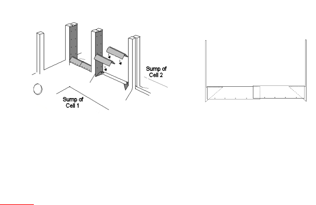
• On multi cell towers, install PVC water redirector panels between each sump using self-tapping screws
provided (See sketch below). Start with screwing the PVC post from the bottom up. Next apply a heavy
bead of RTV sealant on the end of each redirector panel. Start screwing the redirector panels from the end
nearest the post toward the center. Do not screw overlapping panels to allow for expansion and contraction.
(Side View of Redirector Panels)
• Secure tops of adjacent multi cell units together by bolting the two steel support angle brackets provided
to the lifting lugs of each cooling tower shell. The angle brackets should then be bolted together with
hardware provided.
Anchoring
The foundation must be flat, smooth and rigid enough to be capable of independent support of the cooling tower
assembly and water load in the sump at its maximum level. The tower assembly can also be mounted on I-beams
using the integrally molded I-beam pockets (See tower drawings).
• Four hold-down anchor lugs are provided on the sump of each tower cell.
• Support beams and anchor bolts are to be furnished by others.
• Beams should be sized at least 7” wide and in accordance with acceptable structural practices. These beams
should be located in the integrally molded I-beam pockets, and should run the length of the unit.
• Use anchor bolts sized for a minimum of 15,000 lbs. pull-out load per anchor lug for wind loading.
Multi Cell Water Redirectors.

Revised 1-8-2007 9
Electrical Wiring of Fan Motor and Accessories
• Installation of a vibration cut-out switch is recommended. (Refer to tower accessories available).
• All electrical work should be performed only by qualified personnel and in accordance to prevailing
electrical codes, practices and safety standards.
• The motor starter should be sized on voltage, nominal horsepower, and maximum full load current. This
current value can be found on the motor nameplate. If the starter cannot accept the maximum full load motor
current, the next size should be used.
• Motor heaters should be selected on the basics of maximum full load current and service factors based on the
motor nameplate.
• Standard “Cooling Tower Service” motors are supplied with a minimum of a 1.15 Service Factor.
• Optional two speed motors are single winding variable torque.
• Run flexible conduit with some slack from the motor conduit box to terminal box outside the tower where
rigid conduit can be used.
• Conduit holding clip screws can be tapped directly into the tower wall. Use maximum 3/8” long screws.
• For the typical wiring schematic of fan motor and tower accessories, see Delta dwg. DT –B-78-001, included
with these instructions.
Location, Piping and Connections
• Piping should be adequately sized in accordance with accepted standard practices.
• Gravity drain to indoor storage sump requires proper head differential and piping design considerations.
Allowance must be made for flow, pipe size, piping layout and distance of cooling tower from the indoor
storage sump.
• On multiple cell installations, valving and/or pipe sizing should balance pressure drops to provide equal inlet
pressures. Equalizing fittings are provided in the sumps of each cell and can piped together to balance sump
water level. Each cell should be valved separately to allow for flow balancing or isolation from service.
• Prior to start-up check that the PVC locknuts on all bulkhead fittings are properly tightened to prevent
nuisance leaks. A chain wrench can be used to check and tighten the locknuts.
• Check that the SS hexagonal nuts on the inlet and outlet PVC flanges are properly tightened to prevent
nuisance leaks. While tightening the nuts, do not allow the bolt to rotate. This could damage the rubber seal
under the flat washer on the bolt head located inside the cooling tower.
• All supply and return piping must be independently supported.

Revised 1-8-2007 10
PVC Solvent Cementing Instructions
The following procedure is recommended for the preparation and cementing of internal and external piping for
Delta Cooling Towers:
• Cut ends of pipe square using a handsaw and miter box. Tube cutters with wheels designed for use with PVC
are acceptable, providing they do not leave a raised bead on the outside diameter of the pipe.
• Use a chamfering tool or file to put a 10° to 15° chamfer on the end of the pipe. Lightly sand the area to be
cemented to remove gloss. Using a clean rag, wipe pipe surface and fitting socket to remove dirt, moisture
and grease. Acetone or similar solvent is recommended for cleaning.
• Check "dry fit" of pipe and fitting by inserting pipe at least 1/3 of the way into the fitting. Position pipe and
fitting to assure alignment. Pipe and fitting should be at same temperature condition.
• Using a clean, natural bristle brush about 1/2 the size of the pipe diameter, apply a primer to the fitting
socket. Apply primer with a scrubbing motion until the surface is penetrated. Primer should never be applied
with a rag. Repeated applications may be necessary to achieve the desired dissolving action. In the same
manner, apply primer to the pipe surface equal to the depth of the fitting socket, making sure the surface is
well penetrated. Reapply primer to the fitting socket to make sure it is still wet.
• While both surfaces are still wet with primer, use a clean brush to apply a liberal coat of solvent cement to
the male end of the pipe. The amount should be more than sufficient to fill any gap. Next apply a light coat
of solvent cement to the inside of the socket, using straight outward strokes to keep excess cement out of the
socket.
• While both surfaces are still wet with solvent cement, insert the pipe into the socket with a quarter-turn
twisting motion. The pipe must be inserted the full length of the socket. The application of solvent cement to
pipe and fitting, and the insertion of the pipe into the fitting, should be completed in less than one minute. If
necessary, two persons should apply solvent cement to the pipe and fitting simultaneously.
• Hold the joint together for approximately 30 seconds until both surfaces are firmly gripped. After assembly,
a properly made joint will usually show a bead of cement around its entire perimeter. This should be brushed
off. It is recommended that the joint be allowed to cure for 24 hours before pressure testing or operation.

Revised 1-8-2007 11
Operation and Maintenance of Your TM Series Cooling Tower
Safety in Operation of the Fan
NEVER operate the fan when the access panel or the entire fan guard is removed.
NEVER remove access manhole cover while fan is in operation.
NEVER operate fan when any work, access, maintenance, trouble-shooting, etc. is being performed on the
inside of the fan ring assembly or inside the tower plenum.
• Normally, electrical codes dictate a disconnect box at the cooling tower.
• The handle of the disconnect box must be locked in the off position and an OSHA DANGER tag
(DO NOT OPERATE) must be attached to handle securely.
Note: Removing fuses from the disconnect box may provide further assurance, but only when done by qualified
personnel.
The foregoing precautions apply when any type of internal access to the tower is required, including the
following examples:
• Checking, maintenance or replacement of any fan assembly component.
• Checking, maintenance or replacement of the water distribution system inside the tower.
• Cleaning of the fill.
• Any work that necessitates removal of any access door, the fan guard or the manhole cover.
Water Distribution System
Water distribution is accomplished by a low pressure, non-rotating, spray nozzle system
designed to accommodate the specified flow rate.
IMPORTANT:
• The flow rate of the cooling tower must be as close to the design gpm as possible. The water
distribution system, including spray nozzles, is provided for the design flow condition.
Under-pumping or over-pumping will cause the cooling tower to perform inefficiently.
• Design pressure at the inlet connection must be maintained for proper water distribution.
If the pressure is less or greater than the design, proper water dispersion over the internal wet
decking will be impaired. If inlet pressure is low, water spray will not cover the entire wet
decking surface. This causes channeling of air, and does not make maximum use of the heat
transfer media. High inlet pressures will cause the water to over-spray the wet decking
media, hit the internal side walls of the tower shell and drop in a vertical flow along the shell
walls without the opportunity for water / air contact through the heat exchange media.
Excessive high spray pressure may also cause wet decking fatigue and damage.
• The operating inlet pressure should be between 4.0 and 5.5 psi at the tower inlet.

Revised 1-8-2007 12
• The maximum operating inlet water temperature should not exceed 140° F.
CAUTION:
When stepping on top of the fill, distribute the body weight by means of two plywood plates as
described earlier in these instructions.
Fan and Mechanical Drive System and Its Maintenance
Safety
Follow all safety instructions previously discussed.
Motor:
• The standard motor is a totally enclosed motor , Class F insulation, 1.15 minimum service
factor, epoxy coating on outside frame, and is specifically designed for cooling tower duty to
the exclusive specifications of Delta Cooling Towers.
• Should there be a problem with the motor, which may be covered under our standard
warranty, the motor must only be inspected and serviced by an authorized motor
manufactures warranty shop, and Delta Cooling Towers, Inc. must be notified, otherwise the
warranty is void.
• If the motor bearings have grease fittings, follow the lubrication recommendations as
outlined in instructions from motor manufacturer. The majority of motors do not require
greasing.
Start-up Instructions
Complete all start-up instructions before applying heat load.
• Clean any accumulated debris or packaging material from inside tower sump.
• Check to be sure that the fan motor is properly wired for correct rotation as viewed from the
top of the fan. Reverse leads will cause incorrect rotation and reverse direction of airflow.
Note: Fan rotation should always agree with rotation labels. Standard fan rotation is
clockwise, (C.W.) however; non-standard fans may be designed to rotate counter
clockwise, (C.C.W.)
• Check for free rotation of the fan and fan blade tip clearance.
• Fill the cooling tower sump or the cold water storage reservoir on gravity drain applications.
• Water recirculation pump should be primed and all piping below the tower sump filled with
water. Check pump for proper shaft rotation.
• Start water recirculation pump and adjust flow to design. A flow metering device installed in
the inlet is recommended but if not available, use the pressure differential across the pump in
conjunction with the pump curve.
Revised 1-8-2007 13
• Check spray pattern from nozzles to be sure there is no clogging. Remove drift eliminators
for nozzle inspection, then return to proper position.
• Start up fan motor and check amperage and voltage against motor nameplate data.
• The standard make-up valve assembly is shipped with the plastic float ball strapped against
the tower side to prevent damage. To set the ball for proper operation, loosen the screw in the
fulcrum arm, lift or depress the arm with the plunger pressed against the valve seat and
tighten. Repeat until the proper operating level is obtained (Refer to operating level table
below). It is recommended that a shut-off valve be installed in the make-up line.
• After 24 hours of operation:
Check spray nozzles for clogging.
Check tower sump water level.
Water Level in Tower Sump
• When the cooling tower is being operated with pump-suction, the make-up valve assembly
with float ball should be adjusted to set the water operating level as follows:
Tower Model # Operating level (from
bottom of sump)
All Towers
10 inches
• Access the make-up valve through the window louver marked “Access Panel”.
• A lower water level than recommended may cause air to be drawn into the tower outlet
piping and cause pump "cavitation."
• A water level higher than recommended will cause continuous overflow and waste of water
as a result of potential “pull-down” from the piping when the system is shut down.
• The overflow should NEVER be capped, or its elevation altered by raising external piping.
Note: On gravity drain cooling tower(s), make-up assembly, overflow, drain and vortex breaker
are not provided.

Revised 1-8-2007 14
Cold Weather Operation
Cold Weather Protection
The cooling tower may require protection against freezing at light heat loads when the wet-bulb
temperature is under 32°F., or during shutdown when the temperature drops below 32°F.
The following methods are recommended for use in Delta Cooling towers for protection during
cold weather conditions. Recommended equipment is optional and may be ordered from the
factory. Consult the factory for further information on which equipment to choose for your
specific application.
Separate Indoor Sump
This method is virtually a foolproof antifreeze protection system with the added advantage of
minimum maintenance. The indoor sump tank should be large enough to fill the entire
recirculation system without danger of pump cavitation. As a general rule, the tank should be
sized to hold three times the rate of circulation in gallons per minute (gpm).
The tank should be provided with properly sized overflow, make-up drain and suction
connections. When a separate sump is ordered with a cooling tower, the water make-up valve
assembly and the overflow and drain connections are installed in the indoor sump only.
When a sump tank is used, the cooling tower should be located high enough above it to allow
free cold water gravity drain. A bottom outlet can be provided for gravity drain to indoor sump
tank installations.
Reverse siphoning is a back flow of non-potable, recirculating water into a potable water
system, which can occur through the make-up float valve assembly located in the water
reservoir. Should the valve malfunction, blockage of the overflow or outlet lines would cause
water level to rise in the reservoir, and the make-up water pressure could drop below the
atmospheric pressure creating a vacuum at the make-up inlet. Although precautions to
prevent reverse siphoning are incorporated in the cooling tower design, we also recommend
installing a check valve in the water make-up supply line, as a backup precaution.
Electric Immersion Heater
Cooling towers can be ordered with an anti-freeze immersion heater systems, which consist of a
6KW heating element, water level sensor, adjustable thermostat and contactor. Components are
factory installed, but will require field wiring.
Thermostatic On/Off Control
A thermostatically controlled fan for on/off operation, should be considered as an energy saving
feature, for capacity control during winter operation. The thermostatic control can be field set to
insure automatic fan shut-down when cold water drops below design temperatures, as well as fan
start-up when cold water rises to design temperature.
A thermostatic control provides excellent cooling tower anti-freeze protection while reducing
operating costs throughout cold weather operation.
15
PVC Distribution System
To prevent damage to the PVC distribution system during cold weather shut-down, install an
automatic or manual drain line from the hot water inlet piping as close to the cooling tower inlet
as possible. The entire inlet and distribution system must be drained for shut-down in sub-
freezing weather.
Piping
When the cooling tower is located outdoors, adequate measures including the use of heating
tapes and insulation should be considered to protect water lines from freezing.
Operation at Sub-freezing Ambients
See Thermostatic On/Off control
1. Insure that the cooling tower is operating at the maximum possible heat load - An operating
cooling tower will continuously extract heat from the circulating water. Without a heat load,
the water will end up either at the air wet bulb temperature, or as ice, whichever occurs first.
2. Maintain Design Water Flow Rate Over The Fill - Reducing water flow over the fill area
can produce semi-dry regions that are subject to rapid freezing.
3. Make sure a thermostat is installed to control fan operation to off at low cold-water
temperatures.
4. If tower is equipped with two speed motors, operate at low speed to increase leaving water
temperature.
5. Cycle fans periodically to prevent ice from forming on louvers.
6. It may also be necessary to reverse fans for a short period of time to help melt ice by
forcing warm water into tower.
• De-energize the fan(s) for two full minutes before reversing.
• Reverse fan(s) no more than 2 minutes at a time (repeat as necessary). Extended
reverse operation can cause ice to form on fan blades causing an out-of-balance condition.
• If the tower is equipped with a two-speed motor, reverse only at low speed.
• On multi-cell towers, fans immediately adjacent to reversed fans should be shut off
during reversal.
• After reversal, let fan(s) stand idle 5 to 10 minutes before forward operation.
• Monitor the tower closely for unusual vibrations or sounds.
7. Frequent visual inspections and routine maintenance during sub-freezing operation is very
important and should not be overlooked.

16
Trouble-Shooting Guide For TM Series
Induced Draft Cooling Towers
Problem Possible Causes Corrective Actions
Increase in the leaving water
temperature
1. Excess water flow; over pumping.
2. Recirculation of hot discharge air, back into
the cooling tower air intakes. Obstructed air
intakes
3. Proximity of other heat source or discharge
of moist air.
4. Improper operation of spray system.
A. Orifices clogged.
B. Actual water flow is lower than design
sprinkler rating.
5. Clogged fill.
6. Damaged fill.
7. Additional heat load on system.
8. Wet-bulb temperature higher than design.
1. Adjust to the design flow.
2. Eliminate obstructions which impede air discharge.
For proper location of cooling tower(s), see Delta
dwgs. Baffle air discharge, if necessary.
3. Remove source or relocate tower.
4. See water distribution system instructions.
A. Flush spray nozzles, clean orifices, clean
system, install outlet strainer.
B. Install properly rated spray nozzles or increase
to design flow.
5. Clean the fill.
6. Replace the fill.
7. Contact Delta for possible upgrade or addition of
another cooling tower selected for additional load.
8. None required if condition is temporary. Otherwise
consult Factory for upgrade.
Drop in the water flow rate.
Low water flow rate
1. Blockage of spray Nozzle orifices.
2. Low water level in sump causing air to be
drawn into pump and piping.
3. Improper selection of water circulating
pump.
4. Blockage of strainers.
5. Pump malfunction.
1. Flush spray nozzle. Clean whole system. Install
outlet strainer.
2. Adjust float valves. Be sure the system is flooded
and balanced.
3. Replace with proper size pump designed for flow
and head requirements. Check pump “Net positive
suction head.”
4. Backwash or clean.
5. Consult pump specialist.
Noise and vibration 1. Loose bolts.
2. Mechanical interference of rotating parts.
3. Fan propeller damaged or out of balance.
4. Air intake at pump.
5. Pump cavitation.
6. Damaged motor bearings.
1. Recheck and tighten all bolts to specified torque.
2. Inspect propeller for free rotation. Check propeller
for mechanical interference. Adjust, repair or
replace, as necessary.
3. Replace components, as necessary and check
balance. Install vibration cut-out switch.
4. Check basin water level and irregular piping design.
5. Match pump NPSH with system hydraulics.
6. Check and replace motor.
Sudden or short term irregularities of
cold water level in basin
1. Peculiarities of specific system and its
operation.
1. Inspect system and review operation procedures.
Correct, as applicable valve settings, loss of water in
system, fill system to flooded capacity.
Excessively high water level in sump on
gravity drain installation
1. Gravity flow restrictions due to insufficient
head differential.
1.
A. Outlet piping should terminate below sump tank
water level.
B. Increase discharge pipe size.
C. Increase head by mean other than A.

17
Problem Possible Causes Corrective Actions
2. Airlock.
3. Unnecessary obstruction of waterflow
(i.e., partially closed valve).
4. Undersized piping.
5. Horizontal pipe run too long.
6. Improper hydraulic pipe design.
7. Outlet vortex breaker provided.
2. Install an air bleed valve at highest point
of piping, usually at a vertical angle.
3. Remove obstruction.
4. Increase pipe size.
5. Shorten, if possible.
6. Correct design.
7. Remove vortex breaker.
Excessively high water level in tower basin
on closed loop system installations
1. Make-up valve float set too high.
2. Valve or float damaged or
malfunctioning.
3. Make-up water pressure too high.
1. Readjust float arm.
2. Repair or replace.
3. Reduce pressure or contact Delta for
alternate solutions.
Uneven water level in tower basins of multi-
cell installations
1. Unbalanced system hydraulics.
2. More than one make-up valve
operating, and set for different water
levels.
1. A. Install equalizer line with isolation
valves between modules.
C. Adjust inlet water flow to insure equal
distribution to each cooling tower
module.
D. Review outlet header hydraulics and
correct piping design, if applicable.
E. Contact Delta for assistance.
2. A. Adjust float level settings relative
To one another.
B. Shut-off and or/throttle flow to
one or more valves.
C. Installation of equalizers is
highly recommended.
Excessive water carry over (drift) 1. Surfaces of top layer of fill damaged
causing “pooling” of water.
2. Eliminator(s) not in place.
3. Damaged eliminator.
4. Excess water flow.
5. Orifices in spray nozzles clogged
causing improper water dispersement.
6. Blockage of fill.
1. Replace top layer. Protect fill when working
inside tower.
2. Reinstall.
3. Replace.
4. Reduce water flow or install spray nozzles
designed for the actual operating flow.
5. Install outlet strainer. Clean whole system
and spray nozzles.
6. Clean fill.
Premature or excessive corrosion of fan
drive components
1. Excessive drift.
2. Presence of corrosive chemicals in air
or water that was not known at time of
supply.
1. See “ Excessive Water Carry Over (Drift)”
above.
2. Remove source of corrosion or contact Delta
for alternative materials, premium coatings
or other precautions.

18
Motor Trouble Shooting Guide (General)
Problem Possible Causes Corrective Actions
High current draw (all 3 phases) 1. Low line voltage (5 to 10% lower
than nameplate).
2. 200V motor on 230/240V system.
3. 230V motor on 208V system.
4. Incorrect propeller.
5. Incorrect pitch if adjustable
1. Consult power company.
2. Change to 230V motor.
3. Change to 200V or 280V motor.
4. Consult factory.
5. Reduce pitch / consult factory
Low motor current draw 1. Incorrect propeller.
2. Incorrect pitch if adjustable.
1. Consult factory
2. Increase pitch / consult factory
Unbalanced current
(5% from average)
1. Unbalanced line voltage due to:
A. Power supply.
B. Unbalance system loading.
C. High resistance connection.
D. Undersized supply lines.
2. Defective Motor.
1. Consult power company and/or
electrician.
2. Replace motor.
Excessive voltage drop
(2 or 3% of supply voltage)
1. Inadequate power supply.
2. Undersized supply lines.
3. High resistance connections.
1. Consult power company.
2. Increase line sizes.
3. Check motor leads and other
connections.
Overload relays tripping 1. Overload.
2. Unbalanced input current.
3. Single phasing.
4. Excessive voltage drop.
5. Frequent starting or intermittent
overloading.
6. High ambient starter temperature.
7. Wrong size relays.
8. Improper overload settings of
adjustable relays.
1. Reduce load on motor or increase
motor size.
2. Balance supply voltage.
3. Eliminate.
4. Eliminate (see above).
5. Reduce frequency of starting and
overloading or increase motor size.
6. Reduce ambient temperature.
7. Correct size per nameplate current
and service factor.
8. Readjust to motor FL Amps x S.F.
Motor runs very hot 1. Overloaded.
2. Blocked ventilation.
3. High ambient temperature.
4. Unbalanced input current.
5. Single phased.
1. Reduce overload.
2. Fouled fill or air restriction.
3. Reduce ambient temperature.
4. Balanced supply voltage.
5. Eliminate.
Motor will not start 1. Single phased.
2. Rotor or bearings locked.
1. Shut power off – eliminate.
2. Shut power off – check shaft
rotation.
Excessive vibration (Mechanical)
Out of balance
1. Motor mounting.
2. Motor.
1. Check to be sure motor mounting
hardware is tight.
2. Replace motor.
Note: Consult Warranty page prior to replacing or repairing any cooling tower components. Delta recommendation and consent
to remedy material and workmanship defects is necessary, to avoid breach of Warranty.

19
TM Series Optional Accessories
TM Series Optional Accessories Available
Aluminum Ladder(s) with a step platform and railing at the fan elevation custom designed for the cooling
tower.
Safety cage(s).
Two speed motor(s) designed for cooling tower duty to the exclusive specifications of Delta Cooling
Towers.
Vibration cut-out switch provides for fan motor circuit disconnect for shutdown protection should
abnormal fan vibration develop during service. Installation of vibration cut-out switches are
recommended as good design practice.
Thermostat on/off control of fan operation through sensing the temperature of water leaving the tower.
Basin anti-freeze system for cold weather operation.
Custom designed top platform with handrails.
Pre-wired control panels.
Elevated mounting frame structures.
Pumps
Polyethylene Sump tanks up to 2,000 gallons for indoor installation for anti-freeze protection during
winter operation.
Motor space heaters are recommended for unusually high relative humidity conditions where extreme day
to night temperatures can cause excessive condensation in the motor, when in operation during this period.
Plastic outlet sump strainer.
Plastic equalizer fittings.
Variable frequency drive on fan motors, controlled by temperature controller.
High sump level switch
Automatic drain valve
Consult factory or a Delta representative for further information and an updated list of accessories.
TM Series Recommended Replacement Parts
To avoid costly cooling tower downtime, the following replacement parts should be carried in inventory at the
installation site:
Make-up float, or complete make-up valve assembly.
Cartridge of recommended moisture resistant lubricant.
Fan Motor.
Spray Nozzles.
When ordering, include model number and serial number of the cooling tower as it appears on the tower
nameplate. Under normal conditions, shipment of factory replacement parts is made within one day after the
order is received. Spare pumps and pump parts, as well as control panel components, such as fuses and heaters
for magnetic starters, are also available.
20
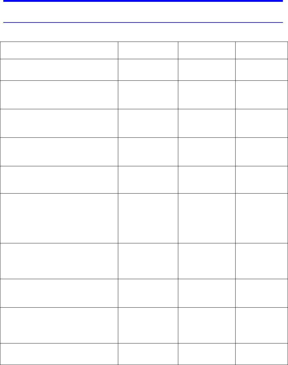
Preventative Maintenance Checklist
Procedure Monthly Every
3 Months
Every
6 months
Inspect General Condition of cooling tower.
¨
Check Water Level in cold water basin.
Adjust if needed.
¨
Check float ball & Make-up Valve for
proper operation.
¨
Check Line Voltage, Motor Amperage,
Water Pressure.
¨
Clean Sump Strainers, if installed.
¨
Lubricate Motor Bearing, (if motor has
fittings for greasing. The majority of motors
require no external greasing). Use Proper
Lubricants. Increase frequency, as necessary
depending on conditions of service.
¨
Check for obstructed Water Flow Through
Orifices. Clean and flush spray nozzles, as
required.
¨
Check All Bolts which can cause unbalance
and vibration and tighten specified torque.
¨
Check Condition of Water for proper
treatment to prevent build-up of algae and
solids concentration
¨
Clean and flush Cold Water Sump
¨
