Deltanode Solutions DDU001 Distributed Antenna System User Manual Fiber Distributed Antenna System DAS
Deltanode Solutions AB Distributed Antenna System Fiber Distributed Antenna System DAS
User Manual

Fiber Distributed Antenna System
(Fiber DAS)
Operation Manual
©Copyright 2017 by Bird Technologies, Inc.
Instruction Book Part Number 920-Fiber-DAS Rev. P4
Delta Node® is a registered trademark of Delta Node Solutions Ltd. and Bird Technologies, Inc.
i
Safety Precautions
The following are general safety precautions that are not necessarily related to any specific part or procedure, and
do not necessarily appear elsewhere in this publication. These precautions must be thoroughly understood and
apply to all phases of operation and maintenance.
WARNING
Keep Away From Live Circuits
Operating Personnel must at all times observe general safety precautions. Do not replace components or make
adjustments to the inside of the test equipment with the high voltage supply turned on. To avoid casualties,
always remove power.
WARNING
Shock Hazard
Do not attempt to remove the RF transmission line while RF power is present.
WARNING
Do Not Service Or Adjust Alone
Under no circumstances should any person reach into an enclosure for the purpose of service or adjustment of
equipment except in the presence of someone who is capable of rendering aid.
WARNING
Safety Earth Ground
An uninterruptible earth safety ground must be supplied from the main power source to test instruments.
Grounding one conductor of a two conductor power cable is not sufficient protection. Serious injury or death can
occur if this grounding is not properly supplied.
WARNING
Resuscitation
Personnel working with or near high voltages should be familiar with modern methods of resuscitation.
WARNING
Remove Power
Observe general safety precautions. Do not open the instrument with the power applied.
Safety Precautions
ii
Safety Symbols
Note: Calls attention to supplemental information.
WARNING
Warning notes call attention to a procedure, which if not correctly performed, could result in personal injury.
CAUTION
Caution notes call attention to a procedure, which if not correctly performed, could result in damage to the
instrument.
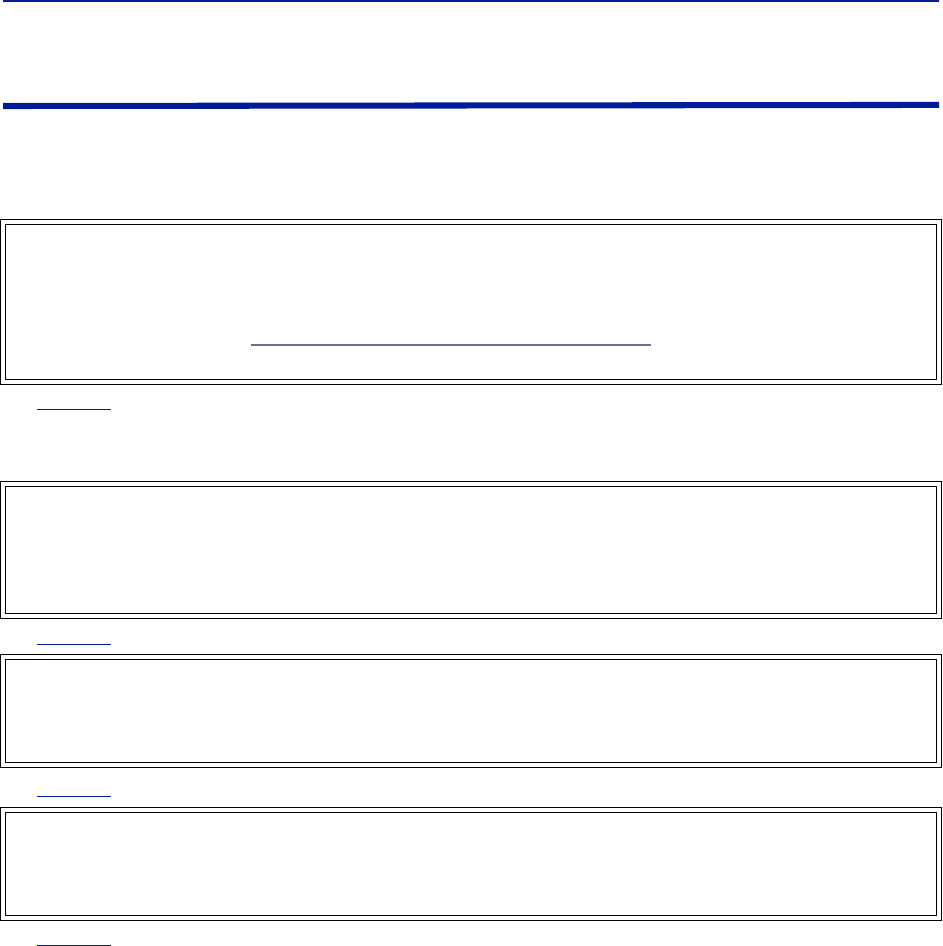
The laser used in this system is a Class 3b laser that produces invisible infra-red coherent
light. Avoid looking into connected fibers and receptacles. Not safe to view with optical
instruments. Always put the protection caps on unused fibers and receptacles.
Fiber Distributed Antenna System (Fiber DAS)
iii
Warning Statements
The following safety warnings appear in the text where there is danger to operating and maintenance personnel
and are repeated here for emphasis.
See
page 42
For CMRS 817-824MHz Applications and American Cellular Applications:
See
page 42
See
page 42
See
page 15
WARNING
This is NOT a consumer device.
It is design for installation by FCC LICENSEES and QUALIFIED INSTALLERS. You MUST have an FCC LICENSE or
express consent of an FCC licensee to operate this device. You MUST register Class B signal boosters (as defined
in 47 CFR 90.219) online at www.fcc.gov/signal-boosters/registration. Unauthorized use may result in
significant forfeiture penalties, including penalties in excess of $100,000 for each continuing violation.
WARNING
This is NOT a consumer device.
It is design for installation by FCC LICENSEES and QUALIFIED INSTALLERS. You MUST have an FCC LICENSE or
express consent of an FCC licensee to operate this device. Unauthorized use may result in significant forfeiture
penalties, including penalties in excess of $100,000 for each continuing violation.
WARNING
This is NOT a consumer device.
It is designed for installation by an installer approved by an ISED licensee.
You MUST have an ISED LICENCE or the express consent of an ISED licensee to operate this device.
WARNING
Avoid looking into connected fibers and receptacles.
The laser used in this system is a Class 3b laser that produces invisible infra-red coherent light. Not safe to view
with optical instruments. Always put the protection caps on unused fibers and receptacles.
Safety Precautions
iv
Caution Statements
The following equipment cautions appear in the text and are repeated here for emphasis.
See
page 116
See
page 43
.
See
page 49
CAUTION
Turn Off Test Tone
Do not forget to turn off the test tone when you are done with your uplink. Better check one extra time. They will
otherwise interfere with the normal operation of the system by causing noise to the base station.
CAUTION
Unauthorized antennas, cables, and/or coupling devices may cause non-conformity with national or international
regulations, could cause damage, or non-conforming ERP/EIRP.
CAUTION
When mating RF connectors, ensure that they are properly aligned and not cross threaded.
Tighten SMA connectors to 8 in.-lbs.
Do over torque RF connectors, this could result in damage to the Unit.
Do not under torque RF connectors, this could result in poor signal transmission.

Fiber Distributed Antenna System (Fiber DAS)
v
Safety Statements
USAGE
ANY USE OF THIS INSTRUMENT IN A MANNER NOT SPECIFIED BY THE MANUFACTURER MAY
IMPAIR THE INSTRUMENT’S SAFETY PROTECTION.
USO
EL USO DE ESTE INSTRUMENTO DE MANERA NO ESPECIFICADA POR EL FABRICANTE, PUEDE
ANULAR LA PROTECCIÓN DE SEGURIDAD DEL INSTRUMENTO.
BENUTZUNG
WIRD DAS GERÄT AUF ANDERE WEISE VERWENDET ALS VOM HERSTELLER BESCHRIEBEN,
KANN DIE GERÄTESICHERHEIT BEEINTRÄCHTIGT WERDEN.
UTILISATION
TOUTE UTILISATION DE CET INSTRUMENT QUI N’EST PAS EXPLICITEMENT PRÉVUE PAR LE
FABRICANT PEUT ENDOMMAGER LE DISPOSITIF DE PROTECTION DE L’INSTRUMENT.
IMPIEGO
QUALORA QUESTO STRUMENTO VENISSE UTILIZZATO IN MODO DIVERSO DA COME
SPECIFICATO DAL PRODUTTORE LA PROZIONE DI SICUREZZA POTREBBE VENIRNE
COMPROMESSA.

Safety Precautions
vi
SERVICE
SERVICING INSTRUCTIONS ARE FOR USE BY SERVICE - TRAINED PERSONNEL ONLY. TO AVOID
DANGEROUS ELECTRIC SHOCK, DO NOT PERFORM ANY SERVICING UNLESS QUALIFIED TO DO
SO.
SERVICIO
LAS INSTRUCCIONES DE SERVICIO SON PARA USO EXCLUSIVO DEL PERSONAL DE SERVICIO
CAPACITADO. PARA EVITAR EL PELIGRO DE DESCARGAS ELÉCTRICAS, NO REALICE NINGÚN
SERVICIO A MENOS QUE ESTÉ CAPACITADO PARA HACERIO.
WARTUNG
ANWEISUNGEN FÜR DIE WARTUNG DES GERÄTES GELTEN NUR FÜR GESCHULTES
FACHPERSONAL.
ZUR VERMEIDUNG GEFÄHRLICHE, ELEKTRISCHE SCHOCKS, SIND WARTUNGSARBEITEN
AUSSCHLIEßLICH VON QUALIFIZIERTEM SERVICEPERSONAL DURCHZUFÜHREN.
ENTRENTIEN
L’EMPLOI DES INSTRUCTIONS D’ENTRETIEN DOIT ÊTRE RÉSERVÉ AU PERSONNEL FORMÉ AUX
OPÉRATIONS D’ENTRETIEN. POUR PRÉVENIR UN CHOC ÉLECTRIQUE DANGEREUX, NE PAS
EFFECTUER D’ENTRETIEN SI L’ON N’A PAS ÉTÉ QUALIFIÉ POUR CE FAIRE.
ASSISTENZA TECNICA
LE ISTRUZIONI RELATIVE ALL’ASSISTENZA SONO PREVISTE ESCLUSIVAMENTE PER IL
PERSONALE OPPORTUNAMENTE ADDESTRATO. PER EVITARE PERICOLOSE SCOSSE
ELETTRICHE NON EFFETTUARRE ALCUNA RIPARAZIONE A MENO CHE QUALIFICATI A FARLA.

Fiber Distributed Antenna System (Fiber DAS)
vii
About This Manual
This manual covers the operating & maintenance instructions for the following models:
Changes to this Manual
We have made every effort to ensure this manual is accurate. If you discover any errors, or if you have suggestions
for improving this manual, please send your comments to our Solon, Ohio factory. This manual may be periodically
updated. When inquiring about updates to this manual refer to the part number: 920-Fiber-DAS; and revision: P4.
Chapter Layout
Introduction — Describes the fundamentals of the Bird Fiber-DAS and provides a list of commonly used
abbreviations and acronyms.
System Description — Describes the Major components that make up a Bird Fiber-DAS system.
Installation Guidelines — Provides FCC requirements and safety considerations when installing a Bird Fiber-
DAS.
Commissioning — Lists the preparations and equipment required to successfully install and commission the Bird
Fiber-DAS.
RF Commissioning — Contains useful advice on how to design a well working system as well as examples for
fine tuning link a budget and controlling noise in a Bird Fiber-DAS.
Model Identification — Provides a breakdown of the Bird part numbers for the Fiber-DAS systems. A table of
part numbers used for Remote Units is also provided.
Fiber-DAS
viii
Table of Contents
Safety Symbols . . . . . . . . . . . . . . . . . . . . . . . . . . . . . . . . . . . . . . . . . . . . . . . . . . . . . . . . . . . . . . . . . . . . . . . . . . . . . . . . ii
Warning Statements . . . . . . . . . . . . . . . . . . . . . . . . . . . . . . . . . . . . . . . . . . . . . . . . . . . . . . . . . . . . . . . . . . . . . . . . . . . iii
Caution Statements . . . . . . . . . . . . . . . . . . . . . . . . . . . . . . . . . . . . . . . . . . . . . . . . . . . . . . . . . . . . . . . . . . . . . . . . . . . iv
Safety Statements . . . . . . . . . . . . . . . . . . . . . . . . . . . . . . . . . . . . . . . . . . . . . . . . . . . . . . . . . . . . . . . . . . . . . . . . . . . . . . v
Changes to this Manual . . . . . . . . . . . . . . . . . . . . . . . . . . . . . . . . . . . . . . . . . . . . . . . . . . . . . . . . . . . . . . . . . . . . . . . . vii
Chapter Layout . . . . . . . . . . . . . . . . . . . . . . . . . . . . . . . . . . . . . . . . . . . . . . . . . . . . . . . . . . . . . . . . . . . . . . . . . . . . . . . vii
Chapter 1 Introduction . . . . . . . . . . . . . . . . . . . . . . . . . . . . . . . . . . . . . . . . . . . . . . . . . . . . . . . . . . . . . . . 1
RF on fiber . . . . . . . . . . . . . . . . . . . . . . . . . . . . . . . . . . . . . . . . . . . . . . . . . . . . . . . . . . . . . . . . . . . . . . . . . . . . . . . . . . . . 1
Definitions . . . . . . . . . . . . . . . . . . . . . . . . . . . . . . . . . . . . . . . . . . . . . . . . . . . . . . . . . . . . . . . . . . . . . . . . . . . . . . . . . . . .2
Chapter 2 System Description. . . . . . . . . . . . . . . . . . . . . . . . . . . . . . . . . . . . . . . . . . . . . . . . . . . . . . . . . 4
Gateways . . . . . . . . . . . . . . . . . . . . . . . . . . . . . . . . . . . . . . . . . . . . . . . . . . . . . . . . . . . . . . . . . . . . . . . . . . . . . . . . . . . . . 4
Central Gateway (CGW) . . . . . . . . . . . . . . . . . . . . . . . . . . . . . . . . . . . . . . . . . . . . . . . . . . . . . . . . . . . . . . . . . . . . . .4
Base Station Gateway (BGW) . . . . . . . . . . . . . . . . . . . . . . . . . . . . . . . . . . . . . . . . . . . . . . . . . . . . . . . . . . . . . . . . .4
Remote Gateway (RGW) . . . . . . . . . . . . . . . . . . . . . . . . . . . . . . . . . . . . . . . . . . . . . . . . . . . . . . . . . . . . . . . . . . . . . 6
Headend . . . . . . . . . . . . . . . . . . . . . . . . . . . . . . . . . . . . . . . . . . . . . . . . . . . . . . . . . . . . . . . . . . . . . . . . . . . . . . . . . . . . .6
DCS - Network Switch . . . . . . . . . . . . . . . . . . . . . . . . . . . . . . . . . . . . . . . . . . . . . . . . . . . . . . . . . . . . . . . . . . . . . . . . 6
Master Frame Unit (MFU) . . . . . . . . . . . . . . . . . . . . . . . . . . . . . . . . . . . . . . . . . . . . . . . . . . . . . . . . . . . . . . . . . . . .7
Base Station Interface Unit (BIU) . . . . . . . . . . . . . . . . . . . . . . . . . . . . . . . . . . . . . . . . . . . . . . . . . . . . . . . . . . . . . . . 8
Interconnect Unit (ICU) . . . . . . . . . . . . . . . . . . . . . . . . . . . . . . . . . . . . . . . . . . . . . . . . . . . . . . . . . . . . . . . . . . . . .13
Fiber Optic Interface (FOI) unit . . . . . . . . . . . . . . . . . . . . . . . . . . . . . . . . . . . . . . . . . . . . . . . . . . . . . . . . . . . . . . .15
PSU – the rack power supply . . . . . . . . . . . . . . . . . . . . . . . . . . . . . . . . . . . . . . . . . . . . . . . . . . . . . . . . . . . . . . . . .20
Remote Unit (RU) . . . . . . . . . . . . . . . . . . . . . . . . . . . . . . . . . . . . . . . . . . . . . . . . . . . . . . . . . . . . . . . . . . . . . . . . . . . . .21
DDR . . . . . . . . . . . . . . . . . . . . . . . . . . . . . . . . . . . . . . . . . . . . . . . . . . . . . . . . . . . . . . . . . . . . . . . . . . . . . . . . . . . . .22
DDS . . . . . . . . . . . . . . . . . . . . . . . . . . . . . . . . . . . . . . . . . . . . . . . . . . . . . . . . . . . . . . . . . . . . . . . . . . . . . . . . . . . . .26
DDH . . . . . . . . . . . . . . . . . . . . . . . . . . . . . . . . . . . . . . . . . . . . . . . . . . . . . . . . . . . . . . . . . . . . . . . . . . . . . . . . . . . . .28
DDU . . . . . . . . . . . . . . . . . . . . . . . . . . . . . . . . . . . . . . . . . . . . . . . . . . . . . . . . . . . . . . . . . . . . . . . . . . . . . . . . . . . . .31
Remote Unit Frequency Summary . . . . . . . . . . . . . . . . . . . . . . . . . . . . . . . . . . . . . . . . . . . . . . . . . . . . . . . . . . . .33
DMU – Remote head end . . . . . . . . . . . . . . . . . . . . . . . . . . . . . . . . . . . . . . . . . . . . . . . . . . . . . . . . . . . . . . . . . . .34
Repeaters . . . . . . . . . . . . . . . . . . . . . . . . . . . . . . . . . . . . . . . . . . . . . . . . . . . . . . . . . . . . . . . . . . . . . . . . . . . . . . . . . . .35
DMR 400 Series Rack Mount Repeater . . . . . . . . . . . . . . . . . . . . . . . . . . . . . . . . . . . . . . . . . . . . . . . . . . . . . . . . .35
DLR 600 Series Low Power Repeater . . . . . . . . . . . . . . . . . . . . . . . . . . . . . . . . . . . . . . . . . . . . . . . . . . . . . . . . . .37
DMR600 Series Medium Power Repeater . . . . . . . . . . . . . . . . . . . . . . . . . . . . . . . . . . . . . . . . . . . . . . . . . . . . . .38
DMR 800Series Medium Power Repeater . . . . . . . . . . . . . . . . . . . . . . . . . . . . . . . . . . . . . . . . . . . . . . . . . . . . . .39
DHR 800 Series High Power Repeater . . . . . . . . . . . . . . . . . . . . . . . . . . . . . . . . . . . . . . . . . . . . . . . . . . . . . . . . . .40
Bird Repeater Frequency Summary . . . . . . . . . . . . . . . . . . . . . . . . . . . . . . . . . . . . . . . . . . . . . . . . . . . . . . . . . . .41
Chapter 3 Installation guidelines . . . . . . . . . . . . . . . . . . . . . . . . . . . . . . . . . . . . . . . . . . . . . . . . . . . . . 42
Health and Safety . . . . . . . . . . . . . . . . . . . . . . . . . . . . . . . . . . . . . . . . . . . . . . . . . . . . . . . . . . . . . . . . . . . . . . . . . . . . .42
Cable Routing/Antenna Selection . . . . . . . . . . . . . . . . . . . . . . . . . . . . . . . . . . . . . . . . . . . . . . . . . . . . . . . . . . . . . . . .43
Antenna Installation . . . . . . . . . . . . . . . . . . . . . . . . . . . . . . . . . . . . . . . . . . . . . . . . . . . . . . . . . . . . . . . . . . . . . . . .43
Safety and Care for Fibers . . . . . . . . . . . . . . . . . . . . . . . . . . . . . . . . . . . . . . . . . . . . . . . . . . . . . . . . . . . . . . . . . . . . . .43
Tools and Material Requirements . . . . . . . . . . . . . . . . . . . . . . . . . . . . . . . . . . . . . . . . . . . . . . . . . . . . . . . . . . . . . . . .44
Fiber Optics . . . . . . . . . . . . . . . . . . . . . . . . . . . . . . . . . . . . . . . . . . . . . . . . . . . . . . . . . . . . . . . . . . . . . . . . . . . . . . .44
Tools . . . . . . . . . . . . . . . . . . . . . . . . . . . . . . . . . . . . . . . . . . . . . . . . . . . . . . . . . . . . . . . . . . . . . . . . . . . . . . . . . . . .44
Miscellaneous Material . . . . . . . . . . . . . . . . . . . . . . . . . . . . . . . . . . . . . . . . . . . . . . . . . . . . . . . . . . . . . . . . . . . . .44
Installing Headend Equipment . . . . . . . . . . . . . . . . . . . . . . . . . . . . . . . . . . . . . . . . . . . . . . . . . . . . . . . . . . . . . . . . . .45
BGW . . . . . . . . . . . . . . . . . . . . . . . . . . . . . . . . . . . . . . . . . . . . . . . . . . . . . . . . . . . . . . . . . . . . . . . . . . . . . . . . . . . . .45
Ethernet Switch . . . . . . . . . . . . . . . . . . . . . . . . . . . . . . . . . . . . . . . . . . . . . . . . . . . . . . . . . . . . . . . . . . . . . . . . . . .45

Fiber Distributed Antenna System (Fiber DAS)
ix
Master Unit . . . . . . . . . . . . . . . . . . . . . . . . . . . . . . . . . . . . . . . . . . . . . . . . . . . . . . . . . . . . . . . . . . . . . . . . . . . . . . .46
Power Supply Unit . . . . . . . . . . . . . . . . . . . . . . . . . . . . . . . . . . . . . . . . . . . . . . . . . . . . . . . . . . . . . . . . . . . . . . . . .47
BIU . . . . . . . . . . . . . . . . . . . . . . . . . . . . . . . . . . . . . . . . . . . . . . . . . . . . . . . . . . . . . . . . . . . . . . . . . . . . . . . . . . . . . . 49
ICU . . . . . . . . . . . . . . . . . . . . . . . . . . . . . . . . . . . . . . . . . . . . . . . . . . . . . . . . . . . . . . . . . . . . . . . . . . . . . . . . . . . . . . 50
FOI . . . . . . . . . . . . . . . . . . . . . . . . . . . . . . . . . . . . . . . . . . . . . . . . . . . . . . . . . . . . . . . . . . . . . . . . . . . . . . . . . . . . . . 50
RFU . . . . . . . . . . . . . . . . . . . . . . . . . . . . . . . . . . . . . . . . . . . . . . . . . . . . . . . . . . . . . . . . . . . . . . . . . . . . . . . . . . . . . .51
Powering Up the Head End . . . . . . . . . . . . . . . . . . . . . . . . . . . . . . . . . . . . . . . . . . . . . . . . . . . . . . . . . . . . . . . . . . . . . 51
Installing Remote Units . . . . . . . . . . . . . . . . . . . . . . . . . . . . . . . . . . . . . . . . . . . . . . . . . . . . . . . . . . . . . . . . . . . . . . . . 52
Single Remote Unit Wall Mounting . . . . . . . . . . . . . . . . . . . . . . . . . . . . . . . . . . . . . . . . . . . . . . . . . . . . . . . . . . . . 52
Double Remote Unit Wall Mounting . . . . . . . . . . . . . . . . . . . . . . . . . . . . . . . . . . . . . . . . . . . . . . . . . . . . . . . . . . 53
Remote Unit Pole Mounting . . . . . . . . . . . . . . . . . . . . . . . . . . . . . . . . . . . . . . . . . . . . . . . . . . . . . . . . . . . . . . . . . 53
Solar Shield . . . . . . . . . . . . . . . . . . . . . . . . . . . . . . . . . . . . . . . . . . . . . . . . . . . . . . . . . . . . . . . . . . . . . . . . . . . . . . . 54
Cabling . . . . . . . . . . . . . . . . . . . . . . . . . . . . . . . . . . . . . . . . . . . . . . . . . . . . . . . . . . . . . . . . . . . . . . . . . . . . . . . . . . . 54
Remote Unit Verification . . . . . . . . . . . . . . . . . . . . . . . . . . . . . . . . . . . . . . . . . . . . . . . . . . . . . . . . . . . . . . . . . . . . 57
Installing the DHR Repeater . . . . . . . . . . . . . . . . . . . . . . . . . . . . . . . . . . . . . . . . . . . . . . . . . . . . . . . . . . . . . . . . . . . . . 58
Single Repeater Wall Mounting . . . . . . . . . . . . . . . . . . . . . . . . . . . . . . . . . . . . . . . . . . . . . . . . . . . . . . . . . . . . . . . 58
Double Repeater Wall Mounting . . . . . . . . . . . . . . . . . . . . . . . . . . . . . . . . . . . . . . . . . . . . . . . . . . . . . . . . . . . . . 59
Repeater Pole Mounting . . . . . . . . . . . . . . . . . . . . . . . . . . . . . . . . . . . . . . . . . . . . . . . . . . . . . . . . . . . . . . . . . . . . 59
Solar Shield . . . . . . . . . . . . . . . . . . . . . . . . . . . . . . . . . . . . . . . . . . . . . . . . . . . . . . . . . . . . . . . . . . . . . . . . . . . . . . . 60
Cabling . . . . . . . . . . . . . . . . . . . . . . . . . . . . . . . . . . . . . . . . . . . . . . . . . . . . . . . . . . . . . . . . . . . . . . . . . . . . . . . . . . . 60
Chapter 4 DAS Software Configuration . . . . . . . . . . . . . . . . . . . . . . . . . . . . . . . . . . . . . . . . . . . . . . . . 64
Ethernet Connection . . . . . . . . . . . . . . . . . . . . . . . . . . . . . . . . . . . . . . . . . . . . . . . . . . . . . . . . . . . . . . . . . . . . . . . . . . 64
BGW Configuration . . . . . . . . . . . . . . . . . . . . . . . . . . . . . . . . . . . . . . . . . . . . . . . . . . . . . . . . . . . . . . . . . . . . . . . . . . . . 65
BGW Naming . . . . . . . . . . . . . . . . . . . . . . . . . . . . . . . . . . . . . . . . . . . . . . . . . . . . . . . . . . . . . . . . . . . . . . . . . . . . . . 65
EXT Ethernet . . . . . . . . . . . . . . . . . . . . . . . . . . . . . . . . . . . . . . . . . . . . . . . . . . . . . . . . . . . . . . . . . . . . . . . . . . . . . . 65
VPN Settings . . . . . . . . . . . . . . . . . . . . . . . . . . . . . . . . . . . . . . . . . . . . . . . . . . . . . . . . . . . . . . . . . . . . . . . . . . . . . . 66
Time Zone . . . . . . . . . . . . . . . . . . . . . . . . . . . . . . . . . . . . . . . . . . . . . . . . . . . . . . . . . . . . . . . . . . . . . . . . . . . . . . . . 66
NTP Servers . . . . . . . . . . . . . . . . . . . . . . . . . . . . . . . . . . . . . . . . . . . . . . . . . . . . . . . . . . . . . . . . . . . . . . . . . . . . . . . 67
Email Server . . . . . . . . . . . . . . . . . . . . . . . . . . . . . . . . . . . . . . . . . . . . . . . . . . . . . . . . . . . . . . . . . . . . . . . . . . . . . . 68
BIU Configuration . . . . . . . . . . . . . . . . . . . . . . . . . . . . . . . . . . . . . . . . . . . . . . . . . . . . . . . . . . . . . . . . . . . . . . . . . . . . . 69
BIU RF1 Status . . . . . . . . . . . . . . . . . . . . . . . . . . . . . . . . . . . . . . . . . . . . . . . . . . . . . . . . . . . . . . . . . . . . . . . . . . . . . 69
BIU RF1 Settings . . . . . . . . . . . . . . . . . . . . . . . . . . . . . . . . . . . . . . . . . . . . . . . . . . . . . . . . . . . . . . . . . . . . . . . . . . . 71
BIU Hardware Test Points . . . . . . . . . . . . . . . . . . . . . . . . . . . . . . . . . . . . . . . . . . . . . . . . . . . . . . . . . . . . . . . . . . . 72
BIU Alarm List . . . . . . . . . . . . . . . . . . . . . . . . . . . . . . . . . . . . . . . . . . . . . . . . . . . . . . . . . . . . . . . . . . . . . . . . . . . . . 72
BIU Change History . . . . . . . . . . . . . . . . . . . . . . . . . . . . . . . . . . . . . . . . . . . . . . . . . . . . . . . . . . . . . . . . . . . . . . . . . 73
BIU Alarm configuration RF1 . . . . . . . . . . . . . . . . . . . . . . . . . . . . . . . . . . . . . . . . . . . . . . . . . . . . . . . . . . . . . . . . . 73
BIU Advanced Network Setup . . . . . . . . . . . . . . . . . . . . . . . . . . . . . . . . . . . . . . . . . . . . . . . . . . . . . . . . . . . . . . . . 74
BIU Advanced Menus . . . . . . . . . . . . . . . . . . . . . . . . . . . . . . . . . . . . . . . . . . . . . . . . . . . . . . . . . . . . . . . . . . . . . . . 74
BIU Application Handling . . . . . . . . . . . . . . . . . . . . . . . . . . . . . . . . . . . . . . . . . . . . . . . . . . . . . . . . . . . . . . . . . . . . 75
BIU Reset to Factory Default . . . . . . . . . . . . . . . . . . . . . . . . . . . . . . . . . . . . . . . . . . . . . . . . . . . . . . . . . . . . . . . . . 75
FOI Configuration . . . . . . . . . . . . . . . . . . . . . . . . . . . . . . . . . . . . . . . . . . . . . . . . . . . . . . . . . . . . . . . . . . . . . . . . . . . . . 76
FOI Opto Status . . . . . . . . . . . . . . . . . . . . . . . . . . . . . . . . . . . . . . . . . . . . . . . . . . . . . . . . . . . . . . . . . . . . . . . . . . . .77
FOI Opto and Attenuator Settings . . . . . . . . . . . . . . . . . . . . . . . . . . . . . . . . . . . . . . . . . . . . . . . . . . . . . . . . . . . . . 79
FOI Fiber Network Subunits . . . . . . . . . . . . . . . . . . . . . . . . . . . . . . . . . . . . . . . . . . . . . . . . . . . . . . . . . . . . . . . . . . 81
FOI Network Setup . . . . . . . . . . . . . . . . . . . . . . . . . . . . . . . . . . . . . . . . . . . . . . . . . . . . . . . . . . . . . . . . . . . . . . . . . 82
FOI Reset to Factory Default . . . . . . . . . . . . . . . . . . . . . . . . . . . . . . . . . . . . . . . . . . . . . . . . . . . . . . . . . . . . . . . . . 83
FOR . . . . . . . . . . . . . . . . . . . . . . . . . . . . . . . . . . . . . . . . . . . . . . . . . . . . . . . . . . . . . . . . . . . . . . . . . . . . . . . . . . . . . . . . 83
RF Strip 1 XXX MHz Status . . . . . . . . . . . . . . . . . . . . . . . . . . . . . . . . . . . . . . . . . . . . . . . . . . . . . . . . . . . . . . . . . . . 84
RF Strip 1 XXX MHz Configuration . . . . . . . . . . . . . . . . . . . . . . . . . . . . . . . . . . . . . . . . . . . . . . . . . . . . . . . . . . . . . 85
FOR Opto Status . . . . . . . . . . . . . . . . . . . . . . . . . . . . . . . . . . . . . . . . . . . . . . . . . . . . . . . . . . . . . . . . . . . . . . . . . . . 87
FOR Opto Gain and Attenuation Settings . . . . . . . . . . . . . . . . . . . . . . . . . . . . . . . . . . . . . . . . . . . . . . . . . . . . . . . 89

Table of Contents
x
FOR Fiber Network Settings . . . . . . . . . . . . . . . . . . . . . . . . . . . . . . . . . . . . . . . . . . . . . . . . . . . . . . . . . . . . . . . . . . 90
FOR Application Handling . . . . . . . . . . . . . . . . . . . . . . . . . . . . . . . . . . . . . . . . . . . . . . . . . . . . . . . . . . . . . . . . . . . 91
Slave FOR . . . . . . . . . . . . . . . . . . . . . . . . . . . . . . . . . . . . . . . . . . . . . . . . . . . . . . . . . . . . . . . . . . . . . . . . . . . . . . . . .91
Naming Components . . . . . . . . . . . . . . . . . . . . . . . . . . . . . . . . . . . . . . . . . . . . . . . . . . . . . . . . . . . . . . . . . . . . . . . . . . 92
Moving Remotes to Different FOI Port . . . . . . . . . . . . . . . . . . . . . . . . . . . . . . . . . . . . . . . . . . . . . . . . . . . . . . . . . . . . 94
Replacing Master Unit Cards . . . . . . . . . . . . . . . . . . . . . . . . . . . . . . . . . . . . . . . . . . . . . . . . . . . . . . . . . . . . . . . . . . . . 94
Moving Master Unit Cards . . . . . . . . . . . . . . . . . . . . . . . . . . . . . . . . . . . . . . . . . . . . . . . . . . . . . . . . . . . . . . . . . . . . . . 94
Chapter 5 Commissioning . . . . . . . . . . . . . . . . . . . . . . . . . . . . . . . . . . . . . . . . . . . . . . . . . . . . . . . . . . 96
Preparations . . . . . . . . . . . . . . . . . . . . . . . . . . . . . . . . . . . . . . . . . . . . . . . . . . . . . . . . . . . . . . . . . . . . . . . . . . . . . . . . . 96
Necessary tools . . . . . . . . . . . . . . . . . . . . . . . . . . . . . . . . . . . . . . . . . . . . . . . . . . . . . . . . . . . . . . . . . . . . . . . . . . . . 96
Software . . . . . . . . . . . . . . . . . . . . . . . . . . . . . . . . . . . . . . . . . . . . . . . . . . . . . . . . . . . . . . . . . . . . . . . . . . . . . . . . . 96
System Commissioning . . . . . . . . . . . . . . . . . . . . . . . . . . . . . . . . . . . . . . . . . . . . . . . . . . . . . . . . . . . . . . . . . . . . . . . . 97
Pre-requisites . . . . . . . . . . . . . . . . . . . . . . . . . . . . . . . . . . . . . . . . . . . . . . . . . . . . . . . . . . . . . . . . . . . . . . . . . . . . . 97
Commissioning Process . . . . . . . . . . . . . . . . . . . . . . . . . . . . . . . . . . . . . . . . . . . . . . . . . . . . . . . . . . . . . . . . . . . . . 97
Bird VPN Access . . . . . . . . . . . . . . . . . . . . . . . . . . . . . . . . . . . . . . . . . . . . . . . . . . . . . . . . . . . . . . . . . . . . . . . . . . . . .100
VPN Settings . . . . . . . . . . . . . . . . . . . . . . . . . . . . . . . . . . . . . . . . . . . . . . . . . . . . . . . . . . . . . . . . . . . . . . . . . . . . .100
Wireless Modem Setup . . . . . . . . . . . . . . . . . . . . . . . . . . . . . . . . . . . . . . . . . . . . . . . . . . . . . . . . . . . . . . . . . . . . . . .104
Modem DHCP . . . . . . . . . . . . . . . . . . . . . . . . . . . . . . . . . . . . . . . . . . . . . . . . . . . . . . . . . . . . . . . . . . . . . . . . . . . .104
Modem VPN Tunnels . . . . . . . . . . . . . . . . . . . . . . . . . . . . . . . . . . . . . . . . . . . . . . . . . . . . . . . . . . . . . . . . . . . . . .104
Modem Port Forwarding . . . . . . . . . . . . . . . . . . . . . . . . . . . . . . . . . . . . . . . . . . . . . . . . . . . . . . . . . . . . . . . . . . .104
BGW Configuration . . . . . . . . . . . . . . . . . . . . . . . . . . . . . . . . . . . . . . . . . . . . . . . . . . . . . . . . . . . . . . . . . . . . . . . .104
Rolling Back Modem Configuration . . . . . . . . . . . . . . . . . . . . . . . . . . . . . . . . . . . . . . . . . . . . . . . . . . . . . . . . . .107
Setup local Network UDP Ports for CGW Access . . . . . . . . . . . . . . . . . . . . . . . . . . . . . . . . . . . . . . . . . . . . . . . . . . .108
Local Connection to Remote Unit . . . . . . . . . . . . . . . . . . . . . . . . . . . . . . . . . . . . . . . . . . . . . . . . . . . . . . . . . . . . . . .108
Local Connection to Remote Unit with Two FOR's . . . . . . . . . . . . . . . . . . . . . . . . . . . . . . . . . . . . . . . . . . . . . . 109
Connection to BGW from Remote Unit . . . . . . . . . . . . . . . . . . . . . . . . . . . . . . . . . . . . . . . . . . . . . . . . . . . . . . . . . .110
Chapter 6 RF Commissioning . . . . . . . . . . . . . . . . . . . . . . . . . . . . . . . . . . . . . . . . . . . . . . . . . . . . . . . 111
Setting up the uplink . . . . . . . . . . . . . . . . . . . . . . . . . . . . . . . . . . . . . . . . . . . . . . . . . . . . . . . . . . . . . . . . . . . . . . . . .111
Noise load on Radio Base Station . . . . . . . . . . . . . . . . . . . . . . . . . . . . . . . . . . . . . . . . . . . . . . . . . . . . . . . . . . . .112
Practical approach . . . . . . . . . . . . . . . . . . . . . . . . . . . . . . . . . . . . . . . . . . . . . . . . . . . . . . . . . . . . . . . . . . . . . . . .114
Chapter 7 Troubleshooting . . . . . . . . . . . . . . . . . . . . . . . . . . . . . . . . . . . . . . . . . . . . . . . . . . . . . . . . . 117
Alarms . . . . . . . . . . . . . . . . . . . . . . . . . . . . . . . . . . . . . . . . . . . . . . . . . . . . . . . . . . . . . . . . . . . . . . . . . . . . . . . . . . . . .117
Base Station Gateway (BGW) Alarms . . . . . . . . . . . . . . . . . . . . . . . . . . . . . . . . . . . . . . . . . . . . . . . . . . . . . . . . .117
Fiber Optic Remote (FOR) Alarms . . . . . . . . . . . . . . . . . . . . . . . . . . . . . . . . . . . . . . . . . . . . . . . . . . . . . . . . . . . .117
Remote Unit (RU) Alarms . . . . . . . . . . . . . . . . . . . . . . . . . . . . . . . . . . . . . . . . . . . . . . . . . . . . . . . . . . . . . . . . . . .121
Fiber optic Interface (FOI) Alarms . . . . . . . . . . . . . . . . . . . . . . . . . . . . . . . . . . . . . . . . . . . . . . . . . . . . . . . . . . . .125
Base Station Interface (BIU) Alarms . . . . . . . . . . . . . . . . . . . . . . . . . . . . . . . . . . . . . . . . . . . . . . . . . . . . . . . . . .131
Medium Power Amplifier (PA) Alarms . . . . . . . . . . . . . . . . . . . . . . . . . . . . . . . . . . . . . . . . . . . . . . . . . . . . . . . .134
Variable Gain Amplifier (VGA) Alarms . . . . . . . . . . . . . . . . . . . . . . . . . . . . . . . . . . . . . . . . . . . . . . . . . . . . . . . .138
Analog Pre-distortion (APD) Amplifier Alarms . . . . . . . . . . . . . . . . . . . . . . . . . . . . . . . . . . . . . . . . . . . . . . . . . .140
Multi-carrier Power Amplifier Interface (MPI) alarms . . . . . . . . . . . . . . . . . . . . . . . . . . . . . . . . . . . . . . . . . . .146
Chapter 8 Model Identification . . . . . . . . . . . . . . . . . . . . . . . . . . . . . . . . . . . . . . . . . . . . . . . . . . . . . . 153
System Model Numbers . . . . . . . . . . . . . . . . . . . . . . . . . . . . . . . . . . . . . . . . . . . . . . . . . . . . . . . . . . . . . . . . . . . . . . .153
Remote End Unit Part Numbers . . . . . . . . . . . . . . . . . . . . . . . . . . . . . . . . . . . . . . . . . . . . . . . . . . . . . . . . . . . . . . . .154
Public Safety DDR Module Numbers . . . . . . . . . . . . . . . . . . . . . . . . . . . . . . . . . . . . . . . . . . . . . . . . . . . . . . . . . .154
Cellular DDR Module Numbers . . . . . . . . . . . . . . . . . . . . . . . . . . . . . . . . . . . . . . . . . . . . . . . . . . . . . . . . . . . . . . 154

1
Chapter 1 Introduction
The Bird fiber distributed antenna system (Fiber-DAS) was developed from the start with fiber-optic cable as the
distribution medium. This allows for excellent radio performance and best in class system noise figure of less than
3 dB, from the remote unit antenna port to the base station interface port.
The Bird Fiber-DAS system is a flexible and scalable solution, meaning the system can be tailored for almost any
requirement. This flexibility provides the user the ability to adjust many of the system’s parameters to fit their
specific needs.
This manual contains design, installation, and commissioning guidelines, as well as system maintenance practices. It
also contains information regarding general practices within in the industry as well.
Fiber-DAS calculator — In addition to this manual, the Fiber-DAS calculator is an indispensable tool, this Excel
spreadsheet includes the following features, providing insight to how well the system will perform:
System Noise Figure calculator
Intermodulation performance calculator
Uplink / Downlink Balance
Dynamic headroom
RF on fiber
A fiber distributed antenna system (Fiber-DAS) is an efficient method of transmitting radio signals over large
distances. Our Fiber-DAS can provide as much as 30 km of fiber between the head-end and the remote unit,
providing that the radio access technology used in the Radio Access Network (RAN) does not suffer timing issues
and that the fiber loss is within the specification.
The Fiber-DAS uses an infra-red light source, modulated with the combined radio signals that need to be
propagated. The fiber channel system is ultra wide-band, ranging from 88 MHz up to 2600 MHz, thus covering most
types of radio communication systems including as FM broadcast, VHF communication radios, LTE, TETRA, GSM,
CDMA, WCDMA and many other radio access technologies.
Most land mobile radio and cellular systems use Frequency Division Duplex (FDD) which means:
Two separate fibers, one for the uplink (signals from the terminal towards the base station) and one for the
downlink (signals from the radio base station towards the terminal)
Or a single fiber and the signals must be multiplexed using different wavelengths.
Bird’s Fiber-DAS uses wave-length division multiplexing (WDM) as the standard configuration featuring the
following:.
Single mode fiber
Angled connectors
Up to 15 dB optical loss
Note: Separate UL/DL fibers can be used if it is necessary or desired.
The dynamic of the fiber is good enough to tolerate multi-carrier, multi-band and multi-operator solutions, but they
share the available dynamics and if there is a large number of carriers the fiber attenuation needs to be considered.
Because the modulation is analog the system requires the fibers to be of single mode type. All connectors used in
Bird’s Fiber-DAS equipment are SC-APC type. It is important that all connectors (i.e. patches) between the Master
Unit (MU) and the Remote Units (RU) be angled, otherwise reflections could result causing problems with the
quality of the signals through the system.
Introduction
2
Definitions
The following abbreviations, industry standard lingo and acronyms are used in this document.
BGW Base station Gateway, see
"Base Station Gateway (BGW)" on page 4
BIU
Base station interface. Also known as the DIU. It is the electrical interface between the Master
Frame Unit (MFU) and the operator radio base station or another source for the radio signals,
such as a off-air repeater. See
"Base Station Interface Unit (BIU)" on page 8
BTS See RBS.
DAS A distributed antenna system. Several antennas connected together in a coaxial network so that
several antennas can be fed a signal from a central location.
DL See “Downlink”
Downlink The signals that are transmitted from a base station towards a terminal (phone).
Fiber
In this document it refers to the telecommunication fibers used to transmit modulated light as
pulses or analog variations on a glass fiber. The Bird Fiber-DAS system should use single-mode
fiber always.
Fiber-DAS
A general name for distribution systems using radio frequency on fiber (RF on Fiber) technology.
DAS means “Distributed Antenna System” which refers to the practice of building “spreading
nets” with coaxial cables, splitters and antennas to cover larger structures.
FOI Fiber-optic interface. See
"Fiber Optic Interface (FOI) unit" on page 15
FOR Fiber-optic remote interface, part of the Remote Unit connecting to the fiber.
GSM Global System for Mobile Communications
ICU Interconnect Unit, RF splitter/combiner unit, see
"Interconnect Unit (ICU)" on page 13
iDEN Integrated Digital Enhanced Network
LTE Long Term Evolution
MFU
Master Frame Unit. The MFU contains the modules that make up the head end of the system.
The MFU is the radio base stations interface with the Fiber-DAS system. The MFU is where the
downlink signals from the base stations are converted into laser light and sent over the fiber-
optics to the Remote Unit (RU) and the uplink signals from the RU are converted to radio
frequency signals and transmitted to the radio base station (RBS, BTS).
PIM
Passive Intermodulation (PIM) is the generation of interfering signals caused by nonlinearities in
the mechanical components of a wireless system. Two signals mix together (amplitude
modulation) to produce sum and difference signals and products within the same band, causing
interference.
QMA Quick connect/disconnect type of RF Connector. Replacement for SMA RF Connectors. See SMA
RBS Radio Base Station. The infrastructure unit normally connected to the antennas in the radio
access network (RAN) and sometimes called just Base Station or Base Transceiver Station (BTS).
RGW Remote Gateway Unit, see
"Remote Gateway (RGW)" on page 6
RU
Remote Unit. This is the unit closest to the antenna that converts the downlink signal from the
fiber to radio frequencies and distributes it over the antenna system. In the reverse, the uplink
radio frequencies are converted to modulated laser light and transmitted back to the MFU.
SC-APC
The type of connector used for all Bird optical equipment. It is recommended that all connectors
between the MFU and the RU are of this type. SC-AP can also be accepted in patch panels. All
connectors MUST BE ANGLED to avoid signal reflections that are detrimental to the signal
quality. Fibers need to be of single-mode type.
Fiber Distributed Antenna System (Fiber DAS)
3
Single mode
fiber
Single Mode Fiber has a relatively narrow diameter, through which only one mode will propagate
typically 1310nm or 1550nm. Single Mode Fiber is required for analog modulated systems such
as the Bird Fiber-DAS system.
SMA Sub-miniature version A. A Type of RF Connector.
Switch A network switch is a computer networking device that connects devices together on a computer
network.
TETRA Terrestrial Trunked Radio. TETRA uses Time Division Multiple Access (TDMA) with four user
channels on one radio carrier and 25 kHz spacing between carriers.
UL See “Uplink”
UMTS
Universal Mobile Telecommunications System is a system where broadband signaling and
packeted data are used. The standards are handled in the 3GPP group and the most common
type of modulation is WCDMA.
Uplink The signals that are transmitted from the terminal (phone) towards the base station.
SC-PC A type of fiber-optic connector which is not angled and should not be used with Bird Fiber-DAS
SC-UPC Ultra-polished fiber-optic connector. Not recommended with Bird Fiber-DAS
RF
Radio Frequencies, denominates the range of transversal electromagnetic waves with a
frequency from 3 kHz to 300 GHz. The upper end of the spectrum is often referred to as
microwave frequencies.
WCDMA
W-CDMA
Wideband Code Division Multiple Access is a technology employed by base station
manufacturers who make UMTS base stations. This technology is commonly used in 3G networks
and the main modulation employed in Europe.
4
Chapter 2 System Description
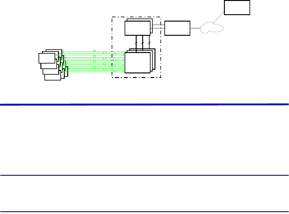
The Fiber-DAS system typically consists of three main segments:
Gateway — The Gateway acts as a firewall ensuring internal traffic on the system remains internal and at the
same time allowing a web interface for monitoring and supervision. The gateway also handles SNMP traps.
Headend — The Headend serves as the interface with the operator’s base station, housing the units required to
transmit and receive communications between the operator’s base station and the remote units of the Fiber-DAS
system.
Remote Units — the remote units are located near the distributed antennas and house the equipment necessary
to transmit and receive communications between the antenna and the headend.
Figure 1 Fiber-DAS System
Gateways
The gateways offered include the Central Gateway (CGW), Base Station Gateway (BGW) and Remote Gateway
(RGW).
For remote supervision of a Fiber-DAS a gateway (RGW or BGW) is installed. BGWs and RGWs are typically located
with the headend equipment, the RGW is a smaller compact embedded solution while the BGW is a full featured
Linux server that can be set up in many different ways.
CGWs are used for monitoring multiple Fiber-DAS systems, communicating with the BGWs and RGWs.
Central Gateway (CGW)
The CGW is used to provide a single remote access point and to compile alarms from multiple BGW/RGW networks.
The unit is a self-powered Linux based server.
Base Station Gateway (BGW)
The BGW assigns IP addresses to all the modules in the Fiber-DAS system, including the Headend and Remote Units
as well as their components.
The BGW is a self-powered Linux based server.
Features of the BGW:
Web interface configuration
Automatic detection of modules
Automatic detection of Remote Units
Capable of handling large systems
Functions for statistics
Remote
Unit
Remote
Unit
Remote
Unit
Head End
Gateway
Central
Gateway
Ethernet
Switch
Master
Frame
Unit
Master
Frame
Unit
Master
Frame
Unit
(BGW/RGW)
Fiber Distributed Antenna System (Fiber DAS)
5
Northbound communication to CGW
Includes firewall to protect local net
Portal to your Master Unit
User-provided certificate based security via HTTPS
Figure 2 Base Station Gateway
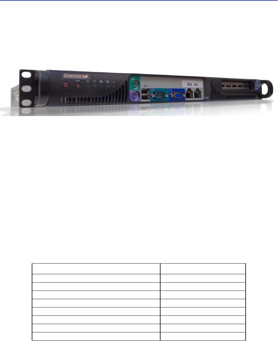
The BGW has two Ethernet ports - INT and EXT.
The INT port is connected to the internal network in the headend’s Master Unit to provide the local
network for all the modules and the Remote Units. It also provides, via the built-in switch in the Master
Unit, a way of locally configuring the network. It provides the web interface for all the settings of the
system as well as many other functions.
The EXT port is a “northbound” Ethernet port that allows the BGW to connect to the Internet, or a WAN/
MAN type of larger network. This means that the system can be monitored and managed remotely.
The BGW is the unit responsible for alarm handling and remote forward of alarms either by SMTP mail forwarding
or by SNMP traps. A MIB file for your SNMP system is available from Bird upon request as well as documentation
regarding SNMP.
If the BGW is replaced the Remote Units may not show up immediately. This is due to the lease time on the address
they have. Eventually they will request a new address and when this is done they will show up.
The BGW can also launch VPN tunnels to a remote supervision center, the CGW. The CGW makes it possible to
manage multiple systems from a single location.The CGW can handle a large number of such tunnels, providing a
central point for supervising all the installations and collecting alarms and statistics from all the systems as well as
centralized alarm management. The BGW can support a second VPN tunnel to the Bird management center
providing supervision and management assistance, if needed.
Table 1 BGW Specifications
Parameter Value
Input power voltage 100-240 VAC
Input power frequency 50 / 60 Hz
Operating temperature 10 to 30 °C (50 to 100 °F)
Power rating, Typical < 100 W
Height 1 U
Width 19” (48.26 cm)
Depth 14.2” (36 cm
Weight < 11 lbs. (5 kg)
System Description
6
Remote Gateway (RGW)
The RGW is a small unit similar to the BGW but intended for small systems where there are only a few remotes or
where there is no headend. The RGW has a form factor that allows it to be mounted inside a repeater casing.
The RGW can be used to run up to 4 Remote Units from a single Repeater on a single Fiber. The RGW has the
capability to connect northbound to a CGW, just like the BGW, and it can also forward alarms through a VPN tunnel
to a CGW.
The memory capacity and features are reduced compared to the BGW but for a small system with a single fiber this
is an option.
In remote locations without Ethernet, the RGW can be equipped with a modem to allow remote access to the
system. Typically a 3G modem is used allowing a VPN tunnel from the RGW to a CGW, enabling supervision,
monitoring and control of the system.
Headend
The headend consists of a 19-inch rack with modules that are selected depending on the system design. Generally
all headend Units contain:
Network switch - connects communication paths between the modules
Interconnect Unit (ICU) - RF splitter/combiner (rack-mount unit or module in the MFU)
Master Frame Unit (MFU), may contain some or all of the following:
Power supply
Base Station Interface Unit (BIU)
Fiber-Optic Interface card (FOI)
Repeater
ICU
A DHCP server built into the RGW and BGW will assign IP addresses to all the headend subunits in the rack and the
Remote Units when they are connected to the system. The configuration is automatic and creates a protected sub-
net for the system.
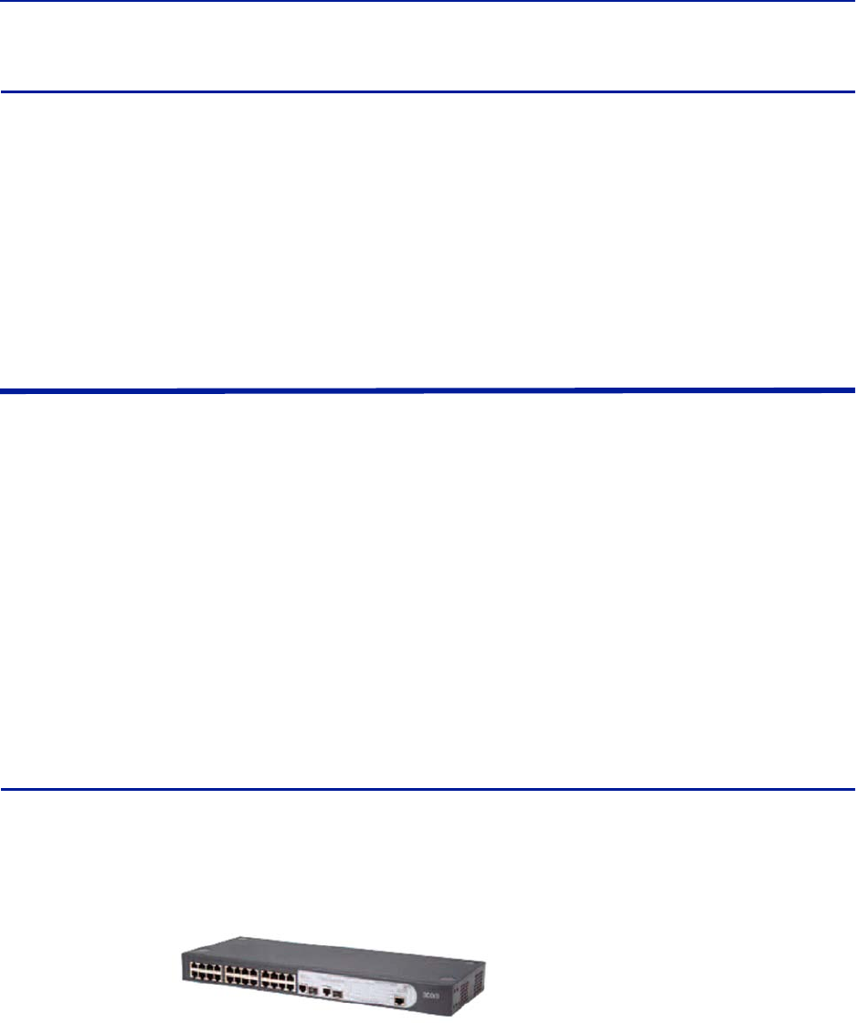
DCS - Network Switch
The network switch is an AC powered, 24-port switch with Spanning Tree Protocol (STP). The network switch
provides an Ethernet link between the MFU and the BGW. Each card slot in the MFU has a dedicated Ethernet port,
each port is connected to the network switch and the network switch is connected to the BGW.
A DC powered option is also available.
Actual network switch may be
different from the image.
Fiber Distributed Antenna System (Fiber DAS)
7
Master Frame Unit (MFU)
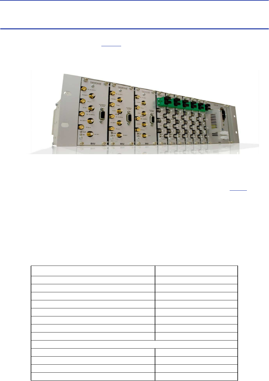
The Master Frame Unit (MFU) houses the Power Supplies, Base Station Interface Units (BIU), Interconnection Units
(ICU), and Fiber-Optic Interface (FOI) cards.
Figure 3
shows an MFU equipped with 3 BIUs, 6 FOIs and one Power
Supply.
Figure 3 Master Frame Unit
Functional description
One MFU supports several modules, or combination of module types. The modules can be placed anywhere in the
frame. There are 16 single slot card positions in each MFU, however module widths vary (see each module’s
specifications) so the number of module that will fit in an MFU depends on the module type. One MFU can house
up to 4 power supplies, 8 ICUs, 8 wide BIUs, 16 slim BIUs, 16 FOIs, or combination of modules. See
Table 2
.
Each MFU requires at least one power supply, although the power supply does not need to be housed within the
MFU. Quite often a system has more than one power supply and they are usually placed together in one MFU for
easy access. Each MFU has two power input connectors, one primary and one redundant. A redundant power
supply connected to an MFU ensures continued operation if one of the power supplies should fail.
The MFU contains two ventilation fans circulating ambient air through the units housed in the frame. These are high
quality fans with a high mean time between failure (MTBF).
Each Module in the MFU are assigned an IP addresses via DHCP leases, modules inherit the MAC address from the
backplane, this ensures that a new module inserted in the rack receives the same IP address as the one it is
replacing, without the need of manual configuration.
Table 2 MFU Specifications
Parameter Value
Input Voltage 28 VDC
Power connector Molex, 10 Pin
Ethernet connector RJ45
Weight (without modules) 5.5 lbs (2.5 kg)
Temperature range, Operational 0 to 40 °C (32 to 104 °F)
Width 19” (48.3 cm)
Height 3 U, 5.25” (13.34 cm)
Depth 11.8” (30 cm)
Maximum number of each type of modules supported
PSU 4
BIU (DBI3xx, DBI3xxC(compact)) 8, 16
FOI (DOI401, DOI30x) 8, 16
ICU 8
System Description
8
Base Station Interface Unit (BIU)
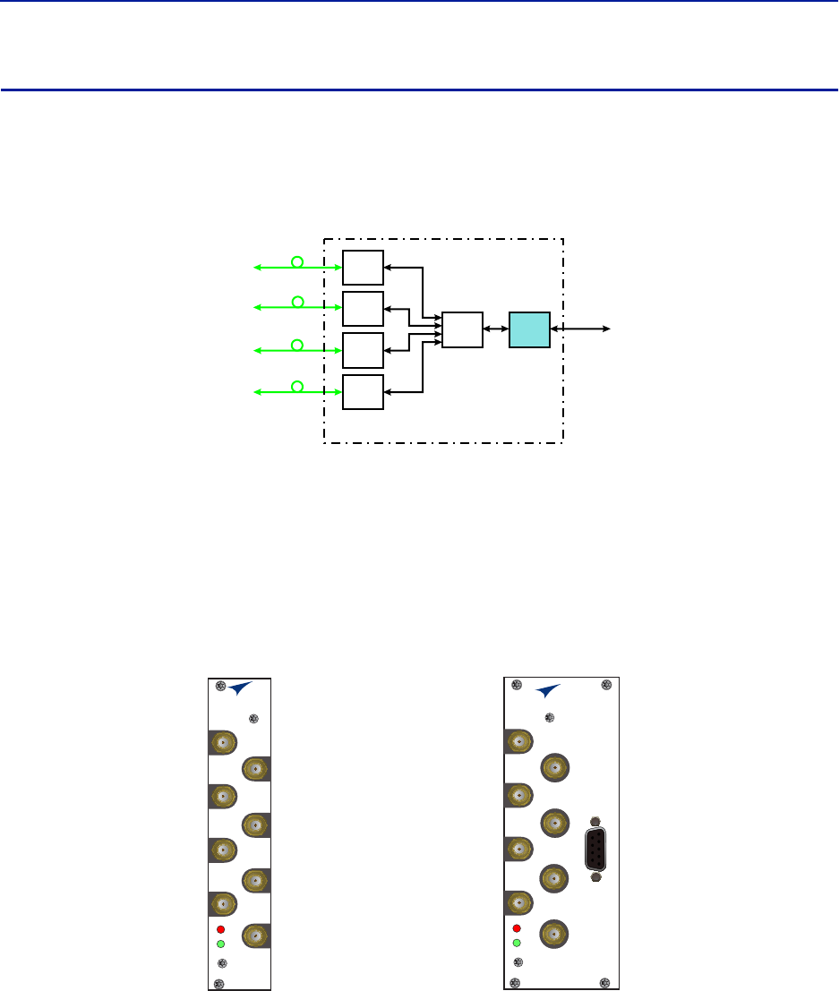
The Base Station Interface Unit (BIU) is the interface between the operator’s base station and the Fiber-DAS
system. The primary purpose of the BIU is to adjust uplink and downlink signal levels.The BIU is powered from the
MFU backplane and communicates via Ethernet with the BGW.
Figure 4 BIU Signal Flow
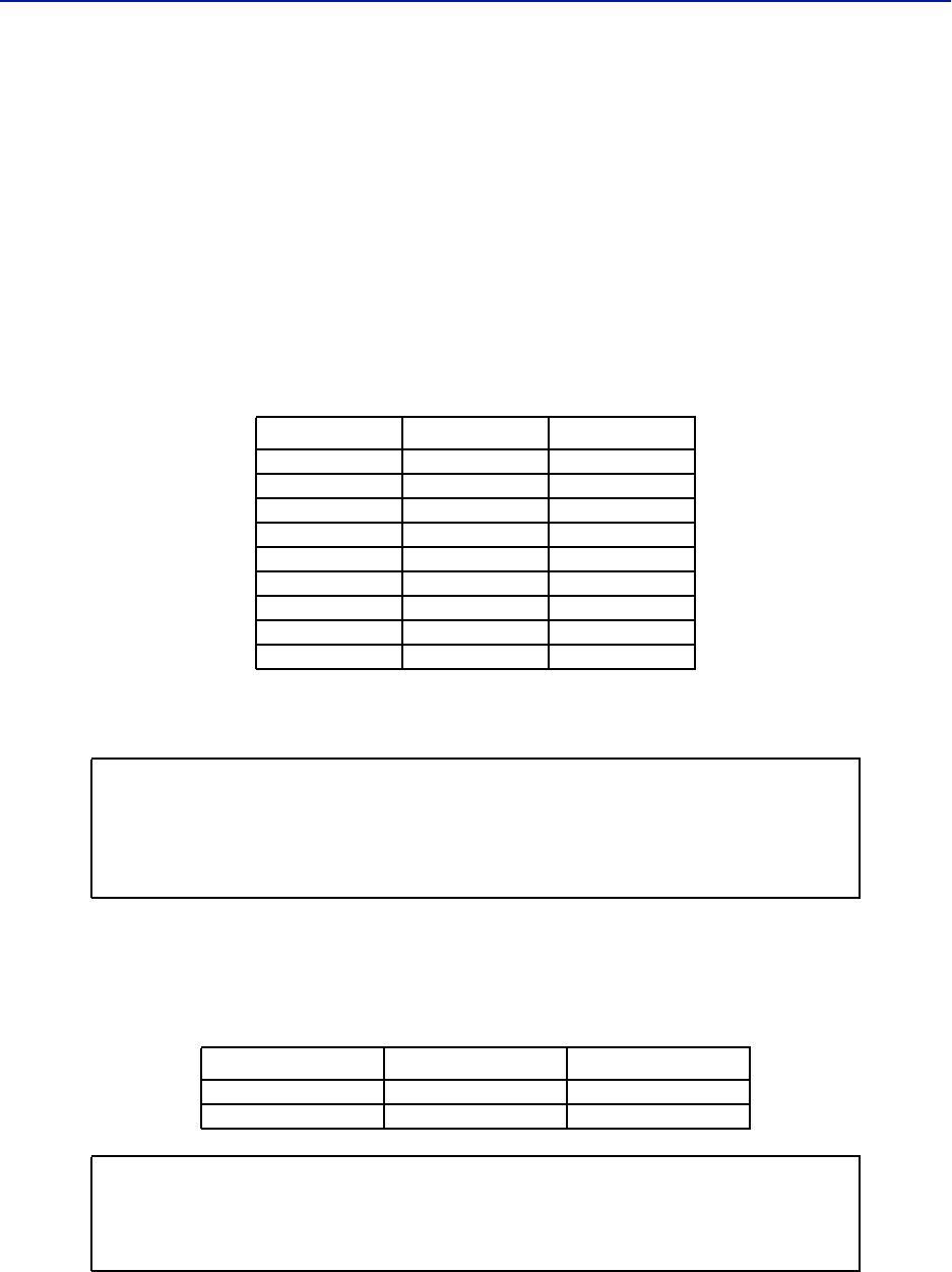
The BIU has uplink and downlink RF connectors on the front panel and is available in two variants, one containing
duplex filters or one with separate uplink/downlink paths, depending on the needs for the connection to the base
station. In most cases the duplexed version with a combined DL/UL ports is used.
In addition to duplexing options, there is a single slot and a dual version of the BIU:
The DBI3xx (wide version) includes an external alarm connector (DB9) and requires two MFU slots.
The DBI3xxC (compact version) does not have an external alarm connector (DB9) , and uses only one MFU
slot.
Figure 5 Base Station Interface Unit (BIU)
Functional description
The BIU has four SMA ports (female type) to connect the RBS/BTS.
Duplexed versions have combined DL/UL connectors used to connect to the RBS, and there are UL test (TP)
connectors that can be used to monitor the signal out from the BIU.
Non-duplexed (simplex) versions have the test connectors replaced by UL connectors and the normally
combined UL/DL connectors are replaced by DL only connectors.
Base
Station
Base Station
Interface
Interconnect
Unit
Fiber-Optic
Interface Units
Fiber-Optic
Cables
to
Remote
Units
(Antenna)
Master Frame Unit
FOI
FOI
FOI
FOI
ICU BIU
BIU
ALM
ON
DL/UL BTS 1
TP UL 1
TP UL 2
DL OUT 1
UL IN 1
DL OUT 2
UL IN 2
DL/UL BTS 2
BIU
ALM
ON
DL/UL BTS 1
TP UL 1
EXTERNAL
ALARM
TP UL 2
DL OUT 1
UL IN 1
DL OUT 2
UL IN 2
DL/UL BTS 2
DBI3xxC DBI3xx
Fiber Distributed Antenna System (Fiber DAS)
9
The BIU has four QMA ports (female type) that are normally used to connect it to an ICU.
There are two uplink (input, RX) ports and two downlink (output, TX) ports.
These are two separate paths, the isolation between DL 1 and DL 2 ports and the isolation between the UL
1 and UL 2 ports is > 50 dB.
There are two separate RF paths in the BIU. The BIU is configured for the specific frequency band it will serve. The
two paths in the BIU cannot have different frequencies; a 900 MHz BIU will have two 900 MHz paths and cannot be
combined with an 1800 MHz path. Separate frequencies require the use of an additional BIU.
RF patch cables are used to patch the DL and UL paths (QMA) to the ICU.The RF patch cables high quality, low PIM
cables such as Bird’s DCC320 cable set.
The DBI 3xx (dual slot) BIU has an alarm output port (DB9 female connector) on the BIU which can be used to
connect external alarms.
Table 3 Alarm Port Pinout
The BIU is technology neutral and the downlink path contains settable attenuators that can be used to adjust the
signal strength to proper levels before feeding them into the ICU. In the uplink there is an amplifier followed by a
settable attenuator used to adjust the signal and the noise level into the base station uplink.
All RF connections are made on the front of the BIU. The maximum recommended input power to the BIU is
30 dBm. A high power alarm is activated at > 30 dBm and a low power alarm at < 10 dBm input power.
Input power above the recommended level can cause permanent unit failure. For high power base stations, an
attenuator should be used to ensure that the input power to the BIU can never exceed specifications.
There is a 0 dBm input version of the BIU available on request.
Pin Signal (A) Signal (B)
1 RS485+ RS485+
2 Alarm out 1 Alarm out 1
3 Ground Ground
4 Not connected Alarm in 2
5 Not connected Alarm in 4
6 RS485+ RS485+
7 Alarm out 2 Alarm out 2
8 G Alarm in 3
9 Not connected Alarm in 1
CAUTION
Overdriving the RF source input into the BIU will cause permanent equipment failure and
will void the warranty. The installer must ensure that input levels are not exceeded.
Plan for maximum power out of the RF source and attenuate accordingly with external
attenuators if needed.
BIU Type Minimum DL Input Maximum DL Input
Low Level -7dBm +7dBm
High Level +20dBm +33dBm
CAUTION
The UL from the FOI card is capable of damaging the UL port on the BIU.
Maximum input to the BIU UL should be no higher than +13dBm.
Use care to properly set FOI levels prior to enabling RF.
System Description
10
The schematic in
Figure 6
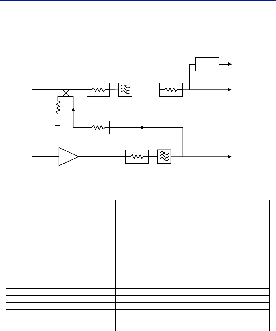
shows one of the channels in the BIU. The signal detector for the downlink level alarms is
shown in the top right corner.
The UL1 and UL2 uplink test ports are 3 dB lower than the signal on the corresponding DL/UL BTS port.
Figure 6 Schematic of One BIU RF Path
Table 4
lists standard cellular BIU’s. Other configurations are available upon request as well as units without
internal duplex filtering.
Table 4 Standard Variants of the BIU
Configuration UL MHz DL MHz RF Input High Level P/N Low Level P/N
2 x FM - 87-108 Simplex DBI302 DBI402
2 x VHF 136-174 136-174 Simplex DBI312 DBI412
2 x TETRA 390 MHz†
† There are several options for the TETRA 5 MHz standard bands.
380-385 390-395 Duplex DBI301 DBI401
2 x UHF 450-470 450-470 Duplex DBI313 DBI413
2 x 700 MHZ ABC-band 698-716 728-746 Duplex DBI307 DBI407
2 x 700 Upper C 777-787 746-756 Duplex DBI304 DBI404
2 x 700 Public Safety 799-805 769-775 Duplex DBI314 DBI414
2 x SMR 800 806-824 851-869 Duplex DBI303 DBI403
2 x 850 MHz 824-849 869-894 Duplex DBI308 DBI408
2 x 800 832-862 791-821 Duplex DBI305 DBI405
2 x GSM-R 900 876-880 921-925 Duplex DBI310 -
2 x 900 MHz 880-915 925-960 Duplex DBI309 DBI409
2 x 1800 MHz 1710-1785 1805-1880 Duplex DBI318 DBI408
2 x 1900 MHz 1850-1915 1930-1995 Duplex DBI319 DBI419
2 x UMTS 2100 MHz 1920-1980 2110-2170 Duplex DBI320 DBI420
2 x AWS 2100 MHz 1710-1780 2110-2180 Duplex DBI321 DBI421
2 x LTE 2600 2500-2570 2620-2690 Duplex DBI326 DBI426

Fiber Distributed Antenna System (Fiber DAS)
11
Table 5 RF and Electrical Performance of the BIU
Table 6 BIU Mechanical Specifications
BIU Indicator Operation
There are two LEDs located on the BIU front panel. One is the power LED (green), the other is the alarm LED (red).
Both LEDs indicate a number of states by different flashing sequences, see
Table 7
.
In an error state the web interface should be used to check the actual condition of the BIU but the LEDs can give a
quick indication on the state of the unit. The LEDs are also useful for locating the physical unit if several BIUs are
installed in the same rack.
Table 7 Indicator Behavior
Parameter Value
Downlink attenuation Settable 10-30 ± 3 dB
Uplink Gain for modules < 1000 MHz Settable 10 to 20 ± 3 dB
Uplink Gain for modules > 1000 MHz Settable -10 to 10 ± 3 dB
IM3 performance > 55 dB
Max input non-destructive < 36 dBm
High input alarm threshold level >33 dBm
Low input alarm threshold level <13 dBm
Input return loss > 20 dB
Impedance for all RF ports 50 Ω
Isolation between ports > 60 dB
Power consumption < 15 W
Temperature range 0-45 °C (32 to 113 °F)
Parameter Value
Base station RF ports SMA, Female
Test ports uplink (if present) SMA, Female
Interconnecting RF ports to ICU QMA, Female
Alarm connector (optional) DB9, Female
Module Width
DBI3xx
DBI3xxC(compact)
2 Slots
1 slot
State ON LED ALM LED Note
Booting 2 Hz Off Normal boot
Booting standalone mode 2 Hz 2 Hz Not attached to rack
Booting read of MAC address failed 2 Hz On Error
Starting 0,1 Hz 90% 0,1 Hz 90% Kernel startup
Operation 0,5 Hz 10% Off Normal operation
Operation 0,5 Hz 10% 1 Hz 10% Minor alarm state
Operation 0,5 Hz 10% 2 Hz 25% Major alarm state
Operation 0,5 Hz 10% On Critical alarm state
System Description
12
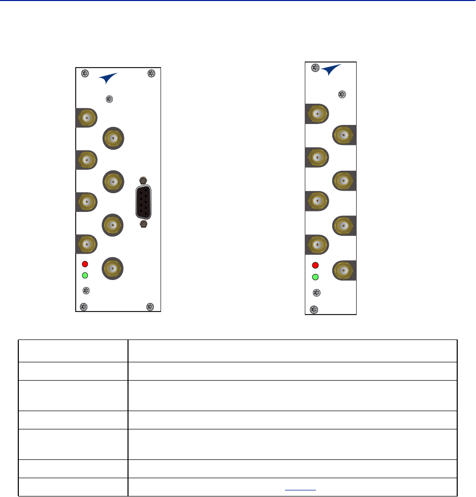
Figure 7 BIU Interfaces
Item Description
DL/UL BTS 1 / 2 Connection from the radio base station (RBS).
TP UL 1/2 Test port for the uplink of the DL/UL BTS port. The signal will be 3dB below
the DL/UL BTS port. Port is not valid on the simplex BIU.
DL OUT 1/2 Simplex downlink feed to the FOI.
UL IN 1/2 Simplex uplink from the FOI. The BIU will attenuate and/or amplify the signal
and then route to the DL/UL BTS port.
EXTERNAL ALARMS Used for external alarm monitoring (DBI3xx, two slot version only).
ON/ALM LED The LEDs indicate various states, see
Table 7
.
BIU
ALM
ON
DL/UL BTS 1
TP UL 1
EXTERNAL
ALARM
TP UL 2
DL OUT 1
UL IN 1
DL OUT 2
UL IN 2
DL/UL BTS 2
BIU
ALM
ON
DL/UL BTS 1
TP UL 1
TP UL 2
DL OUT 1
UL IN 1
DL OUT 2
UL IN 2
DL/UL BTS 2
Fiber Distributed Antenna System (Fiber DAS)
13
Interconnect Unit (ICU)
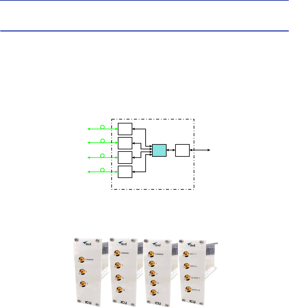
Interconnect units (ICU) are used to couple signals between the BIUs and the FOIs.
The functional purpose of the ICU is:
Downlink - Split the signal from the BIU and route the balanced signals (minus insertion loss) to the FOIs.
Uplink - Combine the signals from the FOIs and route the sum of the signals (minus insertion loss) to the
BIU.
The RF ports on the ICU are QMA.
Figure 8 Interconnect Unit Signal Flow
MFU ICU
The MFU ICUs are available in several different configurations to support a variety of system configurations.
These units are inserted into the MFU and provide signal routing to and from the BIUs and FOIs.
Figure 9 MFU ICU
Base
Station
Base Station
Interface
Interconnect
Unit
Fiber-Optic
Interface Units
Fiber-Optic
Cables
to
Remote
Units
(Antenna)
Master Frame Unit
FOI
FOI
FOI
FOI
ICU BIU
System Description
14
Rack-mount ICU (DIU301, DIU302)
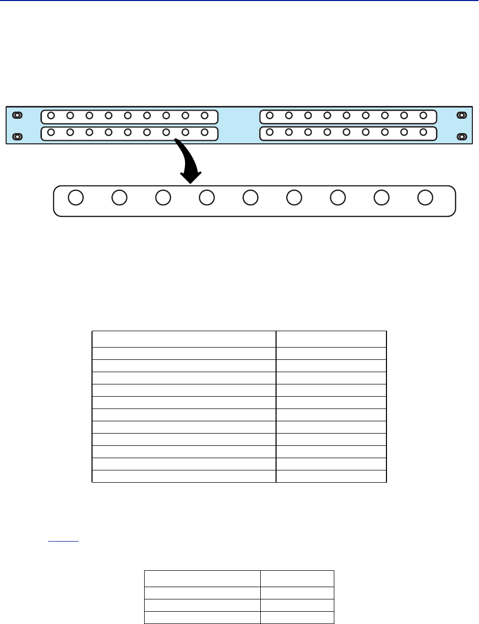
The Rack-mount ICU is a 1U unit that contains four fields containing splitters/combiners. Each field is capable of
splitting one input into eight outputs or combining eight inputs into one output.
Figure 10 Rack-mount ICU
Each of the 4 fields has a COMMON port and ports 1-8.
When used as a combiner, the signals to combine are connected to input ports 1-8, the sum of the signals
(minus insertion loss) will be output on the COMMON port.
When used as a splitter, the combined signal is input on the COMMON port and output on ports 1-8, with
the output ports having balanced signals (minus insertion loss).
Table 8 Rack-mount ICU Specifications
QMA cable kit
A QMA cable kit (Bird part number DCC320) is available for use with the ICU. The kit contains 32 QMA to QMA
cables (see
Table 9
) that can be used to patch between the BIU to the ICU, BIU to the FOI or ICU to FOI.
Table 9 QMA Cable Kit
Parameter Value
Insertion loss (nominal) - DIU301 37 dB
Insertion loss (nominal) - DIU302 21 dB
Bandwidth - DIU301 680-2700 MHz
Bandwidth - DIU302 88-2700 MHz
Operating Temperature -25 to +55 C (-13 to +131F)
Impedance 50 Ohm
IM3 performance > 50 dB
Return loss performance > 20 dB
Maximum common port power 20 dBm
Isolation between ports in same strip > 15 dB
Isolation between ports in different strips > 50 dB
Length Quantity
250 mm (9.8”) 13
350 mm (13.8”) 13
500 mm (19.7”) 6
Fiber Distributed Antenna System (Fiber DAS)
15
Fiber Optic Interface (FOI) unit
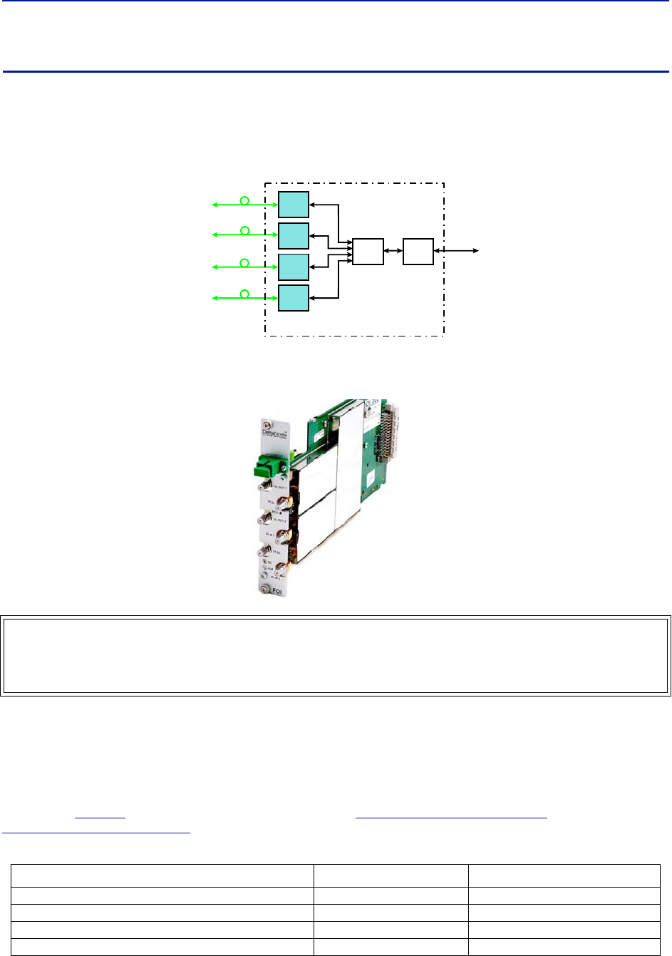
The FOI converts the RF signals in the downlink to fiber-optical laser output that is transmitted on the fiber to the
remote unit. It also receives the laser light transmitted by the Remote Unit and converts it back to RF signals that
are then routed to the ICU and/or BIU.
Figure 11 FOI Signal Flow
The FOI is powered from the MFU backplane and communicates via Ethernet with the BGW.
Figure 12 Fiber Optic Interface (FOI) Unit
This interface is designed to work with SC-APC connectors (angled physical connector) and single mode fibers only.
All connectors between the master unit and the remote unit must be APC, otherwise problems with reflections will
arise, which could cause severe problems in the system.
The Ethernet communication between the Headend and the Remote Units takes place on two sub-carriers in the
FOI where the Ethernet signals are superimposed on the RF signals. The Ethernet sub-carriers are on frequencies
not used by the RF traffic so they do not cause any system performance degradation.
As shown in
Table 10
, Bird offers two styles of FOI cards. The
"DOI300 Series FOI" on page 16
and the
"DOI401Series FOI" on page 19
.
Table 10 FOI Variants
WARNING
Avoid looking into connected fibers and receptacles.
The laser used in this system is a Class 3b laser that produces invisible infra-red coherent light. Not safe to view
with optical instruments. Always put the protection caps on unused fibers and receptacles.
Parameter Fiber Ports Wavelength
DOI 301 2 1310 nm (RX), 1550nm (TX)
DOI 302 (WDM) 1 1310 nm (RX), 1550nm (TX)
DOI 380x 1 various wavelengths available
DOI401 4 1310 nm (RX), 1550nm (TX)
Base
Station
Base Station
Interface
Interconnect
Unit
Fiber-Optic
Interface Units
Fiber-Optic
Cables
to
Remote
Units
(Antenna)
Master Frame Unit
FOI
FOI
FOI
FOI
ICU BIU
System Description
16
DOI300 Series FOI
The DOI300 series supports a single fiber optic link. The fiber-optic interface can either be a WDM (DOI302) which is
most commonly used or an optional duplex feed with separate UL and DL fibers (DOI301). Bird also offers a WDM
option (DOI380x). The WDM utilizes the duplex feed style card but the wavelength for the downlink are defined by
the "x" in the DOI380x part number. Note that the Remote Unit will need to be ordered with the correct WDM
uplink wavelength. Refer to the chart for the WDM wavelengths offered.
DOI300 Series Serving Multiple Remotes
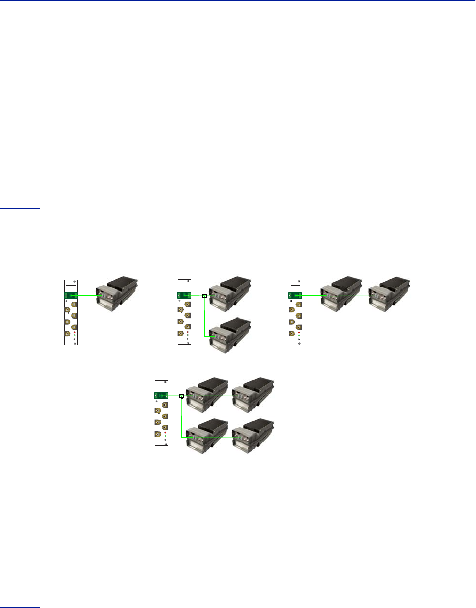
The DOI300 Series FOI can serve up to 4 Remote Units on a single fiber run when using an optical splitter in the first
Remote Unit. When utilizing the DOI302 WDM module each Remote Unit in the series must have different optical
wavelengths in the uplink path to avoid interference.
When utilizing optical splitters, the optical loss of the splitter must be accounted for in the optical link budget. The
DOI300 series FOI has a maximum link budget of 15 dBo.
Figure 13
shows the allowed FOI to FOR/Remote configurations. Bird offers various splitter options for the FOR/
Remote to help account for optical losses. The standard optical splitter will have balanced outputs for each path.
Consult with Bird engineering for special applications.
Figure 13 FOI to Remote Unit Configurations
Functional description
The FOI has a nominal gain of 35 dB and the laser transmitter should see a maximum composite input power of
0 dBm. This means that for 0 dB attenuation in the downlink a maximum input of -35 dBm composite power is
recommended (when attenuators are set to 0 dBm). If the downlink attenuator is set to a higher value the
maximum recommended input is adjusted accordingly.
The output power of the laser is calibrated to 3000 μW. This can be used to check the loss over fiber in the remote
because the remote reports the received optical levels. The loss may be different in the uplink compared to the
downlink because of different wavelengths on the laser.
The FOI contains several adjustable attenuators which are used to compensate for loss before the FOI (e.g. in the
ICU) and for loss on the fiber in the uplink. There are two sets of RF ports on the FOI that can be used to connect
signals from two different strips in the rack-mount ICU, or two different MFU ICUs.
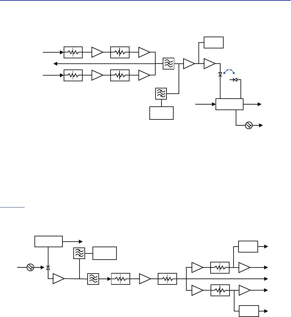
Figure 14
is a block diagram showing the downlink path in the FOI and how the test port is connected. There are
two attenuators that can be set in the downlink path. This allows for balancing the input signals from two different
signal sources so that they can share the dynamics of the laser properly.
DeltaNode
Wireless Technology
TM
FOI
ALM
ON
UL OUT 1
OPTO IN/OUT
TP DL
RES
TP UL
DL IN 1
DL IN 2
UL OUT 2
DeltaNode
Wireless Technology
TM
FOI
ALM
ON
UL OUT 1
OPTO IN/OUT
TP DL
RES
TP UL
DL IN 1
DL IN 2
UL OUT 2
Point-to-Point Daisy-Chained Remotes
Hybrid Split
DeltaNode
Wireless Technology
TM
FOI
ALM
ON
UL OUT 1
OPTO IN/OUT
TP DL
RES
TP UL
DL IN 1
DL IN 2
UL OUT 2
Point-to-Multipoint
DeltaNode
Wireless Technology
TM
FOI
ALM
ON
UL OUT 1
OPTO IN/OUT
TP DL
RES
TP UL
DL IN 1
DL IN 2
UL OUT 2
Fiber Distributed Antenna System (Fiber DAS)
17
Figure 14 FOI Downlink Block Diagram
The RF drive levels are measured and accessible in the web interface.
TP DL is a test point measurement port for the downlink path. The RF level at TP DL will be the same as the input to
the DL ports minus the GUI attenuator settings.
TP DL = “DL IN 1" minus “Att. 1 Downlink 1" minus “Att. 2 Downlink 1".
TP DL = “DL IN 2" minus “Att. 1 Downlink 2" minus “Att. 2 Downlink 2".
Example: Input into DL is -25dBm with the GUI setting for “Att. 1 Downlink 1" of 10 and a GUI setting for “Att 2
Downlink 1" of 0. The test point measurement will be: -25dB (input) minus 10dB (attenuator #1) minus 0dB
(attenuator #2) = -35dBm.
Figure 15
is a block diagram showing the uplink path in the FOI and how the test port is connected. There are two
common attenuators, and two uplink attenuators that can be set in the uplink path.
Figure 15 FOI Uplink Block Diagram
The UL test port on the FOI is tapped before the individual uplink path attenuators. The output level of TP UL will be:
TP/UL[dB] = “Att. Uplink 1" setting - 20dB
TP/UL[dB] = “Att. Uplink 2" setting - 20dB
Example: If the FOI GUI setting for “Att. Uplink 1" is 0, the test port uplink path 1 signals will be 20dB lower than the
uplink signal on the “UL Out 1" port.
Example: If the FOI GUI setting for “Att. Uplink 2" is 20, the test port uplink path 2 signals will be equal to the uplink
signals on “UL Out 2" port.
DETECTOR
LASER
DRIVER
ETHERNET
MODEM
OPTO OUT
DETECTOR
MONITOR
TX-LVL
DL IN 1
DL IN 2
TP DL
STEP ATT
Attenuator 1
Downlink 1
Attenuator 1
Downlink 2
Attenuator 2
Downlink 1
Attenuator 2
Downlink 2
STEP ATT
STEP ATT
STEP ATT
DETECTOR
DETECTOR
CURRENT
SENSOR
ETHERNET
MODEM
OPTO IN
RX-LVL
UL OUT 2
UL OUT 1
TP UL
Attenuator
Common 1
PHOTO
DETECTOR
Attenuator
Common 2
Attenuator
Uplink 1
Attenuator
Uplink 2
STEP ATT STEP ATT
STEP ATT
STEP ATT
RX POWER 1
RX POWER 2
System Description
18
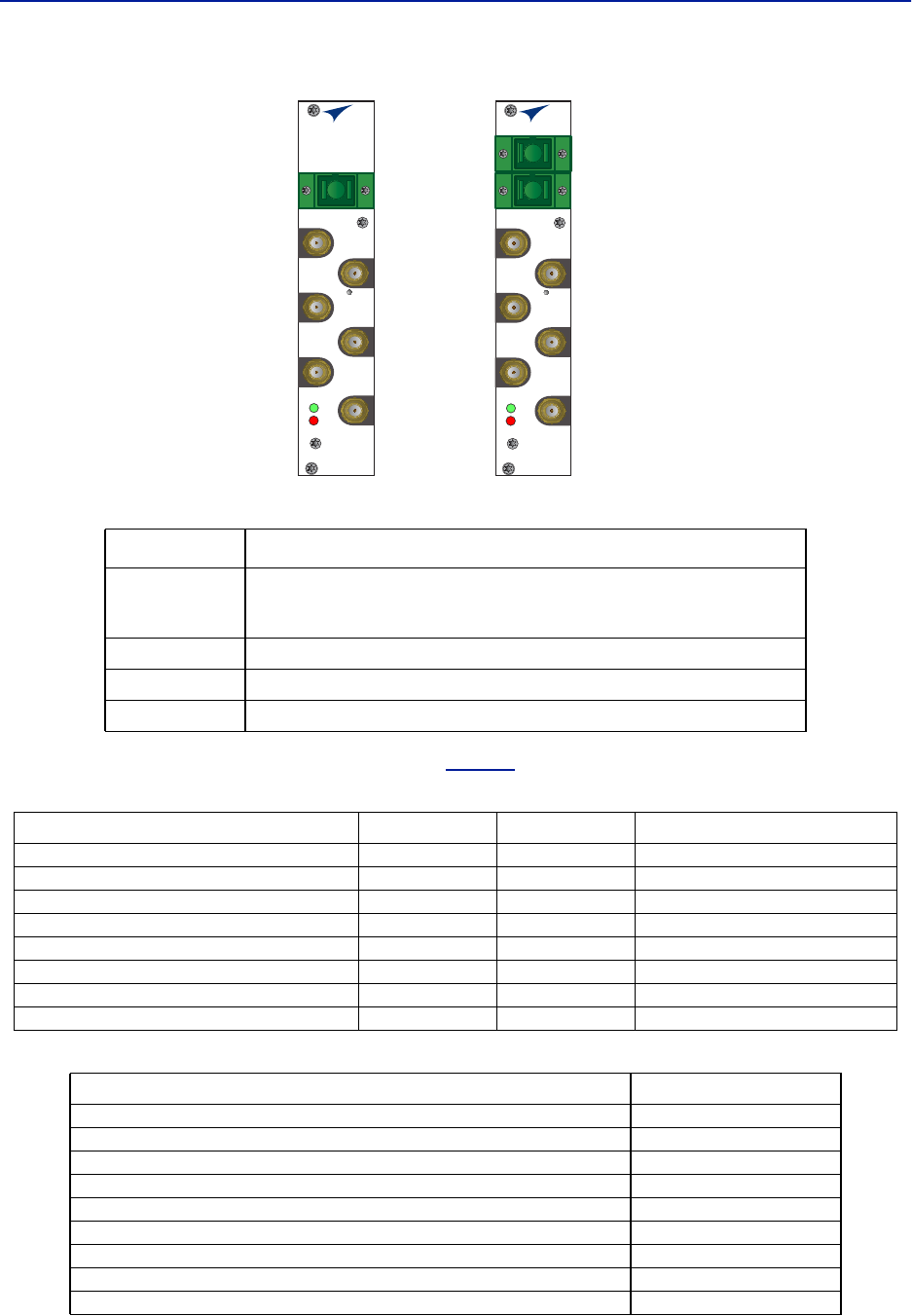
Figure 16 DOI301/302 Interfaces
The two LEDs on the unit provide FOI status as shown in
Table 11
.
Table 11 FOI LED Indicators
Table 12 DOI302 Specifications
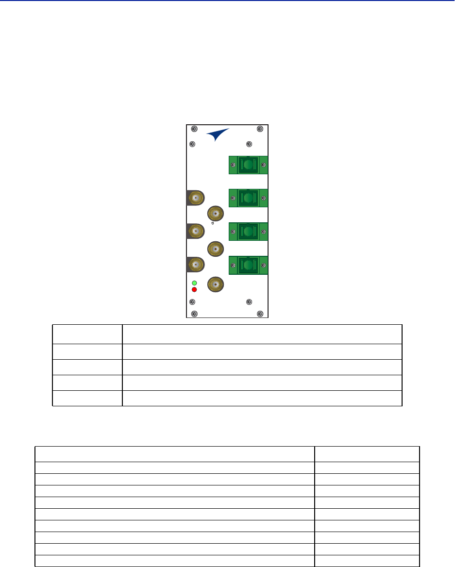
Item Description
OPTO IN/OUT
SC-APC connection for the optical fiber.
DOI302 module with built in WDM has a single connector (combined RX/TX).
DOI301 module without WDM has two connectors, one for TX and one for RX.
UL OUT 1/2 Uplink ports (QMA) to the ICU.
DL IN 1/2 Downlink ports (QMA) to the ICU.
TP UL/DL Test ports (QMA) used to check the signal levels or noise in the system.
State ON LED ALARM LED Note
Booting 2 Hz Off Normal boot
Booting standalone mode 2 Hz 2 Hz Not attached to rack
Booting read of MAC address failed 2 Hz On Error
Starting 0,1 Hz 90% 0,1 Hz 90% Kernel startup
Operation 0,5 Hz 10% Off Normal operation
Operation 0,5 Hz 10% 1 Hz 10% Minor alarm state
Operation 0,5 Hz 10% 2 Hz 25% Major alarm state
Operation 0,5 Hz 10% On Critical alarm state
Parameter Value
Maximum fiber loss from MU to RU, Optical, 15 dBo
Optical output power, Calibrated 3 000 μW
Maximum number of RU supported on single fiber 4
Input RF power recommended, Composite -50 to -35 dBm
Power consumption < 15 W
Operational Temperature range 0 to 45 °C (32 to 133 °F)
Module Width 1 card slot
Optical connector type SC-APC
RF connector type QMA Female
FOI
ALM
ON
UL OUT 1
OPTO IN/OUT
TP DL
RES
TP UL
DL IN 1
DL IN 2
UL OUT 2
DOI302
With WDM
DOI301
Without WDM
FOI
ALM
ON
UL OUT 1
OPTO OUT
OPTO IN
TP DL
RES
TP UL
DL IN 1
DL IN 2
UL OUT 2
Fiber Distributed Antenna System (Fiber DAS)
19
DOI401Series FOI
The DOI401 four port FOI is very similar to DOI302 expect that it has four WDM optical ports instead of one. This
allows the user to install dedicated fibers to each Remote Unit without having to balance optical splitter link
budgets for each remote in a group. The balanced splitter loss is accounted for in the 7 dBo link budget of the
DOI401. Unlike the DOI302, the DOI401 does not require the UL optical signals to be on different wavelengths.
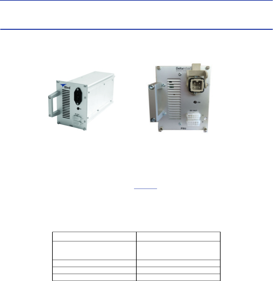
Figure 17 DOI401 Interfaces
Table 13 DOI401 Specifications
Item Description
OPTO IN/OUT SC-APC connections for the optical fiber.
UL OUT 1/2 Uplink ports to the ICU/BIU.
DL IN 1/2 Downlink ports to the ICU/BIU.
TP UL/DL Test ports used to check the signal levels or noise in the system.
Parameter Value
Maximum fiber loss from MU to RU, Optical, 7 dBo
Optical output power, Calibrated 3 000 μW
Maximum number of RU supported on single fiber 1
Input RF power recommended, Composite -50 to -35 dBm
Power consumption < 20 W
Operational Temperature range 0 to 45 °C (32 to 113 °F)
Module Width 2 card slot
Optical connector type SC-APC
RF connector type QMA Female
OPTO IN/OUT 1
OPTO IN/OUT 2
OPTO IN/OUT 3
OPTO IN/OUT 4
FOI
ALM
ON
UL OUT 1
TP DL
RES
TP UL
DL IN 1
DL IN 2
UL OUT 2
System Description
20
PSU – the rack power supply
The Power Supply Unit provides DC power to the Master Unit backplane. The unit is shipped as 240 VAC or 115 VAC
units depending on the country. A -48 VDC input is offered as an option.
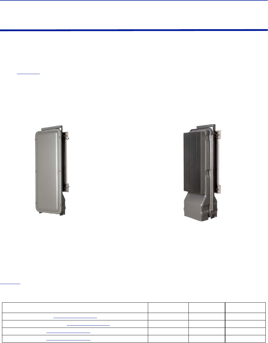
Figure 18 PSU
Functional description
The AC power supply can handle up to 16 cards or one chassis full of cards. The DC power supply is capable of
handling 12 cards or one full chassis that includes the DC power supply.
All connectors are on the front side of the power supply.
Figure 18
shows the PSU equipped with European power
inlet.
The PSU outputs are two 10-pin Molex connectors, these are connected to the chassis to supply power. One
connector should always be connected to the chassis holding the PSU (for driving the fans).
One chassis can hold up to 4 power supplies. Two PSU’s may be connected to a chassis to provide redundancy.
Table 14 PSU Specifications
Parameter Value
Input power voltage, Mains
DPU301
DPU302
86-264 VAC, 50 / 60 Hz
38 - 60 VDC
Operating temperature -25 to 55 °C (32 to 131 °F)
Power rating 240 W
Width 4 card slots
AC Power Supply DC Power Supply
Fiber Distributed Antenna System (Fiber DAS)
21
Remote Unit (RU)
Remote units are available in a wide range of frequencies, gain and output power to cater to support a variety of
requirements. Remote units are also capable of supporting more than one frequency band in a single unit.
Chassis types
Remote units (RUs) are available in two chassis, a single compact chassis for 1-2 bands and a dual chassis for up to 4
bands (
Figure 19
). There are multiple configurations that allow for various power level of amplifiers to be placed
into the chassis. For example it is possible to build a dual chassis with 2 medium power bands and 1 high power
band in the same remote. Each side of a dual chassis is virtually identical to a single chassis remote unit. This
ensures unparalleled flexibility when building multiple operator / multiple band solutions.
A dual chassis may have 1-2 fiber optical remote units (FOR). This allows for redundant fiber feeds, multiple-input
and multiple-output (MIMO) applications, and dedicated amplifiers.
Figure 19 Remote Unit Chassis Types
All Remote Units have an excellent noise figure, contributing to an overall noise figure for the whole system from
remote to head-end into the base station of < 3 dB for the RF link.
Both chassis comply with IP65 protection for use in any environment. The durable coating assists in convection
cooling. No fans are used for the Remote Units.
Note: The heat generated by the Remote Units when powered up is used to prevent water ingress
into units. Remote units must remain powered on when mounted outdoors.
Both wall or pole mounting kits are available for chassis mounting.
Table 15
contains a list of the most common remote units that are used with the Bird Fiber-DAS system. Variants
are available upon request.
Table 15 Remote Comparison Table
Product code Pout (ETSI)†
† Actual power determined by frequency band and spectrum demands.
Pout (FCC) Bands
DDR (medium power). See
"DDR" on page 22
.26-30 33 1-4
DDS (High power quad band). See
"DDS" on page 26
.41 1-4
DDH (high power). See
"DDH" on page 28
.32-43 43 1-2
DDU (high power). See
"DDU" on page 31
.46 1-2
Single Chassis
Remote Unit
Dual Chassis
Remote Unit

System Description
22
DDR
ETSI standard
Bird’s Distributed Radio head is a high performing wideband radio head equipped with a linear power amplifier
supporting all modulations. The light weight, convection cooled IP65 chassis secures the performance in almost any
environment.
Table 16 General Specifications
Table 17 Specifications DDR100 (Single Band) & DDR200 (Dual band)
Table 18 Specifications DDR300(Triple Band) & DDR400(Quad Band)
Cellular Products
Table 19 Available Products, ETSI
Noise Figure, Typical 3 dB
Delay excluding optical fiber < 0.5 μs
Power Supply
Standard
Optional
85 to 264 VAC
-32 to -100 VDC
Operating Temperature -25 to 55 °C (-13 to 131 °F)
Casing IP65
Power Consumption, max, DDR 100 (200) 90 (180) W
Dimensions, W x D x H 11.8 x 5.1 x 27.6 in.
30 x 13 x 70 cm
Weight < 34 lbs (15.2 kg)
Power Consumption, max, DDR 300 (400) 270 (360) W
Dimensions, W x D x H 11.8 x 8.7 x 27.6 in.
30 x 22 x 70 cm
Weight < 60 lbs (27.2 kg)
System UL Frequency
MHz
DL Frequency
MHz
Pout (DL)
dBm/c,
1 Carrier
Pout (DL)
dBm/c,
2 Carriers
Standard
FM 88 - 108 22 ETSI
TERTRA VHF 136 - 174 136 - 174 22 ETSI
TETRA, Public Safety 380 - 385 390 - 395 26 23 ETSI
TETRA, Commercial 410 - 415 420 - 425 26 23 ETSI
TETRA, Commercial 415 - 420 425 - 430 26 23 ETSI
CDMA450 452.5 - 457.5 462.5 - 467.5 33 28 FCC
GSM-R 876 - 880 921 - 925 26 23 ETSI
EGSM900 880 - 915 925 - 960 26 23 ETSI
GSM1800 1710 - 1785 1805 - 1880 28 25 ETSI
UMTS 1920 - 1980 2110 - 2170 30 25 3GPP
LTE 2600 2500-2570 2620-2690 30 43 3GPP

Fiber Distributed Antenna System (Fiber DAS)
23
FCC/IC standard
Bird’s Distributed Radio head is a high performing wideband radio head equipped with a linear power amplifier
supporting all modulations. The light weight, convection cooled IP65 chassis secures the performance in almost any
environment.
Table 20 General Specifications
Table 21 Specifications DDR100 (Single Band) & DDR200 (Dual band)
Table 22 Specifications DDR300 (Triple Band) & DDR400 (Quad Band)
Cellular Products
Table 23 Available Products, FCC/IC
Class B Industrial Booster — This equipment is a Class B Industrial Booster and is restricted to installation as
an In-building Distributed Antenna System (DAS).
FCC RF Exposure — This equipment complies with the FCC RF radiation exposure limits set forth for an
uncontrolled environment. This equipment should be installed and operated with the following minimum distances
between the radiator and your body:
If system will operate on multiple bands, the separation distance required shall be equal to, or greater than, the
band with the largest separation distance.
Noise Figure, Typical 3 dB
Delay excluding optical fiber < 0.5 μs
Power Supply
Standard
Optional
85 – 264 VAC
-32 to -100 VDC
Operating Temperature -25 to 55 °C (-13 to 131 °F)
Casing IP65
Power Consumption, max, DDR 100 (200) 90 (180) W
Dimensions, W x D x H 11.8 x 5.1 x 27.6 in.
30 x 13 x 70 cm
Weight < 34 lbs (15.2 kg)
Power Consumption, max, DDR 300 (400) 270 (360) W
Dimensions, W x D x H 11.8 x 8.7 x 27.6 in.
30 x 22 x 70 cm
Weight < 60 lbs (27.2 kg)
System UL Frequency MHz DL Frequency MHz Pout, DL,
dBm (Composite) Standard
LTE LB 698 - 716 728 - 746 33 FCC/IC
LTE UB 776 – 787†
† Sub-bands available
746 -757† 33 FCC/IC
iDEN 806 - 824 851 - 869 33 FCC/IC
Cellular 824 - 849 869 - 894 33 FCC/IC
PCS1900 1850 - 1915 1930 - 1995 33 FCC/IC
AWS 1710 - 1780 2110 - 2180 33 FCC/IC
WCS 2300 2305 - 2315 2350 - 2360 33 FCC/IC
IMT-E 2500 - 2570 2620 - 2690 33 FCC/IC
LTE 700 MHz (DDR700) 204.7 cm
iDEN 800MHz (DDR850) 173.0 cm
PCS 1900MHz (DDR1900) 142.9 cm
AWS-1 2100MHz (DDR2100) 134.9 cm
AWS-3 2155MHz (DDRAWS3) 97.7 cm
WCS 2300 MHz 97.7 cm

System Description
24
IC RF Exposure — Equipment operating in the Cellular band should be installed and operated with the following
minimum distance of between the radiator and your body:
If system will operate on multiple bands, the separation distance required shall be equal to, or greater than, the
band with the largest separation distance.
The Manufacturer's rated output power of this equipment is for single carrier operation. For situations when
multiple carrier signals are present, the rating would have to be reduced by 3.5 dB, especially where the output
signal is re-radiated and can cause interference to adjacent band users. This power reduction is to be by means of
input power or gain reduction and not by an attenuator at the output of the device.
IC RF exposition — FL'équipement fonctionnant dans la bande cellulaire doit être installé et utilisé avec la
distance minimale suivante entre le radiateur et votre corps:
Si le système fonctionne sur plusieurs bandes, la distance de séparation requise est égale ou supérieure à la bande
avec la plus grande distance de séparation.
Nominale de puissance de sortie du fabricant de cet équipement est pour un fonctionnement à une seule porteuse.
Pour des situations où les signaux porteurs multiples sont présents, la cote devrait être réduite de 3,5 dB, en
particulier lorsque le signal de sortie est re-rayonnée et peut provoquer des interférences avec les utilisateurs de
bandes adjacentes. Cette réduction de puissance est effectuée au moyen d'une puissance d'entrée ou la réduction
de gain, et non par un atténuateur à la sortie du dispositif.
Public Safety Products
Table 24 Available Products, FCC/IC
Class B Industrial Booster — This equipment is a Class B Industrial Booster and is restricted to installation as
an In-building Distributed Antenna System (DAS).
LTE 700 MHz (DDR700) 269.0 cm
iDEN 800MHz (DDR850) 269.7 cm
PCS 1900MHz (DDR1900) 197.3 cm
AWS-1 2100MHz (DDR2100) 171.4 cm
AWS-3 2155MHz (DDRAWS3) 138.6 cm
WCS 2300 MHz 135.5 cm
IMT-E 2600MHz (DDR2600) 166.1 cm
LTE 700 MHz (DDR700) 269.0 cm
iDEN 800MHz (DDR850) 269.7 cm
PCS 1900MHz (DDR1900) 197.3 cm
AWS-1 2100MHz (DDR2100) 171.4 cm
AWS-3 2155MHz (DDRAWS3) 138.6 cm
WCS 2300 MHz 135.5 cm
IMT-E 2600MHz (DDR2600) 166.1 cm
System UL Frequency
MHz
DL Frequency
MHz
Pout, DL,
dBm
(Composite)
Nominal Bandwidth
MHz
Nominal
Passband
Gain
dB
Input/ Output
Impedance
Ohms
Standard
VHF 138-174 138-174 33 24(FCC); 36 (IC)†
† 2MHz with required external duplexers
70 50 FCC/IC
UHF 450-512 450-512 33 62††
††3MHz tor 1.5 MHz with required external duplexers
70 50 FCC/IC
700 793-805 763-775 33 12 70 50 FCC/IC
800 806-824 851-869 33 18 70 50 FCC/IC

Fiber Distributed Antenna System (Fiber DAS)
25
FCC RF Exposure — This equipment complies with the FCC RF radiation exposure limits set forth for an
uncontrolled environment. This equipment should be installed and operated with the following minimum distances
between the radiator and your body.
If system will operate on multiple bands, the separation distance required shall be equal to, or greater than, the
band with the largest separation distance.
IC RF Exposure — Equipment operating in the public safety band should be installed and operated with the
following minimum distance of between the radiator and your body:
If system will operate on multiple bands, the separation distance required shall be equal to, or greater than, the
band with the largest separation distance.
The Manufacturer's rated output power of this equipment is for single carrier operation. For situations when
multiple carrier signals are present, the rating would have to be reduced by 3.5 dB, especially where the output
signal is re-radiated and can cause interference to adjacent band users. This power reduction is to be by means of
input power or gain reduction and not by an attenuator at the output of the device.
IC RF exposition — L'équipement fonctionnant dans la bande de sécurité publique doit être installé et utilisé
avec la distance minimale suivante entre le radiateur et votre corps:
Si le système fonctionne sur plusieurs bandes, la distance de séparation requise est égale ou supérieure à la bande
avec la plus grande distance de séparation.
Nominale de puissance de sortie du fabricant de cet équipement est pour un fonctionnement à une seule porteuse.
Pour des situations où les signaux porteurs multiples sont présents, la cote devrait être réduite de 3,5 dB, en
particulier lorsque le signal de sortie est re-rayonnée et peut provoquer des interférences avec les utilisateurs de
bandes adjacentes. Cette réduction de puissance est effectuée au moyen d'une puissance d'entrée ou la réduction
de gain, et non par un atténuateur à la sortie du dispositif.
VHF public safety band 69.1 cm - This distance must be maintained when a 10.5dBi antenna is used.
UHF public safety band 20.0 cm
700MHz public safety band 36.2 cm - This distance must be maintained when a 5.5dBi antenna is used.
800MHz public safety band 20.0 cm
VHF public safety band (DDR-V) 261.5 cm - This distance must be maintained when a 10.5dBi antenna is used.
UHF public safety band (DDR-U) 224.0 cm
700MHz public safety band (DDR-F) 187.0 cm - This distance must be maintained when a 5.5dBi antenna is used.
800MHz public safety band (DDR-S) 181.0 cm
VHF bande de sécurité publique (DDR-V) 261.5 cm - Sa distance doit être maintenue lorsqu'une antenne de 10,5 dBi est utilisée.
UHF bande de sécurité publique (DDR-U) 224.0 cm
700MHz bande de sécurité publique (DDR-F) 187.0 cm - Sa distance doit être maintenue lorsqu'une antenne de 10,5 dBi est utilisée.
800MHz bande de sécurité publique (DDR-S) 181.0 cm
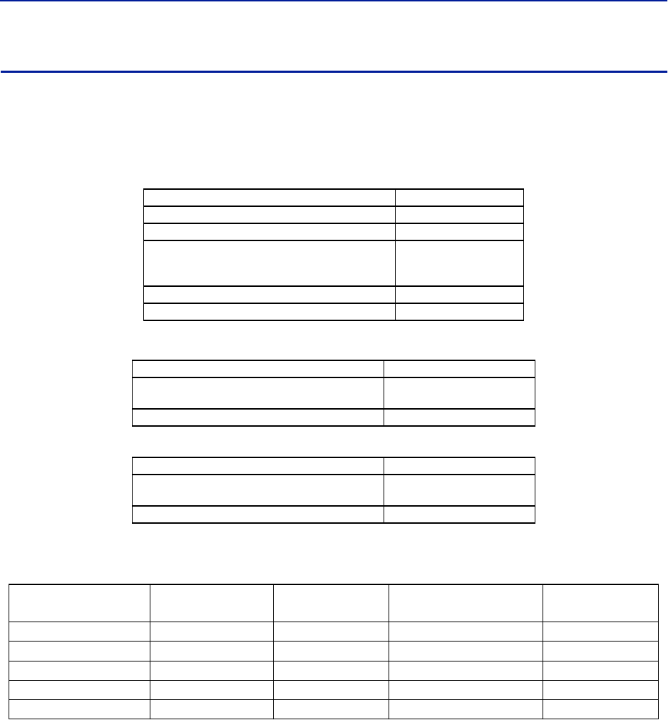
System Description
26
DDS
Bird's DDS series distributed high power radio head is a high performing wideband radio head equipped with a Pre
Distortion power amplifier that supports all modulations. The light weight, convection cooled IP65 chassis secures
the performance in almost any environment.
FCC/IC Standard
Table 25 General Specifications
Table 26 Specifications DDS100 (Single Band) & DDS200 (Dual band)
Table 27 Specifications DDS300 (Triple Band) & DDS400(Quad Band)
Cellular Products
Table 28 Available Products, FCC/IC
Class B Industrial Booster — This equipment is a Class B Industrial Booster and is restricted to installation as
an In-building Distributed Antenna System (DAS).
FCC RF Exposure — This equipment complies with the FCC RF radiation exposure limits set forth for an
uncontrolled environment. This equipment should be installed and operated with the following minimum distances
between the radiator and your body:
If system will operate on multiple bands, the separation distance required shall be equal to, or greater than, the
band with the largest separation distance.
Noise Figure, Typical 3 dB
Delay excluding optical fiber < 0.5 μs
Instantaneous Band Width, Max 15 MHz
Power Supply
Standard
Optional
85 – 264 VAC
-32 to -100 VDC
Operating Temperature -25 to 55 °C (-13 to 131 °F)
Casing IP65
Power Consumption, max, DDS100 (200) 90 (180) W
Dimensions, W x D x H 11.8 x 5.1 x 27.6 in.
30 x 13 x 70 cm
Weight < 34 lbs (15.2 kg)
Power Consumption, max, DDS300 (400) 270 (360) W
Dimensions, W x D x H 11.8 x 8.7 x 27.6 in.
30 x 22 x 70 cm
Weight < 60 lbs (27.2 kg)
System UL Frequency MHz DL Frequency MHz Downlink Power RMS Standard
LTE LB 698 - 716 728 - 746 41 FCC/IC
LTE UB 776 – 787† 746 -757†
† Sub-bands available
41 FCC/IC
850 824 - 849 869 - 894 41 FCC/IC
PCS1900 1850 - 1915 1930 - 1995 41 FCC/IC
AWS 1710 - 1755 2110 - 2155 41 FCC/IC
LTE LB 700 MHz 310.9 cm
LTE UB 700 MHz 349 cm
850MHz 323 cm
PCS 1900MHz 246 cm
AWS 2100MHz 246 cm

Fiber Distributed Antenna System (Fiber DAS)
27
IC RF Exposure — Equipment operating in the Cellular band should be installed and operated with the following
minimum distance of between the radiator and your body:
If system will operate on multiple bands, the separation distance required shall be equal to, or greater than, the
band with the largest separation distance.
The Manufacturer's rated output power of this equipment is for single carrier operation. For situations when
multiple carrier signals are present, the rating would have to be reduced by 3.5 dB, especially where the output
signal is re-radiated and can cause interference to adjacent band users. This power reduction is to be by means of
input power or gain reduction and not by an attenuator at the output of the device.
IC RF exposition — FL'équipement fonctionnant dans la bande cellulaire doit être installé et utilisé avec la
distance minimale suivante entre le radiateur et votre corps:
Si le système fonctionne sur plusieurs bandes, la distance de séparation requise est égale ou supérieure à la bande
avec la plus grande distance de séparation.
Nominale de puissance de sortie du fabricant de cet équipement est pour un fonctionnement à une seule porteuse.
Pour des situations où les signaux porteurs multiples sont présents, la cote devrait être réduite de 3,5 dB, en
particulier lorsque le signal de sortie est re-rayonnée et peut provoquer des interférences avec les utilisateurs de
bandes adjacentes. Cette réduction de puissance est effectuée au moyen d'une puissance d'entrée ou la réduction
de gain, et non par un atténuateur à la sortie du dispositif.
LTE LB 700 MHz 445.1 cm
LTE UB 700 MHz 501 cm
850MHz 475 cm
PCS 1900MHz 362 cm
AWS 2100MHz 351 cm
LTE LB 700 MHz 445.1 cm
LTE UB 700 MHz 501 cm
850MHz 475 cm
PCS 1900MHz 362 cm
AWS 2100MHz 351 cm

System Description
28
DDH
Bird's Distributed High power radio head is a high performing wideband radio head equipped with a feed forward
multi carrier power amplifier that supports all modulations. The light weight, convection cooled IP65 chassis
secures the performance in almost any environment.
ETSI standard
Table 29 General Specifications
Table 30 Specifications DDH100 (Single Band)
Table 31 Specifications DDH200 (Dual Band)
Cellular Products
Table 32 Available Products, ETSI
Noise Figure, Typical 3 dB
Delay excluding optical fiber < 0.5 μs
Power Supply
Standard
Optional
85 – 264 VAC
-32 to -100 VDC
Operating Temperature -25 to 55 °C (-13 to 131 °F)
Casing IP65
Power Consumption, max, DDH100 210 W
Dimensions, W x D x H 11.8 x 5.1 x 27.6 in.
30 x 13 x 70 cm
Weight < 34 lbs (15.2 kg)
Power Consumption, max, DDS200 420 W
Dimensions, W x D x H 11.8 x 8.7 x 27.6 in.
30 x 22 x 70 cm
Weight < 60 lbs (27.2 kg)
SYSTEM
Number of carriers
2 4 8
Composite
Power
Power per
carrier
Composite
Power
Power per
carrier
Composite
Power
Power per
carrier
TETRA 32 29 33 27
CDMA450 32 29 33 27
GSM-R 37 34 40 34
DD 800 37 34 33 27
EGSM900 40 34 40 34 40 31
GSM1800 40 37 40 34 40 31
UMTS 43 40 43 37 43 34
2600 43 40 43 37 43 34

Fiber Distributed Antenna System (Fiber DAS)
29
FCC standards
Table 33 General Specifications
Table 34 Specifications DDH100 (Single Band)
Table 35 Specifications DDH200 (Dual Band)
Cellular Products
Table 36 Available Products, FCC/IC
Note: All specifications subject to change without notice.
Class B Industrial Booster — This equipment is a Class B Industrial Booster and is restricted to installation as
an In-building Distributed Antenna System (DAS).
Note: RF exposure distances are calculated using a 17 dBi antenna
FCC RF Exposure — This equipment complies with the FCC RF radiation exposure limits set forth for an
uncontrolled environment. This equipment should be installed and operated with the following minimum distances
between the radiator and your body:
If system will operate on multiple bands, the separation distance required shall be equal to, or greater than, the
band with the largest separation distance.
Noise Figure, Typical 3 dB
Delay excluding optical fiber < 0.5 μs
Instantaneous Band Width, Max 15 MHz
Power Supply
Standard
Optional
85 – 264 VAC
-32 to -100 VDC
Operating Temperature -25 to 55 °C (-13 to 131 °F)
Casing IP65
Power Consumption, max, DDH100 210 W
Dimensions, W x D x H 11.8 x 5.1 x 27.6 in.
30 x 13 x 70 cm
Weight < 34 lbs (15.2 kg)
Power Consumption, max, DDS200 420 W
Dimensions, W x D x H 11.8 x 8.7 x 27.6 in.
30 x 22 x 70 cm
Weight < 60 lbs (27.2 kg)
System UL Frequency MHz DL Frequency MHz Pout, DL,
dBm (RMS) Standard
LTE LB 698 - 716 728 - 746 43 FCC/IC
LTE UB 776 – 787† 746 -757†
† Sub-bands available
43 FCC/IC
iDEN 806 - 824 851 - 869 40 FCC/IC
Cellular 824 - 849 869 - 894 43 FCC/IC
PCS1900 1850 - 1910 1930 - 1990 43 FCC/IC
AWS 1710 - 1780 2110 - 2180 43 FCC/IC
2600 LTE 2500 - 2570 2620 - 2690 43 FCC/IC
2600 LTE (DDH 2600) 309 cm
AWS3 (DDHAWS3) 309 cm
PCS1900 (DDH1900) 309 cm
Cellular (DDH850) 406 cm

System Description
30
IC RF Exposure — Equipment operating in the Cellular band should be installed and operated with the following
minimum distance of between the radiator and your body:
If system will operate on multiple bands, the separation distance required shall be equal to, or greater than, the
band with the largest separation distance.
The Manufacturer's rated output power of this equipment is for single carrier operation. For situations when
multiple carrier signals are present, the rating would have to be reduced by 3.5 dB, especially where the output
signal is re-radiated and can cause interference to adjacent band users. This power reduction is to be by means of
input power or gain reduction and not by an attenuator at the output of the device.
IC RF exposition — FL'équipement fonctionnant dans la bande cellulaire doit être installé et utilisé avec la
distance minimale suivante entre le radiateur et votre corps:
Si le système fonctionne sur plusieurs bandes, la distance de séparation requise est égale ou supérieure à la bande
avec la plus grande distance de séparation.
Nominale de puissance de sortie du fabricant de cet équipement est pour un fonctionnement à une seule porteuse.
Pour des situations où les signaux porteurs multiples sont présents, la cote devrait être réduite de 3,5 dB, en
particulier lorsque le signal de sortie est re-rayonnée et peut provoquer des interférences avec les utilisateurs de
bandes adjacentes. Cette réduction de puissance est effectuée au moyen d'une puissance d'entrée ou la réduction
de gain, et non par un atténuateur à la sortie du dispositif.
2600 LTE (DDH 2600) 410.1 cm
AWS3 (DDHAWS3) 438.4 cm
PCS1900 (DDH1900) 455.2 cm
Cellular (DDH850) 597.9 cm
2600 LTE (DDH 2600) 410.1 cm
AWS3 (DDHAWS3) 438.4 cm
PCS1900 (DDH1900) 455.2 cm
Cellular (DDH850) 597.9 cm

Fiber Distributed Antenna System (Fiber DAS)
31
DDU
Bird's Distributed High power radio head is a high performing wideband radio head equipped with a feed forward
multi carrier power amplifier that supports all modulations. The light weight, convection cooled IP65 chassis
secures the performance in almost any environment.
FCC standards
Table 37 General Specifications
Table 38 Specifications DDU100 (Single Band)
Table 39 Specifications DDU200 (Dual Band)
Cellular Products
Table 40 Available Products, FCC/IC
Note: All specifications subject to change without notice.
Class B Industrial Booster — This equipment is a Class B Industrial Booster and is restricted to installation as
an In-building Distributed Antenna System (DAS).
FCC RF Exposure — This equipment complies with the FCC RF radiation exposure limits set forth for an
uncontrolled environment. This equipment should be installed and operated with the following minimum distances
between the radiator and your body:
If system will operate on multiple bands, the separation distance required shall be equal to, or greater than, the
band with the largest separation distance.
Noise Figure, Typical 3 dB
Delay excluding optical fiber < 0.5 μs
Instantaneous Band Width, Max 15 MHz
Power Supply
Standard
Optional
85 – 264 VAC
-32 to -100 VDC
Operating Temperature -25 to 55 °C (-13 to 131 °F)
Casing IP65
Power Consumption, max, typical 225 W
Dimensions, W x D x H 11.8 x 5.1 x 27.6 in.
30 x 13 x 70 cm
Weight < 34 lbs (15.2 kg)
Power Consumption, max, typical 450 W
Dimensions, W x D x H 11.8 x 8.7 x 27.6 in.
30 x 22 x 70 cm
Weight < 60 lbs (27.2 kg)
System UL Frequency MHz DL Frequency MHz Pout, DL,
dBm (RMS) Standard
LTE LB 698 - 716 728 - 746 46 FCC/IC
LTE UB 776 - 787 746 - 757 46 FCC/IC
LTE FB 698 - 716/776 - 787 728 - 757 46 FCC/IC
Cellular 824 - 849 869 - 894 46 FCC/IC
PCS1900 1850 - 1910 1930 - 1990 46 FCC/IC
AWS 1710 - 1780 2110 - 2180 46 FCC/IC
DDU-700LC 626.6 cm 17dBi antenna
DDU-700UC 619 cm 17dBi antenna
DDU-850 573.5 cm 17dBi antenna
DDU-AWS3 (2100MHz) 436.5 cm 17dBi antenna
DDU-1900 (PCS 1900MHz) 436.5 cm 17dBi antenna

System Description
32
IC RF Exposure — Equipment operating in the Cellular band should be installed and operated with the following
minimum distance of between the radiator and your body:
If system will operate on multiple bands, the separation distance required shall be equal to, or greater than, the
band with the largest separation distance.
The Manufacturer's rated output power of this equipment is for single carrier operation. For situations when
multiple carrier signals are present, the rating would have to be reduced by 3.5 dB, especially where the output
signal is re-radiated and can cause interference to adjacent band users. This power reduction is to be by means of
input power or gain reduction and not by an attenuator at the output of the device.
IC RF exposition — FL'équipement fonctionnant dans la bande cellulaire doit être installé et utilisé avec la
distance minimale suivante entre le radiateur et votre corps:
Si le système fonctionne sur plusieurs bandes, la distance de séparation requise est égale ou supérieure à la bande
avec la plus grande distance de séparation.
Nominale de puissance de sortie du fabricant de cet équipement est pour un fonctionnement à une seule porteuse.
Pour des situations où les signaux porteurs multiples sont présents, la cote devrait être réduite de 3,5 dB, en
particulier lorsque le signal de sortie est re-rayonnée et peut provoquer des interférences avec les utilisateurs de
bandes adjacentes. Cette réduction de puissance est effectuée au moyen d'une puissance d'entrée ou la réduction
de gain, et non par un atténuateur à la sortie du dispositif.
DDU-700LC 897.3 cm 17dBi antenna
DDU-700UC 889.8 cm 17dBi antenna
DDU-850 884.6 cm 17dBi antenna
DDU-AWS3 (2100MHz) 643.0 cm 17dBi antenna
DDU-1900 (PCS 1900MHz) 623.8 cm 17dBi antenna
DDU-700LC 897.3 cm 17dBi antenna
DDU-700UC 889.8 cm 17dBi antenna
DDU-850 884.6 cm 17dBi antenna
DDU-AWS3 (2100MHz) 643.0 cm 17dBi antenna
DDU-1900 (PCS 1900MHz) 623.8 cm 17dBi antenna

Fiber Distributed Antenna System (Fiber DAS)
33
Remote Unit Frequency Summary
Table 41 ETSI Bands
Table 42 FCC/IC Bands
Information regarding Bird’s Fiber-DAS systems are updated periodically, for the latest information on all of Bird’s
Fiber-DAS products visit Bird’s website:
http://www.birdrf.com/Products/Coverage/Fiber-DAS.aspx
Band 3GPP Band UL Frequency DL Frequency DDR Max
Composite
DDH Max
Composite
FM 88 - 108 22 -
TERTRA VHF 136 - 174 136 - 174 22 -
TETRA, Public Safety 380-385 390-395 26 33
TETRA, Commercial 410-415 420-425 26 33
TETRA, Commercial 415-420 425-430 26 40
CDMA 450 Band 31 452.5-457.5 462.5-467.5 33 40
DD800 Band 20 832-862 791-821 26 40
E-GSM 900 Band 8 880-915 925-960 26 40
GSM 1800 Band 3 1710-1785 1805-1880 28 40
UMTS Band 1 1920-1980 2110-2170 30 43
LTE 2600 Band 7 2500-2570 2620-2690 30 43
Band 3GPP Band UL Frequency DL
Frequency
DDR Max
Composite
DDS Max
Composite
(15MHz)
DDH Max
Composite
DDU Max
Composite
VHF 136-174 136-174 33 N/A N/A N/A
UHF 450-470 450-470 33 N/A N/A N/A
700 Lower Band 12 698-716 728-746 33 N/A 43 46
700 Upper Band 13 & 14 776-806 746-757 33 N/A 43 46
700 Combined Band 12, 13 & 14 698-716
776-806 728-757 33 41 43 46
700 Public Safety 769-775 799-805 33 - - N/A
800 iDEN Band 27 806-824 851-869 33 41 43 N/A
850 Cellular Band 5 824-849 869-894 33 41 43 46
1900 PCS Band 25 1850-1910 1930-1990 33 41 43 46
AWS Band 4 1710-1755 2110-2155 33 41 43 46
2600 LTE Band 7 2500-2570 2620-2690 33 N/A 43 N/A
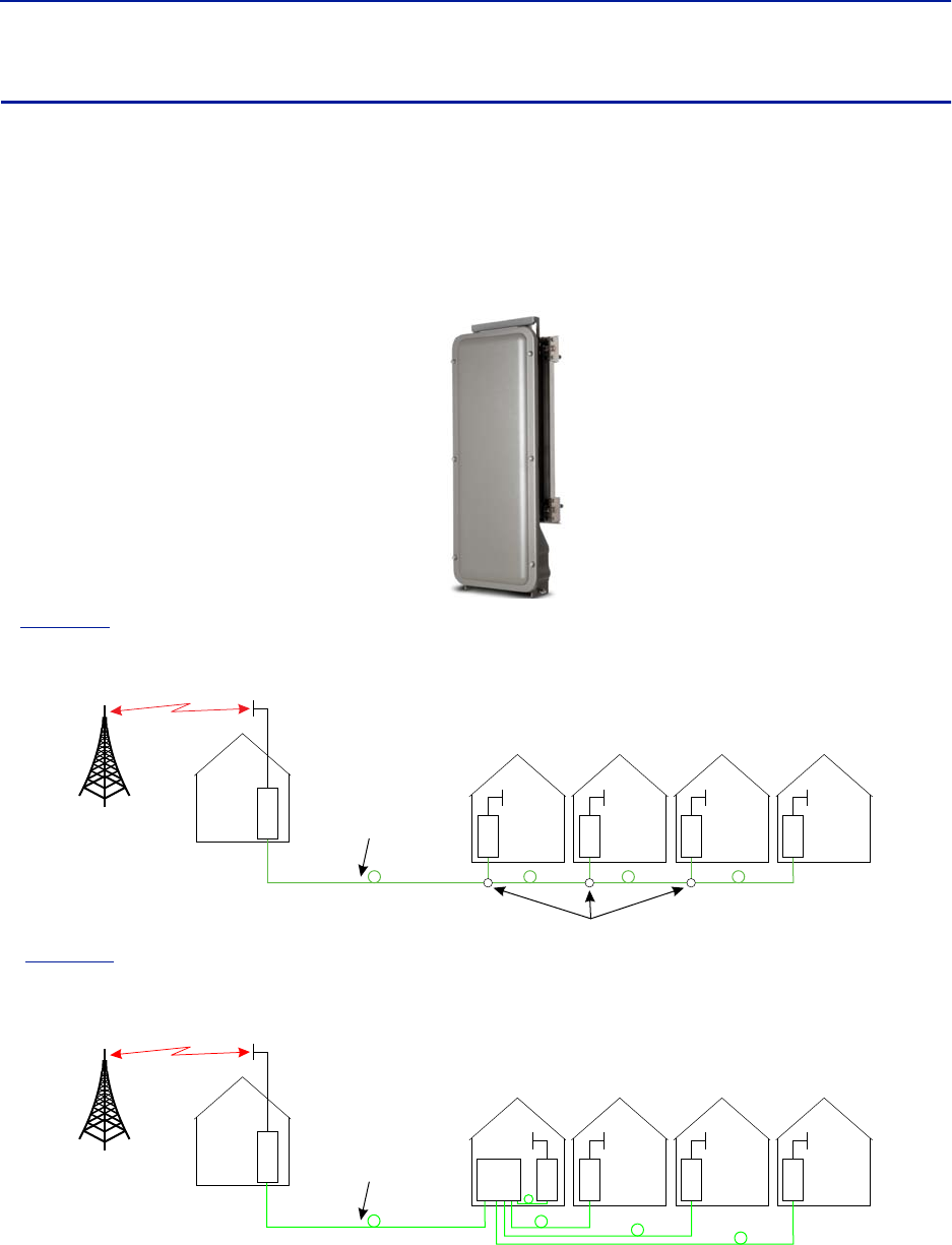
System Description
34
DMU – Remote head end
Bird's DMU100 series is a compact head end that can function as a low power repeater or BTS interface. The unit
can directly support up to 4 remotes or can fiber feed a Headend Master Unit. Remote access is provided by either
the Bird RGW or via Ethernet connection. The unit is a rugged convection cooled, IP65 chassis designed for outdoor
locations.
It is possible to build the DMU to support more than one band, however, the types of bands and the necessary
duplexers for a configuration must be verified to ensure compatibility with the RGW.
Figure 20 DMU – Remote Head End
In
Figure 21
, the DMU is used to pick up the signal at a remote location and then it is transmitted on the fiber to
four different locations that need coverage. The RU can be connected to coaxial spreading networks if needed.
Figure 21 DMU Feeding Remote Units
In
Figure 22
, the DMU is feeding a Headend Master Unit which in turn feeds the Remote Units (RU). This is a far
more flexible solution and would be preferred when possible.
Figure 22 DMU Feeding BMU
The DMU is equipped with a low power uplink amplifier. The unit should be used in a location that has adequate
signal so that power level of a mobile phone will suffice.
D
M
UHead
end R
UR
UR
UR
U
Fiber-Optic Cable
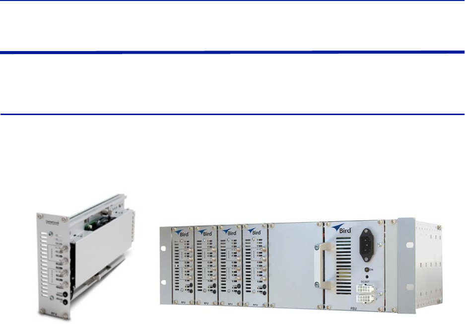
Fiber Distributed Antenna System (Fiber DAS)
35
Repeaters
Bird Technologies offers a wide variety of repeaters to boost off air signals. The repeated signals can feed passive
DAS or can be used as an input into the active DAS.
DMR 400 Series Rack Mount Repeater
The DMR 400 is designed to fit in the Headend Master Frame along with the BIU and FOI cards. The system was
originally designed to be used in moving coverage areas such as ships and trains that require active control over the
downlink gain (link symmetry) to compensate for wide variations in the off-air signals, but the system can easily be
implemented in traditional fixed locations such as offices and hospitals.
Figure 23 DMR 400 Rack Mount Repeater
Although the DMR repeaters are rack mounted with the active DAS components, the DMR repeater can function as
a stand alone unit to provide coverage to a passive DAS.
The DMR repeater family offers link symmetry settings. This function is used to automatically adjust the uplink gain
based on the downlink signal. When installed in moving coverage areas such as trains, the feature prevents the
repeater from desensitizing the donor site by automatically controlling uplink levels.
The DMR repeater also offers self-oscillation protection. This function is used to detect problems with isolation
between the donor and service antenna. The repeater will intervene and lower the gain to a level equal to the
isolation minus the stability margin. The settings are separate for UL and DL.
On/Off
Stability margin: Value setting of how much lower the gain should be than the calculated isolation. Range
of 0.0 to 20.0dBm.
Recovery time: Time that should pass before the repeater reset the gain to the value specified level in “RF
Config” (set gain). Range of 30 to 86,400 seconds.
Recovery margin: Set value of gain level above the gain specified in “RF Config” (set gain) that is used when
the repeater recovers after the “Recovery Time”. Range of 0.0 to 20.0dBm.
The DMR400 offers variable bandwidths up to 35Mhz, depending on the configuration.
Remote access can be provided via an Ethernet connection or through the Bird Remote Gateway. SNMP is a
standard on the units. No proprietary software is required. Operational parameters are set via a web browser.
System Description
36
Table 43 DMR400 Specifications
Table 44 Available Products, Cellular, FCC
Table 45 Available Products, Cellular, ETSI
Gain 50-80 dBm in 1 dB steps
Noise Figure - Typical < 5 dBm
Delay <7 μs
Dimensions 2 card slots
Weight (module) 0.7 kg (1.5 lbs)
Operating Temperature 0 to 40 °C (32 to 104 °F)
Band Uplink Downlink Pout, DL & UL Standard
DMR405 700 Lower 698 - 716 728 - 746 25 dBm FCC
DMR404 700 Upper 776 - 787 746 - 757 25 dBm FCC
DMR407 IDEN 806 - 824 851 - 869 25 dBm FCC
DMR408 Cellular 824 - 849 869 - 894 25 dBm FCC
DMR419 PCS1900 1850 - 1915 1930 - 1995 25 dBm FCC
DMR420 AWS 1710 - 1755 2110 - 2155 25 dBm FCC
Band Uplink Downlink Pout, DL & UL Standard
DMR401 TETRA, Public Safety 380 - 385 390 - 395 19 dBm ETSI
DMR402 TETRA, Commercial 410 - 415 420 - 425 19 dBm ETSI
DMR403 TETRA, Commercial 415 - 420 425 - 430 19 dBm ETSI
DMR411 CDMA450 458 - 460 468 - 4670 25 dBm FCC
DMR410 GSM-R 876 - 880 921 - 925 19 dBm ETSI
DMR409 EGSM900 880 - 915 925 - 960 19 dBm ETSI
DMR418 GSM1800 1710 - 1775 1805 - 1880 19 dBm ETSI
DMR421 UMTS 2100 1920 - 1980 2110 - 2170 23 (DL)/20 (UL) 3GPP
Fiber Distributed Antenna System (Fiber DAS)
37
DLR 600 Series Low Power Repeater
The DLR 600 low power repeater is designed for environments where low signal levels are required. Although small,
the unit still offers Bird’s feature rich functions such as self-oscillation protection, fast AGC, link symmetry
functionality, SNMP and remote access via Ethernet or the Bird Remote Gateway.
Figure 24 DLR 600 Low Power Repeater
Table 46 DLR600 Specifications
Table 47 Available Products, Cellular, FCC
Table 48 Available Products, Cellular, ETSI
Gain 40-70 dBm in 1 dB steps
Noise Figure <5 dB
Delay <7 μs
Power Supply
Standard
optional
100 to 240 VAC
12 to 28 VDC
Dimension (W x D x H) 30 x 5 x 21 cm (11.8x2x8.3 inches)
Weight <1.4 Kg (3.1 lbs)
Operating Temp (DC) -25 to 55 °C (13 to 131 °F)
Operating Temp (AC) 0 to +40 °C (+32 to +104 °F)
Casing IP42
Bandwidth 0-25 MHz
Connectors SMA or N-type
Band Uplink Downlink Pout, DL & UL Standard
DLR607 iDEN 806-824 851-869 16 dBm FCC
DLR608 Cellular 824-849 869-894 16 dBm FCC
DLR619 PCS1900 1850-1915 1930-1995 16dBm FCC
DLR620 AWS 1710-1755 2110-2155 16 dBm FCC
Band Uplink Downlink Pout, DL & UL Standard
DLR609 EGSM900 880-915 925-960 13 dBm ETSI
DLR618 GSM1800 1710-1775 1805-1880 13 dBm ETSI
DLR621 UMTS 2100 1920-1980 2110-2170 15 dBm 3GPP
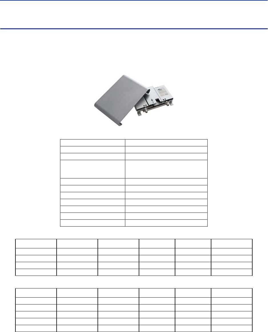
System Description
38
DMR600 Series Medium Power Repeater
The DMR 600 is a medium power repeater with band selective capabilities. Although small, the unit still offers
Bird's feature rich functions such as self-oscillation protection, fast AGC, link symmetry functionality, SNMP and
remote access via Ethernet or the Bird Remote Gateway
Figure 25 DMR 600 Medium Power Repeater
Table 49 DMR600 Specifications
Table 50 Available Products, Cellular, FCC
Table 51 Available Products, Cellular, ETSI
Gain 50-80 dBm in 1 dB steps
Noise Figure <5 dB
Delay <7 μs
Power Supply
Standard
optional
100 to 240 VAC
12 to 30 VDC
Dimension (W x D x H) 30 x 5 x 21 cm (11.8x2x8.3 inches)
Weight <1.4 Kg (3.1 lbs)
Operating Temp (DC) -25 to 55 °C (13 to 131 °F)
Operating Temp (AC) 0 to +40 °C (+32 to +104 °F)
Casing IP42
Bandwidth 25 MHz
Connectors SMA or N-type
Band Uplink Downlink Pout, DL & UL Standard
DMR607 iDEN 806-824 851-869 25 dBm FCC
DMR608 Cellular 824-849 869-894 25 dBm FCC
DMR619 PCS1900 1850-1915 1930-1995 25 dBm FCC
DMR620 AWS 1710-1755 2110-2155 25 dBm FCC
Band Uplink Downlink Pout, DL & UL Standard
DMR604 CDM450 453-457.5 463-467.5 25 dBm FCC
DMR610 GSM-R 876-880 921-925 19 dBm ETSI
DMR609 EGSM900 880-915 925-960 19 dBm ETSI
DMR618 GSM1800 1710-1775 1805-1880 19 dBm ETSI
DMR621 UMTS 2100 1920-1980 2110-2170 23 (DL)/20 (UL) 3GPP
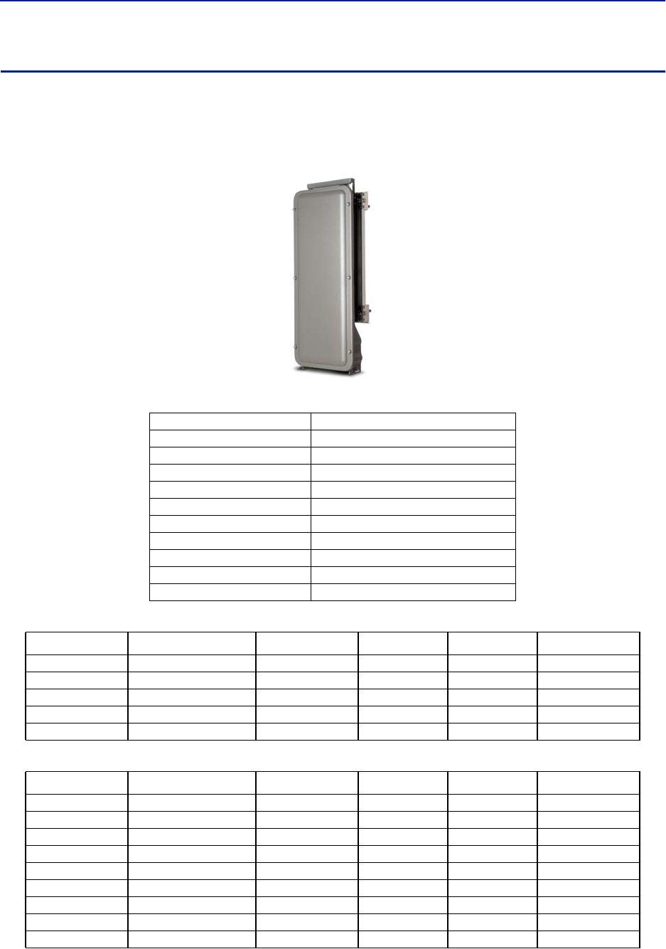
Fiber Distributed Antenna System (Fiber DAS)
39
DMR 800Series Medium Power Repeater
DMR800 repeater platform with medium power band selective repeaters is designed for a small form factor, high
performance and a long lifetime. It can be used for coverage enhancement in up to medium sized indoor
environments.
Figure 26 DMR 800Series Medium Power Repeater
Table 52 DMR800 Specifications
Table 53 Available Products, Cellular, FCC
Table 54 Available Products, Cellular, ETSI
Gain 50-88 dBm in 1 dB steps
Noise Figure <5 dB
Delay <7 μs
Power Supply 85 to 264 VAC
Power Consumption <35 W
Dimension (WxDxH) 30 x 13 x 70 cm (11.8 x 5.1 x 27.6 inches)
Weight <12 kg (26.4 lbs)
Operating Temp -25 to 55 °C (13 to 131 °F)
Casing IP65
Bandwidth 35 MHz
Connectors N-type or DIN 7/16
Band Uplink Downlink Pout, DL & UL Standard
DMR805 700 Lower 698 - 716 728 - 746 25 FCC
DMR804 700 upper 777 - 787 746 - 756 25 FCC
DMR808 Cellular 824 - 849 869 - 894 25 FCC
DMR819 PCS1900 1850 - 1915 1930 - 1995 25 FCC
DMR820 AWS 1710 - 1755 2110 - 2155 25 FCC
Band Uplink Downlink Pout, DL & UL Standard
DMR806 DAB 174 - 240 18 ETSI
DMR801 TETRA, Public Safety 380-385 390-395 19 ETSI
DMR802 TETRA, Commercial 410-415 420-425 19 ETSI
DMR803 TETRA, Commercial 415-420 425-430 19 ETSI
DMR811 CDMA450 458-460 468-470 25 FCC
DMR810 GSM-R 876-880 921-925 19 ETSI
DMR809 EGSM900 880-915 925-960 19 ETSI
DMR818 GSM1800 1710-1775 1805-1880 19 ETSI
DMR821 UMTS 2100 1920-1980 2110-2170 23(DL)/20(UL) 3GPP
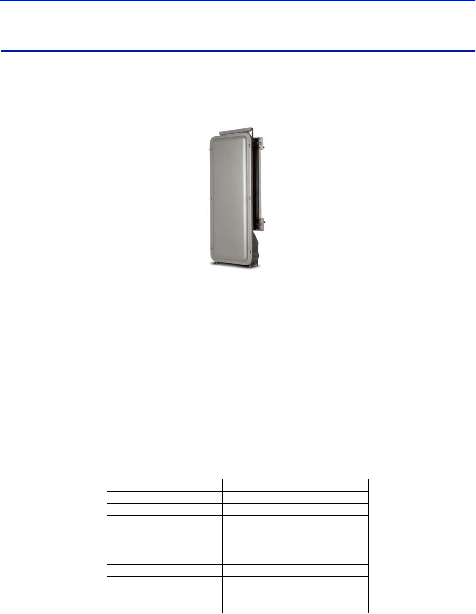
System Description
40
DHR 800 Series High Power Repeater
The DHR 800 offers a high power solution in a light weight, convection cooled IP65 chassis. The unit offers Bird's
feature rich functions such as self-oscillation protection, fast AGC, link symmetry functionality, SNMP and remote
access via Ethernet or the Bird Remote Gateway all in a rugged IP65 chassis.
Figure 27 DHR 800 Series High Power Repeater
The DHR repeater family offers link symmetry settings. This function is used to automatically adjust the uplink gain
based on the downlink signal. When installed in moving coverage areas such as trains, the feature prevents the
repeater from desensitizing the donor site by automatically controlling uplink levels.
The DHR repeater also offers self-oscillation protection. This function is used to detect problems with isolation
between the donor and service antenna. The repeater will intervene and lower the gain to a level equal to the
isolation minus the stability margin. The settings are separate for UL and DL.
On/Off
Stability margin: Value setting of how much lower the gain should be than the calculated isolation. Range
of 0.0 to 20.0dBm.
Recovery time: Time that should pass before the repeater reset the gain to the value specified level in “RF
Config” (set gain). Range of 30 to 86,400 seconds.
Recovery margin: Set value of gain level above the gain specified in “RF Config” (set gain) that is used when
the repeater recovers after the “Recovery Time”. Range of 0.0 to 20.0dBm.
Table 55 DHR800 Specifications
Gain 50-88 dBm in 1 dB steps
Noise Figure <5 dB
Delay <7 μs
Power Supply 85 to 264 VAC
Power Consumption <130 W
Dimension (WxDxH) 30 x 13 x 70 cm (11.8 x 5.1 x 27.6 inches)
Weight <12 kg (26.4 lbs)
Operating Temp -25 to 55 °C (13 to 131 °F)
Casing IP65
Bandwidth 35 MHz
Connectors N-type or DIN 7/16
Fiber Distributed Antenna System (Fiber DAS)
41
Table 56 Available Products, Cellular, FCC
Table 57 Available Products, Cellular, ETSI
Bird Repeater Frequency Summary
Table 58 ETSI Bands
Table 59 FCC Bands
Band Uplink Downlink Pout, DL & UL Standard
DHR807 iDEN 806-824 851-869 33(DL)/25(UL) FCC
DHR808 Cellular 824-849 869-894 33(DL)/25(UL) FCC
DHR819 PCS1900 1850-1915 1930-1995 33(DL)/25(UL) FCC
DHR820 AWS 1710-1755 2110-2155 33(DL)/25(UL) FCC
Band Uplink Downlink Pout, DL & UL Standard
DHR801 TETRA, Public Safety 380-385 390-395 26(DL)/20(UL) ETSI
DHR802 TETRA, Commercial 410-415 420-425 26(DL)/20(UL) ETSI
DHR803 TETRA, Commercial 415-420 425-430 26(DL)/20(UL) ETSI
DHR804 CDMA450 453-457.5 463-467.5 33(DL)/25(UL) FCC
DHR810 GSM-R 876-880 921-925 26(DL)/19(UL) ETSI
DHR809 EGSM900 880-915 925-960 26(DL)/19(UL) ETSI
DHR818 GSM1800 1710-1775 1805-1880 28(DL)/21(UL) ETSI
DHR821 UMTS 2100 1920-1980 2110-2170 30(DL)/21(UL) 3GPP
UL Frequency DL Frequency DMR
400
DLR
600
DMR
600
DHR
800
TETRA Public Safety 380-385 390-395
TETRA, Commercial 410-415 420-425
TETRA, Commercial 415-420 425-430
CDMA 450 458-460 468-470
GSM-R 876-880 921-925
EGSM900 880-915 925-960
GSM 1800 1710-1775 1805-1880
UMTS 1920-1980 2110-2170
UL Frequency DL Frequency DMR
400
DLR
600
DMR
600
DHR
800
Public Safety 800 806-824 851-869
Cellular 850 824-849 869-894
PCS 1900 1850-1915 1930-1995
AWS 1710-1755 2110-2155
42
Chapter 3 Installation guidelines
For CMRS 817-824MHz Applications and American Cellular Applications:
This device complies with part 15 of the FCC rules. Operation is subject to the following two conditions: (1) This
device may not cause harmful interference and (2) this device must accept any interference received, including
interference that may cause undesired operation.
For installations subject to Industry Canada certification:
Health and Safety
Bird DAS system is an advanced system and should be handled by skilled staff. Bird is happy to offer training of
installation service providers in the case this is necessary.
Read all available documentation and warnings before handling the equipment. Equipment failures due to
improper handling are normally not covered by the product warranty.
Respect all warning signs on the equipment and in the documentation. Make sure to only operate the equipment
on frequencies allowed to use. Do not modify the equipment.
The equipment contains a Class 3B laser and the equipment is Class 1. Do never look into the Laser beam directly or
indirectly, it is strong invisible light and may cause serious damage to human eyes.
Always use protective caps on fiber and connector ends when fiber is removed from socket. Always clean socket
and connector after a fiber has been removed before it is reconnected.
Make sure to keep passwords and other operational information away from unauthorized personnel.
WARNING
This is NOT a consumer device.
It is designed for installation by FCC LICENSEES and QUALIFIED INSTALLERS. You MUST have an FCC LICENSE or
express consent of an FCC licensee to operate this device. You MUST register Class B signal boosters (as defined
in 47 CFR 90.219) online at www.fcc.gov/signal-boosters/registration. Unauthorized use may result in
significant forfeiture penalties, including penalties in excess of $100,000 for each continuing violation.
WARNING
This is NOT a consumer device.
It is designed for installation by FCC LICENSEES and QUALIFIED INSTALLERS. You MUST have an FCC LICENSE or
express consent of an FCC licensee to operate this device. Unauthorized use may result in significant forfeiture
penalties, including penalties in excess of $100,000 for each continuing violation.
WARNING
This is NOT a consumer device.
It is designed for installation by an installer approved by an ISED licensee.
You MUST have an ISED LICENCE or the express consent of an ISED licensee to operate this device.
WARNING
Avoid looking into connected fibers and receptacles.
The laser used in this system is a Class 3b laser that produces invisible infra-red coherent light. Not safe to view
with optical instruments. Always put the protection caps on unused fibers and receptacles.
Fiber Distributed Antenna System (Fiber DAS)
43
Cable Routing/Antenna Selection
Ensure all cables, e.g. power cable, fiber-optic cable, Antenna cables are routed and secured in accordance with
local/national requirements while avoiding damage to the cables.
Antennas and coax cables are selected as part of the DAS system design and may vary with location, frequency, and
power level requirements.
Use only authorized and approved antennas, cables and/or coupling devices. The use of unapproved antennas,
cables or coupling devices could cause damage and may be of violation of FCC regulations.
Each individual antenna used with the DAS must be installed to provide the separation distance as specified in the
RF exposure requirements (refer to specific Remote Unit RF Exposure limits in the system description section).
Antenna Installation
The Bird Fiber DAS systems do not include remote or head end antenna. The remote end antenna must be selected
during system design, the antenna manufacturer’s data will be required when calculating link budgets.
Antenna installation instructions are provided by the antenna manufacturer.
External donor antennas that are most commonly used in combination with DDR or DDH Remote Unit family for
outdoor environment are 17 dBi gain antennas.
Safety and Care for Fibers
Every time a fiber is disconnected and re-connected care should be taken to avoid getting dust on the connector or
in the receptacle. Clean with a dry fiber cleaning tool before reconnecting the fiber at all times. A single speck of
dust can severely impact the transmission. Do not touch the fiber ends with your fingers. That will leave grease on
the connectors and may cause severe problems.
CAUTION
Unauthorized antennas, cables, and/or coupling devices may cause non-conformity with national or international
regulations, could cause damage, or non-conforming ERP/EIRP.
WARNING
Avoid looking into connected fibers and receptacles.
The laser used in this system is a Class 3b laser that produces invisible infra-red coherent light. Not safe to view
with optical instruments. Always put the protection caps on unused fibers and receptacles.

Installation guidelines
44
Tools and Material Requirements
Fiber Optics
All fiber optic cables, including patch cords, must be SINGLE MODE. Multi-mode fiber is not supported.
Bird equipment is designed to be used with only SC/APC fiber connectors. All connection points in the fiber must
either be fusion spliced or equipped with APC connectors. UPC connectors anywhere in the fiber path will cause
degradation in the performance of the equipment. APC connectors can be identified by their green jacket.
Total optical loss must be < 15dBo.
Optical return loss -60 dB or greater.
Fiber panel inserts/couplings must be APC.
Tools
Fiber Optic cleaner for SC/APC connectors
T8 Torx bit for card cage modules
Appropriate bit for rack screws
Spectrum analyzer with RF power meter
Appropriate jumper cables to connect spectrum analyzer to Bird equipment
OTDR
Optical power meter
Optical visual fault finder
Fiber splicer
SMA torque wrench calibrate to 0.9 N-m
ESD Strap - (Electrostatic Discharge): The BIU, FOI and Power Supplies contain highly sensitive components
that can be destroyed by static.
NEVER open cards, BGW, CGW, repeaters or remotes!
Miscellaneous Material
AC power cord(s) if using the DPU-301 power supply [AC to DC power supply]
18 AWG power wire if using the DPU-302 power supply [DC to DC power supply]
Ferrite bead filter for the DC supply cable to the DPU-302. The ferrite bead filter must be installed close to
the DPU-302. Follow manufacturer recommendations for proper installation of the ferrite bead filter.
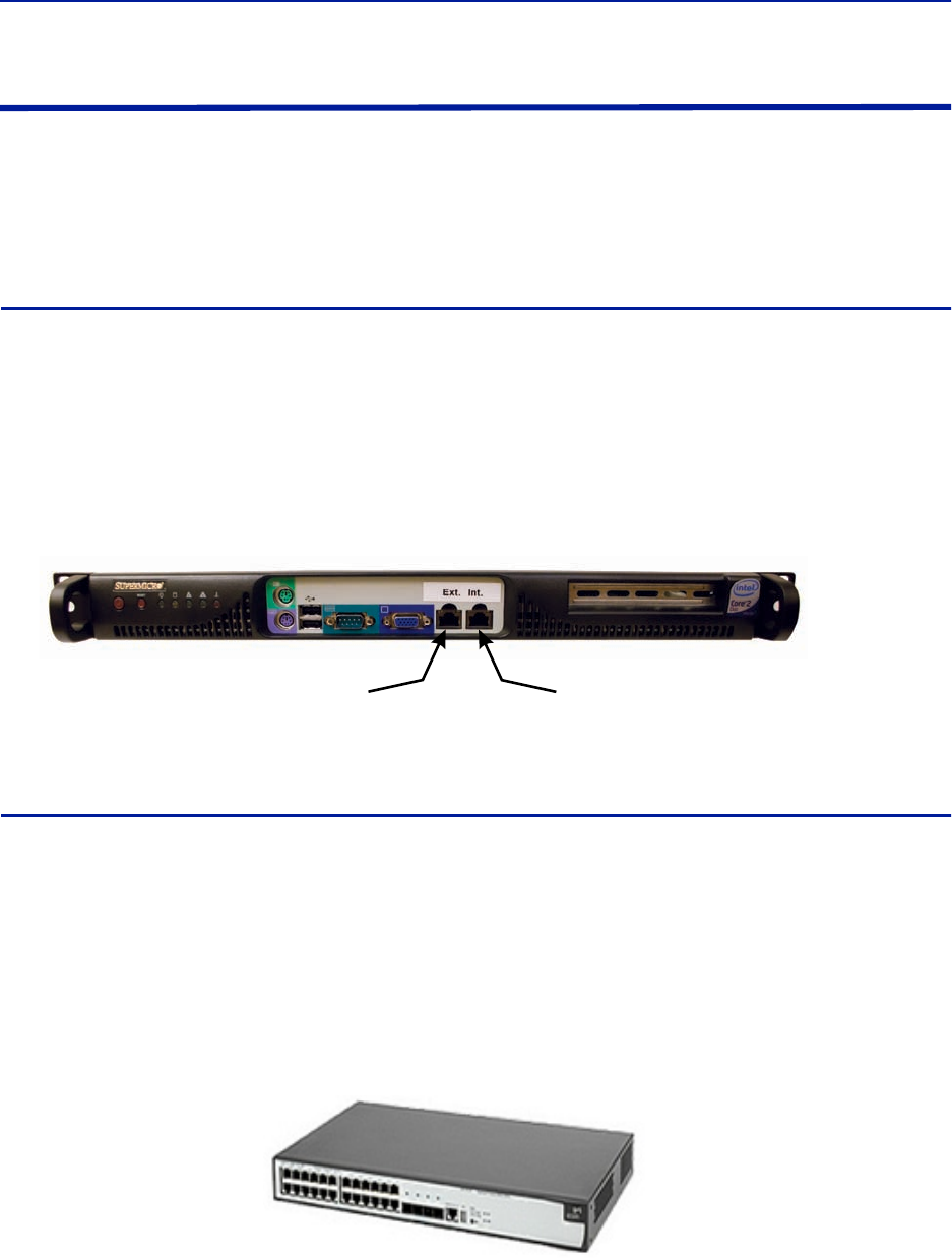
Fiber Distributed Antenna System (Fiber DAS)
45
Installing Headend Equipment
All equipment must be properly grounded. Ground peg in the main connector for both head-end gear (Master Unit)
and remote gear (Remote Units) must be connected to Phase, Neutral and Ground in a proper way before power is
connected.
The chassis of the remote and the rack of the master unit should be grounded to a potential bar or safety grounding
bar when operated. All electrical installations should be done by a certified electrician only.
BGW
The BGW is designed to be installed in a 19" rack.
The BGW is typically mounted near the top of the rack.
Connect power to an available NEMA5-15R receptacle.
Using installer provided Ethernet cable, connect the “Ext” port to the appropriate back-haul connection.
The back-haul connection can be DSL, off air modem, LAN, WAN. See BGW set up instructions.
Figure 28 BGW Installation, Ethernet Connections
Ethernet Switch
The Ethernet switch, ETH, is designed to be installed in a 19" rack.
Placement is typically between the BGW and the Master Frame Unit. Placement consideration should
include proper routing of Ethernet cables and the installation of additional cables after the initial
installation is complete. Mounting may with Ethernet ports to the front or rear of the rack.
Connect power to an available NEMA5-15R receptacle.
Using installer provided Ethernet cable, connect port 25 of the Ethernet switch to the “INT” port on the
BGW.
Figure 29 Ethernet Switch
Back-haul Connection
(LAN, WAN, ETC)
Connect to Head end
Ethernet Switch, Port 25
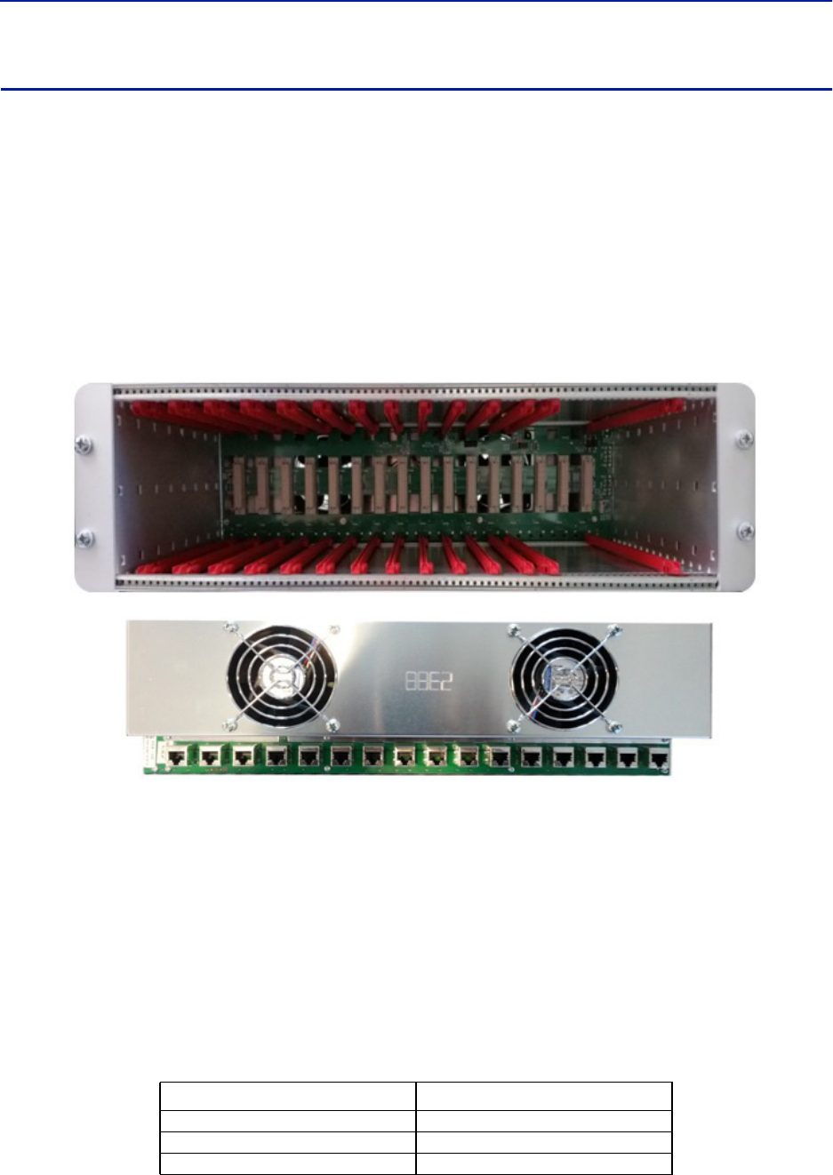
Installation guidelines
46
Master Unit
The Master Unit is designed to be installed in a 19" rack.
Before installing, consider cable routing for all cards to be installed in the Master Unit. The installer may
want to consider horizontal cable managers to be mounted above and below the Master Unit to aid in the
installation and ongoing maintenance of the system.
Each card in the Master Unit will require an Ethernet connection to the BGW in order to be programmed
and monitored. Install contractor provided Ethernet cable between the appropriate Ethernet port and the
Ethernet switch.
Note: The port number on the Master Unit is in reverse order on the back of the Master Unit.
Figure 30 Ethernet Port Numbering, Front and Rear Views
Only the active port on the Master Unit requires an Ethernet connection.
Example: The wide BIU uses two slots in the Master Unit. If installed in slots #1 and #2, only slot
#1 will make physical connection to the backplane. Install an Ethernet cable on the back of the
Master Unit in port #1 to provide the BIU with BGW connectivity.
Note: It is recommended Ethernet cables be installed on all ports. In the event of future configuration
changes this will ensure BGW connectivity regardless of slot changes.
All open slots on the Master Unit require a blank cover plate to allow for proper air circulation. Blank
plates must be ordered separately.
Table 60 Available Blank Cover Plates
Part Number Slots Covered
DBP101 1 Slot
DBP102 2 Slots
DBP104 4 Slots
1
1
2
2
3
3
4
4
5
5
6
6
7
7
8
8
9
9
10
10
11
11
12
12
13
13
14
14
15
15
16
16
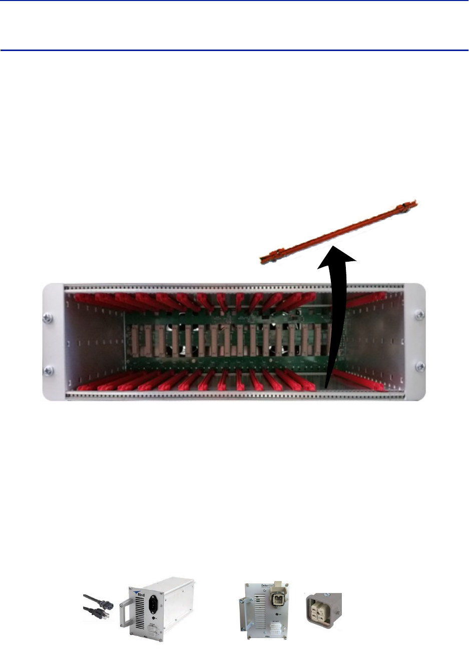
Fiber Distributed Antenna System (Fiber DAS)
47
Power Supply Unit
Bird Technologies offers two different power supplies for the Master Unit: AC (DPU-301) and DC (DPU-302). The
power supply can be located in a Master Unit other than the one it is powering. Each power supply is shipped with
one Molex power supply jumper. If redundant power supplies are required additional power supply jumper(s) will
need to be ordered.
The power supply uses four slots on the Master Unit.
Prior to installing the PSU in the Master Unit chassis the red slide rails must be carefully removed from the
slots that the PSU will occupy.
Figure 31 Slide Rail Removal
PSU DPU-301
The AC DPU-301 power supply has a standard C13 receptacle.
The AC DPU-301 has an input range from 86-264 VAC at 50 or 60 Hz.
Due to site-specific needs on length and varying standards of AC plug types, the AC power cord does not
ship with the equipment. The installation contractor must provide the AC power cord.
The DPU-301 can support a single, fully loaded Master Frame Unit with up to 16 cards (BIU, FOI, ICU). The cards
may be all of one type or a mixture of types.
Figure 32 Power Supply Units
DPU-301 DPU-302
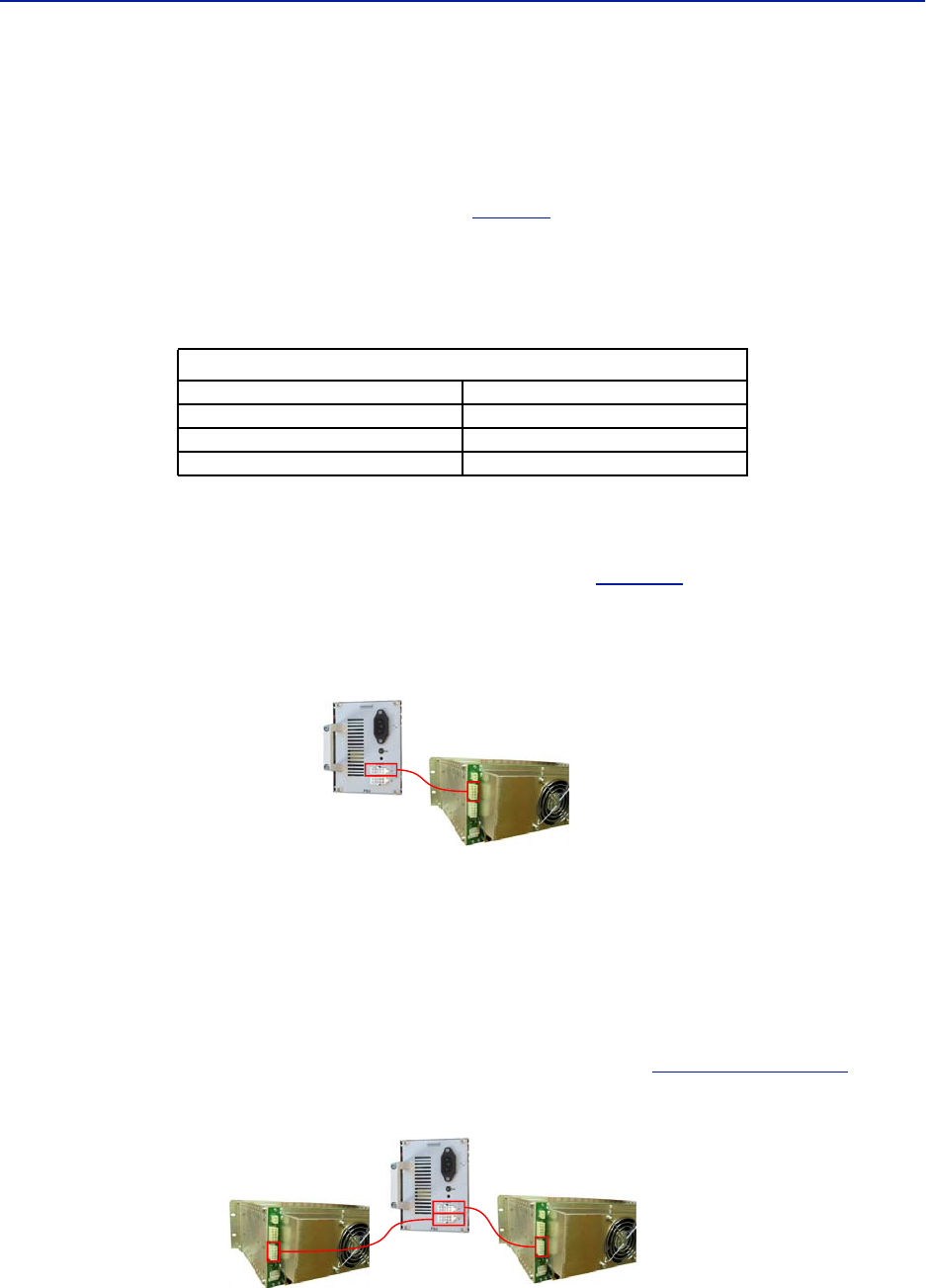
Installation guidelines
48
PSU DPU-302
The DPU-302 uses a HAN four prong Heavy Duty Power Connector.
The DC to DC DPU-302 power supply has in input rating of -36 VDC to -72 VDC.
The DPU-302 requires the installer to provide 18 AWG wire for the HAN 3 A plug kit (Harting P/N 10 20 003
0002) that is provided with the power supply. See
Table 61
for connector pinout.
The DC power supply can support a single Master Frame Unit with up to 12 cards (BIU, FOI, ICU). The cards may be
all of one type or a mixture of cards.
Table 61 DPU-302 Connector Pinout
Primary Power Configuration
Connect the output of the power supply to the input of the Master Unit.
Use P101 on the Master Unit as the main power supply feed. See
Figure 33
.
Note: Note that although there are two output connections on the front of the PSU, the PSU can only
power one Master Frame at a time.
Figure 33 Primary Power Configuration
Backup Power Configuration
It is not required to use a backup/redundant power supply, but if the primary PSU fails a backup PSU will allow the
unit to continue operating without causing an outage.
The system designer may elect to have a single, redundant PSU act as a backup to two different Master Units
simultaneously with the understanding that if the main PSU for each Master Unit fails during the same time period
that the backup/redundant PSU can't support both Master Units.
Use P102 on the Master Unit for a backup/redundant power supply. See
Figure 34 on page 48
.
Figure 34 Backup Power Configuration
Han 3A Pinout
Pin #1 (+) Positive
Pin #2 Not connected
Pin #3 (-) Negative
Pin #4 Earth/Ground
Primary Power for One Master Unit
Backup Power for Two Master Units
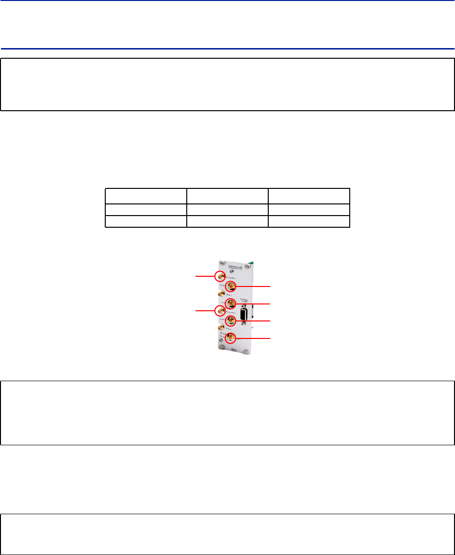
Fiber Distributed Antenna System (Fiber DAS)
49
BIU
The BIU serves as the RF interface between the RF source and the ICU/FOI. Each BIU is pre-set to a frequency band
and is not field tunable.
The BIU has two sets of RF source connections. The units can accept two independent feeds (within the same band).
The feeds can be from separate sources or A and B paths in a MIMO configuration.
Due to the high level of RF coming into BIU, use only quality RF cables.
Figure 35 BIU Connections
Install the BIU in the Master Unit (wide BIU uses two slots, slim BIU uses one slot).
Note: The UL1 and UL2 uplink test ports are 3dB lower than the signal on the corresponding DL/UL
BTS port.
Connect SMA to the RF source. Tighten to 8 in-pounds (0.9 N-m) with a calibrated torque wrench.
Connect QMA to the ICU/FOI.
CAUTION
Overdriving the RF source input into the BIU will cause permanent equipment failure and will void the warranty.
The installer must ensure that input levels are not exceeded. Plan for maximum power out of the RF source and
attenuate accordingly with external attenuators if needed.
BIU Type Minimum DL Input Maximum DL Input
Low Level -7dBm +7dBm
High Level +20dBm +33dBm
CAUTION
When mating RF connectors, ensure that they are properly aligned and not cross threaded.
Tighten SMA connectors to 8 in.-lbs (0.9 N-m).
Do over torque RF connectors, this could result in damage to the Unit.
Do not under torque RF connectors, this could result in poor signal transmission.
CAUTION
Excess tension on the cable or connectors may cause PIM issues.
Cables must be secured in the rack without applying tension to the connectors.
RF
Source ICU
or
FOI
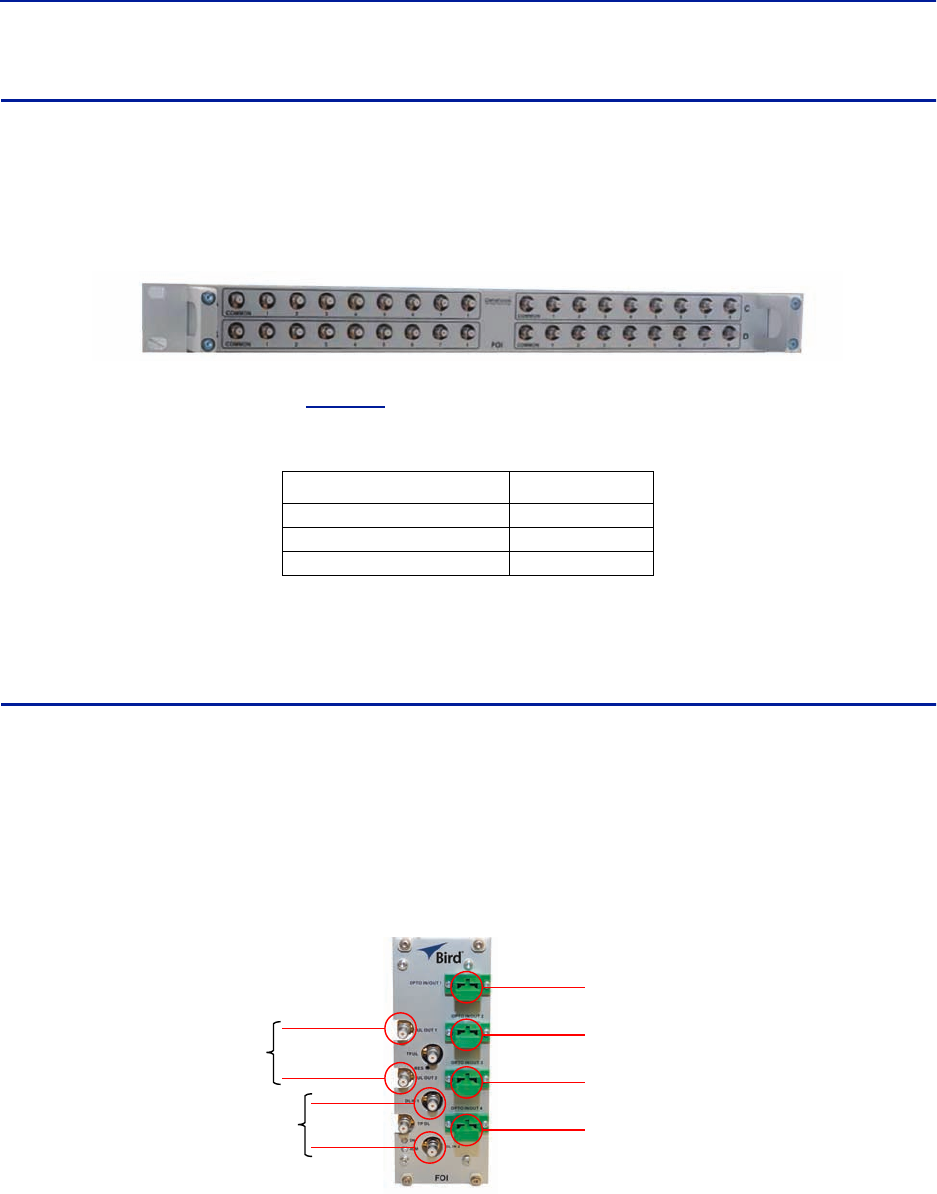
Installation guidelines
50
ICU
The ICU is designed to be installed in a 19" rack.
The ICU is typically installed directly above or below the Master Unit chassis. Consider post installation
changes and testing when selecting a slot to install the ICU.
Figure 36 ICU
The ICU has QMA connectors. QMA cable kit - Bird part number DCC320 is available for use with the ICU. The kit
contains 32 QMA to QMA cables (see
Table 62
) that can be used to patch between the BIU to the ICU, BIU to the
FOI or ICU to FOI.
Table 62 QMA Cable Kit
The ICU is configured with two identical paths - uplink and downlink. The typical configuration [DIU301 (88MHz to
2700MHz)] is four 1:8 splitters/combiners (two for UL and two for DL). Note that the theoretical loss for each
DIU301 is 35dBm.
FOI
The FOI is mounted in the Master Unit chassis (FOI DOI401 uses two slots, FOI DO301/302 uses one slot).
The RF connections are QMA.
The fiber connections are SC/APC.
The FOI can be ordered with an optional DCC330 jumper kit. The kit contains two SC/APC jumpers that are 5 meters
(16.4 feet) in length.
Figure 37 FOI Connections
Length Quantity
250 mm (9.8”) 13
350 mm (13.8”) 13
500 mm (19.7”) 6
OPTO IN/OUT
for
Remote Units
Uplink
Downlink
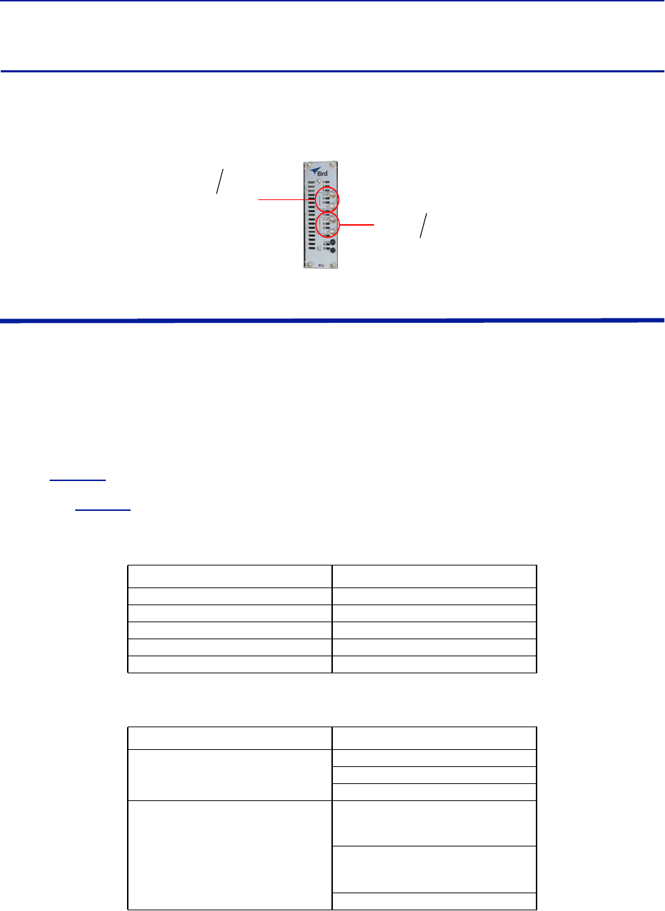
Fiber Distributed Antenna System (Fiber DAS)
51
RFU
The integrated repeater unit, RFU, DMR400 is mounted in the Master Unit chassis. The DMR400 uses two slots in
the Master Unit.
Figure 38 RFU Connections
Powering Up the Head End
1. Apply power to the BGW by pressing the power button on the left side of the unit.
The BGW requires approximately 5 minutes to completely boot up. During the BGW boot process, the modules
in the Master Unit will flash Red and Green.
2. Apply power to the Ethernet Switch and the Master Unit.
3. Verify BGW boot cycle is complete,
Note: The BGW will have green LED's lit even when powered off. This is part of the LAN wake up fea-
ture. When the BGW is running there will be three LED's lit and the hard drive icon showing activity.
4. See
Table 63
for the LED alarm codes for the modules in the Master Unit.
After the BGW boot process is complete, all modules in the Master Unit should have some LED indication. If
not, see
Table 64
.
Table 63 Master Unit Module LED Indicators
Table 64 Master Unit Troubleshooting
Status LED Indication
Normal Green - slow flash
Incoming Alarm Solid Red - Limited to 5 seconds
Warning Red LED flashes 1 Hz 1/8 duty cycle
Error Red LED flashes 2Hz ¼ duty cycle
Critical Red LED remains solid
Malfunction Corrective Action
If no modules have LED indications
Check Power cable to PSU.
Check power source for Master Unit.
Check connection from PSU to Chassis.
If a module does not have LED ON
Indicator
Verify the module is properly seated into
the chassis.
Move a module to another slot on the
Master Unit chassis.
Replace module.
Rebroadcast
Uplink/
Downlink
RF
Source
Donor
Antenna
Service
Antenna
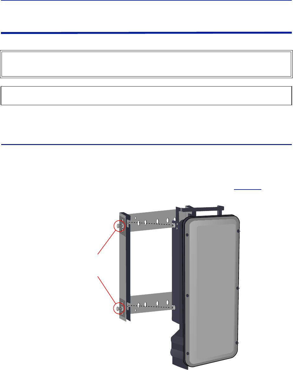
Installation guidelines
52
Installing Remote Units
The remote units are factory configured and should not be opened in the field.
The remotes must be mounted in a vertical position. There are two recommended methods for Remote Unit
installation, wall mounting or pole mounting. Regardless of the mounting style selected, the remotes must be
mounted so that airflow over the external heat sink is not obstructed.
Single Remote Unit Wall Mounting
The remotes are shipped with standard wall mounting brackets. These brackets can be used indoors and outdoors.
Mount the bracket (p/n DMB301) without the remote attached.
Note: Always check local building codes for proper mounting techniques!
Once the bracket is properly mounted, the remote easily slides into the mount. See
Figure 39
.
Note: Figure 39 Remote Wall Mount
Once the remote is attached to the wall mount, the remote must be properly secured to the mount by
tightening bolts at each mounting point.
WARNING
The Remote Units are heavy , use care and always properly support units during installation. If allowed to fall
Remote Units can cause injury or death.
CAUTION
Ensure the surfaces being used to mount Remote Units can safely support the full weight of the remote.
Tighten bolts
(4 places)
After Remote
is Attached
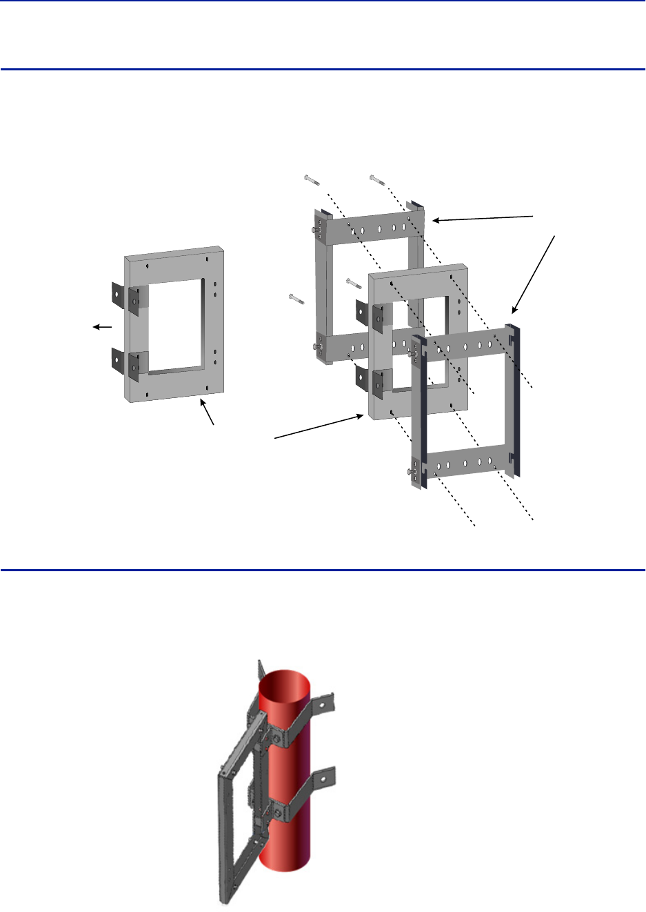
Fiber Distributed Antenna System (Fiber DAS)
53
Double Remote Unit Wall Mounting
Bird Technologies offers a bracket that allows two wall mount racks to be mounted back to back. This reduces the
amount of wall space required when two remotes are located together. The bracket is stainless steel and can be
used indoors or outdoors.
Figure 40 Double Wall Mounting Bracket
Remote Unit Pole Mounting
Bird Technologies also offers a pole mounting option. The pole mount brackets are designed to be used with the
Double Remote Wall Mount bracket.
Figure 41 Remote Unit Pole Mounting Option
Double Wall
Mount Bracket
Mount to Wall
Standard Wall
Mount Brackets
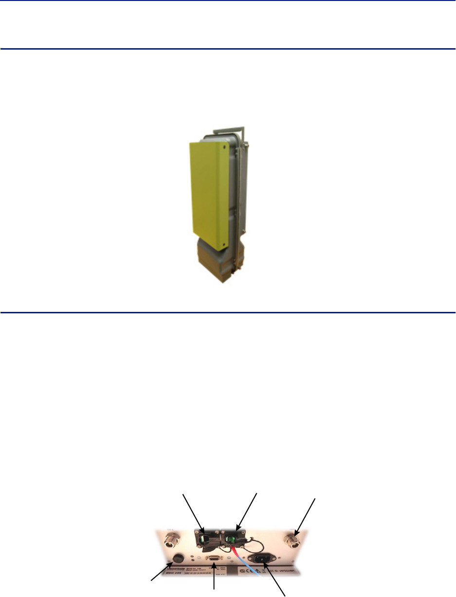
Installation guidelines
54
Solar Shield
Direct exposure to sun light can cause temperatures of the remote to exceed the 55 °C (131°F) rating. A simple
solution offered by Bird is to attach an optional solar shield to the affected remotes. The solar shields (p/n
DMA301) are sold separately.
Figure 42 Remote Unit Solar Shield
Cabling
There are many options for the Bird remotes which can affect the number of connections on the bottom of each
remote. The standard connections are:
Ethernet port
RF Port (N, mini DIN or 7/16 DIN, Simplex or Duplex) - Number of ports varies
Power (AC)
External alarm port
Grounding
Fiber Optic
Figure 43 Remote Unit Cabling Connectors
RF Port
Fiber-Optic
Port
Ethernet
Port
External Alarms
Connector
Input Power
Connector
Chassis
Breather
Port
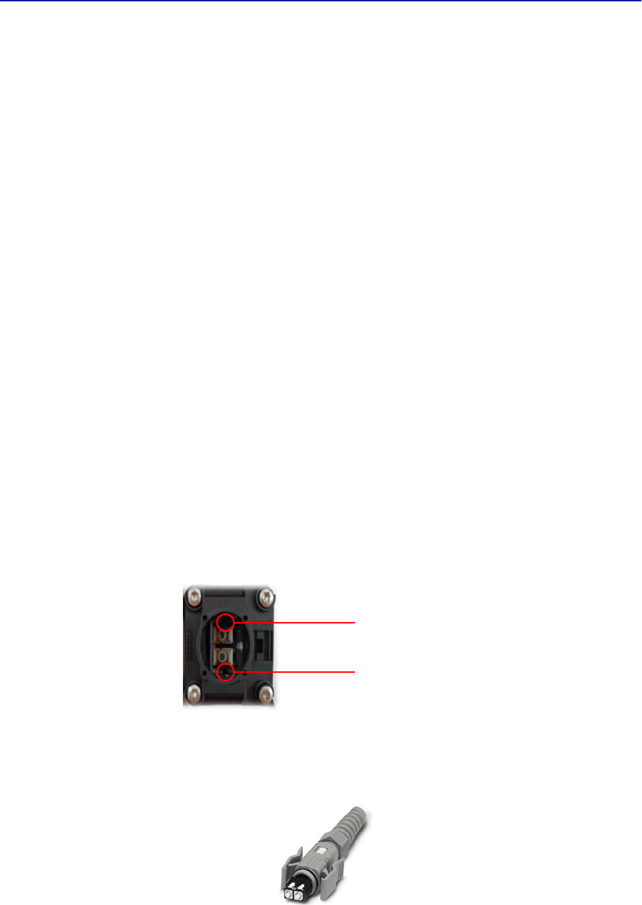
Fiber Distributed Antenna System (Fiber DAS)
55
Ethernet Port
The RJ45 Ethernet port is located on the bottom panel of the remote unit. Connection of the Ethernet port is not
required for normal operation of the DAS. The port offers convenient access to the system GUI during installation,
commissioning and troubleshooting of the DAS. Ensure the provided IP67 rated protective cap is replaced when the
Ethernet port is not in use.
If the Ethernet connection is to be long term or permanent, ensure that the appropriate Ethernet patch cable is
utilized to prevent the ingress of moisture into the port.
The Ethernet port allows for two types of connections.
1. Remote unit is not connected to the FOI in the Master Unit
Access will be limited to the Remote Unit. User may change setting on the Remote Unit.
Static IP address for local access is https://169.254.48.1
Username: "extended"
Password: "admin"
2. Remote Unit is actively connected to the FOI in the Master Unit
Full access to all GUI features will be allowed
Access will require the Master Unit IP address: https://172.22.0.1
Username: "extended"
Password: "admin"
Fiber Optic Connection
The fiber connection on the bottom of the remote has an IP67 rated protective cap. The protective cap must remain
in place until the fiber is to be inserted. This will help prevent foreign particles from degrading performance of the
fiber.
The fiber connection has a keyed slot SC/APC connection. Care must be taken to ensure the fiber is installed
correctly. It is possible to force the connection so that the fiber is installed at a 180 degree rotation causing
performance issues.
Note: The SC/APC key is at the top and bottom on the connection on the remote.
Figure 44 Remote Fiber-Optic Connector
It is highly recommended that only the SCRJ fiber cables be used with the remotes. Not only does the SCRJ cable
prevent the ingress of moisture and dust into to the fiber port but the cable also insures the fibers are correctly
aligned in the connector. SCRJ fiber cables are ordered separately from Bird Technologies.
Figure 45 SCRJ Connector
Keyed
Connector
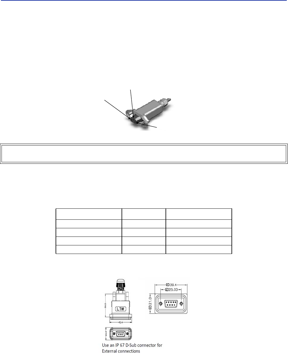
Installation guidelines
56
AC Power Input
The Bird remote only comes with an AC input option. The voltage range will support 120VAC or 240VAC, 50 or 60
Hz. The remote ships with a weather proof C13 connector and weather proof strain relief housing. The unit does not
ship with a power cord - only the power connector. The installation contractor will need to provide a power cable of
at least 14AWG, 3 conductor cable.
Figure 46 Weatherproof AC Input Connector
External Alarm Connection
The external alarm port on the Bird remote requires an IP 67 D-sub connector (not supplied by Bird).
Table 65 Alarm Definitions
Figure 47 External Alarm Connector
WARNING
Electrical installation should only be performed by a licensed electrician.
Alarm Input Level Alarm Text
1 (Pin 9) Error Battery voltage low
2 (Pin 4) Critical Loss of main AC power
3 (Pin 8) Warning External alarm 3
4 (Pin 3) Error External alarm 4
Live
Neutral
Ground
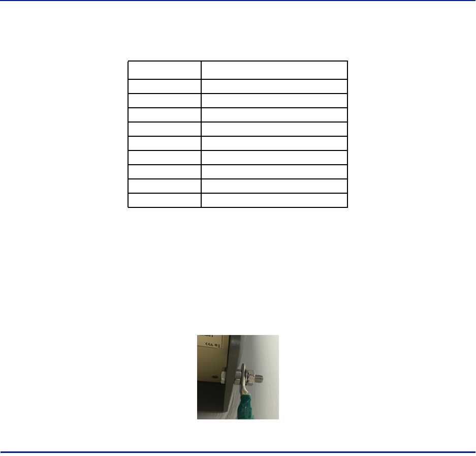
Fiber Distributed Antenna System (Fiber DAS)
57
Table 66 External Alarm Connector Pinout
Grounding
The remotes are furnished with a ground lug to be used if chassis grounding is required to meet local code or
installation requirements. The external grounding lug must be used when the remote is installed in applications
where it is susceptible to lightening strikes.
If the remote is mounted in areas with high EMF such as near high amperage transformers, turbines or broadcast
antennas, properly grounding the chassis will provide reduce the likelihood interference.
Figure 48 Remote Ground Connection
Remote Unit Verification
Once the remote has been properly installed and all connections made the unit may be powered up. The unit is
automatically powered up once power is applied to the AC plug on the bottom of the unit.
The typical power cycle of the remote is approximately 90 seconds. The red and green LED on the bottom of the
remote will flash during the boot cycle.
Once the boot cycle is complete, a solid red LED indicates there is no fiber connection or communication to
the DAS head end.
Pin Function
1Alarm relay output NC
2Alarm relay output NO
3Alarm input 4
4Alarm input 2
5Alarm input ground
6Alarm relay output NC
7Alarm relay output NO
8Alarm input 3
9Alarm input 1
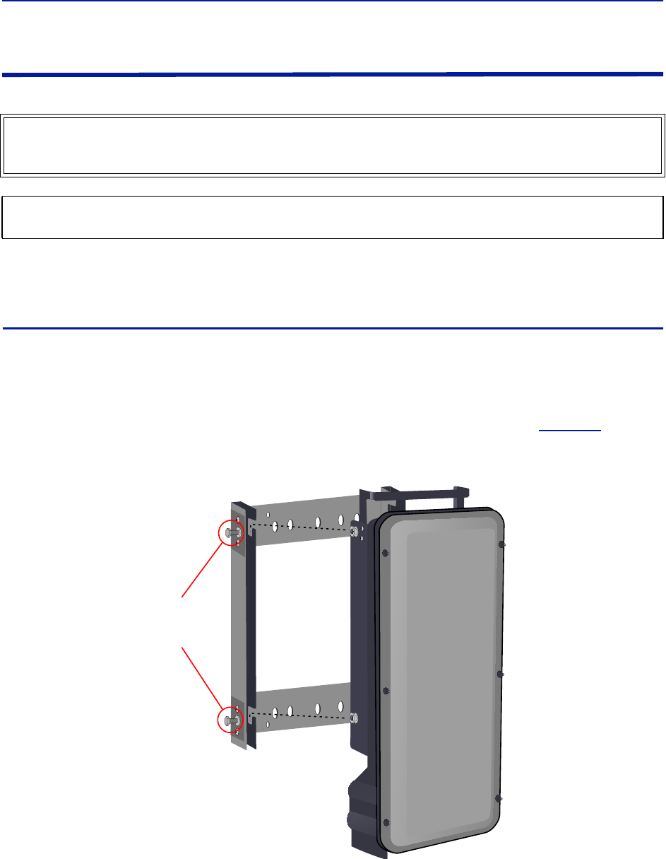
Installation guidelines
58
Installing the DHR Repeater
The repeaters units are factory configured and should not be opened in the field.
The remotes must be mounted in a vertical position. There are two recommended methods for Remote Unit
installation, wall mounting or pole mounting. Regardless of the mounting style selected, the remotes must be
mounted so that airflow over the external heat sink is not obstructed.
Single Repeater Wall Mounting
The repeaters are shipped with standard wall mounting brackets. These brackets can be used indoors and outdoors.
Mount the bracket without the repeater attached.
Note: Always check local building codes for proper mounting techniques.
Once the bracket is properly mounted, the repeater easily slides into the mount. See
Figure 49
.
Figure 49 Repeater Wall Mount
Once the repeater is attached to the wall mount, the repeater must be properly secured to the mount by
tightening bolts at each mounting point.
WARNING
The Repeaters are heavy , use care and always properly support units during installation. If allowed to fall a
Repeater can cause injury or death.
CAUTION
Ensure the surfaces being used to mount the Repeater can safely support the full weight of the Repeater.
Tighten Bolts
(4 places)
after Repeater
is Attached
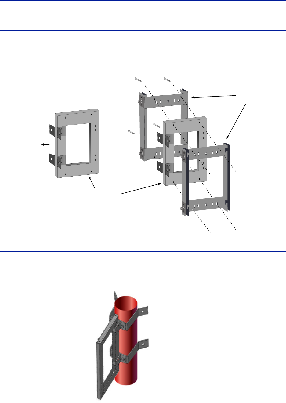
Fiber Distributed Antenna System (Fiber DAS)
59
Double Repeater Wall Mounting
Bird Technologies offers a bracket that allows two wall mount racks to be mounted back to back. This reduces the
amount of wall space required when two repeaters are located together. The bracket is stainless steel and can be
used indoors or outdoors.
Figure 50 Double Wall Mounting Bracket
Repeater Pole Mounting
Bird Technologies also offers a pole mounting option. The pole mount brackets are designed to be used with the
Double Wall Mount bracket.
Figure 51 Repeater Pole Mounting Option
Double Wall
Mount Bracket
Mount to Wall
Standard Wall
Mount Brackets
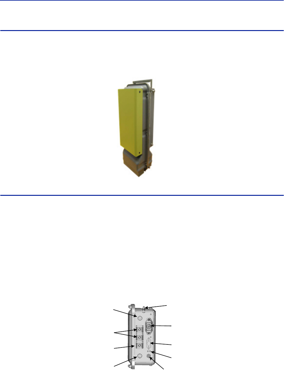
Installation guidelines
60
Solar Shield
Direct exposure to sun light can cause temperatures of the repeater to exceed the 55 °C (131°F) rating. A simple
solution offered by Bird is to attach an optional solar shield to the affected repeaters. The solar shields are sold
separately.
Figure 52 Remote Unit Solar Shield
Cabling
There are many options for the Bird repeaters which can affect the number of connections on the bottom of each
repeater. The standard connections are:
Ethernet port
RF Ports (N-Type standard)
Input Power
External alarm port
Grounding
Fiber Optic (optional)
Figure 53 Repeater Cabling Connectors
Fiber-Optic
Ports (Optional)
Ethernet
Port
Chassis
Ground
External Alarms
Connector
Input Power
Connector
Chassis
Breather
Port
Service Antenna
Connector
Donor Antenna
Connector
LED Indicators
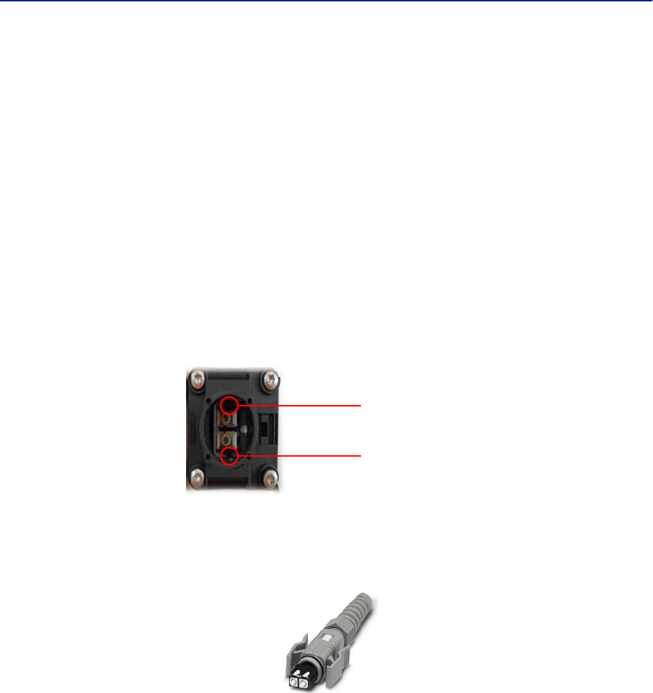
Fiber Distributed Antenna System (Fiber DAS)
61
Ethernet Port
The RJ45 Ethernet port is located on the bottom panel of the repeater unit. Connection of the Ethernet port is not
required for normal operation of the repeater. The port offers convenient access to the system GUI during
installation, commissioning and troubleshooting. Ensure the provided IP67 rated protective cap is replaced when
the Ethernet port is not in use.
If the Ethernet connection is to be long term or permanent, ensure that the appropriate Ethernet patch cable is
utilized to prevent the ingress of moister into the port.
Fiber Optic Connection
If the fiber optic option is ordered, the fiber connection on the bottom of the repeater has an IP67 rated protective
cap. The protective cap must remain in place until the fiber is to be inserted. This will help prevent foreign particles
from degrading performance of the fiber.
The fiber connection has a keyed slot SC/APC connection. Care must be taken to ensure the fiber is installed
correctly. It is possible to force the connection so that the fiber is installed at a 180 degree rotation causing
performance issues.
Note: The SC/APC key is at the top and bottom on the connection on the repeater.
Figure 54 Remote Fiber-Optic Connector
It is highly recommended that only the SCRJ fiber cables be used with the repeaters. Not only does the SCRJ cable
prevent the ingress of moisture and dust into to the fiber port but the cable also insures the fibers are correctly
aligned in the connector. SCRJ fiber cables are ordered separately from Bird Technologies.
Figure 55 SCRJ Connector
Keyed
Connector
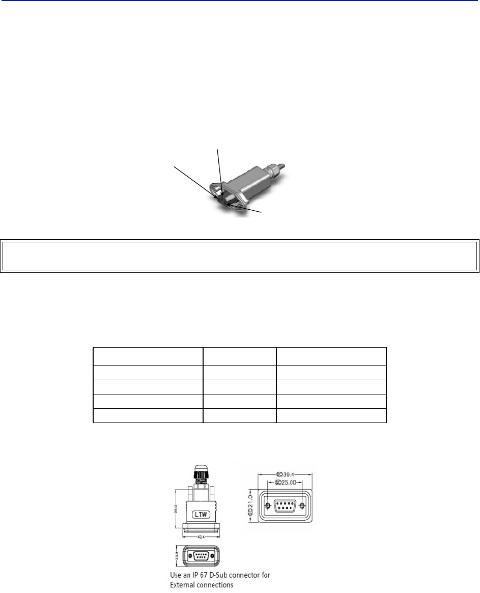
Installation guidelines
62
AC Power Input
The Bird repeater only comes with an AC input option. The voltage range will support 120VAC or 240VAC, 50 or 60
Hz. The remote ships with a weather proof C13 connector and weather proof strain relief housing. The unit does
not ship with a power cord - only the power connector. The installation contractor will need to provide a power
cable of at least 14AWG, 3 conductor cable.
Figure 56 Weatherproof AC Input Connector
External Alarm Connection
The external alarm port on the repeater requires an IP 67 D-sub connector (not supplied by Bird).
Table 67 Alarm Definitions
Figure 57 External Alarm Connector
WARNING
Electrical installation should only be performed by a licensed electrician.
Alarm Input Level Alarm Text
1 (Pin 9) Error Battery voltage low
2 (Pin 4) Critical Loss of main AC power
3 (Pin 8) Warning External alarm 3
4 (Pin 3) Error External alarm 4
Live
Neutral
Ground
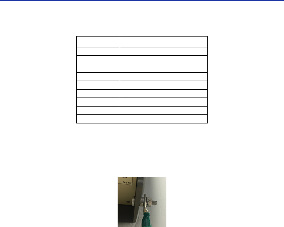
Fiber Distributed Antenna System (Fiber DAS)
63
Table 68 External Alarm Connector Pinout
Grounding
The repeaters are furnished with a ground lug to be used if chassis grounding is required to meet local code or
installation requirements.
Figure 58 Remote Ground Connection
Pin Function
1Alarm relay output NC
2Alarm relay output NO
3Alarm input 4
4Alarm input 2
5Alarm input ground
6Alarm relay output NC
7Alarm relay output NO
8Alarm input 3
9Alarm input 1
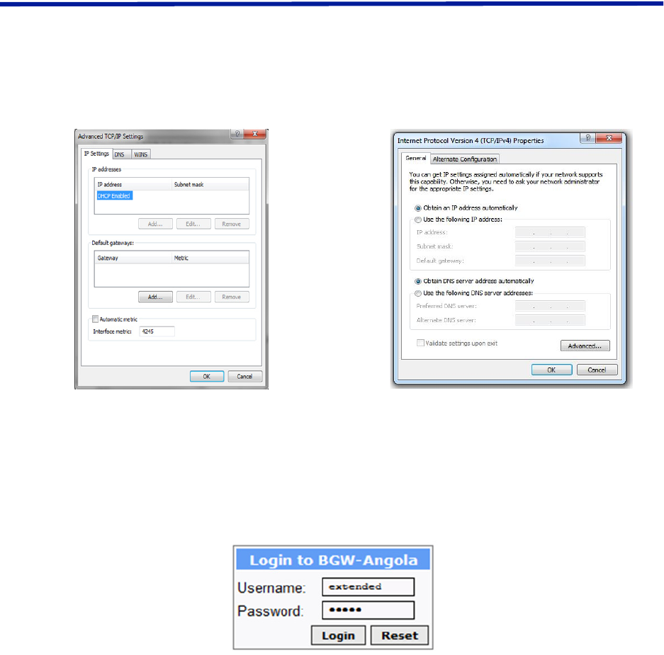
64
Chapter 4 DAS Software Configuration
This section is focused on the GUI interface and initial software setting of the DAS. No special software is require to
access the Bird DAS. Access is provided via most web browsers such as Mozilla Firefox or Google Chrome.
The BGW should be powered up and allowed about 5 minutes to fully boot prior to applying power to the Master
Unit. The BGW will assign IP addresses to the Master Unit components. If the Master Unit is powered up prior to the
BGW then it could take up to 30 minutes for the Master Unit components to get assigned an IP address. Master Unit
cards will show a quick flash of the green LED when an IP address has been assigned.
Special Note: The following is based on version 3.5 software.
Ethernet Connection
1. Connect a laptop to any open port on the Headend Ethernet switch.
2. Ensure the laptop network settings have DHCP enabled and the “Obtain an IP address automatically” radio
button checked.
Figure 59 Windows TCP/IP Settings
3. Using an Internet browser go to https://172.22.0.1 to access the BGW. A successful entry will show access to
the login page.
4. Login to the BGW.
Username: "extended"
Password: "admin"
Figure 60 BGW Login page
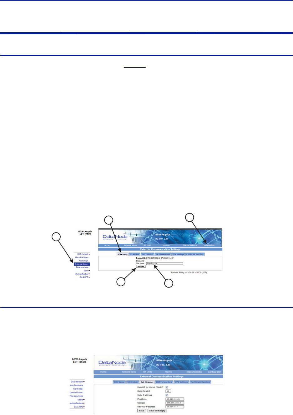
Fiber Distributed Antenna System (Fiber DAS)
65
BGW Configuration
BGW Naming
1. Select Configuration in top right corner. See
Figure 61
.
2. Select External Comm in left menu.
3. Select BGW Name tab in top menu.
4. Enter site name:
a. You may use any combination of alphanumeric characters and the special character of dash "-". Do
not use any other special characters or space.
0 through 9
a through z
A through Z
-
Limit of 56 characters
b. Use a site name that is descriptive enough to distinguish the BGW from other sites. Generic names
may delay troubleshooting efforts.
5. Click Submit.
Note: After the new host name is entered, the unit must be restarted. This is the only change that
requires a restart. Select the physical restart button on the left side of the BGW.
Figure 61 BGW Site Name
EXT Ethernet
In order for the BGW to be able to communicate outward, the Ext Ethernet connection has to be programmed.
Consult with your Internet service provider or IT department for the IP address, Netmask and Gateway IP address
settings.
Figure 62 BGW External Communications
1
54
3
2
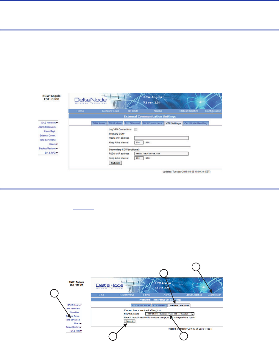
DAS Software Configuration
66
VPN Settings
On occasions, the BGW will be set up behind a firewall. To be able to access the BGW from external locations the
Primary BGW settings will need to be configured to allow access. Consult with your IT department for these
parameters.
Bird Technologies offers monitoring services. When these services are contracted, enter the Bird parameters in the
Secondary BGW settings so that system alarms are correctly forwarded to the Bird NOC.
Figure 63 BGW VPN Settings
Time Zone
To ensure that alarms are correctly labeled with the local time the time zone for the BGW will need to be set.
1. Select Configuration. See
Figure 64
.
2. Click Time serv/zone.
3. Select the Time and Time zone Tab.
4. Select the local time zone from the drop-down menu.
5. Click Submit.
Figure 64 BGW Time Zone Settings
1
54
3
2
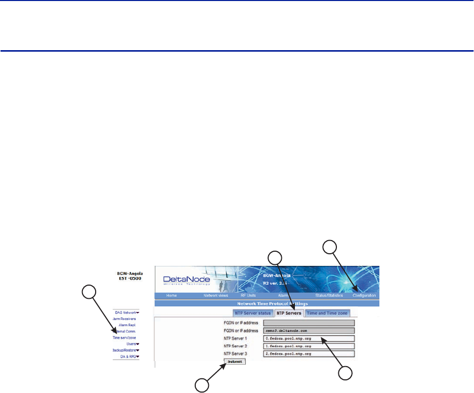
Fiber Distributed Antenna System (Fiber DAS)
67
NTP Servers
NTP servers provide accurate clocks for the BGW. Utilizing multiple sources prevents clock issues as a result of one
server becoming corrupt or dropping out of contact. The BGW is compatible with NTP version 4 servers. The NTP
settings in the image below are the default for Redhat servers.
1. Select Configuration.
2. Click Time serv/zone.
3. Select the NTP Servers Tab.
4. Enter the NTP Server information. The FQDN settings are reserved for deployments utilizing the CGW.
5. Click Submit.
If no Internet access is available, the BGW will create its own clock to give the sub-nodes of the system a valid NTP
service.
Figure 65 NTP Server Settings
1
5
4
3
2
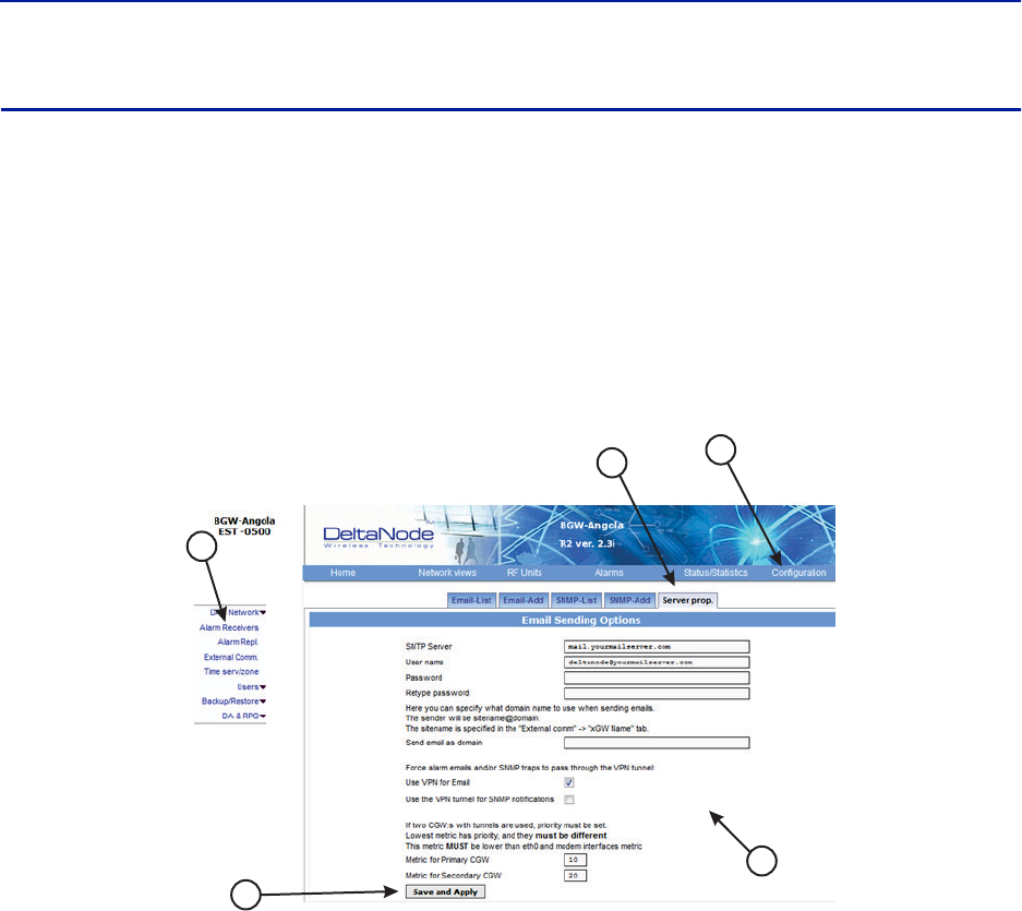
DAS Software Configuration
68
Email Server
The BGW is capable of emailing alarms directly to select email addresses. Access the set up function via
Configuration, Alarm Receivers and Server Prop.
Consult with your IT department for configuration settings.
1. Select Configuration.
2. Click Alarm Receivers.
3. Select the Server Prop. Tab.
4. Enter the Email Server information. Consult with your IT department for configuration settings.
5. Click Save and Apply.
Figure 66 Email Server Settings
1
5
4
3
2
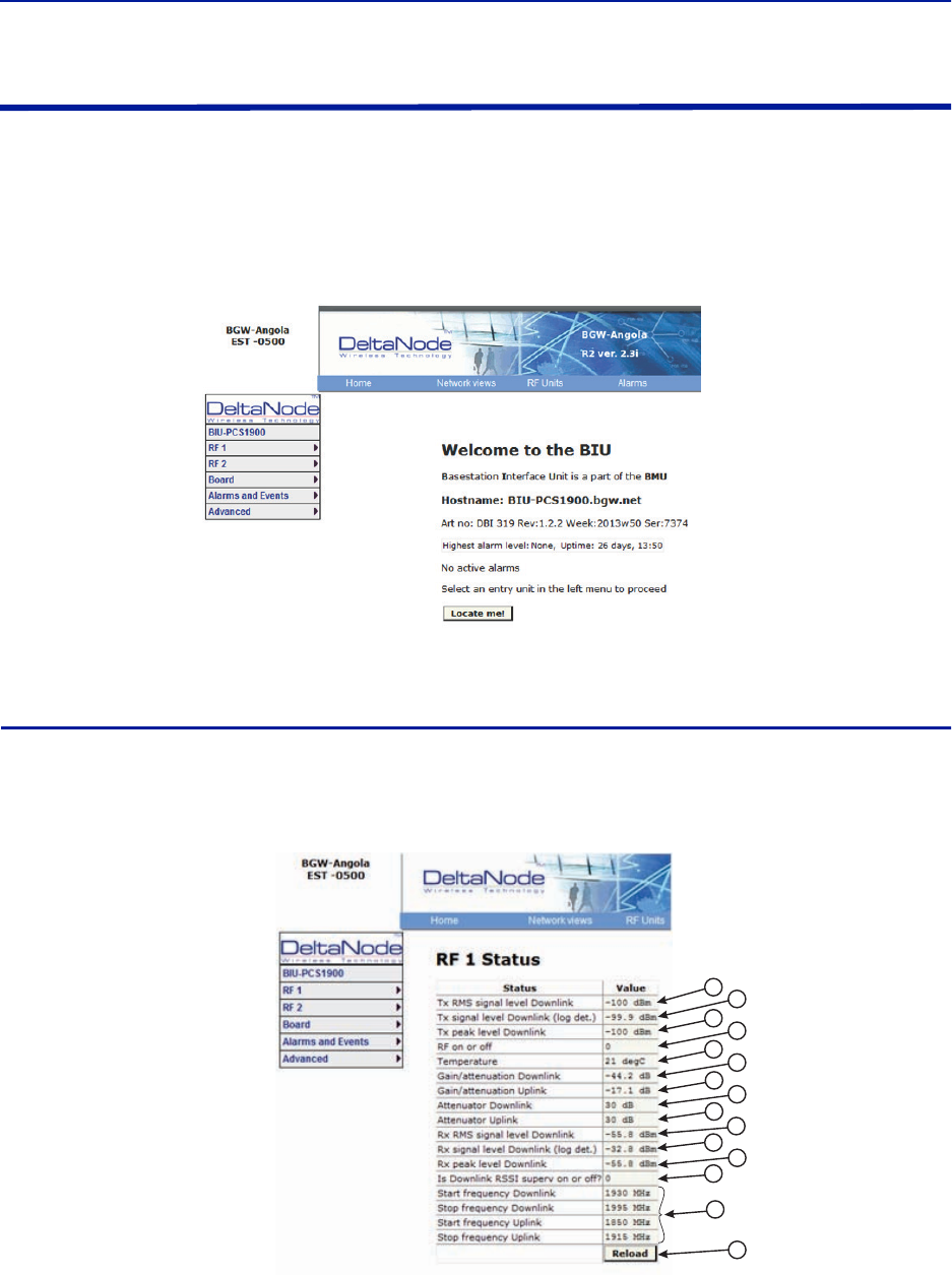
Fiber Distributed Antenna System (Fiber DAS)
69
BIU Configuration
The initial screen for the BIU provides basic information such as name, serial number, part number and active
alarms. The Locate me! button causes an LED to flash on the unit so that the module can be identified in the chassis.
In the left menu, notice the RF 1 and RF 2. The BIU has two RF paths or strips that are correlated to the two RF
inputs on the BIU card. Each RF path has independent settings that can be accessed via the appropriate selection.
Figure 67 BIU Welcome Screen
BIU RF1 Status
This page shows the current status and configuration of the BIU.
Figure 68 BIU RF1 Status
12
3
4
5
6
7
8
9
10
11
12
13
14
15

DAS Software Configuration
70
Item Description
1Downlink RMS value leaving the BIU card to the ICU/FOI. Good for
measuring GSM and UMTS levels.
2 Downlink log detector signal leaving the BIU card to the ICU/FOI.
3Peak downlink RF value exiting the BIU card on the select path.
4
0=RF is set to Off (attenuation is set to maximum).
1= RF is set to On.
Note: This is only in reference to one of the two BIU RF paths/strips.
5Temperature of the BIU card.
6
This measurement is the actual loss of the downlink RF signal in the BIU
taking into account raw or inherent loss of the card plus the adjustable
attenuator.
7
This measurement is the actual gain or loss on the uplink RF signal in the BIU
taking into account raw or inherent gain of the card plus the uplink
adjustable attenuator.
8
Adjustable downlink attenuator setting for the selected RF path.
Note: If RF is turned off (see #4) the attenuator value is automatically set to
maximum attenuation. When RF is turned on, the setting of the adjustable
attenuator will be shown.
9
Adjustable uplink attenuator setting for the selected RF path.
Note: If RF is turned off (see #4) the attenuator value is automatically set to
maximum attenuation. When RF is turned on, the setting of the adjustable
attenuator will be shown.
10
Calculated downlink RMS value entering the BIU card from the BTS.
Note: This is the downlink into the BIU card and not an uplink value.
11
Calculated downlink value entering the BIU card from the BTS .
Note: This is the downlink into the BIU card and not an uplink value.
12
Peak downlink RF value entering the BIU card on the select path.
Note: This is the downlink into the BIU card and not an uplink value.
13 0= Downlink alarm is set to Off.
1= Downlink alarm is set to On.
14 Bandwidth of the BIU card
15 Pressing Reload will refresh the page
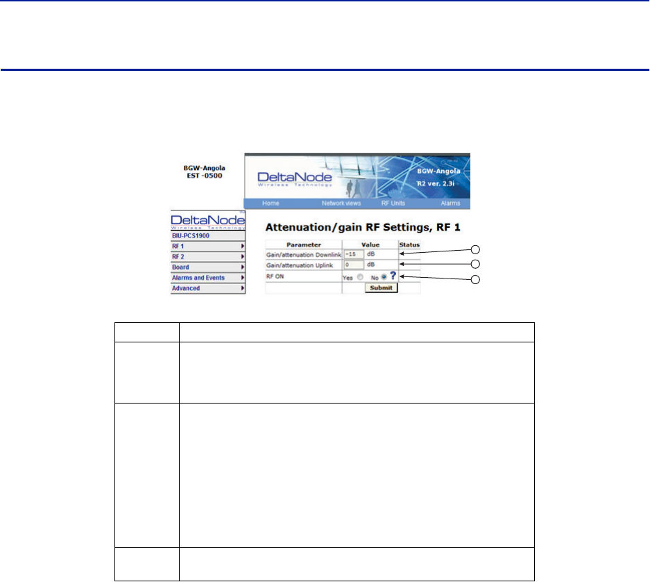
Fiber Distributed Antenna System (Fiber DAS)
71
BIU RF1 Settings
This page will allow the user to change the attenuator values in the BIU for the path selected.
Figure 69 BIU RF1 Settings
Item Description
1
Attenuator setting for the downlink path. Enter a value from -14 to -44
(range varies depending of frequency band).
Note: Click Submit after entering value.
2
Attenuator/Gain setting for the uplink path.
Enter a value from -17 to 12 (range varies depending of frequency band).
Note that the BIU has raw gain in the uplink path on certain BIU types (gain
can be determined by positive value in the setting range.
A selection of 12 indicates full gain of 12dB in the BIU.
A selection of 9 will decrease the BIU uplink output by 3dB.
A selection of 0 will decrease the BIU uplink output by 12dB.
A selection of -17 will decrease the BIU uplink output by 29dB.
Note: Click Submit after entering value.
3This selection turns the uplink path On or Off (maximum attenuation
setting).
1
2
3
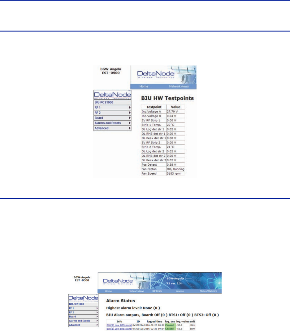
DAS Software Configuration
72
BIU Hardware Test Points
This page shows various test point measurements used for status and troubleshooting purposes.
Figure 70 BIU Hardware Test Points
BIU Alarm List
This page displays all current and past alarms.
Green indicates that the alarm has cleared.
Yellow indicates a warning alarm.
Red indicates a service affecting alarm.
Figure 71 BIU Alarm List
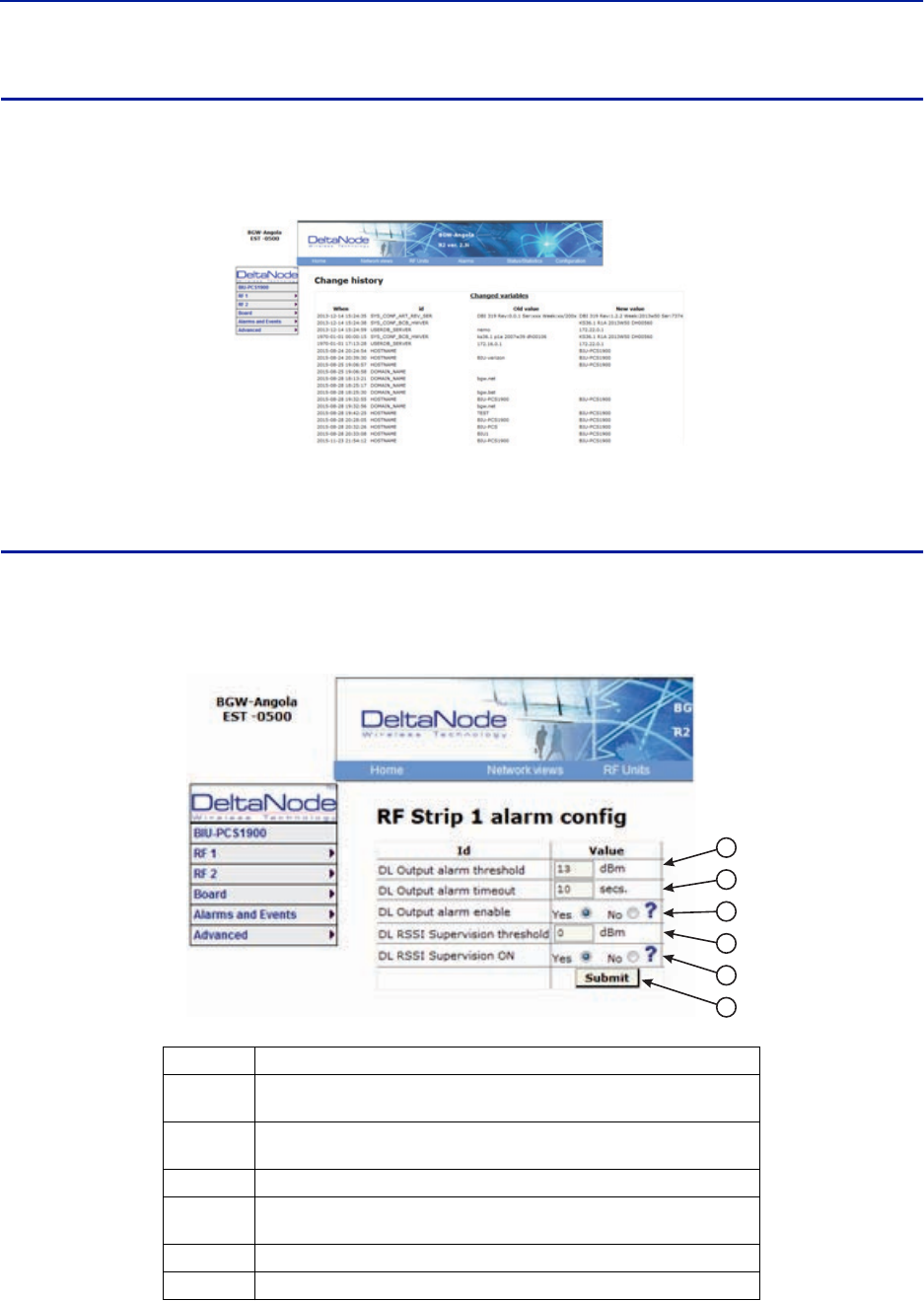
Fiber Distributed Antenna System (Fiber DAS)
73
BIU Change History
This page shows a history of all setting changes.
Figure 72 BIU Change History
BIU Alarm configuration RF1
This page allows for certain alarm thresholds of the BIU to be changed.
Figure 73 BIU Alarm configuration
Item Description
1Set the value in dBm that the BIU downlink output has to exceed in order to
create an alarm
2Set the value in seconds for the amount of time that the BIU downlink
output has to be above the threshold level in order to create an alarm.
3 Enables or disables BIU threshold/high power alarm.
4Set the value in dBm that the BIU downlink output has to drop below in
order to create an alarm.
5 Enables or disables BIU supervision/low level alarm.
6Click Submit after entering value(s).
1
2
3
4
5
6
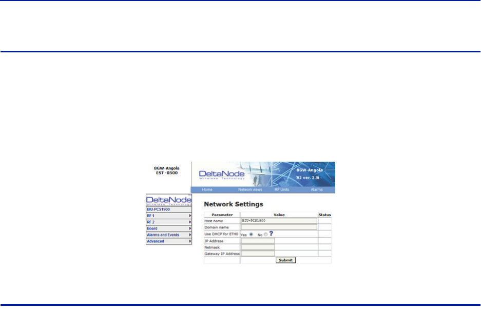
DAS Software Configuration
74
BIU Advanced Network Setup
This page allows for manual override of network settings.
Default configurations should be used with DHCP set to Yes.
Note: Changing DHCP to “No” can cause loss of communications to the BIU and should only be used in
very specific situations.
Figure 74 BIU Network Setup
BIU Advanced Menus
These menus provide information only status and settings of the BIU that are typically used by the manufacturer.
BIU > Advanced>HW config
BIU > Advanced>AD-values RF1
BIU > Advanced>AD-values RF2
BIU > Advanced>ADC raw
BIU > Advanced>Software status
BIU > Advanced>Process status
BIU > Advanced>System status
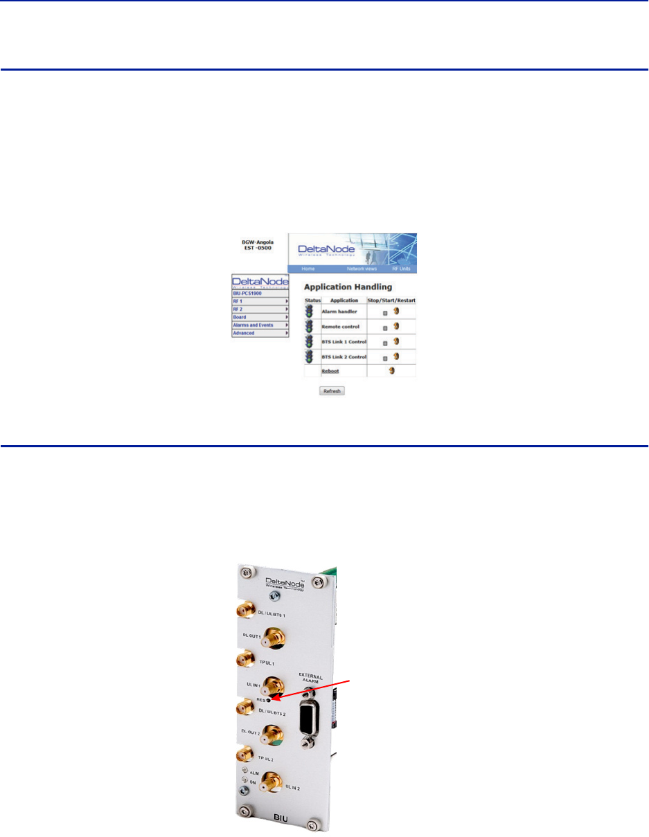
Fiber Distributed Antenna System (Fiber DAS)
75
BIU Application Handling
The application handling page allows for stopping software functions and rebooting software programs.
Alarm Handler: Selecting Reboot (circular icon) will clear all the alarms in the history for the card selected. This is
helpful after turning a system up and wanting to clear alarm log created during the installation and turn up.
Note: Only the Reboot command should be used by the technician. All other functions should only be
used under supervision of Bird engineering as they may cause data corruption if not initiated properly.
The radio button will stop a process and can have negative affects on the function of the DAS.
Figure 75 BIU Application Handling
BIU Reset to Factory Default
To reset the BIU to factory default, carefully press the “Reset” button [located below the UL In 1 QMA connector]
for 10 seconds. This is helpful when a card fails to appear in the Configuration menu.
Figure 76 BIU Reset
Reset
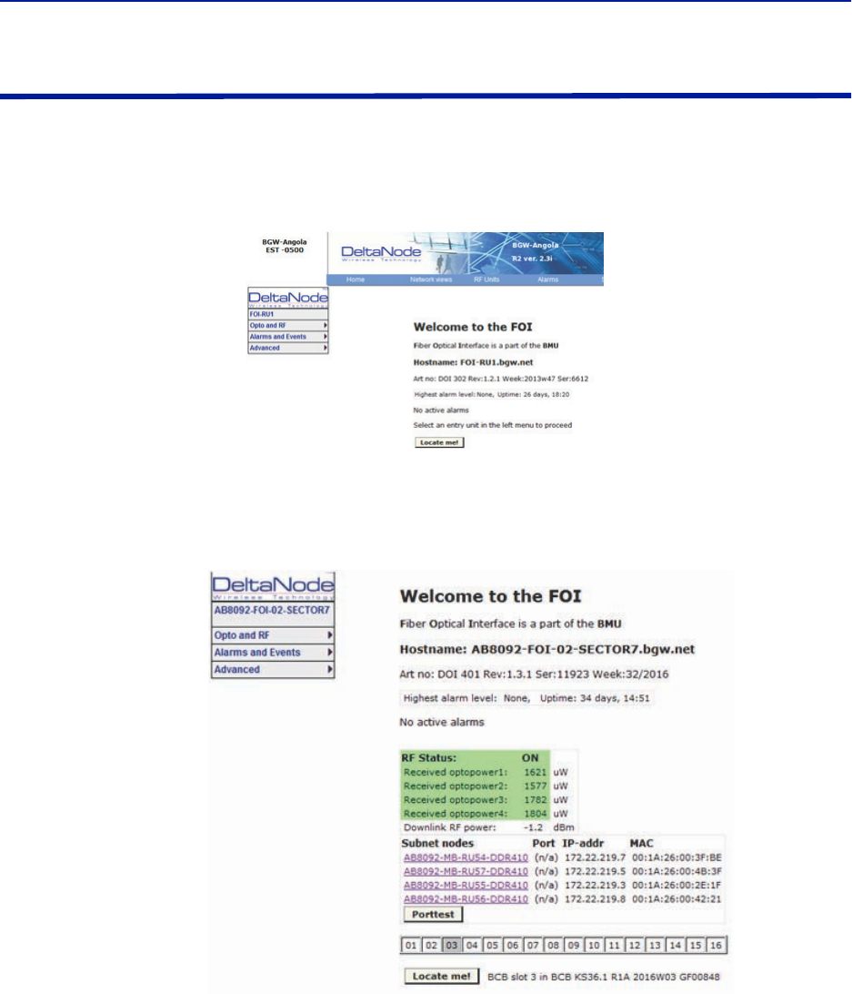
DAS Software Configuration
76
FOI Configuration
The initial screen for the FOI provides basic information such as name, serial number, part number and active
alarms. The Locate me! button causes an LED to flash on the unit so that the module can be identified in the chassis.
Figure 77 FOI Welcome Screen
Figure 78 FOI Welcome Screen SW Version 3.9, DOI401
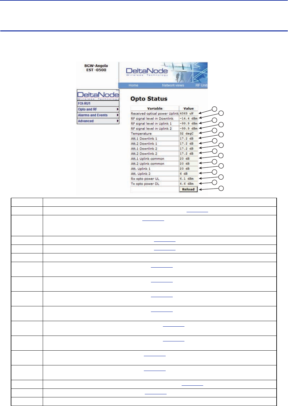
Fiber Distributed Antenna System (Fiber DAS)
77
FOI Opto Status
This page will show the current status and configuration of the FOI.
Figure 79 FOI Opto Status
Item Description
1 Fiber optic received optical power from the remote unit. See item 1 in
Figure 80
for measurement location.
2
RF downlink power to the remote. See item 2 in
Figure 81
for location on the FOI circuitry. Note that with no RF
power into the BIU the FOR will still show signal in the downlink. This is the sub-carrier that is typically 10 dB below
the anticipated RF level.
3 RF path 1 input power from the remote. See item 3 in
Figure 80
for location on the FOI circuitry.
4 RF path 2 input power form the remote. See item 4 in
Figure 80
for location on the FOI circuitry.
5 Temperature of the FOI card
6Downlink path 1 attenuator #1 setting. See item 6 in
Figure 81
for location on the FOI circuitry. Value may be
slightly different than the value in Settings due to changes in temperature compensation.
7Downlink path 1 attenuator #2 setting. See item 7 in
Figure 81
for location on the FOI circuitry. Value may be
slightly different than the value in Settings due to changes in temperature compensation.
8Downlink path 2 attenuator #1 setting. See item 8 in
Figure 81
for location on the FOI circuitry. Value may be
slightly different than the value in Settings due to changes in temperature compensation.
9Downlink path 2 attenuator #2 setting. See item 9 in
Figure 81
for location on the FOI circuitry. Value may be
slightly different than the value in Settings due to changes in temperature compensation.
10 Uplink common path attenuator #1 setting. See item 10 in
Figure 80
for location on the FOI circuitry. Value may
be slightly different than the value in Settings due to changes in temperature compensation.
11 Uplink common path attenuator #2 setting. See item 11 in
Figure 80
for location on the FOI circuitry. Value may
be slightly different than the value in Settings due to changes in temperature compensation.
12 Uplink path #1 attenuator setting. See item 12 in
Figure 80
for location on the FOI circuitry. Value may be slightly
different than the value in Settings due to changes in temperature compensation.
13 Uplink path #2 attenuator setting. See item 13 in
Figure 80
for location on the FOI circuitry. Value may be slightly
different than the value in Settings due to changes in temperature compensation.
14 Calculated uplink optical input from the remote unit. See item 14 in
Figure 80
for location on the FOI circuitry.
15 Calculated downlink optical output. See item 9 in
Figure 81
for location on the FOI circuitry.
16 Pressing Reload will refresh the page
1
2
3
4
5
6
7
8
9
10
11
12
13
14
16
15
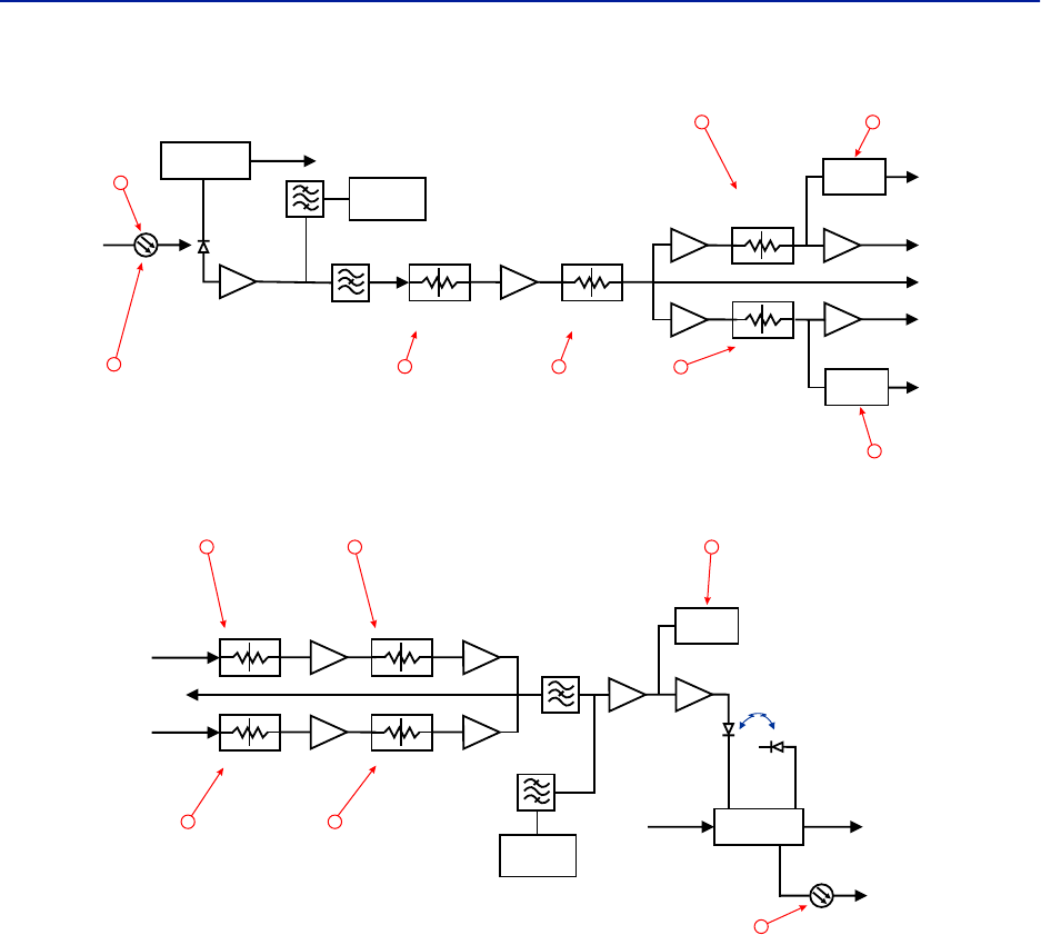
DAS Software Configuration
78
Figure 80 FOI Uplink Measurement Locations
Figure 81 FOI Downlink Measurement Locations
DETECTOR
DETECTOR
CURRENT
SENSOR
ETHERNET
MODEM
OPTO IN
RX-LVL
UL OUT 2
UL OUT 1
TP UL
Attenuator
Common 1
PHOTO
DETECTOR
Attenuator
Common 2
Attenuator
Uplink 1
Attenuator
Uplink 2
STEP ATT STEP ATT
STEP ATT
STEP ATT
RX POWER 1
RX POWER 2
1
3
4
10 11
12
13
14
DETECTOR
LASER
DRIVER
ETHERNET
MODEM
OPTO OUT
DETECTOR
MONITOR
TX-LVL
DL IN 1
DL IN 2
TP DL
STEP ATT
Attenuator 1
Downlink 1
Attenuator 1
Downlink 2
Attenuator 2
Downlink 1
Attenuator 2
Downlink 2
STEP ATT
STEP ATT
STEP ATT
2
67
8 9
15
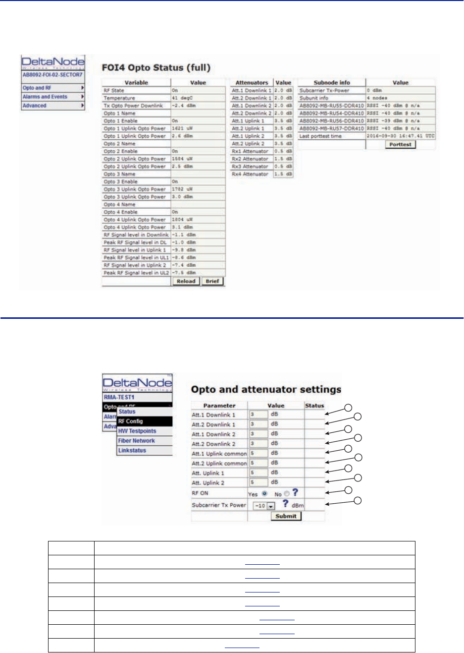
Fiber Distributed Antenna System (Fiber DAS)
79
Figure 82 FOI Opto Status DOI401
FOI Opto and Attenuator Settings
This page will allow changes to be made to the FOI values
Figure 83 FOI Opto and Attenuator Settings
Item Description
1 Downlink path 1 attenuator #1. See item 1 in
Figure 84
for measurement location.
2 Downlink path 1 attenuator #2. See item 2 in
Figure 84
for location on the FOI circuitry.
3 Downlink path 2 attenuator #1. See item 3 in
Figure 84
for location on the FOI circuitry.
4 Downlink path 2 attenuator #2. See item 4 in
Figure 84
for location on the FOI circuitry.
5 Uplink common path attenuator #1. See item 5 in
Figure 85
for location on the FOI circuitry.
6 Uplink common path attenuator #2. See item 6 in
Figure 85
for location on the FOI circuitry.
7 Uplink path 1 attenuator. See item 7 in
Figure 85
for location on the FOI circuitry.
1
2
3
4
5
6
7
8
9
10
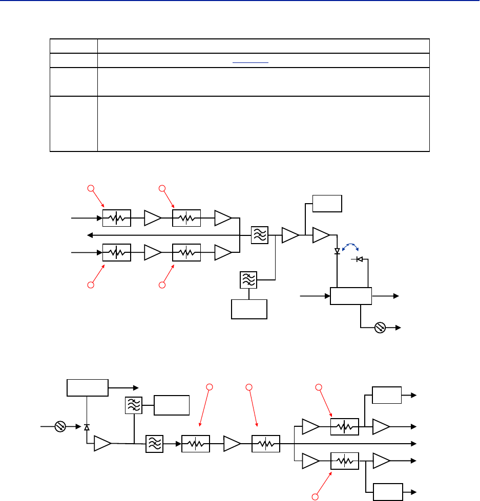
DAS Software Configuration
80
Figure 84 Downlink Opto and Attenuator Settings
Figure 85 Uplink Opto and Attenuator Settings
8 Uplink path 2 attenuator. See item 8 in
Figure 85
for location on the FOI circuitry.
9RF ON Yes set the UL values as selected above. RF No turns off laser.
Note: Setting to “No” will disconnect connectivity to the remote(s)
10
Subcarrier TX Power is used for the communications and control signaling of the DAS.
Default setting is -10dBm for single port FOI cards and 0dBm for the 4-port FOI card.
The value may need to be changed in situations where fiber loss is near the maximum
and communications issues arise. Unnecessarily increasing the subcarrier TX power
may affect RF performance of the DAS.
Item Description
DETECTOR
LASER
DRIVER
ETHERNET
MODEM
OPTO OUT
DETECTOR
MONITOR
TX-LVL
DL IN 1
DL IN 2
TP DL
STEP ATT
Attenuator 1
Downlink 1
Attenuator 1
Downlink 2
Attenuator 2
Downlink 1
Attenuator 2
Downlink 2
STEP ATT
STEP ATT
STEP ATT
12
34
DETECTOR
DETECTOR
CURRENT
SENSOR
ETHERNET
MODEM
OPTO IN
RX-LVL
UL OUT 2
UL OUT 1
TP UL
Attenuator
Common 1
PHOTO
DETECTOR
Attenuator
Common 2
Attenuator
Uplink 1
Attenuator
Uplink 2
STEP ATT STEP ATT
STEP ATT
STEP ATT
RX POWER 1
RX POWER 2
6
57
8
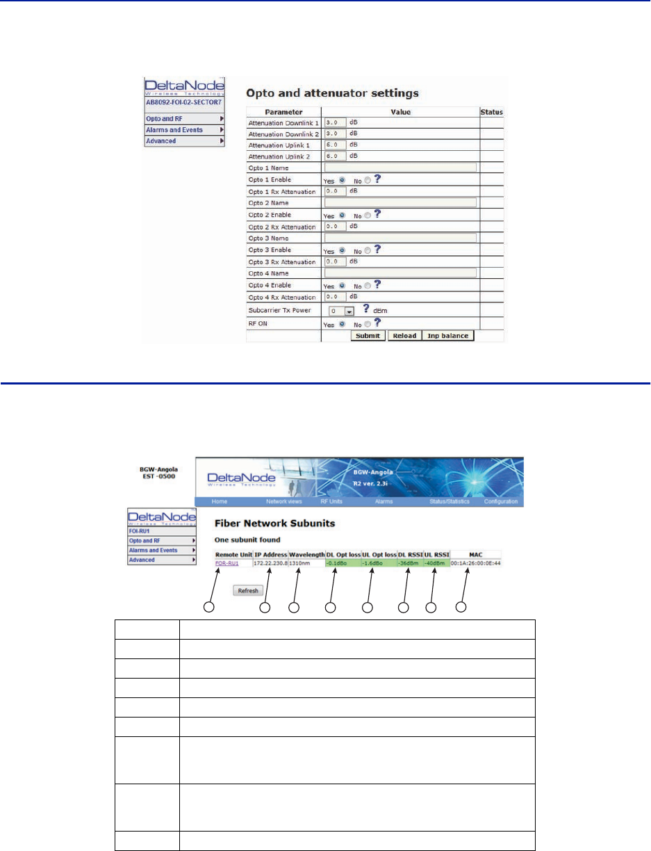
Fiber Distributed Antenna System (Fiber DAS)
81
Figure 86 DOI401 FOI Opto and Attenuator Settings
FOI Fiber Network Subunits
This page provides a visual indication on the fiber link status for each connection to the FOI.
Figure 87 FOI Fiber Network Subunits
Item Description
1 Selecting the remote link will direct the browser to the Remote Unit page.
2 Network IP address of the FOI card.
3Optical wavelength of the transmit laser in the FOI card.
4Subcarrier optical loss between the FOI and FOR in the downlink path.
5Subcarrier optical loss between the FOR and FOI in the uplink path.
6
Subcarrier power to the modem in the downlink path of the FOR - Range
should be -30 to -60. If the level is too high or too low communication and
other system problems may occur.
7
Subcarrier power to the modem in the uplink path of the FOI - Range should
be -30 to -60. If the level is too high or too low communication and other
system problems may occur.
8 MAC address of the FOI card
123456 7 8
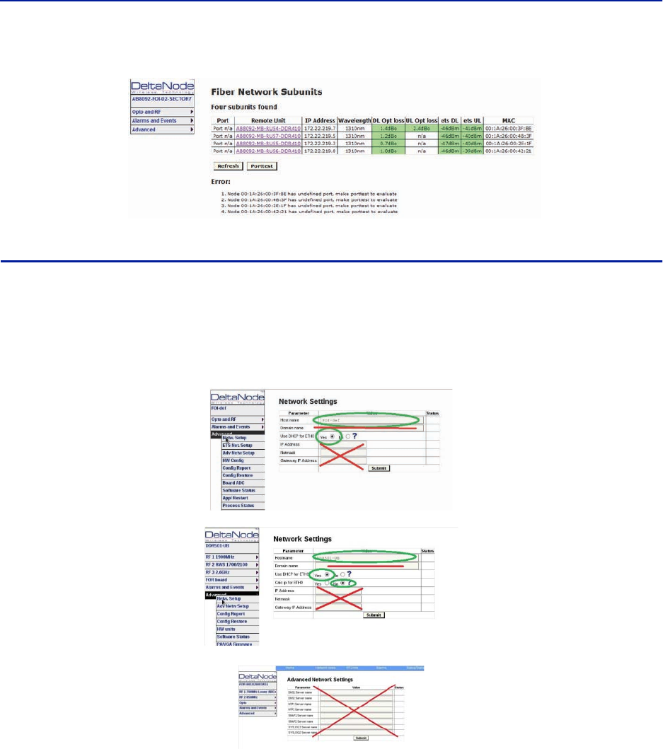
DAS Software Configuration
82
Figure 88 DOI401 FOI Fiber Network Subunits
FOI Network Setup
This page allows for manual override of network settings. Default configurations should be used with DHCP set to
Yes.
Note: Changing DHCP to “No” can cause loss of communications to the BIU and should only be used in
very specific situations. Do not enter IP configuration data in other associated settings.
Figure 89 FOI Network Settings
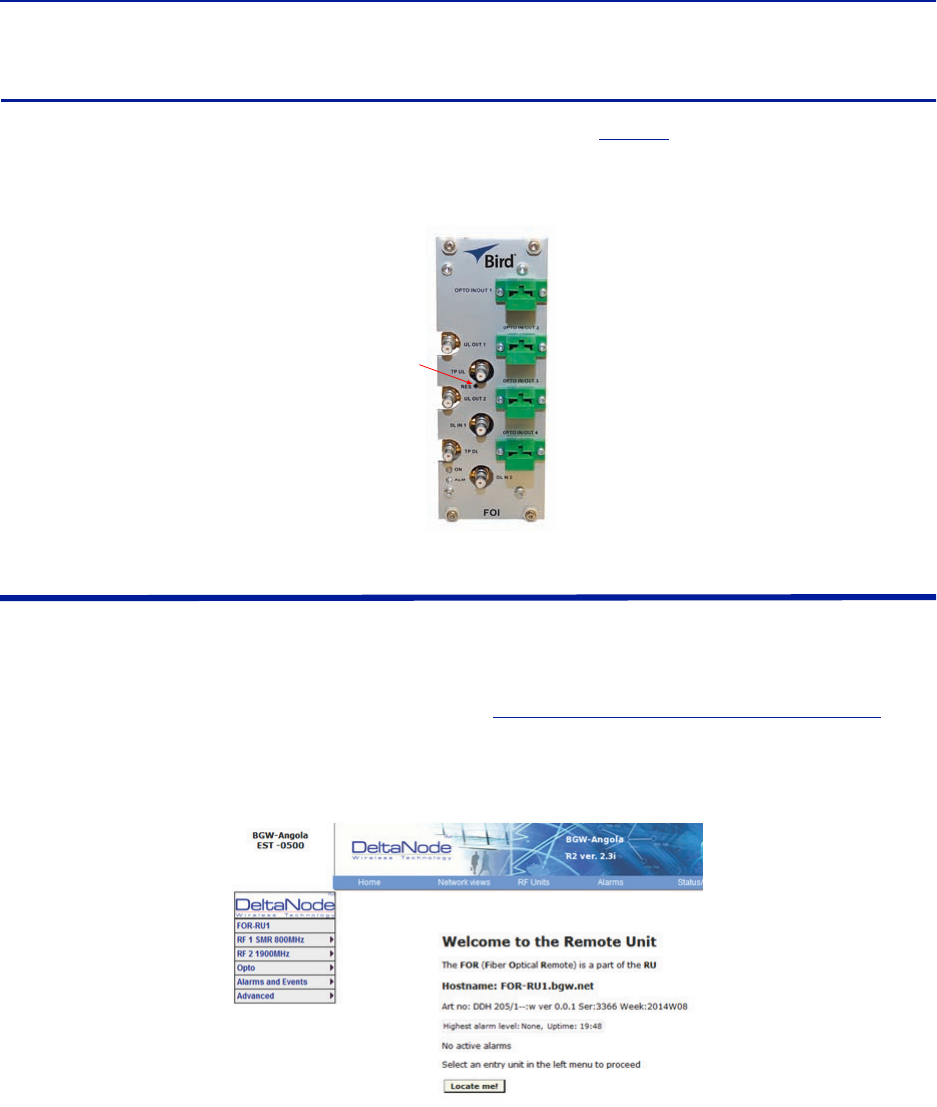
Fiber Distributed Antenna System (Fiber DAS)
83
FOI Reset to Factory Default
To reset the FOI to factory default, carefully press the “Reset” button (see
Figure 90
) for 10 seconds. This is helpful
when a card fails to appear in the Configuration menu.
Figure 90 FOI Reset Button
FOR
The initial screen for the FOR provides basic information such as name, serial number, part number and active
alarms. The Locate me! button causes an LED to flash on the chassis so that the unit can be identified in the field.
Note: If the fiber is just now connected to the FOI card, it could take up to 30 minutes for the FOI to
assign an IP address to the FOR. See section for
"Moving Remotes to Different FOI Port" on page 94
for
details on how to quicken the IP assignment.
Figure 91 FOR Welcome Screen
Reset
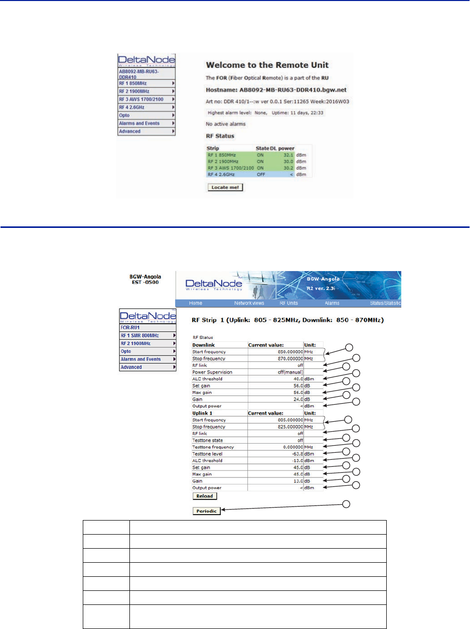
DAS Software Configuration
84
Figure 92 FOR Welcome Screen
RF Strip 1 XXX MHz Status
Figure 93 FOR RF 1 Status
Item Description
1 Downlink frequency band for the RF path/strip selected
2RF link setting for the downlink path: On or Off.
3 Downlink low power alarm turned On or Off.
4Setting of the downlink ALC threshold.
5 Gain setting for the RF path under review.
6Maximum allowed gain will always be the same as the set gain except in
special builds.
1
2
3
4
5
6
7
8
9
10
11
12
13
17
14
18
16
15
19
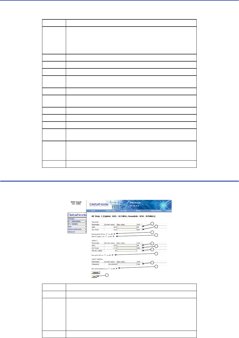
Fiber Distributed Antenna System (Fiber DAS)
85
RF Strip 1 XXX MHz Configuration
Figure 94 FOR RF 1 Configuration
7
The amount of actual gain used by the system. Might not achieve max gain
setting if ALC is in operation. If the set gain is 56 as it is above, RF is turned
on and the actual gain in line 7 is less than 56 then the system is being
overdriven and ALC is kicking in. Reduce gain. Suggest starting with the
value displayed in line 7 since this is the most gain that is being used.
8 Output power of the amplifier for the path under review.
9 Uplink frequency band for the RF path/strip selected
10 RF link setting for the uplink path: On or Off.
11 Status of uplink test tone signal. Test tone automatically turns off after 60
minutes.
12 Uplink test tone frequency setting.
13 Uplink test tone level. Not adjustable. Accounts for losses in internal
duplexers, if any.
14 Uplink ALC threshold setting.
15 Gain setting in the uplink path.
16 Maximum allowed gain set by the system.
17 Actual gain being used in the uplink path. The figure might not match gain
setting if ALC is in operation.
18
Uplink output to the FOI.
Note: If the uplink path is set to Off a reading of “<“ is
returned.
19 Periodic enables a constant update of the status screen.
Item Description
1Downlink gain setting for RF path under review.
2
Downlink ALC setting for RF path under review. The factory default is set at
the rated power of the remote unit (i.e. DDH is set to 43dB). The level could
be set lower for specific situations. Note that the factory level is set at the
antenna port. If remote is shutting down due to being over driven it is
suggested to reduce the ALC level by one or two dB to reduce the number
of alarms.
3 Turns downlink RF on or off.
Item Description
1
2
3
4
5
6
7
8
9
10
11
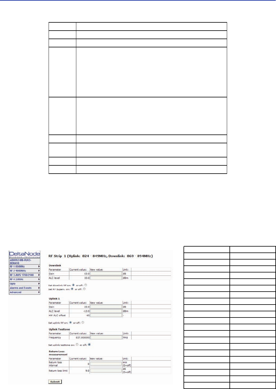
DAS Software Configuration
86
RF Strip 1 XXX MHz Configuration Software Version 3.9
Software release 3.9 introduces settable Return Loss measurements and control over alarms. The default interval
setting is “0” indicating the return loss alarm feature is turned off. Return loss alarms are often disabled when there
is a passive antenna network installed beyond the remote.
The default Return Loss setting is "9". The remote will start shutting down and/or PA damage can result with a
return loss of lower than 6.
Figure 95 FOR RF 1 Configuration, Software Version 3.9
4 Turns downlink low power alarm on or off.
5 Uplink gain setting for RF path under review.
6
Uplink ALC setting for RF path under review. This is the threshold at which
the system will start reducing further gain to prevent increases in uplink RF
to the FOI. After 10dB decrease in gain an uplink alarm will be triggered
Note: Should be left a factory default. Only change if FOR
uplink gain is changed. If gain is increased on FOR uplink
then the same value should be decreased on the ALC.
Example: Changing the UL FOR gain from 12 to 17 would require ALC to be
changed from -13 to -18.
7
Hardware ALC offset measured in tenths of a dB. Default setting of 60
(6dBm) should be used for most applications. Should the software not be
able to reduce uplink gain fast enough after the ALC threshold has been
exceed, hardware attenuation will be added to protect the uplink path. In
the example above, the hardware attenuation will trigger at -7dBm (-
13dBm ALC threshold minus 6dBm HW ALC offset = -7dBm)
8 Turns uplink RF on or off.
9Sets uplink test tone frequency. Must be within uplink frequency limits of
the RF module.
10 Turns on uplink test tone. Test tone times out after 60 minutes.
11 Retrieves current FOR settings from system.
Return Loss (db) VSWR
9.542 2.00
9.262 2.05
8.999 2.10
8.752 2.15
8.519 2.20
8.299 2.25
8.091 2.30
7.894 2.35
7.707 2.40
7.529 2.45
7.360 2.50
7.198 2.55
7.044 2.60
6.896 2.65
6.755 2.70
6.620 2.75
6.490 2.80
6.366 2.85
6.246 2.90
6.131 2.95
6.021 3.00
Item Description
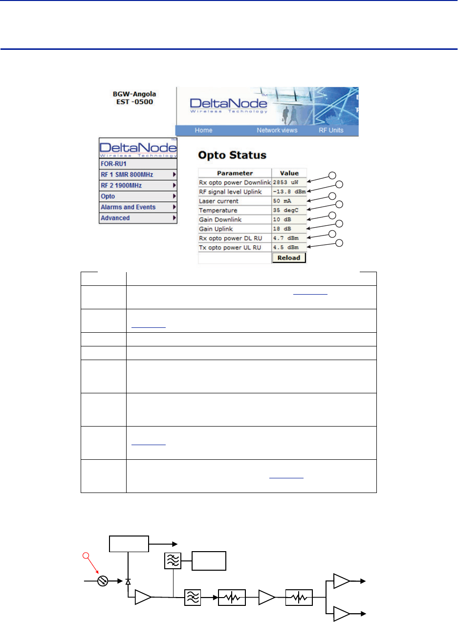
Fiber Distributed Antenna System (Fiber DAS)
87
FOR Opto Status
Figure 96 FOR Opto Status
Figure 97 FOR Downlink Schematic
Item Description
1Optical power received from the FOI. See item 1 in
Figure 97
for
measurement location.
2Uplink signal being fed into the FOR uplink laser circuit. See item 2 in
Figure 98
for measurement location.
3Laser current for the Remote Unit FOR. Should be less than 50mA.
4Temperature of the Remote Unit FOR board.
5
Total gain of the FOR in the downlink. Note that RF Out 1 and 2 are wide
band (FM to 2600MHz) that feed band specific RF amplifiers in the following
VGA stage.
6
Total gain of the FOR in the uplink path. Note that RF In1 and In2 are wide
band (FM to 2600MHz) that are signals from the uplink frequency specific
amplifiers.
7
Calculated downlink signal being received from the FOI. See item 1 in
Figure 97
for measurement location. Takes into consideration optical
wavelength and temperature compensation.
8
Calculated uplink signal being transmitted to the FOI (FOR input from VGA +
FOR uplink gain/attenuation). See item 3 in
Figure 98
for measurement
location.
1
2
3
4
5
6
7
8
CURRENT
SENSOR
ETHERNET
MODEM
OPTO IN
RX-LVL
RF OUT 1
RF OUT 2
PHOTO
DETECTOR
STEP ATT STEP ATT
1
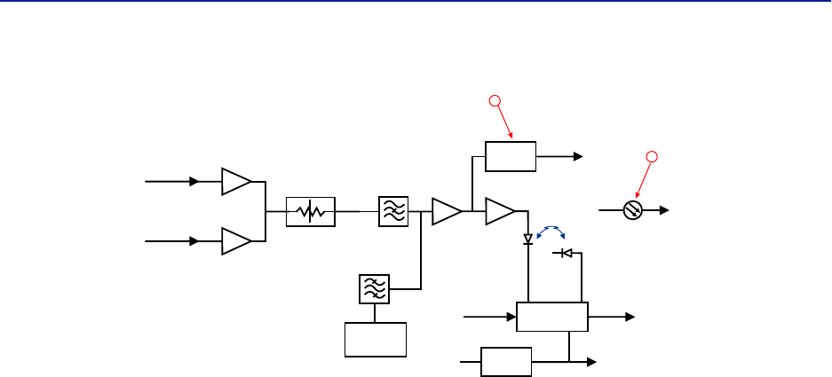
DAS Software Configuration
88
Figure 98 FOR Uplink Schematic
LOG
DETECTOR
VOLTAGE
INVERTER
LASER
DRIVER
ETHERNET
MODEM
OPTO OUT
TX-CURR
MONITOR
DIODE
LASER
DIODE
TX POW
TO
PHOTO DIODE
TX-LVL
+5 V -5 V
RF IN 1
RF IN 2 STEP ATT
2
3
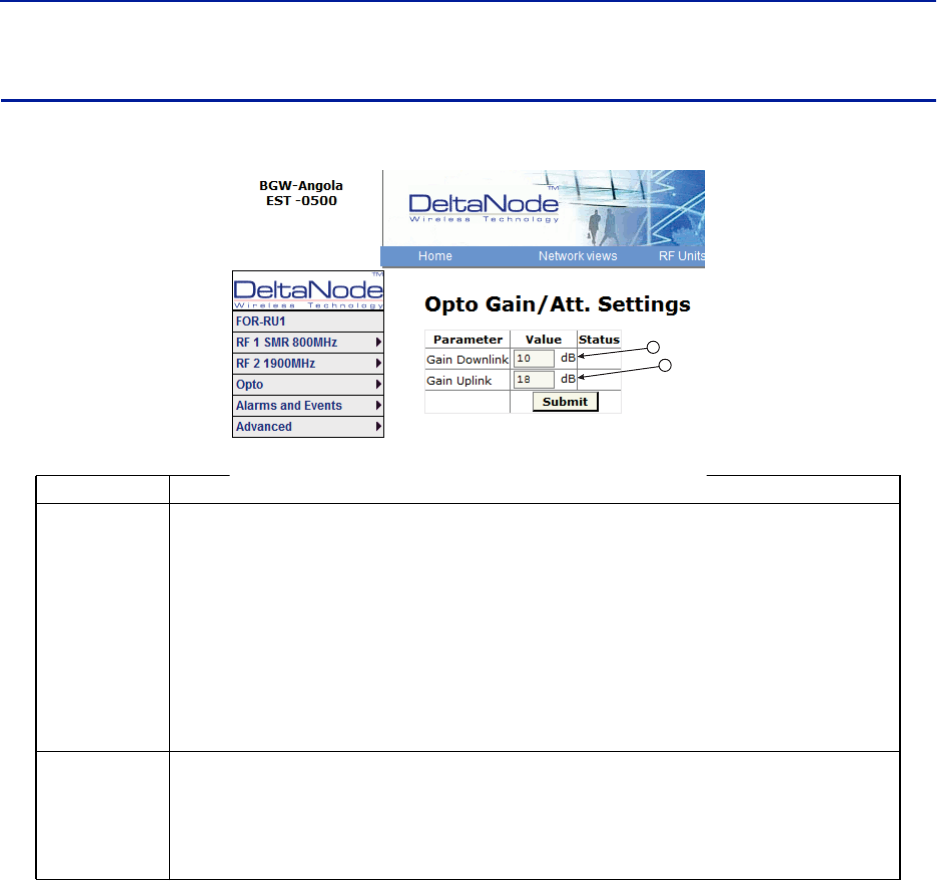
Fiber Distributed Antenna System (Fiber DAS)
89
FOR Opto Gain and Attenuation Settings
Figure 99 FOR Opto Gain Settings
Item Description
1
FOR gain in the downlink path. Range is typically from -20 to +20. FOR downlink path has inherent/raw gain of
+20dB (FM to 2600MHz).
A setting of +20 indicates no attenuation so FOR will have +20dB gain (+20dB gain minus 0dB
attenuation).
A setting of +10 will have 10 of attenuation so this stage will have 10dBm of gain (+20dB gain
minus 10dB of attenuation).
A setting of 0 will have 20dB of attenuation so this stage will have unity gain (+20dB gain minus
20dB of attenuation).
A setting of -10 will have 30dB of attenuation so this stage will have 10dB of loss (+20dB gain minus
30dB of attenuation).
A setting of -20 will have 40dB of attenuation so this stage will have 20dB of loss (+20dB gain minus
40dB of attenuation).
2
FOR gain in the uplink path. Range is typically from 0 to +20dBm (FM to 2600MHz).
A setting of +20 will have full gain of +20dBm.
A setting of +10 will have +10dB gain.
A setting of 0 will have no gain.
Factory default should be used unless high loss in fiber. Note that changes in Gain uplink will
require changes in the FOR UL ALC level.
1
2
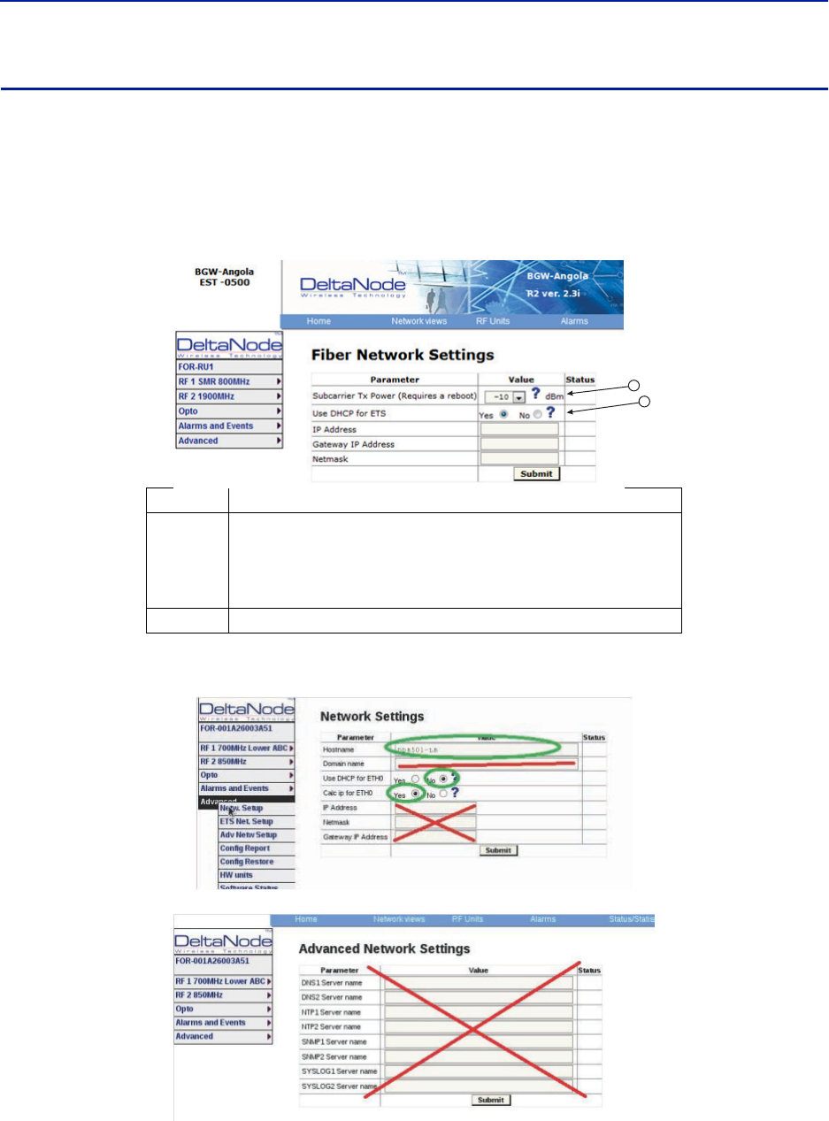
DAS Software Configuration
90
FOR Fiber Network Settings
This page allows for manual override of network settings. Default configurations should be used with DHCP set to
Yes.
Note: Changing DHCP to “No” can cause loss of communications to the BIU and should only be used in
very specific situations. Do not enter IP configuration data in other associated settings.
Figure 100 FOR Network Settings
Figure 101 More FOR Network Settings
ITem Description
1
Subcarrier Tx Power is used for the communications and control signaling of
the DAS. Default setting is -10. The value may need to be changed in
situations where fiber loss is near the maximum and communications issues
arise. Unnecessarily increasing the subcarrier TX power may affect RF
performance of the DAS.
2Default seeing of Yes should be used except for special applications.
1
2
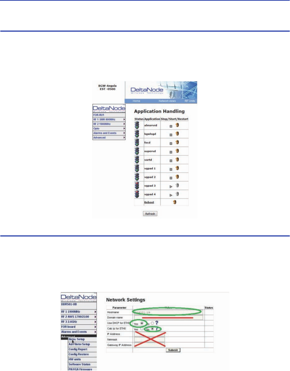
Fiber Distributed Antenna System (Fiber DAS)
91
FOR Application Handling
The application handling page allows for software reset and rebooting functions.
Note: Only the Reboot command should be used by the technician. All other functions should only be
used under supervision of Bird engineering as they may cause data corruption if not initiated properly.
Figure 102 FOR Application Handling
Slave FOR
A Slave FOR is when a remote has a second FOR installed. The Slave FOR is most likely to be used when the remote
is configured for MIMO or has multiple amplifiers in the same band or has redundant fiber.
Settings for the Slave FOR is the same as the main FOR except, “Calc ip for ETH0 is set to “No”.
Figure 103 Slave FOR Network Settings
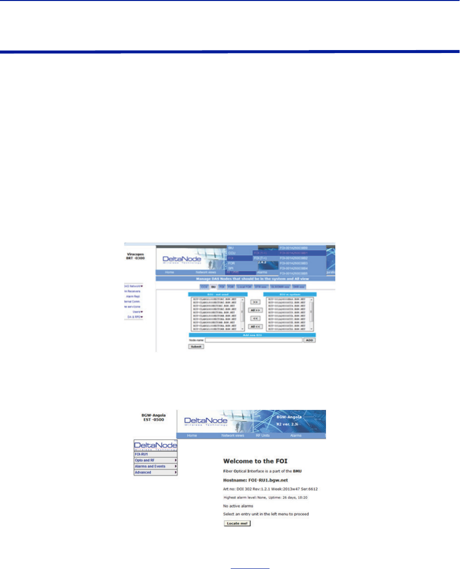
DAS Software Configuration
92
Naming Components
Proper naming of individual components in the DAS is critical to troubleshooting. A recommendation is to start all
component names with their function such as "BIU", "FOI" or "FOR". For example: "BIU-850Sector1".
You may use any combination of alphanumeric characters and the special character of dash "-". Do not use any
other special characters or space.
0 through 9
a through z
A through Z
-
Component names are limited to 56 characters.
1. Select the component to be named from the Configuration menu.
Figure 104 Component Selection
2. Use the Locate Me button to verify which cards is being accessed.
Figure 105 Locate Me Button
3. Go to Advanced>Netw Setup
4. Enter the new card name in the Host Name field. See
Figure 106
.
5. Select submit.
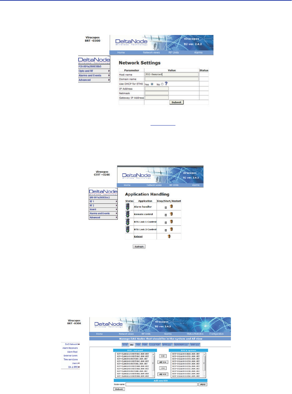
Fiber Distributed Antenna System (Fiber DAS)
93
Figure 106 Unit Naming
6. Go to Advanced > Appl restart.
7. Select the Reboot icon at the bottom of the menu. See
Figure 107
.
8. Select "YES- Restart Process"
Note: After rebooting, it can take up to 5 minutes before the unit shows up in the GUI.
Figure 107 Naming Reboot
9. After all the units have been renamed, go to the Configuration menu and select the correct card type.
10. Highlight all the cards in the right column that had name changes and then select “<<“. Select “Submit”
This will remove the old names from the DAS Configuration.
11. Highlight all the cards in the left column with the new names and then select “>>”. Select “Submit”.
This will move the new card names into the DAS configuration.
Table 69 Submit Newly Named Units
12. Select Network Views > All to confirm that all cards are now part of the configuration.
DAS Software Configuration
94
Moving Remotes to Different FOI Port
All DAS components are assigned IP addresses by the BGW. The FOR in the Remote is the assigned an IP address as
a subunit of the FOI to which it is connected. When the Remote is moved to a different FOI one of several actions
must take place:
1. The lease on the Remote IP address must be given time to expire. This could take up to 30 minutes. Once the
current IP lease expires, the new FOI will then assign the correct IP address to the Remote.
2. Manually power cycle the Remote. During the reboot process, the Remote will release the old IP address and
have the correct IP address assigned by the new FOI.
3. Communications to the remote can only occur when the remote has the correct IP address. Before moving the
fiber, access the FOR via the GUI. In the advanced settings, reboot the FOR. As soon as the reboot has been
initiated, quickly move the head end fiber to the new FOI port. When the Remote finishes the rebooting
process, the new FOI will assign the correct IP address.
Replacing Master Unit Cards
All DAS components are assigned IP addresses by the BGW. When a card is replaced, the card must be assigned a
new IP address by the BGW. On rare occasions, the BGW may have not be able to assign an IP address to the new
card. This is easily corrected by removing the card from the Master Unit chassis (with ESD strap attached) and then
re-install the card. The BGW will then assign the correct IP address.
Moving Master Unit Cards
Occasionally, cards need to be moved to different slots in the Master Unit.
1. Move the card to the new slot.
2. Ensure there is an Ethernet connection for the new card location on the backplane of the Master Unit.
3. Wait for the card to complete the boot process. If the card remains in the boot process (Green LED remains on
for approximately 2 seconds and then off for one second) then the IP address may not have been assigned.
Check Ethernet connection.
4. Log into the GUI to confirm software connectivity. On occasions the card will not show up after being moved.
a. Go to the Configuration menu and remove the card (move from right to left) and then Submit. See
Figure 108 on page 95
.
b. Select the card from the left menu and then add it back to the system on the right and then submit.
c. Go to the Home menu. Log out of the BGW and then log back in.
d. Go to Network Views and log into the card to verify GUI connection.
CAUTION
Always use an ESD strap when installation and removing cards. Failure to comply may
result in permanent disabling damage to the module.
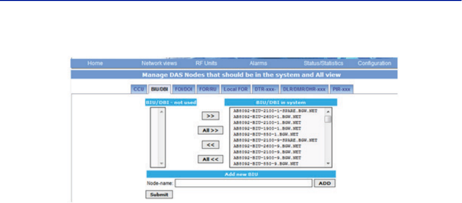
Fiber Distributed Antenna System (Fiber DAS)
95
Figure 108 Manage System Modules