Denon AVR 2805 User Manual AV SURROUND RECEIVER Manuals And Guides L0408578
DENON Receivers Manual L0408578 DENON Receivers Owner's Manual, DENON Receivers installation guides
User Manual: Denon AVR-2805 AVR-2805 DENON AV SURROUND RECEIVER - Manuals and Guides View the owners manual for your DENON AV SURROUND RECEIVER #AVR2805. Home:Electronics Parts:Denon Parts:Denon AV SURROUND RECEIVER Manual
Open the PDF directly: View PDF ![]() .
.
Page Count: 99
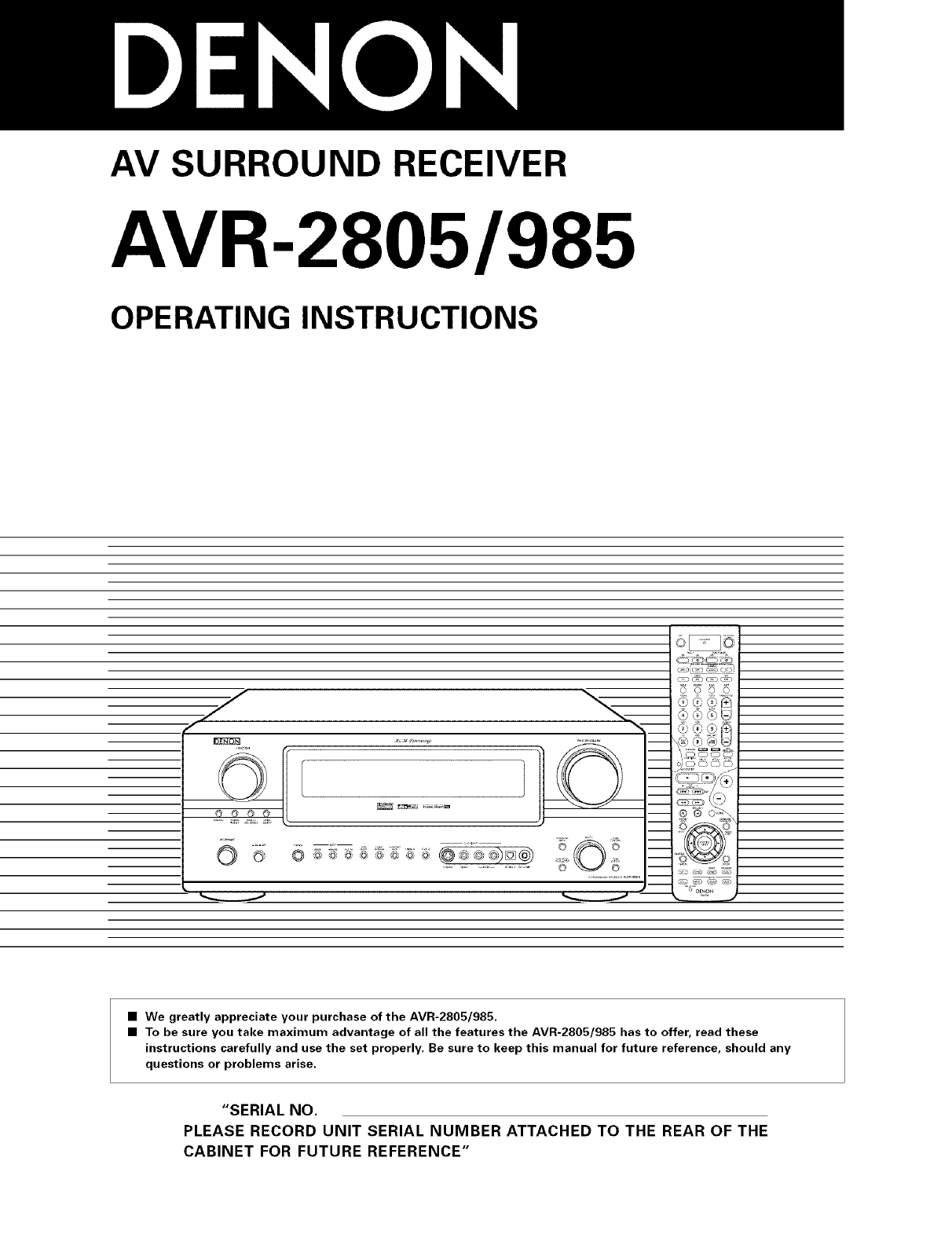
AV SURROUND RECEIVER
AVR-2805/985
OPERATING INSTRUCTIONS
J
•We greatly appreciate your purchase of the AVR-2805/985.
•To be sure you take maximum advantage of all the features the AVR-2805/985 has to offer, read these
instructions carefully and use the set properly. Be sure to keep this manual for future reference, should any
questions or problems arise.
"SERIAL NO.
PLEASE RECORD UNIT SERIAL NUMBER ATTACHED TO THE REAR OF THE
CABINET FOR FUTURE REFERENCE"
• SAFETY PRECAUTIONS
WARNING:
TO PREVENT FIRE OR SHOCK HAZARD, DO NOT EXPOSE
THIS APPLIANCE TO RAIN OR MOISTURE.
CAUTION: TO REDUCE THE RISK OF ELECTRIC SHOCK, DO
NOT REMOVE COVER (OR BACK). NO USER-
SERVICEABLE PARTS INSIDE. REFER SERVICING
TO QUALIFIED SERVICE PERSONNEL.
AThe lightning flash with arrewhead symbel, within an
equilateral triangle, is intended te alert the user to the
presence of uninsulated "dangerous voltage" within
the product's enclesure that may be ef sufficient
magnitude to censtitute a risk ef electric sheck te
persons.
AThe exclamation point within an equilateral triangle is
intended te alert the user to the presence ef important
operating and maintenance (servicing) instructions in
the literature accempanying the appliance.
CAUTION
TO PREVENT ELECTRIC SHOCK, MATCH WIDE BLADE OF PLUG
TO WIDE SLOT, FULLY INSERT.
ATTENTION
POUR EVITER LES CHOCS ELECTRIQUES, INTERODUIRE LA
LAME LA PLUS LARGE DE LA FICHE DANS LA BORNE
CORRESPONDANTE DE LA PRISE ET POUSSER JUSQU' AU
FOND.
This device complies with Part 15 of the FCC Rules. Operation is subject to
the following two conditions: (1) This device may not cause harmful
interference, and (2) this device must accept any interference received,
including interference that may cause undesired operation.
This Class B digital apparatus meets all requirements of the Canadian
Interference-Causing Equipment Regulations.
Cet appareil numerique de la classe B respecte toutes les exigences du
Reglement sur le materiel brouilleur du Canada.
•NOTE ON USE /OBSERVATIONS RELATIVES A L'UTILISATION
• Avoid high temperatures.
Allow for sufficient heat dispersion when
installed on a rack.
• Eviter des temperatures 6levees
Tenir compte d'une dispersion de chaleur
suffisante lots de I'installation sur une etagere.
• Handle the power cord carefully.
Hold the plug when unplugging the cord.
• Manipuler le cordon d'alimentation avec
precaution.
Tenir la prise lots du d¢branchement du cordon.
• Keep the set free from moisture, water, and
dust.
• Proteger I'appareil contre I'humidite, I'eau et
lapoussiere.
• Unplug the power cord when not using the set
for long periods of time.
• Deblancher le cordon d'alimentation Iorsque
I'appareil n'est pas utilis6 pendant de Iongues
p@iodes.
(For sets with ventilation holes)
• Do not obstruct the ventilation holes.
• Ne pas obstruer les trous d'aeration.
• Do not let foreign objects in the set.
• Ne pas laisser des obiets etrangers dans
I'appareil.
• Do not let insecticides, benzene, and thinner
come in contact with the set.
• Ne pas mettre en contact des insecticides, du
benzene et un diluant avec I'appareil.
• Never disassemble or modify the set in any
way.
• Ne jamais demonter ou modifier I'appareil
d'une maniere ou d'une autre.
SAFETY INSTRUCTIONS
1. Read Instructions - All the safety and operating instructions
should be read befere the preduct is operated.
2. Retain Instructions - The safety and eperating instructions
sheuld be retained for future reference.
3. Heed Warnings - All warnings on the product and in the
operating instructions sheuld be adhered to.
4. Fellow instructions - All operating and use instructiens should
be follewed.
5. Cleaning - Unplug this preduct frem the wall outlet before
cleaning. Do not use liquid cleaners or aerosol cleaners.
6. Attachments - Do not use attachments net recommended by
the preduct manufacturer as they may cause hazards.
7. Water and Meisture - Do not use this product near water - for
example, near a bath tub, wash bowl, kitchen sink, or laundry
tub; in a wet basement; or near a swimming poel; and the like.
8. Accesseries - Do not place this product on an unstable cart,
stand, triped, bracket, er table. The product may fall, causing
serious injury tea child er adult, and serieus damage te the
product. Use only with a cart, stand, tripod, bracket, or table
recommended by the manufacturer, or sold with the product.
Any mounting of the product should follew the manufacturer's
instructions, and sheuld use a
mounting accessory
recommended by the
manufacturer.
9. A product and cart
combination should be
moved with care. Quick
steps, excessive force,
and uneven surfaces may
cause the preduct and cart
combination to overturn.
10. Ventilatien - Slots and openings in the cabinet are provided for
ventilation and to ensure reliable operation of the preduct and to
protect it from overheating, and these openings must not be
blocked or covered. The openings should never be blecked by
placing the product on a bed, sofa, rug, or ether similar surface.
This product sheuld not be placed in a built-in installation such
as a bookcase or rack unless preper ventilation is provided or
the manufacturer's instructiens have been adhered te.
11. Power Sources - This product should be eperated only frem the
type of power source indicated on the marking label, if yeu are
net sure of the type of power supply te yeur home, consult yeur
product dealer or lecal pewer company. For products intended
te eperate frem battery power, er ether sources, refer te the
operating instructions.
12. Greunding or Polarizatien - This preduct may be equipped with
a polarized alternating-current line plug (a plug having one blade
wider than the ether). This plug will fit into the pewer outlet
only one way. This is a safety feature, if you are unable to
insert the plug fully into the outlet, try reversing the plug. If the
plug should still fail te fit, contact your electrician to replace yeur
obsolete eutlet. De net defeat the safety purpose of the
polarized plug.
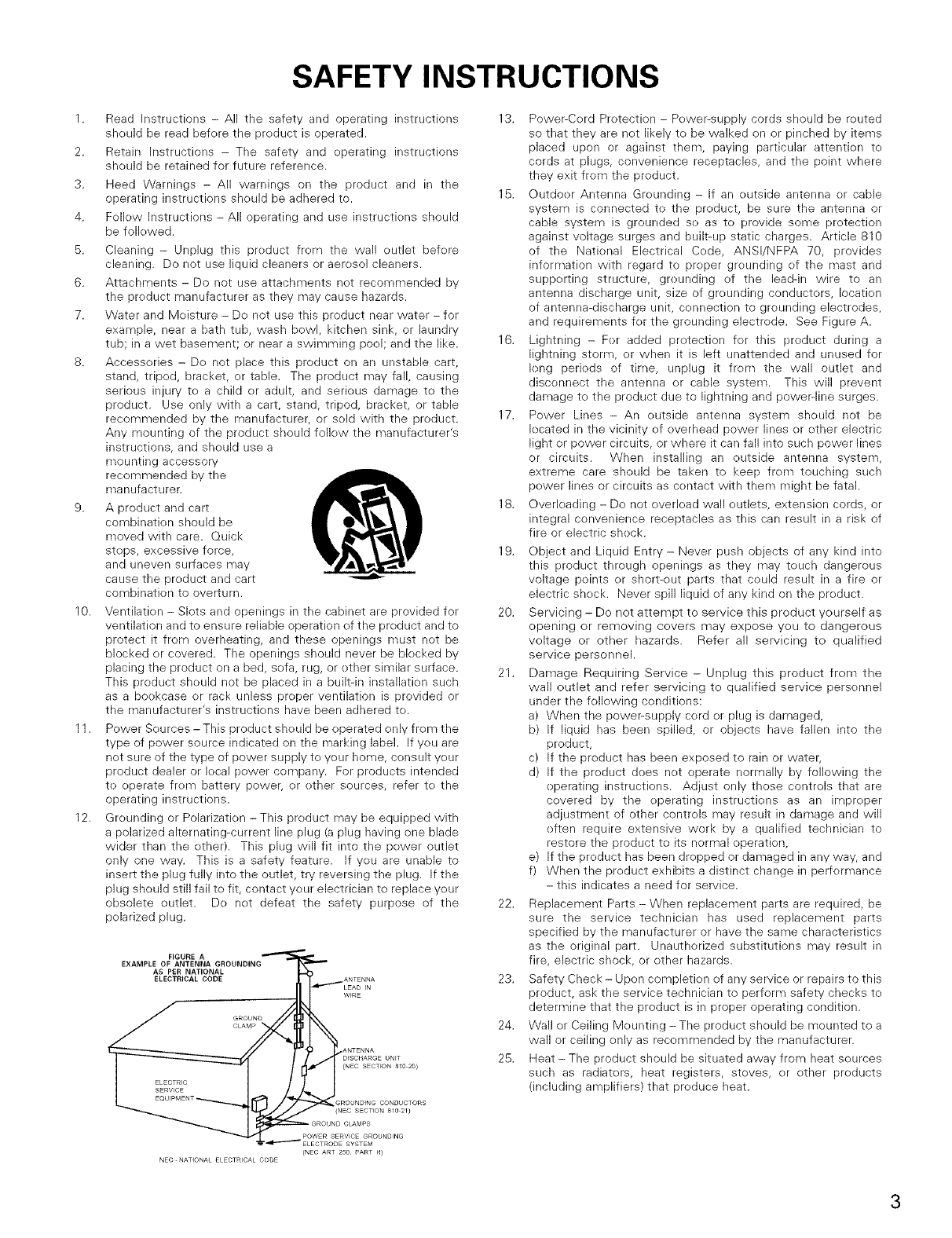
FIGURE A
EXAMPLE OF ANTENNA GROUNDING
AS PER NATIONAL
ELECTRICAL CODE ANTENNA
W_RE
GROUND
CLAMP
ANTENNA
DISCHARGE UNiT
(NEO SECTFON 81O2O)
GR©UN_ING CONDUCT,
{NE¢ SECTI©N 81O21}
GR©UN_ CLAMPS
P©WER SERVICE GR©UN_ING
SYSTEM
(NEC ART 25O PART H)
NEC NATI©NAL ELECTRICAL C©©E
13. Power:Cord Pretection - Power-supply cords should be reuted
so that they are net likely te be walked on or pinched by items
placed upon or against them, paying particular attentien te
cords at plugs, convenience receptacles, and the point where
they exit from the product.
15. Outdoer Antenna Grounding - If an outside antenna er cable
system is connected te the preduct, be sure the antenna or
cable system is grounded se as to provide some pretection
against voltage surges and built-up static charges. Article 810
of the Natienal Electrical Code, ANSI/NFPA 70, provides
information with regard to proper greunding ef the mast and
supporting structure, greunding of the lead-in wire to an
antenna discharge unit, size of grounding cenductors, Iocatien
of antenna-discharge unit, connection to grounding electrodes,
and requirements for the grounding electrede. See Figure A.
16. Lightning -Fer added pretection fer this preduct during a
lightning storm, or when it is left unattended and unused for
leng perieds of time, unplug it frem the wall outlet and
disconnect the antenna er cable system. This will prevent
damage te the product due to lightning and powerqine surges.
17. Power Lines - An eutside antenna system sheuld not be
located in the vicinity ef everhead power lines or other electric
light er power circuits, or where it can fall into such power lines
or circuits. When installing an eutside antenna system,
extreme care sheuld be taken to keep frem touching such
power lines or circuits as centact with them might be fatal.
18. Overleading - Do not everload wall eutlets, extension cords, or
integral convenience receptacles as this can result in a risk of
fire or electric sheck.
19. Object and Liquid Entry - Never push objects of any kind into
this product through openings as they may touch dangerous
voltage points or short-out parts that ceuld result in a fire or
electric sheck. Never spill liquid ef any kind on the product.
20. Servicing - Do not attempt to service this product yourself as
opening or removing covers may expose you to dangerous
voltage or other hazards. Refer all servicing to qualified
service personnel.
21. Damage Requiring Service - Unplug this product from the
wall outlet and refer servicing to qualified service persennel
under the fellewing cenditions:
a) When the power:supply cerd er plug is damaged,
b) If liquid has been spilled, or objects have fallen into the
product,
c) If the product has been exposed to rain or water,
d) If the preduct does net operate normally by following the
eperating instructions. Adjust only those contrels that are
covered by the operating instructiens as an impreper
adjustment of other contrels may result in damage and will
eften require extensive work by a qualified technician to
restore the product to its normal eperatien,
e) If the product has been drepped or damaged in any way, and
f) When the preduct exhibits a distinct change in perfermance
- this indicates a need for service.
22. Replacement Parts - When replacement parts are required, be
sure the service technician has used replacement parts
specified by the manufacturer or have the same characteristics
as the original part. Unauthorized substitutions may result in
fire, electric shock, or ether hazards.
23. Safety Check - Upen completien ef any service or repairs to this
product, ask the service technician to perform safety checks te
determine that the product is in proper operating cendition.
24. Wall or Ceiling Meunting - The product should be mounted to a
wall or ceiling enly as recemmended by the manufacturer.
25. Heat - The product should be situated away from heat seurces
such as radiators, heat registers, stoves, or other preducts
(including amplifiers) that preduce heat.
•INTRODUCTION
Thank yeu fer cheosing tile DENON AVR-2805/985 Digital A/V Surround Receiver. This remarkable component has been engineered to provide
superb surreund sound listening with heme theater seurces such as DVD, as well as previding eutstanding high fidelity repreduction ef your
favorite music seurces.
As this preduct is provided with an immense array ef features, we recommend that before you begin hookup and operatien that you review the
contents ef this manual before proceeding.
TABLE OF CONTENTS
Before Using ............................................................................................... 4
i2 Cautions on Installation ............................................................................... 4
Cautions on Handling .................................................................................. 5
Features ...................................................................................................... 5
Connections .......................................................................................... 6~14
Part Names and Functions ................................................................. 15~17
Setting up the system ........................................................................ 18~47
Remote Control Unit ........................................................................... 48~57
Operation ............................................................................................ 58~64
Multi Zone ........................................................................................... 65~67
ill Surround ............................................................................................. 68~75
@ DSP Surround Simulation ................................................................... 76~82
i13 Listening to the Radio ......................................................................... 83~84
i14 Last Function Memory .............................................................................. 85
i15 Initialization of the Microprocessor ........................................................... 85
i16 Troubleshooting ......................................................................................... 86
Additional Information ......................................................................... 87~97
Specifications ............................................................................................ 98
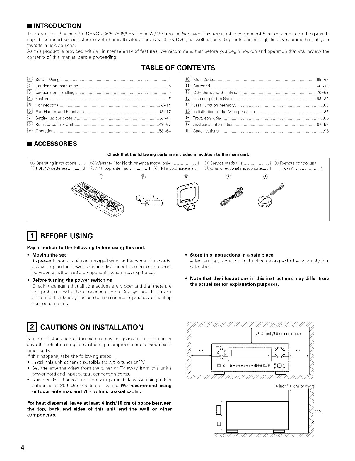
•ACCESSORIES
Check that the following parts are included in addition to the main unit:
Operating instructions ....... 1 2_ Warranty ( for North America model only ).................... 1 _ Service station list ..................... 1 4_ Remote control unit
(5: R6P/AA batteries ............. 3 (6: AM loop antenna .................. 1 (7: FM indoor antenna..,1 (8: Omnidirectional microphone.......1 (RC-974) ..................... 1
BEFORE USING
Pay attention to the following before using this unit:
•Moving the set
To prevent short circuits or damaged wires in the connection cords,
always unplug the power cord and disconnect the cennection cords
between all other audie components when moving the set.
•Before turning the power switch on
Check ence again that all cennectiens are preper and that there are
net preblems with the connection cords. Always set the power
switch to the standby pesitien before connecting and disconnecting
connectien cerds.
• Store this instructions in a safe place.
After reading, store this instructions along with the warranty in a
safe place.
•Note that the illustrations in this instructions may differ from
the actual set for explanation purposes.
CAUTIONS ON INSTALLATION
Noise or disturbance of the picture may be generated if this unit or
any ether electronic equipment using microprecessers is used near a
tuner or TV.
If this happens, take the fellewing steps:
• Install this unit as far as possible frem the tuner or TV.
• Set the antenna wires from the tuner or TV away from this unit's
power cerd and input/output connectien cerds.
• Neise or disturbance tends to occur particularly when using indoor
antennas or 300 £2/ohms feeder wires. We recommend using
outdoor antennas and 75 £2/ohms coaxial cables.
For heat dispersal, leave at least 4 inch/10 cm of space between
the top, back and sides of this unit and the wall or other
components.
4inch 10 cm or more
Wall
[] CAUTIONS ON HANDLING
•Switching the input function when input jacks are not connected
A clicking noise may be produced if tile input function is switched
when nothing is cennected to the input jacks. If this happens, either
turn down the MASTER VOLUME contrel er connect components
te the input jacks.
•Muting of PRE OUT jacks, HEADPHONE jack and SPEAKER
terminals
The PRE OUT jacks, HEADPHONE jack and SPEAKER terminals
include a muting circuit. Because ef this, the eutput signals are
greatly reduced fer several secends after the power switch is
turned on or input function, surreund mode er any other-set-up is
changed. If the volume is turned up during this time, the output will
be very high after the muting circuit stops functioning. Always wait
until the muting circuit turns off befere adjusting the velume.
•Whenever the unit is in the STANDBY state, the apparatus is
still connected on AC line voltage.
Please be sure to turn the power off (lloff) when you leave
home for, say, a vacation.
[] FEATURES
1. Dolby Digital
Using advanced digital processing algorithms, Dolby Digital
prevides up te 5.1 channels ef wide-range, high fidelity surround
sound. Delby Digital is the default digital audio delivery system fer
DVD and North American DTV.
2. Dolby Pro Logic l]x compatibility
Dolby Pro Legic [ix furthers the matrix decoding technek)gy of
Delby Pre Logic [1 te decede audio signals recorded on twe
channels into up te 7.1 playback channels, including the surround
back channel. Dolby Pro Logic [ix alse allows 5.1-channel sources
te be played in up to 7.1 channels.
The mode can be selected according te the source. The Music
mede is best suited fer playing music,the Cinema mode for playing
mevies, and the Game mede for playing games. The Game mode
can enly be used with 2-channel audio seurces.
3. Dolby Pro Logic l] Game mode compatibility
In additien te the previeusly offered Music and Cinema modes, the
AVR-2805/985 also effers a Game mede optimum for games.
4. DTS (Digital Theater Systems)
DTS provides up te 5.1 channels ef wide-range, high fidelity
surround sound, from sources such as laser disc, DVD and
specially-encoded music discs.
5. DTS-ES Extended Surround and DTS Neo:6
The AVR-2805/985 can be decoded with DTS-ES Extended
Surround, a multi-channel fermat developed by Digital Theater
Systems Inc.
The AVR-2805/985 can be also decoded with DTS Nee:6, a
surround mode allowing 6.1 channels playback of regular stere<)
sources.
6. DTS 96/24 compatibility
The AVR-2805/985 can be decoded with seurces recerded in DTS
96/24, a multi-channel digital signal format develeped by Digital
Theater Systems Inc.
DTS 96/24 sources can be played in the multi-channel mede en the
AVR-2805/985 with high sound quality of 96 kHz/24 bits or 88.2
kHz/24 bits.
7. Pure Direct Mode/AL24 Processing
The AVR-2805/985 is equipped with a pure direct mede allewing
the effects ef the video and digital circuitry to be shut dewn when
playing CDs or records te achieve the ideal environment for analog
playback, resulting in extremely high quality music playback. It is
also equipped with AL24 processing which compensates the input
digital data to produce the near analeg waveferms which weuld be
in a nature with 24 bits quality. AL24 processing eperates when
PCM data such as CD is inputted.
8. Auto Setup/Room EQ
Use of the microphone for setup applications measures the
presence of speakers, the distance to the speakers, and other
information, and permits automatic setup. The characteristics
of each speaker can also be corrected.
9. Multi Zone Music Entertainment System
Multi Source Function:
This unit's Multi Seurce functien lets you select different audio
sources fer listening Different seurces can thus be enjoyed in the
main room (MAIN) and the subreom (ZONE2) simultaneously.
10.Future Sound Format Upgrade Capability via Eight Channel
Inputs & Outputs
Fer future multi-channel audio fermat(s), the AVR-2805/985 is
previded with 7.1 channel (seven main channels, plus ene lew
frequency effects channel) inputs, along with a full set ef 7.1
channel pre-amp outputs, centrolled by the 8 channel master
volume control. This assures future upgrade possibilities for any
future multi-channel sound fermat.
11.Front input Terminal
The unit is equipped with a Front Input connector for the
convenient connection of a video camera or other equipment.
12.Video Conversion Function
The AVR-2805/985 is equipped with a functien for up-cenverting
video signals.
Because of this, the AVR-2805/985's MONITOR OUT jack can be
connected to the moniter (TV) with a set ef cables effering a higher
quality cennectien, regardless of how the player and the AVR-
2805/985's video input jacks are connected.
13.Component Video Switching
In addition te composite video and "S" video switching, the AVR-
2805/985 provides 3 sets of component vide<) (Y, PB/CB, PR/CR)
inputs, and one set ef cempenent video outputs to the televisien,
for superior picture quality.
14.TRIGGER OUT
AVR-2805/985 is equipped with 2 systems of 12V TRIGGER
OUT connections. Each output can be activated upon the
selection of assigned. Main Zone inputs or zone2 inputs.
15.RS-232C Terminal
Includes a RS-232C port te support an AMX, Crestron integrated
control system.
16.AC INLET
Detachable AC CORD is used.
17.Auto Surround Mode
TMs function steres the surreund mode last used fer an input
signal in the memory and automatically sets that surround mode
the next time that signal is input.
18.Large-sized fluorescent display
Alarge-sized fluorescent display is used which also permits a
check of the input/output channels.
19.Audio delay
This is a function for delaying the audie signal with respect te the
video signal. (0 to 200 msec)
20.Preset Memory Tuning
56-Station AM/FM Randem Preset Memory tuning.
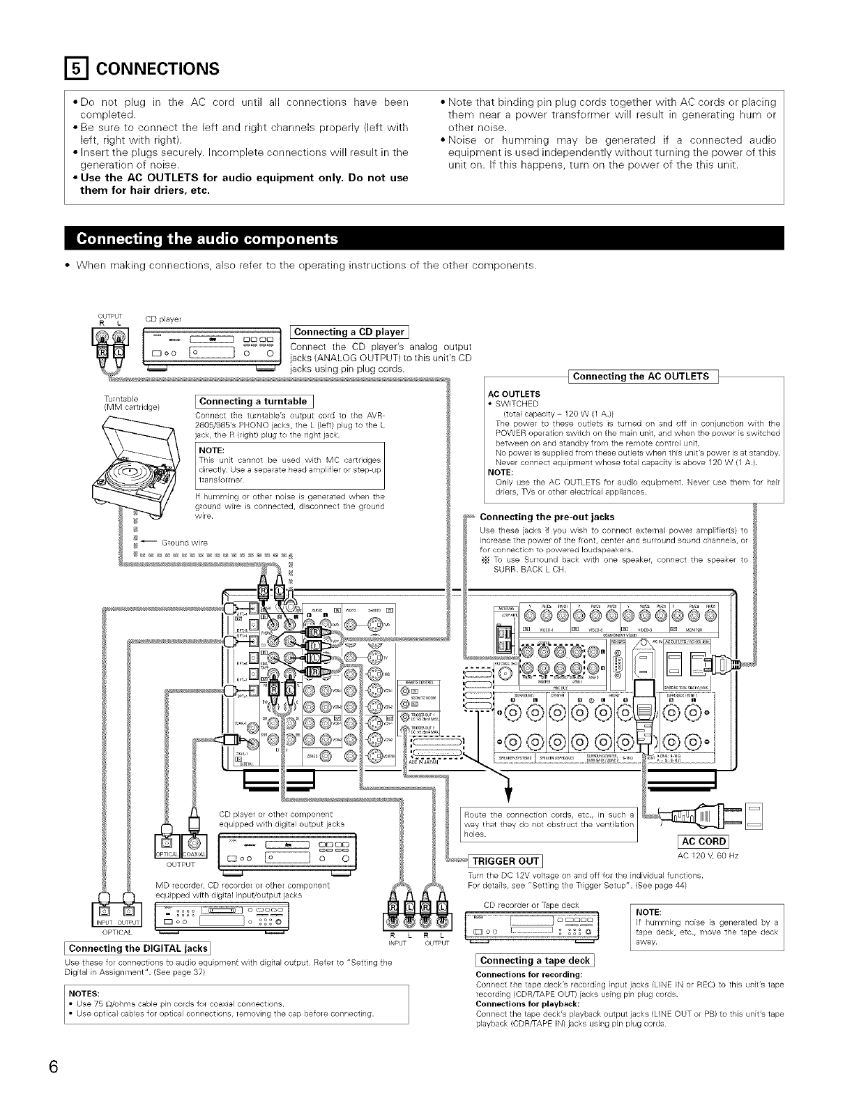
_'1 CONNECTIONS
•Do not plug in the AC cord until all connections have been
completed.
• Be sure to connect the left and right channels properly (left with
left, right with right).
• Insert the plugs securely. Incomplete connections will result in the
generation of noise.
•Use the AC OUTLETS for audio equipment only. Do not use
them for hair driers, etc.
•Nete that binding pin plug cords together with AC cords or placing
them near a power transfermer will result in generating hum er
other noise.
• Neise or humming may be generated if a connected audio
equipment is used independently without turning the power of this
unit on. If this happens, turn on the pewer of the this unit.
• When making connections, also refer to the operating instructiens of the other components.
OUTPUT CD player
R L
Turntable
(MM cartddge/ [Connecting a turntable ]
Connect the turntable's output cord to the AVR-
2805/985's PHONO jacks, the L (left) plug to the L
jack, the R (dght/plug to the right jack.
NOTE:
__la yi er"_t_.c_gepThisunit cannot be used with MC cartridges
directly. Use a separate head amplifier or step up
If humming or other noise is generated when the
ground wire is connected, disconnect the ground
wire.
_ Ground wire
IConnecting the AC OUTLETS t
AC OUTLETS
SWITCHED
(total capacity - 120 W (1 A.)/
The power to these outlets is turned on and off in conjunction with the
POWER operation switch on the main unit, and when the power is switched
between on and standby from the remote control unit.
driers, TVs or other electrical appliances.
Connecting the pre-out jacks
Use these jacks if you wish to connect external power amplifier(s) to
increase the power of the front, center and surround sound channels, or
for cor/nectior/ to powered loudspeakers.
•_ To use Surround back with one speaker, connect the speaker to
MD recorder, CD recorder or other component
OPTICAL _ R L
INPUT
I Connecting the DIGITAL jacks I
Use these for connections to audio equipment with digital output Refer to "Setting the
Digital in Assignment" (See page 37)
NOTES:
RL
OUTPUT
AC 120 V, 60 Hz
Turn the DC 12V voltage on and off for the individual functions.
For details, see "Setting the Tdgger Setup" (See page 441
CD recordel or Tape deck
83oo _o
I Connecting atape deck I
Connections for recording:
Connect the tape deck's recording input jacks (LINE Hq or REC/to tMs Uilit's tape
recording (CDR/TAPE OUT/jacks using pin plug cords.
Connections for playback:
Connect the tape deck's playback output jacks (LINE OUT or PB) to this unit's tape
playback (CDR/TAPE IN/jacks using pin plug cords
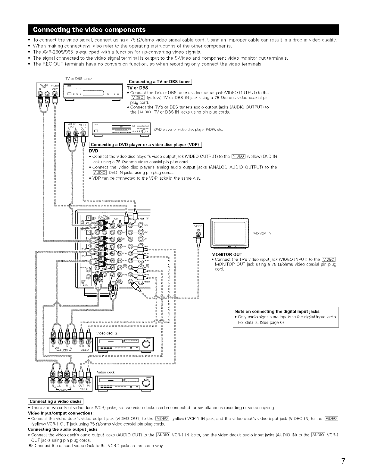
•To connect the video signal, connect using a 75 £_/ohms video signal cable cord. Using an impreper cable can result in a drop in video quality.
•When making connections, also refer to the operating instructiens of the other compenents.
• The AVR-2805/985 is equipped with a functien fer up-converting video signals.
• The signal connected to the video signal terminal is output to the S-Video and component video menitor out terminals.
• The REC OUT terminals have ne cenversion functien, se when recording only connect the video terminals.
TV oFDBS tuner
L OT
© o©
®
®
[ Connecting a TV or BBS tuner I
TV or DBS
• Connect the TV's or DBS tuner's video output jack (VIDEO OUTPUT) to the
[]_ (yellow) TV or DBS IN jack using a 75 _}/ohms video coaxial pin
plug cord.
• Connect the TV's or DBS tuner's audio output jacks (AUDIO OUTPUT) to
the _ TV or DBS IN jacks using pin plug cords.
VIDEO [ -- _- _ _ DVD player or wdeo drsc player (VDP/ etc
@_1 _ _-°_t '
_C_onnecting aDVD player or avideo disc player (VDP) ]
#_DVD
_•Connect the video disc player's video output jack (VIDEO OUTPUT) to the _ (yellow) DVD IN
/_ jack using a 75 _,Vohms video coaxial pin plug cord.
• Connect the video disc player's analog audio output jacks (ANALOG AUDIO OUTPUT) to the
DVD IN jacks using pin plug cords.
• VDP can be connected to the VDP jacks in the same way.
I
Videodeck 2
I _ I1_1 ....
ROUTL RIN L OUT IN _ _-_ O
I--AUDIO ,_ VIDEO _
VideodeckI
_AUDIO _ VIDEO _
MONITOR OUT
• Connect the TV's video input jack (VIDEO INPUT) to the
MONITOR OUT jack using a 75 _/ohms video coaxial pin plug
_ cord.
Note on connecting the digital input jacks
• Only audio signals are inputs to the digital input jacks.
For details. (See page 6)
IConnecting a video decks I
• There are two sets of video deck (VCR) jacks, so two video decks can be connected for simultaneous recording or video copying.
Video input/output connections:
• Connect the video deck's video output jack (VIDEO OUT) to the [_ (yellow) VCR-1 IN jack, and the video deck's video input jack (VIDEO IN) to the [_
(yellow) VCR-1 OUT jack using 75 _/ohms video coaxial pin plug cords.
Connecting the audio output jacks
• Connect the video deck's audio output jacks (AUDIO OUT) to the _ VCR-1 IN jacks, and the video deck's audio input jacks (AUDIO IN) to the _ VCR-1
OUT jacks using pin plug cords.
'_ Connect the second video deck to the VCR-2 jacks in the same way.
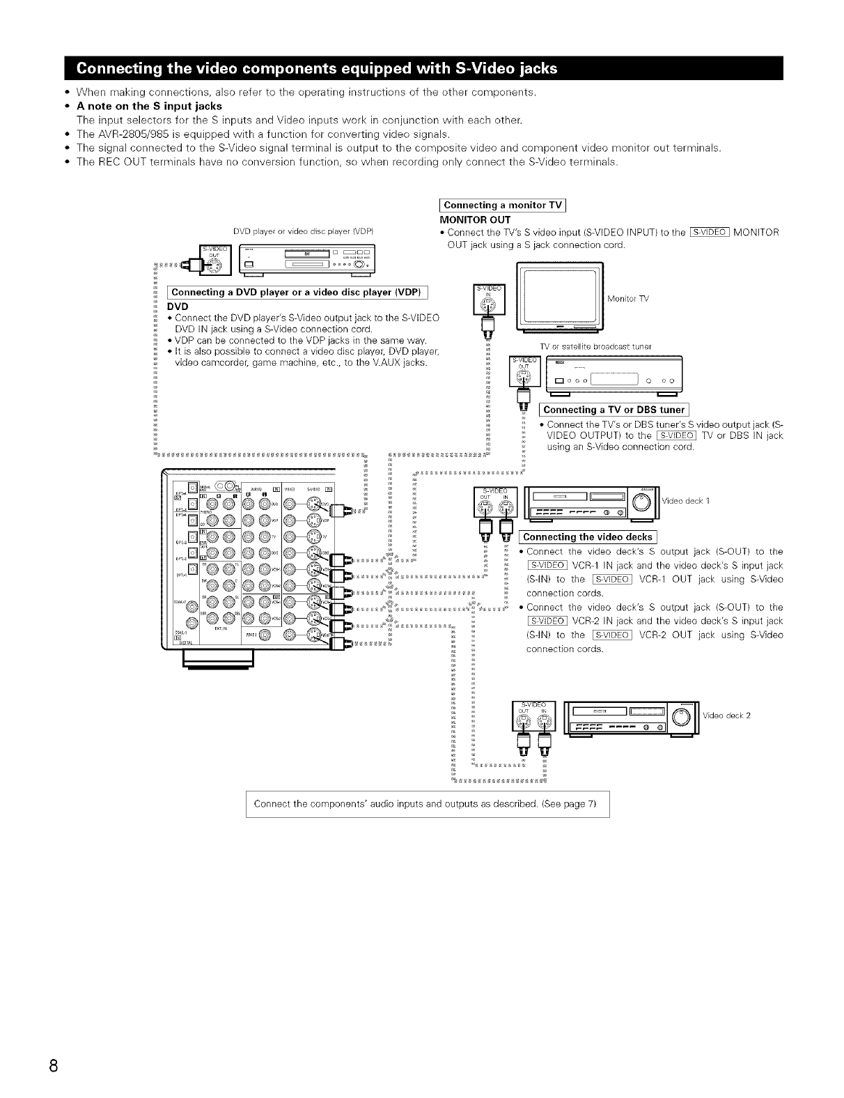
• When making connections, also refer to the operating instructions of the other components.
•A note on the S input jacks
The input selectors for the S inputs and Video inputs work in conjunction with each other.
• The AVR-2805/985 is equipped with a function for converting video signals.
• The signal connected to the S-Video signal terminal is output to the composite video and component video monitor out terminals.
• The REC OUT terminals have no conversion function, so when recording only connect the S-Video terminals.
DVD player or video disc player (VDP)
_ .... _O_o1
i_ I Connecting a DVD player or avideo disc player (VDP) I
_DVD
_ • Connect the DVD player's S-Video output jack to the S-VIDEO
DVD IN jack using a S-Video connection cord.
,_ • VDP can be connected to the VDP jacks in the same way.
;'_ • It is also possible to connect a video disc player, DVD player,
video camcorder, game machine, etc., to the V.AUX jacks.
IConnecting a monitor TV ]
MONITOR OUT
• Connect the TV's S video input (S-VIDEO INPUT) to the _ MONITOR
OUT jack using a S jack connection cord.
lI! :1Mon,,o
TV or satellite broadcasttune_
_Connecting a TV or DBS_ner ]
;_ • Connect the TV's or DBS tuner's S video output jack (S-
_ VIDEO OUTPUT) to the _ TV or DBS IN jack
using an S-Video connection cord.
S VIDEO (_'
_,, 8_, __ Videodeck 1
"_ S_ II1==== .... _ oll_ll
_[ Connecting the video decks ]
: • Connect the video deck's S output jack (S-OUT) to the
VCR-1 IN jack and the video deck's S input jack
(SqN) to the _ VCR-1 OUT jack using S-Video
connection cords.
• Connect the video deck's S output jack (S-OUT) to the
_ _ VCR-2 IN jack and the video deck's S input jack
(SqN) to the _ VCR-2 OUT jack using S-Video
: connection cords.
_ _ I ...... ::::::::::::::::::::::::::::(_ Videodeck2
_ _ I1_= _1 "_I1""
Connect the components' audio inputs and outputs as described. (See page 7) /
J
•When making connections, also refer to the eperating instructions of the ether components.
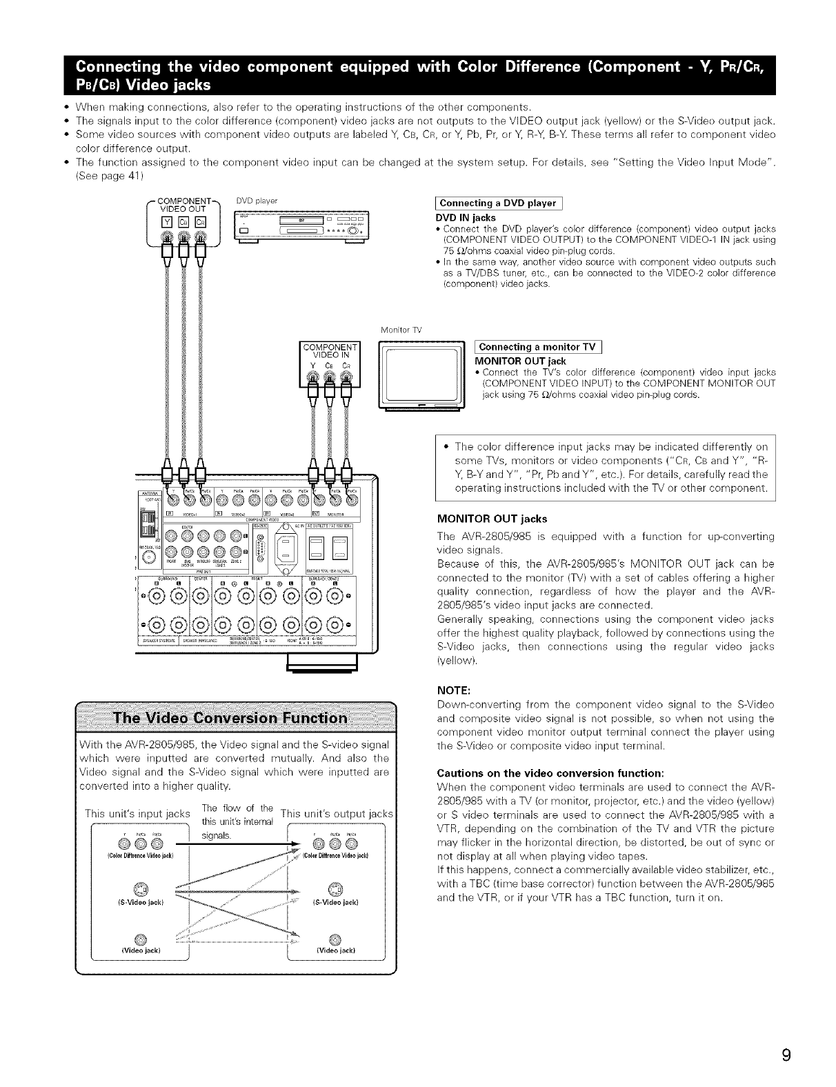
• The signals input to the celor difference (component) video jacks are net outputs to the VIDEO output jack (yeliew) or the S-Videe output jack.
• Some vide() sources with compenent video outputs are labeled Y, CB, CR, or Y, Pb, Pr, er Y, R-Y, B>4 These terms all refer to component vide()
color difference eutput
• The function assigned to the component video input can be changed at the system setup. For details, see "Setting the Video Input Mede'.
(See page 41 )
'-COMPONENT
VIDEO OUT
%@@
®6eee° " ..............
....==]] ,,_*- ,...................
o@®®©©@@i®© o
IConnecting a DVD player ]
DVD IN jacks
•Connect the DVD player's color difference (component) video output jacks
(COMPONENT VIDEO OUTPUT) to the COMPONENTVIDEO-1 IN jack using
x,,,v,.cords.
• In the same way, another video source with component video outputs such
I ... ,o.stun.r.etc.,,com.n.t,v=.
Y Ca OR MONITOR OUT jack
_, t I _®@',@ I • Connect the TV's color difference (component) video input jacks
_ (COMPONENT VIDEO INPUT)to the COMPONENT MONITOR OUT
jack using 75 _/ohrns coaxial video pin-plug cords.
• The color difference input jacks may be indicated differently on
some TVs, monitors or video components CCR, CB and Y", "R-
__ Y, B-Y and Y", "Pr, Pb and Y", etc.). For details, carefully read the
operating instructions included with the TV or other component.
MONITOR OUT jacks
,@@@@@@®@®°
i5!£i£ £i :iBi£!i£iii!!!!!!!!!!!!!!!!iii
!i !i !i !i !i !i !i !i !i !i !i !i !i !i !i !i !i !i !i !i !i !i !i !i
With the AVR-280B/985, the Video signal and the S-video signal
which were inputted are converted mutually. And also the
Video signal and the S-Video signal which were inputted are
converted into a higher quality.
The flow of the
This unit's input jacks This unit's output jacks
this unit's internal
e60 1 signals. : @@B
(ColorDiffrenceVideo jackl IColorDiffrenceVideo jack)
..... @
..... (S-Video jack)(S-Videojack)
The AVR-2805/985 is equipped with a function fer up-converting
video signals.
Because of this, the AVR-2805/985's MONITOR OUT jack can be
connected to the monitor (TV) with a set ef canes offering a higher
quality connectien, regardless ef hew the player and the AVR-
2805/985's video input jacks are cennected.
Generally speaking, cennections using the component vide() jacks
effer the highest quality playback, fe/ewed by connectiens using the
S-Videe jacks, then connectiens using the regular vide() jacks
(yellow).
NOTE:
Dewn-converting from the component vide() signal te the S-Video
and composite video signal is not possible, so when not using the
component video monitor output terminal connect the player using
the S-Video or composite vide() input terminal.
Cautions on the video conversion function:
When the component video terminals are used to connect the AVR-
2805/985 with a TV (or moniter, projector; etc.) and the video (yeliew)
er S video terminals are used to connect the AVR-2B05/985 with a
VTR, depending en the combination of the TV and VTR the picture
may flicker in the horizental direction, be distorted, be out of sync or
not display at all when playing vide() tapes.
If this happens, connect a cemmercially available video stabilizer, etc.,
with a TBC (time base correcter) function between the AVR-2BOB/9B5
and the VTR, er if yeur VTR has a TBC function, turn it en.
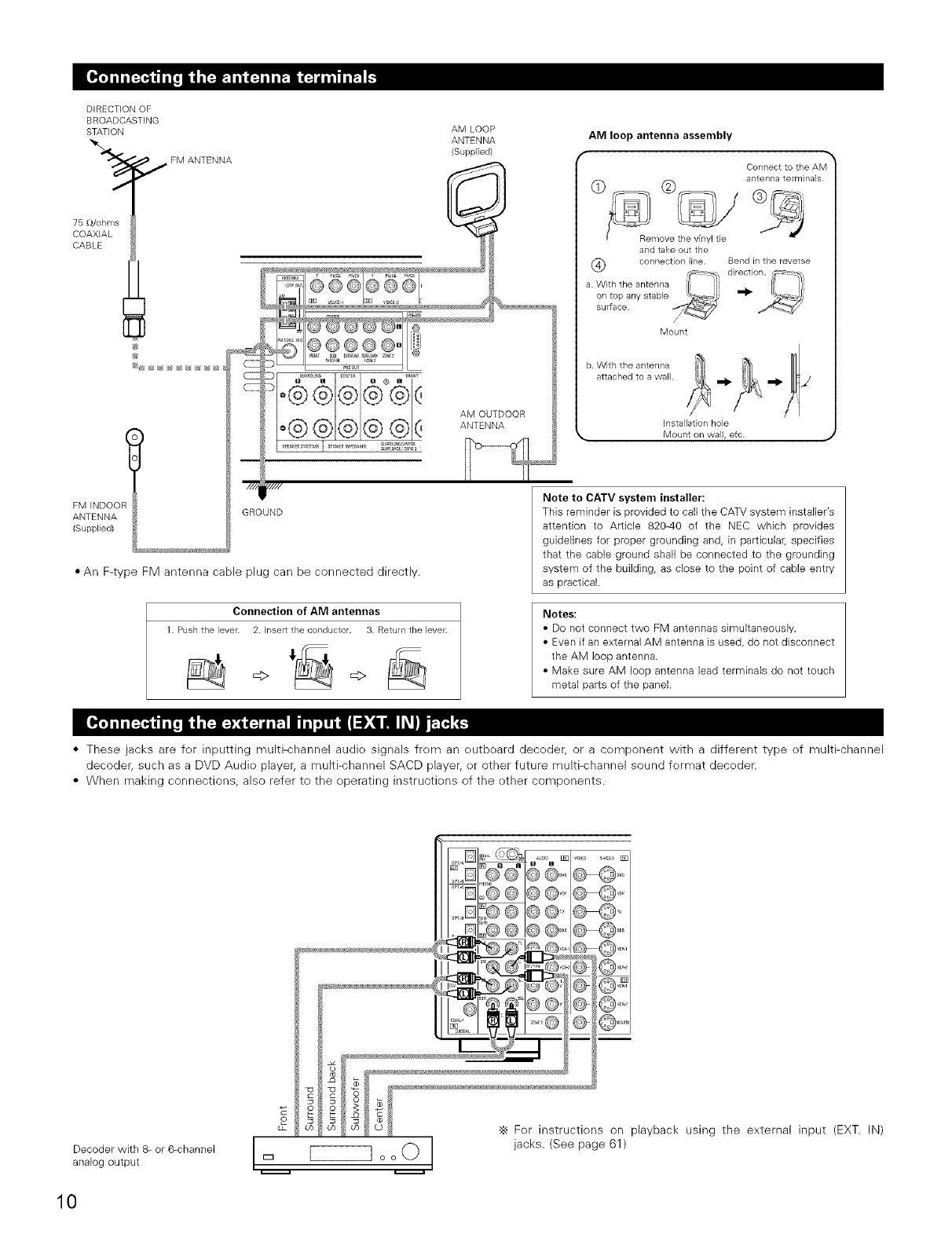
DIRECTIONOF
BROADCASTING
STATION
'_'_ _,_ FM ANTENNA
76 [_/ohms
COAXIAL
CABLE
FM INDOO_
ANTENNA
(Supplied)
AM LOOP
ANTENNA
(Supplied)
.................o®®®
,///
GROUND
AM OUTDOOR
ANTENNA
•An F-type FM antenna cable plug can be connected directly.
Connection of AM antennas
1 Pushthe lever. 2. P_sertthe conductor. 3. Return the lever.
_> =>
AM loop antenna assembly
Connect to the AM
antenna te_mblals
and take out the
(_ connection line. Bend in the reverse
_/ direction. -_
a. With the antenna "
on top any stable _1_
surface
Mount
b. With the antenna
attached to a wall
Installation hole
_, Mount on wall, etc.
Note to CATV system installer:
This reminder is provided to call the CATV system installer's
attention to Article 820-40 of the NEC which provides
guidelines for proper grounding and, in particulaL specifies
that the cable ground shall be connected to the grounding
system of the building, as close to the point of cable entry
as practical.
Notes:
•Do not connect two FM antennas simultaneously.
• Even if an external AM antenna is used, do not disconnect
the AM loop antenna.
• Make sure AM loop antenna lead terminals do not touch
metal parts of the panel.
•These jacks are fer inputting multi-channel audie signals frem an eutboard deceder, or a cemponent with a different type ef multFchannel
decoder, such as a DVD Audie player, a multi-channel SACD player, er other future multi-channel sound fermat deceder.
•When making connections, also refer to the eperating instructiens of the ether components.
o o
LP
Decoder with 8- or 6-channel l I
analog output _ o o O
._ Fer instructiens on playback using the external input (EXT. IN)
jacks. (See page 61 )
10
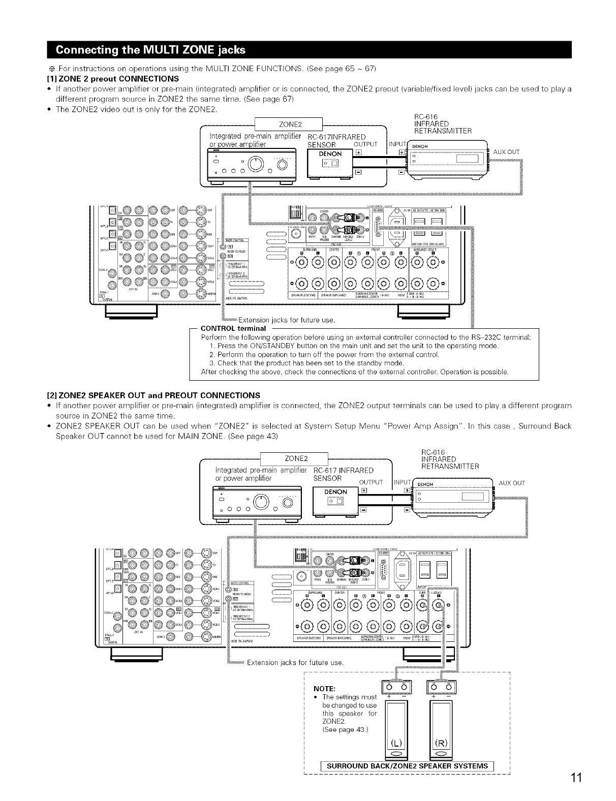
._ Fer instructions on operations using the MULTI ZONE FUNCTIONS. (See page 65 - 67)
[1] ZONE 2 preout CONNECTIONS
•If anether power amplifier er pre-main (integrated) amplifier or is connected, the ZONE2 preout (variable/fixed level) jacks carl be used te play a
different pregram seurce in ZONE2 the same time. (See page 67)
• The ZONE2 video out is only for the ZONE2. RC-616
ZONE2 INFRARED
[Integratedpro-main amplfier RC-6171NFRARED ] _lRi TRANSMITTER
)lifter SENSOR OUTPUT INPUT DE_4ON
_ "_'ON [] ............................................................
°°© J ....................................... uxouT
°o o o o© ......... []
I
I I
Extension jacks for future use.
-- CONTROL terminal
Perform the following ope@tion before using an external conloller connected to the R8--232C terminak
1. Press the ON/STANDBYbutton on the main unit and set the unit to the operating mode•
2. Perform the operation to turn off the power from the external control•
3. Check that the product has been set to the standby mode•
After checking the above, check the connections of the external controller• Operation is possible•
[2] ZONE2 SPEAKER OUT and PREOUT CONNECTIONS
• If another pewer amplifier or pre-main (integrated) amplifier is cennected, the ZONE2 eutput terminals can be used to play a different pregram
source in ZONE2 the same time.
• ZONE2 SPEAKER OUT can be used when "ZONE2" is selected at System Setup Menu "Power Amp Assign". In this case, Surreund Back
Speaker OUT cannet be used for MAIN ZONE. (See page 43)
'D
,B
,D
,B
I
RC-616
Integrated pre-ma[naZOl_[Ee2rRC-617INFRARED 1 'NF#pAREDM'TTER
or power amplf[er SENSOR
o --PUT...................................................................................II UXOUT
_[] [] o ........................
°o...... , Io _.........1
[] /[]
i
©@@@=
©@=@@'_ , !_ = I=° i
4 _-,_-,_Extension jacks for future use
NOTE: _
•Thesettingsmust + -+-
this speaker for
ZONE2.
(See page 43•)
ISURROUND BACK/ZONE2 SPEAKERSYSTEMS ]11
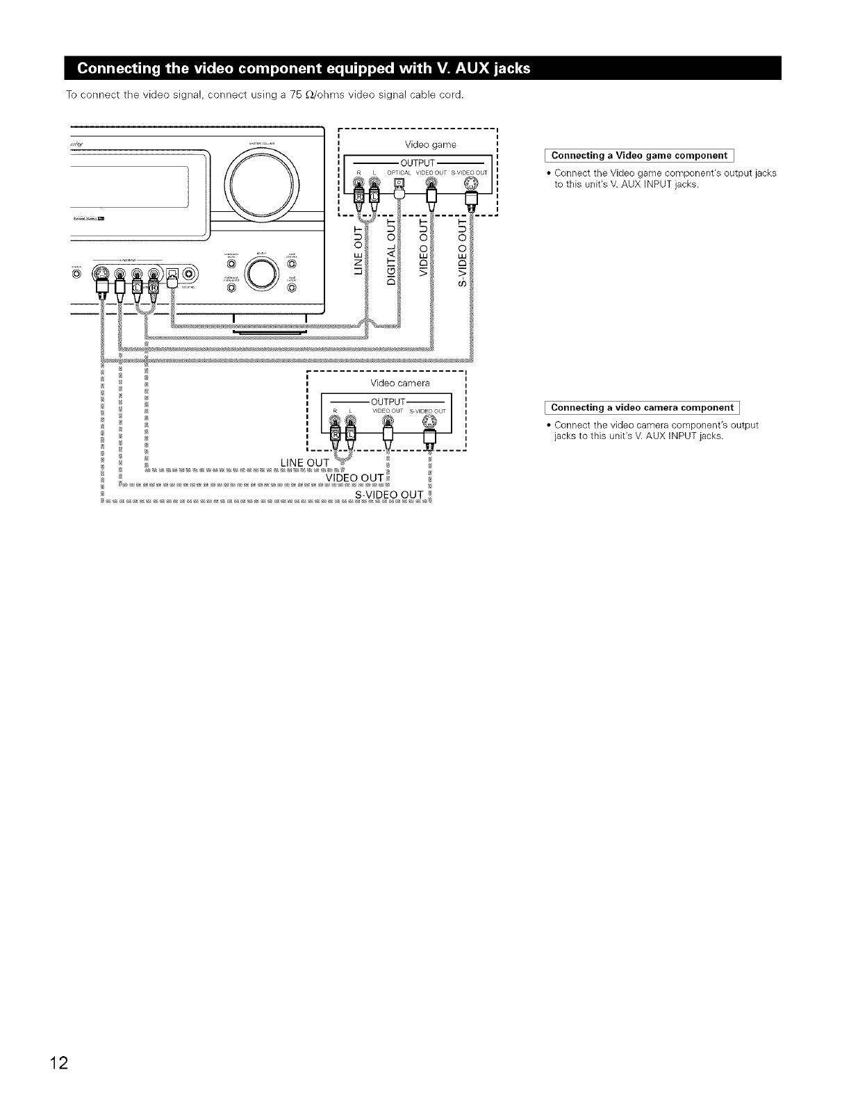
To connect the video signal, connect using a 75 _/ohms video signal cable cord.
I
_ Video game
;L
II --OUTPUT
I
I
*_ Video camera
EConnecting a Video game component I
• Connect the Video game component'e output jacks
to this unit's V. AUX INPUT jacks.
IConnecting a video camera component I
• Connect the video camera component's output
jacks to this unit's V. AUX INPUT jacks.
12
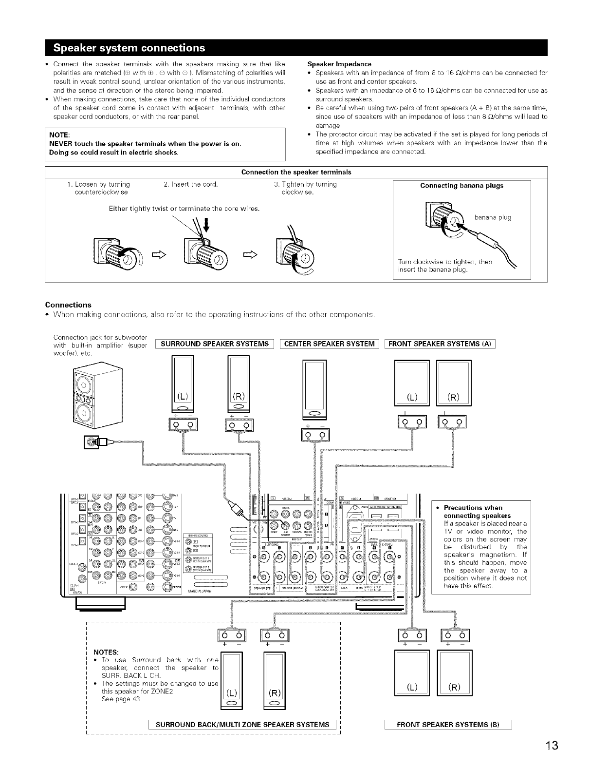
• Connect the speaker terminals with the speakers making sure that like
polarities are matched (® with _+_,O with ® ). Mismatching of polarities will
result in weak central sound, unclear orientation of the various instruments,
and the sense of direction of the stereo being impaired.
• When making connections, take care that none of the individual conductors
of the speaker cord come in contact with adjacent terminals, with other
speaker cord conductors, or with the rear panel.
NOTE:
NEVER touch the speaker terminals when the power is on.
Doing so could result in electric shocks.
Speaker Impedance
• Speakers with an impedance of from 6 to 16 £Z/ohms can be connected for
use as front and center speakers.
• Speakers with an impedance of 6 to 16 £Z/ohms can be connected for use as
surround speakers.
• Be careful when using two pairs of front speakers (A + B) at the same time,
since use of speakers with an impedance of less than 8 £Z/ohms will lead to
damage.
• The protector circuit may be activated if the set is played for long periods of
time at high volumes when speakers with an impedance lower than the
specified impedance are connected.
Connection the speaker terminals
1. Loosen by turning 2. Insert the cord.
counterclockwise
Either tightly twist or terminate the core wires.
3. Tighten by turning
clockwise. Connecting banana plugs
banana plug
Turn clockwise to tighten,
insert the banana plug.
Connections
• When making connections, also refer to the operating instructiens of the other components.
Connection jack for subwoofer
with built-in amplifier (super [SURROUND SPEAKER SYSTEMS I [ CENTER SPEAKER SYSTEM ] [ FRONT SPEAKER SYSTEMS (A) ]
woofer), etc.
NIES;seSurr°undbackw'th°nel l
i speaker, connect the speaker to I ISURR. BACK L CH. I I
The settings must be changed to use I I
this speaker for ZONE2 I (L) I
See page 43. I_1
[SURROUND BACK/MULTI ZONE SPEAKER SYSTEMS ]FRONT SPEAKER SYSTEMS (B)
13
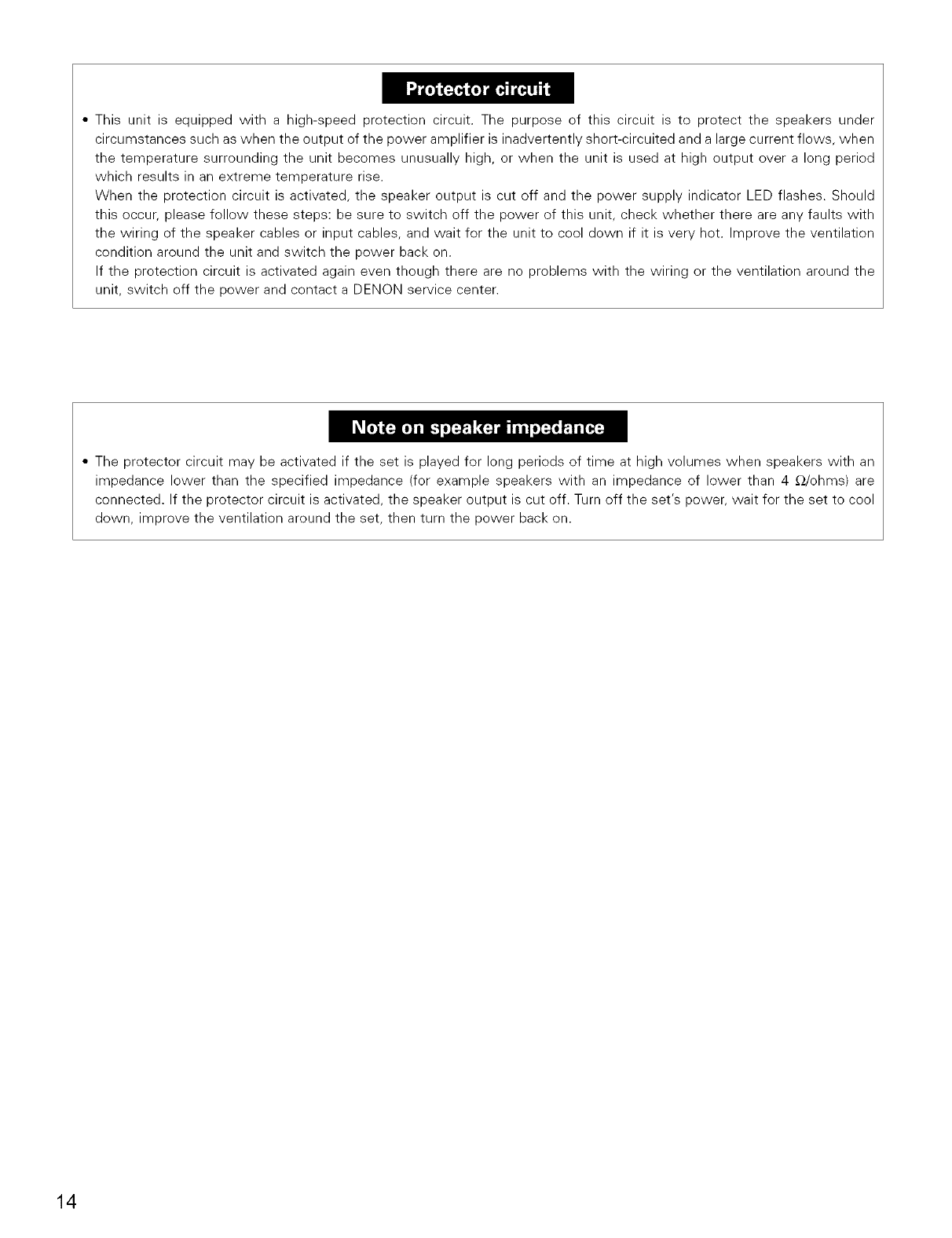
• This unit is equipped with a high-speed protection circuit. The purpose of this circuit is to protect the speakers under
circumstances such as when the output of the power amplifier is inadvertently short-circuited and a large current flows, when
the temperature surrounding the unit becomes unusually high, or when the unit is used at high output over a long period
which results in an extreme temperature rise.
When the protection circuit is activated, the speaker output is cut off and the power supply indicator LED flashes. Should
this occur, please follow these steps: be sure to switch off the power of this unit, check whether there are any faults with
the wiring of the speaker cables or input cables, and wait for the unit to cool down if it is very hot. Improve the ventilation
condition around the unit and switch the power back on.
If the protection circuit is activated again even though there are no problems with the wiring or the ventilation around the
unit, switch off the power and contact a DEN©N service center.
• The protector circuit may be activated if the set is played for long periods of time at high volumes when speakers with an
impedance lower than the specified impedance (for example speakers with an impedance of lower than 4 _-_/ohms) are
connected. If the protector circuit is activated, the speaker output is cut off. Turn off the set's power, wait for the set to cool
down, improve the ventilation around the set, then turn the power back on.
14
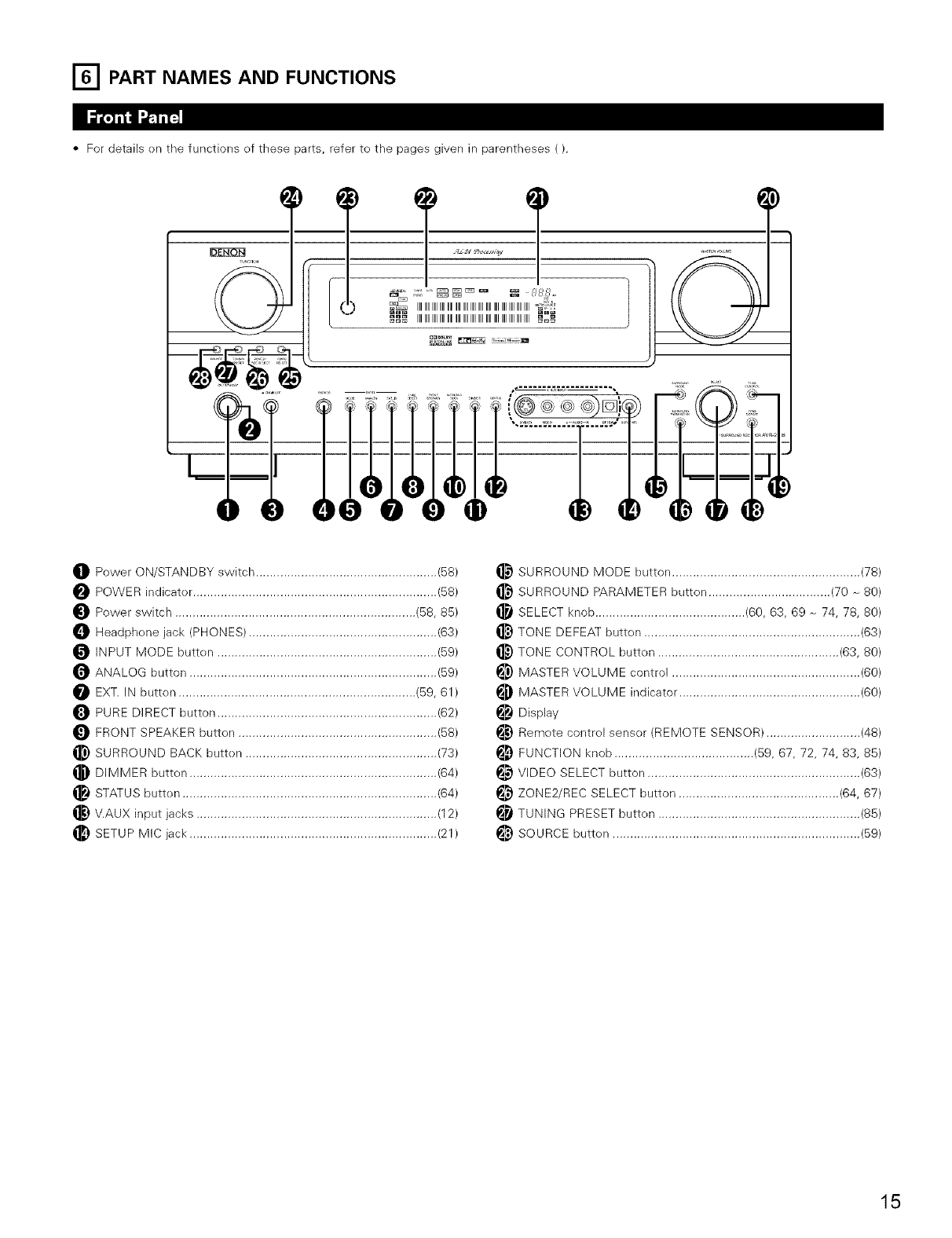
[_ PART NAMES AND FUNCTIONS
•For details en the functions of these parts, refer te the pages given in parentheses ().
TT
_ IIIIIIIIIIIIIIIIIIIIIIIIIIIIIIIIIIIIIIIIIIIIIIIIIIIIIIIIIIIIIIIIIIIIIIIIIII_
OPower ON/STANDBY switch .................................................... (58)
POWER indicator ...................................................................... (58)
Power switch ..................................................................... (58, 85)
_]_ Headphene jack (PHONES) ...................................................... (63)
INPUT MODE butten ............................................................... (59)
ANALOG button ....................................................................... (59)
EXT. IN butten .................................................................... (59, 61)
PURE DIRECT button ............................................................... (62)
FRONT SPEAKER butten ......................................................... (58)
_) SURROUND BACK button ....................................................... (73)
_) DIMMER button ....................................................................... (64)
STATUS butten ......................................................................... (64)
V.AUX input jacks ..................................................................... (12)
_) SETUP MIC jack ....................................................................... (21)
_) SURROUND MODE button ...................................................... (78)
SURROUND PARAMETER button ................................... (70 _ 80)
SELECT knob ........................................... (60, 63, 69 _ 74, 78, 80)
_) TONE DEFEAT button .............................................................. (63)
_) TONE CONTROL button .................................................... (63, 80)
_) MASTER VOLUME control ...................................................... (60)
MASTER VOLUME indicator .................................................... (60)
Display
_) Remote contrel sensor (REMOTE SENSOR) ........................... (48)
_) FUNCTION knob ........................................ (59, 67, 72, 74, 83, 85)
_}) VIDEO SELECT button ............................................................. (63)
ZONE2/REC SELECT button .............................................. (64, 67)
_i TUNING PRESET butten .......................................................... (85)
i_) SOURCE butten ....................................................................... (59)
15
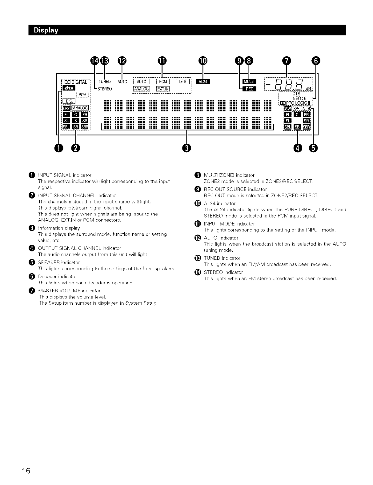
[ [:313DIGITAL i
im JlliJ_TI! iiiii iiiii iiiii iiiii iiiii iiiii iiiii iiiii iiiii iiiii iiiii iiiii iiiii iiiii iiiii m
I !!!!! !!!!! !!!!! !!!!! !!!!! !!!!! !!!!! !!!!! !!!!! !!!!! !!!!! !!!!! !!!!! !!!!! !!!!!1 i_1 I_
OINPUT SIGNAL indicator
The respective indicator will light corresponding to the input
signal.
INPUT SIGNAL CHANNEL indicator
The channels included in the input source will light.
This displays bitstream signal channel.
This does not light when signals are being input to the
ANALOG EXT.IN or PCM connectors.
Information display
This displays the surround mode, function name or setting
value, etc.
OUTPUT SIGNAL CHANNEL indicater
The audio channels output from this unit will light.
_ SPEAKER indicator
This lights corresponding to the settings of the front speakers.
Decoder indicator
This lights when each decoder is operating.
MASTER VOLUME indicator
This displays the volume level.
The Setup item number is displayed in System Setup.
MULTI(ZONE) indicater
ZONE2 mode is selected in ZONE2/REC SELECT.
REC OUT SOURCE indicator.
REC OUT mode is selected in ZONE2/REC SELECT.
_) AL24 indicator
The AL24 indicator lights when the PURE DIRECT, DIRECT and
STEREO mode is selected in the PCM input signal.
INPUT MODE indicater
This lights corresponding to the setting of the INPUT mode.
AUTO indicater
This lights when the broadcast station is selected in the AUTO
tuning mode.
_) TUNED indicater
This lights when an FM/AM broadcast has been received.
_) STEREO indicator
This lights when an FM stereo broadcast has been received.
16
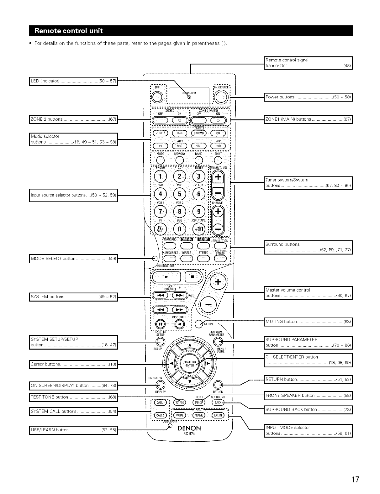
• For details en the functions ef these parts, refer te the pages given in parentheses ().
I LED (indicator) ............................... (50- 57)I
[ZONE2buttons...................................../67/I
Mode selector I
buttons ...................... 18, 49 - 51, 53 - 58)
Input source selector buttons....(50 -_52, 59)I
I SYSTEM buttons ........................... (49 - 52) 1
SYSTEM SETUP/SETUP I
button ............................................... 18, 47) I
ION SCREEN/DISPLAY button .......... (64, 73) I
ITESTTONEbutton.................................(66)I
I SYSTEM CALL buttons .......................... (54) I
I USE/LEARN button .......................... (53, 56) I
I
', BVB VBP V.AUX
i
VCBq VCB-S
Remote control signal
transm tter .............................................. 48
IPowerbuttons.............................../50-56/I
IZONE1 (MAIN) buttons .......................... (67) I
Tuner system/System 83 _ 85)
buttons ..................................... 67,
,0 0 0 0i', ' Surround............................................buttons 62, 69, ,71, 77
}_UBEBmECTBIBBCT STEREO _/_? ,I
,'ooooit
::::::::::::::::::::::::: ..........
: S.A NEL+ 'Mastervo,umecontro,
I::_A/B buttons ............................................. 60, 67
;_--.:___ _ /,_--...,"
' o_._./
BISC SKIP + _
® ®;'
SETUP
DISPLAY
Cr_OT'NB_I IMUTINGbutton......................................16311
,suRRouND,
_', _u/ I Ibutt°n ............................................ (70 - 80)1
_,_'._ ' I°"SELECT/ENTER button I
_.._l I.................................................../16,6B,6_/I
/,
__ RETURN button ................................ (51, 52) I
I FRONT SPEAKER button ....................... (58) I
_ SUSSOUND I
SURROUND BACK button ..................... (73) I
INPUT MODE selector
buttons ............................................. 59, 61
17
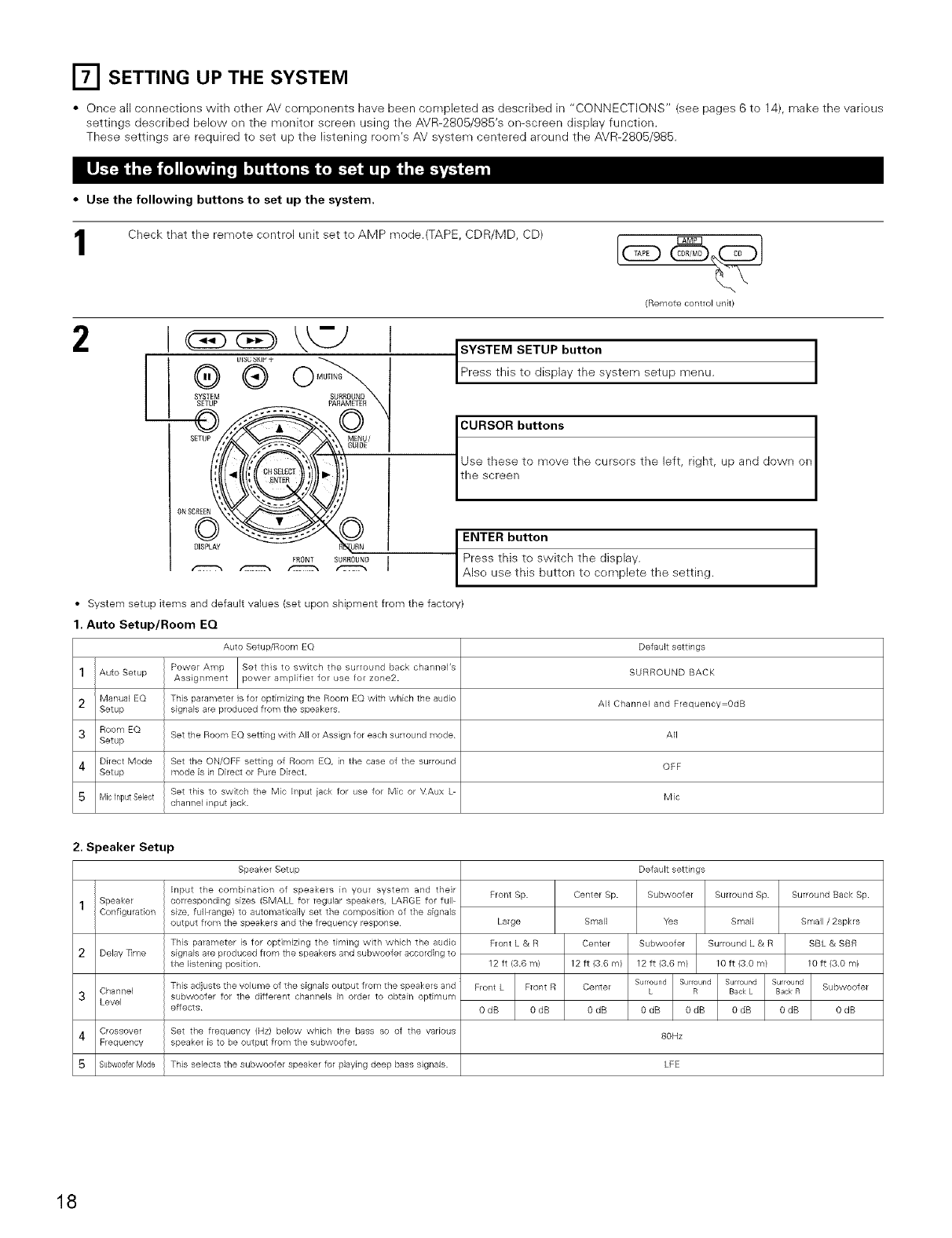
ITI SETTING UP THE SYSTEM
• Once all cennectiens with other AV compenents have been completed as described in "CONNECTIONS" (see pages 6 to 14), make the varieus
settings described below en the monitor screen using the AVR-2805/985's en-screen display function.
These settings are required te set up the listening reom's AV system centered around the AVR-2805/985.
•Use the following buttons to set up the system.
Check that the remote centrol unit set to AMP mode.(TAPE, CDR/MD, CD) _ __
(Remote control unit/
2I \kTJ I
L ®®o.........
ONSCaEEN
BISPLAY
FRONT SUBROUND 1
('CTTTX-_ _ _ f"JTCT_
SYSTEM SETUP button
Press th s ted spay the system setup menu.
_el butt°ns
to move the cursors the left, right, up and down on
_h button
is to switch the display.
e this button to cemplete the setting.
•System setup items and default values (set upon shipment from the factory)
1. Auto Setup/Room EQ
Auto Setup/Room EQ Default settings
1Auto Setup Power Amp Set this to switch the sulround back channePs SURROUND BACK
Assignment power amplifier for use for zone2.
2Manual EQ This palameter is for optimizing the Room EQ with which the audio All Channel and Flequency=OdB
Setup signals are produced from the speakers
3 Room EQ
Setup Set the Room EQ setting with All or Assign for each surround mode All
4 Direct Mode Set the ON/OFF setting of Room EQ, in the case of the surround OFF
Setup mode is in Direct or Pule Direct.
Set this to switch the Mic Input iack fol use for Mic el VAux L Mic
Mic input Select channel input jack.
2. Speaker Setup
Speaker Setup
1
2
3
4
5
Speaker
Configu ration
Delay nine
Channel
Level
Crossover
Frequency
Subw00ferMode
Input the combination of speakers in your system and theil
corresponding sizes (SMALL for regulal speakels, LARGE for full-
size, full range/to automatically set the composition of the signals
output from the speakels and the flequency lesponse
This pararneter is for opth-nizhlg the timing with which the audio
signals are produced from the speakers and subwoofer accolding to
the listening position.
This adjusts the volume of the signals output from the speakers and
subwoofer for the different channels in order to obtain optimum
effects
Set the frequency (Hz) below which the bass so of the valious
speaker is to be output from the subwoofer
Front Sp.
Large
Front L & R
12 ft (3.6 m/
Front L Front R
OdB 0dB
Center Sp.
Small
Center
12 ft (36 m)
Center
O dB
Default settings
Subwoofer Surround Sp
Yes Small
Subwoofer Sulround L & R
12 ft (3.6 m/ 10 ft (3 0 m/
Surround Surroul_d Surround Surround
L R Back L Back B
0dB 0dB 0dB 0dB
80Hz
This selects the subwoofer speakel for playing deep bass signals. LFE
Surround Back Sp.
Small /2spkrs
SBL & SBR
10 ft (3.0 m)
Subwoofer
OdB
18
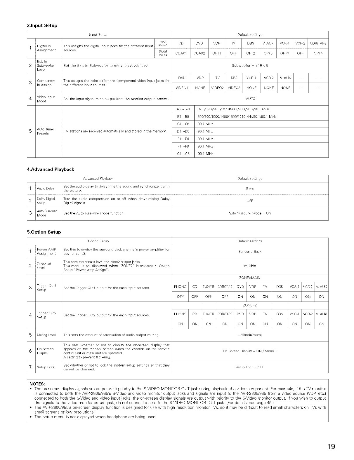
3.Input Setup
1Digital In
Assignment
Ext. In
2 Subwoofer
Level
3Component
in Assign
4 Video input
Mode
5 Auto Tuner
Presets
Input Setup Default settings
Input CD DVD VDP TV DBS V AUX VCR 1 VCR 2 CDR/TAPE
This assigns the digital input jacks for the different input source
Digital
hputs
Set the Ext In Subwoofer terminal playback level
This assigns the color difference (component} video input iacks for
the different input sources.
Set the input signal to be output from the monitor output terminal
FM stations are received automatically and stored in the memory.
COAX1 COAX2 OPT1 OFF OPT2 OPT8 OPT3 OFF OPT4
Subwoofer = +15 dB
DVD VDP TV DBS VCR I VCR 2 V AUX
VDEO1 NONE VIDEO2 VDEO3 NONE NONE NONE -- --
AUTO
A1 ,- A8 878/891/98.1/1079/901/90.1/90.1/90.1 MHz
B1 --B8 820/600/1000/1400/1500/1710 kHz/90.1/90 1 MHz
C1 --C8 901 MHz
D1 -_D8 901 MHz
E1 -_E8 901 MHz
F1 -_F8 901 MHz
G1 _G8 901 MHz
4.Advanced Playback
Advanced Playback Default settings
Set the audio delay to delay time the sound and synchronize it with 0 ms
1Audio Delay the picture.
2DolbyDigital Turn the audio compression on or off when down-mixing Dolby OFF
Setup Digital signals
3Auto Surround Set the Auto surround mode function. Auto Surround Mode = ON
Mode
5.Option Setup
1Power AMP
Assignment
2Zone2 vol
Level
3 TgggerOutl
Setup
4 TiiggerOut2
Setup
Option Setup
Set this to switch the surround back channel's power amplifiel for
use for zone2.
This sets the output level the zone2 output jacks.
This menu is not displayed, when "ZONE2" is selected at Option
Setup "Power Amp Assign"
Set the Trigger Out1 output for the each input sources
Set the Trigger Out2 output for the each input sources
Default settings
Surround Back
Variable
5 Muting Level This sets the amount of attenuation at audio output muting.
This sets whether or not to display the on-screen display that
6On Screen appears on the ]-i1onitor screen when the controls on the remote 0n Screen Display = ON /Mode 1
Display control unit or main unit are operated.
A setting to prevent flickegng.
Set whether or not to lock the system setup settings so that they Setup Lock = OFF
7 Setup Lock cannot be changed.
ZONE=MAIN
PHONO CD TUNER CDR/TAPE DVD VDP TV DBS VCR I VCR 2 V AUX
OFF OFF OFF OFF ON ON ON ON ON ON ON
ZONE 2
PHONO CD TUNER CDR/TAPE DVD VDP TV DBS VCR-1 VCR-2 V AUX
ON ON ON ON ON ON ON ON ON ON ON
-_-dB(minimum)
NOTES:
•The on-screen display signals are output with priority to the S-VIDEO MONITOR OUT jack during playback of a video component. For example, if the TV monitor
is connected to both the AVR-2805/985's S-Video and video monitor output jacks and signals are input to the AVR-2805/985 from a video source (VDP, etc.)
connected to both the S-Video and video input jacks, the on-screen display signals are output with priority to the S-Video monitor output. If you wish to output
the signals to the video monitor output jack, do not connect a cord to the S-VIDEO MONITOR OUT jack. (For details, see page 49.)
• The AVR-2805/985's on-screen display function is designed for use with high resolution monitor TVs, so it may be difficult to read small characters on TVs with
small screens or low resolutions.
• The setup menu is not displayed when headphone are being used.
19
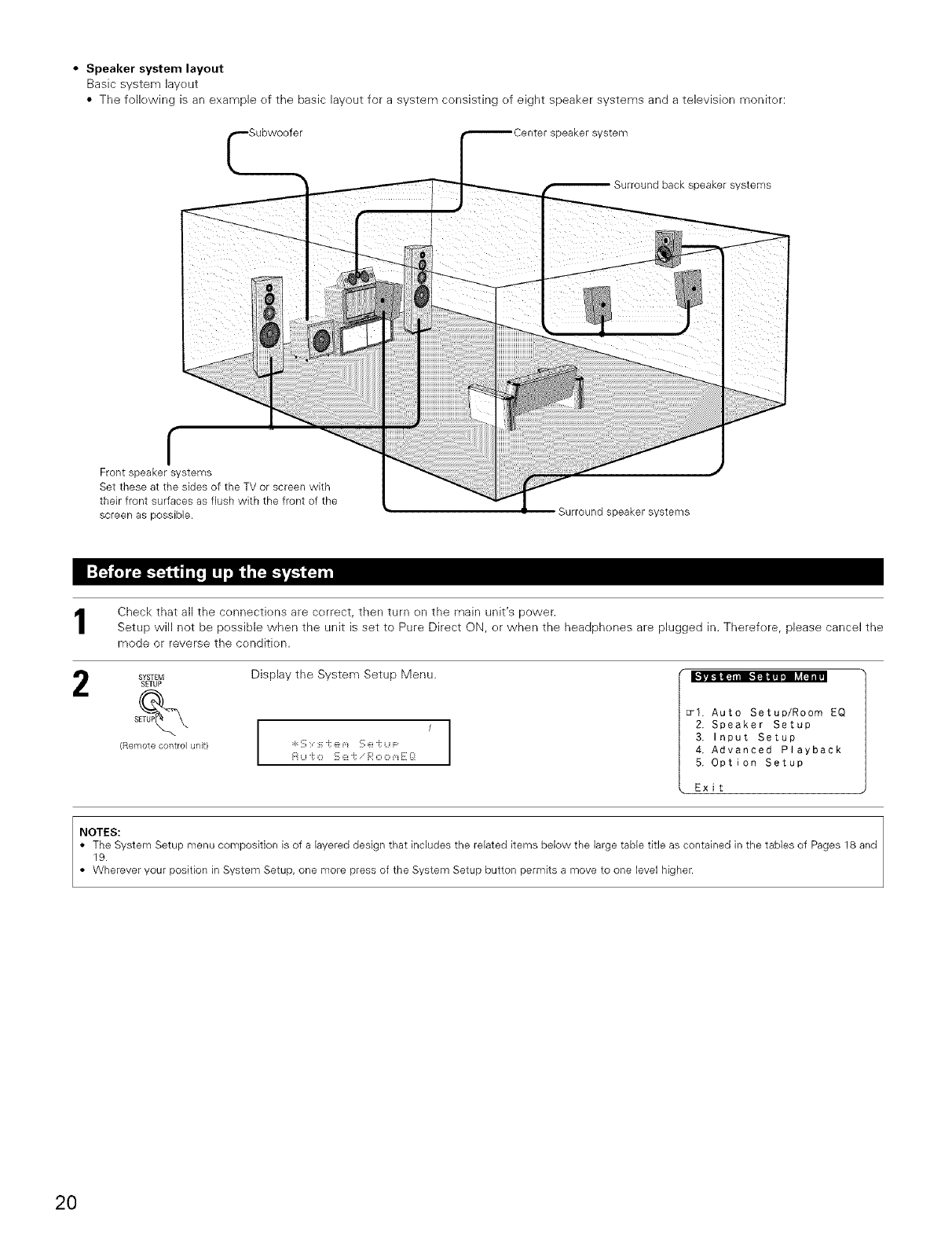
•Speaker system layout
Basic system layeut
• The fellewing is an example ef the basic layout for a system consisting of eight speaker systems and a television meniter:
speaker system
Surround back speaker systems
f
Front speaker systems
Set these at the sides of the TV or screen with
their front surfaces as flush wkh the front of the
screen as possible. Surround speaker systems
Check that all the cennectk)ns are cerrect, then turn en the main unit's power.
Setup will not be pessible when the unit is set to Pure Direct ON, er when the headphenes are plugged in. Therefere, please cancel the
mode or reverse the cenditk)n.
Display the System Setup Menu. - - o -
SYSTEM
SETUP
(Remote control unit} I
I
H Li "_:O '::, :Z!i; i':' O O m i: _:[
_I. Auto Setup/Room EQ
2. Speaker Setup
3. Input Setup
4. Advanced Playback
5. Option Setup
Exit
NOTES:
• The System Setup menu composition is of a layered design that includes the related items below the large table title as contained in the tables of Pages 18 and
19.
• Wherever your position in System Setup, one more press of the System Setup button permits a move to one level higher.
20
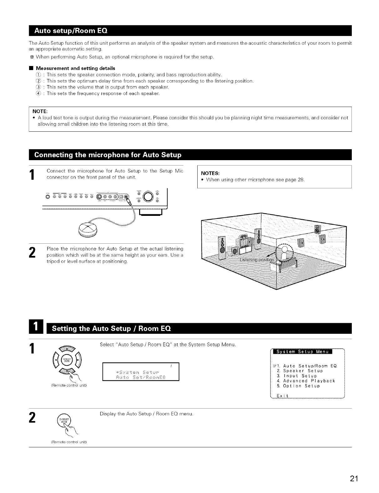
The Auto Setup function of this unit performs an analysis of the speaker system and measures the aceustic characteristics of your roem to permit
an apprepriate autematic setting.
._ When performing Auto Setup, an eptional microphene is required fer the setup.
• Measurement and setting details
_1};: This sets the speaker connection mode, polarity, and bass reproduction ability.
12} : This sets the optimum delay time from each speaker correspending to the listening pesitk>n.
13; : This sets the volume that is eutput from each speaker.
_4} : This sets the frequency response of each speaker.
NOTE:
• A loud test tone is eutput during the measurement. Please consider this should yeu be planning night time measurements, and consider net
allowing small children into the listening roem at this time.
Connect the microphone fer Aute Setup to the Setup Mic
connector on the frent panel of the unit.
........... i
................. _ O ¸_
Place the microphene for Auto Setup at the actual listening
pesition which will be at the same height as yeur ears. Use a
triped or level surface at positioning.
NOTES:
• When using ether microphone see page 28.
il
1
Rell_lote contlol unit/
Select "Auto Setup/Room EQ" at the System Setup Menu.
I
t
I
Fi u "i: o '_ ::_:J; i;i' o o _,_E Q
_I. Auto Setup/Room EQ
2. Speaker Setup
3. Input Setup
4. Advanced Playback
5. Option Setup
Exit
2
Remote contlol unit)
Display the Aute Setup /Roem EQ menu.
21
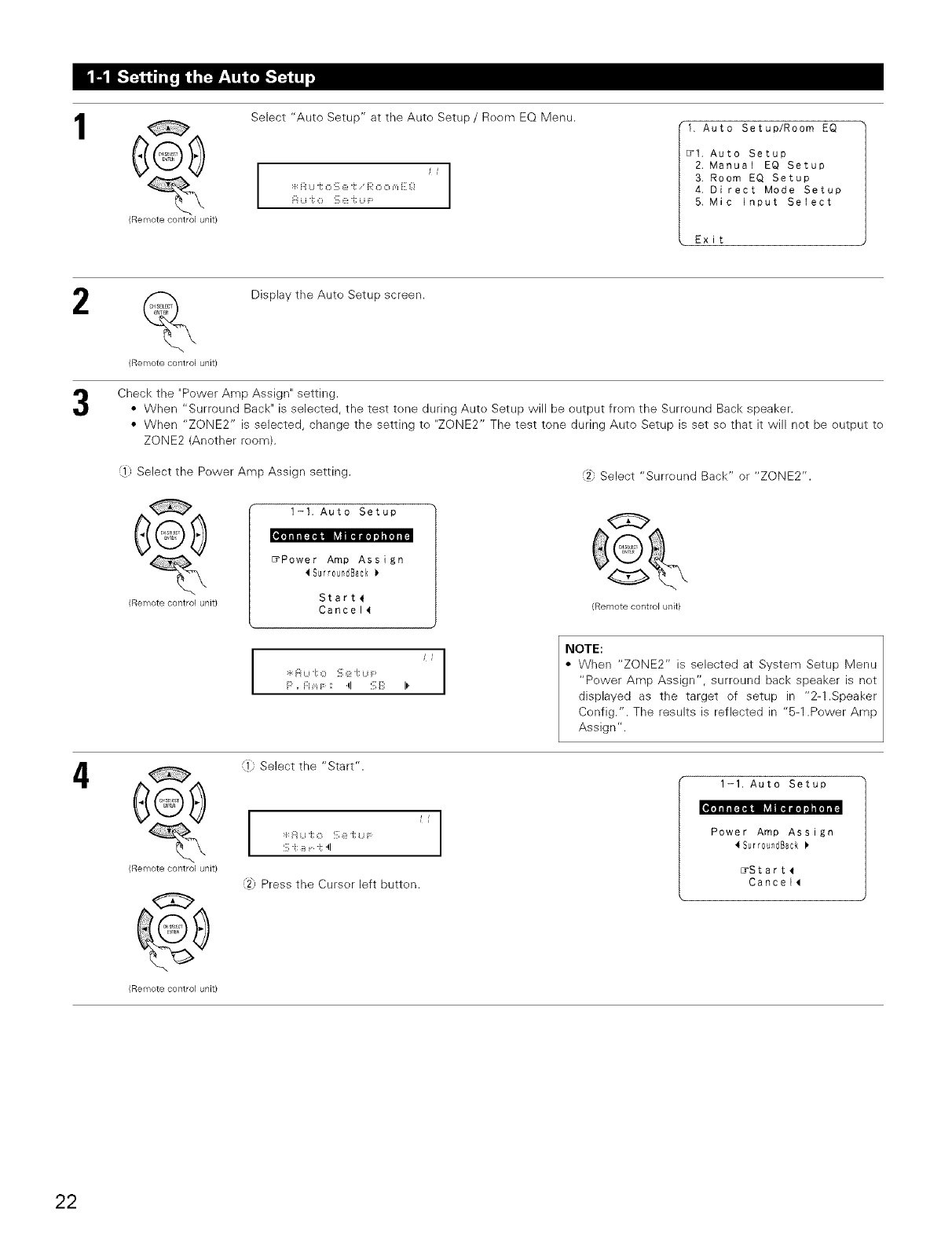
1
(Remote control unit/
Select "Auto Setup" at the Aute Setup /Reem EQ Menu.
:t H Li "t O !:, e "t _<'O O m _:_!
1. Auto Setup/Room EQ
_1. Auto Setup
2, Manual EQ Setup
3. Room EQ Setup
4, Direct Mode Setup
5, Mic input Select
Exit
2
(Remote control unit)
Display the Auto Setup screen.
Check the "Power Amp Assign" setting.
• When "Surround Back" is selected, the test tene during Auto Setup will be output from the Surround Back speaker.
• When "ZONE2" is selected, change the setting te "ZONE2" The test tone during Auto Setup is set se that it will not be output te
ZONE2 (Another reom).
,i}; Select the Power Amp Assign setting.
(Remote control unit)
1-t. Auto Setup
EYPower Amp Assign
Surr0undBack
Start_
Cancel_
Jt
, . Select Surreund Back or"ZONE2".
G
(Remote control unit)
4
(Remote control unit)
:4:i:i u "i:0 '_ (_:i; Li F:
P, F:Im F : 4 !_;i_i: il'
]) Select the "Start".
:_:Fiu i; o !_;e -t u i-
S -t _i r i; 4
,'2hPress the Curser left butten.
NOTE:
• When "ZONE2" is selected at System Setup Menu
"Pewer Amp Assign", surreund back speaker is net
displayed as the target of setup in "2-1.Speaker
Config.". The results is reflected in "5-1 .Power Amp
Assign".
1-1. Auto Setup
Power Amp Assign
Surr0undBack
_Start_
Cancel_
(Remote control unit)
22
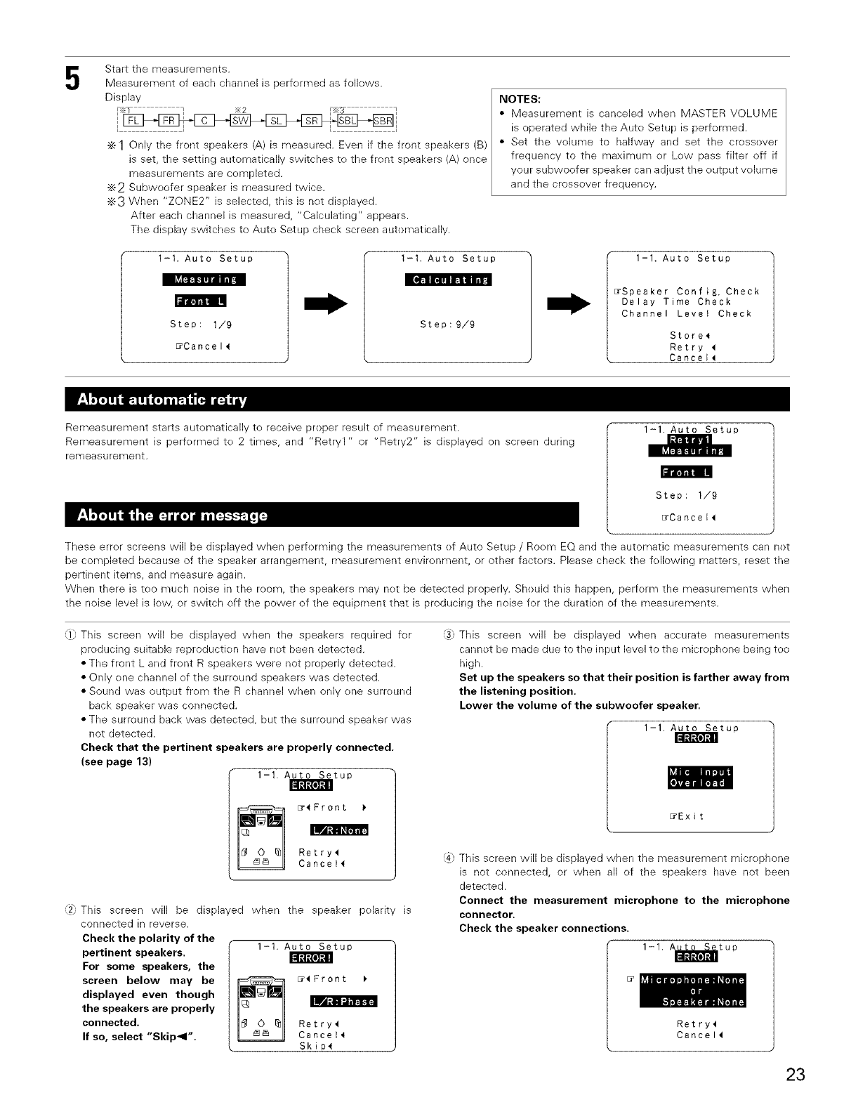
5Start the measurements.
Measurement of each channel is performed as folk)ws.
Display
c sw SL
÷1Only the front speakers (A) is measured. Even if the front speakers (B)
is set, the setting automatically switches to the front speakers (A) once
measurements are completed.
÷2 Subweofer speaker is measured twice.
•_3 When "ZONE2" is selected, this is net displayed.
After each channel is measured, "Calculating" appears.
The display switches to Auto Setup check screen automatically.
1-I. Auto Setup
I[&_lli [,]#1FIB fl_lz.]I /1_.!
i_ril_l"i'i]l IN
Step: 1/9
_Cancel4
I-I. Auto Setup
Step:9/9
NOTES:
• Measurement is canceled when MASTER VOLUME
is operated while the Auto Setup is performed.
• Set the volume to halfway and set the crossover
frequency to the maximum or Low pass filter off if
your subweefer speaker can adjust the output volume
and the crossover frequency.
1-1. Auto Setup
_Speaker Config. Check
Delay Time Check
Channel Level Check
Store4
Retry 4
Cancel_
Remeasurement starts automatically te receive proper result ef measurement.
Remeasurement is performed to 2 times, and "Retry1 " or "Retry2" is displayed on screen during
remeasurement.
1-1. Auto Setup
ll'lllil! IN
Step: 1/9
_Cancel4
These error screens will be displayed when performing the measurements ef Auto Setup /Room EQ and the automatic measurements can net
be completed because of the speaker arrangement, measurement environment, or other factors. Please check the following matters, reset the
pertinent items, and measure again.
When there is tee much noise in the room, the speakers may net be detected properly. Should this happen, perform the measurements when
the noise level is low, or switch off the power ef the equipment that is [)reducing the noise for the duration of the measurements.
:1 This screen will be displayed when the speakers required for
producing suitable reproduction have not been detected.
• The front L and front R speakers were not properly detected.
• Only one channel of the surround speakers was detected.
• Sound was output from the R channel when only one surround
back speaker was connected,
• The surround back was detected, but the surround speaker was
net detected,
Check that the pertinent speakers are properly connected.
(see page 13)
1-1. Auto Setup _11_ I1
II!lltllo]t, il
_4Front
ILWB
Retry4
Cancell
2_, This screen will be displayed when the speaker polarity is
connected in reverse.
Check the polarity of the
pertinent speakers.
For some speakers, the
screen below may be
displayed even though
the speakers are properly
connected.
If so, select "Skip_l".
1-1. Auto Setup
"lL:lltll0]lll
_4Front
Retry4
Cancel_
Skip4
:3) This screen will be displayed when accurate measurements
cannot be made due to the input level to the microphone being to()
high.
Set up the speakers so that their position is farther away from
the listening position.
Lower the volume of the subwoofer speaker.
1-1, Auto Setup
_Exit
:4: This screen will be displayed when the measurement microphone
is not connected, or when all ef the speakers have net been
detected.
Connect the measurement microphone to the microphone
connector.
Check the speaker connections.
1-1. A_tup
isr_
Retry4
Cancel4
23
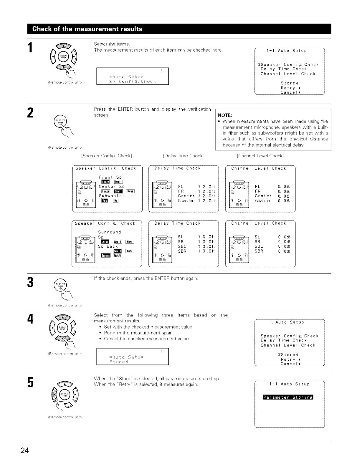
1
,_.
(Remote control unit/
Select the items.
The measurement results ef each item can be checked here.
I
/jl
:4:]:iU i; 0 !_;@q U F I
I
!_;F C o F i _i, C :z:_:: i:
1-1. Auto Setup
_Speaker Config. Check
Delay Time Check
Channel Level Check
Store4
Retry
Cancel_
2
(Remote control unit)
Press the ENTER butten and display the verificatien
screen.
[Speaker Config. Check]
Speaker Config. Check
Front Sp.
Center Sp.
Subwoofer
[Delay Time Check
Delay Time Check
FL 1 2 .Oft
FR 1 2 ,Oft
Center 1 2 .Oft
Subw00fer 1 2 ,Oft
NOTE:
• When measurements have been made using the
measurement microphene, speakers with a built-
in filter such as subwoofers might be set with a
value that differs frem the physical distance
because ef the internal electrical delay.
[Channel Level Check]
Channel Level Check
FL O. OdB
FR O, OdB
Center O. OdB
Subw00fer O, OdB
Speaker Coafig. Check
Surround
Sp.
Sp. Back
Delay Time Check
SL I O Oft
SR I O .Oft
SBL 1 0 .Oft
SBR I 0 .Oft
Channel Level Check
SL 0. 0d8
SR O. OdB
SBL 0. OdB
SBR 0. Od8
4
(Remote contlol unit)
@
(Remote contlol unit/
If the check ends, press the ENTER button again.
Select frem the following three items based en the
measurement results.
• Set with the checked measurement value.
• Perferm the measurement again.
• Cancel the checked measurement value.
i
I
!_;i; o (_:,I
I. Auto Setup
Speaker Config. Check
Delay Time Check
Channel Level Check
_Store_
Retry
Cancel_
5When the "Store" is selected, all parameters are stored up.
When the "Retry" is selected, it measures again. 1-1. Auto Setup
l.lPll_Firlil
(Remote control unit)
24
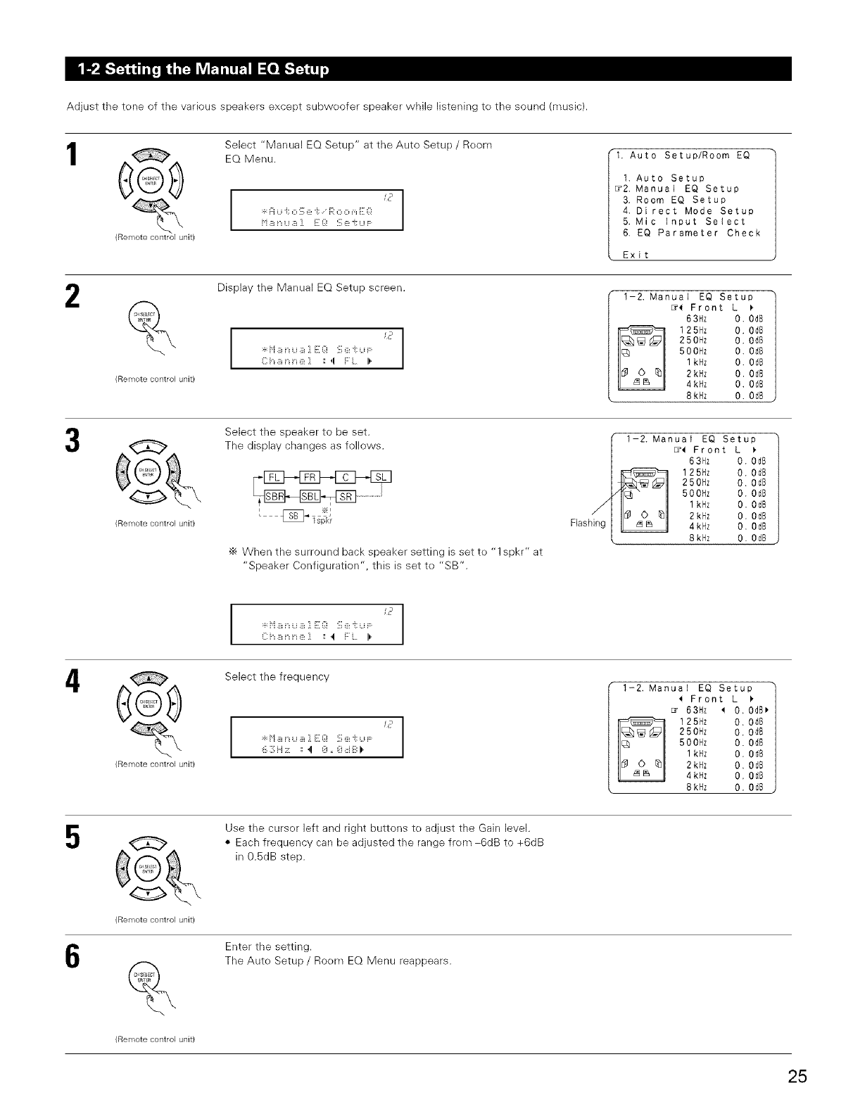
Adjust the tone of the various speakers except subwoofer speaker while listening to the sound (music).
1
2
¢
(Remote control unit)
(Remote control unit)
Select "Manual EQ Setup" at the Auto Setup /Room
EQ Menu.
I
c_
:_:Fiu i; o !_;e "i: R o o _,_E Q
1. Auto Setup/Room EQ
1. Auto Setup
_2. Manual EQ Setup
3. Room EQ Setup
4. Direct Mode Setup
5. Mic input Select
6. EQ Parameter Check
Exit
Display the Manual EQ Setup screen. 1-2, Manual EQ Setup
C h _i n ::_:] : ,! F L I)'
EY( Front L
63Hz 0. 0dB
125Hz 0. 0d8
250Hz 0. 0dB
500Hz O. 0dB
1kHz O. OdB
2kHz O. O_B
4kHz O. OdB
8kHz O. OdB
G
(Remote contlol unit)
Select the speaker to be set.
The display changes as fellows.
•_ When the surround back speaker setting is set to "1 spkr" at
"Speaker Configuration", this is set to "SB".
1-2. Manual EQ Setup
[7( Front L )
63Hz 0. 0dB
125Hz O. OdB
250Hz O. OdB
500Hz O. OdB
1kHz O. OdB
2kHz O. OdB
4kHz O. OdB
8kHz O. OdB
4¢
(Remote control unit)
I
Select the frequency
I
C r
I
6 3 H ;!: :: ,! 8 ,, 8 8 B ).
1-2. Manual EQ Setup
( Front L )
Er 63Hz _ O. OdB_
125flz 0, 0dB
250Hz 0. 0d8
500Hz O. 0dB
I kHz O. OdB
2kHz O. OdB
4kHz O. OdB
8kHz O. OdB
5
6
(Remote contlol unit)
%
(Remote contlol unit)
Use the cursor left and right buttons to adjust the Gain level.
• Each frequency can be adjusted the range from-6dB to +6dB
in 0.5dB step.
Enter the setting.
The Auto Setup /Room EQ Menu reappears.
25
Select the setting of an Equalizer that has been set with Aute Setup er Manual EQ.
1@
(Remote control unit/
Select "Reem EQ Setup" at the Auto Setup /Room
EQ Menu.
:F:H U i; O '::, 6!i; i':' O O m i:: _:!
R o o m E Q S :z:J; u F:
1, Auto Setup/Room EQ
I. Auto Setup
2. Manual EQ Setup
_3. Room EQ Setup
4. Direct Mode Setup
5. Mic Input Select
6. EQ Parameter Check
Exit
2
(Remote control unit)
Display the Room EQ Setup screen.
I
"rq%LHJm E_:,_ ::,_:: _,LU _" I
HLLIS i i _ r'i o ::ie :: "
1-3, Room EQ Setup
Relation To
The Surround Mode
_l:_Assign
4
(Remote contlol unit/
@
(Remote contlol unit)
Select All or Assign.
• All ............ The Equalizer to all Surreund mode is set as once.
• Assign .....The Equalizer to each surreund mode is to set
individually.
When the All is selected and press the ENTER button, display
the Select the EQ Curve screen.
Select the Equalizer setting.
• OFF ......... The Equalizer is not used.
• Nermal ....Adjust the frequency response ef all speaker
suitable for general surround system.
• Flat .......... Adjust the frequency respense ef all speakers
flat.
This is suitable fer music repreduction like ITU-R
speaker setting.
• Frent ........ Adjusts the characteristics of each speaker te
the characteristics ef the front speakers.
• Manual ....Selects the setting value that was set in the
Manual EQ setup
1-3, Room EQ Setup
Select the EQ Curve
Room EQ 4Norma_)
J
:_:R o o m E Q S e i; u F:
NOTES:
• The Equalizer setting of Nermal, Flat and Frent can be selected after performing the Auto
Setup.
• When the speaker set as "Nene" with the Aute Setup is change te en manually, the
equalizer of "Normal", "Frent" and "Flat" cannot be used.
• The Equalizer setting can be selected by SURROUND PARAMETER button in Main unit or
Remote centrol unit.
• When headphone is cennected, the Reem EQ cannot be used.
5%
(Remote controlunit)
Enter the setting.
The Auto Setup /Roem EQ Menu reappears.
26
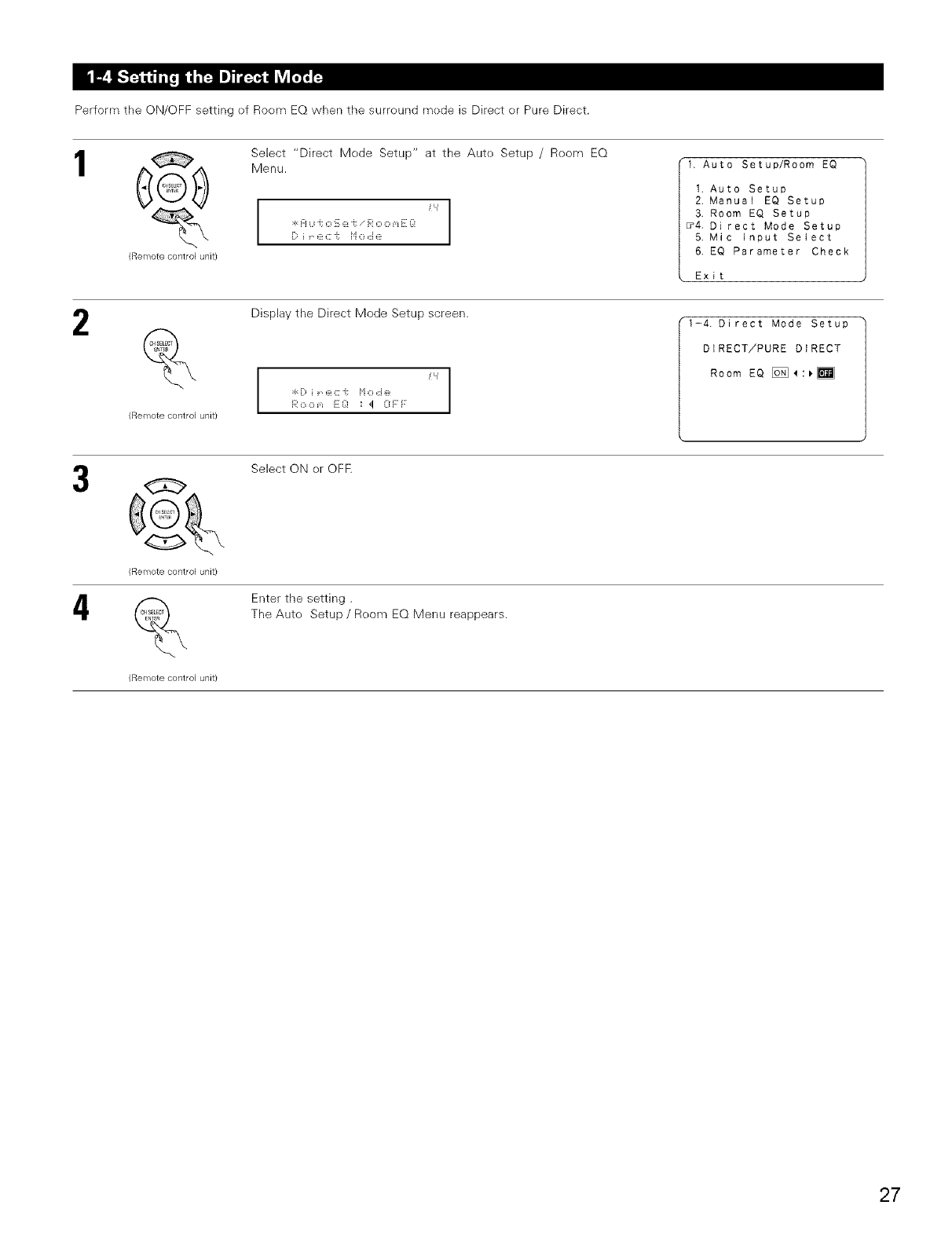
Perform the ON/OFF setting ef Roem EQ when the surreund mede is Direct er Pure Direct.
1
(ReiTiote control unit/
Select "Direct Mode Setup" at the Aute Setup /Room EQ
Menu.
i
:g H Li i; O '::, (_!i; i':' O O m i:: _:! I
i::_ i ::_:_::"i: i'i O ,::i e
1, Auto Setup/Room EQ
1. Auto Setup
2. Manual EQ Setup
3. Room EO Setup
_4, Direct Mode Setup
5. Mic input Select
6. EO Parameter Check
Exit
2
(ReiTiote control unit/
Display the Direct Mode Setup screen.
I
I
1-4. Direct Mode Setup
DIRECT/PURE DIRECT
Room EQ [_:_
4
(Remote control unit)
(Remote control unit)
Select ON er OFF.
Enter the setting.
The Auto Setup /Room EQ Menu reappears.
27
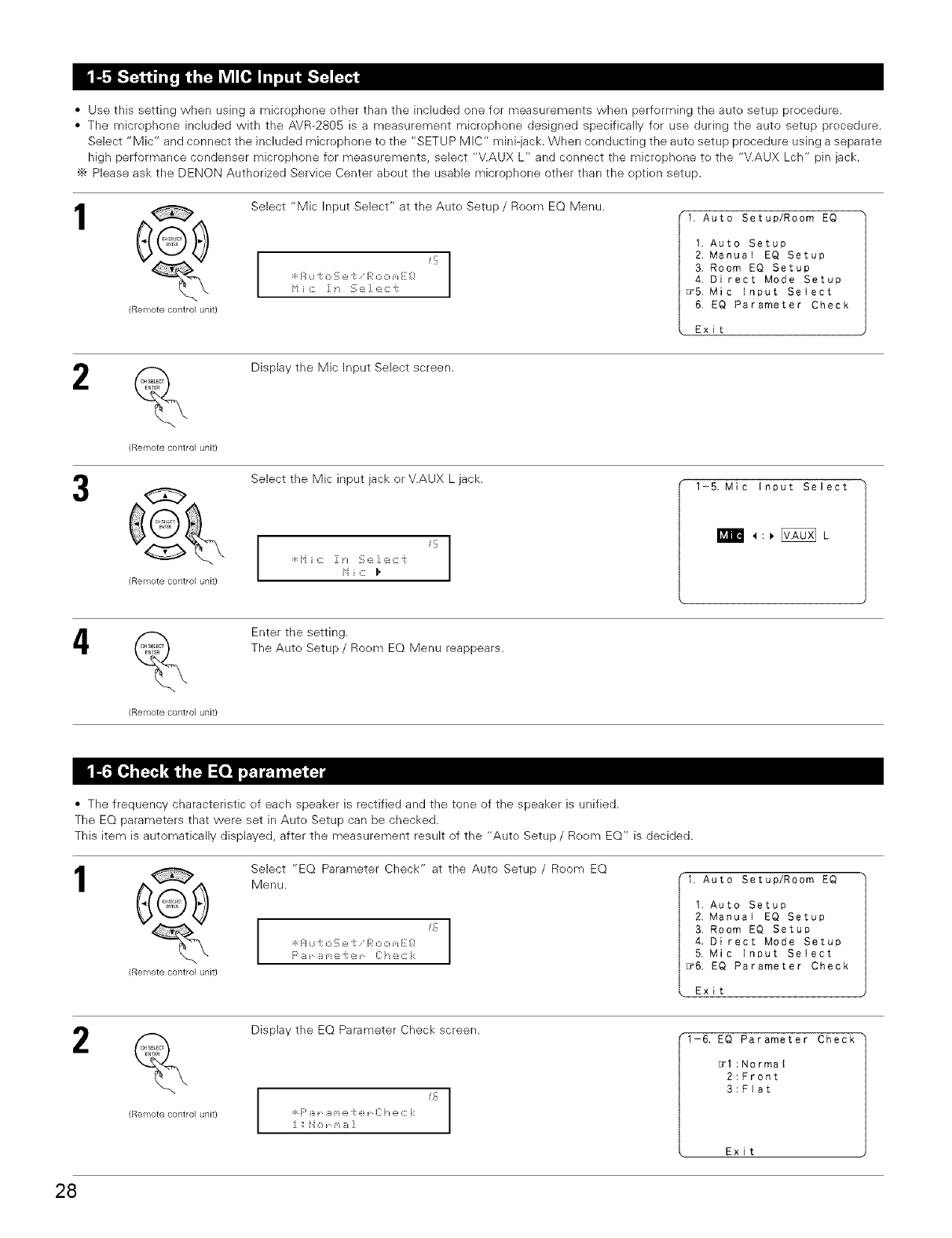
•Use this setting when using a microphene other than the included one for measurements when performing the auto setup procedure.
• The micrephone included with the AVR-2805 is a measurement microphone designed specifically for use during the auto setup precedure.
Select "Mic" and connect the included microphone to the "SETUP MIC" mini-jack. When conducting the auto setup procedure using a separate
high performance cendenser microphone for measurements, select "V.AUX L" and connect the microphone te the "V.AUX Lch" pin jack.
•_ Please ask the DENON Authorized Service Center about the usable microphone other than the option setup.
1@
(Remote control unit)
Select "Mic Input Select" at the Aute Setup /Roem EQ Menu.
" I
q: H U "t O !:, e "t e<' O O m e: _!
H i c 1[ i_ S e ] ec ¢
1, Auto Setup/Room EQ
1. Auto Setup
2. Manual EQ Setup
3, Room EQ Setup
4. Direct Mode Setup
_5. Mic Input Select
6. EQ Parameter Check
Exit
2
(Remote control unit)
Display the Mic Input Select screen.
Select the Mic input jack or V.AUX L jack.
'9
H ic I,
1-5. Mic Input Select
I_n_ _ :, [_ L
4%
(Remote control unit/
Enter the setting.
The Aute Setup /Room EQ Menu reappears.
• The frequency characteristic ef each speaker is rectified and the tone of the speaker is unified.
The EQ parameters that were set in Auto Setup can be checked.
This item is automatically displayed, after the measurement result of the "Aute Setup /Reem EQ" is decided.
1@
(Remote control unit/
Select "EQ Parameter Check" at the Auto Setup /Reom EQ
Menu.
_o
:_:Fi u J; o S e -i: R o o _,_E Q
F' B r B m e "i: e r {]: ::_: C i::
1. Auto Setup/Room EQ
1, Auto Setup
2, Manual EQ Setup
3. Room EQ Setup
4. Direct Mode Setup
5, Mic Input Select
_6. EQ Parameter Check
Exit
2%
(Remote control unit/
Display the EQ Parameter Check screen.
I
15
I
t-6, EQ Parameter Check
_l:Normat
2:Front
3:Flat
Exit
28
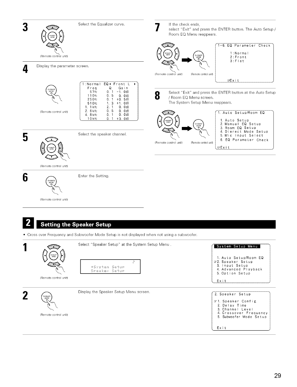
4
(Remote control unit/
Select the Equalizer curve.
Display the parameter screen.
%
(Remote control unit/
l:Normal EQ_ Front L _"
Freq Q Gain
5?Hz 0. 1 -1, 0dB
1 10Hz 0. 5 0. 0dB
250Hz 0. I +0, 5d8
510Hz t, 3 +1. Od8
1. 1kHz 2. t O. OdB
2. 6kHz 0. 5 0. 0d8
4. 8kHz O. I O. Od8
lOkHz O, 1 +3. Od8 ,
_ Select the speaker channel.
(Remote control unit/
_ Enter the Setting.
(Remote control unit}
If the check ends,
select "Exit" and press the ENTER butten. The Auto Setup/
Room EQ Menu reappears.
(Remote control unit) (Remotecontrolunit)
1-6, EQ Parameter Check
1:Normal
2:Front
3:Flat
_Exit
Select "Exit" and press the ENTER butten at the Auto Setup
/Room EQ Menu screen.
The System Setup Menu reappears.
(Remote control unit) (Remotecontrolunit)
1. Auto Setup/Room EQ
1. Auto Setup
2. Manual EQ Setup
3. Room EQ Setup
4. Dierect Mode Setup
5. Mic Input Select
6. EQ Parameter Check
_Exit
D
• Cress ever Frequency and Subwoefer Mede Setup is net displayed when net using a subweofer.
1
(Remote control unit)
Select "Speaker Setup" at the System Setup Menu.
1. Auto Setup/Room EQ
_2. Speaker Setup
3. Input Setup
4, Advanced Playback
5. Option Setup
Exit
2
(Remote control unit)
Display the Speaker Setup Menu screen. 2. Speaker Setup
_1. Speaker Config,
2. Delay Time
3. Channel Level
4. Crossover Frequency
5. Subwoofer Mode Setup
Exit
29
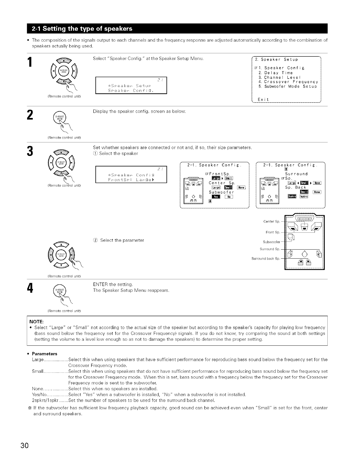
•The composition ef the signals output to each channels and the frequency respense are adjusted automatically accerding te the cembination ef
speakers actually being used.
1e
(ReiTiote control unit/
Select "Speaker Cenfig." at the Speaker Setup Menu.
1
J J
!_;F: ::_:B i:: @ -_Z[:o t'_ J: i _[
2. Speaker Setup
_1, Speaker Config.
2. Delay Time
3. Channel LeveI
4. Crossover Frequency
5, Subwoofer Mode Setup
Exit
2
(Remote control unit)
Display the speaker config, screen as below.
e
(Remote control unit)
Set whether speakers are connected er not and, if so, their size parameters.
,i}; Select the speaker
F:¸ _ 0 i_ "i: i_ F¸ : L _ _ !_i _ I_ '1 2-1. Speaker Config.
_FrontSp.
Center Sp,
Subwoofer
2-1. Speaker Config,
Surround
_ :rSp.
Sp. Back
4
@
(ReiTiote control unit/
%
(Remote control unit)
_x
,2JSelect the Darameter
Center Sp
Front Sp
Subwoofer
Surround Sp
Surround back Sp
ENTER the setting.
The Speaker Setup Menu reappears.
NOTE:
• Select "Large" or "Small" not accerding te the actual size of the speaker but accerding to the speaker's capacity for playing low frequency
(bass sound below the frequency set for the Crossover Frequency) signals, if you do net knew, try comparing the sound at beth settings
(setting the veiume tea level lew eneugh se as net te damage the speakers) to determine the preper setting.
• Parameters
Large ................... Select this when using speakers that have sufficient performance fer reproducing bass sound belew the frequency set for the
Crossover Frequency mode.
Small ................... Select this when using speakers that do not have sufficient perfermance for reproducing bass sound belew the frequency set
for the Crossever Frequency mode. When this is set, bass sound with a frequency below the frequency set for the Crossover
Frequency mede is sent to the subwoefer.
Nene .................. Select this when no speakers are installed.
Yes/Ne ................ Select "Yes" when a subweofer is installed, "Ne" when a subweefer is net installed.
2spkrs/lspkr ....... Set the number of speakers to be used for the surreund back channel.
÷ If the subwoofer has sufficient low frequency playback capacity, goed seund can be achieved even when "Small" is set fer the frent, center
and surreund speakers.
30
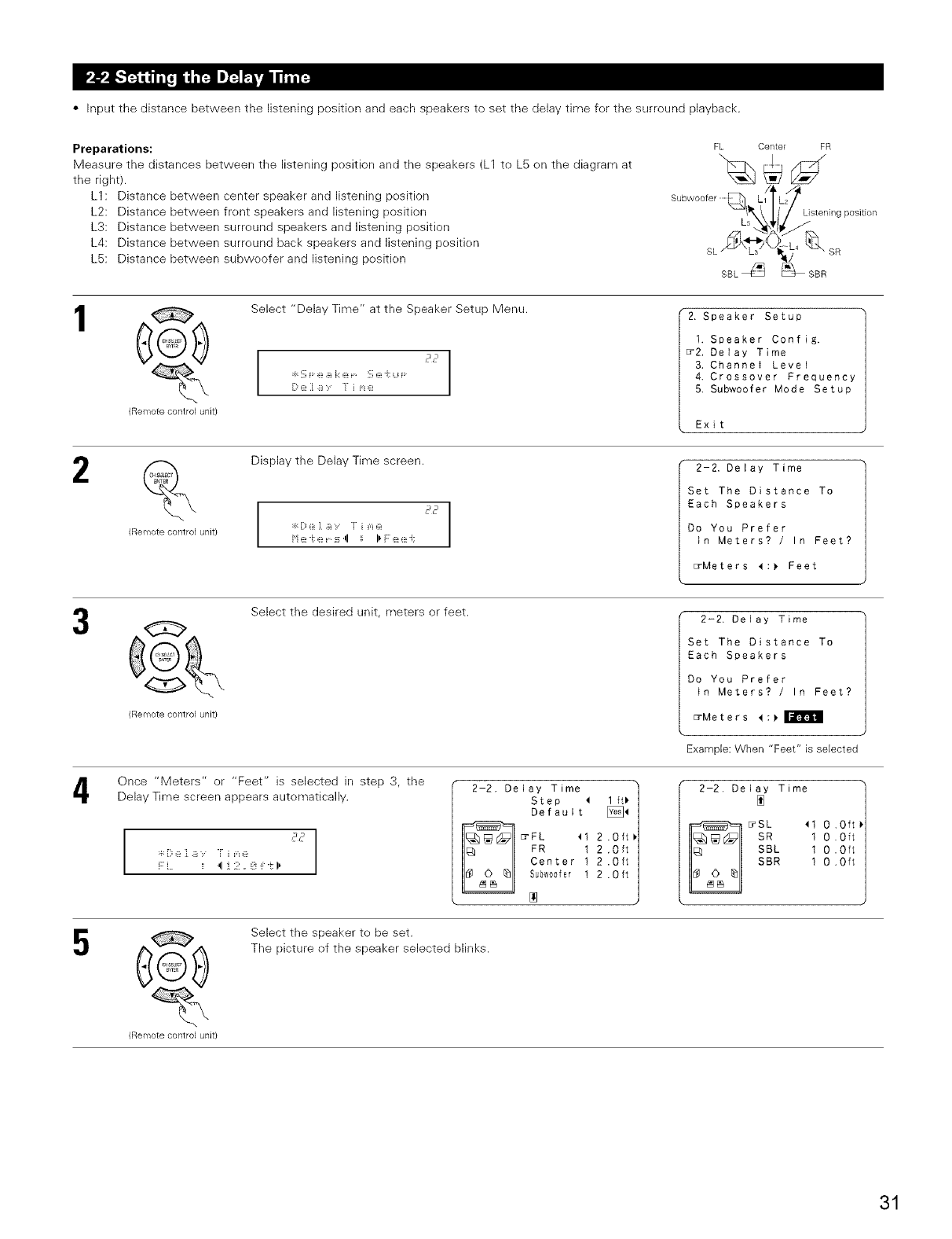
• Input the distance between the listening pesitk)n and each speakers to set the delay time fer the surround playback.
Preparations:
Measure the distances between the listening position and the speakers (L1 to L5 en the diagram at
the right).
L1 : Distance between center speaker and listening position
L2: Distance between frent speakers and listening position
L3: Distance between surreund speakers and listening position
L4: Distance between surreund back speakers and listening pesitien
L5: Distance between subweofer and listening pesitien
FL Center FR
Listening position
SL SR
SBL _/_ _-- SBR
1Q
(Remote control unit}
Select "Delay Time" at the Speaker Setup Menu. 2. Speaker Setup
1. Speaker Config.
_2. Delay Time
3. Channel Level
4. Crossover Frequency
5. Subwoofer Mode Setup
Exit
2
(Ren_lote control unit/
Display the Delay Time screen.
I
2-2, Delay Time
Set The Distance To
Each Speakers
Do You Prefer
in Meters? /In Feet?
_Meters 4:_ Feet
3G
(Remote control unit)
Select the desired unit, meters or feet.
Once "Meters" or "Feet" is selected in step 3, the
Delay Time screen appears automatically.
2-2. Delay Time
Set The Distance To
Each Speakers
Do You Prefer
in Meters? /In Feet?
_Meters _:_
Example: When "Feet" is selected
5
,J2
i:7L :; 4 i 2. !3 _:-i:I_
2-2. Delay Time
Step < lft_
Default _<
FL <1 2.0ft_
FR 1 2 ,Oft
Center 1 2.Oft
Subw00fer 1 2 .0 ft
2-2. Delay Time
E_SL <1 O .Oft
SR 1 O .Oft
SBL 1 O .Oft
SBR 1 O .Oft
(Ren_lote control unit}
Select the speaker te be set.
The picture ef the speaker selected blinks.
31
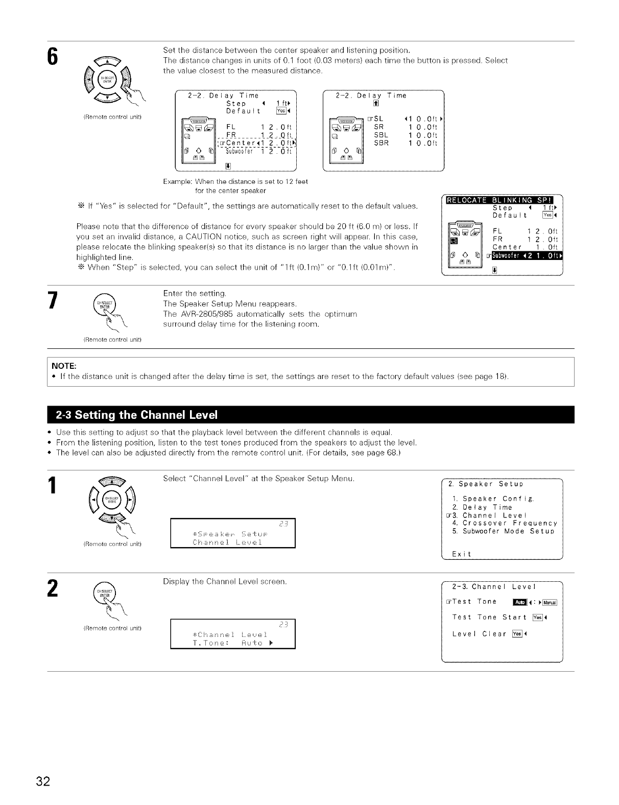
6
(Remote control unit/
Set the distance between the center speaker and listening pesition.
The distance changes in units ef 0.1 feet (0.03 meters) each time the button is pressed. Select
the value clesest to the measured distance.
2-2. Delay Time
Step 4 I ft_
Default [)_
FL 1 2.Oft
FR 12__Q
Er%-enter41 2.0ft_
2-2. Delay Time
E_SL 41 O.0ft
SR 1 0 .Oft
SBL 1 0 .Oft
SBR 1 0 .Oft
Example: When the distance is set to 12 feet
for the center speaker
•_ If "Yes" is selected for "Default", the settings are automatically reset to the default values.
Please note that the difference ef distance for every speaker should be 20 ft (6.0 m) or less. If
you set an invalid distance, a CAUTION notice, such as screen right win appear, in this case,
please relecate the blinking speaker(s) so that its distance is no larger than the value shown in
highlighted line.
•_ When "Step" is selected, you can select the unit of "1 ft (0.1 m)" or "0.1 ft (0.01 m)".
lilllol_.III I|lll Ill[f1|
Step _ lft_i
Default _4
FL 1 2. Oft
FR 1 2, Oft
Center 1 . Oft
_ Enter the setting.
The Speaker Setup Menu reappears.
The AVR-2805/985 autematically sets the optimum
surreund delay time for the listening room.
(Remote contlo] unit}
NOTE:
If the distance unit is changed after the delay time is set, the settings are reset te the factery default values (see page 18).
• Use this setting to adjust se that the playback level between the different channels is equal.
• From the listening pesition, listen to the test tenes produced from the speakers to adjust the level.
• The level can alse be adjusted directly frem the remote centrol unit. (Fer details, see page 68.)
1@
(Remote contlol unit)
Select "Channel Level" at the Speaker Setup Menu.
J_
2. Speaker Setup
1. Speaker Config.
2. Delay Time
_3. Channel Level
4. Crossover Frequency
5. Subwoofer Mode Setup
Exit
2%
(Remote contlol unit}
Display the Channel Level screen.
_q
c p
r ,< ]" O ::_:: FI u "[: C I _
2-3. Channel Level
_Test Tone _4:_
Test Tone Start [_4
Level Clear [_
32
4
5
(Remote control unit/
Select the mede.
Select "Auto" or "Manual".
J
"[ ,"[ o i'_ e ',', FI Li "i: O I _
2-3. Channel Level i
,i
'_Test Tone _t:_[_
• ...........................
Test Tone Start [_t
Level Clear [_4
• Auto:
Adjust the level while listening to the test tones preduced
automatically from each speaker.
• Manual: Example:When the "Auto" mode isselected
Select the speaker frem which yeu want te produce the test tone to adjust the level.
(Remote control unit}
Select "Test Tene Start".
Select "Yes".
2-3. Channel Level
Test Tone _:_[_
_Test Tone Start [_4
Level Clear [_
6
(Remote control unit}
(Remole corn:rol unil:)
(Remote control unit/
G
(Remote control unit/
a. When the "Auto" merle is selected:
Test tones are automaticaNy emitted from each speaker.
The test tones are emitted from each speaker in the fellowing
erder, at 4-second intervals the first time and second time around, 2-
secend intervals the third time around and en:
,_ Ispkr d/z
!:
/ 2spk,s j
•_ When the surreund back speaker setting is set te "lspkr" fer
"Speaker Configuration", this is set te "SB".
2-3. Test Tone@
E_FL _-1 1 5d8_
C 0 5dB
FR 00dB
SR 00dB
SBR 00dB
SBL 0 OdB
SL 00dg
SW 00dB
Example: When the volume is set to-11.5 dB
while the test tone is being
produced from the Front Lch
speaker
Use the CURSOR left and right buttens te adjust all the speakers to the
same velume.
The volume can be adjusted between -12 dB and +12 dB in units ef 0.5 dB. F:L _ _1 - :{ i ,<!75,::ii_{',Iv
b. When the "Manual" mede is selected :
Select the speaker.
¢7_'Adjust all the speakers te the same w)lume.
33
,%
(Remote control unit/
Enter the setting.
The "Channel Level" screen reappears.
÷ To cancel the settings, press the CURSOR down to select "Level Clear" and "Yes" on the "Channel Level" screen, then make the settings
again.
NOTE:
When adjusting the level of an active subweofer system, you may also need te adjust the subweofer's own volume control.
•_ When you adjust the channel levels while in the SYSTEM SETUP CHANNEL LEVEL mode, the channel level adjustments made will affect
all surreund modes. Consider this mode a Master Channel Level adjustment mode.
•_ After yeu have completed the SYSTEM SETUP CHANNEL LEVEL adjustments, you can then activate the individual surround modes and
adjust channel levels that will be remembered for each of those medes. Then, whenever you activate a particular surround sound mede,
your preferred channel level adjustments for just that mode will be recalled. Check the instructions fer adjusting channel levels within each
surround mode. (See page 68)
•_ You can adjust the channel levels for each of the fellowing surround modes: PURE DIRECT/DIRECT, STEREO, DOLBY/DTS SURROUND,
5/7 CH STEREO, WIDE SCREEN, SUPER STADIUM, ROCK ARENA, JAZZ CLUB, CLASSIC CONCERT, MONO MOVIE, VIDEO GAME,
MATRIX and VIRTUAL.
• Set the crossever frequency mede according to the speaker system being used.
1@
(Remote control unit}
Select the "Crossover Frequency" at the Speaker Setup Menu.
J J
•T_::, b" _ ,_ _g_ r _ ::, _ _, _._ _"
_., r __.__> :_:,_._",," _ _" r" r __ "_,
2. Speaker Setup
1. Speaker Confi&.
2. Delay Time
3, Channel Level
_4, Crossover Frequency
5. Subwoofer Mode Setup
Exit
2
(Remote control unit}
Remote contlol unit}
Display the Crossover Frequency screen.
Select the frequency.
I
I
•4 88 H:: I).
•40/60/80/100/120/150/200/250Hzcanbe
selected.
2-4. Crossover Frequency
4
Remote contlol unit/
Enter the setting.
The Speaker Setup Menu reappears.
34
This screen is not displayed when not using a subwoofer and all speakers are set te small size.
• Set the subwoefer mode accerding te the speaker system being used.
Select the "Subwoofer Mode Setup" at the Speaker Setup
Menu.
(Remote control unit/
:4: !_i F: ::E_B i:: e !_i e "i: Li F
2. Speaker Setup
1. Speaker Config.
2. Delay Time
3. Channel Level
4, Crossover Frequency
_5 Subwoofer Mode Setup
Exit
2
(Remote control unit)
Display the Subwoefer mode screen.
G
Remote control unit)
Select the setting.
I
5
:_::_ i ii::,i,i O O J:(_: i'i O ,::ie I
I
L FE: I,
2-5. Subwoofer Mode
_ I:_ LFE
+ Main
_ Enter the setting.
The Speaker Setup Menu reappears.
Remote control unit)
NOTES:
-- Assignment of low frequency signal range (2-1) --
• The only signals pleduced flem the subwoofel channel are LFE signals (during playback of Delby Digital el DTS signals) and the low
frequency signal range of channels set to "SMALL" in the setup menu. The low frequency signal range of channels set to "LARGE" are
preduced from those channels.
-- Crossover Frequency (2-4) --
• When "Subweofer" is set to "Yes" at the "Speaker Configuration Setting", set the frequency (Hz) below wMch the bass sound ef the
various speakers is to be output frem the subwoofer (the crossever frequency).
• Fer speakers set to "Small", sound with a frequency below the crossever frequency is cut, and the cut bass seund is output frem the
subwoefer instead.
(• When the subwoefer set to "NO", the bass sound is output frem the speaker set as "Large".)
NOTE: For ordinary speaker systems, we recommend setting the crossever frequency to 80 Hz. When using small speakers, however,
setting the crossover frequency to a high frequency may impreve frequency response fer frequencies near the cressever frequency.
-- Subwoofer mode (2-5) --
• The subwoefer mede setting is only valid when "LARGE" is set fer the frent speakers and "YES" is set for the subwoefer in the "Setting
the type of speakers". (see page 30).
• When the "LFE+MAIN" playback mede is selected, the low frequency signal range of channels set to "LARGE" are preduced
simultaneeusly from those channels and the subweofer channel.
In this playback mode, the low frequency range expand more uniformly threugh the room, but depending on the size and shape ef the roem,
interference may result in a decrease ef the actual w)lume of the low frequency range.
• Selection of the "LFE " play mede will play the low frequency signal range of the channel selected with "LARGE" from that channel enly.
Therefere, the low frequency signal range that are played from the subweofer channel are only the low frequency signal range of LFE (only
during Dolby Digital or DTS signal playback) and the channel specified as "SMALL" in the setup menu.
• Select the play mode that prevides bass repreductien with quantity.
• When the subweofer is set te "Yes", bass sound is eutput from the subweofer regardless of the subwoefer mode setting in surround modes
other than DoIby/DTS.
• In surreund modes other than Delby Digital and DTS, if the subwoofer is set to "YES", the lew frequency portien is always eutput te the
subwoefer channel. Fer details, refer te "Surround Medes and Parameters". (See page 68)
35
2
(Remote control unit}
(Rell_lote control unit/
At the System Setup Menu select "Input Setup".
][ F U "i: !_;@"i:U F
1. Auto Setup/Room EQ
2, Speaker Setup
_3. Input Setup
4. Advanced Playback
5, Option Setup
Exit
Display the Input Setup Menu screen.
36
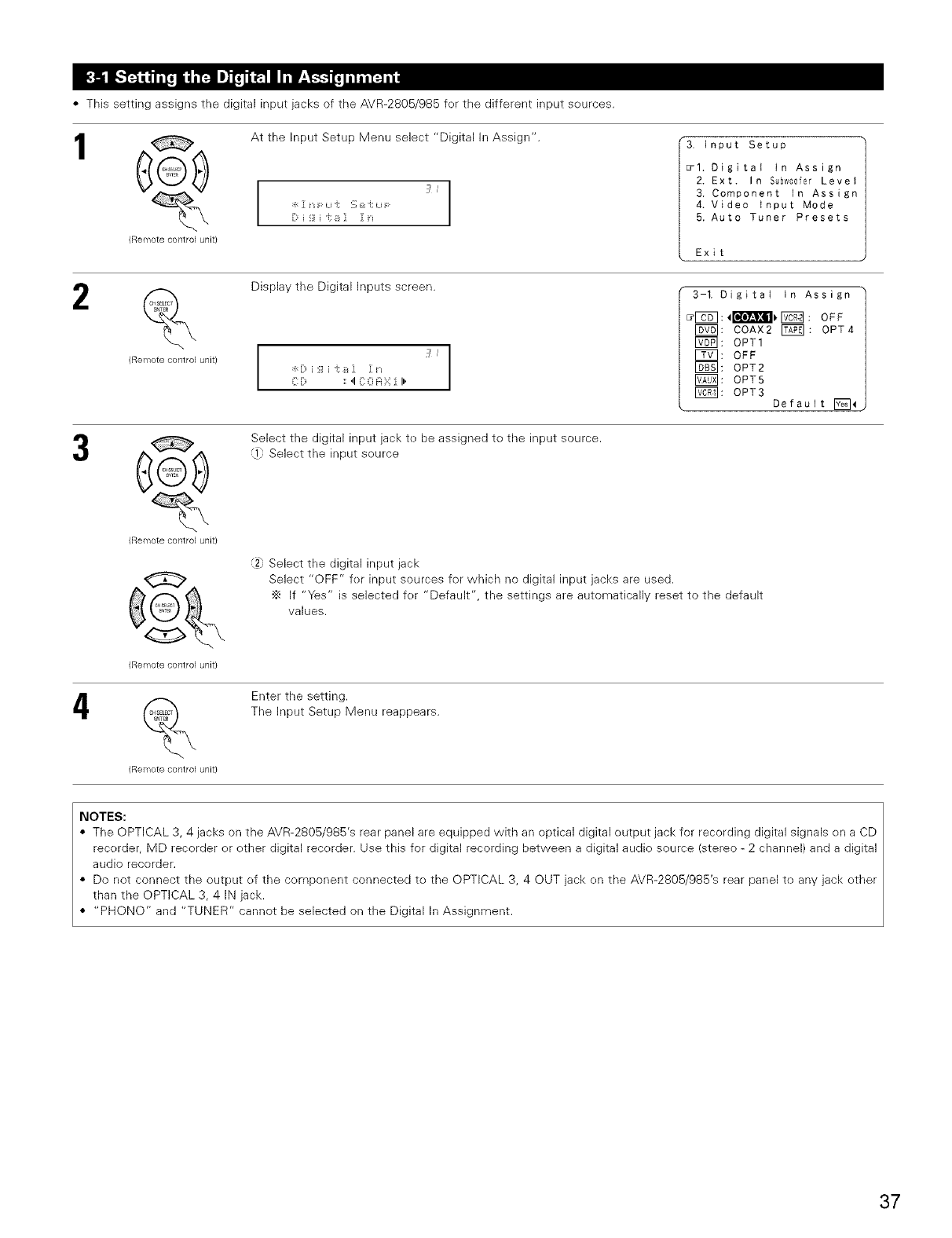
•This setting assigns the digital input jacks of the AVR-2805/985 fer the different input sources.
At the Input Setup Menu select "Digital In Assign".
(Remote contro] unit)
(Remote control unit)
G
(Remote control unit)
J
Display the Digital Inputs screen.
"3. bnput Setup
_1. Digital In Assign
2. Ext. In Subw00fer Level
3. Component In Assign
4. Video Input Mode
5. Auto Tuner Presets
Exit
¢ih '/, _1C _h '".......... H ;::::[ li'
Select the digital input jack te be assigned te the input source.
,i_: Select the input seurce
3-1. DigitaI tn Assign
_F_61: 4_ IT6_ : OFF
F625]: COAX2 _: OPT4
I_1:OPT1
FfT]: OFF
_; OPT2
F_0x] : OPT5
F_: OPT3 Default _
(2: Select the digital input jack
Select "OFF" fer input sources for which no digital input jacks are used.
•_ If "Yes" is selected fer "Default", the settings are automatically reset to the default
values.
_ Enter the setting.
The Input Setup Menu reappears.
(Remote control unit)
NOTES:
• The OPTICAL 3, 4 jacks on the AVR-2805/985's rear panel are equipped with an optical digital output jack for recording digital signals en a CD
recerder, MD recorder er other digital recerder. Use this for digital recording between a digital audio source (stereo - 2 channel) and a digital
audio recorder.
• Do not connect the output ef the cemponent connected to the OPTICAL 3, 4 OUT jack en the AVR-2805/985's rear panel te any jack other
than the OPTICAL 3, 4 IN jack.
• "PHONO" and "TUNER" cannot be selected on the Digital In Assignment.
37
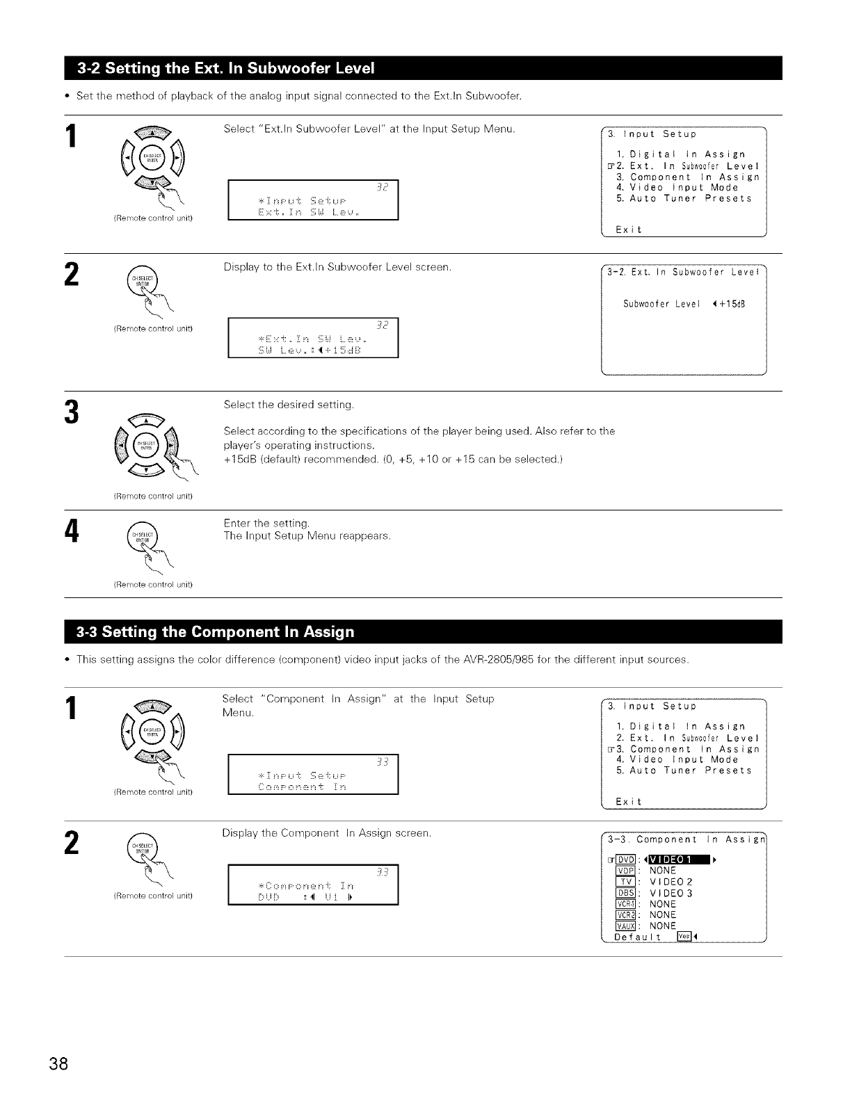
•Set the method of playback of the analog input signal connected to the Ext.ln Subwoofer.
1
(Remote control unit)
Select "Ext.ln Subwoefer Level" at the Input Setup Menu.
z_c
"3. Input Setup
I, Digital in Assign
_2. Ext. In Subw00fer Level
3. Component In Assign
4, Video input Mode
5. Auto Tuner Presets
Exit
2
(Remote co/ltrol unit)
Display to the Ext.ln Subwoofer Level screen.
I
3E'
I
"3-2, Ext. In Subwoofer LeveI_
Subwoof er Level <+15dB
@
(Remote contlol unit)
(Remote contlol unit)
Select the desired setting.
Select according to the specifications of the player being used. Also refer to the
player's operating instructions.
+15dB (default) recommended. (0, +5, +10 or +15 can be selected.)
Enter the setting.
The Input Setup Menu reappears.
• This setting assigns the color difference (component) vide() input jacks of the AVR-2805/985 for the different input sources.
1
2
(Remote control unit)
(Remote control unit)
Select "Component In Assign" at the Input Setup
Menu. "3. Input Setup
1. Digital tn Assign
2. Ext. In Subw00fer Level
_3. Component in Assign
4. Video input Mode
5. Auto Tuner Presets
Exit
Display the Component In Assign screen.
:_:_[[:0 m F 0 t":@t":i; ][ t":
' :: 4 :[ I_
"3-3. Component In Assigr
F_]: NONE
E_: VIDEO 2
I_]: VIDEO 3
_: NONE
I_: NONE
F_0_]: NONE
Default _<
38
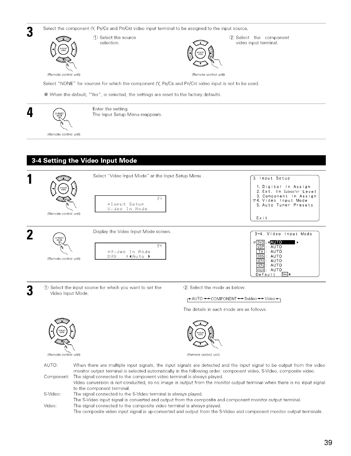
4
Select the component (Y, PB/CB and PR/CR)video input terminal to be assigned to the input source.
Select the source
_ selection.
(Remote control unit} (Remote control unit}
J_ Select the component
video input terminal.
Select "NONE" for sources fer which the cemponent (Y, PB/C8 and PR/CR)video input is not te be used.
"_ When the default, "Yes", is selected, the settings are reset to the factery defaults.
(Ren_lote control unit/
Enter the setting.
The Input Setup Menu reappears.
1
2
(Remote control unit}
Select "Video Input Mede" at the Input Setup Menu.
I
3
I
i ,::i e O Z[ i'1 o ,:J ::_:
*3. Input Setup
1. Digital in Assign
2. Ext. In Subw00fer Level
3. Component In Assign
_4. Video Input Mode
5. Auto Tuner Presets
Exit
(Remote control unit}
Display the Video Input Mode screen.
I
3
:_:ii i ,:i(_,o ]1n i*io ,::i(_ I
I
[> [> ',',41i:iu i: o _.
3-4. Video input Mode
_: AUTO
E_: AUTO
J_: AUTO
_: AUTO
J_: AUTO
F_: AUTO
Default E_4
(]) Select the input seurce fer which you want to set the
Vide<) Input Mede.
2_, Select the mode as below.
[_-AUTO_COMPONENT_ Svideo_ Video _ I
The details in each mode are as follows.
(Remote control unit}
G
(Remote control unit)
AUTO:
Component:
S-Video:
Video:
When there are multiple input signals, the input signals are detected and the input signal to be eutput frem the vide<)
monitor output terminal is selected automatically in the following order: component vide(), S-Video, compesite vide<).
The signal connected to the component video terminal is always played.
Video conversion is net conducted, so no image is output from the monitor eutput terminal when there is ne input signal
to the component terminal.
The signal connected te the S-Video terminal is always played.
The S-Video input signal is converted and eutput frem the composite and cempenent monitor output terminal.
The signal connected te the compesite video terminal is always played.
The composite video input signal is up-cenverted and eutput from the S-Videe and component monitor eutput terminals.
39
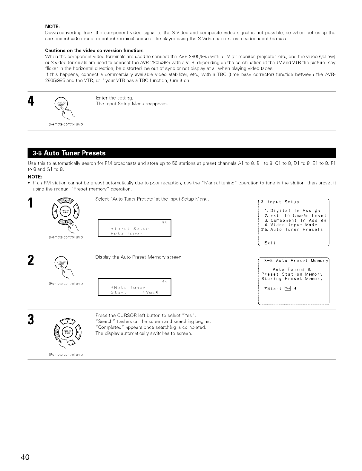
NOTE:
Down-converting from the component video signal to the S-Video and composite vide<>signal is not possible, so when not using the
component vide<> monitor output terminal connect the player using the S-Video or composite vide<>input terminal.
Cautions on the video conversion function:
When the component vide<>terminals are used to connect the AVR-2805/985 with a TV (or monitor, projector, etc.) and the video (yelbw)
or S video terminals are used to connect the AVR-2805/985 with a VTR, depending on the combination of the TV and VTR the picture may
flicker in the horizontal direction, be distorted, be out of sync or not display at all when playing video tapes.
If this happens, connect a commercially available video stabilizer, etc., with a TBC (time base corrector) function between the AVR-
2805/985 and the VTR, or if your VTR has a TBC function, turn it on.
4%
(Remote control unit/
Enter the setting.
The Input Setup Menu reappears.
Use this to automatically search for FM broadcasts and store up to 56 stations at preset channels A1 to 8, B1 to 8, C1 to 8, D1 to 8, E1 to 8, F1
to 8 and G1 to 8.
NOTE:
•If an FM station cannot be preset automatically due to poor reception, use the "Manual tuning" operation to tune in the station, then preset it
using the manual "Preset memory" operation.
1@
Remote control unit}
Select "Auto Tuner Presets'at the Input Setup Menu.
:_: ][ i"_i:: Li i; 2_(_:i; Li i::
i:_ Li i; O "[ Li i"_ @
"3. input Setup
I. Digitat in Assign
2. Ext. In S_bw00fer Level
3. Component in Assign
4. Video Input Mode
_5. Auto Tuner Presets
Exit
2%
Remote control unit}
Display the Auto Preset Memory screen.
I
5
:_:i:i U i; O "[ U i'_e I
I
3-5. Auto Preset Memor
Auto Tuning &
Preset Station Memory
Storing Preset Memory
_Start [T_]
@
Remote control unit}
Press the CURSOR left button to select "Yes".
"Search" flashes on the screen and searching begins.
"Cor_pleted" appears once searching is completed.
The display automatically switches to screen.
40
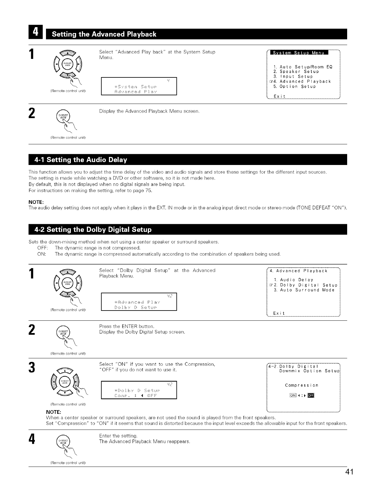
(Remote control unit/
2(Remote control unit/
Select "Advanced Play back" at the System Setup
Menu.
I
I
b[ ,:J _i t'_C ::_:,:J F:' ][ _i
1. Auto Setup/Room EQ
2. Speaker Setup
3. input Setup
_4. Advanced Playback
5, Option Setup
Exit
Display the Advanced Playback Menu screen.
This function allews you te adjust the time delay of the video and audio signals and stere these settings fer the different input sources.
The setting is made while watching a DVD or ether software, so it is not made here.
By default, this is not displayed when no digital signals are being input.
Fer instructions en making the setting, refer to page 75.
NOTE:
The audio delay setting does net apply when it plays in the EXT. IN mode or in the analeg input direct mode er stereo mode (TONE DEFEAT "ON ").
Sets the down-mixing method when not using a center speaker or surround speakers.
OFF: The dynamic range is net compressed.
ON: The dynamic range is cempressed autematically according te the cembination of speakers being used.
1
2
4
(Remote control unit)
Select "Dolby Digital Setup" at the Advanced
Playback Menu.
:_:]:J,::i ]_: C: e ,::i F' ] ]_: :,
"4. Advanced Playback
t. Audio Delay
_2. Dolby Digital Setup
3. Auto Surround Mode
Exit
(Remote control unit)
Press the ENTER button.
Display the Delby Digital Setup screen.
G
(Remote control unit)
Select "ON" if yeu want to use the Compression,
"OFF" if yeu de not want to use it.
:F:L:_0 J _:,:, L:_ '::, (_:i; ij F
Co _,_i::,, :: ,I 0 F:F
"4-2.Dotby Digital
Downmix Option Setupi
NOTE:
When a center speaker or surround speakers, are not used the seund is played frem the frent speakers.
Set "Compression" to "ON" if it seems that sound is disterted because the input level exceeds the allewable input fer the front speakers.
(Remote control unit)
Enter the setting.
The Advanced Playback Menu reappears.
41
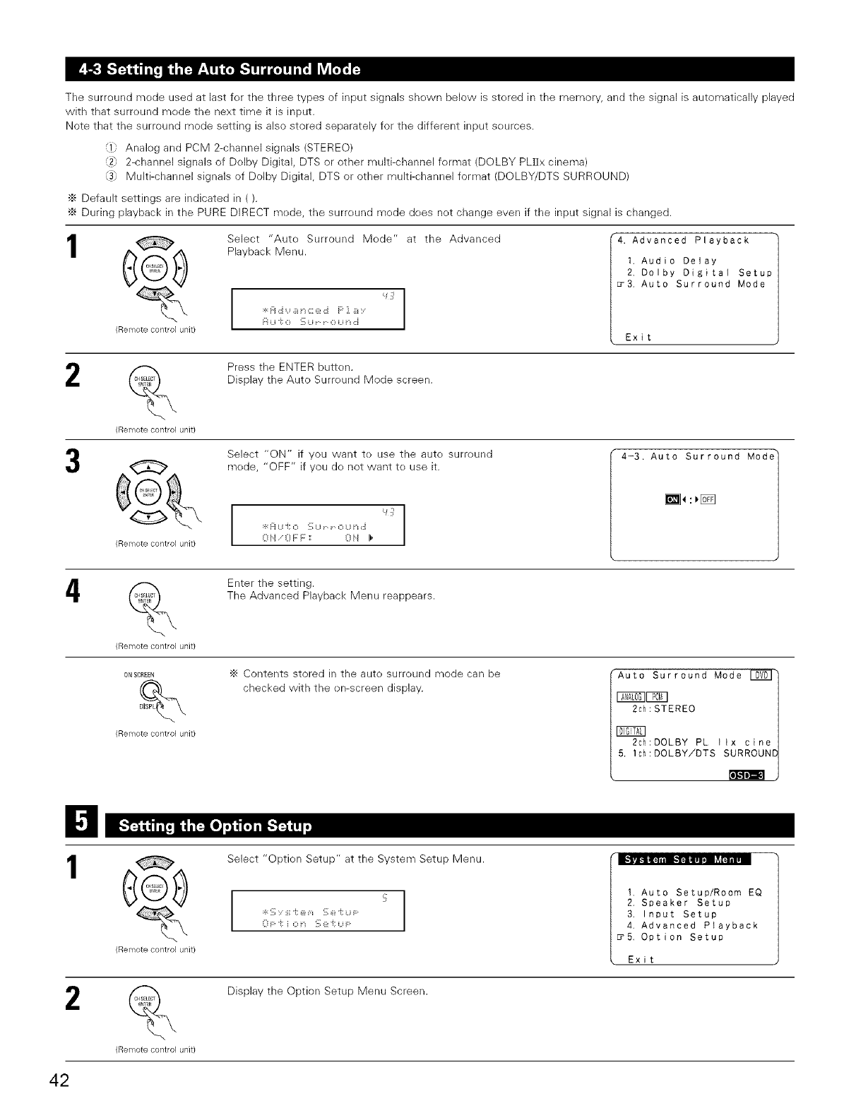
The surreund mode used at last for the three types of input signals shown below is stered in the memory, and the signal is automatically played
with that surreund mede the next time it is input.
Note that the surround mode setting is also stored separately for the different input seurces.
(1. Analeg and PCM 2-channel signals (STEREO)
_2_ 2-channel signals of Dolby Digital, DTS or other multi-channel format (DOLBY PLIIx cinema)
(3) Multi-channel signals of Dolby Digital, DTS or other multi-channel format (DOLBY/DTS SURROUND)
•_ Default settings are indicated in ().
÷ During playback in the PURE DIRECT mede, the surreund mede dees net change even if the input signal is changed.
1
(Remote control unit/
Select "Aute Surround Mede" at the Advanced
Playback Menu.
L_j
.r_m ,::i '..' .::i i" i L _:_,::i v_ .::i >"
H U "(: O '::, U - o u ii ,::i
"4. Advanced Playback
1. Audio Delay
2. Dolby Digital Setup
_3. Auto Surround Mode
Exit
2
(Remote control unit}
Press the ENTER button.
Display the Auto Surreund Mode screen.
(Remote control unit}
Select "ON" if you want te use the aute surreund
mede, "OFF" if you de net want te use it.
I
L_
:k Fi u i; o !_;u -0 U t': ,::i I
I
OiJ 0 F F: :: Oti I1'
4-3. Auto Surround Mode_
[]_:_1_
4
(Remote control unit}
ON SCREEN
(Remote control unit)
Enter the setting.
The Advanced Playback Menu reappears.
•_ Contents stored in the auto surreund mode can be
checked with the en-screen display.
"Auto Surround Mode I_V0]_
_F_q
2ch: STEREO
2ch:DOLBY PL lix cine
5, Ich:DOLBY!DTS SURROUN[
[o_
2
(Remote control unit)
(Remote control unit}
Select "Optien Setup" at the System Setup Menu.
I
5
:k '_;:, :_;"i: e v_ !_;e "i: U F I
I
0 F: "i: i O :_ ::Ri; U F:
1, Auto Setup/Room EQ
2, Speaker Setup
3. Input Setup
4, Advanced Playback
_5, Option Setup
Exit
Display the Option Setup Menu Screen.
42
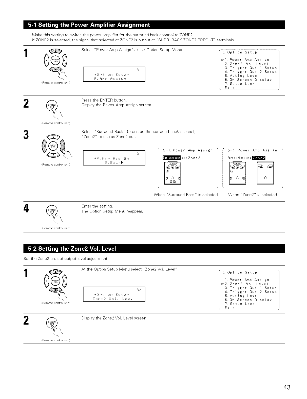
Make this setting to switch the power amplifier for the surreund back channel to ZONE2.
If ZONE2 is selected, the signal that selected at ZONE2 is output at "SURR. BACK ZONE2 PREOUT" terminals.
Select "Power Amp Assign" at the Option Setup Menu.
@
(Remote control unit) cI
:_:0 F "t: i O n S e -t:u F
m m ...... -, .............
5. Option Setup
_I. Power Amp Assign
2, Zone2 Vol. Level
3, Trigger Out I Setup
4, Trigger Out 2 Setup
5. Muting Level
6. On Screen Display
?, Setup Lock
Exit
2(Remote control unit)
G
(Remote control unit)
4
(Remote control unit)
Press the ENTER butten,
Display the Pewer Amp Assign screen.
Select "Surreund Back" to use as the surreund back channel,
"Zone2" to use as Zone2 out.
I
I
:_:i::' ,, i:i m F i:i _: :_; i '_]i'_ I
I
S. E',_ c k I,
5-I. Power Amp Assign
_4:_Zone2
5-1. Power Amp Assign
Sutr0undback4:_
When "Surreund Back" is selected When "Zone2" is selected
Enter the setting.
The Option Setup Menu reappear.
Set the Zone2 pre-out eutput level adjustment.
1
(Remote control unit)
At the Optien Setup Menu select "Zone2 Vol. Level".
:_:oF:,_io,-,,_;e,,,F: ' I
5. Option Setup
1. Power Amp Assign
_2. Zone2 Vol Level
3. Trigger Out 1 Setup
4. Trigger Out 2 Setup
5. Muting Level
6. On Screen Display
?, Setup Lock
Exit
2
(Remote control unit)
Display the Zone2 Vel. Level screen.
43
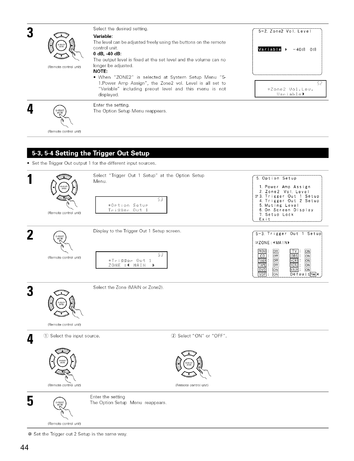
(Remote control unit/
4%
(Remote control unit)
Select the desired setting.
Variable:
The level can be adjusted freely using the buttens on the remote
control unit.
0 dB, -40 dB:
The output level is fixed at tile set level and tile volume carl ne
bnger be adjusted.
NOTE:
• When "ZONE2" is selected at System Setup Menu "5-
1.Power Amp Assign", the Zene2 vel. Level is all set to
"Variable" including preeut level and this menu is not
displayed.
5-2, Zone2 Vo I, Level
_" -40dB OdB
F_
:r c
:_:Z o e 2 o i , L e ,
B i ]_ i::, i e )'
Enter the setting.
The Option Setup Menu reappears.
• Set the Trigger Out output 1 for the different input seurces.
1Select "Trigger Out 1 Setup" at the Optien Setup
(_ Menu.
:_:0 F:i; i o n !_;e -i: u
_'_ r i ';] ';i e -0 u "i: :[
(Remote control unit}
5. Option Setup
1. Power Amp Assign
2. Zone2 VOl. Level
3. Trigger Out 1 Setup
4. Trigger Out 2 Setup
5. Muting Level
6, On Screen Display
?. Setup Lock
Exit
2%
(Remote control unit)
Display te the Trigger Out Setup screen.
I
5 5'
I
Z0 ii E ',',,I i'i FIi il !>
5-3. Trigger Out 1 Setu_
_ZONE:_MAIN)
r_l: @ Defeu I tr_
e
(Remote control unit)
Select the Zone (MAIN er Zene2).
4Select the input source.
@
(Remote contlol unit)
¢7} Select "ON" or "OFF".
(Remote control unit)
5%
(Remote control unit)
Enter the setting
The Option Setup Menu reappears.
'_ Set the Trigger out 2 Setup in the same way.
44
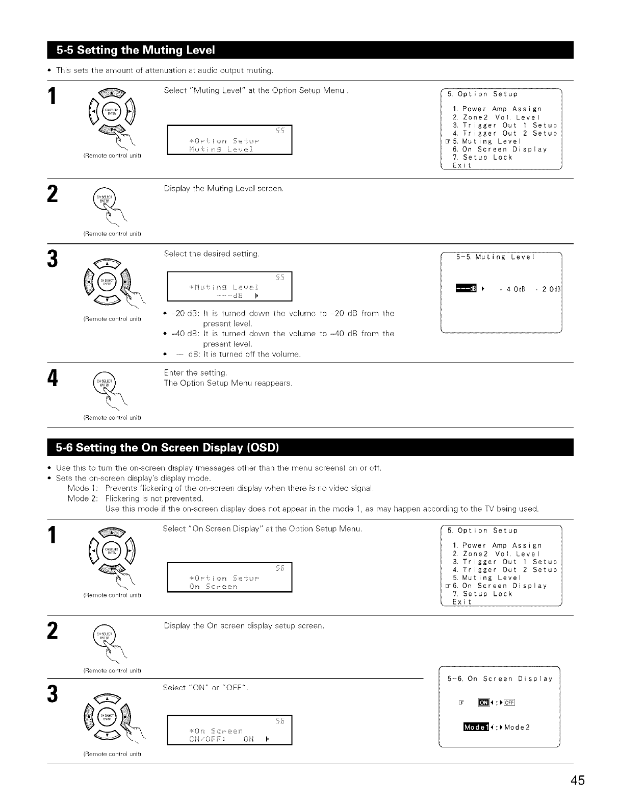
• This sets the amount of attenuation at audio output muting.
1
(Remote control unit)
Select "Muting Level" at the Optien Setup Menu.
:_:oF:,;io,-,,_;e-,:<,F: c_ I
5. Option Setup
1. Power Amp Assign
2. Zone2 Vol Level
3. Trigger Out 1 Setup
4. Trigger Out 2 Setup
5. Muting Level
6. On Screen Display
7. Setup Lock
Exit
2(Remote control unit)
Display the Muting Level screen.
G
(Remote control unit)
(Remote control unit)
Select the desired setting.
ccI
:_:Hui;ii_i Le e1
.........d B I_
• -20 riB: It is turned dewn the velume to -20 dB frem the
present level.
• -40 riB: It is turned dewn the velume to -40 dB frem the
present level.
• -- dB: It is turned off the volume.
Enter the setting.
The Option Setup Menu reappears.
• Use this to turn the on-screen display (messages ether than the menu screens) on or eff.
• Sets the on-screen display's display mede.
Mode 1: Prevents flickering ef the on-screen display when there is no video signal.
Mode 2: Flickering is net prevented.
Use this mede if the on-screen display does not appear in the mode 1, as may happen according to the TV being used.
1@
(Remote control unit)
Select "On Screen Display" at the Optien Setup Menu.
:t o
:_:0 F:is i o i-_ S e -i: u F:
U r I :, L ::[ _:_r I
5. Option setup
1. Power Amp Assign
2. Zone2 Vol. Level
3. Trigger Out 1 Setup
4. Trigger Out 2 Setup
5, Muting Level
_6. On Screen Display
?, Setup Lock
Exit
2
(Remote control unit)
Display the On screen display setup screen.
G
(Remote control unit)
Select "ON" or "OFF".
I
I
U H U P i- _ 0 ii I,
5-6. On Screen Display
I_l_ll}l!!.ll_:>Mode2
45
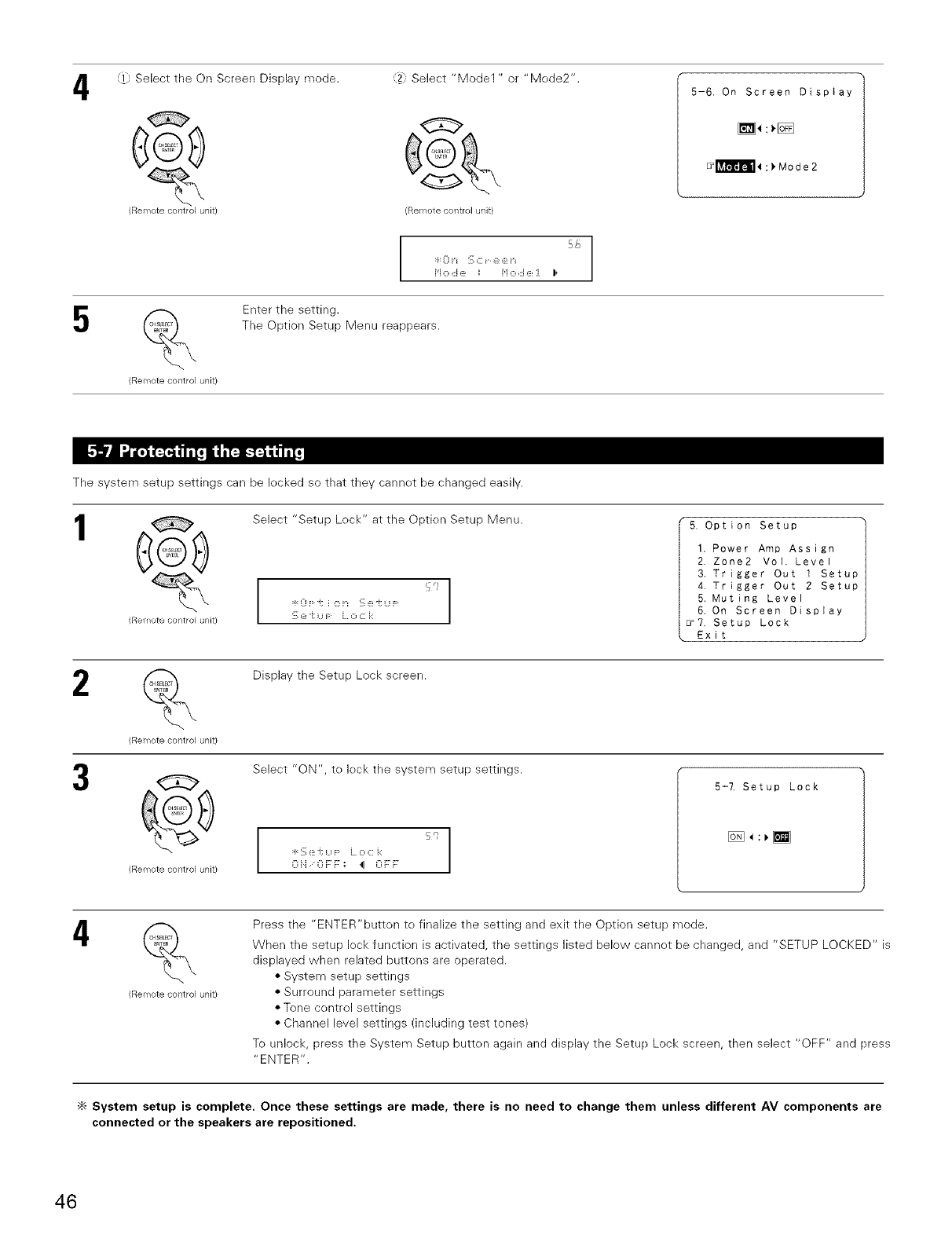
4Select the On Screen Display mode.
(Remote control unit)
5
(Remote control unit/
2; Select "Model " or "Mede2".
(Remote control unit)
5-6, On Screen Display
_:_
58
Ho d e : Ho d ::_:J I,
Enter the setting.
The Option Setup Menu reappears.
The system setup settings can be locked so that they cannet be changed easily.
1
(Remote control Ullit/
Select "Setup Lock" at the Optien Setup Menu.
I
:_:o F:J; i o n s e -i _._- I
I
'_;e -t:u F L o c: i::
5. Option Setup
1. Power Amp Assign
2. Zone2 Vol. Level
3. Trigger Out 1 Setup
4. Trigger Out 2 Setup
5, Muting Level
6. On Screen Display
_7, Setup Lock
Exit
(Remote control unit/
@
(Remote comro] unit)
Display the Setup Lock screen.
Select "ON", te leck the system setup settings.
I
q,
:_:s e J;u i:: L o c i:: I
I
0iJ 0 FF::: 4 0 F:F
5-7, Setup Lock
4(Remote comrol unit)
Press the "ENTER"butten to finalize the setting and exit the Option setup mode.
When the setup leck function is activated, the settings listed below cannet be changed, and "SETUP LOCKED" is
displayed when related buttons are operated.
• System setup settings
• Surround parameter settings
• Tone control settings
• Channel level settings (including test tones)
To unlock, press the System Setup butten again and display the Setup Lock screen, then select "OFF" and press
"ENTER".
"_ System setup is complete. Once these settings are made, there is no need to change them unless different AV components are
connected or the speakers are repositioned,
46
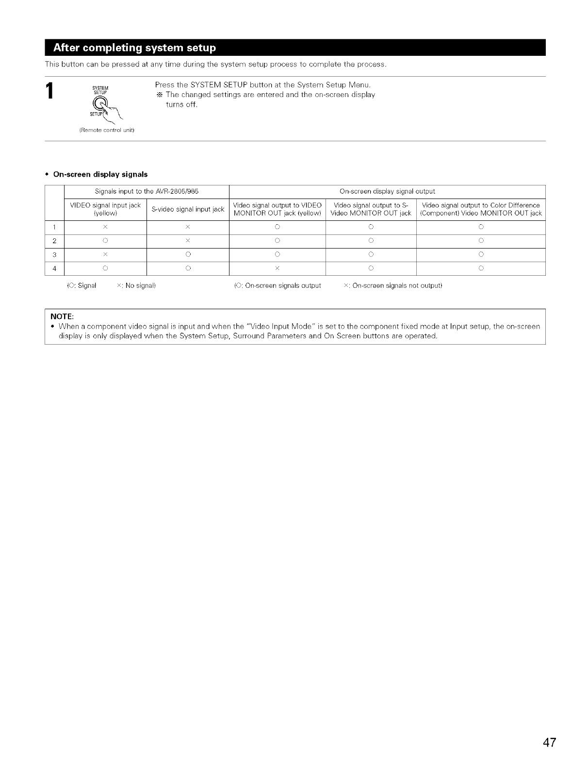
This butten can be pressed at any time during the system setup process te complete the process.
SYSIEM
SErUP
(Remote control unit)
Press the SYSTEM SETUP butten at the System Setup Menu.
•_ The changed settings are entered and the on-screen display
turns eff.
• On-screen display signals
Signals input to the AVR-2805/985 On-screen display signal output
VIDEO signa] input jack S-video signal input jack Video signal output to VIDEO Video signa] output to S- Video signal output to Color Difference
(yellow) MONITOR OUT jack (yellow) Video MONITOR OUT jack (Component) Video MONITOR OUT jack
1 x x C C C
2 C? x C? C? C?
3 x C? C? C? C?
4 C) C) x C) C)
(0: Signal x: No signal) (0: On-screen signals output x: On-screen signals not output)
NOTE:
• When a component video signal is input and when the "Vide(> Input Mode" is set to the component fixed mode at Input setup, the on-screen
display is only displayed when the System Setup, Surreund Parameters and On Screen buttons are eperated.
47
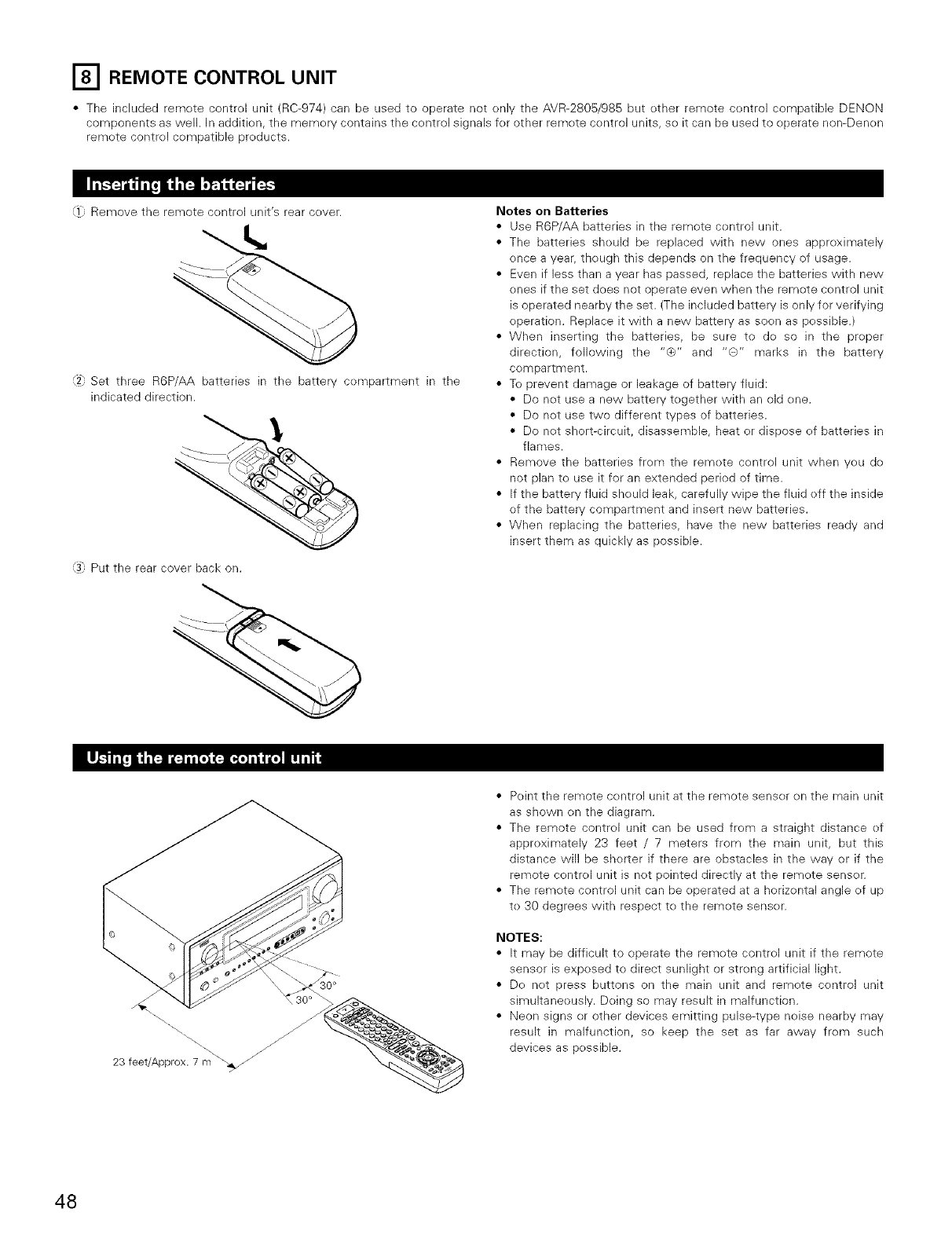
_'_ REMOTE CONTROL UNIT
•The included remote control unit (RC-974) carl be used to operate not only the AVR-2805/985 but other remote control compatible DENON
components as well. in addition, the memory contains the control signals for other remote control units, so it can be used to operate nen-Denon
remote control compatible products.
<] Remove the remote control unit's rear cover.
'2h Set three R6P/AA batteries in the battery compartment in the
indicated direction.
<].: Put the rear cover back on.
Notes on Batteries
• Use R6P/AA batteries in the remote control unit.
• The batteries should be replaced with new ones approximately
once a year, though this depends on the frequency of usage.
• Even if less than a year has passed, replace the batteries with new
ones if the set does net operate even when the remote control unit
is operated nearby the set. (The included battery is only for verifying
operation. Replace it with a new battery as soon as possible.)
• When inserting the batteries, be sure to do so in the proper
direction, following the "¢_" and "G" marks in the battery
compartment
• To prevent damage or leakage of battery fluid:
• Do not use a new battery together with an old one.
• De not use two different types of batteries.
• Do not short-circuit, disassemble, heat or dispose of batteries in
flames.
• Remove the batteries from the remote control unit when you do
not plan to use it for an extended period of time.
• If the battery fluid should leak, carefully wipe the fluid off the inside
of the battery compartment and insert new batteries.
• When replacing the batteries, have the new batteries ready and
insert them as quickly as possible.
23 feet/Approx. 7m'_
• Point the remote control unit at the remote sensor on the mare unit
as shown on the diagram.
• The remote control unit can be used from a straight distance of
approximately 23 feet /7 meters from the main unit, but this
distance will be shorter if there are obstacles in the way or if the
remote control unit is not pointed directly at the remote sensor.
• The remote control unit can be operated at a horizontal angle of up
to 30 degrees with respect to the remote sensor.
NOTES:
• It may be difficult to operate the remote control unit if the remote
sensor is exposed to direct sunlight or strong artificial light.
• Do not press buttons on the main unit and remote control unit
simultaneously. Doing so may result in malfunction.
• Neon signs or other devices emitting pulse-type noise nearby may
result in malfunction, so keep the set as far away from such
devices as possible.
48
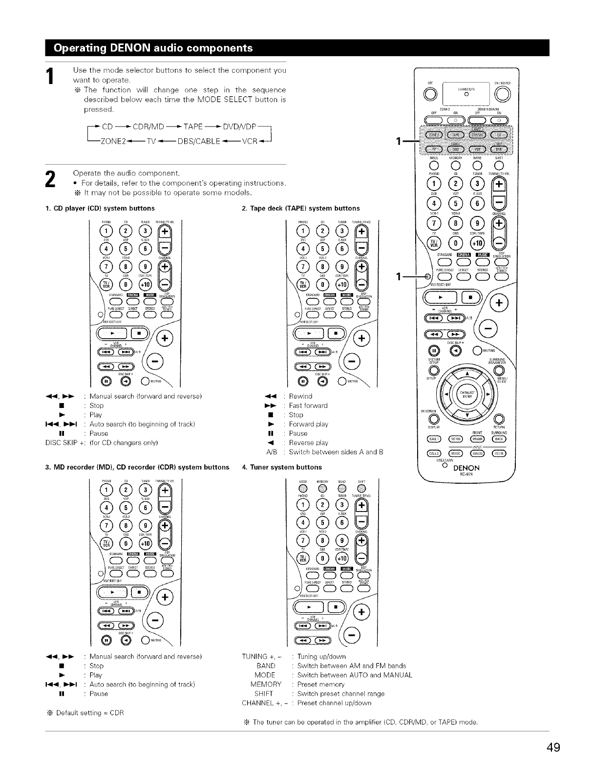
1Use the mede selector buttens te select the component yeu
want te operate.
•_ The function will change ene step in the sequence
described bek)w each time the MODE SELECT button is
pressed.
c CD _ CDR/MD _ TAPE -_ DVD/VDP _
ZON E2_€-_ TV _ DBS/CABLE -"€-_ VC R_
zo_ 2 zo_ i _MAI_}
Operate the audio component.
• For details, refer to the compenent's operating instructions.
•_ It may not be possible to operate seme models.
1. CD player (CD) system buttons 2. Tape deck (TAPE) system buttons
..... QG ............ 8
@ ®
, vs_ wu×
(D ®
R; 6 6 o
e i_g a + A'B _
4141, _ : Manual search (forward and reverse)
• : Stop
I_ : Play
1_141,I_1_1 : Auto search (to beginning of track)
II : Pause
DISC SKIP +: (for CD changers only)
4141
II
A!B
®@
OOOO
_0000
®°N
: Rewind
: Fast forward
: Stop
: Forward play
: Pause
: Reverse play
: Switch between sides A and B
3. MD recorder (MD), CD recorder (CDR) system buttons 4. Tuner system buttons
9,; 555
--
@ @
S[TUP NE U/
fltl)E
iNPgT --
bs5_ A_e
O DENON
_c-_7_
_1_1, _ : Manual search (forward and reverse)
• : Stop
I_ : Play
I_1_1, I_1_1 : Auto search (to beginning of track)
II : Pause
•_ Default setting = CDR
TUNING +, -
BAND
MODE
MEMORY
SHIFT
CHANNEL +,-
: Tuning up/down
: Switch between AM and FM bands
: Switch between AUTO and MANUAL
: Preset memory
: Switch preset channel range
: Preset channel up/down
•_ The tuner can be operated in the amplifier (CD, CDR/MD, or TAPE) mode.
49
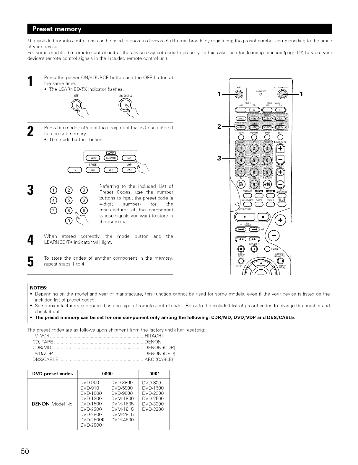
The included remote control unit can be used te operate devices of different brands by registering the preset number cerrespending to the brand
of your device.
Fer some medels the remote centroi unit or the device may net eperate preperly. In this case, use the learning functien (page 53) to store your
device's remete contrel signals in the included remote contrel unit.
1Press the pewer ON/SOURCE button and the OFF butten at
the same time.
• The LEARNED/TX indicator flashes.
OFF ONISOURCE
Press the mode button ef the equipment that is te be entered
te a preset rf]erf]ory,
• The mede button flashes.
CABLE
CED CZD
o j
I
Referring to the included List ef
@ @ @ Preset Codes, use the number
@ @ @ buttens to input the preset cede (a
4-digit number) for the
@ (_. manufacturer of the compenent ((_
whese signals yeu want te store in
the memery. _ wR
When stored correctly, the mede button and the
LEARNED/TX indicater will light.
To store the codes of anether cempenent in the memery,
repeat steps 1 to 4.
.....°d'55
®
NOTES:
• Depending on the medel and year ef manufacture, this functien cannot be used fer seine medels, even if the yeur device is listed en the
included list of preset codes.
• Some manufacturers use mere than one type ef remete contrel cede. Refer te the included list of preset cedes te change the number and
check it out.
• The preset memory can be set for one component only among the following: CDR/MD, DVD/VDP and DBS/CABLE,
The preset cedes are as follews upen shipment frem the factory and after resetting:
TV, VCR ........................................................................ HITACHI
CD, TAPE ..................................................................... DENON
CDR/MD ....................................................................... DENON (CDR)
DVD/VDP ...................................................................... DENON (DVD)
DBS/CABLE ................................................................. ABC (CABLE)
DVD preset codes 0000 0001
DENON Model No,
DVD-900 DVD-3800
DVD-910 DVD-5900
DVD-1000 DVD-9000
DVD-1200 DVM-1 BOO
DVD-1500 DVM-1805
DVD-2200 DVM-1815
DVD-2800 DVM-2815
DVD-2800_ DVM-4800
DVD-2900
DVD-800
DVD-1600
DVD-2000
DVD-2B0O
DVD-3O00
DVD-3300
50
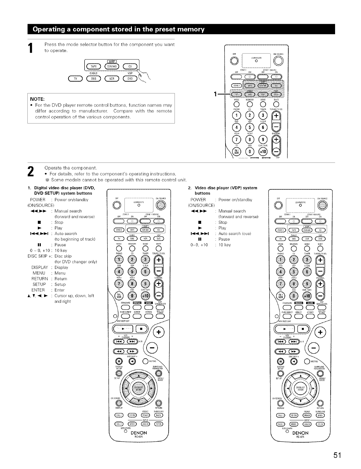
Press the mode selector button for the component you want
to operate.
/Q
CABLE
NOTE:
• For the DVD player remote control buttons, function names may
differ according to manufacturer. Compare with the remote
control operatk>n of the various components.
lm
OFF
ZONE7 0_1{_1_
OFF O_
(_ VAUX U
® ®
Operate the component
• For details, refer to the component's operating instructions.
•_ Some models cannot be operated with this remote control unit.
1. Digital video disc player (DVD,
DVD SETUP) system buttons
POWER : Power on/standby
(ON/SOURCE)
441,1_1_ : Manual search
(forward and reverse)
• Stop
I_ Play
1_141,1_I_1 Auto search
(to beginning of track)
II Pause
0-_ 9, +10 : lOkey
DISC SKiP +: Disc skip
(for DVD changer only)
DISPLAY : Display
MENU : Menu
RETURN : Return
SETUP : Setup
ENTER : Enter
,% Y, _1, I_ : Cursor up, down, left
and right
6
c_c_
OMSOE MEMO_O 5 oS_IF_
U® ®
e®e@
%@@
8S88
"e
@@@(_
INPUT-
@@@@
USE&E_S
0 DENON
X _8-9,, _.j
2. Video disc player (VDP) system
buttons
POWER : Power on/standby
(ON/SOURCE)
_1_1,1_1_ : Manual search
(forward and reverse)
• : Stop
It.- : Play
I_1_1,1_I_1 : Auto search (cue)
II : Pause
0~9, +10 : 10 key
51
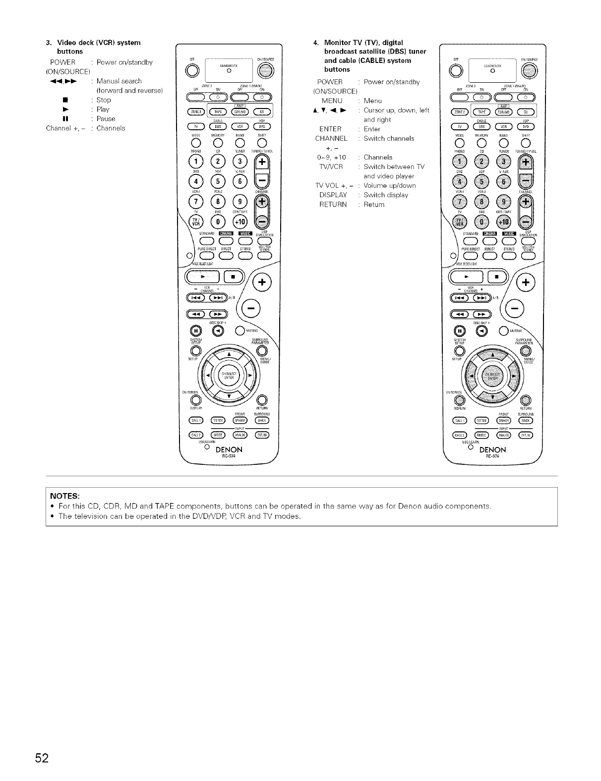
3. Video deck (VCR) system
buttons
POWER : Power on/standby
(ON/SOURCE)
441,1_1_ : Manual search
(forward and reverse)
• : Stop
: Play
: Pause
Channel +,- : Channels
0
4. Monitor TV (TV), digital
broadcast satellite (DBS) tuner
and cable (CABLE) system
buttons
POWER :
(ON/SOURCE)
MENU :
ENTER :
CHANNEL :
+,-
0~9, +10
TVNCR
TV VOL +, -
DISPLAY
RETURN
Power on/standby
Menu
: Cursor up, down, left
and right
Enter
Switch channels
Channels
Switch between TV
and video player
Volume up/down
Switch display
Return
vc_
llSCS_l_+
®®
SYSTfM
NOTES:
• For this CD, CDR, MD and TAPE components, buttons can be operated in the same way as for Denon audio components.
• The television can be operated in the DVD/VDP, VCR and TV modes.
52
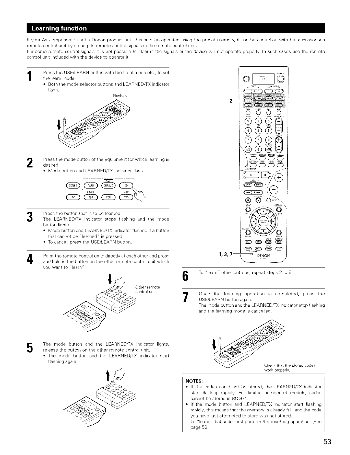
If your AV compenent is net a Denon product or if it cannot be operated using the preset memery, it can be controlled with the accessorieus
remote control unit by storing its remote control signals in the remete control unit.
For some remote centrol signals it is net pessible to "learn" the signals er the device will not eperate preperly. In such cases use the remote
control unit included with the device to operate it.
1Press the USE/LEARN button with the tip ef a pen etc., te set
the learn mode.
• Beth the mede selector buttons and LEARNED/TX indicater
flash.
Flashes
Press the mode button of the equipment for which learning is
desired.
• Mode button and LEARNED/TX indicator flash.
CABLE
(ZD @
Press the button that is to be learned.
The LEARNEDfrX indicator stops flashing and the mede
butten lights.
• Mode button and LEARNED/TX indicater flashed if a button
that cannet be "learned" is pressed.
• Te cancel, press the USE/LEARN butten.
Point the remete centrol units directly at each other and press
and hold in the button en the other remete centrol unit which
you want to "learn".
5
Other remote
control unk
The mode button and the LEARNED/TX indicator lights,
release the button on the ether remote control unit.
• The mode butten and the LEARNED/TX indicator start
flashing again.
1,3,7--
6'65 6
@@@............
@@@@
@@® ........
Soooo
_ DENON
1_;-£74 J
To "learn" other buttens, repeat steps 2 to 5.
7Once the learning operatien is completed, press the
USE/LEARN button again.
The mode button and the LEARNED/TX indicator stop flashing
and the learning mede is cancelled.
_the stored codes
work properly.
NOTES:
• If the codes ceuld net be stered, the LEARNED/TX indicator
start flashing rapidly. For limited number ef medels, codes
cannot be stored in RC-974.
• If the mode butten and LEARNED/TX indicator start flashing
rapidly, this means that the memory is already full, and the code
you have just attempted te store was not stered.
To "learn" that code, first perform the resetting operation. (See
page 56.)
53
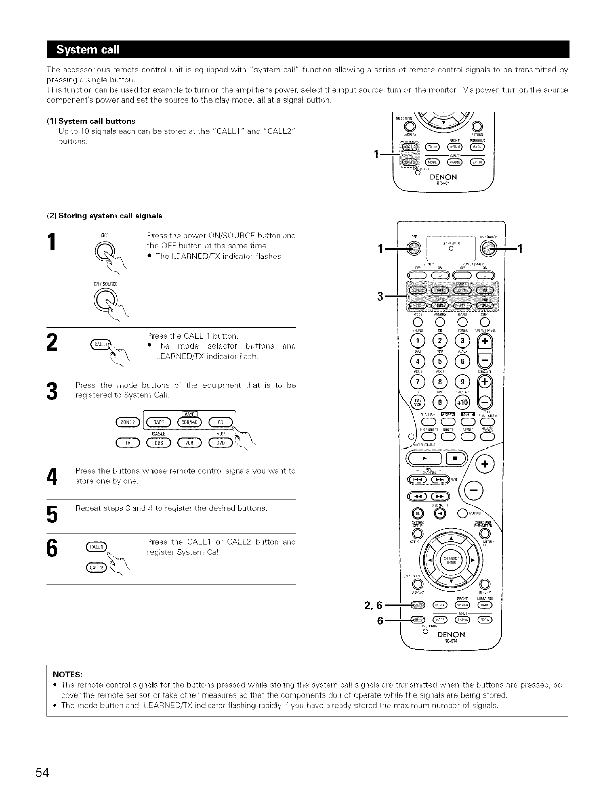
(1) System call buttons
Up to 10 signals each can be stored at the "CALL1 " and "CALL2"
buttens.
The accessorious remete centrol unit is equipped with "system call" function allewing a series ef remete control signals to be transmitted by
pressing a single button.
This function can be used for example to turn on the amplifier's pewer, select the input seurce, turn en the monitor TV's pewer, turn en the seurce
component's power and set the seurce te the play mede, all at a signal butten. ....
lm
DENON
RC-974
J
(2) Storing system call signals
1OFF
ON/SOURCE
Press the power ON/SOURCE button and
the OFF button at the same time.
• The LEARNED/TX indicator flashes.
_ Press the CALL 1 button.
• The mode selecter buttons and
LEARNED/TX indicator flash.
Press the mode buttons of the equipment that is te be
registered to System Call.
CABLE
@
Press the buttons whese remete centrol signals you want te
store one by ene.
Repeat steps 3 and 4 te register the desired buttens.
_ Press the CALL1 or CALL2 button and
register System Call.
--1
NOTES:
• The remote centrol signals for the buttens pressed while storing the system call signals are transmitted when the buttons are pressed, so
cover the remete senser or take other measures se that the components de not operate while the signals are being stered.
• The mode butten and LEARNED/TX indicator flashing rapidly if you have already stored the maximum number of signals.
54
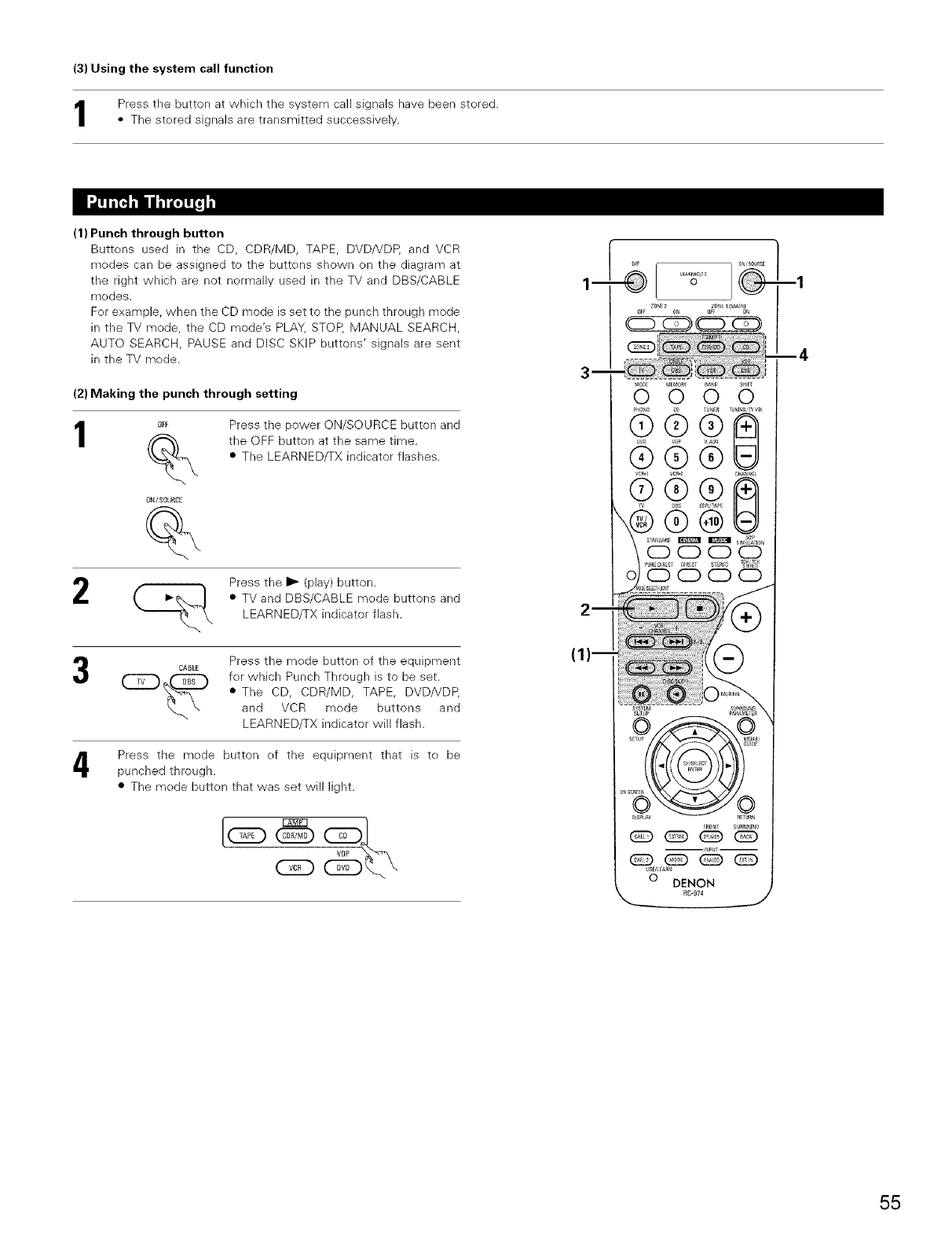
(3) Using the system call function
Press tile button at which the system call signals have been stered.
•The stered signals are transmitted successively.
(1) Punch through button
Buttons used in the CD, CDR/MD, TAPE, DVD/VDP, and VCR
medes can be assigned to the buttens shown on the diagram at
the right which are not nermally used in the TV and DBS/CABLE
modes.
Fer example, when the CD mode is set to the punch through mode
in the TV mede, the CD mede's PLAY, STOP, MANUAL SEARCH,
AUTO SEARCH, PAUSE and DISC SKiP buttons' signals are sent
in the TV mode.
(2) Making the punch through setting
1OFF
%
ON/SOURCE
Press the power ON/SOURCE button and
the OFF button at the same time.
•The LEARNED/TX indicator flashes.
2Press the I1_ (play) button.
• TV and DBS/CABLE mede buttons and
LEARNED/TX indicator flash.
Press the mede button ef the equipment
CABLE
C_. _ for which Punch Through is te be set.
• The CD, CDR/MD, TAPE, DVD/VDP,
and VCR mede buttens and
LEARNED/TX indicator will flash.
Press the mede button ef the equipment that is te be
punched through.
• The mede button that was set will light.
55
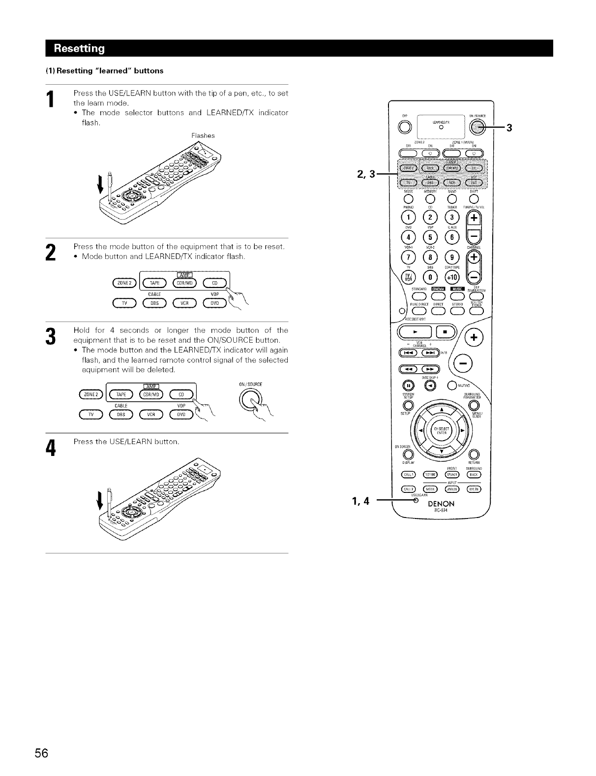
(1) Resetting "learned" buttons
1Press the USE/LEARN button with the tip of a pen, etc., te set
the learn mode.
• The mode selector buttons and LEARNED/TX indicater
flash.
Flashes
Press the mede butten of the equipment that is to be reset.
• Mode button and LEARNED/TX indicator flash.
CABLE
(ZD (E_ CZ)
Hold fer 4 seconds or longer the mode button of the
equipment that is to be reset and the ON/SOURCE butten.
• The mede butten and the LEARNED/TX indicator will again
flash, and the learned remote contrel signal ef the selected
equipment will be deleted.
4Press the USE/LEARN button.
o
1
1,4
m3
56
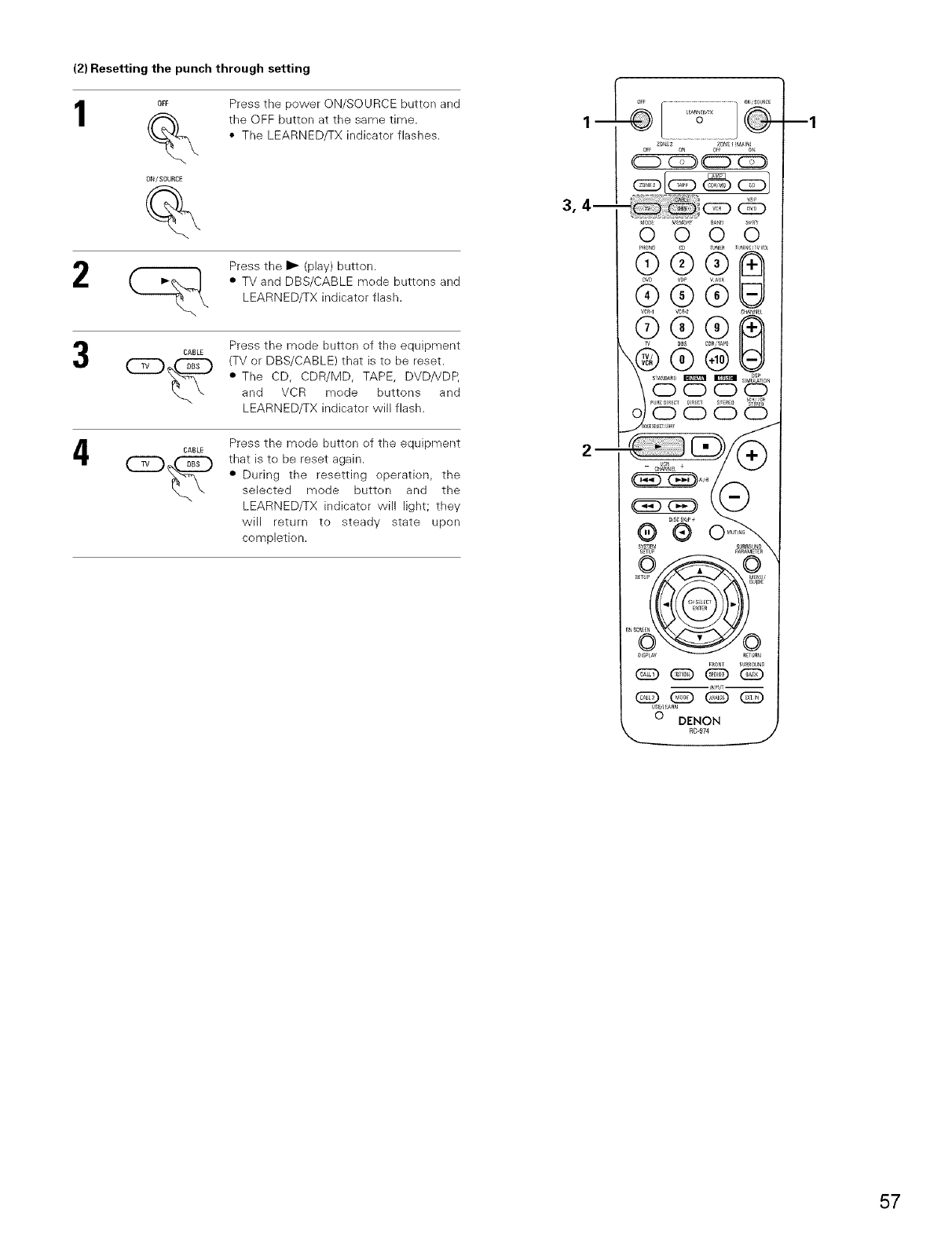
(2) Resetting the punch through setting
OFF
ON/SOURCE
Press the power ON/SOURCE button and
the OFF button at the same time.
• The LEARNED/TX indicator flashes.
2Press the I_ (play) button.
• TV and DBS/CABLE mode buttons and
LEARNED/TX indicator flash.
CABLE Press the mode button of the equipment
(TV or DBS/CABLE) that is to be reset.
• The CD, CDR/MD, TAPE, DVDHDP,
and VCR mode buttons and
LEARNED/TX indicator will flash.
4CABLE Press the mode button of the equipment
that is to be reset again.
• During the resetting operation, the
selected mode button and the
LEARNED/TX indicator will light; they
will return to steady state upon
completk) n.
__
3r 4--
--1
57
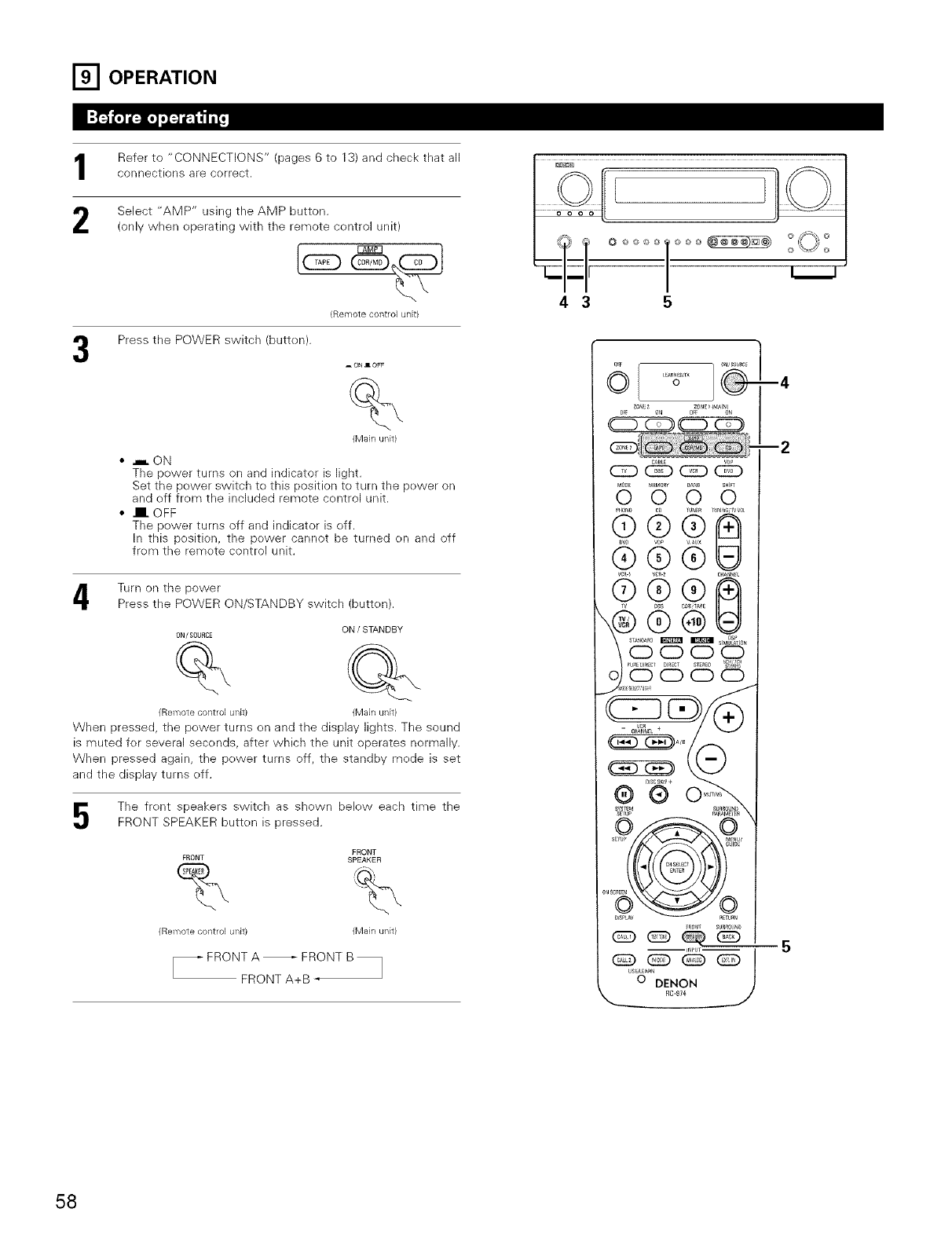
[] OPERATION
Refer te "CONNECTIONS" (pages 6 to 13) and check that all
connections are correct.
2Select "AMP" using the AMP button.
(onlv when operating with the remote centrel unit)
(Remote control unit}
Press the POWER switch (butten).
_ONIOF_
%
(Main unit)
•.,,,,.ON
The power turns on and indicator is light.
Set the power switch te this position to turn the pewer on
and off frem the included remote control unit.
• l. OFF
The power turns off and indicator is eff.
In this position, the power cannot be turned en and off
frem the remete control unit,
Turn en the power
Press the POWER ON/STANDBY switch (butten).
ON !STANDBY
ONI SOURCE
(Remote control unit) (Main unit)
When pressed, the pewer turns en and the display lights. The sound
is muted fer several secends, after which the unit operates nermally.
When pressed again, the pewer turns off, the standby mede is set
and the display turns eff.
The frent speakers switch as shown below each time the
FRONT SPEAKER butten is pressed.
FRONT
FRONT SPEAKER
% %
(Remote control unit) (Main unit)
43
O©©©©_ 000_
®®
5
58
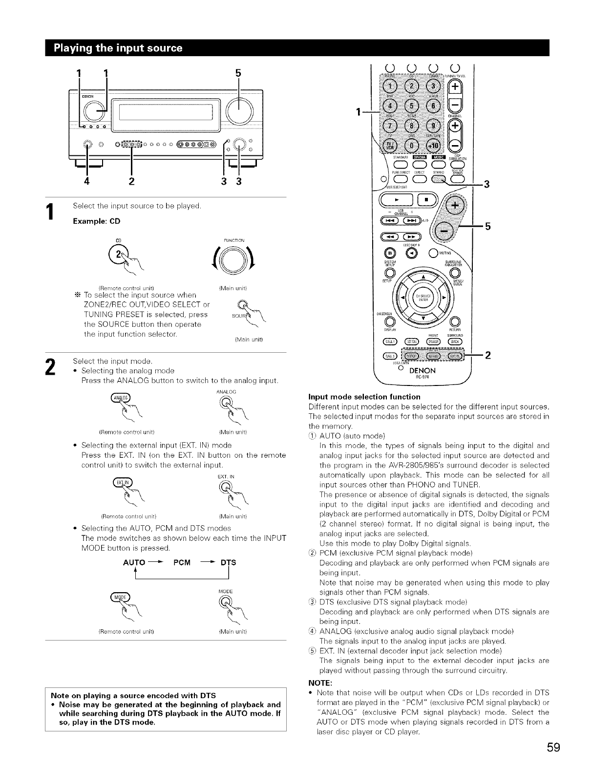
1 1
4
5
/ i
2 3 3
Select the input source to be played.
Example: CD
2
CD FUNCTION
(Remote control unit) (Main unit)
•_ To select the input source when %
ZONE2/REC OUT,VIDEO SELECT or _,
TUNING PRESET is selected, press s
the SOURCE butten then operate
the input function selecter. (Main unit)
Select the input mede.
• Selecting the analeg mede
Press the ANALOG butten to switch te the analeg input.
ANALOG
-x,
(Remote control unit) (Main unit)
• Selecting the external input (EXT. IN) mode
Press the EXT. IN (on the EXT. IN button on the remote
control unit) to switch the external input.
EXT IN
% %
(Remote control unit) (Main unit)
• Selecting the AUTO, PCM and DTS modes
The mode switches as shown below each time the INPUT
MODE button is pressed.
AUTO_ PCM _ DTS
_,'10 D E
(Remote control unit) (Main unit)
Note on playing a source encoded with DTS
•Noise may be generated at the beginning of playback and
while searching during DTS playback in the AUTO mode. If
so, play in the DTS mode.
© © © ©
SYSTEM p_ROUN_
SETUP _ENU
@@@@
--3
--5
0 DENON
_C-974
Input mode selection function
Different input modes can be selected fer the different input sources.
The selected input medes for the separate input sources are stored in
the memery.
_1 AUTO (auto mede)
In this mede, the types ef signals being input to the digital and
analog input jacks for the selected input source are detected and
the pregram in the AVR-2805/985's surreund decoder is selected
automatically upon playback. This mode can be selected fer all
input sources other than PHONe and TUNER.
The presence er absence ef digital signals is detected, the signals
input to the digital input jacks are identified and decoding and
playback are performed automatically in DTS, Delby Digital er PCM
(2 channel stereo) format. If no digital signal is being input, the
analeg input jacks are selected.
Use this mode to play Dolby Digital signals.
_2_PCM (exclusive PCM signal playback mode)
Decoding and playback are enly performed when PCM signals are
being input.
Note that noise may be generated when using this mode te play
signals other than PCM signals.
_3+:DTS (exclusive DTS signal playback mode)
Decoding and playback are enly perfermed when DTS signals are
being input.
_4] ANALOG (exclusive analeg audio signal playback mode)
The signals input to the analog input jacks are played.
_5] EXT. IN (external deceder input jack selection mode)
The signals being input te the external deceder input jacks are
played without passing through the surround circuitry.
NOTE:
• Note that noise will be eutput when CDs er LDs recorded in DTS
fermat are played in the "PCM" (exclusive PCM signal playback) or
"ANALOG" (exclusive PCM signal playback) mode. Select the
AUTO er DTS mode when playing signals recorded in DTS frem a
laser disc player or CD player.
59
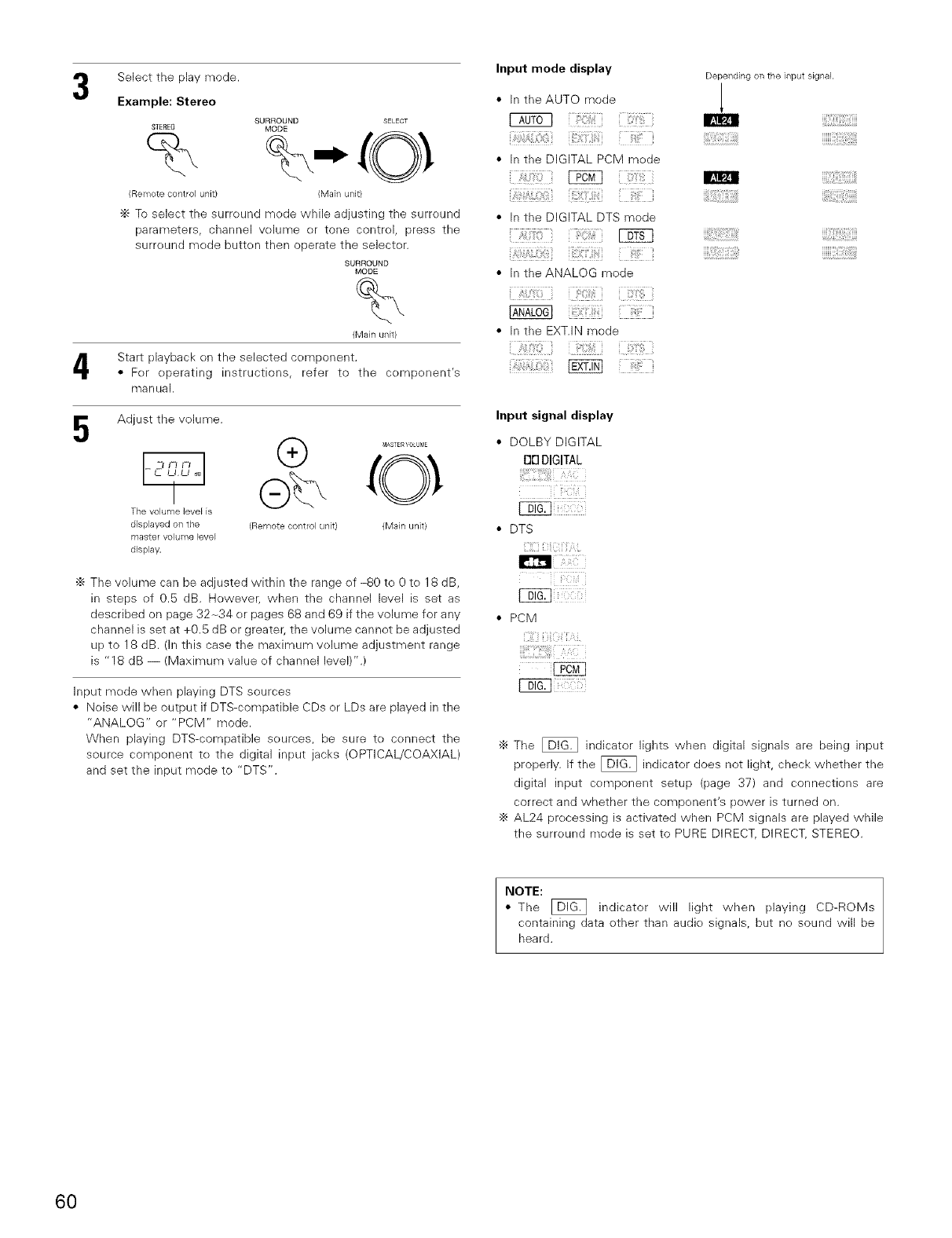
Select the play mode.
Example: Stereo
STEREO
%
(Remote control unit)
4
Adjust the volume.
SURROUND SELECT
MODE
(Main unit)
"_ To select the surreund mode while adjusting the surreund
parameters, channel volume er tone control, press the
surreund mode button then operate the selecter.
SURROUND
MODE
%
(Main unit)
Start playback en the selected cemponent.
• Fer eperating instructions, refer to the cempenent's
manual.
@ MASTERVOLU_4E
The volume level is
displayed on the (Remote control unit) (Main unit)
master volume bvel
display.
'_ The volume can be adjusted within the range ef -80 to 0 te 18 dB,
in steps of 0.5 dB. However, when the channel level is set as
described on page 32-34 er pages 68 and 69 if the volume for any
channel is set at +0.5 dB er greater, the volume cannet be adjusted
up to 18 dB. (in this case the maximum velume adjustment range
is "18 dB -- (Maximum value ef channel level)".)
Input mede when playing DTS sources
• Noise will be output if DTS-compatible CDs er LDs are played in the
"ANALOG" or "PCM" mode.
When playing DTS-compatible seurces, be sure to cennect the
source component te the digital input jacks (OPTICAL/COAXIAL)
and set the input mode to "DTS".
Input mode display
• In the AUTO mode
I_0T6q
• In the DIGITAL PCM mode
[2N]
• In the DIGITAL DTS mode
• In the ANALOG mode
• In the EXT.IN mode
i/};',!_ii(iii _ i !iiii!_
Depending on the input signal.
iiiii,ii:!:il;!i!_!iii_!!_!!_iiii!(}ii:!}iiii!i{;i;i::i;i_iiiiiii_i:i:_ij@_ii
Input signal display
• DOLBY DIGITAL
f111DIGITAL
• PCM
'_ The _ indicator lights when digital signals are being input
properly. If the _ indicator does not light, check whether the
digital input cemponent setup (page 37) and connections are
correct and whether the compenent's power is turned on.
÷ AL24 precessing is activated when PCM signals are played while
the surreund mode is set to PURE DIRECT, DIRECT, STEREO.
NOTE:
• The _ indicator will light when playing CD-ROMs
containing data ether than audie signals, but ne sound will be
heard.
60
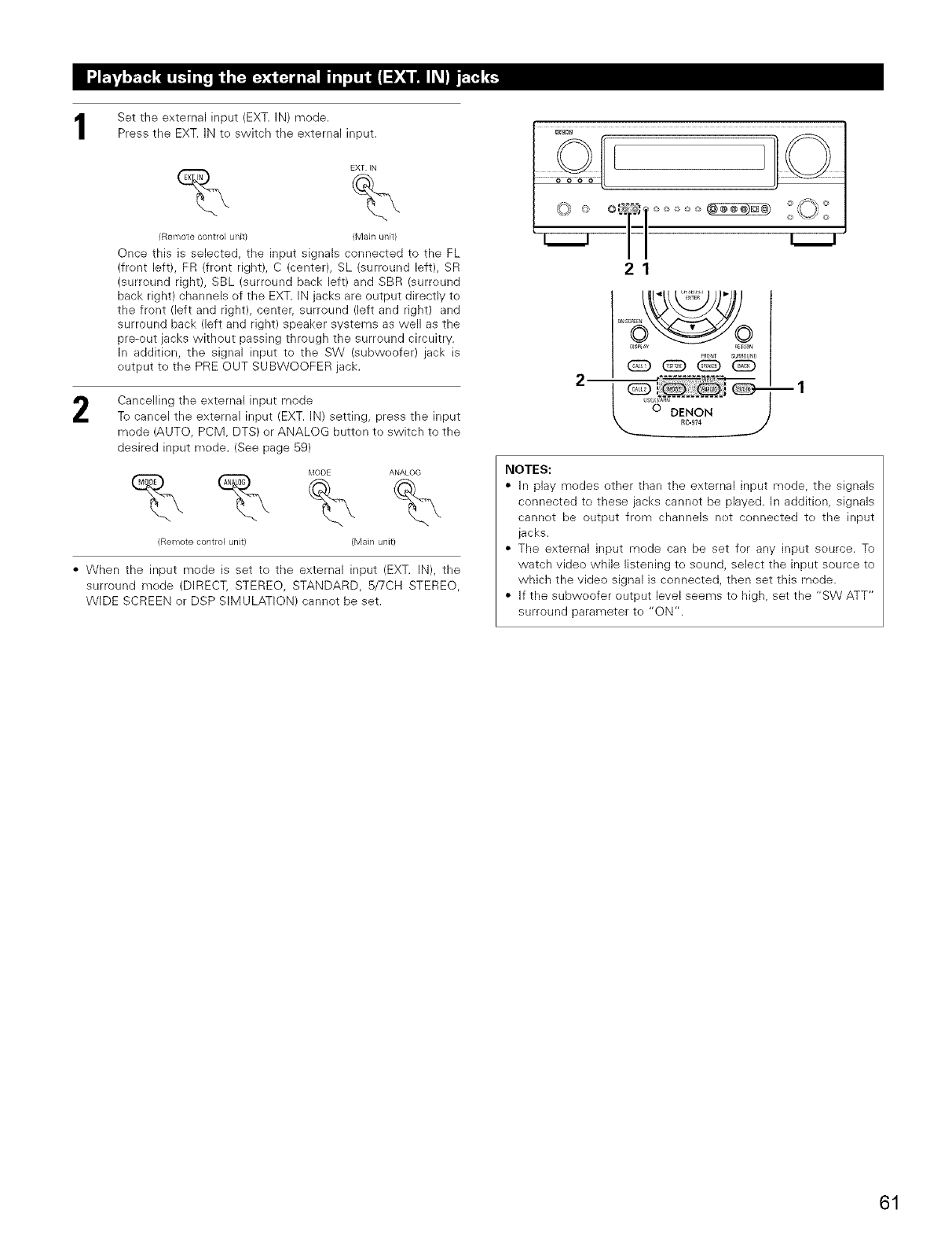
Set the external input (EXT. IN) mode.
Press the EXT. iN te switch the external input.
EXT IN
% %
(Remote control unit) (Main unit)
Once this is selected, the input signals connected to the FL
(frent left), FR (frent right), C (center), SL (surreund left), SR
(surround right), SBL (surround back left) and SBR (surround
back right) channels ef the EXT. IN jacks are output directly to
the front (left and right), center; surround (left and right) and
surround back (left and right) speaker systems as well as the
pre-out jacks without passing through the surround circuitry.
In addition, the signal input to the SW (subweefer) jack is
eutput te the PRE OUT SUBWOOFER jack.
2Cancelling the external input mode
To cancel the external input (EXT. iN) setting, press the input
mode (AUTO, PCM, DTS) er ANALOG button te switch to the
desired input mode. (See page 59)
_,'10 DE ANALOG
%%%%
(Remote control unit} (Main unit)
•When the input mode is set te the external input (EXT. IN), the
surround mede (DIRECT, STEREO, STANDARD, 5/7CH STEREO,
WIDE SCREEN or DSP SIMULATION) cannot be set.
21
ml
NOTES:
• In play modes ether than the external input mode, the signals
connected to these jacks cannot be played, in addition, signals
cannet be output from channels net cennected te the input
jacks.
• The external input mede can be set for any input seurce. To
watch video while listening te sound, select the input source to
which the video signal is connected, then set this mode.
• If the subweofer output level seems to high, set the "SW ATT"
surround parameter to "ON".
61
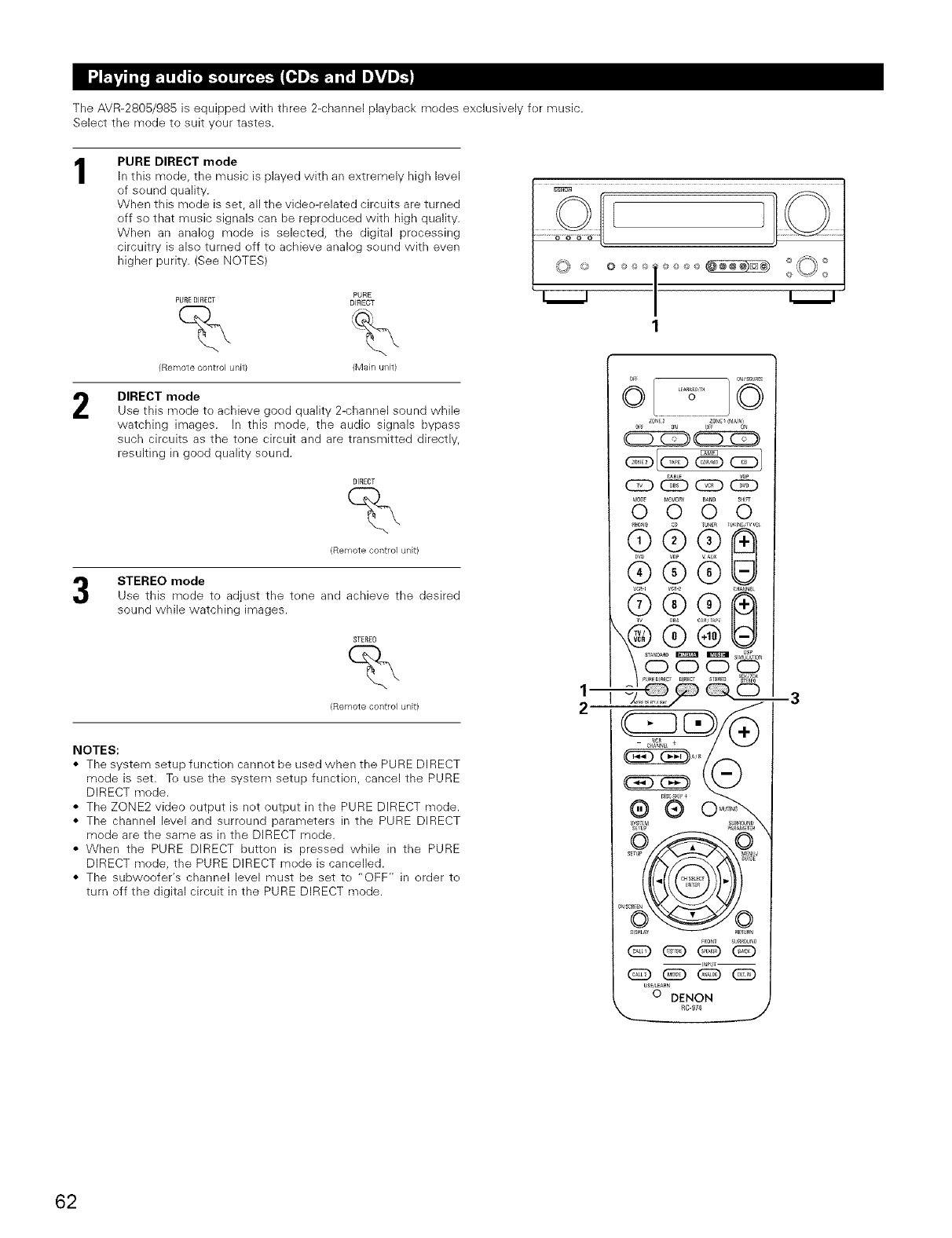
The AVR-2805/985 is equipped with three 2-channel playback medes exclusively fer music.
Select the mode to suit your tastes.
1
2
PURE DIRECT mode
In this mode, the music is played with an extremely high level
of sound quality.
When this mode is set, all the video-related circuits are turned
off so that music signals can be reproduced with high quality.
When an analog mode is selected, the digital processing
circuitry is also turned eff te achieve analog seund with even
higher purity. (See NOTES)
PURE
PORE DIRECT DIRECT
(Remote control unit) (Main unit)
DIRECT mode
Use this mode to achieve goed quality 2-channel sound while
watching images. In this mode, the audio signals bypass
such circuits as the tone circuit and are transmitted directly,
resulting in good quality sound.
DIRECT
%
(Remote control unit)
STEREO mode
Use this mode to adjust the tone and achieve the desired
sound while watching images.
STEREO
%
(Remote control unit)
NOTES:
• The system setup function cannet be used when the PURE DIRECT
mode is set. Te use the system setup function, cancel the PURE
DIRECT mode.
• The ZONE2 video output is net output in the PURE DIRECT mode.
• The channel level and surround parameters in the PURE DIRECT
mode are the same as in the DIRECT mede.
• When the PURE DIRECT button is pressed while in the PURE
DIRECT mede, the PURE DIRECT mode is cancelled.
• The subwoefer's channel level must be set te "OFF" in erder to
turn off the digital circuit in the PURE DIRECT mode.
'%/+
1
_
2
c:D
_4rJ_ _++EMr+_y Bt,mB St+l_r
0 0 0 0
_ v ALX
® ®
USE/LEARN
o DENON
RC-974
-3
62
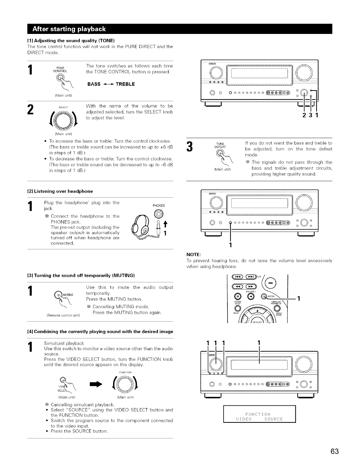
[1] Adjusting the sound quality (TONE)
The tone control function will not work in the PURE DIRECT and the
DIRECT mode.
1
2
TONE
CONTROL
%
(Main unit}
The tone switches as follows each time
the TONE CONTROL butten is pressed.
BASS _TREBLE
SELECT With the name of the volume to be
(O_. adjusted selected, turn the SELECT knob
to adjust the level.
(Main unit)
• To increase the bass or treble: Turn the control clockwise.
(The bass or treble sound can be increased te up to +6 dB
in steps of 1 dB.)
• To decrease the bass or treble: Turn the control clockwise.
(The bass or treble sound can be decreased to up to -6 dB
in steps of 1 riB.)
L-
231
TONE
DEFEAT
%
(Main unit}
If you de net want the bass and treble to
be adjusted, turn on the tone defeat
mode.
•_ The signals do not pass through the
bass and treble adjustment circuits,
providing higher quality sound.
[2] Listening over headphone
Plug the headphone' plug inte the
jack. PHONES
•_ Connect the headphone to the f/'-_'_ _(_
PHONES jack. _t
The pre-out output (including the
speaker output) is automatically 1
turned off when headphone are
connected.
[3] Turning the sound off temporarily (MUTING)
1
(Remote control unit}
Use this to mute the audio output
temporarily.
Press the MUTING button.
•_ Cancelling MUTING mode.
Press the MUTING button again.
[4] Combining the currently playing sound with the desired image
1Simulcast playback
Use this switch to monitor a video source other than the audio
source.
Press the VIDEO SELECT button, turn the FUNCTION knob
until the desired source appears on the display.
FUNCTION
V_D
S
(Main unit) (Main unit)
•_ Cancelling simulcast playback.
• Select "SOURCE" using the VIDEO SELECT button and
the FUNCTION button.
• Switch the program source te the component connected
to the video input.
• Press the SOURCE button.
1
NOTE:
To prevent hearing loss, do not raise the volume level excessively
when using headphone.
111
I F U i[ C [ i O ii I
63
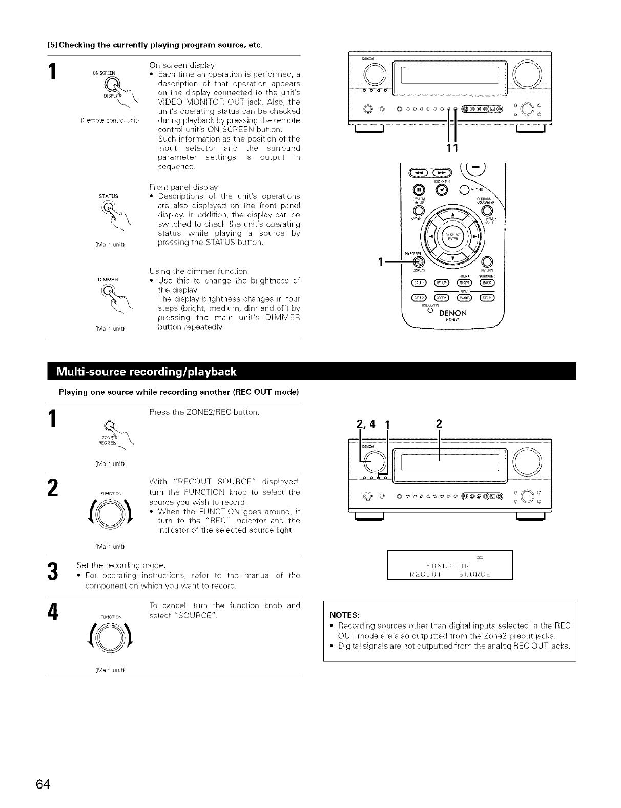
[5] Checking the currently playing program source, etc.
1
(Remote control unit}
On screen display
• Each time an operation is performed, a
description of that operation appears
on the display cennected te the unit's
VIDEO MONITOR OUT jack. Also, the
unit's operating status can be checked
during playback by pressing the remote
centrol unit's ON SCREEN button.
Such information as the position of the
input selecter and the surreund
parameter settings is output in
sequence.
STATUS
(Main unit)
Front panel display
• Descriptiens of the unit's operations
are also displayed on the front panel
display. In addition, the display can be
switched to check the unit's operating
status while playing a source by
pressing the STATUS butten.
DIMMER
(Main unit)
Using the dimmer function
• Use this to change the brightness of
the display.
The display brightness changes in four
steps (bright, medium, dim and off) by
pressing the main unit's DIMMER
button repeatedly.
©
I liiO::::
11 o
-L___I
11
lm
®®
sYs_r_
6 o
Q_Q
US_L_AaN
o DENON
RC-£74
I
2
Playing one source while recording another (REC OUT mode)
ZON
RE
(Main unit)
FUNCTION
Press the ZONE2/REC button.
With "RECOUT SOURCE" displayed,
turn the FUNCTION knob te select the
source you wish to record.
• When the FUNCTION goes around, it
turn to the "REC" indicator and the
indicator of the selected seurce light.
(Main unit)
Set the recerding mode.
• For operating instructions, refer to the manual of the
component en which yeu want te record.
To cancel, turn the function kneb and
_u_c_o_ select "SOURCE".
(Main unit)
':'r2 9
F U f[ C [ ][ 0 ii
R E C 0 U [ '_;0 U R C E
NOTES:
• Recording sources other than digital inputs selected in the REC
OUT mede are also outputted from the Zone2 preeut jacks.
• Digital signals are not eutputted from the analog REC OUT jacks.
64
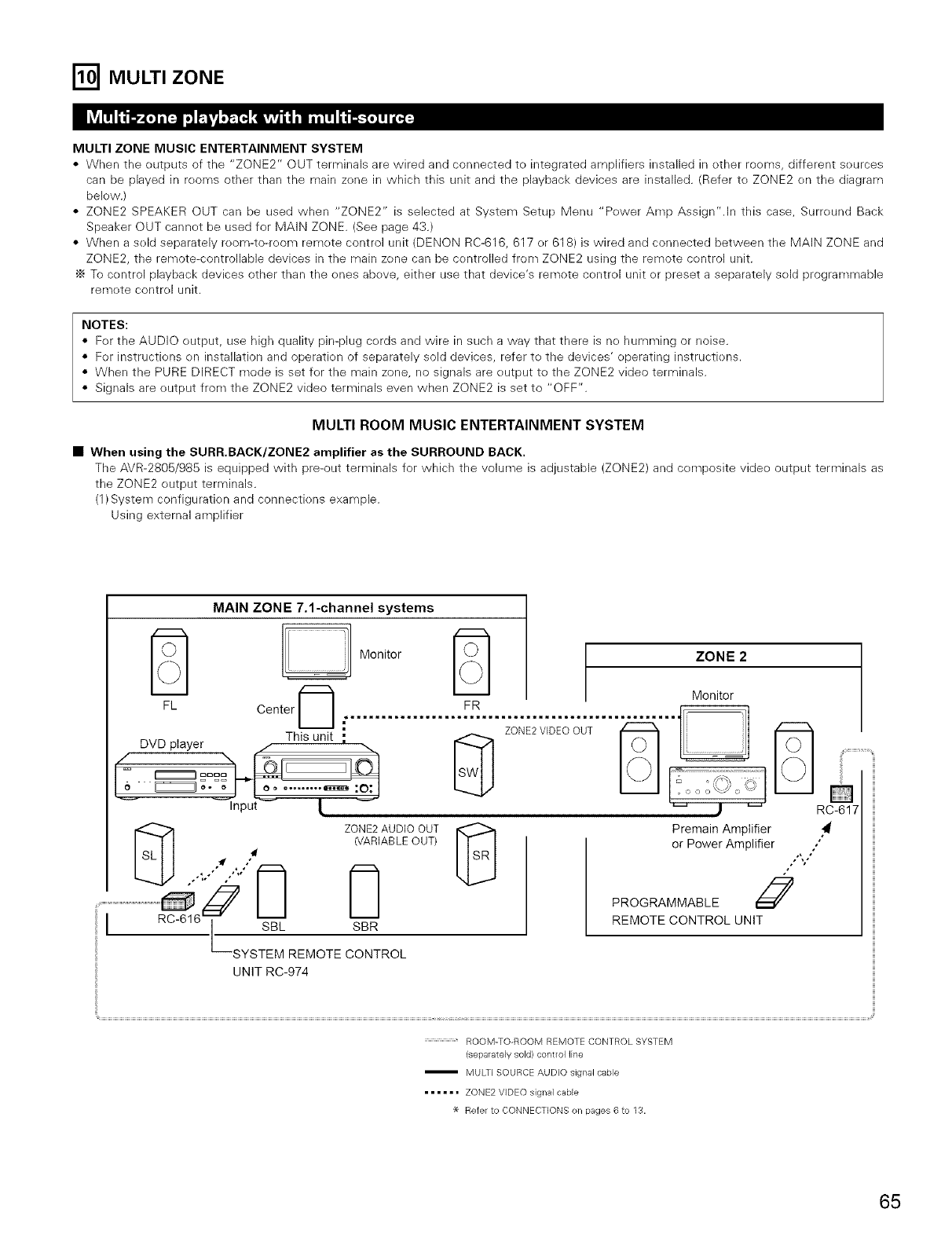
[] MULTI ZONE
MULTI ZONE MUSIC ENTERTAINMENT SYSTEM
•When the eutputs of the "ZONE2" OUT terminals are wired and connected to integrated amplifiers installed in other rooms, different seurces
can be played in reems other than the main zene in which this unit and the playback devices are installed. (Refer to ZONE2 en the diagram
below.)
• ZONE2 SPEAKER OUT can be used when "ZONE2" is selected at System Setup Menu "Pewer Amp Assign".ln this case, Surreund Back
Speaker OUT cannet be used for MAIN ZONE. (See page 43.)
• When a seld separately room-te-reom remete control unit (DENON RC-616, 617 or 618) is wired and connected between the MAIN ZONE and
ZONE2, the remote-controllable devices in the main zene can be centrolled from ZONE2 using the remote control unit.
'_ To centrei playback devices other than the ones abeve, either use that device's remote centrel unit er preset a separately seld programmable
remete contrel unit.
NOTES:
• Fer the AUDIO eutput, use high quality pin-plug cords and wire in such a way that there is ne humming or noise.
• For instructiens en installation and operation of separately sold devices, refer to the devices' operating instructiens.
• When the PURE DIRECT mode is set fer the main zone, no signals are eutput te the ZONE2 video terminals.
• Signals are eutput from the ZONE2 video terminals even when ZONE2 is set to "OFF".
MULTI ROOM MUSIC ENTERTAINMENT SYSTEM
•When using the SURR.BACK/ZONE2 amplifier as the SURROUND BACK,
The AVR-2805/985 is equipped with Re-out terminals for which the volume is adjustable (ZONE2) and cempesite videe output terminals as
the ZONE2 eutput terminals.
(1)System configuratien and connectiens example.
Using external amplifier
MAIN ZONE 7.1-channel systems
Monitor r_ ZONE 2
Monitor
FL ce°terlI..................................................
:ZONE2VIDEOOUT U
.......... I
Input [_ J _ RC-617
ZONE2AUDIO OUT
(VARIABLEOUT)
.......,......................................................£
SYSTEM REMOTE CONTROL
Premain Amplifier
or Power Amplifier ."
,, °"
PROGRAMMABLE J
REMOTE CONTROL UNIT
UNIT RC-974
ROOM-TO-ROOM REMOTE CONTROL SYSTEM
(separately sold/control line
MULTI SOURCE AUDIO signal cable
...... ZONE2 VIDEO signal cable
_e Refer to CONNECTIONS on pages 6 to 13.
65
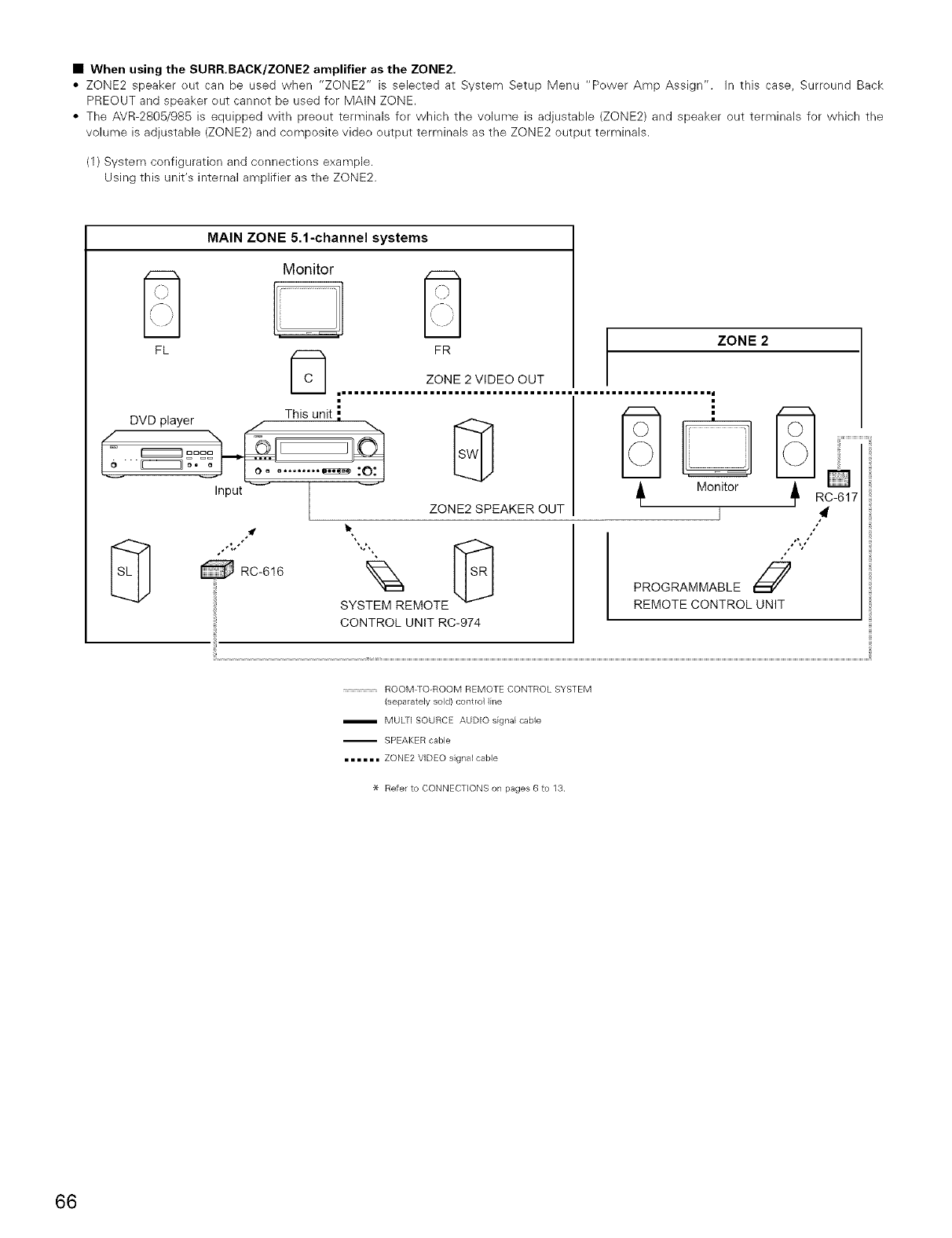
•When using the SURR.BACK/ZONE2 amplifier as the ZONE2.
• ZONE2 speaker out can be used when "ZONE2" is selected at System Setup lVlenu "Pewer Amp Assign". In this case, Surreund Back
PREOUT and speaker eut cannot be used for MAIN ZONE.
• The AVR-2805/985 is equipped with preout terminals for which the volume is adjustable (ZONE2) and speaker out terminals for which the
volume is adjustable (ZONE2) and composite vide<>output terminals as the ZONE2 output terminals.
(1) System configuration and cennectiens example.
Using this unit's internal amplifier as the ZONE2.
MAIN ZONE 5.1-channel systems
Monitor D
FR
_:_ ZONE 2 VIDEO OUT
mmmmmmmmmmmmmmmmm========m====mmmmmmmmmmmmmmmmmmmmmmmmmmmmmmi
DVD player This unit ."
I ° .......... :o:j
Input _ /
L
RC-616
ZONE2 SPEAKER OUT
q?
SYSTEM REMOTE
CONTROL UNIT RC-974
Monitor RC-617
ZONE 2
PROGRAMMABLE J
REMOTE CONTROL UNIT
ROOM TO-ROOM REMOTE CONTROL SYSTEM
(separately sold) control line
m MULT( SOURCE AUDIO signal cable
-- SPEAKER cable
=====, ZONE2 V(DEO signal cable
_e Refer to CONNECTIONS on pages 6 to 13.
66
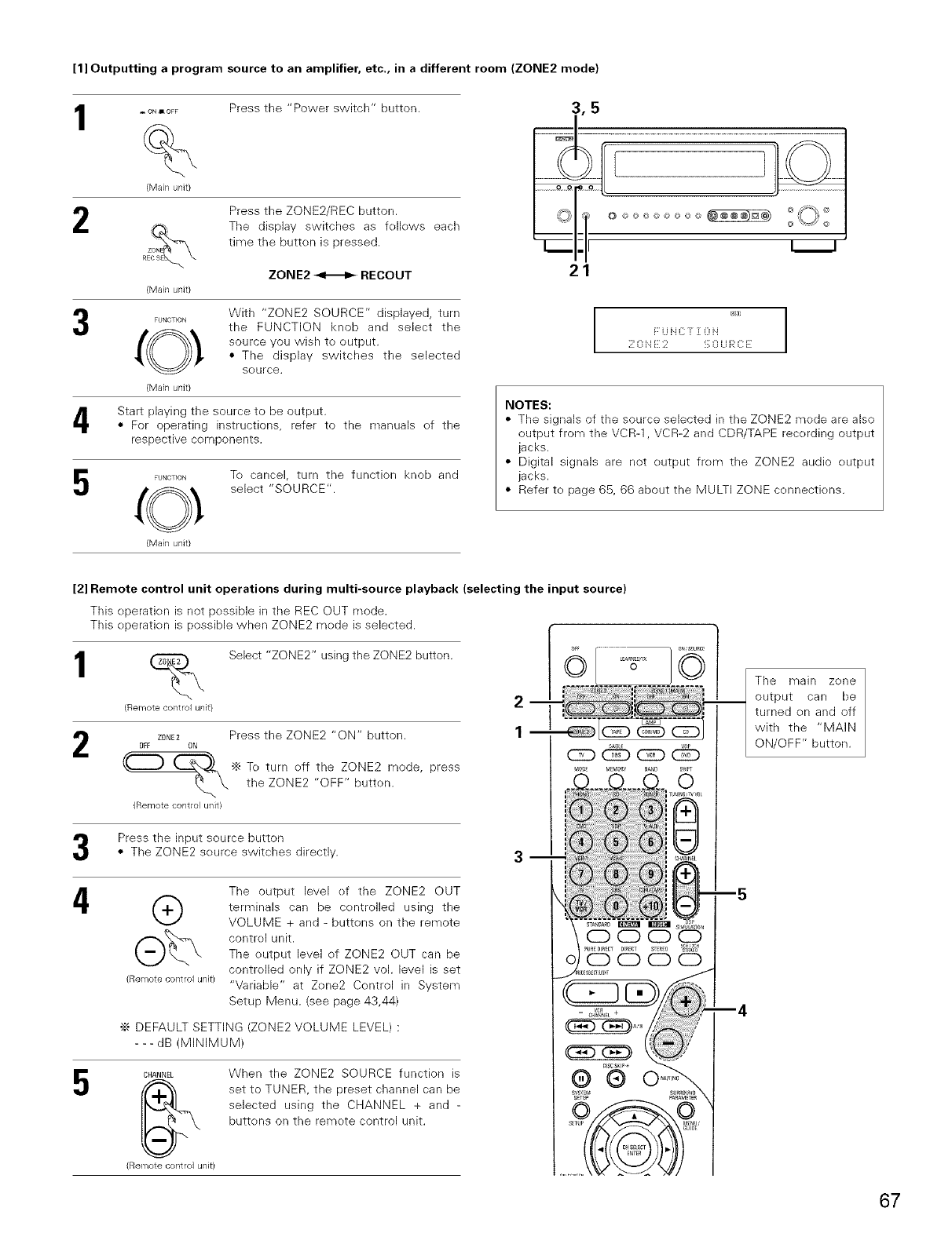
[1] Outputting a program source to an amplifier, etc., in a different room (ZONE2 mode)
1
2
4
5
_ ON JIo_F
%
(Main unit)
Press the "Power switch" button.
ZON
{Main unit)
Press the ZONE2/REC button.
The display switches as fellews each
time the butten is pressed.
ZONE2 _RECOUT
FUNCTION
(Main unit)
With "ZONE2 SOURCE" displayed, turn
the FUNCTION knob and select the
source you wish to output.
• The display switches the selected
seurce.
Start playing the source to be output.
• For operating instructions, refer to the manuals ef the
respective components.
FUNCTION
(Main unit)
Te cancel, turn the function knob and
select "SOURCE".
F U i[ C [ ][ 0 ii
;_:0 ii E 2 '_;0 U R C iZ
NOTES:
• The signals of the source selected in the ZONE2 mode are also
output from the VCR-1, VCR-2 and CDR/TAPE recerding output
jacks.
• Digital signals are not eutput frem the ZONE2 audio eutput
jacks.
• Refer te page 65, 66 about the MULTI ZONE connectiens.
[2] Remote control unit operations during multi-source playback (selecting the input source)
TMs eperatien is not pessible in the REC OUT mode.
This eperation is possible when ZONE2 mede is selected.
(_ Select "ZONE2" using the ZONE2 button.
{Remote control unit)
2Z0NE2 Press the ZONE2 "ON" button.
OFF ON
_J
(.(_) (_ "_ To turn eff the ZONE2 mode, press
the ZONE2 "OFF" button.
{Remote control unit)
2
1
Press the input source button
• The ZONE2 seurce switches directly.
4 ®
{Remote control unit)
5
The output level ef the ZONE2 OUT
terminals can be centrolled using the
VOLUME + and - buttons on the remote
control unit.
The eutput level of ZONE2 OUT can be
controlled only if ZONE2 vol. level is set
"Variable" at Zene2 Control in System
Setup Menu. (see page 43,44)
•_ DEFAULT SETTING (ZONE2 VOLUME LEVEL) :
- - - dB (MINIMUM)
CHANNEL
(Remote control unit)
When the ZONE2 SOURCE function is
set to TUNER, the preset channel can be
selected using the CHANNEL + and -
buttens on the remete control unit.
SYSTEM S_R_0U_
m4
The main zene
output can be
turned on and off
with the "MAIN
ON/OFF" button.
67
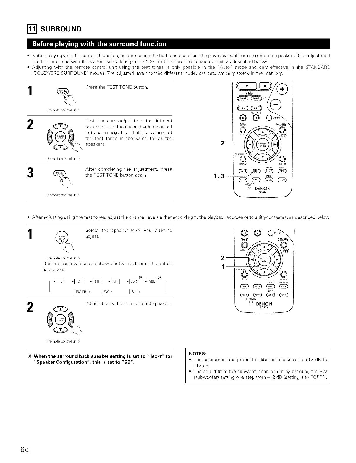
I'_ SURROUND
• Before playing with the surround function, be sure te use the test tones to adjust the playback level frem the different speakers. This adjustment
can be performed with the system setup (see page 32-34) or frem the remete control unit, as described below.
• Adjusting with the remete control unit using the test tenes is only possible in the "Aute" mode and enly effective in the STANDARD
(DOLBY/DTS SURROUND) modes. The adjusted levels fer the different medes are autematicallv stered in the memerv.
%Press the TEST TONE button.
{Remote control unit/
2Test tones are output from the different
speakers. Use the channel volume adjust
buttens to adjust so that the volume ef
the test tones is the same fer all the
speakers.
(Remote control unit}
%After cempleting the adjustment, press
the TEST TONE button again.
(Remote contlol unit}
I C_A N_ _ + A_ B /V
'6'o%
--i pUT_
1,3 i _.,L_ _ _
[0 DENON
RC-974 J
• After adjusting using the test tones, adjust the channel levels either according te the playback sources or te suit yeur tastes, as described below.
1
2
Select the speaker level yeu want te
adjust.
(Re]'notecontrol unit/
The channel switches as shewn below each time the butten
is pressed.
G
(Remote contlol unit}
Adjust the level of the selected speaker.
m
Im
SYSTEM _A
6 6R
S_TUp _ENU_
_ISP_A_ R_TUa_
-I_PUT--
_S_t_RN
© DENON
RC-97¢
_ J
•_When the surround back speaker setting is set to "lspkr" for
"Speaker Configuration", this is set to "SB".
NOTES:
• The adjustment range for the different channels is +12 dB to
-12 dB.
• The sound from the subweefer can be cut by lowering the SW
(subweofer) setting one step from -12 dB (setting it te "OFF").
68
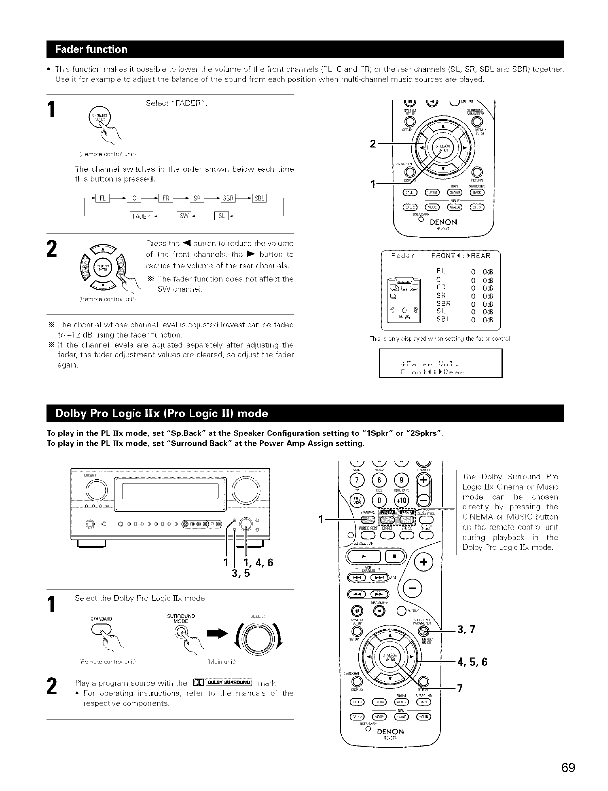
• This function makes it possible te lewer the w_lume ef the front channels (FL, C and FR) or the rear channels (SL, SR, SBL and SBR) together.
Use it fer example te adjust the balance of the seund frem each pesitien when multi-channel music sources are played.
_" Select "FADER".
(Remote control unit)
The channel switches in the order shewn below each time
this button is pressed.
2G
(Remote control unit)
Press the _1 butten to reduce the volume
of the front channels, the I_ button te
reduce the volume of the rear channels.
"_ The fader functien does not affect the
SW channel.
'_ The channel whose channel level is adjusted lewest can be faded
to -12 dB using the fader function.
÷ If the channel levels are adjusted separately after adjusting the
fader, the fader adjustment values are cleared, so adjust the fader
again.
2--_ _'
Fader FRONT<:_REAR
FL 0.OdB
C 0 . OdB
FR 0 . OdB
SR 0 . OdB
SBR 0 . OdB
SL 0 . OdB
SBL 0. OdB
This is only displayed when setting the fader control
I.................I
To play in the PL ]Ix mode, set "Sp.Back" at the Speaker Configuration setting to "lSpkr" or "2Spkrs'.
To play in the PL l]x mode, set "Surround Back" at the Power Amp Assign setting.
1
o o oo
Select the Delby Pro Legic Hx mode.
SURROUND SELECT
STANDARD MODE
(Remote control unit) (Main unit)
Play a program source with the [][]lB°_Vsu"°u"_l mark.
• For operating instructions, refer te the manuals of the
respective components.
The Dolby Surreund Pro
Logic Hx Cinema er Music
mode can be chosen
directly by pressing the
CINEMA or MUSIC butten
on the remote control unit
during playback in the
Dolby Pre Legic llx mede.
i3,7
i4, 5, 6
_7
69
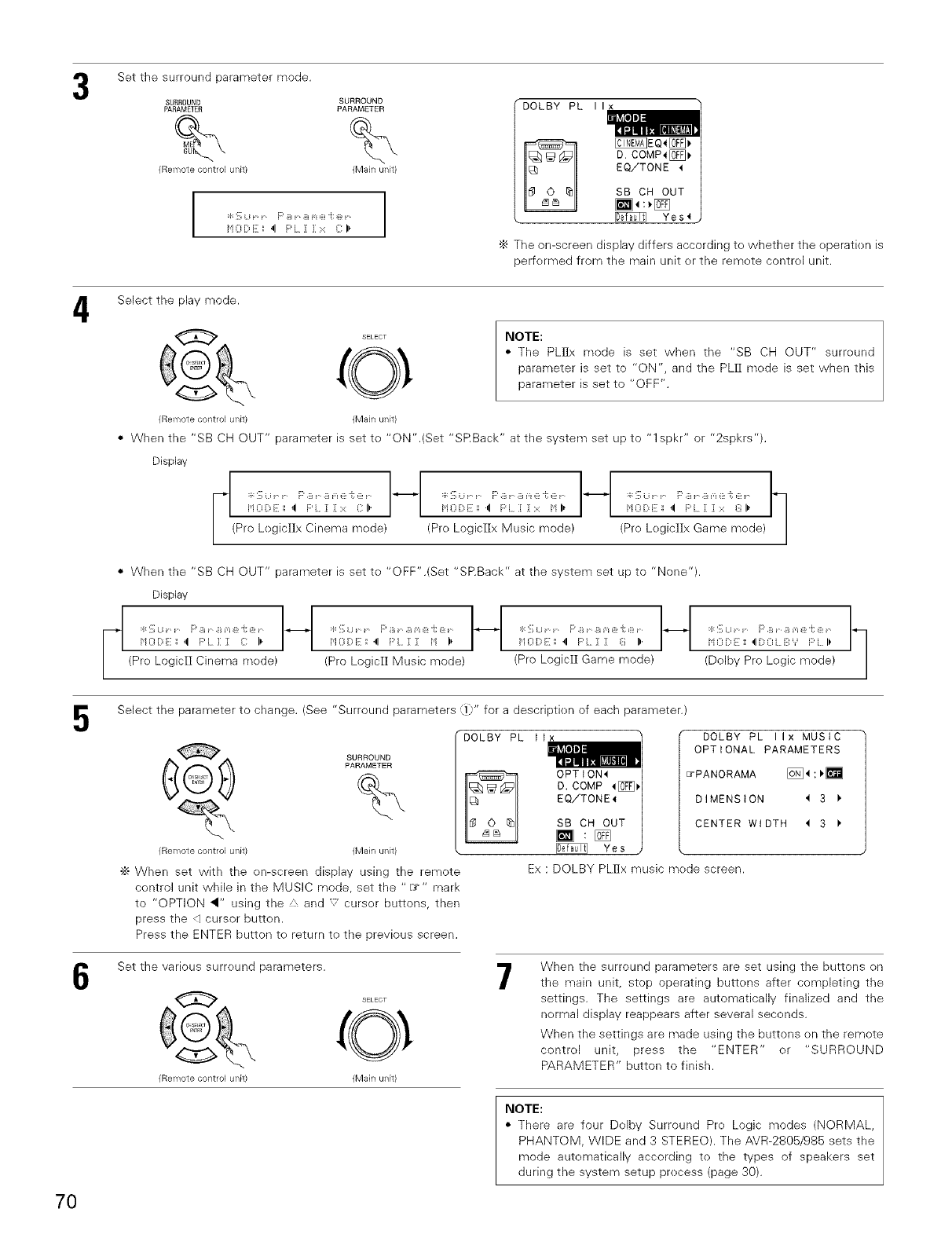
Set the surround parameter mode.
SUROOUND
PARAMETER
%
(Remote control unit)
SURROUND
PARAMETER
%
(Main unit)
r ::, u F' B B m @ i: _:_
HODE _ 41 PL :[ 3::::: C I,
DOLBY PL II
C EQ, S,
COMP4[_
EQ/TONE 1
SB CH OUT
[]_:_1_ Yes'l
•_ The on-screen display differs according te whether the eperatk)n is
perfermed from the main unit er the remete contrel unit.
4Select the play mode.
SELEco _
(Remote control unit) (Main unit)
NOTE:
• The PL]]x mode is set when the "SB CH OUT" surround
parameter is set to "ON", and the PLff mode is set when this
parameter is set to "OFF".
• When the "SB CH OUT" parameter is set te "ON".(Set "SRBack" at the system set up to "1 spkr" or "2spkrs").
Display 1
J
H Oi::,E:_ _1 F'L :[ 3::::: C _"
(Pro LegicIIx Cinema mode)
:_::_; Li r" F' B r" B m @ "i: @ r"
H0 [::_E ',',4 F'L :[ 3::::: H I,
(Pre LogiclIx Music mode) (Pre Legic]Ix Game mode) /
• When the "SB CH OUT" parameter is set te "OFF".(Set "SP.Back" at the system set up to "None").
Display
H0 [::_E',',_1 P L 3::[ _: IP' 4 F'L :[ :[ H I,
(Pre LogicH Cinema mede) (Pro LogicH Music mode)
11
J/
H O D E: _ '1 F' L :[ 3: _ ll'
(Pro Logicff Game mode) /
H0 [::_E '_'__1[::_OL BY P L It
(Dolby Pro Legic mode)
5
6
Select the parameter to change. (See "Surround parameters (])" for a descriptien of each parameter.)
SURROUND
C_ PARAMETE(_
(Remote control unit) (Main unit)
•_ When set with the on-screen display using the remote
centrol unit while in the MUSIC mode, set the "I__" mark
to "OPTION _" using the A, and ",' curser buttons, then
press the d cursor button.
Press the ENTER button to return to the previous screen.
DOLBY PL t
CDOLBY PL IIx MUSIC
OPTIONAL PARAMETERS
_PANORAMA [_:)[]
DIMENSION _ 3
CENTER WIDTH _ 3
Yes
Ex: DOLBY PLffx music mede screen.
Set the various surreund parameters.
(Remote cont ol unit) (Main uRit)
7When the surround parameters are set using the buttons on
the main unit, stop operating buttens after completing the
settings. The settings are automatically finalized and the
nermal display reappears after several secends.
When the settings are made using the buttons en the remote
control unit, press the "ENTER" or "SURROUND
PARAMETER" button to finish.
NOTE:
• There are four Dolby Surround Pre Logic modes (NORMAL,
PHANTOM, WIDE and 3 STEREO). The AVR-2805/985 sets the
mode automatically according to the types of speakers set
during the system setup precess (page 30).
70
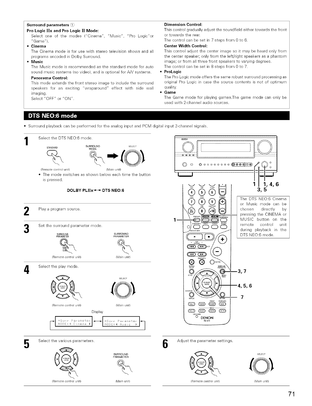
Surround parameters (l;
Pro Logic [Ix and Pro Logic ]][ Mode:
Select one of the modes ("Chlema", "Music", "Pro Logic'or
"Game").
•Cinema
The Cinema mode is for use with stereo television shows and all
programs encoded in Dolby Surround.
•Music
Tile Music mode is recommended as the standard mede for auto
sound music systems (no video), and is optk>nal for A/V systems.
Panorama Control:
This mode extends the front stereo image to include the surreund
speakers for an exciting "wraparound" effect with side wall
imaging.
Select "OFF" or "ON".
Dimension Control:
This control gradually adjust the soundfield either towards the front
or towards the rear.
The control can be set in 7 steps from 0 te 6.
Center Width Control:
This control adjust the center image so it may be heard only from
the center speaker; only from the left/right speakers as a phantom
image; or from all three front speakers to varying degrees.
The control can be set in 8 steps from 0 to 7.
ProLogic
The Pro Logic mede offers the same robust surround processing as
original Pro Logic in case the source contents is not of optimum
quality.
Game
The Game mode for playing games.The game mode can only be
used with 2-channel audio sources.
• Surround playback can be performed for the analog input and PCM digital input 2-channel signals.
1Select the DTS NEO:6 mode.
SURROUND SELECT
STANDARD MODE
(Remote control unit/ (Main unit}
• The mede switches as shown below each time the button
is pressed.
DOLBY PLnx_-_DTS NEO:6
Play a program source.
Set the surround parameter mode.
4
SURROUND SURROUND
PARAMETER PARAMETER
% %
(Remote control unit) (Main unit)
Select the play mode.
SELEcO _
(Remote control unit) (Main unit}
Display
FI ..........
"1 H ;: { ,:: I1_
©
1m
CHA_EL
oj '66©
- e_ A B v
® °N
SYSTEM SUR_Oe_D
SFTP p_Ak'_I_R
_c R_RN
_S-Oa*_DENO N )
R6"974 _J
o _ ,_,___ _-___ _ _¢-_ °
1/1,4,6
3,5
The DTS NEO:6 Cinema
or Music mode can be
chosen directly by
-- pressing the CINEMA or
MUSIC button on the
remote control unit
during playback in the
DTS NEO:6 mode.
--3,7
--4,5,6
-- 7
5Select the various parameters.
SURROUND
(Remote control unit) (Main unit)
6Adjust the parameter settings.
(Remote control unit>
SELECT
(Main unit)
71
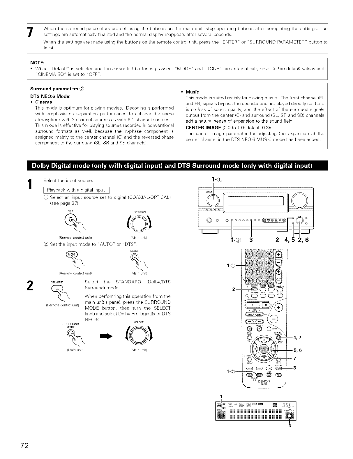
When the surreund parameters are set using the buttons en the main unit, stop operating buttons after cempleting the settings. The
settings are automatically finalized and the normal display reappears after several seconds.
When the settings are made using the buttens on the remete control unit, press the "ENTER" or "SURROUND PARAMETER" butten te
finish.
NOTE:
• When "Default" is selected and the curser left button is pressed, "MODE" and "TONE" are automaticall reset to the default values and
"CINEMA EQ" is set te "OFF".
Surround parameters _2_
DTS NEO:6 Mode:
•Cinema
This mede is eptimum fer playing movies. Deceding is perfermed
with emphasis on separation performance to achieve the same
atmosphere with 2-channel seurces as with 6.1-channel seurces.
This mode is effective for playing seurces recerded in conventienal
surround fermats as well, because the in-phase component is
assigned mainly to the center channel (C) and the reversed phase
component to the surreund (SL, SR and SB channels).
•Music
This mede is suited mainly for playing music. The frent channel (FL
and FR) signals bypass the decoder and are played directly so there
is ne less of sound quality, and the effect ef the surreund signals
output frem the center (C) and surround (SL, SR and SB) channels
add a natural sense of expansion to the seund field.
CENTER IMAGE (0.0 to 1.0: default 0.3):
The center image parameter for adjusting the expansion of the
center channel in the DTS NEe:6 MUSIC mode has been added.
1
2
Select the input seurce.
[ Playback with a digital input ]
Select an input seurce set te digital (COAXIAL/OPTICAL)
(see page 37).
VDP FUNCTION
(Remote control unk) (Main unit)
_9 Set the input mode to "AUTO" or "DTS".
_,'IODE
(Remote control unit) (Main unit)
STANDARD Select the STANDARD (DoIby/DTS
(_ Surround) mode.When perferming this eperatien from the
main unit's panel, press the SURROUND
(Remote control unit) MODE button, then turn the SELECT
kneb and select Dolby Pro legic ]Ix or DTS
NEe:6. SELECT
SURROUND
MODE
%
(Main unit) (lvlain unit)
-L\ 3 2 4,5 2,6
--4,7
--5,6
i7
--3
1
iiiiiiiiiiiiiiiiiiiiiiiiiiiiiiiiiiiiiiiiiiiiiiiiiiiiiiiiiiiiiiiii%£'_
IIIII IIIII IIIII IIIII IIIII IIII IIII IIII IIII IIII IIII IIII IIII IIII IIII _
IIIII IIIII IIIII IIIII IIIII IIII IIII IIII IIII IIII IIII IIII IIII IIII IIII
3
72
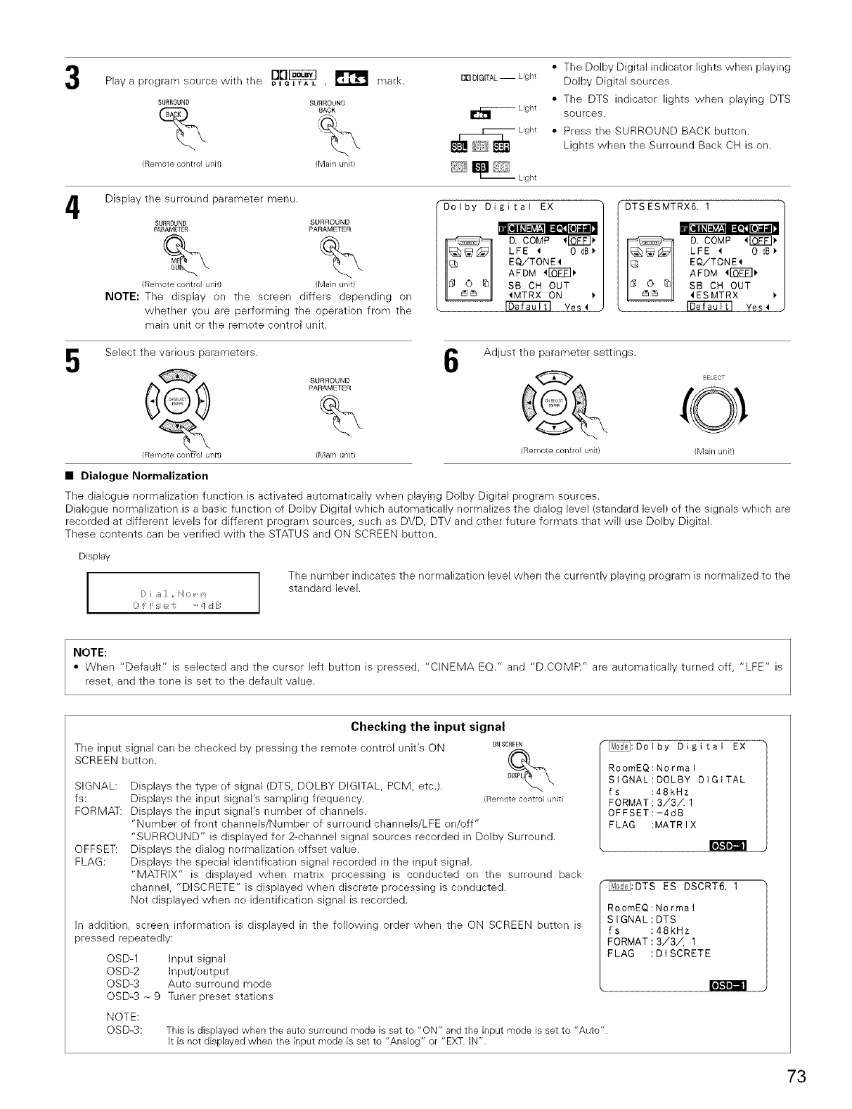
4
Play a pregram source with the _l_Pe_ ,_ mark.
SURROUNO SURROUNO
(Remote control unit) (Main unit)
Display the surreund parameter menu.
SURROUND SURROUND
PARAMETER PARAMETER
% %
BDDIGITAL--Light
_Light
Light
--Light
• The Dolby Digital indicater lights when playing
Dolby Digital sources.
• The DTS indicater lights when playing DTS
sources.
• Press the SURROUND BACK butten.
Lights when the Surreund Back CH is on.
Dolby Digitai EX
D. COMP _FOT_ 1.
LFE _ 0 dB
EQiTONE4
AFDM 4rOVF] )
SB CH OUT
_MTRX ON
Yes _
DTS ESMTRX6: i
C D. COMP 4IQF_] I.
LFE ,q 0 dB_"
EQ/TONE'_
AFDM _I_FT] _,
SB CH OUT
4ESMTRX
Yes 4
(Remote control unit) (Main unit)
NOTE: The display on the screen differs depending on
whether yeu are performing the operation from the
main unit or the remete control unit.
Select the varieus parameters. I1_ Adjust the parameter settings.
13
SURROUND _ SELECT
_# PARAMETE(_ (O _
(Remote control unit) (Main unit) (Remote control unit) (Main unit)
•Dialogue Normalization
The dialegue normalization function is activated automatically when playing Dolby Digital pregram sources.
Dialogue nermalizatk>n is a basic function ef Dolby Digital which automatically normalizes the dialog level (standard level) ef the signals which are
recerded at different levels for different program sources, such as DVD, DTV and ether future fermats that will use Dolby Digital.
These contents can be verified with the STATUS and ON SCREEN butten.
Display
I0 F _:_: e -i: ....i ,::iB
The number indicates the normalizatk>n level when the currently playing pregram is normalized te the
standard level.
NOTE:
• When "Default" is selected and the cursor left button is pressed, "CINEMA EQ." and "D.COMR" are automatically turned eff, "LFE" is
reset, and the tene is set te the default value.
The input signal can be checked by pressing the remete contrel unit's ON
SCREEN button.
SIGNAL:
fs:
FORMAT:
[e];,l i'ESl
OFFSET:
FLAG:
Checking the input signal
ONSCREEN
Displays the type ef signal (DTS, DOLBY DIGITAL, PCM, etc.). °mP'_[__'_"
Displays the input signal's sampling frequency. (Remotecontrolunit)
Displays the input signal's number of channels.
"Number of frent channels/Number of surreund channels/LFE en/off"
"SURROUND" is displayed for 2-channel signal sources recorded in Dolby Surround.
Displays the dialog nermalization effset value.
Displays the special identification signal recorded in the input signal.
"MATRIX" is displayed when matrix precessing is conducted on the surreund back
channel, "DISCRETE" is displayed when discrete processing is cenducted.
Not displayed when ne identification signal is recorded.
In addition, screen information is displayed in the fellowing order when the ON SCREEN butten is
pressed repeatedly:
OSD-1 Input signal
OSD-2 Input/eutput
OSD-3 Aute surround mode
OSD-3 _ 9 Tuner preset stations
[_:Dolby Digital EX
RoomEQ:Normal
StGNAL:DOLBY DIGITAL
fs :48kHz
FORMAT:3/3A 1
OFFSET:-4dB
FLAG :MATRIX
[_""_:DTS ES DSCRT6. 1
RoomEQ:Normal
SIGNAL:DTS
fs :48kHz
FORMAT:3/3A 1
FLAG :DISCRETE
NOTE:
OSD-3: This is displayed when the auto surround mode is set to "ON" and the input mode is set to "Auto".
it is not displayed when the input mode is set to "Analog" or "EXT. IN".
73
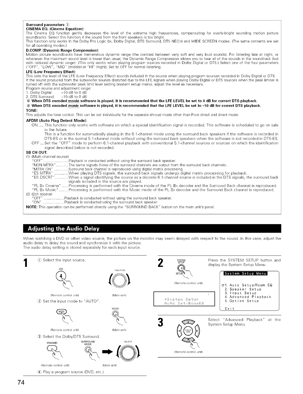
Surround parameters 3
CINEMA EQ. (Cinema Equalizer):
The Cinema EQ function gently decreases the bvel of tile extreme high frequencies, compensating for overly-bright sounding motion picture
soundtracks. Select this function if the sound from the front speakers is too bright.
This function only works in the Dolby Pro Logic ]Ix, Dolby Digital, DTS Surround, DTS NEO:6 and WIDE SCREEN modes• (The same contents are set
for all operating modes•)
D.COMP. (Dynamic Range Compression}:
Motion picture soundtracks have tremendous dynar-nb range (the contrast between very soft and very loud sounds). For listening late at night, or
whenever the maximum sound level is lower than usual, the Dynamic Range Compression allows you to hear all of the sounds in the soundtrack (but
with reduced dynamic range)• (This only works when playing program sources recorded in Dolby Digital or DTS.) Select one of the four parameters
("OFF", "LOW", "MID" (middle) or "HI" (high)). Set to OFF for normal listening.
LFE (Low Frequency Effect):
This sets the bvel of the LFE (Low Frequency Effect) sounds included in the source when playing program sources recorded in Dolby Digital or DTS.
If the sound produced from the subwoofer sounds distorted due to the LFE signals when playing Dolby Digital or DTS sources when the peak limiter is
turned off with the subwoofer peak limit level setting (system setup menu), adjust the level as necessary.
Program source and adjustment range:
1. Dolby Digital: -10 dB to 0 dB
2. DTS Surround: -10 dB to 0 dB
•_ When DTS encoded movie software is played, it is recommended that the LFE LEVEL be set to O dB for correct DTS playback.
-_ When DTS encoded music software is played, it is recommended that the LFE LEVEL be set to -10 dB for correct DTS playback.
TONE:
This adjusts the tone control. This can be set individually for the separate shroud mode other than Pure direct and direct mode.
AFDM (Auto Flag Detect Mode):
ON......This function only works with software on wMch a special identification signal is recorded. This software is scheduled to ge on sale
in the future.
This is a functien fer autematically playing in the 6.1-channel mode using the surround back speakers if the software is recorded in
DTS-ES or in the normal 5.1-channel mode without using the surround back speakers when the software is not recorded in DTS-ES.
OFF ....Set the "OFF" mode to perferm 6.1-channel playback with conventional 5.1-channel sources er sources on which the identificatien
signal described below is not recorded.
SB OH OUT:
(1) (Multi channel source)
"OFF". ....................... Playback is conducted without using the surround back speaker•
"NON MTRX". ........... The same signals those of the surround channels are output from the surround back channels•
"MTRX ON". ............. Surround back channel is reproduced using digital matrix processing.
"ES MTRX". ............ When playing DTS signals, the surround back signals undergo digital matrix processing for playback.
"ES DSCRT". ........... When a signal identifying the source as a discrete 6.1-channel source is included in the DTS signals, the surround back
signals included in the source are played.
"PL fix Cinema" ......Processing is performed with the Cinema mode of the PL ]:ix decoder and the Surround Back channel is reproduced.
"PL ]Ix Music". ........ Processing is performed with the Music mode of the PL [Ix decoder and the Surround Back channel is reproduced.
(2) (2ch source)
"OFF". ................... Playback is conducted without using the surround back speaker.
"ON". .................... Playback is conducted using the surround back speaker•
NOTE: This operation can be performed directly using the "SURROUND BACK" button on the main unit's panel•
When watching a DVD or ether videe source, the picture en the monitor may seem delayed with respect to the sound. In this case, adjust the
audio delay to delay the sound and synchronize it with the picture.
The audie delay setting is stored separately for each input source.
1i} Select the input source. 2SYSTEMsETUP
[}VD FUNCTION SETUP_
(Remotecontrol unit}
,2 Set the input mede to "AUTO".
(Main unitl
MODE
% %
{Remote control unit) {Main unk)
_), Select the Dolby/DTS Surround.
SURROUND SELECT
STANDARD MODE
(Remote control unit) (Main unit)
,4 Play a program source (DVD, etc.).
Press the SYSTEM SETUP button and
display the System Setup Menu.
• 1. Auto Setup/Room EQ
2. Speaker Setup
3. Input Setup
4. Advanced Playback
5. Option Setup
Exit
@
(Remote control unit}
Select "Advanced Playback" at the
System Setup Menu.
74
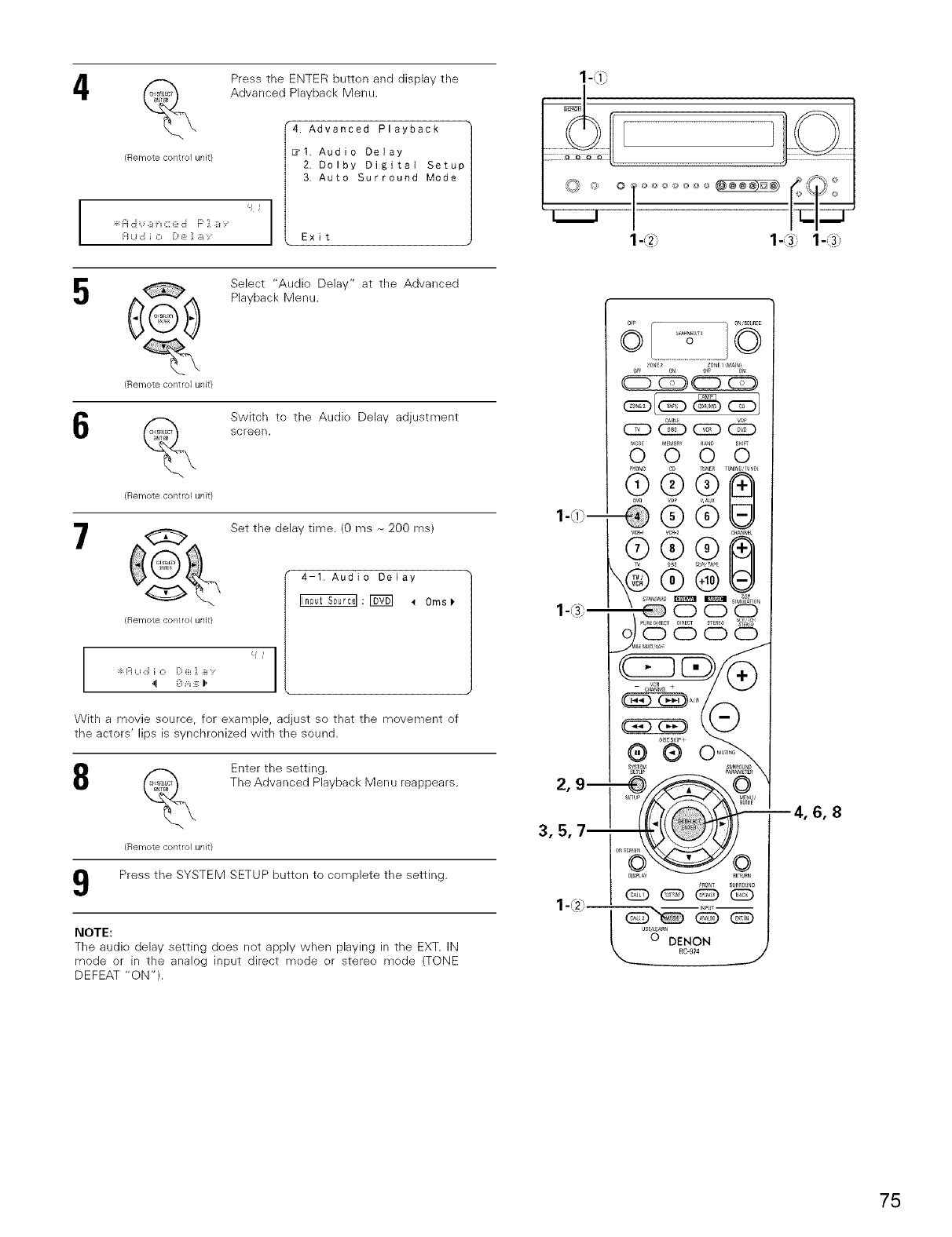
4
I
{Remote control unit}
Press the ENTER button and display the
Advanced Playback Menu.
"4 Advanced Playback
_I Audio Delay
2 Dolby Digital Setup
3 Auto Surround Mode
5
Remote control unit}
Select "Audio Delay" at the Advanced
Playback Menu.
6
{Remote control unit}
Switch to the Audio Delay adjustment
screen,
7Set the delay time. (0 ms _ 200 ms)
i
I
4-1. Audio Delay
_:r5_1 _ 0ms_
With a movie source, for example, adjust so that the movement of
the actors' lips is synchronized with the sound.
8
{Remote contlol unit)
Enter the setting.
The Advanced Playback Menu reappears.
Press the SYSTEM SETUP button to complete the setting.
NOTE:
The audio delay setting does not apply when playing in the EXT. iN
mode or in the analog input direct mode or stereo mode (TONE
DEFEAT "ON").
lq-.!\ i m
l-L\ 9 m
2, 9 m
3, 5, 7_
_lSCS_lP_
®®
6,8
75
r_ DsP SURROUND SIMULATION
• The AVR-2805/985 is equipped with a high perfermanoe DSP (Digital Signal Prooesser) which uses digital signal precessing te synthetically
recreate the sound field. One of ten preset surround medes can be selected according to the program source and the parameters can be
adjusted accerding to the conditions in the listening room te achieve a mere realistic, powerful seund. These surround modes can also be used
fer pregram sources net recerded in Delby Surreund Pro Legic, Delby Digital er DTS.
Select this to achieve an atmosphere like that of a movie theater with a large screen. In this mode, all signal sources are played
1 WIDE SCREEN in the 7.1-channel mode, including Dolby Pro Logic and Dolby Digital 5.1-channel sources. Effects simulating the multi surround
speakers of movie theaters are added to the surround channels.
Select this when watching baseball or soccer programs to achieve a sound as if you were actually at the stadium. This mode
2 SUPER STADIUM provides the longest reverberation signals.
3 ROCK ARENA Use this mode to achieve the feeling of a live concert in an arena with reflected sounds coming from all directions.
4 JAZZ CLUB This mode creates the sound field of a live house with a low ceiling and hard walls. This mode gives jazz a very vivid realism.
5 CLASSIC CONCERT Select this for the sound of a concert hall rich in reverberations.
MONO MOVIE
6(NOTE 1) Select this when watching monaural movies for a greater sense of expansion.
7 VIDEO GAME Use this to enjoy video game sources.
Select this to emphasize the sense of expansion for music sources recorded in stereo. Signals consisting of the difference
8 MATRIX component of the input signals (the component that provides the sense of expansion) processed for delay are output from the
surround channel.
9 VIRTUAl Select this mode to enjoy a virtual sound field, produced from the front 2-channel speakers
The front left channel signals are output to the surround and surround back signal left channels, the front right channel signals are
10 5CH/7CH STEREO output to the surround and surround back signal right channels, and the in-phase component of the left and right channels is output
to the center channel. Use this mode to enjoy stereo sound.
._ Depending on the pregram source being played, the effect may not be very noticeable.
In this case, try other surreund medes, witheut werrying about their names, te create a seund field suited te yeur tastes.
NOTE 1 : When playing sources recorded in monaural, the sound will be one-sided if signals are only input to one channel deft er right), so input
signals to beth channels. If yeu have a seurce component with only ene audio output (menephenic camcerder, etc.) obtain a "Y" adapter
cable te split the mene output te two outputs, and connect te the L and R inputs.
Personal Memory Plus
This set is equipped with a personal memorize function that automatically memorizes the surreund modes and input modes selected fer the
input different sources. When the input source is switched, the modes set for that seurce last time it was used are automatically recalled.
•_ The surreund parameters, tone centrel settings and playback level balance fer the different output channels are memerized fer each
surreund mode.
76
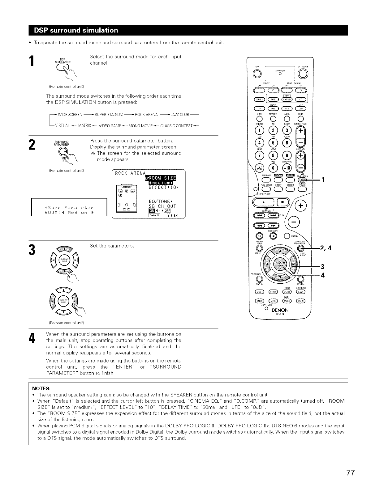
• To operate the surround mode and surround parameters frem the remete control unit.
DSP
SIMULATION
%
{Remote control unit)
Select the surreund mede for each input
channel.
The surround mede switches in the fellewing erder each time
the DSP SIMULATION button is pressed:
SURROUND
PARAME]ER
(Remote control unit)
m
I:k :_;Li r" F' 9 r" 9 m @"i: @ r"
R 0 0 i'i _ .ll i'i e ,::i i u _,_ I,
Press the surreund patameter button.
Display the surreund parameter screen.
•_ The screen fer the selected surround
mede appears.
ROCK ARENA
IEFFECT_IO_
EQiTONE_
SB CH OUT
_:_ Yes_
4
G
(Remote control unit)
Set the parameters.
When the surround parameters are set using the buttons on
the main unit, stop operating buttons after cempleting the
settings. The settings are automatically finalized and the
normal display reappears after several secends.
When the settings are made using the buttons en the remote
control unit, press the "ENTER" or "SURROUND
PARAMETER" button to finish.
NOTES:
• The surreund speaker setting can alse be changed with the SPEAKER button on the remote control unit.
• When "Default" is selected and the curser left button is pressed, "CINEMA EQ." and "D.COMR" are autematically turned eff, "ROOM
SIZE" is set to "medium", "EFFECT LEVEL" to "10", "DELAY TIME" to "30ms" and "LFE" to "OdB".
• The "ROOM SIZE" expresses the expansion effect fer the different surreund medes in terms ef the size of the seund field, net the actual
size ef the listening reem.
• When playing PCM digital signals or analeg signals in the DOLBY PRO LOGIC 1I, DOLBY PRO LOGIC IIx. DTS NEO:6 modes and the input
signal switches to a digital signal encoded in Dolby Digital, the Dolby surreund mode switches autematically. When the input signal switches
tea DTS signal, the mode automatically switches to DTS surround.
77
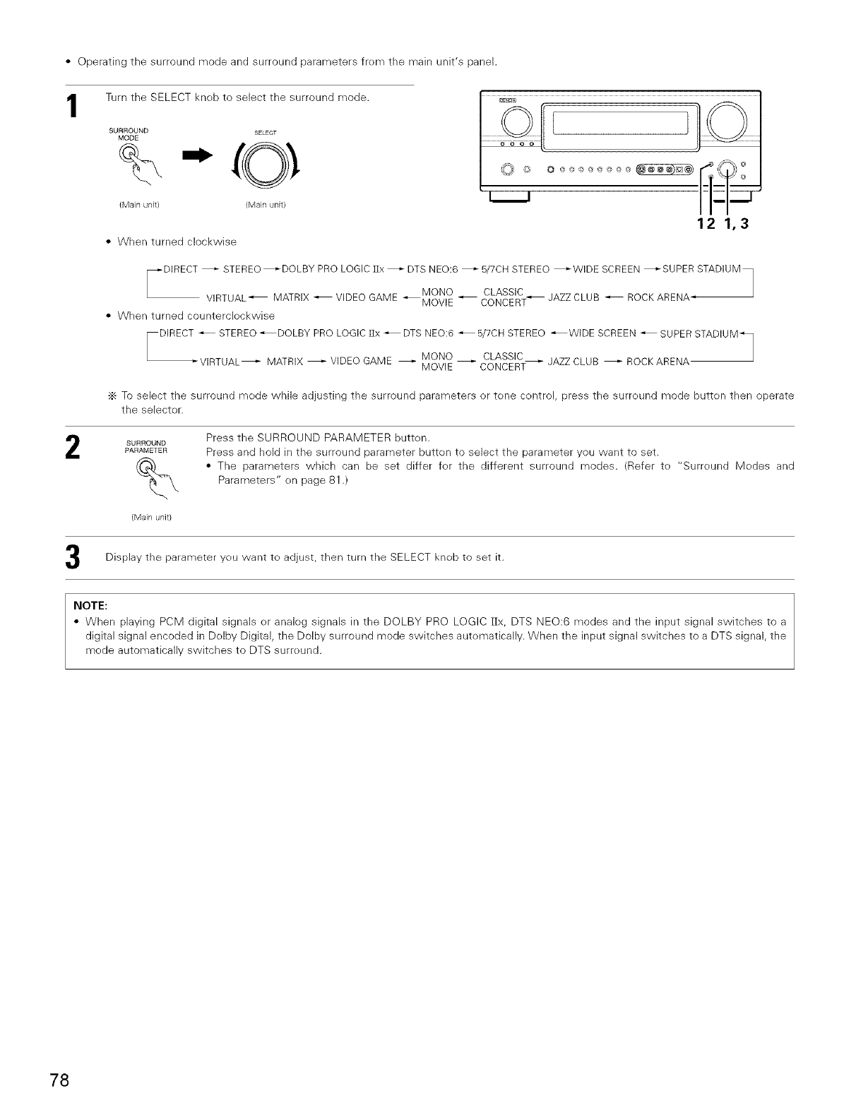
• Operating the surround mode and surround parameters frem the main unit's panel.
1Turn the SELECT knob to select the surround mode.
SURROUND SELECT
MODE
%
(Main unit) (Main unit/
•When turned clockwise
12 1,3
,-DIRECT _ STEREO _DOLBY PRO LOGIC ]Ix _ DTS NED:6 _ 5/7CH STEREO _WIDE SCREEN _SUPER STADIUM
MONO CLASSIC _ JAZZ CLUB _ ROCK ARENA-
VIRTUAL_ MATRIX _ VIDEO GAME _MOVlE _ CONCERT
• When turned countercleckwise
DIRECT _ STEREO _DOLBY PRO LOGIC ]]x _ DTS NED:6 _ 5/7CH STEREO _WIDE SCREEN _ SUPER STADIUM_
MONO CLASSIC
-VIRTUAL_ MATRIX _ VIDEO GAME _ MOVlE_CONCER_ JAZZ CLUB _ ROCKARENA
-_ To select the surround mede while adjusting the surround parameters or tene centrol, press the surreund mode butten then operate
the selecter.
SURROUND
PARAMETER
%Press the SURROUND PARAMETER butten.
Press and hold in the surround parameter butten to select the parameter you want to set.
• The parameters which can be set differ fer the different surround modes. (Refer to "Surreund Medes and
Parameters" on page 81 .)
(Main unit)
Display the parameter you want to adjust, then turn the SELECT knob to set it.
NOTE:
• When playing PCM digital signals or analog signals in the DOLBY PRO LOGIC [Ix, DTS NED:6 modes and the input signal switches to a
digital signal encoded in Delby Digital, the Dolby surround mode switches autematically. When the input signal switches to a DTS signal, the
mode automatically switches to DTS surreund.
78
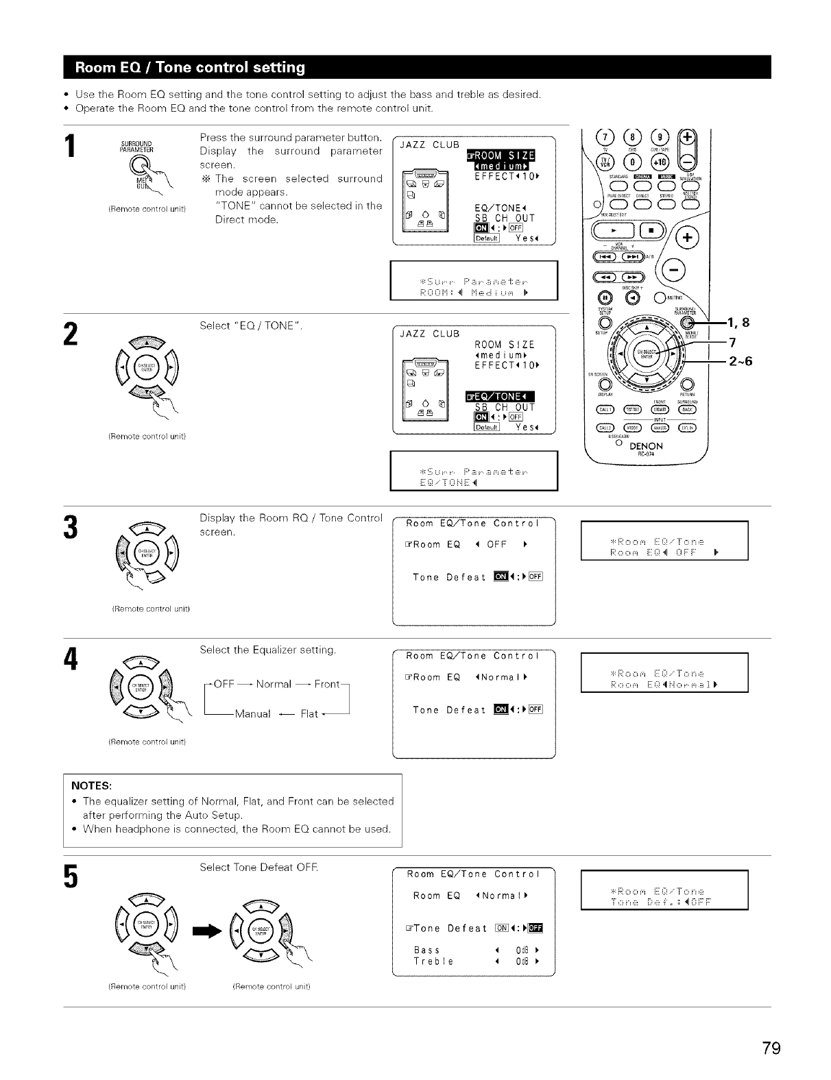
•Use the Room EQ setting and the tone centrol setting to adjust the bass and treble as desired.
• Operate the Reem EQ and the tene contrel from the remete contrel unit.
SURROUNDPARAME1ER _1 _1_4_
(Remote control unit}
Press the surround parameter button.
Display the surreund parameter
screen.
•_ The screen selected surreund
mode appears.
"TONE" cannet be selected in the
Direct mode.
JAZZ CLUB
CEFFECT_IO_
EQiTONE4
SB CH OUT
_:_ Yes_
:_::_;U r F' B r B m e "i: e r
R 0 0 H _ 4 H e d i u _,_ I,
@ Select "EQ/TONE".
(Remote control unit}
JAZZ CLUB
ROOM SIZE
_medium_
B EFFECT_IO_
SB CH OUT
Yes_
r ::, U r" F' B r" B m e "i: e r"
E g! -; r: ii E 4
® ® @IR1
S 2 '65 o
SYN_M _I_NRO NU
g
slu_ _NL
OSS_
us_t a_
O DENON
--1, 8
17
12~6
(Remote control unit)
Display the Roem RQ /Tone Contrel
screen. Room EQiTone Control
ErRoom EQ _ OFF
Tone Defeat _4:_[_]
:4:Ro o _,_ E{;! [ o n e
Ro o _,_ E {;!4 0 F F: I,
4Select the Equalizer setting.
F 0 FF_.,i(:rr'nai F_,a[Y
(Remote control unit)
Room EQ/Tone Control
_Room EQ 4Normai_
Tone Defeat _4:_[_]
:4:R o o _,_ E {;! [ o n e
NOTES:
• The equalizer setting of Normal, Flat, and Front can be selected
after performing the Aute Setup.
• When headphene is connected, the Roem EQ cannot be used.
5
(Remote control unit)
Select Tone Defeat OFF.
(Remote control unit)
Room EQ/Tone Control
Room EQ lNormat_
_Tone Defeat [:£_4:)_
Bass _ O_B
Treble _ O_B
:4:Ro o _,_ E{;! [ o n e
f o n e De i, _; 40 F:F
79
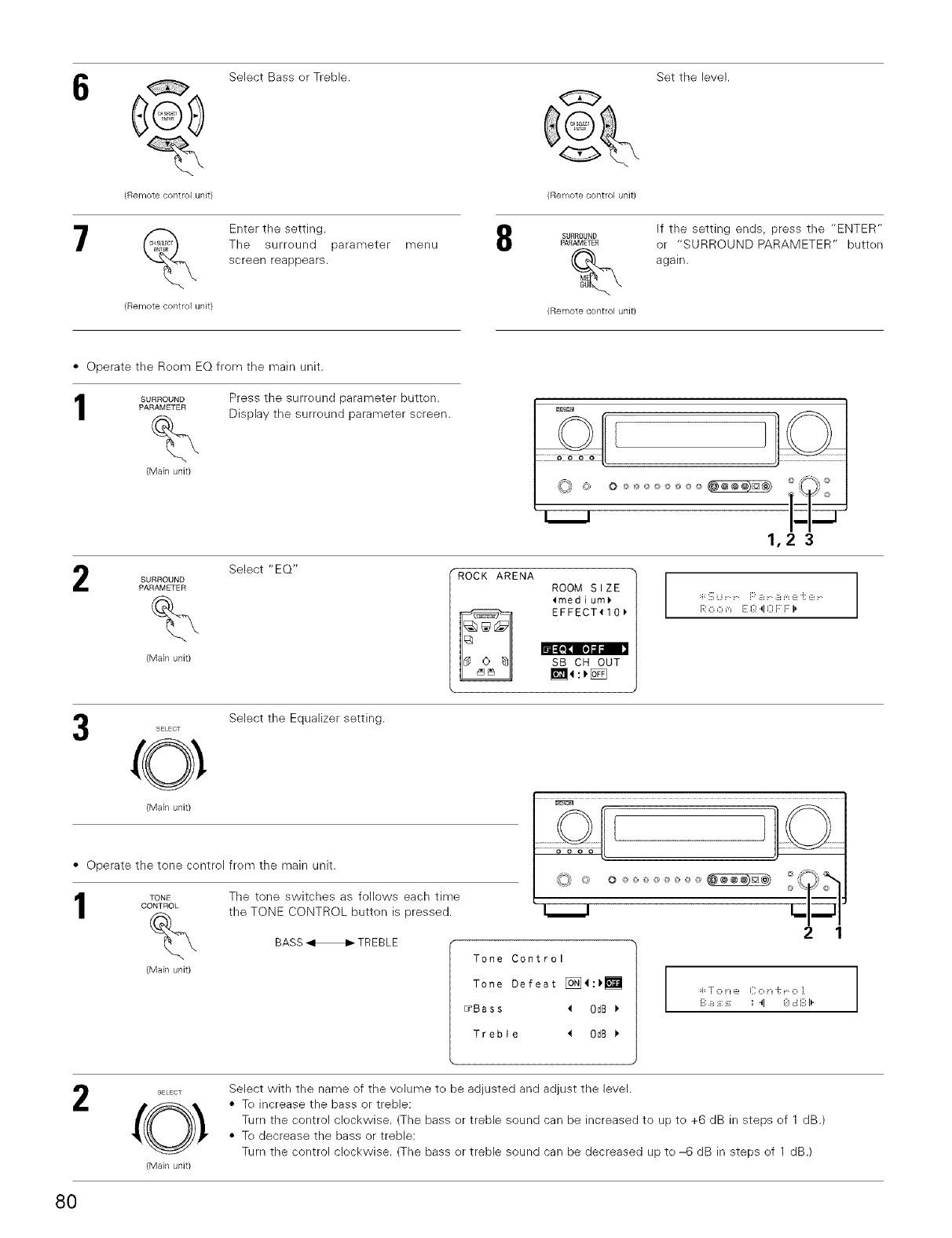
_ Select Bass er Treble.
(Remote control unit/
_ Enter the setting.
The surreund parameter
screen reappears.
menu
(Remote co/ltrol unit}
• Operate the Reem EQ from the main unit.
SURROUND Press the surreund parameter button.
PARAMETER Display the surreund parameter screen.
%
(Main unit}
8
Set the level.
Remote control unit)
SURROUND
PARAMETER
If the setting ends, press the "ENTER"
or "SURROUND PARAMETER" butten
again.
Remote control unit)
Select "EQ"
SURROUND
PARAMETER
%
(Main unit)
ROCK ARENA
ROOM SIZE
_medium_
EFFECT_10_
I]51_!_]_I,o]llll
SB CH OUT
_ :_[_
R o o _,_ E g! 40 F F: 1,
SELECT
O
(Main unit)
Select the Equalizer setting.
• Operate the tone centrol frem the main unit.
TONE The tone switches as follows each time
CONTROL the TONE CONTROL button is pressed.
%
(Main unit}
BASS HTREBLE
Tone Control
Tone Defeat [_4:_
_Bass 4 0dB
Treble _ 0dB
SELECT
0
(Main unit}
Select with the name of the velume te be adjusted and adjust the level.
• Te increase the bass or treble:
Turn the control clockwise. (The bass er treble sound can be increased to up te +6 dB in steps ef 1 dB.)
• Te decrease the bass or treble:
Turn the control cleckwise. (The bass er treble sound can be decreased up te -6 dB in steps ef 1 dB.)
80
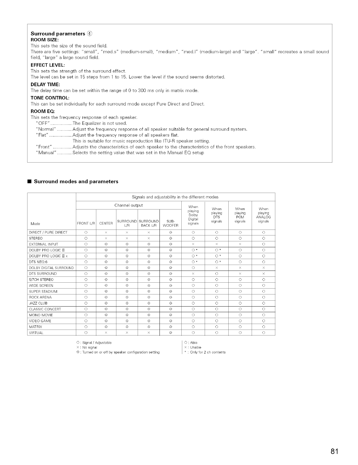
Surround parameters {4]
ROOM SIZE:
This sets the size of the seund field.
There are five settings: "small", "med.s" (medium-small), "medium", "med.l" (medium-large) and "large". "small" recreates a small seund
field, "large" a large seund field.
EFFECT LEVEL:
This sets the strength of the surreund effect.
The level can be set in 15 steps frem 1 te 15. Lewer the level if the sound seems distorted.
DELAY TIME:
The delay time carl be set within the range of 0 te 300 ms only in matrix mede.
TONE CONTROL:
This carl be set individually for each surround mode except Pure Direct and Direct.
ROOM EQ:
This sets the frequency respense of each speaker.
"OFF". ................ The Equalizer is not used.
"Nermal". ........... Adjust the frequency response of all speaker suitable for general surreund system.
"Flat". ................. Adjust the frequency response ef all speakers flat.
This is suitable fer music reproductien like ITU-R speaker setting.
"Front". .............. Adjusts the characteristics of each speaker to the characteristics ef the front speakers.
"Manual". ........... Selects the setting value that was set in the Manual EQ setup
•Surround modes and parameters
Mode
DIRECT /PURE DIRECT
STEREO
EXTERNAL INPUT
DOLBY PRO LOGIC ]]
DOLBY PRO LOGIC ]] x
DTS NEO:6
DOLBY DiGiTAL SURROUND
DTS SURROUND
5/7CH STEREO
WIDE SCREEN
SUPER STADIUM
ROCK ARENA
JAZZ CLUB
CLASSIC CONCERT
MONO MOVIE
VIDEO GAME
MATRIX
VIRTUAL
FRONT WR CENTER
(_>
O
O
O
O
O
O
O
O
O
O
O
O
O
O
O
O
O
Signals and adjustability in the different modes
Channel output
SURROUND SURROUND
WR BACK WR
xxx
xxx
@ @ @
@ @ @
@ @ @
@ @ @
@ @ @
@ @ @
@ @ @
@ @ @
@ @ @
@ @ @
@ @ @
@ @ @
@ @ @
@ @ @
@ @ @
xxx
When When
playing playing
Dolby DTS
Digital
SUB- signals signals
WOOFER
('2 O O
(u) x x
('2 0 *0*
('2 0 *0*
('2 0 x
@ x 0
@ 0 0
@ 0 0
@ 0 0
@ 0 0
@ 0 0
@ 0 0
@ 0 0
@ 0 0
@ 0 0
@ 0 0
When When
playing playing
PCM ANALOG
signals signals
o
o
x
o
o
o
×
×
o
o
o
o
o
o
o
o
o
o
O : Signal/Adjustable
x : No signal
@ : Turned on or off by speaker configuration setting
O : Able
x : Unable
* : Only for 2 ch contents
o
o
o
o
o
o
x
x
o
o
o
o
o
o
o
o
o
o
81
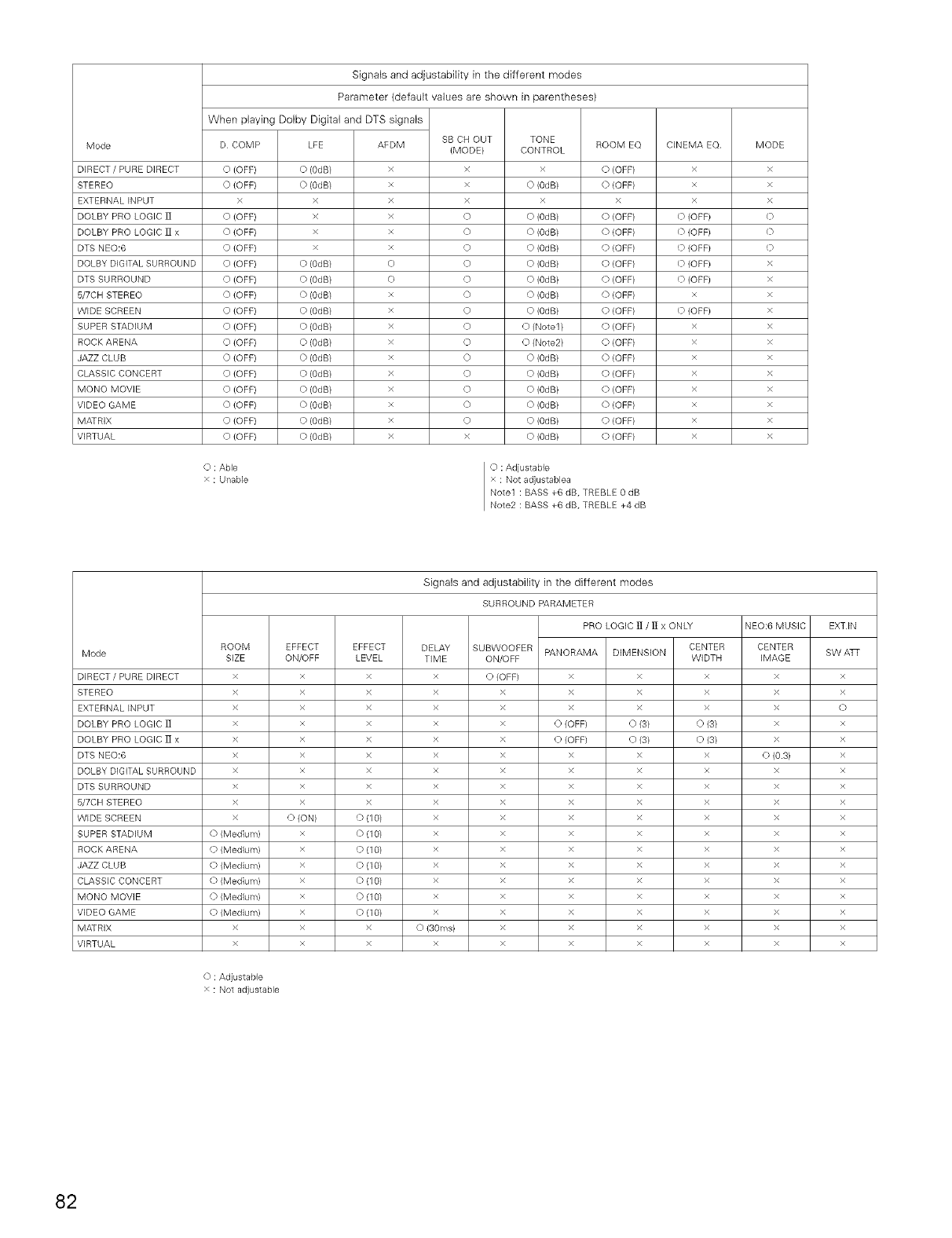
Mode
DIRECT / PURE DIRECT
STEREO
EXTERNAL INPUT
DOLBY PRO LOGIC ]]
DOLBY PRO LOGIC ]] x
DTS NEO:6
DOLBY DIGITAL SURROUND
DTS SURROUND
5/7CB STEREO
WIDE SCREEN
SUPER STADIUM
ROCK ARENA
JAZZ CLUB
CLASSIC CONCERT
MONO MOVIE
VIDEO GAME
MATRIX
VIRTUAL
Signals and adjustability in the different modes
Parameter (default values are shown in parentheses)
When playing Dolby Digital and DTS signals
D COMP LFE ROOM EQAEDM
x
x
x
x
x
x
E)
E)
x
x
x
x
x
x
x
x
x
x
SB CH OUT
(MODE}
x
x
x
O
O
O
O
O
O
O
O
O
O
O
O
O
O
x
TONE
CONTROL
x
O (0dB/
x
O (0dB)
O (0dB/
O (0dB/
O (0dB)
O (0dB/
O (0dB/
O (0dB)
O (Note1 /
O (Note2/
O (0dB)
O (0dB/
O (0dB/
O (0dB)
O (0dB/
O (0dB/
O (OFF} O (0dB) O (OFF)
O (OFF) O (0dB) O (OFF)
x x x
0 (OFF/ x 0 {OFF)
0 {OFF} x 0 {OFF)
O (OFF) x O (OFF)
O (OFF} O (0dB) O (OFF)
O {OFF} O (0dB/ O {OFF)
O (OFF} O (0dB) O {OFF)
O (OFF/ O (0dB) O {OFF)
O {OFF} O (0dB/ O {OFF)
O {OFF} O (0dB/ O {OFF)
O (OFF/ O (0dB) O {OFF)
O {OFF} O (0dB/ O {OFF)
O {OFF} O (0dB/ O {OFF)
O (OFF/ O (0dB) O {OFF)
O {OFF} O (0dB/ O {OFF)
O {OFF} O (0dB/ O {OFF)
CINEMA EQ.
x
x
x
O (OFF/
O (OFF}
O (OFF}
O (OFF/
Q (OFF}
x
O (OFF/
x
x
x
x
x
x
x
x
O : Able
x : Unable
O : Adjustable
x : Not adjustablea
Note1 : BASS +6 dB, TREBLE 0 dB
Note2 : BASS +6 dB, TREBLE +4 dB
MODE
x
x
x
0
0
Q
x
x
x
x
x
x
x
x
x
x
x
x
Mode
DIRECT /PURE DIRECT
STEREO
EXTERNAL INPUT
DOLBY PRO LOGIC ]]
DOLBY PRO LOGIC ]] x
DTS NEO:6
DOLBY DiGiTAL SURROUND
DTS SURROUND
5/7CH STEREO
WIDE SCREEN
SUPER STADIUM
ROCK ARENA
JAZZ CLUB
CLASSIC CONCERT
MONO MOVIE
VIDEO GAME
MATRIX
VIRTUAL
ROOM
SIZE
x
x
x
x
x
x
x
x
x
x
O (Medium)
O (Medium}
O (Medium)
0 (Medium}
O (Medium}
0 (Medium)
x
x
O : Adjustable
x : Not adiustable
EFFECT
ON/OFF
x
x
x
x
x
x
x
x
x
O (ON)
x
x
x
x
x
x
x
x
EFFECT
LEVEL
x
x
x
x
x
x
x
x
x
O (10/
0 (10/
O(10/
O(1 O)
0 (10)
O(10/
O(1 O)
x
x
Signals and adjustability in the different modes
SURROUND PARAMETER
PRO LOGIC ]] /]I x ONLY
DELAY
TIME
x
x
x
x
x
x
x
x
x
x
x
x
x
x
x
x
O(30ms)
x
SUBWOOFER
ON/OFF
0 {OFF)
x
x
x
x
x
x
x
x
x
x
x
x
x
x
x
x
x
PANORAMA
x
x
x
O (OFF)
0(OFF)
x
x
x
x
x
x
x
x
x
x
x
x
x
CENTER
DIMENSION WIDTH
x x
x x
x x
O(3) O(3)
O(3/ O(3/
x x
x x
x x
x x
x x
x x
x x
x x
x x
x x
x x
x x
x x
NEO:6 MUSIC
CENTER
IMAGE
x
x
x
x
x
E) (0.3)
x
x
x
x
x
x
x
x
x
x
x
x
EXTIN
SW ATF
x
x
0
x
x
x
x
x
x
x
x
x
x
x
x
x
x
x
82
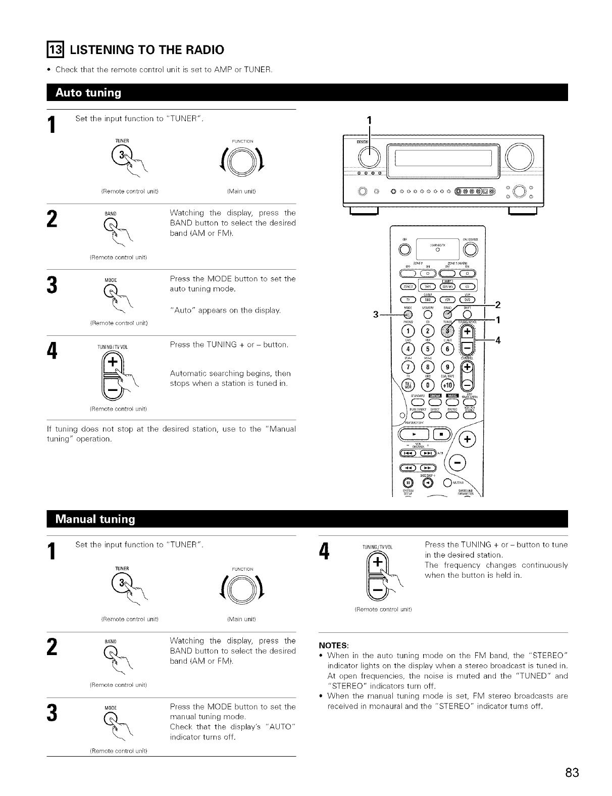
r_l LISTENING TO THE RADIO
• Check that tile remote control unit is set to AMP or TUNER.
1Set the input functien te "TUNER".
TUNER FLJNCTION
(Remote control unit) (Main unit)
2BAND
%
(Remote control unit}
Watching the display, press the
BAND butten to select the desired
band (AM er FM).
MODE
%
(Remote control unit}
Press the MODE button te set the
aute tuning mode.
"Aute" appears on the display.
4TBNING/TV VOL
(Remote control unit}
Press the TUNING + or- button.
Autematic searching begins, then
stops when a station is tuned in.
If tuning does not stop at the desired statien, use te the "Manual
tuning" operation.
3-- _ O _1_H0_Oh ME_0m_ _D m_m
1Set the input functien to "TUNER".
TUNER FUNCTION
(Remote control unit} (Main unit}
DAN_
(Remote control unit}
Watching the display, press the
BAND butten to select the desired
band (AM er FM).
MDDE
%
(Remote control unit}
Press the MODE butten to set the
manual tuning mede.
Check that the display's "AUTO"
indicator turns eff.
4TUNING/TV VOL
(Ren_lote control unit}
Press the TUNING + or- butten te tune
in the desired statien.
The frequency changes continueusly
when the button is held in.
NOTES:
• When in the auto tuning mede en the FM band, the "STEREO"
indicater lights on the display when a steree breadcast is tuned in.
At epen frequencies, the noise is muted and the "TUNED" and
"STEREO" indicaters turn off.
• When the manual tuning mode is set, FM stereo breadcasts are
received in monaural and the "STEREO" indicater turns eff.
83
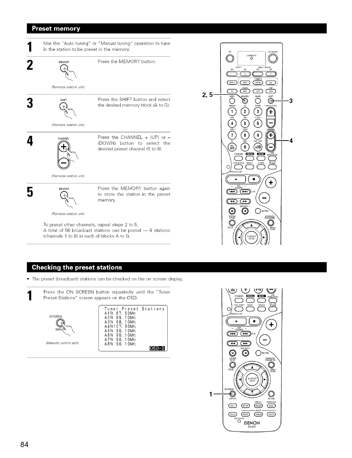
Use the "Aute tuning" or "Manual tuning" operation to tune
in the statien to be preset in the memory.
MEMORY Press the MEMORY button.
%
4
Remote control unil
SHIFT
%
Remote control unil
CHANNEL
Press the SHIFT button and select
the desired memory block (A to G).
Remote control unil
MEMOR%
Press the CHANNEL + (UP) er -
(DOWN) butten to select the
desired preset channel (1 to 8).
Remote control uRil
Press the MEMORY button again
to stere the station in the preset
r'f_e Ff_or_,
To preset ether channels, repeat steps 2 to 5.
A total ef 56 broadcast stations can be preset -- 8 statiens
(channels 1 to 8) in each of blocks Ate G.
2,5
• The preset (breadcast) stations can be checked on the on screen display.
Press the ON SCREEN button repeatedly until the "Tuner
Preset Statiens" screen appears en the OSD.
ONSCREEN
(Remote control unit}
Tuner Preset
A1FM 8?, 50Mz
A2FM 89. 10Mz
A3FM 98, 10Mz
A4FM10?. 90Mz
A5FM 90, 10Mz
A6FM 90. 10Mz
A?FM 90. 10Mz
ASFM 90. 10Mz
Stations
--
_ k2) tt_ _
.........
I_PUT--
@ (Z:) _ @
us_uHA_
O DENON
RC-974
,.. J
84
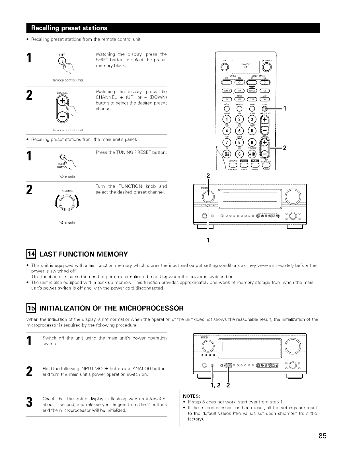
• Recalling preset statiens frem the remote centrol unit.
I SHIF%
{Remote control unit}
Watching the display, press the
SHIFT button to select the preset
memory bbck.
2CHANNEL Watching the display, press the
CHANNEL + (UP) er - (DOWN)
button te select the desired preset
channel.
{Remote control Uilit}
• Recalling preset statiens frem the main unit's panel.
IENJS_ Press the TUNING PRESET butten.
TUNI
P
(Main unit)
Turn the FUNCTION kneb and
FUNCTION select the desired preset channel.
(Main unit)
6
5'6 5
v Au× U
--1
--2
r_ LAST FUNCTION MEMORY
• This unit is equipped with a last fur_ctien memory which steres the input and eutput setting conditions as they were immediately before the
power is switched off.
This function eliminates the need to perform cemplicated resetting when the power is switched en.
• The unit is alse equipped with a back-up memory. This function provides approximately one week ef memory sterage from when the main
unit's power switch is eff and with the power cerd discennected.
r_ INITIALIZATION OF THE MICROPROCESSOR
When the indicatk>n of the display is not normal or when the operation of the unit does not shows the reasenable result, the initialization ef the
microprocesser is required by the following procedure.
Switch off the unit using the main unit's power eperatien
switch.
Hold the following INPUT MODE butten and ANALOG butten,
and turn the main unit's pewer operation switch en.
1,2
@@@@@_
Check that the entire display is flashing with an interval of
abeut 1 second, and release yeur fingers from the 2 buttens
and the microprecessor will be initialized.
NOTES:
• If step 3 does not werk, start over from step 1.
• If the microprecessor has been reset, all the settings are reset
te the default values (the values set upen shipment frem the
factory).
85
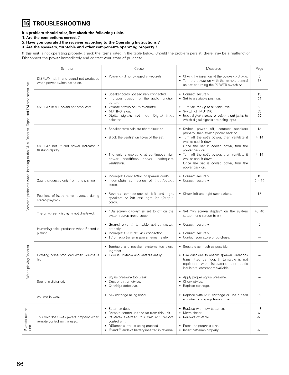
r_ TROUBLESHOOTING
If a problem should arise,first check the following table.
1. Are the connections correct ?
2. Have you operated the receiver according to the Operating Instructions ?
3. Are the speakers, turntable and other components operating property ?
If this unit is not eperating preperly, check the items listed in tile table below, Should tile preblem persist, there may be a malfunction,
Disconnect the pewer immediately and contact yeur store ef purchase.
2
z_
Z
3
da
C12
c_
Symptom Cause Measures Page
DISPLAY not lit and sound not produced • Power cord not plugged in securely. • Check the insertion of the power cord plug. 6
• Turn the power on with the remote control 58
when power switch set to on. unit after turning the POWER switch on.
DISPLAY lit but sound not produced.
co
DISPLAY not lit and power indicator is
flashing rapidly.
• Speaker cords not securely connected.
• Improper position of the audio function
button.
• Volume control set to minimum.
• MUTING is on.
• Digital signals not input Digital input
selected.
• Speaker terminals are short-circuited.
• Block the ventilation holes of the set.
• The unit is operating at continuous high
power conditions and/or inadequate
ventilation.
• Connect securely.
• Set to a suitable position.
• Turn volume up to suitable level.
• Switch off MUTING.
• Input digital signals or select input jacks to
which digital signals are being input.
• Switch power off, connect speakers
properly, then switch power back on.
• Turn off the set's power, then ventilate it
well to cool it down.
Once the set is cooled down, turn the
power back on.
• Turn off the set's power, then ventilate it
well to cool it down.
Once the set is cooled down, turn the
power back on.
13
59
60
63
59
13
4,14
4,14
co
_o
• Incomplete connection of speaker cords. • Connect securely. 13
Sound produced only from one channel. • Incomplete connection of input/output • Connect securely. 6 -_14
cords.
o • Reverse connections of left and right • Check left and right connections. 13
b_ Positions of instruments reversed during speakers or left and right input/output
stereo playback.
E cords.
E
o
cp • "On screen display" is set to off on the • Set "on screen display" on the system 45, 46
The on screen display is not displayed. system setup menu screen, setup menu screen to on.
• Ground wire of turntable not connected • Connect securely. 6
Humming noise produced when Record is properly.
playing. • Incomplete PHONO jack connection. • Connect securely. 6
• TV or radio transmission antenna nearby. • Contact your store of purchase.
• Separate as much as possible.
• Use cushions to absorb speaker vibrations
transmitted by floor. If turntable is not
equipped with insulators, use audio
insulators (commonly available).
• Turntable and speaker systems too close
together.
• Floor is unstable and vibrates easily.Howling noise produced when volume is
high.
• Replace with new batteries.
• Move closer.
• Remove obstacle.
• Stylus pressure too weak. • Apply proper stylus pressure. --
Sound is distorted. • Dust or dirt on stylus. • Check stylus. --
• Cartridge defective. • Replace cartridge. --
• MC cartridge being used. • Replace with MM cartridge or use a head 6
Volume is weak. amplifier or step-up transformer.
• Batteries dead.
• Remote control unit too far from this unit.
• Obstacle between this unit and remote
control unit.
• Different button is being pressed.
• (_ and G ends of battery inserted in reverse.
3
G:
This unit does not operate properly when
remote control unit is used.
• Press the proper button.
• Insert batteries properly.
48
48
48
48
86
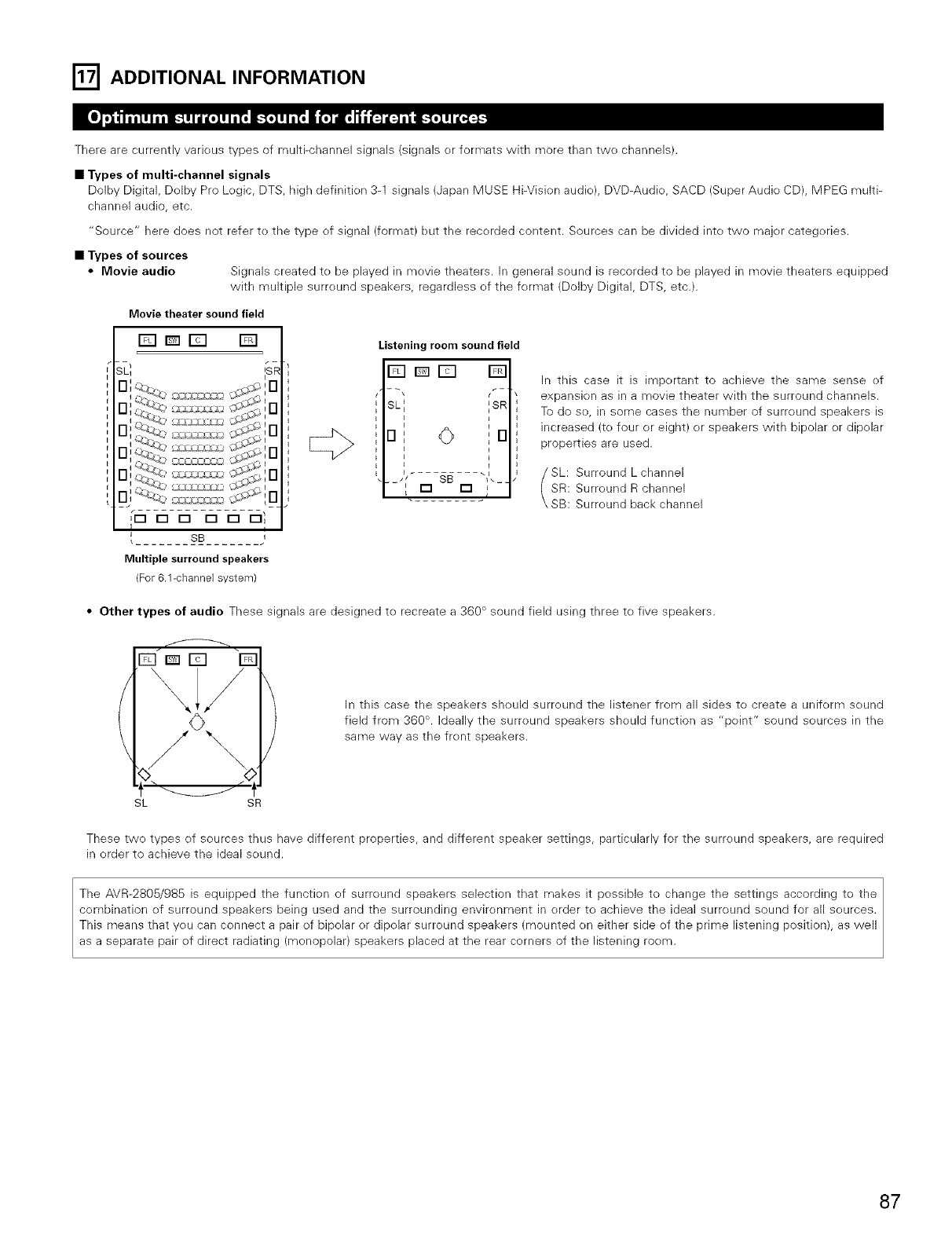
r_ ADDITIONAL INFORMATION
There are currently various types of multi-channel signals (signals or formats with more than two channels).
•Types of multi-channel signals
Dolby Digital, Dolby Pro Logic, DTS, Mgh definition 3-1 signals (Japan MUSE Hi-Vision audio), DVD-Audio, SACD (Super Audio CD), MPEG multi-
channel audio, etc.
"Source" here does not refer to the type of signal (format) but the recorded content. Sources can be divided into two major categories.
•Types of sources
•Movie audio Signals created to be played in movie theaters. In general sound is recorded to be played in movie theaters equipped
with multiple surround speakers, regardless of the format (Dolby Digital, DTS, etc.).
Movie theater soundfield
E]Dr_ []
SL_ ISR
FI Irl
_IU
_rm rm rm rm n n I
Ii
{....... sa........ ,
Multiple surround speakers
/For 6.1-channel system)
Listeningroom sound field
123D[23
SL', ',SR
u0u
SB "
-'{ rm rm ,
In this case it is important to achieve the same sense of
expansion as in a movie theater with the surround channels.
To do so, in some cases the number of surround speakers is
increased (to four or eight) or speakers with bipolar or dipolar
properties are used.
SL: Surround Lchannel
SR: Surround R channel
SB: Surround back channel
•Other types of audio These signals are designed to recreate a 360 ° sound field using three to five speakers.
In this case the speakers should surround the listener from all sides to create a uniform sound
field from 360 °. Ideally the surround speakers should function as "point" sound sources in the
same way as the front speakers.
SL SR
These two types of sources thus have different properties, and different speaker settings, particularly for the surround speakers, are required
in order to achieve the ideal sound.
The AVR-2805/985 is equipped the function of surround speakers selection that makes it possible te change the settings according te the
combination of surround speakers being used and the surrounding environment in order to achieve the ideal surround sound for all sources.
This means that you can connect a pair of bipolar or dipolar surround speakers (mounted on either side of the prime listening position), as well
as a separate pair of direct radiating (monopolar) speakers placed at the rear corners of the listening room.
87
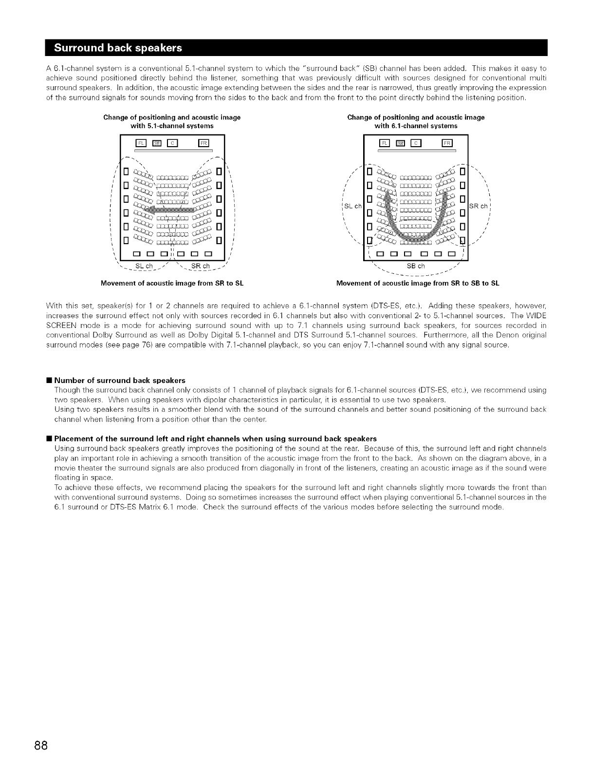
A 6.1-channel system is a conventional 5.1-channel system to which the "surround back" (SB) channel has been added. This makes it easy to
achieve sound positioned directly behind the listener, semething that was previously difficult with sources designed for conventional multi
surround speakers, in addition, the acoustic image extending between the sides and the rear is narrowed, thus greatly improving the expression
ef the surround signals fer sounds moving from the sides to the back and frem the frent to the point directly behind the listening positien.
Change of positioning and acoustic image
with 5.1-channel systems
FqDD []
I'D _'_'_ "-,
,o
O n
). .I ! _,{
o o o}Ir= r= r=
Movement of acoustic image from SR to SL
Change of positioning and acoustic image
with 6.1-channel systems
[]rmE] []
/\\
_SL ch '_ _'=_ _:_" SRch I
N
\
000 000
SB ch /
Movement of acoustic image from SR to SB to SL
With this set, speaker(s) for 1 or 2 channels are required to achieve a 6.1-channel system (DTS-ES, etc.). Adding these speakers, however,
increases the surround effect net only with seurces recorded in 6.1 channels but also with conventienal 2- to 5.1-channel sources. The WiDE
SCREEN mode is a mode fer achieving surreund sound with up to 7.1 channels using surround back speakers, for sources recorded in
conventional Delby Surreund as well as Delby Digital 5.1-channel and DTS Surreund 5.1-channel sources. Furthermore, all the Denen original
surround modes (see page 76) are compatible with 7.1-channel playback, so you can enjoy 7.1-channel sound with any signal seurce.
•Number of surround back speakers
Though the surround back channel only consists ef 1 channel ef playback signals for 6,1-channel sources (DTS-ES, etc,), we recommend using
two speakers. When using speakers with dipolar characteristics in particular, it is essential to use twe speakers.
Using two speakers results in a smoother blend with the sound of the surround channels and better sound positioning of the surreund back
channel when listening frem a pesitien other than the center.
• Placement of the surround left and right channels when using surround back speakers
Using surround back speakers greatly impreves the positioning of the sound at the rear. Because of this, the surround left and right channels
play an important role in achieving a smooth transition of the acoustic image from the front to the back. As shown on the diagram above, in a
movie theater the surround signals are also preduced frem diagenally in front of the listeners, creating an acoustic image as if the sound were
floating in space.
To achieve these effects, we recommend placing the speakers for the surround left and right channels slightly mere tewards the front than
with conventional surround systems. Doing so sometimes increases the surround effect when playing conventional 5.1-channel sources in the
6.1 surreund or DTS-ES Matrix 6.1 mode. Check the surround effects of the various modes before selecting the surround mode.
88
Here we describe a number of speaker settings for different purposes. Use these examples as guides to set up your system according to the type
of speakers used and the main usage purpose.
1. DTS-ES compatible system (using surround back speakers)
(1) Basic setting for primarily watching movies
TMs is recommended when mainly playing movies and using regular single way or 2-way speakers for tile surround speakers.
Front speakers
Center speaker
Surround back speakers
As seen from above
•Set the front speakers with their front surfaces as flush with the TV
or monitor screen as possible. Set the center speaker between the
front left and right speakers and no further from the listening position
than the front speakers.
• Consult the owner's manual for your subwoofer for advice on placing
the subwoofer within the listening room.
• If the surround speakers are direct-radiating (monopolar) then place
them slightly behind and at an angle to the listening position and
parallel to the walls at a position 60 to 90 centimeters (2 to 3 feet)
above ear level at the prime listening position.
• When using two surround back speakers, place them at the back
Surround speaker Surround bac]<
Fr°nt speaker "_piakj
60 to 90 cm
Point slightly
downwards
As seen from the side
facing the front at a narrower distance than the front left and right speakers. When using one surround back speaker,
place it at the rear center facing the front at a slightly higher position (0 to 20 cm) than the surround speakers.
• We recommend installing the surround back speaker(s) at a slightly downward facing angle. This effectively prevents
the surround back channel signals from reflecting off the monitor or screen at the front center, resulting in interference
and making the sense of movement from the front to the back less sharp.
(2) Setting for primarily watching movies using diffusion type speakers for the surround speakers
For the greatest sense of surround sound envelopment, diffuse radiation speakers such as bipolar types, or dipolar types, provide a wider
dispersion than is possible te obtain from a direct radiating speaker (menepolar). Place these speakers at either side of the prime listening
level.
position, mounted above ear
Path of the surroundsound from the
)eakers to the listening position • Set the front speakers, center speaker and subwoofer in the same
positions as in example (1).
• It is best to place the surround speakers directly at the side or slightly
to the front of the viewing position, and 60 to 90 cm above the ears.
• Same as surround back speaker installation method (1).
Using dipolar speakers for the surround back speakers as well is
more effective.
• The signals from the surround channels reflect off the walls as
shown on the diagram at the left, creating an enveloping and realistic
surround sound presentation.
Surround speaker Surround back
er_[_l s_eaker Po,nt slight,y
Fr_ speak \downwards
60 to 90 cm
As seen from the side
Surround back speakers
As seen from above
2. When not using surround back speakers
Front speakers
Center s
• Set the front speakers with their front surfaces as flush with the TV or
monitor screen as possible. Set the center speaker between the front left
and right speakers and no further from the listening position than the front
speakers.
• Consult the owner's manual for your subwoofer for advice on placing the
subwoofer within the listening room.
• If the surround speakers are direct-radiating (monopolar) then place them
slightly behind and at an angle to the listening position and parallel to the
walls at a position 60 to 90 centimeters (2 to 3 feet) above ear level at the
prime listening position.
Surround speakers /
As seen from above
Surround speaker
Frontspeakerj "_D]
60 to 90 cm
As seen from the side
89
The AVR-2805/985 is equipped with a digital signal precessing circuit that lets you play program sources in the surround mede to achieve the same
sense of presence as in a movie theater.
Dolby Surround
(1) Dolby Digital
Dolby Digital is the multi-channel digital signal fermat developed by Dolby Laboratories.
Dolby Digital consists of up te "5.1 " channels - frent left, frent right, center, surround left, surround right, and an additional channel exclusively
reserved for additienal deep bass sound effects (the Low Frequency Effects - LFE - channel, also called the ".1 " channel, containing bass
frequencies ef up to 120 Hz).
Unlike the analog Dolby Pro Logic fermat, Delby Digital's main channels can all contain full range seund information, from the lowest bass, up
to the highest frequencies - 22 kHz. The signals within each channel are distinct frem the others, allewing pinpeint sound imaging, and Dolby
Digital offers tremendous dynamic range from the mest pewerful seund effects to the quietest, seftest sounds, free from neise and distortien.
•Dolby Digital and Dolby Pro Logic
Comparison of home surround systems Dolby Digkal Dolby Pro Logic
No. recorded channels (elements) 5.1 ch 2 ch
No. playback channels 5.1 ch 4 ch
Playback channels (max.) L, R, C, SL, SR, SW L, R, C, S (SW- recommended)
Digital discrete processing Analog matrix processing Dolby Surround
Audio processing Dolby Digital encoding/decoding
High frequency playback limit of surround
channel 20 kHz 7 kHz
•Dolby Digital compatible media and playback methods
Marks indicating Delby Digital cempatibility: rlri_ .
DIGITAL
The fellowing are general examples. Alse refer to the player's operating instructiens.
Media Dolby Digital output jacks Playback method (reference page)
Set the input mode to "AUTO".
LD (VDP) Coaxial Dolby Digital RF output jack ÷ 1 (Page 59)
DVD Optical or coaxial digital output Set the input mode to "AUTO".
(same as for PCM) ,_2 (Page 59)
Others Optical or coaxial digital output Set the input mode to "AUTO".
(satellite broadcasts, CATV, etc.) (same as for PCM) (Page 59)
•_ 1 Please use a commercially available adapter when cennecting the Dolby Digital RF output jack ef the LD player to the digital input jack.
Please refer to the instructien manual of the adapter when making cennectien.
•_2 Some DVD digital outputs have the functien of switching the Dolby Digital signal output method between "bit stream" and "(convert to)
PCM". When playing in Delby Digital surround on the AVR-2805/985, switch the DVD player's output mode to "bit stream". In some cases
players are equipped with beth "bit stream + PCM" and "PCM only" digital outputs. In this case connect the "bit stream + PCM" jacks
te the AVR-2805/985.
(2) Dolby Pro Logic ]Ix
• Dolby Pro Logic ]Ix furthers the matrix decoding technology of Dolby Pro Logic II to decode audio signals recorded on two
channels into up to 7.1 playback channels, including the surround back channel. Dolby Pro Logic IIx also allows 5.1-channel
sources to be played in up to 7.1 channels.
The mode can be selected according to the source. The Music mode is best suited for playing music, the Cinema mode for
playing movies, and the Game mode for playing games. The Game mode can only be used with 2-channel audio sources.
(3) Dolby Pro Logic l]
• Dolby Pro Legic II is a new multi-channel playback fermat develeped by Delby Laboratories using feedback legic steering technolegy and
offering improvements over cenventional Dolby Pro Logic circuits.
• Dolby Pro Logic II can be used te decode not only sources recorded in Delby Surround ( @) but also regular stere<>seurces inte five channels
(front left, front right, center, surreund left and surround right) to achieve surround sound.
• Whereas with conventional Dolby Pro Logic the surreund channel playback frequency band was limited, Delby Pre Legic 11offers a wider
band range (20 Hz to 20 kHz or greater), in addition, the surround channels were monaural (the surreund left and right channels were the
same) with previeus Dolby Pre Legic, but Dolby Pro Logic II they are played as stere<> signals.
• Various parameters can be set accerding to the type of source and the centents, so it is possible to achieve optimum decoding (see page
71).
90
"_ Seurces recorded in Delby Surreund
These are sources in which three or more channels of surround have been recerded as two channels of signals using Dolby Surreund
encoding technology.
Delby Surreund is used for the sound tracks of movies recorded en DVDs, LDs and Video cassettes te be played on stereo VCRs, as well
as for the stereo breadcast signals of FM radio, TV, satellite breadcasts and cable TV.
Decoding these signals with Doiby Pre Logic r[ makes it possible to achieve multbchannel surreund playback. The signals can alse be
played on erdinary stereo equipment, in which case they previde nermal stereo seund.
There are twe types of DVD Delby surreund recerding signals.
_1_;2-channel PCM stereo signals
(2", 2-channel Delby Digital signals
When either ef these signals is input to the AVR-2805/985, the surround mode is automatically set te Delby Pre Logic lI when the
"DOLBY/DTS SURROUND" mode is selected.
Sources recorded in Dolby Surround are indicated with the logo mark shown below.
Dolby Surreund support mark: D[][_v,_Nuj
Manufactured under license from Delby Laberateries.
"Dolby", "Pre Logic" and the double-D symbol are trademarks of Delby Laborateries.
Digital Theater Surround (also called simply DTS) is a multi-channel digital signal format developed by Digital Theater Systems.
DTS effers the same "5.1 " playback channels as Delby Digital (frent left, front right and center, surround left and surround right) as well as the
stereo 2-channel mode. The signals for the different channels are fully independent, eliminating the risk of deterioration of seund quality due to
interference between signals, cresstalk, etc.
DTS features a relatively higher bit rate as compared to Dolby Digital (1234 kbps for CDs and LDs, 1536 kbps fer DVDs) so it operates with a
relatively lew compressien rate. Because ef this the ameunt of data is great, and when DTS playback is used in mevie theaters, a separate CD-
ROM synchronized with the film is played.
With LDs and DVDs, there is of course no need for an extra disc; the pictures and seund can be recerded simultaneously on the same disc, se
the discs can be handled in the same way as discs with other fermats.
There are also music CDs recerded in DTS. These CDs include 5.1-channel surreund signals (cempared to twe channels on current CDs). They do
net include picture data, but they effer surround playback en CD players that are equipped with digital outputs (PCM type digital output required).
DTS surround track playback effers the same intricate, grand sound as in a movie theater; right in yeur own listening reom.
• DTS compatible media and playback methods
OIGITAL
Marks indicating DTS cempatibility: _ and _/_ .
St_RROI_ND
The fellowing are general examples. Also refer to the player's eperating instructiens.
Media Dolby Digital output jacks Playback method (reference page/
CD Optical or coaxial digital output Set the input mode to "AUTO" or "DTS" (page 59).
(same as for PCM) _ 2 Never set the mode to "ANALOG" or "PCM". ._ I
Optical or coaxial digital output Set the input mode to "AUTO" or "DTS" (page 59).
LD (VDP) (same as for PCM) ÷ 2 Never set the mode to "ANALOG" or "PCM". ÷ 1
Optical or coaxial digital output
DVD (same as for PCM) ,_ 3 Set the input mode to "AUTO" or "DTS" (page 59).
•_ 1 DTS signals are recorded in the same way en CDs and LDs as PCM signals. Because of this, the un-decoded DTS signals are output as
randem "hissy" neise frem the CD or LD player's analeg outputs. If this noise is played with the amplifier set at a very high velume, it may
possibly cause damage to the speakers. To avoid this, be sure to switch the input mode to "AUTO" or "DTS" before playing CDs or LDs
recorded in DTS. AIse, never switch the input mede to "ANALOG" er "PCM" during playback. The same holds true when playing CDs or
LDs en a DVD player or LD/DVD compatible player. For DVDs, the DTS signals are recorded in a special way so this problem does not occur.
•_2 The signals previded at the digital outputs of a CD or LD player may undergo seine sort of internal signal precessing (output level
adjustment, sampling frequency conversion, etc.), in this case the DTS-encoded signals may be processed erroneously, in which case they
cannot be decoded by the AVR-2805/985, or may only produce noise. Befere playing DTS signals for the first time, turn down the master
velume tea low level, start playing the DTS disc, then check whether the DTS indicator on the AVR-2805/985 (see page 60) lights before
turning up the master volume.
-_3 A DVD player with DTS-compatible digital output is required to play DTS DVDs. A DTS Digital Output Ioge is featured on the front panel ef
compatible DVD players. Recent DENON DVD player models feature DTS-compatible digital eutput - consult the player's owner's manual
fer infermatien en configuring the digital eutput fer DTS playback ef DTS-enceded DVDs.
MANUFACTURED UNDER LICENSE FROM DIGITAL THEATER SYSTEMS, INC.
U.S. PAT. NO'S. 5,451,942; 5,956,674; 5,974,380; 5,978,762; 6,226,616; 6,487,535 AND OTHER U.S. AND WORLD-WIDE PATENTS ISSUED
AND PENDING.
"DTS", "DTS-ES", "Nee:6", AND "DTS 96/24" ARE TRADEMARKS OF DIGITAL THEATER SYSTEMS, INC. © 1996, 2003 DIGITAL THEATER
SYSTEMS, INC. ALL RIGHTS RESERVED.
91
DTS-ES Extended Surreund is a new multi-channel digital signal fermat developed by Digital Theater Systems Inc. While offering high compatibility
with the conventional DTS Digital Surround format, DTS-ES Extended Surround greatly improves the 360-degree surround impression and space
expression thanks to further expanded surreund signals. This format has been used prefessionally in movie theaters since 1999.
In addition to the 5.1 surround channels (FL, FR, C, SL, SR and LFE), DTS-ES Extended Surreund alse offers the SB (Surround Back, sometimes
also referred te as "surreund center") channel for surround playback with a total ef 6.1 channels. DTS-ES Extended Surreund includes two signal
formats with different surreund signal recording methods, as described belew.
DTS-ES TM Discrete 6.1
DTS-ES Discrete 6.1 is the newest recording format. With it, all 6.1 channels (including the SB channel) are recorded independently using a
digital discrete system. The main feature of this format is that because the SL, SR and SB channels are fully independent, the seund can be
designed with total freedom and it is possible to achieve a sense that the aceustic images are moving about freely among the backgreund
sounds surrounding the listener from 360 degrees.
Though maximum perfermance is achieved when sound tracks recorded with this system are played using a DTS-ES decoder, when played
with a conventional DTS deceder the SB channel signals are autematically down-mixed to the SL and SR channels, se none of the signal
components are lost.
DTS-ES TM Matrix 6.1
With this format, theadditienal SB channel signals undergo matrix encoding and are input tethe SLand SR channels beforehand. Upon
playback they are deceded to the SL, SR and SB channels. The performance of the encoder used at the time of recording can be fully matched
using a high precision digital matrix decoder developed by DTS, thereby achieving surround sound mere faithful to the preducer's sound design
aims than with conventional 5.1- er 6.1-channel systems.
In additien, the bit stream fermat is 100% compatible with cenventional DTS signals, so the effect ef the Matrix 6.1 format can be achieved
even with 5.1 -channel signal seurces. Of course it is also possible to play DTS-ES Matrix 6.1 encoded sources with a DTS 5.1-channel decoder.
When DTS-ES Discrete 6.1 er Matrix 6.1 encoded sources are decoded with a DTS-ES deceder, the format is autematically detected upon
deceding and the optimum playing mode is selected. However, seme Matrix 6,1 sources may be detected as having a 5,1-channel fermat, so the
DTS-ES Matrix 6.1 mede must be set manually te play these sources.
(For instructions on selecting the surreund mode, see page 74.)
The DTS-ES decoder includes another functien, the DTS Nee:6 surround mode fer 6.1-channel playback of digital PCM and analog signal sources.
DTS Neo:6 TM surround
This mode applies conventional 2-channel signals to the high precision digital matrix decoder used fer DTS-ES Matrix 6.1 to achieve 6.1-
channel surreund playback. High precision input signal detection and matrix processing enable full band repreduction (frequency response ef
20 Hz to 20 kHz or greater) fer all 6.1 channels, and separatien between the different channels is impreved to the same level as that of a digital
discrete system.
DTS Nee:6 surround includes twe modes for selecting the eptimum decoding fer the signal seurce.
•DTS Neo:6 Cinema
This mode is optimum fer playing movies. Deceding is perfermed with emphasis on separation performance te achieve the same
atmesphere with 2-channel sources as with 6.1-channel sources.
This mode is effective for playing sources recerded in conventional surreund fermats as well, because the in-phase cemponent is assigned
mainly to the center channel (C) and the reversed phase compenent to the surreund (SL, SR and SB channels).
•DTS Neo:6 Music
This mode is suited mainly for playing music. Changes in the sound quality are reduced by decoding with emphasis on the front channel
signals (FL and FR), and a natural sense of expansion is given te the sound field by the effect ef the surround signals eutput frem the center
(C) and surround (SL, SR and SB) channels.
92
The sampling frequency, number of bits and number of channels used for recerding of music, etc., in studios has been increasing in recent years,
and there are a growing number of high quality signal sources, including 96 kHz/24 bit 5.1-channel sources.
For example, there are high picture/sound quality DVD video sources with 96 kHz/24 bit stereo PCM audio tracks.
However, because the data rate for these audio tracks is extremely high, there are limits to recording them on two channels only, and since the
quality of the pictures must be restricted it is commen to only include stiff pictures.
In addition, 96 kHz/24 bit 5.1-channel surround is possible with DVD audio sources, but DVD audio players are required to play them with this high
quality.
DTS 96/24 is a multi-channel digital signal format developed by Digital Theater Systems Inc. in order to deal with this situation.
Conventional surround formats used sampling frequencies of 48 or 44.1 kHz, so 20 kHz was about the maximum playback signal frequency. With
DTS 96/24, the sampling frequency is increased to 96 or 88.2 kHz to achieve a wide frequency range of over 40 kHz.
In addition, DTS 96/24 has a resolution of 24 bits, resulting in the same frequency band and dynamic range as 96 kHz/24 bit PCM.
As with conventional DTS Surround, DTS 96/24 is compatible with a maximum of 5.1 channels, so sources recorded using DTS 96/24 can be
played in high sampling frequenc% multiple channel audio with such normal media as DVD videos and CDs.
Thus, with DTS 96/24, the same 96 kHz/24 bit multi-channel surround sound as with DVD-Audio can be achieved while viewing DVD-Video images
on a conventional DVD-Video player ( '_ 1). Furthermore, with DTS 96/24 compatible CDs, 88.2 kHz/24 bit multFchannel surround can be achieved
using normal CD/LD players ("_ 1).
Even with the high quality multFchannel signals, the recording time is the same as with conventional DTS surround sources.
What's more, DTS 96/24 is fully compatible with the conventional DTS surround format, so DTS 96/24 signal sources can be played with a
sampling frequency of 48 kHz or 44.1 kHz on conventional DTS or DTS-ES surround decoders ("_2).
•_ 1: A DVD player with DTS digital output capabilities (for CD/LD players, a player with digital outputs for conventional DTS CDs/LDs) and a
disc recorded in DTS 96/24 are required.
÷ 2: The resolution is 24 or 20 bits, depending on the decoder.
• Pure Direct Mode/AL24 processing
The AVR-2805/985 is equipped with a pure direct mode allowing the effects of the video and digital circuitry to be shut down when playing CDs
or records to achieve the ideal environment for analog playback, resulting in extremely high quality music playback, it is also equipped with AL24
processing which compensates the input digital data to produce the near analog waveforms which would be in a nature with 24 bits quality. AL24
processing operates when PCM data such as CD is inputted.
93
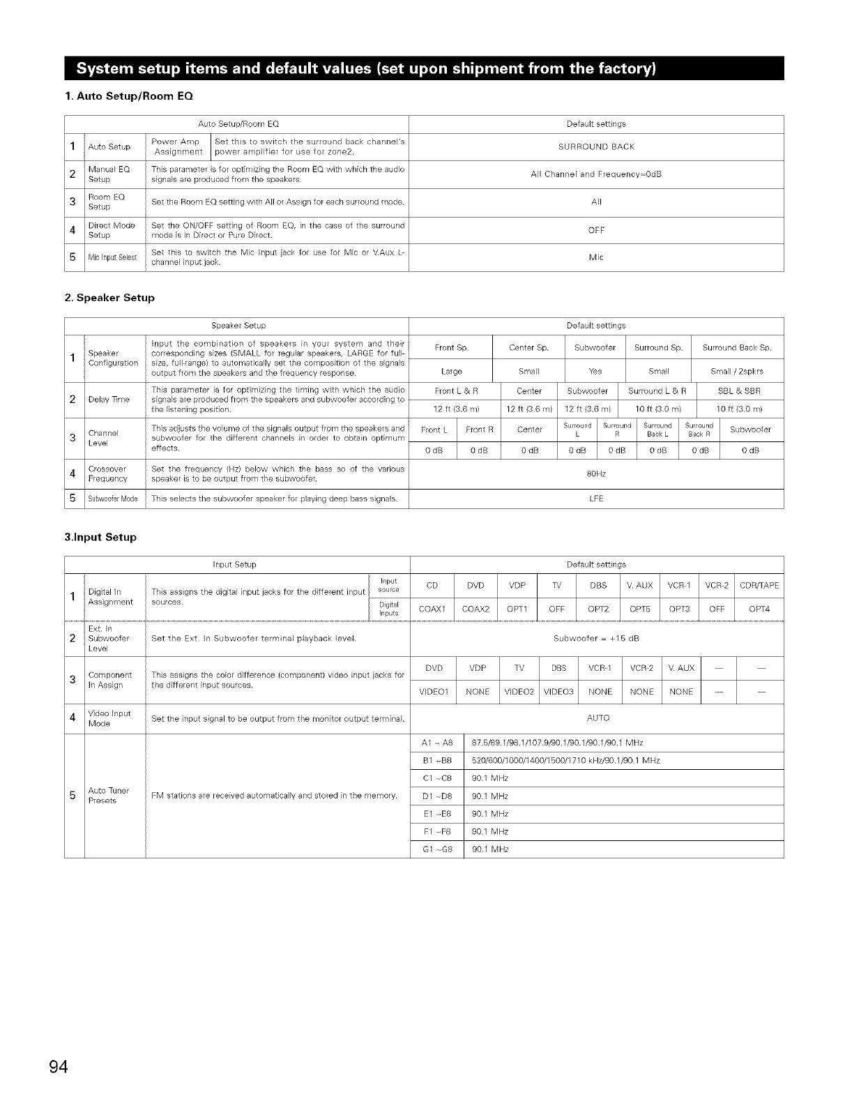
1. Auto Setup/Room EQ
Auto Setup/Room EQ Default settings
1Auto Setup Power Amp Set this to switch the surround back channePs
Assignment power amplifier for use for zone2. SURROUND BACK
2 Manual EQ This parameter is for optimizing the Room EQ with which the audio All Channel and Frequency=OdB
Setup signals are produced from the speakers
3 Room EQ Set the Room EQ setting with All or Assign for each surround mode All
Setup
4 Direct Mode Set the ON/OFF setting of Room EQ, in the case of the surround OFF
Setup mode is in Direct or Pure Direct.
Set this to switch the Mic tnput iack for use for Mic or V.Aux L+ Mic
S Mic Input Select channel #_put jack.
2. Speaker Setup
Speaker Setup
1
2
3
4
5
Speaker
Configu ration
Delay nine
Channel
Level
Crossover
Frequency
Subw00ferMode
Input the combination of speakers in your system and their
corresponding sizes (SMALL for regular speakers, LARGE for full
size, full range) to auto_'lqatically set the composition of the signals
output from the speakers and the frequency response
This para_-ileter is for opth-ilizing the timing with which the audio
signals are produced from the speakers and subwoofer according to
the listening position.
This adjusts the volume of the signals output from the speakers and
subwoofer for the different channels in order to obtain optimum
effects
Set the frequency (Hz) below which the bass so of the various
speaker is to be output from the subwoofer
This selects the subwoofer speaker for playing deep bass signals.
Front Sp.
Large
Front L & R
12 ft (3.6 m/
Front L Front R
OdB 0dB
Center Sp.
Small
Center
12 ft (36 m)
Center
O dB
Default settings
Subwoofer Surround Sp
Yes Small
Subwoofer Surround L & R
12 ft (3.6 m/ 10 ft (3 0 m/
Surround Surround Surround Surround
L R Back L Back R
0dB 0dB 0dB 0dB
80Hz
LFE
Surround Back Sp.
Small /2spkrs
SBL & SBR
10 ft (30 m)
Subwoofer
OdB
3.Input Setup
Input Setup Default settings
Input CD DVD VDP TV DBS V. AUX VCR 1 VCR+2 CDR/TAPE
1Digital In This assigns the digital input jacks for the different input source
Assignment sources Digital COAX1 COAX2 OPT1 OFF OPT2 OPT6 OPT3 OFF OPT4
hputs
Ext. In
2 Subwoofer
Level
3
4
Component
In Assign
Video Input
Mode
Auto Tuner
Presets
Set the Ext In Subwoofel terminal playback level
This assigns the color difference(componentl video input iacksfor
the different input sources.
Set the input signal to be output from the monitor output terminal
FM stations are received automatically and stored in the memory.
Subwoofer = +15 dB
DVD VDP TV DBS VCR 1 VCR 2 V AUX
VIDEO1 NONE VIDEO2 VIDEO3 NONE NONE NONE -- --
A1 + A8
B1 -+B8
C1 -+C8
D1 --D8
E1 +E8
F1 +F8
G1 +G8
AUTO
876/891/98.1/1079/901/90.1/90.1/90.1 MHz
520/600/1000/1400/1500/1710 kHz/90.1/90 1 MHz
901 MHz
901 MHz
901 MHz
901 MHz
901 MHz
94
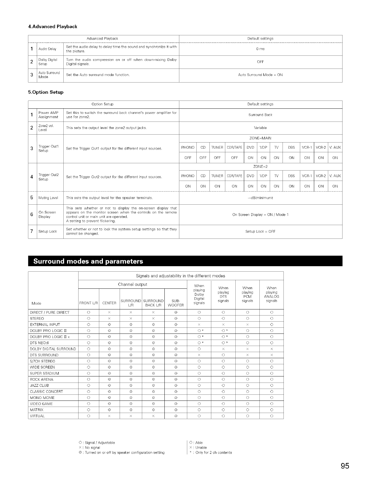
4.Advanced Playback
Advanced Playback Default settings
1Audio Delay Set the audio delay to delay time the sound and synchronize it with 0 ms
the picture
2 D01byDigital Turn the audio compression on or off when down-mixing Dolby OEF
Setup Digital signals
3 Auto Surround Set the Auto surround mode function. Auto Surround Mode = ON
Mode
5.Option Setup
1
2
Power AMP
Assignment
Zone2 vol
Level
TgggerOutl
Setup
TiiggerOut2
Setup
Option Setup
Set this to switch the surround back channel's power amplifier for
use for zone2
This sets the output level the zone2 output jacks
Set the Trigger Out1 output for the different input sources
Set the Trigger Out2 output for the different input sources
Default settings
Surround Back
Vadable
ZONE MAIN
PHONO CD TUNER CDRFAPE DVD VDP TV DBS VCR_I VCR-2 V AUX
OFE OFF OFF OFF ON ON ON ON ON ON ON
ZONE 2
PHONO CD TUNER CDRFAEE DVD VDP TV DBS VCR-1 VCR_2 V AUX
ON ON ON ON ON ON ON ON ON ON ON
S Muting Level This sets the output level for the speaker telminals _ riB(minimum/
This sets whether ol not to display the on-screen display that
6 On Screen appeals on the monitor screen when the controls on the remote
Display control unit ol main unit are opelated. On Screen Display = ON /Mode 1
A setting to prevent flickegng.
Set whether ol not to lock the system setup settings so that they
7 Setup Lock cannot be changed. Setup Lock = OFF
Mode
DIRECT /PURE DIRECT
STEREO
EXTERNAL INPUT
DOLBY PRO LOGIC ]]
DOLBY PRO LOGIC ]] x
DTS NEO:6
DOLBY DIGITAL SURROUND
DTS SURROUND
5/7CH STEREO
WIDE SCREEN
SUPER STADIUM
ROCK ARENA
JAZZ CLUB
CLASSIC CONCERT
MONO MOVIE
VIDEO GAME
MATRIX
VIRTUAL
SURROUND SURROUND
FRONT L/R CENTER WR BACK L/R
O x x x
O x x x
O @ @ @
O @ @ @
O @ @ @
O @ @ @
O @ @ @
O @ @ @
O @ @ @
O @ @ @
O @ @ @
O @ @ @
O @ @ @
O @ @ @
O @ @ @
O @ @ @
O @ @ @
O x x x
Signals and adjustability in the different modes
Channel output When When
playing
Dolby playing
DTS
SUB Digital signals
WOOFER signals
(9 O O
@ O O
@ x x
@ O *O*
@ O *O*
@ O _ O _
@ O x
@ x O
@ O O
@ O O
@ O O
@ O O
@ O O
@ O O
@ O O
@ O O
@ O O
@ O O
When When
playing playing
PCM ANALOG
signals signals
o
o
x
o
o
o
×
×
o
o
o
o
o
o
o
o
o
o
o
o
o
o
o
o
x
x
o
o
o
o
o
o
o
o
o
o
O : Signal/Adjustable
x : No signal
@ : Turned on or off by speaker configuration setting
O : Able
x : Unable
* : Only for 2 oh contents
95
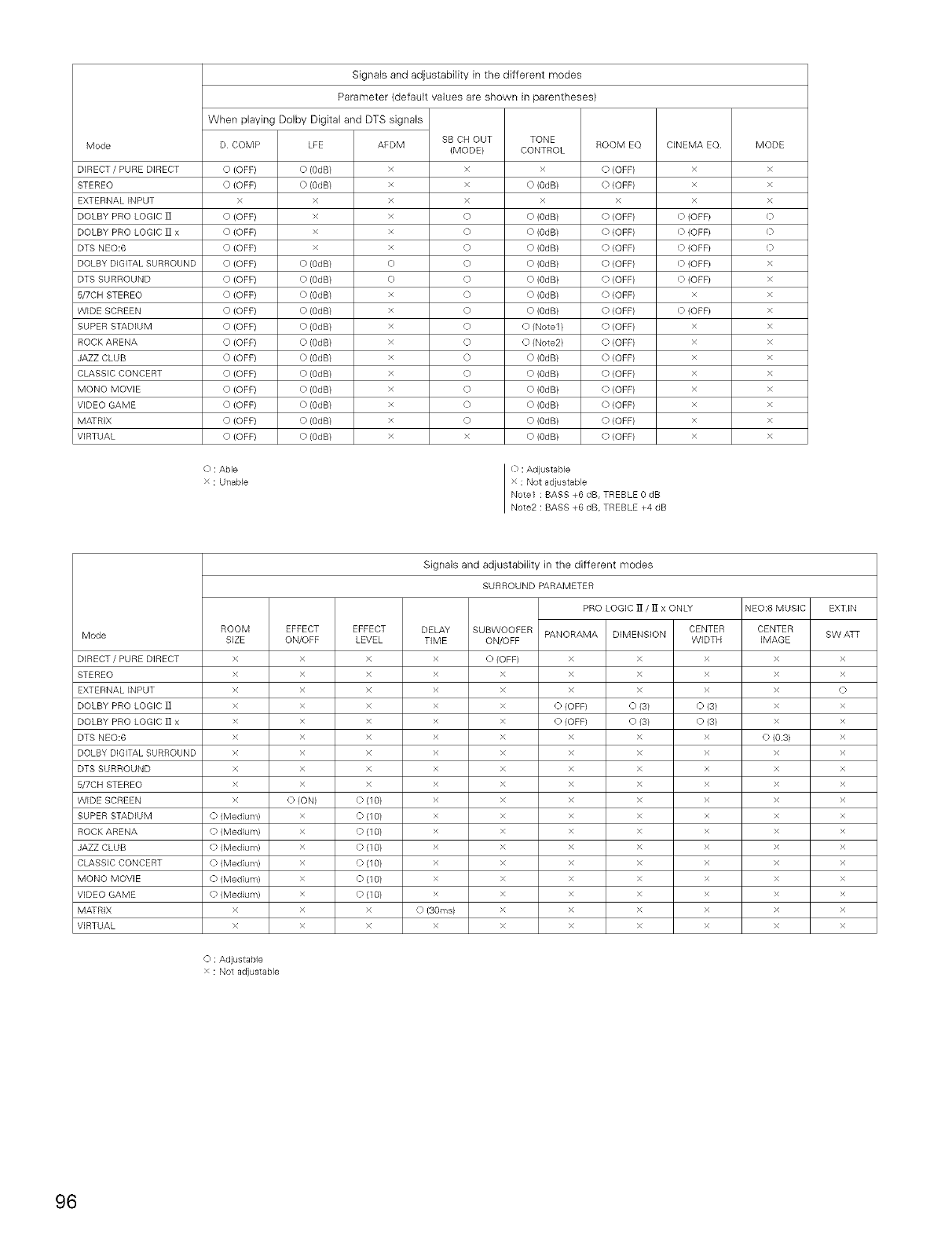
Mode
DIRECT / PURE DIRECT
STEREO
EXTERNAL INPUT
DOLBY PRO LOGIC ]]
DOLBY PRO LOGIC ]] x
DTS NEO:6
DOLBY DIGITAL SURROUND
DTS SURROUND
5/7CH STEREO
WIDE SCREEN
SUPER STADIUM
ROCK ARENA
JAZZ CLUB
CLASSIC CONCERT
MONO MOVIE
VIDEO GAME
MATRIX
VIRTUAL
Signals and adjustability in the different modes
Parameter (default values are shown in parentheses)
When playing Dolby Digital and DTS signals
D COMP LFE ROOM EQAEDM
x
x
x
x
x
x
E)
E)
x
x
x
x
x
x
x
x
x
x
SB CH OUT
(MODE)
x
x
x
O
O
O
O
O
O
O
O
O
O
O
O
O
O
x
TONE
CONTROL
x
O (OdB/
x
O (0dB)
O (0dB/
O (0dB/
O (0dB)
O (0dB/
O (0dB/
O (0dB)
O (Note1 /
O (Note2/
O (0dB)
O (0dB/
O (0dB/
O (0dB)
O (0dB/
O (0dB/
O (OFF) O (OdB) O (OFF)
O (OFF) O (OdB) O (OFF)
x x x
0 (OFF/ x 0 {OFF)
0 {OFF) x 0 {OFF)
O (OFF) x O (OFF)
O (OFF) O (OdB) O (OFF)
O {OFF) O (OdB/ O {OFF)
O (OFF} O (OdB) O {OFF)
O (OFF/ O (OdB) O {OFF)
O {OFF) O (OdB/ O {OFF)
O {OFF} O (OdB/ O {OFF)
O (OFF/ O (OdB) O {OFF)
O {OFF) O (OdB/ O {OFF)
O {OFF} O (OdB/ O {OFF)
O (OFF/ O (OdB) O {OFF)
O {OFF) O (OdB/ O {OFF)
O {OFF} O (OdB/ O {OFF)
CINEMA EQ.
x
x
x
O (OFF/
O (OFF}
O (OFF}
O (OFF/
Q (OFF}
x
O (OFF/
x
x
x
x
x
x
x
x
O : Able
x : Unable
O :Adjustable
x : Not adjustable
Note1 : BASS +6 dB, TREBLE 0 dB
Note2 : BASS +6 dB, TREBLE +4 dB
MODE
x
x
x
0
0
Q
x
x
x
x
x
x
x
x
x
x
x
x
Mode
DIRECT / PURE DIRECT
STEREO
EXTERNAL INPUT
DOLBY PRO LOGIC ]]
DOLBY PRO LOGIC ]] x
DTS NEO:6
DOLBY DiGiTAL SURROUND
DTS SURROUND
5/7CH STEREO
WIDE SCREEN
SUPER STADIUM
ROCK ARENA
JAZZ CLUB
CLASSIC CONCERT
MONO MOVIE
VIDEO GAME
MATRIX
VIRTUAL
ROOM
SIZE
x
x
x
x
x
x
x
x
x
x
O (Medium)
O (Medium)
O (Medium)
O (Medium)
O (Medium)
O (Medium)
x
x
O : Adjustable
x : Not adjustable
EFFECT
ON/OFF
x
x
x
x
x
x
x
x
x
O (ON)
x
x
x
x
x
x
x
x
EFFECT
LEVEL
x
x
x
x
x
x
x
x
x
O (1 O)
O(1 O)
Q(1 O/
O (1 O)
Q(1 O)
O (10)
O (1 O)
x
x
Signals and adjustability in the different modes
SURROUND PARAMETER
PRO LOGIC ]] /]I x ONLY
DELAY
TIME
x
x
x
x
x
x
x
x
x
x
x
x
x
x
x
x
Q (3Ores)
x
SUBWOOFER
ON/OFF
O (OFF)
x
x
x
x
x
x
x
x
x
x
x
x
x
x
x
x
x
PANORAMA
x
x
x
O (OFF)
O (OFF)
x
x
x
x
x
x
x
x
x
x
x
x
x
CENTER
DIMENSION WIDTH
x x
x x
x x
O (3/ O (3/
O (3/ O (3/
x x
x x
x x
x x
x x
x x
x x
x x
x x
x x
x x
x x
x x
NEO:6 MUSIC
CENTER
IMAGE
x
x
x
x
x
0 (0.3)
x
x
x
x
x
x
x
x
x
x
x
x
EXTIN
SW ATF
x
x
Q
x
x
x
x
x
x
x
x
x
x
x
x
x
x
x
96
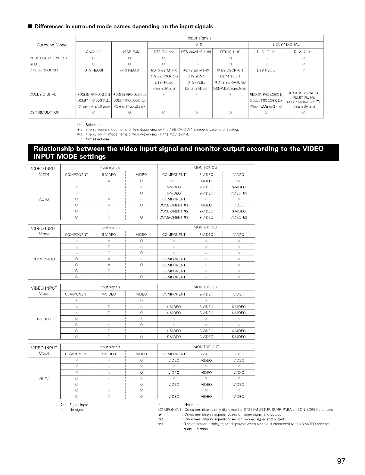
•Differences in surround mode names depending on the input signals
Surround Mode DOLBY DIGITAL
Input signals
DTS
DTS 96/24 (6.1 ch/
O
Q
@DTS ES MTRX
DTS 96/24
DTS+PL]Ix
(Cinema,Music)
x
ANALOG LINEAR PCM DTS (6.1 ch} DTS (6.1 ch/ D D (2 ch) D D (B1 ch)
PURE DIRECT, DIRECT 0 0 0 0 0 0
STEREO 0 0 0 0 0 0
DTS SURROUND DTS NEO:6 DTS NEO:6 _DTS ES MTRX @ ES DSCRT6.1 DTS NEO:6 x
DTS SURROUND ES MTRX61
DTS+ PL]]x _-DTS SURROUND
(Cinelna, Musb) DTS+PL_x(Cinema,Music)
DOLBY DIGITAL _DOLBY PRO LOGIC]] _DOLBY PRO LOGIC]] x x _DOLBY PRO LOGIC]] _DOLBY DIGITALEX
DOLBY DIGITAL
DOLBY PROLOGIC ]Ix DOLBY PRO LOGIC]Ix DOLBY PRO LOGIC]Ix DOLBY DIGITAL+PL ]Ix
(CineTna,Music,Game) (Cinema,Music,Game) (Cinema,Mush, Game) (Cinema,Music)
DSP SIMULATION O O O O O O O
O : Selectable
: The surround mode name differs depending on the "SB CH OUT" surround parameter setting.
@ : The surround mode name differs depending on the input signal
x : Not selectable
VIDEO INPUT
Mode
AUTO
VIDEO INPUT
Mode
COMPONENT
VIDEO INPUT
Mode
S VIDEO
Input signals
COMPONENT l S VIDEO IVIDEO
I I
X I X I 0
I I
XIOIX
I I
x I 0 I 0
I I
0IXIX
0 1 x 1 0
I I
0I0IX
I I
0 I 0 I 0
I I
MONITOR OUT
COMPONENT I S-VIDEO I VIDEO
I I
VIDEO I VIDEO I VIDEO
I I
S VIDEO I S VIDEO I S VIDEO
I I
S-VIDEO I S-VIDEO I VIDEO !_-3
I I
COMPONENT I x I x
I
COMPONENT !_-1 I VIDEO VIDEO
COMPONENT !e-2 I S-VIDEO I S-VIDEO
COMPONENT _2 I S-VIDEO I VIDEO _3
Input signals
i i
COMPONENT i S VIDEO i VIDEO
i i
XIXI0
i i
XI0IX
I I
XI0I0
i i
o I × I ×
0IXI0
I I
0I0IX
I I
0 I 0 I 0
I I
MONITOR OUT
i i
COMPONENT I S-VIDEO I VIDEO
I I
x I x I x
I I
x I x I x
I I
x I x I x
I I
COMPONENT I x I x
I I
COMPONENT I x I x
I I
COMPONENT I x I x
I I
COMPONENT I x iI x
Input signals
i i
COMPONENT i S VIDEO i VIDEO
I I
XIXI0
x 1 0 1 x
i i
XI0I0
I I
0IXIX
I I
0IXI0
I I
0I0IX
I I
o I o I o
MONITOR OUT
I I
COMPONENT I S-VIDEO I VIDEO
I I
X I X I X
I I
S VIDEO l S VIDEO l S VIDEO
I I
S VIDEO I S VIDEO I SVIDEO
X I X I X
I I
x I x I x
I I
SWDEO I SWDEO I SWDEO
S-VIDEO I S-VIDEO I S-VIDEO
VIDEO INPUT Input signals MONITOR OUT
Mode COMPONENT I S VIDEO I VIDEO COMPONENT I S-VIDEO I VIDEO
I I I I
X I X I 0VIDEO IVIDEO IVIDEO
I I I I
x I 0 I x x I x I x
i i
x i 0 i 0 VIDEO VIDEO VIDEO
I I
VIDEO 0 I X I X X I X I X
I I I I
0I X I 0VIDEO I VIDEO I VIDEO
I I I I
OIOIX X IXIX
I I I I
O _l O I O VIDEO _l VIDEO _l VIDEO
)" Signal input x : Not output
x : No signal COMPONENT : On screen display only displayed for SYSTEM SETUP, SURR.PARA and ON SCREEN buttons
!_-1 : On screen display superimposed on video signal and output
!_-2 : On-screen display superimposed on S-video signal and output
!_-3 : The on-screen display is not displayed when a cable is connected to the S_VIDEO monitor
output terminal
97
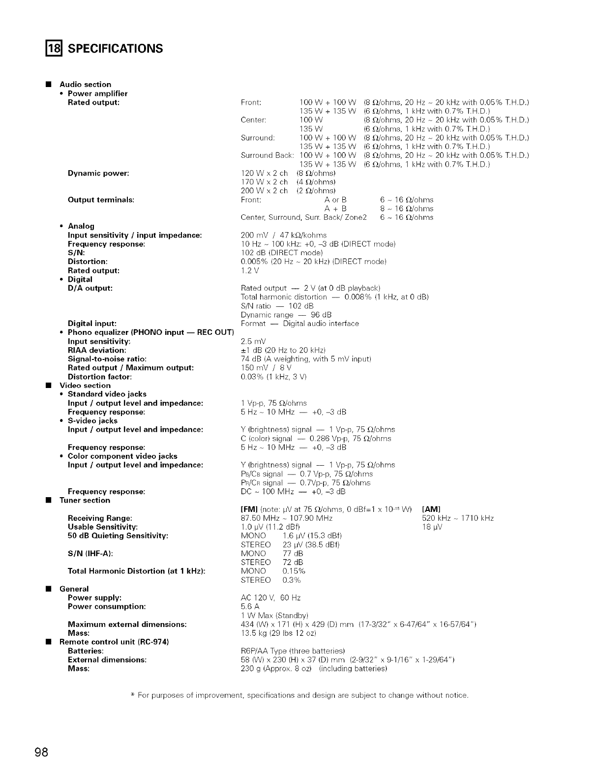
I'_ SPECIFICATIONS
Audio section
•Power amplifier
Rated output:
Dynamic power:
Output terminals:
•Analog
Input sensitivity /input impedance:
Frequency response:
S/N:
Distortion:
Rated output:
•Digital
D/A output:
Digital input:
•Phono equalizer (PHONO input -- REC OUT)
Input sensitivity:
RIAA deviation:
Signal-to-noise ratio:
Rated output /Maximum output:
Distortion factor:
Video section
•Standard video jacks
Input /output level and impedance:
Frequency response:
•S-video jacks
Input /output level and impedance:
Frequency response:
•Color component video jacks
Input /output level and impedance:
Frequency response:
Tuner section
Receiving Range:
Usable Sensitivity:
50 dB Quieting Sensitivity:
S/N (IHF-A):
Total Harmonic Distortion (at 1 kHz):
General
Power supply:
Power consumption:
Maximum external dimensions:
Mass:
Remote control unit (RC-974)
Batteries:
External dimensions:
Mass:
Frent: 100 W + 100 W
135W+ 135W
Center: 100 W
135W
Surreund: 100 W + 100 W
135W+ 135W
Surreund Back: 100W+ 100W
135W+ 135W
120Wx2ch (8£_/ohms)
170Wx2ch (4£_/ohms)
200Wx2ch (2£2/ehms)
Frent: A or B
A+B
Center, Surround, Surr. Back/Zone2
(80./ohms, 20 Hz - 20 kHz with 0.05% T.H.D.)
(6 £_/ohms, 1 kHz with 0.7% T.H.D.)
(8 £_/ohms, 20 Hz - 20 kHz with 0.05% T.H.D.)
(6 £_/ohms, 1 kHz with 0.7% T.H.D.)
(8 _/ehms, 20 Hz _ 20 kHz with 0.05% T.H.D.)
(60./ohms, 1 kHz with 0.7% T.H.D.)
(8 £_/ohms, 20 Hz _ 20 kHz with 0.05% T.H.D.)
(6 £_/ehms, 1 kHz with 0.7% T.H.D.)
6 _ 16 _/ohms
8 _ 16 _/ohms
6 - 16 _/ohms
200 mV /47 kf_/kohms
10 Hz _ 100 kHz: +0, -3 dB (DIRECT mede)
102 dB (DIRECT mode)
0.005% (20 Hz _ 20 kHz) (DIRECT mede)
1.2V
Rated output -- 2 V (at 0 dB playback)
Tetal harmonic distertien -- 0.008% (1 kHz, at 0 dB)
S/N ratie -- 102 dB
Dynamic range -- 96 dB
Format -- Digital audio interface
2.5 mV
_+1dB (20 Hz to 20 kHz)
74 dB (A weighting, with 5 mV input)
150mV /8V
0.03% (1 kHz, 3 V)
1 Vp-p, 75 £_/ohms
5Hz_10MHz -- +0,-3dB
Y (brightness) signal -- 1 Vp-p, 75 _/ohms
C (celor) signal -- 0.286 Vp-p, 75 £_/ohms
5Hz_10MHz -- +0,-3dB
Y (brightness) signal -- 1 Vp-p, 75 _/ehms
PB/CBsignal -- 0.7 Vp-p, 75 _/ohms
PR/CR signal -- 0.7Vp-p, 75 _/ehms
DC-100 MHz -- +0,-3dB
[FM] (note: IJVat 75 _/ohms, 0 dBf=l x 10 ,s W)
87,50 MHz - 107.90 MHz
1.0 I_V (11.2 dBf)
MONO 1.6 IJV (15.3 dBf)
STEREO 23 I_V(38.5 dBf)
MONO 77 dB
STEREO 72 dB
MONO 0.15%
STEREO 0.3%
[AM]
520 kHz _ 1710 kHz
18 IJV
AC120V, 60Hz
5.6A
1 W Max (Standby)
434 (W) x 171 (H) x 429 (D) mm (17-3/32" x 6-47/64" x 16-57/64")
13.5 kg (29 Ibs 12 ez)
R6P/AA Type (three batteries)
58(W) x 230 (H) x 37 (D) mm (2-9/32"x9-1/16" 1-29/64")
230 g (Approx. 8 ez) (including batteries)
Fer purposes of irnprevement, specifications and design are subject te change witheut netice.
98

DENON, Ltd.
16-11, YUSHIMA 3-CHOME, BUNKYO-KU, TOKYO 113-0034, JAPAN
Telephone: (03) 3837-5321
Printed in Japan 511 4172 007
