Denon AVR 488 User Manual RECEIVER Manuals And Guides L0802044
DENON Receivers Manual L0802044 DENON Receivers Owner's Manual, DENON Receivers installation guides
User Manual: Denon AVR-488 AVR-488 DENON RECEIVER - Manuals and Guides View the owners manual for your DENON RECEIVER #AVR488. Home:Electronics Parts:Denon Parts:Denon RECEIVER Manual
Open the PDF directly: View PDF ![]() .
.
Page Count: 54
DE 0
AV SURROUND RECEIVER
AVR-488
m
Owner's Manual
Manuel de I'Utilisateur
SAFETY PRECAUTIONS
CAUTION:
TO REDUCETHE RISK OF ELECTRIC SHOCK, DO NOT REMOVE
COVER (OR RACK). NO USER-SERVICEABLE PARTS INSIDE.
REFER SERVICINGTO QUALIFIED SERVICE PERSONNEL.
The lightning flash with arrowhead symbol, within an equilateral
triangle, is intended to alert the user to the presence of
uninsulated "dangerous voltage" within the product's enclosure
that may be of sufficient magnitude to constitute a risk of electric
shock to persons.
The exclamation point within an equilateral triangle is intended
to alert the user to the presence of important operating
and maintenance (servicing) instructions in the literature
accompanying the appliance.
WARNING:
TO REDUCETHE RiSK OF FiRE OR ELECTRIC SHOCK, DO NOT
EXPOSE THIS APPUANCE TO RAmN OR MOmSTURE.
1.
2.
3.
4.
5.
6.
7
10.
11.
12.
SAFETY INSTRUCTIONS
Read hstructions -All the safety and operating instructions should be read 13. Power-Cord Protection -Power-supply cords should be routed so that they
before the product is operated.
Retain Instructions - The safety and operating instructions should be
retained for future reference.
Heed Warnings - All warnings on the product and in the operating
instructions should be adhered to.
Follow Instructions - All operating and use instructions should be followed.
Cleaning - Unplug this product from the wall outlet before cleaning. Do not
use liquid cleaners or aerosol cleaners.
Attachments - Do not use attachments not recommended by the product
manufacturer as they may cause hazards.
Water and Moisture - Do not use this product near water - for example,
near a bath tub, wash bowl, kitchen sink, or laundry tub; in a wet basement;
or near a swimming pool; and the like.
Accessories - Do not place this product on an unstable cart, stand, tripod,
bracket, or table. The product may fall, causing serious injury to a child or
adult, and serious damage to the product. Use only with a cart, stand,
tripod, bracket, or table recommended by the manufacturer, or sold with the
product. Any mounting of the product should
follow the manufacturer's instructions, and should
use a mounting accessory recommended by the
manufacturer.
A product and cart combination should be moved
with care. Quick stops, excessive force, and
uneven surfaces may cause the product and cart
combination to overturn.
Ventilation - Slots and openings in the cabinet are provided for ventilation
and to ensure reliable operation of the product and to protect it from
overheating, and these openings must not be blocked or covered. The
openings should never be blocked by placing the product on a bed, sofa,
rug, or other similar surface. This product should not be placed in a built-in
installation such as a bookcase or rack unless proper ventilation is provided
or the manufacturer's instructions have been adhered to.
Power Sources - This product should be operated only from the type of
power source indicated on the marking label. If you are not sure of the type
of power supply to your home, consult your product dealer or local power
company. For products intended to operate from battery power, or other
sources, refer to the operating instructions.
Grounding or Polarization -This product may be equipped with a polarized
alternating-current line plug (a plug having one blade wider than the other).
This plug will fit into the power outlet only one way. This is a safety feature.
If you are unable to insert the plug fully into the outlet, try reversing the
plug. If the plug should still fail to fit, contact your electrician to replace your
obsolete outlet. Do not defeat the safety purpose of the polarized plug.
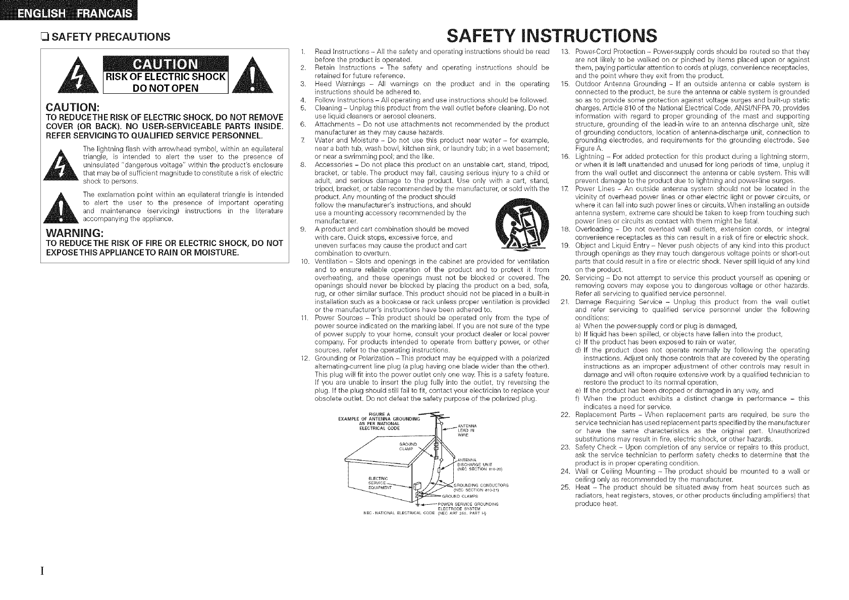
FIGURE A
EXAMPLE OF ANTENNA GROUNDING
AS PER NATIONAL
are not likely to be walked on or pinched by items placed upon or against
them, paying particular attention to cords at plugs, convenience receptacles,
and the point where they exit from the product.
15. Outdoor Antenna Grounding - If an outside antenna or cable system is
connected to the product, be sure the antenna or cable system is grounded
so as to provide some protection against voltage surges and built-up static
charges. Article 810 of the National Electrical Code, ANSI/NFPA 70, provides
information with regard to proper grounding of the mast and supporting
structure, grounding of the lead-in wire to an antenna discharge unit, size
of grounding conductors, location of antenna-discharge unit, connection to
grounding electrodes, and requirements for the grounding electrode. See
Figure A.
16. Lightning - For added protection for this product during a lightning storm,
or when it is left unattended and unused for long periods of time, unplug it
from the wall outlet and disconnect the antenna or cable system. This will
prevent damage to the product due to lightning and power-line surges.
1X Power Lines - An outside antenna system should not be located in the
vicinity of overhead power lines or other electric light or power circuits, or
where it can fall into such power lines or circuits. When installing an outside
antenna system, extreme care should be taken to keep from touching such
power lines or circuits as contact with them might be fatal.
18. Overloading - Do not overload wall outlets, extension cords, or integral
convenience receptacles as this can result in a risk of fire or electric shock.
19. Object and Liquid Entry - Never push objects of any kind into this product
through openings as they may touch dangerous voltage points or short-out
parts that could result in a fire or electric shock. Never spill liquid of any kind
on the product.
20. Servicing - Do not attempt to service this product yourself as opening or
removing covers may expose you to dangerous voltage or other hazards.
Refer all servicing to qualified service personnel.
21. Damage Requiring Service - Unplug this product from the wall outlet
and refer servicing to qualified service personnel under the following
conditions:
a) When the power-supply cord or plug is damaged,
b) If liquid has been spilled, or objects have fallen into the product,
c) If the product has been exposed to rain or water,
d) If the product does not operate normally by following the operating
instructions. Adjust only those controls that are covered by the operating
instructions as an improper adjustment of other controls may result in
damage and win often require extensive work by a qualified technician to
restore the product to its normal operation,
e) If the product has been dropped or damaged in any way, and
f) When the product exhibits a distinct change in performance - this
indicates a need for service.
22. Replacement Parts - When replacement parts are required, be sure the
service technician has used replacement parts specified by the manufacturer
or have the same characteristics as the original part. Unauthorized
substitutions may result in fire, electric shock, or other hazards.
23. Safety Check - Upon completion of any service or repairs to this product,
ask the service technician to perform safety checks to determine that the
product is in proper operating condition.
24. Wall or Ceiling Mounting - The product should be mounted to a wall or
ceiling only as recommended by the manufacturer.
25. Heat - The product should be situated away from heat sources such as
radiators, heat registers, stoves, or other products (including amplifiers) that
produce heat.
FCC iNFORMATiON (For US customers)
1. PRODUCT
TMs product complies with Part 15 of the FCC Rules. Operation is subject to the following two conditions: (1) this
product may not cause harmful interference, and (2) this product must accept any interference received, including
interference that may cause undesired operation.
2. IMPORTANT NOTICE: DO NOT MODIFYTHIS PRODUCT
This product, when installed as indicated in the instructions contained in this manual, meets FCC requirements.
Modification not expressly approved by DENON may void your authority, granted by the FCC, to use the product.
3. NOTE
This product has been tested and found to comply with the limits for a Class B digital device, pursuant to Part 15
of the FCC Rules. These limits are designed to provide reasonable protection against harmful interference in a
residential installation.
This product generates, uses and can radiate radio frequency energy and, if not installed and used in accordance
with the instructions, may cause harmful interference to radio communications. However, there is no guarantee
that interference will not occur in a particular installation. If this product does cause harmful interference to radio or
television reception, which can be determined by turning the product OFF and ON, the user is encouraged to try to
correct the interference by one or more of the following measures:
* Reorient or relocate the receiving antenna.
* Increase the separation between the equipment and receiver.
* Connect the product into an outlet on a circuit different from that to which the receiver is connected.
* Consult the local retailer authorized to distribute this type of product or an experienced radio/TV technician for
help.
This Class B digital apparatus complies with Canadian ICES-O03.
Cet appareil numerique de la dasse B est conforme _ la norme NMB-O03 du Canada.
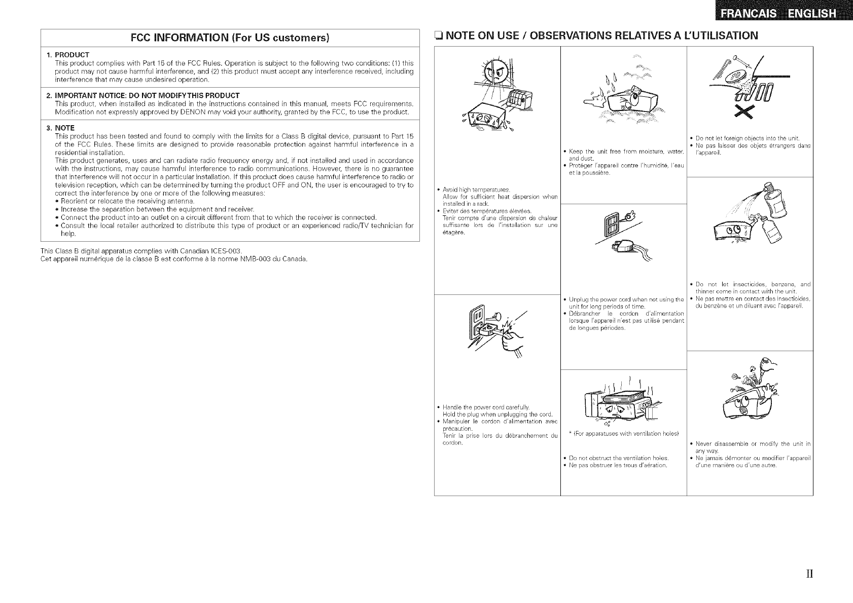
[_ NOTE ON USE /OBSERVATIONS RELATIVES A L'UTILISATION
•Avoid hightemperatures
Allow for sufficient heat dispersion when
installed in arack
Eviterdes temp@ratures@lev6es.
Tenir compte d'une dispersion de chaleur
suffisante Iors de I'instaflation sur une
_tag@re
•Handle the power cord carefully
Hold the plug when unplugging the cord.
•Manipuler le cordon d'alimentation avec
pr@caution
Tenir la pdse Iors du d@branchemellt du
cordon
Keep the unit free from moisture, water,
and dust
ProtBger I'appareil contre I'humidit@, I'eau
et la poussi¢re
Q
J
• Unplug thepower cord when not using the
unit for long periods of time
D6brancher le cordon d'alimentation
Iorsque I'appareil n'est pas utilisB pendant
de Iongues p@riodes
(Forapparatuses with ventilation holes)
• Do not obstruct the ventilation holes
• Ne pas obstruer les trous d'a@ration
• Do not let foreign objects into the unit
Ne pas laisser des objets @trangers darts
I'appareil
Never disassemble or modify the unit in
any way
•Ne jamais d@monter ou modifier I'appareil
d'une man[are ou d'une autre
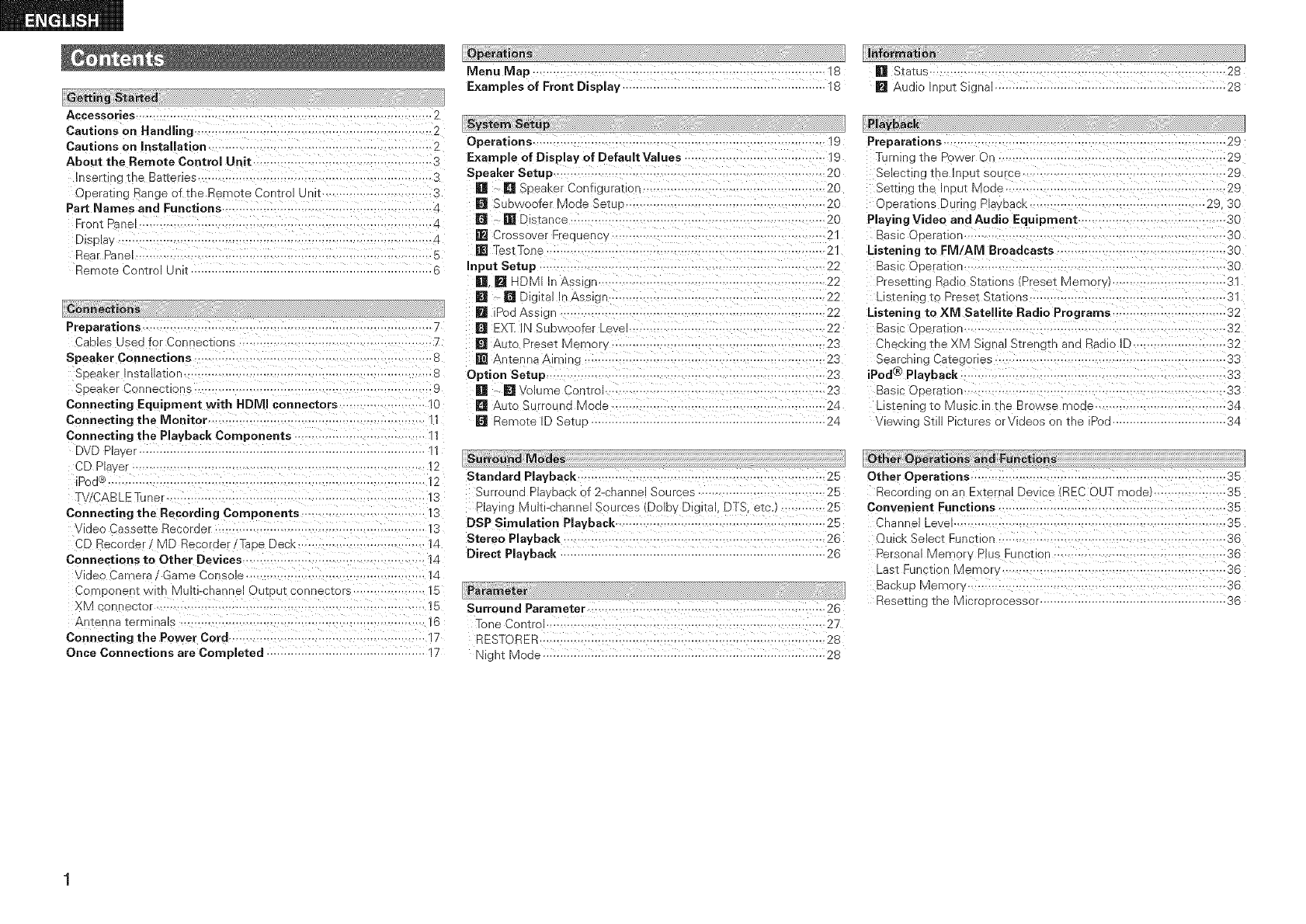
lGetting Started
Accessories ................................................................. 2
Cautions on HandEng ................................................................. 2
Cautions on Installation ........................................... 2
About the Remote Control Unit ..................................... 3
n._rt -jtne Batteries ........................................................... 3
Operating _ange of the Remote Con-rol unl[ .............................. 3
Part Names and Functions ............................................... 4
Front P__e=................................................................... 4
DisDla ......................................................................................... 4
Rear Pa- al .................................................................................. 5
Remote 3ontrol Unit 6
Preparations .......................................................... 7
Cables Used for Cor nectlons ......................................... 7
Speaker Connections .................................... B
SDeaKe nstallallon .................................................................. B
Soeaker Connections .................................................................. 9
Connecting Equipment with HDMI connectors ..................... O
Connecting the Monitor ........................................... 11
Connecting the Playback Components ............................ 11
DVD Pla, er ................................................................................... ""
CD Player ..................................... 12
.Operation s
Menu Map ........................................................ 1B
E×amples of Front Display .......................................................... 13
lSYstamSetup
Operations ..................................................... ]9
Example of Display of Default Values ........................................ ]9
Speaker Setup ......................................................... 20
[] • [] Soeaker ConYguratlon ......................................... 20
[] Subwoofel Mode SetL o ...................................................... 20
[] -[]E _tance ................................................................... 20
[] Crossover Frequency ......................................... 2
[] Test Tone .................................................... 2
Input Setup .......................................................... 22
[] HDMI In Asslg ............................................................. 22
[] _[] Digital In Assig .................................................... 22
[] iPodAss g................................................................. 22
EX]: IN Subwoofel =evel ...................................... 22
[] Auto Preset Memo , -.................................................. 23
[] Antenna & rnlng ................................................... 23
Option Setup ................................................ 23
[] • []Volume Control .......................................... 23
[] Auto Surround Mode .................................................. 24
[] Remote ID SetLo .................................................................. 24
LSurraend Moae_
Pod¢ ............................................................................... 12 Standard Playback .......................................
T\/CABLETuner .............................................................. 3 Surround Plavoac _f 2-channelSources
Connecting the Recording Components ........................ ]3
oec Cassette Recorder ....................................... 3
CE Recordel MD _ecorde /Taoe Deck .................................. 14
Connections to Other Devices ..................... 1A
(Jec Camera Game Console .................................................... 1A
Co_Donent wlw Multi-channel Output connectors - 15
XM connecEor .............................................................. 15
Anter na terminals ...................................................... 16
Connecting the Power Cord ...................................................... 17
Once Connections are Completed .............................................. 17
............ 25
............................ 25
Plav ng Multi-channe 3ources (Dolby Digital, DTS. etc./ ............. 25
DSP Simulation Playback .......................................................... 25
Stereo Playback ............................................................... 26
Direct Playback 26
lPerarne_er
Surround Parameter ....................................................... 26
Tone Control ................................................ 27
RESTERER ............................................................................... 28
Night Mode ................................................................................. 28
llnf0rmatlbn
[] Status ................................................................................ 28
[] Audio Input S=gna 28
l Playback
Preparations ..................................................................... 29
Turning the Power On ........................................ 29
Select'-g tne InouE source .................................... 29
Settirgtne -gut Moue .......................................... 29
Operations During P ayDacK........................................ 29 30
Playing Video and Audio Equipment ......................................... 30
Basic C Deratlon .................................................... 30
Listening to FM/AIVI Broadcasts ................................ 30
Basc Operation ....................................................... 30
Presettln_ Radio Stations (Preset Memor, •................................ 31
Listening to Preset Stations ....................................................... 31
Listening to XM Satellite Radio Programs ............................. 32
Bas :OE_ratlop ...............................................32
CtecKing _ _e XM Signal Strength and Radio ID ......................... 32
Searching Categories ................................................... 33
iPod ®Playback ...................................................................... 33
Basic Ooeratlon ....................................................................... 33
LisTening to Music _ the Browse r 1cue .................................. 34
wewlng $1 Pictures or wueos on tne Pod .............................. 34
Other Op_at onSe"d Funct0n_
Other Operations ....................................................... 35
Record qg _n an External Device REC OUT mode ................ 35
Convenient Functions ............................................................. 35
Channel Le el ................................................... 35
Quick Select Function ............................................... 36
Personal Memory Plus Function ................................................. 36
Last Fur ct on Memor_ ..................................................... 36
Backuo Memory ................................................. 36
Resetting the Microprocessoi ............................................. 36
OperatingDENONAudioComponents.i;; ,i;,:i i .;;ii.i:_i:.37
OperatingPreset components ....t_..:.:t,.,i...-,,-i..t_ ........ 37_ 39
PunchThrough Function ;; :ii:i_ .....:::_.i :... ;:::ii:i :.....L.LI_ :....:::40
Iii_!_;!_i_!i!_!i_!_i!i!!!_ii_i_!_!i_!ii_!_!i_!_!!_!illi_l_i_i_i_l!_i_;_i%!!l!li_i_i_l_l%_l%l_l_l%_l_ll_ll_l_;_;_;_l_;_li_l_l_ll_l_l_l_l_l_l_l_%_:__ii_!_i_!_i_!_l_i_l_i_li_l_ililill_!_l_!_lli_l%_l!i_l_!_i_l_l_!_i!i!i!_;!_
List of preset codes ........................................... End of this manual
Thank you for purchasing this DENON product. To ensure proper
operation, please read this owner's manual carefully before using the
product.
After reading them, be sure to keep them for future reference.
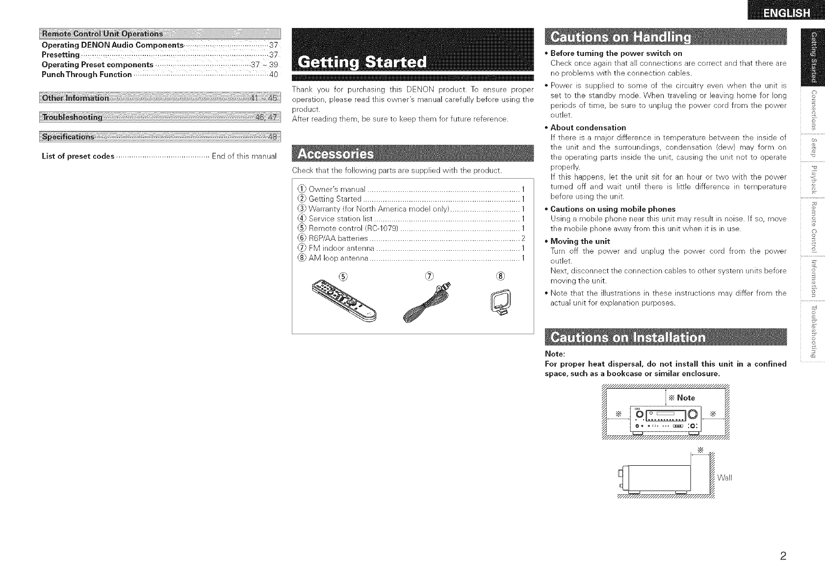
Check that the following parts are supplied with the product.
_ Owner's manual ...................................................................... 1
@_Getting Started ........................................................................ 1
(_ Warranty (for North America model only) ................................ 1
_4_Service station list ................................................................... 1
_5_Remote control (RC-1079) ....................................................... 1
_._ R6P/AA batteries ..................................................................... 2
_ FM indoor antenna .................................................................. 1
_ AM loop antenna ..................................................................... 1
®Before turning the power switch on
Check once again that all connections are correct and that there are
no problems with the connection cables.
® Power is supplied to some of the circuitry even when the unit is
set to the standby mode. When traveling or leaving home for long
periods of time, be sure to unplug the power cord from the power
outlet.
About condensation
If there is a major difference in temperature between the inside of
the unit and the surroundings, condensation (dew) may form on
the operating parts inside the unit, causing the unit not to operate
properly.
If this happens, let the unit sit for an hour or two with the power
turned off and wait until there is little difference in temperature
before using the unit.
Cautions on using mobile phones
Using a mobile phone near this unit may result in noise, if so, move
the mobile phone away from this unit when it is in use.
Moving the unit
Turn off the power and unphg the power cord from the power
outlet.
Next, disconnect the connection cables to other system units before
moving the unit.
Note that the illustrations in these instructions may differ from the
actual unit for explanation purposes.
_ote:
For proper heat dispersal, do not install this unit in aconfined
space, such as abookcase or similar enclosure.
_zzzzzzzzzzzzzzzzz_
÷Note
_/////////////'_/////////////////////_///////////_
//////_////////////////_/////////////_,
i ,?
©
d
?
©
©
©
©
2
©
©
_2
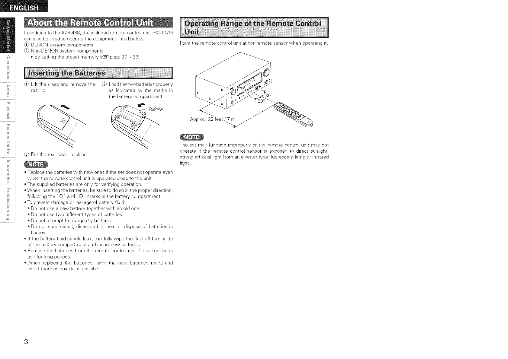
In addition to the AVR488, the included remote control unit (RC-1079)
can also be used to operate the equipment listed below.
@) DENON system components
_) Nen-DENON system components
• By setting the preset memory (_q_=_page87 -_39}
_ Lift the clasp and remove the _) Loadthetwobatteriesproperly
rear lid. as indicated by the marks in
the battery compartment.
@ Put the rear cover back on.
* Replace the batteries with new ones if the set does not operate even
when the remote control unit is operated close to the unit.
o The supplied batteries are only for verifying operation.
o When inserting the batteries, be sure to do so in the proper direction,
following the "(_" and "Q" marks in the battery compartment.
o To prevent damage or leakage of battery fluid:
o De not use a new battery together with an old one.
o Do net use two different types of batteries.
" Do net attempt to charge dry batteries.
" De not short-circuit, disassemble, heat or dispose of batteries in
flames.
If the battery fluid should leak, carefully wipe the fluid off the inside
of the battery compartment and insert new batteries.
" Remove the batteries from the remote control unit if it will net be in
use for long periods.
"When replacing the batteries, have the new batteries ready and
insert them as quickly as possible.
Point the remote control unit at the remote sensor when operating it.
Approx. 23 feet /7 m
The set may function improperly or the remote control unit may not
operate if the remote control sensor is exposed to direct sunlight,
strong artificial light from an inverter type fluorescent lamp or infrared
light.
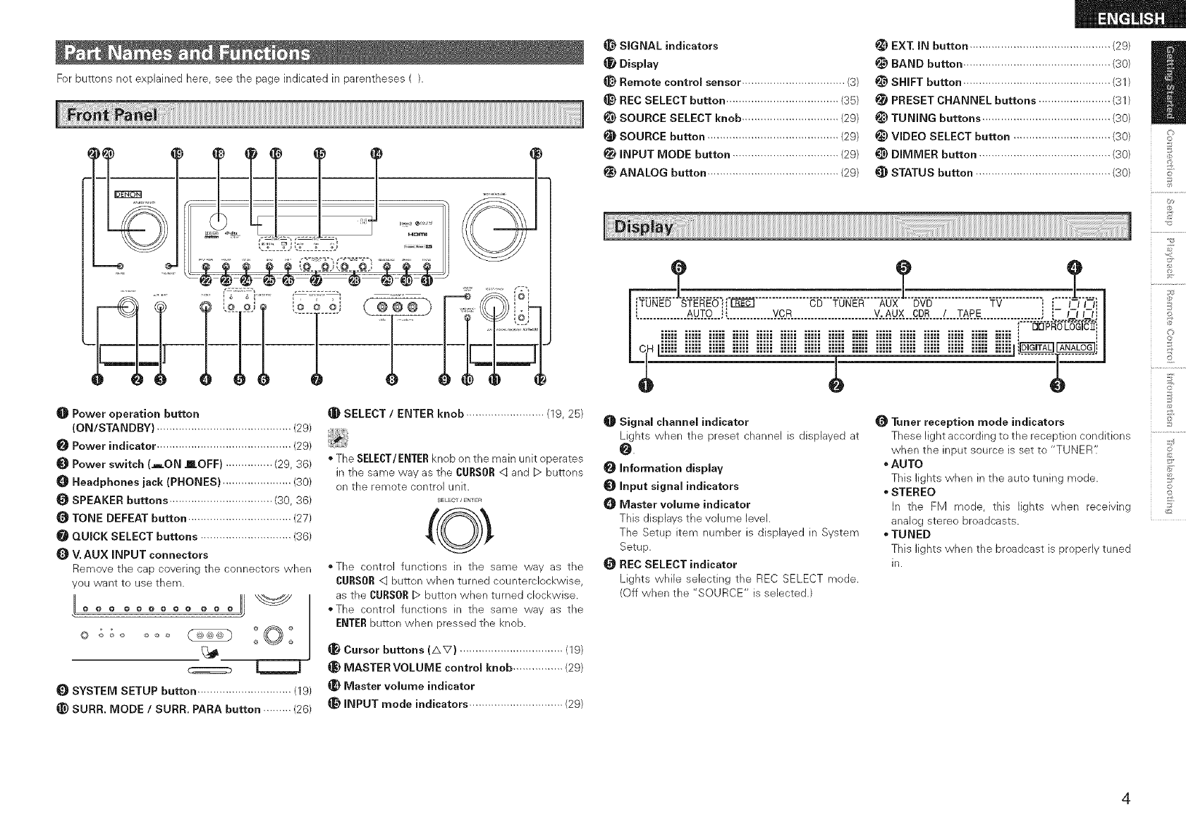
Forbuttonsnotexplainedhere,seethepageindicatedinparentheses().
.======@
OPower operation button
(ON/STANDBY) ........................................... (29)
Power indicator ........................................... (29)
Power switch (AON mOFF) ............... (29, 36)
Headphones jack (PHONES) ...................... (30)
SPEAKER buttons ................................. (30, 36)
O TONE DEFEAT button ................................. (27)
QUICK SELECT buttons ............................. (36)
V. AUX INPUT connectors
Remove the cap covering the connectors when
you want to use them.
LL
@ @ @ @ @ @ @ @ @ @ @ @
©
SYSTEM SETUP button .............................. (19)
SURR. MODE /SURR. PARA button ......... (26)
_]_ SELECT /ENTER knob ......................... (19, 25)
• The SELECT/ENTERknob on the main unit operates
in the same way as the CURSOR<qand D buttons
on the remote control unit.
SELECT/ENTER
• The control functions in the same way as the
CURSOR<:] button when turned counterclockwise,
as the CURSORD button when turned clockwise.
oThe control functions in the same way as the
ENTERbutton when pressed the knob.
Cursor buttons (AV) ................................. (19)
_) MASTER VOLUME control knob ................ (29)
_} Master volume indicator
@ INPUT mode indicators .............................. (29)
SIGNAL indicators
Display
_) Remote contromsensor ................................. (3)
_) REC SELECT button .................................... (35)
_) SOURCE SELECT knob ............................... (29)
SOURCE button .......................................... (29)
INPUT MODE button .................................. (29)
_) ANALOG button .......................................... (29)
EXT. IN button ............................................. (29)
BAND button ............................................... (30)
i_ SHIFT button ............................................... (31)
!_ PRESET CHANNEL buttons ....................... (31)
!_) TUNING buttons ......................................... (30)
_) VIDEO SELECT button ............................... (30)
_) DIMMER button .......................................... (30)
STATUS button ........................................... (30)
©
£
©
d
Signal channel indicator
Lights when the preset channel is displayed at
0.
information display
Input signal indicators
_) Master volume indicator
This displays the volume level.
The Setup item number is displayed in System
Setup.
REC SELECT indicator
Lights whib sebcting the REC SELECT mode.
(Off when the "SOURCE" is selected.)
Tuner reception mode indicators
These light according to the reception conditions
when the input source is set to "TUNER'i
•AUTO
This lights when in the auto tuning mode.
STEREO
In the FM mode, this lights when receiving
analog stereo broadcasts.
TUNED
This lights when the broadcast is properly tuned
in.
@
£
©
©
o
©
©
©
2
©
©
_2
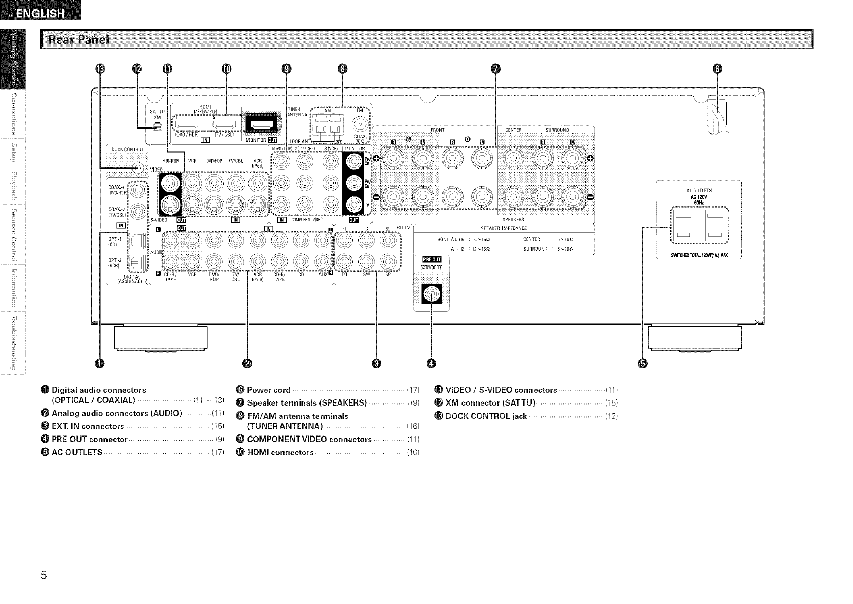
Digital audio connectors
(OPTICAL /COAXIAL) ........................ (11 -_ 13)
Analog audio connectors (AUDIO) ............. (11)
_) EXT. IN connectors ..................................... (15)
0PRE OUT connector ...................................... (9)
AC OUTLETS ............................................... (17)
SPEAKERS
SPEAKERIMPEDANC£
CENFER :6 _16_
SURROUND ; 6_16_
60_
swr_l.iB) TOfid.120W(1iL)M,_
Power cord .................................................. (17)
Speaker terminals (SPEAKERS) .................. (9)
FM/AM antenna terminals
(TUNER ANTENNA) .................................... (16)
COMPONENTVIDEO connectors ............... (11)
_) HDMI connectors ........................................ (10)
VIDEO /S-VIDEO connectors ..................... (11)
Xlvl connector (SATTU) .............................. (15)
_) DOCK CONTROL jack ................................. (12)
[Front ]
i @
i :-@JII
i ]lli ...............i
_ II............... II
Ta_,
i_J/NEIW_aK_ 1_C_-R,'MO
Q--
DENON
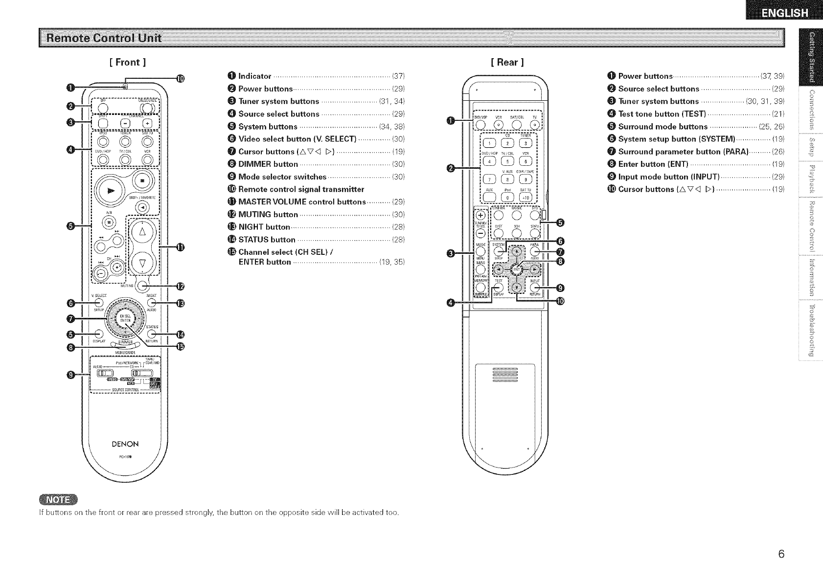
O Indicator ...................................................... (37)
Power buttons ............................................. (29)
Tuner system buttons .......................... (31, 34)
0Source select buttons ................................ (29)
System buttons .................................... (34, 33)
Q Video select button (V, SELECT) ............... (30)
Cursor buttons (AVq D) ......................... (19)
DIMMER button .......................................... (30)
Mode selector switches ............................. (30)
_) Remote control signal transmitter
MASTER VOLUME control buttons ........... (29)
MUTING button .......................................... (30)
_) NIGHT button .............................................. (23)
STATUS button ........................................... (23)
Channel select (CH SEL) /
ENTER button ....................................... (19, 35)
If buttons on the front or rear are pressed strongly, the button on the opposite side will be activated too.
@-
[ Rear ]
bw_vu_ vc_ SAT/C_I TV _
IDw/_p TV,C_k VCa
Power buttons ........................................ (37, 39)
Source select buttons ................................ (29)
Tuner system buttons .................... (30, 31, 39)
0 Test tone button (TEST) ............................. (21)
Surround mode buttons ...................... (25, 26)
System setup button (SYSTEM) ................ (19)
Surround parameter button (PARA) .......... (26)
Enter button (ENT) ..................................... (19)
Input mode button (INPUT) ....................... (29)
_) Cursor buttons (AV<:] D) ......................... (19)
r_
©
©
d
©
l;
2
©
£
©r
Connections for all compatible audio and video signal formats are
described in these operating instructions. Please select the types
of connections suited for the equipment you are connecting.
With some types of connections, certain settings must be made
on the AVR-488. For detaiJs, refer to the instructions for the
respective connection items below.
* Do not plug in the power cord until all connections have been
completed.
o When making connections, also refer to the operating instructions of
the other components.
o Be sure to connect the left and right channels properly (Jeff with left,
right with right).
o Do not bundle power cords together with connection cables. Doing
so can result in humming or noise.
2
©
©
_2
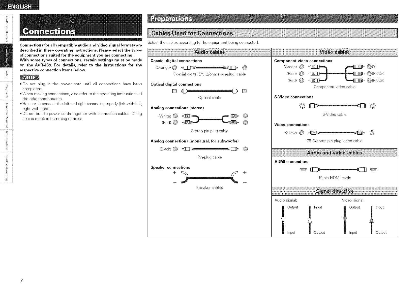
Select the cables according to the equipment being connected.
Coaxial digital connections
(Orange)@ _ @
Coaxial digital (75 O/ohms pin-plug) cable
Optical digital connections
D_D
Optical cable
Analog connections (stereo}
(White) @ L L @
(Red) @ __ @
Stereo pin@hg cable
Analog connections (monaural, for subwoofer)
(Black) @ _ @
Pin-plug cable
Speaker connections
+ +
Speaker cables
Component video connections
(Green) @ _ _(Y)
(Blue) _ _ _(PB/CB}
(Red) @ @(PR/CR)
Component video cable
S-Video connections
S-Video cable
Video connections
(Yellow) @ @
75 O/ohms pin-plug video cable
HDMI connections
19-pin HDMI cable
Audio signal: Video signal:
joutpu,Inputjoutpu,input
Input Output Input Output
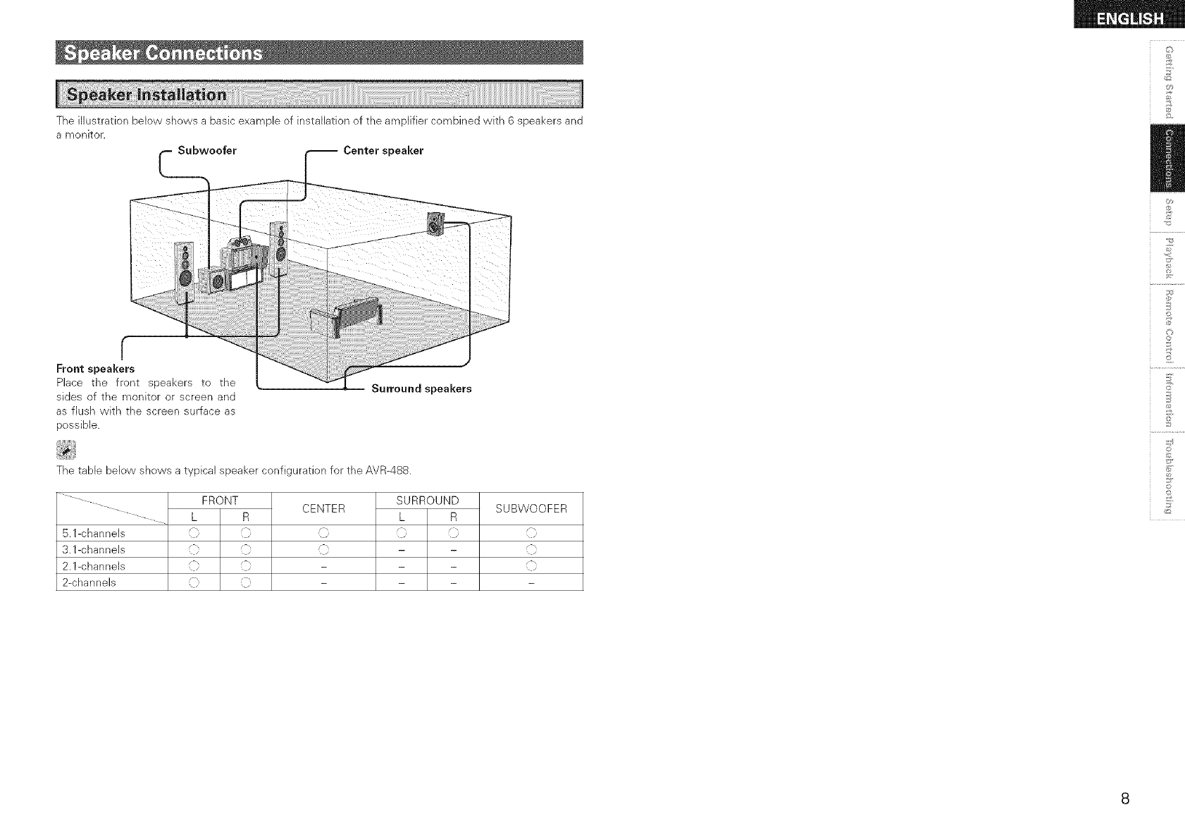
Theillustrationbelowshowsabasicexampleofinstallationoftheamplifiercombinedwith6speakersand
amonitor. Subwoofer Center speaker
_2
r
Front speakers
Place the front speakers to the
sides of the monitor or screen and
as flush wkh the screen surface as
possible.
Surround speakers
The table below shows a typical speaker configuration for the AVR-488.
FRONT CENTER SURROUND
L R L R
5.1-channels _} _} i _} _}
3.1 -c hann els i[ i[ i[ - -
2.l-channels :[[, :[[ - - -
2-channels [ [ - - -
SUBWOOFER
©
©
*&
2
©
©
_2
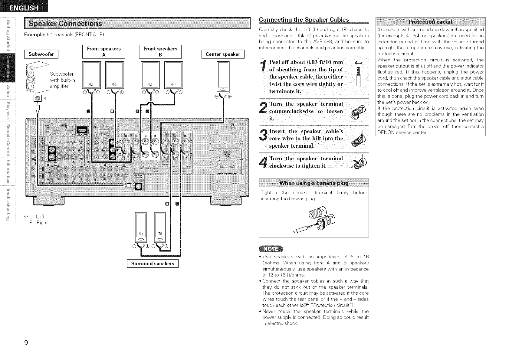
Example: 5.1-channels (FRONT A+B)
Subwoofer ]
Subwoofer
with built-in
amplifier
Front speakers
A
÷ L : Left
R : Right
Front speakers
BCenterspeaker ]
Q
I S.rro_ndspeakersI
Carefu cnech _ne left _na ngnT D_ channels
ana + re@ an@ - clack :_olarmes on _ne speakers
Demg connec_e@ [c the AVR488 _na De sure To
q_erconnec_ _ne cnannels ana )olarmes correc_
Peel off about 0.03 ft/10 mm
of sheathing from the tip of
the speaker cable, then either
twist the core wire tightly or
terminate it.
Turn the speaker terminal
counterclockwise to loosen
it. _)
Insert the speaker cable's
core wire to the hill into the _)
speaker terminal.
Turn the speaker terminal
clockwise to tighten it. _
iii!!!!!!!!!!!!!!!!!!!!!!!!!!!!!!!!!!!_iWih!_!i_!_!!_i!_i_!i_!_i_i_!;_:_!_;_!_!_!_!i!!;!!_;i!_i_i_i_i_i_i_i_i_i_i_i_i_i_i_i_i_i_i_i_i_i_i_i_i_i_i_i_i_i_i_i_i_i_i_i_i_i_i_i_¸
Tighten the speaker terminal firmly before
inserting the banana plug.
¢9
• Use speakers with an impedance of 6 to 16
O/ohms. When using front A and B speakers
simultaneously, use speakers with an impedance
of 12 to 16 O/ohms.
• Connect the speaker cables in such a way that
they do not stick out of the speaker terminals.
The protection circuit may be activated if the core
wires touch the rear panel or if the + and - sides
touch each other (_ "Protection circuit").
"Never touch the speaker terminals while the
power supply is connected. Doing so could result
in electric shock.
If speakers with an impedance lower than specified
(for example 4 O/ohms speakers) are used for an
extended period of time with the volume turned
up high, the temperature may rise, activating the
_rotection circuit.
When the protection circuit is activated, the
speaker output is shut off and the power indicator
flashes red. If this happens, unplug the power
cord, then check the speaker cable and input cable
connections, if the set is extremely hot, wait for it
to cool off and improve ventilation around it. Once
this is done, plug the power cord back in and turn
the set's power back on.
If the protection circuit is activated again even
though there are no problems in the ventilation
around the set nor in the connections, the set may
be damaged. Turn the power off, then contact a
DENON service center.
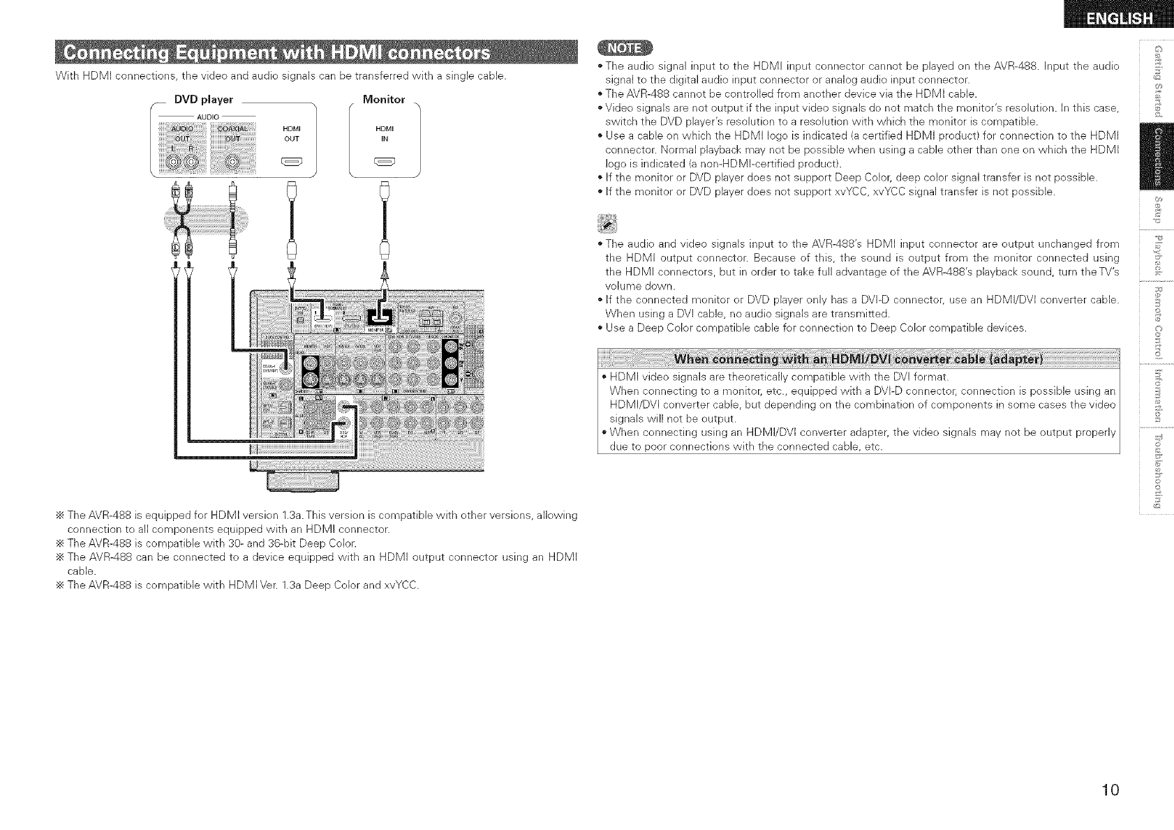
WithHDMIconnections,thevideoandaudiosignalscanbetransferredwithasinglecable.
Monitor
HDMI HDMI
OUT tN
÷ The AVR-488 is equipped for HDMI version 1.3a. This version is compatible with other versions, allowing
connection to all components equipped with an HDMI connector.
÷ The AVR-488 is compatible with 30- and 36-bit Deep Color.
The AVR488 can be connected to a device equipped with an HDMI output connector using an HDMI
cable.
÷ The AVR-488 is compatible with HDMI Ver. 1.3a Deep Color and xvYCC.
• The audio signal input to the HDMI input connector cannot be played on the AVR-488. Input the audio
signal to the digital audio input connector or analog audio input connector.
The AVR-488 cannot be controlled from another device via the HDMI cable.
• Video signals are not output if the input video signals de not match the monitor's resolution. In this case,
switch the DVD player's resolution to a resolution with which the monitor is compatible.
Use a cable on which the HDMI logo is indicated (a certified HDMI product) for connection to the HDMI
connector. Normal playback may not be possible when using a cable other than one on which the HDMI
logo is indicated (a non-HDMI-certified product).
• If the monitor or DVD player does not support Deep Color, deep color signal transfer is not possible.
If the monitor or DVD player does not support xvYCC, xvYCC signal transfer is not possible.
• The audio and video signals input to the AVR-488's HDMI input connector are output unchanged from
the HDMI output connector. Because of this, the sound is output from the monitor connected using
the HDMI connectors, but in order to take full advantage of the AVR-488's playback sound, turn the TV's
volume down.
If the connected monitor or DVD player only has a DVI-D connector, use an HDMI/DVI converter cable.
When using a DVI cable, no audio signals are transmitted.
• Use a Deep Color compatible cable for connection to Deep Color compatible devices.
HDMI video signals are theoretically compatible with the DVI format.
When connecting to a monitor; etc., equipped with a DVI-D connector, connection is possible using an
HDMI/DVI converter cable, but depending on the combination of components in some cases the video
signals will not be output.
"When connecting using an HDMI/DVI converter adapter, the video signals may not be output properly
due to poor connections with the connected cable, etc.
_2
+4
+
+,
©
+ o
©
10
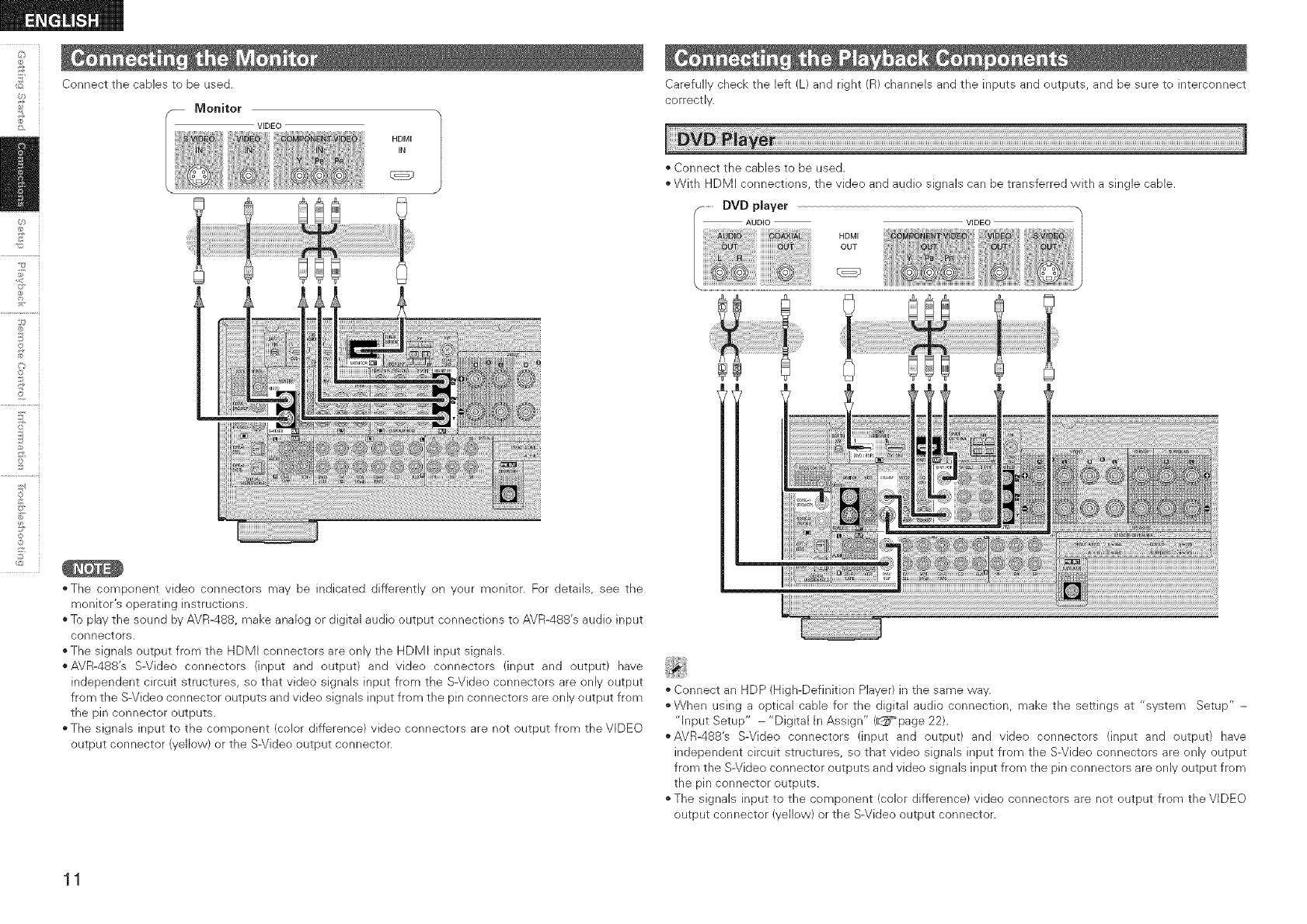
Connect the cables to be used.
VIDEO
HDMI
IN
£
£
2
©
©
!° i
"The component video connectors may be indicated differently on your monitor. For details, see the
monitor's operating instructions.
* To pBy the sound by AVR-488, make analog or digital audio output connections to AVR-488's audio input
connectors.
o The signals output from the HDMI connectors are only the HDMI input signals.
*AVR-488's S-Video connecters (input and output) and video connectors (input and output) have
independent circuit structures, so that video signals input from the S-Video connectors are only output
from the S-Video connector outputs and video signals input from the pin connecters are only output from
the pin connector outputs.
o The signals input to the component (color difference) video connectors are not output from the VIDEO
output connector (yellow) or the S-Video output connector.
Carefully check the left (L) and right (R) channels and the inputs and outputs, and be sure to interconnect
correctly.
• Connect the cables to be used.
• With HDMI connections, the video and audio signals can be transferred with a single cable.
............DVD player
VIDEO
• Connect an HDP (High-Definition Player) in the same way.
"When using a optical cable for the digital audio connection, make the settings at "system Setup" -
"Input Setup" - "Digital In Assign" (_page 22).
,,AVR-488's S-Video connectors (input and output) and video connectors (input and output) have
independent circuit structures, so that video signals input from the S-Video connectors are only output
from the S-Video connector outputs and video signals input from the pin connectors are only output from
the pin connector outputs.
"The signals input to the component (color difference) video connectors are not output from the VIDEO
output connector (yellow) or the S-Video output connector.
11
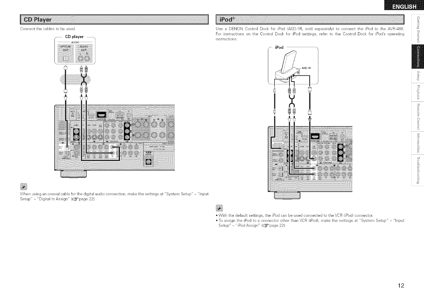
Connect the cables to be used.
CD player
AUDIO /
When using an coaxial cable for the digital audio connection, make the settings at "System Setup" - "Input
Setup"-"Digital In Assign" (_page 22).
Use a DENON Control Dock for iPod (ASD-1R, sold separately) to connect the iPod to the AVR-488.
For instructions on the Control Dock for iPod settings, refer to the Control Dock for iPod's operating
instructions.
iPod
©
©
"With the default settings, the iPod can be used connected to the VCR (iPod) connector.
"To assign the iPod to a connector other than VCR (iPod), make the settings at "System Setup" - "Input
Setup" - "iPod Assign" (_=_page 22).
12
£
©r
2
©
©
jI!i!i!i!i ! i i! i! L i ! ! i ! i!! !! !! !i !ii !ii! i! ! i! i! i! ! i! i! i! ! ! ! i! i! i! i! i! i! i!;i i i i i i i i i ! i ii i i i i i i i i i i ii i i! i ii i ii i i i ii i i ! i! i i i i i i i i i ii i! i ! i i i i i i i ii i! ii!i! ii!i iiii i i ii ii i ii i ii!i! ii!i! i iiiii i i i i i i i ii!i! ii!i! ii i iiiiii ii i ii i iii i!iii!i!iii!i i i ii ii iii ii i i ii ii ii i i i i i i ii ii i i i i ii i!i i! !i i ii!ii!ii!ii i ii i iii i!iii!i!iii!i i i iiiiiiiiii i i iii i iii!i iii!i!i i i !i !i !ii ii i i iii iiiii!i ii !i iii ii ii i ! ! ! ii i i i ii ii iiiiiiiiiiiiiiiiiiiiiiiiiiiiiiiiiiiiiiiiiiiiiiiiiiiiiiiiiiiiiiiiiiiiiiiiiiiiiiiiiiiiiiiiiiiiiiiiiiiiiiiiiiiiiiiiiiiiiiiiiiiiiiiiiiiiiiiiiiiiiiiiiiiiiiiiiiiiiiiiiiiiiiiiiiiiiiiiiiiiiiiiiiiiiiiiiiiiiiiiiiiiiiiiiiiiiiiiiiiiiiiiiiiiiiiiiiiiiiiiiiiiiiiiiiiiiiiiiiiiiiiiiiiiiiiiiiiiiiiiiiii j
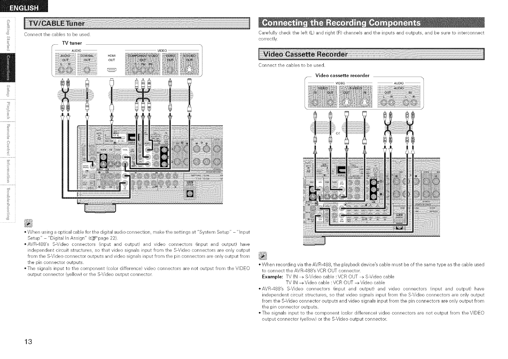
Connect the cables to be used.
TV tuner
AUDIO VIDEO
HDMI
OUT
"When using a optical cable for the digital audio connection, make the settings at "System Setup" - "Input
Setup" - "Digital In Assign" (_page 22).
"AVR-488's S-Video connectors (input and output) and video connectors (input and output) have
independent circuit structures, so that video signals input from the S-Video connectors are only output
from the S-Video connector outputs and video signals input from the pin connectors are only output from
the pin connector outputs.
"The signals input to the component (color difference) video connectors are not output from the VIDEO
output connector (yellow) or the S-Video output connector.
Carefully check the left (L) and right (R) channels and the inputs and outputs, and be sure to interconnect
correctly.
iiiiJi i !i iii!i i iiiili!il;!i!i
Connect the cables to be used.
__ Video cassette recorder
VIDEO AUDIO
"When recording via the AVR488, the playback device's cable must be of the same type as the cable used
to connect the AVR-488's VCR OUT connector.
Example: TV IN _ S-Video cable :VCR OUT _ S-Video cable
TV IN _Videe cable :VCR OUT _Video cable
,,AVR-488's S-Video connectors (input and output) and video connectors (input and output) have
independent circuit structures, so that video signals input from the S-Video connectors are only output
from the S-Video connector outputs and video signals input from the pin connectors are only output from
the pin connector outputs.
"The signals input to the component (color difference) video connectors are not output from the VIDEO
output connector (yellow) or the S-Video output connector.
13
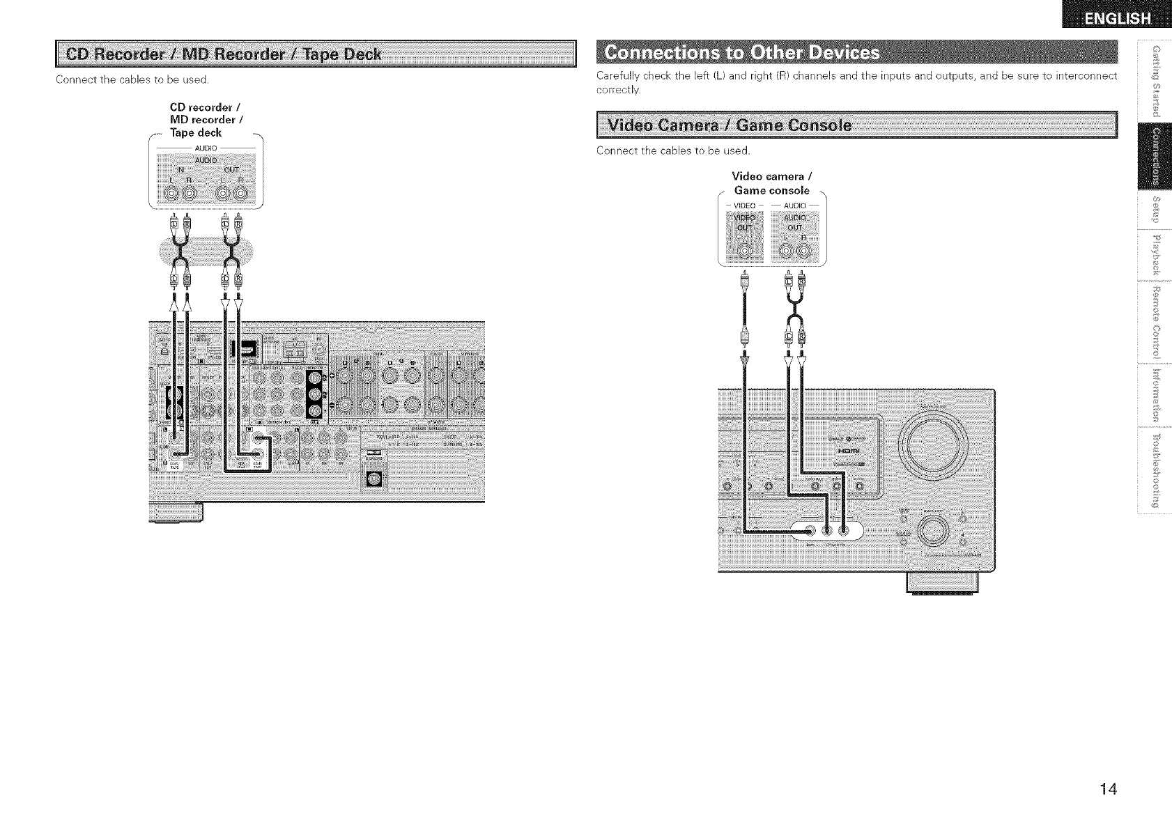
Connect the canes to be used.
CD recorder /
MD recorder /
Tape deck
AUDIO
Carefully check the left (L) and right (R) channels and the inputs and outputs, and be sure to interconnect
correctly.
Connect the canes to be used.
Video camera /
fGame console _,
VIDEO AUDIO /
]
_2
©
©
14
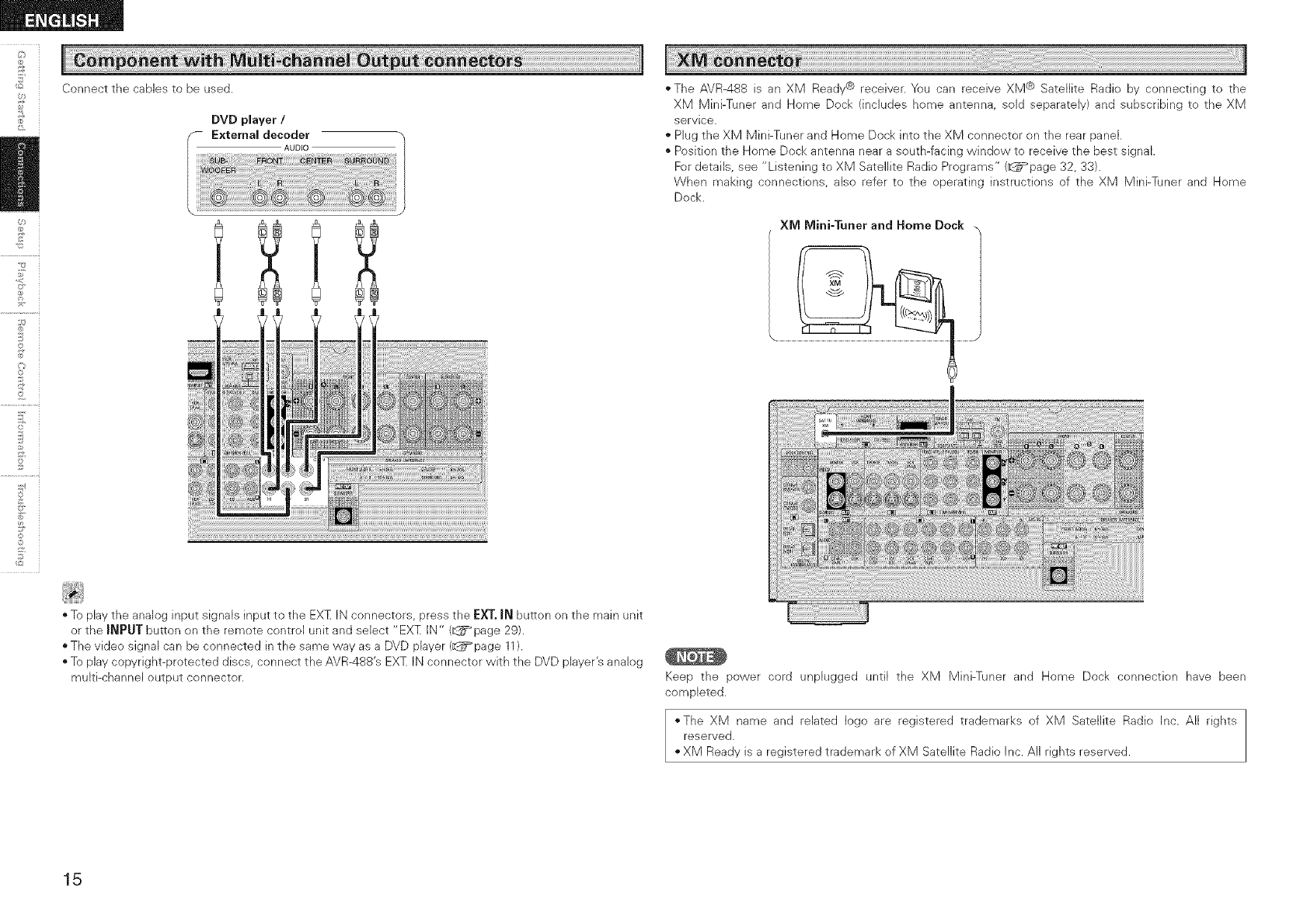
Connect the cables to be used.
DVD player /
External decoder
AUDIO
©
©
" The AVR-488 is an XM Ready@ receiver. You can receive XM @ Satellite Radio by connecting to the
XM Mini-Tuner and Home Dock (includes home antenna, said separately) and subscribing to the XM
service.
Plug the XM Mini-Tuner and Home Dock into the XM connector on the rear panel.
" Position the Home Dock antenna near a south-facing window to receive the best signal.
For details, see "Listening to XM Satellite Radio Programs" (_page 32, 33}.
When making connections, also refer to the operating instructions of the XM Mini-Tuner and Home
Dock.
XM Mini-Tuner and Home Dock
"To play the analog input signals input to the EXT IN connectors, press the EXT. J_ button on the main unit
or the J_PUT button on the remote control unit and select "EXT IN" (_ page 29).
The video signal can be connected in the same way as a DVD player (_page 11).
"To play copyright-protected discs, connect the AVR-488's EXT IN connector with the DVD player's analog
multi-channel output connector. Keep the power cord unplugged until the XM Mini-Tuner and Home Dock connection have been
completed.
*The XM name and related logo are registered trademarks of XM Satellite Radio Inc. All rights
reserved.
XM Ready is a registered trademark of XM Satellite Radio Inc. All rights reserved.
15
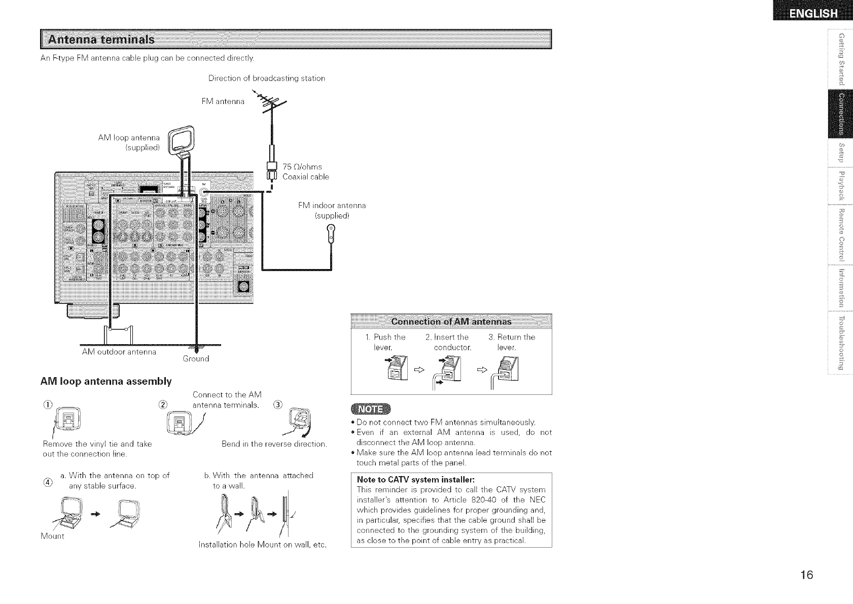
An F-type FM antenna cable plug can be connected directly.
AM loop antenna
(supplied)
AM outdoor antenna
Direction of broadcasting station
FM antenna "_,_
75 _/ohms
Coaxial cable
FM indoor antenna
(supplied)
Ground
AM loop antenna assembly
Remove the vinyl tie and take
out the connection line.
Connect to the AM
antenna terminals. _
Bend in the reverse direction.
a. With the antenna on top of
_4} any stable surface.
b. With the antenna attached
to a wall.
Mount
Installation hole Mount on wall, etc.
1. Push the 2. Insert the 3. Return the
lever, conductor, lever.
• Do not connect two FM antennas simultaneously.
• Even if an external AM antenna is used, do not
disconnect the AM loop antenna.
• Make sure the AM loop antenna lead terminals do not
touch metal parts of the panel.
Note to CATV system installer:
This reminder is provided to call the CATV system
installer's attention to Article 820-40 of the NEC
which provides guidelines for proper grounding and,
in particular, specifies that the cane ground shall be
connected to the grounding system of the building,
as close to the point of cable entry as practical.
_2
©
o
©
16
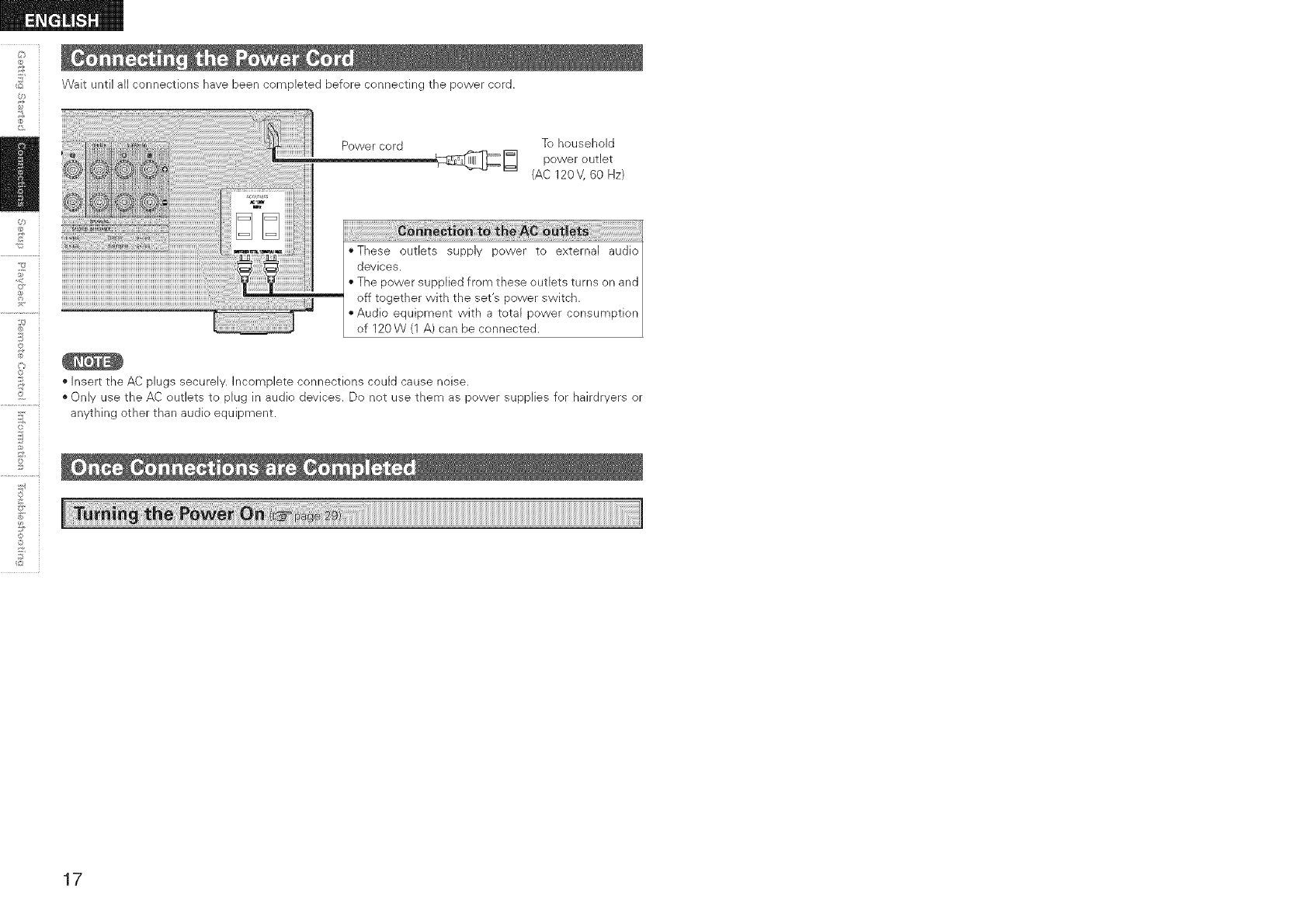
Wait until all connections have been completed before connecting the power cord.
Power cord To household
r_ power outlet
(AC 120V, 60 Hz)
"These outlets supply power to external audio
devices.
• The power supplied from these outlets turns on and
off together with the set's power switch.
• Audio equipment with a total power consumption
of 120W (1 A) can be connected.
• Insert the AC plugs securely. Incomplete connections could cause noise.
• Only use the AC outlets to plug in audio devices. Do not use them as power supplies for hairdryers or
anything other than audio equipment.
2
©
©
_2
17
JOption Setup
(_page 23, 24)
Volume Control
_ •Volume Limit
i• Power On Level
i • Mute Level
_ = Auto Surround Mode
:• Remote ID Setup
J Surround Parameter
MODE
CINEMA EQ
D.COMP
LFE
CENTER iMAGE
PANORAMA
DiMENSiON
CENTER WIDTH
DELAYTIME
EFFECT LEVEL
ROOM SiZE
SUBWOOFER AT'£
Subwoofer
Default
Tone Control
•Tone Defeat
• Bass
•Treble
RESTORER
=Night Mode
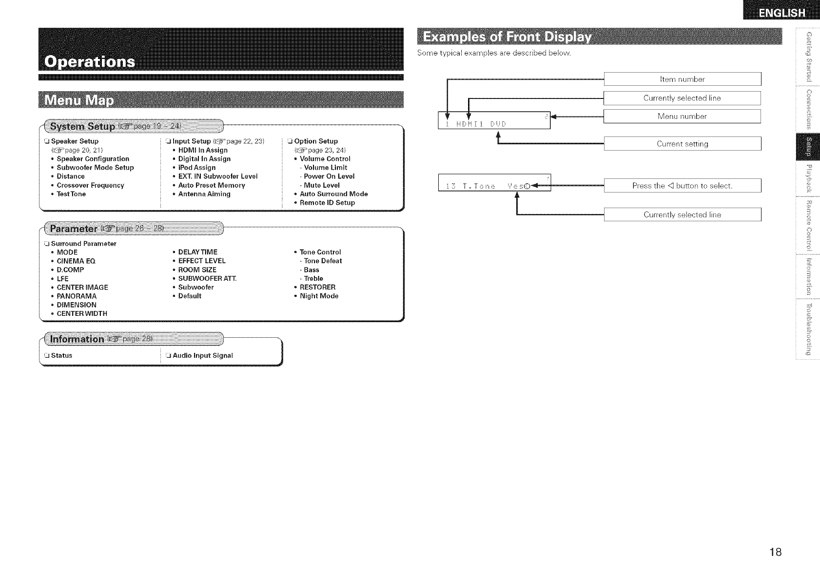
Some typical examples are described below.
IFi [::,i'i :[ i) i)
€
I Item number
I
Currently selected line
Menu number
J Current setting
I
! Press the <] button to select.
I
J Currently selected line
I
©
©
o
©
18
©r
2
SYSTEM SETUP AV
ENTER, <_
[Front]
- ENTER
AV<]E> =
[Rearl
!s' SYSTEM SETUP _ :® ......
i ii r'N|r'n
AV<]D
About the button names in these explanations
< > : Buttons on the main unit
[ ] : Buttons on the remote centre[ unit
Button name only:
Buttons on the main unit and remote control unit
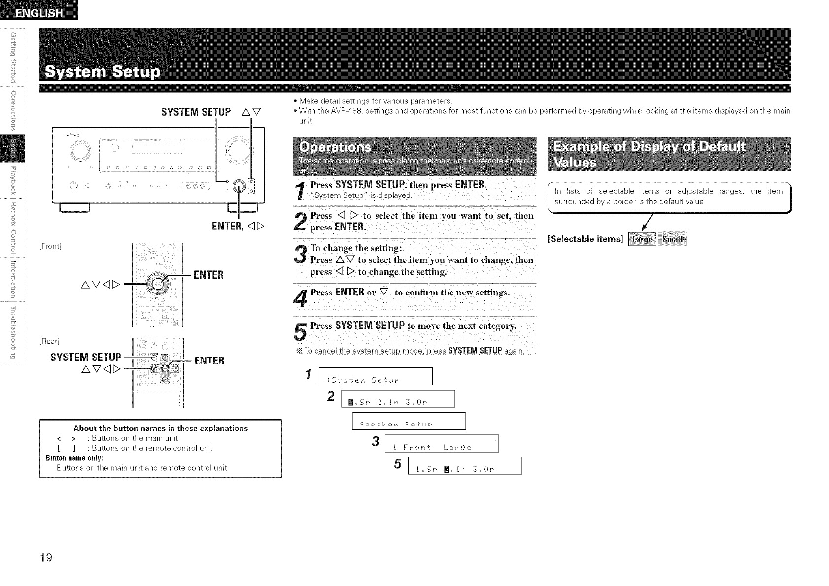
*Make detail sellings for various narameTers
*With the AVR488 semn _s ana ooerations for most functions ca oe oerformed by operating while looking at the items displayed on the main
unlr
Press SYSTEM SETUP, then press ENTER.
"Svstem SetuP" is Jisolaved.
Press <] [_> to selecl the item you want tu set. then
press ENTER.
To change the setting:
Press AV to select the item you want to change, then
press <] _ to change the setting.
Press ENTER or V to confirm the new" settings.
Press SYSTEMSETUPto move the next category,
Yc cancel me system so[up moae, press SYSTEM SETUP again,
1 [ :i: '[i; :i ;; _ _'_ 'i[: i' "[:U F: ]
2 [ _,, 'i[: ::iii' = ][ i_ i:]:,, i] : ]
I:ii:F:, i i:: i' r 'ii: i' ',; ,., ,- 'l
3I], [:, 0,, ;; ,. !,r !],, 'l
I n lists of selectabie items or adjustable ranges, the item
surrounded by a border is the default value.
Y)
19
Select front speaker size.
[Seleotableitem<
Select center speaker use and size.
[Soleotable,tern<
Select surround speakers use and size.
[ eleotableitem<
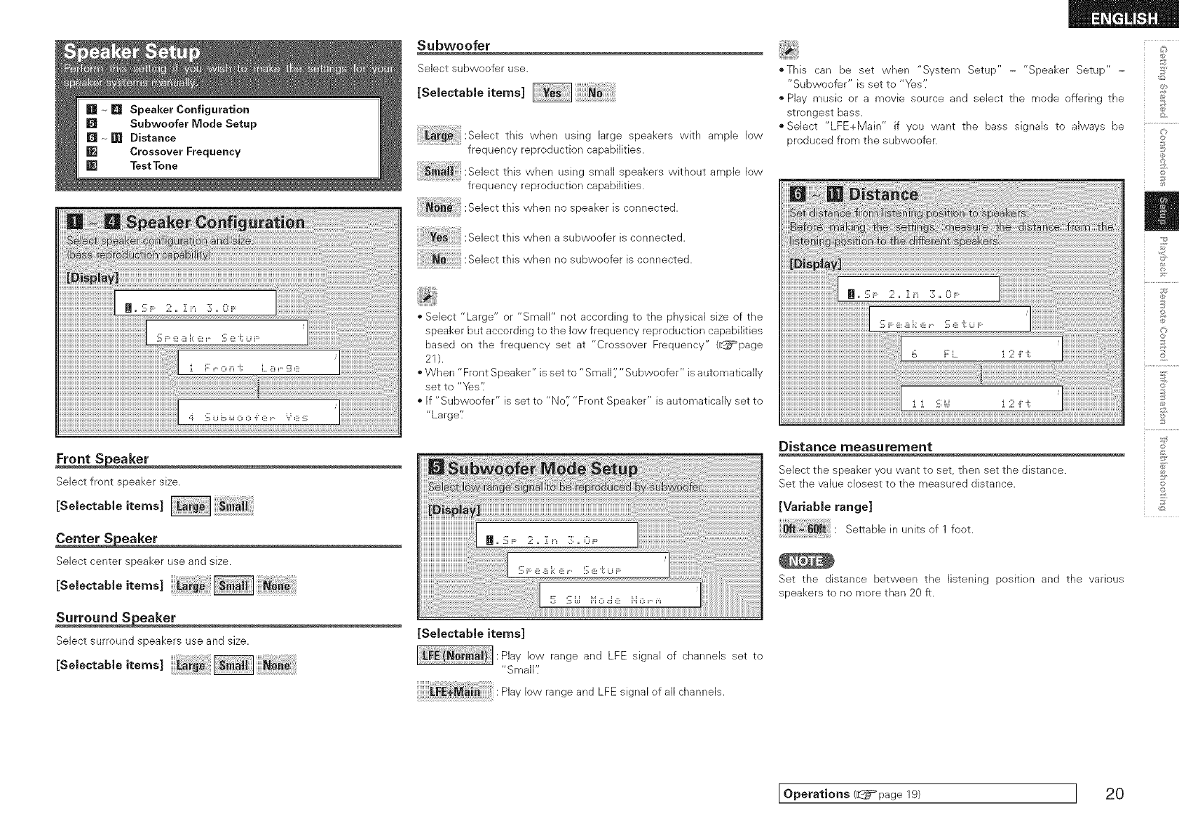
Subwoofer
Select subwoofer use.
[ o,ootob,o,tom<
this when using large speakers with ample low
frequency reproduction capabilities.
_ii :SelectthiswhenusingsmaUspeakerswithoutample low
frequency reproduction capabilities.
Selectth_swhennospeaker_sconnected.
Ye;:Selectthis when a subwoofer isconnected.
: _ ::Selectthiswhennosubwooferisconnected.
• Select "Large" or "Small" not according to the physical size of the
speaker but according to the low frequency reproduction capabilities
based on the frequency set at "Crossover Frequency" (_page
21).
• When "Front Speaker" is set to "Small ','"Subwoofer" is a utomatica Ily
set to "Yes'i
• If "Subwoofer" is set to "No'; "Front Speaker" is automatically set to
"Large'[
[Selectable items]
Play low range and LFE signal of channels set to
"Small';
Play low range and LFE signal of all channels.
oThis can be set when "System Setup" - "Speaker Setup" - :>
"Subwoofer" is set to "Yes';
" Play music or a movie source and select the mode offering the
strongest bass.
• Select "LFE+Main" if you want the bass signals to always be
produced from the subwoofer.
Distance measurement
Select the speaker you want to set, then set the distance.
Set the value closest to the measured distance.
[Variable range]
Seeable_nunitsof1foot.
Set the distance between the listening position and the various
speakers to no more than 20 ft.
©
*4
@
©
o
©
Operations (d_i=page 19) I 20
5
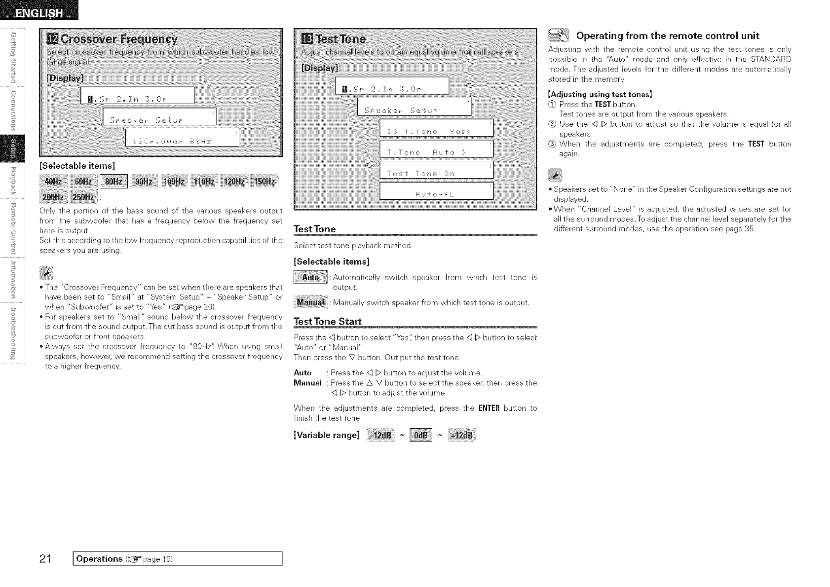
[Selectable items]
Only the portion of the bass sound of the various speakers output
from the subwoofer that has a frequency below the frequency set
here is output.
Set this according to the low frequency reproduction capabilities of the
speakers you are using.
T
;;Y" i
• The "Crossover Frequency" can be set when there are speakers that
have been set to "Small" at "System Setup" - "Speaker Setup" or
when "Subwoofer" is set to "Yes" (_page 20).
• For speakers set to "Small'; sound below the crossover frequency
is cut from the sound output. The cut bass sound is output from the
subwoofer or front speakers.
• Always set the crossover frequency to "80Hz'/When using small
speakers, however, we recommend setting the crossover frequency
to a higher frequency.
Test Tone
Select test tone playback method.
[Selectable items]
:Automatically switch speaker from which test tone is
output.
Manually switch speaker from which test tone is output.
Test Tone Start
Press the <:]button to select "Yes',' then press the <:] D button to select
"Auto" or "Manual'.'
Then press the V button. Out put the test tone.
Auto : Press the <:]D button to adjust the volume.
Manuam : Press the A V button to select the speaker, then press the
<qD button to adjust the volume.
When the adjustments are completed, press the ENTER button to
finish the test tone.
[Variable range] ~
~ Operating from the remote control unit
Adjusting with the remote control unit using the test tones is only
possible in the '_,uto" mode and only effective in the STANDARD
mode. The adjusted levels for the different modes are automatically
stored in the memory.
[Adjusting using test tones]
(1} Press the TESTbutton.
Test tones are output from the various speakers.
_} Use the q D button to adjust so that the volume is equal for all
speakers.
_} When the adjustments are completed, press the TEST button
again.
" Speakers set to "None" in the Speaker Configuration settings are not
displayed.
• When "Channel Level" is adjusted, the adjusted vahes are set for
all the surround modes. To adjust the channel level separately for the
different surround modes, use the operation see page 35.
21 IOperations/ page 19/ I
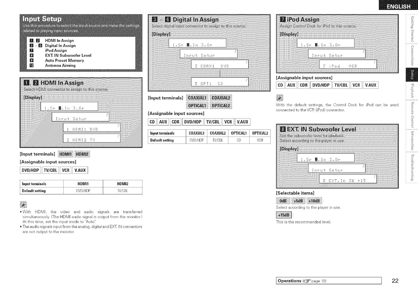
[,nputtor,,,,na,s
[Assignable input sources]
Input terminals tIDMI1 HDMI2
Default setting DVD/HDP B//CBL
[input terminals]
[AssignabJe input sources]
[Assignable input sources]
Inpatterminals COAXIAL1tCOA×JAL2tOPTICAL1 0PTICAL2
Default setting DVD/HDP TV/CBL CD VCR
With the default settings, the Control Dock for iPod can be used
connected to theVCR (iPod) connector.
[SelestabJe items]
£
©
@
£
©
*With HDMI, the video and audio signals are transferred
simuJtaneously. (The HDMI audio signaJ is output from the monitor.)
At this time, set the input mode to '_,uto'/
o The audio signals input from the analog, digital and EXT IN connectors
are net output to the monitor.
Select according to the player in use.
This is the recommended level.
Operations (_page 19) ] 22
2
©
©
_2
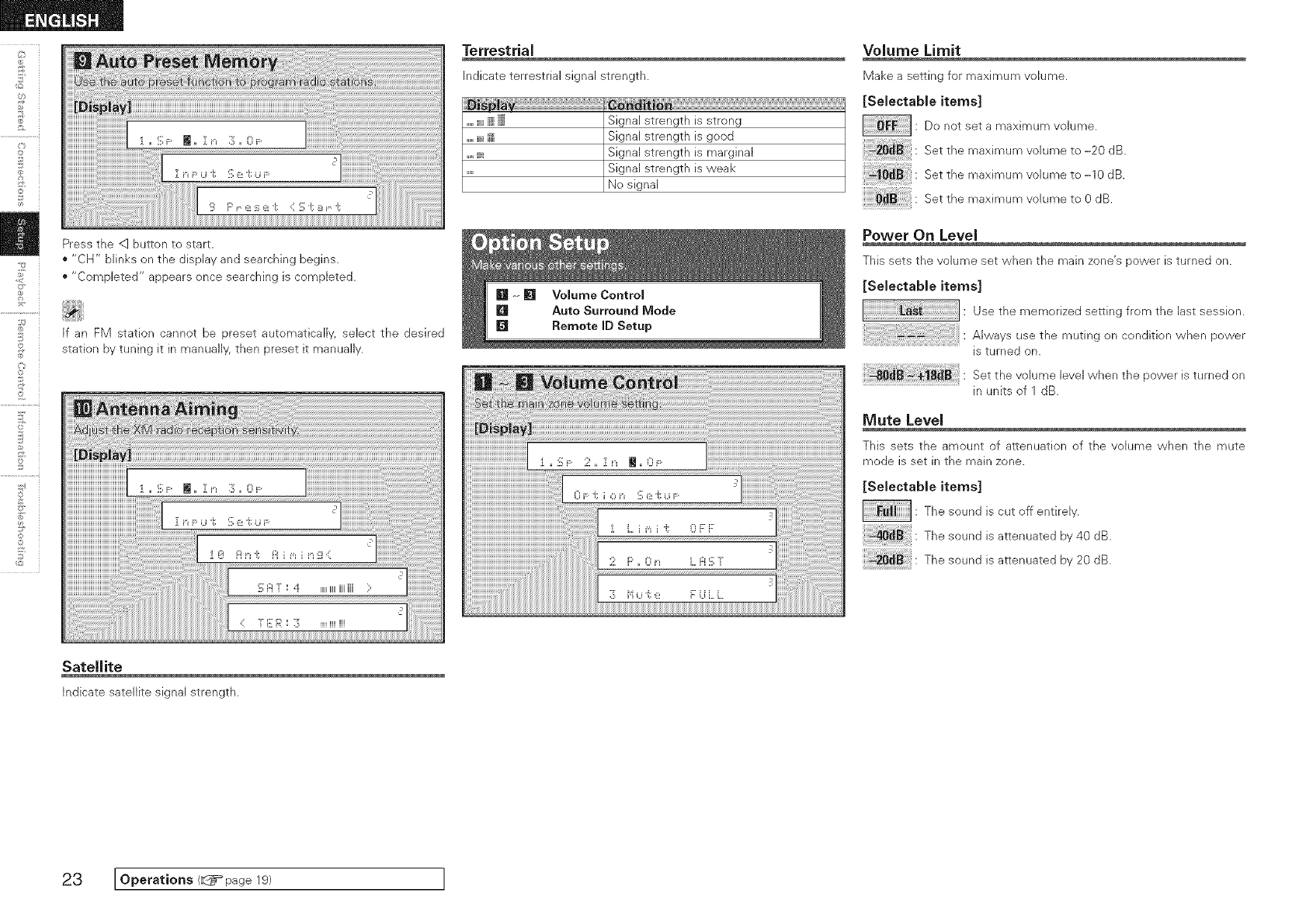
Press the <1button to start.
"CH" blinks on the display and searching begins.
• "Completed" appears once searching is completed.
If an FM station cannot be preset automatically, select the desired
station by tuning it in manually, then preset it manually.
Terrestrial
indicate terrestrial signal strength.
_,,,_i Signal strength is strong
....._ i;ii Signal strength is good
....._i_ Signal strength is marginal
..... Signal strength is weak
No signal
Volume Limit
k/lake a setting for maximum volume.
[SeJectabJe items]
: Do not set a maximum volume.
Setthemaximumvolumeto-;0d_
Setthemaximumvolumeto-_0d_
Set the maximum volume to 0 dB.
Power On Level
This sets the volume set when the main zone's power is turned on.
[Selectable items]
Use the memorized setting from the last session.
Always use the muting on condition when power
is turned on.
Set the volume level when the power is turned on
in units of 1 dB.
Mute Level
This sets the amount of attenuation of the vohme when the mute
mode is set in the main zone.
[Selectable items]
: The sound is cut off entirely.
The sound is attenuated by 40 dB.
20_ : The sound is attenuated by 20dB.
Satellite
Indicate satellite signal strength.
23 IOpe atio.s< page I
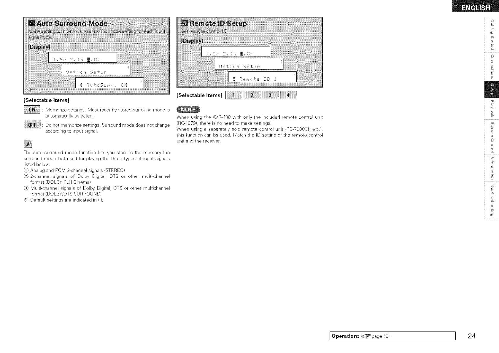
[SeJectabJe items]
: Memorize settings. Most recently stored surround mode is
automatically selected.
Do not memorize settings. Surround mode does not change
according to input signal.
The auto surround mode function lets you store in the memory the
surround mode last used for playing the three types of input signals
listed below.
q} Analog and PCM 2-channel signals (STEREO)
_2}2 channd signals of Dolby Digital, DTS or other multi channel
format (DOLBY PLI] Cinema)
@} Multi-channel signals of Ddby Digital DTS or other muitichannel
format (DOLBY/DTS SURROUND)
Default settings are indicated in ().
[SelectaMeitems] ii!i!i!i!i!i!i!i!i!i!i!i!i_!_!_i!_i!_i!_i!_i!_i!_i!_i!_i!_!_!_!!_!i!_iiiiiiiiiiiiii_!_!_!_!_!_!_!_!_!_!_!_!_!i_!_i!iiiiiiiiiiiiiii!_i!!i!]i!]i!]i!]i!]i!]i!]i!!i!_!!i!_!_!
When using the AVR-488 with only the included remote control unit
(RC-1079), there is no need to make settings.
When using a separately sold remote control unit (RC-7000CI, etc.),
this function can be used. Match the ID setting of the remote control
unit and the receiver.
©
©
o
©
Operations (d_i=page 19) I24
F_
-4¸
©r
2
©
©
_2
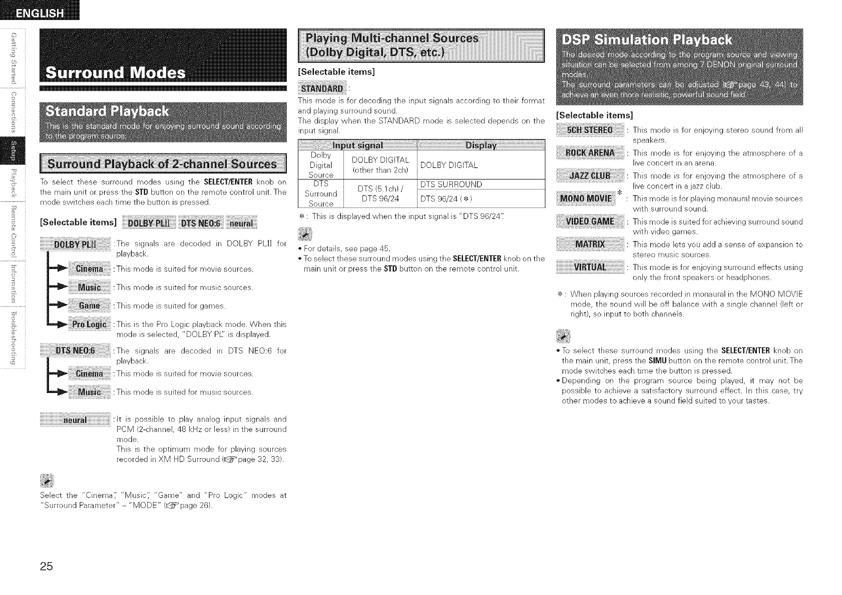
To select these surround modes using the SELECT/ENTERknob on
the main unit or press the STD butten on the remote control unit. The
mode switches each time the button is pressed.
[Selectable items] _[_ PIll
:The signals are decoded in DOLBY PLI] far
playback.
:This mode is suited for movie seurces.
:This mode issuited for music sources.
This mode is suited for games.
,,_ _i_ _] :This is the Pro Logic playback mode. When this
mode is selected, "DOLBY PL" is displayed.
:The signals are decoded in DTS NEO:6 for
playback.
:This mode is suited for movie sources.
:This mode is suited for music sources.
:It is possible to play analog input signals and
PCM (2-channel, 48 kHz or less) in the surround
mode.
This is the optimum mode for playing sources
recorded in XM HD Surround (_page 32, 33).
[Selectable items]
This mode is for decoding the input signals according to their format
and playing surround sound.
The display when the STANDARD mode is selected depends on the
input signal.
Dolby DOLBY DIGITAL
Digital (other than 2ch) DOLBY DIGITAL
Source
DTS DTS SURROUND
DTS (5.1ch) /
Surround DTS 96/24 DTS 96/24 ( * )
Source
: This is displayed when the input signal is "DTS 96/24':
• For details, see page 46.
To select these surround modes using the SELECT/ENTERknob on the
main unit or press the STD button on the remote control unit.
[Selectable items]
This mode is for enjoying stereo sound from all
speakers.
This mode is for enjoying the atmosphere of a
live concert in an arena.
This mode is for enjoying the atmosphere of a
live concert in a jazz club.
This mode is for playing monaural movie sources
with surround sound.
This mode is suited for achieving surround sound
with video games.
This mode Jets you add a sense of expansion to
stereo music sources.
This mode is for enjoying surround effects using
only the front speakers or headphones.
*: When playing sources recorded in monaural in the MONO MOVIE
mode, the sound will be off balance with a single channel (left or
right), so input to both channels.
To select these surround modes using the SELECT/ENTERknob on
the main unit, press the SIMU button on the remote control unit. The
mode switches each time the button is pressed.
"Depending on the program source being played, it may not be
possible to achieve a satisfactory surround effect. In this case, try
other modes to achieve a sound field suited to your tastes.
Select the "Cinema',' "Music',' "Game" and "Pro Logic" modes at
"Surround Parameter" - "MODE" (_page 26).
25
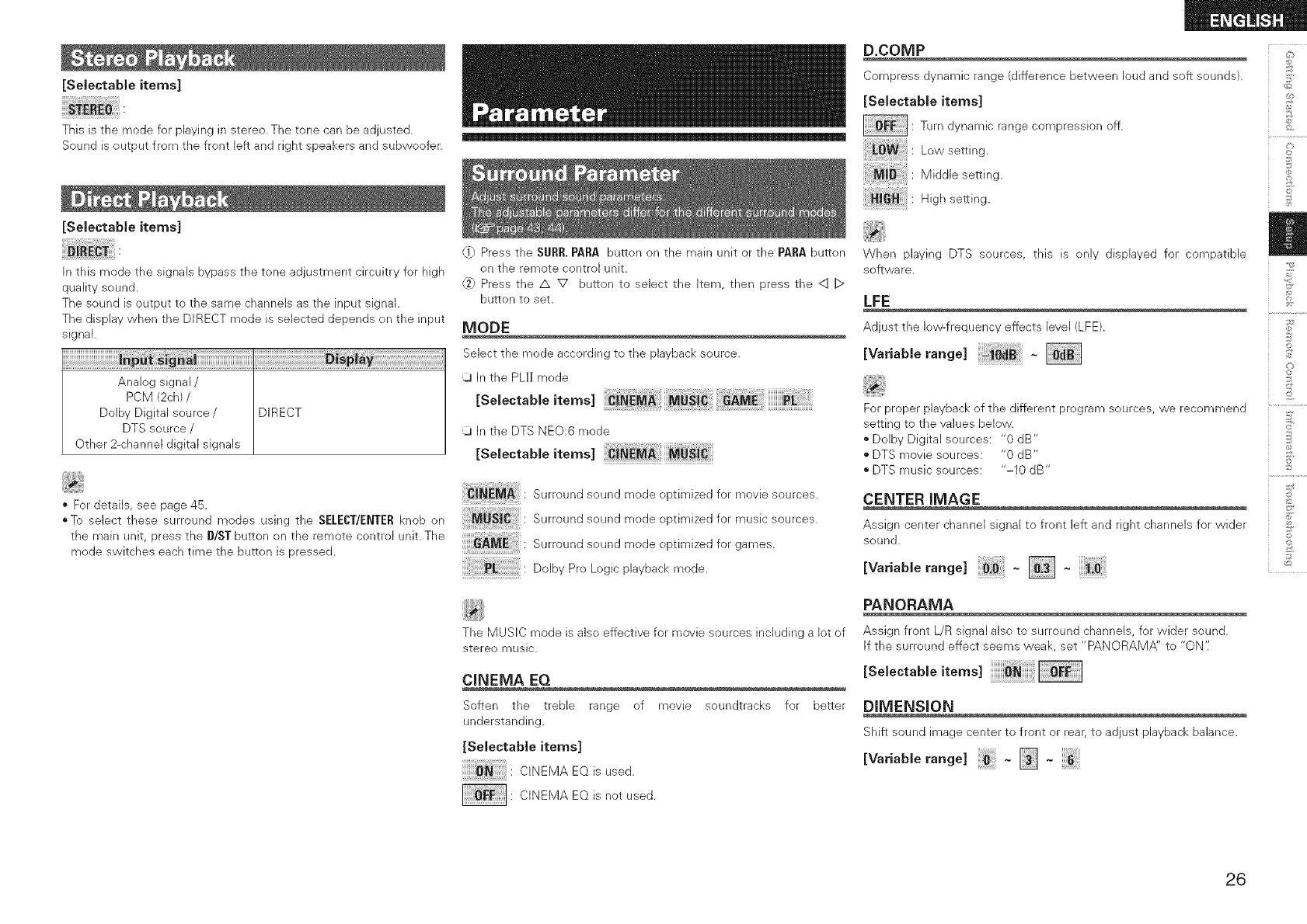
[Selectable items]
This is the mode for playing in stereo. The tone can be adjusted.
Sound is output from the front left and right speakers and subweofer.
[SeJectabJe items]
In this mode the signals bypass the tone adjustment circuitry for high
quality sound.
The sound is output to the same channels as the input signal.
The display when the DIRECT mode is selected depends on the input
signal.
Analog signal /
PCM (2ch) /
DoJby DigitaJ source/ DIRECT
DTS source /
Other 2-channel digital signaJs
• For details, see page 45.
oTo select these surround modes using the SELECT/ENTERknob on
the main unit, press the D/ST button on the remote control unit. The
mode switches each time the button is pressed.
{1} Press the $URR. PARA button on the main unit or the PARA button
on the remote control unit.
6} Press the /x V button to select the Item, then press the <1 D
button to set.
MODE
Select the mode according to tile playback source.
In the PLI] mode
ESo,eotob,eitem<
ij In the DTS NEe:6 mode
[SeJectableitems]
iiiii_iiii_i:_M_i!iiii: Surround sound mode optimized for movie sources.
iiiiii:_!_i_!JiBi!i!ili!i!i!iii: Surround sound mode optimized for music sources.
Surroundsound modeoptimizedforgames.
UolbyPro Logicplayback mode.
The MUSIC mode is also effective for movie sources including a lot of
stereo music.
CINEMA EQ
Soften the treble range of movie soundtracks for better
understanding.
[SelectabJe items]
C INEM A EQ is us ed.
: CINEMA EQ is not used.
D.COMP _:_
Compress dynamic range (difference between loud and soft sounds). _>
[Selectabie items] _?
: Turn dynamic range compression off.
Low setti ng. _[_
M idd b setti ng. ,_,!_
0
High setting. _
When playing DTS sources, this is only displayed for compatible
software.
LFE
Adjust the low-frequency effects level (LFE).
[Variable range]
For proper playback of the different program sources, we recommend
setting to the values below.
*Dolby Digital sources: "0 dB"
*DTS movie sources: "0 dB"
*DTS music sources: "-10 dB"
CENTER IMAGE
Assign center channel signal to front left and right channels for wider
sound.
EVo.ab e,a°ge
PANORAMA
Assign front L/R signal also to surround channels, for wider sound.
If the surround effect seems weak, set "PANORAMA" to "ON':
[SelectabJe items]
DIMENSION
Shift sound image center to front or rear, to adjust playback balance.
_S
£
@
£
R_
©r
O
26
2
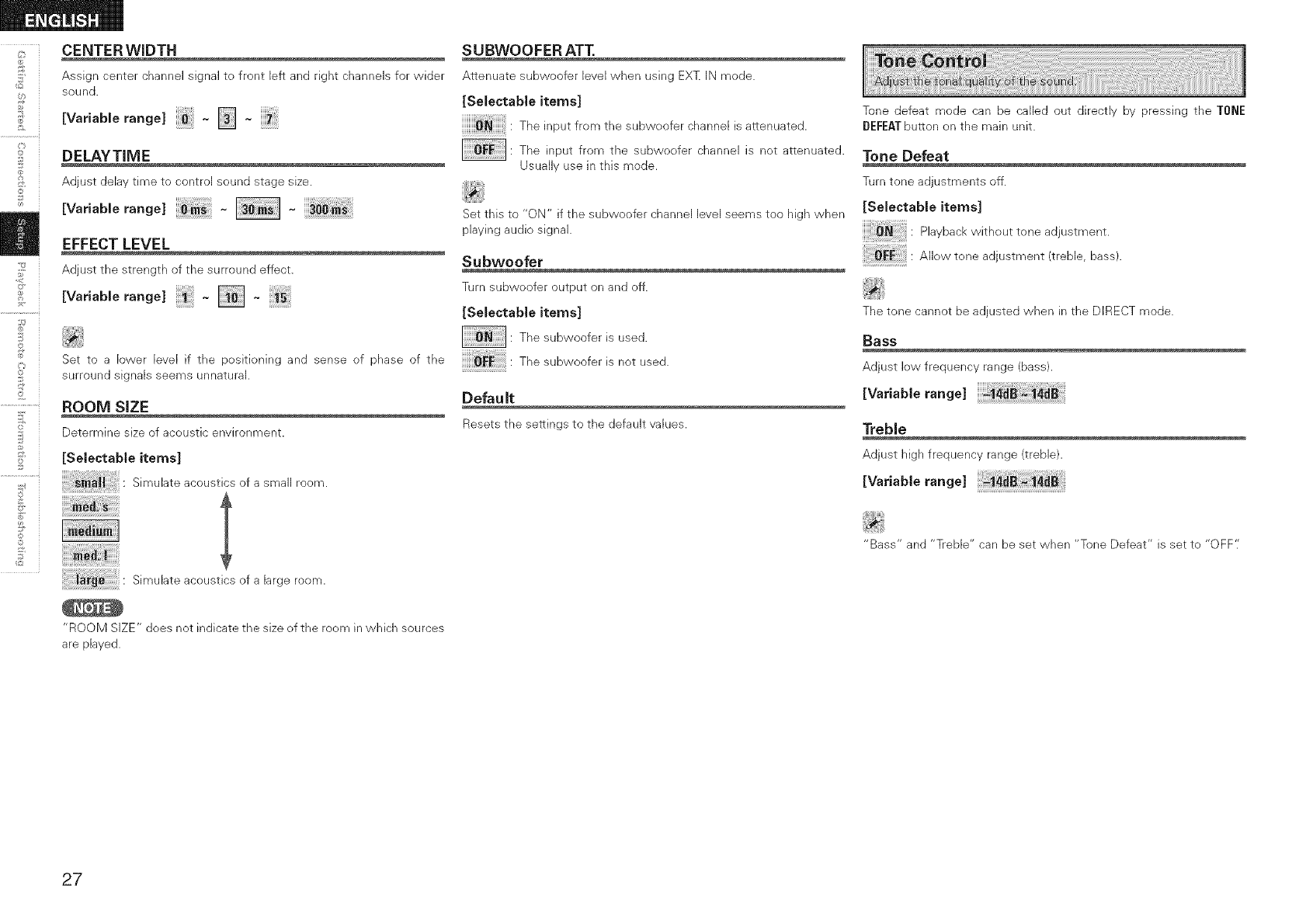
CENTER WIDTH
Assign center channel signal to front left and right channels for wider
sound.
EVa. b erange]- [] -
DELAYTIME
Adjust delay time to control sound stage size.
[Variable range] ~~
EFFECT LEVEL
Adjust tile strength of the surround effect.
Evoriob,orang<
©
©
_2
Set to a lower level if the positioning and sense of phase of the
surround signals seems unnatural.
ROOM SIZE
Determine size of acoustic envhonment.
[Selectable items]
S_muhteacousticsofasmaUroom.
Simuhte acoustics efa large room.
SUBWOOFER ATT.
Attenuate subwoofer level when using EXZ IN mode.
[Selectable items]
The input from the subwoofer channel is attenuated.
: The input from the subwoofer channel is not attenuated.
Usually use in this mode.
Set this to "ON" if the subwoofer channel level seems too high when
playing audio signal.
Subwoofer
Turn subwoofer output on and off.
[Selectable items]
: The subwoofer is used.
The subweefer is net used.
Default
Resetsthe settings to the default values.
Tone defeat mode can be called out directly by pressing the TONE
DEFEATbutton on the main unit.
Tone Defeat
Turn tone adjustments off.
[Selectable items]
Playback without tone adjustment.
AHow tone adjustment (treble, bass).
The tone cannot be adjusted when in the DIRECT mode.
Bass
Adjust low frequency range (bass).
[Variable range]
Treble
Adjust high frequency range (treble).
Wo.ob,eronge
"Bass" and "Treble" can be set when "Tone Defeat" is set to "OFF':
"ROOM SIZE" does not indicate the size of the room in which sources
are played.
27
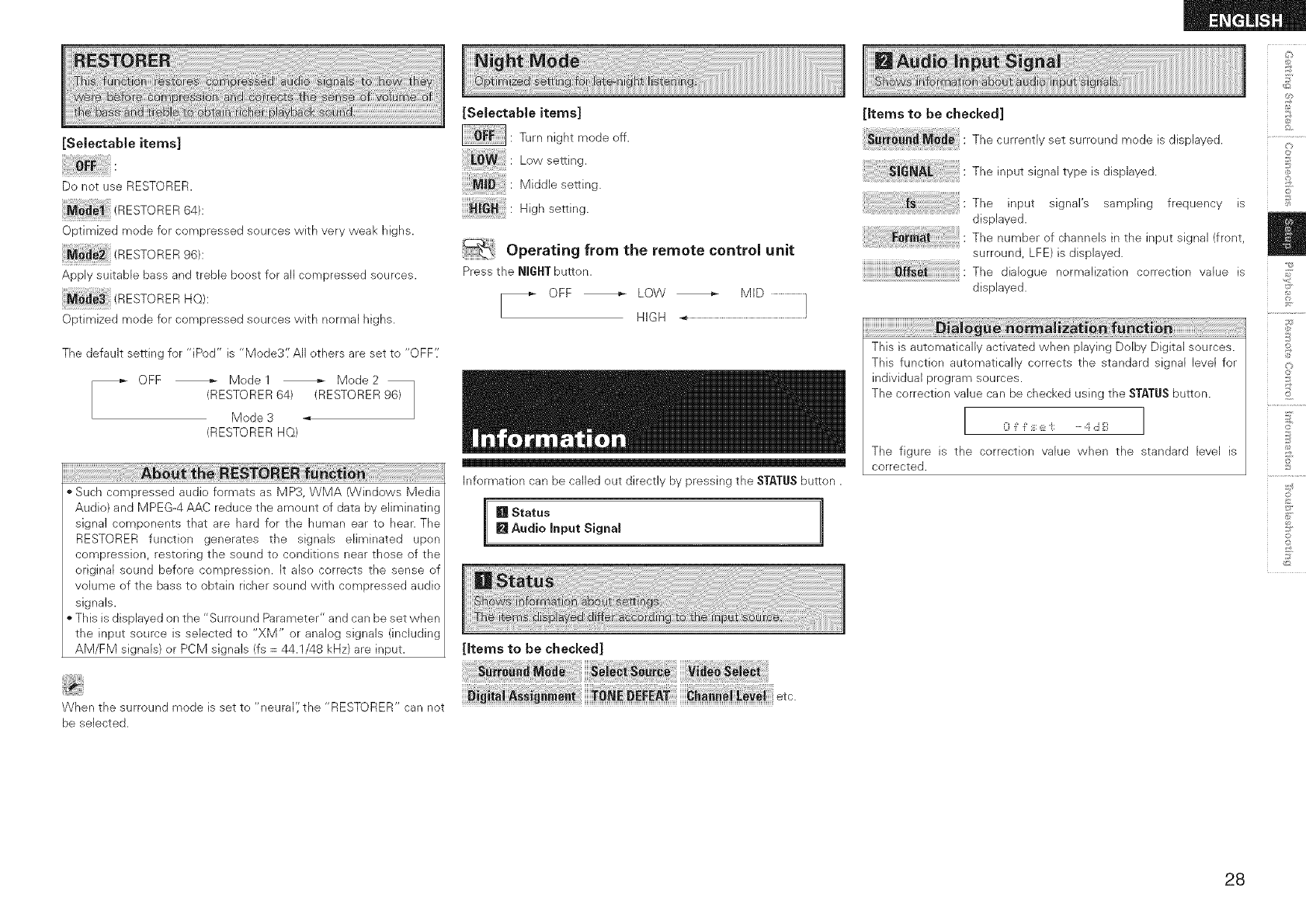
[Selectable items]
Do not use RESTORER.
_ _ (RESTORER64):
Optimized mode for compressed sources with very weak highs.
ESTORER96 :
Apply suitable bass and treble boost for all compressed sources.
(RESTORER He):
Optimized mode for compressed sources with normal highs.
The default setting for "iPod" is "Mode3'.' All others are set to "OFF'.'
_ OFF _ Model Mode2
RESTORER 64) (RESTORER 96)
/
Mode 3 _
RESTORER HQ)
Such compressed audio formats as MP3, WMA (Windows Media
Audio) and MPEG-4 AAC reduce the amount of data by eliminating
signal components that are hard for the human ear to hear. The
RESTORER function generates the signals eliminated upon
compression, restoring the sound to conditions near those of the
original sound before compression. It also corrects the sense of
volume of the bass to obtain richer sound with compressed audio
signals.
This is displayed on the "Surround Parameter" and can be set vvhen
the input source is selected to "XM" or analog signals (including
AM/FM signals) or PCM signals (fs = 44.1/48 kHz) are input.
[Selectable items]
: Turn night mode off.
: Low setting.
: Middle setting.
: High setting.
Operating from the remote control unit
Pressthe NIGHTbutton.
[_ OFF _ LOW _ MID .........................}
HIGH -_.........................................................................................
Information can be called out directly by pressing the STATUSbutton.
[] Status ]
[] Audio Input Signal
[Items to be checked]
[Items to be checked]
Thecurrentlysetsurroundmode d sp ayed.
Theinputsignaltypeisdisplayed,
The input signal's sampling frequency is
displayed.
The number ofchannelsinthe inputsignal(flont,
surround,LFE) isdisplayed.
The dialogue nolmalizationcenection value is
displayed.
This is automatically activated when playing Dolby Digital sources.
This function automatically corrects the standard signal level for
individual program sources.
The correction value can be checked using the STATUSbutton.
3
0 i: i: !!:(,-i:: ...._i8 iii', ]
The figure is the correction value when the standard bvel is
corrected.
£
©
@
£
©
o
©
When the surround mode is set to "neural'i the "RESTORER" can not ...................................................................................................................................................................................................................................
be selected.
28
©
©
"£
©
2
©
©
_2
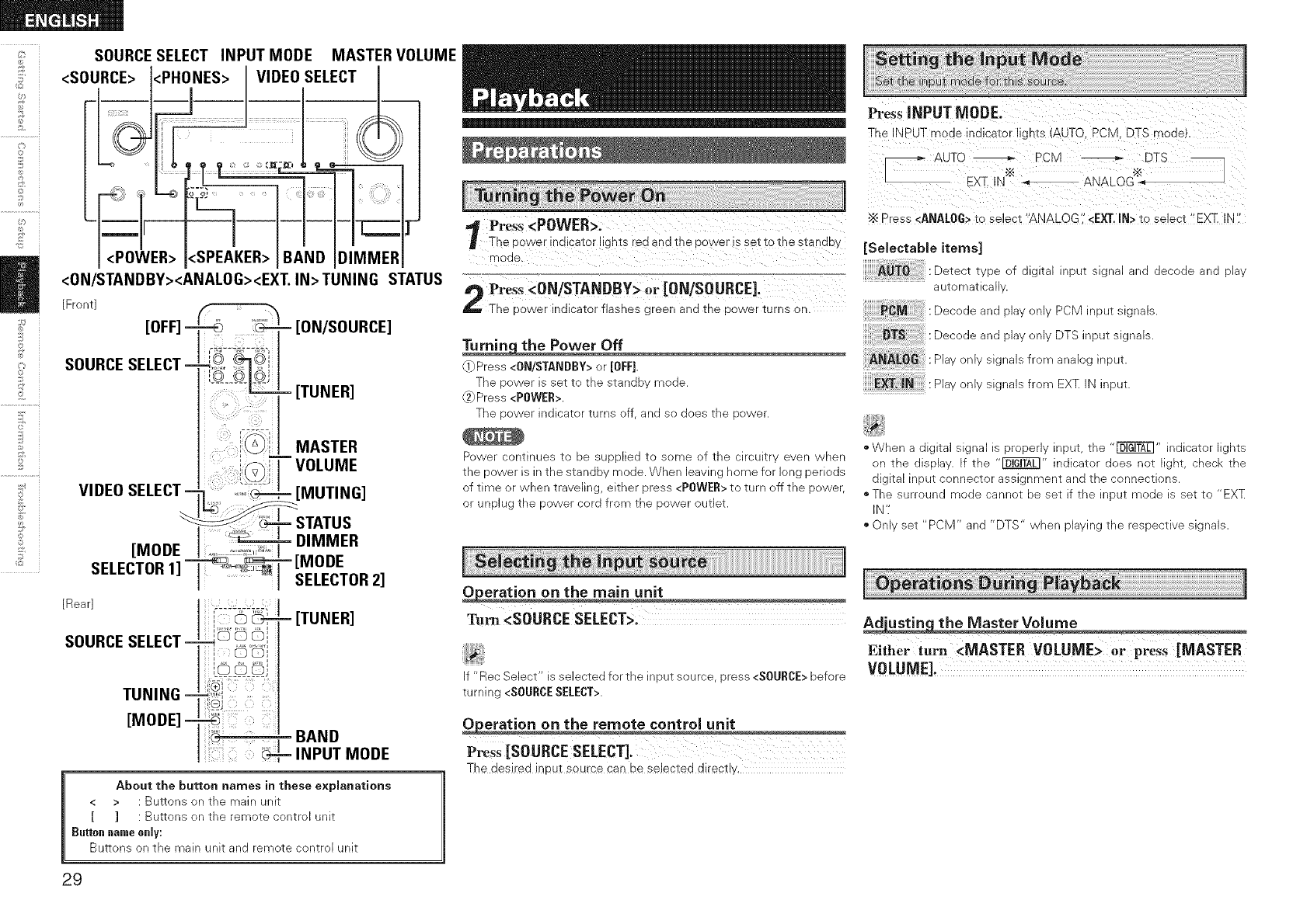
SOURCESELECT INPUT MODE MASTER VOLUME
<SOURCE> <PHONES> VIDEO SELECT
<POWER> <SPEAKER> DIMMER
<ON/STANDBY><ANALOG><EXT. IN>TUNING STATUS
[Front]
ON/SOURCE]
[TUNER]
MASTER
VOLUME
MUTING]
About the button names in these explanations
< > : Buttons on the main unR
[ ] : Buttons on the remote control unit
Buttoin Inameonly:
Buttons on the main unit and remote control unit
Press <POWER>.
The cower indicator IIgr [s rec1 an(3 Ine eo\A!er is set io 1[ne stanaD_/
WlOCI_
Pre_s <ON/STANDBY> or [ON/SOURCE]_
The _ower indicator flashes green and the Dower turns or-
i[Press <ONISTANDBY> or [OFF]
The ")ower is se[ _o The stance moae
Press <POWER>
The sower inalcator Turns ff aria so aces tne¢ :)we(
Power commues _c De SUeDIleo to some of _ne Nrcugl . even wnen
The Dower is hline stanc1D _ mode. When leaving ome for long PerioDs
}f time )r wnen _raveung, either )ress <P[}WER> to tur off the eower
}r unplug tne power cora from the Dower OUTleI
Tu_ <SOURCE SELECT>.
f "Rec Select s selected for the inpu_source press <SOURCE>before
turning <SOURCESELECT>.
P_S_ [SOURCE SELECT].
The desired input source can be selected directly,
Press INPUT MODE.
The NPUT mode indicator lights (ALTO. PCIVl. DTS mode).
_ AUTO _ PCM DTS
- EXZ IN"" &IX_LOG':&_
Press <ANALOG>to select "ANALOG <EXT.IN> to select "EX]_ IN
[Selectable items]
AUTO Detect tw)e of slggal neu_ slgna _na lecoqe ana elav
PCM
DTS
ANALOG
EXT.iN
aLgomatlca
Decode and Nav onw PCM input signals
Decode and slav onw DTS ineut signals
Piav nly signals from analog input
Plav )nly signals from EXT N neuT
*When a a _l_a slgna is erode nr u_ _ne "_ "/alCaTor [.jnTS
on The ]lSCla z The _" nalca[or aoes not IgnT, cnecb The
algga hou_ connector assignment ana _ne connections
.The surround moae }annoT De SeT •tne neuI moae s SeT Ic "EX_
N
On set "PCM and "DTS" when Naymg _ne reseec[we slg _als
Either turn <MASTER VOLUME> or press [MASTER
VOLUME].
29
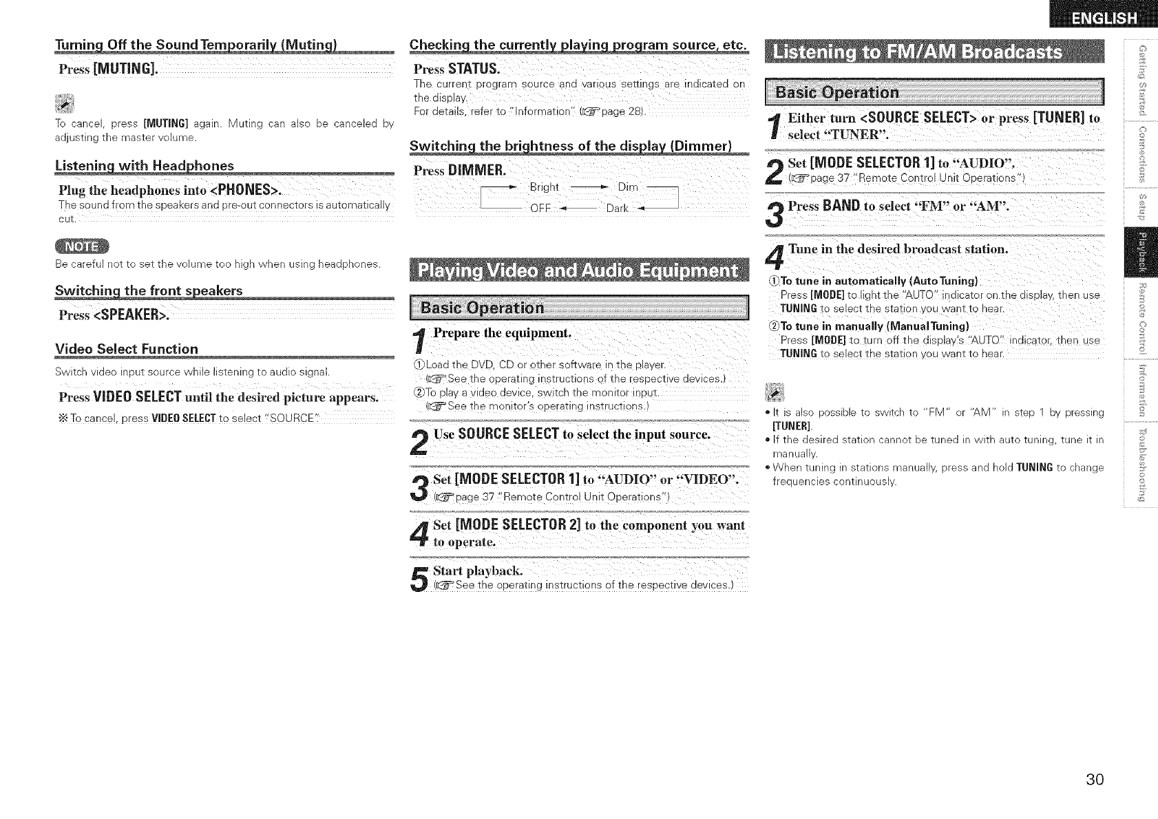
Press[MUTING].
J_
Tc :ancel oress [MUTING] agan Muting can also se :anceleo ov
adjusting me mas_er volume
Plug the headphones into <PHONES>.
The sound from the speaKers and pro-our conneciors is auiorNaiicall ,
Be carefu net _( set The volume Tee mgn when usm _ nea(]pnones
Press <SPEAKER>.
Video Select Function
3witch video _ 3u_ source wnHe stenlng -[o audio signa_
Press VIDEO SELECTuntil the desired picture appears.
"_ To cancel oress VIDEOSELECTto select "SOURCE'
Press STATUS.
The current prograrY_ _ou[ce an(] vanous se[[Jngs _r@ ^]lcaTe(] or
tne (]replay
For details refer to "Information" ',_= aage 28
Press DIMMER.
_ Bngnl _ Dim _
3FF Dark _'_
Prepare the equipment.
,f_Load the D\ D. CD or other software _tne player
_:_='See 1:noopera_:lng instructlor s of the res(]e twe (]evlces.
,_To play a vl(]eo (]evlce. sw _cntne monl[or 1DUI,
See The moniTor S operatinginsTrUCTiOns
)Use SOURCESELECTto select the input source.
Set [MODE SELECTOR1] to "AUDIO" or "VIDEO".
(_page 37 "Remote Control Unit ODerat ons"
Set [MODE SELECTOR2] to the component you want
to operate,
Start playback.
(_:_See the operating nstructions of the respectwe (]ewces.
,_ Either turn <SOURCE SELECT>or press [TUN ER]
/ select "TUNER".
Set [MODE SELECTOR1] to "AUDIO".
(_=_page 37 "Remote Cent 3[ Unit C _>eradons"
Press BAND to select "FM" or "AM".
4_[une in the desired broadcast station.
]_)To tune in automatically [AutoTuning}
Pres_ [MODE] to light the "AUTO -l(]lcator on tne (]lsDla ,, tnen use
TUNING to select the station you want to near.
To tune in manually (IVianuaiTuning)
Pres_ [MODE] _o turn Dff the (]lsplay's "AUTO" in(]lcator, tnen use
TUNING to select the s[atlon ,ou want _o near
1
to
•g S also OOSSIDle IO swl_cn IC FM -" "AM" _ SIeD DV pressing
[TUNER].
• [f the (]eslre(] s_atlen cannot De Tune(] _" A/IU auto TunIP_, Tune IT. In
manu8
•When tunng Ins_a_Ionsmanua Dressan(] oldTUNING To cnanje
freeuencies conunuous
©
©
<L
©
3O
<SOURCE SELECT> SHIFT STATUS
_L
©
©
<PRESET CHANNEL> TUNING
[Front]
©
2
©
©
_2 [Rear]
SHIFT [CHANNEL]
i[SAT TU]
[MODE =
SELECTOR1]
i iiiii] !
- STATUS
About the button names in these explanations
< > : Buttons on the main unit
[ ] : Buttons on the remote control unit
Buttonnameonly:
Buttons on the main unit and remote contro[ unit
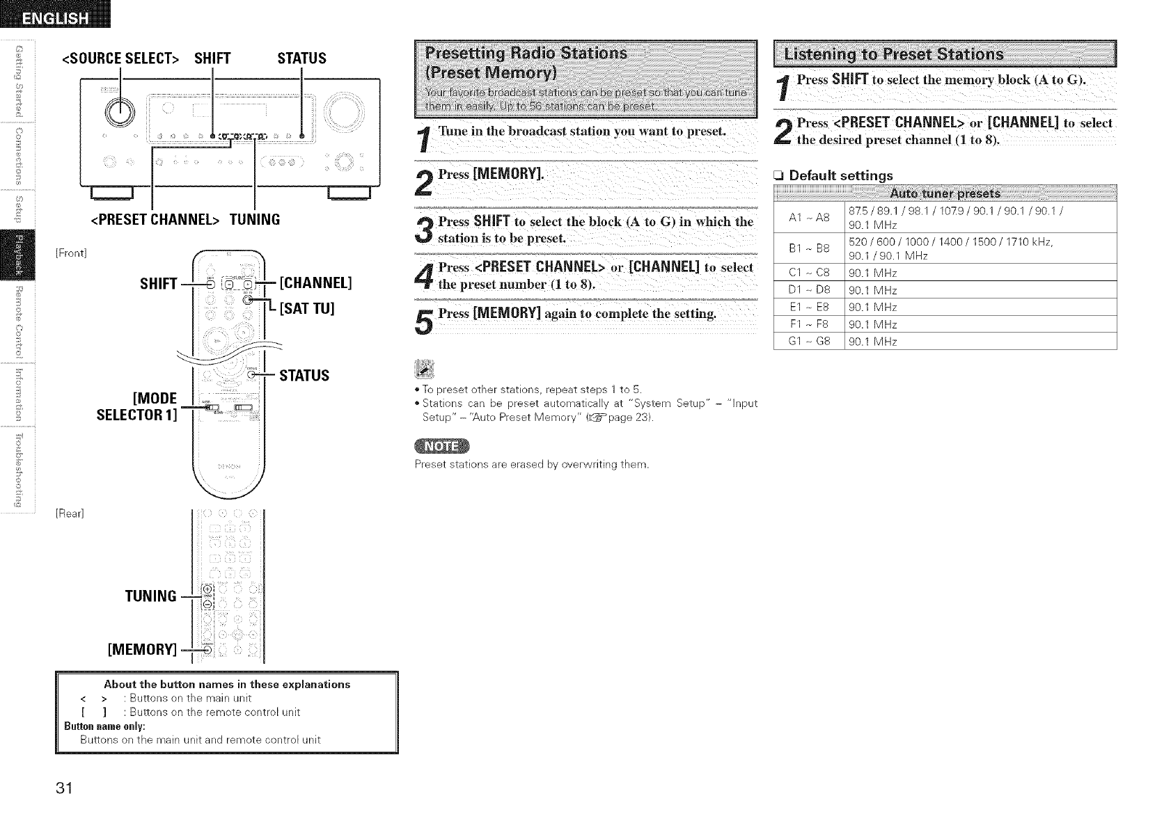
Press SHIFT to select the memory block (A to G,.
Tune in the broadcast station you want to preset. Press <PRESET CHANNEL> or [CHANNEL] to select
the desired preset channel (1 to 8_.
Press [MEMORY].
a_ Press SHIFT to select the block 4A to G) in which the
station is to be preset.
[_ DefauJt settings
AUto tuner presets
A1 _A8 875/891/93.1/10_9/901/90.1/90.1/
90.1 MHz
BI--B8 520/600/lO00/1400/1500/1710kHz,
90.1 /90.1 MHz
Press <PRESET CHANNEL> or [CHANNEL] to select Cl _ CS
the preset number (1 to 8). D1 _ D8 90.1 MHz
90.1 MHz
Press [MEMORY] again to complete the setting. E1 -- E8 90.1 MHzF1 -_F8 90.1 MHz
G1 _ G8 90.1 MHz
•To _resei omer s_at[ons reeeaT steps 1 to 5
• Stations can De 3reset _utomaTteal _l "S_em Setle
SetuE " - "Auto Preset Memory" (_page 23
neul
Preset siaT[ons are eraseu D_ werwrmng Them
31
ABOUT XM RADIO
XM Radio offers an extraordinary variety of commercial-free music,
plus the best in premier sports, news, talk radio, stand-up comedy,
children's and entertainment programming. XM is broadcast in superior
digital audio from coast to coast. From rock to reggae, from classical to
hip hop, XM has something for every music fan. For U.S. customers,
information about XM Radio is available online at www.xmradio.com.
For Canadian customers, information about XM Canada is online at
www.xmradio.ca.
XlVl READY@ LEGAL
XM monthly service subscription sold separately. XM Mini-Tuner
and Home Dock required (each sold separately) to receive XM
service. Installation costs and other fees and taxes, including a one-
time activation fee may apply. All fees and programming subject to
change. Channels with frequent explicit language are indicated with
an XL. Channel blocking is available for XM radio receivers by calling
1-800- XMRADIO (US residents) and 1-877-GETXMSR (Canadian
residents). For a fuji listing of the XM commercial- free channels and
advertisingsupported channels, visit ]ineup.xmradio.com (US residents)
or xmradio.ca (Canadian residents). Subscriptions subject to Customer
Agreement available at xmradio.cem {US residents) and xmradio.ca
(Canadian residents). Only available in the 48 contiguous United States
and Canada. @2007 XM Satellite Radio Inc. All rights reserved. All
other trademarks are the property of their respective owners.
XIVI READY@ SUBSCRIPTIONS
Once you have installed the XM Mini-Tuner Dock, inserted the XM
Mini-Tuner, connected the XM Dock to your XM Ready@ home audio
system, and installed the antenna, you are ready to subscribe and
begin receiving XM programming. There are three places to find your
eight character XM Radio ID: On the XM Mini-Tuner, on the XM Mini-
Tuner package, and on XM Channel 0. Record the Radio ID in the
following eight squares for reference. rTr9
Note: The XM Radio ID does not use the letters "1'/ "0'; "S" or
"F'/ Activate your XM Satellite Radio service in the U.S. online at
7_cb ac_wa_e.xmradlo.cort ca -800-XM-RADIC -800-967-
2346 Activate our XI\ Satelhte Radio serwce _" Canada onune at
_CDS:/acTwate.xmradlo.ca or ca -877-GET-XMSR -877-438-9677
eL w need 3 majol credit sara x'M wl send 3 slgna fror_ The
satellites _o activate the fu cnanne neuD Activation nnrma _aKes
0 tc 15 minutes DUT aunt" _ peak Dusy Denoas vou mav eed t( Keep
_our Xk Read' qomeaua svstem on for Jetoan nour. Vher you
can access the fu qeuD on our XM Read me audio S s_em vou
are done
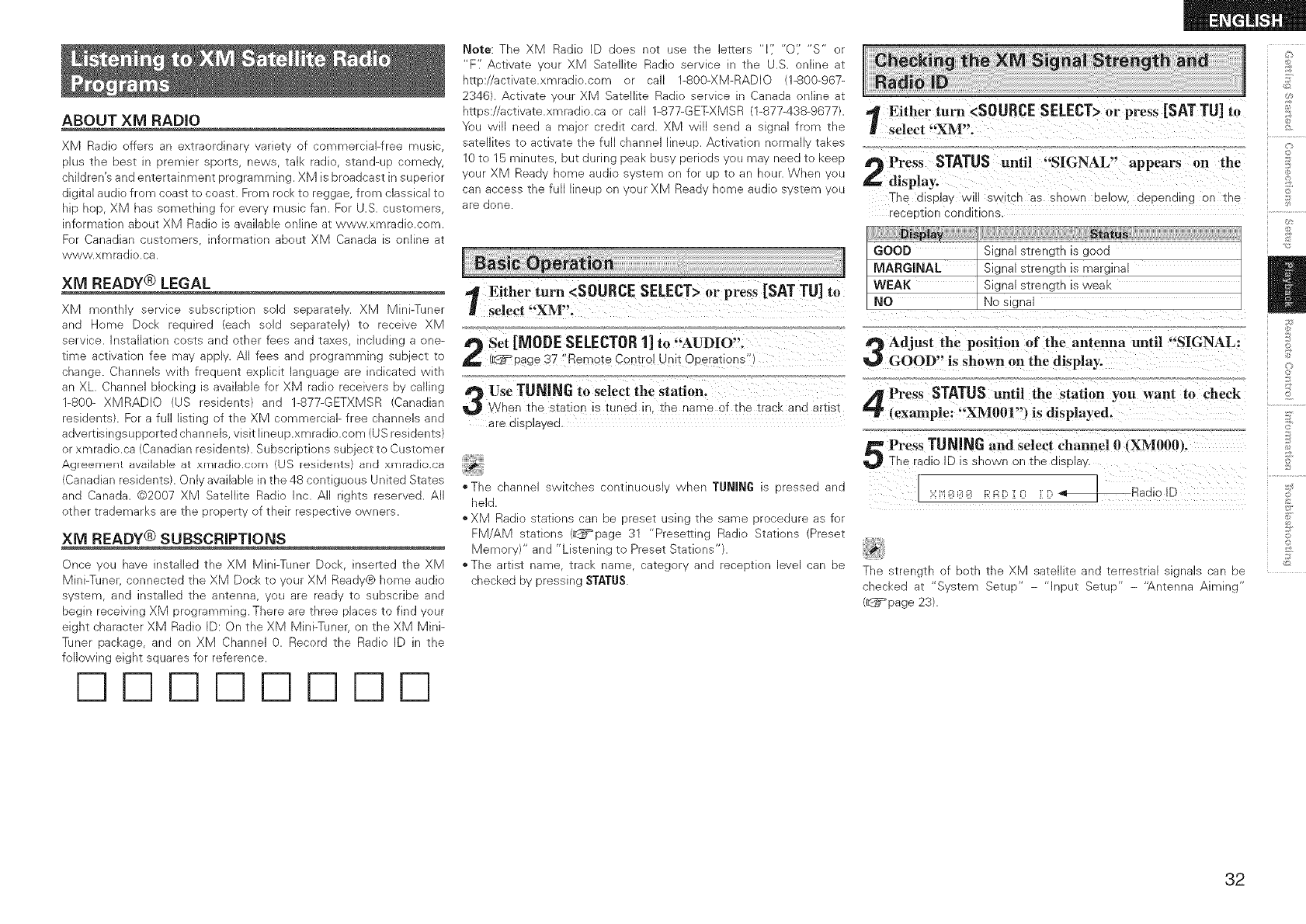
Either turn <SOURCE SELECT>or press [SAT TU] to
select "XM'.
Set SELECTOR1] to "AUDIO".
[MODE
(_Tpage 37 "Remote Control Unit Operations"
Use TUNING to select the station.
W/hen the statior s tuned in. the name of the track and artist
_re olsplayed
"The cnanne SWiTcnes commuous wner TUNING :_c essea and
rleld
*XM Radio s'Ea_lons can De _. eseT using The same orocedure _s for
FM AM s_a_lons _page 31 Presetting Radi Stations (Preset
Memer and ustenmg to Preset Stations
€The artist name _racl< ame caTegory and receetlon eve sa De
checked by pressing STATUS.
Either turn <SOURCE SELECT>or press [SM TU] to
select "XM".
Press STATUS until "SIGNAL" appears on the
,display.
The display wn SWITChas ShOWn below depending on tne
"eceotlon conditions
GOOD Signal strength is good
MARGINAL Signal strength is marginal
WEAK Signal strength is weak
NO No signal
Adjust the position of the antenna until "SIGNAL:
GOOD" is shown on the display:
Press STATUSuntil the station you want to check
(example: "XM001") is displayed.
Press TUNinG and select channel 0 XM000/.
The radio ID is shown on the display.
_;:__;:__;:_i_'i:Er:,r ni r: _Radio ID
The s_reng_n of Down _ne XM sa'EellRe and _erreswla Big lois ?an De
checked at "System Setup" - "Input Setup" - '_.ntenna Aiming"
(_page 23).
©
o
£
©
_S
£
d
o
@
S
32
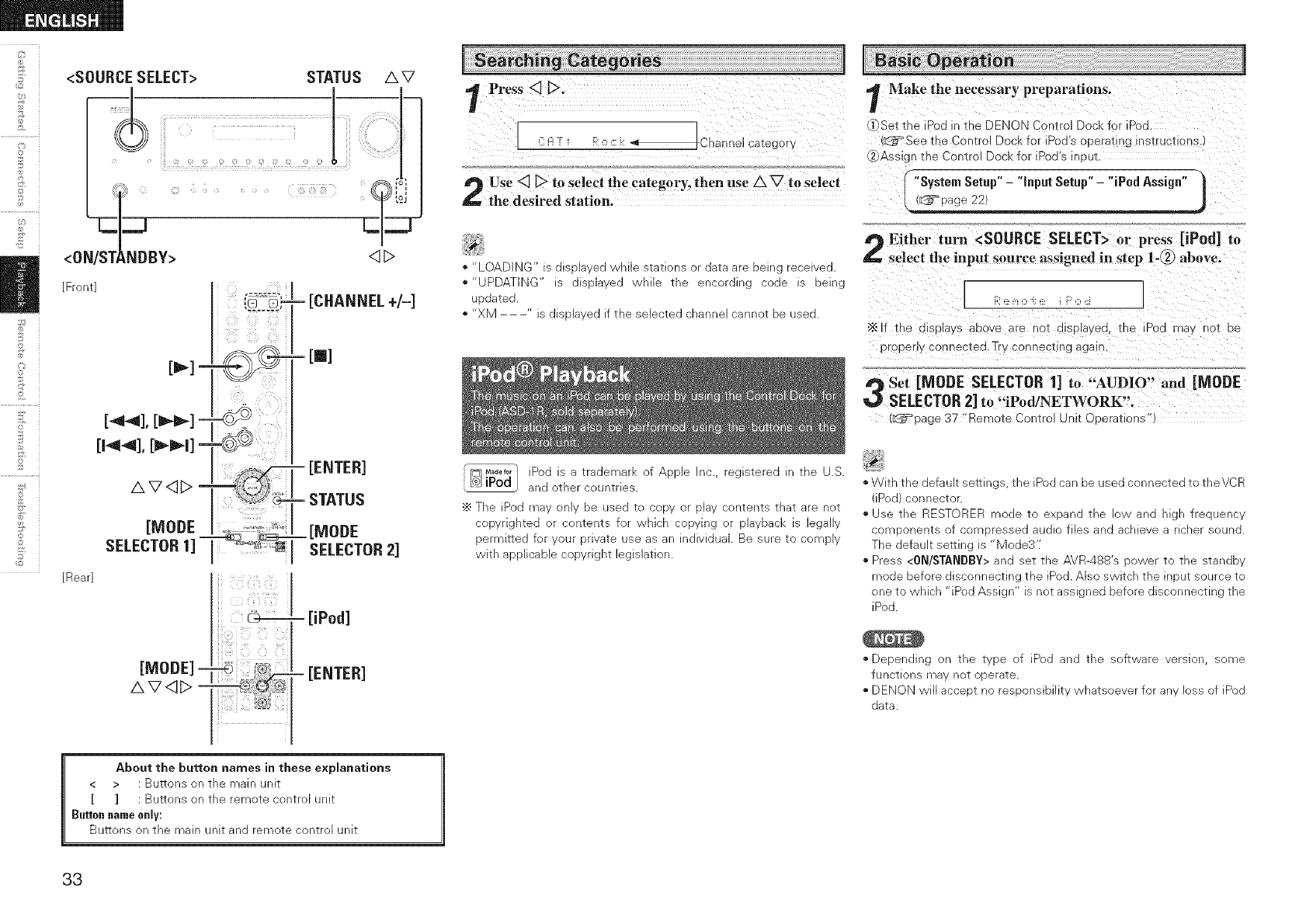
ii <SOURCESELECT> STATUS
ii!
AV
[Front]
[Rear]
[iPod]
[ENTER]
Press <] D.
_m[ChanneJ categor_
Use <__ to select the category, then use AV to select
the desired station.
•"LOADING" s alsola\ eo wnlle stations or oata are being recewea
•"UPDATING" s alselavea While me encorulnj coae 3 Delhi
DoaTeo
" "XM s ulsolavea if the selected channel cannot oe usea
its}M_a._or Sod _ _ traueman of ADDle hC reg stereo " me U.S.
® iPod ano )_ner counTHe5
÷ The Poc [T]av on De Jseo "[o ?ODV )r DlaV conIenIs ThaT are _OT
copyrlgnTeo DI :omems for wnlcr copying )r ola DaCI_ S egauy
t)ermlHeo z_. Moor orlva_e use as ar nOlVlOU8 Be sure t(_ cow 91
V_/ITn a )DIICaole copyrlgm eg _laIIOP
Make the necessary preparations.
.i- Set the IPod _n_he DENON Contro Dock for iPod
d_b:_Seethe C_n[rol Dock for iPoa s operat_n¢ ns_rucxlons.
_Ass -3nthe Control Dock for iPod's ir ouL
"System Setup" -"input Setup" -"iPud Assign" I
(_ vage 22) j
Either turn <SOURCESELECT>or press [iPod] to
select the input source assigned in step 1-(_) above.
[...........1
"_lf the a splays aoc_e are no_ alsplayea. _he iPod ma', no_ oe
o )peny connected.Try connecting aga-
a,_ Set [MODE SELECTOR1] to "AUDIO" and [MODE
_,_ SELECTOR2] to "iPod/NETWORK'.
(d_= page 37 "Remote Control Unit Coerations"
*With the default serrln d s _ne Sod can De used connected to theVCR
Pod connec_ol
use me RESTORER moae _o exoano me swana nigh freouencv
comoonenis f somoressea aua files and achieve a ncner souno
]-he default semng s Vlode3'[
Press <0N/STANDBY> and set me AVR-488's )ower _o me s_anao,.
mode before disconnecting the iPod. Also switch the ir ou_ source _o
one to which "iPod Assign" is not assigned before disconnecting the
iPod.
*Depending on the type of [Pod and the software version, some
functions may not operate•
DENON will accept no responsibility whatsoever for any Joss of iPod
data.
About the button names in these explanations
< > : Buttons on the main unit
[ ] : Buttons on the remote control unit
Button name only:
Buttons on the main unit and remote control unit
33
=1 Press [MODE] for2 Seconds or more, to change from
Rem0te Mode to Browse Mode'
(iPodscreen)
use [a_] t. Selectthe item; then press [ENTER] Or
[D] to select the music fi!e robe played,
PreSs[ENTER] or [_]-
Playback starts.
Stopping playback temporarily
During playback, press [ENTER]or [1_].
Press again to resume playback.
Fast-forwarding or fast-reversing
During playback, either press and hold [A] (to fast-reverse) or [V] (to
fast-forward), or press [44] or [_,-_-].
To cue to the beginning of a track
During pByback, either press [A] (to cue to the previous track) or [V]
(to cue to the next track), or press [144] or [_-_l].
To stop
During playback, either press and hold [ENTER]or press [m].
Playing repeatedly
Press [CHANNEL-].
ESo,ectab,eitom<
Shuffling playback
Press [CHANNEL+].
ESolectableitom<
To switch between the Browse and Remote modes
Either press and hold [MODE].
N
*The title name, artist name and album name can be checked by
pressing STATUSduring playback.
*On the AVR-488, folder and file names can be displayed as titles. Any
characters that cannot be displayed are replaced with " . (period)'[
1Priii and hold [MODE]tO iet the Remote modei
Watching the iP0d's screen, use [/k_] t£ Select
"Photos" or _Wideos",
Press[ENTER] _til the imag e you want to view is
displayed,
o
@
©
@
£
©
o
©
"TV Out" at the iPod's "S[ideshow Settings" or "Video Settings" must
be set to "On" in order to display the iPod's photo data or videos on
the monitor. For details, see the iPod's operating instructions.
34
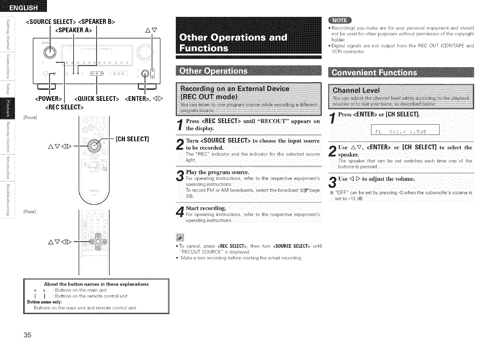
©
©
©
2
<SOURCE SELECT><SPEAKERB>
<SPEAKERA> I AV
<RECSELECT>
©
AV <]1> :
[Front]
ii _, '_,_ix_i_'_!i
_!_iii_(ii(iiil))((!_iii(iiiiii!i_ ii
-[CH SELECT]
[Rear]
AV<_I> -
*Recordings you make are for your personal enjoyment and should
not be used for other purposes without permission of the copyright
holder.
. Digital signals are not output from the REC OUT (CDR/TAPE and
VCR) connector.
Press <REC SELECT> mltil "RECOUT" appears on
the display.
Turn <SOURCE SELECT>to choose the input source
to be recorded,
The "_EC" indicator ana me ina cator for the selected source
llgnt.
Play the program source.
For oeerating qstruc_ior _ refer to tne esDec_ ve eau oments
operal;mg nstruciions,
To record FM or AM broaacasts select the broadcast {_:3_page
3C
Press <ENTER> or [CH SELECT], ]
Use AV. <ENTER> or [CH SELECT] to select the
_speaken
The seeaKer mat :ar oe sei swlicnes eacn time one of the
DU_QnS 5 9ressea
Use <3 [> to adjust the volume.
OFF _'anbe set by pressu_g <3 when the subwoofer's olume is
set to -12 dB.
Start recording.
For oEerating qstrucrlon_ refer tc me resoectwe eauloments
opera':ins nstructlons.
*To cancel, press <REC SELECT>,then turn <SOURCESELECT> until
"RECOUT SOURCE" is displayed.
*Make a test recording before starting the actual recording.
About the button names in these explanations
< > : Buttons on the main unit
[ ] : Buttons on the remote control unit
Button name only:
Buttons on the main unit and remote control unit
35
Set the input SOurce, input mode, Surr0_d mode and
vol_e to the conditions you want to store,
9Press and hold <QUICK SELECT> umi! !!MemOry:!
appears on the display.
Quick Select 1
Quick Select 2
Quick Select 3
[Quick Select Defaults]
Input Source
DVD/HDP
TV/CBL
VCR
Volume
40 dB
40 dB
40 dB
Te ca[[ out the settings, press <QUICK SELECT>at which the desired
settings were stored.
The surround parameters, tone central and the vohmes of the different
speakers are stored for the individuaJ surround modes.
1Turn offthe powec using<POWER>:
Press <POWER> while Simultaneously pressing
g., <SPEAKERA> and <SPEAKERB>.
Oncethe display Starts flashing at interYal s of about !
second, release the two buttons.
If in step 3 the dispBy does not flash at intervaJs of about 1 second,
start over from step 1.
O
@
©
@
£
©
o
©
36
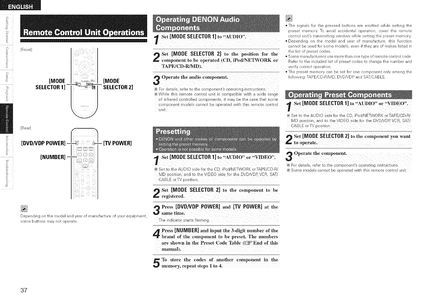
_L
©
©
[Front]
[MODE [MODE
SELECTOR1] "T_ _ra SELECTOR2]
©
©
_2
[Rear]
[DVD/VDP POWER] ...................
(33
!
iiii i
-[I"V POWER]
Depending on the model and year of manufacture of your equipment,
some buttons may not operate.
Set [MODE SELECTOR1] to "AUDIO".
Set [MODE SELECTOR 2] to the position for the
component to be operated (CD. iPod/NETWORK or
TAPE/CD-R/MD _.
Operate the audio component.
•_ For details, refe io the corneonent 3 operating hsiruciions.
"_ NhlJe this "emote coNIroI URT IS cOr'NDaIIDle vvltn a Wide I_nge
OTIr Trared controlled components, i_ ma, De the case tna[ some
componenT models cannei De operated /vltn ThiS remote 3oniro
UNIT.
Set [MODE SELECTOR1] to "AUDIO" or "VIDEO".
Set to the AUDIO side for the CD. iPod/NETWORK orTAPE/CD-R
MD oosmon, ana to the VIDE D sloe for the DVDNDR VCR SAT
3ABLE orTV Dosmon.
Set [MODE SELECTOR 2] to the component to be
registered.
Press [DVDNDP POWER]and [13/ POWER]at the
same time.
The indicator starts flashinc
Press [NUMBER] and input the 3-digit number of the
brand of the component to be preset. The numbers
are shown in the Preset Code Table (_End of this
manualt.
To store the codes of another component in the
memory, repeat steps 1to 4.
,,The SigNalS z_ TNe dressed DU_[ONS are emitted _/nlle :_e_lNg the
eseT memol. To avoid aooldenTa operation cover the rerno_e
CONTrOl JNIIS transmlEing vvIndov_ While seT[ing the :)reset memor
','Depending rne "T_Odeland eal _f manufacture _nls function
cannot De used for some models ever if the' are )f makes szed In
[ne IISI _ 9reset COdeS
. Some manufacturers use more than one I )e of remote control code
Refer t Tne ncluded gt o1 -)rese_ codes _o cnange _ne number and
verif correc_ oDerazion
The Drese_ memo_ ca De se_ for one :on' DONeNTonly among The
following: TAPE/CD-R/MD DVE/VDP and SAT 3ABLE
Set [MODE SELECTOR1] to "AUDIO" or "VIDEO".
Set _o me AUDIO s_aeTor _ne CD Pod/NETWORK orTAPE/CD-R
MD Dos :ion. and to the VlDEC slae Tor _ne DVDNDP VCF. SAT/
CABLE orTV dosl[Ior
f_ Set [MODE SELECTOR2] to the component you want
to operate.
Operate the component.
For aeiallS refer to the COrdponent s operating insiructlons
Some modelS cannoi De C 3eraiea vvim IBIS remo[e conirol unlL
37
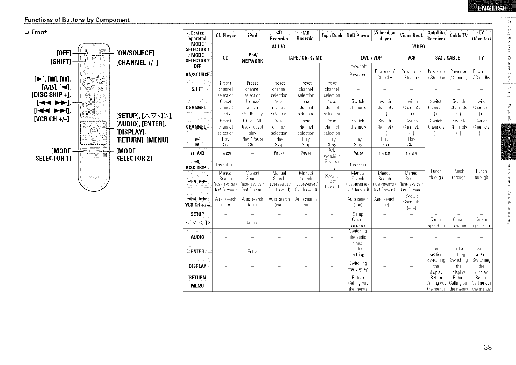
Functions of Buttons b Corn orient c_
Front
,OFF,
[SHIFT]
[=,,,-],[m],[it],
[A/B], [_l],
[DISC SKIP +],
[44 _i_], =
[144 I_l_I],
WCR CH +I-]
[MODE =
SELECTOR1]
_===
=[ON/SOURCE]
- [CHANNEL +/-]
[SETUP], [A V<:]b>],
[AUDIO], [ENTER],
[DISPLAY],
[RETURN], [MENU]
- [MODE
SELECTOR2]
Device
Operated
MODE
SELECTOR1
MODE CD
SELECTOR2
OFF
0N/S0URCE
Preset
SHIFT channel
selection
Preset
CHANNEL+ channel
selection
Preset
CHANNEL_ channel
selection
_- Play
[] Stop
||, AID Pause
_1, Discskip +
DISC SKiP + Manual
Search
4,.4 _ID,, fast-reverse/
fast-forward}
1-_,,4 l_,_lD_l Auto search
VCRCH÷/_ (cue)
SETUP
AUDIO
ENTER
DISPLAY
RETURN
MENU
' CB MB
CDPlayer iPed TapeDeck
Recorder Recorder
AUDIO
iPod/
NETWORK
Preset
channel
selection
1-track/
album
shuffleplay
1-track/AIb
trackrepeat
play
Play/Pause
Stop
Manual
Search
fast-reverse/
fast-forward)
Auto search
(cue/
Cursor
Enter
TAPE/CD-R/MD
Preset Preset
channel channel
selection sebction
Preset Preset
channel channel
selection sebction
Preset Preset
channel channel
selection selection
Play Play
Stop Stop
Pause Pause
Manual Manual
Search Search
fast-reverse/ fast-reverse/
fast-forward} fast-forward)
Autosearch Auto search
(cue) (cue}
Preset
channel
sdection
Preset
channel
sdection
Preset
channel
sebction
Play
Stop
A/B
switching
Reverse
play
Rewind
Fast
forward
V!d°ed!s"WdeeDeCkSo,e,.oD", eTV TV
BVD Player p ayer Rece ver (Monitor)
VIDEO
DVD 'VDP
Poweroff
Poweron /
Poweron Standby
Switch Switch
Channeb Channels
I+/ (4
Switcll Switch
Channeb Channels
() (/
Play Play
Stop Stop
Pause Pause
Discskip
Manual Manual
Search Search
(fast-reverse/ (fast-reverse/
fast-forwardl fast-forward}
Auto search Auto search
(cue) (cue/
Setup
Cursor
operation
Switching
the audio
signal
Enter
setting
Switching
the display
Return
Callingout
the menus
VCR
Poweron /
Standby
Switch
Channeb
1+/
Switch
ChanneB
Play
Stop
Pause
Manual
Search
(fast-reverse/
fast-forward}
Switch
ChanneB
{,+/
SAT /CABLE TV
Poweron Poweron Poweron
/Standby /Standby /Standby
Switch Switch Switch
Channeb Channeb Channeb
1+/ {+) {+)
Switcil Switch Switch
Channels Channels Channels
() () ()
Punch Punch Punch
through through through
Cursor Cursor Cursor
operation operation operation
Enter Enter Enter
setting setting setting
Switching Switching Switching
the the the
display display display
Return Return Return
Callingout Callingout Callingout
the menus the menus the menus
o
©
£
©
d
©r
o
Z
38
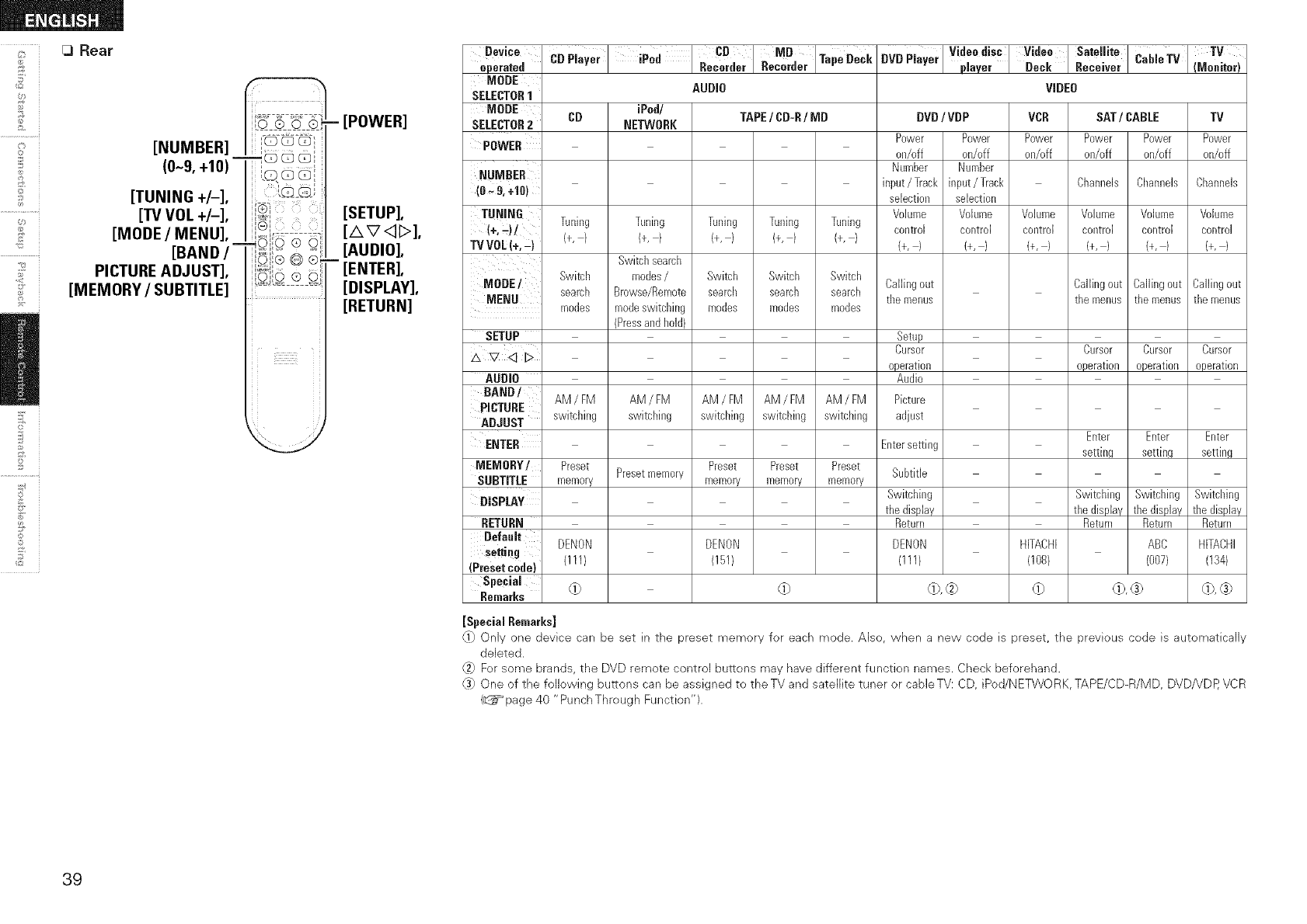
[3 Rear
©
©
©
6V_
[NUMBER] I"i:U_:_i
_QGG'_
(0-9, +10) _, ',
,.Q Q G,_
[TUNING +/-], _@S}
[TV VOL +/-], iiiGi
[MODE /MENU], ,, I_ ..... -
_©i © ® o
[BAND /'_ ........
dO,® Q ®
PICTURE ADJUST], l_'s,,....
0,'0 ® G
[MEMORY/SUBTITLE] 'u: ----:
2
©
©
_2
- [POWER]
[SETUP],
[AV<D],
[AUDIO],
- [ENTER],
[DISPLAY],
[RETURN]
Device
operated
MODE
SELECTOR1
MODE CD
SELECTOR2
POWER
NUMBER
(0 _ & +10)
TUNING
(+_)/ Tuning
TV VDL(+,-) (+, /
Switch
MODE/ search
MENU modes
SETUP
_ V <1L>
AUDIO
BAND/ AM/FM
_ICTURE
DJUST switching
ENTER
MEMORY/ Preset
SUBTITLE memory
DISPLAY
RETURN
Default
setting DENON
(Preset cede) (I 11}
Special
RemarKs (i)
CBPlayer =iPod CDRecorder .eoorao,MD'I,Ta" Dec,
AUDIO
iPod/
NETWORK
Tuning
(+,1
Switchsearch
modes/
Browse/Remote
modeswitching
(Pressand hold)
AM/EM
switching
Presetmemory
TAPE/CD-R/MD
Tuning Tuning Tuning
(+,) (+,) (+, /
Switch Switch Switch
search search search
modes modes modes
AM /FM AM /FM AM /FM
swkchhlg swkchhlg switching
Preset Preset Preset
memory memory memory
DVDPlayer VideediSC Video Sate!lite CableTV TV
paver Deck Rece ver (Meniter)
DVD/VDP
Power
on/off
Number
input/Track
selection
Volume
control
(+, /
Callingout
the menus
Setup
Cursor
operation
Audio
Picture
adjust
VIDEO
VCR SAT/CABLE TV
Power Power Power Power Power
on/off on/off on/off on/off on/o-f
Number
input/Track Channels Channels Channels
selection
Vokmle Volume Volume Vokmle Volume
control control control control control
(+,) (+, / (+,) (+,) (+,)
Callingout Callingout Callingout
themenus themenus themenus
Cursor Cursor Cursor
operation operation operation
Enterse_ing
DENON
(151/
db
Subtitle
Swkchhlg
Enter
setting
the display
Return
DENON HFACHI
(IH/ (108/
@,@ @ d_,® dk®
Enter Enter
setting setting
Switching Switching Switching
the display the display the display
Return Return Return
ABC HITACHI
(007) (134)
[Special RemarEs]
_1) Only one device can be set in the preset memory for each mode• Also, when a new code is preset, the previous cede is automatically
deleted.
_ For some brands, the DVD remote control buttons may have different function names. Check beforehand•
(3) One of the following buttons can be assigned to the TV and satellite tuner or cabJeTV: CD, iPod/NETWORK, TAPE/CD-R/MD, DVD/VDP, VCR
(_=_page 40 "PunchThrough Function")•
39
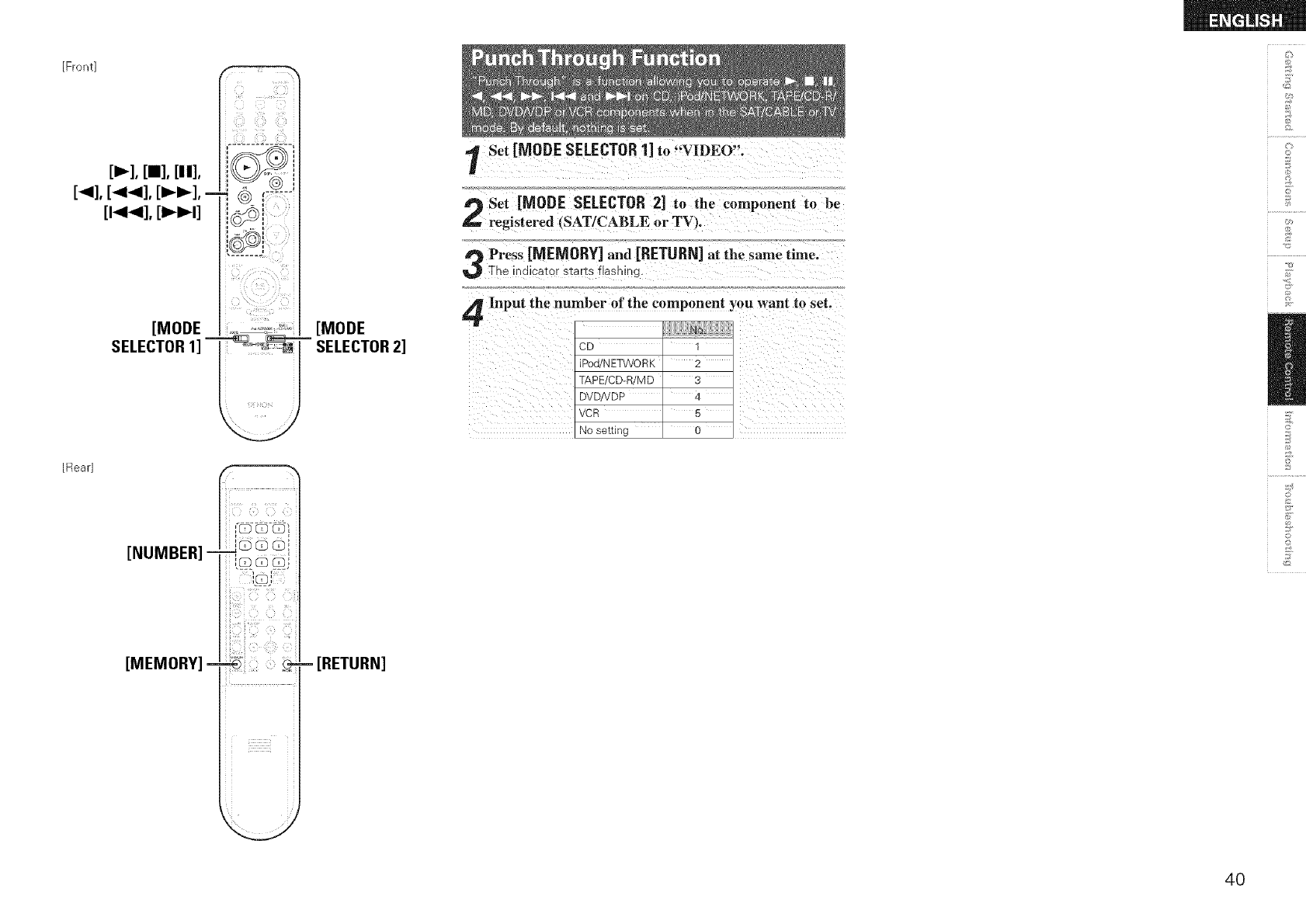
[Front]
[p,,,-],[aa],[it],
[<], [<<], [_i_],-
[t<<], [i_t]
[MODE
SELECTOR1]
ilili i!iiiiiii
[Rear]
[NUMBER] _G _ G[
',%8s _j
i
i
[MEMORY] - _' )
i
[MODE
SELECTOR2]
- [RETURN]
Set [MODE SELECTOR1] to "'VIDEO".
Set [MODE SELECTOR 2] to the component to be
L. registered (SAT/CABLE or TV_.
Press [MEMORY] and [RETURN]at the same time°
The indicator starts flashing.
Input the number of the component you want to set.
CD q
iPod/N ETWO RK 2
TAPE/CD-R/M D 3
DVD!VDP 4
VCR 5
No setting 0
d_
©
d
w
©
©
4O
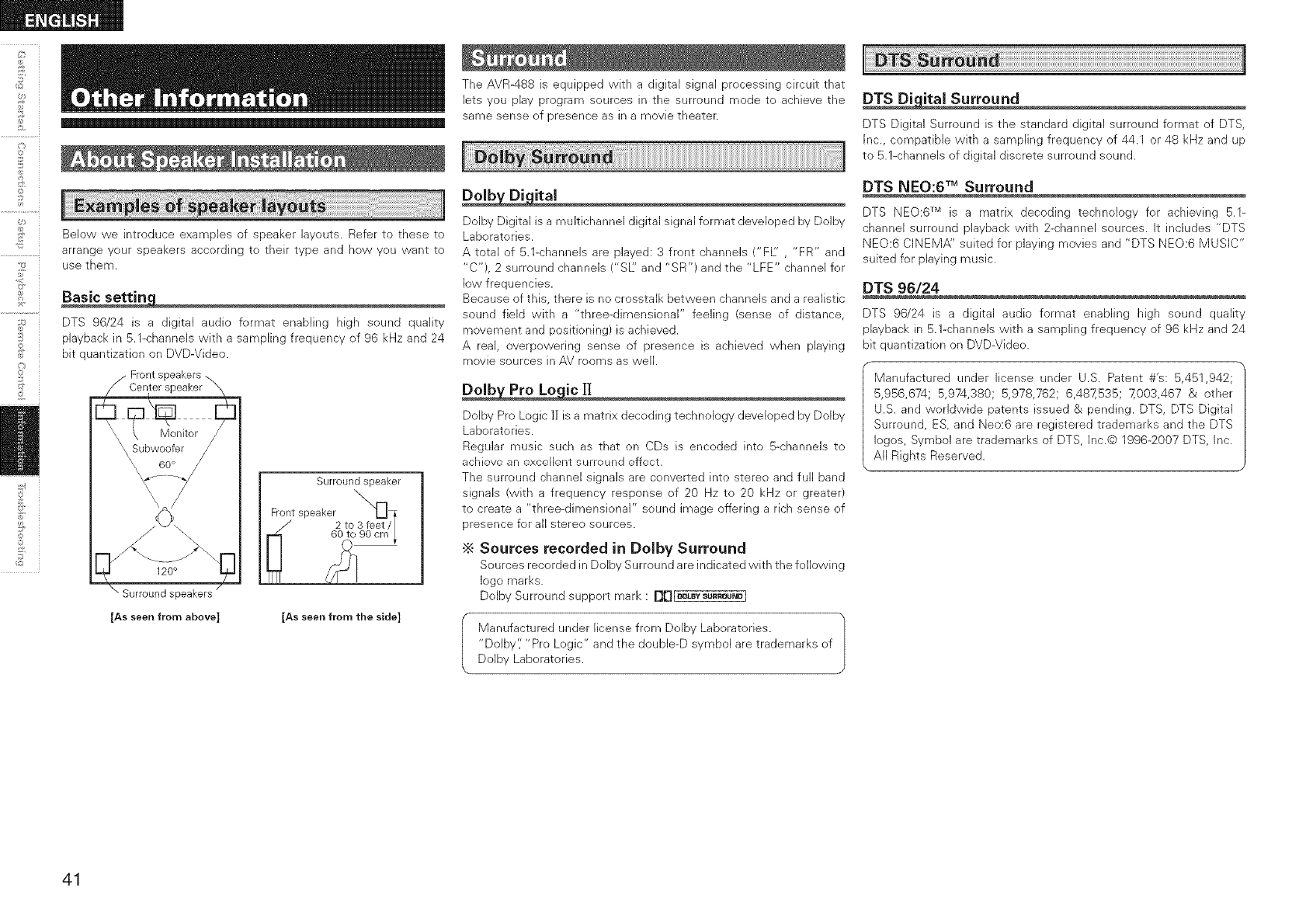
©
C}
©
©
_2
Below we introduce examples of speaker layouts. Refer to these to
arrange your speakers according to their type and how you want to
use them.
DTS 96/24 is a digital audio format enabling high sound quality
playback in 5.1-channels with a sampling frequency of 96 kHz and 24
bit quantization on DVD-Video.
Front speakers \
Center speaker
Surround speaker
Front speaker _]
2 to 3 feet N
" 60 to 90 cm_
[As seen from above] [As seen from the side]
The AVR488 is equipped with a digital signal processing circuit that
lets you play program sources in the surround mode to achieve the
same sense of presence as in a movie theater.
Dolby Digital is a multichannel digital signal format developed by Dolby
Laboratories.
A total of 5.1-channels are played: 3 front channels ('FL" ,"FR" and
"C"), 2 surround channels ("SI/: and "SR") and the "LFE" channel for
low frequencies.
Because of this, there is no crosstalk between channels and a realistic
sound field with a "three-dimensional" feeling (sense of distance,
movement and positioning) is achieved.
A real, overpowering sense of presence is achieved when playing
movie sources in AV rooms as well.
Dolby Pro Logic l] is a matrix decoding technology developed by Dolby
Laboratories.
Regular music such as that on CDs is encoded into 5-channels to
achieve an excellent surround effect.
The surround channel signals are converted into stereo and full band
signals (with a frequency response of 20 Hz to 20 kHz or greater)
to create a "three-dimensional" sound image offering a rich sense of
presence for all stereo sources.
•_ Sources recorded in Dolby Surround
Sources recorded in Dolby Surround are indicated with the following
logo marks.
Dolby Surround support mark : I][][_LBYSU"OU_D]
Manufactured tinder license from Dolby Laboratories.
"Dolby'; "Pro Logic" and the double-D symbol are trademarks of
Dolby Laboratories.
DTS Digital Surround is the standard digital surround format of DTS,
Inc., compatible with a sampling frequency of 44.1 or 48 kHz and up
to 5.1-channels of digital discrete surround sound.
DTS NEO:6 TM Surround
DTS NEO:6 TM is a matrix decoding technology for achieving 5.1-
channel surround playback with 2-channel sources. It includes "DTS
NEO:6 CINEMA" suited for playing movies and "DTS NEO:6 MUSIC"
suited for playing music.
DTS 96/24
DTS 96/24 is a digital audio format enabling high sound quality
playback in 5.1-channels with a sampling frequency of 96 kHz and 24
bit quantization on DVD-Video.
Manufactured under license under U.S. Patent #'s: 5,451,942;
5,956,674; 5,974,980; 5,978,762; 6,487,535; 7,003,467 & other
U.S. and worldwide patents issued & pending. DTS, DTS Digital
Surround, ES, and Neo:6 are registered trademarks and the DTS
Iogos, Symbol are trademarks of DTS, Inc.@ 1996-2007 DTS, Inc.
All Rights Reserved.
41
Neural Surround TM, a breakthrough in audio technology, will bring the
excitement of surround music to more of America's listening audience.
It provides the rich envelopment and discrete image detail of surround
sound in a format 100 % compatible with stereo. With superior
spectral resolution and channel separation, Neural Surround TM draws
the brain's attention to sonic details in musical instruments, vocals,
and ambience that are typically masked by other playback systems.
This allows the listener to fully experience the richness and subtleties
in recorded performance as never before. As the chosen format for XM
Satellite Radio's new XM HD surround programming, Neural Surround
will help deliver more surround music to more listeners than any other
broadcast format. XM Satellite Radio will be the first radio company to
broadcast surround sound on the radio 24 hours a day and will offer
three channels fully dedicated to Neural Surround TM music. This alone
will amount to more than 25,000 hours of Neural Surround TM music
each year.
neural
SURROUND
This product is manufactured under license from Neural Audio
Corporation.
D&M Holdings Inc. hereby grants the user a non-exclusive,
nontransferable, limited license right exercisable to use the NA
SURROUND Technology and other US and Werld Wide Patents
Pending technology.
"Neural" and "Neural Audio" and "Neural Surround" are
trademarks of Neural Audio Corporation. All Rights Reserved.
HDMI is a digital interface standard for next generation TVs based
on DVI (Digital Visual Interface) standards and optimized for use in
consumer equipment.
Non-compressed digital video and multi-channel audio signals are
transmitted with a single connection.
HDMI is also compatible with HDCP (High-bandwidth Digital Contents
Protection), a technology for protecting copyrights that encrypts digital
video signals in the same was as with DVL
Eliminates on-screen color banding, for smooth tonal transitions and
subtle gradations between colors.
Enables increased contrast ratio.
Can represent many times more shades of gray between black and
white.
At 30-bit pixel depth, a four times improvement would be the minimu m,
and the typical improvement would be eight times or more.
xvYCC
Next-generation "xvYCC" color space supports 1.8 times as many
colors as existing HDTV signals.
Lets HDTVs display colors more accurately.
Enables displays with natural, vivid colors.
"HDMI'i "HDMI logo" and "High-Definition Multimedia Interface"
are trademarks or registered trademarks of HDMI Licensing
LLC.
d_
©
9,
©
d
?
©
42
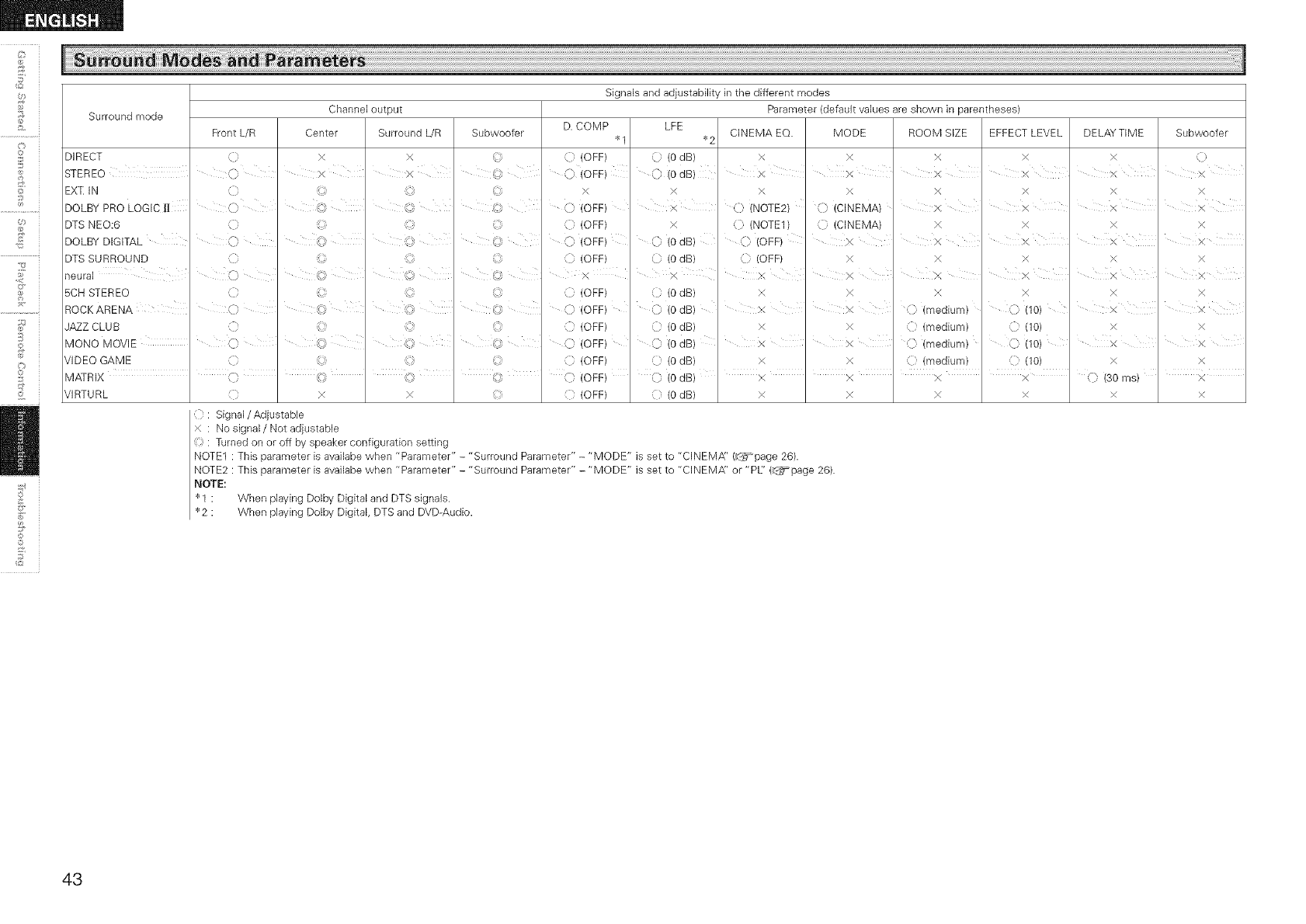
©
©
£
S
C_
©
©
_2
Signals and adjustability in the different modes
Surround mode Parameter (default values are shown in parentheses)
D. COMP LFE QNEMA EQ. MODE ROOM SIZE EFFECT LEVEL DELAYTIME
DIRECT
STEREO
EXT IN
DOLBY PRO LOGIC l[
DTS NEO:6
DOLBY DIGITAL
DTS SURROUND
neural
5CH STEREO
ROCKARENA
JAZZ CLUB
Front L/R
o
O
C
MONO MOVIE I
VIDEO GAME
Channel output
Center Surround L/R
x x
× ×
©
©
©
©
N,:_i
@
©
©
©
©
©
@
©
Subwoofer
{} (OFF)
_I _2
(0 dB)
© (OdB)
x x x
x x x
}< x
© (CINEMA) x
(} (CINEMA) x
x
x x
X ' x
x x
X , (} (medium)
x C (medium)
X () (medium)
x () (medium)
X
X
X
X
X
,_) (10)
© (10)
C (10)
(7 (10)
©
©
©
©
©
©
©
©
©
©
©
x
(} (OFF)
} (OFF)
(} (OFF)
{}} (OFF)
X
{} (OFF)
() (OFF)
{} (OFF)
(} (OFF)
{} (OFF)
X
L }× ¸i A
X
) (0 dB)
© (0 dB)
x
© (0 dB)
/.) (0 dB)
} (0 dB)
© (0 dB)
) (0 dB)
}<
(} (NOTE2)
{} (NOTE1)
© (OFF)
'{i (OFF)
x
X
x
X
X
X
X X
X, X
x
x
x
x
x
x
x
x
x
Subwoofer
C
x
x
x
x
×
x
x
x
x
x
x
x
MATR IX , < ' (, ' _',,
VIRTU RL } x x
_" (OFF)
} (OFF) { (0 dB) X
{ : Signal/Adjustable
x : No signal/Not adjustabb
: Turned on or off by speaker configulation setting
NOTE1 : This parameter is availabe when "Parameter" - "Surround Parameter" - "MODE" is set to "CINEMfY' (_page 26).
NOTE2 : This parameter is availabe when "Parameter" - "Surround Parameter" - "MODE" is set to "CINEMfY' or "PL' (_page 26).
NOTE:
I : When playingDolby Digitaland DTS signals.
2 : When playingDolby Digital,DTS and DVD-Audio.
(} (0 dB) I x I x I x I x I C) (30 ms) ' x
xxxxx
43
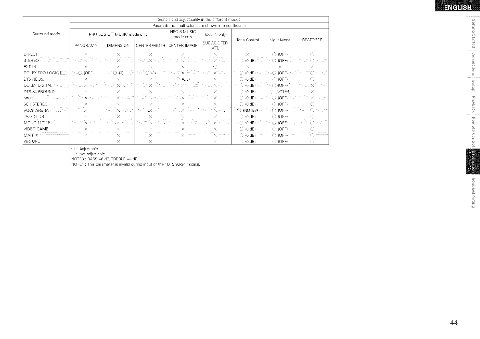
Surround mode
DIRECT
STEREO
EXq: IN
DOLBY PRO LOGIC |!
DTS NEO:6
DOLBY DIGITAL
DTS SURROUND
PRO LOGIC ]1 MUSIC mode only
PANORAMA
VIDEO GAME
MATRIX
VIRTURL
x
x
x,
C} (OFF)
x
x
x
Signals and adjustability in the different modes
Parameter (default values are shown in parentheses)
neural I x
5CH STEREO x
RODKARENA
JAZZ CLUB x
MONO MOVIE I x
x
x
x
{ : Adjustabb
x : Not adjustable
DIMENSION CENTER WIDTH
x x
x x
x x
}, (s)} (s)
x x
X X
x x
x
NEO:6 MUSIC
mode only
CENTER IMAGE
x
x
X
::} (0.3)
EXT IN only
SUBWOOFER
ATT
x
x
x
X X
x x
x X x
x
x
x
x
x
x
}<
x
x
x
x x
x x
x x
x x
x X
x x
Tone Control Night Mode
x (OFF)
0 (0 dB) ) (OFF)
x x,
) (0 dB) } (OFF)
(0 dB) (OFF)
0 (0 dB) C (OFF)
(0 dB) .(NOTE4)
/.) (0 dB) ) (OFF)
(0 dB) (OFF)
C (NOTE3) } (OFF)
C (0 dB) C (OFF)
) (0 dB) C (OFF)
C (0 dB) (OFF)
RESTORER
,D
Q
(}
x
x
Q
Q
Q
O
Q
NOTE3 : BASS +6 dB, TREBLE +4 dB
NOTE4 : This parameter is invalid during input of the "DTS 96/24 "signal.
ilkl
i I
(0 dB) C:, (OFF) ' _)
{ : (0 dB) { : (OFF) }
d_
0
£
©
d
£
@
?
0
Z
44
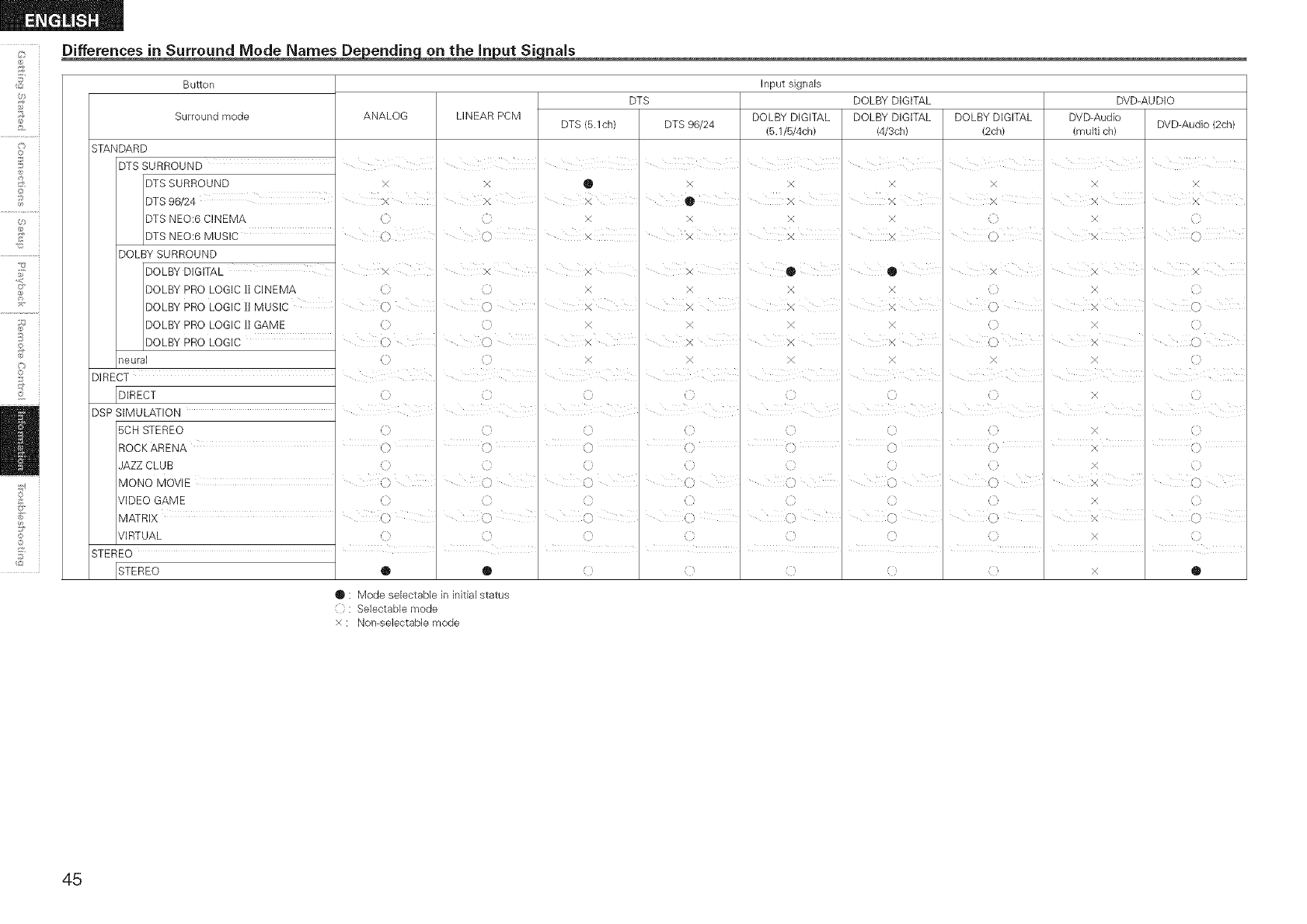
Differences in Surround Mode Names De endin on the in ut Si rials
©
©
£
C_
©
©
_2
Button
DTS
Surround mode ANALOG LINEAR PCM DTS (B.1ch) DTS 96/24
STANDARD
DTS SURROUND I , ,
DTS SURROUND x x • x
DTS 96/24 x x x I •
DTS NEO:6 CINEMA x x
DTS NEO:6 MUSIC I (}
Input signals
DOLBY DIGITAL
DOLBY DIGITAL DOLBY DIGITAL DOLBY DIGITAL
(5.1/5/4ch) (4/3ch) (2ch)
x x x
, x , x
x x
() x x I x x ,,
DVD-AUDIO
DVD-Audio DVD-Audio (2oh/
(multi ch)
x x
3{ x
x
x I (
DOLBY SURROUND
DOLBY DIGITAL
DOLBY PRO LOGIC I! CINEMA
DOLBY PRO LOGIC H MUSIC
DOLBY PRO LOGIC l! GAME
DOLBY PRO LOGIC
neural
x
(>
_/ X ¸
()
C'
(>
DIRECT I
DIRECT
DSP SIMULATION
5CH STEREO
x
(
(1
(:1
()
x
x
X
x
x
x
x
x
() ,:)
<) (}
0 ¸ •
x x
x x
)4: X
x x
(:
C
()
x
()
(}
x ::
0
x {?
(}
x (?
x }
I
x
ROCK ARENA ' (} I () ' (} I (3 I () ' (} I (3 I X I (3
JAZZ CLUB 11 ( { {i { ×
MONO MOVIE I } "" , F-_j , x ""
k)k)
VIDEO GAME {i {} {i {} {} {i {} X {}
MATRIX "' C} (} (} X (}
VIRTUAL { (} { (} ( { (} X }
ii iiiii
STEREO '''' ''''
ISTEREO ® ® x®
• : Mode selectable in initial status
{ } : Selectable mode
>( : Non-selectable mode
45
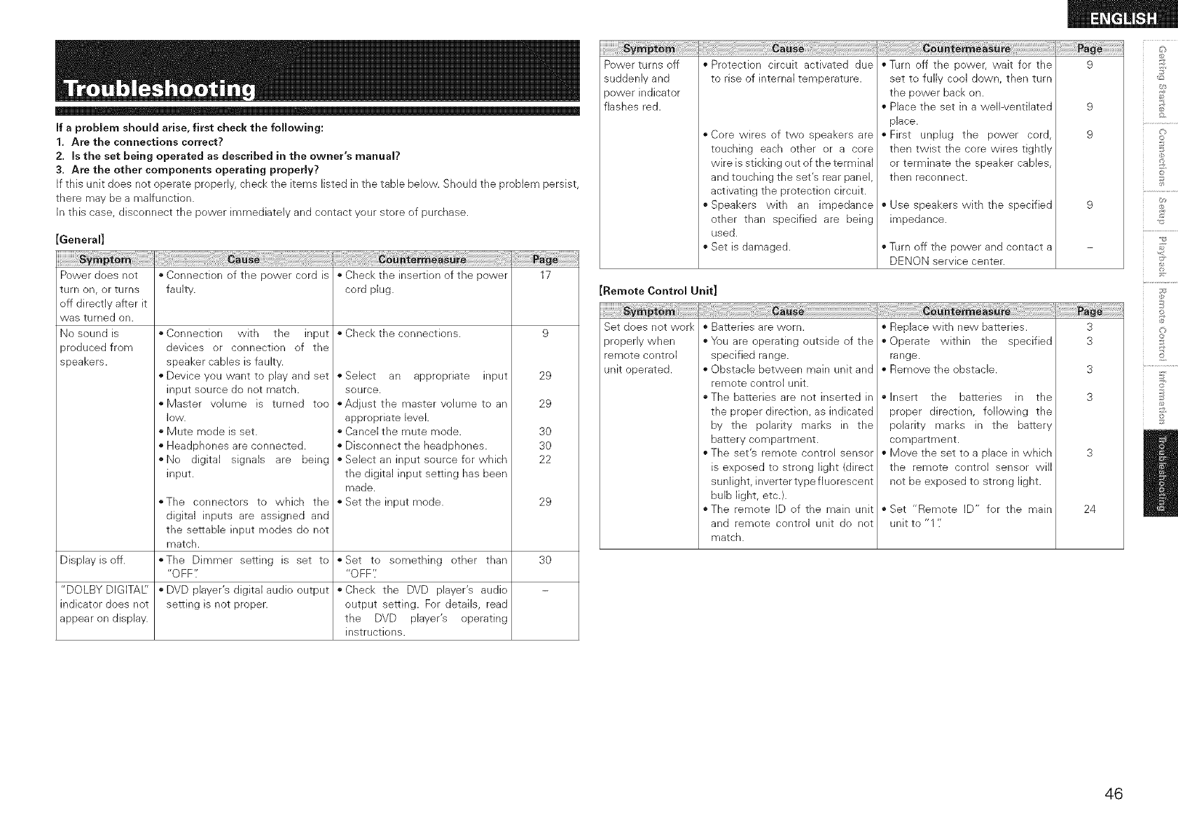
If a problem should arise, first check the following:
1. Are the connections correct?
2. Is the set being operated as described in the owner's manual?
3. Are the other components operating properly?
If this unit does not operate properly, check tile items listed in tile table below. Should tile problem persist,
there may be a malfunction.
In this case, disconnect the power immediately and contact your store of purchase.
turn on, or turns
off directly after it
was turned on.
No sound is
aroduced from
speakers.
[General]
Power does not * Connection of the power cord is * Check the insertion of the power 17
faulty, cord plug.
• Check the connections. 9
`` Connection with the input
devices or connection of the
speaker cables is faulty.
`` Device you want to play and set
input source do not match.
`` Master volume is turned too
]©W.
`` Mute mode is set.
`` Headphones are connected.
``No digital signals are being
input.
``Select an appropriate input
source.
``Adjust the master volume to an
appropriate level.
``Cancel the mute mode.
``Disconnect the headphones.
``Select an input source for which
the digital input setting has been
made.
``Set the input mode.
"The connectors to which the
digital inputs are assigned and
the settable input modes do not
match.
``The Dimmer setting is set to
"OFF".
`` DVD player's digital audio output
setting is not proper.
29
29
3O
3O
22
29
Display isoff. ``Set to something other than 30
"OFF'.'
"DOLBY DIGITAE' ``Check the DVD player's audio
indicator does not output setting. For details, read
appear on display, the DVD player's operating
instructions.
Power turns off
suddenly and
power indicator
flashes red.
iiiii!!ii!_iiiiiiiiiiii!!_!_i_i_iiiiiiiiiiiiiiiiiiiiiiiiiiiiii_iii_i_!!i!_i!_i!_i!_i!_i!_i!_i!_i!_i!_i!_i!_i!_i!_i!_i!_i!_i!_i!ii!_i!i(!_!i!_i!_i!i_!i_!_i_i_!_!_!_!_!i_zi_i_ili_i_!_i_!_i_i_i_!_i!_i!_i!__i!i{!iiiiiiiiiiiiiiiiiii%iii%i!!
`` Protection circuit activated due
to rise of internal temperature.
`` Core wires of two speakers are
touching each other or a core
wire is sticking out of the terminal
and touching the set's rear panel,
activating the protection circuit.
``Speakers with an impedance
other than specified are being
used.
`` Set is damaged.
`` Turn off the power, wait for the
set to fully cool down, then turn
the power back on.
`` Place the set in a wellwentilated
place.
`` First unplug the power cord,
then twist the core wires tightly
or terminate the speaker cables,
then reconnect.
`` Use speakers with the specified
impedance.
`` Turn off the power and contact a
DENON service center.
Remote Control Unit]
Set does not work
properly when
remote control
unit operated.
`` Batteries are worn.
``You are operating outside of the
specified range.
`` Obstacle between main unit and
remote control unit.
``The batteries are not inserted in
the proper direction, as indicated
by the polarity marks in the
battery compartment.
``The set's remote control sensor
is exposed to strong light (direct
sunlight, inverter type fluorescent
bulb light, etc.).
``The remote ID of the main unit
and remote control unit do not
match.
`` Replace with new batteries.
`` Operate within the specified
range.
`` Remove the obstacle.
`` Insert the batteries in the
proper direction, following the
polarity marks in the battery
compartment.
`` Move the set to a place in which
the remote control sensor will
not be exposed to strong light.
`` Set "Remote ID" for the main
unit to "1 '/
9
9
9
3
3
3
3
24
©
©
£
©
@
£
©
46
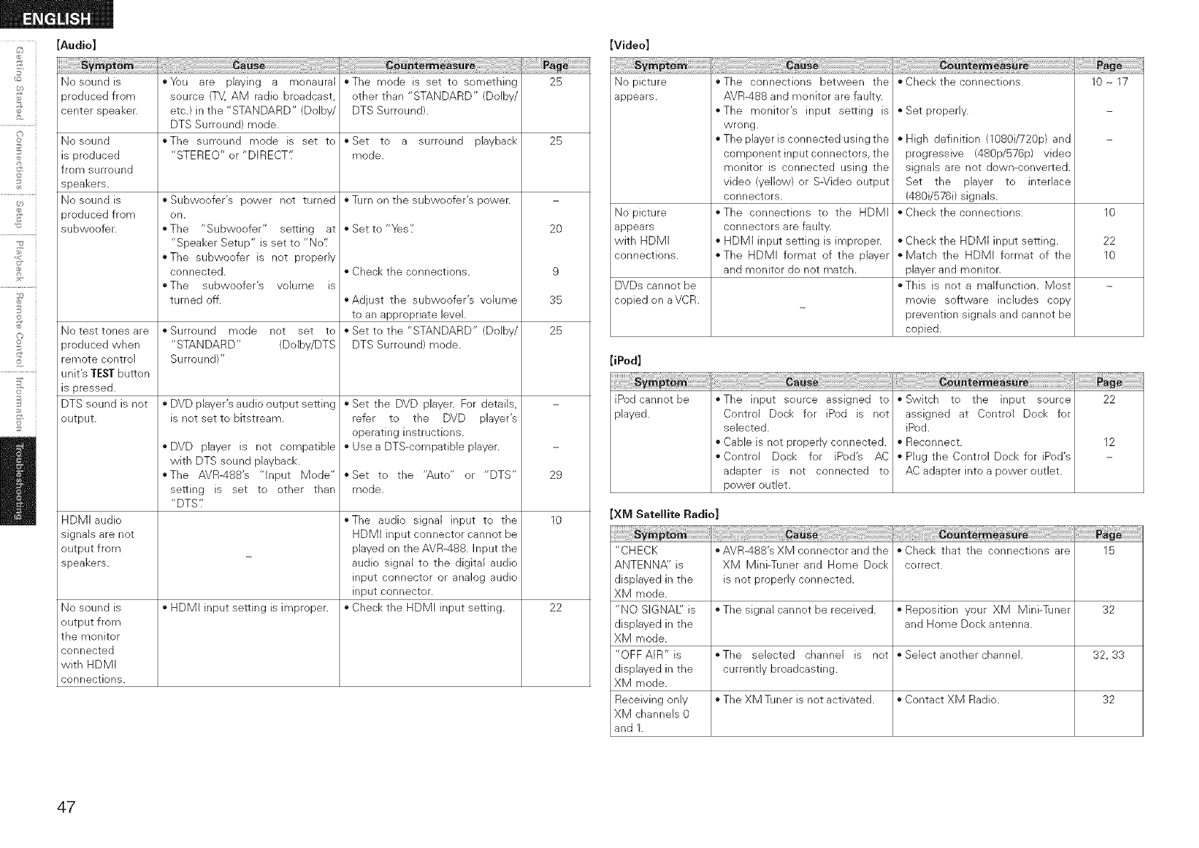
,"b
©
©
£
©
[Audio]
sypt
No sound is
aroduced from
center speaker.
No sound
is produced
from surround
speakers.
No sound is
aroduced from
subwoofer.
No test tones are
aroduced when
remote control
unit's TESTbutton
is pressed.
DTS sound is not
output.
HDMI audio
signals are not
output from
speakers.
No sound is
output from
the monitor
connected
with HDMI
connections.
[Video]
*_)u are playing a monaural
source (TV, AM radio broadcast,
etc.) in the "STANDARD" (Dolby/
DTS Surround) mode.
"The surround mode is set to
"STEREO" or "DIRECT'.'
• Subwoofer's power not turned
on.
• The "Subwoofer" setting at
"Speaker Setup" is set to "No'[
• The subwoofer is not properly
connected.
oThe subwoofer's volume is
turned off.
oSurround mode not set to
"STANDARD" (DoIby/DTS
Surround)"
• DVD player's audio output setting
is net set to bitstream.
• DVD player is not compatible
with DTS sound playback.
The AVR-488's "Input Mode"
setting is set to other than
"DTS'J
HDMI input setting is improper.
oThe mode is set to something
other than "STANDARD" (Dolby/
DTS Surround).
25
• Set to a surround playback 25
mode.
*Turn on the subwoofer's power.
o Set to "Yes'/
• Check the connections.
,,Adjust the subwoofer's volume
to an appropriate level.
• Set to the "STANDARD" (Dolby/
DTS Surround) mode.
• Set the DVD player. For details,
refer to the DVD player's
operating instructions.
• Use a DTS-compatible player.
o Set to the "Auto" or "DTS"
mode.
*The audio signal input to the
HDMI input connector cannot be
played on the AVR-488. Input the
audio signal to the digital audio
input connector or analog audio
input connector.
Check the HDMI input setting.
20
9
35
25
29
10
22
No picture
appears.
No picture
appears
with HDMI
connections.
"The connections between the
AVR-488 and monitor are faulty.
"The monitor's input setting is
wrong.
"The player is connected using the
component input connectors, the
monitor is connected using the
video (yellow) or S-Video output
connectors.
*The connections to the HDMI
connectors are faulty.
" HDMI input setting is improper.
The HDMI format of the player
and monitor do not match.
DVDs cannot be
copied on a VCR.
[iPod]
iPod cannot be
played.
"Check the connections.
" Set properly.
High definition (1080i/720p) and
progressive (480p/576p) video
signals are not down-converted.
Set the player to interlace
(480i/576i) signals.
"Check the connections.
"Check the HDMI input setting.
"Match the HDMI format of the
player and monitor.
*This is not a malfunction. Most
movie software includes copy
prevention signals and cannot be
copied.
10 _ 17
10
22
10
"The input source assigned to
Control Dock for iPod is not
selected.
" Cable is not properly connected.
Control Dock for iPod's AC
adapter is not connected to
power outlet.
!_{_!_!_!i!_!i_ii_ii_iiiiiiiiiiiiiiiiiiii_i_i_i_i_i_i_ii!_!i_ii!_i_!_i_;_;_i_!i_!_¸!I¸!i!i!i!i!i!i!i!i!i!i!i!i!i!i!i!i!i!i!i!i!i!i!i!ii¸_i¸iil;!iiii!iii_iiiiii_
" Switch to the input source
assigned at Control Dock for
iPed.
• Reconnect.
Plug the Control Dock for iPed's
AC adapter into a power outlet.
22
12
XM Satellite Radio
"CHECK *AVR-488's XM connector and the *Check that the connections are 15
ANTENNA" is XM Mini-Tuner and Home Dock correct.
displayed in the is not properly connected.
XM mode.
"NO SIGNAE is *The signal cannot be received. *Reposition your XM Mini-Tuner 32
displayed in the and Home Dock antenna.
XM mode.
"OFFAIR"is *The selected channel is not oSebctanotherchannel. 32,33
displayed in the currently broadcasting.
XM mode.
Receiving only • The XM Tuner is not activated. • Contact XM Radio. 32
XM channels 0
and 1.
47
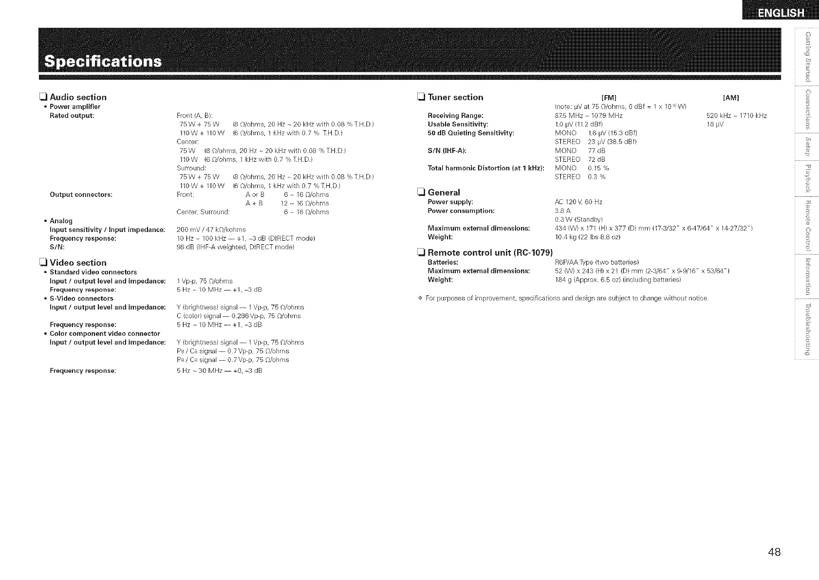
d_
O
[_1Audio section [_1Tuner section [FM] [AM]
Power amplifier (note: _V at 75 O/ohms, 0 dBf = 1 x 10 _sW)
Rated output: Front (A, B): Receiving Range: 8Z5 MHz - 10Z9 MHz 520 kHz ~ 1710 kHz _}
o
75 W + 75 W (8 G/ohms, 20 Hz ~ 20 kHz with 0.08 % TH.D.) Usable Sensitivity: 1.0 #V (11.2 dBf) 18 #V
110 W + 110 W (6 O/ohms, 1 kHz with 0.7 % TH.D.) 50 dB Quieting Sensitivity: MONO 1.6 #V (15.3 dBf) ........
Center: STEREO 23 #V (38.5 dBf) _"_
75 W (8 O/ohms, 20 Hz ~ 20 kHz with 0.08 % TH.D.) SIN (IRF-A}: MONO 77 dB _,s
110W (60/ohms, 1kHzwithO.7%TH.D.) STEREO 72dB ...........................
Surround: Total harmonic Distortion (at 1 kRz}: MONO 0.15 %
75 W + 75 W (8 O/ohms, 20 Hz ~ 20 kHz with 0.08 % TH.D.) STEREO 0.3 % '
110W + 110W (6 O/ohms, 1 kHz with 0.7 % TH.D.)
Output connectors: Front: A ol B 6 ~ 16 O/ohms [_ General ..........................
A+B 12 - 16 O/ohms Power supply: AC 120V, 60 Hz ;;_i>
Center, Surround: 6 ~ 16 _')/ohms Power consumption: 3.8 A i_
£
0.3 W (Standby)
434 (W) x 171 (H) x 377 (D) mm (17-3/32" x 6-47/64" x 14-27/32") {:>
10.4 kg (22 Ibs 8.8 oz) iii
Analog
Input sensitivity /Input impedance:
Frequency response:
S/N:
[_l Video section
Standard video connectors
input /output level and impedance:
Frequency response:
* S-Video connectors
input /output level and impedance:
©
©
Frequency response:
*Color component video connector
input /output level and impedance:
200 mV /47 kO/kohms
10 Hz ~ 100 kHz -- +1, -3 dB (DIRECT mode)
98 dB (IHF-A weighted, DIRECT mode)
1Vp@, 75 _')/ohms
5Hz- IOMHz +1, 3rib
Y (brightness) signal- 1 Vp-p, 75 O/ohms
C (color) signal- 0.286 Vp-p, 75 O/ohms
5Hz _ 10 MHz-- +l,-3dB
Y (brightness) signal- 1 Vp-p, 75 Q/ohms
PB/CB signal -- 0.7 Vp-p, 75 O/ohms
PR/CR signal -- 0.7 Vp-p, 75 O/ohms
5 Hz _ 30 MHz-- +0,-3 dB
Freqnency response:
Maximum external dimensions:
Weight:
[_ Remote control unit (R0-1079)
Batteries: R6P/AA Type (two batteries)
Maximum external dimensions: 52 (W) x 243 (H) x 21 (D) mm (2-3/64" x 9@/16" x 53/64")
Weight: 184 g (Approx. 6.5 oz) (including batteries)
=_=For purposes of improvement, specifications and design are subject to change without notice.
48
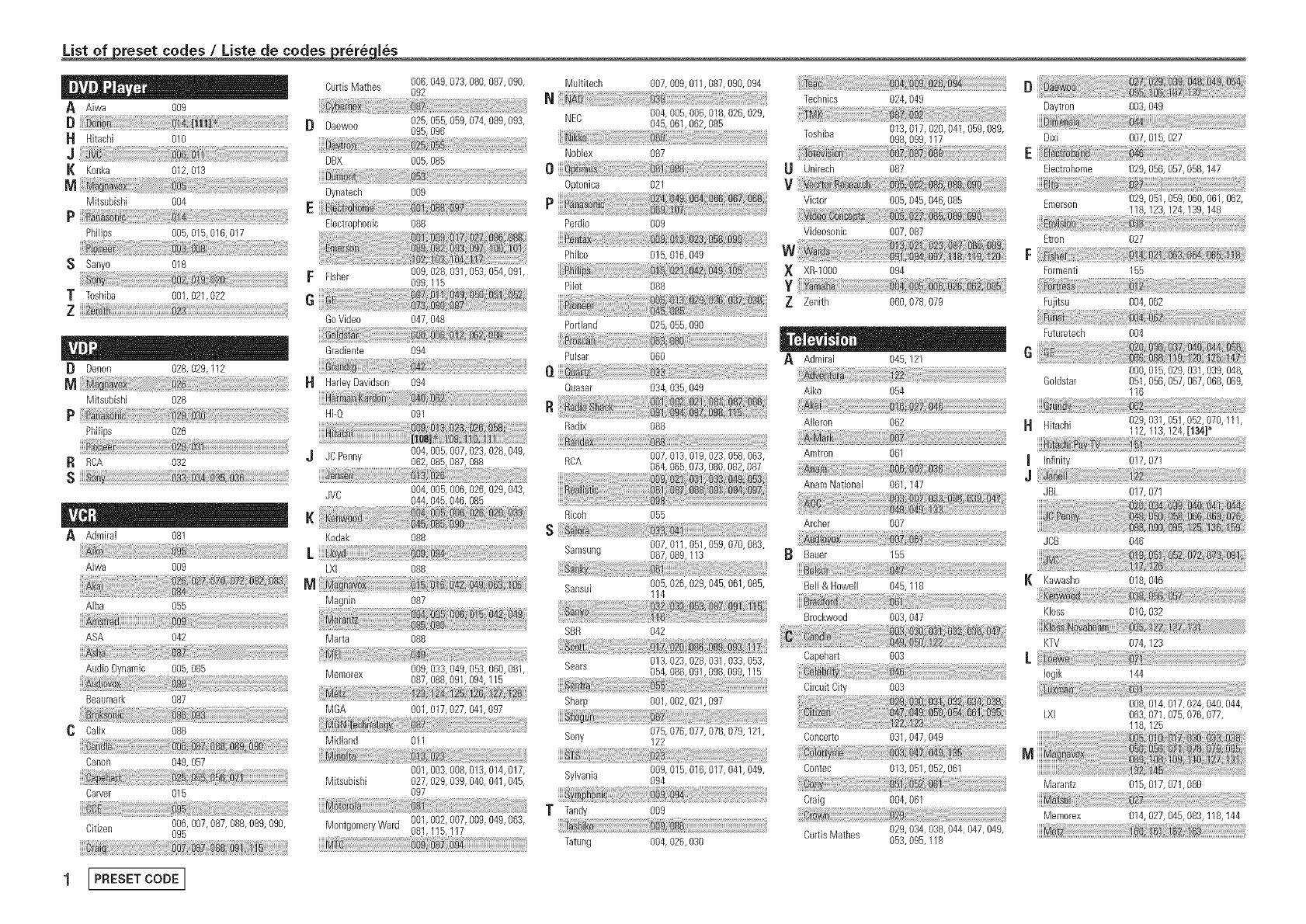
List of reset codes /Liste de codes rere les
I I ' , o
A Aiwa 009
D
H Hitachi 010
J
K Konka 012, 013
M
MksuNsN 004
P
PNlips 005, 015,016, 017
Ssanyo 018
TToshiba 001,021,022
Z [[[[
[} Denon 028, 029,112
M
Mitsubishi 028
P
PNlips 026
R RCA 032
s
AAdmiral 081
Aiwa 009
AIba 055
ASA 042
Audio Dynamic 005, 085
Beaumark 087
C Calix 088
Canon 049, 057
Carver 015
Citizen 006, 007,087, 088,089, 090,
095
Dynatech
Curtis Mathes 006, 049, 073,080, 087,090, Multitech 007,009,011,087,090, 094
O92 N
Daewoo 025, 055, 059,074, 089,093, NEC 045,004'061,005'062,006'085018'026,029,
095, 096
NoNex 087
DBX 005, 085
.... O
009 Optonica 021 b:49
Bectrophonic 088 Perdio 009
Technics 024,049 Daytron 003, 049
Toshiba 013,017, 020,041,059,089,
098,099,117 Dixi 007, 015,027
E
Unirech 087 Electrohome 029, 056,057,058,147
V
Victor 005,045, 046,085 Emerson 029, 051,059, 060,061,062,
118,129,124,139,148
............................................. :::::::::::::::::::::
FFisher 009, 028, 091,053, 054,091,
099,115
G
Go Video 047, 048
_ta _
Gradiente 094
HarleyDavidson 094
Hi-Q 091
J JC Penny 004,005,007,029,028,049,
062,085,087,088
JVC 004,005,006,026,029,043,
044,045,046, 085
Kodak 088
LXI 088
M
Magnin 087
Marta 088
Memorex 009, 033, 049,053, 060,081
087, 088,091,094, 115
MGA 001,017, 027, 041,097
Midland 011
001,003, 008,019, 014,017,
Mitsubishi 027, 029, 099,040, 041,045,
097
MontgomeryWard 001,002, 007,009, 049,069,
081,115,117
nta_5_ Videosonic 007,087
Philco 015,016,049 VV vva_ _i _§ i_ii§i20
X XR-1000 094
Pilot 088 y
Z Zenith 060,078,079
Portland 025,055, 090
Pulsar 060 AAdmiral 045,121
O. Quasar 034,035, 049 Aiko 054
Radix 088 Aileron 062
RCA 007,013,019, 023,058, 063,
064,065,073,080,082,087
Etron 027
F
Formenti 155
Fujitsu 004, 062
Futuretech 004
000, 015,029, 031,099, 048,
GoHstar 051,056,057, 067,068, 069,
116
029, 031,051,052,070,111,
H Hitachi 112,113,124,[134]*
Amtron 061 _it_hi_ i
Infinity 017, 071
J
Anam National 061,147 ........................................................................................................................
JBL 017, 071
Ricoh 055
S
Samsung 007,011,051,059,070,083,
087,089,113
iiiiii_ii_!i_yi_i_i_i_i_!i_i_i_i!i!ii!iiiiiiiii:i:_!i!_!_!i_i_i_!_!_!_!_;_i!_!_!i!_i_i_!i!_!!_i!_i_i_i_i_i_i_@iiiiiiiiii_!_i;!_!_!_i_:_i!ii_ii!iiJ:!;!_!ii_ii_!_!_i_i_ii!_i!;!!_i!i_!iS_!i!i!_!_!:!!_!!_!_!!_!_:_!_!!i!_i!i!ii!i!_!_:!_iii!_i_ii_i!_!ii_!i_i!_i_i!i!_!_!!!!
Sansui 005,026,029, 045,061,085,
114
Archer 007
Bauer 155
Bell & Howell 045,118
.....#ra_fo
Brockwood 003,047
SBR 042 :
Bears 013,023,028, 091,039, 053, Capehart 003
054,088, 091,098,099,115
r_
Sharp 001,002,021,097
Sony 075,076,077, 078, 079,121,
122
Sylvania 009,015, 016,017,041,049,
O94
v :
Tandy 009
hi _ .....
Tatung 004,026,090
i_ _i_ili_ii_iiiiiiii!iiiiiiiiiiiiiiiiii_i_i_i_i_i_i_i!_i_i_i_i!_i_i_ii_!i_!!!!_!i!i!i!i;i_!!_i_i_!_!_!_!_ii!ii_i!_i_i_!_:;i_;ii;_;_;i;i_:i_;i!_
Circuit City 003
JCB 046
K Kawasho 018,046
Kloss 010, 032
KTV 074, 129
[
Iogik 144
008, 014,017,024, 040,044,
LXI 063, 071,075,076,077,
118,125
Concerto 091,047, 049
Contec 013,051,052, 061
Craig 004,061
CurtisMathes 029,034, 098,044, 047,049,
053,095,118
Marantz 015, 017,071,080
...._te
Memorex 014, 027,045,083,118,144
1[PRESETCODE ]
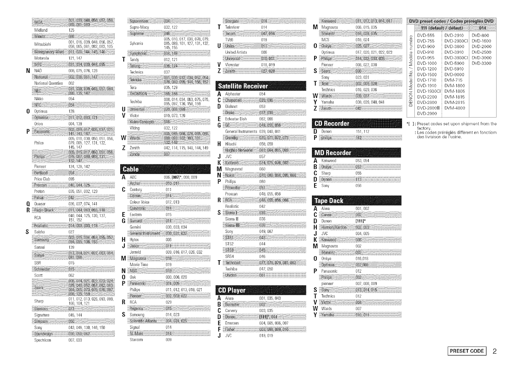
Midland 125 Supre-Macy 032,122 T Tebview 014 _ Magnavox 006,015,035
o DVD-555 i DVD-2910 DVD-800
.................................................................................. 005,010,017,030,078,079 TV86 019 MCS 016,024 DVDW55 i DVD-2930CI DVD-1600
Mitsubishi 001,016,039, 048,066,057, Sylvania 085, 089,101,127, 131,132,
058,066,081,082,083,105 145,155 U 0 DVD-900 i DVD-3800 DVD-2000
UnitedArtists 006 0ptimus 017,020,021,022,023 _ DVD-910 i DVD-3910 DVD-2500
Motorola 121,147 p :_ DVD-955 i DVD-3930CI DVD-3000
T Tan@ 012,121 ...........
Viewstar 018,019 Pioneer 006,022,030 _ BVD-1000 i uva-5900 DVD-3300
................................................................................................................... _: DVD-1200 i DVD-5910
N NAD 008,075,076,128 Technics 037 _ DVD-1500 I DVD-9000
Tee Sony 023,031
NationaIQuenties 002 ........................... , , , T DVD-1710 i DVM-715
Tera 035,129 -- - - --- -_, Technics ..........................8i01029,036 ........................ _ DVD-1910 ! DVM-1800
z DVD-1930CII DVM-1805
A Alphastar 054
Nikko 054 ............................ O DVD-2200 :_DVM-1815
Toshiba 095,097,136,158,159 yYamaha 038]0391040104i S DVD-2800 i DVM-2815
0 0ptimus 128 U [} Dishnet 053 Z DVD-2800]Ii i DVM-4800
......................................................................................................................................................................................... .............................................................................................................................................................DVD-2900 :
Vv_ctor 019,073,126 ..................o6{060.................................................
0don 004, 139 6 I '' , ,, *[ ]: Preset codes set upon sMpment from the
Viking 032,122 factory.
GeneralInstruments 039,040,041 [_ Denon 151,112 : Les codes preregles different en fonctiom
006,010,030,060,051,066, P des_vra_sonde_'us_ne.
Philco 078, 085,127,131,132, I't Hitachi 058,059
145,147 Z Zenith 042,114,115,140,144,149 ,J JVC 057
AKenwood 063,064
Pioneer 124,128,142 _ Magnavoxl 060 C sharp..... 055
PdoeCBb 095 A ABC 006, [007}*, 008,009 N [}
pPhi[ips 060
.....Pioion..................................... .................... 0 Century............ 011 ESony 056
Proscan 048,055, 056
flfiuasal ..........................................036,037}074,141 ...............................Coloul Voice................................0i2} b13 ...................................................R
Realistic 042 _ Aiwa 001,002
.....R6A..........................................b40, 044 i25,130:i37, ...... E Eastern 015 S C
161,162 6 S_erraH o36 B Denon [m]*
Gemini 030,033,034 _ _rnr} do
S Saisho 027 Sony 049,067 J JVC 004,005
HHytex 006
Sansui 13g ,j STS2 044
.......................................................................................................................................................... _ Magnavox 002
Jerrold 009,016, 017,026, 032 ............................................................................................
s_s4 046 00nkyo .........................................oi6}o18...........................................................
s_ o16 Mo,,_eT_meo19 f
Toshiba 047,050 pPanasonic 012
sco_ 062 0 Oak 000,006,020
Ppioneer 007,008, 009
Philips 011,012, 013,018, 021 _ S
Sharp 011,012,013,026,093,099, A Aiwa 001,035,043 T Technics 012
100,104,121 R RCA 029
C Carvery 003,035 W Wards 007
Signature 045,144 S Samsung 014,023 [} y Ya _tm
E Emerson 004,006,006,00_
Sony 043, 046,138,146,150 Signal 014 F
........ J JVC 018,019
Spectdcon 007, 033 Starcom 009
I PRESET CODEr 2

DENON
www.denon.com
Denon Brand Company, D&M Holdings Inc.
Printed in China OOD 511 4641 101
