Denon AVR 5803 User Manual AV SURROUND RECEIVER Manuals And Guides L0211060
DENON Receivers Manual L0211060 DENON Receivers Owner's Manual, DENON Receivers installation guides
AV Surround Receiver AVR-5803 L0211060
User Manual: Denon AVR-5803 AVR-5803 DENON AV SURROUND RECEIVER - Manuals and Guides View the owners manual for your DENON AV SURROUND RECEIVER #AVR5803. Home:Electronics Parts:Denon Parts:Denon AV SURROUND RECEIVER Manual
Open the PDF directly: View PDF ![]() .
.
Page Count: 84
AV SURROUND RECEIVER
AVR-5803
OPERATING INSTRUCTIONS
J
......_.... _ ½=°=°=°=
@0o
_uu
• We greatly appreciate your purchase of the AVR-5803.
•To be sure you take maximum advantage of all the features the AVR-5803 has to offer, read these instructions
carefully and use the set properly. Be sure to keep this manual for future reference should any questions or
problems arise.
"SERIAL NO
PLEASE RECORD UNIT SERIAL NUMBER ATTACHED TO THE REAR OF THE
CABINET FOR FUTURE REFERENCE"
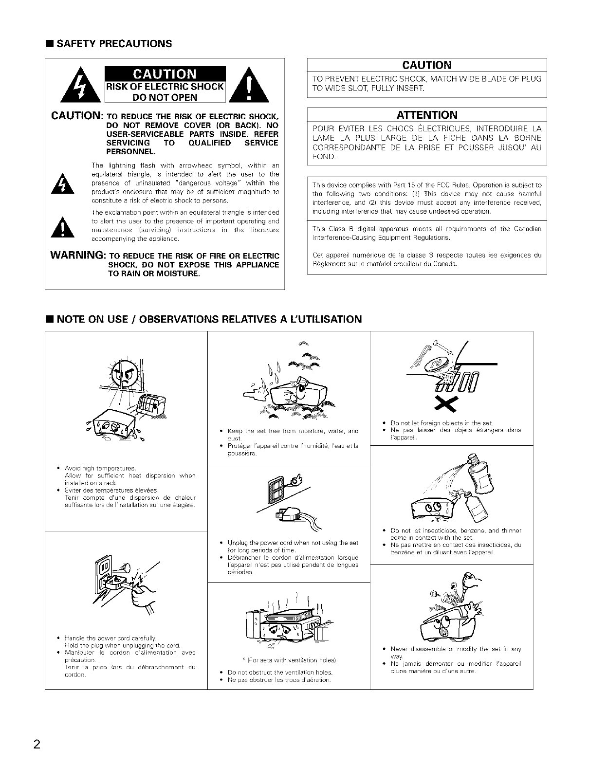
•SAFETY PRECAUTIONS
CAUTION: TO REDUCE THE RISK OF ELECTRIC SHOCK,
DO NOT REMOVE COVER (OR BACK), NO
USER-SERVICEABLE PARTS INSIDE, REFER
SERVICING TO QUALIFIED SERVICE
PERSONNEL,
The lightning flash with arrowhead symbol, within an
_1_ equilateral triangle, is intended to aEert the user to the
presence of uninsulated "dangerous voltage" within the
product's enclosure that may be of sufficient magnitude to
constitute a risk of electric shock to persons¸
The exclamation point within an equiEateral triangle is intended
to a]eF_ the user to the presence of impoF_ant operating andmaintenance (servicing) instructions in the literature
accompanying the appliance¸
WARNING: TO REDUCE THE RISK OF FIRE OR ELECTRIC
SHOCK, DO NOT EXPOSE THIS APPLIANCE
TO RAIN OR MOISTURE,
CAUTION
TO PREVENT ELECTRIC SHOCK, MATCH WIDE BLADE OF PLUG
TO WIDE SLOT, FULLY INSERT.
ATTENTION
POUR EVITER LES CHOCS ELECTRIQUES, INTERODUIRE LA
LAME LA PLUS LARGE DE LA FICHE DANS LA BORNE
CORRESPONDANTE DE LA PRISE ET POUSSER JUSQU' AU
FOND
This device complies with Par_ 15 of the FCC Rules Operation is subject to
the folEowing two conditions: (1) This device may not cause harmfuE
interference, and (2) this device must accept any interference received,
including interference that may cause undesired operation
This Class B digital apparatus meets all requirements of the Canadian
Interference-Causing Equipment Regulations
Cet appareil numerique de la dasse B respecte toutes les exigences du
R@glement sur le materiel brouilleur du Canada
•NOTE ON USE /OBSERVATIONS RELATIVES A L'UTILISATION
.
.@\
• Avoid high temperatures
AIow for sufficient heat dispersion when
installed on a rack
• Eviter des temp@ratures _ crees
T_nir compte drune dispersior de chaleur
suffisante Iors de 1'installation sur ne 6tag_re
• Hand}e the power cord carefully
Hold the plug when unplugging the cord
• Manpule le cordon d'alimentation avec
pr_ca tion
TenJr la pise ors du d_branchement du
cordon
• Keep the set free from moist ie, water, and
dust
• Protager I'appareil contre I'humidit_, I'eau et la
ooussiare
• Unplugthepowercordwhennot srgtheset
for }ong periods of time
• D@brancher }e cordon d'alimentation Iorsque
Irappareil n'est pas utilis@ pendart de Iongues
o@riodes
(For sets with ventilation holes}
• Do rot obstruct the ventilation holes
• Nepasobstruerlestro sd'aaration
• Do not Jet foreign objects r the set
• Ne pas laisser des objets @trangers dans
*appare
• DO not let insecticides, benzene, and thinner
come in contact with the set
• Ne pas mettre en contact des insecticides, du
benzene et un diluart avec 'aooareil
• Never disassemble or modfy the set in any
way
• Ne jamais damonter ou modifier 'apoareil
dr emaniereou dr eautre
2
1.
2.
3.
4.
5.
6.
7.
8.
g.
10.
11.
12.
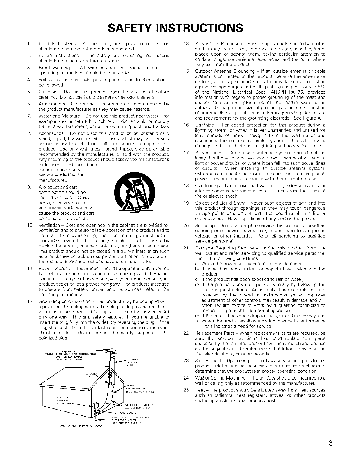
SAFETY INSTRUCTIONS
Read Instructions - All the safety and operating instructions
should be read before the product is operated.
Retain Instructions -The safety and operating instructions
should be retained for future reference
Heed Warnings -All warnings on the product and in the
operating instructions should be adhered to
Follow Instructions - All operating and use instructions should
be followed
Cleaning -Unplug this product from the wall outlet before
cleaning Do not use liquid cleaners or aerosol cleaners
Attachments - Do not use attachments not recommended by
the product manufacturer as they may cause hazards
Water and Moisture -Do not use this product near water - for
example, near a bath tub, wash bowl, kitchen sink, or laundry
tub; in a wet basement; or near a swimming pool; and the like.
Accessones - Do not place this product on an unstable cart,
stand, tripod, bracket, or table The product may fall, causing
serious injury to a child or adult, and serious damage to the
product. Use only with a cart, stand, tripod, bracket, or table
recommended by the manufacturer, or sold with the product.
Any mounting of the product should follow the manufacturer's
instructions, and should use a
mounting accessory
recommended by the
manufacturer
A product and cart
combination should be
moved with care Quick
stops, excessive force,
and uneven surfaces may
cause the product and cart
combination to overturn.
Ventilation -Slots and openings in the cabinet are provided for
ventilation and to ensure reliable operation of the product and to
protect it from overheating, and these openings must not be
blocked or covered. The openings should never be blocked by
placing the product on a bed, sofa, rug, or other similar surface.
This product should not be placed in a built=in installation such
as a bookcase or rack unless proper ventilation is provided or
the manufacturer's instructions have been adhered to
Power Sources -This product should be operated only from the
type of power source indicated on the marking label. If you are
not sure of the type of power supply to your home, consult your
product dealer or local power company. For products intended
to operate from battery power, or other sources, refer to the
operating instructions.
Grounding or Polarization -This product may be equipped with
a polarized alternating=current line plug (a plug having one blade
wider than the other). This plug will fit into the power outlet
only one way. This is a safety feature If you are unable to
insert the plug fully into the outlet, try reversing the plug. If the
plug should still fail to fit, contact your electrician to replace your
obsolete outlet Do not defeat the safety purpose of the
polarized plug
13 Power=Cord Protection -Powe_-supp]y cords should be routed
so that they are not likely to be walked on or pinched by items
placed upon or against them, paying particular attention to
cords at plugs, convenience receptacles, and the point where
they exit from the product
15 Outdoor Antenna Grounding -If an outside antenna or cable
system is connected to the product, be sure the antenna or
cable system is grounded so as to provide some protection
against voltage surges and built=up static charges Article 810
of the National Electrical Code, ANSI/NFPA 70, provides
information with regard to proper grounding of the mast and
supporting structure, grounding of the lead=in wire to an
antenna discharge unit, size of grounding conductors, location
of antenna-discharge unit, connection to grounding electrodes,
and requirements for the grounding electrode See Figure A
16 Lightning - For added protection for this product during a
lightning storm, or when it is left unattended and unused for
long periods of time, unplug it from the wall outlet and
disconnect the antenna or cable system This will prevent
damage to the product due to lightning and power-line surges
17 Power Lines - An outside antenna system should not be
located in the vicinity of overhead power lines or other electric
light or power circuits, or where it can fall into such power lines
or circuits When installing an outside antenna system,
extreme care should be taken to keep from touching such
power lines or circuits as contact with them might be fatal.
18 Overloading -Do not overload wall outlets, extension cords, or
integral convenience receptacles as this can result in a risk of
fire or electric shock
19
20.
21.
Object and Liquid Entry -Never push objects of any kind into
this product through openings as they may touch dangerous
voltage points or short=out parts that could result in a fire or
electric shock Never spill liquid of any kind on the product.
Servicing - Do not attempt to service this product yourself as
opening or removing covers may expose you to dangerous
voltage or other hazards. Refer all servicing to qualified
service personnel
Damage Requiring Service -Unplug this product from the
wall outlet and refer servicing to qualified service personnel
under the following conditions:
a) When the power_supply cord or plug is damaged,
b) If liquid has been spilled, or objects have fallen into the
product,
c) If the product has been exposed to rain or water,
d) If the product does not operate normally by following the
operating instructions Adjust only those controls that are
covered by the operating instructions as an _mproper
adjustment of other controls may result in damage and will
often require extensive work by a qualified technician to
restore the product to its normal operation,
e) If the product has been dropped or damaged in any way, and
f) When the product exhibits a distinct change in performance
-this indicates a need for service
22 Replacement Parts - When replacement parts are required, be
sure the service technician has used replacement parts
specified by the manufacturer or have the same characteristics
as the original part Unauthorized substitutions may result in
fire, electric shock, or other hazards.
23 Safety Check - Upon completion of any service or repairs to this
product, ask the service technician to perform safety checks to
determine that the product is in proper operating condition
24 Wall or Ceiling Mounting - The product should be mounted to a
wall or ceiling only as recommended by the manufacturer.
25 Heat -The product should be situated away from heat sources
such as radiators, heat registers, stoves, or other products
(including amplifiers) that produce heat.
_NEC ART 25O PART _}
NEC NATIONAL ELECTR_CA_ CODE
3
•INTRODUCTION
Thank you for choosing the DENON AVR_5803 Digital Surround A /V receiver This remarkable component has been engineered to provide superb
surround sound listening with home theater sources such as DVD, as well as providing outstanding high fidelity reproduction of your favorite music
sources.
As this product is provided with an immense array of features, we recommend that before you begin hookup and operation that you review the
contents of this manual before proceeding
TABLE OF CONTENTS
Before Usng .............................................................................................. 4
Cautions on Installation .............................................................................. 4
Cautions on Handling ................................................................................. S
Features ................................................................................................. 5, 6
Connections ......................................................................................... 6-14
Pm Names and Functions ................................................................. 15, 16
Setting up the system ....................................................................... 16-37
Remote Control Unit ................................................................................ 37
Operation ........................................................................................... 38-47
Surround ............................................................................................. 48-60
DEN©N Original Surround Modes ..................................................... 61-65
Listening to the Radio ............................................................ 66-68
Last Function Memory ............................................................................. 68
Initialization of the Microprocessor ................................................. 68
T_oubbshooting .......................................................................... 69
Additional Information ............................................................ 70-81
Specifications ..................................................................................... 82, 83
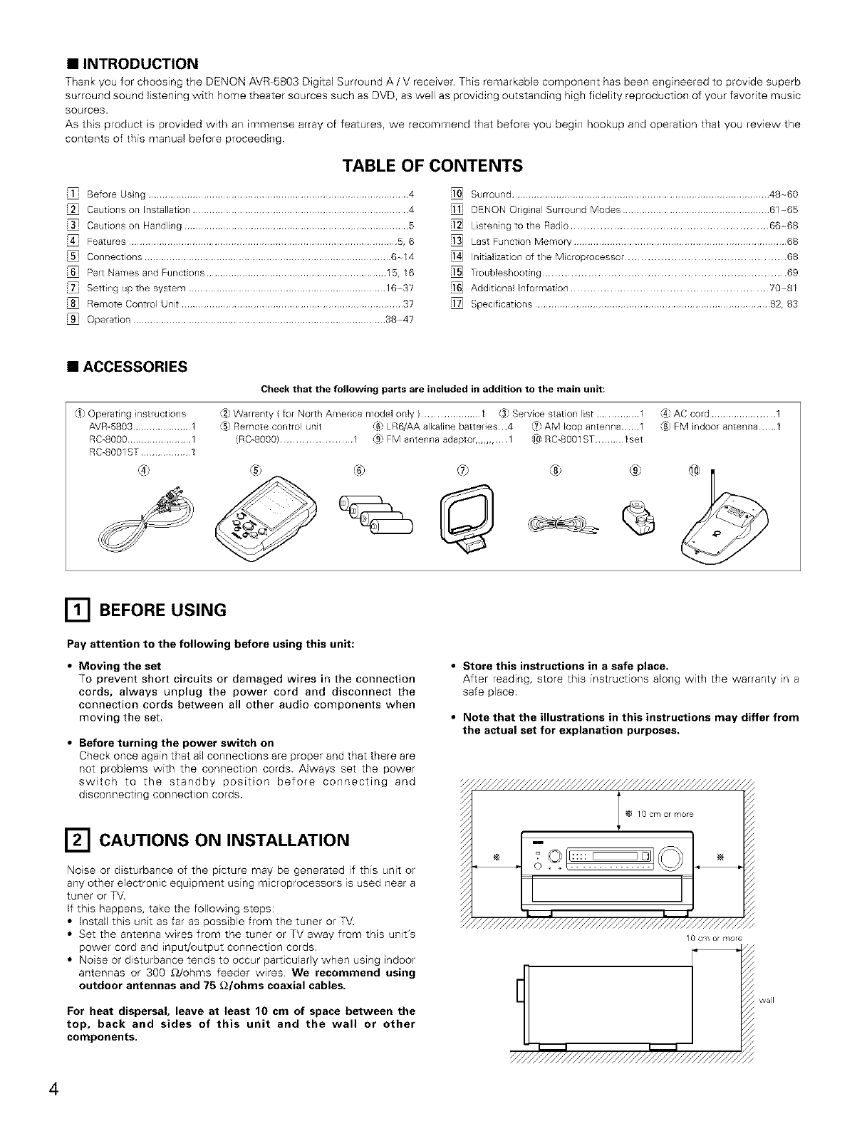
•ACCESSORIES
_} Operatinginstructions
AVR-5803.....................1
RC_8000.......................1
RC_S001ST..................1
Check that the following parts are included in addition to the main unit:
,_2.Warranty ( for North America model only ).................... 1 3} Service station list ............... 1
6) Remote control unit _ LR6/AA alkaline batteries¸ 4 _ AM loop antenna¸¸¸¸¸¸1
iRGS000) ....................... 1 _ FM antenna adaptor,.,,,1 _ RC_8001ST .......... 1set
®
/A_AC cord ...................... 1
{8} FM indoor antenna 1
[] BEFORE USING
Pay attention to the following before using this unit:
•Moving the set
To prevent short circuits or damaged wires in the connection
cords, always unplug the power cord and disconnect the
connection cords between all other audio components when
moving the set,
•Before turning the power switch on
Check once again that all connections are proper and that there are
not problems with the connection cords. Always set the power
switch to the standby position before connecting and
disconnecting connection cords.
[] CAUTIONS ON INSTALLATION
Noise or disturbance of the picture may be generated if this unit or
any other electronic equipment using microprocessors is used near a
tuner or TV.
If this happens, take the following steps:
• Install this unit as far as possible from the tuner or TV.
• Set the antenna w_res from the tuner or TV away from this unit's
power cord and input/output connection cords.
• Noise or disturbance tends to occur particularly when using indoor
antennas or 300 £_/ohms feeder wires We recommend using
outdoor antennas and 75 _2/ohms coaxial cables.
For heat dispersal, leave at least 10 cm of space between the
top, back and sides of this unit and the wall or other
components.
•Store this instructions in a safe place.
After reading, store this instructions along with the warranty in a
safe place.
•Note that the illustrations in this instructions may differ from
the actual set for explanation purposes.
////////////////////////////////////////////////_
I _ 10cr,/or r,/ore
o
LJ
Y///////////////////////////////////////////////
0cm or r,/ore
/////////////////////////////////////////_
wall
4
[] CAUTIONS ON HANDLING
•Switching the input funCtion when input jacks are not
connected
Aclicking noise may be produced if the input function is switched
when nothing is connected to the input jacks If this happens,
either turn down the MASTER VOLUME control or connect
components to the input jacks
•Muting of PRE OUT jacks and SPEAKER terminals
The PRE OUT jacks and SPEAKER terminals include a muting
circuit Because of this, the output signals are greatly reduced for
several seconds after the power switch is turned on or input
function, surround mode or any other-setup is changed. If the
volume is turned up during this time, the output will be very high
after the muting circuit stops functioning Always wait until the
muting circuit turns off before adjusting the volume.
[] FEATURES
1. Digital Surround Sound Decoding
Featuring dual 32 bit high speed DSP processors, operating
entirely in digital domain, surround sound from digital sources
such as DVD, DTV and satellite are faithfully re=created
2. Dolby Digital
Using advanced digital processing algorithms, Dolby Digital
provides up to 51 channels of wide-range, high fidelity surround
sound. Dolby Digital is the default digital audio delivery system for
North American DVD and DTV, and is available on laser discs as
well as some digital satellite direct4o-home services.
3. DTS (Digital Theater Systems)
DTS provides up to 51 channels of wide-range, high fidelity
surround sound, from sources such as laser disc, DVD and
specially-encoded music discs.
4. Lucasfilm Home THX Ultra2 Certified
Home THX is the unique collaboration between Lucasfilm Ltd and
audio equipment manufacturers. THX Ultra2 certification is the
highest performance level, and provides a ngorous set of
performance standards, along with proprietary surround sound
post-processing technologies, designed to enhance the surround
soundtrack playback experience in the home theater
In addition to improvements to the power amplifier with respect
to previous THX Ultra standards, two surround modes have been
added: the THX Ultra2 Cinema mode and the THX Music mode
5. THX Surround EX
The AVR-BB03 is fully compatible with THX Surround EX, the latest
surround format.
6. DTS-ES Extended Surround and DTS Neo:6
The AVR_5803 is compatible with DTS_ESExtended Surround, a new
muIt -channel format developed by Digital Theater Systems Inc.
The AVR-5803 is also compatible with DTS Neo:B, a surround mode
allowing 6.1-channel playback of regular stereo sources.
7. DTS 96/24 compatibility
The AVR_BB03 is compatible with sources recorded in DTS 96/24, a
new multi channel digital signal format developed by Digital Theater
Systems lnc
DTS 96/24 sources can be played in the muir-channel mode on the
AVR-BB03 with high sound quality of 96 kHz!24 bits or 882 kHz/24 bits
8. Dolby Pro Logic 1I decoder
Dolby Pro Logic ][ is a new format for playing multichannel audio
signals that offers improvements over conventional Do(by Pro
Logic It can be used to decode not only sources recorded in
Dolby Surround but also regular stereo sources into five channels
(front left/right, center and surround left/dght). In addition, various
parameters can be set according to the type of source and the
contents, so you can adjust the sound field with greater precision.
9. Wide screen mode for a 7.t-channel sound even with
5.1-channel sources
DENQN has developed a wide screen mode with a new design
which recreates the effects of the multi surround speakers in
movie theaters. The result is 7.1_channel sound taking full
advantage of surround back speakers, even with Dolby Pro Logic
or Dolby Digital/DTS 5 1-channel signals
•Whenever the power switch is in the STANDBY state, the
apparatus is still connected on AC line voltage.
Please be sure to unplug the cord when you leave home for,
say, a vacation.
10.Dual Surround Speaker Mode
Provides for the first time the ability to optimize surround sound
reproduction using two different types of surround sound
speakers as well as two different surround speaker positions:
(1) Movie Surround
Motion picture soundtracks use the surround channel(s) to
provide the ambient elements of the acoustic environment
they want the audience to realize This is best accomplished by
the use of specially-designed surround speakers that offer a
wide diffusion pattern (bipolar dispersion) or by using surround
speakers that provide broad dispersion with a minimum of on-
axis localization (dipolar dispersion). Side wall mounting (closer
to the ceiling) of the surround speakers provides the greatest
envelopment, minimizing localization of direct sound from the
speakers
(2) Music Surround
With full range discrete surround channels, as well as three
discrete full range front channels, digital formats such as Dolby
and DTS offer thblling surround sound music listening.
Producers of multFchannel discrete digital music recordings
almost always favor the use of direct radiating (monopolar)
surround speakers, placed in the rear corners of the room,
since that is how they configure their studios during the
mixing/creation process.
The DENON AVR-BBO3 provides the ability to connect two
different sets of surround speakers, and place them in the
appropriate locations in your home theater room, so that you
can enjoy both movie soundtracks and music listening, with
optimum results and no compromise
11.Multi-zone control
The AVR=5803 is equipped with two sets of multi-zone outputs
allowing a source other than the one currently being played to be
selected.
(1) MultFzone 1
These are level adjustable pre-outputs. (A fixed output level
can also be selected.)
The video signals of the input source selected with the multF
zone 1 selector are output
(2) MultFzone 2
When set at the System Setup Menu, the power amplifier for
the surround back channel can be used as the multi-zone 2
power amplifier and speakers can be connected to the multF
zone 2 speaker terminals for playback
12.Component Video Switching
The AVR-B803 provides 3 sets of component video (% R_Y, B_Y)
inputs for the DVD, TV and DBS/SAT inputs, and one set of
component video outputs to the television, for superior picture
quality
The AVR-BBO3 is also equipped with a function for up-converting
composite video or SWideo signals to component video signals.
13.Video Select Function
Allow you to watch one source (visual) while listening to another
source (audio).
5
14.Seven Identical Power Amplifiers
Featuring discrete high current power transistors, the power amp
section is THX Ultra certified for top performance with the widest
range of speaker systems. Rated at 170 watts into 8 _2/ohms, the
amp channels feature additional low impedance drive capability
15.Future Sound Format Upgrade Capability via Eight Channel
Inputs & Outputs
For future multi=channel audio format(s), the AVR=BS03 is provided
with 71 channel (seven main channels, plus one low frequency
effects channel} inputs, along with a full set of 71 channel pre-
amp outputs, controlled by the 8 channel master volume control.
This assures future upgrade possibilities for any future multi-
channel sound format
A/D converters are provided for each channel for digital down-
m_xlng compatibility.
16.Dolby Headphone Compatibility
This is a three=dimensional sound technology developed jointly by
Dolby Laboratories and Lake Technology Ltd. of Australia for
achieving surround sound using regular headphones.
17.DENON Link
This terminal can be used to connect a Denon DVD player for high
quality digital multichannel playback.
18.Auto Surround Mode
This function stores the surround mode last used for an hqput
signal in the memory and automagcally sets that surround mode
the next time that signal is input.
19.Audio Delay
This is a function for delaying the audio signal with respect to the
video signal. (0 to 200 msec)
20.Setup Lock
This is a function that locks the system setup and surround
parameter settings, etc., so that they cannot be changed
r_ CONNECTIONS
•Do not plug in the AC cord until all connections have been
completed.
• Be sure to connect the left and right channels propedy (left with
Jeft, right with right)
• Insert the plugs securely. Incomplete connections will result in
the generation of noise.
•Use the AC OUTLETS for audio equipment only. Do not
use them for hair driers, etc.
• Note that binding pin plug cords together with AC cords or
placing them near a power transformer will result in generating
hum or other noise.
• Noise or humming may be generated if a connected audio
equipment is used independently without turning the power of
this unit on If this happens, turn on the power of the this unit.
6
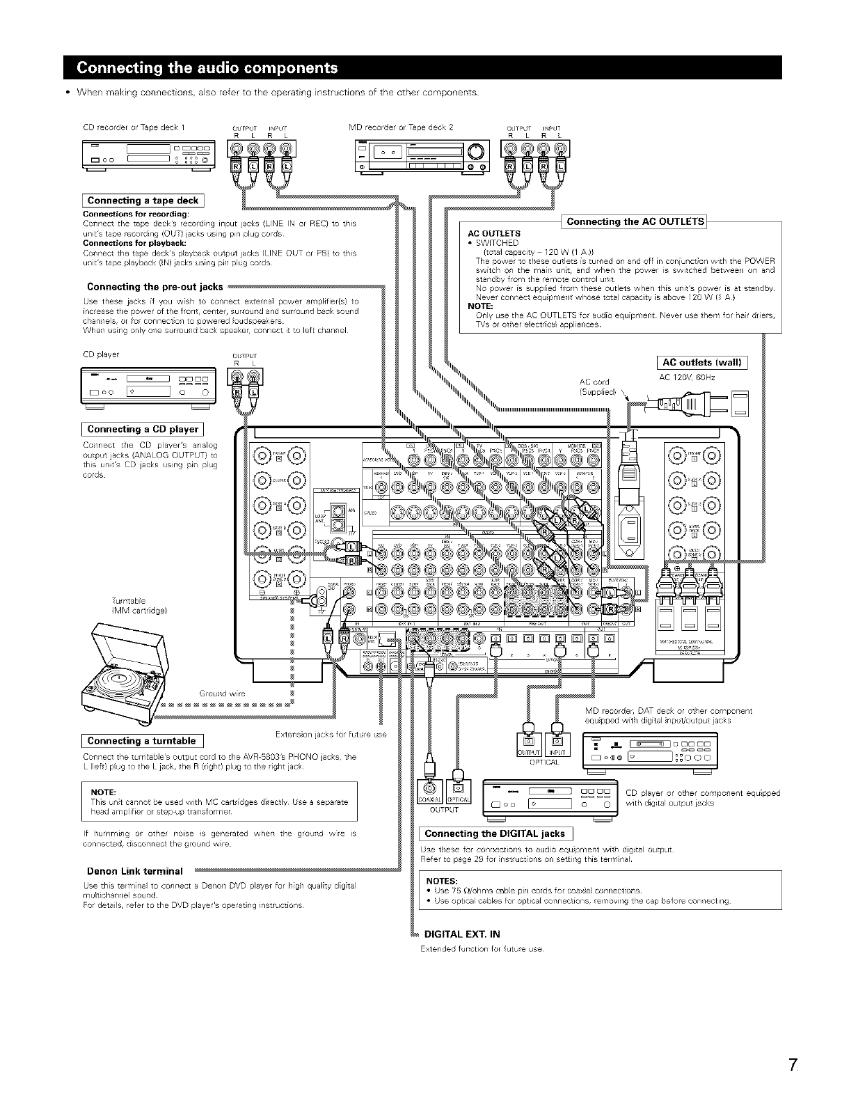
• When making connections, also refer to the operating instructions of the other components
CD ecorder or Tape deck 1 ou r_'UT IN['Ur
R L R L
[:oo
MD recorder or Tape deck 2 OUTPU I_'IT
R L R L
Connecting a tape deck]
Connections for recording:
Connect the aide deck's record ng input jacks (LINE IN or REC} to this
units tape ecording (O T} iacks using pin plug cords
Connections for playback:
Connect the tape deck's playback output jacks (LI#_E OUT or PB} to this
u/its tape playback {N) acks using pl/plug cords
Connecting the pre-out jacks
Use these jacks if you wish to connect ex e r/a] power amplifier{s} to
increase the power of the front, center, surround and surround back sound
channels, or fo_ connect on to powered oudspeakers
When usng only one surrou/d back speaker connect it to lef[ clan/el
IConnecting the AC OUTLETS_
AC OUTLETS
• SWITCHED
{tota] capacity 120 W (1 A)}
The power to these outlets is turned on and ofl in coniunct on with the POWER
switch on the mairl unt, and when tile power is switched between on and
standby from the remote control unit
No power is suppled lrom these outlets when this unit's power is at standby
Never connect equ pine/t whose total capacity is above 120 W (1 A}
NOTE:
Only use the AC OUTLETS ol audio equipment Never use her,/for/air dres,
TVs or other electr[ca( appliances
[ AC outlets (wail) ]
AC cord AC 120V, 6OHz
[Connecting aCD player ]
Connect the CD player's analog
output jacks (ANALOG OUTPUT} to
this units CD iacks using pl/ plug
cords
@
Tumtable
{MM cartridge}
Groundwire
Extens on jacks for future use
[Connecting aturntable ]
Connect the tumtabie's output cold to the AVR 5803's PHONO jacks, the
L (left} plug to the L iack, the R (right) plug to the ight jack OPTICAL
MD recorder, DAT deck or other component
equ pped with digital nput,/output acks
NOTE:
This unt cannot be used with MC cartridges di ectly Use a separate
head amplifier or step up transformer
If humming or ot/e noise is generated when the gound w]e is
connected, disconnect the ground wire
Denon Link terminal
Use this term na] o connect a Denon DVD player for hg/ qua]ty dgtal
rPu tic_lar/l/el soun_
For detai s, refer to the DVD player's operat ng i/struet[or/s
_ -- _ DDOD | CD player or other compo/ent equpped
OUTPUT [Doo [o _==oJ withdigitaloutputiacks
Connecting the DIGITAL jacks ]
Use these for connections to audio equ pment with digital output
Refer to page 29 for nst uctions on set[ing this term r/a]
NOTES:
Use 7b _/ohl¥1s cable pill oo_ds or coaxa conr/ectiol/s
• Use optical cables for optical connections, e T1ov11gthe Gap belore cor//ecti/g
DIGITAL EXT. IN
Extended function for futue use
7
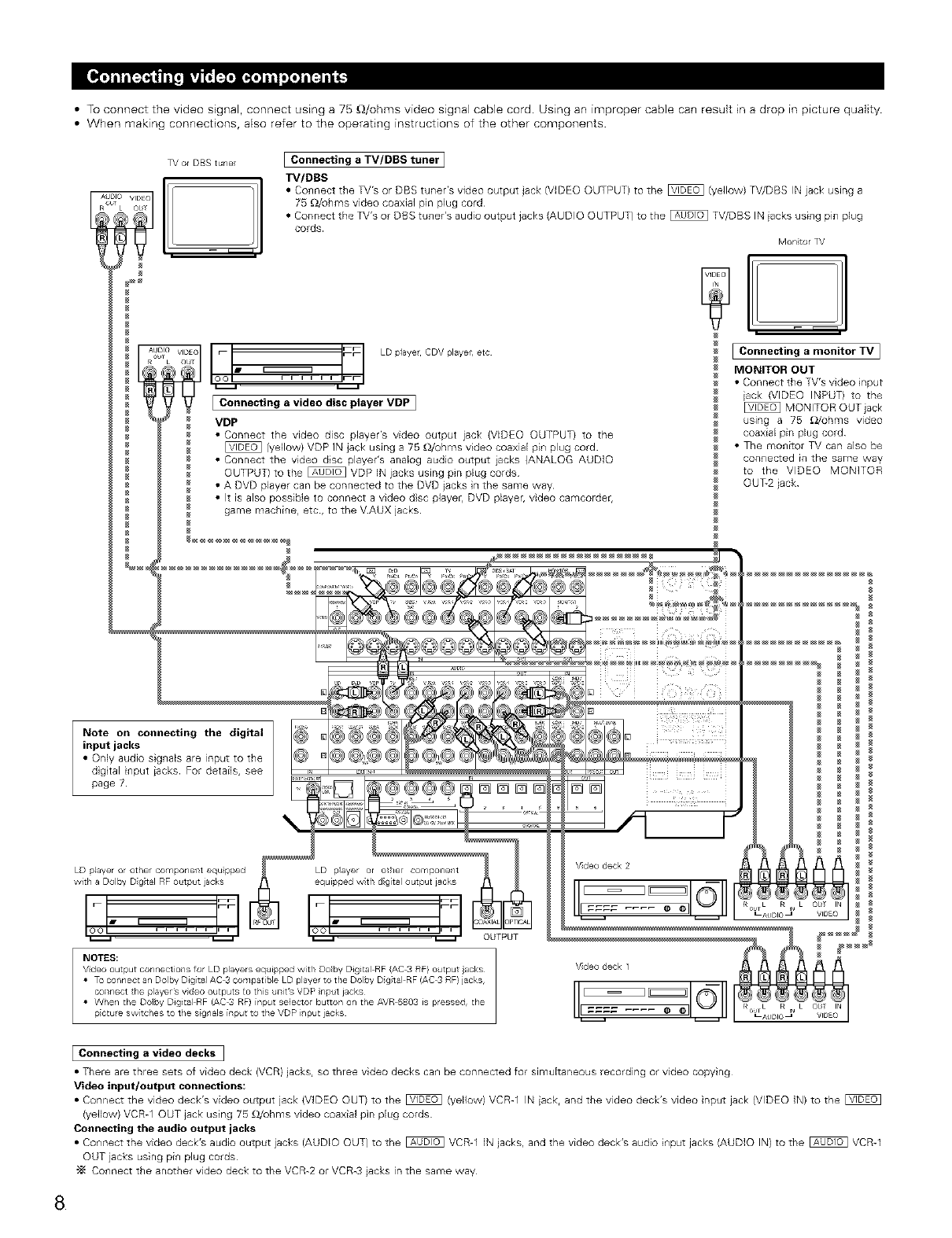
• To connect the video signal, connect using a 75 _/ohms video signal cable cord. Using an improper cable can result in a drop in picture quality.
• When making connections, also refer to the operating instructions of the other components
TVorDBStunel
VIDEO I
ObT
IConnecting a TV/DBS tuner I
TV/DBS
•Connect the TV's or DBS tuner's video output jack (VIDEO OUTPUT) to the _ (yellow) TV/DBS IN jack using a
75 _)/ohms video coaxial pin plug cord
• Connect the TV's or DBS tuller's audio output jacks (AUDIO OUTPUT) to the _ TV/DBS IN iacks usillg pin plug
cords
Mort tor TV
ic_cq m "_ LD playe CDV player,etc
IFFI
JConnecting avideo disc player VDP ]
VDP
• Connect the video disc player's video output jack (VIDEO OUTPUT) to the
(yellow) VDP IN jack using a 75 _/ohms video coaxial pin plug cord
• Connect the video disc player's analog audio output jacks (ANALOG AUDIO
OUTPUT) to the _ VDP IN jacks using pin plug cords
• A DVD player can be connected to the DVD jacks n the same way
• It is also possible to connect a video dsc player, DVD player, video camcorder,
game machine, etc, to the VAUX jacks
w
Connecting monitor TV
a
MONITOR OUT
• Connect the TV's video input
iack (VIDEO INPUT) to the
MONITOR OUT jack
using a 75 OJohms video
coaxial pin plug cord¸
• The monitor TV can also be
connected in the same way
to the VIDEO MONITOR
OUT-2 jack
p;ctu e sw tches to the signals input to the VDP i/put jacks
JConnecting a video decks ]
• There are three sets of video deck (VCR) jacks, so three video decks Ca_l be connected for simultaneous recording or video copying
Video input/output connections:
= C_r_r_ect t_e video deckts v_deo o_p_t jac_ (VIDEO oum_ t_ the _ (yeaow_ vary1 JN _ck r arid t_e video dec_s video _r_p_ jack (VIDEO IN) to t_e
(yellow) VCR-1 OUT jack using 75 _/ohnqs video coaxial pin plug cords
Connecting the audio output jacks
• CO_lnect the video deck's audio output jacks (AUDIO OUT) to the _ VCR-1 IN jacks, and the video deck's audio i_lput jacks (AUDIO IN) to the _ VCR-1
OUT jacks using pin plug cords
"_ Connect the another video deck to the VCR-2 or VCR-3 jacks in the same way
8
•When making connections, also refer to the operating instructions of the other components
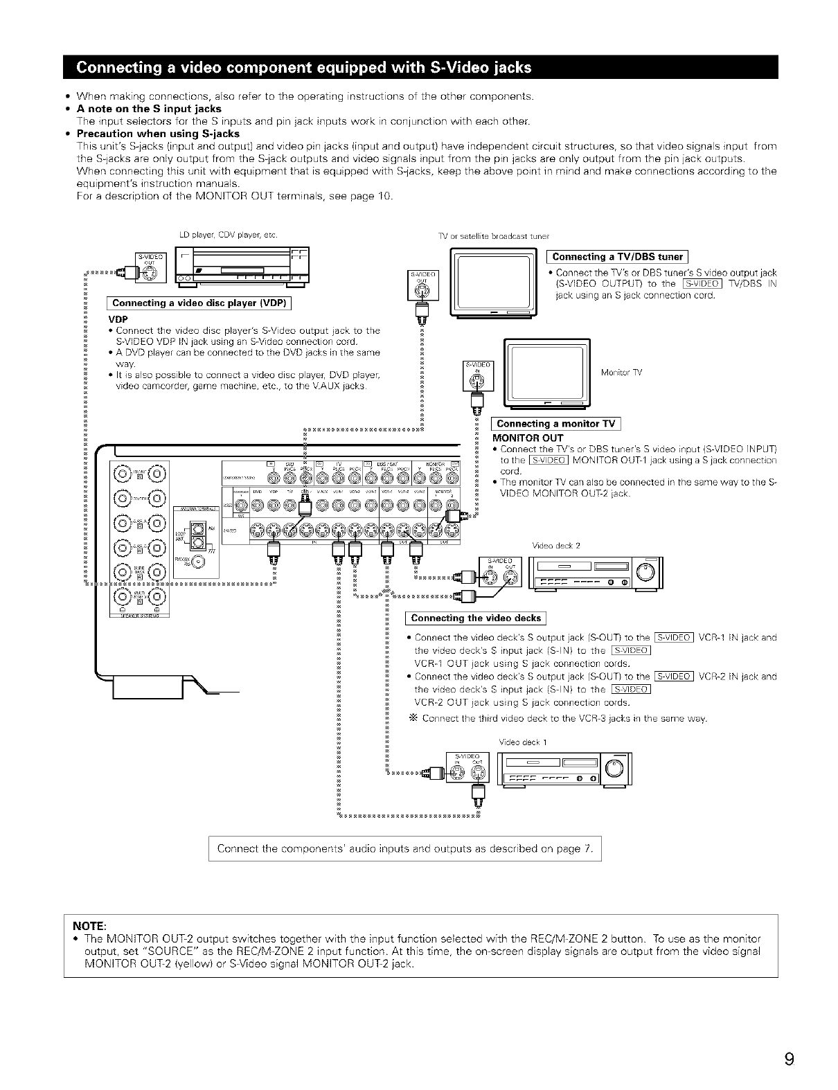
•A note on the S input jacks
The input selectors for the S inputs and pin jack inputs work in conjunction with each other
•Precaution when using S-jacks
This unit's S-jacks (input and output) and video pin jacks (input and output) have independent circuit structures, so that video signals input from
the S-jacks are only output from the S-jack outputs and video signals input from the pin jacks are only output from the pin jack outputs.
When connecting this unit with equipment that is equipped with S-jacks, keep the above point in mind and make connections according to the
equipment's instruction manuals.
For a description of the MONITOR OUT terminals, see page 10.
LD playe CDV player, etc
I I. YI
IOOL I L J_l
IConnecting a video disc player {VDP) I
VDP
• Connect the video disc player's S-Video output jack to the
S-VIDEO VDP IN iack using an S-Video connection cord
• A DVD player can be connected to the DVD jacks in the same
way
• It is also possible to connect a video disc playeh DVD player,
video camcordeh game machine, etc, to the VAUX iacks
]_/or satellite broadcast tune[
IConnecting a TV/DBS tuner ]
• Connect the TV's or DBS tuner's S video output iack
(S-VIDEO OUTPUT} to the _ TV/DBS IN
jack using an S jack connection cord
@ @
_ !11 Montor TV
IConnecting a monitor TV I
MONITOR OUT
• Connect the TV's or DBS tuner's S video input {S-VIDEO iNPUT}
to the _ MONITOR OUT-1 jack using a S jack connection
cord
• The monitor TV can also be connected in the same way to the S-
VIDEO MONITOR OU%2 jack
Video deck 2
_ I ==== .... oel 0
[Connecting the video decks 1
• Connect the video deck's S output jack (SHOUT) to the _ VCRhl IN jack and
the video deck's S input jack (SHIN) to the
VCR-1 OUT iack using Siack connection cords
• Connect the video deck's S output jack (SHOUT) to the _ VCRh2 IN jack and
the video deck's S input jack (SHIN) to the
VCR-2 OUT iack using S iack connection cords
"_ Connect the third video deck to the VCRh3 jacks in the same way
Vdeo deck 1
%...... _ iI 7 _ II _l I O_
Connect the components' audio inputs and outputs as described on page 7 ]
NOTE:
• The MONITOR OUT-2 output switches together with the input function selected with the REC/M-ZONE 2 button To use as the monitor
output, set "SOURCE" as the REC/M-ZONE 2 input function At this time, the on-screen display signals are output from the video signal
MONITOR 0U%2 (yellow) or S-Video signal MONITOR OUT-2 iack.
9
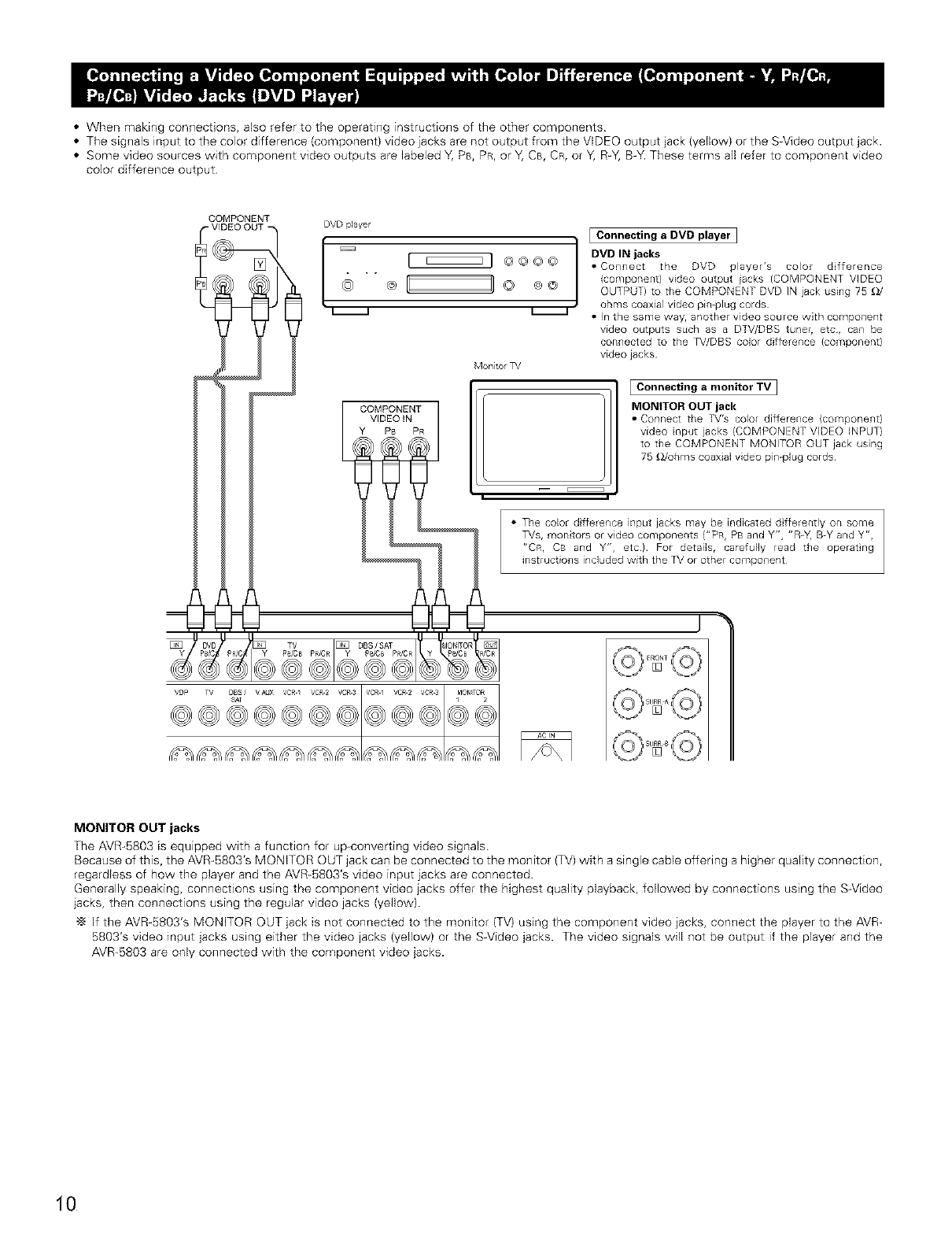
• When making connections, also refer to the operating instructions of the other components
•The signals input to the color difference (component) video jacks are not output from the VIDEO output jack (yellow) or the S_Video output jack.
• Some video sources with component video outputs are labeled Y, PB, PR, or Y, CB, CR, or Y, R_Y,B-Y. These terms all refer to component video
color difference output
COMPONENT DVD player
-VIDEO OUT
[ 000o ]
Monitor TV
COMPONENT 1
VIDEO IN
Ps PR
i-- E::::::::::::::_ I
_ONITOR
IConnecting aDVD player I
DVD IN jacks
•Connect the DVD player's color d fference
(component) video output iacks (COMPONENT VIDEO
OUTPUT) to the COMPONENT DVD IN jack using 75 £_/
ohms coaxial video pin@lug cords
•In the same way, another video source with component
video outputs such as a DTV/DBS tuner, etc, can be
connected to the TV/DBS color difference (component)
video jacks
IConnecting amonitor TV ]
MONITOR OUT jack
• Connect the TV's color difference (component)
video input jacks (COMPONENT VIDEO INPUT)
to the COMPONENT MONITOR OUT jack using
75 _Johms coaxial video pin-plug cords¸
• The color dfference input jacks may be indicated dfferently on some
TVs, monitors or video componer_ts ("PB, PB and Y", "R-Y, B-Y and yr,,
r'CR, CB and Y", etc) For details, carefully read the operatng
instructions included with the TV or other component
MONITOR OUT jacks
The AVR-BB03 is equipped with a function for up converting video signals
Because of this, the AVR-BB03's MONITOR OUT jack can be connected to the monitor (TV) with a single cable offering a higher quality connection,
regardless of how the player and the AVR-B803's video input iacks are connected.
Generally speaking, connections using the component video jacks offer the highest quality playback, followed by connections using the S-Video
jacks, then connections using the regular video jacks (yellow).
-_ If the AVR-BB03's MONITOR OUT jack is not connected to the monitor (TV) using the component video jacks, connect the player to the AVR-
5B03's video input jacks using either the video jacks (yellow) or the S-Video jacks. The video signals will not be output if the player and the
AVR-BBO3 are only connected with the component video jacks.
10
_. AM LOOP ANTENNA
(Supplied}
F type converter plug {attached)
• Whefl usil/g the FM allteflr/a
at Cae{_ to this apparatus
25 [_/ohms
COAX AL
CABLE
f
DIRECTION OF
BROADCASTING
STATION
FM ANTENNA
1_ FEEDER
CABLE
),(
_NNNNNNN_
FM INDOOR 300 _/o/ms
ANTENNA
(Suppl ed}
FM ANTENNA
ADAPTER
{Supplied)
• L
@@@
AM OUTDOOR
ANTENNA
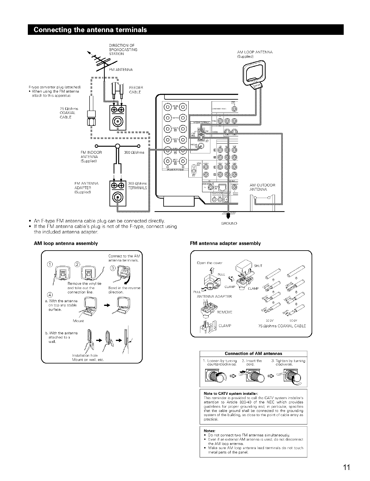
•An F-type FM antenna cable plug can be connected directly.
•If the FM antenna cable's plug is not of the F-type, connect using
the incEuded antenna adapter.
AM loop antenna assembly
GROUND
FM antenna adapter assembly
a_/te_/_a terminals
and take out the Bend in the reverse
coTsnect[on line direction
a Wth the a_/te_/_sa
ors top a_/y stable
surface
Mount
b With the a_/te_/f_a
attac/ed to a
wall
IilStal at[on/ole
ANTENNA ADAPTER
CLAMP
so@/ 5c 27
25 £_/ohms COAXIAL CABLE
Collnectioll of .l_t_ al_tenltas
1 Loosen by turning 2 Insert the 3 _ghten by turning
couT_tere)ockw[se cord¸ clockwise
Note to CATV system installer:
This reminder is provided to call the CATV system [nsCaller's
atcent[on to Artic)e 820 40 of the NEe which provides
guidelines for proper grounding and, in particular, specifies
ttlat the cable gfouTld shall be col/Tlected to the g/oul/dirlg
syster¢l Of the bu[Idil/g, as close to the poirlt Of cable el/try as
pract[ca_
Notes_
• Do not connect two FM antennas si_/lu)taneous_y
• Eve_/ if a_ exter_/al AM ante_/_a is used¸ do not discoT_nect
the AM loop antenna¸
• Make sure AM loop ar_tef_na lead te_mi_/als do not touch
r qeta_ parts el the pal/el
11
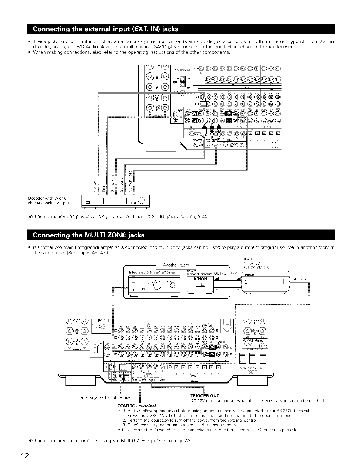
• These jacks are for inputting multi-channel audio signals from an outboard decoder, or a component with a different type of multi-channel
decoder, such as a DVD Audio player, or a multi-channel SACD player, or other future multPchannel sound format decoder
• When making connections, also refer to the operating instructions of the other components
Decoder with 8- or 6-
channel anaEog output
i
I-
W3'="k_ _-@_@@@@@@@@@@@
N_Jl%
............ "d /'i]..... ;'
_@@@@@@_@@@
=!
"_ For instructions on playback using the external input (EXT IN) iacks, see page 44
• If another pre-main (integrated) amplifier is connected, the muki-zone jacks can be used to play a different program source in another room at
the same time. (See pages 46, 47)
RC4316
g®®e®®@e6 @@
@@@@@@@@@
5®®6 .....
[]
t._Duii=t._2
€ @
ii>iiiiii iiii>i_i i
.i r+ i,,<
=';<+='==,.,iiil
!? .......E=[3
@® ........
TRIGGEROUT
Extenson jacks for _utu_ use_jacksfor future use I P_?_V_t_urOnsU_n and °ff when the product's power istumid onExte_si°n and off
CONTROLterminal
Perform the following operation before using an external contro/er connected to the RS-232Cterminal:
1 Pressthe ON/STANDBYbutton on the main unit and set the unit to the operating mode
2 Per;orm the operation to turn off the power from the external control
3 Check that the product has been set to the standby mode
After checking the above, check the connections of the external controller Operation is possible
"_ For instructions on operations using the MULTI ZONE jacks, see page 43.
12
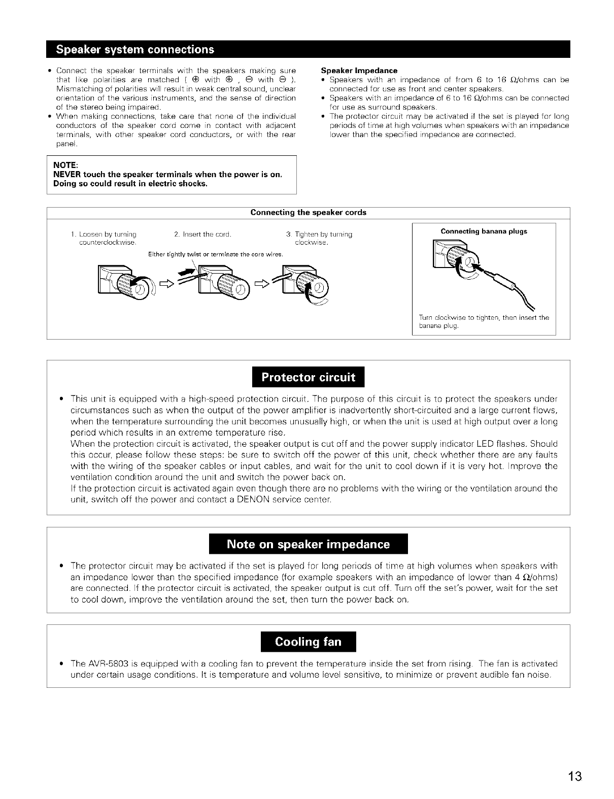
• Connect the speaker terminals with the speakers making sure
that like polarities are matched ( (_ with (_ ,(_ with e ).
Mismatching of polarities will result in weak central sound, unclear
orientation of the various instruments, and the sense of direction
of the stereo being impaired.
• When making connections, take care that none of the individual
conductors of the speaker cord come in contact with adjacent
terminals, with other speaker cord conductors, or with the rear
panel
NOTE:
NEVER touch the speaker terminals when the power is on,
Doing so could result in electric shocks.
Speaker Impedance
• Speakers with an tmpedance of from 6 to 16 £_/ohms can be
connected for use as front and center speakers
• Speakers with an impedance of 6 to 16 £_/ohms can be connected
for use as surround speakers
• The protector circuit may be activated if the set is played for long
periods of time at high volumes when speakers with an impedance
lower than the specified impedance are connected.
Connecting the speaker cords
Loosen by turning 2 Inser_ the cord 3 Tighten by turning
counterclockwise clockwise
Either t;ghtly twist or terminate the core wires.
Connecting banana plugs
Turn clockwise to tighten, then insert the
banana plug
This unit is equipped with a high-speed protection circuit. The purpose of this circuit is to protect the speakers under
circumstances such as when the output of the power amplifier is inadvertently short-circuited and a large current flows,
when the temperature surrounding the unit becomes unusually high, or when the unit is used at high output over a long
period which results in an extreme temperature rise.
When the protection circuit is activated, the speaker output is cut off and the power supply indicator LED flashes. Should
this occur, please follow these steps: be sure to switch off the power of this unit, check whether there are any faults
with the wiring of the speaker cables or input cables, and wait for the unit to cool down if it is very hot. Improve the
ventilation condition around the unit and switch the power back on.
If the protection circuit is activated again even though there are no problems with the wiring or the ventilation around the
unit, switch off the power and contact a DENON service center.
The protector circuit may be activated if the set is played for long periods of time at high volumes when speakers with
an impedance lower than the specified impedance (for example speakers with an impedance of lower than 4 £)/ohms)
are connected. If the protector circuit is activated, the speaker output is cut off. Turn off the set's power, wait for the set
to cool down, improve the ventilation around the set, then turn the power back on.
The AVR-5803 is equipped with a cooling fan to prevent the temperature inside the set from rising. The fan is activated
under certain usage conditions. It is temperature and volume level sensitive, to minimize or prevent audible fan noise.
13
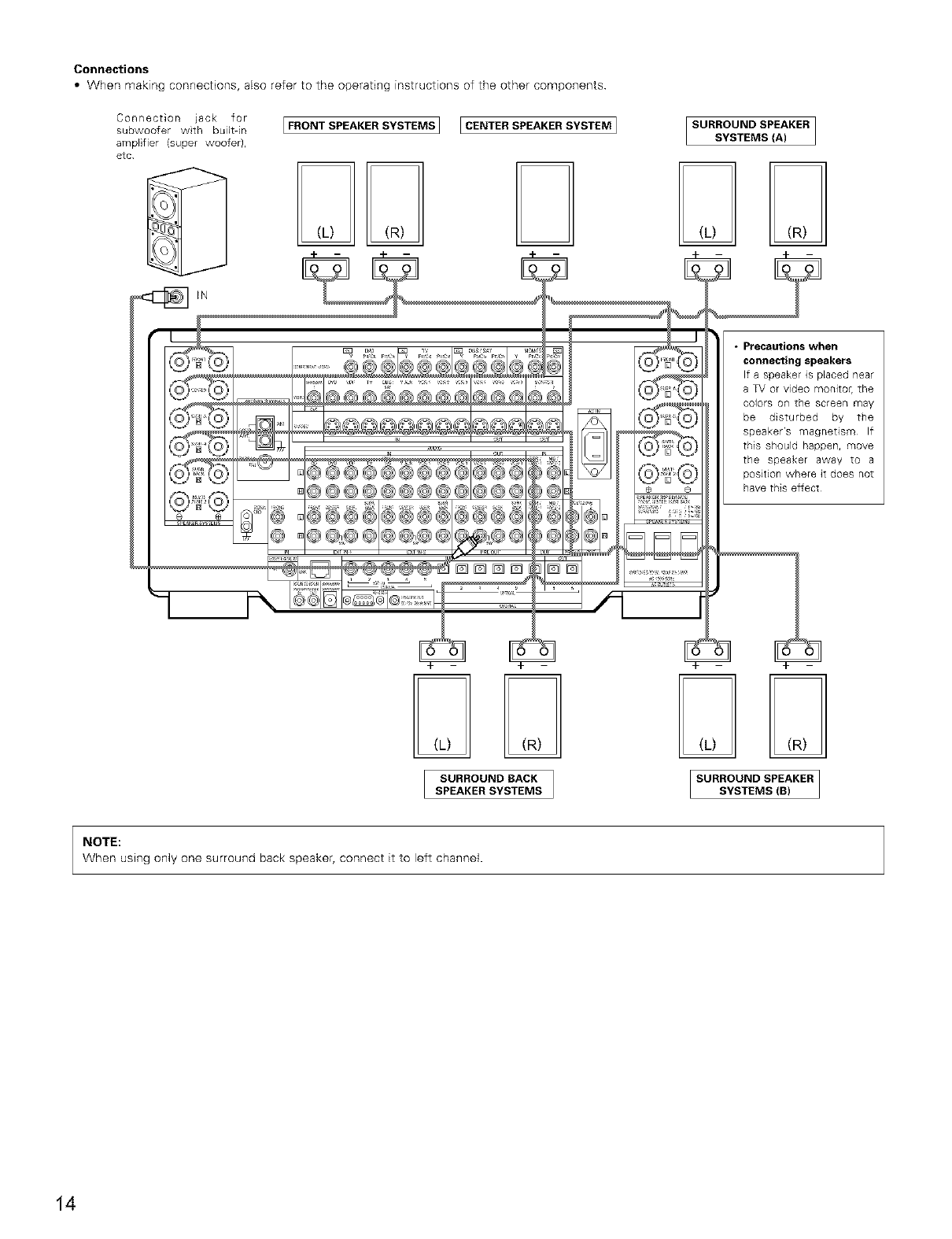
Connections
•When making connections, also refer to the operating instructions of the other components
Connection }ack for
subwoofer wth built-in
am@tier {super woofer),
etc
[FRONT SPEAKER SYSTEIViS 1 [ CENTER SPEAKER SYSTEIVi I
• pl'ecautions wherl
connecting speakers
If a speaker is placed near
a TV or video monitoh the
Colors Or] the screen may
be disturbed by the
speaker's magnetism If
this should happen, move
the speaker away to a
position where it does not
have this effect
SURROUND BACK
SPEAKERSYSTEMS
NOTE:
When using only one surround back speaker, connect it to left channel•
14
[] PART NAMES AND FUNCTIONS
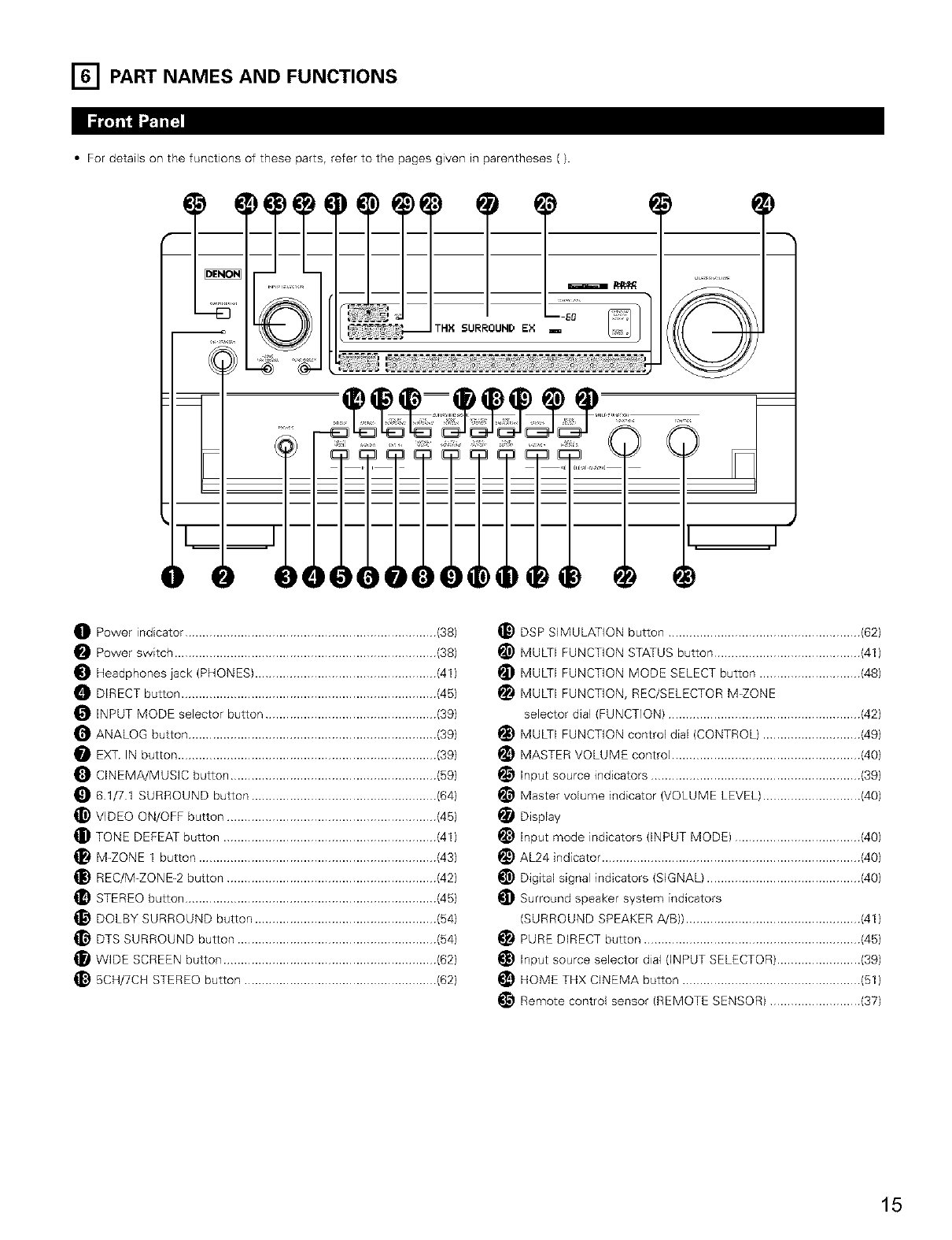
•For details on the functions of these parts, refer to the pages given in parentheses ().
@®®®
O Power indicator ........................................................................ (38)
Power switch ........................................................................... (38)
Headphones jack (PHONES) .................................................... (41)
DIRECT button ......................................................................... (45)
INPUT MODE selector button ................................................. (39)
O ANALOG button ....................................................................... (39)
EXT IN button .......................................................................... (39)
CINEMA/MUSIC button ........................................................... (59)
61/71 SURROUND button ..................................................... (64)
_) VIDEO ON/OFF button ............................................................ (45)
TONE DEFEAT button ............................................................. (41)
M-ZONE 1 button .................................................................... (43)
REC/M-ZONE-2 button ............................................................ (42)
STEREO button ........................................................................ (45)
_} DOLBY SURROUND button .................................................... (64)
DTS SURROUND button ......................................................... (64)
WIDE SCREEN button ............................................................. (62)
5CH/7CH STEREO button ....................................................... (62)
_) DSP SIMULATION button ....................................................... (62)
_) MULTI FUNCTION STATUS button .......................................... (41)
MULTI FUNCTION MODE SELECT button ............................. (48)
MULTI FUNCTION, REC/SELECTOR M_ZONE
selector dial (FUNCTION) ....................................................... (42)
MULTI FUNCTION control dial (CONTROL) ............................ (49)
MASTER VOLUME control ...................................................... (40)
_} Input source indicators ............................................................ (39)
Master volume indicator (VOLUME LEVEL) ............................ (40)
Display
input mode indicators (INPUT MODE) .................................... (40)
_) AL24 indicator .......................................................................... (40)
_) Digital signal indicators (SIGNAL) ............................................ (40)
Surround speaker system indicators
(SURROUND SPEAKER A/B)) .................................................. (41)
PURE DIRECT button .............................................................. (45)
input source selector dial (INPUT SELECTOR) ........................ (39)
HOME THX CINEMA button ................................................... (51)
_} Remote control sensor (REMOTE SENSOR) .......................... (37)
15
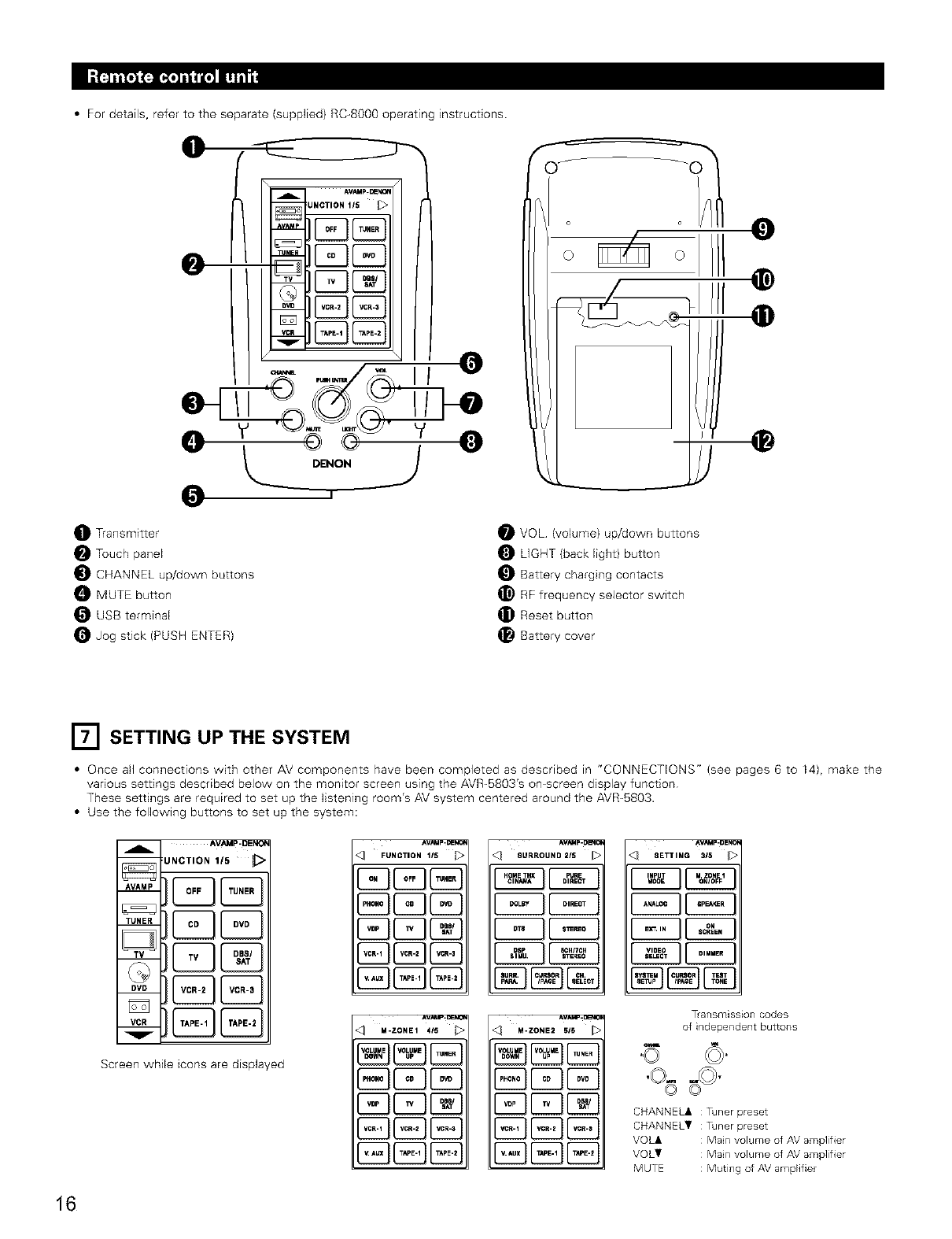
• For details, refer to the separate (supplied) RC-8000 operating instructions
DENON
O Transmitter
Touch panel
CHANNEL up/down buttons
MUTE button
USB terminal
O Jog stick (PUSH ENTER}
VOL (volume) up/down buttons
LIGHT (back light} button
Battery charging contacts
_} RF frequency selector switch
_ Reset button
_! Battery cover
[] SETTING UP THE SYSTEM
• Once all connections with other AV components have been completed as described in "CONNECTIONS" (see pages 6 to 14), make the
various settings described below on the monitor screen using the AVR-SB03's on-screen display function
These settings are required to set up the listening room's AV system centered around the AVR_5803.
• Use the following buttons to set up the system:
AVAMp'DENO_
UNCTION 115
Screen while icons are displayed
_UNCTIO.1/S D
C23[23
E3E3
AVNd p- DERi_
SURROUND2/S
^V_Mp-uENue
8eTTIN_ S_S
M-ZONE2 515
T_ansmission codes
of independent buttons
"O
CHANNELA : Tdner preset
CHANNELT : Tdner preset
VOLA : Main volume of AV amplifier
VOLT : Main volume of AV amplifier
MUTE : Muting of AV amplifier
16
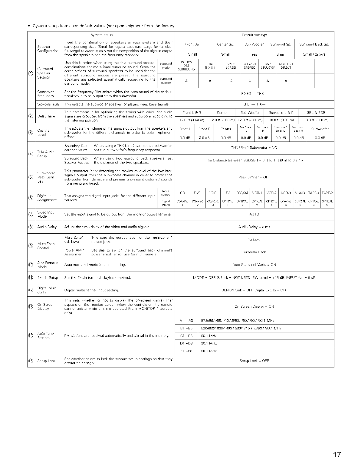
• System setup items and default values (set upon shipment from the factow)
Speaker
CoTlf gurat[on
(Su/round
Speaker
Setti/g)
System setup
Input tie cor'lbinat[on of speakers n your system and the]r
cor/esponding sizes (Sr/lall for regu(a/ speakers, Large for lull size,
full range} to automatically set the composition of the signals output
from the speakers a_d the frequeT_¢y respo_/se
C ossover Set the frequeTlcy (Hz) below which the Bass souTld of tile various
Frequency speakers is to be output l_om t/_e st,bwoofe_
Subwo0fer mode This selects the subwoofer speakel for playing deep bass sigl/als
Delay _me
Ci/annel
Level
THXAudio
Setup
Subwoofer
Peak Limk
Lev
This parameter is for optim zing tile timing wCh w!/ic/ the audio
sigr_als are produced f_om the speakers and subwoofer aocording to
the listening position¸
T/is adiusts the volume of the signals output from the speakers a_ld
subwoofel lot the diflereTlt chal/llels in older to o_tair/ optimum
effe_s
Boundary Gain When using a THX Ultra2 cor'lpatJble subwoofe
compensat_oT_ set the subwoofer s l_equency respo_/se
Surround Back
Speake Posit ol"
T/is parameter is for detect ng the maximum leve of the low bass
sigr_als output from tt_e subwooler cha_nel i_/ o_de_ to protect the
subwoofe_ from damage arid preve_/t unp(easa_t distorted sou_/ds
from be[llg p_oduoed
Set the nput signal to be output from the moTl[tor output terr,/inal
Adjust the time delay of the v_deo and audio signals¸
Mult_ Zone1 T_l[s sets ttle Output level lot ttle multi zol/e 1
vol Level output jacks
Power AMP Set tills to switch the surround bac_< chanrlel's
Assignmel/t power amp(if[er for use for multi ZOTle 2
Auto surround mode function setting
Set the Extln telminal playback method¸
Digital muir[channel input setting
This sets whethe/ or i/or to display the on_c/eeT1 display that
FM stations are rece veal auto ¥1at[ca_ly aT_d stoed i/ the memory
Set whether oF not to lock the system setup settJ/gs so treat tt_ey
ca_/_ot be oha_/ged
Front Sp
Small
Fro/t L & R
120 ft (360 r,/}
A1 A8
BI B8
CI C8
DI D8
Defau t sett ngs
Center Sp Sub Woofe
Small Yes
FIXED THX
LFE _HX
Center
120 ft (3¸60 m)
Sur ouTld Sp
Small
Su round L & R
10 0 fC(3 00 m)
THX Ultra2 Subwoofer NO
Tie Distance Betwee / SBL/SBR 0 fc to I ft (0 m to 03 m}
Peak Li ¥_[ter OFF
AUTO
Audio Delay 0 r,/s
Var able
SurrouTld Bao_
Auto Sulround Mode ON
MODE DSF' SBack N©T USED, SW Level +15 dB, INPUT Vol 0 dB
DENON Link OF_ Digital Ext I_/ OFF
On Screen Disp(ay ON
87 _89 1/98 1/1079/90 1/90 1/90 I_0 I MHz
520/600/1000/140_1500/1710 _<Hz/90 1/90 1 MHz
901 MHz
901 MHz
901 MHz
Setup Lock OFF
Su round Back Sp
Small /2sprs
SBL & SBR
100 ft (300 r,9
Subwoofer
OOdB
17
NOTES:
• The omscreen display signals are output with priority to the S_VIDEO MONITOR OUT jack during playback of a video component For
example, if the TV monitor is connected to both the AVR-5803's S_Video and video monitor output jacks and signals are input to the AVR-
5803 from a video source (VDP, etc.) connected to both the S_Video and video input jacks, the omscreen display signals are output with
priority to the S_Video monitor output. If you wish to output the signals to the video monitor output jack, do not connect a cord to the S_
V]DEO input jack. (For details, see page 37)
• The AVR-5803's on-screen display function is designed for use with high resolution monitor TVs, so it may be difficuk to read small
characters on TVs with small screens or low resolutions
• The setup menu is not displayed when headphones are being used.
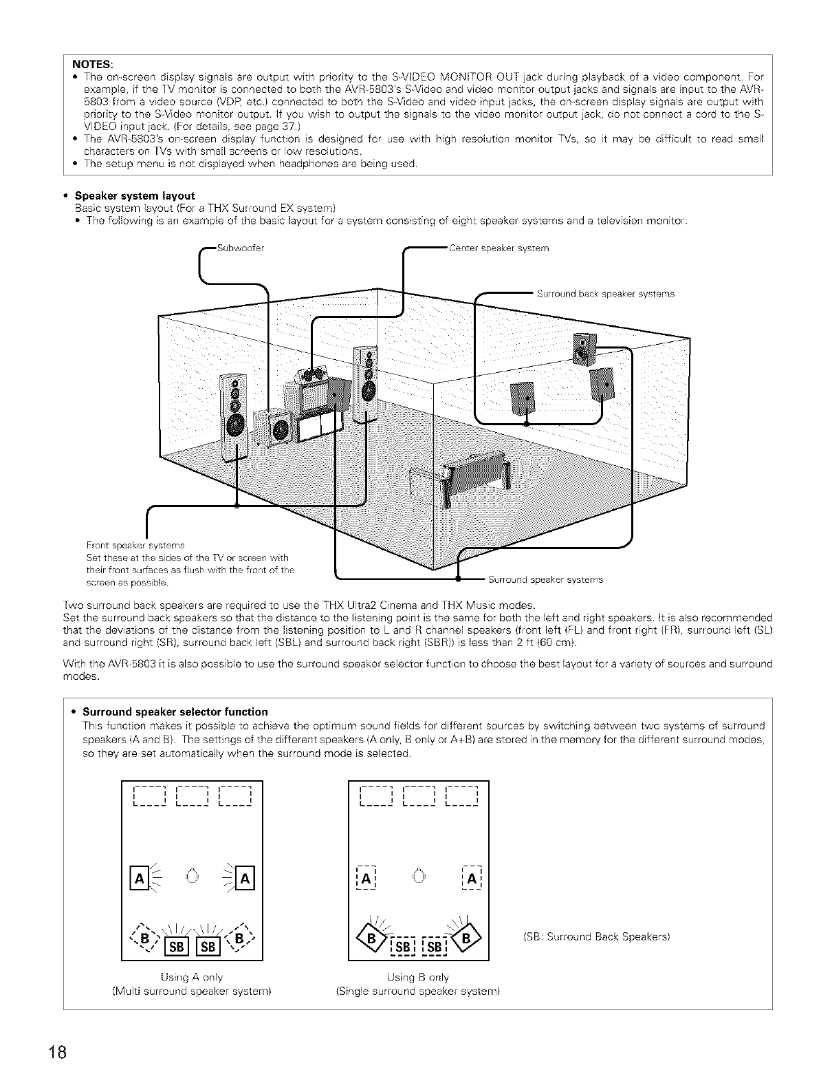
•Speaker system layout
Basic system layout (For a THX Surround EX system)
• The following is an example of the basic layout for a system consisting of eight speaker systems and a television monitor:
;peakersystem
Surround hock speaKer s ¢stems
r
Front speaker systems
Set these at the sides of the TVor screen1with
their front surfaces as flush with the front of the
screen as possible Surround speaker systems
Two surround back speakers are required to use the THX Ultra2 Cinema and THX Music modes.
Set the surround back speakers so that the distance to the listening point is the same for both the left and right speakers. It is also recommended
that the deviations of the distance from the listening position to L and R channel speakers (front left (FL) and front right (FR), surround left (SL)
and surround right (SR), surround back left (SBL) and surround back right (SBR)) is less than 2 ft (60 cm)
With the AVR-5803 it is also possible to use the surround speaker selector function to choose the best layout for a variety of sources and surround
modes.
•Surround speaker selector function
This function makes it possible to achieve the optimum sound fields for different sources by switching between two systems of surround
speakers (A and B) The settings of the different speakers (A only, B only or A+B) are stored in the memory for the different surround modes,
so they are set automatically when the surround mode is selected
'.... i '.... i '.... i
L___, L___, L____,
".' _12_EI_12.EI"-"
Using A only
(Multi surround speaker system)
'.... i '.... i '.... i
L____,L____,L___,
I i I i
I i I i
,A, ,A,
......
SBI ISB', X7
Using B only
(Single surround speaker system)
(SB: Surround Back Speakers)
18
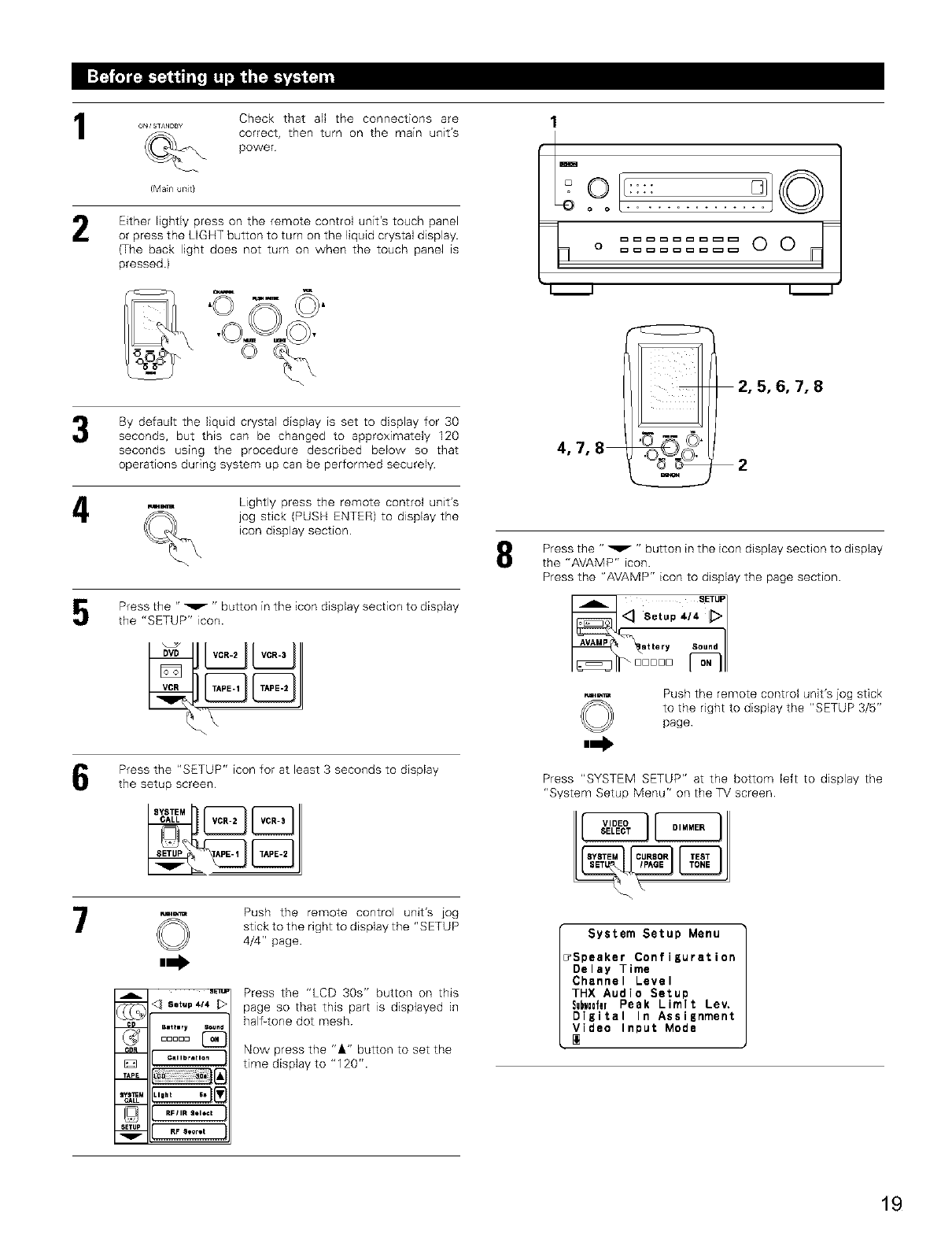
1
2
o_; ST^NDB¥
(Main uTlit}
Check that aN the connections are
correct, then turn on the main unit's
power
Either lightly press on the remote control unit's touch panel
or press the LIGHT button to turn on the liquid crystal display.
(The back light does not turn on when the touch panel is
pressed)
1
..........
;o
J
4
7
By default the fiquid crystal display is set to display for 30
seconds, but this can be changed to approximately I20
seconds using the procedure described below so that
operations during system up can be performed securely
Lightly press the remote control unit's
jog stick (PUSH ENTER) to display the
icon display section.
Press the "_ " button in the icon display section to display
the "SETUP" icon.
Press the "SETUP" icon for at least 3 seconds to display
the setup screen
A
m
TAP_
aYS_M
CALL
SETUP
v
eL_ B,_z
©
Setup 4/4
BlttlrY
DDDDD
Callbratlan
RFIIR _Ol6Ck
RF So_rlt
Push the remote control unit's iog
stick to the right to display the "SETUP
4/4" page.
Press the "LCD 30s" button on this
page so that this part is displayed in
half-tone dot mesh
Now press the "&" button to set the
time display to "120".
4,7,8
2,5,6,7,8
2
Press the " v" button inthe icon display section to display
the "AVAMP" icon.
Press the "AVAMP" icon to display the page section.
©
,,-I,
Push the remote control unit's jog stick
to the right to display the "SETUP 3/5"
page
Press "SYSTEM SETUP" at the bottom left to display the
"System Setup Menu" on the TV screen
System Setup Menu
TSpeaker ConfiKuration
Delay Time
Channel Level
TRX Audio Setup
SubwD0ferPeak Limit Lev.
Digital In Assisnment
Video Input Mode
19
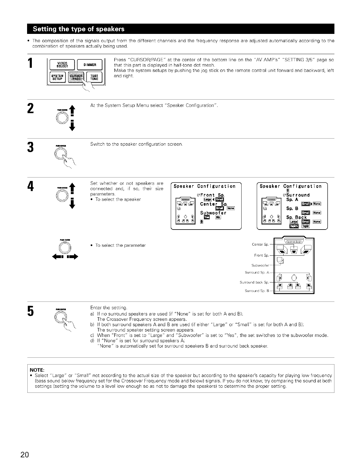
• The composition of the signals output from the different channels and the frequency response are adjusted automatically according to the
combination of speakers actually being used
1Press "CURSOR/PAGE" at the center of the bottom line on the "AV AMP's" "SE_ING 3/5" page so
that this part is displayed in halftone dot mesh.
Make the system setups by pushing the jog stick on the remote control unit forward and backward, left
and right
2At the System Setup Menu select "Speaker Configuration"
_E Switch to the speaker configuration screen
4Set whether or not speakers are
connected and, if so, their size
parameters
• To selectthe speaker
rSpeaker Configuration
_Front S.
Cent e_p_]
Subwoofer
'Speaker Configuration
_Surround
S_ A _[_]
Sp. B _[_
Sp, Back
• To select the parameter Center Sp
Front Sp
Subwoofer
Surround Sp A
Sulround back Sp
Sulround Sp B
Enter the setting
a) If no surround speakers are used (if "None" is set for both A and B):
The Crossover Frequency screen appears.
b) If both surround speakers A and B are used (if either "Large" or "Small" is set for both A and B):
The surround speaker setting screen appears
c) When "Front" is set to "Large" and "Subwoofer" is set to "Yes", the set switches to the subwoofer mode
d) If "None" is set for surround speakers A:
"None" is automatically set for surround speakers B and surround back speaker
2O
Parameters
Large ................ Select this when ushqg speakers that can fully reproduce low sounds of below 80 Hz.
Smafl ................ Select this when using speakers that cannot reproduce low sounds of below 80 Hz with sufficient volume.
When this setting is selected, low frequencies of below 80 Hz are assigned to the subwoofer
None ............... Select this when no speakers are installed
Yes/No ............. Select "Yes" when a subwoofer is installed, "No" when a subwoofer is not installed
2spkrs/lspkr..Select the number of speakers to be used for the surround back channel.
If the subwoofer has sufficient low frequency playback capacity, good sound can be achieved even when "Small" is set for the front, center
and surround speakers
To take full advantage of the performance of the Home THX certified speaker systems, set the front, center and surround speaker size
parameters to "Smafi" and the subwoofer to "Yes".
For the majority of speaker system configurations, using the SM4,LL setting for all five main speakers and Subwoofer On with a connected
subwoofer will yield the best results
When "Front" is set to "Small", "Subwoofer" is automatically set to "Yes", and when "Subwoofer" is set to "No", "Front" is automatically
set to "Large".
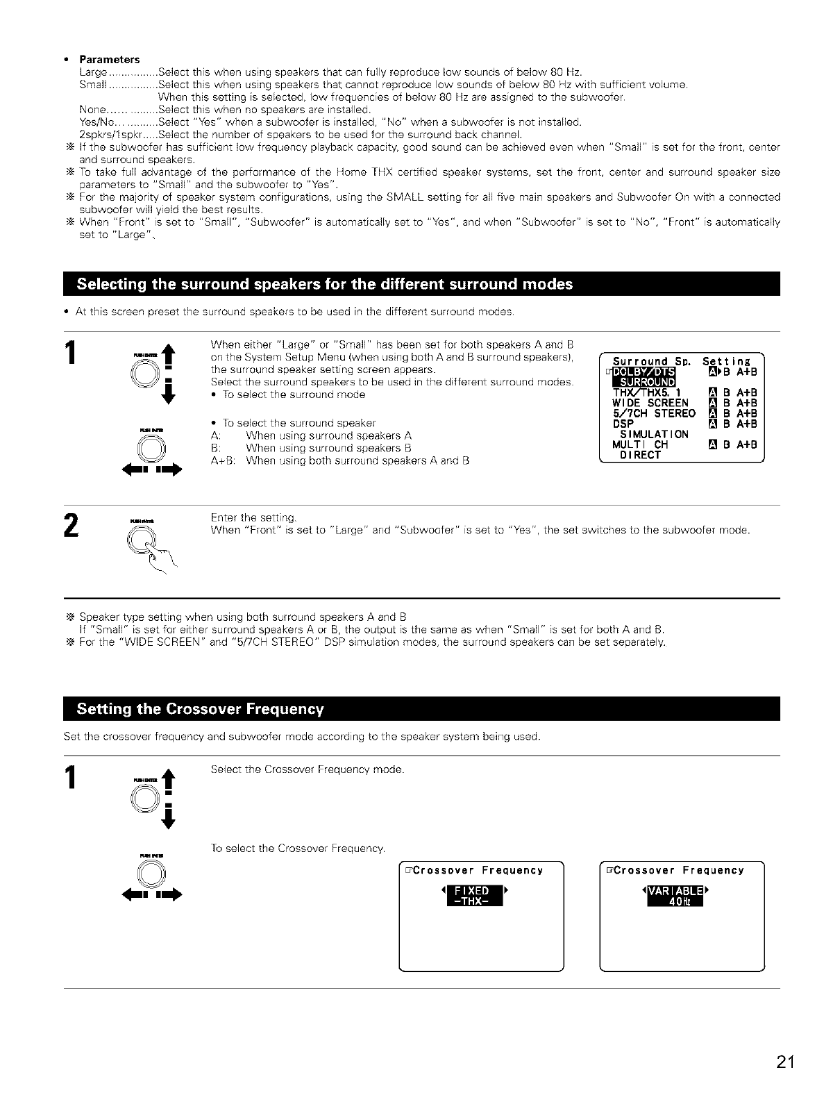
• At this screen preset the surround speakers to be used in the different surround modes
1When either "Large" or "SmalF' has been set for both speakers 4, and B
on the System Setup Menu (when using both 4, and B surround speakers),
the surround speaker setting screen appears.
Select the surround speakers to be used in the different surround modes
• To select the surround mode
• To selectthe surround speaker
4`: When using surround speakers A
B: When using surround speakers B
4,+B: When using both surround speakers 4, and B
Surround Sp. SettinK
THX/'rHX5. 1 [] B A+B
WIDE SCREEN [] B A+B
5/?CH STEREO [] B A+B
DSP [] B A+B
SIMULATION
MULTI CH [] BA+B
DIRECT
Enter the setting
When "Front" is set to "Large" and "Subwoofer'" is set to "Yes", the set switches to the subwoofer mode.
,_ Speaker type setting when using both surround speakers 4, and B
If "Small" is set for either surround speakers A or B, the output is the same as when "Small" is set for both A and B.
'_ For the "WIDE SCREEN" and "5/7CH STEREO" DSP simulation modes, the surround speakers can be set separately
Set the crossover frequency and subwoofer mode according to the speaker system being used
Select the Crossover Frequency mode
To select the Crossover Frequency.
u_Crossover Frequency _Crossover Frequency
'E
21
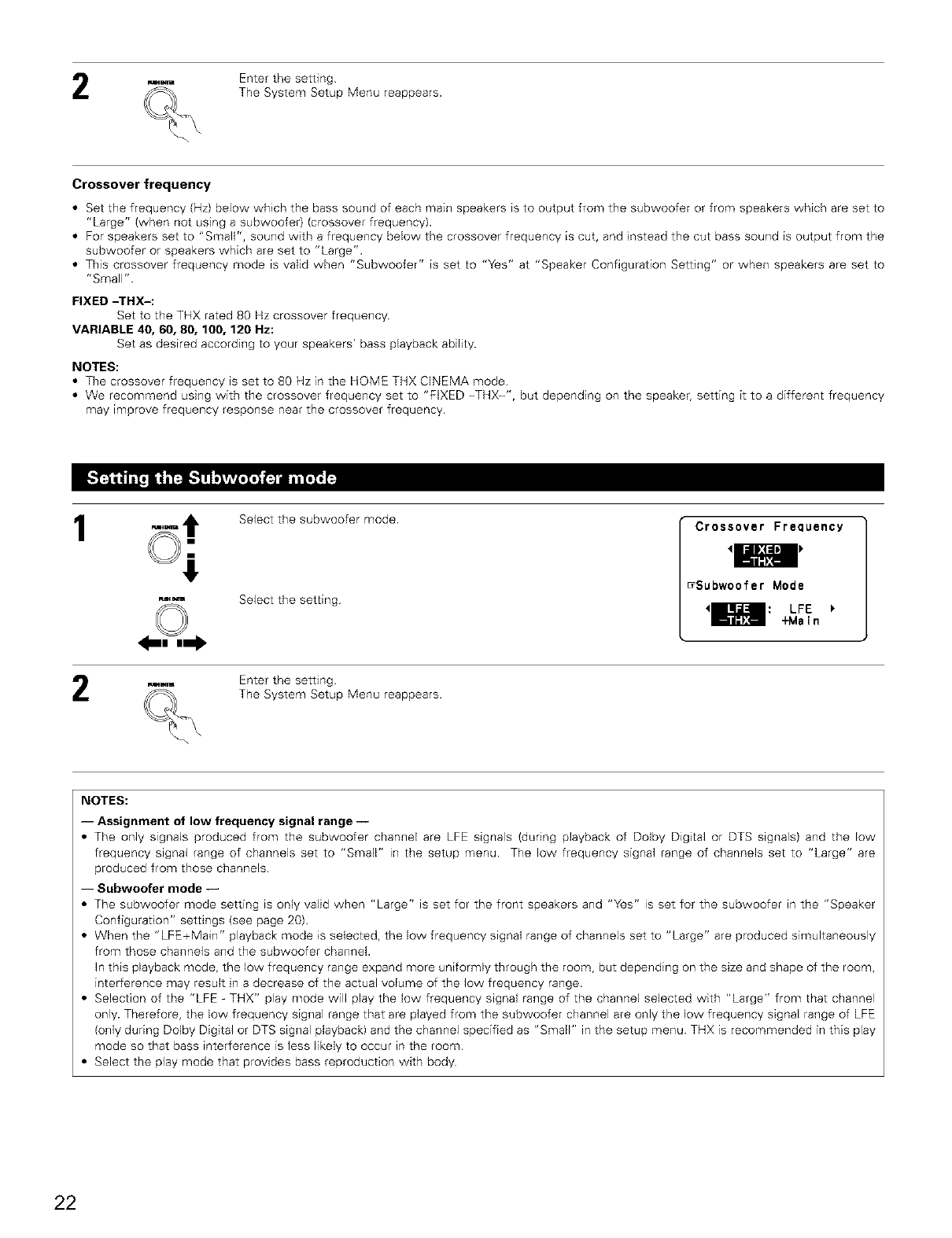
Enter the setting
The System Setup Menu reappears.
Crossoverfrequency
•Set the frequency (Hz) below which the bass sound of each main speakers is to output from the subwoofer or from speakers which are set to
"Large" (when not using a subwoofer) (crossover frequency).
• For speakers set to "Small", sound with a frequency below the crossover frequency is cut, and instead the cut bass sound is output from the
subwoofer or speakers which are set to "Large".
• This crossover frequency mode is valid when "Subwoofer" is set to "Yes" at "Speaker Configuration Setting" or when speakers are set to
"Small"
FIXED -THX-:
Set to the THX rated 80 Hz crossover frequency.
VARIABLE 40, 60, 80, 100, 120 Hz:
Set as desired according to your speakers' bass playback ability.
NOTES:
• The crossover frequency is set to 80 Hz in the HOME THX CINEMA mode
• We recommend using with the crossover frequency set to "FIXED -THX-", but depending on the speaker, setting it to a different frequency
may improve frequency response near the crossover frequency.
1Select the subwoofer mode
Select the setting
mm
_m Enter the setting
___ The System Setup Menu reappears.
Crossover Frequency
'IHI
_Subwoofer Mode
<_[_: LFE
+Main
NOTES:
-- Assignment of low frequency signal range --
• The only signals produced from the subwoofer channel are LFE signals /during playback of Dolby Digital or DTS signals} and the low
frequency signal range of channels set to "Small" in the setup menu. The low frequency signal range of channels set to "Large" are
produced from those channels
-- Subwoofer mode --
• The subwoofer mode setting is only valid when "Large" is set for the front speakers and "Yes" is set for the subwoofer in the "Speaker
Configuration" settings (see page 20).
• When the "LFE+Main" playback mode is selected, the low frequency signal range of channels set to "Large" are produced simultaneously
from those channels and the subwoofer channel.
In this playback mode, the low frequency range expand more uniformly through the room, but depending on the size and shape of the room,
interference may result in a decrease of the actual volume of the low frequency range.
• Selection of the "LFE -THX" play mode will play the low frequency signal range of the channel selected with "Large" from that channel
only. Therefore, the low frequency signal range that are played from the subwoofer channel are only the low frequency signal range of LFE
(only during Dolby Digital or DTS signal playback) and the channel specified as "Small" in the setup menu THX is recommended in this play
mode so that bass interference is less likely to occur in the room.
• Select the play mode that provides bass reproduction with body
22
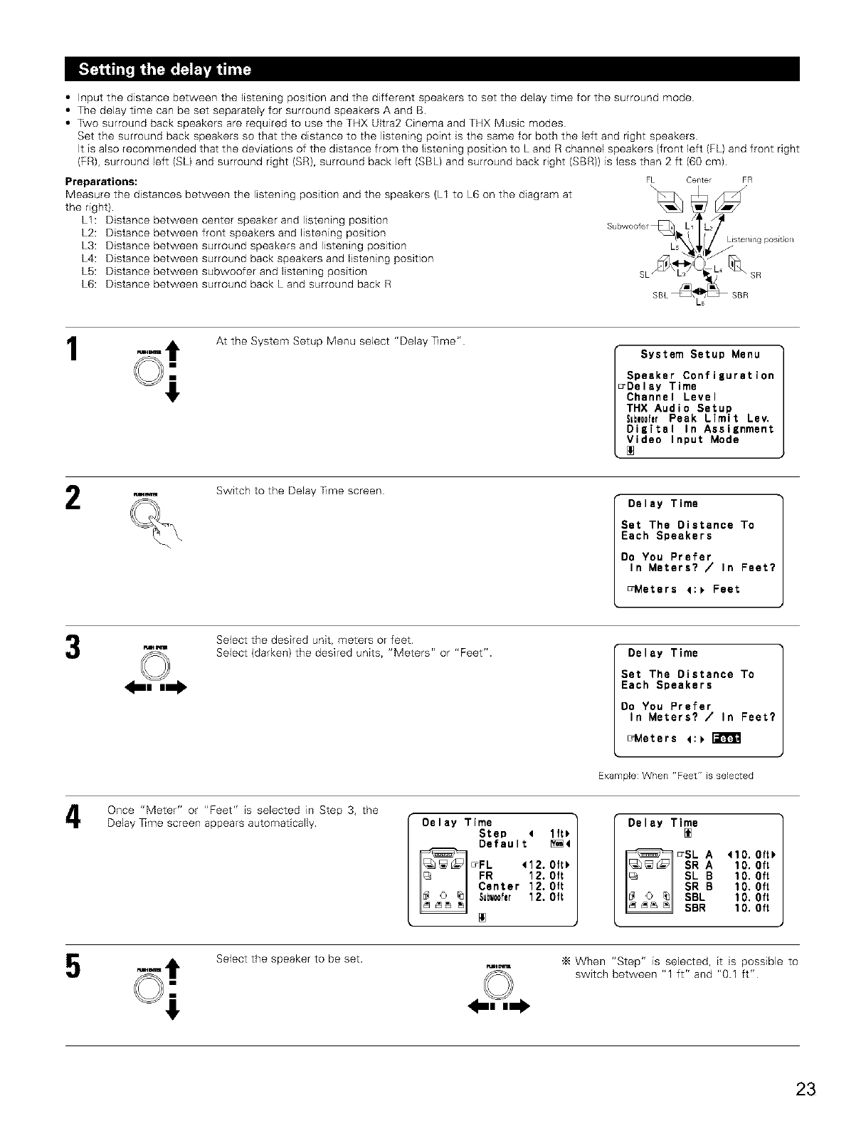
•Input the distance between the listening position and the different speakers to set the delay time for the surround mode
• The delay time can be set separately for surround speakers A and B.
• Two surround back speakers are required to use the THX Ultra2 Cinema and THX Music modes
Set the surround back speakers so that the distance to the listening point is the same for both the left and right speakers
It is also recommended that the deviations of the distance from the listening position to L and R channel speakers (front left (FL) and front right
(FR), surround left (SL) and surround right (SR), surround back left (SBL) and surround back right (SBR)) is less than 2 ft (60 cm).
Preparations:
Measure the distances between the listening position and the speakers (L1 to L6 on the diagram at
the right)
LI: Distance between center speaker and listening position
L2: Distance between front speakers and listening position
L3: Distance between surround speakers and listening position
L4: Distance between surround back speakers and listening position
LS: Distance between subwoofer and listening position
L6: Distance between surround back L and surround back R
FL Center
SBL I
FR
SR
SBR
1At the System Setup Menu select "Delay Time"
System Setup Menu
Speaker Configuration
7Delay Time
Channel Level
THX Audio Setup
S=tw00ferPeak Limit Lev.
Digital In Assignment
Video Input Mode
Switch to the Delay Time screen
Delay Time
Set The Distance To
Each Speakers
Oa You Prefer
In Meters? /In Feet?
_Meters 4:_ Feet
Select the desired unit, meters or feet
Select (darken) the desired units, "Meters" or "Feet". Delay Time
Set The Distance To
Each Speakers
Do You Prefer
In Maters? /In Feet?
_Meters _:_
Example: When "Feet" is selected
Once "Meter" or "Feet" is selected in Step 3, the
Delay ]]me screen appears automatically. Delay Time
Step 4 lft_
Default _4
FL 412.0ft_
FR 12.0ft
Center 12.0ft
5um0fer 12.0ft
Delay Time
_SL A 410.0ft_
SR A 10.0ft
I_I SL B 10. Oft
I__ _1 SR B 10.0ft
_SBL lO. Oft
SBR 10.0ft
Select the speaker to be set. When "Step" is selected, it is possible to
switch between "1 ft" and "0.1 ft"
23
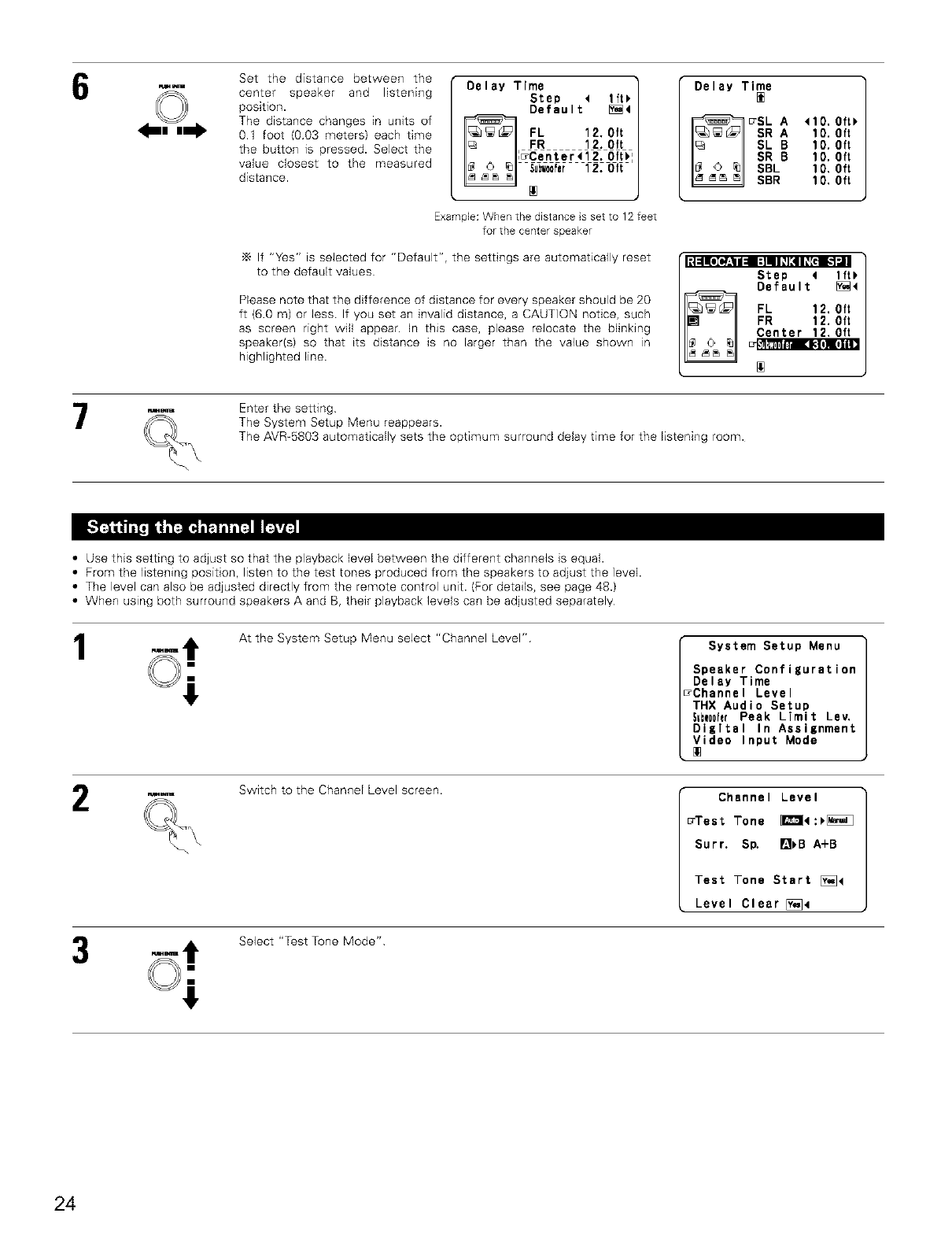
Set the distance between the
center speaker and listening
position.
The distance changes in units of
01 foot (003 meters) each time
the button is pressed. Select the
value closest to the measured
distance.
Delay Time
Step < lft_
Default [_4
FL 12, Oft
, FR 12. Oft
,_Center _] 2. 0ft_
[]
ExampJe: When the distance s set to 12 feet
for the center speaker
If "Yes" is selected for "Default", the settings are automatically reset
to the default values [:|:lln[oio_:_ll::lqlll[41_[d [_1"j
Please note that the difference of distance for every speaker should be 20
ft (6.0 m) or less If you set an invalid distance, a CAUTION notice, such
as screen right wifl appear. In this case, please relocate the blinking
speaker(s) so that its distance is no larger than the value shown in
highlighted line.
Delay Time
[]
SL A <10.0ft)
SR A 10.0ft
SL B 10. Oft
I_ __1 SR B 10,0ft
I_ __ _1 SBL 10, Oft
SBR 10.0ft
Step 4lft_
Default [_<
FL 12. Oft
FR 12. Oft
Center 12,0ft
[]
Enter the setting
The System Setup Menu reappears.
The AVR-6803 automatically sets the optimum surround delay time for the listening room.
•Use this setting to adjust so that the playback level between the different channels is equal.
• From the listening position, listen to the test tones produced from the speakers to adjust the level.
• The level can also be adjusted directly from the remote control unit. (For details, see page 48.)
• When using both surround speakers A and B, their playback levels can be adjusted separately
1At the System Setup Menu select "Channel Level" System Setup Menu
Speaker Configuration
Delay Time
7Channe I Level
THX Audio Setup
5=bw00hrPeak Limit Lev.
Digital In Assignment
Video Input Mode
Switch to the Channel Level screen. Channel Level
_Test Tone _4:_
Surr. S_ []_B A+B
Test Tone Start [_]4
Level Clear [_]4
Select "Test Tone Mode"
24
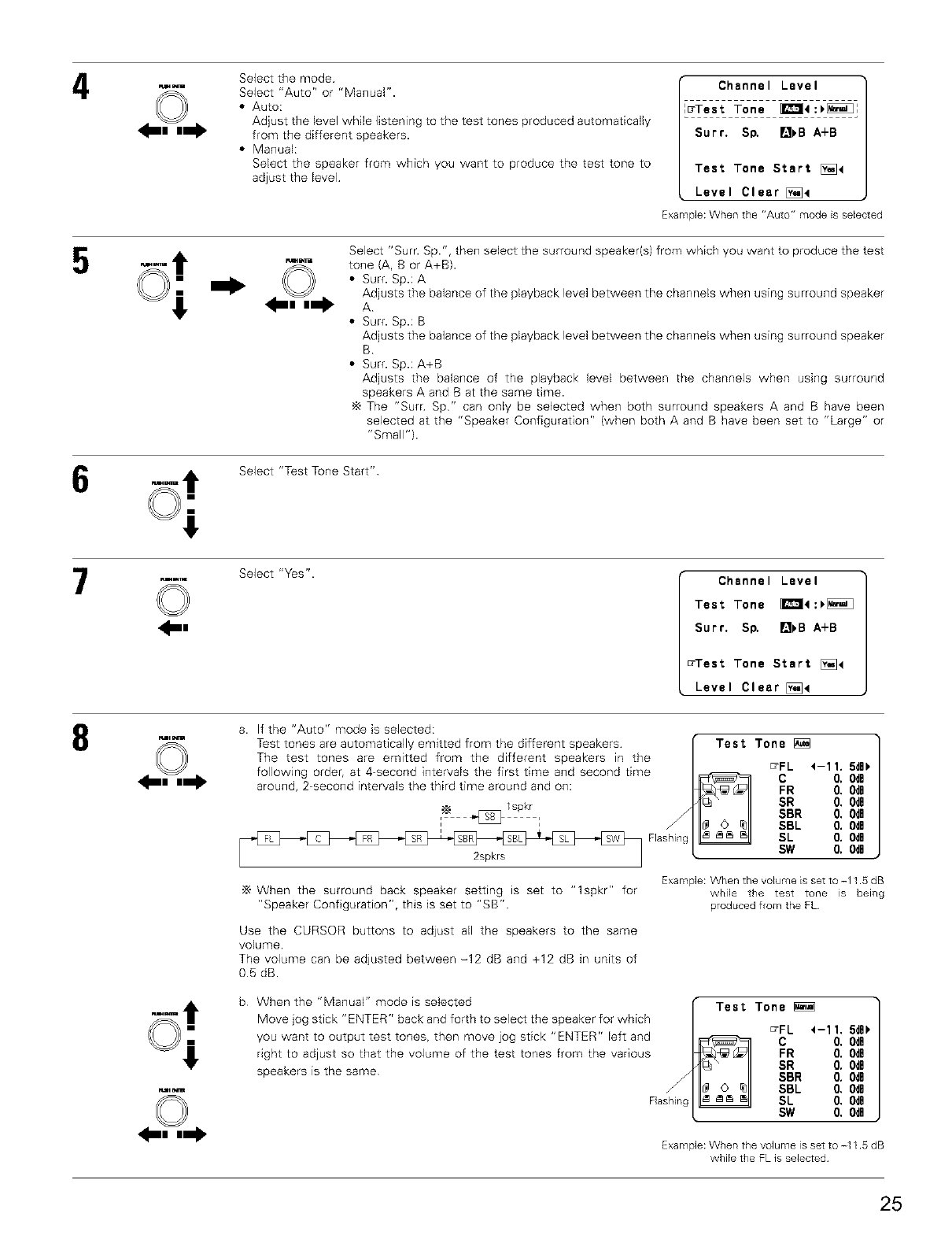
4Select the mode
Select "Auto" or "Manual".
• Auto:
Adjust the level while listening to the test tones produced automatically
from the different speakers.
• Manual:
Select the speaker from which you want to produce the test tone to
adjust the level
Channel Level
_Test Tone _4:_:
Surr. Sp. []_B A+B
Test Tone Start [_4
Level Clear [_4
Example:Whenthe"Auto"modeisselected
Select "Sum Sp.", then select the surround speaker(s) from which you want to produce the test
tone (A, B or A+B).
• Surf. Sp.: A
Adjusts the balance of the playback level between the channels when using surround speaker
A
• Surf. Sp.: B
Adjusts the balance of the playback level between the channels when using surround speaker
B
• Surf. Sp.: A+B
Adjusts the balance of the playback level between the channels when using surround
speakers A and B at the same time.
The "Surr Sp" can only be selected when both surround speakers A and B have been
selected at the "Speaker Configuration" (when both A and B have been set to "Large" or
"Small").
Select "Test Tone Start"
7_R
©Select "Yes". Channel Level
Test Tone _4:_
Surr. Sp. []_B A+B
_Test Tone Start [_4
Level Clear [_4
8a. If the "Auto" mode is selected:
Test tones are automatically emitted from the different speakers
The test tones are emitted from the different speakers in the
following order, at 4-second intervals the first time and second time
around, 2-second intervals the third time around and on:
2spkrs
When the surround back speaker setting is set to "lspkr" for
"Speaker Configuration", this is set to "SB".
Use the CURSOR buttons to adjust all the speakers to the same
volume.
The volume can be adjusted between -12 dB and +12 dB in units of
05 dB.
b When the "Manual" mode is selected
Move jog stick "ENTER" back and forth to select the speaker for which
you want to output test tones, then move jog stick "ENTER" left and
right to adjust so that the volume of the test tones from the various
speakers is the same
Flashing
Test Tone [_
_FL 4-1 1. 5dB_
C 0, 0dB
FR 0, 0dB
SR 0. 0dO
SBR 0. 0dB
SBL 0. 0dB
SL 0. 0dB
SW 0, 0dB
Example: When the volume is set to -11 5 dB
while the test tone is being
produced from the FL
Test Tone
_FL 4-11. 5d8)
C 0. 0dB
FR 0. 0dB
SR O. OdB
SBR O. OdB
SBL O. OdB
Flashing SL O. OdB
SW 0. 0dB
Example: When the volume is set to -11 5 dB
while the FL is selected
25
After the above settings are completed, press jog stick "ENTER"
The "Channel Level" screen reappears
Press jog stick "ENTER" again to return to the System Setup Menu screen
"_ To cancel the settings, select "Level Clear" and "Yes" on the "Channel Level" screen, then make the settings again
The level of each channel should be adjusted to 75 dB (C-weighted, slow meter mode) on a sound level meter at the listening position.
If a sound level meter is not available adjust the channels by ear so the sound levels are the same. Because adjusting the subwoofer level test
tone by ear is difficult, use a well known music selection and adiust for natural balance.
NOTE: When adjusting the level of an active subwoofer system, you may also need to adjust the subwoofer's own volume control
When you adiust the channel levels while in the SYSTEM SETUP CHANNEL LEVEL mode, the channel level adjustments made will affect
ALL surround modes Consider this mode a Master Channel Level adjustment mode.
After you have completed the SYSTEM SETUP CHANNEL LEVEL adjustments, you can then activate the individual surround modes and
adjust channel levels that will be remembered for each of those modes. Then, whenever you activate a particular surround sound mode,
your preferred channel level adjustments for just that mode will be recalled Check the instructions for adjusting channel levels within each
surround mode on page 48.
You can adjust the channel levels for each of the following surround modes: DIRECT, STEREO, 5CH/7CH STEREO, DOLBY/DTS SURROUND,
HOME THX CINEMA, WIDE SCREEN, SUPER STADIUM, ROCK ARENA, JAZZ CLUB, CLASSIC CONCERT, MONO MOVIE, and MATRIX
When using either surround speakers A or B, or when using surround speakers A and B at the same time, be sure to adjust the balance of
playback levels between each channel for the various selections of "A or B" and "A and B".
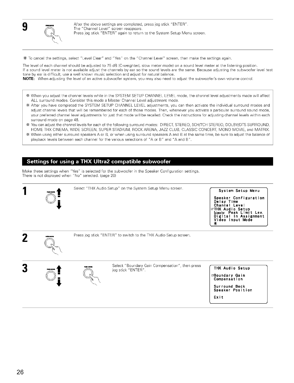
Make these settings when "Yes" is selected for the subwoofer in the Speaker Configuration settings.
There is not displayed when "No" selected. (page 20)
1Select "THX Audio Setup" on the System Setup Menu screen System Setup Menu
Speaker Configuration
Delay Time
Channel Level
7THX Audio Setup
S=bwooferPeak Limit Lev.
Digltal In Assignment
Video Input Mode
Press jog stick "ENTER" to switch to the THX Audio Setup screen.
Select "Boundary Gain Compensation", then press
jog stick "ENTER" THX Audio Setup
_Boundary Gain
Compensatlon
Surround Back
Speaker Position
Exit
26
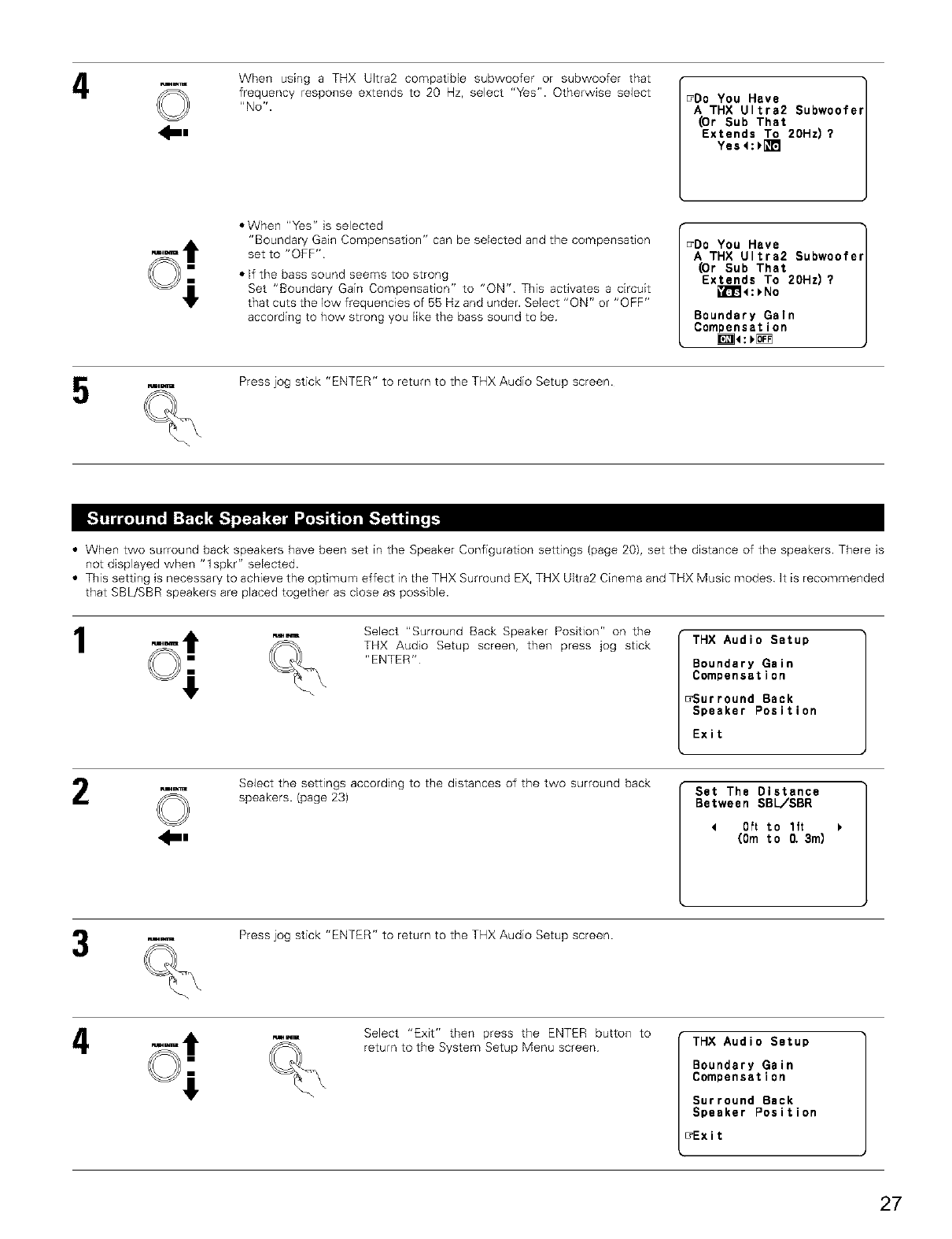
4mR
©When using a THX Ultra2 compatiMe subwoofer or subwoofer that
frequency response extends to 20 Hz, select "Yes". Otherwise select
"No". FDO You Have
A THX Ultra2 Subwoofef
Dr Sub That
Extends To 20Hz)?
Yes 4:)l_m
• When "Yes" is selected
"Boundary Gain Compensation" can be seEected and the compensation
set to "OFF"
• If the bass sound seems too strong
Set "Boundary Gain Compensation" to "ON" This activates a circuit
that cuts the low frequencies of 55 Hz and under. SeEect "ON" or "OFF"
according to how strong you Eikethe bass sound to be
_Do You Have
A THX Ultra2 Subwoofe
Dr Sub That
Extends To 20Hz)?
_l_l_:_No
Boundary Galn
Compensation
ra_E Press jog stick "ENTER" to return to the THX Audio Setup screen.
• When two surround back speakers have been set in the Speaker Configuration settings (page 20), set the distance of the speakers. There is
not displayed when "1spkr" selected.
• This setting is necessary to achieve the optimum effect in the THX Surround EX, THX Ultra2 Cinema and THX Music modes It is recommended
that SBL]SBR speakers are placed together as cEose as possible.
1Select "Surround Back Speaker Position" on the
THX Audio Setup screen, then press jog stick
"ENTER"
THX Audio Setup
Boundary Gain
Compensation
_Surround Back
Speaker Position
Exit
2_R
©Select the settings according to the distances of the two surround back
speakers. (page 23) Set The Distance
Between SBL/SBR
4Oft to lft
(0m to 0. 3m)
Press jog stick "ENTER" to return to the THX Audio Setup screen.
wm
4
Select "Exit" then press the ENTER button to
return to the System Setup Menu screen THX Audio Setup
Boundary Gain
Compensation
Surround Back
Speaker Position
_Exit
27
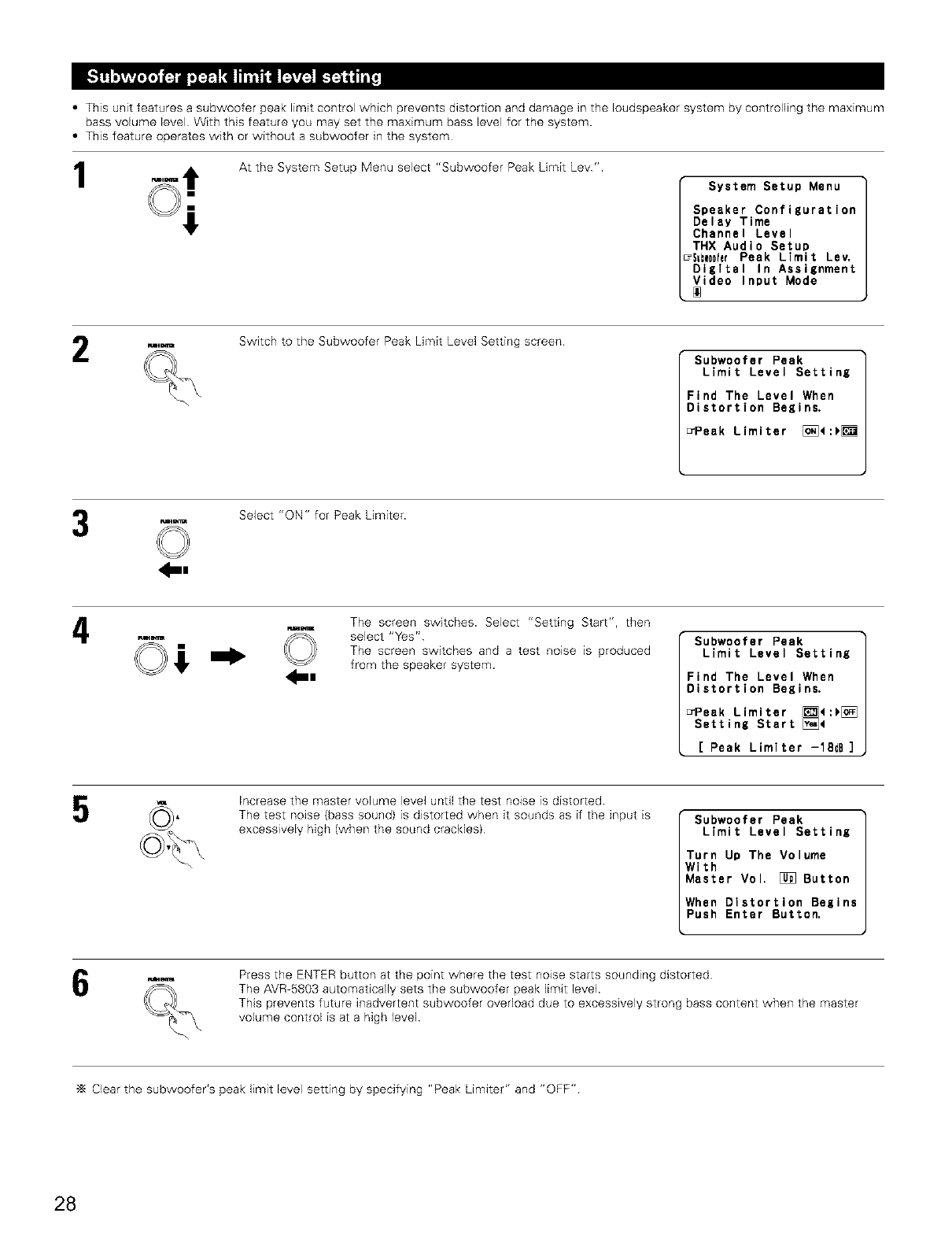
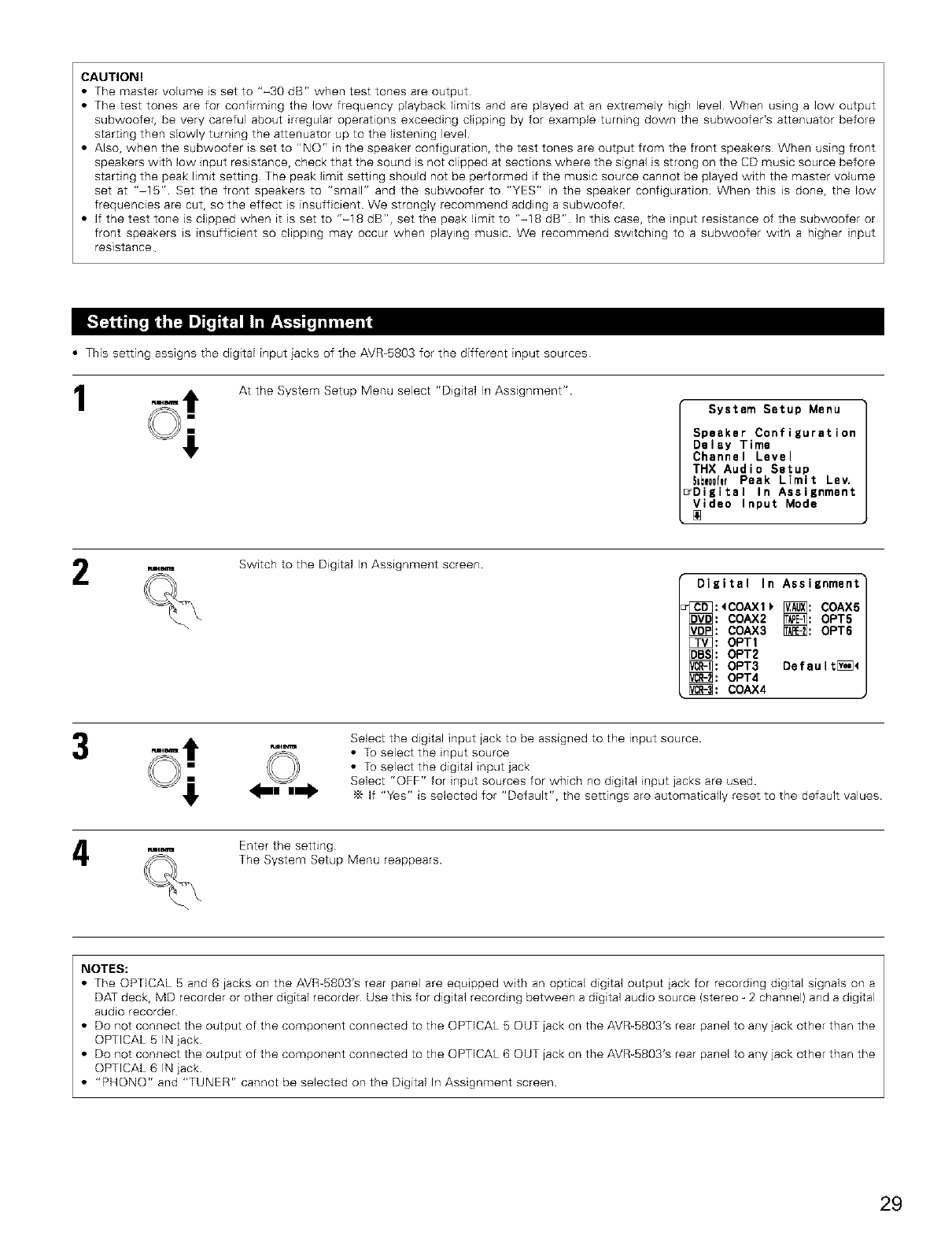
• This unit features a subwoofer peak limit control which prevents distortion and damage in the loudspeaker system by controlling the maximum
bass volume level With this feature you may set the maximum bass level for the system.
• This feature operates with or without a subwoofer in the system
1At the System Setup Menu select "Subwoofer Peak Limit Lev'.
System Setup Menu
Speaker Configuration
Delay Time
Channel Level
THX Audio Setup
7_=bw00hr Peak Limit Lev.
Digital In Assignment
Video Input Mode
Switch to the Subwoofer Peak Limit Level Setting screen
Subwoofer Peak
Limit Level Setting
Find The Level When
Distortion Begins.
_Peak Limiter [_]<:_
©
_s
Select "ON" for Peak Limiter.
4_m The screen switches. Select "Setting Start", then
select "Yes"
The screen switches and a test no_se is produced
from the speaker system.
Subwoofer Peak
Limit Level Setting
Find The Level When
Distortion Begins.
_Peak Limiter _4:_[_
Setting Start [_]4
[Peak Limlter -18dB ]
Increase the master volume level until the test noise is distorted.
The test noise (bass sound) is distorted when it sounds as if the input is
excessively high (when the sound crackles) Subwoofer Peak
Limit Level Setting
Turn Up The Volume
With
Master Vol, [_ Button
When Distortion Begins
Push Enter Button.
Press the ENTER button at the point where the test noise starts sounding distorted
The AVR-5803 automatically sets the subwoofer peak limit level.
This prevents future inadvertent subwoofer overload due to excessively strong bass content when the master
volume control is at a high level.
Clear the subwoofer's peak limit level setting by specifying "Peak Limiter" and "OFF"
28
CAUTION!
• The master volume is set to "-30 dB" when test tones are output
• The test tones are for confirming the low frequency playback limits and are played at an extremely high level When using a low output
subwoofer, be very careful about irregular operations exceeding clipping by for example turning down the subwoofer's attenuator before
starting then slowly turning the attenuator up to the listening level.
• Also, when the subwoofer is set to "NO" in the speaker configuration, the test tones are output from the front speakers When using front
speakers with low input resistance, check that the sound is not clipped at sections where the signal is strong on the CD music source before
starting the peak limit setting The peak limit setting should not be performed if the music source cannot be played with the master volume
set at "-15" Set the front speakers to "small" and the subwoofer to "YES" in the speaker configuration. When this is done, the low
frequencies are cut, so the effect is insufficient. We strongly recommend adding a subwoofer.
• If the test tone is clipped when it is set to "-18 dB", set the peak limit to "-18 dB" ]n this case, the input resistance of the subwoofer or
front speakers is insufficient so clipping may occur when playing music. We recommend switching to a subwoofer with a higher input
resistance
• This setting assigns the digital input iacks of the AVR_5803 for the different input sources
1At the System Setup Menu select "Digital In Assignment".
System Setup Menu
Speaker Configuration
Delay Time
Channel Level
THX Audio Setup
S=bw00ferPeak Limit Lev.
_Digital In Assignment
Video Input Mode
R=_eel=
2Switch to the Digital In Assignment screen.
Digital In Assignment
ut3_:_COAX1_ [_]: COAX5
[_: COAX2 _: OPT5
[_)_: COAX3 [_: OPT6
[_: OPT1
[_: OPT2
[_: OPT3 Default[_
[_: OPT4
[_: COAX4
t Select the digital input jack to be assigned to the input source.
,_m= _ • To select the input source
,.w., • To select the digital input jack
i Select "OFF" for input sources for which no digital input jacks are used.If "Yes" is selected for "Default", the settings are automatically reset to the default values.
.=m= Enter the setting
q,_ The System Setup Menu reappears.
NOTES:
• The OPTICAL 5 and 6 iacks on the AVR-5803's rear panel are equipped with an optical digital output jack for recording digital signals on a
DAT deck, MD recorder or other digital recorder Use this for digital recording between a digital audio source (stereo _2 channel) and a digital
audio recorder
• Do not connect the output of the component connected to the OPTICAL 5 OUT jack on the AVR_5803's rear panel to any jack other than the
OPTICAL 5 IN jack.
• Do not connect the output of the component connected to the OPTICAL 6 OUT jack on the AVR_5803's rear panel to any jack other than the
OPTICAL 6 IN iack.
• "PHONO" and "TUNER" cannot be selected on the Digital In Assignment screen.
29
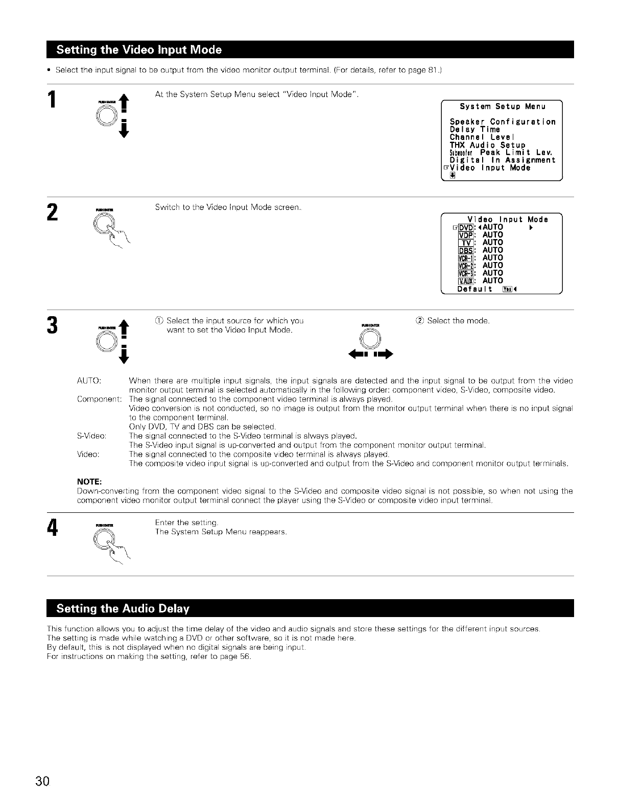
• Select the input signal to be output from the video monitor output terminal. (For details, refer to page 81 .)
1At the System Setup Menu select "Video Input Mode".
System Setup Menu
Speaker Configuration
Delay Time
Channel Level
THX Audio Setup
Sebw00ferPeak Limit Lev.
Digital In Assignment
7Video Input Mode
Switch to the Video Input Mode screen.
Video Input Mode
_[_:<AUTO
[_: AUTO
[Z_: AUTO
[_B_: AUTO
_: AUTO
_: AUTO
[_: AUTO
[_: AUTO
Default [_4
(1:) Select the input source for which you
want to set the Video Input Mode.
,:.2_Select the mode
AUTO: When there are multiple input signals, the input signals are detected and the input signal to be output from the video
monitor output terminal is selected automatically in the following order: component video, S-Video, composite video.
Component: The signal connected to the component video terminal is always played
Video conversion is not conducted, so no image is output from the monitor output terminal when there is no input signal
to the component terminal.
Only DVD, TV and DBS can be selected
S-Video: The signal connected to the S-Video terminal is always played.
The S-Video input signal is up-converted and output from the component monitor output terminal
Video: The signal connected to the composite video terminal is always played
The composite video input signal is up-converted and output from the S-Video and component monitor output terminals.
NOTE:
Down-converting from the component video signal to the S-Video and composite video signal is not possible, so when not using the
component video monitor output terminal connect the player using the S-Video or composite video input terminal
Enter the setting
The System Setup Menu reappears.
This function allows you to adjust the time delay of the video and audio signals and store these settings for the different input sources
The setting is made while watching a DVD or other software, so it is not made here
By default, this is not displayed when no digital signals are being input
For instructions on making the setting, refer to page 56.
3O
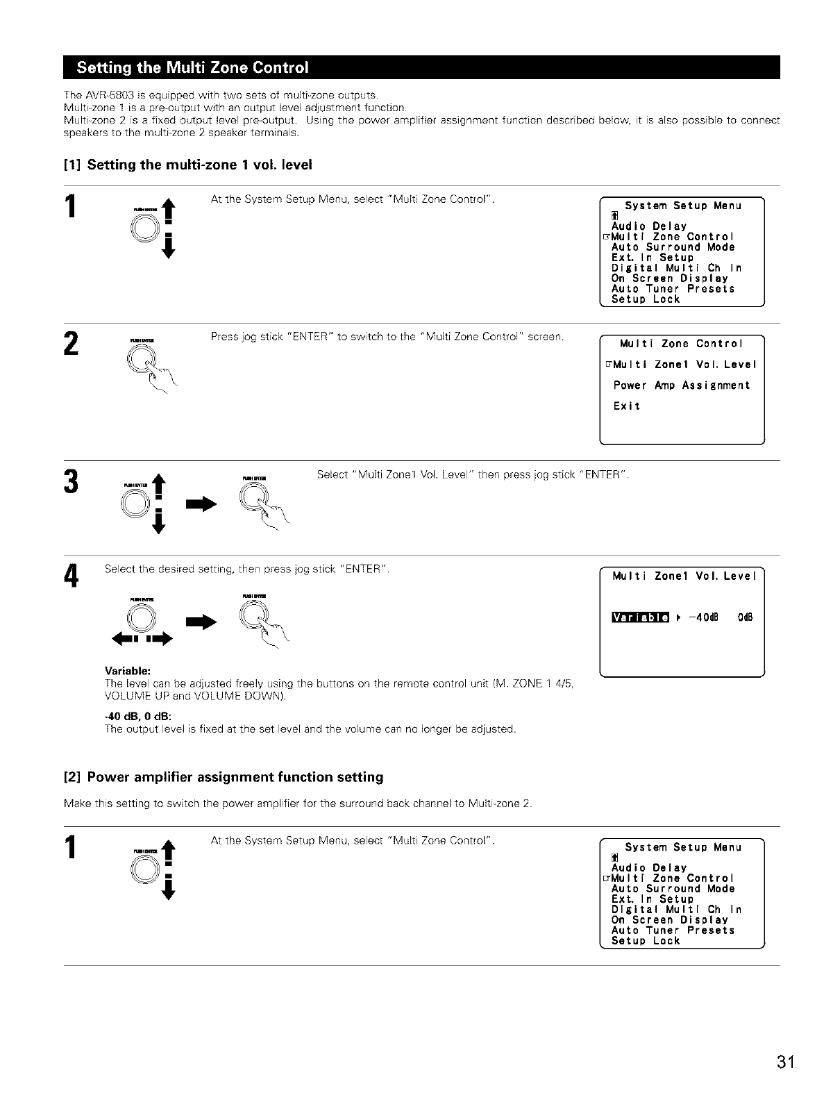
The AVR-5803 is equipped with two sets of multi-zone outputs
Multi-zone 1 is a pre+output with an output +evel adjustment function
Multi-zone 2 is a fixed output level pre+output Using the power amplifier assignment function described below, it is also possible to connect
speakers to the multi-zone 2 speaker terminals
[1] Setting the multi-zone 1 vol. level
1At the System Setup Menu, select "Multi Zone Control". System Setup Menu
Audio Delay
7Multi Zone Control
Auto Surround Mode
Ext. In Setup
Digital Multi Ch In
On Screen Display
Auto Tuner Presets
Setup Lock
tame_n=
2Press jog stick "ENTER" to switch to the "Multi Zone Control" screen Multi Zone Control
_Multi Zone1Vol, Level
Power Amp Assignment
Exit
Select "Multi Zone1 Vol. Level" then press jog stick "ENTER"
4Select the desired setting, then press jog stick "ENTER"
Variable:
The level can be adjusted freely using the buttons on the remote control unit (M ZONE 1 4/5,
VOLUME UP and VOLUME DOWN)
-40 dB, 0 dB:
The output level is fixed at the set level and the volume can no longer be adjusted.
[2] Power amplifier assignment function setting
Make this setting to switch the power amplifier for the surround back channel to Multi_zone2
1At the System Setup Menu, select "Multi Zone Control". System Setup Menu
Audio Delay
7Multi Zone Control
Auto Surround Mode
Ext, In Setup
Digital Multi Ch In
On Screen Display
Auto Tuner Presets
Setup Lock
31
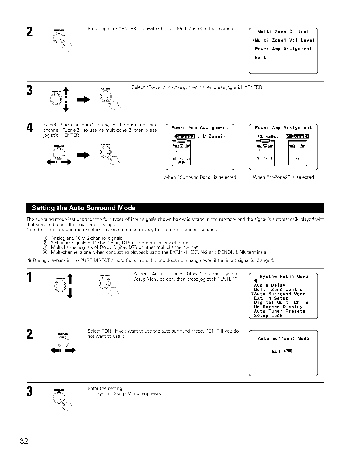
2Press jog stick "ENTER" to switch to the "Multi Zone Control" screen Multi Zone Control
_Multi Zone1Vol. Level
Power Amp Assignment
Exit
Select "Power Amp Assignment" then press jog stick "ENTER".
Select "Surround Back" to use as the surround back
channel, "Zone_2" to use as multi_zone 2, then press
jog stick "ENTER"
ww
Power Amp Assignment
413ffll_[T_ : M-Zone2_
When "Surround Back" is selected
Power Amp Assignment
4SurroundBack:
When "M-Zone2" is selected
The surround mode last used for the four types of input signals shown below is stored in the memory and the signal is automatically played with
that surround mode the next time it is input
Note that the surround mode setting is also stored separately for the different input sources.
Analog and PCM 2-channel signals
2-channel signals of Dolby Digital, DTS or other multichannel format
Multichannel signals of Dolby Digital, DTS or other multichannel format
_4_ Multi_channel signal when conducting playback using the EXT.INq EXT.IN_2 and DENON LINKterminals
,_ During playback in the PURE DIRECT mode, the surround mode does not change even if the input signal is changed
1_m Select "Auto Surround Mode" on the System
Setup Menu screen, then press jog stick "ENTER" System Setup Menu
Audio Delay
Multi Zone Control
7Auto Surround Mode
Ext, In Setup
Digital Multi Ch In
On Screen Display
Auto Tuner Presets
Setup Lock
2Select "ON" if you want to use the auto surround mode, "OFF" if you do
not want to use it Auto Surround Mode
_:_[_
rJ_E Enter the setting
The System Setup Menu reappears.
32
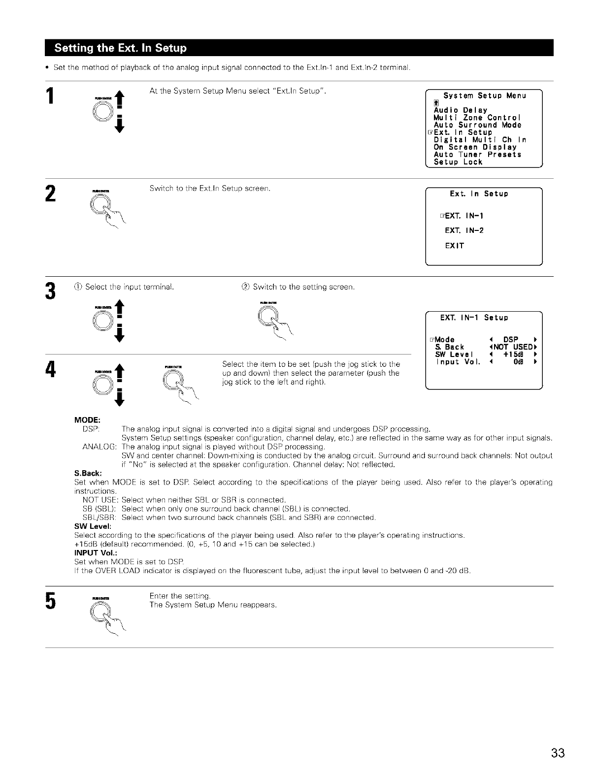
• Set the method of playback of the analog input signal connected to the Ext Ira1 and Ext Ira2 terminal
1At the System Setup Menu select "Ext.ln Setup". System Setup Menu
Audio Delay
Multi Zone Control
Auto Surround Mode
_Ext, In Setup
Digital Multi Ch In
On Screen Display
Auto Tuner Presets
Setup Look
Switch to the Extln Setup screen. Ext. In Setup
_EX_ IN-1
EX_ IN-2
EXIT
4
_ Select the input terminal. ,:.2_Switch to the setgng screen.
Flml_
w_ Select the item to be set (push the jog stick to the
up and down) then select the parameter (push the
jog stick to the left and right).
EX_ IN-1 Setup
_Mode < DSP
Back <NOT USED_
SW Level 4+15dB
Input Vol, < 0dB
MODE:
DSP: The analog input signal is converted into a digital signal and undergoes DSP processing.
System Setup settings (speaker configuration, channel delay, etc.) are reflected in the same way as for other input signals.
ANALOG: The analog input signal is played without DSP processing
SW and center channel: Dowmmixing is conducted by the analog circuit Surround and surround back channels: Not output
if "No" is selected at the speaker configuration. Channel delay: Not reflected.
S.Back:
Set when MODE is set to DSR Select according to the specificagons of the player being used. Also refer to the player's operating
instructions
NOT USE: Select when neither SBL or SBR is connected.
SB (SBL): Select when only one surround back channel (SBL) is connected
SBL/SBR: Select when two surround back channels (SBL and SBR) are connected
SW Level:
Select according to the specifications of the player being used Also refer to the player's operating instructions
+15dB (default) recommended (0, +5, 10 and +15 can be selected.)
INPUT Vol.:
Set when MODE is set to DSP
If the OVER LOAD indicator is displayed on the fluorescent tube, adjust the input level to between 0 and _20 dB.
Enter the setting
The System Setup Menu reappears.
33
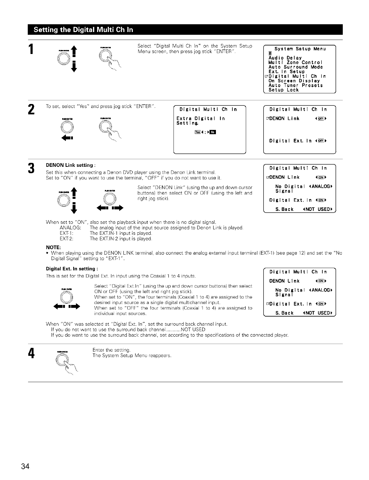
1Select "Digital Multi Ch In" on the System Setup
Menu screen, then press jog stick "ENTER" System Setup Menu
Audio Delay
Multi Zone Control
Auto Surround Mode
Ext. In Setup
7Digital Multi Ch In
On Screen Display
Auto Tuner Presets
Setup Lock
2To set, select "Yes" and press jog stick "ENTER"
.I-,
Digital Multi Ch In
Extra Digital In
Settlng.
Digital Multi Ch In
_DENON Link <[_
Digital Ext. In 4[_
DENON Link setting :
Set this when connecting a Denon DVD player using the Denon Link terminal
Set to "ON" if you want to use the terminal, "OFF" if you do not want to use it
Select "DENON Link" (using the up and down cursor
buttons) then select ON or OFF (using the left and
right jog stick)
Digital Multi Ch In
_DENON Link 4[_
No Digital 4ANALOG_
SiKnal
Digital Ext, In 4[_
S. Back 4NOT USED_
When set to "ON", also set the playback input when there is no digital signal
ANALOG: The analog input of the input source assigned to Denon Link is played
EXT-I: The EXT.IN-1 input is played
EXT-2: The EXT.IN-2 input is played
NOTE:
• When playing using the DENON LINK terminal, also connect the analog external input terminal (EXq-1) (see page 12) and set the "No
Digital Signal" setting to "EX%l ".
Digital Ext. In setting :
This is set for the Digital Ext. In input using the Coaxial 1 to 4 inputs
Select "Digital Ext In" (using the up and down cursor buttons) then select
ON or OFF (using the left and right jog stick)
When set to "ON", the four terminals (Coaxial 1 to 4) are assigned to the
desired input source as a single digital multichannel input.
When set to "OFF" the four terminals (Coaxial 1 to 4) are assigned to
individual input sources.
Digital Multi Ch In
DENON Link 4[_
No Digital <ANALOG_
Slznal
7Digital Ext. In 4[_
S. Dack tNOT USED_
When "ON" was selected at "Digital Ext. In", set the surround back channel input.
If you do not want to use the surround back channel ........... NOT USED
If you do want to use the surround back channel, set according to the specifications of the connected player.
4Enter the setting
The System Setup Menu reappears.
34
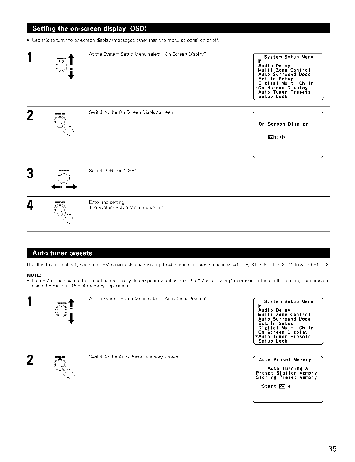
• Use this to turn the on-screen display (messages other than the menu screens) on or off
1At the System Setup Menu select "On Screen Display" System Setup Menu
Audio Delay
Multi Zone Control
Auto Surround Mode
Ext, In Setup
Digital Multi Ch In
_On Screen Display
Auto Tuner Presets
Setup Lock
Switch to the On Screen Display screen
On Screen Display
_:_[_
Select "ON" or "OFF"
Enter the setting
The System Setup Menu reappears.
Use this to automatically search for FM broadcasts and store up to 40 stations at preset channels A1 to 8, B1 to 8, C1 to 8, D1 to 8 and E1 to 8
NOTE:
•If an FM station cannot be preset automatically due to poor reception, use the "Manual tuning" operation to tune in the station, then preset it
using the manual "Preset memory" operation
1At the System Setup Menu select "Auto Tuner Presets". System Setup Menu
Audio Delay
Multi Zone Control
Auto Surround Mode
Ext. In Setup
Digital Multi Ch In
On Screen Display
_Auto Tuner Presets
Setup Lock
R'_E
2Switch to the Auto Preset Memory screen Auto Preset Memory
Auto Turning &
Preset Station Memory
Storing Preset Memory
_Start _ 4
35
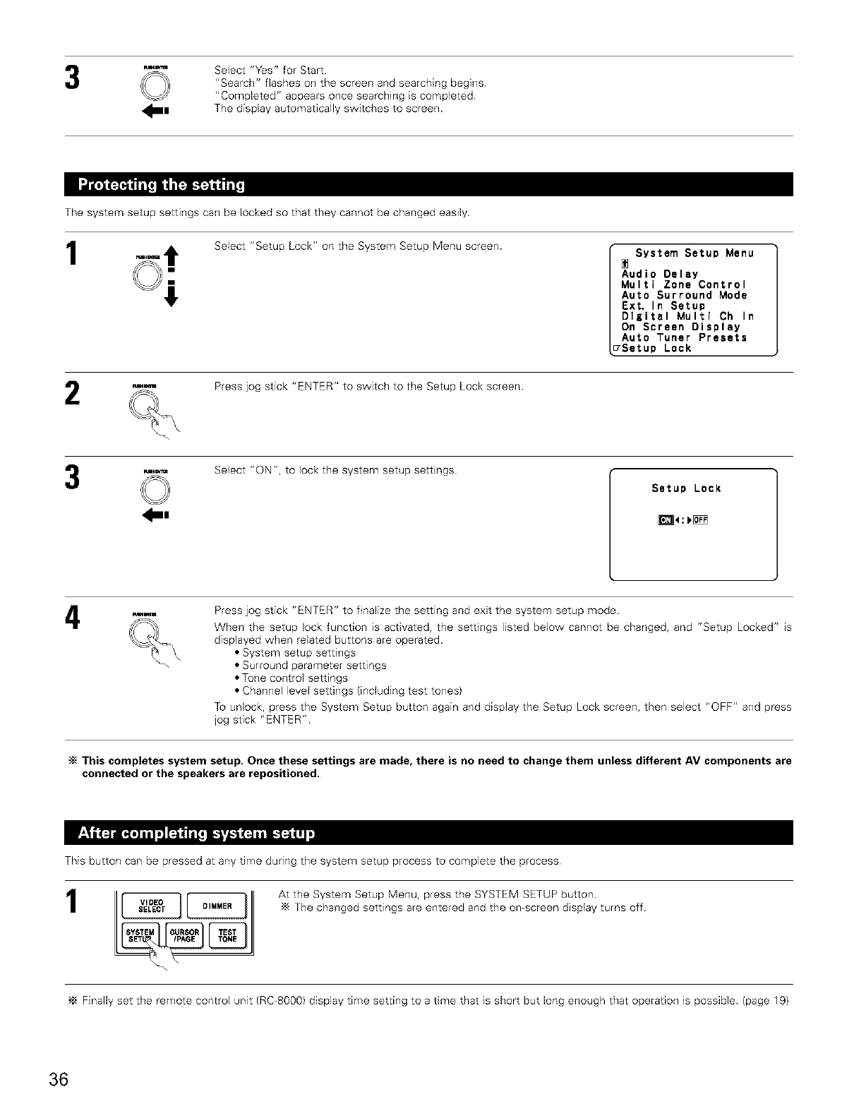
©Select "Yes" for Start
"Search" flashes on the screen and searching begins
"Completed" appears once searching is completed
The display automatically switches to screen.
The system setup settings can be locked so that they cannot be changed easily.
1Select "Setup Lock" on the System Setup Menu screen System Setu¢ Menu
Audio Delay
Multi Zone Control
Auto Surround Mode
Ext. In Setup
Digital Multi Ch In
On Screen Display
Auto Tuner Presets
7Setup Lock
Press jog stick "ENTER" to switch to the Setup Lock screen
©
_|
Select "ON", to lock the system setup settings
Press jog stick "ENTER" to finalize the setting and exit the system setup mode.
When the setup lock function is activated, the settings listed below cannot be changed, and "Setup Locked" is
displayed when related buttons are operated.
• System setup settings
• Surround parameter settings
• Tone control settings
• Channel level settings (including test tones)
To unlock, press the System Setup button again and display the Setup Lock screen, then select "OFF" and press
jog stick "ENTER".
"_ This completes system setup, Once these settings are made, there is no need to change them unless different AV components are
connected or the speakers are repositioned.
This button can be pressed at any time during the system setup process to complete the process
1At the System Setup Menu, press the SYSTEM SETUP button
The changed settings are entered and the on-screen display turns off.
Finally set the remote control unit (RC-8000) display time setting to a time that is short but long enough that operation is possible (page 19)
36
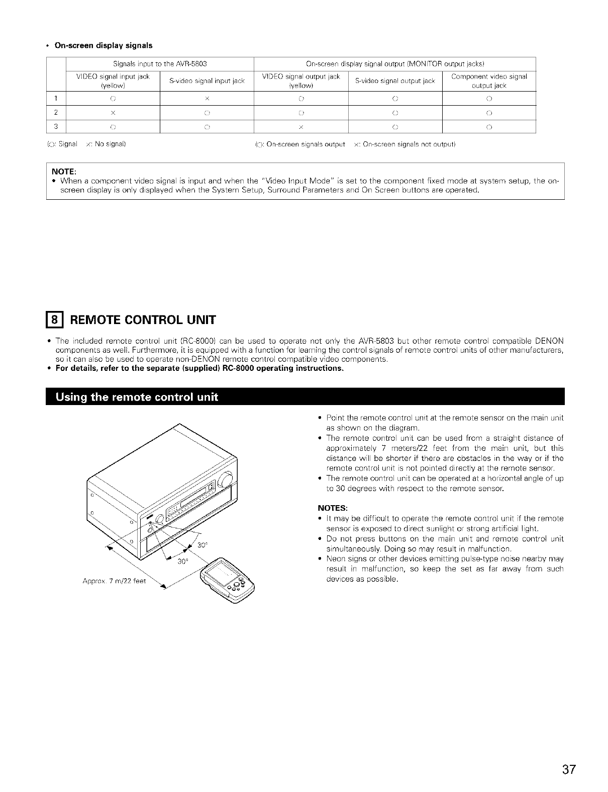
• On-screen display signals
SignaB input to the AVR-5803 On-screen display signal output (MONITOR output jacks)
VDEQ signal input iack S-video signal input jack VIDEO signal output iack S-video signal output jack Component video signal
(yellow) (yellow) output jack
1 ( x _ ( (
2 x , _ ( (
3 O (' x (} O
({}: Sgnal x: No signal) ((): Omscreen signaB output x: On-screen signals not output)
NOTE:
• When a component video signal is hqput and when the "Video Input Mode" is set to the component fixed mode at system setup, the om
screen display is only displayed when the System Setup, Surround Parameters and Ors Screen buttons are operated.
[] REMOTE CONTROL UNIT
• The included remote control unit (RC-8000) can be used to operate not only the AVR-5803 but other remote control compatible DENON
components as well. Furthermore, it is equipped with a function for learning the control signals of remote control units of other manufacturers,
so it can also be used to operate nomDENON remote control compatible video components
•For details, refer to the separate (supplied} RC-8000 operating instructions,
Approx 7 m/22 feet
• Point the remote control unit at the remote sensor on the main unit
as shown on the diagram
• The remote control unit can be used from a straight distance of
approximately 7 meters/22 feet from the main unit, but this
distance will be shorter if there are obstacles in the way or if the
remote control unit is not pointed directly at the remote sensor.
• The remote control unit can be operated at a horizontal angle of up
to 30 degrees with respect to the remote sensor.
NOTES:
• It may be difficult to operate the remote control unit if the remote
sensor is exposed to direct sunlight or strong artificial light.
• Do not press buttons on the main unit and remote control unit
simultaneously Doing so may result in malfunction
• Neon signs or other devices emitting pulse4ype noise nearby may
result in malfunction, so keep the set as far away from such
devices as possible.
37
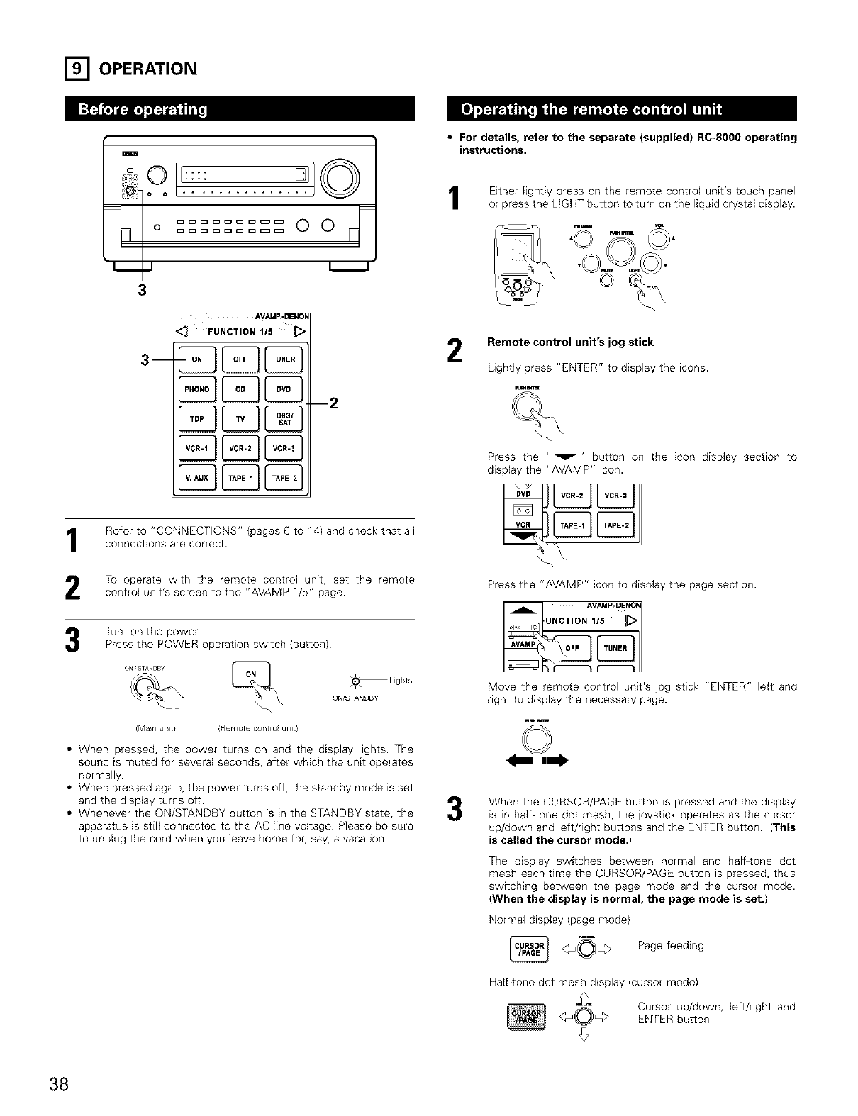
[] OPERATION
m
3
AVAMp-DENOp
<_ FUNCTION I15
Refer to "CONNECTIONS" (pages 6 to 14) and check that allconnections are correct.
To operate with the remote control unit, set the remote
control unit's screen to the "AVAMP 1/5" page
Turn on the power
Press the POWER operation switch (button)
ON/STANDBY
(Man uTlit} (Remote contro unit}
• When pressed, the power turns on and the display lights. The
sound is muted for several seconds, after wMch the unit operates
normally.
• When pressed again, the power turns off, the standby mode is set
and the display turns off.
• Whenever the ON/STANDBY button is in the STANDBY state, the
apparatus is still connected to the AC line voltage. Please be sure
to unplug the cord when you leave home for, say, a vacation
•For details, refer to the separate (supplied) RC-800O operating
instructions.
1Either lightly press on the remote control unit's touch panel
or press the LIGHT button to turn on the liquid crystal display.
2Remote control unit's jog stick
Lightly press "ENTER" to display the icons.
ru_E_l_
%
Press the ""_" " button on the icon display section to
display the "AVAMP" icon.
Press the "AVAMP" icon to display the page section.
Move the remote control unit's jog stick "ENTER" left and
right to display the necessary page.
w_
When the CURSOR/PAGE button is pressed and the display
is in half4one dot mesh, the joystick operates as the cursor
up/down and left/right buttons and the ENTER button. (This
is called the cursor mode.)
The display switches between normal and half4one dot
mesh each time the CURSOR/PAGE button is pressed, thus
switching between the page mode and the cursor mode.
(When the display is normal, the page mode is set.)
Normal display (page mode)
_0_> Page feeding
Half-tone dot mesh display (cursor mode)
"_ Cursor up/down, left/right and
ENTER button
38
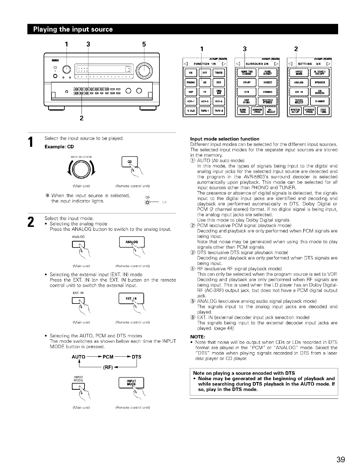
1
oO
3 5
F
, 0
2
<I _UNCnON 116
3
I,o°.oo.o":,T%
2
I
I
ISelect the input source to be played.
Example: CD
_NPLJT_;E_ECTOR
0 %
(Mainunit) (Remotecontrolunit}
-_ When the input source is selected, cD
the input indicator lights. .0. Lit
Select the input mode.
• Selecting the analog mode
Press the ANALOG button to switch to the analog input.
ANALOG L_
{Main unk) (Remote control unit}
• Selecting the external input (EXT. IN) mode
Press the EXT. IN (on the EXT. IN button on the remote
control unit) to switch the external input.
BXT liq
{Main u/it) (Remote control unit}
• Selecting the AUTO, PCM and DTS modes
The mode switches as shown below each time the INPUT
MODE button is pressed.
AUTO _PCM _DTS
(RF) "_
INPUT
MODE
{Main u/it) (Remote control unit}
Input mode selection function
Different input modes can be selected for the different input sources.
The selected input modes for the separate input sources are stored
in the memory.
_I) AUTO (All auto mode)
In this mode, the types of signals being input to the digital and
analog input jacks for the selected input source are detected and
the program in the AVR_5803's surround decoder is selected
automatically upon playback. This mode can be selected for all
input sources other than PHONO and TUNER.
The presence or absence of digital signals is detected, the signals
input to the digital input jacks are identified and decoding and
playback are performed automatically in DTS, Dolby Digital or
PCM (2 channel stereo) format. If no digital signal is being input,
the analog input jacks are selected.
Use this mode to play Dolby Digital signals
_2; PCM (exclusive PCM signal playback mode)
Decoding and playback are only performed when PCM signals are
being input.
Note that noise may be generated when using this mode to play
signals other than PCM signals
@ DTS (exclusive DTS signal playback mode)
Decoding and playback are only performed when DTS signals are
being input.
_4}RF (exclusive RF signal playback mode)
This can only be selected when the program source is set to VDR
Decoding and playback are only performed when RF signals are
being input This is used when the LD player has an Dolby Digital-
RF (AC-3RF) output jack, but does not have a PCM digital output
jack
@ ANALOG (exclusive analog audio signal playback mode)
The signals input to the analog input jacks are decoded and
played
@ EXT. IN (external decoder input jack selection mode)
The signals being input to the external decoder input jacks are
played (page 44)
NOTE:
• Note that noise will be output when CDs or LDs recorded in DTS
format are played in the "PCM" or "ANALOG" mode Select the
"DTS" mode when playing signals recorded in DTS from a laser
disc player or CD player
Note on playing a source encoded with DTS
• Noise may be generated at the beginning of playback and
while searching during DTS playback in the AUTO mode. If
so, play in the DTS mode,
39
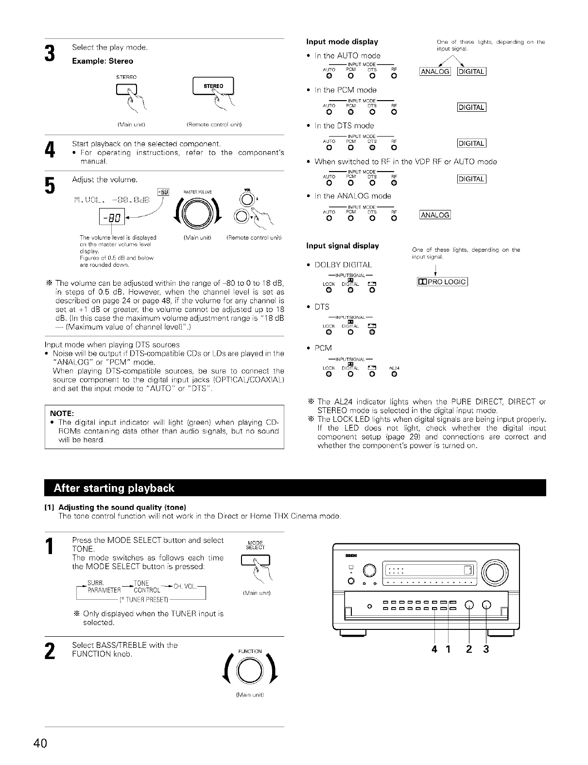
Select the play mode.
Example: Stereo
STEREO
(Mainu/Jr) (Remotecontrolunit}
Start playback on the selected component.
•For operating instructions, refer to the component's
manual.
Adjust the volume.
Tie volulne leve is displayed {Main u/it)
o_/the maste_ volume ]evel
display¸
Figures of 05 dB and below
are _ou_/ded down¸
The volume can be adjusted within the range of -80 to 0 to 18 dB,
in steps of 05 dB However, when the channel level is set as
described on page 24 or page 48, if the volume for any channel is
set at +1 dB or greater, the volume cannot be adjusted up to 18
dB. (In this case the maximum volume adjustment range is "18 dB
-- (Maximum value of channel level)".)
Input mode when playing DTS sources
•Noise will be output if DTS-compatible CDs or LDs are played in the
"ANALOG" or "PCM" mode
When playing DTS-compatible sources, be sure to connect the
source component to the digital input jacks (OPTICAL/COAXIAL)
and set the input mode to "AUTO" or "DTS"
NOTE:
• The digital input indicator will light (green) when playing CD-
ROMs containing data other than audio signals, but no sound
will be heard
Input mode display
• In the AUTO mode
OOOO
One of these lights, dependi/g oil the
input signal
• In the PCM mode
-- INPUT MODE --
AUTO PCM DTS RF
OO O O
• In the DTS mode
-- INPUT MODE --
AUTO PCM DTS RF
0000
• When switched to RF in the VDP RF or AUTO mode
-- INPUT MODE --
AUTO PCM DTS RF
0000
• In the ANALOG mode
-- INPUT MODE --
AUTO PCM DTS RF
000 0
Input signal display
• DOLBY DIGITAL
00O
• DTS
--_NPUTSI_IGNAL--
LOCK DIGITAL
OOO
•PCM
--INPUTSIGNAL--
LOCK DIGITAL _ AL24
O O O O
One of these ights, dependi/g oil the
input signal
[FN PRO LOGIC]
The AL24 indicator lights when the PURE DIRECT, DIRECT or
STEREO mode is selected in the digital input mode
The LOCK LED lights when digital signals are being input properly.
If the LED does not light, check whether the digital input
component setup (page 29) and connections are correct and
whether the component's power is turned on.
[1] Adjusting the sound quality (tone)
The tone control function will not work in the Direct or Home THX Cinema mode.
1Press the MODE SELECT button and select
TONE.
The mode switches as follows each time
the MODE SELECT button is pressed:
SURR
_" PARAMETER
(* TUNERPRESETI
Only displayed when the TUNER input is
selected.
Select BASS/TREBLE with the
FUNCTION knob.
MODE
SELECT
(Main unit/
FUNCTION
(Mail unt)
mo L:::I
0 ..........
1
4 1 2 3
4O
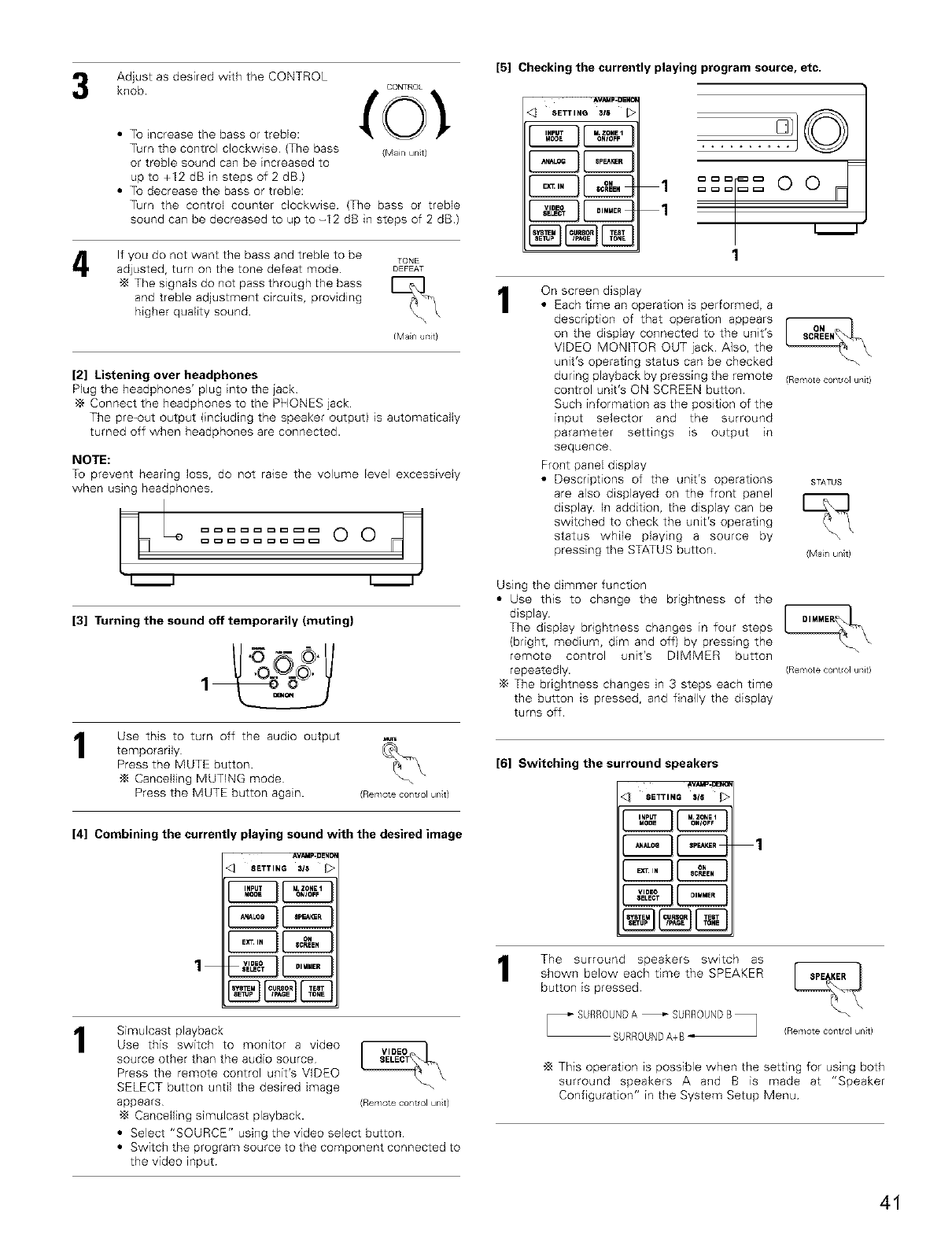
Adjust as desired with the CONTROL
knob.
• To increase the bass or treble:
Turn the control clockwise (The bass
or treble sound can be increased to
up to +12 dB in steps of 2 dB)
• To decrease the bass or treble:
CONTROL
to .
(Mail unt)
Turn the control counter c]ockwise (The bass or treble
sound can be decreased to up to -12 dB in steps of 2 dB.)
If you do not want the bass and treble to be TONE
adjusted, turn on the tone defeat mode. DEFEAT
"_ The signals do not pass through the bass
and treble adjustment circuits, providing
higher quality sound.
(Main uTlit}
[2] Listening over headphones
Plug the headphones' plug into the jack
•_ Connect the headphones to the PHONES jack
The pre-out output (including the speaker output) is automatically
turned off when headphones are connected.
NOTE:
To prevent hearing loss, do not raise the volume level excessively
when using headphones oodl
i i i i
[3] Turning the sound off temporarily (muting)
1Use this to turn off the audio output
temporarily
Press the MUTE button.
Cancelling MUTING mode
Press the MUTE button again. (Remote control unit)
[4] Combining the currently playing sound with the desired image
_VAMP_ENCf
SETTING 3/5 _>
1
1Simulcast playback
Use this switch to monitor a video
source other than the audio source
Press the remote control unit's VIDEO
SELECT button until the desired image
appears
-_ Cancelling simulcast playback.
(Rerr/ote ¢ol/t/ol unit)
• Select "SOURCE" using the video select button
• Switch the program source to the component connected to
the video input
[5] Checking the currently playing program source, etc.
AVAMF4]ENO
<_ SETTINQ 3/8
,oo
1
1
1On screen display
• Each time an operation is performed, a
description of that operation appears
on the display connected to the unit's
VIDEO MONITOR OUT jack Also, the
unit's operating status can be checked
during playback by pressing the remote
control unit's ON SCREEN button.
Such information as the position of the
input selector and the surround
parameter settings is output in
sequence
Front panel display
• Descriptions of the unit's operations
are also displayed on the front panel
display. In addition, the display can be
switched to check the unit's operating
status while playing a source by
pressing the STATUS button.
(Renote contd ur,it)
STATUS
(Mail unt)
Using the dimmer function
• Use this to change the brightness of the
display
The display brightness changes in four steps
(bright, medium, dim and off) by pressing the
remote control unit's DIMMER button
repeatedly.
•_ The brightness changes in 3 steps each time
the button is pressed, and finally the display
turns off.
(Renote contd ur,it)
[6] Switching the surround speakers
Av_J_.o_x_
SETTING 315
1
1The surround speakers switch as
shown below each time the SPEAKER
button is pressed
SURROU@A+B_ (Rerr/ote OOTlt/OI unit)
"_ This operation is possible when the setting for using both
surround speakers A and B is made at "Speaker
Configuration" in the System Setup Menu
41
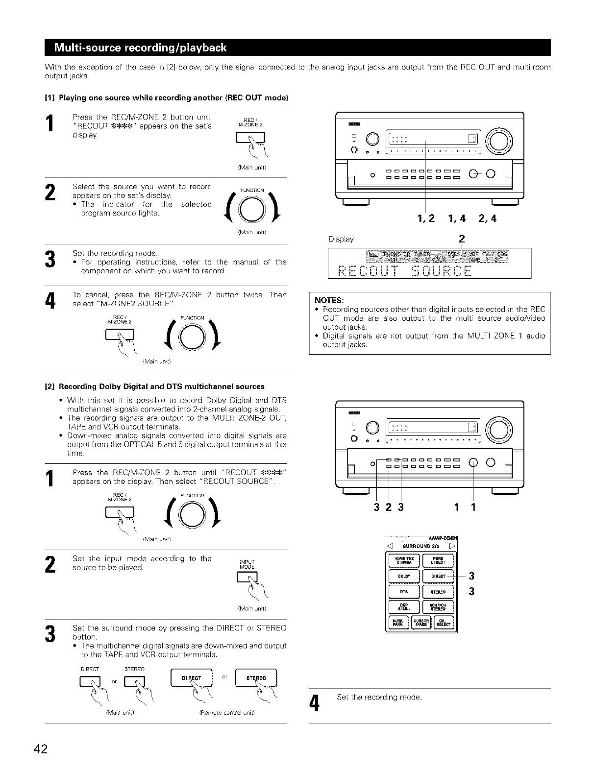
With the exception of the case in [2] below, only the signal connected to the analog input jacks are output from the REC OUT and muki-room
output jacks
[1] Playing one source while recording another (REC OUT mode)
Press the REC/M_ZONE 2 button until
"RECOUT _$$_" appears on the set's
display
REC /
M ZONE 2
(Mail unt)
Select the source you want to record FUNCTION
appears on the set's disp,ay _O_
• The indicator for the selected
program source lights
(Mail unt)
Set the recording mode.
•For operating instructions, refer to the manual of the
component on which you want to record
To cancel, press the REC/M_ZONE 2 button twice. Then
select "M-ZONE2 SOURCE".
m
O
o
L_J L_J
1,2 1,4 2,4
Display 2
:,,,,:,,, : :::: : ,,,, :::::,,,,: :
U.. L.., =..., =..._ =..._ _ ...._ =..._ =..._ U.. =..., _....
NOTES:
•Recording sources other than digital inputs selected Hqthe REC
OUT mode are also output to the multi source audio/video
output jacks
• Digital signals are not output from the MULTI ZONE 1 audio
output jacks
REC /FUNCTION
{Main ulJt)
[2] Recording Dolby Digital and DTS multichannel sources
•With this set it is possible to record Dolby Digital and DTS
multichannel signals converted into 2-channel analog signals
• The recording signals are output to the MULTi ZONE-2 OUT,
TAPE and VCR output terminals.
• Down=mixed analog signals converted into digital signals are
output from the OPTICAL 5 and 6 digital output terminals at this
time
1Press the REC/M=ZONE 2 button until "RECOUT _--_---1:$"
appears on the display Then select "RECOUT SOURCE".
REC /FUNCTION
{Main ulJt)
Set the input mode according to the _NPtJT
source to be played MODE
(Mail unt)
Set the surround mode by pressing the DIRECT or STEREO
button.
• The multichannel digital signals are down=mixed and output
to the TAPE and VCR output terminals
DIRECT STEREO
\
(Mail unt) (Remote coflt/ol ul/Jt)
m
0 ..........
°F "S
L_J L_J
323 1 1
AvAMF-ce_o
8URROU idD 21_
3
3
Set the recording mode.
42
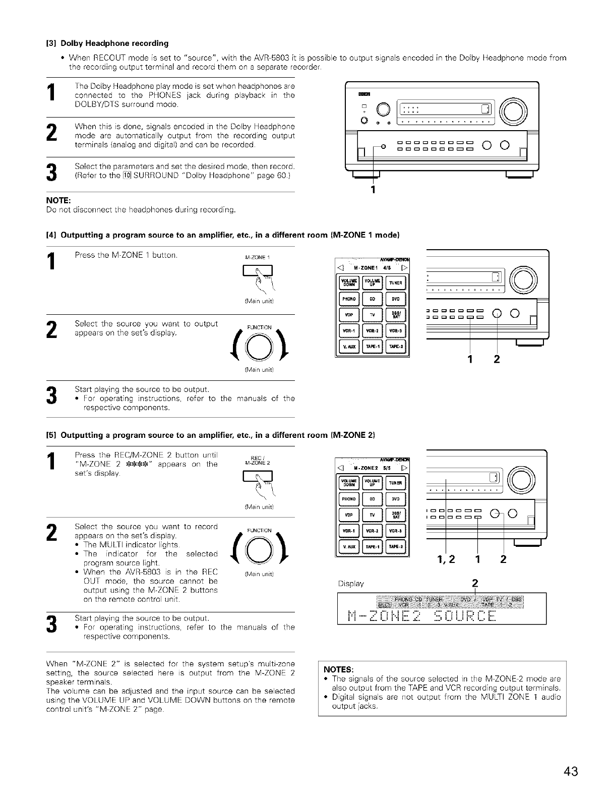
[3] Dolby Headphone recording
•When RECOUT mode is set to "source", with the AVR=5803 it is possible to output signals encoded in the Dolby Headphone mode from
the recording output terminal and record them on a separate recorder
The Dolby Headphone play mode is set when headphones are
connected to the PHONES jack during playback in the
DOLBY/DTS surround mode.
When this is done, signals encoded in the Dolby Headphone
mode are automatically output from the recording output
terminals (analog and digital} and can be recorded
Select the parameters and set the desired mode, then record.
(Refer to the [101SURROUND "Dolby Headphone" page 60)
NOTE:
Do not disconnect the headphones during recording.
m
O ..........
[4] Outputting a program source to an amplifier, etc,, in a different room (M-ZONE 1 mode}
1Press the M-ZONE 1 button M ZONE 1
(Mail unt)
Select the source you want to output FUNCTION
appears on the set's disp,ay _0_"
(Mail unS
Start playing the source to be output.
• For operating instructions, refer to the manuals of the
respective components.
M-ZONE1 4/5
8B{238E3
8EX23E@
1 2
[5] Outputting a program source to an amplifier, etc,, in a different room (M-ZONE 2)
Press the REC/M_ZQNE 2 button until
"M-ZONE 2 $$_--$" appears on the
set's display
2
nee /
M ZONE 2
(Mail unS
Select the source you want to record FUNCTION
appears on the set's disp,ay _0_"
• The MULTI indicator lights
• The indicator for the selected
program source light
• When the AVR-5803 is in the REC (MailunS
OUT mode, the source cannot be
output using the M-ZONE 2 buttons
on the remote control unit.
Start playing the source to be output.
• For operating instructions, refer to the manuals of the
respective components.
4_ M .ZONE2 SIS ,
I
J
1,2 1 2
Display 2
I
=,_,,,,,,, =_=,,_:,,, ,.... ,=_=_=,:, = =,,,
:: :,,,,,,,,,:::,,,,,: ....... ,,,,,,,,,,,:,,,,,,,:,
NOTES:
• The signals of the source selected in the M=ZONE=2 mode are
also output from the TAPE and VCR recording output terminals.
• Digital signals are not output from the MULTI ZONE 1 audio
output jacks
When "M-ZONE 2" is selected for the system setup's multi-zone
setting, the source selected here is output from the M-ZONE 2
speaker terminals.
The volume can be adjusted and the input source can be selected
using the VOLUME UP and VOLUME DOWN buttons on the remote
control unit's "M_ZONE 2" page
43
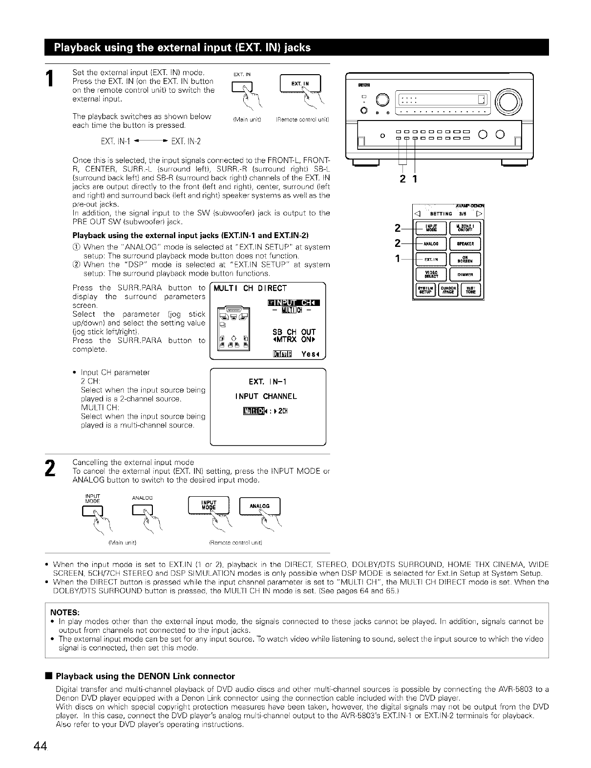
1Set the external input (EXT IN) mode
Press the EXT IN (on the EXT IN button
on the remote control unit) to switch the
external input.
The playback switches as shown below
each time the button is pressed
EXT.IN-1_ EXT IN-2
BXT IN
(Main unt) (Remote control un;t}
Once this is selected, the input signals connected to the FRONT-L, FRONT-
R, CENTER, SURR-L (surround left}, SURR_R (surround right) SB<
(surround back left) and SB-R (surround back right) channels of the EXT IN
jacks are output directly to the front (left and dght), center, surround (left
and right} and surround back (left and right) speaker systems as well as the
pre-out jacks.
In addition, the signal input to the SW (subwoofer) jack is output to the
PRE OUT SW (subwoofer) jack.
Playback using the external input jacks (EXT.IN-1 and EXT, IN-2)
_ When the "ANALOG" mode is selected at "EXTIN SETUP" at system
setup: The surround playback mode button does not function
(27When the "DSP" mode is selected at "EXTIN SETUP" at system
setup: The surround playback mode button functions.
Press the SURR.PARA button to
display the surround parameters
screen
Select the parameter (jog stick
up/down) and select the setting value
(jog stick left/right)
Press the SURR.PARA button to
complete
MULTI CH DIRECT
SB CH OUT
_MTRX ON_
Yes4
EX_ IN-1
INPUT CHANNEL
_4:_2CH
• Input CH parameter
2 CH:
Select when the input source being
played is a 2-channel source
MULTI CH:
Select when the input source being
played is a multi-channel source
m
O ..........
L ODOODOODD
o...... 0 0
TT
21
<_ 8ETT,NG_IS I>
Cancelling the external input mode
To cancel the external input (EXT IN) setting, press the INPUT MODE or
ANALOG button to switch to the desired input mode
_NPUT ANALOG
MODE
(Mail unit} /Remote contro] unit)
•When the input mode is set to EXTIN (1 or 2), playback in the DIRECT, STEREO, DOLBY/DTS SURROUND, HOME THX CINEMA, WIDE
SCREEN, 5CH/7CH STEREO and DSP SIMULATION modes is only possible when DSP MODE is selected for Extln Setup at System Setup
• When the DIRECT button is pressed while the input channel parameter is set to "MULTi CH", the MULTI CH DIRECT mode is set When the
DOLBY/DTS SURROUND button is pressed, the MULTI CH IN mode is set (See pages 64 and 65)
NOTES:
•In play modes other than the external input mode, the signals connected to these jacks cannot be played. In addition, signals cannot be
output from channels not connected to the input jacks.
• The external input mode can be set for any input source. To watch video while listening to sound, select the input source to which the video
signal is connected, then set this mode
• Playback using the DENON Link connector
Digital transfer and multi-channel playback of DVD audio discs and other multi-channel sources is possible by connecting the AVR-5803 to a
Denon DVD player equipped with a Denon Link connector using the connection cable included with the DVD player.
With discs on which special copyright protection measures have been taken, however, the digital signals may not be output from the DVD
player. In this case, connect the DVD player's analog multi=channel output to the AVR-5803's EXTIN_I or EXTIN=2 terminals for playback
Also refer to your DVD player's operating instructions.
44
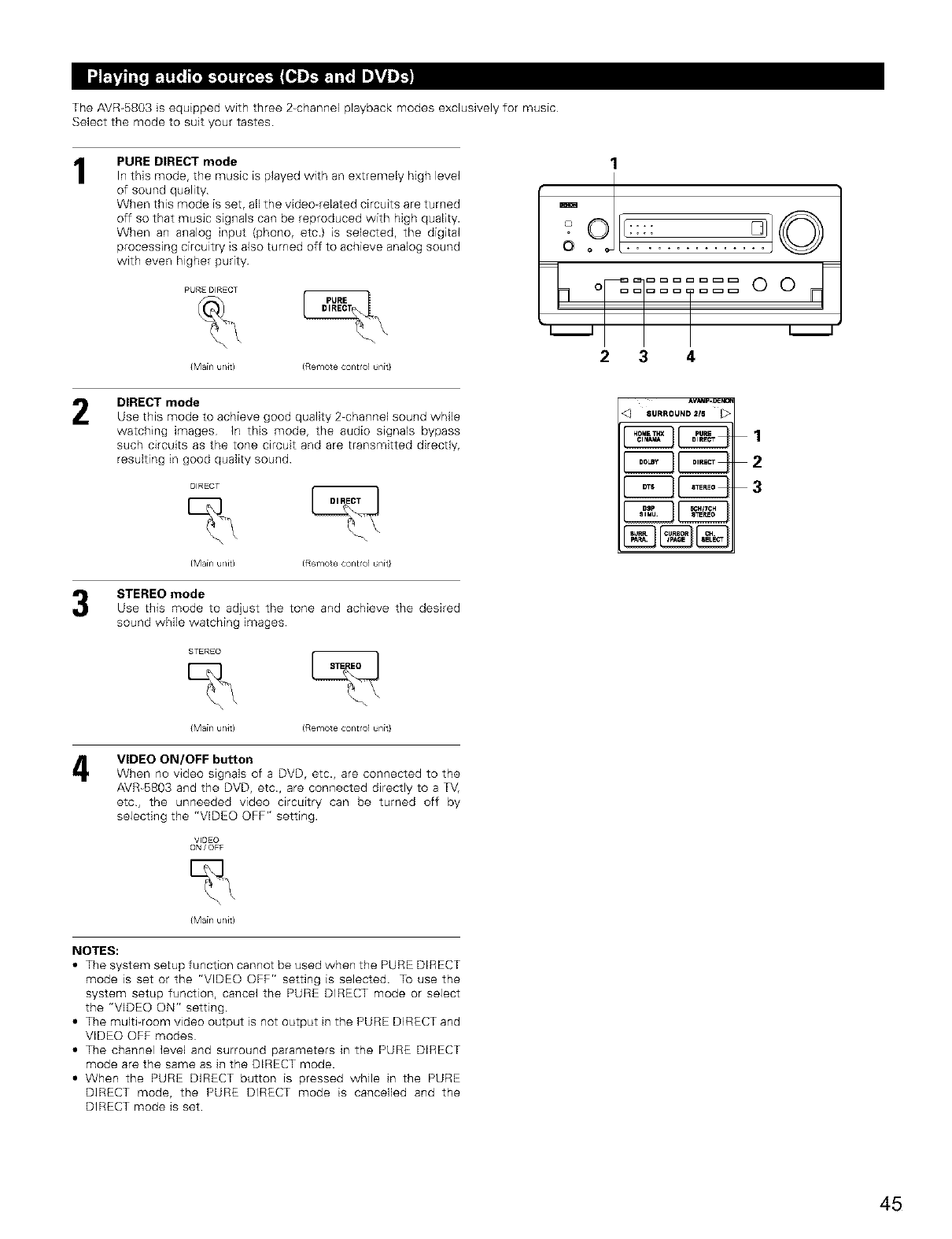
The AVR-5803 is equipped with three 2_channel playback modes exclusively for music
Select the mode to suit your tastes
1PURE DIRECT mode
In this mode, the music is played with an extremely high level
of sound quality
When this mode is set, all the video-related circuits are turned
off so that music signals can be reproduced with high quality.
When an analog input (phono, etc) is selected, the digital
processing circuitry is also turned off to achieve analog sound
with even higher purity
PUREDIRECT _.
{Main u/Jr) (Remote control unit}
1
-oo
O ..........
2 3 4
2
4
DIRECT mode
Use this mode to achieve good quality 2-channel sound wMle
watching images h_ this mode, the audio signals bypass
such circuits as the tone circuit and are transmitted directly,
resulting in good quality sound
DIRECT
{Main u/Jr) (Remote control unit}
STEREO mode
Use this mode to adjust the tone and achieve the desired
sound while watching images
STEREO L_
{Main u/it) (Remote control unit}
VIDEO ON/OFF button
When no video signals of a DVD, etc., are connected to the
AVR_5803 and the DVD, etc., are connected directly to a TV,
etc, the unneeded video circuitry can be turned off by
selecting the "VIDEO OFF" setting.
V_DEO
ON/OFF
AV_'AP'_ _
SURROUND 2is
CZ3 1
2
3
{Main u/Jr)
NOTES:
•The system setup function cannot be used when the PURE DIRECT
mode is set or the "VIDEO OFF" setting is selected. To use the
system setup function, cancel the PURE DIRECT mode or select
the "VIDEO ON" setting
• The multi_room video output is not output in the PURE DIRECT and
VIDEO OFF modes
• The channel level and surround parameters in the PURE DIRECT
mode are the same as in the DIRECT mode.
• When the PURE DIRECT button is pressed while in the PURE
D]RECT mode, the PURE DIRECT mode is cancelled and the
DIRECT mode is set
45
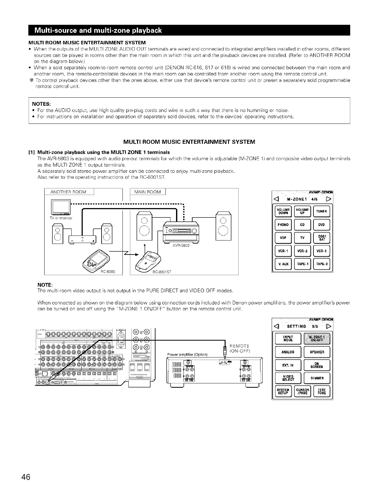
MULTI ROOM MUSIC ENTERTAINMENT SYSTEM
•When the outputs of the MULTI ZONE AUDIO OUT terminals are wired and connected to integrated amplifiers installed in other rooms, different
sources can be played in rooms other than the main room in which this unit and the playback devices are installed (Refer to ANOTHER ROOM
on the diagram below.)
• When a sold separately room-to-room remote control unit (DENON RC-616, 617 or 618) is wired and connected between the main room and
another room, the remote-controllable devices in the main room can be controlled from another room using the remote control unit
To control playback devices other than the ones above, either use that device's remote control unit or preset a separately sold programmable
remote control unit
NOTES:
• For the AUDIO output, use high quality pin®lug cords and wire tn such a way that there is no humming or no4se
• For instructions on instaflation and operation of separately sold devices, refer to the devices' operating instructions.
MULTI ROOM MUSIC ENTERTAINMENT SYSTEM
[1] Multi-zone playback using the MULTI ZONE 1 terminals
The AVR=5803 is equipped with audio pre=out terminals for which the volume is adjustable (M-ZONE 1) and composite video output terminals
as the MULTI ZONE 1 output terminals
A separately sold stereo power amplifier can be connected to enjoy multi_zone playback.
Also refer to the operating instructions of the RC-8001ST.
ANOTHER ROOM MAIN ROOM J
D[ ..........................;"...
AVAMp-DENC_
<! .-ZONE1415 _>
NOTE:
The multi=room video output is not output in the PURE DIRECT and VIDEO OFF modes.
When connected as shown on the diagram below using connection cords included with Denon power amplifiers, the power amplifier's power
can be turned on and off using the "M=ZONE 1 ON/OFF" button on the remote control unit.
(ON-OFF)
Poweramplifier(Option)
t D°°°II_='_ t
000000f®®
O000D_
AV._4P_DENOE
< SETTIN6315 ;>
46
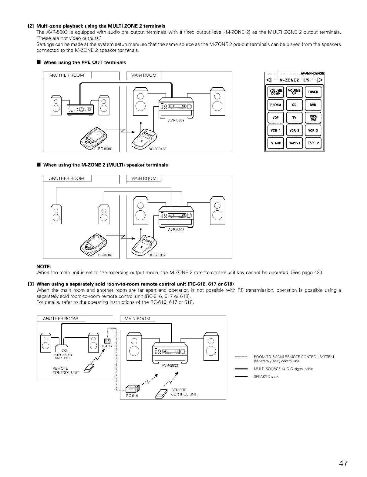
[2] Multi-zone playback using the MULTI ZONE 2 terminals
The AVR-5803 is equipped with audio pre output terminals with a fixed output level (M-ZONE 2) as the MULTI ZONE 2 output terminals.
(These are not video outputs)
Settings can be made at the system setup menu so that the same source as the M-ZONE 2 pre-out terminals can be played from the speakers
connected to the M-ZONE 2 speaker terminals
•When using the PRE OUT terminals
ANOTHER ROOM I MAIN ROOM [
7
AVR 5803
_"_RC 8001 ST
AVAMp- DEI_IO_
<_ M-ZONE2 515 _[_
•When using the M-ZONE 2 (MULTI} speaker terminals
I MAIN ROOM [
ANOTHERROOM
_"_RC AVR 5803
7--
8001ST
NOTE:
When the main unit is set to the recording output mode, the M-ZONE 2 remote control unit key cannot be operated. (See page 42.)
[3] When using a separately sold room-to-room remote control unit (RC-616, 617 or 618)
When the main room and another room are far apart and operation is not possible with RF transmission, operation is possible using a
separately sold room4o-room remote control unit (RC-616, 617 or 618).
For details, refer to the operating instructions of the RC-616, 617 or 618.
ANOTHER ROOM
INTEGRATED •
AMPLIFIER /_a
REMOTE J
CONTROL UNIT
MAIN ROOM ]
13'lrl3
AVR 5803
R6_16
4
,l_f t •
I
REMOTE
CONTROL UNIT
...........................ROOM TO ROOM REMOTE CONTROL SYSTEM
{separately sold} contro line
MULTI SOURCE AUDIO signal cable
SPEAKER came
47
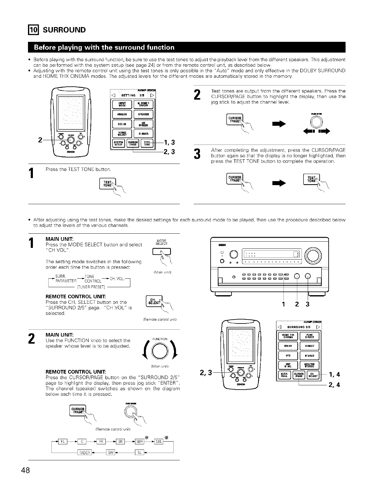
I_]SURROUND
•Before playing with the surround function, be sure to use the test tones to adjust the playback level from the different speakers This adjustment
can be performed with the system setup (see page 24) or from the remote control unit, as described below
• Adjusting with the remote control unit using the test tones is only possible in the "Auto" mode and only effective in the DOLBY SURROUND
and HOME THX CINEMA modes The adjusted levels for the different modes are automatically stored in the memory
2
1
SETTING 315
E2E3
1,3
2,3
Press the TEST TONE button.
Teat tones are output from the different speakers. Press the
CURSOR/PAGE button to highlight the display, then use the
jog stick to adjust the channel level.
_m
After completing the adjustment, press the CURSOR/PAGE
button again so that the display is no longer highlighted, then
press the TEST TONE button to complete the operation.
• After adjusting using the test tones, make the desired settings for each surround mode to be played, then use the procedure described below
to adjust the levels of the various channels.
MAIN UNIT: MODE
Press the MODE SELECT button and select SELECT
"CH VOL"
The setting mode switches in the following
order each time the button is pressed:
(Main uTlit)
(TUNERPRESET)
REMOTE CONTROL UNIT:
Press the CH. SELECT button on the
"SURROUND 2/5" page "CH VOL" is
selected
(Remote cont/ol unit}
MAIN UNIT:
Use the FUNCTION knob to select the
speaker whose level is to be adjusted.
FUNCTION
(Main unit}
REMOTE CONTROL UNIT:
Press the CURSOR/PAGE button on the "SURROUND 2/5"
page to highlight the display, then press jog stick "ENTER".
The channel (speaker) switches as shown on the diagram
below each time it is pressed.
_m
(Remote control unit}
m
0 .... ToIs
0
1 2 3
SURROUND 215
[2E][2E]
r q[2E]
_2, 4
48
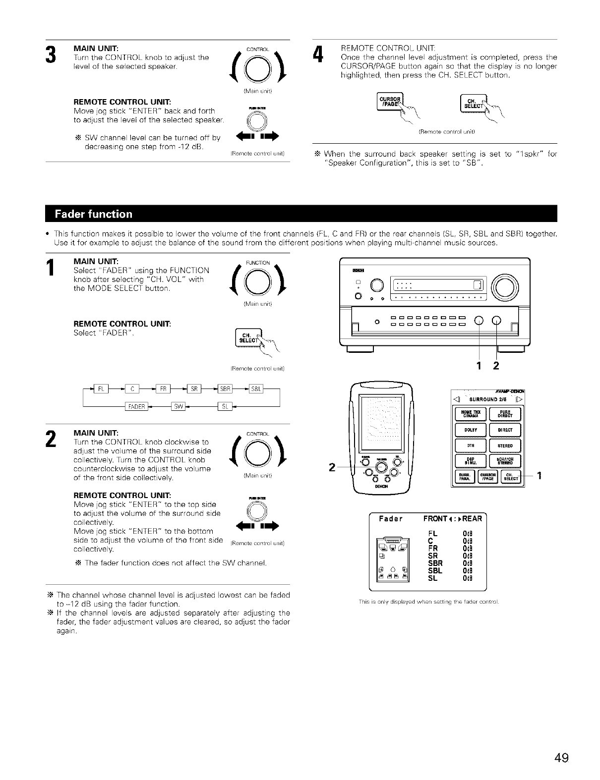
MAIN UNIT:
Turn the CONTROL knob to adjust the
level of the selected speaker
REMOTE CONTROL UNIT:
Move jog stick "ENTER" back and forth
to adjust the level of the selected speaker.
SW channel level can be turned off by
decreasing one step from -12 dB.
CONTROL 4
(Mail unit}
w_
(R®mote control unit}
REMOTE CONTROL UNIT:
Once the channel level adjustment is completed, press the
CURSOR/PAGE button again so that the display is no longer
highlighted, then press the CH SELECT button
(Rerr/ote ¢ol/t rol unit}
'_ When the surround back speaker setting is set to "lspkr" for
"Speaker Configuration", this is set to "SB".
•This function makes it possible to lower the volume of the front channels (FL, C and FR) or the rear channels {SL, SR, SBL and SBR) together.
Use it for example to adjust the balance of the sound from the different positions when playing multi_channel music sources.
MAIN UNIT: FUNCTION
Select "FADER" using the FUNCTION _ 0 _
knob after selecting "CH. VOL" with
the MODE SELECT button
(Mail unit}
REMOTE CONTROL UNIT:
Select "FADER" \
(R®mote control unit}
2MAIN UNIT: coNmo:
Turn the CONTROL knob clockwise to _ 0 _
adjust the volume of the surround side
collectively. Turn the CONTROL knob
counterclockwise to adjust the volume
of the front side collectively. (Mail unit}
REMOTE CONTROL UNIT: Fw,lm
Move jog stick "ENTER" to the top side _
to adjust the volume of the surround side .w.,
collectively.
Move jog stick "ENTER" to the bottom
side to adjust the volume of the front side (Remotecontrounit}
collectively.
The fader function does not affect the SW channel.
•_ The channel whose channel level is adjusted lowest can be faded
to -12 dB using the fader function.
•_ If the channel levels are adjusted separately after adjusting the
fader, the fader adjustment values are cleared, so adjust the fader
again
2
m
O ..........
i i
12
O
_Hal4
<3 SUrrOUND215
I .....II = 0ol
1
Fader FRONT4:_REAR
FL 0dB
C OdB
FR 0dE
SR 0dE
SBR 0dB
SBL 0dB
SL 0dB
Ths s only d splayed when setting the fader co/trol
49
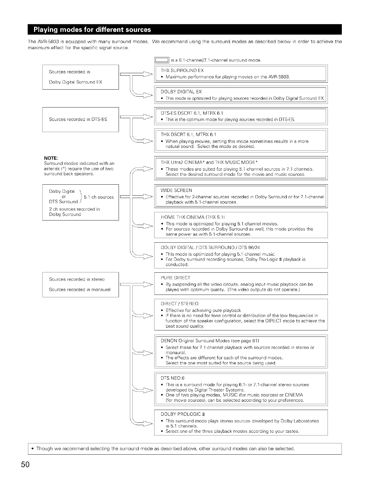
The AVR-5803 is equipped with many surround modes We recommend using the surround modes as described below in order to achieve the
maximum effect for the specific signal source
Sources recorded in
Dolby Digital Surround EX
Sources recorded in DTS-ES
_]is a 61 channel/71 channel surround mode
THX SURROUND EX
• Maximum performance for playing movies on the AVR 5803
DOLBY DIGITAL EX
• This mode is optimized for playing sources recorded in Dolby Digital Surround EX
DTS ES DSCRT 61, MTRX 61
• This is the optimum mode for playing sources recorded in DTS ES
THX DSCRT 6.1, MTRX 61
• When playing movies, setting this mode sometimes results in a more
natural sound Select the mode as desired
NOTE:
Surround modes indicated with an
asterisk (_} require the use of two
surround back speakers
Dolby Digital
or 51 ch sources
DTS Surround
2 ch sources recorded in
Dolby Surround
Sources recorded in stereo
Sources recorded in monaural
THX Ultra2 CINEMA * and TEIX MUSIC MODE _
• These modes are suited for playing 51 channel sources in 71 channels
Select the desired surround mode for the movie and music sources
WIDE SCREEN
• Effective for 2 channel sources recorded in Dolby Surround or for 71 channel
playback with 51 channel sources
HOME TEIX CINEMA (THX 511
• This mode is optimized for playing 51 channel movies
• For sources recorded in Dolby Surround as well, this mode provides the
same power as with 81 channel sources
DOLBY DIGITAL /DTS SURROUND /DTS 96/24
• This mode is optimized for playing 51 channel music
• For Dolby surround recording sources, Dolby Pro-Logic ]! playback is
conducted
PURE DIRECT
• By suspending all the video circuits, analog input music playback can be
played with optimum quality (The video outputs do not operate)
DIRECT /STEREO
• Effective for achieving pure playback
• If there is no need for tone control or distribution of the low frequencies in
function of the speaker configuration, select the DIRECT mode to achieve the
best sound quality
DENON Original Surround Modes (see page 61)
• Select these for 71 channel playback with sources recorded in stereo or
monaural
• The effects are different for each of the surround modes
Select the one most suited for the source being used
DTS NEO:6
• This is a surround mode for playing 61 or 71 channel stereo sources
developed by Digital Theater Systems
• One of two playing modes, MUSIC (for music sourcesl or CINEMA
(for movie sourcesl, can be selected according to your preferences
DOLBY PROLOGIC 11
• This surround mode plays stereo sources developed by Dolby Laboratories
in 51 channels
• Select one of the three playback modes according to your tastes
• Though we recommend selecting the surround mode as described above, other surround modes can also be selected
5O
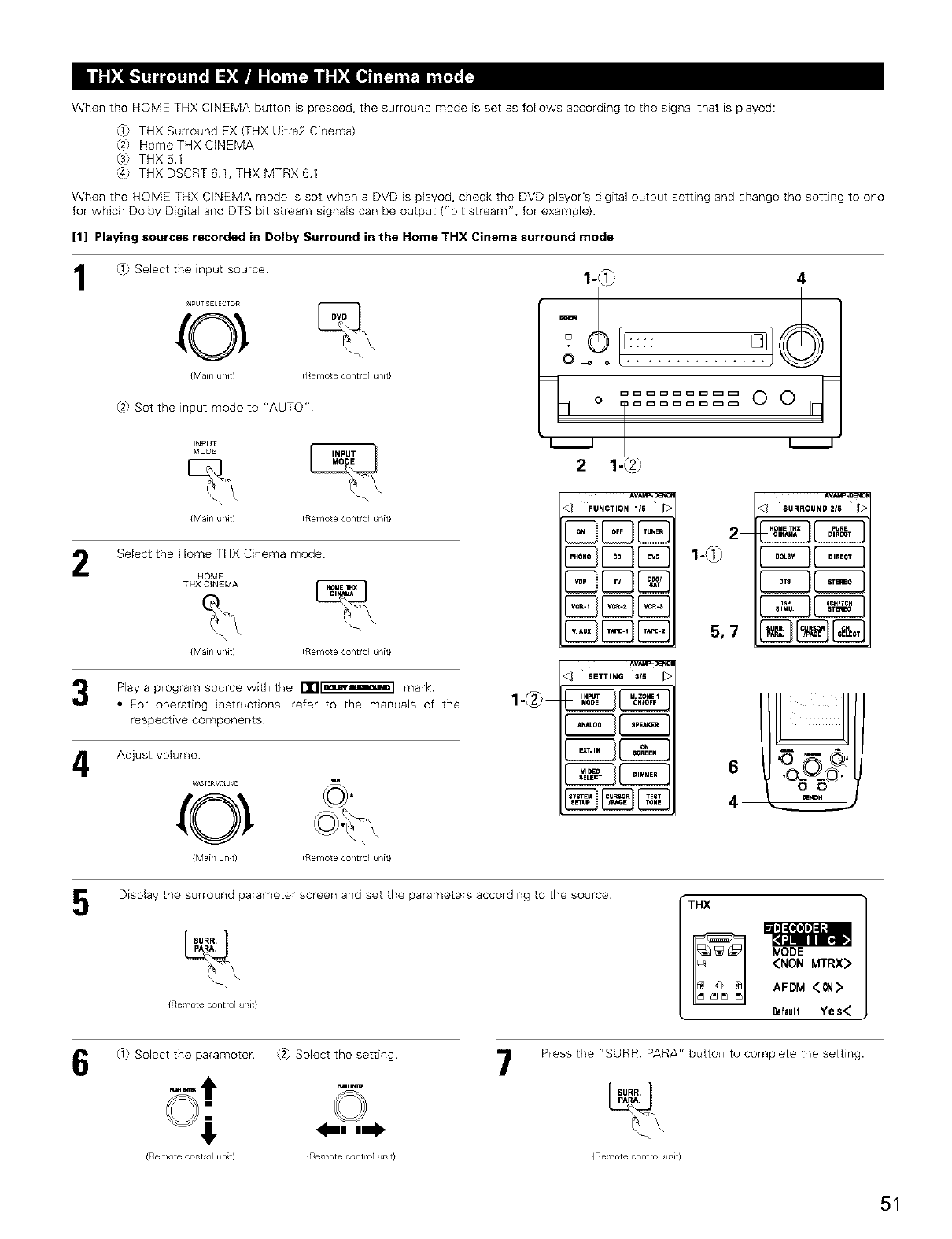
When the HOME THX CINEMA button is pressed, the surround mode is set as follows according to the signal that is played:
_} THX Surround EX (THX Ultra2 Cinema}
(8 Home THX CINEMA
@ THX 6.1
{4}' THXDSCRT6.1,THXMTRX61
When the HOME THX CINEMA mode is set when a DVD is played, check the DVD player's digital output setting and change the setting to one
for which Dolby Digital and DTS bit stream signals can be output ("bit stream", for example}.
[1] Playing sources recorded in Dolby Surround in the Home THX Cinema surround mode
1
2
4
_} Select the input source
N_UT 5;E ECTOR
0 %
(Mainunit) (Remotecontrolunit}
,s h
?JSet the input mode to "AUTO"
INPUT
MODE _
{Main ul/Jt) (Remote controlun[t}
Select the Home THX Cinema mode.
HOME
THX CINEMA _
{Main u/it} (Remote control unit}
Play a program source wkh the I'Tl[mm_] mark.
•For operating instructions, refer to the manuals of the
respective components.
Adjust volume
MAS]ER _( UblE
{Mainu/it) (Remotecontrolunit}
1-@
1"0_ 4
ood
2 1-@_
'_ FUNCTION 115
E 3CD
2
5,7
AVARe,g_'O
'_ SURROUND 2/5
AVA,_.DENO
<_ SETTINGSI_ _>
Display the surround parameter screen and set the parameters according to the source.
{Re ¥_ote control uTlit}
•THX
MODE
<NON MTRX>
AFDM <_ >
Default Yes<
_} Select the parameter.
(Remote cof_trol unit)
t2J Select the setting.
{Re ¥_ote control uTlit}
7Press the "SURR PARA" button to complete the setting.
{Re ¥_ote control uilit}
51
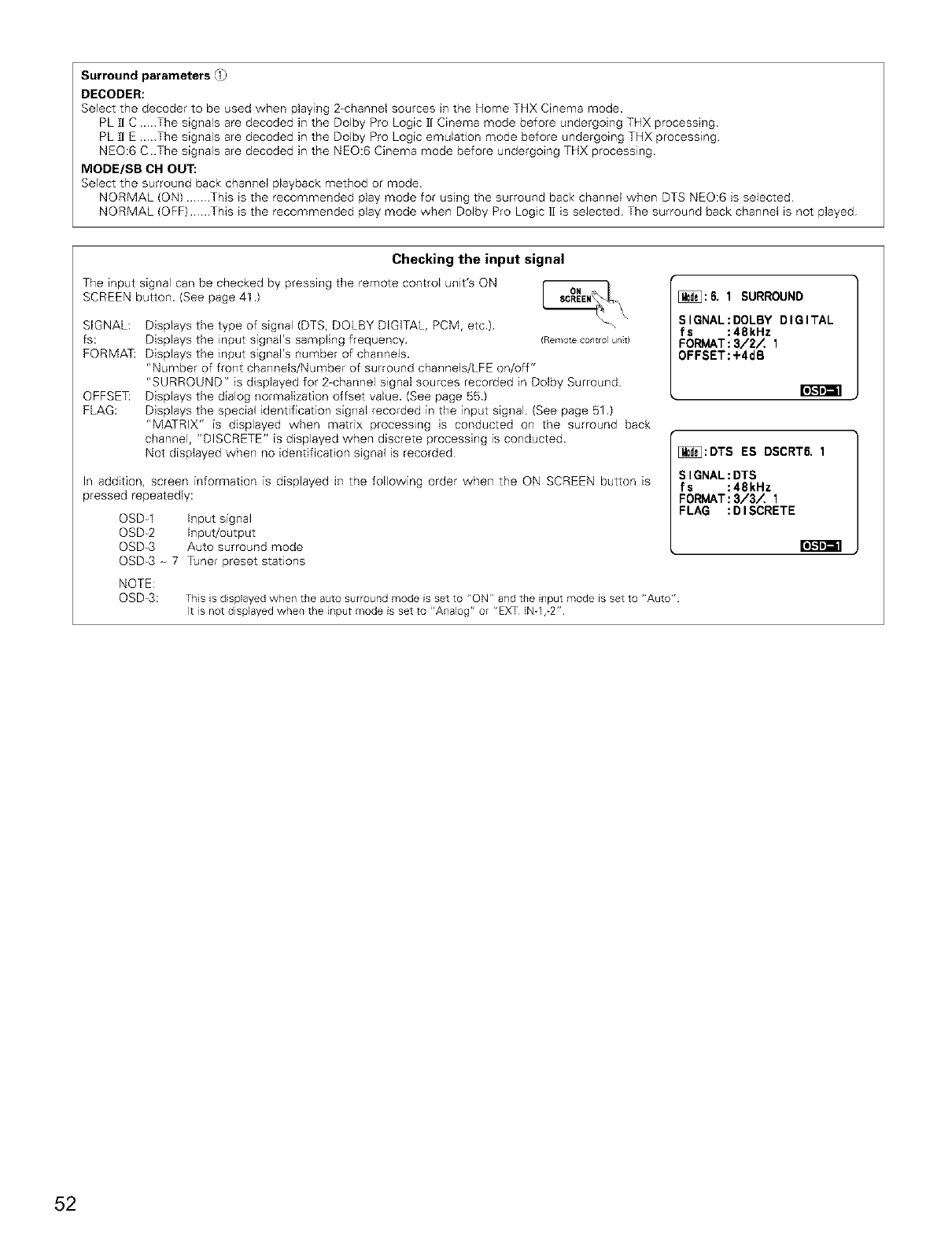
Surround parameters _1_
DECODER:
Select the decoder to be used when playing 2-channel sources hqthe Home THX Cinema mode.
PL I] C ...The signals are decoded in the Dolby Pro Logic ]1 Cinema mode before undergoing THX processing
PL I] E ...The signals are decoded in the Dolby Pro Logic emulation mode before undergoing THX processing
NEO:6 C.The signals are decoded in the NEO:6 Cinema mode before undergoing THX processing.
MODE/SB CH OUT:
Select the surround back channel playback method or mode.
NORMAL (ON) ....This is the recommended play mode for ushqg the surround back channel when DTS NEO:6 is selected
NORMAL (OFF)....This is the recommended play mode when Dolby Pro Logic 1[ is selected The surround back channel is not played
Checking the input signal
The input signal can be checked by pressing the remote control unit's ON
SCREEN button. (See page 41 .)
SIGNAL:
fs:
FORMA_
OFFSE_
FLAG:
Displays the type of signal (DTS, DOLBY DIGITAL, PCM, etc.) __"
Displays the input signal's sampling frequency. (Remotecontrolunt)
Displays the input signal's number of channels.
"Number of front channels/Number of surround channels/LFE on/off"
"SURROUND" is displayed for 2-channel signal sources recorded in Dolby Surround
Displays the dialog normalization offset value. (See page 55.)
Displays the special identification signal recorded in the input signal (See page 51 .)
"MATRIX" is displayed when matrix processing is conducted on the surround back
channel, "DISCRETE" is displayed when discrete processing is conducted.
Not displayed when no identification signal is recorded
In addition, screen information is displayed in the following order when the ON SCREEN button is
pressed repeatedly:
OSDq Input signal
OSD_2 Input/output
OSD_3 Auto surround mode
OSD_3 - 7 Tuner preset stations
[_:6. 1 SURROUND
SIGNAL:DOLBY DIGITAL
fs :48kHz
FORMAT:3/2_ 1
OFFSET:+4dB
[_:DTS ES DSCRT6, 1
SIGNAL:DTS
fs :48kHz
FORMAT:3/3_ 1
FLAG :DISCRETE
r_F4r_l
NOTE:
OSD_3: This is displayed when the auto surround mode is set to "ON" and the i_put mode is set to "Auto"
It is not displayed when the input mode is set to "Analog" or "EXT [N_1,-2"
52
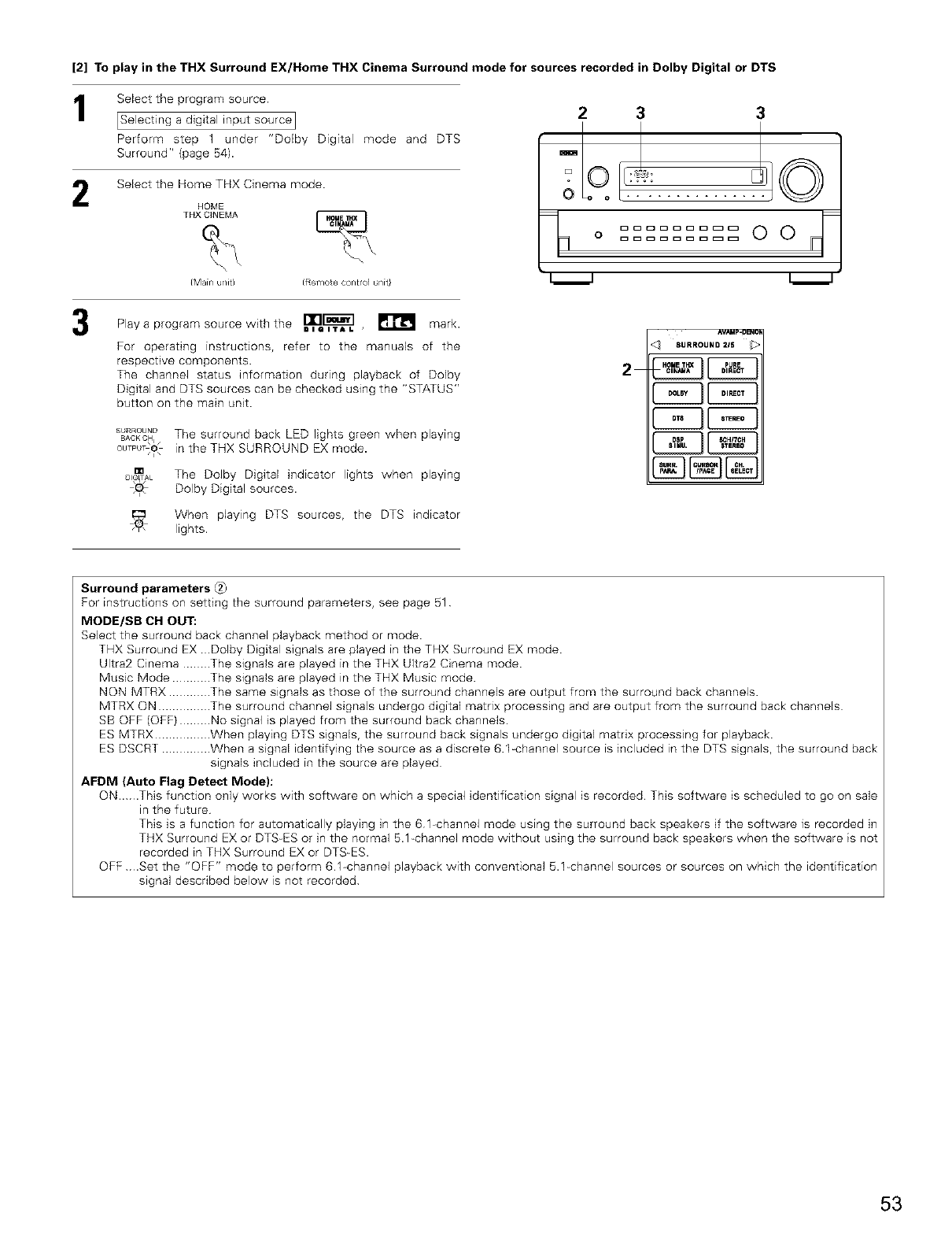
[2] To play in the THX Surround EX/Home THX Cinema Surround mode for sources recorded in Dolby Digital or DTS
1
2
Select the program source
[Selecting a digital input source I
Perform step 1 under "Dolby Digital mode and DTS
Surround" (page 54).
Select the Home THX Cinema mode.
HOME
THX CINEMA _
{Main u/it{ (Remote control unit}
2 3 3
O
Play a program source with the =l_l=lv[:_].L ,_ mark.
For operating instructions, refer to the manuals of the
respective components
The channel status information during playback of Dolby
Digital and DTS sources can be checked using the "STATUS"
button on the main unit.
SURROUND
BACKC_,_The surround back LED lights green when playing
ou,P _o in the THX SURROUND EX mode.
mThe Dolby Digital indicator lights when playing
Dolby Digital sources.
When playing DTS sources, the DTS indicator
lights.
2
^v/_up-geN_
SURROUND=IS _>
Surround parameters
For instructions on setting the surround parameters, see page 51
MODE/SB CH OUT:
Select the surround back channel playback method or mode.
THX Surround EX .Dolby Digital signals are played in the THX Surround EX mode.
Ultra2 Cinema ........ The signals are played in the THX Ultra2 Cinema mode.
Music Mode ........... The signals are played in the THX Music mode.
NON MTRX ............ The same signals as those of the surround channels are output from the surround back channels.
MTRX ON ............... The surround channel signals undergo digital matrix processing and are output from the surround back channels
SB OFF (OFF) ......... No signal is played from the surround back channels.
ES MTRX ................ When playing DTS signals, the surround back signals undergo digital matrix processing for playback.
ES DSCRT .............. When a signal identifying the source as a discrete 6.1=channel source is included in the DTS signals, the surround back
signals included in the source are played
AFDM (Auto Flag Detect Mode):
ON...This function only works with software on which a special identification signal is recorded This software is scheduled to go on sale
in the future
This is a function for automatically playing in the 6 l-channel mode using the surround back speakers if the software is recorded in
THX Surround EX or DTS=ES or in the normal 5.1_channel mode without using the surround back speakers when the software is not
recorded in THX Surround EX or DTS=ES.
OFF .Set the "OFF" mode to perform 6 1 channel playback with conventional 5.1=channel sources or sources on which the identification
signal described below is not recorded
53
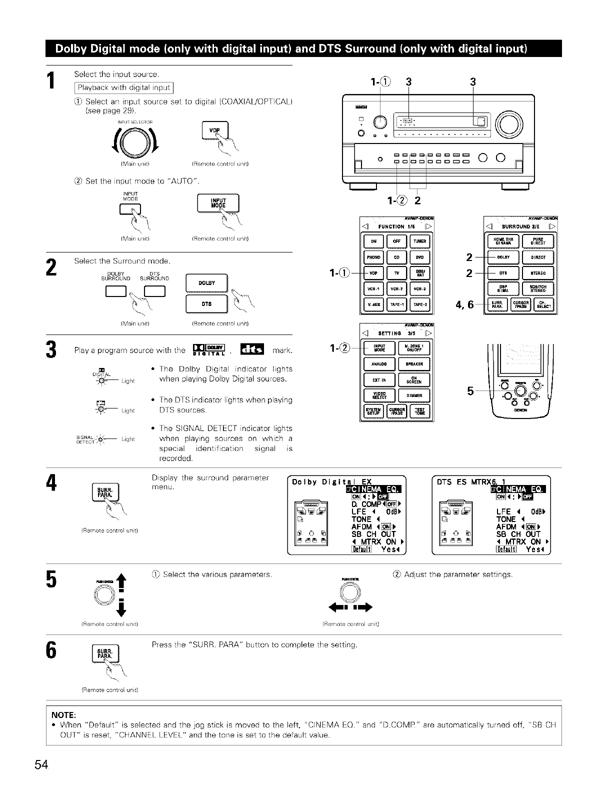
I
2
Select the input source.
[ Playback with digital input I
@ Select an hqput source set to digital (COAXIAL/OPTICAL)
(see page 29).
N_UT !;ELECT{/R
0
(Mainunit( (Remotecontrolunit}
?/ Set the input mode to "AUTO"
INPUT
MODE _
(Main ul/it( (Remote controlunit}
Select the Surround mode.
DOLBY DTS
(Main u/it) (Remote control unit}
rw,l_ m
Play a program source with the WI_I_L_'L , _ mark.
m * The Dolby Digital indicator lights
when playing Dolby Digital sources.
_ Light
SIGNAL _O_ Light
OETECT _ i -
•The DTS indicator lights when playing
DTS sources
•The SIGNAL DETECT indicator lights
when playing sources on which a
special identification signal is
recorded
Display the surround parameter
_ menu.
(Re¥_otecontrol uTlit}
1-_ 3 3
0o o .........
o ...... 0 0
.N '
1
1-@)
^V_F.UeNC_
FUNCSION1IS _>
EBED 2
2
4,6
AV_P-_
SURROUNO216
E2B
AV_
<] SETTING 315
®®
Dolby Digital EX
LFE t 0dB_
TONE 4
AFDM _[_
SB CH OUT
MTRX ON
Yes_
•DTS ES MTRX_
LFE 4OdBb
TONE
AFD_I q[_
SB CH OUT
qMTRX ON
_Yes4
_1} Select the various parameters (2} Adjust the parameter settings
(Re ¥_ote control u_lit} (R@T_lOt@co/t(ol ur/t}
Press the "SURR. PARA" button to complete the setting.
(Remote cotltro u/it(
NOTE:
•When "Default" is selected and the jog stick is moved to the left, "CliXIEMA EQ." and "D.COMR" are automatically turned off, "SB CH
OUT" is reset, "CHANNEL LEVEL" and the tone is set to the default value.
54
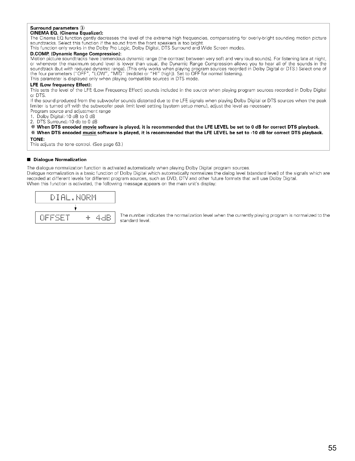
Surround parameters _3)
CINEMA EQ. (Cinema Equalizer):
The Cinema EQ function gently decreases the level of the extreme high frequencies, compensating for overly=bright sounding motion picture
soundtracks Select this function if the sound from the front speakers is too bright
This function only works in the Dolby Pro Logic, Dolby Digital, DTS Surround and Wide Screen modes.
D.COMP. (Dynamic Range Compression):
Motion picture soundtracks have tremendous dynamic range (the contrast between very soft and very loud sounds) For listening late at night,
or whenever the maximum sound level is lower than usual, the Dynamic Range Compression allows you to hear all of the sounds in the
soundtrack (but with reduced dynamic range). (This only works when playing program sources recorded in Dolby Digital or DTS) Select one of
the four parameters ("OFF", "LOW", "MID" (middle) or "HI" (high)) Set to OFF for normal Eistening
This parameter is displayed only when playing compatible sources in DTS mode.
LFE (Low frequency Effect):
This sets the level of the LFE (Low Frequency Effect) sounds included in the source when playing program sources recorded in Dolby Digital
or DTS.
If the sound produced from the subwoofer sounds distorted due to the LFE signals when playing Dolby Digital or DTS sources when the peak
limiter is turned off with the subwoofer peak limit level setting (system setup menu), adjust the level as necessary
Program source and adjustment range
1. Dolby Digital:_10 dB to 0 dB
2. DTS Surround:-10 db to 0 dB
"_ When DTS encoded movie software is played, it is recommended that the LFE LEVEL be set to 0 dB for correct DTS playback.
"_ When DTS encoded music software is played, it is recommended that the LFE LEVEL be set to -10 dB for correct DTS playback.
TONE:
This adjusts the tone control (See page 63)
•Dialogue Normalization
The dialogue normalization function is activated automatically when playing Dolby Digital program sources
Dialogue normalization is a basic function of Dolby Digital which automatically normalizes the dialog level (standard level) of the signals which are
recorded at different levels for different program sources, such as DVD, DTV and other future formats that will use Dolby Digital
When this function is activated, the following message appears on the main unit's display:
I.......................................I
=...=_ _ ....=L... _ = "_'=..._L.. = The number indicates the normalization level when the currently playing program
standard level
is normalized to the
55
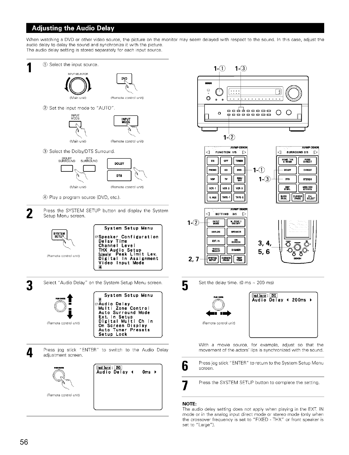
When watching a DVD or other video source, the picture on the monitor may seem delayed with respect to the sound In this case, adjust the
audio delay to delay the sound and synchronize it with the picture
The audio delay setting is stored separately for each input source.
1_} Select the input source
_N_UT _E_ECTOR
0 %
(Mainunit) (Remotecontrolunk}
(2} Set the input mode to "AUTO"
INPUT
MODE
{Main u/it) (Remote control unit}
(3) Select the Dolby/DTS Surround
DOLBY DTS
SURROUND SURROUND[_]_ __
{Main unit) (Remote control unit}
(4_ Play a program source (DVD, etc.)
Press the SYSTEM SETUP button and display the System
Setup Menu screen.
{Remote control uTlit}
System Setup Menu
_Speaker Configuration
Delay Time
Channel Level
THX Audio Setup
S=bwooferPeak Limit Lev.
Digital In Assignment
Video Input Mode
1-@
2,7
1-@} 1-®
o ':::.........©
o .....oo
L_J L_J
1-@
^v_p_geN_
<3 FUNCTION,_S _>
E]E3 E2B
E2E3
Av_p._
SeTTINO3/5
__ 3,4,
5,6
Select "Audio Delay" on the System Setup Menu screen
{Remote control ullit}
System Setup Menu
rAudio Delay
Multi Zone Control
Auto Surround Mode
Ext. In Setup
Digital Multi Ch In
On Screen Display
Auto Tuner Presets
Setup Lock
Press jog stick "ENTER" to switch to the Audio Delay
adjustment screen.
r._m
%
{Remote control uTlit}
Audio Delay 40ms
Set the delay time (O ms _ 200 ms)
Fum_r_
{Re ¥_ote control unit}
Audio Delay _200ms
With a movie source, for example, adjust so that the
movement of the actors' lips is synchronized with the sound.
Press jog stick "ENTER" to return to the System Setup Menu
screen.
Press the SYSTEM SETUP button to complete the setting.
NOTE:
The audio delay setting does not apply when playing in the EXT IN
mode or in the analog input direct mode or stereo mode (only when
the crossover frequency is set to "FIXED _ THX" or front speaker is
set to "Large")
56
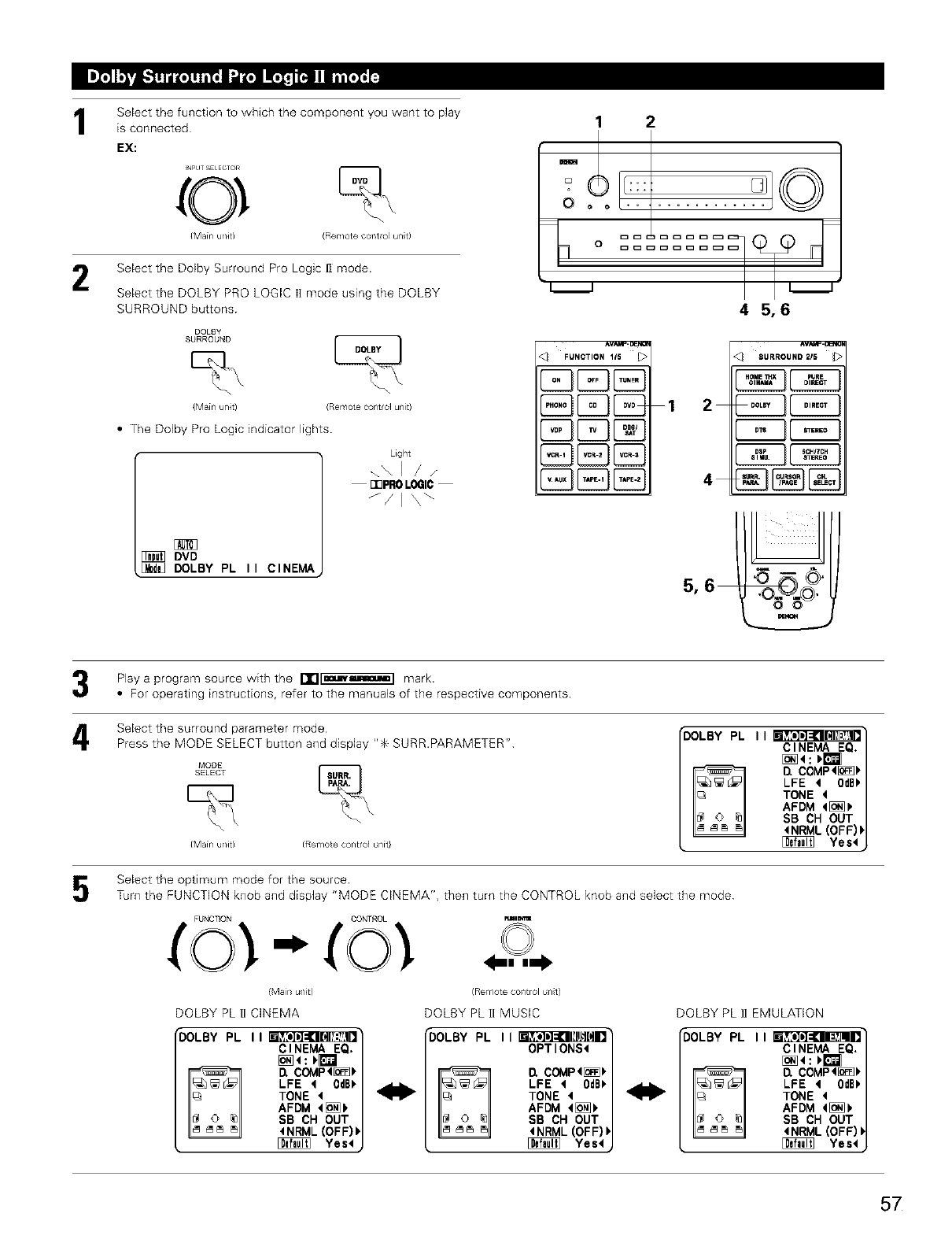
Select the function to which the component you want to play
is connected
EX:
2
_N_LJT_;E_ECTOR
{Mainu/it) (Remotecontolunt)
Select the Dolby Surround Pro Logic 1] mode.
Select the DOLBY PRO LOGIC II mode using the DOLBY
SURROUND buttons
DQLBY
SURROUND
{Main unit) (Remote contro] unit)
•The Dolby Pro Logic indicator lights
Light
\\1 /x
rePROLOGIC
_/I \\
DVD
[_ DOLBY PL II CINEMA
12
+:'o°o':::.......... ©
l
i i i i
45,6
_umcTio.l,S I>
1
SURROU.D2_S _>
4
r
4
Play a program source with the rt"l[muwaammmm] mark.
•For operating instructions, refer to the manuals of the respective components.
Select the surround parameter mode
Press the MODE SELECT button and display "_ SURR.PARAMETER"
MODE _
SELECT
{Main unit) (Remote control unit}
_DOLBY PL I I CINEMA EQ.
D, COMP4[_
LFE 4OdB_
TONE
AFDM 4[_P +
SB CH OUT
4NRML (OFF) I
_Yes4
Select the optimum mode for the source.
Turn the FUNCTION knob and display "MODE CINEMA", then turn the CONTROL knob and select the mode
FUNCT)ON GONTROL m_
(Main unk) (Remote COlltrOl ant)
DOLBY PL 1I CINEMA
"DOLBY PL I I CINEMA EQ.
D. COMP4[_
LFE 4 0dBk
TONE 4
AFDM 4[o_
SB CH OUT
4NRML (OFF))
Yes4
DOLBY PL II MUSIC
_DOLBY PL IIm OPTIONS4
_COMp4[i_
LFE 40dBk
TONE 4
AFDM 4[_k
SB CH OUT
4NRML(OFF)I
Yes4
DOLBY PL _I EMULATION
_OLBY PL IIm CINEMA EQ+
_COMP4[_k
LFE 40dBb
TONE <
AFDM 4[_k
SB CH OUT
4NRML(OFF)I
_Yes4
57
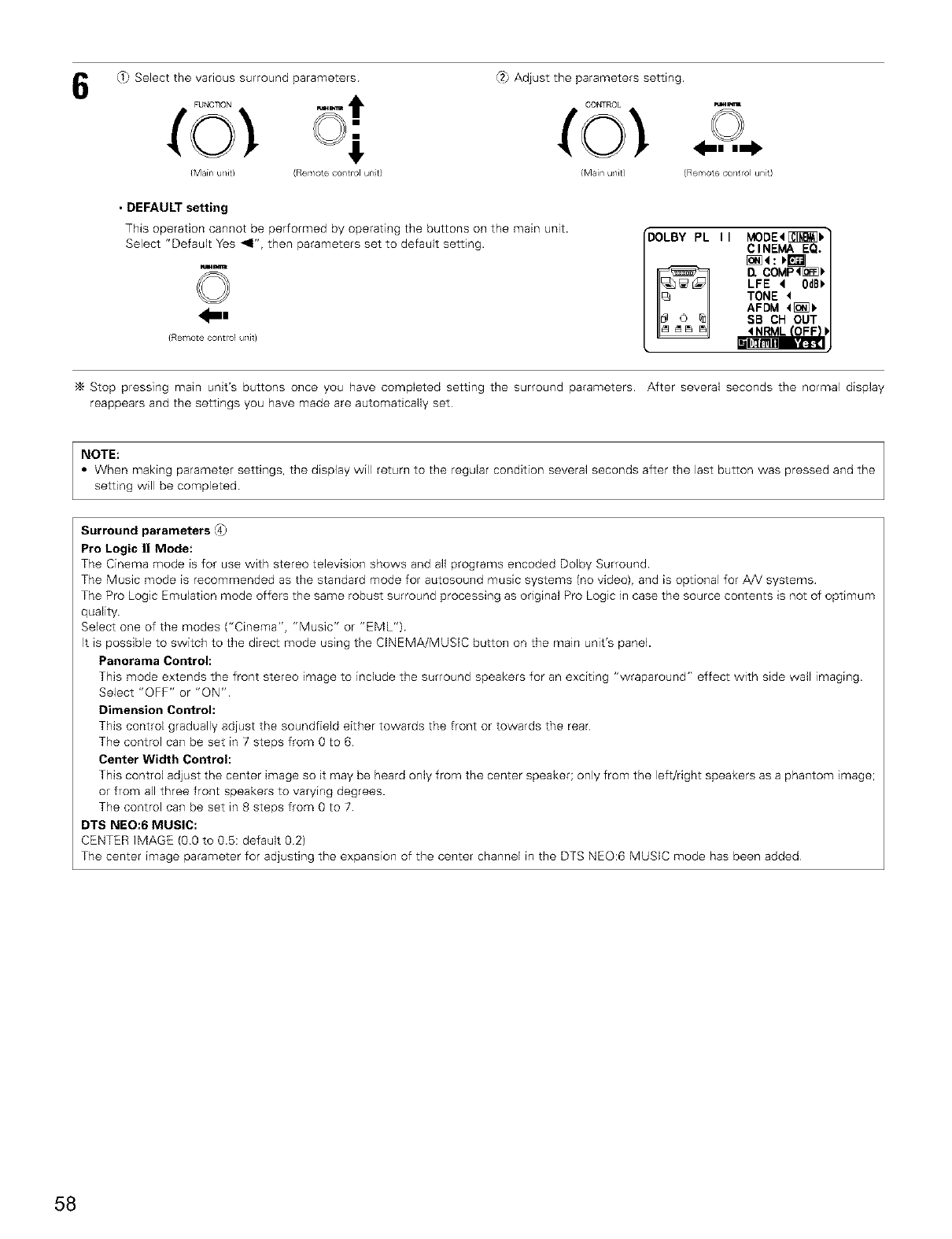
_ Select the various surround parameters (2_Adjust the parameters setting.
FUNCTION
(Main u@t) (Remote co/trol unt)
CONTROL
{Main u/it)
_m
(Remote ¢ol/t rol unit)
• DEFAULT setting
This operation cannot be performed by operating the buttons on the main unit.
Select "Default Yes _1", then parameters set to default setting.
©
41_|
{Remote contro] uTlit}
DOLBY PL I I MODE<[:_]_]I."
CINEMA EQ.
l1 COMP!_
LFE 4 0dBb
TONE <
AFDM 4[_>
SB CH OUT
Stop pressing main unit's buttons once you have completed setting the surround parameters. After several seconds the normal display
reappears and the settings you have made are automatically set
NOTE:
•When making parameter settings, the display will return to the regular condition several seconds after the last button was pressed and the
setting will be completed
Surround parameters @_
Pro Logic II Mode:
The Cinema mode is for use with stereo television shows and all programs encoded Dolby Surround.
The Music mode is recommended as the standard mode for autosound music systems (no video), and is optional for A!V systems
The Pro Logic Emulation mode offers the same robust surround processing as original Pro Logic in case the source contents is not of optimum
quality
Select one of the modes ("Cinema", "Music" or "EML")
It is possible to switch to the direct mode using the CINEMA/MUSIC button on the main unit's panel.
Panorama Control:
This mode extends the front stereo image to include the surround speakers for an exciting "wraparound" effect with side wall imaging.
Select "OFF" or "ON".
Dimension Control:
This control gradually adjust the soundfield either towards the front or towards the rear
The control can be set in 7 steps from 0 to 6
Center Width Control:
This control adjust the center image so it may be heard only from the center speaker; only from the left/nght speakers as a phantom image;
or from all three front speakers to varying degrees.
The control can be set in 8 steps from 0 to 7
DTS NEO:6 MUSIC:
CENTER IMAGE (0O to 0.5: default 02)
The center image parameter for adjusting the expansion of the center channel in the DTS NEO:6 MUSIC mode has been added
58
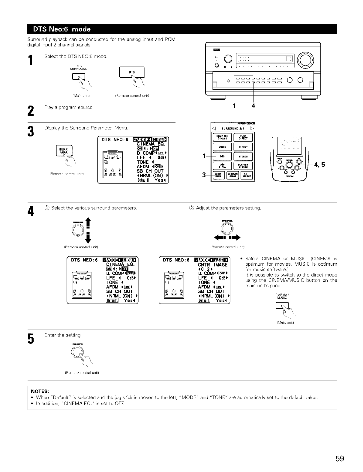
Surround playback can be conducted for the analog input and PCM
digital input 2_channel signals
Select the DTS NEO:6 mode.
DTS
SURROUND
(Main u/it) (Remote control unit}
Play a program source
Display the Surround Parameter Menu.
®
(Remote contro] UTlit}
DTS NEO:6 CINEMA EQ.
COMP<_]_
LFE 4OdBb
TONE 4
AFDM <[_
SB CH OUT
<NRML(ON) P
Yes4
m
O..........
o==2 == OO
1 4
AVAI_._
*q SURROUNOZl5 1>
[2E3
1CEZI
4_.) Select the various surround parameters
{Remote contro] uTlit}
DTS NEO:6 CINEMA EQ.
_COMP<_
LFE <0dB_
TONE 4
AFDM <[_
SB CH OUT
4NRML(ON) I
Yes<
(2) Adjust the parameters setting.
wm
(Remote control unit}
•DTS NEO:6 CNTR IMAGE
40. 2_
D, COMP<[_]_
LFE <0dB_
TONE 4
AFDM 4[oi__
SB CH OUT
<NRML (ON) I
Yes4
•Select CINEMA or MUSIC. (CINEMA is
optimum for movies, MUSIC is optimum
for music software}
It is possible to switch to the direct mode
using the CINEMA/MUSIC button on the
main unit's panel
CINEMA/
MUSIC
Enter the setting
%
(Remote contro UTlit}
(Main u/it)
NOTES:
•When "Default" is selected and the jog stick is moved to the left, "MODE" and "TONE" are automatically set to the default value.
• In addition, "CINEMA EQ." is set to OFF.
59
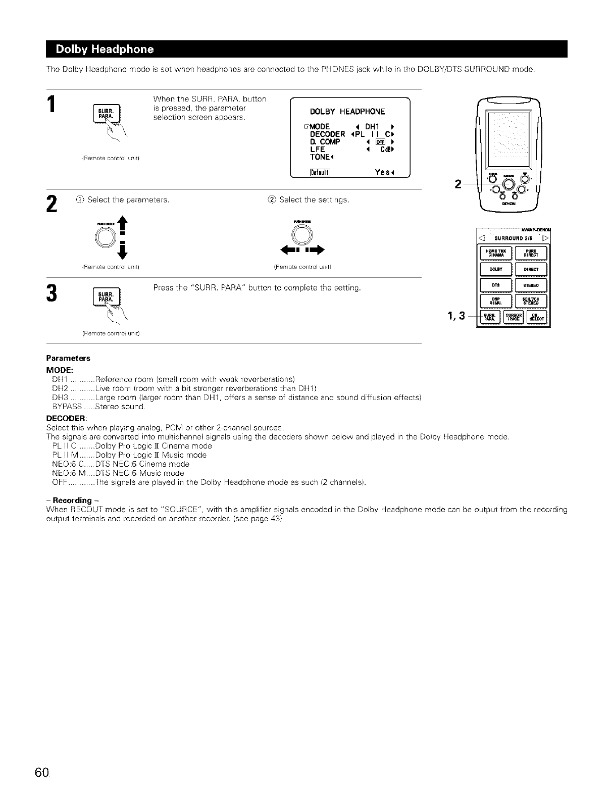
The Dolby Headphone mode is set when headphones are connected to the PHONES iack while in the DOLBY/DTS SURROUND mode
1
{Remote control uTlit}
When the SURR PARA button
_spressed, the parameter
selection screen appears. DOLBY HEADPHONE
_MODE 4 DH1
DECODER <PL II C_
COMP 4 [_
LFE 4 0dBb
TONE<
Yes<
2_} Select the parameters
{Remote cor/trol atilt}
(Remote COTlt/OI ul/it/
t2J Select the settings.
(Remote COTltrOI u/it)
Press the "SURR. PARA" button to complete the setting.
1,3
AV_p.OEN_
,q SURrouND216_>
C2E3
Parameters
MODE:
DH1 ........... Reference room (small room with weak reverberations)
DH2 ........... Live room (room with a bit stronger reverberations than DH1)
DH3 ........... Large room (larger room than DH1, offers a sense of distance and sound diffusion effects)
BYPASS.. Stereo sound
DECODER:
Select this when playing analog, PCM or other 2-channel sources
The signals are converted into multichannel signals using the decoders shown below and played in the Dolby Headphone mode.
PL II C........ Dolby Pro Logic ]I Cinema mode
PLIIM ... Dolby Pro Logic ]I Music mode
NEO:6C.. DTSNEO:6Cinemamode
NEO:6M. DTSNEO:6Musicmode
OFF ............ The signals are played in the Dolby Headphone mode as such (2 channels)
-Recording -
When RECOUT mode is set to "SOURCE", with this amplifier signals encoded in the Dolby Headphone mode can be output from the recording
output terminals and recorded on another recorder. (see page 43)
6O
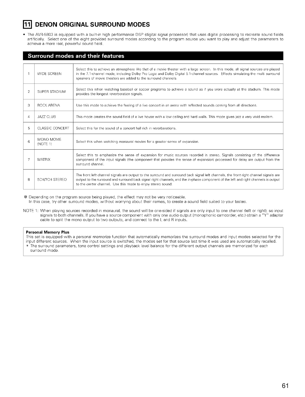
[] DENON ORIGINAL SURROUND MODES
•The AVR_5803 is equipped with a built_in high performance DSP (digital signal processor) that uses digital processing to recreate sound fields
artificiafly Select one of the eight provided surround modes according to the program source you want to play and adjust the parameters to
achieve a more real, powerful sound field
Select this to achieve an atmosphere like that of a movie theater with a large screen In this mode, aN signal sources are played
1 WIDE SCREEN in the 71-channel mode, including Dolby Pro Logc and Dolby Digital S 1-channel sources Effects simulat ng the multi surround
speakers of movie theaters are added to the surround channels
Select this when watching baseball or soccer programs to achieve a sound as if you were actually at the stadium This mode
2 SUPER STADIUM provides the longest reverberat on signals
3 ROCK ARENA Use this mode to achieve the feeling of a live concert in an arena with reflected sounds coming from aft directions
4 JAZZ CLUB This mode creates the sound field of a live house with a low ceiling and hard walls This mode gves jazz a very vivid realism
S CLASSIC CONCERT Select this for the sound of a concert hall rich in reverberations
MONO MOVIE
6 Select this when watching monaural movies for a greater sense of expansion
(NOTE 1)
Select this to emphasize the sense of expansion for music sources recorded n stereo Signals consisting of the difference
7 MATRIX component of the input signals (the component that provides the sense of expansion) processed for delay are output from the
surround chanllel
The front left channel signals are output to the surround and surround back sgnal left channels, the front right channel signals are
8 5CH/7CN STEREO output to the surround and surround back signal right channels, and the imphase component of the Jeft and right channels is output
to the center channel Use this mode to en)oy stereo sound
Depending on the program source being played, the effect may not be very noticeable.
In this case, try other surround modes, without worrying about their names, to create a sound field suited to your tastes
NOTE 1: When playing sources recorded _n monaural, the sound will be one-sided if signals are only input to one channel (left or right), so input
signals to both channels. If you have a source component with only one audio output (monophonic camcorder, etc) obtain a "Y" adaptor
cable to split the mono output to two outputs, and connect to the L and R inputs.
Personal Memory Plus
This set is equipped with a personal memorize function that automatically memorizes the surround modes and input modes selected for the
input different sources When the input source is switched, the modes set for that source last time it was used are automatically recalled.
The surround parameters, tone control settings and playback level balance for the different output channels are memorized for each
surround mode
61
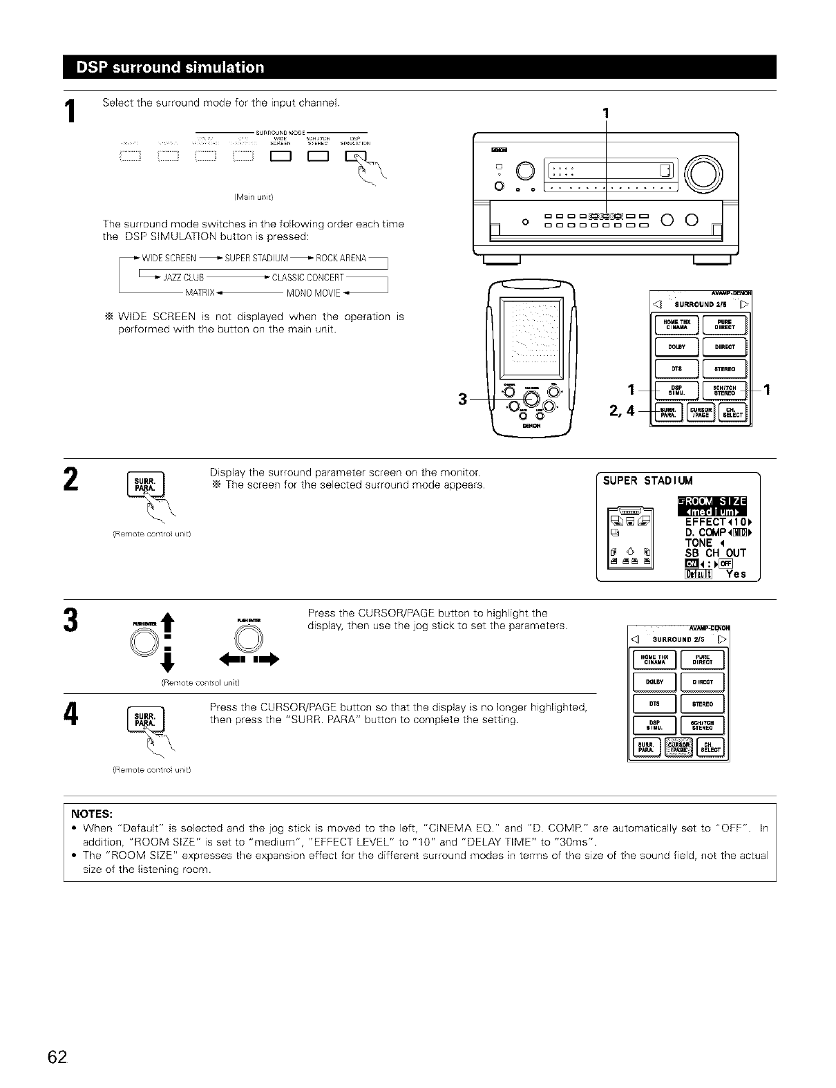
1Select the surround mode for the input channel
SURROUND MODE
_'DE SCm 7OH DS_
.... SCReEn SERES SI_U_a IOn
(Main utlit}
The surround mode switches in the following order each time
the DSP SIMULATION button is pressed:
MATRIX_ MONOMOVIE
"_ WIDE SCREEN is not displayed when the operation is
performed with the button on the main unit.
io,:::i q©
0 ...........
F
o......... 0 0 q
3
0
©, 1
2,4
CE3 1
(Remote cotlt/ol ul/it)
Display the surround parameter screen on the monitor
The screen for the selected surround mode appears SUPER STADIUM
i;.{eI_] l,.']llkd:
EFFECT<IO_
D. COMP<[_
TONE <
SB CH OUT
_:_ Yes
_Bm=
(Remote ¢ol/tlol unit)
(Remote cotlt/ol ul/it)
Press the CURSOR/PAGE button to highlight the
display, then use the jog stick to set the parameters
Press the CURSOR/PAGE button so that the display is no longer highlighted,
then press the "SURR. PARA" button to complete the setting.
AVAqp.O_O_
<_ SURROUND 2/5
NOTES:
•When "Default" is selected and the jog stick is moved to the left, "CINEMA EQ." and "D COMR" are automatically set to "OFF" In
addition, "ROOM SIZE" is set to "medium", "EFFECT LEVEL" to "I0" and "DELAY TIME" to "30ms"
• The "ROOM SIZE" expresses the expansion effect for the different surround modes in terms of the size of the sound field, not the actual
size of the listening room.
62
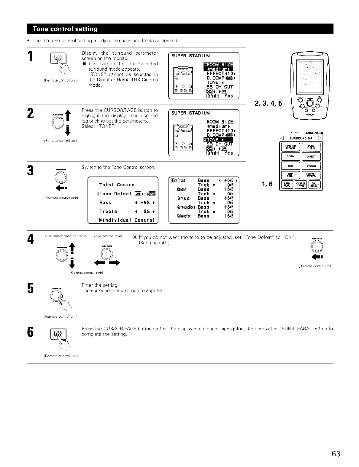
•Use the tone control setting to adjust the bass and treble as desired
1
(Remote ¢ol/t rol unit)
Display the surround parameter
screen on the monitor
"_ The screen for the selected
surround mode appears•
"TONE" cannot be selected in
the Direct or Home THX Cinema
mode.
SUPER STADIUM
_o:e_ I-Il!'d:
EFFECT410_
D. COMP4_
TONE 4
SB CH OUT
Yes
2
{Remote control uTlit}
Press the CURSOR/PAGE button to
highlight the display, then use the
jog stick to set the parameters•
Select "TONE"•
SUPER STADIUM
ROOM SIZE
4medium_
EFFECT410_
D. COMP4_
Bm[*](l=l 1(21
SB CH OUT
m4:_D_ Yes
Fu=m_r_=
©
_m
{Remote control uTlit}
Switch to the Tone Control screen•
Total Control
_Tone Defeat []_4:V_
Bass 4+6dB
Treble 40dB
_lndivldual Control
"[_=Fr0nt Bass 4 -F6dB
Treble 0¢B
Center Bass +6dB
Treble 0dB
Surround Bass +6dB
Treble OdB
SurroundBeekBass +6dB
Treble 0dO
SubwoeferBass +6dB
2,3,4,5
1,6
O
D(_O+4
AVAMp-_NC(
SURROUND 2/6 _>
4ToselectBasso Treble Tosetthe evel _ If you do not want the tone to be adjusted, set "Tone Defeat" to "ON". ,_,
_ (See page 41 ) _
{Remote COTltrC_ u/it)
(Remote control unit}
(F{emote cont ro(ul/it)
Enter the setting
The surround menu screen re-appears.
(Remote control unit}
Press the CURSOR/PAGE button so that the display is no longer highlighted, then press the "SURR. PARA" button to
complete the setting•
63
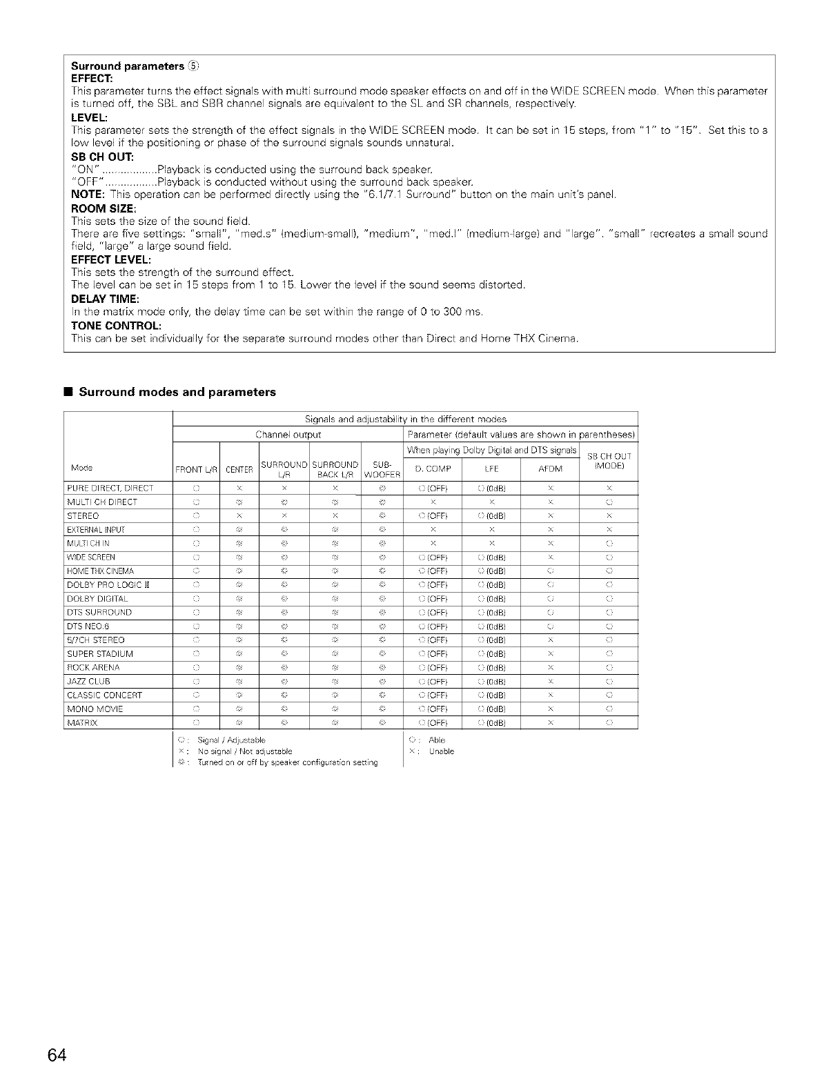
Surround parameters :5=
EFFECT,"
This parameter turns the effect signals with muW surround mode speaker effects on and off in the WIDE SCREEN mode When this parameter
is turned off, the SBL and SBR channel signals are equivalent to the SL and SR channels, respectively
LEVEL:
This parameter sets the strength of the effect signals in the WIDE SCREEN mode It can be set in 15 steps, from "1 " to "15" Set this to a
low level if the positioning or phase of the surround signals sounds unnatural.
SB OH OUT:
"ON". ................. Playback is conducted ushqg the surround back speaker
"OFF". ................ Playback is conducted without using the surround back speaker
NOTE: This operation can be performed directly using the "61/71 Surround" button on the main unit's panel.
ROOM SIZE:
This sets the size of the sound field
There are five settings: "small", "med s" (medium-small), "medium", "reed F' (mediumdarge) and "large". "smaIF' recreates a small sound
field, "large" a large sound field
EFFECT LEVEL:
This sets the strength of the surround effect
The level can be set in 1B steps from 1 to 1B Lower the level if the sound seems distorted.
DELAY TIME:
In the matrix mode only, the delay time can be set within the range of 0 to 300 ms
TONE CONTROL:
This can be set individually for the separate surround modes other than Direct and Home THX Cinema
•Surround modes and parameters
Signalsa_d adjustab lity in the different modes
Cha_lneloutput Parameter {default values are shown HIparentheses}
MOL)e
PURE DIRECT, DIRECT
MUL-I CH DIRECT
STEREO
EXTERNALNPUT
MUL-I CH N
WDE SCREEN
HOME THX CINEMA
DOLB¥ PRO LOGIC ]]
DOLB¥ DIGITAL
DTS SURROUND
DTS NE06
5/7CH S-EREO
SUPER STADIUM
ROCK ARENA
AZZ CLUB
C ASSIC CONCERT
MONO MOVIE
MA_RX
When playing Dolby Dgita and DTS sgnas
FRONT [JR CENTER SURROUND SURROUND SUB D COMP LFE
[JR BACK L/R WOOFER
( x > _ {OFF} {Od B)
( x > _ {OFF} {Od B)
( _ _ (OFF} (OdB)
( _ _ (OFF} (OdB)
( _ _ (OFF} (OdB)
( _ _ (OFF} (OdB)
( _ _ (OFF} (OdB)
( _ _ (OFF} (OdB)
( _ _ (OFF} (OdB)
( _ _ (OFF} (OdB)
( _ _ (OFF} (OdB)
( _ _ (OFF} (OdB)
( _ _ (OFF} (OdB)
( _ _ (OFF} (OdB)
( _ _ (OFF} (OdB)
: : Sigllal /Adjustable xC; Able
x : No signal /Not adjustable Unable
: Tuned on or off by speake cotll gurat[or/setting
SB CH OUT
AFDM (MODEl
x x
x {}
x x
x x
x {}
x {}
{1 {}
{1 {}
{1 {}
{1 {}
64
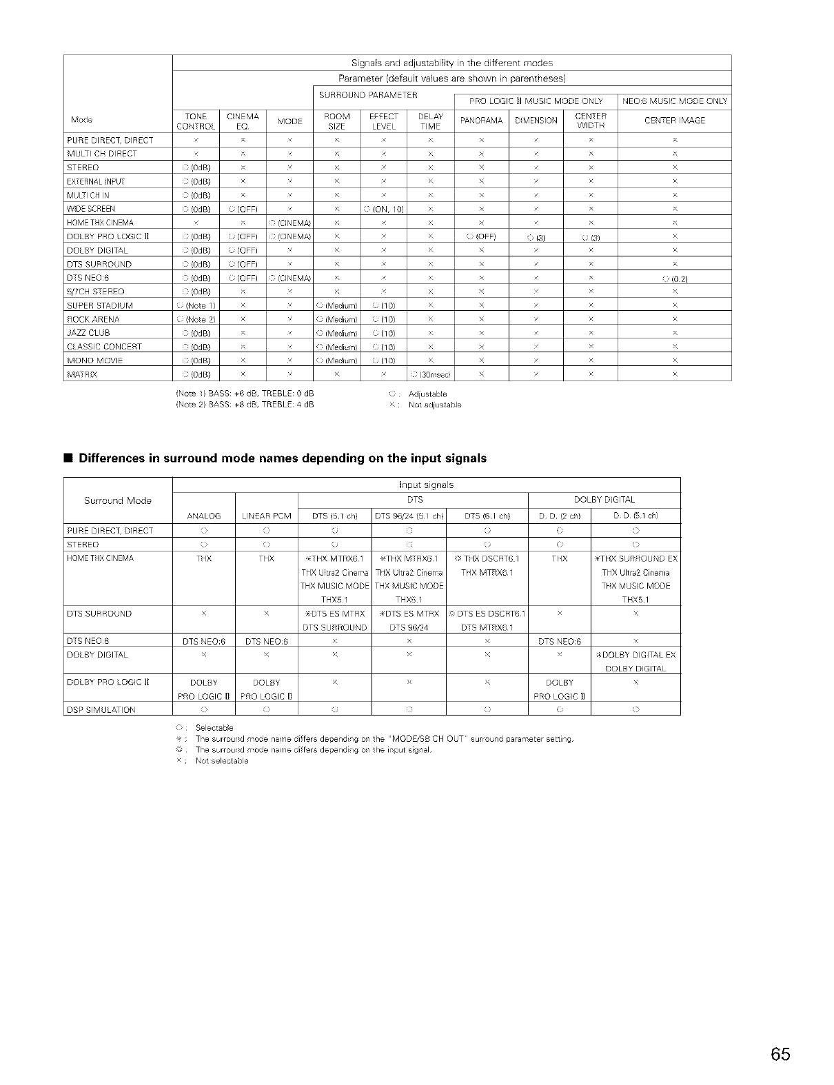
Mode
PURE DIRECT, DIRECT
MULti CH DIRECT
STEREO
EXTERNALNPUT
MUL-I CH N
WDE SCREEN
HOME THX CINEMA
DOLBY PRO LOGIC 1]
DOLBY DIGITAL
DTS SURROUND
DTS NEO6
5/7CH S-EREO
SUPER STADIUM
ROCK ARENA
AZZ CLUB
C ASSIC CONCERT
MONO MOVIE
MA:RX
SignaB and adjustabiEty in the different modes
Parameter (defadt values are shown in parentheses)
SURROUND PARAMETER PRO LOGIC II MUSIC MODE ONL v
TONE CNEMA ROOM EFFECT DELAY CENTER
MODE PANORAMA D MENSION
CONTROL EQ SIZE LEVE TIME WIDTH
> > > x
> > > x
(0dB} > > > x
( (0dB} > > > x
( (0dB} > > > x
( (0dB} (OFF) > ( (ON, 10) > x
> fC]NEM/ > > x
(} (0dB} (; (OFF) } {C]NEMA > x > (} (OFF} ( {3} {; (3)
(} (0dB} O (OFF) x > x > x x
(} (0dB} O (OFF) x > x > x x
(} (0dB} O (OFF) } {CINEMA > x > x x
(} (0dB} > x > x > x x
O (Note I ) X x {} (Medium) O (10) X x x
O (Note 2) X x {} (Medium) O (10) X x x
(} (0dB} X x {} (Medium) O (10) X x x
(} (0dB} X x {} (Medium) O (10) X x x
(} (0dB} X x {} (Medium) O (10) X x x
(} (0dB} > x > x (} 130msec} x x
NEO:6 MUSIC MODE ONL v
CENTER MAGE
>
>
>
>
>
>
>
>
>
>
) (0 2)
>
>
>
>
>
>
>
(Note 1} BASS: +6 dB, TREBLE: 0 dB
(Note 2} BASS: +8 dB, TREBLE: 4 dB
(} Adiustable
> : Not adiustable
•Differences in surround mode names depending on the input signals
Surround Mode
PURE DIREC% DIRECT
STEREO
HOMETHXCINEMA
ANALOG LINEAR PCM DTS (51 ch}
} ) )
} ) )
THX THX _THX MTRX61
THX Ultra2 Cinema
THX MUSIC MODE
THX51
DTS SURROUND x x >DTS ES MTRX
DTS SURROUND
DTS NEO6 DTS NEO6 DTS NEO6 > DTS NEO:6
DOLBY DIGITAL x x >
DOLBY PRO LOGIC 1] DOLBY DOLBY > DOLBY
PRO LOGIC I1 PRO LOGIC I] PRO LOGC I1
DSP SIMULATION } (
{} Selectable
input signals
DTS
DTS 96/24 (51 ch} DTS (6 1 ch}
(
(
_THX MTRX6 1 THX DSCRT6 I
THX Utra2 Cinema THX MTRX6 1
THX MUSIC MODE
THX51
DTS ES MTRX DTS ES DSCRT6 1
DTS 96/24 DTS MTRX6 1
x
x
x
(
DOLBY DIGITAL
D D (2 oh) D D f51 ch}
(i {}
THX _THX SURROUND EX
THX Ultra2 Cinema
THX MUS}C MODE
THX51
x
x
_DOLBY DIGITAL EX
DOLBY DIGITAL
x
_- : The surroulld mode name differs depending on the "MODE/SB CH OUT su round parameter sett ng
The surroulld mode name d[ffers deper/dil/g ol/the irlput sigl/al
x Not selectabIe
65
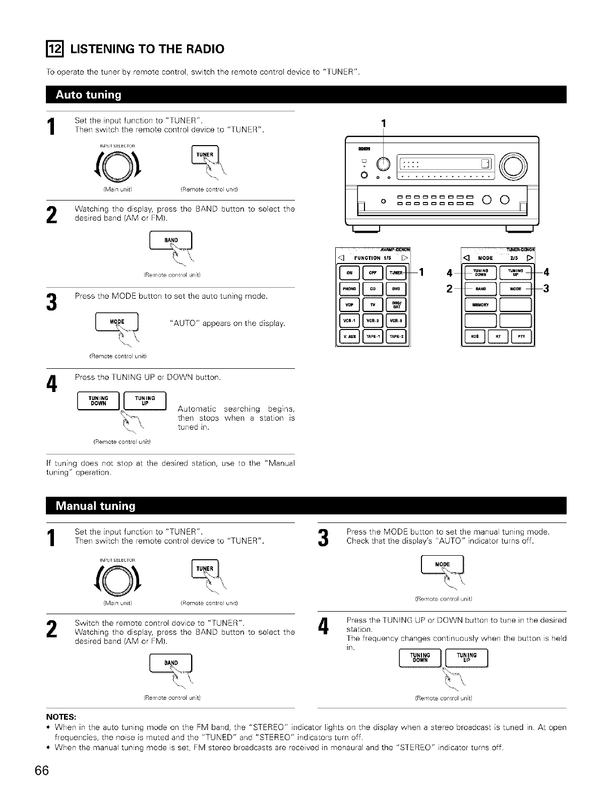
[] LISTENING TO THE RADIO
To operate the tuner by remote control, switch the remote control device to "TUNER".
Set the input function to "TUNER".Then switch the remote control device to "TUNER".
INPUT SELECTOR
0e
{Mair} u/it) (Remote conto u/it)
Watching the display, press the BAND button to select the
desired band (AM or FM).
(Remote col/t rol _r/it)
Press the MODE button to set the auto tuning mode.
(Remote coTlt/ol ul/it)
"AUTO" appears on the display.
4Press the TUNING UP or DOWN button.
(Remote ooTlt/ol unit)
Automatic searching begins,
then stops when a station is
tuned in.
If tuning does not stop at the desired station, use to the "Manual
tuning" operation
1
Oo o
%0
_VAMp_oENI_
<_ FUNCTION 1/5
1 4
2
_JNF_-OBXON
_:_ MODE ZIS J_
4
3
Set the input function to "TUNER".
Then switch the remote control device to "TUNER".
INPUT SELECTOR
0
(Mairl u/it) (Remote conto u/it)
Press the MODE button to set the manual tuning mode
Check that the display's "AUTO" indicator turns off.
(Remote ¢ol/t rol unit)
Switch the remote control device to "TUNER" bl
Watching the display, press the BAND button to select the
desired band (AM or FM).
(Remote col/t rol _r/it)
Press the TUNING UP or DOWN button to tune in the desired
station
The frequency changes continuously when the button is held
in.
(Rer,/ote ¢o/trol ur/t)
NOTES:
•When in the auto tuning mode on the FM band, the "STEREO" indicator lights on the display when a stereo broadcast is tuned in At open
frequencies, the noise is muted and the "TUNED" and "STEREO" indicators turn off.
• When the manual tuning mode is set, FM stereo broadcasts are received in monaural and the "STEREO" indicator turns off.
66
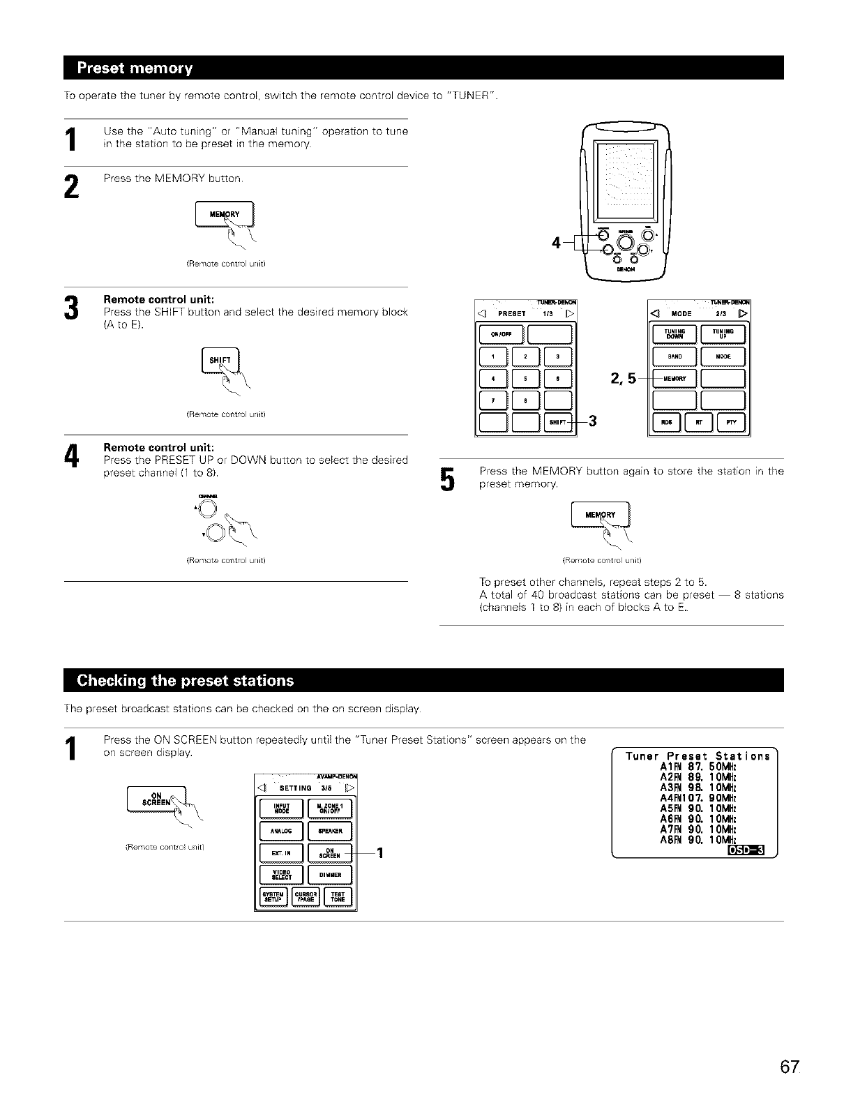
To operate the tuner by remote control, switch the remote control device to "TUNER".
1
2
Use the "Auto tuning" or "Manual tuning" operation to tune
in the station to be preset in the memory
Press the MEMORY button
(m@mot@ 6©fltrO u/k)
Remote control unit:
Press the SHIFT button and select the desired memory block
(A to E).
(Remote coTltrol ul/it/
Remote control unit:
Press the PRESET UP or DOWN button to select the desired
preset channel (1 to 8).
(Remote coT_trol u_/it/
O
4½
PRESET 1t3
{2BCZ3
Dlxox
2,5
3
q MODE 213 _>
Press the MEMORY button again to store the station in the
preset memory.
(Remote coTlt rol ul/it/
To preset other channels, repeat steps 2 to 5.
A total of 40 broadcast stations can be preset -- 8 stations
(channels 1 to 8) in each of blocks A to E.
The preset broadcast stations can be checked on the on screen display
Press the ON SCREEN button repeatedly until the "Tuner Preset Stations" screen appears on the
on screen display
\
(Remote COTlt/Ol ul/it/
,q SETT,NO316 b
E3E3 [._-11€1<1
1
Tuner Preset Stations"
A1P_ 8% 50MHz
A2FM89, IOMHz
A3FM98, IOMHz
A4FMIO?. 90MHz
A5P_ 90. IOMHz
A6FM90. IOMHz
A?FM90, IOMHz
A8F_ 90, IOMHz
67
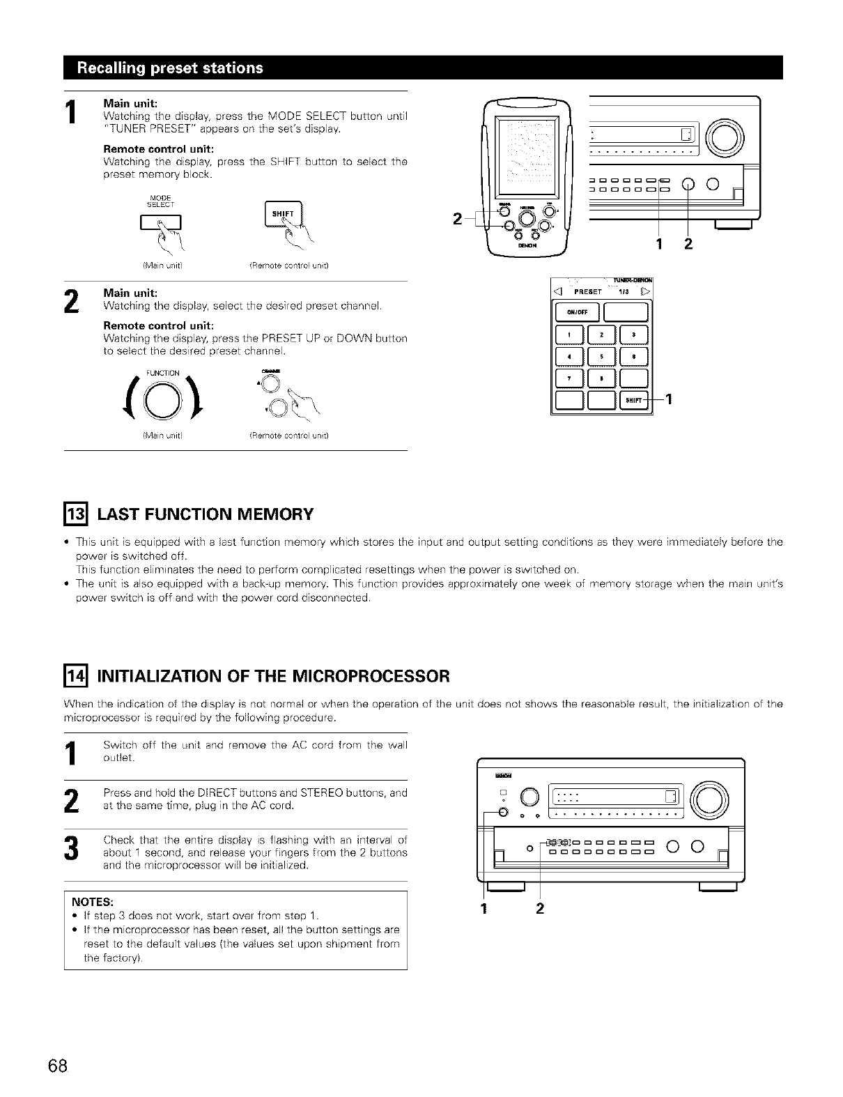
1
2
Main unit:
Watching the display, press the MODE SELECT button until
"TUNER PRESET" appears on the set's display
Remote control unit:
Watching the display, press the SHIFT button to select the
preset memory block.
MODE
SELECT
(Main u/Jr) (Remote coflt o u/Jr)
Main unit:
Watching the display, select the desired preset channel
Remote control unit:
Watching the display, press the PRESET UP or DOWN button
to select the desired preset channel.
(Main u/Jr) (Remote coflt o u/Jr)
2
0
mm
J
1 2
%°7
I'_ LAST FUNCTION MEMORY
•This unit is equipped with a last function memory which stores the input and output setting conditions as they were immediately before the
power is switched off.
This function eliminates the need to perform complicated resettings when the power is switched on.
• The unit is also equipped with a back_up memory. This function provides approximately one week of memory storage when the main unit's
power switch is off and with the power cord disconnected
[] INITIALIZATION OF THE MICROPROCESSOR
When the indication of the display is not normal or when the operation of the unit does not shows the reasonable result, the initialization of the
microprocessor is required by the following procedure.
Switch off the unit and remove the AC cord from the walloutlet
Press and hold the DIRECT buttons and STEREO buttons, and
at the same time, plug in the AC cord.
Check that the entire display is flashing with an interval of
about 1 second, and release your fingers from the 2 buttons
and the microprocessor will be initialized.
NOTES:
• If step 3 does not work, start over from step 1.
• If the microprocessor has been reset, all the button settings are
reset to the default values (the values set upon shipment from
the factory)
mO [l::::
1 2
68
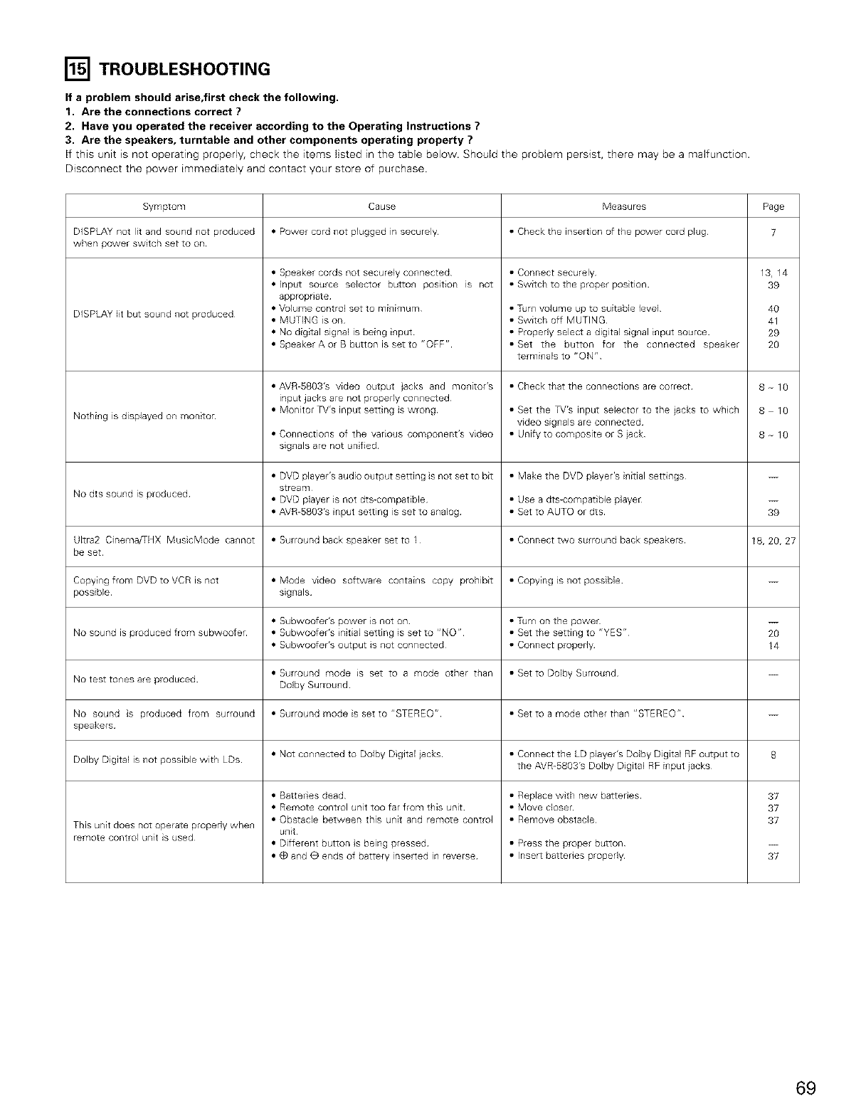
[] TROUBLESHOOTING
If a problem should arise,first check the following.
1. Are the connections correct ?
2. Have you operated the receiver according to the Operating Instructions ?
3. Are the speakers, turntable and other components operating property ?
If this unit is not operating properly, check the items listed in the table below. Should the problem persist, there may be a malfunction.
Disconnect the power immediately and contact your store of purchase
Symptom Cause Measures Page
DISPLAY not lit and sound not produced • Power cord not plugged in securely •Check the insertion of the power cord plug 7
when power switch set to on
• Speaker cords not securely connected •Connect securely 13, 14
• Input source selector button position is not •Switch to the proper position 39
appropriate
DISPLAY lit but sound not produced • Volume control set to minimum •Turn volume up to suitable level 40
• MUTING is on •Switch off MUTING 41
• No digital signal is being input •Propedy select a digital signal input source 29
• SpeakerAorBbuttonissetto"OFF" ,Set the button for the connected speaker 20
terminals to "ON"
• AVR-US03's video output jacks and monitor's •Check that the connections are correct 8 10
input jacks are not properly connected
Nothing is displayed on monitor • Monitor TV's input setting is wrong •Set the TV's input selector to the jacks to which 8 10
video signals are connected
• Connections of the various component's video •Unify to composite or S jack 8 10
signals are not unified
• DVD player's audio output setting is not set to bit •Make the DVD player's initial settings
stream
No dts sound is produced • DVD player is not dts-compatible •Use a dts-compatible player --
• AVR-SS03's input setting is set to analog •Set to AUTO or dts 39
Ultra2 Cinema/THX MusicMode cannot • Surround back speaker set to I •Connect two surround back speakers 18, 20, 27
be set
Copying from DVD to VCR is not • Mode video software contains copy prohibit •Copying is not possible
possible signals
• Subwoofer's power Esnot on •Turn on the power --
No sound is produced from subwoofer • Subwoofer's initial setting is set to "NO" •Set the setting to "YES" 20
• Subwoofer's output is not connected •Connect properly 14
• Surround mode is set to a mode other than •Set to Dolby Surround
No test to_es are produced Dolby Surrou_d
No sound is produced from surround • Surround mode is set to "STEREO" • Set to a mode other than "STEREO" --
speakers
Dolby Digital is not possible with LDs • Not connected to Dolby Digital jacks • Connect the LD player's Dolby Digital RF output to 8
the AVR-SS03's Dolby Digital RE input jacks
• BatteE es dead • Replace with new batteries 37
• Remote control unit too far from this unit • Move closer 37
• Obstacle between this unit and remote control • Remove obstacle 37
This unit does not operate propedy when unit
remote control unit is used • Different button s being pressed • Press the proper button --
• (_ and O ends of battery inserted in reverse • Inserl batteries properly 37
69
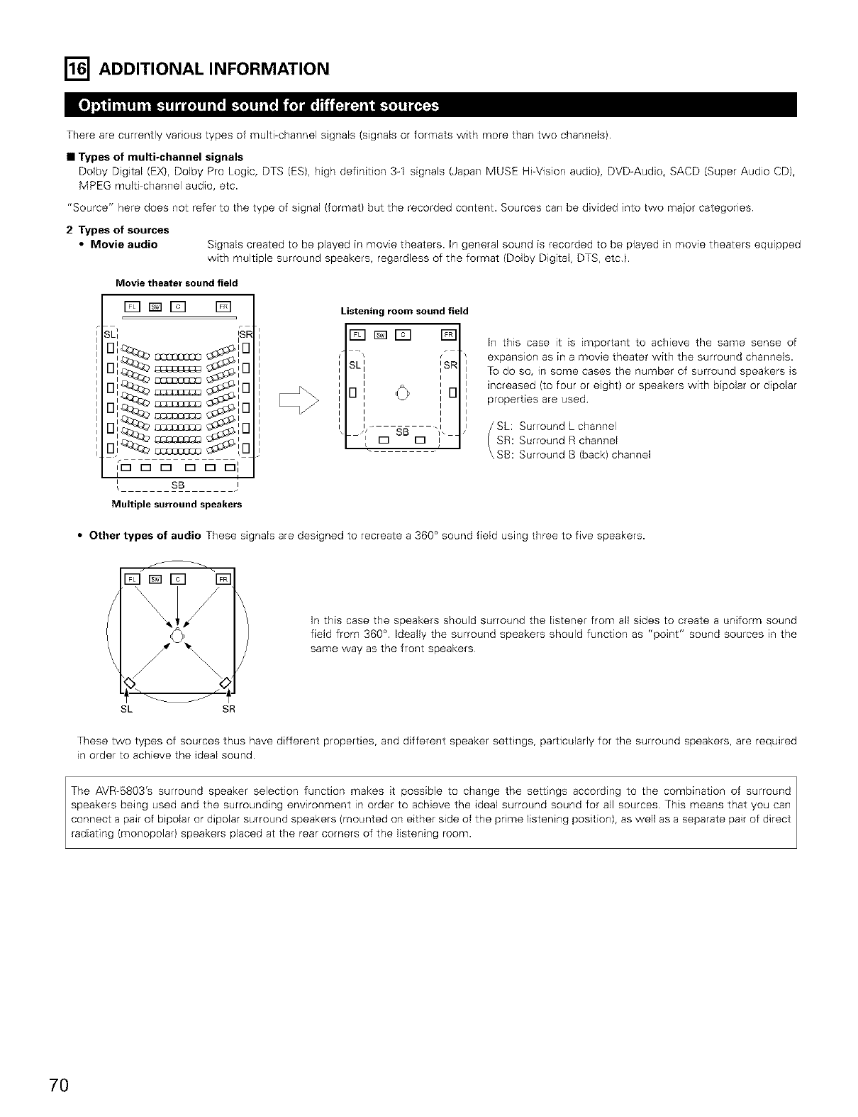
[] ADDITIONAL INFORMATION
There are currently various types of multi-channel signals (signals or formats with more than two channels)
•Types of multi-channel signals
Dolby Digital (EX), Dolby Pro Logic, DTS (ES), high definition 3-1 signals (Japan MUSE Hi=Vision audio), DVD-Audio, SACD (Super Audio CD),
MPEG multi=channel audio, etc.
"Source" here does not refer to the type of signal (format) but the recorded content. Sources can be divided into two major categones
2 Types of sources
•Movie audio Signals created to be played in movie theaters. In general sound is recorded to be played in movie theaters equipped
with multiple surround speakers, regardless of the format (Dolby Digital, DTS, etc).
Movie theater sound field
D_D D
,DDE] DDD]
I t
SB
Listening room sound field
Fq_E_ D
ism
I
iD
I
In this case it is important to achieve the same sense of
expansion as in a movie theater with the surround channels.
To do so, in some cases the number of surround speakers is
increased (to four or eight) or speakers with bipolar or dipolar
properties are used
SL: Surround Lchannel
SR: Surround R channel
SB: Surround B (back) channel
Multiple surround speakers
•Other types of audio These signals are designed to recreate a 360 ° sound field using three to five speakers.
In this case the speakers should surround the listener from all sides to create a uniform sound
field from 360 °. Ideally the surround speakers should function as "point" sound sources in the
same way as the front speakers
SL SR
These two types of sources thus have different properties, and different speaker settings, particularly for the surround speakers, are required
in order to achieve the ideal sound.
radiating (monopolar} speakers placed at the rear corners of the listening room.
7O
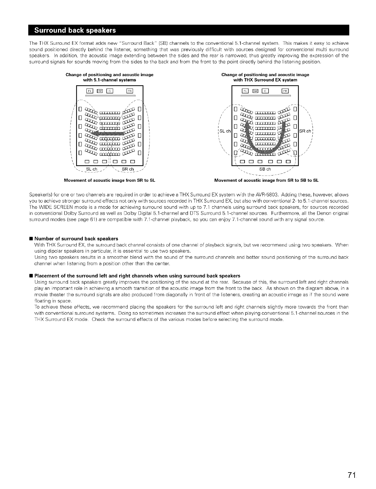
The THX Surround EX format adds new "Surround Back" (SB) channels to the conventional 5.1_channel system This makes it easy to achieve
sound positioned directly behind the listener, something that was previously difficult with sources designed for conventional multi surround
speakers In addition, the acoustic image extending between the sides and the rear is narrowed, thus greatly improving the expression of the
surround signals for sounds moving from the sides to the back and from the front to the point directly behind the listening position
Change of positioning and acoustic image
with 5.1-channel systems
Fq _ r_q D
u J:8
O__
D D c_llD D D
Skch __ _. SRch
Movement of acoustic image from SR to SL
Change of positioning and acoustic image
with THX Surround EX s stem
Dr_D D
J "
/OSRch)1SLch 18950:33:_
\_ \ //
\//
D D D D [_ D
SB ch
Movement of acoustic image from SR to SS to SL
Speaker(s) for one or two channels are required in order to achieve a THX Surround EX system with the AVR_5803. Adding these, however, allows
you to achieve stronger surround effects not only with sources recorded in THX Surround EX, but also with conventional 2- to 51 channel sources.
The WIDE SCREEN mode is a mode for achieving surround sound with up to 7.I channels using surround back speakers, for sources recorded
in conventional Dolby Surround as well as Dolby Digital B 1-channel and DTS Surround B 1-channel sources Furthermore, all the Denon original
surround modes (see page 61) are compatible with 7 %channel playback, so you can enjoy 7 1-channel sound with any signal source
•Number of surround back speakers
With THX Surround EX, the surround back channel consists of one channel of playback signals, but we recommend using two speakers When
using dipolar speakers in particular, it is essential to use two speakers.
Using two speakers results in a smoother blend with the sound of the surround channels and better sound positioning of the surround back
channel when listening from a position other than the center
•Placement of the surround left and right channels when using surround back speakers
Using surround back speakers greatly improves the positioning of the sound at the rear. Because of this, the surround left and right channels
play an important role in achieving a smooth transition of the acoustic image from the front to the back As shown on the diagram above, in a
movie theater the surround signals are also produced from diagonally in front of the listeners, creating an acoustic image as if the sound were
floating in space.
To achieve these effects, we recommend placing the speakers for the surround left and right channels slightly more towards the front than
with conventional surround systems. Doing so sometimes increases the surround effect when playing conventional 5 1-channel sources in the
THX Surround EX mode. Check the surround effects of the various modes before selecting the surround mode
71
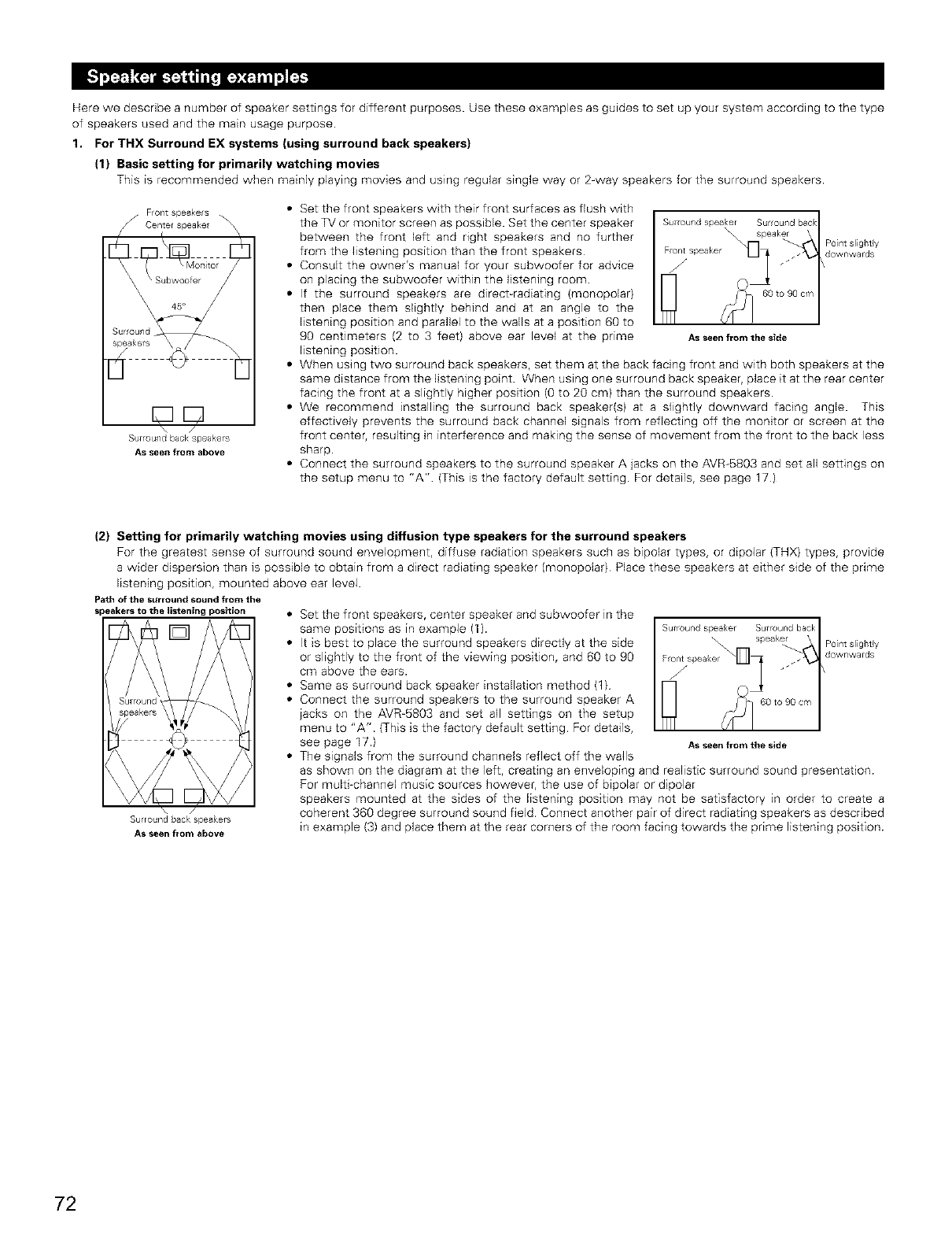
Here we describe a number of speaker settings for different purposes. Use these examples as guides to set up your system according to the type
of speakers used and the main usage purpose.
1. For THX Surround EX systems (using surround back speakers)
(1) Basic setting for primarily watching movies
This is recommended when mainly playing movies and using regular single way or 2-way speakers for the surround speakers.
•Frontspeakers
/Centerspeakel
Sur_
spe
d
DD
\/
Surround back speakers
AS seen from above
•Set the front speakers with their front surfaces as flush with
the TV or monitor screen as possible. Set the center speaker
between the front left and right speakers and no further
from the listening position than the front speakers
• Consult the owner's manual for your subwoofer for advice
on placing the subwoofer within the listening room
• If the surround speakers are direct_radiating (monopolar)
then place them slighdy behind and at an angle to the
listening position and parallel to the walls at a position 60 to
90 centimeters (2 to 3 feet) above ear level at the prime Asseenfromthe slde
listening position.
• When using two surround back speakers, set them at the back facing front and with both speakers at the
same distance from the listening point When using one surround back speaker, place it at the rear center
facing the front at a slightly higher position (0 to 20 cm) than the surround speakers.
• We recommend installing the surround back speaker(s) at a slightly downward facing angle. This
effectively prevents the surround back channel signals from reflecting off the monitor or screen at the
front center, resulting in interference and making the sense of movement from the front to the back less
sharp.
• Connect the surround speakers to the surround speaker A jacks on the AVR-5803 and set all settings on
the setup menu to "A" (This is the factory default setting. For details, see page 17)
Surround speak<or Sur ound back
speaker Point sliglltly
Llownwards
\
60 to 90 cm
(2) Setting for primarily watching movies using diffusion type speakers for the surround speakers
For the greatest sense of surround sound envelopment, diffuse radiation speakers such as bipolar types, or dipolar (THX) types, provide
a wider dispersion than is possible to obtain from a direct radiating speaker (monopolar) Place these speakers at either side of the prime
listening position, mounted above ear level.
Path of the surround sound from the
speakers to the listening position
[]
]E
Surround back _)eakers
AS seen from above
• Set the front speakers, center speaker and subwoofer in the
same positions as in example (1).
• It is best to place the surround speakers directly at the side
or slightly to the front of the viewing position, and 60 to 90
cm above the ears.
• Same as surround back speaker installation method (1)
• Connect the surround speakers to the surround speaker A
iacks on the AVR-5803 and set all settings on the setup
menu to "A" (This is the factory default setting For details,
see page 17.) Asseenfromthe side
• The signals from the surround channels reflect off the walls
as shown on the diagram at the left, creating an enveloping and realistic surround sound presentation
For multi channel music sources however, the use of bipolar or dipolar
speakers mounted at the sides of the listening position may not be satisfactory in order to create a
coherent 360 degree surround sound field Connect another pair of direct radiating speakers as described
in example (3) and place them at the rear corners of the room facing towards the prime listening position
SurrOund spea er Surround back
speaker Point sliglltly
Llownwards
60 to 90 cm
72
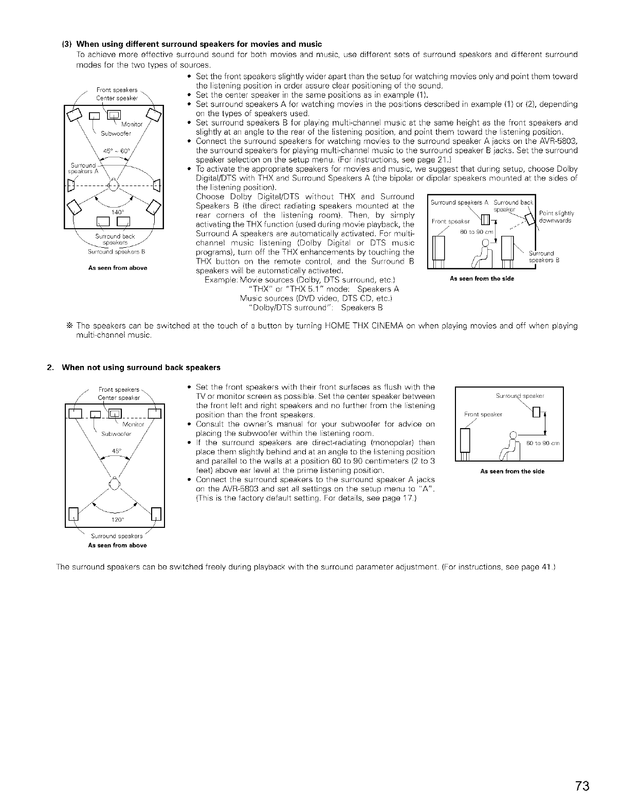
FroTstspeake s
_ Cef_ter speaker
/i
\\ Surroul/d back
_-_peak_
Surround speakers B
(3} When using different surround speakers for movies and music
To achieve more effective surround sound for both movies and music, use different sets of surround speakers and different surround
modes for the two types of sources
•Set the front speakers slightly wider apart than the setup for watching movies only and point them toward
the listening position in order assure clear positioning of the sound
\ • Set the center speaker in the same positions as in example (1).
• Set surround speakers A for watching movies in the positions described in example (1) or (2), depending
on the types of speakers used
• Set surround speakers B for playing multi-channel music at the same height as the front speakers and
slightly at an angle to the rear of the listening position, and point them toward the listening position
• Connect the surround speakers for watching movies to the surround speaker A jacks on the AVR-6803,
the surround speakers for playing multi-channel music to the surround speaker B jacks. Set the surround
speaker selection on the setup menu (For instructions, see page 21 )
• To activate the appropriate speakers for movies and music, we suggest that during setup, choose Dolby
Digital/DTS with THX and Surround Speakers A (the bipolar or dipolar speakers mounted at the sides of
As seen from above
the listening position).
Choose Dolby Digital/DTS without THX and Surround
Speakers B (the direct radiating speakers mounted at the
rear corners of the listening room) Then, by simply
activating the THX function (used during movie playback, the
Surround A speakers are automatically activated. For multi-
channel music listening (Dolby Digital or DTS music
programs), turn off the THX enhancements by touching the
THX button on the remote control, and the Surround B
speakers will be automatically activated.
Example: Movie sources (Dolby, DTS surround, etc)
"THX" or "THX 5.1 " mode: Speakers A
Music sources (DVD video, DTS CD, etc)
"Dolby/DTS surround": Speakers B
Surround speakers A Surround back
\
_]_ Point slightly
Front spea_<er downwards
/J 60 to 90 cr,/
Surround
speakers B
As seen from the side
The speakers can be switched at the touch of a button by turning H©ME THX CINEMA on when playing movies and off when playing
multi_channel music.
2. When not using surround back speakers
Fro_st speakers
Center speaker
• Set the front speakers with their front surfaces as flush with the
TV or monitor screen as possible Set the center speaker between
the front left and right speakers and no further from the listening
position than the front speakers
• Consult the owner's manual for your subwoofer for advice on
placing the subwoofer within the listening room.
• If the surround speakers are direct-radiating (monopolar) then
place them slightly behind and at an angle to the listening position
and parallel to the walls at a position 60 to 90 centimeters (2 to 3
feet) above ear level at the prime listening position.
• Connect the surround speakers to the surround speaker A jacks
on the AVR-5803 and set all settings on the setup menu to "A".
(This is the factory default setting. For details, see page 17)
AS seen from the side
120"
\" Surround speakers j
AS seen from above
The surround speakers can be switched freely during playback with the surround parameter adjustment (For instructions, see page 41 )
73
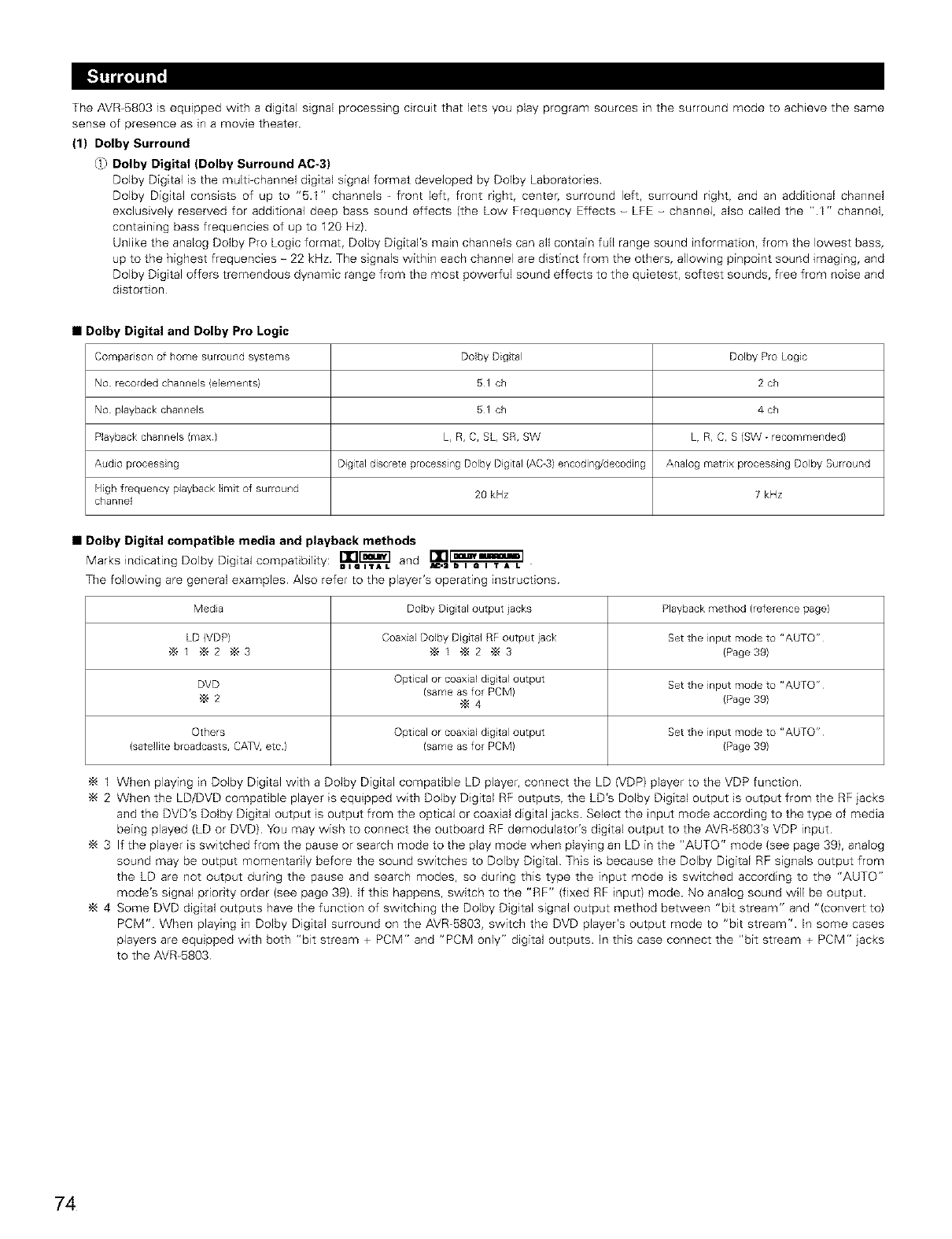
The AVR-5803 is equipped with a digital signal processing circuit that lets you play program sources in the surround mode to achieve the same
sense of presence as in a movie theater.
(1) Dolby Surround
0) Dolby Digital (Dolby Surround AC-3)
Dolby Digital is the multi_channel digital signal format developed by Dolby Laboratories
Dolby Digital consists of up to "5.1" channels _ front left, front right, center, surround left, surround right, and an additional channel
exclusively reserved for additional deep bass sound effects (the Low Frequency Effects - LFE - channel, also called the ".I" channel,
containing bass frequencies of up to 120 Hz)
Unlike the analog Dolby Pro Logic format, Dolby Digital's main channels can all contain full range sound informagon, from the lowest bass,
up to the highest frequencies - 22 kHz. The signals within each channel are distinct from the others, allowing pinpoint sound imaging, and
Dolby Digital offers tremendous dynamic range from the most powerful sound effects to the quietest, softest sounds, free from noise and
distorgon
•Dolby Digital and Dolby Pro Logic
Comparison of home surround systems
No recorded channels (elements)
No playback channels
Playbackchannels (max)
Audio processing
High frequency playbacklimit of surround
channel
Dolby Dig tal
51 ch
51 ch
L, R, C, SL, SR, SW
Digital discrete process ng Dolby Digital (AC-3) encoding/decoding
20 kHz
Dolby Pro Logic
2 ch
4 ch
h, R, C, S (SW - recommended)
Analog matrix processing Dolby Surround
7 kHz
•Dolby Digital compatible media and playback methods
Marks indicating Dolby Digital compagbility: nI_TI_A L and L_,a_
The following are general examples Also refer to the player's operating instructions
Media Dolby Dig tal output }acks Playback method (reference page)
LD (VDP) Coaxial Dolby Digital RF output jack Set the input mode to "AUTO"
1 _ 2 @ 3 "_ 1 -_ 2 _ 3 (Page 39)
DVD Optical or coaxial dgtal output Set the input mode to "AUTO"
'_ 2 (same as for PCM)
4 (Page 39)
Others Optical or coaxial dgtal output Set the input mode to "AUTO"
(satellite broadcasts, CAW, etc) (same as for PCM) (Page 39)
1 When playing in Dolby Digital with a Dolby Digital compatible LD player, connect the LD (VDP) player to the VDP function.
2 When the LD/DVD compatible player is equipped with Dolby Digital RF outputs, the LD's Dolby Digital output is output from the RF iacks
and the DVD's Dolby Digital output is output from the optical or coaxial digital jacks Select the input mode according to the type of media
being played (LD or DVD) You may wish to connect the outboard RF demodulator's digital output to the AVR_5803's VDP input
3 If the player is switched from the pause or search mode to the play mode when playing an LD in the "AUTO" mode (see page 39), analog
sound may be output momentarily before the sound switches to Dolby Digital This is because the Dolby Digital RF signals output from
the LD are not output during the pause and search modes, so during this type the input mode is switched according to the "AUTO"
mode's signal priority order (see page 39) If this happens, switch to the "RF" (fixed RF input) mode. No analog sound will be output.
4 Some DVD digital outputs have the function of switching the Dolby Digital signal output method between "bit stream" and "(convert to)
PCM" When playing in Dolby Digital surround on the AVR-5803, switch the DVD player's output mode to "bit stream". In some cases
players are equipped with both "bit stream + PCM" and "PCM only" digital outputs. In this case connect the "bit stream + PCM" iacks
to the AVR_5803
74
@) Dolby Pro Logic ]1
•Dolby Pro Logic ]I is a new multi-channel playback format developed by Dolby Laboratories using feedback logic steering technology and
offering improvements over conventional Dolby Pro Logic circuits.
• Dolby Pro Logic ]1 can be used to decode not only sources recorded in Dolby Surround (':_) but also regular stereo sources into five
channels (front left, front right, center, surround left and surround right) to achieve surround sound
• Whereas with conventional Dolby Pro Logic the surround channel playback frequency band was limited, Dolby Pro Logic ]1 offers a wider
band range (20 Hz to 20 kHz or greater) In addition, the surround channels were monaural (the surround left and right channels were
the same) with previous Dolby Pro Logic, but Dolby Pro Logic 1]they are played as stereo signals
• Various parameters can be set according to the type of source and the contents, so it is possible to achieve optimum decoding (see page
57)
'_ Sources recorded in Dolby Surround
These are sources in which three or more channels of surround have been recorded as two channels of signals using Dolby Surround
encoding technology
Dolby Surround is used for the sound tracks of movies recorded on DVDs, LDs and video cassettes to be played on stereo VCRs, as
well as for the stereo broadcast signals of FM radio, TV, satellite broadcasts and cable TV
Decoding these signals with Dolby Pro Logic makes it possible to achieve multi-channel surround playback The signals can also be
played on ordinary stereo equipment, in which case they provide normal stereo sound
There are two types of DVD Dolby surround recording signals.
(1) 2-channel PCM stereo signals
(2} 2_channel Dolby Digital signals
•Sources recorded in Dolby Surround are indicated with the logo mark shown below.
Dolby Surround support mark: I1111_]
Manufactured under license from Dolby Laboratories
"Dolby", "Pro Logic" and the double-D symbol are trademarks of Dolby Laboratories.
Confidential Unpublished Works. @1992-2000 Dolby Laboratories. All rights reserved
_s) Dolby Headphone
• This is a three-dimensional sound technology developed jointly by Dolby Laboratories and bake Technology Ltd. of Australia for achieving
surround sound using regular headphones.
• Previously, when using headphones all the sounds resonated inside the head and it was uncomfortable to listen over headphones for
long periods of time. Dolby Headphone simulates speaker playback in a room and places the sound at the front or the sides, outside the
head, to achieve a powerful sound like the sound of movie or home theaters This technology is mainly for multichannel audio/video
equipment with Dolby Digital or Dolby Pro Logic Surround decoding functions and works with a high performance digital signal
processing (DSP) chip
• Dolby Headphone is effective not only for multichannel sources but also for stereo programs.
• On the AVR-B8O3, it is possible to output signals encoded in the Dolby Headphone mode from the recording output terminal and record
them on a separate recorder
(2) DTS Digital Surround
DTS Digital Surround (also called simply DTS) is a multi-channel digital signal format developed by Digital Theater Systems.
DTS offers the same "51" playback channels as Dolby Digital (front left, front right and center, surround left and surround right) as well as
the stereo 2-channel mode The signals for the different channels are fully independent, eliminating the risk of deterioration of sound quality
due to interference between signals, crosstalk, etc.
DTS features a relatively higher bit rate as compared to Dolby Digital (1234 kbps for CDs and LDs, I536 kbps for DVDs) so it operates with a
relatively low compression rate Because of this the amount of data is great, and when DTS playback is used in movie theaters, a separate
CD-ROM synchronized with the film is played
With LDs and DVDs, there is of course no need for an extra disc; the pictures and sound can be recorded simultaneously on the same disc,
so the discs can be handled in the same way as discs with other formats
There are also music CDs recorded in DTS These CDs include 5.1-channel surround signals (compared to two channels on current CDs). They
do not include picture data, but they offer surround playback on CD players that are equipped with digital outputs (PCM type digital output
required).
DTS surround track playback offers the same intricate, grand sound as in a movie theater, right in your own listening room
•DTS compatible media and playback methods
_IalTAL
Marks indicating DTS compatibility: _ and _ .
lUnOUND
The following are general examples. Also refer to the player's operating instructions.
75
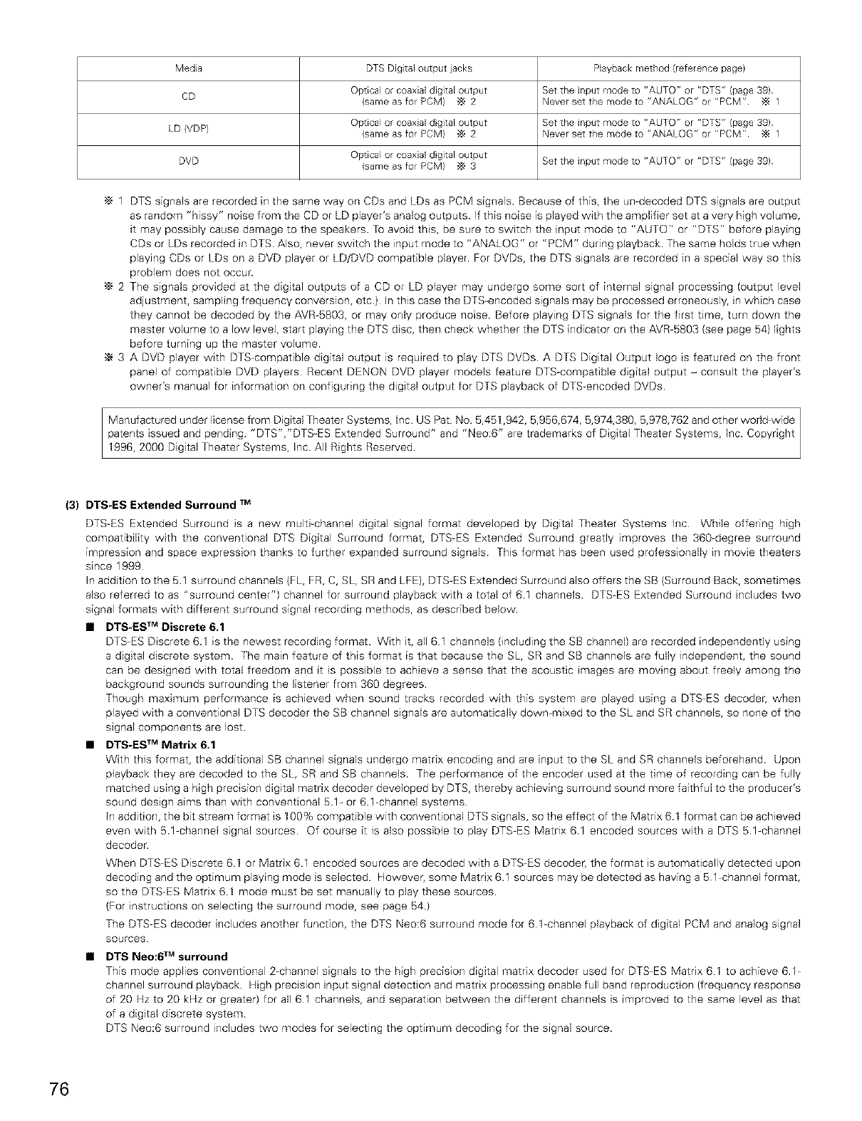
Media DTS Digital output jacks Playback method {reference page)
CD Optical or coaxial digitaE output Set the input mode to "AUTO" or "DTS" {page 39)
{same as for PCM) _ 2 Never set the mode to "ANALOG" or "PCM" _ 1
Optical or coaxial d gitaE output Set the input mode to "AUTO" or "DTS" {page 39)
LD (VDP) {same as for PCM) _ 2 Never set the mode to "ANALOG" or "PCM" _ 1
DVD Optical or coaxial d gitaE output
{same as for PCM) _ 3 Set the input mode to "AUTO" or "DTS" {page 39)
•_ 1 DTS signals are recorded in the same way on CDs and LDs as PCM signals Because of this, the umdecoded DTS signals are output
as random "hissy" noise from the CD or LD player's analog outputs. If this noise is played with the amplifier set at a very high volume,
it may possibly cause damage to the speakers. To avoid this, be sure to switch the input mode to "AUTO" or "DTS" before playing
CDs or LDs recorded in DTS. Also, never switch the input mode to "ANALOG" or "PCM" during playback The same holds true when
playing CDs or LDs on a DVD player or LD/DVD compatible player. For DVDs, the DTS signals are recorded in a special way so this
problem does not occur.
•_ 2 The signals provided at the digital outputs of a CD or LD player may undergo some sort of internal signal processing (output level
adjustment, sampling frequency conversion, etc) In this case the DTS-encoded signals may be processed erroneously, in which case
they cannot be decoded by the AVR-SB03, or may only produce noise. Before playing DTS signals for the first time, turn down the
master volume to a low level, start playing the DTS disc, then check whether the DTS indicator on the AVR-5803 (see page 64) lights
before turning up the master volume.
3 A DVD player with DTS-compatible digital output is required to play DTS DVDs. A DTB Digital Output logo is featured on the front
panel of compatible DVD players Recent DENON DVD player models feature DTS compatible digital output - consult the player's
owner's manual for information on configuring the digital output for DTB playback of DTS-encoded DVDs
1996, 2000 Digital Theater Systems, Inc. All Rights Reserved.
(3) DTS-ES Extended Surround TM
DTS-ES Extended Surround is a new multi-channel digital signal format developed by Digital Theater Systems Inc While offering high
compatibility with the conventional DTS Digital Surround format, DTS-ES Extended Surround greatly improves the 360=degree surround
impression and space expression thanks to further expanded surround signals This format has been used professionally in movie theaters
since 1999
In addition to the 6.1 surround channels (FL, FR, C, SL, SR and LFE), DTS-ES Extended Surround also offers the SB (Surround Back, sometimes
also referred to as "surround center") channel for surround playback with a total of 61 channels. DTS-ES Extended Surround includes two
signal formats with different surround signal recording methods, as described below
•DTS-ES TM Discrete 6,1
DTS-ES Discrete 6.I is the newest recording format. With it, all 61 channels (including the SB channel) are recorded independently using
a digital discrete system The main feature of this format is that because the SL, SR and SB channels are fully independent, the sound
can be designed with total freedom and it is possible to achieve a sense that the acoustic images are moving about freely among the
background sounds surrounding the listener from 360 degrees.
Though maximum performance is achieved when sound tracks recorded with this system are played using a DTS-ES decoder, when
played with a conventional DTB decoder the SB channel signals are automatically down-mixed to the SL and SR channels, so none of the
signal components are lost.
•DTS-ES TM Matrix 6.1
With this format, the additional SB channel signals undergo matrix encoding and are input to the SL and BR channels beforehand. Upon
playback they are decoded to the SL, SR and SB channels. The performance of the encoder used at the time of recording can be fully
matched using a high precision digital matrix decoder developed by DTS, thereby achieving surround sound more faithful to the producer's
sound design aims than with conventional 5.1- or 6.1-channel systems.
In addition, the bit stream format is 100% compatible with conventional DTS signals, so the effect of the Matrix 6.I format can be achieved
even with 5 1-channel signal sources Of course it is also possible to play DTS-ES Matrix 6.1 encoded sources with a DTS 5 1-channel
decoder
When DTS=ES Discrete 6.1 or Matrix 61 encoded sources are decoded with a DTS-ES decoder, the format is automatically detected upon
decoding and the optimum playing mode is selected However, some Matrix 6.1 sources may be detected as having a 51-channel format,
so the DTS=ES Matrix 6.I mode must be set manually to play these sources.
(For instructions on selecting the surround mode, see page 54.)
The DTS-ES decoder includes another function, the DTS Neo:6 surround mode for 6 1-channel playback of digital PCM and analog signal
sources
•DTS Neo:6 TM surround
This mode applies conventional 2-channel signals to the high precision digital matrix decoder used for DTS-ES Matrix 61 to achieve 61-
channel surround playback High precision input signal detection and matrix processing enable full band reproduction (frequency response
of 20 Hz to 20 kHz or greater) for all 61 channels, and separation between the different channels is improved to the same level as that
of a digital discrete system
DTS Neo:B surround includes two modes for selecting the optimum decoding for the signal source.
76
•DTS Neo:6 Cinema
This mode is optimum for playing movies Decoding is performed with emphasis on separation performance to achieve the same
atmosphere with 2=channel sources as with 6.1=channel sources.
This mode is effective for playing sources recorded in conventional surround formats as weJl, because the imphase component is
assigned mainly to the center channel (C) and the reversed phase component to the surround (SL, SR and SB channels)
•DTS Neo:6 Music
This mode is suited mainly for playing music. The front channel (FL and FR) signals bypass the decoder and are played directly so there
is no loss of sound quality, and the effect of the surround signals output from the center (C) and surround (SL, SR and SB) channels
add a natural sense of expansion to the sound field.
(4) DTS 96/24
The sampling frequency, number of bits and number of channels used for recording of music, etc., in studios has been increasing recent
years, and there are a growing number of high quality signal sources, including 96 kHz/24 bit 5.%channel sources
For example, there are high picture/sound quality DVD video sources with 96 kHz/24 bit stereo PCM audio tracks.
However, because the data rate for these audio tracks is extremely high, there are limits to recording them on two channels only, and since
the quality of the pictures must be restricted it is common to only include still pictures
In addition, 96 kHz/24 bit 5.1=channel surround is possible with DVD audio sources, but DVD audio players are required to play them with this
high quality.
DTS 96/24 is a multFchannel digital signal format developed by Digital Theater Systems Inc in order to deal with this situation.
Conventional surround formats used sampling frequencies of 48 or 441 kHz, so 20 kHz was about the maximum playback signal frequency.
With DTS 96/24, the sampling frequency is increased to 96 or 882 kHz to achieve a wide frequency range of over 40 kHz.
In addition, DTS 96/24 has a resolution of 24 bits, resulting in the same frequency band and dynamic range as 96 kHz/24 bit PCM.
As with conventional DTS Surround, DTS 96/24 is compatible with a maximum of 51 channels, so sources recorded using DTS 96/24 can be
played in high sampling frequency, multiple channel audio with such normal media as DVD videos and CDs.
Thus, with DTS 96/24, the same 96 kHz/24 bit multFchannel surround sound as with DVD_Audio can be achieved while viewing DVD=Video
images on a conventional DVD_Video player ( _ 1) Furthermore, with DTS 96/24 compatible CDs, 882 kHz/24 bit multi-channel surround can
be achieved using normal CD/LD players (,_ 1).
Even with the high quality multFchannel signals, the recording time is the same as with conventional DTS surround sources
What's more, DTS 96/24 is fully compatible with the conventional DTS surround format, so DTS 96/24 signal sources can be played with a
sampling frequency of 48 kHz or 441 kHz on conventional DTS or DTS_ES surround decoders ('_2)
1 : A DVD player with DTS digital output capabilities (for CD/LD players, a player with digital outputs for conventional DTS CDs/LDs) and
a disc recorded in DTS 96/24 are required.
"_2: The resolution is 24 or 20 bits, depending on the decoder
(5) Home THX Cinema Surround
THX is an exclusive set of standards and technologies established by the world-renowned film production company, Lucasfilm Ltd THX grew
from George Lucas' personal desire to make your experience of the film soundtrack, in both movie theaters and in your home theater, as
faithful as possible to what the director intended
Movie soundtracks are mixed in special movie theaters called dubbing stages and are designed to be played back in movie theaters with
similar equipment and conditions The soundtrack created for movie theaters is then transferred directly onto Laserdisc, VHS tape, DVD, etc,
and is not changed for playback in a small home theater environment
THX engineers developed patented technologies to accurately translate the sound from the movie theater environment into the home,
correcting the tonal and spatial errors that occur. On the AVR_5803, when the Home THX Cinema mode is on, THX processing is automatically
added after the Dolby Pro Logic, Dolby Digital or DTS decoder:
Re-Equalization TM
The tonal balance of a film soundtrack will be excessively bright and harsh when played back over audio equipment in the home because film
soundtracks are designed to be played back in large mowe theaters using very different professional equipment Re-Equalizagon restores the
correct tonal balance for watching a movie soundtrack in a small home environment.
Timbre MatchingTM
The human ear changes our perception of a sound depending on the direction from which the sound is coming In a movie theater, there is
an array of surround speakers so that the surround information is all around you. In a home theater, only two speakers located to the side of
your head are used. The ]-mbre Matching feature filters the information going to the surround speakers so that they more closely match the
tonal characteristics of the sound coming from the front speakers This ensures seamless panning between the front and surround speakers.
Adaptive Decorrelation TM
In a movie theater, a large number of surround speakers help create an enveloping surround sound experience, while in a home theater there
are usually only two speakers This can make the surround speakers sound like headphones that lack spaciousness and envelopment. The
surround sounds will also collapse into the closest speaker as you move away from the middle seating position Adaptive Decorrelagon slightly
changes one surround channel's time and phase relationship with respect to the other surround channel This expands the listening position
and creates--with only two speakers--the same spacious surround experience as in a movie theater.
77
THX Ultra2 TM
Before any home theater component can be THX Ultra2 certified, it must incorporate all the features above and also pass a rigorous series
of quality and performance tests Only then can a product feature the THX Ultra2 logo, which is your guarantee that the Home Theater
products you purchase will give you superb performance for many years to come THX Ultra2 requirements cover every aspect of the product
including power amplifier performance, pre-amplifier performance and operation, as well as hundreds of other parameters in both the digital
and analog domain
In addition to improvements to the power amplifier with respect to previous THX Ultra standards, two surround modes have been added: the
THX Ultra2 Cinema mode and the THX MusicMode
THX Ultra2 Cinema
THX Ultra2 Cinema mode plays B1 movies using all B speakers giving you the best possible movie watching experience. In this mode, new
THX processing blends the side surround speakers and back surround speakers providing the optimal mix of ambient and directional surround
sounds.
DTS-ES (Matrix and 61 Discrete) and Dolby Digital Surround EX encoded soundtracks wifl be automatically detected in Ultra2 Cinema mode
if the appropriate flag has been encoded
Some Dolby Digital Surround EX soundtracks are m_ssing the digital flag that allows automatic switching If you know that the movie that you
are watching is encoded in Surround EX, you can manually select the THX Surround EX playback mode, otherwise THX Ultra2 Cinema mode
will apply processing to provide optimum replay.
THX MusicMode
For the replay of 5.1 multi_channel music the THX MusicMode should be selected. In this mode new THX processing is applied to the surround
channels of all 51 encoded music sources such as DTS and Dolby Digital to provide a wide stable rear soundstage
Advanced Speaker Array
ASA processing offers maximum effect when two surround back speakers are used and the speakers are placed near each other This
technology is used for Ultra2 Cinema, THX Music MODE and THX Surround EX.
Boundary Gain Compensation
When using a THX Ultra2 compatible subwoofer or a subwoofer with ultra-low frequency playback capabilities (with afrequency response
extending to approximately 20 Hz), the low frequency band may rise and the sound may seem booming. This technology compensates the
gain and makes the audible level flat.
I Lucasfilm, THX, Home THX, Re-Equalization, ]]mbre Matching, Adaptive Decorrelation and THX Ultra are trademarks of Lucasfilm Ltd.
(6) THX Surround EX
h 1999, a new surround system was launched simultaneously with the release of the movie "Star Wars Episode I" "Dolby Digital Surround
EX" is a new movie sound track that greatly enhances the sense of spatial expression and the positioning of the surround channel sound The
result is 360 degrees of movement and moving sound effects that seem to pass right over the listener's head.
This system was developed jointly by Lucasfilm THX and Dolby Laboratories, fusing Lucasfilm's idea of improving spatial expression and
achieving a uniform 360 degree sound positioning with Dolby Laboratories' matrix encoding technology Emphasis was placed on compatibility
with the existing system Dolby Digital B 1-channel, and the new "surround back (SB) channel" was added to achieve improvements over the
conventional 51-channel system in terms of the positioning of the sound at the rear, the acoustic image of sound moving from the two sides
to the back as well as sound moving from the front to the center rear with the multi surround speaker systems used in movie theaters, thereby
enabling various types of surround sound
The surround back channel signal is a matrix-encoded signal inserted into both the Dolby Digital SL (surround left) and SR (surround right)
channels. Upon playback, the signals are decoded by a high precision digital matrix decoder within the Dolby Digital decoder into the SL, SR
and BB channels and output as 61 channels of signals. With the AVR-BBO3, the signals further undergo Home THX Cinema processing to
achieve a THX Surround EX system.
Even without the proper environment for playing the SB channel, Dolby Digital Surround EX signals are 100% compatible with existing B1-
channel playback systems, so they can be played as such. In this case, the SB channel signal is produced as a monaural signal from both the
SL and SR channels, so none of the signal components are missing. The effects specific to THX Surround EX (the sense of spatial expression
and the positioning of the sound), however, are the same as with conventional 5 1-channel surround systems.
of Dolby Laboratories Used under authorization
78
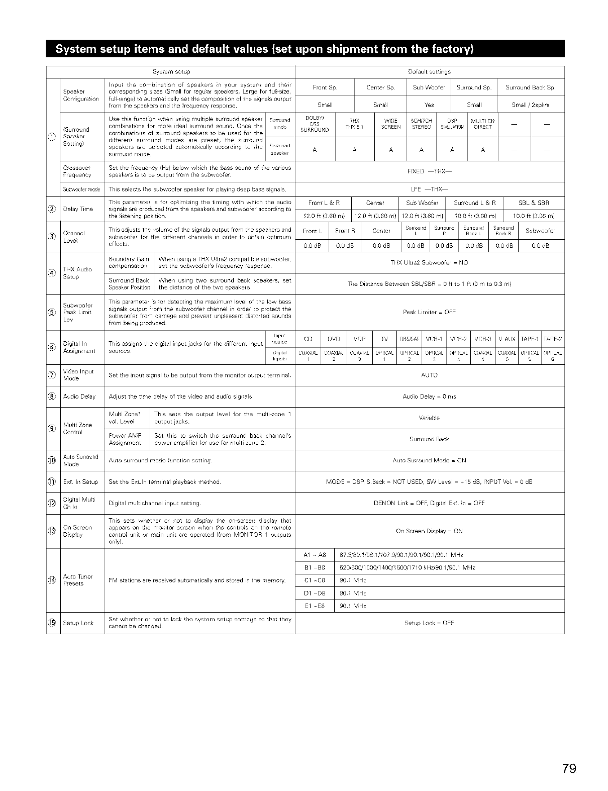
Syste ¥1setup
Input tie cor'lbinat[on of speakers n your system and their
corresponding sizes (Small for regu}ar speakers, Large for ful size,
full range} to automatically set the composition of the signa s output
from the speakers and the frequency respo/se
Speaker
COTll gurat[on
(Surround
Speaker
Setti/g)
C ossovef Set the frequency (Hz) below which the bass souTld of the various
Frequency speakers is to be output l_om t/_e st,bwoofe_
Subwo0fer mode This selects the subwoofer speakel for playing deep bass sigl/als
Delay _me
Ci/annel
Level
THXAudio
Setup
Subwoofer
Peak Limk
Lev
This parameter is for optim zing the timing wCh w!/ic/ the audio
sigr_als are produced f_om the speakers and subwoofer aocofding to
the listening position¸
T/is adiusts the volurl'e of the sigl/als output fror'l the speakers a_ld
subwoofel lof the diflefeTlt ehal/llels in older to o_tain optimum
effe_s
Boundary Gain When using a THX Ultra2 cor'lpatJble subwoofe
compensat_oT_ set the subwoofer s l_equeney respo_/se
Surround Back
Speake Posit ol"
T/is parameter is for detect ng the maximum leve of the low bass
sigr_als output from tl_e subwoolef cha_nel i_/ o_de_ to protect the
subwoofe_ from damage arid preve_/t unp(easa_t distorted sou_/ds
from be[llg produoed
Set the nput signal to be output from the moTl[tor output terr,/inal
Adjust the tff_e delay ol the v_deo and audio signals¸
Mult_ Zone1 T_l[s sets tile output level lot tile multi zol/e 1
vol Level output jacks
Power AMP Set tllis to switch the surround bacl< chanrlel's
Assignmel/t power amp(if[er for use for multi ZOTle 2
Auto surround mode function setting
Set the Extln telminal playback method¸
Digital muir[channel input setting
This sets whethe/ or i/or to display the on_c/eeT1 display that
FM stations are rece veal auto Ylat[ca_ly aT_d stoed i/ the memory
Set whether oF not to lock the system setup settJ/gs so that they
ca_/_ot be oha_/ged
Front Sp
Small
Ffo/t L & R
120 ft (360 n/}
A1 A8
BI B8
CI C8
DI D8
Defau t sett ngs
Center Sp Sub Woofe
Small Yes
FIXED THX
LFE _HX
Center
120 ft (3¸60 m}
Sur ouTld Sp
Small
Su round L & R
10 0 fC(3 00 m)
THX Ultra2 Subwoofer NO
Tie Distance Betwee / SBL/SBR 0 fc to I ft (0 m to 03 m}
Peak Li¥_itef OFF
AUTO
Audio Delay 0 ms
Var able
SurfouTld Bao_
Auto Sulround Mode ON
MODE DSP SBack NQTUSED, SWLevel +15dB, INPUTVol 0dB
DENON Link OF_ Digital Ext I_/ OFF
On Screen Disp(ay ON
87 _89 1/98 1/1079/90 1/90 1/90 I_0 I MHz
520/600/1000/140_1500/1710 _<Hz/90 1/90 1 MHz
901 MHz
901 MHz
901 MHz
Setup Lock OFF
Su round Back Sp
Small /2sprs
SBL & SBR
100 ft (300 m}
Subwoofer
OOdB
79
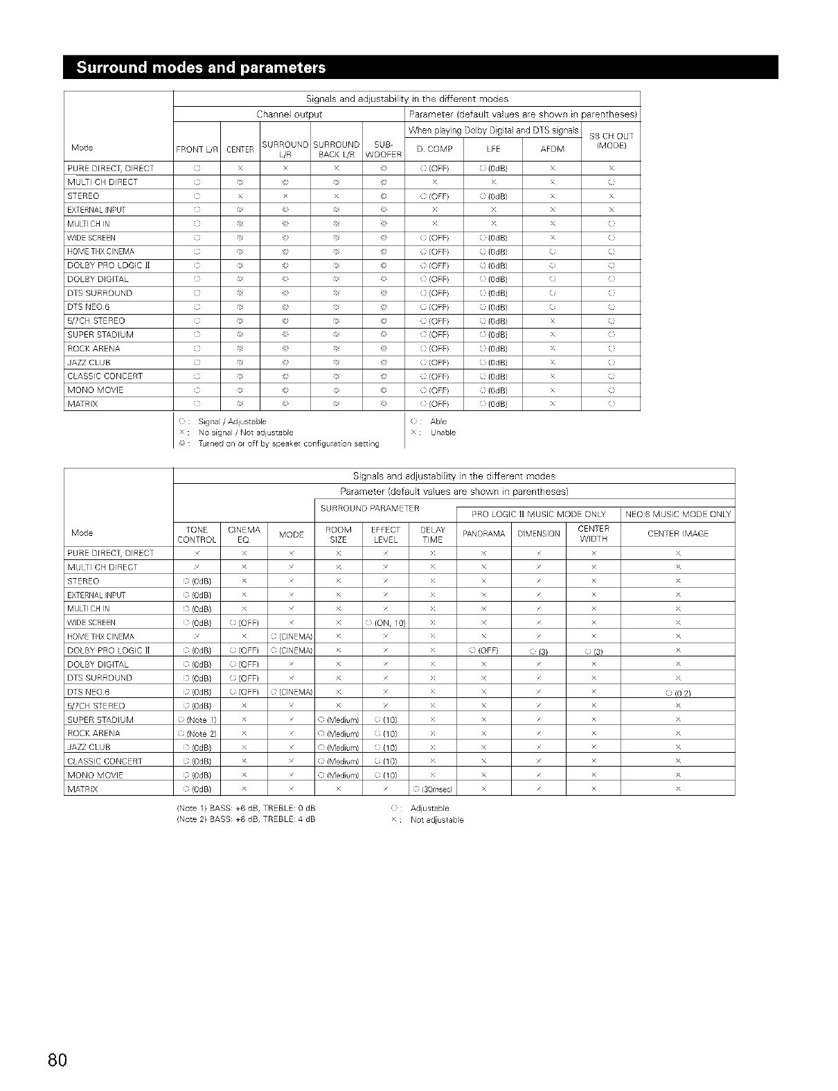
Mode
PURE DIRECT, DIRECT
MULti CH DIRECT
STEREO
EXTERNALNPUT
MUL-I CH N
WDE SCREEN
HOME THX CINEMA
DOLB¥ PRO LOGIC 11
DOLB¥ DIGITAL
DTS SURROUND
DTS NEO6
5/7CH S-EREO
SUPER STADIUM
ROCK ARENA
AZZ CLUB
C ASSIC CONCERT
MONO MOVIE
MA:RX
Mode
PURE DIREC% DIRECT
MULti CH DIRECT
STEREO
EXTERNALNPUT
MUL-I CH N
WDE SCREEN
HOME THX CINEMA
DOLB¥ PRO LOGIC 11
DOLB¥ DIGITAL
DTS SURROUND
DTS NEO6
5/7CH S-EREO
SUPER STADIUM
ROCK ARENA
AZZ CLUB
C ASSIC CONCERT
MONO MOVIE
MA:RX
Signals and adjustab lity in the different modes
Channel output Parameter (default values are shown m parentheses)
When playing Dolby Dgita and DTS sgnas
BURROUNB SURROUND SUB
FRONT [JR CENTER [JR BACK L/R WOOFER D COMP LFE
( x > _ {OFF} {Od B)
( x > _ {OFF} {Od B)
( _ _ {OFE} {OdB)
( _ _ {OFE} {OdB)
( _ _ {OFE} {OdB)
( _ _ {OFE} {OdB)
( _ _ {OFE} {OdB)
( _ _ {OFE} {OdB)
( _ _ {OFE} {OdB)
( _ _ {OFE} {OdB)
( _ _ {OFE} {OdB)
( _ _ {OFE} {OdB)
( _ _ {OFE} {OdB)
( _ _ {OFE} {OdB)
( _ _ {OFE} {OdB)
: : SJgtlal /Adiustabie xC; Able
x : No signal /Not adjustable Unable
: Tuned on or off by speake cotll gurat[or/setting
SB CH OUT
AFDM {MODEl
x x
×
x x
x x
×
×
Signals and adjustabiEty in the different modes
Parameter (default values are shown in parentheses)
SURROUND PARAMETER PRO LOGIC II MUSIC MODE ONL v
TONE CNEMA ROOM EFFECT DELAY CENTER
MODE PANORAMA D MENSION
CONTROL EQ SIZE LEVE TIME WIDTH
> > > x
> > > x
(OdB} > > > x
( (OdB} > > > x
( (OdB} > > > x
( (OdB} (OFF) > ( (ON, I0} > x
> fC]NEM/ > > x
(} (OdB} (; (OFF) } {C]NEMA > x > (} (OFF} ( {3} {; (3)
0 (OdB} 0 (OFF) x > x > x x
0 (OdB} 0 (OFF) x > x > x x
(} (OdB} 0 (OFF) } {CINEMA > x > x x
0 (OdB} > x > x > x x
0 (Note I ) X x {} (Medium) 0 (1O) X x x
0 (Note 2) X x {} (Medium) 0 (1 O) X x x
(} (OdB} X x {} IMediun/I 0 11O) X x x
(} (OdB} X x {} IMediun/I 0 11O) X x x
(} (OdB} X x {} IMediun/I 0 11O) X x x
(} (OdB} > x > x (} 130rr'sec} x x
NEO:6 MUSIC MODE ONL v
CENTER MAGE
>
>
>
>
>
>
>
>
>
>
) (0 2)
>(
>(
>(
>(
>(
>(
>(
(Note 1} BASS: +6 dB, TREBLE: 0 dB
(Note 2} BASS: +8 dB, TREBLE: 4 dB
(} Adiustable
> : Not adiustabie
8O
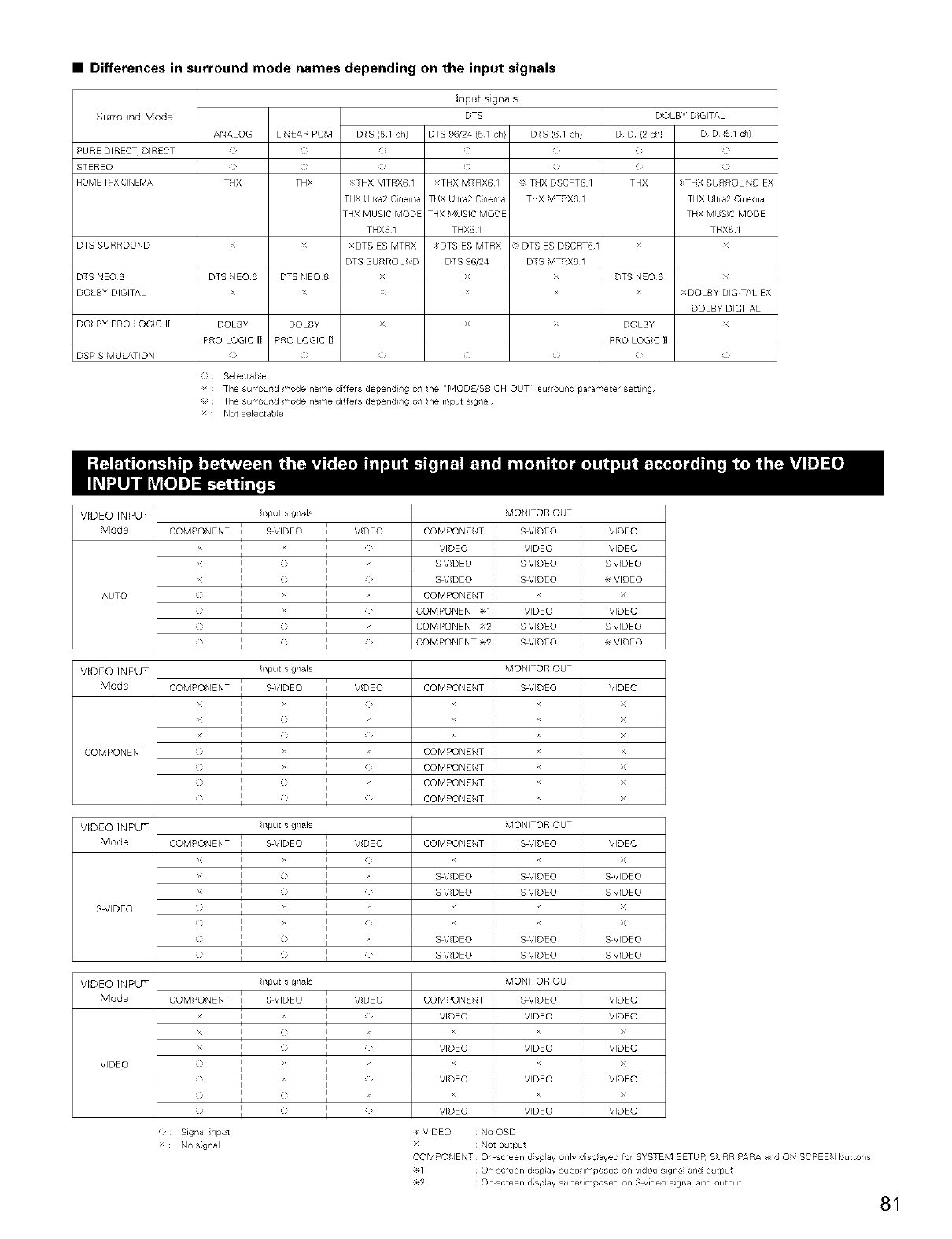
•Differences in surround mode names depending on the input signals
Surround Mode
PURE DIRECT, DIRECT
STEREO
HOMETHXCINEMA
ANALOG LINEAR PCM DTS (51 ch}
C_ C_ C;
THX THX _THX MTRX6
THX Ultra2 Cinema
THX MUSIC MODE
THXB1
DTS SURROUND >DTS ES MTRX
DTS SURROUND
DTS NEO6 DTS NEO6 DTS NEO6 > DTS NEO:6
DOLBY DIGITAL x x >
DOLBY PRO LOGIC 1] DQLBY DQLBY > DOLBY
PRO LOGIC I] PRO LOGIC I] PRO LOGC ]]
DSP SIMU ATION : : (
: Selectable
Input signals
DTS
DTS 96/24 (51 ch} DTS (6 1 ch}
(
(
_THX MTRX6 1 THX DSCRT6 I
THX Utra2 Cinema THX MTRX6 1
THX MUSIC MODE
THX51
DTS ES MTRX DTS ES DSCRT6 1
DTS 96/24 DTS MTRX6 1
x
x
x
(
DOLBY DIGITAL
D D (2 oh) D D/51 ch}
( (i
C¸ (3
THX _THX SURROUND EX
THX Ultra2Cinema
THX MUS}C MODE
THX51
x
x
_DOLBY DIGITAL EX
DOLBY DIGITAL
x
C
_- ; The surround mode name differs depending on the "MODE/SB CH OUT su round parameter sett ng
The surround mode name differs dependi/g o/the input sgnal
x Not selectaMe
VIDEO INPUT
Mode
AUTO
VIDEO INPUT
Mode
COMPONENT
VIDEO INPUT
Mode
S VIDEO
COMPONENT
x
x
x
Irlput sigl/als
I SVIDEO I VDEO
I I >
I < I
I I
I I
i i
I I c
i i
I I
I I
MONITOR OUT
COMPONENT I S VIDEO I VIDEO
V,DEO I WDEO I V,DEO
S VDEO I S VIDEO I S VIDEO
S VDEO I S VIDEO I _ VIDEO
COMPONENT I I
i i
COMPONENT 1 I V_DEO I VIDEO
COMPONENT 2 I SVIDEO I S VIDEO
COMPONENT 2 I SVIDEO I _ VIDEO
COMPONENT
x
x
x
Irlput sigl/als
iS VIDEO iVDEO
I I
I I
I I
I ( I
I I
I I
I I
I I
I I
COMPONENT
>
>
>
COMPONENT
COMPONENT
COMPONENT
COMPONENT
MONITOR OUT
i S VIDEO
I
i
I
i
1
1
1
1
1
i VIDEO
I
I x
I
I x
I
I
I
I
I
Irlput sigl/als
COMPONENT I SVIDEO I VDEO
I I
I I
× ] o ] o
> I I
i i
C} I I C}
i i
o ] < ]
o ] < ] c
MONITOR OUT
COMPONENT I S VIDEO I VIDEO
>1 1
S VDEO I S VIDEO I S VIDEO
S VDEO S VIDEO S VIDEO
> I I x
I I
> I I x
I I
S VDEO I S VIDEO I S VIDEO
S VDEO I S VIDEO I S VIDEO
VIDEO INPUT nput signals MONITOR OUT
Mode COMPONENT i SVIDEO i VIDEO COMPONENT i SVIDEO i VIDEO
I I I I
x i i C} VIDEO i V_DEO i VIDEO
I I I I
x I (_ I x >_ i i x
I < I > V,DEO I V_DEO I V,DEO
V_DEO > I I > I I
c I I c VIDEO V_DEO VIDEO
C I I > i i
C I I C VIDEO V_DEO VIDEO
Signa nput
> No signal
_ V}DEO No OSD
Not output
COMPONENT On screen d splay onJy displayed for SYSTEM SETUF_ SURR PARA aid ON SCREEN buttons
1 On screen d splay supenmposed on video signa and output
2 On screen d splay supe imposed on S video signal and output
81
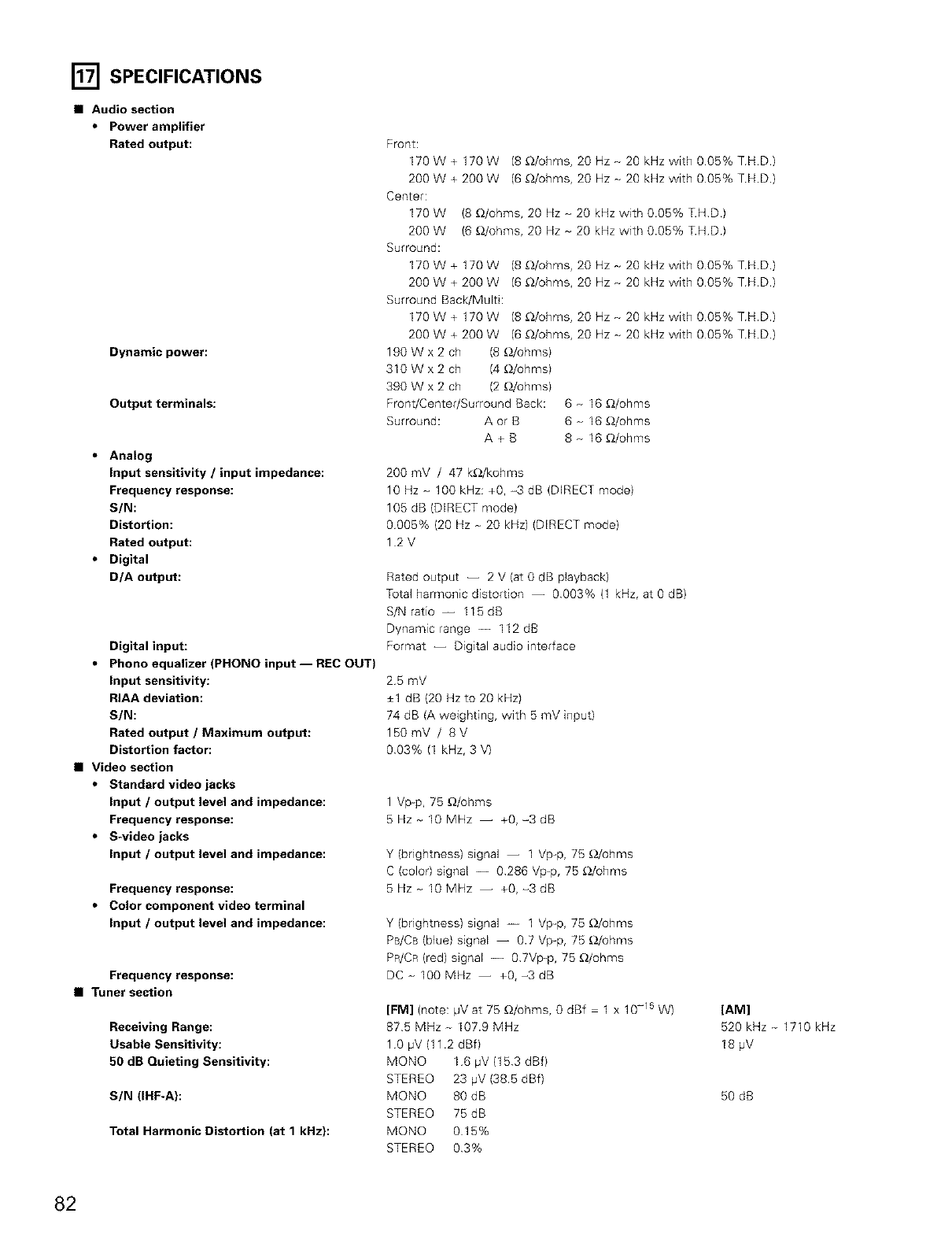
[] SPECIFICATIONS
•Audio section
•Power amplifier
Rated output:
Dynamic power:
Output terminals:
•Analog
Input sensitivity /input impedance:
Frequency response:
S/N:
Distortion:
Rated output:
•Digital
D/A output:
Digital input:
•Phono equalizer (PHONO input-- REC OUT)
Input sensitivity:
RIAA deviation:
S/N:
Rated output /Maximum output:
Distortion factor:
•Video section
•Standard video jacks
Input /output level and impedance:
Frequency response:
•S-video jacks
Input /output level and impedance:
Frequency response:
•Color component video terminal
Input /output level and impedance:
Frequency response:
•Tuner section
Receiving Range:
Usable Sensitivity:
50 dB Quieting Sensitivity:
SIN (IHF-A}:
Total Harmonic Distortion (at 1 kHz):
Front:
170W+ 170W (8_/ohms, 20Hz-20kHzwith006%TH.D.
200W+200W (6_/ohms, 20Hz-20kHzwith005%TH.D.
Center:
170 W 18 _2/ohms, 20 Hz - 20 kHz with 0.05% T.HD)
200 W 16 _2/ohms, 20 Hz - 20 kHz with 0.05% T.HD)
Surround:
170W+ 170W (8_/ohms, 20Hz_20kHzwith006%TH.D.
200W+200W (6_/ohms, 20Hz_20kHzwith005%TH.D.
Surround Back/MulS:
170W+ 170W (8_/ohms, 20Hz_20kHzwith006%TH.D.
200W+200W (6_/ohms, 20Hz_20kHzwith005%TH.D.
190Wx2 ch (8 _/ohms)
310Wx2 ch (4 _)/ohms)
390 W x 2 ch (2 _/ohms)
Front/Center/Surround Back: 8 - I8 _/ohms
Surround: A or B 8 _ I8 _/ohms
A + B 8 _ 18 _/ohms
200 mV /47 k£_/kohms
10 Hz _ 100 kHz: +0, -3 dB (DIRECT mode)
106 dB (DIRECT mode)
0005% (20 Hz _ 20 kHz) (DIRECT mode)
12V
Rated output -- 2 V (at 0 dB playback)
Total harmonic distortion -- 0003% (1 kHz, at 0 dB)
S/N ratio -- I16 dB
Dynamic range -- 112dB
Format -- Digital audio interface
25 mV
+1 dB (20 Hz to 20 kHz)
74 dB (A weighting, with 6 mV input)
150mV /8V
003% (1 kHz, 3 V)
1 Vp-p, 75 _/ohms
5Hz_ 10MHz -- +0,-3dB
Y (brightness) signal -- 1 Vp-p, 7B _)/ohms
C (color) signal -- 0286 Vp-p, 7B _)/ohms
5Hz_ IOMHz -- +0,-3dB
Y (brightness) signal -- 1 Vp_p, 75 _)/ohms
PB/CB (blue) signal -- 0.7 Vp-p, 75 _)/ohms
PR/CR (red) signal -- 0 7Vp_p, 76 £_/ohms
DC_ 100MHz -- +0,-3dB
[FM] (note: pV at 75 _/ohms, 0 dBf 1 x 10-15 W)
875 MHz - I07.9 MHz
10 pV (11.2 dBf)
MONO 16 pV (153 dBf)
STEREO 23 pV (38.5 dBf)
MQNO 80 dB
STEREO 75 dB
MONO 015%
STEREO 03%
[AM]
520 kHz - 1710 kHz
18 ,uV
50 dB
82
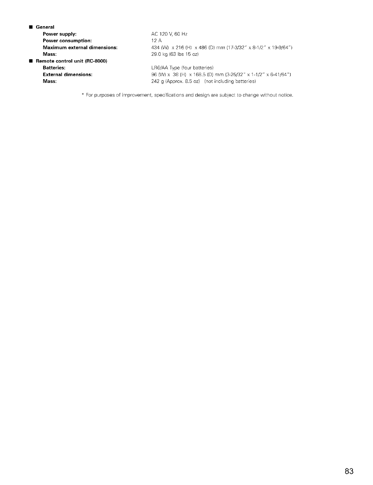
•General
Power supply:
Power consumption:
Maximum external dimensions:
Mass:
•Remote control unit (RC-8000)
Batteries:
External dimensions:
Mass:
AC 120 V, 60 Hz
12A
434 (W) x 216 (H) x 486 (D) mm (17_3/32" x 8q/2" x 19_9/64")
290 kg (63 Ibs 15 oz)
LR6/AA Type (four batteries)
96 (W) x 38 (H) x 168.5 (D) mm (3-26/32" x lq/2" x 6-41/64")
242 g (Approx 8.5 oz) (not including batteries)
* For purposes of improvement, specifications and design are subject to change without notice.
83

DENON, Ltd.
16 11, YUSHIMA 3 CHOME, BUNKYOU KU, TOKYO 113 0034, JAPAN
Telephone: (03) 3837 5321
Printed in Japan 51 / 3874 005
