Denon Avr 890 Users Manual
0811b2ff-90de-426d-a.. 0811b2ff-90de-426d-a1e3-7eb995a395c9
AVR-890 to the manual 0811b2ff-90de-426d-a1e3-7eb995a395c9
2015-01-23
: Denon Denon-Avr-890-Users-Manual-221435 denon-avr-890-users-manual-221435 denon pdf
Open the PDF directly: View PDF ![]() .
.
Page Count: 76
bThe illustrations used for explaining operations in this manual show the buttons of
the remote control unit.
The same operations can be performed using the buttons with the same names on
the main unit panel.
bLes illustrations des boutons présentes dans ce manuel servent à expliquer le
fonctionnement de la télécommande.
Vous pouvez contrôler l’appareil à l’aide du bouton portant le même nom sur la
façade de l’appareil.
AV SURROUND RECEIVER
AVR-890
Owner’s Manual
Manuel de l’Utilisateur
GraphicalUserInterface
English
Use this manual in combination with the
operating guide displayed on the GUI screen.
Menu Map (vpage 20)
Examples of GUI Menu Screen Displays (vpage 21)
Remote Control Unit Operations (vpage 55)
Français
Utilisez ce manuel en même temps que le guide
d’utilisation affiché sur l’écran GUI (Interface
graphique).
Plan du menu (vpage 20)
Exemples d’affichage sur écran et d’affichage avant
(vpage 21)
Fonctionnement de la télécommande (vpage 55)
n SAFETY PRECAUTIONS
CAUTION
RISK OF ELECTRIC SHOCK
DO NOT OPEN
CAUTION:
TO REDUCE THE RISK OF ELECTRIC SHOCK, DO NOT REMOVE
COVER (OR BACK). NO USER-SERVICEABLE PARTS INSIDE.
REFER SERVICING TO QUALIFIED SERVICE PERSONNEL.
The lightning flash with arrowhead symbol, within an equilateral
triangle, is intended to alert the user to the presence of
uninsulated “dangerous voltage” within the product’s enclosure
that may be of sufficient magnitude to constitute a risk of electric
shock to persons.
The exclamation point within an equilateral triangle is intended
to alert the user to the presence of important operating
and maintenance (servicing) instructions in the literature
accompanying the appliance.
WARNING:
TO REDUCE THE RISK OF FIRE OR ELECTRIC SHOCK, DO NOT
EXPOSE THIS APPLIANCE TO RAIN OR MOISTURE.
ENGLISH FRANCAIS
I
CAUTION:
HOT SURFACE. DO NOT TOUCH.
The top surface over the internal heat sink may become
hot when operating this product continuously.
PRECAUTION:
SURFACE CHAUDE. NE PAS TOUCHER.
La surface supérieure du dissipateur de chaleur peut
devenir chaude si vous utilisez ce produit en continu.
IMPOTANT SAFETY
INSTRUCTIONS
1. Read these instructions.
2. Keep these instructions.
3. Heed all warnings.
4. Follow all instructions.
5. Do not use this apparatus near water.
6. Clean only with dry cloth.
7. Do not block any ventilation openings.
Install in accordance with the manufacturer’s instructions.
8. Do not install near any heat sources such as radiators, heat registers,
stoves, or other apparatus (including amplifiers) that produce heat.
9. Do not defeat the safety purpose of the polarized or grounding-type plug. A
polarized plug has two blades with one wider than the other. A grounding
type plug has two blades and a third grounding prong. The wide blade or the
third prong are provided for your safety. If the provided plug does not fit into
your outlet, consult an electrician for replacement of the obsolete outlet.
10. Protect the power cord from being walked on or pinched particularly at
plugs, convenience receptacles, and the point where they exit from the
apparatus.
11. Only use attachments/accessories specified by the manufacturer.
12. Use only with the cart, stand, tripod, bracket, or table
specified by the manufacturer, or sold with the apparatus.
When a cart is used, use caution when moving the cart/
apparatus combination to avoid injury from tip-over.
13. Unplug this apparatus during lightning storms or when
unused for long periods of time.
14. Refer all servicing to qualified service personnel.
Servicing is required when the apparatus has been damaged in any way,
such as power-supply cord or plug is damaged, liquid has been spilled or
objects have fallen into the apparatus, the apparatus has been exposed to
rain or moisture, does not operate normally, or has been dropped.
15. Batteries shall not be exposed to excessive heat such as sunshine, fire or
the like.
CAUTION:
• The ventilation should not be impeded by covering the ventilation
openings with items, such as newspapers, tablecloths, curtains,
etc.
• No naked flame sources, such as lighted candles, should be
placed on the unit.
• Observe and follow local regulations regarding battery disposal.
• Do not expose the unit to dripping or splashing fluids.
• Do not place objects filled with liquids, such as vases, on the
unit.
ATTENTION:
• La ventilation ne doit pas être gênée en recouvrant les ouvertures
de la ventilation avec des objets tels que journaux, rideaux, tissus,
etc.
• Aucune flamme nue, par exemple une bougie, ne doit être placée
sur l’appareil.
• Veillez à respecter les lois en vigueur lorsque vous jetez les piles
usagées.
• L’appareil ne doit pas être exposé à l’eau ou à l’humidité.
• Ne pas poser d’objet contenant du liquide, par exemple un vase,
sur l’appareil.
CAUTION:
To completely disconnect this product from the mains, disconnect
the plug from the wall socket outlet.
The mains plug is used to completely interrupt the power supply to
the unit and must be within easy access by the user.
PRECAUTION:
Pour déconnecter complètement ce produit du courant secteur,
débranchez la prise de la prise murale.
La prise secteur est utilisée pour couper complètement
l’alimentation de l’appareil et l’utilisateur doit pouvoir y accéder
facilement.
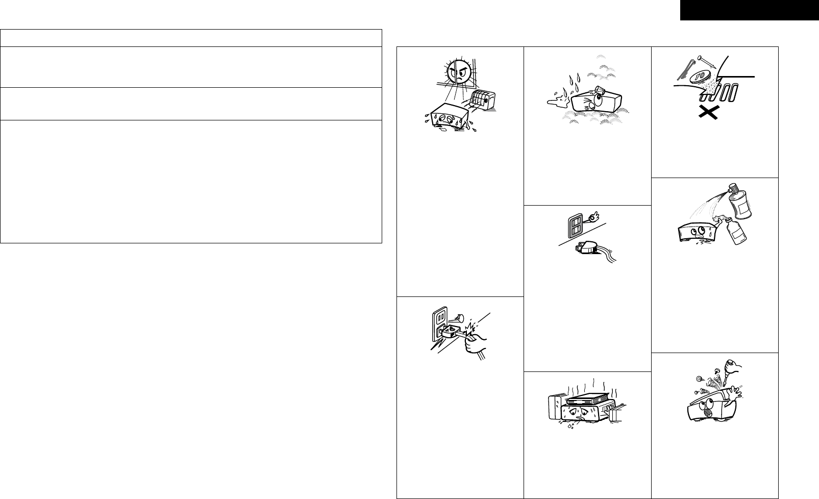
• Avoid high temperatures.
Allow for sufficient heat dispersion when
installed in a rack.
• Eviter des températures élevées.
Tenir compte d’une dispersion de chaleur
suffisante lors de l’installation sur une
étagère.
• Handle the power cord carefully.
Hold the plug when unplugging the cord.
• Manipuler le cordon d’alimentation avec
précaution.
Tenir la prise lors du débranchement du
cordon.
• Keep the unit free from moisture, water,
and dust.
• Protéger l’appareil contre l’humidité, l’eau
et la poussière.
• Unplug the power cord when not using the
unit for long periods of time.
• Débrancher le cordon d’alimentation
lorsque l’appareil n’est pas utilisé pendant
de longues périodes.
* (For apparatuses with ventilation holes)
• Do not obstruct the ventilation holes.
• Ne pas obstruer les trous d’aération.
• Do not let foreign objects into the unit.
• Ne pas laisser des objets étrangers dans
l’appareil.
• Do not let insecticides, benzene, and
thinner come in contact with the unit.
• Ne pas mettre en contact des insecticides,
du benzène et un diluant avec l’appareil.
• Never disassemble or modify the unit in
any way.
• Ne jamais démonter ou modifier l’appareil
d’une manière ou d’une autre.
n NOTE ON USE / OBSERVATIONS RELATIVES A L’UTILISATION
FCC INFORMATION (For US customers)
1. PRODUCT
This product complies with Part 15 of the FCC Rules. Operation is subject to the following two conditions: (1) this
product may not cause harmful interference, and (2) this product must accept any interference received, including
interference that may cause undesired operation.
2. IMPORTANT NOTICE: DO NOT MODIFY THIS PRODUCT
This product, when installed as indicated in the instructions contained in this manual, meets FCC requirements.
Modification not expressly approved by DENON may void your authority, granted by the FCC, to use the product.
3. NOTE
This product has been tested and found to comply with the limits for a Class B digital device, pursuant to Part 15
of the FCC Rules. These limits are designed to provide reasonable protection against harmful interference in a
residential installation.
This product generates, uses and can radiate radio frequency energy and, if not installed and used in accordance
with the instructions, may cause harmful interference to radio communications. However, there is no guarantee
that interference will not occur in a particular installation. If this product does cause harmful interference to radio or
television reception, which can be determined by turning the product OFF and ON, the user is encouraged to try to
correct the interference by one or more of the following measures:
• Reorient or relocate the receiving antenna.
• Increase the separation between the equipment and receiver.
• Connect the product into an outlet on a circuit different from that to which the receiver is connected.
• Consult the local retailer authorized to distribute this type of product or an experienced radio/TV technician for
help.
This Class B digital apparatus complies with Canadian ICES-003.
Cet appareil numérique de la classe B est conforme à la norme NMB-003 du Canada.
ENGLISHFRANCAIS
II

ENGLISH
Flow of operations through playback ·········································2
Accessories ··················································································2
Cautions on Handling ···································································3
Cautions on Installation ·······························································3
About the Remote Control Unit···················································3
Inserting the Batteries ··································································3
Operating Range of the Remote Control Unit ······························3
Part Names and Functions ···························································4
Front Panel ····················································································4
Display ··························································································5
Rear Panel ·····················································································6
Remote Control Unit ·····································································7
Connections
Important Information ··································································8
Cables Used for Connections ·······················································8
Converting Input video signals for Output
(Video Conversion Function) ·························································9
Installing/Setting the Speakers ················································· 10
Connecting the Speakers ··························································· 11
Connecting Devices ····································································12
Connecting Devices not Equipped with HDMI terminals ········ 13
Once Connections are Completed ············································· 19
Turning the Power On ·································································19
Turning the Power Off ································································· 19
Selecting the Input Source ·························································19
Settings
Playback
Getting Started
Checking the Status (Information) ·····························51
Playing Components ···································································40
Playing Blu-ray Disc / DVD Players ··············································40
iPod® Playback ···········································································40
Listening to FM/AM Broadcasts ·················································41
Listening to SIRIUS Satellite Radio Programs ····························42
Operations During Playback ························································44
Selecting the Surround Mode ····················································44
q Playing Sources According to the Sources’ Audio Signal
Format/Number of Channels (Standard Playback) ·············· 44
w Playing in a DENON Original Surround Mode ························45
e Direct Playback ·······································································45
r Stereo Playback ······································································46
t Playing the Pure Direct Mode ················································46
Adjusting the Sound and Picture Quality
(Audio/Video Adjust) ··································································46
Adjusting the Sound (Audio Adjust) ············································46
Adjusting the Tone (Tone Control) ···············································48
Adjusting MultEQ®, Dynamic EQ™, Dynamic Volume™
Settings (Audyssey Settings) ······················································48
Adjust Tonal Quality for Each Speaker Using Graphic Equalizer
(Manual EQ) ················································································50
Restoring Compressed Audio to Nearly Pre-compressed
Conditions for Playback (RESTORER) ·········································50
Adjusting the Audio Delay Time while Watching the Picture
(Audio Delay) ···············································································50
Adjusting the Picture Quality (Picture Adjust) ·····························51
Menu Map ····················································································20
Examples of GUI Menu Screen Displays ···································21
Making the Optimum Settings for the Connected Speakers
Automatically (Audyssey™ Auto Setup) ··································22
Making detailed settings (Manual Setup)·································27
Making the Input Settings (Input Setup) ··································34
Convenient functions
HDMI Control Function ·······························································52
Setting the Power to Standby After a Certain Amount of
Time (Sleep Timer Function) ······················································52
Adjust the Volume of the Different Speakers ··························53
Saving Frequently Used Settings (Quick Select Function) ·····53
MAIN ZONE settings ··································································53
ZONE2 settings···········································································53
Various Memory Functions ························································53
Playing 2-Channel Sound in ZONE2
(Multizone Function)··························································54
Operating the Connected Devices by Remote
Control Unit
Registering Preset Codes ···························································55
Operating Registered Devices ···················································55
Assigning buttons that are Not Used to Operate Other
Devices (Punch Through Function)············································57
Other Information ·······························································58
Troubleshooting···································································65
Restoring All the Settings to as They were at the Time of
Purchase (Resetting the Microprocessor) ·································68
Specifications ········································································68
n Contents
List of preset codes ··································End of this manual
2
ENGLISH
Getting Started Connections Playback Remote Control Information Troubleshooting Specifi cationsMulti-ZoneSettings
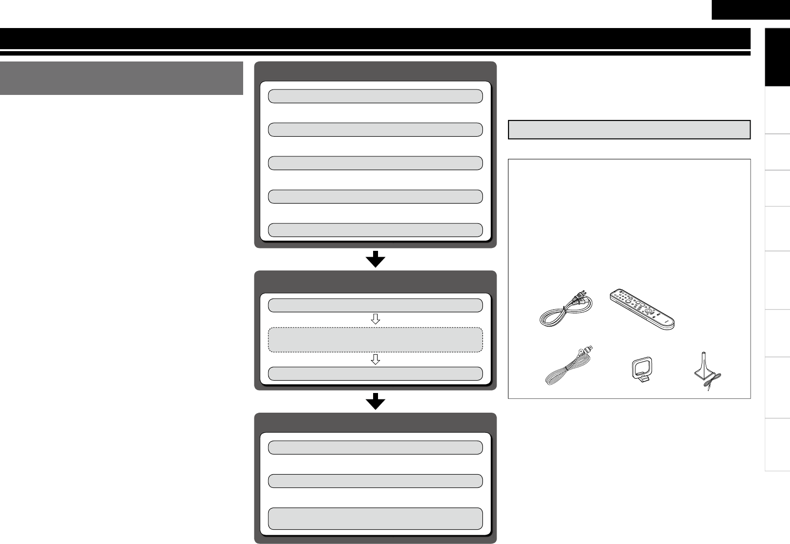
Perform the operations leading to playback on the AVR-890 in the
order shown below.
Connections
⇩
Installing/Setting the Speakers (vpage 10)
Connecting Devices (vpage 12)
⇩
Turning the Power On (vpage 19)
Flow of operations through
playback
Getting Started
Thank you for purchasing this DENON product. To ensure proper
operation, please read this owner’s manual carefully before using the
product.
After reading them, be sure to keep them for future reference.
q Owner’s manual ......................................................................1
w Getting Started ........................................................................1
e Warranty (for North America model only) ................................ 1
r Service station list ...................................................................1
t Power cord (Cord length: Approx. 5.6 ft / 1.7 m) .................... 1
y Remote control unit (RC-1117) ................................................ 1
u R6/AA batteries ....................................................................... 2
i FM indoor antenna ..................................................................1
o AM loop antenna .....................................................................1
Q0 Setup microphone
(DM-A409, Cord length: Approx. 25 ft / 7.6 m) .......................1
Check that the following parts are supplied with the product.
t
i o
y
Q0
Accessories
⇩
Connecting the Speakers (vpage 11)
Playback
⇩
Playing Components (vpage 40)
⇩
Selecting the Surround Mode (vpage 44)
Audyssey™ Auto Setup (vpage 22)
Settings
Manual Setup (vpage 27)
Perform “Manual Setup” as necessary.b
Input Setup (vpage 34)
Getting Started
⇩
Selecting the Input Source (vpage 19)
Adjusting the Sound and Picture Quality
(vpage 46)
ENGLISH
Getting Started Connections Playback Remote Control Information Troubleshooting SpecificationsMulti-ZoneSettings
In addition to the AVR-890, the included remote control unit (RC-
1117) can also be used to operate the equipment listed below.
q DENON system components
w Non-DENON system components
• By setting the preset memory (vpage 55)
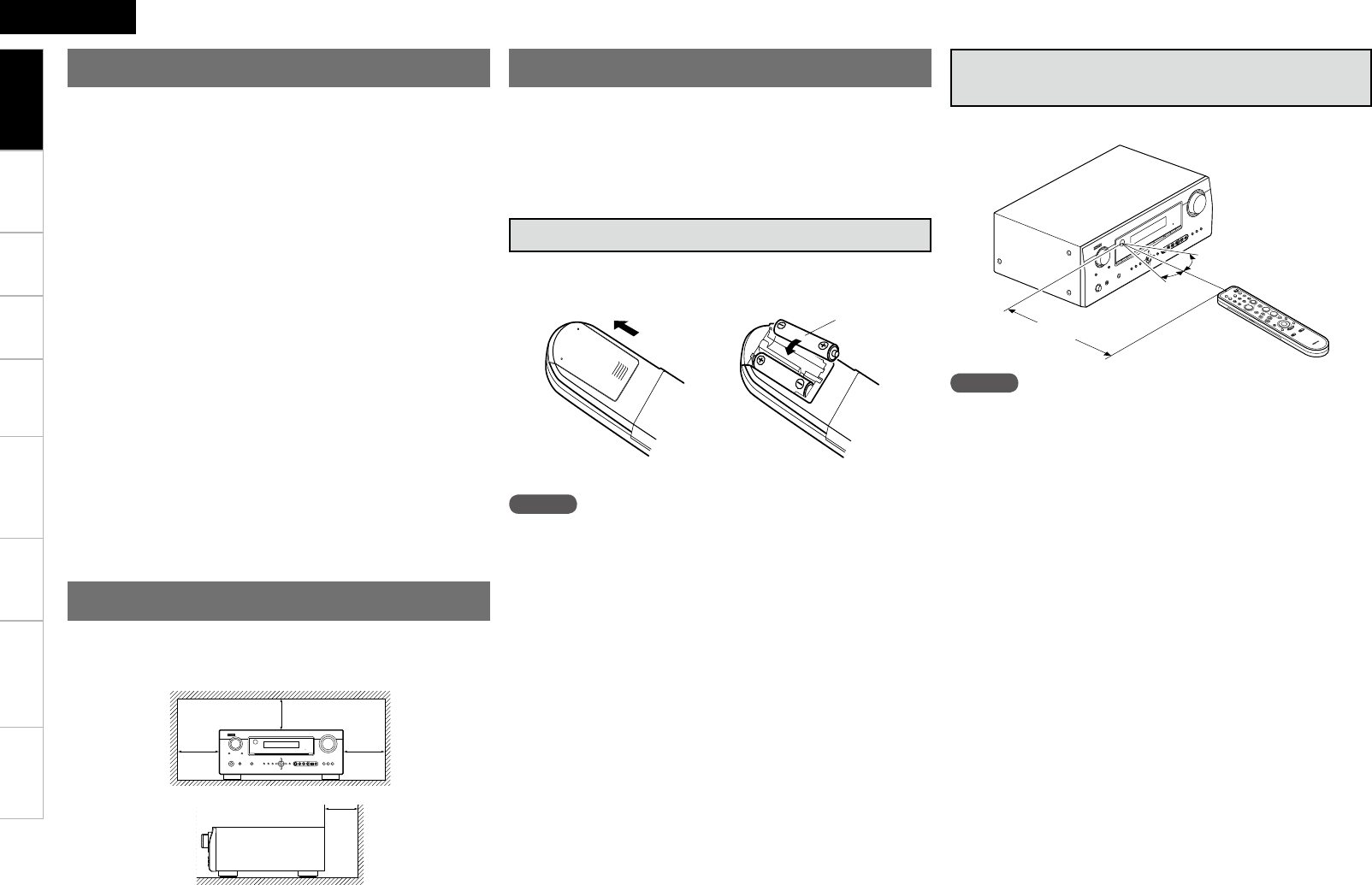
30°
30°
Approx. 23 feet / 7 m
Point the remote control unit at the remote sensor when operating it.
NOTE
The set may function improperly or the remote control unit may not
operate if the remote control sensor is exposed to direct sunlight,
strong artificial light from an inverter type fluorescent lamp or infrared
light.
NOTE
• Replace the batteries with new ones if the set does not operate
even when the remote control unit is operated close to the unit.
• The supplied batteries are only for verifying operation.
• When inserting the batteries, be sure to do so in the proper direction,
following the “q” and “w” marks in the battery compartment.
• To prevent damage or leakage of battery fluid:
• Do not use a new battery together with an old one.
• Do not use two different types of batteries.
• Do not attempt to charge dry batteries.
• Do not short-circuit, disassemble, heat or dispose of batteries in
flames.
• If the battery fluid should leak, carefully wipe the fluid off the inside
of the battery compartment and insert new batteries.
• Remove the batteries from the remote control unit if it will not be in
use for long periods.
• Used batteries should be disposed of in accordance with the local
regulations regarding battery disposal.
Operating Range of the Remote Control
Unit
• Before turning the power switch on
Check once again that all connections are correct and that there are
no problems with the connection cables.
• Power is supplied to some of the circuitry even when the unit is
set to the standby mode. When traveling or leaving home for long
periods of time, be sure to unplug the power cord from the power
outlet.
• About condensation
If there is a major difference in temperature between the inside of
the unit and the surroundings, condensation (dew) may form on
the operating parts inside the unit, causing the unit not to operate
properly.
If this happens, let the unit sit for an hour or two with the power
turned off and wait until there is little difference in temperature
before using the unit.
• Cautions on using mobile phones
Using a mobile phone near this unit may result in noise. If so, move
the mobile phone away from this unit when it is in use.
• Moving the unit
Turn off the power and unplug the power cord from the power
outlet.
Next, disconnect the connection cables to other system units before
moving the unit.
• Note that the illustrations in these instructions may differ from the
actual unit for explanation purposes.
Note:
For proper heat dispersal, do not install this unit in a confined
space, such as a bookcase or similar enclosure.
b Note
b
Wall
b
b
Cautions on Handling
Cautions on Installation
About the Remote Control Unit
Getting Started
e Put the rear cover back on.
q Lift the clasp and remove the
rear cover.
w Load the two batteries properly
as indicated by the marks in the
battery compartment.
R6/AA
Inserting the Batteries
Connections Playback Remote Control Information Troubleshooting Specifications
ENGLISH
Multi-ZoneSettings
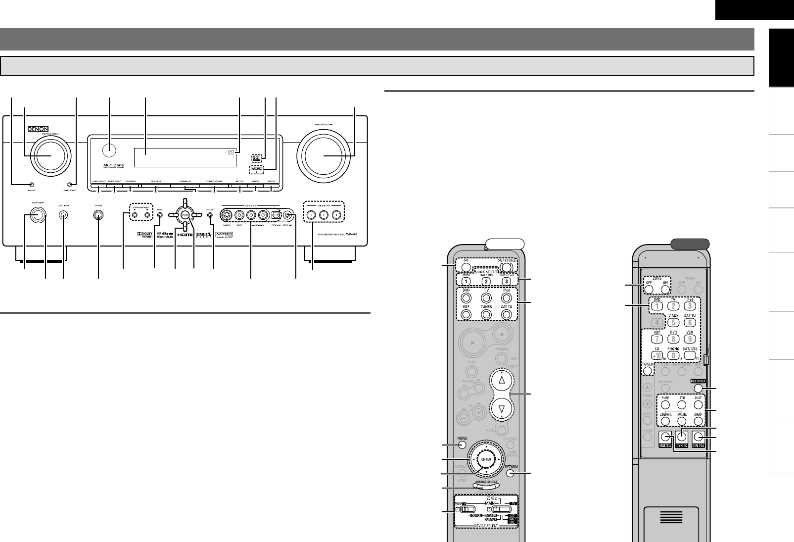
Part Names and Functions
Front Panel
q
e
o,Q0
Q1
u
o,Q0
i
y
r
o,Q0
Q0
t
w
Q2
Q4
Q3
Q5
q
Q7Q6
Q0 Q1 Q2 Q3 Q4 Q5 W9W8 E0
Q8
w e r t y
Q9 W0
u
i
W1W2W3W4W5W6
o
W7
i MASTER VOLUME control knob ··············· (40)
o SOURCE SELECT knob ······························ (19)
Q0 ZONE2 SELECT button ···························(54)
Q1 ZONE2 ON/OFF button ···························(54)
Q2 RESTORER button ······································ (50)
Q3 DYNAMIC EQ™ button ······························ (49)
Q4 DYNAMIC VOLUME™ button ··················· (49)
Q5 MULTEQ® button ·······································(48)
Buttons, terminals and displays only provided on the main unit
Button that function in the same way as remote control buttons
For buttons not explained here, see the page indicated in parentheses ( ).
q Power operation button
(ON/STANDBY) ·········································· (19)
w SURROUND MODE buttons ······················ (44)
e MENU button ·············································· (20)
r Cursor buttons (uio p) ························· (20)
t ENTER button ············································· (20)
y RETURN button ·········································· (20)
u QUICK SELECT buttons ····························· (53)
q
e
o,Q0
Q1
u
o,Q0
i
y
r
o,Q0
Q0
t
w
Q2
Q4
Q3
Q5
Front Rear
n Buttons that function in the same way as front panel buttons
W3 MASTER VOLUME indicator
W4 Display
W5 Remote control sensor ································ (3)
W6 TUNING PRESET button ···························· (42)
W7 SOURCE MODE SELECT button ··············· (19)
W8 FRONT SPEAKERS SELECT button ··········· (44)
W9 DIMMER button ·········································· (33)
E0 STATUS button ·········································· (51)
Q6 Power indicator ·········································· (19)
Q7 Power switch (hON jOFF) ··············· (19, 68)
Q8 Headphones jack (PHONES) ······················ (44)
Q9 V. AUX INPUT connectors ························· (16)
W0 SETUP MIC jack ·········································· (23)
W1 AUDYSSEY DYNAMIC VOLUME™
indicator ······················································ (49)
W2 HD AUDIO indicator ··································· (45)
Getting Started
Connections Playback Remote Control Information Troubleshooting Specifications
ENGLISH
Multi-ZoneSettings
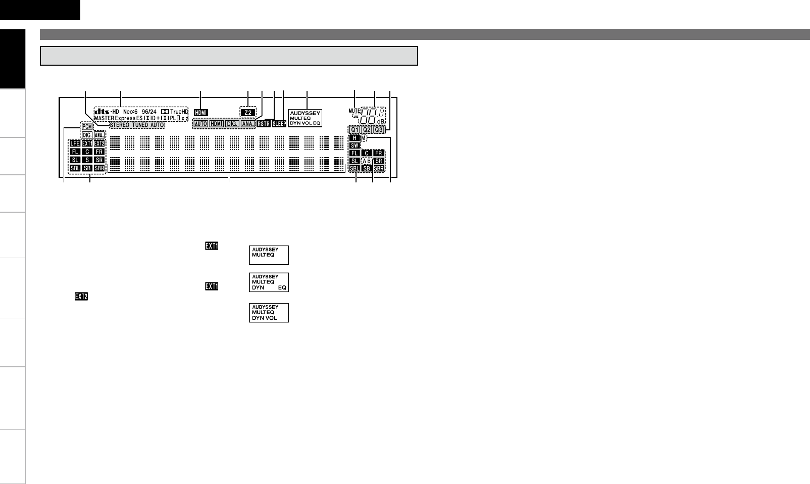
Part Names and Functions
ioQ5 Q0Q1
Q6 Q2Q4 Q3
Q7 u
wq e r t y
q Input audio signal indicators
w Input signal channel indicators
These light when digital signals are input.
When playing HD Audio sources, the“ ”
indicator lights when an extension channel (a
channel other than the front, center, surround,
surround back or LFE channel) is input. If there
are two or more extension channels, the “ ”
and “ ” indicators light.
e Information display
The input source name, surround mode, setting
values and other information are displayed
here.
r Output signal channel indicators
t Front speaker indicator
These light according to the settings of the
front A and B speakers (vpage 44).
y Monitor output indicators
These light according to the HDMI monitor
output setting.
u QUICK SELECT indicators
These light when the Quick Select function is
set (vpage 53).
i Master volume indicator
o MUTE indicator
Lights when the muting mode is set (vpage
44).
Q0 AUDYSSEY indicator
These light as shown below in the different
modes (vpage 48).
: During “MultEQ” operation
: During “MultEQ” , “Dynamic EQ”
operation
: During “MultEQ” , “Dynamic EQ”,
“Dynamic Volume” operation
b When speakers settings are changed after
Audyssey™ Auto Setup, either the indicators’
frame turns off or all the indicators turn off.
Q1 SLEEP TIMER indicator
Lights when the sleep timer is operating
(vpage 52).
Q2 RESTORER indicator
Lights during “RESTORER” operation (vpage
50).
Q3 Input mode indicators
Q4 ZONE2 indicator
Lights when signals are being output to the
ZONE2 (vpage 54).
Q5 HDMI indicator
Lights when HDMI input signals are detected
(vpage 13).
Q6 Decoder indicators
The indicator for the currently operating decoder
lights.
Display
Getting Started
Q7 Tuner reception mode indicators
This lights according to the reception conditions
when the input source is set to “TUNER”.
• AUTO
This lights when in the auto tuning mode.
• STEREO
In the FM mode, this lights when receiving
analog stereo broadcasts.
• TUNED
This lights when the broadcast is properly
tuned in.
Connections Playback Remote Control Information Troubleshooting Specifications
ENGLISH
Multi-ZoneSettings
q w e r t y
i uQ1Q2Q5Q6 o
Q0
Q3
Q4
Part Names and Functions
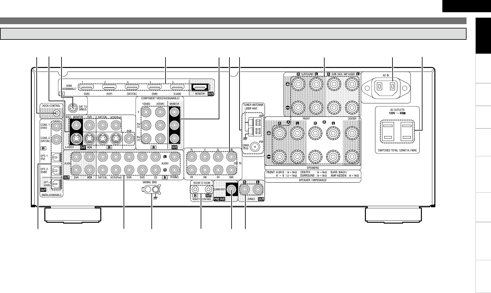
Rear Panel
q Digital audio connectors ···························(15)
w Analog audio connectors ··························(14)
e SIGNAL GND terminal ······························(15)
r REMOTE CONTROL jacks ·························(18)
t PRE OUT connector ···································(11)
y ZONE2 connectors ····································(54)
u AC OUTLETS ··············································(18)
i AC inlet (AC IN) ··········································(18)
o Speaker terminals ·····································(11)
Q0 FM/AM antenna terminals ·······················(17)
Q1 EXT. IN connectors ····································(16)
Q2 COMPONENT VIDEO connectors ·············(14)
Q3 HDMI connectors ·······································(13)
Q4 SIRIUS connector ······································(17)
Q5 VIDEO/S-VIDEO connectors ·····················(15)
Q6 Control dock for iPod
DOCK CONTROL jack ································(14)
Getting Started
Connections Playback Remote Control Information Troubleshooting Specifications
ENGLISH
Multi-ZoneSettings
Part Names and Functions
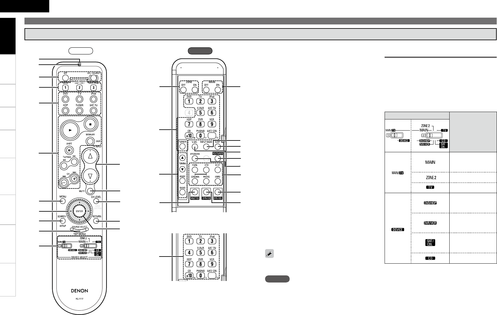
Remote Control Unit
q
w
e
r
t
y
u
o
Q0
t
i
Q1
Q2
Q3
Q4
Q5
Q6
Q7
t
Q8
W0
W1
W8
W7
W4
W5
W6
W2
W3
NOTE
Buttons on the back panel may operate when the
back lid is pressed.
q Remote control signal transmitter
w Indicator ····················································· (55)
e Power buttons ··········································· (19)
r QUICK SELECT buttons ···························· (53)
t SOURCE SELECT button ·························· (19)
y System buttons ········································· (55)
u MENU button ············································ (20)
i Cursor buttons (uio p) ························ (20)
o SEARCH button ········································· (41)
Q0 DEVICE SELECT switches ··················· (40, 55)
Q1 Master volume control buttons ··············· (40)
Q2 MUTING button ········································· (44)
Q3 Channel level adjustment button ············ (53)
Q4 RETURN button ········································· (20)
Q5 ENTER button ············································ (20)
Q6 ZONE2 power button ································ (54)
Q7 Tuner operation buttons ·························· (42)
Q8 MULTEQ® button ····································· (48)
Q9 Number buttons (0 ~ 9, +10) ···················· (55)
W0 MAIN ZONE power buttons ····················· (19)
W1 INPUT MODE button ································· (37)
W2 SLEEP TIMER button ································ (52)
W3 VIDEO SELECT button ······························ (36)
W4 RESTORER button ····································· (50)
W5 FRONT HEIGHT SPEAKER
ON/OFF button ·········································· (48)
W6 Surround mode buttons ··························· (44)
W7 DYNAMIC VOLUME™ button ·················· (49)
W8 DYNAMIC EQ™ button ····························· (49)
Q9
For buttons not explained here, see the page
indicated in parentheses ( ).
RearFront Operations Possible by Remote Control
Unit
Operations on the AVR-890
Operations on six devices other that
the AVR-890
Preset the remote control codes of the devices
to be operated (vpage 55).
Switch two device selector switches according
to the devices to be operated.
Position of switches
Operable devices
AVR-890
(MAIN ZONE)
iPod
AVR-890 (ZONE2)
TV
Blu-ray disc player
or
DVD Player
DVD recorder
or
Video deck
Satellite receiver
or
Cable TV
CD player
ZONE2 operations (vpage 54)
Punch through setting (vpage 57)
n
n
•
•
n
n
Getting Started
8
ENGLISH
Getting Started Playback Remote Control Information Troubleshooting Specifi cationsMulti-ZoneSettings
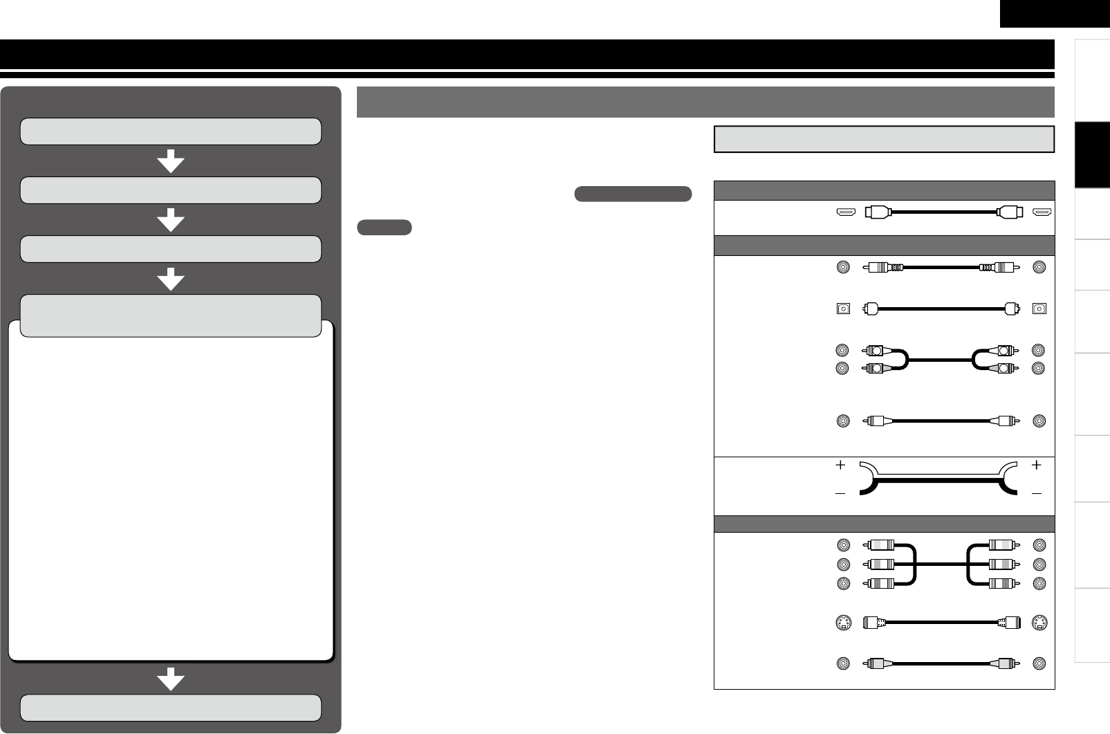
Connections for all compatible audio and video signal formats
are described in this owner’s manual. Please select the types of
connections suited for the equipment you are connecting.
After connections are completed, certain settings must be made on
the receiver. Make the settings indicated “Set as necessary ”
for the individual items.
Select the cables according to the equipment being connected.
Important Information
Cables Used for Connections
Audio and video cables
HDMI
connections HDMI cable
Audio cables
Coaxial digital
connections Coaxial digital cable
Optical digital
connections Optical cable
Analog
connections
R
L
R
L
Stereo pin-plug cable
Analog
connections
(monaural, for
subwoofer) Pin-plug cable
Speaker
connections
Speaker cables
Video cables
Component
video
connections
Component video cable
S-Video
connections S-Video cable
Video
connections 75 Ω/ohms pin-plug video cable
(White)
(Red)
n HDMI (vpage 12)
n Monitor (TV) (vpage 13)
n Playback Components
• Blu-ray Disc player / DVD player (vpage 14)
• iPod® (vpage 14)
• CD Player (vpage 14)
• Record Player (vpage 15)
n Recording Components
• Digital Video Recorder (vpage 15)
• Video Cassette Recorder (vpage 15)
n SAT/CABLE Tuner (vpage 16)
n Other Devices
• Video Camera / Game Console (vpage 16)
• Component with Multi-channel Output connectors
(vpage 16)
• SIRIUS Connector (vpage 17)
• Antenna terminals (vpage 17)
• External Controller (vpage 18)
n Power Cord (vpage 18)
Connection Flown
Turning the Power On (vpage 19)
Installing/Setting the Speakers (vpage 10)
Connecting Devices (vpage 12)
(Yellow)
(Green)
(Blue)
(Red)
Connections
NOTE
• Do not plug in the power cord until all connections have been
completed.
• When making connections, also refer to the operating instructions
of the other components.
• Be sure to connect the left and right channels properly (left with
left, right with right).
• Do not bundle power cords together with connection cables. Doing
so can result in humming or noise.
Connecting the Speakers (vpage 11)
Connecting Devices not Equipped with HDMI
terminals (vpage 13)
Connections
Getting Started Playback Remote Control Information Troubleshooting Specifications
ENGLISH
Multi-ZoneSettings
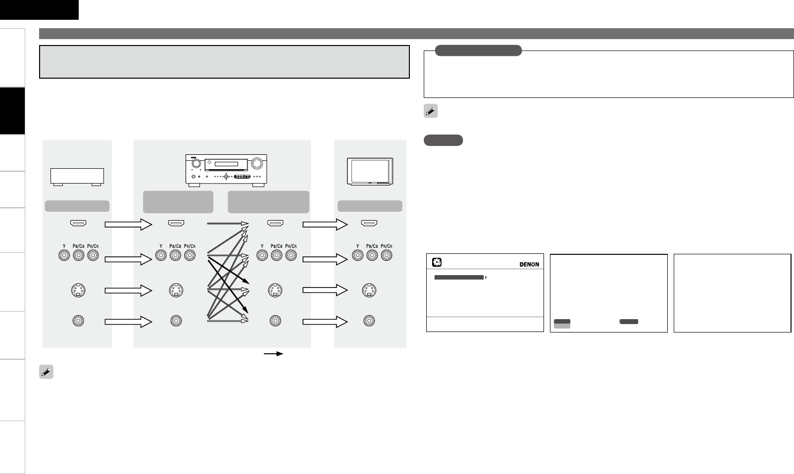
Converting Input video signals for Output
(Video Conversion Function)
The AVR-890 is equipped with four types of video input/output terminals (HDMI, Component video, S-
Video and video).
Use the terminals according to the devices to be connected.
This function automatically converts various formats of video signals input to the AVR-890 into the format
used to output the video signals from the AVR-890 to a monitor.
• The video conversion function supports the NTSC, PAL, SECAM, NTSC 4.43, PAL-N, PAL-M and PAL-60
formats.
• The resolution of the video signal input to the AVR-890’s HDMI terminal is the resolution set at
“Resolution” (vpage 36). (1080p HDMI signals and 1080p component signals are output at 1080p,
regardless of the setting.)
Important Information
Examples of GUI menu
Menu screen• Status display screen•
When the input source is
switched
When the volume is adjusted
M E N U
Audio/Video Adjust
Information
Auto Setup
Manual Setup
Input Setup
Adjust various audio and video parameters
I n p u t D V D A u t o
Mode STEREO
Master Volume -80.0dB
Status display: The operating status is displayed temporarily on the
screen when the input source is switched or the
volume is adjusted.
n
HDMI connector
Component video
connectors
S-Video connector
Video connector
Monitor
HDMI connector
Component video
connectors
S-Video connector
Video connector
HDMI connector
Component video
connectors
Video connector
HDMI connector
Component video
connectors
Video connector
Video device
AVR-890
Output Input
(IN)
Output
(MONITOR OUT) Input
S-Video connector S-Video connector
: When 480i/576i signals are input
Resolutions of HDMI-compatible TVs can be checked at “HDMI Information” (vpage 51).
NOTE
HDMI signals cannot be converted into analog signals.
When a non-standard video signal from a game machine or some other source is input, the video
conversion function might not operate.
480p/576p/1080i/720p/1080p component video input signals cannot be converted into S-Video or Video
format.
•
•
•
Set when using the video conversion function.
“Video Convert” (vpage 36)
Set when changing the resolution of the video signal.
“Resolution” (vpage 36)
•
•
Set as Necessary
Connections
0
ENGLISH
Getting Started Playback Remote Control Information Troubleshooting SpecificationsMulti-ZoneSettings
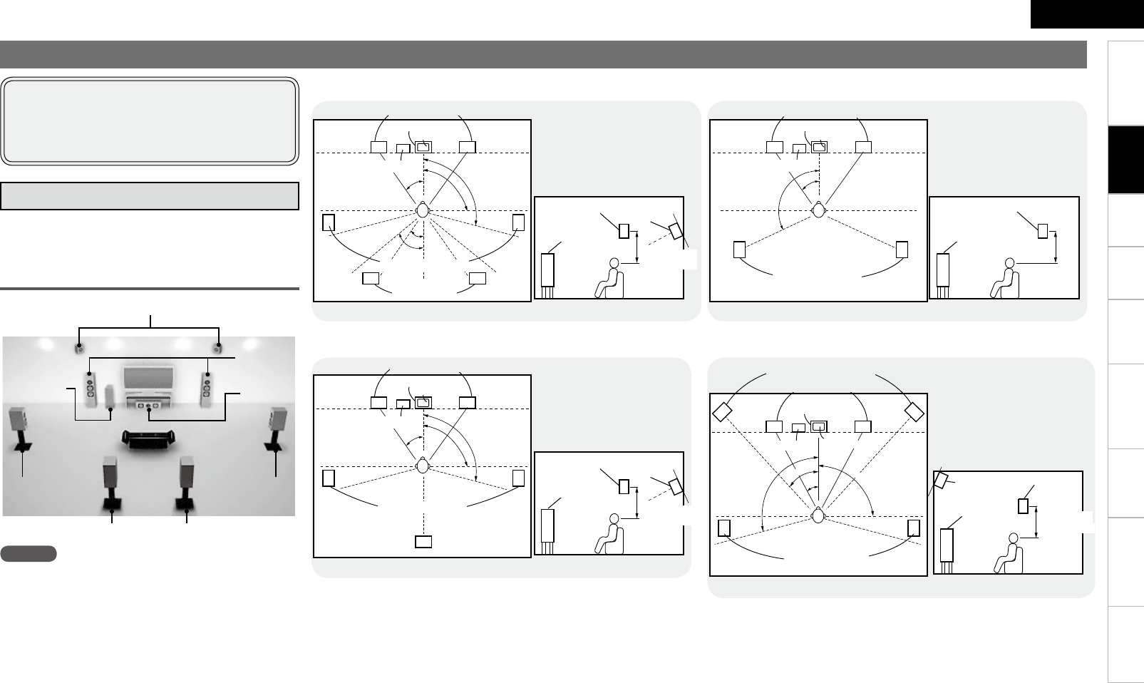
Installing/Setting the Speakers
NOTE
It is not possible to use the front height speakers and
surround back speakers simultaneously.
• The AVR-890 is compatible with various types of
surround playback.
• Decide on the surround modes to be played on
the AVR-890 before making connections and
settings.
Below we introduce examples of speaker layouts. Refer
to these to arrange your speakers according to their
type and how you want to use them.
Installing All the Speakers
Surround back speakers
Center
speaker
Front
speakers
Subwoofer
Front Height speakers
Surround
speaker
Surround
speaker
z1
z4
z5
z2
z3
Monitor
Center speaker
Subwoofer
GAs seen from aboveH
z1: 22 ~ 30˚
z2: 90˚
z3: 110˚
Surround back
speaker
GAs seen from the sideH
Surround speakers
Surround
speaker
Front
speaker 2 to 3 feet /
60 to 90 cm Point slightly
downwards
Surround back
speakers
Front speakers
When 7.1ch (Surround Back Speaker) Connectedn
z4: 30˚
z5: 45˚
z1
z2
z3
Front speakers
GAs seen from aboveH GAs seen from the sideH
Monitor
Center speaker z1: 22 ~ 30˚
z2: 90˚
z3: 110˚
Subwoofer
Surround speakers
Surround back
speaker
Front
speaker
Surround
speaker Surround back
speaker
Point slightly
downwards
2 to 3 feet /
60 to 90 cm
z1
z2
Surround speakers
Front speakers
Monitor
Center speaker
Subwoofer
z1: 22 ~ 30˚
z2: 120˚
Front
speaker
Surround
speaker
2 to 3 feet /
60 to 90 cm
GAs seen from aboveH GAs seen from the sideH
When 6.1ch Connectedn
When 5.1ch Connectedn
z4
z2
z1
z3
Front speakers
Subwoofer Monitor
Surround speakers
Center speaker
Front height speakers
GAs seen from aboveH
z1: 30˚
z2: 45˚
Surround
speaker
Front height
speaker
Point slightly
downwards
2 to 3 feet /
60 to 90 cm
GAs seen from the sideH
Front speaker
When 7.1ch (Front Height Speaker) Connectedn
z3: 90˚
z4: 110˚
a Determine the Speaker Layout
Connections
Getting Started Playback Remote Control Information Troubleshooting Specifications
ENGLISH
Multi-ZoneSettings
Protection circuit
If the core wires touch the rear panel and the screws
etc., or the ± sides touch each other, the protection
circuit will be activated and the power indicator will
flash red at intervals of 0.5 secs.
If the protection circuit is activated, the speaker
output is isolated, and the power supply goes to
the standby state. If the power supply is turned off,
after the power supply cord is withdrawn, please
confirm that speaker cable and input cable are
connected.
Also, if replaying large sound levels by using
a speaker having an impedance less than that
specified (eg, 4 Ω/ohms), the temperature will rise,
and the protection circuit might be activated. The
power supply will go into the standby state, and the
power indicator will flash red at 2 second intervals.
In this case, please switch off the power supply,
and wait until the AVR-890 has cooled down, and
the surrounding ventilation is good.
Even if there are no problems with the surrounding
ventilation and connections, in the event of the
protection circuit becoming activated, due to
thinking that the AVR-890 has failed, please contact
DENON Service center after switching off.
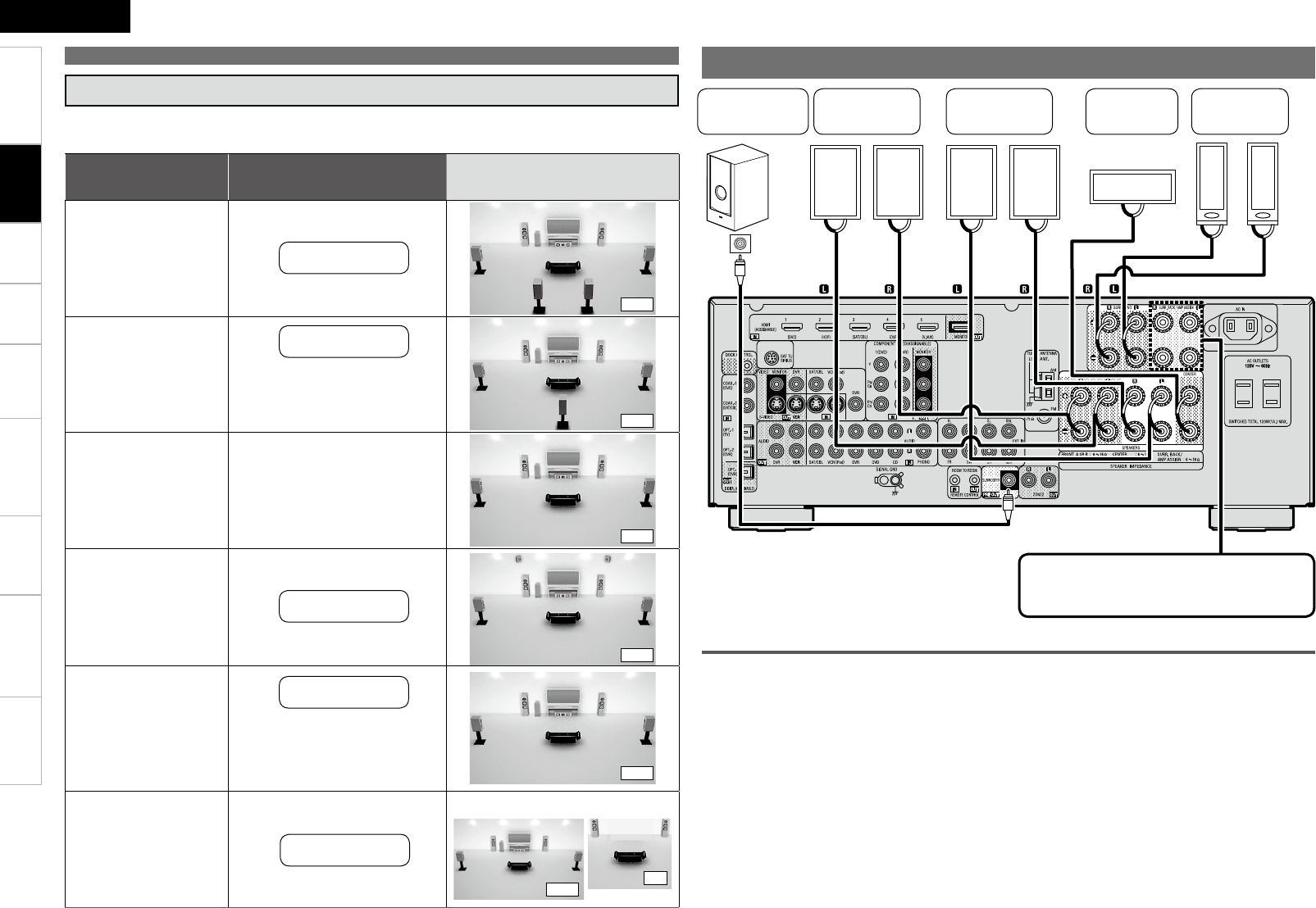
w q
w q w q
*/
(L) (R)
w qw q
(R) (L)
w qw q
(R) (L)
Subwoofer with
built-in amplifier
Center
speaker
Surround
speakers
Front speakers
A
Front speakers
B
For connections of the SURR. BACK/AMP
ASSIGN speaker terminals, see “Amp Assign”
(vpage 27).
Connecting the Speakers
s
Set the “Amp Assign” Mode According to the Speaker Layout
The signals output from the AVR-890’s SURR. BACK/AMP ASSIGN speaker terminals can be
switched to signals of the surround mode being used (vpage 27 “Amp Assign”).
Amp assign mode
(vpage 27)
SURR. BACK/AMP ASSIGN
Speaker connections Example of speaker installation
Normal
Normal
Normal
Front Height
Front A Bi-Amp
or
Front B Bi-Amp
ZONE2
(Default)
MAIN ZONE ZONE2
Front Height
speakers
Surround back
speakers
Surround back
speakers
Not connected
Front A or B
speakers
b For connections, see
“About bi-amp connections”
(vpage 12).
(7.1)
(6.1)
(5.1)
(7.1)
(5.1)
(5.1) (2)
b Connect to the “L” speaker
terminal.
b Set “S.Back” (vpage 28)
to “1spkr”.
b
Set the “S.Back” setting
(vpage 28) to “None”.
Installing/Setting the Speakers
ZONE2
speakers
Connections
2
ENGLISH
Getting Started Playback Remote Control Information Troubleshooting SpecificationsMulti-ZoneSettings
Connecting Devices
NOTE
• These functions will not work if the device connected to the HDMI
terminal does not support Deep Color or x.v.Color signal transfer or
the Auto Lip Sync function.
• The HDMI control function may not work depending on the device it
is connected to and its settings.
• You cannot operate a TV or Blu-ray Disc player / DVD player that is
not compatible with the HDMI control function.
Connecting Devices Equipped with
HDMI terminals
Important Information
n About HDMI
“HDMI” is the abbreviation of “High Definition Multimedia
Interface”. This interface allows transfer of digital video signals
and digital audio signals over a single HDMI cable.
n Functions usable with HDMI connections
Deep Color
Eliminates on-screen color banding, for smooth tonal transitions and
subtle gradations between colors.
x.v.Color
Enables displays with natural, vivid colors. “x.v.Color” is a Sony
registered trademark.
Auto Lip Sync (vpage 30)
HDMI 1.3 incorporates an automatic video/audio synching capability
that allows devices to perform this synchronization automatically with
total accuracy.
HDMI control function (vpage 30, 52)
This function allows you to operate external devices from the receiver
and operate the receiver from external devices.
“HDMI”, “HDMI logo” and “High-Definition Multimedia Interface”
are trademarks or registered trademarks of HDMI Licensing LLC.
NOTE
• Connect the speaker cables in such a way that they do not stick out
of the speaker terminals. The protection circuit may be activated if
the core wires touch the rear panel or if the + and – sides touch each
other (v“Protection circuit”).
• Never touch the speaker terminals while the power supply is
connected. Doing so could result in electric shock.
1 Peel off about 0.03 ft / 10 mm of sheathing
from the tip of the speaker cable, then either
twist the core wire tightly or terminate it.
2 Turn the speaker terminal counterclockwise
to loosen it.
3 Insert the speaker cable’s core wire to the hilt
into the speaker terminal.
4Turn the speaker terminal clockwise to tighten
it.
Use speakers with an impedance of 6 to 16 Ω/ohms. When using front
A and B speakers simultaneously, use speakers with an impedance of
12 to 16 Ω/ohms.
n When using a banana plug
Tighten the speaker terminal firmly before
inserting the banana plug.
Connecting the Speaker Cables
Carefully check the left (L) and right (R) channels and + (red) and –
(black) polarities on the speakers being connected to the AVR-890,
and be sure to interconnect the channels and polarities correctly.
wq wq
(R) (L)
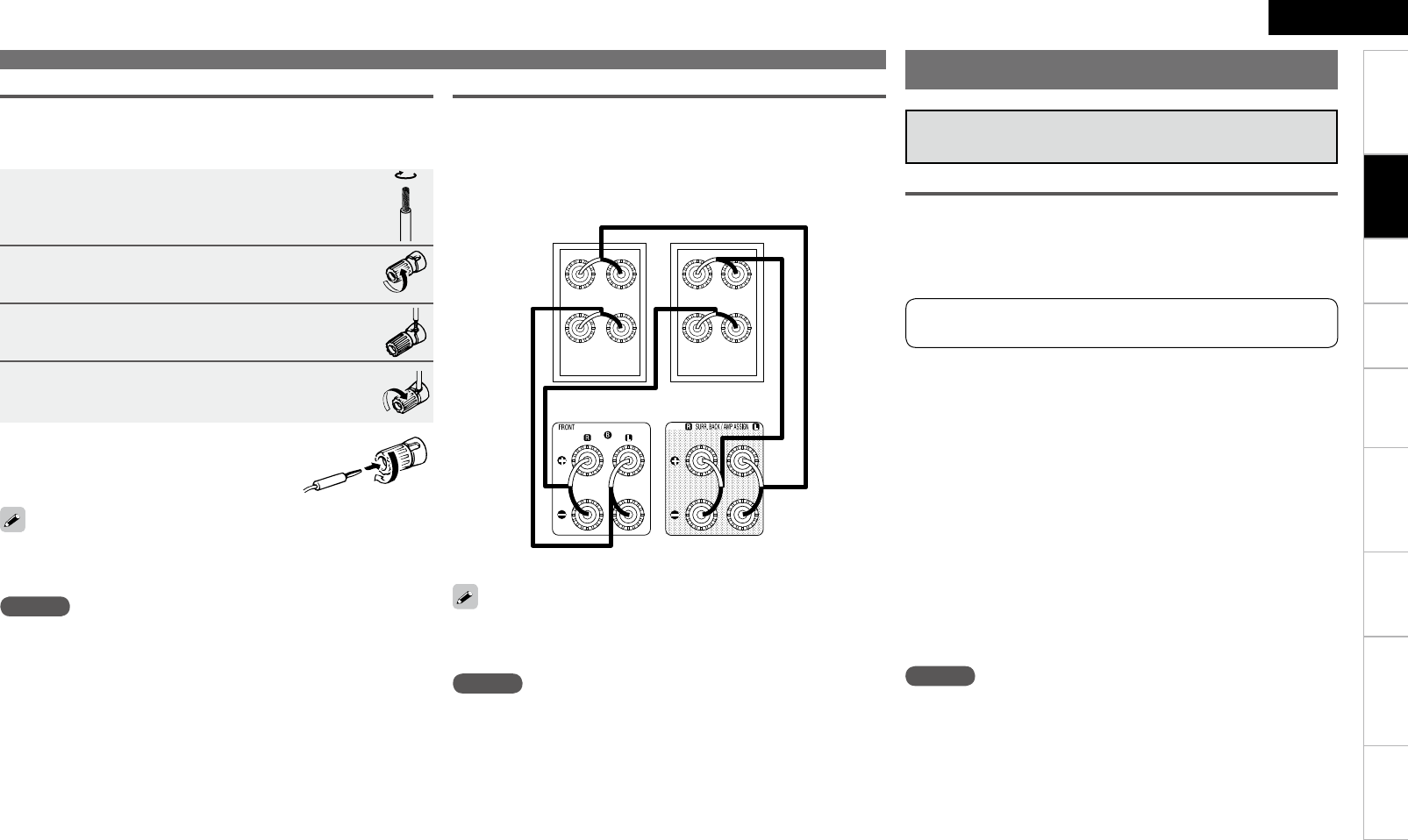
When in the “Front A Bi-Amp” and “Front B Bi-Amp” modes, the
same signals are output from the front speaker terminals and the AMP
ASSIGN terminals.
About Bi-amp Connections
These connections make for higher quality playback sound with no
interference between the signals of the bass and treble units.
When the amplifier assignment mode is set to “Front A Bi-Amp” or
“Front B Bi-Amp”, connect as shown below. (The illustration shows a
connection example for the front B Bi-Amp speakers.)
NOTE
• Use speakers compatible with bi-amp connections.
• When making bi-amp connections, be sure to remove the short-
circuiting plate or wire between the speaker’s woofer and tweeter
terminals.
Front speakers B
Connecting the Speakers
AVR-890
Connections
ENGLISH
Getting Started Playback Remote Control Information Troubleshooting SpecificationsMulti-ZoneSettings
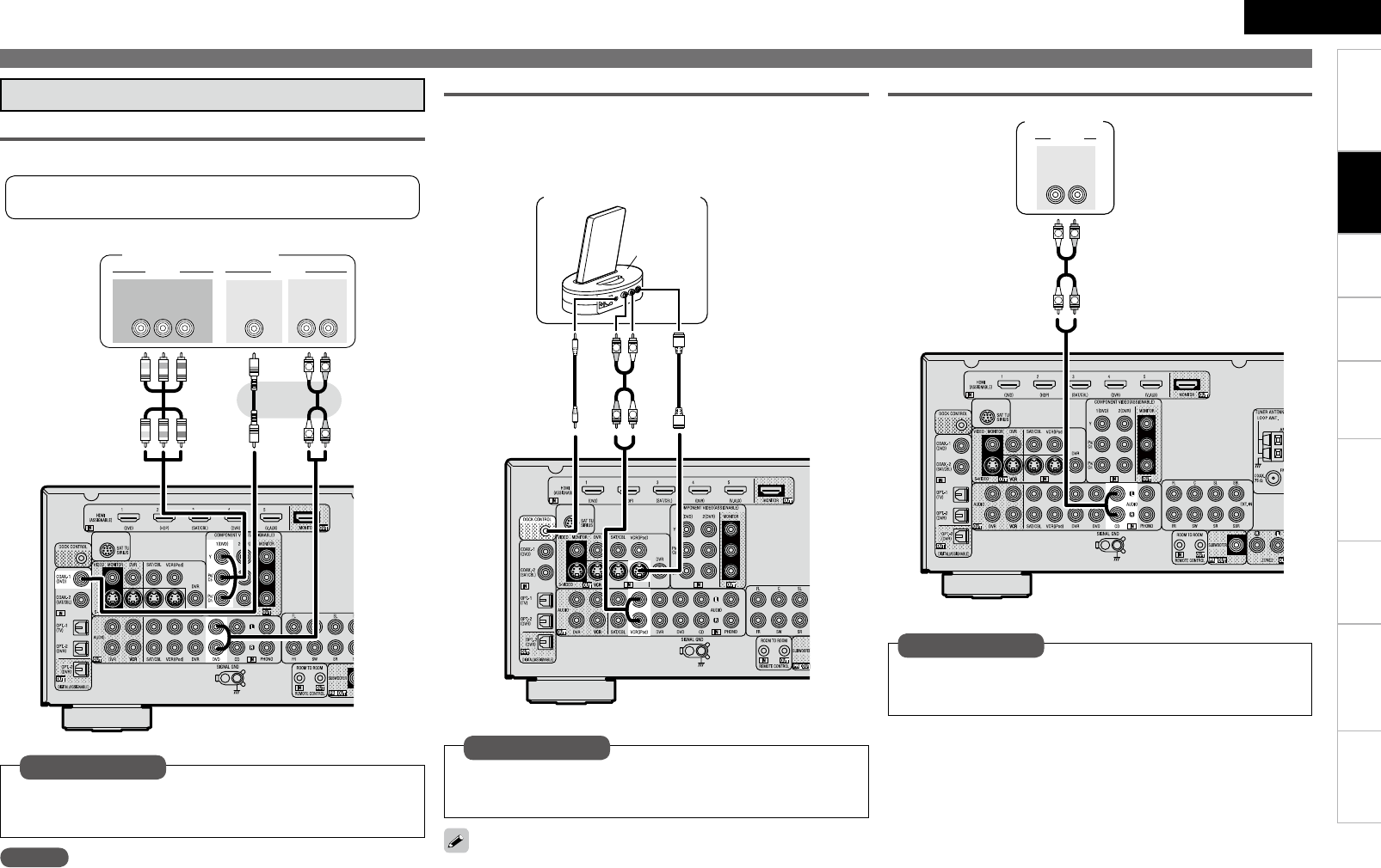
• Select the terminal to use and connect the device.
• For video connections, see “Converting input video signals for output
(Video Conversion Function)” (vpage 9).
*/
7*%&0
$0.10/&/57*%&0
: 1#13
7*%&0
*/
"6%*0
015*$"-
065
47*%&0
*/
Monitor (TV)
The component video connectors may be indicated differently on your
monitor. For details, see the monitor’s operating instructions.
Monitor (TV)
For instructions on HDMI connections, see “Connecting Devices
Equipped with HDMI terminals” on page 12.
Connecting devices
NOTE
• If the menu “HDMI Audio Out” setting (vpage 30) is set to
“Amp”, the sound may be interrupted when the monitor’s power is
turned off.
• The audio signal from the HDMI output terminal (sampling
frequency, number of channels, etc.) may be limited by the HDMI
audio specifications of the connected device regarding permissible
inputs.
• Use a cable on which the HDMI logo is indicated (a certified HDMI
product) for connection to the HDMI connector. Normal playback
may not be possible when using a cable other than one on which the
HDMI logo is indicated (a non-HDMI-certified product).
• When the AVR-890 is connected to other devices with HDMI cables,
also connect the AVR-890 and TV using an HDMI cable.
• When a device supporting Deep Color signal transfer is connected,
use a cable compatible with HDMI ver.1.3a.
• Video signals are not output if the input video signals do not match
the monitor’s resolution. In this case, switch the Blu-ray Disc player /
DVD player’s resolution to a resolution with which the monitor is
compatible.
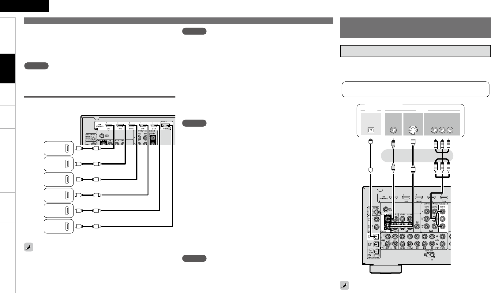
The AVR-890 allows connection of inputs from up to 5 HDMI
devices and output to 1 TV.
065
)%.*
065
)%.*
065
)%.*
065
)%.*
065
)%.*
*/
)%.*
Blu-ray
Disc Player
Digital Video
Recorder
Monitor
(TV)
Connections
NOTE
• No sound is output when connected to a device equipped with a
DVI-D terminal. Also make the audio connections.
• Signals cannot be output to DVI-D devices that do not support
HDCP.
• Depending on the combination of devices, the video signals may not
be output.
n Connecting to a device equipped with a DVI-D
terminal
When an HDMI/DVI conversion cable (sold separately) is used, the
HDMI video signals are converted to DVI signals, allowing connection
to a device equipped with a DVI-D terminal.
NOTE
The audio signals output from the HDMI connectors are only the
HDMI input signals.
n Settings related to HDMI connections
Set as necessary. For details, see the respective reference pages.
Input Assign (vpage 35)
Set this when changing the input sources of the different terminals.
HDMI Setup (vpage 30)
Make these settings related to HDMI input/output signals.
• RGB Range
• Auto Lip Sync
• HDMI Audio Out
• HDMI Control
• Standby Source
• Power Off Control
Connecting Devices not
Equipped with HDMI terminals
Game
Console
SAT/CABLE
Tuner
DVD
Player
NOTE
When a device that does not support HDCP is connected, video
signals are not properly output.
n Copyright protection system (HDCP)
The AVR-890 supports HDCP (High-bandwidth Digital Contents
Protection). HDCP is a copyright protection technology for digital video
signals. The devices connected to the AVR-890 must also support
HDCP.
Connections
ENGLISH
Getting Started Playback Remote Control Information Troubleshooting SpecificationsMulti-ZoneSettings
Connecting Devices not Equipped with HDMI terminals
R
L
R
L
"6%*0
"6%*0
3-
065
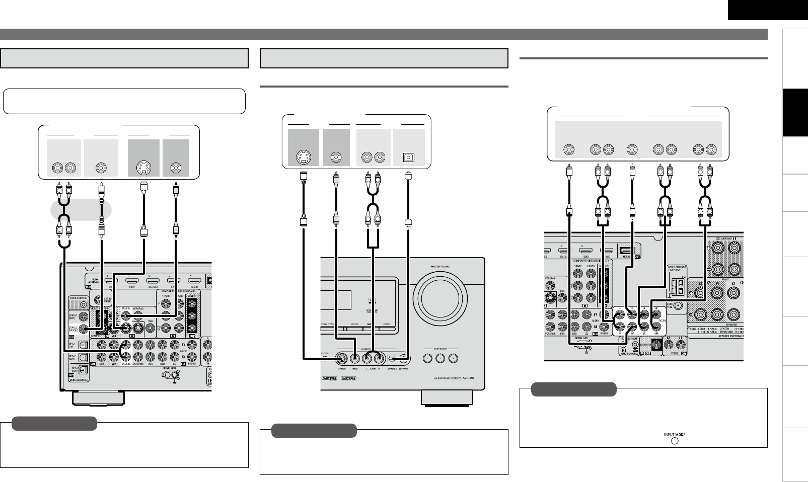
CD Player
CD Player
Set this to change the input signal to which the input source
is assigned.
“Input Assign” (vpage 35)
Set as necessary
R
L
R
L
7*%&0
$0.10/&/57*%&0
: 1#13
065
"6%*0
"6%*0
3-
065
065
$0"9*"-
Blu-ray Disc player /
DVD player
NOTE
When connected to a Blu-ray Disc player, and playing Dolby
TrueHD, DTS-HD, Dolby Digital Plus, connect the HDMI.
Set this to change the input signal to which the input source
is assigned.
“Input Assign” (vpage 35)
Set as necessary
Playback Components
Blu-ray Disc player / DVD player
Select the terminal to use and connect the device.
RL
RL
Control dock for iPod
With the default settings, the iPod can be used connected to the VCR
(iPod) connector.
Set this to assign the iPod to a terminal other than “VCR
(iPod)”.
“iPod Dock” (vpage 35)
Set as necessary
Control dock for iPod®
Use a DENON control dock for iPod (ASD-1R, ASD-11R, ASD-3N or
ASD-3W sold separately) to connect the iPod to the AVR-890. For
instructions on the control dock for iPod settings, refer to the control
dock for iPod’s operating instructions.
ASD-3N or
ASD-3W
For instructions on HDMI connections, see “Connecting Devices
Equipped with HDMI terminals” on page 12.
Connections
ENGLISH
Getting Started Playback Remote Control Information Troubleshooting SpecificationsMulti-ZoneSettings
(/% "6%*0
065
R
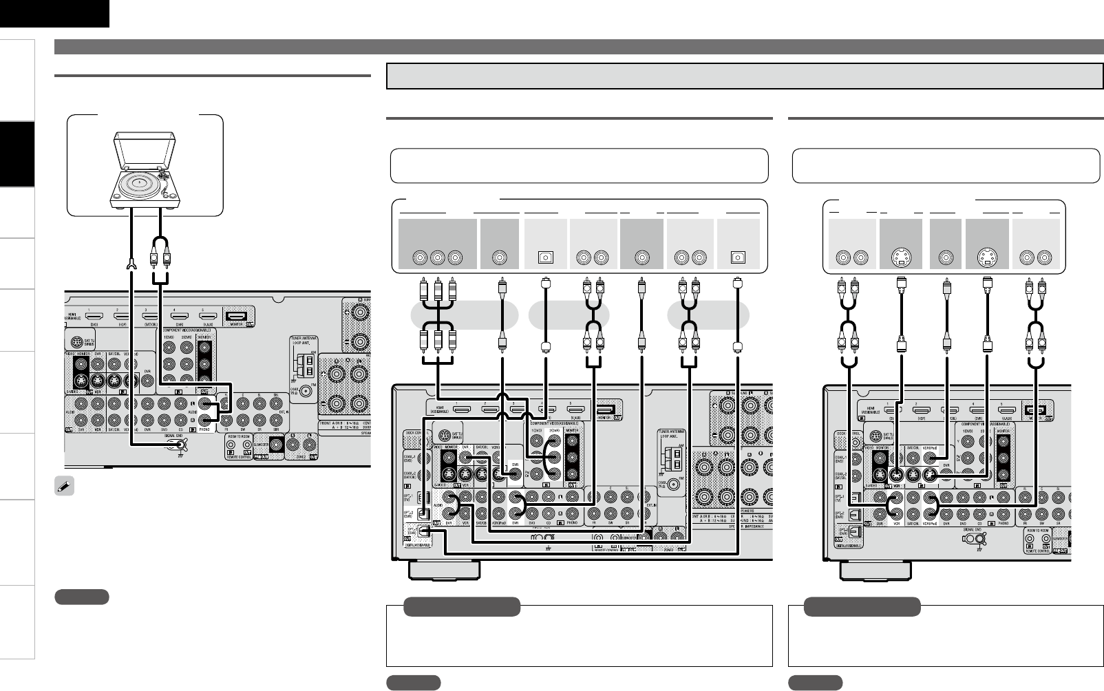
L
Turntable
(MM cartridge)
Record Player
The AVR-890 is compatible with record players with an MM
cartridge. When you connect to a record player with an MC
cartridge, use a commercially available MC head amp or a step-
up transformer.
When you increase the volume without connecting the record
player, there may be “booming” noise from the speakers.
•
•
NOTE
The SIGNAL GND terminal of the AVR-890 is not a safety ground
connection. Connect it to reduce noise when noise is excessive.
Note that depending on the record player, connecting the ground
line may have the reverse effect of increasing noise. In this case,
it is not necessary to connect the ground line.
Recording Components
R
L
R
L
R
L
R
L
3- 3-
065 */
"6%*0"6%*0 7*%&07*%&0
065 */
015*$"-015*$"-
*/
"6%*0"6%*0
065
7*%&0 7*%&0
$0.10/&/57*%&0
: 1#13
065
DVD Recorder
NOTE
• To record video signals through the AVR-890, use the same type of video
cable for connection between the AVR-890 and the player as the cable used
for connection between the AVR-890 and the recorder.
• Do not connect the output of the component connected to the AVR-890’s
OPTICAL2 output connector to any input connector other than OPTICAL2.
• Digital signals are not output from the analog REC OUT connector.
Set this to change the input signal to which the input source is
assigned.
“Input Assign” (vpage 35)
Set as necessary
Digital Video Recorder
Select the terminal to use and connect the device.
3-
065065
"6%*07*%&0
"6%*0 7*%&0
"6%*0
3-
*/
"6%*0 7*%&0 47*%&0
065
47*%&0
*/
R
L
R
L
R
L
R
L
Video cassette recorder
NOTE
• To record video signals through the AVR-890, use the same
type of video cable for connection between the AVR-890 and
the player as the cable used for connection between the AVR-
890 and the recorder.
• Digital signals are not output from the analog REC OUT
connector.
Set this to change the input signal to which the input
source is assigned.
“Input Assign” (vpage 35)
Set as necessary
Video Cassette Recorder
Select the terminal to use and connect the device.
For instructions on HDMI connections, see “Connecting Devices Equipped
with HDMI terminals” on page 12.
For instructions on HDMI connections, see “Connecting
Devices Equipped with HDMI terminals” on page 12.
Connecting Devices not Equipped with HDMI terminals
Connections
ENGLISH
Getting Started Playback Remote Control Information Troubleshooting SpecificationsMulti-ZoneSettings
065
"6%*0 7*%&0
7*%&0"6%*0
3-
065 065
$0"9*"- 47*%&0
065
R
L
R
L
SAT/CABLE Tuner
SAT/CABLE Tuner
Connecting Devices not Equipped with HDMI terminals
Set this to change the input signal to which the input source
is assigned.
“Input Assign” (vpage 35)
Set as necessary
Select the terminal to use and connect the device.
For instructions on HDMI connections, see “Connecting Devices
Equipped with HDMI terminals” on page 12.
R
L
R
L
065
"6%*07*%&0
7*%&0 "6%*0
3-
065 065
015*$"-
47*%&0
065
Video camera /
Game console
Other Devices
Video Camera / Game Console
R
L
R
L
R
L
R
L
R
L
R
L
46#
800'&3
$&/5&3 463306/%
#"$,
3-
463306/%
3-
'30/5
3-
"6%*0
Blu-ray Disc player / DVD player /
External decoder
To play analog signals input from the external input (EXT. IN)
terminal, set “Input Mode” (vpage 37) on the menu to “EXT.
IN”.
“EXT. IN” can also be selected with .
Set as necessary
Component with Multi-channel Output connectors
The video signal can be connected in the same way as a Blu-ray Disc
player / DVD player (vpage 14).
Set this to change the input signal to which the input source
is assigned.
“Input Assign” (vpage 35)
Set as necessary
Connections
Getting Started Playback Remote Control Information Troubleshooting Specifications
ENGLISH
Multi-ZoneSettings
Connecting Devices not Equipped with HDMI terminals
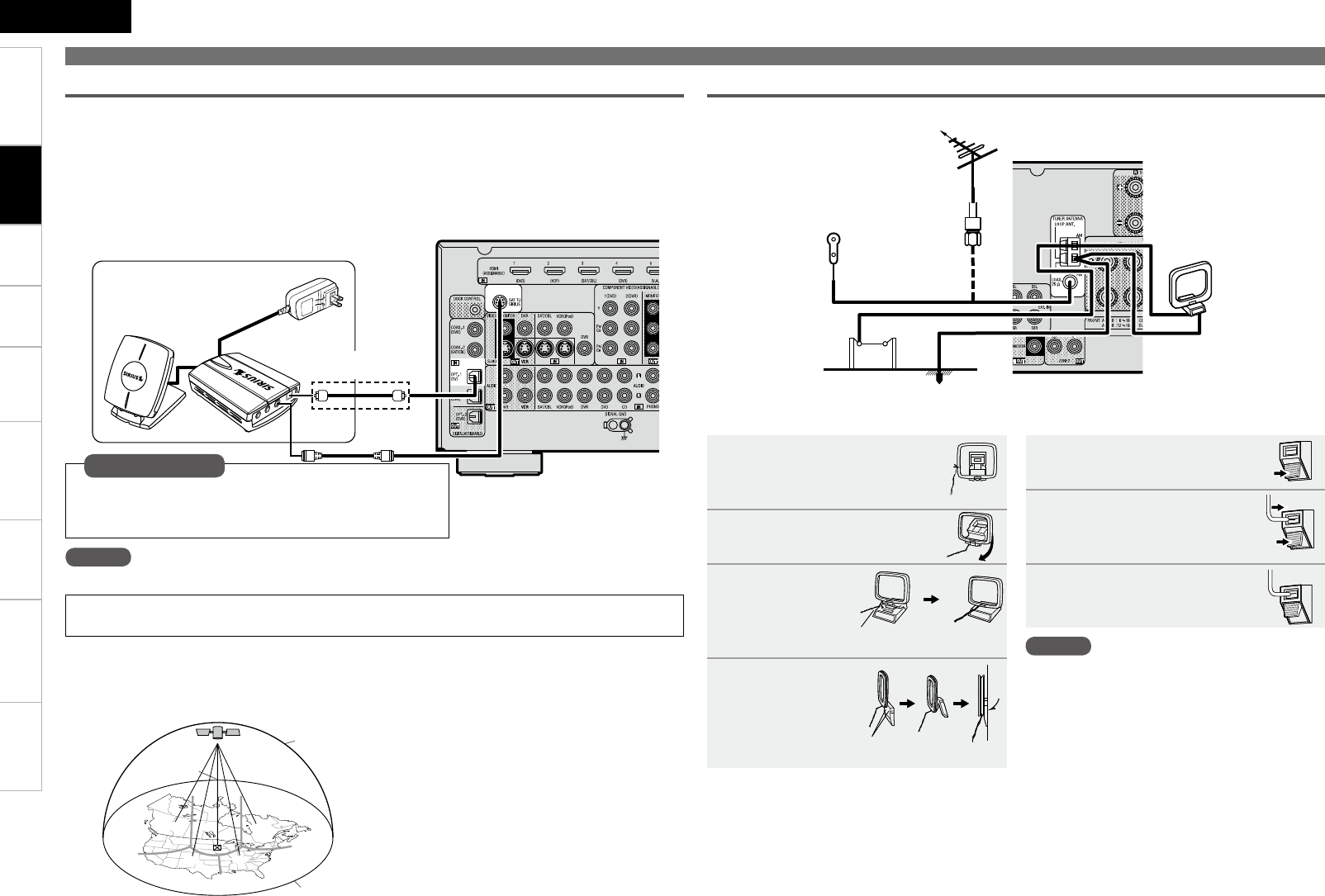
SIRIUSConnect Home Tuner
SIRIUS Connector
• The AVR-890 is a SIRIUS Satellite Radio Ready® receiver. You can receive SIRIUS® Satellite Radio by
connecting to the SiriusConnect Home Tuner and subscribing to the SIRIUS service.
• Plug the SIRIUS connector on the rear panel.
• Position the Home Tuner antenna near a south-facing window to receive the best signal.
For details, see “Listening to SIRIUS Satellite Radio Programs” (vpage 42, 43).
When making connections, also refer to the operating instructions of the SiriusConnect Home Tuner.
NOTE
Keep the power cord unplugged until the SiriusConnect Home Tuner connection have been completed.
“SIRIUS, XM and all related marks and logos are trademarks of Sirius XM Radio Inc. and its subsidiaries.
All rights reserved. Service not available in Alaska and Hawaii.”
n Positioning the Antenna
For a consistent satellite signal, the antenna must be positioned correctly. Use the following map to
determine which area you are in and position the antenna accordingly.
q
we
r
t
SOUTH
NORTH
WEST
SKY
EAST
HORIZON
Area 1 : Point the antenna toward the sky in the east,
northeast, or southeast, either through a
window or outside.
Area 2 : Point the antenna toward the sky in the north
or northeast, either through a window or
outside.
Area 3 : Point the antenna toward the sky in the north
or northwest, either through a window or
outside.
Area 4 : Point the antenna toward the sky in the west,
northwest, or southwest, either through a
window or outside.
Area 5 : Put the antenna outside and point it straight
up. The antenna cannot be used indoors.
b When connecting
digital audio
Direction of broadcasting station
AM loop
antenna
(supplied)
FM antenna
75 Ω/ohms
Coaxial cable
FM indoor antenna
(supplied)
Ground
AM outdoor antenna
Antenna terminals
n AM loop antenna assembly
1Remove the vinyl tie and take
out the connection line.
2Bend in the reverse direction.
3
With the antenna
on top of any
stable surface.
3
With the antenna
attached to a wall.
-1
-2
Mount
Installation hole Mount on wall, etc.
1Push the lever.
2Insert the conductor.
3Return the lever.
n Connection of AM antennas
NOTE
• Do not connect two FM antennas
simultaneously.
• Even if an external AM antenna is used, do not
disconnect the AM loop antenna.
• Make sure the AM loop antenna lead terminals do
not touch metal parts of the panel.
Set this to change the input signal to which the input
source is assigned.
“Input Assign” (vpage 35)
Set as necessary
Connections
8
ENGLISH
Getting Started Playback Remote Control Information Troubleshooting SpecificationsMulti-ZoneSettings
Connecting Devices not Equipped with HDMI terminals
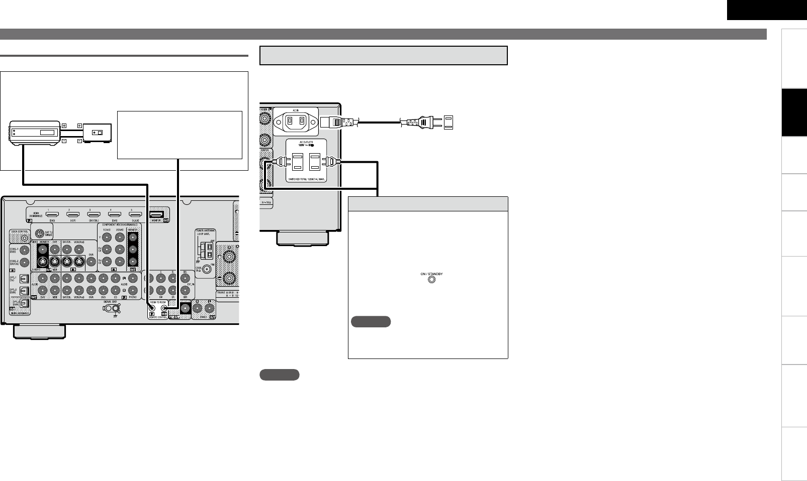
REMOTE CONTROL jacksn
"69
065
External Controller
Extension jack for future use.
(Connect devices corresponding
with room to room function to
this jack.)
Infrared
retransmitter
Input Output
Infrared
sensor
NOTE
• Insert the AC plugs securely. Incomplete connections could cause
noise.
• Only use the AC outlets to plug in audio equipment. Do not use
them as power supplies for hairdryers or anything other than audio
equipment.
Wait until all connections have been completed before connecting the
power cord.
To household
power outlet
(AC 120 V, 60 Hz)
Power cord
(included)
Connection to the AC outlets
• These outlets supply power to external
audio equipment.
• Audio equipment with a total power
consumption of 120 W (1 A) can be
connected.
• The power supply turns on and off
together with the on the main unit.
When set to “ON”, power is supplied from
the outlet. When set to “STANDBY”, no
power is supplied.
NOTE
When “HDMI Control” (vpage 30) is
set to “ON”, power is supplied constantly
to the AC outlet (UNSWITCHED).
Connecting the Power Cord
Connections
ENGLISH
Getting Started Playback Remote Control Information Troubleshooting Specifi cationsMulti-ZoneSettings
Once Connections are
Completed
Turning the Power On
1Press .
The power indicator lights red and the
power is set to the standby mode.
2Press .
The power indicator fl ashes green and the
power turns on.
b Also press when in standby
mode, the power turns on.
When has been pressed, the input source set with the
is set. If a has been pressed, the input source
stored in the memory for the quick select function is set (vpage
53 “Saving frequently used settings (Quick Select Function)”).
NOTE
• Power continues to be supplied to some of the circuitry even when
the power is in the standby mode. When leaving home for long
periods of time or when traveling, either press to turn off the
power, or unplug the power cord from the power outlet.
• When the ZONE2 power is switched on, and you want to switch off
the MAIN ZONE power, press .
1Press .
The power is set to the standby mode.
2Press .
The power indicator turns off, and so does
the power.
This operation can also be performed by pressing a on
the main unit.
Front
Front
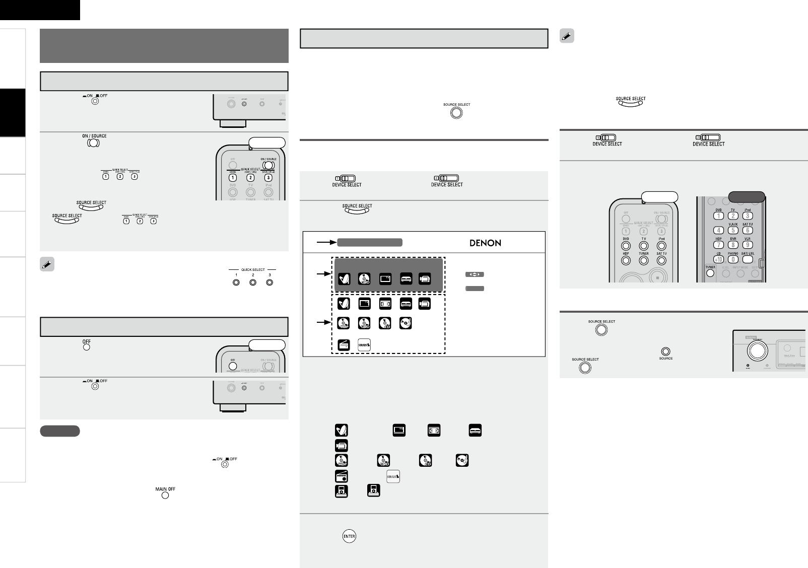
Selecting the Input Source
There are three ways to select the input source, as described below.
q Selecting the input source using the Source Select menu (GUI
menu)
w Selecting the input source using the SOURCE SELECT button
(Remote control unit)
e Selecting the input source using the (Main unit)
q Using the Source Select Menu
The input source can also be selected using the source selection
menu.
1Set to “MAIN/TV” to “MAIN”.
2Press .
Display the “Source Select” menu.
q Input Source : The name of the highlighted input source is
displayed.
w Recently used sources : The currently selected input source is
highlighted.
e Icons for the input sources in the different categories are
displayed.
Video : (SAT/CBL), (TV), (VCR), (DVR),
(V.AUX)
Player : (HDP), (DVD), (CD), (PHONO)
Tuner : (TUNER), (SIRIUS)
iPod : b “ ” is displayed when using a control dock for
iPod.
3Use uio p to select the input source icon, then
press .
The input source is set and the source selection menu is turned
off.
SOURCE SELECT :SAT/CBL
Recent Source
Enter
Select
ENTER
SOURCE SELECT :SAT/CBL
Recent Source
Enter
Select
ENTER
q
w
e
Use the device selection buttons on the remote control unit to set
the device to be operated beforehand.
Input sources that are not going to be used can be set ahead of time.
Make this setting at “Source Delete” (vpage 32).
To turn off the source selection menu without selecting an input
source, press again.
•
•
•
1Set to “MAIN/TV” to “MAIN”.
2Press the SOURCE SELECT button (vpage 7).
The desired input source can be selected directly.
e Operating on the Main Unit
w Operating on the Remote Control Unit
Rear
Front
Turn .
b If “Tuning Preset” mode is selected for
the input source, press before turning
.
Turning the Power Off
Connections
20
ENGLISH
Getting Started Connections Playback Remote Control Information Troubleshooting SpecificationsMulti-Zone
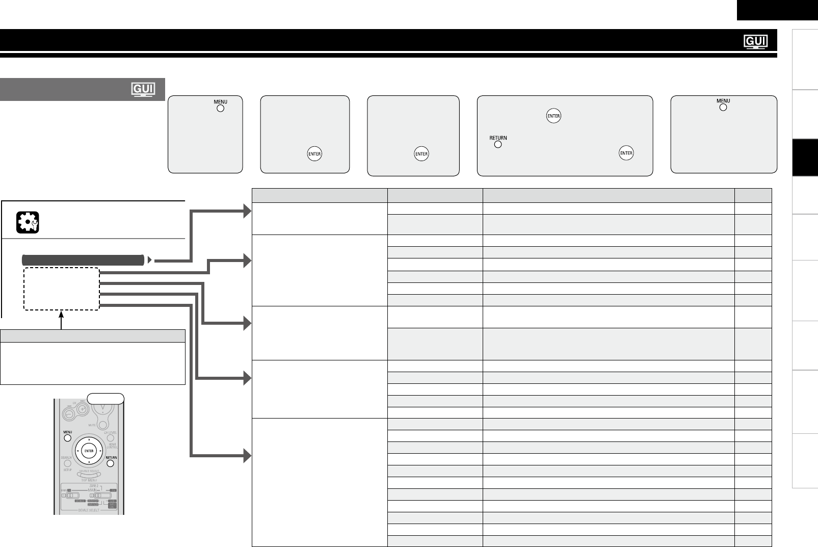
With the AVR-890, settings and operations for most functions can be performed by operating while looking at the menus displayed on the monitor screen.
M E N U
Audio/Video Adjust
Information
Auto Setup
Manual Setup
Input Setup
Adjust various audio and video parameters
1 Press .
The menu is
displayed.
3 Press ui to
select the item
you want to
set, then press
p or .
4 Use uio p to select the item,
then press to set.
b To return to the previous item, press o or
.
b Select “Default Yes”, then press to
reset to the default setting.
5 Press .
The settings made up to
that point are entered and
the settings menu screen
turns off.
2 Press ui to
select the item
you want to
set, then press
p or .
⇩
⇩
⇩
⇩
Items that only need to be set once
Set these for example upon purchase.
Once these items are set, there is no need to
set them again unless the speaker layout or the
connected speakers have been changed.
n Operations
Setting menusn
Setting items Detailed items Description Page
Audio/Video Adjust
Adjust various audio/video
parameters.
Audio Adjust Adjust various audio parameters. 46
Picture Adjust Adjust various video parameters. 51
Information
Show information about receiver
settings, input signals, etc.
Status Shows information about current settings. 51
Audio Input Signal Shows information about audio input signals. 51
HDMI Information Displays the HDMI input/output signals and TV information. 51
Auto Surround Mode Displays the settings stored for the auto surround mode. 51
Quick Select Displays the settings stored for the Quick Select function. 51
Preset Channel Shows information about preset channels. 51
Auto Setup
Makes the optimum speaker
settings and corrects for the acoustic
characteristics of the room.
Audyssey™ Auto
Setup
Makes the optimum settings for the speakers being used
automatically.
22
Parameter Check Check Audyssey Auto Setup measurement results.
This item is only displayed after Audyssey Auto Setup has been
performed.
26
Manual Setup
Use this to make various types of
detailed settings.
Speaker Setup Sets the speaker size and distance, the channel level, etc. 27
HDMI Setup Make settings for HDMI video/audio output. 30
Audio Setup Make settings for audio playback. 30
ZONE2 Setup Make settings for audio playback in a ZONE2 system. 31
Option Setup Make various other settings. 32
Input Setup
Use this to make settings related to
playing input sources.
Input Assign Change input connector assignment. 35
Video Makes the video settings. 36
Input Mode Sets the audio input mode and decode mode. 37
Rename Change the display name for this source. 37
Source Level Adjust the playback level of the audio input. 38
iPod Playback Mode Make settings for iPod playback. 38
Auto Preset Use the auto preset function to program radio stations. 38
Preset Skip
Set the preset memories that you do not want to display when tuning.
38
Preset Name Assign name to a preset memory. 38
Parental Lock Set the channel radio reception limits. 39
Antenna Aiming Check the SIRIUS radio reception sensitivity. 39
Front
Settings
Menu Map
Settings
2
ENGLISH
Getting Started Connections Playback Remote Control Information Troubleshooting SpecificationsMulti-Zone
M E N U
Audio/Video Adjust
Information
Auto Setup
Manual Setup
Input Setup
Adjust various audio and video parameters
INPUT SETUP
RENAME
D V D D V D
Default
Input ENTER Enter RETURN Cancel
A/a/!/0
SEARCH
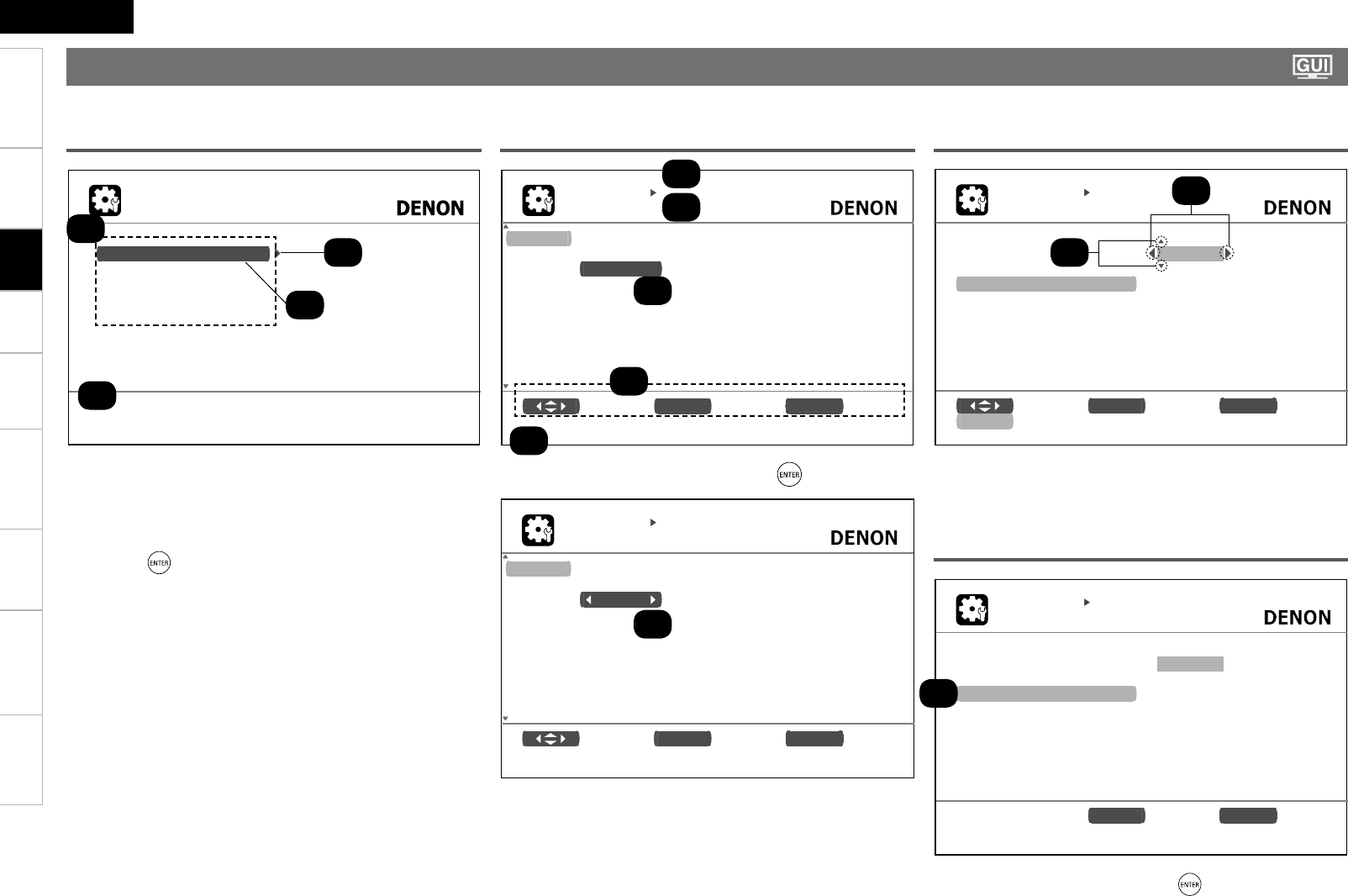
Typical examples are described below.
GExample 1H Top Menu Display
z1 : The menu items are displayed here.
z2 : Guide text for the currently selected setup item.
z3 : The selected line is displayed here.
The currently selected item is displayed on the display.
Use ui to move to the item you want to set.
z4 : Switch to the next item.
Use p or to switch.
GExample 2H Display when changing settings
z1 : History item.
z2 : Currently selected setup item.
z3 : Operation button guidance.
z4 : Guide text for the currently selected setup item.
z5 : Use uio p to move to the item you want to set.
z6 : o p is displayed at the sides of items whose setting can be changed.
Use o p to change to the desired setting.
INPUT SETUP
INPUT ASSIGN
Default [ HDMI ][DIGITAL] [ COMP ] [ iPod ]
D V D HDMI1 Coax1 1-RCA None
HDP HDMI2 None None None
T V N o n e O p t 1 N o n e N o n e
SAT/CBL HDMI3 Coax2 None None
VCR None None None Assign
DVR HDMI4 Opt2 2-RCA None
V.AUX HDMI5 Opt3 None None
S e l e c t ENTER Enter RETURN Return
Change HDMI input connector assignment
⇩Press .
z1
INPUT SETUP
INPUT ASSIGN
Default [ HDMI ][DIGITAL] [ COMP ] [ iPod ]
D V D HDMI1 Coax1 1-RCA None
HDP HDMI2 None None None
T V N o n e O p t 1 N o n e N o n e
SAT/CBL HDMI3 Coax2 None None
VCR None None None Assign
DVR HDMI4 Opt2 2-RCA None
V.AUX HDMI5 Opt3 None None
S e l e c t ENTER Enter RETURN Return
Change HDMI input connector assignment
z2
z4
z3
GExample 3H Display when inputting characters
z1 : When o p is pressed, the cursor moves to the left or right.
z2 : When ui is pressed at the position at which you want to input the
character, the character is input.
INPUT SETUP
RENAME
D V D
Default
ENTER Enter RETURN Return
D V D
GExample 4H Display when resetting
z1 : Press i to select “Default”, then press to set.
z1
z1
z1
z2
z2
z3
z4
z5
z6
Examples of GUI Menu Screen Displays
Settings
22
ENGLISH
Getting Started Connections Playback Remote Control Information Troubleshooting Specifi cationsMulti-Zone
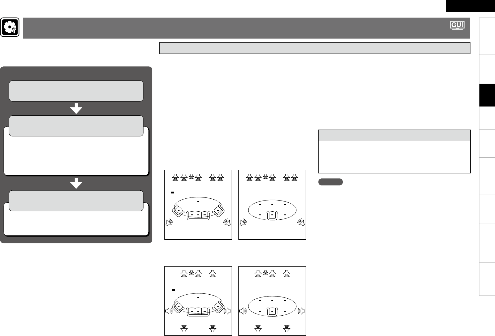
The acoustic characteristics of the connected speakers and
listening room are measured and the optimum settings are made
automatically.
NOTE
• Loud test sounds may be played during Audyssey Auto Setup. This is
part of normal operation. If there is background noise in room, these
test signals will increase in volume.
• Do not stand between the speakers and setup microphone or allow
obstacles in the path while the measurements are being made. This
will cause inaccurate readings.
• Make the room as quiet as possible. Background noise can disrupt
the room measurements. Close windows, silence cell phones,
televisions, radios, air conditioners, fl uorescent lights, home
appliances, light dimmers, or other devices as measurements may
be affected by these sounds.
Cell phones should be placed away from all audio electronics during
the measurement process as Radio Frequency Interference (RFI)
may cause measurement disruptions (even if the cell phone is not in
use).
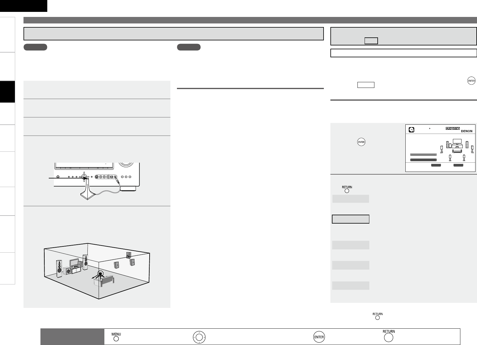
Audyssey MultEQ® automatically measures the acoustical
problems in the listening environment to create the best audio
experience for your home theater.
• When Audyssey™ Auto Setup is performed, MultEQ®, Dynamic
EQ™ and Dynamic Volume™ functions (vpage 48) are enabled.
• Use the included setup microphone (DM-A409) to perform Audyssey
Auto Setup.
• Measurements are performed by placing the calibrated microphone
successively at multiple positions throughout the listening area as
shown in GExample qH. For best results, it is strongly recommended
to measure 6 positions so that the measurements have the proper
spatial weighting.
Even if the listening environment is small as shown in GExample wH,
measuring at multiple points throughout the listening environment
results in more effective correction.
n When using Front Height Speakers
GExample qH GExample wH
FHL FL SW C FR FHR
SL SR
*M
FHL FL SW C FR FHR
SL SR
*M
n When using Surround Back Speakers
GExample qH GExample wH
FL SW C FR
SL SR
SBRSBL
*M
FL SW C FR
SL SR
SBRSBL
*M
( : Measuring positions)
Important Information
About the main listening position (*M)
The main listening position refers to the most central position where
one would normally sit within the listening environment.
MultEQ uses the measurements from this position to calculate
speaker distance, level, polarity, and the optimum crossover value
for the subwoofer.
FHL : Front height speaker (L)
FL : Front speaker (L)
SW : Subwoofer
C : Center speaker
FR : Front speaker (R)
FHR : Front height speaker (R)
SR : Surround speaker (R)
SBR : Surround back speaker (R)
SBL : Surround back speaker (L)
SL : Surround speaker (L)
( : Measuring positions)
n Check Audyssey Auto Setup Measurement
Results (Parameter Check) (vpage 26)
Audyssey Auto Setup Flown
Step 1 : Connect the included Setup
Microphone (vpage 23)
Step 3 : Performing the Audyssey Auto Setup
Procedure (vpage 24)
Step 2 : Audyssey Auto Setup Preparations
(vpage 23)
n Changing the amplifi er assignment (Amp Assign)
(vpage 23)
n Set the channel to be measured (Channel Select)
(vpage 24)
Making the Optimum Settings for the Connected Speakers Automatically
(Audyssey™ Auto Setup)
Settings
2
ENGLISH
Getting Started Connections Playback Remote Control Information Troubleshooting SpecificationsMulti-Zone
Making the Optimum Settings for the Connected Speakers Automatically (Audyssey™ Auto Setup)
1 Check the speaker connections.
(vpage 11 “Connecting the Speakers”)
2 Turn on the power of the TV and subwoofer.
Set the TV’s input to the AVR-890.
3 Turn on the AVR-890’s power.
(vpage 19 “Turning the Power On”)
4 Connect the included calibrated setup microphone to
the SETUP MIC jack on the main unit.
The Audyssey Auto Setup screen appears automatically.
5 Mount the setup microphone on a tripod or stand and
install it at the main listening position.
When installing the setup microphone, adjust its height so that
the section where the sound is received is at the height of the
ears during listening.
Sound
receptor
Setup
microphone
a Connect the included Setup Microphone
When using a subwoofer with adjustable gain and
crossover frequency
When using a subwoofer, make the following settings before starting
Audyssey Auto Setup:
n When using a subwoofer with a direct mode
Set the direct mode to “On” and disable the volume adjustment
and crossover frequency setting.
n When using a subwoofer without a direct mode
Make the following settings:
• Volume : “12 o’clock position”
• Crossover frequency : “Maximum/Highest Frequency”
• Low pass filter : “Off”
• Standby mode : “Off”
NOTE
• Do not hold the microphone in your hand during measurements.
• Avoid placing the microphone close to a seat back or wall as sound
reflections may give inaccurate results.
s Audyssey Auto Setup Preparations
around items indicate the default setting.
NOTE
• Do not disconnect the setup microphone until Audyssey Auto Setup
is completed.
• When using headphones, unplug the headphones before starting
Audyssey Auto Setup.
Perform the following settings if adjustments, etc., are required for
the speaker environment you’re using.
If you do not need to perform the following settings, or have already
completed them, select “Auto Setup Start” and then press .
Proceed to “ STEP2 ”.
STEP1 Preparation
1Press ui to select
“Amp Assign”, then
press .
2Press o p to select Amp Assign Mode, then press
.
Normal : The sound of the surround back channel is output
from the speakers connected to the SURR.
BACK/AMP ASSIGN terminals.
ZONE2 : If the ZONE2 power is on, the sound of the
ZONE2 channel is output from the speakers
connected to the SURR. BACK/AMP ASSIGN
terminals.
Front A Bi-Amp : The sound of the front A bi-amp channel is output
from the speakers connected to the SURR.
BACK/AMP ASSIGN terminals.
Front B Bi-Amp : The sound of the front B bi-amp channel is output
from the speakers connected to the SURR.
BACK/AMP ASSIGN terminals.
Front Height : The sound of the front height channel is output
from the speakers connected to the SURR.
BACK/AMP ASSIGN terminals.
Changing the amplifier assignment (Amp Assign)
The signals output from the AVR-890’s SURR. BACK/AMP ASSIGN
speaker terminals can be switched to signals of the surround mode
being used.
AUTO SETUP
AUDYSSEY AUTO SETUP MultEQ
STEP1 Preparation [1/6]
Connect the speakers
and place them accord-
ing to the recommenda-
ations in the manual.
Set the following
items if nesessary.
Amp Assign
Channel Select
Auto Setup Start
ENTER Enter RETURN Cancel
Set use of surround back ch. for your system
n To cancel Audyssey Auto Setup
To cancel, press then use o p to select “Yes”.
: Moves the cursor (Up/Down/Left/Right) : Decision the setting : Return to previous menu
Remote control
operation buttons : Displaying the menu
Cancel the menu
Settings
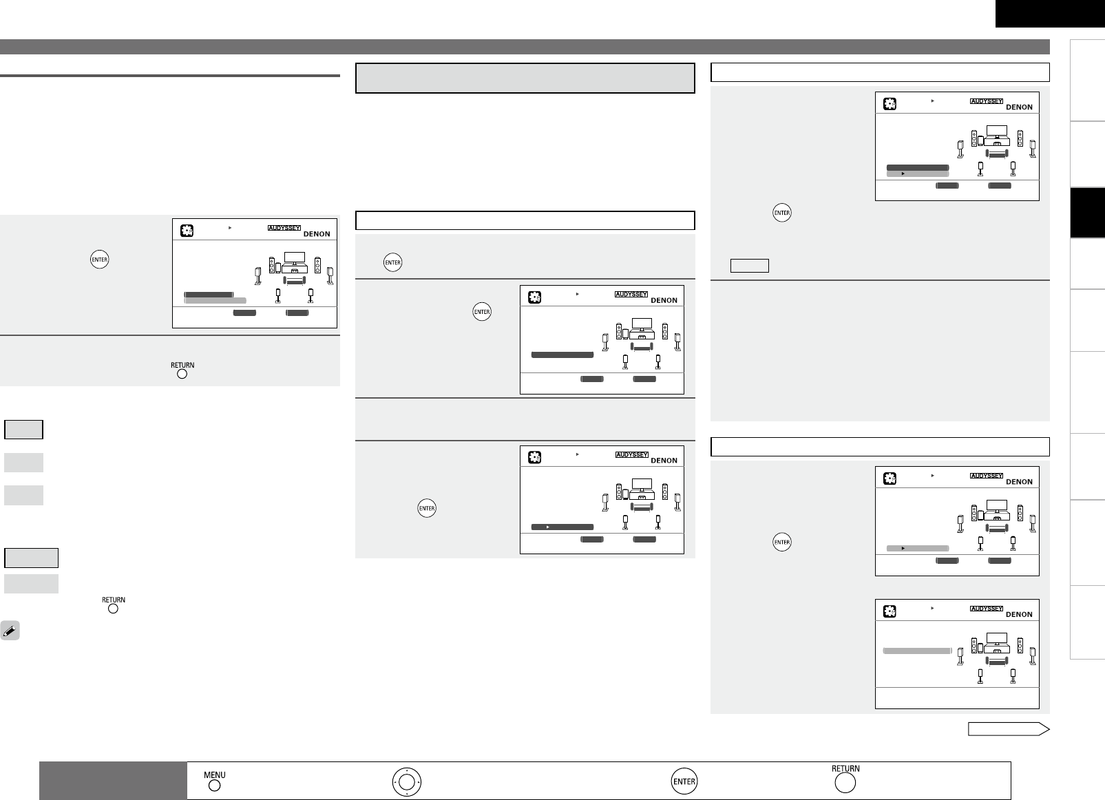
2
ENGLISH
Getting Started Connections Playback Remote Control Information Troubleshooting SpecificationsMulti-Zone
Making the Optimum Settings for the Connected Speakers Automatically (Audyssey™ Auto Setup)
1Press ui to select
“Channel Select”,
then press .
2Press ui to select a channel, press o p to select
the item, and then press .
AUTO SETUP
AUDYSSEY AUTO SETUP MultEQ
STEP1 Preparation [1/6]
Connect the speakers
and place them accord-
ing to the recommenda-
ations in the manual.
Set the following
i t e ms if nesessary.
Amp Assign
Channel Select
Auto Setup Start
ENTER Enter RETURN Cancel
Skip unused ch’s measurement for timesaving.
n Front
A : The sound is output from front speakers A when measuring
the front speakers.
B : The sound is output from front speakers B when measuring
the front speakers.
A + B : The sound is output simultaneously from front speakers A
and B when measuring the front speakers.
See overleaf
Set the channel to be measured (Channel Select)
• Front
The front speaker to be measured can be selected ahead of time
here.
•
Subwoofer, Surround Back
If you set the channels you will not use beforehand, those channels
will not be measured. Therefore, you can save an amount of time
commensurate with that which would have been taken to measure
those channels.
n Subwoofer, Surround Back
Measure : Default setting. Measure the selected channel.
Skip : Skip the selected channel and do not measure.
b To cancel, press .
When “Amp Assign” is set to “Normal”, only then is “Surround Back”
displayed.
d : Performing Audyssey Auto Setup
Audyssey Auto Setup detects the presence of each speaker and
automatically calculates the speaker size, channel level, distance,
and optimal crossover frequency setting. Audyssey MultEQ®
corrects acoustical distortions within the listening area.
Once started, MultEQ will play a series of test tones through each
speaker.
Before starting, connect and position all of your speakers.
•
•
•
1Press ui to select “Auto Setup Start”, then press
.
2Select “Measure”
and then press .
3Once all the speakers have been detected, check the
results of detection of the connected speakers.
4 Press ui to
select “Next 1
Measurement”, then
press .
AUTO SETUP
AUDYSSEY AUTO SETUP MultEQ
STEP2 Speaker Detection
Please place the mic-
rophone at ear height
at main listening
position.
Measure
ENTER Enter RETURN Cancel
Test Tone will start for measurement
[2/6]
STEP2 Speaker Detection
STEP3 Measurement
5Once the screen on
the right appears,
move the setup
microphone to the
second position,
use ui to select
“Measure”, then
press .
Measurements for the second position begin.
b To skip this step, select “Next 1 Calculation” and proceed to
STEP4 .
6Perform Step 5 repeatedly for the 3rd, 4th, 5th, and
6th measurements.
Once measurements for the sixth position are completed,
“Measurements finished.” is displayed.
b Measure at a total of six positions, including the main listening
position and positions around it. It is possible to stop the settings
with five positions or fewer, but for better results we recommend
measuring at six positions.
AUTO SETUP
AUDYSSEY AUTO SETUP MultEQ
STEP3 Measurement
Please place the mic-
rophone at ear height
a t 2 n d l i s t e n i m g
position.
Measure
Next Calculation
ENTER Enter RETURN Cancel
Start next measurement. Test Tone will start
[3/6]
STEP4 Calculation
7 Once measurements
are nished, use
ui to select “Next
1 Calculation”, then
press .
Analysis begins.
b Analysis takes several
minutes to complete.
The time required for
this analysis depends on
the number of speakers
connected. The greater
the number of speakers
connected, the longer
analysis will take.
AUTO SETUP
AUDYSSEY AUTO SETUP MultEQ
STEP3 Measurement
Please place the mic-
rophone at ear height
a t 2 n d l i s t e n i m g
position.
Measure
Next Calculation
ENTER Enter RETURN Cancel
Proceed to Step 4 (Analyze)
[3/6]
AUTO SETUP
AUDYSSEY AUTO SETUP MultEQ
STEP4 Calculation
Now calculating...
Please wait.
■■■■■
2 5 %
[4/6]
⇩
: Moves the cursor (Up/Down/Left/Right) : Decision the setting : Return to previous menu
Remote control
operation buttons : Displaying the menu
Cancel the menu
AUTO SETUP
AUDYSSEY AUTO SETUP MultEQ
STEP2 Spkr Detect Check
F r o n t Y e s
Center Yes
Subwoofer Yes
Surround Yes
S.Back Yes
2 s p k r s
Retry
Next Measurement
ENTER Enter RETURN Cancel
Goto Step3 (Measurement) after speaker check
[2/6]
Settings
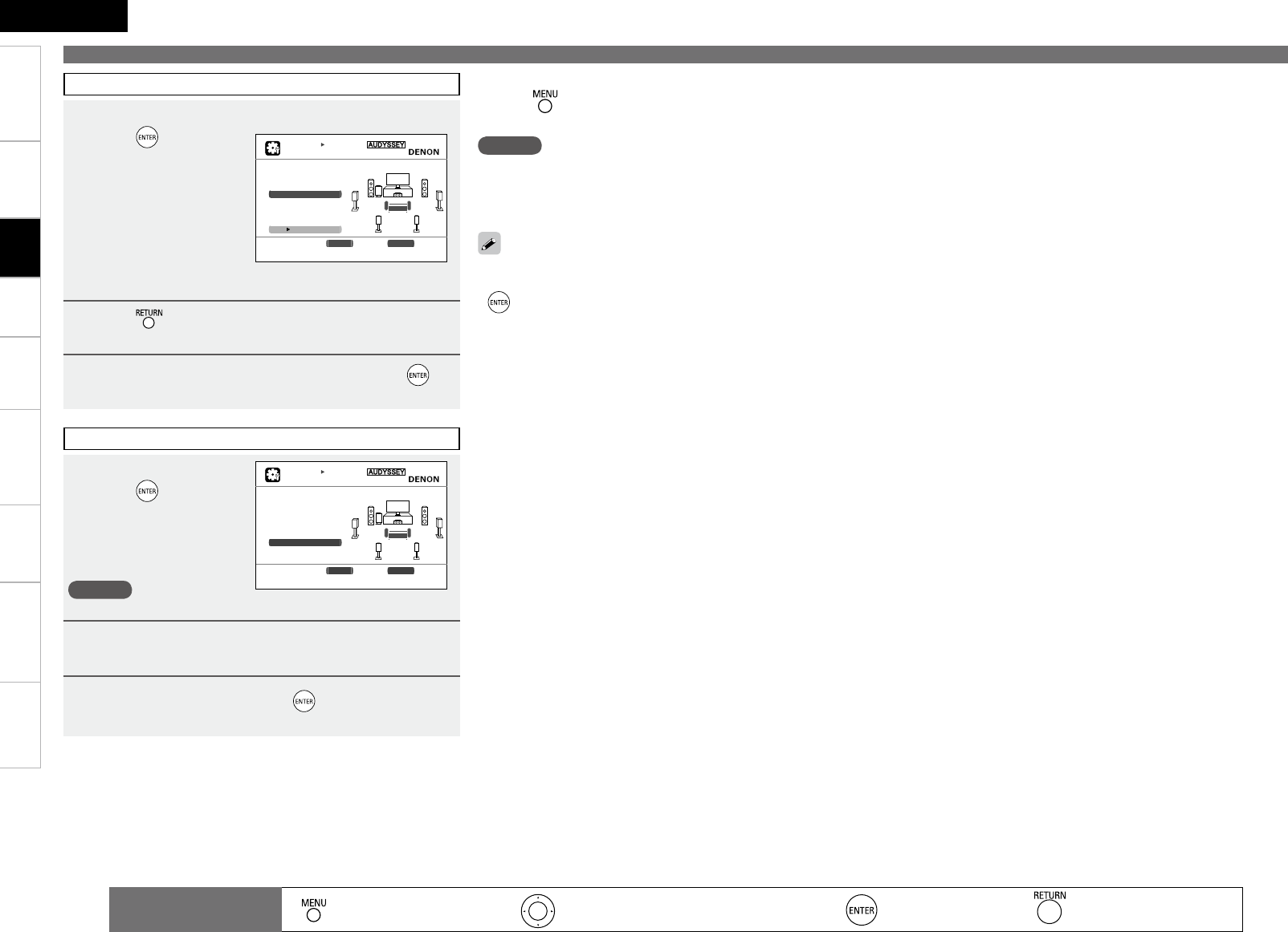
2
ENGLISH
Getting Started Connections Playback Remote Control Information Troubleshooting SpecificationsMulti-Zone
Making the Optimum Settings for the Connected Speakers Automatically (Audyssey™ Auto Setup)
STEP5 Check
8 Use ui to select the item you want to check, then
press .
The measurement result
confirmation screen is
displayed.
b Subwoofer or other
speakers may be set to
a value that does not
correspond to the actual
distance.
9Press .
This returns you to analysis results items, so repeat step 8.
10
Press i to select “Next 1 Store”, then press .
AUTO SETUP
AUDYSSEY AUTO SETUP MultEQ
S T E P 5 C h e c k
Check processing res-
ults.To proceed,press
"Next"
Spkr Config Check
Distance Check
Ch.Level Check
Crossover Check
Next Store
ENTER Enter RETURN Cancel
Select item to check
[5/6]
STEP6 Store
11
Select “Store”, then
press .
“Now Storing... Please
wait.” is displayed on the
GUI menu while the results
are being stored.
NOTE
Do not turn the power off while the settings are being stored.
12
Disconnect the setup microphone from the AVR-
890.
13
Select “Exit” and then press .
AUTO SETUP
AUDYSSEY AUTO SETUP MultEQ
S T E P 6 S t o r e
Press "Store" to store
calculation results.
Store
ENTER Enter RETURN Cancel
Apply and store measurement result.
[5/6]
Exiting the GUI Menu
Press while the GUI menu is displayed.
The GUI menu display disappears.
n
• If the result differs from the actual connection status or an error
message appears, use ui to GUI menu “Retry” and then press
to repeat the measurement.
• If the result still differs from the actual connection status after
re-measurement or the error message still appears, it is possible
that the speakers are not connected properly. Turn the AVR-890
off, check the speaker connections and repeat the measurement
process from the beginning.
• For instance, If the location or direction of a speaker is altered,
Audyssey Auto Setup should be performed again to ensure the
correct EQ solution for the new room configuration.
NOTE
Do not change the speaker connections or subwoofer volume,
or speaker locations after making measurements. If changes are
necessary, make the changes and use Audyssey™ Auto Setup once
again for an updated EQ solution.
: Moves the cursor (Up/Down/Left/Right) : Decision the setting : Return to previous menu
Remote control
operation buttons : Displaying the menu
Cancel the menu
Settings
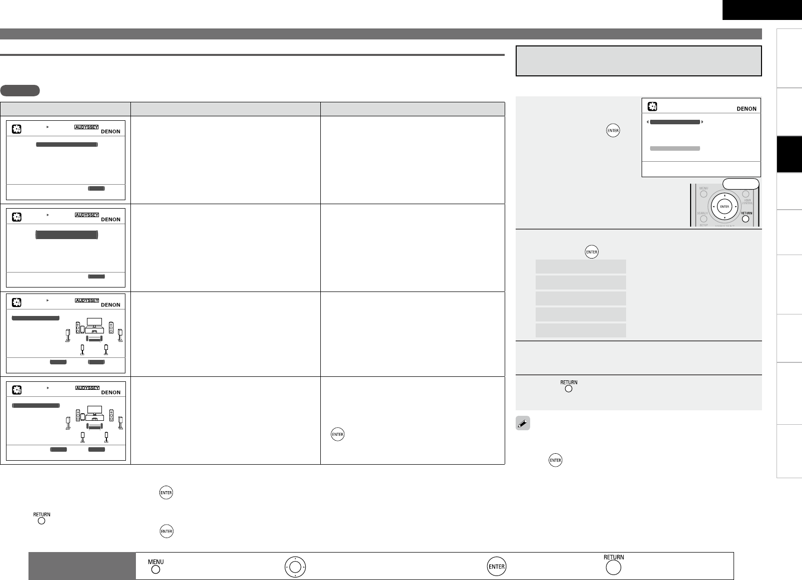
2
ENGLISH
Getting Started Connections Playback Remote Control Information Troubleshooting SpecificationsMulti-Zone
Making the Optimum Settings for the Connected Speakers Automatically (Audyssey™ Auto Setup)
This is displayed after Audyssey Auto Setup is completed.
Even if the settings are changed after Audyssey Auto Setup, Audyssey
Auto Setup settings can be restored by selecting “Restore” then
pressing .
1Press ui to select
“Parameter Check”,
then press p or .
2Use ui to select the item you want to check, then
press p or .
Speaker Config. Check : Check the speaker configuration
Distance Check : Check the distance
Channel Level Check : Check the channel level
Crossover Freq. Check : Check the crossover frequency
EQ Check : Check the equalizer
3Use o p to switch the display between the different
speakers.
4Press .
The confirmation screen reappears. Repeat steps 2 and 3.
Check Audyssey Auto Setup
Measurement Results (Parameter Check)
AUTO SETUP
PARAMETER CHECK
Speaker Config Check
Distance Check
Channel Level Check
Crossover Check
E Q C h e c k
Restore
Show speaker configuration result
Error messages (examples) Cause Measures
AUTO SETUP
AUDYSSEY AUTO SETUP MultEQ
Caution!
No microphone or Speaker
Retry
RETURN Cancel
Check cause of problem!
• Included setup microphone is not connected.
• Not all speakers could be detected.
• The front L speaker was not properly detected.
• Connect the included setup microphone to the
SETUP MIC jack on the main unit.
• Check the speaker connections.
AUTO SETUP
AUDYSSEY AUTO SETUP MultEQ
Caution!
Ambient noise is too high
o r L e v e l i s t o o l o w
Retry
RETURN Cancel
Check cause of problem!
• Too much noise in the room for accurate
measurements to be made.
• Speaker or subwoofer sound is too low for
accurate measurements to be made.
• Either turn off any device generating noise or
move it away.
• Try again when the surroundings are quieter.
• Check the speaker installation and the direction
in which the speakers are facing.
• Adjust the subwoofer’s volume.
AUTO SETUP
AUDYSSEY AUTO SETUP MultEQ
Caution!
F r o n t R N o n e
Retry
ENTER Enter RETURN Cancel
Check cause of problem!
• Displayed speaker could not be detected.
· The front R speaker were not properly detected.
· Only one channel of the surround speakers was
detected.
· Sound was output from the R channel when only
one surround back speaker was connected.
· The surround back, but the surround speaker was
not detected.
• Check the connections of the displayed
speaker.
AUTO SETUP
AUDYSSEY AUTO SETUP MultEQ
Caution!
Front L Phase
Retry
S k i p
ENTER Enter RETURN Cancel
Check cause of problem!
• Displayed speaker connected with the polarities
reversed.
• Check the polarities of the displayed speaker.
• For some speakers, this error message may
be displayed even if the speaker is properly
connected. If you are sure that the wiring is
correct, press ui to select “Skip”, then press
.
NOTE Be sure to turn the power off before checking the speaker connections.
n To perform Audyssey Auto Setup again
Press ui to select “Retry”, then press .
n To cancel Audyssey Auto Setup
Press , the “Cancel auto setup?” prompt is displayed.
Press o p and select “Yes”, then press .
Error Messages
If Audyssey Auto Setup could not be completed due to speaker installation, the measuring environment, etc., an error message is displayed. If
this happens, check the relevant items, be sure to take the necessary measures, then perform Audyssey Auto Setup over again.
Front
: Moves the cursor (Up/Down/Left/Right) : Decision the setting : Return to previous menu
Remote control
operation buttons : Displaying the menu
Cancel the menu
Settings
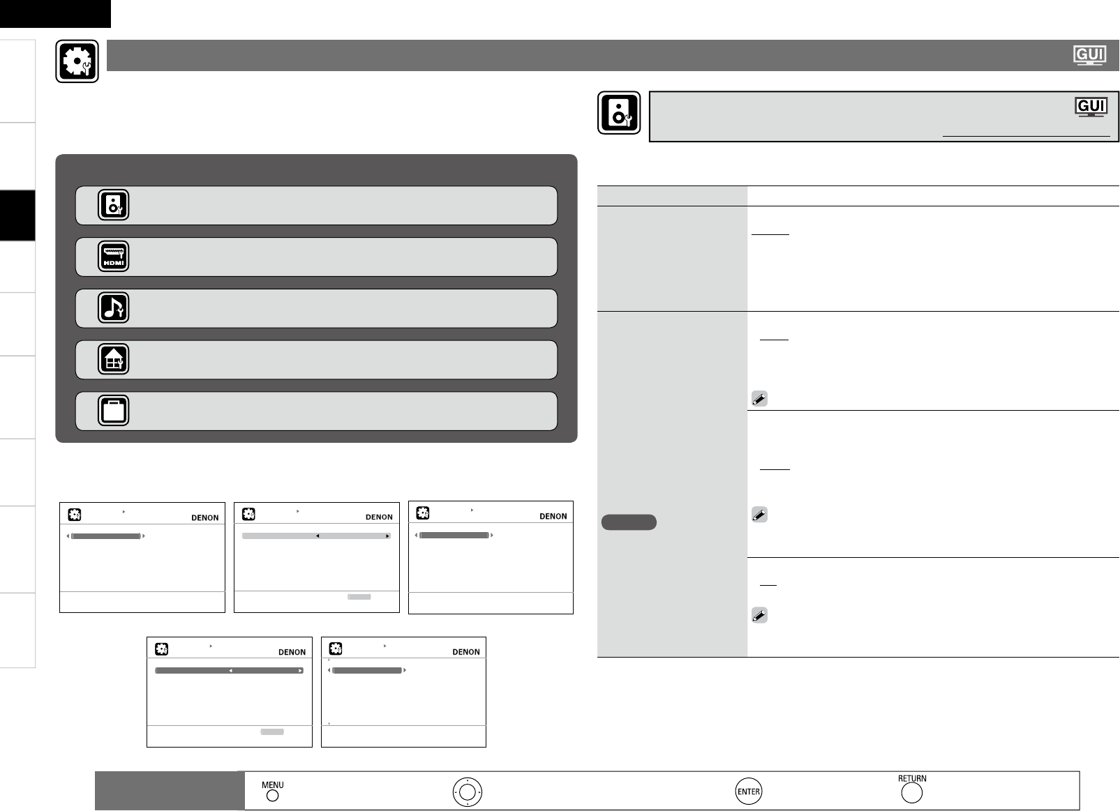
2
ENGLISH
Getting Started Connections Playback Remote Control Information Troubleshooting Specifi cationsMulti-Zone
Setting items Setting contents
Amp Assign
Sets the signal output to the
speaker connected to the
SURR. BACK/AMP ASSIGN
terminals.
Normal : The surround back channel audio signals are output.
ZONE2 : The ZONE2 audio signals are output.
Front A Bi-Amp : The bi-amp audio signals are output. Set this for bi-amp
playback of the front A speakers.
Front B Bi-Amp : The bi-amp audio signals are output. Set this for bi-amp
playback of the front B speakers.
Front Height : The front height channel audio signals are output.
Speaker Confi g.
Select speaker confi guration
and size.
(bass reproduction capability)
NOTE
Select “Large” or “Small” not
according to the physical size
of the speaker but according
to the low frequency
reproduction capabilities
based on the frequency set
at “Crossover Frequency”
(vpage 29).
Front : Set the front speaker size.
Large : Use of a large speaker that can adequately play back low
frequencies.
Small : Use of a small speaker that has inadequate playback capacity for
low frequencies.
If “Subwoofer” is set to “No”, “Front” is automatically set to “Large”.
•
•
Center : Set the presence and size of the center speaker.
Large : Use of a large speaker that can adequately play back low
frequencies.
Small : Use of a small speaker that has inadequate playback capacity for
low frequencies.
None : Select when a center speaker is not connected.
• “Large” is not displayed when “Front” is set to “Small”.
• Even if “Center” has been set to “Large”, when “Front” is set to
“Small”, the “Center” setting automatically switches to “Small”.
•
•
•
Subwoofer : Set the presence of a subwoofer.
Yes : Use a subwoofer.
No : Select when a subwooofer is not connected.
When “Front” is set to “Small”, “Subwoofer” can automatically set
to “Yes”.
•
•
Use this procedure to set the speakers manually or if you wish to change the settings made with
Audyssey Auto Setup.
Making the speaker settings (Speaker Setup)
Default settings are underlined.
Use this procedure to change Audyssey™ Auto Setup settings or to change the various audio,
video and display settings.
The set can be used without changing these settings. Make these settings as necessary.
For a description of “Menu Map” and operating instructions, see page 20.
Items that can be set with the Manual Setup proceduren
Making the speaker settings (Speaker Setup) vpage 27
Making the HDMI settings (HDMI Setup) vpage 30
Making the audio settings (Audio Setup) vpage 30
Making other settings (Option Setup) vpage 32
Making the ZONE2 settings (ZONE2 Setup) vpage 31
n Examples of Menu Screen Displays
Speaker Setup HDMI Setup Audio Setup
MANUAL SETUP
SPEAKER SETUP
Amp Assign
Speaker Config.
Bass Setting
Distace
Channel Level
Crossover Frequency
Front Speaker Setup
Assign surround back AMP for other use
MANUAL SETUP
HDMI SETUP
lamroNegnaRBGR
A u t o L i p S y n c O N
PMAtuOoiduA
FFOlortnoCIMDH
RETURN Return
Use video range from 16 (black) to 235 (white)
MANUAL SETUP
AUDIO SETUP
EXT.IN SW Level
2ch Direct/Stereo
Auto Surround Mode
EQ Customize
Set subwoofer playback level in EXT. IN mode
ZONE2 Setup Option Setup
MANUAL SETUP
ZONE2 SETUP
Bd0hcLleveL
Bd0hcRleveL
Volume Display Relative
FFOtimiLemuloV
P o w e r O n L e v e l L a s t
lluFleveLetuM
RETURN Return
Adjust the left channel output level
MANUAL SETUP
OPTION SETUP
Volume Control
Source Delete
On-Screen Display
Quick Select Name
Zone Rename
Trigger Out
Remote ID Setup
2 3 2 C P o r t
Make settings for volume control
: Moves the cursor (Up/Down/Left/Right) : Decision the setting : Return to previous menu
Remote control
operation buttons : Displaying the menu
Cancel the menu
Making detailed settings (Manual Setup)
Settings
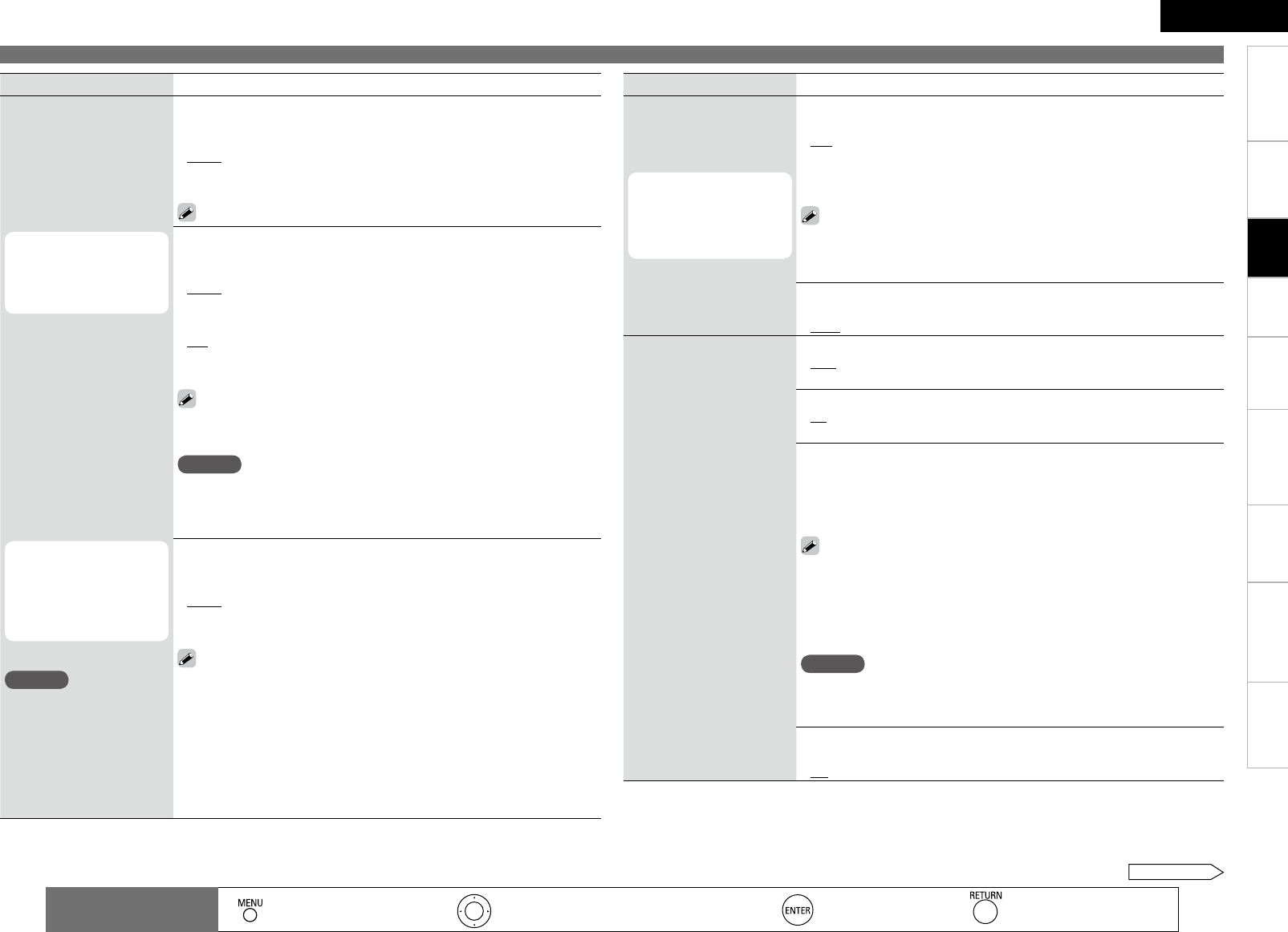
28
Getting Started Connections Playback Remote Control Information Troubleshooting Specifications
ENGLISH
Multi-Zone
Making detailed settings (Manual Setup)
Setting items Setting contents
Speaker Config.
Select speaker configuration
and size.
(bass reproduction capability)
“S.Back” is displayed
when the “Amp Assign”
setting (vpage 27) is
set to “Normal”.
“Front Height” is
displayed when the “Amp
Assign” setting (vpage
27) is set to “Front
Height”.
NOTE
Select “Large” or “Small” not
according to the physical size
of the speaker but according
to the low frequency
reproduction capabilities
based on the frequency set
at “Crossover Frequency”
(vpage 29).
Surround : Set the presence and size of the Surround speakers.
Large : Use of a large speaker that can adequately play back low
frequencies.
Small : Use of a small speaker that has inadequate playback capacity for
low frequencies.
None : Select when the surround speakers are not connected.
“Large” is not displayed when “Front” is set to “Small”.
•
•
•
S.Back : Set the presence, size and number of surround back speakers.
Large : Use of a large speaker that can adequately play back low
frequencies.
Small : Use of a small speaker that has inadequate playback capacity for
low frequencies.
None : Select when the surround back speakers are not connected.
2sp : Use two surround back speakers.
1sp : Use only one surround back speaker. Surround back audio is output
from the surround back L terminal.
• “Large” is not displayed when “Surround” is set to “Small”.
• Even if “S.Back” is set to “Large”, the “S.Back” setting is automatically
switched to “Small” if “Surround” is set to “Small”.
NOTE
Even when the Surround Back Speaker setting is other than “None”,
sound may not be emitted from the surround back speaker, depending
on the playback source. In this case, “Surround Back” setting other
than “OFF” (vpage 47).
•
•
•
•
•
Front Height : Set the front height speaker size.
Large : Use of a large speaker that can adequately play back low
frequencies.
Small : Use of a small speaker that has inadequate playback capacity for
low frequencies.
None : Select when a front height speaker is not connected.
• “Large” is not displayed when “Front” is set to “Small”.
• Even if “Front Height” is set to “Large”, the “Front Height” setting
is automatically switched to “Small” if “Front” is set to “Small”.
•
•
•
Setting items Setting contents
Bass Setting
Make the settings related to
playback of low frequency
signals (subwoofer and LFE).
This can be set when
“Speaker Config.” –
“Subwoofer” (vpage
27) is set to “Yes”.
Subwoofer Mode : Select low range signal to be reproduced by
subwoofer.
LFE : Add the low frequency signal of the channel for which the speaker
size is set to “Small” to the subwoofer signal and output it.
LFE+Main : Add the low frequency signal of all channels to the subwoofer
signal and output it.
• Play music or a movie source and select the mode offering the
strongest bass.
• Select “LFE+Main” if you want the bass signals to always be
produced from the subwoofer.
•
•
LPF for LFE : Set the upper limit of the low frequency signals output from
the subwoofer.
80Hz / 90Hz / 100Hz / 110Hz / 120Hz / 150Hz / 200Hz / 250Hz•
Distance
Set the distance from the
listening position to the
speakers.
Measure the distance from
the listening position to the
speakers beforehand.
Unit : Set the unit of distance.
Feet
Meters
•
•
Step : Set the minimum variable width of the distance.
1ft / 0.1ft
0.1m / 0.01m
•
•
FL (Front L)/ FR (Front R)/ C (Center)/ SW (Subwoofer)/ SL (Surround L)/
SR (Surround R/ SBL (Surr. Back L)/ SBR (Surr. Back R)/ FHL (Front Height L)/
FHR (Front Height R) : Select the speaker you want to set, and set the
distance. Set the value that is closest to the measured distance.
0.0ft ~ 60.0ft / 0.00m ~ 18.00m
• The speakers that can be selected differ depending on the “Amp Assign”
(vpage 27) and “Speaker Config.” (vpage 27) settings.
• Default settings :
Front/Center/Subwoofer/Front Height : 3.6 meters (12 feet)
Surround/Surr. Back : 3.0 meters (10 feet)
NOTE
Set the difference in the distance between the speakers to less than 6.0
meters (20 feet). “Relocate Speaker” is displayed on the screen if an
inappropriate distance is set.
•
•
Default : Reset all distance settings to factory default.
Yes : Reset to the defaults.
No : Do not reset to the defaults.
•
•
: Moves the cursor (Up/Down/Left/Right) : Decision the setting : Return to previous menu
Remote control
operation buttons : Displaying the menu
Cancel the menu
Settings
See overleaf
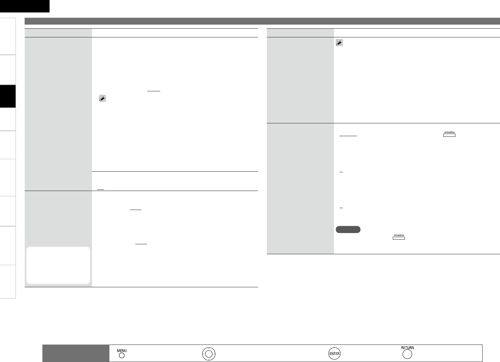
2
Getting Started Connections Playback Remote Control Information Troubleshooting Specifications
ENGLISH
Multi-Zone
Setting items Setting contents
Channel Level
Set the volume of the test
tone to be the same when it
is output from each speaker.
Test Tone Start : Output test tones.
FL (Front L)/ C (Center)/ FR (Front R)/ SR (Surround R)/
SBRz (Surround Back R)/ SBLz (Surround Back L)/ SL (Surround L)/
FHL (Front Height L)/ FHR (Front Height R)/ SW (Subwoofer) : Select
the speaker.
z
When the “S.Back” setting (vpage 28) is set to “1sp”, “SB” is
displayed.
–12.0dB ~ +12.0dB (0.0dB) : Adjust the volume.
• When “Channel Level” is adjusted, the adjusted values are set for
all the surround modes. To adjust the channel level separately for the
different surround modes, use the operation see “Adjust the volume of
the different speakers” (vpage 53).
• Speakers set to “None” in the “Speaker Config.” (vpage 27) settings
are not displayed.
• When o is pressed while the subwoofer volume is set to “–12dB”, the
“Channel Level” setting switches to “OFF”.
• If output of the test tones begins while the muting mode is set, the
muting mode is canceled.
•
Default : Reset all channel level settings to factory default.
Yes : Reset to the defaults.
No : Do not reset to the defaults.
•
•
Crossover Frequency
Outputs at below set
frequency, each speaker’s
bass signal output from the
subwoofer. Set this according
to the low frequency
reproduction capabilities of
the speakers you are using.
This can be set when
“Speaker Config.” –
“Subwoofer” (vpage
27) is set to “Yes” or
“No”.
Crossover : Outputs at below set frequency, each speaker’s bass signal
output from the subwoofer.
40Hz / 60Hz / 80Hz / 90Hz / 100Hz / 110Hz / 120Hz / 150Hz / 200Hz /
250Hz
Advanced : Set the low frequency signals to be output from the signals
of the respective speakers to the subwoofer.
Front / Center / Surround / S.Back / Front Height : Select the speaker.
· 40Hz / 60Hz / 80Hz / 90Hz / 100Hz / 110Hz / 120Hz / 150Hz / 200Hz /
250Hz : Set the crossover frequency.
•
•
•
Setting items Setting contents
Crossover Frequency • Always set the crossover frequency to “80 Hz”. When using small
speakers, however, we recommend setting the crossover frequency
to a higher frequency.
• For speakers set to “Small”, sound below the crossover frequency
is cut from the sound output. The cut bass sound is output from the
subwoofer or front speakers.
• The speakers that can be set when “Advanced” is selected differ
according to the “Bass Setting” setting (vpage 28).
· When “LFE” is selected, speakers set to “Small” at “Speaker
Config.” (vpage 27) can be set.
· When “LFE+Main” is selected, speakers can be set regardless of
the speaker size setting.
Front Speaker Setup
Select front speakers to use
for each surround mode.
Setting : Choose the method for setting the front speakers.
Normal : The front speakers are set using the .
Custom : The front speakers used for the different playing modes are
set in advance.
2CH DIRECT/STEREO : The front speakers used in the direct, stereo and
pure direct play modes are set in advance.
A : Front speaker A is used.
B : Front speaker B is used.
A+B : Both front speakers A and B are used.
MULTI CH : The front speakers used in modes other than the direct, stereo
and pure direct play modes are set in advance.
A : Front speaker A is used.
B : Front speaker B is used.
A+B : Both front speakers A and B are used.
NOTE
• When set to “Custom”, does not operate.
• The front speaker setting stored for the “Quick Select” function is given
priority.
•
•
•
•
•
•
•
•
Making detailed settings (Manual Setup)
: Moves the cursor (Up/Down/Left/Right) : Decision the setting : Return to previous menu
Remote control
operation buttons : Displaying the menu
Cancel the menu
Settings
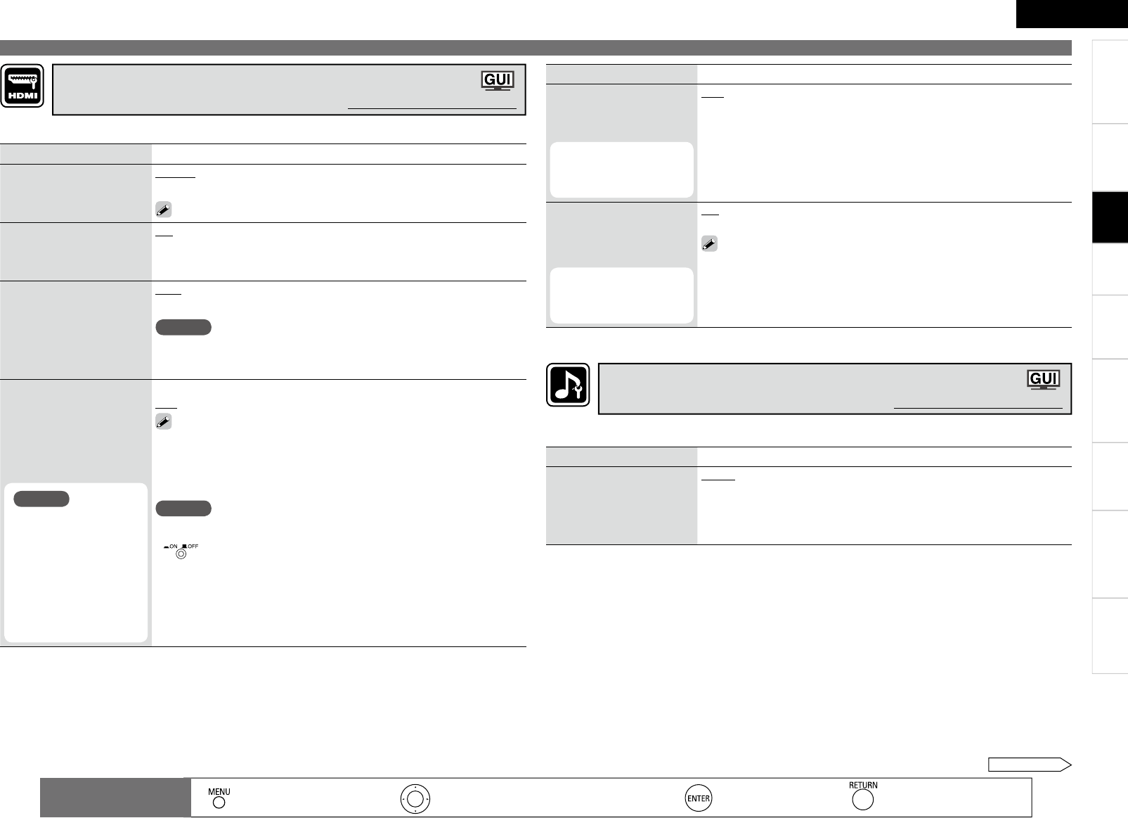
0
Getting Started Connections Playback Remote Control Information Troubleshooting Specifi cations
ENGLISH
Multi-Zone
Setting items Setting contents
RGB Range
Set the video range of RGB
output from the HDMI
terminal.
Normal : Output with RGB video range (16 (black) to 235 (white)).
Enhanced : Output with RGB video range (0 (black) to 255 (white)).
This setting is valid when using a TV equipped with a DVI terminal.
Auto Lip Sync
Automatic compensation
for timing shift in audio and
video output.
ON : Compensated.
OFF : Not compensated.
HDMI Audio Out
Select HDMI audio output
device.
Amp : Use speakers connected to AVR-890 for audio playback.
TV : Use speakers of TV for audio playback.
NOTE
When the HDMI control function is operating, the setting of audio playback
in the connected TV takes priority (vpage 52 “Controlling HDMI-
compatible devices from the AVR-890 (HDMI Control Function)”).
HDMI Control
External devices can be
controlled from the AVR-
890 and the AVR-890 can
be controlled from external
devices.
NOTE
The HDMI control
function controls
operations of a TV that
is compatible with the
HDMI control function.
Make sure that the TV
and HDMI are connected
when you perform HDMI
control.
ON : Use the HDMI control function.
OFF : Do not use the HDMI control function.
• Please consult the operating instructions for each connected device
to check the settings.
• For details on the HDMI control function, see “Controlling HDMI-
compatible devices from the AVR-890 (HDMI Control Function)”
(vpage 52).
NOTE
• When “Control” is set to “ON”, it consumes more standby power.
• When not using this unit for a long period, we recommend that you press
to turn off (jOFF) the power.
• When the “HDMI Control” setting has been changed, always turn off the
power to the connecting devices afterwards and then turn back on.
• The “HDMI Control” does not work when the power to the equipment is
off.
• When “HDMI Control” is set to “ON”, power is supplied constantly to the
AC outlet (UNSWITCHED).
Make settings for HDMI video/audio output.
Making the HDMI settings (HDMI Setup)
Default settings are underlined.
Setting items Setting contents
Standby Source
Set the HDMI connector for
HDMI signal input during
standby.
This can be set when
“HDMI Control” is set
to “ON”.
Last : Standby with last used input source during power on.
HDMI1 / HDMI2 / HDMI3 / HDMI4 / HDMI5 : The standby mode is set at
the input source assigned to the respective.
Power Off Control
The power of the AVR-890
and external device turn off
together.
This can be set when
“HDMI Control” is set
to “ON”.
ON : Switched.
OFF : Not switched.
• Please consult the operating instructions for each connected device
to check the settings.
• For details on the HDMI control function, see “Controlling HDMI-
compatible devices from the AVR-890 (HDMI Control Function)”
(vpage 52).
Making detailed settings (Manual Setup)
: Moves the cursor (Up/Down/Left/Right) : Decision the setting : Return to previous menu
Remote control
operation buttons : Displaying the menu
Cancel the menu
Setting items Setting contents
EXT.IN SW Level
Set the playback level of the
analog subwoofer signals
input from the external input
terminals (EXT. IN).
+15dB : This is the recommended level.
+10dB / +5dB / 0dB : Select the level according to the player being used.
Make settings for audio playback.
Making the audio settings (Audio Setup)
Default settings are underlined.
Settings
See overleaf
Getting Started Connections Playback Remote Control Information Troubleshooting Specifi cations
ENGLISH
Multi-Zone
Setting items Setting contents
EQ Customize
Set so that unused equalizer
settings are not displayed
when is used.
Audyssey Byp. L/R
/
Audyssey Flat / Manual
Used
Not Used
NOTE
• Set so that “Audyssey Byp. L/R” and “Audyssey Flat” settings can be
made when Audyssey™ Auto Setup is performed.
• Equalizer settings for which “Not Used” is set with the Quick Select
function cannot be stored and called out.
•
•
Setting items Setting contents
2CH DIRECT/STEREO
Make speaker settings for 2-
channel mode playback.
Setting : Select the method for setting the speakers used in the 2-channel
direct and stereo playback modes.
Basic : The settings at “Speaker Setup” (vpage 27) are applied.
Custom : Make separate settings for 2-channel mode.
Front : Set the front speaker size.
Large : Use of a large speaker that can adequately play back low
frequencies.
Small : Use of a small speaker that has inadequate playback capacity
for low frequencies.
SW : Set the presence of a subwoofer.
Yes : Use a subwoofer.
No : Select when a subwoofer is not connected.
SW Mode : Select low range signal to be reproduced by subwoofer.
LFE : Add the low frequency signal of the channel for which the speaker
size is set to “Small” to the subwoofer signal and output it.
LFE+Main : Add the low frequency signal of all channels to the
subwoofer signal and output it.
Crossover : Outputs at below set frequency, each speaker’s bass signal
output from the subwoofer.
40Hz / 60Hz / 80Hz / 90Hz / 100Hz / 110Hz / 120Hz / 150Hz / 200Hz
/ 250Hz
Distance FL / Distance FR : Select the speaker you want to set, and set
the CH Level. Set the value that is closest to the measured distance.
0.0ft ~ 60.0ft (12.0ft) / 0.00m ~ 18.00m (3.6m)
CH Level FL/ CH Level FL FR : Select the speaker you want to set, and
set the CH Level. Adjust the level of each channel.
–12.0dB ~ +12.0dB(0.0dB)
•
•
•
•
•
•
•
•
•
•
•
Auto Surround Mode
Make setting for memorizing
surround mode setting for
each input signal type.
ON : Memorize settings. Most recently stored surround mode is
automatically selected.
OFF : Do not memorize settings. Surround mode does not change
according to input signal.
The auto surround mode function lets you store in the memory the
surround mode last used for playing the four types of input signals
listed below.
q Analog and PCM 2-channel signals
w Dolby Digital and DTS 2-channel signals
e Dolby Digital and DTS multi-channel signals
r Multi-channel signals other than Dolby Digital and DTS (PCM, etc.)
NOTE
When playing in the PURE DIRECT mode, the surround mode does not
change even if the input signal is changed.
Making detailed settings (Manual Setup)
: Moves the cursor (Up/Down/Left/Right) : Decision the setting : Return to previous menu
Remote control
operation buttons : Displaying the menu
Cancel the menu
Setting items Setting contents
Level Lch
Adjust the left channel output
level.
–12dB ~ +12dB (0dB)
Level Rch
Adjust the right channel
output level.
–12dB ~ +12dB (0dB)
Volume Display
Set the ZONE2 volume
display method.
Relative : The volume is displayed within the range of – – –dB (Minimum),
–80 dB ~ +18 dB.
Absolute : The volume is displayed within the range of 0, 1 ~ 99.
Vol.Limit
Make a setting for maximum
volume.
OFF : Do not set a maximum volume.
–20dB(61) / –10dB(71) / 0dB(81)
Power On Level
Defi ne the volume setting
that is active when the power
is turned on.
Last : Use the memorized setting from the last session.
– – – : Always use the muting on condition when power is turned on.
–80dB(1) ~ +18dB(99) : The volume is adjusted to the set level.
Mute Level
Set the amount of attenuation
when muting is on.
Full : The sound is cut off entirely.
–40dB : The sound is attenuated by 40 dB.
–20dB : The sound is attenuated by 20 dB.
• The volume is displayed using the display method set at “Volume Display” (vpage 31).
• Set the main volume at “Volume Control” (vpage 32).
Make settings for audio playback in a ZONE2 system.
“ZONE2 Setup” is displayed when ZONE2 is selected with “Amp Assign” (vpage 27).
Making the ZONE2 settings (ZONE2 Setup)
Default settings are underlined.
Settings
2
Getting Started Connections Playback Remote Control Information Troubleshooting Specifi cations
ENGLISH
Multi-Zone
Making detailed settings (Manual Setup)
Setting items Setting contents
Volume Control
Set the MAIN ZONE volume
setting.
Volume Display : Set the volume display method.
Relative : The volume is displayed within the range of – – –dB (Minimum),
–80.5 dB ~ +18 dB.
Absolute : The volume is displayed within the range of 0, 1 ~ 99.
•
•
Vol.Limit : Make a setting for maximum volume.
OFF : Do not set a maximum volume.
–20dB(61) / –10dB(71) / 0dB(81)
•
•
Power On Level : This sets the volume set when the MAIN ZONE’s power
is turned on.
Last : Use the memorized setting from the last session.
– – – : Always use the muting on condition when power is turned on.
–80dB(1) ~ +18dB(99) : The volume is adjusted to the set level.
•
•
•
Mute Level : This sets the amount of attenuation of the volume when the
mute mode is set in the MAIN ZONE.
Full : The sound is cut off entirely.
–40dB : The sound is attenuated by 40 dB.
–20dB : The sound is attenuated by 20 dB.
•
•
•
Source Delete
Remove input sources
that are not used from the
display.
TUNER / PHONO / CD / DVD / HDP / TV / SAT/CBL / VCR / DVR /
V.AUX / SIRIUS : Select the sources you do not want to use.
ON : Use this source.
Delete : Do not use this source.
NOTE
• The currently selected input source cannot be set.
• Input sources set to “Delete” cannot be selected using .
•
•
GUI
Make the settings related to
displays on the TV screen.
Screensaver : Make screensaver settings.
ON : The screen switches to the screensaver if no operation is performed
for approximately 3 minutes while a menu is displayed or while an iPod
screen is displayed. When you press uio p, the screen saver is
cancelled and the screen before that screen saver started is displayed.
OFF : Turn the screensaver function off.
•
•
Wall Paper : Set wallpaper to display the background when playback is
stopped, etc.
Picture : Set the background to a picture (DENON logo).
Black : Set the background to black.
•
•
Making other settings (Option Setup)
Default settings are underlined.
See overleaf
: Moves the cursor (Up/Down/Left/Right) : Decision the setting : Return to previous menu
Remote control
operation buttons : Displaying the menu
Cancel the menu
Setting items Setting contents
GUI
Make the settings related to
displays on the TV screen.
Format : Set the video signal format to be output for the TV you are
using.
NTSC : Select NTSC output.
PAL : Select PAL output.
The “Format” can also be set by the following procedure. However,
the GUI screen is not displayed.
1. Press and hold o on the main unit and for at least 3 seconds.
“Video Format” appears on the display.
2. Press o p and set the video signal format.
3. Press , or to complete the setting.
NOTE
When a format other than the video format of the connected TV is set, the
picture will not be displayed properly.
•
•
Text : The mode name is displayed when the operation for switching the
surround mode, input mode, etc., is performed.
ON : Turn display on.
OFF : Turn display off.
•
•
Master Volume : Master volume display during adjustment.
Bottom : Displayed at the bottom of the screen.
Top : Displayed at the top of the screen.
OFF : Turn display off.
•
•
•
Tuner Information : This sets the time the GUI menu is displayed when a
tuner operation is performed.
Always : Show display continuously.
30sec : Show display for 30 seconds after operation.
10sec : Show display for 10 seconds after operation.
OFF : Turn display off.
•
•
•
•
iPod Information
:
This sets the time the GUI menu is displayed when an
iPod operation is performed.
Always : Show display continuously.
30sec : Show display for 30 seconds after operation.
10sec : Show display for 10 seconds after operation.
OFF : Turn display off.
•
•
•
•
Settings
Getting Started Connections Playback Remote Control Information Troubleshooting Specifications
ENGLISH
Multi-Zone
Making detailed settings (Manual Setup)
Setting items Setting contents
Quick Select Name
Change the Quick Select
name.
Rename Label : Change the display name of the selected “Quick Select”
setting.
1. Use ui to select the name of the Quick Select setting you want
to change, then press .
2. Use o p to set the cursor to the character you want to change.
3. Use ui to change the character, then press .
• Up to 16 characters can be input.
• The input character type can be switched by pressing while the
display name is being changed.
• The types of characters that can be input are as shown below.
GUpper case charactersH ABCDEFGHIJKLMNOPQRSTUVWXYZ
GLower case charactersH abcdefghijklmnopqrstuvwxyz
GSymbolsH ! “ # $ % & ‘ ( ) * + , - . / : ; < = > ? @ [ \ ] ^ _ ` { | } ˜
GNumbersH 0123456789 (Space)
4. Repeat steps 2 and 3 to change the display name.
Zone Rename
Rename the display names
of the different zones as
desired.
1. Use ui to select the zone name you want to change, then press
.
MAIN ZONE / ZONE2
2. Use o p to set the cursor to the character you want to change.
3. Use ui to change the character, then press .
• Up to 10 characters can be input.
• The input character type can be switched by pressing while the
display name is being changed.
• The types of characters that can be input are as shown below.
GUpper case charactersH ABCDEFGHIJKLMNOPQRSTUVWXYZ
GLower case charactersH abcdefghijklmnopqrstuvwxyz
GSymbolsH ! “ # $ % & ‘ ( ) * + , - . / : ; < = > ? @ [ \ ] ^ _ ` { | } ˜
GNumbersH 0123456789 (Space)
4. Repeat steps 2 and 3 to change the display name.
: Moves the cursor (Up/Down/Left/Right) : Decision the setting : Return to previous menu
Remote control
operation buttons : Displaying the menu
Cancel the menu
Setting items Setting contents
Remote ID
Set when you operate
another DENON AV amplifier
with the remote control unit
of the AVR-890. Match the
remote control unit you are
using with the remote ID of
the AVR-890.
1 / 2 / 3 / 4
When using the AVR-890 with only the included remote control unit
(RC-1117), use Remote ID “1” (default).
When using a separately sold remote control unit (RC-7000CI, etc.),
this function can be used. Match the ID setting of the remote control
unit and the receiver.
Dimmer
Adjust display brightness of
the receiver.
Bright : Normal display brightness.
Dim : Reduced display brightness.
Dark : Very low display brightness.
OFF : Turns the display off.
Switching is also possible by pressing on the main unit.
•
•
•
•
Setup Lock
Protect settings from
inadvertent change.
ON : Turn protection on.
OFF : Turn protection off.
When “Setup Lock” is set to “ON”, the settings listed below can
no longer be changed. Also, “SETUP LOCKED!” is displayed if you
attempt to operate related settings.
・RESTORER ・Dynamic Volume
・MultEQ ・Channel Level
・Dynamic EQ ・Audio Delay
•
•
Settings
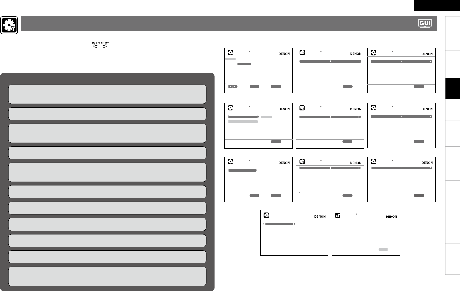
Getting Started Connections Playback Remote Control Information Troubleshooting Specifi cations
ENGLISH
Multi-Zone
Make the settings related to the currently selected input source.
Before displaying the menu screen, press to switch to the input source to be set.
The items that can be set differ according to the selected input source.
The set can be used without changing these settings. Make these settings as necessary.
For a description of “Menu map” and operating instructions, see page 20.
n Examples of Menu Screen Displays
Assign Video Input Mode
INPUT SETUP
INPUT ASSIGN
Default [ HDMI ][DIGITAL] [ COMP ] [ iPod ]
D V D HDMI1 Coax1 1-RCA None
HDP HDMI2 None None None
T V N o n e O p t 1 N o n e N o n e
SAT/CBL HDMI3 Coax2 None None
VCR None None None Assign
DVR HDMI4 Opt2 2-RCA None
V.AUX HDMI5 Opt3 None None
S e l e c t ENTER Enter RETURN Return
Change HDMI input connector assignment
INPUT SETUP
VIDEO
ecruoStceleSoediV
Video Convert ON
IMDH&golanArelacSp/i
Resolution(Analog) Auto
Resolution(HDMI) Auto
Progressive Mode Auto
lluFtcepsA
RETURN Return
Select desired video input source
INPUT SETUP
INPUT MODE
otuAedoMtpunI
otuAedoMedoceD
RETURN Return
Automatically detect input signal and playback
Rename Source Level iPod Playback Mode
INPUT SETUP
RENAME
D V D
Default
RETURN Return
D V D
INPUT SETUP
SOURCE LEVEL
Bd0tupnIgolanA
Bd0tupnIlatigiD
RETURN Return
Compensate analog audio input playback level
INPUT SETUP
PLAYBACK MODE
FFOtaepeR
FFOelffuhS
RETURN Return
Cancel repeat mode
Auto Preset Preset Skip Preset Name
INPUT SETUP
AUTO PRESET
Start
ENTER Enter RETURN Return
Start the auto preset process
INPUT SETUP
]7/1[PIKSTESERP
AkcolB
A Block Presets ON
A 1 F M 8 7 . 5 0 M H z O N
A 2 F M 8 9 . 1 0 M H z O N
A 3 F M 9 8 . 1 0 M H z O N
A 4 F M 1 0 7 . 9 0 M H z O N
A 5 F M 9 0 . 1 0 M H z O N
A 6 A M 9 0 . 1 0 M H z O N
A 7 A M 9 0 . 1 0 M H z O N
A 8 A M 9 0 . 1 0 M H z O N
RETURN Return
Change memory blocks
INPUT SETUP
]7/1[EMANTESERP
AkcolB
A 1 F M 8 7 . 5 0 M H z [ ]
A 2 F M 8 9 . 1 0 M H z [ ]
A 3 F M 9 8 . 1 0 M H z [ ]
A 4 F M 1 0 7 . 9 0 M H z [ ]
A 5 F M 9 0 . 1 0 M H z [ ]
A 6 A M 9 0 . 1 0 M H z [ ]
A 7 A M 9 0 . 1 0 M H z [ ]
A 8 A M 9 0 . 1 0 M H z [ ]
RETURN Return
Change memory blocks
Parental Lock Antenna Aiming
INPUT SETUP
PARENTAL LOCK
Lock Setting
E d i t L o c k C o d e
Set a listening limit to any channel
INPUT SETUP
ANTENNA AIMING
Satellite
Terrestrial
RETURN Return
Adjust antenna position for best signal
Items that can be set with the Input Setup proceduren
Changing the Input Sources Assigned to the Input Terminals
(Input Assign) vpage 35
Making the video settings (Video) vpage 36
Changing the Input Source’s Input Mode and Decoding mode
(Input mode) vpage 37
Changing the Input Source’s Display Name (Rename) vpage 37
Correcting the Input Source’s Playback Level (Source Level)
vpage 38
Setting the iPod Playback Mode (iPod Playback Mode) vpage 38
Setting the Preset Channels to be Skipped (Preset Skip) vpage 38
Presetting Radio Stations (Auto Preset) vpage 38
Assign Name to a Preset Memory (Preset Name) vpage 38
Setting Radio Reception Restrictions (Parental Lock) vpage 39
Check the SIRIUS Radio Reception Sensitivity (Antenna Aiming)
vpage 39
Settings
Making the Input Settings (Input Setup)
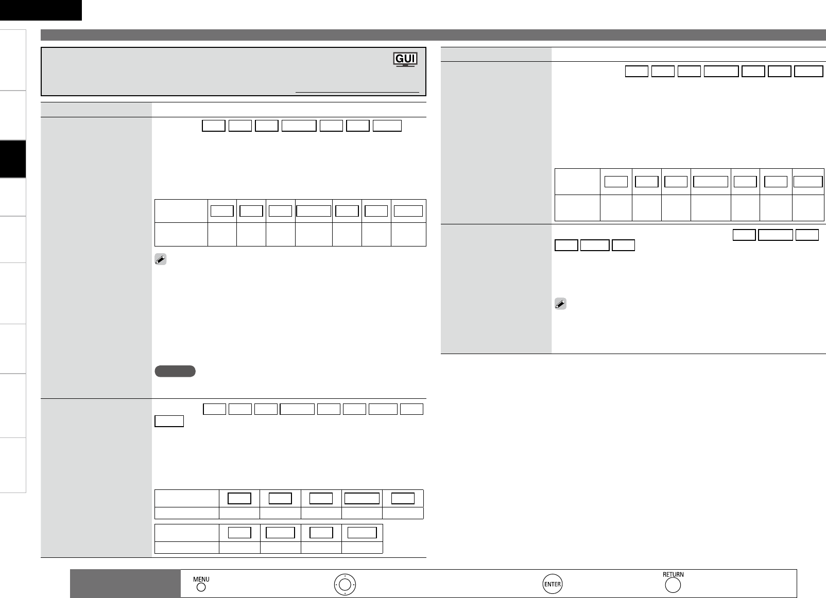
Getting Started Connections Playback Remote Control Information Troubleshooting Specifications
ENGLISH
Multi-Zone
Setting items Setting contents
Input Assign (HDMI)
Assign input sources to input
connectors.
HDMI
:
The DVD HDP TV SAT/CBL VCR DVR V.AUX input
sources are assigned to the HDMI input terminals as shown below.
HDMI1 / HDMI2 / HDMI3 / HDMI4 / HDMI5
None : Do not assign an HDMI input terminal to the currently selected
input source.
b Upon purchase, the settings of the different input sources are as shown
below.
Input
source DVD HDP TV SAT/CBL VCR DVR V.AUX
Default
setting HDMI1 HDMI2 None HDMI3 None HDMI4 HDMI5
• When HDMI is assigned to an input source, the audio signal switches
to HDMI along with the video signal. To use with the digital audio
input connectors assigned, set menu “Input Mode” (vpage 37) to
“Digital”.
• When the AVR-890 and TV are connected with an HDMI cable, if the
TV is not compatible with HDMI audio signal playback, only the video
signals are output to the monitor.
• The audio signals input from the analog, digital and EXT. IN connectors
are not output to the TV.
NOTE
When “HDMI Control” is set to “ON”, HDMI cannot be assigned to “TV”
at the “HDMI” settings (vpage 30).
•
•
Input Assign (Digital)
Assign input sources to input
connectors.
Digital : The DVD HDP TV SAT/CBL VCR DVR V.AUX CD
SIRIUS input sources are assigned to the digital audio input terminals as
shown below.
Coax1 / Coax2 / Opt1 / Opt2 / Opt3
None : Do not assign a digital input terminal to the currently selected
input source.
b Upon purchase, the settings of the different input sources are as shown
below.
Input source DVD HDP TV SAT/CBL VCR
Default setting Coax1 None Opt1 Coax2 None
Input source DVR V.AUX CD SIRIUS
Default setting Opt2 Opt3 None None
•
•
Making the input settings (Input Setup)
Setting items Setting contents
Input Assign (Component)
Assign input sources to input
connectors.
Component : The DVD HDP TV SAT/CBL VCR DVR V.AUX
input sources are assigned to the component video input terminals as
shown below.
1-RCA (Component video 1 input terminal) / 2-RCA (Component video
2 input terminal)
None
: Do not assign the component video input terminals to the currently
selected input source.
bUpon purchase, the settings of the different input sources are as shown
below.
Input
source DVD HDP TV SAT/CBL VCR DVR V.AUX
Default
setting 1-RCA None None None None 2-RCA None
•
•
iPod Dock
Change the input source to
which the control dock for
iPod is assigned.
The control dock for iPod can be assigned to the DVD SAT/CBL VCR
DVR V.AUX CD input sources.
Assign
: Assign the currently selected input source to the Control Dock for
iPod input.
None
: Do not assign the currently selected input source to the Control Dock
for iPod input.
• With the default settings, the control dock for iPod can be used
connected to the VCR (iPod) connector.
• Even if “iPod Dock” is set to “Input Assign”, if AVR-890 and control
dock for iPod are not connected, the input is used as the normal input
source.
Changing the Input Sources Assigned to the
Input Terminals (Input Assign)
Default settings are underlined.
: Moves the cursor (Up/Down/Left/Right) : Decision the setting : Return to previous menu
Remote control
operation buttons : Displaying the menu
Cancel the menu
Settings
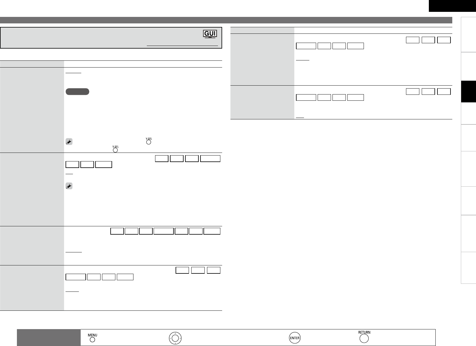
Getting Started Connections Playback Remote Control Information Troubleshooting Specifications
ENGLISH
Multi-Zone
Setting items Setting contents
Video Select
Switch video input source
while listening to audio
signal.
Source : Play the picture and sound of the input source.
DVD / HDP / TV / SAT/CBL / VCR / DVR / V.AUX : Select video input
source to view. This can be set for individual input sources.
NOTE
It is not possible to select HDMI input signals.
When playing HDMI video input signals, the analog video signal of
another input source cannot be selected for the HDMI video output.
Input sources for which “Delete” is selected at “Source Delete” (vpage
32) cannot be selected.
Input sources for which “None” is selected at “Input Assign” (vpage
35) cannot be selected.
•
This can also be set by pressing .
• To cancel, press to select “Source”.
•
•
•
•
Video Convert
The input video signal is
converted automatically in
function of the connected
TV (vpage 9 “Converting
Input Video Signals for
Output (Video Conversion
Function)”).
This can be set when the input source is DVD HDP TV SAT/CBL
VCR DVR V.AUX .
ON : The input video signal is converted.
OFF : The input video signal is not converted.
When a non-standard video signal from a game machine or some other
source is input, the video conversion function might not operate. In this
case set “Video Convert” to “OFF”.
When “Video Convert” is set to “OFF”, the video conversion function
does not work. In this case, connect the AVR-890 and TV with the same
type of cable.
•
•
i/p Scaler
The input source’s resolution
is converted to the resolution
set at “Resolution”.
This can be set to the DVD HDP TV SAT/CBL VCR DVR V.AUX
input sources.
OFF : Do not use i/p scaler function.
Analog : Analog signals are converted to HDMI signals.
Analog and HDMI : Both analog signals and HDMI signals are converted
to the desired HDMI resolution.
Resolution
Set the output resolution.
Resolution A (Analog) : Analog
Video
Resolution H (HDMI) : HDMI
This can be set when the input source is set to DVD HDP TV
SAT/CBL VCR DVR V.AUX , and when “i/p Scaler” is set to anything
other than “OFF”.
AUTO : Detect monitor panel resolution and automatically set output
resolution.
480p/576p / 1080i / 720p / 1080p / 1080p:24Hz : Select the output
resolution.
Making the video settings (Video)
Default settings are underlined.
Making the input settings (Input Setup)
The items that can be set depend on the input source and the “Input Assign” setting.
: Moves the cursor (Up/Down/Left/Right) : Decision the setting : Return to previous menu
Remote control
operation buttons : Displaying the menu
Cancel the menu
Settings
Setting items Setting contents
Progressive Mode
Select optimum progressive
mode for video material.
This can be set when the input source is set to DVD HDP TV
SAT/CBL VCR DVR V.AUX , and when “i/p Scaler” is set to anything
other than “OFF”.
AUTO : The video material is automatically detected and the appropriate
mode is set.
Video1 : Select mode suitable for video playback.
Video2 : Select mode suitable for video and 30-frame film material
playback.
Aspect
Set the aspect ratio of the
video signal output from the
HDMI terminal.
This can be set when the input source is set to DVD HDP TV
SAT/CBL VCR DVR V.AUX , and when “i/p Scaler” is set to anything
other than “OFF”.
Normal : Output at 4:3 aspect ratio.
Full : Output at 16:9 aspect ratio.
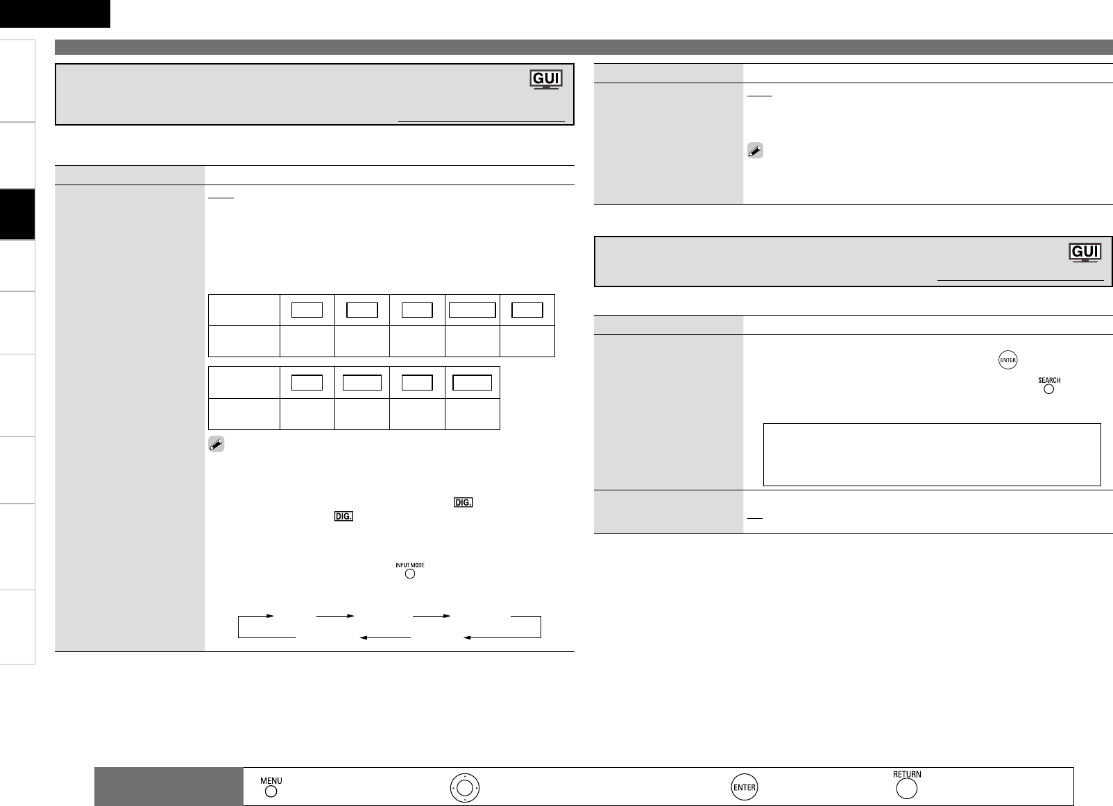
Getting Started Connections Playback Remote Control Information Troubleshooting Specifications
ENGLISH
Multi-Zone
Making the input settings (Input Setup)
Setting items Setting contents
Decode Mode
Set the input source’s
decoding mode.
Auto : Detect type of digital input signal and decode and play
automatically.
PCM : Decode and play only PCM input signals.
DTS : Decode and play only DTS input signals.
• This can be set for input sources for which “HDMI” or “Digital” is
assigned at “Input Assign” (vpage 35).
• Normally set this to “Auto”.
Setting items Setting contents
Rename
Change the input source’s
display name to the desired
name.
1. Use o p to set the cursor to the character you want to change.
2. Use ui to change the character, then press .
Up to 8 characters can be input.
The input character type can be switched by pressing while the
display name is being changed.
• The types of characters that can be input are as shown below.
GUpper case charactersH ABCDEFGHIJKLMNOPQRSTUVWXYZ
GLower case charactersH abcdefghijklmnopqrstuvwxyz
GSymbolsH ! “ # $ % & ‘ ( ) * + , - . / : ; < = > ? @ [ \ ] ^ _ ` { | } ˜
GNumbersH 0123456789 (Space)
•
•
Default
The changed display names
are reset to the defaults.
Yes : Reset to the defaults.
No : Do not reset to the defaults.
Changing the Input Source’s Display Name (Rename)
Default settings are underlined.
Use this procedure to change the display name of the currently selected input source.
: Moves the cursor (Up/Down/Left/Right) : Decision the setting : Return to previous menu
Remote control
operation buttons : Displaying the menu
Cancel the menu
Settings
Setting items Setting contents
Input Mode
Set the audio input modes for
the different input sources.
Auto : Automatically detect input signal and perform playback.
HDMI : Play only signals from HDMI input. (Excluding CD and SIRIUS)
Digital : Play only signals from digital input.
Analog : Play only signals from analog input.
EXT. IN : Play only signals from EXT. IN input.
b Upon purchase, the settings of the different input sources are as shown
below.
Input
source DVD HDP TV SAT/CBL VCR
Default
setting Auto HDMI Digital Auto Analog
Input
source DVR V.AUX CD TUNER
Default
setting Auto Auto Analog Analog
• The “HDMI” settings are made for input sources for which HDMI
input terminals are assigned at “Input Assign” (vpage 35).
• The “Digital” settings are made for input sources for which digital
input terminals are assigned at “Input Assign” (vpage 35).
•
When a digital signal is properly input, the “ ” indicator lights on
the display. If the “ ” indicator does not light, check the digital
input connector assignment and the connections.
• The surround mode cannot be set if the input mode is set to “EXT.
IN”.
•
This can also be set by pressing .
Each time you press the button, the input mode display will change.
Auto HDMI Digital
AnalogEXT. IN
The selectable input modes depend on the input source and “Input Assign” setting (vpage 35
“Changing the input sources assigned to the input terminals”).
Changing the Input Source’s Input Mode and
Decoding mode (Input Mode)
Default settings are underlined.
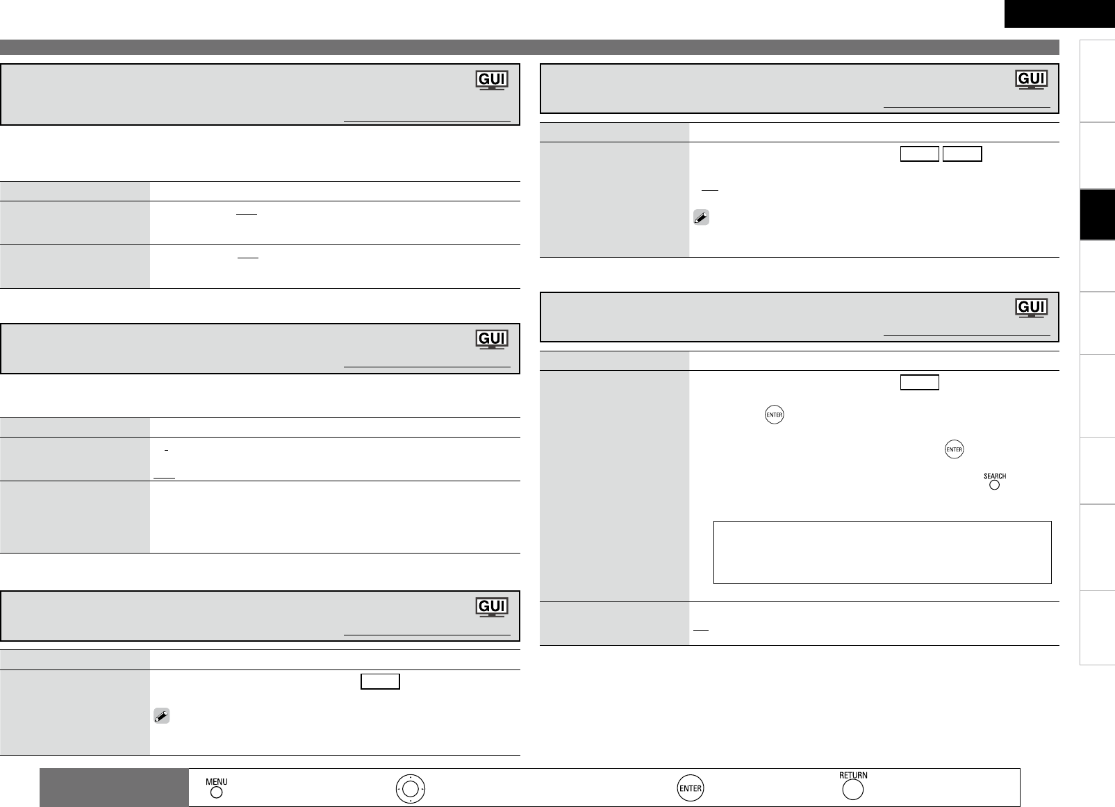
8
Getting Started Connections Playback Remote Control Information Troubleshooting Specifications
ENGLISH
Multi-Zone
Making the input settings (Input Setup)
: Moves the cursor (Up/Down/Left/Right) : Decision the setting : Return to previous menu
Remote control
operation buttons : Displaying the menu
Cancel the menu
Setting items Setting contents
Preset Name
Assign name to a preset
memory.
This can be set when the source is set to TUNER .
1. Use ui to select the preset channel name you want to change,
then press .
2. Use o p to set the cursor to the character you want to change.
3. Use ui to change the character, then press .
• Up to 8 characters can be input.
• The input character type can be switched by pressing while the
display name is being changed.
• The types of characters that can be input are as shown below.
GUpper case charactersH ABCDEFGHIJKLMNOPQRSTUVWXYZ
GLower case charactersH abcdefghijklmnopqrstuvwxyz
GSymbolsH ! “ # $ % & ‘ ( ) * + , - . / : ; < = > ? @ [ \ ] ^ _ ` { | } ˜
GNumbersH 0123456789 (Space)
4. Repeat steps 2 and 3 to change the display name.
Default
The changed display names
are reset to the defaults.
Yes : Reset to the defaults.
No : Do not reset to the defaults.
Assign Name to a Preset Memory (Preset Name)
Default settings are underlined.
Setting items Setting contents
Preset Skip
Set the preset memories that
you do not want to display
when tuning.
This can be set when the source is set to TUNER SIRIUS .
A ~ G : Select the preset channel(s) you do not want to display.
ON : Display this number.
Skip : Skip this number.
If you set “Block Presets” to “Skip”, you can skip the preset memory
blocks (A to G).
•
•
Setting the Preset Channels to be Skipped (Preset Skip)
Default settings are underlined.
Setting items Setting contents
Auto Preset
Use the auto preset function
to program radio stations.
This can be set when the source is set to TUNER .
Start : Start the auto preset process.
If an FM station cannot be preset automatically, select the desired station
by tuning it in manually, then preset it manually.
Presetting Radio Stations (Auto Preset)
Default settings are underlined.
Settings
Setting items Setting contents
Repeat
Make settings for repeat
mode.
All : Repeat all songs.
One : Repeat the current song.
OFF : Cancel repeat mode.
Shuffle
Make settings for shuffle
mode.
n When DENON control dock for iPod ASD-1R or ASD-11R is
connected
Songs : Shuffle all songs.
Albums : Shuffle songs from current album only.
OFF : Cancel shuffle mode.
This can be selected for input sources for which “Input Assign” is assigned at the “iPod Dock”
(vpage 35) setting.
Setting the iPod Playback Mode (iPod Playback Mode)
Default settings are underlined.
Setting items Setting contents
Source Level (Analog)
Correct the playback level of
the analog audio input.
–12dB ~ +12dB (0dB)
Source Level (Digital)
Correct the playback level of
the digital audio input.
–12dB ~ +12dB (0dB)
Use this procedure to correct the playback level of the currently selected input source's audio input.
Set this if there are differences in the input volume levels between the different sources. The analog
input level and digital input level can be corrected separately.
Correcting the Input Source’s Playback Level
(Source Level) Default settings are underlined.
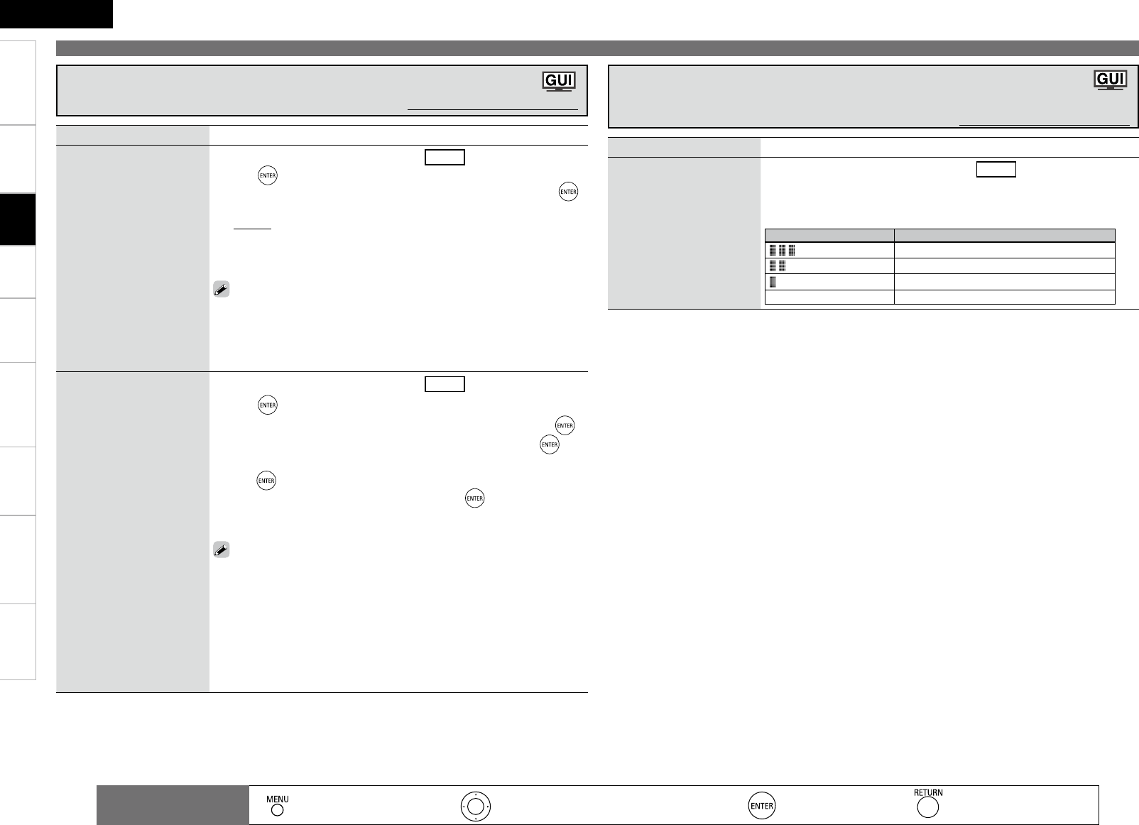
Getting Started Connections Playback Remote Control Information Troubleshooting Specifications
ENGLISH
Multi-Zone
Setting items Setting contents
Antenna Aiming
Check the SIRIUS radio
reception sensitivity.
This can be set when the source is set to SIRIUS .
Satellite : Indicate satellite signal strength.
Terrestrial : Indicate terrestrial signal strength.
SIRIUS Antenna
Display Condition
Signal strength is excellent
Signal strength is good
Signal strength is weak
No signal
Check the SIRIUS Radio Reception Sensitivity
(Antenna Aiming)
Default settings are underlined.
Setting Radio Reception Restrictions (Parental Lock)
Default settings are underlined.
Making the input settings (Input Setup)
: Moves the cursor (Up/Down/Left/Right) : Decision the setting : Return to previous menu
Remote control
operation buttons : Displaying the menu
Cancel the menu
Settings
Setting items Setting contents
Lock Setting
Set the channel radio
reception limits.
This can be set when the source is set to SIRIUS .
1. Press .
2. Using uio p, input the password (4 digits number) and press .
3. Select channel by pressing ui, and set the lock by pressing o p.
• Unlock : Do not lock selected channel(s).
• Lock : Lock selected channel(s).
b
When a Parental Locked channel is tuned, “Code : [ ]” is displayed,
then input the password.
The default password is “0000”.
If the password is wrong, “Incorrect Code” is displayed. Input the correct
password.
While listening to the channel being played, you can also set parental lock
(vpage 43).
•
•
•
Edit Lock Code
Change the password. This can be set when the source is set to SIRIUS .
1. Press .
2. Input “Current Lock Code” (4 digits) using uio p, and press .
3. Input “New Lock Code” (4 digits) using uio p, and press .
4. Input “Repeat New Lock Code” (4 digits) again using uio p, and
press .
5. Press ui to select “Execute”, and then press .
If the correct password is input, “Completed” is displayed, and the new
password is modified.
If the “Current Code” is incorrectly input, “Incorrect Code” is displayed,
and proceed again from step
1
.
If the password input is 3 digits or less, “Enter 4-digit” is displayed, and
input again with a 4 digit password.
If the new password is not correctly input, “
Code don’t Match
” is displayed
and the password does not change.
The password cannot be cleared even if the operation to reset the unit is
performed. We recommend writing down the password so as not to forget
it.
•
•
•
•
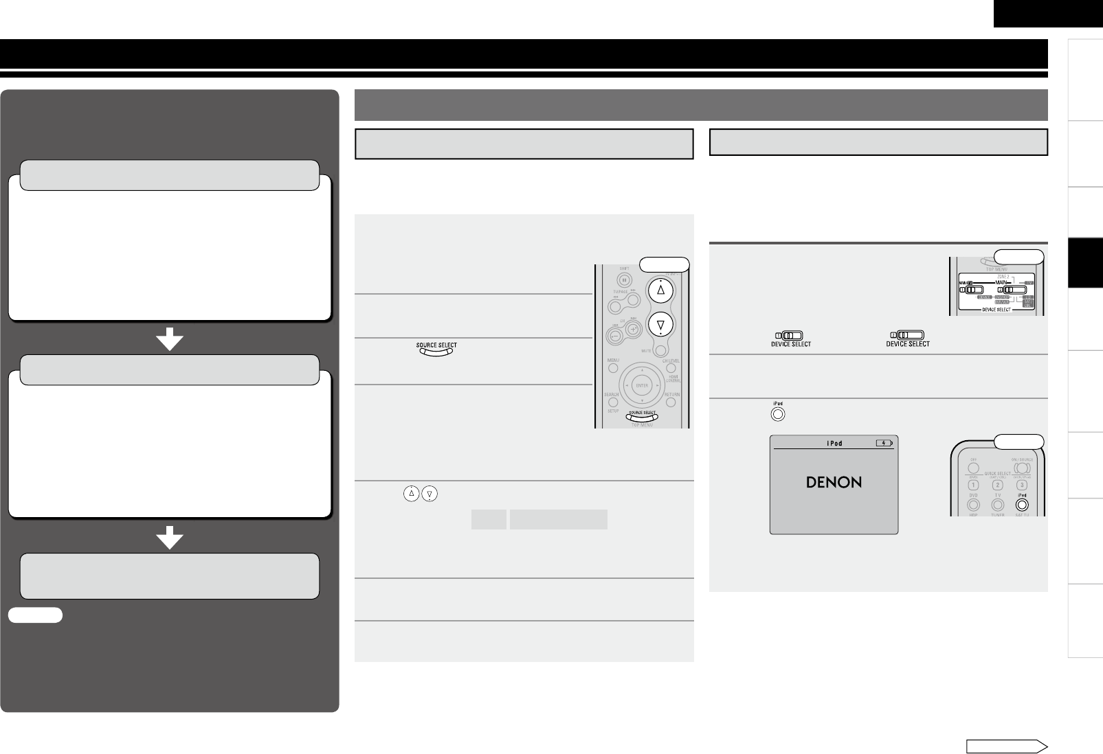
0
ENGLISH
Getting Started Connections Remote Control Information Troubleshooting Specifi cationsMulti-ZoneSettings
Playback
Playing Components
1Prepare for playback.
① Turn on the power of the TV, subwoofer and player.
② Set the TV’s input to the AVR-890.
③ Load the disc in the player.
2Turn on the AVR-890’s power.
(vpage 19 “Turning the Power On”)
3Press and select the input
source.
4Play the component connected to
the AVR-890.
Make the necessary settings on the
player (language setting, subtitles
setting, etc.) beforehand.
5Use to adjust the volume.
GVariable rangeH – – – –80.5dB ~ 18.0dB
※ The variable range differs according to the input signal and
channel level setting.
6Select the desired surround mode.
(vpage 44 “Selecting the Surround Mode”)
7Adjust the desired sound eld effects.
(vpage 46 “Adjusting the Sound and Picture Quality”)
The following describes the procedure for playing Blu-ray disc/
DVD players.
Use the same procedure to play other components.
Playing Blu-ray Disc / DVD Players
The music / video on an iPod can be played by using the control
dock for iPod (ASD-1R, ASD-11R, ASD-3N or ASD-3W sold
separately).
Connect the control dock for iPod beforehand (vpage 14 “iPod®”).
iPod® Playback
1 Prepare for playback.
q Set the iPod in the DENON control dock
for iPod.
w Assign the control dock for iPod’s input
(vpage 35).
e Set to “MAIN/TV” to “MAIN”.
2Turn on the AVR-890’s power.
(vpage 19 “Turning the Power On”)
3 Press to select the input source assigned in step
1-w above.
(iPod screen)
b If the screens above are not displayed, the iPod may not be
properly connected. Try connecting again.
Listening to music on an iPod®
OK to disconnect.
Front
Adjusting the Sound and Picture Quality
(Audio/Video Adjust) (vpage 46)
Playing Components (vpage 40)
n Playing Blu-ray Disc/DVD Players (vpage 40)
n iPod® Playback (vpage 40)
n Listening to FM/AM Broadcasts (vpage 41)
n Listening to SIRIUS Satellite Radio Programs
(vpage 42)
n Operations During Playback (vpage 44)
n Operation Flow
Before starting playback, make the connections between the
different components and the settings on the receiver.
Selecting the Surround Mode (vpage 44)
q Standard Playback (vpage 44)
w Playing in a DENON original surround mode
(vpage 45)
e Direct Playback (vpage 45)
r Stereo Playback (vpage 46)
t Playing the Pure Direct mode (vpage 46)
NOTE
● Also refer to the operating instructions of the connected
components when playing them.
● External devices can be controlled by remote control unit
(vpage 55 “Operating the Connected Devices by Remote
Control Unit”).
See overleaf
Front
Front
Playback
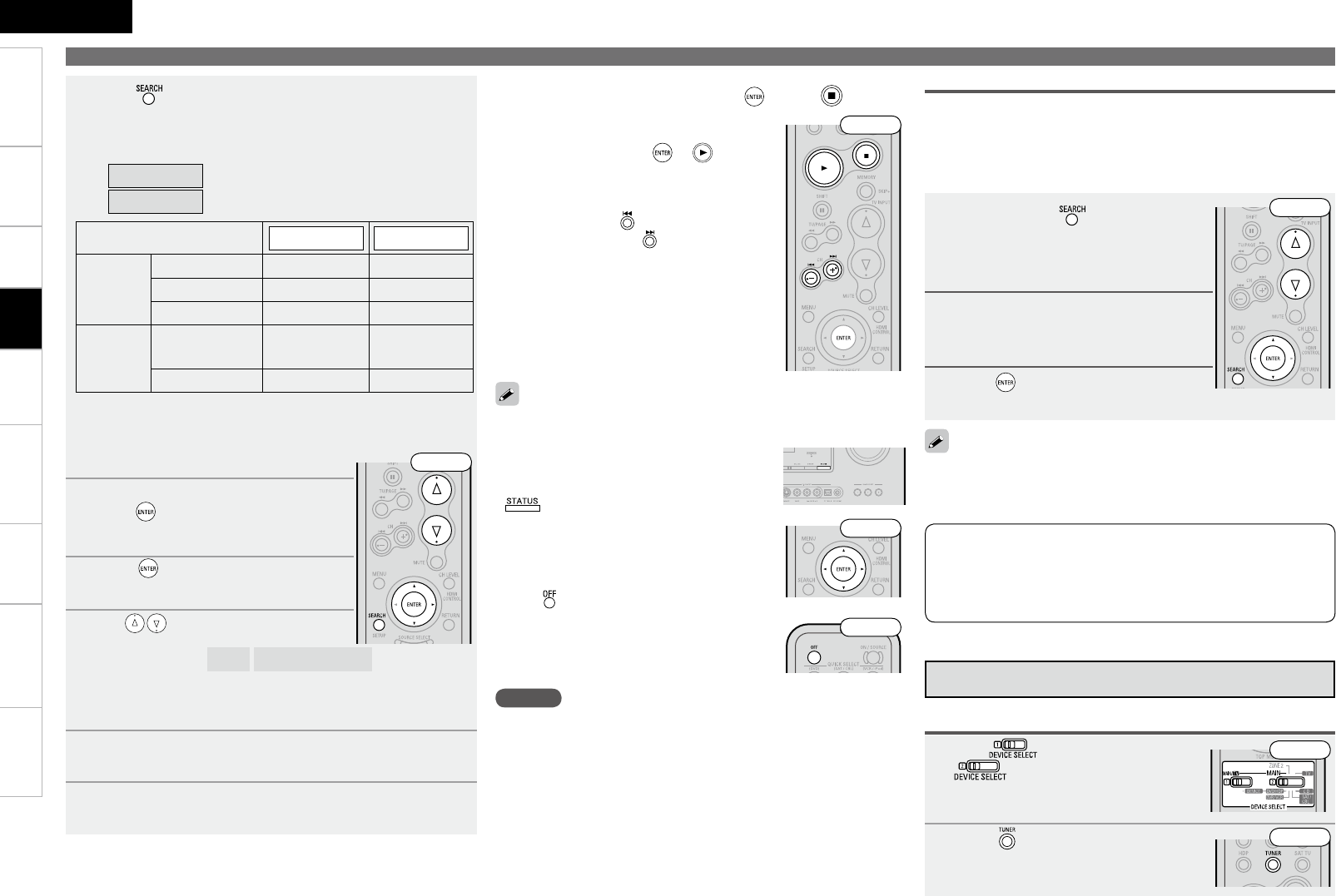
ENGLISH
Getting Started Connections Remote Control Information Troubleshooting SpecificationsMulti-ZoneSettings
Playing Components
Use the RESTORER mode to expand the low and high frequency
components of compressed audio files and achieve a richer sound.
The default setting is “Mode 3” (vpage 50).
To check the name of the title, the artist or the
album when playing in browse mode, press
.
The time (default : 30 sec) for which the GUI
menu are displayed can be set at menu “GUI-
iPod” (vpage 32). Press uio p to return
to the original screen.
Press and set the AVR-890’s power to the
standby mode before disconnecting the iPod.
Also switch the input source to one to which
the menu “iPod dock” is not assigned before
disconnecting the iPod.
•
•
•
•
4 Press and hold it down for a 2 seconds or more to
select the display mode.
There are two modes for display the contents recorded on the
iPod.
Browse mode
:Displayed on the TV screen.
Remote mode
:Displayed on the iPod’s screen.
Display mode Browse mode Remote mode
Playable
files
Audio file
S S
Picture file
A Sz2
Video file
Sz1Sz2
Active
buttons
Remote control
unit (AVR-890)
S S
iPod®A S
z1: When using an ASD-11R, ASD-3N or ASD-3W control dock for
iPod.
z2: Video may not be output, depending on the combination of
ASD-1R or ASD-11R and iPod.
5 Use ui to select the menu, then
press or p to select the music or
video le to be played.
6 Press or p.
Playback starts.
7 Use to adjust the volume.
GVariable rangeH – – – –80.5dB ~ 18.0dB
※ The variable range differs according to the input signal and
channel level setting.
8 Select the desired surround mode.
(vpage 44 “Selecting the Surround Mode”)
9 Adjust the desired sound eld effects.
(vpage 46 “Adjusting the Sound and Picture Quality”)
n To stop
During playback, either press and hold or press .
n Stopping playback temporarily
During playback, press or .
Press again to resume playback.
n To cue to the beginning of a track
During playback, either press (to cue to
the current track) or (to cue to the next
track).
n Repeat playback and shuffle
playback
“iPod Playback Mode” (vpage 38)
iPod is a trademark of Apple Inc., registered in the U.S. and other
countries. The iPod may only be used to copy or play contents
that are not copyrighted or contents for which copying or playback
is legally permitted for your private use as an individual. Be sure to
comply with applicable copyright legislation.
NOTE
Depending on the type of iPod and the software version, some
functions may not operate.
DENON will accept no responsibility whatsoever for any loss of iPod
data.
•
•
1 Press and hold to set the Remote
mode.
“Remote iPod” is displayed on the AVR-
890’s display.
2 Watching the iPod’s screen,
use ui to select “Photos” or
“Videos”.
3 Press until the image you want to
view is displayed.
“TV Out” at the iPod’s “Slideshow Settings” or “Video Settings”
must be set to “On” in order to display the iPod’s photo data or videos
on the monitor. For details, see the iPod’s operating instructions.
Viewing Still Pictures or Videos on the iPod®
Photo and video data on the iPod can be viewed on the monitor.
Only for iPod equipped with slideshow or video functions. (When
using an ASD-1R or ASD-11R)
Video may not be output, depending on the combination of ASD-1R
or ASD-11R and iPod.
•
•
Front
Front
Front
Front
Front
1Set to “MAIN/TV” and
to “MAIN”.
2Press to select “TUNER”.
Listening to FM/AM Broadcasts
Basic Operation
Front
Front
Playback
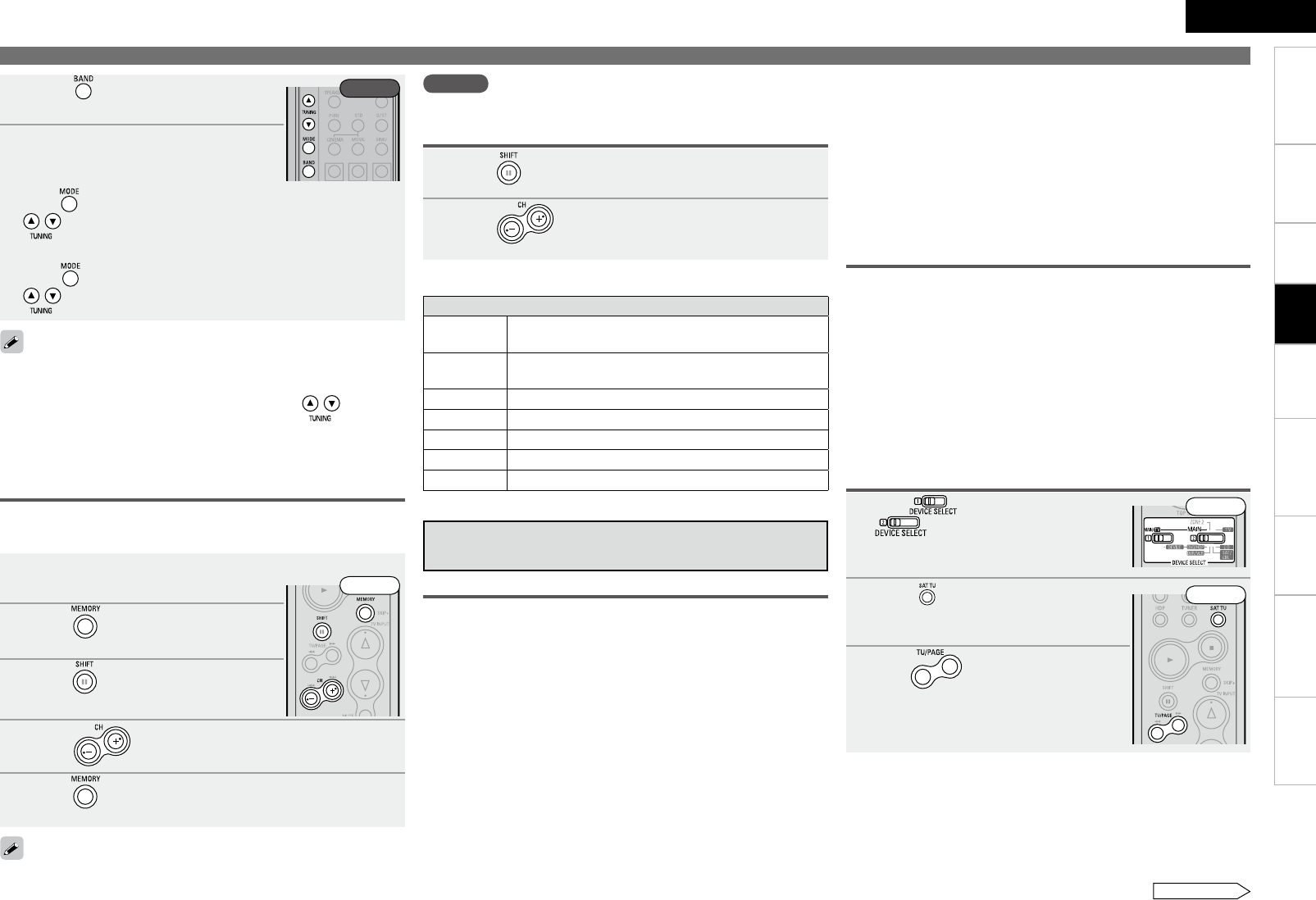
2
ENGLISH
Getting Started Connections Remote Control Information Troubleshooting SpecificationsMulti-ZoneSettings
3Press to select “FM” or “AM”.
4Tune in the desired broadcast
station.
q To tune in automatically (Auto Tuning)
Press to light the “AUTO” indicator on the display, then use
to select the station you want to hear.
w To tune in manually (Manual Tuning)
Press to turn off the display’s “AUTO” indicator, then use
to select the station you want to hear.
1Tune in the broadcast station you want to preset.
2Press .
3Press
to select the block (A to G)
in which the station is to be preset.
4Press to select the preset number (1 to 8).
5Press again to complete the setting.
• To preset other stations, repeat steps 1 to 5.
• Stations can be preset automatically at menu “Auto Preset” (vpage
38).
NOTE
Preset stations are erased by overwriting them.
• If the desired station cannot be tuned in with auto tuning, tune it in
manually.
• When tuning in stations manually, press and hold to change
frequencies continuously.
• The time (default : 30 sec) for which the GUI menu are displayed can
be set at “GUI-Tuner” (vpage 32).
Presetting Radio Stations (Preset Memory)
Your favorite broadcast stations can be preset so that you can tune
them in easily. Up to 56 stations can be preset.
Playing Components
1Press to select the memory block (A to G).
2Press to select the desired preset channel (1
to 8).
n Default settings
Auto tuner presets
A1 ~ A8 87.5 / 89.1 / 98.1 / 107.9 / 90.1 / 90.1 / 90.1 /
90.1 MHz
B1 ~ B8 520 / 600 / 1000 / 1400 / 1500 / 1710 kHz,
90.1 / 90.1 MHz
C1 ~ C8 90.1 MHz
D1 ~ D8 90.1 MHz
E1 ~ E8 90.1 MHz
F1 ~ F8 90.1 MHz
G1 ~ G8 90.1 MHz
Listening to Preset Stations
Rear
Front
Family friendly packages are also available to restrict channels featuring
content that may be inappropriate for children.
To subscribe to XM, U.S. customers should visit xmradio.com or call
1-800-XMRADIO (1-800-967-2346); Canadian customers should visit
xmradio.ca or call XM Listener Care at 1-877-GETXMSR (1-877-438-
9677).
To subscribe to SIRIUS, U.S. and Canadian customers can call 1-888-
539-SIRI (1-888-539-7474) or visit sirius.com (US) or siriuscanada.ca
(Canada).
Listening to SIRIUS Satellite Radio
Programs
About SIRIUS XM Radio
To listen to Satellite Radio, you’ll need to connect either a SIRIUS or XM
Satellite Radio tuner (sold separately) to your satellite-ready receiver.
Satellite Radio is available to residents of the US (except Alaska and
Hawaii) and Canada.
Satellite Radio delivers a variety of commercial-free music from
categories ranging from Pop, Rock, Country, R&B, Dance, Jazz,
Classical and many more plus coverage of all the top professional
and college sports including play by play games from select leagues
and teams. Additional programming includes expert sports talk,
uncensored entertainment, comedy, family programming, local traffic
and weather and news from your most trusted sources.
Whether you purchase a SIRIUS or XM tuner, you’ll need to activate
and subscribe to begin enjoying the service. Easy to follow installation
and setup instructions are provided with the satellite tuners. Whichever
service you choose, there are a variety of programming packages
available, including the option of adding “The Best of SIRIUS”
programming to your XM tuner or “The Best of XM” programming
to your SIRIUS tuner, enabling you to enjoy the most popular
programming among both services. The “Best of” packages are not
available to SIRIUS or XM Canada subscribers at this time.
SIRIUS XM Radio Legal
SIRIUS, XM and all related marks and logos are trademarks of Sirius
XM Radio Inc. and its subsidiaries. All other marks and logos are the
property of their respective owners. All rights reserved. SIRIUS and
XM subscriptions sold separately. Taxes and a one-time activation fee
may apply. XM tuners and home docks or SIRIUS tuners (each sold
separately) are required to receive the SIRIUS or XM satellite radio
service. All programming and fees subject to change. It is prohibited to
copy, decompile, disassemble, reverse engineer, hack, manipulate or
otherwise make available any technology or software incorporated in
receivers compatible with the SIRIUS or XM Satellite Radio Systems.
Service not available in Alaska and Hawaii.
Playback
1Set to “MAIN/TV” and
to “MAIN”.
2Press to select “SIRIUS”.
3Use to select the channel.
When the channel is tuned in, the name of
the track and artist are displayed.
Basic Operation
Front
Front
See overleaf
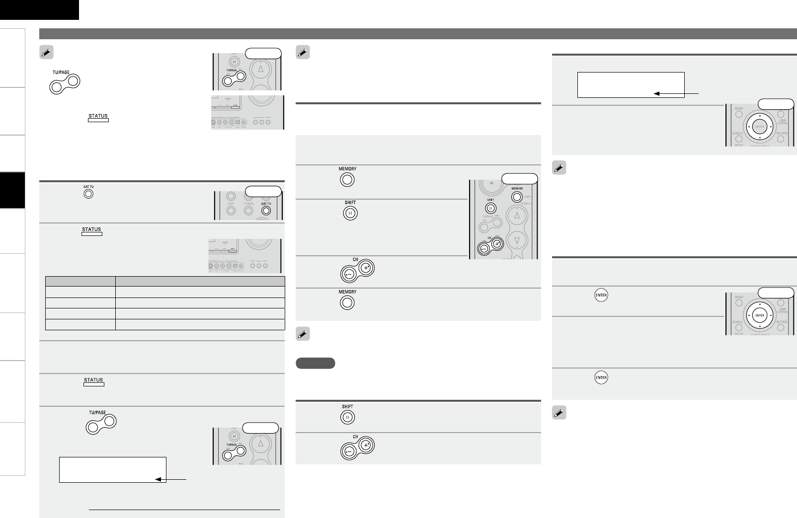
ENGLISH
Getting Started Connections Remote Control Information Troubleshooting SpecificationsMulti-ZoneSettings
1Press to select “SIRIUS”.
2Press on the main unit until “SIGNAL” appears
on the display.
The display will switch as shown below,
depending on the reception conditions.
Display Status
EXCELLENT Signal strength is excellent
GOOD Signal strength is good
WEAK Signal strength is weak
NO SIGNAL No signal
3Adjust the position of the antenna until “SIGNAL:
EXCELLENT” is shown on the display.
4Press on the main unit until the channel you
want to check (example: “SR001”) is displayed.
5Press and select channel 0 (SR000).
Channel No. and Sirius ID are alternately
shown on the display.
SR000 SiriusID
************
b Write your own SIRIUS ID for storage use.
Sirius ID :
• The channel switches continuously when
is pressed and held.
• The song title, artist name, composer name,
category and reception level can be checked
by pressing on the main unit.
• The time (default : 30 sec) for which the GUI
menu are displayed can be set at menu “GUI-
Tuner” (vpage 32).
Press uio p to return to the original screen.
Front
The strength of both the SIRIUS and terrestrial signals can be checked
at menu “Antenna Aiming” (vpage 39).
Playing Components
Checking the SIRIUS Signal Strength and Radio ID
Front
1Press to select the memory block (A to G).
2Press to select the desired preset channel (1
to 8).
1Tune in the broadcast channel you want to preset.
2Press .
3Press to select the block (A
to G) in which the channel is to be
preset.
4Press to select the preset number (1 to 8).
5Press again to complete the setting.
To preset other channels, repeat steps 1 to 5.
NOTE
Preset channels are erased by overwriting them.
Presetting Radio Channels (Preset Memory)
Your favorite broadcast channels can be preset so that you can tune
them in easily. Up to 56 channels can be preset.
Listening to Preset Channels
Front
1Press o p.
SR001 Hits 1
CAT : Pops
2Use o p to select the category,
then use ui to select the desired
channel.
Channel category
• “UPDATING” is displayed while the encoding code is being
updated.
• “SIRIUS UPDATING” is displayed when updating SIRIUS tuner
firmware.
• Refer to “Troubleshooting” – “SIRIUS Satellite Radio” regarding other
messages (vpage 67).
Searching Categories
Front
Playback
Sirius ID
Front
1Tune to the channel you want to lock.
2Press for at least 3 seconds.
“Code: [ ]” is displayed.
3Enter the 4-digit lock code using
uio p.
When you enter the correct code, the corresponding channel is
locked.
4Press .
• Channels under Parental Lock cannot be tuned in by performing
Tuning Up/Down or by category search.
• Channels stored in preset memory can be tuned in by the preset
channel select operation, even if Parental Lock is applied.
• When a channel to which Parental Lock is applied is being played,
Parental Lock for that channel is cancelled by performing Step2.
• See “Edit Lock Code” (vpage 39) for the method of changing
Parental Lock Code.
• You can also set “Parental Lock” from the menu (vpage 39).
Parental Lock
Front
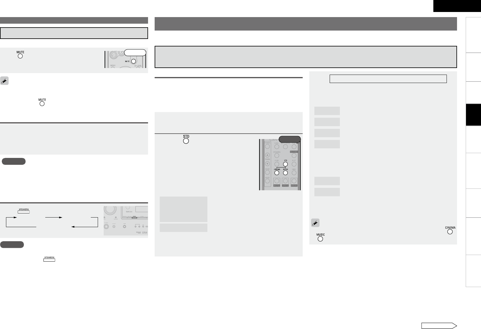
ENGLISH
Getting Started Connections Remote Control Information Troubleshooting SpecificationsMulti-ZoneSettings
Playing Components
Turning Off the Sound Temporarily (Muting)
Press .
The sound is reduced to the level set at menu “Mute Level” (vpage
31).
To cancel, press again. Muting can also be canceled by adjusting
the master volume.
•
•
Listening with Headphones
Plug the headphones into the PHONES jack on the main
unit.
The sound from the speakers and pre-out connectors is automatically
cut.
NOTE
To prevent hearing loss, do not raise the volume level excessively
when using headphones.
Unplug headphones when performing Audyssey™ Auto Setup or
other settings.
•
•
Switching the front speakers
Press .
Front A Front B
Front A+B
NOTE
When you set to “Custom” with “Front Speaker Setup“ (vpage 29),
you cannot operate .
Operations During Playback
Front
Selecting the Surround Mode
Select a surround mode to enjoy surround playback with your favorite sound field effects.
1Playing the source (vpage 40).
2Press to select the surround
mode.
n Multichannel sources
The surround modes that can be selected
differ according to the input source.
n 2channel sources
When you select “DOLBY PLgz”, set “Amp
Assign” to “Front Height”.
DOLBY PLgx,
DOLBY PLg
or
DOLBY PLgz
: The signals are decoded in DOLBY PLgx,
DOLBY PLg or DOLBY PLgz, for playback.
DTS NEO:6 : The signals are decoded in DTS NEO:6 for
playback.
z: DOLBY PLgx can be selected when surround back speakers are
being used.
Operations
The selectable surround modes depend on the following:
• Format of the audio signals being input
• Number of channels of the audio signals being input
• The set amplifier assignment mode (vpage 27)
3
Select the mode for the source at “Mode” (vpage
46).
n DOLBY PLgx, DOLBY PLg
Cinema : This mode is suited for movie sources.
Music : This mode is suited for music sources.
Game : This mode is suited for games.
Pro Logic : This is the Pro Logic playback mode. This can be
selected when playing with a DOLBY PLg decoder.
When this mode is selected, “DOLBY PL” is
displayed.
n DTS NEO:6
Cinema : This mode is suited for movie sources.
Music : This mode is suited for music sources.
※ The modes that can be selected depend on the input source
being played.
The “Cinema” and “Music” modes can also be set by pressing
or .
This is the operation for playing 2-channel sources.
Rear
z
See overleaf
Playback
q Playing Sources According to the Sources’ Audio Signal Format/Number of
Channels (Standard Playback)
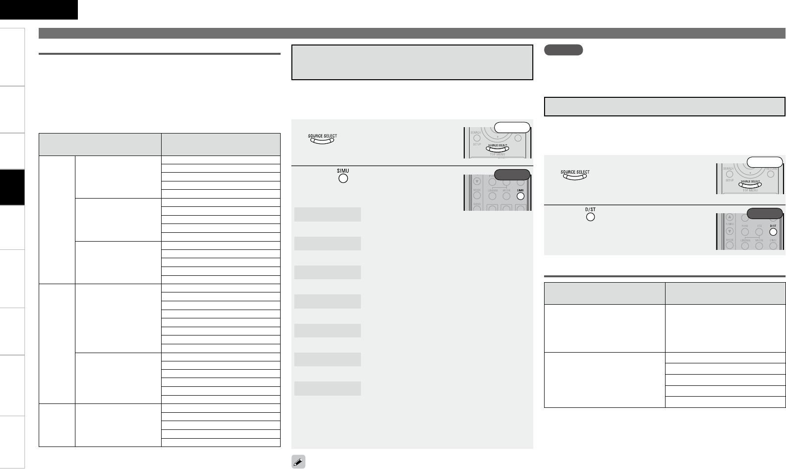
ENGLISH
Getting Started Connections Remote Control Information Troubleshooting SpecificationsMulti-ZoneSettings
In the case of standard playback of multi channel sources, the
AVR-890 recognizes the format of the multi-channel audio input
signal and automatically operates the appropriate decoder for
surround sound.
Input signal The indication contents of
the display
Dolby
Digital
Dolby Digital
(other than 2ch)/
Dolby Digital EX
DOLBY DIGITAL
DOLBY DIGITAL EX
DOLBY DIGITAL+PLgx CINEMA
DOLBY DIGITAL+PLgx MUSIC
DOLBY DIGITAL+PLgz
Dolby Digital Plus
(z1)
DOLBY DIGITAL+
DOLBY DIGITAL++EX
DOLBY DIGITAL++PLgx C
DOLBY DIGITAL++PLgx M
DOLBY DIGITAL++PLgz
Dolby TrueHD (z1)
DOLBY TrueHD
DOLBY HD+EX
DOLBY HD+PLgx CINEMA
DOLBY HD+PLgx MUSIC
DOLBY HD+PLgz
DTS
DTS (5.1ch)/
DTS-ES Discrete 6.1 /
DTS-ES Matrix 6.1 /
DTS 96/24
DTS SURROUND
DTS+PLgx CINEMA
DTS+PLgx MUSIC
DTS+PLgz
DTS+NEO:6
DTS ES MTRX6.1 (z2)
DTS ES DSCRT6.1 (z3)
DTS 96/24 (z4)
DTS-HD (z1)
DTS-HD HI RES
DTS-HD MSTR
DTS-HD+NEO:6
DTS-HD+PLgx CINEMA
DTS-HD+PLgx MUSIC
DTS-HD+PLgz
PCM PCM
(multi ch)
MULTI CH IN
MULTI IN+PLgx CINEMA
MULTI IN+PLgx MUSIC
MULTI IN+PLgz
MULTI CH IN 7.1
z1:When a signal is input, the HD AUDIO indicator lights.
z2:This is displayed when the input signal is “DTS-ES Matrix 6.1”
and the AVR-890’s “AFDM” setting (vpage 47) is set to “ON”.
z3:This is displayed when the input signal is “DTS-ES Discrete
6.1”.
z4:This is displayed when the input signal is “DTS 96/24”.
Displaying the currently playing surround mode
n Surround playback of multichannel sources
(Dolby Digital, DTS, etc.)
Selecting the Surround Mode
w Playing in a DENON Original
Surround Mode
Depending on the program source being played, it may not be possible
to achieve a satisfactory surround effect. In this case, try other modes
to achieve a sound field suited to your tastes.
NOTE
When the input signal is DOLBY TrueHD, DOLBY DIGITAL Plus,DTSHD
you cannot select DENON original surround mode.
The desired mode according to the program source and viewing
situation can be selected from among 7 DENON original surround
modes.
1Select the input source by pressing
and play the source (vpage
40).
2Press to select the Surround
mode.
5CH/7CH STEREO : This mode is for enjoying stereo sound from all
speakers.
ROCK ARENA : This mode is for enjoying the atmosphere of a
live concert in an arena.
JAZZ CLUB : This mode is for enjoying the atmosphere of a
live concert in a jazz club.
MONO MOVIE : This mode is for playing monaural movie
sources with surround sound. z1
VIDEO GAME : This mode is suited for achieving surround
sound with video games.
MATRIX : This mode lets you add a sense of expansion
to stereo music sources.
VIRTUAL : This mode is for enjoying surround effects
using only the front speakers or headphones.
z1: When playing sources recorded in monaural in the MONO
MOVIE mode, the sound will be off balance with a single
channel (left or right), so input to both channels.
e Direct Playback
In this mode the signals bypass the tone adjustment circuitry for
high quality sound.
The sound is output to the same channels as the input signal.
1Select the input source by pressing
and play the source (vpage
40).
2Press to select the “DIRECT”.
Displaying the currently playing surround mode
Input signal The indication contents of
the display
Analog signal /
PCM (2ch) /
Dolby Digital source /
DTS source /
Other 2-channel digital signals
DIRECT
PCM (multi ch)
MULTI CH DIRECT
M DIRECT + PLgx CINEMA
M DIRECT + PLgx MUSIC
M DIRECT + PLgz
M DIRECT 7.1
Front
Front
Rear
Rear
Playback
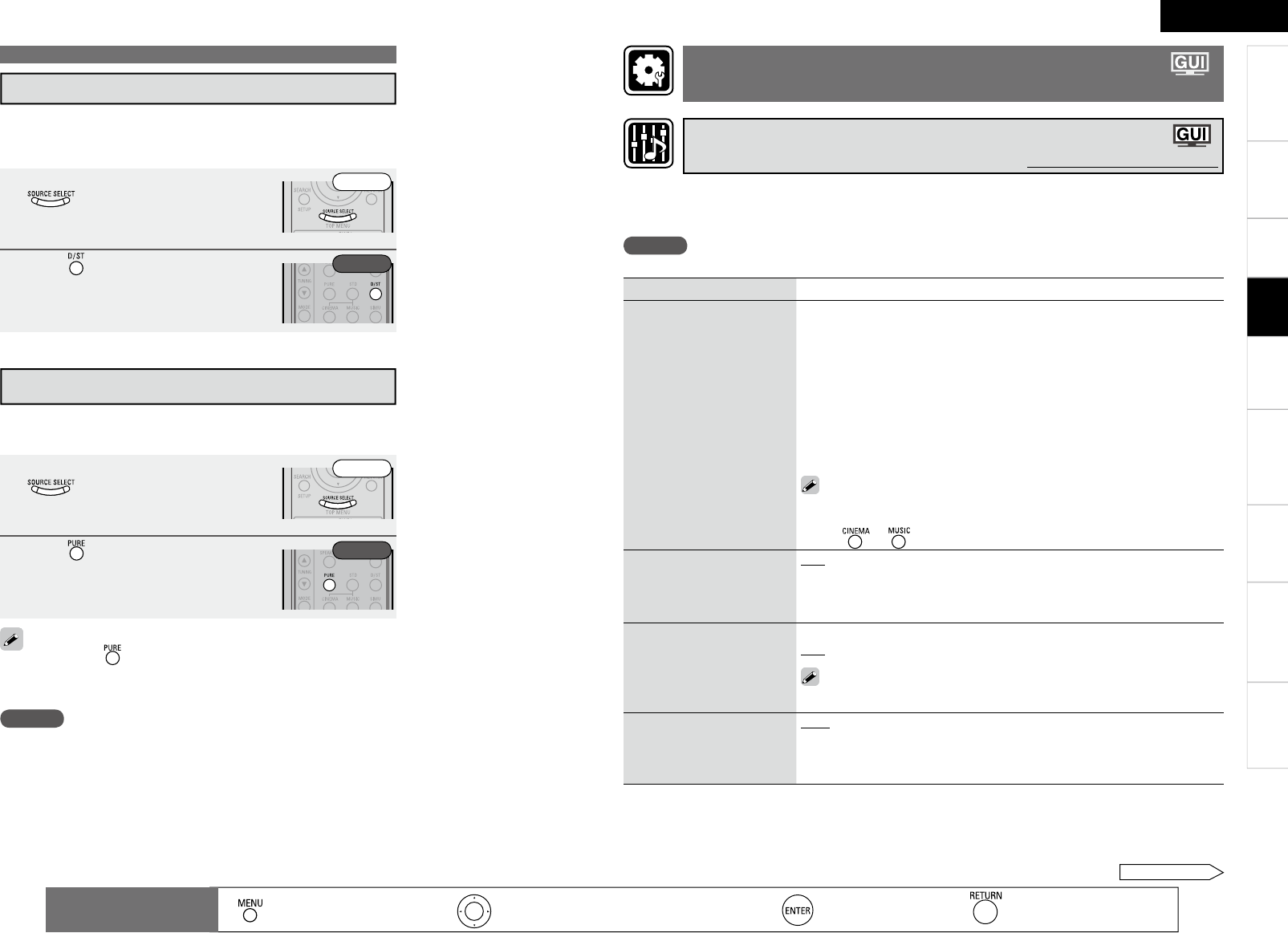
ENGLISH
Getting Started Connections Remote Control Information Troubleshooting Specifi cationsMulti-ZoneSettings
Selecting the Surround Mode
r Stereo Playback
This is the mode for playing in stereo. The tone can be adjusted.
Sound is output from the front left and right speakers and
subwoofer.
1 Select the input source by pressing
and play the source (vpage
40).
2Press to select the “STEREO”.
To cancel, press again.
The channel level and surround parameters in the PURE DIRECT
mode are the same as in the DIRECT mode.
•
•
t Playing the Pure Direct Mode
This is the mode that recreates the original sound most faithfully,
providing extremely high quality sound.
1Select the input source by pressing
and play the source (vpage
40).
2Press .
NOTE
When in the PURE DIRECT mode, the GUI menu is not displayed
and the display on the main unit is turned off.
Front
Front
Rear
Rear
The sound being played in the surround mode can be adjusted to your liking.
The items (parameters) that can be adjusted depend on the signal being input and the currently set surround
mode. For details on the adjustable parameters, see “Surround Modes and Parameters” (vpage 60).
NOTE
Some of the setting items cannot be set while playback is stopped. Set these items during playback.
Setting items Setting contents
Mode
Set the play mode for
playing 2-channel sources in
surround.
n In the PLgx, PLg or PLgz mode
Cinema : This is the mode for cinema source.
Music : This is the mode for music source.
Game : This is the mode for game source.
ProLogic : Dolby Pro Logic playback mode (PLg mode only). (This is
the mode for 4-channel playback (front L, front R, center, surround
(MONO).)
n In the DTS NEO:6 mode
Cinema : This is the mode for cinema source.
Music : This is the mode for music source.
• The “Music” mode is also effective for movie sources including a
lot of stereo music.
• The “Cinema” and “Music” modes can also be set by pressing
or .
Cinema EQ
Soften the treble range of
movie sound tracks for better
understanding.
OFF : “Cinema EQ” is not used.
ON : “Cinema EQ” is used.
Dynamic Range
Compression (D.Comp)
Compress dynamic range
(difference between loud
and soft sounds).
Low/Mid/High : These set the compression level.
OFF : Turn dynamic range compression off.
The “D.Comp” indicator lights when playing DTS source that supports
the “D.Comp” function.
Dynamic Range Control
(DRC)
Compress dynamic range
Auto : Dynamic range compression of Dolby TrueHD sources turns on and
off automatically.
Low/Mid/High : These set the compression level.
OFF : Turn dynamic range compression off.
: Moves the cursor (Up/Down/Left/Right) : Decision the setting : Return to previous menu
Remote control
operation buttons : Displaying the menu
Cancel the menu
Playback
See overleaf
Adjusting the Sound and Picture Quality
(Audio/Video Adjust)
Adjusting the Sound (Audio Adjust)
Default settings are underlined.
Getting Started Connections Remote Control Information Troubleshooting Specifications
ENGLISH
Multi-ZoneSettings
: Moves the cursor (Up/Down/Left/Right) : Decision the setting : Return to previous menu
Remote control
operation buttons : Displaying the menu
Cancel the menu
Setting items Setting contents
LFE
Adjust the low-frequency
effects level (LFE).
–10dB ~ 0dB
For proper playback of the different program sources, we recommend
setting to the values below.
• Dolby Digital sources : “0dB”
• DTS movie sources : “0dB”
• DTS music sources : “–10dB”
Center Image
Assign center channel signal
to front left and right channels
for wider sound.
0.0 ~ 1.0 (0.3)
Panorama
Assign front L/R signal also
to surround channels, for
wider sound.
ON : Set.
OFF : Do not set.
Dimension
Shift sound image center
to front or rear, to adjust
playback balance.
0 ~ 6 (3)
Center Width
Assign center channel signal
to front left and right channels
for wider sound.
0 ~ 7 (3)
Delay Time
Adjust delay time to control
sound stage size.
0ms ~ 300ms (30ms)
Effect Level
Adjust the strength of the
surround effect.
1 ~ 15 (10)
Set to a lower level if the positioning and sense of phase of the
surround signals seems unnatural.
Room Size
Determine size of acoustic
environment.
NOTE
“Room Size” does not
indicate the size of the room
in which sources are played.
Small : Simulate acoustics of a small room.
Medium small : Simulate acoustics of a medium-small room.
Medium : Simulate acoustics of a medium room.
Medium large : Simulate acoustics of a medium-large room.
Large : Simulate acoustics of a large room.
Setting items Setting contents
AFDM (Auto Flag Detect
Mode)
Detects the source’s surround
back channel signal and sets
the optimum surround mode
automatically.
ON : Set.
OFF : Do not set.
Surround Back
Sets the method of
generating of the surround
back channel.
n For 2-channel sources
ON : The surround back channel is used.
OFF : No signal is played from the surround back channels.
n For multi channel sources
Set this to set the method of generating of the surround back channel
for sources that do not include surround back signals and when you
do not want to play the surround back signals included in the source.
Check the audio signals of the source being played before making this
setting.
OFF : No signal is played from the surround back channels.
MTRX ON : Generate and play the surround back signals from the
surround channel signals.
PLgx CINEMAz1 : Generate and play the surround back signals by
decoding the signals in the “Dolby Pro Logic gx Cinema” mode.
PLgx MUSICz2 : Generate and play the surround back signals by
decoding the signals in the “Dolby Pro Logic gx Music” mode.
ES MTRX : Generate and play the surround back signals from the
surround channel signals of the DTS source.
ES DSCRTz3 : Play the surround back signals included in the 6.1-
channel DTS source.
DSCRT ONz3 : Play the surround back signals included in the 7.1-
channel source.
z1 : This can be selected when “S.Back” in the “Speaker Config.”
settings (vpage 28) is set to “2sp”.
z2 : This can be selected when “S.Back” in the “Speaker Config.”
settings (vpage 28) is set to “2sp” or “1sp”.
z3 : When “AFDM” is set to “ON”, the surround back channel is played
with the AFDM function. When selected while “AFDM” is set to
“OFF”, the source’s surround back signals are played.
This can also be set by pressing .
NOTE
This is valid when the “Amp Assign” setting (vpage 27) is set to “7.1-
channel surround back” or “6.1-channel surround back”, and when the
“S.Back” setting (vpage 28) is set to “Large” or “Small”.
Playback
Adjusting the Sound and Picture Quality (Audio/Video Adjust)
8
Getting Started Connections Remote Control Information Troubleshooting Specifications
ENGLISH
Multi-ZoneSettings
Setting items Setting contents
Front Height
Set whether or not to use
the front height channel.
ON : Use the front height channel.
OFF : Do not use the front height channel.
This can also be set by pressing
.
Subwoofer ATT
Attenuate subwoofer level
when using EXT. IN mode.
ON : The input from the subwoofer channel is attenuated.
OFF : The input from the subwoofer channel is not attenuated. Usually use
in this mode.
Set this to “ON” if the subwoofer channel level seems too high when
playing audio signal.
Subwoofer
Turn subwoofer output on
and off.
ON : The subwoofer is used.
OFF : The subwoofer is not used.
Default
Restores all the surround
parameter settings to their
defaults.
Yes : Reset to the defaults.
No : Do not reset to the defaults.
Setting items Setting contents
Tone Control
Sets the tone control function
ON and OFF.
This can be set when
“Dynamic EQ” (vpage
49) is set to “OFF”.
ON : Allow tone adjustment (treble, bass).
OFF : Playback without tone adjustment.
The tone cannot be adjusted when in the DIRECT mode.
Bass
Adjusts the low frequencies.
This can be set when
“Tone Control” is set to
“ON”.
–6dB ~ +6dB (0dB)
Treble
Adjusts the high
frequencies.
This can be set when
“Tone Control” is set to
“ON”.
–6dB ~ +6dB (0dB)
Setting items Setting contents
MultEQ
Corrects the frequency
response of the different
speakers.
NOTE
• “MultEQ” and “Manual
EQ” settings for which
“Not Used” has been set at
“EQ Customize” (vpage
31) cannot be selected.
• When using headphones,
“MultEQ” is set to “OFF”.
Audyssey : Optimize frequency response of all speakers.
Audyssey Byp.L/R : Optimize frequency response of speakers except
front L and R speakers.
Audyssey Flat : Optimize frequency response of all speakers to flat
response.
Manual : Apply frequency response set with “Manual EQ” (vpage 50).
OFF : “MultEQ” equalization cannot be used.
• When “Audyssey”, “Audyssey Byp. L/R” or “Audyssey Flat” is
selected, “ ” lights.
• After running Audyssey Auto Setup, if the Speaker Configuration,
Distance, Channel Level, and Crossover Frequency have changed
without increasing the number of speakers measured, only
“ ” lights.
• This can also be set by pressing .
• When “Audyssey™ Auto Setup” (vpage 22) procedure is performed, “MultEQ”, “Dynamic EQ”
and “Dynamic Volume” functions are enabled.
• Operating conditions for each function
• Dynamic EQ :
When “MultEQ” is set to “ON”
• Dynamic Volume :
When “Dynamic EQ” is set to “ON”
• Setting :
When “Dynamic Volume” is set to “ON”
NOTE
If the speaker settings are changed after “Audyssey Auto Setup” is performed, “MultEQ”, “Dynamic
EQ” and “Dynamic Volume” functions cannot be selected and “Run Audyssey” is displayed.
If this happens, either perform “Audyssey Auto Setup” again, or perform the “Restore” operation
(vpage 26) to restore the settings to as they were after “Audyssey Auto Setup”was performed.
MultEQ
Dynamic EQ
Dynamic Volume
Setting
: Moves the cursor (Up/Down/Left/Right) : Decision the setting : Return to previous menu
Remote control
operation buttons : Displaying the menu
Cancel the menu
Playback
Adjusting the Sound and Picture Quality (Audio/Video Adjust)
Adjusting MultEQ®, Dynamic EQ™, Dynamic Volume™
Settings (Audyssey Settings)
Default settings are underlined.
Adjusting the Tone (Tone Control)
Default settings are underlined.
See overleaf
Getting Started Connections Remote Control Information Troubleshooting Specifications
ENGLISH
Multi-ZoneSettings
: Moves the cursor (Up/Down/Left/Right) : Decision the setting : Return to previous menu
Remote control
operation buttons : Displaying the menu
Cancel the menu
Setting items Setting contents
Dynamic EQ
Audyssey Dynamic EQ™
solves the problem of
deteriorating sound quality
as volume is decreased by
taking into account human
perception and room
acoustics.
This can be set when the
“MultEQ” (vpage 48)
is set to anything other
than “OFF”.
ON : Use Dynamic EQ function.
OFF : Do not use Dynamic EQ function.
• When set to “ON”, “ ” is displayed.
• When “MultEQ” is set to “OFF”, “Dynamic EQ” is automatically set
to “OFF”
• This can also be set by pressing .
Dynamic EQ : ON/Volume : OFF
“Green” “OFF”
Dynamic EQ / Volume : OFF
NOTE
“Tone Control” is set to “OFF” when “Dynamic EQ” is set to “ON”.
Reference Level Offset : Audyssey Dynamic EQ is referenced to the
standard film mix level. It makes adjustments to maintain the reference
response and surround envelopment when the volume is turned down
from 0 dB. However, film reference level is not always used in music or
other non-film content. The Dynamic EQ Reference Level Offset provides
three offsets from the film level reference (5 dB, 10 dB, and 15 dB) that can
be selected when the mix level of the content is not within the standard.
0dB (Film Ref) : This is the default setting and should be used when
listening to movies.
5dB : Select this setting for content that has a very wide dynamic range,
such as classical music.
10dB : Select this setting for jazz or other music that has a wider dynamic
range. This setting should also be selected for TV content as that is
usually mixed at 10 dB below film reference.
15dB : Select this setting for pop/rock music or other program material
that is mixed at very high listening levels and has a compressed dynamic
range.
Setting is enabled when “Dynamic EQ” is “ON”.
•
•
•
•
“Red” “Off”
Playback
Setting items Setting contents
Dynamic Volume
Audyssey Dynamic Volume™
Dynamic Volume solves the
problem of large variations
in volume level between
television programs,
commercials, and between
the soft and loud passages
of movies.
This can be set when
“Dynamic EQ” (vpage
49) is set to “ON”.
ON : Use Dynamic Volume. The Dynamic Volume effect will be at the level
of the “Setting” (vpage 49)
OFF : Do not use Dynamic Volume.
• When set to “ON”, “ ” is displayed.
• When “MultEQ” is set to “OFF”, “Dynamic Volume” is automatically
set to “OFF”.
• This can also be set by pressing .
Dynamic EQ / Volume : ON
“Green” “Red”
Dynamic EQ : ON / Volume : OFF
Setting
Set Dynamic Volume effect.
This can be set when
“Dynamic EQ” (vpage
49) is set to “ON”.
Day : Low setting provides the least adjustments to the loudest and
softest of sounds.
Evening : Middle setting prevents loud and soft sounds from being much
louder and softer respectively than average sounds.
Midnight : High setting affects volume the most, causing all sounds to be
of equal loudness.
Adjusting the Sound and Picture Quality (Audio/Video Adjust)
“Green” “Red”
0
Getting Started Connections Remote Control Information Troubleshooting Specifications
ENGLISH
Multi-ZoneSettings
: Moves the cursor (Up/Down/Left/Right) : Decision the setting : Return to previous menu
Remote control
operation buttons : Displaying the menu
Cancel the menu
Setting contents
OFF : Do not use RESTORER.
Mode1 (RESTORER 64) : Optimized mode for compressed sources with very weak highs.
Mode2 (RESTORER 96) : Apply suitable bass and treble boost for all compressed sources.
Mode3 (RESTORER HQ) : Optimized mode for compressed sources with normal highs.
• The default setting for “iPod” is “Mode3”. All others are set to “OFF”.
• When set to something other than “OFF”, “ ” is displayed.
• This can also be set by pressing during playback.
OFF Mode 1
(RESTORER 64)
Mode 2
(RESTORER 96)
Mode 3
(RESTORER HQ)
Setting contents
0ms ~ 200ms
• If you wish to adjust the “Audio Delay” while playing HDMI or component video signals, press u
to set “GUI” to “OFF”. This way the audio delay can be adjusted while watching the picture. (Press
the u again. The display switches to the display of the menu screen only.)
• This cannot be adjusted when playing in the EXT. IN, DIRECT or STEREO mode (with “Front
Speaker” set to “Large”, “Tone Control” to “OFF” and “MultEQ” and “RESTORER” to “OFF”).
• When the Auto Lipsync Correction function is operating, you can set within the range 0 ~ 100 ms.
• Store “Audio Delay” for each input source.
• Such compressed audio formats as MP3, WMA (Windows Media Audio) and MPEG-4 AAC reduce the
amount of data by eliminating signal components that are hard for the human ear to hear. The RESTORER
function generates the signals eliminated upon compression, restoring the sound to conditions near
those of the original sound before compression. It also corrects the sense of volume of the bass to obtain
richer sound with compressed audio signals.
• This can be set with analog signals or when a PCM signal (fs = 44.1/48 kHz) is input.
Playback
Adjusting the Sound and Picture Quality (Audio/Video Adjust)
Restoring Compressed Audio to Nearly Pre-compressed
Conditions for Playback (RESTORER)
Default settings are underlined.
Adjusting the Audio Delay Time while Watching the
Picture (Audio Delay)
Default settings are underlined.
Setting items Setting contents
Adjust CH
Adjust the tonal quality of
the individual speakers.
1. Select speaker adjustment method.
All CH : Adjust tonal quality for all speakers together.
L/R CH : Adjust tonal quality for each L/R speaker pair.
Each CH : Adjust tonal quality for each speaker separately.
2. Select the frequency band to be adjusted.
63Hz / 125Hz / 250Hz / 500Hz / 1kHz / 2kHz / 4kHz / 8kHz /
16kHz
b When “L/R CH” or “Each CH” is selected, select the speaker to be
adjusted.
3. Adjust the level.
–20.0dB ~ +6.0dB (0dB)
Base Curve Copy
Copy MultEQ® “Audyssey
Flat” correction curve.
Yes : Copy.
No : Do not copy.
“Base Curve Copy” is displayed after the Audyssey Auto Setup
procedure has been performed.
Default
Reset the “Manual EQ”
settings to their defaults.
Yes : Reset to the defaults.
No : Do not reset to the defaults.
Adjust Tonal Quality for Each Speaker Using Graphic
Equalizer (Manual EQ)
Default settings are underlined.
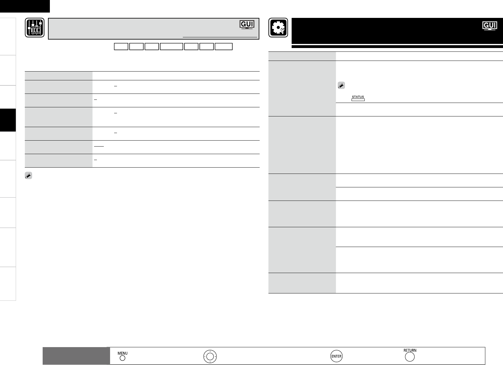
Getting Started Connections Remote Control Information Troubleshooting Specifi cations
ENGLISH
Multi-ZoneSettings
Setting items Setting contents
Status
Shows information about
current settings.
Select Source / Name / Surround Mode / Input Mode / Decode Mode /
HDMI / Digital / Component / iPod Dock / Video Select / Video Convert /
i/p Scaler / Resolution / Progressive Mode / Aspect
You can also display current status on the main unit’s display each time you
press on the main unit.
ZONE2
POWER/ Select Source/ Master Volume•
Audio Input Signal
Shows information about
audio input signals.
Surround Mode : The currently set surround mode is displayed.
Signal : The input signal type is displayed.
fs : The input signal’s sampling frequency is displayed.
Format : The number of channels in the input signal (front, surround, LFE)
is displayed.
Offset : The dialogue normalization correction value is displayed.
Flag : This is displayed when inputting signals including a surround back
channel. “MATRIX” is displayed with Dolby Digital EX and DTS-ES Matrix
signals, “DISCRETE” with DTS-ES Discrete signals.
HDMI Information
Shows information about
HDMI input signals and
monitor.
HDMI Signal Information
Resolution / Color Space / Pixel Depth •
HDMI Monitor Information
Interface / Suport Resolution •
Auto Surround Mode
Shows information about
auto surround mode
settings.
Analog/PCM / Digital 2ch / Digital 5.1ch / Multi CH
Quick Select
Shows information about
quick select settings.
Quick Select 1 / Quick Select 2 / Quick Select 3
Select Source / Video Select / MultEQ / Dynamic EQ / Dynamic Vol /
Analog/PCM / Digital 2ch / Digital 5.1ch / Multi CH
•
ZONE2 Quick Select
Z2 Quick Select 1 : Select Source / Volume Level
Z2 Quick Select 2 : Select Source / Volume Level
Z3 Quick Select 3 : Select Source / Volume Level
Preset Channel
Shows information about
preset channels.
A 1 ~ G 8
TUNER / SIRIUS•
: Moves the cursor (Up/Down/Left/Right) : Decision the setting : Return to previous menu
Remote control
operation buttons : Displaying the menu
Cancel the menu
Playback
Checking the Status
(Information)
Setting items Setting contents
Contrast
Adjust picture contrast.
–6 ~ +6 (0)
Brightness
Adjust picture brightness.
0 ~ +12
Chroma Level
Adjust picture chroma level
(saturation).
–6 ~ +6 (0)
Hue
Adjust color hue.
–6 ~ +6 (0)
DNR
Reduce overall picture noise.
OFF / Low / Middle / High
Enhancer
Emphasize picture contours.
0 ~ +12
“DNR” and “Enhancer” are each effective with HDMI output.
The value set at “Picture Adjust” is stored in the memory individually for each input source.
•
•
This can be set when the input source is DVD HDP TV SAT/CBL VCR DVR V.AUX .
With input sources other than the ones above, this can be set when “Video Select” is selected. In this
case, the original input source settings are called out.
Can be set when the “Video Convert” setting (vpage 36) is “ON”.
•
b
•
Adjusting the Picture Quality (Picture Adjust)
Default settings are underlined.
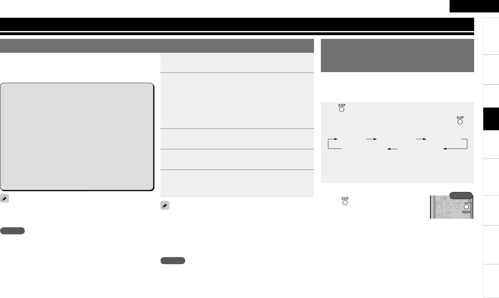
2
ENGLISH
Getting Started Connections Remote Control Information Troubleshooting Specifi cationsMulti-ZoneSettings
1Turn the power on for all the equipment connected by
HDMI cable.
2Set the HDMI control function for all equipment
connected by HDMI cable.
Set “HDMI Control” (vpage 30) to “ON“.
b Please refer to the owner’s manual as regards setting of connected
devices.
b Carry out Steps 1 and 2 should any of the equipment be
unplugged.
3Switch the television input to the HDMI connected to
the AVR-890.
4Switch the AVR-890 input to the HDMI input source
and check if the picture from the player is ok.
5When you turn the TV’s power to standby, check that
the power of the AVR-890 and player also goes on
standby.
If the HDMI control function does not operate properly, check the
following points.
• Is the TV or player compatible with the HDMI control function?
• Is the AVR-890 properly set?
• Is “HDMI Control” (vpage 30) set to “ON”?
• Is “Power Off Control” (vpage 30) set to “ON”?
• Are the HDMI control function settings of all equipment correct?
NOTE
Should any of the operations below be performed, the interlocking
function may be reset, in which case, repeat step’s 1 and 2.
Menu “HDMI” (vpage 30) setting has changed.
There is a change to the connection between the equipment and the
HDMI, or an increase in equipment.
•
•
NOTE
• When you power off AVR-890, the HDMI control function does not
operate.
• Some functions may not operate depending on the connected
TV or player. Check the owner’s manual of each device for details
beforehand.
• When “HDMI Control” is set to “ON”, it is not possible to assign an
HDMI terminal to “TV” at “HDMI” (vpage 30).
• When “HDMI Control” (vpage 30) is set to “ON”, power is supplied
constantly to the AC outlet (UNSWITCHED).
Convenient functions
When you make an HDMI connection with a TV or player
compatible with AVR-890 and HDMI control functions, you can
perform the following operations by setting the HDMI control
function of each device.
Press and display the time you want to set.
The “SLEEP” indicator on the display lights.
• The time switches as shown below each time is
pressed.
Sleep:OFF Sleep:120min
Sleep:30min Sleep:60min
Sleep:90min
• The time display turns off after about 5 seconds, and the
setting is activated.
• Once the set time has passed, the power is automatically set
to standby.
This function allows you to automatically set the power to standby
after the set amount of time has passed.
When the sleep timer turns the power off in the MAIN ZONE, the
power also turns off in the ZONE2.
HDMI Control Function Setting the Power to Standby
After a Certain Amount of Time
(Sleep Timer Function)
n To cancel the sleep timer
Press to set “OFF”.
• The “SLEEP” indicator on the display turns
off.
• To play the TV’s sound on the AVR-890, make optical digital
connections (vpage 13 “Connecting the monitor (TV)”).
• To use this function, set “HDMI Control” (vpage 30) to “ON”.
Rear
n AVR-890 power off can be linked to the TV power
off step
z When you set “Output audio from amp” in the TV audio
output setup operation, you can switch the amp power
on.
n You can switch audio output devices with a TV
operation
n You can adjust AVR-890 volume in the TV volume
adjustment operation
n You can switch AVR-890 input source through
linkage to TV input switching
n When playing the player, the AVR-890 input
function switches to the function of that player
Playback
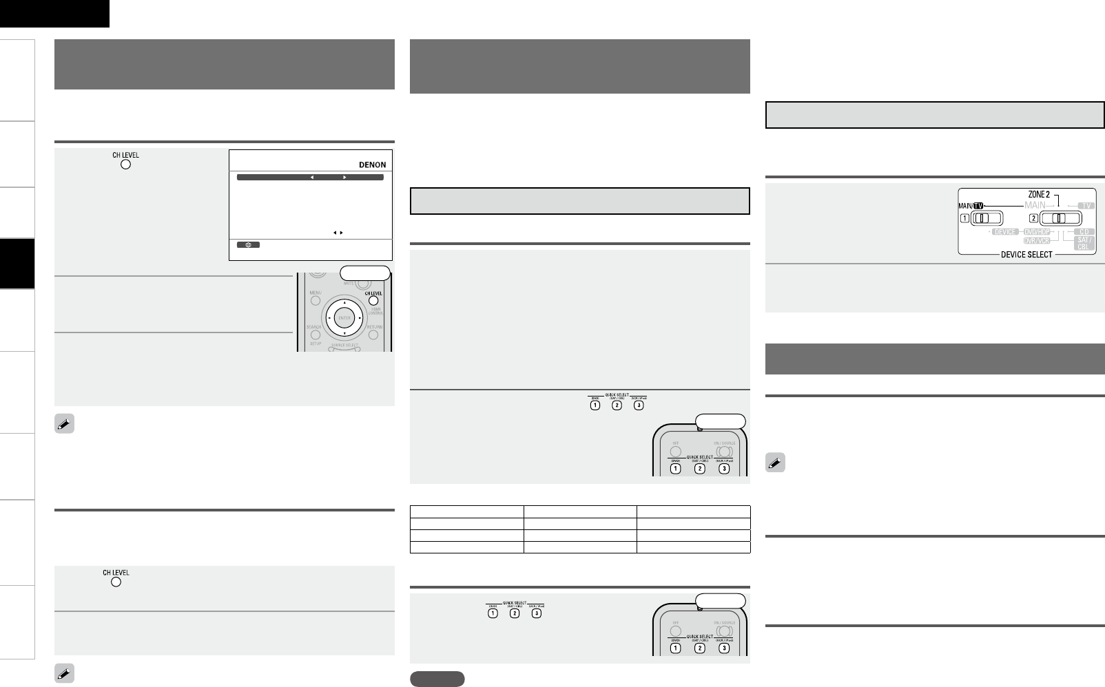
ENGLISH
Getting Started Connections Remote Control Information Troubleshooting SpecificationsMulti-ZoneSettings
1Press .
2Press ui to select the speaker.
The speaker that can be set switches each
time one of the buttons is pressed.
3Press o p to adjust the volume.
b In the case of a subwoofer, reducing the volume when it is at “–12
dB” will change the setting to “OFF” (none).
CHANNEL LEVEL
Bd0.0LtnorF
Bd0.0retneC
Bd0.0RtnorF
Bd0.0refoowbuS
Bd0.0RdnuorruS
Bd0.0RkcaB.S
Bd0.0LkcaB.S
Bd0.0LdnuorruS
raeRtnorFredaF
Select
1Use or i to select “Fader”, then select the item
to be adjusting using o or p.
2Press o p to adjust the volume of the speakers.
• The fader function does not affect the subwoofer.
• The fader can be adjusted until the volume of the speaker adjusted
to the lowest value is –12 dB.
1 Set the items below to the settings you want to save.
q Input source (vpage 40)
w Input Mode (vpage 37)
e Surround Mode (vpage 44)
r Audyssey Settings (MultEQ®, Dynamic EQ™, Dynamic
Volume™) (vpage 48)
t Front Speaker Setup (vpage 29)
y Volume setting (vpage 40)
u Video select (vpage 36)
2 Press and hold the desired until “Memory”
appears on the display.
The current settings will be memorized.
NOTE
Input sources stored with the quick select function cannot be selected
if they have been deleted at menu “Source Delete” (vpage 32). In
this case, store them again.
Adjust the Volume of the
Different Speakers
You can adjust the channel level either according to the playback
sources or to suit your taste, as described below.
Saving Frequently Used Settings
(Quick Select Function)
This function allows you to save all the settings shown in step
1. When frequently used settings are saved, they can easily be
set again the next time you want to use them. This function also
allows you to always enjoy the same playback environment.
• Three sets of settings can be saved.
Saving the settings
Press the at which the
settings you want to call out are saved.
Calling the settings out
This function lets you adjust (fade) the sound from all the front (Front
speaker / center speaker / Front Height speaker) or rear (Surround speaker /
Surround Back speaker) speakers at once.
If headphones are plugged in, the headphones settings screen
appears.
The surround parameters, tone settings and the volumes of the
different speakers are stored for the individual surround modes.
GQuick Select DefaultsH
Input Source Volume
Quick Select 1 DVD –40 dB
Quick Select 2 SAT/CBL –40 dB
Quick Select 3 VCR/iPod –40 dB
n Naming Quick Select settings
“Quick Select Name” (vpage 33).
Various Memory Functions
Adjust the volume of the different speakers
Adjusting the volume of groups of speakers
(Fader Function)
Personal Memory Plus Function
This function sets the settings (input mode, surround mode, HDMI
output mode, MultEQ, Dynamic EQ, Dynamic Volume, audio delay
etc.) last selected for the individual input sources.
Last Function Memory
This stores the settings as they were directly before the standby mode
was set.
When the power is turned back on, the settings are restored to as they
were directly before the standby mode was set.
Backup Memory
The various settings are backed up for about 1 week, even if the power
is turned off or the power cord is disconnected.
Saving the settings
It is also possible to save three settings for ZONE2.
1Set the remote control unit’s
device selector switches as
shown on right.
2Perform steps 1 and 2 under “MAIN ZONE
settings”.
MAIN ZONE settings
ZONE2 settings
Front
Front
Front
Playback
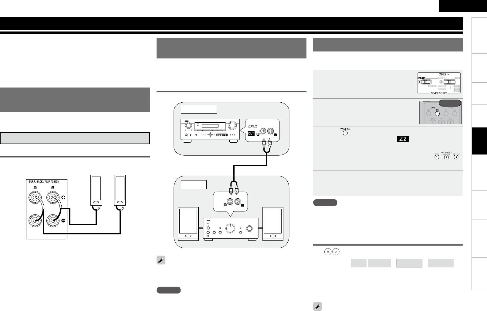
ENGLISH
Getting Started Connections Playback Remote Control Information Troubleshooting SpecificationsSettings
Playing 2-Channel Sound in ZONE2 (Multizone Function)
2-channel sound can be played in rooms other than the MAIN
ZONE where multichannel sound is played.
There are two methods to do this, as described below. Choose
one of the methods.
q ZONE2 playback by speaker output
wZONE2 playback by audio output (PRE OUT) (using an
external amplifier))
q ZONE2 Playback by Speaker
Output
Preparations
Connecting and setting the speakers
Connecting the speakersn
w q w q
(L) (R)
Necessary settings
Set the AMP ASSIGN mode to “ZONE2”.
“Amp Assign” (vpage 27)
Perform the settings at “ZONE2 Setup”.
“Making the ZONE2 settings” (vpage 31)
n
•
•
w ZONE2 Playback by Audio
Output
Connection (ZONE2)
The audio signals connected to the AVR-890’s ZONE2 output terminals
(ZONE2 OUT) are output to the ZONE2’s amplifier and played with that
amplifier.
RL
RL
"69
*/
Adjust the volume on the connected amplifier.
Also be sure to read the operating instructions of the connected
devices.
•
•
1Set the remote control unit’s
“device selector switches” as
shown on right.
2Turn on the AVR-890’s power.
(vpage 19 “Turning the Power On”)
3Press to turn on the ZONE2 power.
When the power turns on, the “ ” indicator lights on the
display.
b The power can be turned on by pressing the one of
while in the standby mode.
4Use the input source selector to choose the input
source.
The selected input source is shown on the display.
NOTE
When “SOURCE” is selected for the input source, the sound being
played in the MAIN ZONE is played. No sound is output if a digital
audio input source is being played in the MAIN ZONE.
Adjusting the volume (for “q ZONE2 playback by
speaker output”)
Use to adjust the volume.
GVariable rangeH – – – –80dB(1) ~ –40dB(41) ~ +18dB(99)
b The volume can be adjusted up to the level set at “Vol. Limit”
(vpage 31).
b The volume display is the display set at “Volume Display”
(vpage 31).
AVR-890
The operation is the same for “q ZONE2 playback by speaker
output” and “w ZONE2 playback by audio output”.
Playback
MAIN ZONE
ZONE2
Rear
For “w ZONE2 playback by audio output”, adjust the volume on the
connected amplifier.
NOTE
• We recommend using high quality pin-plug cables for audio
connections in order to prevent noise.
• It is not possible to play the digital audio signals input from the
HDMI, COAXIAL or OPTICAL terminals in ZONE2. Play using analog
connections (in stereo).
With the Amp Assign function, Zone 2 audio signals are output from
the AVR-890's SURR BACK/AMP ASSIGN terminals.
Multi-Zone
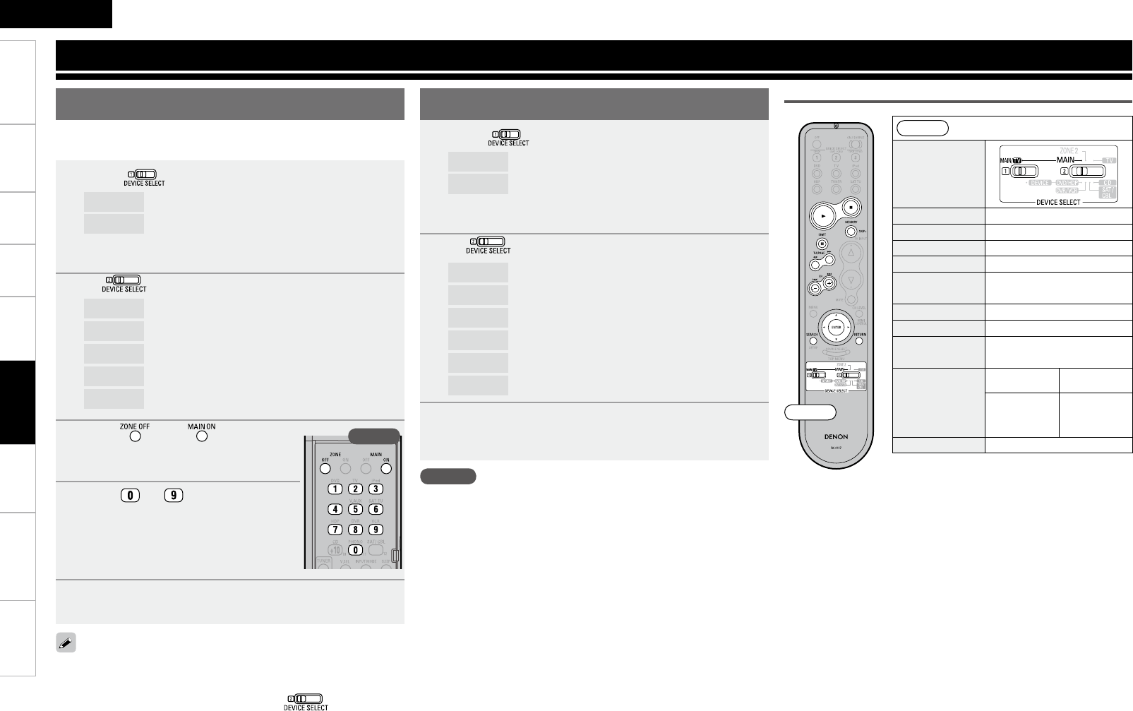
ENGLISH
Getting Started Connections Playback Information Troubleshooting SpecificationsMulti-ZoneSettings
1 Switch .
MAIN/TV : To operate the TV or iPod
DEVICE : To operate a Blu-ray disc player, DVD player,
Digital video recorder, video deck, satellite
receiver, cable TV or CD player
2 Set to the component you want to operate.
MAIN : iPod
TV : TV
DVD/HDP : DVD player or Blu-ray disc player
DVR/VCR : DVD recorder or video deck
SAT/CBL : Satellite receiver or cable TV
CD : CD player
3 Operate the component.
b For details, refer to the component’s operating instructions.
Operating the Connected Devices by Remote Control Unit
• Some manufacturers use more than one type of remote control code.
Refer to the included list of preset codes to change the number and
verify correct operation.
• VDP (Video Disc Player) can be preset when is set to “DVD/
HDP”.
• The preset memory can be set for one component only among the
following: DVD/HDP, DVR/VCR and SAT/CABLE.
1 Switch .
MAIN/TV : To register a TV
DEVICE : To operate a Blu-ray disc player, DVD player,
Digital video recorder, video deck, satellite
receiver, cable TV or CD player
2 Set to the component to be registered.
TV : TV
DVD/HDP : DVD player or Blu-ray disc player
DVR/VCR : Digital video recorder or video deck
SAT/CBL : Satellite receiver or cable TV
CD : CD player
3 Press and at the same
time.
The indicator starts flashing.
4 Press ~ and input the 3-
digit number of the brand of the
component to be preset. The numbers
are shown in the Preset Code Table
(vEnd of this manual).
5 To store the codes of another component in the
memory, repeat steps 1 to 4.
DENON and other makes of components can be operated by setting
the preset memory.
NOTE
Depending on the model and year of manufacture, this function cannot
be used for some models, even if they are of makes listed in the list
of preset codes.
Front
DEVICE SELECT
1Play / Pause
2Stop
MEMORY
MEMORYz1
TU/PAGE
Page up/down z1
8 9 Auto search
(cue)
uio pCursor
ENTER Enter
3Pause
SEARCH
Press and
hold Once
Browse/Remote
mode switching
Page search
mode switching
z2
RETURN Return
z1 : This operation is possible when using a
DENON ASD-3N or ASD-3W Control Dock
for iPod.
z2 : This operation is possible when using a
DENON ASD-1R or ASD-11R Control Dock
for iPod.
iPod
Rear
Front
Registering Preset Codes
Remote Control
Operating Registered Devices
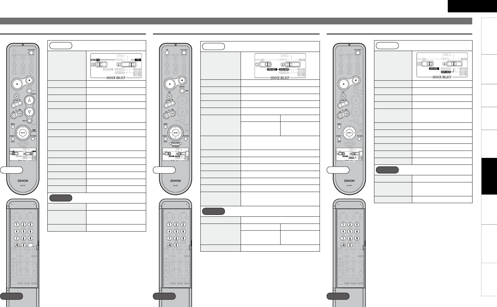
ENGLISH
Getting Started Connections Playback Information Troubleshooting SpecificationsMulti-ZoneSettings
Front
DEVICE SELECT
ON/SOURCE Power on / Standby
1Playz
3Pausez
2Stopz
6 7 Manual search z
(fast-reverse / fast-forward)
CH + – Channelz
TV INPUT Switching the input
VOLUME df d : TV Volume (+)
f : TV Volume (–)
MUTE TV MUTE
MENU Calling out the menus
uio pCursor operation
ENTER Enter setting
SETUP Setup
RETURN Return
Rear
1 ~ 12 Channels
Defau
lt setting
(Preset code)
HITACHI
(014)
Special Remarks q
z : When the punch through function
(vpage 57) is set, this functions as the
button for the device for which punch
through is set.
TV
Operating Registered Devices
Blu-ray Disc / DVD Player
Front
DEVICE SELECT
POWER OFF Power off
ON/SOURCE Power on or Power on / Standby
1Play
2Stop
SHIFT, 3Pause
SKIP +
BD Player DVD Player
– Disc skip
6 7 Manual search
(fast-reverse / fast-forward)
8 9 Auto search (cue)
MENU Calling out the menus
uio pCursor operation
ENTER Enter setting
SETUP Setup
RETURN Return
SOURCE SELECT /
TOP MENU Calling out the top menus
Rear
0 ~ 9, +10 Number input / Track selection
Defau
lt setting
(Preset code)
BD Player DVD Player
DENON
(121)
DENON
(111)*
Special Remarks q, w
* : The initial setting of Preset code is 111 (DVD Player).
Front
DEVICE SELECT
ON/SOURCE Power on / Standby
1Play
2Stop
SHIFT, 3Pause
6 7 Manual search
(fast-reverse / fast-forward)
CH + –
Switch
channel
s
(+, –)
MENU Calling out the menus
uio pCursor operation
ENTER Enter setting
SETUP Setup
RETURN Return
Rear
0 ~ 9, +10
C
hannel
s
Defau
lt setting
(Preset code)
HITACHI
(008)
Special Remarks q, w
Digital Video Recorder / Video Deck
【Special Remarks】
q Only one device can be set in the preset memory for each mode.
When a new preset code is registered, the existing code is automatically erased.
w For some brands, the DVD remote control buttons may have different function names.
Check beforehand.
Front Front Front
Rear Rear Rear
Remote Control
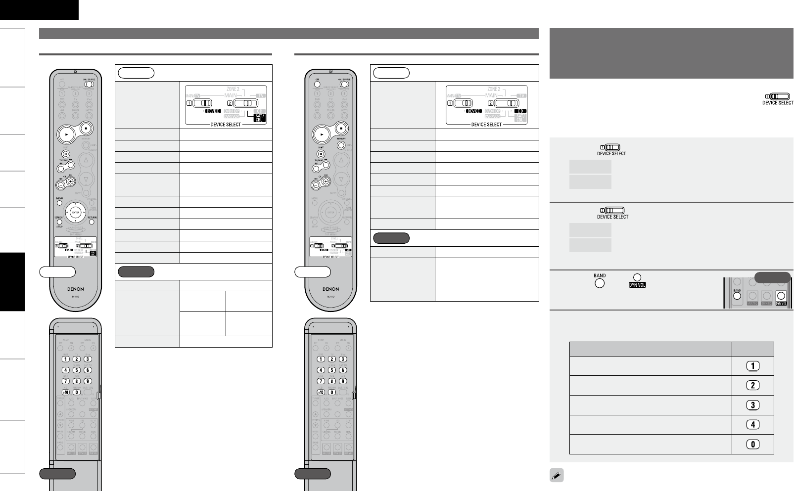
ENGLISH
Getting Started Connections Playback Information Troubleshooting SpecificationsMulti-ZoneSettings
Operating Registered Devices
Satellite receiver/Cable TV
Front
DEVICE SELECT
ON/SOURCE Power on / Standby
1Playz
3Pausez
2Stopz
6 7 Manual search z
(fast-reverse / fast-forward)
CH + – Channelz
uio pCursor operation
ENTER Enter setting
MENU
Calling out the menus
SETUP
Setup
RETURN Return
Rear
0 ~ 9, +10 Channels
Defau
lt setting
(Preset code)
Satellite
Receiver Cable TV
–ABC
(009)
Special Remarks q
z : When the punch through function
(vpage 57) is set, this functions as the
button for the device for which punch
through is set.
1 Switch .
MAIN/TV : Assigning TV buttons to operate other devices
DEVICE : Assigning satellite receiver or cable TV buttons to
operate other devices
2 Switch .
TV : Assigning TV buttons to operate other devices
SAT/CBL : Assigning satellite receiver or cable TV buttons to
operate other devices
3 Press and at the same time.
The indicator starts flashing.
4Refer to the table below and input the number
corresponding to the device to be assigned.
Device to be assigned Numbers
iPod, Tuner
CD Player
Blu-ray Disc Player / DVD Player
DVD Recorder, Video Deck
No setting
The Blu-ray disc Player/DVD player, Digital Video recorder, video deck,
or CD player can be operated as described below even when
is set to the “SAT/CBL” or “TV” position.
• Play • Stop • Pause
• fast-forward • fast-reverse • Auto Search
Front
DEVICE SELECT
POWER OFF Power off
ON/SOURCE Power on or Power on / Standby
1Play
2Stop
SHIFT, 3Pause
SKIP + Disc skip +
6 7 Manual search
(fast-reverse / fast-forward)
8 9 Auto search (cue)
Rear
0 ~ 9, +10 Number input / Track selection
Defau
lt setting
(Preset code)
DENON
(111)
Special Remarks q
CD Player
This is set to “No setting” upon purchase.
Rear
Front Front
Rear Rear
【Special Remarks】
q Only one device can be set in the preset memory for each mode.
When a new preset code is registered, the existing code is automatically erased.
w For some brands, the DVD remote control buttons may have different function names. Check beforehand.
Remote Control
Assigning buttons that are Not
Used to Operate Other Devices
(Punch Through Function)
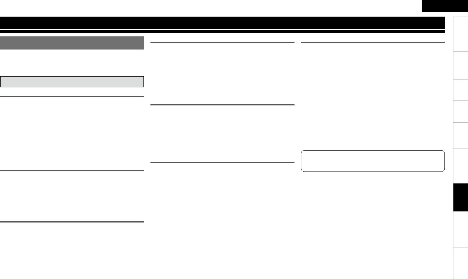
8
ENGLISH
Getting Started Connections Playback Remote Control Troubleshooting SpecificationsMulti-ZoneSettings
Other Information
The AVR-890 is equipped with a digital signal processing circuit that
lets you play program sources in the surround mode to achieve the
same sense of presence as in a movie theater.
Dolby Digital
Dolby Digital is a multichannel digital signal format developed by Dolby
Laboratories.
A total of 5.1-channels are played: 3 front channels (“FL” , “FR” and
“C”), 2 surround channels (“SL” and “SR”) and the “LFE” channel for
low frequencies.
Because of this, there is no crosstalk between channels and a realistic
sound field with a “three-dimensional” feeling (sense of distance,
movement and positioning) is achieved.
A real, overpowering sense of presence is achieved when playing
movie sources in AV rooms as well.
Dolby Digital Plus
Dolby Digital Plus is an improved Dolby Digital signal format that is
compatible with up to 7.1-channels of discrete digital sound and also
improves sound quality thanks to extra data bit rate performance. It
is upwardly compatible with conventional Dolby Digital, so it offers
greater flexibility in response to the source signal and the conditions
of the playback equipment.
Dolby TrueHD
Dolby TrueHD is a high definition audio technology developed by Dolby
Laboratories, using lossless coding technology to faithfully reproduce
the sound of the studio master.
This format is compatible with a maximum sampling frequency of 96
kHz and up to 7.1-channels, so it is used for applications particularly
prioritizing sound quality.
Dolby Pro Logic gx
Dolby Pro Logic gx is a further improved version of the Dolby Pro Logic
g matrix decoding technology.
Audio signals recorded in 2-channels are decoded to achieve a natural
sound with up to 7.1-channels.
There are 3 modes: “Music” suited for playing music, “Cinema”
suited for playing movies, and “Game” which is optimized for playing
games.
Dolby Pro Logic g
Dolby Pro Logic g is a matrix decoding technology developed by Dolby
Laboratories.
Regular music such as that on CDs is encoded into 5-channels to
achieve an excellent surround effect.
The surround channel signals are converted into stereo and full band
signals (with a frequency response of 20 Hz to 20 kHz or greater)
to create a “three-dimensional” sound image offering a rich sense of
presence for all stereo sources.
Manufactured under license from Dolby Laboratories.
“Dolby”, “Pro Logic” and the double-D symbol are trademarks of
Dolby Laboratories.
Dolby Digital EX
Dolby Digital EX is a 6.1-channel surround format proposed by Dolby
Laboratories that allows users to enjoy in their homes the “DOLBY
DIGITAL SURROUND EX” audio format jointly developed by Dolby
Laboratories and Lucas Films.
The 6.1 channels of sound, including surround back channels, provide
improved sound positioning and expression of space.
Surround
Dolby Surround
Dolby Pro Logic gz
Dolby Pro Logic gz introduces a new dimension to Home Entertainment
through the addition of a pair of front height channels. Compatible with
stereo, 5.1 and 7.1 content, Dolby Pro Logic gz provides enhanced
spaciousness, depth and dimension to movies, concert video and
videogame playback while maintaining the full integrity of the source
mix.
Dolby Pro Logic gz identifies and decodes spatial cues that occur
naturally in all content, directing this information to the front height
channels, complementing the performance of left and right surround
sound speakers. Content that is encoded with Dolby Pro Logic
gz height channel information can be even more revealing, with
perceptually discrete height channel information bringing an exciting
new dimension to home entertainment. Dolby Pro Logic gz, with
front height channels is also an ideal alternative for households that
cannot support the placement of back surround speakers of a typical
7.1 channel system but may have bookshelf space available to support
the addition of height speakers.
Information
ENGLISH
Getting Started Connections Playback Remote Control Troubleshooting SpecificationsMulti-ZoneSettings Information
DTS Surround
DTS Digital Surround
DTS Digital Surround is the standard digital surround format of DTS,
Inc., compatible with a sampling frequency of 44.1 or 48 kHz and up
to 5.1-channels of digital discrete surround sound.
DTS-ES™ Discrete 6.1
DTS-ES™ Discrete 6.1 is a 6.1-channel discrete digital audio format
adding a surround back (SB) channel to the DTS digital surround sound.
Decoding of conventional 5.1-channel audio signals is also possible
according to the decoder.
DTS-ES™ Matrix 6.1
DTS-ES™ Matrix 6.1 is a 6.1-channel discrete digital audio format
inserting a surround back (SB) channel to the DTS digital surround
sound through matrix encoding. Decoding of conventional 5.1-channel
audio signals is also possible according to the decoder.
DTS-HD High Resolution Audio
DTS-HD High Resolution Audio is an improved version of the
conventional DTS, DTS-ES and DTS 96/24 signals formats, compatible
with sampling frequencies of 96 or 48 kHz and up to 7.1-channels
of discrete digital sound. High data bit rate performance provides
high quality sound. This format is fully compatible with conventional
products, including conventional DTS digital surround 5.1-channel
data.
DTS-HD Master Audio
DTS-HD Master Audio is DTS, Inc’s lossless audio format compatible
with up to 96 kHz/7.1-channels. The lossless audio coding technology
faithfully reproduces the sound of the studio master. It is fully
compatible with conventional products, including conventional DTS
digital surround 5.1-channel data.
DTS NEO:6™ Surround
DTS NEO:6™ is a matrix decoding technology for achieving 6.1-
channel surround playback with 2-channel sources. It includes “DTS
NEO:6 Cinema” suited for playing movies and “DTS NEO:6 Music”
uited for playing music.
Surround
DTS 96/24
DTS 96/24 is a digital audio format enabling high sound quality
playback in 5.1-channels with a sampling frequency of 96 kHz and 24
bit quantization on DVD-Video.
Manufactured under license under U.S. Patent #’s: 5,451,942;
5,956,674; 5,974,380; 5,978,762; 6,226,616; 6,487,535; 7,212,872;
7,333,929; 7,392,195; 7,272,567 & other U.S. and worldwide patents
issued & pending. DTS is a registered trademark and the DTS
logos, Symbol, DTS-HD and DTS-HD Master Audio are trademarks
of DTS, Inc.© 1996-2008 DTS, Inc. All Rights Reserved.
Manufactured under license from Audyssey Laboratories. U.S.
and foreign patents pending. Audyssey MultEQ® is a registered
trademark of Audyssey Laboratories. Audyssey Dynamic EQ™ is a
trademark of Audyssey Laboratories. Audyssey Dynamic Volume™
is a trademark of Audyssey Laboratories.
Audyssey MultEQ®
Audyssey MultEQ is a room equalization solution that calibrates any
audio system so that it can achieve optimum performance for every
listener in a large listening area. Based on several room measurements,
MultEQ calculates an equalization solution that corrects for both
time and frequency response problems in the listening area and also
performs a fully automated surround system setup.
Audyssey Dynamic EQ™
Audyssey Dynamic EQ solves the problem of deteriorating sound
quality as volume is decreased by taking into account human perception
and room acoustics. Audyssey Dynamic EQ works in tandem with
Audyssey MultEQ to provide well-balanced sound for every listener
at any volume level.
Audyssey Dynamic Volume™
Audyssey Dynamic Volume solves the problem of large variations in
volume level between television programs, commercials, and between
the soft and loud passages of movies.
Audyssey Dynamic EQ is integrated into Dynamic Volume so that as
the playback volume is adjusted automatically, the perceived bass
response, tonal balance, surround impression, and dialog clarity
remain the same.
Audyssey
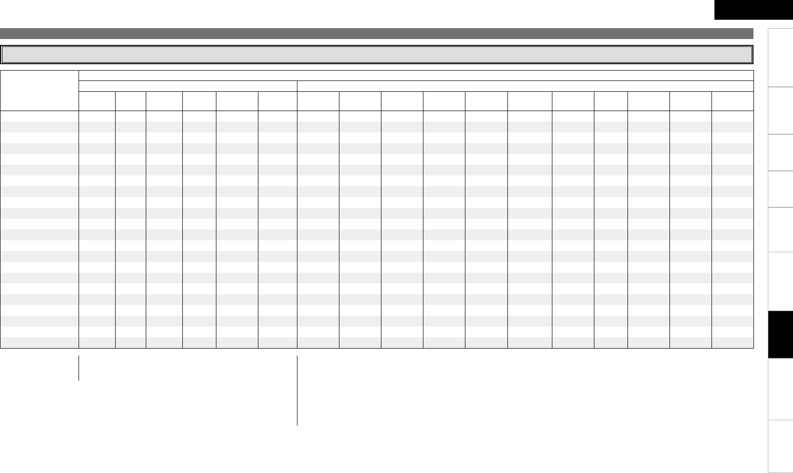
0
ENGLISH
Getting Started Connections Playback Remote Control Troubleshooting SpecificationsMulti-ZoneSettings
Surround Modes and Parameters
Surround
Surround mode
Signals and adjustability in the different modes
Channel output Parameter (default values are shown in parentheses)
Front L/R Center Surround
L/R
Surround
Back L/R
Front Height
L/R Subwoofer D. Comp
z1
LFE
z2
AFDM
z1
Surround
Back Cinema EQ. Mode Room Size Effect
Level Delay Time Subwoofer DRC
z3
PURE DIRECT, DIRECT S D D D D D S (OFF) S (0dB) A A A A A A A S S (Auto)
MULTI CH DIRECT S D D D A D A S (0dB) S (ON) S A A A A A A A
STEREO S A A A A D S (OFF) S (0dB) A A A A A A A A S (Auto)
EXT. IN S D D D A D A A A A A A A A A A A
MULTI CH IN S D D D A D A S (0dB) S (ON) S S (OFF) A A A A A A
DOLBY PRO LOGIC gxS D D D A D S (OFF) A A S S (NOTE1) S (Cinema) A A A A S (Auto)
DOLBY PRO LOGIC g S D D A A D S (OFF) A A S S (NOTE2) S (Cinema) A A A A S (Auto)
DTS NEO:6 S D D D A D S (OFF) A A S S (NOTE1) S (Cinema) A A A A A
DOLBY PRO LOGIC gzS D D A D D S (OFF) A A A S (OFF) A A A A A A
DOLBY DIGITAL S D D D D D S (OFF) S (0dB) S (ON) S S (OFF) A A A A A A
DOLBY DIGITAL Plus S D D D D D S (OFF) S (0dB) S (ON) S S (OFF) A A A A A A
DOLBY TrueHD S D D D D D S (OFF) S (0dB) S (ON) S S (OFF) A A A A A S (Auto)
DTS SURROUND S D D D D D S (OFF) S (0dB) S (ON) S S (OFF) A A A A A A
DTS 96/24 S D D D D D S (OFF) S (0dB) S (ON) S S (OFF) A A A A A A
DTS-HD S D D D D D S (OFF) S (0dB) S (ON) S S (OFF) A A A A A A
5CH/7CH STEREO S D D D D D S (OFF) S (0dB) A S A A A A A A A
ROCK ARENA S D D D D D S (OFF) S (0dB) A S A A
S (Medium)
S (10) AAA
JAZZ CLUB S D D D D D S (OFF) S (0dB) A S A A
S (Medium)
S (10) AAA
MONO MOVIE S D D D D D S (OFF) S (0dB) A S A A
S (Medium)
S (10) AAA
VIDEO GAME S D D D D D S (OFF) S (0dB) A S A A
S (Medium)
S (10) AAA
MATRIX S D D D D D S (OFF) S (0dB) A S A A A A S (30 ms) A A
VIRTUAL S A A A A D S (OFF) S ( 0dB) A A A A A A A A A
S : Signal / Adjustable
A : No signal / Not adjustable
NOTE1 : This parameter is available when the menu “Mode” (vpage 46) is set to “Cinema”.
NOTE2 : This parameter is available when the menu “Mode” (vpage 46) is set to “Cinema” or “PL”.
NOTE:
z1 : When playing Dolby Digital and DTS signals.
z2 : When playing Dolby Digital, DTS and Linear PCM (multi ch).
z3 : When playing Dolby TrueHD signal.
S : Signal / Adjustable
A : No signal / Not adjustable
D : Turned on or off by speaker configuration setting
Information
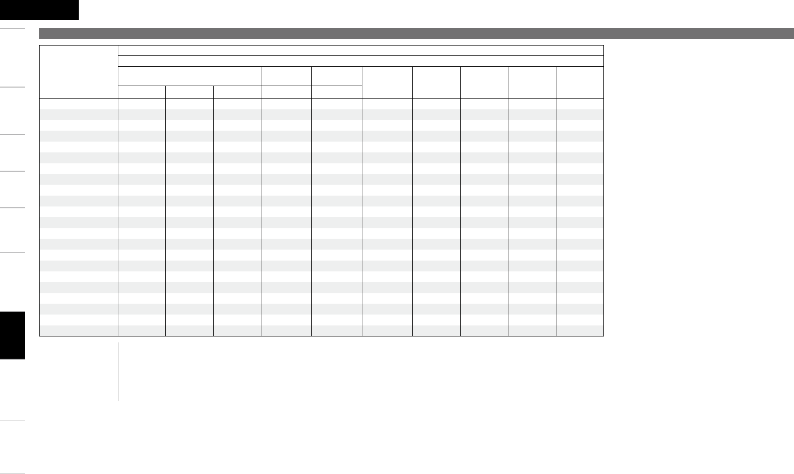
ENGLISH
Getting Started Connections Playback Remote Control Troubleshooting SpecificationsMulti-ZoneSettings
Surround
Surround mode
Signals and adjustability in the different modes
Parameter (default values are shown in parentheses)
PRO LOGIC g/gx MUSIC mode only NEO:6 MUSIC
mode only EXT. IN only Tone Control
(NOTE4) MultEQ Dynamic EQ
(NOTE5)
Dynamic
Volume
(NOTE6)
RESTORER
(NOTE7)
Panorama Dimension Center Width Center Image Subwoofer ATT
PURE DIRECT, DIRECT A A A A A A A A A A
MULTI CH DIRECT A A A A A A A A A A
STEREO A A A A A S (0dB) S (OFF) S (OFF) S (OFF) S
EXT. IN A A A A S A A A A A
MULTI CH IN A A A A A S (0dB) S (OFF) S (OFF) S (OFF) A
DOLBY PRO LOGIC gxS (OFF) S (3) S (3) A A S (0dB) S (OFF) S (OFF) S (OFF) S
DOLBY PRO LOGIC g S (OFF) S (3) S (3) A A S (0dB) S (OFF) S (OFF) S (OFF) S
DTS NEO:6 A A A S (0.3) A S (0dB) S (OFF) S (OFF) S (OFF) S
DOLBY PRO LOGIC gzA A A A A S (0dB) S (OFF) S (OFF) S (OFF) A
DOLBY DIGITAL A A A A A S (0dB) S (OFF) S (OFF) S (OFF) A
DOLBY DIGITAL Plus A A A A A S (0dB) S (OFF) S (OFF) S (OFF) A
DOLBY TrueHD A A A A A S (0dB) S (OFF) S (OFF) S (OFF) A
DTS SURROUND A A A A A S (0dB) S (OFF) S (OFF) S (OFF) A
DTS-96/24 A A A A A S (0dB) S (OFF) S (OFF) S (OFF) A
DTS-HD A A A A A S (0dB) S (OFF) S (OFF) S (OFF) A
5CH/7CH STEREO A A A A A S (0dB) S (OFF) S (OFF) S (OFF) S
ROCK ARENA A A A A A S (NOTE3) S (OFF) S (OFF) S (OFF) S
JAZZ CLUB A A A A A S (0dB) S (OFF) S (OFF) S (OFF) S
MONO MOVIE A A A A A S (0dB) S (OFF) S (OFF) S (OFF) S
VIDEO GAME A A A A A S (0dB) S (OFF) S (OFF) S (OFF) S
MATRIX A A A A A S (0dB) S (OFF) S (OFF) S (OFF) S
VIRTUAL A A A A A S (0dB) S (OFF) S (OFF) S (OFF) S
S : Adjustable
A : Not adjustable
NOTE3 : BASS +6 dB, TREBLE +4 dB
NOTE4 : Cannot be set when the “Dynamic EQ” (vpage 49) setting is “ON”.
NOTE5 : Cannot be set when the “MultEQ” (vpage 48) setting is “OFF”.
NOTE6 : Cannot be set when the “Dynamic EQ” (vpage 49) setting is “OFF”.
NOTE7 : “RESTORER” can be set for analog or PCM 48 kHz or 44.1 kHz input signals.
Information
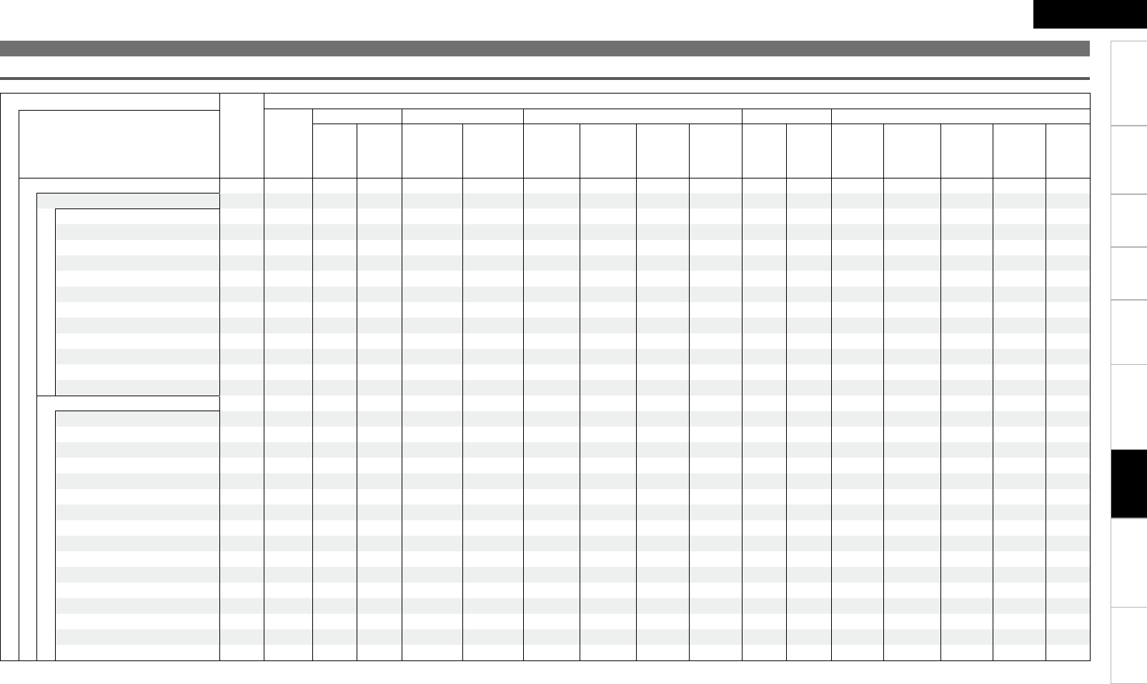
2
ENGLISH
Getting Started Connections Playback Remote Control Troubleshooting SpecificationsMulti-ZoneSettings
Differences in Surround Mode Names Depending on the Input Signals
Surround
Button
Note
Input signals
ANALOG
PCM DTS-HD DTS DOLBY DOLBY DIGITAL
Surround mode Linear
PCM
(multi ch)
Linear
PCM
(2ch)
DTS-HD
Master
Audio
DTS-HD
High
Resolution
Audio
DTS ES
DSCRT
(With Flag)
DTS ES
MTRX
(With Flag)
DTS
(5.1ch)
DTS
96/24
DOLBY
TrueHD
DOLBY
DIGITAL
Plus
DOLBY
DIGITAL
EX (With
Flag)
DOLBY
DIGITAL EX
(With no
Flag)
DOLBY
DIGITAL
(5.1/5/4ch)
DOLBY
DIGITAL
(4/3ch)
DOLBY
DIGITAL
(2ch)
STANDARD
DTS SURROUND
DTS-HD MSTR A A A F A A A A A A A A A A A A
DTS-HD HI RES A A A A F A A A A A A A A A A A
DTS ES DSCRT6.1 z1 z3A A A A A F D A A A A A A A A A A
DTS ES MTRX6.1 z1 z3A A A A A A F D A A A A A A A A A
DTS SURROUND A A A A A S S F A A A A A A A A
DTS 96/24 A A A A A A A A F A A A A A A A
DTS (–HD) + PLgx CINEMA z2 z3A A A S S S S S S A A A A A A A
DTS (–HD) + PLgx MUSIC z1 z3A A A S S S S S S A A A A A A A
DTS (–HD) + PLgzz1 z4A A A S S S S S S A A A A A A A
DTS (–HD) + NEO:6 z1 z3A A A S S A S S S A A A A A A A
DTS NEO:6 CINEMA S A S A A A A A A A A A A A A S
DTS NEO:6 MUSIC S A S A A A A A A A A A A A A S
DOLBY SURROUND
DOLBY TrueHD A A A A A A A A A F A A A A A A
DOLBY DIGITAL+ A A A A A A A A A A F A A A A A
DOLBY DIGITAL EX z1 z3A A A A A A A A A A A S S S S A
DOLBY (D+) (HD) +EX z1 z3A A A A A A A A A S S A A A A A
DOLBY DIGITAL A A A A A A A A A A A S F F F A
DOLBY (D) (D+) (HD) +PLgx CINEMA
z2 z3A A A A A A A A A S S F D S S S A
DOLBY (D) (D+) (HD) +PLgx MUSIC
z1 z3A A A A A A A A A S S S S S S A
DOLBY (D) (D+) (HD) +PLgz
z1 z4A A A A A A A A A S S S S S S A
DOLBY PRO LOGIC gx CINEMA z3S A S A A A A A A A A A A A A S
DOLBY PRO LOGIC gx MUSIC z3S A S A A A A A A A A A A A A S
DOLBY PRO LOGIC gx GAME z3S A S A A A A A A A A A A A A S
DOLBY PRO LOGIC g
z
z4S A S A A A A A A A A A A A A S
DOLBY PRO LOGIC g CINEMA S A S A A A A A A A A A A A A S
DOLBY PRO LOGIC g MUSIC S A S A A A A A A A A A A A A S
DOLBY PRO LOGIC g GAME S A S A A A A A A A A A A A A S
DOLBY PRO LOGIC S A S A A A A A A A A A A A A S
F : Mode selectable in initial status
D : Mode fixed when “AFDM” is “ON”
S : Selectable mode
A : Non-selectable mode
NOTE:
z1: This mode is not available when the surround back speaker setup is set to “None”.
z2: This mode is not available when the surround back speaker setup is set to “1sp” or “None”.
z3: Can be set when “Amp Assign” is set to “Normal”.
z4: Not selectable when “Amp Assign” is set to anything other than “Front Height”.
Information
ENGLISH
Getting Started Connections Playback Remote Control Troubleshooting SpecificationsMulti-ZoneSettings
Surround
Button
Note
Input signals
ANALOG
PCM DTS-HD DTS DOLBY DOLBY DIGITAL
Surround mode Linear
PCM
(multi ch)
Linear
PCM
(2ch)
DTS-HD
Master
Audio
DTS-HD
High
Resolution
Audio
DTS ES
DSCRT
(With Flag)
DTS ES
MTRX
(With Flag)
DTS
(5.1ch)
DTS
96/24
DOLBY
TrueHD
DOLBY
DIGITAL
Plus
DOLBY
DIGITAL
EX (With
Flag)
DOLBY
DIGITAL
EX (With
no Flag)
DOLBY
DIGITAL
(5.1/5/4ch)
DOLBY
DIGITAL
(4/3ch)
DOLBY
DIGITAL
(2ch)
STANDARD
MULTI CH IN
MULTI CH IN A F A A A A A A A A A A A A A A
MULTI IN + PLgx CINEMA z2 z3A S A A A A A A A A A A A A A A
MULTI IN + PLgx MUSIC z1 z3A S A A A A A A A A A A A A A A
MULTI IN + PLgzz1 z5A S A A A A A A A A A A A A A A
MULTI IN + Dolby EX z1 z3A S A A A A A A A A A A A A A A
MULTI CH IN 7.1 z3A F D (7.1) A A A A A A A A A A A A A A
DIRECT
DIRECT S A S S S S S S S S S S S S S S
MULTI CH DIRECT A S A A A A A A A A A A A A A A
M DIRECT + PLgx CINEMA z2 z3A S A A A A A A A A A A A A A A
M DIRECT + PLgx MUSIC z1z3A S A A A A A A A A A A A A A A
M DIRECT + PLgzz1z5A S A A A A A A A A A A A A A A
M DIRECT + Dolby EX z1 z3A S A A A A A A A A A A A A A A
M DIRECT 7.1 z3A S (7.1) A A A A A A A A A A A A A A
PURE DIRECT
PURE DIRECT S A S S S S S S S S S S S S S S
MULTI CH PURE DIRECT A S A A A A A A A A A A A A A A
M PURE D + PLgx CINEMA z2 z3A S A A A A A A A A A A A A A A
M PURE D + PLgx MUSIC z1 z3A S A A A A A A A A A A A A A A
M PURE D + PLgzz1 z5A S A A A A A A A A A A A A A A
M PURE D + Dolby EX z1 z3A S A A A A A A A A A A A A A A
M CH PURE DIRECT 7.1 z3A S (7.1) A A A A A A A A A A A A A A
DSP SIMULATION
5CH/7CH STEREO z4S S S S S S S S S S S S S S S S
ROCK ARENA S S S S S S S S S S S S S S S S
JAZZ CLUB S S S S S S S S S S S S S S S S
MONO MOVIE S S S S S S S S S S S S S S S S
VIDEO GAME S S S S S S S S S S S S S S S S
MATRIX S S S S S S S S S S S S S S S S
VIRTUAL S S S S S S S S S S S S S S S S
STEREO
STEREO F S F S S S S S S S S S S S S S
NOTE :
z1: This mode is not available when the surround back speaker setup is set to “None”.
z2: This mode is not available when the surround back speaker setup is set to “1sp” or “None”.
z3: Can be set when “Amp Assign” is set to “Normal”.
z4: If the surround back speaker setup is set to “None”, then “5CH STEREO” is displayed.
z5: Not selectable when “Amp Assign” is set to anything other than “Front Height”.
F : Mode selectable in initial status
D : Mode fixed when “AFDM” is “ON”
S : Selectable mode
A : Non-selectable mode
Information
ENGLISH
Getting Started Connections Playback Remote Control Troubleshooting SpecificationsMulti-ZoneSettings
Relationship Between Video Signals and Monitor Output
MAIN ZONE MONITOR OUT
Video Convert Input Signals Output Signals GUI menu displayed
HDMI COMPONENT S-VIDEO VIDEO HDMI COMPONENT S-VIDEO VIDEO HDMI COMPONENT S-VIDEO VIDEO
ON/OFF A A A A A A A A Only the GUI menu is displayed
ON A A A S VIDEO VIDEO VIDEO VIDEO S (VIDEO) A (VIDEO) z3A (VIDEO) z3A (VIDEO) z3
ON A A S A S-VIDEO S-VIDEO S-VIDEO S-VIDEO S (S-VIDEO) A (S-VIDEO) z3A (S-VIDEO) z3A (S-VIDEO) z3
ON A A S S
ON A S (1080p) A A
COMPONENT COMPONENT
A A
S (COMPONENT)
A (COMPONENT) z2A z2A z2
ON A S (1080i ~ 480p) A A A (COMPONENT)z3A A
ON A S (480i/576i) A A COMPONENT COMPONENT A (COMPONENT) z3A (COMPONENT) z3
ON A S (1080p) A S A
VIDEO
A (COMPONENT) A A (VIDEO)
ON z1A S (1080p) A S VIDEO A S (VIDEO) S (VIDEO) S (VIDEO)
ON A S (1080i ~ 480p) A S A
S (COMPONENT) A (COMPONENT) z3A A (VIDEO)
ON A S (480i/576i) A S COMPONENT COMPONENT A (COMPONENT) z3A (COMPONENT) z3
ON A S (1080p) S A
S-VIDEO S-VIDEO
A (COMPONENT) A (S-VIDEO) A (S-VIDEO)
ON z1A S (1080p) S A A S (S-VIDEO) S (S-VIDEO) S (S-VIDEO)
ON A S (1080i ~ 480p) S A
S (COMPONENT) A (COMPONENT) z3A (S-VIDEO) A (S-VIDEO)
ON A S (480i/576i) S A COMPONENT COMPONENT A (COMPONENT) z3A (COMPONENT) z3
ON A S (1080p) S S
S-VIDEO S-VIDEO
A (COMPONENT) A (S-VIDEO) A (S-VIDEO)
ON z1A S (1080p) S S A S (S-VIDEO) S (S-VIDEO) S (S-VIDEO)
ON A S (1080i ~ 480p) S S S (COMPONENT) A (COMPONENT) z3A (S-VIDEO) A (S-VIDEO)
ON A S (480i/576i) S S COMPONENT COMPONENT A (COMPONENT) z3A (COMPONENT) z3
ON S A A A
HDMI
A
AA
S (HDMI)
A z2
A z2A z2
ON S A A S VIDEO A (VIDEO) z2
ON S A S A S-VIDEO S-VIDEO A (S-VIDEO) z2A (S-VIDEO) z2
ON S A S S
ON S S A A
COMPONENT
AA
A (COMPONENT) z2
A z2A z2
ON S S A S VIDEO A (VIDEO) z2
ON S S S A S-VIDEO S-VIDEO A (S-VIDEO) z2A (S-VIDEO) z2
ON S S S S
OFF A A A S
A
A
AVIDEO
Only the GUI menu
is displayed A z2
OFF A A S A S-VIDEO A
OFF A A S S VIDEO
OFF A S A A
COMPONENT
AA
OFF A S A S VIDEO
OFF A S S A S-VIDEO A
OFF A S S S VIDEO
OFF S A A A
HDMI
A
AA
OFF S A A S VIDEO
OFF S A S A S-VIDEO A
OFF S A S S VIDEO
OFF S S A A
COMPONENT
AA
OFF S S A S VIDEO
OFF S S S A S-VIDEO A
OFF S S S S VIDEO
S : Video signal input present
A : No video signal input
z1 : When no HDMI monitor is connected or the HDMI monitor’s power is
not on
S ( ) : Superimposed on the picture indicated in ( ).
A ( ) : Only the picture in ( ) is output.
A : Neither the picture nor the GUI menu is output.
z2 : Only the GUI menu is displayed when no HDMI monitor is connected or the HDMI
monitor’s power is not on.
z3 : When no HDMI monitor is connected or the HDMI monitor’s power is “OFF”, the
GUI menu is superimposed on the picture indicated in ( ).
The main zone video conversion function is compatible with the following
formats: NTSC, PAL, SECAM, NTSC4.43, PAL -N, PAL -M and PAL -60.
When SECAM signals of video input are up-converted, the signals are
output in PAL format from the S-Video and Video connectors.
The GUI menu display cannot be superimposed when x.v.Color signals
and computer’s resolution (e.g. VGA) are input.
•
•
•
Information
Getting Started Connections Playback Remote Control Information Specifications
ENGLISH
Multi-ZoneSettings
If a problem should arise, first check the following:
1. Are the connections correct?
2. Is the set being operated as described in the owner’s manual?
3. Are the other components operating properly?
If this unit does not operate properly, check the items listed in the table below. Should the problem persist,
there may be a malfunction.
In this case, disconnect the power immediately and contact your store of purchase.
Symptom Cause Countermeasure Page
Set does not
operate properly.
• External noise or interference is
causing the set to malfunction.
• Reset the microprocessor. 68
Power does not
turn on, or turns
off directly after it
was turned on.
• Connection of the power cord is
faulty.
• Check the insertion of the power
cord plug.
18
No sound is
produced from
speakers.
• Connection with the input
devices or connection of the
speaker cables is faulty.
• Device you want to play and set
input source do not match.
• Master volume is turned too
low.
• Mute mode is set.
• Headphones are connected.
• No digital signals are being
input.
• The connectors to which the
digital inputs are assigned and
the settable input modes do not
match.
• Check the connections.
• Select an appropriate input
source.
• Adjust the master volume to an
appropriate level.
• Cancel the mute mode.
• Disconnect the headphones.
• Select an input source for which
the digital input setting has been
made.
• Set the input mode.
11
19, 40
40
44
44
35
37
Display is off. • The “Dimmer” setting is set to
“OFF”.
• The PURE DIRECT mode is set.
• Set to something other than
“OFF”.
• Set a surround mode other than
the PURE DIRECT mode.
33
46
“DOLBY DIGITAL”
indicator does not
appear on display.
• Blu-ray Disc player / DVD player’s
digital audio output setting is not
proper.
• Check the Blu-ray Disc player /
DVD player’s audio output setting.
For details, read the Blu-ray Disc
player / DVD player’s operating
instructions.
–
GGeneralH
Symptom Cause Countermeasure Page
Power switches
off suddenly while
you are using
the AVR-890, the
power indicator
will flash in red
at intervals of
approximately 2
seconds.
• The protection circuit will be
activated depending upon the
temperature rise in the internal
parts of the unit.
• Please switch off power at once,
and re-apply the power after
the body temperature has fallen
sufficiently.
• Please re-install AVR-890 in a
place having good ventilation.
3
–
Power switches
off suddenly while
you are using
the AVR-890, the
power indicator
will flash red
at intervals of
approximately 0.5
seconds.
• Use speakers having impedance
less than that specified.
• If speaker cable core wires touch
each other or the core wires
become disconnected from their
terminals, the protection circuit
will be activated in the event of
core wires coming into contact
with the AVR-890 rear panel.
• Please use speakers which have
the specified impedance.
• Unplug the power cord, then
after twisting the core wires
together tightly again, or effecting
termination treatments etc,
please reconnect once again.
11
11
Even applying
power, the power
display flashes
red at intervals of
approximately 0.5
seconds.
• The AVR-890 amplifier circuit has
failed.
• Switch off the power and please
contact the DENON service
adviser.
–
Set does not work
properly when
remote control
unit operated.
• Batteries are worn.
• You are operating outside of the
specified range.
• Obstacle between main unit and
remote control unit.
• The batteries are not inserted in
the proper direction, as indicated
by the polarity marks in the
battery compartment.
• The set’s remote control sensor
is exposed to strong light (direct
sunlight, inverter type fluorescent
bulb light, etc.).
• Settings do not match the remote
control unit’s DEVICE SELECT
switch.
• Replace with new batteries.
• Operate within the specified
range.
• Remove the obstacle.
• Insert the batteries in the
proper direction, following the
polarity marks in the battery
compartment.
• Move the set to a place in which
the remote control sensor will
not be exposed to strong light.
• Match the settings to the remote
control unit’s DEVICE SELECT
switch.
3
3
3
3
3
55
Troubleshooting
Troubleshooting
Getting Started Connections Playback Remote Control Information Specifications
ENGLISH
Multi-ZoneSettings
Symptom Cause Countermeasure Page
Dolby TrueHD,
DTS-HD, Dolby
Digital Plus audio
is not output.
• HDMI is not connected.
• Blu-ray Disc player’s audio output
setting is not set to bitstream.
• Blu-ray Disc player is not
compatible with DTS sound
playback.
• Connect the HDMI.
• Set the Blu-ray Disc player. For
details, refer to the Blu-ray Disc
player’s operating instructions.
• Use a DTS-compatible player.
12
–
–
Symptom Cause Countermeasure Page
No sound is
produced from
center speaker.
• You are playing a monaural source
(TV, etc.) in the “STANDARD”
(Dolby/DTS Surround) mode.
• The mode is set to something
other than “STANDARD” (Dolby/
DTS Surround).
44
No sound
is produced
from surround
speakers.
• The surround mode is set to
“STEREO”, “DIRECT” or “PURE
DIRECT”.
• Set to a surround playback
mode.
45, 46
No sound is
produced from
surround back
speaker.
• The surround back speaker’s
power amplifier is assigned to a
different channel.
• “S.Back” setting is set to
“None”.
• The “Audio/Video Adjust”
– “Audio Adjust” – “Surround
Back” settings are “OFF”.
• Surround mode not set to a mode
for 6.1- or 7.1-channel playback.
• Check the setting and change it
as necessary.
• Set to something other than
“None”.
• Please set “Audio/Video Adjust”
– “Audio Adjust” – “Surround
Back” to settings other than
“OFF”.
• Select a surround playback
mode.
27
28
47
44
No sound is
produced from
subwoofer.
• Subwoofer’s power not turned
on.
• The “Subwoofer” setting at
“Speaker Config.” is set to “No”.
• The subwoofer is not properly
connected.
• The subwoofer’s volume is
turned off.
• Turn on the subwoofer’s power.
• Set to “Yes”.
• Check the connections.
• Adjust the subwoofer’s volume
to an appropriate level.
–
27
11
53
DTS sound is not
output.
• Blu-ray Disc player / DVD player’s
audio output setting is not set to
bitstream.
• Blu-ray Disc player / DVD player is
not compatible with DTS sound
playback.
• The AVR-890’s “Decode Mode”
setting is set to “PCM”.
• Set the Blu-ray Disc player / DVD
player. For details, refer to the
Blu-ray Disc player / DVD player’s
operating instructions.
• Use a DTS-compatible player.
• Set to the “Auto” or “DTS”
mode.
–
–
37
HDMI audio
signals are not
output from
speakers.
• The “Manual Setup” – “HDMI
Setup” – “HDMI Audio Out”
setting is set to “TV”.
• Set to “Amp”. 30
No sound is
output from
the monitor
connected
with HDMI
connections.
• The “Manual Setup” – “HDMI
Setup” – “HDMI Audio Out”
setting is set to “Amp”.
• Set to “TV”. 30
GAudioH
Troubleshooting
Symptom Cause Countermeasure Page
No picture
appears.
• The connections between the
AVR-890 and monitor are faulty.
• The monitor’s input setting is
wrong.
• PURE DIRECT mode is set.
• The player is connected using
the component input connectors,
the monitor is connected
using the video (yellow) output
connectors.
• Check the connections.
• Set properly.
• Cancel the PURE DIRECT mode.
• High definition (1080i/720p) and
progressive (480p/576p) video
signals are not down-converted.
Set the player to interlace
(480i/576i) signals.
12 ~ 16
–
46
–
Picture cannot be
recorded.
• Input source does not match
recorder’s video connection
connector (video).
• The video conversion function
does not work for the REC
OUT connectors. Match the
input source and recorder
connections.
15
DVDs cannot be
copied on a DVR. –
• This is not a malfunction. Most
movie software includes copy
prevention signals and cannot be
copied.
–
The menu screen
and status
indicators are not
displayed.
• “OFF” is displayed for the
status.
• The main volume display is
“OFF”.
• The display during tuner operation
is “OFF”.
• The display during iPod operation
is “OFF”.
• When viewing HDMI or
component video signals via the
AVR-890, the GUI menu appears
when the MENU button on the
main unit or the MENU button on
the remote control unit.
• Set “Manual Setup” – “Option
Setup” – “GUI” – “Text” to
“ON”.
• Set “Manual Setup” – “Option
Setup” – “GUI” – “Master
Volume” to “Top” or “Bottom”.
• Set when “Manual Setup” –
“GUI ” – “Tuner Information” is
not “OFF”.
• Set when “Manual Setup”
– “GUI” – “ iPod Information” is
not “OFF”.
9
32
32
32
32
GVideoH
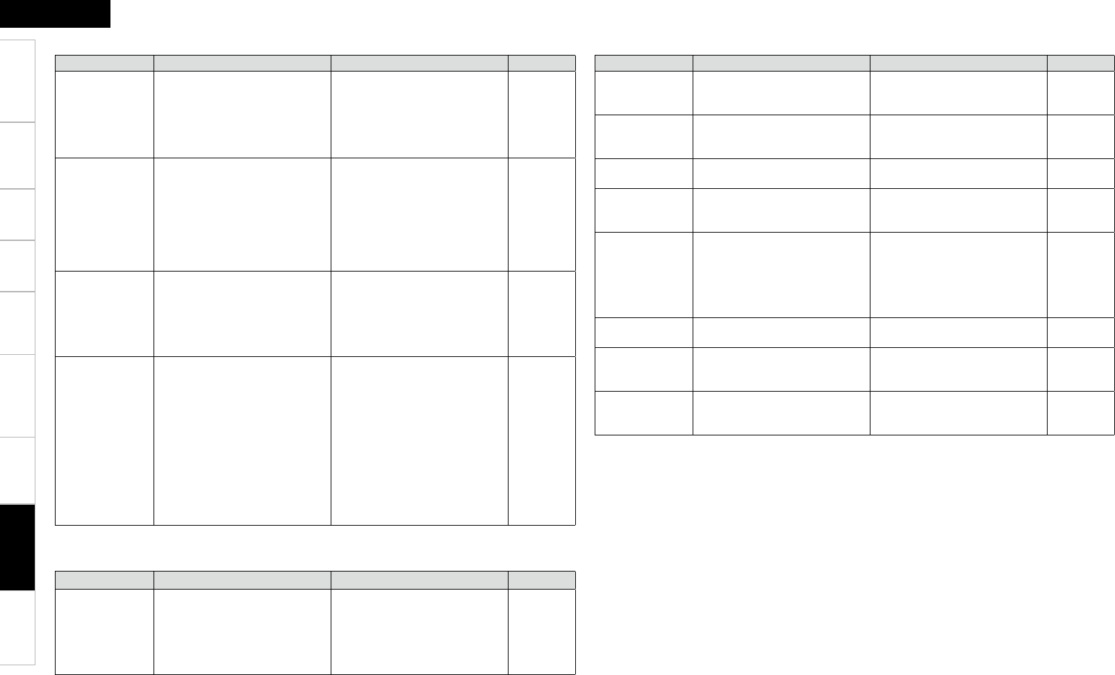
Getting Started Connections Playback Remote Control Information Specifications
ENGLISH
Multi-ZoneSettings
Symptom Cause Countermeasure Page
HDMI audio
signals are not
output from
speakers.
• The “Manual Setup” – “HDMI
Setup” – “HDMI Audio Out”
setting is set to “TV”.
• Set to “Amp” 30
No picture
appears
with HDMI
connections.
• The connections to the HDMI
connectors are faulty.
• HDMI input setting is improper.
• The monitor is not compatible
with copyright protection
(HDCP).
• The HDMI format of the player
and monitor do not match.
• Check the connections.
• Check the HDMI input setting.
• Connect a monitor that is
compatible with copyright
protection (HDCP).
• Match the HDMI format of the
player and monitor.
12
35
12
12
No sound is
output from
the monitor
connected
with HDMI
connections.
• The “Manual Setup” – “HDMI
Setup” – “HDMI Audio Out”
setting is set to “Amp”.
• Set to “TV”. 30
When performing
the following
operations on a
connected device,
AVR-890 has the
same operations.
⋅ Power ON/OFF
⋅ Switching audio
output devices
⋅ Adjust volume
⋅ Switch input
source
• HDMI’s CEC function is
operating.
• Set “Manual Setup” – “HDMI
Setup” -– “HDMI Control” to
“OFF”.
When you only want to operate
the power on/off each device, set
“Power Off Control” to “OFF”.
30
GHDMIH
Symptom Cause Countermeasure Page
iPod cannot be
played.
• The input source assigned to
“iPod Dock” is not selected.
• Cable is not properly connected.
• Control dock for iPod’s AC
adapter is not connected to
power outlet.
• Switch to the input source
assigned at “iPod Dock”.
• Reconnect.
• Plug the control dock for iPod’s
AC adapter into a power outlet.
35
14
–
GiPodH
Troubleshooting
GSIRIUS Satellite RadioH
Symptom Cause Countermeasure Page
“CHECK SIRIUS
TUNER” is
displayed.
• The SiriusConnect Home Tuner
unit is not connected.
• Check that the connections are
correct.
17
”ANTENNA
ERROR” is
displayed.
• The antenna is not connected. • Check that the connections are
correct.
17
”NO SIGNAL” is
displayed.
• The signal cannot be received. • Reposition the antenna. –
”INVALID
CHANNEL” is
displayed.
• Channel is not present. • Select another channel. –
”ACQUIRING
SIGNAL” is
displayed.
• The signal cannot be received.
• Displays while SiriusConnect
Home Tuner is connected.
• Reposition your SiriusConnect
Home Tuner and Home Dock
antenna.
• Reposition your SiriusConnect
Home Tuner and Home Dock
antenna.
–
–
”Call SIRIUS”z
is displayed.
• Channels are not subscribed to. • If you subscribe to the channel,
you can receive the channel.
–
”SUBSCRIPTION
UPDATED” is
displayed.
• While updating contract
information.
– –
”Enter Lock
Code [ ]” is
displayed.
• Selected channels are locked. • Please insert pass word (4 digits)
into “[ ]”.
43
z: After scroll displays “Call 888-539-....” twice, displays “Call SIRIUS”.
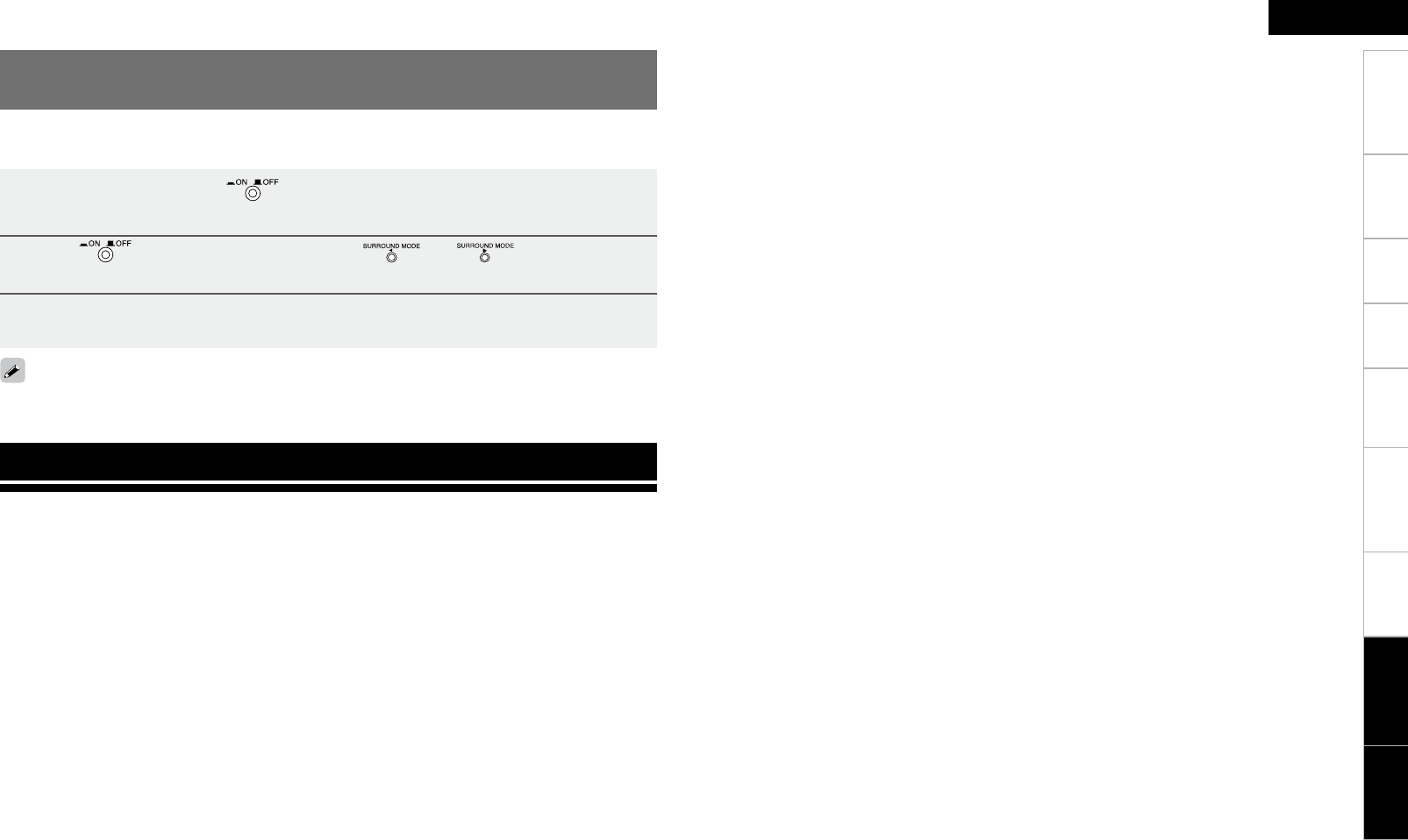
8
Getting Started Connections Playback Remote Control Information
ENGLISH
Multi-ZoneSettings
1 Turn off the power using on the main unit.
2 Press while simultaneously pressing and on the main unit.
3 Once the display starts ashing at intervals of about 1 second, release the two
buttons.
If in step 3 the display does not flash at intervals of about 1 second, start over from step 1.
Restoring All the Settings to as They were at the
Time of Purchase (Resetting the Microprocessor)
Perform this procedure if the display is abnormal or if operations cannot be performed.
When the microprocessor is reset, all the settings are reset to their default values.
n Video section
• Standard video connectors
Input / output level and impedance: 1 Vp-p, 75 Ω/ohms
Frequency response: 5 Hz ~ 10 MHz — +1, –3 dB
• S-Video connectors
Input / output level and impedance: Y (brightness) signal — 1 Vp-p, 75 Ω/ohms
C (color) signal — 0.286 Vp-p, 75 Ω/ohms
Frequency response: 5 Hz ~ 10 MHz — +1, –3 dB (when video convert set to “OFF”)
• Color component video connector
Input / output level and impedance: Y (brightness) signal — 1 Vp-p, 75 Ω/ohms
PB / CB signal — 0.7 Vp-p, 75 Ω/ohms
PR / CR signal — 0.7 Vp-p, 75 Ω/ohms
Frequency response: 5 Hz ~ 60 MHz — +0, –3 dB (when video convert set to “OFF”)
n Tuner section [FM] [AM]
(note: µV at 75 Ω/ohms, 0 dBf = 1 x 10-15 W)
Receiving Range: 87.5 MHz ~ 107.9 MHz 520 kHz ~ 1710 kHz
Usable Sensitivity: 1.0 µV (11.2 dBf) 18 µV
50 dB Quieting Sensitivity: 1.6 µV (15.3 dBf)
23 µV (38.5 dBf)
S/N (IHF-A): 77 dB
72 dB
Total harmonic Distortion (at 1 kHz): MONO 0.15 %
STEREO 0.3 %
n General
Power supply: AC 120 V, 60 Hz
Power consumption: 6.0 A
0.3 W (Standby)
Maximum external dimensions: 434 (W) x 171 (H) x 377 (D) mm (17-3/32” x 6-47/64” x 14-27/32”)
Weight: 11.3 kg (24 lbs 14.6 oz)
n Remote control unit (RC-1117)
Batteries: R6/AA Type (two batteries)
Maximum external dimensions: 52 (W) x 243 (H) x 21 (D) mm (2-3/64” x 9-9/16” x 53/64”)
Weight: 184 g (Approx 6.5 oz) (including batteries)
z For purposes of improvement, specifications and design are subject to change without notice.
Troubleshooting Specifications
n Audio section
• Power amplifier
Rated output:Front (A, B):
105 W+105 W (8 Ω/ohms, 20 Hz ~ 20 kHz with 0.08 % T.H.D.)
135 W+135 W (6 Ω/ohms, 1 kHz with 0.7 % T.H.D.)
Center:
105 W (8 Ω/ohms, 20 Hz ~ 20 kHz with 0.08 % T.H.D.)
135 W (6 Ω/ohms, 1 kHz with 0.7 % T.H.D.)
Surround:
105 W+105 W (8 Ω/ohms, 20 Hz ~ 20 kHz with 0.08 % T.H.D.)
135 W+135 W (6 Ω/ohms, 1 kHz with 0.7 % T.H.D.)
Surround Back:
105 W+105 W (8 Ω/ohms, 20 Hz ~ 20 kHz with 0.08 % T.H.D.)
135 W+135 W (6 Ω/ohms, 1 kHz with 0.7 % T.H.D.)
Output connectors:Front: A or B 6~16 Ω/ohms
A + B 12~16 Ω/ohms
Center, Surround, Surround Back / Amp Assign:
6~16 Ω/ohms
• Analog
Input sensitivity / Input impedance: 200 mV / 47 kΩ/kohms
Frequency response: 10 Hz ~ 100 kHz — +1, –3 dB (DIRECT mode)
S/N: 100 dB (IHF-A weighted, DIRECT mode)
Specifications

PRESET CODE
DEVICE SELECT : TV
Television
3M 100
AAddison 163
Admiral 033, 044, 050, 141
Advent 130
Adventura 041
Aiko 138
Akai 018, 019, 034, 119, 137, 151
Albatron 127, 131
Alleron 039
America Action 139
Ampro 129
Amtron 038
Anam 139
Anam National 035, 038
AOC 030, 036, 079, 137 151, 154
Apex 048, 062
Apex Digital 174
Audiovox 038, 067, 071, 138, 139, 140
Aventura 029
Axion 120
BBang & Olufsen 146
Barco 020
Baur 034
Belcor 030
Bell & Howell 033
Benq 089, 135
Blue Sky 020
Bradford 038, 139
Brillian 145
Brockwood 030
Broksonic 050, 139, 141
byd:sign 123
CCandle 037, 041, 137, 151
Carnivale 137, 151
Carver 155
CCE 147, 152
Celebrity 034
Celera 048
Changhong 048
Ching Tai 163
Chun Yun 157, 163, 169, 173
Chung Hsin 160, 169
Citizen 037, 038, 049, 137, 138,
151, 153, 156
Clarion 139
Coby 074
Contec 139
Contec/Cony 038
Craig 038, 139
Crosley 049, 155
Crown 038, 139, 153
CTX 082
Curtis Mathes 010, 019, 044, 137, 140,
143, 151, 153, 155, 156
CXC 038, 139
Cytron 118
DDaewoo 030, 036, 049, 138, 140, 153
Daytron 030
Dell 012, 032
Denon 143
DiamondVision 125
Dimensia 010
Disney 060
Dumont 013, 030
Durabrand 012, 029, 050, 111, 136,
139, 141
Dwin 044, 128
EElectroband 034
Electrograph 142
Electrohome 034, 035, 050
Element 106
Emerson 012, 029, 030, 038, 039,
049, 050, 139, 141, 153
Emprex 124
Envision 137, 151
Epson 080, 097
Erres 149
ESA 018, 029
Ether 158
FFirstar 170
Fujitsu 037, 039, 077
Funai 029, 038, 039, 139
Furi 165
Futuretech 038, 139
GGateway 085, 142, 144
GE 010, 012, 035, 040, 045,
055, 140
GFM 027, 028
Gibralter 013, 030, 137, 151
Go Video 134
Goldstar 012, 030, 036, 137, 151
Gradiente 084
Grundig 152
Grunpy 038, 039, 139
HHaier 107, 114, 136, 148
Hallmark 012
Hankook 158, 168, 169
Harman/Kardon 155
Harvard 038, 139
Havermy 044
Hello Kitty 140
Hewlett Packard 068
Hisense 087, 167, 174
Hitachi [014]z, 058, 103, 143, 181
HP 031
Hyundai 133
IIlo 090, 115, 117, 122
IMA 038
Infinity 155
InFocus 099
Initial 117
Innova 152
Insignia 029, 108, 109, 110
JJaneil 041
JBL 155
JC Penney 010, 036, 037, 040
JCB 034
Jean 159, 163, 167, 170
Jinxing 161, 165, 167
JVC 023, 024, 025, 040, 050
KKawasho 034
Kaypani 154
KEC 139
Kenwood 030, 137, 151
Kioto 020, 155
KLH 048
Kloss Novabeam 038, 041
Kolin 166, 169
KTV 038, 137, 139, 147, 151, 153
LLG 012, 030, 036, 127, 151
Logik 033
LXI 010, 012, 155
MM & S 155
Magnasonic 049
Magnavox 028, 037, 047, 054, 056,
137, 151, 155
Majestic 033
Marantz 046, 137, 151, 152, 155
Maxent 112, 142
Mediator 149
Megapower 127
Megatron 012, 143
Memorex 012, 029, 033, 036, 050, 141
MGA 012, 030, 036, 137, 151
Megatron 013, 040, 153
Mintek 117
Mitsubishi 012, 030, 036, 044, 057, 178
Monivision 127, 131
Montgomery Ward 033
Motorola 035, 044
MTC 030, 036, 137, 151, 156
Multitech 038, 139, 147
NNAD 012, 152
NEC 030, 035, 036, 081, 137, 151
Netsat 152
Net-TV 090, 142
Newave 163, 164, 168
Nikko 012, 137, 138, 151
Norcent 079, 174
Norwood Micro 090
Noshi 150
NTC 138
OOlevia 064, 072, 078
Onwa 038, 139
Oppo 121
Optoma 098
Optonica 044
Orion 050, 141
Otto Versand 034
PPanasonic 007, 008, 009, 035, 040,
059, 069, 176
Penney 012, 030, 137, 150, 151,
153, 156
Philco 030, 035, 036, 037, 050,
137, 151, 155
Philips 020, 021, 022, 035, 037,
046, 066, 105, 149, 152,155
Philips Magnavox 020, 046, 047
Phonola 149
Pilot 030, 137, 151, 153
Pioneer 180, 184
Polaroid 030, 048, 075
Portland 030, 036, 138, 153
Prima 083, 130
Princeton 127
Prism 040
Proscan 010
Proton 012, 154
Protron 073
Proview 086, 106
Pulsar 013, 030
Pye 149
QQuasar 035, 040
Quelle 034
RRadio Shack/
Realistic 010, 038
Radiola 149
RadioShack 012, 030, 137, 139, 151, 153
RCA 010, 011, 030, 035, 036,
043, 045, 150, 156
Realistic 012, 030, 137, 139, 151, 153
Runco 013, 137, 151
SSampo 137, 142, 151, 153, 154
Samsung
012, 018, 019, 030, 036,
101, 102, 137, 147, 151,
152, 156
Samsux 153
Sansui 050, 141
Sanyo 092
SBR 149
Sceptre 096
Scimitsu 030
Scotch 012
Scott 012, 030, 038, 039, 116, 139
Sears 010, 012, 029, 039, 088, 155
SEI 034
Sharp 015, 016, 017, 044, 070,
153, 179, 183
Shen Ying 163
Sheng Chia 044, 164
Shogun 030
Signature 033
Simpson 037
Sinudyne 034
SKY 152
Skygiant 169
Sony 000, 001, 002, 034, 052,
053, 175, 182
Soundesign 012, 037, 038, 039, 139
Sova 073
Sowa 162, 167
Squareview 029
SSS 030, 038, 139
Starlite 038, 139
Studio Experience 131
Superscan 044
Supre-Macy 041
Supreme 034
SVA 020, 113, 148, 174
Sylvania 026, 027, 028, 029, 037,
063, 104, 137, 151, 155
Symphonic 029, 038, 139
Synco 157, 162, 163, 164, 168, 172
Syntax 072
Syntax-Brillian 072, 088
TTacico 163, 168
Tandy 044
Tatung 035, 090, 144, 159, 162, 167
Technics 040
Techview 132
Techwood 040
Teco 159, 164, 168
Teknika 030, 033, 036, 037, 038,
039, 138, 139, 153, 155, 156
List of preset codes / Liste de codes préréglés

PRESET CODE
Telefunken 019
TMK 012
Toshiba 003, 004, 005, 006, 030,
051, 156, 177
Totevision 153
Trutech 091
Tuntex 158, 163
TVS 050, 141
UUS Logic 090
VVector Research 137, 151
Vidikron 155
Vidtech 012, 030, 036
Viewsonic 061, 076, 142
Viking 041
Viore 115
Vizio 061, 093, 094, 095, 126, 144
WWards 010, 012, 030, 033, 036,
039, 137, 151, 155
Westinghouse 061, 065, 140
White
Westinghouse 049, 050, 141
YYamaha 030, 036, 137, 151
Yapshe 171
ZZenith 012, 013, 014, 030, 033,
042, 050, 138, 141
TV/VCR Combination
RRCA 011
SSylvania 026
TV/DVD Combination
AAkai 119
Apex 062
Axion 120
CCoby 074
Cytron 118
DDiamondVision 125
Disney 060
GGFM 028
HHaier 114
IIlo 117
Initial 117
Insignia 108
LLG 030
MMintek 117
OOppo 121
PPanasonic 069
Philips 066
Polaroid 075
RRCA 010
SSansui 051
Sharp 070
Sylvania 027, 063
TToshiba 005, 051
WWestinghouse 065
TV/DVD/VCR Combination
MMagnavox 028
PPanasonic 059
TToshiba 006
DEVICE SELECT : DVD/HDP
Blu-ray Disc Player
DDenon 121
DVD Player
AAccele Vision 088
Accurian 146
Advent 131
Akai 098, 126
Alco 129
Allegro 142
Amphion
MediaWorks 117
AMW 117
Apex 025, 026, 027, 028, 049,
059, 136
Apple 109
Arrgo 043
Aspire 132
Astar 090
Audiovox 075, 129
Axion 099
BBang & Olufsen 137
Blaupunkt 136
Blue Parade 039
BOSS 089
Broksonic 061, 126
CCalifornia Audio
Labs 128
Changhong 071, 153
CineVision 074, 142
Coby 050, 081
Curtis Mathes 143
CyberHome 029, 043, 151, 152, 155, 156
Cytron 097
DDaewoo 057, 142
Denon 014, 070, [111]z, 112, 128
Desay 116
DiamondVision 124, 125
Disney 053, 063
Durabrand 144
EEmerson 127, 138, 145
Enterprise 138
Epson 120
ESA 145
FFisher 139
Funai 145
GGateway 068, 154
GE 044, 054, 136
GFM 101
Go Video 012, 142
Gradiente 128
Greenhill 136
HHaier 103
Harman/Kardon 082, 140
Hitachi 013
Hiteker 025
IIlo 096
Initial 096, 136
Insignia 055, 102, 145
Integra 039
Irradio 091
iSymphony 108
JJBL 140
JVC 030, 031, 032, 033, 034
KKawasaki 129
Kenwood 080, 128
KLH 058, 129, 136
Koss 067, 134
LLandel 147
Lasonic 141
Lenoxx 133, 144
LG 055, 076, 077, 095, 138, 142
Liquid Video 134
Liteon 068, 146
MMagnavox 047, 062, 127, 135, 145
Memorex 053, 126
Microsoft 044
Mintek 096, 136
Mitsubishi 056
NNesa 136
Next Base 147
Nexxtech 115
OOnkyo 071, 135
Oppo 100, 114
Optoma 122
Oritron 067, 134
PPanasonic
017, 018, 019, 020, 021,
022, 023, 024, 078, 083,
084, 085, 128, 135
Philips 007, 037, 038, 047, 052,
064, 073, 104, 135
Pioneer 039, 040, 041, 042, 087
Polaroid 028, 086
Proceed 025
Proscan 044
Protron 119
QQwestar 067
RRCA 035, 036, 039, 044, 129, 136
Regent 133
Rio 142
Rowa 130
SSampo 148, 150
Samsung 011, 012, 013, 015, 016,
048, 128
Sansui 008, 126
Sanyo 126, 139
Sharp 051, 060, 079, 092, 093, 094
Shinsonic 096
Sonic Blue 142
Sony
000, 001, 002, 003, 004,
005, 006 ,045, 065, 066,
105, 106, 107
Sungale 113
Superscan 127
Sylvania 046, 101, 123, 127, 145
Symphonic 038
TTeac 129, 149, 157, 158
Technics 128
Theta Digital 039
Toshiba 007, 008, 009, 010, 069,
126, 135
Trutech 110
UUrban Concepts 135
US Logic 096
VVenturer 129
VocoStar 118
WWestinghouse 072
XXbox 044
YYamaha 017, 128
ZZenith 055, 135, 138, 142
DVD/VCR Combination
BBroksonic 061
CCineVision 074
GGo Video 012
IInsignia 055
PPanasonic 018, 019, 020
SSamsung 012, 048
Sony 002, 003, 004, 005
Sylvania 046
TToshiba 007, 010
TV/DVD Combination
AAkai 098
Apex 026
Audiovox 075
Axion 099
CCoby 081
Cytron 097
DDiamondVision 124
Disney 063
GGFM 101
HHaier 103
IIlo 096
Initial 096
Insignia 102
LLG 077
MMintek 096
OOppo 100
PPanasonic 078
Philips 073
Polaroid 086
RRCA 035
SSansui 008
Sharp 079
Sylvania 046, 123
TToshiba 008, 101
WWestinghouse 072
TV/DVD/VCR Combination
MMagnavox 062
PPanasonic 021
TToshiba 009
DEVICE SELECT : DVR/VCR
Digital Video Recorder
AABS 035
Alienware 035
BBang & Olufsen 079
CCyberPower 035
DDell 035
DIRECTV 063, 065, 066, 067, 071,
073, 077
Dish Network 076
Dishpro 076
EEchostar 076
Expressvu 076
GGateway 035
GOI 076
HHewlett Packard 035
HNS 072
Howard Computers 035
HP 035
HTS 076
Hughes Network
Systems 063, 065, 066, 067, 073
Humax 063
Hush 035

PRESET CODE
IiBUYPOWER 035
JJVC 063, 076
LLinksys 035
MMedia Center PC 035
Microsoft 035
Mind 035
NNiveus Media 035
Northgate 035
PPanasonic 070
Philips 063, 065, 066, 067, 068, 072
Proscan 077
RRCA 063, 065, 072, 077
ReplayTV 069
SSamsung 065, 067, 072
Sonic Blue 069
Sony 035, 064, 074, 078
Stack 035
Systemax 035
TTagar Systems 035
Tivo 063, 064, 065, 068, 073,
074, 078
Toshiba 035, 075
Touch 035
UUltimateTV 077
VViewsonic 035
Voodoo 035
ZZT Group 035
Video Cassette Recorder
AABS 035
Adventura 008, 033
Aiwa 008, 033
Akai 020
Alienware 035
American High 032
Asha 013, 030
Audio Dynamics 018
Audiovox 031
BBeaumark 013, 030
Bell & Howell 029
Broksonic 056
CCalix 031
Candle 030, 031
Canon 032
CineVision 058
Citizen 030, 031
Colortyme 018
Craig 013, 030, 031
Curtis Mathes 012, 018, 030, 032
Cybernex 013, 030
CyberPower 035
DDaewoo 019, 033
Davidson 008
DBX 018
Dell 035
Denon 014
DIRECTV 061
Durabrand 025
Dynatech 008, 033
EElectrohome 010, 031
Electrophonic 031
Emerson 008, 010, 021, 031, 032, 033
FFisher 029
Fuji 026, 032
Funai 008, 021, 033
GGarrard 008, 033
Gateway 035
GE 012, 013, 030, 032
Go Video 013, 048
Goldstar 018, 031
Gradiente 008, 033
HHarley Davidson 033
Harman/Kardon 018
Headquarter 029
Hewlett Packard 035
Hitachi [008]z, 014
Howard Computers 035
HP 035
Hughes Network
Systems 014, 061
Humax 061
Hush 035
IiBUYPOWER 035
Insignia 059
Instant Replay 032
JJC Penney 018, 029, 030, 031, 032
JCL 032
JVC 016, 017, 018, 029
KKenwood 018, 029
Kodak 031, 032
LLG 031
Linksys 035
Lloyd's 008, 033
LXI 031
MMagnasonic 021
Magnavox 008, 021, 022, 025, 028, 032
Magnin 013, 031
Marantz 018, 029, 032
Marta 031
Matsushita 032
Media Center PC 035
MEI 032
Memorex 008, 013, 025, 029, 030,
031, 032, 033, 062
MGA 010, 013
MGN Technology 013, 030
Microsoft 035
Mind 035
Minolta 014
Mitsubishi 010, 038
Motorola 032
MTC 008, 013, 030
Multitech 008, 030, 033
NNEC 018, 029
Nikko 031
Niveus Media 035
Noblex 013, 030
Northgate 035
OOlympus 032
Optimus 021, 031
Optonica 024
Orion 044, 062
PPanasonic 000, 001, 002, 003, 004,
032, 060
Penney 013, 014
Pentax 014
Philco 032
Philips 024, 032, 041, 061
Philips Magnavox 041
Pilot 031
Profitronic 013
Pulsar 025
QQuarter 029
Quartz 029
Quasar 032
RRadioShack 008, 024, 031
Radio Shack/
Realistic 024, 029, 030, 031, 032, 033
Radix 031
Randex 031
RCA 011, 012, 013 ,014, 015,
030, 032, 051
Realistic 008, 024, 029, 030, 031,
032, 033
ReplayTV 060
Ricavision 035
Runco 025
SSamsung 013, 019, 020, 030, 040,
048, 049, 061
Sanky 025
Sansui 008, 044, 062
Sanyo 013, 029, 030
Scott 010, 019
Sears 008, 014, 029, 031, 032
Sharp 023, 024, 042
Shogun 013, 030
Singer 032
Sonic Blue 060
Sony
005, 006, 007, 008, 026
,034, 035, 036, 037, 045 ,
052, 053, 054
Stack 035
STS 014, 032
Sylvania 008, 010, 021, 022, 032,
033, 046, 055
Symphonic 008, 021, 022, 033
Systemax 035
TTagar Systems 035
Tandy 029
Tashiko 031
Teac 008, 033
Technics 032
Teknika 008, 031, 032, 033
Thomas 008
Tivo 061
TMK 013, 030
Toshiba 009, 010, 019, 035, 039,
047, 050, 057
Totevision 013, 030, 031
Touch 035
UUnitech 013, 030
VVector 019
Vector Research 018
Video Concepts 018, 019
Videosonic 013, 030
Viewsonic 035
Villain 008
Voodoo 035
WWards 008, 013, 014, 024, 030,
031, 032, 033
XXR-1000 008, 032, 033
YYamaha 018, 029
ZZenith 008, 025, 026, 027, 043
ZT Group 035
DVD/VCR Combination
BBroksonic 056
CCineVision 058
GGo Video 048
IInsignia 059
PPanasonic 002, 003, 004
SSamsung 040, 048, 049
Sony 037, 045, 052, 053, 054
Sylvania 046
TToshiba 039, 050, 057
TV/VCR Combination
RRCA 051
SSylvania 055
TV/DVD/VCR Combination
MMagnavox 022
PPanasonic 001
TToshiba 047
DEVICE SELECT : SAT/CBL
Satellite Receiver
AAccessHD 109
Alpha Digital 109
Alphastar 083
Artec 106
CCaptiveWorks 102
Channel Master 111
Chaparral 077
Coolsat 103
Coship 114
Crossdigital 120
DDigital Stream 110
DIRECTV
058, 059, 060, 061, 062, 063,
064, 068, 069, 073, 074, 075,
076, 088, 089, 090, 093,
095, 116
Dish Network 052, 053, 054, 055, 065, 091,
115, 119
Dishpro 115, 119
Drake 078
EEchostar 052, 065, 091, 115, 119
Expressvu 119
GGE 056, 057, 112
General Instrument 079, 117
GOI 119
Goodmind 112
HHisense 118
Hitachi 074, 084
HTS 119
Hughes Network
Systems
060, 062, 067, 068, 070,
075, 093
Humax 104
IIlo 118
Insignia 096
JJerrold 117
JVC 052, 065, 091, 119
LLasonic 113
LG 096, 105
MMagnavox 073, 107
Memorex 073
MicroGem 108
Mitsubishi 068, 099
Motorola 117
NNext Level 117
PPanasonic 061, 095, 097
PRESET CODE
Pansat 100
Paysat 073
PCT 111
Philco 107
Philips 060, 067, 068, 070, 072,
073, 090
Pioneer 060
Primestar 082
Proscan 056, 057
Proton 118
RRadioShack 117
RCA 056, 057, 058, 070, 076, 086,
087, 088, 089, 092
Realistic 080
SSamsung 060, 062, 069, 070, 071, 094
Sharp 098
Sony 059, 066, 116
Star Choice 117
STS 085
TTivax 109
Tivo 060, 070
Toshiba 063
UUltimateTV 116
Uniden 073, 081
US Digital 118
VViewsat 101
Voom 117
ZZenith 064, 096
Cable TV
AABC [009]z, 010, 012, 028, 040
Adelphia 007
Americast 047
Antronix 014, 015
Archer 015
AT&T 003
BBell South 047
CCable Vision 006
Cabletenna 014
Cableview 013
Clearmaster 046
ClearMax 046
Colour Voice 016
Comcast 000, 005, 033
Comtronics 017
Contec 018
Coolmax 046
COX 005
DDaeryung 036
Director 033
Dumont 051
EEastern 019
Everquest 041
FFocus 045
GGC Electronics 015
GE 009, 010
Gehua 033
Gemini 020, 041
General Instrument 005, 010, 033, 044
Goldstar 042
HHamlin 021
Hitachi 010
JJasco 041
Jerrold 005, 010, 020, 028, 029, 033,
041, 044
LLG 050
MMagnavox 022
MegaCable 005
Memorex 023, 040
Motorola 000, 003, 005, 033, 037,
039, 044
Movie Time 024
Multitech 046
NNEC 011
NET Brazil 035
NSC 024
OOak 018
PPace 008, 043
Panasonic 026, 027, 040
Paragon 040
Philips 016, 022
Pioneer 002, 030, 036, 042
Popular Mechanics 045
Proscan 009, 010
Pulsar 040
QQuasar 040
RRadioShack 041, 046
RCA 013, 027
Realistic 015
Recoton 045
Regal 021
Regency 019
Rembrandt 010
Runco 040
SSamsung 008, 034, 042
Scientific Atlanta 001, 002, 003, 007, 012,
036, 038
Signal 020, 041
Signature 010
Sony 006, 048
Sprucer 027
Standard
Component 025
Starcom 020, 028, 041
Stargate 020, 041
Starquest 020, 041
Supercable 044
Supermax 046
TTime Warner 004
Tocom 031
Torx 049
Toshiba 040
Trans PX 044
Tristar 046
TS 049
Tusa 020, 041
TV86 024
UUnika 014, 015
United Cable 028
Universal 014, 015
VV2 046
View Star 018, 022, 024
Viewmaster 046
Vision 046
Vortex View 046
ZZenith 032, 040, 047
Zentek 045
DEVICE SELECT : CD
CD Player
AAccuphase 018
Acoustic Research 019
ADS 020
Aiwa 021
Akai 022
Audio Alchemy 023
Audio Pro 024
Audio-Technica 025
BB & K 026
CCalifornia Audio
Labs 036
Carver 040, 041
DDenon 001, 042, [111]z
DKK 035
DMX Electronics 040
Dynamic Bass 041
GGE 017
Genexxa 037
HHarman/Kardon 007
JJVC 003, 011, 012
KKenwood 038, 039
LKrell 040
LLinn 040
MMagnavox 027
Marantz 028
Miro 035
Mission 040
Musical Fidelity 029
NNEC 030
NSM 040
OOnkyo 002
Optimus 035, 037, 039, 041
PPhilips 009, 010
Pioneer 006
Polk Audio 040
Proscan 017
Proton 040
QQED 040
Quad 040
RRCA 000, 017
Realistic 041
Rotel 040
SSAE 040
Sansui 040
Sanyo 031
SAST 040
Sharp 032
Silsonic 038
Sonic Frontiers 040
Sony 004, 005, 008, 013, 014
Soundesign 033
Symphonic 034
TTAG McLaren 040
Technics 015
WWards 040
YYamaha 016
ZZonda 040
DVD preset codes / Codes préréglés DVD
e Model No. / Modéle numéro
111
(default / default) 014
DVD-900
DVD-700
DVD-1000
DVD-1400
DVD-1500
DVD-1710
DVD-1720
DVD-1730
DVD-1740
DVD-1910
DVD-1920
DVD-1930
DVD-1940
DVD-2200
DVD-2800
DVD-2800g
DVD-2900
DVD-2910
DVD-2930
DVD-3800
DVD-3910
DVD-3930
DVD-A11
DVD-A1XV
DVD-A1
DVD-800
DVD-1600
DVD-2000
DVD-2500
DVD-3000
DVD-3300
Blu-Ray preset codes /
Codes préréglés Blu-Ray
e Model No. /
Modéle numéro
121
DVD-1800BD
DVD-2500BT
DVD-3800BD
DVD-A1UDCI
[ ]* :
Preset codes set upon shipment from
the factory.
*[ ] : Les codes préréglés diffèrent en fonctiom
des livraison de l’usine.

Denon Brand Company, D&M Holdings Inc.
Printed in China 5411 10256 003D
www.denon.com
