Denon Stereo Amplifier Avc A1Hd Users Manual
AVC-A1HD to the manual b58dcbbf-eeba-4058-bfe4-2beb4cb17141
2015-01-23
: Denon Denon-Denon-Stereo-Amplifier-Avc-A1Hd-Users-Manual-221504 denon-denon-stereo-amplifier-avc-a1hd-users-manual-221504 denon pdf
Open the PDF directly: View PDF ![]() .
.
Page Count: 74
- Getting Started
- Connections
- GUI Menu Operations
- Auto Setup
- Manual Setup
- Speaker Setup
- Audio Setup
- Option Setup
- Amp Assign (AVC-A1HD only)
- Pre-out Assign (AVP-A1HD only)
- XLR Out Polarity (AVP-A1HD only)
- POA Setting (AVP-A1HD only)
- Volume Control
- Source Delete
- GUI
- Quick Select Name
- Trigger Out 1
- Trigger Out 2
- Trigger Out 3
- Trigger Out 4
- Transducer Setup
- Digital Out
- Remote ID
- 232C Port (1)
- Dimmer
- Setup Lock
- Maintenance Mode
- Firmware Update
- Add New Feature
- Surround Mode
- Parameters
- Information
- Other Operations and Functions
- Amp Assign / Multi-Zone Connections and Operations (AVC-A1HD only)
- Other Information
- Troubleshooting
- Specifications
AV SURROUND AMPLIFIER
AVC-A1HD
AV SURROUND PRE-AMPLIFIER
AVP-A1HD
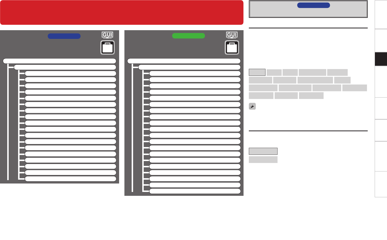
The owner’s manual is organized in the following two volumes.
• GOriginal versionH
• GUpgrade versionH ·······························This version
NOTE
• Products that have been upgraded cannot be returned to the previous state.
• This model has been upgraded previously. This manual contains details of all of
the upgrades. Therefore, you do not need any manuals other than the “Original
version” and “Upgrade version” (this version).
Owner’s Manual GUpgrade versionHOwner’s Manual GUpgrade versionHn Symbols used in this manual
AVC-A1HD This symbol indicates contents for AVC-A1HD.
AVP-A1HD This symbol indicates contents for AVP-A1HD.
This symbol indicates items described in the
“Original version”.
Getting Started Connections Setup Other Operations Multi-Zone Information Troubleshooting Specifications
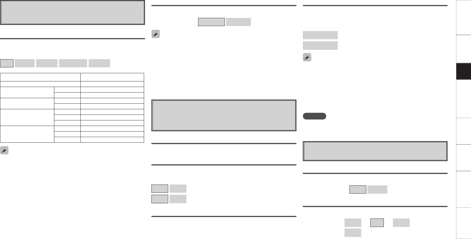
Accessories ······················································································2
Functions that are added/changed/deleted by this upgrade
······2, 3
Changes to the Panel Display ························································4
Front Panel ····················································································· 4
Rear Panel ······················································································4
Part Names and Functions ····························································· 5
Front Panel ····················································································· 5
Display ···························································································5
Remote Control Unit ······································································6
Getting Started
Speaker Installation ·······································································6
Speaker Layout ·············································································6
Speaker Connections ··································································7, 8
Connecting Equipment with HDMI connectors ···························9
Connections to Other Devices ·······················································9
External Power Amplifier ································································9
Connections
Auto Setup ·············································································· 12, 13
a Auto Setup ······································································14 ~ 21
s Option ····················································································· 22
d Parameter Check ····································································· 22
Auto Setup
Contents Surround Mode
GUI Menu Map ··········································································10,11
GUI Menu Operations
Speaker Setup···············································································23
a Speaker Configuration ·····························································23
s Subwoofer Setup ····································································24
d Distance ·················································································· 24
f Channel Level····································································24, 25
g Crossover Frequency ······························································25
h THX Audio Setup ·····································································25
Audio Setup ·················································································· 26
a EXT. IN Setup ··········································································26
s 2ch Direct/Stereo ······························································26, 27
d Auto Surround Mode ······························································27
f Manual EQ ·············································································· 27
Option Setup ·················································································28
a Amp Assign ( AVC-A1HD only) ··············································28
a Pre-out Assign ( AVP-A1HD only) ··········································29
s XLR Out Polarity ( AVP-A1HD only) ·······································30
d POA Setting ( AVP-A1HD only) ·············································30
s Volume Control ( AVP-A1HD : f) ·········································30
d Source Delete ( AVP-A1HD : g) ···········································30
f GUI ( AVP-A1HD : h) ····························································31
g Quick Select Name ( AVP-A1HD : j) ···································31
h Trigger Out 1 ( AVP-A1HD : k) ·············································32
j Trigger Out 2 ( AVP-A1HD : l) ·············································32
k Trigger Out 3 ( AVP-A1HD : A0) ·············································32
l Trigger Out 4 ( AVP-A1HD : A1) ·············································32
A0 Transducer Setup ( AVP-A1HD : A2) ······································32
A1 Digital Out ( AVP-A1HD : A3) ·················································33
A2 Remote ID ( AVP-A1HD : A4) ·················································33
A3 232C Port (1) ( AVP-A1HD : A5) ·············································33
A4 Dimmer ( AVP-A1HD : A6) ·····················································33
A5 Setup Lock ( AVP-A1HD : A7) ················································33
A6 Maintenance Mode ( AVP-A1HD : A8) ···································33
A7 Firmware Update ( AVP-A1HD : A9) ······································34
A8 Add New Feature ( AVP-A1HD : S0) ······································ 34
Manual Setup
HOME THX CINEMA ····································································· 35
Surround Playback of 2-channel Sources ·····································35
Playing Multi-channel Sources (Dolby Digital, DTS, etc.) ·············35
Standard Playback ········································································36
Surround Playback of 2-channel Sources ·····································36
Playing Multi-channel Sources (Dolby Digital, DTS, etc.) ·············37
Audio······························································································38
a Surround Parameters ······················································38 ~ 40
s Tone ························································································40
d Audyssey Settings·····························································41, 42
f A-DSX Soundstage ···························································42, 43
g RESTORER ··············································································43
h Audio Delay ·············································································43
Parameters
Status ····························································································44
a MAIN ZONE ············································································ 44
s ZONE2/3/4 ·············································································· 44
Quick Select ··················································································44
Information
Other Operations and Functions ················································45
Amp Assign / Multi-Zone Connections and Operations
(AVC-A1HD only) ································································ 46 ~ 61
Other Information ······························································· 62 ~ 69
Troubleshooting ·····································································70, 71
Specifications ···············································································72
Connections Setup Other Operations Multi-Zone Information Troubleshooting SpecificationsGetting Started
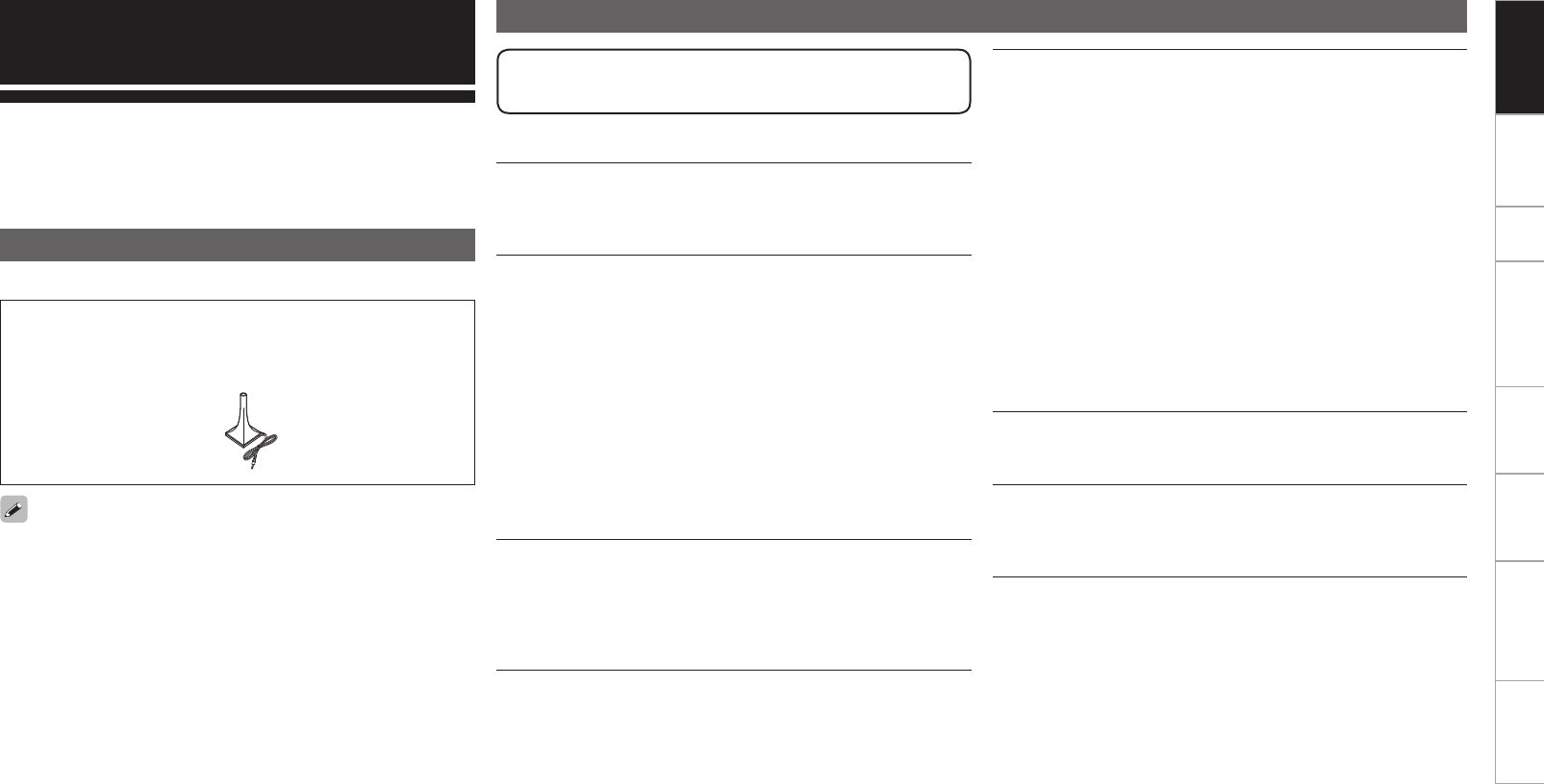
Check that the following parts are supplied with the product.
q CD-ROM (Owner’s manual) ..................................................... 1
w Setup microphone (DM-A409, Cord length: Approx. 6.0 m) .... 1
Thank you for purchasing this DENON product. To ensure proper
operation, please read this owner’s manual carefully before using the
product.
After reading them, be sure to keep them for future reference.
Getting Started
Accessories
w
Note that the illustrations in this instructions are for explanation
purposes and may differ from the actual unit.
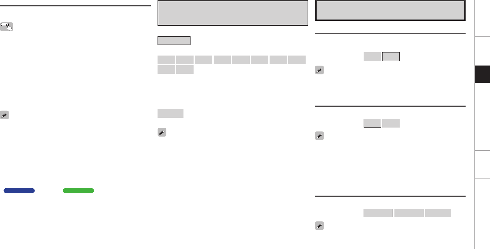
Functions that are added/changed/deleted by this upgrade
Additional functions
Audyssey Dynamic Volume®
Audyssey Dynamic Volume® is technology that solves the problem
of large variations in volume level between television programs,
commercials, and between the soft and loud passages of movies.
DENON LINK 4th (Jitter-free playback)
DENON LINK 4th adds high-quality playback of HD audio in addition to
the outstanding performance of DENON LINK 3rd, high quality audio
signal transmission technology developed by DENON.
By connecting an AV amplifier and Blu-ray Disc player that both
support DENON LINK 4th with a DENON LINK cable (supplied with
the Blu-ray Disc player) and HDMI cable (sold separately), you can
control the Blu-ray Disc player using the master clock signal sent from
the AV amplifier.
As D/A conversion is performed by the AV amplifier master clock,
there are no effects of clock jitter from the HDMI transfer, enabling
jitter free playback.
Sound localization becomes clearer, producing the clear sense of
space in the sound images that can only be achieved from HD audio.
Audyssey DSX™
By connecting front height speakers to this unit and playing back
through Audyssey DSX™, you can experience a more powerful
playback expression in the height audio range. By connecting front
wide speakers, you can experience a more powerful playback
expression in the wide audio range.
When this product is upgraded, all settings return to the
default settings. Reconfigure settings as required.
Dolby Pro Logic gz
Dolby Pro Logic gz introduces a new dimension to Home
Entertainment through the addition of a pair of front height channels.
Compatible with stereo, 5.1-channel and 7.1-channel content, Dolby
Pro Logic gz provides enhanced spaciousness, depth and dimension
to movies, concert video and video game playback while maintaining
the full integrity of the source mix.
Dolby Pro Logic gz identifies and decodes spatial cues that occur
naturally in all content, directing this information to the front height
channels, complementing the performance of left and right surround
sound speakers. Content that is encoded Explanation of terms with
Dolby Pro Logic gz height channel information can be even more
revealing, with perceptually discrete height channel information
bringing an exciting new dimension to home entertainment.
Dolby Pro Logic gz, with front height channels is also an ideal
alternative for households that cannot support the placement of
back surround speakers of a typical 7.1-channel system but may have
bookshelf space available to support the addition of height speakers.
HDMI (Ver. 1.4a with 3D)
This unit can output 3D video signals input from a Blu-ray Disc player
to a TV that supports a 3D system.
DTS Neo:X
This technology enables the playback of 2-channel source audio or
7.1/5.1 multi-channel source audio through a maximum 9.1 channel
speakers, achieving an even broader sound field.
Connections Setup Other Operations Multi-Zone Information Troubleshooting SpecificationsGetting Started
Deleted Functions
Surround B speakers unsupported
As front height speakers and front wide speakers are now supported
by this upgrade, surround B speakers can no longer be used.
Audyssey MultEQ® XT
As Audyssey MultEQ® XT 32 is supported by this upgrade, Audyssey
MultEQ® XT is deleted.
DTS Neo:6
As DTS Neo:X is supported by this upgrade, DTS Neo:6 is deleted.
Night Mode function
In this upgrade, the night mode in which the volume can be set to
low level for listening at nighttime is deleted. The same effect can be
obtained from setting “Dynamic EQ®” and “Dynamic Volume®” in
the GUI menu (vpage 41) to “ON”.
Mic Select function
The Mic Select function is deleted when the product is upgraded.
Only the supplied setup microphone (DM-A409) can be used.
For details on the items that are added/changed/deleted
from the GUI menu, see “GUI Menu Map” (vpage 10, 11).
Changed Functions
Support for front height speakers and front wide speakers
Front height or front wide channels can be played back through the
FH/FW/AMP ASSIGN-2 speaker terminals and the PRE OUT FH/FW
terminals. This enables you to enjoy a maximum 9.3 channel surround
playback.
Audyssey MultEQ® XT 32
Audyssey MultEQ® corrects both time and frequency response
problems in the listening area so that every listener can enjoy music
and movie with the optimum sounds. It performs a fully automated
surround system setup. The unit is equipped Audyssey MultEQ® XT
32 that can correct much higher details, particularly in the bass range
of the speakers. The high resolution correction reproduces much
clearer surround sound.
Direct Mode function (Multi-channel)
When multi-channel signals are input, the signals are output directly
without being mixed-down to 2 channels.
Surround Back function
When surround back speakers are used and a surround back signal
is recorded in the input signal, audio is output automatically from the
surround back speakers.
Web Control function
When this product is upgraded, previously saved contents cannot be
called.
After completing the upgrade, reconfigure the settings.
For details on the web control operating procedures, see mpage 61
AVC-A1HD , mpage 63 AVP-A1HD .
Connections Setup Other Operations Multi-Zone Information Troubleshooting SpecificationsGetting Started
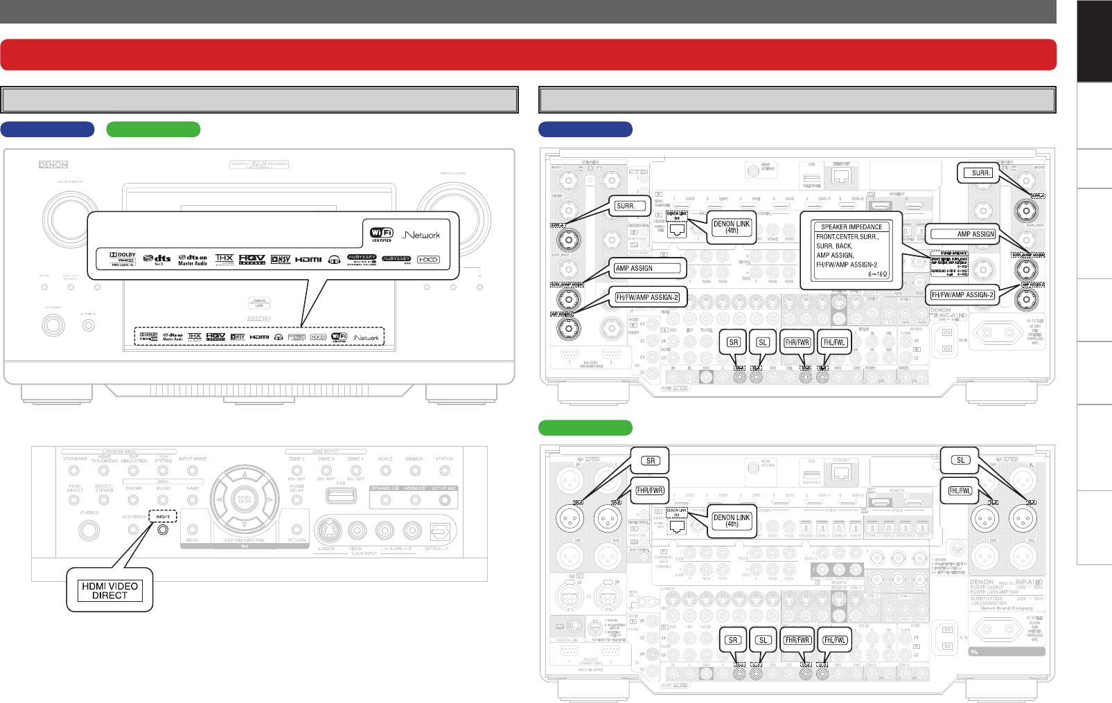
Changes to the Panel Display
After completing the upgrade, labels are attached to the changed parts of the panel. For details of the changed parts, see the illustration below.
Front Panel Rear Panel
AVP-A1HDAVC-A1HD AVC-A1HD
GWith the door openHAVP-A1HD
Connections Setup Other Operations Multi-Zone Information Troubleshooting SpecificationsGetting Started
Part Names and Functions
Front Panel
When this unit is upgraded, the night mode cannot be set when the NIGHT
button is pressed.
q HDMI video direct button
(HDMI VIDEO DIRECT)
When this button is pressed, video signals
recorded on the BD or DVD are output directly.
Video signals input from the HDMI IN terminal
are output directly from the HDMI OUT terminal
without being processed by this unit.
GWith the door openH
t Surround speaker indicators
These light according to the settings of the
surround A and B speakers.
Q1 NIGHT indicator
This lights when the night mode is selected.
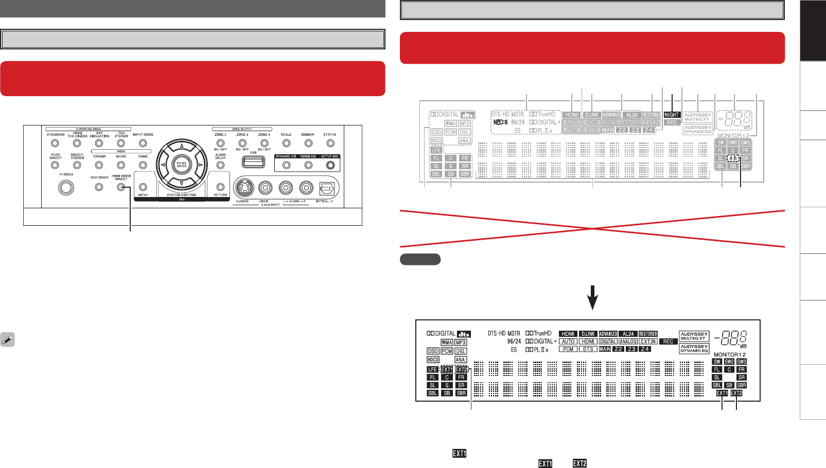
Display
q
When the upgrade is performed, the sections highlighted in the illustration
below do not light.
t
uQ4Q8 o iQ1Q0Q6 Q2
Q3Q5Q7 y
wq e r
NOTE
The NEO:6 indicator does not light after the upgrade because DTS NEO:X is supported.
wq e
q Input signal channel indicators
When there is 1 extension channel in the input
signal, the indicator lights. If there are two
or more extension channels, the and
indicators light.
w Front height speaker indicator
This lights when audio signals are being output
from the front height speakers.
e Front wide speaker indicator
This lights when audio signals are being output
from the front wide speakers.
When the video direct function is on, temporary
display in the GUI menu cannot be used.
Setup Other Operations Multi-Zone Information Troubleshooting SpecificationsGetting Started Connections
q HDMI video direct button (NGT)
When this button is pressed, video signals
recorded on the BD or DVD are output directly.
Video signals input from the HDMI IN terminal
are output directly from the HDMI OUT terminal
without being processed by this unit.
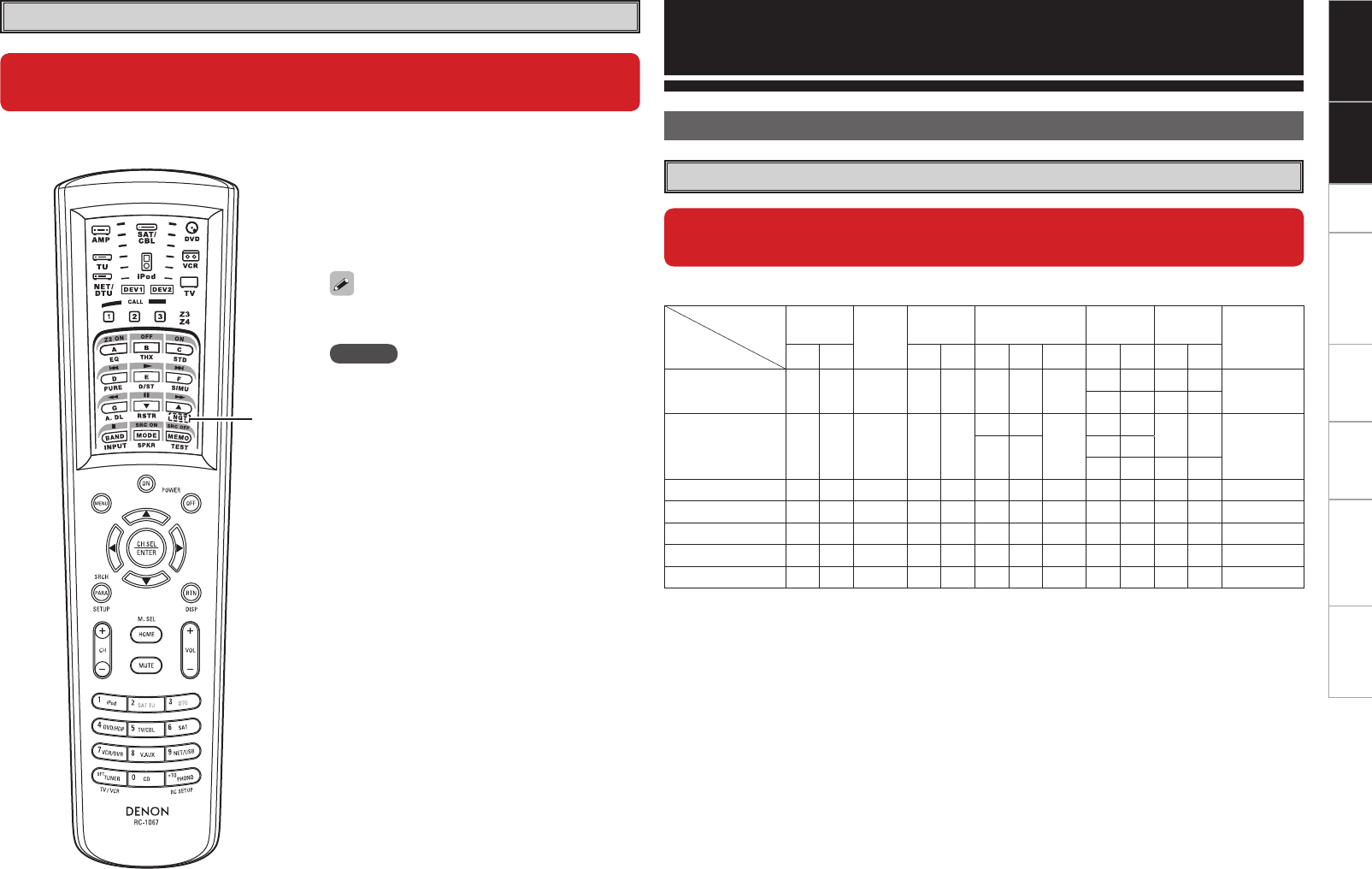
n Main remote control unit (RC-1067)
Remote Control Unit
NOTE
When using 3D video devices that transmit radio
communication signals (such as infrared signals etc)
between the various units (such as the monitor, 3D
glasses, 3D transmitter unit etc), the remote control
unit may not operate due to interference from those
radio communication signals. If this occurs, adjust
the direction and distance of the 3D communication
for each unit, and check that the remote control unit
operation is not affected by these signals.
q
When this unit is upgraded, the night mode cannot be set when the NGT
button is pressed.
Connections
Speaker Installation
Speaker Layout
When this unit is upgraded, the speaker configurations supported by this
unit change.
The table below shows a typical speaker configuration for the unit.
Speaker
Configuration
FRONT CENTER SURROUND SURROUND BACK FRONT
HEIGHT
FRONT
WIDE SUBWOOFER
(b2)
L R L R L R 1 only L R L R
9.1-channels (b1) S S S S S S S –S S – – S
– – S S
7.1-channels S S S S S
S S
–
– – – – S
– – S S
– – S S
6.1-channels S S S S S – – S– – – – S
5.1-channels S S S S S – – – – – – – S
3.1-channels S S S – – – – – – – – – S
2.1-channels S S – – – – – – – – – – S
2-channels S S – – – – – – – – – – –
b1 To perform the 9.1 channel playback using front height speakers or front wide speakers, a separate
power amplifier (sold separately) is required.
b2 The unit can be connected to a maximum of 3 subwoofers.
When the video direct function is on, temporary
display in the GUI menu cannot be used.
Getting Started Setup Other Operations Multi-Zone Information Troubleshooting SpecificationsConnections
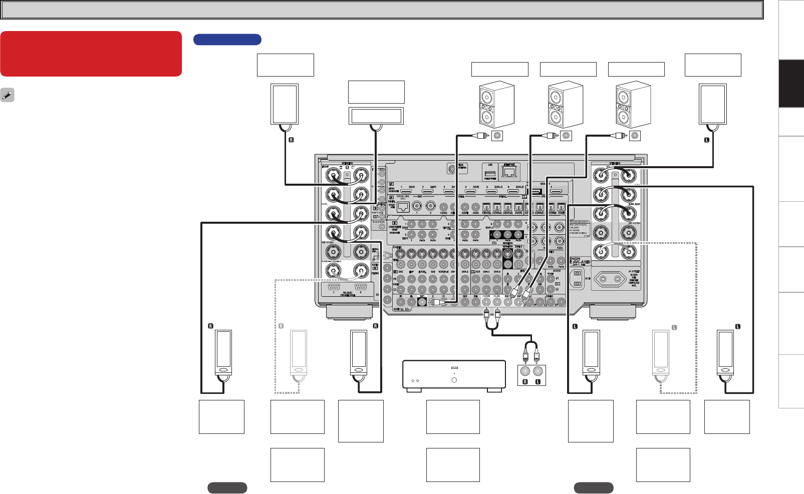
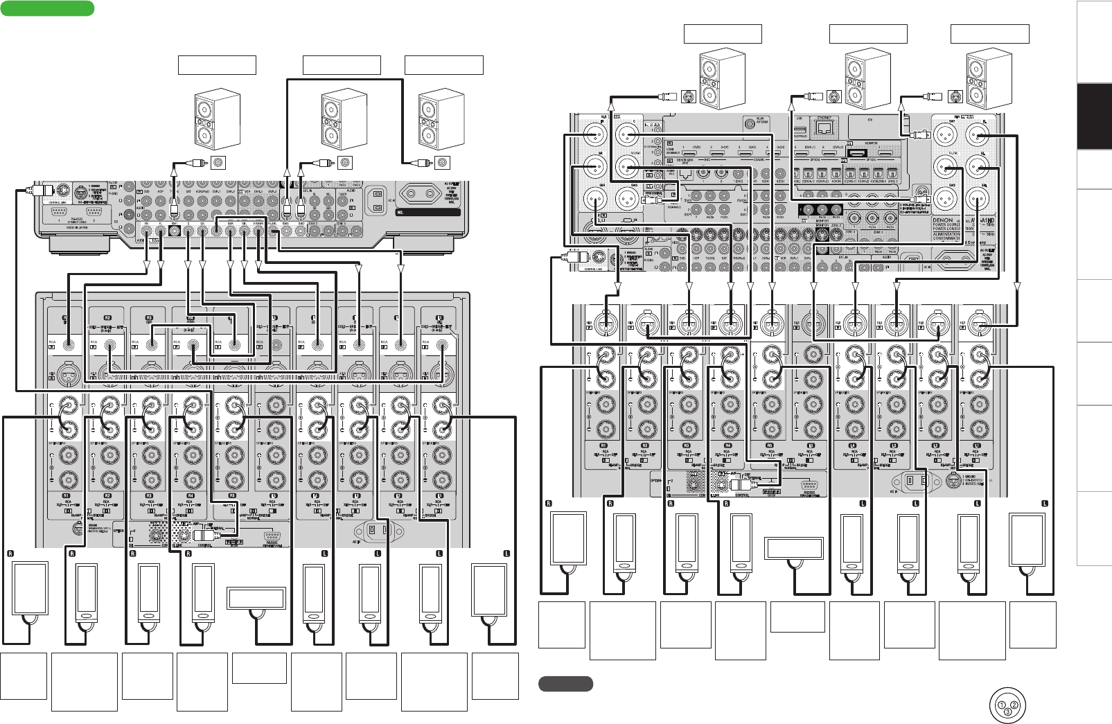
Speaker Connections
• When using just one surround back speaker,
connect it to the left channel (SBL).
• When using Subwoofer 2 or 3, set GUI menu
“Manual Setup” – “Speaker Setup” – “Subwoofer
Setup” (vpage 24).
When this unit is upgraded, the
terminal names and connection
methods change.
NOTE
It is not possible to use the front height speakers
and front wide speakers simultaneously.
AVC-A1HD
(R) (L)
(L)
(R) (L)
(R) (R) (L)
*/
w q w q w q
w q
w q w q
w q w q
w q
*/ */
RL
RL
*/
Front
speaker (R)
Center
speaker Subwoofer
with built-in
amplifier
Surround
speaker
(R)
b L : Left
R : Right
Front
speaker (L)
Surround
back
speaker
(R)
Surround
speaker
(L)
Surround
back
speaker
(L)
Subwoofer 3 Subwoofer 2Subwoofer 1
Front height
speaker
(R)
Front wide
speaker
(R)
Front height
speaker
(L)
Front wide
speaker
(L)
or or
Front height
speaker
(L/R)
Front wide
speaker
(L/R)
or
Power amplifier
NOTE
It is not possible to use the front height speakers
and front wide speakers simultaneously.
Getting Started Setup Other Operations Multi-Zone Information Troubleshooting SpecificationsConnections
AVP-A1HD
n Connecting the RCA pre-out terminal (Example : 9.3-channels)
n Connecting the XLR pre-out terminal (Example : 9.3-channels)
SPEAKERS
XLR
RCA
SPEAKERS
XLR
RCA
SPEAKERS
XLR
RCA
SPEAKERS
XLR
RCA
SPEAKERS
XLR
RCA
SPEAKERS
XLR
RCA
SPEAKERS
XLR
RCA
SPEAKERS
XLR
RCA
SPEAKERS
XLR
RCA
SPEAKERS
XLR
RCA
*/
(R) (L) (L) (L)
(R)
*/ */
(L)
(R) (R)
w q
w qw q
w q
w q
w qw qw q
w q
This unit
SPEAKERS
XLR
SPEAKERS
XLR
SPEAKERS
XLR
SPEAKERS
XLR
SPEAKERS
XLR
SPEAKERS
XLR
SPEAKERS
XLR
SPEAKERS
XLR
SPEAKERS
XLR
SPEAKERS
XLR
IN IN IN
(R) (L) (L) (L)
(R) (L)
(R) (R)
w q
w qw q
w q
w q
w qw q
w q
Subwoofer with
built-in amplifier
NOTE
The default AVP-A1HD balance model XLR pre-out terminal pin alignment is as shown.
q : GROUND w : HOT e : COLD
POA-A1HD
This unit
POA-A1HD
b L : Left
R : Right
Front
speaker
(R)
Center
speaker
Subwoofer
with built-in
amplifier
Surround
speaker
(R)
Surround
back
speaker
(R)
Subwoofer 3Subwoofer 2Subwoofer 1
Front height/
Front wide
speaker
(R)
Front
speaker
(L)
Surround
speaker
(L)
Surround
back
speaker
(L)
Front height/
Front wide
speaker
(L)
Subwoofer 1Subwoofer 2Subwoofer 3
Front
speaker
(R)
Center
speaker
Surround
speaker
(R)
Surround
back
speaker
(R)
Front height/
Front wide
speaker
(R)
Front
speaker
(L)
Surround
speaker
(L)
Surround
back
speaker
(L)
Front height/
Front wide
speaker
(L)
Getting Started Setup Other Operations Multi-Zone Information Troubleshooting SpecificationsConnections
NOTE
• When playing back 3D video, refer to the instructions provided in the manual of your playback device
together with this manual.
• If you operate the menu while playing back 3D video content, the playback video is replaced by the menu
screen. The playback video is not displayed behind the menu screen.
• This unit does not show the status display while playing back 3D video content.
• If 3D video with no 3D information is input, the menu screen and status display on this unit are displayed
over the playback video.
• If 2D video is converted to 3D video on the television, the menu screen and status display on this unit
are not displayed correctly. To view the menu screen and status display on this unit correctly, turn the
television setting that converts 2D video to 3D video off.
• When computer resolution (e.g. VGA) video or 3D video contents are being played back, the status display
cannot be displayed.
• When the menu is operated during playback of a computer resolution video (e.g. VGA) or 3D video
contents, the playback video switches to the video in the menu screen.
• When a 3D compatible television and 3D incompatible television are connected at the same time, when
you want to playback 3D video, switch the “Monitor Out” (vmpage 31) setting to the terminals that
the 3D compatible television is connected to before playing the content on the player.
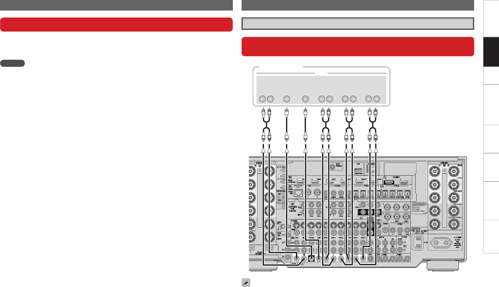
Connecting Equipment with HDMI connectors Connections to Other Devices
External Power Amplifier
When using just one surround back speaker, connect it to the left channel (SBL).
When this unit is upgraded, 3D video can be played back.
When this unit is upgraded, the terminal names and connection methods
will change.
This unit supports input and output of 3D (3 dimensional) video signals of HDMI 1.4a.
To play back 3D video, you need a TV and player that provide support for the HDMI 1.4a 3D function and a
pair of 3D glasses.
R
L
R
L
R
L
R
L
R
L
R
L
R
L
R
L
46#
800'&3
$&/5&3 463306/%
#"$,
3-
463306/%
3-
'30/5
3-
"6%*0
'30/5)&*()5
'30/58*%&
3-
Power amplifier
or
0
Getting Started Connections Other Operations Multi-Zone Information Troubleshooting SpecificationsSetup
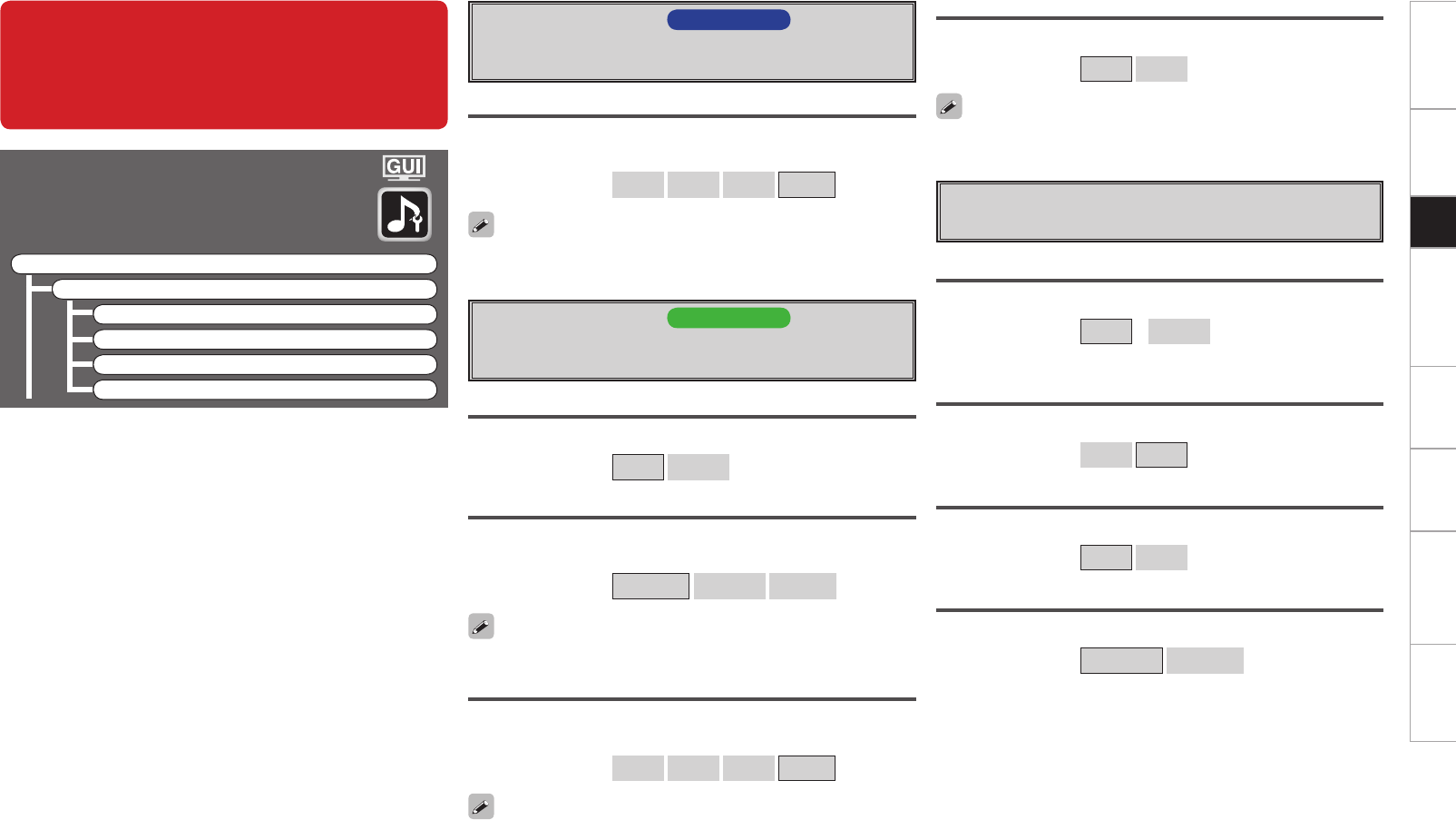
GUI Menu Operations
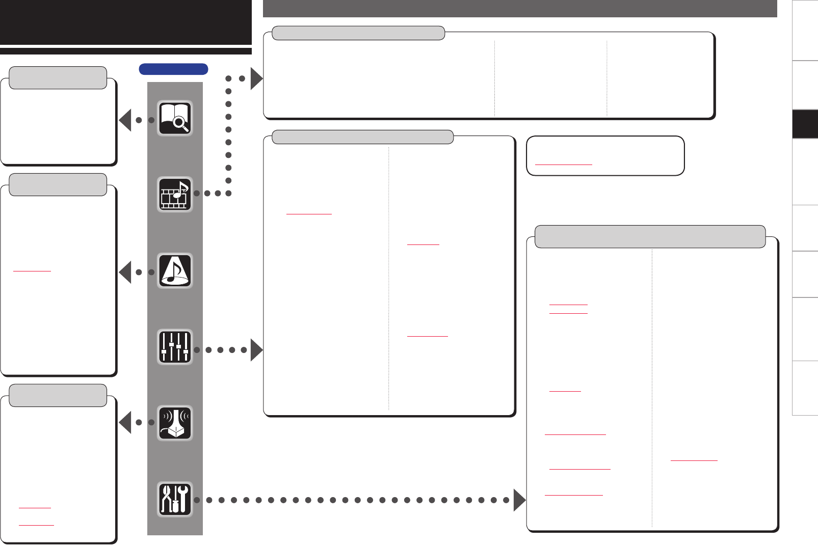
GUI Menu Map
Parameters (vpage 38 ~ 43, mpage 52)
Information
(vpage 44)
n Status
• MAIN ZONE
• ZONE2/3/4
n Audio Input Signal
n HDMI Information
n Auto Surround Mode
n Quick Select
n Preset Station n Audio
• Surround Parameters
· Mode
· Decoder
· Cinema EQ
· DRC
· D.COMP
· LFE
· Center Image
· Center Gain
· Panorama
· Dimension
· Center Width
· Delay Time
· Effect
· Effect Level
· Room Size
· AFDM
· SB CH Out
· Height Gain
· Subwoofer Att.
· Subwoofer
· Default
Source Select (vmpage 42 ~ 45)
n PHONO
• Video
• Input Mode
• Rename
• Source Level
n DVD, HDP, TV/CBL, SAT, VCR, DVR-1, DVR-2, V.AUX, CD, TUNER
• Play (iPod)
• Playback Mode (iPod)
• Assign
• Video
n NET/USB
• Play
• Playback Mode
• Still Picture
• Video
• Input Mode
• Rename
• Source Level
Manual Setup
(vpage 23 ~ 28, 30 ~ 34, mpage 31, 33 ~ 37, 41)
n Speaker Setup
(vpage 23 ~ 25)
• Speaker Configuration
· Front
· Center
· Subwoofer
· Surround A
· Surround B
· Surround
· Surround Back
· Front Height
· Front Wide
• Subwoofer Setup
• Distance
• Channel Level
· Mode
· Surround
· Start
· Default
• Crossover Frequency
• THX Audio Setup
• Surround Speaker
n HDMI Setup (vmpage 31)
n Audio Setup (vpage 26, 27)
• EXT. IN Setup
· Surround Speaker
· Subwoofer Level
• 2ch Direct/Stereo
• Downmix Option
• Auto Surround Mode
• Manual EQ
Auto Setup
(vpage 12 ~ 22)
n Auto Setup
• STEP1 Preparation
• STEP2 Detection &
Measurement (main)
• STEP3 Measurement
(2nd – 8th)
• STEP4 Calculation
• STEP5 Check
• STEP6 Store
• Finish
n Option
• Room EQ
• Direct Mode
• Mic Select
n Parameter Check
n Network Setup
(vmpage 33 ~ 36)
n Zone Setup (vmpage 37)
n Option Setup
(vpage
28,
30 ~ 34)
• Amp Assign
• Volume Control
• Source Delete
• GUI
· Screensaver
· Wall Paper
· Format
· Text
· Master Volume
· NET/USB
· iPod
• Quick Select Name
• Trigger Out 1
• Trigger Out 2
• Trigger Out 3
• Trigger Out 4
• Transducer Setup
• Digital Out
• Remote ID
• 2Way Remote
• 232C Port (1)
• Dimmer
• Setup Lock
• Maintenance Mode
• Firmware Update
• Add New Feature
n Language (vmpage 41)
Surround Mode
(vpage 35 ~ 37)
n STEREO
n DIRECT
n STANDARD
n DOLBY HEADPHONE
(When using headphones)
n DOLBY PL
II
x, DOLBY PL
II
or
DOLBY PL
n DOLBY PL
II
z
n DTS NEO:6
n DTS NEO:X
n HOME THX CINEMA
n 7CH STEREO
n WIDE SCREEN
n SUPER STADIUM
n ROCK ARENA
n JAZZ CLUB
n CLASSIC CONCERT
n MONO MOVIE
n VIDEO GAME
n MATRIX
• Input Mode
• Rename
• Source Level
AVC-A1HD
GCharacter colorH
Blue characters : Changed or added
Red characters : Deleted
• Tone
· Tone Defeat
· Bass
· Treble
· Front
· Center
· Surround
· Surround Back
· Front Height
· Front Wide
· Subwoofer
• Room EQ
• Audyssey Settings
· MultEQ® XT 32
· Dynamic EQ®
· Reference Level Offset
· Dynamic Volume®
· Setting
• A-DSX Soundstage
· Audyssey DSX™
· Stage Width
· Stage Height
• RESTORER
• Night Mode
• Audio Delay
n Picture Adjust
• Contrast
• Brightness
• Chroma Level
• Hue
• DNR
• Enhancer
• Sharpness
Getting Started Connections Other Operations Multi-Zone Information Troubleshooting SpecificationsSetup
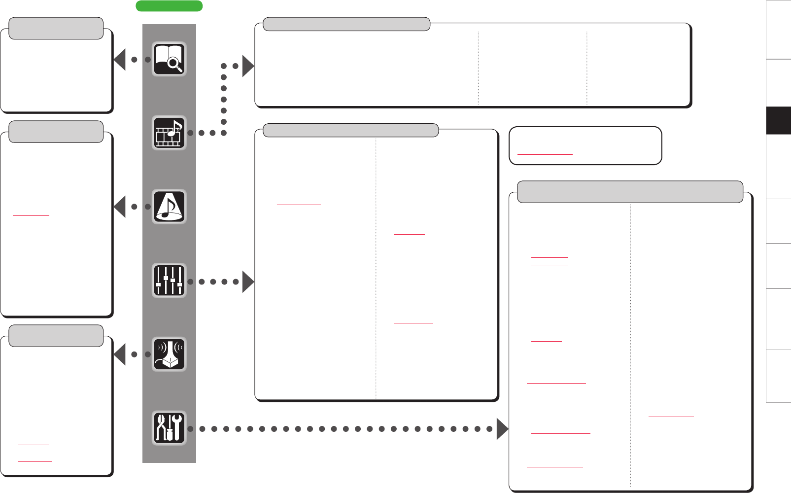
AVP-A1HD
GCharacter colorH
Blue characters : Changed or added
Red characters : Deleted
Information
(vpage 44)
n Status
• MAIN ZONE
• ZONE2/3/4
n Audio Input Signal
n HDMI Information
n Auto Surround Mode
n Quick Select
n Preset Station
Auto Setup
(vpage 12 ~ 22)
n Auto Setup
• STEP1 Preparation
• STEP2 Detection &
Measurement (main)
• STEP3 Measurement
(2nd – 8th)
• STEP4 Calculation
• STEP5 Check
• STEP6 Store
• Finish
n Option
• Room EQ
• Direct Mode
• Mic Select
n Parameter Check
Surround Mode
(vpage 35 ~ 37)
n STEREO
n DIRECT
n STANDARD
n DOLBY HEADPHONE
(When using headphones)
n DOLBY PL
II
x, DOLBY PL
II
or
DOLBY PL
n DOLBY PL
II
z
n DTS NEO:6
n DTS NEO:X
n HOME THX CINEMA
n 7CH STEREO
n WIDE SCREEN
n SUPER STADIUM
n ROCK ARENA
n JAZZ CLUB
n CLASSIC CONCERT
n MONO
n VIDEO GAME
n MATRIX
Parameters (vpage 38 ~ 43, mpage 54)
n Audio
• Surround Parameters
· Mode
· Decoder
· Cinema EQ
· DRC
· D.COMP
· LFE
· Center Image
· Center Gain
· Panorama
· Dimension
· Center Width
· Delay Time
· Effect
· Effect Level
· Room Size
· AFDM
· SB CH Out
· Height Gain
· Input Channel
· Subwoofer Att.
· Subwoofer
· Default
• Tone
· Tone Defeat
· Bass
· Treble
· Front
· Center
· Surround
· Surround Back
· Front Height
· Front Wide
· Subwoofer
• Room EQ
• Audyssey Settings
· MultEQ® XT 32
· Dynamic EQ®
· Reference Level Offset
· Dynamic Volume®
· Setting
• A-DSX Soundstage
· Audyssey DSX™
· Stage Width
· Stage Height
• RESTORER
• Night Mode
• Audio Delay
n Picture Adjust
• Contrast
• Brightness
• Chroma Level
• Hue
• DNR
• Enhancer
• Sharpness
Manual Setup
(vpage 23 ~ 34, mpage 31, 34 ~ 38, 43)
n Speaker Setup
(vpage 23 ~ 25)
• Speaker Configuration
· Front
· Center
· Subwoofer
· Surround A
· Surround B
· Surround
· Surround Back
· Front Height
· Front Wide
• Subwoofer Setup
• Distance
• Channel Level
· Mode
· Surround
· Start
· Default
• Crossover Frequency
• THX Audio Setup
• Surround Speaker
n HDMI Setup (vmpage 31)
n Audio Setup (vpage 26, 27)
• EXT. IN Setup
· Mode
· Surround Back Input
· Surround Speaker
· Subwoofer Level
· Input Att.
• 2ch Direct/Stereo
• Downmix Option
• Auto Surround Mode
• Manual EQ
n Network Setup
(vmpage 34 ~ 37)
n Zone Setup (vmpage 38)
n Option Setup (vpage 28 ~ 34)
• Pre-out Assign
• XLR Out Polarity
• POA Setting
• Volume Control
• Source Delete
• GUI
· Screensaver
· Wall Paper
· Format
· Text
· Master Volume
· NET/USB
· iPod
• Quick Select Name
• Trigger Out 1
• Trigger Out 2
• Trigger Out 3
• Trigger Out 4
• Transducer Setup
• Digital Out
• Remote ID
• 2Way Remote
• 232C Port (1)
• Dimmer
• Setup Lock
• Maintenance Mode
• Firmware Update
• Add New Feature
n Language (vmpage 43)
Source Select (vmpage 44 ~ 48)
n PHONO
• Video
• Input Mode
• Rename
• Source Level
• Input Att.
n DVD, HDP, TV/CBL, SAT, VCR, DVR-1, DVR-2, V.AUX, CD, TUNER
• Play (iPod)
• Playback Mode (iPod)
• Assign
• Video
n NET/USB
• Play
• Playback Mode
• Still Picture
• Video
• Input Mode
• Rename
• Source Level
• Input Mode
• Rename
• Source Level
• Input Att.
Getting Started Connections Other Operations Multi-Zone Information Troubleshooting SpecificationsSetup
Auto Setup
When this unit is upgraded, the “Auto Setup”
contents are returned to the default settings.
When configuring the “Auto Setup” settings, refer
to this version of the Owner's Manual instead of
the “Original version”.
The acoustic characteristics of the connected speakers and
listening room are measured and the optimum settings are made
automatically. This is called “Auto Setup”.
To perform measurement, place the setup microphone in multiple
locations all around the listening area. For best results, we
recommend you measure in six or more positions, as shown in
the illustration (up to eight positions).
• When performing Auto Setup, Audyssey MultEQ® XT 32/Dynamic
EQ®/Dynamic Volume® functions become active (vpage 41, 42).
• To set up the speakers manually, use “Manual Setup” – “Speaker
Setup”(vpage 23 ~ 25) on the menu.
NOTE
• Make the room as quiet as possible. Background noise can disrupt
the room measurements. Close windows, silence cell phones,
televisions, radios, air conditioners, fluorescent lights, home
appliances, light dimmers, or other devices as measurements may
be affected by these sounds.
• Cell phones should be placed away from all audio electronics during
the measurement process as Radio Frequency Interference (RFI)
may cause measurement disruptions (even if the cell phone is not in
use).
• Do not unplug the setup microphone from the main unit until Auto
Setup is completed.
• Do not stand between the speakers and setup microphone or allow
obstacles in the path while the measurements are being made. This
will cause inaccurate readings.
• Loud test sounds may be played during Auto Setup. This is part of
normal operation. If there is background noise in room, these test
signals will increase in volume.
•Operating the MASTER VOLUME knob or main remote control
VOL +/– button during measurement cancels the measurement.
•Measurement cannot be performed when headphones are connected.
Before performing Auto Setup, disconnect the headphone plug.
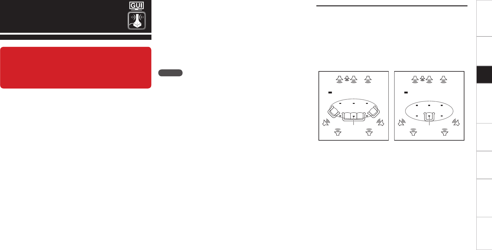
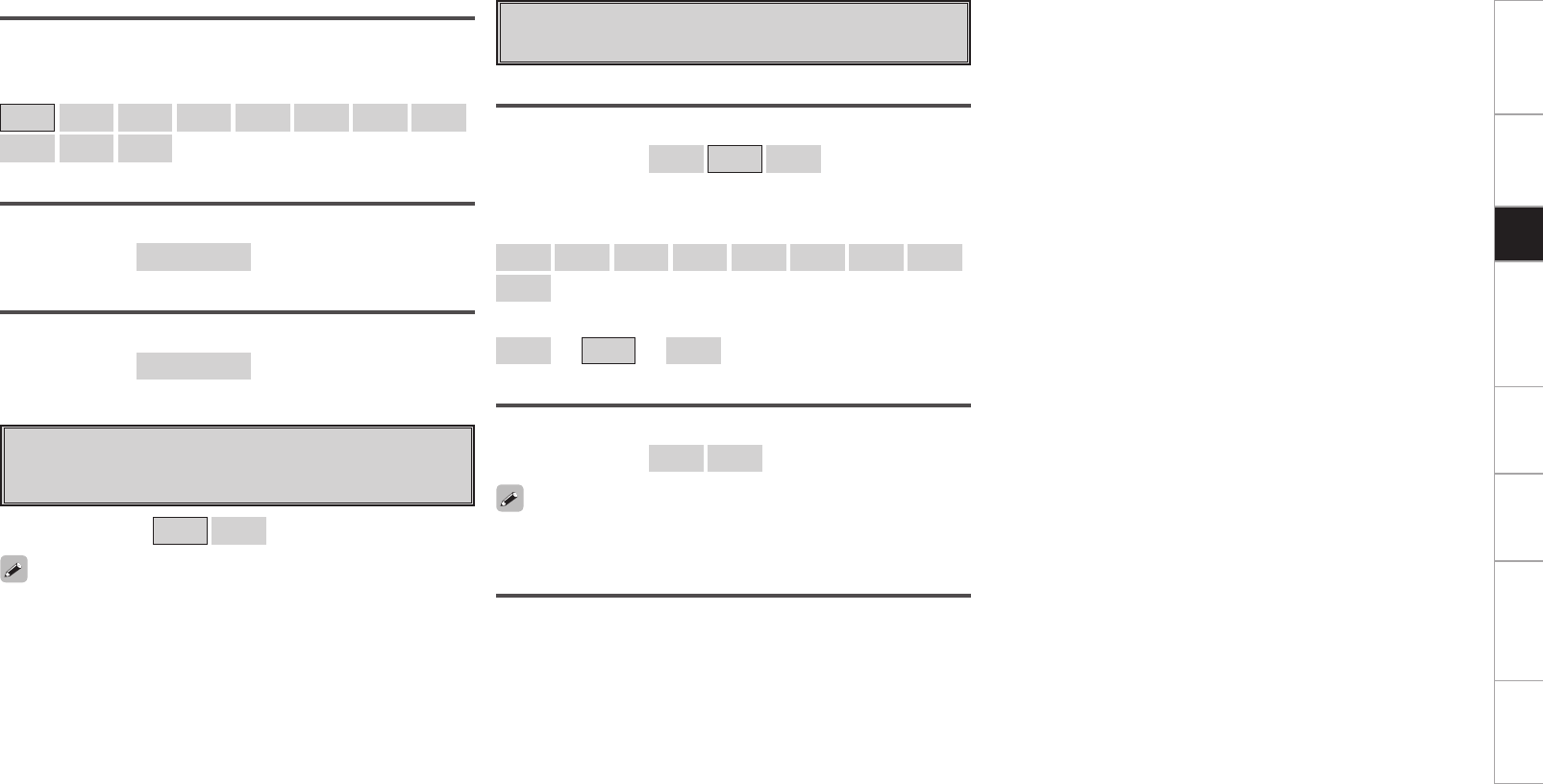
About setup microphone placement
• Measurements are performed by placing the setup microphone
successively at multiple positions throughout the entire listening
area, as shown in GExample qH. For best results, we recommend
you measure in six or more positions, as shown in the illustration (up
to eight positions).
• Even if the listening environment is small as shown in GExample wH,
measuring at multiple points throughout the listening environment
results in more effective correction.
FL SW C FR
SR
SBL SBR
SL *M
FL SW C FR
SR
SBL SBR
SL *M
GExample qH GExample wH
( :Measuring positions) ( :Measuring positions)
FL
: Front speaker (L)
SL
: Surround speaker (L)
FR
: Front speaker (R)
SR
: Surround speaker (R)
C
: Center speaker
SBL
: Surround back speaker (L)
SW
: Subwoofer
SBR
: Surround back speaker (R)
n About the main listening position (*M)
The main listening position is the position where listeners would
normally sit or where one would normally sit alone within the
listening environment. Before starting Auto Setup, place the
setup microphone in the main listening position. MultEQ® XT 32
uses the measurements from this position to calculate speaker
distance, level, polarity, and the optimum crossover value for the
subwoofer.
Getting Started Connections Other Operations Multi-Zone Information Troubleshooting SpecificationsSetup
1Set up the subwoofer
If using a subwoofer capable of the following adjustments, set
up the subwoofer as shown below.
n When using a subwoofer with a direct mode
Set the direct mode to “On” and disable the volume adjustment
and crossover frequency setting.
n When using a subwoofer without a direct mode
Make the following settings:
• Volume : “12 o’clock position”
• Crossover frequency : “Maximum/Highest Frequency”
• Low pass filter : “Off”
• Standby mode : “Off”
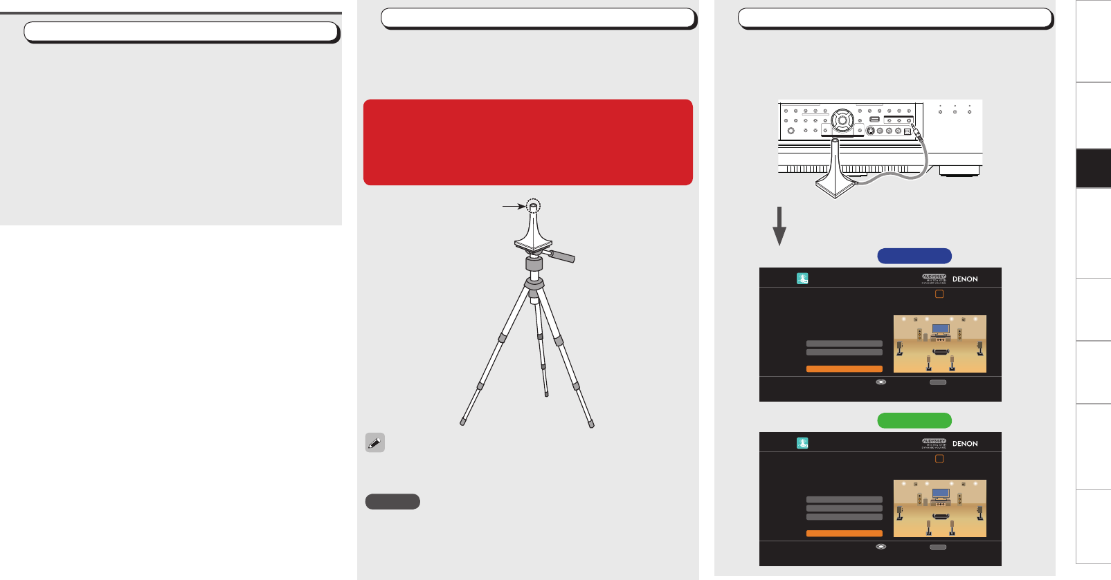
Before starting Auto Setup 2Set up the microphone
Mount the setup microphone on a tripod or stand and
place it in the main listening position.
When placing the setup microphone, adjust the height of the
sound receptor to the level of the listener’s ear.
When starting Auto Setup, always use the supplied
setup microphone (DM-A409).
Correct measurements cannot be taken if the setup
microphone from the prior upgrade (DM-A505Z) is
used.
Sound receptor
Setup microphone
If you do not have a tripod or stand, set up the microphone on, for
example, a seat without a back.
NOTE
• Do not hold the setup microphone in your hand during
measurements.
• Avoid placing the setup microphone close to a seat back or wall as
sound reflections may give inaccurate results.
3Connect the setup microphone
Connect the setup microphone to the SETUP MIC
jack of this unit.
When placing the setup microphone, adjust the height of the
sound receptor to the level of the listener’s ear.
AUTO SETUP
1 2 3 4 5 6
Amp Assign
RETURN
Auto Setup Start
Channel Select
STEP1 Preparation
Connect the speakers and place them according
to the recommendations in the manual.
Set the following items
if necessary.
Start Auto Setup
Enter Cancel
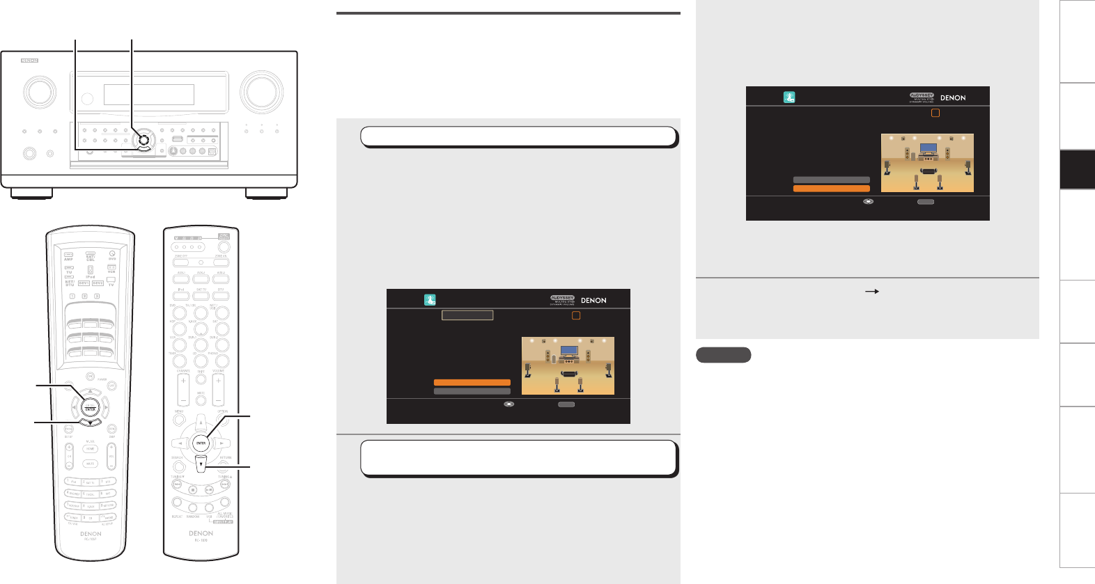
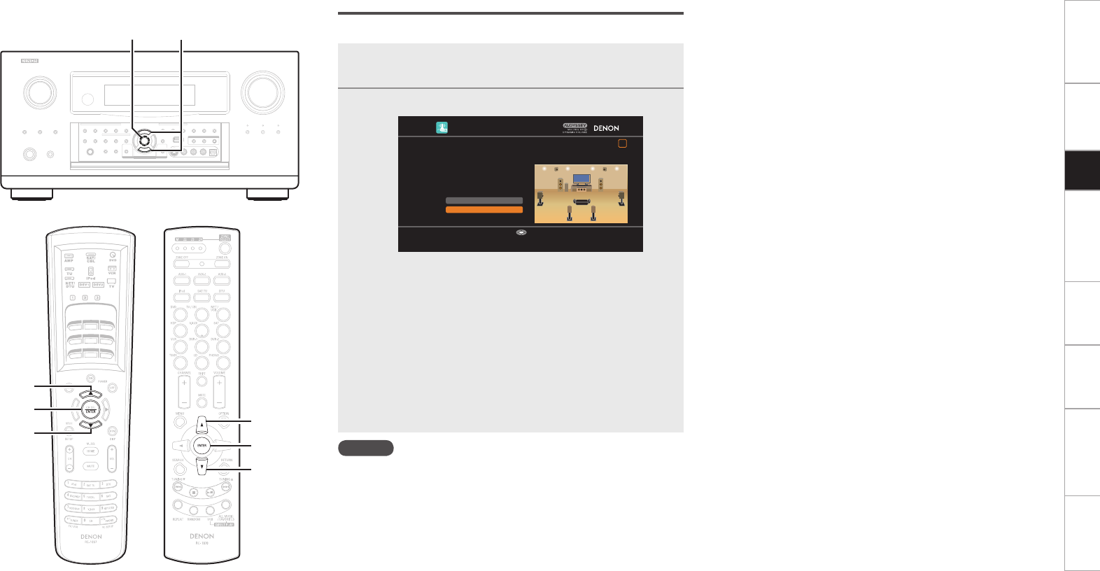
When the setup microphone is connected, the
setup screen is displayed.
AUTO SETUP
1 2 3 4 5 6
XLR Out Polarity
Pre-out Assign
RETURN
Auto Setup Start
Channel Select
STEP1 Preparation
Connect the speakers and place them according
to the recommendations in the manual.
Set the following items
if necessary.
Start Auto Setup
Enter Cancel
GSetup screen AVC-A1HD H
GSetup screen AVP-A1HD H
Getting Started Connections Other Operations Multi-Zone Information Troubleshooting SpecificationsSetup
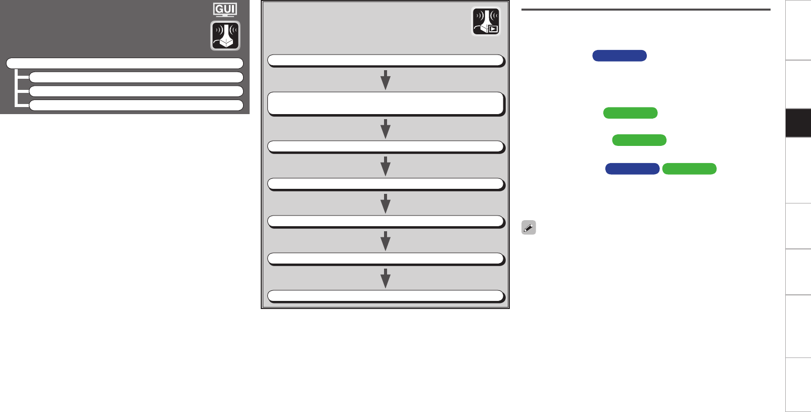
Auto Setup
Optimize settings for speakers in use.
F Menu tree F
Auto Setup
a Auto Setup
s Option
d Parameter Check
a Auto Setup
The settings are performed automatically.
GAuto Setup flowH
STEP1 Preparation vpage 14, 15
STEP2 Detection & Measurement (main)
vpage 16, 17
STEP3 Measurement (2nd – 8th) vpage 18
STEP4 Calculation vpage 18
STEP5 Check vpage 19
STEP6 Store vpage 19
Finish vpage 20
STEP1 Preparation
• Configure the following settings as required.
• To start Auto Setup without configuring the following settings,
perform step 4 only, and then proceed to step 2.
n Amp Assign AVC-A1HD
Select the method for using the power amplifier in accordance with
the connected speaker configuration.
Choose this when “Amp Assign” in the GUI menu is set to anything
other than “Normal”.
n Pre-out Assign AVP-A1HD
Change the pre-out terminal assignment.
n XLR Out Polarity AVP-A1HD
Set to switch the XLR pre-out terminal polarity.
n Channel Select AVC-A1HD AVP-A1HD
The measurement time can be shortened by selecting the speakers
to be measured in advance. Please set if necessary.
When measuring 2 or 3 subwoofers, configure the “Channel
Select” settings.
• “Front Height” is displayed when the “Amp Assign” – “Assign Mode”
setting (vpage 28) in the GUI menu and the “Extension Channel”
setting (vpage 28, 29) are set to “Front Height”.
• “Front Wide” is displayed when the “Amp Assign” – “Assign Mode”
setting (vpage 28) in the GUI menu and the “Extension Channel”
setting (vpage 28, 29) are set to “Front Wide”.
Getting Started Connections Other Operations Multi-Zone Information Troubleshooting SpecificationsSetup
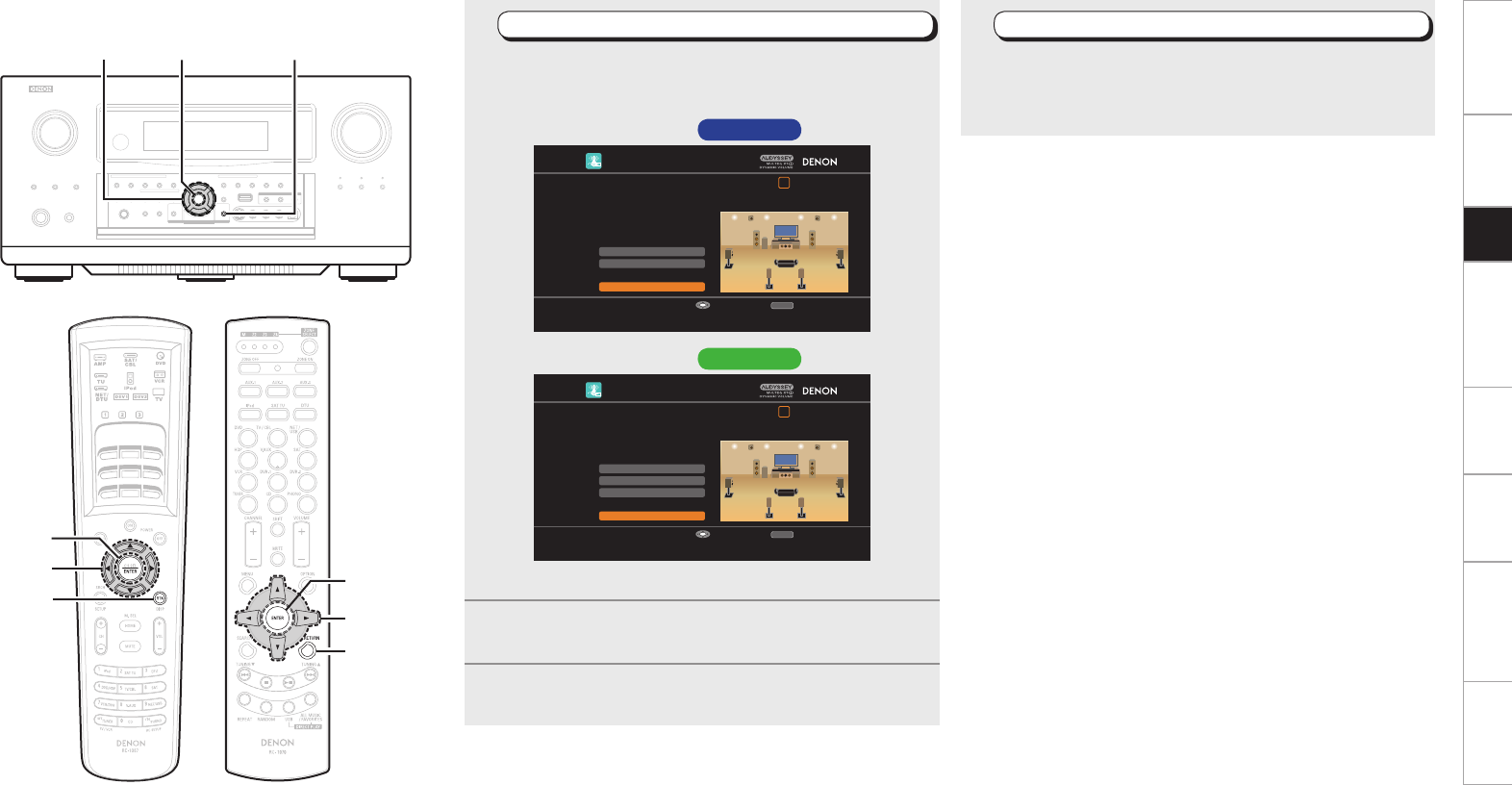
RETURN
ENTER
uio p
1Configuring Various Settings
Use ui to select the item you want to set, and then
press ENTER.
The menu screen of the selected setting is displayed.
AUTO SETUP
1 2 3 4 5 6
Amp Assign
RETURN
Auto Setup Start
Channel Select
STEP1 Preparation
Connect the speakers and place them according
to the recommendations in the manual.
Set the following items
if necessary.
Start Auto Setup
Enter Cancel
AUTO SETUP
1 2 3 4 5 6
XLR Out Polarity
Pre-out Assign
RETURN
Auto Setup Start
Channel Select
STEP1 Preparation
Connect the speakers and place them according
to the recommendations in the manual.
Set the following items
if necessary.
Start Auto Setup
Enter Cancel
GSetup screen AVC-A1HD H
GSetup screen AVP-A1HD H
b For details of the items that can be set, see page 28 ~ 30.
2Press uio p to set.
3Press RETURN to return to the previous screen.
4Start Auto Setup
Use ui to select “Auto Setup Start” and then press
ENTER.
Proceed to “STEP2 Detection & Measurement (main)” (vpage
16).
uio p
RETURN
ENTER
(Main remote control unit) (Sub remote control unit)
ENTER
uio p
RETURN
Getting Started Connections Other Operations Multi-Zone Information Troubleshooting SpecificationsSetup
ENTER
i
i
ENTER
STEP2 Detection & Measurement (main)
• In STEP 2, the subwoofer volume level and main listening position
volume are measured.
• This step automatically checks the speaker configuration and speaker
size, and calculates the channel level, distance, and crossover
frequency. It also corrects distortion in the listening area.
• Install the supplied setup microphone to the main listening position.
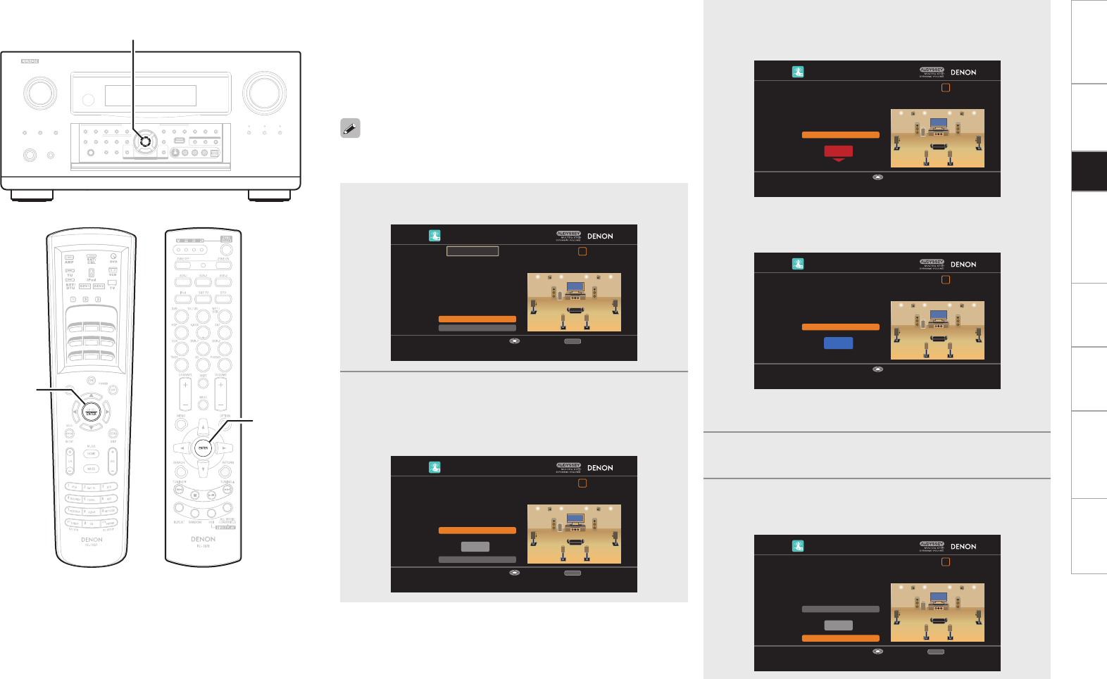
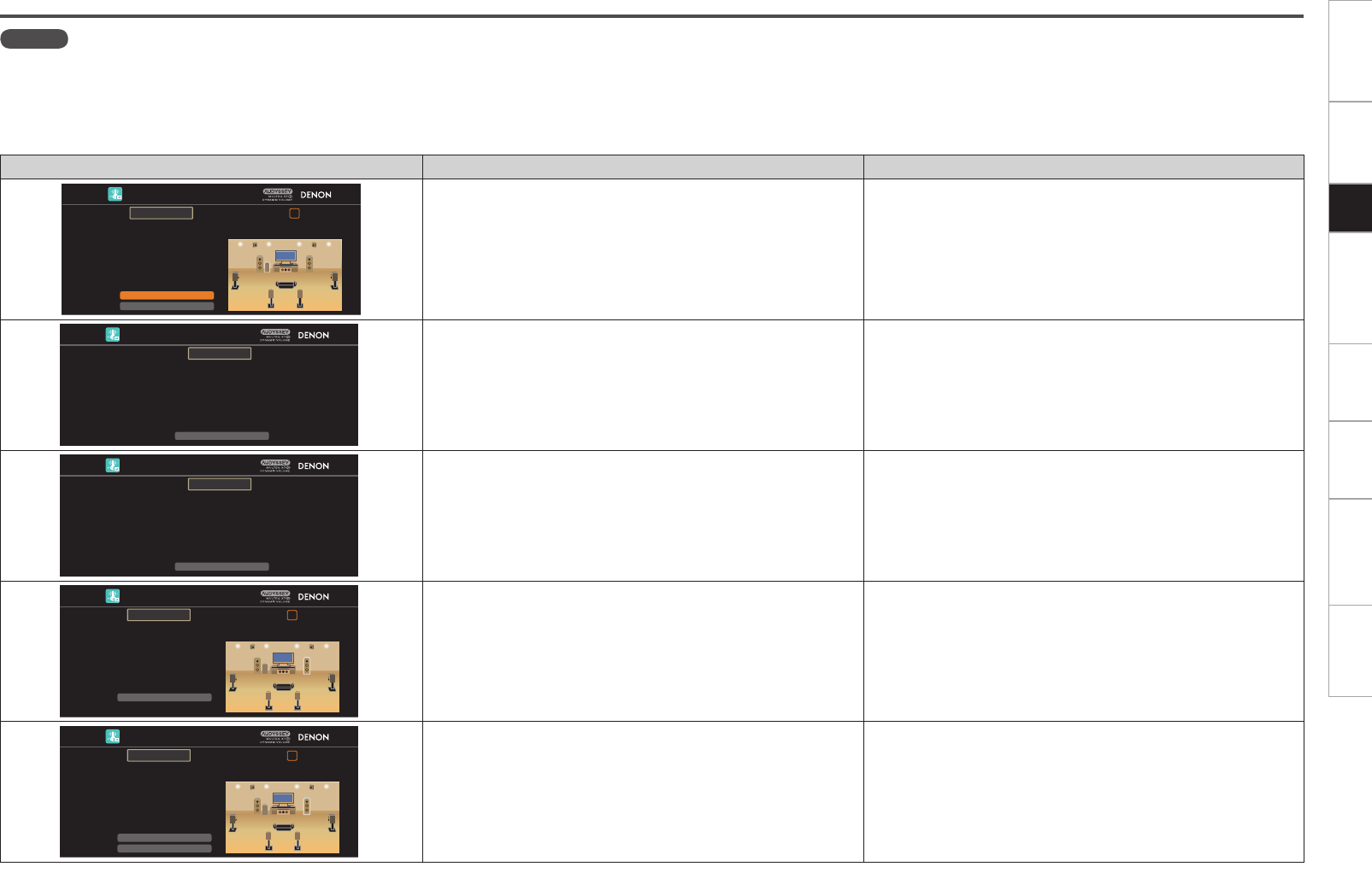
1Measuring the subwoofer volume level
Select “Measure” and then press ENTER.
Measure the subwoofer volume level.
b When “Channel Select” – “Subwoofer” in the GUI menu is set to
“Skip”, the subwoofer volume level is not measured.
b When 2 or 3 subwoofers are used, measure the volume level of
each.
b After measuring the volume level of the subwoofer, if the following
error message is displayed, adjust the subwoofer volume level
using “Adjusting the subwoofer volume level” (vpage 17).
AUTO SETUP
1 2 3 4 5 6
RETURN
Skip
SW Level Matching
The subwoofer's level is too high or low. Please select "SW
Level Matching" and adjust the level of your subwoofer unit.
If you do not want to use the
subwoofer, select "Skip".
Proceed to subwoofer volume adjustment item
Enter Cancel
Caution!
2Perform measurement of the
main listening position
When the subwoofer volume level measurement
is completely, the connected speakers are detected
automatically.
b The measuring channel changes depending on the setting of
“STEP1 Preparation” (vpage 14).
b It takes a few minutes for speaker measurement to complete.
3The detected speakers are displayed.
b The illustration below shows an example of when the front
speakers, center speaker, subwoofer, surround speakers, surround
back speakers and front height speakers have been detected.
AUTO SETUP
1 2 3 4 5 6
RETURN
Next→Measurement
Retry
STEP2 Speaker Detection Check
Front
Center
Subwoofer
Surround
Surr. Back
Front Height
Yes
Yes
1 spkr
Yes
2 spkrs
Yes
Proceed to STEP 3 after checking speaker connection result
Enter Cancel
b If a connected speaker is not displayed, the speaker may not be
connected correctly. Check the speaker connection.
b To re-measure, press i to select “Retry”, and press ENTER.
4Use i to select “Next Measurement” and then
press ENTER.
Proceed to “STEP3 Measurement (2nd – 8th)” (vpage 18).
NOTE
If “Caution!” is displayed on the television screen, see “Error
messages” (vpage 21). Check the related items, and implement
the necessary measures. After resolving the error, perform Auto Setup
again.
n When measuring has stopped
Press ENTER.
(Main remote control unit) (Sub remote control unit)
ENTER
i
Getting Started Connections Other Operations Multi-Zone Information Troubleshooting SpecificationsSetup
ENTER
n Adjusting the subwoofer volume level
The optimum subwoofer volume level is 75 dB.
During “Measuring the subwoofer volume level” (vpage 16),
an error message is displayed when one level of subwoofers is
outside the 72 to 78 dB range.
When using a subwoofer with built-in amplifier (active type), adjust
the subwoofer volume so that the subwoofer level is within the 72
to 78 dB range.
When 2 or 3 subwoofers are used, adjust the volume level of each
subwoofer so that their volume level will set between 72~78 dB.
1Select “SW Level Matching” and then press ENTER.
AUTO SETUP
1 2 3 4 5 6
RETURN
Skip
SW Level Matching
The subwoofer's level is too high or low. Please select "SW
Level Matching" and adjust the level of your subwoofer unit.
If you do not want to use the
subwoofer, select "Skip".
Proceed to subwoofer volume adjustment item
Enter Cancel
Caution!
2Select “SW Test Start” and then press ENTER.
Measure the subwoofer volume level.
During measuring, a “Testing…” message is displayed.
When measurements are completed, the measurement level
value is displayed.
AUTO SETUP
1 2 3 4 5 6
RETURN
Next
dB
SW Test Start
SW Level Matching
Please place the microphone at ear height at main
listening position, then push ENTER.
Start measurement. Output test tone from subwoofer
Enter Cancel
3Adjust the subwoofer volume level of your subwoofer
so that the level display is within the range of 72 to
78 dB.
AUTO SETUP
1 2 3 4 5 6
99.8dB
Stop
SW Level Matching
Please adjust the level of your active subwoofer unit
so that the level indicates approx. 75dB
Change from red to blue when level matches
Enter
b If the measured level is outside the 72 to 78 dB range, the level
indicator is red.
b When measuring stops, press ENTER.
AUTO SETUP
1 2 3 4 5 6
75.5dB
Stop
SW Level Matching
Please adjust the level of your active subwoofer unit
so that the level indicates approx. 75dB
Change from red to blue when level matches
Enter
b If the measured level is within the 72 to 78 dB range, the level
indicator is blue.
4When the measured level is within the 72 to 78 dB
range, press ENTER.
5Select “Next” and then press ENTER.
Proceed to step 2 of “STEP2 Detection & Measurement
(main)“(vpage 16).
AUTO SETUP
1 2 3 4 5 6
RETURN
Next
dB
SW Test Start
SW Level Matching
After adjustment, push "Next".
Proceed to next measurement
Enter Cancel
ENTER
(Main remote control unit) (Sub remote control unit)
ENTER
Getting Started Connections Other Operations Multi-Zone Information Troubleshooting SpecificationsSetup
ENTER ui
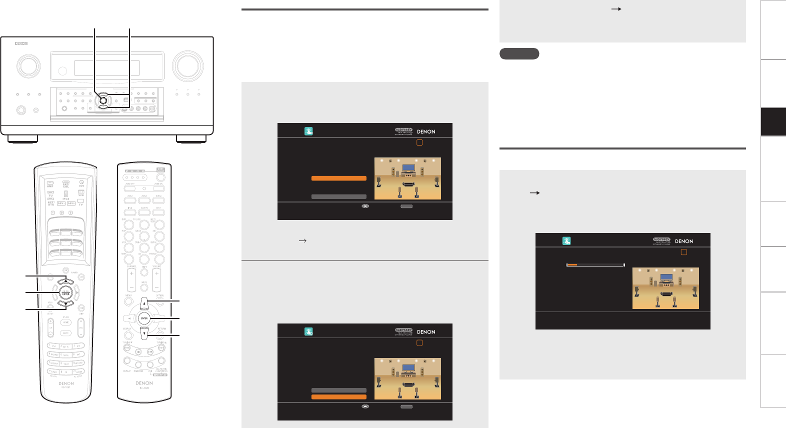
STEP3 Measurement (2nd – 8th)
• In STEP 3, you will perform measurements at multiple positions
(two to eight positions) other than the main listening position.
Measurements can be made in up to eight positions.
• You can achieve a more effective correction of distortion within the
listening area by performing measurements at multiple positions.
• Move the provided set up microphone to the measurement point.
1Move the setup microphone to position 2, use ui to
select “Measure”, and then press ENTER.
The measurement of the second position starts.
AUTO SETUP
1 2 3 4 5 6
Measure
RETURN
Next→Calculation
STEP3 Measurement (2nd)
Please place the microphone at ear
height at 2nd listening position.
Start measurement. Output large test tone during measuring
Enter Cancel
b To omit measurements from the 2nd position onwards, press i,
select “Next Calculation” and press
ENTER
. Proceed to “STEP4
Calculation”.
2Repeat step 1, measuring positions 3 to 8.
When measurement of position 8 is completed, a “Measurements
finished.” message is displayed.
b To re-measure, press i to select “Retry”, and press ENTER. Re-
measure the previous point.
AUTO SETUP
1 2 3 4 5 6
Retry
RETURN
Next→Calculation
STEP3 Measurement (Finish)
Measurements finished.
Proceed to STEP 4 (Calculation)
Enter Cancel
3Use i to select “Next Calculation” and then press
ENTER.
Proceed to “STEP4 Calculation” (vpage 18).
NOTE
If “Caution!” is displayed on the television screen, see “Error
messages” (vpage 21). Check the related items, and implement
the necessary measures. After resolving the error, perform Auto Setup
again.
n When measuring has stopped
Press ENTER.
STEP4 Calculation
In STEP 4, the measured results from STEP 2 and STEP 3 are analyzed.
When the measurements are completed, press i to select
“Next Calculation”, and press ENTER.
The measured results from STEP 2 and STEP 3 are automatically
analyzed, and the frequency response of each speaker in the listening
room is determined.
AUTO SETUP
1 2 3 4 5 6
STEP4 Calculation
Now calculating…Please wait.
20%
b
It takes a few minutes for analysis to complete. The time required
for this analysis depends on the number of speakers connected.
The more connected speakers there are, the longer it takes to
perform analysis.
ENTER
u
i
(Main remote control unit) (Sub remote control unit)
i
ENTER
u
Getting Started Connections Other Operations Multi-Zone Information Troubleshooting SpecificationsSetup
RETURN
ENTER
uio
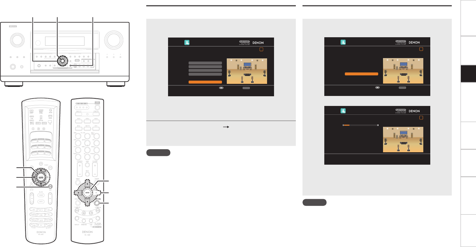
STEP5 Check
In STEP 5, the results of the analysis from STEP 4 are confirmed.
1Use ui to select the item you want to check, and
then press ENTER.
AUTO SETUP
1 2 3 4 5 6
Crossover Check
Ch. Level Check
Distance Check
Spkr Config Chck
RETURN
Next→Store
STEP5 Check
Check processing results.
To proceed, press "Next".
Proceed to STEP 6 (Store)
Enter Cancel
b
A value that is different to the measured distance may be set.
b To check other items, press
RETURN
and select the item that you
want to check.
2Use i to select “Next Store” and then press
ENTER.
Proceed to “STEP6 Store” (vpage 19).
NOTE
• If the result differs from the actual connection status, or if “Caution!”
is displayed, see “Error messages” (vpage 21). Check the related
items, and implement the necessary measures. After resolving the
error, perform Auto Setup again.
• If the result still differs from the actual connection status after
remeasurement or the error message still appears, it is possible that
the speakers are not connected properly. Turn this unit off, check the
speaker connections and repeat the measurement process from the
beginning.
• If you change speaker positions or orientation, perform Auto Setup
again to find the optimal equalizer settings.
STEP6 Store
In STEP 6, the measured results from STEP 2 and STEP 3 are saved.
Select “Store” and then press ENTER.
Save the measurement results.
⇩
AUTO SETUP
1 2 3 4 5 6
RETURN
Store
STEP6 Store
Press "Store" to store calculation results.
Apply and store measurement result
Enter Cancel
AUTO SETUP
1 2 3 4 5 6
STEP6 Store
Now storing…Please wait.
20%
b
It takes approximately 20 seconds to finish saving the results.
b If the measuring results are not to be saved, press RETURN. A
message “Cancel auto setup?” will be displayed. Press o then
select “Yes”. All the measured Auto Setup data will be erased.
NOTE
During saving of measurement results, be sure not to turn off the
power.
uio
RETURN
ENTER
(Main remote control unit) (Sub remote control unit)
ENTER
RETURN
uio
0
Getting Started Connections Other Operations Multi-Zone Information Troubleshooting SpecificationsSetup
ENTER ui
Finish
Auto Setup is complete.
1Unplug the setup microphone from the unit’s SETUP
MIC jack.
2Set Audyssey Dynamic Volume®.
AUTO SETUP
1 2 3 4 5 6
Yes
No
Finish
Storing complete.
Auto Setup is now finished.
Please unplug microphone.
Turn on Dynamic Volume ?
Turn Dynamic Volume off and exit Auto Setup
Exit
b This feature adjusts the output volume to the optimal level while
constantly monitoring the level of the audio input to the unit.
Optimal volume control is performed automatically without any
loss in the dynamism and clarity of the sound when, for example,
the volume suddenly increases for commercials shown during
television programs.
n When turning Dynamic Volume® on
Use u to select “Yes”, and then press ENTER.
The unit automatically enters “Evening” mode.
n When turning Dynamic Volume® off
Use i to select “No”, and then press ENTER.
NOTE
• After performing Auto Setup, do not change the speaker connections
or subwoofer volume. In event of a change, perform Auto Setup
again.
• After performing Auto Setup with two or three subwoofers, do not
change the channel distances and levels of any of the subwoofers.
ENTER
u
i
(Main remote control unit) (Sub remote control unit)
i
ENTER
u
Getting Started Connections Other Operations Multi-Zone Information Troubleshooting SpecificationsSetup
Examples Error details Measures
AUTO SETUP
1 2 3 4 5 6
RETURN
Skip
SW Level Matching
The subwoofer's level is too high or low. Please select "SW
Level Matching" and adjust the level of your subwoofer unit.
If you do not want to use the
subwoofer, select "Skip".
Proceed to subwoofer volume adjustment item
Enter Cancel
Caution!
• Correct measurement is not possible due to inappropriate subwoofer
volume.
• When using a subwoofer with built-in amplifier (active type), use
“SW Level Matching” to adjust the subwoofer volume (vpage 17
“Adjusting the subwoofer volume level”).
• When using a subwoofer without a built-in amplifier, select “Skip”,
and then press ENTER.
AUTO SETUP
RETURN
Retry
No microphone or speaker
Check cause of problem!
Cancel
Caution!
• The connected setup microphone is broken, or a device other than
the supplied setup microphone is connected.
• Not all speakers could be detected.
• The front L speaker was not properly detected.
• Connect the included setup microphone to the SETUP MIC jack of
this unit.
• Check the speaker connections.
AUTO SETUP
RETURN
Retry
Ambient noise is too high
or Level is too low
Check cause of problem!
Cancel
Caution!
• There is too much noise in the room for accurate measurements to
be made.
• Speaker or subwoofer sound is too low for accurate measurements
to be made.
• Either turn off any device generating noise or move it away.
• Perform again when the surroundings are quieter.
• Check the speaker installation and the direction in which the speakers
are facing.
• Adjust the subwoofer’s volume.
AUTO SETUP
1 2 3 4 5 6
RETURN
Retry
Front R None
Check cause of problem!
Cancel
Caution!
• The displayed speaker could not be detected.
(The screen on the left indicates that the front right speaker cannot
be detected.)
• Check the connections of the displayed speaker.
AUTO SETUP
1 2 3 4 5 6
RETURN
Skip
Retry
Front R Phase
Check cause of problem!
Cancel
Caution!
• The displayed speaker is connected with the polarity reversed.
(The screen on the left indicates that the polarity phases of the front
right speakers are reversed.)
• Check the polarity of the displayed speaker.
• For some speakers, this error message may be displayed even if
the speaker is properly connected. If you are sure the connection is
correct, press ui to select “Skip”, then press ENTER.
Error messages
NOTE
• An error message is displayed if Auto Setup could not be completed due to speaker placement, the measurement environment, etc. Check the related items, and implement the necessary measures. After resolving
the error, perform Auto Setup again.
• If the result still differs from the actual connection status after remeasurement or the error message still appears, it is possible that the speakers are not connected properly. Turn this unit off, check the speaker
connections and repeat the measurement process from the beginning.
• Be sure to turn off the power before checking speaker connections.
Getting Started Connections Other Operations Multi-Zone Information Troubleshooting SpecificationsSetup
s Option
Make direct mode settings.
Direct Mode
Select MultEQ® XT 32 use for DIRECT or PURE DIRECT mode.
[Selectable items] ON OFF
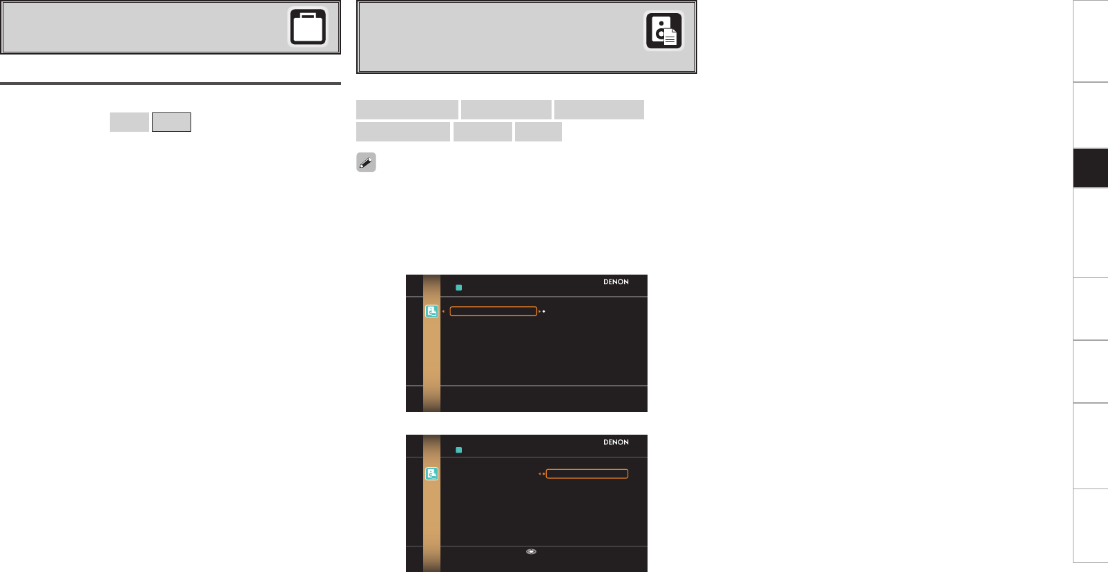
d Parameter Check
Check Auto Setup measurement results.
This is displayed after the Auto Setup procedure is
completed.
[Selectable items]
Spkr Config Check Distance Check Ch. Level Check
Crossover Check EQ Check Restore
• If “EQ Check” is selected, press ui to select equalizing curve
(“Audyssey” or “Audyssey Flat”) to be checked, and then press
ENTER or p.
Use ui to switch the display between the different speakers.
• If “Restore” is selected, all settings are returned to the Auto Setup
results (values initially calculated by MultEQ® XT 32) even if each
setting was changed manually.
⇩
PARAMETER CHECK
Restore
Spkr Config Check
Distance Check
Ch.Level Check
Crossover Check
EQ Check
Yes
No
Restore auto setup measurement result
RESTORE
Restore Yes
No
Restore auto setup measurement result
Enter
Getting Started Connections Other Operations Multi-Zone Information Troubleshooting SpecificationsSetup
Make detailed settings for various parameters.
Speaker Setup
Use this procedure to set the speakers manually
or if you wish to change the settings made with
the Auto Setup procedure.
F Menu tree F
Manual Setup
Speaker Setup
a Speaker Configuration
s Subwoofer Setup
d Distance
f Channel Level
g Crossover Frequency
h THX Audio Setup
Manual Setup Front
Select front speaker size.
[Selectable items] Large Small
a Speaker Configuration
Select speaker configuration and size.
(bass reproduction capability)
Center
Select center speaker use and size.
[Selectable items] Large Small None
Subwoofer
Select subwoofer use.
[Selectable items] Yes No
Surround
Select surround speakers use and size.
[Selectable items] Large Small None
Surround Back
Select surround back speaker use and size.
[Selectable items] Large Small None
2spkrs 1spkr
• Select “Large” or “Small” not according to the physical size of the
speaker but according to the low frequency reproduction capabilities
based on the frequency set at “Crossover Frequency” (vpage
25).
• When “Front” is set to “Small”, “Subwoofer” is automatically set to
“Yes”.
• If “Subwoofer” is set to “No”, “Front” is automatically set to
“Large”.
• If “Surround” is set to “None”, “Surround Back”, “Front Height” and
“Front Wide” are automatically set to “None”.
• When using just one surround back speaker, connect it to the left
channel (SBL).
• To take full advantage of the performance of the Home THX certified
speaker systems, set the front, center and surround speaker size
parameters to “Small” and the subwoofer to “Yes”.
• “Front Height” can be set when the “Option Setup” – “Amp Assign”
– “Assign Mode” setting (vpage 28) in the GUI menu is “Front
Height”, or the “Option Setup” – “Amp Assign” – “Extension
Channel” setting (vpage 28, 29) is set to “Front Height”.
• “Front Wide” can be set when the “Option Setup” – “Amp Assign”
– “Assign Mode” setting (vpage 28) in the GUI menu is “Front
Wide”, or the “Option Setup” – “Amp Assign” – “Extension Channel”
setting (vpage 28, 29) is set to “Front Wide”.
Large : Use a large speaker that can adequately play back low
frequencies.
Small : Use a small speaker that has inadequate playback capacity
for low frequencies.
Front Height
Select front height speaker use and size.
[Selectable items] Large Small None
Front Wide
Select front wide speaker use and size.
[Selectable items] Large Small None
When this unit is upgraded, the “Speaker Setup”
contents are changed.
When configuring the “Speaker Setup” settings,
refer to this version of the Owner's Manual
instead of the “Original version”.
Getting Started Connections Other Operations Multi-Zone Information Troubleshooting SpecificationsSetup
s Subwoofer Setup
Select subwoofer output configuration and bass signal for
playback.
Configuration
Select number of subwoofers and configuration.
[Selectable items]
1SP 2SP L/R 2SP MIX 3SP L/R/LFE 3SP MIX
• THX recommends LFE–THX– mode so that bass interference is less
likely to occur in the room.
• This can be set when the GUI menu “Speaker Configuration” –
“Subwoofer” is set to “Yes”.
• Play music or a movie source and select the mode offering the
strongest bass.
• Select “LFE+Main” if you want the bass signals to always be
produced from the subwoofer.
Mode
Select bass signal for playing with the subwoofer.
[Selectable items] LFE–THX– LFE+Main
When “2SP MIX” or “3SP MIX” is selected, “Subwoofer 1”,
“Subwoofer 2” and “Subwoofer 3” are each displayed.
Subwoofer Configuration Subwoofer Connector
1SP SW1
2SP L/R L SW1
R SW2
2SP MIX 1 SW1
2 SW2
3SP L/R/LFE
L SW1
R SW2
LFE SW3
3SP MIX
1 SW1
2 SW2
3 SW3
Distance measurement
Select the speaker you want to set, then set the distance.
Set the value closest to the measured distance.
[Variable range]
0.00m ~ 18.00m : Display when “Meters” is set.
0.0ft ~ 60.0ft : Display when “Feet” is set.
NOTE
Set the space between each speaker to less than 6.00 m (20.0 ft).
Two surround back speakers are required to use the THX Ultra2
Cinema, THX Music mode and THX Games mode.
Set the surround back speakers so that the distance to the listening
position is the same for both the left and right speakers.
It is also recommended that the deviations of the distance from the
listening position to L and R channel speakers (front left (FL) and front
right (FR), surround left (SL) and surround right (SR), surround back left
(SBL) and surround back right (SBR)) is less than 60 cm (2 ft).
d Distance
Set distance from listening position to speakers.
Before making the settings, measure the distance from the
listening position to the different speakers.
Meters / Feet
Select unit for distance.
Step
Select step (smallest distance).
[Selectable items]
0.1m 0.01m : Can be selected when “Meters” is set.
1ft 0.1ft : Can be selected when “Feet” is set.
Default
Resets the settings to the default values.
Mode
Select test tone playback method.
[Selectable items] Auto Manual
f Channel Level
Adjust channel levels to obtain equal volume from all speakers.
Start
Output test tone.
[Variable range] –12dB ~ 0dB ~ +12dB
OFF z
z: The subwoofer volume can be turned “OFF” by pressing o when
the subwoofer volume is “–12dB”.
Getting Started Connections Other Operations Multi-Zone Information Troubleshooting SpecificationsSetup
Operating from the main remote control unit
Adjusting with the main remote control unit using the test tones is
only possible in the “Auto” mode and only effective in the STANDARD
(Dolby/DTS Surround) and HOME THX CINEMA modes. The adjusted
levels for the different modes are automatically stored in the
memory.
GAdjusting using test tonesH
q Press the TEST button.
Test tones are output from the various speakers.
w Use the o p button to adjust so that the volume is equal for all
speakers.
e When the adjustments are completed, press the TEST button
again.
• The level of each channel should be adjusted to 75 dB (Cweighted,
slow meter mode) on a sound level meter at the listening position. If
a sound level meter is not available adjust the channels by ear so the
sound levels are the same. Because adjusting the subwoofer level
test tone by ear is difficult, use a well known music selection and
adjust for natural balance.
• Speakers set to “None” in the “Speaker Configuration” settings are
not displayed.
• When “Channel Level” is adjusted, the adjusted values are set for
all the surround modes. To adjust the channel level separately for
the different surround modes, use the operation see mpage 65
AVC-A1HD , mpage 67 AVP-A1HD .
Default
Resets the settings to the default values.
g Crossover Frequency
Select crossover frequency from which subwoofer handles low
range signal.
[Selectable items]
FIXED–THX– :
Setup when using a THX-certified speaker.
40Hz 60Hz 80Hz 90Hz 100Hz 110Hz 120Hz 150Hz
200Hz 250Hz :
Only the portion of the bass sound of the various speakers output
from the subwoofer that has a frequency below the frequency set
here is output.
Set this according to the low frequency reproduction capabilities of the
speakers you are using.
Advanced :
Specify crossover frequency for each speaker.
• Please set all THX Certified speakers, set the “Speaker Configuration”
for all speakers to “Small”. We recommend using with the crossover
frequency set to “FIXED–THX–”, but depending on the speaker,
setting it to a different frequency may improve frequency response
near the crossover frequency.
• The “Crossover Frequency” can be set when there are speakers
that have been set to “Small” at GUI menu “Speaker Configuration”
or when “Subwoofer” is set to “Yes” (vpage 23).
• At the “Advanced” settings, if the “Subwoofer Setup” (vpage 24)
setting is set to “LFE–THX–”, GUI menu speakers for which “Speaker
Configuration” is set to “Small” can be set. If set to “LFE+Main”,
the setting can be made regardless of the speaker size.
• For speakers set to “Small”, sound below the crossover frequency
is cut from the sound output. The cut bass sound is output from the
subwoofer or front speakers.
h THX Audio Setup
Set the speaker to play the optimal THX surround mode.
THX Ultra2 Subwoofer
Set when using a subwoofer compatible with THX Ultra2 standards or
a subwoofer that can be properly played at low range.
[Selectable items] Yes No
Make these settings when “Yes” is selected for the subwoofer in the
“Speaker Configuration” settings. This option is not available when
“No” is selected (vpage 23).
BGC (Boundary Gain Compensation)
If bass sound feels big compensate by lowering volume.
[Selectable items] ON OFF
• If the bass sound seems too strong:
Set “BGC” to “ON”. This activates a filter that gently reduces very
deep bass below 55 Hz to provide the flattest overall deep bass
response. Select “ON” or “OFF” according to how strong you prefer
the deep bass response to be.
• This can be set when the “THX Ultra2 Subwoofer” setting is set to
“Yes”.
SB Speaker Position
Set the distance between the left and right surround back speakers.
[Selectable items] Under 0.3m 0.3m – 1.2m Over 1.2m
• When two surround back speakers have been set in “Speaker
Configuration” (vpage 23), set the distance of the speakers. This
option is not available when “1spkr” is selected.
• This setting is necessary to achieve the optimum effect in the THX
Surround EX, THX Ultra2 Cinema, THX Music mode and THX Games
mode.
Getting Started Connections Other Operations Multi-Zone Information Troubleshooting SpecificationsSetup
a EXT. IN Setup AVC-A1HD
Setup playback method for analog signals inputted from external
input connectors (EXT. IN).
Audio Setup
Make settings for audio playback.
F Menu tree F
Manual Setup
Audio Setup
a EXT. IN Setup
s 2ch Direct/Stereo
d Auto Surround Mode
f Manual EQ
s 2ch Direct/Stereo
Make speaker settings for 2-channel mode playback.
Setting
To change the settings, select “Custom”.
[Selectable items] Basic z
Custom
z: Use the same settings as in “Speaker Setup”.
Front
Select front speaker size.
[Selectable items] Large Small
Subwoofer
Select subwoofer use.
[Selectable items] Yes No
Subwoofer Mode
Select low range signal to be reproduced by subwoofer.
[Selectable items] LFE–THX– LFE+Main
Subwoofer Level
Set the subwoofer level for playback.
Select according to the player in use.
[Selectable items] 0dB +5dB +10dB +15dB
We recommend setting to “+15dB”.
When this unit is upgraded, the “Audio Setup”
contents are changed.
When configuring the “Audio Setup” settings,
refer to this version of the Owner's Manual
instead of the “Original version”.
a EXT. IN Setup AVP-A1HD
Setup playback method for analog signals inputted from external
input connectors (EXT. IN).
Mode
Select playback mode.
[Selectable items] DSP Analog
Surround Back Input
Select surround back channel input in combination with the connected
player.
[Selectable items] Not Used SBL/SBR SB(SBL)
This can be set when “Mode” is set to “DSP”.
Subwoofer Level
Set the subwoofer level for playback.
Select according to the player in use.
[Selectable items] 0dB +5dB +10dB +15dB
We recommend setting to “+15dB”.
Input Att.
Setup when input level is too large and playback volume is distorted.
[Selectable items] OFF –6dB
This can be set when “Mode” is set to “DSP”.
Getting Started Connections Other Operations Multi-Zone Information Troubleshooting SpecificationsSetup
Crossover
Select crossover frequency from which subwoofer handles low range
signal.
[Selectable items]
THX 40Hz 60Hz 80Hz 90Hz 100Hz 110Hz 120Hz
150Hz 200Hz 250Hz
Distance FL
Set distance from listening position to front left speaker.
[Variable range] 0.00m ~ 18.00m
Distance FR
Set distance from listening position to front right speaker.
[Variable range] 0.00m ~ 18.00m
d Auto Surround Mode
Make setting for memorizing surround mode setting for each input
signal type.
[Selectable items] ON OFF
• The auto surround mode function lets you store in the memory the
surround mode last used for playing the four types of input signals
listed below.
q Analog and PCM 2-channel signals
w Dolby Digital and DTS 2-channel signals
e Dolby Digital and DTS multi-channel signals
r Multi-channel signals other than Dolby Digital and DTS (PCM,
DSD, etc.)
• When playing in the PURE DIRECT mode, the surround mode does
not change even if the input signal is changed.
f Manual EQ
Adjust tonal quality for each speaker using graphic equalizer.
Adjust CH
Select speaker adjustment method.
[Selectable items] Each L/R All
Select the speaker and frequency band and adjust the level.
[Selectable items]
63Hz 125Hz 250Hz 500Hz 1kHz 2kHz 4kHz 8kHz
16kHz
[Variable range]
–20dB ~ 0dB ~ +6dB
Curve Copy
Copy MultEQ® XT 32’s “Audyssey Flat” correction curve.
[Selectable items] Yes No
“Curve Copy” is displayed after the Auto Setup procedure has been
performed.
Default
Resets the settings to the default values.
Getting Started Connections Other Operations Multi-Zone Information Troubleshooting SpecificationsSetup
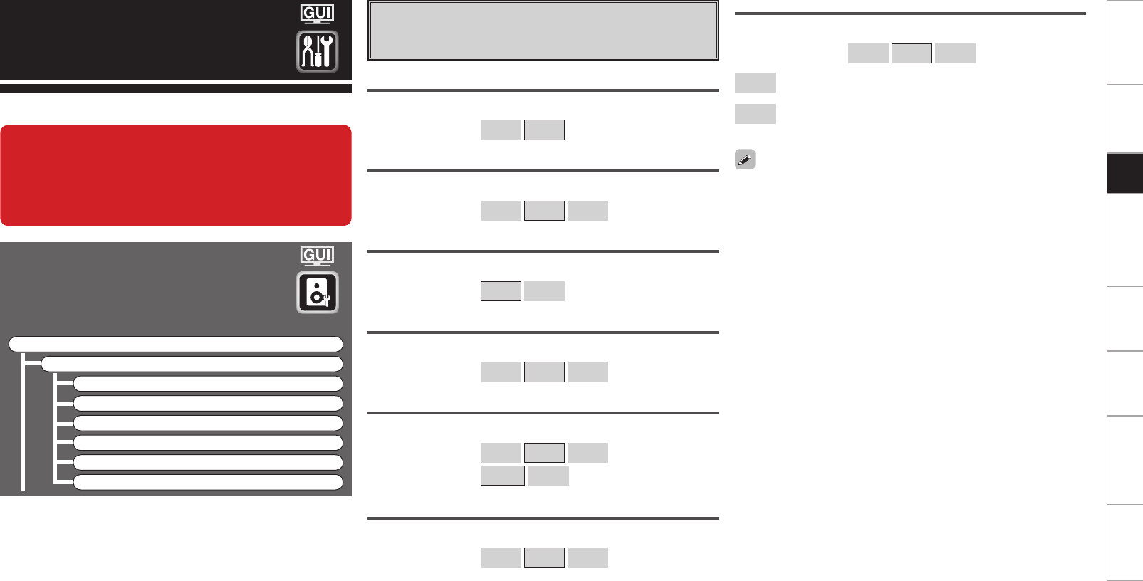
Option Setup AVC-A1HD
Make various other settings.
F Menu tree F
Manual Setup
Option Setup
a Amp Assign
s Volume Control
d Source Delete
f GUI
g Quick Select Name
h Trigger Out 1
j Trigger Out 2
k Trigger Out 3
l Trigger Out 4
A0 Transducer Setup
A1 Digital Out
A2 Remote ID
A3 232C Port (1)
A4 Dimmer
A5 Setup Lock
A6 Maintenance Mode
A7 Firmware Update
A8 Add New Feature
When this unit is upgraded, the “Option Setup” contents are changed.
When configuring the “Option Setup” settings, refer to this version of the Owner's Manual instead of
the “Original version”.
Option Setup AVP-A1HD
Make various other settings.
F Menu tree F
Manual Setup
Option Setup
a Pre-out Assign
s XLR Out Polarity
d POA Setting
f Volume Control
g Source Delete
h GUI
j Quick Select Name
k Trigger Out 1
l Trigger Out 2
A0 Trigger Out 3
A1 Trigger Out 4
A2 Transducer Setup
A3 Digital Out
A4 Remote ID
A5 232C Port (1)
A6 Dimmer
A7 Setup Lock
A8 Maintenance Mode
A9 Firmware Update
S0 Add New Feature
Assign Mode
The places where the surround amplifier and surround back amplifier
are used can be set freely according to the usage environment. This
makes it possible to output sound to rooms other than the room
(the MAIN ZONE) where surround playback is performed (multi-zone
playback) or play the sound with high quality using the front speakers
(bi-wiring/bi-amp connections).
[Selectable items]
Normal ZONE2 ZONE3 ZONE(MONO) Bi-Wiring
Bi & ZONE2 Bi & ZONE3 Bi & ZONE(MONO) Bi-Amp
ZONE2/ZONE3 ZONE2/3(MONO) 2CH Bi-Wiring 2CH Bi-Amp
Front Height Front Wide Free Assign
a Amp Assign AVC-A1HD
Change the assignment for the power amps.
For details, see “Multi-Zone Settings with the Amp Assign Function”
(vpage 46 ~ 61).
Extension Channel
Set the channel to add to the speaker system.
[Selectable items]
Front Height : Add front height channel to the speaker system.
Front Wide : Add front wide channel to the speaker system.
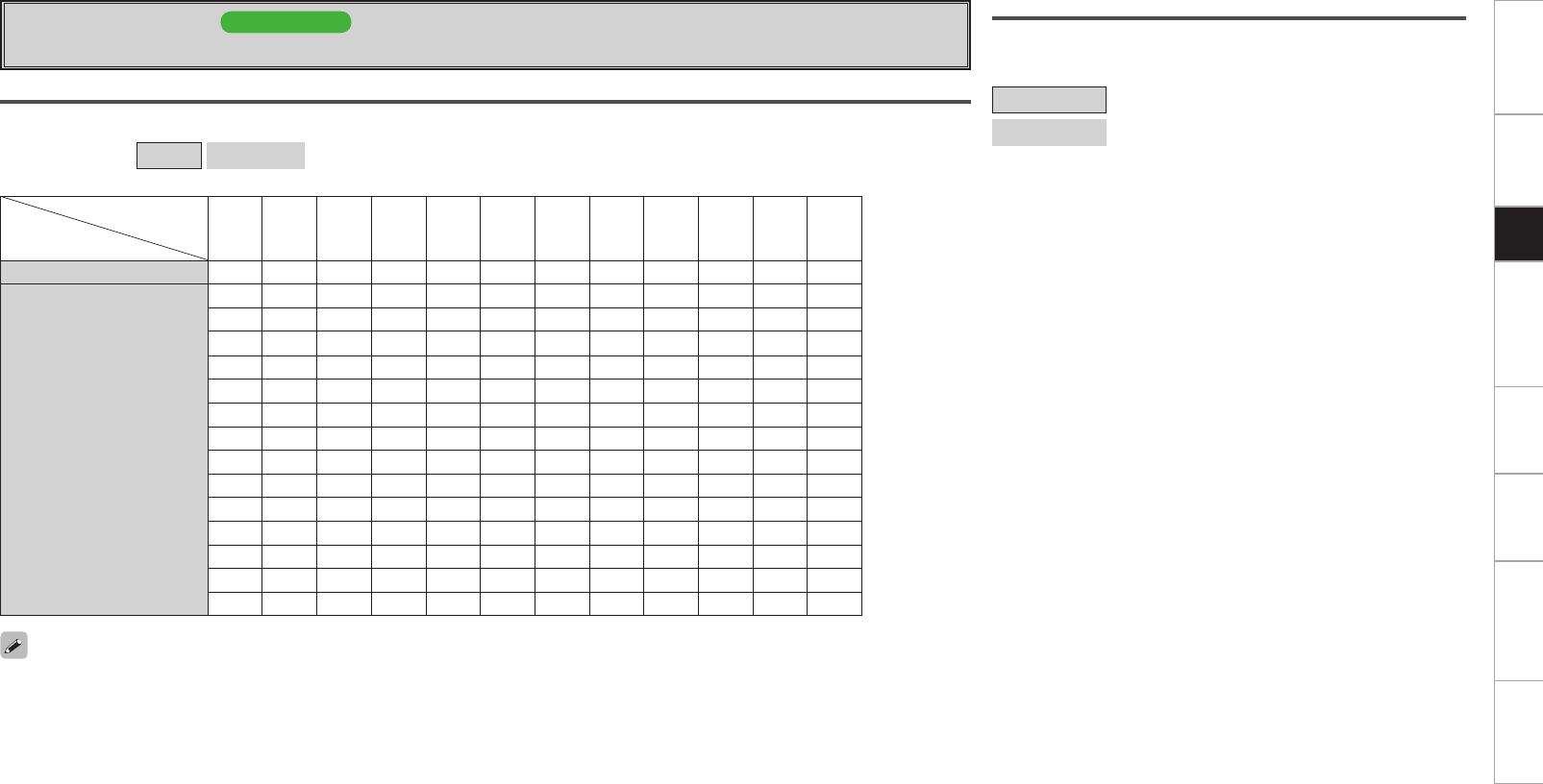
Getting Started Connections Other Operations Multi-Zone Information Troubleshooting SpecificationsSetup
Extension Channel
Set the channel to add to the speaker system.
[Selectable items]
Front Height : Add front height channel to the speaker system.
Front Wide : Add front wide channel to the speaker system.
Assign Mode
Setting “Free Assign” allows you to freely assign each pre-out to any channel, depending on the environment used.
[Selectable items] Normal Free Assign
a Pre-out Assign AVP-A1HD
Change the pre-out assignment.
• Channels that are set up in the GUI menu “Speaker Setup” – “Speaker Configuration” to “None” can be set up, but will not generate output.
• Pre-out terminals in ZONE2 and ZONE3 can not be allocated.
Preout terminal
Pre-out Assign
FL FR C SL SR SBL SBR FHL/
FWL
FHR/
FWR SW1 SW2 SW3
Normal FL FR C SL SR SBL SBR FHL FHR SW1 SW2 SW3
Free Assign
FL FL FL FL FL FL FL FL FL FL FL FL
FR FR FR FR FR FR FR FR FR FR FR FR
C C C C C C C C C C C C
SL SL SL SL SL SL SL SL SL SL SL SL
SR SR SR SR SR SR SR SR SR SR SR SR
SBL SBL SBL SBL SBL SBL SBL SBL SBL SBL SBL SBL
SBR SBR SBR SBR SBR SBR SBR SBR SBR SBR SBR SBR
FHL FHL FHL FHL FHL FHL FHL FHL FHL FHL FHL FHL
FHR FHR FHR FHR FHR FHR FHR FHR FHR FHR FHR FHR
FWL FWL FWL FWL FWL FWL FWL FWL FWL FWL FWL FWL
FWR FWR FWR FWR FWR FWR FWR FWR FWR FWR FWR FWR
SW1 SW1 SW1 SW1 SW1 SW1 SW1 SW1 SW1 SW1 SW1 SW1
SW2 SW2 SW2 SW2 SW2 SW2 SW2 SW2 SW2 SW2 SW2 SW2
SW3 SW3 SW3 SW3 SW3 SW3 SW3 SW3 SW3 SW3 SW3 SW3
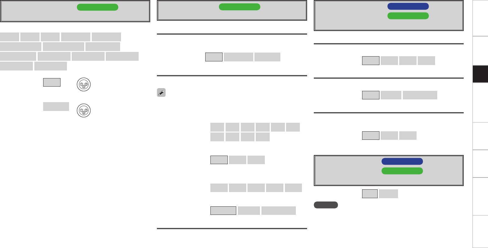
0
Getting Started Connections Other Operations Multi-Zone Information Troubleshooting SpecificationsSetup
d Source Delete AVC-A1HD
g Source Delete AVP-A1HD
Remove input sources that are not used from the display.
[Selectable items] ON Delete
NOTE
• Input sources being used in the various zones cannot be deleted.
• Input sources set to “Delete” cannot be selected from GUI menu
“Source Select” or using the SOURCE SELECT knob on the main unit
or SOURCE SELECT button on the remote control unit.
s Volume Control AVC-A1HD
f Volume Control AVP-A1HD
Set the MAIN ZONE volume setting.
Volume Limit
Make a setting for maximum volume.
[Selectable items] OFF –20dB –10dB 0dB
Power On Level
This sets the volume set when the MAIN ZONE’s power is turned on.
[Selectable items] Last – – –dB –80dB ~ 18dB
Mute Level
This sets the amount of attenuation of the volume when the mute
mode is set in the MAIN ZONE.
[Selectable items] Full –40dB –20dB
s XLR Out Polarity AVP-A1HD
Set to switch the XLR pre-out terminal polarity.
d POA Setting AVP-A1HD
Set when connecting the receiver to a POA-A1HD.
POA LINK
Set when connecting the receiver to a POA-A1HD through a CONTROL
LINK.
[Selectable items] OFF ON (Single) ON (Dual)
[Selectable channels]
Front L Front R Center Surround L Surround R
Surround Back L Surround Back R Front Height L
Front Height R Front Wide L Front Wide R Subwoofer 1
Subwoofer 2 Subwoofer 3
[Selectable items] XLR q GROUND
w HOT
e COLD
XLR (INV) q GROUND
w COLD
e HOT
POA 1/POA 2
Set POA-A1HD for which the MODE select switch is set to “1” or “2”.
LINK Check
Check CONTROL LINK.
n Input Selector
Select the setup channel.
[Selectable items] L1 R1 L2 R2 L3 R3
L4 R4 L5 R5
Select the connector input to be used for each channel.
[Selectable items] RCA XLR OFF
See the POA-A1HD operating instructions.
n Power Amp
Select the setup channel.
[Selectable items] L1/L2 L3/L4 L5/R5 R1/R2 R3/R4
Set the power amp usage for each channel.
[Selectable items] NORMAL BI-AMP BRIDGE (BTL)
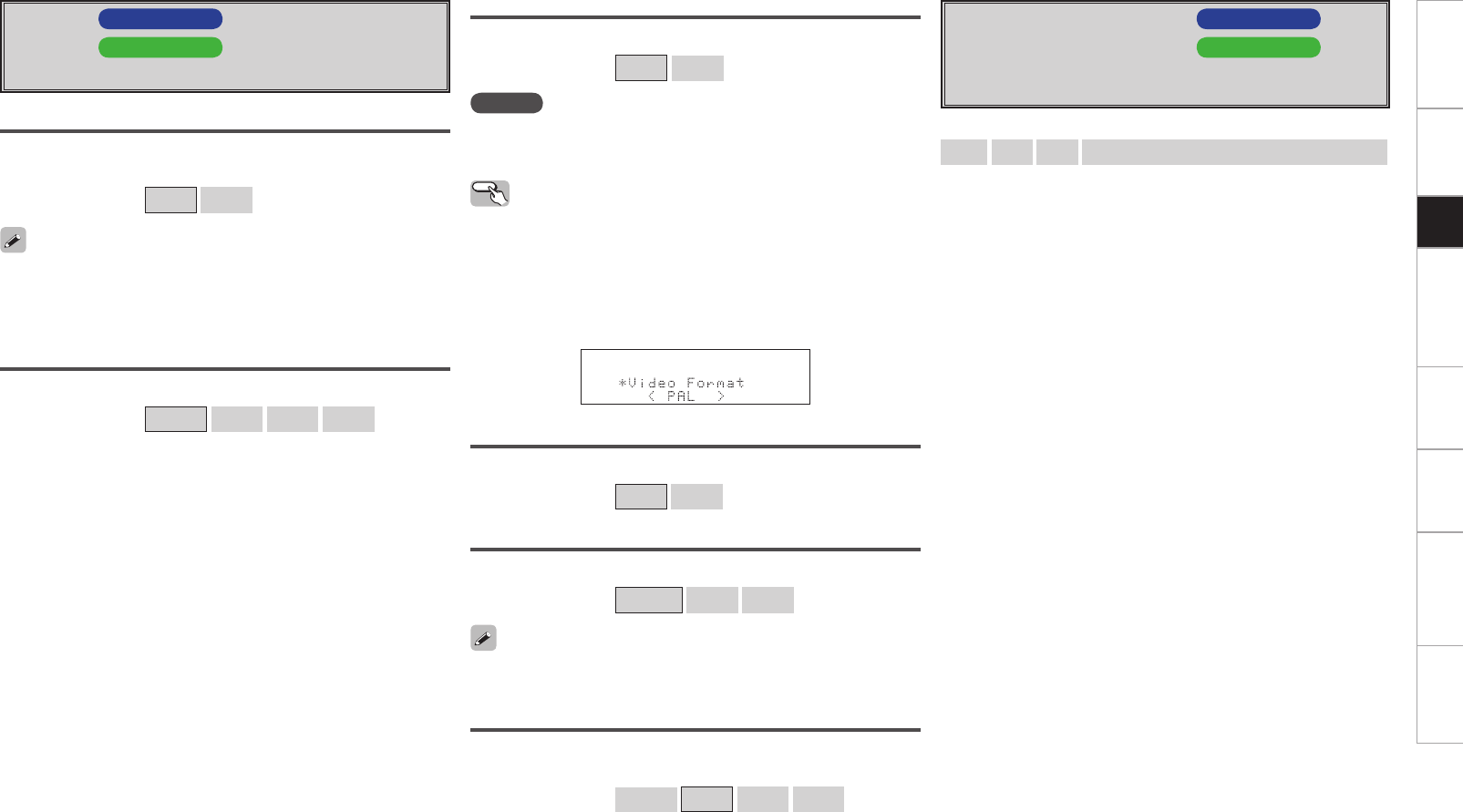
Getting Started Connections Other Operations Multi-Zone Information Troubleshooting SpecificationsSetup
f GUI AVC-A1HD
h GUI AVP-A1HD
Make GUI related settings.
Screensaver
Make screensaver settings.
Use the screensaver to prevent burn-in on the monitor screen.
[Selectable items] ON OFF
Wall Paper
Change the GUI background.
[Selectable items] Picture Black Gray Blue
Format
Select the video output signal format to match the monitor.
[Selectable items] PAL NTSC
NOTE
When a format other than the video format of the connected monitor
is set, the picture will not be displayed properly. Use the procedure
described below to change the video format.
When “Screensaver” is set to “ON”, the screensaver is activated if no
operation is performed for about 3 minutes.
When uio p, ENTER or MENU button is pressed, the screen saver is
cleared and the corresponding operation is performed.
Master Volume
Master volume display during adjustment.
[Selectable items] Bottom Top OFF
NET/USB, iPod
This sets the time the on-screen display is displayed when an operation
is performed.
[Selectable items] Always 30s 10s OFF
Text
Text information display.
[Selectable items] ON OFF
Operating from the main unit
b The GUI menu is not displayed when performing this setting.
q Press and hold the AUDIO DELAY and RETURN buttons for at least 3
seconds.
“Video Format” appears on the display.
w Use the o p button to make the setting.
e Press the ENTER, MENU or RETURN button to complete the
setting.
g Quick Select Name AVC-A1HD
j Quick Select Name AVP-A1HD
Change “Quick Select” display name.
Up to 16 characters can be input.
[Input characters]
A ~ Z a ~ z 0 ~ 9 ! # % & ’ ( ) * + , - . / : ; < = “ > ? @ [ \ ] (space)
When the master volume display is hard to see when superimposed
on movie subtitles, set to “Top”.
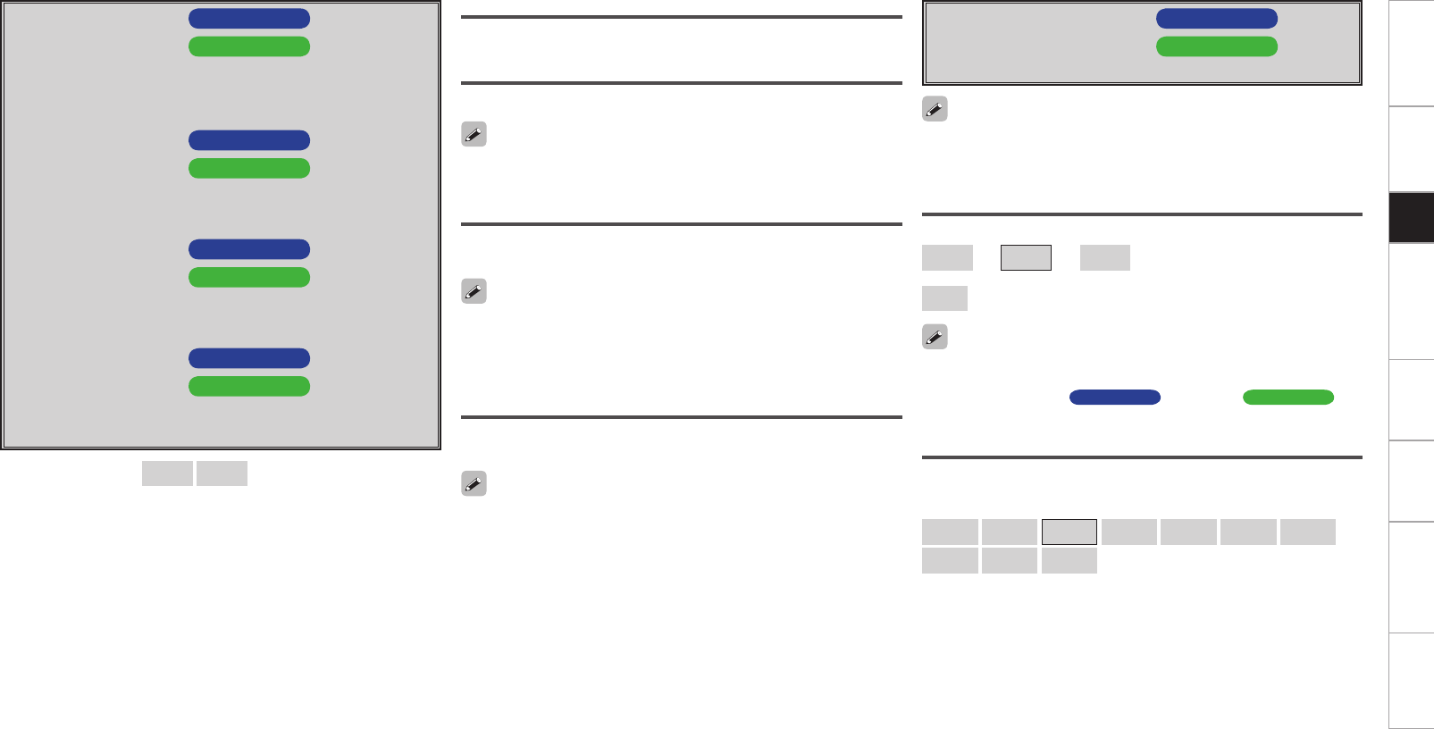
Getting Started Connections Other Operations Multi-Zone Information Troubleshooting SpecificationsSetup
h Trigger Out 1 AVC-A1HD
k Trigger Out 1 AVP-A1HD
Select the conditions to turn on the trigger out 1 with respect to
the zone, input source, surround mode, HDMI monitor, etc.
For details about the trigger out function, see mpage 22.
j Trigger Out 2 AVC-A1HD
l Trigger Out 2 AVP-A1HD
This sets the conditions to turn on the trigger out 2, in the same
way as “Trigger Out 1” above.
k Trigger Out 3 AVC-A1HD
A0 Trigger Out 3 AVP-A1HD
This sets the conditions to turn on the trigger out 3, in the same
way as “Trigger Out 1” above.
l Trigger Out 4 AVC-A1HD
A1 Trigger Out 4 AVP-A1HD
This sets the conditions to turn on the trigger out 4, in the same
way as “Trigger Out 1” above.
[Selectable items] ON – – –
Setting with Respect to the Zone
When the power of the zone turned on/off, the trigger out turns on.
Setting with Respect to the Input Source
When the input source set to on is selected, the trigger out turns on.
Associated with respect to the input source for zones set to “ON” at
“Setting with Respect to the Zone”.
A0 Transducer Setup AVC-A1HD
A2 Transducer Setup AVP-A1HD
Settings when using transducer.
The Transducer Setup can be accessed through GUI menu “Speaker
Setup” – “Subwoofer Setup” is “1SP”, “2SP L/R” or “2SP MIX”. The
transducer signal is outputted from “SW3”.
Level
[Variable range]
–12dB ~ 0dB ~ +12dB : Set the transducer level.
OFF : Turn the transducer output off.
Setting with Respect to the Surround Mode
When the surround mode set to on is selected, the trigger out turns
on.
Setting with Respect to the Monitor
When the HDMI monitor set to on is selected, the trigger out turns
on.
This is effective when the “MAIN ZONE” has been set to “ON” for
the “Setting with Respect to the Zone” and the input source which is
set to “ON” has been selected for the “Setting with Respect to the
Input Source”.
This is effective when the “MAIN ZONE” has been set to “ON” for
the “Setting with Respect to the Zone” and the input source which is
set to “ON” has been selected for the “Setting with Respect to the
Input Source”. When you adjust “Level”, the adjusted value is set for all surround
modes. To adjust the level for individual surround modes, use “Channel
Level” (vmpage 65 AVC-A1HD , mpage 67 AVP-A1HD ).
LPF
Set the upper limit of the low frequency output to the transducer.
[Selectable items]
40Hz 60Hz 80Hz 90Hz 100Hz 110Hz 120Hz
150Hz 200Hz 250Hz
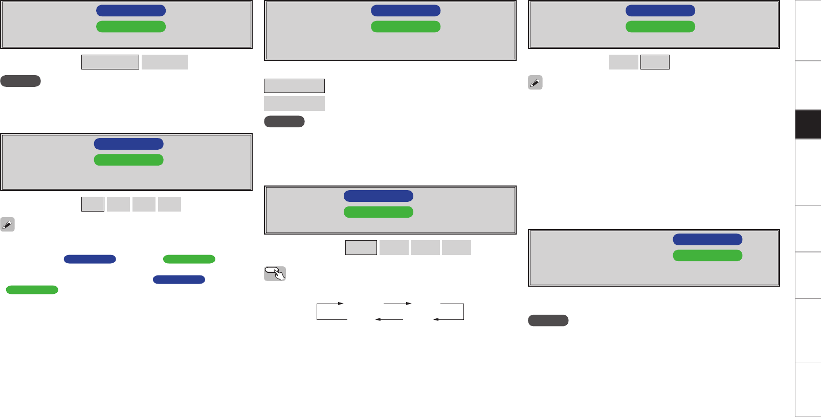
Getting Started Connections Other Operations Multi-Zone Information Troubleshooting SpecificationsSetup
A2 Remote ID AVC-A1HD
A4 Remote ID AVP-A1HD
Set remote control ID.
Match the ID setting of the remote control unit and the receiver.
• When changing the remote ID, also change the AMP, iPod and
NET/DTU modes of the main remote control unit at the same time
(v
mpage 70 AVC-A1HD , mpage 72 AVP-A1HD
).
• When changing the remote ID, also change the sub remote control
unit at the same time (
v
mpage 75 AVC-A1HD , mpage 77
AVP-A1HD ).
A1 Digital Out AVC-A1HD
A3 Digital Out AVP-A1HD
Set usage of OPT4 OUT.
NOTE
The ZONE4 operations cannot be performed when set to “Rec
Select”.
[Selectable items] ZONE4 Select Rec Select
[Selectable items] 1 2 3 4
A3 232C Port (1) AVC-A1HD
A5 232C Port (1) AVP-A1HD
Set when external controller or 2-way remote control unit (RC-
7000CI and RC-7001RCI, sold separately) is connected.
NOTE
In order to use a 2-way remote control (RC-7000CI or RC-7001RCI, sold
separately), set “2Way Remote”. In this case, the RS-232C terminal
cannot be used for an external controller.
A4 Dimmer AVC-A1HD
A6 Dimmer AVP-A1HD
Adjust display brightness of the receiver.
Operating from the main unit
Press the DIMMER button.
[Selectable items] Bright Dim Dark OFF
Bright Dim
DarkOFF
A5 Setup Lock AVC-A1HD
A7 Setup Lock AVP-A1HD
Protect settings from inadvertent change.
• When “Setup Lock” is set to “ON”, the settings listed below can
no longer be changed. Also, “SETUP LOCKED!” is displayed if you
attempt to operate related buttons.
⋅ GUI menu operations
⋅ RESTORER
⋅ Parameters
⋅ MultEQ® XT 32
⋅ Channel Level
⋅ Audio Delay
• To cancel the setting, press the MENU button to re-display the “Setup
Lock” screen, then change the setting to “OFF”.
[Selectable items] ON OFF
A6 Maintenance Mode AVC-A1HD
A8 Maintenance Mode AVP-A1HD
This sets the function for maintenance by a DENON service
person or installer. (For professional use only.)
NOTE
Only use this function if so instructed by a DENON service person or
installer.
This function allows a DENON service person or installer to check the
unit’s status and make settings via the Internet.
[Selectable items]
Serial Control : Set when using an external controller.
2Way Remote : Set when using a 2-way remote control unit.
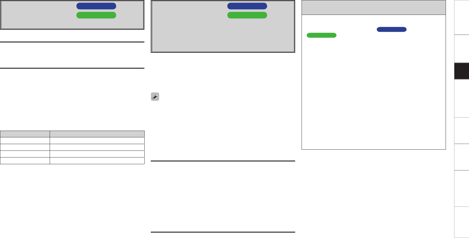
Getting Started Connections Other Operations Multi-Zone Information Troubleshooting SpecificationsSetup
A7 Firmware Update AVC-A1HD
A9 Firmware Update AVP-A1HD
Update the firmware of the receiver.
Check for Update
You can check for firmware updates. You can also check approximately
how long it will take to complete an update.
Start
Execute the update process.
When updating starts, the power indicator becomes red and the GUI
screen is shut down.
The amount of update time which has elapsed is displayed during the
update process.
When updating is complete the power indicator becomes green and
normal status is resumed.
b If the display reads as shown below, check the settings and network
environment, then update again.
Display Description
Updating failed Updating failed.
Login failed Failure to log into server.
Server is busy Server is busy. Wait a while then try again.
Connection fail Failure connecting to server. Upgrade
Execute the upgrade process.
When upgrading starts, the power indicator becomes red and the GUI
screen is shut down.
The amount of upgrade time which has elapsed is displayed during the
upgrade process.
When upgrading is complete the power indicator becomes green and
normal status is resumed.
b If the upgrade is not successful, an error message identical to those
in “Firmware Update” will appear on the display.
A8 Add New Feature AVC-A1HD
S0 Add New Feature AVP-A1HD
Display the new functions which can be purchased for downloading
to the unit and upgrade.
With this upgrade, the software is also upgraded so there is no
need to use “Add New Feature”.
This feature is used when there are further firmware upgrades.
When you purchase a new function and register your user information,
“Registered” is displayed on this menu and you can proceed with the
upgrade.
Upon completion of the upgrade, you can start using the new
function.
Notes concerning use of “Firmware Update” and
“Add New Feature”
• In order to use these functions, you must have the correct system
requirements and settings for a broadband Internet connection.
For details, see mpage 33 ~ 36 AVC-A1HD , mpage 34 ~ 37
AVP-A1HD .
• Do not turn off the power until updating or upgrating is completed.
• Normally there is no need to use this function, aside from the cases
described below.
⋅ Firmware Update : In the case of applying the latest firmware
updates (free)
⋅ Add New Feature : In the case of future upgrades to add new
functions to the receiver (payment required)
⋅ Information regarding the “Firmware Update” function and “Add
New Feature” will be announced on the DENON web site each
time related plans are defined.
• Even with a broadband connection to the Internet, approximately
1 hour is required for the updating/upgrading procedure to be
completed.
Once updating/upgrading starts, normal operations on the unit
cannot be performed until updating/upgrading is completed.
Furthermore, updating/upgrading the firmware may reset the
backup data for the parameters, etc., set for the unit.
• When updating/upgrading the firmware, we recommend using
wired connections (Ethernet cable).
When “Not Registered” is displayed on the Add New Feature screen,
you cannot upgrade.
To use the upgrade function, you should purchase an upgrade package
from the DENON website.
To purchase the package, you will need the ID number shown on this
screen.
To display the ID number on the screen, hold the p and STATUS
buttons on the remote control unit down for 3 seconds or more.
Upgrade Status
A list of the additional functions provided by the Upgrade will be
displayed.
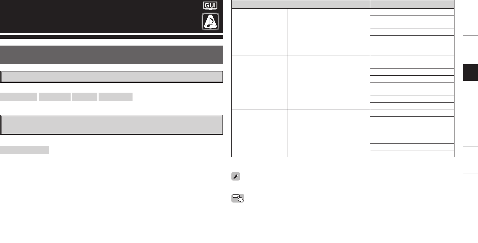
Getting Started Connections Other Operations Multi-Zone Information Troubleshooting SpecificationsSetup
Surround Mode
HOME THX CINEMA
THX surround sound mode to recreate the authentic sound of movie soundtracks.
Surround Playback of 2-channel Sources
[Selectable items]
PLgx CINEMA PLg CINEMA Pro Logic PLgz HEIGHT
[Selectable items]
HOME THX CINEMA :
This mode is for decoding the input signals according to their format and playing THX surround sound.
The display when the HOME THX CINEMA mode is selected depends on the input signal and surround
back output playback mode.
Playing Multi-channel Sources
(Dolby Digital, DTS, etc.)
Operating from the main unit or main remote control unit
Press the HOME THX CINEMA button on the main unit or the THX button on the main remote control
unit.
For details, see page 66.
Input signal Display
Dolby Digital Source
DOLBY DIGITAL
(other than 2ch) /
DOLBY DIGITAL EX /
DOLBY DIGITAL Plus /
DOLBY TrueHD
THX SURROUND EX
THX Ultra2 Cinema
THX Music Mode
THX Games Mode
THX Cinema
PLgx C+THX
PLgz+THX
DTS Surround Source
DTS (5.1ch) /
DTS-ES Discrete 6.1 /
DTS-ES Matrix 6.1 /
DTS 96/24 /
DTS-HD High Resolution Audio /
DTS-HD Master Audio
ES MTRX6.1+THX
ES DSCRT6.1+THX (z)
THX Ultra2 Cinema
THX Music Mode
THX Games Mode
THX Cinema
PLgx C+THX
PLgz+THX
DVD-Audio, SACD PCM (multi ch) /
DSD (multi ch)
THX SURROUND EX
THX Ultra2 Cinema
THX Music Mode
THX Games Mode
THX Cinema
PLgx C+THX
PLgz+THX
z: This is displayed when the input signal is “DTS-ES Discrete 6.1”.
Getting Started Connections Other Operations Multi-Zone Information Troubleshooting SpecificationsSetup
Select the “Cinema”, “Music”, “Game” and “Pro Logic” modes at GUI menu “Parameters” – “Audio” –
“Surround Parameters” – “Mode” (vpage 38).
Surround Playback of 2-channel Sources
DOLBY PLgx or DOLBY PLg
Cinema : This mode is suited for movie sources.
Music : This mode is suited for music sources.
Game : This mode is suited for games.
Pro Logic :This mode can be selected when a DOLBY Pro Logic decoder is used to play 2-
channel source in 4.1-channel surround sound (Left/Center/Right/Surround Mono).
This can be selected when playing with a DOLBY PLg decoder. When this mode is
selected, “DOLBY PL” is displayed.
n When using a surround back speaker
[Selectable items]
DOLBY PLgx : This mode can be selected when a Dolby Pro Logic gx decoder is used to play back
2-channel source in 6.1/7.1-channel surround sound including the surround back
channel.
By adding the surround back channel, a stronger surround feeling is obtained compared
to Dolby Pro Logic g.
DTS NEO:X : This mode can be selected when a DTS NEO:X decoder is used to play back 2-channel
source in a maximum of 9.1 channel surround sound including the surround back
channel.
n When using a front height speaker
[Selectable items]
DOLBY PLgz : This mode can be selected when a Dolby PLgz decoder is used to play back 2-channel
source in a maximum of 9.1 channel including the front height channel.
By adding a front height channel, the vertical expression is emphasized, improving the
three-dimensionality of the sound.
DTS NEO:X : This mode can be selected when a DTS NEO:X decoder is used to play back 2-channel
source in a maximum of 9.1 channel including the front height channel.
n When using a front wide speaker
DTS NEO:X : This mode can be selected when a Dolby PLgz decoder is used to play back 2-channel
source in a maximum of 9.1 channel including the front wide channel.
n When the surround back speakers, front height speakers and front wide
speakers are not being used
[Selectable items]
DOLBY PLg : This mode can be selected when a Dolby Pro Logic g decoder is used to play back 2-
channel source in 5.1-channel surround sound with a natural, realistic feel.
DTS NEO:X : This mode can be selected when a DTS NEO:X decoder is used to play back 2-channel
source in 5.1-channel surround sound including the surround back channel.
Operating from the main unit
The “Cinema”, “Music”, or “Game” modes can be directly selected with the CINEMA, MUSIC or GAME
button on the main unit.
Standard Playback
This is the standard mode for enjoying surround sound according to the program source.
To select these surround modes pressing the STANDARD button on the main unit or press the STD button
on the main remote control unit. The mode switches each time the button is pressed.
At this point, configure the “Audyssey DSX™” settings. For details, see page 42.
Operating from the main unit
The “Cinema”, “Music”, or “Game” modes can be directly selected with the CINEMA, MUSIC or GAME
button on the main unit.
DOLBY PLgz
Height : This mode is the playback mode for Dolby PLgz front height.
DTS NEO:X
Cinema : This mode is suited for movie sources.
Music : This mode is suited for music sources.
Game : This mode is suited for games.
NOTE
• DTS NEO:X mode cannot be selected when the sampling frequency of the input signal is 32 kHz,64 kHz
and 128 kHz.
• DTS NEO:X cannot be selected when the input signal is DSD.
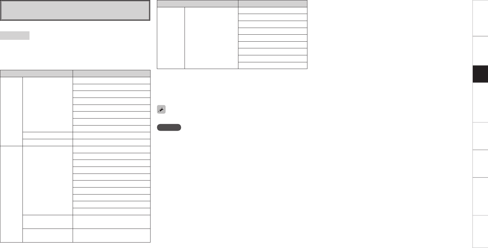
Getting Started Connections Other Operations Multi-Zone Information Troubleshooting SpecificationsSetup
For details, see page 66 ~ 68.
[Selectable items]
STANDARD :
This mode is for decoding the input signals according to their format
and playing surround sound.
The display when the STANDARD mode is selected depends on the
input signal and surround back output playback mode.
Playing Multi-channel Sources
(Dolby Digital, DTS, etc.)
Input signal Display
Dolby
Digital
Source
DOLBY DIGITAL
(other than 2ch)/
DOLBY DIGITAL EX
DOLBY DIGITAL
DOLBY DIGITAL EX
DOLBY DIGITAL+PLgx CINEMA
DOLBY DIGITAL+PLgx MUSIC
DOLBY DIGITAL+NEO:X CINEMA
DOLBY DIGITAL+NEO:X MUSIC
DOLBY DIGITAL+NEO:X GAME
DOLBY DIGITAL+PLgz
DOLBY DIGITAL Plus DOLBY DIGITAL+
DOLBY TrueHD DOLBY TrueHD
DTS
Surround
Source
DTS (5.1ch)/
DTS-ES Discrete
6.1 /
DTS-ES Matrix 6.1 /
DTS 96/24
DTS SURROUND
DTS+PLgx CINEMA
DTS+PLgx MUSIC
DTS+PLgz
DTS+NEO:X CINEMA
DTS+NEO:X MUSIC
DTS+NEO:X GAME
DTS ES MTRX6.1(z1)
DTS ES DSCRT6.1(z2)
DTS 96/24(z3)
DTS-HD High
Resolution Audio DTS-HD HI RES
DTS-HD Master
Audio DTS-HD MSTR
Input signal Display
DVD-
Audio,
SACD
PCM(multi ch) /
DSD(multi ch)(z4)
MULTI CH IN
MULTI IN+Dolby EX
MULTI IN+PLgx CINEMA
MULTI IN+PLgx MUSIC
MULTI IN+PLgz
MULTI CH IN 7.1
MULTI IN+NEO:X CINEMA
MULTI IN+NEO:X MUSIC
MULTI IN+NEO:X GAME
z1 : This is displayed when the input signal is “DTS-ES Matrix 6.1”
and the speaker configuration is 6.1 channel.
z2 : This is displayed when the input signal is “DTS-ES Discrete 6.1”.
z3 : This is displayed when the input signal is “DTS 96/24”.
z4 : DTS NEO:X cannot be selected when the input signal is DSD.
NOTE
• DTS NEO:X mode cannot be selected when the sampling frequency
of the input signal is 32 kHz, 64 kHz and 128 kHz.
• Audyssey DSX™ mode can be selected even when the STANDARD
button is pressed.
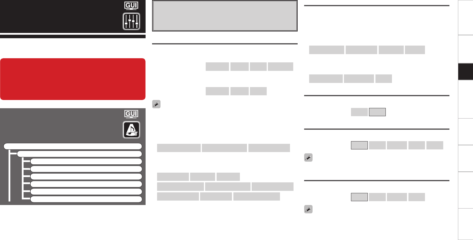
Getting Started Connections Other Operations Multi-Zone Information Troubleshooting SpecificationsSetup
Parameters
Audio
Adjust various audio parameters.
F Menu tree F
Parameters
Audio
a Surround Parameters
s Tone
d Audyssey Settings
f A-DSX Soundstage
g RESTORER
h Audio Delay
Parameters can be called out directly by pressing the PARA button on
the main remote control unit.
a Surround Parameters
Adjust surround sound parameters.
The adjustable parameters differ for the different surround modes
(vpage 64, 65).
Mode
Select the mode according to the playback source.
n In the PLgx or PLg mode
[Selectable items] Cinema Music Game Pro Logic z
z: Can be selected in the PLg mode.
n In the DTS NEO:X mode
[Selectable items] Cinema Music Game
The “Music” mode is also effective for movie sources including a lot
of stereo music.
When this unit is upgraded, the “Audio” contents
are changed.
When configuring the “Audio” settings, refer to
this version of the Owner's Manual instead of the
“Original version”.
n In the THX mode (for 2-channel sources)
[Selectable items]
Surround Back ON Surround Back OFF THX Games Mode
n In the THX mode (for Multi-channel sources)
[Selectable items]
THX Surr. EX ES DSCRT ES MTRX
PLIIx Cinema + THX THX Ultra2 Cinema THX Music Mode
THX Games Mode THX Cinema Surround Back ON
Cinema EQ
Soften the treble range of movie soundtracks for better understanding.
[Selectable items] ON OFF
Decoder
Select this when playing analog, PCM or other 2 channel sources.
The signals are converted into multi channel signals using the decoders
shown below and played in the Dolby Headphone mode.
n In the THX mode (for 2-channel sources)
[Selectable items]
PLIIx CINEMA PLII CINEMA Pro Logic PLIIz
n In the DOLBY HEADPHONE mode
[Selectable items]
PLII CINEMA PLII MUSIC OFF
DRC
Compress dynamic range (difference between loud and soft sounds).
[Selectable items] Auto Low Middle High OFF
This can be set in the Dolby TrueHD mode.
D.COMP
Compress dynamic range (difference between loud and soft sounds).
[Selectable items] OFF Low Middle High
When playing DTS sources, this is only displayed for compatible
software.
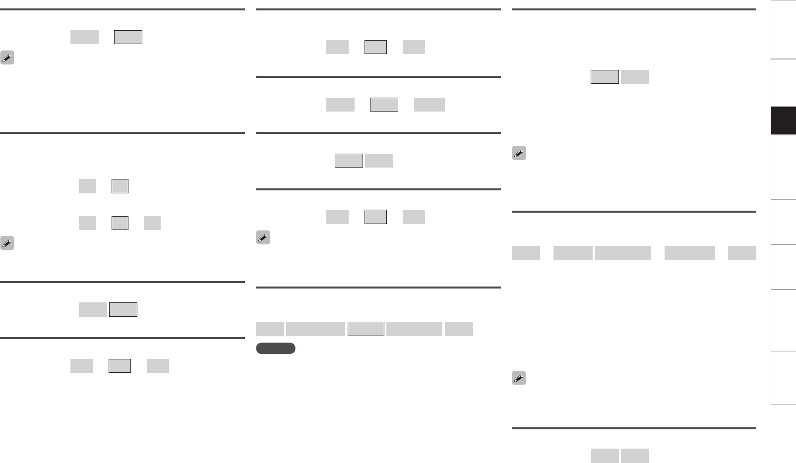
Getting Started Connections Other Operations Multi-Zone Information Troubleshooting SpecificationsSetup
LFE
Adjust the low-frequency effects level (LFE).
[Variable range] –10dB ~ 0dB
Center Gain
Assign center channel signal to front left and right channels for wider
sound.
n In DTS NEO:X mode, “Cinema” or “Game” is selected.
[Variable range] 0.0 ~ 1.0
n In DTS NEO:X mode, “Music” is selected.
[Variable range] 0.0 ~ 0.3 ~ 1.0
Panorama
Assign front L/R signal also to surround channels, for wider sound.
[Selectable items] ON OFF
For proper playback of the different program sources, we recommend
setting to the values below.
• Dolby Digital sources: “0 dB”
• DTS movie sources: “0 dB”
• DTS music sources: “–10 dB”
Delay Time
Adjust delay time to control sound stage size.
[Variable range] 0ms ~ 30ms ~ 300ms
Effect
Switch effect signal for multi-surround speakers on and off.
[Selectable items] ON OFF
Effect Level
Adjust effect signal level.
[Variable range] 1 ~ 10 ~ 15
Room Size
Determine size of acoustic environment.
[Selectable items]
Small Medium small Medium Medium large Large
Set to a lower level if the positioning and sense of phase of the
surround signals seems unnatural.
NOTE
“Room Size” does not indicate the size of the room in which sources
are played.
Dimension
Shift sound image center to front or rear, to adjust playback balance.
[Variable range] 0 ~ 3 ~ 6
Center Width
Assign center channel signal to front left and right channels for wider
sound.
[Variable range] 0 ~ 3 ~ 7
This can be set when playing back a DTS NEO:X.
AFDM
Auto-select surround mode by source.
This function only works for software containing a special identification
signal.
If the software being played is recorded in Dolby Digital EX, it is played
in 6.1-channels. If not, it is played in 5.1-channels.
[Selectable items] ON OFF
Example : Playing Dolby Digital software (with EX flag)
• When “AFDM” is set to “ON”, the surround mode is automatically
set to the DOLBY D + PLgx C mode.
• To play in the DOLBY DIGITAL EX mode, set “AFDM” to “OFF” and
“SB CH Out” to “MTRX ON”.
Some Dolby Digital EX sources do not include EX flags. If the playback
mode does not switch automatically even when “AFDM” is set to
“ON”, set “SB CH Out” to “MTRX ON” or “PLgx CINEMA”.
SB CH Out (for Multi-channel sources)
Select playback mode for surround back channels.
[Selectable items]
ON z1
MTRX ON PL
II
x CINEMA z2
PL
II
x MUSIC z3
OFF
z1: Convert the 5.1-channel source of the DTS/DTS-HD input signals
to the 7.1-channel output recommended by DTS and then play.
This can be selected when playing the 5.1-channel source of DTS/
DTS-HD.
z2: This can be selected when “Surround Back” is set to “2spkrs”
at the GUI menu “Manual Setup” – “Speaker Setup” – “Speaker
Configuration” setting (vpage 23).
z3: This can be selected when “Surround Back” is set to “2spkrs”
or “1spkr” at the GUI menu “Manual Setup” – “Speaker Setup”
–“Speaker Configuration” setting.
SB CH Out (for 2-channel sources)
Determine whether to use surround back speakers.
[Selectable items] ON OFF
When using the surround back speaker, you can change the “SB
CH Out” setting by pressing the STANDARD button.
0
Getting Started Connections Other Operations Multi-Zone Information Troubleshooting SpecificationsSetup
Subwoofer Att.
Attenuate subwoofer level when using EXT. IN input.
[Selectable items] ON OFF
Set this to “ON” if the subwoofer channel level seems too high when
playing Super Audio CD.
Subwoofer
Turn subwoofer output on and off.
[Selectable items] ON OFF
Default
Resets the settings to the default values.
Tone Defeat
Turn tone adjustments off.
[Selectable items] ON OFF
NOTE
• The tone cannot be adjusted when in the DIRECT, PURE DIRECT and
HOME THX CINEMA mode.
• “Tone” cannot be set when “Dynamic EQ®” (vpage 41) is set to
“ON”.
Bass
Adjust bass for all channels together.
[Variable range] –6dB ~ +6dB
Treble
Adjust treble for all channels together.
[Variable range] –6dB ~ +6dB
“Bass” and “Treble” can be set when “Tone Defeat” is set to “OFF”.
s Tone
Adjust the tonal quality of the sound.
Front
Adjust each front channel tone.
[Selectable items] Bass Treble
[Variable range] –6dB ~ +6dB
Center
Adjust each center channel tone.
[Selectable items] Bass Treble
[Variable range] –6dB ~ +6dB
Surround
Adjust each surround channel tone.
[Selectable items] Bass Treble
[Variable range] –6dB ~ +6dB
Surround Back
Adjust each surround back channel tone.
[Selectable items] Bass Treble
[Variable range] –6dB ~ +6dB
Subwoofer
Adjust each subwoofer channel tone.
[Selectable items] Bass
[Variable range] –6dB ~ +6dB
This can be set individually for the separate surround mode other than
PURE DIRECT, DIRECT and HOME THX CINEMA mode.
Input Channel AVP-A1HD
Select channel using external input connectors (EXT. IN) for source
being played.
[Selectable items] 8CH 2CH
Can be selected when GUI menu “Manual Setup” – “Audio Setup”–
“EXT. IN Setup”– “Mode” is set to “DSP” (vpage 26).
Height Gain
Control the front height channel volume.
[Selectable items] Low Middle High
NOTE
“Height Gain” is displayed for the following settings.
• When the “Speaker Setup” – “Speaker Configuration” – “Front
Height” setting (vpage 23) is set other than to “None”.
• When surround mode is “PLgz” or the PLgz decoder is used.
Front Height
Adjust each front height channel tone.
[Selectable items] Bass Treble
[Variable range] –6dB ~ +6dB
Front Wide
Adjust each front wide channel tone.
[Selectable items] Bass Treble
[Variable range] –6dB ~ +6dB
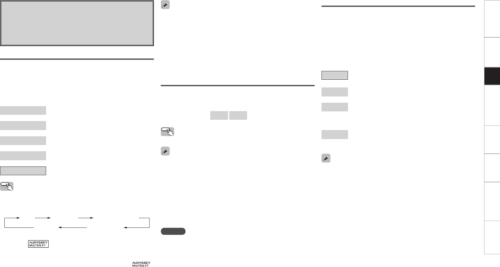
Getting Started Connections Other Operations Multi-Zone Information Troubleshooting SpecificationsSetup
d Audyssey Settings
Set Audyssey MultEQ® XT 32, Audyssey Dynamic EQ® and
Audyssey Dynamic Volume®. These can be selected after Auto
Setup has been performed.
For additional information on Audyssey technology, please see
page 63.
Operating from the main unit or main remote
control unit
Press the ROOM EQ button on the main unit or the EQ button on the
main remote control.
Audyssey Audyssey Byp. L/R
Audyssey Flat
Manual
OFF
• When “Audyssey”, “Audyssey Byp. L/R” or “Audyssey Flat” is
selected, “ ” lights.
• After running Auto Setup, if the Speaker Configuration, Distance,
Channel Level, and Crossover Frequency have changed without
increasing the number of speakers measured, only “ ”
lights.
• “Audyssey”, “Audyssey Byp. L/R” and “Audyssey Flat” can be
selected after the Auto Setup procedure has been performed.
• After performing “Auto Setup”, the “MultEQ® XT 32” setting
automatically becomes “Audyssey”.
• If the settings of speakers for which “None” has been determined
at “Auto Setup” are changed, “Audyssey”, “Audyssey Byp. L/R” and
“Audyssey Flat” cannot be selected. Either perform Auto Setup
again, or return to the setting after running Auto Setup with “Auto
Setup” – “Parameter Check” – “Restore” (vpage 22).
• When using headphones, “MultEQ® XT 32” is always set to “OFF”.
Audyssey
OFF
Manual
Audyssey Byp. L/R
Audyssey Flat
MultEQ® XT 32
MultEQ® XT 32 corrects both time and frequency response problems
in the listening area based on Auto Setup calibration. We recommend
“Audyssey”.
MultEQ® XT 32 is the prerequisite function for Dynamic EQ® and
Dynamic Volume®.
[Selectable items]
Audyssey : Optimize the frequency response of all
speakers.
Audyssey Byp. L/R : Optimize frequency response of speakers
except front L and R speakers.
Audyssey Flat : Optimize frequency response of all speakers to
flat response.
Manual : Apply frequency response set with “Manual
EQ” (vpage 27).
OFF : Turn “MultEQ® XT 32” equalizer off.
Dynamic EQ®
Solve the problem of deteriorating sound quality as volume is decreased
by taking into account human perception and room acoustics. Works
with MultEQ® XT 32.
[Selectable items] ON OFF
Operating from the main unit
Press DYNAMIC EQ button.
• “Dynamic EQ®” can only be set when Auto Setup has been
performed.
• After performing “Auto Setup”, the “Dynamic EQ®” setting
automatically becomes “ON”.
• When “MultEQ® XT 32” is set to “OFF” or “Manual”, “Dynamic
EQ®” is automatically set to “OFF”.
• Before running Auto Setup and after running Auto Setup, if the
number of speakers has increased or you pressed DYNAMIC EQ
button, “Run Audyssey” is displayed. In this case, either perform
Auto Setup, or return to the setting after running Auto Setup with
“Auto Setup” – “Parameter Check” – “Restore” (vpage 22).
NOTE
• “Dynamic EQ®” cannot be set in the following situations.
• If “Auto Setup” fails to be completed.
• After running Auto Setup, when the number of used speakers has
increased from the number of measured speakers.
• When you set ”Dynamic EQ®” to ”ON”, “Tone” (vpage 40)
cannot be used.
Reference Level Offset
Audyssey Dynamic EQ® is referenced to the standard film mix level. It
makes adjustments to maintain the reference response and surround
envelopment when the volume is turned down from 0 dB. However,
film reference level is not always used in music or other non-film
content.
Dynamic EQ® Reference Level Offset provides three offsets from the
film level reference (5 dB, 10 dB, and 15 dB) that can be selected when
the mix level of the content is not within the standard.
[Selectable items]
0dB : This is the default setting and should be used when
listening to movies (Film Ref).
5dB : Select this setting for content that has a very wide
dynamic range, such as classical music.
10dB : Select this setting for jazz or other music that has a wider
dynamic range. This setting should also be selected for
TV content as that is usually mixed at 10 dB below film
reference.
15dB : Select this setting for pop/rock music or other program
material that is mixed at very high listening levels and has
a compressed dynamic range.
Setting is enabled when “Dynamic EQ®” is “ON” (vpage 41).
Getting Started Connections Other Operations Multi-Zone Information Troubleshooting SpecificationsSetup
f A-DSX Soundstage
Adjust Audyssey DSX™ setting and sound stage parameters.
Operating from the main unit
Press DYNAMIC EQ button.
Dynamic Volume®
Solve the problem of large variations in volume level between TV, movies
and other content (between quiet passages and loud passages, etc.)
by automatically adjusting to the user’s preferred volume setting.
[Selectable items]
ON : Use Dynamic Volume®.
Dynamic Volume® effect will be at the level of the
“Setting”.
OFF : Do not use Dynamic Volume®.
Dynamic EQ / Volume : ON Dynamic EQ : ON / Volume : OFF
Dynamic EQ / Volume : OFF
Dynamic EQ / Volume : ON
Dynamic EQ / Volume : OFF
Dynamic EQ : ON / Volume : OFF
• “Dynamic Volume®” can only be set when Auto Setup has been
performed.
• When “MultEQ® XT 32” is set to “OFF” or “Manual”, “Dynamic
Volume®” is automatically set to “OFF”.
• Before running Auto Setup and after running Auto Setup, if the
number of speakers has increased or you pressed DYNAMIC EQ
button, “Run Audyssey” is displayed. In this case, either perform
Auto Setup, or return to the setting after running Auto Setup with
“Auto Setup” – “Parameter Check” – “Restore” (vpage 22).
NOTE
“Dynamic Volume®” cannot be set in the following situations.
• If “Auto Setup” fails to be completed.
• After running Auto Setup, when the number of used speakers has
increased from the number of measured speakers.
Setting
Set Dynamic Volume® effect.
[Selectable items]
Midnight : Most adjustment to loudest and softest sounds.
Evening : Medium adjustment to loudest and softest sound.
Day : Least adjustment to loudest and softest sounds.
• Can be set when “Dynamic Volume®” (vpage 42) is set to “ON”.
• is displayed when set to “Midnight”, “Evening” or “Day”.
• If “Dynamic Volume®” is set to “Yes” in Auto Setup (vpage 20),
the setting is automatically changed to “Evening”.
• “Setting” can only be set when Auto Setup has been performed.
NOTE
“Setting” cannot be set in the following situations.
• If “Auto Setup” fails to be completed.
• After running Auto Setup, when the number of used speakers has
increased from the number of measured speakers.
• If “Dynamic Volume®” setting is “OFF”.
Audyssey DSX™
Provides more immersive surround sound by adding the new
channels.
[Selectable items]
ON-Height- : Turn on A-DSX processing for height expansion.
ON-Wide- : Turn on A-DSX processing for wide expansion.
OFF : Do not set Audyssey DSX™.
Operating from the main unit or main remote
control unit
Press the STANDARD button on the main unit or STD button on the
main remote control until “A-DSX” is shown in the display.
Stage Width
Adjust sound stage width when using front wide speakers.
[Variable range] –10 ~ 0 ~ +10
Getting Started Connections Other Operations Multi-Zone Information Troubleshooting SpecificationsSetup
h Audio Delay
Compensate for mismatched timing between video and audio.
Delay audio.
This sets the delay time for audio signals.
[Variable range] 0ms ~ 200ms
• This cannot be adjusted when playing in the EXT. IN, DIRECT or
STEREO mode (with “Crossover Frequency” set to “FIXED–THX–”,
“Front” set to “Large”, “Tone Defeat” to “ON” and “MultEQ® XT
32” to “OFF”).
• The adjustment range is 0 to 100 ms when the Auto Lipsync
Correction function is activated.
Operating from the main unit or the main
remote control unit
b The GUI menu is not displayed when carrying out this setting.
q Press the AUDIO DELAY button on the main unit or A. DL button on
the main remote control unit.
w Use the o p button to set.
[Selectable items]
OFF
Mode1 (RESTORER 64)
Mode2 (RESTORER 96)
Mode3 (RESTORER HQ)
The default setting for “NET/USB” and “iPod” is “Mode3”. All others
are set to “OFF”.
g RESTORER
This function restores compressed audio signals to how they
were before compression and corrects the sense of volume of
the bass and treble to obtain richer playback sound.
Operating from the main unit or main remote
control unit
During playback, press the RESTORER button on the main unit or the
RSTR button on the main remote control unit.
When set to something other than “OFF”, “ ” is displayed.
Mode 1
(RESTORER 64)
Mode 2
(RESTORER 96)
Mode 3
(RESTORER HQ)
OFF
About the RESTORER function
• Such compressed audio formats as MP3, WMA (Windows Media
Audio) and MPEG-4 AAC reduce the amount of data by eliminating
signal components that are hard for the human ear to hear. The
RESTORER function generates the signals eliminated upon
compression, restoring the sound to conditions near those of the
original sound before compression. It also corrects the sense of
volume of the bass to obtain richer sound with compressed audio
signals.
• This is displayed on the GUI menu and can be set when the input
source is set to “NET/USB”, or when analog signals or PCM signals
(fs = 44.1/48 kHz) are input.
Stage Height
Adjust sound stage height when using front height speakers.
[Variable range] –10 ~ 0 ~ +10
About Audyssey Dynamic Surround Expansion
(A-DSX)
Audyssey DSX™ is a scalable system that adds new speakers to
improve surround impression.
Starting with a 5.1 system Audyssey DSX™ first adds Wide channels
for the biggest impact on envelopment. Research in human hearing
has proven that information from the Wide channels is much more
critical in the presentation of a realistic soundstage than the Back
Surround channels found in traditional 7.1 systems. Audyssey DSX™
then creates a pair of Height channels to reproduce the next most
important acoustical and perceptual cues. In addition to these new
Wide and Height channels, Audyssey DSX™ applies Surround
Envelopment Processing to enhance the blend between the front
and surround channels.
• “Audyssey DSX™” can be set when you are using front height
speakers or front wide speakers.
• “Audyssey DSX™” is only valid when using a center speaker.
• “Audyssey DSX™” is valid when surround mode is STANDARD
mode other than PLgz Height or DTS NEO:X.
• “A-DSX Soundstage” cannot be configured if the HD Audio source
being played includes Front height and Front wide channels. In
this case, the respective channels are played back using the input
signals.
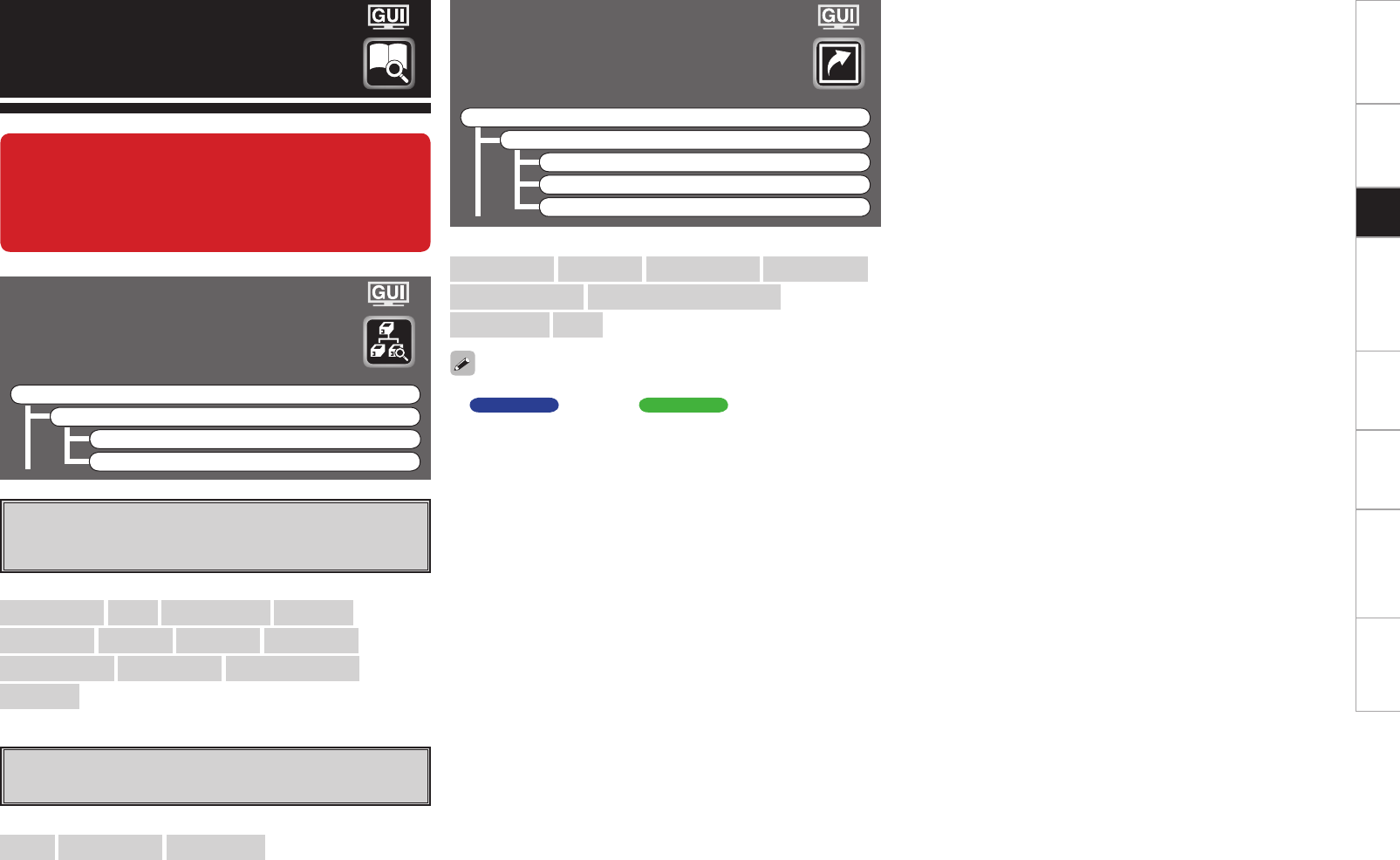
Getting Started Connections Other Operations Multi-Zone Information Troubleshooting SpecificationsSetup
Quick Select
Shows information about “Quick Select” settings.
F Menu tree F
Information
Quick Select
Quick Select 1
Quick Select 2
Quick Select 3
[Items to be checked]
Select Source Input Mode MultEQ® XT 32 Dynamic EQ®
Dynamic Volume® Auto Surround Mode setting
Volume Level Name
For instructions on storing settings at Quick Select 1 to 3, see mpage
65 AVC-A1HD , mpage 67 AVP-A1HD .
Information
a MAIN ZONE
Shows information about settings for MAIN ZONE.
The items displayed differ according to the input source.
s ZONE2/3/4
Shows information about settings for multi-zone.
[Items to be checked]
Select Source Name Surround Mode Rec Select
Video Select i/p Scaler Input Mode Source Level
MultEQ® XT 32 Dynamic EQ® Dynamic Volume®
RESTORER etc.
[Items to be checked]
Power Select Source Volume Level
Status
Shows information about current settings.
F Menu tree F
Information
Status
a MAIN ZONE
s ZONE2/3/4
When this unit is upgraded, the “Status” or
“Quick Select” contents are changed.
To check items related to “Status” or “Quick
Select”, refer to this version of the Owner's
Manual instead of the “Original version”.
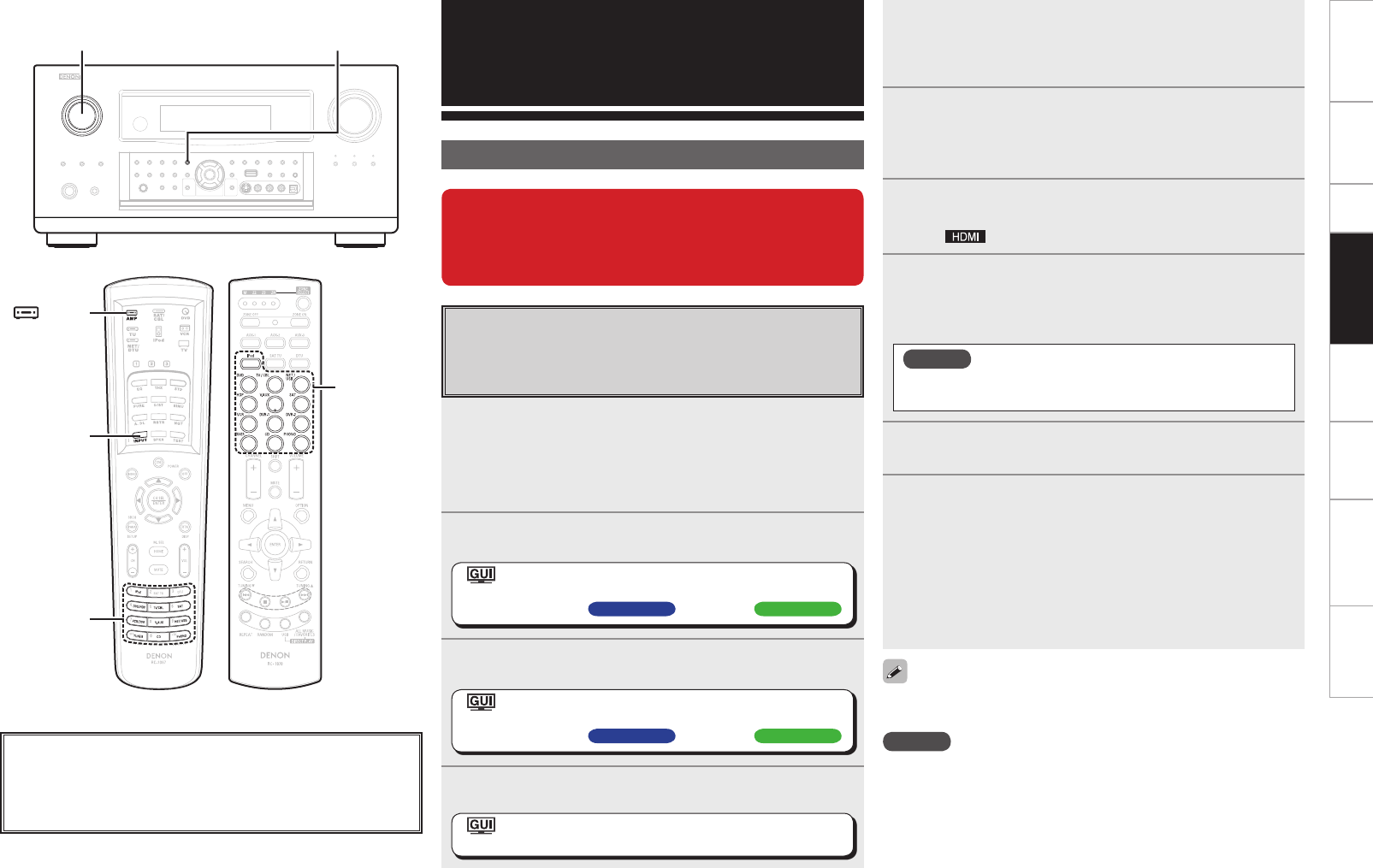
Getting Started Connections Setup Multi-Zone Information Troubleshooting SpecificationsOther Operations
Other Operations and
Functions
Playback of Blu-ray Disc HD audio using
DENON LINK 4th
When playing a Blu-ray Disc, you can enjoy jitter-free playback of
the HD audio.
1Connect this unit to a DENON LINK 4th compatible
Blu-ray Disc player using a DENON LINK cable and
HDMI cable.
b For connection instructions, refer to the respective equipment’s
operating instructions.
2Assign “DENON LINK” to each of the input sources.
: “Source Select” – “(input source)” – “Assign” –
“Digital” – “DENON LINK”
(vmpage 43 AVC-A1HD , mpage 46 AVP-A1HD )
3Assign the HDMI input terminals used to connect the
player to the input source.
: “Source Select” – “(input source)” – “Assign” –
“HDMI” – “1” ~ “6”
(vmpage 43 AVC-A1HD , mpage 45 AVP-A1HD )
4Set the HDMI control function of this unit to “ON”.
: “Manual Setup” – “HDMI Setup” – “HDMI Control”
– “Control” –“ON” (vmpage 31)
Convenient Functions
SOURCE SELECT INPUT MODE
About the button names in these explanations
< > : Buttons on the main unit
[ ] : Buttons on the remote control unit
Button name only:
Buttons on the main unit and remote control unit
When the upgrade is completed, you will be able
to enjoy high quality playback using DENON
LINK 4th, audio signal transmission developed
by DENON.
5Set the DENON LINK settings of the player to “4th”.
b For setting instructions, refer to the player’s operating
instructions.
6Set the HDMI control function of this player to
“On”.
b For setting instructions, refer to the player’s operating
instructions.
7Select the input source assigned in operations 2 and 3
using SOURCE SELECT.
The “ ” indicator lights on the display.
8In INPUT MODE, set the audio input mode to
“Auto”.
b When a Blu-ray Disc is played, it is automatically played back using
DENON LINK 4th.
NOTE
Jitter-free playback can only be used when the audio input
mode is set to “Auto”.
9 Select the surround mode.
10
Play back a Blu-ray Disc.
Playback starts according to the type of input signal and surround
mode.
During jitter-free playback, the DENON LINK CLOCK CONTROL
indicator on the player lights.
b For instructions on the operations, refer to the player’s operating
instructions.
b This display may differ depending on the player. For details, refer to
the player’s operating instructions.
Set the input mode to “Auto”, and all discs other than Blu-ray Discs are
automatically played back using DENON LINK 3rd.
NOTE
• When the input mode is set to “HDMI”, jitter-free playback cannot be
used. Playback is in HDMI.
• When the input mode is set to “Digital”, playback is fixed to the
DENON LINK 3rd mode and Blu-ray Disc audio cannot be played
back.
INPUT
MODE
[ AMP]
SOURCE
SELECT
(Main remote control unit) (Sub remote control unit)
SOURCE
SELECT
Getting Started Connections Setup Other Operations Information Troubleshooting SpecificationsMulti-Zone
Amp Assign / Multi-Zone Connections and Operations AVC-A1HD
This unit is compatible with the following types of playback:
• Multi-zone playback (ZONE2 & ZONE3)
• Bi-amp playback (front speaker)
• Bi-wiring playback (front speaker)
NOTE
• For bi-amp and bi-wiring playback, use speakers compatible with that type of connection.
• When conducting bi-amp or bi-wiring playback, remove the short-circuiting boards (or wires) from the
speaker terminals.
Multi-Zone Settings with the Amp Assign Function
The amp assign function lets you assign the amplifiers for the different channels built into the this unit to
the speaker outputs for the different zones.
Select the desired playback environment from among “Setting 1” to “Setting 16”, then set the corresponding
“Amp Assign” mode at GUI menu “Manual Setup” – “Option Setup” – “Amp Assign” (vpage 28).
Connect the speakers as described at “Speaker connections”.
With “Setting 2” to “Setting 6”, “Setting 8” to “Setting 10”, “Setting 12” and “Setting 13”, it is possible
to switch the Amp Assign mode between the 9.1/7.1-channel mode and the multi-zone mode without
changing the speaker connections.
When the upgrade is performed, “Amp assignment settings” and “Multi-
zone connection method” are returned to the default settings.
When configuring the “Amp Assign/Multi-Zone Connections and Operations”
settings, refer to this version of the Owner's Manual instead of the “Original
version” .
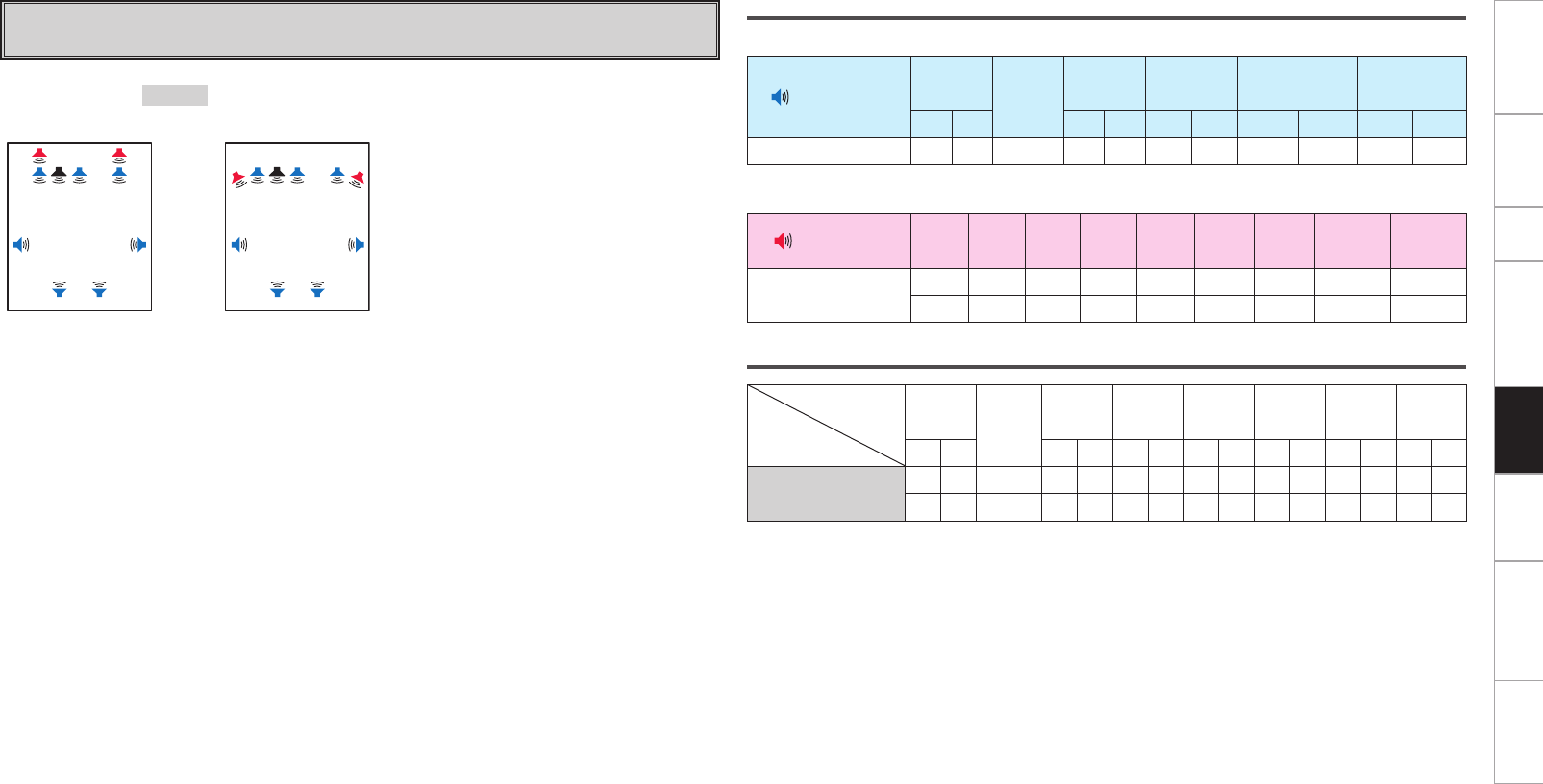
Getting Started Connections Setup Other Operations Information Troubleshooting SpecificationsMulti-Zone
Setting 1:
F 9.1-channel playback
Speaker connections
n Speakers to connect to the speaker terminals
Speaker terminal FRONT CENTER SURR.SURR.BACK AMP ASSIGN FH/FW/
AMP ASSIGN-2
R L R L R L R L R L
Speaker to connect FR FL C SR SL SBR SBL
n Power amps to connect to the pre-out terminals
Pre out terminal FR FL C SR SL SBR SBL FHR/FWR FHL/FWL
Speaker to connect FHR FHL
FWR FWL
Audio output speakers
Speaker
Amp
Assign mode
FRONT CENTER SURR. SURR.
BACK
FRONT
HEIGHT
FRONT
WIDE ZONE2 ZONE3
R L R L R L R L R L R L R L
Normal S S S S S S S S S
S S S S S S S S S
Amp Assign mode :Normal (Settings for upgrade)
MAIN ZONE MAIN ZONE
FL SW
SBL SBR
C FR
FHL FHR
SL SR
z1or
FL SW
SBL SBR
C FR
FWL FWR
SL SR
z2
z1 :
To connect front height speakers, select “Front
Height” in “Manual Setup” – “Option Setup” –
“Amp Assign” – “Extension Channel” settings
(vpage 28
, 29
) in the GUI menu.
z2 :
To connect front wide speakers, select “Front
Wide” in “Manual Setup” – “Option Setup” –
“Amp Assign” – “Extension Channel” settings
(vpage 28
, 29
) in the GUI menu.
GSpeaker abbreviationsH
FL : Front speaker (L) SL : Surround speaker (L) FHL : Front height speaker (L)
FR : Front speaker (R) SR : Surround speaker (R) FHR : Front height speaker (R)
C: Center speaker SBL : Surround back speaker (L) FWL : Front wide speaker (L)
SW : Subwoofer SBR : Surround back speaker (R) FWR : Front wide speaker (R)
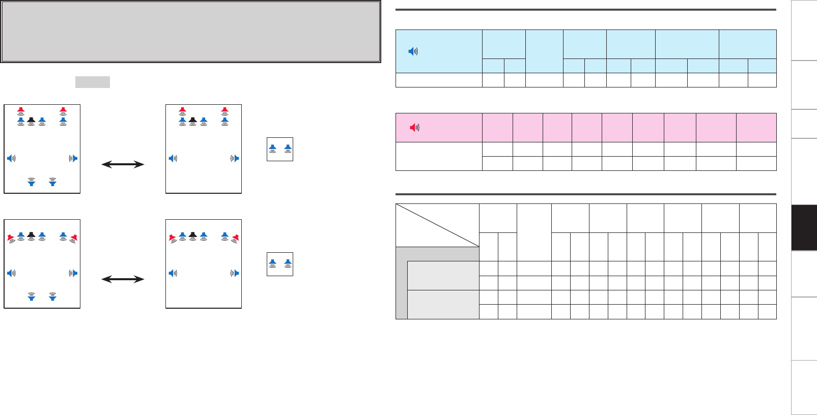
Getting Started Connections Setup Other Operations Information Troubleshooting SpecificationsMulti-Zone
Setting 2:
With this setting it is possible to switch between the following two playback modes.
F 9.1-channel playback
F Multi-zone playback
• 7.1-channel playback + ZONE2 stereo playback
Amp Assign mode :ZONE2
MAIN ZONE MAIN ZONE
FL SW
SBL SBR
C FR
FHL FHR
SL SR
z1
Press ZONE2
ON/OFF button.
FL SW C FR
FHL FHR
SL SR
z1+
ZONE2
Z2L Z2R
ZONE2 ON
MAIN ZONE MAIN ZONE
FL SW
SBL SBR
C FR
FWL FWR
SL SR
z2
Press ZONE2
ON/OFF button.
FL SW C FR
FWL FWR
SL SR
z2+
ZONE2
Z2L Z2R
ZONE2 ON
z1 :
To connect front height speakers, select “Front Height” in “Manual Setup” – “Option Setup” – “Amp
Assign” – “Extension Channel” settings (vpage 28
, 29
) in the GUI menu.
z2 :
To connect front wide speakers, select “Front Wide” in “Manual Setup” – “Option Setup” – “Amp
Assign” – “Extension Channel” settings (vpage 28
, 29
) in the GUI menu.
Speaker connections
n Speakers to connect to the speaker terminals
Speaker terminal FRONT CENTER SURR. SURR.BACK AMP ASSIGN FH/FW/
AMP ASSIGN-2
R L R L R L R L R L
Speaker to connect FR FL C SR SL SBR SBL Z2R Z2L
n Power amps to connect to the pre-out terminals
Pre out terminal FR FL C SR SL SBR SBL FHR/FWR FHL/FWL
Speaker to connect FHR FHL
FWR FWL
Audio output speakers
Speaker
Amp
Assign mode
FRONT
CENTER
SURR. SURR.
BACK
FRONT
HEIGHT
FRONT
WIDE ZONE2 ZONE3
RL RLRLRLRLRLRL
ZONE2
ZONE2 OFF SS S SSSSSS
S S S S S S S S S
ZONE2 ON S S S S S S S S S
S S S S S S S S S

Getting Started Connections Setup Other Operations Information Troubleshooting SpecificationsMulti-Zone
Setting 3:
With this setting it is possible to switch between the following two playback modes.
F 9.1-channel playback
F Multi-zone playback
• 7.1-channel playback + ZONE3 stereo playback
Amp Assign mode :ZONE3
MAIN ZONE MAIN ZONE
FL SW
SBL SBR
C FR
FHL FHR
SL SR
z1
Press ZONE3
ON/OFF button.
FL SW C FR
FHL FHR
SL SR
z1+
ZONE3
Z3L Z3R
ZONE3 ON
MAIN ZONE MAIN ZONE
FL SW
SBL SBR
C FR
FWL FWR
SL SR
z2
Press ZONE3
ON/OFF button.
FL SW C FR
FWL FWR
SL SR
z2+
ZONE3
Z3L Z3R
ZONE3 ON
z1 :
To connect front height speakers, select “Front Height” in “Manual Setup” – “Option Setup” – “Amp
Assign” – “Extension Channel” settings (vpage 28
, 29
) in the GUI menu.
z2 :
To connect front wide speakers, select “Front Wide” in “Manual Setup” – “Option Setup” – “Amp
Assign” – “Extension Channel” settings (vpage 28
, 29
) in the GUI menu.
Speaker connections
n Speakers to connect to the speaker terminals
Speaker terminal FRONT CENTER SURR. SURR.BACK AMP ASSIGN FH/FW/
AMP ASSIGN-2
R L R L R L R L R L
Speaker to connect FR FL C SR SL SBR SBL Z3R Z3L
n Power amps to connect to the pre-out terminals
Pre out terminal FR FL C SR SL SBR SBL FHR/FWR FHL/FWL
Speaker to connect FHR FHL
FWR FWL
Audio output speakers
Speaker
Amp
Assign mode
FRONT
CENTER
SURR. SURR.
BACK
FRONT
HEIGHT
FRONT
WIDE ZONE2 ZONE3
RL RLRLRLRLRLRL
ZONE3
ZONE3 OFF SS S SSSSSS
S S S S S S S S S
ZONE3 ON S S S S S S S S S
S S S S S S S S S

0
Getting Started Connections Setup Other Operations Information Troubleshooting SpecificationsMulti-Zone
Speaker connections
n Speakers to connect to the speaker terminals
Speaker terminal FRONT CENTER SURR. SURR.BACK AMP ASSIGN FH/FW/
AMP ASSIGN-2
R L R L R L R L R L
Speaker to connect FR FL C SR SL SBR SBL Z3
MONO
Z2
MONO
n Power amps to connect to the pre-out terminals
Pre out terminal FR FL C SR SL SBR SBL FHR/FWR FHL/FWL
Speaker to connect FHR FHL
FWR FWL
Audio output speakers
Speaker
Amp
Assign mode
FRONT
CENTER
SURR. SURR.
BACK
FRONT
HEIGHT
FRONT
WIDE ZONE2 ZONE3
R L R L R L R L R L Monaural Monaural
ZONE (MONO)
ZONE2 OFF /
ZONE3 OFF
SS S SSSSSS
SS S SSSS SS
ZONE2 ON /
ZONE3 OFF
S S S S S S S S
S S S S S S S S
ZONE2 OFF /
ZONE3 ON
S S S S S S S S
S S S S S S S S
ZONE2 ON /
ZONE3 ON
S S S S S S S S S
S S S S S S S S S
Setting 4:
With this setting it is possible to switch between the following two playback modes.
F 9.1-channel playback
F Multi-zone playback
• 7.1-channel playback + ZONE2 monaural playback + ZONE3 monaural playback
Amp Assign mode :ZONE (MONO)
MAIN ZONE MAIN ZONE ZONE2 ZONE3
FL SW
SBL SBR
C FR
FHL FHR
SL SR
z1
Press ZONE2
ON/OFF or
ZONE3 ON/OFF
button.
FL SW C FR
FHL FHR
SL SR
z1+
Z2
ZONE2 ON /
ZONE3 OFF
Z3
ZONE2 OFF /
ZONE3 ON
Z2
Z3
ZONE2 ON /
ZONE3 ON
MAIN ZONE MAIN ZONE ZONE2 ZONE3
FL SW
SBL SBR
C FR
FWL FWR
SL SR
z2
Press ZONE2
ON/OFF or
ZONE3 ON/OFF
button.
FL SW C FR
FWL FWR
SL SR
z2+
Z2
ZONE2 ON /
ZONE3 OFF
Z3
ZONE2 OFF /
ZONE3 ON
Z2
Z3
ZONE2 ON /
ZONE3 ON
z1 :
To connect front height speakers, select “Front Height” in “Manual Setup” – “Option Setup” – “Amp
Assign” – “Extension Channel” settings (vpage 28
, 29
) in the GUI menu.
z2 :
To connect front wide speakers, select “Front Wide” in “Manual Setup” – “Option Setup” – “Amp
Assign” – “Extension Channel” settings (vpage 28
, 29
) in the GUI menu.
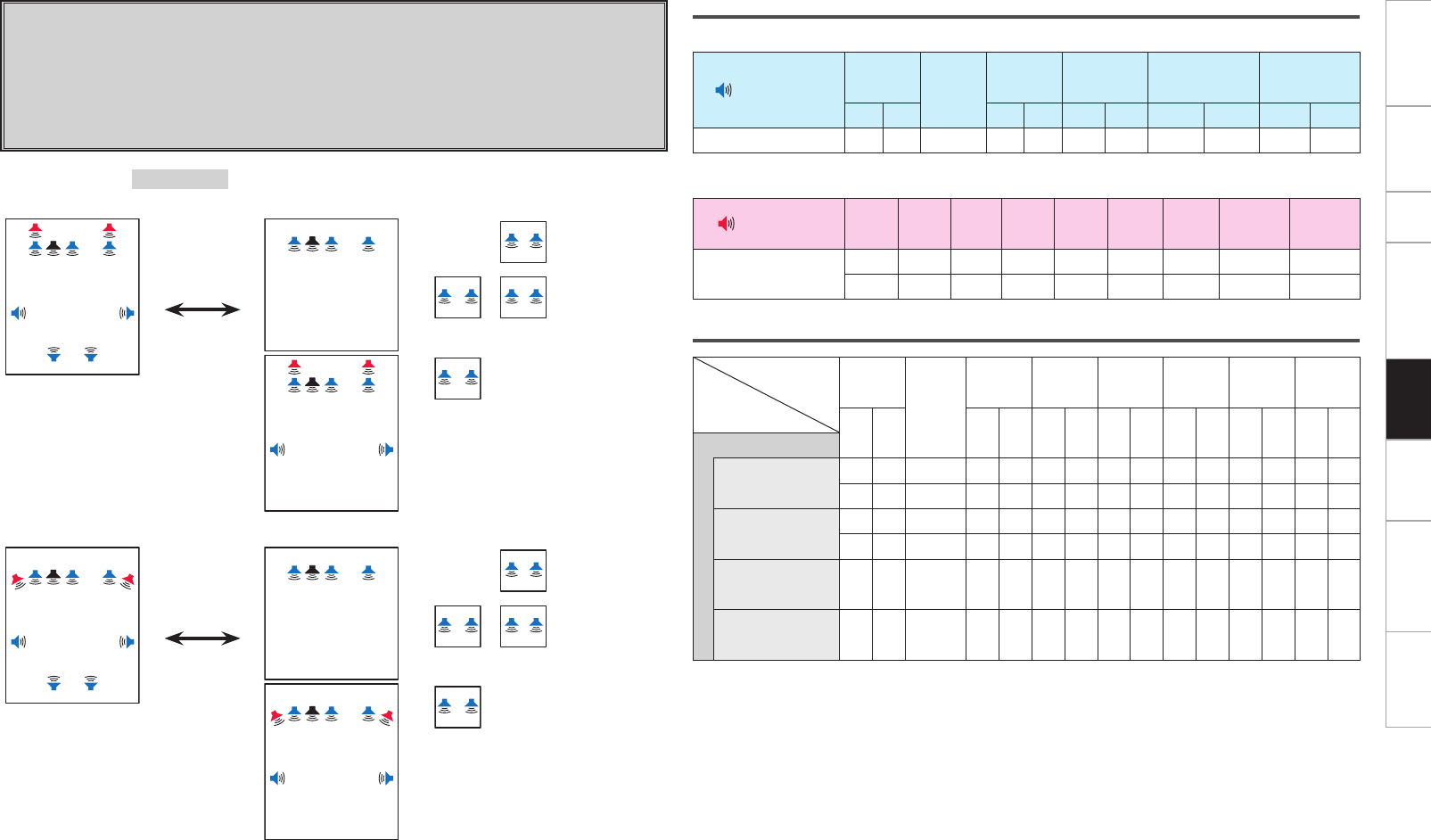
Getting Started Connections Setup Other Operations Information Troubleshooting SpecificationsMulti-Zone
Speaker connections
n Speakers to connect to the speaker terminals
Speaker terminal FRONT CENTER SURR. SURR.BACK AMP ASSIGN FH/FW/
AMP ASSIGN-2
R L R L R L R L R L
Speaker to connect FR FL C SR SL SBR SBL Z3R Z3L Z2R Z2L
n Power amps to connect to the pre-out terminals
Pre out terminal FR FL C SR SL SBR SBL FHR/FWR FHL/FWL
Speaker to connect FHR FHL
FWR FWL
Audio output speakers
Speaker
Amp
Assign mode
FRONT
CENTER
SURR. SURR.
BACK
FRONT
HEIGHT
FRONT
WIDE ZONE2 ZONE3
R L R L R L R L R L R L R L
ZONE2/ZONE3
ZONE2 OFF /
ZONE3 OFF
S S S S S S S S S
S S S S S S S S S
ZONE2 ON /
ZONE3 OFF
S S S S S S S S S
S S S S S S S S S
ZONE2 OFF /
ZONE3 ON S S S S S
ZONE2 ON /
ZONE3 ON S S S S S S S
Setting 5:
With this setting it is possible to switch between the following two playback modes.
F 9.1-channel playback
F Multi-zone playback
• 3.1-channel playback + ZONE2 stereo playback + ZONE3 stereo playback
• 3.1-channel playback + ZONE3 stereo playback
• 7.1-channel playback + ZONE2 stereo playback
Amp Assign mode :ZONE2/ZONE3
MAIN ZONE MAIN ZONE ZONE2 ZONE3
FL SW
SBL SBR
C FR
FHL FHR
SL SR
z1
Press ZONE2
ON/OFF or
ZONE3 ON/OFF
button.
FL SW C FR
+
Z3L Z3R
ZONE2 OFF /
ZONE3 ON
Z2L Z2R
Z3L Z3R
ZONE2 ON /
ZONE3 ON
FL SW C FR
FHL FHR
SL SR
z1
Z2L Z2R
ZONE2 ON /
ZONE3 OFF
MAIN ZONE MAIN ZONE ZONE2 ZONE3
FL SW
SBL SBR
C FR
FWL FWR
SL SR
z2
Press ZONE2
ON/OFF or
ZONE3 ON/OFF
button.
FL SW C FR
+
Z3L Z3R
ZONE2 OFF /
ZONE3 ON
Z2L Z2R
Z3L Z3R
ZONE2 ON /
ZONE3 ON
FL SW C FR
FWL FWR
SL SR
z2
Z2L Z2R
ZONE2 ON /
ZONE3 OFF
z1 :
To connect front height speakers, select “Front Height” in “Manual Setup” – “Option Setup” – “Amp
Assign” – “Extension Channel” settings (vpage 28
, 29
) in the GUI menu.
z2 :
To connect front wide speakers, select “Front Wide” in “Manual Setup” – “Option Setup” – “Amp
Assign” – “Extension Channel” settings (vpage 28
, 29
) in the GUI menu.
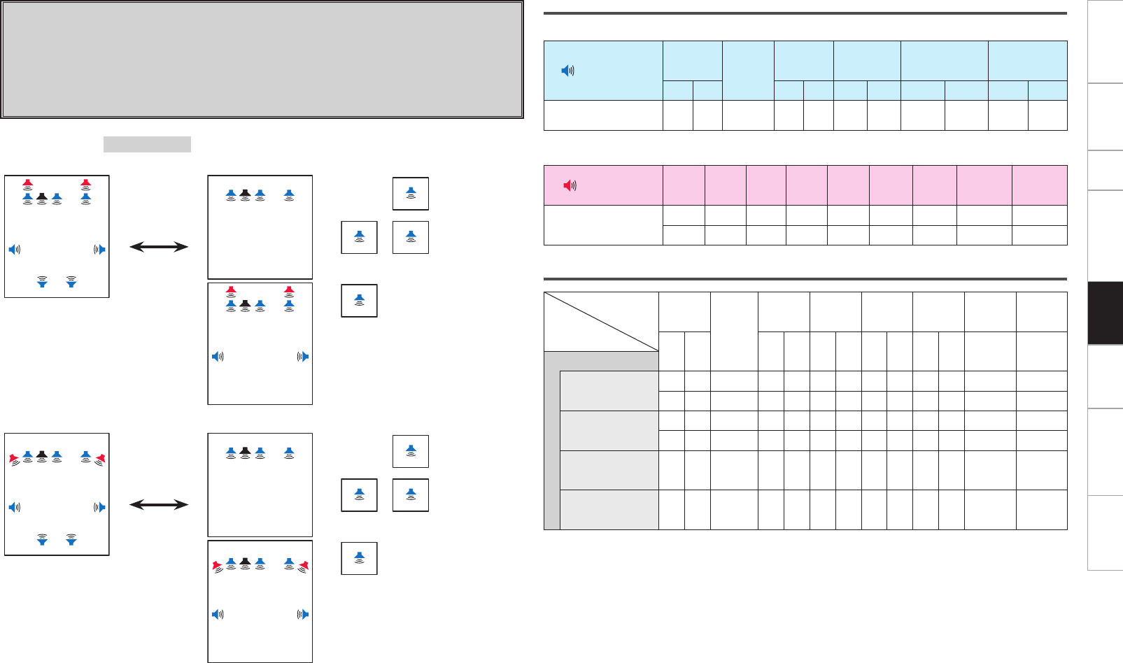
Getting Started Connections Setup Other Operations Information Troubleshooting SpecificationsMulti-Zone
Speaker connections
n Speakers to connect to the speaker terminals
Speaker terminal FRONT CENTER SURR. SURR.BACK AMP ASSIGN FH/FW/
AMP ASSIGN-2
R L R L R L R L R L
Speaker to connect FR FL C SR SL SBR SBL Z3
MONO
Z3
MONO
Z2
MONO
Z2
MONO
n Power amps to connect to the pre-out terminals
Pre out terminal FR FL C SR SL SBR SBL FHR/FWR FHL/FWL
Speaker to connect FHR FHL
FWR FWL
Audio output speakers
Speaker
Amp
Assign mode
FRONT
CENTER
SURR. SURR.
BACK
FRONT
HEIGHT
FRONT
WIDE ZONE2 ZONE3
R L R L R L R L R L Monaural Monaural
ZONE2/3 (MONO)
ZONE2 OFF /
ZONE3 OFF
S S S S S S S S S
S S S S S S S S S
ZONE2 ON /
ZONE3 OFF
S S S S S S S S
S S S S S S S S
ZONE2 OFF /
ZONE3 ON S S S S
ZONE2 ON /
ZONE3 ON S S S S S
Setting 6:
With this setting it is possible to switch between the following two playback modes.
F 9.1-channel playback
F Multi-zone playback
• 3.1-channel playback + ZONE2 monaural playback + ZONE3 monaural playback
• 3.1-channel playback + ZONE3 monaural playback
• 7.1-channel playback + ZONE2 monaural playback
Amp Assign mode :ZONE2/3 (MONO)
MAIN ZONE MAIN ZONE ZONE2 ZONE3
FL SW
SBL SBR
C FR
FHL FHR
SL SR
z1
Press ZONE2
ON/OFF or
ZONE3 ON/OFF
button.
FL SW C FR
+
Z3
ZONE2 OFF /
ZONE3 ON
Z2
Z3
ZONE2 ON /
ZONE3 ON
FL SW C FR
FHL FHR
SL SR
z1
Z2
ZONE2 ON /
ZONE3 OFF
MAIN ZONE MAIN ZONE ZONE2 ZONE3
FL SW
SBL SBR
C FR
FWL FWR
SL SR
z2
Press ZONE2
ON/OFF or
ZONE3 ON/OFF
button.
FL SW C FR
+
Z3
ZONE2 OFF /
ZONE3 ON
Z2
Z3
ZONE2 ON /
ZONE3 ON
FL SW C FR
FWL FWR
SL SR
z2
Z2
ZONE2 ON /
ZONE3 OFF
z1 :
To connect front height speakers, select “Front Height” in “Manual Setup” – “Option Setup” – “Amp
Assign” – “Extension Channel” settings (vpage 28
, 29
) in the GUI menu.
z2 :
To connect front wide speakers, select “Front Wide” in “Manual Setup” – “Option Setup” – “Amp
Assign” – “Extension Channel” settings (vpage 28
, 29
) in the GUI menu.
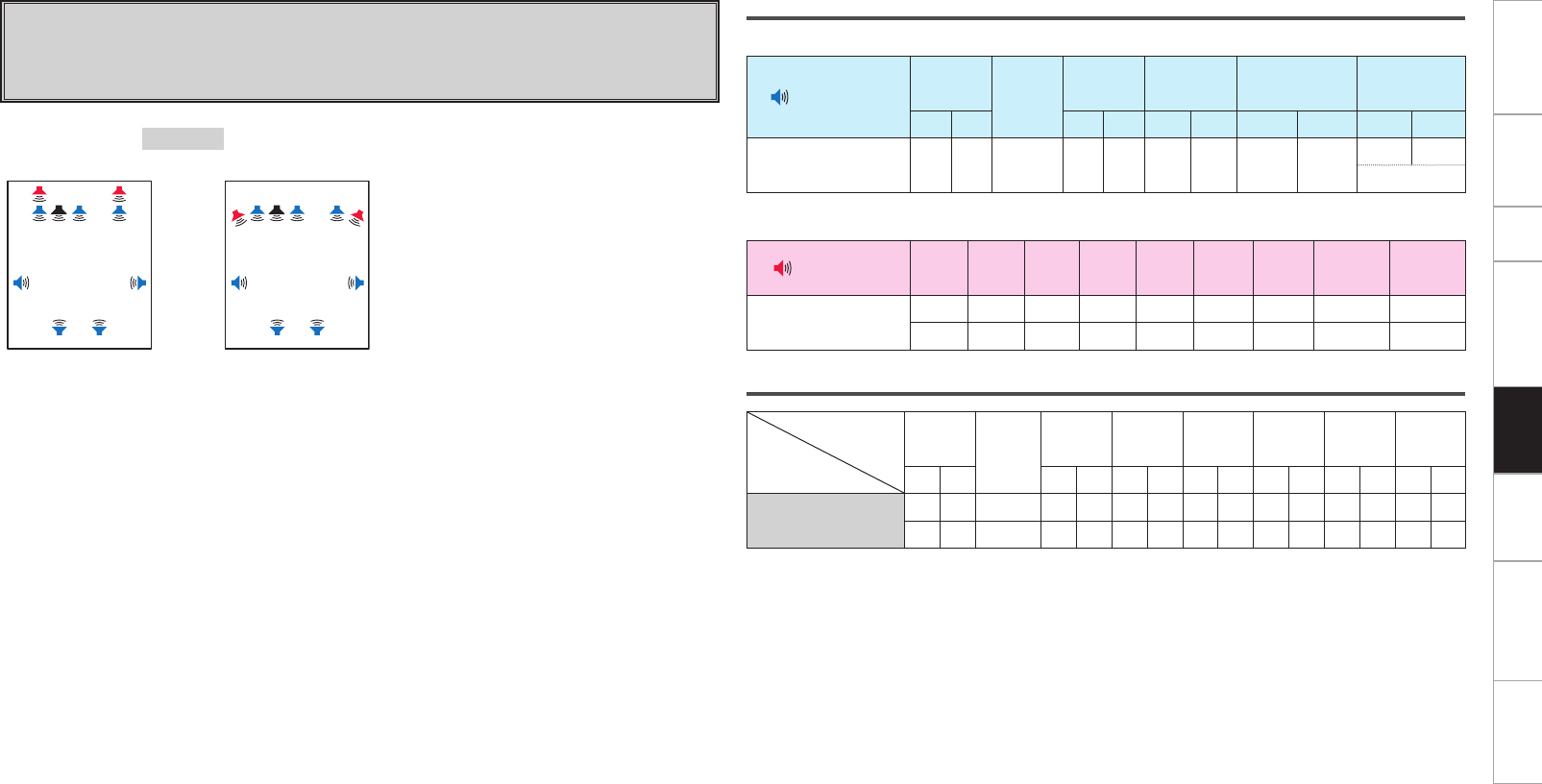
Getting Started Connections Setup Other Operations Information Troubleshooting SpecificationsMulti-Zone
Speaker connections
n Speakers to connect to the speaker terminals
Speaker terminal FRONT CENTER SURR. SURR.BACK AMP ASSIGN FH/FW/
AMP ASSIGN-2
R L R L R L R L R L
Speaker to connect FR FL C SR SL SBR SBL FR FL
Bi-Wiring
n Power amps to connect to the pre-out terminals
Pre out terminal FR FL C SR SL SBR SBL FHR/FWR FHL/FWL
Speaker to connect FHR FHL
FWR FWL
Audio output speakers
Speaker
Amp
Assign mode
FRONT CENTER SURR. SURR.
BACK
FRONT
HEIGHT
FRONT
WIDE ZONE2 ZONE3
R L R L R L R L R L R L R L
Bi-Wiring S S S S S S S S S
S S S S S S S S S
Setting 7:
F Making bi-wiring connections for the FL and FR channels in the MAIN
ZONE and conducting 9.1-channel playback
(switching with other modes not possible)
Amp Assign mode :Bi-Wiring
MAIN ZONE MAIN ZONE
FL SW
SBL SBR
C FR
FHL FHR
SL SR
z1or
FL SW
SBL SBR
C FR
FWL FWR
SL SR
z2
z1 :
To connect front height speakers, select “Front
Height” in “Manual Setup” – “Option Setup” –
“Amp Assign” – “Extension Channel” settings
(vpage 28
, 29
) in the GUI menu.
z2 :
To connect front wide speakers, select “Front
Wide” in “Manual Setup” – “Option Setup” –
“Amp Assign” – “Extension Channel” settings
(vpage 28
, 29
) in the GUI menu.
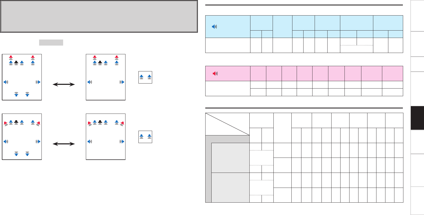
Getting Started Connections Setup Other Operations Information Troubleshooting SpecificationsMulti-Zone
Speaker connections
n Speakers to connect to the speaker terminals
Speaker terminal FRONT CENTER SURR. SURR.BACK AMP ASSIGN FH/FW/
AMP ASSIGN-2
R L R L R L R L R L
Speaker to connect FR FL C SR SL SBR SBL FR FL Z2R Z2L
Bi-Wiring
n Power amps to connect to the pre-out terminals
Pre out terminal FR FL C SR SL SBR SBL FHR/FWR FHL/FWL
Speaker to connect FHR FHL
FWR FWL
Audio output speakers
Speaker
Amp
Assign mode
FRONT
CENTER
SURR. SURR.
BACK
FRONT
HEIGHT
FRONT
WIDE ZONE2 ZONE3
R L R L R L R L R L R L R L
Bi & ZONE2
ZONE2 OFF
S S S S S S S S S
Bi-Wiring
S S S S S S S
S S
ZONE2 ON
S S S S S S S S S
Bi-Wiring
S S S S S S S
S S
Setting 8:
With this setting it is possible to switch between the following two playback modes.
F 9.1-channel playback
F Multi-zone playback
• Bi-wiring connection 7.1 channel playback + ZONE2 stereo playback
Amp Assign mode :Bi & ZONE2
MAIN ZONE MAIN ZONE
FL SW
SBL SBR
C FR
FHL FHR
SL SR
z1
Press ZONE2
ON/OFF button.
FL SW C FR
FHL FHR
SL SR
z1+
ZONE2
Z2L Z2R
ZONE2 ON
MAIN ZONE MAIN ZONE
FL SW
SBL SBR
C FR
FWL FWR
SL SR
z2
Press ZONE2
ON/OFF button.
FL SW C FR
FWL FWR
SL SR
z2+
ZONE2
Z2L Z2R
ZONE2 ON
z1 :
To connect front height speakers, select “Front Height” in “Manual Setup” – “Option Setup” – “Amp
Assign” – “Extension Channel” settings (vpage 28
, 29
) in the GUI menu.
z2 :
To connect front wide speakers, select “Front Wide” in “Manual Setup” – “Option Setup” – “Amp
Assign” – “Extension Channel” settings (vpage 28
, 29
) in the GUI menu.
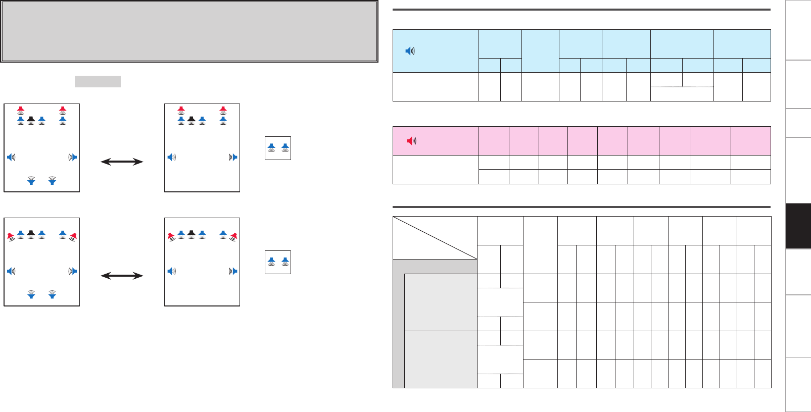
Getting Started Connections Setup Other Operations Information Troubleshooting SpecificationsMulti-Zone
Speaker connections
n Speakers to connect to the speaker terminals
Speaker terminal FRONT CENTER SURR. SURR.BACK AMP ASSIGN FH/FW/
AMP ASSIGN-2
R L R L R L R L R L
Speaker to connect FR FL C SR SL SBR SBL FR FL Z3R Z3L
Bi-Wiring
n Power amps to connect to the pre-out terminals
Pre out terminal FR FL C SR SL SBR SBL FHR/FWR FHL/FWL
Speaker to connect FHR FHL
FWR FWL
Audio output speakers
Speaker
Amp
Assign mode
FRONT
CENTER
SURR. SURR.
BACK
FRONT
HEIGHT
FRONT
WIDE ZONE2 ZONE3
R L R L R L R L R L R L R L
Bi & ZONE3
ZONE3 OFF
S S S S S S S S S
Bi-Wiring
S S S S S S S
S S
ZONE3 ON
S S S S S S S S S
Bi-Wiring
S S S S S S S
S S
Setting 9:
With this setting it is possible to switch between the following two playback modes.
F 9.1-channel playback
F Multi-zone playback
• Bi-wiring connection 7.1 channel playback + ZONE3 stereo playback
Amp Assign mode :Bi & ZONE3
MAIN ZONE MAIN ZONE
FL SW
SBL SBR
C FR
FHL FHR
SL SR
z1
Press ZONE3
ON/OFF button.
FL SW C FR
FHL FHR
SL SR
z1+
ZONE3
Z3L Z3R
ZONE3 ON
MAIN ZONE MAIN ZONE
FL SW
SBL SBR
C FR
FWL FWR
SL SR
z2
Press ZONE3
ON/OFF button.
FL SW C FR
FWL FWR
SL SR
z2+
ZONE3
Z3L Z3R
ZONE3 ON
z1 :
To connect front height speakers, select “Front Height” in “Manual Setup” – “Option Setup” – “Amp
Assign” – “Extension Channel” settings (vpage 28
, 29
) in the GUI menu.
z2 :
To connect front wide speakers, select “Front Wide” in “Manual Setup” – “Option Setup” – “Amp
Assign” – “Extension Channel” settings (vpage 28
, 29
) in the GUI menu.
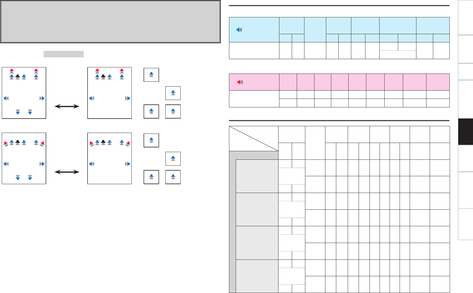
Getting Started Connections Setup Other Operations Information Troubleshooting SpecificationsMulti-Zone
Speaker connections
n Speakers to connect to the speaker terminals
Speaker terminal FRONT CENTER SURR. SURR.BACK AMP ASSIGN FH/FW/
AMP ASSIGN-2
R L R L R L R L R L
Speaker to connect FR FL C SR SL SBR SBL FR FL Z3
MONO
Z2
MONO
Bi-Wiring
n Power amps to connect to the pre-out terminals
Pre out terminal FR FL C SR SL SBR SBL FHR/FWR FHL/FWL
Speaker to connect FHR FHL
FWR FWL
Audio output speakers
Speaker
Amp
Assign mode
FRONT
CENTER
SURR. SURR.
BACK
FRONT
HEIGHT
FRONT
WIDE ZONE2 ZONE3
R L R L R L R L R L Monaural Monaural
Bi & ZONE (MONO)
ZONE2 OFF /
ZONE3 OFF
S S S S S S S S S
Bi-Wiring
S S S S S S S
S S
ZONE2 ON /
ZONE3 OFF
S S S S S S S S
Bi-Wiring
S S S S S S
S S
ZONE2 OFF /
ZONE3 ON
S S S S S S S S
Bi-Wiring
S S S S S S
S S
ZONE2 ON /
ZONE3 ON
S S S S S S S S S
Bi-Wiring
S S S S S S S
S S
Amp Assign mode :Bi & ZONE (MONO)
MAIN ZONE MAIN ZONE ZONE2 ZONE3
FL SW
SBL SBR
C FR
FHL FHR
SL SR
z1
Press ZONE2
ON/OFF or
ZONE3 ON/OFF
button.
FL SW C FR
FHL FHR
SL SR
z1+
Z2
ZONE2 ON /
ZONE3 OFF
Z3
ZONE2 OFF /
ZONE3 ON
Z2
Z3
ZONE2 ON /
ZONE3 ON
MAIN ZONE MAIN ZONE ZONE2 ZONE3
FL SW
SBL SBR
C FR
FWL FWR
SL SR
z2
Press ZONE2
ON/OFF or
ZONE3 ON/OFF
button.
FL SW C FR
FWL FWR
SL SR
z2+
Z2
ZONE2 ON /
ZONE3 OFF
Z3
ZONE2 OFF /
ZONE3 ON
Z2
Z3
ZONE2 ON /
ZONE3 ON
z1 :
To connect front height speakers, select “Front Height” in “Manual Setup” – “Option Setup” – “Amp
Assign” – “Extension Channel” settings (vpage 28
, 29
) in the GUI menu.
z2 :
To connect front wide speakers, select “Front Wide” in “Manual Setup” – “Option Setup” – “Amp
Assign” – “Extension Channel” settings (vpage 28
, 29
) in the GUI menu.
Setting 10:
With this setting it is possible to switch between the following two playback modes.
F 9.1-channel playback
F Multi-zone playback
• 7.1-channel playback + ZONE2 monaural playback + ZONE3 monaural playback with bi-wiring
connections
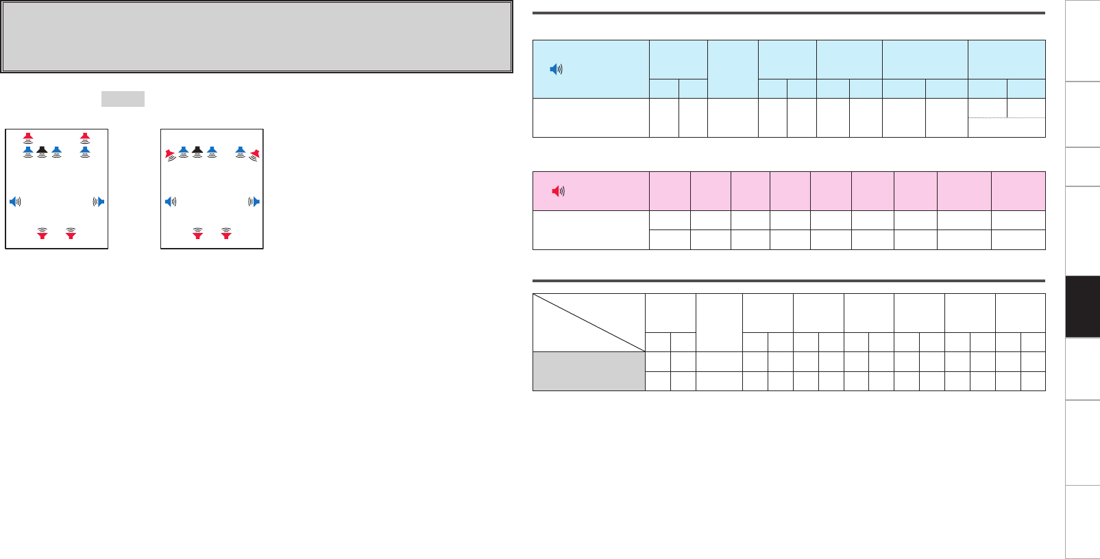
Getting Started Connections Setup Other Operations Information Troubleshooting SpecificationsMulti-Zone
Speaker connections
n Speakers to connect to the speaker terminals
Speaker terminal FRONT CENTER SURR. SURR.BACK AMP ASSIGN FH/FW/
AMP ASSIGN-2
R L R L R L R L R L
Speaker to connect FR FL C SR SL FR FL
Bi-Amp
n Power amps to connect to the pre-out terminals
Pre out terminal FR FL C SR SL SBR SBL FHR/FWR FHL/FWL
Speaker to connect SBR SBL FHR FHL
SBR SBL FWR FWL
Audio output speakers
Speaker
Amp
Assign mode
FRONT CENTER SURR. SURR.
BACK
FRONT
HEIGHT
FRONT
WIDE ZONE2 ZONE3
R L R L R L R L R L R L R L
Bi-Amp S S S S S S S S S
S S S S S S S S S
Setting 11:
F Making bi-amp connections for the FL and FR channels in the MAIN
ZONE and conducting 9.1-channel playback
(switching with other modes not possible)
Amp Assign mode :Bi-Amp
MAIN ZONE MAIN ZONE
FL SW
SBL SBR
C FR
FHL FHR
SL SR
z1or
FL SW
SBL SBR
C FR
FWL FWR
SL SR
z2
z1 :
To connect front height speakers, select “Front
Height” in “Manual Setup” – “Option Setup” –
“Amp Assign” – “Extension Channel” settings
(vpage 28
, 29
) in the GUI menu.
z2 :
To connect front wide speakers, select “Front
Wide” in “Manual Setup” – “Option Setup” –
“Amp Assign” – “Extension Channel” settings
(vpage 28
, 29
) in the GUI menu.
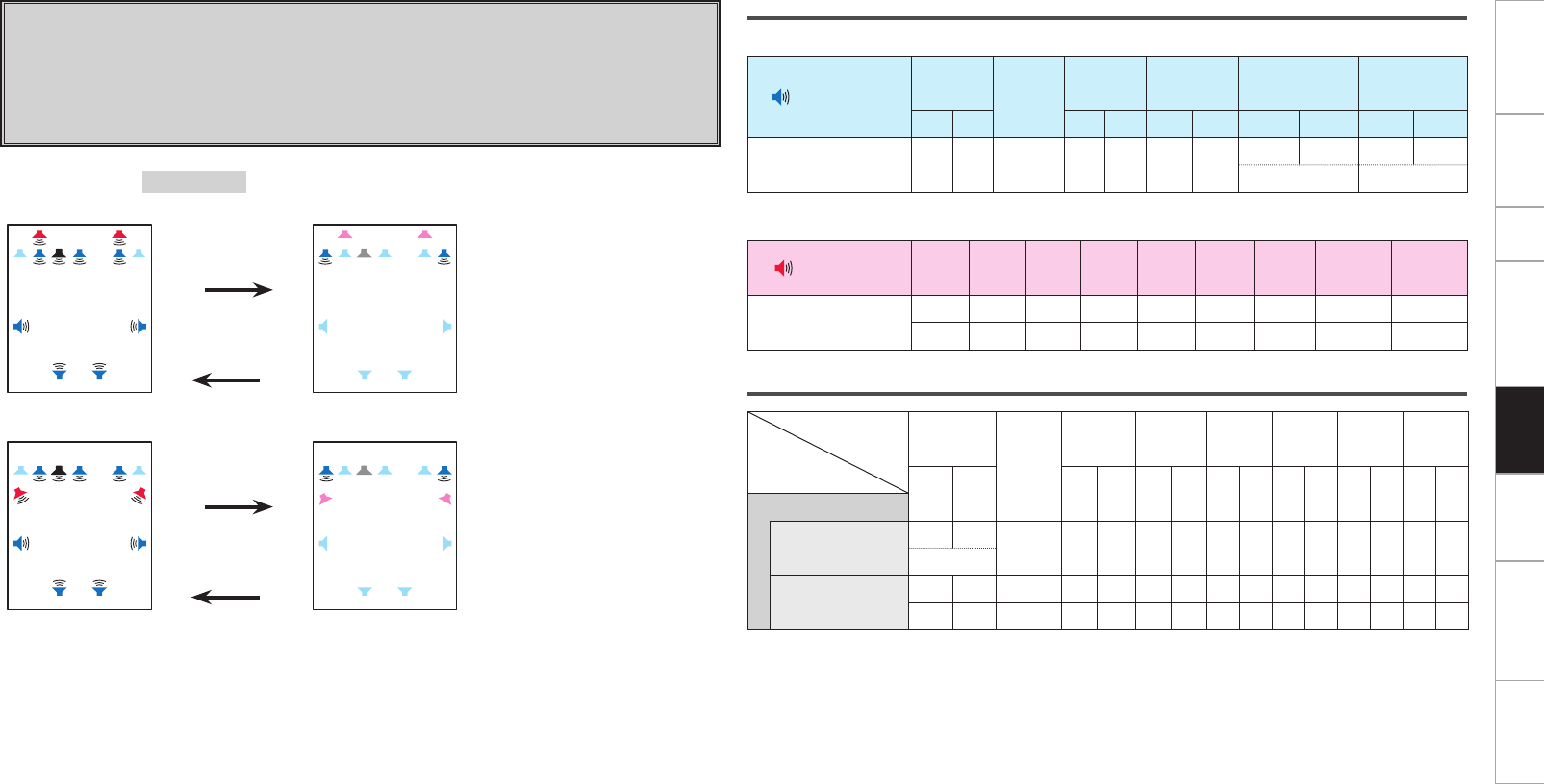
Getting Started Connections Setup Other Operations Information Troubleshooting SpecificationsMulti-Zone
Setting 12:
With this setting it is possible to switch between the following two playback modes.
F 9.1-channel playback
F Switching between bi-wiring playback using speakers exclusively for 2-
channel playback
Switching ················Surround Mode switching
Speaker connections
n Speakers to connect to the speaker terminals
Speaker terminal FRONT CENTER SURR. SURR.BACK AMP ASSIGN FH/FW/
AMP ASSIGN-2
R L R L R L R L R L
Speaker to connect FR FL C SR SL SBR SBL FR FL FR FL
Bi-Wiring Bi-Wiring
n Power amps to connect to the pre-out terminals
Pre out terminal FR FL C SR SL SBR SBL FHR/FWR FHL/FWL
Speaker to connect FHR FHL
FWR FWL
Audio output speakers
Speaker
Amp
Assign mode
FRONT
CENTER
SURR. SURR.
BACK
FRONT
HEIGHT
FRONT
WIDE ZONE2 ZONE3
R L R L R L R L R L R L R L
2CH Bi-Wiring
For 2-channel playback S S
Bi-Wiring
For multi channel
playback
S S S S S S S S S
S S S S S S S S S
Amp Assign mode :2CH Bi-Wiring
MAIN ZONE MAIN ZONE
FL SW
SBL SBR
C FR FR
FHL FHR
FL
SL SR
z1
Press DIRECT/
STEREO button.
Press STANDARD
button.
FL
FL SW
SBL SBR
C FR FR
FHL FHR
SL SR
z1
MAIN ZONE MAIN ZONE
FL SW
SBL SBR
C FR
FRFL
FWL FWR
SL SR
z2
Press DIRECT/
STEREO button.
Press STANDARD
button.
FL SW
SBL SBR
C FR FRFL
FWL FWR
SL SR
z2
z1 :
To connect front height speakers, select “Front Height” in “Manual Setup” – “Option Setup” – “Amp
Assign” – “Extension Channel” settings (vpage 28
, 29
) in the GUI menu.
z2 :
To connect front wide speakers, select “Front Wide” in “Manual Setup” – “Option Setup” – “Amp
Assign” – “Extension Channel” settings (vpage 28
, 29
) in the GUI menu.
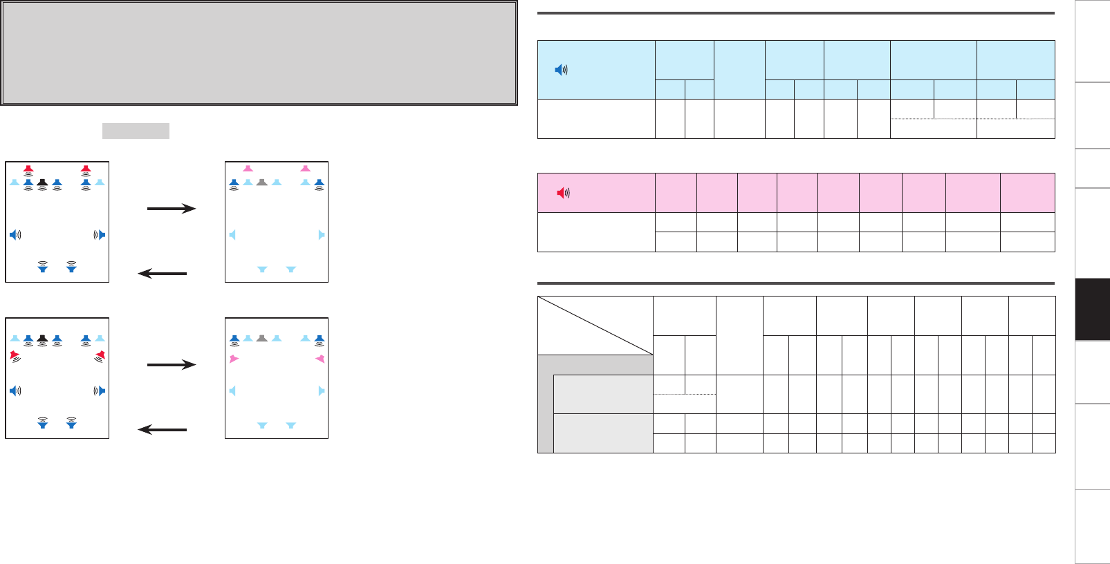
Getting Started Connections Setup Other Operations Information Troubleshooting SpecificationsMulti-Zone
Speaker connections
n Speakers to connect to the speaker terminals
Speaker terminal FRONT CENTER SURR. SURR.BACK AMP ASSIGN FH/FW/
AMP ASSIGN-2
R L R L R L R L R L
Speaker to connect FR FL C SR SL SBR SBL FR FL FR FL
Bi-Amp Bi-Amp
n Power amps to connect to the pre-out terminals
Pre out terminal FR FL C SR SL SBR SBL FHR/FWR FHL/FWL
Speaker to connect FHR FHL
FWR FWL
Audio output speakers
Speaker
Amp
Assign mode
FRONT
CENTER
SURR. SURR.
BACK
FRONT
HEIGHT
FRONT
WIDE ZONE2 ZONE3
R L R L R L R L R L R L R L
2ch Bi-Amp
For 2-channel playback S S
Bi-Amp
For multi channel
playback
S S S S S S S S S
S S S S S S S S S
Setting 13:
With this setting it is possible to switch between the following two playback modes.
F 9.1-channel playback
F Switching between bi-amp playback using speakers exclusively for 2-
channel playback
Switching ················Surround Mode switching
Amp Assign mode :2ch Bi-Amp
MAIN ZONE MAIN ZONE
FL SW
SBL SBR
C FR FR
FHL FHR
FL
SL SR
z1
Press DIRECT/
STEREO button.
Press STANDARD
button.
FL
FL SW
SBL SBR
C FR FR
FHL FHR
SL SR
z1
MAIN ZONE MAIN ZONE
FL SW
SBL SBR
C FR
FRFL
FWL FWR
SL SR
z2
Press DIRECT/
STEREO button.
Press STANDARD
button.
FL SW
SBL SBR
C FR FRFL
FWL FWR
SL SR
z2
z1 :
To connect front height speakers, select “Front Height” in “Manual Setup” – “Option Setup” – “Amp
Assign” – “Extension Channel” settings (vpage 28
, 29
) in the GUI menu.
z2 :
To connect front wide speakers, select “Front Wide” in “Manual Setup” – “Option Setup” – “Amp
Assign” – “Extension Channel” settings (vpage 28
, 29
) in the GUI menu.
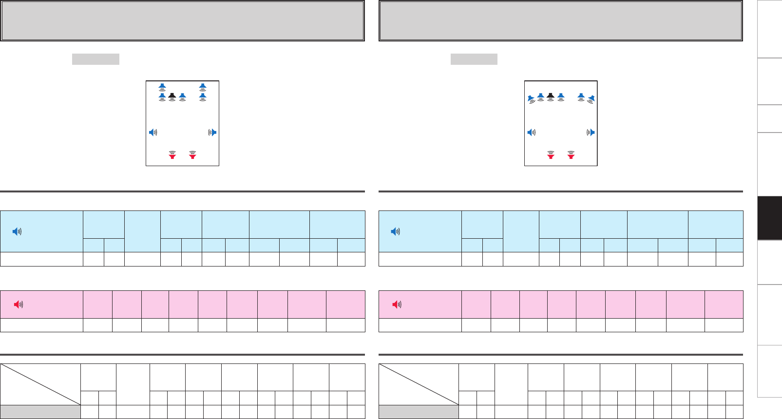
0
Getting Started Connections Setup Other Operations Information Troubleshooting SpecificationsMulti-Zone
Setting 14:
F 9.1 channel playback when front height speakers are connected to the
speaker terminals of this unit
Speaker connections
n Speakers to connect to the speaker terminals
Speaker terminal FRONT CENTER SURR. SURR.BACK AMP ASSIGN FH/FW/
AMP ASSIGN-2
R L R L R L R L R L
Speaker to connect FR FL C SR SL FHR FHL
n Power amps to connect to the pre-out terminals
Pre out terminal FR FL C SR SL SBR SBL FHR/FWR FHL/FWL
Speaker to connect SBR SBL
Audio output speakers
Speaker
Amp
Assign mode
FRONT CENTER SURR. SURR.
BACK
FRONT
HEIGHT
FRONT
WIDE ZONE2 ZONE3
RL RLRLRLRLRLRL
Front Height S S S S S S S S S
Amp Assign mode :Front Height
MAIN ZONE
FL SW
SBL SBR
C FR
FHL FHR
SL SR
Setting 15:
F 9.1 channel playback when front wide speakers are connected to the
speaker terminals of this unit
Speaker connections
n Speakers to connect to the speaker terminals
Speaker terminal FRONT CENTER SURR. SURR.BACK AMP ASSIGN FH/FW/
AMP ASSIGN-2
R L R L R L R L R L
Speaker to connect FR FL C SR SL FWR FWL
n Power amps to connect to the pre-out terminals
Pre out terminal FR FL C SR SL SBR SBL FHR/FWR FHL/FWL
Speaker to connect SBR SBL
Audio output speakers
Speaker
Amp
Assign mode
FRONT CENTER SURR. SURR.
BACK
FRONT
HEIGHT
FRONT
WIDE ZONE2 ZONE3
R L R L R L R L R L R L R L
Front Wide S S S S S S S S S
Amp Assign mode :Front Wide
MAIN ZONE
FL SW
SBL SBR
C FR
FWL FWR
SL SR
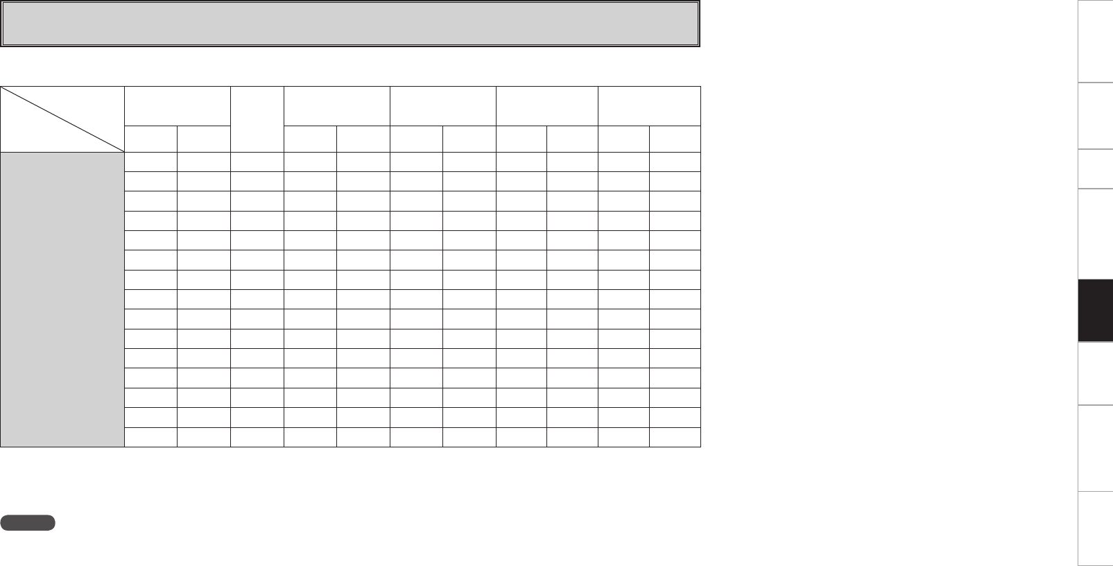
Getting Started Connections Setup Other Operations Information Troubleshooting SpecificationsMulti-Zone
Setting 16:
F Free assign
n Amp Assign mode setting and speakers connected to the various speaker terminals
z1 :
Displayed when “Front Height” is selected in “Manual Setup” – “Option Setup” – “Amp Assign” – “Extension Channel” settings (vpage 28
,
29
) in the GUI menu.
z2 :
Displayed when “Front Wide” is selected in “Manual Setup” – “Option Setup” – “Amp Assign” – “Extension Channel” settings (vpage 28
,
29
) in the GUI menu.
Speaker terminal
Amp Assign
mode
FRONT
CENTER
SURR. SURR.BACK AMP ASSIGN FH/FW/
AMP ASSIGN-2
R L R L R L R L R L
Free Assign
FL FL FL FL FL FL FL
FR FR FR FR FR FR FR
CCCCCCC
SL SL SL SL SL SL SL
SR SR SR SR SR SR SR
SBL SBL SBL SBL SBL SBL SBL
SBR SBR SBR SBR SBR SBR SBR
FHLz1 FHLz1 FHLz1 FHLz1 FHLz1 FHLz1 FHLz1
FHRz1 FHRz1 FHRz1 FHRz1 FHRz1 FHRz1 FHRz1
FWLz2 FWLz2 FWLz2 FWLz2 FWLz2 FWLz2 FWLz2
FWRz2 FWRz2 FWRz2 FWRz2 FWRz2 FWRz2 FWRz2
Z2L Z2L Z2L Z2L Z2L Z2L Z2L
Z2R Z2R Z2R Z2R Z2R Z2R Z2R
Z3L Z3L Z3L Z3L Z3L Z3L Z3L
Z3R Z3R Z3R Z3R Z3R Z3R Z3R
NOTE
The above is an example of the selectable channels when “Stereo” is set for the ZONE2 and ZONE3 channel setting.
If “Mono” is selected, “Z2 (MONO)” and “Z3 (MONO)” are displayed.
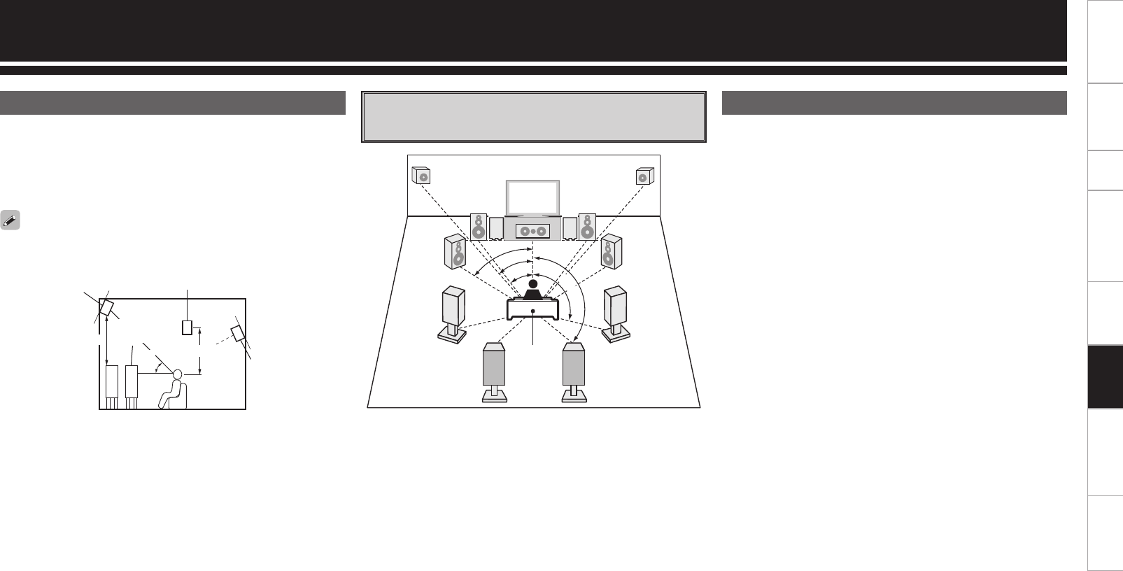
Getting Started Connections Setup Other Operations Multi-Zone Troubleshooting SpecificationsInformation
This unit is compatible with Audyssey DSX™ (vpage 63), Dolby
Pro Logic gz (vpage 63) and DTS NEO:X (vpage 63), which
offers an even wider and deeper surround sensation.
When using Audyssey DSX™, install front wide speakers or front
height speakers.
When using Dolby Pro Logic gz, install front height speakers.
Other Information
About Speaker Installation When surround back/front height/front
wide speakers are installed DENON LINK 4th adds high-quality playback of HD audio in addition to
the outstanding performance of DENON LINK 3rd, high quality audio
signal transmission technology developed by DENON.
By connecting an AV amp and Blu-ray Disc player that both support
DENON LINK 4th with a DENON LINK cable (supplied with the Blu-ray
Disc player) and HDMI cable (sold separately), you can control the Blu-
ray Disc player using the master clock signal sent from the AV amp.
As D/A conversion is performed by the AV amp master clock, there
are no effects of clock jitter from the HDMI transfer, enabling jitter
free playback. Sound localization becomes clearer, producing the clear
sense of space in the sound images that can only be achieved from
HD audio.
z1 : Recommended for Dolby Pro Logic gz
z2 : Recommended for Audussey DSX™
z1
z2
45˚
Front wide
speaker
At least 1 m
Surround speaker
Front
speaker
Surround back
speaker
• Point slightly
downwards
GAs seen from the sideH
60 ~ 90 cm
Front height
speaker
• Point slightly
downwards
Install the surround back speakers in a position 60 to 90 cm higher
than ear level.
About DENON LINK 4th
GSpeaker abbreviationsH
FL : Front speaker (L) SBL : Surround back speaker (L)
FR : Front speaker (R) SBR : Surround back speaker (R)
C: Center speaker FHL : Front height speaker (L)
SW : Subwoofer FHR : Front height speaker (R)
SL : Surround speaker (L) FWL : Front wide speaker (L)
SR : Surround speaker (R) FWR : Front wide speaker (R)
FHRFHL
FL FR
SL SR
FWL FWR
SW
1
SW
2
C
SBL SBR
z1
z2
z3
z5
z4
Listening
position
z1 22° ~ 30° z2 22° ~ 45° z3 55° ~ 60°
z4 90° ~ 110° z5 135° ~ 150°
Getting Started Connections Setup Other Operations Multi-Zone Troubleshooting SpecificationsInformation
Dolby Pro Logic gz
This mode can be selected when a Dolby Pro Logic gz decoder is
used to play back 2-channel source in 7.1-channel surround sound with
added front height channel.
By adding a front height channel, the vertical expression is emphasized,
improving the three-dimensionality of the sound.
Surround
Dolby Surround
This unit is equipped with a digital signal processing circuit that lets
you play program sources in the surround mode to achieve the same
sense of presence as in a movie theater.
Manufactured under license from Dolby Laboratories.
“Dolby”, “Pro Logic” and the double-D symbol are trademarks of
Dolby Laboratories.
DTS Surround
DTS NEO:X™ Surround
This matrix decoding technology uses the DTS NEO:X decoder to
playback 2-channel source or 5.1/6.1/7.1 channel surround sources as
a maximum of 11.1 channel surround sound.
There are 3 modes: “Music” suited for playing music, “Cinema”
suited for playing movies, and “Game” which is optimized for playing
games.
Manufactured under license under U.S. Patent No’s: 5,956,674;
5,974,380; 5,978,762; 6,487,535; 6,226,616; 7,212,872; 7,003,467;
7,272,567; 7,668,723; 7,392,195; 7,930,184; 7,333,929; 7,548,853;
7,283,634 & other U.S. and worldwide patents issued and
pending. DTS-HD, the Symbol, & DTS-HD and the Symbol
together are registered trademarks & DTS-HD Master Audio is a
trademark of DTS, Inc. Product includes software. ©DTS, Inc. All
Rights Reserved.
Audyssey
Audyssey Dynamic EQ®
Dynamic EQ® solves the problem of deteriorating sound quality as
volume is decreased by taking into account human perception and
room acoustics. Audyssey Dynamic EQ® works in tandem with
Audyssey MultEQ® XT 32 to provide well-balanced sound for every
listener at any volume level.
Audyssey Dynamic Volume®
Dynamic Volume® solves the problem of large variations in volume
level between television programs, commercials, and between the soft
and loud passages of movies. Audyssey Dynamic EQ® is integrated
into Dynamic Volume® so that as the playback volume is adjusted
automatically, the perceived bass response, tonal balance, surround
impression, and dialog clarity remain the same.
Audyssey MultEQ® XT 32
MultEQ® XT 32 is a room equalization solution that calibrates any
audio system so that it can achieve optimum performance for every
listener in a large listening area. Based on several room measurements,
MultEQ® XT 32 calculates an equalization solution that corrects for
both time and frequency response problems in the listening area and
also performs a fully automated surround system setup.
Audyssey Dynamic Surround Expansion™
(Audyssey DSX™)
Audyssey DSX™ is a scalable system that adds new speakers to
improve surround impression. Audyssey DSX™ first adds Wide
channels for the biggest impact on envelopment and then creates
Height channels to reproduce the next most important acoustical
and perceptual cues. Surround Envelopment Processing is used to
enhance the blend between the front and surround channels.
Manufactured under license from Audyssey Laboratories™.
U.S. and foreign patents pending. Audyssey MultEQ® XT 32
is a registered trademark of Audyssey Laboratories. Audyssey
Dynamic EQ® is a registered trademark of Audyssey Laboratories.
Audyssey Dynamic Volume® is a registered trademark of
Audyssey Laboratories. Audyssey DSX™ is a trademark of
Audyssey Laboratories.
For more information, visit www.audyssey.com.
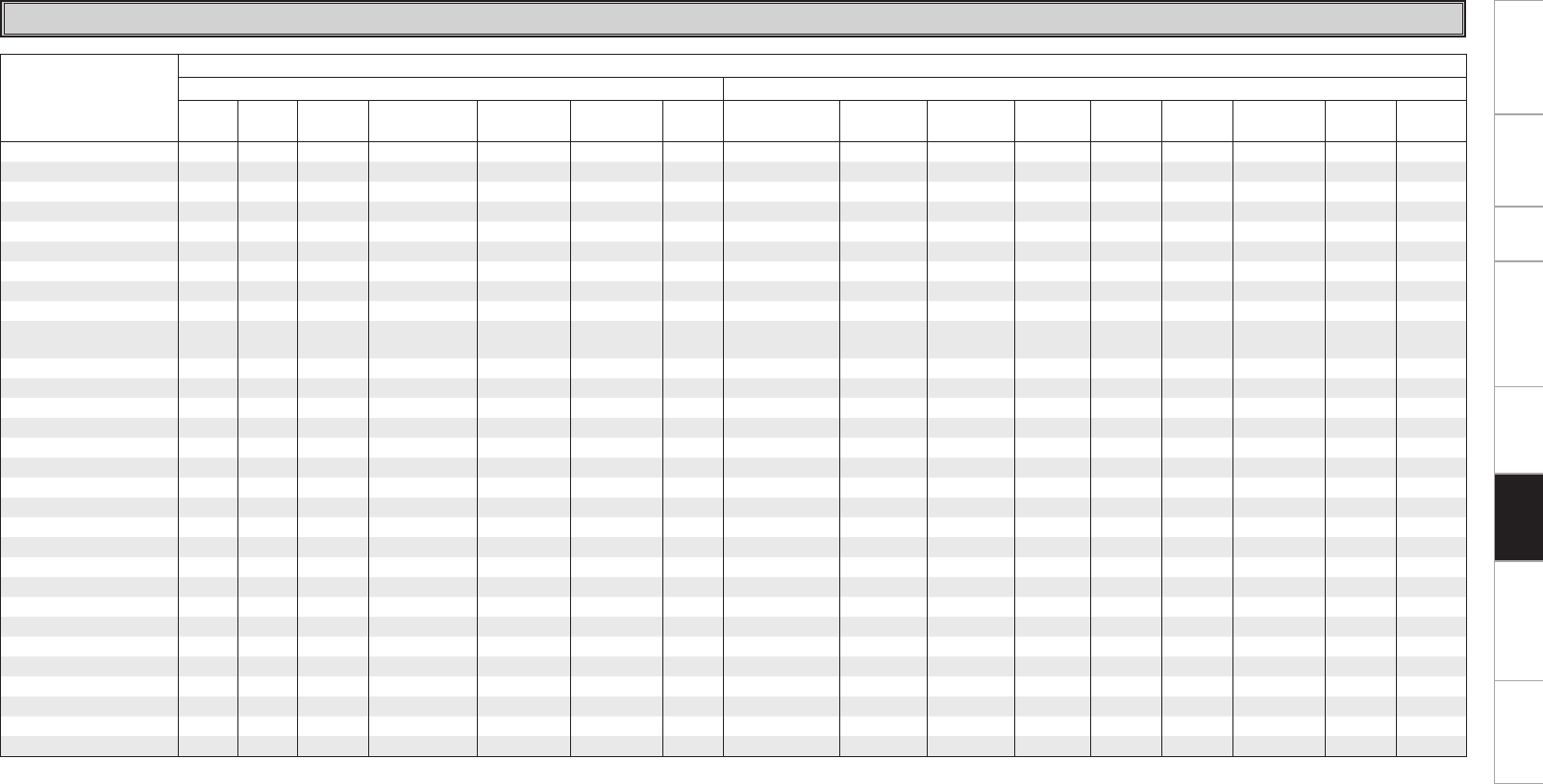
Getting Started Connections Setup Other Operations Multi-Zone Troubleshooting SpecificationsInformation
S : Signal / Adjustable
D : Turned on or off by speaker configuration setting
z1 : When playing Dolby Digital and DTS signals.
z2 : When playing Dolby TrueHD signal.
z3 : When playing Dolby Digital, DTS, DVD-Audio and Super Audio CD.
z4 : When playing Dolby Digital signals.
Surround Modes and Parameters
Surround mode
Signals and adjustability in the different modes
Channel output Parameters (default values are shown in parentheses)
Front
L/R Center Surround
L/R
Surround back
L/R
Front height
L/R
Front wide
L/R
Subwoofer
D. COMP
z1
DRC
z2
LFE
z3
AFDM
z4SB CH Out Cinema EQ. Mode Decoder Room Size
PURE DIRECT, DIRECT (2ch) S D S (OFF) S (Auto)
PURE DIRECT, DIRECT (5.1ch) S D D D D D D S (OFF) S (Auto) S (0dB)
DSD DIRECT S
DSD MULTI DIRECT S D D D S (0dB)
MULTI CH DIRECT S D D D D D D S (OFF) S (Auto) S (0dB)
STEREO S D S (OFF) S (Auto) S (0dB)
EXT. IN S D D D D
MULTI CH IN S D D D D D D S (0dB) S S (NOTE3) S (NOTE4)
WIDE SCREEN S D D D D D D S (OFF) S (Auto) S (0dB) S (OFF)
HOME THX CINEMA (2ch) S D D D D D S
(PLgx CINEMA) S
HOME THX CINEMA (5.1ch) S D D D D D D S (0dB) S (ON) S
DOLBY PRO LOGIC gxS D D D D S (OFF) S (Auto) S S (NOTE1) S (Cinema)
DOLBY PRO LOGIC g S D D D S (OFF) S (Auto) S S (NOTE2) S (Cinema)
DOLBY PRO LOGIC gzS D D D D D S (OFF) S (Auto) S
DTS NEO:X S D D D D D D S (OFF) S (Auto) S (NOTE1) S
DOLBY DIGITAL S D D D D D D S (OFF) S (0dB) S (ON) S S (NOTE3) S (NOTE4)
DOLBY DIGITAL Plus S D D D D D D S (OFF) S (0dB) S (ON) S S (NOTE3) S (NOTE4)
DOLBY TrueHD S D D D D D D S (Auto) S (0dB) S (ON) S S (NOTE3) S (NOTE4)
DTS SURROUND S D D D D D D S (OFF) S (0dB) S S (NOTE3) S (NOTE4)
DTS 96/24 S D D D D D D S (OFF) S (0dB) S S (NOTE3) S (NOTE4)
DTS-HD S D D D D D D S (OFF) S (0dB) S S (NOTE3) S (NOTE4)
7CH STEREO S D D D D D D S (OFF) S (Auto) S (0dB) S (Medium)
SUPER STADIUM S D D D D D D S (OFF) S (Auto) S (0dB) S (Medium)
ROCK ARENA S D D D D D D S (OFF) S (Auto) S (0dB) S (Medium)
JAZZ CLUB S D D D D D D S (OFF) S (Auto) S (0dB) S (Medium)
CLASSIC CONCERT S D D D D D D S (OFF) S (Auto) S (0dB) S (Medium)
MONO MOVIE S D D D D D D S (OFF) S (Auto) S (0dB) S (Medium)
VIDEO GAME S D D D D D D S (OFF) S (Auto) S (0dB) S (Medium)
MATRIX S D D D D D D S (OFF) S (Auto) S (0dB) S (Medium)
DOLBY HEADPHONE S S
NOTE1 : This parameter is availabe when the GUI menu “Parameters” – “Audio” – “Surround Parameters” – “Mode” is set to “Cinema” (vpage 38).
NOTE2 : This parameter is availabe when the GUI menu “Parameters” – “Audio” – “Surround Parameters” – “Mode” is set to “Cinema” or “Pro Logic” (vpage
38).
NOTE3 : This parameter can be used when the “Parameters” – “Audio” – “Surround Parameters” – “SB CH Out” setting of GUI menu is set to “OFF”, “ON”, “MTRX
ON” or “PLgx CINEMA”, or when a DTS NEO:X decoder is used and the “Mode” setting is “Cinema” (vpage 38, 39).
NOTE4 : This can be set when a DTS NEO:X decoder (+NEO:X) is used.

Getting Started Connections Setup Other Operations Multi-Zone Troubleshooting SpecificationsInformation
S : Signal / Adjustable
z5 : This item cannot be set when the GUI menu “Parameters” – “Audio” –
“Audyssey Settings” – “MultEQ® XT 32” is set to “OFF” (vpage 41).
z6 : This item cannot be set when the GUI menu “Parameters” – “Audio” –
“Audyssey Settings” – “Dynamic EQ®” is set to “OFF” (vpage 41).
z7 : This item can be set when the input signal is analog, PCM 48 kHz or 44.1
kHz.
Surround Mode
Signals and adjustability in the different modes
Parameters (default values are shown in parentheses)
Effect Level Delay Time Subwoofer
PRO LOGIC II/IIx MUSIC mode only
Height Gain
DTS NEO:X EXT. IN mode only
Tone MultEQ® XT 32 Dynamic EQ®
z5
Dynamic Volume®
z6
RESTORER
z7
Panorama
Dimension
Center Width Center Gain Subwoofer Att.
PURE DIRECT, DIRECT (2ch) S S (NOTE7) S (NOTE7) S (NOTE7)
PURE DIRECT, DIRECT (5.1ch) S (NOTE7) S (NOTE7) S (NOTE7)
DSD DIRECT S
DSD MULTI DIRECT
MULTI CH DIRECT S (NOTE7) S (NOTE7) S (NOTE7)
STEREO S (0dB) S (OFF) S (OFF) S (OFF) S
EXT. IN S
MULTI CH IN S (NOTE5) S (0dB) S (OFF) S (OFF) S (OFF) S
WIDE SCREEN S (ON, 10) S (0dB) S (OFF) S (OFF) S (OFF) S
HOME THX CINEMA (2ch) S (0dB) S (OFF) S (OFF) S (OFF) S
HOME THX CINEMA (5.1ch) S (0dB) S (OFF) S (OFF) S (OFF) S
DOLBY PRO LOGIC gxS (OFF) S (3) S (3) S (0dB) S (OFF) S (OFF) S (OFF) S
DOLBY PRO LOGIC gS (OFF) S (3) S (3) S (0dB) S (OFF) S (OFF) S (OFF) S
DOLBY PRO LOGIC gzS (Medium) S (0dB) S (OFF) S (OFF) S (OFF) S
DTS NEO:X S (NOTE6) S (0dB) S (OFF) S (OFF) S (OFF) S
DOLBY DIGITAL S (NOTE5) S (0dB) S (OFF) S (OFF) S (OFF)
DOLBY DIGITAL Plus S (NOTE5) S (0dB) S (OFF) S (OFF) S (OFF)
DOLBY TrueHD S (NOTE5) S (0dB) S (OFF) S (OFF) S (OFF)
DTS SURROUND S (NOTE5) S (0dB) S (OFF) S (OFF) S (OFF)
DTS 96/24 S (NOTE5) S (0dB) S (OFF) S (OFF) S (OFF)
DTS-HD S (NOTE5) S (0dB) S (OFF) S (OFF) S (OFF)
7CH STEREO S (10) S (0dB) S (OFF) S (OFF) S (OFF) S
SUPER STADIUM S (10) S (NOTE8) S (OFF) S (OFF) S (OFF) S
ROCK ARENA S (10) S (NOTE9) S (OFF) S (OFF) S (OFF) S
JAZZ CLUB S (10) S (0dB) S (OFF) S (OFF) S (OFF) S
CLASSIC CONCERT S (10) S (0dB) S (OFF) S (OFF) S (OFF) S
MONO MOVIE S (10) S (0dB) S (OFF) S (OFF) S (OFF) S
VIDEO GAME S (10) S (0dB) S (OFF) S (OFF) S (OFF) S
MATRIX S (10) S (0dB) S (OFF) S (OFF) S (OFF) S
DOLBY HEADPHONE S (OFF) S (OFF) S (OFF) S
NOTE5 : This can be set when a PLgz decoder (+PLgz) is used.
NOTE6 : Default value for “DTS NEO:X Cinema” or “DTS NEO:X Game” : 1.0
Default value for “DTS NEO:X Music” : 0.3
NOTE7 : This parameter is availabe when the GUI menu “Auto Setup” – “Option” – “Direct Mode” is set to “ON”(vpage 22).
NOTE8 : In this mode, the “Tone Defeat” setting is “OFF”, Bass is +6 dB, and Treble is 0 dB. (Default)
NOTE9 : In this mode, the “Tone Defeat” setting is “OFF”, Bass is +6 dB, and Treble is +4 dB. (Default)
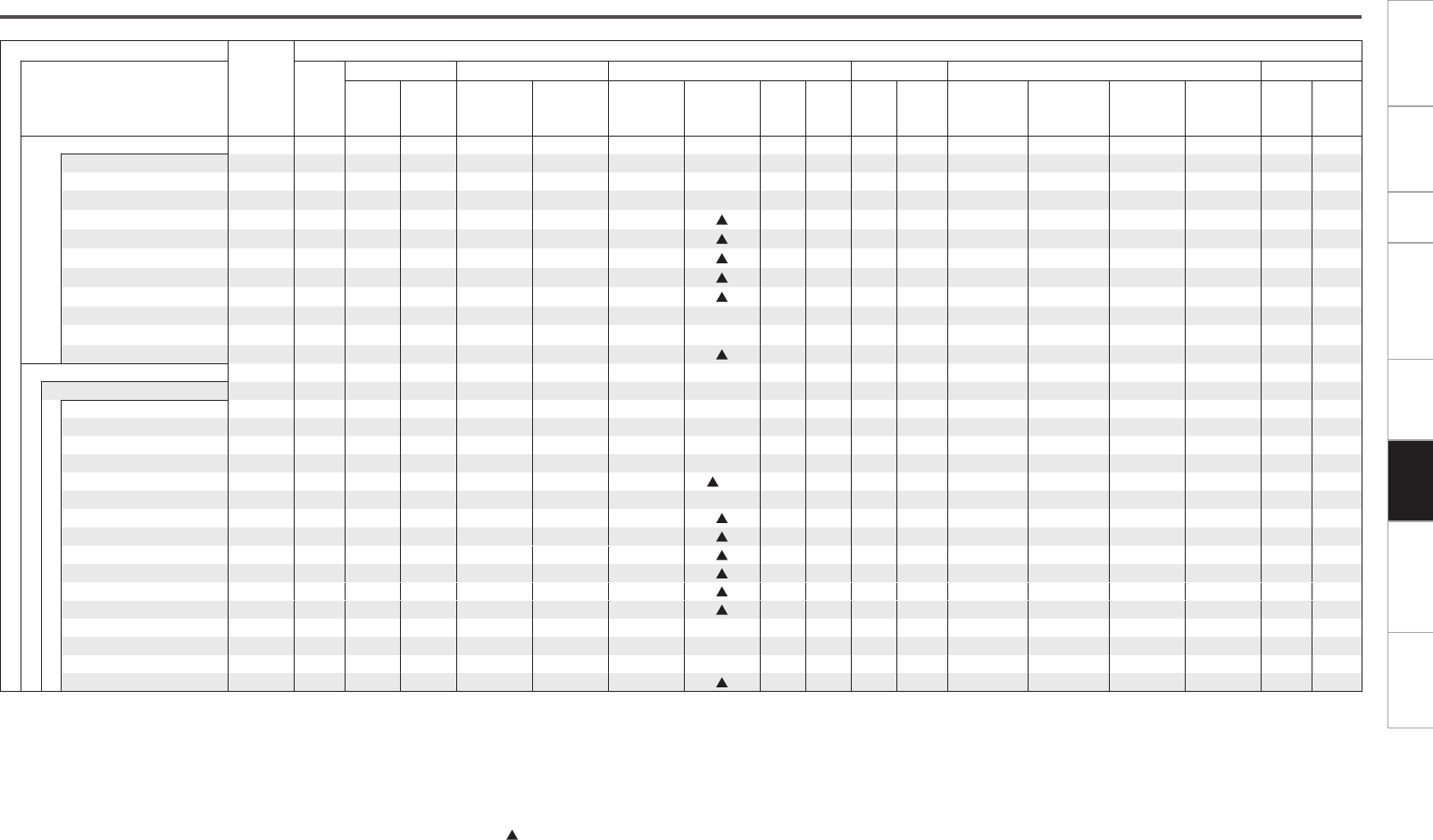
Getting Started Connections Setup Other Operations Multi-Zone Troubleshooting SpecificationsInformation
F : Mode selectable in initial status
S : Selectable mode
Differences in Surround Mode Names Depending on the Input Signals
Button
Note
Input signals
Surround mode ANALOG
PCM DTS-HD DTS DOLBY DOLBY DIGITAL Super Audio CD
PCM
(multi ch)
PCM
(2ch)
DTS-HD
Master Audio
DTS-HD
High Resolution
Audio
DTS ES DSCRT
(With Flag)
DTS ES MTRX
(With Flag)
z8
DTS
(5.1ch)
DTS
96/24
DOLBY
TrueHD
DOLBY
DIGITAL
Plus
DOLBY DIGITAL
EX
(With Flag)
DOLBY DIGITAL
EX
(With no Flag)
DOLBY
DIGITAL
(5.1/5/4/3ch)
DOLBY DIGITAL
(2ch)
DSD
(multi ch)
DSD
(2ch)
HOME THX CINEMA
ES DSCRT6.1 + THX z1S
ES MTRX6.1 + THX z2u
THX SURROUND EX z1S S S D S S S
THX Ultra2 Cinema z3S S S S S S S S S S S
THX Music Mode z3S S S S S S S S S S S
THX Games Mode z3S S S S S S S S S S S S S SS
THX Cinema S S S S S S S S S S S S
PLgx C + THX z4S S S S S S S S S S S S S SS
PLg C + THX S S S S
DOLBY PL + THX S S S S
PLgz + THX z5S S S S S S S S S S S S S S S S
STANDARD
DTS SURROUND
DTS-HD MSTR F
DTS-HD HI RES F
DTS ES DSCRT6.1 z1F
DTS ES MTRX6.1 z2u F
DTS SURROUND S F F
DTS 96/24 F
DTS (–HD) + PLgx CINEMA z3S S S S
DTS (–HD) + PLgx MUSIC z1S S S S
DTS (–HD) + PLgzz5S S S S S
DTS(-HD) + NEO:X CINEMA z6S S S S S
DTS(-HD) + NEO:X MUSIC z6S S S S S
DTS(-HD) + NEO:X GAME z6S S S S S
DTS NEO:X CINEMA z7S S S
DTS NEO:X MUSIC z7S S S
DTS NEO:X GAME z7S S S
Audyssey DSX™ S S S S S
z1 : This mode is not available when the surround back speaker setup is set to “None” (vpage 23).
z2 : This cannot be selected when the “Speaker Configuration” settings are set to anything other than “Front”, “Center”, “Surround” and “Surround Back (1spkr)”.
z3 : This mode is not available when the surround back speaker setup is set to “1spkr” or “None” (vpage 23).
z4 : For input signals other than 2 channel signals, this mode cannot be selected when surround back speaker is set to “1spkr” or “None” (vpage 23).
z5 : This mode is not available when the front height speaker setup is set to “None” (vpage 23).
z6 : When the surround back speaker, front height speaker and front wide speaker are all set to “None”, this cannot be selected (vpage 23).
z7 : This cannot be selected for 2-channel playback when only front speakers are used.
z8 : When using DTS ES MTRX signal input, only u can be selected when the “Speaker Configuration” settings are set to “Front”, “Center”, “Surround” and “Surround Back (1spkr)”
(vpage 23). Also, only can be selected when the “Speaker Configuration” setting is “Surround Back (2spkrs)”, “Front Height” and “Front Wide” (vpage 23).
Getting Started Connections Setup Other Operations Multi-Zone Troubleshooting SpecificationsInformation
F : Mode selectable in initial status
D : Mode fixed when “AFDM” is “ON”
S : Selectable mode
Button
Note
Input signals
Surround mode
ANALOG
PCM DTS-HD DTS DOLBY DOLBY DIGITAL Super Audio CD
PCM
(multi ch)
PCM
(2ch)
DTS-HD
Master Audio
DTS-HD
High Resolution
Audio
DTS ES DSCRT
(With Flag)
DTS ES MTRX
(With Flag)
DTS
(5.1ch)
DTS
96/24
DOLBY
TrueHD
DOLBY
DIGITAL
Plus
DOLBY
DIGITAL EX
(With Flag)
DOLBY
DIGITAL EX
(With no Flag)
DOLBY
DIGITAL
(5.1/5/4/3ch)
DOLBY
DIGITAL (2ch)
DSD
(multi ch)
DSD
(2ch)
STANDARD
DOLBY SURROUND
DOLBY TrueHD F
DOLBY DIGITAL+ F
DOLBY DIGITAL SFF
DOLBY DIGITAL EX z1SSS
DOLBY (D+) (HD) +EX z1S S
DOLBY (D) (D+) (HD) +PL
g
x CINEMA
z3S S D F S S
DOLBY (D) (D+) (HD) +PL
g
x MUSIC
z1S S S S S
DOLBY (D) (D+) (HD) +PL
g
z
z5S S S S S
DOLBY (D) (D+) (HD) + NEO:X CINEMA
z6S S S S S
DOLBY (D) (D+) (HD) + NEO:X MUSIC
z6S S S S S
DOLBY (D) (D+) (HD) + NEO:X GAME
z6S S S S S
DOLBY PRO LOGIC
g
x CINEMA
z1 z7S S F S
DOLBY PRO LOGIC
g
x MUSIC
z1 z7S S S S
DOLBY PRO LOGIC gx GAME z1 z7S S S S
DOLBY PRO LOGIC g CINEMA z7S S S S
DOLBY PRO LOGIC g MUSIC z7S S S S
DOLBY PRO LOGIC g GAME z7S S S S
DOLBY PRO LOGIC z7S S S S
DOLBY PRO LOGIC gz HEIGHT z5S S S S
Audyssey DSX™ z9S S S S S
DOLBY PRO LOGICgx CINEMA A-DSX z1 z7 z9S S S S
DOLBY PRO LOGICgx MUSIC A-DSX z1 z7 z9S S S S
DOLBY PRO LOGICgx GAME A-DSX z1 z7 z9S S S S
DOLBY PRO LOGICg CINEMA A-DSX z7z9S S S S
DOLBY PRO LOGICg MUSIC A-DSX z7 z9S S S S
DOLBY PRO LOGICg GAME A-DSX z7 z9S S S S
DOLBY PRO LOGIC A-DSX z7 z9S S S S
DOLBY HEADPHONE z10 S S S S S S S S S S S S S S S
z1 : This mode is not available when the surround back speaker setup is set to “None” (vpage 23).
z3 : This mode is not available when the surround back speaker setup is set to “1spkr” or “None” (vpage 23).
z5 : This mode is not available when the front height speaker setup is set to “None” (vpage 23).
z6 : When the surround back speaker, front height speaker and front wide speaker are all set to “None”, this cannot be selected (vpage 23).
z7 : This cannot be selected for 2-channel playback when only front speakers are used.
z9 : This mode is not available when the front height speaker and front wide speaker setup is set to “None” (vpage 23).
z10 : You can select this when the headphone plug is inserted into the headphone jack.
Getting Started Connections Setup Other Operations Multi-Zone Troubleshooting SpecificationsInformation
F : Mode selectable in initial status
S : Selectable mode
Button
Note
Input signals
Surround mode
ANALOG
PCM DTS-HD DTS DOLBY DOLBY DIGITAL Super Audio CD
PCM
(multi ch)
PCM
(2ch)
DTS-HD
Master Audio
DTS-HD
High Resolution
Audio
DTS ES DSCRT
(With Flag)
DTS ES MTRX
(With Flag)
DTS
(5.1ch)
DTS
96/24
DOLBY
TrueHD
DOLBY
DIGITAL
Plus
DOLBY
DIGITAL EX
(With Flag)
DOLBY
DIGITAL EX
(With no Flag)
DOLBY
DIGITAL
(5.1/5/4/3ch)
DOLBY
DIGITAL (2ch)
DSD
(multi ch)
DSD
(2ch)
STANDARD
MULTI CH IN
MULTI CH IN FF
MULTI CH IN 7.1 z1F
MULTI IN + PLgx CINEMA z3S S
MULTI IN + PLgx MUSIC z1S S
MULTI IN + DOLBY EX z1S S
MULTI IN + PLgz z5S S
MULTI IN + NEO:X CINEMA z6S
MULTI IN + NEO:X MUSIC z6S
MULTI IN + NEO:X GAME z6S
Audyssey DSX™ z9S S
DIRECT
DIRECT S S S S S S S S S S S S S S
DSD DIRECT S
DSD MULTI DIRECT S
MULTI CH DIRECT S
PURE DIRECT
PURE DIRECT S S S S S S S S S S S S S S
DSD PURE DIRECT S
DSD MULTI PURE S
MULTI CH PURE DIRECT S
DSP SIMULATION
7CH STEREO z11 S S S S S S S S S S S S S S S S S
WIDE SCREEN S S S S S S S S S S S S S S S S S
SUPER STADIUM S S S S S S S S S S S S S S S S S
ROCK ARENA S S S S S S S S S S S S S S S S S
JAZZ CLUB S S S S S S S S S S S S S S S S S
CLASSIC CONCERT S S S S S S S S S S S S S S S S S
MONO MOVIE S S S S S S S S S S S S S S S S S
VIDEO GAME S S S S S S S S S S S S S S S S S
MATRIX S S S S S S S S S S S S S S S S S
STEREO
STEREO F S F S S S S S S S S S S S S S F
z1 : This mode is not available when the surround back speaker setup is set to “None” (vpage 23).
z3 : This mode is not available when the surround back speaker setup is set to “1spkr” or “None” (vpage 23).
z5 : This mode is not available when the front height speaker setup is set to “None” (vpage 23).
z6 : When the surround back speaker, front height speaker and front wide speaker are all set to “None”, this cannot be selected (vpage 23).
z9 : This mode is not available when the front height speaker and front wide speaker setup is set to “None” (vpage 23).
z11 : If the surround back speaker, front height speaker and front wide speaker setup is set to “None” and when using headphones, then “5CH STEREO” is displayed.
When surround back speakers and front height speakers, or surround back speakers and front wide speakers are used, “9CH STEREO” is displayed.

Getting Started Connections Setup Other Operations Multi-Zone Troubleshooting SpecificationsInformation
Setting
Status Speaker terminal
ZONE2 ZONE3 SURR. SURR. BACK AMP ASSIGN FH/FW/AMP
ASSIGN-2
ZONE2
ON ON SL/SR – – Z2 L/R
OFF SL/SR – – Z2 L/R
OFF ON SL/SR SBL/SBR – –
OFF SL/SR SBL/SBR – –
ZONE3
ON ON SL/SR – – Z3 L/R
OFF SL/SR SBL/SBR – –
OFF ON SL/SR – – Z3 L/R
OFF SL/SR SBL/SBR – –
ZONE
(MONO)
ON ON SL/SR – – Z2/Z3
OFF SL/SR – – Z2
OFF ON SL/SR – – Z3
OFF SL/SR SBL/SBR – –
Bi & ZONE2
ON ON SL/SR – FL/FR Z2 L/R
OFF SL/SR – FL/FR Z2 L/R
OFF ON SL/SR SBL/SBR FL/FR –
OFF SL/SR SBL/SBR FL/FR –
Bi & ZONE3
ON ON SL/SR – FL/FR Z3 L/R
OFF SL/SR SBL/SBR FL/FR –
OFF ON SL/SR – FL/FR Z3 L/R
OFF SL/SR SBL/SBR FL/FR –
Bi & ZONE
(MONO)
ON ON SL/SR – FL/FR Z2/Z3
OFF SL/SR – FL/FR Z2
OFF ON SL/SR – FL/FR Z3
OFF SL/SR SBL/SBR FL/FR –
ZONE2/
ZONE3
ON ON – – Z3 L/R Z2 L/R
OFF SL/SR – – Z2 L/R
OFF ON – – Z3 L/R –
OFF SL/SR SBL/SBR – –
ZONE2/3
(MONO)
ON ON – – Z3(MONO) Z2(MONO)
OFF SL/SR – – Z2(MONO)
OFF ON – – Z3(MONO) –
OFF SL/SR SBL/SBR – –
Multi-Zone Power On/Off
Setting
Status Speaker terminal
Surround mode SURR. SURR. BACK AMP ASSIGN FH/FW/AMP
ASSIGN-2
2CH Bi-Wiring STEREO/DIRECT – – FL/FR FL/FR
Other SL/SR SBL/SBR – –
2CH Bi-Amp STEREO/DIRECT – – FL/FR FL/FR
Other SL/SR SBL/SBR – –
STEREO or DIRECT (2ch) Mode
Relationship Between Amp Assign Setting and
Speaker Output
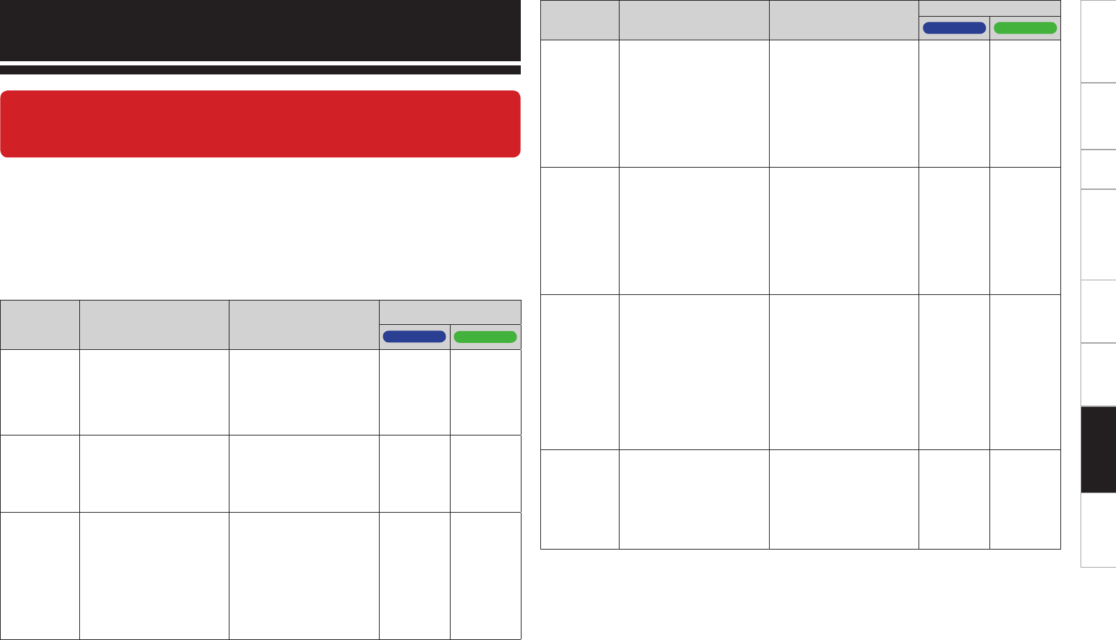
0
Getting Started Connections Setup Other Operations Multi-Zone Information SpecificationsTroubleshooting
If a problem should arise, first check the following:
1. Are the connections correct?
2. Is the set being operated as described in the owner’s manual?
3. Are the other components operating properly?
If this unit does not operate properly, check the items listed in the table below. Should the problem persist,
there may be a malfunction.
In this case, disconnect the power immediately and contact your store of purchase.
Troubleshooting
Symptom Cause Countermeasure
Page
AVC-A1HD AVP-A1HD
No sound
is produced
from center
speaker.
• You are playing a monaural
source (TV, AM radio
broadcast, etc.) in the
“STANDARD” (Dolby/DTS
Surround) or “HOME THX
CINEMA” mode.
• The mode is set to
something other than
“STANDARD” (Dolby/DTS
Surround) or “HOME THX
CINEMA” .
35 ~ 37 35 ~ 37
No sound
is produced
from surround
speakers.
• The surround mode is set
to “STEREO”.
• Set to a surround playback
mode.
35 ~ 37,
m47
35 ~ 37,
m49
No sound
is produced
from surround
back speaker.
• Surround back speaker
setting is set to “None”.
• Surround mode not set to
a mode for 6.1- or 7.1-
channel playback.
• The surround back
speaker’s power amplifier
is assigned to a different
channel.
• Set to something other
than “None”.
• Select a surround playback
mode.
• Sound is not output from
the surround back speakers.
Change the settings.
23
35 ~ 37,
m48
28,
46 ~ 61
23
35 ~ 37,
m50
–
GAudioH
When this unit is upgraded, the “Audio” contents are changed.
To check items related to “Audio”, refer to this version of the Owner's
Manual instead of the “Original version”.
Symptom Cause Countermeasure
Page
AVC-A1HD AVP-A1HD
No sound
is produced
from front
height
speaker.
• The settings are not
configured to use front
height speakers.
• The front height speaker
setting is “None”.
• The “Extension Channel”
setting is “Front Wide”.
• In the “Amp Assign”
settings, set to use front
height speakers.
• Set the front height
speakers to something
other than “None”.
• Set the “Extension
Channel” setting to “Front
Height”.
28,
46 ~ 61
23
28
–
23
29
No sound
is produced
from front
wide speaker.
• The settings are not
configured to use front
wide speakers.
• The front wide speaker
setting is “None”.
• The “Extension Channel”
setting is “Front Height”.
• In the “Amp Assign”
settings, set to use front
wide speakers.
• Set the front wide
speakers to something
other than “None”.
• Set the “Extension
Channel” setting to “Front
Wide”.
28,
46 ~ 61
23
28
–
23
29
No sound
is produced
from
subwoofer.
• Subwoofer’s power not
turned on.
• The subwoofer was not
detected by Auto Setup, or
subwoofer is set as “No”
in the speaker settings.
• The subwoofer is not
properly connected.
• The subwoofer volume
setting is too low or “Off”.
• Turn on the subwoofer’s
power.
• Set the subwoofer settings
to “Yes”.
• Check the connections.
• Adjust the subwoofer’s
volume to an appropriate
level.
–
23
7
–
–
23
8
–
No test tones
are produced
when main
remote
control unit’s
TEST button is
pressed.
• Surround mode not set
to “STANDARD” (Dolby/
DTS Surround) or “HOME
THX CINEMA” mode.
• Set to the “STANDARD”
(Dolby/DTS Surround) or
“HOME THX CINEMA”
mode.
35 ~ 37 35 ~ 37
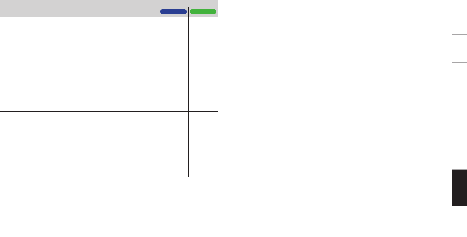
Getting Started Connections Setup Other Operations Multi-Zone Information SpecificationsTroubleshooting
Symptom Cause Countermeasure
Page
AVC-A1HD AVP-A1HD
DTS sound is
not output.
• DVD player’s audio output
setting is not set to
bitstream.
• DVD player is not
compatible with DTS
sound playback.
• The unit’s “Decode Mode”
setting is set to “PCM”.
• Set the DVD player.
For details, refer to the
DVD player’s operating
instructions.
• Use a DTS-compatible
player.
• Set to the “Auto” or “DTS”
mode.
–
–
m45
–
–
m47
Saved
contents
cannot be
called using
the Web
Control
function.
• Contents saved before the
upgrade cannot be called.
• After completing the
upgrade, reconfigure the
settings.
m61 m63
HDMI audio
signals
are not
output from
speakers.
• The “Manual Setup”
– “HDMI Setup” – “Audio”
setting is set to “TV”.
• Set to “Amp”. m31 m31
No sound is
output from
the monitor
connected
with HDMI
connections.
• The “Manual Setup”
– “HDMI Setup” – “Audio”
setting is set to “Amp”.
• Set to “TV”. m31 m31

Getting Started Connections Setup Other Operations Multi-Zone Information Troubleshooting Specifications
n Audio section
• Power amplifier
Rated output: Front:
150 W + 150 W (8 Ω/ohms, 20 Hz ~ 20 kHz with 0.05 % T.H.D.)
170 W + 170 W (6 Ω/ohms, 1 kHz with 0.7 % T.H.D.)
Center:
150 W (8 Ω/ohms, 20 Hz ~ 20 kHz with 0.05 % T.H.D.)
170 W (6 Ω/ohms, 1 kHz with 0.7 % T.H.D.)
Surround:
150 W + 150 W (8 Ω/ohms, 20 Hz ~ 20 kHz with 0.05 % T.H.D.)
170 W + 170 W (6 Ω/ohms, 1 kHz with 0.7 % T.H.D.)
Surround back/Front height/Front wide:
150 W + 150 W (8 Ω/ohms, 20 Hz ~ 20 kHz with 0.05 % T.H.D.)
170 W + 170 W (6 Ω/ohms, 1 kHz with 0.7 % T.H.D.)
Dynamic power: 200 W x 2ch (8 Ω/ohms)
340 W x 2ch (4 Ω/ohms)
Output connectors: Front, Center, Surround, Surround back,
Front height, Front wide 6 ~ 16 Ω/ohms
• Analog
Input sensitivity / Input impedance: 200 mV / 47 kΩ/kohms
Frequency response: 10 Hz ~ 100 kHz — +1, –3 dB (DIRECT mode)
S/N: 102 dB (IHF–A weighted, DIRECT mode)
Distortion: 0.005 % (20 Hz ~ 20 kHz) (DIRECT mode)
Rated output: 1.2 V
• Digital
D/A output: Rated output — 2 V (at 0 dB playback)
Total harmonic distortion — 0.005 % (1 kHz, at 0 dB)
Dynamic range — 110 dB
Digital input: Format — Digital audio interface
• Phono equalizer (PHONO input — REC OUT)
Input sensitivity: 2.5 mV
RIAA deviation: ±1 dB (20 Hz to 20 kHz)
S/N: 74 dB (A weighting, with 5 mV input)
Rated output: 150 mV
Distortion factor: 0.03 % (1 kHz, 3 V)
b For purposes of improvement, specifications and design are subject to change without notice.
Specifications
AVC-A1HD AVP-A1HD
When this unit is upgraded, the “Audio section” contents are changed.
To check items related to “Audio section”, refer to this version of the Owner's
Manual instead of the “Original version”.
No specifications are changed by this upgrade.

D&M Holdings Inc.
3520 10058 00AD
www.denon.com
