Densitron Computers 3600 Multi Media Computer User Manual Manual
Densitron Computers Ltd Multi Media Computer Manual
Manual
TCF/DCL/01/002 rev1 2/2/2001 PD
Appendix 4 Instruction Manual
G
ETTING
S
TARTED AND
R
EFERENCE
G
UIDE
C
ASSIUS
PC

ii Cassius PC Getting Started and Reference Guide
The contents of this manual and the associated software are the property of Densitron Corporation and are copyrighted.
Any reproduction in whole or in part is strictly prohibited.
Densitron Corporation have prepared this manual. It is furnished on the condition that the customer will use it solely for
the purpose of supporting the operation, service and maintenance of Cassius PC. The rights of the customer with respect
to this document will be governed by mutually acceptable provisions of the contract with Densitron Corporation or its
authorised distributor. This document shall not be duplicated by the customer, released, disclosed or used in whole or
part, for any purpose other than that stated herein, without the express written permission of Densitron Corporation.
Although every effort has been made to ensure that the contents of the document are accurate, Densitron Corporation and
its authorised distributor assume no responsibility for any errors contained herein.
Intel, Pentium and Celeron are registered trademarks of Intel Corporation. Microsoft and Windows are registered
trademarks of the Microsoft Corporation in the United State and/or other countries. PS/2 is a registered trademark of the
IBM Corporation. Cassius PC is a registered trademark of Densitron Corporation. Other company, product, or service
names may be the trademarks or service marks of others.
All other trademarks, trade names, and product names are trademarks or registered trademarks of their respective holders.
Information in this document is subject to change without notice.
Copyright © 2000 Densitron Computers Ltd.
Published November 2000.
Document number (DEN-CAS-1.00-GR-1.00A-UK)
Version 1.0 C3600 Cassius
Document Revision History
Revision Date Comments
1.0 7/12/2000 First release
Contents
About This Guide..................................................................................................................................v
Documentation Available vi
Typographical Conventions vi
C H A P T E R 1 1–1
Getting Started..................................................................................................................................1–1
What’s in the Box? 1–2
Getting to Know your Cassius PC 1–3
Cordless Keyboard and Mouse 1–11
Safety Precautions 1–15
Switching On 1–18
Windows 2000 Emergency Repair Diskette (where applicable) 1–20
C H A P T E R 2 2–1
Using your Cassius PC......................................................................................................................2–1
Introduction 2–2
Remote Control 2–2
TV Tuner 2–4
FM Radio Tuner 2–6
DVD Player 2–7
C H A P T E R 3 3–1
Maintaining your Cassius PC ..........................................................................................................3–1
Introduction 3–2
Cleaning your Cassius PC 3–2
Memory Expansion 3–2
System Battery Replacement 3–4
PC Card Slot 3–6
Other Queries 3–7
C H A P T E R 4 4–1
Reinstalling Software........................................................................................................................4–1
Reinstalling Drivers 4–2

iv Cassius PC Getting Started and Reference Guide
Obtaining New Drivers 4–2
Reinstalling Programs 4–2
C H A P T E R 5 5–1
Bios Setup ..........................................................................................................................................5–1
The BIOS Setup 5–2
Using the Bios Setup 5–2
Changing your Bios Settings 5–3
C H A P T E R 6 6–1
Troubleshooting ................................................................................................................................6–1
Problems Switching On 6–2
Problems with your Keyboard and Mouse 6–4
A P P E N D I X A A–I
Regulatory Statements and Battery Disposal.................................................................................A–I
CE Symbol A–II
FCC Part 68 A–II
FCC Part 15 A–III
Laser Compliance Statement A–IV
Disposing of the System Battery A–V
Liquid Crystal Display Warning A–V
Macrovision Copy Protection A–VI
Japanese Telecommunication Business Law A–VI
A P P E N D I X B B–1
Overview........................................................................................................................................... B–1
Computers Explained B–2
Your Cassius PC B–5
Index.........................................................................................................................................................
About This Guide
This section describes the contents and conventions of this guide and provides
a list of available Cassius PC documentation.
The Cassius PC Getting Started and Reference Guide contains the chapters
and appendix shown below.
Chapter 1: Getting Started — Describes how to start using your Cassius PC.
Chapter 2: Using Your Cassius PC — Describes ways you can use your
Cassius PC.
Chapter 3: Maintaining Your Cassius PC — Describes how to maintain and
upgrade your Cassius PC.
Chapter 4: Reinstalling Software — Describes how to reinstall software on
your Cassius PC.
Chapter 5: Bios Setup — Describes the bios setup facility.
Chapter 6: Troubleshooting – Describes how to resolve problems with your
Cassius PC.
Appendix A: Regulatory Statements and Battery Disposal — Describes the
CE symbol, the FCC statements to which your Cassius PC conforms and how
to dispose of your system battery.
Appendix B: Overview – Provides a specification of your Cassius PC and a
brief explanation of some computer terminology.

vi Cassius PC Getting Started and Reference Guide
Documentation Available
The Cassius PC documentation set consists of:
Cassius PC Getting Started and Reference Guide — Describes how to set up
and use your Cassius PC.
www.cassiuspc.com and www.cassiuspc.co.uk — Provides online information
about your Cassius PC.
Typographical Conventions
This guide uses the typographical conventions shown below.
Convention Used
Italic For cross-references.
Bold For features, buttons, menu
options and field names.
> To indicate a menu option.
For example, Select
File > Exit.
! Bullets For lists and instructions.
C H A P T E R 1
Getting Started
This chapter describes how to start using your Cassius PC.
In This Chapter
! What’s in the Box
! Getting to Know your Cassius PC
! The Cordless Keyboard and Mouse
! Safety Precautions
! Switching On
! Windows 2000 Emergency Repair Diskette

1–2 Cassius PC Getting Started and Reference Guide
What’s in the Box?
Your Cassius PC comes with the equipment listed below.
! Main unit, including a stand.
! Cordless keyboard and wrist rest.
! Cordless mouse.
! Batteries for the keyboard and mouse.
! Hardware drivers on the Cassius PC Software CD.
! Software disks and licence documentation for the operating system.
! AC power cord.
! Cassius PC Getting Started and Reference Guide.
! FM antenna (Cassius Intertainment Only).
! Remote control handset (Cassius Intertainment Only).
Chapter 1 Getting Started 1–3
Getting to Know your Cassius PC
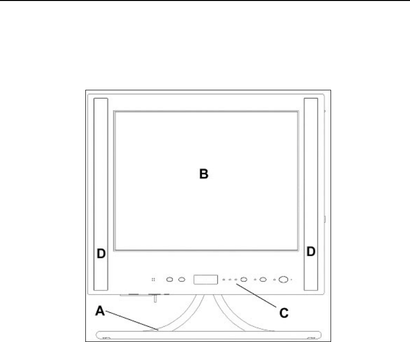
Front View of your Cassius PC
The front view of your Cassius PC is shown below.
Each feature is described below.
Item Description Function
A Stand Supports your Cassius PC.
B 15” Flat Screen Provides a sharp, flicker free display.
C Button Panel Refer to Button Panel, page 1–7.
D Integral Speakers Outputs stereo audio.
1–4 Cassius PC Getting Started and Reference Guide
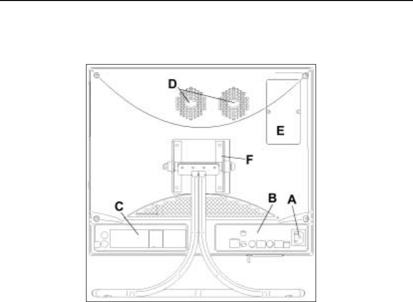
Rear View of your Cassius PC
The rear view of your Cassius PC is shown below.
Each feature is described below.
Item Description Function
A Power Socket Connect your AC power cord to this port.
B Connection Block 1
(Intertaiment Only) Refer to Connection Block .
C Connection Block 2 Refer to Connection Block 2.
D Heat Vents Used to help keep the system cool. DO NOT
BLOCK.
E Memory Door Used to access the memory bay for upgrading
memory and replacing the CMOS Battery.
Chapter 1 Getting Started 1–5
Item Description Function
F VESA Mounting
Plate Attaches your Cassius PC to any VESA
Standard mounting arms or stands.
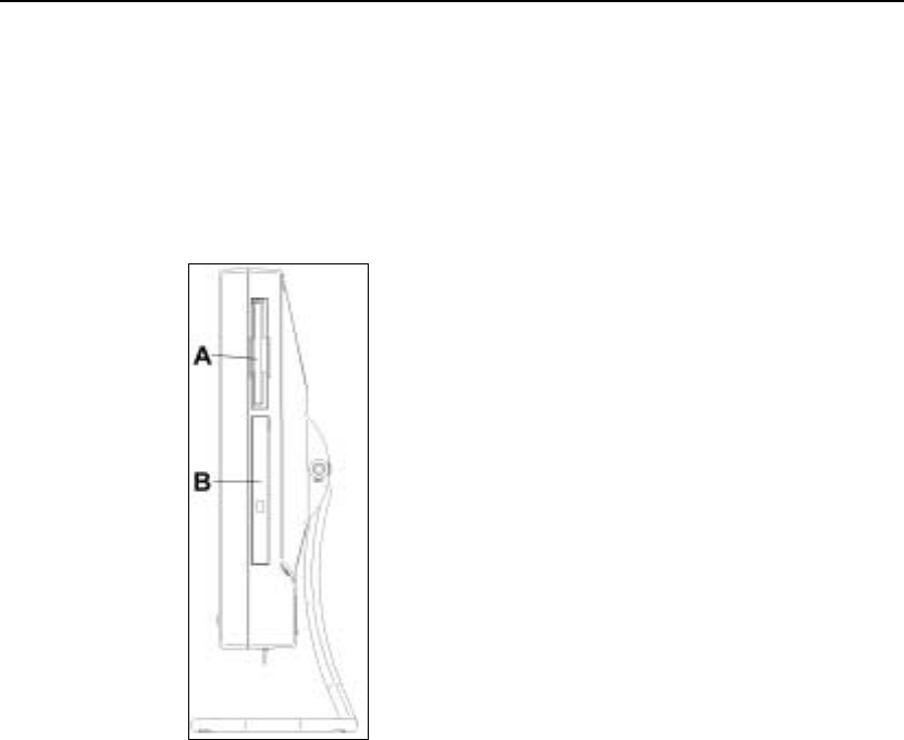
Side View of your Cassius PC
The side view of your Cassius PC is shown below.
Each feature is described below.
Item Description Function
A Floppy Disk Drive
(3½ inch). The eject button
is at the top of the drive.
For use with 3.5” floppy disks. Insert
floppy discs with the label towards
the front of your Cassius PC.
1–6 Cassius PC Getting Started and Reference Guide
Item Description Function
B DVD Drive (Intertainment)
or CD ROM Drive (Pro) The DVD drive accepts all CDs and
DVDs. The CD drive will accept
CDs only. The eject button only
operates with power. After ejecting
the tray, draw it out fully. Insert disc
firmly, pushing at centre until it
clicks in place over the spindle with
the label visible. If the unit is
switched off, you can eject the
CD/DVD tray by inserting a
straightened paper clip into the hole
beside the eject button.
Bottom View of your Cassius PC
The bottom view of your Cassius PC is shown below.
The table below describes each feature.
Item Description Function
A USB Socket Allows you to connect external USB
devices.
B Rotary Volume Control Sets volume level for the built-in
speakers.
Chapter 1 Getting Started 1–7
Item Description Function
C Headphone Socket Allows you to connect headphones.
Speakers become mute when you
connect headphones.
D PCMCIA Socket Allows you to connect Type I and
Type II PC Cards. Either the blank
card supplied or your PCMCIA card
should be in this socket. The socket
should not be left empty.
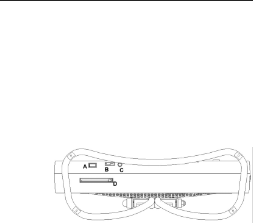
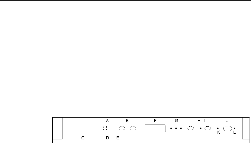
Button Panel
The button panel of your Cassius PC is shown below.
The table below describes each feature.
Item Description Function
A Internal
Microphone Allows you to provide audio input.
B LCD Brightness
Control Buttons Brightness setting remains the same when the
system is switched off.
C USB Socket Allows you to connect external USB devices.
D Rotary Volume
Control Sets volume level for the built-in speakers.
E Headphone Socket
Allows you to connect headphones. Speakers
become mute when you connect headphones.
F Infrared Window
For use with the remote control and IrDA
function. Keep this window clean.
1–8 Cassius PC Getting Started and Reference Guide
G Three LEDs and a
button for the
internal wireless
keyboard.
The left LED indicates Caps Lock; the centre
LED indicates Num Lock; the right LED and
the button are for connection, refer to the
manual for the keyboard. These LEDs only
show the status of the wireless keyboard. If an
external keyboard is plugged into the purple
external keyboard socket on the rear of your
Cassius PC the status of Num Lock and Caps
Lock will be indicated by LEDs on the
external keyboard.
H Disc Drive Activity
LED Flickers when data is transferring between
drives.
I Standby Button
Allows you to put your Cassius PC into
standby mode.
J Power Switch Allows you to switch on or off your Cassius
PC.
K Power LED LED Status Meaning
Off No power
Orange Closed down
Flashing Orange Standby mode
Flashing green Sleep mode
Green Operational.
L Hardware Reset
Button Use a straightened paper clip to press this
button if the Cassius PC stops responding.
Rear Connection Blocks
The two connection blocks at the rear of your Cassius PC are shown below.
Connectors that are only present on the Cassius Intertainment are indicated in
the text below.

Chapter 1 Getting Started 1–9
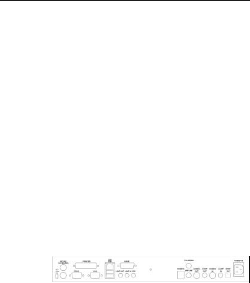
Connection Block 1
Connection block 1 at the rear of your Cassius PC is shown below.
The table below describes each feature.
! Ext. KBD/MS (RF DIS.) — RF device switch. Allows you to enable or
disable the wireless keyboard and mouse. Your Cassius PC is supplied
enabled (switch down). If you want to use a conventional PS/2 keyboard
and mouse, move this switch up to disable RF keyboard and mouse.
! Mouse (green) — External PS/2 mouse port. To enable this port, move
the RF DIS switch up.
! Keyboard (purple) — External PS/2 keyboard port. To enable this port,
move the RF DIS switch up.
! Printer (red) — Parallel printer port.
! COM1 (dark green) — Serial (RS-232) port.
! VGA (blue) — External VGA video port to connect an external analogue
monitor. This allows the system to drive two displays simultaneously.
! LAN (top) — Connector for a 10/100Base-T Ethernet LAN connection.
Use a category five LAN cable for this port. Two LEDs above the port
indicate successful connection (yellow) and data flow (green).
! USB (bottom) — Two USB ports for connecting external USB devices.
! GAME (yellow) — Game port for connecting a joystick or MIDI device.
(Intertainment)
! LINE OUT (green) — Line out audio jack connector. Colour coded in
accordance with the Intel Microsoft PC 1999 specifications.
1–10 Cassius PC Getting Started and Reference Guide
! LINE IN (blue) — Line in audio jack connector. Colour coded in
accordance with the Intel Microsoft PC 1999 specifications.
! MIC (red) — Microphone jack connector. Colour coded in accordance
with the Intel Microsoft PC 1999 specifications.
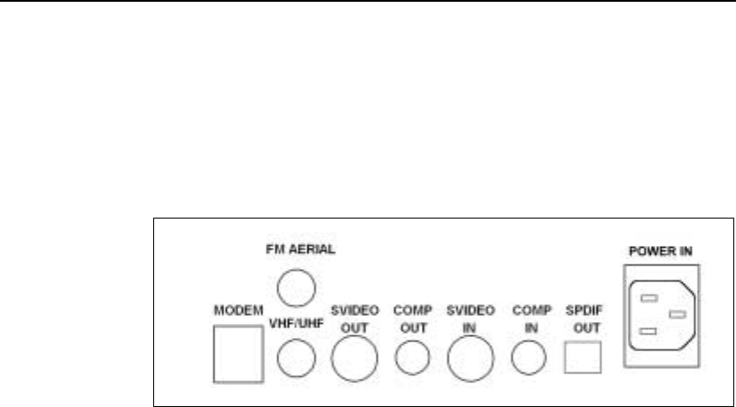
Connection Block 2
Connection block 2 at the rear of your Cassius PC is shown below.
Each feature is described below.
! MODEM — Modem socket.
! FM AERIAL — FM radio antenna connection. (Intertainment)
! VHF RF AERIAL — TV antenna connection or satellite/cable
connection. (Intertainment)
! SVIDEO OUT — S-video output for connection to external television and
video devices. (Intertainment)
! COMP OUT — Composite video output socket for connection to external
television and video devices. (Intertainment)
! SVIDEO IN — S-video input to display video from an external source.
(Intertainment)
! COMP IN — Composite video input to display video from an external
source. (Intertainment)
! S/PDIF OUT — S/PDIF output socket to stream digital audio from DVD
discs. You can use this to connect to an external digital decoder.
(Intertainment)
Chapter 1 Getting Started 1–11
! POWER IN — IEC three-pin power input connector.
Cordless Keyboard and Mouse
This section explains how to:
! Install batteries in the keyboard and mouse.
! Switch your Cassius PC to using a normal keyboard and mouse using the
Ext. KBD/MS switch on the back of your Cassius PC.
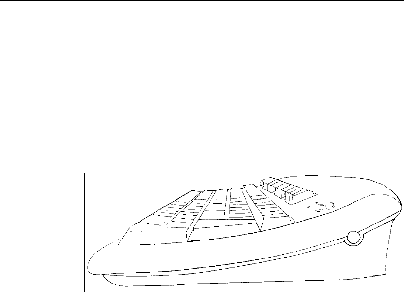
Keyboard
The side view of your keyboard is shown below.
1–12 Cassius PC Getting Started and Reference Guide
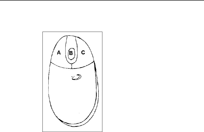
Mouse
The top view of your mouse is shown below.
The table below describes each feature.
Item Description Function
A Left Mouse Button Allows you to select buttons, menus and other
software features.
B Mouse Wheel Allows you to scroll through some
applications.
C Right Mouse
Button Allows you to use context sensitive menus and
other software features.

Chapter 1 Getting Started 1–13
The bottom view of your mouse is shown below.
The table below describes each feature.
Item Description Function
D Connect Button
Used for manually connecting RF mouse to
your Cassius PC. Refer to Manually
Connecting the Cordless Keyboard and Mouse
below.
E Mouse Ball If mouse operation is unreliable, this may need
cleaning.
The cordless keyboard and cordless wheel mouse require batteries. A set of
batteries is supplied.
The keyboard requires two AA alkaline batteries and the mouse requires two
AAA alkaline batteries.
You should replace the batteries when prompted by the computer. Use alkaline
batteries for best performance; other battery types are acceptable, but do not
mix types.

1–14 Cassius PC Getting Started and Reference Guide
Remove the batteries when not using the cordless keyboard and mouse for a
long time.
To Install Batteries in the Keyboard
! Remove the battery compartment cover on the underside of the keyboard.
! Insert the batteries as indicated on the keyboard.
! Carefully replace the battery compartment cover.
To Install Batteries in the Mouse
! Press the tab on the underside of the mouse and slide away the battery
compartment cover on the top of the mouse.
! Insert two AAA batteries according to the diagram in the battery
compartment.
! Carefully replace the battery compartment cover.
To Use a Normal Keyboard and Mouse
! Switch off your Cassius PC.
! Disable the wireless keyboard and mouse switching up the RF DIS.
switch. Refer to Connection Block 1.
! Connect a normal keyboard to the purple external PS/2 keyboard port.
Refer to Connection Block 1.
! Connect a normal mouse to the green external PS/2 mouse port. Refer to
Connection Block 1.
! Switch on your Cassius PC.
Manually Connecting the Cordless Keyboard and Mouse
It may be necessary for you to manually connect the cordless keyboard and
mouse. The procedure below describes this.
! Power on your Cassius PC and wait until the Cassius logo appears on the
screen.

Chapter 1 Getting Started 1–15
! Press the Connect button on the front panel of the PC and press the
Connect button on the right side of the keyboard. For the locations of
these buttons refer to the diagrams shown in Button Panel and Keyboard
above.
! Press the Connect button on the button panel once again and press the
Connect button on the underside of the RF mouse.
You have now manually connected the keyboard and mouse to the same
channel and it should function correctly. If you are still experiencing problems,
please refer to Chapter 6, Troubleshooting.
Safety Precautions
This section describes the safety instructions you should follow with your
Cassius PC.
Using your Cassius PC
Your Cassius PC will automatically detect whether it is connected to the mains
in a country using a 110v or a 220/240v power supply and will switch
accordingly. Therefore you can take it abroad and plug it in without altering
the power settings.
You should however note that you should operate your Cassius PC within a
temperature range of 40°F — 100°F (4°C — 38°C). You can store it within a
temperature range of 0°F — 140°F (8°C — 60°C).
Follow the safety instructions shown below when using your Cassius PC.
! Do not open your Cassius PC, except when upgrading the memory or
changing the system coin-cell battery.
! Before disconnecting a device from your Cassius PC, turn it off and wait
five seconds. This is not necessary for USB or PCMCIA devices.
! Plug your Cassius PC into a grounded power source. Only use three-wire
extension cables with plugs that are grounded. This only applies in
countries that use grounded power sources.
! Ensure you cannot trip over or step on the power cable and that nothing
rests on it.

1–16 Cassius PC Getting Started and Reference Guide
! Ensure nothing is spilled onto your Cassius PC. If it gets wet, unplug it
immediately from the power supply and allow it to dry for at least 24
hours.
! Ensure only compatible devices are pushed into connectors on your
Cassius PC.
Positioning your Cassius PC
Follow the safety instructions shown below for comfort and efficiency.
! Do not keep your Cassius PC near radiators or other heat sources, on loose
papers or cloth, or in closed spaces.
! Ensure the screen of your Cassius PC is a comfortable distance from your
eyes and at eye level or slightly lower.
! Reduce screen reflections by adjusting the screen tilt and brightness. If
necessary adjust the lighting around you.
Chapter 1 Getting Started 1–17
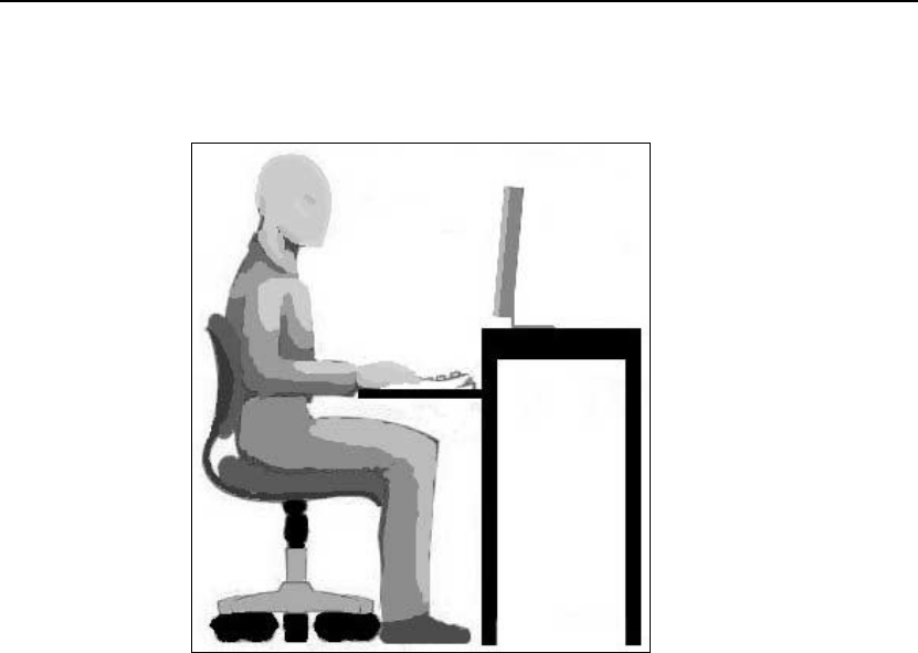
Posture
An example of a suitable sitting position is shown below.
! Use a chair that supports your lower back.
! Ensure your forearms are horizontal, your wrists are comfortable and your
upper arms hang naturally beside you.
! Ensure your wrists are supported when using the cordless keyboard or
mouse.
! Sit upright; rest your feet on the floor and keep your thighs level. Ensure
the weight of your legs rests on your feet, not your seat.

1–18 Cassius PC Getting Started and Reference Guide
Switching On
Before switching on, ensure that the conditions below are met.
! The Cassius PC is positioned as outlined in the Safety Precautions section.
! The cordless keyboard and mouse have batteries correctly installed.
! The cordless keyboard and mouse are on a flat surface. Attach the wrist
pad to the keyboard for comfort if desired.
! The power cable is connected firmly to the AC power outlet and your
Cassius PC.
Windows Registration Procedure
Note Registration takes about 15 minutes. Ensure this process is not
interrupted.
Follow the instructions shown below.
! Connect your modem to a telephone line (if required).
! Turn on your Cassius PC using the power switch on the right.
Your Cassius PC will now boot up. Whenever you start your Cassius PC you
will see a standard black and white screen whilst your computer performs
some self-checks. This is quite normal.
Once your Cassius PC has performed its checks, it will begin to load
Windows.
The very first time that you turn on your Cassius PC, the computer will begin
the Windows Registration Procedure. This short process lets the computer
know your name, the company the computer belongs to (if applicable), the
local time, the country you are in and other useful information. The procedure
will also register your copy of Windows.
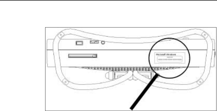
Chapter 1 Getting Started 1–19
The product key for the Microsoft Windows supplied with your Cassius PC is
on the underside of your Cassius PC as shown below.
Follow the instructions on your screen to successfully set up your Cassius PC.
Throughout this guide, click means click the left mouse button.
To enter information in one of the text areas, move the mouse pointer over the
white space and click. You will then see a cursor blinking beside the area.
Type your text and then click on the next text area. Once you have completed
all the text areas in a window, click the appropriate button (usually OK or
Next) in the bottom of the window.
Brief explanations of the features of this process are given below.
Densitron License Agreement — A contract that you must agree to before
using your copy of Windows.
Regional and Keyboard Settings — Allows you to select your region and
keyboard.
Name —Your name.
Computer Name — What your Cassius PC will be called when viewed across
a network.
Organisation —Organisation or company for which you work. Leave this
blank if not applicable.
Product Key — Found on the back of the appropriate CD.

1–20 Cassius PC Getting Started and Reference Guide
Password — Password you want to use with your Cassius PC.
Modem — Instructions to set up your modem.
Microsoft License Agreement — Contract that you must agree to before
using your copy of Windows.
Date/Time Properties— Confirm or set the date and time.
To Complete the Set up Process
! Restart your Cassius PC by selecting Start > Shut Down, selecting
Restart and clicking OK.
Setup is complete.
Your Cassius PC is now operational. You can set up your Cassius PC to
connect to the Internet by double-clicking the Connect to the Internet icon on
the screen when the system has finished restarting. The Microsoft Internet
Configuration Setup Wizard will guide you through the process.
Windows 2000 Emergency Repair Diskette (where applicable)
Windows 2000 may become corrupted by some process during its use. In some
cases, this can prevent it starting properly. To combat this, you can prepare an
Emergency Repair Diskette beforehand that you can use to restore your
computer’s settings in such an emergency.
Note The repair diskette can be used if Windows becomes corrupted to
restore your system configuration. It is not a file backup tool.
To Create an Emergency Repair Diskette
Follow the instructions shown below.
! Select Start > Programs > Densitron Accessories and click Create
Repair Disk.
Your Cassius PC displays the Repair Disk Utility window.
! Click Create Repair Disk. Label a spare diskette Emergency Repair
Disk. Insert it in the drive and click OK.
Your Cassius PC formats the diskette, copies the configuration files and
displays the Repair Disk Utility window.

Chapter 1 Getting Started 1–21
! Click Exit. Remove the diskette from the drive and store it in a safe place.
To Boot from an Emergency Repair Diskette
! Switch off your Cassius PC.
! Insert the Emergency Repair Diskette.
! Switch on your Cassius PC.

1–22 Cassius PC Getting Started and Reference Guide
C H A P T E R 2
Using your Cassius PC
This chapter describes ways you can use your Cassius PC.
In This Chapter
! Remote Control (Intertainment only)
! TV Tuner (Intertainment only)
! FM Radio Tuner (Intertainment only)
! DVD Player (Intertainment only)
2–2 Cassius PC Getting Started and Reference Guide
Introduction
As well as being a high performance computer, you can also use your Cassius
PC as a television, a radio and a DVD player. Furthermore, you can control all
these features with a single remote control. This chapter provides a brief
overview of these special features so that you may begin to use them. You can
find further documentation within the Help files of the programs mentioned.
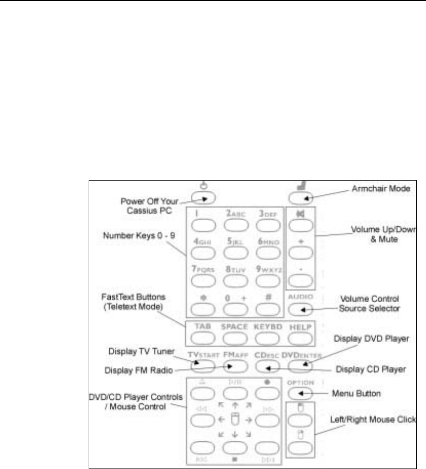
Remote Control
The remote control allows you to operate the TV tuner, FM radio tuner, DVD
player and other features of your Cassius PC.

Chapter 2 Using your Cassius PC 2–3
Armchair Mode
Press the Armchair Mode remote controller button to operate your Cassius
PC as a television, CD player or DVD player. In armchair mode, the green
button labels on the remote control indicate the functions available. These
buttons enable full control of all functions of your Cassius PC.
In Armchair Mode the television picture fills the screen.
TV Tuner
Press the TV
START
remote controller button to display the TV tuner. When
using the TV tuner in armchair mode, the remote controller buttons function as
described below.
! Number buttons 0-9 — Select channel number.
! + / - buttons — Volume Up/Down.
Teletext
To view teletext pages (where available) press any of the four colored
FastText buttons on the remote controller. When using teletext, the remote
controller buttons function as described below.
! Number buttons 0-9 — Enter desired teletext page number.
!
Red/green/yellow & blue buttons — FastText buttons for selecting the
quick jump pages displayed at the bottom of the current teletext page.
DVD Player
Press the DVD
ENTER
remote controller button to display the DVD player.
When you are playing a DVD in armchair mode, the remote controller buttons
function as described below.
! Number buttons 0-9 — Select a new chapter in a DVD movie.
! + / - buttons — Volume Up/Down
! Play/stop/rewind/fast forward — Normal functions that control the
playback of a DVD movie.
! / buttons — Previous chapter/next chapter in a DVD movie.

2–4 Cassius PC Getting Started and Reference Guide
TV Tuner
The TV tuner feature allows you to use your Cassius PC to view television
broadcasts. In some countries, it may be necessary to obtain a television
licence to use the TV functions.
To Use the TV Tuner
! Please ensure that you have plugged an antenna or cable television
connection into the TV Antenna socket on the rear of your Cassius PC
before continuing.
! When you first use the TV tuner, it is necessary to scan for the TV
channels that can be received in your area. Once you have completed this
procedure, you will not need to repeat it unless you move the Cassius PC
to another location in the country.
! Click the TV Tuner icon to open the TV tuner application.
! The first time you open the TV tuner application, your Cassius PC be asks
you if you want to Auto Tune. We recommend that you choose to Auto
Tune by clicking the Tune button. This ensures that when using the TV
tuner in the future, you can easily choose all available channels. You can
also select whether to search for cable/satellite channels or for terrestrial
antenna channels.
! The TV tuner application indicates the channels found by the Auto Tune.
You can rename these if required to allow easier channel selection by
clicking the Edit button.
! Click OK to return to the TV viewer.
! To change channel, click the Menu button, and click the desired channel
from the Tuner menu. Alternatively, press the channel number on the
remote control as documented in the remote control instructions above.
! You can increase or decrees the volume by pressing the increase volume
buttons as described below.
Software Features
The on-screen buttons in the TV Tuner function are described below.
! Menu Displays the menus for adjustment of TV settings.

Chapter 2 Using your Cassius PC 2–5
! Display TV broadcasts.
! Freeze current TV picture.
! Capture current TV broadcast.
! + / - Channel Up/Down.
! / Volume Up/Down.
! Mute the sound.
! 888 Display subtitles (where available).
! Fill the screen with the TV broadcast.
! Show all tuner channels on-screen at once.
! View teletext in TV screen.
! Run Teletext Explorer.
! Select Help > Contents to find additional information on the use of the
TV viewer.
Teletext
Teletext is a limited availability service that allows you to access information
from your TV tuner. Additionally the software allows you to view Teletext
pages in an Internet explorer style window or a TV style full-screen mode for
use with the remote control.
You can view Teletext in two ways – from within the TV viewer or from a
separate program called Teletext Explorer. Both allow you to view teletext
either in a window or full-screen.
Viewing Teletext within TV Viewer
! Click the Teletext button in the TV Tuner application.
! Type in the number of the teletext page required using the number keys on
the keyboard and press Enter to view that page.
! Select Help > Contents to find additional information on the use of
teletext within the TV viewer.
You may also use the remote control in armchair mode. Refer to Armchair
Mode above.

2–6 Cassius PC Getting Started and Reference Guide
Viewing Teletext with Teletext Explorer
Teletext Explorer offers additional features over viewing teletext within the
TV viewer including a search facility. The use of Teletext Explorer is similar
to that of Microsoft Internet Explorer. Consequently, many of the buttons will
be familiar to Microsoft Internet Explorer users.
! Type in the number of the teletext page required using the number keys on
the keyboard and press Enter to view that page.
You may also use the remote control in armchair mode. Refer to Armchair
Mode above.
The on-screen buttons function as described below.
! / Go back to previous page / Go forward.
! Go to home teletext page.
! The channel on which teletext is being received from can be selected using
the drop-down menu beside the home page button.
! The Search button opens a text search dialog for text within a teletext page
! The Print button prints any page.
! Select Help > Contents to find additional information.
FM Radio Tuner
The FM radio tuner feature allows you to use your Cassius PC to listen to FM
radio stations.
The FM radio tuner runs in a window or full screen and is remote control
compatible.
To Use the FM Radio Tuner
! Click the FM Radio icon.
! The appearance of the radio on the screen is identical to that of a normal
radio. The functions of the buttons are the same as those on a normal
radio. Click the buttons using your mouse. Presets can be added by
scanning for the radio station and then clicking and holding on the desired
preset button.

Chapter 2 Using your Cassius PC 2–7
DVD Player
The DVD player feature allows you to use your Cassius PC to play DVDs. The
program that allows you to do this starts automatically when you put a DVD
videodisc in the DVD drive. You use the program to perform all the functions
you would with a standalone DVD player.
DVD videos are stored on an optical disc. You must always take great care
when handling the DVD so that you do not mark the side read by the DVD
drive.
The DVD player runs in window or full screen and is remote control
compatible.
To Use the DVD Player
! Insert a DVD videodisc in the DVD drive or if the DVD is already
inserted, click the DVD icon.
! The buttons on the DVD player represent the standard playback buttons on
any video recorder or DVD player. To play the DVD movie click the
(play) button.
Software Features
You can fast forward or rewind the current DVD movie using the standard fast
forward and rewind keys.
DVD movies also offer the feature of navigating to a particular scene in a film.
You can do this using the chapter selection buttons: and . A DVD
movie is divided into discrete chapters that, during normal playback, will be
switched between seamlessly but offers the viewer the option of skipping
particular scenes.
It is also possible to set parental guidance levels in the DVD player. This
allows only a certain level of film content to be viewed without entering a
password. To enable this feature select Menu > Parental Guidance.
! Select Menu > Help to find additional information about features of the
DVD player.

2–8 Cassius PC Getting Started and Reference Guide
C H A P T E R 3
Maintaining your Cassius PC
This chapter describes how to maintain and upgrade your Cassius PC.
In This Chapter
! Cleaning your Cassius PC
! Memory Expansion
! System Battery Replacement
! PC Card Slot
! Other Queries
3–2 Cassius PC Getting Started and Reference Guide
Introduction
Your Cassius PC is completely integrated. Consequently the only internal
expansion feature is main memory.
Cleaning your Cassius PC
To clean the case, keyboard, mouse and LCD you should only use products
designed for computers. You should never use water or damp cloths.
You should not clean the LCD screen with ammonia based household window
cleaners as these will irreparably damage the specially coated LCD glass.
Memory Expansion
You can install additional main memory in your Cassius PC.
Your Cassius PC will only accept 3.3 volt PC133 144-pin SO-DIMM memory
of size 32, 64, 128 or 256 MB. While your Cassius PC can use PC100 144-pin
SO-DIMM memory, this will impact system performance and we do not
recommend it.
Contact your Densitron dealer for more information on purchasing the correct
memory.
Your Cassius PC can also use error check and correction (ECC) compatible
SO-DIMMs.
Densitron recommend you contact your Densitron supplier for the correct
memory.
Chapter 3 Maintaining your Cassius PC 3–3
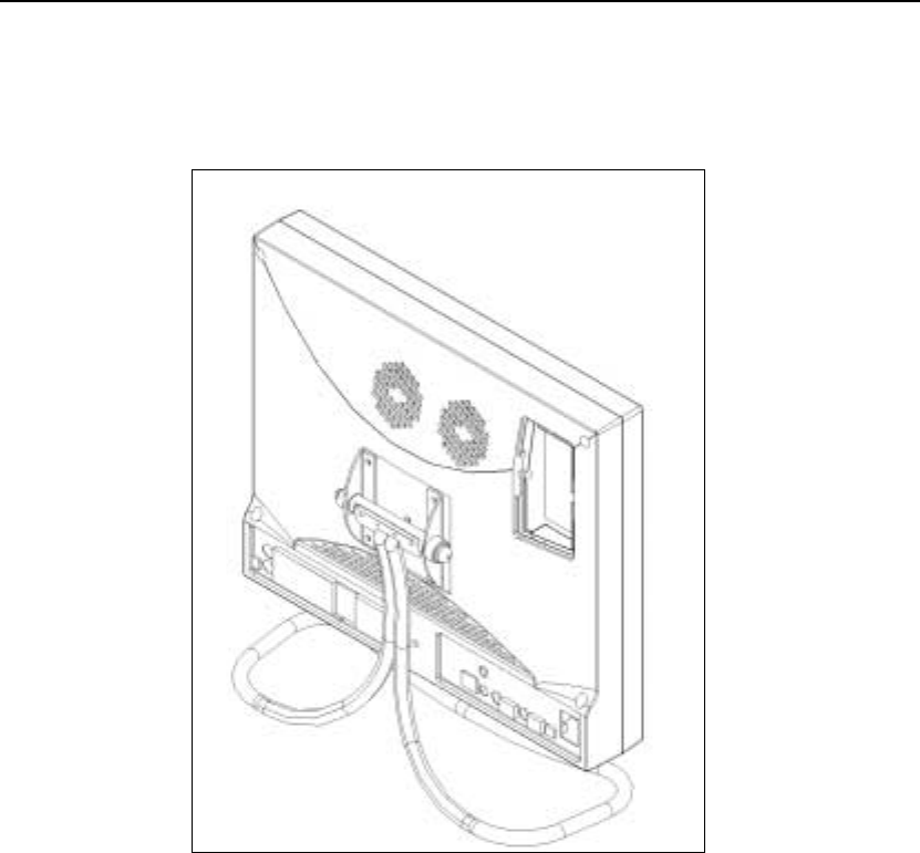
To Install Memory
The memory and battery compartment at the top of the rear of your Cassius PC
is shown below.
Follow the instructions shown below.
! Turn off your Cassius PC and any peripherals.
! Disconnect the power cord and any other cables connected to your Cassius
PC.
! Place your Cassius PC face down on a soft flat surface.

3–4 Cassius PC Getting Started and Reference Guide
! Touch an unpainted metal surface around one of the connectors on the rear
of your Cassius PC to ground yourself with respect to the computer.
Repeat this frequently during the installation process.
! Use a cross-headed screwdriver to remove the two screws from the
memory bay door. Ensure you do not drop the screws inside your Cassius
PC.
! Carefully remove the plastic door to expose the memory expansion socket.
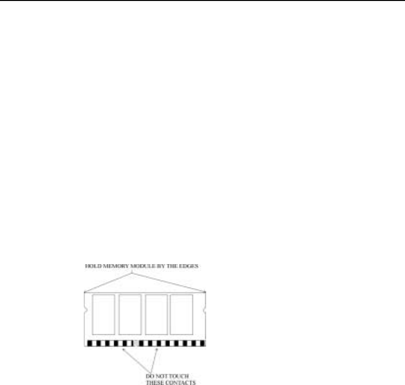
! Holding the new memory at the edges and keeping the SO-DIMM card at
about 45° to the circuit board, gently insert the edge with the gold contacts
into the memory slot. The SO-DIMM will only fit one way round, so
ensure that the cut in the SO-DIMM card lines up with the bump in the
socket at this stage.
! Gently push the SO-DIMM card flat until it clicks into place.
! Replace the plastic door and screws. Reconnect your Cassius PC and
switch it on.
! Check the memory value on the boot screen. If the memory value does not
appear or you hear a bleeping sound, check that you have correctly
installed the memory. If your Cassius PC still does not work, contact the
helpline.
System Battery Replacement
When your Cassius PC is not connected to a power source, the system battery
saves any changes you have made to the BIOS settings (refer to Chapter 5,
Bios Setup) and also maintains the correct time and date on your system. This
battery may run out after a few years, in which case you should replace it.
Your battery needs replacing when your Cassius PC keeps loosing its
configuration or time and date settings.
You must use a 3.0 Volt CR2032 coin-cell replacement battery.

Chapter 3 Maintaining your Cassius PC 3–5
LITHIUM BATTERY WARNING (ENGLISH)
CAUTION
Danger of explosion if battery is incorrectly replaced. Replace only with the
same or equivalent type recommended by the manufacturer. Dispose of used
batteries according to the manufacturer’s instructions.
LITHIUM BATTERY WARNING (DANISH)
ADVARSEL!
Lithiumbatteri – Eksplosionsfare ved fejlagtig håndtering. Udskiftning må kun
ske med batteri af same fabrikat og type. Lever det brugte batteri tilbage
tilleverandøren.
LITHIUM BATTERY WARNING (FINNISH)
VAROITUS
Paristo voi räjähtää, jos se on virheellisesti asennettu. Vaihda paristo
ainoastaan valmistajan suosittelemaan tyyppiin. Hävitä käytetty paristo
valmistajan ohjeiden mikaisesti.
LITHIUM BATTERY WARNING (SWEDISH)
VARNING
Eksplosionsfara vid felaktigt batteribyte. Andvänd samma batterityp eller en
ekvivalent typ som rekommenderas av apparattillverkaren. Kassera använt
batteri enligt fabrikantens instruction.
To Replace the Battery
! Turn off your Cassius PC and any peripherals.
! Disconnect the power cord and any other cables connected to your Cassius
PC.
! Place your Cassius PC face down on a soft flat surface.
! Touch an unpainted metal surface around one of the connectors on the rear
of your Cassius PC to ground yourself with respect to the computer.
Repeat this frequently during the installation process.
! Use a cross-headed screwdriver to remove the two screws from the
memory bay door. Ensure you do not drop the screws inside your Cassius
PC.
! Carefully remove the door to expose the battery socket.

3–6 Cassius PC Getting Started and Reference Guide
! Remove the battery from its socket with your fingers or a blunt,
non-conductive object. Ensure you do not damage the socket or circuit
traces around it.
! Insert the new battery in the socket with the “+” side facing up.
! Replace the plastic cover and screws. Reconnect your Cassius PC and
switch it on.
! Re-set the clock of your Cassius PC when you next enter Windows. If you
had previously made changes to the BIOS configuration, you will need to
re-enter your settings.
! Dispose of the old battery as indicated in Appendix A, Regulatory
Statements and Battery Disposal.
PC Card Slot
The PC card slot on the bottom of your Cassius PC allows you to add extra
functionality to your system by inserting a device card. The slot supports one
PCMCIA or PC CARD type peripheral of size Type I or II.
Your Cassius PC may be switched on or off when installing a card in the slot.
To Insert a PCMCIA Card or PC CARD
! Press the card into the PC card slot as far as you can, with the text facing
away from you.
! Position your card below the slot so that the end of the card that contains
the connection pins points upwards and the bevelled side of the card points
away from you.
! Press the card into the slot as far as you can. Be careful not to force the
card too far in as you may damage it and your Cassius PC.
! If your Cassius PC is turned on, you will hear a two-toned beep when you
correctly insert the card.
! Follow the instructions supplied with your card to install the features
required. Always be careful with any extensions that may be joined to the
bottom of your card so as not to damage your device.

Chapter 3 Maintaining your Cassius PC 3–7
! A brown PC Card icon in the bottom right corner of the Windows screen
indicates a correctly installed PC Card. You can double-click this icon to
view more information on the status of the card.
! If you wish to remove the card whilst your Cassius PC is switched on, you
must first disable the card device. To do this, click the PC Card icon on
your desktop, select the device you wish to disable and click Stop. A
message will appear to tell you that you may remove the card.
To Remove a PCMCIA Card or PC CARD
! Press the button beside the card once to release the eject button
! Press the button again to remove the card.
CAUTION
Either the blank card supplied or your PCMCIA card should be in this socket.
The socket should not be left empty.
Other Queries
If you have any other queries, try the Cassius web site at
http://www.cassiuspc.co.uk and http://cassiuspc.com or contact the help line.

3–8 Cassius PC Getting Started and Reference Guide
C H A P T E R 4
Reinstalling Software
This chapter describes how to reinstall the software on your Cassius PC.
In This Chapter
! Reinstalling Drivers
! Obtaining New Drivers
! Reinstalling Programs

4–2 Cassius PC Getting Started and Reference Guide
Reinstalling Drivers
Drivers are software applications that your Cassius PC uses to communicate
with its hardware devices such as the hard disk or the monitor. Drivers act as
the bridge between, for example, your audio applications and the soundcard
inside your Cassius PC.
If your existing versions have been deleted or corrupted, you will need to
reinstall them. If you desire the latest versions of these drivers, you must
download them from the Cassius website and then install them.
The Cassius PC Software CDROM makes driver installation very simple.
To Install a Driver
! Insert the Cassius PC Software CDROM into your CDROM drive. The
Cassius PC Setup menu will automatically appear.
! Select Drivers from the main menu to display the driver section.
! Select the driver you want to install.
! Follow the instructions on screen to complete installation.
The new drivers will be used when you restart your Cassius PC.
Obtaining New Drivers
You can download copies of up-to-date drivers for your Cassius PC from the
Cassius web site at http://www.cassiuspc.co.uk and http://cassiuspc.com.
The web site also provides installation instructions.
Reinstalling Programs
Your Cassius PC comes with all the necessary programs installed. However, in
the unlikely event that the programs become corrupted, you will need to
reinstall them.
The Cassius PC Software CDROM contains the setup programs required to
reinstall all the basic software shipped with your Cassius PC, such as
Cinemaster 2000 (Intertainment only), TV Viewer (Intertainment only) and
others.

Chapter 4 Reinstalling Software 4–3
To Install a Program
! Insert the Cassius PC Software CDROM into your CDROM drive. The
Cassius PC Setup menu will automatically appear.
! Select Software from the main menu to display the software section.
! Select the program you want to install.
! Follow the instructions on screen to complete installation.
You may need to restart your PC to complete installation.

4–4 Cassius PC Getting Started and Reference Guide
C H A P T E R 5
Bios Setup
This chapter describes how to use the bios setup facility.
In This Chapter
! The Bios Setup
! Using the Bios Setup
! Changing your Bios Settings

5–2 Cassius PC Getting Started and Reference Guide
The BIOS Setup
The BIOS setup facility on your Cassius PC is an interface that allows you to
change the way your computer controls its resources. For example, from the
BIOS setup you can, control the allocation of memory within the system,
disable particular hardware devices and set the boot sequence of your Cassius
PC.
The settings in the BIOS setup on your Cassius PC have already been
configured for optimum performance and reliability, so there should be no
need for change. However, if you want to make changes in the operation of
your Cassius PC, you may need to alter some settings.
Due to the advanced nature of some of the options, inappropriate alteration of
the settings in the BIOS Setup can result in your Cassius PC failing to operate
and possible damage to some of its components. Densitron Computers Ltd
accepts no responsibility for damage caused to your system in this fashion, and
strongly recommends that you do not make any changes in the BIOS Setup
unless they are necessary. If you are in any doubt about the changes you are
about to make, please contact the help line.
Using the Bios Setup
To Access the BIOS Setup Facility
! Turn on your Cassius PC and wait for the boot screen to show.
Note The boot screen is the first page you see when you turn on your
Cassius PC. It shows the speed of your processor, progress of the
memory check and the results of drive detection.
! Press the DEL button on your keyboard.
Note If you miss the opportunity to do this, restart your Cassius PC and try
again.
After a few moments you will see the BIOS menu — a blue screen with
various submenus listed.
! Use the arrow keys on your keyboard to select the desired submenu
required and press ENTER.
! Use the arrow keys to select the submenu option required.

Chapter 5 Bios Setup 5–3
5–3
! Use the PAGE UP and PAGE DOWN keys to change the value of the
highlighted parameter, or press ENTER to select a value from a list.
! Pressing ESC on completing your changes to return to the main BIOS
menu by button.
! Select either Save & Exit Setup to store your changes and exit, or Exit
Without Saving to discard your changes and leave the program.
Your Cassius PC will reboot and any saved changes will take effect.
Changing your Bios Settings
The following section describes the modifications you are able to make to your
BIOS settings. Options that should not be changed have been locked to prevent
accidental modification.
Standard CMOS Features
DATE/TIME — Sets the date and time of your computer. These can also be
changed from Windows.
HALT ON — Sets the errors that will cause the computer to pause during
boot up. Options are All Errors, No Errors, All But Keyboard, All But Diskette
and All But Disk/Key. Depending on the setting, if the computer does not find
a keyboard or floppy disk drive when you turn it on, it will stop booting up,
tell you what is missing and give you the option to continue or turn off and
connect your device. Default is All Errors.
Advanced BIOS Features
VIRUS WARNING — When Enabled, this feature will prevent a virus
writing to the boot sector of your hard disk drive. This can prevent common
procedures from working correctly, so the default is Disabled.
PROCESSOR NUMBER FEATURE — When Enabled, this feature allows
tracing of your computer via its unique processor serial number. Default is
Disabled for privacy reasons.
QUICK POWER ON SELF TEST — When Enabled, this feature reduces
the boot-up time by skipping certain initialization tests. The default is Disabled
to identify any problems as soon as they occur.

5–4 Cassius PC Getting Started and Reference Guide
BOOT DEVICES — Sets the order in which your Cassius PC looks for boot
devices. A boot device is a drive that tells the computer what to do once it has
completed its boot-up tests. Your hard disk drive, for example, will tell your
computer to load Windows. The default sequence is Floppy and then HDD0.
Consequently, your Cassius PC first looks at the floppy drive for boot
information, and failing that will look at the C: drive (HDD0). You may
change the order, if for example, you want to boot from the CDROM.
BOOT UP NUMLOCK STATUS — Sets the state of the keyboard Numlock
feature when you turn on your Cassius PC. If Numlock is On (indicated by the
Numlock light), the number pad on the right of your keyboard can be used to
type in numbers. If the Numlock is Off, the other functions written on the pad
are used. By default Numlock is On at startup.
TYPEMATIC RATE SETTING — When Enabled, this feature allows you
to set the delay and repeat rate of a character when its key is held down on the
keyboard. If Disabled, the default rates of 250ms and 6chars/sec respectively
are used. Since the Cassius PC is designed for a Microsoft Windows operating
system that overrides this setting, the default is Disabled.
SECURITY OPTION — Only applicable once a User Password has been set
in the main BIOS menu. If set to Setup, you must enter your password to make
changes in the BIOS setup in feature. If set to System, the password is required
every time you start your Cassius PC.
VIDEO BIOS SHADOW — If Enabled, which is the default, the contents of
your video ROM is copied to RAM to increase graphics performance. This can
cause problems with some high-graphics applications such as 3D games. If
you experience crashing when loading video intensive applications, try
disabling this feature.
Advanced Chipset Features
SYSTEM BIOS CACHEABLE — If Enabled, the performance of your
Cassius PC is improved by caching the system BIOS ROM to memory.
However, system errors may result if any program attempts to write to this
memory space. Try disabling this feature if your Cassius frequently crashes
whilst using a particular program. The default setting is Enabled.
VIDEO RAM CACHEABLE — Selecting Enabled improves video
performance by caching video memory. However, if any programs use the
space in which the memory is cached, the system may crash. Try disabling this

Chapter 5 Bios Setup 5–5
5–5
feature if you experience frequent crashes when running particular programs.
By default this setting is Enabled.
AGP APERTURE SIZE — In high-graphics applications, your video card
can obtain extra memory from your RAM via the AGP bus. The AGP aperture
size dictates the maximum amount of extra memory the video card can use. If
you install extra memory in your system, increase the value here to improve
video performance. Be aware that the more memory used by the video card,
the less is available for your programs to run. By default, the AGP aperture
size is set to half the available system RAM.
Integrated Peripherals
SIS 630 ONCHIP PCI DEVICE — Enables or disables your Audio, Network
or Modem capabilities. If you disable a device you will not be able to use it
until you enable it. By default, all devices are Enabled.
SIS 950 SUPER I/O — Enables or disables your onboard serial and parallel
ports. By default, these should all be enabled.
USB CONTROLLER — Enables or disables USB support on your system.
The default is Enabled and this setting should be kept unless there is some
specific reason to disable the USB ports.
USB KEYBOARD — Enables or disables support for USB keyboards.
Default is disabled.
SYSTEM SHARE MEMORY SIZE — Specifies the amount of memory set
aside for your graphics card. Available shared memory sizes are 2MB, 4MB,
8MB, 16MB, 32MB and 64MB. If you install extra memory in your Cassius
PC, you can increase this value to improve graphics performance. The more
memory you allocate to the video card, the less memory is available to run
your programs. By default, 16MB of system memory is assigned to shared
graphics memory. If you use 3D applications or games heavily, you may want
to increase the amount, however, bear in mind this limits the main system
memory.
SIS 301 DISPLAY TYPE — Sets the display type for your Cassius PC.
Please note that while the built-in TFT flat screen of your Cassius PC can
display the XGA resolution of 1024x768, devices attached to the analogue
VGA output port may not be able to be set at such a high resolution in
Windows. Default is Auto.

5–6 Cassius PC Getting Started and Reference Guide
Power Management Setup
This submenu allows you to configure the energy saving capabilities on your
Cassius PC. From here you can set your Cassius PC to turn off various
components if they are unused for a particular time, and can set which inputs
are necessary to wake them up again.
ACPI FUNCTION — Enable this option to allow control of power
management features from within your ACPI compatible operating system
(such as Windows 98 or 2000). The default setting is Enabled.
ACPI SUSPEND TYPE — Sets the Suspend method. Selecting S1 (POS)
enables Power On Suspend mode, which maintains power to all essential
components and shuts down components that are unnecessary for basic system
function such as the hard disk drive. Selecting S3 (STR) enables Suspend To
RAM mode, which stores your current information to memory and turns off
power to all components except the RAM. Default is S3 (STR).
SWITCH FUNCTION — Sets the function of the Standby button. If set to
Disabled, the Standby button has no effect. If set to Break/Wake, on pressing
the standby button the system enters Suspend mode. Standby must then be
pressed again for full power. The default setting is Break/Wake.
POWER BUTTON OVERRIDE — Sets the function of the Power button
once the computer is turned on. Selecting Instant Off means that your Cassius
PC will turn off immediately when the Power button is pressed. Selecting
Delay 4 Seconds means that you will have to hold the Power button down for
4 seconds to turn the computer off. This is the default to prevent accidentally
turning your computer off.
PM WAKE UP EVENTS — Sets the events that will make your Cassius PC
power up from Shutdown or wake up from Suspend.
PnP/PCI Configurations
This submenu allows you to configure the PCI controller within your Cassius
PC. The PCI bus connects many of the extra features in your Cassius PC to the
CPU and memory, and the configuration options within this submenu are used
to control this PCI interface. Your Cassius PC comes with these values pre-set,
and there should be no need to change them.

Chapter 5 Bios Setup 5–7
5–7
PC Health Status
This PC Health Status submenu allows you to help monitor your CPU. From
within this submenu you can view information such as CPU fan speed, CPU
I/O voltage and CPU core temperature, which can help identify system
problems in the event of errors. This submenu also allows you to set the
SHUTDOWN TEMPERATURE. In the event that the CPU starts to overheat,
the computer will turn off at the temperature set here to prevent any permanent
CPU damage.
Frequency/Voltage Control
This submenu allows you to set the frequency at which the processor and bus
circuitry within your Cassius PC operate. It is also used to enable auto-
detection of the PCI clock frequency and to enable spectrum spread
modulation of the clock generator to minimise electromagnetic interference.
Your Cassius PC will come with these options pre-set and you should not
change them. Doing so could permanently damage your Cassius PC.
User Password
This option allows you to set the system password for your Cassius PC. The
system password prevents other people from using your PC or changing the
BIOS Settings. Please refer to Advanced BIOS Features above for information
about how to set the function of your password. To disable the password
function, leave this field blank.

5–8 Cassius PC Getting Started and Reference Guide
C H A P T E R 6
Troubleshooting
This chapter describes how to troubleshoot problems with your Cassius PC.
In This Chapter
! Problems Switching On.
! Problems with your Keyboard and Mouse.

6–2 Cassius PC Getting Started and Reference Guide
Problems Switching On
This section covers a number of possible causes and solutions for your Cassius
PC failing to correctly switch on. In many cases, you will find the solution by
following the instructions below in order. Consequently, it will be unnecessary
to seek technical advice.
Problem Cause Solution
No lights
illuminated on
button panel.
Your Cassius PC
is not receiving
mains power.
1 Check the mains lead is securely
plugged into the mains power wall
socket and into the back of your
Cassius PC.
2 Check the mains power wall socket
into which your Cassius is plugged is
functioning correctly by plugging
another appliance into the same
socket.
3 Remove the mains lead from the
mains power wall socket and from
the back of your Cassius PC and
check the fuse in the plug. If you are
unsure of this procedure, contact a
qualified electrician.
4 If none of the above resolves the
problem please contact your
Densitron service centre.

Chapter 6 Troubleshooting 6–3
Problem Cause Solution
No display on
screen but
lights on front
panel
illuminated.
Your Cassius PC
is in sleep mode
or in soft-power
mode.
1 If you have returned to your
computer having left it on for some
time try pressing a key on the
keyboard and moving the mouse to
bring your Cassius PC out of sleep
mode.
2 If you have just plugged your Cassius
PC into the mains power supply, you
must press the power button located
on the right of the button panel to
switch on the computer.
3 Unplug your Cassius PC from the
mains power wall socket and plug it
in again. Then press the power button
on the button panel.
4 If none of the above resolves the
problem, please contact your
Densitron service centre.
You can hear
your Cassius
PC booting
but there is no
picture.
The display
connection or
the display itself
is damaged.
1 If you have connected another
display to the analogue VGA output
on the rear of your Cassius PC,
switch it off, remove the power
supply connector from the mains
wall socket try unplugging it and
switching on your Cassius PC again.
2 Please contact your Densitron service
centre. There are no user serviceable
parts or fixes for this problem.

6–4 Cassius PC Getting Started and Reference Guide
Problems with your Keyboard and Mouse
Your Cassius PC is supplied with a cordless keyboard and mouse. It is also
possible to connect an external keyboard and mouse to the PS/2 sockets on the
rear of your Cassius PC. Please note which type of keyboard and mouse you
are having problems with before troubleshooting the problem.
Problem Cause Solution
Your
CORDLESS
keyboard or
mouse is not
functioning.
There are a
number of reasons
for the cordless
keyboard and
mouse not to
work.
1 Ensure the Ext. KBD/MS switch
on the rear of your Cassius PC is
in the down position. It may be
necessary to manually connect
your keyboard or mouse. Please
refer to Chapter 1, Getting
Started, Manually Connecting
the Cordless Keyboard and
Mouse.
2 The cordless keyboard and
mouse both require batteries. Try
replacing the batteries in the
dysfunctional device, following
all the guidelines on battery
safety and disposal in Appendix
A, Regulatory Statements and
Battery Disposal, Disposing of
the System Battery.
Your external
keyboard or
mouse is not
functioning.
The keyboard and
mouse are
connected into the
wrong ports on
the rear of your
Cassius PC or are
not selected as the
input device.
1 Ensure the external keyboard is
connected to the bottom
keyboard PS/2 port on the rear of
your Cassius PC and the mouse
is connected into the top mouse
PS/2 port.
2 Ensure the Ext. KBD/MS is in
the up position.

Chapter 6 Troubleshooting 6–5
If you are unable to resolve a problem using these troubleshooters or your
problem is not covered support is available on the Cassius PC website at
www.cassiuspc.com and www.cassiuspc.co.uk.
Alternatively please contact your Densitron service centre.

6–6 Cassius PC Getting Started and Reference Guide
A P P E N D I X A
Regulatory Statements and Battery
Disposal
This appendix describes the CE symbol, how to dispose of your system battery
and the FCC regulatory compliance statements.
In This Appendix
! CE Symbol
! FCC Part 68
! FCC Part 15
! Laser Compliance Statement
! Disposing of the System Battery
! Liquid Crystal Display Warning
! Macrovision Copy Protection
! Japanese Telecommunication Business Law

A–II Cassius PC Getting Started and Reference Guide
CE Symbol
The CE symbol indicates that your Cassius PC complies with the European
Union EMC Directive and Low Voltage Directive. This means your Cassius
PC meets the technical standards shown below.
! EN 55022 — Limits and Methods of Measurement of Radio Interference
Characteristics of Information Technology Equipment. There are two
classifications of emissions requirements; class A for typical commercial
areas and class B for typical domestic areas. Your Cassius PC complies
with class B.
! EN 50082-1 (1992) — Electromagnetic compatibility – Generic immunity
standard Part 1: Residential, commercial and light industry.
! EN 60950 — Safety of Information Technology Equipment.
FCC Part 68
The modem in your Cassius PC complies with the FCC, Part 68 Rules and
Regulations.
The telephone company may request the information shown below.
! Ringer Equivalence Number
! FCC Registration Number
The FCC label provided on the back of your Cassius PC displays this
information.
Note The Ringer Equivalence Number (REN) is used to determine the
quantity of devices, which may be connected to the telephone line.
Excessive RENs on the telephone line may result in the devices not
ringing in response to an incoming call. In most, but not all areas, the
sum of the RENs should not exceed five (5). To be certain of the
number of devices that may be connected to the line, as determined by
the total RENs, contact the telephone company to determine the
maximum REN for your area.
If the modem malfunctions, disconnect it from the telephone line until the
problem is corrected. If you do not disconnect the modem and correct the
problem, the telephone company may temporarily disconnect your service.
Appendix A Regulatory Statements and Battery Disposal A–III
A–III
No customer repairs are possible to the device. The telephone company must
notify you if it makes changes to the telephone line that would affect the
modem in any way. If advance notice is not practical, the phone company will
contact you as soon as possible. In addition, you will be advised of your rights
to file a complaint with the FCC if you believe it is necessary.
Do not connect this modem to a coin telephone line or party line.
Users should ensure for their own protection that the electrical ground
connections of the power utility, telephone lines, and internal metallic water
pipe system, if present, are connected together. This precaution may be
particularly important in rural areas.
CAUTION
Users should not attempt to make such connections themselves, but should
contact the appropriate electricity inspection authority, or electrician, as
appropriate.
If you have any problems, contact Densitron.
FCC Part 15
This device has been tested and found to comply with the limits for a Class B
digital device, pursuant to Part 15 of the FCC rules. These limits are designed
to provide reasonable protection against harmful interference in a residential
installation. This equipment generates, uses and can radiate radio frequency
energy and, if not installed and used in accordance with the instructions, may
cause harmful interference to radio or television reception. However, there is
no guarantee that interference will not occur in a particular installation. If this
equipment does cause interference to radio and television reception, which can
be determined by turning the equipment off and on, the user is encouraged to
try to correct the interference by one or more of the following measures:
! Reorient or relocate the receiving antenna
! Increase the separation between the equipment and receiver
! Connect the equipment into an outlet on a circuit different from that to
which the receiver is connected
! Consult the dealer or an experienced radio/TV technician for help

A–IV Cassius PC Getting Started and Reference Guide
Accessories: This equipment has been tested and found to comply with the
limits of a Class B digital device. The accessories associated with this
equipment are as follows:
! Shielded video cable
! Shielded power cord
These accessories are required to be used in order to ensure compliance with
FCC rules.
American Users
Caution! — The Federal Communications Commission warns the users that
changes or modifications to the unit not expressly approved by the party
responsible for compliance could void the user’s authority to operate the
equipment.
Laser Compliance Statement
The CD-ROM drive (Cassius Pro only) or DVD-ROM drive (Cassius
Intertainment only) in this unit contains a Class 1 Laser that is harmful to the
eyes. The classification label (shown below) of the drive is on the surface of
the drive.
CLASS 1 LASER PRODUCT TO IEC 60825-1
APPAREIL A LASER DE CLASSE 1
LASER KLASSE 1 NACH IEC 60825-1
LUOKAN 1 LASERLAITE
PRODUIT LASER CATEGORIE 1
KLASSE 1 LASER APPARAT
DANGER
Do not attempt to disassemble the cabinet. Refer servicing to qualified
personnel only. No user adjustments or serviceable parts are inside.

Appendix A Regulatory Statements and Battery Disposal A–V
A–V
Use of controls or adjustments or performance of procedures other than those
specified herein may result in hazardous radiation exposure.
Class 1 laser products are not considered hazardous. The design of the unit
ensures no exposure to laser radiation above a Class 1 level during normal
operation, user maintenance or servicing.
Disposing of the System Battery
You should not need to replace the system battery in your Cassius PC more
than every few years. The UL recognized system battery, Panasonic CR2032
3v, contains lithium and can explode if it is not properly handled or disposed
of. Replace only with a battery of the same type. To avoid possible injury or
death do not:
! Throw or immerse the battery into water
! Allow it to heat up to more than 212°F (100°C)
! Attempt to repair or disassemble it.
When you need to dispose of the battery, obtain the address of the nearest
battery deposit site from your local waste disposal agency.
Liquid Crystal Display Warning
The fluorescent lamp in the liquid crystal display (LCD) contains mercury. Do
not put it in trash that is disposed of in landfills. Dispose of it as required by
local ordinances or regulations.
The LCD is made of glass, and rough handling or dropping the computer can
cause the LCD to break. If the LCD breaks and the internal fluid gets into your
eyes or on your hands, immediately wash the affected areas with water for at
least 15 minutes; if any symptoms are present after washing, seek medical
attention.

A–VI Cassius PC Getting Started and Reference Guide
Macrovision Copy Protection
The notice below applies only to Cassius Intertainment PCs with a DVD
function and a TV-out function.
This device is protected by U.S. patent umbers 4631603, 4577216, 4819098,
4907093, and other intellectual property rights. The use of Macrovision’s copy
protection technology in the device must be authorized by Macrovision and is
intended for home use and other limited pay-per-view use only, unless
otherwise authorized in writing by Macrovision. Reverse engineering or
disassembly is prohibited.
Japanese Telecommunication Business Law
If you are using the modem in your Cassius PC in Japan, specify the country
as Japan in the Dialling properties, found under Modem Properties in Control
Panel. Using the modem functions with another setting is a violation of the
Japanese Telecommunications Business Law.
A P P E N D I X B
Overview
This chapter gives you a brief overview of your Cassius PC.
In This Chapter
! Computers Explained
! Your Cassius PC

B–2 Cassius PC Getting Started and Reference Guide
Computers Explained
This section gives you a brief introduction to computers and what they do. An
overview of the technology is very useful when using computers, and will help
you get the most from you system.
How Computers Work
A computer is a complex body of electronic components that work with each
other to provide a versatile system capable of performing many different tasks.
Each part of your computer has a specialised function, and in a basic sense,
will take in data, perform some calculations on it, then output the results.
These calculations go on millions of times a second, and the end result is a
smooth-running system.
Hardware
Inside all computers you will find the same main types of components, as
outlined below.
! Motherboard – This is the large, main circuit board onto which most
components are fixed.
! Central Processing Unit (CPU) or Processor – This is the microchip that
performs the majority of the brain work within the computer. This chip is
responsible for many of the calculations that make your computer run, and
for orchestrating the other devices so that they are used efficiently. The
speed of your system is highly dependant on the speed of this chip, and so
computers are often sold by the specification of this chip. The faster the
processor is, the faster will be the computer.
! Random Access Memory (RAM) or Memory – This is space in which
information is stored on a temporary basis. The more information that can
be stored here, the less there is that needs to be recalculated, and hence the
faster the system performs overall. Combined with the CPU, the quantity
of RAM is a major factor in dictating the speed of your system. The more
RAM you have, the faster will be your computer.
! Hard Disk Drive (HDD) – The HDD is the disk on which all your files
and programs are kept. Whenever you install a program onto your
computer or save a document, the information is stored on your hard disk
drive. To help identify the drives on your computer, they are assigned

Appendix B Overview B–3
B–3
drive letters, and the drive letter for the hard disk drive is C – hence it is
the C drive. The capacity of your HDD dictates how much information
you could potentially store. The bigger your HDD, the more you can store.
! Floppy Disk Drive (FDD) – The FDD allows you to save files to small,
removable disks that can then be read by other computers. Since nearly all
computers will have a 3.5” floppy disk drive (where 3.5” is the dimension
of the disk), it is a convenient way to transfer small files between
computers.
! Compact Disc Read Only Memory Drive (CD-ROM Drive) – This is a
disk drive that reads from CD type disks. You can use this drive to listen
to music CDs, or to read data stored on data CDs. However, you cannot
save data to CD-ROM disks. This requires a special type of drive and disk.
! Digital Versatile Disc Read Only Memory (DVD-ROM Drive) – This is
a disk drive that will read DVD disks as well as ordinary CD-ROMs.
DVDs are similar to CD in physical size and use, but they can hold much
more information than ordinary CDs. Consequently, movies are written
onto DVDs because you cannot fit a whole film on a CD.
In addition to the devices listed above there are numerous other components
working in the background to keep your computer running. Whilst their roles
are crucial, it is not necessary to spend time illustrating them in this manual.
An extensive amount of information on computers is available from your local
library or on the Internet.
All the physical devices within your computer are referred to as hardware. In
addition to the internal hardware of your system, you can connect external
hardware to your computer. These devices are called peripherals, and include
mice, keyboards, scanners and printers.
Software
With the hardware in place, you now need software in order to get your
computers to perform useful tasks. Software is the name given to the programs
loaded onto your machine. For example, the CD Player software is a program
that allows you to play CDs on your computer using the CD drive. Without
software, your computer is quite useless.
Software can be divided into three main types: operating systems, drivers and
applications.

B–4 Cassius PC Getting Started and Reference Guide
An operating system is the masterpiece of software that starts running when
you switch on your PC, and stops running only when you switch off your PC.
Operating systems are very large pieces of software, and very complicated in
their behaviour, which gives you immense flexibility to customise the way
your computer behaves. It is this level of intricacy that means your computer
must take some time to load this piece of software, and hence this is the reason
you must wait for it to load every time your start your PC. In the case of your
Cassius PC, the operating system will be either Windows ME or Windows
2000. These operating systems are the platform on which all other programs
run, and give a friendly environment in which to work.
Drivers are small programs that the operating system uses to talk to the
hardware devices on your computer. They act as the translator between, for
example, your video card and your operating system. Whilst your operating
system can partially communicate with your devices without their help, correct
drivers must be loaded for each device in order to utilise the full functionality
of your hardware.
Finally, applications are the programs you run within your operating system in
order to utilise its capabilities. Just as drivers are the bridge between hardware
and the operating system, applications are the bridge between the operating
system and you.
In order to help clarify the function of these three types of software, let us take
the example of playing a CD audio disc on your Cassius PC. You will insert a
CD into your CD drive, and then close the door. The hardware will tell the
drivers that an audio CD has been loaded, and these will tell the operating
system. The operating system then loads the CD player application, which
gives you the ability to control the CD drive. If you decide to stop the CD
playing, you will click Stop within the program. The program then tells the
operating system, which then tells the CD drive through the drivers. This may
seem like an awkward and drawn-out communication line, but it is actually
highly efficient, and allows great flexibility. You have the ability to update the
drivers if a new version comes out, and you can use more than one particular
program to control one particular device.
The first step in using any computer is familiarising yourself with the
operating system by taking some time to explore its capabilities. Information is
available from the Getting Started Windows documentation supplied with your
Cassius PC, as well as from numerous books available from bookshops or
libraries. In addition, both operating systems and applications are supplied

Appendix B Overview B–5
B–5
with Help files, which are instruction manuals that you can access on your
computer.
Your Cassius PC
Your Cassius PC is unique. No other PC offers the wide range of features that
Cassius provides in such a small case. As well as being a high specification
workstation, your Cassius PC is a fully integrated multimedia centre, utilising
notebook technology to create an elegant desktop solution. Your Cassius PC
can do everything a normal PC can, plus much more. You can compile desktop
publications, create digital images, browse the Internet, play 3D computer
games, listen to music and much more. In addition, the Intertainment™ model
allows you to watch DVD videos, listen to FM radio, watch NICAM Stereo
TV and connect your PC to a TV or video.
The key features of your Cassius PC are shown below.
! Intel Pentium III/Celeron II Processor
! Socket 370PGA Motherboard
! PC133 Synchronous DRAM
! One 144-pin SO-DIMM Socket Accepting PC100/133 Memory Modules
up to 256MB
! SIS 630 System Chipset
! 3D Graphics Accelerator
! Wavetable Soundcard
! 15" TFT Flat Screen Display
! DVD-ROM Drive (Intertainment Only)
! CD-ROM Drive (Pro Only)
! 10/100 BaseT Ethernet Port
! Internal Stereo Speakers and Microphone
! Headphone Connection Port, Line Out, Line In, Microphone In
! External VGA Connector for Dual Display Mode
! One PC Card / PCMCIA Type 2/3 Socket

B–6 Cassius PC Getting Started and Reference Guide
! 2.5" UltraDMA Hard Disk Drive
! 56kbps V.90 Internal Modem
! Stereo FM Tuner (Intertainment Only)
! NICAM Digital Stereo TV Tuner (Intertainment Only)
! Teletext Decoder (UK Intertainment Only)
! Front Mounted IrDA Infra Red Port
! Wireless Keyboard and Mouse with Additional PS/2 Keyboard and Mouse
Ports
! S/PDIF Digital Audio Output
! One RS232 Serial Port
! One Bi-directional ECP/EPP Parallel/Printer Port
! Three USB Ports
! Composite / S-Video Input and Output Ports (Intertainment Only)
! VESA FPMPMI (Flat Panel Monitor Physical Mounting Interface)
Compliant Stand and Mounting
! Microsoft Windows Operating System
Index
Batteries
Disposing of System, A–V
Installing in the Keyboard, 1–14
Installing in the Mouse, 1–14
Replacement of System, 3–4
Button Panel, 1–7
Cassius PC
Bottom View, 1–6
Front View, 1–3
Parts List, B–5
Rear View, 1–4
Side View, 1–5
CE Symbol, A–II
Computers Explained, B–2
Connection Blocks
Block 1, 1–9
Block 2, 1–10
Rear, 1–8
Conventions
Typographical, vi
Cordless Keyboard and Mouse, 1–11
Documentation Available, vi
DVD Player, 2–7
Emergency Repair Diskette, 1–20
FM Radio Tuner, 2–6
Getting to Know your Cassius PC, 1–3
Hardware, B–2
How Computers Work, B–2
Inserting a PCMCIA Card or PC CARD, 3–6
Installing Memory, 3–3
Keyboard, 1–11
Manually Connecting the Cordless Keyboard and Mouse, 1–14
Memory Expansion, 3–2
Mouse, 1–11
Normal Keyboard and Mouse, 1–14
Parts List, 1–2

II Cassius PC Getting Started and Reference Guide
PC Card Slot, 3–5
Positioning your Cassius PC, 1–16
Posture, 1–17
Problems Switching On, 6–2
Problems with your Keyboard and Mouse, 6–4
Radio Tuner, 2–6
Remote Control, 2–2
Removing a PCMCIA Card or PC CARD, 3–6
Repair Diskette, 1–20
Safety
Precautions, 1–15
Using your Cassius PC, 1–15
Software, B–3
Switching On, 1–18
System Battery Replacement, 3–4
Television Tuner, 2–4
TV Tuner, 2–4
Typographical Conventions, vi
What’s in the Box?, 1–2
Windows Registration Procedure, 1–18