Denso Wave orporated AN20R01 High Frequency 13.56 MHz Transceiver User Manual 1 1 1732 cover
Denso Wave Incorporated High Frequency 13.56 MHz Transceiver 1 1 1732 cover
UserManual.wiki
>
Denso Wave orporated
>
AN20R01 User Manual
User manual
Navigation menu
Upload a User Manual
Namespaces
Wiki Guide
HTML
PDF
Info
Views
User Manual
Discussion / Help
Navigation
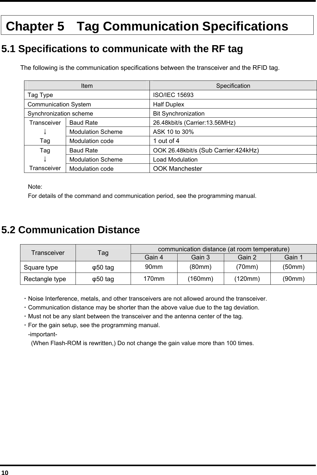
![11 5.3 Communication Area (reference) Square * Gain = 3, 50 tag Rectangle * Gain = 3, 50 tag -100-80-60-40-200204060801000 20 40 60 80 100 120 140 160 180-100-80-60-40-20020406080100-100-80 -60 -40 -20 0 20 40 60 80 100distance 60mm [mm][mm]-60-50-40-30-20-1001020304050600 102030405060708090100110-60-50-40-30-20-100102030405060-60 -50 -40 -30 -20 -10 0 10 20 30 40 50 60distance 40mm[mm][mm]](https://usermanual.wiki/Denso-Wave-orporated/AN20R01/User-Guide-1541806-Page-23.png)