Dentsply Professional Division DPD81675 Remote Transmitter User Manual Manual
Dentsply Professional Division Remote Transmitter Manual
UserManual.wiki
>
Dentsply Professional Division
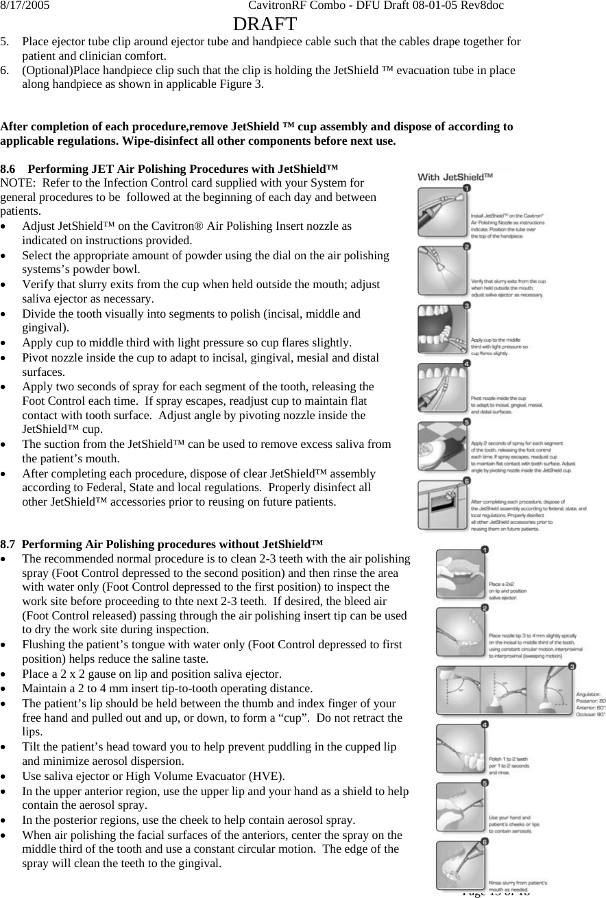
>
DPD81675 User Manual
Manual
Navigation menu
Upload a User Manual
Namespaces
Wiki Guide
HTML
PDF
Info
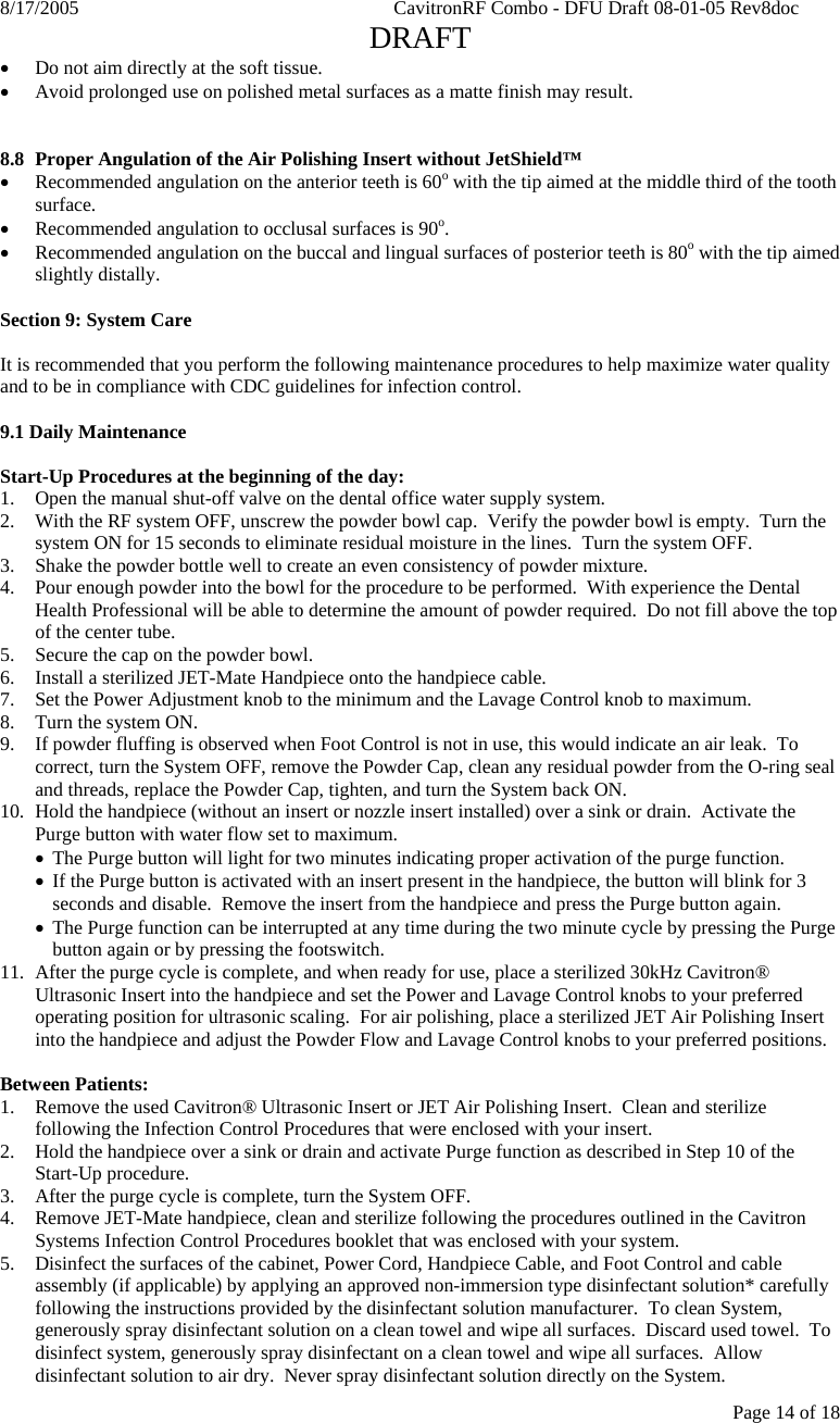
Views
User Manual
Discussion / Help
Navigation