Desa Cgfp28P Users Manual 103414 01
Desa-Tech-Cgfp28P-Owners-Manual desa-tech-cgfp28p-owners-manual
Desa-Tech-Cgfp28Pt-Owners-Manual desa-tech-cgfp28pt-owners-manual
CGFP28P _CGFP28PT_manual_103414-01C
CGFP28PT to the manual e1495a86-2c56-d104-0521-92810fc785f9
2015-02-04
: Desa Desa-Cgfp28P-Users-Manual-512487 desa-cgfp28p-users-manual-512487 desa pdf
Open the PDF directly: View PDF ![]() .
.
Page Count: 34
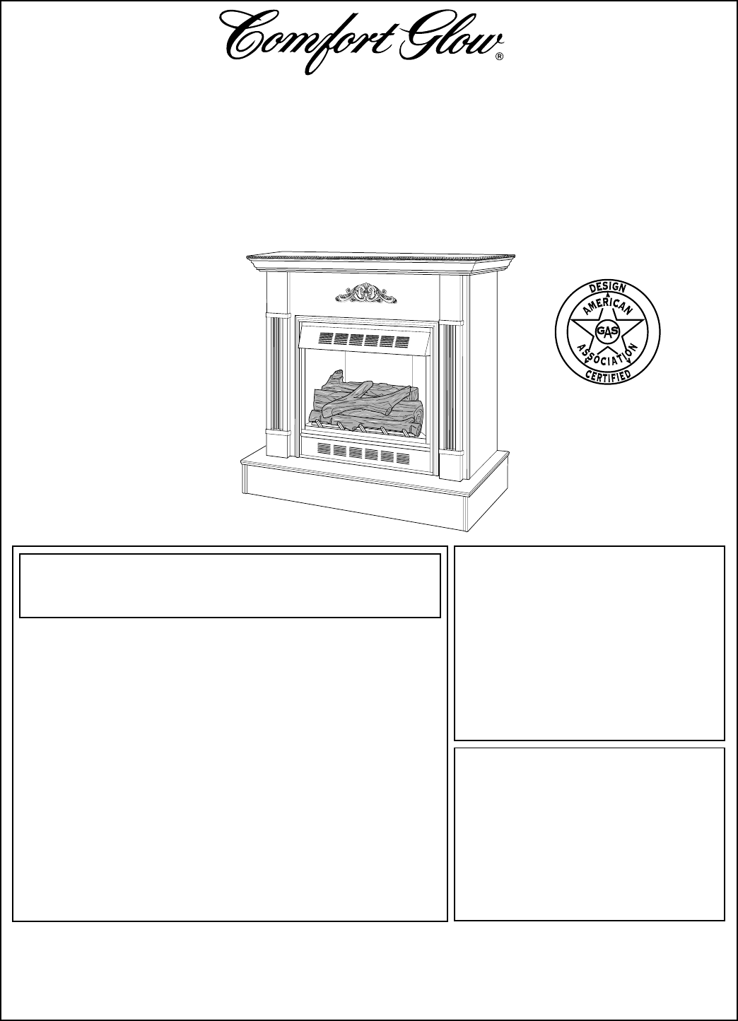
Shown with optional
cabinet mantel and
hearth base.
®
WARNING: If the information in this manual is not
followed exactly, a fire or explosion may result caus-
ing property damage, personal injury, or loss of life.
— Do not store or use gasoline or other flammable
vapors and liquids in the vicinity of this or any
other appliance.
— WHAT TO DO IF YOU SMELL GAS
• Do not try to light any appliance.
• Do not touch any electrical switch; do not use
any phone in your building.
• Immediately call your gas supplier from a
neighbor’s phone. Follow the gas supplier’s
instructions.
• If you cannot reach your gas supplier, call the
fire department.
— Installation and service must be performed by a
qualified installer, service agency, or the gas
supplier.
WARNING: Improper installa-
tion, adjustment, alteration, ser-
vice, or maintenance can cause
injury or property damage. Re-
fer to this manual for correct
installation and operational pro-
cedures. For assistance or ad-
ditional information consult a
qualified installer, service
agency, or the gas supplier.
WARNING: This is an unvented
gas-fired heater. It uses air (oxy-
gen) from the room in which it is
installed. Provisions for ad-
equate combustion and venti-
lation air must be provided.
Refer to
Air for Combustion and
Ventilation
section on page 4 in
this manual.
Save this manual for future reference.
OWNER’S OPERATION AND INSTALLATION
MANUAL
UNVENTED (VENT-FREE)
PROPANE/LP GAS FIREPLACE
CGFP28P
AND
CGFP28PT
This appliance may be installed in an aftermarket* manufactured (mobile) home, where not prohibited
by state or local codes.
* Aftermarket: Completion of sale, not for purpose of resale, from the manufacturer
2
103414
UNVENTED PROPANE/LP GAS FIREPLACE
CGFP28P and CGFP28PT
1. This appliance is only for use with the
type of gas indicated on the rating plate.
This appliance is not convertible for use
with other gases.
2. Do not place propane supply tank(s)
inside any structure. Locate propane
supply tank(s) outdoors.
SAFETY
INFORMATION
DANGER: Carbon monoxide
poisoning may lead to death!
Carbon Monoxide Poisoning: Early
signs of carbon monoxide poisoning re-
semble the flu, with headaches, dizziness,
or nausea. If you have these signs, the fire-
place may not be working properly. Get
fresh air at once! Have fireplace serviced.
Some people are more affected by carbon
monoxide than others. These include preg-
nant women, people with heart or lung dis-
ease or anemia, those under the influence of
alcohol, and those at high altitudes.
Propane Gas: Propane gas is odorless.
An odor-making agent is added to the gas.
The odor helps you detect a gas leak. How-
ever, the odor added to the gas can fade. Gas
may be present even though no odor exists.
Make certain you read and understand all
Warnings. Keep this manual for reference.
It is your guide to safe and proper operation
of this fireplace.
WARNING ICON G 001
WARNINGS
IMPORTANT: Read this owner’s
manual carefully and completely
before trying to assemble, oper-
ate, or service this fireplace. Im-
proper use of this fireplace can
cause serious injury or death
from burns, fire, explosion, elec-
trical shock, and carbon monox-
ide poisoning.
WARNING: Any change to
this fireplace or its controls can
be dangerous.
3. If you smell gas
• shut off gas supply
• do not try to light any appliance
• do not touch any electrical switch; do
not use any phone in your building
• immediately call your gas supplier
from a neighbor’s phone. Follow the
gas supplier’s instructions
• if you cannot reach your gas supplier,
call the fire department
4. This fireplace shall not be installed in
a bedroom or bathroom.
5. Never install the fireplace
• in a recreational vehicle
• where curtains, furniture, clothing, or
other flammable objects are less than
42 inches from the front, top, or sides
of the fireplace
• in high traffic areas
• in windy or drafty areas
6. Do not use this fireplace as a wood-
burning fireplace. Use only the logs
provided with the fireplace.
7. Do not add extra logs or ornaments
such as pine cones, vermiculite, or rock
wool. Using these added items can
cause sooting. Do not add lava rock
around base. Rock and debris could fall
into the control area of fireplace.
8. You must operate this fireplace with the
fireplace screen in place. Make sure
fireplace screen is in place before run-
ning fireplace.
9. This fireplace is designed to be smoke-
less. If logs ever appear to smoke, turn
off fireplace and call a qualified service
person.
Note:
During initial operation,
slight smoking could occur due to log
curing and fireplace burning manufac-
turing residues.
10. To prevent the creation of soot, follow
the instructions in Cleaning and Main-
tenance, page 21.
11. Do not allow fans to blow directly into
the fireplace. Avoid any drafts that al-
ter burner flame patterns. Ceiling fans
can create drafts that alter burner flame
patterns. Altered burner patterns can
cause sooting.
12. Before using furniture polish, wax, car-
pet cleaner, or similar products, turn
heater off. If heated, the vapors from
these products may create a white pow-
der residue within burner box or on
adjacent walls or furniture.
13. Do not use a blower insert, heat ex-
changer insert or other accessory not
approved for use with this heater.
14. This fireplace needs fresh air ventila-
tion to run properly. This fireplace has
an oxygen depletion sensor (ODS) pi-
lot light safety system. The ODS shuts
down the fireplace if not enough fresh
air is available. See Air for Combus-
tion and Ventilation, pages 4 through
6. If fireplace keeps shutting off, see
Troubleshooting, pages 22 through 24.
15. Do not run fireplace
• where flammable liquids or vapors
are used or stored
• under dusty conditions
16. Do not use this fireplace to cook food
or burn paper or other objects.
17. Never place any objects in the fireplace
or on logs.
18. Fireplace front and screen becomes
very hot when running fireplace. Keep
children and adults away from hot sur-
faces to avoid burns or clothing igni-
tion. Fireplace will remain hot for a
time after shutdown. Allow surfaces to
cool before touching.
19. Carefully supervise young children
when they are in the room with fireplace.
20. Do not use fireplace if any part has been
exposed to or under water. Immediately
call a qualified service technician to
inspect the fireplace and to replace any
part of the control system and any gas
control which has been under water.
21. Do not operate fireplace if any log is
broken. Do not operate fireplace if a
log is chipped (dime-sized or larger).
22. Turn fireplace off and let cool before
servicing. Only a qualified service per-
son should service and repair fireplace.
23. Operating fireplace above elevations of
4,500 feet could cause pilot outage.
24. To prevent performance problems, do
not use propane fuel tank of less than
100 lbs. capacity.
3
103414
OWNER’S MANUAL
PRODUCT
IDENTIFICATION
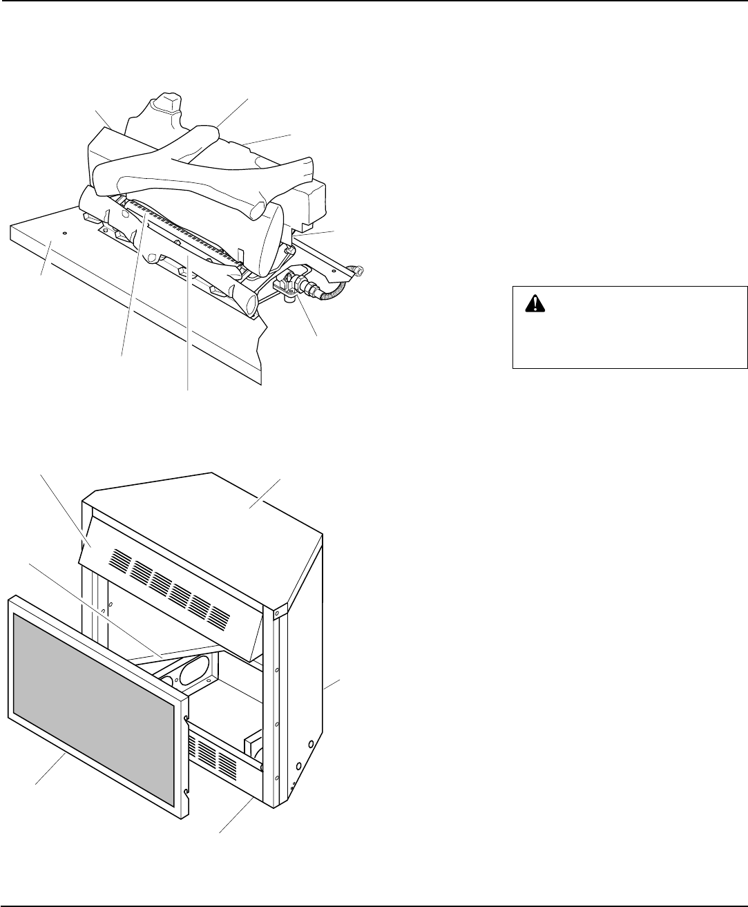
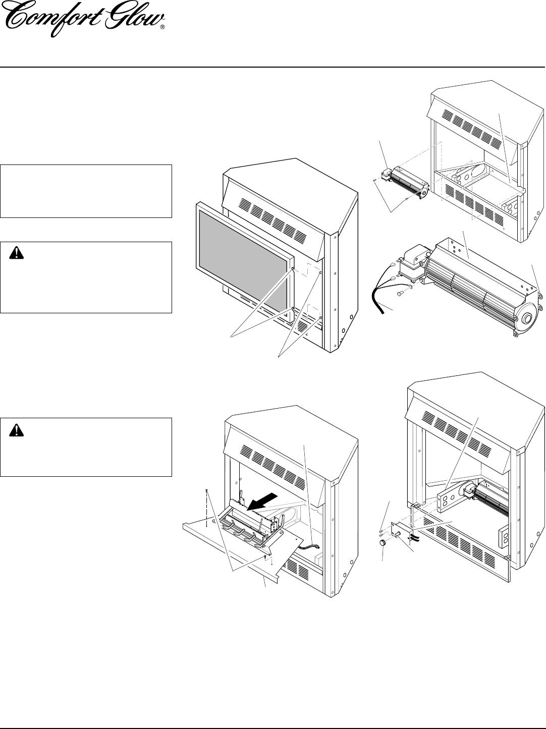
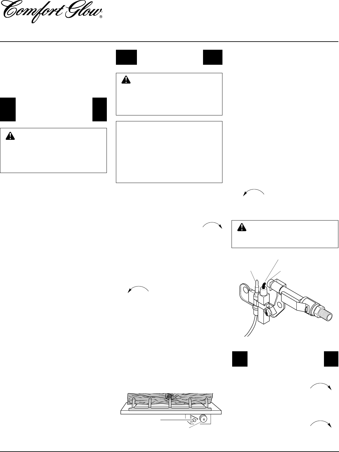
Figure 1 - Log Base Assembly
Figure 2 - Fireplace
LOCAL CODES
Install and use fireplace with care. Follow all
local codes. In the absence of local codes, use
the latest edition of The National Fuel Gas
Code ANS Z223, also known as NFPA 54*.
*Available from:
American National Standards Institute, Inc
.
1430 Broadway
New York, NY 10018
National Fire Protection Association, Inc.
Batterymarch Park
Quincy, MA 02269
UNPACKING
1. With utility knife, cut the carton all the
way around above the staples on the
bottom tray. Lift the carton off the fire-
box. Remove packing.
2. Locate two screws above top corners
of the fireplace screen. Remove and
discard these screws. Lift fireplace
screen up and pull out to remove.
3. Remove protective packaging applied to
logs, log base assembly, and fireplace.
4. Check all items for any shipping dam-
age. If damaged, promptly inform
dealer where you bought fireplace.
Top Louvered
Hood
Bottom Louver
Assembly
Screen Assembly
Top Outer
Casing
Firebox
Support
Rear Access Door
Base
Rear Burner
Front Log (#3)
Front Burner
Bottom Mid
Log (#2)
Top Log (#4)
Rear Log (#1)
Gas Regulator
CAUTION: Do not remove the
metal data plates from the grate
assembly. The data plates contain
important product information.
4
103414
UNVENTED PROPANE/LP GAS FIREPLACE
CGFP28P and CGFP28PT
AIR FOR
COMBUSTION AND
VENTILATION
Today’s homes are built more energy effi-
cient than ever. New materials, increased
insulation, and new construction methods
help reduce heat loss in homes. Home owners
weather strip and caulk around windows and
doors to keep the cold air out and the warm air
in. During heating months, home owners
want their homes as airtight as possible.
While it is good to make your home energy
efficient, your home needs to breathe. Fresh
air must enter your home. All fuel-burning
appliances need fresh air for proper com-
bustion and ventilation.
Exhaust fans, fireplaces, clothes dryers, and
fuel burning appliances draw air from the
house to operate. You must provide ad-
equate fresh air for these appliances. This
will insure proper venting of vented fuel-
burning appliances.
PROVIDING ADEQUATE
VENTILATION
The following are excerpts from National
Fuel Gas Code. NFPA 54/ANS Z223.1, Sec-
tion 5.3, Air for Combustion and Ventilation.
All spaces in homes fall into one of the three
following ventilation classifications:
1. Unusually Tight Construction
2. Unconfined Space
3. Confined Space
The information on pages 4 through 6 will
help you classify your space and provide
adequate ventilation.
Unusually Tight Construction
The air that leaks around doors and win-
dows may provide enough fresh air for
combustion and ventilation. However, in
Confined Space and Unconfined
Space
The National Fuel Gas Code (ANS Z223.1,
1992 Section 5.3) defines a confined space
as a space whose volume is less than 50
cubic feet per 1,000 Btu per hour (4.8 m3 per
kw) of the aggregate input rating of all
appliances installed in that space and an
unconfined space as a space whose volume
is not less than 50 cubic feet per 1,000 Btu
per hour (4.8 m3 per kw) of the aggregate
input rating of all appliances installed in that
space. Rooms communicating directly with
the space in which the appliances are in-
stalled*, through openings not furnished
with doors, are considered a part of the
unconfined space.
This heater shall not be installed in a con-
fined space or unusually tight construction
unless provisions are provided for adequate
combustion and ventilation air.
* Adjoining rooms are communicating only
if there are doorless passageways or ventila-
tion grills between them.
WARNING: This heater shall
not be installed in a confined space
or unusually tight construction
unless provisions are provided for
adequate combustion and ventila-
tion air. Read the following instruc-
tions to insure proper fresh air for
this and other fuel-burning appli-
ances in your home.
buildings of unusually tight construction,
you must provide additional fresh air.
Unusually tight construction is de-
fined as construction where:
a. walls and ceilings exposed to the
outside atmosphere have a con-
tinuous water vapor retarder with
a rating of one perm (6x10-11 kg per
pa-sec-m2) or less with openings
gasketed or sealed
and
b. weather stripping has been added
on openable windows and doors
and
c. caulking or sealants are applied to
areas such as joints around win-
dow and door frames, between
sole plates and floors, between
wall-ceiling joints, between wall
panels, at penetrations for plumb-
ing, electrical, and gas lines, and
at other openings.
If your home meets all of the three
criteria above, you must provide ad-
ditional fresh air. See
Ventilation Air
From Outdoors
, page 6.
If your home does not meet all of the
three criteria above, proceed to
Deter-
mining Fresh-Air Flow For Fireplace
Location
, page 5..
PRODUCT
FEATURES
OPERATION
This vent-free fireplace is clean burning. It
requires no outside venting. There is no heat
loss out a vent or up a chimney. Heat is
generated by both realistic flames and glow-
ing embers. The fireplace requires no electric-
ity making it ideal for emergency backup heat.
SAFETY FEATURES
This fireplace has a pilot with an Oxygen
Depletion Sensor Shutoff System (ODS).
The ODS/pilot is a required feature for vent-
free room heaters. The ODS system protects
against oxygen depletion and any interrup-
tion in the fuel supply. If either occurs, the
ODS shuts off gas flow to the burner, turn-
ing the fireplace off. An internal regulator
controls fluctuations in your gas pressure.
PIEZO IGNITION SYSTEM
This fireplace has a piezo ignitor. This sys-
tem requires no matches, batteries, or other
sources to light fireplace.
THERMOSTAT CONTROL
MODELS (CGFP28PT)
These fireplaces have a thermostat sensing
bulb and a control valve. The thermostat
controls the heat output and flame height.
This maintains a consistent room tempera-
ture. Even the lowest setting provides real-
istic flames and glowing embers from two
burners. Selecting higher comfort settings
allows fireplace to run longer, producing
greater heat output. At lower comfort set-
tings, the fireplace will run less. This results
in increased heating comfort. This can also
result in lower gas bills. An optional ther-
mostatically (GA3650T) or manually
(GA3750) controlled blower is available
(see Accessories, page 32).
VARIABLE MANUAL
CONTROL (CGFP28P)
These fireplaces have a variable manual con-
trol valve which allows the user to choose the
heat setting that best suits his needs. Any
setting between low and high may be selected
by simply turning the control knob. An op-
tional manually controlled blower (GA3750)
is available (see Accessories, page 32).

5
103414
OWNER’S MANUAL
AIR FOR
COMBUSTION AND
VENTILATION
Continued
DETERMINING FRESH-AIR FLOW FOR FIREPLACE LOCATION
Determining if You Have a Confined or Unconfined Space
Use this work sheet to determine if you have a confined or unconfined space.
Space: Includes the room in which you will install fireplace plus any adjoining rooms with doorless passageways or ventilation grills
between the rooms.
1. Determine the volume of the space (length x width x height).
Length x Width x Height = _________________cu. ft. (volume of space)
Example:
Space size 22 ft. (length) x 18 ft. (width) x 8 ft. (ceiling height) = 3168 cu. ft. (volume of space)
If additional ventilation to adjoining room is supplied with grills or openings, add the volume of these rooms to the total volume of
the space.
2. Divide the space volume by 50 cubic feet to determine the maximum Btu/Hr the space can support.
_________________ (volume of space) ÷ 50 cu. ft. = (Maximum Btu/Hr the space can support)
Example:
3168 cu. ft. (volume of space) ÷ 50 cu. ft. = 63.3 or 63,300 (maximum Btu/Hr the space can support)
3. Add the Btu/Hr of all fuel burning appliances in the space.
Vent-free fireplace ___________________Btu/Hr
Gas water heater* ___________________Btu/Hr
Gas furnace ___________________Btu/Hr
Vented gas heater ___________________Btu/Hr
Gas fireplace logs ___________________Btu/Hr
Other gas appliances* + ___________________Btu/Hr
Total = ___________________Btu/Hr
* Do not include direct-vent gas appliances. Direct-vent draws combustion air from the outdoors and vents to the outdoors.
4. Compare the maximum Btu/Hr the space can support with the actual amount of Btu/Hr used.
_________________ Btu/Hr (maximum the space can support)
_________________ Btu/Hr (actual amount of Btu/Hr used)
Example:
63,300 Btu/Hr (maximum the space can support)
68,000 Btu/Hr (actual amount of Btu/Hr used)
The space in the above example is a confined space because the actual Btu/Hr used is more than the maximum Btu/Hr the space can support.
You must provide additional fresh air. Your options are as follows:
A. Rework work sheet, adding the space of an adjoining room. If the extra space provides an unconfined space, remove door to adjoin-
ing room or add ventilation grills between rooms. See Ventilation Air from Inside Building, page 6.
B. Vent room directly to the outdoors. See Ventilation Air from Outdoors, page 6.
C. Install a lower Btu/Hr fireplace, if lower Btu/Hr size makes room unconfined.
If the actual Btu/Hr used is less than the maximum Btu/Hr the space can support, the space is an unconfined space. You will need no
additional fresh air ventilation.
WARNING: If the area in which the heater may be operated is smaller than that defined as an unconfined space
or if the building is of unusually tight construction, provide adequate combustion and ventilation air by one of
the methods described in the
National Fuel Gas Code, ANS Z223.1, 1992, Section 5.3
or applicable local codes.
Example:
Gas water heater 40,000 Btu/Hr
Vent-free fireplace + 28,000 Btu/Hr
Total = 68,000 Btu/Hr
Continued
6
103414
UNVENTED PROPANE/LP GAS FIREPLACE
CGFP28P and CGFP28PT
Outlet
Air
Ventilated
Attic
Outlet
Air
Inlet
Air
Inlet Air Ventilated
Crawl Space
To
Crawl
Space
To Attic
Or
Remove
Door into
Adjoining
Room,
Option
3
Ventilation Grills
Into Adjoining Room,
Option 2
Ventilation
Grills
Into Adjoining
Room,
Option 1
12"
12"
AIR FOR
COMBUSTION AND
VENTILATION
Continued
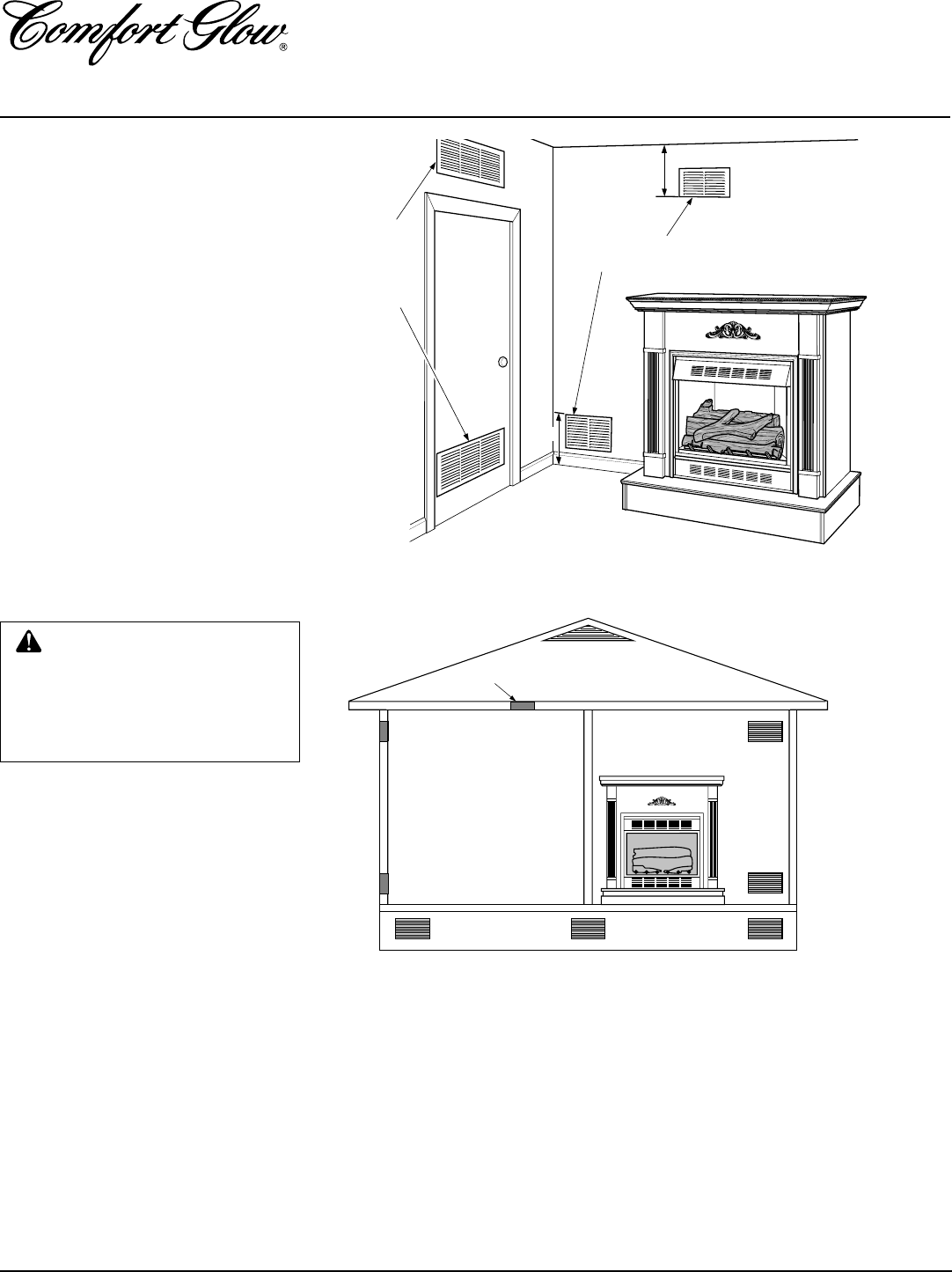
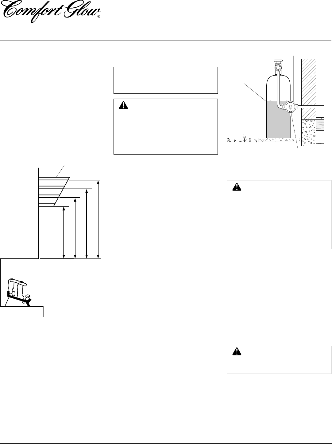
VENTILATION AIR
Ventilation Air From Inside
Building
This fresh air would come from an adjoining
unconfined space. When ventilating to an
adjoining unconfined space, you must pro-
vide two permanent openings: one within
12" of the ceiling and one within 12" of the
floor on the wall connecting the two spaces
(see options 1 and 2, Figure 3). You can also
remove door into adjoining room (see op-
tion 3, Figure 3). Follow the National Fuel
Gas Code NFPA 54/ANS Z223.1, Section
5.3, Air for Combustion and Ventilation for
required size of ventilation grills or ducts.
Figure 4 - Ventilation Air from Outdoors
Ventilation Air From Outdoors
Provide extra fresh air by using ventilation
grills or ducts. You must provide two per-
manent openings: one within 12" of the
ceiling and one within 12" of the floor.
Connect these items directly to the outdoors
or spaces open to the outdoors. These spaces
include attics and crawl spaces.
IMPORTANT:
Do not provide openings for
inlet or outlet air into attic if attic has a
thermostat-controlled power vent. Heated air
entering the attic will activate the power vent.
Figure 3 - Ventilation Air from Inside Building
WARNING: Rework work-
sheet, adding the space of the
adjoining unconfined space. The
combined spaces must have
enough fresh air to supply all
appliances in both spaces.
7
103414
OWNER’S MANUAL
INSTALLATION
Continued
CAUTION: This fireplace cre-
ates warm air currents. These cur-
rents move heat to wall surfaces
next to fireplace. Installing fire-
place next to vinyl or cloth wall
coverings or operating fireplace
where impurities (such as to-
bacco smoke, aromatic candles,
cleaning fluids, oil or kerosene
lamps, etc.) in the air exist, may
discolor walls.
IMPORTANT:
Vent-free heaters add mois-
ture to the air. Although this is beneficial,
installing fireplace in rooms without enough
ventilation air may cause mildew to form
from too much moisture. See Air for Com-
bustion and Ventilation, pages 4 through 6.
IMPORTANT:
Make sure the fireplace is
level. If fireplace is not level, log set will not
work properly.
NOTICE: A qualified service per-
son must install fireplace. Follow
all local codes.
WARNING: Never install the
fireplace
• in a bedroom or bathroom
• in a recreational vehicle
• where curtains, furniture,
clothing, or other flammable
objects are less than 42 inches
from the front, top, or sides of
the fireplace
• in high traffic areas
• in windy or drafty areas
Note:
Your Comfort Glow fireplace is de-
signed to be used in zero clearance installa-
tions. Wall or framing material can be placed
directly against any exterior surface on the
rear, sides, or top of your fireplace, except
where stand-off spacers are integrally at-
tached. If stand-off spacers are attached to
your fireplace, these spacers can be placed
directly against wall or framing materials.
Use the dimensions shown for rough open-
ings to create the easiest installation (see
Built-In Fireplace Installation, page 13).
CHECK GAS TYPE
Use only propane gas. If your gas supply is
not propane gas, do not install fireplace.
Call dealer where you bought fireplace for
proper type fireplace.
ELECTRICAL HOOKUP
(When Using Optional
Blower)
The optional blower accessories (GA3650T
and GA3750) have a power cord 5 feet in
length. You must locate the fireplace within
reach of a 120 volt grounded electrical out-
let, or install an electrical outlet within reach
of the blower power cord. For built-in in-
stallation, an outlet accessory (GA3555) is
available (see Accessories, page 32). This
allows the outlet to be installed inside the
firebox. All electrical installations should
be performed by a qualified service person.
ASSEMBLING AND
ATTACHING OPTIONAL
BRASS TRIM ACCESSORY
(Included with Mantel)
Note:
The instructions below show assem-
bling and attaching brass trim to fireplace.
Do not yet install brass trim if performing a
built-in installation (See Built-In Fireplace
Installation, page 13).
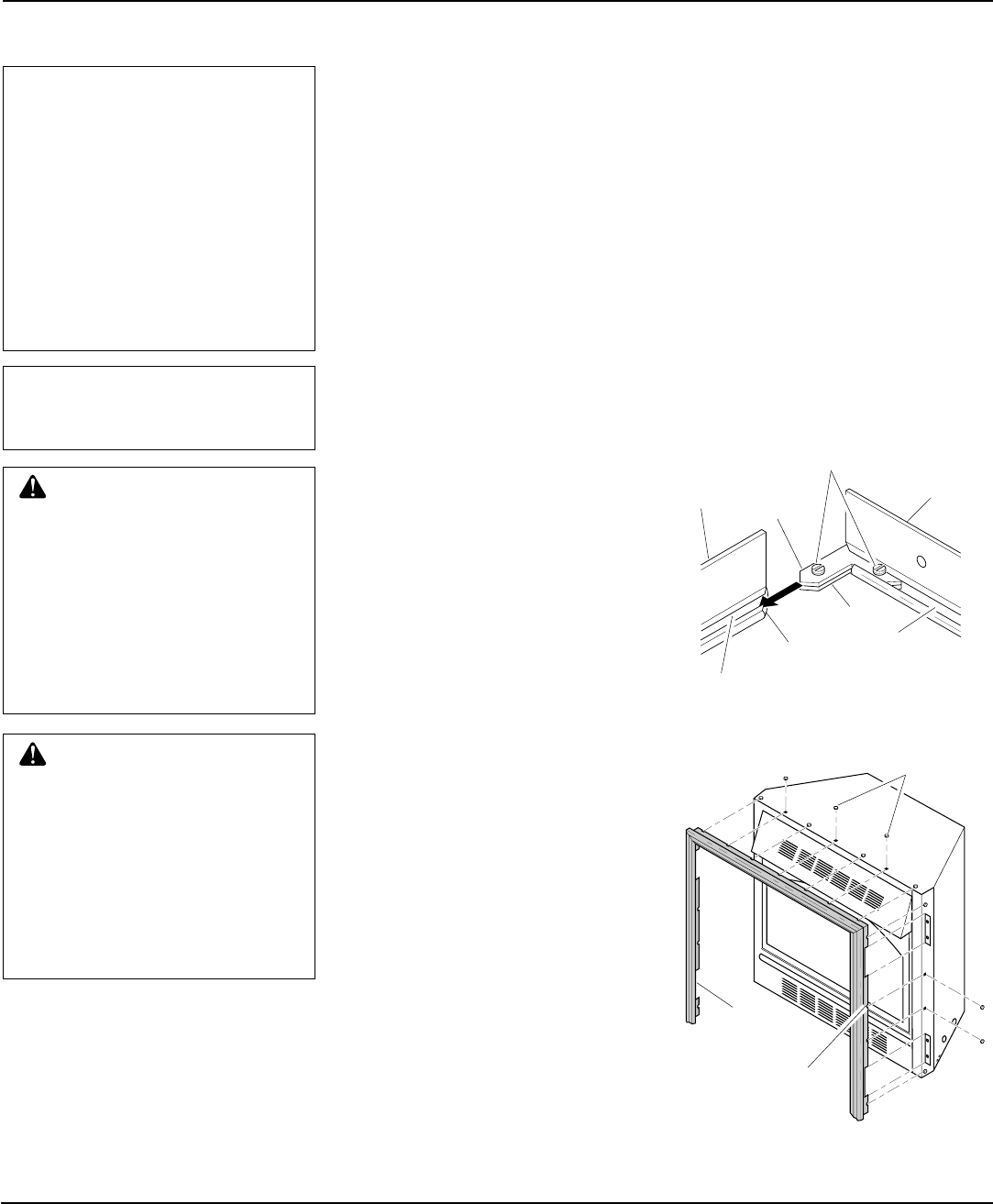
1. Remove packaging from three pieces
of brass trim.
2. Locate four brass screws, two adjust-
ing plates with set screws, and two
shims in the hardware packet.
3. Align shim under adjusting plate as
shown in Figure 5.
Figure 5 - Assembling Brass Trim
Side
Brass
Trim Top
Brass
Trim
Slot
Mitered Edge
Slot
Shim
Set Screws
Adjusting
Plate
Figure 6 - Attaching Brass Trim to Fire-
place
Trim Hanging
Screws
Assembled
Brass Trim
Hanging
Notches on
Trim
4. Slide one end of adjusting plate/shim
in slot on mitered edge of top brass trim
(see Figure 5).
5. Slide other end of adjusting plate/shim
in slot on mitered edge of side brass
trim (see Figure 5).
6. While firmly holding edges of brass
trim together, tighten both set screws
on the adjusting plate with slotted
screwdriver.
7. Repeat steps 1 through 6 for other side.
8. Tighten trim hanging screws (#10 x
6.25 shoulder) into holes in cabinets.
Place the assembled trim onto fireplace
cabinet. Align hanging notches on trim
with hanging screws on side of fireplace
(see Figure 6). Push trim firmly into
place, sliding hanging notches over
hanging screws.
NOTICE: This heater is intended
for use as supplemental heat. Use
this heater along with your pri-
mary heating system. Do not in-
stall this heater as your primary
heat source. If you have a central
heating system, you may run
system’s circulating blower while
using heater. This will help circu-
late the heat throughout the
house. In the event of a power
outage, you can use this heater
as your primary heat source.
8
103414
UNVENTED PROPANE/LP GAS FIREPLACE
CGFP28P and CGFP28PT
INSTALLATION
Continued
INSTALLING GA3650T
BLOWER ACCESSORY
(For CGFP28P Model Only)
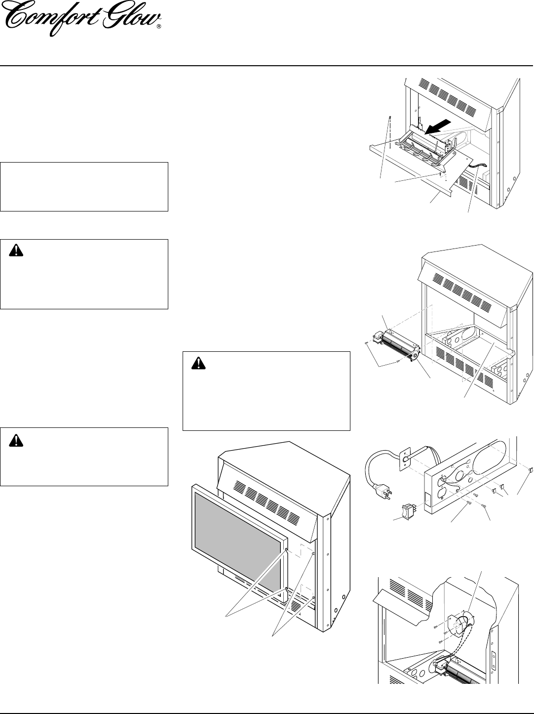
1. Remove fireplace screen (see Figure 7).
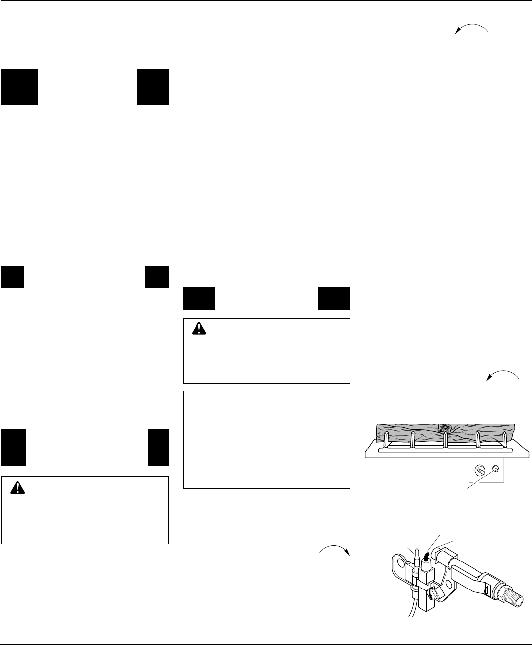
Figure 8 - Removing Log Base from Fire-
place
NOTICE: Shut-off gas supply and
disconnect heater from gas sup-
ply. Contact a qualified service
person to do this.
CAUTION: Do not pick up log
base assembly by burners. This
could damage burners. Only
handle base by grates.
Screws
Log Base
Flexible Gas Line
2. If logs are installed, carefully remove
the logs and set aside, noting the prop-
erly mounted location of each.
3. Remove screws that attach log base as-
sembly to fireplace (do not discard).
Carefully lift up log base assembly and
remove from fireplace, taking care to
pull flexible gas line through the ac-
cess holes (see Figure 8).
Figure 7 - Removing Fireplace Screen
WARNING: You must operate
this fireplace with the fireplace
screen in place. Make sure fire-
place screen is in place before
running fireplace.
Notches
Screen Mounting Screws
AUTO
OFF
ON
3
2
1
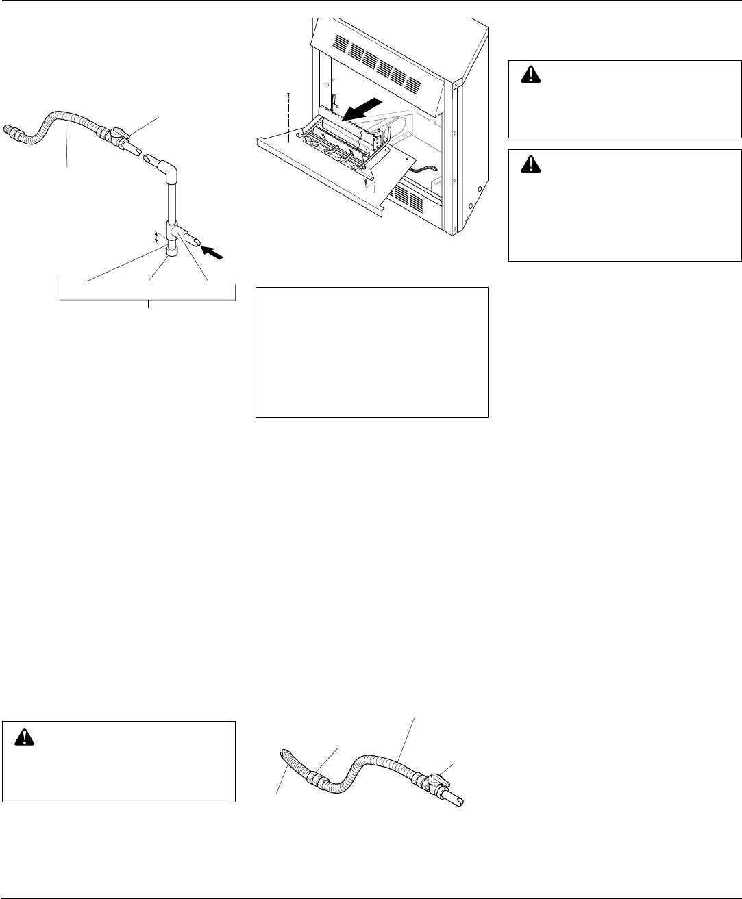
Figure 9 - Mounting Blower to Firebox
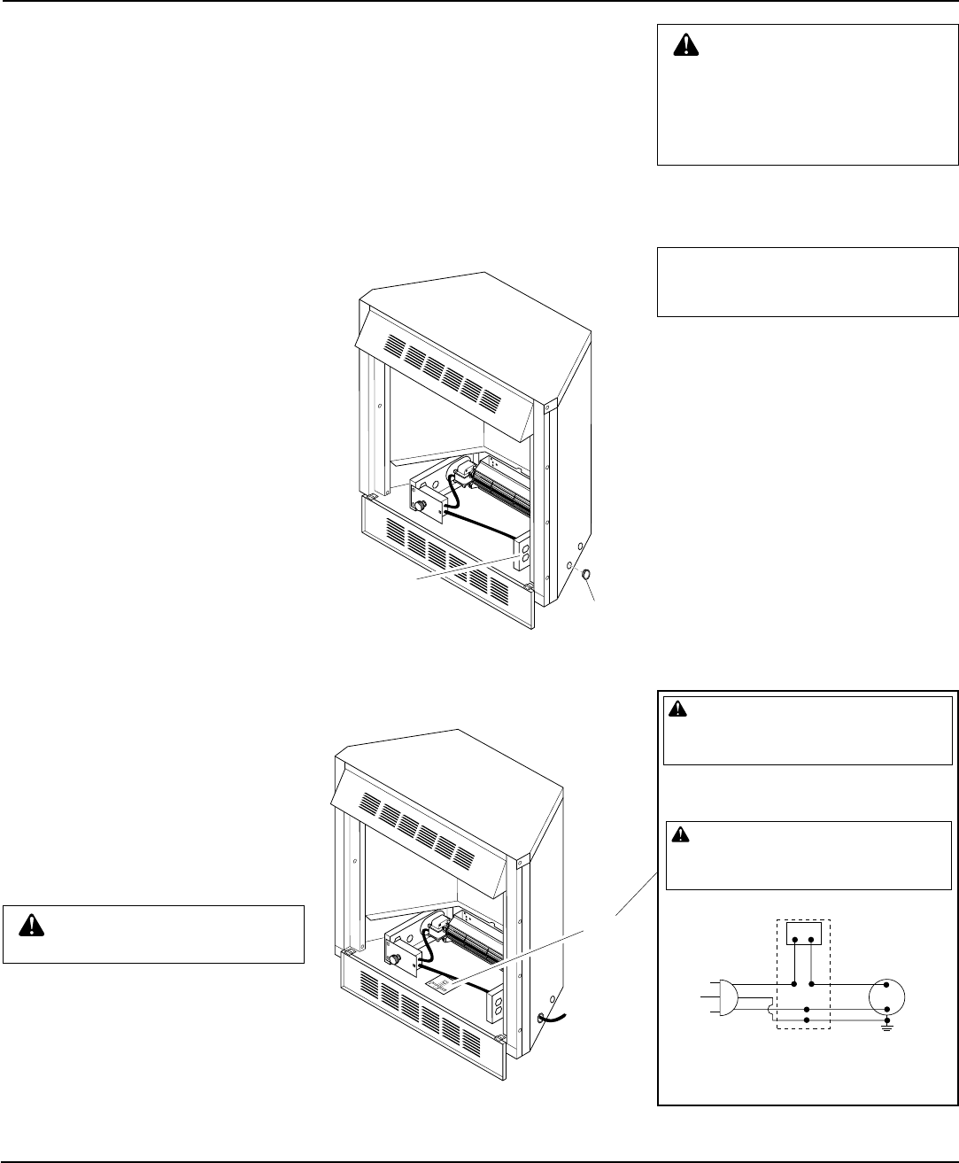
Figure 10 - Installing Power Cord, Mount-
ing Plate, and Selector switch
Figure 11 - Installing Switch and Cover
Assembly
Blower
#8 Screws
Lower Rear
Wall of Firebox
Exhaust
Port
#6 Screws #10 Screw
Wire
Clips
Selector
Switch
Switch and Cover Assembly
4. Place the blower against lower rear wall
of firebox outer wrapper with the ex-
haust port directed upward. Align the
holes in top mounting tabs of blower
with holes in wall of wrapper (see Fig-
ure 9). Using two #8 screws provided,
mount blower and tighten screws firmly.
5. Route terminals end of power cord
through large hole near top of left floor
support bracket. Make sure to pass the
cord from the outside (left side) towards
the center of firebox (see Figure 10).
6. Using two #6 screws provided attach
power cord mounting plate to the outside
face of left floor support bracket. Drive
screws from inside (right side) of floor sup-
port bracket. Attach the plate so that the
power cord is directed towards rear of fire-
box (see Figure 10). Tighten screws firmly.
7. Remove the three screws (do not dis-
card) and cover plate from center of
firebox wrapper rear wall. Discard this
cover plate.
8. Mount the supplied thermostatic switch
and cover assembly into firebox wrap-
per wall. Do this by feeding terminal
ends of wire harness into the hole. Al-
low wires to fall to bottom of firebox
cavity (see Figure 11).
9. Using three screws from step 7, attach
switch and cover assembly to firebox
wrapper rear wall. Tighten screws
firmly (see Figure 11).
10. Mount selector switch to front flange
of left floor support bracket. Align
graphics on switch upright and push
firmly to snap switch into rectangular
hole. Push the selector switch to the off
(middle) position (see Figure 10).
11. Install three plastic wire clips provided
into floor support bracket (see Figure 10).
Secure by pushing clips firmly into holes.
WARNING: Failure to connect
all wires properly as indicated
may cause electrical short circuit
or personal injury. A qualified
electrician should check that all
connections are made properly.
9
103414
OWNER’S MANUAL
INSTALLATION
Continued
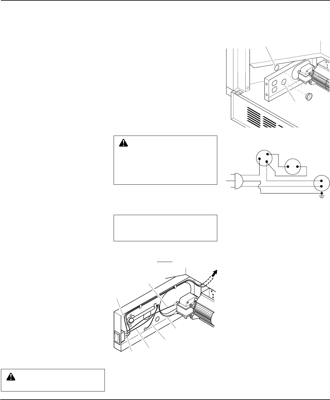
Figure 12 - Wire Attachment
Figure 13 - Installing Bushings
Bushing Location
for Recessed
Installation
Bushing Location for
Freestanding Installation
Note:
To prevent short
circuit, white wire MUST
be connected to motor.
WARNING: Never touch the
blower wheel while in operation.
12. Attach green ground wire ring terminal
to floor support bracket using #10 sheet
metal grounding screw provided (see
Figure 10, page 8). Tighten screw firmly.
13. Attach all five remaining wiring terminals
to the appropriate switch or motor termi-
nal. Carefully note the correct color cod-
ing (see Figures 12 and 14). Push female
wire terminals fully onto male terminal.
14. Secure wires into the appropriate plas-
tic wire clips (see Figure 12).
15. Plug in blower power cord.
If your fireplace system is installed
as a freestanding unit with an acces-
sory mantel, install one plastic bush-
ing (provided) into the 1.5" hole in the
lower left side of the outer casing (see
Figure 13). Route power cord through
plastic bushing. Plug the power cord
into a properly grounded three-prong
wall receptacle near the firebox.
If your fireplace system installation is
recessed, install one plastic bushing pro-
vided into the 1.5" hole near the middle of
the left floor support bracket (see Figure
13). Route power cord through plastic
bushing. Plug the power cord into a prop-
erly installed duplex outlet. (If an outlet is
not available, the accessory model
GA3555 Outlet Kit with cover can be in-
stalled in your fireplace. This will supply
a convenient three-prong grounded elec-
trical outlet for your blower. Refer to the
installation manual provided with the
model GA3555 accessory for instructions
on wiring the duplex outlet.)
16. Check to make sure that the power cord
and wires are completely clear of the
blower wheel and that there are no other
foreign objects in blower wheel. Turn
blower on by pushing the selector switch
to the on position and check for opera-
tion. Turn blower off before continuing.
17. Peel off the backing paper and stick the
supplied wiring diagram decal on the
firebox bottom approximately 12" in
front of blower.
AUTO
OFF
ON
3
2
1
Blue
Wire
Red Wire
Green
Wire
Black
Wire
White
Wire
Blue
Wire
To Switch and
Cover Assembly
Figure 14 - Wiring Diagram
If any of the original wire as supplied with
the appliance must be replaced, it must be
replaced with 105˚C wire or it's equivalent.
WARNING: Failure to position
the parts in accordance with sup-
plied diagrams or failure to use
only parts specifically approved
with this heater may result in dam-
age or personal injury.
NOTICE: A qualified service per-
son must connect fireplace to
gas supply. Follow all local codes.
Blue
Fan Switch
(Off/On/Auto)
Red Fan
Switch
(N.O.)
Green
White
On
110/115
V.A.C.
Blower
Motor
Black
Off
1
2
3
Auto
18. Replace log base assembly in fireplace.
Feed flexible gas supply line into fire-
place base area while replacing log base
assembly. Make sure the entire flexible
gas line is in fireplace base area.
Note:
If firebrick is installed, make sure
the back of the firebox bottom slides
under the rear panel of the firebrick. (lift
the firebrick up if necessary.)
IMPORTANT:
Do not pick up log base
assembly by burners. This could damage
burners. Only handle base by grates.
19. Reattach log base assembly to fireplace
with screws removed in step 3.
20. Install logs and fireplace screen per in-
structions in operating manual provided
with fireplace.
21. Connect gas supply to fireplace per in-
structions in operating manual provided
with fireplace. OPERATING THE BLOWER
Light your gas appliance with the blower
off. After about 5 minutes, turn the blower
on to deliver heated air at the top louvers.
The thermostatic ally-controlled blower fea-
tures a three position switch. The three set-
tings are: ON, OFF, and AUTO. In the ON
position, the blower will operate constantly.
In the OFF position, the blower will not
operate. In the AUTO position, the blower
will start when the thermostat senses a suf-
ficient increase in firebox temperature.
Note:
Your gas logs and thermostat blower
will not turn on and off at the same time. The
fireplace may run for several minutes before
the blower turns on. After the heater modu-
lates to the pilot position, the blower will
continue to run. The blower will shut off
after the firebox temperature decreases.
Note:
It is safe to operate fireplace with
blower turned off. However, the blower helps
distribute heated air from the fireplace.
Note:
Periodically check the louvers of the
firebox and remove any dust, dirt, or other
obstructions.
10
103414
UNVENTED PROPANE/LP GAS FIREPLACE
CGFP28P and CGFP28PT
INSTALLATION
Continued
INSTALLING GA3650T
BLOWER ACCESSORY
(For CGFP28PT Model Only)
1. Remove fireplace screen (see Figure 15).
NOTICE: Shut-off gas supply and
disconnect heater from gas sup-
ply. Contact a qualified service
person to do this.
CAUTION: Do not pick up log
base assembly by burners. This
could damage burners. Only
handle base by grates.
Figure 15 - Removing Fireplace Screen
Notches
Screen Mounting Screws
Figure 18 - Attaching Speed Control to
Firebox
Screws
Speed
Control
Control
Knob
Left Floor
Support
Bracket
Control
Shaft
Figure 17 - Mounting Blower to Firebox
Blower
Screws
Lower
Rear Wall
of Firebox
Exhaust Port
Figure 16 - Removing Log Base from
Fireplace
Screws
Log Base
Flexible
Gas Line
WARNING: You must operate
this fireplace with the fireplace
screen in place. Make sure fire-
place screen is in place before
running fireplace.
2. If logs are installed, carefully remove
the logs and set aside, noting the prop-
erly mounted location of each.
3. Remove screws that attach log base as-
sembly to fireplace. Carefully lift up log
base assembly and remove from fire-
place, taking care to pull flexible gas line
through the access holes (see Figure 16).
4. Attach power cord to blower motor by
firmly pushing the two female termi-
nals of the power cord onto the two
spade terminals on blower motor. Us-
ing screw provided, attach ringed ter-
minal of power cord to mounting tab
of blower housing (see Figure 17).
Tighten screw securely.
5. Place the blower against lower rear wall
of firebox outer wrapper with the ex-
haust port directed upward. Align the
holes in top mounting tabs of blower
with holes in wall of wrapper (see Fig-
ure 17). Using 2 screws provided, mount
blower and tighten screws securely.
6. Be certain that all wire terminals are
securely attached to terminals on
blower motor and that the screw retain-
ing the green ground wire is tight.
7. Place control knob provided on plastic
control shaft of speed control.
8. Mount the speed control on the front
leg of the left floor support bracket us-
ing 2 screws provided (see Figure 18).
Top Mount-
ing Tab
Power Cord
11
103414
OWNER’S MANUAL
WARNING: Never touch the
blower wheel while in operation.
Variable
Fan Switch
WhiteWhite
Black
Green
On
110/115
V.A.C.
Blower
Motor
Black
Black
Black
Off
Variable
Fan Switch
White
White
Black
Green
On
110/115
V.A.C.
Blower
Motor
Black
Black
Black
Off
Wiring
Diagram
WARNING: Failure to position
the parts in accordance with sup-
plied diagrams or failure to use
only parts specifically approved
with this heater may result in dam-
age or personal injury.
NOTICE: A qualified service per-
son must connect fireplace to
gas supply. Follow all local codes.
Operating the Blower
Light your gas appliance with the blower
off. After about 15 minutes, turn the blower
on to deliver heated air at the top louvers.
The blower features a variable control which
allows you to select the speed you desire.
Note:
Periodically check the louvers of the
firebox and remove any dust, dirt, or other
obstructions.
Figure 19 - Installing Plastic Bushing for
Power Cord
Plastic
Bushing
Right Floor
Support
Bracket
Figure 20 - Location of Wiring Diagram Decal, 12" in Front of Blower and 3" from
Blower Speed Control
101584-05
120 Vac. 60 Hz. . 78 Amps
DESA International, Bowling Green, KY
WARNING: Never attempt to service heater
while it is plugged in, operating, or hot. Burns and
electrical shock could result. Only a qualified ser-
vice person should service or repair heater.
If any of the original wire as supplied with the appliance
must be replaced, it must be replaced with 105°C wire or
it’s equivalent.
WARNING: Label all wires prior to discon-
nection when servicing controls. Wiring errors
can cause improper and dangerous operation.
Verify proper operation after servicing.
INSTALLATION
Continued
9. Plug in blower power cord.
a. If your fireplace system is installed
as a freestanding unit with an ac-
cessory mantel, determine whether
the power cord will exit the left side
or the right side of the firebox. In-
stall 1 plastic bushing provided into
the 1.5" hole in the floor support
bracket on the exit side (see Figure
19). Install the second plastic bush-
ing provided into the 1.5" hole in the
outer casing through which the
power cord will exit. Route power
cord through both plastic bushings
and plug the power cord into a prop-
erly grounded 3-prong wall recep-
tacle near the firebox.
b.If your fireplace system installation
is recessed, you must install GA3555
Outlet kit with cover in your fireplace
which will supply a convenient 3-
prong grounded electrical outlet for
your blower. Refer to the installation
manual provided with the model
GA3555 accessory for instructions on
wiring the duplex outlet.
Note:
A qualified installer must
make all electrical connections.
10. Check to make sure that the power cord
is completely clear of the blower wheel
and that there are no other foreign ob-
jects in blower wheel. Turn blower on
and check for operation. Turn blower
off by rotating knob fully counterclock-
wise before continuing.
11. Peel off the backing paper and stick the
supplied wiring diagram decal on the
firebox bottom approximately 12" in
front of blower and 3" to the right of the
blower speed control. (see Figure 20).
12. Replace log base assembly in fireplace.
Feed flexible gas supply line into fire-
place base area while replacing log base
assembly. Make sure the entire flexible
gas line is in fireplace base area.
Note:
If firebrick is installed, make sure
the back of the firebox bottom slides
under the rear panel of the firebrick. (lift
the firebrick up if necessary.)
IMPORTANT:
Do not pick up log base
assembly by burners. This could damage
burners. Only handle base by grates.
13. Reattach log base assembly to fireplace
with screws removed in step 3.
Note:
Discard the remaining hardware
items.
14. Install logs and fireplace screen per in-
structions in operating manual provided
with fireplace.
15. Connect gas supply to fireplace per in-
structions in operating manual provided
with fireplace.
12
103414
UNVENTED PROPANE/LP GAS FIREPLACE
CGFP28P and CGFP28PT
42"
16"
Figure 23 - Placing Hearth Base Acces-
sory Against Wall
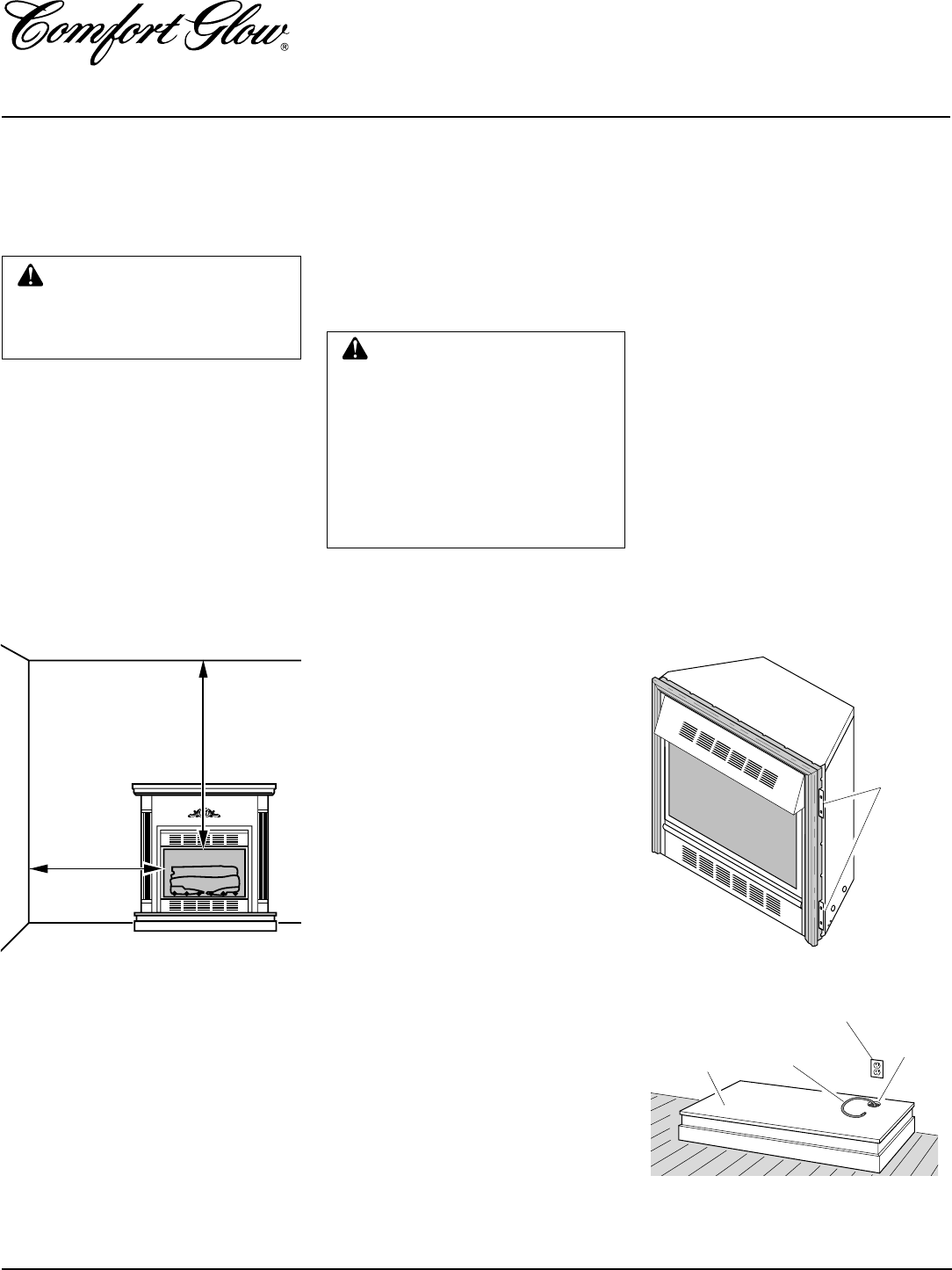
Figure 22 - Location of Nailing Flanges
Nailing
Flanges
INSTALLATION
Continued
INSTALLATION
CLEARANCES
Note:
Clearances are the same if
using optional cabinet mantel or built-
in installation.
WARNING: Maintain the mini-
mum clearances. If you can, pro-
vide greater clearances from
floor, ceiling, and adjoining wall.
Carefully follow the instructions below. This
will ensure safe installation.
Minimum Wall and Ceiling
Clearances (see Figure 21)
A. Clearances from the side of the fire-
place opening to any combustible wall
should not be less than 16 inches for a
cabinet mantel or 12 inches for a cor-
ner installation.
B. Clearances from the top of the fireplace
opening to the ceiling should not be less
than 42 inches.
Note:
The instructions below show installa-
tion using the GMC11F/GMC12U/
GMC13F series cabinet mantel and the
GC3333F/GC3334U/GC3335F series
hearth base accessories (see Accessories,
page 32). A brass trim kit is included with
each mantel accessory. The hearth base ac-
cessory shown is optional for this installa-
tion. You can install fireplace and cabinet
mantel directly on the floor.
1. Assemble cabinet mantel, brass trim
kit, and hearth base. Assembly instruc-
tions are included with each accessory.
2. If installing an optional blower acces-
sory (see Accessories, page 32). Install
a properly grounded 120 volt, three
prong electrical outlet at fireplace lo-
cation if outlet is not there. If possible,
locate outlet so cabinet mantel will
cover it when installed (see Figure 24).
3. Break off nailing flanges (see Figure
22) with hammer or pliers.
4. Place mantel and base in desired loca-
tion. Place heater in front opening of
mantel. Make sure all pieces fit prop-
erly. Remove mantel.
5. Mark floor and base or wall for gas line
entrance. Make sure there is enough
clearance between heater and mantel
for gas line.
IMPORTANT:
Make sure
there are no electrical lines where gas
piping will go through floor or wall.
WARNING: For conventional
installation, it is recommended
you use the cabinet mantel or
hearth base specified in this
manual. Surface clearances may
not be sufficient with other cabi-
net mantels and hearth bases.
This may create a fire hazard. See
Accessories
, page 32, for correct
mantels and hearth bases.
CONVENTIONAL FIREPLACE
INSTALLATION
Figure 21 - Minimum Clearance to Wall
and Ceiling
MINIMUM
CLEARANCE
Side Wall - 16 "
Ceiling - 42"
Floor - 0"
Electrical Outlet
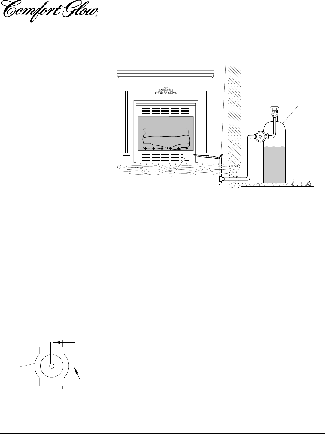
Hearth Base Flexible Gas
Line
Gas Line
Access
Hole
6. Place hearth base accessory against
wall at installation location. Cut an ac-
cess hole in hearth base top to run flex-
ible gas line to fireplace (see Figure 24).
Make sure to locate access hole so cabi-
net mantel will cover it when installed.
Note:
You can secure base to floor us-
ing wood screws. Countersink screw
heads and putty over.
7. Install gas piping to fireplace location.
This installation includes an approved
flexible gas line (if allowed by local
codes) after the manual shutoff valve.
The flexible gas line must be the last
item installed on the gas piping. See In-
stalling Gas Piping to Fireplace Loca-
tion, page 14.
8. Carefully place fireplace on top of
hearth base (Figure 24, page 13). Be
careful not to scratch or damage hearth
base.
Note:
You can secure fireplace to
hearth or floor. Open louver door. Lo-
cate screw holes in bottom of base.
Secure with wood screws through these
holes and into hearth or floor.
Conventional installation of this fireplace
involves installing fireplace along with the
corner, face, or cabinet mantel and hearth
base accessories against a wall in your home.
Follow the instructions below to install the
fireplace in this manner.
13
103414
OWNER’S MANUAL
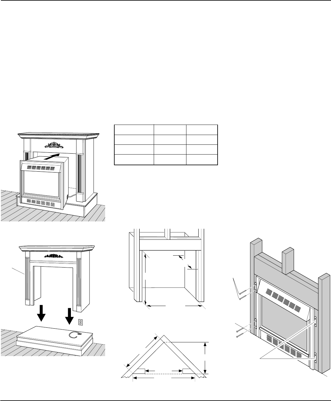
34 3/4"
17 3/4"
33"
39 3/8" 27 7/8"
55 5/8"
34 3/4"
INSTALLATION
Continued
9. If using an optional blower, install it
now. Follow instructions provided with
the blower.
10. Connect fireplace to gas supply (see
Connecting Fireplace To Gas Supply,
page 15).
11. Check all gas connections for leaks. See
Checking Gas Connections, pages 15
and 16.
12. After heater is secured, replace mantel
on hearth base (see Figure 25). Make
sure mantel is flush against wall. In-
stall brass trim (see page 7).
Figure 24 - Inserting Fireplace Into Cabi-
net Mantel
Figure 25 - Installing Cabinet Mantel
Cabinet
Mantel
BUILT-IN FIREPLACE
INSTALLATION
(Check Local Building Codes)
Built-in installation of this fireplace involves
installing fireplace into a framed-in enclo-
sure. This makes the front of fireplace flush
with wall. An optional brass trim accessory
is available (see Accessories, page 32). The
brass trim will extend past the sides of the
fireplace approximately 1/2". This will cover
the rough edges of the wall opening. If
installing a mantel above the fireplace, but
you must follow the clearances shown in
Figure 29, page 14. Follow the instructions
below to install the fireplace in this manner.
Actual Framing
Height 32 3/8" 33"
Front Width 34 5/16" 34 3/4"
Depth 16 11/16" 17 3/4"
Continued
Figure 26 - Rough Opening for Installing
in Wall
1. Frame in rough opening. Use dimen-
sions shown in Figure 26 for the rough
opening.
If installing in a corner, use dimensions
shown in Figure 27 for the rough open-
ing. The height is 33" which is the same
as the wall opening in Figure 26.
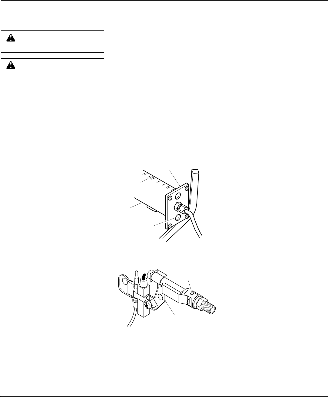
Figure 28 - Attaching Fireplace to Wall
Studs
2. If using optional blower, install it now.
Also install and properly ground
GA3555 three prong 120 volt outlet in
fireplace. Follow instructions included
in kits.
3. Install gas piping to fireplace location.
This installation includes an approved
flexible gas line (if allowed by local
codes) after the manual shutoff valve.
The flexible gas line must be the last
item installed on the gas piping. See In-
stalling Gas Piping to Fireplace Loca-
tion, page 14.
4. Carefully set fireplace in front of rough
opening with back of fireplace inside
wall opening.
5. Attach flexible gas line to fireplace gas
regulator. See Connecting Fireplace to
Gas Supply, page 15.
6. Carefully insert fireplace into rough
opening.
7. Attach fireplace to wall studs using
nails or wood screws through holes in
nailing flange (see Figure 28).
8. Check all gas connections for leaks. See
Checking Gas Connections, pages 15
and 16.
9. If using optional GA7090 Brass Trim
Kit, install brass trim after final finish-
ing and/or painting of wall (see Figure
6, page 7).
Figure 27 - Rough Opening for Installing
in Corner
Nailing
Flanges
Nails or
Wood
Screws
14
103414
UNVENTED PROPANE/LP GAS FIREPLACE
CGFP28P and CGFP28PT
20"
24
1
/2
"
27
1
/2
"
30"
2
1/2
"
6"
8"
10"
Propane
Supply Tank
External Regulator
Vent Pointing Down
Figure 30 - External Regulator With Vent
Pointing Down
CAUTION: Use only new,
black iron or steel pipe. Inter-
nally-tinned copper tubing may
be used in certain areas. Check
your local codes. Use pipe of 1/2"
diameter or greater to allow
proper gas volume to fireplace. If
pipe is too small, undue loss of
pressure will occur.
CAUTION: Use pipe joint seal-
ant that is resistant to liquid pe-
troleum (LP) gas.
Install sediment trap in supply line as shown
in Figure 31, page 15. Locate sediment trap
where it is within reach for cleaning. Locate
sediment trap where trapped matter is not
likely to freeze. A sediment trap traps mois-
ture and contaminants. This keeps them
from going into fireplace gas controls. If
sediment trap is not installed or is installed
wrong, fireplace may not run properly.
Installation must include a manual shutoff
valve, union, and plugged 1/8" NPT tap.
Locate NPT tap within reach for test gauge
hook up. NPT tap must be upstream from
fireplace (see Figure 31, page 15).
Check your building codes for any special
requirements for locating manual shutoff
valve to fireplaces.
Apply pipe joint sealant lightly to male
threads. This will prevent excess sealant
from going into pipe. Excess sealant in pipe
could result in clogged fireplace valves.
INSTALLATION
Continued
Mantel Clearances for Built-In
Installation
If placing mantel above built-in fireplace,
you must meet minimum clearance between
mantel shelf and top of fireplace opening.
Figure 29 - Minimum Mantel Clearances
for Built-In Installation
Mantel Shelf
INSTALLING GAS PIPING TO
FIREPLACE LOCATION
NOTICE: A qualified service per-
son must connect fireplace to
gas supply. Follow all local codes.
CAUTION: Never connect
heater directly to the propane
supply. This heater requires an
external regulator (not supplied).
Install the external regulator be-
tween the heater and propane
supply.
Installation Items Needed
Before installing fireplace, make sure you
have the items listed below.
• external regulator (supplied by installer,
see Figure 30)
• piping (check local codes)
• sealant (resistant to propane/LP gas)
• manual shutoff valve *
• test gauge connection *
• sediment trap
• tee joint
• pipe wrench
• approved flexible gas line with gas con-
nector (if allowed by local codes) (not
provided)
* An A.G.A. design-certified manual shutoff
valve with 1/8" NPT tap is an acceptable
alternative to test gauge connection. Pur-
chase the optional A.G.A. design-certified
manual shutoff valve from your dealer. See
Accessories, page 32.
The installer must supply an external regu-
lator. The external regulator will reduce
incoming gas pressure. You must reduce
incoming gas pressure to between 11 and 14
inches of water. If you do not reduce incom-
ing gas pressure, heater regulator damage
could occur. Install external regulator with
the vent pointing down as shown in Figure
30. Pointing the vent down protects it from
freezing rain or sleet.
If your installation does not meet the above
minimum clearances, you must:
• raise the mantel to an acceptable height,
OR
• remove the mantel.
Note:
All Vertical
measurements
are from top of
fireplace
opening to
bottom of
mantel shelf.
All measure-
ments are in
inches.
15
103414
OWNER’S MANUAL
INSTALLATION
Continued
Continued
* Purchase the optional A.G.A. design-cer-
tified manual shutoff valve from your dealer.
See Accessories, page 32.
Figure 31 - Gas Connection
CONNECTING FIREPLACE
TO GAS SUPPLY
Installation Items Needed
• 5/16" hex socket wrench or nut-driver
• Phillips screwdriver
• sealant (resistant to propane/LP gas, not
provided)
1. Remove fireplace screen. Remove two
screws that hold fireplace screen in
place for shipping. These screws are
located near top of screen. Discard
screws. Lift fireplace screen up and pull
out to remove.
2. Remove screws that attach log base
assembly to fireplace. Carefully lift up
log base assembly and remove from
fireplace (see Figure 32).
Figure 32 - Removing Log Base Assem-
bly From Fireplace
CAUTION: Do not pick up log
base assembly by burners. This
could damage burners. Only
handle base by grates.
A.G.A. Design-Certified
Manual Shutoff Valve
With 1/8" NPT Tap*
3" Minimum
From
External
Regulator
(11" W.C.
to 14"
W.C.
Pressure)
Approved
Flexible
Gas Line
Tee Joint
Sediment Trap
Cap
Pipe Nipple
4. Attach a 45˚ flare union gas connector
to flexible gas line from gas supply (see
Figure 33). Connect flare union to flex-
ible gas line attached to gas regulator
of fireplace (see Figure 33).
5. Check all gas connections for leaks. See
Checking Gas Connections, column 3.
6. Replace log base assembly back into
fireplace. Feed flexible gas line into
fireplace base area while replacing log
base assembly. Make sure the entire
flexible gas line is in fireplace base area.
Reattach log base assembly to
fireplace
with screws removed in step 2.
NOTICE : Most building codes do
not permit concealed gas con-
nections. A flexible gas line is
provided to allow accessibility
from the fireplace. The flexible
gas supply line connection to the
manual shutoff valve should be
accessible.
3. Route flexible gas line (provided by
installer) from manual shutoff valve to
fireplace. Route flexible gas supply line
through one of the access holes.
CHECKING GAS
CONNECTIONS
Figure 33 - Attaching Flexible Gas Lines
Together
Flexible Gas Line from
Fireplace Gas Regulator
Provided with Fireplace
To Fireplace
Gas Regulator Gas
Connector
Flexible Gas Line from
Manual Shutoff Valve
Provided by Installer
Manual
Shutoff
Valve
➞
➞
WARNING: Test all gas pip-
ing and connections for leaks
after installing or servicing. Cor-
rect all leaks at once.
Pressure Testing Gas Supply
Piping System
Test Pressures In Excess Of 1/2 PSIG
1. Disconnect fireplace and its individual
manual shutoff valve from gas supply
piping system. Pressures in excess of 1/2
psig will damage fireplace gas regulator.
2. Cap off open end of gas pipe where
manual shutoff valve was connected.
3. Pressurize supply piping system by ei-
ther using compressed air or opening
propane supply tank valve.
4. Check all joints of gas supply piping
system. Apply mixture of liquid soap
and water to gas joints. Bubbles form-
ing show a leak.
5. Correct all leaks at once.
6. Reconnect fireplace and manual shutoff
valve to gas supply. Check reconnected
fittings for leaks.
WARNING: Never use an open
flame to check for a leak. Apply a
mixture of liquid soap and water
to all joints. Bubbles forming
show a leak. Correct all leaks at
once.
To
External
Regulator
16
103414
UNVENTED PROPANE/LP GAS FIREPLACE
CGFP28P and CGFP28PT
ON
POSITION
OFF
POSITION
INSTALLATION
Continued
Test Pressures Equal To or Less Than
1/2 PSIG
1. Close manual shutoff valve (see Fig-
ure 34).
2. Pressurize supply piping system by ei-
ther using compressed air or opening
propane supply tank valve.
3. Check all joints from propane supply
tank to manual shutoff valve (see Fig-
ure 35). Apply mixture of liquid soap
and water to gas joints. Bubbles form-
ing show a leak.
4. Correct all leaks at once.
Pressure Testing Fireplace Gas
Connections
1. Open manual shutoff valve (see Fig-
ure 34).
2. Open propane supply tank valve.
3. Make sure control knob of fireplace is
in the OFF position.
4. Check all joints from manual shutoff
valve to thermostat gas valve (see Fig-
ure 35). Apply mixture of liquid soap
and water to gas joints. Bubbles form-
ing show a leak.
5. Correct all leaks at once.
6. Light fireplace (see Operating Fire-
place, pages 18 and 19 [Thermostat-
controlled models] or pages 19 and 20
[Manually-controlled models]). Check
all other internal joints for leaks.
7. Turn off fireplace (see To Turn Off Gas
to Appliance, page 18, [Thermostat-
controlled models] or page 20 [Manu-
ally-controlled models]).
Figure 34 - Manual Shutoff Valve
Open
Manual
Shutoff
Valve
Figure 35 - Checking Gas Joints
Propane
Supply
Tank
Manual Gas Valve
Manual Shutoff Valve
Closed
17
103414
OWNER’S MANUAL
3
2
44
INSTALLATION
Continued
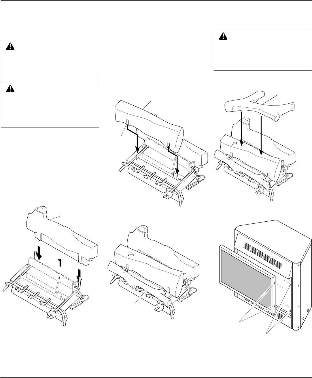
INSTALLING LOGS
WARNING: Failure to position
the parts in accordance with these
diagrams or failure to use only
parts specifically approved with
this heater may result in property
damage or personal injury.
Each log is marked with a number. These
numbers will help you identify the log when
installing. It is very important to install
these logs exactly as instructed. Do not
modify logs. Only use logs supplied with
heater.
1. Slide rear log (#1) into place behind
rear burner. Make sure flat areas at bot-
tom of log are behind rear burner (see
Figure 36).
Tab
Figure 37 - Installing Bottom Mid Log
Bottom Mid Log (#2)
Rear Log (#1)
Front Log (#3)
Figure 38 - Installing Front Log
Top Log (#4)
Figure 36 - Installing Rear Log
Figure 39 - Installing Top Log
Figure 40 - Installing Fireplace Screen
WARNING: You must operate
this fireplace with the fireplace
screen in place. Make sure fire-
place screen is in place before
running fireplace.
Notches
Screws for
Mounting Screen
2 . Slide bottom mid log (#2) into place in
behind front burner. Make sure tabs at
bottom of log are behind front burner
(see Figure 37).
3. Place front log (#3) into place in front
of bottom mid log (#2) (see Figure 38).
Make sure notches on bottom rest on
grate prongs.
4. Finally place top log (#4) over bottom
mid log (#2) by matching the notches
under log (#4) with the raised blocks
of log (#2) (see Figure 39).
5. Install fireplace screen by slipping
notches of fireplace screen over screws
on front of fireplace (see Figure 40).
CAUTION: Do not remove the
metal data plates attached to the
heater base assembly. The data
plates contain important warranty
information.
18
103414
UNVENTED PROPANE/LP GAS FIREPLACE
CGFP28P and CGFP28PT
CAUTION: Do not try to adjust
heating levels by using the
manual shutoff valve.
TO TURN OFF GAS
TO APPLIANCE
Shutting Off Fireplace
Turn control knob clockwise to
the OFF position.
Shutting Off Burners Only (pilot
stays lit)
Turn control knob clockwise to
the PILOT position.
Figure 42 - Pilot
Figure 41 - Control Knob and Ignitor But-
ton Location
LIGHTING
INSTRUCTIONS
WARNING: You must operate
this fireplace with the fireplace
screen in place. Make sure fire-
place screen is installed before
running fireplace.
NOTICE: During initial operation
of new fireplace, burning logs
will give off a paper-burning
smell. Orange flame will also be
present. Open window to vent
smell. Operate fireplace on HI
position to burn off odor. This
will only last a few hours.
Thermocouple
Ignitor Electrode
Pilot Burner
1. STOP! Read the safety information
in previous column.
2. Make sure manual shutoff valve is
fully open.
3. Turn control knob clockwise
Clockwise
to the OFF position.
4. Wait five (5) minutes to clear out any
gas. Then smell for gas, including
near the floor. If you smell gas,
STOP! Follow “B” in the safety in-
formation above. If you don’t smell
gas, go to the next step.
5. Turn control knob counterclockwise
C-clockwise
to the PILOT position.
Press in control knob for five (5) sec-
onds (see Figure 41).
Note:
If running fireplace for first
time, there will be air in gas line. You
may need to press in control knob for
30 seconds or longer. This will allow
air to bleed from the gas system.
6. Continue pressing control knob in.
Press and release ignitor button. This
will light pilot. The pilot is attached
to the front burner. If needed, keep
pressing ignitor button until pilot
lights.
A. This appliance has a pilot which must
be lighted by hand. When lighting the
pilot, follow these instructions exactly.
B. BEFORE LIGHTING smell all
around the appliance area for gas. Be
sure to smell next to the floor because
some gas is heavier than air and will
settle on the floor.
WHAT TO DO IF YOU SMELL
GAS
• Do not try to light any appliance.
• Do not touch any electric switch;
do
not use any phone in your building.
• Immediately call your gas supplier
from a neighbor’s phone. Follow
the gas supplier’s instructions.
• If you cannot reach your gas sup-
plier, call the fire department.
C. Use only your hand to push in or turn
the gas control knob. Never use tools.
If the knob will not push in or turn
by hand, don’t try to repair it, call a
qualified service technician or gas
supplier. Force or attempted repair
may result in a fire or explosion.
D. Do not use this appliance if any part
has been under water. Immediately
call a qualified service technician to
inspect the appliance and to replace
any part of the control system and
any gas control which has been un-
der water.
FOR YOUR SAFETY
READ BEFORE
LIGHTING
OPERATING
FIREPLACE
Thermostat-Controlled Model
CGFP28PT
WARNING: If you do not fol-
low these instructions exactly, a
fire or explosion may result caus-
ing property damage, personal
injury or loss of life.
Ignitor Button
Control Knob
• If control knob does not pop out
when released, contact a qualified
service person or gas supplier for
repairs.
7. Keep control knob pressed in for 30
seconds after lighting pilot. After 30
seconds, release control knob.
Note:
If pilot goes out, repeat steps
3 through 7. This fireplace has a
safety interlock system. Wait one (1)
minute for system to reset before
lighting pilot again.
Note:
If pilot does not stay lit, con-
tact a qualified service person or gas
supplier for repairs. Until repairs are
made, light pilot with match. To light
pilot with match, see Manual Light-
ing Procedure, page 19.
8. Turn control knob counterclockwise
to desired heating level. The
burners should light. Set control
knob to any heat level between HI
and LO.
19
103414
OWNER’S MANUAL
IGNITOR
Continued
OPERATING
FIREPLACE
Continued
THERMOSTAT
CONTROL
OPERATION
1. Follow steps 1 through 5 under Light-
ing Instructions, page 18.
2. Depress control knob and light pilot
with match.
3. Keep control knob pressed in for 30
seconds after lighting pilot. After 30
seconds, release control knob. Now
follow step 8, page 18.
MANUAL LIGHTING
PROCEDURE
Variable Manually-Controlled
Model CGFP28P
A. This appliance has a pilot which must
be lighted by hand. When lighting the
pilot, follow these instructions exactly.
B. BEFORE LIGHTING smell all
around the appliance area for gas. Be
sure to smell next to the floor because
some gas is heavier than air and will
settle on the floor.
WARNING: If you do not fol-
low these instructions exactly, a
fire or explosion may result caus-
ing property damage, personal
injury or loss of life.
FOR YOUR SAFETY
READ BEFORE
LIGHTING
You can set the thermostat control knob
to any comfort level between HI and LO.
The thermostat will gradually modulate
the heat output and flame height from
higher to lower settings, or pilot, in order
to maintain the comfort level you select.
The ideal comfort setting will vary by
household depending upon the amount
of space to be heated, the output of the
central heating system, etc.
Note:
Selecting the HI setting will cause
the burner to remain on without modu-
lating down in most cases.
LIGHTING
INSTRUCTIONS
WARNING: You must operate
this fireplace with the fireplace
screen in place. Make sure fire-
place screen is installed before
running fireplace.
NOTICE: During initial operation
of new fireplace, burning logs
will give off a paper-burning
smell. Orange flame will also be
present. Open window to vent
smell. Operate fireplace on HI
position to burn off odor. This
will only last a few hours.
1. STOP! Read the safety information
in previous column.
2. Make sure manual shutoff valve is
fully open.
3. Turn control knob clockwise
Clockwise
to the OFF position.
4. Wait five (5) minutes to clear out any
gas. Then smell for gas, including
near the floor. If you smell gas,
STOP! Follow “B” in the safety in-
formation above. If you don’t smell
gas, go to the next step.
Figure 43 - Control Knob and Ignitor But-
ton Location
Ignitor Button
Control Knob
WHAT TO DO IF YOU SMELL
GAS
• Do not try to light any appliance.
• Do not touch any electric switch; do
not use any phone in your building.
• Immediately call your gas supplier
from a neighbor’s phone. Follow
the gas supplier’s instructions.
• If you cannot reach your gas sup-
plier, call the fire department.
C. Use only your hand to push in or turn
the gas control knob. Never use tools.
If the knob will not push in or turn
by hand, don’t try to repair it, call a
qualified service technician or gas
supplier. Force or attempted repair
may result in a fire or explosion.
D. Do not use this appliance if any part
has been under water. Immediately
call a qualified service technician to
inspect the appliance and to replace
any part of the control system and
any gas control which has been un-
der water.
5. Slightly depress and turn control knob
counterclockwise
C-clockwise
to the PI-
LOT position. Press in control knob for
five (5) seconds (see Figure 43).
Note:
If running fireplace for first
time, there will be air in gas line. You
may need to press in control knob for
30 seconds or longer. This will allow
air to bleed from the gas system.
•If control knob does not pop out
when released, contact a qualified
service person or gas supplier for
repairs.
6. Continue pressing control knob in.
Press and release ignitor button. This
will light pilot. The pilot is attached
to the front burner. If needed, keep
pressing ignitor button until pilot
lights.
Note:
If pilot does not stay lit, con-
tact a qualified service person or gas
supplier for repairs. Until repairs are
made, light pilot with match. To light
pilot with match, see Manual Light-
ing Procedure, page 20.
7. Keep control knob pressed in for 30
seconds after lighting pilot. After 30
seconds, release control knob.
Note:
If pilot goes out, repeat steps
3 through 7.
8. Slightly depress and turn control
knob counterclockwise
C-clockwise
to
the HIGH position. Both burners
should light. Set control knob to de-
sired heat setting.
Figure 44 - Pilot
Thermocouple
Ignitor Electrode
Pilot Burner
20
103414
UNVENTED PROPANE/LP GAS FIREPLACE
CGFP28P and CGFP28PT
INSPECTING
BURNERS
Check pilot flame pattern and burner flame
patterns often.
PILOT FLAME PATTERN
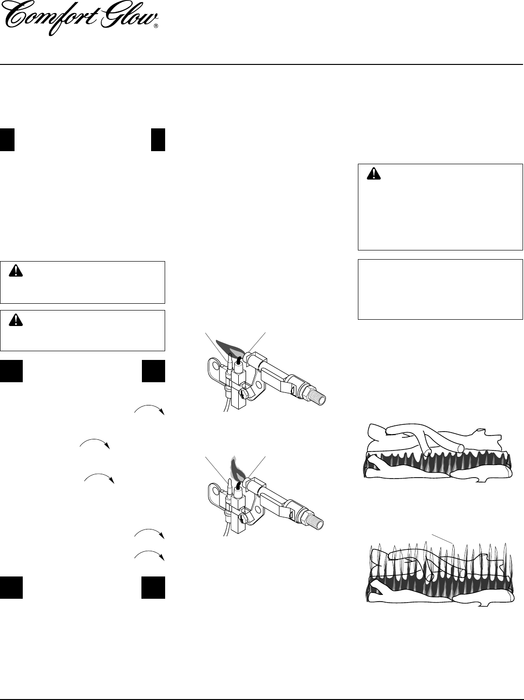
Figure 45 shows a correct pilot flame pattern.
Figure 46 shows an incorrect pilot flame
pattern. The incorrect pilot flame is not touch-
ing the thermocouple. This will cause the
thermocouple to cool. When the thermo-
couple cools, the fireplace will shutdown.
If pilot flame pattern is incorrect, as shown
in Figure 46
• turn fireplace off (see To Turn Off Gas to
Appliance, page 18 [Thermostat-con-
trolled models} or column 1, this page,
[Manually-controlled models])
•
see Troubleshooting, pages 22 through 24
Thermocouple Pilot Burner
Figure 45 - Correct Pilot Flame Pattern
Figure 46 - Incorrect Pilot Flame Pattern
FRONT BURNER FLAME
PATTERN
Figure 47 shows correct front burner flame
pattern. Figure 48 shows incorrect front
burner flame pattern. The incorrect burner
flame pattern shows yellow tipping at top of
blue flame.
WARNING: If front burner
flame pattern shows yellow tip-
ping, your fireplace could pro-
duce increased levels of carbon
monoxide. Follow instructions at
bottom of this page. Yellow flame
on rear burner is normal.
NOTICE: Do not mistake orange
flames with yellow tipping. Dirt
or other fine particles are burned
by fireplace, causing brief
patches of orange flame.
If front burner flame pattern is incorrect, as
shown in Figure 48
• turn fireplace off (see To Turn Off Gas to
Appliance, page 18 [Thermostat-con-
trolled models} or column 1, this page,
[Manually-controlled models])
•
see Troubleshooting, pages 22 through 24
Figure 48 - Incorrect Front Burner Flame
Pattern
Figure 47 - Correct Front Burner Flame
Pattern
Thermocouple Pilot Burner
WARNING: Do not operate
heater between pilot and high
positions.
CAUTION: Do not try to ad-
just heating levels by using the
manual shutoff valve.
The variable control valve can be set to
any heat setting and flame height de-
sired, by simply turning the control knob
until that setting is attained. Even the
lowest setting provides realistic flames
and glowing embers from two burners.
Selecting higher settings produces
greater heat output. This results in in-
creased heating comfort.
TO TURN OFF GAS
TO APPLIANCE
Shutting Off Fireplace
1. Turn control knob clockwise
Clockwise
to the HIGH position.
2. Slightly depress control knob and
turn clockwise
Clockwise
to the PILOT
position.
3. Slightly depress control knob and
turn clockwise
Clockwise
to the OFF
position.
Shutting Off Burners Only (pilot
stays lit)
1. Turn control knob clockwise
Clockwise
to the HIGH position.
2. Press in and turn clockwise
Clockwise
to the PILOT position.
OPERATING
FIREPLACE
Continued
Yellow Tipping At
Top of Blue Flame
VARIABLE MANUAL
CONTROL OPERATION
MANUAL LIGHTING
PROCEDURE
1. Follow steps 1 through 5 under Light-
ing Instructions, page 19.
2. Depress control knob and light pilot
with match.
3. Keep control knob pressed in for 30
seconds after lighting pilot. After 30
seconds, release control knob. Now
follow step 8, page 19.
21
103414
OWNER’S MANUAL
CLEANING AND
MAINTENANCE
WARNING: Turn off fireplace
and let cool before cleaning.
CAUTION: You must keep
control areas, burners, and cir-
culating air passageways of fire-
place clean. Inspect these areas
of fireplace before each use. Have
fireplace inspected yearly by a
qualified service person. Fire-
place may need more frequent
cleaning due to excessive lint
from carpeting, pet hair, etc.
LOGS
• If you remove logs for cleaning, refer to
Installing Logs, page 17, to properly re-
place logs.
• Replace log(s) if broken or chipped
(dime-sized or larger).
CLEANING BURNER
INJECTOR HOLDER AND
PILOT AIR INLET HOLE
The primary air inlet holes allow the proper
amount of air to mix with the gas. This
provides a clean burning flame. Keep these
holes clear of dust, dirt, and lint. Clean these
air inlet holes prior to each heating season.
Blocked air holes will create soot. We rec-
ommend that you clean the unit every 2,500
hours of operation or every three months.
We also recommend that you keep the burner
tube and pilot assembly clean and free of
dust and dirt. To clean these parts we recom-
mend using compressed air no greater than
30 PSI. Your local computer store, hard-
ware store, or home center may carry com-
pressed air in a can. You can use a vacuum
cleaner in the blow position. If using com-
pressed air in a can, please follow the direc-
tions on the can. If you don't follow direc-
tions on the can, you could damage the pilot
assembly.
1. Shut off the unit, including the pilot.
Allow the unit to cool for at least thirty
minutes.
2. Inspect burner, pilot, and primary air
inlet holes on injector holder for dust
and dirt (see Figure 49).
Figure 49 - Injector Holder On Outlet
Burner Tube
3. Blow air through the ports/slots and
holes in the burner.
4. Check the injector holder located at the
end of the burner tube again. Remove
any large particles of dust, dirt, lint, or
pet hairs with a soft cloth or vacuum
cleaner nozzle.
5. Blow air into the primary air holes on
the injector holder.
6. In case any large clumps of dust have
now been pushed into the burner repeat
steps 3 and 4.
Clean the pilot assembly also. A yellow tip
on the pilot flame indicates dust and dirt in
the pilot assembly. There is a small pilot air
inlet hole about two inches from where the
pilot flame comes out of the pilot assembly
(see Figure 50). With the unit off, lightly
blow air through the air inlet hole. You may
blow through a drinking straw if compressed
air is not available.
Burner
Tube
Injector Holder
Primary Air Inlet
Holes
Figure 50 - Pilot Inlet Air Hole
Pilot Assembly
Pilot Air Inlet
Hole
Ports/Slots

22
103414
UNVENTED PROPANE/LP GAS FIREPLACE
CGFP28P and CGFP28PT
OBSERVED PROBLEM
When ignitor button is pressed, there is no
spark at ODS/pilot
When ignitor button is pressed, there is
spark at ODS/pilot but no ignitio
ODS/pilot lights but flame goes out when
control knob is released
TROUBLESHOOTING
Note:
All troubleshooting items are listed in
order of operation.
WARNING: Turn off fireplace
and let cool before servicing. Only
a qualified service person should
service and repair fireplace.
CAUTION: Never use a wire,
needle, or similar object to clean
ODS/pilot. This can damage ODS/
pilot unit.
POSSIBLE CAUSE
1. Ignitor cable pinched or wet
2. Ignitor electrode not connected to igni-
tor cable
3. Piezo ignitor nut is loose
4. Broken ignitor cable
5. Ignitor electrode broken
6. Bad piezo ignitor
7. Ignitor electrode positioned wrong
1. Gas supply turned off or manual shutoff
valve closed
2. Control knob not in PILOT position
3. Control knob not pressed in while in
PILOT position
4. Air in gas lines when installed
5. ODS/pilot is clogged
6. Gas regulator setting is not correct
1. Control knob not fully pressed in
2. Control knob not pressed in long enough
3. Manual shutoff valve not fully open
4. Thermocouple connection loose at con-
trol valve
5. Pilot flame not touching thermocouple,
which allows thermocouple to cool,
causing pilot flame to go out. This prob-
lem could be caused by one or both of
the following:
A) Low gas pressure
B) Dirty or partially clogged ODS/pilot
6. Thermocouple damaged
7. Control valve damaged
8. On thermostat models, safety interlock
system has been triggered
REMEDY
1. Free ignitor cable if pinched by any
metal or tubing. Keep ignitor cable dry
2. Reconnect ignitor cable
3. Tighten nut holding piezo ignitor to base
panel of log set. Nut is located behind
base panel.
4. Replace ignitor cable
5. Replace ignitor
6. Replace piezo ignitor
7. Replace ignitor
1. Turn on gas supply or open manual
shutoff valve
2. Turn control knob to PILOT position
3. Press in control knob while in PILOT
position
4. Continue holding down control knob. Re-
peat igniting operation until air is removed
5. Clean ODS/pilot (see Cleaning and
Maintenance, page 21) or replace ODS/
pilot assembly
6. Replace gas regulator
1. Press in control knob fully
2. After ODS/pilot lights, keep control
knob pressed in 30 seconds
3. Fully open manual shutoff valve
4. Hand tighten until snug, then tighten
1/4 turn more
5. A) Contact local natural gas company
B) Clean ODS/pilot (see Cleaning
and Maintenance, page 21) or replace
ODS/pilot assembly
6. Replace thermocouple
7. Replace control valve
8. Wait one minute for safety interlock sys-
tem to reset. Repeat ignition operation
Note:
For additional help, visit DESA
International's Technical Service web
site at www.desatech.com.
www.desatech.com

23
103414
OWNER’S MANUAL
OBSERVED PROBLEM
One or both burners do not light after ODS/
pilot is lit
Delayed ignition of one or both burners
Burner backfiring during combustion
Yellow flame in front burner during burner
combustion
Slight smoke or odor during initial operation
Fireplace produces a whistling noise when
burners are lit
Moisture/condensation noticed on windows
White powder residue forming within burner
box or on adjacent walls or furniture
REMEDY
1. Clean burner(s) (see Cleaning and Main-
tenance, page 21) or replace burner
orifice(s)
2. Replace burner orifice(s)
3. Contact local propane gas company
4. Contact qualified service person
1. Contact local propane gas company
2. Clean burner(s) (see Cleaning and Main-
tenance, page 21) or replace burner
orifice(s)
3. Contact qualified service person
1. Clean burner (see Cleaning and Main-
tenance, page 21) or replace burner
orifice
2. Replace damaged burner
3. Replace gas regulator
1. Check burner(s) for dirt and debris. If
found, clean burner(s) (see Cleaning and
Maintenance, page 21)
2. Replace gas regulator
1. Problem will stop after a few hours of
operation
1. Turn control knob to LO position and
let warm up for a minute
2. Operate burners until air is removed
from line. Have gas line checked by lo-
cal propane gas company
3. Observe minimum installation clear-
ances (see pages 12 through 14)
4. Clean burners (see Cleaning and Main-
tenance, page 21) or replace burner
orifice(s)
1. Refer to Air for Combustion and Venti-
lation requirements (page 4)
1. Turn heater off when using furniture
polish, wax, carpet cleaners, or similar
products
TROUBLESHOOTING
Continued
POSSIBLE CAUSE
1. Burner orifice(s) clogged
2. Burner orifice(s) diameter is too small
3. Inlet gas pressure is too low
4. Mislocated crossover tube
1. Manifold pressure is too low
2. Burner orifice(s) clogged
3. Mislocated crossover tube
1. Burner orifice is clogged or damaged
2. Damaged burner
3. Gas regulator defective
1. Not enough air
2. Gas regulator defective
1. Residues from manufacturing processes
and logs curing
1. Turning control knob to HI position
when burners are cold
2. Air in gas line
3. Air passageways on fireplace blocked
4. Dirty or partially clogged burner
orifice(s)
1. Not enough combustion/ventilation air
1. When heated, vapors from furniture pol-
ish, wax, carpet cleaners, etc. turn into
white powder residue
Continued
www.desatech.com
24
103414
UNVENTED PROPANE/LP GAS FIREPLACE
CGFP28P and CGFP28PT
TROUBLESHOOTING
Continued
WARNING
If you smell gas
• Shut off gas supply.
• Do not try to light any appliance.
• Do not touch any electrical switch; do not use any phone in your building.
• Immediately call your gas supplier from a neighbor’s phone. Follow the gas
supplier’s instructions.
• If you cannot reach your gas supplier, call the fire department.
IMPORTANT:
Operating fireplace where impurities in air exist may create odors. Cleaning supplies,
paint, paint remover, cigarette smoke, cements and glues, new carpet or textiles, etc., create fumes.
These fumes may mix with combustion air and create odors. These odors will disappear over time.
POSSIBLE CAUSE
1. Metal expanding while heating or con-
tracting while cooling
1. Fireplace burning vapors from paint, hair
spray, glues, cleaners, chemicals, new
carpet, etc. (See
IMPORTANT
state-
ment above)
2. Gas leak. See Warning statement
above
1. Not enough fresh air is available
2. Low line pressure
3. ODS/pilot is partially clogged
1. Gas leak. See Warning statement
above
2. Control valve defective
1. Foreign matter between control valve
and burner
2. Gas leak. See Warning statement
above
OBSERVED PROBLEM
Fireplace produces a clicking/ticking noise
just after burners are lit or shut off
Fireplace produces unwanted odors
Fireplace shuts off in use (ODS operates)
Gas odor even when control knob is in OFF
position
Gas odor during combustion
REMEDY
1. This is common with most fireplaces. If
noise is excessive, contact qualified ser-
vice person
1. Open window and ventilate room. Stop
using odor causing products while fire-
place is running
2. Locate and correct all leaks (see Check-
ing Gas Connections, pages 15 and 16)
1. Open window and/or door for ventilation
2. Contact local natural gas company
3. Clean ODS/pilot (see Cleaning and
Maintenance, page 21)
1. Locate and correct all leaks (see Check-
ing Gas Connections, pages 15 and 16)
2. Replace control valve
1. Take apart gas tubing and remove for-
eign matter
2. Locate and correct all leaks (see Check-
ing Gas Connections, pages 15 and 16)
www.desatech.com

25
103414
OWNER’S MANUAL
SERVICE HINTS
When Gas Pressure Is Too Low
• pilot will not stay lit
• burners will have delayed ignition
• fireplace will not produce specified heat
When Gas Quality Is Bad
• pilot will not stay lit
• burners will produce flames and soot
• fireplace will backfire when lit
You may feel your gas pressure is too low or
gas quality is bad. If so, contact your local
propane/LP gas supplier.
TECHNICAL
SERVICE
Btu (Low/High) 20,000/28,000
Type Gas Propane/LP Gas Only
Ignition Piezo
Manifold Pressure 7.9" W.C.
Inlet Gas Pressure
(in. of water)
Maximum 14"
Minimum 11"
Shipping Weight 80 lbs.
SPECIFICATIONS
You may have further questions about in-
stallation, operation, or troubleshooting.
If so, contact DESA International’s Techni-
cal Service Department at 1-800-DESA LOG
(1-800-337-2564).
You can also visit DESA International’s
Technical Service web site at
www.desatech.com
These Parts Centrals are privately-owned businesses. They have agreed to support our
customer’s needs by providing original replacement parts and accessories.
Baltimore Electric
1348 Dixwell Avenue
Hamden, CT 06514-0322
1-800-397-7553
203-248-7553
Parts Department
Portable Heater Parts
342 N. County Rd. 400 E.
Valparaiso, IN 46383-9704
All States
219-462-7441
1-800-362-6951
Parts Department
FBD
1349 Adams St.
Bowling Green, KY 42103-3414
502-846-1199
1-800-654-8534
Four Flags Power Products
1115 Stateline Road
Niles, MI 49120-4728
616-684-2697
1-800-268-4983
Parts Only
Master Parts Distributor
1251 Mound Ave. NW
Grand Rapids , MI 49504-2672
616-791-0505
1-800-446-1446
Fax: 1-616-791-8270
Parts Department
Washer Equipment Co.
1715 Main Street
Kansas City, MO 64108-2195
KS, MO, AR
816-842-3911
Parts Department
East Coast Energy Products
707 Broadway
W. Long Branch, NJ 07764-1542
732-870-8809
1-800-755-8809
Parts Department
Tarantin Tank Co.
P.O. Box 6129
Freehold, NJ 07728-6129
908-780-9340
1-800-922-0724
Parts Department
Heater & Fireplace Store
1922 N Route 9
Cape May Court, NJ 08210-1110
609-624-0678
Parts Department
Dayton Hardware
P.O. Box 275
North Dayton Station
Dayton, OH 45404-0275
All States
937-258-3721
OH 1-800-762-3426
Parts Department
Halco Enterprises
208 Carter Drive, Unit 21
West Chester, PA 19382-4500
610-430-7717
1-800-368-0803
Parts Department
LaPorte’s Parts and Service
2444 North 5th Street
Hartsville, SC 29550-7704
803-332-0191
Parts Department
Cans Unlimited, Inc.
P.O. Box 645
Taylor, SC 29687-0013
All States
803-879-3009
1-800-845-5301
Parts Department
PARTS CENTRALS
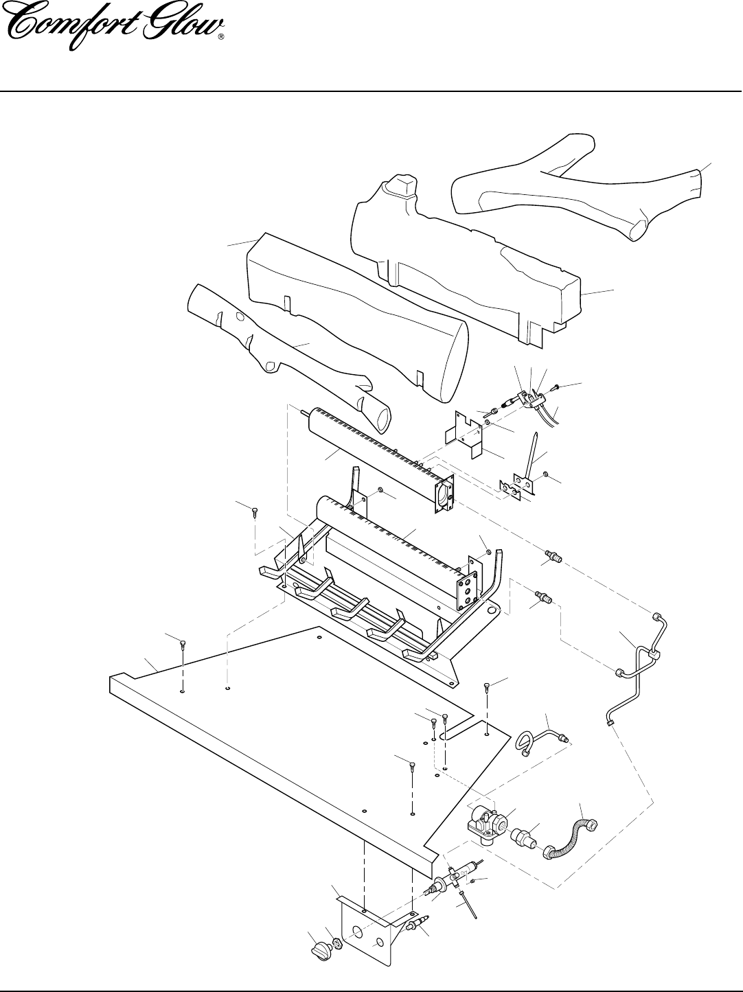
26
103414
UNVENTED PROPANE/LP GAS FIREPLACE
CGFP28P and CGFP28PT
ILLUSTRATED
PARTS
BREAKDOWN
LOG BASE ASSEMBLY
VARIABLE MANUALLY-
CONTROLLED MODEL
CGFP28P
27
8
9
8
8
19 13
12
8
6
3
4
1
2
77-1 7-2
10
18
23
16
11
26
14
6
6
6
6
21
15
19
5
29
24
30
20
28
31
25
17
22
27
103414
OWNER’S MANUAL
This list contains replaceable parts used in your fireplace. When ordering parts, follow the
instructions listed under Replacement Parts on page 32 of this manual.
KEY
NO. PART NUMBER DESCRIPTION QTY.
1 103682-04 Rear Log (#1) 1
2 103682-02 Bottom Mid Log (#2) 1
3 103682-01 Front Log (#3) 1
4 103682-03 Top Log (#4) 1
5 102568-02 Control Valve 1
6 098304-01 Screw, #10 Phillips, Black 8
7 099059-02 O.D.S. Pilot 1
7-1 098594-01 Ignitor 1
7-2 098593-01 Thermocouple 1
8 098249-01 Nut 6
9 101006-01 Pilot Bracket 1
10 101330-05 Front Burner 1
11 100999-02 Rear Burner Assembly 1
12 102257-08CJ Base Assembly 1
13 098271-06 Ignitor Cable 1
14 103410-01CK Firebox Bottom 1
15 098867-10 Gas Regulator 1
16 101004-01 Front Burner Injector 1
17 102445-01 Piezo Ignitor 1
18 101007-01 Crossover Tube 1
19 099387-05 Pilot Tube 1
20 101972-01 Valve and Piezo Bracket 1
21 M11084-38 Regulator Hex Screw 2
22 102668-01 Front Burner Tube 1
23 101008-01 Gasket 1
24 101973-01 Inlet Tube 1
25 098276-01 1/8" Plug 1
26 101004-10 Rear Burner Injector 1
27 M11084-26 Hex Screw, #10 2
28 098508-01 Valve Retainer Nut 1
29 101628-01 Flex Hose 1
30 097809-02 Adapter 1
31 098354-01 Control Knob 1
PARTS AVAILABLE — NOT SHOWN
100563-01 Warning Plate 1
101055-02 Lighting Instructions Plate 1
100565-01 Warning Plate Fastener 1
101416-34 Information Video 1
101976-02 Control Position Decal 1
PARTS LIST
LOG BASE ASSEMBLY
VARIABLE MANUALLY-
CONTROLLED
MODEL
CGFP28P
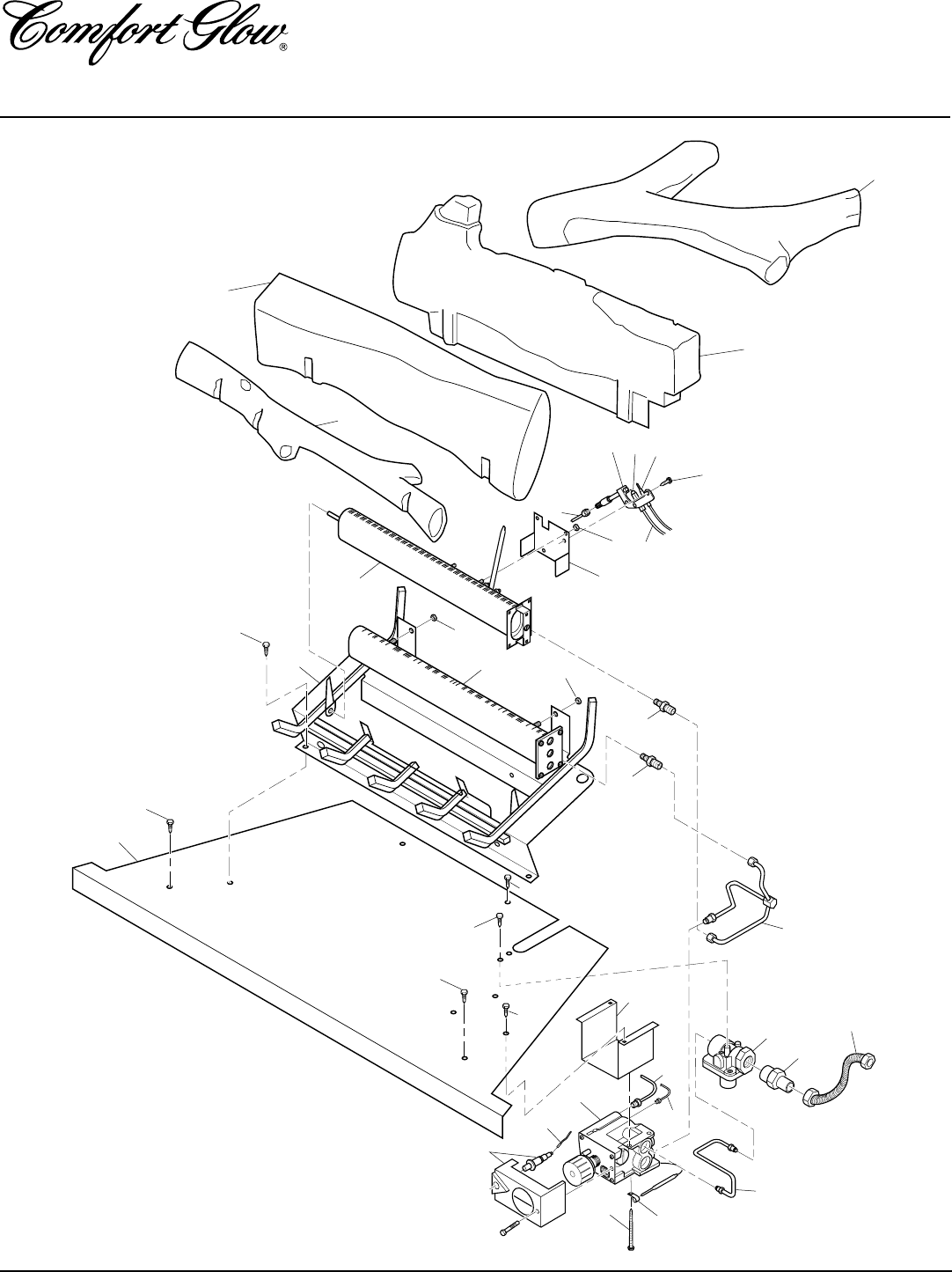
28
103414
UNVENTED PROPANE/LP GAS FIREPLACE
CGFP28P and CGFP28PT
ILLUSTRATED
PARTS
BREAKDOWN
LOG BASE ASSEMBLY
THERMOSTAT-
CONTROLLED
MODEL
CGFP28PT
18
6
27
8
9
8
8
19
13
12
3
4
1
2
77-1 7-2
10
16
11
26
14
5
6
6
6
6
22
25
23
19
24
13 7-2
20
15 28
21
17
29
103414
OWNER’S MANUAL
PARTS LIST
LOG BASE ASSEMBLY
THERMOSTAT-
CONTROLLED
MODEL
This list contains replaceable parts used in your fireplace. When ordering parts, follow the
instructions listed under Replacement Parts on page 32 of this manual.
KEY
NO. PART NUMBER DESCRIPTION QTY.
1 103682-04 Rear Log (#1) 1
2 103682-02 Bottom Mid Log (#2) 1
3 103682-01 Front Log (#3) 1
4 103682-03 Top Log (#4) 1
5 M11084-38 Screw 2
6 098304-01 Screw, #10 Phillips, Black 8
7 099059-02 O.D.S. Pilot 1
7-1 098594-01 Ignitor 1
7-2 098593-01 Thermocouple 1
8 098249-01 Nut 4
9 101006-01 Pilot Bracket 1
10 101330-05 Front Burner Assembly 1
11 100999-02 Rear Burner Assembly 1
12 102257-08CJ Base Assembly 1
13 098271-06 Ignitor Cable 1
14 103410-01CK Firebox Bottom 1
15 098867-10 Gas Regulator 1
16 101004-01 Front Burner Injector 1
17 102845-01 Inlet Tube 1
18 101382-01 Thermovalve Bracket 1
19 099387-03 Pilot Tube 1
20 102846-01 Burner Tube 1
21 097809-02 Adapter 1
22 099211-01 Screw 2
23 098544-01 Thermostat Clamp 1
24 101329-18 Thermostat Gas Valve Assembly 1
25 101381-01 Cover and Piezo 1
26 101004-10 Rear Burner Injector 1
27 M11084-26 Hex Screw, #10 2
28 101628-01 Flex Hose 1
PARTS AVAILABLE — NOT SHOWN
100563-01 Warning Plate 1
101054-01 Lighting Instructions Plate 1
100565-01 Warning Plate Fastener 1
101416-34 Information Video 1
CGFP28PT
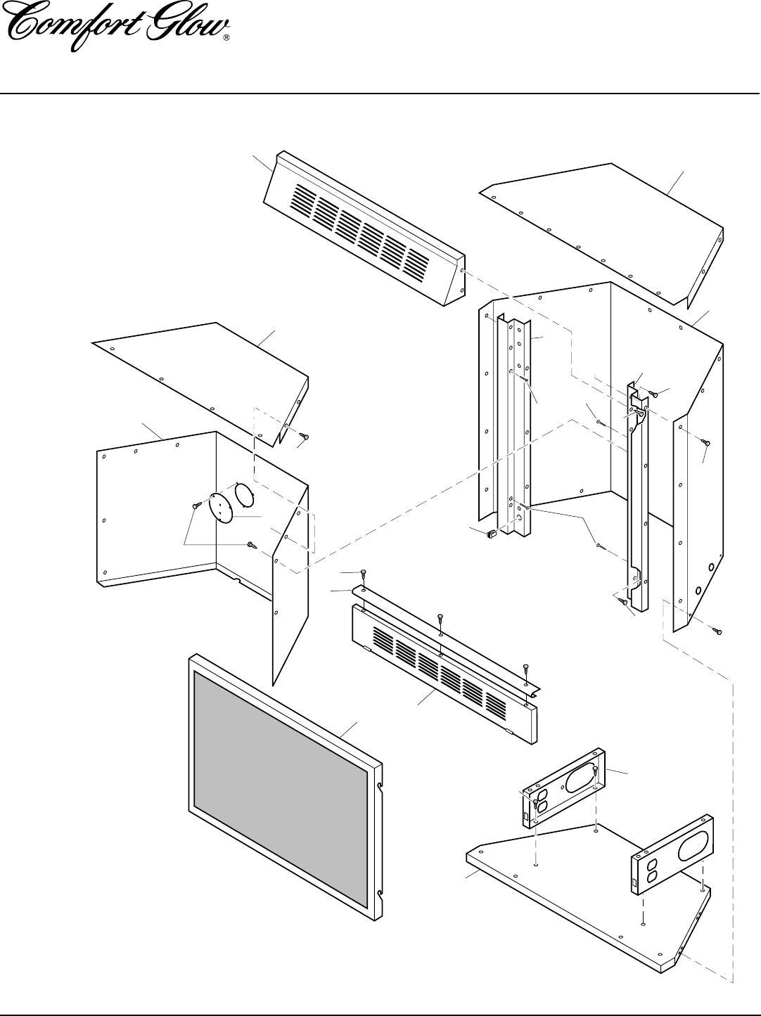
30
103414
UNVENTED PROPANE/LP GAS FIREPLACE
CGFP28P and CGFP28PT
ILLUSTRATED
PARTS
BREAKDOWN
FIREPLACE
1
2
3
4
15
10
11
9
18
6
17
12
16
16
16
7
8
16
16
5
14
16
13 13
13
CGFP28P
CGFP28PT
31
103414
OWNER’S MANUAL
PARTS LIST
FIREPLACE
This list contains replaceable parts used in your fireplace. When ordering parts, follow the
instructions listed under Replacement Parts on page 32 of this manual.
CGFP28P
CGFP28PT
KEY
NO. PART NUMBER DESCRIPTION QTY.
1 101357-01 Top Outer Casing 1
2 103207-01 Outer Casing 1
3 102758-01CK Right Front Side 1
4 102759-01CK Left Front Side 1
5 101514-01CK Cover 1
6 101784-01 Snap-in Magnet 2
7 103411-01CK Louver Hood 1
8 101838-03CJ Firebox Wrapper 1
9 103412-01CK Louver Door 1
10 101727-02 Screen Assembly 1
11 101348-01 Firebox Support 2
12 103208-01 Outer Base 1
13 099230-02 Shoulder Screw 4
14 098304-01 Phillips Pan Head Screw, #10 12
15 101872-03 Firebox Top 1
16 M11084-26 Hex Screw, #10 63
17 101746-01 Handle 1
18 100587-01 Brass Screw, #6-20x3/8" 3
PARTS AVAILABLE — NOT SHOWN
100639-01 Caution Decal 1
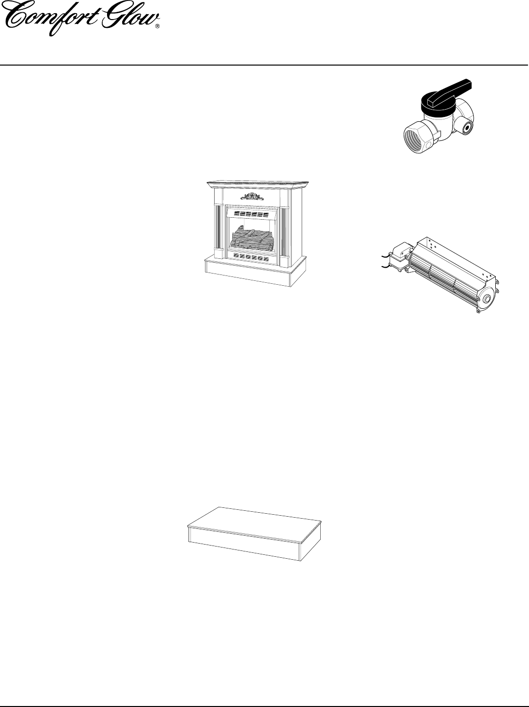
32
103414
UNVENTED PROPANE/LP GAS FIREPLACE
CGFP28P and CGFP28PT
MANUAL SHUTOFF VALVE -
GA5010
For all models. Manual shutoff valve with
1/8" NPT tap. Fits 1/2" NPT pipe.
BLOWER ACCESSORIES-
Increase air circulation to maximize heat
distribution.
GA3650T - T/Stat Blower (for
t/stat fireplaces only)
Features ON/OFF/AUTO setting. In the auto
position, the blower will automatically cycle
on and off as needed.
GA3750 - Manual Blower (for all
fireplaces)
Features variable speed control knob.
BRASS TRIM ACCESSORY -
GA7090
Optional with built-in installation. Provides a
finished appearance covering rough and/or
unfinished mantel or wall opening, edges, etc.
DUPLEX OUTLET KIT -
GA3555
Use for built-in installations when hard wir-
ing a blower.
ACCESSORIES
Purchase these fireplace accessories from
your local dealer or Parts Central (see page
25). If they can not supply these accessories,
call DESA International’s Sales Depart-
ment at 1-800-458-2472 for referral infor-
mation. You can also write to the address
listed on the back page of this manual.
CABINET MANTEL ACCES-
SORY WITH FIREPLACE
PERIMETER BRASS TRIM
GMC11F Series - Walnut Finished
Hardwood Veneer
GMC12U Series - Unfinished Hard-
wood Veneer
GMC13F Series - Medium Stained Oak
Veneer
Mantel features moldings, fluted sides, and
medallion. Available in walnut finished or
unfinished hardwood, ready to stain or paint.
Shown with optional base accessory.
Dimensions (H x W x D): 44" x 573/4" x 227/8"
HEARTH BASE
GC3333F Series - Walnut Finished
Hardwood Veneer
GC3334U Series - Unfinished Hard-
wood Veneer
GC3335F Series - Medium Stained
Oak Veneer
The hearth base creates a handsome riser for
the fireplace .
Dimensions (H xW xD): 6 1/2" x 58" x 28 9/16"
Note:
Use only original replacement parts.
This will protect your warranty coverage for
parts replaced under warranty.
PARTS UNDER WARRANTY
Contact authorized dealers of this product.
If they can’t supply original replacement
part(s), call DESA International’s Technical
Service Department at 1-800-DESA LOG
(1-800-337-2564).
When calling DESA International, have
ready
• your name
• your address
• model number of your fireplace
• how fireplace was malfunctioning
• type of gas used (propane or natural gas)
• purchase date
Usually, we will ask you to return the defec-
tive part to the factory.
PARTS NOT UNDER
WARRANTY
Contact authorized dealers of this product or
Parts Central. If they can’t supply original
replacement part(s), call DESA International’s
Parts Department at 1-800-972-7879 for re-
ferral information.
When calling DESA International, have
ready
• model number of your fireplace
• the replacement part number
REPLACEMENT
PARTS

33
103414
OWNER’S MANUAL
NOTES
_______________________________________________________________________________________________
_______________________________________________________________________________________________
_______________________________________________________________________________________________
_______________________________________________________________________________________________
_______________________________________________________________________________________________
_______________________________________________________________________________________________
_______________________________________________________________________________________________
_______________________________________________________________________________________________
_______________________________________________________________________________________________
_______________________________________________________________________________________________
_______________________________________________________________________________________________
_______________________________________________________________________________________________
_______________________________________________________________________________________________
_______________________________________________________________________________________________
_______________________________________________________________________________________________
_______________________________________________________________________________________________
_______________________________________________________________________________________________
_______________________________________________________________________________________________
_______________________________________________________________________________________________
_______________________________________________________________________________________________
_______________________________________________________________________________________________
_______________________________________________________________________________________________
_______________________________________________________________________________________________
_______________________________________________________________________________________________
_______________________________________________________________________________________________
_______________________________________________________________________________________________
_______________________________________________________________________________________________
_______________________________________________________________________________________________
_______________________________________________________________________________________________
_______________________________________________________________________________________________
_______________________________________________________________________________________________
_______________________________________________________________________________________________
_______________________________________________________________________________________________
_______________________________________________________________________________________________

LIMITED WARRANTY
COMFORT GLOW VENT-FREE PROPANE/LP GAS FIREPLACE
DESA International warrants this product to be free from defects in materials and components for two (2) years from the date of first
purchase, provided that the product has been properly installed, operated and maintained in accordance with all applicable instructions.
To make a claim under this warranty the Bill of Sale or cancelled check must be presented.
This warranty is extended only to the original retail purchaser. This warranty covers the cost of part(s) required to restore this heater
to proper operating condition and an allowance for labor when provided by a DESA Authorized Service Center. Warranty part(s) MUST
be obtained through authorized dealers of this product and/or DESA International who will provide original factory replacement parts.
Failure to use original factory replacement parts voids this warranty. The heater MUST be installed by a qualified installer in accordance
with all local codes and instructions furnished with the unit.
This warranty does not apply to parts that are not in original condition because of normal wear and tear, or parts that fail or become
damaged as a result of misuse, accidents, lack of proper maintenance or defects caused by improper installation. Travel, diagnostic cost,
labor, transportation and any and all such other costs related to repairing a defective heater will be the responsibility of the owner.
TO THE FULL EXTENT ALLOWED BY THE LAW OF THE JURISDICTION THAT GOVERNS THE SALE OF THE PRODUCT;
THIS EXPRESS WARRANTY EXCLUDES ANY AND ALL OTHER EXPRESSED WARRANTIES AND LIMITS THE DURA-
TION OF ANY AND ALL IMPLIED WARRANTIES, INCLUDING WARRANTIES OF MERCHANTABILITY AND FITNESS
FOR A PARTICULAR PURPOSE TO TWO (2) YEARS ON ALL COMPONENTS FROM THE DATE OF FIRST PURCHASE;
AND DESA INTERNATIONAL’S LIABILITY IS HEREBY LIMITED TO THE PURCHASE PRICE OF THE PRODUCT AND
DESA INTERNATIONAL SHALL NOT BE LIABLE FOR ANY OTHER DAMAGES WHATSOEVER INCLUDING INDIRECT,
INCIDENTAL OR CONSEQUENTIAL DAMAGES.
Some states do not allow a limitation on how long an implied warranty lasts or an exclusion or limitation of incidental or consequential
damages, so the above limitation on implied warranties, or exclusion or limitation on damages may not apply to you.
This warranty gives you specific legal rights, and you may also have other rights that vary from state to state.
For information about this warranty write:
2701 Industrial Drive
P.O. Box 90004
Bowling Green, KY 42102-9004
www.desatech.com
KEEP THIS WARRANTY
WARRANTY INFORMATION
Model
Serial No.
Date Purchased
Always specify model and serial numbers when communicating with the factory.
We reserve the right to amend these specifications at any time without notice. The only warranty applicable is our standard written
warranty. We make no other warranty, expressed or implied.
103414-01
Rev. C
03/99
NOT A UPC
103414 01
