Designated Parking 101 security transmitter User Manual MS200 Installation Manua screen formatl pub
Designated Parking Corp. security transmitter MS200 Installation Manua screen formatl pub
USERS MANUAL
Designated Parking Corp page 1 www.dp-corp.com
Installation Manual
MySpot™ 200
Remote Controlled Parking Barrier
Congratula-
tions!
MySpot 200 rug-
ged construction,
careful design and
attention to detail
will provide you
with years of ser-
vice and enjoy-
ment. However,
like all things me-
chanical and elec-
tronic, proper and careful installation is
essential in order for the product to
perform as designed.
We suggest that you keep the enclosed
User Manual in the car’s glove compart-
ment, along with the Emergency Key/
Security Wrench. The Key allows you to
manually lower the barrier. The wrench
allows access to the Key. The User
Manual will refresh your memory how to
do it, as well as show you how to recog-
nize when the radio batteries need re-
placing and how to go about it.
A summary installation procedure is avail-
able at the back of this manual.
Kit Contents
Verify that all the parts listed were deliv-
ered in the kit.
Warning: The packing carton contains a
cardboard mounting template. Follow the
directions on the carton to safely open it
and preserve the template.
If external damage to the packing is evi-
dent, notify the carrier immediately. Ship-
ping damage is not covered by the manu-
facturer’s warranty.
1 PowerPod assembly
1 IdlePod assembly
1 barrier assembly
1 or 2 HT transmitter (s)
7 12 mm masonry anchors
7 6 mm Allen bolts for anchors
1 6 mm Allen wrench
6 8 mm Security Barrier bolts
1 Security wrench
1 Tube of sealant
1 Manual
1 Template printed on cardboard
Note: Adhesive for mounting the pods is
available as a separate option and is not
included in the kit.
Unpacking
Insert here picture showing 3D assembly
of the MS200 with names of key parts
Terminology
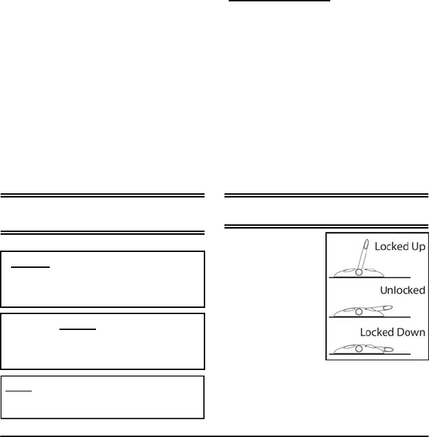
The barrier can be
in one of 3 posi-
tions as shown in
Fig. 2
With reference to
Figure 1:
1 > PowerPod
2 > IdlePod
3 > Barrier
4 > Stub Figure 2
Designated Parking Corp page 2 www.dp-corp.com
Front or Middle?
MySpot 200 can
be positioned in
two distinct loca-
2:Site Preparation
Gravel, Sand
Mounting the pods directly to gravel
or sand is not recommended, as
neither the bolts nor the adhesive will
provide adequate grip. A suitable
concrete footing needs to be poured
for each of the pods.
Asphalt
The installer needs to check the
integrity of the asphalt or macadam
surface to make sure that the depth
and strength are adequate to support
mounting bolts. In some cases, the
use of the optional adhesive kit may
be the better way to mount the pods.
It is not recommended to use the
bolts if the depth of the roadway is
less than 50 mm (2”).
Special asphalt anchors are avail-
able. These use epoxy to create a
rigid surface around the anchors.
Contact the factory for details.
TOOLS: Unless you use the adhesive
kit, you will need a power drill and a 12
mm (15/32”) masonry drill bit for setting
the anchors into the roadway to mount
the two pods.
Where to position
MySpot?
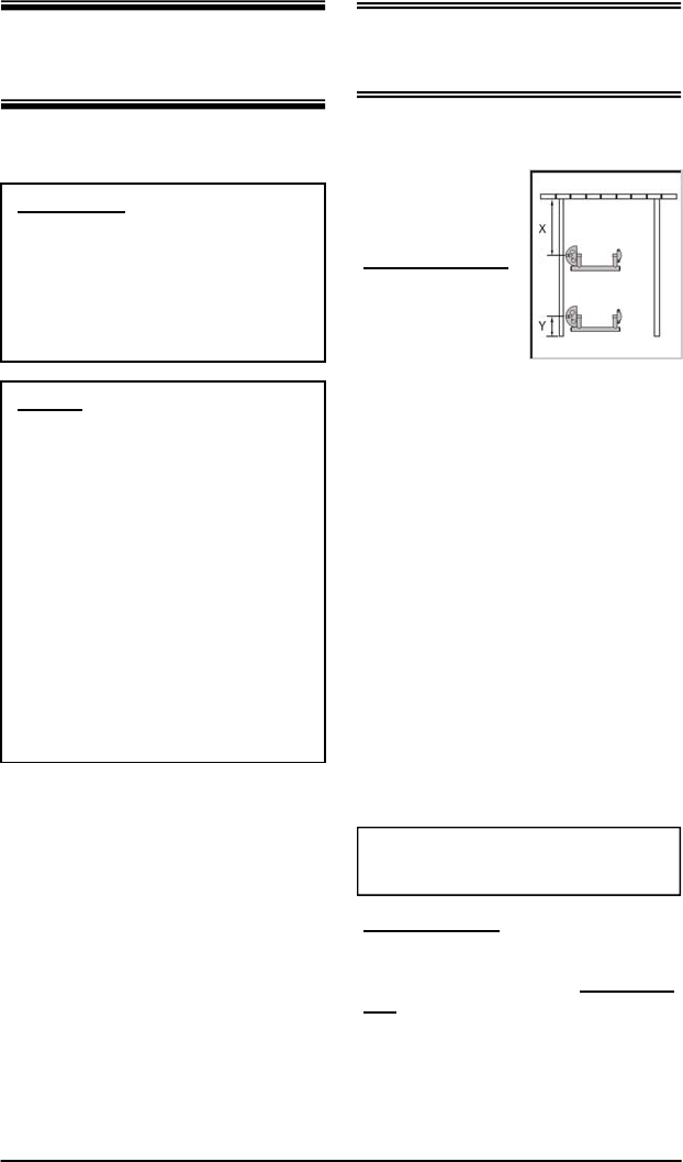
Middle mounting
means that the
barrier will stay
under the car
while the car is
parked in the
space. The advan-
tages of middle-
mounting are:
• Barrier is further removed from dirt
and debris pushed from the main
access lane
• Cars making J turns are less likely
to bump into the raised barrier
accidentally
• The barrier is protected from in-
clement weather while the car is
parked over it
• Cars entering adjacent lanes are
less likely to accidentally hit the
barrier
When placing the barrier in the middle
of the stall, the center line of the device
should be about 1.5 meters (5 feet)
from the rear of the stall (dimension “X”
in figure 1).
Front mounting means that the car
drives in and parks behind the barrier.
A benefit of front mounting is that the
barrier can to be used as a theft deter-
rent, raising it with the car parked be-
hind it. The barrier should be installed
as close to the front limit of the space
as possible, to allow the barrier to rise
behind even a large vehicle.
(Dimension “Y” in Figure 1 should be
less than 1 foot or 30 cm.)
WARNING: Locate the PowerPod so that
persons getting in or out of the car will
not trip on the pod.
Figure 3
Designated Parking Corp page 3 www.dp-corp.com
Standing Water
MySpot 200
is sealed to
prevent wa-
ter from en-
tering the
unit. The
PowerPod
should not be exposed for extended
period of time to standing water or ice.
To prevent such occurrence, select a
spot for the pod that is slightly raised
above the surface, or add a plate to
raise it.
The barrier rotates around the bearing
surfaces on the two pods. The force
that brings the barrier down to allow
access to the space comes from gravity
pulling the barrier. Excessive friction
along the travel of the barrier will pre-
vent proper operation of the device.
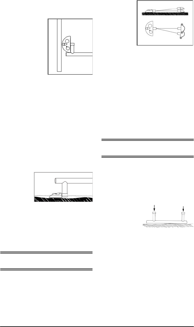
The two pods
need to be
reasonably
aligned with
each other,
so that the
barrier is free
to rotate.
Alignment
means that
the two pods face each other so that an
imaginary line extending from the shaft
of the PowerPod will line up abeam with
the opening in the IdlePod. This align-
ment also applies to the height – a
significant (more than 1 inch) height
difference between the two pods will
hamper the free motion of the barrier.
If the PowerPod mounting area is not
level, the use of a shim under the
PowerPod may be required to level it
with the IdlePod.
Pods Line up
Barrier Clearance
Left Align
The PowerPod
should be in-
stalled at the left
side of the space
(facing the park-
ing spot from the
outside). The
round end of the
PowerPod should
touch the stripe
marking the left
limit of the park-
ing stall. This will
guarantee that, regardless where the
car is positioned as the car drives in,
the front wheel will ride over the barrier
on the side close to the PowerPod.
Installing the device further to the right
of the space will cause the right wheel
of the car to engage the barrier. This
increases the stress on the barrier and
on the mounting bolts (or adhesive) that
attach the pods to the driveway.
Figure 4
Figure 5
Figure 6
The front edge of the barrier must be
able to travel 3” (from its “unlocked”,
Unlocked position) before it hits the
ground. A rise in the roadway any-
where between the two pods may inter-
fere with this full range of motion.
To check the
surface, place
the barrier up-
side-down on
the ground.
Observe any
height irregulari-
ties. If the roadway is lower in between
the two ends of the barrier, there is no
problem. If the roadway at even one
point is 7 mm (¼”) higher, move the
barrier towards the front or the rear of
the space until a better location is
found.
If the rise in the middle is unavoidable,
you may have to raise one or both pods
using a suitable plastic or metal plate.
The use of wood or plywood is not rec-
ommended as it will rot.
Figure 7
Designated Parking Corp page 4 www.dp-corp.com
Designated Parking offers a number of
adhesives that have been tested for
mounting the pods to concrete and
compacted asphalt.
In general, a fast-curing epoxy such as
Devcon DA012 (“10 minute epoxy”) will
provide good adhesion. Cure time for
the DA012 is 1.5 hours at 25oC. A less
expensive alternative is to use silicones
such as GE SCS2003 It cures partially
in about 3 hours.
1. Thoroughly clean the roadway
where the pods are to be installed.
The surface must be free of sand,
gravel and loose particles.
2. Place the cardboard template to
position the assembled MySpot
200 and verify that the surface
meets the criteria specified in sec-
tion 2.
3. Turn the 2 pods upside down.
4. Apply about 2 mm (0.080”) of ad-
hesive uniformly over the surface
of the bottoms of the two pods.
5. Turn the pods over and place
them carefully in position as
guided by the template.
6. Press lightly on the pods. Do not
wipe adhesive from around the
base unless it is in abundance.
7. Do not remove the template as
yet.
Proceed to section 6
Prior to the mounting of MySpot 200,
the barrier needs to be assembled to
complete the assembly of the device.
This will self-align the two pods.
1. Make sure that the stub on the
PowerPod is in the Locked Up
position. (See inset for instruc-
tions how to manually bring the
shaft to the Locked Up position if
necessary.)
2. Rotate the stub on the IdlePod
until it too is in the Locked up posi-
tion.
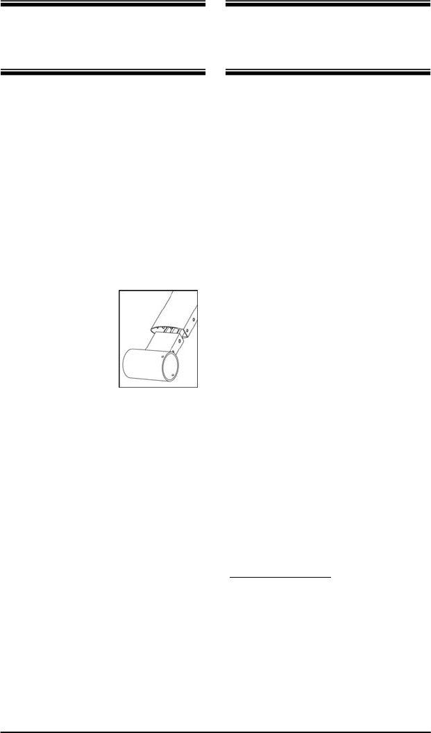
3. Slide the bar-
rier over stub
of the Power-
Pod. The
grooved sur-
face of the
barrier should
be facing back,
away from the
entrance to the
parking space.
4. Make sure the holes on the side of
the barrier align with the threaded
holes in the stub.
5. Secure the barrier to the stub us-
ing 2 security bolts.
6. Repeat the process for the IdlePod
side and secure the barrier to the
stub using 2 security bolts.
MySpot 200 is now ready for attach-
ment to the roadway. The mounting
procedure is quite different when using
adhesive than when using mounting
bolts.
3:Assemble Barrier 4: Mount
Using Adhesive
Figure 8
Designated Parking Corp page 5 www.dp-corp.com
Remove PowerPod Cover
Remove the cover
of the PowerPod.
Use the security
socket to remove
the 4 security
bolts around the
circumference of
the PowerPod.
Lift the cover gen-
tly about 2“ and
disconnect the an-
tenna cable by pulling its RCA plug
from the socket.
Warning! Pulling the cover without
disconnecting the antenna cable will
damage the antenna cable or the
electronic module in the base of the
PowerPod.
What to do if an anchor rotates in
its seat: If the hole is only slightly
oversize, use a sharp point to hold
the anchor against the wall of the
hole and gently tighten the bolt. At
some point, the expanding anchor
will grip the walls of the hole. Turn
the bolt another ½ turn to make sure
the anchor is set.
If the hole is too large, you may need
to fill it with concrete mix or epoxy,
and then re-drill once the mixture has
hardened. Inserting the anchor into
the liquid epoxy may fill the threads
and prevent the anchor from accept-
ing the bolts. If the bolt is placed
while the filler is not yet hardened, it
may not be able to be withdrawn
later.
Mount Pods
Remove the 4 protective plastic caps
that seal the mounting holes of the
PowerPod. Using the bolts that came
with the anchors and the sealing wash-
ers, secure the base of the PowerPod
to the roadway. Make sure that the
base is lying reasonably flat on the
surface. Do not tighten the bolts until
the IdlePod has been installed.
If one of the corners of the base is lifted
because of surface irregularities, insert
a plastic or metal shim under that area
before tightening the mounting bolts.
Applying excessive force on the base
Drill Mounting Holes
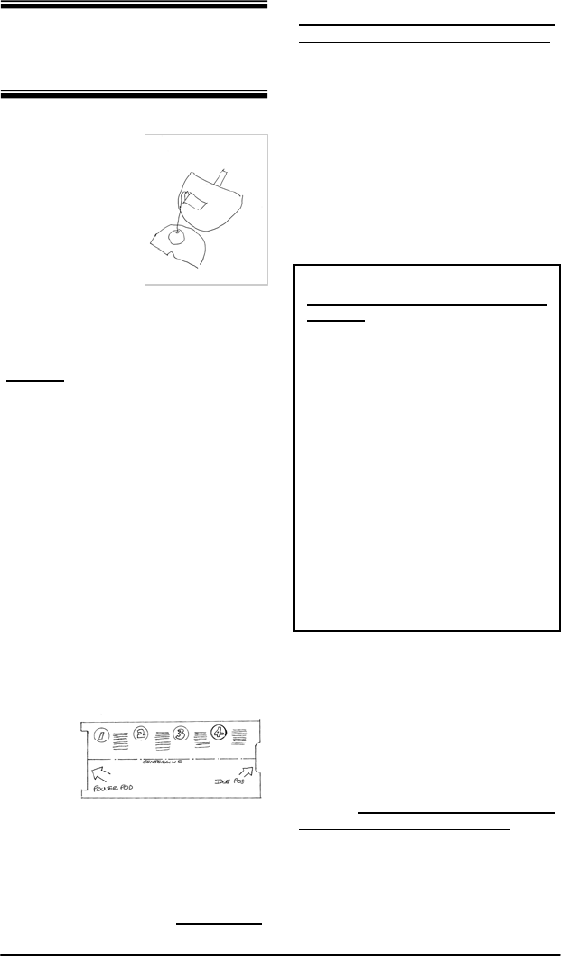
Position the template (Figure 8) on the
surface carefully. Place the IdlePod
and the
Power-
Pod in
the tem-
plate so
that they
align
with the
respec-
tive markings and cutouts on the tem-
plate.
Using the pods as templates, mark the
7 holes on the roadway. Remove the
Figure 9
Figure 10
5: Mount
Using Bolts
Do Not remove IdlePod
Cover
The IdlePod can be mounted without
opening the cover using the two exter-
nal bolts. A third mounting bolt under
the cover will be accessed later.
PowerPod before drilling to prevent
dirt from getting into the mechanism.
Drill 7 holes using a 12 mm (15/32”)
masonry drill. Take extra time to make
sure that each hole is aligned with the
pod openings.
Clean the area and gently hammer in
the anchors until they are flush with the
surface. Gently remove the screws
from the anchors making sure that none
of the anchors rotates in its seat. If an
anchor rotates freely, see inset.
Designated Parking Corp page 6 www.dp-corp.com
Check for Free Motion
MySpot is shipped in “hibernation”
mode, to prevent the radio batteries
from discharging.
The radio in MySpot 200 is activated by
rotating the shaft from the Locked Up
position to the Unlocked position. This
requires the use of the Emergency key,
as described in the inset to the left
.
Release the shaft to allow the barrier to
fall. Verify that the rotation of the bar-
rier is smooth and that it comes to a
stop about 50 mm (2”) above the high-
est spot on the ground. Do not press
down on the barrier at this time.
Raise the barrier manually. Verify that
the barrier is locked in the Locked Up
position. If you notice resistance to the
movement of the barrier, slightly rotate
the pods until optimum performance is
reached.
Tighten the 7 mounting bolts that hold
down the two pods. Close the Power-
Pod cover if it is open (remember to
connect the antenna cable).
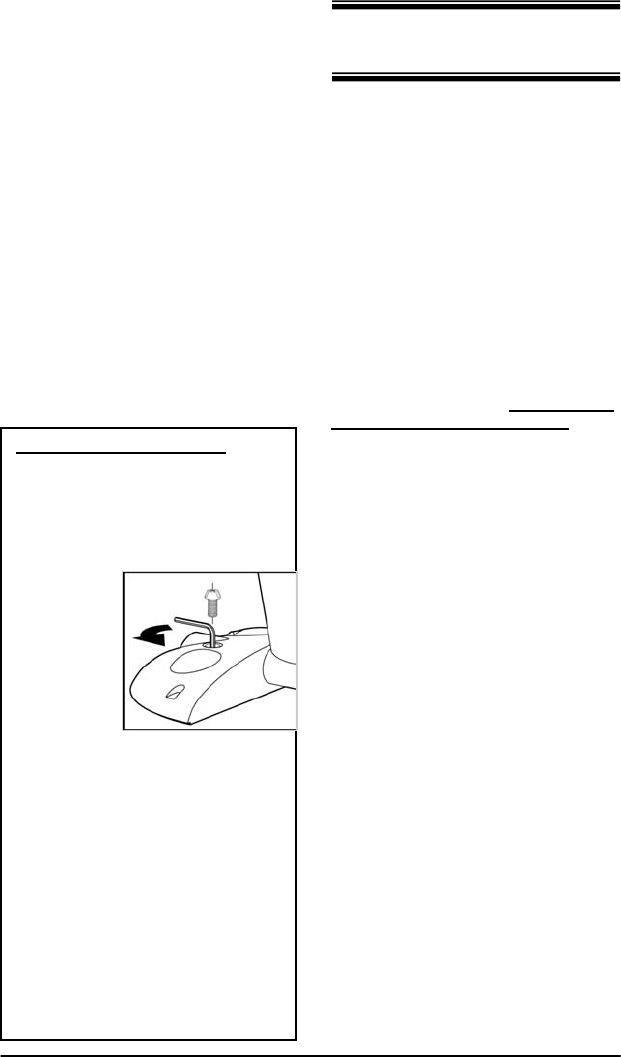
Rotating the shaft manually
If it is necessary to rotate the shaft
manually, with the cover in place,
follow this procedure:
1. Remove the security bolt to gain
access
to the
Emer-
gency
Key.
2. P l a c e
the 6
mm
Allen
wrench
in the
Emergency Key.
3. Turn the wrench counter clock-
wise. This releases the lock or
locks that are holding the shaft
and the internal mechanism.
4. If the barrier was in the Lock up
position, it should fall freely.
5. If the barrier was in the Lock
down position, it should rise.
6. Remove the Allen wrench
Figure 11
where the surface is highly irregular
may bend the base over time, causing
internal misalignment and eventual
operational failure.
Likewise, install the IdlePod using the
two external bolts. Tighten the mount-
ing bolts.
Remove the cover of the IdlePod, and
drill a 3rd 12 mm hole into the roadway
through the clearance hole in the base.
Insert the anchor with the bolt and the
washer. Gently hammer in the bolt until
the anchor is flush with the roadway,
below the base of the IdlePod. Tighten
the bolt.
Reinstall the cover using the security
bolt.
6: Test
Check Radio Operation
1. With the barrier in the Locked Up
position, press the center button
on the HT transmitter.
2. The first activation may not result
in a visible response, as the com-
mand is used to program the radio
receiver to recognize the transmit-
ter.
3. Press the center transmitter key
again. The barrier should fall to its
Unlocked position.
4. If you hear a whirl of the motor but
the barrier does not drop, verify
that the barrier can move freely.
Designated Parking Corp page 7 www.dp-corp.com
Once the first transmitter has been added
(“programmed”) to the authorized list in
the radio receiver in the PowerPod, addi-
tional transmitters (up to a total of 15) can
be programmed without opening the
PowerPod by this procedure:
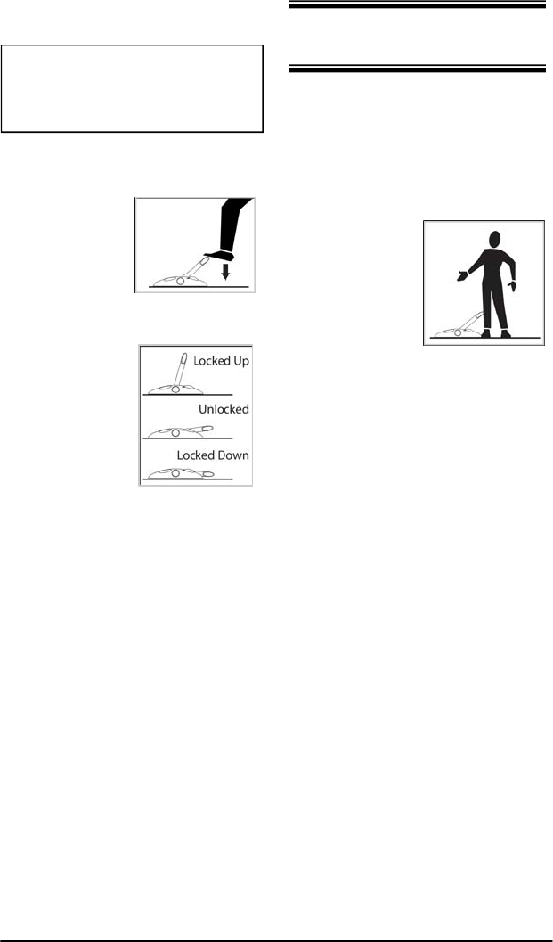
1. Place the barrier in the Locked Up
position.
Prop the
barrier with
your leg so
that the
barrier will
not fall when
activated.
2. Hold the
authorized
transmitter in
one hand, and the new one in the
other.
3. Press the center button on the au-
thorized transmitter. The motor will
whirl. Observe the green indicator
on the face of the HT transmitter – it
will stay lit for 2 seconds.
4. As soon as the indicator on the Au-
thorized transmitter turns off and the
motor stopped whirling, press the
center switch on the new transmitter.
The green indicator on it will turn on
for 2 seconds.
5. As soon as the green indicator on
the new transmitter turns off, press
the center button on the “old” trans-
mitter.
6. To verify that the new transmitter
works, move away from the barrier
and activate the transmitter. The
motor should respond and the barrier
should fall.
The same procedure can be used to add
another button on a transmitter to the list.
Each of the 3 buttons on the HT has its
own code, and all 3 can be programmed
into the PowerPod if desired. The 3 keys
allow the same transmitter to control 3
separate MySpot 200.
Warning! In the case of adhesive
mounting, do not proceed further
until the adhesive has cured to at
least 50% strength.
1. Bring the barrier to the Unlocked
position using the HT transmitter.
2. Step on the
barrier on
the side
close to the
PowerPod.
This simu-
lates the car
driving over
the barrier.
The barrier
will yield if
you exert at
least 85 Kg
(190 lbs)
and will lock
in the
Locked
Down posi-
tion.
3. Step again on
the barrier, and observe the
Locked Up motion of its leading
edge. It should move at least 18
mm (3/4”) while you stand on it,
and should return to the Locked
Down position once you step off.
Failure of the barrier to move this
“Overtravel” amount means that
there is a rise in the roadway be-
tween the pods that interferes with
the full travel of the barrier.
4. If the test failed on the Overtravel,
resolve the problem before pro-
ceeding to the next step. Solu-
tions include raising the pods or
leveling the bump on the roadway.
5. Press the center button on the HT;
the barrier should rise back to the
Locked Up position.
Figure 13
Figure 14
Figure 12
Check Operation 7: Add Transmitter

Designated Parking Corp page 8 www.dp-corp.com
How the Sensor Works
The concept behind the sensor is that the device
counts the number of times that a wheel of the
car passes over the barrier.
In a typical sequence of operation for a middle-
installed barrier (see section xx), the barrier drops
to allow the car to enter. The car front wheel
drives over the barrier, but the rear wheel does
not. The sensor has therefore counted only one
wheel, and will not respond to remote commands
to rise.
Once the car leaves the space, the front wheel
passes over the barrier a second time. The
sensor has now counted 2 passes, and will
respond to the command to raise the barrier.
MySpot 200 is equipped with a wheel
sensor. The purpose of this sensor is
to prevent activation of the barrier if the
car is parked over it.
The product is shipped with this sensor
enabled. If it is desired to change the
setting of this sensor, open the cover of
the PowerPod, identify the Configura-
tion switch and use one of the proce-
dures below:
To disable the wheel sensor:
1. Hold down the Configuration
switch for more than 5 seconds
(but less than 10 seconds)
2. Release button.
To enable the wheel sensor:
1. Open the cover of the PowerPod
2. Hold down the Configuration
switch for more than 5 seconds
(but less than 10 seconds)
3. Release button, immediately press
it for 1 second and release it
again.
HomeLink is a registered trade mark of Johnson Control
Car Sensor
Using HomeLink™
MySpot 200 is compatible with Johnson
Control HomeLink car-installed trans-
mitters. Follow the manufacturer’s
instructions how to program the author-
ized transmitter into the HomeLink unit.
(The instructions are usually part of the
car’s owner manual.)
The programming of the transmitter to
the HomeLink unit needs to be done
after the HT transmitter was taught to
the PowerPod.
Remove Transmitters
The only way to delete transmitters is to
erase the programming in the unit. This
is also the case when the only author-
ized transmitter has been lost, and a
replacement transmitter needs to be
added.
1. Open the cover of the PowerPod.
Remember the antenna cable.
2. Press and hold the Configuration
switch for more than 5 seconds
but less than 10 seconds. Re-
lease the switch,
3. The unit has been returned to the
factory setting. To program the
first transmitter, just activate it.
4. Connect the antenna and close
the cover
5. Apply silicone to seal the bolts.
Figure 15
Designated Parking Corp page 9 www.dp-corp.com
Never drive over the barrier when
obstructions are visible under the
barrier.
Warning: Never raise the barrier
when foreign articles are on the bar-
rier (e.g. tree limbs), as it can cata-
pult these (if they are light enough).
Help
A troubleshooting chart is provided
at the end of this manual
If you need assistance with the installa-
tion, repair or other problems, please
contact the company that sold the sys-
tem to you first. They are likely to pro-
vide you with immediate support, espe-
cially if the product was purchased
overseas.
Designated Parking web site is a good
source of tips, troubleshooting informa-
tion and a way to contact the factory
engineers to address unusual prob-
lems. www.dp-corp.com
Copyright and Patents
MySpot 200 is covered by design and
utility patent applications and issued
patents. MySpot is a trademark of
Designated Parking Corp.
Replacing transmitter
batteries
When the batteries in the HT transmitter
approach their end-of-life, the HT will
signal the condition by delaying the
transmission of a command. The green
indicator on the transmitter will flash for
a few seconds, before the normal pat-
tern of turning solid for 2 seconds (while
it sends the command) takes place.
To replace the batteries, open the two
small Philips screws on the back of the
unit. Replace the 2 Lithium button bat-
teries with CR2016 batteries. Observe
polarity! Check operation of the indica-
tor before closing. If OK, close with the
two screws.
Replacing PowerPod
Batteries
The batteries should provide up to 4
years of life
under normal
operating
conditions.
When the
batteries ap-
proach their
end-of-life, MySpot 200 will become
“sluggish” – it will delay the response to
the transmitter commands by about 5
seconds. This is an intentional re-
minder that the batteries need replac-
ing.
If the batteries are not replaced before
they are completely exhausted after 50-
100 additional operations, the barrier
will accept one last command and will
stay down .
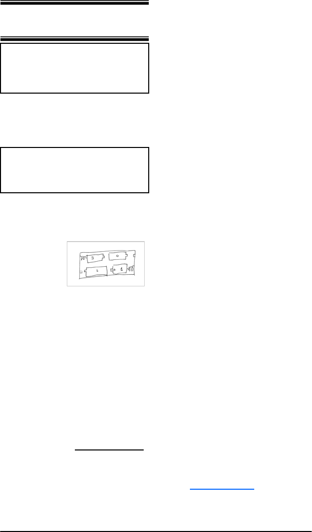
To replace the batteries, open the cover
of the PowerPod and pull out the 4
batteries. Replace with fresh (4) D
alkaline batteries. Observe polarity!!
Reversing the polarity of some or all the
batteries will damage the radio receiver.
The most important maintenance is to
clear the immediate area of the MySpot
200 of debris of any kind.
8: Maintenance
Figure 16

Designated Parking Corp page 10 www.dp-corp.com
FCC THIS DEVICE COMPLIES WITH PART 15 OF THE
FCC RULES. OPERATION IS SUBJECT TO THE FOLLOW-
ING TWO CONDITIONS: (1) THIS DEVICE MAY NOT CAUSE
HARMFUL INTERFERENCE, AND (2) THIS DEVICE MUST
ACCEPT ANY INTERFERENCE RECEIVED,INCLUDING
INTERFERENCE THAT MAY CAUSE UNDESIRED OPERA-
TION.
THE MANUFACTURER IS NOT RESPONSIBLE FOR ANY
RADIO OR TV INTERFERENCE CAUSED BY UNAUTHOR-
IZED MODIFICATIONS TO THIS EQUIPMENT. SUCH
MODIFICATIONS COULD VOID THE USER’S AUTHORITY
TO OPERATE THE EQUIPMENT.
CE Hereby, Designated Parking Corp.,
declares that MySpot 202 is in compliance
with the essential requirements and other
relevant provisions of Directive 1999/5/EC .
A copy of the Statement of Conformity can be
found on the Company’s web site.
Rudor M. Teich, President
Limited Warranty
Except as otherwise provided, Seller warrants for a period of
twelve (12) months from the date of shipment that the goods
supplied to Buyer shall be of good materials and workmanship.
Seller makes no warranty with respect to the following: (a)
materials not manufactured by Seller, the use of which is
suggested by Seller’s general recommendations, application or
installation procedures, or otherwise; (b) goods sold by Seller to
Buyer for other than resale; (c) goods which have been subject
to abuse, accident, alteration, misuse, negligence or alterations;
and (d) all display items sold by Seller to Buyer.
THE FOREGOING WARRANTIES ARE EXCLUSIVE, AND IN
LIEU OF ANY AND ALL OTHER WARRANTIES, EXPRESS
OR IMPLIED, WRITTEN OR ORAL WHETHER IMPLIED BY
OPERATION OF LAW OR OTHERWISE, INCLUDING BUT
NOT LIMITED TO, ANY IMPLIED WARRANTY OF MER-
CHANTABILITY OR FITNESS FOR ANY PARTICULAR
PURPOSE, USE, OR INFRINGMENT.SELLER DOES NOT
ASSUME, NOR AUTHORIZE ANY REPRESENTATIVE OR
OTHER PERSON TO ASSUME FOR IT, ANY OBLIGATION
OR LIABILITY OTHER THAN AS EXPRESSLY SET FORTH
HEREIN.
Limitation of Remedies.
Seller's obligations under the above warranties (contained in
Section 10) are conditioned upon Seller actually receiving
notice from Buyer of the alleged defect within the warranty
period and the existence of an actual defect in the goods as
revealed upon examination by Seller. The sole liability of the
Seller for breach of such warranties shall be to provide Buyer
with replacement for, or repair of, defective parts in the manner
provided herein. This exclusive remedy shall not be deemed to
have failed of its essential purposes so long as Seller is willing
to repair or replace the defective part(s) in the manner pre-
scribed herein.
Seller shall not be liable for any labor or other expenses
incurred by Buyer in the removal, repair or replacement of the
goods or any component part claimed to be defective, nor shall
Seller be liable for any expenses incurred by the Buyer in order
to remedy any defect. Seller’s acceptance of shipped goods
shall not be deemed an admission that such goods are noncon-
forming under the above warranties. If the Seller finds that any
goods are not defective, such goods will be reshipped to Buyer
at its expense and Buyer will be charged for shipping charges
incurred by Seller.
Under no circumstances and in no event will the Seller be
liable for any personal injury or property damage, loss of
profits or revenue, loss of business, consequential, incen-
tive, punitive, special or contingent damages or expenses
of any kind incurred by Buyer or any third party, based
upon warranty, contract, strict liability, negligence or any
other cause of action arising under this Agreement or in
connection with the product or services provided here-
under even if the other party or any other person has been
advised of the possibility of such damages The discharge
of Seller's warranty obligation hereunder shall constitute
fulfillment of all liabilities of Seller to Buyer, whether based
on contract, negligence or otherwise. The remedies set
forth herein shall be the exclusive remedies available to the
Buyer and in lieu of all other remedies, and the liability of
Seller, whether in contract, in tort, warranty or otherwise,
shall not exceed the price of the goods sold, supplied or
furnished by Seller which give rise to the claim.
Any suit or action arising out of or relating to this Agreement or
the breach thereof, must be commenced within one (1) year
after the date of shipment of the goods to the Buyer. The
foregoing shall not limit the time within which any suit or action
must be brought to collect an amount agreed to be paid by
Buyer or to enforce a judgment in favor of Seller or to collect
any amount awarded to Seller.

Designated Parking Corp page 11 www.dp-corp.com
Troubleshooting
No response to Transmitter
Step
No. Test YES NO
1 Is the correct button pushed and does
indicator on transmitter light up when
button is pushed?
go to step 2 Replace battery in transmitter
2 Has this transmitter worked before? go to step
2a Add transmitter to memory of MySpot 200
3 Is barrier locked in Locked Up posi-
tion? go to step 4 go to step 5
4 Use Emergency key to release barrier,
then raise barrier and retest. Is unit
now working properly?
Jam
cleared go to step 6
5 Is barrier locked in Locked Down
position? go to step 8 Force barrier to locked down or locked up
position and go to step 1
6 Is there another transmitter that does
control the unit? go to step 7 Replace batteries in the PowerPod . If this
does not help, erase memory of MySpot (see
manual)
7 Add transmitter to memory of MySpot.
Does it work? Done Replace transmitter
8 With the barrier down, step on it a
couple of times to simulate a car
passing over the barrier with both
wheels. Is the barrier responding the
transmitter?
Done go to step 4
2a Has the barrier been slow to respond
recently Replace
PowerPod
batteries
go to step 3
Motor responds but no motion of barrier
Step
No. Test YES NO
1 Is barrier locked in Up position? go to step 2 Goto step 4
2 While motor sounds, push barrier
down. Did it move? go to step 3 Open PowerPod cover and check operation
3 Check alignment of pods and a bent
barrier Done
4 Is it locked in Down position?

Designated Parking Corp page 12 www.dp-corp.com
Express Installation Instructions
1. Clear area where unit is to be installed
2. Use the inside of the packing carton as a template to position the two pods
3. Apply adhesive to the bottoms of the pods and press them into place
4. Open cover of IdlePod and remove security screw for access to Emer-
gency key
5. Slide barrier over shaft of PowerPod so that screw hole on barrier tube
mates with hole in the tube-bearing on the shaft
6. Fit other end of barrier over pins in IdlePod. Close Cover.
7. Screw barrier tube to bearing on PowerPod side
8. Use emergency key to release the lock. The barrier should fall freely.
9. Wait for adhesive to cure before driving or stepping over barrier.
10 Ridge Road
West Orange, NJ 07052-4018
USA
www.dp-corp.com
Email Support@dp-corp.com
Tel +1.973 669-8214
Fax +1.973 669-5161
Manual P/N :
Revised 1 May 2004