Designated Parking 103 MYSPOT REMOTE CONTROLLED PARKING BARRIER-TX User Manual Installation Manual V17 pub
Designated Parking Corp. MYSPOT REMOTE CONTROLLED PARKING BARRIER-TX Installation Manual V17 pub
instruction manual
Designated Parking Corp V17 page 24 www.dp-corp.com
FCC THIS DEVICE COMPLIES WITH PART
15 OF THE FCC RULES. OPERATION IS SUB-
JECT TO THE FOLLOWING TWO CONDITIONS:
(1) THIS DEVICE MAY NOT CAUSE HARMFUL
INTERFERENCE, AND (2) THIS DEVICE MUST
ACCEPT ANY INTERFERENCE RE-
CEIVED,INCLUDING INTERFERENCE THAT
MAY CAUSE UNDESIRED OPERATION.
THE MANUFACTURER IS NOT RESPONSIBLE
FOR ANY RADIO OR TV INTERFERENCE
CAUSED BY UNAUTHORIZED MODIFICATIONS
TO THIS EQUIPMENT. SUCH MODIFICATIONS
COULD VOID THE USER’S AUTHORITY TO
OPERATE THE EQUIPMENT.
CE Hereby, Designated Parking Corp.,
declares that MySpot 202 is in compliance
with the essential requirements and other
relevant provisions of Directive 1999/5/
EC . A copy of the Statement of Confor-
mity can be found on the Company’s web
site.
Rudor M. Teich, President
Express Installation Instructions
1. Clear area where unit is to be installed
2. Assemble barrier to the stubs of the 2 pods using security
bolts
3. Position plates using template
4. Apply adhesive to the bottoms of the mounting plates and
press them into place
5. Attach pods to plates
6. Wait for adhesive to cure before driving or stepping over
barrier.
10 Ridge Road
West Orange, NJ 07052-4018
USA
www.dp-corp.com
Email Support@dp-corp.com
Tel +1.973 669-8214
Fax +1.973 669-5161
Manual P/N : 92-1002 Revised 26APR2007
Copyright and Patents
MySpot 200 is covered by design and utility patent applications and
issued patents. MySpot is a trademark of Designated Parking Corp.
Designated Parking Corp V17 page 1 www.dp-corp.com
Installation Manual
MySpot™ 200 V4
Remote Controlled Parking Barrier
Congratulations!
MySpot 200 rugged construction,
careful design and attention to
detail will provide you with years
of service and enjoyment. How-
ever, like all things mechanical
and electronic, proper and careful
installation is essential in order
for the product to perform as de-
signed.
We suggest that you keep this
manual in the car’s glove com-
partment, along with the Emer-
gency Key/Security Wrench. The
key allows you to manually lower
the barrier. The wrench allows
access to the Key. The User
manual will refresh your memory
how to do it, as well as show you
how to recognize when the radio
batteries need replacing and how
to go about it.
A summary installation proce-
dure is available at the back of
this manual. A pictorial man-
ual is available separately. If external damage to the packing is
evident, notify the carrier immediately.
Shipping damage is not covered by the
manufacturer’s warranty.
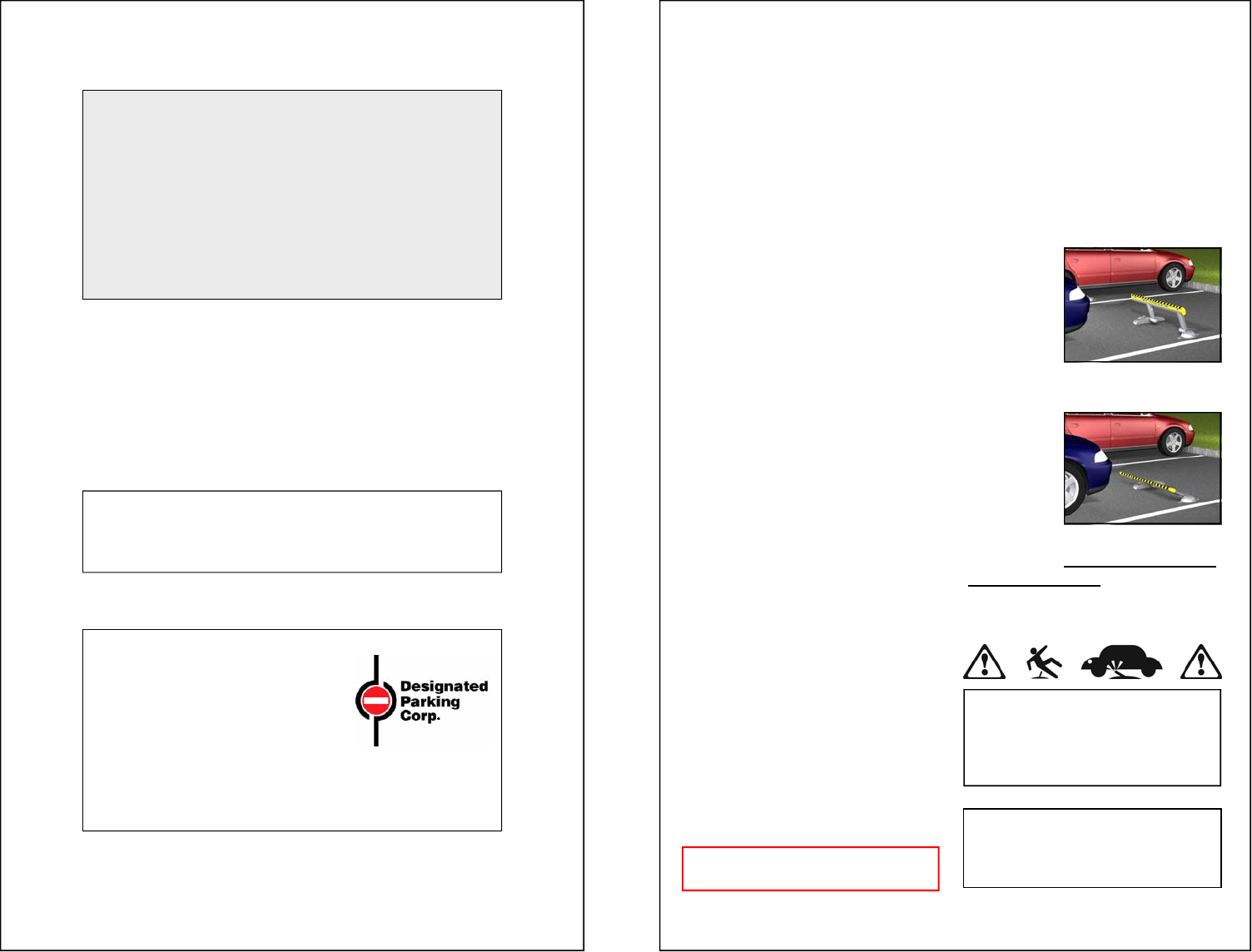
WARNING! Barrier may cause pedes-
trian or users to trip over it. Please install
and provide warning signs accordingly.
Note that Public Liability should be in
place.
This manual applies to MySpot 200
version 4 (shipments after JUL 2006).
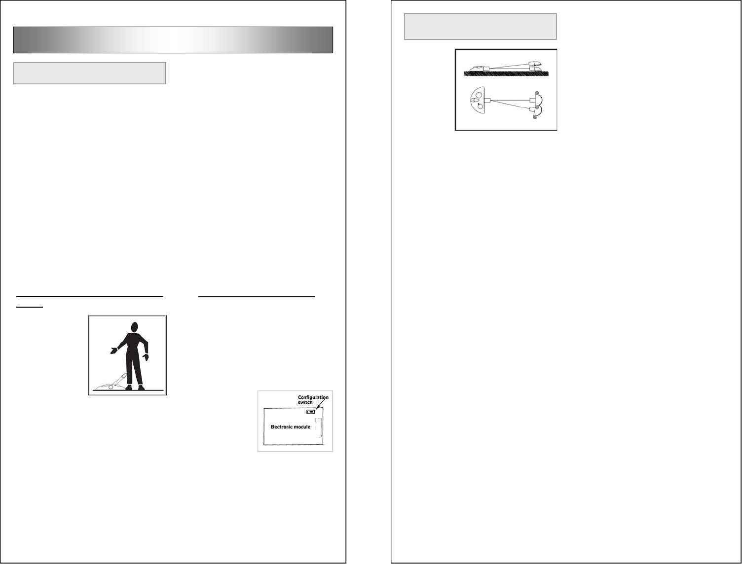
MySpot 200
is installed
as shown to
block ac-
cess to a
parking
space.
On com-
mand, the
barrier falls
forward to
allow ac-
cess.
A video
showing the installation is avail-
able on www.dp-corp.com/
downloads/videos
Designated Parking Corp V17 page 2 www.dp-corp.com
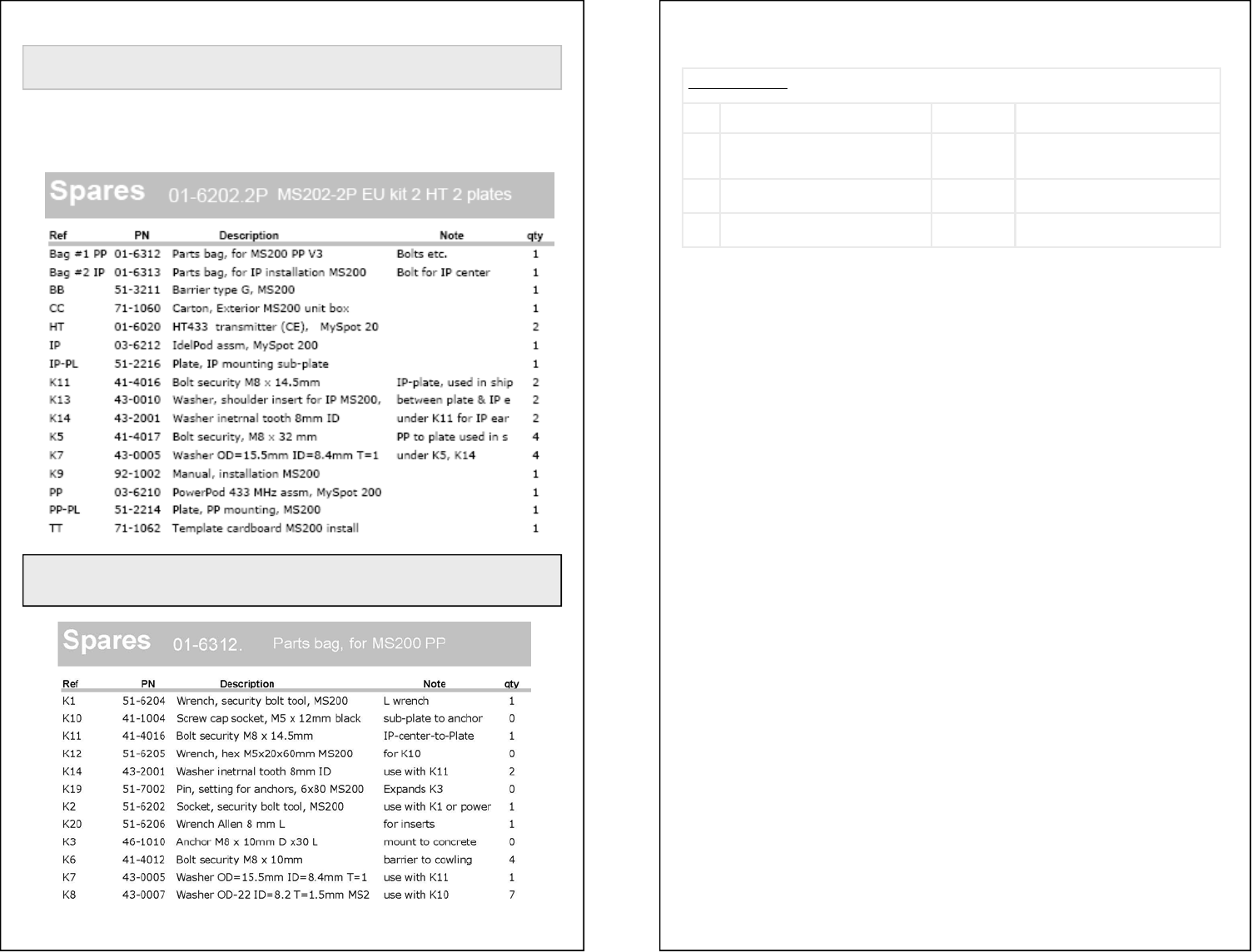
Kit Contents
Below is a list of the main assemblies and parts in the carton. Please note the “Ref: des-
ignator on the leftmost column. This ref will be used throughout the manual to identify
parts and assemblies. Anchors and their bolts are not included in the kits and should be
ordered separately.
NOTE (4) K5 bolts, (2) K11 bolts and (6) K7 washers are used to fasten the PowerPod and the Idle-
Pod, respectively, to the mounting plates during shipping. These 6 bolts are not in the parts bag “kit”
detailed below, and are listed in the part list above.
Designated Parking Corp V17 page 23 www.dp-corp.com
Can not Reboot
Step Test YES NO
1 Is barrier in the UP position when trying to
boot or change sensor setting? go to step 2 Configuration (“Boot”) Switch is ignored
except when barrier is in the Locked Up
position
2 Disconnect battery cable for 15 seconds,
reconnect. Problem still exists? go to step 3
3 Replace batteries in PowerPod. Problem still
exists? Replace elec-
tronic module
Designated Parking Corp V17 page 22 www.dp-corp.com
Troubleshooting
No response to Remote control
Step Test YES NO
1 Is the correct button pushed and does indica-
tor on remote control light up when button is
pushed?
go to step
2 Replace battery in remote control
2 Has this remote control worked before? go to step
2a Add remote control to memory of MySpot 200
3 Is barrier locked in Locked Up position? go to step
4 go to step 5
4 Use Emergency key to release barrier, then
raise barrier manually slowly and retest. Is
unit now working properly?
Jam
cleared go to step 6
5 Is barrier locked in Locked Down position? go to step
8 Bring barrier to locked up position and go to step
1
6 Is there another remote control that does
control the unit? go to step
7 Replace batteries in the PowerPod . If this does
not help, erase memory of MySpot (see manual)
7 Add remote control to memory of MySpot.
Does it work? Done Replace remote control
8 With the barrier down, step on it a couple of
times to simulate a car passing over the
barrier with both wheels. Is the barrier
responding the remote control?
Done go to step 4
2a Has the barrier been slow to respond recently Replace
PowerPod
batteries
go to step 3
Motor responds but no motion of barrier
Step Test YES NO
1 Is barrier locked in Up position? go to step 2 Go to step 4
2 While motor sounds, push barrier down.
Did it move? go to step 3 Open PowerPod cover and check
operation
3 Check alignment of pods or a bent barrier Done
4 Is it locked in Down position? Step on the barrier and
retest Step on barrier and compress spring,
twice and re-test
Step Test YES NO
2 Check wires from the optical sensors to
the electronic module. Are cables dam-
aged?
Move wires
away from edge Make sure opto is not subject to bright light
during test
Barrier goes up and then drops
1 “arm” the barrier by stepping on it and
repeat the test. Problem exists? Go to step 2 It was due to barrier being manually manipu-
lated and going out of synch.
Designated Parking Corp V17 page 3 www.dp-corp.com
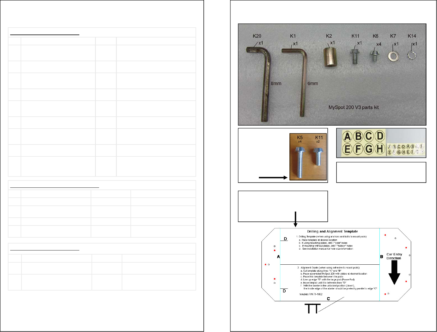
Cardboard template provided in
the MySpot 200 carton. Do not
discard accidentally.
These security
bolts are
shipped at-
tached to the
mounting plates
for the 2 pods. Labels for identifying remote controls
and matching them to installed units
Designated Parking Corp V17 page 4 www.dp-corp.com
Note: Adhesive for mounting
the pods is available as a
separate option and is not
included in the kits.
Unpacking
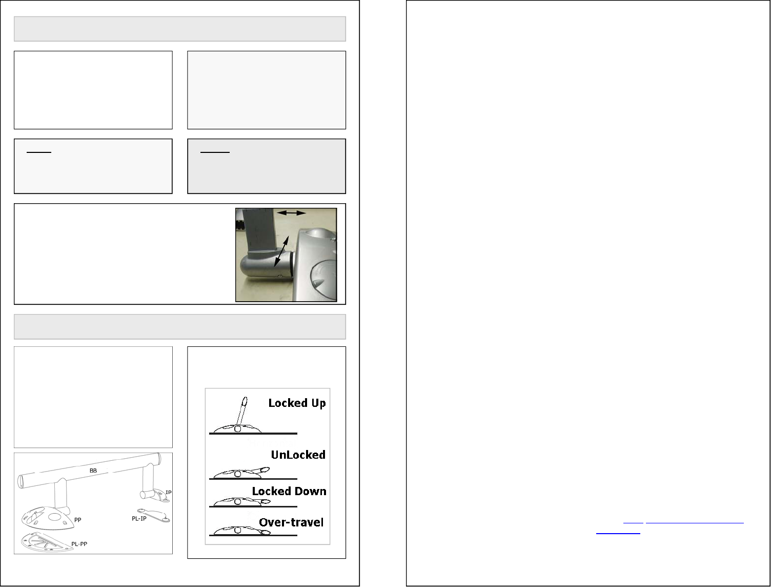
Terminology
The main components of MySpot
200
PP = PowerPod
IP = IdlePod
BB = Barrier
PL-PP = Mounting Plate, PP
PL-IP = Mounting plate, IP
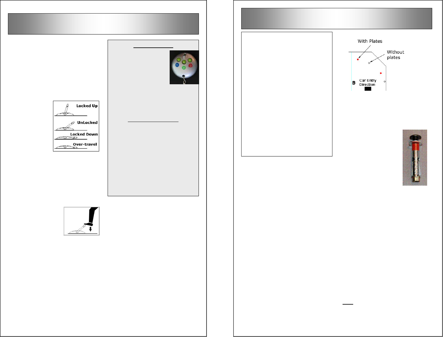
The barrier can be in one of 4 posi-
tions as shown.
Please check the contents of
the carton against the list on
page 2. identify each of the
items, as you may need to
refer to their designation dur-
ing installation.
A cardboard cover inside the
carton doubles as the installa-
tion template TT. Do not dis-
card this part when unpacking.
Note: The mounting hardware
is not provided inside the kit.
See next page for information
on the available kits.
NOTE: The cowlings at the end of the 2
pods are intentionally “floating” and are
designed not to be attached rigidly to the
shafts. This is required to accommodate
slight installation misalignment between
the pods.
Designated Parking Corp V17 page 21 www.dp-corp.com
Limited Warranty
Except as otherwise provided, Seller warrants
for a period of twelve (12) months from the date
of shipment that the goods supplied to Buyer
shall be of good materials and workmanship.
Seller makes no warranty with respect to the
following: (a) materials not manufactured by
Seller, the use of which is suggested by Seller’s
general recommendations, application or instal-
lation procedures, or otherwise; (b) goods sold
by Seller to Buyer for other than resale; (c)
goods which have been subject to abuse, acci-
dent, alteration, misuse, negligence or altera-
tions; and (d) all display items sold by Seller to
Buyer.
THE FOREGOING WARRANTIES ARE EXCLUSIVE,
AND IN LIEU OF ANY AND ALL OTHER WARRAN-
TIES, EXPRESS OR IMPLIED, WRITTEN OR ORAL
WHETHER IMPLIED BY OPERATION OF LAW OR
OTHERWISE, INCLUDING BUT NOT LIMITED TO,
ANY IMPLIED WARRANTY OF MERCHANTABILITY
OR FITNESS FOR ANY PARTICULAR PURPOSE,
USE, OR INFRINGMENT.SELLER DOES NOT AS-
SUME, NOR AUTHORIZE ANY REPRESENTATIVE
OR OTHER PERSON TO ASSUME FOR IT, ANY
OBLIGATION OR LIABILITY OTHER THAN AS
EXPRESSLY SET FORTH HEREIN.
Limitation of Remedies.
Seller's obligations under the above warranties
(contained in Section 10) are conditioned upon
Seller actually receiving notice from Buyer of
the alleged defect within the warranty period
and the existence of an actual defect in the
goods as revealed upon examination by Seller.
The sole liability of the Seller for breach of such
warranties shall be to provide Buyer with re-
placement for, or repair of, defective parts in the
manner provided herein. This exclusive remedy
shall not be deemed to have failed of its essen-
tial purposes so long as Seller is willing to repair
or replace the defective part(s) in the manner
prescribed herein.
Seller shall not be liable for any labor or other
expenses incurred by Buyer in the removal,
repair or replacement of the goods or any com-
ponent part claimed to be defective, nor shall
Seller be liable for any expenses incurred by
the Buyer in order to remedy any defect.
Seller’s acceptance of shipped goods shall not
be deemed an admission that such goods are
nonconforming under the above warranties. If
the Seller finds that any goods are not defec-
tive, such goods will be reshipped to Buyer at
its expense and Buyer will be charged for ship-
ping charges incurred by Seller.
Help
A troubleshooting chart is pro-
vided on the next page.
If you need assistance with the in-
stallation, repair or other problems,
please contact the company that sold
the system to you first. They are
likely to provide you with immediate
support, especially if the product was
purchased overseas.
Designated Parking web site is a
good source of tips, troubleshooting
information and a way to contact the
factory engineers to address unusual
problems.
You can download the latest manu-
als at www.designatedparking.com/
downloads
Under no circumstances and in no event will the
Seller be liable for any personal injury or property
damage, loss of profits or revenue, loss of busi-
ness, consequential, incentive, punitive, special or
contingent damages or expenses of any kind in-
curred by Buyer or any third party, based upon
warranty, contract, strict liability, negligence or any
other cause of action arising under this Agreement
or in connection with the product or services pro-
vided hereunder even if the other party or any other
person has been advised of the possibility of such
damages The discharge of Seller's warranty obliga-
tion hereunder shall constitute fulfillment of all
liabilities of Seller to Buyer, whether based on
contract, negligence or otherwise. The remedies set
forth herein shall be the exclusive remedies avail-
able to the Buyer and in lieu of all other remedies,
and the liability of Seller, whether in contract, in
tort, warranty or otherwise, shall not exceed the
price of the goods sold, supplied or furnished by
Seller which give rise to the claim.
Any suit or action arising out of or relating to
this Agreement or the breach thereof, must be
commenced within one (1) year after the date of
shipment of the goods to the Buyer. The forego-
ing shall not limit the time within which any suit
or action must be brought to collect an amount
agreed to be paid by Buyer or to enforce a
judgment in favor of Seller or to collect any
amount awarded to Seller.
Designated Parking Corp V17 page 20 www.dp-corp.com
Never drive over the barrier when
obstructions are visible under the
barrier.
Replacing remote control
batteries
When the batteries in the HT remote
control approach their end-of-life, the
HT will signal the condition by delay-
ing the transmission of a command.
The green indicator on the remote
control will flash for a few seconds,
before the normal pattern of turning
solid for 2 seconds (while it sends
the command) takes place.
To replace the batteries, open the
two small Philips screws on the back
of the unit. Replace the 2 Lithium
button batteries with CR2016 batter-
ies. Observe polarity! Check opera-
tion of the indicator before closing. If
OK, close with the two screws.
Replacing PowerPod Bat-
teries
The batteries should provide 2 to 3
years of life under normal operating
conditions. When the batteries ap-
proach their end-of-life, MySpot 200
will become “sluggish” – it will delay
the response to the remote control
commands by about 5 seconds.
This is an intentional reminder that
the batteries need replacing.
If the batteries are not replaced be-
fore they are completely exhausted
after 50 additional operations, the
barrier will accept one last command
and will stay down .
To replace the
batteries, open the
cover of the
PowerPod and pull
out the 5 batteries.
It may require that
you cut the straps
that hold the bat-
teries — these
were provided for shipping only.
Replace with fresh D alkaline batter-
ies.
The most important maintenance is
to clear the immediate area of the
MySpot 200 of debris of any kind.
8: Maintenance
Observe polarity!! Reversing the
polarity of some or all the batteries
will damage the radio receiver, or
may cause the radio not to work at
all.
Designated Parking Corp V17 page 5 www.dp-corp.com
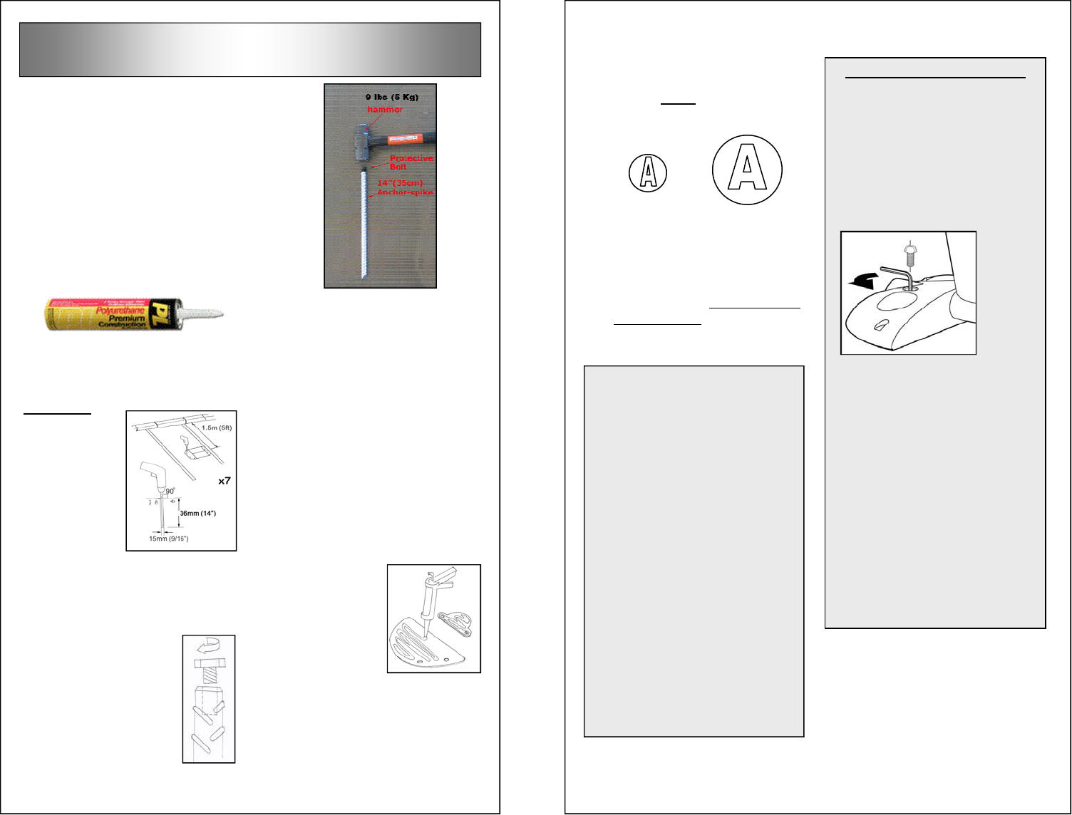
SP14/7 Spike Kit
This kit contains 7 spikes, special
M8 hex head bolts, washers and a
wrench. The
spikes were
developed to
mount the
pods in a
relatively soft
surface such
as macadam
or asphalt.
It is strongly
recom-
mended that
the spikes be
used in con-
junction with adhesive such as DPC
EPX1. An industrial grade premium
adhesive with polyurethane can be
used instead of the EPX1
The bolt shown in the picture is used
to protect the head of the spike dur-
ing hammering, and is removed after
the spike is pushed flush with the
surface.
The spike should
be hammered into
a pre-drilled 9/16”
or 5/8” (15mm or
16mm) hole drilled
vertically, using a
heavy hammer. A
9 lbs (4.5KG) ham-
mer works best.
Note that the
spikes require a
14” (36 cm) clearance below the
surface.
CA6/7 Anchor Kit
This kit contains 7 metric concrete
anchors, special M8 hex head bolts,
washers and a wrench.
The anchors are 10 mm in diameter
and 60mm long. They are suitable
for fixing the plates to any concrete
— reinforced hard concrete or soft-
ware cement. They are not suitable
for fixing the plates to asphalt, mac-
adam and similarly soft aggregates.
To install, drill 10mm holes in the
surface, 65 mm deep. Push the
anchor until its head is flush with the
surface, all the while keeping the
bolt in the anchor. Make sure that
no debris enter the thread after the
anchor has been placed in the holes,
so do the cleaning before you re-
move the bolt.
FRACTIONAL ANCHORS
DPC can provide special US specifi-
cation anchors that measure 5/8”
diameter by 1 5/8” long. And accept
5/16” bolts. The kit (MA7) is avail-
able from DPC.
Designated Parking Corp V17 page 6 www.dp-corp.com
Front or Middle?
MySpot 200 can be positioned in two
distinct locations within the parking
space – in the middle or at the front.
Installation in the front is allowed
only in private driveways.
2: Site Preparation
Gravel, Sand
Mounting the pods directly to
gravel or sand is not recom-
mended, as neither the bolts nor
the adhesive will provide ade-
quate grip. A suitable concrete
footing needs to be poured for
each of the pods.
Asphalt
The installer needs to check the
integrity of the asphalt or mac-
adam surface to make sure that
the depth and strength are ade-
quate to support mounting an-
chors. In some cases, the use of
the optional adhesive EPX1 may
be the better way to mount the
pods. It is not recommended to
use the concrete anchors on as-
phalt.
Special asphalt anchors are avail-
able from Designated Parking (SP-
14). These are 35 cm (14”) long
spikes
TOOLS: Unless you use adhesive,
you will need a power drill and a 10
mm (13/32”) masonry drill bit for set-
ting the concrete anchors into the
roadway to mount the two pods.
Where to position
MySpot?
Middle mounting means that the
barrier will stay under the car while
the car is parked
in the space.
The advantages
of middle-
mounting are:
• Barrier is
further re-
moved from
dirt and de-
bris pushed from the main ac-
cess lane
• Cars making J turns are less
likely to bump into the raised
barrier accidentally
• The barrier is protected from
inclement weather while the car
is parked over it
• Cars entering adjacent lanes are
less likely to accidentally hit the
barrier
When placing the barrier in the mid-
dle of the stall, the center line of the
device should be about 1.5 meters (5
feet) from the rear of the stall
(dimension “Y” in the drawing
above).
Designated Parking Corp. recom-
mends installing the barrier in the
middle of the space.
WARNING: Locate the PowerPod
so that persons getting in or out
of the car will not trip on the pod.
Designated Parking Corp V17 page 19 www.dp-corp.com
1. Carefully clean the base from
any particles.
2. Make sure that the emergency
key tang fits in the hole of the
slide latch. Failure to observe
this precaution will bend the key
and possibly damage the
mechanism.
3. Check the integrity of the sili-
cone seal which is glued inside
the cover. It should be continu-
ous without deformation or cuts.
4. Make sure
that the sur-
faces of the 4
bushings in
the base
which hold the inserts are cov-
ered with Teflon or similar water
-resistant grease.
5. Holding the cover close to the
base, plug in the antenna cable
6. Place the cover over the base
and make sure that the 4 holes
in the cover line up with the
holes in the base
7. Secure the 4 inserts using the
K20 8 mm Allen wrench (10 mm
on products shipped before
March 2005).
Tighten the
inserts se-
curely using a
torque wrench
set to 80 Kg-
cm (75 in-lb) to compress the
gasket seal.
8. For outdoor
applica-
tions, run a
pressure
test on the
PowerPod
to make
sure that it
is properly
sealed and
thus water
proof. Use
DPC PT1 pressure tester.
9. Attach the PowerPod to the
mounting plate using the metal
washers under the head of the
bolts. Failure to use the wash-
ers will deform the plastic inserts
and allow water to seep into the
PowerPod.
Closing the PowerPod Cover
Designated Parking Corp V17 page 18 www.dp-corp.com
Removing the PowerPod
Cover
1. Use the security socket to re-
move the 4 security bolts that
attach the PowerPod to the
mounting plate.
2. Using
the K20
8 mm
Allen
wrench,
remove
the 4
plastic
inserts
that attach the cover to the
base.
3. Lift the cover gently about 2“
and disconnect the antenna
cable by pulling its RCA plug
from the socket.
Warning! Pulling the cover with-
out disconnecting the antenna
cable will damage the antenna
cable or the electronic module
in the base of the PowerPod.
Warning! The PowerPod is
sealed against water using white
Teflon grease. Make sure not to
touch or remove this grease
else the housing will no longer
be water resistant.
1 or 2-button modes
To place the HT remote control in the
2-button mode (where a sequence of
2 keys is required before a command
is sent out):
• Press and hold buttons 1 & 2
simultaneously.
• After 5 seconds, the indicator on
the HT will start flashing. Re-
lease the buttons. Make sure
that the indicator continues to
flash.
• Press button 2 and hold until the
flashing indicator turns off.
To place the HT in the 1-button
mode, follow the sequence above
but as the last step press and hold
button 1.
TEST: Press any button once. IF
the indicator responds immediately,
you are in 1-button mode.
programmed button(s) on the
authorized “A” remote control.
9. To verify that the new remote
control works, press the newly
programmed button(s) on the B
remote control. The motor
should respond and the barrier
should fall.
The same procedure can be used to
add another button on the same re-
mote control to the list. Each of the 3
buttons on the HT has its own code,
and all 3 can be programmed into
the PowerPod if desired. The 3 keys
allow the same remote control to
control 3 separate MySpot 200.
Designated Parking Corp V17 page 7 www.dp-corp.com
Standing Water
MySpot 200 is sealed to prevent
water from entering the unit. The
PowerPod should not be exposed for
extended period of time to standing
water or ice. To prevent such occur-
rence, select a spot for the pod that
is
slightly raised above the surface, or
add a plate to raise it.
Right Align
The Barrier should
be installed on the
right side of the
space. Mount the
pods so that the
edge of the barrier
touches the edge
of the space. This way you are as-
sured that at least one wheel will
drive over the barrier.
Designated Parking recommends
mounting the barrier on the right
hand side, as shown in the drawing
above. The reason is that when in-
stalled as shown, the right hand
wheel of the car will drive over the
barrier between the two pods. This
minimizes the “speed bump” effect
on the car and makes for a smoother
entry and exit.
Beware of low ground
Front mounting means that the car
drives in and parks behind the bar-
rier. This mode of installation is suit-
able only to single-car driveways.
A benefit of front mounting is that the
barrier can to be used as a theft
deterrent, raising it with the car
parked behind it. The barrier should
be installed as close to the front limit
of the space as possible, to allow the
barrier to rise behind even a large
vehicle.
Installing the barrier in the front in
multi-car parking areas will dra-
matically increase the likelihood
that the barrier will be bumped
into by passing vehicles, and is
thus strongly discouraged.
The forces applied to the barrier
when the car drives over it create a
force that is
trying to lift the
corner of the
PowerPod
shown with the
red arrow on
the above pic-
ture. Make sure
to secure this corner above all others
to the surface, and use all 4 bolts to
attach the plate to the ground and
the pod to the plate.
Likewise, make sure that when
mounting the IdlePod plate IP to the
ground, 3 bolts are used. When se-
curing the IdlePod to its plate, place
the insert K13 between the plate
and the earls of the IdlePod. Use
three bolts K11, a star washer K14
and the flat washer K8. Installing the
3rd bolt requires opening the cover
of the IdlePod.
Designated Parking Corp V17 page 8 www.dp-corp.com
Barrier Clearance
The front (leading) edge of the bar-
rier must be able to travel 3” [8 cm]
(from its Unlocked position) before it
hits the ground. A rise in the road-
way anywhere along the contact
point between the barrier and the
ground will interfere with this full
range of motion.
To check
the surface,
place the
barrier up-
side-down
on the
ground.
Observe
any height irregularities. If the road-
way is lower in between the two ends
of the barrier, there is no problem. If
the roadway at even one point is 7
mm (¼”) higher, move the barrier
towards the front or the rear of the
space until a better location is found.
If the rise in the middle is unavoid-
able, you may have to raise one or
both pods using a suitable plastic or
metal plate. The use of wood or
plywood is not recommended as it
will rot.
3: Assemble Barrier
Prior to the mounting of MySpot 200,
the barrier needs to be assembled to
complete the assembly of the device.
This will self-align the two pods.
1. Make sure that the stub on the
PowerPod is in the Locked Up
position. (See inset for instruc-
tions how to manually bring the
shaft to the Locked Up position if
necessary.)
2. Rotate the stub on the IdlePod
until it too is in the Locked up
position.
3. Slide the barrier over the stub of
the PowerPod. The grooved
surface of the barrier should be
facing back, away from the en-
trance to the parking space.
The reflective yellow label on the
front of the barrier should face
the entrance to the parking
space.
4. Make sure that the holes on the
barrier line up with the threaded
holes in the stub.
5. S e c u r e
the barrier
to the stub
using 2
washers
K14 and 2
short se-
curity
bolts K6.
6. Repeat the process for the Idle-
Pod side and secure the barrier
to the stub using washers K14
and security bolts K6 .
Beware of uneven surface
Designated Parking Corp V17 page 17 www.dp-corp.com
Once the first remote control has
been added (“programmed” or
“paired”) to the authorized list in the
radio receiver in the PowerPod per
section 6, additional remote controls
(up to a total of 15) can be pro-
grammed.
Adding Remote controls
1. Make sure that any barrier in the
vicinity that is still unpro-
grammed is
placed in the
Unlocked posi-
tion.
2. Place the barrier
in the Locked
Up position.
Prop the barrier with your leg so
that the barrier will not fall when
activated.
3. Hold the authorized remote con-
trol (“A”) in one hand, and the
new one (“B”) in the other.
4. The sequence as explained be-
low is A-A-B-A.
5. Press the previously pro-
grammed button(s) on the au-
thorized A remote control. The
motor will whirl. The green indi-
cator on the HT remote control
will stay lit for 2 seconds. If the
remote control is set to a 2-
button mode, press the two keys
in sequence to get the motor to
whirl.
6. Two seconds after the motor
stopped, press the authorized
key A again. The motor should
sound again.
7. Two seconds after the motor
stopped, press the desired but-
ton(s) on the new (“B”) remote
control. The green indicator on
it will turn on for 2 seconds. In
the case of 2-button setting,
press the same key sequence
on the new remote control as
you do on the authorized remote
control.
8. After the green indicator on the
new remote control turns off,
wait 2 seconds then press the
First Remote control
seconds to acknowledge a suc-
cessful “reboot”.
6. The unit has been returned to
the factory setting. To program
the first remote control, just acti-
vate it.
7. Connect the antenna and close
the cover.
Once the MySpot has been erased,
it will learn the first remote control it
“sees” as a valid remote control.
1. Place the barrier in the Locked
Up position.
2. Press the button, or sequence of
buttons (if the HT is in the two-
button mode), on the remote
control that you wish to pair with
the barrier.
3. The motor should whirl and the
barrier should fall. The remote
control has now been paired
with the barrier.
Designated Parking Corp V17 page 16 www.dp-corp.com
7: Programming the Radio
The only way to delete remote con-
trols is to erase the programming in
the unit. This is also the case when
the only authorized remote control
has been lost, and a replacement
remote control needs to be added.
This erasure is known as a “boot”.
There are two ways to boot the con-
troller — through a switch inside the
PowerPod, and through a command
sequence from an authorized HT
remote control. The latter solution is
preferred as it does not require open-
ing the PowerPod. However, if an
authorized remote control is not
available or is not working properly, it
can not be used.
BOOT USING HT REMOTE CON-
TROL :
1. Place the
barrier in
the Locked
Up position
and prop
the barrier
with your
leg so that
it will not fall
2. Using an authorized remote
control press the button or se-
quence of buttons that you use
to lower and raise the barrier.
3. The motor in the PowerPod will
whirl.
4. Wait 2 seconds, then repeat
step 2.
Erase Memory (Boot)
BOOT USING THE SWITCH:
1. Open the cover of the Power-
Pod. (See insert on next page
for details.) Remember the an-
tenna cable.
2. Place the barrier in the Locked
Up position.
3. Press and
hold the
Configura-
tion switch
(marked
“Boot” on the
circuit board)
for more
than 5 seconds but less than 10
seconds.
4. Release the switch.
5. After a 3 second delay, the mo-
tor will operate for a couple of
5. Without waiting for the motor to
stop, press and hold buttons #1
and #3 for 2 seconds. The LED
indicator must not come on. If it
does, repeat step 5.
6. Immediately, press button #2 for
2 seconds. Release the button.
7. The LED will start flashing to
indicate that it has entered the
Command mode.
8. Immediately (within 3-4 sec-
onds) press button #1, followed
within a second with button #2.
9. The Controller should respond
within a few seconds with activa-
tion of the motor for 1-2 seconds
Designated Parking Corp V17 page 9 www.dp-corp.com
The barrier rotates around the bear-
ing surfaces on the two pods. The
force that brings the barrier down to
allow access to the space comes
from gravity pulling the barrier. Ex-
cessive friction along the travel of the
barrier will prevent proper operation
of the device.
The two pods need to be reasonably
aligned with each other, so that the
barrier is free to rotate. Alignment
means that the two pods face each
other so that an imaginary line ex-
tending from the shaft of the Power-
Pod will line up abeam with the
opening in the IdlePod. This align-
ment also applies to the height – a
significant (more than 1 inch) height
difference between the two pods will
hamper the free motion of the bar-
rier.
If the PowerPod mounting area is not
level, the use of a shim under the
PowerPod or its mounting plate may
be required to level it with the Idle-
Pod.
MySpot 200 is now ready for at-
tachment to the roadway.
Line up the Pods
Aligning the IP and PP is critical
Designated Parking Corp V17 page 10 www.dp-corp.com
Asphalt offers a relatively weak sur-
face for mounting MySpot 200. For
the most reliable installation pour
concrete footing for the 7 bolts for
the mounting of the plates.
For normal duty applications, the
plates can be attached to the surface
using a combination of adhesive
(DPC EPX1) and special spike-
anchors available from DPC (model
SP14). An alternate adhesive that
can be purchased anywhere is a
premium industrial adhesive with
polyurethane.
Installation
1. U s e t h e
template
that is
provided
with the
MySpot kit
to mark
the loca-
tion of the
anchors.
2. Drill 5/8” (16mm) holes perpen-
dicular to the ground.
3. Apply the adhesive
to the hole, filling it
about 50%.
4. Protect the anchors
by threading the
supplied protective
bolts and secure
them to the anchors
with a wrench.
5a: Asphalt Installation
5. Using a heavy hammer (at least
5 lb. 2.5 Kg), drive the anchors
into the ground until the head of
the anchor is flush with the as-
phalt surface.
6. Using the wrench, remove the
bolts.
7. Place the plates over the an-
chors to make sure that the
holes line up. If some holes are
off, you may have to drill the
plate.
8. Apply 1/8” (4mm) thickness of
adhesive to the full surface of
the bottoms of the plates.
9. Mount the plates and secure
with washers
and bolts to
the anchors.
10. Use the adhe-
sive to caulk
the edge of
the plates to
prevent water
entry under the plates.
Designated Parking Corp V17 page 15 www.dp-corp.com
Releasing the shaft manually
If it is necessary to rotate the shaft
manually, with the cover in place,
follow this procedure:
1. Remove the security bolt as
shown above to gain access
to the Emergency Key.
2. Place the 6 mm Allen wrench
in the
Emer-
gency
Key.
3. Turn the wrench counter
clockwise. This releases the
lock or locks that are holding
the shaft and the internal
mechanism.
4. If the barrier was in the
Locked Up position, it should
fall freely.
5. If the barrier was in the
Locked Down position, step
on the barrier as you rotate
the key. Your weight will re-
move the pressure from the
latches and allow the key to
operate them with ease.
6. Remove the Allen wrench
8. NOTE: The barrier must be
pushed down to the Overtravel
position twice to allow raising the
barrier.
9. Apply matching ID labels
to the PowerPod
and to
the
remote
control (e.g. “A” l a -
bel).
10. For applications where one
driver is given one or two HT
remote controls and no addi-
tional control of the barrier is
required, the installation is
now complete.
RE-PROGRAMMING
.
For applications where a number
of side-by-side units need to be
controlled by the same remote
control, each of the barriers
needs to be reprogrammed per
section 7. That entails the fol-
lowing steps:
1. Erase the memory of one
MySpot 200 unit at a time.
2. Teach the unit the address of
the first remote control by
simply transmitting from the
remote control with the bar-
rier in the Locked Up posi-
tion.
3. Add the next remote control
(s).
Designated Parking Corp V17 page 14 www.dp-corp.com
6: Test
MySpot 200 is shipped with two HT
remote controls. These are pre-
programmed at the factory, so that the
#2 button in each remote control con-
trols the barrier.
The test below verifies normal opera-
tion of the MySpot 200 and checks the
alignment of the pods.
1. With the
barrier in
the Locked
Up posi-
tion, press
the center
button on
the HT
remote
control.
2. The barrier should drop to the
Unlocked position.
3. If you hear the motor whirl but the
barrier does not drop, repeat
step 1 above. If the barrier still
does not drop, follow the trouble-
shooting section at the end of this
manual.
4. Step on the
barrier on the
side close to the
PowerPod.
This simulates
the car driving over the barrier.
The barrier will yield if you exert
at least 85 Kg (190 lbs) and will
lock in the Locked Down position.
5. Step again on the barrier, and
observe the motion of its leading
edge. It should move vertically at
least 18 mm (3/4”) while you
stand on it, and should return to
the Locked Down position once
you step off. Failure of the barrier
Why 3 buttons?
Each button on the HT
remote control gener-
ates an individual code.
That allows one remote
control to control 3 indi-
vidual MySpot 200.
You may use any button for your
MySpot, or you can program all 3 for
the same unit.
1 or 2 Button Code?
The HT is shipped in the mode
where only one button is required to
be activated (see above). For appli-
cations where more than 3 adjacent
barriers need to be controlled, the
HT remote control can be set to a
two-button mode. Up to 9 adjacent
barriers can individually be con-
trolled. A command is sent only
after 2 buttons are sent (e.g. 2-1).
See section 7 “Programming”.
to move this “Overtravel” amount
means that there is a rise in the
roadway between the pods that
interferes with the full travel of the
barrier.
6. If the test failed on the Overtravel,
resolve the problem before pro-
ceeding to the next step. Solu-
tions include raising the pods or
leveling the bump on the road-
way.
7. Press the button on the HT re-
mote control; the barrier should
rise back to the Locked Up posi-
tion.
Designated Parking Corp V17 page 11 www.dp-corp.com
5b: Concrete Installation
Pods’ Covers
The PowerPod is factory sealed
and should not be opened. It is
mounted via 4 bolts that are fitted
through the plastic inserts that
hold the cover to the base of the
PowerPod.
The IdlePod is mounted using 3
bolts — two external bolts and an
internal one The 3rd bolt is
added by opening the cover. To
protect the internal mechanism of
the IdlePod, it is recommended
that the cover only be opened
after all the drilling has been com-
pleted.
1. Thoroughly clean the roadway
where the pods are to be in-
stalled. The surface must be
free of sand, gravel and loose
particles.
2. Place the template in the de-
sired location. Verify that the
template is perpendicular to the
parking bay stripes.
3. Position the assembled MySpot
200 and verify that the surface
meets the criteria specified in
sections 2 and 3.
4. Note that there are two types of
holes marked on the template —
solid and hollow. The solid
holes should be used if install-
ing the pods with mounting
plates; the hollow holes are for
use if installing the pods directly
without plates (not recom-
mended).
5. Use a 1/4” (6mm) masonary drill
to mark the 7 holes in the con-
crete, by drill about 1/2” (13mm)
through the template.
6. Remove the tem-
plate and drill 7
holes using a 10
mm (13/32”) ma-
sonry drill. Take
extra time to make
sure that each
hole is right on the
spot.
7. Clean the area
and gently ham-
mer in the anchors until they are
flush with the surface. Cleaning
after the anchors are installed
may cause dirt to clog the
threads in the anchor.
8. Next attach the plates to the
anchors.
9. Use 7 bolts K10 with washers
K8 to secure the 2 plates to the
anchors. The bolts and washers
are supplied separately with the
anchors.
10. Use tool K12 to lightly tighten
the 7 bolts. (See note page 13.)
11. Place the barrier and pods as-
sembly over the plates.
12. Use the 4 bolts K5 (32mm long)
with washers K7 to secure the
Designated Parking Corp V17 page 12 www.dp-corp.com
What to do if an anchor rotates
in its seat:
If the hole is only slightly oversize,
use a sharp point to hold the an-
chor against the wall of the hole
and gently tighten the bolt. At
some point, the expanding anchor
will grip the walls of the hole. Turn
the bolt another ½ turn to make
sure the anchor is set.
If the hole is too large, you may
need to fill it with concrete mix or
epoxy, and then re-drill once the
mixture has hardened. Inserting
the anchor into the liquid epoxy
may fill the threads and prevent
the anchor from accepting the
bolts. If the bolt is placed while the
filler is not yet hardened, it may not
be able to be withdrawn later.
PowerPod to its plate. Once the
plates have been secured per
note on page 13, tighten the
Secure bolts as much as possi-
ble.
13. Use the 2
bolts K11,
with washers
K8 and K14 to
secure the
IdlePod to its
plate. Tighten
as much as
possible.
14. Remove the cover of the Idle-
Pod by opening its 3 security
bolts as shown on the right.
15. Attach the base to the plate with
the 3rd bolt K11, washers K14
and K7. Tighten. The picture
below shows the IdlePod parts
USE THREAD LOCKING
To prevent the mounting
bolts from loosening up, it
is strongly recommended
that a thread locking liquid
(such as Loctite Blue) be
used on the thread of the
Security bolts as they are
used. Loose bolts in-
crease the stress on the
remaining bolts and can
cause metal failure on the
mounting ears of the Idle-
Pod or failure of the
threads in the plates..
WARNING! Attaching the 3rd bolt
between the IdlePod and its plate
IS NOT OPTIONAL. Failure to do
so will cause the ears of the Idle-
Pod to break when a car drives
over the IdlePod cowling.
Designated Parking Corp V17 page 13 www.dp-corp.com
kit (01-6313) as it is supplied in
the MySpot 200 V3 kit.
16. Close the cover of the IP.
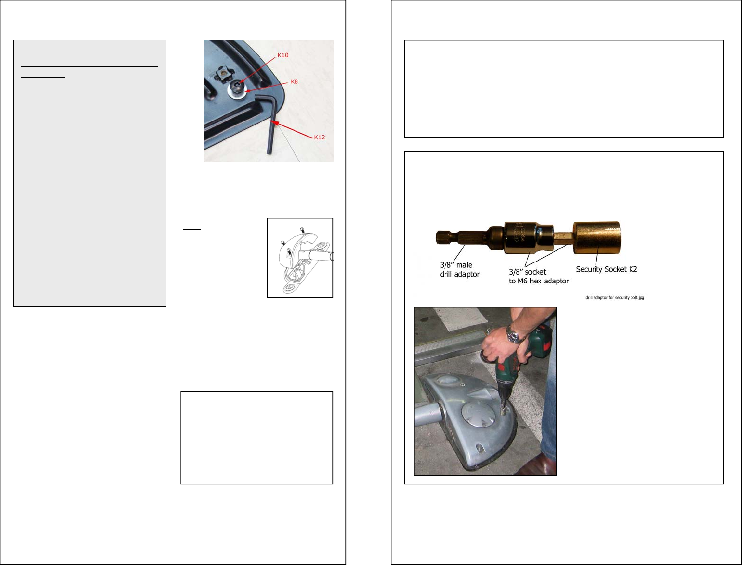
TIP: Use a power drill with a 6mm adaptor to drive the Security Socket
K2. It allows much more force as your weight can press against the bolt.
NOTE: Unless you are experienced with the installation of MySpot 200, you
may have to move the mounting plates somewhat once the two pods are at-
tached to it, to better align the pods. For this reason it is suggested that you
only hand tighten the bolts first.
When you feel sure that the plates are perfectly aligned, tighten the 7 bolts se-
curely.