Device Solutions PA0053 LoRa2 Radio Module User Manual Device Solutions Inc
Device Solutions Inc. LoRa2 Radio Module Device Solutions Inc
Users Manual

7/7/2017 Page 1(8)
Device Solutions Inc
Proprietary & Confidential
http://www.device-solutions.com/
Phone/Fax: (919) 732-7872
PA0053 Technical User Manual
1 Introduction
The Device Solutions PA0053 Transceiver Board is based on a Semtech SX1276 Low Power Long Range
Multiband RF Transceiver. The PA0053 card has Modular approval under FCC Part 15, Subpart C and
applicable Industry Canada RSSs. This document summarizes the requirements for integrating the
PA0053 into additional products.
2 Regulatory Requirements
To conform to the modular approval, the integration must conform to the following:
1. There must be no changes to the antenna system.
2. There must be no changes to the remainder of the module.
3. Unless the product is smaller than palm sized, it shall be labeled “Contains FCC ID: OXW-
PA0053” per FCC requirements.
4. Unless the product is smaller than palm sized, it shall be labeled “Contains IC: 10572A-PA0053”
per IC requirements.
5. All integrations must conform to applicable RF exposure limits and associated usage conditions
for installation type (fixed, portable, mobile).
6. The user manual shall include the following text:
This device uses RF energy to communicate. To reduce RF Exposure, this device must be installed in a manner to ensure
a 20cm separation is maintained between the devices antenna and the body of the user or nearby people.
This device complies with Part 15 of the FCC Rules. This device complies with Industry Canada’s license-exempt RSSs.
Operation of the device is subject to the following two conditions: (1) The device may not cause harmful interference,
and (2) The device must accept any interference that may cause undesired operation.
This product has been tested and complies with the specifications for a Class B digital device, pursuant to Part 15 of the
FCC Rules. These limits are designed to provide reasonable protection against harmful interference in a residential
installation. This equipment generates, uses, and can radiate radio frequency energy and, if not installed and used
according to the instructions, may cause harmful interference to radio communications. However, there is no guarantee
that interference will not occur in a particular installation.
If this equipment does cause harmful interference to radio or television reception, which is found by turning the
equipment off and on, the user is encouraged to try to correct the interference by one or more of the following
measures:
•Reorient or relocate the receiving antenna
•Increase the separation between the equipment or devices
•Connect the equipment to an outlet other than the receiver's
•Consult a dealer or an experienced radio/TV technician for assistance
Changes or modifications not expressly approved by the party responsible for compliance could void the user's authority
to operate the equipment.
7/7/2017 Page 2(8)
Device Solutions Inc
Proprietary & Confidential
http://www.device-solutions.com/
Phone/Fax: (919) 732-7872
3 Other Recommendations
1. The PA0053 board shall be installed in such a way as to maximize clearance around the antenna.
4 Example Host Product Assembly Instructions
4.1 Screw PCB to enclosure
- #4-20 3/10 inch T10 Screws (HW0016)
- PA0053 PCB, Qty. = 1
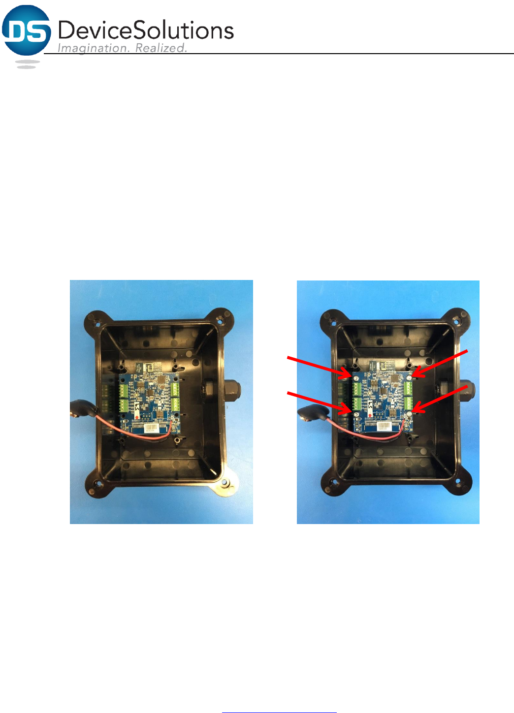
Be sure to label the PA0053 PCB with the PA level number sticker.
Using four #4 screws that are 3/10 inch long T10 screws, secure the PA0053 PCB to the lower four screw
mounts in the enclosure (shown below). The PCB should be placed in the enclosure with the wire gland
pointing to the right and the PCB antenna pointed north (shown below). Be sure to tighten the screws so
that the PCB cannot move freely.
7/7/2017 Page 3(8)
Device Solutions Inc
Proprietary & Confidential
http://www.device-solutions.com/
Phone/Fax: (919) 732-7872
4.2 Install Battery Holder
4.2.1 Add double sided tape to battery holder
- Battery Holder (HW0054)
- Double sided tape (HW0056)
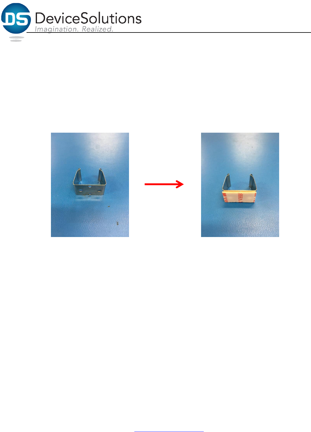
Cut the double sided tape to be 0.5 inches by 1 inch. Wipe the back of the battery holder bracket with
an isopropyl alcohol wipe. Once the bracket is dry, apply the double sided tape to the bracket. Press
firmly on the tape to ensure a strong adhesion to the bracket.
7/7/2017 Page 4(8)
Device Solutions Inc
Proprietary & Confidential
http://www.device-solutions.com/
Phone/Fax: (919) 732-7872
4.2.2 Place battery Holder in enclosure
- Battery Holder (HW0054)
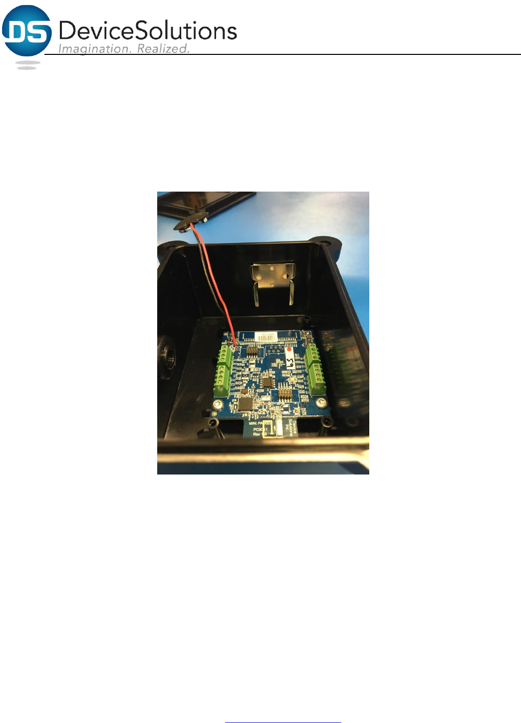
The battery holder should be place as shown in the picture below. The enclosure should be placed with
the wire gland pointed to the left. In this orientation the battery holder will be placed on the north
enclosure wall. The battery holder should be approximately 0.5 inches down from the top edge of the
enclosure wall and centered between the screw mounts.
7/7/2017 Page 5(8)
Device Solutions Inc
Proprietary & Confidential
http://www.device-solutions.com/
Phone/Fax: (919) 732-7872
4.2.3 Add battery retention clip
- Battery Holder Retention clip (HW0055) top
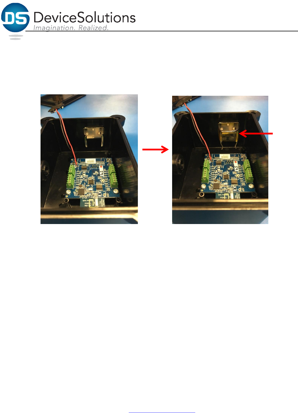
To prevent the retention clip from rattling around enclosure during shipping, the retention clip should
be placed on the main bracket of the battery holder and taped as shown below.
7/7/2017 Page 6(8)
Device Solutions Inc
Proprietary & Confidential
http://www.device-solutions.com/
Phone/Fax: (919) 732-7872
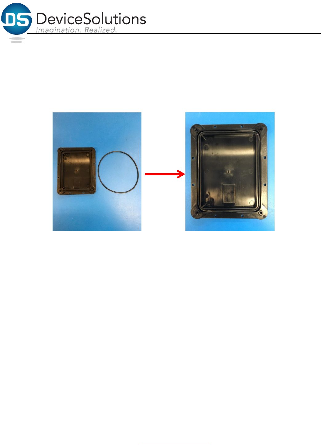
4.3 Insert O-ring into enclosure base
- O-ring (HW0002)
- Enclosure base (refer to section 3 for enclosure part number), Qty. = 1
The O-ring should be placed within the groove of the enclosure base. Be sure to press the O-ring
completely into place to ensure a good seal when closing the enclosure.
7/7/2017 Page 7(8)
Device Solutions Inc
Proprietary & Confidential
http://www.device-solutions.com/
Phone/Fax: (919) 732-7872
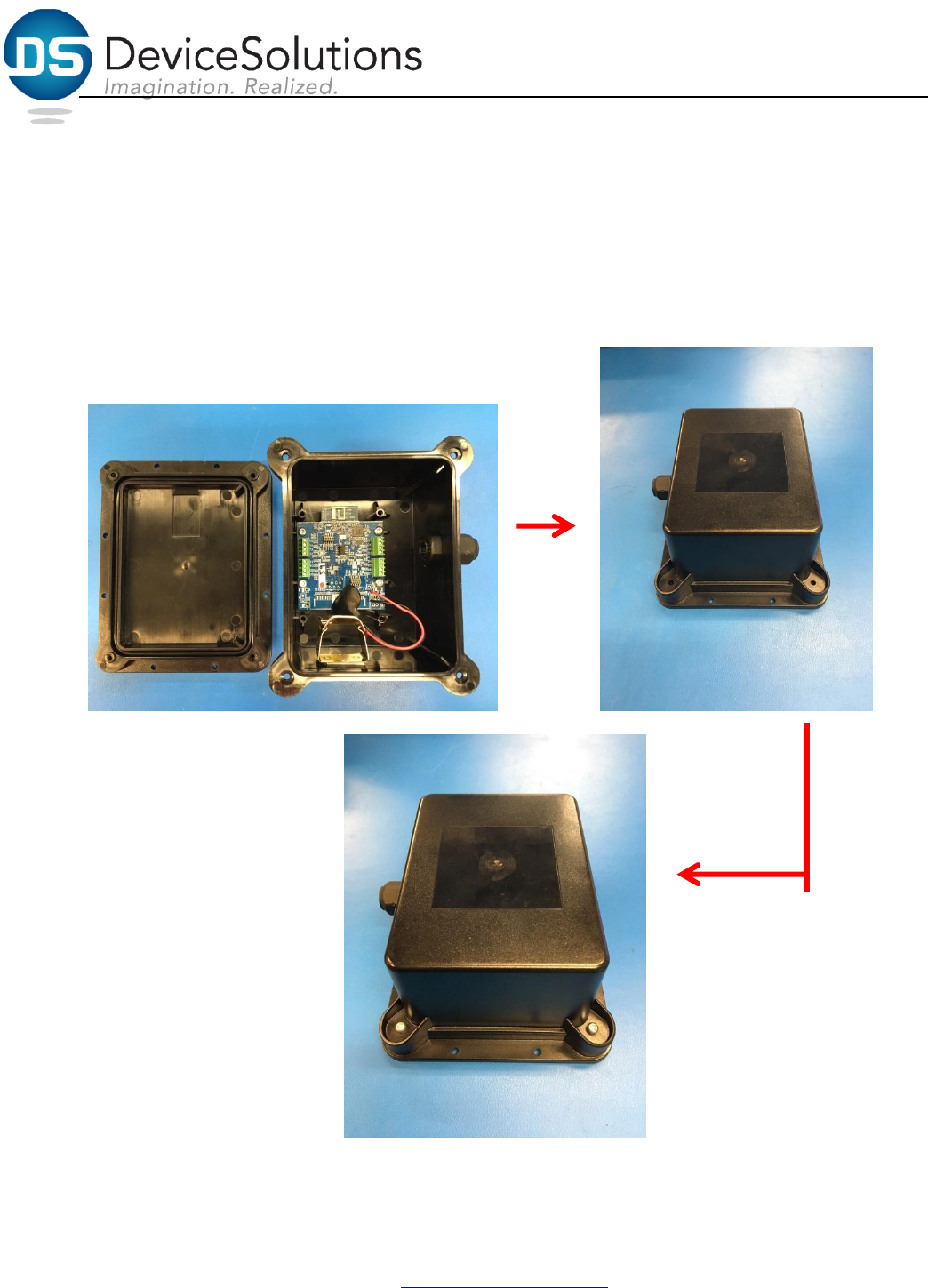
4.4 Secure enclosure base to enclosure
- #4-20, 3/8 T10 screws (HW0006)
Place the enclosure base on the table (shown below), while ensuring the O-ring is still in place turn the
enclosure top over and set in place. There are tabs in corners of the enclosure top and bottom, be sure
to line these up properly for a good fit. Using the #4 screws that are 3/8 inch long T10 screws, secure the
enclosure base to the enclosure top (tighten the screws to 7-8 inch-pounds of torque).
7/7/2017 Page 8(8)
Device Solutions Inc
Proprietary & Confidential
http://www.device-solutions.com/
Phone/Fax: (919) 732-7872
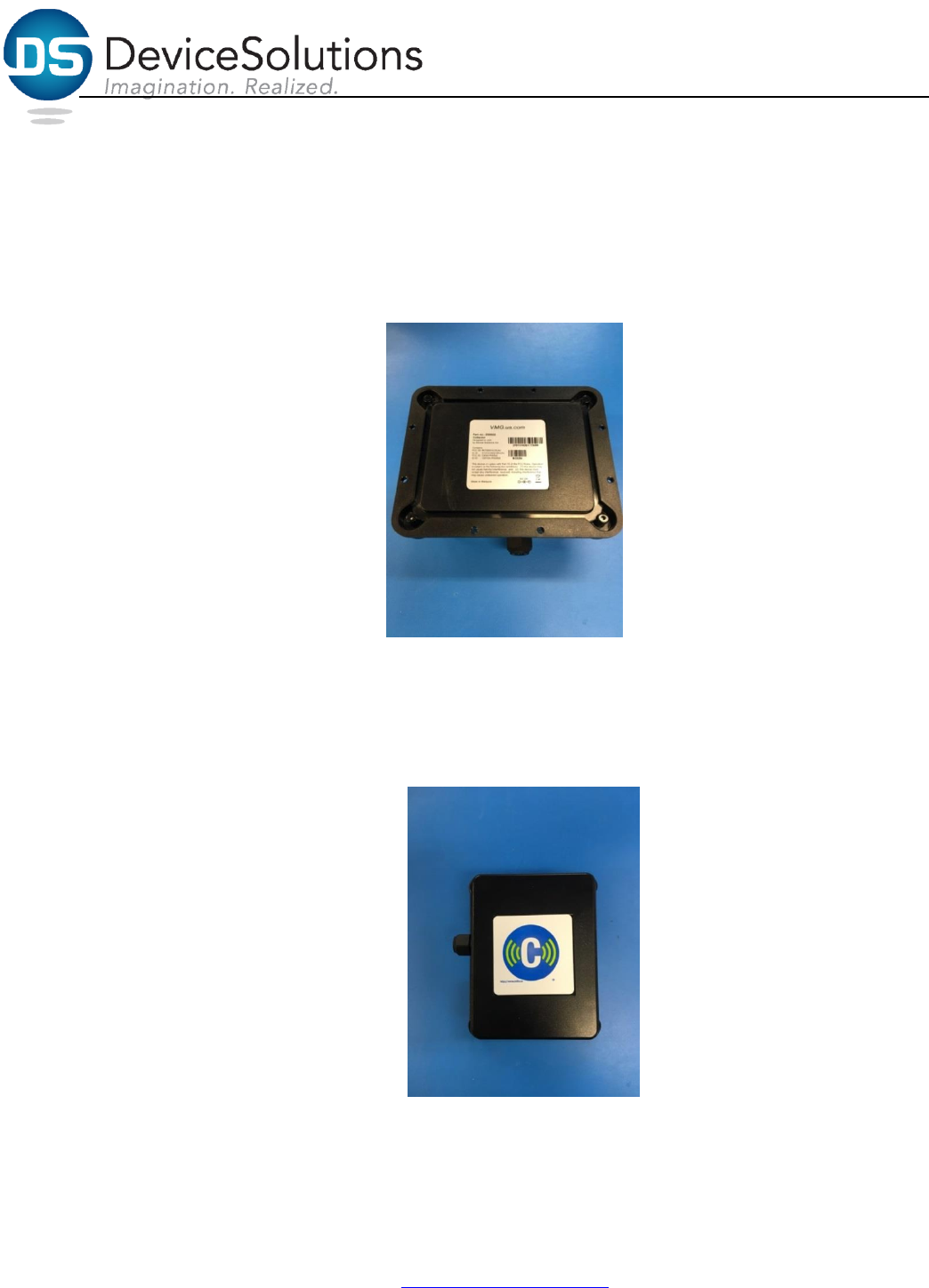
4.5 Add FCC label to enclosure base
- FCC label
With the enclosure base facing up and oriented as shown below, place the FCC label within the recessed
square. Be sure to smooth the FCC label to ensure readability. Please refer to the FCC Label pdf that
outlines the format and information requirements for FCC Labels (P18-20-0001-1).
4.6 Add Cellio label to enclosure top
- Cellio logo label (DO0067)
With the enclosure base facing down and oriented as shown below, place the Cellio label within the
recessed square. Be sure to smooth the Cellio label to avoid any wrinkles or air bubbles.