Dewalt DW717 TYPE2 User Manual MITER SAW Manuals And Guides 1301456L
User Manual: Dewalt DW717 TYPE2 DW717 TYPE2 DEWALT MITER SAW - Manuals and Guides View the owners manual for your DEWALT MITER SAW #DW717TYPE2. Home:Tool Parts:Dewalt Parts:Dewalt MITER SAW Manual
Open the PDF directly: View PDF ![]() .
.
Page Count: 7
,I
I-
o0
Z
m
@
"O
o
Eo
O
O3
C
im
"O
|m
m
m
m
==
DEWALTIndustrial Tool Co., 701 Joppa Road, Baltimore, MD 21286
(MAY11) Part No. N107210 DW717 Copyright©2008, 2009, 2011 DEWALT
The following aretrademarks for one or more DEWALTpower tools: the yellow and black color scheme;
the "D" shaped air intake grill; the array of pyramids on the handgrip; the kit box configuration; and the
array of lozenge-shaped humps on the surface of the tool.
f
Definitions: Safety Guidelines
The definitions below describe the level of severity for each signal word. Please read the
manual and pay attention to these symbols.
I_j,DANGER: Indicates an imminently hazardous situation which, if not avoided, will result
in death or serious injury.
_WARNING: Indicates a potentially hazardous situation which, if not avoided, could result
in death or serious injury.
i_CAUTION: Indicates a potentially hazardous situation which, if not avoided, may result in
minor or moderate injury.
NOTICE: Indicates a practice not related to personal injury which, if not avoided, may
result in property damage.
IF YOU HAVE ANY QUESTIONS OR COMMENTS ABOUT THIS OR ANY DEWALTTOOL, CALL
US TOLL FREE AT: 1-800-4-DEWALT (1-800-433-9258}
Important Safety Instructions
AARNING: Read all instructions before operating product. Failure to follow all
instructions listed below may result in electric shock, fire and/or serious injury.
READ ALL INSTRUCTIONS
Double Insulation
Double insulatedtools are constructed throughout with two separate layersof electrical insulation
or one double thickness of insulation between you and the tool's electrical system. Tools built with
this insulation system are not intended to be grounded. As a result, your tool is equipped with a
two prong plug which permits you to use extension cords without concern for maintaining a ground
connection.
NOTE: Double insulation does not take the place of normal safety precautions when operating this
tool. The insulation system is for added protection against injury resulting from a possible electrical
insulation failure within the tool.
ACAUTION: WHEN SERVICING USE ONLY IDENTICAL REPLACEMENT PARTS. Repair or
replace damaged cords.
Polarized Plugs
Polarized plugs (one blade is wider than the other) are used on equipment to reduce the risk of
electric shock. When provided, this plug will fit in the polarized outlet only one way. If the plug does
not fit fully in the outlet, reverse the plug. If it still does not fit, contact a qualified electrician to install
the proper outlet. Do not change the plug in any way.
Safety Instructions For All Tools
This miter saw accepts the DEWALT worklight and laser attachments.
_WARNING: Toreduce the risk of eye injury, ALWAYS use eye protection when operating
the miter saw.
•KEEP GUARD IN PLACE and in working order.
•REMOVE ADJUSTING KEYS AND WRENCHES. Form habit of checking to see that keys
and adjusting wrenches are removed from spindle before turning tool on. Tools, scrap pieces,
and other debris can be thrown at high speed, causing injury.
•KEEP WORK AREA CLEAN. Cluttered areas and benches invite accidents.
•DO NOT USE THE MACHINE IN A DANGEROUS ENVIRONMENT. The use of power tools
in damp or wet locations or in rain can cause shock or electrocution. Keep your work area well-lit
to avoid tripping or placing arms, hands, and fingers in danger.
•KEEP CHILDREN AWAY. All visitors should be kept at a safe distance from work area. Your
shop is a potentially dangerous environment.
•MAKE WORKSHOP CHILDPROOF with padlocks, master switches, or by removing starter
keys. The unauthorized start-up of a machine by a child or visitor may result in injury.
•DON'T FORCE TOOL. It will do the job better and be safer at the rate for which it was
designed.
•USE RIGHT TOOL. Don't force tool or attachment to do a job for which it was not designed.
Using the incorrect tool or attachment may result in personal injury.
•WEAR PROPER APPAREL. No loose clothing, gloves, neckties, rings, bracelets, or other
jewelry to get caught in moving parts. Non-slip footwear is recommended. Wear protective hair
covering to contain long hair. Air vents may cover moving parts and should also be avoided.
•ALWAYS USE SAFETY GLASSES. Everyday eyeglasses are NOT safety glasses. Also
use face or dust mask if cutting operation is dusty. ALWAYS WEAR CERTIFIED SAFETY
EQUIPMENT."
• ANSI Z87.1 eye protection (CAN/CSA Z94.3)
• ANSI $12.6 ($3.19) hearing protection
• NIOSH/OSHA/MSHA respiratory protection
•SECURE THE WORKPIECE. Use clamps or a vise to hold the workpiece on the table and
against the fence or when your hand will be dangerously close to the blade [within 6" (152 mm)].
It is safer than using your hand and it frees both hands to operate tool
•DON'T OVERREACH. Keep proper footing and balance at all times. Loss of balance may
cause personal injury.
•MAINTAIN TOOLS WITH CARE. Keep tools sharp and clean for best and safest performance.
Follow instructions for lubricating and changing accessories. Poorly maintained tools and
machines can further damage the tool or machine and/or cause injury.
•TURN THE MACHINE "OFF" AND DISCONNECT THE MACHINE FROM THE POWER
SOURCE before installing or removing accessories, before adjusting or changing set-ups,
when making repairs or changing locations. An accidental start-up can cause injury. Do not
touch the plug's metal prongs when unplugging or plugging in the cord.
•REDUCE THE RISK OF UNINTENTIONAL STARTING. Make sure that the switch is in the
"OFF" position before plugging in the power cord.
•USE PROPER EXTENSION CORD. Make sure your extension cord is in good condition. If
your product is equipped with a cordset, use only 3-wire extension cords that have 3-prong
grounding-type plugs and 3-pole receptacles that accept the tool's plug. When using an
extension cord, be sure to use one heavy enough to carry the current your product will draw. An
undersized cord will cause a drop in line voltage resulting in loss of power and overheating. The
following table shows the correct size to use depending on cord length and nameplate ampere
rating. If in doubt, use the next heavier gauge. The smaller the gauge number, the heavier the
cord.
Ampere Rating
More
Than
0
6
10
12
Not More
Than
6
10
12
16
Minimum Gauge for Cord Sets
Volts Total Length of Cord in Feet (meters)
120V 25 (7.6) 50 (15.2) 100 (30.5) 150 (45.7)
240V 50 (15.2) 100 (30.5) 200 (61.0) 300 (91.4)
AWG
18
18
16
14
16
16
16
12
16 14
14 12
14 12
Not Recommended
•CHECK FOR DAMAGED PARTS. Before further use of the tool, a guard or other part that is
damaged should be carefully checked to determine that it will operate properly and perform its
intended function--check for alignment of moving parts, binding of moving parts, breakage of
parts, mounting and any other conditions that may affect its operation. A guard or other part
that is damaged should be properly repaired or replaced. Do not use tool if switch does not turn
it on and off.
•USE RECOMMENDEDACCESSORIES. Use only accessories that are recommended by the
manufacturer for your model. Accessories that may be suitable for one tool may be hazardous
when used on another tool Consult the instruction manual for recommended accessories. The
use of improper accessories may cause risk of injury to persons.
•NEVER STAND ON TOOL. Serious injury could occur if the tool is tipped or if the cutting tool
is unintentionally contacted.
•NEVER LEAVE TOOL RUNNING UNATTENDED. TURN POWER OFF. Don't leave tool until
it comes to a complete stop. Serious injury can result.
•DO NOT OPERATE ELECTRIC TOOLS NEAR FLAMMABLE LIQUIDS OR IN GASEOUS
OR EXPLOSIVE ATMOSPHERES. Motors in these tools may spark and ignite fumes.
•STAY ALERT, WATCH WHAT YOU ARE DOING, AND USE COMMON SENSE. DO NOT
USE THE MACHINE WHEN YOU ARE TIRED OR UNDER THE INFLUENCE OF DRUGS
or ALCOHOL. A moment of inattention while operating power tools may result in injury.
Additional Safety Rules For Miter Saws
AWARNING: Do not allow familiarity (gained from frequent use of your saw) to replace safety rules.
Always remember that a careless fraction of a second is sufficient to inflict severe injury.
•DO NOT OPERATE THIS MACHINE until it is completely assembled and installed according
to the instructions. A machine incorrectly assembled can cause serious injury.
•OBTAIN ADVICE from your supervisor, instructor, or another qualified person if you are not
thoroughly familiar with the operation of this machine. Knowledge is safety.
•STABILITY. Make sure the miter saw is placed on a secure supporting surface and does not
slip or move during use. If the mobility kit is installed, raise the moveable caster(s) so saw is in
its stationary position.
•FOLLOWALL WIRING CODES and recommended electrical connections to prevent shock or
electrocution. Protect electric supply line with at least a 15 ampere time-delay fuse or a circuit
breaker."
•MAKE CERTAIN the blade rotates in the correct direction. The teeth on the blade should point
in the direction of rotation as marked on the saw.
•TIGHTEN ALL CLAMP HANDLES, knobs and levers prior to operation. Loose clamps can
cause parts or the workpiece to be thrown at high speeds.
•BE SURE all blade and blade clamps are clean, recessed sides of blade clamps are against
blade and arbor screw is tightened securely. Loose or improper blade clamping may result in
damage to the saw and possible personal injury.
•ALWAYS USE A SHARP BLADE. Check the blade to see if it runs true and is free from
vibration. A dull or a vibrating blade can cause damage to the machine and/or serious injury.
•DO NOT OPERATE ON ANYTHING OTHER THAN THE DESIGNATED VOLTAGE for the
saw. Overheating, damage to the tool and personal injury may occur.
•DO NOT WEDGE ANYTHING AGAINST THE FAN to hold the motor shaft. Damage to tool
and possible personal injury may occur.
•DO NOT force cutting action. Stalling or partial stalling of motor can cause damage. To the
machine or blade and/or serious injury.
•ALLOW THE MOTOR TO COME TO FULL SPEED prior to starting cut. Starting the cut too
soon may cause damage to the machine or blade and/or serious injury.
•NEVER CUT FERROUS METALS (Those with any iron or steel content) or masonry. Either of
these can cause the carbide tips to fly off the blade at high speeds causing serious injury.
•DO NOT USEABRASIVE WHEELS. The excessive heat and abrasive particles generated by
them may damage the saw and cause personal injury.
•NEVER have any part of your body in line with the path of the saw blade. Personal injury will
OCCUr.
• NEVER apply blade lubricant to a running blade. Applying lubricant could cause your hand to
move into the blade resulting in serious injury.
•DO NOT place either hand in the blade area when the saw is connected to the power source.
Inadvertent blade activation may result in serious injury.
•DO NOT PERFORM FREE-HAND OPERATIONS (workpiece not supported by table and
fence). Hold the work firmly against the fence and table. Free-hand operations on a miter saw
could cause the workpiece to be thrown at high speeds, causing serious injury.
•NEVER REACHAROUND orbehind the saw blade. A blade can cause serious injury.
•DO NOT reach underneath the saw unless it is unplugged and turned off. Contact with saw
blade may cause personal injury.
•SECURE THE MACHINE TO A STABLE SUPPORTING SURFACE. Vibration can possibly
cause the machine to slide, walk, or tip over, causing serious injury.
•USE ONLY CROSSCUT SAW BLADES recommended for miter saws. For best results, do
not use carbide tipped blades with hook angles in excess of 7 degrees. Do not use blades with
deep gullets. These can deflect and contact the guard, and can cause damage to the machine
and/or serious injury.
•USE ONLY BLADES OF THE CORRECT SIZE AND TYPE specified for this tool to prevent
damage to the machine and/or serious injury.
•INSPECT BLADE FOR CRACKS or other damage prior to operation. A cracked or damaged
blade can come apart and pieces can be thrown at high speeds, causing serious injury. Replace
cracked or damaged blades immediately.
•CLEAN THE BLADE AND BLADE CLAMPS prior to operation. Cleaning the blade and
blade clamps allows you to check for any damage to the blade or blade clamps. A cracked
or damaged blade or blade clamp can come apart and pieces can be thrown at high speeds,
causing serious injury.
•DO NOT use lubricants or cleaners (particularly spray or aerosol) in the vicinity of the plastic
guard. Thepolycarbonate material used in the guard is subject to attack by certain chemicals.
•ALWAYS USE THE KERF PLATE AND REPLACE THIS PLATE WHEN DAMAGED. Small
chip accumulation under the saw may interfere with the saw blade or may cause instability of
workpiece when cutting.
•USE ONLY BLADE CLAMPS specified for this tool to prevent damage to the machine and/or
serious injury.
•CLEAN THE MOTOR AIR SLOTS of chips and sawdust. Clogged motor air slots can cause
the machine to overheat, damaging the machine and possibly causing a short which could
cause serious injury.
•KEEP ARMS, HANDS, AND FINGERS away from the blade to prevent severe cuts. Clamp
all workpieces that would cause your hand to be within [within 6" (152 mm)] of the saw blade.
•NEVER LOCK THE SWITCH IN THE "ON" position. Severe personal injury may result.
•TURN OFF THE MACHINE and allow the blade to come to a complete stop before raising
the arm and prior to cleaning the blade area, removing debris in the path of the blade, before
servicing or adjusting tool. A moving blade can cause serious injury.
•PROPERLY SUPPORT LONG OR VVIDE WORKPIECES. L_s of control of tee weH<p£_'e
canc_,seZnju0,;
•NEVER cross am_ b front otbiade wh:_ us@g _c_:>/.Ah:_ts rnake a_9' rut: (unp<t'_'vet_d)before
matdng a finiW_cut se that yeu can check 1t_?path of the bbde or severe persotia: injury :nay
_;su/t
•ADDITIONAL INFORMATION r_warding the sab and proper operatk_ of power k_:_Js(7.e.
asafety vMeo) is avd_!e #ore/he Pewer lbd beti_ute, 1300 Sumner Avenue, C_ve@nc_.
OH 44115..285I _W%c_:p<:_wertodbsdtute.com). In£wnaden Lsalso ,_/d£d£e, ffem the Nat£_nd
SafeB/C(xlr?cfl, 1121 .Spr,hg Lake Drive., ttasca, tL 60148-820L f@_se rater to the Arr_tk:,an
t,_tMnaI Stand_:_tds k?sfitute /F4St 01. ! Safely R_tuirements for Woodweff@\g fvMdt#tes and
U?e _ZS, Dc_a_n rant of L&b_r OSHA 1910,218 Fqagulat£m&
_WARNING: De not connect unit te ebctrk_af power seutce until comp_te bsttuctk)ns are read
__d undetst(_d.
_WA_RNING: _WAYS wear proper personal hearing protection that conforms to ANSI
$12o6 ($3.19) d_ring _o Under sor_ _,conditions and duty#kin of u_e, ndse fiom th_ product
may aontr_t_ute to heating toss,
_WARNING; NPVIt_ MAKE AfVY CUT UNL_gS Tt_IE D/_4TER_ALtS S(L'URED ON DIE FA_LE
AHD AGAtNS7 714_I:Kt'dCZ:}
_WARNING:Seme dus_ c;,eated by powe_ sand#_; saw# W, gt29db_, dfiLfing, and other
construction actidt£,s confabs chem£'aLs known to the State of Cdifemb to cause cancer, birth
det_._te or outer t_toductbve harm. t:£>me exarr_o£_ of _ese ch_n£.a/s ate:
•_frcvn/ea_bbased pabts,
•ctys_ine sffica fiem brk:t_ add cement and other masonry prodacts, and
• arsenic and d_tomfum 2era chemicd!},dreated lumber.
'YLx_r_:isk#otn these ex¢>osures yaries, depe_?din>gon how often you _M thi£ tZDe of woe,k; to z(_m'e
you_ e_7:>osureto #_ese chem£als: work in awett ve_2i_ated de& _d ,verk wi_h a£pto've-vJ safety
aCus_n','en_,s_ch as d?ose dust masks that ate special!y des_nc_t to fi_4eJout mk:toscqt_]C paHide._,
Avoid prolonged contact with dust from power sanding, sawing, grinding, drilling, and
other construction activities. Wear protective clothing and wash exposed areas with
soap and water. Allowing dust to get into y_Jr mouth, eyes, or lay on the _in may
protT_te absorption of harmful chemicals.
_WARNING: L]se of this t_at can genende and!or disbur_ dust, which may ceuse se_k:_usand
petme_ent respiratory or other/n/u04 A_,¢'_¢s use HIOS_ t/OSH/_ approv_ tespkatety p_otec_ion
_ptopnate for #m dust dxp<)sure, D[_c_:tparticles away from lace <_zndbod?:
For y<_¢ conve._tience _,_d safe_]_ the £_lbwtng warning £,beb are on your miter saw.
AWARNING: FOR YOUR OWN SAFETY, READ INSTRUCTION MANUAL BEFORE
OPERATING SAW.
WHEN SERVICING, USE ONLY IDENTICAL REPLACEMENT PARTS,
ALWAYS WEAR EYE PROTECTION.
DO NOT EXPOSE TO RAIN _USE IN DAMP LOCATIONS.
<}I'dMOWNG F_NC,'ES:
ALWAYS ADJUST FENCE PROPERLY
BEFORE USE. CLAMP SMALL PIECES
BEFORE CUTTING. SEE MANUAL.
ON GU4RD:
DANGER-KEEP AWAY FROM BLADE.
ON UPPF:R GUARD:
PROPERLY SECURE BRACKET WITH BOTH SCREWS BEFORE USE.
m_
ON (2 PLACE@
_tWARNING: FOR YOUR OWN SAFET_ READ INSTRUCTION _
MANUAL BEFORE OPERATING MITER SAW. KEEP HANDS OUT OF
PATH OF SAW BLADE. DO NOT OPERATE SAW WITHOUT GUARDS
IN PLACE_ CHECK LOWER GUARD FOR PROPER CLOSING BEFORE
EACH USE. ALWAYS TIGHTEN ADJUSTMEfv_Y KNOBS BEFORE USE.
DO NOT PERFORM ANY OPERATION FREEHAND. NEVER REACH
IN BACK OF SAW BLADE. NEVER CROSS ARMS IN FRONT OF
BLADE. TURN OFF TOOL AND WAIT FOR SAW BLADE TO STOP BEFORE MOVING
WORKPIECE, CHANGING SETTINGS OR MOVING HAND& DISCONNECT POWER
BEFORE CHANGING BLADE OR SERVICING. TO REDUCE THE RISK OF INJURY,
RETURN CARRIAGE TO THE FULL REAR POSITION AFTER EACH CROSSCUT
OPERATION. TNINK! YOU CAN PP_JENT ACCIDENTS.
@.tB,_S£:(2PMCSS)
DW7080
END
PLATE
DW7082
DW708z
DWS7085 DW7187
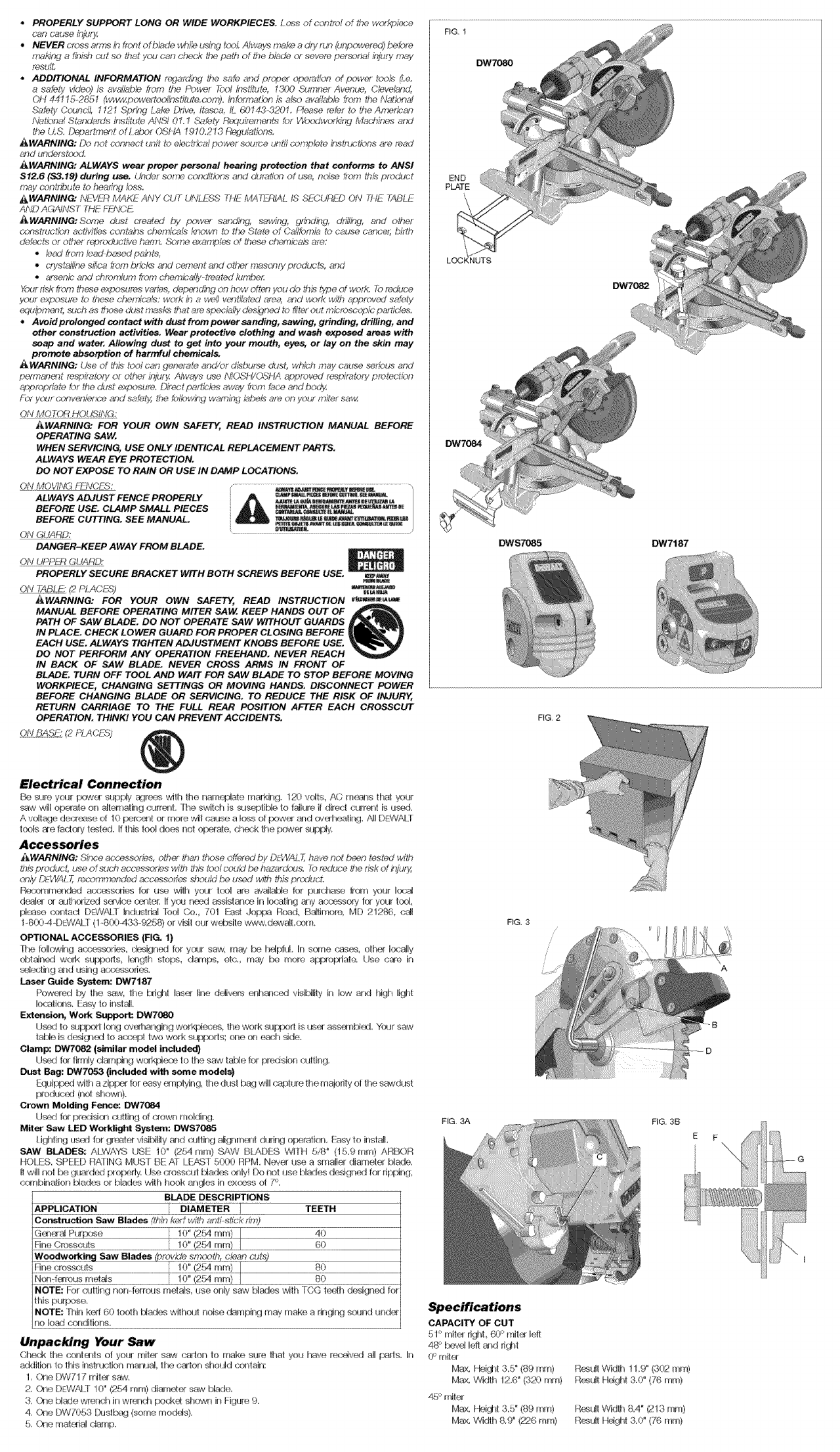
Electrical Connection
Be sure, youl pow_;{ supply _:Irees wilh the nam_:.'late marking. 1_} volts, AC m_-_s th_ ye_r
saw will opexate on _[a-l_ing (Mi'rel_, fhe s,4;ltcJ'l Js s_tible to JaJklle if direct current is u_.t,
A voit_.}e decr(@se d10 I_:._'cr£1_or more wiil cause a toss d|:x>w(_ ald ov¢_heating,/_Jl DP?,]AW
teob _e fadery L_.._led. If thb tool dod-_ net of_rae c¢_K;k the p(_,,er s li'>t:_y,
Accessories
iIWARNING: ('£n_'e accessories, othec _han those oD'ered.,% D_WAL 77have not heen tested w#h
thb [.VOdUCt, _dse of suc'h aucessot_s With U)iS tO0_ C:Od£1 l_? h_%_S, l_t? t'd_4'UCY_ lhe tL_;/< Of/r_U_
c_}!y {_WAI _recemn_nded ac'_ofi_;_ should be u._._ with this pt<×_uct+
R(_x_mm_-_ded arx_:_sodes for use wilh your tool are available for purcha_} fl_)m yoHr k×;_J
dc_ah c_ authc__ed sewbe cenle[: If yc*J n(_t assist_ in locating any accessory let your kx£
[$:_-_se rx:_ldad DF)/VAiT industria! Tool Co,, /'01 Easl dopt>3 Road, Ba!_imore, MD 2127@, <;_l
1-8004-D_::WAI]- (! -8(X,_433 9258,} or visit oul w_4_ile www_de_alt @m,
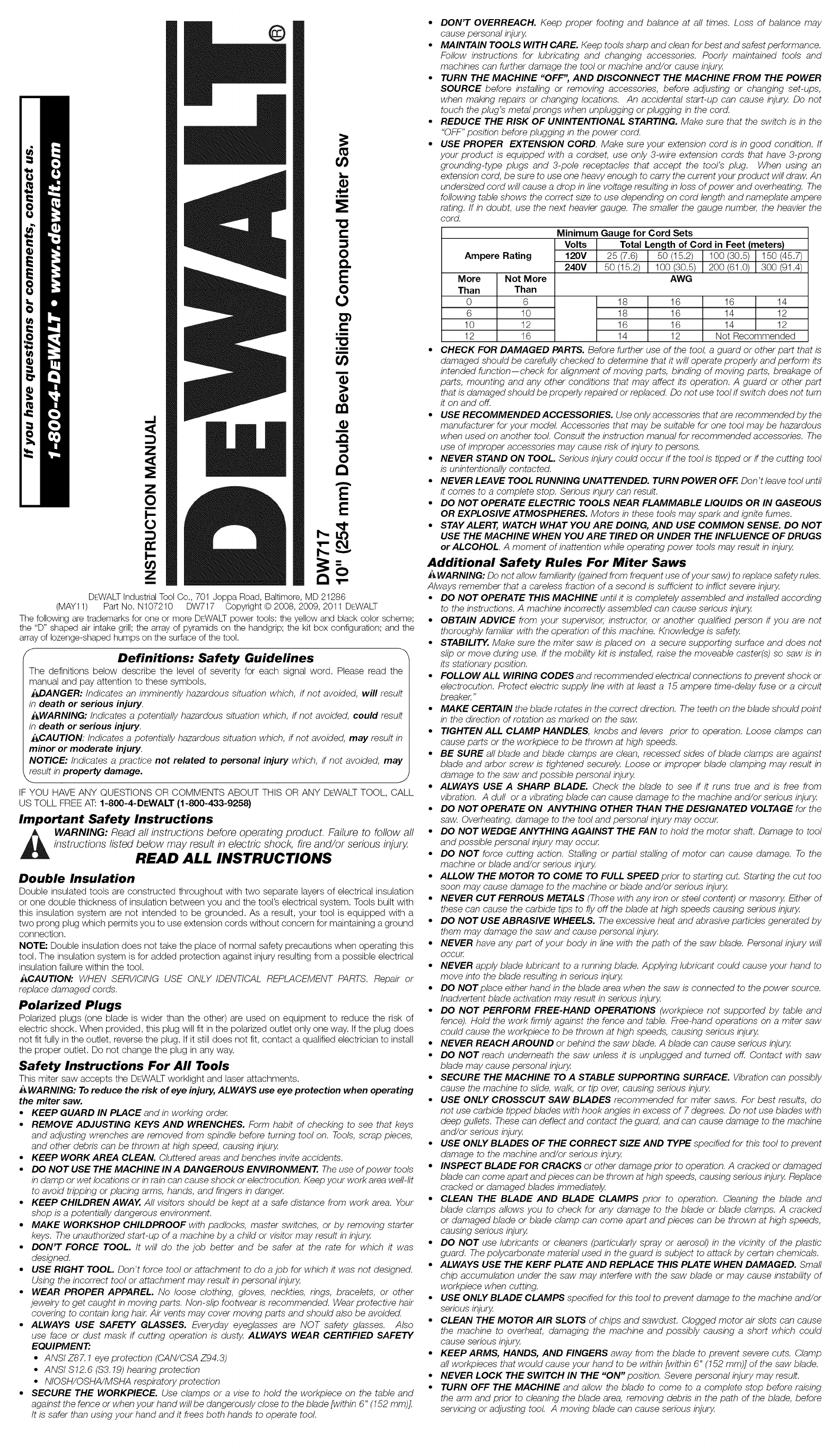
OPTIONAL ACCESSORIES (FIG. 1)
Ihe iolk_wing a_;¢sorie_s, design_,_J for y___Jrsaw, may be I_fJt'Ad. In s<_rle _mses, offer k_sally
obtained work sut,T_oris, k__gth steps, damps, e4o. m_/ Ir:_:_more aFf)mtmate. Use c_'e in
se_6_:4ingaid usirig a_sxyssork:¢,
Lair Guide System: DW7187
Pewelred by the saw, the bri_lt k_s_;r line ct641\,{_seriht-_lced visi[Jllty ih low and high light
Io{_4k_-_s, Faw to Fista$
Extension, Wo_ _ort: DW7080
I,k_d h_ sup[_xl long ov_hangiHg workt_x;es, the work sur_:x:_fl is us(_ ass_nbl_t, Youl saw
tabb is desig]ext to a<_x4:Jl'_wo work su_x._rls; _ _eon each _de_
Clamp: DW7082 (similar mode included)
tJ_d f(xr firmly darnF_ng w_kfJe<_ to the saw table for pnedsbr_ hulling
Dust Bag: _7053 (included with some models)
Equi[_J with azit)f:'_ for easy _ rlpiying, [he dus! bag will capture the Inaiority ef [he ss_4dust
t:_oduc_,_:J(nel shown).
Crown Molding Fence: DW7084
U_:_,dfor pr_:,_;isk__cutting of crown moMin,g,
Miter Saw LED Worklight St_stern: DWS70S5
ligtding usad for t]r{£_k:_ visibiiily and _.Jlting alignrn_._lt dudn!j oi:×:_ration_I::asy to instal!.
SAW BLADES: ALWAYS USE !0" (254 ram) SAW BM\DFS WITH 5/8 ° (15,9 ram) ARBOR
HOI ES, SPE[:D RATING MUST BE AT lFtwr 5000 RPM, Nev(_ use a smalbr diameter blade,
If will ftot be guarded prol:_fly. Use <_esscul [_ades oldyi Do not use blades designed Jor rit_l_ng
combination gtades or blades with hook ang_ in ex_s of 7°.
BLADE DESCRIPTIONS
APPLICATION TEETH
Constroction Saw Blades _fin kerr with anfi-dickKm)
e !0" (2_ ram) [ 40
Fine Cn:_ss_xJts [ 10" (254 ram) [ 60
Weoewerkir._i Saw Blades _'tde smc<)lh, dean c4,,t@
Fille cross<_xts _[ !0" (2{;,4 ram) [ 80
N_xi frTrous me|r_s / 10" (2Ed ram} | 80
NOTE: For cutting nonferrous metals, use onty saw blades with TCG td_ih designed F,r
this purpese,
NOTE: ihin kerr 60 tooth t:dad_s wilhoH! noise damping may make a ringing sc*md under
no load c__ditiens.
Unpacking Your Saw
Cheek the conla_ts of your rniter saw _salon te make sure that yeu have recxdv_t a!l Fads, In
aldilion to this instm<!ion mallual_ the catch shoHId G_ _tain:
1. One DW717 rnik_ saw,
2. Q_e DI::WALT 10" (254 mrr9 diameter saw blade,
3, C'_le Made wr_lch in wren<f_ pec_ shov_,n in Figure 9,
4, One DW7053 Dustbr!:l (some rnedds),
& C_]e mat_-aial damp.
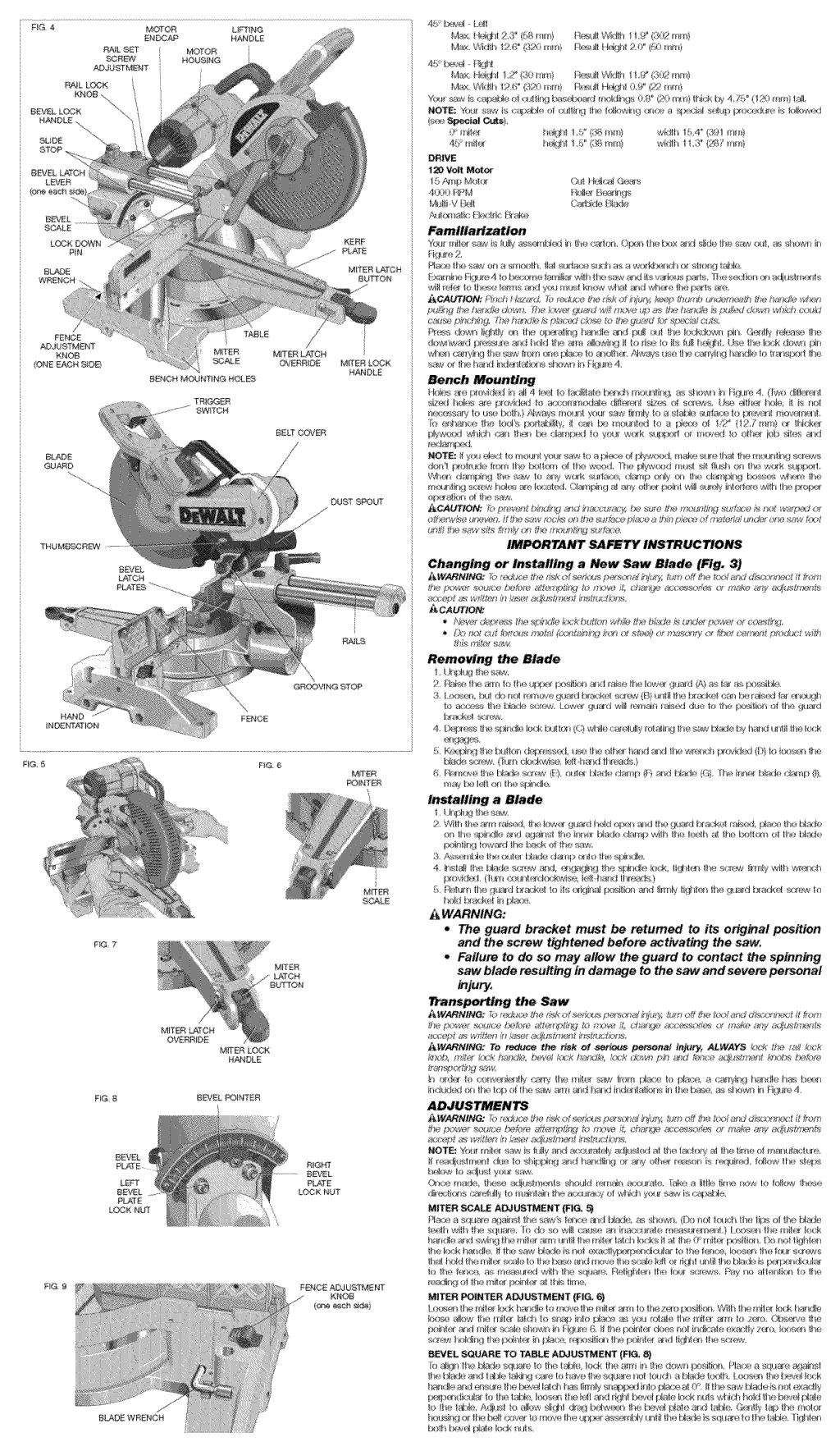
FIG. 3
CAPACITY OF CUT
51° reih:_ Ii#-iL (£P mit_x left
48 *' betel left and ri_f_t
Max, Hei{Iht 3,5" (89 Into)
Max, Width 12.6" (320 ram)
45 ÷`mitr-._"
Max, t,-tei[_t 3,5" (89 ram)
Ma,x, Width 8.9 _'('Z26 mm)
FIG. 3B
E
Result Width 11 _9" (3(K2ram)
R_ut! Hdght 3.@ (76 mRl)
Rc_ul! Widlh 8.4" (213 ram)
R_ull Heighl 3,0" (7"6 ram)
A
FfG 4LIFT NG
HANDLE
BEVEL
BCAtE
LOCK DOWN
PN
BLADE
WRENCH
MRERL_TCN
BU_ON
BLADE
GU#_RD
TRIGGER
SWITCH
BELZ COBER
MFrER LOCK
HANDLE
THUMB_BEW
BEVEL
LA!©H
FG 6
F_G 7
M_
BUTTON
FIG BEVEL _NTER
BEVEL
LE_
BEVEL
FtJCTE
LOCK NUT
RGHT
BEVEL
PLATE
LOCK NUT
FIG @
Bb_DE WRENCH
FENCE _JUBTMENT
KNOB
FIG10
RG _1
MITER LOCK
ROD
LOCK N_JW
rig t0A R_LLGCKKNOB
!"¸"-% ....
Z27--:: '
PROPER CUT
F_ i4
F_G 16
FIG 15 A
FIG 17
ANGLE *'A_
_G !8
CFt_N MOLDING FLAT ON TABLE
_D AGAINST FENCE
CRC@¢N MOL©B4G BE'_¢EEN FENCE AN© TABLE
F_15
FIG20
F_@21
RIGHT WRONG
FIG, _4
FIG _B
RG 26 _8 R_W_
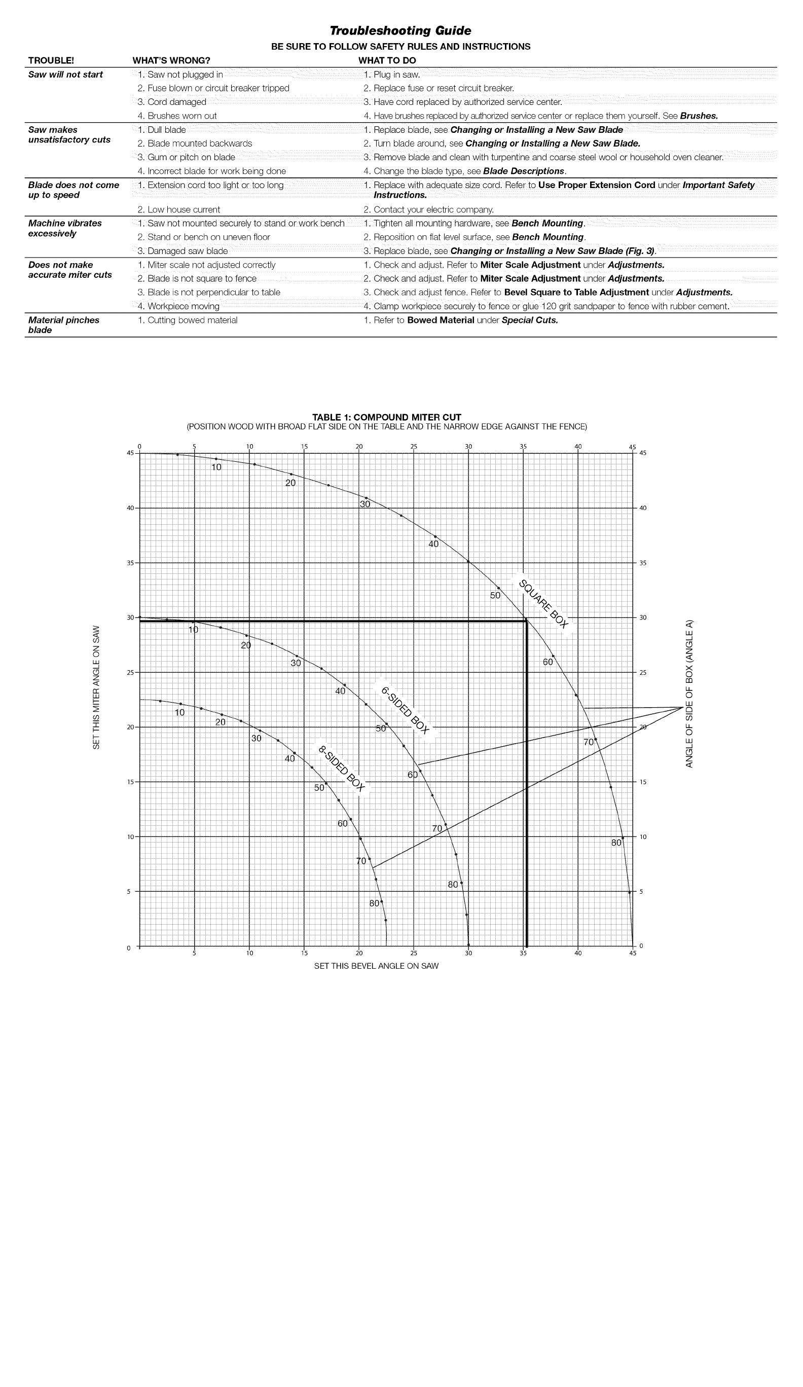
- EXAMPLES-
NO. SIDES ANGLE MITER OR BEVEL
4 45°
5 36°
6 30°
7 25.7 °
8 22.5 °
9 20°
10 18°
(The chart assumes that all sides are of equal length.) For a shape that is not shown in the chart,
use the following formula. 180° divided by the number of sides equals the miter (if the material is
cut vertically) or bevel angle (if the material is cut laying flat).
CUTTING COMPOUND MITERS
A compound miter is a cut made using a miter angle and a bevel angle at the same time. This is
the type of cut used to make frames or boxes with slanting sides like the one shown in Figure 16.
NOTE: If the cutting angle varies from cut to cut, check that the bevel clamp knob and the miter
lock knob are securely tightened. These knobs must be tightened after making any changes in
bevel or miter.
The chart (Table 1) shown will assist you in selecting the proper bevel and miter settings for
common compound miter cuts. To use the chart, select the desired angle "A" (Fig. 16) of your
project and locate that angle on the appropriate arc in the chart. From that point follow the chart
straight down to find the correct bevel angle and straight across to find the correct miter angle.
Set your saw to the prescribed angles and make a few trial cuts. Practice fitting the cut pieces
together until you develop a feel for this procedure and feel comfortable with it.
EXAMPLE: To make a 4 sided box with 26° exterior angles (Angle A, Fig. 16), use the upper right
arc. Find 26° on the arc scale. Follow the horizontal intersecting line to either side to get miter
angle setting on saw (42°). Likewise, follow the vertical intersecting line to the top or bottom to
get the bevel angle setting on the saw (18°). Always try cuts on a few scrap pieces of wood to
verify settings on saw.
CUTTING BASE MOLDING
ALWAYS MAKE A DRY RUN WITHOUT POWER BEFORE MAKING ANY CUTS.
Straight 90° cuts:
Position the wood against the fence and hold it in place as shown in Figure 11. Turn on the
saw, allow the blade to reach full speed and lower the arm smoothly through the cut.
CUTTING BASE MOLDING UP TO 4.75" (121 mm) HIGH VERTICALLY AGAINST THE
FENCE
Position material as shown in Figure 11.
All cuts made with the back of the molding against the fence and bottom of the molding against
the base.
INSIDE CORNER:
Left side
1. Miter left 45 °
2. Save left side of cut
Right side
1. Miter Right 45 °
2. Save right side of cut
Material up to 6.5" (159 mm) can
CUTTING CROWN MOLDING
OUTSIDE CORNER:
Left side
1. Miter right at 45 °
2. Save left side of cut
Right side
1. Miter left at 45 °
2. Save right side of cut
be cut as described above.
Your miter saw is better suited to the task of cutting crown molding than any other type tool
made. In order to fit properly, crown molding must be compound mitered with extreme accuracy.
The two flat surfaces on a given piece of crown molding are at angles that, when added together,
equal exactly 90°. Most, but not all, crown molding has a top rear angle (the section that fits flat
against the ceiling) of 52° and a bottom rear angle (the part that fits flat against the wall) of 38°.
Your miter saw has special pre-set miter latch points at 31.62 ° left and right for cutting crown
molding at the proper angle and bevel stop pawls at 33.85 ° left and right. There is also a mark on
the Bevel scale at 33.85 °.
The chart below gives the proper settings for cutting crown molding. (The numbers for the miter
and bevel settings are very precise and are not easy to accurately set on your saw.) Since most
rooms do not have angles of precisely 90°, you will have to fine tune your settings anyway.
PRETESTING WITH SCRAP MATERIAL IS EXTREMELY IMPORTANT!
INSTRUCTIONS FOR CUTTING CROWN MOLDING LAYING FLAT AND USING THE
COMPOUND FEATURES
1. Molding laying with broad back surface down flat on saw table (Fig. 17).
2. The settings below are for All Standard (U.S.) crown molding with 52° and 38 ° angles.
BEVEL SE'rI'ING
33.85 ° Left
33.85 ° Right
33.85 ° Right
33.85 ° Left
TYPE OF CUT
LEFT SIDE, INSIDE CORNER:
1. Top of molding against fence
2. Miter table set right 31.62 °
3. Save left end of cut
RIGHT SIDE, INSIDE CORNER:
1. Top of molding against fence.
2. Miter table set at left 31.62 °
3. Save right end of cut
LEFT SIDE, OUTSIDE CORNER:
1. Top of molding against fence.
2. Miter table set at left 31.62 °
3. Save left end of cut
RIGHT SIDE, OUTSIDE CORNER:
1. Top of molding against fence
2. Miter table set right 31.62 °
3. Save right end of cut
When setting bevel and miter angles for all compound miters, remember that:
The angles presented for crown moldings are very precise and difficult to set exactly. Since they
can easily shift slightly and very few rooms have exactly square corners, all settings should be
tested on scrap molding.
PRETESTING WITH SCRAP MATERIAL IS EXTREMELY IMPORTANT!
ALTERNATIVE METHOD FOR cu'rI'ING CROWN MOLDING
Place the molding on the table at an angle between the fence and the saw table, as shown in
Figure 18. Use of the crown molding fence accessory (DW7084) is highly recommended because
of its degree of accuracy and convenience. The crown molding fence accessory is available for
purchase from your local dealer.
The advantage to cutting crown molding using this method isthat no bevel cut is required. Minute
changes in the miter angle can be made without affecting the bevel angle. This way, when corners
other than 90° are encountered, the saw can be quickly and easily adjusted for them. Use the
crown molding fence accessory to maintain the angle at which the molding will be on the wall.
INSTRUCTIONS FOR CUTTING CROWN MOLDING ANGLED BETWEEN THE FENCE
AND BASE OF THE SAW FOR ALL CUTS:
1. Angle the molding so the bottom of the molding (part which goes against the wall when
installed) is against the fence and the top of the molding is resting on the base of the saw, as
shown in Figure 18.
2. The angled "flats" on the back of the
saw.
INSIDE CORNER:
Left side
1. Miter right at 45°
2. Save right side of cut
Right side
1. Miter left at 45 °
2. Save left side of cut
molding must rest squarely on the fence and base of the
OUTSIDE CORNER:
Left side
1. Miter left at 45 °
2. Save right side of cut
Right side
1. Miter right at 45 °
2. Save left side of cut
The wax, available at most hardware stores and industrial mill supply houses, provides proper
lubrication and keeps chips from adhering to the blade.
Be sure to properly secure workpiece.
Refer to Saw Blades under Optional Accessories for correct saw blade.
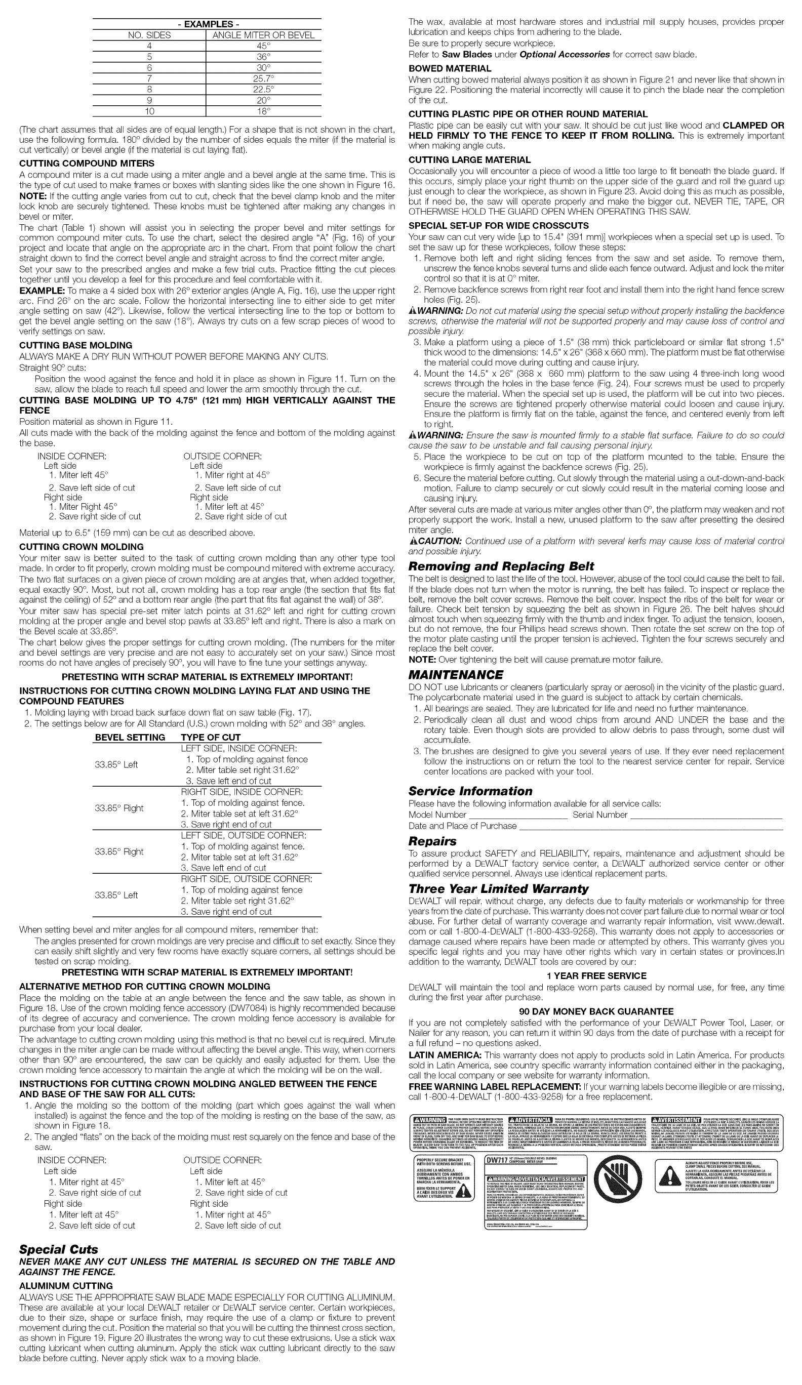
BOWED MATERIAL
When cutting bowed material always position it as shown in Figure 21 and never like that shown in
Figure 22. Positioning the material incorrectly will cause it to pinch the blade near the completion
of the cut.
cu'n'ING PLASTIC PIPE OR OTHER ROUND MATERIAL
Plastic pipe can be easily cut with your saw. It should be cut just like wood and CLAMPED OR
HELD FIRMLY TO THE FENCE TO KEEP IT FROM ROLLING. This is extremely important
when making angle cuts.
CU'I-I'ING LARGE MATERIAL
Occasionally you will encounter a piece of wood a little too large to fit beneath the blade guard. If
this occurs, simply place your right thumb on the upper side of the guard and roll the guard up
just enough to clear the workpiece, as shown in Figure 23. Avoid doing this as much as possible,
but if need be, the saw will operate properly and make the bigger cut. NEVER TIE, TAPE, OR
OTHERWISE HOLD THE GUARD OPEN WHEN OPERATING THIS SAW.
SPECIAL SET-UP FOR WIDE CROSSCUTS
Your saw can cut very wide [up to 15.4" (391 mm)] workpieces when a special set up is used. To
set the saw up for these workpieces, follow these steps:
1. Remove both left and right sliding fences from the saw and set aside. To remove them,
unscrew the fence knobs several turns and slide each fence outward. Adjust and lock the miter
control so that it is at 0° miter.
2. Remove backfence screws from right rear foot and install them into the right hand fence screw
holes (Fig. 25).
_WARNING: Do not cut material using the special setup without properly installing the backfence
screws, otherwise the material will not be supported properly and may cause loss of control and
possible injury.
3. Make a platform using a piece of 1.5" (38 mm) thick particleboard or similar flat strong 1.5"
thick wood to the dimensions: 14.5" x 26" (368 x 660 mm). The platform must be flat otherwise
the material could move during cutting and cause injury.
4. Mount the 14.5" x 26" (368 x 660 mm) platform to the saw using 4 three-inch long wood
screws through the holes in the base fence (Fig. 24). Four screws must be used to properly
secure the material. When the special set up is used, the platform will be cut into two pieces.
Ensure the screws are tightened properly otherwise material could loosen and cause injury.
Ensure the platform is firmly flat on the table, against the fence, and centered evenly from left
to right.
AWARNING: Ensure the saw is mounted firmly to a stable flat surface, Failure to do so could
cause the saw to be unstable and fall causing personal injury.
5. Place the workpiece to be cut on top of the platform mounted to the table. Ensure the
workpiece is firmly against the backfence screws (Fig. 25).
6. Secure the material before cutting. Cut slowly through the material using a out-down-and-back
motion. Failure to clamp securely or cut slowly could result in the material coming loose and
causing injury.
After several cuts are made at various miter angles other than 0°, the platform may weaken and not
properly support the work. Install a new, unused platform to the saw after presetting the desired
miter angle.
ACAUTION: Continued use of a platform with several kerfs may cause loss of material control
and possible injury.
Removing and Replacing Belt
The belt is designed to last the life of the tool. However, abuse of the tool could cause the belt to fail.
If the blade does not turn when the motor is running, the belt has failed. To inspect or replace the
belt, remove the belt cover screws. Remove the belt cover. Inspect the ribs of the belt for wear or
failure. Check belt tension by squeezing the belt as shown in Figure 26. The belt halves should
almost touch when squeezing firmly with the thumb and index finger. To adjust the tension, loosen,
but do not remove, the four Phillips head screws shown. Then rotate the set screw on the top of
the motor plate casting until the proper tension is achieved. Tighten the four screws securely and
replace the belt cover.
NOTE: Over tightening the belt will cause premature motor failure.
MAINTENANCE
DO NOT use lubricantsor cleaners (particularly spray or aerosol) in the vicinity of the plastic guard.
The polycarbonate material used in the guard is subject to attack by certain chemicals.
1. All bearings are sealed. They are lubricated for life and need no further maintenance.
2. Periodically clean all dust and wood chips from around AND UNDER the base and the
rotary table. Even though slots are provided to allow debris to pass through, some dust will
accumulate.
3. The brushes are designed to give you several years of use. If they ever need replacement
follow the instructions on or return the tool to the nearest service center for repair. Service
center locations are packed with your tool.
Service Information
Please have the following informationavailable for all service calls:
Model Number Serial Number
Date and Place of Purchase
Repairs
To assure product SAFETY and RELIABILITY, repairs, maintenance and adjustment should be
performed by a DEWALT factory service center, a DEWALT authorized service center or other
qualified service personnel. Always use identical replacement parts.
Three Year Limited Warranty
DEWALT will repair, without charge, any defects due to faulty materials or workmanship for three
years from the date of purchase. This warranty does not cover part failure due to normal wear or tool
abuse. For further detail of warranty coverage and warranty repair information, visit www.dewalt.
com or call 1-800-4-DEWALT (1-800-433-9258). This warranty does not apply to accessories or
damage caused where repairs have been made or attempted by others. This warranty gives you
specific legal rights and you may have other rights which vary in certain states or provinces.In
addition to the warranty, DEWALT tools are covered by our:
1 YEAR FREE SERVICE
DEWALT will maintain the tool and replace worn parts caused by normal use, for free, any time
during the first year after purchase.
90 DAY MONEY BACK GUARANTEE
If you are not completely satisfied with the performance of your DEWALT Power Tool, Laser, or
Nailer for any reason, you can return it within 90 days from the date of purchase with a receipt for
a full refund - no questions asked.
LATIN AMERICA: This warranty does not apply to products sold in Latin America. For products
sold in Latin America, see country specific warranty information contained either in the packaging,
call the local company or see website for warranty information.
FREE WARNING LABEL REPLACEMENT: If your warning labels become illegible or are missing,
call 1-800-4-DEWALT (1-800-433-9258) for a free replacement.
y...... ,
_PNOPE_LY SECUNE BRACI(ET
WiTH BOTH $C_£WS BEFORE USE. ALWAYS AOJtlST FENCE PROFEREY BEFORE OSE,
_1 CLAM P S MALL PIECES BEF0_E CUTTIN _. SEE MANUAL,
ASEGURE LA MENSULA AJ_STE LAG_iA DEBiOAMEN_ ANTES 0E UTILIZARLA
OEBIBAMEN3'E C0_ AMIBOS HE_AMBEt_TA.A_EGURELASpIEZAS PEOUE_AS ANTESOE
TOXNJLLOS ANTES _)EPONER EN C0_ARLA$. CONSULT_ELMANUAL,
MA_CHA LA HERf_AMIENTA.
_IIEN FIXER LESUPPORT
AEAiOE DES DEUX VIS
%AVAST tlJTIIISATION.
DW717 ................
Special Cuts
NEVER MAKE ANY CUT UNLESS THE MATERIAL IS SECURED ON THE TABLE AND
AGAINST THE FENCE.
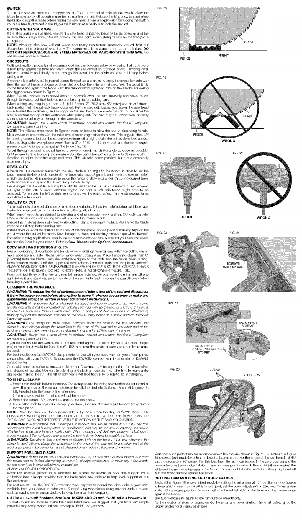
ALUMINUM CUTTING
ALWAYS USE THE APPROPRIATE SAW BLADE MADE ESPECIALLY FOR CUTTING ALUMINUM.
These are available at your local DEWALT retailer or DEWALT service center. Certain workpieces,
due to their size, shape or surface finish, may require the use of a clamp or fixture to prevent
movement during the cut. Position the material so that you will be cutting the thinnest cross section,
as shown in Figure 19. Figure 20 illustrates the wrong way to cut these extrusions. Use a stick wax
cutting lubricant when cutting aluminum. Apply the stick wax cutting lubricant directly to the saw
blade before cutting. Never apply stick wax to a moving blade.
TROUBLE!
Saw will not start
Saw makes
unsatisfactory cuts
Blade does not come
up to speed
Machine vibrates
excessively
Does not make
accurate miter cuts
Material pinches
blade
Troubleshooting Guide
BE SURE TO FOLLOW SAFETY RULES AND INSTRUCTIONS
WHAT'S WRONG? WHAT TO DO
1: Saw not plugged in 1. Plug in Saw.
2. Fuse blown or circuit breaker tripped 2. Replace fuse or reset circuit breaker.
3. c0rd darnaged 3. Have €ord replaced by authorized se_ice Center.
4. Brushes worn out 4. Have brushes replaced by authorized service center or replace them yourself. See Brushes.
1: Dull blade 1: Replace blade; see ChangingorlnstallingaNewSawBlade
2. Blade mounted backwards 2. Turn blade around, see Changing or Installing a New Saw Blade.
3. Gum or pitch on blade 3] Rem0ve blade and clean With turpentine and coarse steel wool or household oven cleaner.
4. Incorrect blade for work being done 4. Change the blade type, see Blade Descriptions.
J: Extension cord t0o light 0tree I°ng i. Replace with adequate size cord. Refer to Use Proper Extension Cord Under Important Safety
Instructions.
2. Low house current 2. Contact your electric company.
1:Saw not mounted securely to stand or work bench 1. Tighten all mounting hardware; see Bench Mounting. ......
2. Stand or bench on uneven floor 2. Reposition on flat level surface, see Bench Mounting.
S. Damaged saw blade 3] Replace blade; see changing or Installing a New Saw Blade (Fig. 3).
1. Miter scale not adjusted correctly 1. Check and adjust. Refer to Miter Scale Adjustment under Adjustments.
Z Blade iSnot square to fence zoheCkandad]ust. Refer to Miter Scale Adjustment under Adjustments,
3. Blade is not perpendicular to table 3. Check and adjust fence. Refer to Bevel Square to Table Adjustment under Adjustments.
4! workpiece moving 41clamp worRpiece securely to fence or glue i20 grit SandpaPer to fence with rubber Cement
1. Cutting bowed material 1. Refer to Bowed Material under Special Cuts.
cO
Z
o
LU
.J
(5
Z
<
r,r
LU
(,0
i
w
cO
0
45-
40-
35-
30 ....
25-
20-
15-
10-
TABLE 1: COMPOUND MITER CUT
(POSITIONWOOD WITH BROAD FLATSIDEON THE TABLEAND THE NARROWEDGEAGAINSTTHE FENCE)
iiiiiiiii
10 15 20 25 30 35 40 45
iiiiiiiii
Z[ iZi ]Z] iZi ]Z] Z[ iZi ]Z] iZi ]Z] Zi ]Z] iZi ]Z] iZi Zi ]Z] iZi ]Z] iZi
10 15 20 25 30 35 40 45
SET THIS BEVEL ANGLE ON SAW
35
3O
25
15
10
LU
_J
o
z
X
o
Cl3
LL
o
LU
tm
LL
o
LU
_J
o
z
<
