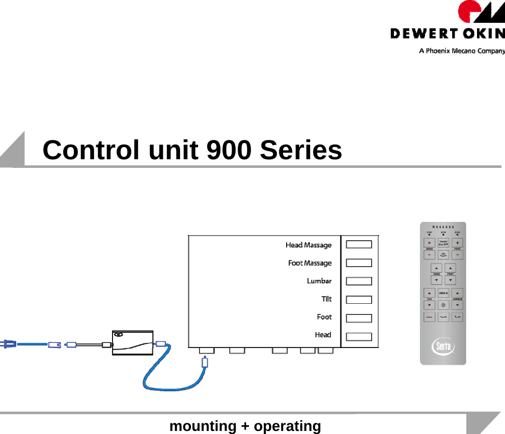
DewertOkin CU258-4 Control Unit 258-4 User Manual 900 series 2012 11 14x

DewertOkin GmbH Control Unit 258-4 900 series 2012 11 14x

User Manual

     Control unit 900 Series    mounting + operating
   October 31, 2012    Page 2 of 12  1 Overview This control unit is designated to operate an electrically driven bed with optional comfort functions.  •  Power supply is provided via SMPS so the control box has protection class III.  •  The system is operated with an RF remote. The RF receiver is integrated into the control unit.  Bed view from beneath  Here for example you can see a control unit with two actuators and two massage motors connected  Actuator 1 Actuator 2 Control unitMassage motor 1 2Massage motor 2
   October 31, 2012    Page 3 of 12  2  Mounting the control unit  This mounting bracket is fixed on the flipside of the bed   These two bolts fix the position of the control unit between the mounting bracket.  The clip snaps in the holding fixtures of the control unit
   October 31, 2012    Page 4 of 12 Control Unit 258-4  2.1 (with integrated Bluetooth® module)
This Bluetooth module has been grantedG). Antenna GAIN: 0.5dBiF). Antenna Type: PCB antennaE). BIT Rate of Transmission: 1Mbps, 2Mbps, 3Mbps   October 31, 2012    Page 5 of 12  Performance data control unit Duty cycle  2/18 min. or 10 %, max, 5 switching cycles per minute Output voltage  29 V / 6A Further features   Housing colour  black RAL 9005 Housing material  ABS + PC Ports  drives: 4 actuators / 2 vibration motors  1 power input / 1 multifunction output /  2 USB ports /1 DC output Indicators + buttons  Reset + pairing button / Pairing LED for RF Power LED Protection type  IP20 Protection class  III Relative humidity  30% - 75% Ambient temperature  +50°F - +104°F Power supply  external  WT12 Bluetooth® module     A). Operation Frequency: 2402-2480MHzC). Number of Channel: 79 D). Channel space: 1MHz“ContainsFCC ID: QOQWT12A“ContainsIC: 5123A-BGTWT12A”
   October 31, 2012    Page 6 of 12              Performance data RF receiver modulation GFSK Frequency Range  2.403~2.480GHz Battery  30V supply voltage  Working Current  <60mA Standby Current  <20mA Ambient Temperature -40—85Ԩ PCB Material & Size  FR4  1.6mm  120*120mm Integrated RF receiver     1   Key Function 1 Pairing enable
   October 31, 2012    Page 7 of 12   2.2  Power supply 3.00.209.033.00   Connecting cable73178 to control box  Power supply cable 3.00.401.151.30 to mains power  Performance data Output voltage 29 V DC constant voltage output Components  Indicators LED operating status indication (green) Colour black RAL 9005 Further data  Protection type IP20 Protection class II Relative humidity 30% - 75% Ambient temperature +50°F - +104°F Power supply wide input voltage range 100-240 V AC Safety NTC temperature sensor, thermal fuse, current sensing and limitation by control circuit, self resetting current limiting fuse on primary side as double safety, not self resetting
   October 31, 2012    Page 8 of 12  Remote Control 258D   Key Function 1  Massage Head + 2  Massage timer ON/OFF 3  Massage Foot + 4  Massage Head - 5  Start all Massage 6  Massage Foot - 7  Relay 1 on 8  Relay 3 on 9  Relay 2 on 10  Relay 4 on 11  Relay 5 on 12  Position Zero G 13  Relay 7 on 14  Relay 6 on 15 Light ON/OFF 16  Relay 8 on 17 Position All flat 18 Position Lounge 19 Position TV/PC Frontside                  1           2            3                  4                      5                      6                      7                        8                       9                      10               11                  12                  13               14         15          16                17          18         19           Pairing button  & battery box  (flipside)  Insert 3x AAA                              20        20 Pairing
   October 31, 2012    Page 9 of 12   Performance data remote (RF transmitter) Modulation GFSK Frequency Range  2.403~2.480GHz Battery AAA Working Current  <40mA Standby Current  <8uA Ambient Temperature -40—85Ԩ RC Dimension  145*50*14mm PCB Material & Size  FR4  1.6mm  79*42mm Housing Material  ABS+PC
   October 31, 2012    Page 10 of 12  3  Board Schematics (remote)  3.1 Remote   3.2 RX module Pls insert diagram
   October 31, 2012    Page 11 of 12 4 Functional Description  Take cable 3.00.401.151.30 and connect it to mains supply.  The system is delivered paired! You can test the functions of the system with the RF remote. Pairing instruction (in case of trouble) Pairing the remote with the control box.  The distance between remote and control box for pairing should be less than 2 meters! 1.  Remove the battery cover on the flipside of the remote.  2.  Insert/check existing 3x AAA batteries. 3.  Push the reset button on the control box twice with something spiky.  The green pairing LED  adjoining is lit. Now you have 10 s to pair remote and receiver. 4.  On the flipside of the remote is a silicone push button positioned above the batteries (13).  A blue LED starts blinking as the button is pressed.  Keep it pressed until the blue LED is lit continuously, then pairing is completed, the blue LED light fades away.                        IC warning - English:  This device complies with Industry Canada licence-exempt RSS standard(s). Operation is subject to the following two conditions: (1) this device may not cause interference, and (2) this device must accept any interference, including interference that may cause undesired operation of the device. 2. Changes or modifications not expressly approved by the party responsible for  compliance could void the user's authority to operate the equipment.   - French: Le présent appareil est conforme aux CNR d'Industrie Canada applicables aux appareils radio exempts de licence. L'exploitation est autorisée aux deux conditions suivantes : (1) l'appareil ne doit pas produire de brouillage, et (2) l'utilisateur de l'appareil doit accepter tout brouillage radioélectrique subi, même si le brouillage est susceptible d'en compromettre le fonctionnement."  RSS-102 Statement: This equipment complies with Industry Canada radiation exposure limits set forth for an uncontrolled environment. Déclaration CNR-102: Cet équipement est conforme à l'exposition aux rayonnements Industry Canada limites établies pour un environnement non contrôlé.
   October 31, 2012    Page 12 of 12  FCC Warning: z This device complies with Part 15 of the FCC Rules. Operation is subject to the following two conditions:  z (1) this device may not cause harmful interference, and z (2) this device must accept any interference received, including interference that may cause undesired operation. z Changes or modifications not expressly approved by the party responsible for compliance could void the user's authority to operate the equipment. z NOTE: This equipment has been tested and found to comply with the limits for a Class B digital device, pursuant to Part 15 of the FCC Rules. These limits are designed to provide reasonable protection against harmful interference in a residential installation. This equipment generates, uses and can radiate radio frequency energy and, if not installed and used in accordance with the instructions, may cause harmful interference to radio communications. However, there is no guarantee that interference will not occur in a particular installation. If this equipment does cause harmful interference to radio or television reception, which can be determined by turning the equipment off and on, the user is encouraged to try to correct the interference by one or more of the following measures: z -- Reorient or relocate the receiving antenna. z -- Increase the separation between the equipment and receiver. z -- Connect the equipment into an outlet on a circuit different from that to which the receiver is connected. z -- Consult the dealer or an experienced radio/TV technician for help.     * RF warning for Portable device: The device can be used in portable exposure condition without restriction. The device has been evaluated to meet general RF exposure requirement.

Navigation menu