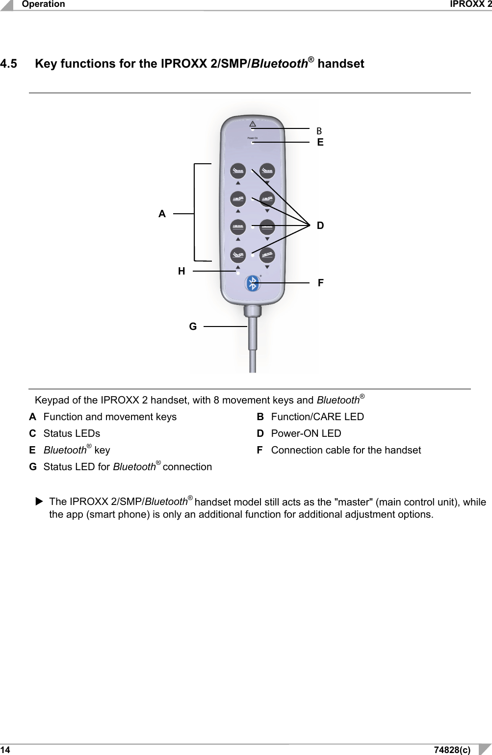
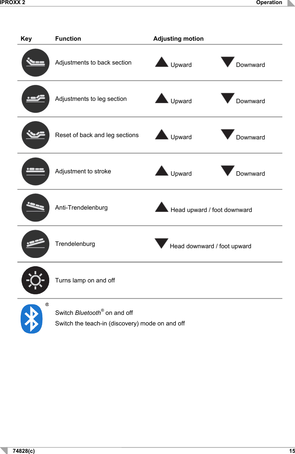
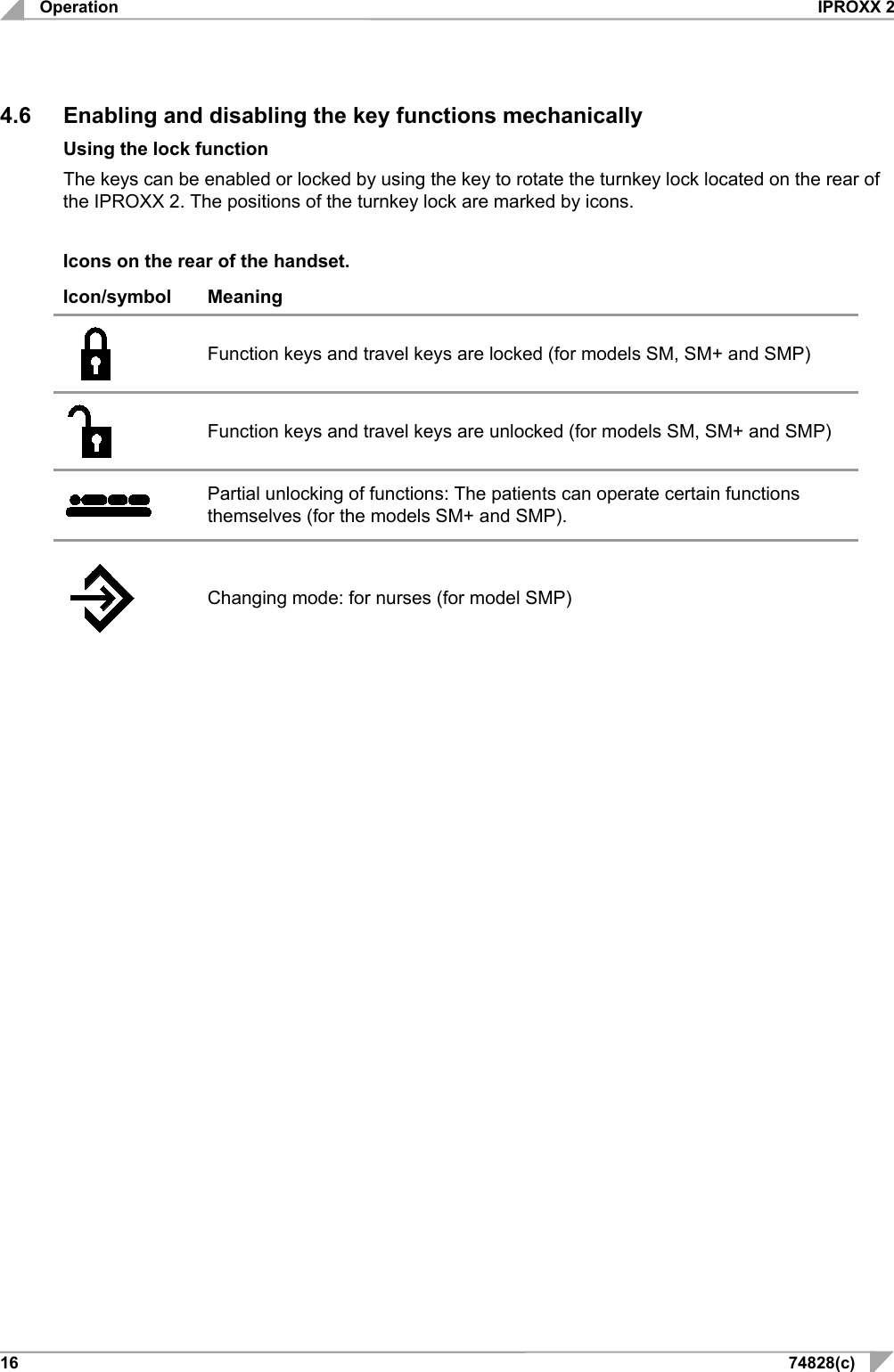
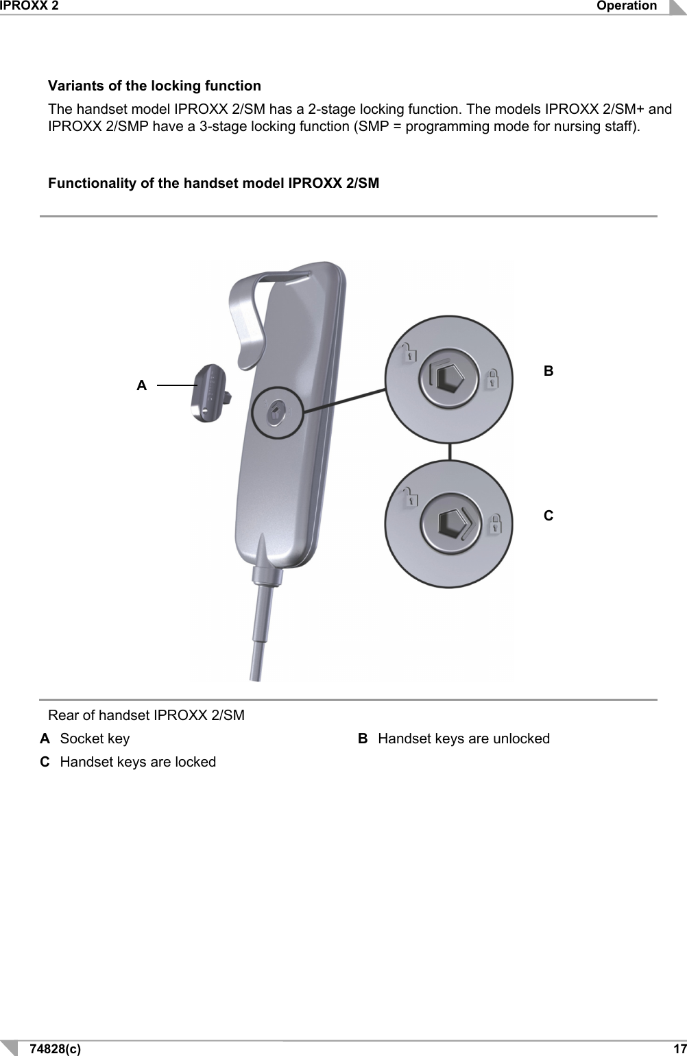
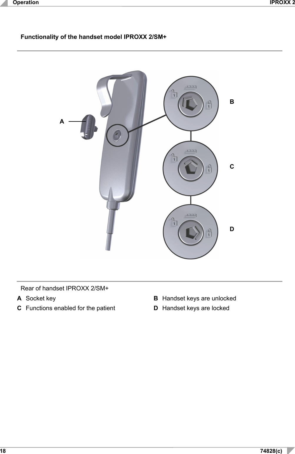
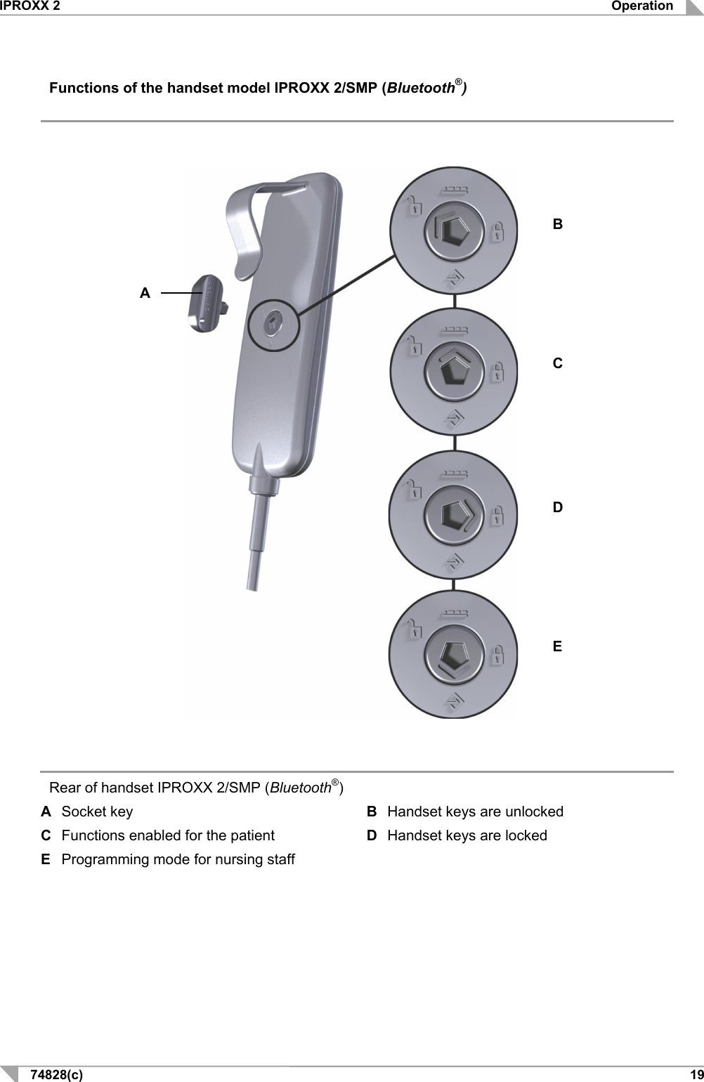
DewertOkin IPR2SMPBT Handset IPROXX2/SMP/Bluetooth User Manual O3YIPR2SMPBT UserMan

DewertOkin GmbH Handset IPROXX2/SMP/Bluetooth O3YIPR2SMPBT UserMan

O3YIPR2SMPBT UserMan

      System Instructions                   IPROXX 2
IPROXX 2   74828(c)   3 Document revision history  Version Date Modification, change (-)  11/12 First release (a) 03/14 Ratings plate (b) 04/15 Technical specifications (c) 06/17 Optional: Bluetooth®  Disclaimer and exclusion of liability DewertOkin is not responsible for damage resulting from: • failure to observe these instructions, • changes made to this product which have not been approved by DewertOkin, or • the use of replacement parts which have not been approved or manufactured by DewertOkin. .  Manufacturer's address  DewertOkin GmbH Weststrasse 1 32278 Kirchlengern, Germany Germany Tel: +49 (0)5223/979-0 Fax.: +49 (0)5223/75182 http://www.dewertokin.de  Info@dewertokin.de
 IPROXX 2 4  74828(c) Document revision history .............................................................................................................................. 3 Disclaimer and exclusion of liability ............................................................................................................... 3 Manufacturer's address ................................................................................................................................... 3 1. General Information ................................................................................................. 5 1.1 About these system instructions ....................................................................................................... 5 1.2 Conventions used ................................................................................................................................ 5 2. Safety notices .......................................................................................................... 6 2.1 Proper and intended usage ................................................................................................................. 6 3. Handset description ................................................................................................ 8 3.1 IPROXX 2 handset ................................................................................................................................ 8 3.2 Technical specifications .................................................................................................................... 11 4. Operation ................................................................................................................ 12 4.1 General information ........................................................................................................................... 12 4.2 Information on battery power............................................................................................................ 12 4.3 Connecting the handset to the drive system .................................................................................. 12 4.4 Key functions for the IPROXX 2 handset (an example) .................................................................. 13 4.5 Key functions for the IPROXX 2/SMP/Bluetooth® handset ............................................................ 14 4.6 Enabling and disabling the key functions mechanically ............................................................... 16 4.7 Key functions ...................................................................................................................................... 20 4.8 Display functions ............................................................................................................................... 21 4.9 iOS smart phone ................................................................................................................................. 22 5. Troubleshooting .................................................................................................... 27 5.1 Self-test of the IPROXX 2 handset .................................................................................................... 28 5.2 Malfunctioning of the permanent connection between the IPROXX 2 and iOS smart phone .... 28 6. Maintenance ........................................................................................................... 29 7. Disposal .................................................................................................................. 30 7.1 Packaging material ............................................................................................................................. 30 7.2 Handset components ......................................................................................................................... 30 EU Declaration of Conformity ....................................................................................................................... 31 Additional information ................................................................................................................................... 33
IPROXX 2 General Information 74828(c)   5 1. General Information 1.1 About these system instructions These instructions are intended specifically for the IPROXX 2 handset. These instructions are not operating instructions for the end product. They should be used only in conjunction with the installa-tion instructions for the DewertOkin double drive or DewertOkin control unit to which the handset is connected.   CAUTION The notices in these instructions must be followed! Following the guidelines during installation and connection procedures will help to minimize: • the risk of accident and injury, and • damage to the drive system or the end product.  These instructions have been written with due care and attention. However, we cannot guarantee that the data, images and drawings are complete and correct nor do we accept any liability for the in-formation contained therein, unless required by law.  We reserve the right to make unannounced technical changes in the course of our continual product improvement process!  1.2 Conventions used  Triangular notice symbol: Notices which do not relate to safety are indicated in these in-structions with a triangle. Menu YXZ Names of buttons, displays, programs and menus in the smart phone are highlighted in bold  Explanations of warning notices   CAUTION CAUTION indicates a hazardous situation which, if not avoided, could result in minor or moderate injury.    WARNING WARNING indicates a hazardous situation which, if not avoided, could result in death or serious injury.   NOTICE NOTICE is used to address practices which are not related to personal injury but may result in damage to the product or surroundings.
Safety notices IPROXX 2 6  74828(c) 2. Safety notices 2.1 Proper and intended usage The IPROXX 2 handset is used to operate DewertOkin drive systems. It is also used to lock and unlock the adjustment functions on beds used to care for sick people. • It can be used for care purposes (CARE). • It can be used in a hospital (HOSP).    CAUTION This handset should only be used for the applications described above. Any other use is forbidden. Improper usage can lead to accidents or destruction of the unit. Such non-approved applications will lead immediately to the expiration of all guaran-tee and warranty claims on the part of the end-product manufacturer against the manufacturer.   Improper usage Be sure to follow the notices below concerning improper usage. You should include them in your product manual in order to inform the users of your end product.    WARNING The IPROXX 2 handset not be used: • near high-frequency surgical equipment or defibrillators, • in any environment where combustible or explosive gases or vapours (e.g., anaes-thesiology) may be present, • in a humid environment or outdoors, or • in any application that will be cleaned with an automated washing system.    CAUTION The IPROXX 2 handset may not be operated: • by small children, • by frail or infirm persons without supervision, or • in the proximity of small children.    CAUTION You should only use spare parts which have been manufactured or approved by DewertOkin. Only these parts will guarantee a sufficient level of safety.
IPROXX 2 Safety notices 74828(c)   7 Product labelling  The rating plates shown are only an example. The specifications for your handset may differ from this illustration.               Rating plates (examples)  IPROXX 2  IPROXX 2/SMP/Bluetooth® Model name xxxxx Article number U in: 24 – 29V   Input voltage Prod.date Calendar week / year Serial No. Serial number IPX6 Protection degree SW: yyyyy Software  Use in dry rooms only!  Conformity mark  Follow all special disposal instructions!  Always follow the instructions in the manual!
Handset description IPROXX 2 8  74828(c) 3. Handset description The IPROXX 2 handset is used to control and adjust the end product. Adjustments are made using the keypad and the adjustment functionality can be locked or unlocked on the handset.  3.1 IPROXX 2 handset The variants of the IPROXX 2 handset differ in the number of adjustment function keys (movement keys), the lock function, and the optional mounting clip. The following variations in the buttons and lock functions are available: • IPROXX 2 with a maximum of 10 travel keys and 1 optional lamp key, • IPROXX 2/SM with a maximum of 10 movement keys, 2-stage lock function and one optional lamp key, • IPROXX 2/SM+ with a maximum of 10 movement keys, 3-stage lock function and one optional lamp key, • IPROXX 2/SMP with a maximum of 10 movement keys, 3-stage lock function, one optional lamp key, with programmable key pairs, • IPROXX 2/SMP/Bluetooth® with 8 movement keys, 3-stage lock function, with programmable key pairs and Bluethooth® interface                                                       Example: Handset with 10 travel keys and lamp key A  Function and movement keys B  Function/CARE LED C  Mounting clip (optional) D  Status LEDs (only with the IPROXX 2/SMP model) E  Optional: Status LED (only for the IPROXX 2/SM, SM + and SMP models) F  Lamp key G Connection cable for the handset H Power-On/Battery LED A    G     C    E   H     B    F    D
IPROXX 2 Handset description 74828(c)   9 IPROXX 2/SMP/Bluetooth® handset                                        IPROXX 2/SMP/Bluetooth® handset A Function and movement keys B Function/CARE LED C  Mounting clip (optional) D  Status LED E  Power-ON LED F  Bluetooth® key G  Connection cable for the handset H  Status LED for Bluetooth®     A    G     C   H     B    F    D   E
Handset description IPROXX 2 10 74828(c) Rear of the handset, with turnkey lock                            Turnkey lock on the rear of the handset (for the IPROXX 2/SM, SM + and SMP models) A  Socket key B  Mounting clip (optional) C  Turnkey lock with 2-stage locking function (for the IPROXX 2/SM model) D  Turnkey lock with 3-stage locking function (for the IPROXX 2/SM+ model) E  Turnkey lock with 3-stage locking function (for the IPROXX 2/SMP and IPROXX2/SMP/Bluetooth® models)    The "Operation" Chapter includes information about operating the handset.     A    C    D    B    E
IPROXX 2 Handset description 74828(c)   11 3.2 Technical specifications Connection voltage 24 – 29 V DC Protection degree IPX6 Protection class III Length x width x height (with mounting clip) 170 mm x 60 mm x 51 mm Weight with cable Approx. 300 g Ambient conditions for operation, storage and transport Transport / storage temperature From -20 °C to +50 °C From -4 °F to +122 °F Operating temperature From +10 °C to +40 °C From +50 °F to +104 °F Relative humidity From 30% to 75% Air pressure From 800 hPa to 1060 hPa Height < 2000 m
Operation IPROXX 2 12 74828(c) 4. Operation  When this document refers to the model IPROXX 2/SMP, this also includes the model IPROXX 2/SMP/Bluetooth®.  4.1 General information Ensuring single-fault protection (for the IPROXX 2/SM, SM + and SMP models) For ensuring single-fault safety, drive motions can be disabled using the integrated lock function. This function makes use of an electro-mechanical switch to break the motor circuit.    CAUTION Single-fault protection can only be ensured when the turnkey lock has been set to    (completely locked setting).   The "Enabling and Disabling the Key Functionality" section describes how to operate this locking mechanism.  4.2 Information on battery power  If you are operating your system on battery power then observe the following notice.   NOTICE After it has been used to move your application (in the turnkey lock positions  or  ), the IPROXX handset should be turned back to its locked position (turnkey lock position   ). This prevents the system from gradually discharging when the bat-tery is connected!  4.3 Connecting the handset to the drive system During initial commissioning, connect the handset to the corresponding handset port on the Dewer-tOkin drive system.  A sticker on the drive system will indicate where the handset port is located.   NOTICE Only connect the components according to the specifications found on the sticker. Any other arrangement of connections may damage the drive system.
IPROXX 2 Operation 74828(c)   13 4.4 Key functions for the IPROXX 2 handset (an example)                                                        IPROXX 2 handset with 11 keys A  Function and movement keys B  Function/CARE LED C  Status LEDs (only with the IPROXX 2/SMP model) D  Optional: Status LED (only for the IPROXX 2/SM, SM + and SMP models) E  Lamp key F  Connection cable for the handset G  Power-On/Battery LED     A    G     E   H     B    F    D
Operation IPROXX 2 14 74828(c) 4.5 Key functions for the IPROXX 2/SMP/Bluetooth® handset                                              Keypad of the IPROXX 2 handset, with 8 movement keys and Bluetooth® A  Function and movement keys B  Function/CARE LED C  Status LEDs D  Power-ON LED E  Bluetooth® key F  Connection cable for the handset G  Status LED for Bluetooth® connection    The IPROXX 2/SMP/Bluetooth® handset model still acts as the "master" (main control unit), while the app (smart phone) is only an additional function for additional adjustment options.   A    G     E   H     B    F    D
IPROXX 2 Operation 74828(c)   15 Key   Function  Adjusting motion   Adjustments to back section  Upward  Downward  Adjustments to leg section  Upward  Downward  Reset of back and leg sections  Upward  Downward  Adjustment to stroke  Upward  Downward  Anti-Trendelenburg  Head upward / foot downward  Trendelenburg  Head downward / foot upward  Turns lamp on and off   Switch Bluetooth® on and off Switch the teach-in (discovery) mode on and off
Operation IPROXX 2 16 74828(c) 4.6 Enabling and disabling the key functions mechanically Using the lock function The keys can be enabled or locked by using the key to rotate the turnkey lock located on the rear of the IPROXX 2. The positions of the turnkey lock are marked by icons.  Icons on the rear of the handset. Icon/symbol  Meaning      Function keys and travel keys are locked (for models SM, SM+ and SMP)    Function keys and travel keys are unlocked (for models SM, SM+ and SMP)  Partial unlocking of functions: The patients can operate certain functions themselves (for the models SM+ and SMP).    Changing mode: for nurses (for model SMP)
IPROXX 2 Operation 74828(c)   17 Variants of the locking function The handset model IPROXX 2/SM has a 2-stage locking function. The models IPROXX 2/SM+ and IPROXX 2/SMP have a 3-stage locking function (SMP = programming mode for nursing staff).   Functionality of the handset model IPROXX 2/SM                           Rear of handset IPROXX 2/SM A  Socket key  B  Handset keys are unlocked C Handset keys are locked     B    C    A
Operation IPROXX 2 18 74828(c) Functionality of the handset model IPROXX 2/SM+                           Rear of handset IPROXX 2/SM+ A  Socket key  B  Handset keys are unlocked C  Functions enabled for the patient  D  Handset keys are locked    B    C    A    D
IPROXX 2 Operation 74828(c)   19 Functions of the handset model IPROXX 2/SMP (Bluetooth®)                          Rear of handset IPROXX 2/SMP (Bluetooth®) A  Socket key  B  Handset keys are unlocked C  Functions enabled for the patient  D  Handset keys are locked E  Programming mode for nursing staff      B    C    A    D    E
Operation IPROXX 2 20 74828(c) 4.7 Key functions 4.7.1 Locking the keys Rotate the turnkey on the back side of the handset in order to lock the key functions. 1  Insert the socket key in the turnkey lock. 2  Turn the key until the arrow on the turnkey lock is pointing towards   (as shown in the illustra-tions on pages 17, 18 and 19). The function and movement buttons on the handset are now com-pletely locked and disabled. 3  You can verify that the functions are disabled by pressing on a button.    CAUTION Press on a movement button in order to double check that the functions are locked and disabled. If there is still a resulting motion despite the block, then the handset should be replaced.   4.7.2 Unlocking the keys (for the IPROXX 2/SM, SM+ and SMP(Bluetooth®) models)  Rotate the turnkey on the back side of the handset in order to unlock the key functions. 1  Insert the socket key in the turnkey lock. 2  Turn the key until the arrow on the turnkey lock is pointing towards   (as shown in the illustra-tions on pages 17, 18 and 19). 3  The function and movement buttons on the handset are now enabled.  4.7.3 Unlocking functions for the patient (for the IPROXX 2/SM+ and SMP(Bluetooth®) models) For the handset models IPROXX 2/SM+ and SMP, it is possible to enable some of the operating functions for the patient. 1  Insert the socket key in the turnkey lock. 2  Turn the key until the arrow on the turnkey lock is pointing towards   (as shown in the illus-trations on pages 18 and 19). 3  The function and travel keys on the handset are now partially enabled.
IPROXX 2 Operation 74828(c)   21 4.7.4 Enabling the programming function for nursing staff (for the IPROXX 2/SMP(Bluetooth®)) When using the handset model IPROXX 2/SMP(Bluetooth®), the key lock function can be pro-grammed by the nursing staff. 1  Insert the socket key in the turnkey lock. 2  Turn the key until the arrow on the turnkey lock is pointing towards   (as shown in the illustra-tion on page 19). When set to this position, the handset cannot be used to carry out adjustment movements. 3  The key pair and function keys on the handset can be programmed by the nursing staff. Briefly press the particular key that you wish to enable. The function of the corresponding key pair is then enabled. The status LED for each key pair shows the status of those keys: - Status LED is on: That key pair is enabled for the patient. - Status LED is off: That key pair is locked for the patient. 4  Enable the Bluetooth® function so that the smart phone can be used. 5  Turn the turnkey back until the arrow is pointing towards the  . The movements correspond-ing to the unlocked keys are now possible.  4.8 Display functions The IPROXX 2 handset features a function/CARE LED and a battery/power-on LED. The handsets with the lock function also feature a lock-status LED. They have the following functions: Function/CARE LED • illuminates when function or travel keys are pressed, • illuminates continuously when there is a fault or error, • does not illuminate for key press when there is a fault or error.  Battery/power-on LED • can only illuminates if there is a battery connector on the control unit • illuminates when the handset is enabled, • flashes when the battery is charging from mains power, • illuminates continuously when powered from mains power cable without the battery, • illuminates continuously when powered from mains power cable with a charged battery, • is not illuminated when operating from battery power.  Status LED  • illuminates when you press an unlocked key pair, • does not illuminate when you press a locked key pair,  Status LED for Bluetooth® • illuminates green when Bluetooth® is enabled, • flashes blue when the discovery mode for Bluetooth® is enabled, • illuminates blue when a Bluetooth® connection has been established.   The table of errors in the "Troubleshooting" Chapter describes how errors are displayed by the LED display.
Operation IPROXX 2 22 74828(c) 4.9 iOS smart phone 4.9.1 Installing the app on your smart phone • Open the app store • Download the "Dewert smart remote" app from the app store 4.9.2 Discovering new devices on your iOS smart phone The IPROXX 2/SMP/Bluetooth® model can be discovered on your smart phone so that you can use the smart phone app for operations. Requirements: • The Bluetooth® function in the smart phone is activated. • The handset is connected to a control unit. • The control unit is connected to the power supply.  Before the discovery process, you should have configured all settings   for the patient, as de-scribed in section 4.7.4. Key 9 (Bluetooth®) must be activated (enabled).  a) Initial commissioning (before smart phone discovery) 1  Insert the key into the turnkey lock (on the IPROXX 2/SMP/Bluetooth®). 2  Turn the key until the arrow on the turnkey lock is set to "Changing mode" (   ). Then activate the Bluetooth® function as described in section 4.7.4. 3  Turn the turnkey back until the arrow is pointing towards the   (unlocked). The Bluetooth® LED should now be flashing blue. 4  Activate Bluetooth® on your smart phone. 5  Start the "Dewert smart remote" app. Go to Settings (   ). The available Bluetooth® devices will be shown. 6  Select the Bluetooth® device (IPROXX ...). 7  Pair with the smart phone. 8  You can use the app when the turnkey lock is set to either unlocked (  ) or to patient mode (). Function enabled for patients are then shown in the app. 9  The status LEDs are illuminated in green next to key pairs that are enabled. They are not lit for key pairs that are disabled.
IPROXX 2 Operation 74828(c)   23 b) Discovery for more smart phones 1  Insert the key into the turnkey lock (on the IPROXX 2/SMP/Bluetooth®). 2  Turn the key until the arrow on the turnkey lock is set to "Changing mode" (   ). Then activate the Bluetooth® function as described in section 4.7.4. 3  Turn the key until the arrow on the turnkey lock is set to unlocked (   ). Then press the Blue-tooth® button. The Bluetooth® LED should now be flashing blue. 4  Activate Bluetooth® on your smart phone. 5  Start the "Dewert smart remote" app. Go to Settings (   ). The available Bluetooth® devices will be shown. 6  Select the Bluetooth® device (IPROXX ...). 7  Pair with the smart phone. 8  You can use the app when the turnkey lock is set to either unlocked (  ) or to patient mode  (). Function enabled for patients are then shown in the app. 9  The status LEDs are illuminated in green next to key pairs that are enabled. They are not lit for key pairs that are disabled.  c) Using smart phones that have already been discovered. 1  Insert the key into the turnkey lock (on the IPROXX 2/SMP/Bluetooth®). 2  Turn the turnkey back until the arrow is pointing towards unlocked (   ) or patient mode (   ). 3  Activate Bluetooth® on your smart phone. 4  Start the "Dewert smart remote" app. The smart phone will automatically pair with the most re-cently used IPROXX 2 handset. 5  If you wish to change to another IPROXX 2 handset, press the Settings button (   ) and discon-nect the other connections. Then select another IPROXX 2 handset.
Operation IPROXX 2 24 74828(c) 4.9.3 Setting the range threshold 1  Insert the socket key in the turnkey lock. 2  Turn the key until the arrow on the turnkey lock is pointing towards   (as shown in the illustra-tion on page 19). 3  Depending on the desired range (refer to the figure below): Press and hold the corresponding level key. At the same time, press the Bluetooth® key. This confirms the range level setting. 4  Turn the key until the arrow on the turnkey lock points to    or  . Then remove the key.  If the handset is outside of the set Bluetooth® range, the app's movement keys are deactivated and the message "Device is out of range ..." is shown.   NOTICE The desired range is dependent on the environment (obstacles, WIFI, radio interfer-ence, etc). The set range level can be viewed in the app.                                               Each key represents a different range level for the Bluetooth® connection  F  Bluetooth® key    Level 7     F     Max. level 8   Level 5    Level 3    Min. level 1      Level 6     Level 4     Level 2
IPROXX 2 Operation 74828(c)   25 4.9.4 Deleting a connection between the smart phone and the IPROXX 2 handset 1  Insert the key in the turnkey lock. 2  Turn the key until the arrow on the turnkey lock is pointing towards   (as shown in the illustra-tion on page 19). 3  Go the "Settings" on the smart phone and select Bluetooth. 4  Press the icon   next to the entry IPROXX .... 5  Select "Delete/forget device". 6  Select "Delete/ignore device" to confirm and delete the connection to that device. 7  Turn the key until the arrow on the turnkey lock points to   or  . Then remove the key.  To re-establish the connection, follow the steps in section 4.9.2 "Discovering new devices on your iOS smart phone".  4.9.5 App settings Various setting can be made after clicking on the   icon:  Changing the name of the IPROXX 2 handset 1  Touch the "Name" button. The "Rename device" window opens. 2  Enter a new name for the device and save it.  Changing the user interface 1  Touch the "User interface" button to change the layout.  Under-bed light ON/OFF 1  Touch the button for the under-bed light (   ) to switch the light on or off.  Customizing the security settings 1  Touch the "Security" button. The "Safety lock" settings are displayed. • Under "Auto lock", you can set the time that the app remains open (after the last touch). You can specify a time between 10 and 30 seconds. • Under "Unlock", you can set the time that the app needs for unlocking. You can specify a time between 1 and 6 seconds. 2  Touch the "Security" button. The "PIN CODE & TOUCH ID" settings are displayed. You can spec-ify a PIN code or touch ID here to protect the application from unauthorized use.
Operation IPROXX 2 26 74828(c) 4.9.6 Unlocking the safety lock feature on the smart phone The safety lock is automatically switched on after the specified time; this is shown using the lock icon.   1  Press the lock icon (   ) until the app has been unlocked. The time remaining until the end of the unlock process is indicated by a progress bar (circle diagram).  4.9.7 Resetting to factory default settings Any paired device and smart phone profiles will be deleted when you reset to the factory default set-tings. 1  Insert the key into the turnkey lock (on the IPROXX 2/SMP/Bluetooth®). 2  Turn the turnkey until the arrow is pointing towards the   (Changing mode). 3  Press and hold the Bluetooth® button until the blue LED (the status LED) flashes twice. The paired device is then deleted from the list of discovered devices. All settings on the IPROXX 2 handset are reset to the factory setting.
IPROXX 2 Troubleshooting 74828(c)   27 5. Troubleshooting  LED signal/error  Meaning  Measure / Action No movements can be carried out on the end product. - The handset is locked.  - The locking mechanism is malfunctioning. - The power supply or con-necting cables are defective.  - The battery is not charged or not connected. - The controller or drive is de-fective. - Use the turnkey to en-able the handset. - Check the locking mechanism. - Check the power supply. - Check the connecting cables. - Connect and/or re-charge the battery. Please contact your sup-plier or sales agent. The function/CARE LED on the handset does not illuminate when a key is pressed. There is an error in the control system. Please contact your sup-plier or sales agent. The function/CARE LED on the handset illuminates continu-ously, even when a key is not pressed. (Only for single-fault protected drive systems) There is an error in the control system. Please contact your sup-plier or sales agent. The battery/power-on LED does not illuminate (handset is locked; with the exception of battery-operated mode). There is a handset error. Please contact your sup-plier or sales agent. The battery/power-on LED is il-luminated brightly (handset is locked). There is a handset error. Please contact your sup-plier or sales agent. The status LED is illuminated when locked. There is a handset error. Please contact your sup-plier or sales agent. The status LED does not illumi-nate when enabled. - There is a handset error. - There is a controller error. Please contact your sup-plier or sales agent.
Troubleshooting IPROXX 2 28 74828(c) 5.1 Self-test of the IPROXX 2 handset The IPROXX 2 handset carries out a self-test in the following situations: • When switching from locked mode to programming mode or to patient mode • When switching between the patient mode and the nursing staff mode • When the handset is started If one or more keys are pressed or jammed during the self-test, the handset will switch to an error mode and the error will be displayed as follows: • The corresponding locking LEDs for the affected key pairs flash yellow The handset must be switched off before it can be switched on and operated again. Pull the connec-tor, wait 30 seconds, and then reconnect the connector plug.  The handset will also switch to error mode whenever a movement key is pressed for more than 60 seconds on the handset or in the app.  5.2 Malfunctioning of the permanent connection between the IPROXX 2 and iOS smart phone If the permanent connection between the smart phone and the IPROXX 2 handset is interrupted, the app displays the message Pairing error. You should delete the connection data on the smart phone to remedy this error.
IPROXX 2 Maintenance 74828(c)   29 6. Maintenance  Type of check Explanation Time interval Check the function and safety of the electrical sys-tem. A qualified electrician should carry out this inspection. Periodic inspections can be carried out at intervals based on the risk as-sessment which you con-duct for your end product. Look over the housing peri-odically for any signs of damage. Check the housing for breaks or cracks. The IP-class protection will be impaired by any breakage or cracks. At least every six months. Look over the plug-in con-nections and electrical ac-cess points for signs of damage. Check that all electrical cables and connections are firmly seated and correctly positioned. At least every six months. Look over the cables for any signs of damage. Check the connecting cables for pinching or shearing. Also check the strain relief and kink protec-tions mechanisms, in particular after any mechanical load. At least every six months. Periodic functional test of the handset Move the drive to the end posi-tions in order to test the end switches. At least every six months.   Cleaning and care The IPROXX 2 was designed so that it would be easy to clean. Its smooth surfaces simplify the cleaning process.   NOTICE Never clean the handset in an automated washing system or with a high-pressure cleaner. Do not allow fluids to penetrate the handset. Damage to the handset could result. Do not use a cleanser that contains benzene, alcohol or similar solvents.  1  Be sure to disconnect the handset cable from the drive or controller before you start cleaning. 2  Clean the IPROXX 2 handset using a moist cloth. 3  Be sure that you do not damage the connecting cables during the cleaning.
 Disposal IPROXX 2 30 74828(c) 7. Disposal 7.1 Packaging material The packaging material should be sorted into recyclable components and then disposed of in accor-dance with the appropriate national environmental regulations (in Germany according to the recycling law KrWG from 01.06.2012; internationally according to the EU Directive 2008/98/EC (Waste Framework Directive WFD as of 12.12.2008)).  7.2 Handset components The IPROXX 2 handset consists of electronic components, cables and metal and plastic parts. You should observe all corresponding national and regional environmental regulations when disposing of the IPROXX 2 handset. The disposal of the product is regulated in Germany by Elektro-G, internationally by the EU Directive 2011/65/EC (RoHS), or by any applicable national laws and regulations. (The product is not regu-lated by the EU Directive 2012/19/EC (WEEE).)   The IPROXX 2 handset should not be disposed of with normal household waste!
  EU Declaration of Conformity In compliance with Appendix IV of the EU Directive 2014/30/EU In compliance with Appendix IV of the EU Directive 2014/35/EC In compliance with Appendix VI of the EU Directive 2011/65/EU The manufacturer: DewertOkin GmbH Weststraße 1 32278 Kirchlengern Germany declares that the following product         IPROXX 2     with DewertOkin drive system         IPROXX 2 SM  with DewertOkin drive system         IPROXX 2 SM+  with DewertOkin drive system         IPROXX 2 SMP  with DewertOkin drive system meets the requirements of the following EU directives: Electromagnetic Compatibility Directive 2004/108/EC Low Voltage Directive 2006/95/EC RoHS Directive 2011/65/EU of the European Parliament and of the Council of 8 June 2011 on the restriction of the use of certain hazardous substances in electrical and electronic equipment Applied standards:   EN 60335-1:2012 /A11:2014   EN 55014-1:2006/A1:2009/A2:2011   EN 55014-2:1997/A1:2001/A2:2008   EN 61000-3-2:2014   EN 61000-3-3:2013   EN 62233:2008 This declaration of conformity is no longer valid if constructional changes are made which  significantly change the control unit (i.e., which influence the technical specifications found in the instructions or the intended use)!  Kirchlengern, Germany on 13 June 2017      Dr.-Ing. Josef G. Groß                     Managing Director
  EU Declaration of Conformity In compliance with Appendix VI of the RED-Directive 2014/53/EU In compliance with Appendix VI of the EU Directive 2011/65/EU The manufacturer: DewertOkin GmbH Weststraße 1 32278 Kirchlengern Germany declares that the following product         IPROXX 2 SMP/Bluetooth®         with DewertOkin drive system meets the requirements of the following EU directives: RED Directive 2014/53/EU on the harmonisation of the laws of the Member States relating to the making available on the market of radio equipment RoHS Directive 2011/65/EU of the European Parliament and of the Council of 8 June 2011 on the restriction of the use of certain hazardous substances in electrical and electronic equipment Applied standards:   EN 60335-1:2012 /A11:2014   EN 55014-1:2006/A1:2009/A2:2011   EN 55014-2:1997/A1:2001/A2:2008   EN 61000-3-2:2014   EN 61000-3-3:2013   EN 62233:2008   EN 62479:2010   ETSI EN 300328   ETSI EN 300489-1   ETSI EN 300489-3 This declaration of conformity is no longer valid if constructional changes are made which  significantly change the control unit (i.e., which influence the technical specifications found in the instructions or the intended use)!   Kirchlengern, Germany on 13 June 2017      Dr.-Ing. Josef G. Groß                     Managing Director
  Additional information IPROXX 2 The following standards and norms were used in accordance with EN 60601-1, IEC 60601-1, Edition 3.1, EN 60601-1, Section 7.8.1 Colours of indicating lights EN 60601-1, Section 8.10 Components and wiring EN 60601-1, Section 8.10.4.1 Operating voltage / Input voltage EN 60601-1, Section 9.3 Hazards associated with surfaces, corners and edges EN 60601-1, Section 11 Temperature EN 60601-1, Section 13 Hazardous situation and fault conditions: 15W limited supply circuit EN 60601-1, Section 15.4.7.1 Mechanical strength EN 60601-1, Section 15.4.7.2 Accidental operation EN 60601-1, Section 16.6 Leakage current: Touch current <100µA EN 60601-1, Section 17 EMC  The following standards and norms were used in accordance with EN 60601-2-52, IEC 60601-2-52, third Edition, (Particular requirements for the safety and essential performance of medical beds), the following standards have been used  EN 60601-2-52, Section 201.3.8 Applied Part B EN 60601-2-52, Section 201.9.2.2.5 Hold to run controls / momentary contact switch EN 60601-2-52, Section 201.9.2.3.1 Unintended movement:  Means to deactivate IPROXX 2 SM, IPROXX 2 SM+, IPROXX 2 SMP EN 60601-2-52, Section 201.11.6.5.101 Ingress of water: min IPX4 EN 60601-2-52, Section 201.11.1.1 Temperature EN 60601-2-52, Section 201.15.3.4.1 Falling test EN 60601-2-52, Section 201.15.4.4 Indicator lights  “Ready for Normal Use” not required EN 60601-2-52, Section BB.3.3.3 Dimensions for handles EN 60601-2-52, Section BB.3.4.1 Operating forces
FCC WARNING This device complies with Part 15 of the FCC Rules. Operation is subject to the following two conditions: (1)  this device may not cause harmful interference, and (2)  this device must accept any interference received, including interference that may cause undesired operation. Section 15.21 Information to user Changes or modifications not expressly approved by the party responsible for compliance could void the user's authority to operate the equipment. NOTE: This equipment has been tested and found to comply with the limits for a Class B digital device, pursuant to part 15 of the FCC Rules. These limits are designed to provide reasonable protection against harmful interference in a residential installation. This equipment generates, uses and can radiate radio frequency energy and, if not installed and used in accordance with the instructions, may cause harmful interference to radio communications. However, there is no guarantee that interference will not occur in a particular installation. If this equipment does cause harmful interference to radio or television reception, which can be determined by turning the equipment off and on, the user is encouraged to try to correct the interference by one or more of the following measures:   Reorient or relocate the receiving antenna.   Increase the separation between the equipment and receiver.   Connect the equipment into an outlet on a circuit different from that to which the receiver is connected. Consult the dealer or an experienced radio/ TV technician for help. IC WARNING This device complies with Industry Canada licence-exempt  RSS standard(s). Operation is subject to the following two conditions: (1)  this device may not cause interference, and (2)  this device must accept any interference, including interference that my cause undesired operation of the device. Le présent appareil est conforme aux CNR d’Industrie Canada applicables aux appareils radio exempts de licence. Lexploitation est autorisée aux deux conditions suivantes: (1)  l’appareil ne diot pas produire de brouillage, et (2)  l’utilisateur de lappareil diot accepter tout bouillage radioélectrique subi, méme si le brouillage est susceptible d’en compromettre le fonctionnement.
     DewertOkin GmbH  Weststrasse 1 Kirchlengern 32278, Germany Tel: +49 (0)5223/979-0 Fax.: +49 (0)5223/75182 http://www.dewertokin.de  Info@dewertokin.de ID No.: 74828

Navigation menu