Dialogic Dsi Spci Network Interface Boards Users Manual U03HSP05
DSI SPCI Network Interface Boards to the manual 0b5b00a5-126a-4285-96e0-86b8ebbb377c
2015-02-04
: Dialogic Dialogic-Dsi-Spci-Network-Interface-Boards-Users-Manual-513197 dialogic-dsi-spci-network-interface-boards-users-manual-513197 dialogic pdf
Open the PDF directly: View PDF ![]() .
.
Page Count: 111 [warning: Documents this large are best viewed by clicking the View PDF Link!]

March 2009 U03HSP
www.dialogic.com
Dialogic® DSI SPCI Network Interface Boards
Programmer's Manual

2
Copyright and Legal Notice
Copyright © 1993-2009 Dialogic Corporation. All Rights Reserved. You may not reproduce this document in whole or in part without
permission in writing from Dialogic Corporation at the address provided below.
All contents of this document are furnished for informational use only and are subject to change without notice and do not represent a
commitment on the part of Dialogic Corporation or its subsidiaries (“Dialogic”). Reasonable effort is made to ensure the accuracy of the
information contained in the document. However, Dialogic does not warrant the accuracy of this information and cannot accept
responsibility for errors, inaccuracies or omissions that may be contained in this document.
INFORMATION IN THIS DOCUMENT IS PROVIDED IN CONNECTION WITH DIALOGIC® PRODUCTS. NO LICENSE, EXPRESS OR IMPLIED,
BY ESTOPPEL OR OTHERWISE, TO ANY INTELLECTUAL PROPERTY RIGHTS IS GRANTED BY THIS DOCUMENT. EXCEPT AS PROVIDED IN
A SIGNED AGREEMENT BETWEEN YOU AND DIALOGIC, DIALOGIC ASSUMES NO LIABILITY WHATSOEVER, AND DIALOGIC DISCLAIMS
ANY EXPRESS OR IMPLIED WARRANTY, RELATING TO SALE AND/OR USE OF DIALOGIC PRODUCTS INCLUDING LIABILITY OR
WARRANTIES RELATING TO FITNESS FOR A PARTICULAR PURPOSE, MERCHANTABILITY, OR INFRINGEMENT OF ANY INTELLECTUAL
PROPERTY RIGHT OF A THIRD PARTY.
Dialogic products are not intended for use in medical, life saving, life sustaining, critical control or safety systems, or in nuclear facility
applications.
Due to differing national regulations and approval requirements, certain Dialogic products may be suitable for use only in specific
countries, and thus may not function properly in other countries. You are responsible for ensuring that your use of such products occurs
only in the countries where such use is suitable. For information on specific products, contact Dialogic Corporation at the address
indicated below or on the web at www.dialogic.com.
It is possible that the use or implementation of any one of the concepts, applications, or ideas described in this document, in marketing
collateral produced by or on web pages maintained by Dialogic may infringe one or more patents or other intellectual property rights
owned by third parties. Dialogic does not provide any intellectual property licenses with the sale of Dialogic products other than a
license to use such product in accordance with intellectual property owned or validly licensed by Dialogic and no such licenses are
provided except pursuant to a signed agreement with Dialogic. More detailed information about such intellectual property is available
from Dialogic’s legal department at 9800 Cavendish Blvd., 5th Floor, Montreal, Quebec, Canada H4M 2V9. Dialogic encourages all
users of its products to procure all necessary intellectual property licenses required to implement any concepts or
applications and does not condone or encourage any intellectual property infringement and disclaims any responsibility
related thereto. These intellectual property licenses may differ from country to country and it is the responsibility of
those who develop the concepts or applications to be aware of and comply with different national license requirements.
Dialogic, Dialogic Pro, Brooktrout, Diva, Cantata, SnowShore, Eicon, Eicon Networks, NMS Communications, NMS (stylized), Eiconcard,
SIPcontrol, Diva ISDN, TruFax, Exnet, EXS, SwitchKit, N20, Making Innovation Thrive, Connecting to Growth, Video is the New Voice,
Fusion, Vision, PacketMedia, NaturalAccess, NaturalCallControl, NaturalConference, NaturalFax and Shiva, among others as well as
related logos, are either registered trademarks or trademarks of Dialogic Corporation or its subsidiaries. Dialogic's trademarks may be
used publicly only with permission from Dialogic. Such permission may only be granted by Dialogic’s legal department at 9800
Cavendish Blvd., 5th Floor, Montreal, Quebec, Canada H4M 2V9. Any authorized use of Dialogic's trademarks will be subject to full
respect of the trademark guidelines published by Dialogic from time to time and any use of Dialogic’s trademarks requires proper
acknowledgement
Windows is a registered trademark of Microsoft Corporation in the United States and/or other countries. Other names of actual
companies and products mentioned herein are the trademarks of their respective owners.
This document discusses one or more open source products, systems and/or releases. Dialogic is not responsible for your decision to
use open source in connection with Dialogic products (including without limitation those referred to herein), nor is Dialogic responsible
for any present or future effects such usage might have, including without limitation effects on your products, your business, or your
intellectual property rights.
Publication Date: March 2009
Document Number: U03HSP, Issue 5

Dialogic® DSI SPCI Network Interface Boards Programmer's Manual Issue 5
3
Contents
Revision History ........................................................................................................... 6
1 Introduction ........................................................................................................ 7
1.1 Related Documentation............................................................................................................ 7
2 Specification ........................................................................................................ 8
2.1 Product Identification .............................................................................................................. 8
2.2 Capability .............................................................................................................................. 8
2.3 License Buttons ...................................................................................................................... 8
2.3.1 Run Modes ............................................................................................................ 8
2.3.2 Capacity ............................................................................................................ 9
3 Installation........................................................................................................ 10
3.1 Introduction ......................................................................................................................... 10
3.2 Hardware configuration ......................................................................................................... 11
3.2.1 Board Option Switch / Link Settings ............................................................................ 11
3.3 Software Installation for Windows® ......................................................................................... 11
3.3.1 Installing Development Package for Windows® ............................................................. 11
3.3.2 Starting the Windows® Device Driver .......................................................................... 12
3.3.3 Clearing Windows® 2000 Install Wizard ....................................................................... 13
3.3.4 Removing Development Package for Windows® ............................................................ 14
3.4 Software Installation for Linux ................................................................................................ 14
3.4.1 Installing Development Package for Linux .................................................................... 14
3.4.2 Device Drivers from Source Code................................................................................ 15
3.4.3 Verifying Device Driver Loading .................................................................................. 16
3.5 Software Installation for Solaris .............................................................................................. 16
3.5.1 Installing the Development Package for Solaris ............................................................ 16
3.5.2 Solaris 9 - Interface Name Checking ........................................................................... 17
3.5.3 Solaris 10 - Additional Commands .............................................................................. 17
3.5.4 Non-serviced interrupts reports .................................................................................. 17
3.5.5 Removing the Development Package for Solaris ........................................................... 18
4 Configuration and Operation ............................................................................. 19
4.1 Overview ............................................................................................................................. 19
4.1.1 System Structure ..................................................................................................... 19
4.2 System Configuration ............................................................................................................ 21
4.2.1 System Configuration File Syntax ............................................................................... 21
4.2.2 Generating a System Configuration File ....................................................................... 22
4.3 Protocol Configuration ........................................................................................................... 24
4.3.1 Protocol Configuration using the s7_mgt utility ............................................................. 24
4.3.2 Protocol Configuration Using Individual Messages ......................................................... 24
4.4 Board Information Diagnostics ................................................................................................ 26
4.5 Geographic Addressing .......................................................................................................... 27
4.6 Watchdog Timer ................................................................................................................... 27
4.7 Using the CT bus .................................................................................................................. 27
4.7.1 Switching Model ....................................................................................................... 28
4.7.2 Static Initialization .................................................................................................... 28
4.7.3 Dynamic Operation ................................................................................................... 29
4.7.4 Example Code - Building and Sending SC_LISTEN ........................................................ 29
5 Program Execution ............................................................................................ 32
5.1 Program Execution under Windows® ........................................................................................ 32
5.2 Program Execution under Linux .............................................................................................. 33
5.3 Program Execution under Solaris ............................................................................................ 34

Contents
4
5.4 Developing a User Application ................................................................................................ 34
6 Message Reference ............................................................................................ 36
6.1 Overview ............................................................................................................................. 36
6.1.1 General Configuration Messages ................................................................................. 36
6.1.2 Hardware Control Messages ....................................................................................... 36
6.1.3 MTP Interface Messages ............................................................................................ 37
6.1.4 Event Indication Messages ......................................................................................... 37
6.1.5 Message Summary Table ........................................................................................... 37
6.2 General Configuration Messages ............................................................................................. 39
6.2.1 SSD Reset Request ................................................................................................... 39
6.2.2 Board Reset Request................................................................................................. 40
6.2.3 Board Status Indication ............................................................................................. 42
6.2.4 Board Configuration Request ...................................................................................... 43
6.2.5 General Module Identification Message ........................................................................ 49
6.2.6 Read Board Info Request Message .............................................................................. 50
6.3 Hardware Control Messages ................................................................................................... 53
6.3.1 LIU Configuration Request ......................................................................................... 53
6.3.2 LIU Control Request .................................................................................................. 57
6.3.3 LIU Read Configuration Request ................................................................................. 59
6.3.4 LIU Read Control Request .......................................................................................... 60
6.3.5 LIU State Request .................................................................................................... 61
6.3.6 LIU CT bus Initialization Request ................................................................................ 62
6.3.7 CT bus Listen Request ............................................................................................... 65
6.3.8 Fixed Data Output Request ........................................................................................ 67
6.3.9 Reset Switch Request ............................................................................................... 68
6.3.10 CT bus Connect Request ............................................................................................ 69
6.3.11 Configure Clock Request............................................................................................ 74
6.3.12 Configure Clock Priority Request ................................................................................. 77
6.4 Event Indication Messages ..................................................................................................... 79
6.4.1 Board Status Indication ............................................................................................. 79
6.4.2 s7_mgt Completion Status Indication .......................................................................... 80
6.4.3 Clock Event Indication .............................................................................................. 81
6.4.4 LIU Status Indication ................................................................................................ 83
6.4.5 Error Indication ........................................................................................................ 84
6.4.6 MTP2 Level 2 State Indication .................................................................................... 86
6.4.7 MTP2 Q.752 Event Indication ..................................................................................... 87
6.4.8 MTP3 Q.752 Event Indication ..................................................................................... 89
7 CONFIGURATION COMMAND Reference ............................................................. 91
7.1 Physical Interface Parameters ................................................................................................ 91
7.1.1 SS7_BOARD Command ............................................................................................. 91
7.1.2 LIU_CONFIG Command ............................................................................................. 93
7.1.3 LIU_SC_DRIVE Command ......................................................................................... 95
7.1.4 SCBUS_LISTEN Command ......................................................................................... 96
7.2 MTP Parameters ................................................................................................................... 97
7.2.1 MTP Global Configuration .......................................................................................... 97
7.2.2 MTP Link Set .......................................................................................................... 98
7.2.3 MTP Signaling Link ................................................................................................... 98
7.2.4 MTP Route ........................................................................................................ 100
7.2.5 MTP User Part ........................................................................................................ 102
7.3 ISUP Parameters ................................................................................................................ 102
7.3.1 Global ISUP Configuration ....................................................................................... 102
7.3.2 ISUP Circuit Group Configuration .............................................................................. 103
7.4 TUP Parameters .................................................................................................................. 105
7.4.1 Global TUP Configuration ......................................................................................... 105
7.4.2 TUP Circuit Group Configuration ............................................................................... 106

Dialogic® DSI SPCI Network Interface Boards Programmer's Manual Issue 5
5
8 Host Utilities ................................................................................................... 108
8.1 ssds .................................................................................................................................. 108
8.1.1 Description ........................................................................................................ 108
8.1.2 Syntax ........................................................................................................ 108
8.1.3 Command Line Options ........................................................................................... 108
8.2 s7_mgt .............................................................................................................................. 109
8.2.1 Description ........................................................................................................ 109
8.2.2 Syntax ........................................................................................................ 109
8.2.3 Command Line Options ........................................................................................... 109
8.2.4 Example ........................................................................................................ 110
Tables
Table 1: SPCI Network Interface Board Capability ................................................................................. 8
Table 2: Relationship between License Button Codes, Run Modes and Protocol Modules ............................. 9
Table 3: Protocol Dimensioning .......................................................................................................... 9
Table 4: Files Installed on a System Running Windows® ...................................................................... 12
Table 6: Files Installed on a System Running Linux ............................................................................. 15
Table 7: Files Installed on a System Running Solaris ........................................................................... 17
Table 8: Typical Telephony Systems Configurations ............................................................................ 19
Table 9: Host Processes and Utilities ................................................................................................. 20
Table 10: Board Diagnostics – Hardware Parameters ........................................................................... 26
Table 11: Message Summary ........................................................................................................... 37

Revision History
6
Revision History
Issue Date Description
A 12-Apr-00 Initial release for evaluation purposes. Some sections incomplete.
B 20-Apr-00 Several minor corrections especially relating to LIU configuration and
switching. Addition of installation section for Windows® NT.
1 30-Jul-01 Sections detailing support for Windows® 2000, Linux and Solaris added.
Additional messages to read LIU state, indicate clock events and s7_mgt
completion status.
2 06-Jan-03 Branding changed to Intel® NetStructure™. Septel PCI now SPCI4 / SPCI2S
and Septel cP now CPM8. References to NUP protocol removed.
INAP_API.LIB added.
3 23-May-05 Remove INAP_API module.
Change name of package in Solaris DPK to <dpksol32.Z / dpksol64.Z >.
Add geographic addressing, gctload as a service, watchdog timer, Linux
driver source code release.
Added board Option Switch / Link settings, General Module Identification
Message and Read Board Info Request Message and Set on-board LED's
Message.
Add capacity section and support for Windows® XP.
4 05-Mar-09 Removed CPM8 specific content as product is now EOL.
Updated to Dialogic® branding. Refreshed operating system support and
documented new “bundled” license button set and corresponding run
modes.
5 20-Mar-09 Clarification to ISUP-S and TUP-S protocol dimensioning.
Note: Current software and documentation supporting Dialogic® DSI SPCI Network
Interface Boards is available at:
http://www.dialogic.com/support/helpweb/signaling

Dialogic® DSI SPCI Network Interface Boards Programmer's Manual Issue 5
7
1 Introduction
The range of Dialogic® DSI SPCI Network Interface Boards includes
specialized T1/E1 SS7 signaling boards for use in PCI host computer systems.
All boards offer a common interface to the application allowing applications to
be easily ported between hardware architectures. This Programmer’s Manual
relates to the low density Dialogic® DSI SPCI4 Network Interface Boards and
Dialogic® DSI SPCI2S Network Interface Boards. Each low density board
contains an embedded signaling processor capable of handling up to 4 SS7
signaling links and runs software which is downloaded onto the board at run
time.
The boards provide a suitable hardware platform for running the Dialogic®
DSI protocol for realizing Signaling System Number 7 signaling nodes. The
boards can be used under any of the following operating systems: Windows®
2000, Windows® XP, Linux and Solaris. Throughout the remainder of this
document the term "Windows®" may be used to collectively refer to the
Windows® 2000 and the Windows® XP operating systems.
This document is the Dialogic® DSI SPCI Network Interface Boards
Programmer’s Manual and it is targeted at system developers who choose to
integrate the boards in a host computer and to develop applications that
make use of the underlying SS7 protocol stack. The Programmer's Manual
includes information on software installation, system configuration, protocol
configuration, and operation of the board and SS7 software stack.
The Programmer's Manual should be used in conjunction with the appropriate
Installation Guide and Regulatory Notice for the board, the Dialogic® Software
Environment Programmer's Manual and the Programmer’s Manuals for the
individual protocol modules as detailed in section 1.1.
High Density board ranges SS7HD and SS7MD are not covered by this
manual, and users should refer instead to the relevant documentation
package.
1.1 Related Documentation
64-0393-xx Dialogic® DSI SPCI Network Interface Boards Installation Guide
60-1554-xx Dialogic® DSI SPCI Regulatory Notices
U10SSS - Dialogic® Distributed Signaling Interface Components - Software
Environment Programmer's Manual
05-2331-xx - Dialogic® SS7 Protocols MTP2 Programmer’s Manual
05-2471-xx - Dialogic® SS7 Protocols MTP3 Programmer’s Manual
U04SSS - Dialogic® SS7 Protocols ISUP Programmer's Manual
U09SSS - TUP Programmer’s Manual
U32SSS - Dialogic® DSI Protocol Stacks - Host Licensing User Guide
2 Specification
8
2 Specification
2.1 Product Identification
The product designations are as follows:
• Dialogic® DSI SPCI4 Network Interface Boards – Four T1/E1 interfaces
• Dialogic® DSI SPCI2S Network Interface Boards – Two T1/E1 interfaces
and two serial interfaces
Throughout this manual the term "SPCI" is used to refer (individually and/or
collectively, depending on context) to either or both such type of boards.
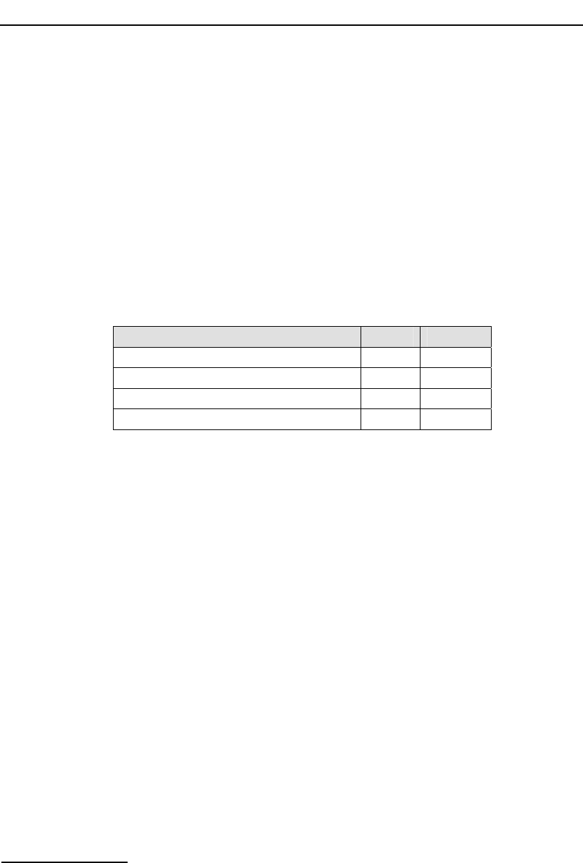
2.2 Capability
Table 1: SPCI Network Interface Board Capability
Number of: SPCI4 SPCI2S
T1/E1 links 4 2
V.11 / V.35 synchronous serial interfaces 0 2
H.100 Computer Telephony bus (CT bus) 1 1
SS7 links 4 4
2.3 License Buttons
The ss7.dc3 codefile supports different protocol module combinations that are
enabled by fitting the correct license button to the board. Each license button
is marked with a two letter code that is used for identification.
2.3.1 Run Modes
The run_mode parameter in either the SS7_BOARD command or the Board
Reset Request message determines the protocol modules that are started by
the code file at run time. The following table shows the relationship between
the license buttons and the supported run modes.

Dialogic® DSI SPCI Network Interface Boards Programmer's Manual Issue 5
9
Table 2: Relationship between License Button Codes, Run Modes and Protocol Modules
Button Code
Item Market Name
Description
Maximum Number
of SS7 Links
Run Modes supported
MTP2
MTP3
ISUP-S
ISUP
ISUP-L
TUP-S
TUP
TUP-L
MON
MM SS7SBPCIMONQ Monitoring 4
√
M3 SS7SBPCIMTPQ MTP 4 √ √
√
T1 SS7SBPCIISTUPSQ ISUP, TUP (Small) 2 √ √ √
√
√
T2 SS7SBPCIISTUPQ ISUP, TUP (Regular) 4 √
√ √ √ √
T4 SS7SBPCIISTUPLQ ISUP, TUP (Large) 4 √
√ √ √ √
2.3.2 Capacity
The figures in the table below indicate the capacity for modules running on
the DSI SPCI Boards.
Table 3: Protocol Dimensioning
Capacity
Run Mode
Maximum
Number of Link
Sets
Maximum
Number of
Routes
Maximum
Number of
Circuit Groups
Maximum
Numbers of
Circuits
MTP3 4 64
ISUP-S 2 64 44 1024
TUP-S 2 64 44 1024
ISUP 4 64 64 2048
TUP 4 64 64 2048
ISUP-L 4 64 128 4096
TUP-L 4 64 128 4096

3 Installation
10
3 Installation
3.1 Introduction
This Programmer's Manual covers the installation and use of the software
contained in the following distributions:
• Development Package for Windows®
• Development Package for Linux
• Development Package for Solaris
• User Part Development Package
• Code Files for Dialogic® DSI SPCI Network Interface Boards (various
protocols).
Each Development Package contains the device driver, library functions,
and header files for use by an application, a number of executables to be run
as part of the software environment, and a utility to configure the protocol
software. The installation of each package type is described in the following
sections.
The User Part Development Package contains example source code to
illustrate the techniques used for interfacing with the protocol modules and
protocol-specific header files for use when building an application. It is
distributed as a zip file and a tar file, and is applicable to all supported
operating systems. Extract the contents of the User Part Development
Package onto the development machine maintaining the sub-directory
structure.
The Code File contains the operating software for the DSI SPCI Boards. It is
in the form of a single binary file, which is downloaded by the host, to the
board, at run-time. Code Files all have a file suffix .dc3 and must not be
confused with code files for other products which use different suffixes. A
single SS7 Code File (ss7.dc3) includes SS7 protocol options (MTP, ISUP and
TUP). The Code File is used in conjunction with a software license button,
which is purchased and installed on the board to determine the protocols that
the user is authorized to run. The types of license buttons available are
described above. It is subsequently downloaded onto the board at run time.
Some SS7 protocols may also, optionally, be run as Host Protocol Binaries
subject to the purchase of appropriate licenses. Transferring some of the
work to the host allows the user to optimize system performance.
The Development Package, Code File and the User Part Development
Package may be obtained by downloading it from the Dialogic website at:
http://www.dialogic.com/support/helpweb/signaling.
They must be copied onto the target host machine maintaining binary file
integrity; possible transfer methods include copying using transferable media
and ftp.

Dialogic® DSI SPCI Network Interface Boards Programmer's Manual Issue 5
11
3.2 Hardware configuration
3.2.1 Board Option Switch / Link Settings
The DSI SPCI Boards contain some switches and links used to establish
optional settings at the time of installation in a host. These must be set as
follows:
• CT Bus termination links - full details of how to use these links is provided
in the relevant board Installation Guide.
• BOOT Mode option switch - ensure the switch is set to the default setting
of "8".
• ADDR Switch - the default setting for this switch is "0", and is commonly
used, but see section 4.5 on Geographic Addressing for alternative usage
of this switch.
3.3 Software Installation for Windows®
The Development Package for Windows® is distributed electronically. The
distribution is in the form of a single self extracting binary named
DPKWIN.EXE. This binary can be run directly from a hard disk.
3.3.1 Installing Development Package for Windows®
If the development package is to be used with a board then the board must
be installed before installation of the Development Package to ensure that the
driver is correctly loaded.
Before installing a new release of the Development Package, it is necessary to
remove any previous release of the package. Refer to instructions in section
3.3.4 Removing Development Package for Windows®.
The installation must be performed by a user with Administrator privileges.
Before performing the installation, close all other applications.
To perform the installation, run the self-extracting binary DPKWIN.EXE. The
installation procedure prompts for an installation directory. The default
directory is c:\septel. If required, the default directory can be modified.
The following files (or similar) are transferred to the installation directory.
Note that a number of additional files relating to other products in the range
are installed at the same time.

3 Installation
12
Table 4: Files Installed on a System Running Windows®
Name Description
gctlib.lib Library to be linked with user's application (Microsoft*).
gctlibb.lib Library to be linked with user's application (Borland*).
INC Sub-directory containing include files.
system.txt Example system configuration file.
config.txt Example protocol configuration file.
gctload.exe
ssds.exe
s7_mgt.exe
s7_log.exe
s7_play.exe
tick_nt.exe
tim_nt.exe
servcfg.exe
gctserv.exe
mtpsl.exe
upe.exe
Executables for use as described elsewhere in this
manual.
The installation process automatically installs the device driver so the setup
program must be allowed to reboot the target machine when it has finished
installing the package.
Installation is now complete, although the device driver is not yet running.
The files the user needs to use, have been installed in the installation
directory. It is recommended that the user does not modify any files in this
directory, but instead creates a working directory into which all the necessary
files are copied.
If the machine is a development machine without any target boards, then no
further installation is required.
3.3.2 Starting the Windows® Device Driver
The device driver is initially installed as "Manual", it must therefore be
manually started by a user with Administrator privilege using the following
procedure:
1) Select the Control Panel (Start Æ Settings Æ Control Panel).
2) Select the "System" icon. In the "system properties" select the
"Hardware" tab and then select "Device manager". A tree of device nodes
is presented.
3) From the toolbar select "View Æ ShowHiddenDevices": Open the "Non
Plug and Play Drivers" device node branch. The "Septel" driver should be
displayed. If the board was not present at install of the Development
Package the device node may not be visible, this issue can be resolved by
starting the driver interface at a command prompt using the command:

Dialogic® DSI SPCI Network Interface Boards Programmer's Manual Issue 5
13
Net start Septel
After rebooting the interface will be displayed as expected.
4) Right click on the "Septel" driver and select "Properties" and then select
the "Driver" tab.
5) The driver can be started immediately by selecting "start" in the "current
status" field.
Note: To automatically start the driver at system startup, select the "Automatic" option
from the "Startup" menu. The system must be re-started for this change to take
effect. It is strongly recommended that automatic startup be NOT enabled until
the correct operation has first been verified using manual startup.
On some systems, when using DSI SPCI Boards, the device driver does not
get registered. It may be necessary to manually start the driver using the
command "net start septel".
3.3.3 Clearing Windows® 2000 Install Wizard
The Windows® 2000 system may fail to fully recognize that the board is
controlled by the driver. It may consequently produce an "Install Wizard"
window for each board that is present at system boot.
This "Install Wizard" window may be quit without any problems; however, the
user may choose to use this work around to prevent the "Install Wizard"
window being presented, thereby removing the need for manual intervention:
1) Select the Control Panel (Start Æ Settings Æ Control Panel).
2) Select the "System" icon. In the "system properties" select the
"Hardware" tab and then select "Device manager". A tree of device nodes
is presented.
3) Open the "Other Devices" branch. One "Network Controller" is listed for
each installed SS7 board.
Note: Additional Network Controllers may be listed for other non-WDM
boards in the system, in which case the user must identify which belongs to
each resource.
4) "Disable" and then "enable" each of these "Network Controller". This is
achieved by right clicking on the device.
5) Reboot the system.
The "Install Wizard" window will no longer be presented for the device.

3 Installation
14
3.3.4 Removing Development Package for Windows®
Prior to installing a new version of the Development Package for Windows®,
the previous package must be removed as follows. This procedure requires a
user with Administrator privilege.
1) Select the Control Panel (Start Æ Settings Æ Control Panel).
2) Select "Add/Remove Programs".
3) Scroll down the devices and select "SS7 Development Package" and
select "Remove".
4) When package removal is confirmed, restart the target machine.
3.4 Software Installation for Linux
The Development Package for Linux is distributed electronically. The
distribution is in the form of a single compressed file called dpklnx6.Z.
3.4.1 Installing Development Package for Linux
Install the Development Package as follows:
1) Login and switch to a user account with root privileges.
2) Create a new directory on the development system to act as the root
directory for the software. This directory is referred to as the install
directory.
3) Copy the dpklnx6.Z file to the install directory. Take care to ensure
binary file integrity is maintained and the ".Z" file suffix remains in upper
case.
4) Extract the files using the command:
tar --no-same-owner -zxvf dpklnx6.Z
The following files (or similar) are extracted into the current working
directory. Note: additional files and directories relating to other products in
the range are installed at the same time.

Dialogic® DSI SPCI Network Interface Boards Programmer's Manual Issue 5
15
Table 5: Files Installed on a System Running Linux
Name Description
gctlib.lib Library to be linked with user's application.
system.txt Example system configuration file.
config.txt Example protocol configuration file.
gctload.exe
ssds.exe
s7_mgt.exe
s7_log.exe
s7_play.exe
tick_nt.exe
tim_nt.exe
upe.exe
Executables for use as described elsewhere in this
manual.
INC Sub-directory containing header files for use with user’s
application.
SPCI_CPM_DRIVER Source code for the SPCI Network Interface Board
drivers.
The procedure to build and install these is described in
section 3.4.2.
3.4.2 Device Drivers from Source Code
When the package is unloaded the source code for the driver for the DSI SPCI
Boards is found in the subdirectory named SPCI_CPM_DRIVER. This source
code must be built for the required Kernel version as described below.
A build script, named build_spci_cpm.sh, is included in this subdirectory. To
build the driver, run this script.
This build script assumes a suitable environment for building Kernel modules
is available. This must include the appropriate Kernel include files being found
at: /usr/src/linux-`uname -r`/include.
(e.g., /usr/src/linux-2.4.7-10/include). If these are not found, the build
will fail.
Some Linux installations do not create a system source directory with the
required name, for example some SMP kernels do not create a directory with
the required smp suffix. If this is the case, then a softlink needs to be created
to give an appropriate path to the system header files. For example:
cd /usr/src
ln –s linux-2.4.27 linux-2.4.27smp
Some later version of Linux uses a revised format for the remap_page_range
parameters (for example Red Hat Linux Kernel Versions greater than 2.4.20
require this revised format). The build script supports an optional new_remap
parameter. If this parameter is set, the compile uses the revised format.
The build script supports an optional clean parameter that removes the
driver and all intermediate files.
Under some versions of Linux a warning similar to the following is generated:
warning: changing search order for system directory.

3 Installation
16
This warning can be safely ignored.
For compatibility with the pre-built drivers the existing name format is
retained for Linux 2.4 drivers e.g., sptcpi-2.4.18-14smp.o. However, this
name format causes problems under Linux Kernel version 2.6; therefore, all
Linux 2.6 drivers are named sptpci26.ko.
An install script, named install_spci_cpm.sh, is included in the package.
This script installs the device driver, automatically allocates the major device
numbers, and creates the four appropriate device nodes. This replaces the
manual procedures to perform these operations, as described above.
The install script supports an optional remove parameter. This causes the
device driver to be removed and the device nodes to be deleted.
The installation must be performed by a user with root privileges.
3.4.3 Verifying Device Driver Loading
When the device driver is loaded it outputs status messages to the system
log.
The system log is displayed using the command:
dmesg | more
An example message is:
sptpci V1.06
Copyright (C) 2000-2007 Dialogic Corporation. All rights
reserved.
Using major device number 127.
sptpci Device Id 0 @ Bus: 1 Device: 9 Function: 0
3.5 Software Installation for Solaris
The Development Package for Solaris is distributed electronically. The
distribution is in the form of two compressed files called dpksol32.Z and
dpksol64.Z for use with 32 bit or 64 bit kernels respectively.
The Development Package is suitable for use in the following configurations:
• Solaris 9 (32 and 64 Bit)
• Solaris 10 (32 and 64 bit)
3.5.1 Installing the Development Package for Solaris
Copy the appropriate file to the Solaris system. Take care to ensure the
binary file integrity is maintained and the ".Z" file suffix remains in upper
case.
The file must then be uncompressed and installed as shown below.
Note: This installation must be performed by a user with root privileges.
uncompress <dpksol32.Z / dpksol64.Z>
pkgadd –d <dpksol32 / dpksol64>
The Solaris package installation utility (pkgadd) prompts for further input.

Dialogic® DSI SPCI Network Interface Boards Programmer's Manual Issue 5
17
On successful completion of the installation procedure, the following message
is displayed, and the user needs to reboot the system.
Installation of DKseptel was successful.
The following files (or similar) are transferred into the /opt/DKseptel
directory.
Note: Additional files relating to other products in the range are installed at the same
time.
Table 6: Files Installed on a System Running Solaris
Name Description
libgctlib.so
libgctlib.so.1
libgctlib.so.1.0.1
Library to be linked with user's application.
INC Sub-directory containing header files for use with user’s application.
system.txt Example system configuration file.
config.txt Example protocol configuration file.
gctload.exe
ssds.exe
tick_sol.exe
tim_sol.exe
s7_mgt.exe
s7_log.exe
upe.exe
Executables for use as described elsewhere in this manual.
3.5.2 Solaris 9 - Interface Name Checking
To use the package under Solaris 9, interface name checking must be
disabled. This is done by adding the following line to the /etc/system file:
set sunddi_netifname_constraints=0
The driver will not start properly if this line is not added.
3.5.3 Solaris 10 - Additional Commands
Customers using Solaris 10 must perform the following additional commands
after installing the package:
cd/opt/DKseptel
chown root ssdh
chmod +s ssdh
Note: The commands should be executed by a user with super-user permissions.
3.5.4 Non-serviced interrupts reports
Some systems exhibit problems due to non-serviced interrupts being reported
by the system. The problem can result in large numbers of event reports that
can impact the system performance.
The DSI SPCI Board drivers included in this package include an optional
work-around to eliminate these problems.

3 Installation
18
To enable this functionality the following line must be added to the
/etc/system file:
set sptpci:spt_claimint=1
The system has to be rebooted to force the change to take effect.
3.5.5 Removing the Development Package for Solaris
The Development Package for Solaris is removed using the package removal
utility:
pkgrm <dpksol32 / dpksol64>
The Solaris package removal utility (pkgrm) then prompts for further input.
On successful completion of the procedure the following message is displayed
and the user should reboot the system:
Removal of <dpksol32 / dpksol64> was successful.

Dialogic® DSI SPCI Network Interface Boards Programmer's Manual Issue 5
19
4 Configuration and Operation
4.1 Overview
Prior to performing software configuration, the user should gain an
appreciation of:
• the flexibility of the protocol stack,
• the run-time options that exist,
• the mechanisms used to select particular features.
This section gives an overview of these aspects.
The user should also consult the Software Environment Programmer’s
Manual, which describes the basic principles of modules and message
passing.
4.1.1 System Structure
The SS7 software running on the board communicates with an application
running on the main CPU of the host computer. The physical interface to the
board uses the PCI bus. All communication with the board is handled by a
device driver and the messages passing to and from the board are managed
by a process (ssds) that runs on the host computer.
In addition to running the application on the host computer, the user may,
depending on the size of the overall system and the network topology, elect
to also run some of the SS7 protocol modules on the host. In such cases, the
interface between the application and the SS7 protocol software remains
identical. This allows for easy migration from a small system contained on a
single board to a large system distributed over many boards with minimal
changes to the application. When a protocol is run on the host, it is necessary
to purchase and install a Software License on the host.
The table illustrates some possible system configurations for a telephony
system.
Table 7: Typical Telephony Systems Configurations
Small System Medium System Large System
Software running on
the board MTP2
MTP3
ISUP / TUP
MTP2
MTP3 MTP2
Software running on
Host Computer User Application ISUP / TUP
User Application MTP3
ISUP / TUP
User Application
Number of boards Single Single signaling
board (additional
boards may
support voice only)
Multiple

4 Configuration and Operation
20
The following abbreviations are used in the table:
MTP2 Message Transfer Part – Level 2
MTP3 Message Transfer Part – Level 3
ISUP ISDN User Part
TUP Telephony User Part
In all cases, the process called ssds (SS7 Software Driver) must be run on
the host computer. This handles message transfer between the host and the
board using the device driver.
To define which protocol modules run on the host, edit the text file
system.txt.
Run the program gctload, which reads the system configuration parameters
from the file system.txt and starts up the selected processes bringing the
system into operation.
For further details of gctload, refer to the Software Environment
Programmer’s Manual.
The following processes for use on the host are included in the distribution.
All must be run on the host with the exception of s7_mgt, s7_log, and
s7_play, which are optional:
Table 8: Host Processes and Utilities
Name Description
gctload Process to initialize the system environment and start up all other related
processes running on the host, deriving the configuration from a text file
(system.txt).
ssds Process to interface with the device driver for passing messages to and from
the board(s) and for downloading software to the board(s).
tick_nt
tick_lnx
tick_sol
Protocol timer process to send periodic “tick” notification to the tim_xxx
process which in turn handles protocol timers.
tim_nt
tim_lnx
tim_sol
Process to receive periodic tick notification from tick_xxx and handle protocol
timers for all other processes.
s7_mgt Process to perform single shot protocol configuration for all protocol modules,
deriving the configuration parameters from a text file (config.txt). This process
is optional. As an alternative to using it, the user may elect to perform
protocol configuration by sending messages directly to the other modules in
the system.
s7_log Utility process to allow messages received from the protocol stack to be
logged to a text file. This is useful for diagnostic purposes.
s7_play Utility process used to generate messages from a text file and send them into
the system.

Dialogic® DSI SPCI Network Interface Boards Programmer's Manual Issue 5
21
4.2 System Configuration
System configuration is handled by the program gctload, which reads the
system configuration data from a file called system.txt. This file must be
edited to reflect the requirements of your system, prior to running gctload.
System initialization requires first that a pool of message buffers is created
for subsequent inter-process communication. Secondly, that a message
queue is created for each process that runs and that any message re-
direction for modules that are running remotely is initialized. Then all
processes can be started.
The program gctload exists to handle this initialization sequence and to
create the inter-process communication environment. It reads input from the
text file called system.txt, carries out all system initialization and starts up
all processes. system.txt is a user configurable file containing details of all
the module identifiers known to the system, details of whether they are local
modules or remote modules accessed by a local module (message
redirection), and lists the command line for all processes to be started by
gctload.
gctload creates a message queue for each of the local module identifiers. It
subsequently expects a process to service its message queue otherwise
messages written to that queue will never be read, causing eventual loss of
system messages.
gctload initializes the message queue look-up table so that messages
destined for modules that do not exist locally are re-directed to a message
queue for a module that does exist locally.
Having created the system environment, gctload proceeds to spawn all
processes listed in the system.txt file in the order listed.
4.2.1 System Configuration File Syntax
The system configuration file system.txt is a text file used by gctload to
configure the software environment.
The file syntax permits the use of comments to improve the readability of the
file. Comments are inserted into the file by using an asterisk *; all characters
on the line after the asterisk are ignored.
Numbers can be entered in either decimal or hexadecimal format.
Hexadecimal numbers must be prefixed with 0x. For example, the value
eighteen can be entered in either of the following formats:
0x12 *(Hexadecimal)
18 *(Decimal)
The System Configuration File contains the following commands:
a) LOCAL commands to allow gctload to generate message queues
for modules running locally.
b) REDIRECT commands to cause messages generated for modules
not running locally to be redirected via a module that is running
locally.
c) FORK_PROCESS commands advising gctload of any processes
that need to be started locally.

4 Configuration and Operation
22
The full syntax of each command is listed in the Software Environment
Programmer’s Manual.
An example system.txt file is shown below:
*
* Example system.txt for the Development Package for Windows®.
*
* Edit this file to reflect your configuration.
*
* Essential modules running on host:
*
LOCAL 0x20 * ssd/ssds - Board interface task
LOCAL 0x00 * tim_nt - Timer task
*
* Optional modules running on the host:
*
LOCAL 0xcf * s7_mgt - Management/config task
LOCAL 0x2d * upe - Example user part task
*
* Modules running on the board (all redirected via ssd):
*
* REDIRECT 0x23 0x20 * ISUP module
* REDIRECT 0x4a 0x20 * TUP module
REDIRECT 0x22 0x20 * MTP3 module
REDIRECT 0x71 0x20 * MTP2 module
REDIRECT 0x10 0x20 * CT bus/Clocking control module
REDIRECT 0x8e 0x20 * On-board management module
*
* Redirection of status indications:
*
REDIRECT 0xdf 0x2d * LIU/MTP2 status messages -> upe
REDIRECT 0xef 0x2d * Other indications -> upe
*
* Now start-up all local tasks:
*
FORK_PROCESS ssds.exe
FORK_PROCESS tim_nt.exe
FORK_PROCESS tick_nt.exe
FORK_PROCESS s7_mgt.exe
FORK_PROCESS upe.exe
*
4.2.2 Generating a System Configuration File
This section describes the procedure for generating a system configuration
file (system.txt) and details any operating system specific differences in
behaviour of the development packages.
First, the file must contain LOCAL declarations for all modules that run on the
host computer. As a minimum this must include the SSDS module and the
timer module. Hence the following declarations must exist:
LOCAL 0x20 * ssd / ssds - Board interface task
LOCAL 0x00 * tim_xxx - Timer task
LOCAL declarations are required for any optional modules that run on the
host. Typically, this includes s7_mgt and the user's own application module.
It may also include host-based protocol modules and the s7_log utility. For
example:

Dialogic® DSI SPCI Network Interface Boards Programmer's Manual Issue 5
23
LOCAL 0xcf * s7_mgt - Management/config task
LOCAL 0x2d * upe - Example user part task
LOCAL 0x3d * s7_log - Prints messages to screen/file
After the LOCAL declarations, REDIRECT commands are added for modules
that run on the board so that messages destined for these modules are
transported via ssds (module_id = 0x20) and the device driver, to the board.
These REDIRECT commands are always required:
REDIRECT 0x71 0x20 * MTP2 module
REDIRECT 0x10 0x20 * CT bus/Clocking control module
REDIRECT 0x8e 0x20 * On-board management module
Further REDIRECT commands are required for protocols chosen to run on the
board. This typically includes MTP3 and one or more user parts. For example:
REDIRECT 0x23 0x20 * ISUP module
REDIRECT 0x4a 0x20 * TUP module
REDIRECT 0x22 0x20 * MTP3 module
Next, ensure status indications issued from the board can arrive at a module
running on the host. (If this does not happen, the system will quickly run out
of available messages for inter-process communication).
Two module_id's (0xdf and 0xef) require redirection to a suitable process
running on the host. Initially these messages should be redirected to the
s7_log utility, which prints out a line for each message received. Ultimately,
the user's own application will expect to receive these notifications.
REDIRECT 0xdf 0x3d * LIU/MTP2 status messages -> s7_log
REDIRECT 0xef 0x3d * Other indications -> s7_log
Include FORK_PROCESS commands for all modules that run on the host
computer.
All systems require ssds, tim, and tick modules to be run.
For Windows®, these FORK_PROCESS commands are mandatory:
FORK_PROCESS ssds.exe
FORK_PROCESS tim_nt.exe
FORK_PROCESS tick_nt.exe
For Linux, these FORK_PROCESS commands are mandatory:
FORK_PROCESS ssds
FORK_PROCESS tim_lnx
FORK_PROCESS tick_lnx
For Solaris, these FORK_PROCESS commands are mandatory:
FORK_PROCESS ssds
FORK_PROCESS tim_sol
FORK_PROCESS tick_sol
Finally, include FORK_PROCESS commands for any modules chosen to run on
the host (e.g., protocol modules, user's application or diagnostic utilities). For
example:
FORK_PROCESS s7_mgt
FORK_PROCESS upe
FORK_PROCESS s7_log

4 Configuration and Operation
24
4.3 Protocol Configuration
The Development Package contains a protocol configuration utility, s7_mgt
which performs initialization of all the software modules running on the
signaling board. It reads the protocol configuration data from a text file called
config.txt and provides a quick and flexible method of configuring the
protocol modules without the need to write software for that purpose.
Alternatively, the protocol stack may be configured by sending individual
configuration messages documented in the per-module Programmer’s
Manuals to each protocol module. This approach is of particular use if the
application needs to reset the board and run a new configuration without
stopping the application program. It is described in section 4.3.2 Protocol
Configuration Using Individual Messages.
4.3.1 Protocol Configuration using the s7_mgt utility
The default configuration file used by s7_mgt is config.txt. The -k option
allows the user to specify an alternative filename if required. For example:
s7_mgt -kmyconfig.txt
The format of the configuration commands is described in Appendix A.
s7_mgt can optionally be configured to send a message to a nominated
module on completion of the configuration sequence. This option is activated
using the –i option to specify the receiving module_id. For example:
s7_mgt –i0xef
To assist problem diagnosis, run s7_mgt using the –d option, and additional
diagnostic output will be generated. For example:
s7_mgt –i0xef -d
See section 4.4 Board Information Diagnostics, for diagnostic output format.
4.3.2 Protocol Configuration Using Individual Messages
As an alternative to using the s7_mgt configuration utility it is possible to
carry out the protocol configuration by building and sending messages
directly to the board. This approach does mean that it is necessary to write
some application code to handle the configuration but has the advantage that
the application can, if required, re-configure the board without re starting the
application.
All communication with the board is in the form of sending and receiving
messages. The configuration sequence is described in the following section.
The application must allocate a message structure using the library function
getm() and send it to the board using the library function GCT_send(). The
application must periodically call the library function GCT_receive() or
GCT_grab() in order to receive messages from the board. GCT_receive() will
block until a message is available whilst GCT_grab() will return immediately.
Once the application has finished processing the received message, it must
release the message structure back to the system by calling the library
function relm(). The library functions are all described in the Software
Environment Programmer's Manual.

Dialogic® DSI SPCI Network Interface Boards Programmer's Manual Issue 5
25
To configure the board using individual messages, the following sequence
must be used. (The format of all the messages is described in Section 5 of
this manual):
1) Build and send an SSD Reset Message.
This contains the parameters to initialize the ssds module.
2) Build and send a Board Reset Message for each board.
This includes the id of the board and the name of the Code File.
It causes the board to be reset and the Code File downloaded.
3) Wait until a Board Status Message is received (for each board).
Inspect the status field to determine whether the reset was successful.
On failure you should check carefully the parameters and try again.
On success continue to the next step.
4) Build and send a Board Configuration Message. This contains all
mandatory protocol configuration parameters for the Message Transfer
Part (MTP)
(such as point codes, physical link settings and MTP configuration
parameters).
5) Wait until a Board Configuration Confirmation Message is received.
Inspect the status field which is zero on success.
On failure re-check the configuration parameters and go back to resetting
the board.
6) Optionally, send LIU Configuration Request Messages for each T1/E1
line interface unit on the board to configure the appropriate operating
mode.
Ensure the status field is zero in the confirmation message.
7) Optionally, send MTP Config Route Messages for any remote signaling
points (other than adjacent signaling points. The route configuration for
adjacent signaling points is automatically set up using the board
configuration message). Ensure the status field is zero in the confirmation
message.
8) If a user part (e.g., ISUP or TUP) is included in the Code File, build and
send the per-module configuration message (as defined in the
Programmer’s Manual for the User Part Module). Ensure the status field is
zero in the confirmation message.
9) If a user part is included, build and send circuit group configuration
messages for each circuit group (as defined in the Programmer’s Manual
for the User Part Module). Ensure the status field is zero in the
confirmation message.
10) The protocol stack is now configured ready for use (the same as if the
configuration utility s7_mgt had been used). The user must send an MTP
Activate Signaling Link message for each signaling link to start up SS7
operation.

4 Configuration and Operation
26
4.4 Board Information Diagnostics
To assist in diagnosis of configuration problems and reporting hardware
details when encountering problems, a diagnostic display feature is available
in s7_mgt.
When s7_mgt is run with the –d command line option, a diagnostic display of
board hardware parameters is generated in this format following
configuration of the board.
S7_MGT Board identification: board_id 0
Board type: 2 (SPCI)
Hardware revision: 0
RAM size: 0x00000000
Interface type: 0
RTB switch: 0
ADDR switch: 0
BOOT switch: 8
Shelf: 0
Slot: 0
Firmware: V1.02
Electronic serial number: 01-000007e09eb9-8a
License serial number: 02-0000008c92f7-72
The parameters are as described below:
Table 9: Board Diagnostics – Hardware Parameters
Parameter Description
Board type Board types are reported as follows:
2 SPCI2S or SPCI4
Hardware revision The board hardware revision number.
RAM size The on-board RAM size.
Interface type Parameter not supported for DSI SPCI Boards. Value
returned equals 0.
RTB switch Parameter not supported for DSI SPCI Boards. Value
returned equals 0.
ADDR switch Geographic addressing switch setting, that is, the
address at which the board appears when the –o3
feature of ssds is used.
BOOT switch The setting of the board's rotary switch labeled “Boot”.
Default setting - 8.
Shelf Parameter not supported for DSI SPCI Boards. Value
returned equals 0.
Slot Parameter not supported for DSI SPCI Boards. Value
returned equals 0.
Firmware Firmware revision number.
Electronic serial number The board's electronic serial number.
License serial number License serial number. The serial number of the fitted
license button (all zero's if none found).

Dialogic® DSI SPCI Network Interface Boards Programmer's Manual Issue 5
27
4.5 Geographic Addressing
Geographic Addressing allows the logical position of a board (or board_id) in
a system to remain the same irrespective of the addition or removal of other
boards on the PCI bus. Two address modes are supported:
• PCI address mode – (default) addressing determined by enumerating
boards on the PCI bus at boot time (i.e., the default order found by the
operating system).
• Switch address mode - determined by a 16 position ADDR switch on the
board.
The configuration of Geographic Addressing is controlled by command line
parameters to the ssds utility. See section 8.1 ssds for details.
4.6 Watchdog Timer
An optional host to board watchdog timer may be configured. This allows the
board to detect a failure of the host software. If such a condition is detected,
then the board goes into a reset state. This prevents a condition whereby the
software on the host has stopped running but the boards still presents an "in-
service" condition to the remote end.
This functionality is controlled by command line parameters to the ssds
utility. See section 8.1 ssds for details.
4.7 Using the CT bus
The SPCI2S and SPCI4 boards support two or four T1/E1 Line Interface Units
and a CT bus interface (H.100) respectively. The on-board signaling processor
handles the SS7 signaling timeslots whilst the remaining circuits (voice or
data bearer circuits) are passed to the CT bus for distribution to other boards.
All communication between the application and the board is message-based.
Initial configuration is usually handled by the configuration utility s7_mgt,
which takes commands from the text file (config.txt) and generates all the
necessary configuration messages for the board. Subsequent operation is
entirely message driven, messages being passed in both directions between
the board and the application.
One of the roles of the application is to control the dynamic switching
between the CT bus and the T1/E1 line interfaces. This section provides
details of how to interface with the CT bus, including the initial (static)
configuration and the subsequent (dynamic) switching.
The operation of the CT bus switching interface is described in terms of the
SCbus switching model using the messages MVD_SC_DRIVE_LIU,
MVD_MSG_SC_LISTEN and MVD_MSG_SC_FIXDATA and config.txt
commands LIU_SC_DRIVE and SCBUS_LISTEN.

4 Configuration and Operation
28
4.7.1 Switching Model
The basic switching model assumes that at system initialization all incoming
T1/E1 timeslots and all resource board output timeslots are connected up to
channels on the CT bus and that these connections are never changed. This
has the advantage that once the on-board CT bus drivers have been set up
they are never changed so the chances of inadvertently causing CT bus
conflict is minimized. It also means that the user can predict the exact CT bus
channels where any input timeslot can be located and this in turn can assist
with fault diagnosis and general system test.
It is also possible to generate fixed patterns on any T1/E1 output timeslots to
provide the correct idle pattern for presentation to the network on all circuits
where there is no active call.
Having completed the system initialization, all drives to the CT bus are set
up. Then, on a dynamic (call by call) basis, the connectivity must be modified
when a new call arrives and when it finishes.
When a new call arrives, the application, in general, needs to initiate two
listen commands. One command causes the resource to listen to the
appropriate CT bus channel to hear the incoming voice path and the other
causes the T1/E1 interface to listen to the output from the resource board to
generate the outgoing voice path.
When a call clears, the application needs to initiate generation of the fixed
idle pattern towards the network operation (and may wish to connect an idle
pattern to the resource board).
4.7.2 Static Initialization
Static initialization is handled by the s7_mgt utility. For each T1/E1 line
interface unit, user must include an LIU_SC_DRIVE command in the
config.txt file. The syntax for this command is detailed in appendix A.
The LIU_SC_DRIVE command has several parameters. board_id and
liu_id together uniquely identify the affected line interface unit. sc_channel
is the channel number of the first channel on the CT bus that is to be used for
timeslots from the specified LIU. ts_mask is a mask identifying which
timeslots on the T1/E1 interface are carrying voice circuits (as opposed to
signaling) and therefore need to be connected to the CT bus. The least
significant bit of ts_mask must always be zero when driving from an T1/E1
interface.
As an example, consider a two board system where the first board has 4 E1
ports and the second board has 4 T1 ports. We allow the first 512 CT bus
channels to be used by other boards in the system and therefore start at
sc_channel 512.

Dialogic® DSI SPCI Network Interface Boards Programmer's Manual Issue 5
29
LIU_SC_DRIVE 0 0 512 0xfffefffe * 30 E1 voice ccts on ts 1..15 &
17..31
LIU_SC_DRIVE 0 1 542 0xfffefffe * 30 E1 voice ccts on ts 1..15 &
17..31
LIU_SC_DRIVE 0 2 572 0xfffefffe * 30 E1 voice ccts on ts 1..15 &
17..31
LIU_SC_DRIVE 0 3 602 0xfffefffe * 30 E1 voice ccts on ts 1..15 &
17..31
LIU_SC_DRIVE 1 0 632 0x00fffffe * 23 T1 voice ccts on timeslots
1..23
LIU_SC_DRIVE 1 1 655 0x00fffffe * 23 T1 voice ccts on timeslots
1..23
LIU_SC_DRIVE 1 2 678 0x00fffffe * 23 T1 voice ccts on timeslots
1..23
LIU_SC_DRIVE 1 3 701 0x00fffffe * 23 T1 voice ccts on timeslots
1..23
4.7.3 Dynamic Operation
The application controls dynamic changes to CT bus switching by sending the
MVD_MSG_SC_LISTEN message to the board. This message is documented
in chapter 5 Program Execution. It contains the liu_id, the timeslot number
on the T1/E1 interface and the CT bus channel number (sc_channel) to
which the timeslot listens. The message is directed to the correct board by
calling the GCT_set_instance function prior to calling GCT_send.
When a new call arrives, the application needs to instigate 2 listen commands
(although they do not necessarily both apply to the SS7 board). One connects
the voice circuit in the forward direction and the other connects it in the
backward direction.
When a call terminates, the application must issue a fixed data message to
ensure the network port sees the voice idle pattern.
4.7.4 Example Code - Building and Sending SC_LISTEN
/*
* Example function for building and sending an MVD_MSG_SC_LISTEN
* message to a SPCI2S or SPCI4 signalling board.
*
* The only change that the user needs to make is to fill in the
* OUR_MOD_ID definition below so that is equal to the module_id
* of the application module.
*/
#define OUR_MOD_ID (0xef)
#include "system.h" /* Definitions of u8, u16 etc */
#include "msg.h" /* Definitions of HDR, MSG etc */
#include "libc.h" /* Used only for memset prototype */
#include "sysgct.h" /* Prototypes for GCT_xxx */

4 Configuration and Operation
30
#include "pack.h" /* Prototypes for rpackbytes */
#include "ss7_inc.h" /* Message & module definitions */
/*
* Macro to generate the value for use in the rsp_req field of the
* message header in order to request a confirmation message:
*/
#define RESPONSE(module) (((unsigned short) 1) << ((module) & 0x0f))
/*
* Function to drive an SCbus / CT bus timeslot
* onto a timeslot on a PCM port:
*/
int listen_to_scbus(board_id, liu_id, timeslot, sc_channel)
int board_id; /* board_id (0, 1, 2 ...) */
int liu_id; /* PCM port id (*/
int timeslot; /* Timeslot on the PCM port (1 .. 31) */
int sc_channel; /* SCbus / CT bus channel number */
{
MSG *m;
u8 *pptr;
/*
* Allocate a message (and fill in type, id, rsp_req & len):
*/
if ((m = getm(MVD_MSG_SC_LISTEN, 0, RESPONSE(OUR_MOD_ID), MVDML_SCLIS))
!= 0)
{
pptr = get_param(m);
memset(pptr, 0, m->len);
/*
* Enter the parameters in machine independent format:
*/
rpackbytes(pptr, MVDMO_SCLIS_liu_id, (u32)liu_id, MVDMS_SCLIS_liu_id);
rpackbytes(pptr, MVDMO_SCLIS_timeslot, (u32)timeslot,
MVDMS_SCLIS_timeslot);
rpackbytes(pptr, MVDMO_SCLIS_sc_channel, (u32)sc_channel,
MVDMS_SCLIS_sc_channel);
m->hdr.dst = MVD_TASK_ID;

Dialogic® DSI SPCI Network Interface Boards Programmer's Manual Issue 5
31
m->hdr.src = OUR_MOD_ID;
/*
* Call GCT_set_instance to route the message to the
* correct board and GCT_send to send the message.
* If GCT_send returns non-zero release the message.
*/
GCT_set_instance(board_id, (HDR *)m);
if (GCT_send(m->hdr.dst, (HDR *)m) != 0)
relm((HDR *)m);
}
return(0);
}

5 Program Execution
32
5 Program Execution
This chapter describes how to start the software running. It assumes that the
software has already been installed and the configuration files system.txt
and config.txt have been modified accordingly. Refer to previous sections if
unsure.
There are three main stages to get a new application up and running
although the procedure may vary slightly depending on the operating system.
1) The device driver must be installed and running.
2) The protocol software running on the host must be run up.
3) Write your application (making use of the examples supplied), compile it
(using the header files supplied), and link it with the supplied libraries to
generate a finished application program.
The details of how these steps are achieved for each operating system are
given below.
5.1 Program Execution under Windows®
Ensure the device driver has been installed and the system configuration file
(system.txt) has been modified according to the system requirements to
select the correct protocols etc.
Ensure the code file has been copied to the directory containing the SS7
binaries.
If using s7_mgt, ensure the protocol configuration file config.txt has been
edited to provide protocol configuration.
To start the software running, change to the directory containing the binaries
and run gctload in the background, optionally specify the system
configuration file.
To run the system in a separate console, enter:
start gctload -csystem.txt
To run the system within the current console, enter:
gctload -csystem.txt
The gctload program initializes the system environment and starts up other
processes. The s7_mgt process configures all the protocol modules. A
banner confirms that the system is running.
The example utility mtpsl may be used to activate and deactivate signaling
links as follows:
mtpsl { act | deact } <linkset_id> <link_ref>
mtpsl act 0 0
mtpsl deact 0 0
The host software can be shutdown by running gctload from the command
line using the –x command line option as follows:
gctload -x

Dialogic® DSI SPCI Network Interface Boards Programmer's Manual Issue 5
33
5.2 Program Execution under Linux
Ensure the device driver has been installed and the system configuration file
(system.txt) has been modified according to the system requirements to
select the correct protocols etc.
Ensure the code file has been copied to the directory containing the SS7
binaries.
If using s7_mgt, ensure the protocol configuration file config.txt has been
edited to provide protocol configuration.
To start the software running, change to the directory containing the binaries
and run gctload optionally specify the system configuration file.
To run the system in the foreground, enter:
gctload -csystem.txt
To run it in the background enter:
gctload -csystem.txt &
The gctload program initializes the system environment and starts up other
processes. The s7_mgt process configures all the protocol modules. A
banner confirms that the system is running.
The example utility mtpsl may be used to activate and deactivate signaling
links as follows:
mtpsl { act | deact } <linkset_id> <link_ref>
mtpsl act 0 0
mtpsl deact 0 0
To shutdown the host software, run gctload using the "–x" parameter
gctload –x
Any modules that have been started by gctload are terminated
automatically.

5 Program Execution
34
5.3 Program Execution under Solaris
Ensure the device driver has been installed and the system configuration file
(system.txt) has been modified according to the system requirements to
select the correct protocols etc.
Ensure the code file has been copied to the directory containing the SS7
binaries.
If using s7_mgt, ensure the protocol configuration file config.txt has been
edited to provide protocol configuration.
To start the software running, change to the directory containing the binaries
and run gctload optionally specifying the system configuration file.
To run the system in the foreground enter:
gctload -csystem.txt
To run it in the background enter:
gctload -csystem.txt &
The gctload program initializes the system environment and starts up other
processes. The s7_mgt process configures all the protocol modules. A
banner confirms that the system is running.
The example utility mtpsl may be used to activate and deactivate signaling
links as follows:
mtpsl { act | deact } <linkset_id> <link_ref>
mtpsl act 0 0
mtpsl deact 0 0
To shutdown the host software run gctload using the –x parameter:
gctload –x
Any modules that have been started by gctload are terminated
automatically.
5.4 Developing a User Application
The development package, with the User Part Development Package, contains
the files to allow the user to develop applications. These consist of makefile
definitions, C header files (.h), and libraries.
A single definitions file is supplied (for each operating system) containing the
definitions relating to the user's own development environment. This file is
then included in the make files for all other processes. The user may need to
modify this definitions file to ensure correct paths etc are set up.
The definitions file is called one of the following depending on the operating
system:
makdefs.mnt (Windows®)
makdefs.mlx (Linux)
makdefs.ms2 (Solaris)
The following library files must be linked with the users application code:

Dialogic® DSI SPCI Network Interface Boards Programmer's Manual Issue 5
35
gctlib.lib (Windows® using Microsoft compiler)
gctlibb.lib (Windows® using Borland compiler)
gctlib.lib (Linux)
gctlib.lib (Solaris)
Some simple example programs are supplied to illustrate the techniques for
interfacing to the protocol stack although they are not intended to show a
real application. Before starting to develop an application, you can familiarize
yourself with the example programs and how they are built.
The example programs are contained in the User Part Development Package.
upe is a framework for a User Part module and contains a worked example of
exchanging messages with the MTP3 module. It loops back any MTP-
TRANSFER-INDICATIONS messages that it receives and reports other MTP
indications to the user.
mtpsl is an example of how to send messages to MTP3 to activate and
deactivate signaling links. It can be used as a command line tool for this
purpose initially. It is intended that the user builds the example code into the
management application.
ctu is an example of how a user application can interface with telephony user
parts, e.g., ISUP or TUP.
A makefile is included to allow you to build the application programs. To build
the program, change to the appropriate directory and enter (to build ctu):
nmake /f ctu.mnt (Windows®)
make -f ctu.mlx (Linux)
make -f ctu.ms2 (Solaris)

6 Message Reference
36
6 Message Reference
6.1 Overview
This section describes the individual messages that may be sent to and
received from the Dialogic® DSI SPCI Network Interface Board. Some
messages are sent by the user's application software whilst others are sent
by utility programs such as the configuration utility s7_mgt.
Prior to sending any message to the DSI SPCI Network Interface Board the
application must call the library function GCT_set_instance to select the board
to which the message is sent. After receiving a message from the board, the
application must call the library function GCT_get_instance to determine
which board the message came from. These library functions are described in
the Software Environment Programmer's Manual.
The messages are grouped into four categories:
• General Configuration Messages,
• Hardware Control Messages,
• MTP Interface Messages, and
• Event Indication Messages.
6.1.1 General Configuration Messages
General Configuration Messages are normally issued by the s7_mgt
configuration utility in which case they need not, and must not, be generated
by any user application software.
If the user elects not to use s7_mgt, then it is necessary for the application to
build and send messages to configure the SSD module, reset each individual
DSI SPCI Board, configure each board and optionally configure additional
routes.
6.1.2 Hardware Control Messages
Hardware Control Messages are used to control various hardware devices on
the board. This includes the T1/E1 Line Interface Units (LIU), the digital cross
connect switches and the clocking mode for the DSI SPCI Board.
In a static configuration, all these hardware blocks can be set up using the
s7_mgt configuration utility along with the appropriate commands in the
config.txt file.
If dynamic control of the hardware is required (or the user has elected to not
use s7_mgt), then the user application needs to build and send at least some
of the Hardware Control Messages.

Dialogic® DSI SPCI Network Interface Boards Programmer's Manual Issue 5
37
6.1.3 MTP Interface Messages
MTP Interface Messages allow signaling links to be activated and deactivated
by the user and provide a mechanism for communication between the MTP3
module and the user part module (e.g., ISUP or TUP). In many cases, the
user part module is an SS7 Protocol binary so the user does not need to
handle the MTP-TRANSFER, MTP-PAUSE, MTP_RESUME & MTP-STATUS
primitives as they pass directly between MTP3 and the user part module.
In the case that the user application is implementing the user part
functionality, then the MTP primitives are applicable and these are
documented in the MTP Interface messages section.
6.1.4 Event Indication Messages
Event Indication Messages are the mechanism by which protocol and software
error events are reported to the application. These messages are generated
asynchronously by different modules within the stack.
6.1.5 Message Summary Table
The following table lists, by message type, all the messages described in this
manual:
Table 10: Message Summary
Message
Type Mnemonic Description
0x0008 MGT_MSG_EVENT_IND Error Indication
0x0201 MGT_MSG_SS7_STATE MTP2 Level 2 State Indication
0x0202 MGT_MSG_SS7_EVENT MTP2 Q.752 Event Indication
0x0301 MGT_MSG_MTP_EVENT MTP3 Q.752 Event Indication
0x06a0 SSD_MSG_STATE_IND Board Status Indication
0x0e01 MVD_MSG_LIU_STATUS LIU Status Indication
0x0e23 MVD_MSG_CLK_IND Clock Event Indication
0x0f09 API_MSG_CNF_IND s7_mgt Completion Status Indication
0x1e37 Confirmation of LIU_MSG_R_CONFIG
0x1e38 Confirmation of LIU_MSG_R_CONTROL
0x1e39 Confirmation of LIU_MSG_R_STATE
0x3312 Confirmation of MTP_MSG_CNF_ROUTE
0x3680 Confirmation of SSD_MSG_RESET
0x3681 Confirmation of SSD_MSG_RST_BOARD
0x3e00 Confirmation of MVD_MSG_RESETSWX
0x3e15 Confirmation of MVD_MSG_SC_FIXDATA
0x3e17 Confirmation of MVD_MSG_SC_LISTEN

6 Message Reference
38
0x3e18 Confirmation of MVD_MSG_SC_DRIVE_LIU
0x3e1f Confirmation of MVD_MSG_SC_CONNECT
0x3e20 Confirmation of MVD_MSG_CNFCLOCK
0x3e21 Confirmation of MVD_MSG_CLK_PRI
0x3e34 Confirmation of LIU_MSG_CONFIG
0x3e35 Confirmation of LIU_MSG_CONTROL
0x3f10 Confirmation of MGT_MSG_CONFIG0
0x5e37 LIU_MSG_R_CONFIG LIU Read Configuration Request
0x5e38 LIU_MSG_R_CONTROL LIU Read Configuration Request
0x5e39 LIU_MSG_R_STATE LIU State Request
0x6111 GEN_MSG_MOD_IDENT General Module Identification Message
0x6f0d MGT_MSG_R_BRDINFO Read Board Info Request Message
0x7680 SSD_MSG_RESET SSD Reset Request
0x7681 SSD_MSG_RST_BOARD Board Reset Request
0x7e00 MVD_MSG_RESETSWX Reset Switch Request
0x7e15 MVD_MSG_SC_FIXDATA Fixed Data Request
0x7e17 MVD_MSG_SC_LISTEN SCbus Listen Request
0x7e18 MVD_MSG_SC_DRIVE_LIU SCbus Initialization Request
0x7e1f MVD_MSG_SC_CONNECT SCbus Connect Request
0x7e20 MVD_MSG_CNFCLOCK Configure Clock Request
0x7e21 MVD_MSG_CLK_PRI Configure Clock Priority Request
0x7e34 LIU_MSG_CONFIG LIU Configuration Request
0x7e35 LIU_MSG_CONTROL LIU Control Request
0x7f10 MGT_MSG_CONFIG0 Board Configuration Request
0x830a Confirmation of MTP_MSG_ACT_SL
0x830b Confirmation of MTP_MSG_DEACT_SL

Dialogic® DSI SPCI Network Interface Boards Programmer's Manual Issue 5
39
6.2 General Configuration Messages
6.2.1 SSD Reset Request
Synopsis:
Message sent to SSD once at initialization to set up run-time options.
Note: When using s7_mgt, this message is generated by s7_mgt and must not be
generated by the user.
Message Format:
MESSAGE HEADER
Field Name Meaning
type SSD_MSG_RESET (0x7680)
id 0
src Sending module's module_id
dst SSD_TASK_ID (0x20)
rsp_req used to request a confirmation
hclass 0
status Status Response (if confirmation requested)
err_info 0
len 24
PARAMETER AREA
Offset Size Name
0 1 module_id - must be set to SSD_TASK_ID
1 2 reserved – set to zero
3 1 mgmt_id
4 18 reserved – set to zero
22 2 num_boards
Description:
This message is used during initialization by the application to reset the ssd
module and set up its run-time parameters.
Parameter Description:
mgmt_id
The module_id of the management module, to which ssd sends board status
indications.

6 Message Reference
40
num_boards
The maximum number of boards that ssd is required to manage. This must
not exceed 16.
Status Response
The confirmation message (if requested) indicates success by status of zero.
On error, the following value can be found in the status message
confirmation.
Value Mnemonic Description
2 SSD_BAD_PARAM The SSD Reset Request message was incorrectly formatted.
6.2.2 Board Reset Request
Synopsis:
Message sent to SSD to cause a single board to be reset and a code file
downloaded.
Note: When using s7_mgt, this message is generated by s7_mgt and must not be
generated by the user.
Message Format:
MESSAGE HEADER
Field Name Meaning
type SSD_MSG_RST_BOARD (0x7681)
id board_id
src Sending module's module_id
dst SSD_TASK_ID (0x20)
rsp_req used to request a confirmation
hclass 0
status Status Response (if confirmation requested)
err_info 0
len 26
PARAMETER AREA
Offset Size Name
0 2 board_type
2 4 phy_id
6 18 code_file
24 2 run_mode

Dialogic® DSI SPCI Network Interface Boards Programmer's Manual Issue 5
41
Description:
This message is used during initialization (or re-configuration) by the
application to reset a board and download the code file that contains the
operating software for the board.
The download operation is supervised by the device driver that reads the
binary format code file and transfers it to the board.
The confirmation message (if requested) indicates success by status of zero.
This implies that the reset operation has commenced but does not imply
completion. The application must then wait until a Board Status Indication
is received. This indicates either successful completion of the reset and
download operation or failure during the procedure.
Parameter Description:
board_type
The type of board to be reset. This must be set to 2 for DSI SPCI Boards.
phy_id
The physical ID for the DSI SPCI Board. This field must be set to the same
value as the board_id. (i.e., 0 … one less than the number of boards
supported).
code_file
Null terminated string giving the filename of the code file to be downloaded to
the board.
run_mode
Number taken from the following table to indicate which protocols are to be
run.
Note: It is only possible to activate protocols that have been licensed to run on the
board by use of a suitable license button.

6 Message Reference
42
Run Mode
Value Run Mode
Mnemonic Protocols selected to run on the board
1 DTI Digital Trunk Interface only, no protocol software. This
mode does NOT require the use of a software license
button.
2 MTP2 MTP2 protocol only.
3 MTP MTP3 plus MTP2 protocols.
25 ISUP-S ISUP, small version, plus all MTP.
4 ISUP ISUP, regular version, plus all MTP.
5 ISUP-L ISUP, large version, plus all MTP.
26 TUP-S TUP, small version, plus all MTP.
6 TUP TUP, regular version, plus all MTP.
7 TUP-L TUP, large version, plus all MTP.
See section 2.3.2 Capacity for details of the capacity for modules running on
the DSI SPCI Boards.
Status Response
The confirmation message (if requested) indicates success by status of zero.
No status values indicating errors are defined.
6.2.3 Board Status Indication
Synopsis
Message sent to the application on completion of the reset and download
sequence or on detection of a board status event.
Format
MESSAGE HEADER
Field Name Meaning
type SSD_MSG_STATE_IND (0x06a0)
id board_id
src SSD_TASK_ID (0x20)
dst mgmt_id for SSD
rsp_req 0
hclass 0
status Event Type (see below)
err_info 0
len 0
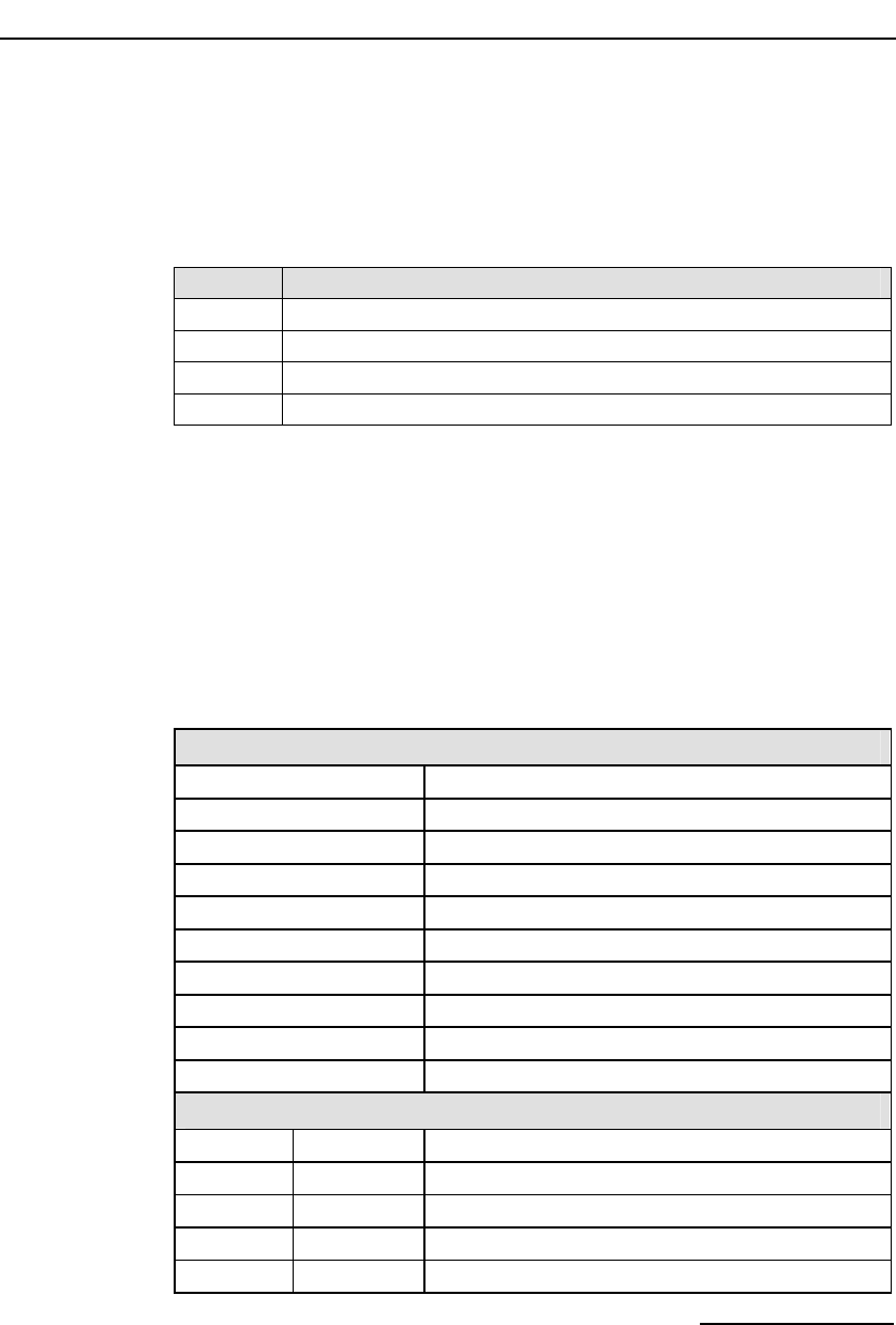
Dialogic® DSI SPCI Network Interface Boards Programmer's Manual Issue 5
43
Description
Event Type
This message is used to convey the status of a board reset operation (success
of failure) to the user. The status is indicated in the status field of the
message header. The following table shows the possible Event Type values:
Value Meaning
0x60 Reset successful
0x62 Board failure
0x66 License validation failure
0x67 License appears corrupt
6.2.4 Board Configuration Request
Synopsis:
Message sent to a board immediately after starting the code running to
provide protocol configuration parameters.
Note: When using s7_mgt, this message is generated by s7_mgt and must not be
generated by the user.
Message Format:
MESSAGE HEADER
Field Name Meaning
type MGT_MSG_CONFIG0 (0x7F10)
id 0
src Sending module's module_id
dst MGMT_TASK_ID (0x8e)
rsp_req used to request a confirmation
hclass 0
status Status Response (if confirmation requested)
err_info 0
len 68
PARAMETER AREA
Offset Size Name
0 2 config_type (Must be set to 2)
2 2 flags
4 2 l1_flags
6 2 l2_flags

6 Message Reference
44
PARAMETER AREA
8 2 max_sif_len
10 2 l3_flags
12 4 pc
16 2 ssf
18 2 up_enable
20 2 link0_flags
22 2 link0_slc
24 4 link0_adj_pc
28 2 link0_stream
30 2 link0_timeslot
32 2 link1_flags
34 2 link1_slc
36 4 link1_adj_pc
40 2 link1_stream
42 2 link1_timeslot
44 2 link2_flags
46 2 link2_slc
48 4 link2_adj_pc
52 2 link2_stream
54 2 link2_timeslot
56 2 link3_flags
58 2 link3_slc
60 4 link3_adj_pc
64 2 link3_stream
66 2 link3_timeslot
Description:
This message must be the first message sent to the DSI SPCI Board once the
SS7 software is running. It is used to configure all modules on the board for
operation. The message contains signaling point codes for this signaling point
and the adjacent signaling point(s), flags to permit various level 1, level 2,
and level 3 run-time options to be selected and the physical link parameters.
Once the DSI SPCI Board has been configured, you must reset it before
configuring it again.
The confirmation message (if requested) indicates success by status of zero.
To ensure configuration is complete before subsequent messages are issued
to the board, the user should always request a confirmation message and
check the status for success.

Dialogic® DSI SPCI Network Interface Boards Programmer's Manual Issue 5
45
If the board is not licensed to run the requested software configuration,
status value of 0xfe is returned.
Parameter Description:
flags - Global flags
Bit 0 is set to 1 to indicate that the user does not wish to use signaling
software. This allows operation of the board without a software license button
providing the board is used only for T1/E1 interface and switching purposes.
If signaling software is required, then this bit must be set to zero.
Bit 9 is set to 1 to disable automatic MTP route configuration, in which case
the user must send individual MTP Route Configuration messages for each
destination. When set to zero, the board automatically configures an MTP
route to each adjacent signaling point using the link set directly connected to
the signaling point.
Bit 10 is reserved for future use and must be set to 1.
Bit 12 is set to 1 to cause all signaling links to be automatically activated.
Usually, this bit is set to zero and the user sends individual MTP Link
Activation requests to activate each link.
Bit 15 is set to 1 for diagnostic purposes to cause the results of internal
board configuration to be passed to the host. When set, all confirmation
messages generated internally on the board during the configuration
sequence are sent to the module_id 0xdf on the host.
All other bits are reserved for future use and must be set to zero.
l1_flags - level 1 flags
Bit 0 controls the reference source used for on-board clocks when acting as
CT bus Primary Master. If set to 1, the clock is recovered from one of the line
interfaces. If set to zero, the on-board clock oscillator is used.
Bit 6 and 7 together select the initial CT bus clocking mode as shown in the
following table. The clocking mode can be modified subsequently and
dynamically using the MVD_MSG_CNFCLOCK message.
Bit 7 Bit 6 CT bus clocking mode
0 0 The CT bus interface is disabled - The board is electrically
isolated from the other boards using the CT bus. The CT bus
connection commands may still be used, but the connections made
are only visible to this board. The on-board clocks are synchronized
to the source selected by bit 0 of this flags parameter.
0 1 Primary Master, A Channel - The board drives CT bus clock set A
using the clock source selected by bit 0 of this flags parameter.
1 0 Secondary Master, B Channel - The board is configured to drive
clock set B in Secondary Master mode. The on-board clocks are
synchronized to the CT bus clock set A. It will automatically switch
to become Primary Master if the board driving clock set A fails.
1 1 Slave, initially A Channel – The board uses the CT bus clocks,
which must be generated by another board on the CT bus. Initially
the board recovers from clock set A, though will switch over
automatically to recover from clock set B if set A fails.

6 Message Reference
46
Bit 13 is set to 1 to cause the board to drive the CT_NETREF1 clocks on the
CT bus. The highest priority in-sync line interface is used as a clock source. If
this bit is set to zero then CT_NETREF1 clock is not driven.
All other bits are reserved and must be set to zero.
l2_flags - level 2 flags
Bit 1 is set to 1 for ANSI operation or zero for ITU-T operation.
Bit 3 is set to 1 for ANSI operation or zero for ITU-T operation.
Bit 5 is set to 1 to cause Link Status Signal Units (LSSU) to have a two octet
status field. Usually this bit is set to zero, and LSSUs have a single octet
status field.
All other bits are reserved for future use and must be set to zero.
max_sif_len - maximum Signaling Information Field length
The maximum Signaling Information Field length in octets that is permitted
over the signaling link. Usually set to 272 although it may be set to 62 for
inter-working with switches that do not support 272 octet messages.
l3_flags - level 3 flags
Bit 0 is set to 1 to disable the level 3 discrimination function (allowing the
signaling point to receive all messages irrespective of the destination point
code contained in the message) or zero to allow the discrimination function to
function normally.
Bit 1 is set to 1 to disable sub-service field (SSF) discrimination. If this bit is
set to zero, received MSUs whose ssf values do not match the configured ssf
value are discarded.
Bit 8 is set to 1 to select ANSI operation or zero for ITU-T operation.
Bit 9 is set to 1 to select ANSI style 24 bit point codes in the MTP routing
label or zero to select ITU-T style 14 bit point codes. This bit must be set to 1
if ANSI operation is selected.
Bit 10 is set to 1 for ANSI operation or zero for ITU-T operation.
Bit 11 is set to 1 for ANSI operation or zero for ITU-T operation.
All other bits are reserved for future use and must be set to zero.
Note: For ANSI operation bits 8, 9, 10, and 11 must all be set to 1.
pc - point code
The pure binary representation of this signaling point code. Must be in the
range 0 to 16383 for 14 bit point code operation, or 0 to 16777215 for 24 bit
point code operation.
ssf - sub-service field
The value used in the sub-service field of all messages generated by level 3.
Must be in the range 0 to 15. For ANSI operation, the 2 least significant bits
must be set to 1.

Dialogic® DSI SPCI Network Interface Boards Programmer's Manual Issue 5
47
up_enable - User Part Enable
A 16 bit mask used to enable or disable reception of messages on a per user
part basis. If bit N is set to 1, then messages for user part N are received by
the signaling point.
For example, to enable the TUP User Part (Service indicator = 4) set the
up_enable field to 0x0010, For ISUP (Service Indicator = 5), set the
up_enable field to 0x0020. To use both TUP and ISUP, set up_enable to
0x0030.
linkn_flags - Per link flags
Bit 0 is set to 1 to force the use of the emergency proving period during link
alignment. This bit is usually set to zero and uses the appropriate proving
period according to Q.703.
Bit 1 is set to 1 to cause a signaling link test (in accordance with ITU-T
Q.707) to be carried out before a link is put into service, or zero if a test is
not required. This bit is usually set to 1.
Bit 2 is set to 1 to cause a signaling link test (in accordance with ITU-T
Q.707) to be carried out every 30 seconds. This bit is usually set to 1, but is
ignored if Bit 1 is set to zero.
Bit 8 is used to select the MTP2 error correction mode. It is set to 1 to select
PCR (Preventive Cyclic Retransmission) operation, or zero for the Basic
Method of Error Correction.
Bits 10 and 11 are used to select the data rate for the link as detailed
below.
Bit 11 Bit 10 Data Rate
0 0 64kbps
1 1 56kbps
0 1 48kbps
Note: When using a serial port, 56 kbps and 48 kbps operation is only supported when
the clock is applied externally.
Bit 13 is only used when the link has been configured to run over a serial
port (i.e., bit 14 is set). If set to 1, an external clock is used (Receive clock).
If set to zero, an internal clock (Transmit clock) is used. If the link has not
been configured to run over a serial port, this bit must be set to zero.
Bit 14 is set to 1 to use a serial port, rather than a PCM timeslot for this link.
In this mode the stream and timeslot parameters for this link are ignored
(and must be set to zero). If this bit is set to zero, the link uses the specified
stream and timeslot. The serial port used by the signaling processors for each
link is fixed, according to the following table:
linkn Serial Port
0 B
1 A
2 Cannot be used for a serial port.
3 Cannot be used for a serial port.

6 Message Reference
48
Bit 15 is set to 1 to disable the link, or zero to enable the link.
All other bits are reserved for future use and must be set to zero.
linkn_slc - Signaling link code
The signaling link code for the link, which must be in the range 0 to 15. The
signaling link code must be agreed with the administration at the other end of
the link and must be unique within a link set. Usually, the first link in a link
set is assigned the value 0, the next 1, and so on.
linkn_adj_pc - Adjacent point code
The point code of the signaling point at the remote end of the link. Must be in
the range 0 to 16383 for 14 bit point code operation or 0 to 16777215 for 24
bit point code operation.
Note: All links in a link set must have the same adjacent point code.
linkn_stream - Signaling stream
When linkn_timeslot is set to a non-zero value, the linkn_stream is the logical
identity of the T1/E1 line interface (liu_id - in the range 0 to one less than the
number of LIUs fitted) containing the signaling link.
Note: For the SPCI2S, stream identifiers for the PCM interfaces are implemented on
streams 2 and 3.
linkn_timeslot - Signaling timeslot
The timeslot used for signaling. For an E1 interface, the valid range is
1 ... 31. For a T1 interface, the valid range is 1 ... 24. Alternatively, the
timeslot may be set to zero, and the switch path set up manually using the
switch control messages.
Status Response
The confirmation message (if requested) indicates success by status of zero.
On error, the following status value can be found in the confirmation
message.
Value Description
0xff The Board Configuration Request has failed.
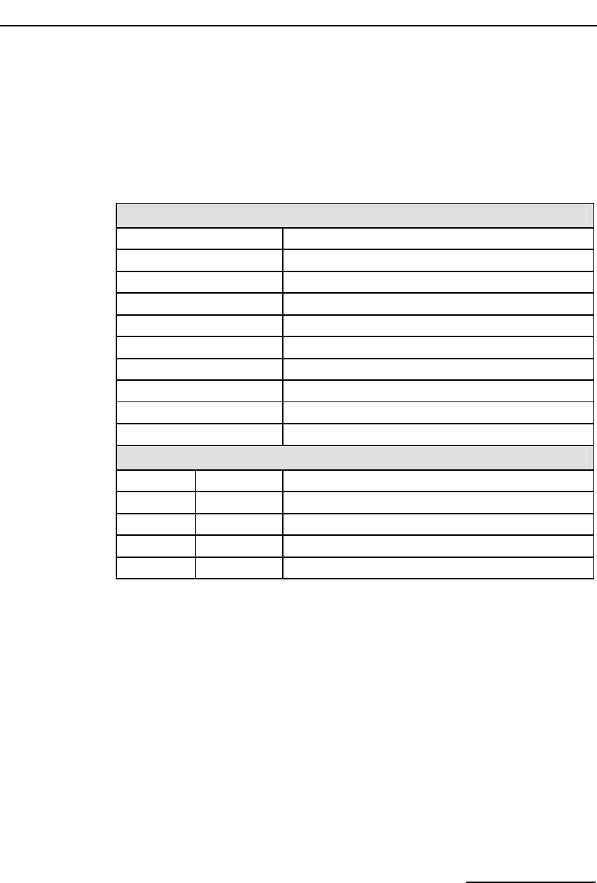
Dialogic® DSI SPCI Network Interface Boards Programmer's Manual Issue 5
49
6.2.5 General Module Identification Message
Synopsis:
Message used to request the module type and software revision number.
Message Format:
MESSAGE HEADER
Field Name Meaning
Type GEN_MSG_MOD_IDENT (0x6111)
Id 0
Src Sending module_id
Dst on-board management task (0x8e)
rsp_req used to request a confirmation
hclass 0
status Status Response – zero on success
err_info 0
len 28
PARAMETER AREA
Offset Size Name
0 2 reserved
2 1 maj_rev
3 1 min_rev
4 24 text
Description:
This message is provided to request a reply indicating the software version
for module under test. On receipt of this request, the module returns the
message with status "SUCCESS" to the sender including the information
requested.
Note: This message can be sent to the on-board management task to obtain the version
of the code file running on a live system.
Parameter Description:
maj_rev
Major revision identifier for the object being queried.
min_rev
Minor revision identifier for the object being queried.

6 Message Reference
50
text
Null terminated string giving textual module identity (e.g., "SS7.DC3").
6.2.6 Read Board Info Request Message
Synopsis
Message used to request basic board information. This message may be sent
to several Dialogic® DSI SS7 Boards, but only the parameters relevant to the
Dialogic® DSI SPCI Network Interface Boards are described below.

Dialogic® DSI SPCI Network Interface Boards Programmer's Manual Issue 5
51
Format
MESSAGE HEADER
Field Name Meaning
type MGT_MSG_R_BRDINFO (0x6f0d)
id 0
src Sending module_id
dst MGMT_TASK_ID (0x8e)
rsp_req used to request a confirmation
hclass 0
status Status Response (if confirmation requested)
err_info 0
len 60
PARAMETER AREA
Offset Size Name
0 1 board_type
1 1 board_rev
2 1 reserved
3 1 swa
4 1 swb
5 1 reserved
6 1 reserved
7 1 reserved
8 1 prom_maj_rev
9 1 prom_min_rev
10 8 esn
18 8 lsn
26 4 reserved
30 20 reserved
50 10 reserved
Parameter Description:
board_type
The DSI SPCI Board type. The table shows the possible values and their
meaning.
Value Mnemonic Meaning
2 BRDINFO_BTYPE_SPCI SPCI2S or SPCI4 board

6 Message Reference
52
board_rev
The DSI SPCI Board hardware revision number.
swa
The setting of the board's rotary switch labeled "Boot".
Note: The switch should be set to 8.
swb
Geographic addressing switch setting, that is, the address at which the board
appears when the -o3 feature of ssds is used.
prom_maj_rev
Firmware major revision number.
prom_min_rev
Firmware minor revision number.
esn
The board's electronic serial number.
lsn
License serial number. The serial number of the fitted license button.
Status Response
The confirmation message (if requested) indicates success by status of zero.
On error, the following status value can be found in the confirmation
message.
Value Mnemonic Description
0x01 None Invalid message length.

Dialogic® DSI SPCI Network Interface Boards Programmer's Manual Issue 5
53
6.3 Hardware Control Messages
6.3.1 LIU Configuration Request
Synopsis:
Message sent by the application to establish the operating mode for a Line
Interface Unit (LIU).
Note: When using s7_mgt, this message is generated by s7_mgt as a result of the
LIU_CONFIG command. It therefore does not need be generated by the user.
Message Format:
MESSAGE HEADER
Field Name Meaning
type LIU_MSG_CONFIG (0x7e34)
id liu_id
src Sending Module ID
dst MVD_TASK_ID (0x10)
rsp_req used to request a confirmation
hclass 0
status Status Response (if confirmation requested)0
err_info 0
len 40
PARAMETER AREA
Offset Size Name
0 1 liu_type
1 1 line_code
2 1 frame_format
3 1 crc_mode
4 1 build_out
5 1 faw
6 1 nfaw
7 4 Reserved for future use, must be set to zero.
11 1 ais_gen
12 1 rai_gen
13 1 Reserved for future use, must be set to zero.
14 4 clear_mask
18 22 Reserved for future use, must be set to zero

6 Message Reference
54
Description:
This message is sent to the DSI SPCI Board to configure the operating mode
a line interface unit. All configuration parameters must be supplied in the
message (it is not possible to modify individual operating parameters in
isolation). On receipt of the message the board first verifies that the fitted
hardware options support the requested operating mode and then initializes
(or re-initializes) the line interface unit.
The confirmation message (if requested) indicates success by status of zero.
Parameter Description:
A description of the permitted parameter values are given below. When the
DSI SPCI Board is initially configured all the line interfaces are initialized to a
disabled condition.
liu_type
The physical type of interface according to the following table: (note that this
must be selected by the user to be appropriate for the actual hardware fitted
otherwise an error status is returned). The preferred method for configuring
an E1 interface is to select liu_type=5.
liu_type Description
1 Disabled (used to deactivate a LIU). In this mode the LIU does not produce
an output signal.
2 E1 75ohm unbalanced interface (for future use).
3 E1 120ohm balanced interface.
4 T1
5 E1 75ohm or 120ohm setting based on fitted hardware.
line_code
The line coding technique taken from the following table:
line_code Description
1 HDB3 (E1 only).
2 AMI with no Zero Code Suppression.
3 AMI with Zero Code Suppression (The appropriate bit in the clear_mask
parameter may be set to disable Zero Code Suppression for individual
timeslots if required.) (T1 only).
4 B8ZS (T1 only).
frame_format
The frame format taken from the following table:
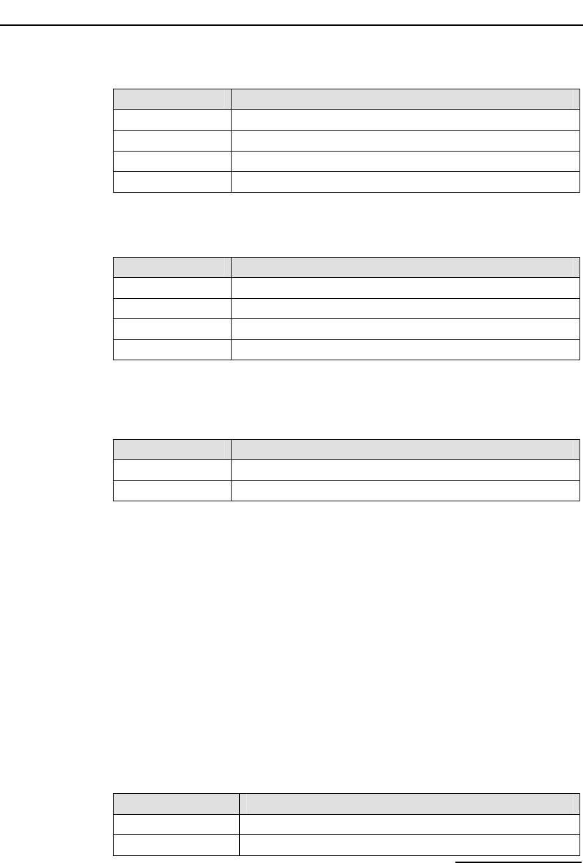
Dialogic® DSI SPCI Network Interface Boards Programmer's Manual Issue 5
55
frame_format Description
1 E1 double frame (E1 only).
2 E1 CRC4 multiframe (E1 only).
4 D3/D4 (Yellow alarm = bit 2 in each channel) (T1 only).
7 ESF (Yellow alarm in data link channel) (T1 only).
crc_mode
The CRC mode taken from the following table:
crc_mode Description
1 CRC generation disabled.
2 CRC4 enabled (frame_format must be set to 2).
3 CRC4 compatibility mode (frame_format must be set to 2).
4 CRC6 enabled (frame_format must be set to 7).
build_out
Configurable line build out is not supported by the board, so the following
fixed values must be used.
Build_out Description
0 Setting for E1 devices.
1 Setting for T1 devices.
faw
The 8 bit value to be used for any E1 frame alignment word bit positions that
are not modified by other options. This allows the spare bit designated "For
International Use" to be set by the user when CRC4 mode is disabled. Valid
values are 0x9b or 0x1b. When using T1, this parameter must be set to zero.
[E1 default = 0x9b].
nfaw
The 8 bit value to be used for any E1 non-frame alignment word bit positions
that are not modified by other options. Normally, this parameter is set to
0x9f for E1 operation and set to zero for T1.
ais_gen
The (initial) mode used to generate the Alarm Indication Signal (Blue Alarm)
taken from the following table. The user may subsequently modify the setting
of the outgoing signal using the LIU_MSG_CONTROL message.
ais_gen Description
1 Disabled - do not generate AIS / Blue alarm.
2 Enabled - generate AIS / Blue alarm.

6 Message Reference
56
rai_gen
The (initial) mode used to generate the Remote Alarm Indication (Yellow
Alarm) taken from the following table. The user may subsequently modify the
setting of the outgoing RAI alarm using the LIU_MSG_CONTROL message.
rai_gen Description
1 Disabled - do not generate RAI / Yellow alarm.
2 Forced active - generate RAI / Yellow alarm.
3 Automatic generation of RAI / Yellow alarm upon loss of
synchronization.
clear_mask
For use with T1 interfaces and line_code mode 3 (AMI with Zero Code
Suppression) to disable zero code suppression on selected channels. This
parameter is a 32 bit mask. Zero code suppression may be disabled for the
signaling channel timeslot by setting the appropriate bit in the mask. The
least significant bit corresponds to timeslot 0 and the most significant bit to
timeslot 31. Bits are set to 1 to disable zero code suppression.
Status Response
The confirmation message (if requested) indicates success by status of zero.
On error, the following status values can be found in the confirmation
message.
Value Mnemonic Description
0x01 None Invalid framer ID.
0x02 None Invalid message length.

Dialogic® DSI SPCI Network Interface Boards Programmer's Manual Issue 5
57
6.3.2 LIU Control Request
Synopsis:
Message sent by the application to dynamically control operation for a Line
Interface Unit (LIU). Allows setting of outgoing alarms and diagnostic
loopbacks.
Message Format:
MESSAGE HEADER
Field Name Meaning
type LIU_MSG_CONTROL (0x7e35)
id liu_id
src Sending Module ID
dst MVD_TASK_ID (0x10)
rsp_req used to request a confirmation
hclass 0
status Status Response (if confirmation requested)
err_info 0
len 16
PARAMETER AREA
Offset Size Name
0 1 ais_gen
1 1 rai_gen
2 1 loop_mode
3 13 Reserved for future use, must be set to zero.
Description:
This message is sent to the DSI SPCI Board to perform dynamic changes to
the operation of the Line Interface Unit. It allows the user to control
generation of AIS (Blue alarm) and RAI (Yellow alarm) and to activate various
diagnostic loopback modes.
The confirmation message (if requested) indicates success by status of zero.
Parameter Description:
ais_gen
The mode used to generate the Alarm Indication Signal (Blue Alarm) taken
from the following table:
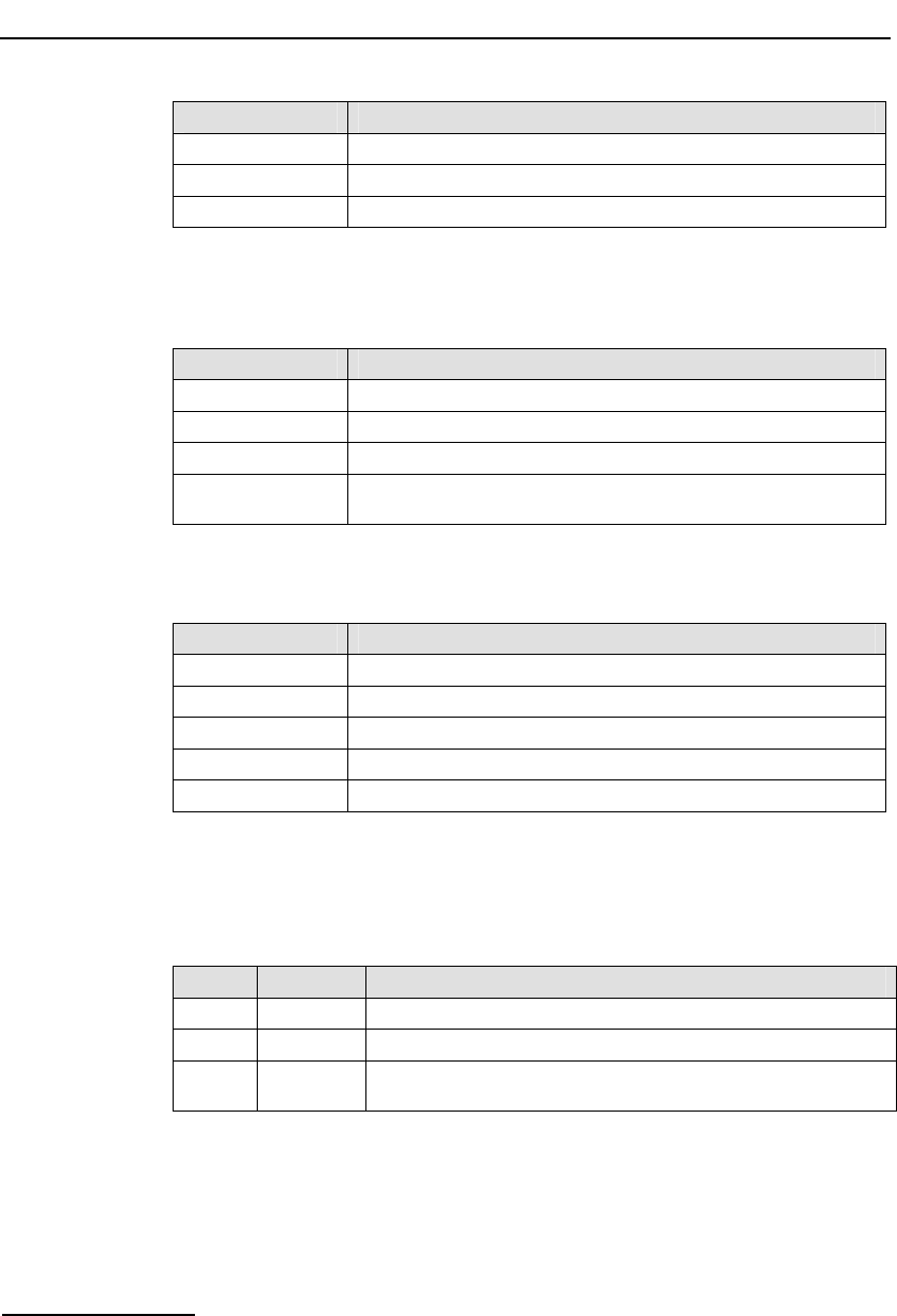
6 Message Reference
58
ais_gen Description
0 Do not change AIS / Blue alarm generation mode.
1 Disabled - do not generate AIS / Blue alarm.
2 Enabled - generate AIS / Blue alarm.
rai_gen
The mode used to generate the Remote Alarm Indication (Yellow Alarm)
taken from the following table:
rai_gen Description
0 Do not change RAI / Yellow alarm generation mode.
1 Disabled - do not generate RAI / Yellow alarm.
2 Forced active - generate RAI / Yellow alarm.
3 Automatic generation of RAI / Yellow alarm upon loss of
synchronization.
loop_mode
The diagnostic loop back mode taken from the following table:
loop_mode Description
0 Do not change diagnostic loop back mode.
1 Disabled - remove any diagnostic loop.
2 Payload loopback.
3 Remote loopback.
4 Local loopback.
Status Response
The confirmation message (if requested) indicates success by status of zero.
On error, the following status values can be found in the confirmation
message.
Value Mnemonic Description
0x01 None Invalid framer ID.
0x02 None Invalid message length.
0x03 None Control parameters are not consistent with the type of device being
controlled or with each other.

Dialogic® DSI SPCI Network Interface Boards Programmer's Manual Issue 5
59
6.3.3 LIU Read Configuration Request
Synopsis:
Message sent by the application to read back the current LIU configuration
from the DSI SPCI Board.
Message Format:
MESSAGE HEADER
Field Name Meaning
type LIU_MSG_R_CONFIG (0x5e37)
id liu_id
src Sending Module ID
dst MVD_TASK_ID (0x10)
rsp_req used to request a confirmation
hclass 0
status Status Response (if confirmation requested)
err_info 0
len 40
PARAMETER AREA
Offset Size Name
0 40 Parameter area formatted as for the LIU_MSG_CONFIG
message. The user should set the fields to zero and the
module writes the current configuration parameters in the
confirmation message.
Description:
This message is sent to the DSI SPCI Board to read back the current
operating configuration of the Line Interface Unit.
The user should always request a confirmation message. This indicates
success by status of zero, and contains the current configuration parameters
in the parameter area of the message.
Status Response
The confirmation message (if requested) indicates success by status of zero.
On error, the following status value can be found in the confirmation
message.

6 Message Reference
60
Value Mnemonic Description
0x01 None Invalid framer ID.
0x02 None Invalid message length.
0x03 None Control parameters are not consistent with the type of
device being controlled or with each other.
6.3.4 LIU Read Control Request
Synopsis:
Message sent by the application to read back the current LIU control options
from the DSI SPCI Board.
Message Format:
MESSAGE HEADER
Field Name Meaning
type LIU_MSG_R_CONTROL (0x5e38)
id liu_id
src Sending Module ID
dst MVD_TASK_ID (0x10)
rsp_req used to request a confirmation
hclass 0
status Status Response (if confirmation requested)
err_info 0
len 16
PARAMETER AREA
Offset Size Name
0 16 Parameter area formatted as for the LIU_MSG_CONTROL
message. The user should set the fields to zero and the
module writes the current control parameters in the
confirmation message.
Description:
This message is sent to the DSI SPCI Board to read back the current control
parameters selected for the Line Interface Unit.
The user should always request a confirmation message. This indicates
success by status of zero and contains the current control parameters in the
parameter area of the message.

Dialogic® DSI SPCI Network Interface Boards Programmer's Manual Issue 5
61
Status Response
The confirmation message (if requested) indicates success by status of zero.
On error, the following status value can be found in the confirmation
message.
Value Mnemonic Description
0x01 None Invalid framer ID.
0xff None Invalid message length.
6.3.5 LIU State Request
Synopsis:
Message sent by the application to read the current state of a Line Interface
Unit (LIU).
Message Format:
MESSAGE HEADER
Field Name Meaning
type LIU_MSG_R_STATE (0x5e39)
id liu_id
src Sending Module ID
dst MVD_TASK_ID (0x10)
rsp_req used to request a confirmation
hclass 0
status Status Response (if confirmation requested)
err_info 0
len 1
PARAMETER AREA
Offset Size Name
1 1 state
Description:
This message is sent to the DSI SPCI Board to read the current operating
state of a Line Interface Unit.
The user should always request a confirmation message. This indicates
success by status of zero and contains the current state in the parameter
area of the message.
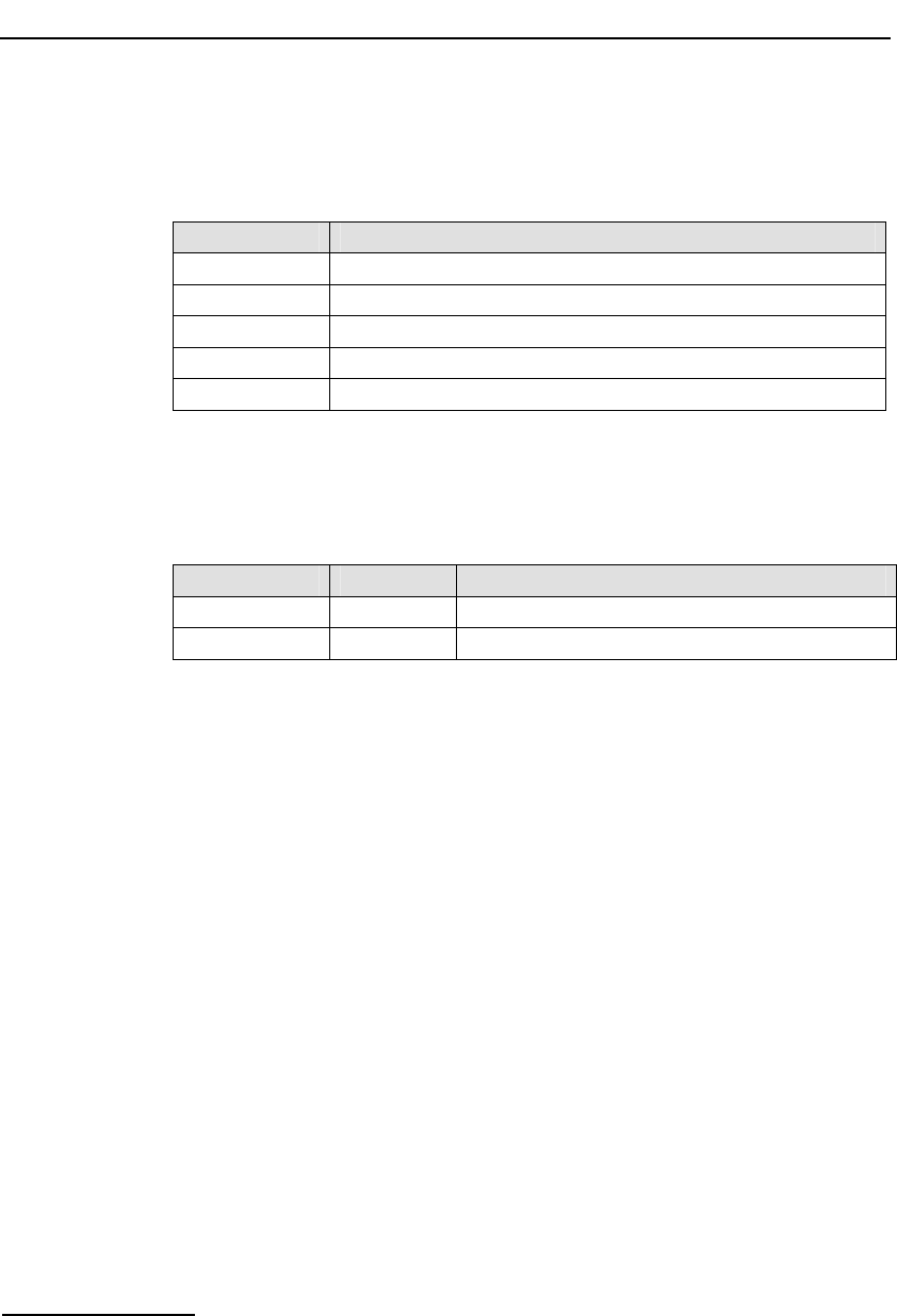
6 Message Reference
62
Parameter Description:
state
The current state of the LIU from the following table:
State Description
0 OK
1 PCM Loss
2 AIS
3 Sync Loss
4 Remote Alarm
Status Response
The confirmation message (if requested) indicates success by status of zero.
On error, the following status values can be found in the confirmation
message.
Value Mnemonic Description
0x01 None Invalid framer ID.
0xff None Invalid message length.
6.3.6 LIU CT bus Initialization Request
Synopsis:
This message is sent to the board at initialization time to set up a static
switch path through the board between the Line Interface Unit (LIU) and the
CT bus. It connects selected incoming voice timeslots from a T1/E1 LIU to a
sequential block of channels on the CT bus and prepares the outgoing
timeslots for subsequent use by the MVD_MSG_SC_LISTEN message.
Note: When using s7_mgt, this message is generated by s7_mgt as a result of the
LIU_SC_DRIVE command. It therefore does not need be generated by the user.

Dialogic® DSI SPCI Network Interface Boards Programmer's Manual Issue 5
63
Message Format:
MESSAGE HEADER
Field Name Meaning
type MVD_MSG_SC_DRIVE_LIU (0x7e18)
id 0
src Sending Module ID
dst MVD_TASK_ID (0x10)
rsp_req used to request a confirmation
hclass 0
status Status Response (if confirmation requested)
err_info 0
len 10
PARAMETER AREA
Offset Size Name
0 2 liu_id
2 2 sc_channel
4 4 ts_mask
8 2 mode
Parameter Description:
liu_id
The identifier of the T1/E1 Line Interface Unit in the range 0 to one less than
the number of LIUs fitted. This parameter can also be set to the special value
0x83 to select the signaling processor instead of an LIU. In this case timeslots
0 ... 3 correspond to signaling processor 0 ... 3 respectively.
sc_channel
The channel number of the first channel to be used on the CT bus. This must
be in the range from 0 up to one less than the total number of channels on
the CT bus.
ts_mask
A 32 bit timeslot mask where each bit position is set to 1 if the corresponding
timeslot on the T1/E1 interface is required to be connected to the CT bus. The
least significant bit (bit 0) represents timeslot 0. Each timeslot for which the
corresponding bit is set in ts_mask is connected up to the CT bus, other
timeslots are not affected in any way.

6 Message Reference
64
Timeslots containing SS7 signaling processed by the signaling processor on
the DSI SPCI Board should not be included in the timeslot mask. Usually, the
mask should be set to include all bearer (voice) timeslots but no signaling
timeslots. Bit 0 (corresponding to timeslot 0 on the LIU) must not be set as
timeslot 0 for an E1 interface contains synchronization information whilst
timeslot 0 for a T1 interface does not exist.
As an example, for an E1 interface with SS7 signaling on timeslot 16, and the
remaining 30 timeslots used for voice circuits, ts_mask should be set to value
0xfffefffe. For a T1 interface with signaling on timeslot 24, ts_mask must be
set to value 0x00fffffe.
mode
This parameter controls how the CT bus channels are allocated. Usually,
(mode=1) the first timeslot connected to the CT bus is connected to
sc_channel and each subsequent timeslot that is selected is connected to
the next CT bus channel. This allows maximum utilization of channels on the
CT bus.
An alternative mode (mode=2) (only used if there is a specific requirement
for it) associates (but does not necessarily connect) timeslot 0 on the LIU
with sc_channel and subsequent timeslots on the LIU with subsequent CT
bus channels. Connections are only made when the corresponding bit in the
timeslot mask is set to 1. This mode of operation preserves the spacing
between timeslots that was originally found on the T1/E1 interface but does
result in a number of CT bus channels being not used.
Status Response
The confirmation message (if requested) indicates success by status of zero.
On error, the following status value can be found in the confirmation
message.
Value Mnemonic Description
0xff None Setup failed

Dialogic® DSI SPCI Network Interface Boards Programmer's Manual Issue 5
65
6.3.7 CT bus Listen Request
Synopsis:
Message sent to the DSI SPCI Board to establish a connection from the CT
bus to an outgoing timeslot on an T1/E1 Line Interface Unit (LIU).
Message Format:
MESSAGE HEADER
Field Name Meaning
type MVD_MSG_SC_LISTEN (0x7e17)
id 0
src Sending Module ID
dst MVD_TASK_ID (0x10)
rsp_req Used to request a confirmation
hclass 0
status Status Response (if confirmation requested)
err_info 0
len 6
PARAMETER AREA
Offset Size Name
0 2 liu_id
2 2 timeslot
4 2 sc_channel
Description:
This message is sent to the DSI SPCI Board to establish a connection from
the CT bus to an outgoing timeslot on the T1/E1 Line Interface Unit (LIU). It
is issued by the application and is typically used at the start of each call
although it may also be issued during a call to connect to a different resource.
Correct operation of this message is dependent upon the use, at initialization
time, of the MVD_MSG_SC_DRIVE_LIU message (or the LIU_SC_DRIVE
command in config.txt when using s7_mgt).
When a new call arrives the application uses this message to connect the
appropriate resource from the CT bus out to the network. When the call
finishes, the application uses the MVD_MSG_SC_FIXDATA message to
generate the appropriate IDLE pattern on the LIU.
The MVD_MSG_SC_LISTEN message can also be generated at configuration
time using s7_mgt as a result of the SCBUS_LISTEN command in the
config.txt file. However, this only sets up a static configuration and still
requires the user application to control any dynamic connections.

6 Message Reference
66
Parameter Description:
liu_id
The identifier of the T1/E1 Line Interface Unit in the range 0 to one less than
the number of LIUs fitted. This parameter can also be set to the special value
0x83 to select the signaling processor instead of an LIU. In this case,
timeslots 0 ... 3 correspond to signaling processor 0 ... 3 respectively.
Note: For the SPCI2S, valid values for the LIU identifiers are 2 and 3.
timeslot
The timeslot number on the T1/E1 line interface unit on which the data from
the CT bus is transmitted. The valid range for timeslot is 1 to 31 for an E1
interface and 1 to 24 for a T1 interface.
sc_channel
The channel number on the CT bus to which the LIU listens. This must be in
the range 0 to one less than the total number of channels on the CT bus.
Status Response
The confirmation message (if requested) indicates success by status of zero.
On error, the following status values can be found in the confirmation
message.
Value Mnemonic Description
0xd2 MVIP_INVALID_STREAM Invalid stream specified in listen request.
0xd3 MVIP_INVALID_TIMESLOT Invalid timeslot specified in listen request.
0xff None Invalid message length.

Dialogic® DSI SPCI Network Interface Boards Programmer's Manual Issue 5
67
6.3.8 Fixed Data Output Request
Synopsis:
Message sent to the DSI SPCI Board in order to generate a fixed pattern on a
specific T1/E1 Line Interface Unit timeslot.
Message Format:
MESSAGE HEADER
Field Name Meaning
type MVD_MSG_SC_FIXDATA (0x7e15)
id 0
src Sending Module ID
dst MVD_TASK_ID (0x10)
rsp_req Used to request a confirmation
hclass 0
status Status Response (if confirmation requested)
err_info 0
len 6
PARAMETER AREA
Offset Size Name
0 2 liu_id
2 2 timeslot
4 2 pattern
Description:
This message is sent to the DSI SPCI Board in order to generate a fixed
pattern on a specific timeslot of an T1/E1 Line Interface Unit. It is typically
issued at initialization and whenever a call terminates to generate an IDLE
pattern towards the network.
Parameter Description:
liu_id
The identifier of the T1/E1 Line Interface Unit in the range 0 to one less than
the number of LIUs fitted.
Note: For the SPCI2S, valid values for the LIU identifiers are 2 and 3.
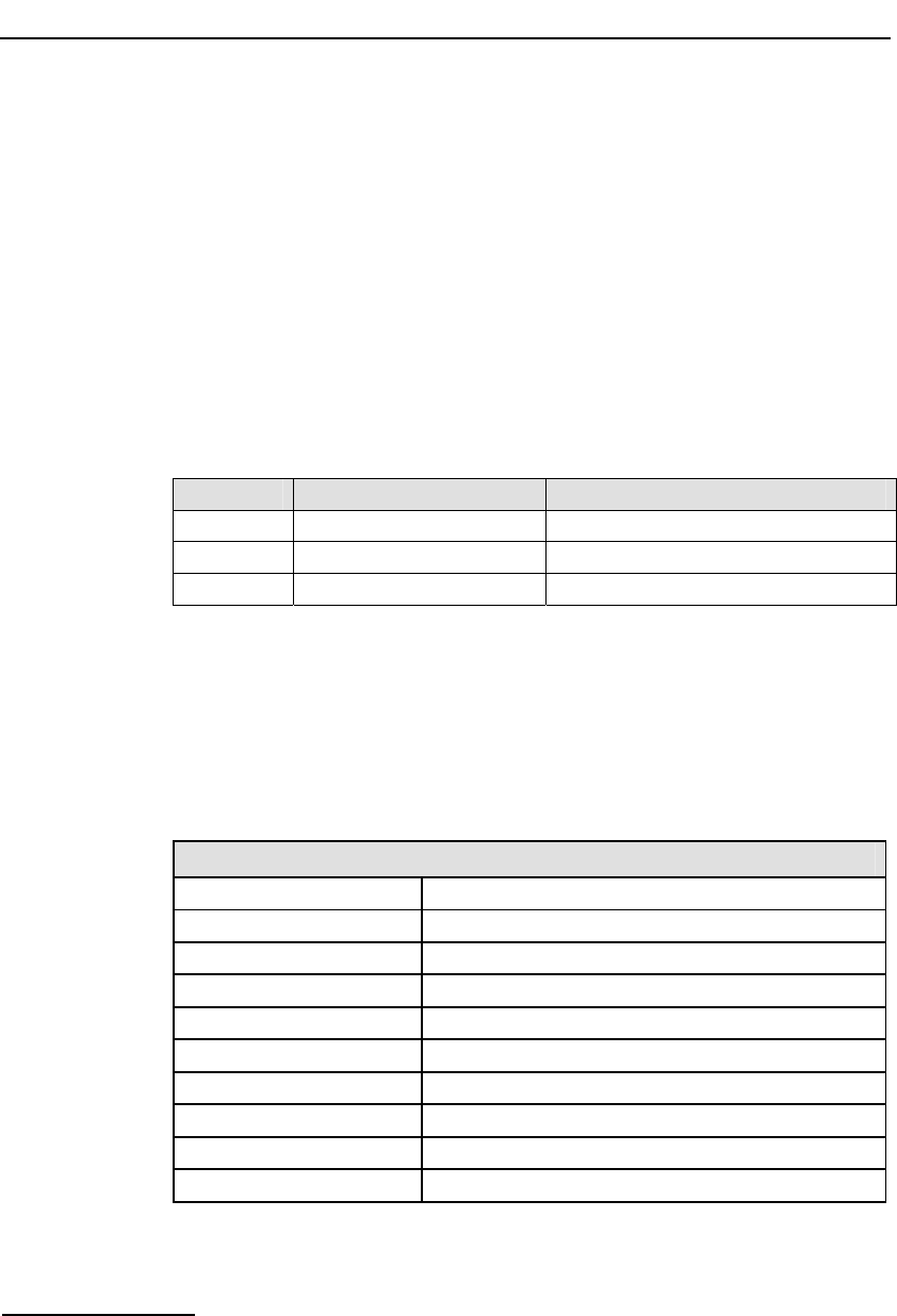
6 Message Reference
68
timeslot
The timeslot number on the T1/E1 line interface unit on which the fixed data
is transmitted. The valid range for timeslot is 1 to 31 for an E1 interface and
1 to 24 for a T1 interface.
pattern
The value of the fixed data to be generated. The value must be in the range 0
to 255. Typical values are 0xff for an "all ones" idle pattern, or 0x2a for an
ITU-T E1 idle pattern.
Status Response
The confirmation message (if requested) indicates success by status of zero.
On error, the following status values can be found in the confirmation
message.
Value Mnemonic Description
0xd2 MVIP_INVALID_STREAM Invalid stream specified in listen request.
0xd3 MVIP_INVALID_TIMESLOT Invalid timeslot specified in listen request.
0xff None Fixed pattern generation request failed.
6.3.9 Reset Switch Request
Synopsis:
Resets the digital switch to its default state in accordance with the current
board configuration.
Message Format:
MESSAGE HEADER
Field Name Meaning
type MVD_MSG_RESETSWX (0x7e00)
id 0
src Sending Module ID
dst MVD_TASK_ID (0x10)
rsp_req used to request a confirmation
hclass 0
status 0
err_info 0
len 0

Dialogic® DSI SPCI Network Interface Boards Programmer's Manual Issue 5
69
Description:
This message is sent to the DSI SPCI Board to reset the state of the digital
cross connect switch in accordance with the configuration set using the DSI
SPCI Board configuration message. All CT bus streams are tri-stated leaving
just switch paths established using the board configuration message (i.e.,
signaling timeslots) in place.
The confirmation message (if requested) indicates success by status of zero.
On receipt of the confirmation message the operation to reset the switch has
completed.
Status Response
The confirmation message (if requested) indicates success by status of zero.
No error status values are defined.
6.3.10 CT bus Connect Request
Synopsis:
Message sent to the DSI SPCI Board to control the switch path through the
CT bus switch.
Note: This message provides an alternative approach for controlling switching through
the CT bus switch allowing connections to the CT bus to be utilized only as
required (rather than being set up at initialization time).

6 Message Reference
70
Message Format:
MESSAGE HEADER
Field Name Meaning
type MVD_MSG_SC_CONNECT (0x7e1f)
id 0
src Sending Module ID
dst MVD_TASK_ID (0x10)
rsp_req used to request a confirmation
hclass 0
status Status Response (if confirmation requested)
err_info 0
len 16
PARAMETER AREA
Offset Size Name
0 2 local_stream
2 2 local_slot
4 2 mode
6 2 source_stream
8 2 source_slot
10 2 dest_stream
12 2 dest_slot
14 2 pattern
Description:
This message is sent to the DSI SPCI Board to control the CT bus switch.
Several different actions can be performed depending on the value of the
mode parameter, these are CT bus to local bus connection, local bus to CT
bus connection, duplex connection between CT bus, and local bus and duplex
connection between local bus timeslots.
The confirmation message (if requested) indicates success by status of zero.
Parameter Description:
The following table depicts which parameters are required for each of the
seven different modes. (* = parameter is required)
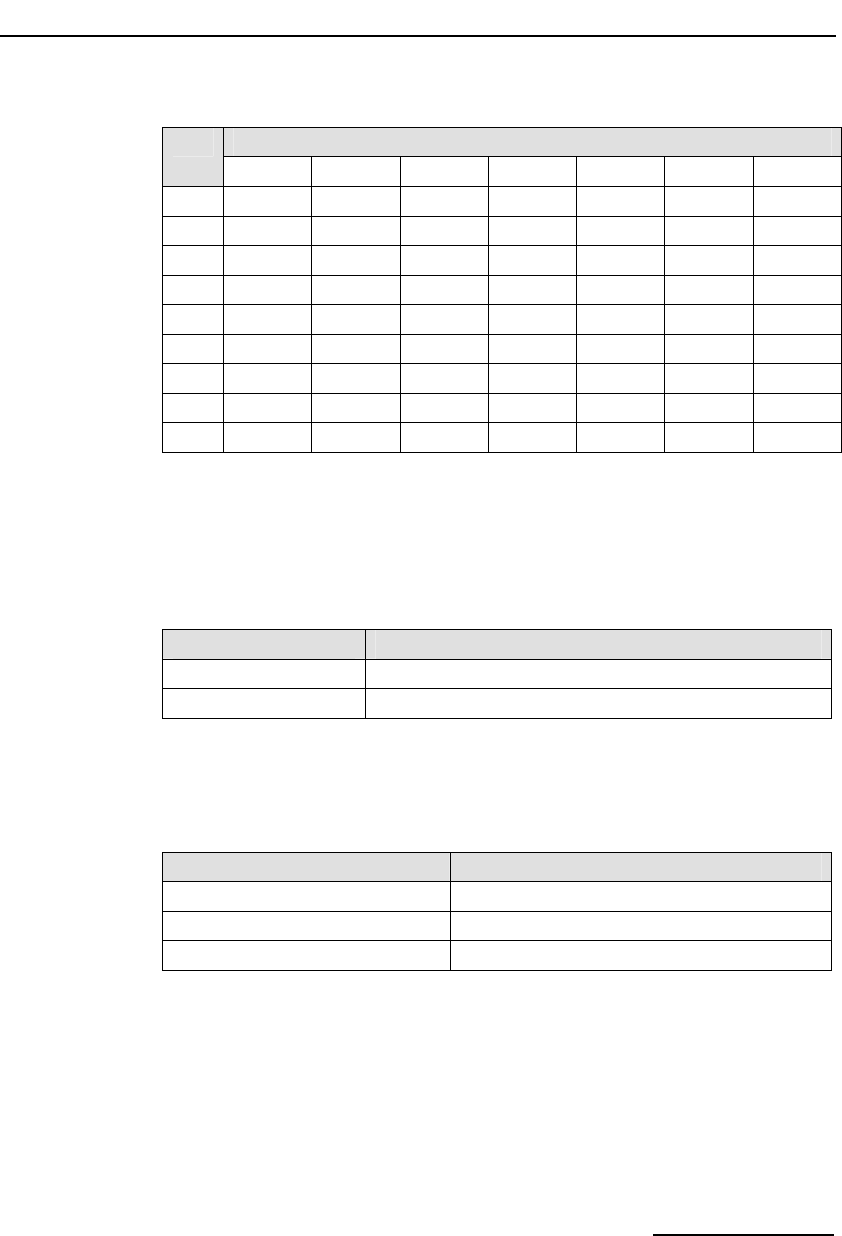
Dialogic® DSI SPCI Network Interface Boards Programmer's Manual Issue 5
71
Mode Required Parameters
local st local ts source st source ts dest st dest ts pattern
1 * * * *
2 * * * *
3 * * * * * *
4 * *
5 * *
6 * *
10 * * *
11 * * * *
12 * * * *
If a parameter is not required, it must be set to zero.
local_stream
The local stream defines which local stream to use for all the modes of
operation. The local streams are either an liu_id or a special identifier to allow
connection to the signaling processor as follows:
Local Stream Connected to
0 ... 3 liu_id 0 ... 3
131 (0x83) Signaling Processor
local_slot
The local slot defines which timeslot on the local stream to use for all the
modes of operation. The local slot value has the following valid ranges
depending on the type of local stream:
Local Stream Type Local Slot Range
Local stream to E1 LIU 1 … 31
Local stream to T1 LIU 1 … 24
Local stream to signaling processor 0 … 3
mode
The value of the mode parameter determines which of the following
operations to perform.
mode = 1 : Make a simplex connection from a timeslot on the CT bus to a
timeslot on the local bus. Using parameters local_stream, local_slot,
source_stream and source_slot, to specify the local and CT bus timeslots
respectively.

6 Message Reference
72
mode = 2 : Make a simplex connection from a timeslot on the local bus to a
timeslot on the CT bus. Using parameters local_stream, local_slot,
dest_stream and dest_slot, to specify the local and CT bus timeslots
respectively.
mode = 3 : Make a duplex connection between a local stream timeslot and 2
CT bus timeslots. Using parameters local_stream, local_slot, source_stream
and source_slot, to specify one simplex connection and local_stream,
local_slot, dest_stream and dest_slot, to specify the other simplex
connection.
mode = 4 : Remove a simplex connection from a timeslot on the CT bus to a
timeslot on the local bus. Using parameters local_stream and local_slot, to
specify the timeslot for disconnection.
mode = 5 : Remove a simplex connection from a timeslot on the local bus to
a timeslot on the CT bus. Using parameters local_stream and local_slot, to
specify the timeslot for disconnection.
mode = 6 : Remove a duplex connection between 2 timeslots on the CT bus
and 1 timeslot on the local bus. Using parameters local_stream and
local_slot, to specify both timeslots for disconnection.
mode = 10 : Generate a fixed pattern (e.g., idle pattern) on a local timeslot.
local_stream specifies the liu_id, local_slot the timeslot, and pattern the 8 bit
data to be output on the timeslot.
mode = 11 : Make a simplex connection between two local bus timeslots
(without using the CT bus). In this case, source_stream and source_slot
specify the source of the signal in terms of liu_id and timeslot respectively.
local_stream and local_slot specify the outgoing timeslot.
mode = 12 : Make a duplex connection between two local bus timeslots
(without using the CT bus). In this case, source_stream and source_slot
specify one timeslot in terms of liu_id and timeslot, whilst local_stream and
local_slot specify the other timeslot.
source_stream
The source stream references which of the CT bus streams is used as a
source of data. The parameter takes values in the range 0 … 31. For some
modes (e.g., 11 and 12), this field is used to specify a local_stream instead of
a CT bus stream.
source_slot
The source slot references the CT bus timeslot from which to connect or
disconnect to the local stream. The source slot value has the following ranges
depending on the CT bus speed.
CT bus speed Source Slot Range
4 Mbps 0 ... 63
8 Mbps 0 … 128
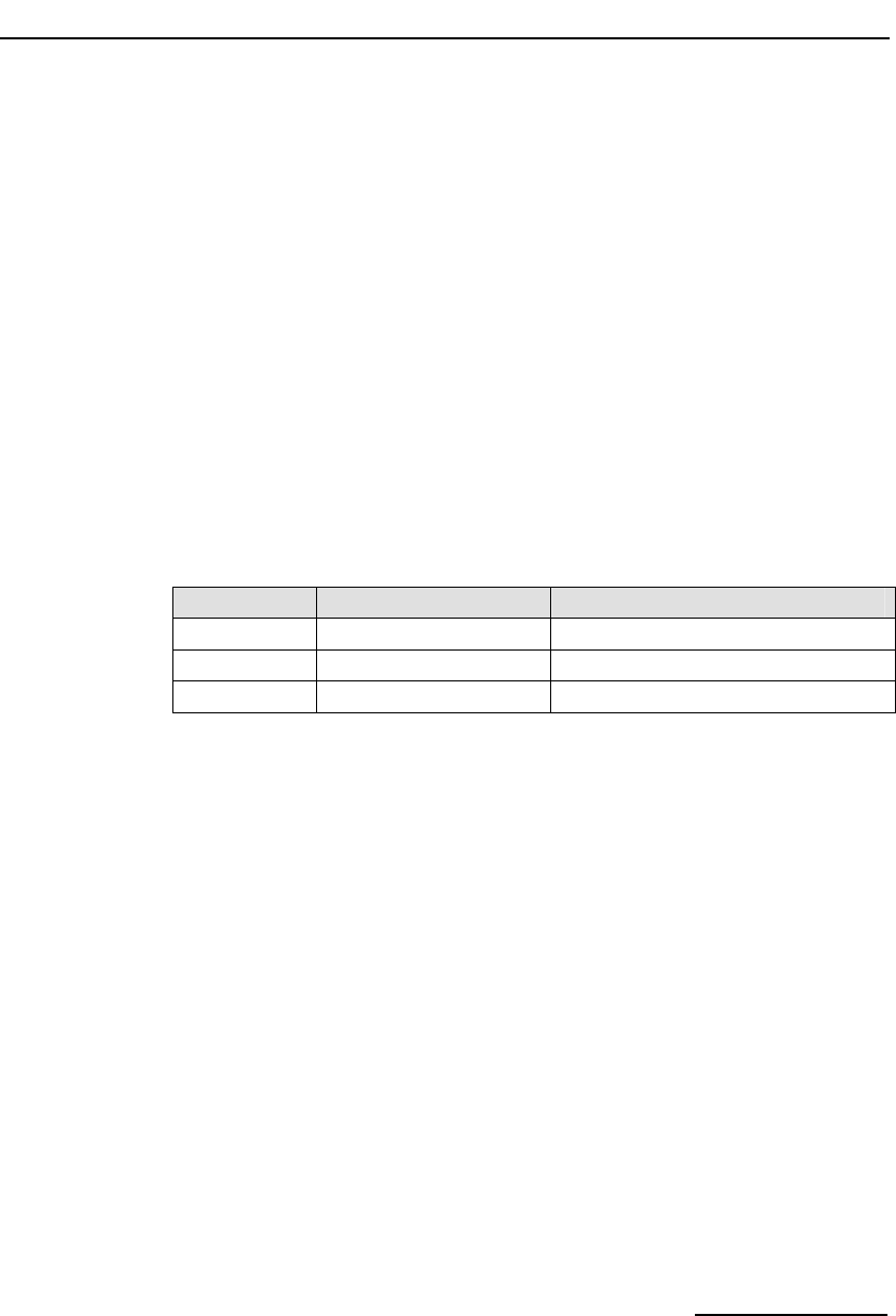
Dialogic® DSI SPCI Network Interface Boards Programmer's Manual Issue 5
73
dest_stream
The destination stream references which of the CT bus streams is used as a
destination for the data. The parameter takes values in the range 0…31.
dest_slot
The destination slot references the CT bus timeslot to which a local stream
timeslot can be connected or disconnected. The destination slot value has the
same range as the source slot.
pattern
The value of the fixed data to be generated. The value must be in the range 0
to 255. Typical values are 0xff for an "all ones" idle pattern, or 0x2a for an
ITU-T E1 idle pattern.
Status Response
The confirmation message (if requested) indicates success by status of zero.
On error, the following status values can be found in the confirmation
message.
Value Mnemonic Description
0xd2 MVIP_INVALID_STREAM Invalid stream specified in listen request.
0xd3 MVIP_INVALID_TIMESLOT Invalid timeslot specified in listen request.
0xff None Invalid message length.

6 Message Reference
74
6.3.11 Configure Clock Request
Synopsis:
Message sent to a DSI SPCI Board to configure the clocking mode for the
board.
Message Format:
MESSAGE HEADER
Field Name Meaning
type MVD_MSG_CNFCLOCK (0x7e20)
id 0
src Sending Module ID
dst MVD_TASK_ID
rsp_req used to request a confirmation
hclass 0
status Status Response (if confirmation requested)
err_info 0
len 8
PARAMETER AREA
Offset Size Name
0 2 bus_speed
2 2 clk_mode
4 2 pll_clk_src
6 2 ref1_mode
8 2 Reserved. Set to zero
Description:
This message is used to control the on-board clock circuitry. It allows the
user to select the CT bus clocking mode and the reference clock sources for
the local and bus reference clocks.
The confirmation message (if requested) indicates success by status of zero.
Parameter Description:
bus_speed
This parameter is used to set the CT bus speed; the permissible values are as
follows:

Dialogic® DSI SPCI Network Interface Boards Programmer's Manual Issue 5
75
Value Bus speed
0 No change
2 4.096 MHz (Reserved for future use)
3 8.192 MHz
clk_mode
This parameter determines the clocking mode for the DSI SPCI Board, the
permissible values are as follows:
Value Clock Mode
0 No change
1 CT bus Primary Master, driving Clock Set A
2 CT bus Secondary Master, driving Clock Set B
3 CT bus Slave, initially using Clock Set A
4 CT bus disabled
10 CT bus Primary Master, driving Clock Set B
11 CT bus Secondary Master, driving Clock Set A
12 CT bus Slave, initially using Clock Set B
When mode 4 is selected ("CT bus disabled"), the DSI SPCI Board is
electrically isolated from the other boards using the CT bus. The CT bus
connection commands may still be used, but the connections made are only
visible to this board. The on-board clocks are synchronized to the configured
pll_clk_src reference.
If the DSI SPCI Board is configured to be Slave to the CT bus, then it
automatically switches between using Clock Set A and Clock Set B if it detects
a failure on the current clock set.
When a board is acting as Primary Master, it uses the clock reference set by
the pll_clk_src parameter to drive the CT bus clock.
As Secondary Master, the pll_clk_src must be set to an appropriate source
ready for use if the board acting as Primary Master stops driving the CT bus
clock. Until this time, the on-board clocks on the Secondary Master board are
synchronized to the CT bus clock provided by the Primary Master.
pll_clk_src
This parameter determines the source of the PLL reference clock, the
permissible values are:
Value PLL Clock Source
0 No change
1 Clock recovered from one of the line interfaces according to priority
order.
5 Local reference oscillator
7 NETREF 1

6 Message Reference
76
The PLL clock is used as the reference when acting as CT bus Primary Master.
If the clock is to be recovered from one of the line interfaces then the
highest-priority in sync line interface is used as the reference. Each line
interface is assigned a priority: by default liu_id=0 is the highest priority and
liu_id=7 the lowest. The user may modify the priority order by sending the
MVD_MSG_CLOCK_PRI message. If none of the interfaces are available for
recovery, then the phase locked loop runs in holdover mode, outputting a
clock with the same frequency as the last valid signal. When a valid signal
returns, it waits for a short period to verify that it is stable and then
automatically switches to use it as the clock reference.
If using one of the NETREF signals as the reference source, then another
board in the system must be providing this reference by driving a clock
source onto the appropriate CT bus NETREF lines. If the NETREF signal is lost,
the board continues with the PLL in holdover mode until another
MVD_MSG_CNFCLOCK message is received to switch to a new mode.
Note: If the NETREF signal recovers, it is still necessary to re-set the clock configuration
and move out of holdover mode by sending MVD_MSG_CNFCLOCK and re-
selecting the appropriate mode.
ref1_mode
This parameter determines whether the CT bus NETREF_1 clock is driven onto
the CT bus by this board. The permissible values are as follows:
Value NETREF_1 clock Mode
0 No Change
1 Drive NETREF_1 using clock recovered from highest priority line
interface.
6 Tri-state (i.e., Not driven)
When the NETREF_1 signal is being driven then the clock source is the
highest priority line interface. If no interface is available for clock recovery,
then no signal is driven onto the bus.
Driving the NETREF_1 signal is independent of the clk_mode and pll_clk_src
settings for this board.
Status Response
The confirmation message (if requested) indicates success by status of zero.
On error, the following status value can be found in the confirmation
message.
Value Mnemonic Description
0xff None Request to configure clocking mode fails.

Dialogic® DSI SPCI Network Interface Boards Programmer's Manual Issue 5
77
6.3.12 Configure Clock Priority Request
Synopsis:
Message sent to a DSI SPCI Board to configure the clock recovery priority
order.
Message Format:
MESSAGE HEADER
Field Name Meaning
type MVD_MSG_CLOCK_PRI (0x7e21)
id 0
src Sending Module ID
dst MVD_TASK_ID
rsp_req used to request a confirmation
hclass 0
status Status Response (if confirmation requested)
err_info 0
len 8
PARAMETER AREA
Offset Size Name
0 1 liu0_pri
1 1 liu1_pri
2 1 liu2_pri
3 1 liu3_pri
4 1 liu4_pri
5 1 liu5_pri
6 1 liu6_pri
7 1 liu7_pri
Description:
This message allows the user to specify a priority for each line interface.
When configured to recover clock from the line interfaces, this priority is used
to decide which line interface to use as the clock source. The highest priority
in-sync line interface is used, with the board automatically moving through
the list of clock sources as line interfaces lose synchronization or are deemed
stable again. If no interfaces are in sync, the board remains in "holdover"
mode, based on the last valid clock that was recovered.
The confirmation message (if requested) indicates success by status of zero.

6 Message Reference
78
Parameter Description:
liun_pri
The relative priority for each LIU using the values taken from the following
table:
Value Meaning
0 No change to the interface’s priority.
1 … 32 New priority value for the line interface. The value 1 indicates highest
priority, 32 the lowest priority. If two interfaces are given the same priority,
the lowest-numbered interface is used first.
255 Special value indicating that the line interface must not be used for clock
recovery.
Status Response
The confirmation message (if requested) indicates success by status of zero.
On error, the following status value can be found in the confirmation
message.
Value Mnemonic Description
0xff None Request to configure clock recovery priority order fails.

Dialogic® DSI SPCI Network Interface Boards Programmer's Manual Issue 5
79
6.4 Event Indication Messages
6.4.1 Board Status Indication
Synopsis:
Message sent to the application on completion of the reset and download
sequence or on detection of a board failure.
Note: This message is not required when using the configuration utility s7_mgt.
Message Format:
MESSAGE HEADER
Field Name Meaning
type SSD_MSG_STATE_IND (0x06a0)
id board_id
src SSD_TASK_ID (0x20)
dst mgmt_id for SSD
rsp_req 0
hclass 0
status Board Status
err_info 0
len 0
Description:
This message is used to convey the status of a board reset operation
(whether success of failure) to the user.

6 Message Reference
80
Parameter Description:
Board Status
Value Mnemonic Description
0x60 SSDSI_RESET Processor successfully reset.
0x62 SSDSI_FAILURE Failure to reset board.
0x64 SSDSI_BRD_RMVD Board removed (hot swap only).
0x65 SSDSI_BRD_INS Board inserted (hot swap only).
0x66 SSDSI_LIC_FAIL License validation failure.
0x67 SSDSI_LIC_CRP License corruption.
0x70 SSDSI_BCONG_CLR Message congestion towards board cleared.
0x71 SSDSI_BCONG_ON Message congestion towards board occurred.
0x72 SSDSI_DIS_CLR Message congestion discard towards board cleared.
0x73 SSDSI_DIS_ON Message congestion discard towards board.
0x74 SSDSI_FAIL Message congestion - board failure.
6.4.2 s7_mgt Completion Status Indication
Synopsis:
Message issued by s7_mgt on completion of initial configuration sequence.
Message Format:
MESSAGE HEADER
Field Name Meaning
type API_MSG_CNF_IND (0x0f09)
id 0
src 0xcf
dst Notification Module (see below)
rsp_req 0
hclass 0
status Completion Status (see below)
err_info Reserved for future use
len 0

Dialogic® DSI SPCI Network Interface Boards Programmer's Manual Issue 5
81
Description:
This message is issued by s7_mgt on completion of the initial configuration
sequence and indicates either success (status=zero) or an error condition
that occurred during configuration. The message is only issued when s7_mgt
is run with the –i command line option specifying the module_id of the
Notification Module to which the message is sent. For example:
s7_mgt –i0x2d
Note: It is recommended that the user invoke this option and then wait for the
API_MSG_CNF_IND message to ensure the application does not attempt to send
messages until initial configuration is complete.
Parameter Description:
Completion Status
The result of initial configuration coded as follows:
Value Meaning
0 Success
1 Error opening config.txt file
2 Syntax or value error in config.txt file
3 Error during configuration (invalid parameters)
4 Error during configuration (no response)
6.4.3 Clock Event Indication
Synopsis:
Message issued by the board to indicate on-board clocking related events.
Message Format:
MESSAGE HEADER
Field Name Meaning
type MVD_MSG_CLK_IND (0x0e23)
id 0
src MVD_TASK_ID
dst 0xdf
rsp_req 0
hclass 0
status Event ID (see below)
err_info Reserved for future use
len 0

6 Message Reference
82
Description:
This message is issued by the board to indicate events within the on-board
clocking circuitry.
Parameter Description:
Event ID
This field specifies the event that caused the indication to be generated:
event_id Description
1 PLL entered hold-over mode
Issued by boards acting as primary or secondary clock master when its
nominated clock reference becomes unavailable. The phase-locked-loop
starts operating in “hold-over” mode, continuing to generate an on-board
clock at the same frequency as the last valid reference signal.
2 PLL left hold-over mode
The nominated clock reference for a primary or secondary master board has
become available and the is now being used as the input to the board’s clock
circuitry.
3 CT bus clock set A fail
The CT bus clock set A signals are not being correctly driven.
4 CT bus clock set A recover
The CT bus clock set A signals are being driven.
5 CT bus clock set B fail
The CT bus clock set B signals are not being correctly driven.
6 CT bus clock set B recover
The CT bus clock set B signals are being driven.
7 Master clock changeover
The board issuing this indication has automatically changed from secondary
master to primary master role for the clock set it was configured to drive.
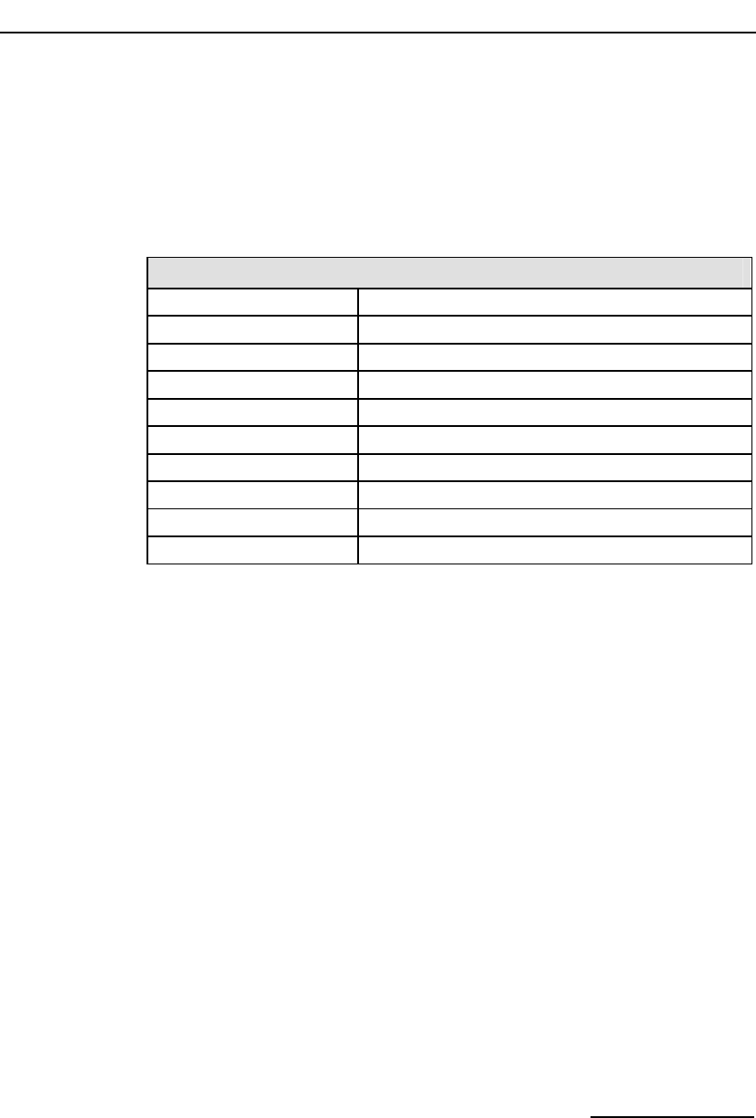
Dialogic® DSI SPCI Network Interface Boards Programmer's Manual Issue 5
83
6.4.4 LIU Status Indication
Synopsis:
Message issued by the board to notify of changes of LIU status.
Message Format:
MESSAGE HEADER
Field Name Meaning
type MVD_MSG_LIU_STATUS (0x0e01)
id liu_id
src MVD_TASK_ID
dst MGMT_TASK_ID
rsp_req 0
hclass 0
status liu_status (see below)
err_info Reserved for future use.
len 0
Description:
This message is issued by the board for every change of state on the trunk
interface.
Parameter Description:
liu_id:
The identity of the Line Interface Unit to which the status indication applies.
liu_status
The status field in the message header is coded as follows:

6 Message Reference
84
Value Mnemonic State
10 LIUS_SYNC_LOSS Frame Sync Loss
11 LIUS_IN_SYNC Frame Sync OK
12 LIUS_AIS AIS Detected
13 LIUS_AIS_CLRD AIS Cleared
14 LIUS_REM_ALARM Remote Alarm
15 LIUS_REM_ALM_CLRD Remote Alarm Cleared
20 LIUS_PCM_LOSS PCM Loss
21 LIUS_PCM_OK PCM Restored
22 LIUS_FRAME_SLIP Frame Slip
25 LIUS_BER5_OCRD BER > 1 in 100,000
26 LIUS_BER5_CLRD BER5 cleared
27 LIUS_BER3_OCRD BER > 1 in 1,000
28 LIUS_BER3_CLRD BER3 cleared
6.4.5 Error Indication
Synopsis:
Message issued to management to advise of errors or unexpected events
occurring within the protocol software.
Message Format:
MESSAGE HEADER
Field Name Meaning
type MGT_MSG_EVENT_IND (0x0008)
id 0 (unless shown below)
src sending module id
dst MGMT_TASK_ID
rsp_req 0
hclass 0
status Error Code (see below)
err_info Timestamp
len 0

Dialogic® DSI SPCI Network Interface Boards Programmer's Manual Issue 5
85
Parameter Description:
Error Code
The Error Code is coded as shown in the following table:
Value Mnemonic ID Description
0x31 S7E_RESET_ERR MTP2 Failed to initialize.
0x33 S7E_POOL_EMPTY l2_llid No free buffers in MTP2 transmit pool.
0x34 S7E_TX_FAIL l2_llid Failed to send LSSU/FISU to driver.
0x35 S7E_HDR_ERR l2_llid No room to add level 2 header, SU not
transmitted.
0x36 S7E_LEN_ERR l2_llid Length Error, SU not transmitted.
0x37 S7E_MSU_SEND l2_llid Failed to send SU to lower layer, protocol
should handle retransmission.
0x39 S7E_BAD_PRIM l2_llid MTP2 unable to accept primitive.
0x3a S7E_BAD_LLID l2_llid Invalid l2_llid in HDR structure.
0x3b S7E_MEM_ERR l2_llid MTP2 memory allocation error.
0x3c S7E_RTVL_ERR l2_llid MTP2 failure to perform retrieval.
0x51 MTP_BAD_PRIM 0 MTP3 unable to accept primitive.
0x52 MTP_POOL_EMPTY 0 No free frames in MTP3 transmit pool.
0x53 MTP_TX_FAIL 0 MTP3 failed to send MSU to lower layer.
0x54 MTP_LEN_ERR 0 MSU too long for buffer.
0x55 MTP_SLT_FAIL link_id Signaling link test failure.
0x57 MTP_TALLOC_ERR 0 MTP3 Failed to allocate T_FRAME.
0x58 MTP_BAD_ID 0 Invalid ID in message HDR.
0x59 MTP_MALLOC_ERR 0 MTP3 unable to allocate MSG.
0x5a MTP_BSNT_FAIL link_id Failure to retrieve BSNT.
0x5b MTP_RTV_FAIL link_id Retrieval failure.
0x5c MTP_BAD_FSN link_id Erroneous FSN in COA.
0x5d MTP_BAD_COO link_id COO received after changeover complete.
0x5e MTP_SNMM_ERR 0 Internal software error.
0x5f MTP_SLTM_ERR 0 Internal software error.
0x60 MTP_NO_COA link_id Failed to receive COA.
0x61 MTP_NO_CBA link_id Failed to receive CBA.
0x66 MTP_TIM_ERR timer ref MTP3 attempt to re-use active timer resource.
0x67 MTP_RRT_OVRFLW Messages discarded due to overflow of Re-
Routing buffer.
0x68 MTP_FLUSH_FAIL link_id MTP3 failed to receive Flush Ack from level 2.
0x69 MTP_FLUSH_L2 link_id MTP2 transmission buffers flushed (due to
RPO).

6 Message Reference
86
6.4.6 MTP2 Level 2 State Indication
Synopsis:
Indication issued by the board every time the level 2 link state control state
machine changes state.
Message Format:
MESSAGE HEADER
Field Name Meaning
type MGT_MSG_SS7_STATE (0x0201)
id llid (Level 2 logical link id - 0 ... 3)
src SS7_TASK_ID
dst 0xdf
rsp_req 0
hclass 0
status Link State (see below)
err_info Reserved for future use
len 0
Description:
This message is issued by the MTP2 module every time a change of state
takes place at level 2. It is intended only for diagnostic use by system
management. Normally the MTP Pause and MTP Resume Indications are used
by the user parts to determine destination accessibility.
The level 2 link state control state machine is defined in Q.703.
Parameter Description:
Link State
The status field in the message header is used to indicate the state that has
just been entered. It is coded as follows:
Value Mnemonic State
1 S7S_IN_SERVICE In Service
2 S7S_OUT_SERVICE Out of Service
3 S7S_INIT_ALIGN Initial Alignment
4 S7S_ALIGN_NOT_RDY Aligned, Not Ready
5 S7S_ALIGN_READY Aligned, Ready
6 S7S_PROC_OUTAGE Processor Outage

Dialogic® DSI SPCI Network Interface Boards Programmer's Manual Issue 5
87
6.4.7 MTP2 Q.752 Event Indication
Synopsis:
Message issued by MTP2 to advise management of protocol events in
accordance with ITU-T Q.752.
Message Format:
MESSAGE HEADER
Field Name Meaning
type MGT_MSG_SS7_EVENT (0x0202)
id l2_llid
src MTP2 module id
dst Management module id
rsp_req 0
hclass 0
status Event Code (see below)
err_info Timestamp
next 0
len 0
Description:
This primitive is used by MTP2 to advise management of the occurrence of
protocol related events in accordance with Q.752. These events relate to the
following:
• the reason for a signaling link (previously in service) going out of service
(events prefixed S7F_).
• the occurrence of congestion related events (prefixed S7G_).
• a timer expired (prefixed S7T_).
• a proving failure (prefixed S7P_).
Parameter Description:
Event Code
The Event Code is coded as shown in the following table:

6 Message Reference
88
Value Mnemonic Description
0 S7F_STOP Stop request received
1 S7F_FIBR_BSNR
Abnormal FIBR/BSNR
2 S7F_EDA Excessive delay of acknowledgement
3 S7F_SUERM Excessive error rate (SUERM)
4 S7F_ECONG Excessive congestion
5 S7F_SIO_RXD
Unexpected SIO received
6 S7F_SIN_RXD Unexpected SIN received
7 S7F_SIE_RXD Unexpected SIE received
8 S7F_SIOS_RXD
SIOS received
16 S7G_CONG Onset of signaling link congestion
17 S7G_CONG_CLR
Abatement of signaling link congestion
18 S7G_CONG_DIS
Congestion event caused MSU discard
32 S7T_T1_EXP Timer T1 expiry
33 S7T_T2_EXP Timer T2 expiry
34 S7T_T3_EXP Timer T3 expiry
48 S7P_AERM Failed proving attempt
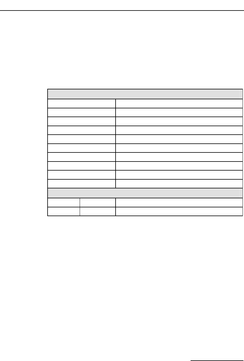
Dialogic® DSI SPCI Network Interface Boards Programmer's Manual Issue 5
89
6.4.8 MTP3 Q.752 Event Indication
Synopsis:
Message issued by MTP3 to notify management of various protocol events in
accordance with ITU-T Q.752.
Message Format:
MESSAGE HEADER
Field Name Meaning
type MGT_MSG_MTP_EVENT (0x0301)
id 0
src MTP3 module id
dst Management module id
rsp_req 0
hclass 0
status Event Code (see below)
err_info Timestamp
len Either 0, 1, 2 or 4
PARAMETER AREA
Offset Size Name
0 len Event specific parameters
Description:
This primitive is used by MTP2 to advise management of the occurrence of
protocol related events in accordance with Q.752. These events either relate
to the reason for a signaling link (that was in service) going out of service
(events prefixed S7F_) or the occurrence of congestion related events
(prefixed S7G_).
Parameter Description:
Event Code
The Event Code coding and the meaning of the event specific parameters are
given in the following table:
• link is indicated as (linkset_id * 256) + link_ref, (size = 2).
• linkset is indicated as linkset_id, (size = 1).
• point code is a 4 byte value, (size = 4).

6 Message Reference
90
Value Mnemonic Paramter Description
1 MTPEV_CO link Changeover
2 MTPEV_CB link Changeback
3 MTPEV_REST link Restoration commenced
4 MTPEV_RPO link Remote processor outage
5 MTPEV_RPO_CLR link Remote processor outage cleared
6 MTPEV_CONG link Signaling link congestion
7 MTPEV_CONG_CLR link Congestion cleared
8 MTPEV_CONG_DIS link MSU discarded due to congestion
9 MTPEV_LS_LOST linkset Link set failure
10 MTPEV_LS_OK linkset Link set recovered
13 MTPEV_DEST_LOST point code Destination unavailable
14 MTPEV_DEST_OK point code Destination available
15 MTPEV_AJSP_LOST linkset Adjacent SP inaccessible
16 MTPEV_AJSP_OK linkset Adjacent SP accessible.

Dialogic® DSI SPCI Network Interface Boards Programmer's Manual Issue 5
91
7 CONFIGURATION COMMAND Reference
This chapter describes the commands and parameters used in the protocol
configuration file config.txt. These are used by the s7_mgt utility to perform
single-shot configuration of the protocol stack at startup.
7.1 Physical Interface Parameters
7.1.1 SS7_BOARD Command
Syntax: SS7_BOARD <board_id> <board_type> <flags> <code_file>
<run_mode>
Example: SS7_BOARD 0 SPCI4 0x0043 ss7.dc3 ISUP-L
Command to configure an SPCI4 board in the system.
<board_id>
The logical id of the board within the system in the range 0 ... 15.
<board_type>
The board type within the system. Possible values are:
• SPCI2S for Dialogic® DSI SPCI2S Network Interface Boards.
• SPCI4 for Dialogic® DSI SPCI4 Network Interface Boards boards.
<flags>
A 16 bit value that provides additional level 1 configuration for the board. The
meaning of each bit may vary with different board types. The bits in the flags
field are used as follows:
Bit 0 controls the reference source used for on-board clocks when acting as
CT bus Primary Master. If set to 1 then the clock is recovered from one of the
line interfaces. If set to zero then the on-board clock oscillator is used.
Bit 1 is reserved for future use and must always be set to 1.
Bit 6 and 7 together select the initial clocking mode for the CT bus as shown
in the following table. The clocking mode can subsequently modified
dynamically using the MVD_MSG_CNFCLOCK message:

7 CONFIGURATION COMMAND Reference
92
Bit 7 Bit 6 CT Bus Clocking Mode
0 0
The CT bus interface is disabled - In this mode, the board is electrically
isolated from the other boards using the CT bus. The CT bus connection
commands may still be used, but the connections made are only visible to
this board. When using this mode, the on-board clocks are synchronized
to the source selected by bit 0 of this flags parameter.
0 1
Primary Master, Clock set A - The board drives CT bus clock set A
using the clock source selected by bit 0 of this flags parameter.
1 0
Secondary Master, Clock set B - The board is configured to drive clock
set B in Secondary Master mode. It automatically switches to become
Primary Master if the board driving clock set A fails. While acting as
Secondary Master the on-board clocks are synchronized to the CT bus
clock set A.
1 1
Slave, initially using Clock set A – The board uses the CT bus clocks,
which must be generated by another board on the CT bus. Initially the
board recovers from clock set A, though will switch over automatically to
recover from clock set B if set A fails.
Bit 13 causes the board to drive the CT_NETREF1 clocks on the CT bus when
set to 1. The highest priority in-sync line interface is used as a clock source.
If this bit is set to zero then the CT_NETREF1 clock is not driven. By default,
liu_id=0 is the highest priority and liu_id=7 is the lowest. The priority may
however be modified using the MVD_MSG_CLOCK_PRI message.
All other bits are reserved and must be set to zero.
<code file>
The name of the Code File which gets downloaded to the board when it is
reset. Code Files for Dialogic® DSI SPCI Network Interface Boards all use the
suffix .dc3. All SS7 protocols are included in a single Code File called ss7.dc3.
The selection of which protocols are run is made using the run_mode
parameter below.
<run_mode>
The run_mode determines which protocols are invoked at run time.
<run_mode> must be set to one of the following tokens depending on the
protocols that are required to run on the board (note that only protocols
permitted to be run by the software license are allowed to run):

Dialogic® DSI SPCI Network Interface Boards Programmer's Manual Issue 5
93
run_mode Protocols selected to Run on the Board
DTI Digital Trunk Interface only, no protocol software. This mode does NOT
require the use of a software license button).
MTP2 MTP2 protocol only.
MTP MTP3 plus MTP2 protocols.
ISUP-S ISUP, small version, plus all MTP.
ISUP ISUP, regular version, plus all MTP.
ISUP-L ISUP, large version, plus all MTP.
TUP-S TUP, small version, plus all MTP.
TUP TUP, regular version, plus all MTP.
TUP-L TUP, large version, plus all MTP.
DTI Digital Trunk Interface only, no protocol software. This mode does NOT
require the use of a software license button).
MTP2 MTP2 protocol only.
MTP MTP3 plus MTP2 protocols.
See section 2.3.2 Capacity for details of the capacity for modules running on
the DSI SPCI Boards.
7.1.2 LIU_CONFIG Command
Syntax: LIU_CONFIG <board_id> <liu_id> <liu_type> <line_code>
<frame_format> <crc_mode>
Example: LIU_CONFIG 0 0 5 1 1 1
This command is used during initialization to configure the operating
parameters for a T1/E1 line interface unit.
<board_id>
The logical identity of the board in the range from 0 to one less than the
number of boards supported.
<liu_id>
The identifier of the T1/E1 Line Interface Unit in the range from 0 to one less
than the number of interfaces supported.
Note: For the SPCI2S, valid values for the LIU identifiers are 2 and 3.
<liu_type>
The physical type of interface according to the following table: (note that this
must be selected by the user to be appropriate for the actual hardware fitted
otherwise an error status is returned).

7 CONFIGURATION COMMAND Reference
94
liu_type Description
1 Disabled (used to deactivate a LIU). In this mode the LIU does not produce
an output signal.
2 E1 75ohm unbalanced interface (for future use).
3 E1 120ohm balanced interface.
4 T1
5 E1 75ohm or 120ohm setting based on fitted hardware. (This is the
preferred method of selecting an E1 interface).
<line_code>
The line coding technique taken from the following table:
line_code Description
1 HDB3 (E1 only).
2 AMI with no Zero Code Suppression.
3 AMI with Zero Code Suppression (The appropriate bit in the clear_mask
parameter may be set to disable Zero Code Suppression for individual
timeslots if required) (T1 only).
4 B8ZS (T1 only).
<frame_format>
The frame format taken from the following table:
frame_format Description
1 E1 double frame (E1 only)
2 E1 CRC4 multiframe (E1 only)
4 D3/D4 (Yellow alarm = bit 2 in each channel) (T1 only)
7 ESF (Yellow alarm in data link channel) (T1 only)
<crc_mode>
The CRC mode taken from the following table:
crc_mode Description
1 CRC generation disabled
2 CRC4 enabled (frame_format must be set to 2)
3 CRC4 compatibility mode (frame_format must be set to 2)
4 CRC6 enabled (frame_format must be set to 7)

Dialogic® DSI SPCI Network Interface Boards Programmer's Manual Issue 5
95
7.1.3 LIU_SC_DRIVE Command
Syntax: LIU_SC_DRIVE <board_id> <liu_id> <sc_channel>
<ts_mask> {<mode>}
Example: LIU_SC_DRIVE 0 0 512 0xfffefffe
This command is used during initialization to set up a static switch path
through the board between the Line Interface Unit (LIU) and the CT bus. It
connects selected incoming voice timeslots from an T1/E1 LIU to a sequential
block of channels on the CT bus and prepares the outgoing timeslots for
subsequent use by the MVD_MSG_SC_LISTEN message.
<board_id>
The logical identity of the board in the range from 0 to one less than the
number of boards supported.
<liu_id>
The identifier of the T1/E1 Line Interface Unit in the range 0 to one less than
the number of LIUs fitted. This parameter can also be set to the special value
0x83 to select the signaling processor instead of an LIU. In this case timeslots
0 ... 3 in the ts_mask correspond to signaling processor 0…3.
Note that, for the SPCI2S, valid values for the LIU identifiers are 2 and 3.
<sc_channel>
The channel number of the first channel to be used on the CT bus. This must
be in the range from 0 up to one less than the total number of channels on
the CT bus.
<ts_mask>
A 32 bit timeslot mask where each bit position is set to 1 if the corresponding
timeslot on the T1/E1 interface is required to be connected to the CT bus. The
least significant bit (bit 0) represents timeslot 0. Each timeslot for which the
corresponding bit is set in ts_mask is connected up to the CT bus; other
timeslots are not affected in any way.
Timeslots containing SS7 signaling that are processed by the signaling
processor on the board should not be included in the timeslot mask. Usually
the mask should be set to include all bearer (voice) timeslots but no signaling
timeslots. Bit 0 (corresponding to timeslot 0 on the LIU) must not be set.
As an example, for an E1 interface with SS7 signaling on timeslot 16, and the
remaining 30 timeslots used for voice circuits, ts_mask should be set to the
value 0xfffefffe. For a T1 interface with signaling on timeslot 24, ts_mask
should be set to the value 0x00fffffe.

7 CONFIGURATION COMMAND Reference
96
<mode>
This parameter allows the user to select how the CT bus channels are
allocated. Usually (mode=1) the first timeslot connected to the CT bus is
connected to sc_channel and each subsequent timeslot that is selected is
connected to the next CT bus channel. This allows maximum utilization of
channels on the CT bus.
An alternative mode (mode=2) (only used if there is a specific requirement
for it) associates (but does not necessarily connect) timeslot 0 on the LIU
with sc_channel and subsequent timeslots on the LIU with subsequent CT bus
channels. Connections are only made when the corresponding bit in the
timeslot mask is set to 1. This mode of operation preserves the spacing
between timeslots that was originally found on the T1/E1 interface but does
result in a number of CT bus channels being not used.
The mode parameter is optional and may be omitted altogether. This has the
same effect as setting it to 1.
7.1.4 SCBUS_LISTEN Command
Syntax: SCBUS_LISTEN <board_id> <liu_id> <timeslot>
<sc_channel>
Example: SCBUS_LISTEN 0 0 31 23
This command establishes a connection from the CT bus to an outgoing
timeslot on the Line Interface Unit (LIU).
Dynamic modification of voice paths can only be performed by issuing
messages directly to the board. The MVD_MSG_SC_LISTEN message is
recommended for this purpose.
<board_id>
The logical identity of the board in the range from 0 to one less than the
number of boards supported.
<liu_id>
The identifier of the T1/E1 Line Interface Unit in the range 0 to one less than
the number of LIUs fitted. This parameter can also be set to the special value
0x83 to select the signaling processor instead of an LIU. In this case timeslots
0 ... 3 correspond to signaling processor 0 ... 3 respectively.
Note that, for the SPCI2S, valid values for the LIU identifiers are 2 and 3.
<timeslot>
The timeslot number on the T1/E1 line interface unit on which the data from
the CT bus is transmitted. The valid range for timeslot is 1 to 31 for an E1
interface and 1 to 24 for a T1 interface.
<sc_channel>
The channel number on the CT bus to which the LIU listens. This must be in
the range from 0 up to one less than the total number of channels on the CT
bus.

Dialogic® DSI SPCI Network Interface Boards Programmer's Manual Issue 5
97
7.2 MTP Parameters
7.2.1 MTP Global Configuration
Syntax: MTP_CONFIG <reserved1> <reserved2> <options>
Example: MTP_CONFIG 0 0 0x00040f00
The global configuration parameters for the Message Transfer Part (MTP).
<reserved1>, <reserved2>
These parameters are reserved for backwards compatibility. For applications
conforming to this release of the documentation these parameters must
always be set to zero.
<options>
A 32 bit value containing run-time options for the operation of the MTP as
follows:
Bit 0 is set to 1 to disable the MTP3 message discrimination function
(allowing the signaling point to receive all messages irrespective of the
destination point code contained in the message) or zero to allow the
discrimination function to function normally.
Bit 1 is set to 1 to disable sub-service field (SSF) discrimination. If this bit is
set to zero, received MSUs whose ssf value does not match the configured ssf
value for that link set are discarded.
Bit 2 is set to 1 to cause MTP3 to generate a UPU (User Part Unavailable)
message to the network on receipt of a message containing a Service
Indicator value that has not been configured. If set to zero the message is
discarded without sending UPU.
Bit 8 is set to 1 to select ANSI operation; otherwise it must be set to zero.
Bits 9 and 20 are used to select the point codes used in the MTP routing
lable as defined below:
Bit 9 Bit 20 Point Code Description
0 0 14-bit ITU
0 1 16-bit Japan
1 x(1) 24-bit ANSI
(1) x indicates don’t care.
Bit 10 is set to 1 for ANSI operation; otherwise it is set to zero.
Bit 11 is set to 1 for ANSI operation; otherwise it is set to zero.
Bit 18 is used to control MTP functionality in the event of detection of RPO
(Remote Processor Outage). If set to 1, RPO is handled in accordance with
the ITU-T 1992 (and later) recommendations. If set to zero, on detection of
RPO the signaling link is taken out of service and restoration commenced.
This bit is usually set to 1.
Bit 20 used in conjunction with bit 9 to select point codes (see above).

7 CONFIGURATION COMMAND Reference
98
Bit 21 is set to 1 for use in Japanese networks; otherwise it must be set to
zero.
All other bits are reserved for future use and must be set to zero.
Note: For ANSI operation bits 8, 9, 10, 11, and 18 must all be set to 1.
7.2.2 MTP Link Set
Syntax: MTP_LINKSET <linkset_id> <adjacent_spc>
<num_links> <flags> <local_spc> <ssf>
Example: MTP_LINKSET 0 321 2 0x0000 456 0x8
Configuration of a link set to an adjacent signaling point.
<linkset_id>
The logical identity of the link set, in the range 0 to one less than the number
of link sets supported, The linkset_id is used in other commands for
reference.
<adjacent_spc>
The signaling point code of the adjacent signaling point.
<num_links>
The number of links to be allocated to the link set.
<flags>
A 16 bit value reserved for future use to specify run time options. Currently
no options are defined so the parameter must be set to zero.
<local_spc>
The signaling point code of the signaling point itself.
<ssf>
The value to be used in the sub-service field of all level 3 messages and
checked for by the discrimination function in all received messages. This is a
4 bit value. Note that for ANSI operation both of the two least significant bits
must be set to 1.
Note: For correct operation the adjacent point code must also appear in a MTP_ROUTE
declaration.
7.2.3 MTP Signaling Link
Syntax: MTP_LINK <link_id> <linkset_id> <link_ref> <slc>
<board_id> <blink> <stream> <timeslot> <flags>
Example: MTP_LINK 0 0 2 2 0 1 0 16 0x0006
Configuration of a signaling link.

Dialogic® DSI SPCI Network Interface Boards Programmer's Manual Issue 5
99
<link_id>
The link’s unique logical link identity. It must be in the range 0 to one less
than the total number of signaling links supported.
<linkset_id>
The logical identity of the link set to which the link belongs. The linkset must
already have been configured using the MTP_LINKSET command.
<link_ref>
The logical identity within the link set of the signaling link. It must be in the
range 0 to one less than the number of links in the link set.
<slc>
The signaling link code for the signaling link. This must be unique within the
link set and is usually the same as the <link_ref>. The valid range is 0…15.
<board_id>
The board id of the signaling processor allocated for this signaling link.
<blink>
The index of the signaling processor (within the board) allocated for this
signaling link. It must be in the range 0 to one less than the number of
signaling processors on the board.
<stream>
When <timeslot> is set to a non-zero value, the <stream> parameter is the
logical identity of the T1/E1 line interface (liu_id) containing the signaling link
It must be in the range 0 to one less than the number of line interfaces.
Note: For the SPCI2S, stream identifiers for the PCM interfaces are implemented on
streams 2 and 3.
<timeslot>
The timeslot used for signaling in the range 1 ... 31. For an E1 interface the
valid range is 1 ... 31. For a T1 interface the valid range is 1 ... 24. When set
to zero the signaling path through the board must be set up manually using
the switch control messages.
<flags>
A 16 bit value containing additional run-time options.
Bit 0 is set to 1 to force the use of the emergency proving period during link
alignment or zero to use the appropriate proving period according to the
MTP3 recommendations.
Bit 1 is set to 1 to cause a signaling link test (in accordance with ITU-T Q.707
/ ANSI T1.111.7) to be carried out before a link is put into service, or zero if
a test is not required.

7 CONFIGURATION COMMAND Reference
100
Bit 2 is set to 1 to cause a signaling link test (in accordance with ITU-T Q.707
/ ANSI T1.111.7) to be carried out every 30 seconds. Note that this bit is
ignored unless bit 1 is also set to 1.
Bit 8 is used to select the MTP2 error correction mode. It is set to 1 to select
PCR (Preventive Cyclic Retransmission) operation or zero for the Basic
Method of Error Correction.
Bit 11 is set to 1 to select 56kbit/s operation for the link or zero for 64kbit/s
operation.
Note: When using a serial port, 56kbit/s operation is only supported when the clock is
applied externally.
Bit 13 is only used when the link has been configured to run over a serial
port. If set to 1 an external clock is used (Receive clock). If set to zero an
internal clock (Transmit clock) is used. If the link has not been configured to
run over a serial port, this bit must be set to zero.
Bit 14 is set to 1 to use a serial port rather than a PCM timeslot for this link.
In this mode the stream and timeslot parameters for this link are ignored
(and must be set to zero). If this bit is set to zero, the link uses the specified
stream and timeslot. The serial port used by the signaling processors for each
link is fixed, according to the following table:
Blink Serial Port
0 B
1 A
2 Cannot be used for a serial port.
3 Cannot be used for a serial port.
Bit 15 is set to 1 to disable the link or zero to enable the link.
All other bits are reserved for future use and must be set to zero.
7.2.4 MTP Route
Syntax: MTP_ROUTE <dpc> <norm_ls> <user_part_mask>
<flags> <second_ls>
Example: MTP_ROUTE 567 0 0x0020 0x0000 0
Configuration of a route for use with one or more user parts.
<dpc>
The point code of the remote signaling point for which this command is
configuring routing data. It may be either an adjacent point code or a point
code accessible via an adjacent Signaling Transfer Point.
<norm_ls>
The linkset_id of the normal link set used to reach the specified destination.
The norm_ls must be a linkset_id that has already been configured using the
MTP_LINKSET command. The normal link set may be any of the following:

Dialogic® DSI SPCI Network Interface Boards Programmer's Manual Issue 5
101
a) The only link set used to reach the destination.
b) The preferred link set used to reach the destination.
c) One of a pair of links sets forming a combined link set.
In the latter two cases a second link set (second_ls) must also be specified.
Within a link set messages are automatically load-shared across links using
the Signaling Link Selection (SLS) field in the message.
<second_ls>
The linkset_id of an optional second link set used to reach the specified
destination. This may be either of the following options:
a) The secondary link set used to reach the destination only on failure of the
preferred link set.
b) One of a pair of links sets forming a combined link set over which load-
sharing takes place. (in this case bit 1 must also be set in the <flags>
parameter of the command).
When a second link set is specified the user must also set bit 0 in the
<flags> field of this command.
<user_part_mask>
This is a 16 bit field used identify the user parts that are supported over this
route. The bits are labelled 0 to 15 and for each user part supported the bit
corresponding to the Service Indicator for that user part must be set. (e.g.,
To support just ISUP messages, the ISUP Service Indicator is 5 so bit 5
should be set. Therefore a value of 0x0020 would be appropriate).
<flags>
A 16 bit field containing run-time configuration options for the route as
follows:
Bit 0 is set to 1 to indicate that a second link set is specified within the
command. If zero the second_ls parameter is ignored.
Bit 1 is used to determine whether or not to load-share messages across the
two link sets. It is only used when two link sets are specified for the route.
When set the MTP3 module load-shares messages for the destination equally
across each of the two specified link sets. Otherwise the MTP3 module
considers the normal link set to be the preferred link set and only uses the
second link set in the event of failure of the normal link set. The bit may be
set to 1 to enable load-sharing across the two link sets, or zero to disable
load-sharing and use preferred and secondary link sets.
All other bits are reserved for future use and must be set to zero.

7 CONFIGURATION COMMAND Reference
102
7.2.5 MTP User Part
Syntax: MTP_USER_PART <si> <module_id>
Example: MTP_USER_PART 0x0a 0x2d
Configuration of a local user part module (other than a user part which has its
own config command in config.txt).
<si>
The service indicator.
<module_id>
The module id of the user process.
Note: This command must not be used when the corresponding configuration commands
are used (ISUP_CONFIG, TUP_CONFIG etc) as these commands automatically
perform the function of the MTP_USER_PART command.
7.3 ISUP Parameters
7.3.1 Global ISUP Configuration
Syntax: ISUP_CONFIG <res1> <res2> <user_id> <options>
<num_grps> <num_ccts> [<partner_id>]
Example: ISUP_CONFIG 0 0 0x2d 0x0435 4 128
The global configuration parameters for the ISUP module.
<res1>, <res2>
Reserved for backwards compatibility. These fields should be set to zero.
<user_id>
The module_id of the application running on the host that uses the ISUP
module.
<options>
A 16 bit value containing global run-time options for the operation of the
ISUP module. The meaning of each bit is as defined for the 'options'
parameter in the ISUP Configure Request message as detailed in the ISUP
Programmer's Manual

Dialogic® DSI SPCI Network Interface Boards Programmer's Manual Issue 5
103
<num_grps>
The maximum number of ISUP circuit groups that the user intends to use.
This must not exceed the maximum number of circuit groups supported
otherwise module configuration will fail. Typically <num_grps> would be set
to the maximum number of circuit groups supported.
<num_ccts>
The maximum number of ISUP circuits that the user intends to use. This must
not exceed the maximum number of circuits supported otherwise module
configuration will fail. Typically <num_ccts> is set to 32 times the number of
groups for E1 operation and 24 times the number of circuit groups for T1
operation.
Note: The valid range for the circuit identifier (cid) is from zero up to one less than the
maximum number of circuits (num_ccts).
<partner_id>
Optional parameter for use when operating in dual resilient configuration.
This parameter is the module_id of the ‘partner’ ISUP module (equivalent to
the ‘module_id field in the ISUP Configure Request message as documented
in the ISUP Programmer’s Manual).
7.3.2 ISUP Circuit Group Configuration
Syntax: ISUP_CFG_CCTGRP <gid> <dpc> <base_cic> <base_cid>
<cic_mask> <options> <user_inst> <user_id> <opc>
<ssf> <variant> <options2>
Example: ISUP_CFG_CCTGRP 0 3 1 1 0x7fff7fff 0x00000003 0 0x2d
2 0x8 4 0x00000000
The configuration parameters for a group of ISUP circuits. Usually a group is
all the circuits on a single E1 or T1 interface.
<gid >
The group id of the circuit group in the range 0 to one less than the number
of groups supported.
<dpc>
The destination point code for all circuits in the circuit group.
<base_cic>
The Circuit Identification Code (CIC) that is allocated to the first circuit in the
circuit group.
<base_cid>
The logical id for the first circuit in the circuit group. It must lie in the range 0
to one less than the number of circuits supported.

7 CONFIGURATION COMMAND Reference
104
<cic_mask>
A 32 bit mask with bits set to indicate which circuits are to be allocated to the
circuit group. Bit zero must always be set as it represents the
base_cic/base_cid. Subsequent bits represent the subsequent circuits. Note
that ANSI circuit groups are not permitted to contain more than 24 circuits.
<options>
A 32 bit value containing run-time options for the ISUP circuit group (see
"Configure Circuit Group Request" section of the ISUP Programmer’s Manual).
Bits 0 through 15 are equivalent to the "options" field and bits 16 through 31
represent the "ext_options" field as detailed in the ISUP Programmer’s
Manual.
<user_inst>
The instance number of the user application. Typically only a single user
application exists so this field would be set to zero.
<user_id>
The module_id of the user application.
<opc>
Originating Point Code. The local point code for all circuits in the group.
<ssf>
The value to be used in the sub-service field of all ISUP messages for this
circuit group.
<variant>
The protocol "variant" for this circuit group. Refer to the ISUP Programmer’s
Manual for full details.
<options2>
A 32 bit value containing additional run-time options for the ISUP circuit
group (see "Configure Circuit Group Request" section of the ISUP
Programmer’s Manual). Bits 0 through 31 are equivalent to the
"ext_1_options" as detailed in the ISUP Programmer’s Manual.

Dialogic® DSI SPCI Network Interface Boards Programmer's Manual Issue 5
105
7.4 TUP Parameters
7.4.1 Global TUP Configuration
Syntax: TUP_CONFIG <res1> <res2> <user_id> <options>
<num_grps> <num_ccts> <partner_id>
Example: TUP_CONFIG 0 0 0x2d 0x8541 4 128
The global configuration parameters for the TUP module.
<res1>, <res2>
Reserved for backwards compatibility. These fields should be set to zero.
<user_id>
The module_id of the application running on the host that uses the TUP
module.
<options>
A 16 bit value containing global run-time options for the operation of the TUP
module. The meaning of each bit is as defined for the 'options' parameter in
the TUP Configure Request message as detailed in the TUP Programmer's
Manual.
<num_grps>
The maximum number of TUP circuit groups that the user intends to use. This
must not exceed the maximum number of circuit groups supported otherwise
module configuration will fail. Typically <num_grps> would be set to the
maximum number of circuit groups supported.
<num_ccts>
The maximum number of TUP circuits that the user intends to use. This must
not exceed the maximum number of circuits supported otherwise module
configuration will fail. Typically <num_ccts> is set to 32 times the number of
groups for E1 operation and 24 times the number of circuit groups for T1
operation.
Note: The valid range for the circuit identifier (cid) is from zero up to one less than the
maximum number of circuits (num_ccts).
<partner_id>
Optional parameter for use when operating in dual resilient configuration.
This parameter is the module_id of the "partner" TUP module (equivalent to
the "ucic_id" field in the TUP Configure Request message as documented in
the TUP Programmer’s Manual).

7 CONFIGURATION COMMAND Reference
106
7.4.2 TUP Circuit Group Configuration
Syntax: TUP_CFG_CCTGRP <gid> <dpc> <base_cic> <base_cid>
<cic_mask> <options> <user_inst> <user_id> <opc>
<ssf> <variant> <options2>
Example: TUP_CFG_CCTGRP 0 3 1 1 0x7fff7fff 0x00000003 0 0x2d
123 0x8 0 0x0
The configuration parameters for a group of TUP circuits.
<gid >
The group id of the circuit group in the range 0 to one less than the number
of groups supported.
<dpc>
The destination point code for the circuits in the circuit group.
<base_cic>
The Circuit Identification Code (CIC) that is allocated to the first circuit in the
circuit group.
<base_cid>
The logical id for the first circuit in the circuit group. It must lie in the range 0
to one less than the number of circuits supported.
<cic_mask>
A 32 bit mask with bits set to indicate which circuits are to be allocated to the
circuit group. Bit zero must always be set as it represents the
base_cic/base_cid. Subsequent bits represent the subsequent circuits.
<options>
A 32 bit value containing run-time options for the TUP circuit group (see
"Configure Circuit Group Request" section of the TUP Programmers Manual).
<user_inst>
The instance number of the user application. Typically only a single user
application exists so this field would be set to zero.
<user_id>
The module_id of the user application.
<opc>
Originating Point Code. The local point code for all circuits in the group.

Dialogic® DSI SPCI Network Interface Boards Programmer's Manual Issue 5
107
<ssf>
The value to be used in the sub-service field of all TUP messages for this
circuit group.
<variant>
This field is reserved for future use and must be set to zero.
<options2>
This field is reserved for future use and must be set to zero.

8 Host Utilities
108
8 Host Utilities
This section describes some of the utilities that can be used with the
Dialogic® DSI SPCI Network Interface Boards. See the software environment
Programmer's Manual for details of the gctload, tim, tick, s7_log and
s7_play utilities.
8.1 ssds
8.1.1 Description
The ssds utility interfaces with the device driver for passing messages to and
from the board and controls the downloading software to the board.
The ssds utility also controls the mapping of configured to handle different
modes of addressing for each board within a system. This functionality is
described as Geographic Addressing.
can be based on either the PCI bus enumeration or the ADDR switch setting
on the board.
If ssds is defined as the congestion-handling module for gctload then it will
stop retrieving messages from the board until the congestion abates. Other
congestion handling steps may be required depending on the system
configuration and state.
8.1.2 Syntax
ssds [-v -d]
8.1.3 Command Line Options
The ssds utility supports the following command line options:
-o
This parameter specifies the Geographic Addressing mode of operation. It can
take the following values:
-o1 PCI address mode
-o3 Switch address mode
If the parameter is omitted then operation defaults to PCI address mode.
See section 4.5 Geographic Addressing for further information.
-a
For Switch address modes it is necessary to specify a second command line
parameter (-a) for ssds containing a list of the addresses for each logical
board position (or board_id) derived from the ADDR switch setting. The
address list format is:
-a6,4,2,3,12,14
Up to a maximum of 16 addresses can be specified in this list.

Dialogic® DSI SPCI Network Interface Boards Programmer's Manual Issue 5
109
If using Switch address mode , board_id = 0 would be the board with ADDR
switch set to 6, board_id = 1 would be the board with ADDR switch set to 4
and so on.
It is not necessary for all boards listed in this parameter to actually exist in a
system. Any board listed, but missing, would result in a gap in the logical
board_id sequence.
-v
Show version information.
-d
Enable diagnostic tracing.
8.2 s7_mgt
8.2.1 Description
The s7_mgt utility performs one-time protocol configuration for all protocol
modules, deriving the configuration parameters from a text file (config.txt by
default). This process is optional. As an alternative, the user may elect to
perform protocol configuration by sending messages directly to the other
modules in the system. See section 4.3.2 Protocol Configuration Using
Individual Messages for more information.
8.2.2 Syntax
s7_mgt [-v -k<config_file> -m<module_id> -i<notify_id> -d]
8.2.3 Command Line Options
The s7_mgt utility supports the following command line options:
-v
Show version information.
-k<config file>
Specifies the SS7 configuration file. The default is config.txt.
-m<module id>
Specifies the unique module ID that is assigned to s7_mgt for the Inter
Process Communication (IPC) environment. The module ID may be entered in
decimal or hexadecimal (prefixed by 0x) format. If the module ID is not
specified, the utility uses a module ID of 0xcf. The module ID assigned must
have a corresponding LOCAL entry in the system.txt file and must not be in
use by any other process on the host.

8 Host Utilities
110
-i<notify module id>
The module to which an indication is sent when the configuration is complete.
-d
Enable diagnostic tracing.
8.2.4 Example
To run the s7_mgt utility as module ID 0xdf with the file my_config.txt as its
configuration file and notifying the module 0xef on completion, the command
is:
s7_mgt -m0xdf -kmy_config.txt -i0xef

Dialogic® DSI SPCI Network Interface Boards Programmer's Manual Issue 5
111
