Dickie Toys 49013TX RC TOY-TRANSMITTER User Manual TABLE OF CONTENTS
Dickie Toys Hong Kong Ltd. RC TOY-TRANSMITTER TABLE OF CONTENTS
USERS MANUAL

TIMCO ENGINEERING INC.
849 NW State Road 45
Newberry, Florida 32669
http://www.timcoengr.com
888.472.2424 F 352.472.2030 email: tei@timcoengr.com
APPLICANT: DICKIE-SPIELZEUG GmbH & CO KG
Test Report
Product Name: RC TOY- TRANSMITTER
FCC ID: NLB49013TX
Applicant:
DICKIE-SPIELZEUG GmbH & CO KG
WERKSTRABE 1
D-90765 FUERTH D-90765
GERMANY
FCC ID: NLB49013TX
REPORT #: D\DICKIE\219UT6\219UT6TestReport.doc
COVER SHEET

TIMCO ENGINEERING INC.
849 NW State Road 45
Newberry, Florida 32669
http://www.timcoengr.com
888.472.2424 F 352.472.2030 email: tei@timcoengr.com
APPLICANT: DICKIE-SPIELZEUG GmbH & CO KG
TABLE OF CONTENTS LIST
APPLICANT: DICKIE-SPIELZEUG GmbH & CO KG
FCC ID: NLB49013TX
TEST REPORT CONTAINING:
PAGE 1.............TEST EQUIPMENT LIST
PAGE 2.............TEST PROCEDURE
PAGE 3.............RADIATION INTERFERENCE TEST DATA
PAGE 4.............OCCUPIED BANDWIDTH
PAGE 5.............OCCUPIED BANDWIDTH PLOT
EXHIBITS INCLUDING:
BLOCK DIAGRAM
SCHEMATIC
INSTRUCTION MANUAL
LABEL SAMPLE
LABEL LOCATION
EXTERNAL PHOTOGRAPHS
INTERNAL PHOTOGRAPHS
CIRCUIT DESCRIPTION
TEST SET UP PHOTOGRAPH
FCC ID: NLB49013TX
REPORT #: D\DICKIE\219UT6\219UT6TestReport.doc
TABLE OF CONTENTS

TIMCO ENGINEERING INC.
849 NW State Road 45
Newberry, Florida 32669
http://www.timcoengr.com
888.472.2424 F 352.472.2030 email: tei@timcoengr.com
APPLICANT: DICKIE-SPIELZEUG GmbH & CO KG
Equipment List
Device Manufacturer Model Serial
Number Cal/Char
Date Due Date
3/10-Meter
OATS TEI N/A N/A Listed
3/27/04 3/26/07
3-Meter
OATS TEI N/A N/A Listed
1/11/06 1/10/09
Biconnical
Antenna Eaton 94455-1 1057 CAL
12/12/05 12/12/07
Biconnical
Antenna Eaton 94455-1 1096 CAL
8/17/04 8/17/06
Biconnical
Antenna Electro-
Metrics BIA-25 1171 CAL
4/29/05 4/29/07
Blue Tower
Quasi-Peak
Adapter
HP 85650A 2811A01279 CAL
4/13/05 4/13/07
Blue Tower
RF
Preselector
HP 85685A 2926A00983 CAL
9/5/05 9/5/07
Blue Tower
Spectrum
Analyzer
HP 8568B 2928A04729
2848A18049 CAL
4/13/05 4/13/07
LISN Electro-
Metrics ANS-25/2 2604 CAL
8/27/04 8/27/06
LISN Electro-
Metrics EM-7820 2682 CAL
4/28/05 4/28/07
Log-
Periodic
Antenna
Eaton 96005 1243 CAL
12/14/05 12/14/07
FCC ID: NLB49013TX
REPORT #: D\DICKIE\219UT6\219UT6TestReport.doc
Page 1 of 5

TIMCO ENGINEERING INC.
849 NW State Road 45
Newberry, Florida 32669
http://www.timcoengr.com
888.472.2424 F 352.472.2030 email: tei@timcoengr.com
APPLICANT: DICKIE-SPIELZEUG GmbH & CO KG
TEST PROCEDURE
GENERAL: This report shall NOT be reproduced except in full without the
written approval of TIMCO ENGINEERING, INC.
RADIATION INTERFERENCE: The test procedure used was ANSI STANDARD C63.4-2003
using a HEWLETT PACKARD spectrum analyzer with a pre-selector. The bandwidth of
the spectrum analyzer was 100 kHz with an appropriate sweep speed. The analyzer
was calibrated in dB above a microvolt at the output of the antenna. The
resolution bandwidth was 100 kHz and the video bandwidth was 300 kHz. The
ambient temperature of the UUT was 80ºC with a humidity of 76%.
FORMULA OF CONVERSION FACTORS: The Field Strength at 3m was established by
adding the meter reading of the spectrum analyzer (which is set to read in units
of dBuV) to the antenna correction factor supplied by the antenna manufacturer.
The antenna correction factors are stated in terms of dB. The gain of the Pre-
selector was accounted for in the Spectrum Analyzer Meter Reading.
Example:
Freq (MHz) METER READING + ACF = FS
33 20 dBuV + 10.36 dB = 30.36 dBuV/m @ 3m
ANSI STANDARD C63.4-2003 10.1.7 MEASUREMENT PROCEDURES: The unit under test was
placed on a table 80 cm high and with dimensions of 1m by 1.5m. The table used
for radiated measurements is capable of continuous rotation.
When an emission was found, the table was rotated to produce the maximum signal
strength. At this point, the antenna was raised and lowered from 1m to 4m. The
antenna was placed in both the horizontal and vertical planes.
FCC ID: NLB49013TX
REPORT #: D\DICKIE\219UT6\219UT6TestReport.doc
Page 2 of 5

TIMCO ENGINEERING INC.
849 NW State Road 45
Newberry, Florida 32669
http://www.timcoengr.com
888.472.2424 F 352.472.2030 email: tei@timcoengr.com
APPLICANT: DICKIE-SPIELZEUG GmbH & CO KG
APPLICANT: DICKIE-SPIELZEUG GmbH & CO KG
FCC ID: NLB49013TX
NAME OF TEST: RADIATION INTERFERENCE
RULES PART NO.: 15.235
REQUIREMENTS: CARRIER FREQUENCY WILL NOT EXCEEDS 80 dBuV/m AT 3M.
OUT-OF-BAND EMISSIONS SHALL NOT EXCEED:
30 - 88 MHz 40.0 dBuV/M MEASURED AT 3 METERS
88 - 216 MHz 43.5 dBuV/M
216 - 960 MHz 46.0 dBuV/M
ABOVE 960 MHz 54.0 dBuV/M
TEST DATA:
Tuned
Frequency
MHz
Emission
Frequency
MHz
Meter
Reading
dBuV
Ant.
Polarity Coax
Loss
dB
Correction
Factor
dB
Field
Strength
dBuV/m
Margin
dB
49.9 49.86 46.1 H 0.97 11.20 58.27 21.73
49.9 49.86 59.0 V 0.97 11.07 71.04 8.96
49.9 99.72 17.2 H 1.40 11.38 29.98 13.52
49.9 99.72 18.5 V 1.40 11.55 31.45 12.05
49.9 199.40 12.0 V 2.10 17.22 31.32 12.18
49.9 199.40 12.3 H 2.10 17.32 31.72 11.78
SAMPLE CALCULATION: FSdBuV/m = MR (dBuV) + ACFdB.
Emissions attenuated more than 20 dB below the permissible value are not
reported.
TEST PROCEDURE: The procedure used was ANSI STANDARD C63.4-2003. The spectrum
was scanned from 30 MHz to 1000 MHz. When an emission was found, the table was
rotated to produce the maximum signal strength. The antenna was placed in both
the horizontal and vertical planes and the worse case emissions were reported.
The UUT was tested in 3 orthogonal planes.
PERFORMED BY: RICHARD BLOCK DATE: 2/28/2006
FCC ID: NLB49013TX
REPORT #: D\DICKIE\219UT6\219UT6TestReport.doc
Page 3 of 5

TIMCO ENGINEERING INC.
849 NW State Road 45
Newberry, Florida 32669
http://www.timcoengr.com
888.472.2424 F 352.472.2030 email: tei@timcoengr.com
APPLICANT: DICKIE-SPIELZEUG GmbH & CO KG
APPLICANT: DICKIE-SPIELZEUG GmbH & CO KG
FCC ID: NLB49013TX
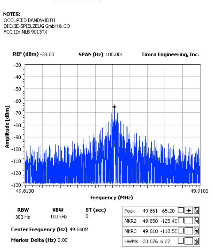
NAME OF TEST: Occupied Bandwidth
RULES PART NO.: 15.235
REQUIREMENTS: The field strength of any emissions appearing between the band
edges and up to 10 kHz above and below the band edges shall be attenuated at
least 26 dB below the level of the un-modulated carrier or to the general limits
of 15.209, whichever permits the higher emission levels.
THE GRAPH ON THE NEXT PAGE REPRESENTS THE EMISSIONS TAKEN FOR THE DEVICE.
METHOD OF MEASUREMENT: A small sample of the transmitter output was fed into
the spectrum analyzer and the attached plot was taken. The vertical scale is
set to 10 dB per division.
PERFORMED BY: RICHARD BLOCK DATE: 2/28/06
FCC ID: NLB49013TX
REPORT #: D\DICKIE\219UT6\219UT6TestReport.doc
Page 4 of 5
TIMCO ENGINEERING INC.
849 NW State Road 45
Newberry, Florida 32669
http://www.timcoengr.com
888.472.2424 F 352.472.2030 email: tei@timcoengr.com
APPLICANT: DICKIE-SPIELZEUG GmbH & CO KG
FCC ID: NLB49013TX
REPORT #: D\DICKIE\219UT6\219UT6TestReport.doc
Page 5 of 5