Digi 50M1520 802.11 a/b/g Spread Spectrum Transmitter User Manual Nehs1081 qxp
Digi International Inc 802.11 a/b/g Spread Spectrum Transmitter Nehs1081 qxp
UserManual.wiki
>
Digi
>
50M1520 User Manual
>
User Manual 1
Contents
1.
User Manual 1
2.
User Manual 2
User Manual 1
Navigation menu
Upload a User Manual
Namespaces
Wiki Guide
HTML
PDF
Info
Views
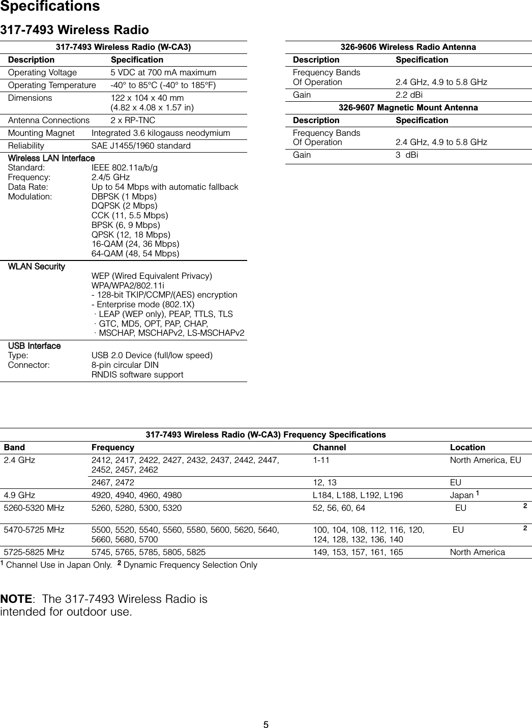
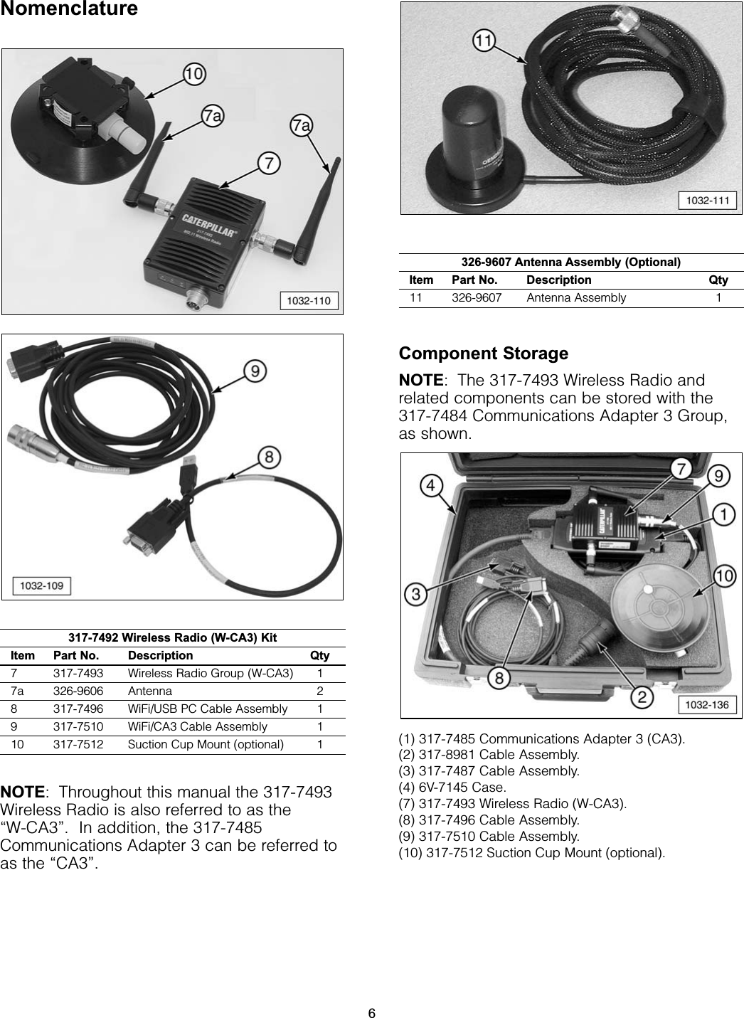
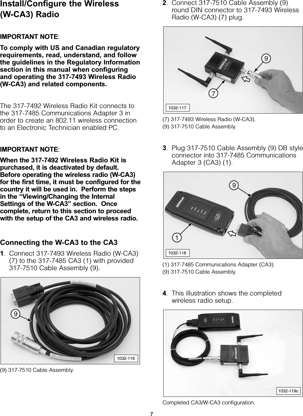
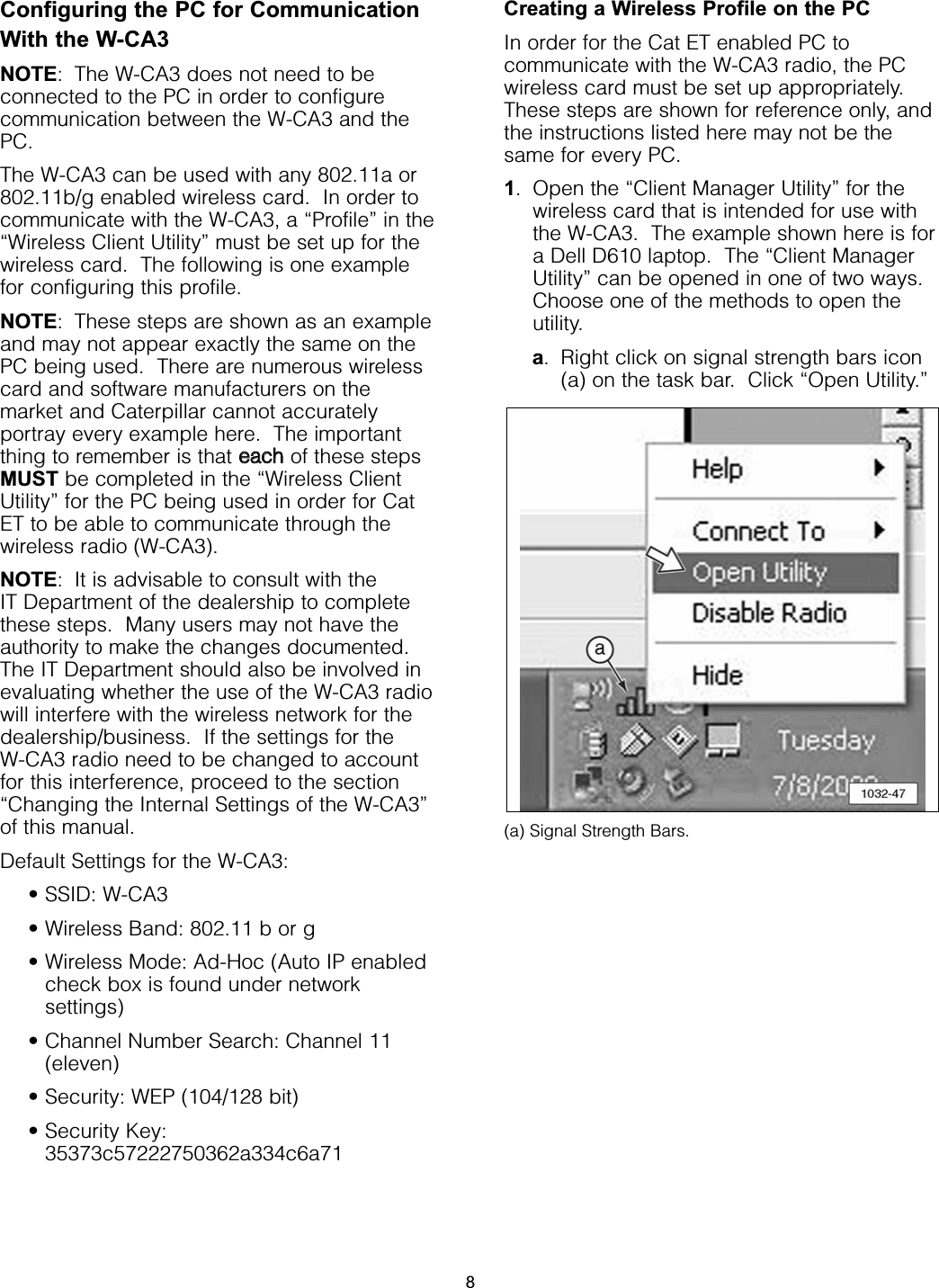
User Manual
Discussion / Help
Navigation