Digi 90000278 B Users Manual
90000278_B to the manual fc4d00fc-b89d-4164-8bb1-376f6c4c030b
2015-02-04
: Digi Digi-90000278-B-Users-Manual-513541 digi-90000278-b-users-manual-513541 digi pdf
Open the PDF directly: View PDF ![]() .
.
Page Count: 24

Hardware Reference Manual
Digi One EM
90000278_B
Digi International Inc. 2002. All Rights Reserved
The Digi logo is a registered trademark of Digi International, Inc.
Connectware and Digi One are trademarks of Digi International, Inc.
Information in this document is subject to change without notice and does not represent a
commitment on the part of Digi International.
Digi provides this document “as is,” without warranty of any kind, either expressed or
implied, including, but not limited to, the implied warranties of fitness or merchantability for
a particular purpose. Digi may make improvements and/or changes in this manual or in
the product(s) and/or the program(s) described in this manual at any time.
This product could include technical inaccuracies or typographical errors. Changes are
periodically made to the information herein; these changes may be incorporated in new
editions of the publication.
Digi One EM Hardware Guide 3
Contents
Chapter 1 Introduction 5
About This Guide.............................................................................5
Introducing the Digi One EM ..........................................................6
Support Information.........................................................................7
Chapter 2 About the Digi One EM 8
Digi One EM Drawing.....................................................................8
Connectors: Power and Serial Interface (P4)...................................9
Connectors: Ethernet Interface (P1) ..............................................10
Reset Switch ..................................................................................11
LEDs ..............................................................................................11
Chapter 3 About the Development Board 13
Overview........................................................................................13
Cautions .........................................................................................13
Development Board Illustration.....................................................14
DB-9 Serial Interface (P1) .............................................................15
Reset Switch (SW1).......................................................................16
Power Jack (P7) .............................................................................17
LEDs (CR4 - CR11) .....................................................................18
4 Digi One EM Hardware Guide
Chapter 4 Sample Application: TTL Signals to EIA-232 19
Appendix A Digi One EM Specifications 20
Network Interfaces.........................................................................20
Serial Interface...............................................................................20
Data Rates (bps).............................................................................20
Modem Control..............................................................................20
Flow Control Options ....................................................................20
Environmental................................................................................20
Power Requirements......................................................................20
Mechanical.....................................................................................20
Appendix B Digi One EM Certifications 21
FCC Part 15 Class A......................................................................21
ICES 003 Class A ..........................................................................22
Product Safety................................................................................22
Digi One EM Hardware Reference 5
Chapter 1
Introduction
About This Guide
Purpose
The purpose of this guide is to enable developers to integrate
the Digi One EM into other devices, enabling these devices to
make use of the Digi One EM’s rich networking features.
Audience
This document is written for developers tasked with
integrating Digi One EM device servers into other devices.
Scope
This document provides the information required for electrical
integration of the Digi One EM into another device. It does
not address how to configure or administer the device server
or how to write applications to use its functionality. These
topics are covered in other documents in the library.
6 Digi One EM Hardware Reference
Introducing the Digi One EM
Product Overview
The Digi One EM is part of the Digi One Family of single port
device servers that provide simple, reliable and cost-effective
network connections for serial devices. The Digi One EM
provides fully transparent serial device connectivity over
industry-standard Ethernet connections and allows both
equipment manufacturers and systems integrators to
network-enable products at a fraction of the time and cost
required to develop a custom solution. It is a highly flexible
and compact single component solution with a robust on-
board TCP/IP stack and 10/100 Base-T Ethernet support.
From medical systems to building control and industrial
automation, in virtually any application where embedded
serial connectivity over Ethernet is needed, the Digi One EM
is the ideal choice, delivering high-performance functionality.
Cautions • To guard against damage to the Digi One EM due to elec-
trostatic discharge (ESD), do not remove it from its pro-
tective packaging until you have been properly grounded.
To ground yourself, put the wrist strap on (included in the
package) and then attach the clip to a metal surface.
• Input voltage for the Digi One EM must be in the range of
5VDC to 9VDC.
Digi One EM Hardware Reference 7
Support Information
To get help with a question or technical problem or to make
comments and recommendations about our products or
documentation, use the following contact information.
General
Digi International
11001 Bren Road East
Minnetonka, MN 55343
U.S.A
www.digi.com
Customer Service and Support
United States: 1 877-912-3444
Other Locations: 1 952-912-3444
www.support.digi.com
8 Digi One EM Hardware Reference
Chapter 2
About the Digi One EM
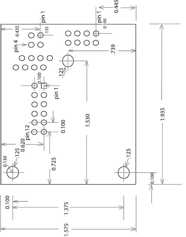
Digi One EM Drawing
The following figure shows the Digi One EM layout and
dimensions.
Digi One EM Hardware Reference 9
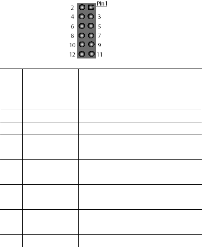
Connectors: Power and Serial Interface (P4)
The Digi One EM has a single 12-pin, serial interface port
(labeled P4) that supports EIA-232 (TTL levels only), data
rates up to 230 Kbps and full-modem control. The following
figure helps you locate pins, and the table helps you identify
which signal uses each pin.
Pin Signal Name Description
1+5VDC to
+9VDC (input
only) Input power to Digi One EM
2 GND Reference Ground for input power
3 RxD Receive Data (input)
4 TxD Transmit Data (output)
5 RTS Request To Send
6 DTR Data Terminal Ready
7 CTS Clear To Send
8 DCD Data Carrier Detect
9 DSR Data Set Ready
10 RST~ Reset
11 Reserved Not used
12 Reserved Not used
10 Digi One EM Hardware Reference
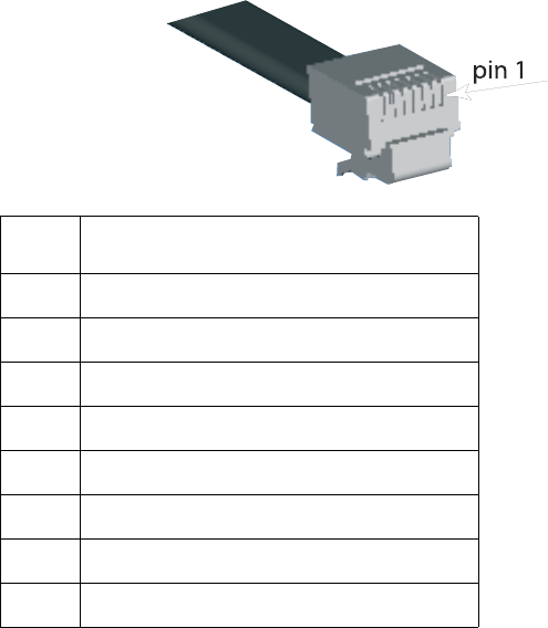
Connectors: Ethernet Interface (P1)
The Digi One EM Ethernet connector is an eight-wire, RJ-45
jack meeting the requirements of ISO 8877 for 10/100Base-
T. The following figure helps you locate pins and the table
helps you identify which signal uses each pin.
Pin Signal Name
1 TxD+ (Transmit Data)
2 TxD- (Transmit Data)
3 RxD+ (Receive Data)
4 Not used
5 Not used
6 RxD- (Receive Data)
7 Not used
8 Not used
Digi One EM Hardware Reference 11
Reset Switch
The reset switch, located between P3 and CR1, does the
following (depending on how long you hold the switch down):
• It reboots the Digi One EM if you press and release the
switch immediately.
• It reboots the Digi One EM and restores the configuration
to factory defaults. (Press and hold the switch down for
about 20 seconds while powering the Digi One EM up.)
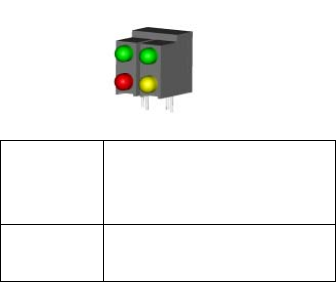
LEDs
Digi One EM LEDs provide information on port activity,
diagnostics, and Ethernet activity.
LED Color Function Interpretation
Top left Green Indicates serial
port activity
• Off means that the serial
channel is idle.
• Blinking indicates an
active connection.
Top
right Green Network link sta-
tus
• Off means that no link
has been detected.
• On means that a link
has been detected.

12 Digi One EM Hardware Reference
Bottom
left Red Diagnostics
• Blinking 1-1-1 means
starting the operating
system.
• Blinking 1-5-1 means
configuration has been
returned to factory
defaults.
• Steady blinking means
the device is seeking an
IP address from a
DHCP server.
Note: If other blinking
patterns occur, call Digi
Technical Support.
Bottom
right Yellow Reserved NA
LED Color Function Interpretation
Digi One EM Hardware Reference 13
Chapter 3
About the Development Board
Overview
The development board provides the following interfaces:
• A DB-9 serial interface that enables serial connections
from your device to the Digi One EM module. See "DB-9
Serial Interface (P1)" on page 15.
• A 12-position socket to supply both power and ground to
the Digi One EM.
• A reset switch to reboot the Digi One EM. See "Reset
Switch (SW1)" on page 16.
• A standard 2.0 mm jack that accepts 5 volts DC +/- 5%
from a regulated power supply. See "Power Jack (P7)" on
page 17.
• Eight LEDs. One (labeled CR4) tells you if the power is
on. The other seven (labeled CR5 - CR11) are active
when EIA-232 signals are detected. See "LEDs (CR4 -
CR11)" on page 18.
• A reserved 3-pin header (labeled P5)
Cautions
• Although the Digi One EM can handle up to 9 VDC, this
voltage can harm the development board, which works
only with the 5 volt regulated power supply. The board
does not regulate power.
• To guard against damage to the development board due
to electrostatic discharge (ESD), do not remove it from its
protective packaging until you have been properly
grounded. To ground yourself, put the wrist strap on
(included in the package) and then attach the clip to a
metal surface.
14 Digi One EM Hardware Reference
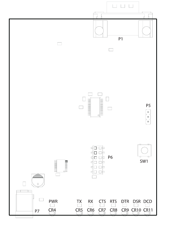
Development Board Illustration
Digi One EM Hardware Reference 15
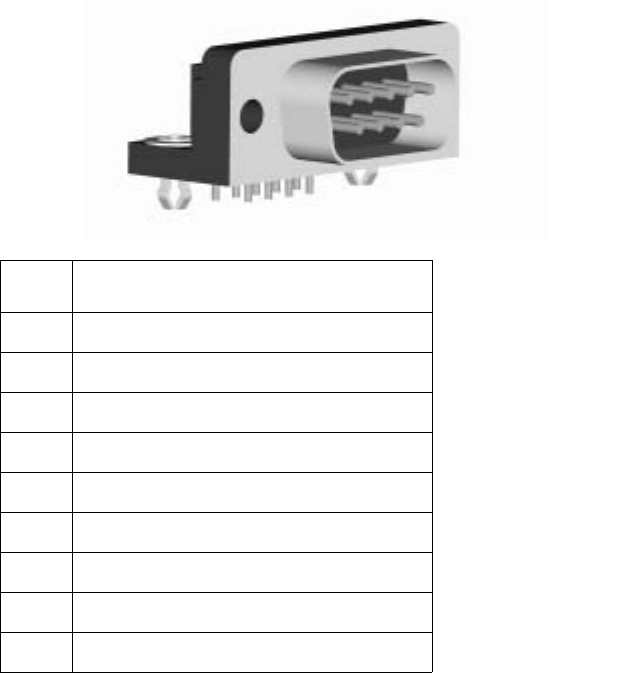
DB-9 Serial Interface (P1)
The following figure helps you locate specific DB-9 pins and
the table maps signals to pins.
Pin Signal
1 Data Carrier Detect (DCD)
2 Receive Data (RxD)
3 Transmit Data (TxD)
4 Data Terminal Ready (DTR)
5 Signal/Chassis Ground (GND)
6 Data Set Ready (DSR)
7 Request To Send (RTS)
8 Clear To Send (CTS)
9 Unused
Pin 1
Pin 5
Pin 6 Pin 9
16 Digi One EM Hardware Reference
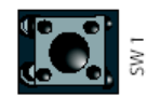
Reset Switch (SW1)
The reset switch reboots the Digi One EM.

Digi One EM Hardware Reference 17
Power Jack (P7)
The power jack accepts 5 volts DC +/- 5% from a regulated
power supply. The development board is polarity sensitive.
The +5 volts is assumed to be the center contact on
connector, and the ground is the outside of the connector
barrel, as shown in the following figure.

18 Digi One EM Hardware Reference
LEDs (CR4 - CR11)
The LED labeled CR4 is a power indicator. The other seven
LEDs display EIA-232 signal activity. The following table
describes the specific signal associated with each LED.
LED Signal
CR5 Tx (Transmit Data)
CR6 Rx (Receive Data)
CR7 CTS (Clear to Send)
CR8 RTS (Request to Send)
CR9 DTR (Data Terminal Ready)
CR10 DSR (Data Set Ready)
CR11 DCD (Data Carrier Detect)
Digi One EM Hardware Reference 19
Chapter 4
Sample Application: TTL Signals to
EIA-232
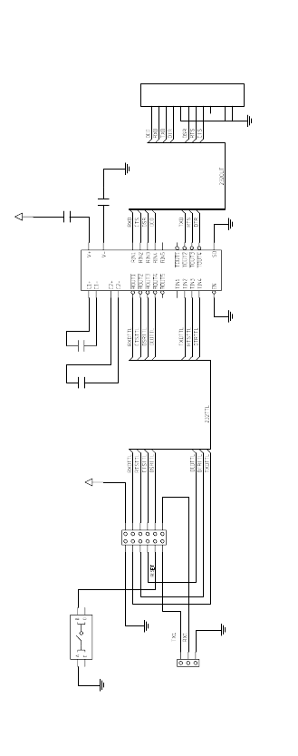
The following figure is an example of how to convert the Digi
One EM signals to normal serial voltage levels.
0.1uF
1
2
C6
0.1uF
1
2
C4
0.1uF
1
2
C3
0.1uF
2
1
C5
+5V
GND
11
10
9
8
7
6
5
4
3
2
1
DB9
P1
RS-232 SERIAL 9-PIN CONNECTOR
SHIELD
SHIELD
GND
GND
17
13
25
24
16
15
14
12
2821
120
36
27
19 18
22 23
26 27
54
89
ADM211E
U1
RS-232 LINE RECVR 5RX 4TX
+5V
GND
1211
109
87
65
43
21
SOCKET 2X6
DIGI ONE EM CONNECTOR
P6
3
2
1
RESERVED HEADER
P5
GND
GND GND
RESET SWITCH
13
24
SW1
20 Digi One EM Hardware Reference
Appendix A Digi One EM Specifications
Network Interfaces
• RJ-45 connector
• 10/100Base-T
• Half- and full-duplex support
Serial Interface
One TTL EIA-232 serial interface
Data Rates (bps)
110, 134, 150, 200, 300, 600, 1200, 2400, 3600, 4800, 9600,
19200, 38400, 57600, 115200, 230400
Modem Control
DTR, DSR, DCD
Flow Control Options
RTS/CTS, DTR/DSR, XON/XOFF, None
Environmental
• Operating Temperature: 50 0F to 131 0F (10 0C to 55 0C)
• Humidity: 5% to 90%
• Altitude: 12,000 feet (3657.60 meters)
Power Requirements
+5VDC @ 370 mA to 9VDC @ 230 mA typical
Mechanical
• Length: 1.93 inches (49.02 millimeters)
• Width: 1.57 inches (39.87 millimeters)
• Height: 0.974 inches (24.73 millimeters)
Digi One EM Hardware Reference 21
Appendix B Digi One EM Certifications
This product complies with the following standards:
FCC Part 15 Class A
Radio Frequency Interference (RFI) (FCC 15.105)
This equipment has been tested and found to comply with the
limits for Class A digital devices pursuant to Part 15 of the
FCC Rules. These limits are designed to provide reasonable
protection against harmful interference in a residential
environment. This equipment generates, uses, and can
radiate radio frequency energy, and if not installed and used
in accordance with the instruction manual, may cause
harmful interference to radio communications. However,
there is no guarantee that interference will not occur in a
particular installation. If this equipment does cause harmful
interference to radio or television reception, which can be
determined by turning the equipment off and on, the user is
encouraged to try and correct the interference by one or more
of the following measures:
• Reorient or relocate the receiving antenna.
• Increase the separation between the equipment and the
receiver.
• Connect the equipment into an outlet on a circuit different
from that to which the receiver is connected.
• Consult the dealer or an experienced radio/TV technician
for help.
Labeling Requirements (FCC 15.19)
This device complies with Part 15 of FCC rules. Operation is
subject to the following two conditions: (1) this device may
not cause harmful interference, and (2) this device must
accept any interference received, including interference that
may cause undesired operation.
22 Digi One EM Hardware Reference
Modifications (FCC 15.21)
Changes or modifications to this equipment not expressly
approved by Digi may void the user’s authority to operate this
equipment.
ICES 003 Class A
This Class A digital apparatus meets the requirements of the
Canadian Interference-Causing Equipment Regulations.
Cet appareil numérique de la Classe A respecte toutes les
exigences du Règlement sur le matériel brouilleur du
Canada.
Product Safety
• UL 60950
• EN60950
• CSA 22.2 No. 60950
Digi One EM Hardware Reference
Digi One EM Hardware Reference
