Digi MCWIFI Wireless 802.11b/g Embedded Module User Manual RCM5600WM
Digi International Inc Wireless 802.11b/g Embedded Module RCM5600WM
Digi >
Users Manual
MiniCore RCM5600W
C-Programmable Wi-Fi Core Module
User’s Manual
019–0174 • 090128–B

MiniCore RCM5600W
Digi International Inc.
www.rabbit.com
MiniCore RCM5600W User’s Manual
Part Number 019-0174 • 090128–B • Printed in U.S.A.
©2009 Digi International Inc. • All rights reserved.
Digi International reserves the right to make changes and
improvements to its products without providing notice.
Trademarks
Rabbit, MiniCore, and Dynamic C are registered trademarks of Digi International Inc.
Wi-Fi is a registered trademark of the Wi-Fi Alliance.
Rabbit 5000 and MiniCore are trademarks of Digi International Inc.
No part of the contents of this manual may be reproduced or transmitted in any form or by any means
without the express written permission of Digi International.
Permission is granted to make one or more copies as long as the copyright page contained therein is
included. These copies of the manuals may not be let or sold for any reason without the express written
permission of Digi International.
The latest revision of this manual is available on the Rabbit Web site, www.rabbit.com,
for free, unregistered download.

User’s Manual
TABLE OF CONTENTS
Chapter 1. Introduction 1
1.1 RCM5600W Features ...........................................................................................................................2
1.2 Advantages of the RCM5600W............................................................................................................3
1.3 Development and Evaluation Tools......................................................................................................4
1.3.1 RCM5600W Standard Development Kit ......................................................................................4
1.3.2 RCM5600W Deluxe Development Kit.........................................................................................4
1.3.3 Optional Add-Ons.........................................................................................................................5
1.3.4 Software ........................................................................................................................................5
1.3.5 Online Documentation ..................................................................................................................5
1.4 Certifications.........................................................................................................................................6
1.4.1 FCC Part 15 Class B .....................................................................................................................6
1.4.2 Industry Canada Labeling.............................................................................................................7
1.4.3 Europe ...........................................................................................................................................8
Chapter 2. Getting Started 9
2.1 Install Dynamic C .................................................................................................................................9
2.2 Hardware Connections........................................................................................................................10
2.2.1 Step 1 — Prepare the Interface Board for Development ............................................................10
2.2.2 Step 2 — Install Module on Interface Board..............................................................................11
2.2.3 Step 3 — Connect Antenna.........................................................................................................12
2.2.4 Step 4 — Connect USB Cable....................................................................................................12
2.3 Run a Sample Program .......................................................................................................................14
2.3.1 Troubleshooting ..........................................................................................................................15
2.4 Where Do I Go From Here? ...............................................................................................................16
2.4.1 Technical Support .......................................................................................................................16
Chapter 3. Running Sample Programs 17
3.1 Introduction.........................................................................................................................................17
3.2 Sample Programs ................................................................................................................................18
Chapter 4. Hardware Reference 21
4.1 RCM5600W Digital Inputs and Outputs ............................................................................................22
4.1.1 Memory I/O Interface .................................................................................................................28
4.1.2 Other Inputs and Outputs............................................................................................................28
4.2 Serial Communication ........................................................................................................................29
4.2.1 Serial Ports..................................................................................................................................29
4.2.2 Programming Port.......................................................................................................................30
4.3 Wi-Fi...................................................................................................................................................31
4.3.1 Antenna Grounding Requirements..............................................................................................33
4.4 Programming Modes...........................................................................................................................34
4.4.1 Standalone Operation of the RCM5600W..................................................................................35
4.5 Other Hardware...................................................................................................................................36
4.5.1 Clock Doubler.............................................................................................................................36
4.5.2 Spectrum Spreader ......................................................................................................................36

MiniCore RCM5600W
4.6 Memory.............................................................................................................................................. 37
4.6.1 SRAM.........................................................................................................................................37
4.6.2 Flash Memory............................................................................................................................. 37
4.6.3 Encryption RAM Memory ......................................................................................................... 37
Chapter 5. Software Reference 39
5.1 More About Dynamic C..................................................................................................................... 39
5.2 Dynamic C Function Calls................................................................................................................ 41
5.2.1 Digital I/O................................................................................................................................... 41
5.2.2 Serial Communication Drivers................................................................................................... 41
5.2.3 Serial Flash Memory Use........................................................................................................... 42
5.2.4 User and ID Blocks .................................................................................................................... 44
5.2.5 Wi-Fi Drivers.............................................................................................................................. 44
5.2.6 Interface Board Function Calls................................................................................................... 45
5.2.6.1 Board Initialization............................................................................................................ 45
5.3 Upgrading Dynamic C ....................................................................................................................... 46
5.3.1 Add-On Modules........................................................................................................................ 46
Chapter 6. Using the Wi-Fi Features 47
6.1 Introduction to Wi-Fi ......................................................................................................................... 47
6.1.1 Infrastructure Mode.................................................................................................................... 47
6.1.2 Ad-Hoc Mode............................................................................................................................. 48
6.1.3 Additional Information............................................................................................................... 48
6.2 Running Wi-Fi Sample Programs ...................................................................................................... 49
6.2.1 Wi-Fi Setup ................................................................................................................................ 50
6.2.2 What Else You Will Need.......................................................................................................... 51
6.2.3 Configuration Information.......................................................................................................... 52
6.2.3.1 Network/Wi-Fi Configuration........................................................................................... 52
6.2.3.2 PC/Laptop/PDA Configuration ......................................................................................... 53
6.2.4 Wi-Fi Sample Programs ............................................................................................................. 55
6.2.4.1 Wi-Fi Operating Region Configuration............................................................................. 55
6.2.4.2 Wi-Fi Operation................................................................................................................. 57
6.2.5 RCM5600W Sample Programs.................................................................................................. 60
6.3 Dynamic C Wi-Fi Configurations...................................................................................................... 67
6.3.1 Configuring TCP/IP at Compile Time .......................................................................................67
6.3.2 Configuring TCP/IP at Run Time............................................................................................... 71
6.3.3 Other Key Function Calls........................................................................................................... 71
6.4 Where Do I Go From Here?............................................................................................................... 72
Appendix A. RCM5600W Specifications 73
A.1 Electrical and Mechanical Characteristics ........................................................................................ 74
A.1.1 mini PCI Express Connector Design Recommendations .......................................................... 78
A.2 Rabbit 5000 Microprocessor Characteristics .................................................................................... 79
Appendix B. Interface Board 81
B.1 Introduction ....................................................................................................................................... 82
B.1.1 Interface Board Features............................................................................................................ 83
B.2 Mechanical Dimensions and Layout ................................................................................................. 84
B.2.1 Headers ...................................................................................................................................... 85
B.3 Power Supply..................................................................................................................................... 86
B.4 Using the Interface Board.................................................................................................................. 87
B.4.1 Add Additional Boards.............................................................................................................. 88
B.5 Interface Board Jumper Configurations ............................................................................................ 89

User’s Manual
Appendix C. Prototyping Board 91
C.1 Introduction........................................................................................................................................92
C.1.1 Prototyping Board Features........................................................................................................92
C.2 Mechanical Dimensions and Layout..................................................................................................93
C.2.1 Headers.......................................................................................................................................95
C.3 Using the Prototyping Board..............................................................................................................96
C.3.1 Add Additional Boards...............................................................................................................97
Appendix D. Digital I/O Accessory Board 99
D.1 Introduction......................................................................................................................................100
D.1.1 Digital I/O Accessory Board Features .....................................................................................100
D.2 Mechanical Dimensions and Layout................................................................................................101
D.2.1 Headers.....................................................................................................................................102
D.3 Using the Digital I/O Accessory Board ...........................................................................................103
D.3.1 Configuration ...........................................................................................................................104
D.3.2 Add Additional Boards ............................................................................................................106
Appendix E. Serial Communication Accessory Board 107
E.1 Introduction ......................................................................................................................................108
E.1.1 Serial Communication Accessory Board Features ...................................................................108
E.2 Mechanical Dimensions and Layout................................................................................................109
E.2.1 Headers .....................................................................................................................................110
E.3 Using the Serial Communication Accessory Board.........................................................................111
E.3.1 Configuration............................................................................................................................112
E.3.2 Add Additional Boards.............................................................................................................114
Appendix F. Power Supply 115
F.1 Power Supplies .................................................................................................................................115
F.1.1 Battery Backup .........................................................................................................................116
F.1.2 Battery-Backup Circuit.............................................................................................................117
F.1.3 Reset Generator.........................................................................................................................117
Index 119
Schematics 123

MiniCore RCM5600W

User’s Manual 1
1. INTRODUCTION
The RCM5600W MiniCore module provides a compact module in
a mini PCI Express form factor with integrated Wi-Fi/802.11b/g
functionality to allow you to create a low-cost, low-power, Wi-Fi
based control and communications solution for your embedded
system.
A Development Kit is available with the essentials that you need
to design your own microprocessor-based system, and includes
a complete Dynamic C software development system. The
Development Kit also contains an Interface Board with a USB
connection that will allow you to evaluate the RCM5600W, and
a Prototyping Board to help you to develop your own applica-
tions. You will also be able to write and test software for the
RCM5600W modules, including Wi-Fi applications.
The RCM5600W has a Rabbit 5000 microprocessor operating at up to 73.73 MHz, flash
memory, two clocks (main oscillator and real-time clock), and the circuitry necessary to
reset and manage the Rabbit 5000. An edge connector brings out the RCM5600W user
interface to a 52-pin mini PCI Express socket on the motherboard the RCM5600W is
mounted on.
The RCM5600W receives its +3.3 V power from the motherboard on which it is mounted.
The RCM5600W can interface with other CMOS-compatible digital devices through the
motherboard.

2MiniCore RCM5600W
1.1 RCM5600W Features
•Small size: 1.20" × 2.00" × 0.40"
(30 mm × 51 mm × 10 mm)
•Microprocessor: Rabbit 5000 running
at 73.73 MHz
•Up to 35 general-purpose I/O lines each configurable with up to four alternate functions
•3.3 V I/O lines
•
Six CMOS-compatible serial ports — f
our ports are configurable as a clocked serial port
(SPI), and two ports are configurable as SDLC/HDLC serial ports.
•Airoha single-chip 802.11b/g transceiver
•External I/O bus can be configured for 8 data lines, 8 address lines (shared with parallel
I/O lines), and I/O read/write
•1MB SRAM and 1MB serial flash memory
•Battery-backable real-time clock
•Watchdog supervisor
Currently there is one RCM5600W production model. Table 1 summarizes its main features.
The RCM5600W is programmed through a USB connector on the motherboard using a
USB cable supplied with the Development Kit.
NOTE: The RabbitLink cannot be used to program the RCM5600W.
Appendix A provides detailed specifications for the RCM5600W.
Table 1. RCM5600W Features
Feature RCM5600W
Microprocessor Rabbit® 5000 at 73.73 MHz
SRAM 1MB
Serial Flash Memory
(program) 1MB
Serial Ports
6 shared high-speed, CMOS-compatible ports:
6 are configurable as asynchronous serial ports;
4 are configurable as clocked serial ports (SPI);
2 are configurable as SDLC/HDLC serial ports;
1 asynchronous serial port is used during programming
Wi-Fi 802.11b/g standard, ISM 2.4 GHz

User’s Manual 3
1.2 Advantages of the RCM5600W
•Fast time to market using a fully engineered, “ready-to-run/ready-to-program” micro-
processor core.
•Competitive pricing when compared with the alternative of purchasing and assembling
individual components.
•Easy C-language program development and debugging
•Rabbit Field Utility to download compiled Dynamic C .bin files.
•Generous memory size allows large programs with tens of thousands of lines of code,
and substantial data storage.
4MiniCore RCM5600W
1.3 Development and Evaluation Tools
1.3.1 RCM5600W Standard Development Kit
The RCM5600W Standard Development Kit contains the hardware essentials you will
need to use your RCM5600W module. These items are supplied in the standard version of
the Development Kit.
•RCM5600W module.
•2.4 GHz dipole antenna with mounting bracket and U.FL to RP-SMA connector cable.
•Interface Board with standoffs/connectors.
•Prototyping Board with standoffs/connectors.
•USB cable to program RCM5600W via Interface Board.
•Dynamic C CD-ROM, including product documentation on disk.
•Getting Started instructions.
•Registration card.
Figure 1. RCM5600W Standard Development Kit
1.3.2 RCM5600W Deluxe Development Kit
In addition to the items included in the standard Development Kit, the Deluxe Develop-
ment Kit contains the following items.
•Universal AC adapter, 5 V DC, 2 A (includes Canada/Japan/U.S., Australia/N.Z., U.K.,
and European style plugs). Development Kits sold in North America may contain an
AC adapter with only a North American style plug.
•Digital I/O and Serial Communication accessory boards for use with certain sample
programs.
•DB9 to 10-pin header serial cable.
•Rabbit 5000 Processor Easy Reference poster.
Rabbit, Dynamic C, and Digi are registered trademarks of Digi International Inc.
MiniCore RCM5600W
The RCM5600W MiniCore module provides a compact module in a mini PCI Express form factor
with integrated Wi-Fi/802.11b/g functionality to allow you to create a low-cost, low-power, Wi-Fi
based control and communications solution for your embedded system. These Getting Started instruc-
tions included with the Development Kit will help you get your RCM5600W up and running so that
you can run the sample programs to explore its capabilities and develop your own applications.
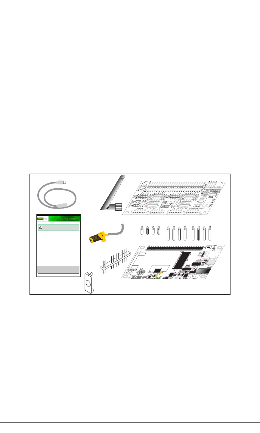
Development Kit Contents
The RCM5600W Standard Development Kit contains the following items
• RCM5600W module.
• 2.4 GHz dipole antenna with mounting bracket and RP-SMA connector cable.
• Interface Board with standoffs/connectors.
• Prototyping Board with standoffs/connectors.
• USB cable to program RCM5600W via Interface Board.
•Dynamic C®CD-ROM, with complete product documentation on disk.
•Getting Started instructions.
• Registration card.
Visit our online Rabbit store at www.rabbit.com/store/ for the latest information on peripherals and
accessories that are available for the RCM5600W MiniCore modules.
Step 1 — Install Dynamic C®
Before doing any development, you must install Dynamic C. Insert the CD from the Development Kit
in your PC’s CD-ROM drive. If the installation does not auto-start, run the setup.exe program in
the root directory of the Dynamic C CD. Install any Dynamic C modules after you install Dynamic C.
CAUTION: Provide ESD protection such as smocks and grounding straps on your footwear
while assembling the RCM5600W module, installing it on another board, and while making or
removing any connections.
USB Cable
Interface Board
Getting Started
Instructions
Standoffs
Prototyping Board
IDC Header
Strip
Antenna
Antenna
Bracket
RP-SMA Connector
Cable

User’s Manual 5
1.3.3 Optional Add-Ons
Rabbit has a power supply and an Antenna Add-On Kit available for the RCM5600W.
•Separate power supply (Part No. 101-1273)
The universal AC adapter is available for customers who purchased the Standard
Development Kit. This universal AC adapter may be used if your RCM5600W does not
work when you power it through the USB cable, and you do not have your own +5 V
DC power supply.
•Antenna Add-On Kit (Part No. 101-1295)
X2.4 GHz dipole antenna
XU.FL to RP-SMA connector cable
RCM5600W modules purchased individually or in production quantities do not come
with an antenna or a connector cable. The Antenna Add-On Kit provides a convenient
source of these items.
Visit our Web site at www.rabbit.com or contact your Rabbit sales representative or
authorized distributor for further information.
1.3.4 Software
The RCM5600W is programmed using version 10.50 or later of Dynamic C. A compatible
version is included on the Development Kit CD-ROM. This version of Dynamic C
includes the popular µC/OS-II real-time operating system, point-to-point protocol (PPP),
FAT file system, RabbitWeb, and other select libraries.
Rabbit also offers for purchase the Rabbit Embedded Security Pack featuring the Secure
Sockets Layer (SSL) and a specific Advanced Encryption Standard (AES) library. In addi-
tion to the Web-based technical support included at no extra charge, a one-year telephone-
based technical support subscription is also available for purchase. Visit our Web site at
www.rabbit.com for further information and complete documentation, or contact your
Rabbit sales representative or authorized distributor
1.3.5 Online Documentation
The online documentation is installed along with Dynamic C, and an icon for the docu-
mentation menu can be placed on the workstation’s desktop. Double-click this icon to
reach the menu. If the icon is missing, use your browser to find and load default.htm in
the docs folder, found in the Dynamic C installation folder.
The latest versions of all documents are always available for free, unregistered download
from our Web sites as well.

6MiniCore RCM5600W
1.4 Certifications
The systems integrator and the end-user are ultimately responsible for the channel range
and power limits complying with the regulatory requirements of the country where the end
device will be used. Dynamic C function calls and sample programs illustrate how this is
achieved by selecting the country or region, which sets the channel range and power limits
automatically. See Section 6.2.4.1 for additional information and sample programs dem-
onstrating how to configure an end device to meet the regulatory channel range and power
limit requirements.
Only RCM5600W modules bearing the FCC certification are certified for use in Wi-Fi
enabled end devices, and any applications must have been compiled using Dynamic C
v. 10.50 or later. The certification is valid only for RCM5600W modules equipped with
the dipole antenna that is included with the modules, or a detachable antenna with a 60 cm
coaxial cable (Digi International part number 29000105). Follow the antenna grounding
recommendations provided in Section 4.3.1. Changes or modifications to this equipment
not expressly approved by Digi International may void the user's authority to operate this
equipment.
In the event that these conditions cannot be met, then the FCC certification is no longer
considered valid and the FCC ID can not be used on the final product. In these circum-
stances, the systems integrator or end-user will be responsible for re-evaluating the end
device (including the transmitter) and obtaining a separate FCC certification.
NOTE: Any regulatory certification is voided if the RF shield on the RCM5600W
module is removed.
1.4.1 FCC Part 15 Class B
The RCM5600W MiniCore module has been tested and found to comply with the limits
for Class B digital devices pursuant to Part 15 Subpart B, of the FCC Rules. These limits
are designed to provide reasonable protection against harmful interference in a residential
environment. This equipment generates, uses, and can radiate radio frequency energy, and
if not installed and used in accordance with the instruction manual, may cause harmful
interference to radio communications. However, there is no guarantee that interference
will not occur in a particular installation. If this equipment does cause harmful interfer-
ence to radio or television reception, which can be determined by turning the equipment
off and on, the user is encouraged to try and correct the interference by one or more of the
following measures:
•Reorient or relocate the receiving antenna.
•Increase the separation between the equipment and the receiver.
•Connect the equipment into an outlet on a circuit different from that to which the
receiver is connected.
•Consult the dealer or an experienced radio/TV technician for help.

User’s Manual 7
Labeling Requirements (FCC 15.19)
If the FCC identification number is not visible when the module is installed inside another
device, then the outside of the device into which the module is installed must also display
a label referring to the enclosed module or the device must be capable of displaying the
FCC identification number electronically. This exterior label can use wording such as the
following: “Contains Transmitter Module FCC ID: MCQ-MCWIFI” or “Contains FCC
ID: MCQ-MCWIFI.” Any similar wording that expresses the same meaning may be used.
The following caption must be included with documentation for any device incorporating
the RCM5600W MiniCore module.
1.4.2 Industry Canada Labeling
FCC ID: MCQ-MCWIFI
This device complies with Part 15 of FCC rules. Operation is
subject to the following two conditions:
(1) this device may not cause harmful interference, and
(2) this device must accept any interference received, including
interference that may cause undesired operation.
Caution — Exposure to Radio-Frequency Radiation.
To comply with FCC RF exposure compliance requirements, for mobile
configurations, a separation distance of at least 20 cm must be maintained
between the antenna of this device and all persons.
This device must not be co-located or operating in conjunction with any
other antenna or transmitter.
IC: 1846A-MCWIFI RCM5600W
DIGI INTL
This Class B digital apparatus complies with Canadian standard
ICES-003.
Cet appareil numérique de la classe B est conforme à la norme
NMB-003 du Canada.

8MiniCore RCM5600W
1.4.3 Europe
The marking shall include as a minimum:
•the name of the manufacturer or his trademark;
•the type designation;
•equipment classification, (see below).
NOTE: Manufacturers are recommended to declare the classification of their devices in
accordance with Table 2 and EN 300 440-2 [5] clause 4.2, as relevant. In particular,
where an SRD that may have inherent safety of human life implications, manufacturers
and users should pay particular attention to the potential for interference from other
systems operating in the same or adjacent bands.
Regulatory Marking
The equipment shall be marked, where applicable, in accordance with CEPT/ERC Recom-
mendation 70-03 or Directive 1999/5/EC, whichever is applicable. Where this is not appli-
cable, the equipment shall be marked in accordance with the National Regulatory
requirements.
Receiver
Class Risk Assessment of Receiver Performance
1Highly reliable SRD communication media, e.g., serving human life
inherent systems (may result in a physical risk to a person).
2Medium reliable SRD communication media, e.g., causing
inconvenience to persons that cannot be overcome by other means.
3Standard reliable SRD communication media,e.g., inconvenience to
persons that can simply be overcome by other means.

User’s Manual 9
2. GETTING STARTED
This chapter describes the RCM5600W hardware in more detail, and
explains how to set up and use the accompanying Interface Board.
NOTE: This chapter (and this manual) assume that you have the RCM5600W Develop-
ment Kit. If you purchased an RCM5600W module by itself, you will have to adapt the
information in this chapter and elsewhere to your test and development setup.
2.1 Install Dynamic C
To develop and debug programs for the RCM5600W modules (and for all other Rabbit
hardware), you must install and use Dynamic C.
If you have not yet installed Dynamic C version 10.50 (or a later version), do so now by
inserting the Dynamic C CD from the Development Kit in your PC’s CD-ROM drive. If
autorun is enabled, the CD installation will begin automatically.
If autorun is disabled or the installation does not start, use the Windows Start | Run menu
or Windows Disk Explorer to launch setup.exe from the root folder of the CD-ROM.
The installation program will guide you through the installation process. Most steps of the
process are self-explanatory.
Once your installation is complete, you will have up to three new icons on your PC desk-
top. One icon is for Dynamic C, another opens the documentation menu, and the third is for
the Rabbit Field Utility, a tool used to download precompiled software to a target system.
If you have purchased any of the optional Dynamic C modules, install them after installing
Dynamic C. The modules may be installed in any order. You must install the modules in
the same folder where Dynamic C was installed.
10 MiniCore RCM5600W
2.2 Hardware Connections
There are four4 steps to connecting the Interface Board for use with Dynamic C and the
sample programs:
1. Insert standoffs/connectors on the Interface Board.
2. Install the RCM5600W module on the Interface Board.
3. Connect antenna.
4. Connect the USB cable between the Interface Board and the workstation PC.
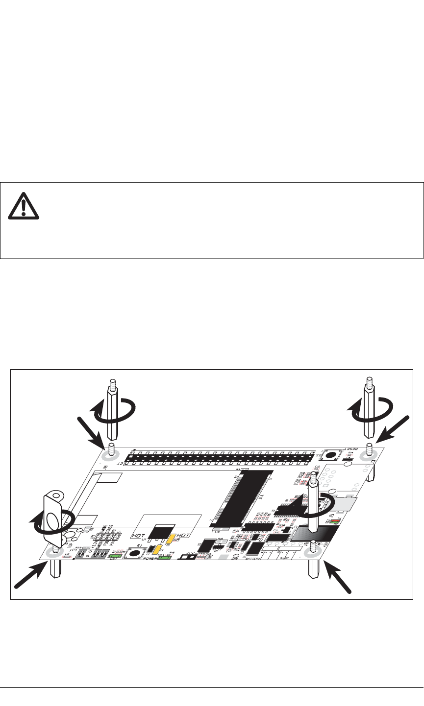
2.2.1 Step 1 — Prepare the Interface Board for Development
Insert a short plastic standoff supplied from the Development Kit in one of the corner
holes from the bottom of the Interface Board, then secure it with a long plastic standoff
from above as shown in Figure 2. Repeat this step so that plastic standoffs/connectors are
in place at three positions and the antenna bracket is at the fourth position.
Figure 2. Insert Standoffs/Connectors
CAUTION: Provide ESD protection such as smocks and grounding straps on your
footwear.while assembling the RCM5600W module, installing it on another
board, and while making or removing any connections.
Remember to use ESD protection regardless of whether you are working with the
RCM5600W module on the Interface Board or in your own OEM application.
User’s Manual 11
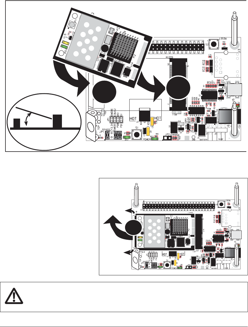
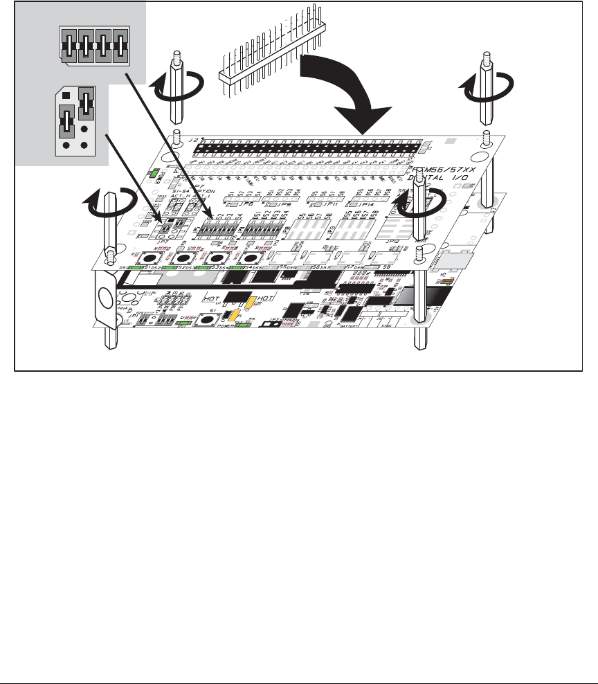
2.2.2 Step 2 — Install Module on Interface Board
Position the RCM5600W module with the edge connectors facing the mini PCI Express
socket J1A at an angle as shown in Figure 3 below. Insert the edge connectors into the
mini PCI Express socket J1A, then press down on the opposite edge of the RCM5600W
module to snap it into place in holder J1B.
Figure 3. Install the RCM5600W Module on the Interface Board
Should you need to remove the
RCM5600W module, use two
fingernails to hold back the spring
clip at J1B from the two
RCM5600W corners, lift up the
edge of the RCM5600W above
J1B, then pull the RCM5600W
away to remove the edge connec-
tors from the mini PCI Express
socket.
CAUTION: Remove power before attempting to insert or remove the RCM5600W
in the mini PCI Express socket.
Interface
Board
J1A
J1B
J1B
RCM5600W
RCM5600W
J1A
J1B
12 MiniCore RCM5600W
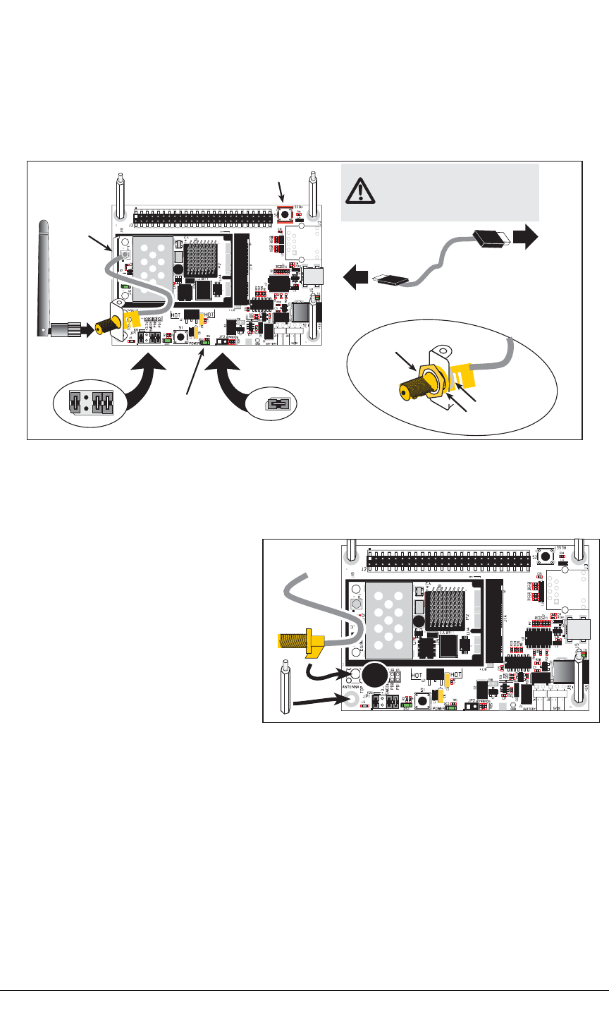
2.2.3 Step 3 — Connect Antenna
Install the antenna U.FL to RP-SMA connector cable in the bracket using two lockwashers
and the nut as shown in the insert in Figure 4. Connect the wire to connector P1 on the
RCM5600W, then attach the antenna to the antenna RP-SMA connector.
Figure 4. Connect Antenna and USB Cable
Alternate Antenna Connector Cable Installation
2.2.4 Step 4 — Connect USB Cable
The USB cable connects the RCM5600W to the PC running Dynamic C to download pro-
grams and to monitor the RCM5600W module during debugging. It also supplies power to
the Interface Board and the RCM5600W via the USB interface.
Connect the USB cable between USB connector J5 on the Interface Board and your PC as
shown in Figure 4. Note that the USB cable connectors are different at either end, so there
is only one way to connect them between the PC and the Interface Board.
If you prefer, you may solder the
RP-SMA antenna connector directly
to the Interface Board at P1 as shown
in the diagram at right. Before doing
so, make sure that you use a long
plastic standoff instead of the an-
tenna bracket. Then connect the wire
to connector P1 on the RCM5600W,
and attach the antenna to the antenna
RP-SMA connector.
RESET
JP1
4
3
2
1
6
57
8
Power LED
JP2
To
PC USB port
J5
Connect
wire to P1
nut
lockwashers
CAUTION: Do not remove the RF shield
since any attempt to remove the shield
will damage the RF circuits underneath it.
Any regulatory certification is voided
if the RF shield on the RCM5600W
module is removed.
P1
User’s Manual 13
Your PC should recognize the new USB hardware, and the LEDs next to the USB connec-
tor on the Interface Board will flash — if you get an error message, you will have to install
USB drivers. Drivers for Windows XP are available in the Dynamic C Drivers\Rabbit
USB Programming Cable\WinXP_2K folder — double-click DPInst.exe to install
the USB drivers. Drivers for other operating systems are available online at
www.ftdichip.com/Drivers/VCP.htm.
The green power LED on the Interface Board should light up when you connect the USB
cable. The RCM5600W and the Interface Board are now ready to be used.
NOTE: A RESET button is provided on the Interface Board above the Ethernet jack to
allow a hardware reset without disconnecting power.
NOTE: Pins 1–2 on header JP1 on the Interface Board must be jumpered to download
and debug applications and sample programs with Dynamic C running. Pins 1–2 should
be left unjumpered to run an program already loaded in flash memory.
CAUTION: Do not jumper pins 1–3 on header JP1 on the Interface Board.
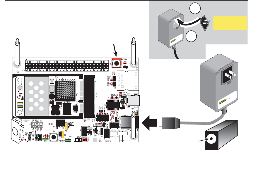
Alternate Power Supply Connections — Deluxe Development Kit
The deluxe Development Kit contains a separate AC adapter that may be used to supply
power to the Interface Board and the RCM5600W when the USB cable is not connected or
when more power is needed than the USB cable is able to supply. The AC adapter may
also be used to supply power when the USB cable is connected, in which case the power
supply through the USB cable will be disconnected automatically.
Figure 5. Alternate Power Supply Connections—Deluxe Development Kit
AC Adapter
RESET
Remove slot cover,
insert tab into slot
Snap plug into place
2
1
Assemble
AC Adapter
+
J6
14 MiniCore RCM5600W
First, prepare the AC adapter for the country where it will be used by selecting the plug.
The deluxe Development Kit presently includes Canada/Japan/U.S., Australia/N.Z., U.K.,
and European style plugs. Snap in the top of the plug assembly into the slot at the top of
the AC adapter as shown in Figure 5, then press down on the spring-loaded clip below the
plug assembly to allow the plug assembly to click into place. Release the clip to secure the
plug assembly in the AC adapter.
Connect the AC adapter to DC input jack J6 on the Interface Board as shown in Figure 5.
Plug in the AC adapter. The green power LED on the Interface Board should light up. The
RCM5600W and the Interface Board are now ready to be used.
Note that the center pin of J6 is positive.
2.3 Run a Sample Program
If you already have Dynamic C installed, you are now ready to test your programming
connections by running a sample program. Start Dynamic C by double-clicking on the
Dynamic C icon on your desktop or in your Start menu. Select the “Communications” tab
in the Dynamic C Options > Project Options menu and verify that Use USB to Serial
Converter is selected to support the USB cable. Choose Store Program in RAM on the
“Compiler” tab for faster compiling when running sample programs. Click OK.
You may have to select the COM port assigned to the USB USB cable on your PC. In
Dynamic C, select Options > Project Options, then select this COM port on the “Com-
munications” tab, then click OK. You may type the COM port number followed by Enter
on your computer keyboard if the COM port number is outside the range on the dropdown
menu.
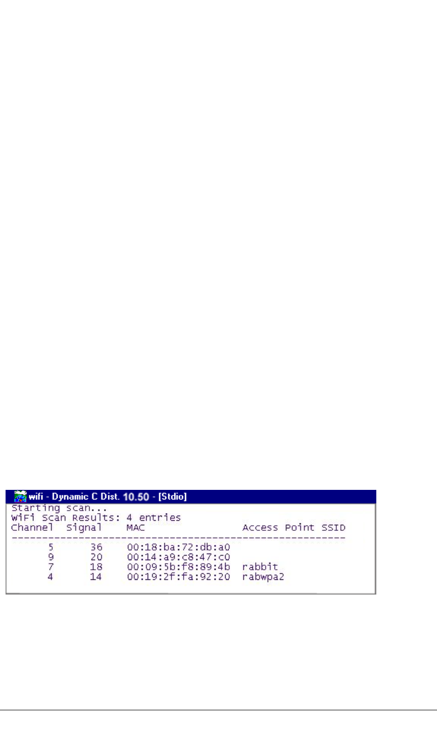
Now find the WIFISCAN.C sample program in the Dynamic C Samples\WiFi folder,
open it with the File menu, then compile and run the sample program by pressing F9.
The Dynamic C STDIO window will display Starting scan...., and will display a list
of access points/ad-hoc hosts similar to the one shown here.
The following fields are shown in the Dynamic C STDIO window.
•Channel—the channel the access point is on (1–11).
•Signal—the signal strength of the access point.
•MAC—the hardware (MAC) address of access point.
•Access Point SSID—the SSID the access point is using.

User’s Manual 15
2.3.1 Troubleshooting
It may be possible that your PC or laptop is unable to deliver enough current through the
USB connection if you are not using a separate power supply. The RCM5600W will not
operate in this case, and the solution is to use a separate 5 V power supply as described in
the Alternate Power Supply Connections section. Contact Technical Support (see
Section 2.4.1) or visit our Web site if you would like to get the universal AC adapter from
the Deluxe Development Kit.
If you receive the message Could Not Open Serial Port, check that the COM port
assigned to the USB cable was identified and set up in Dynamic C as described above.
This same error occurs when Windows has already allocated the COM port to another
process.
If you receive the message No Rabbit Processor Detected, the USB cable may
be connected to the wrong COM port, or the connection may be faulty. First, check both
ends of the USB cable to ensure that it is firmly plugged into the PC and the USB connec-
tor in the Interface Board. Ensure that the module is firmly and correctly installed in its
connector on the Interface Board.
If Dynamic C appears to compile the BIOS successfully, but you then receive a communi-
cation error message when you compile and load a sample program, it is possible that your
PC cannot handle the higher program-loading baud rate. Try changing the maximum
download rate to a slower baud rate as follows.
•Locate the Serial Options dialog on the “Communications” tab in the Dynamic C
Options > Project Options menu. Select a slower Max download baud rate. Click OK
to save.
If a program compiles and loads, but then loses target communication before you can
begin debugging, it is possible that your PC cannot handle the default debugging baud
rate. Try lowering the debugging baud rate as follows.
•Locate the Serial Options dialog on the “Communications” tab in the Dynamic C
Options > Project Options menu. Choose a lower debug baud rate. Click OK to save.
Press <Ctrl-Y> to force Dynamic C to recompile the BIOS. You should receive a BIOS
successfully compiled message once this step is completed successfully.

16 MiniCore RCM5600W
2.4 Where Do I Go From Here?
If the sample program ran fine, you are now ready to go on to other sample programs and to
develop your own applications. The source code for the sample programs is provided to allow
you to modify them for your own use. The RCM5600W User’s Manual also provides
complete hardware reference information for the RCM5600W, the Interface Board, the Proto-
typing Board, and the accessory boards in the Deluxe Development Kit.
For advanced development topics, refer to the Dynamic C User’s Manual, also in the
online documentation set.
2.4.1 Technical Support
NOTE: If you purchased your RCM5600W through a distributor or through a Rabbit part-
ner, contact the distributor or partner first for technical support.
If there are any problems at this point:
•Use the Dynamic C Help menu to get further assistance with Dynamic C.
•Check the Rabbit Technical Bulletin Board and forums at www.rabbit.com/support/bb/
and at www.rabbit.com/forums/.
•Use the Technical Support e-mail form at www.rabbit.com/support/.

User’s Manual 17
3. RUNNING SAMPLE PROGRAMS
To develop and debug programs for the RCM5600W (and for all
other Rabbit hardware), you must install and use Dynamic C.
This chapter provides a tour of its major features with respect to
the RCM5600W.
3.1 Introduction
To help familiarize you with the RCM5600W modules, Dynamic C includes several
sample programs. Loading, executing and studying these programs will give you a solid
hands-on overview of the RCM5600W’s capabilities, as well as a quick start with
Dynamic C as an application development tool.
NOTE: The sample programs assume that you have at least an elementary grasp of ANSI
C. If you do not, see the introductory pages of the Dynamic C User’s Manual for a sug-
gested reading list.
In order to run the sample programs discussed in this chapter and elsewhere in this manual,
1. Your RCM5600W must be installed on the Interface Board as described in Chapter 2,
“Getting Started.”
2. Dynamic C must be installed and running on your PC.
3. The USB cable must connect the Interface Board to your PC.
4. Power must be applied to the RCM5600W through the Interface Board.
Refer to Chapter 2, “Getting Started,” if you need further information on these steps.
To run a sample program, open it with the File menu (if it is not still open), then compile
and run it by selecting Run in the Run menu (or press F9). The RCM5600W must be in
Program Mode (see Figure 11) and must be connected to a PC using the USB cable.
Complete information on Dynamic C is provided in the Dynamic C User’s Manual.
18 MiniCore RCM5600W
3.2 Sample Programs
Of the many sample programs included with Dynamic C, several are specific to the
RCM5600W. These programs will be found in the SAMPLES\RCM5600W folder. Sample
programs in the SAMPLES folder one level up are generic samples that can be run on any
Rabbit-based product.
•FLASHLED.C—demonstrates the use of costatements to flash LED DS1 on the Inter-
face Board. PD0 on the RCM5600W is used to drive the LED.
•TOGGLESWITCH.C—monitors switch S1 and LED DS1 on the Interface Board. LED
DS1 on the Interface Board is turned on and off when you press switch S1. PD0 on the
RCM5600W is used to drive the LED, and PD1 detects the activity on switch S1.
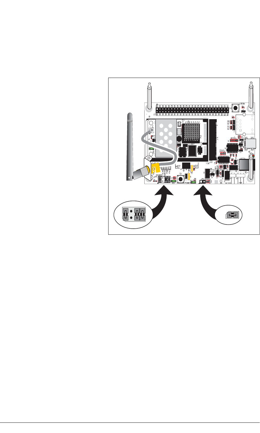
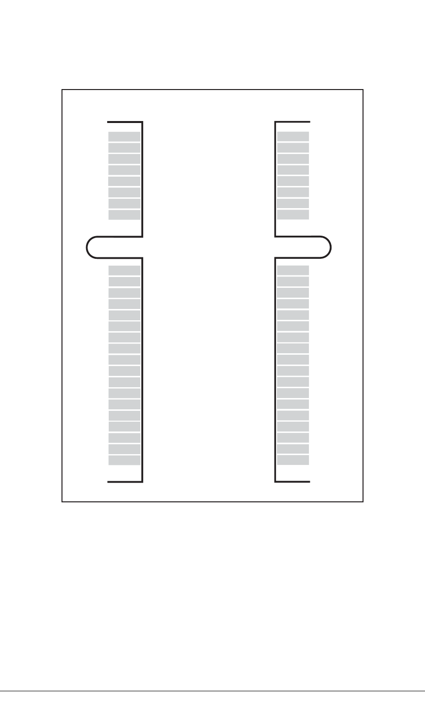
Before you compile and run the fol-
lowing sample programs, make sure
that pins 1–2, 5–6, and 7–8 on
header JP1 of the Interface Board
are jumpered. The pins on header
JP2 must also be jumpered. Each
sample program has comments that
describe the purpose and function of
the program. Follow the instructions
at the beginning of the sample
program.
CAUTION: Do not jumper pins
1–3 on header JP1 on the Inter-
face Board.
JP1
4
3
2
1
6
57
8
JP2
User’s Manual 19
The Digital I/O accessory board may also be used to run the TOGGLESWITCH.C and the
SERIALTOSERIAL.C sample programs. This accessory board is included only with the
Deluxe Development Kit.
To install the Digital I/O accessory board, insert the strip of header pins included with the
accessory board into the socket at J12 on the bottom side of the Digital I/O accessory
board. Then line up the Digital I/O accessory board with the Interface Board standoffs/
connectors and install the Digital I/O accessory board pins into socket J2 on the Interface
Board. Secure the Digital I/O accessory board with the long plastic standoffs/connectors
from above as shown in Figure 6—note that one plastic standoff/connector needs to be
inserted “upside down” to secure the Digital I/O accessory board to the antenna bracket.
Figure 6. Install Digital I/O Accessory Board
Pins 1–2, 3–4, 5–6, and 7–8 on headers JP5 and JP8 on the Digital I/O accessory board
must be jumpered. Pins 2–4 and 3–5 on header JP7 on the Digital I/O accessory board
must also be jumpered.
Uncomment the following line in the sample programs when you are using the Digital I/O
accessory board.
#define DIGITAL_IO_ACCESSORY
•TOGGLESWITCH.C—monitors switches S1, S2, S3, and S4 on the Digital I/O acces-
sory board and lights LEDs DS1–DS4 when the corresponding pushbutton switch is
pressed. LEDs DS1–DS2 on the Digital I/O accessory board are controlled by PA4–
PA7, and switches S1–S4 are controlled by PB4–PB7 respectively.
JP5
JP8
4
3
2
1
6
57
8
4
3
2
1
6
5
78
JP7
Install header connector strip
in bottom socket
20 MiniCore RCM5600W
The SERIALTOSERIAL.C sample program is in the SAMPLES\RCM5600W\SERIAL
folder.
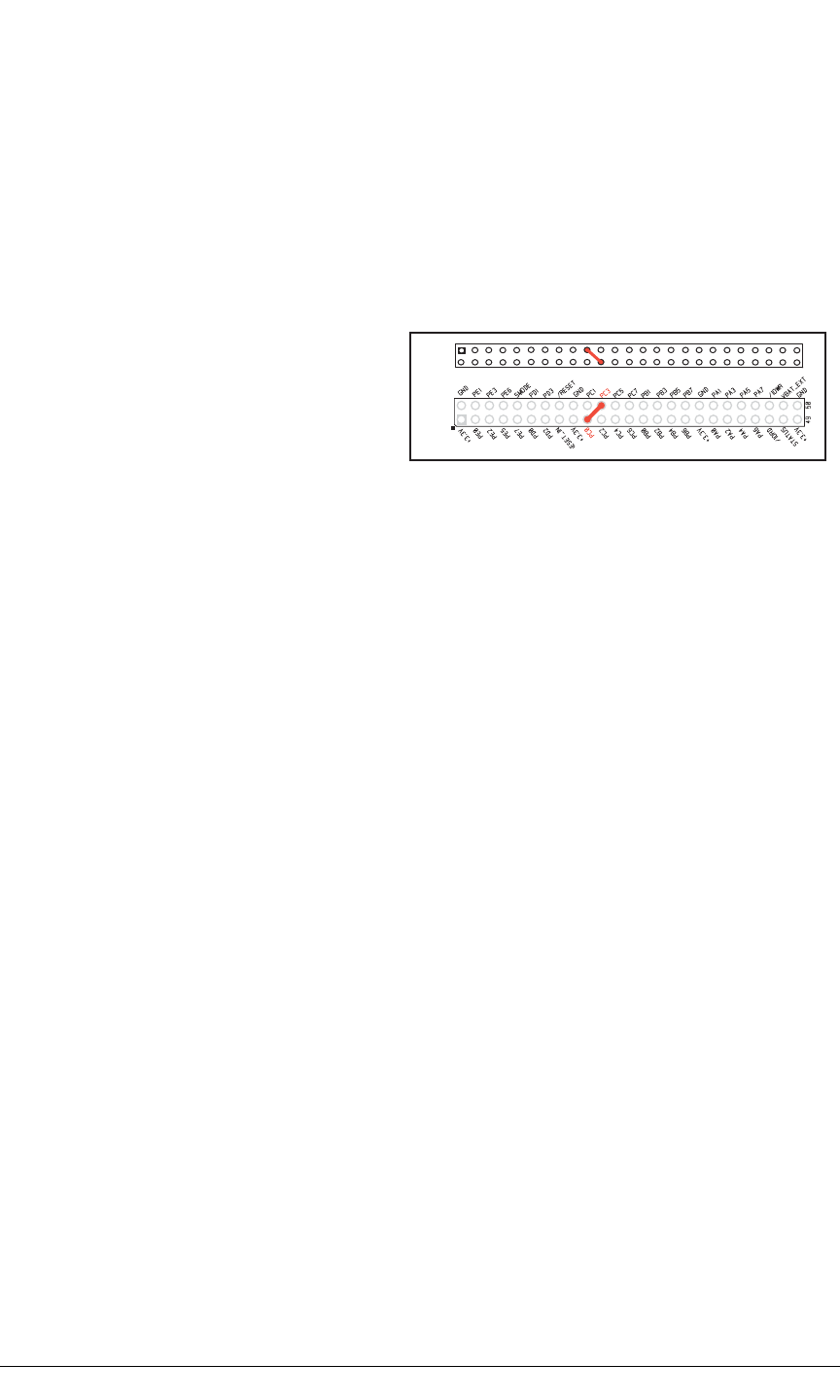
•SERIALTOSERIAL.C—monitors switches S1, S2, S3, and S4 on the Digital I/O acces-
sory board and lights LEDs DS1–DS4 when the corresponding pushbutton switch is
pressed. LEDs DS1–DS2 on the Digital I/O accessory board are controlled by PA4–PA7,
and switches S1–S4 are controlled by PB4–PB7 respectively. The sample program sends
messages from Serial Port B to Serial Port C to indicate that a switch was pressed.
Messages received by Serial Port C are displayed in Dynamic C’s STDIO window.
Before you compile and run this
sample program, you will need to
connect J2 pin 19 (PC0/TxD) to J2
pin 22 (PC3/RxC) or the correspond-
ing holes on P2.
If you are using the Serial Communi-
cation accessory board, you should connect pin 3 (TXD) on header J3 to pin 5 (RXC)
on header J4 instead.
P2
J2
User’s Manual 21
4. HARDWARE REFERENCE
Chapter 4 describes the hardware components and principal hardware
subsystems of the RCM5600W. Appendix A, “RCM5600W Specifica-
tions,” provides complete physical and electrical specifications.
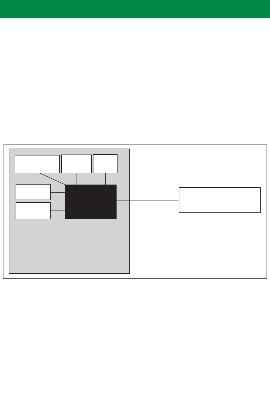
Figure 7 shows the Rabbit-based subsystems designed into the RCM5600W.
Figure 7. RCM5600W Subsystems
RCM5600W
MiniCore Module
RABBIT ®
5000
+3.3 V
CMOS-level
signals
Customer-specific
applications
Real-Time
Clock
Main
Clock
SRAM
Serial
Flash
Wi-Fi
22 MiniCore RCM5600W
4.1 RCM5600W Digital Inputs and Outputs
Figure 8 shows the RCM5600W pinouts for the edge connector.
Figure 8. RCM5600W Pinouts
The edge connectors are designed to interface with a 52-pin mini PCI Express socket.
GND
n.c.
n.c.
LNK
PE0
PE2
PE5
PE7
PD0
PD2
PC0
PC2
PC4/TxB
PB0/SCLK
PB2
PB4
PB6
PA0
PA2
PA4
PA6
/IORD
/IOWR
STATUS
SMODE
GND
1
51
2
52
+3.3 V
n.c.
n.c.
ACT
PE1
PE3
PE6
/RESET_IN
PD1
PD3
PC1
PC3
PC5/RxB
/RESET
PB3
PB5
PB7
PA1
PA3
PA5
PA7
VBAT_EXT
PB1/CLKA
PC6/TxA
PC7/RxA
+3.3 V
Bottom Top
n.c. = not connected
User’s Manual 23
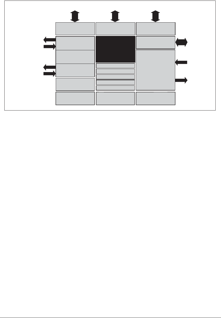
Figure 9 shows the use of the Rabbit 5000 microprocessor ports in the RCM5600W mod-
ules.
Figure 9. Use of Rabbit 5000 Ports
The ports on the Rabbit 5000 microprocessor used in the RCM5600W are configurable,
and so the factory defaults can be reconfigured. Table 2 lists the Rabbit 5000 factory
defaults and the alternate configurations.
RABBIT ®
5000
Port A Port B Port D
Port E
PA0PA7 PB0PB7
PE0PE3
PE5PE7
PD0PD3
/RESET
/IORD
/IOWR
Watchdog
11 Timers
Clock Doubler
Slave Port
Real-Time Clock
Backup Battery
Support
Misc. I/O
/RESET_IN
Port C
(Serial Ports B, C & D)
Programming
Port
(Serial Port A)
PB1, PC6, STATUS
PC0, PC2, PC4
PC1, PC3, PC5
Serial Ports E & F
PC7, /RESET_IN,
SMODE0, SMODE1
Memory & I/O
Interface
RAM
Wi-Fi

24 MiniCore RCM5600W
Table 2. RCM5600W Pinout Configurations
Pin Pin Name Default Use Alternate Use Notes
1GND
2 +3.3 V
3–6 n.c.*
7LNK
8ACT
9 PE0 Input/Output
I/O Strobe I0
A20
Timer C0
TCLKF
INT0
QRD1B
10 PE1 Input/Output
I/O Strobe I1
A21
Timer C1
RXD/RCLKF
INT1
QRD1A
Input Capture
11 PE2 Input/Output
I/O Strobe I2
A22
Timer C2
TXF
DREQ0
QRD2B
12 PE3 Input/Output
I/O Strobe I3
A23
Timer C3
RXC/RXF/SCLKD
DREQ1
QRD2A
Input Capture
13 PE5 Input/Output
I/O Strobe I5
INT1
PWM1
RXB/RCLKE
Input Capture

User’s Manual 25
14 PE6 Input/Output
I/O Strobe I6
PWM2
TXE
DREQ0
Serial Port E
15 PE7 Input/Output
I/O Strobe I7
PWM3
RXA/RXE/SCLKC
DREQ1
Input Capture
16 /RESET_IN Input Input to Reset Generator
17 PD0 Input/Output
I/O Strobe I0
Timer C0
D8
INT0
SCLKD/TCLKF
QRD1B
18 PD1 Input/Output
IA6
I/O Strobe I1
Timer C1
D9
INT1
RXD/RCLKF
QRD1A
Input Capture
19 PD2 Input/Output
I/O Strobe I2
Timer C2
D10
DREQ0
TXF/SCLKC
QRD2B
Serial Port F
20 PD3 Input/Output
IA7
I/O Strobe I3
Timer C3
D11
DREQ1
RXC/RXF
QRD2A
Input Capture
Table 2. RCM5600W Pinout Configurations (continued)
Pin Pin Name Default Use Alternate Use Notes

26 MiniCore RCM5600W
21 PC0 Input/Output
TXD
I/O Strobe I0
Timer C0
TCLKF
Serial Port D
22 PC1 Input/Output
RXD/TXD
I/O Strobe I1
Timer C1
RCLKF
Input Capture
23 PC2 Input/Output TXC/TXF
I/O Strobe I2
Timer C2 Serial Port C
24 PC3 Input/Output RXC/TXC/RXF
I/O Strobe I3
Timer C3
25 PC4 Input/Output TXB
I/O Strobe I4
PWM0 Serial Port B
26 PC5 Input/Output RXB/TXB
I/O Strobe I5
PWM1
27 PB0 Input/Output SCLKB
External I/O Address
IA6
SCLKB (used by serial
flash)
28 /RESET Reset output Reset input Reset output from Reset
Generator or external
reset input
29 PB2 Input/Output /SWR
External I/O Address
IA0
30 PB3 Input/Output /SRD
External I/O Address
IA1
31 PB4 Input/Output
SA0
External I/O Address
IA2
32 PB5 Input/Output SA1
External I/O Address
IA3
33 PB6 Input/Output
/SCS
External I/O Address
IA4
Table 2. RCM5600W Pinout Configurations (continued)
Pin Pin Name Default Use Alternate Use Notes

User’s Manual 27
34 PB7 Input/Output /SLAVATN
External I/O Address
IA5
35–42 PA[0:7] Input/Output
Slave port data bus
(SD0–SD7)
External I/O data bus
(ID0–ID7)
43 /IORD Output External I/O read strobe
44 VBAT_EXT Battery input
45 /IOWR Output External I/O write strobe
46 PB1 Input/Output
SCLKA
External I/O Address
IA7
Programming port
SCLKA
47 STATUS Output Programming port
48 PC6 Input/Output
TXA/TXE
I/O Strobe I6
PWM2
Programming port
49 SMODE Input
50 PC7 Input/Output
RXA/TXA/RXE
I/O Strobe I7
PWM3
SCLKC
Input Capture
51 GND
52 +3.3 V
* n.c. = Not Connected.
Table 2. RCM5600W Pinout Configurations (continued)
Pin Pin Name Default Use Alternate Use Notes

28 MiniCore RCM5600W
4.1.1 Memory I/O Interface
The Rabbit 5000 address lines (A0–A19) and data lines (D0–D7) are routed internally to
the onboard SRAM. I/0 write (/IOWR) and I/0 read (/IORD) are available for interfacing
to external devices.
Parallel Port A can also be used as an external I/O data bus to isolate external I/O from the
main data bus. Parallel Port B pins PB2–PB7 can also be used as an external address bus.
When using the external I/O bus for any other reason, you must add the following line at
the beginning of your program.
#define PORTA_AUX_IO // required to enable external I/O bus
Selected pins on Parallel Ports D and E as specified in Table 2 may be used for input
capture, quadrature decoder, DMA, and pulse-width modulator purposes.
4.1.2 Other Inputs and Outputs
The status, /RESET_IN, and SMODE I/O are normally associated with the programming
port. Since the status pin is not used by the system once a program has been downloaded
and is running, the status pin can then be used as a general-purpose CMOS output. The
programming port is described in more detail in Section 4.2.2.
/RESET_IN is an external input used to reset the Rabbit 5000 microprocessor and the
RCM5600W memory. /RESET is an output from the reset circuitry that can be used to
reset other peripheral devices.
The two SMODE pins, SMODE0 and SMODE1, are tied together to +3.3 V via a pullup
resistor, and may be used as a special input when the RCM5600W is operating in the Run
Mode. The logic state of these two pins determines the startup procedure after a reset.

User’s Manual 29
4.2 Serial Communication
The RCM5600W board does not have any serial level converters directly on the board.
However, an Ethernet or other serial interface may be incorporated on the board the
RCM5600W is mounted on. For example, the Serial Communication accessory board in
the Deluxe Development Kit has an RS-232 transceiver, and the Interface Board has
Ethernet and USB connections.
4.2.1 Serial Ports
There are six serial ports designated as Serial Ports A, B, C, D, E, and F. All six serial
ports can operate in an asynchronous mode up to the baud rate of the system clock divided
by 8. An asynchronous port can handle 7 or 8 data bits. A 9th bit address scheme, where
an additional bit is sent to mark the first byte of a message, is also supported.
Serial Port A is normally used as a programming port, but may be used either as an asyn-
chronous or as a clocked serial port once application development has been completed and
the RCM5600W is operating in the Run Mode.
Serial Port B, shared by the RCM5600W module’s serial flash and by the A/D converter in
the Wi-Fi circuit, is set up as a clocked serial port. Since this serial port is set up for syn-
chronous serial communication, you will lose the peripheral functionality if you try to use
the serial port in the asynchronous mode.
NOTE: Since Serial Port B is shared, exercise care if you attempt to use Serial Port B for
other serial communication. Your application will have to manage the sharing negotia-
tions to avoid conflicts when reading or writing to the devices already using Serial Port B.
Any conflict with Serial Port B while the RCM5600W is powering up may prevent an
application from loading from the serial flash when the RCM5600W powers up or resets.
Do not drive or load the Serial Port B or SCLKB (PC4, PC5, and PB0) pins while the
RCM5600W is powering up.
Serial Ports C and D can also be operated in the clocked serial mode. In this mode, a clock
line synchronously clocks the data in or out. Either of the two communicating devices can
supply the clock.
Serial Ports E and F can also be configured as SDLC/HDLC serial ports. The IrDA proto-
col is also supported in SDLC format by these two ports. Serial Ports E and F must be con-
figured before they can be used. The following macros show one way to do this.
#define SERE_TXPORT PEDR
#define SERE_RXPORT PEDR
#define SERF_TXPORT PFDR
#define SERF_RXPORT PFDR

30 MiniCore RCM5600W
Table 3 summarizes the possible parallel port pins for the serial ports and their clocks.
4.2.2 Programming Port
The RCM5600W programming port is accessed via the USB connector (J5) on the Inter-
face Board. The programming port uses the Rabbit 5000’s Serial Port A for communica-
tion. Dynamic C uses the programming port to download and debug programs.
The programming port is also used to cold-boot the Rabbit 5000 on the RCM5600W after
a reset.
Table 3. Rabbit 5000 Serial Port and Clock Pins
Serial Port A
TXA PC6, PC7
Serial Port E
TXE PE6, PC6
RXA PC7,PE7 RXE PE7, PC7
SCLKA PB1 RCLKE PE5, PC5
Serial Port B
TXB PC4, PC5 TCLKE PE4, PC4
RXB PC5, PE5
Serial Port F
TXF PD2, PE2, PC2
SCLKB PB0 RXF PD3, PE3, PC3
Serial Port C
TXC PC2, PC3 RCLKF PD1, PE1, PC1
RXC PC3, PD3, PE3 TCLKF PD0, PE0, PC0
SCLKC PD2, PE2, PE7, PC7
RCLKE/TCLKE and RCLKF/TCLKF must be
selected to be on the same parallel port as
RXE/TXE and RXF/TXF respectively.
Serial Port D
TXD PC0, PC1
RXD PC1, PD1, PE1
SCLKD PD0, PD3, PE0, PE3,
PC3
User’s Manual 31
4.3 Wi-Fi
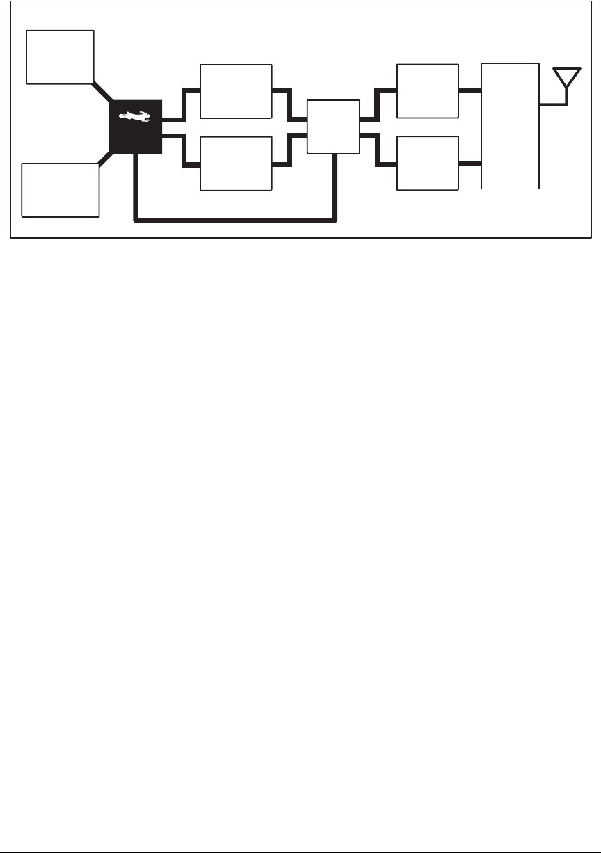
Figure 10 shows a functional block diagram for the Wi-Fi circuits.
Figure 10. RCM5600W Wi-Fi Block Diagram
The Wi-Fi transmission is controlled by the Rabbit 5000 chip, which contains the Wi-Fi
Media Access Control (MAC). The Rabbit 5000 implements the 802.11b/g baseband
MAC functionality, and controls the 802.11b/g integrated Airoha AL2236 transceiver.
Program code is stored in the serial flash and is loaded into an SRAM for execution when
power is applied to the RCM5600W modules. The data interface between the processor
MAC and the AL2236 transceiver consists of a D/A converter and an A/D converter. Both
converters convert “I” and “Q” data samples at a rate of 40 MHz.
The AL2236 is a single-chip transceiver with integrated power amplifier for the 2.4 GHz
Industrial, Scientific, and Medical (ISM) band. It is configured and controlled by the
Rabbit 5000 via a 3-wire serial data bus. The AL2236 contains the entire receiver, trans-
mitter, VCO, PLL, and power amplifier necessary to implement an 802.11b/g radio.
The AL2236 can transmit and receive data at up to 11Mbits/s in the 802.11b mode and at
up to 54 Mbits/s in the 802.11g mode. It supports 802.11b/g channels 1–13 (2.401 GHz to
2.472 GHz). Channel 14 is not used. The data modulate the channel carrier in such a way
so as to produce a spread spectrum signal within the 22 MHz channel bandwidth of the
selected channel. The channel numbers and associated frequencies are listed below in
Table 4.
The Wi-Fi channels have a certain amount of overlap with each other. The further apart
two channel numbers are, the less the likelihood of interference. If you encounter interfer-
ence with a neighboring WLAN, change to a different channel. For example, use channels
1, 6, and 11 to minimize any overlap.
U15
Antenna
Switch
P1
XCVR
U8
AL2236
Rx Path
Tx Path
Rx
Baseband
Tx
Baseband
3-wire serial bus
U4
Serial
Flash
U10
SRAM

32 MiniCore RCM5600W
Many countries specify the channel range and power limits for Wi-Fi devices operated
within their borders, and these limits are set automatically in the RCM5600W in firmware
according to the country or region. For example, only channels 1–11 are authorized for use
in the United States or Canada, and so channels 12 and 13 are disabled. See Section 6.2.4.1
for additional information and sample programs demonstrating how to configure an end
device to meet the regulatory channel range and power limit requirements. Table 5 pro-
vides additional information on which channels are allowed in selected countries. Any
attempt to operate a device outside the allowed channel range or power limits will void
your regulatory approval to operate the device in that country.
Table 4. Wi-Fi Channel Allocations
Channel Center Frequency
(GHz) Frequency Spread
(GHz)
1 2.412 2.401–2.423
2 2.417 2.406–2.428
3 2.422 2.411–2.433
4 2.427 2.416–2.438
5 2.432 2.421–2.443
6 2.437 2.426–2.448
7 2.442 2.431–2.453
8 2.447 2.436–2.458
9 2.452 2.441–2.463
10 2.457 2.446–2.468
11 2.462 2.451–2.473
12*2.467 2.456–2.478
13*2.472 2.461–2.483
14
(not used) 2.484 2.473–2.495
* These channels are disabled for units delivered for sale in the United
States and Canada.

User’s Manual 33
The following regions have macros and region numbers defined for convenience.
The same omnidirectional antenna is used to transmit and receive the 802.11b/g RF signal.
An antenna switch isolates the high-power RF Tx signal path from the RF Rx signal path.
The antenna switch at U15 works by alternately connecting the antennas to either the
AL2236 Tx output or to the AL2236 Rx input. In order to support this antenna-sharing
scheme, the RCM5600W module operates the radio in a half-duplex mode so that receive
and transmit operations never occur at the same time
The RF connector on the Interface Board is an RP-SMA connector with its outer casing
attached to the RCM5600W ground.
There are two LEDs close to the RF shield, a green LED at DS1 (LINK) to indicate associa-
tion with the Wi-Fi access point, and a yellow LED at DS2 (ACT) to indicate activity.
4.3.1 Antenna Grounding Requirements
When deploying the RCM5600W in a production environment, take care to ensure that the
antenna is properly grounded via the RP-SMA connector and the U.FL to RP-SMA con-
nector cable. The RP-SMA connector must be firmly attached to a bracket or soldered to a
grounded location. If you are using a bracket, it must make firm contact with a ground
such as the plated, grounded mounting hole provided on the Interface Board.
Table 5. Worldwide Wi-Fi Macros and Region Numbers
Region Macro Region
Number Channel Range
Americas IFPARAM_WIFI_REGION_AMERICAS 01–11
Mexico
IFPARAM_WIFI_REGION__MEXICO_
INDOORS 1 1–11 (indoors)
IFPARAM_WIFI_REGION_MEXICO_
OUTDOORS 2 9–11 (outdoors)
Canada IFPARAM_WIFI_REGION_CANADA 31–11
Europe, Middle East,
Africa, except France IFPARAM_WIFI_REGION_EMEA 4 1–13
France IFPARAM_WIFI_REGION_FRANCE 5 10–13
Israel IFPARAM_WIFI_REGION_ISRAEL 63–11
China IFPARAM_WIFI_REGION_CHINA 71–11
Japan IFPARAM_WIFI_REGION_JAPAN 81–14*
* Channel 14 is not available for the RCM5600W.
Australia IFPARAM_WIFI_REGION_AUSTRALIA 91–11
34 MiniCore RCM5600W
4.4 Programming Modes
The USB cable is used to connect the programming port of the RCM5600W to a PC USB
port via the Interface Board.
Whenever the RCM5600W is reset, the operating mode is determined by the state of the
SMODE pins. The RCM5600W is automatically in Program Mode when the SMODE
pins, which are tied together, are pulled up to +3.3 V. This happens when the RCM5600W
is installed on the Interface Board, and pins 1–2 on header JP1 on the Interface Board are
jumpered. When the SMODE pins are pulled low by removing the jumpers from pins 1–2
on header JP1 on the Interface Board, the Rabbit 5000 will operate in the Run Mode once
the RCM5600W is reset. The USB cable may be used for a serial connection to the pro-
gramming port when the RCM5600W is operating in the Run Mode.
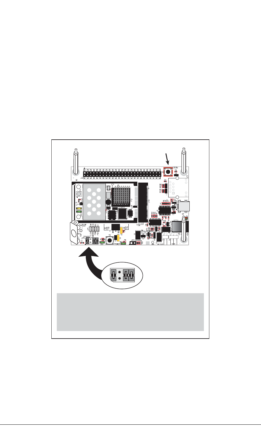
Figure 11. Switching Between Program Mode and Run Mode
A program “runs” in either mode, but can only be downloaded and debugged when the
RCM5600W is in the Program Mode.
Refer to the Rabbit 5000 Microprocessor User’s Manual for more information on the pro-
gramming port.
JP1
4
3
2
1
6
57
8
RESET
RESET RCM5600W when changing mode:
Short out /RESET_IN to GND, OR
Press RESET button (if using Interface Board), OR
Cycle power off/on
after removing or attaching jumper on pins 12.

User’s Manual 35
4.4.1 Standalone Operation of the RCM5600W
The RCM5600W must be programmed via the Interface Board or via a similar arrange-
ment on a customer-supplied board. Once the RCM5600W has been programmed success-
fully, reset the RCM5600W. The RCM5600W may be reset by cycling power off/on or by
pressing the RESET button on the Interface Board. The jumper across pins 1–2 on header
JP1 on the Interface Board must be removed in order for the RCM5600W to operate in the
Run Mode after it is reset. The RCM5600W module may now be removed from the Inter-
face Board for end-use installation.
CAUTION: Power to the Interface Board or other boards should be disconnected when
removing or installing your RCM5600W module to protect against inadvertent shorts
across the pins or damage to the RCM5600W if the pins are not plugged in correctly.
Do not reapply power until you have verified that the RCM5600W module is plugged
in correctly.

36 MiniCore RCM5600W
4.5 Other Hardware
4.5.1 Clock Doubler
The RCM5600W takes advantage of the Rabbit 5000 microprocessor’s internal clock dou-
bler. A built-in clock doubler allows half-frequency crystals to be used to reduce radiated
emissions. The 73.73 MHz frequency specified for the RCM5600W model is generated
using a 36.864 MHz crystal.
The clock doubler should not be disabled since Wi-Fi operations depend highly on CPU
resources.
4.5.2 Spectrum Spreader
The Rabbit 5000 features a spectrum spreader, which helps to mitigate EMI problems. The
spectrum spreader is on by default, but it may also be turned off or set to a stronger setting.
The means for doing so is through a simple configuration macro as shown below.
NOTE: Refer to the Rabbit 5000 Microprocessor User’s Manual for more information
on the spectrum-spreading setting and the maximum clock speed.
1. Select the “Defines” tab from the Dynamic C Options > Project Options menu.
2. Normal spreading is the default, and usually no entry is needed. If you need to specify
normal spreading, add the line
ENABLE_SPREADER=1
For strong spreading, add the line
ENABLE_SPREADER=2
To disable the spectrum spreader, add the line
ENABLE_SPREADER=0
NOTE: The strong spectrum-spreading setting is not recommended since it may limit
the maximum clock speed or the maximum baud rate. It is unlikely that the strong set-
ting will be used in a real application.
3. Click OK to save the macro. The spectrum spreader will be set according to the macro
value whenever a program is compiled using this project file.

User’s Manual 37
4.6 Memory
4.6.1 SRAM
RCM5600W boards have 1MB of SRAM installed at U10.
4.6.2 Flash Memory
RCM5600W boards have 1MB of serial flash memory installed at U4.
A “user block” area is defined to store persistent data. The function calls writeUser-
Block() and readUserBlock() are provided for this. Refer to the Rabbit 5000 Micro-
processor Designer’s Handbook for additional information.
4.6.3 Encryption RAM Memory
The tamper detection feature of the Rabbit 5000 microprocessor can be used to detect any
attempt to enter the bootstrap mode. When such an attempt is detected, the VBAT RAM
memory in the Rabbit 5000 chip is erased.

38 MiniCore RCM5600W

OEM User’s Manual 39
5. SOFTWARE REFERENCE
Dynamic C is an integrated development system for writing
embedded software. It runs on a Windows-based PC and is
designed for use with single-board computers and other devices
based on the Rabbit microprocessor. Chapter 5 describes the
libraries and function calls related to the RCM5600W.
5.1 More About Dynamic C
Dynamic C has been in use worldwide since 1989. It is specially designed for program-
ming embedded systems, and features quick compile and interactive debugging. A com-
plete reference guide to Dynamic C is contained in the Dynamic C User’s Manual.
Since the RCM5600W has a serial flash memory, all software development must be done
in the static SRAM. The flash memory and SRAM options are selected with the Options >
Program Options > Compiler menu.
NOTE: An application should be compiled directly to the SRAM on the RCM5600W
module using the Store Program in RAM compiler option while debugging for
faster upload times and to save wear on the flash, but should be recompiled to Store
Program in Flash after the USB cable is disconnected. Your final code must always
be stored in flash memory for reliable operation.
Developing software with Dynamic C is simple. Users can write, compile, and test C and
assembly code without leaving the Dynamic C development environment. Debugging
occurs while the application runs on the target. Alternatively, users can compile a program
to an image file for later loading. Dynamic C runs on PCs under Windows NT and later—
see Rabbit’s Technical Note TN257, Running Dynamic C® With Windows Vista®, for
additional information if you are using a Dynamic C under Windows Vista. Programs can
be downloaded at baud rates of up to 460,800 bps after the program compiles.

40 MiniCore RCM5600W
Dynamic C has a number of standard features.
•Full-feature source and/or assembly-level debugger, no in-circuit emulator required.
•Royalty-free TCP/IP stack with source code and most common protocols.
•Hundreds of functions in source-code libraries and sample programs:
XExceptionally fast support for floating-point arithmetic and transcendental functions.
XRS-232 and RS-485 serial communication.
XAnalog and digital I/O drivers.
XI2C, SPI, GPS, file system.
XLCD display and keypad drivers.
•Powerful language extensions for cooperative or preemptive multitasking
•Loader utility program to load binary images into Rabbit targets in the absence of
Dynamic C.
•Provision for customers to create their own source code libraries and augment on-line
help by creating “function description” block comments using a special format for
library functions.
•Standard debugging features:
XBreakpoints—Set breakpoints that can disable interrupts.
XSingle-stepping—Step into or over functions at a source or machine code level, µC/OS-II aware.
XCode disassembly—The disassembly window displays addresses, opcodes, mnemonics, and
machine cycle times. Switch between debugging at machine-code level and source-code level by
simply opening or closing the disassembly window.
XWatch expressions—Watch expressions are compiled when defined, so complex expressions
including function calls may be placed into watch expressions. Watch expressions can be updated
with or without stopping program execution.
XRegister window—All processor registers and flags are displayed. The contents of general registers
may be modified in the window by the user.
XStack window—shows the contents of the top of the stack.
XHex memory dump—displays the contents of memory at any address.
XSTDIO window—printf outputs to this window and keyboard input on the host PC can be
detected for debugging purposes. printf output may also be sent to a serial port or file.

OEM User’s Manual 41
5.2 Dynamic C Function Calls
5.2.1 Digital I/O
The RCM5600W was designed to interface with other systems, and so there are no drivers
written specifically for the Rabbit 5000 I/O. The general Dynamic C read and write func-
tions allow you to customize the parallel I/O to meet your specific needs. For example, use
WrPortI(PEDDR, &PEDDRShadow, 0x00);
to set all the Port E bits as inputs, or use
WrPortI(PEDDR, &PEDDRShadow, 0xFF);
to set all the Port E bits as outputs.
When using the external I/O bus on the Rabbit 5000 chip, add the line
#define PORTA_AUX_IO // required to enable external I/O bus
to the beginning of any programs using the auxiliary I/O bus.
The sample programs in the Dynamic C
SAMPLES/RCM5600W
folder provide further
examples.
5.2.2 Serial Communication Drivers
Library files included with Dynamic C provide a full range of serial communications sup-
port. The
RS232.LIB
library provides a set of circular-buffer-based serial functions. The
PACKET.LIB
library provides packet-based serial functions where packets can be delimited
by the 9th bit, by transmission gaps, or with user-defined special characters. Both libraries
provide blocking functions, which do not return until they are finished transmitting or
receiving, and nonblocking functions, which must be called repeatedly until they are fin-
ished, allowing other functions to be performed between calls. For more information, see
the Dynamic C Function Reference Manual and Rabbit Semiconductor’s Technical Note
TN213, Rabbit Serial Port Software, both included with the online documentation.

42 MiniCore RCM5600W
5.2.3 Serial Flash Memory Use
The RCM5600W module has a serial flash memory that contains the user block and stores
the application program. Two function calls are provided to work with the serial boot
flash. These function calls are in the Dynamic C LIB\Rabbit4000\BIOSLIB\
BOOTDEV_SFLASH.LIB library.
sbfRead
int sbfRead(void *dest, unsigned long offset, unsigned nbytes);
DESCRIPTION
Reads up to 64K from anywhere on the serial boot flash. This function call supports
both the blocking mode for use with µC/OS-II and a mutex for preemptive multitask-
ing, and the nonblocking mode for cooperative multitasking. See the description for
sbfWriteFlash()
for more information on using a µC/OS-II and a mutex with the
serial flash driver.
PARAMETERS
dest near pointer to the destination buffer
offset the physical offset into the serial flash
nbytes the number of bytes to read
RETURN VALUE
0 if successful.
The return values below apply only if
_SPI_USE_UCOS_MUTEX
is not
#defined
:
positive
N
to indicate that the SPI port is being used by device n
if more than
_SPI_MAXTIME
milliseconds elapse while waiting for the SPI port to become
available, one of the following two runtime errors will occur:
ERR_SPI_MUTEX_ERROR
(when using µC/OS-II) or
-ETIME
(if not using µC/OS-II).

OEM User’s Manual 43
sbfWriteFlash
int sbfWriteFlash(unsigned long flashDst, void* Src,
unsigned len);
DESCRIPTION
Writes
len
bytes (up to 64K) to physical address
flashDst
from
Src
.
Keep calling
sbfWriteFlash()
until it returns zero or a negative error code. A pos-
itive return value indicates that the serial flash SPI port is being used by another device.
If you are using µC/OS-II and
_SPI_USE_UCOS_MUTEX
is
#defined
, you may
call
sbfWriteFlash()
just once. If more than
_SPI_MAXTIME
milliseconds
elapse while waiting for the SPI port to become available, one of the following two run-
time errors will occur:
ERR_SPI_MUTEX_ERROR
(when using µC/OS-II) or
-ETIME
(if not using µC/OS-II).
NOTE: This function call is not power-fail safe. The
writeUserBlock()
function
call provides a safer way to store critical data using redundant copies.
PARAMETERS
flashDst the physical address of the flash destination
Src near pointer to the source data
len the number of bytes to write
RETURN VALUE
0 if successful.
-1 if an attempt was made to write to the user/ID block or program area.
The return values below apply only if
_SPI_USE_UCOS_MUTEX
is not
#defined
:
-EBUSY
to indicate a busy writing to the serial flash
positive
N
to indicate that the SPI port is being used by device n
if more than
_SPI_MAXTIME
milliseconds elapse while waiting for the SPI port to become
available, one of the following two runtime errors will occur:
ERR_SPI_MUTEX_ERROR
(when using µC/OS-II) or
-ETIME
(if not using µC/OS-II).

44 MiniCore RCM5600W
5.2.4 User and ID Blocks
The sample program USERBLOCK_INFO.C in the Dynamic C SAMPLES\USERBLOCK
folder can be used to determine the version of the ID block, the size of the ID and user
blocks, whether or not the ID/user blocks are mirrored, the total amount of flash memory
used by the ID and user blocks, and the area of the user block available for your applica-
tion.
The USERBLOCK_CLEAR.C sample program shows you how to clear and write the con-
tents of the user block that you are using in your application (the calibration constants in
the reserved area and the ID block are protected).
NOTE: Since RCM5600W MiniCore modules have a serial boot flash that shares the
serial flash SPI lines with other devices, exercise care when accessing the user block.
Pay attention to the instructions associated with the user block function calls in the
Dynamic C
LIB\Rabbit4000\BIOSLIB\IDBLOCK.LIB
library.
5.2.5 Wi-Fi Drivers
Complete information on the Wi-Fi libraries and function calls is provided in Chapter 6.
Additional information on TCP/IP is provided in the Dynamic C TCP/IP User’s Manual.

OEM User’s Manual 45
5.2.6 Interface Board Function Calls
The function calls described in this section are for use with the Interface Board features.
The source code is in the Dynamic C LIB\Rabbit4000\RCM5xxx\RCM56xxW.LIB
library if you need to modify it for your own board design.
The sample programs in the Dynamic C
SAMPLES\RCM5600W
folder illustrate the use of
the function calls.
Other generic functions applicable to all devices based on Rabbit microprocessors are
described in the Dynamic C Function Reference Manual.
5.2.6.1 Board Initialization
brdInit
void brdInit(void);
DESCRIPTION
Call this function at the beginning of your program. This function initializes Parallel
Ports A through E for use with the Interface Board. This function call is intended for
demonstration purposes only, and can be modified for your applications.
Summary of Initialization
1. I/O port pins are configured for Interface Board operation.
2. Unused configurable I/O are set as outputs.
4. LEDs are off.
5. The slave port is disabled.
Pins PB0, PB1, PC6, PC7, PD4, PD7, and PE4 are configured separately by the BIOS and associ-
ated libraries. Parallel port H is configured automatically as part of the 16-bit memory setup, and
cannot be used as a general purpose I/O port.
RETURN VALUE
None.

46 MiniCore RCM5600W
5.3 Upgrading Dynamic C
Dynamic C patches that focus on bug fixes are available from time to time. Check the Web
site www.rabbit.com/support/ for the latest patches, workarounds, and bug fixes.
5.3.1 Add-On Modules
Starting with Dynamic C version 10.40, Dynamic C includes the popular µC/OS-II real-
time operating system, point-to-point protocol (PPP), FAT file system, RabbitWeb, and
other select libraries. Rabbit also offers for purchase the Rabbit Embedded Security Pack
featuring the Secure Sockets Layer (SSL) and a specific Advanced Encryption Standard
(AES) library.
In addition to the Web-based technical support included at no extra charge, a one-year
telephone-based technical support subscription is also available for purchase.
Visit our Web site at www.rabbit.com for further information and complete documentation.

User’s Manual 47
6. USING THE WI-FI FEATURES
6.1 Introduction to Wi-Fi
Wi-Fi, a popular name for 802.11b/g, refers to the underlying technology for wireless local
area networks (WLAN) based on the IEEE 802.11 suite of specifications conforming to
standards defined by IEEE. IEEE 802.11b describes the media access and link layer control
for a 2.4 GHz implementation, which can communicate at a top bit-rate of 11 Mbits/s. Other
standards describe a faster implementation (54 Mbits/s) in the 2.4 GHz band (802.11g).
The adoption of 802.11 has been fast because it's easy to use and the performance is com-
parable to wire-based LANs. Things look pretty much like a wireless LAN.
Wi-Fi (802.11b/g) is the most common and cost-effective implementation currently avail-
able. This is the implementation that is used with the RCM5600W MiniCore module. A
variety of Wi-Fi hardware exists, from wireless access points (WAPs), various Wi-Fi
access devices with PCI, PCMCIA, CompactFlash, USB and SD/MMC interfaces, and
Wi-Fi devices such as Web-based cameras and print servers.
802.11b/g can operate in one of two modes—in a managed-access mode (BSS), called an
infrastructure mode, or an unmanaged mode (IBSS), called the ad-hoc mode. The 802.11
standard describes the details of how devices access each other in either of these modes.
6.1.1 Infrastructure Mode
The infrastructure mode requires an access point to manage devices that want to communi-
cate with each other. An access point is identified with a channel and service set identifier
(SSID) that it uses to communicate. Typically, an access point also acts as a gateway to a
wired network, either an Ethernet or WAN (DSL/cable modem). Most access points can
also act as a DHCP server, and provide IP, DNS, and gateway functions.
When a device wants to join an access point, it will typically scan each channel and look
for a desired SSID for the access point. An empty-string SSID (" ") will associate the
device with the first SSID that matches its capabilities.
Once the access point is discovered, the device will logically join the access point and
announce itself. Once joined, the device can transmit and receive data packets much like
an Ethernet-based MAC. Being in a joined state is akin to having link status in a
10/100Base-T network.
802.11b/g interface cards implement all of the 802.11b/g low-level configurations in firm-
ware. In fact, the 802.11b/g default configuration is often sufficient for a device to join an

48 MiniCore RCM5600W
access point automatically, which it can do once enabled. Commands issued to the chip set
in the interface allow a host program to override the default configurations and execute
functions implemented on the interface cards, for example, scanning for hosts and access
points.
6.1.2 Ad-Hoc Mode
In the ad-hoc mode, each device can set a channel number and an SSID to communicate
with. If devices are operating on the same channel and SSID, they can talk with each
other, much like they would on a wired LAN such as an Ethernet. This works fine for a
few devices that are statically configured to talk to each other, and no access point is
needed.
6.1.3 Additional Information
802.11 Wireless Networking; published by O'Reilly Media, provides further information about
802.11b wireless networks.

User’s Manual 49
6.2 Running Wi-Fi Sample Programs
In order to run the sample programs discussed in this chapter and elsewhere in this manual,
1. Your module must be plugged in to the Interface Board as described in Chapter 2, “Get-
ting Started.”
2. Dynamic C must be installed and running on your PC.
3. The USB cable must connect the USB connector on the Interface Board to your PC.
4. Power must be applied to the module through the Interface Board.
Refer to Chapter 2, “Getting Started,” if you need further information on these steps.
To run a sample program, open it with the File menu, then compile and run it by pressing F9.
Each sample program has comments that describe the purpose and function of the pro-
gram. Follow the instructions at the beginning of the sample program.
Complete information on Dynamic C is provided in the Dynamic C User’s Manual.
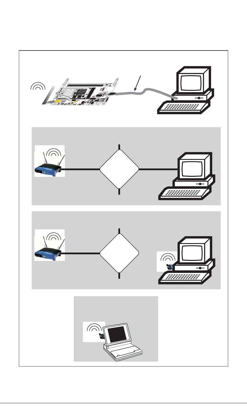

User’s Manual 51
6.2.2 What Else You Will Need
Besides what is supplied with the RCM5600W Development Kits, you will need a PC with
an available USB port to program the RCM5600W module. You will need either an access
point for an existing Wi-Fi network that you are allowed to access and have a PC or note-
book connected to that network (infrastructure mode), or you will need at least a PDA or
PC with Wi-Fi to use the ad-hoc mode.

52 MiniCore RCM5600W
6.2.3 Configuration Information
6.2.3.1 Network/Wi-Fi Configuration
Any device placed on an Ethernet-based Internet Protocol (IP) network must have its own
IP address. IP addresses are 32-bit numbers that uniquely identify a device. Besides the IP
address, we also need a netmask, which is a 32-bit number that tells the TCP/IP stack what
part of the IP address identifies the local network the device lives on.
The sample programs configure the RCM5600W modules with a default TCPCONFIG
macro from the LIB\Rabbit4000\TCPIP\TCP_CONFIG.LIB library. This macro
allows specific IP address, netmask, gateway, and Wi-Fi parameters to be set at compile
time. Change the network settings to configure your RCM5600W module with your own
Ethernet settings only if that is necessary to run the sample programs; you will likely need
to change some of the Wi-Fi settings.
•Network Parameters
These lines contain the IP address, netmask, nameserver, and gateway parameters.
#define _PRIMARY_STATIC_IP "10.10.6.100"
#define _PRIMARY_NETMASK "255.255.255.0"
#define MY_NAMESERVER "10.10.6.1"
#define MY_GATEWAY "10.10.6.1"
There are similar macros defined for the various Wi-Fi settings as explained in Section 6.3.1.
The Wi-Fi configurations are contained within TCPCONFIG 1 (no DHCP) and TCPCON-
FIG 5 (with DHCP, used primarily with infrastructure mode). You will need to #define
TCPCONFIG 1 or #define TCPCONFIG 5 at the beginning of your program.
NOTE: TCPCONFIG 0 is not supported for Wi-Fi applications.
There are some other “standard” configurations for TCPCONFIG. Their values are docu-
mented in the LIB\Rabbit4000\TCPIP\TCP_CONFIG.LIB library. More information
is available in the Dynamic C TCP/IP User’s Manual.
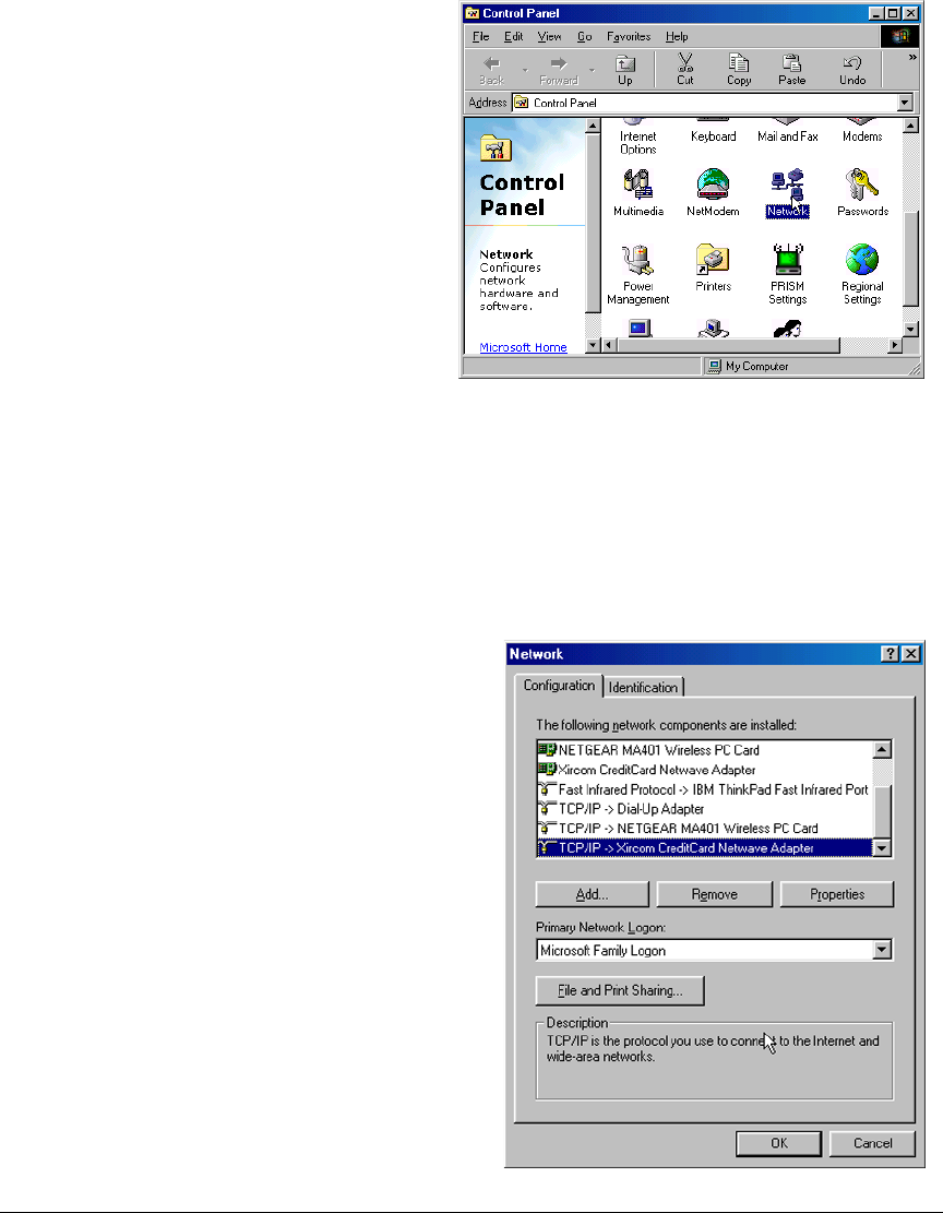
User’s Manual 53
6.2.3.2 PC/Laptop/PDA Configuration
This section shows how to configure your PC or notebook to run the sample programs.
Here we’re mainly interested in the PC or notebook that will be communicating wirelessly,
which is not necessarily the PC that is being used to compile and run the sample program
on the RCM5600W module.
When you are using an access point with your setup in the infrastructure mode, you will also
have to set the IP address and netmask (e.g., 10.10.6.99 and 255.255.255.0) for the access
point. Check the documentation for the access point for information on how to do this.
Infrastructure Mode (via Ethernet connection)
This section provides configuration
information for the three possible Wi-Fi
setups shown in Figure 12. Start by
going to the control panel (Start >
Settings > Control Panel) and click on
Network Connections. The screen
shots shown here are from Windows
2000, and the interface is similar for
other versions of Windows.
Check with your administrator if you are
unable to change the settings as
described here since you may need
administrator privileges.
1. Go to the Local Area Connection to
select the network interface card used you
intend to use (e.g., TCP/IP Xircom Credit
Card Network Adapter) and click on the
“Properties” button. Depending on which
version of Windows your PC is running,
you may have to select the “Local Area
Connection” first, and then click on the
“Properties” button to bring up the Ether-
net interface dialog. Then “configure”
your interface card for an “Auto-Negotia-
tion” or “10Base-T Half-Duplex” connec-
tion on the “Advanced” tab.
NOTE: Your network interface card will
likely have a different name.
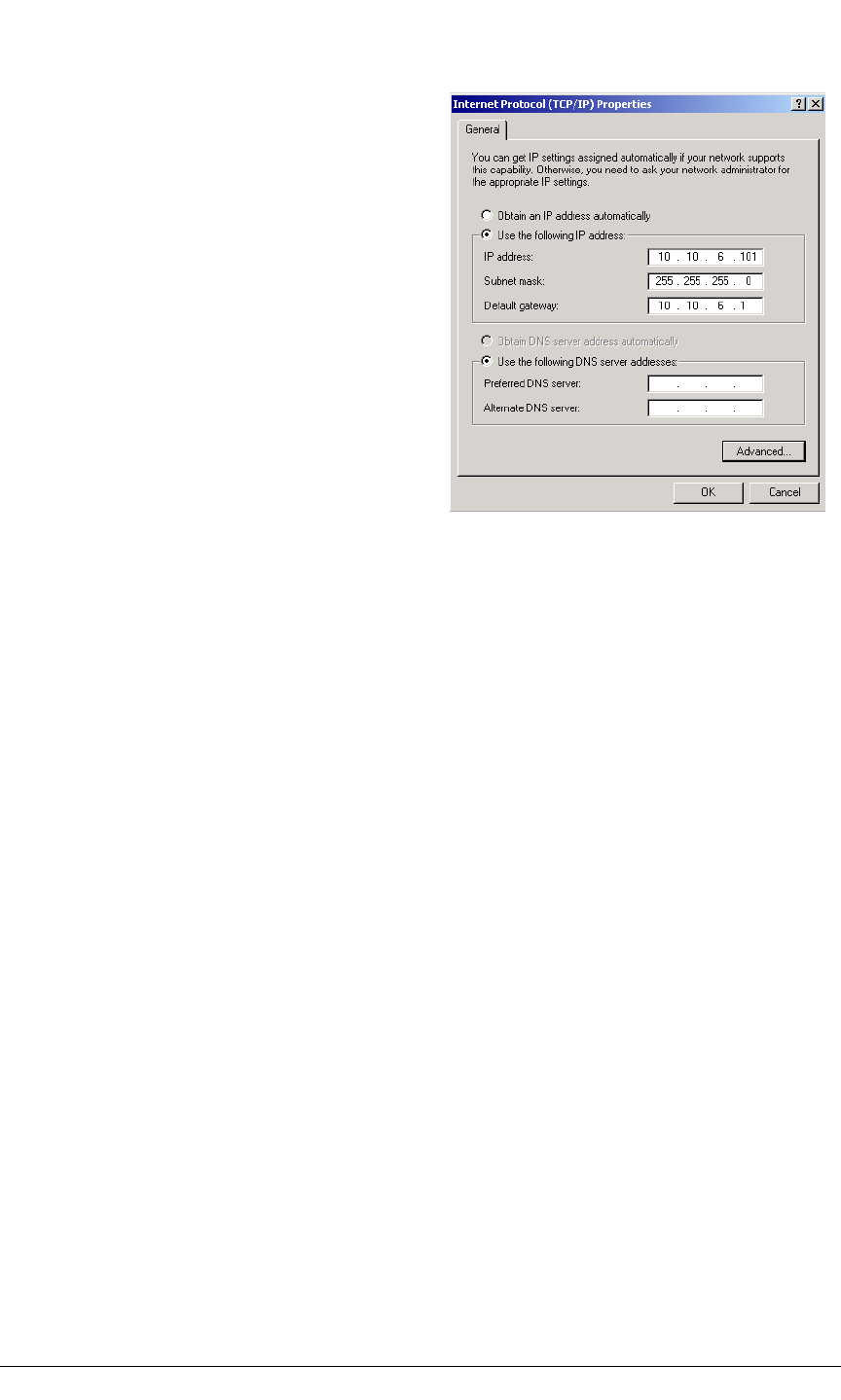
54 MiniCore RCM5600W
3. Click <OK> or <Close> to exit the various dialog boxes.
Infrastructure Mode (via wireless connection)
Set the IP address and netmask for your wireless-enabled PC or notebook as described in
Step 2 for Infrastructure Mode (via Ethernet connection) by clicking on Network
Connections, then on Local Area Connection. Now click on Wireless Network
Connection to select the wireless network you will be connecting to. Once a sample
program is running, you will be able to select the network from a list of available networks.
You will have to set your wireless network name with the access point SSID macro for the
infrastructure mode as explained in Section 6.3, “Dynamic C Wi-Fi Configurations.”
Ad-Hoc Mode
Set the IP address and netmask for your wireless-enabled PC or notebook as described in
Step 2 for Infrastructure Mode (via Ethernet connection) by clicking on Network
Connections, then on Local Area Connection. Now click on Wireless Network
Connection to select the wireless network you will be connecting to. Once a sample
program is running, you will be able to select the network from a list of available networks.
You will have set your wireless network name with the Wi-Fi channel macros for the ad-
hoc mode as explained in Section 6.3, “Dynamic C Wi-Fi Configurations.”
2. Now select the IP Address tab, and check
Specify an IP Address, or select TCP/IP
and click on “Properties” to fill in the fol-
lowing fields:
IP Address : 10.10.6.101
Netmask : 255.255.255.0
Default gateway : 10.10.6.1
TIP: If you are using a PC that is already on
a network, you will disconnect the PC
from that network to run these sample
programs. Write down the existing set-
tings before changing them so that you
can restore them easily when you are fin-
ished with the sample programs.
The IP address and netmask need to be set
regardless of whether you will be using the
ad-hoc mode or the infrastructure mode.

User’s Manual 55
Once the PC or notebook is set up, we're ready to communicate. You can use Telnet or a
Web browser such as Internet Explorer, which come with most Windows installations, to
use the network interface, and you can use HyperTerminal to view the serial port when
these are called for in some of the later sample programs.
Now we’re ready to run the sample programs in the Dynamic C Samples\TCPIP\WiFi
folder. The sample programs should run as is in most cases.
6.2.4 Wi-Fi Sample Programs
The sample programs in Section 6.2.4.1 show how to set up the country- or region-specific
attributes, but do not show the basic setup of a wireless network. The sample programs in
Section 6.2.4.2 show the setup and operation of a wireless network — the WIFISCAN.C
sample program is ideal to demonstrate that the RCM5600W has been hooked up correctly
and that the Wi-Fi setup is correct so that an access point can be found.
6.2.4.1 Wi-Fi Operating Region Configuration
The country or region you select will automatically set the power and channel require-
ments to operate the RCM5600W module. The following three options are available.
1. Country or region is set at compile time. This option is ideal when the end device is
intended to be sold and used only in a single region. If the end device is to be deployed
across multiple regions, this method would require an application image to be created for
each region. This option is the only approved option for RCM5600W modules in Japan.
2. Country or region is set via the 802.11d feature of the access point. This option uses
beacons from an access point to configure the RCM5600W country or region automati-
cally. The end user is responsible for enabling 802.11d on the access point and then
selecting the correct country to be broadcast in the beacon packets.
NOTE: This option sets the power limit for RCM5600W to the maximum level permitted
in the region or the capability of the RCM5600W, whichever is less. Since the beacons
are being sent continuously, the ifconfig IFS_WIFI_TX_POWER function cannot
be used with this option.
3. Country or region is set at run time. This is a convenient option when the end devices
will be deployed in multiple regions. A serial user interface would allow the RCM5600W
module to be configured via a Web page. Systems integrators would still have to make
sure the end devices operate within the regulatory requirements of the country or region
where the units are being deployed.
These options may be used alone or in any combination. The three sample programs in the
Dynamic C Samples\WiFi\Regulatory folder illustrate the use of these three options.
•REGION_COMPILETIME.C—demonstrates how you can set up your RCM5600W-
based system at compile time to operate in a given country or region to meet power and
channel requirements.
The country or region you select will automatically set the power and channel require-
ments to operate the RCM5600W module. Rabbit recommends that you check the
regulations for the country where your system incorporating the RCM5600W will be

56 MiniCore RCM5600W
deployed for any other requirements. Any attempt to operate a device outside the
allowed channel range or power limits will void your regulatory approval to operate
the device in that country.
Before you compile and run this sample program, uncomment the #define IFC_
WIFI_REGION line corresponding to the region where your system will be deployed.
The Americas region will be used by default if one of these lines is not uncommented.
Now compile and run this sample program. The Dynamic C STDIO window will dis-
play the region you selected.
The sample program also allows you to set up the TCP/IP configuration, and set the IP
address and SSID as shown in the sample code below.
#define TCPCONFIG 1
#define _PRIMARY_STATIC_IP "10.10.6.170"
#define IFC_WIFI_SSID "rabbitTest"
•REGION_MULTI_DOMAIN.C—demonstrates how the multi-domain options from the
access point can be used to configure your RCM5600W-based system to meet regional
regulations. The sample program includes pings to indicate that the RCM5600W-based
system has successfully received country information from your access point.
The country or region you select will automatically set the power and channel require-
ments to operate the RCM5600W module. Rabbit recommends that you check the
regulations for the country where your system incorporating the RCM5600W will be
deployed for any other requirements.
Before you compile and run this sample program, verify that the access point has the
802.11d option enabled and is set for the correct region or country. Check the TCP/IP
configuration parameters, the IP address, and the SSID in the macros, which are repro-
duced below.
#define TCPCONFIG 1
#define WIFI_REGION_VERBOSE
#define _PRIMARY_STATIC_IP "10.10.6.170"
#define IFC_WIFI_SSID "rabbitTest"
Now compile and run this sample program. The #define WIFI_REGION_VERBOSE
macro will display the channel and power limit settings. The Dynamic C STDIO win-
dow will then display a menu that allows you to complete the configuration of the user
interface.
•REGION_RUNTIME_PING.C—demonstrates how the region or country can be set at
run time to configure your RCM5600W-based system to meet regional regulations. The
sample program also shows how to save and retrieve the region setting from nonvola-
tile memory. Once the region/country is set, this sample program sends pings using the
limits you set.
The country or region you select will automatically set the power and channel require-
ments to operate the RCM5600W module. Digi International recommends that you
check the regulations for the country where your system incorporating the RCM5600W
will be deployed for any other requirements.

User’s Manual 57
Before you compile and run this sample program, check the TCP/IP configuration
parameters, the IP address, and the SSID in the macros, which are reproduced below.
#define TCPCONFIG 1
// #define WIFI_REGION_VERBOSE
#define PING_WHO "10.10.6.1"
#define _PRIMARY_STATIC_IP "10.10.6.170"
#define IFC_WIFI_SSID "rabbitTest"
Now compile and run this sample program. Uncomment the #define WIFI_REGION_
VERBOSE macro to display the channel and power limit settings. The Dynamic C STDIO
window will then display a menu that allows you to complete the configuration of the
user interface.
6.2.4.2 Wi-Fi Operation
•WIFIDHCPORTSTATIC.C—demonstrates the runtime selection of a static IP configura-
tion or DHCP. The SAMPLES\TCPIP\DHCP.C sample program provides further exam-
ples of using DHCP with your application.
Before you compile and run this sample program, check the TCP/IP configuration
parameters, the IP address, and the SSID in the macros, which are reproduced below.
#define USE_DHCP
#define TCPCONFIG 1
#define _PRIMARY_STATIC_IP "10.10.6.100"
#define IFC_WIFI_SSID "rabbitTest"
Modify the values to match your network. You may also need to modify the values for
MY_GATEWAY if you are not pinging from the local subnet.
Now press F9 to compile and run the sample program. When prompted in the Dynamic C
STDIO window, type 's' for static configuration or 'd' for DHCP.
•WIFIMULTIPLEAPS.C—demonstrates changing access points using WEP keys. You
will need two access points to run this sample program. The access points should be
isolated or on separate networks.
The sample program associates the RabbitCore or MiniCore module with the first access
point (AP_0 defined below) with WEP key KEY0 (defined below). After associating,
the sample program waits for a predefined time period, and then pings the Ethernet
address of the access point (AP_ADDRESS_0). The sample program then associates
with the second access point and pings its Ethernet address (AP_1, KEY1, AP_
ADDRESS_1), and then switches back and forth between the two access points.
When changing access points, first bring the IF_WIFI0 interface down by calling
ifdown(IF_WIFI0). Next, change the SSID and key(s) using ifconfig() calls.
Finally, bring the IF_WIFI0 interface back up by calling ifup(IF_WIFI0). Note that
the sample program checks for status while waiting for the interface to come up or
down.
Before you compile and run this sample program, check the TCP/IP configuration
parameters, the IP address, and the SSID in the macros, which are reproduced below.
#define TCPCONFIG 1
#define IFC_WIFI_ENCRYPTION IFPARAM_WIFI_ENCR_WEP

58 MiniCore RCM5600W
You do not need to configure the SSID of your network since that is done from the
access point names.
Now configure the access to the two access points.
// First Access Point
#define AP_0 "test1"
#define AP_0_LEN strlen(AP_0)
#define MY_ADDRESS_0 "10.10.6.250" // use this static IP when connected to AP 0
#define PING_ADDRESS_0 "10.10.6.1" // address on AP 0 to ping
#define KEY_0 "0123456789abcdef0123456789"
// Second Access Point
#define AP_1 "test2"
#define AP_1_LEN strlen(AP_1)
#define MY_ADDRESS_1 "10.10.0.99" // use this static IP when connected to AP 1
#define PING_ADDRESS_1 "10.10.0.50"// address on AP 1 to ping
#define KEY_1 "0123456789abcdef0123456789"
#define IFC_WIFI_SSID AP_0
#define _PRIMARY_STATIC_IP MY_ADDRESS_0
Modify the access point names and keys to match your access points and network.
•WIFIPINGYOU.C—sends out a series of pings to a RabbitCore or MiniCore module on
an ad-hoc Wi-Fi network.
This sample program uses some predefined macros. The first macro specifies the
default TCP/IP configuration from the Dynamic C LIB\Rabbit4000\TCPIP\TCP_
CONFIG.LIB library.
#define TCPCONFIG 1
Use the next macro unchanged as long as you have only one RCM5600W MiniCore
module. Otherwise use this macro unchanged for the first RabbitCore or MiniCore
module.
#define NODE 1
Then change the macro to #define NODE 2 before you compile and run this sample
program on the second RabbitCore or MiniCore module.
The next macros assign an SSID name and a channel number to the Wi-Fi network.
#define IFC_WIFI_SSID "rab-hoc"
#define IFC_WIFI_OWNCHANNEL "5"
Finally, IP addresses are assigned to the RabbitCore or MiniCore modules.
#define IPADDR_1 "10.10.8.1"
#define IPADDR_2 "10.10.8.2"
As long as you have only one RabbitCore or MiniCore module, the Dynamic C STDIO
window will display the pings sent out by the module. You may set up a Wi-Fi enabled
laptop with the IP address in IPADDR_2 to get the pings.
If you have two RabbitCore or MiniCore modules, they will ping each other, and the
Dynamic C STDIO window will display the pings.

User’s Manual 59
•WIFISCAN.C—initializes the RCM5600W and scans for other Wi-Fi devices that are
operating in either the ad-hoc mode or through access points in the infrastructure mode.
No network parameter settings are needed since the RCM5600W does not actually join
an 802.11 network. This program outputs the results of the scan to the Dynamic C
STDIO window.
•WIFISCANASSOCIATE.C— demostrates how to scan Wi-Fi channels for SSIDs using
ifconfig IFS_WIFI_SCAN. This takes a while to complete, so ifconfig() calls a
callback function when it is done. The callback function is specified using ifconfig
IFS_WIFI_SCAN.
Before you run this sample program, configure the Dynamic C TCP_CONFIG.LIB
library and your TCPCONFIG macro.
1. Use macro definitions in the “Defines” tab in the Dynamic C Options > Project
Options menu to modify any parameter settings.
If you are not using DHCP, set the IP parameters to values appropriate to your network.
Set the macro IFC_WIFI_SSID= to define a C-style string to set the SSID of your
access point as, for example,
or use an empty string, "", to associate with the strongest BSS available.
Alternatively, you may create your own CUSTOM_CONFIG.LIB library modeled on the
Dynamic C TCP_CONFIG.LIB library. Then use a TCPCONFIG macro greater than or
equal to 100, which will invoke your CUSTOM_CONFIG.LIB library to be used.
Remember to add the CUSTOM_CONFIG.LIB library to LIB.DIR.
2. If you are using DHCP, change the definition of the TCPCONFIG macro to 5. The default
value of 1 indicates Wi-Fi with a static IP address.
Now compile and run the sample program. Follow the menu options displayed in the
Dynamic C STDIO window.
Note that ifconfig IFS_WIFI_SCAN function calls do not return data directly since
the scan takes a fair amount of time. Instead, callback functions are used. The callback
function is passed to ifconfig() as the only parameter to IFS_WIFI_SCAN.
ifconfig(IF_WIFI0, IFS_WIFI_SCAN, scan_callback, IFS_END);
_PRIMARY_STATIC_IP = "10.10.6.100"
_PRIMARY_NETMASK = "255.255.255.0"
MY_NAMESERVER = "10.10.6.1"
MY_GATEWAY = "10.10.6.1"
IFC_WIFI_SSID = "My Access Point"
Press s to scan available access points
Press a to scan access points and associate
Press m to print WIFI MAC status

60 MiniCore RCM5600W
The data passed to the callback function are ephemeral since another scan may occur.
Thus, the data need to be used (or copied) during the callback function.
While waiting for user input, it is important to keep the network alive by calling
tcp_tick(NULL) regularly.
6.2.5 RCM5600W Sample Programs
The following sample programs are in the Dynamic C SAMPLES\RCM5600W\TCPIP\
folder. The Interface Board must be set up as described in Section 3.2.
•PINGLED.C—This program demonstrates ICMP by pinging a remote host. It will pro-
duce a long flash of LED DS1 on the Interface Board when a ping is sent, and a short
flash when a ping is received.
Before you compile and run this sample program, change PING_WHO and IFC_WIFI_
SSID to the host and SSID you want to ping. You may modify PING_DELAY to change
the amount of time in milliseconds between the outgoing pings.
Uncomment the VERBOSE define to see the incoming ping replies.
•PINGLED_WPA_PSK.C—This program demonstrates the use of WPA PSK (Wi-Fi
Protected Access with Pre-Shared Key). WPA is a more secure replacement for WEP.
The implementation in the sample program supports use of the TKIP (Temporal Key
Integrity Protocol) cypher suite.
The sample program uses macros to configure the access point for WPA PSK, specify
the TKIP cypher suite, assign the access point SSID, and set the passphrase.
#define WIFI_USE_WPA // Bring in WPA support
#define IFC_WIFI_ENCRYPTION IFPARAM_WIFI_ENCR_TKIP // Define cypher suite
#define IFC_WIFI_SSID "rabbitTest"
The next macro specifies a suitable pre-shared key to use instead of the passphrase. The
key may be entered either as 64 hexadecimal digits or as an ASCII string of up to 63
characters. Authentication should be set to “open system,” which basically means that
knowing the key is sufficient to allow access.
#define IFC_WIFI_WPA_PSK_HEXSTR \
"1010101010101010101010101010101010101010101010101010101010101010"
TIP: There is a good chance of typos since the key is long. First, enter the key in this
sample program macro, then copy and paste it to your access point. This ensures that
both the RCM5600W and the access point have the same key.
TIP: For an initial test, it may be easier to use the 64 hex digit form of the key rather than
the ASCII passphrase. A passphrase requires considerable computation effort, which
delays the startup of the sample program by about 30 seconds.
Change PING_WHO and IFC_WIFI_SSID to the host and SSID you want to ping. You
may modify PING_DELAY to change the amount of time in milliseconds between the
outgoing pings.
Uncomment the VERBOSE define to see the incoming ping replies.

User’s Manual 61
Once you have compiled the sample program and it is running, LED DS1 will go on
with a brief toggle off when a ping is sent. LED DS1 will go off for a longer duration
when a ping is received. LED DS1 is controlled by PD0.
•PINGLED_WPA2_CCMP.C—This sample program demonstrates the use of WPA2 PSK
(Wi-Fi Protected Access with Pre-Shared Key).). WPA is a more secure replacement
for WEP. The implementation in the sample program uses the Advanced Encryption
Standard (AES) based algorithm, also known as the CCMP (Counter Mode with Cipher
Block Chaining Message Authentication Code Protocol) cypher suite.
Apart from the configuration of WPA2_CCMP at the top of the sample program, the rest
of the code is identical to the case without WPA2 PSK. Indeed, most of the TCP/IP
sample programs should work with WPA2 CCMP simply by using the same configura-
tion settings.
Configure your access point for WPA2 PSK before you run this sample program.
Specify the CCMP cypher suite, and enter a suitable pre-shared key. The key may be
entered either as 64 hexadecimal digits or as an ASCII string of up to 63 characters.
Authentication should be set to “open system,” which basically means that knowingt
the key is sufficient to allow access.
TIP: There is a good chance of typos since the key is long. First, enter the key in this
sample program macro, then copy and paste it to your access point. This ensures that
both the RCM5600W and the access point have the same key.
TIP: For an initial test, it may be easier to use the 64 hex digit form of the key rather than
the ASCII passphrase. A passphrase requires considerable computation effort, which
delays the startup of the sample program by about 30 seconds.
Now change PING_WHO and IFC_WIFI_SSID to the host and SSID you want to ping.
You may modify PING_DELAY to change the amount of time in milliseconds between
the outgoing pings.
Uncomment the VERBOSE define to see the incoming ping replies.
Once you have compiled the sample program and it is running, LED DS1 will go on
with a brief toggle off when a ping is sent. LED DS1 will go off for a longer duration
when a ping is received. LED DS1 is controlled by PD0.

62 MiniCore RCM5600W
•PINGLED_STATS.C—This program is similar to PINGLED.C, but it also displays
receiver/transmitter statistics in the Dynamic C STDIO window.
Before you compile and run this sample program, change PING_WHO and IFC_WIFI_
SSID to the host and SSID you want to ping. You may modify PING_DELAY to change
the amount of time in milliseconds between the outgoing pings.
Modify the value in the MOVING_AVERAGE macro to change the moving average filter-
ing of the statistics. Also review the GATHER_INTERVAL and GRAPHICAL macros,
which affect the number of samples to gather and create a bar graph display instead of a
numeric display.
Uncomment the VERBOSE define to see the incoming ping replies.
Once you compile and run this sample program, LED DS1 on the Interface Board will
go on with a brief toggle off when a ping is sent, and the LED will go off for a longer
duration when a ping is received.
•SMTP.C—This program demonstrates using the SMTP library to send an e-mail when
the S1 switch on the Interface Board is pressed. LED DS1 on the Interface Board will
light up when e-mail is being sent. LED DS1 is controlled by PD0.
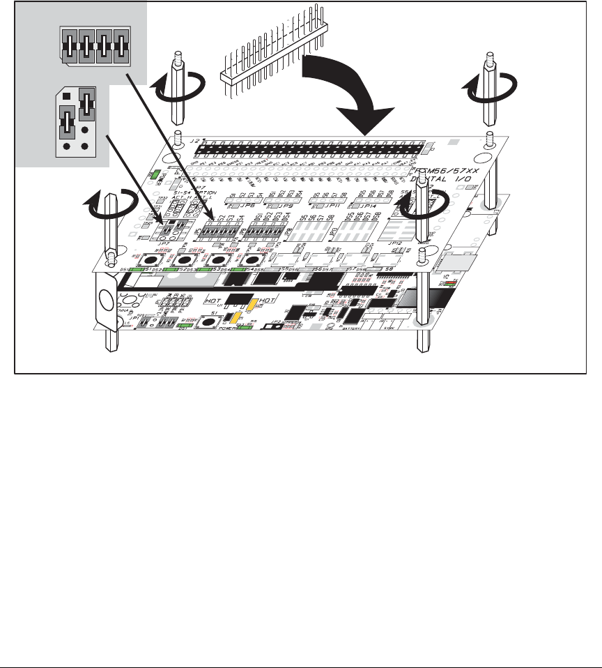
User’s Manual 63
The Digital I/O accessory board may also be used to run the BROWSELED.C, PINGLED.C,
and PINGLED_STATS.C sample programs. This accessory board is included only with the
Deluxe Development Kit.
To install the Digital I/O accessory board, insert the strip of header pins included with the
accessory board into the socket at J12 on the bottom side of the Digital I/O accessory
board. Then line up the Digital I/O accessory board with the Interface Board
standoffs/
connectors and install the Digital I/O accessory board pins into socket J2 on the
Interface Board. Secure the Digital I/O accessory board with the long plastic stand-
offs/connectors from above as shown in Figure 13—note that one plastic standoff/connec-
tor needs to be inserted “upside down” to secure the Digital I/O accessory board to the
antenna bracket.
Figure 13. Install Digital I/O Accessory Board
Pins 1–2, 3–4, 5–6, and 7–8 on headers JP5 and JP8 on the Digital I/O accessory board
must be jumpered. Pins 2–4 and 3–5 on header JP7 on the Digital I/O accessory board
must also be jumpered.
JP5
JP8
4
3
2
1
6
57
8
4
3
2
1
6
5
78
JP7
Install header connector strip
in bottom socket

64 MiniCore RCM5600W
•BROWSELED.C—This program demonstrates a basic controller running a Web page.
Four “device LEDs” are created along with four buttons to toggle them. Users can use
their Web browser to change the status of the lights. The DS1, DS2, DS3, and DS4
LEDs on the Digital I/O accessory board will match those on the Web page. As long as
you have not modified the TCPCONFIG 1 macro in the sample program, enter the fol-
lowing server address in your Web browser to bring up the Web page served by the
sample program. Remember to configure the access point to match the default settings
of the TCPCONFIG 1 macro.
http://10.10.6.100.
Otherwise use the TCP/IP settings you entered in the in the “Defines” tab in the Dynamic C
Options > Project Options menu.
Once you compile and run this sample program, you can use the buttons in the Web
browser to toggle the LEDs on the Digital I/O accessory board on/off.
•PINGLED.C—This program demonstrates ICMP by pinging a remote host. It will flash
LED DS2 on the Digital I/O accessory board when a ping is sent and it will flash LED
DS3 when a ping is received.
Before you compile and run this sample program, change PING_WHO and IFC_WIFI_
SSID to the host and SSID you want to ping. You may modify PING_DELAY to change
the amount of time in milliseconds between the outgoing pings.
Uncomment the VERBOSE define to see the incoming ping replies.
•PINGLED_STATS.C—This program is similar to PINGLED.C, but it also displays
receiver/transmitter statistics in the Dynamic C STDIO window.
Before you compile and run this sample program, change PING_WHO and IFC_WIFI_
SSID to the host and SSID you want to ping. You may modify PING_DELAY to change
the amount of time in milliseconds between the outgoing pings.
Modify the value in the MOVING_AVERAGE macro to change the moving average filter-
ing of the statistics. Also review the GATHER_INTERVAL and GRAPHICAL macros,
which affect the number of samples to gather and create a bar graph display instead of a
numeric display.
Uncomment the VERBOSE define to see the incoming ping replies.
Once you compile and run this sample program, LED DS2 on the Digital I/O accessory
board will flash when a ping is sent, and LED DS3 will flash when a ping is received.
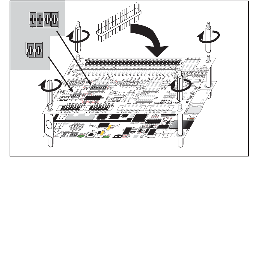
User’s Manual 65
The Serial Communication accessory board needs to be installed to run the SERIAL_TO_
WIFI.C sample program. This accessory board is included only with the Deluxe Develop-
ment Kit.
To install the Serial Communication accessory board, insert the strip of header pins
included with the accessory board into the socket at J12 on the bottom side of the Serial
Communication accessory
board. Then line up the
Serial Communication
accessory board
with the Interface Board or Digital I/O accessory board standoffs/
connectors and install the
Serial Communication accessory board pins into socket J2 on the Interface Board or the
Digital I/O accessory board. Secure the Serial Communication accessory board with the
long plastic standoffs/connectors from above as shown in Figure 14—note that one plastic
standoff/connector needs to be inserted “upside down” to secure the Serial Communica-
tion accessory board above the antenna bracket.
Figure 14. Install Serial Communication Accessory Board
Pins 1–2, 3–4, 5–6, and 7–8 on header JP5 on the Serial Communication accessory board
must be jumpered. Pins 1–2 and 3–4 on header JP7 on the Serial Communication acces-
sory board must also be jumpered.
•SERIAL_TO_WIFI.C—This program demonstrates using TCP over Wi-Fi, which is
handled automatically by the libraries. This sample program uses the RabbitWeb HTTP
enhancements to configure a simple serial to Wi-Fi converter.
This sample program only supports listening TCP sockets, which means that serial to
Wi-Fi devices can only be started by another device initiating the network connection
to the Rabbit.
JP5
4
3
2
1
6
57
8
4
3
2
1
JP7
Install header connector strip
in bottom socket

66 MiniCore RCM5600W
Each serial port can be associated with a specific TCP port. The Rabbit will listen on
each of these TCP ports for a connection, which will then be associated with a specific
serial port. Data will then be shuttled between the serial and Wi-Fi connections.
Before you compile and run this sample program, define the _PRIMARY_STATIC_IP
and IFC_WIFI_SSID in the sample program to match your network settings.
Now compile and run this program.
As long as you have not modified the TCPCONFIG 1 macro in the sample program,
enter the following server address in your Web browser to bring up the Web page
served by the sample program. Remember to configure the access point to match the
default settings of the TCPCONFIG 1 macro.
http://10.10.6.100.
Select the serial port settings in the Web browser. You may leave the TCP port and baud
rate settings at their defaults, then set 8 data bits, no parity, and 1 stop bit. Click Submit
to save the changed settings.
Now start a Telnet seession to associate a serial port with a TCP port is with telnet:
Open a cmd window via Run > cmd and type telnet 10.10.6.100 4567 at the prompt to
associate Serial Port C, for example, where 4567 was the TCP port assigned to Serial
Port C in the previous setup performed via the Web browser.
Next, open a serial utility such as Tera Term or Hyperterminal configured to match the
settings selected via the Web browser. Finally, use the 10-pin to DB9 serial cable
included with the Deluxe Devlopment Kit to connect the PC serial port selected in your
serial utility to header J4 (Serial Port C) or header J3 (Serial Port D), depending on the
TCP port selected for the Telnet session. As you type characters in the Telnet utility
window, you will be able to observe them in the serial utility window, and vice versa.

User’s Manual 67
6.3 Dynamic C Wi-Fi Configurations
Rabbit has implemented a packet driver for the RCM5600W that functions much like an
Ethernet driver for the Dynamic C implementation of the TCP/IP protocol stack. In addi-
tion to functioning like an Ethernet packet driver, this driver implements a function call to
access the functions implemented on the 802.11b/g interface, and to mask channels that
are not available in the region where the RCM5600W will be used.
The Wi-Fi interface may be used either at compile time using macro statements or at run
time with the ifconfig() function call from the Dynamic C LIB\Rabbit4000\TCPIP\
NET.LIB library.
6.3.1 Configuring TCP/IP at Compile Time
Digi International has made it easy for you to set up the parameter configuration using
already-defined
TCPCONFIG
macros from the Dynamic C LIB\Rabbit4000\TCPIP\
TCP_CONFIG.LIB
library at the beginning of your program as in the example below.
#define TCPCONFIG 1
There are two
TCPCONFIG
macros specifically set up for Wi-Fi applications with the
RCM5600W module. (TCPCONFIG 0 is not supported for Wi-Fi applications.)
These default IP address, netmask, nameserver, and gateway network parameters are set
up for the
TCPCONFIG
macros.
#define _PRIMARY_STATIC_IP "10.10.6.100"
#define _PRIMARY_NETMASK "255.255.255.0"
#define MY_NAMESERVER "10.10.6.1"
#define MY_GATEWAY "10.10.6.1"
The use of quotation marks in the examples described in this chapter is important since the
absence of quotation marks will be flagged with warning messages when encrypted librar-
ies are used.
Wi-Fi Parameters
•Access Point SSID—
IFC_WIFI_SSID
. This is the only mandatory parameter. Define
the
IFC_
WIFI_SSID macro to a string for the SSID of the access point in the infra-
structure (BSS) mode, or the SSID of the ad-hoc network in the ad-hoc (IBSS) mode.
The default is shown below.
#define IFC_WIFI_SSID "rabbitTest"
•Mode—
IFC_WIFI_MODE
determines the mode:
IFPARAM_WIFI_INFRASTRUCT for the infrastructure mode, or IFPARAM_WIFI_ADHOC
for the ad-hoc mode.
The default is shown below.
#define IFC_WIFI_MODE IFPARAM_WIFI_INFRASTRUCT
TCPCONFIG 1
No DHCP
TCPCONFIG 5
DHCP enabled

68 MiniCore RCM5600W
•Your Own Channel—
IFC_WIFI_CHANNEL
determines the channel on which to operate.
The default is shown below.
#define IFC_WIFI_CHANNEL 0
The default 0 means that any valid channel may be used by the requested SSID. This
parameter is mandatory when creating an ad-hoc network. While it is optional for the
infrastructure mode, it is usually best left at the default 0.
Note that there are restrictions on which channels may be used in certain countries.
These are provided in Table 5 for some countries.
•Region/Country—
IFC_WIFI_REGION
sets the channel range and maximum power
limit to match the region selected. Table 5 lists the regions that are supported and their
corresponding macros.
The region selected must match the region where the RCM5600W MiniCore module
will be used.
The default is shown below.
#define
IFC_
WIFI_REGION IFPARAM_WIFI_REGION_AMERICAS
•Disable/enable encryption—
IFC_WIFI_ENCRYPTION
indicates whether or not encryp-
tion is enabled.
The default (encryption disabled) is shown below.
#define IFC_WIFI_ENCRYPTION IFPARAM_WIFI_ENCR_NONE
The following encryption options are available.
•IFPARAM_WIFI_ENCR_NONE — no encryption is used.
•IFPARAM_WIFI_ENCR_ANY — any type of encryption is used.
•IFPARAM_WIFI_ENCR_WEP — use WEP encryption. You will need to define at least
one WEP key (see below).
•IFPARAM_WIFI_ENCR_TKIP — use TKIP or WPA encryption. You will need to
define a passphrase or a key for TKIP encryption, as well as define the WIFI_USE_WPA
macro (see below).
•IFPARAM_WIFI_ENCR_CCMP — use CCMP or WPA2 encryption. You will need to
define at least one WEP key (see below).
•There are four encryption keys (0, 1, 2, 3) associated with the IFC_WIFI_WEP_KEYNUM
macro (default 0). One or more of the following additional macros must be defined as
well. The default is for the keys to remain undefined.
IFC_WIFI_WEP_KEY0_BIN
IFC_WIFI_WEP_KEY1_BIN
IFC_WIFI_WEP_KEY2_BIN
IFC_WIFI_WEP_KEY3_BIN
IFC_WIFI_WEP_KEY0_HEXSTR
IFC_WIFI_WEP_KEY1_HEXSTR
IFC_WIFI_WEP_KEY2_HEXSTR
IFC_WIFI_WEP_KEY3_HEXSTR

User’s Manual 69
These macros specify the WEP keys to use for WEP encryption. These keys can be
either 40-bit or 104-bit (i.e., 5 bytes or 13 bytes). They must be defined as a comma-
separated list of byte values.
Note that you do not necessarily need to define all four WEP keys. You may typically
just define one key, but make sure it matches the key used on all other devices, and set
IFC_WIFI_WEP_KEYNUM to point to the correct key.
If both IFC_WIFI_WEP_KEY#_BIN and IFC_WIFI_WEP_KEY#_HEXSTR are defined
for a particular key, the hex version will be used.
•Use WPA encryption.
The following macro must also be used to compile WPA functionality into the Wi-Fi
driver. This is necessary to enable TKIP encryption.
#define WIFI_USE_WPA
•Set WPA passphrase—IFC_WIFI_WPA_PSK_PASSPHRASE is a string that matches the
passphrase on your access point. It may also point to a variable.
Define an ASCII passphrase here, from 1 to 63 characters long. An example is shown
below.
#define IFC_WIFI_WPA_PSK_PASSPHRASE "now is the time"
If possible, you should use IFC_WIFI_WPA_PSK_HEXSTR instead of IFC_WIFI_
WPA_PSK_PASSPHRASE to set the key.
•Set WPA hexadecimal key—IFC_WIFI_WPA_PSK_HEXSTR is a string of hexadecimal
digits that matches the 256-bit (32-byte) hexadecimal key used by your access point.
Specify a 64 hexadecimal digit (256 bits) key here. This key will be used and will over-
ride any passphrase set with the IFC_WIFI_WPA_PSK_PASSPHRASE macro. The
example hex key shown below
#define IFC_WIFI_WPA_PSK_HEXSTR \
"57A12204B7B350C4A86A507A8AF23C0E81D0319F4C4C4AE83CE3299EFE1FCD27"
is valid for the SSID "rabbitTest" and the passphrase "now is the time".
Using a passphrase is rather slow. It takes a Rabbit 5000 more than 20 seconds to gen-
erate the actual 256-bit key from the passphrase. If you use a passphrase and #define
WIFI_VERBOSE_PASSPHRASE, the Wi-Fi library will helpfully print out the hex key
corresponding to that passphrase and SSID.
•Authentication algorithm—IFC_WIFI_AUTHENTICATION can be used to specify the
authentication modes used.
The default shown below allows enables both open-system authentication and shared-
key authentication.
#define IFPARAM_WIFI_AUTH_ANY

70 MiniCore RCM5600W
The following authentication options are available.
•IFPARAM_WIFI_AUTH_OPEN — only use open authentication.
•IFPARAM_WIFI_AUTH_SHAREDKEY — only use shared-key authentication (useful
for WEP only).
•IFPARAM_WIFI_WPA_PSK — use WPA preshared-key authentication (useful for
TKIP and CCMP only).
•Fragmentation threshold—IFC_WIFI_FRAG_THRESHOLD sets the fragmentation
threshold. Frames (or packets) that are larger than this threshold are split into multiple
fragments. This can be useful on busy or noisy networks. The value can be between
256 and 2346.
The default, 0, means no fragmentation.
#define IFC_WIFI_FRAG_THRESHOLD 0
•RTS threshold—IFC_WIFI_RTS_THRESHOLD sets the RTS threshold, the frame size
at which the RTS/CTS mechanism is used. This is sometimes useful on busy or noisy
networks. Its range is 1 to 2347.
The default, 2347, means no RTS/CTS.
#define IFC_WIFI_RTS_THRESHOLD 2347
Examples are available within Dynamic C. Select “Function Lookup” from the Help
menu, or press <ctrl-H>. Type “TCPCONFIG” in the Function Search field, and hit
<Enter>. Scroll down to the section on “Wi-Fi Configuration.” The Dynamic C TCP/IP
User’s Manual.(Volume 1) provides additional information about these macros and Wi-Fi.
It is also possible to redefine any of the above parameters dynamically using the ifcon-
fig() function call. Macros for alternative Wi-Fi configurations are provided with the
ifconfig() function call, and may be used to change the above default macros or
configurations.

User’s Manual 71
6.3.2 Configuring TCP/IP at Run Time
There is one basic function call used to configure Wi-Fi and other network settings —
ifconfig(). See the Dynamic C TCP/IP User’s Manual, Volume 1 for more informa-
tion about this function call.
6.3.3 Other Key Function Calls
Remember to call sock_init() after all the Wi-Fi parameters have been defined. The
Wi-Fi interface will be up automatically as long as you configured Dynamic C at compile
time with one of the TCPCONFIG macros. Otherwise the Wi-Fi interface is neither up nor
down, and must be brought up explicitly by calling either ifup(IF_WIFI0) or
ifconfig(IF_WIFI0,…). You must bring the interface down when you configure
Dynamic C at run time before modifying any parameters that require the interface to be
down (see Section 6.3.2) by calling ifdown(IF_WIFI0). Then bring the interface back up.
Finally, no radio transmission occurs until you call tcp_tick(NULL).
Instead of executing the above sequence based on sock_init(), you could use sock_
init_or_exit(1) as a debugging tool to transmit packets (ARP, DHCP, association,
and authentication) while bringing up the interface and to get the IP address.

72 MiniCore RCM5600W
6.4 Where Do I Go From Here?
NOTE: If you purchased your RCM5600W through a distributor or through a Rabbit part-
ner, contact the distributor or partner first for technical support.
If there are any problems at this point:
•Use the Dynamic C Help menu to get further assistance with Dynamic C.
•Check the Rabbit Technical Bulletin Board and forums at www.rabbit.com/support/bb/
and at www.rabbit,com/forums/.
•Use the Technical Support e-mail form at www.rabbit.com/support/.
If the sample programs ran fine, you are now ready to go on.
An Introduction to TCP/IP and the Dynamic C TCP/IP User’s Manual.provide
background and reference information on TCP/IP, and are available on the CD and on our
Web site.

User’s Manual 73
APPENDIX A. RCM5600W
SPECIFICATIONS
Appendix A provides the specifications for the RCM5600W.
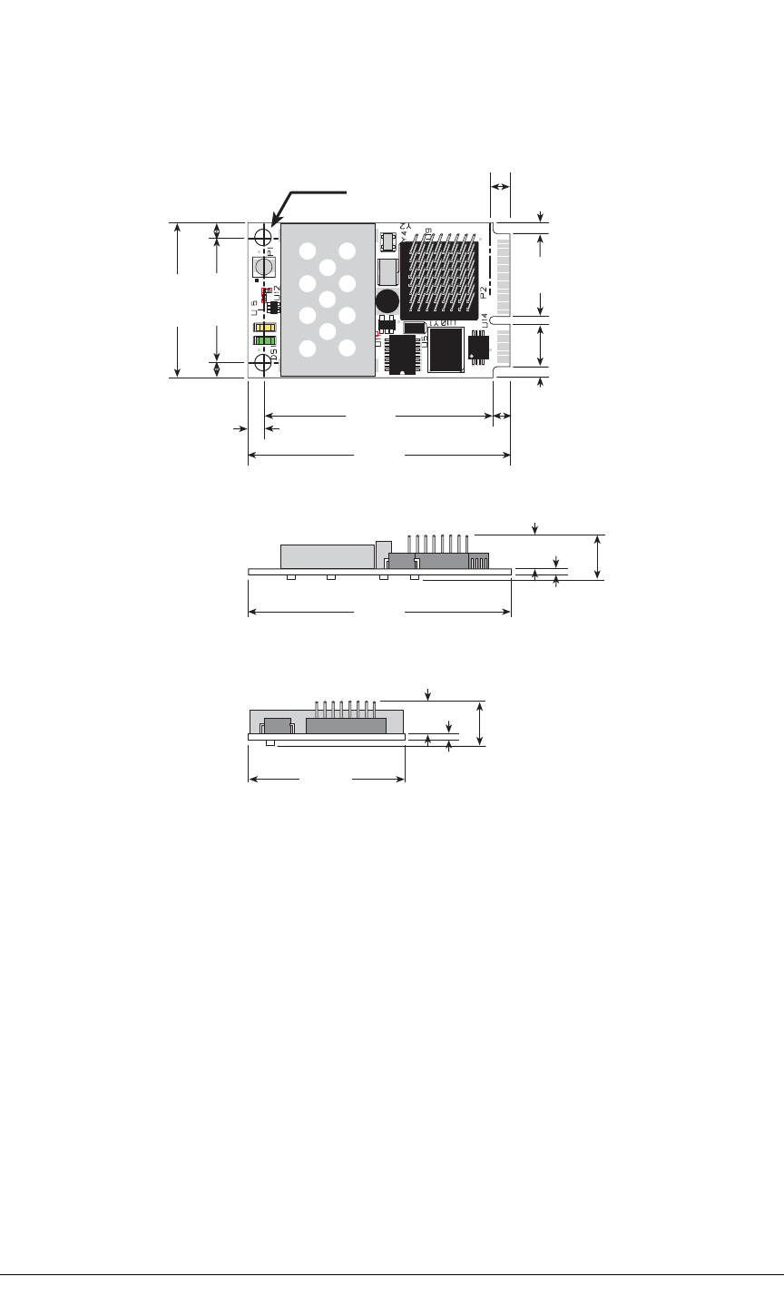
74 MiniCore RCM5600W
A.1 Electrical and Mechanical Characteristics
Figure A-1 shows the mechanical dimensions for the RCM5600W.
Figure A-1. RCM5600W Dimensions
0.326
(8.3)
0.326
(8.3)
0.039
(1.0)
0.039
(1.0)
× 2
0.125
dia
(3.2)
0.958
(24.3)
1.20
(30)
0.114
(2.9)
0.114
(2.9)
0.085
(2.2)
0.085
(2.2)
1.762
(44.8)
2.00
(51)
0.130
(3.3)
2.00
(51)
1.20
(30)
0.40
(10)
0.114
(2.9)
0.642
(16.3)
0.324
(8.2)
0.050
(1.3)
0.157
(4.0)
0.4
0
(10)
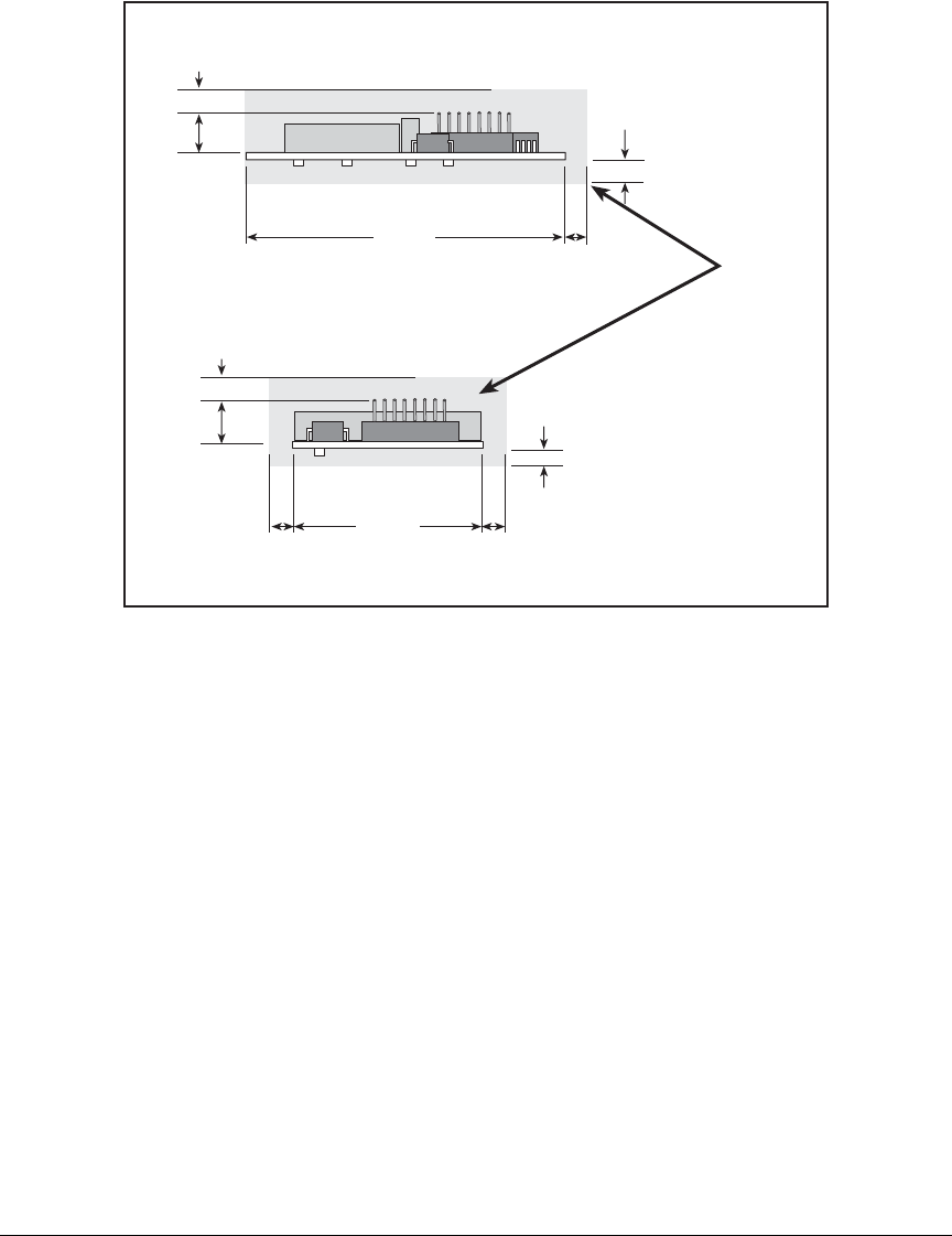
User’s Manual 75
It is recommended that you allow for an “exclusion zone” of 0.08" (2 mm) around the
RCM5600W top and bottom and 0.04" (1 mm) around the three non-connector edges
when the RCM5600W is incorporated into an assembly that includes other printed circuit
boards. This “exclusion zone” that you keep free of other components and boards will
allow for sufficient air flow, and will help to minimize any electrical or electromagnetic
interference between adjacent boards. Figure A-2 shows this “exclusion zone.”
Figure A-2. RCM5600W “Exclusion Zone”
0.08
(2)
0.08
(2)
Exclusion
Zone
0.04
(1)
0.04
(1)
0.08
(2)
0.326
(8.3)
0.04
(1)
0.08
(2)
0.326
(8.3)
2.00
(51)
1.20
(30)

76 MiniCore RCM5600W
Table A-1 lists the electrical, mechanical, and environmental specifications for the
RCM5600W.
Table A-1. RCM5600W Specifications
Parameter RCM5600W
Microprocessor Rabbit® 5000 at 73.73 MHz
EMI Reduction Spectrum spreader for reduced EMI (radiated emissions)
Serial Flash Memory
(program) 1MB
SRAM 1MB
Backup Battery Connection for user-supplied backup battery
(to support RTC)
General-Purpose I/O up to 35 parallel digital I/0 lines configurable with four layers of
alternate functions
Additional Inputs Reset in
Additional Outputs Status, reset out
External I/O Bus Can be configured for 8 data lines and
8 address lines (shared with parallel I/O lines),
plus I/O read/write
Serial Ports
6 high-speed, CMOS-compatible ports:
•all 6 configurable as asynchronous (with IrDA), 4 as clocked serial
(SPI), and 2 as SDLC/HDLC
•1 clocked serial port shared with programming port
Serial Rate Maximum asynchronous baud rate = CLK/8
Slave Interface Slave port allows the RCM5600W to be used as an intelligent
peripheral device slaved to a master processor
Real-Time Clock Yes
Timers Ten 8-bit timers (6 cascadable from the first),
one 10-bit timer with 2 match registers, and
one 16-bit timer with 4 outputs and 8 set/reset registers
Watchdog/Supervisor Yes
Pulse-Width Modulators 4 channels synchronized PWM with 10-bit counter or
4 channels variable-phase or synchronized PWM with 16-bit
counter
Input Capture 2-channel input capture can be used to time input signals from various
port pins
Quadrature Decoder 2-channel quadrature decoder accepts inputs
from external incremental encoder modules
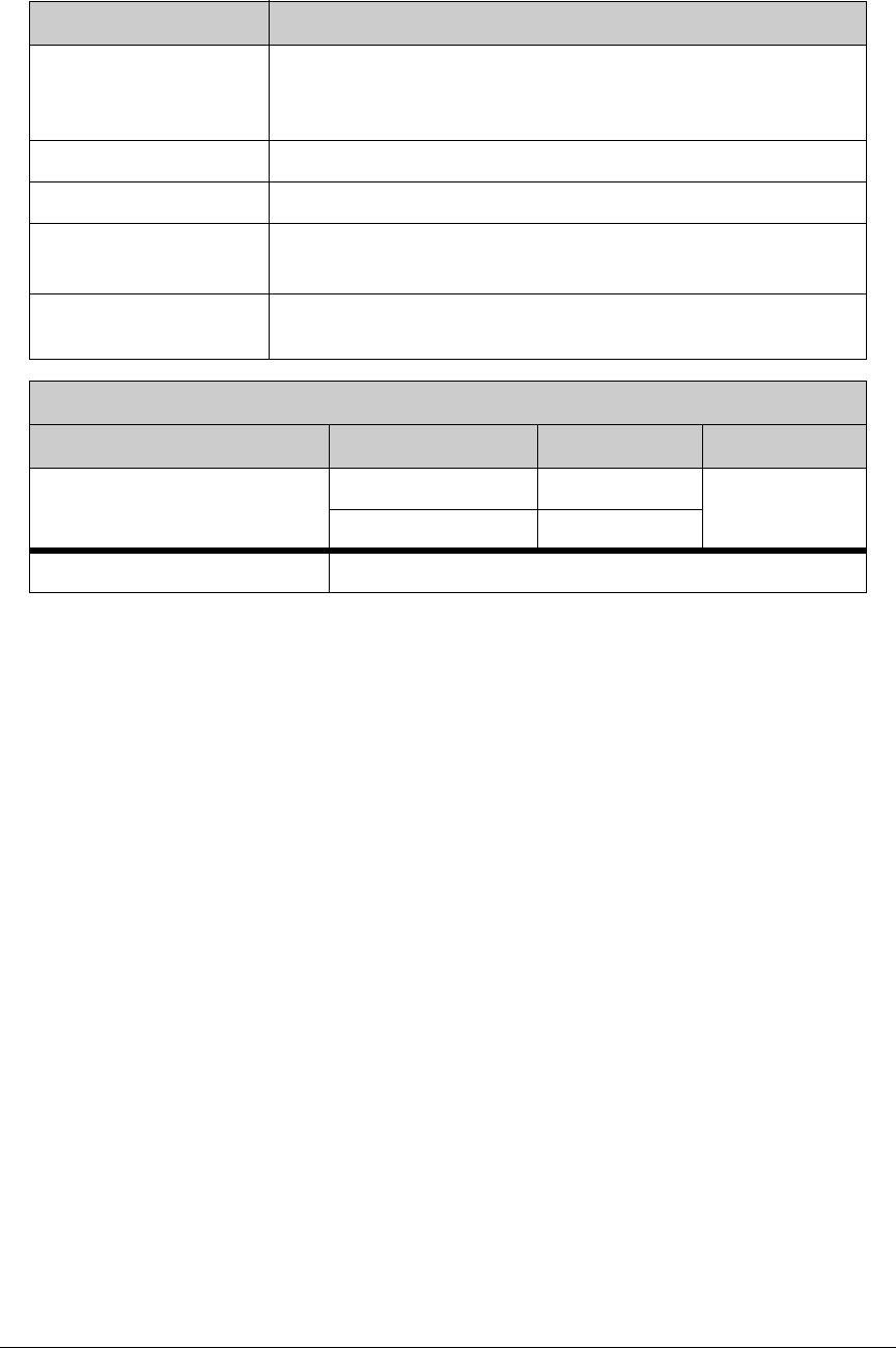
User’s Manual 77
Power
3.15 V DC (min.) – 3.45 V DC (max.)
625 mA @ 3.3 V while transmitting/receiving
85 mA @ 3.3 V while not transmitting/receiving
Operating Temperature –30°C to +55°C
Humidity 5% to 95%, noncondensing
Connectors Edge connectors for interface with
52-pin mini PCI Express socket
Board Size 1.20" × 2.00" × 0.40"
(30 mm × 51 mm × 10 mm)
Wi-Fi
Region 802.11b 802.11g
Typical Average Antenna
Output Power
Americas, Japan 19 dBm 15 dBm
Other Regions 18 dBm
Compliance 802.11b/g, 2.4 GHz
Table A-1. RCM5600W Specifications (continued)
Parameter RCM5600W
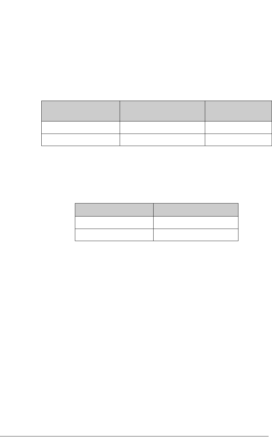
78 MiniCore RCM5600W
A.1.1 mini PCI Express Connector Design Recommendations
The RCM5600W is mounted on the Interface Board via a mini PCI Express connector
and a corresponding locking latch connector. These are offered by manufacturers as a
matched set, although in some cases different manufacturer’s parts may be interchange-
able. Table A-2 lists the recommended parts for the mini PCI Express connector and the locking
latch connector used for the Interface Board.
Other manufacturers such as Molex offer similar connectors and latches, but these can
have different mechanical structures and PCB footprints to what we use on the Interface
Board. Table A-3 lists a pair of matched Molex parts that might be used.
Follow the PCB design and layout recommendations and considerations provided by the
manufacturer for the connector and latch that you select.
Table A-2. Interface Board Connector-Related Parts
Connector Part Manufacturer Part Number Rabbit Store Part
Number
mini PCI Express Connector Pinrex 984-63-052202 498-0090
Latch Connector FOXCONN AS0B226S68K-7F 498-0091
Table A-3. Molex Connector-Related Parts
Connector Part Molex Part Number
mini PCI Express Connector 67910-0002
Latch Connector 48099-4000

User’s Manual 79
A.2 Rabbit 5000 Microprocessor Characteristics
The Rabbit 5000 Microprocessor User’s Manual, which is included with the online docu-
mentation, provides complete specifications and timing diagrams for the Rabbit 5000
microprocessor.
Rabbit’s Technical Note TN227, Interfacing External I/O with Rabbit Microprocessor
Designs, which is also included with the online documentation, contains suggestions for
interfacing I/O devices to the Rabbit 5000 microprocessors.

80 MiniCore RCM5600W

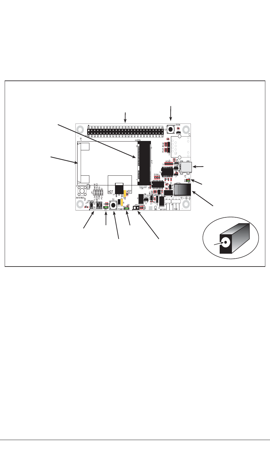
82 MiniCore RCM5600W
B.1 Introduction
The Interface Board included in the Development Kit makes it easy to connect an
RCM5600W module to a power supply and a PC workstation for development.
The Interface Board is shown below in Figure B-1, with its main features identified.
Figure B-1. Interface Board
+
Power Input
Jack
Power
LED
User
LED
Program/Run Mode
Switch/LED
Jumper Settings
mini PCI Express
socket
User
Switch
Current-Limiting
Configuration
Jumper
RCM5600W
Snap-In holder
Stacking
User Interface
Connector
Reset
Switch
mini USB
Programming/Power
Connector
USB LEDs

User’s Manual 83
B.1.1 Interface Board Features
•Power Connection—Power is supplied to the Interface Board either from the PC via
the USB connection or through a power supply jack, J6. A chip at U4 disconnects the
USB power supply from the rest of the Interface Board when power is supplied through
jack J6.
Users providing their own power supply should ensure that it delivers +5 V DC at 10 W.
•Regulated Power Supply—The raw DC voltage is routed to a 3.3 V linear regulator.
The regulator provides stable power to the RCM5600W module and other boards con-
nected to it.
•Power LED—The power LED lights whenever power is connected to the Interface
Board.
•Reset Switch—A momentary-contact, normally open switch is connected directly to the
RCM5600W’s /RESET_IN pin. Pressing the switch forces a hardware reset of the system.
•mini USB Connector—A USB cable is used to connect the RCM5600W via the Inter-
face Board to your PC to enable you to program your RCM5600W module.
•mini PCI Express socket—The Interface Board provides a 52-pin mini PCI Express
socket to enable you to install your RCM5600W module. There is a snap-in holder to
hold the opposite end of the RCM5600W module firmly in place.
•I/O Switch and LED—One momentary-contact, normally open switch is connected to
PD1 on the RCM5600W module and may be read as an input by sample applications.
One LED is connected to PD0 on the RCM5600W module, and may be driven as an
output indicator by sample applications.
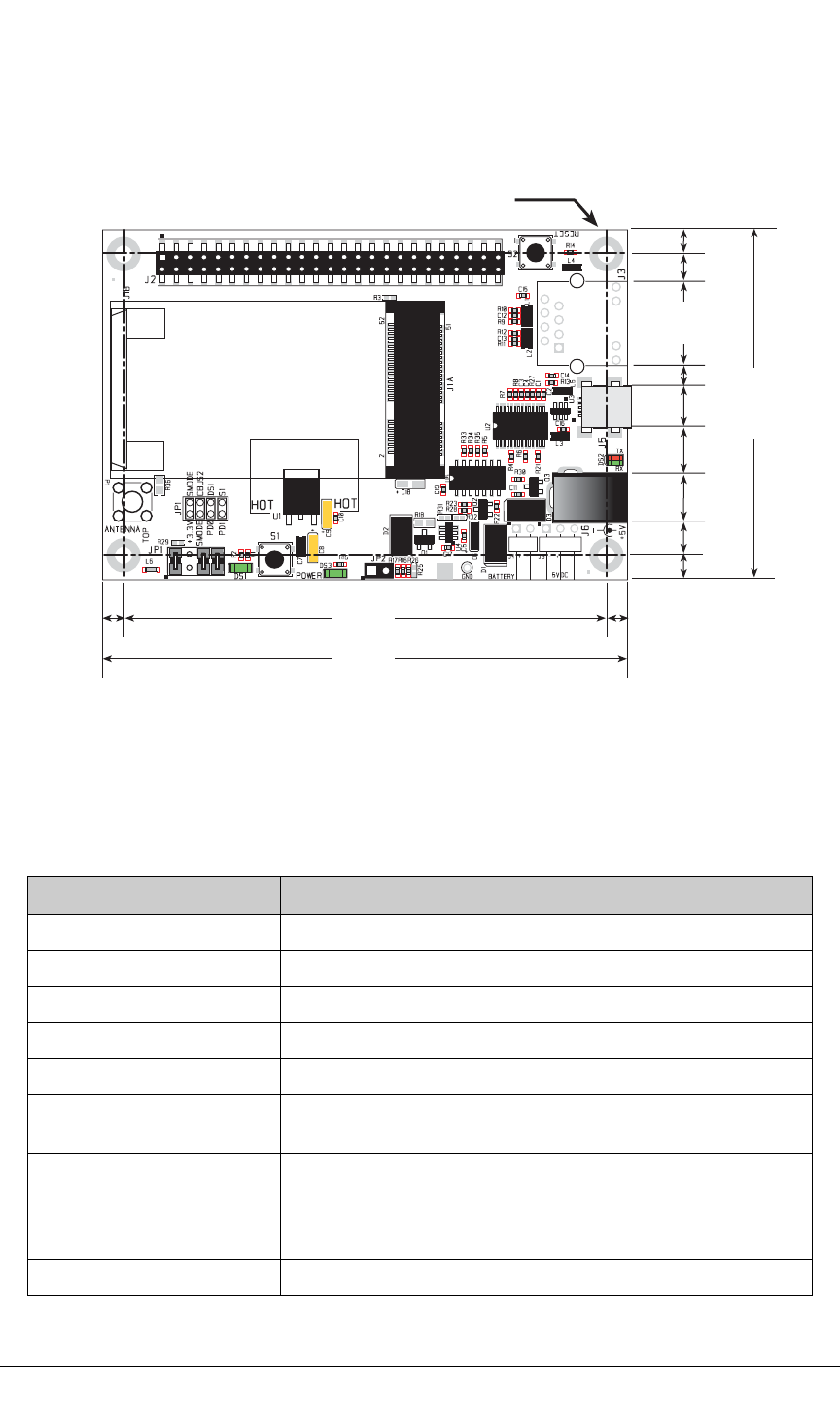
84 MiniCore RCM5600W
B.2 Mechanical Dimensions and Layout
Figure B-2 shows the mechanical dimensions and layout for the Interface Board.
Figure B-2. Interface Board Dimensions
Table B-1 lists the electrical, mechanical, and environmental specifications for the Inter-
face Board.
Table B-1. Interface Board Specifications
Parameter Specification
Board Size 2.50" × 3.75" × 0.60" (64 mm × 95 mm × 15 mm)
Operating Temperature –40°C to +85°C
Humidity 5% to 95%, noncondensing
Input Voltage +5 V DC
Output Voltage +3.3 V DC
Maximum Current Draw
(including user-added circuits) nominal 750 mA max. for USB supply,
1.5 A for separate power supply
Other Connectors
One 2 × 25 IDC header sockets, 0.1" pitch,
One 52-pin mini PCI Express socket to accept RCM5600W
One mini USB connector
One 2 mm power supply jack
Standoffs/Spacers 4
0.15
(3.8)
0.15
(3.8)
0.175
(4.4)
3.45
(88)
3.75
(95)
2.50
(64)
0.175
(4.4)
0.181
(4.6)
0.628
(15.9)
0.230
(5.8)
0.360
(9.1)
0.317
(8.1)
0.304
(7.7)
0.130
(3.3)
× 4
0.125 dia
(3.2)
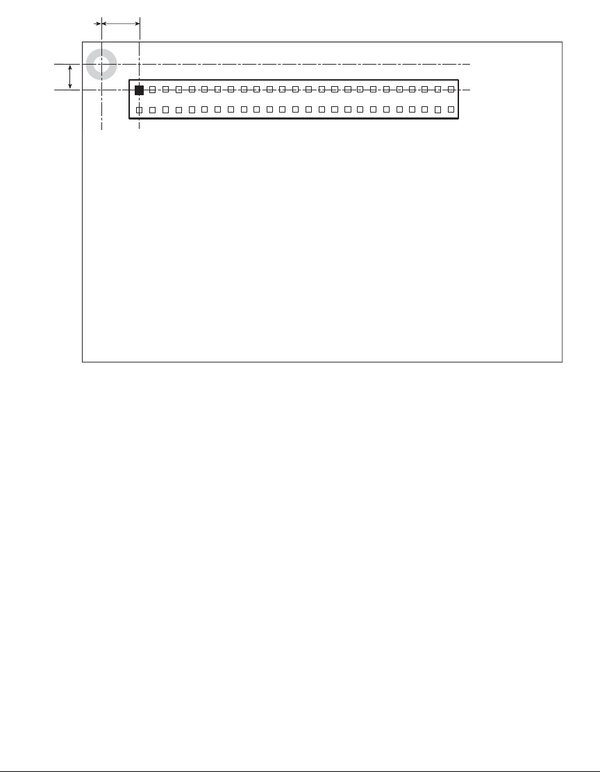
User’s Manual 85
B.2.1 Headers
The Interface Board has a header socket at J2 for physical connection to other boards. J2 is
a 2 × 25 SMT header socket with a 0.1" pin spacing. Figure B-3 shows the layout of
another board to be plugged into the Interface Board — this footprint is identical for the
Interface Board and the two accessory boards. The values are relative to the mounting
hole.
Figure B-3. Interface Board Footprint
0.110
(2.8)
MiniCore Boards
Footprint
J2
0.275
(1.27)
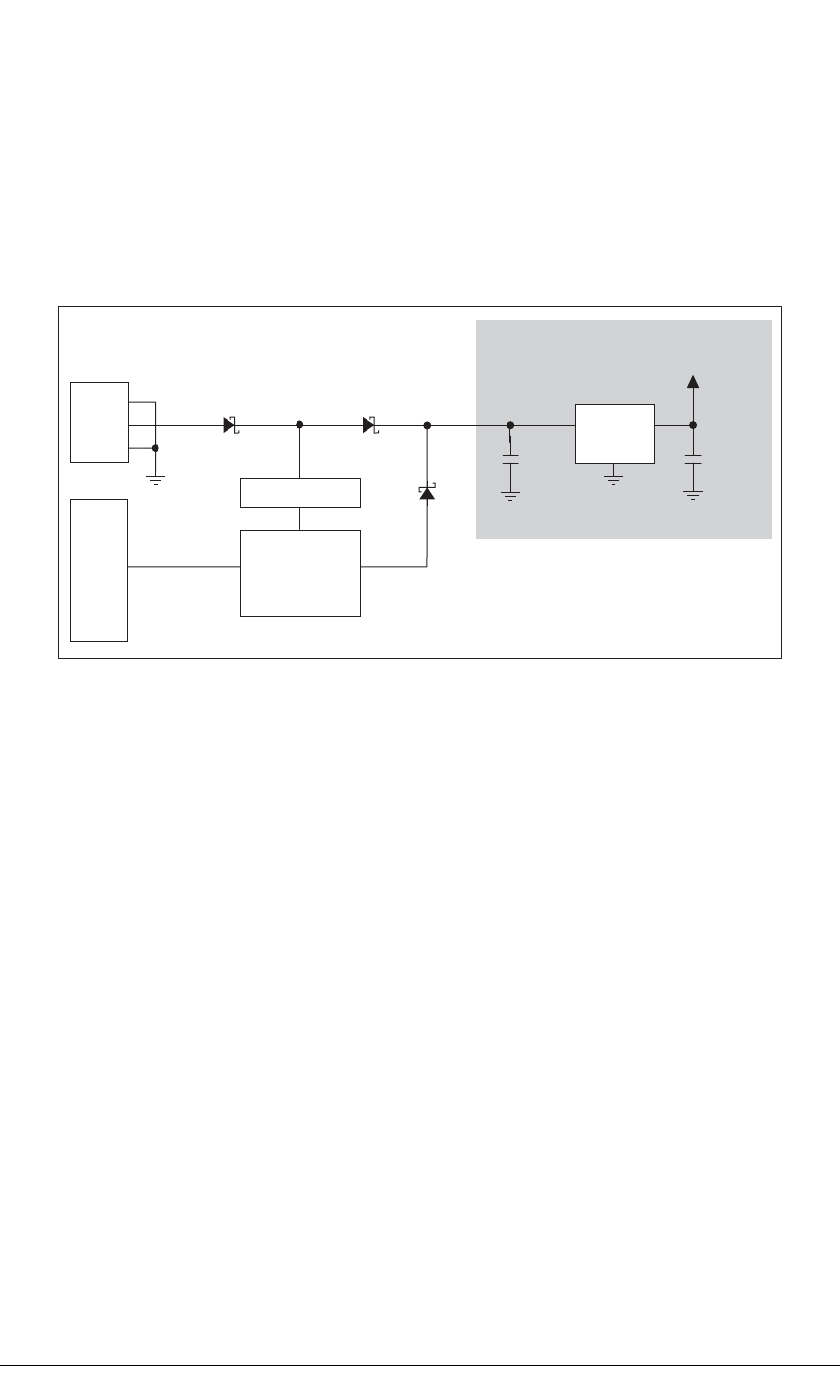
86 MiniCore RCM5600W
B.3 Power Supply
The RCM5600W requires a regulated 3.15 V – 3.45 V DC power source to operate.
Depending on the amount of current required by the application, different regulators can
be used to supply this voltage.
The Interface Board has an onboard +3.3 V linear regulator. The Interface Board is pro-
tected against reverse polarity by a Shottky diode at D3 as shown in Figure B-4.
Figure B-4. Interface Board Power Supply
Power may be supplied to the Interface Board either via the mini USB connector at J5 or
through the power supply jack J6. When a separate power supply is used, the chip at U4
disables power from the mini USB connector, which continues to supply power only to the
USB interface chip. Diodes at D1 and D2 prevent power from going back to the other
power supply that is not supplying power. A separate power supply is required whenever
the Interface Board is not connected to the PC.
A jumper on header JP2 controls the current limiting applied to the power drawn via the
mini USB connector — the current is nominally limited to 700 mA when a jumper is
installed (default), and is nominally limited to 500 mA when no jumper is installed.
LINEAR POWER
REGULATOR
POWER
IN
J6
10 µF
LD29150DT33R
U1
+RAW
+3.3 V
1
2
3
2
1
3B240
D3
10 µF
B240
D1
J5
mini USB
CONNNECTOR
U4
D2
B240
VBUS POWER
SWITCH
CONTROLLER
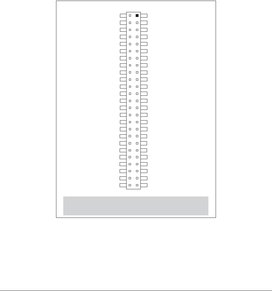
User’s Manual 87
B.4 Using the Interface Board
The Interface Board is also a demonstration board. It can be used to demonstrate the func-
tionality of the
RCM5600W
right out of the box without any modifications to either board.
The Interface Board comes with the basic components necessary to demonstrate the oper-
ation of the RCM5600W. One LEDs (DS1) is connected to PD0, and one switch (S1) is
connected to PD1 to demonstrate the interface to the Rabbit 5000 microprocessor. Reset
switch S2 is the hardware reset for the RCM5600W.
The Interface
Board provides the user with RCM5600W connection points brought out con-
veniently to header
socket
J2. Other boards such as the Prototyping Board or the accessory
boards from the Deluxe Development Kit can be plugged into header socket J2.
The pinouts
for header socket J2 are shown in Figure B-5.
Figure B-5. Interface Board Pinout
Note: These pinouts are as seen on
the Top Side.
+3.3 V
PE0
PE2
PE5
PE7
PD0
PD2
/RESET_IN
+3.3 V
PC0
PC2
PC4/TxB
PC6/TxA
PB0/SCLKB
PB2
PB4
PB6
+3.3 V
PA0
PA2
PA4
PA6
/IORD
STATUS
+3.3 V
GND
PE1
PE3
PE6
SMODE
PD1
PD3
/RESET
GND
PC1
PC3
PC5/RxB
PC7/RxA
PB1/SCLKA
PB3
PB5
PB7
GND
PA1
PA3
PA5
PA7
/IOWR
VBAT_EXT
GND
J2

88 MiniCore RCM5600W
B.4.1 Add Additional Boards
The Prototyping Board and the two accessory boards included with the Deluxe Develop-
ment Kit may be installed on the Interface Board as shown in Figure B-6.
Figure B-6. Install Additional Boards on Interface Board
1. Insert the header strip into header socket J2 on the Interface Board or the board already
installed above the Interface Board.
2. Line up the board being installed above the pins extending from the header socket and
the stand-offs/connectors.
3. Press down to install the board.
4. Insert additional plastic standoffs/connectors as shown to hold the board firmly in place
and to hold another board if desired.
When additional boards are installed, the board-to-board spacing is 0.7" (17.8 mm).
Multiple boards should be installed in this sequence from bottom to top.
•Interface Board with RCM5600W installed.
•Prototyping Board.
•Serial Communication accessory board.
•Digital I/O accessory board.
Install header connector strip
in bottom socket
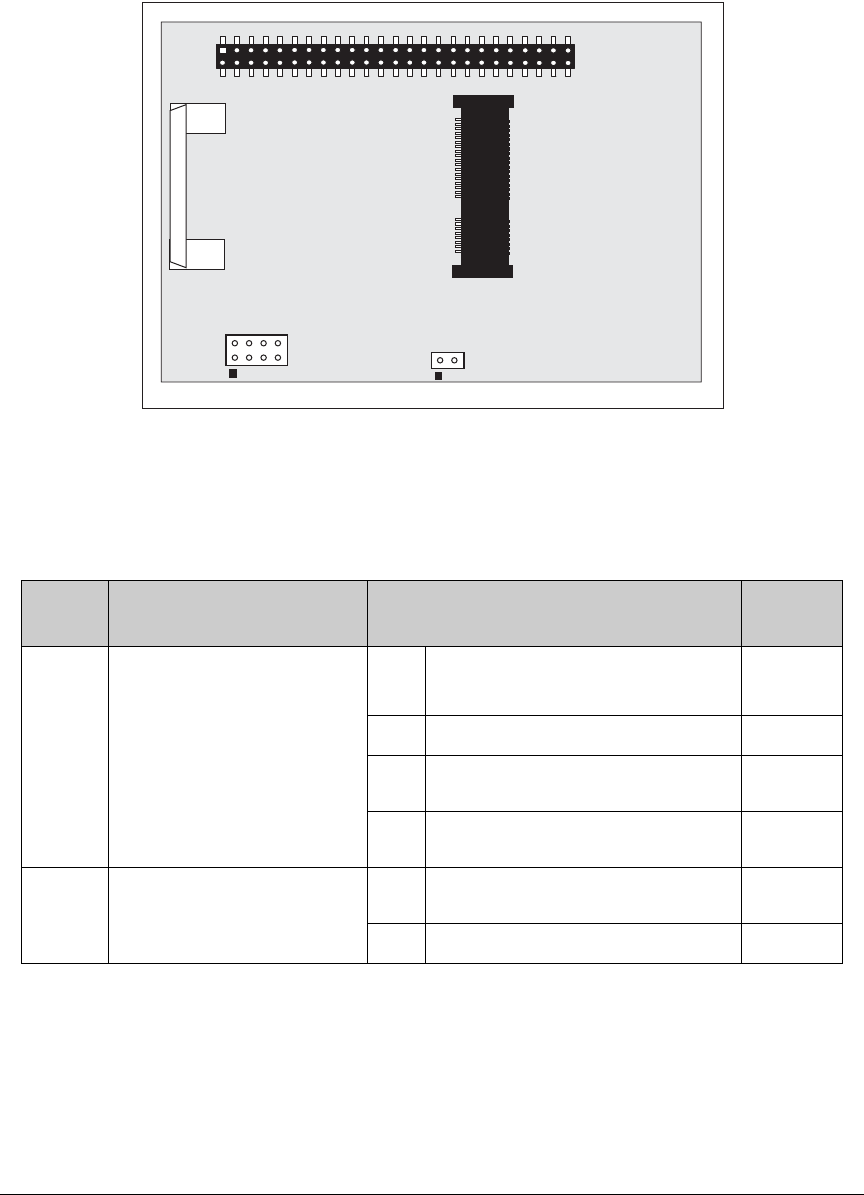
User’s Manual 89
B.5 Interface Board Jumper Configurations
Figure B-7 shows the header locations used to configure the various Interface Board
options via jumpers.
Figure B-7. Location of Configurable Jumpers on Interface Board
Table B-2 lists the configuration options using either jumpers or 0 Ω surface-mount resistors.
Table B-2. Interface Board Jumper Configurations
Header Description Pins Connected Factory
Default
JP1 Dynamic C Setup
1–2 SMODE pins pulled up
(Programming Mode)*
* The RCM5600W will operate in Run Mode when these pins are not jumpered.
×
3–4 Reserved for future use
5–6 LED DS1 connected ×
7–8 Switch S1 connected ×
JP2 mini USB Connector Power
Supply Current Limiting
1–2 Nominal 700 mA ×
n.c. Nominal 500 mA
JP1 JP2

90 MiniCore RCM5600W

User’s Manual 91
APPENDIX C. PROTOTYPING BOARD
Appendix C describes the features and accessories of the Proto-
typing Board, and explains the use of the Prototyping Board to
build prototypes of your own circuits. The Prototyping Board
mounts on the Interface Board from which it receives its power
and signals.
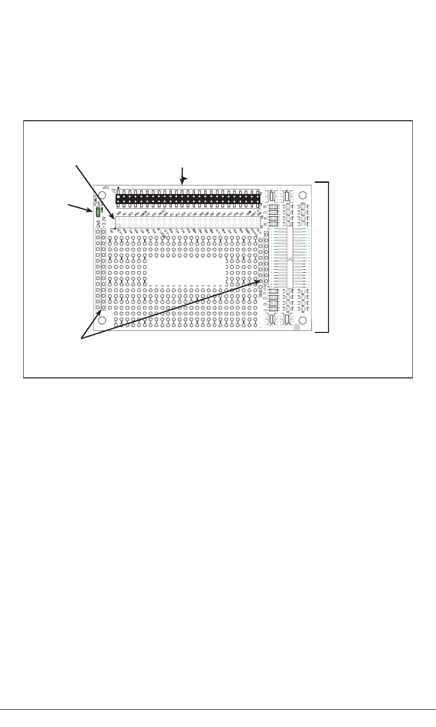
92 MiniCore RCM5600W
C.1 Introduction
The Prototyping Board included in the Development Kit provides a prototyping area for
more advanced hardware development. The Prototyping Board is shown below in
Figure C-1, with its main features identified.
Figure C-1. Prototyping Board
C.1.1 Prototyping Board Features
•Power Connection—Power is supplied to the Prototyping Board via the RCM5600W
header socket connections.
•Power LED—The power LED lights whenever power is connected to the Prototyping
Board.
•Module Extension Headers—The complete pin set of the RCM5600W module is
duplicated below header J2. Developers can solder wires directly into the appropriate
holes, or, for more flexible development, a 2 × 25 header strip with a 0.1" pitch can be
soldered into place. See Figure C-4 for the header pinouts.
•Prototyping Area—A generous prototyping area is provided for the installation of
through-hole and surface-mount components. +3.3 V and ground buses run along the
left and right edges of the through-hole prototyping area. The through-hole area is set
up to accept components with a pitch of 0.1" or widths of 0.3" or 0.6". Several areas for
surface-mount devices are also available. (Note that there are SMT pads on both the top
and the bottom of the Prototyping Board.) Each SMT pad is connected to a hole
designed to accept a 30 AWG solid wire.
Power
LED
Through-Hole
Prototyping Area
3.3 V and GND
Buses
SMT Prototyping
Area
RCM5600W
Module
Extension Header
Stacking
User Interface
Connector
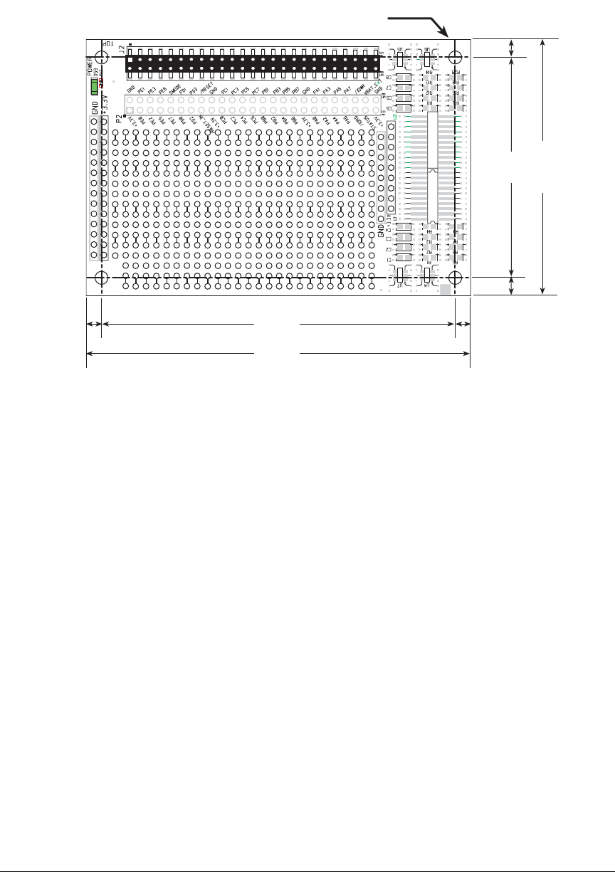

94 MiniCore RCM5600W
Table C-1 lists the electrical, mechanical, and environmental specifications for the Proto-
typing Board.
Table C-1. Prototyping Board Specifications
Parameter Specification
Board Size 2.50" × 3.75" × 0.52" (64 mm × 95 mm × 13 mm)
Operating Temperature –40°C to +85°C
Humidity 5% to 95%, noncondensing
Operating Voltage +3.3 V DC
Current Draw from Interface
Board (excluding user-added
circuits) 2 mA
Prototyping Area 1.7" × 2.7" (40 mm × 70 mm) throughhole, 0.1" spacing,
additional space for SMT components
Connectors Two 2 × 25 IDC header sockets, 0.1" pitch
(a 2 × 25 IDC header strip is included to connect the Prototyping
Board to the Interface Board below it)
Standoffs/Spacers 4
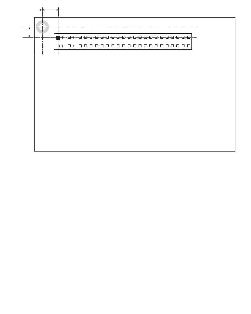
User’s Manual 95
C.2.1 Headers
The Prototyping Board has a header socket at J2 for physical connection to other boards
above it, and a header socket at J12 on the bottom side to connect to boards below it. J2
and J12 are 2 × 25 SMT header sockets with a 0.1" pin spacing. Figure C-3 shows the
layout of another board to be plugged into the Interface Board — this footprint is identical
for the Prototyping Board and the two accessory boards. The values are relative to the
mounting hole.
Figure C-3. MiniCore Boards Footprint
0.110
(2.8)
MiniCore Boards
Footprint
J2
0.275
(1.27)
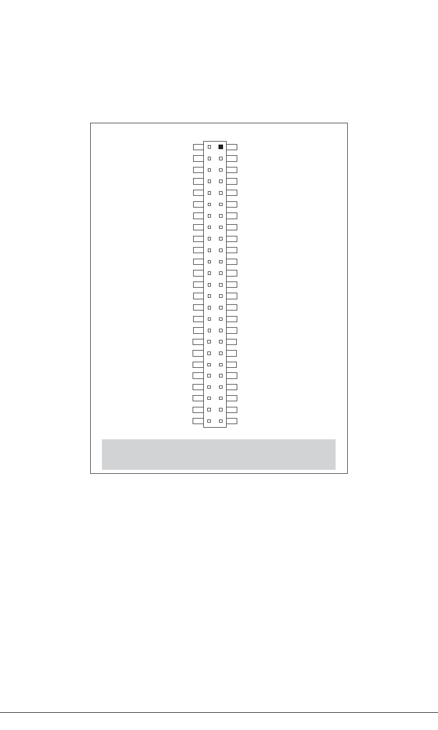
96 MiniCore RCM5600W
C.3 Using the Prototyping Board
The
Prototyping Board provides the user with RCM5600W connection points brought out
conveniently to labeled points below header
J2.
The pinouts for header socket J2 are shown
in Figure C-4.
Figure C-4. MiniCore Boards Pinout
There is a 1.7" × 2.7" through-hole prototyping space available on the Prototyping Board.
The holes in the prototyping area are spaced at 0.1" (2.5 mm).
+3.3 V and GND traces run
along the left edge of the Prototyping Board for easy access.
Small to medium circuits can
be prototyped using point-
to-point wiring with 20 to 30 AWG wire between the prototyping
area, the
+3.3 V and GND traces,
and the surrounding area where surface-mount compo-
nents may be installed.
Small holes are provided around the surface-mounted components
that may be installed around the prototyping area.
Note: These pinouts are as seen on
the Top Side.
+3.3 V
PE0
PE2
PE5
PE7
PD0
PD2
/RESET_IN
+3.3 V
PC0
PC2
PC4/TxB
PC6/TxA
PB0/SCLKB
PB2
PB4
PB6
+3.3 V
PA0
PA2
PA4
PA6
/IORD
STATUS
+3.3 V
GND
PE1
PE3
PE6
SMODE
PD1
PD3
/RESET
GND
PC1
PC3
PC5/RxB
PC7/RxA
PB1/SCLKA
PB3
PB5
PB7
GND
PA1
PA3
PA5
PA7
/IOWR
VBAT_EXT
GND
J2
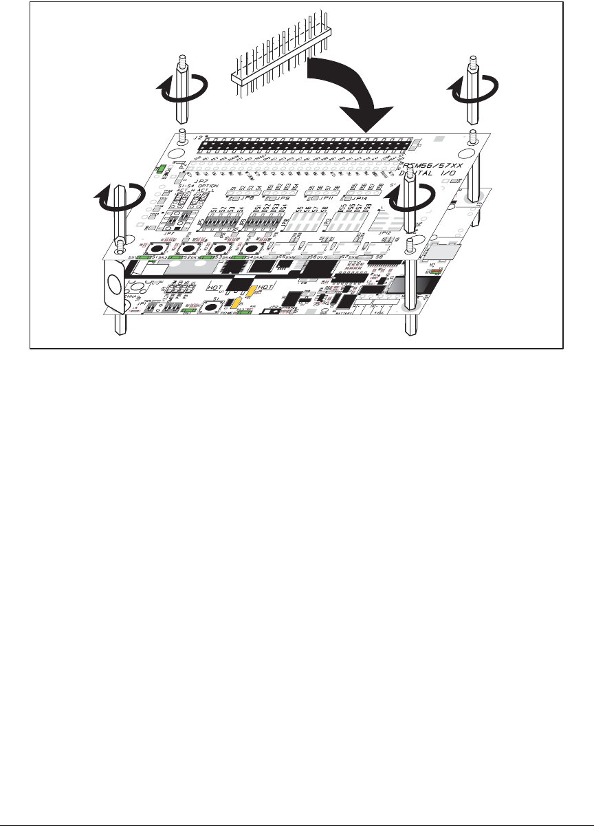
User’s Manual 97
C.3.1 Add Additional Boards
The Prototyping Board and the two accessory boards included with the Deluxe Develop-
ment Kit may be installed on the Interface Board as shown in Figure C-5.
Figure C-5. Install Additional Boards
1. Insert the header strip into header socket J2 on the Interface Board or the board already
installed above the Interface Board.
2. Line up the board being installed above the pins extending from the header socket and
the stand-offs/connectors.
3. Press down to install the board.
4. Insert additional plastic standoffs/connectors as shown to hold the board firmly in place
and to hold another board if desired—note that one plastic standoff/connector needs to
be inserted “upside down” to secure the Prototyping Board to the antenna bracket.
When additional boards are installed, the board-to-board spacing is 0.7" (17.8 mm).
Multiple boards should be installed in this sequence from bottom to top.
•Interface Board with RCM5600W installed.
•Prototyping Board.
•Serial Communication accessory board.
•Digital I/O accessory board.
Install header connector strip
in bottom socket

98 MiniCore RCM5600W

User’s Manual 99
APPENDIX D. DIGITAL I/O ACCESSORY
BOARD
Appendix D describes the features and accessories of the Digital
I/O accessory board, and explains how to use the Digital I/O
accessory board. The Digital I/O accessory board mounts on the
Interface Board or other board already installed on the Interface
Board from which it receives its power and signals.
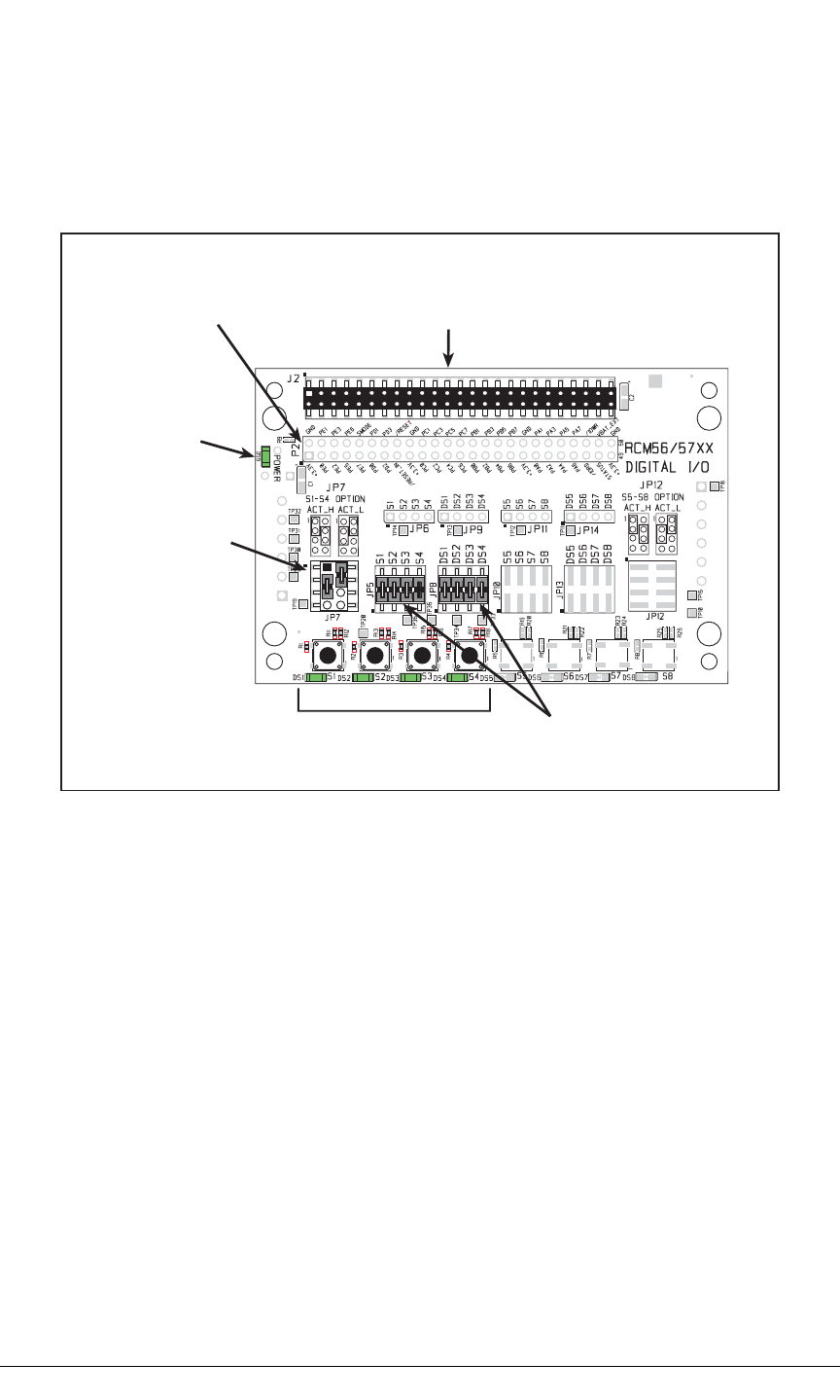
100 MiniCore RCM5600W
D.1 Introduction
The Digital I/O accessory board included in the Deluxe Development Kit provides Push-
button switches and LEDs to use in conjunction with selected sample programs. The Dig-
ital I/O accessory board is shown below in Figure D-1, with its main features identified.
Figure D-1. Digital I/O Accessory Board
D.1.1 Digital I/O Accessory Board Features
•Power Connection—Power is supplied to the Digital I/O accessory board via the
RCM5600W header socket connections.
•Power LED—The power LED lights whenever power is connected to the Digital I/O
accessory board.
•Module Extension Headers—The complete pin set of the RCM5600W module is
duplicated below header J2. Developers can solder wires directly into the appropriate
holes, or, for more flexible development, a 2 × 25 header strip with a 0.1" pitch can be
soldered into place. See Figure D-4 for the header pinouts.
•I/O Switches and LEDs—Four momentary-contact, normally open switches are con-
nected to PB4–PB7 on the RCM5600W module and may be read as an input by sample
applications.
Four LEDs are connected to PA4–PA7 on the RCM5600W module, and may be driven
as an output indicator by sample applications.
Power
LED
RCM5600W
Module
Extension Header
User Switches
and LEDs
Pullup/
Pulldown
Jumper
Configuration
LED and Switch
Signal Connections
Stacking
User Interface
Connector
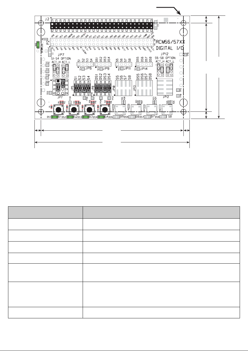
User’s Manual 101
D.2 Mechanical Dimensions and Layout
Figure D-2 shows the mechanical dimensions and layout for the Digital I/O accessory board.
Figure D-2. Digital I/O Accessory Board Dimensions
Table D-1 lists the electrical, mechanical, and environmental specifications for the Digital
I/O accessory board.
Table D-1. Digital I/O Accessory Board Specifications
Parameter Specification
Board Size 2.50" × 3.75" × 0.52" (64 mm × 95 mm × 13 mm)
Operating Temperature –40°C to +85°C
Humidity 5% to 95%, noncondensing
Operating Voltage +3.3 V DC
Current Draw from Interface
Board 6 mA (typical)
Connectors Two 2 × 25 IDC header sockets, 0.1" pitch
(a 2 × 25 IDC header strip is included to connect the Digital I/O
accessory board to the board below it)
Standoffs/Spacers 4
0.15
(3.8)
0.15
(3.8)
0.175
(4.4)
3.45
(88)
3.75
(95)
2.50
(64)
0.175
(4.4)
× 4
0.125 dia
(3.2)
2.15
(55)
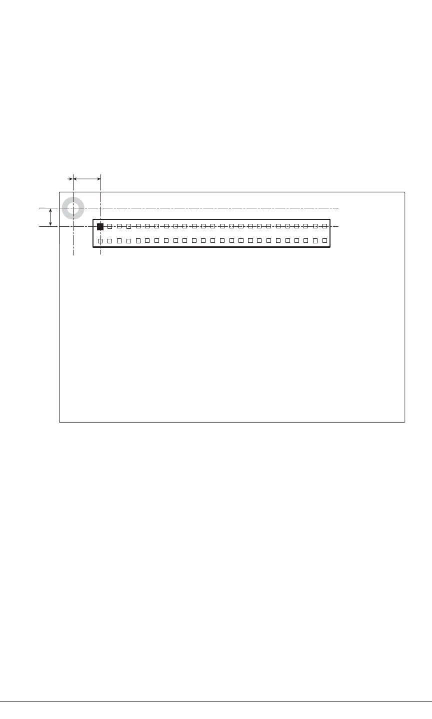
102 MiniCore RCM5600W
D.2.1 Headers
The Digital I/O accessory board has a header socket at J2 for physical connection to other
boards above it, and a header socket at J12 on the bottom side to connect to boards below
it. J2 and J12 are 2 × 25 SMT header sockets with a 0.1" pin spacing. Figure D-3 shows
the layout of another board to be plugged into the Digital I/O accessory board — this foot-
print is identical for the Prototyping Board and the two accessory boards. The values are
relative to the mounting hole.
Figure D-3. MiniCore Boards Footprint
0.110
(2.8)
MiniCore Boards
Footprint
J2
0.275
(1.27)
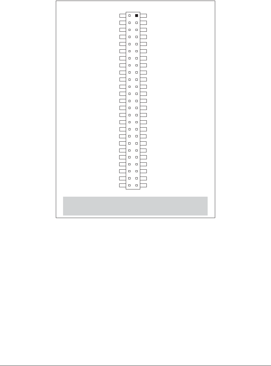
User’s Manual 103
D.3 Using the Digital I/O Accessory Board
The Digital I/O accessory board
provides the user with RCM5600W connection points
brought out conveniently to labeled points below header
J2.
The pinouts for header socket J2
are shown in Figure D-4.
Figure D-4. MiniCore Boards Pinout
Note: These pinouts are as seen on
the Top Side.
+3.3 V
PE0
PE2
PE5
PE7
PD0
PD2
/RESET_IN
+3.3 V
PC0
PC2
PC4/TxB
PC6/TxA
PB0/SCLKB
PB2
PB4
PB6
+3.3 V
PA0
PA2
PA4
PA6
/IORD
STATUS
+3.3 V
GND
PE1
PE3
PE6
SMODE
PD1
PD3
/RESET
GND
PC1
PC3
PC5/RxB
PC7/RxA
PB1/SCLKA
PB3
PB5
PB7
GND
PA1
PA3
PA5
PA7
/IOWR
VBAT_EXT
GND
J2
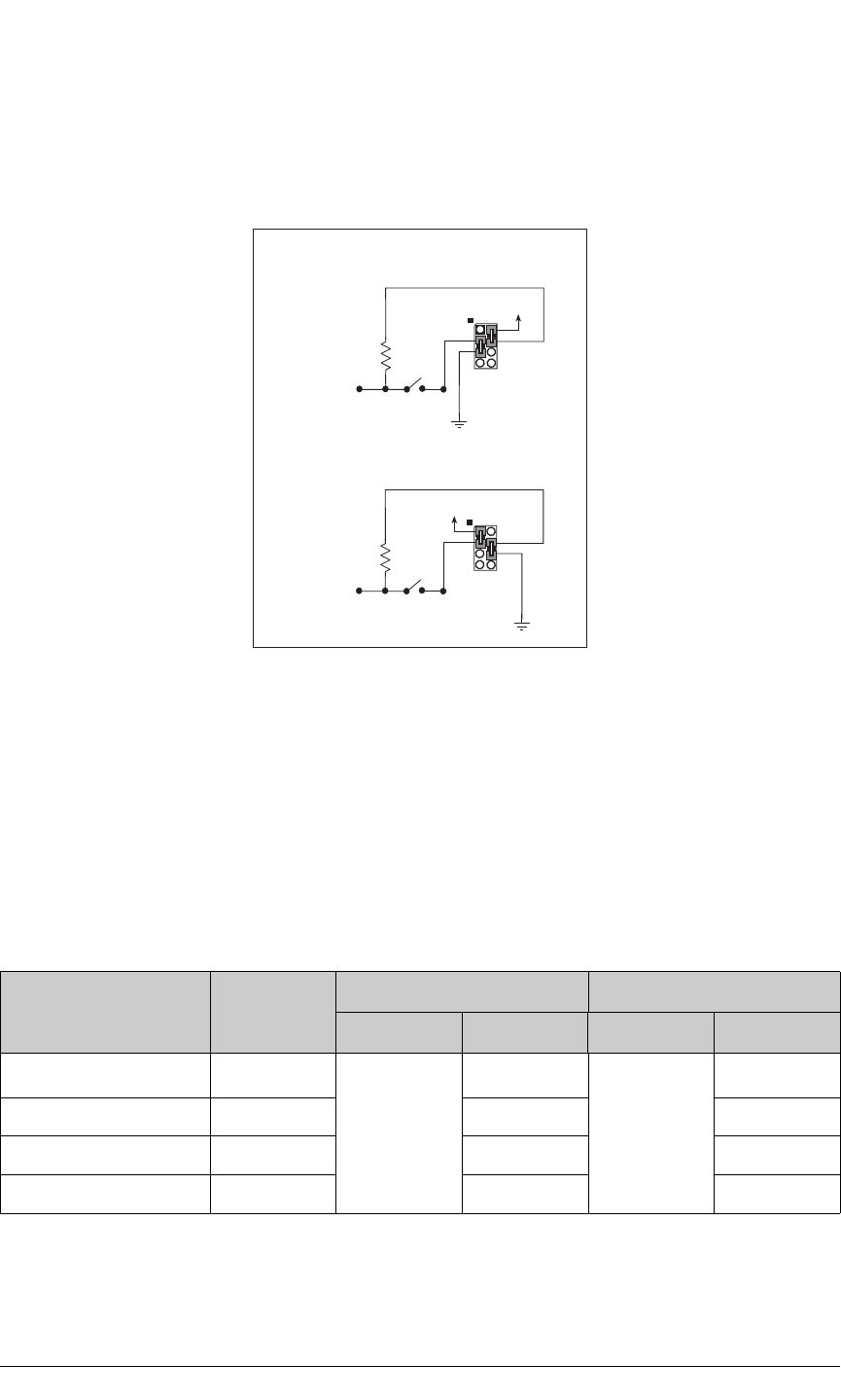
104 MiniCore RCM5600W
D.3.1 Configuration
The pushbutton switches may be configured active high (pulled down) or active low
(pulled up) via jumper settings on header JP7 for the four switches installed. Jumpers on
JP12 may be set up in a similar way after additional switches are installed at S5–S8.
Figure D-5. Pushbutton Switch Configuration
The four LED output indicators are set up as sinking outputs. Four additional LEDs may
be installed at DS5–DS8.
Jumpers on headers JP5 and JP8 connect the RCM5600W signals to the pushbutton
switches or LEDs. These jumpers may be removed and other RCM5600W signals may be
connected to the switch or LED positions above these headers via headers JP6 and JP9.
Table D-2 lists the connection options for the switches and LEDs.
Table D-2. Digital I/O Accessory Board Switch/LED Connection Options
Default RCM5600W
Signal Switch/LED Connected via Alternate Connection
Header Pins Header Pin
PB4 S1*
JP5
1–2
JP6
1
PB5 S2 3–4 2
PB6 S3 5–6 3
PB7 S4 7–8 4
47 kW
+V
JP7
S1S4
ACTIVE LOW
47 kW
+V JP7
S1S4
ACTIVE HIGH
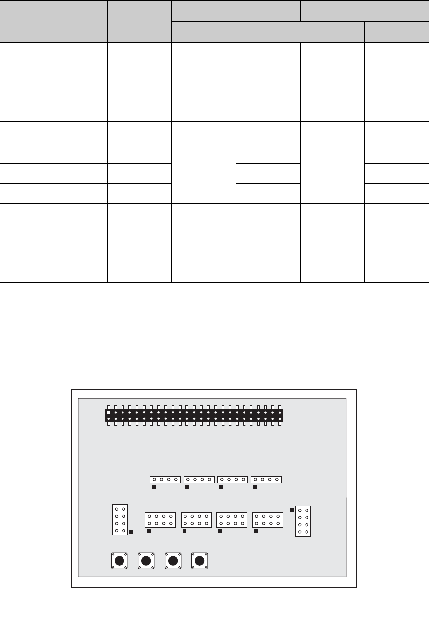
User’s Manual 105
NOTE: Switches S5–S8, LEDs DS5–DS8, and the corresponding configuration headers
JP10–JP14 and circuits are not stuffed.
Figure D-6 shows the locations of the configurable jumpers.
Figure D-6. Location of Configurable Jumpers on Digital I/O Accessory Board
PA4 DS1
JP8
1–2
JP9
1
PA5 DS2 3–4 2
PA6 DS3 5–6 3
PA7 DS4 7–8 4
PB0 S5†
JP10
1–2
JP11
1
PB1 S6 3–4 2
PB2 S7 5–6 3
PB3 S8 7–8 4
PA0 DS5
JP13
1–2
JP14
1
PA1 DS6 3–4 2
PA2 DS7 5–6 3
PA3 DS8 7–8 4
* Switches S1–S4 are pulled high or low via jumpers on header JP7.
† Switches S5–S8 are pulled high or low via jumpers on header JP12 (not stuffed).
Table D-2. Digital I/O Accessory Board Switch/LED Connection Options (cont’d)
Default RCM5600W
Signal Switch/LED Connected via Alternate Connection
Header Pins Header Pin
JP7 JP5 JP8 JP10 JP13 JP12
JP6 JP9 JP11 JP14
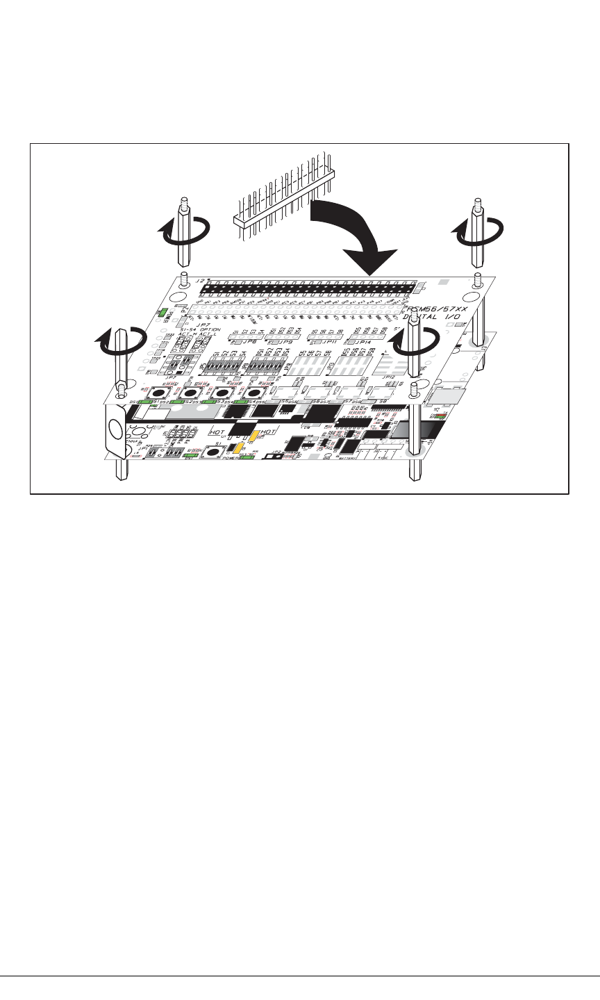
106 MiniCore RCM5600W
D.3.2 Add Additional Boards
The Prototyping Board and the two accessory boards included with the Deluxe Develop-
ment Kit may be installed on the Interface Board as shown in Figure D-7.
Figure D-7. Install Additional Boards
1. Insert the header strip into header socket J2 on the Interface Board or the board already
installed above the Interface Board.
2. Line up the board being installed above the pins extending from the header socket and
the stand-offs/connectors.
3. Press down to install the board.
4. Insert additional plastic standoffs/connectors as shown to hold the board firmly in place
and to hold another board if desired—note that one plastic standoff/connector needs to
be inserted “upside down” to secure the Prototyping Board or other accessory board
above the antenna bracket.
When additional boards are installed, the board-to-board spacing is 0.7" (17.8 mm).
Multiple boards should be installed in this sequence from bottom to top.
•Interface Board with RCM5600W installed.
•Prototyping Board.
•Serial Communication accessory board.
•Digital I/O accessory board.
Install header connector strip
in bottom socket

User’s Manual 107
APPENDIX E. SERIAL COMMUNICATION
ACCESSORY BOARD
Appendix E describes the features and accessories of the Serial
Communication accessory board, and explains how to use the
Serial Communication accessory board. The Serial Communica-
tion accessory board mounts on the Interface Board or other
board already installed on the Interface Board from which it
receives its power and signals.
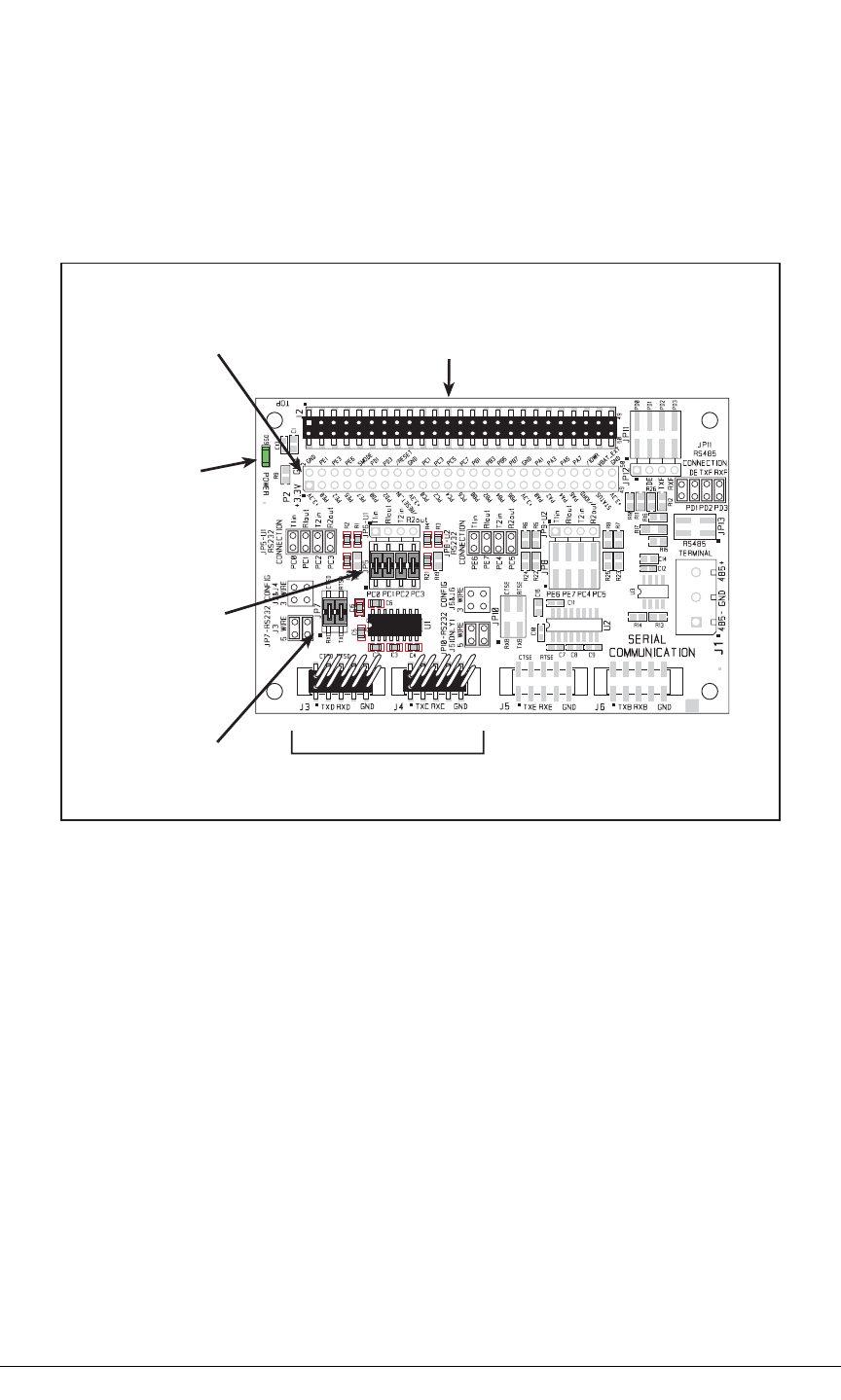
108 MiniCore RCM5600W
E.1 Introduction
The Serial Communication accessory board included in the Deluxe Development Kit pro-
vides two 3-wire serial ports to use in conjunction with selected sample programs. The
Serial Communication accessory board is shown below in Figure E-1, with its main fea-
tures identified.
Figure E-1. Serial Communication Accessory Board
E.1.1 Serial Communication Accessory Board Features
•Power Connection—Power is supplied to the Serial Communication accessory board
via the RCM5600W header socket connections.
•Power LED—The power LED lights whenever power is connected to the Serial Com-
munication accessory board.
•Module Extension Headers—The complete pin set of the RCM5600W module is
duplicated below header J2. Developers can solder wires directly into the appropriate
holes, or, for more flexible development, a 2 × 25 header strip with a 0.1" pitch can be
soldered into place. See Figure E-4 for the header pinouts.
•RS-232 Headers—Serial Ports C and D are brought out as 3-wire RS-232 ports on
headers J4 and J3 respectively. Header J3 can be set up as a 5-wire RS-232 serial port
with flow control provided by Serial Port C.
Power
LED
RCM5600W
Module
Extension Header
CTS/RTS
Available on J3 RS-232 Headers
PC0PC3
Brought Out
to J3 and J4
Serial Port D Serial Port C
Stacking
User Interface
Connector
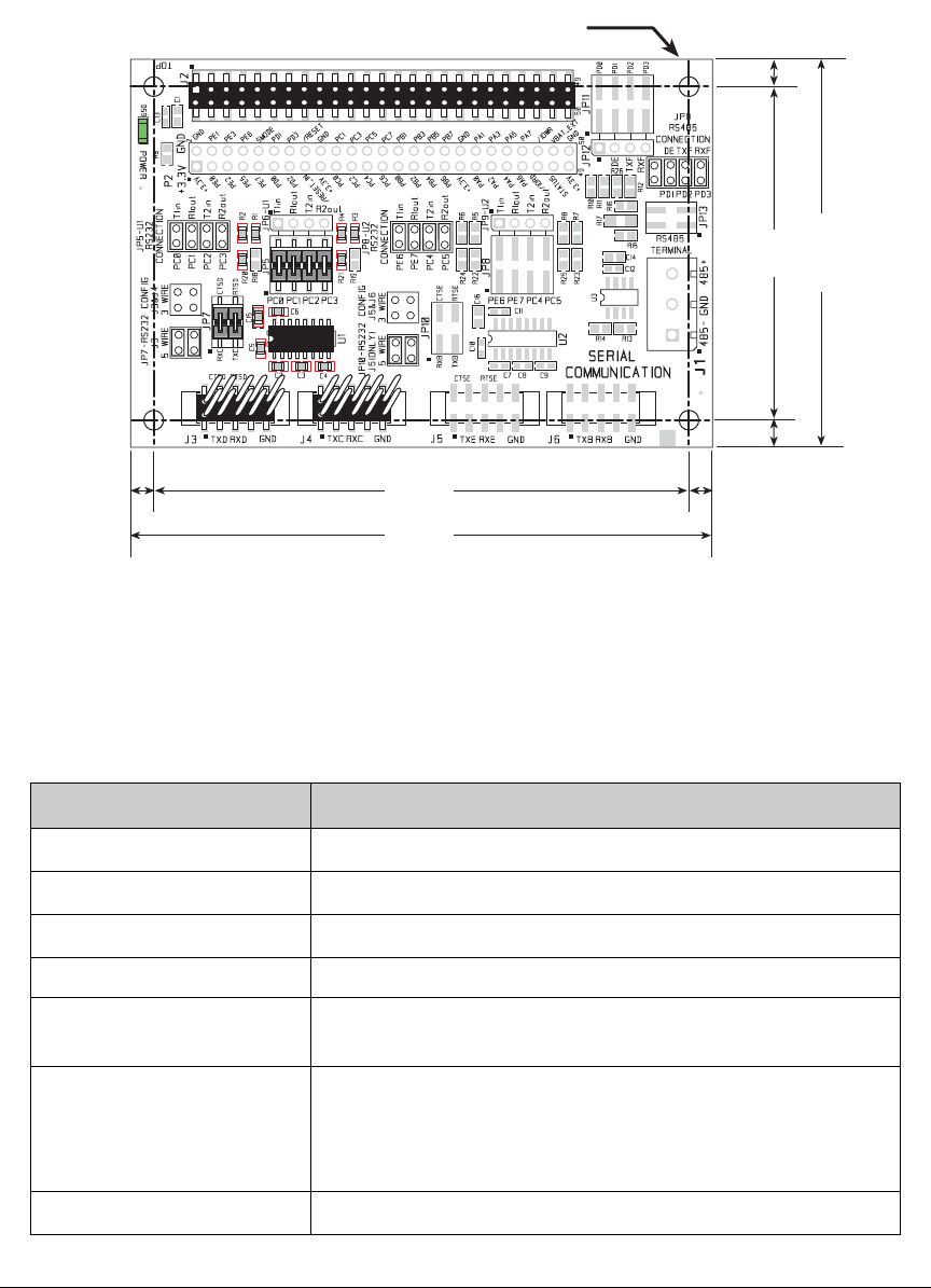
User’s Manual 109
E.2 Mechanical Dimensions and Layout
Figure E-2 shows the mechanical dimensions and layout for the
Serial Communication
acces-
sory board.
Figure E-2. Serial Communication Accessory Board Dimensions
Table E-1 lists the electrical, mechanical, and environmental specifications for the Serial
Communication accessory board.
Table E-1. Serial Communication Accessory Board Specifications
Parameter Specification
Board Size 2.50" × 3.75" × 0.52" (64 mm × 95 mm × 13 mm)
Operating Temperature –40°C to +85°C
Humidity 5% to 95%, noncondensing
Operating Voltage +3.3 V DC
Current Draw from Interface
Board 10 mA (typical)
Connectors
Two 2 × 25 IDC header sockets, 0.1" pitch
(a 2 × 25 IDC header strip is included to connect the Serial
Communication accessory board to the board below it)
Two 2 × 5 IDC headers, 0.1" pitch
Standoffs/Spacers 4
0.15
(3.8)
0.15
(3.8)
0.175
(4.4)
3.45
(88)
3.75
(95)
2.50
(64)
0.175
(4.4)
× 4
0.125 dia
(3.2)
2.15
(55)

110 MiniCore RCM5600W
E.2.1 Headers
The Serial Communication accessory board has a header socket at J2 for physical connec-
tion to other boards above it, and a header socket at J12 on the bottom side to connect to
boards below it. J2 and J12 are 2 × 25 SMT header sockets with a 0.1" pin spacing.
Figure E-3 shows the layout of another board to be plugged into the Serial Communica-
tion accessory board — this footprint is identical for the Prototyping Board and the two
accessory boards. The values are relative to the mounting hole.
Figure E-3. MiniCore Boards Footprint
0.110
(2.8)
MiniCore Boards
Footprint
J2
0.275
(1.27)
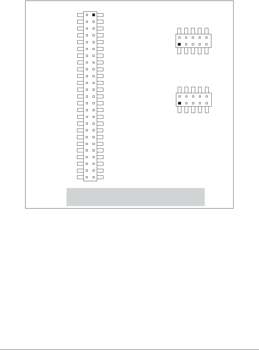
User’s Manual 111
E.3 Using the Serial Communication Accessory Board
The Serial Communication accessory board
provides the user with RCM5600W connection
points brought out conveniently to labeled points below header
J2.
The pinouts for header
socket J2 and the RS-232 headers at J3 and J4 are shown in Figure E-4.
Figure E-4. Serial Communication Accessory Board Pinout
The remaining RS-232 header positions at J5 and J6, and the RS-485 screw-terminal
header position at J1 are unstuffed.
Note: These pinouts are as seen on
the Top Side.
TxD
RxD
GND
CTSD
RTSD
J3
TxC
RxC
GND
J4
+3.3 V
PE0
PE2
PE5
PE7
PD0
PD2
/RESET_IN
+3.3 V
PC0
PC2
PC4/TxB
PC6/TxA
PB0/SCLKB
PB2
PB4
PB6
+3.3 V
PA0
PA2
PA4
PA6
/IORD
STATUS
+3.3 V
GND
PE1
PE3
PE6
SMODE
PD1
PD3
/RESET
GND
PC1
PC3
PC5/RxB
PC7/RxA
PB1/SCLKA
PB3
PB5
PB7
GND
PA1
PA3
PA5
PA7
/IOWR
VBAT_EXT
GND
J2

112 MiniCore RCM5600W
E.3.1 Configuration
Serial Ports C and D are brought out as 3-wire RS-232 serial ports on headers J4 and J3
respectively. Jumpers may be installed on header JP7 to use header J3 as a 5-wire RS-232
serial port with flow control provided by Serial Port C.
Jumpers on headers JP5 connect the RCM5600W signals to the RS-232 transceiver. Jump-
ers may be installed on header JP7 to use header J3 as a 5-wire RS-232 serial port with
flow control provided by Serial Port C. Note that Serial Port C does not support flow con-
trol using serial DMA, so the following macro must be used with flow control via Serial
Port C on the Serial Communication accessory board.
#define SER_DMA_DISABLE
The jumpers at header JP5 connect the Serial Port D and Serial Port C signals to the RS-232
transceiver. These jumpers may be removed so that other RCM5600W serial port signals
may be connected via JP6 to the RS-232 transceiver.
NOTE: Headers J1, J5, J6, and the associated circuits and configuration headers are not
stuffed.
Table E-2. Serial Communication Accessory Board RS-232 Connection Options
Default
RCM5600W
Signal Header Serial Port Connected via Alternate Connection
Header Pins Header Pin
PC0 J3 Serial Port D
(RS-232)
JP5
1–2
JP6
1
PC1 3–4 2
PC2 J3/J4*
* Configured via header JP7.
Serial Port C
(RS-232)
5–6 3
PC3 7–8 4
PE6 J5 Serial Port E
(RS-232)
JP8
1–2
JP9
1
PE7 3–4 2
PC4 J5/J6†
† Configured via header JP10 (unstuffed).
Serial Port B
(RS-232)
5–6 3
PC5 7–8 4
PD0 —
JP11
1–2
JP12
1
PD1
J1‡
‡ Termination and bias resistors enabled via header JP13 (unstuffed).
Flow Enable 3–4 2
PD2 Serial Port F
(RS-485)
5–6 3
PD3 7–8 4
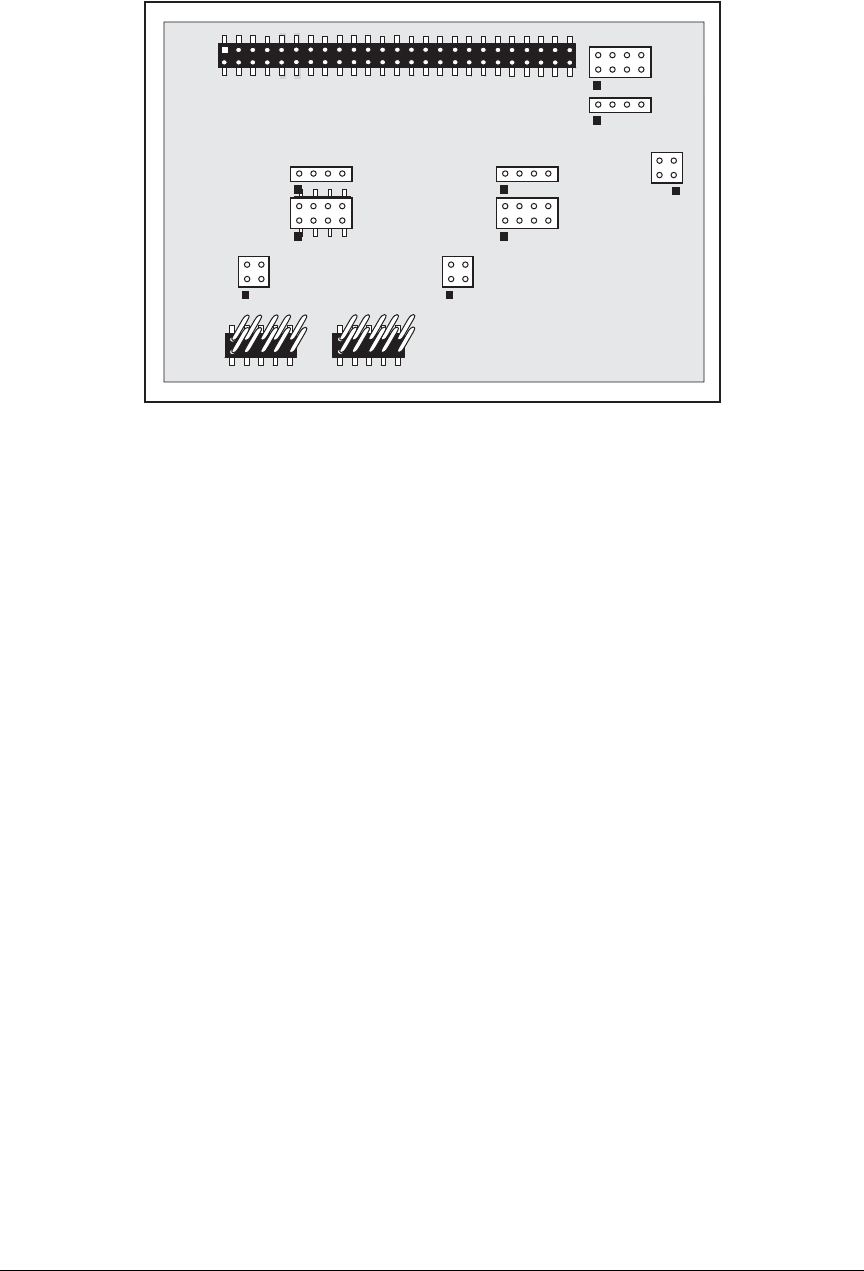

114 MiniCore RCM5600W
E.3.2 Add Additional Boards
The Prototyping Board and the two accessory boards included with the Deluxe Develop-
ment Kit may be installed on the Interface Board as shown in Figure E-6.
Figure E-6. Install Additional Boards
1. Insert the header strip into header socket J2 on the Interface Board or the board already
installed above the Interface Board.
2. Line up the board being installed above the pins extending from the header socket and
the stand-offs/connectors.
3. Press down to install the board.
4. Insert additional plastic standoffs/connectors as shown to hold the board firmly in place
and to hold another board if desired—note that one plastic standoff/connector needs to
be inserted “upside down” to secure the Prototyping Board or other accessory board
above the antenna bracket.
When additional boards are installed, the board-to-board spacing is 0.7" (17.8 mm).
Multiple boards should be installed in this sequence from bottom to top.
•Interface Board with RCM5600W installed.
•Prototyping Board.
•Serial Communication accessory board.
•Digital I/O accessory board.
Install header connector strip
in bottom socket

User’s Manual 115
APPENDIX F. POWER SUPPLY
Appendix G provides information on the current requirements
of the RCM5600W, and includes some background on the chip
select circuit used in power management.
F.1 Power Supplies
The RCM5600W requires a regulated 3.15 V – 3.45 V DC power source. The MiniCore
design presumes that the voltage regulator is on the user board, and that the power is made
available to the RCM5600W board through the edge connectors.
An RCM5600W with no loading at the outputs operating at 73.73 MHz typically draws
85 mA, and may draw up to 625 mA while the Wi-Fi circuit is transmitting or receiving..
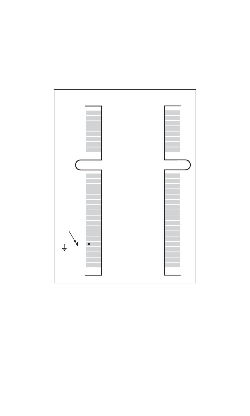
116 MiniCore RCM5600W
F.1.1 Battery Backup
The RCM5600W does not have a battery, but there is provision for a customer-supplied
battery to keep the Rabbit 5000 real-time clock running.
The edge connector, shown in Figure F-1, allows access to the external battery. This
makes it possible to connect an external 3 V power supply. This allows the internal Rabbit
5000 real-time clock to retain data with the RCM5600W powered down.
Figure F-1. External Battery Connections
A lithium battery with a nominal voltage of 3 V and a minimum capacity of 165
mA·h
is
recommended. A lithium battery is strongly recommended because of its nearly constant
nominal voltage over most of its life.
The drain on the battery by the RCM5600W
is typically 5 µA when no other power is
supplied. If a 165 mA·h battery is used, the battery can last about 3.75 years:
GND
n.c.
n.c.
LNK
PE0
PE2
PE5
PE7
PD0
PD2
PC0
PC2
PC4/TxB
PB0/SCLK
PB2
PB4
PB6
PA0
PA2
PA4
PA6
/IORD
/IOWR
STATUS
SMODE
GND
1
51
2
52
+3.3 V
n.c.
n.c.
ACT
PE1
PE3
PE6
/RESET_IN
PD1
PD3
PC1
PC3
PC5/RxB
/RESET
PB3
PB5
PB7
PA1
PA3
PA5
PA7
VBAT_EXT
PB1/CLKA
PC6/TxA
PC7/RxA
+3.3 V
Bottom Top
External
Battery
n.c. = not connected
165 mA·h
5 µA
------------------------ 3.75 years.=
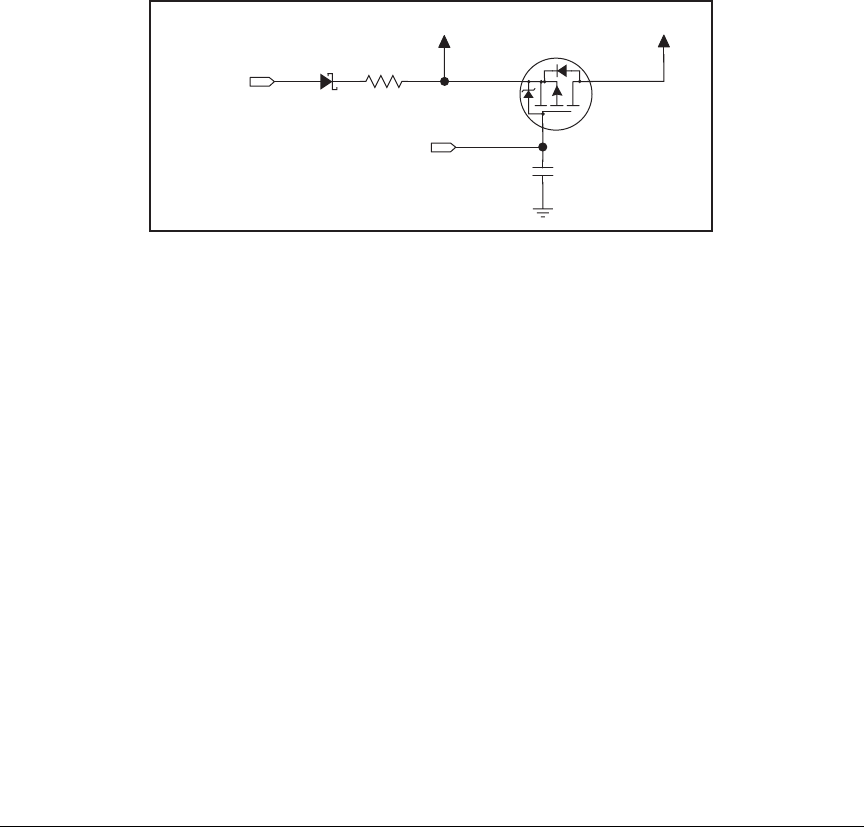
User’s Manual 117
The actual life in your application will depend on the current drawn by components not on
the RCM5600W and on the storage capacity of the battery. The RCM5600W does not drain
the battery while it is powered up normally.
Cycle the main power off/on on the RCM5600W after you install a backup battery for the
first time, and whenever you replace the battery. This step will minimize the current drawn
by the real-time clock oscillator circuit from the backup battery should the RCM5600W
experience a loss of main power.
NOTE: Remember to cycle the main power off/on any time the RCM5600W is removed
from the Interface Board or motherboard since that is where the backup battery would
be located.
Rabbit’s Technical Note TN235, External 32.768 kHz Oscillator Circuits, provides addi-
tional information about the current draw by the real-time clock oscillator circuit.
F.1.2 Battery-Backup Circuit
Figure F-2 shows a suggested battery-backup circuit.
Figure F-2. RCM5600W Backup Battery Circuit
The battery-backup circuit serves the following purposes:
•It reduces the battery voltage to real-time clock, thereby limiting the current consumed
by the real-time clock and lengthening the battery life.
•It ensures that current can flow only out of the battery to prevent charging the battery.
•Switches to battery power only when the +3.3 V system power supply is off.
F.1.3 Reset Generator
The RCM5600W uses a reset generator to reset the Rabbit 5000 microprocessor when the
voltage drops below the voltage necessary for reliable operation. The reset occurs between
2.85 V and 3.00 V, typically 2.93 V. The RCM5600W has a reset output on the edge connec-
tor.
VBATIO
47 kW
R12
VBAT-EXT
External Battery
+3.3 V
D1
C1
2,2 nF
Q1
FDV302P
RESOUT

118 MiniCore RCM5600W

User’s Manual 119
INDEX
A
accessory boards
Digital I/O ....................... 100
configuration options .. 104
LED outputs ............ 104
pushbutton switches 104
dimensions .................. 101
specifications ...............101
Serial Communication .... 108
configuration options .. 112
RTS/CTS ................. 112
dimensions .................. 109
specifications ...............109
additional information
online documentation .......... 5
antenna
extension .............................6
antenna connections
grounding requirements 6, 33
via bracket on Interface Board
....................................... 12
via RP-SMA connector sol-
dered to Interface Board 12
B
battery backup
battery life ....................... 117
circuit .............................. 117
reset generator ................. 117
board initialization
function calls ..................... 45
brdInit() .........................45
C
certifications ........................... 6
Europe .................................8
FCC .....................................6
Industry Canada ..................7
labeling requirements .......... 7
clock doubler ........................ 36
compiler options ...................39
connectors
design and layout recommen-
dations ........................... 78
mini PCI Express .............. 78
D
Development Kits ................... 4
Deluxe Development Kit .... 4
AC adapter ...................... 4
accessory boards ............. 4
Standard Development Kit ..4
Dynamic C ...................... 4
Getting Started instruc-
tions .............................. 4
Interface Board ................ 4
Prototyping Board ........... 4
USB cable ....................... 4
digital I/O .............................. 22
function calls ..................... 41
memory interface .............. 28
SMODE0 .......................... 28
SMODE1 .......................... 28
Digital I/O accessory board
............................... 99, 100
features ............................ 100
dimensions
Digital I/O accessory board
..................................... 101
Interface Board ................. 84
Prototyping Board ............. 93
RCM5600W ...................... 74
Serial Communication
accessory board .......... 109
Dynamic C .............. 5, 9, 14, 39
add-on modules ............. 9, 46
installation ....................... 9
compiler options ............... 39
libraries
BOOTDEV_SFLASH.LIB
..................................... 42
Rabbit Embedded Security
Pack .......................... 5, 46
sample programs ............... 18
standard features
debugging ...................... 40
telephone-based technical
support ...................... 5, 46
troubleshooting ................. 15
upgrades and patches ........ 46
E
exclusion zone ...................... 75
external I/O bus .................... 28
software ............................. 28
F
features
Digital I/O accessory board
..................................... 100
Interface Board ................. 83
Prototyping Board ............. 92
RCM5600W ........................ 2
Serial Communication
accessory board .......... 108
H
hardware connections ........... 10
install RCM5600W on
Interface Board ............. 11
USB cable ......................... 12
I
install additional boards
......................... 88, 97, 106
Interface Board ..................... 82
dimensions ........................ 84
features .............................. 83
jumper configurations ....... 89
jumper locations ................ 89
mounting RCM5600W ..... 11
power supply ..................... 86
power supply jack polarity 82
specifications .................... 84

120 MiniCore RCM5600W
J
jumper configurations
accessory boards
Digital I/O ....................104
Serial Communication .112
Interface Board ..................89
Prototyping Board
JP2 (analog inputs
reference) ....................89
L
labeling requirements ..............7
LEDs
Wi-Fi association and activity
........................................33
O
operating region configura-
tion ................................55
optional add-ons ......................5
antenna and connector cable 5
power supply .......................5
P
pinout
Digital I/O accessory board
......................................103
RCM5600W
alternate configurations .24
RCM5600W edge connec-
tors .................................22
Serial Communication acces-
sory board ....................111
power supplies
+3.3 V ..............................115
battery backup .................116
Program Mode .......................34
switching modes ................34
programming port .................30
Prototyping Board .................92
dimensions .........................93
expansion area ...................92
features ..............................92
prototyping area .................96
specifications .....................94
R
Rabbit 5000
tamper detection ................37
VBAT RAM memory ........37
Rabbit subsystems .................23
RCM5600W
mounting on Interface Board
.......................................11
Run Mode ..............................34
switching modes ................34
S
sample programs ...................18
accessory boards
Digital I/O ................19, 63
Serial Communication ...65
getting to know the
RCM5600W
FLASHLED.C ...............18
SERIALTOSERIAL.C
...............................19, 20
TOGGLESWITCH.C
...............................18, 19
hardware setup ..................17
PC/notebook configuration 53
TCP_CONFIG.LIB ...........52
USERBLOCK_CLEAR.C 44
USERBLOCK_INFO.C ....44
Wi-Fi
BROWSELED.C ...........64
PINGLED.C ......60, 63, 64
PINGLED_STATS.C
.........................62, 63, 64
PINGLED_WPA_PSK.C
.....................................60
PINGLED_WPA2_
CCMP.C .....................61
SERIAL_TO_WIFI.C ...65
SMTP.C .........................62
TOGGLESWITCH.C ....63
WIFI_SCAN.C ........55, 59
WIFI_SCANASSOCIATE.C
.....................................59
WIFIDHCPORTSTATIC.C
.....................................57
WIFIMULTIPLEAPS.C 57
WIFIPINGYOU.C .........58
Wi-Fi configuration macros
.......................................52
Wi-Fi network configuration .
52
Wi-Fi regulatory setup
operating region
configuration ...............55
REGION_COMPILETIME.C
.....................................55
REGION_MULTI_
DOMAIN.C ................56
REGION_RUNTIME_
PING.C .......................56
serial communication ............29
function calls .....................41
software
PACKET.LIB ................41
RS232.LIB .....................41
Serial Communication accessory
board ...........................108
features ............................108
serial flash memory
function calls .....................42
sbfRead ..........................42
sbfWriteFlash ................43
software
BOOTDEV_SFLASH.LIB
.....................................42
serial ports .......................29, 30
programming port ..............30
Serial Port B (shared) ........29
Serial Port E
configuration information ..
29
Serial Port F
configuration information ..
29
software ...................................5
external I/O bus .................41
I/O drivers .........................41
libraries
BOOTDEV_SFLASH.LIB
.....................................42
TCP_CONFIG.LIB .......67
sample programs ...............18
serial communication drivers
.......................................41
serial flash boot drivers .....42
troubleshooting ..................15
Wi-Fi configuration at
compile time .................67
configuration macros .....67
access point SSID ......67
authentication ............69
channel .......................68
enable/disable encryp-
tion ..........................68
encryption keys ..........68
fragmentation threshold
.................................70
mode ..........................67
other macros ..............70
region/country ............68
RTS threshold ............70
select encryption key .68
set WPA hex key .......69
set WPA passphrase ..69
WPA encryption ........69

User’s Manual 121
network configuration ... 67
TCPCONFIG macro ..... 67
Wi-Fi configuration at run
time ............................... 71
Wi-Fi drivers ..................... 44
specifications ........................73
accessory boards
headers ................ 102, 110
Digital I/O accessory board
..................................... 101
dimensions ........................ 74
electrical, mechanical, and
environmental ............... 76
exclusion zone ................... 75
Interface Board ................. 84
headers ..........................85
Prototyping Board .............94
headers ..........................95
Rabbit 5000 DC characteris-
tics ................................. 79
Serial Communication
accessory board .......... 109
spectrum spreader
settings .............................. 36
subsystems
digital inputs and outputs .. 22
switching modes ................... 34
T
tamper detection ....................37
technical support ................... 16
troubleshooting ..................... 15
U
USB cable
connections ....................... 12
user block
function calls ..................... 44
readUserBlock() ............ 37
writeUserBlock() ........... 37
V
VBAT RAM memory ........... 37
W
Wi-Fi
additional resources .......... 72
bring interface down ......... 71
bring interface up .............. 71
circuit description ............. 31
function calls
ifconfig() ................. 67, 71
ifconfig(IF_WIFI0,…) .. 71
ifdown(IF_WIFI0) ........ 71
ifup(IF_WIFI0) ............. 71
sock_init() ..................... 71
sock_init_or_exit(1) ...... 71
tcp_tick(NULL) ............ 71
sample programs ............... 55

122 MiniCore RCM5600W

User’s Manual 123
SCHEMATICS
090-0280 RCM5600W Schematic
www.rabbit.com/documentation/schemat/090-0280.pdf
090-0281 Interface Board Schematic
www.rabbit.com/documentation/schemat/090-0281.pdf
090-0270 Prototyping Board Schematic
www.rabbit.com/documentation/schemat/090-0270.pdf
090-0272 Digital I/O Accessory Board Schematic
www.rabbit.com/documentation/schemat/090-0272.pdf
090-0271 Serial Communication Accessory Board Schematic
www.rabbit.com/documentation/schemat/090-0271.pdf
You may use the URL information provided above to access the latest schematics directly.
