Digi PS2CTH XBee Pro ZB TH module User Manual
Digi International Inc XBee Pro ZB TH module
UserManual.wiki
>
Digi
>
PS2CTH User Manual
User Manual
Navigation menu
Upload a User Manual
Namespaces
Wiki Guide
HTML
PDF
Info
Views
User Manual
Discussion / Help
Navigation
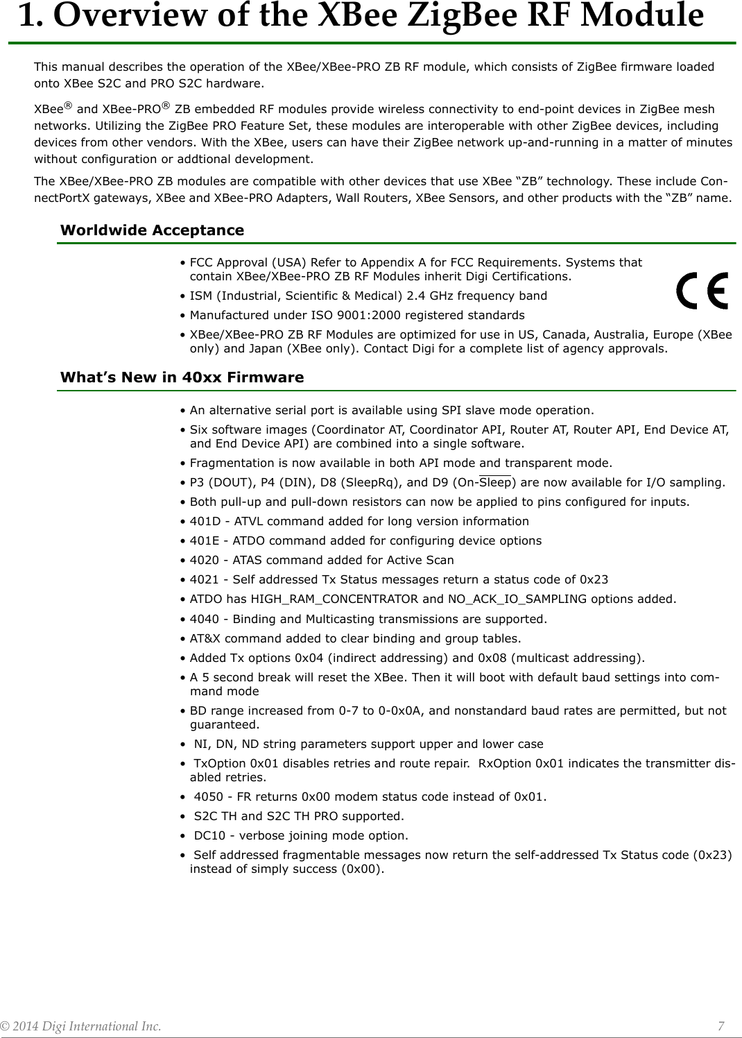
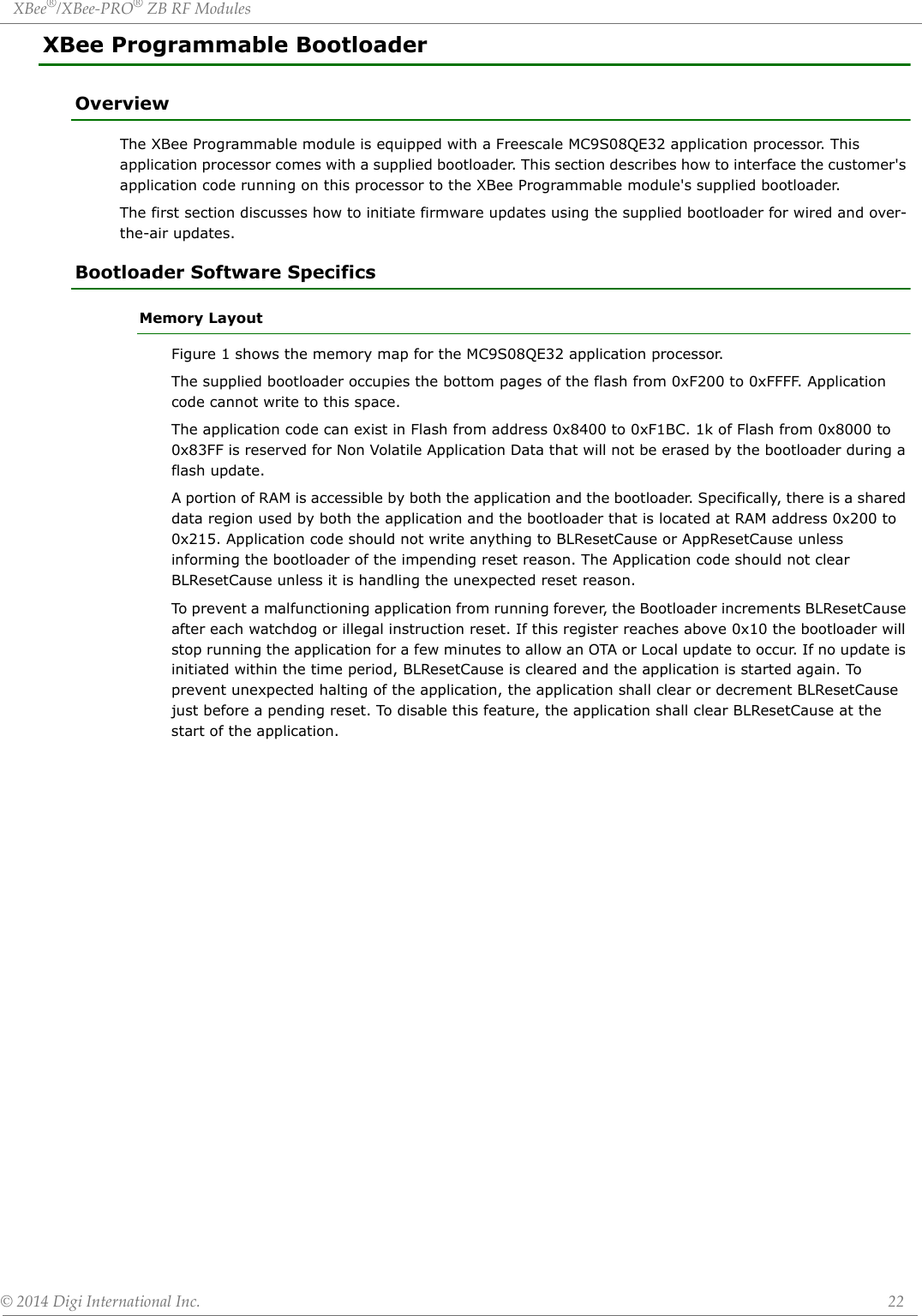
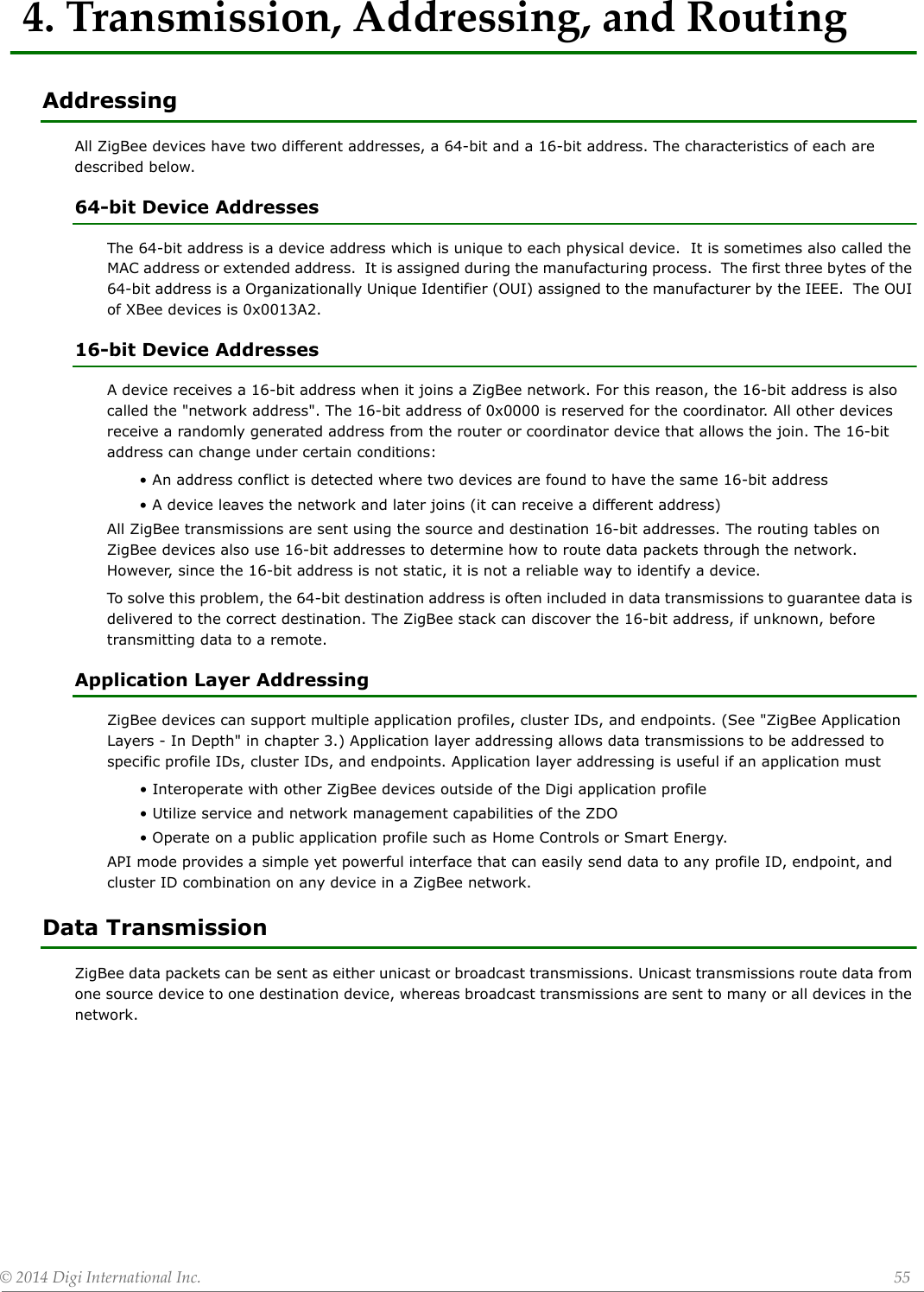
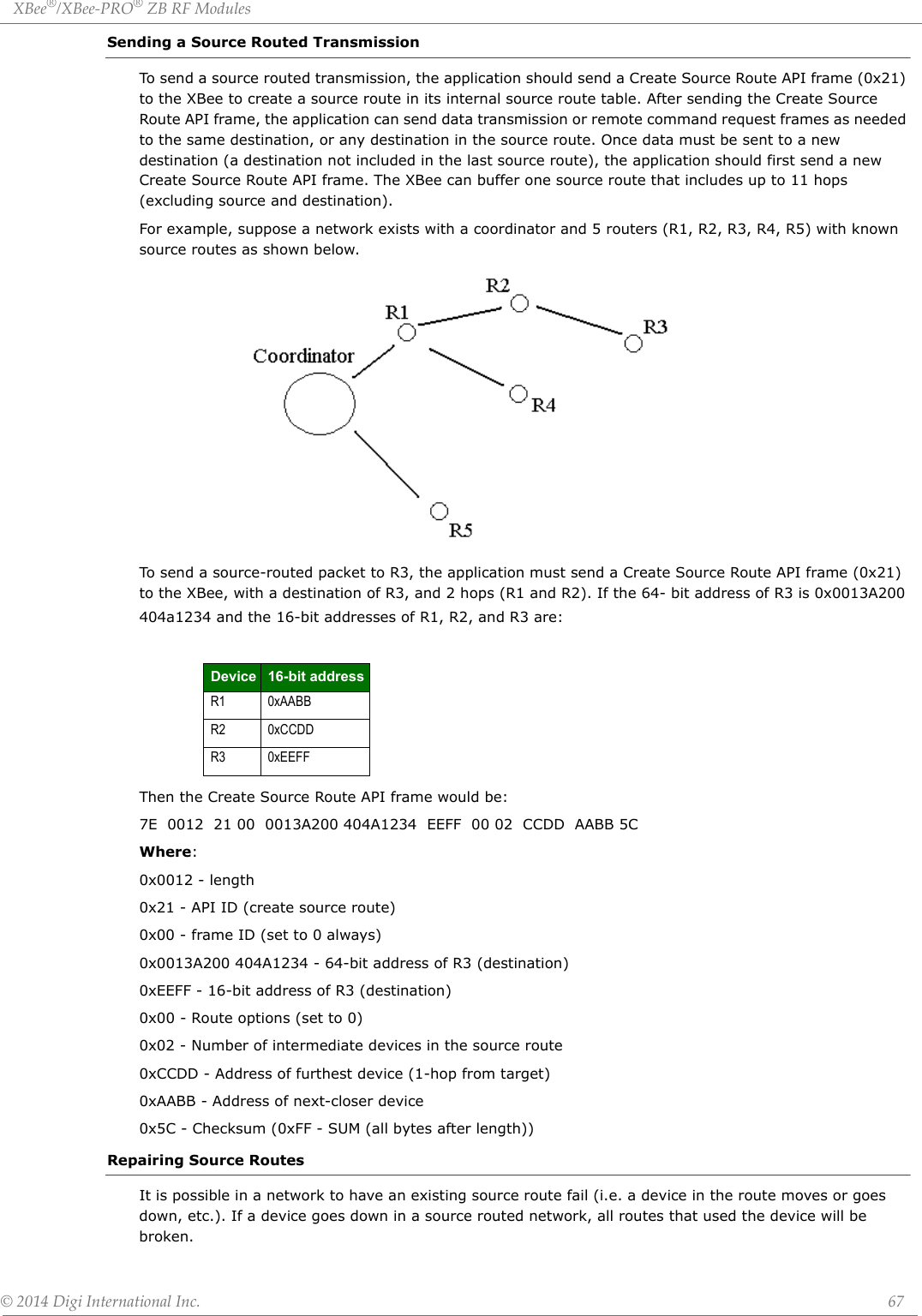
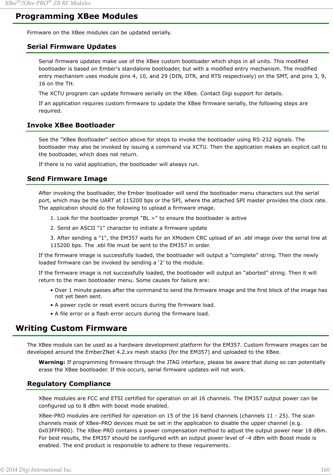
![XBee®/XBee‐PRO®ZBRFModules©2014DigiInternationalInc. 2© 2014 Digi International Inc. All rights reserved. Digi, Digi International, the Digi logo, XBee(R) and XBee-PRO(R) are trademarks or registered trademarks of Digi Interna-tional Inc. in the United Sates and other couuntries worldwide. ZigBee(R) is a registered trademark of the ZigBee alliance. All other trademarks mentioned in this document are the property of their respective owners. Information in this document is subject to change without notice and does not represent a commitment on the part of Digi International. Digi provides this document “as is,” without warranty of any kind, expressed or implied, including, but not limited to, the implied warranties of fitness or merchantability for a particular purpose. Digi may make improvements and/or changes in this manual or in the product(s) and/or the program(s) described in this manual at any time.This product could include technical inaccuracies or typographical errors. Changes are periodically made to the information herein; these changes may be incorporated in new editions of the publication.For basic information to help get you started on the XBee/XBee-PRO ZB RF Module, navigate to the Getting Started Guide at digi.com/support. Enter the keyword 'XBee-PRO ZB' and select the Documentation tab. Under the Documentation tab, you will find the XBee-PRO ZB RF Module Development Kit Getting Started Guide.Technical Support: Phone: (866) 765-9885 toll-free U.S.A. & Canada(801) 765-9885 Worldwide8:00 am - 5:00 pm [U.S. Mountain Time]Live Chat: www.digi.com Online Support: www.digi.com/support/eservice/login.jspEmail: rf-experts@digi.com](https://usermanual.wiki/Digi/PS2CTH/User-Guide-2348528-Page-2.png)
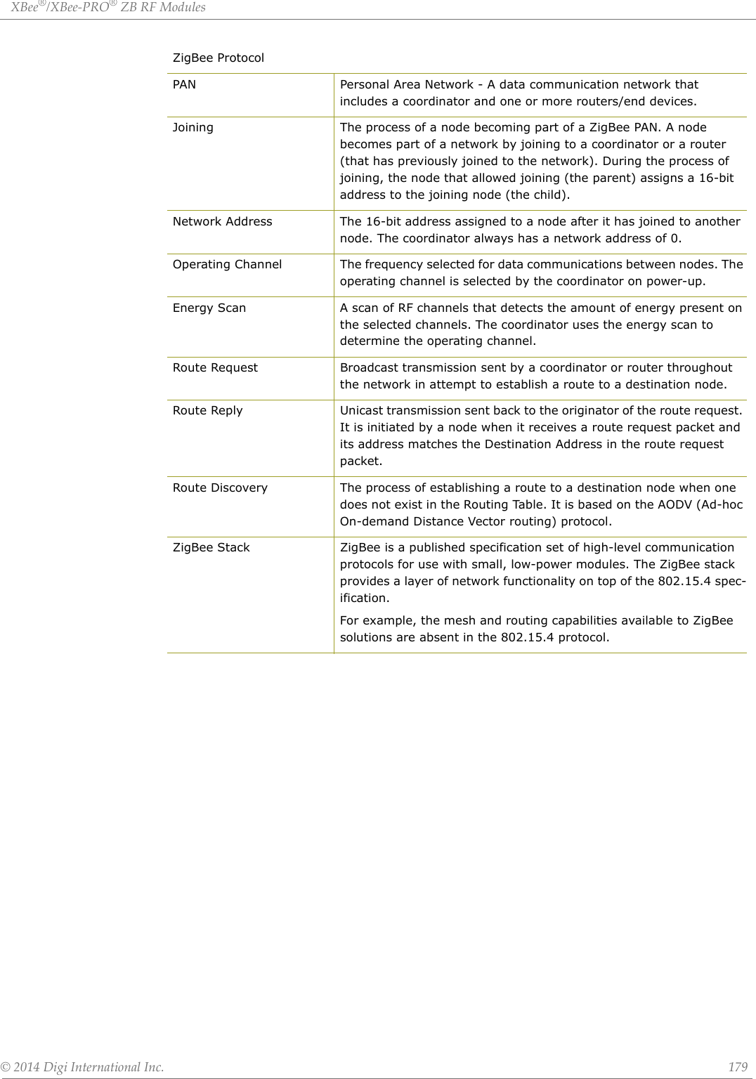
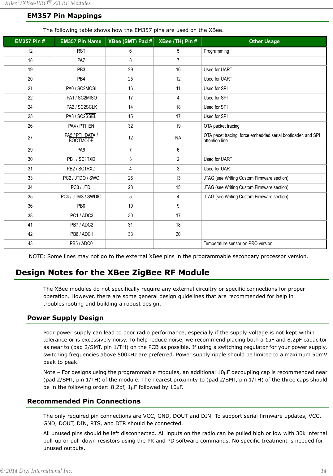
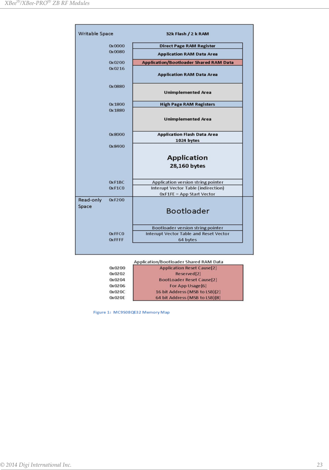
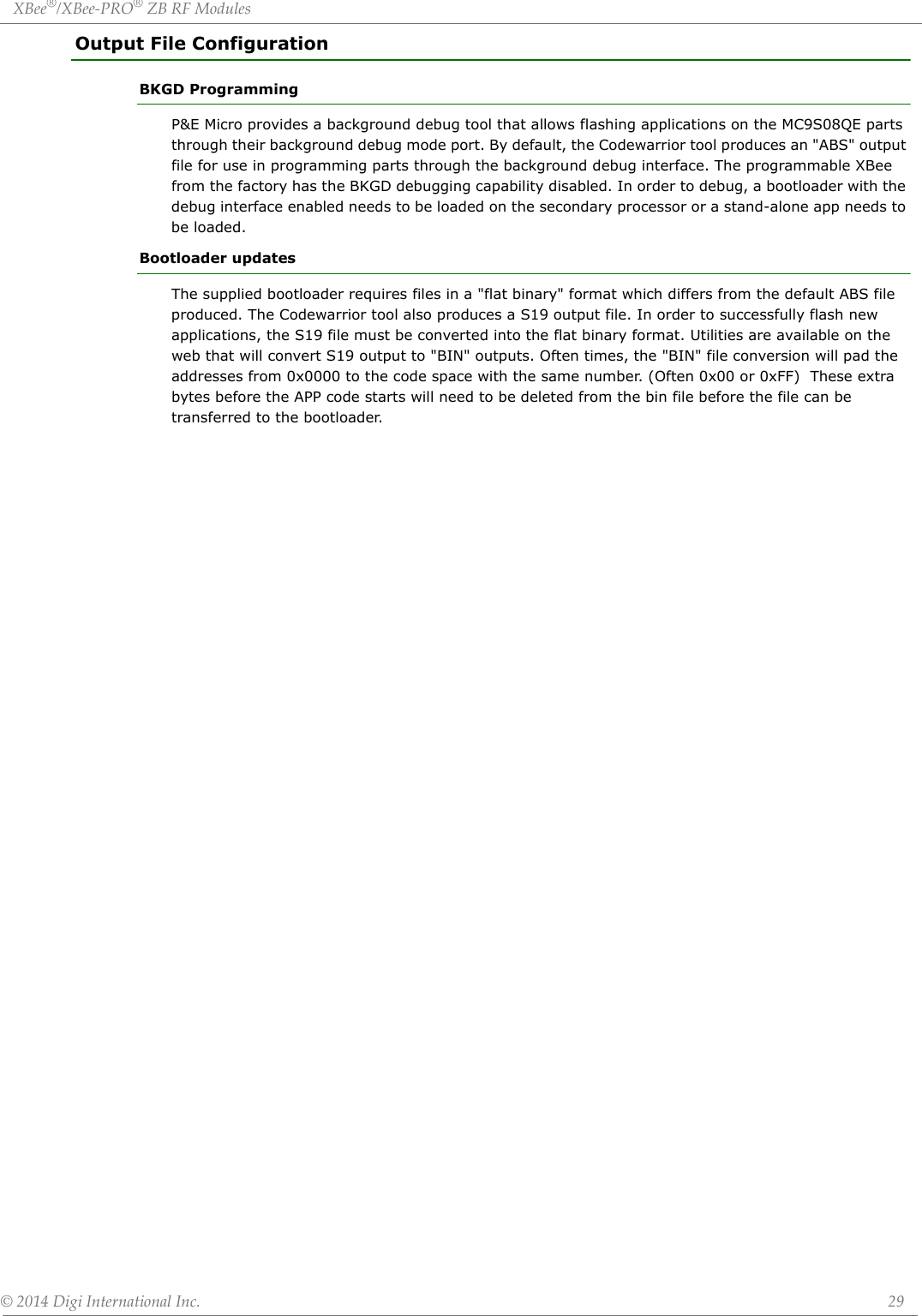
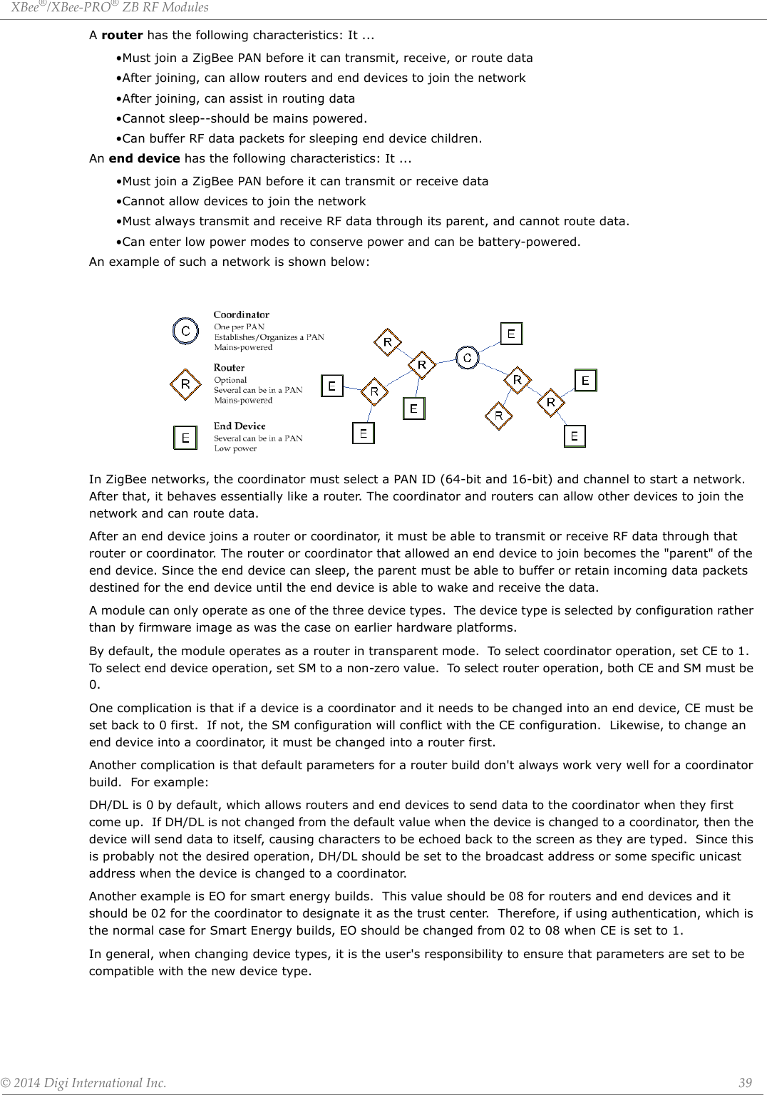
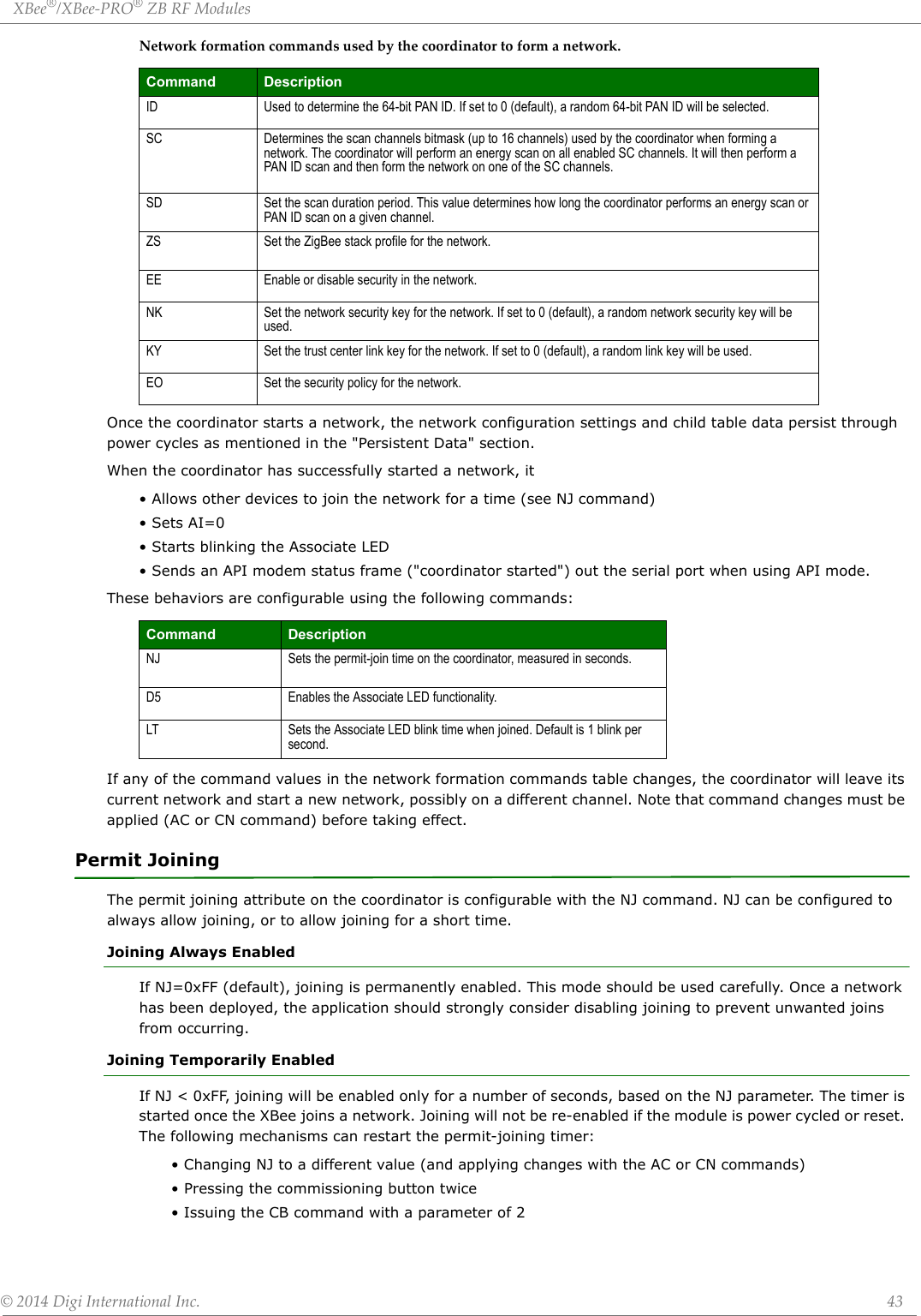
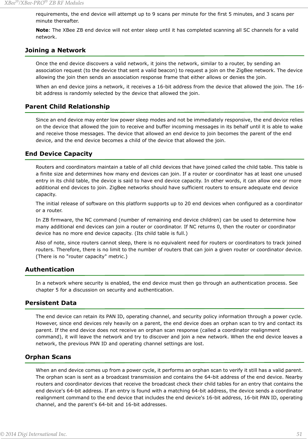
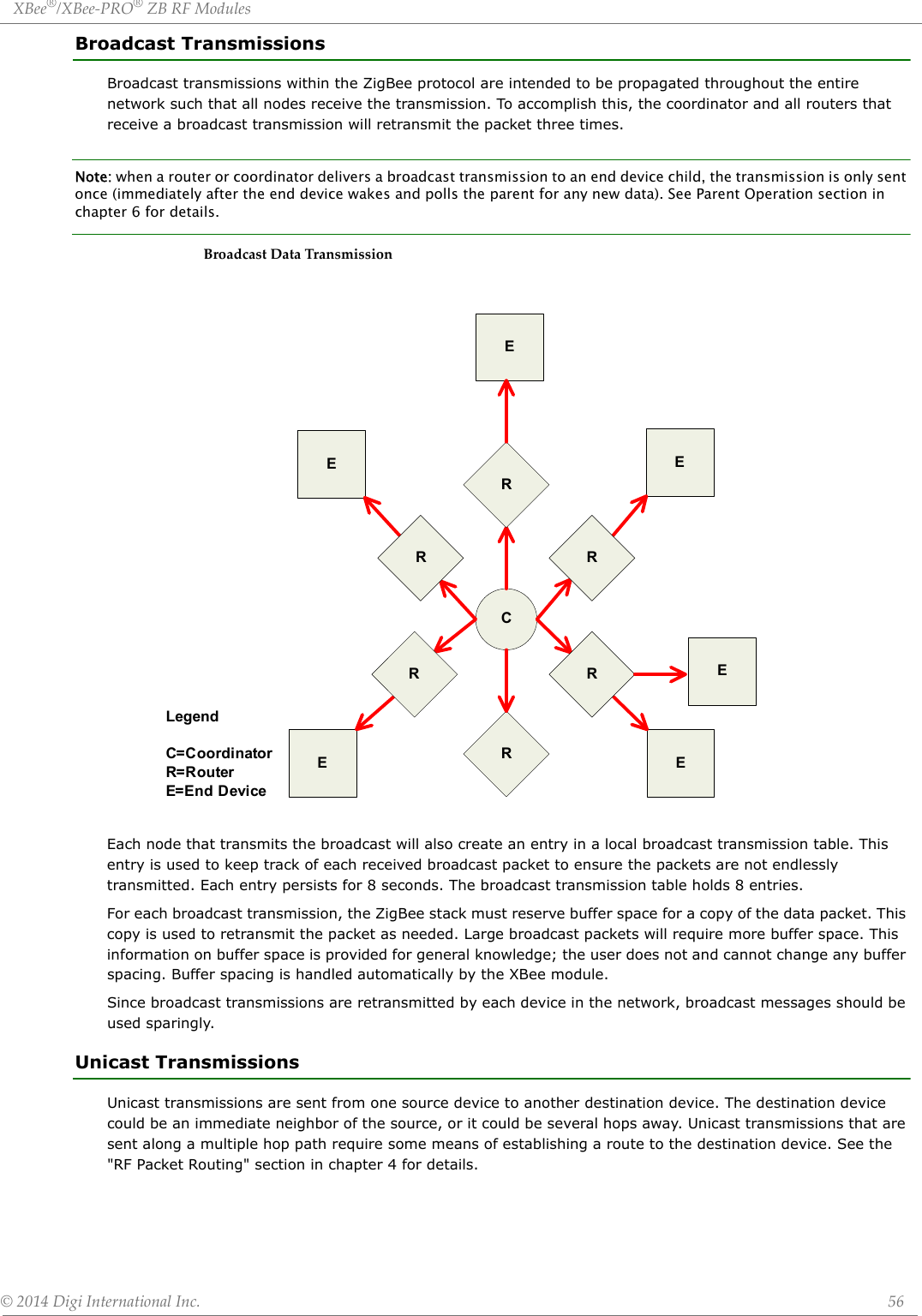
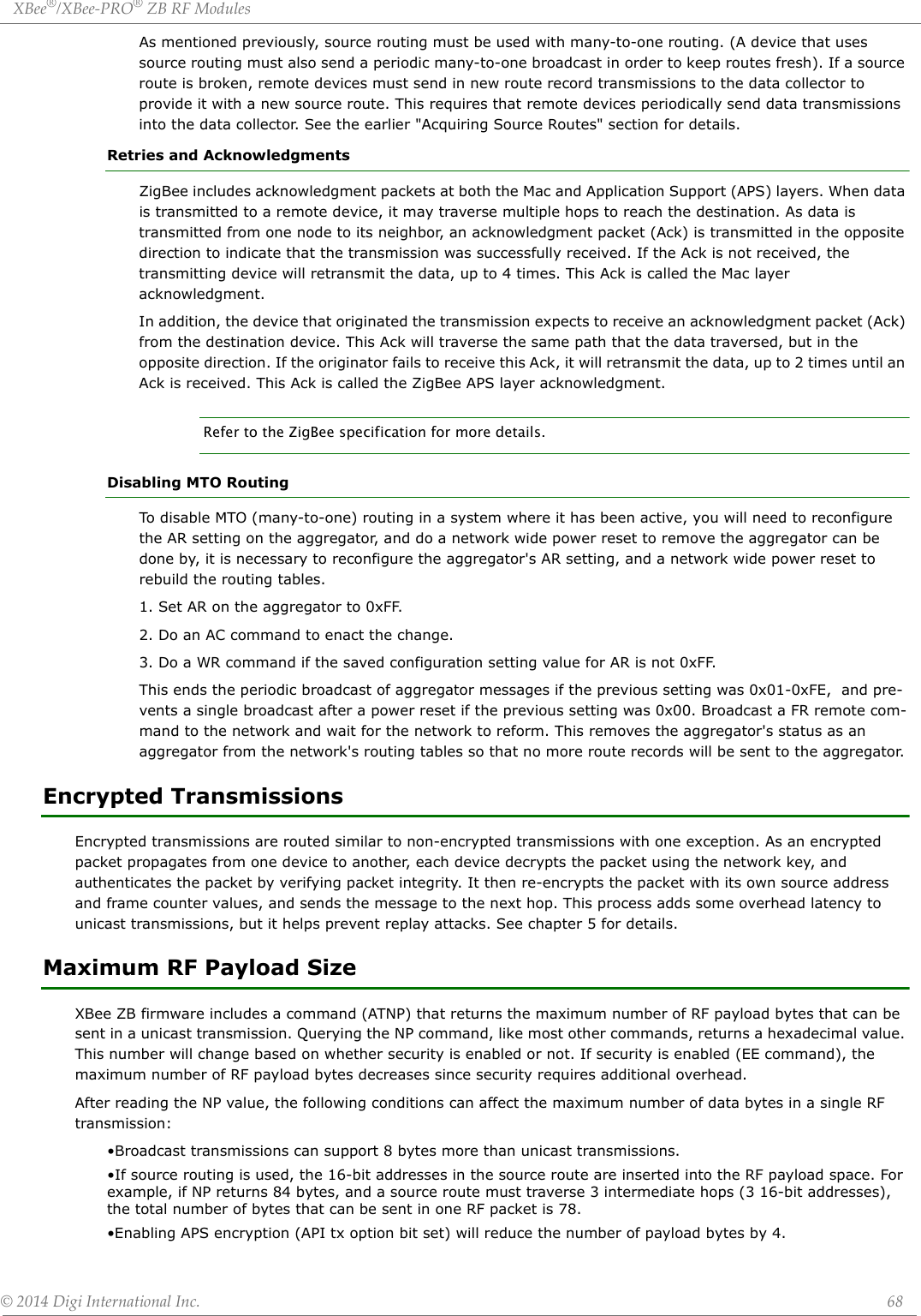
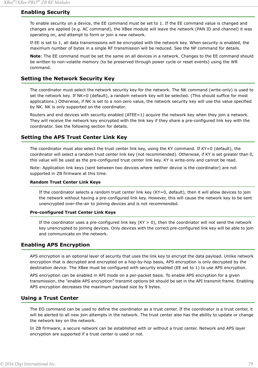
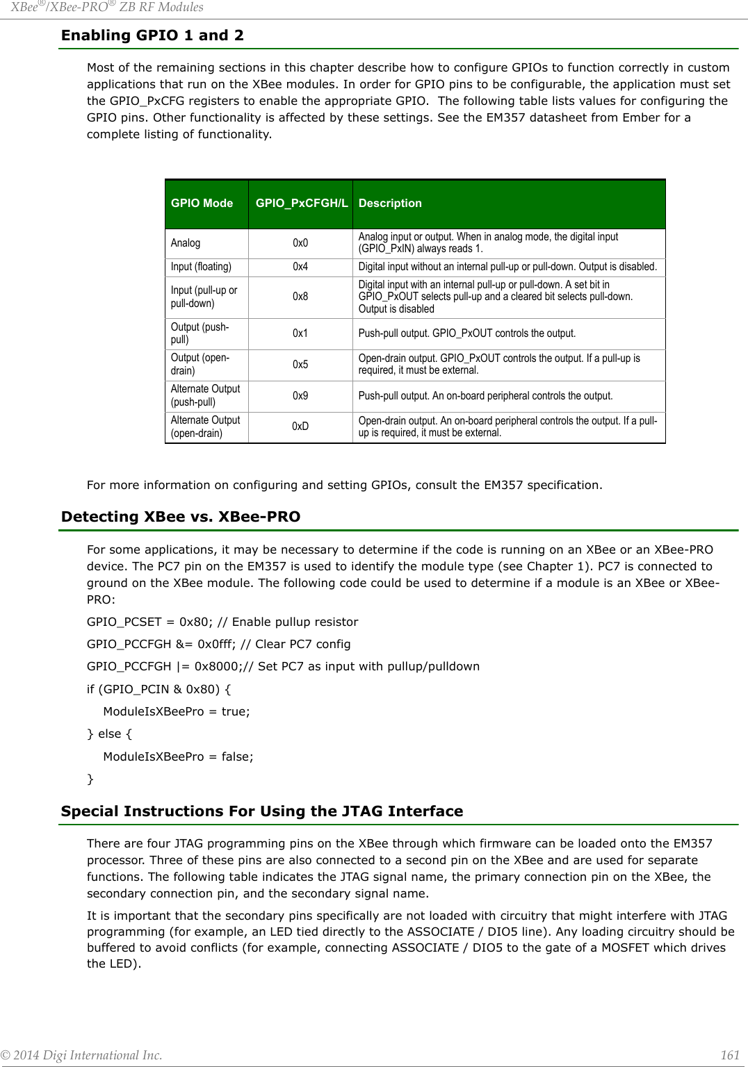
![XBee®/XBee‐PRO®ZBRFModules©2014DigiInternationalInc. 12Pin Signals for the XBee ZigBee Surface Mount Module• Signal Direction is specified with respect to the module• See Design Notes section below for details on pin connections.• * Refer to the Writing Custom Firmware section for instructions on using these pins if JTAG functions are needed.PinAssignmentsforXBeeSurfaceMountModules(Low‐assertedsignalsaredistinguishedwithahorizontallineabovesignalname.)Pin # Name Direction Default State Description1 GND - - Ground2 VCC - - Power Supply3 DOUT / DIO13 Both Output UART Data Out / GPIO4 DIN / CONFIG / DIO14 Both Input UART Data In / GPIO5 DIO12 Both GPIO6 RESET Input Module Reset7 RSSI PWM / DIO10 Both Output RX Signal Strength Indicator / GPIO8 PWM1 / DIO11 Both Disabled Pulse Width Modulator / GPIO9 [reserved] - Disabled Do Not Connect10 DTR / SLEEP_RQ / DIO8 Both Input Pin Sleep Control Line / GPIO11 GND - - Ground12 SPI_ATTN / BOOTMODE / DIO19 Output Output Serial Peripheral Interface AttentionDo not tie low on reset13 GND - - Ground14 SPI_CLK / DIO18 Input Input Serial Peripheral Interface Clock / GPIO15 SPI_SSEL / DIO 17 Input Input Serial Peripheral Interface not Select / GPIO16 SPI_MOSI / DIO16 Input Input Serial Peripheral Interface Data In / GPIO17 SPI_MISO / DIO15 Output Output Serial Peripheral Interface Data Out / GPIO18 [reserved]* - Disabled Do Not Connect19 [reserved]* - Disabled Do Not Connect20 [reserved]* - Disabled Do Not Connect21 [reserved]* - Disabled Do Not Connect22 GND - - Ground23 [reserved] - Disabled Do Not Connect24 DIO4 Both Disabled GPIO25 CTS / DIO7 Both Output Clear to Send Flow Control / GPIO26 ON / SLEEP / DIO9 Both Output Module Status Indicator / GPIO27 VREF Input -Not used for EM357. Used for programmable secondary processor. For compatibility with other XBee modules, we recommend connecting this pin to the voltage reference if Analog Sampling is desired. Otherwise, connect to GND.28 ASSOCIATE / DIO5 Both Output Associate Indicator / GPIO29 RTS / DIO6 Both Input Request to Send Flow Control / GPIO30 AD3 / DIO3 Both Disabled Analog Input / GPIO31 AD2 / DIO2 Both Disabled Analog Input / GPIO32 AD1 / DIO1 Both Disabled Analog Input / GPIO33 AD0 / DIO0 Both Input Analog Input / GPIO / Commissioning Button34 [reserved] - Disabled Do Not Connect35 GND - - Ground36 RF Both - RF IO for RF Pad Variant37 [reserved] - Disabled Do Not Connect](https://usermanual.wiki/Digi/PS2CTH/User-Guide-2348528-Page-12.png)
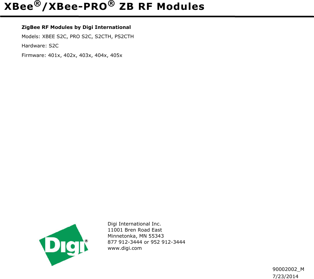
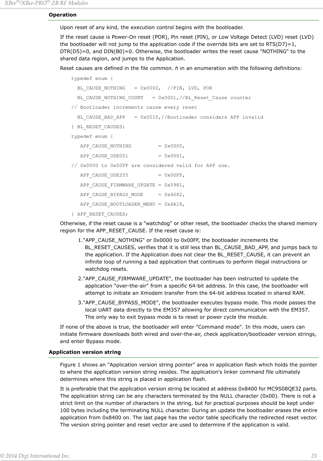
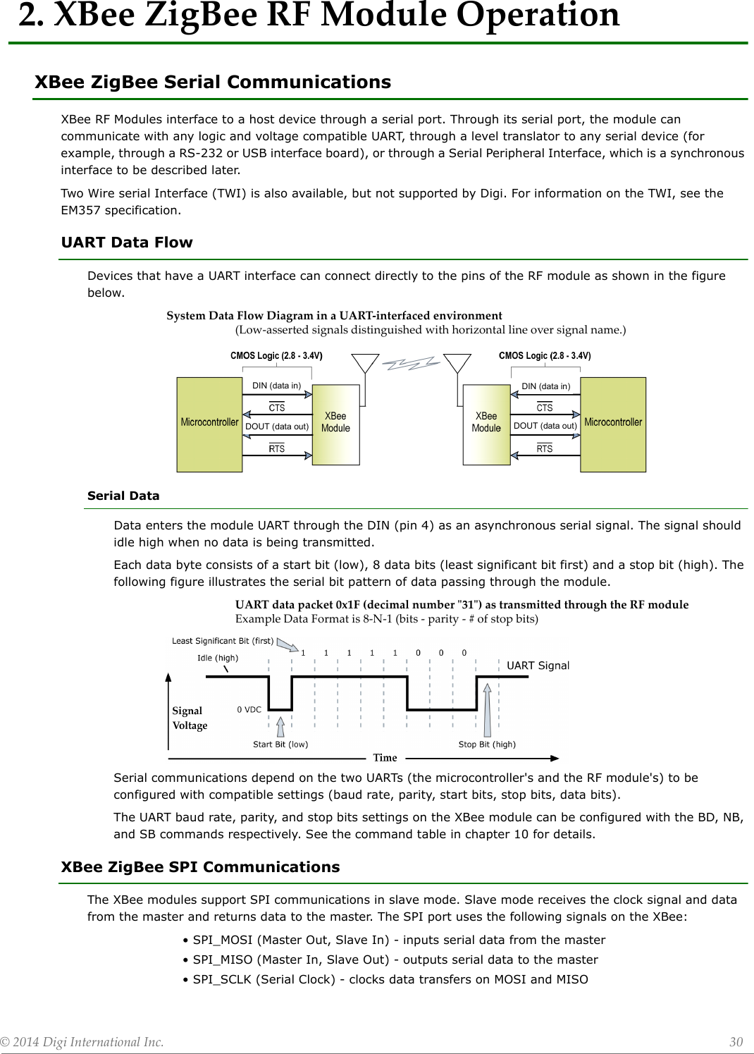
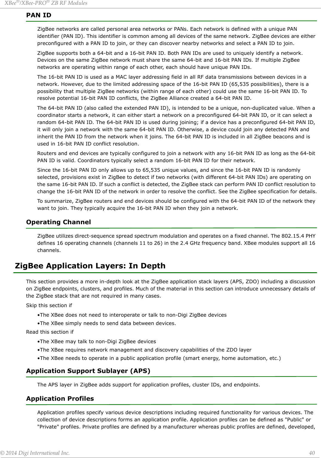
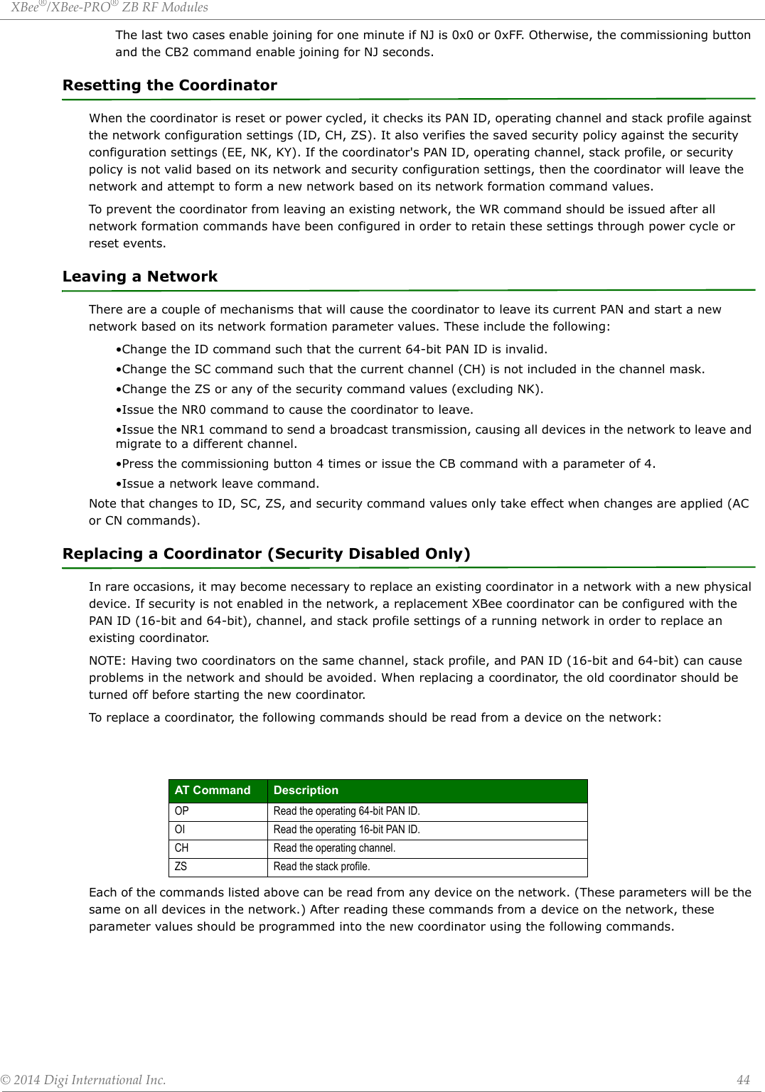
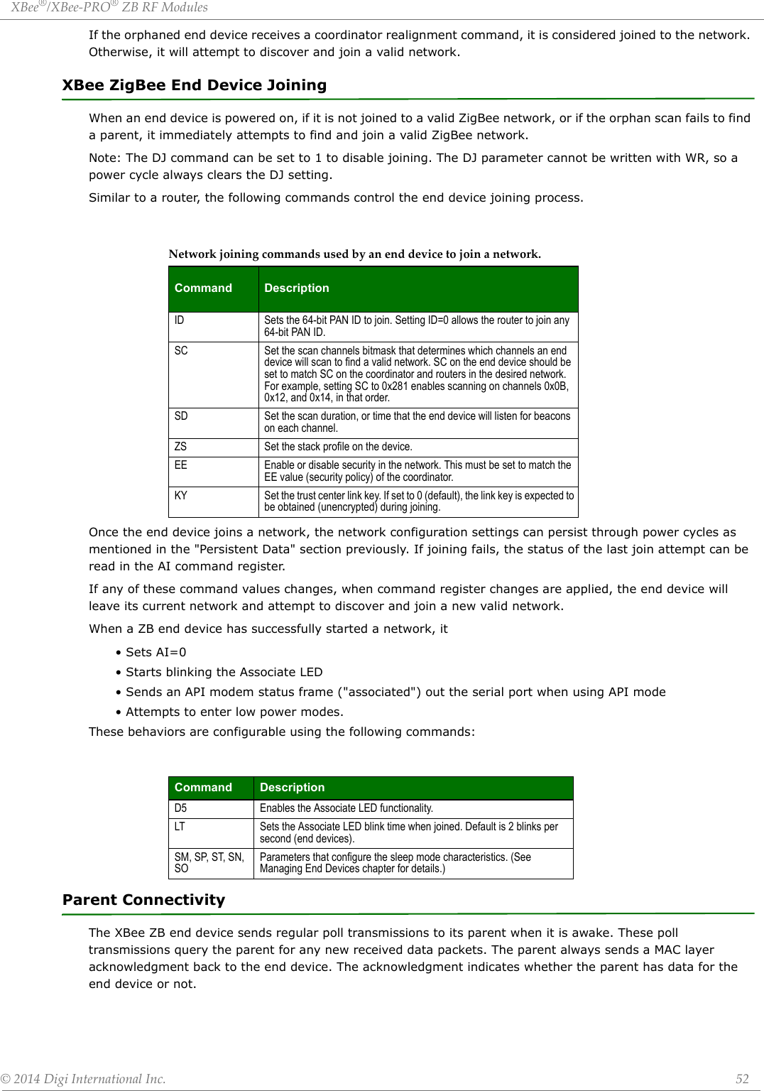
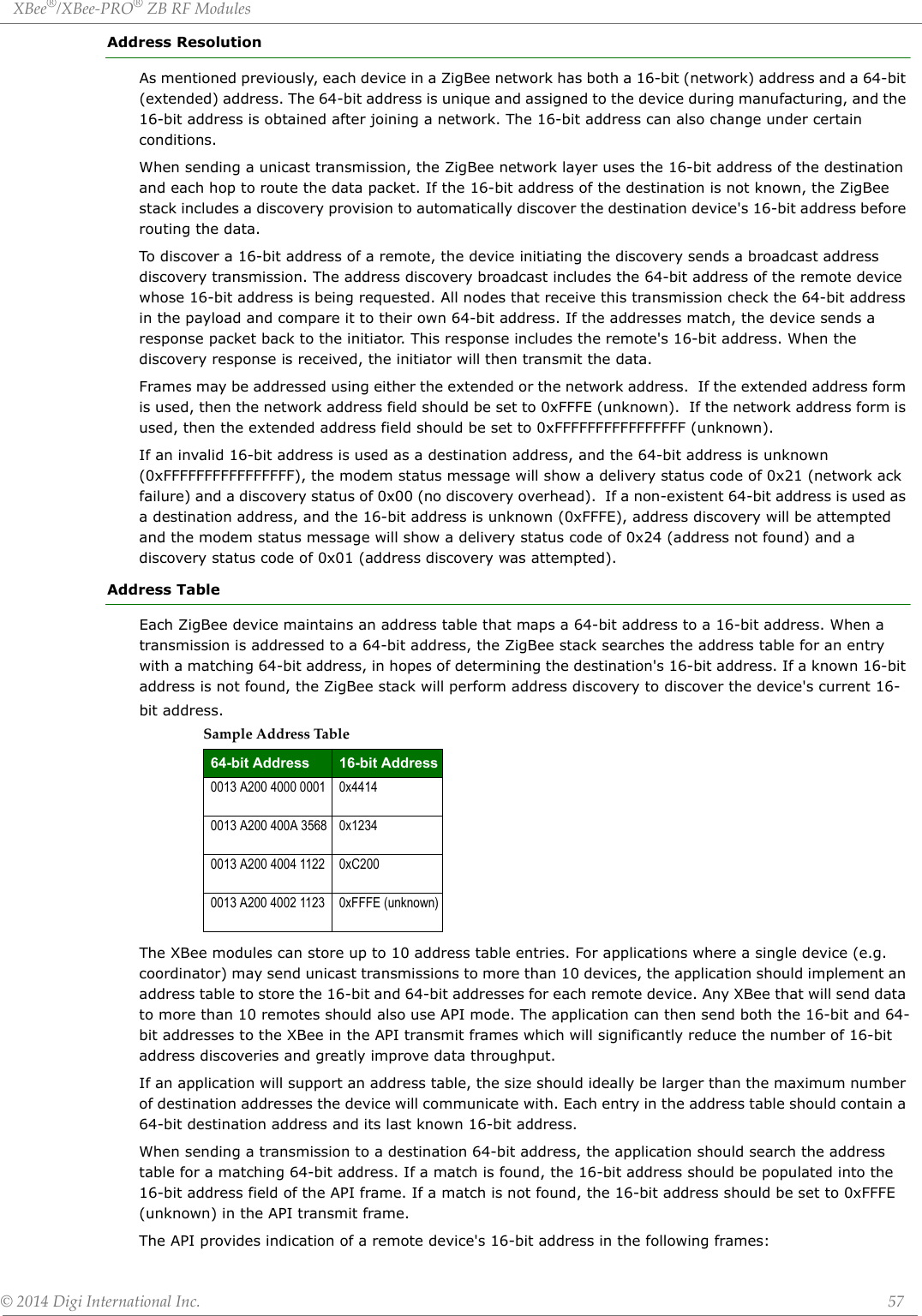
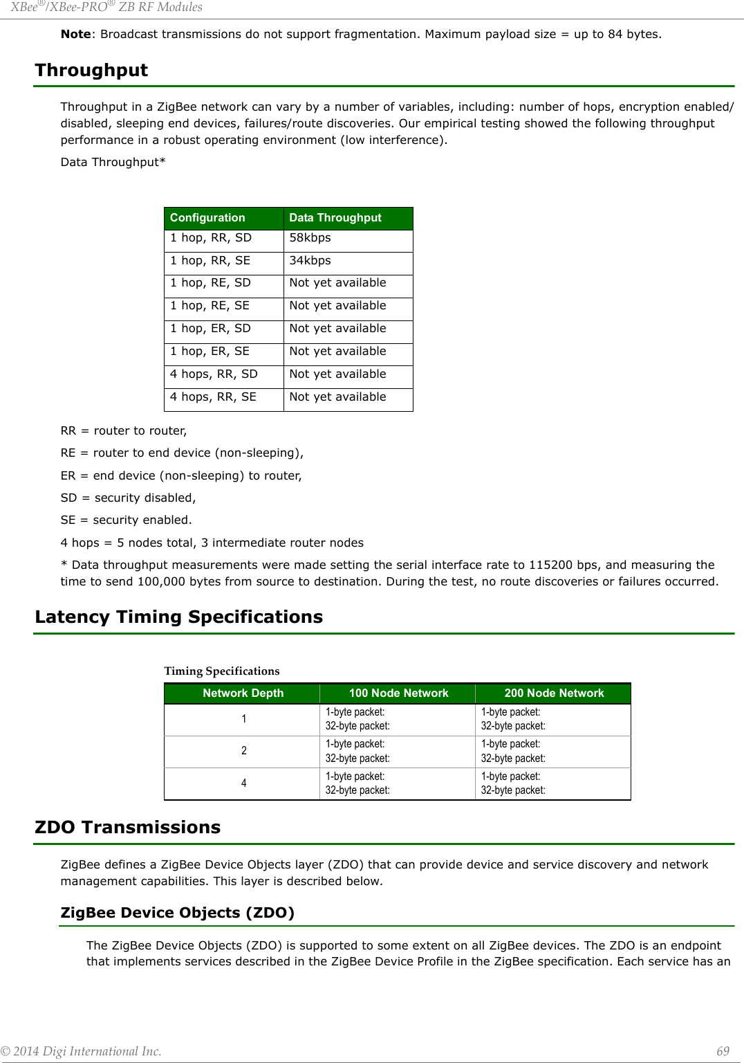
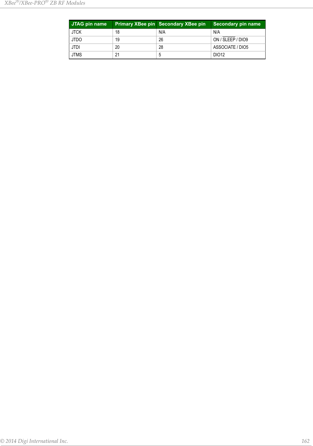
![XBee®/XBee‐PRO®ZBRFModules©2014DigiInternationalInc. 13Pin Signals for the XBee ZigBee Through-hole ModulePinAssignmentsforXBeeThrough‐holeModules(Low‐assertedsignalsaredistinguishedwithahorizontallineabovesignalname.)Pin # Name Direction Default State Description1 VCC - - Power Supply2 DOUT / DIO13 Both Output UART Data Out3 DIN / CONFIG / DIO14 Both Input UART Data In4 DIO12 / SPI_MISO Both Disabled GPIO/ SPI slave out5 RESET Input Input Module Reset6 RSSI PWM / PWMO DIO10 Both Output RX signal strength indicator / GPIO7 PWM1 / DIO11 Both Disabled GPIO8 [reserved] - - Do Not Connect9DTR / SLEEP_RQ / DIO8 Both Input Pin Sleep Control Line / GPIO10 GND - - Ground11 SPI_MOSI / DIO4 Both Disabled GPIO/ SPI slave in 12 CTS / DIO7 Both Output Clear-to-Send Flow Control / GPIO13 ON_SLEEP / DIO9 Both Output Module Status Indicator / GPIO14 VREF - - Not connected15 ASSOCIATE / DIO5 Both Output Associate Indicator / GPIO16 RTS / DIO6 Both Input Request to Send Flow Control / GPIO17 AD3 / DIO3 / SPI_SSEL Both Disabled Analog Input / GPIO / SPI Slave Select18 AD2 / DIO2 / SPI_CLK Both Disabled Analog Input / GPIO / SPI Clock19 AD1 / DIO1 / SPI_ATTN Both Disabled Analog Input / GPIO / SPI Attention20 AD0 / DIO0 / CB Both Disabled Analog Input / GPIO / Commissioning Button](https://usermanual.wiki/Digi/PS2CTH/User-Guide-2348528-Page-13.png)
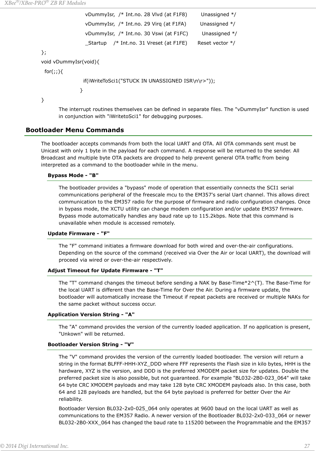
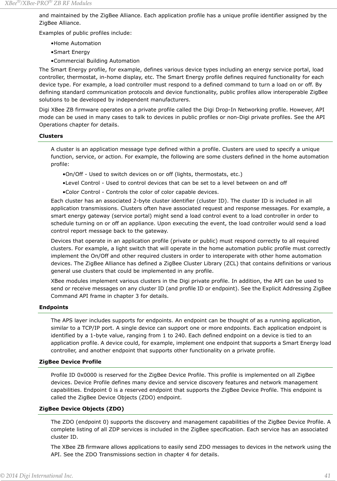
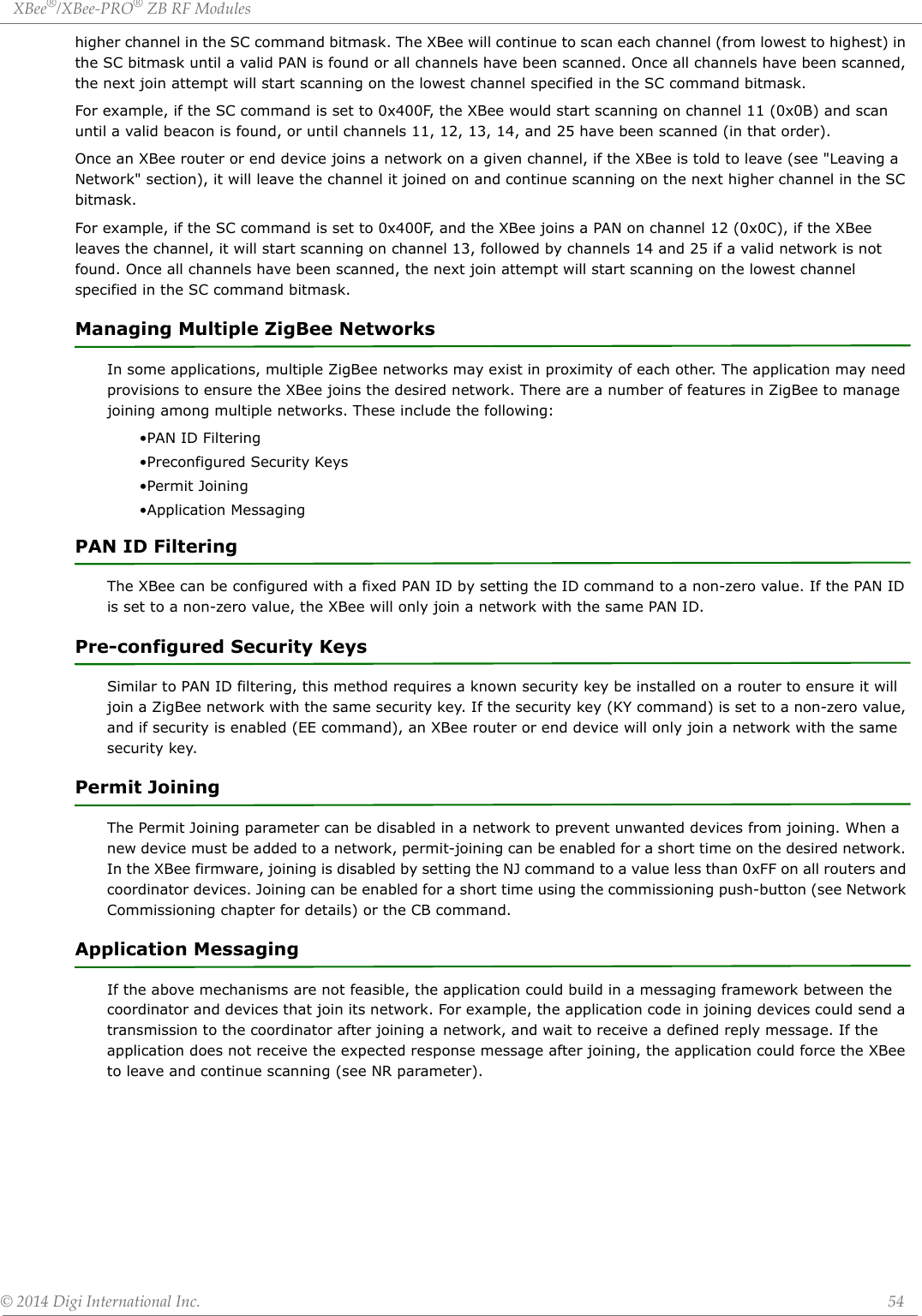
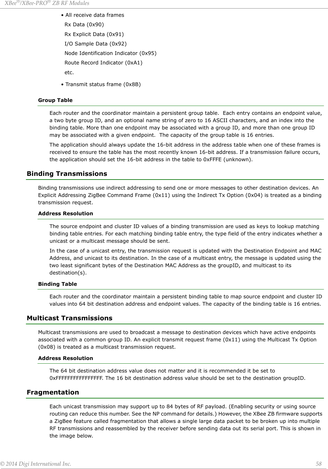
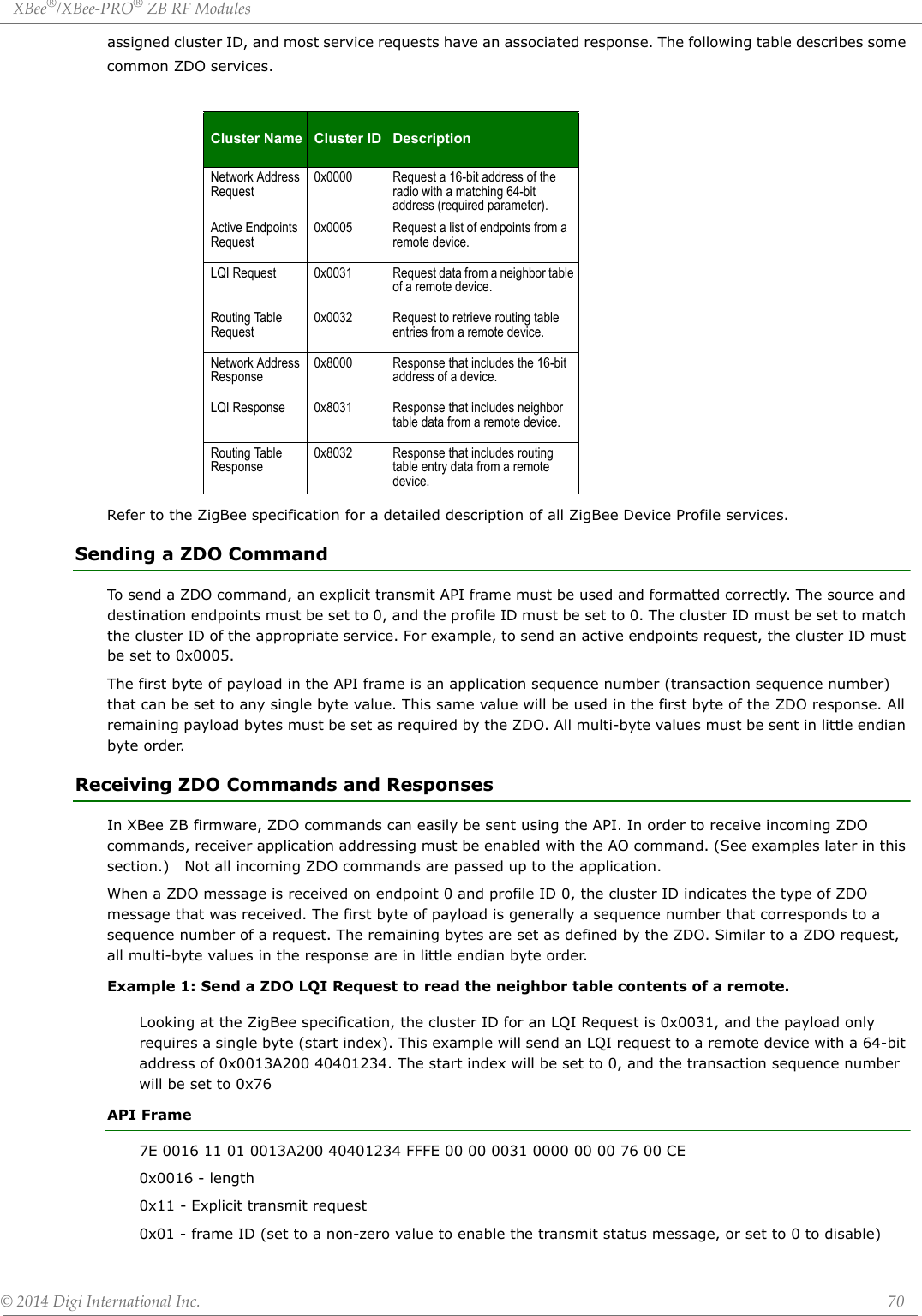
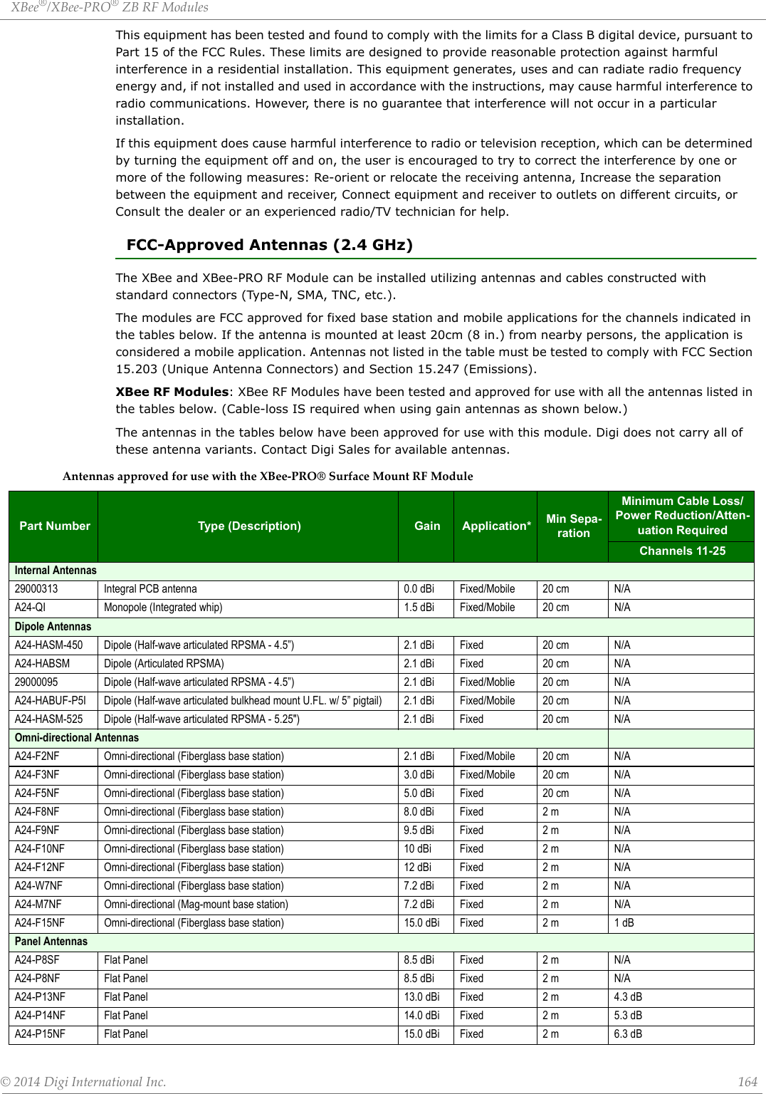
![XBee®/XBee‐PRO®ZBRFModules©2014DigiInternationalInc. 26Application Interrupt Vector table and Linker Command FileSince the bootloader flash region is read-only, the interrupt vector table is redirected to the region 0xF1C0 to 0xF1FD so that application developers can use hardware interrupts. Note that in order for Application interrupts to function properly, the Application's linker command file (*.prm extension) must be modified appropriately to allow the linker to place the developers code in the correct place in memory. For example, the developer desires to use the serial communications port SCI1 receive interrupt. The developer would add the following line to the Codewarrior linker command file for the project:VECTOR ADDRESS 0x0000F1E0 vSci1RxThis will inform the linker that the interrupt function "vSci1Rx()" should be placed at address 0x0000F1E0. Next, the developer should add a file to their project "vector_table.c" that creates an array of function pointers to the ISR routines used by the application.extern void _Startup(void);/* _Startup located in Start08.c */extern void vSci1Rx(void);/* sci1 rx isr */ extern short iWriteToSci1(unsigned char *);void vDummyIsr(void);#pragma CONST_SEG VECTORSvoid (* const vector_table[])(void) = /* Relocated Interrupt vector table */{vDummyIsr,/* Int.no. 0 Vtpm3ovf (at F1C0)Unassigned */vDummyIsr, /* Int.no. 1 Vtpm3ch5 (at F1C2) Unassigned */vDummyIsr, /* Int.no. 2 Vtpm3ch4 (at F1C4) Unassigned */vDummyIsr, /* Int.no. 3 Vtpm3ch3 (at F1C6) Unassigned */vDummyIsr, /* Int.no. 4 Vtpm3ch2 (at F1C8) Unassigned */vDummyIsr, /* Int.no. 5 Vtpm3ch1 (at F1CA) Unassigned */vDummyIsr, /* Int.no. 6 Vtpm3ch0 (at F1CC) Unassigned */vDummyIsr, /* Int.no. 7 Vrtc (at F1CE) Unassigned */vDummyIsr, /* Int.no. 8 Vsci2tx (at F1D0) Unassigned */vDummyIsr, /* Int.no. 9 Vsci2rx (at F1D2) Unassigned */vDummyIsr, /* Int.no. 10 Vsci2err (at F1D4) Unassigned */vDummyIsr, /* Int.no. 11 Vacmpx (at F1D6) Unassigned */vDummyIsr, /* Int.no. 12 Vadc (at F1D8) Unassigned */vDummyIsr, /* Int.no. 13 Vkeyboard (at F1DA) Unassigned */vDummyIsr, /* Int.no. 14 Viic (at F1DC) Unassigned */vDummyIsr, /* Int.no. 15 Vsci1tx (at F1DE) Unassigned */vSci1Rx, /* Int.no. 16 Vsci1rx (at F1E0) SCI1RX */vDummyIsr, /* Int.no. 17 Vsci1err (at F1E2) Unassigned */vDummyIsr, /* Int.no. 18 Vspi (at F1E4) Unassigned */vDummyIsr, /* Int.no. 19 VReserved12 (at F1E6) Unassigned */vDummyIsr, /* Int.no. 20 Vtpm2ovf (at F1E8) Unassigned */vDummyIsr, /* Int.no. 21 Vtpm2ch2 (at F1EA) Unassigned */vDummyIsr, /* Int.no. 22 Vtpm2ch1 (at F1EC) Unassigned */vDummyIsr, /* Int.no. 23 Vtpm2ch0 (at F1EE) Unassigned */vDummyIsr, /* Int.no. 24 Vtpm1ovf (at F1F0) Unassigned */vDummyIsr, /* Int.no. 25 Vtpm1ch2 (at F1F2) Unassigned */vDummyIsr, /* Int.no. 26 Vtpm1ch1 (at F1F4) Unassigned */vDummyIsr, /* Int.no. 27 Vtpm1ch0 (at F1F6) Unassigned */](https://usermanual.wiki/Digi/PS2CTH/User-Guide-2348528-Page-25.png)
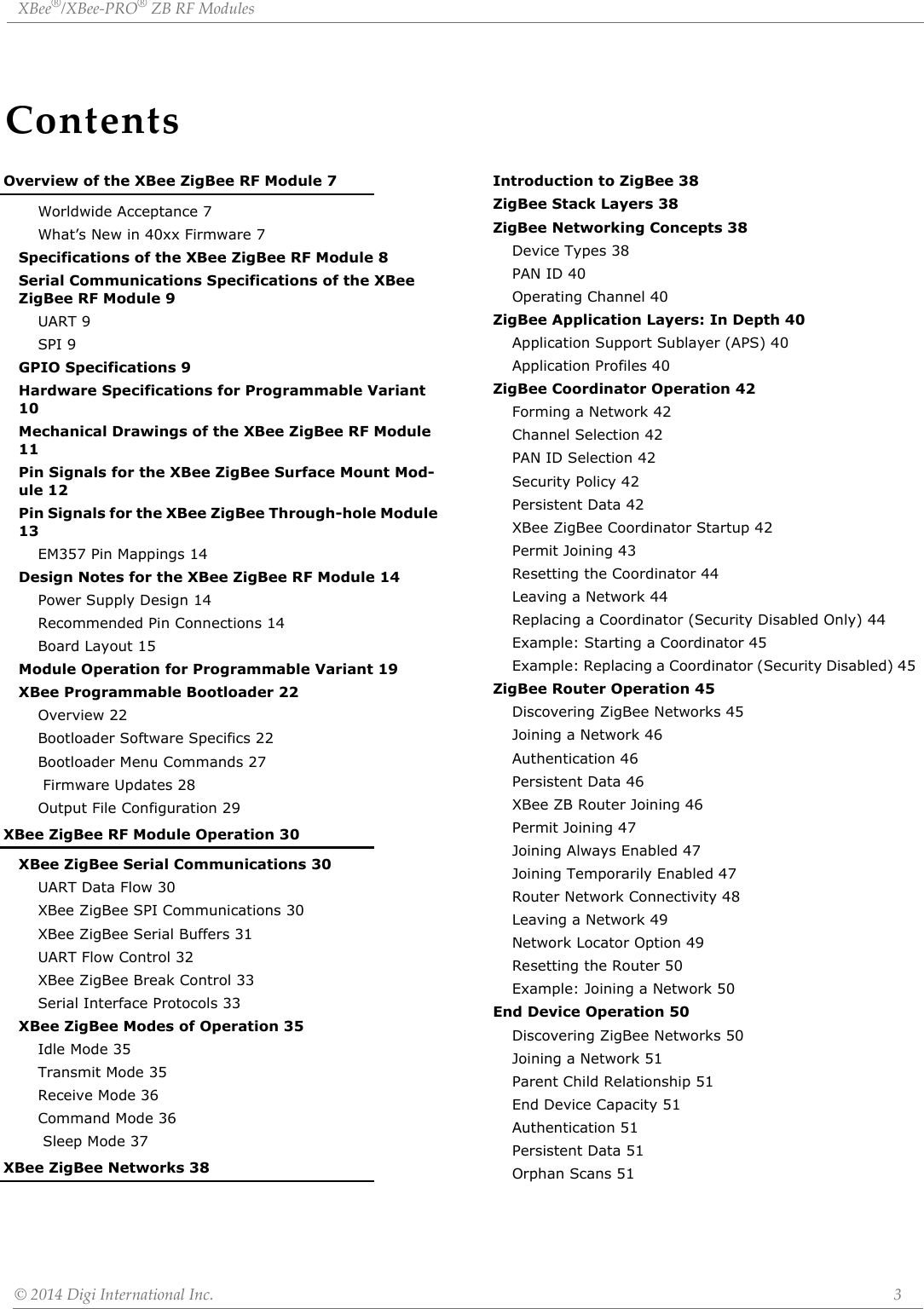
![XBee®/XBee‐PRO®ZBRFModules©2014DigiInternationalInc. 36When data is transmitted from one node to another, a network-level acknowledgement is transmitted back across the established route to the source node. This acknowledgement packet indicates to the source node that the data packet was received by the destination node. If a network acknowledgement is not received, the source node will re-transmit the data. It is possible in rare circumstances for the destination to receive a data packet, but for the source to not receive the network acknowledgment. In this case, the source will retransmit the data, which could cause the destination to receive the same data packet multiple times. The XBee modules do not filter out duplicate packets. The application should include provisions to address this potential issueSee Data Transmission and Routing in chapter 4 for more information. Receive ModeIf a valid RF packet is received, the data is transferred to the serial transmit buffer.Command ModeTo modify or read RF Module parameters, the module must first enter into Command Mode - a state in which incoming serial characters are interpreted as commands. Command Mode is only available over the UART when not using the Smart Energy firmware. The API Mode section in Chapter 9 describes an alternate means for configuring modules which is available with the SPI and with Smart Energy, as well as over the UART with ZB code.AT Command ModeTo Enter AT Command Mode:Send the 3-character command sequence “+++” and observe guard times before and after the com-mand characters. [Refer to the “Default AT Command Mode Sequence” below.]Default AT Command Mode Sequence (for transition to Command Mode):•No characters sent for one second [GT (Guard Times) parameter = 0x3E8]•Input three plus characters (“+++”) within one second [CC (Command Sequence Character) parame-ter = 0x2B.]•No characters sent for one second [GT (Guard Times) parameter = 0x3E8]Once the AT command mode sequence has been issued, the module sends an "OK\r" out the UART pad. The "OK\r" characters can be delayed if the module has not finished transmitting received serial data.When command mode has been entered, the command mode timer is started (CT command), and the module is able to receive AT commands on the UART port. All of the parameter values in the sequence can be modified to reflect user preferences.NOTE: Failure to enter AT Command Mode is most commonly due to baud rate mismatch. By default, the BD (Baud Rate) parameter = 3 (9600 bps).To Send AT Commands:Send AT commands and parameters using the syntax shown below.SyntaxforsendingATCommandsTo read a parameter value stored in the RF module’s register, omit the parameter field.The preceding example would change the RF module Destination Address (Low) to “0x1F”. To store the new value to non-volatile (long term) memory, subsequently send the WR (Write) command.Example: ATDL 1F<CR>“AT” PrexASCII CommandSpace(optional)Parameter(optional, HEX)Carriage Return](https://usermanual.wiki/Digi/PS2CTH/User-Guide-2348528-Page-35.png)
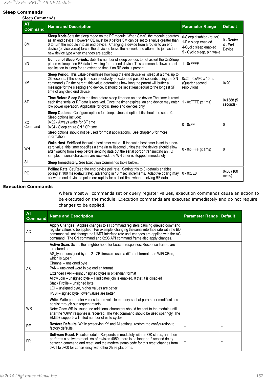
![XBee®/XBee‐PRO®ZBRFModules©2014DigiInternationalInc. 37For modified parameter values to persist in the module’s registry after a reset, changes must be saved to non-volatile memory using the WR (Write) Command. Otherwise, parameters are restored to previously saved values after the module is reset.Command Response When a command is sent to the module, the module will parse and execute the command. Upon successful execution of a command, the module returns an “OK” message. If execution of a command results in an error, the module returns an “ERROR” message.Applying Command Changes Any changes made to the configuration command registers through AT commands will not take effect until the changes are applied. For example, sending the BD command to change the baud rate will not change the actual baud rate until changes are applied. Changes can be applied in one of the following ways:•The AC (Apply Changes) command is issued.•AT command mode is exited.To Exit AT Command Mode:1. Send the ATCN (Exit Command Mode) command (followed by a carriage return). [OR]2. If no valid AT Commands are received within the time specified by CT (Command Mode Timeout) Command, the RF module automatically returns to Idle Mode. For an example of programming the RF module using AT Commands and descriptions of each config-urable parameter, please see the Command Reference Table chapter. Sleep ModeSleep modes allow the RF module to enter states of low power consumption when not in use. XBee RF modules support both pin sleep (sleep mode entered on pin transition) and cyclic sleep (module sleeps for a fixed time). XBee sleep modes are discussed in detail in chapter 7.](https://usermanual.wiki/Digi/PS2CTH/User-Guide-2348528-Page-36.png)

![XBee®/XBee‐PRO®ZBRFModules©2014DigiInternationalInc. 710x0013A200 40401234 - 64-bit address of the remote0xFFFE - 16-bit address of the remote (0xFFFE = unknown). Optionally, set to the 16-bit address of the destination if known.0x00 - Source endpoint0x00 - Destination endpoint0x0031 - Cluster ID (LQI Request, or Neighbor table request)0x0000 - Profile ID (ZigBee Device Profile)0x00 - Broadcast radius0x00 - Tx Options0x76 - Transaction sequence number0x00 - Required payload for LQI request command0xCE - Checksum (0xFF - SUM (all bytes after length))DescriptionThis API frame sends a ZDO LQI request (neighbor table request) to a remote device to obtain data from its neighbor table. Recall that the AO command must be set correctly on an API device to enable the explicit API receive frames in order to receive the ZDO response.Example 2: Send a ZDO Network Address Request to discover the 16-bit address of a remote.Looking at the ZigBee specification, the cluster ID for a network Address Request is 0x0000, and the payload only requires the following:[64-bit address] + [Request Type] + [Start Index]This example will send a Network Address Request as a broadcast transmission to discover the 16-bit address of the device with a 64-bit address of 0x0013A200 40401234. The request type and start index will be set to 0, and the transaction sequence number will be set to 0x44API Frame7E 001F 11 01 00000000 0000FFFF FFFE 00 00 0000 0000 00 00 44 34124040 00A21300 00 00 330x001F - length0x11 - Explicit transmit request0x01 - frame ID (set to a non-zero value to enable the transmit status message, or set to 0 to disable)0x00000000 0000FFFF - 64-bit address for a broadcast transmission0xFFFE - Set to this value for a broadcast transmission.0x00 - Source endpoint0x00 - Destination endpoint0x0000 - Cluster ID (Network Address Request)0x0000 - Profile ID (ZigBee Device Profile)0x00 - Broadcast radius0x00 - Tx Options0x44 - Transaction sequence number0x34124040 00A21300 00 00 - Required payload for Network Address Request command0x33 - Checksum (0xFF - SUM (all bytes after length))DescriptionThis API frame sends a broadcast ZDO Network Address Request to obtain the 16-bit address of a device with a 64-bit address of 0x0013A200 40401234. Note the bytes for the 64-bit address were inserted in little endian byte order. All multi-byte fields in the API payload of a ZDO command must have their data inserted in little endian byte order. Also recall that the AO command must be set correctly on an API device to enable the explicit API receive frames in order to receive the ZDO response.](https://usermanual.wiki/Digi/PS2CTH/User-Guide-2348528-Page-70.png)

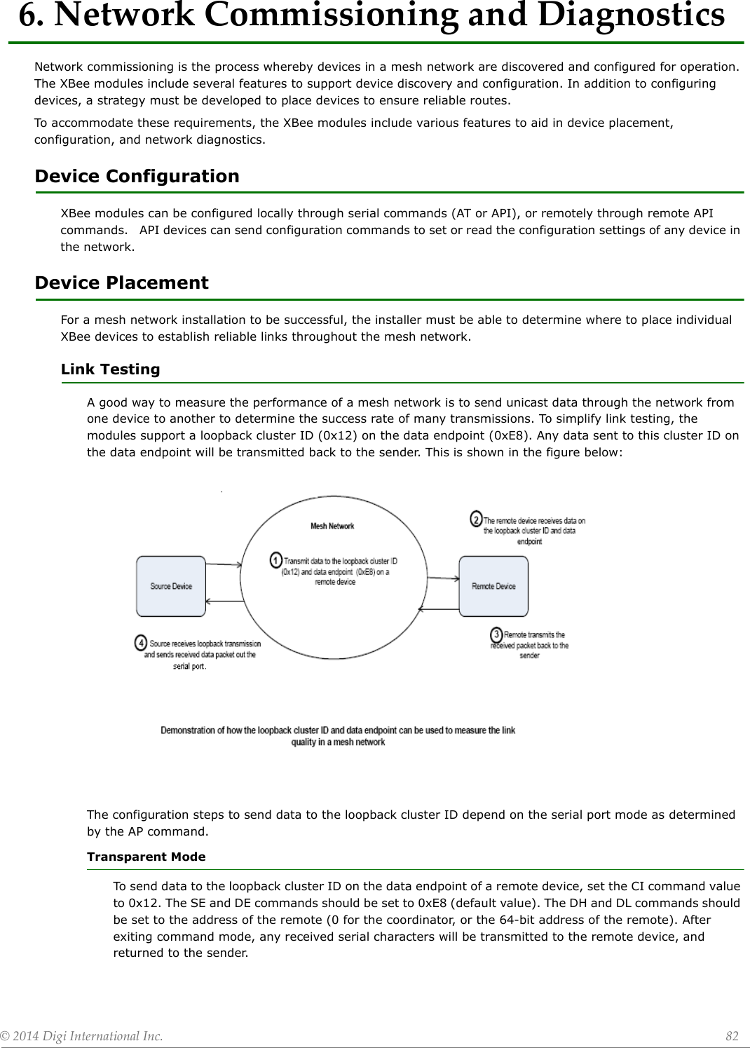
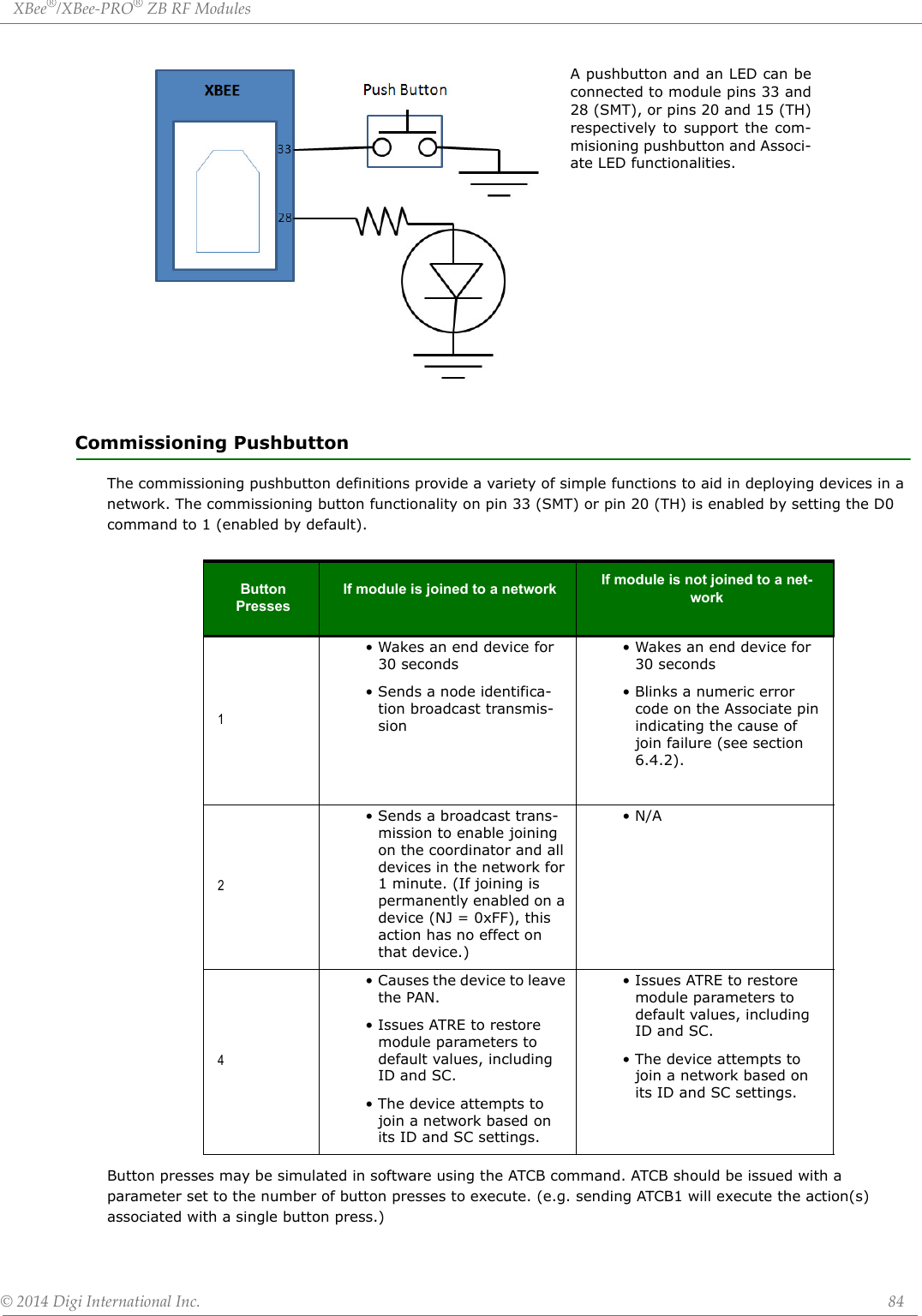
![XBee®/XBee‐PRO®ZBRFModules©2014DigiInternationalInc. 83API ModeSend an Explicit Addressing ZigBee Command API frame (0x11) using 0x12 as the cluster ID and 0xE8 as the source and destination endpoint. Data packets received by the remote will be echoed back to the sender.RSSI IndicatorsIt is possible to measure the received signal strength on a device using the DB command. DB returns the RSSI value (measured in –dBm) of the last received packet. However, this number can be misleading. The DB value only indicates the received signal strength of the last hop. If a transmission spans multiple hops, the DB value provides no indication of the overall transmission path, or the quality of the worst link – it only indicates the quality of the last link and should be used sparingly.The DB value can be determined in hardware using the RSSI/PWM module pin (pin 6). If the RSSI PWM functionality is enabled (P0 command), when the module receives data, the RSSI PWM is set to a value based on the RSSI of the received packet. (Again, this value only indicates the quality of the last hop.) This pin could potentially be connected to an LED to indicate if the link is stable or not.Device DiscoveryNetwork DiscoveryThe network discovery command can be used to discover all Digi modules that have joined a network. Issuing the ND command sends a broadcast node discovery command throughout the network. All devices that receive the command will send a response that includes the device’s addressing information, node identifier string (see NI command), and other relevant information. This command is useful for generating a list of all module addresses in a network.When a device receives the node discovery command, it waits a random time before sending its own response. The maximum time delay is set on the ND sender with the NT command. The ND originator includes its NT setting in the transmission to provide a delay window for all devices in the network. Large networks may need to increase NT to improve network discovery reliability. The default NT value is 0x3C (6 seconds). ZDO DiscoveryThe ZigBee Device Profile includes provisions to discover devices in a network that are supported on all ZigBee devices (including non-Digi products). These include the LQI Request (cluster ID 0x0031) and the Network Update Request (cluster ID 0x0038). The LQI Request can be used to read the devices in the neighbor table of a remote device, and the Network Update Request can be used to have a remote device do an active scan to discover all nearby ZigBee devices. Both of these ZDO commands can be sent using the XBee Explicit API transmit frame (0x11). See the API chapter for details. Refer to the ZigBee specification for formatting details of these two ZDO frames.Joining AnnounceAll ZigBee devices send a ZDO Device Announce broadcast transmission when they join a ZigBee network (ZDO cluster ID 0x0013). These frames will be sent out the XBee's serial port as an Explicit Rx Indicator API frame (0x91) if AO is set to 1. The device announce payload includes the following information:[ Sequence Number] + [16-bit address] + [64-bit address] + [Capability]The 16-bit and 64-bit addresses are received in little-endian byte order (LSB first). See the ZigBee specification for details.Commissioning Pushbutton and Associate LEDThe XBee modules support a set of commissioning and LED behaviors to aid in device deployment and commissioning. These include the commissioning pushbutton definitions and associate LED behaviors. These features can be supported in hardware as shown below.CommissioningPushbuttonandAssociateLEDFunctionalities](https://usermanual.wiki/Digi/PS2CTH/User-Guide-2348528-Page-82.png)
![XBee®/XBee‐PRO®ZBRFModules©2014DigiInternationalInc. 89Add GroupThe purpose of the Add Group command is to add a group table entry to associate an active endpoint with a groupID and optionally a groupName. The groupID is a two byte value. The groupName consists of zero to 16 ASCII characters.The intent of the example which follows is to add a group table entry which associates endpoint E7 with groupID 1234 and groupName "ABCD".The example packet is given in three parts, the preamble, ZCL Header, and ZCL payload:Preamble = "11 01 "+LocalDevice64Addr+"FFFE E6 E7 0006 C105 00 00"The packet is addressed to the local node, using a source endpoint of 0xE6, clusterID of 0x0006, and profileID of 0xC105. The destination endpoint E7 holds the endpoint parameter for the "Add Group" command.ZCL_header = "01 ee 00"The first field (byte) is a frame control field which specifies a Cluster Specific command (0x01) using a Client->Server direction(0x00). The second field is a transaction sequence number which is used to associate the response with the command request. The third field is the command identifier for "Add Group" ( 0x00)[2].ZCL_payload = "3412 04 41 42 43 44"The first two bytes is the group Id to add in little endian representation. The next byte is the string name length (00 if no string is wanted). The other bytes are the descriptive ASCII string name ("ABCD") for the group table entry. Note the string is represented with its length in the first byte, and the other bytes containing the ASCII characters.The example packet in raw hex byte form:7e001e11010013a2004047b55cfffee6e70006c105000001ee0034120441424344c7The response in raw hex byte form, consisting of two packets:7e0018910013a2004047b55cfffee7e68006c1050009ee00003412387e00078b01fffe00000076The response in decoded form:ZigBee Explicit Rx Indicator API 0x91 64DestAddr 0x0013A2004047B55C 16DestAddr 0xFFFE SrcEP 0xE7 DestEP 0xE6 ClusterID 0x8006 ProfileID 0xC105 Options 0x00 RF_Data 0x09EE00003412The response in terms of Preamble, ZCL Header, and ZCL payload: Preamble = "910013a2004047b55cfffee7e68006c10500"The packet has its endpoint values reversed from the request, and the clusterID is 0x8006 indicating a Group cluster response.ZCL_header = "09 ee 00"](https://usermanual.wiki/Digi/PS2CTH/User-Guide-2348528-Page-88.png)
![XBee®/XBee‐PRO®ZBRFModules©2014DigiInternationalInc. 90The first field is a frame control field which specifies a Cluster Specific command (0x01) using a Server-> Client direction. The second field is a transaction sequence number which is used to associate the response with the command request. The third field is the command identifier "Add Group" (0x00)[2].ZCL_payload = "00 3412"The first byte is a status byte (SUCCESS=0x00)[3][4]. The next two bytes hold the group ID (0x1234) in little endian form.And here is the decoded second message, which is a Tx Status for the original command request. If the FrameId value in the original command request had been zero, or if no space was available in the transmit UART buffer, then no Tx Status message would occur.ZigBee Tx Status API 0x8B FrameID 0x01 16DestAddr 0xFFFE Transmit Retries 0x00 Delivery Status 0x00 Discovery Status 0x00 SuccessView GroupThe purpose of the View Group command is to get the name string which is associated with a particular endpoint and groupID.The intent of the example is to get the name string associated with the endpoint E7 and groupID 1234.The packet:Preamble = "11 01 "+LocalDevice64Addr+"FFFE E6 E7 0006 C105 00 00"The packet is addressed to the local node, using a source endpoint of 0xE6, clusterID of 0x0006, and profileID of 0xC105. The destination endpoint E7 is the endpoint parameter for the "View Group" command.ZCL_header = "01 ee 01"The first field is a frame control field which specifies a Cluster Specific command (0x01) using a Client->Server direction(0x00). The second field is a transaction sequence number which is used to associate the response with the command request. The third field is the command identifier "View Group" (0x01) [5].ZCL_payload = "3412"The two byte value is the groupID in little-endian representation.The packet in raw hex byte form:7e001911010013a2004047b55cfffee6e70006c105000001ee013412d4The response in raw hex byte form, consisting of two packets:7e001d910013a2004047b55cfffee7e68006c1050009ee010034120441424344247e00078b01fffe00000076The command response in decoded form:ZigBee Explicit Rx Indicator API 0x91 64DestAddr 0x0013A2004047B55C 16DestAddr 0xFFFE SrcEP 0xE7 DestEP 0xE6 ClusterID 0x8006 ProfileID 0xC105 Options 0x00 RF_Data 0x09EE010034120441424344](https://usermanual.wiki/Digi/PS2CTH/User-Guide-2348528-Page-89.png)
![XBee®/XBee‐PRO®ZBRFModules©2014DigiInternationalInc. 91The response in terms of Preamble, ZCL Header, and ZCL payload:Preamble = "910013a2004047b55cfffee7e68006c10500"The packet has its endpoint values reversed from the request, and the clusterID is 0x8006 indicating a Group cluster response.ZCL_header = "09 ee 01"The first field is a frame control field which specifies a Cluster Specific command (0x01) using a Server->Client direction (0x08). The second field is a transaction sequence number which is used to associate the response with the command request. The third field is the command identifier "View Group" (0x01) [6].ZCL_payload = "00 3412 0441424344"The first byte is a status byte (SUCCESS=0x00)[6][4]. The next two bytes hold the groupID (0x1234) in little-endian form. The next byte is the name string length (0x04). The remaining bytes are the ASCII name string characters ("ABCD").And here is the decoded second message, which is a Tx Status for the original command request. If the FrameId value in the original command request had been zero, or if no space was available in the transmit UART buffer, then no Tx Status message would occur.ZigBee Tx Status API 0x8B FrameID 0x01 16DestAddr 0xFFFE Transmit Retries 0x00 Delivery Status 0x00 Discovery Status 0x00 SuccessGet Group Membership (1 of 2)The purpose of this first form of the Get Group Membership command is to get all the groupIDs associated with a particular endpoint.The intent of the example is to get all the groupIDs associated with endpoint E7.The example packet is given in three parts, the preamble, ZCL Header, and ZCL payload:Preamble = "11 01 "+LocalDevice64Addr+"FFFE E6 E7 0006 C105 00 00"The packet is addressed to the local node, using a source endpoint of 0xE6, clusterID of 0x0006, and profileID of 0xC105. The destination endpoint E7 holds the endpoint parameter for the "Get Group Membership" command.ZCL_header = "01 ee 02"The first field (byte) is a frame control field which specifies a Cluster Specific command (0x02) using a Client->Server direction(0x00). The second field is a transaction sequence number which is used to associate the response with the command request. The third field is the command identifier for "Get Group Membership" (0x02) [7].ZCL_payload = "00"The first byte is the group count. If it is zero, then all groupIDs with an endpoint value which matches the given endpoint parameter will be returned in the response.The example packet in raw hex byte form:7e001811010013a2004047b55cfffee6e70006c105000001ee020019](https://usermanual.wiki/Digi/PS2CTH/User-Guide-2348528-Page-90.png)
![XBee®/XBee‐PRO®ZBRFModules©2014DigiInternationalInc. 92The response in raw hex byte form, consisting of two packets:7e0019910013a2004047b55cfffee7e68006c1050009ee02ff013412357e00078b01fffe00000076The response in decoded form:ZigBee Explicit Rx Indicator API 0x91 64DestAddr 0x0013A2004047B55C 16DestAddr 0xFFFE SrcEP 0xE7 DestEP 0xE6 ClusterID 0x8006 ProfileID 0xC105 Options 0x00 RF_Data 0x09EE02FF013412The response in terms of Preamble, ZCL Header, and ZCL Payload: Preamble = "910013a2004047b55cfffee7e68006c10500"The packet has the endpoints reversed from the request, and the clusterID is 0x8006 indicating a Group cluster response.ZCL_header = "09 ee 02"The first field is a frame control field which specifies a Cluster Specific command (0x01) using a Server->Client direction (0x08). The second field is a transaction sequence number which is used to associate the response with the command request. The third field is the command identifier "Get Group Membership" (0x02) [8].ZCL_payload = "FF 01 3412"The first byte is the remaining capacity of the group table. 0xFF means unknown. The XBee returns this value because the capacity of the group table is dependent on the remaining capacity of the binding table, thus the capacity of the group table is unknown. The second byte is the group count (0x01). The remaining bytes are the groupIDs in little-endian representation.And here is the decoded second message, which is a Tx Status for the original command request. If the FrameId value in the original command request had been zero, or if no space was available in the transmit UART buffer, then no Tx Status message would occur.ZigBee Tx Status API 0x8B FrameID 0x01 16DestAddr 0xFFFE Transmit Retries 0x00 Delivery Status 0x00 Discovery Status 0x00 SuccessGet Group Membership (2 of 2)The purpose of this second form of the Get Group Membership command is to get the set of groupIDs associated with a particular endpoint which are a subset of a list of given groupIDs.The intent of the example is to get the groupIDs associated with endpoint E7 which are a subset of a given list of groupIDs (0x1234, 0x5678).The example packet is given in three parts, the preamble, ZCL Header, and ZCL payload:Preamble = "11 01 "+LocalDevice64Addr+"FFFE E6 E7 0006 C105 00 00"The packet is addressed to the local node, using a source endpoint of 0xE6, clusterID of 0x0006, and profileID of 0xC105. The destination endpoint E7 is the endpoint parameter for the "Get Group Membership" command.ZCL_header = "01 ee 02"](https://usermanual.wiki/Digi/PS2CTH/User-Guide-2348528-Page-91.png)
![XBee®/XBee‐PRO®ZBRFModules©2014DigiInternationalInc. 93The first field (byte) is a frame control field which specifies a Cluster Specific command (0x02) using a Client->Server direction(0x00). The second field is a transaction sequence number which is used to associate the response with the command request. The third field is the command identifier for "Get Group Membership" (0x02) [7].ZCL_payload = "02 34127856"The first byte is the group count. The remaining bytes are a groupIDs which use little-endian representation.The example packet in raw hex byte form:7e001c11010013a2004047b55cfffee6e70006c105000001ee02023412785603The response in raw hex byte form, consisting of two packets:7e0019910013a2004047b55cfffee7e68006c1050009ee02ff013412357e00078b01fffe00000076The response in decoded form:ZigBee Explicit Rx Indicator API 0x91 64DestAddr 0x0013A2004047B55C 16DestAddr 0xFFFE SrcEP 0xE7 DestEP 0xE6 ClusterID 0x8006 ProfileID 0xC105 Options 0x00 RF_Data 0x09EE02FF013412The response in terms of Preamble, ZCL Header, and ZCL Payload: Preamble = "910013a2004047b55cfffee7e68006c10500"The packet has the endpoints reversed from the request, the clusterID is 0x8006 indicating a Group cluster response.ZCL_header = "09 ee 02"The first field is a frame control field which specifies a Cluster Specific command (0x01) using a Server->Client direction (0x08). The second field is a transaction sequence number which is used to associate the response with the command request. The third field is the command identifier "Get Group Membership" (0x02) [8].ZCL_payload = "FF 01 3412"The first byte is the remaining capacity of the group table. 0xFF means unknown. The XBee returns this value because the capacity of the group table is dependent on the remaining capacity of the binding table, thus the capacity of the group table is unknown. The second byte is the group count (0x01). The remaining bytes are the groupIDs in little-endian representation.And here is the decoded second message, which is a Tx Status for the original command request. If the FrameId value in the original command request had been zero, or if no space was available in the transmit UART buffer, then no Tx Status message would occur.ZigBee Tx Status API 0x8B FrameID 0x01 16DestAddr 0xFFFE Transmit Retries 0x00 Delivery Status 0x00 Discovery Status 0x00 Success](https://usermanual.wiki/Digi/PS2CTH/User-Guide-2348528-Page-92.png)
![XBee®/XBee‐PRO®ZBRFModules©2014DigiInternationalInc. 94Remove GroupThe purpose of the Remote Group command is to remove a Group Table entry which associates a given endpoint with a given groupID.The intent of the example is to remove the association of groupID [TBD] with endpoint E7.The example packet is given in three parts, the preamble, ZCL Header, and ZCL payload:Preamble = "11 01 "+LocalDevice64Addr+"FFFE E6 E7 0006 C105 00 00"The packet is addressed to the local node, using a source endpoint of 0xE6, clusterID of 0x0006, and profileID of 0xC105. The destination endpoint E7 is the endpoint parameter for the "Remove Group" command.ZCL_header = "01 ee 03"The first field is a frame control field which specifies a Cluster Specific command (0x01) using a Client->Server direction(0x00). The second field is a transaction sequence number which is used to associate the response with the command request. The third field is the command identifier "Remove Group" (0x03) [9].ZCL_payload = "3412"The two bytes value is the groupID to be removed in little-endian representation.The packet in raw hex byte form:7e001911010013a2004047b55cfffee6e70006c105000001ee033412d2The response in raw hex byte form, consisting of two packets:7e0018910013a2004047b55cfffee7e68006c1050009ee03003412357e00078b01fffe00000076The command response in decoded form:ZigBee Explicit Rx Indicator API 0x91 64DestAddr 0x0013A2004047B55C 16DestAddr 0xFFFE SrcEP 0xE7 DestEP 0xE6 ClusterID 0x8006 ProfileID 0xC105 Options 0x00 RF_Data 0x09EE03003412The response in terms of Preamble, ZCL Header, and ZCL payload:Preamble = "910013a2004047b55cfffee7e68006c10500"The packet has its endpoint values reversed from the request, and the clusterID is 0x8006 indicating a Group cluster response.ZCL_header = "09 ee 03"The first field is a frame control field which specifies a Cluster Specific command (0x01) using a Server->Client direction (0x08). The second field is a transaction sequence number which is used to associate the response with the command request. The third field is the command identifier "Remove Group" (0x03) [10].ZCL_payload = "00 3412"](https://usermanual.wiki/Digi/PS2CTH/User-Guide-2348528-Page-93.png)
![XBee®/XBee‐PRO®ZBRFModules©2014DigiInternationalInc. 95The first byte is a status byte (SUCCESS=0x00)[10][4]. The next two bytes is the groupID (0x1234) value in little-endian form.And here is the decoded second message, which is a Tx Status for the original command request. If the FrameId value in the original command request had been zero, or if no space was available in the transmit UART buffer, then no Tx Status message would occur.ZigBee Tx Status API 0x8B FrameID 0x01 16DestAddr 0xFFFE Transmit Retries 0x00 Delivery Status 0x00 Discovery Status 0x00 SuccessRemove All GroupsThe purpose of the Remove All Groups command is to clear all entries from the group table which are associated with a target endpoint.The intent of the example is to remove all groups associated with endpoint E7.The packet:Preamble = "11 01 "+LocalDevice64Addr+"FFFE E6 E7 0006 C105 00 00"The packet is addressed to the local node, using a source endpoint of 0xE6, clusterId of 0x0006, and profileID of 0xC105. The destination endpoint E7 is the endpoint parameter for the "Remove All Groups" command.ZCL_header = "01 ee 04"The first field is a frame control field which specifies a Cluster Specific command (0x01) using a Client->Server direction(0x00). The second field is a transaction sequence number which is used to associate the response with the command request. The third field is the command identifier "Remove All Groups" (0x04) [11].ZCL_payload = ""No payload is needed for this command.The packet in raw hex byte form:7e001711010013a2004047b55cfffee6e70006c105000001ee0417The response in raw hex byte form, consisting of two packets:7e0016910013a2004047b55cfffee7e68006c1050009ee04007c7e00078b01fffe00000076The command response in decoded form:ZigBee Explicit Rx Indicator API 0x91 64DestAddr 0x0013A2004047B55C 16DestAddr 0xFFFE SrcEP 0xE7 DestEP 0xE6 ClusterID 0x8006 ProfileID 0xC105 Options 0x00 RF_Data 0x09ee0400The response in terms of Preamble, ZCL Header, and ZCL payload. Preamble = "910013a2004047b55cfffee7e68006c10500"](https://usermanual.wiki/Digi/PS2CTH/User-Guide-2348528-Page-94.png)
![XBee®/XBee‐PRO®ZBRFModules©2014DigiInternationalInc. 96The packet has its endpoints values reversed from the request, and the clusterID is 0x8006 indicating a Group cluster response.ZCL_header = "09 ee 04"The first field is a frame control field which specifies a Cluster Specific command (0x01) using a Server->Client direction (0x08). The second field is a transaction sequence number which is used to associate the response with the command request. The third field is the command identifier "Remove All Groups" (0x04) [10].ZCL_payload = "00"The first byte is a status byte (SUCCESS=0x00)[4].And here is the decoded second message, which is a Tx Status for the original command request. If the FrameID value in the original command request had been zero, or if no space was available in the transmit UART buffer, then no Tx Status message would occur.ZigBee Tx Status API 0x8B FrameID 0x01 16DestAddr 0xFFFE Transmit Retries 0x00 Delivery Status 0x00 Discovery Status 0x00 SuccessDefault ResponsesMany errors are returned as a default response. For example, a RFData payload of a response containing 08010b788b would be decoded as:ZCL_header = "08 01 03" - general command/server-to-client, transseqnum=1, default_response_command(0x03)ZCL_payload = "78 8b" - original cmdID, status code (0x8b) EMBER_ZCL_STATUS_NOT_FOUNDCommon Status CodesThis section lists some of the more frequently occuring status codes.0x00 EMBER_ZCL_STATUS_SUCCESS: Command request was successful0x01 EMBER_ZCL_STATUS_FAILURE: Command request failed - for example, a call to remove an entry from the group table returned an error0x80 EMBER_ZCL_STATUS_MALFORMED_COMMAND: no RFData in the API frame; ZCL Payload appears truncated from what is expected0x81 EMBER_ZCL_STATUS_UNSUP_CLUSTER_COMMAND: unexpected direction in the Frame Control Field of the ZCL Header; unexpected command identifier code value in the ZCL header0x82 EMBER_ZCL_STATUS_UNSUP_GENERAL_COMMAND: unexpected frametype in the Frame Control Field of the ZCL Header0x84 EMBER_ZCL_STATUS_UNSUP_MANUF_GENERAL_COMMAND: unexpected manufacturer specific indication in the Frame Control Field of the ZCL Header0x8b EMBER_ZCL_STATUS_NOT_FOUND: An attempt at Get Group Membership or Remove Group could not find a matching entry in the group tableA full set of status codes appears in the documentation [4].](https://usermanual.wiki/Digi/PS2CTH/User-Guide-2348528-Page-95.png)
![XBee®/XBee‐PRO®ZBRFModules©2014DigiInternationalInc. 97Bibliography[1] ZigBee Cluster Library, document 075123r02, section 3.6.The following cross references all appear in the ZCL document:[2] Add Group Command, section 3.6.2.2.3.[3] Add Group Response, section 3.6.2.3.1.[4] Status Enumerations, section 2.5.3.[5] View Group Command, section 3.6.2.2.4.[6] View Group Response, section 3.6.2.3.2.[7] Get Group Membership Command, section 3.6.2.2.5.[8] Get Group Membership Response, section 3.6.2.3.3.[9] Remove Group Command, section 3.6.2.2.6.[10] Remove Group Response, section 3.6.2.3.4.[11] Remove All Groups Command, section 3.6.2.2.7.](https://usermanual.wiki/Digi/PS2CTH/User-Guide-2348528-Page-96.png)
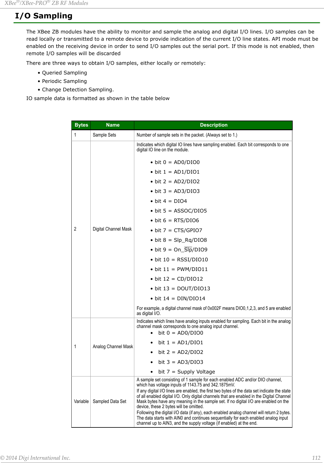
![XBee®/XBee‐PRO®ZBRFModules©2014DigiInternationalInc. 113The sampled data set will include 2 bytes of digital I/O data only if one or more I/O lines on the device are configured as digital I/O. If no pins are configured as digital IO, these 2 bytes will be omitted. Pins are configured as digital I/O by setting them to a value of 3, 4, or 5.The digital I/O data is only relevant if the same bit is enabled in the digital I/O mask. Analog samples are returned as 10-bit values. The analog reading is scaled such that 0x0000 represents 0 V, and 0x3FF = 1.2 V. (The analog inputs on the module cannot read more than 1.2 V.) Analog samples are returned in order starting with AIN0 and finishing with AIN3, and the supply voltage. Only enabled analog input channels return data as shown in the figure below.To convert the A/D reading to mV, do the following:AD(mV) = (A/D reading * 1200mV) / 1024The reading in the sample frame represents voltage inputs of 1143.75 and 342.1875 mV for AD0 and AD1 respectively.Queried SamplingThe IS command can be sent to a device locally, or to a remote device using the API remote command frame (see chapter 8 for details). When the IS command is sent, the receiving device samples all enabled digital IO and analog input channels and returns an IO sample. If IS is sent locally, the IO sample is sent out the serial port. If the IS command was received as a remote command, the IO sample is sent over-the-air to the device that sent the IS command.If the IS command is issued in command mode, the module returns a carriage return-delimited list containing the above-listed fields. If the IS command is issued in API mode, an API command response contains the same information.The following table shows an example of the fields in an IS response.Periodic I/O SamplingPeriodic sampling allows an XBee module to take an I/O sample and transmit it to a remote device at a periodic rate. The periodic sample rate is set by the IR command. If IR is set to 0, periodic sampling is disabled. For all other values of IR, data will be sampled after IR milliseconds have elapsed and transmitted to a remote device. The DH and DL commands determine the destination address of the I/O samples. DH and DL can be set to 0 to transmit to the coordinator, or to the 64-bit address of the remote device (SH and SL). Only devices running in API mode can send I/O data samples out their serial port. Devices running in transparent mode will discard received I/O data samples.A sleeping end device will transmit periodic IO samples at the IR rate until the ST timer expires and the device can resume sleeping.Change Detection SamplingModules can be configured to transmit a data sample immediately whenever a monitored digital I/O pin changes state. The IC command is a bitmask that can be used to set which digital I/O lines should be monitored for a state change. If one or more bits in IC is set, an I/O sample will be transmitted as soon as a state change is observed in one of the monitored digital IO lines. Change detection samples are transmitted to the 64-bit address specified by DH and DL. Example Sample AT Response0x01 [1 sample set]0x0C0C [Digital Inputs: DIO 2, 3, 10, 11 low]0x03 [Analog Inputs: A/D 0, 1]0x0408 [Digital input states: DIO 3, 10 high, DIO 2, 11 low]0x03D0 [Analog input ADIO 0= 0x3D0]0x0124 [Analog input ADIO 1=0x120]](https://usermanual.wiki/Digi/PS2CTH/User-Guide-2348528-Page-112.png)
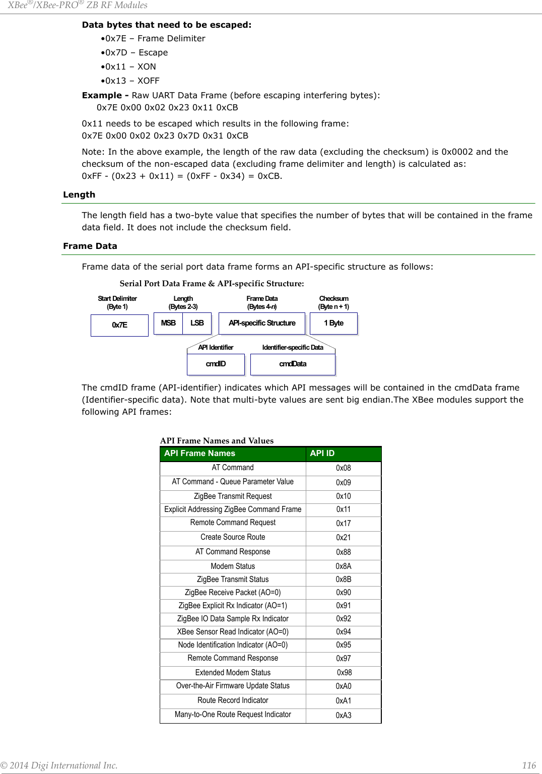
![XBee®/XBee‐PRO®ZBRFModules©2014DigiInternationalInc. 117ChecksumTo test data integrity, a checksum is calculated and verified on non-escaped data.To calculate: Not including frame delimiters and length, add all bytes keeping only the lowest 8 bits of the result and subtract the result from 0xFF.To verify: Add all bytes (include checksum, but not the delimiter and length). If the checksum is correct, the sum will equal 0xFF.API ExamplesExample: Create an API AT command frame to configure an XBee to allow joining (set NJ to 0xFF). The frame should look like: 0x7E 0x00 0x05 0x08 0x01 0x4E 0x4A 0xFF 5FWhere 0x0005 = length 0x08 = AT Command API frame type 0x01 = Frame ID (set to non-zero value) 0x4E4A = AT Command ('NJ') 0xFF = value to set command to 0x5F = ChecksumThe checksum is calculated as [0xFF - (0x08 + 0x01 + 0x4E + 0x4A + 0xFF)]Example: Send an ND command to discover the devices in the PAN. The frame should look like:0x7E 0x00 0x04 0x08 0x01 0x4E 0x44 0x64Where 0x0004 = length 0x08 = AT Command API frame type 0x01 = Frame ID (set to non-zero value) 0x4E44 = AT command ('ND') 0x64 = ChecksumThe checksum is calculated as [0xFF - (0x08 + 0x01 + 0x4E + 0x44)]Example: Send a remote command to the coordinator to set AD1/DIO1 as a digital input (D1=3) and apply changes to force the IO update. The API remote command frame should look like:0x7E 0x00 0x10 0x17 0x01 0x00 0x00 0x00 0x00 0x00 0x00 0x00 0x00 0xFF 0xFE 0x02 0x44 0x31 0x03 0x70Where 0x10 = length (16 bytes excluding checksum)0x17 = Remote Command API frame type0x01 = Frame ID0x0000000000000000 = Coordinator's address (can be replaced with coordinator's actual 64-bit address if known)0xFFFE = 16- bit Destination Address0x02 = Apply Changes (Remote Command Options)0x4431 = AT command ('D1')0x03 = Command Parameter (the parameter could also be sent as 0x0003 or 0x00000003)0x70 = Checksum](https://usermanual.wiki/Digi/PS2CTH/User-Guide-2348528-Page-116.png)
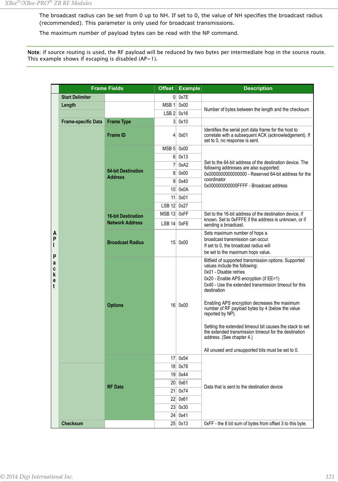
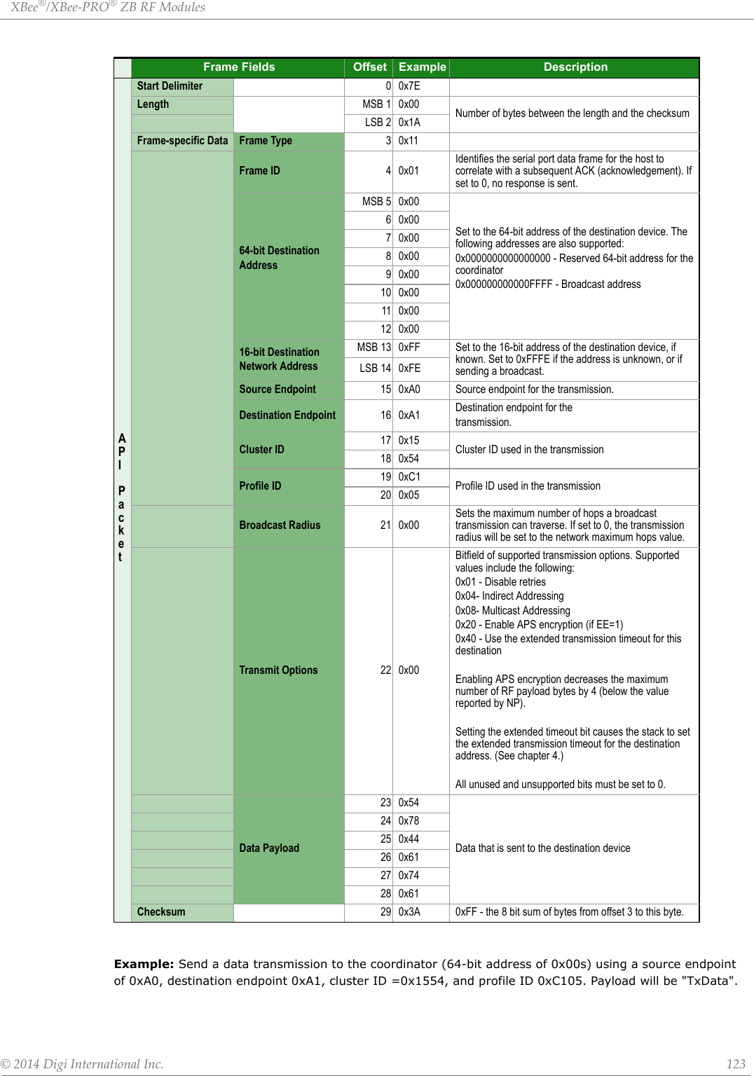
![XBee®/XBee‐PRO®ZBRFModules©2014DigiInternationalInc. 122Example: The example above shows how to send a transmission to a module where escaping is disabled (AP=1) with destination address 0x0013A200 40014011, payload "TxData1B". If escaping is enabled (AP=2), the frame should look like: 0x7E 0x00 0x16 0x10 0x01 0x00 0x7D 0x33 0xA2 0x00 0x40 0x0A 0x01 0x27 0xFF 0xFE 0x00 0x00 0x54 0x78 0x44 0x61 0x74 0x61 0x30 0x41 0x7D 0x33The checksum is calculated (on all non-escaped bytes) as [0xFF - (sum of all bytes from API frame type through data payload)]. Example: Send a transmission to the coordinator without specifying the coordinator's 64-bit address. The API transmit request frame should look like:0x7E 0x00 0x16 0x10 0x01 0x00 0x00 0x00 0x00 0x00 0x00 0x00 0x00 0xFF 0xFE 0x00 0x00 0x54 0x78 032 0x43 0x6F 0x6F 0x72 0x64 0xFCWhere 0x16 = length (22 bytes excluding checksum) 0x10 = ZigBee Transmit Request API frame type 0x01 = Frame ID (set to non-zero value) 0x0000000000000000 = Coordinator's address (can be replaced with coordinator's actual 64-bit address if known 0xFFFE = 16-bit Destination Address 0x00 = Broadcast radius 0x00 = Options 0x547832436F6F7264 = Data payload ("Tx2Coord") 0xFC = ChecksumExplicit Addressing ZigBee Command Frame Frame Type: 0x11Allows ZigBee application layer fields (endpoint and cluster ID) to be specified for a data transmission.Similar to the ZigBee Transmit Request, but also requires ZigBee application layer addressing fields to be specified (endpoints, cluster ID, profile ID). An Explicit Addressing Request API frame causes the module to send data as an RF packet to the specified destination, using the specified source and destination endpoints, cluster ID, and profile ID.The 64-bit destination address should be set to 0x000000000000FFFF for a broadcast transmission (to all devices). The coordinator can be addressed by either setting the 64-bit address to all 0x00s and the 16-bit address to 0xFFFE, OR by setting the 64-bit address to the coordinator's 64-bit address and the 16-bit address to 0x0000. For all other transmissions, setting the 16-bit address to the correct 16-bit address can help improve performance when transmitting to multiple destinations. If a 16-bit address is not known, this field should be set to 0xFFFE (unknown). The Transmit Status frame (0x8B) will indicate the discovered 16-bit address, if successful.The broadcast radius can be set from 0 up to NH. If set to 0, the value of NH specifies the broadcast radius (recommended). This parameter is only used for broadcast transmissions.The maximum number of payload bytes can be read with the NP command. Note: if source routing is used, the RF payload will be reduced by two bytes per intermediate hop in the source route.](https://usermanual.wiki/Digi/PS2CTH/User-Guide-2348528-Page-121.png)
,nwkUpdateId(1)0x05 Reject ZS Not an association candidate because ZS does not match beacon response0x06 Reject ID Not an association candidate because configured panId does not match beacon response0x07 Reject NJ Not an association candidate because response is not allowing joins0x08 panID Match JV/NW with search option (DO80) has found a matching network panId(2)0x09 Reject LQIRSSI JV/NW with search option(DO80) candidate rejected because signal weaker than one already found0x0A Beacon Saved Saving beacon response for a joinable networkextendedPanId(8),panid(2),radioTxPower(1),radioChannel(1),joinMethod(1),nwkManagerId(2),nwkUpdateId(1),channelMask(2)0x0B AIAI value has changedAIStatusCode(1)0x00: Association succeeded0x21: No Pans were found0x22: No Valid Pans were found0x23: Join not allowed0x24: No beacons0x25: Unexpected Join Error - device was asked to join when already in a joined state0x27: Join Failure0x28: Call Tech Support0x2A: Coordinator start failure0x2B: Discovering Coordinator0xFE: Stack Initialization Failure0x0C Permit Join Permit Join duration has changed value(1)](https://usermanual.wiki/Digi/PS2CTH/User-Guide-2348528-Page-134.png)

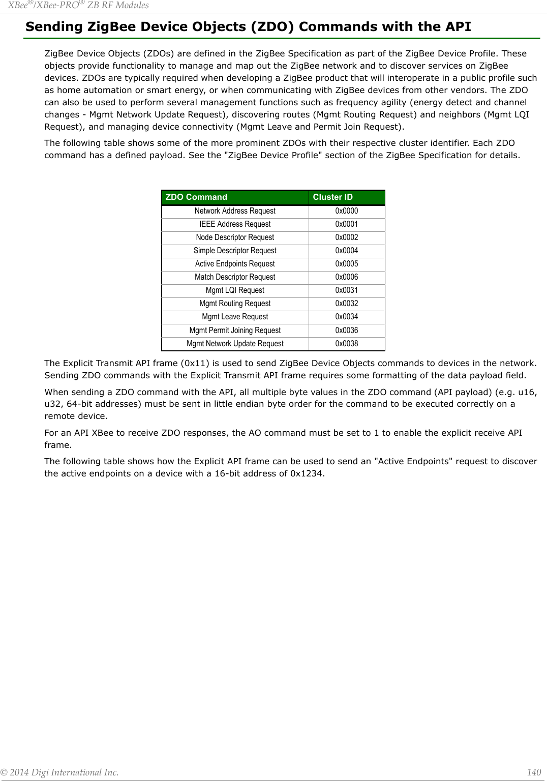
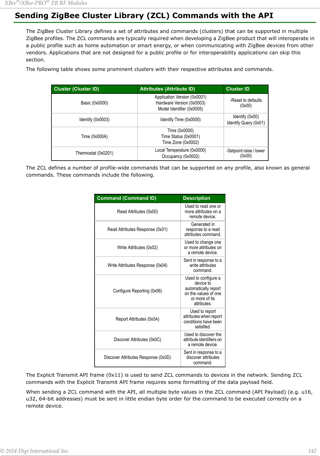
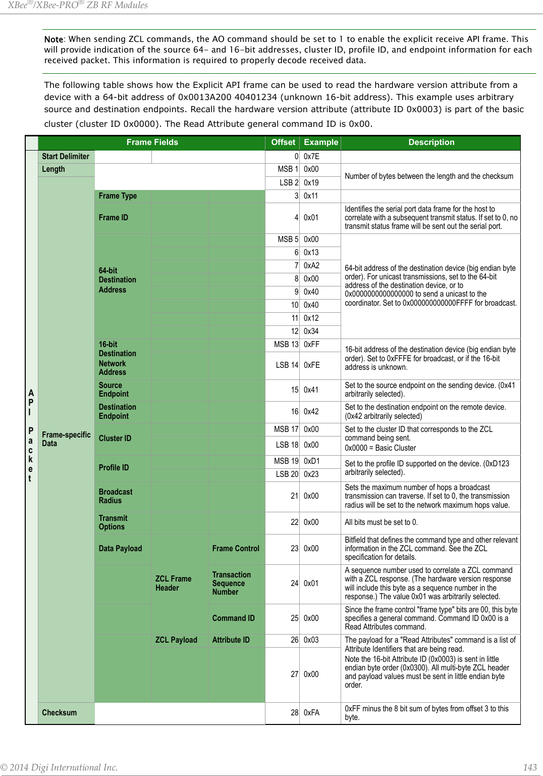
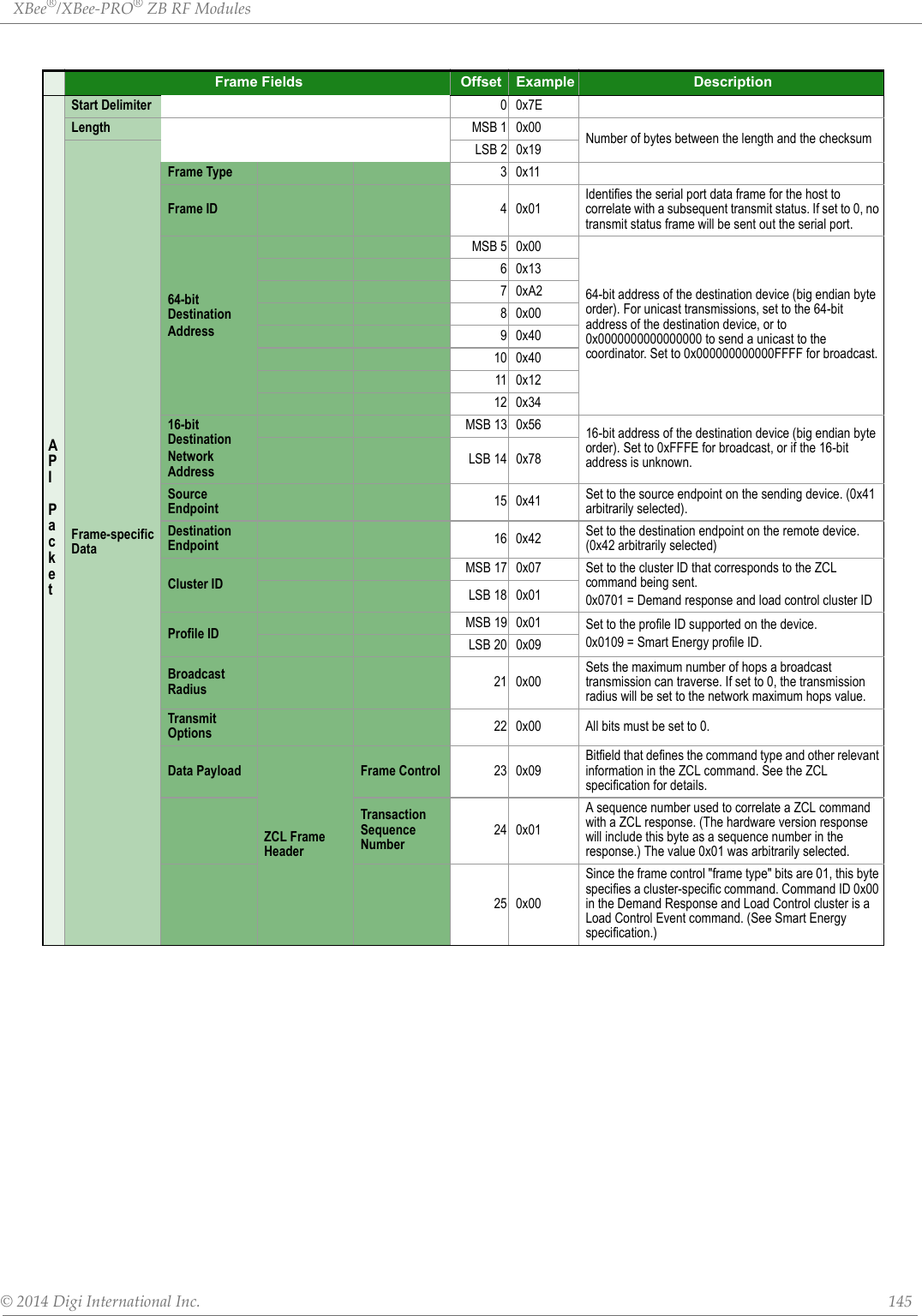
![XBee®/XBee‐PRO®ZBRFModules©2014DigiInternationalInc. 141Frame Fields Offset Example DescriptionAPI PacketStart Delimiter 00x7ELength MSB 1 0x00 Number of bytes between the length and the checksumFrame-specific Data LSB 2 0x17Frame Type 30x11Frame ID 40x01Identifies the serial port data frame for the host to correlate with a subsequent transmit status. If set to 0, no transmit status frame will be sent out the serial port.64-bit DestinationAddressMSB 5 0x0064-bit address of the destination device (big endian byte order). For unicast transmissions, set to the 64-bit address of the destination device, or to 0x0000000000000000 to send a unicast to the coordinator. Set to 0x000000000000FFFF for broadcast.60x0070x0080x0090x0010 0x0011 0xFF12 0xFF16-bit DestinationNetwork AddressMSB 13 0xFF 16-bit address of the destination device (big endian byte order). Set to 0xFFFE for broadcast, or if the 16-bit address is unknown. LSB 14 0xFESource Endpoint 15 0x00 Set to 0x00 for ZDO transmissions (endpoint 0 is the ZDO endpoint).Destination Endpoint 16 0x00 Set to 0x00 for ZDO transmissions (endpoint 0 is the ZDO endpoint).Cluster IDMSB 17 0x00 Set to the cluster ID that corresponds to the ZDO command being sent.0x0005 = Active Endpoints RequestLSB 18 0x05Profile ID MSB 19 0x00 Set to 0x0000 for ZDO transmissions (Profile ID 0x0000 is the ZigBee Device Profile that supports ZDOs).LSB 20 0x00Broadcast Radius 21 0x00Sets the maximum number of hops a broadcast transmission can traverse. If set to 0, the transmission radius will be set to the network maximum hops value.Transmit Options 22 0x00 All bits must be set to 0.Data PayloadTransaction Sequence Number 23 0x01 The required payload for a ZDO command. All multi-byte ZDO parameter values (u16, u32, 64-bit address) must be sent in little endian byte order.The Active Endpoints Request includes the following payload:[16-bit NwkAddrOfInterest]Note the 16-bit address in the API example (0x1234) is sent in little endian byte order (0x3412).ZDO Payload 24 0x3425 0x12Checksum 26 0xA6 0xFF minus the 8 bit sum of bytes from offset 3 to this byte.](https://usermanual.wiki/Digi/PS2CTH/User-Guide-2348528-Page-140.png)
![XBee®/XBee‐PRO®ZBRFModules©2014DigiInternationalInc. 148AddressingAddressingCommandsATCommand Name and Description Parameter Range DefaultDHDestination Address High.Set/Get the upper 32 bits of the 64-bit destination address. When combined with DL, it defines the 64-bit destination address for data transmission. Special definitions for DH and DL include 0x000000000000FFFF (broadcast) and 0x0000000000000000 (coordinator).0 - 0xFFFFFFFF 0DLDestination Address Low. Set/Get the lower 32 bits of the 64-bit destination address. When combined with DH, it defines the 64-bit destination address for data transmissions. Special definitions for DH and DL include 0x000000000000FFFF (broadcast) and 0x0000000000000000 (coordinator).0 - 0xFFFFFFFF 0xFFFF(Coordinator)0 (Router/End Device)MY 16-bit Network Address. Read the 16-bit network address of the module. A value of 0xFFFE means the module has not joined a ZigBee network0 - 0xFFFE[read-only] 0xFFFEMP 16-bit Parent Network Address. Read the 16-bit network address of the module's parent. A value of 0xFFFE means the module does not have a parent.0 - 0xFFFE[read-only] 0xFFFENC Number of Remaining Children. Read the number of end device children that can join the device. If NC returns 0, then the device cannot allow any more end device children to join. 0 - MAX_CHILDREN(maximum varies) read-only SH Serial Number High. Read the high 32 bits of the module's unique 64-bit address. 0 - 0xFFFFFFFF [read-only] factory-setSL Serial Number Low. Read the low 32 bits of the module's unique 64-bit address. 0 - 0xFFFFFFFF[read-only] factory-setNINode Identifier. Stores a string identifier. The register only accepts printable ASCII data. In AT Command Mode, a string can not start with a space. A carriage return ends the command. Command will automatically end when maximum bytes for the string have been entered. This string is returned as part of the ND (Node Discover) command. This identifier is also used with the DN (Destination Node) command. In AT command mode, an ASCII comma (0x2C) cannot be used in the NI string20-Byte printable ASCII stringASCII space character (0x20)SESource Endpoint. Set/read the ZigBee application layer source endpoint value. This value will be used as the source endpoint for all data transmissions. SE is only used in transparent mode.The default value 0xE8 (Data endpoint) is the Digi data endpoint 0 - 0xFF 0xE8DEDestination Endpoint. Set/read Zigbee application layer destination ID value. This value will be used as the destination endpoint all data transmissions. DE is only used in transparent mode.The default value (0xE8) is the Digi data endpoint. 0 - 0xFF 0xE8CICluster Identifier. Set/read Zigbee application layer cluster ID value. This value will be used as the cluster ID for all data transmissions. CI is only used in transparent mode.The default value0x11 (Transparent data cluster ID).0 - 0xFFFF 0x11TOTransmit Options. Set/read ZigBee application layer source transmit options value. This value will be used as the transmit options for all data transmissions in transparent mode.0 - 0xFFUnused bits must be set to 0. These bits may be logically ORed together: 0x01 - Disable retries and route repair.0x20 - Enable APS Encryption (if EE=1).Note that this decreases the maximum RF payload by 4 bytes below the value reported by NP.0x40 - Use the extended timeout for this destination.0x00NPMaximum RF Payload Bytes. This value returns the maximum number of RF payload bytes that can be sent in a unicast transmission. If APS encryption is used (API transmit option bit enabled), the maximum payload size is reduced by 9 bytes. If source routing is used (AR < 0xFF), the maximum payload size is reduced further.Note: NP returns a hexadecimal value. (e.g. if NP returns 0x54, this is equivalent to 84 bytes)0 - 0xFFFF [read-only]DDDevice Type Identifier. Stores a device type value. This value can be used to differentiate different XBee-based devices. Digi reserves the range 0 - 0xFFFFFF.For the XBee ZB SMT module, the device type is 0xA0000.0 - 0xFFFFFFFF 0xA0000CRConflict Report. The number of PAN id conflict reports that must be received by the network manager within one minute to trigger a PAN ID change. A corrupt beacon can cause a report of a false PAN id conflict. A higher value reduces the chance of a spurious PAN ID change. Starting with revision 4050, setting CR to 0 will instead set the threshold value to the default configuration value (3).1-0x3F 3](https://usermanual.wiki/Digi/PS2CTH/User-Guide-2348528-Page-147.png)
![XBee®/XBee‐PRO®ZBRFModules©2014DigiInternationalInc. 149NetworkingNetworkingCommandsATCommand Name and Description Parameter Range DefaultCHOperating Channel. Read the channel number used for transmitting and receiving between RF modules. Uses 802.15.4 channel numbers. A value of 0 means the device has not joined a PAN and is not operating on any channel.XBee0, 0x0B - 0x1A XBee-PRO0, 0x0B - 0x19(Channels 11-25)[read-only]CE Coordinator Enable. Set/read whether module is a coordinator.0 - Not a coordinator1 - Coordinator(SM must be 0 in order to set CE to 1.)0IDExtended PAN ID. Set/read the 64-bit extended PAN ID. If set to 0, the coordinator will select a random extended PAN ID, and the router / end device will join any extended PAN ID. Changes to ID should be written to non-volatile memory using the WR command to preserve the ID setting if a power cycle occurs.0 - 0xFFFFFFFFFFFFFFFF 0OP Operating Extended PAN ID. Read the 64-bit extended PAN ID. The OP value reflects the operating extended PAN ID that the module is running on. If ID > 0, OP will equal ID.0x01 - 0xFFFFFFFFFFFFFFFF [read-only]NHMaximum Unicast Hops. Set / read the maximum hops limit. This limit sets the maximum broadcast hops value (BH) and determines the unicast timeout. The timeout is computed as (50 * NH) + 100 ms. The default unicast timeout of 1.6 seconds (NH=0x1E) is enough time for data and the acknowledgment to traverse about 8 hops.0 - 0xFF 0x1EBH Broadcast Hops. Set/Read the maximum number of hops for each broadcast data transmission. Setting this to 0 will use the maximum number of hops. 0 - 0x1E 0OI Operating 16-bit PAN ID. Read the 16-bit PAN ID. The OI value reflects the actual 16-bit PAN ID the module is running on. 0 - 0xFFFF [read-only]NTNode Discovery Timeout. Set/Read the node discovery timeout. When the network discovery (ND) command is issued, the NT value is included in the transmission to provide all remote devices with a response timeout. Remote devices wait a random time, less than NT, before sending their response.0x20 - 0xFF [x 100 msec] 0x3C (60d)NONetwork Discovery options. Set/Read the options value for the network discovery command. The options bitfield value can change the behavior of the ND (network discovery) command and/or change what optional values are returned in any received ND responses or API node identification frames. Options include:0x01 = Append DD value (to ND responses or API node identification frames)002 = Local device sends ND response frame when ND is issued.0 - 0x03 [bitfield] 0SCScan Channels. Set/Read the list of channels to scan.Coordinator - Bit field list of channels to choose from prior to starting network.Router/End Device - Bit field list of channels that will be scanned to find a Coordinator/Router to join.Changes to SC should be written using WR command to preserve the SC setting if a power cycle occurs. Bit (Channel): 0 (0x0B) 4 (0x0F) 8 (0x13) 12 (0x17)1 (0x0C) 5 (0x10) 9 (0x14) 13 (0x18)2 (0x0D) 6 (0x11) 10 (0x15) 14 (0x19)3 (0x0E) 7 (0x12) 11 (0x16) 15 (0x1A)XBee1 - 0xFFFF [bitfield]XBee-PRO1-0x7FFF(bit 15 is not allowed) 7FFFSDScan Duration. Set/Read the scan duration exponent. Changes to SD should be written using WR command.Note: If channel 26 (0x8000) is enabled in the search channel mask (SC), transmit power on all channels will be capped at 3 dBm during network formation or joining.Coordinator - Duration of the Active and Energy Scans (on each channel) that are used to determine an acceptable channel and Pan ID for the Coordinator to startup on.Router / End Device - Duration of Active Scan (on each channel) used to locate an available Coordinator / Router to join during Association.Scan Time is measured as:(# Channels to Scan) * (2 ^ SD) * 15.36ms - The number of channels to scan is determined by the SC parameter. The XBee can scan up to 16 channels (SC = 0xFFFF).Sample Scan Duration times (13 channel scan):If SD = 0, time = 0.200 sec SD = 2, time = 0.799 sec SD = 4, time = 3.190 sec SD = 6, time = 12.780 secNote: SD influences the time the MAC listens for beacons or runs an energy scan on a given channel. The SD time is not a good estimate of the router/end device joining time requirements. ZigBee joining adds additional overhead including beacon processing on each channel, sending a join request, etc. that extend the actual joining time.0 - 7 [exponent] 3ZS ZigBee Stack Profile. Set / read the ZigBee stack profile value. This must be set the same on all devices that should join the same network. 0 - 2 0](https://usermanual.wiki/Digi/PS2CTH/User-Guide-2348528-Page-148.png)
![XBee®/XBee‐PRO®ZBRFModules©2014DigiInternationalInc. 150NJNode Join Time. Set/Read the time that a Coordinator/Router allows nodes to join. This value can be changed at run time without requiring a Coordinator or Router to restart. The time starts once the Coordinator or Router has started. The timer is reset on power-cycle or when NJ changes. For an end device to enable rejoining, NJ should be set less than 0xFF on the device that will join. If NJ < 0xFF, the device assumes the network is not allowing joining and first tries to join a network using rejoining. If multiple rejoining attempts fail, or if NJ=0xFF, the device will attempt to join using association.0 - 0xFF [x 1 sec] 0xFF (always allows joining)JVChannel Verification. Set/Read the channel verification parameter. If JV=1, a router or end device will verify the coordinator is on its operating channel when joining or coming up from a power cycle. If a coordinator is not detected, the router or end device will leave its current channel and attempt to join a new PAN. If JV=0, the router or end device will continue operating on its current channel even if a coordinator is not detected.0 - Channel verification disabled1 - Channel verification enabled0NWNetwork Watchdog Timeout. Set/read the network watchdog timeout value. If NW is set > 0, the router will monitor communication from the coordinator (or data collector) and leave the network if it cannot communicate with the coordinator for 3 NW periods. The timer is reset each time data is received from or sent to a coordinator, or if a many-to-one broadcast is received.0 - 0x64FF [x 1 minute](up to over 17 days)0 (disabled)JNJoin Notification. Set / read the join notification setting. If enabled, the module will transmit a broadcast node identification packet on power up and when joining. This action blinks the Associate LED rapidly on all devices that receive the transmission, and sends an API frame out the serial port of API devices. This feature should be disabled for large networks to prevent excessive broadcasts.0 - 1 0ARAggregate Routing Notification. Set/read the periodic time for broadcasting aggregate route messages. If used, these messages enable many-to-one routing to the broadcasting device. Set AR to 0x00 to send only one broadcast, to 0xFF to disable broadcasts, or to other values for periodic broadcasts in 10 second units.0 - 0xFF 0xFF (disabled)NetworkingCommandsATCommand Name and Description Parameter Range Default](https://usermanual.wiki/Digi/PS2CTH/User-Guide-2348528-Page-149.png)
![XBee®/XBee‐PRO®ZBRFModules©2014DigiInternationalInc. 151Security RF Interfacing SecurityCommandsATCommand Name and Description Parameter Range DefaultEE Encryption Enable. Set/Read the encryption enable setting. 0 - Encryption disabled1 - Encryption enabled 0EOEncryption Options. Configure options for encryption. Unused option bits should be set to 0. Options include:0x01 - Send the security key unsecured over-the-air during joins0x02 - Use trust center (coordinator only0 - 0xFFNKNetwork Encryption Key. Set the 128-bit AES network encryption key. This command is write-only; NK cannot be read. If set to 0 (default), the module will select a random network key. 128-bit value 0KYLink Key. Set the 128-bit AES link key. This command is write only; KY cannot be read. Setting KY to 0 will cause the coordinator to transmit the network key in the clear to joining devices, and will cause joining devices to acquire the network key in the clear when joining.128-bit value 0RFInterfacingCommandsATCommand Name and Description Parameter Range DefaultPLPower Level. Select/Read the power level at which the RF module transmits conducted power. For XBee-PRO (S2B) Power Level 4 is calibrated and the other power levels are approximate. Calibration occurs every 15 seconds based on radio characteristics determined at manufacturing time, the ambient temperature, and how far off the voltage is from the typical 3.3 V. If the input voltage is too high, the module will reset.For the regular XBee, when operating on channel 26, no PL/PM selection will allow greater than +3 dBm output.XBee(boost mode disabled)0 = -5 dBm1 = -1 dBm2 = +1 dBm3 = +3 dBm4 = +5 dBmXBee-PRO(Boost mode enabled)4 =+18 dBM3 = +16 dBm (approx.)2 = +14 dBm (approx.)1 = +12 dBm (approx.)0 = 0 dBm (approx.)4PMPower Mode (XBee only). Set/read the power mode of the device. Enabling boost mode will improve the receive sensitivity by 2dB and increase the transmit power by 3dBNote:This command is disabled on the XBee-PRO. It is forced on by the software to provide the extra sensitivity. Boost mode imposes a slight increase in current draw. See section 1.2 for details.0-1, 0= -Boost mode disabled, 1= Boost mode enabled. 1DBReceived Signal Strength. This command reports the received signal strength of the last received RF data packet or APS acknowledgment. The DB command only indicates the signal strength of the last hop. It does not provide an accurate quality measurement for a multihop link. DB can be set to 0 to clear it. The DB command value is measured in -dBm. For example if DB returns 0x50, then the RSSI of the last packet received was -80dBm.0 - 0xFFObserved range forXBee-PRO:0x1A - 0x58For XBee:0x 1A - 0x5CPP Peak Power. Read the dBm output when maximum power is selected (PL4). 0x0-0x12 [read only]](https://usermanual.wiki/Digi/PS2CTH/User-Guide-2348528-Page-150.png)
![XBee®/XBee‐PRO®ZBRFModules©2014DigiInternationalInc. 152Serial Interfacing (I/O)SerialInterfacingCommandsATCommand Name and Description Parameter Range DefaultAP API Enable. Enable API Mode. This command is ignored when using SPI. API mode 1 is always used.0 = API-disabled (operate in transparent mode)1 = API-enabled2 = API-enabled (w/escaped control characters)1AOAPI Options. Configure options for API. Current options select the type of receive API frame to send out the Uart for received RF data packets. 0 - Default receive API indicators enabled1 - Explicit Rx data indicator API frame enabled (0x91)3 - enable ZDO passthrough of ZDO requests to the serial port which are not supported by the stack, as well as Simple_Desc_req, Active_EP_req, and Match_Desc_req.0BDInterface Data Rate. Set/Read the serial interface data rate for communication between the module serial port and host.Any value above 0x0A will be interpreted as an actual baud rate. Standard baud rates are supported.Non-standard baud rates are permitted but their performance is not guaranteed.0 - 0x0A(standard baud rates)0 = 1200 bps1 = 24002 = 48003 = 96004 = 192005 = 384006 = 576007 = 1152008 = 2304009 = 460800A = 9216003NB Serial Parity. Set/Read the serial parity setting on the UART. 0 = No parity1 = Even parity2 = Odd parity3 = Mark parity0SB Stop Bits. Set/read the number of stop bits for the UART. (Two stop bits are not supported if mark parity is enabled.)0 = 1 stop bit1 = 2 stop bits 0ROPacketization Timeout. Set/Read number of character times of inter-character silence required before packetization. Set (RO=0) to transmit characters as they arrive instead of buffering them into one RF packet The RO command is only supported when operating in transparent mode.0 - 0xFF [x character times] 3D7 DIO7 Configuration. Select/Read options for the DIO7 line of the RF module.0 = Unmonitored digital input1 = CTS Flow Control3 = Digital input4 = Digital output, low5 = Digital output, high6 = RS-485 transmit enable (low enable)7 = RS-485 transmit enable (high enable)1D6 DIO6 Configuration. Configure options for the DIO6 line of the RF module.0 = Unmonitored digital input1 = RTS flow control3 = Digital input4 = Digital output, low5 = Digital output, high0](https://usermanual.wiki/Digi/PS2CTH/User-Guide-2348528-Page-151.png)
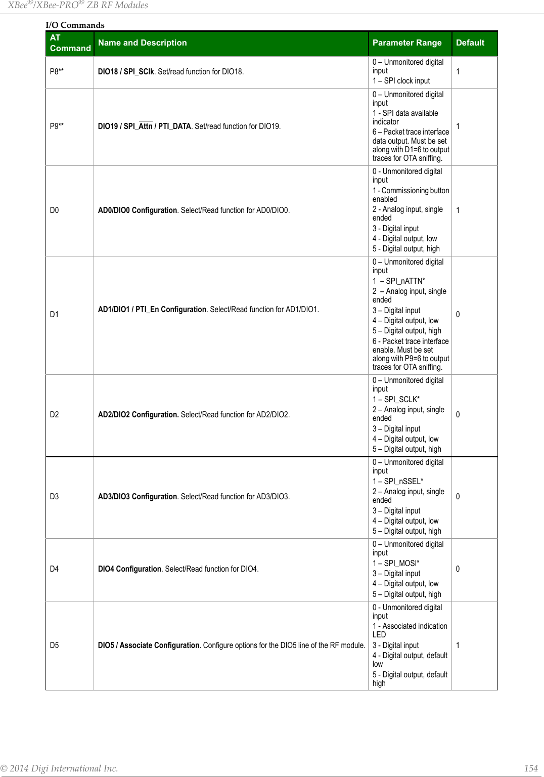
![XBee®/XBee‐PRO®ZBRFModules©2014DigiInternationalInc. 155D8 DIO8 / DTR / Slp_Rq. Set/Read function for DIO8.0 – Unmonitored digital input1 – Input to sleep and wake module3 – Digital input4 – Digital output, low5 – Digital output, highLTAssoc LED Blink Time. Set/Read the Associate LED blink time. If the Associate LED functionality is enabled (D5 command), this value determines the on and off blink times for the LED when the module has joined a network. If LT=0, the default blink rate will be used (500ms coordinator, 250ms router/end device). For all other LT values, LT is measured in 10ms.0, 0x0A - 0xFF (100 - 2550 ms) 0PRPull-up/down Resistor. Set/read the bit field that configures the internal pull-up/down resistor status for the I/O lines. "1" specifies the pull-up/down resistor is enabled. "0" specifies no internal resistors are used. The input will be floating.Bits:"0 - DIO4 (Pin 24/SMT, Pin 11/TH)1 - AD3 / DIO3 (Pin 30/SMT, Pin 17/TH)2 - AD2 / DIO2 (Pin 31/SMT, Pin 18/TH)3 - AD1 / DIO1 (Pin 32/SMT, Pin 19/TH)4 - AD0 / DIO0 (Pin 33/SMT, Pin 20/TH)5 - RTS / DIO6 (Pin 29/SMT, Pin 16/TH)6 - DTR / Sleep Request / DIO8 (Pin 10/SMT, Pin 9/TH)7 - DIN / Config (Pin 4/SMT, Pin 3/TH)8 - Associate / DIO5 (Pin 28/SMT, Pin 15/TH)9 - On/Sleep / DIO9 (Pin 26/SMT, Pin 13/TH)10 - DIO12 (Pin 5/SMT, Pin 4/TH)11 - PWM0 / RSSI / DIO10 (Pin 7/SMT, Pin 6/TH)12 - PWM1 / DIO11 (Pin 8/SMT, Pin 7/TH)13 - CTS / DIO7 (Pin 25/SMT, Pin 12/TH)14 - DOUT / DIO13 (Pin 3/SMT, Pin 2/TH)0 - 0x7FFF 0x1FFFPDPull-up / down direction. Set/read an internal pull-up or pull-down resistor for the corresponding bits in the PR command. If the bit is set, an internal pull-up resistor is used. If it is clear, an internal pull-down resistor is used. See the PR command for the bit order.0 - 0x7FFF 0x1FBFRP RSSI PWM Timer. Time the RSSI signal will be output on the PWM after the last RF data reception or APS acknowledgment.. When RP = 0xFF, output will always be on. 0 - 0xFF [x 100 ms] 0x28 (40d)DCDevice Controls.Bit settings enable or disable certain behaviors.Bit 0 - Joiner Global Link Key. Indicates whether a joiner node uses a global link key or a unique link key.Bit 1 - Network Leave Request Not Allowed. Indicates if a router node should discard or accept network leave commands.Bit 2 - reserved.Bit 3 - reserved.Bit 4 - Verbose Joining Mode. See XBee ZigBee API Operation frame type 0x98, Extended Modem Status for a full description.0-0xFFFF 0x00DODevice Options. Bit0 - Reserved. Bit1 - Reserved for Smart Energy devices. Bit2 - 0/1 = First or Best Join. First join means the device will join the network through the first acceptable Beacon response it receives. Best join means the device will join the network through the strongest Beacon response it receives after searching all search mask channels. Bit3 - Disable NULL Transport Key (Coordinator Only). Bit4 - Disable Tx Packet Extended Timeout. Bit5 - Disable ACK for End Device I/O Sampling. Bit6 - Enable High Ram Concentrator. Bit7 - Enable ATNW to find new network before leaving the network. 0x00-0xFF 0x00%V Supply Voltage. Reads the voltage on the Vcc pin in mV. -0x-0xFFFF [read only] -V+Voltage Supply Monitoring. The voltage supply threshold is set with the V+ command. If the measured supply voltage falls below or equal to this threshold, the supply voltage will be included in the IO sample set. V+ is set to 0 by default (do not include the supply voltage).The units of this command are mV. For example, to include a measurement of the supply voltage when it exceeds 3.3 V, set V+ to 3300 = 0xCE4.0-0xFFFF 0TP Reads the module temperature in Degrees Celsius. Accuracy +/- 7 degrees. 1° C = 0x0001 and -1° C = 0xFFFF. Command is only available on PRO module. 0x0-0xFFFF -I/OCommandsATCommand Name and Description Parameter Range Default](https://usermanual.wiki/Digi/PS2CTH/User-Guide-2348528-Page-154.png)
![XBee®/XBee‐PRO®ZBRFModules©2014DigiInternationalInc. 156• * indicates that the option is available on the TH module, but not the SMT module.• ** indicates that the command is available on the SMT module, but not the TH module.DiagnosticsAT Command OptionsDiagnosticsCommandsATCommand Name and Description Parameter Range DefaultVR Firmware Version. Read firmware version of the module as a 4-digit hex number. 0 - 0xFFFF [read-only] Factory-setVL Version Long. Shows detailed version information, module type, a time stamp for the build, Ember stack version, and bootloader version. N/A N/AHVHardware Version. Read the hardware version of the module.version of the module. This command can be used to distinguish among different hardware platforms. The upper byte returns a value that is unique to each module type. The lower byte indicates the hardware revision.The regular XBee returns a value of 0x22xx for this command. the XBee-PRO returns a value of 0x21xx.0 - 0xFFFF [read-only] Factory-setAIAssociation Indication. Read information regarding last node join request:0x00 - Successfully formed or joined a network. (Coordinators form a network, routers and end devices join a network.)0x21 - Scan found no PANs0x22 - Scan found no valid PANs based on current SC and ID settings0x23 - Valid Coordinator or Routers found, but they are not allowing joining (NJ expired)0x24 - No joinable beacons were found0x25 - Unexpected state, node should not be attempting to join at this time0x27 - Node Joining attempt failed (typically due to incompatible security settings)0x2A - Coordinator Start attempt failed‘0x2B - Checking for an existing coordinator0x2C - Attempt to leave the network failed0xAB - Attempted to join a device that did not respond.0xAC - Secure join error - network security key received unsecured0xAD - Secure join error - network security key not received0xAF - Secure join error - joining device does not have the right preconfigured link key0xFF - Scanning for a ZigBee network (routers and end devices)Note: New non-zero AI values may be added in later firmware versions. Applications should read AI until it returns 0x00, indicating a successful startup (coordinator) or join (routers and end devices)0 - 0xFF[read-only] --ATCommandOptionsCommandsATCommand Name and Description Parameter Range DefaultCTCommand Mode Timeout. Set/Read the period of inactivity (no valid commands received) after which the RF module automatically exits AT Command Mode and returns to Idle Mode.2 - 0x028F [x 100 ms] 0x64 (100d)CN Exit Command Mode. Explicitly exit the module from AT Command Mode. -- --GTGuard Times. Set required period of silence before and after the Command Sequence Characters of the AT Command Mode Sequence (GT + CC + GT). The period of silence is used to prevent inadvertent entrance into AT Command Mode.1 - 0x0CE4 [x 1 ms](max of 3.3 decimal sec)0x3E8(1000d)CCCommand Sequence Character. Set/Read the ASCII character value to be used between Guard Times of the AT Command Mode Sequence (GT + CC + GT). The AT Command Mode Sequence enters the RF module into AT Command Mode. 0 - 0xFF 0x2B (‘+’ ASCII)](https://usermanual.wiki/Digi/PS2CTH/User-Guide-2348528-Page-155.png)
![©2014DigiInternationalInc. 163AppendixA:AgencyCertificationsUnited States FCCThe XBee RF Module complies with Part 15 of the FCC rules and regulations. Compliance with the labeling requirements, FCC notices and antenna usage guidelines is required.To fulfill FCC Certification, the OEM must comply with the following regulations:1.The system integrator must ensure that the text on the external label provided with this device is placed on the outside of the final product.2.XBee RF Module may only be used with antennas that have been tested and approved for use with this module [refer to the antenna tables in this section].OEM Labeling RequirementsWARNING: The Original Equipment Manufacturer (OEM) must ensure that FCC labeling requirements are met. This includes a clearly visible label on the outside of the final product enclosure that displays the contents shown in the figure below. Required FCC Label for OEM products containing the XBee S2C SMT RF Module Required FCC Label for OEM products containing the XBee-PRO S2C SMT RF Module Required FCC Label for OEM products containing the XBee S2C TH RF ModuleRequired FCC Label for OEM products containing the XBee-PRO S2C TH RF ModuleFCC NoticesIMPORTANT: The XBee and XBee-PRO RF Module have been certified by the FCC for use with other products without any further certification (as per FCC section 2.1091). Modifications not expressly approved by Digi could void the user's authority to operate the equipment.IMPORTANT: OEMs must test final product to comply with unintentional radiators (FCC section 15.107 & 15.109) before declaring compliance of their final product to Part 15 of the FCC Rules.IMPORTANT: The RF module has been certified for remote and base radio applications. If the module will be used for portable applications, the device must undergo SAR testing.Contains FCC ID: MCQ-XBS2CThis device complies with Part 15 of the FCC Rules. Operation is subject to the following two conditions: (1.) this device may not cause harmful interference and (2.) this device must accept any interference received, including interference that may cause undesired operation.Contains FCC ID:MCQ-XBPS2CThis device complies with Part 15 of the FCC Rules. Operation is subject to the following two conditions: (1.) this device may not cause harmful interference and (2.) this device must accept any interference received, including interference that may cause undesired operation.Contains FCC ID:MCQ-S2CTHThis device complies with Part 15 of the FCC Rules. Operation is subject to the following two conditions: (1.) this device may not cause harmful interference and (2.) this device must accept any interference received, including interference that may cause undesired operation.Contains FCC ID: MCQ-PS2CTHThis device complies with Part 15 of the FCC Rules. Operation is subject to the following two conditions: (1.) this device may not cause harmful interference and (2.) this device must accept any interference received, including interference that may cause undesired operation.](https://usermanual.wiki/Digi/PS2CTH/User-Guide-2348528-Page-162.png)

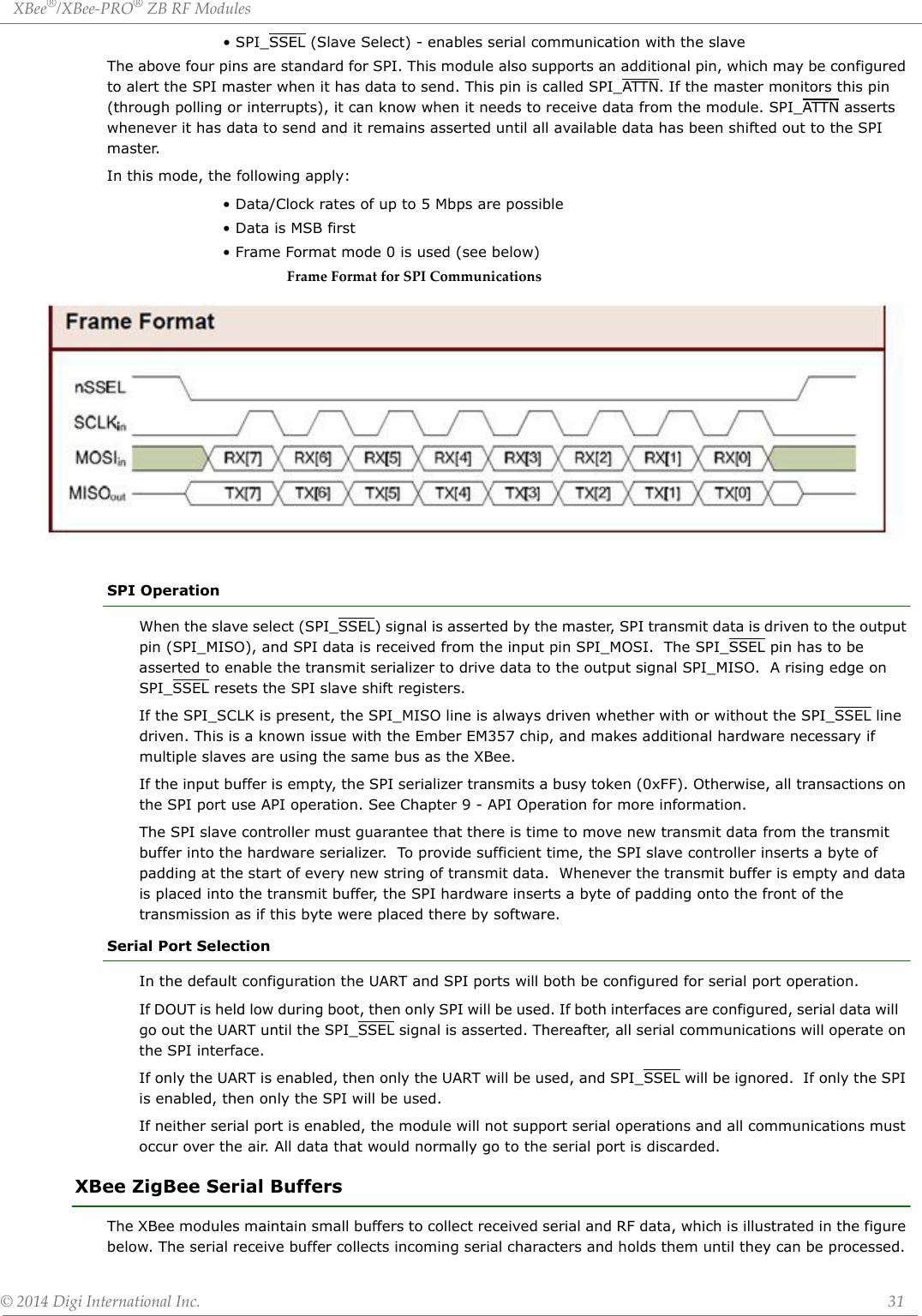
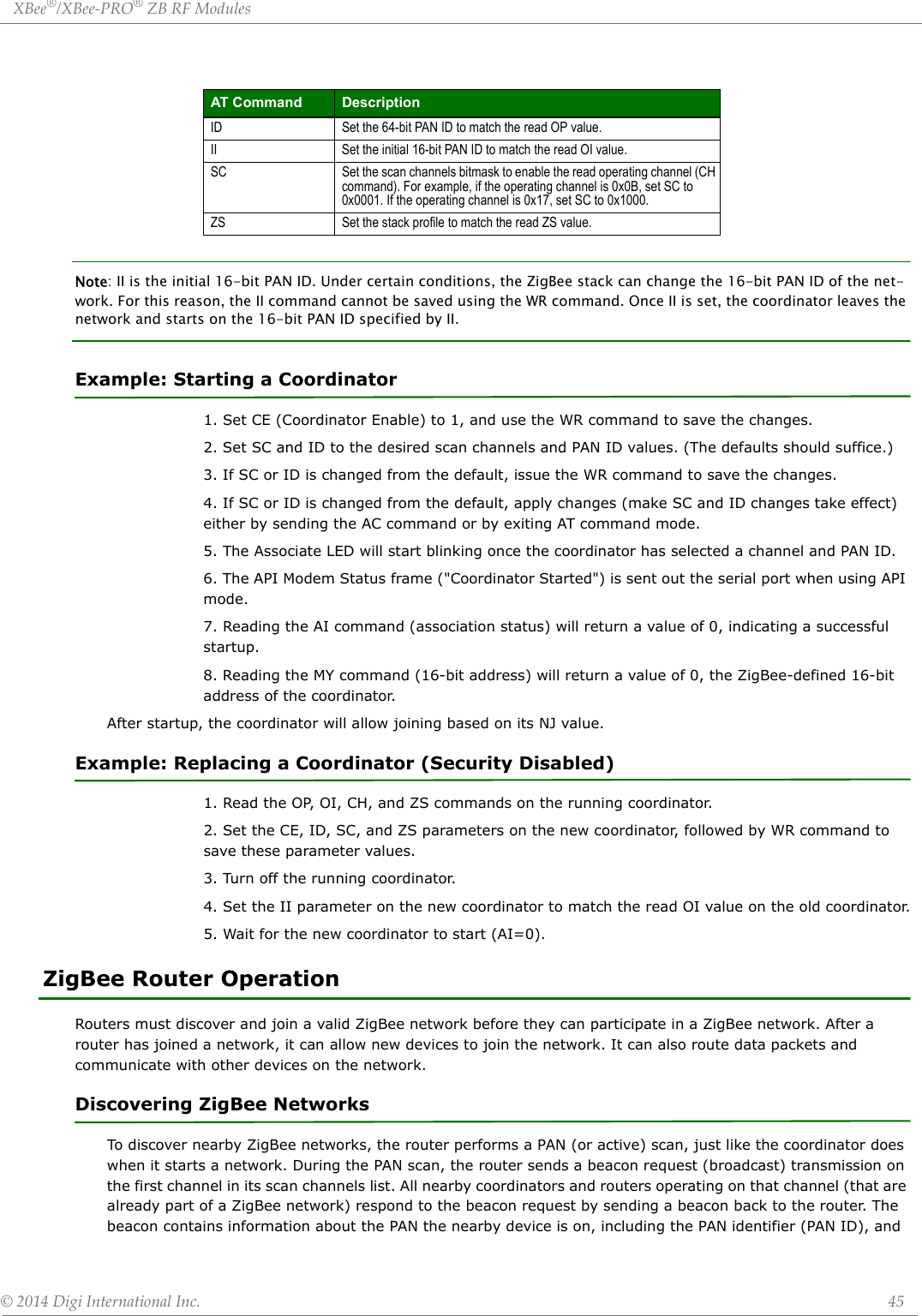
![©2014DigiInternationalInc. 171AppendixB:MigratingfromXBeeZBtoXBeeZBRFModulesThe XBee ZB RF modules are designed to be compatible with the XBee ZB. The ZB SMT modules have all the features of the ZB modules, and offer the increased feature set described in this user’s guide. For further information on the ZB, see the XBee/XBee-PRO ZB RF Modules User’s Guide available at www.digi.com. Pin MappingMapping of the ZB SMT pins to the ZB pins is shown in the table below. The pin names are from the S2C SMT module.ZB SMT Pin #Name ZB Pin #1 GND2VCC13 DOUT / DIO13 24 DIN / CONFIG / DIO14 35 DIO12 46RESET57 RSSI PWM / DIO10 68 PWM1 / DIO11 79 [reserved] 810 DTR / SLEEP_RQ / DIO8 911 GND 1012 SPI_ATTN / BOOTMODE / DIO1913 GND14 SPI_CLK / DIO1815 SPI_SSEL / DIO1716 SPI_MOSI / DIO1617 SPI_MISO / DIO1518 [reserved]19 [reserved]20 [reserved]21 [reserved]22 GND23 [reserved]24 DIO4 1125 CTS / DIO7 1226 ON / SLEEP / DIO9 1327 VREF 14](https://usermanual.wiki/Digi/PS2CTH/User-Guide-2348528-Page-170.png)
![XBee®/XBee‐PRO®ZBRFModules©2014DigiInternationalInc. 172 MountingOne of the important differences between the ZB SMT and the ZB modules is the way they mount to the PCB. The ZB is designed with through-hole pins, while the ZB SMT is designed with Surface Mount Technology (SMT). As such, different mounting techniques are required.Digi International has designed a footprint which will allow either module to be attached to a PCB. The layout is shown below. All dimensions are in inches.28 ASSOCIATE / DIO5 1529 RTS / DIO6 1630 AD3 / DIO3 1731 AD2 / DIO2 1832 AD1 / DIO1 1933 AD0 / DIO0 2034 [reserved]35 GND36 RF37 [reserved]ZB SMT Pin #Name ZB Pin #](https://usermanual.wiki/Digi/PS2CTH/User-Guide-2348528-Page-171.png)